Blandford gateshead millenium
10
Bridge Engineering 2 Conference 2007 27 April 2007, University of Bath, Bath, UK A CRITICAL ANALYSIS OF THE GATESHEAD MILLENNIUM BRIDGE Z A Blandford University of Bath Abstract: This article explores the aesthetics and construction of the Gateshead Millennium Bridge. Loading on the bridge has also been assessed and a simple analysis of the bridge has been carried out. This paper seeks to critically analyse the bridge, inform on what the designer actually decided and discuss any issues that arise from these decisions. The simple analysis includes temperature loading and wind loading. Keywords: Bridge, arch, cable-stayed, steel structure, rotating, Gateshead, Millennium 1 Introduction The Gateshead Millennium Bridge (also known as the Baltic Millennium Bridge) is located over the Tyne River between Gateshead and Newcastle, UK. The bridge is a cable-stayed arch bridge. The steel arch supports the curved steel deck using 18 steel cables. Figure 1: The Gateshead Millennium Bridge The bridge was designed as a competition entry, hoping to regenerate the area of Gateshead. The bridge at Gateshead today is the winning entry of the competition, designed by Wilkinson Eyre Architects and Gifford and Partners (Structural engineer). The most pioneering feature of this bridge is that it is the world’s first rotating bridge. The bridge has been designed to open, as shown in Fig. 2, to allow large boats to pass underneath it. Small boats can pass under the deck in the closed position. Figure 2: The Bridge in its open position The concept of the rotating bridge was a reaction to three main design constraints: 1. The bridge should be 4.5m above the spring high tides in its closed position. 2. Nothing was to be built on the Gateshead quayside. 3. The deck should have a maximum slope of 1:20 to allow for disabled access. Looking at Fig. 2 it can be seen that the piers that transfer the loading from the arch to the 30m deep
Transcript of Blandford gateshead millenium
Bridge Engineering 2 Conference 2007 27 April 2007, University of Bath, Bath, UK
A CRITICAL ANALYSIS OF THE GATESHEAD MILLENNIUM BRIDGE
Z A Blandford
University of Bath
Abstract: This article explores the aesthetics and construction of the Gateshead Millennium Bridge. Loading on the bridge has also been assessed and a simple analysis of the bridge has been carried out. This paper seeks to critically analyse the bridge, inform on what the designer actually decided and discuss any issues that arise from these decisions. The simple analysis includes temperature loading and wind loading.
Keywords: Bridge, arch, cable-stayed, steel structure, rotating, Gateshead, Millennium
1 Introduction
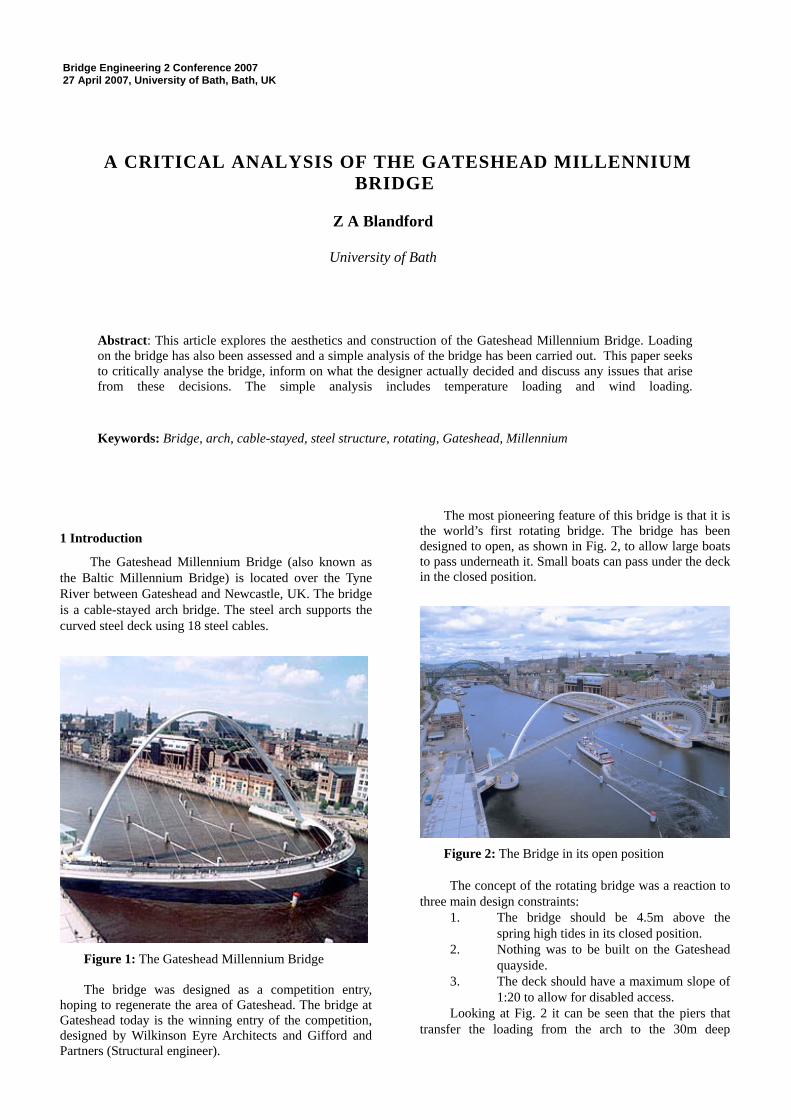
The Gateshead Millennium Bridge (also known as the Baltic Millennium Bridge) is located over the Tyne River between Gateshead and Newcastle, UK. The bridge is a cable-stayed arch bridge. The steel arch supports the curved steel deck using 18 steel cables.
Figure 1: The Gateshead Millennium Bridge The bridge was designed as a competition entry,
hoping to regenerate the area of Gateshead. The bridge at Gateshead today is the winning entry of the competition, designed by Wilkinson Eyre Architects and Gifford and Partners (Structural engineer).
The most pioneering feature of this bridge is that it is the world’s first rotating bridge. The bridge has been designed to open, as shown in Fig. 2, to allow large boats to pass underneath it. Small boats can pass under the deck in the closed position.
Figure 2: The Bridge in its open position The concept of the rotating bridge was a reaction to
three main design constraints: 1. The bridge should be 4.5m above the
spring high tides in its closed position. 2. Nothing was to be built on the Gateshead
quayside. 3. The deck should have a maximum slope of
1:20 to allow for disabled access. Looking at Fig. 2 it can be seen that the piers that
transfer the loading from the arch to the 30m deep
concrete foundations are located at the edge of the river to meet requirement 2.
This is a bridge that looks beautiful and meets all the requirements in an innovative way.
2 Bridge Aesthetics
The Gateshead Millennium Bridge does not take into account all of the considerations proposed by Leonhardt for an aesthetically pleasing bridge. It does, most importantly, portray its function and structure very simply. Unnecessary complication in the design has been avoided and overall the bridge is very interesting and pleasing to look at
2.1 Fulfilment of Function
The Gateshead Millennium Bridge’s beautiful shape and innovative tilting mechanism is a result of the necessity to accommodate the movement of water traffic under the bridge. The curved shape of the deck in plan at first appears unnecessary as pedestrians and cyclists have to traverse a non-direct route between Gateshead and Newcastle. However, this shape is crucial in providing sufficient height above the water when the bridge is in the upright position.
A user of the bridge can clearly see the cables that support the deck; the structural form of this bridge is obvious. This bridge is incredibly simple, yet highly innovative, which reflects that it truly fulfils its function.
2.2 Proportions of the Bridge
The curved deck of the bridge balances the geometry of the supporting arch. The dimensions, and the deck depth look correct, creating a beautiful bridge.
2.3 Order within the Structure
The curves of the Gateshead Millennium Bridge are pleasing to the eye because your flow of vision is not interrupted as you look at the bridge. As there is only one line cables, there are not problems with overlapping. The deck is curved to enable the cables to fit along the same plane.
2.4 Refinement of Design
It is clear from the design that the bridge has been very carefully thought about. The finest details of the design have been considered so that it functions well and looks impressive.
The cables lie on one plane, giving an uncluttered appearance. Cables that appear to the viewer to be crossing at varying angles bring a sense of chaos.
2.5 Integration into the Environment
The Gateshead Millennium Bridge is incorporated well into its surrounding environment, it does not detract from the existing Tyne Bridge and Robert Stephenson’s High Level Bridge, but reflects their use of arches. This can be seen in Fig. 3.
Figure 3: Incorporation into the environment
2.6 Texture
Having not visited the Gateshead Millennium Bridge, it is difficult to comment on its texture. Looking at the bridge it appears to be smooth which complements its curved form. In some aspects, the bridge looks like a giant sculpture.
2.7 Colour
During the day, the bridge is seen as two white curves, the arch and the deck. The choice of cable colour has caused them to retreat into the background during some weather conditions, yet they are clearly visible on other occasions. This gives the bridge a variety of appearances.
Figure 4: Cables merging into the background At night, the bridge is lit in a variety of colours. The
cables are virtually invisible at night. This choice was informed by the need to reduce light pollution, as the cables were too thin to reflect the light effectively. The main aim of the lighting was to define the bridge’s structural form and this is successful even though practical requirements dictated most of the choices for lighting. These included pedestrian safety; the materials used and harbour rules (not distracting ships). Despite these restraints, the lighting of the bridge has proved to
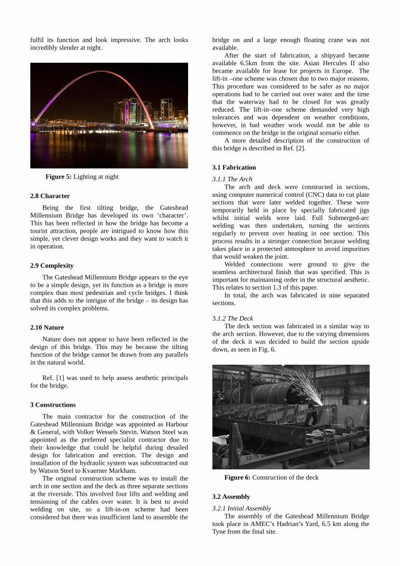
fulfil its function and look impressive. The arch looks incredibly slender at night.
Figure 5: Lighting at night
2.8 Character
Being the first tilting bridge, the Gateshead Millennium Bridge has developed its own ‘character’. This has been reflected in how the bridge has become a tourist attraction, people are intrigued to know how this simple, yet clever design works and they want to watch it in operation.
2.9 Complexity
The Gateshead Millennium Bridge appears to the eye to be a simple design, yet its function as a bridge is more complex than most pedestrian and cycle bridges. I think that this adds to the intrigue of the bridge – its design has solved its complex problems.
2.10 Nature
Nature does not appear to have been reflected in the design of this bridge. This may be because the tilting function of the bridge cannot be drawn from any parallels in the natural world.
Ref. [1] was used to help assess aesthetic principals
for the bridge.
3 Constructions
The main contractor for the construction of the Gateshead Millennium Bridge was appointed as Harbour & General, with Volker Wessels Stevin. Watson Steel was appointed as the preferred specialist contractor due to their knowledge that could be helpful during detailed design for fabrication and erection. The design and installation of the hydraulic system was subcontracted out by Watson Steel to Kvaerner Markham.
The original construction scheme was to install the arch in one section and the deck as three separate sections at the riverside. This involved four lifts and welding and tensioning of the cables over water. It is best to avoid welding on site, so a lift-in-on scheme had been considered but there was insufficient land to assemble the
bridge on and a large enough floating crane was not available.
After the start of fabrication, a shipyard became available 6.5km from the site. Asian Hercules II also became available for lease for projects in Europe. The lift-in –one scheme was chosen due to two major reasons. This procedure was considered to be safer as no major operations had to be carried out over water and the time that the waterway had to be closed for was greatly reduced. The lift-in–one scheme demanded very high tolerances and was dependent on weather conditions, however, in bad weather work would not be able to commence on the bridge in the original scenario either.
A more detailed description of the construction of this bridge is described in Ref. [2].
3.1 Fabrication
3.1.1 The Arch The arch and deck were constructed in sections,
using computer numerical control (CNC) data to cut plate sections that were later welded together. These were temporarily held in place by specially fabricated jigs whilst initial welds were laid. Full Submerged-arc welding was then undertaken, turning the sections regularly to prevent over heating in one section. This process results in a stronger connection because welding takes place in a protected atmosphere to avoid impurities that would weaken the joint.
Welded connections were ground to give the seamless architectural finish that was specified. This is important for maintaining order in the structural aesthetic. This relates to section 1.3 of this paper.
In total, the arch was fabricated in nine separated sections. 3.1.2 The Deck
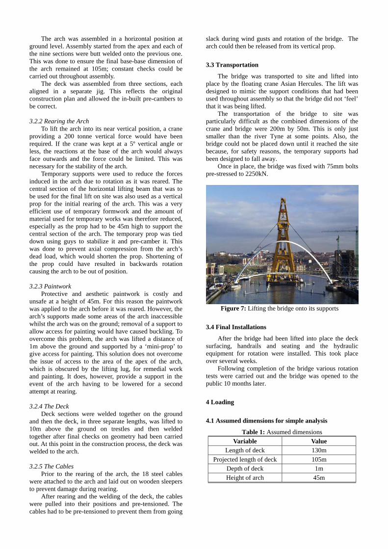
The deck section was fabricated in a similar way to the arch section. However, due to the varying dimensions of the deck it was decided to build the section upside down, as seen in Fig. 6.
Figure 6: Construction of the deck
3.2 Assembly
3.2.1 Initial Assembly The assembly of the Gateshead Millennium Bridge
took place in AMEC’s Hadrian’s Yard, 6.5 km along the Tyne from the final site.
The arch was assembled in a horizontal position at ground level. Assembly started from the apex and each of the nine sections were butt welded onto the previous one. This was done to ensure the final base-base dimension of the arch remained at 105m; constant checks could be carried out throughout assembly.
The deck was assembled from three sections, each aligned in a separate jig. This reflects the original construction plan and allowed the in-built pre-cambers to be correct. 3.2.2 Rearing the Arch
To lift the arch into its near vertical position, a crane providing a 200 tonne vertical force would have been required. If the crane was kept at a 5º vertical angle or less, the reactions at the base of the arch would always face outwards and the force could be limited. This was necessary for the stability of the arch.
Temporary supports were used to reduce the forces induced in the arch due to rotation as it was reared. The central section of the horizontal lifting beam that was to be used for the final lift on site was also used as a vertical prop for the initial rearing of the arch. This was a very efficient use of temporary formwork and the amount of material used for temporary works was therefore reduced, especially as the prop had to be 45m high to support the central section of the arch. The temporary prop was tied down using guys to stabilize it and pre-camber it. This was done to prevent axial compression from the arch’s dead load, which would shorten the prop. Shortening of the prop could have resulted in backwards rotation causing the arch to be out of position. 3.2.3 Paintwork
Protective and aesthetic paintwork is costly and unsafe at a height of 45m. For this reason the paintwork was applied to the arch before it was reared. However, the arch’s supports made some areas of the arch inaccessible whilst the arch was on the ground; removal of a support to allow access for painting would have caused buckling. To overcome this problem, the arch was lifted a distance of 1m above the ground and supported by a ‘mini-prop’ to give access for painting. This solution does not overcome the issue of access to the area of the apex of the arch, which is obscured by the lifting lug, for remedial work and painting. It does, however, provide a support in the event of the arch having to be lowered for a second attempt at rearing. 3.2.4 The Deck
Deck sections were welded together on the ground and then the deck, in three separate lengths, was lifted to 10m above the ground on trestles and then welded together after final checks on geometry had been carried out. At this point in the construction process, the deck was welded to the arch.
3.2.5 The Cables
Prior to the rearing of the arch, the 18 steel cables were attached to the arch and laid out on wooden sleepers to prevent damage during rearing.
After rearing and the welding of the deck, the cables were pulled into their positions and pre-tensioned. The cables had to be pre-tensioned to prevent them from going
slack during wind gusts and rotation of the bridge. The arch could then be released from its vertical prop.
3.3 Transportation
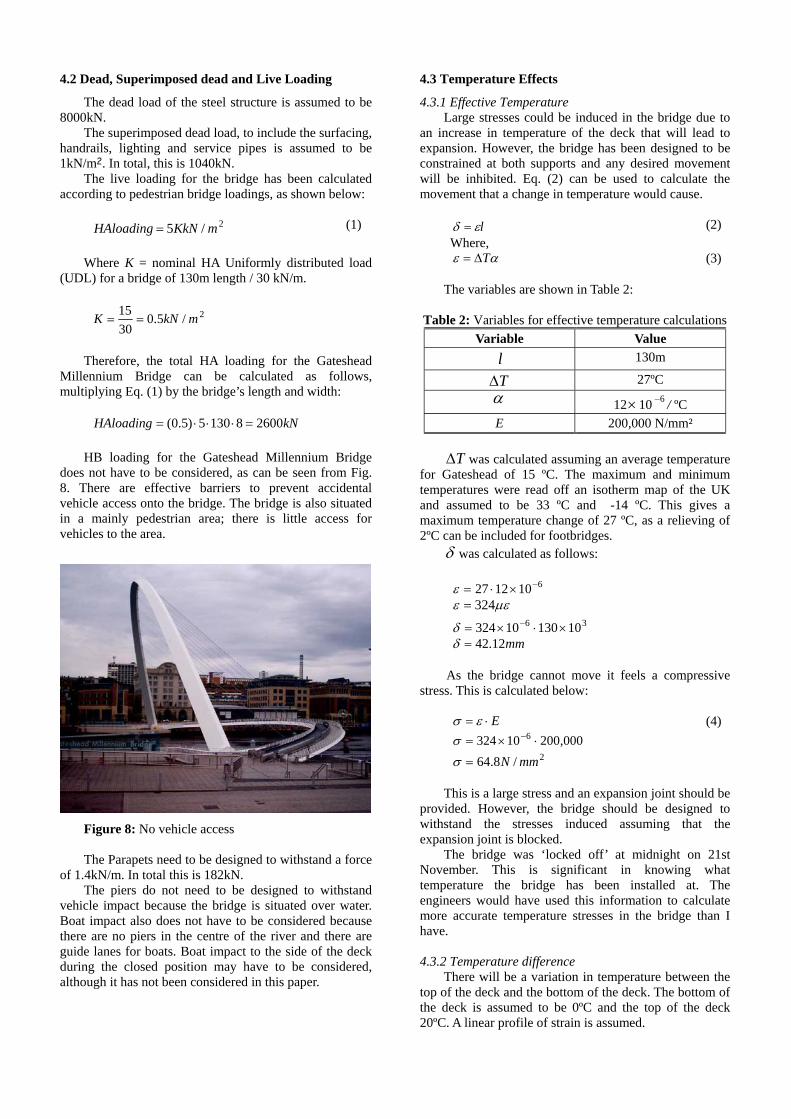
The bridge was transported to site and lifted into place by the floating crane Asian Hercules. The lift was designed to mimic the support conditions that had been used throughout assembly so that the bridge did not ‘feel’ that it was being lifted.
The transportation of the bridge to site was particularly difficult as the combined dimensions of the crane and bridge were 200m by 50m. This is only just smaller than the river Tyne at some points. Also, the bridge could not be placed down until it reached the site because, for safety reasons, the temporary supports had been designed to fall away.
Once in place, the bridge was fixed with 75mm bolts pre-stressed to 2250kN.
Figure 7: Lifting the bridge onto its supports
3.4 Final Installations
After the bridge had been lifted into place the deck surfacing, handrails and seating and the hydraulic equipment for rotation were installed. This took place over several weeks.
Following completion of the bridge various rotation tests were carried out and the bridge was opened to the public 10 months later.
4 Loading
4.1 Assumed dimensions for simple analysis
Table 1: Assumed dimensions Variable Value
Length of deck 130m Projected length of deck 105m
Depth of deck 1m Height of arch 45m
4.2 Dead, Superimposed dead and Live Loading
The dead load of the steel structure is assumed to be 8000kN.
The superimposed dead load, to include the surfacing, handrails, lighting and service pipes is assumed to be 1kN/m². In total, this is 1040kN.
The live loading for the bridge has been calculated according to pedestrian bridge loadings, as shown below:
2/5 mKkNHAloading = (1)
Where K = nominal HA Uniformly distributed load
(UDL) for a bridge of 130m length / 30 kN/m.
2/5.03015 mkNK ==
Therefore, the total HA loading for the Gateshead
Millennium Bridge can be calculated as follows, multiplying Eq. (1) by the bridge’s length and width:
kNHAloading 260081305)5.0( =⋅⋅⋅=
HB loading for the Gateshead Millennium Bridge
does not have to be considered, as can be seen from Fig. 8. There are effective barriers to prevent accidental vehicle access onto the bridge. The bridge is also situated in a mainly pedestrian area; there is little access for vehicles to the area.
Figure 8: No vehicle access The Parapets need to be designed to withstand a force
of 1.4kN/m. In total this is 182kN. The piers do not need to be designed to withstand
vehicle impact because the bridge is situated over water. Boat impact also does not have to be considered because there are no piers in the centre of the river and there are guide lanes for boats. Boat impact to the side of the deck during the closed position may have to be considered, although it has not been considered in this paper.
4.3 Temperature Effects
4.3.1 Effective Temperature Large stresses could be induced in the bridge due to
an increase in temperature of the deck that will lead to expansion. However, the bridge has been designed to be constrained at both supports and any desired movement will be inhibited. Eq. (2) can be used to calculate the movement that a change in temperature would cause.
lεδ = (2)
Where, αε TΔ= (3)
The variables are shown in Table 2:
Table 2: Variables for effective temperature calculations Variable Value
l 130m
TΔ 27ºC α 12×10 / ºC 6−
E 200,000 N/mm²
TΔ was calculated assuming an average temperature for Gateshead of 15 ºC. The maximum and minimum temperatures were read off an isotherm map of the UK and assumed to be 33 ºC and -14 ºC. This gives a maximum temperature change of 27 ºC, as a relieving of 2ºC can be included for footbridges.
δ was calculated as follows:
6101227 −×⋅=ε μεε 324=
36 1013010324 ×⋅×= −δ mm12.42=δ
As the bridge cannot move it feels a compressive
stress. This is calculated below:
E⋅= εσ 000,20010324 6 ⋅×= −σ
2/8.64 mmN=σ
(4)
This is a large stress and an expansion joint should be
provided. However, the bridge should be designed to withstand the stresses induced assuming that the expansion joint is blocked.
The bridge was ‘locked off’ at midnight on 21st November. This is significant in knowing what temperature the bridge has been installed at. The engineers would have used this information to calculate more accurate temperature stresses in the bridge than I have.
4.3.2 Temperature difference
There will be a variation in temperature between the top of the deck and the bottom of the deck. The bottom of the deck is assumed to be 0ºC and the top of the deck 20ºC. A linear profile of strain is assumed.
Deck profile Strain profile Axial force
CA
Temperature profile Stress profile Bending moment
Figure 9: Profiles The profile in Fig. 9 can be used to calculate the axial
force and bending moment induced in the deck due to the temperature difference between the top and bottom. These values are very rough estimates as a rectangular profile for the deck has been chosen for simplicity. It was assumed that as exact dimensions of the curved deck, which varied in depth across its section, was unknown that simplifying the form would allow initial behaviour to be assessed. The obvious error with this assumption is that the centroidal axis is central, which in the case of the actual bridge design, it is not.
The axial force and bending moment induced due to temperature effects can be calculated as shown below:
αε ⋅= 1max T
μεε 240101220 6max =×⋅= −
(5)
E⋅= maxmax εσ
26max /48000,20010240 mmN=⋅×= −σ
(6)
AN axial ⋅= σ
1000500maxσσ
=axial 2/24 mmNaxial =σ
kNN 6.8601104.35824 3 =×⋅=
(7)
bottom
axial
yI
M⋅
=σ
kNmM 4752500
109924 9=
×⋅=
(8)
This is a large axial force and bending moment. In
reality, these values will be less as the deck shape has been designed to reduce these values. This is why the deck is the shape shown in Fig.10 and not the rectangular hollow section that I assumed.
Figure 10: Deck profile
4.4 Wind Loading
Millennium Bridge is a difficult struc
following calculations give a simple analysis of the b
4.4.1 Maximum wind gust ust that could be expected to
occu
The Gatesheadture to analyse for wind loading. This is due to its
shape, but also the many different positions it needs to be analysed in. It is important that the cables are pre-stressed enough so that they do not go slack, especially in the open position.
The ridge in its closed position. The calculations have
been carried out according to BS 5400-2:2006.
The maximum wind gr at a point on the bridge is calculated as follows:
211 ssvkVc = (9)
es were found using various tables and figu
Ta e 3: Variables for maximum wind gust calculation.
The variablres in BS 5400-2:2006. They are in Table 3. A height
of 25m (just above mid-height) was assumed. In reality, the bridge would have been analysed by a computer at all heights and at all opening positions.
bl
Variable Value v - mea ind sp
31 for Nen hourly weed
wcastle
1k - wind coefficient 1.60 for 100m length
1s - funnelling factor 1.00
2s - gust factor 1.24
herefore, the maximum wind gust can be estimated
as:
.4.2 Horizontal Wind Load
d acts at the centroid of the part
T
15.61
)24.1()00.1()60.1(31−=
⋅⋅⋅=
msV
V
c
c
4The horizontal wind loa of the bridge under consideration. In this case, the
deck has been considered.
Dt CqAP 1= (10)
here, q is the dynamic pressure head, W
2
2
/7.37)5.61()613.0(
613.0
mNq
Vq c
=⋅=
=
(11)
is the solid projected area; therefore the projected
length has been used. (The span of the deck). 1A
DC is the drag coefficient, calculated as a function of b/d and read off a chart. The parapet has been assumed to be open. Therefore, d is just the depth of the deck.
818
18
==
====
db
mdepthdmwidthb
has been chosen as 2.0 because this is the
minimum coefficient for a foot and cycle track bridge. DC
Therefore, the horizontal wind load on the Gateshead Millennium Bridge can be calculated as,
kNPt 9.72105)7.37( =⋅⋅=
4.4.3 Longitudinal Wind Loads
Longitudinal wind loads on the structure:
kNPCqAP
LS
DLS
98.1)9.7).(25.0(25.0 1
===
(12)
Longitudinal wind loads on the parapet:
kNPPP
L
tL
16.3)9.7()4.0(4.0
=⋅==
(13)
Therefore, the parapet should be designed to
withstand this point load.
4.4.4 Uplift and Downward force The value of uplift that could be caused is important
because this is the amount that the cables need to be pre-stressed by to ensure that they do not go slack if the bridge deck is uplifted.
Lv CqAP 3= (14)
Where, q is the dynamic pressure head, is the plan
area of the deck, depends on b/d and is read of a chart. Therefore, uplift can be calculated:
3ALC
kNPv 5.14)37.0(1040)7.37( =⋅⋅=
However, the deck is not quite horizontal, therefore
becomes 0.75 and becomes 29.4kN. This is almost a doubling in the uplift.
LC vP
It can be seen that the forces on the deck would be much smaller if it was horizontal, however, there are other reasons why a slightly inclined deck was chosen. Perhaps it gives a better stability and a better angle for the cables.
It does allow small boats to pass under the deck whilst the bridge is still in the closed position.
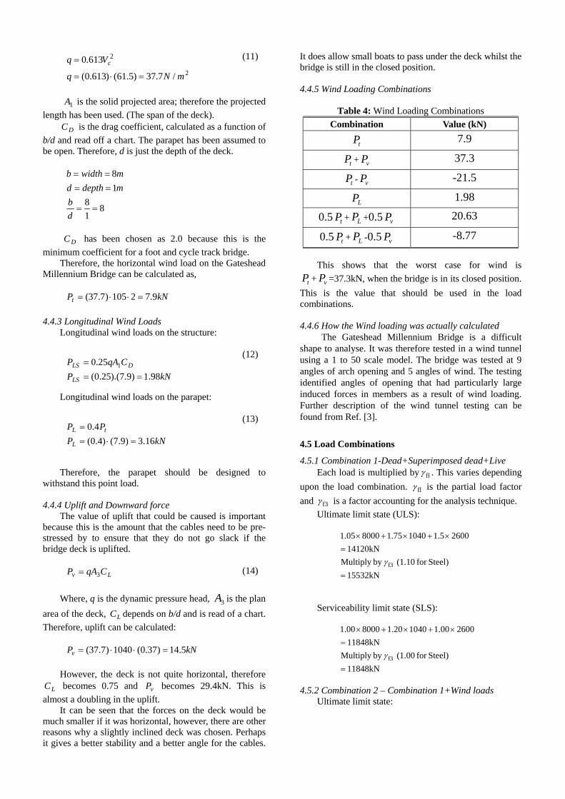
4.4.5 Wind Loading Combinations
Table 4: Wind Loading Combinations Combination Value (kN)
tP 7.9
tP + vP 37.3
tP - vP -21.5
LP 1.98
0.5 + +0.5 tP LP vP 20.63
0.5 + -0.5 tP LP vP -8.77 This shows that the worst case for wind is
+ =37.3kN, when the bridge is in its closed position. This is the value that should be used in the load combinations.
tP vP
4.4.6 How the Wind loading was actually calculated
The Gateshead Millennium Bridge is a difficult shape to analyse. It was therefore tested in a wind tunnel using a 1 to 50 scale model. The bridge was tested at 9 angles of arch opening and 5 angles of wind. The testing identified angles of opening that had particularly large induced forces in members as a result of wind loading. Further description of the wind tunnel testing can be found from Ref. [3].
4.5 Load Combinations
4.5.1 Combination 1-Dead+Superimposed dead+Live Each load is multiplied by flγ . This varies depending
upon the load combination. flγ is the partial load factor and f3γ is a factor accounting for the analysis technique.
Ultimate limit state (ULS):
15532kNSteel)for (1.10 by Multiply
14120kN26001.510401.7580001.05
f3
=
=×+×+×
γ
Serviceability limit state (SLS):
11848kNSteel)for (1.00 by Multiply
11848kN26001.0010401.2080001.00
f3
=
=×+×+×
γ
4.5.2 Combination 2 – Combination 1+Wind loads
Ultimate limit state:
14862kNby Multiply
13511kN37.31.10
26001.2510401.7580001.05
f3
=
=×+
×+×+×
γ
Serviceability limit state is calculated as above for
every combination. However, as ULS is used for most parts of the analysis of the bridge, the serviceability limit state loadings are not included in this paper.
4.5.3 Combination 2 – Dead+Superimposed dead+Wind
Ultimate limit state:
11299kNby Multiply
10272kN37.31.4010401.7580001.05
f3
=
=×+×+×
γ
4.5.4 Combination 3 – Combination 1+Effective Temperature
Ultimate limit state:
14913kNby Multiply
kN135573.671.30
26001.2510401.7580001.05
f3
=
=×+
×+×+×
γ
4.5.5 Combination 4 – Combination 1 + Parapet Load+Pier impact
This scenario is not relevant for the Gateshead Millennium Bridge because pier impact cannot occur, as the piers are not located in the centre of the river. There is also a 5th Combination that considers friction that should be taken into account in reality.
It can be seen that the worst load case is combination 1, Dead + Superimposed dead + Live. The value of 15532kN (148kN/m) will be used during analysis of the structure.
5 Structural Analysis
The overall structure of the Gateshead Millennium Bridge consists of two curves, one is the arch and the other is the deck. The arch supports the deck through cables. The deck is divided into two sections. On one side is the footpath and from this the cycle path cantilevers out. The cables are connected between these two areas. The deck profile is shown in Fig.10.
Due to the many assumptions made, this analysis is not very accurate, but it gives an initial idea for the forces that members should be designed to withstand.
5.1 Analysis of the Arch
The arch supports the deck through 18 cables and carries these forces to the supports and down to the foundations. During analysis, it has been assumed that the 18 cables are at an equal spacing of 5.25m and that the end cables are 10.5m from the supports. This extra
spacing is due to the difficulty in connecting a cable at the angle required, close to the edge of the bridge.
It has also been assumed that the arch self-weight is half the factored dead weight of the entire structure. This is not an unreasonable assumption because the two curves appear to be equal in dimensions; this is particularly noticeable in the open position. The arch self-weight has been taken to be 4620kN.
The total weight of the deck has therefore been assumed to be 10912kN. It has been assumed that each cable takes the weight of the section of deck that it is holding up. Each section is assumed to be equal. The end cables are assumed to carry 50% more load.
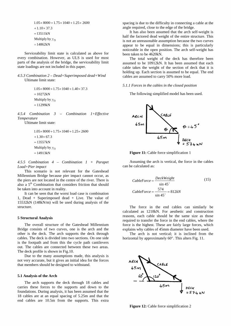
5.1.1 Forces in the cables in the closed position
The following simplified model has been used.
Figure 11: Cable force simplification 1 Assuming the arch is vertical, the force in the cables
can be calculated as:
kNCableForce
DeckWeightCableForce
81245sin
57445sin
==
=
o
o
(15)
The force in the end cables can similarly be
calculated as 1218kN. For aesthetic and construction reasons, each cable should be the same size as those required to transfer the force in the end cables, where the force is the highest. These are fairly large forces, which explains why cables of 45mm diameter have been used.
The arch is not vertical; it is inclined from the horizontal by approximately 60°. This alters Fig. 11.
Figure 12: Cable force simplification 2

This will increase the force in the cables as they enter
the arch at an angle. 5.1.2 Forces in the cables in the open position
In the open position, Fig.11 becomes,
Figure 13: Cable force simplification (open) The force in the cables now depends on the amount of
pre-stressing that has been applied. From the diagram it can be seen that the cable should sag. It remains in tension due to the force in it from pre-stressing.
5.1.3 Buckling
The arch can now be checked for buckling. The following assumption has been made.
igure 14: Arch buckling simplification
uler buckling was calculated using Eq. (16).
F E
43
2
62
2
2
10133
,130
10200
mI
Hence
IP
LEIP
crit
crit
−×=
×⋅=
=
π
π
(16)
his value of I is the minimum value at which the
arch
5.2 Analysis of the Deck
induced in the deck are of the form
T will not buckle. It shows that a diameter of several
metres is necessary, particularly at the base of the arch as the current bridge shows. This I value is similar to the
value estimated for the deck, which shows that the deck and the arch are similar in dimension. Although a large simplification has been made, Euler buckling is conservative so this should not have a great adverse effect on the accuracy of the answer.
The bending moments:
Figure 15: Bending moments in the deck
he cables provide 18 supports along the length of the
Tdeck. The maximum bending moment will occur in
the end spans as shown in Fig. 15. To calculate this moment a point of contraflexure has been assumed at a distance of 1/5th of the span from the first cable to the support. The deck is then assumed to be simply supported between these to points and the maximum bending moment can be calculated.
kNmM
wlM
9178
)4.8(1048
2
max
2
max
=⋅
=
=
(17)
his is the moment that the deck should be designed
to w
5.3 How the bridge was actually analysed
was actually analy
6 Serviceability
eeds to be assessed under serviceability con
6.1 Creep
is not an issue for the Gateshead Millennium Brid
Tithstand. In practice, the moment will be calculated at
many points along the length of the deck and these will be used to design a varying deck profile. There may also be enhancement of moment due to the jelly effect.
The Gateshead Millennium Bridge sed at many different opening angles using the
computer software, LUSAS.
The bridge nditions. This includes creep, deflection and vibrations.
Creep ge because it is constructed from steel and creep is
only an issue in concrete structures.
6.2 Deflection
The maximum deflection of the deck has been r in the span with the maximum moment.
Thisassumed to occu
is near to the end of the bridge, so maximum deflection is more likely to be occurring nearer the centre. However, the deck is support by cables at regular intervals and the end spans are the largest. Deflection has been calculated using the simple equation shown below.
m
EIwl 45
=δ(18)
6
36
4
108.4109910200384
)4.8(1045384
−
−
×=×⋅×⋅
⋅⋅=
δ
δ
This is a very small deflection and is likely to be
inaccurate. However, deflections will not be large in this brid
Excessive vibrations in footbridges are a problem. If vibration is too high (above 75Hz) then
peop
yleigh-Ritz method.
ge because cables support the deck at regular intervals and the overall span is not very long.
6.3 Vibration
the frequency of le will not want to use the bridge. If the frequency is
too low (below 5Hz) then the bridge may be unsafe and further analysis to find the maximum acceleration of the deck needs to be carried out.
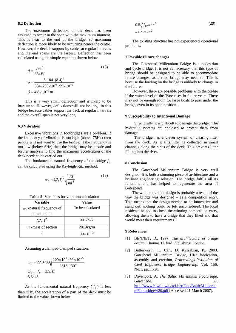
The fundamental natural frequency of the bridge of can be calculated using the Ra
42)( EIlnn βω =
(19)
ml
Table 5: Variables for vibration calculation Variable Value
nω -natural frequency of To be calculated th e e nth mod
2)( lnβ 22.3733
m -mass of section 2 813kg/mI 31099 −×
Assuming a clamped-clamped situation.
Hzf on
n
5.31302813
1099102003733.2239 ×⋅×
=−
ω4
==⋅
ω
As the f ndamental natural frequency ( ) is less
than 5Hz, the acceleration of a part of the deck must be limi
55.3 ≤
u of
ted to the value shown below.
2
20
/9.0
/5.0
sm
smf
=
(20)
The existing structure has not experienced vibrational
problems.
7 Possible Future changes
The Gateshead Millennium Bridge is a pedestrian and cycle bridge. It is not as necessary that this type of bridge should be designed to be able to accommodate future changes, as a road bridge may need to. This is because the loading on the bridge is unlikely to change in the future.
However, there are possible problems with the bridge if the water level of the Tyne rises in future years. There may not be enough room for large boats to pass under the bridge, even in its open position.
9 Susceptibility to Intentional Damage
Structurally, it is difficult to damage the bridge. The hydraulic systems are enclosed to protect them from damage.
The bridge has a clever system of clearing litter from the deck. As it tilts litter is collected in small channels along the sides of the deck. This prevents litter falling into the river.
8 Conclusion
The Gateshead Millennium Bridge is very well designed. It is both a stunning piece of architecture and a brilliant engineering solution. The bridge fulfils all its functions and has helped to regenerate the area of Gateshead.
The well though out design is probably a result of the way the bridge was designed – as a competition entry. This means that the design needed to be innovative and stand out, nothing could be left unconsidered. The local residents helped to chose the winning competition entry, allowing them to have a bridge that they liked and that would meet their requirements.
9 References
[1] BENNET, D., 1997. The architecture of bridge design, Thomas Telford Publishing, London.
[2] Butterworth, K. Carr, D. Kassabian, P., 2003. Gateshead Millennium Bridge, UK: fabrication, assembly and erection, Proceedings-Institution of Civil Engineers Bridge Engineering, Vol. 156, No.1, pp.11-20.
[3] Davenport, A. The Baltic Millennium Footbridge, Gateshead, UK http://www.blwtl.uwo.ca/User/Doc/BalticMillenniumFootbridge%20.pdf [Accessed 21 March 2007].


![The Globular Amphora Culture on the Territory of Belarus and Its Role in the Development of the Сommunities during the ІІІ – the beginnig of the ІІ millenium BC [in Belarusian]](https://static.fdokumen.com/doc/165x107/6334fc00cd4bf2402c0ade52/the-globular-amphora-culture-on-the-territory-of-belarus-and-its-role-in-the-development.jpg)