
Voltage transient detection and induction for debug and test
Upload
khangminh22Category
view
0download
0
www.achronix.com
Bitstream Programming and Debug Interface User Guide (UG004)

Bitstream Programming and Debug Interface User Guide (UG004)
www.achronix.com 2
Copyrights, Trademarks and DisclaimersCopyright © 2019 Achronix Semiconductor Corporation. All rights reserved. Achronix, Speedcore, Speedster, and ACE are trademarks of Achronix Semiconductor Corporation in the U.S. and/or other countries All other trademarks are the property of their respective owners. All specifications subject to change without notice.
NOTICE of DISCLAIMER: The information given in this document is believed to be accurate and reliable. However, Achronix Semiconductor Corporation does not give any representations or warranties as to the completeness or accuracy of such information and shall have no liability for the use of the information contained herein. Achronix Semiconductor Corporation reserves the right to make changes to this document and the information contained herein at any time and without notice. All Achronix trademarks, registered trademarks, disclaimers and patents are listed at http://www.achronix.com/legal.
Achronix Semiconductor Corporation2903 Bunker Hill LaneSanta Clara, CA 95054USA
Website: www.achronix.comE-mail : [email protected]

Bitstream Programming and Debug Interface User Guide (UG004)
www.achronix.com 3
Table of Contents
Chapter - 1: Configuration Overview . . . . . . . . . . . . . . . . . . . . . . . . . . . . . . . . . . . . . . . . . . . . . . . . . . 7Supported Operating Systems . . . . . . . . . . . . . . . . . . . . . . . . . . . . . . . . . . . . . . . . . . . . . . . . . . . . . . . . . . . . 8
Minimum Hardware Requirements . . . . . . . . . . . . . . . . . . . . . . . . . . . . . . . . . . . . . . . . . . . . . . . . . . . . . . . . 8
Board-Level Device Connections . . . . . . . . . . . . . . . . . . . . . . . . . . . . . . . . . . . . . . . . . . . . . . . . . . . . . . . . . . 8
Chapter - 2: JTAG Configuration Using the Bitporter Pod . . . . . . . . . . . . . . . . . . . . . . . . . . . . . . 11Introduction . . . . . . . . . . . . . . . . . . . . . . . . . . . . . . . . . . . . . . . . . . . . . . . . . . . . . . . . . . . . . . . . . . . . . . . . . . . . . 12
ACE and the acx_stapl_player . . . . . . . . . . . . . . . . . . . . . . . . . . . . . . . . . . . . . . . . . . . . . . . . . . . . . . . . . . . . . . . . . 12
Bitporter USB Drivers . . . . . . . . . . . . . . . . . . . . . . . . . . . . . . . . . . . . . . . . . . . . . . . . . . . . . . . . . . . . . . . . . . . . . . . . . 12
Connecting the Bitporter Pod . . . . . . . . . . . . . . . . . . . . . . . . . . . . . . . . . . . . . . . . . . . . . . . . . . . . . . . . . . . . 14Introduction . . . . . . . . . . . . . . . . . . . . . . . . . . . . . . . . . . . . . . . . . . . . . . . . . . . . . . . . . . . . . . . . . . . . . . . . . . . . . . . . . . 14
Connecting the Bitporter Pod . . . . . . . . . . . . . . . . . . . . . . . . . . . . . . . . . . . . . . . . . . . . . . . . . . . . . . . . . . . . . . . . . 15
Disconnecting the Bitporter Pod . . . . . . . . . . . . . . . . . . . . . . . . . . . . . . . . . . . . . . . . . . . . . . . . . . . . . . . . . . . . . . . 18
Power Cycling the Bitporter Pod . . . . . . . . . . . . . . . . . . . . . . . . . . . . . . . . . . . . . . . . . . . . . . . . . . . . . . . . . . . . . . . 18
Verifying the Setup . . . . . . . . . . . . . . . . . . . . . . . . . . . . . . . . . . . . . . . . . . . . . . . . . . . . . . . . . . . . . . . . . . . . . . . . . . . 19
Handling Multiple Pods Connected to the Same PC . . . . . . . . . . . . . . . . . . . . . . . . . . . . . . . . . . . . . . . . . . . . . 20
Configuring Ethernet-Connected Bitporter Pods for a Multi-User Environment . . . . . . . . . . . . . . . . . . . 21
Troubleshooting Bitporter Pod Connections . . . . . . . . . . . . . . . . . . . . . . . . . . . . . . . . . . . . . . . . . . . . . . . 24Known Bitporter Issues . . . . . . . . . . . . . . . . . . . . . . . . . . . . . . . . . . . . . . . . . . . . . . . . . . . . . . . . . . . . . . . . . . . . . . . 24
Bitporter Connection Errors . . . . . . . . . . . . . . . . . . . . . . . . . . . . . . . . . . . . . . . . . . . . . . . . . . . . . . . . . . . . . . . . . . . 32
Chapter - 3: JTAG Configuration Using the FTDI FT2232H . . . . . . . . . . . . . . . . . . . . . . . . . . . . 36Overview . . . . . . . . . . . . . . . . . . . . . . . . . . . . . . . . . . . . . . . . . . . . . . . . . . . . . . . . . . . . . . . . . . . . . . . . . . . . . . . 36
FTDI Board-Level Device Connections . . . . . . . . . . . . . . . . . . . . . . . . . . . . . . . . . . . . . . . . . . . . . . . . . . . . 37FTDI JTAG Pinout . . . . . . . . . . . . . . . . . . . . . . . . . . . . . . . . . . . . . . . . . . . . . . . . . . . . . . . . . . . . . . . . . . . . . . . . . . . . 37
FTDI Voltage Compatibility . . . . . . . . . . . . . . . . . . . . . . . . . . . . . . . . . . . . . . . . . . . . . . . . . . . . . . . . . . . . . . . . . . . . 37
FTDI EEPROM Interface . . . . . . . . . . . . . . . . . . . . . . . . . . . . . . . . . . . . . . . . . . . . . . . . . . . . . . . . . . . . . . . . . . . . . . 38
FTDI Crystal Requirements . . . . . . . . . . . . . . . . . . . . . . . . . . . . . . . . . . . . . . . . . . . . . . . . . . . . . . . . . . . . . . . . . . . 44
FTDI Interface in ACE . . . . . . . . . . . . . . . . . . . . . . . . . . . . . . . . . . . . . . . . . . . . . . . . . . . . . . . . . . . . . . . . . . . . 45
Programming Speeds and Requirements . . . . . . . . . . . . . . . . . . . . . . . . . . . . . . . . . . . . . . . . . . . . . . . . . 46JTAG Interface . . . . . . . . . . . . . . . . . . . . . . . . . . . . . . . . . . . . . . . . . . . . . . . . . . . . . . . . . . . . . . . . . . . . . . . . . . . . . . . 46
Known Limitations . . . . . . . . . . . . . . . . . . . . . . . . . . . . . . . . . . . . . . . . . . . . . . . . . . . . . . . . . . . . . . . . . . . . . . 46Achronix Tools Do Not Support Multi-Device JTAG Scan Chains with the FTDI FT2232H on Existing Boards . . . . . . . . . . . . . . . . . . . . . . . . . . . . . . . . . . . . . . . . . . . . . . . . . . . . . . . . . . . . . . . . . . . . . . . . . . . . . . . . . . . . . . 46

Bitstream Programming and Debug Interface User Guide (UG004)
www.achronix.com 4
Software and Driver Install for FTDI . . . . . . . . . . . . . . . . . . . . . . . . . . . . . . . . . . . . . . . . . . . . . . . . . . . . . . 46Introduction . . . . . . . . . . . . . . . . . . . . . . . . . . . . . . . . . . . . . . . . . . . . . . . . . . . . . . . . . . . . . . . . . . . . . . . . . . . . . . . . . 46
ACE and the acx_stapl_player . . . . . . . . . . . . . . . . . . . . . . . . . . . . . . . . . . . . . . . . . . . . . . . . . . . . . . . . . . . . . . . . 47
Connecting to the FTDI FT2232H Device . . . . . . . . . . . . . . . . . . . . . . . . . . . . . . . . . . . . . . . . . . . . . . . . . . 49Connecting to the FT2232H via USB . . . . . . . . . . . . . . . . . . . . . . . . . . . . . . . . . . . . . . . . . . . . . . . . . . . . . . . . . . . 49
Disconnecting the FT2232H interface . . . . . . . . . . . . . . . . . . . . . . . . . . . . . . . . . . . . . . . . . . . . . . . . . . . . . . . . . 49
Verifying the Setup . . . . . . . . . . . . . . . . . . . . . . . . . . . . . . . . . . . . . . . . . . . . . . . . . . . . . . . . . . . . . . . . . . . . . . . . . . . 49
Handling Multiple FT2232H Devices Connected to the Same PC . . . . . . . . . . . . . . . . . . . . . . . . . . . . . . . . . 50
Chapter - 4: JTAG Configuration Using the Bitporter2 Pod . . . . . . . . . . . . . . . . . . . . . . . . . . . . 52Software and Driver Install for Bitporter2 . . . . . . . . . . . . . . . . . . . . . . . . . . . . . . . . . . . . . . . . . . . . . . . . . 53
Introduction . . . . . . . . . . . . . . . . . . . . . . . . . . . . . . . . . . . . . . . . . . . . . . . . . . . . . . . . . . . . . . . . . . . . . . . . . . . . . . . . . 53
ACE and the acx_stapl_player . . . . . . . . . . . . . . . . . . . . . . . . . . . . . . . . . . . . . . . . . . . . . . . . . . . . . . . . . . . . . . . . 53
Connecting the Bitporter2 Pod . . . . . . . . . . . . . . . . . . . . . . . . . . . . . . . . . . . . . . . . . . . . . . . . . . . . . . . . . . . 55Bitporter2 Board-Level Device Connections . . . . . . . . . . . . . . . . . . . . . . . . . . . . . . . . . . . . . . . . . . . . . . . . . . . . 55
Verifying the Setup . . . . . . . . . . . . . . . . . . . . . . . . . . . . . . . . . . . . . . . . . . . . . . . . . . . . . . . . . . . . . . . . . . . . . . . . . . . 56
Handling Multiple Pods Connected to the Same PC . . . . . . . . . . . . . . . . . . . . . . . . . . . . . . . . . . . . . . . . . . . . . 58
Chapter - 5: Using the Achronix STAPL Player . . . . . . . . . . . . . . . . . . . . . . . . . . . . . . . . . . . . . . . 59A Brief Background Description of STAPL . . . . . . . . . . . . . . . . . . . . . . . . . . . . . . . . . . . . . . . . . . . . . . . . 59
STAPL Actions, JTAG, Secure Mode, and Encrypted Bitstreams . . . . . . . . . . . . . . . . . . . . . . . . . . . . . . . . . 59
STAPL Procedures . . . . . . . . . . . . . . . . . . . . . . . . . . . . . . . . . . . . . . . . . . . . . . . . . . . . . . . . . . . . . . . . . . . . . . . . . . . 60
Directory Location of acx_stapl_player . . . . . . . . . . . . . . . . . . . . . . . . . . . . . . . . . . . . . . . . . . . . . . . . . . . 60
acx_stapl_player Command Syntax Overview . . . . . . . . . . . . . . . . . . . . . . . . . . . . . . . . . . . . . . . . . . . . . 61
Picking a STAPL Action (-a Option) . . . . . . . . . . . . . . . . . . . . . . . . . . . . . . . . . . . . . . . . . . . . . . . . . . . . . . . 63Disabling a Recommended Procedure . . . . . . . . . . . . . . . . . . . . . . . . . . . . . . . . . . . . . . . . . . . . . . . . . . . . . . . . . 63
Enabling an Optional Procedure . . . . . . . . . . . . . . . . . . . . . . . . . . . . . . . . . . . . . . . . . . . . . . . . . . . . . . . . . . . . . . . 63
Choosing Specific JTAG Connections by Name (-p Option) . . . . . . . . . . . . . . . . . . . . . . . . . . . . . . . . . 64FTDI FT2232H Device Naming Conventions . . . . . . . . . . . . . . . . . . . . . . . . . . . . . . . . . . . . . . . . . . . . . . . . . . . . 65
Bitporter Pod Naming Conventions . . . . . . . . . . . . . . . . . . . . . . . . . . . . . . . . . . . . . . . . . . . . . . . . . . . . . . . . . . . . 65
Querying the Availability of Connected Pods (-q Option) . . . . . . . . . . . . . . . . . . . . . . . . . . . . . . . . . . . 65Autodetection Mode . . . . . . . . . . . . . . . . . . . . . . . . . . . . . . . . . . . . . . . . . . . . . . . . . . . . . . . . . . . . . . . . . . . . . . . . . . 65
Querying the Availability of Named Pods . . . . . . . . . . . . . . . . . . . . . . . . . . . . . . . . . . . . . . . . . . . . . . . . . . . . . . . 67
Configuring the Bitporter Pod's IP Address (-i* Options) . . . . . . . . . . . . . . . . . . . . . . . . . . . . . . . . . . . 69Bitporter Pod MAC Addresses . . . . . . . . . . . . . . . . . . . . . . . . . . . . . . . . . . . . . . . . . . . . . . . . . . . . . . . . . . . . . . . . 69
Querying the Bitporter Pod's Current Ethernet IP Configuration (-iq) . . . . . . . . . . . . . . . . . . . . . . . . . . . . . 70
Configuring the Bitporter Pod for DHCP (Dynamic IP Address) (-id Option) . . . . . . . . . . . . . . . . . . . . . . . 70
Configuring the Bitporter Pod to Use a Static IP Address (-is Option) . . . . . . . . . . . . . . . . . . . . . . . . . . . . . 71

Bitstream Programming and Debug Interface User Guide (UG004)
www.achronix.com 5
Configuring the Bitporter Pod to Use a Static IP Address (-is Option) . . . . . . . . . . . . . . . . . . . . . . . . . . . . 71
Programming a Device . . . . . . . . . . . . . . . . . . . . . . . . . . . . . . . . . . . . . . . . . . . . . . . . . . . . . . . . . . . . . . . . . . . 72
Troubleshooting the Achronix STAPL Player . . . . . . . . . . . . . . . . . . . . . . . . . . . . . . . . . . . . . . . . . . . . . . 73Exit Codes . . . . . . . . . . . . . . . . . . . . . . . . . . . . . . . . . . . . . . . . . . . . . . . . . . . . . . . . . . . . . . . . . . . . . . . . . . . . . . . . . . . 73
Known Achronix STAPL Player Issues . . . . . . . . . . . . . . . . . . . . . . . . . . . . . . . . . . . . . . . . . . . . . . . . . . . . . . . . . . 77
Revision History . . . . . . . . . . . . . . . . . . . . . . . . . . . . . . . . . . . . . . . . . . . . . . . . . . . . . . . . . . . . . . . . . . 79

Bitstream Programming and Debug Interface User Guide (UG004)
www.achronix.com 6

Bitstream Programming and Debug Interface User Guide (UG004)
www.achronix.com 7
Chapter - 1: Configuration OverviewThe embedded programming and configuration logic in the Achronix core is designed to support a variety of programming and debugging options. There are three external interfaces that can be used as communication channels between Achronix hardware and software:
The Achronix Bitporter pod – provides a JTAG-only interface via USB or Ethernet to Achronix devices. Device configuration must be completed via JTAG, along with communication with debug tools such as Snapshot and the JTAG Browser. See .JTAG Configuration Using the Bitporter Pod (see page 11)
Caution!
The Bitporter pod has been discontinued. Therefore, support may be limited.
The Achronix Bitporter2 pod – provides a JTAG-only interface via USB to Achronix devices. Device configuration must be completed via JTAG, along with communication with debug tools such as Snapshot and the JTAG Browser.
An FTDI FT2232H device – provides a lower-cost JTAG interface to Achronix devices through USB. This interface also allows debug tools to be accessible via JTAG. See JTAG Configuration Using the FTDI
.FT2232H (see page 36)
The figure below outlines the basic block diagram of the programming and configuration logic, including additional logic to implement security features. The configuration management unit controls the startup and shutdown sequence from configuration mode to the user mode and back. The configuration management unit includes the provisions for configuring the device with a secure bitstream using a 256-bit advanced encryption standard (AES) algorithm in cipher block chaining (CBC) mode. The device contains a small non-volatile memory for the storage of the required AES key.
Figure 1: Configuration Options

Bitstream Programming and Debug Interface User Guide (UG004)
www.achronix.com 8
1.
2.
3.
Supported Operating SystemsJTAG interactions are currently supported under the following operating systems for with acx_stapl_playerFTDI Interface or Bitporter2.
32-bit and 64-bit Red Hat Enterprise Linux Release 6.0 and above
32-bit and 64-bit CentOS 6.0 and above
64-bit Microsoft Windows 7 Pro SP1
Minimum Hardware RequirementsPentium-class PC with a minimum of 512 MB of memory (2 GB for Windows 7)
A USB 2.0 port if configuring through FTDI interface OR
A powered USB 2.0 port and/or Ethernet connection if configuring through the Bitporter pod
Notes
A USB port connection is required to change the Ethernet configuration of a Bitporter pod. Bitporter pods are configured to use DHCP by default when connecting via Ethernet — if this configuration is acceptable, no USB connection is needed.
USB 1.0 and 1.1 ports may be used for the Bitporter, Bitporter2 and FTDI interfaces, but USB 2.0 is strongly recommended for performance reasons.
USB 3.x ports may be used for Bitporter (Windows only) and Bitporter2 or FTDI (both Linux and Windows) interfacing, but performance will be limited to USB 2.0 speeds. In Linux, the Bitporter pod is unsupported when connected to USB 3.x ports.
Board-Level Device ConnectionsThe figure below details the board-level electrical connections to the JTAG header used to connect the Bitporter and Bitporter2, and the figure following provides the mechanical specifications. (The value of V is DDO_JTAGdependent on the IO voltage of the JTAG target chip)

Bitstream Programming and Debug Interface User Guide (UG004)
www.achronix.com 9
Figure 2: JTAG Header Electrical Connections
Caution
The Tck produced by both FT232H device, and by all Bitporters, is only present during programming. Further it's frequency accuracy and stability cannot be guaranteed. Therefore it is not recommended to use this clock for any other purpose than JTAG programming of the device.

Bitstream Programming and Debug Interface User Guide (UG004)
www.achronix.com 10
Figure 3: JTAG Header Mechanical Specifications

Bitstream Programming and Debug Interface User Guide (UG004)
www.achronix.com 11
Chapter - 2: JTAG Configuration Using the Bitporter PodThe Bitporter pod (figure below) connects between a host PC via either a 10/100 Ethernet or USB 2.0 connection and a JTAG-compliant connector on the target system. When connected, the Bitporter pod supports device configuration and debug, along with flash memory programming.
Note
USB 1.0 and 1.1 are also supported, but discouraged for performance reasons. USB 3.x ports will work in Windows, but are limited to USB 2.0 speeds. USB 3.x ports are not supported in Linux.
Figure 4: Bitporter Pod
The JTAG configuration flow is as follows:
Generate a file from a placed-and-routed design within ACE.design_name.jam
Connect the Bitporter pod to either the USB or Ethernet port of the host PC and to the JTAG port of the target Achronix core.

Bitstream Programming and Debug Interface User Guide (UG004)
www.achronix.com 12
Download the STAPL file to the Achronix core using , executed from the command-acx_stapl_playerline, or via the Download view within ACE (see “Playing a STAPL File” in the (UG001) for ACE User Guidedetails).
IntroductionPrior to device configuration, both the STAPL player ( ), and (if USB connectivity is desired) acx_stapl_playerthe USB drivers for the Bitporter pod must be installed on the host system.
The STAPL player and the optional Bitporter USB drivers are included as a part of the ACE software suite. Intended for general use, ACE includes a graphical download tool, the Snapshot debugging tool, the JTAG Browser tool, and the HW Demo tool. Some FPGA devices also have SerDes auto-tuning included within ACE.
Note
No license file or license server is needed when running the STAPL player from the command line, or when running within ACE Lab Mode. When the STAPL Player is used from within non-Lab-Mode ACE, the ACE software suite itself does require a license.
ACE and the acx_stapl_playerWhen the ACE software suite is installed, it includes a copy of the command-line acx_stapl_player tool and the Bitporter USB drivers. The installation of ACE is covered in a separate document, the Achronix Software &
(UG002).License User Guide
Important!
Disconnect any attached Bitporter pods from the host PC before installing the ACE software suite.
After ACE is installed, the acx_stapl_player associated with the Bitporter will be found at:
<ace_install_dir> /system/cmd/acx_stapl_player
ACE uses the acx_stapl_player at this location for all Bitporter interactions. Users may also use this acx_stapl_player from the command-line if desired.
Note
To ease command-line usage in Windows, this location will be automatically added to the PATH environment variable by the ACE installer.
Bitporter USB DriversThe Bitporter USB drivers are present in the ACE software distribution.
WindowsIn Windows, the ACE installer automatically installs the Bitporter’s USB drivers if the "Bitporter Pod USB Drivers" checkbox was selected during installation.
If the USB driver component was enabled, when the USB drivers are being installed, a Windows Security dialog might be displayed. Click to confirm that the drivers should be installed.Install

Bitstream Programming and Debug Interface User Guide (UG004)
www.achronix.com 13
1.
Figure 5: Windows Security Driver Installation Confirmation Dialog Box (Example Screenshot from Windows 7)
Linux
Note
The Bitporter's acx_stapl_player is a 32-bit executable, with the associated dependencies. If installing onto a 64-bit operating system, the 32-bit prerequisites for and will libX11.so.6 libusb-0.1.so.4also need to be installed by a user with administrator privileges.Example: On a clean CentOS 6.4 x86_64 installation, the following additional libraries (with their own dependencies) had to be installed before acx_stapl_player could be used:
libX11-1.5.0-4.el6.i686
libusb-0.1.12-23.el6.i686
In Linux, an USB driver installation script is found in the same directory as the acx_stapl_player itself.
To install the Bitporter USB driver (after the prerequisite shared libraries are present, as mentioned in the above note):
Change to the directory containing the acx_stapl_player
% cd <ace_install_dir>/system/cmd

Bitstream Programming and Debug Interface User Guide (UG004)
www.achronix.com 14
2. With administrator privileges (via or ), run the Perl install script sudo su install_acx_bitporter_usb.pl
% sudo perl ./install_acx_bitporter_usb.pl
After the installation completes successfully, the script ends with the following message:
Bitporter USB driver, version x.y.z, installed.
Note
Linux USB Bitporter connections are currently only supported on CentOS 5 and 6 or RHEL 5 and 6. Other Linux releases are not supported by Achronix, but may work if they include .udev
Connecting the Bitporter PodIntroduction
Choosing a Connection Type — USB versus Ethernet
Ethernet
Ethernet-connected Bitporter pods are usable from multiple PCs at once.
While this eases use, it also adds risk: users can overwrite each other's programs. The Achronix acx_stapl_player/Bitporter programming system does prevent multiple users from programming the device simultaneously, but does not ensure that the connected hardware is not already mid-test. Multi-user test protection/queueing is left up to the customer.
Pod autodetect visibility is limited to the pod's local subnet. Beyond the local subnet, the pod's IP address must be known before a user can connect to it.
Bitporter performance may be slower via Ethernet than via High-Speed USB, depending upon network configuration. On a congested network, programming via Ethernet can take up to 5× longer than via High-Speed USB.
Before attempting Ethernet connection to a Bitporter pod, please consult the network administrator to ensure the Bitporter is allowed to connect to the necessary network.
A USB connection is required to alter the Bitporter pod's Ethernet configuration, for example, selecting static IP over DHCP, changing the static IP, etc. (see command-line options , , and in -id -iq -is Table: Supported
)acx_stapl_player Command Options (see page 61)
USB
Bitporter performance may be faster via USB than via Ethernet, depending upon network configuration. However, a USB-connected Bitporter is only usable from the PC hosting the connection.

Bitstream Programming and Debug Interface User Guide (UG004)
www.achronix.com 15
Connecting the Bitporter Pod
Warning!
Always supply power to the Bitporter pod first (the pod's POWER LED must be lit) before supplying power to the target board.
The Bitporter pod must always be powered (the pod's POWER LED must be lit) while the connected target board is powered.
Always power down the target board before powering down the Bitporter pod.
When power-cycling the Bitporter pod, leave it turned off (the pod's POWER LED must be unlit) for at least 5 seconds.
The Bitporter pod is sensitive to electrostatic discharge (ESD). When operating the pod, ESD precautions must be observed to ensure proper function.
The Bitporter pod has four labeled jacks:
“TARGET”, used by the 14-pin JTAG ribbon cable
“ETHERNET”
“USB 2.0”
“+5V DC”
The Bitporter chooses between its Ethernet interface and its USB interface based solely upon whether DC power is being provided at the “+5V DC” jack.
If DC power is being provided, then only the Ethernet interface is active, and the USB interface is ignored by the pod, even if no Ethernet cable is plugged in.
If no DC power is being provided, and the pod is connected to a powered USB port, then the USB interface is active, and the Ethernet interface is ignored, even if the Ethernet cable is plugged in.
Since the pod requires power, if the pod is not connected to either the DC power cable or a powered USB port, the pod will not work (the Bitporter pod will not work when connected to unpowered USB ports).
Note
Errors may be reported when both the USB cable and the DC power cable are connected, at least from the USB-connected PC. That PC may attempt to connect via the USB interface, but since the Bitporter itself is ignoring that interface, the connection protocol can fail in unusual ways.To avoid problems, do not connect both DC power and USB simultaneously.

Bitstream Programming and Debug Interface User Guide (UG004)
www.achronix.com 16
1.
2.
3.
4.
5.
6.
a.
b.
7.
8.
Connecting the Bitporter Pod via USB
Caution!
Before connecting the Bitporter pod:
Do not plug in the Bitporter USB cable until after the software installation (see Software and ). If the Bitporter USB cable is connected to the Driver Install for Bitporter (see page 12)
workstation during USB driver installation, the USB driver may not install correctly.
When using the USB interface, do not plug in the DC power cable. The DC power cable is only used for the Ethernet interface. When using the USB interface, all power to the Bitporter pod is provided through the USB cable. As long as the DC power cable is connected, the USB interface is ignored by the Bitporter.
Note
When the DC power cable is plugged into the Bitporter, the Bitporter switches to Ethernet mode and disables (ignores) the USB interface.
Turn off the power to the target hardware.
Connect one end of the JTAG flat ribbon cable to the target JTAG connector. The red strip is pin 1.
Note
If the target JTAG connector is not keyed, the target’s user guide should specify the location of pin 1 on the target JTAG connector.
Connect the other end of the JTAG flat ribbon cable to the Bitporter pod. The plug is keyed.
Connect the USB cable to the host PC.
Connect the USB cable to the Bitporter pod.
Pod initialization:
During the pod initialization, the Bitporter pod’s power LED turns on and the COMM LED may flash. Once pod initialization completes successfully, the power LED remains lit, and the COMM LED turns off.
In Windows, after pod initialization is complete, a temporary popup notification indicating that a USB-connected Bitporter pod is initialized correctly may appear at the taskbar:
Figure 6: Example (Win7) Popup Notification Indicating Bitporter Initialization
Turn on the power to the target hardware.
Continue to .Verifying the Setup (see page 19)
Connecting the Bitporter Pod via Ethernet

Bitstream Programming and Debug Interface User Guide (UG004)
www.achronix.com 17
1.
2.
3.
4.
5.
Connecting the Bitporter Pod via EthernetThe Bitporter pod supports Ethernet connectivity to one or more PCs, supporting both static and dynamic (via DHCP) IP addressing. Before attempting Ethernet connection to a Bitporter pod, please consult the network administrator to ensure that:
The Bitporter pod is allowed to connect to the necessary network. If the Bitporter pod’s MAC address is needed, see .Bitporter Pod MAC Addresses (see page )
If using dynamic IP / DHCP: verify a DHCP server covers the network segment onto which the pod will be attached.
If using static IP: consult with the system administrator to determine the static IP addressing settings to be explicitly assigned to the pod. The Bitporter pod will need to be configured with these settings via the USB interface (see ) before it can Configuring the Pod to Use a Static IP Address (-is Option) (see page )be connected to the Ethernet network.
If connecting through a firewall: the Bitporter communicates on TCP port 27000.
Note
The pod also responds to UDP broadcasts on port 27001 during pod autodetection, but this only works when the host and pod are within the same network segment, which is rarely the case when communicating through a firewall.
By default, all Bitporter pods are set up to use DHCP negotiation the first time they are plugged into an Ethernet network. Since the pod stores its Ethernet configuration in flash memory, the Ethernet configuration typically only needs to be performed once.
Note
Only pods on the same subnet (without an intervening router) can be automatically detected by the acx_stapl_player (see the command-line option). Use the option to connect to pods -q -p <podname>on non-local subnets, using the IP address version of the podname.
To connect to a Bitporter pod via Ethernet:
Turn off the power to the target system.
If the pod is connected to the PC via USB, disconnect the USB cable from the Bitporter.
Connect the JTAG flat ribbon cable to the target JTAG pins. The red strip is pin 1.
Note
If the target JTAG connector is not keyed, the target’s user guide will specify the location of pin 1 on the target JTAG connector.
Connect the JTAG flat ribbon cable to the Bitporter pod. The plug is keyed.
Connect the DC power cable to the power outlet and the pod. The Bitporter pod's POWER LED should now be on. The pod's COMM LED should start blinking.

Bitstream Programming and Debug Interface User Guide (UG004)
www.achronix.com 18
6.
7.
8.
1.
2.
3.
4.
1.
2.
3.
1.
2.
3.
4.
5.
Connect the Ethernet cable to the Ethernet jacks on the wall and the pod. Once the Bitporter pod's COMM LED stops blinking and turns off, the pod has successfully acquired an IP address.
Note
If the COMM LED does not stop blinking (it should take less than ten seconds), talk to the network administrator to verify that the Bitporter pod's MAC address has permission to connect to the local network, and that the Bitporter pod is connected to the proper Ethernet network jack.
Turn on the power to the target hardware.
Continue to .Verifying the Setup (see page 19)
The pod is now able to be referred to by name as or . The latter name net <serial_number> net <ip_address>must be used if pod communication is being attempted across subnets (see Table: Supported acx_stapl_player
).Command Options (see page 61)
Disconnecting the Bitporter Pod
Warning!
An unpowered Bitporter must never be connected to powered target hardware, or the Bitporter may be damaged.
To end a programming session and disconnect the Bitporter pod from the target hardware:
Wait until finishes running.acx_stapl_player
Turn off the power to the target hardware.
(Optional) Disconnect the JTAG ribbon cable.
Disconnect the USB cable for USB-connected pods, or the Bitporter’s DC power cable for Ethernet-connected pods.
Alternately, if it is undesirable to remove power from the target hardware:
Wait until finishes running.acx_stapl_player
Disconnect the JTAG ribbon cable.
Disconnect the USB cable for USB-connected pods, or the Bitporter’s DC power cable for Ethernet-connected pods.
Power Cycling the Bitporter PodBecause a powered target must never be connected to an unpowered Bitporter, the proper Bitporter and target board power cycling sequence is:
Turn off the target board.
Unplug the Bitporter from its power source (either the USB cable, or the DC power supply).
Wait at least 5 seconds.
Plug the Bitporter back into its power source (either the USB cable, or the DC power supply) and wait for the POWER LED to light up.
Turn on the target board.

Bitstream Programming and Debug Interface User Guide (UG004)
www.achronix.com 19
1.
2.
3.
4.
5.
1.
2.
Alternately, if powering-cycling the target device is not desirable, the following sequence would also be safe:
Disconnect the JTAG ribbon cable from the Bitporter.
Unplug the Bitporter from its power source (either the USB cable, or the DC power supply).
Wait at least 5 seconds.
Plug the Bitporter back into its power source (either the USB cable, or the DC power supply) and wait for the POWER LED to light up.
Connect the JTAG ribbon cable to the Bitporter.
Verifying the Setup
Bitporter Connectivity Self TestTo verify that the STAPL player, (the optional USB drivers,) and Bitporter pod are functioning correctly:
Open a command prompt in the installation directory.
At the command prompt, run:
acx_stapl_player -q
The program returns a listing of all correctly connected and currently available pods (those not actively in use). For example:
Example output with 1 USB pod and 2 Ethernet pods
Achronix STAPL Player (acx_stapl_player) -- Version 5.2
(c) Copyright 2006-2013 Achronix Semiconductor Corp. All rights reserved.
contains elements of Jam STAPL Player Version 2.5 (20040526)
Copyright (C) 1997-2004 Altera Corporation
******************************************* Attempting to find all reachable pods: *
******************************************Attempting to auto-detect Bitporter pods (USB pods and Ethernet pods on this subnet)...
...autodetection found 3 pods.|==========|======================================|
| Pod | Detected || Name | Availability |
|==========|======================================|| usb12345 | ++AVAILABLE++ |
| net12346 | --in use, owner is 192.168.100.123-- || net12347 | ++AVAILABLE++ |
|==========|======================================|
Refer to “Connecting to Specific Pods by Name (-p option)” in Using the Achronix STAPL Player (see page 59)for complete details.

Bitstream Programming and Debug Interface User Guide (UG004)
www.achronix.com 20
1.
2.
Bitporter-to-Target-Device Connectivity TestAfter the Bitporter connectivity self test has completed successfully, it is still useful to ensure the Bitporter is properly connected to the target device via the JTAG ribbon cable. See the previous information in this chapter which describes the proper way to connect the Bitporter.
Warning!
An unpowered Bitporter pod must never be connected to powered target hardware, or the Bitporter pod may be damaged.
Open a command prompt and navigate to the STAPL player installation directory.
At the command prompt, run:
acx_stapl_player -aREAD_IDCODE read_idcode.jam
Note
The file is on the development kit CD in the directory. If that file read_idcode.jam /Softwareis unavailable, the READ_IDCODE action is also present in every STAPL bitstream ( ) file *.jamgenerated by ACE.
After successfully starting communications with the Bitporter Pod, the program returns the device ID code of the target device.
Note
The actual text output, including the ID code, varies slightly by device type and revision.
Example IDCODE output (varies for each device type)
Entering JTAG programming mode...Reading Device ID code...IDCODE=0010000 00010000 00001011 001000001Exiting JTAG programming mode...
Exit code = 0... Success
Handling Multiple Pods Connected to the Same PCBy default the Achronix STAPL player assumes that it is operating in a single Bitporter pod environment. If this is true, no special actions by the user are necessary — when finds only one pod during the acx_stapl_playerauto-detection phase, it uses that pod.
The Achronix STAPL player can support multiple users sharing a collection or pool of Bitporter pods connected to a single PC via USB, and/or Bitporter pods connected to a collection of PCs via Ethernet.
Warning!
When multiple pods are connected to a single PC, the user must specify which pod should be used with the command-line option (see -p Table: Supported acx_stapl_player Command Options (see page 61)).

Bitstream Programming and Debug Interface User Guide (UG004)
www.achronix.com 21
1.
If no specific pod/pods are named with the command-line option, and multiple pods are auto-detected, the -pacx_stapl_player exits with an error, informing the user that they must specify (by name) which pod/pods are allowed to be used.
Example of the Error Message When Multiple Bitporter Pods are Detected But None Were Named at
the Command Line
No user-specified pods requested, multiple connected pods found. To be safe, the user must always specify which pod(s) to use (by using the "-p<podname>" option) when multiple pods are connected. For more information, please see the chapter "Connecting the Bitporter Pod" in the Bitstream Programming and Debug Interface User Guide (UG004).
Tip
The command-line option can be used to list the pods detected by (see -q acx_stapl_player Table: ).Supported acx_stapl_player Command Options (see page 61)
Configuring Ethernet-Connected Bitporter Pods for a Multi-User EnvironmentThese additional configuration steps are directly related to the (still-open) known Bitporter issue "Ethernet Bitporter hangs, stops responding to pings (#3898)". While waiting for a hardware/firmware fix from the Bitporter vendor, Achronix has implemented a partial workaround using shared lock files to block concurrent Bitporter pod access. When all user profiles using the Bitporter pod are correctly configured, these steps should cause attempts to communicate with an already-in-use Bitporter pod to abort before actually attempting to open a connection to the Bitporter pod (thus avoiding it hanging).
This partial workaround blocks most concurrent Bitporter interaction within ACE, including via Snapshot, the Download view, the JTAG Browser view, the HW Demo view, and the Tcl commands and run_stapl_action
.run_snapshot
Caution!
Pod status queries performed with and the Tcl command acx_stapl_player -q get_pod_namesare not blocked in this partial workaround – these queries may still cause Ethernet-connected Bitporter pods to hang if executed while the pod is already in use.
The ACX_BITPORTER_LOCK_DIR Environment VariableTo take full advantage of this workaround, a new environment variable must be added to each machine/profile which will be executing . In addition, a shared network directory must be configured, with acx_stapl_playerthe cooperation of the network administrator.
Work with the local network administrator to configure a single network-shared directory which is accessible to all workstations/all users which interact with Ethernet-connected Bitporter pods. This path may be named differently on different workstations/operating systems, but must be a single directory accessible to all, with both read and write permissions enabled for all Bitporter pod users. This directory will contain the shared lock files.

Bitstream Programming and Debug Interface User Guide (UG004)
www.achronix.com 22
2.
1.
2.
3.
4.
a.
b.
For each Ethernet-connected Bitporter user and workstation combination, the environment variable must be configured to point to the single network-shared directory. Users ACX_BITPORTER_LOCK_DIR
should work with their system administrator if help is needed configuring environment variables.
Caution!
This file locking scheme is only effective when users of a given Bitporter pod are configured to use allthe exact same shared directory for their lock files. If different directories or non-shared directories are used, then users will not be able to see each others' lock file(s), and communication attempts made to contact already busy Bitporter pods will cause those Bitporter pods to hang.
Unreachable or Unconfigured ACX_BITPORTER_LOCK_DIR
When the environment variable is not found, or the directory path saved in the ACX_BITPORTER_LOCK_DIRenvironment variable is not reachable, a warning message is logged reporting the problem. Then the
resorts to some fallback directory locations which are less desirable but allow work to acx_stapl_playerproceed.
The log messages indicating is not configured are:ACX_BITPORTER_LOCK_DIR
WARNING: Environment variable ACX_BITPORTER_LOCK_DIR is not defined!WARNING: Unable to guarantee safe Bitporter ownership collision detection.
WARNING: Please contact Achronix Tech Support for proper acx_stapl_player setup.
The fallback directory locations are less desirable because they cannot correctly block Bitporter pod access from multiple workstations — they only potentially block concurrent Bitporter pod access from the local workstation.
There are four directory locations checked. Later locations are only checked when prior locations are not defined or are inaccessible. In priority order, the attempted directory locations are:
The directory pointed to by the environment variable ACX_BITPORTER_LOCK_DIR
The directory pointed to by the environment variable TEMP
The directory pointed to by the environment variable TMP
An operating-system specific hard-coded path:
(On Windows) the directory " " on the same drive as the current working directory/windows/temp
(On Linux) the directory " "/tmp
Note
The fallback directories typically map to local directories on the workstation executing . Thus, they are not visible to other workstations, and Bitporter pod access is not acx_stapl_player
gated when communication attempts originate from separate workstations.
If none of the directories are accessible for creation of the lock file, the following messages are logged (example from Windows), and the exits with an error code:acx_stapl_player
Attempting to connect to user-specified pod(s):WARNING: Environment variable ACX_BITPORTER_LOCK_DIR is not defined!
WARNING: Unable to guarantee safe Bitporter ownership collision detection.WARNING: Please contact Achronix Tech Support for proper acx_stapl_player setup.
WARNING: Unable to find directory '/windows/temp' : No such file or directory

Bitstream Programming and Debug Interface User Guide (UG004)
www.achronix.com 23
WARNING: Lock file directory path not found - unable to acquire lock file.
PROGRAM ERROR: The user-specified pod was not opened. Unable to proceed.PROGRAM ERROR: Bitporter JTAG Pod Hardware Initialization FAILED.
PROGRAM ERROR: Exiting with error code: -10
Caution!
Access to Ethernet-connected Bitporter pods ownership of a lock file. Failure to create this lock requiresfile causes the to exit.acx_stapl_player
Error Messaging for Locked Bitporter Pod
The error message shown below occurs when the file lock is already owned for the requested Bitporter pod:
Attempting to connect to user-specified pod(s): WARNING: Bitporter pod net172.16.210.101 is already in use; the lock file 'U:\locks
/acx_pod_net172.16.210.101.lock' reports it is currently owned by user: docauthor pid: 31478
computer: test-1
PROGRAM ERROR: The user-specified pod was not opened. Unable to proceed. PROGRAM ERROR: Bitporter JTAG Pod Hardware Initialization FAILED.
PROGRAM ERROR: Exiting with error code: -10
Note
The file lock also prohibits a user from concurrently accessing the same Bitporter pod from multiple processes on the same machine. This is one of the reasons the lock file contains the user name, computer name, and pid (process id) — a user may collide with their own still-running access.
Bitporter Interactions that Check the Lock File
This workaround blocks concurrent execution of STAPL actions (the option acx_stapl_player -a<action> and the Tcl commands . and run_stapl_action <stapl_file> <action> run_snapshot
) on specifically named Ethernet-connected Bitporter pods. It also blocks executions <snapshot_file> attempted by the button in the ACE Snapshot Debugger view, the button in the ACE Arm Run <selected_action>Download view, the and buttons in the JTAG Browser view, the button in the HW Demo Write Read Downloadview, and the buttons on the various Speedster SerDes-derived IP's Link Tuning tools. Also Update/Run/Syncblocked are pod IP configuration queries (the option) for named Ethernet-connected acx_stapl_player -iqBitporter pods.
USB pod communications are not directly affected by "Ethernet Bitporter hangs, stops responding to pings (#3898)", and thus are not affected by the . This commands includes the ACX_BITPORTER_LOCK_DIR
and pod network setup options, since these acx_stapl_player -id acx_stapl_player -is<config> are only allowed when connected to a pod via USB.
Pod status queries (the option or the Tcl command ) do not use the acx_stapl_player -q get_pod_nameslock files (they cannot, since these depend upon a non-directed network broadcast on the local network segment to detect connected pods). The inability to block these commands is perhaps mitigated by "Ethernet-connected Bitporter hangs, stops responding to pings (#3898)" workaround #2, where users are warned not to use these commands when interacting with Ethernet pods.

Bitstream Programming and Debug Interface User Guide (UG004)
www.achronix.com 24
Any connections to Ethernet pods which are discovered via autodetection (i.e. named with the "not" option) do not use the lock files. (Autodetection utilizes the acx_stapl_player -p<pod_name_list>
same network broadcast behavior as pod status queries, and will not detect Bitporters which are connected as recommended in "Ethernet-connected Bitporter hangs, stops responding to pings (#3898)" workaround #2.) If a user does not follow the directions in "Ethernet Bitporter hangs, stops responding to pings (#3898)" workaround #2, and if that user attempts to connect to their Ethernet pod through autodetection, they may still hang their Bitporter pod.
Is there a way to force ownership, and ignore a pre-existing lock file?
If users ever need to force ownership of the lock file, there is the command-line option "acx_stapl_player -". The " " will attempt to delete the old lock file before creating a new lock file.f -p<podname> -f
If permissions disallow file deletion, the same Warning message as above (about the lock file being owned) is displayed, and the pod communication attempt will fail. In this case the lock file must be deleted manually by someone with the correct permissions (a superuser or the previous owner). If the file must be deleted manually, note that the full path to the lock file is shown in the warning message, as is the file owner.
Be aware that the " " option only affects the forced deletion of the lock file. It does not mean that a user may -finterrupt a Bitporter that is already communicating - such interruptions are blocked by the Bitporter itself (if the Bitporter doesn't hang due to the interruption).
Troubleshooting Bitporter Pod ConnectionsKnown Bitporter Issues
Bitporter Pod Does not Work When Connected to USB 3.x Ports (Linux)This situation is the result of a limitation of the USB drivers provided to Achronix by the upstream vendor. Because the Bitporter hardware has reached end of life, no fix for this issue will be provided. The workaround is to use only USB 1.x or 2.0 ports on Linux workstations, or to use an Ethernet connection to the Bitporter pod.
Bitporter Pod Does not Work When Connected to USB Ports in RedHat/CentOS 7This situation is the result of a limitation of the USB drivers provided to Achronix by the upstream vendor. Because the Bitporter hardware has reached end of life, no fix for this issue will be provided. The workaround is to use a supported operating system, or use an Ethernet connection to the Bitporter instead of USB.
Ethernet-connected Bitporter Hangs, Stops Responding to Pings (#3898)
Warning!
Do not use the ! Even a can cause a working ping command to check whether a pod is hung pingBitporter pod to hang, if that pod is already busy handling JTAG communications.
Any concurrent network communication with an Ethernet-connected Bitporter pod may cause that pod to hang.
When a Bitporter hang occurs, any active acx_stapl_player session appears to hang while it waits for an OS network stack timeout (after the network timeout, the acx_stapl_player logs an error message and exits with an appropriate error code.) Simultaneously, the Bitporter pod stops responding to all communication attempts, even simple status queries ( ) and ICMP pings.acx_stapl_player -q

Bitstream Programming and Debug Interface User Guide (UG004)
www.achronix.com 25
Note
Within the ACE GUI, the Download view, the SnapShot Debugger view, the JTAG Browser view, the HW Demo view, and the various SerDes Auto-Tune tools all talk to the Bitporter pods via the
, and they are all thus affected by this issue.acx_stapl_player
Our vendor reports that this is a Bitporter hardware issue. Because the Bitporter hardware has been discontinued, no fix is expected from the vendor.
Problem Details
The Bitporter is unable to manage concurrent network communications while in the midst of high-speed communication, like that experienced during SnapShot or device programming.
Even non-Achronix broadcast Ethernet traffic on the network segment containing the Bitporter may cause a hang, if that traffic arrives while the Bitporter is already busy.
Achronix has already implemented a software-only partial fix, to block concurrent Bitporter access originating from acx_stapl_player STAPL actions, as mentioned in "Configuring Ethernet Bitporters for a Multiuser Environment". This partial fix will block most concurrent Bitporter interactions originating within ACE.
Pod status queries ( ) and the Tcl command are blocked acx_stapl_player -q get_pod_names notin the ACX_BITPORTER_LOCK_DIR partial fix – these may still cause Ethernet-connected Bitporter pods to hang, if executed while the pod is already in use. The additional workaround options described below will block all unwanted traffic not covered already by the ACX_BITPORTER_LOCK_DIR.
Recovering from a Bitporter Hang
After a Bitporter hang, the user must power cycle the Bitporter pod to resume normal functionality. (And don't forget that an unpowered Bitporter should be connected to a powered target device - either disconnect the neverpod from the target, or power cycle the target as well.)
Be aware that the Bitporter hang may have left the connected device in an unsupported state - it may be necessary to power-cycle the connected device to resume normal operation.
Workarounds to Avoid the Conditions which cause a Bitporter Hang
The simplest workaround is to use a USB connection instead of an Ethernet connection to the Bitporter. In a multi-user environment, the connected PC could then be shared via " " or VNC in Linux, and RDP or VNC ssh -Xin Windows. As a side-effect, communications with the Bitporter will be faster (typically 3x faster), since the USB connection has shown noticeably lower latency than the Ethernet connection in real-world tests, halving the time to program the chip.
If Ethernet connectivity is still required, there are a few potential workaround solutions. Each still requires that user workstations are already properly configured to use the ACX_BITPORTER_LOCK_DIR. Each tries to block unwanted network traffic, while allowing only TCP traffic on port 27000 to reach the Bitporters.
Side Effects
A side-effect of isolating the Bitporter pods from the communicating PCs means the pods will no longer be visible to software auto-detection, including pod status queries ( and the acx_stapl_player -qTcl command ). Also, users will now be required to specify the Bitporters by their IP-get_pod_namesaddress names (like " ") instead of the serial number names (like " ").net192.168.1.123 net12345

Bitstream Programming and Debug Interface User Guide (UG004)
www.achronix.com 26
1.
2.
3.
4.
5.
Consult your local Network Administrator
It is recommended that the local network administrator be consulted before implementing any of these workarounds. Many corporations have network security policies that restrict which workaround options may be allowed on their networks.
Ethernet Workaround Option 1: Put the Bitporter Behind an Inexpensive Firewall Router
Each Bitporter will be plugged into it's own firewall/router, in a 1-to-1 relationship. Bitporter pods will not share firewall routers. Nothing else but the single Bitporter will be plugged into the LAN ports of the firewall/router.
By default, these inexpensive firewall routers will not respond to ping requests - they are meant to protect devices on their LAN ports from malicious/suspicious traffic on their WAN port. If ping support is required on the WAN port, please consult your network administrator and/or the firewall router's manual for help.
For the D-Link EBR-2310:
Over a USB connection, configure the Bitporter for a static IP address of 192.168.0.101. (The 192.168.0.x subnet is the default subnet used for the LAN hosted by the D-Link EBR-2310.) See the sections titled "Connecting the Bitporter Pod" and "Configuring the Bitporter Pod's IP address (-i option)" for configuration details.Example:> acx_stapl_player -is,192.168.0.101,255.255.255.0,192.168.0.1
Connect the power cable for the D-Link EBR-2310 (The LAN and WAN ports are all empty at this point.)
Connect a workstation already configured for DHCP (which we'll call ) to one of the LAN workstation_aEthernet ports (colored blue) on the D-Link EBR-2310. (This will be a short-term connection, only used during the configuration process.) Note that it may take up to 30 seconds for to workstation_aautomatically re-initialize its network connection.
Using a web browser on , navigate to http://192.168.0.1 (the address of the D-Link EBR-workstation_a2310 on its hosted LAN). Note that it may take up to 30 seconds for to automatically re-workstation_ainitialize its network connection (from the previous step) before the web browser will work correctly again.
Press the "Log In" button. (The default user name "Admin" and blank password will work for now.)

Bitstream Programming and Debug Interface User Guide (UG004)
www.achronix.com 27
6.
a.
b.
i.
ii.
iii.
iv.
v.
vi.
vii.
c.
i.
ii.
iii.
7.
8.
a.
b.
c.
d.
Assisted by your local network administrator, configure the WAN IP address of the D-Link EBR-2310 to a non-changing IP address (which we'll call from now on). This can be done with a static IP dlink_wan_ipaddress (configured in the D-Link EBR-2310 itself) or by associating the D-Link EBR-2310's MAC address with a known IP address in an upstream DHCP server (frequently called a dynamically assigned static IP address, or a MAC/IP binding).
Ask your network administrator whether the D-Link EBR-2310 should use a static IP address, or a MAC/IP binding. Explain that some form of unchanging IP address will be required, as you'll be referring to this IP address long-term from within ACE and the acx_stapl_player.
If using a static IP:Get the desired static IP address, subnet mask, gateway IP address, and DNS server address(es) from your Network Admin
In the browser, navigate to the "Setup" page on the D-Link EBR-2310.
Press the "Manual Configure" button
At the drop-down box labeled "My Internet Connection is:", select "Static IP"
In the section labeled "Static IP Address Internet Connection Type", type in the static IP address, subnet mask, gateway IP address, and DNS server address(es) provided earlier by your Network Admin.
Press the "Save Settings" button
Make a special note of this static IP address (the ) – this will be seen as the dlink_wan_ipexternal IP address of the Bitporter for all future ACE and acx_stapl_player commands!
If using MAC/IP binding:Provide to your Network Admin the MAC address of the D-Link EBR-2310. This can be found on the "Status"(top links) page of the D-Link EBR-2310's configuration website, under the "Device Info"(left links) tab, in the section titled "WAN", under the heading "MAC Address:". There are two MAC addresses listed on this page - ensure you're getting the one from the WAN section, the LAN section.not
Wait for your Network Admin to make the necessary changes to the DHCP server
Make a special note of the IP address chosen by your Network Admin (the ) dlink_wan_ip– this will be seen as the external IP address of the Bitporter for all future ACE and acx_stapl_player commands!
Connect the D-Link EBR-2310's WAN port (colored gray, labeled "Internet") to the local company network.
The local network administrator should configure the D-Link EBR-2310 for Remote Management (allowing configuration changes through the WAN port).(While not strictly required, this is highly recommended, as it allows the D-Link EBR-2310 to be reconfigured in the future without plugging a workstation into the LAN ports each time a config change is required.)
Select the "Tools" link near the top of the D-Link EBR-2310's configuration page
Enable the checkbox labeled "Enable Remote Management"
Press the "Save Settings" button
From now on, may be unplugged from the D-Link EBR-2310's LAN ports, and workstation_aconfiguration changes may happen from any workstation on the company LAN, by navigating a web browser to http:// :8080dlink_wan_ip

Bitstream Programming and Debug Interface User Guide (UG004)
www.achronix.com 28
9.
a.
b.
c.
d.
10.
11.
a.
b.
c.
d.
e.
f.
g.
h.
12.
13.
a.
Disable the DHCP server on the D-Link EBR-2310
Select the "Setup" link near the top of the D-Link EBR-2310's configuration page
Select the "Network Settings" link on the left side of the "Setup" page
Deselect (uncheck) the checkbox labeled "Enable DHCP Server"
Press the "Save Settings" button
Connect the Bitporter to the D-Link EBR-2310 using any of the four remaining Ethernet jacks marked LAN. (Nothing should be plugged into the other jacks marked LAN, unless this is temporarily necessary when reconfiguring the D-Link EBR-2310.)
Set up "Port Forwarding" on the D-Link EBR-2310 for the Bitporter's TCP port 27000.
Select the "Advanced" link near the top of the D-Link EBR-2310's configuration page
Select the "Port Forwarding" link on the left side of the "Advanced" page
Under "Name", type "Bitporter"
Under "IP Address", type the Bitporter's static IP address: "192.168.0.101"
Under "TCP", type "27000"
Leave the other fields alone, at their default values
Select (check) the checkbox to the left for this row (which will enable this port forwarding setting).
Press the "Save Settings" button
At this point, the D-Link EBR-2310 WAN port should be connected to the company LAN, and the D-Link EBR-2310 LAN ports should be empty, except for the connection to the Bitporter.
Confirm the ''acx_stapl_player'' can communicate with the Bitporter
From the command-line, ask the Bitporter for its IP configuration. The pod name will be "net".dlink_wan_ip
For example, if the IP address of the D-Link EBR-2310 is 192.168.100.123, the command-line would read:> acx_stapl_player -pnet192.168.100.123 -iqand the expected results would be
Achronix STAPL Player (acx_stapl_player)(c) Copyright Achronix Semiconductor Corp. All rights reserved.
contains elements of Jam STAPL Player Version 2.5 (20040526)
Copyright (C) 1997-2004 Altera Corporation
********************************************* Checking current Ethernet configuration: *********************************************Attempting to connect to user-specified pod(s):Successfully opened Bitporter pod net192.168.100.123Current Bitporter IP Configuration: DHCP = off ip = 192.168.0.101 mask = 255.255.255.0 gateway = 192.168.0.1
Note the difference between the "name" of the Bitporter (net192.168.100.123 in our example) and the reported IP Configuration of the Bitporter (192.168.0.101) - this shows that the port forwarding is working correctly. The Bitporter is now protected from unwanted network traffic.

Bitstream Programming and Debug Interface User Guide (UG004)
www.achronix.com 29
14.
1.
2.
3.
4.
5.
From now on, users should always talk to this Ethernet-connected Bitporter by "name". The "name" will be "net ", where is replaced by the WAN IP address of the D-Link dlink_wan_ip dlink_wan_ipEBR-2310.
For the Linksys BEFSR41:
Over a USB connection, configure the Bitporter for a static IP address of 192.168.1.101 (the 192.168.1.x subnet is the default subnet used for the LAN hosted by the Linksys BEFSR41). (See the sections titled "Connecting the Bitporter Pod" and "Configuring the Bitporter Pod's IP address (-i option)".)Example:> acx_stapl_player -is,192.168.1.101,255.255.255.0,192.168.1.1
Connect the power cable for the Linksys BEFSR41 (The LAN and WAN/Internet ports are all empty at this point.)
Connect a workstation already configured for DHCP (which we'll call ) to one of the LAN workstation_aEthernet ports (numbered 1-4) on the Linksys BEFSR41. (This will be a short-term connection, only used during the configuration process.)
Using a web browser on , navigate to (the default address of the Linksys workstation_a http://192.168.1.1BEFSR41 on its hosted LAN). Note that it may take up to 30 seconds for to automatically re-workstation_ainitialize its network connection (from the previous step) before the web browser will work properly again.
A pop-up dialog will appear titled "Authentication Required". Leave the "User Name" field blank, and enter "admin" for the "Password" field. (These are the default login credentials for every Linksys BEFSR41.) Press the "Log In" button.

Bitstream Programming and Debug Interface User Guide (UG004)
www.achronix.com 30
6.
a.
b.
i.
ii.
iii.
iv.
v.
vi.
c.
i.
ii.
iii.
7.
Assisted by your local network administrator, configure the Internet/WAN IP address of the Linksys BEFSR41 to a non-changing IP address (which we'll call from now on). This can be done linksys_wan_ipwith a static IP address (configured in the Linksys BEFSR41 itself) or by associating the Linksys BEFSR41's MAC address with a known IP address in an upstream DHCP server (frequently called a dynamically assigned static IP address, or a MAC/IP binding).
Ask your network administrator whether the Linksys BEFSR41 should use a static IP address, or a MAC/IP binding. Explain that some form of unchanging IP address will be required, as you'll be referring to this IP address long-term from within ACE and the acx_stapl_player.
If using a static IP:Get the desired static IP address, subnet mask, gateway IP address, and DNS server address(es) from your Network Admin. Your Network Admin may also want to assign a Host Name and/or Domain Name to the Linksys BEFSR41.
In the browser, navigate to the "Setup-Basic Setup" page on the Linksys BEFSR41.
Under the "Internet Setup" section heading, at the drop-down box labeled "Internet Connection Type", select "Static IP"
Type in the static IP address, subnet mask, gateway IP address, and DNS server address(es) provided earlier by your Network Admin. If your Network Admin recommended/required a Host Name and/or Domain Name, fill that in too.
Make a special note of this static IP address (the ) – this will be seen as linksys_wan_ipthe external IP address of the Bitporter for all future ACE and acx_stapl_player commands!
Press the "Save Settings" button
If using MAC/IP binding:Provide to your Network Admin the MAC address of the Linksys BEFSR41. This can be found on the "Status - Router" page of the Linksys BEFSR41's configuration website, in the section titled "Information", under the heading "MAC Address:".
Wait for your Network Admin to make the necessary changes to the DHCP server
Make a special note of the IP address chosen by your Network Admin (the linksys_wan_ip) – this will be seen as the external IP address of the Bitporter for all future ACE and acx_stapl_player commands!
Connect the Linksys BEFSR41's Internet/WAN port to the local company network.

Bitstream Programming and Debug Interface User Guide (UG004)
www.achronix.com 31
8.
a.
b.
c.
d.
e.
f.
g.
h.
i.
9.
a.
b.
c.
10.
11.
a.
b.
i.
ii.
iii.
iv.
v.
vi.
c.
12.
The local network administrator should configure the Linksys BEFSR41 for Remote Administration (allowing configuration changes through the WAN/Ethernet port).(While not strictly required, this is highly recommended, as it allows the Linksys BEFSR41 to be reconfigured in the future without plugging a workstation into the LAN ports each time a config change is required.)
With the co-operation of your Network Admin, choose a new administration password to be used with this Linksys BEFSR41.
Navigate to the "Administration - Management" page of the Linksys BEFSR41's configuration site
In the section titled "Router Access - Local Router Access", type the new password into the fields labeled "Router Password:" and "Re-enter to confirm:".
Press the "Save Settings" button
log back into the Linksys BEFSR41 using the new password
Navigate to the "Administration - Management" page of the Linksys BEFSR41's configuration site
In the section titled "Router Access - Remote Router Access", at the "Remote Administration" heading, select the radio button labeled "Enabled". (Note that the Administration Port field contains the value "8080".)
Press the "Save Settings" button
From now on, may be unplugged from the Linksys BEFSR41's numbered LAN ports, workstation_aand configuration changes may happen from any workstation on the company LAN, by navigating a web browser to http:// :8080linksys_wan_ip
Disable the DHCP server on the Linksys BEFSR41
Navigate to the "Setup - Basic Setup" page within the Linksys BEFSR41's configuration site
In the section "Network Setup - Network Address Server Settings (DHCP)", under the heading "Local DHCP Server", select the radio button labeled "Disable"
Press the "Save Settings" button
Connect the Bitporter to the Linksys BEFSR41 using any of the four numbered LAN Ethernet jacks. (Nothing should be plugged into the other numbered LAN jacks, unless this is temporarily necessary when reconfiguring the Linksys BEFSR41.)
Set up "Port Forwarding" on the Linksys BEFSR41 for the Bitporter's TCP port 27000.
Navigate to the "Applications & Gaming - Port Range Forwarding" page within the Linksys BEFSR41's configuration site
Fill in the first row of the Port Range table with the following values:
Under "Name", type "Bitport"
Under "Start", type "27000"
Under "End", type "27000"
Under "Protocol", select "TCP"
Under "IP Address", fill in the last part of the Bitporter's static IP address: "101" (so it reads 192.168.1.101)
Select (check) the checkbox under "Enabled" (which will enable this port forwarding setting).
Press the "Save Settings" button
At this point, the Linksys BEFSR41 Internet/WAN port should be connected to the company LAN, and the Linksys BEFSR41 LAN ports should be empty, except for the connection to the single Bitporter.

Bitstream Programming and Debug Interface User Guide (UG004)
www.achronix.com 32
13.
a.
14.
Confirm the can communicate with the Bitporteracx_stapl_player
From the command-line, ask the Bitporter for its IP configuration. The pod name will be "net".linksys_wan_ip
For example, if the IP address of the Linksys BEFSR41 is 192.168.100.123, the command-line would read:> acx_stapl_player -pnet192.168.100.123 -iqand the expected results would be
Achronix STAPL Player (acx_stapl_player)(c) Copyright Achronix Semiconductor Corp. All rights reserved.
contains elements of Jam STAPL Player Version 2.5 (20040526)Copyright (C) 1997-2004 Altera Corporation
********************************************
* Checking current Ethernet configuration: *********************************************
Attempting to connect to user-specified pod(s):Successfully opened Bitporter pod net192.168.100.123
Current Bitporter IP Configuration: DHCP = off
ip = 192.168.1.101 mask = 255.255.255.0
gateway = 192.168.1.1
Note the difference between the "name" of the Bitporter (net192.168.100.123 in our example) and the reported IP Configuration of the Bitporter (192.168.1.101) - this shows that the port forwarding is working correctly. The Bitporter is now protected from unwanted network traffic.
From now on, users should always talk to this Ethernet-connected Bitporter by "name". The "name" will be "net ", where is replaced by the WAN IP address of the linksys_wan_ip linksys_wan_ipLinksys BEFSR41.
Ethernet Workaround Option 2: Configure a network segment/subnet containing only Bitporters.
This option requires significant assistance from a network administrator.
Set aside a network segment/subnet which will contain only Bitporters. This subnet must contain no PCs, printers, or servers, not even the hosts running or ACE. When on this isolated subnet, the acx_stapl_playerBitporters will see no broadcast traffic.
Configure all Bitporters to use static IP addresses (not DHCP) within the subnet. This should allow the network administrators to eliminate all DHCP traffic from the Bitporters' network segment.
Ethernet Workaround Option 3: With a sufficiently configurable switch/router, block all network traffic to every Bitporter except on TCP port 27000.
This option requires significant assistance from a network administrator.
This can be a simpler option than Workaround Option 2, if sufficiently configurable networking hardware already exists onsite.
Bitporter Connection Errors

Bitstream Programming and Debug Interface User Guide (UG004)
www.achronix.com 33
Bitporter Connection Errors
General Connection ErrorsBelow is a listing of possible error messages that can occur during pod setup or pod operation with both USB and Ethernet-connected Bitporters:
“Attempting to auto-detect Bitporter pods (USB pods and Ethernet pods on this subnet)... found 0 pods.”
During the operation of acx_stapl_player, if no pods are connected, or if all detected connected pods are busy, the following error message sequence is displayed:
Achronix STAPL Player (acx_stapl_player) -- Version 5.2
(c) Copyright 2006-2013 Achronix Semiconductor Corp. All rights reserved.
contains elements of Jam STAPL Player Version 2.5 (20040526)Copyright (C) 1997-2004 Altera Corporation
********************************************* Attempting to find all reachable pods: *
********************************************Attempting to auto-detect Bitporter pods (USB pods and Ethernet pods on this subnet)...
...found 0 pods.
INFO: No pods found during auto-detection phase. (Auto-detection can only find Ethernet-
connected pods on the local subnet, and USB-connected pods which are not currently in use.)
INFO: Please verify that your Bitporter cables are plugged in properly. If you are using
Ethernet, please ensure that the power supply is plugged in to the Bitporter pod. If you are
using a USB connection, do not connect the power supply to the Bitporter pod. For more
information, please see the Chapter "Connecting the Bitporter Pod" in the ACE Programming Guide
(UG004).
To solve this, ensure that the desired Bitporter pod is properly connected and is not busy with another process.
“PROGRAM ERROR: Bitporter driver library not found - unable to program device.”
If during the operation of acx_stapl_player, the following error message sequence is displayed:
PROGRAM ERROR: Bitporter driver library not found - unable to program device.
PROGRAM ERROR: Exiting with error code: -10
First verify that the host machine is running a supported operating system, and if on a 64-bit Linux, ensure the 32-bit compatibility libraries are installed.
If the host system is running a supported operating system, ensure the file is in the same libjnetserver.sodirectory as the acx_stapl_player executable.
“Unknown Bitporter pod SDK error code! Unable to decode. (-2130669553)”
The full error message, usually mixed in with some other PROGRAM ERROR messages:
PROGRAM ERROR: Error detecting local Bitporter pods: Unknown Bitporter pod SDK error code! Unable
to decode. (-2130669553)

Bitstream Programming and Debug Interface User Guide (UG004)
www.achronix.com 34
Most of the time, if this is reported it means both the Bitporter's USB cable and the dedicated DC power cable are connected to the Bitporter. One or the other must be disconnected.
The Bitporter is only able to pay attention to either the USB connection or the Ethernet connection.
While the dedicated DC power cable is connected to the Bitporter (and its power is on), the Bitporter ignores the USB interface and only utilizes the Ethernet interface, even if the Ethernet cable is not connected.
The USB interface is only used when the dedicated DC power connection is not used. (The Bitporter is able to draw sufficient power over the USB interface, and must be connected to a powered USB port for USB to work correctly.)
See the beginning of this chapter for further details about the proper ways to connect cables to the Bitporter.
Note
If this problem is still reported after the USB/Ethernet/Power cables are properly attached, please contact Achronix Technical Support.
USB Connection ErrorsBelow is a listing of possible USB-specific error messages that can occur during pod setup or pod operation:
“Port has not been opened”
An attempt was made to access a USB-connected Bitporter before it was "opened". This error can occur if the Bitporter is power-cycled or unplugged without restarting the acx_stapl_player software.
“Unable to retrieve pathname for USB device”
This is an internal error. Please contact Achronix technical support.
“USB communication error”
A communication error not covered by another message was encountered. Check connections and POWER LED status.
“USB communication timeout”
No response was received from the Bitporter pod within a timeout period. Check connections and POWER LED status. This error can also occur if the Bitporter is suddenly unplugged or powered down.
“Unable to load hid.dll. One or more exported functions missing”
The Windows library could not be loaded because its interface was incompatible. This is an internal hid.dllerror. Please contact Achronix technical support.
“Can't open setupapi.dll: <reason>”
Windows could not open . The error string returned from Windows follows. Please make a note setupapi.dllof the entire error message, and contact Achronix technical support.
“Can't open hid.dll: <reason>“
Windows could not open its USB driver file . The error string returned from Windows follows. Please hid.dllmake a note of the entire error message, and contact Achronix technical support.

Bitstream Programming and Debug Interface User Guide (UG004)
www.achronix.com 35
“USB read error. <reason>”
The Windows driver returned an error from a read operation. The Windows error text follows. This error can occur if the Bitporter is powered down or unplugged during operation. If that was not the source of the problem, please make a note of the entire error message, and contact Achronix technical support.
“USB write error. <reason>”
The Windows driver returned an error from a write operation. The Windows error text follows. This error can occur if the Bitporter is powered down or unplugged during operation. If that was not the source of the problem, please make a note of the entire error message, and contact Achronix technical support.
"No available Achronix Bitporter products with matching serial number found on USB port."
When auto-detecting the various hardware attached to the USB ports, at least one Achronix Bitporter pod was found, but the pod with the specified serial number was not found or was already in use. Verify the serial number was correct (be sure to enter it exactly as shown on the serial number sticker), then check the connection and be sure the POWER LED is illuminated before starting the software. See Bitporter Pod Naming Conventions (see
for more details.page )
Ethernet Connection ErrorsThere are a number of network-related error messages that can occur during the TCP/IP and Ethernet setup process and operation:
"No available Achronix Bitporter products with matching serial number found on local subnet."
The program attempted to connect to an Ethernet pod name using a serial number (e.g. “net54321”), and no Achronix Bitporter pod with a matching serial number (e.g. "54321") was found on the local subnet. Check the connection and ensure that the POWER LED is on and the COMM LED has finished blinking before starting the software. If the pod’s TCP/IP settings were manually configured, verify that the provided settings are correct. Verify with the network administrator that the pod is on the same local subnet as the PC attempting to connect. See for more details on Ethernet pod name usage Bitporter Pod Naming Conventions (see page )restrictions. See describing Querying the Bitporter Pod's Current Ethernet IP Configuration (-iq) (see page )how to check a Bitporter's current IP configuration, realizing if the pod can't be found any other way, it can be reconnected via USB to run the IP configuration query.
"No available Achronix Bitporter product found at supplied network address."
The program attempted to connect to an Ethernet pod specified by an IP address but no Bitporter pod was found at that address. Check the connection and ensure that the POWER LED is on and the COMM LED has finished blinking before starting the software. If the pod’s TCP/IP settings were manually configured, verify that the provided settings are correct. If the pod is configured to use DHCP, verify with the network administrator that the attempted network address is correct. See Querying the Bitporter Pod's Current Ethernet IP Configuration (-iq)
describing how to check a Bitporter's current configuration, realizing if the pod can't be found any (see page )other way, it can be reconnected via USB to run the IP configuration query.
"Network device is not an Achronix Bitporter pod."
The program attempted to connect to a pod at the specified IP address, but the hardware at that IP address does not appear to be an Achronix Bitporter pod. Verify the IP address of the desired pod (if necessary, re-connect the pod using USB and see ) and Querying the Bitporter Pod's Current Ethernet IP Configuration (-iq) (see page )that the correct address was specified.

Bitstream Programming and Debug Interface User Guide (UG004)
www.achronix.com 36
1.
2.
3.
Chapter - 3: JTAG Configuration Using the FTDI FT2232H
OverviewAn FTDI FT2232H device provides a low-cost interface to Achronix devices through a USB 2.0 (USB 1.0/3.0 compatible) interface. This device supports JTAG communication which enables debug and configuration interfaces for Achronix devices.
The diagram below shows how a Speedcore/Speedster device interfaces to ACE via the FTDI device. In this setup, the FTDI device's multi-protocol synchronous serial engine (MPSEE) is configured for single-chip USB-to-JTAG communication.The device interfaces to the host PC via a USB 2.0 (compatible with USB1.0/USB3.0) interface. ACE is used for configuring and debugging the Speedcore/Speedster device using the built-in FTDI drivers.
Figure 7: FTDI Interface
The FT2232H has two independent configurable interfaces. Each interface can be configured as UART, FIFO, JTAG, SPI, I2C or bit-bang mode with independent baud rate generators. In addition to these, the FT2232H supports a host bus emulation mode, a CPU-Style FIFO mode and a fast opto-isolated serial interface mode. Achronix tools currently support configuration and debug through the JTAG interface.
The FTDI configuration flow is as follows:
Generate a file from a placed-and-routed design within ACE.design_name.jam
Connect the FTDI programming port (USB 2.0) on the board to the USB port of the host PC.
Download the STAPL file to the Achronix core using , executed from the command acx_stapl_playerline, or via the Download view within ACE (see “Playing a STAPL File” in the (UG001) for ACE User Guidedetails).

Bitstream Programming and Debug Interface User Guide (UG004)
www.achronix.com 37
Figure 8: FTDI Basic Block Diagram
FTDI Board-Level Device ConnectionsFTDI JTAG PinoutThe FTDI FT2232H supports two JTAG interfaces. In order to use the programming routines built into ACE, the FTDI FT2232H pins must be connected as detailed in the table below.
Table 1: FTDI-to-Speedcore eFPGA Connections
JTAG Signal Name JTAG HeaderPin Number FTDI Port Name FTDI Device
Pin Number
TRST_N 1 BDBUS[4] 43
TCK 9 BDBUS[0] 38
TMS 7 BDBUS[3] 41
TDI 3 BDBUS[1] 39
TDO 5 BDBUS[2] 40
FTDI Voltage Compatibility

Bitstream Programming and Debug Interface User Guide (UG004)
www.achronix.com 38
FTDI Voltage CompatibilityThe FTDI FT2232H has two voltage rails; V and V . V must be connected to 1.8V, while V CORE CCIO CORE CCIOmust be connected 3.3V. As a result, the output ports from the FTDI FT2232H have a 3.3V range. However, Speedcore and Speedster devices both require 1.8V for the configuration signals, including JTAG. Therefore, it is necessary to insert voltage level shifters between the output of the FTDI FT2232H and the JTAG input signals of the target device.
FTDI EEPROM InterfaceAn external EEPROM helps select the operating mode for FTDI. Adding an external EEPROM allows each of the chip’s channels to be independently configured as a serial UART (RS232 mode), parallel FIFO (245) mode or fast serial (opto-isolation) mode. The EEPROM be programmed using the Achronix template file to allow mustthe Achronix device drivers to find and communicate with the FT2232H device. When used without an external EEPROM, the FT2232H defaults to a USB-to-dual-asynchronous-serial-port device; this mode is supported notby Achronix.
The external EEPROM can also be used to customize the USB VID, PID, Serial Number, Product Description Strings and Power Descriptor value of the FT2232H. Other parameters controlled by the EEPROM include Remote Wake Up, Soft Pull Down on Power-Off and I/O pin drive strength. The following table summarizes modes that are configurable using the EEPROM:
Table 2: EEPROM Configuration Modes
ASYNCSerial UART
ASYNCFIFO (245)
SYNCFIFO (245)
ASYNCBit-
bang
SYNCBit-
bangMPSSE
Fast Serial
Interface
CPU-StyleFIFO
Host BusEmulation
EEPROM Configured YES YES YES YES YES
Application Software Configured
YES YES YES YES YES
Programming the EEPROMCustomers can use the FTDI utility, to program the EEPROM. A generic template file for programming FT_PROGthe EEPROM, named , is available on the Achronix Example_Achronix_EEPROM_Template_for_FTDI.zipFTP ( ) under the following directory: .https://secure.achronix.com/ /public/Achronix/ACE/Support/
Unzip this to a local folder. The archive contains a template file Example_Achronix_EEPROM_Template_for_FTDI.xml
The table below lists the values of the parameters in the Achronix generic EEPROM file:
Table 3: Generic Achronix EEPROM File Contents
Variable Value Programmable Comments
Manufacturer Achronix Yes
Product Description
Achronix FT2232H Connection Yes String “Achronix” is required anywhere in the
value

Bitstream Programming and Debug Interface User Guide (UG004)
www.achronix.com 39
Variable Value Programmable Comments
Serial Number AC+Auto_generate Yes Must be a non-zero/not-null value starting with AC
VendorID 0x0403 No
ProductID 0x6010 No
Step 1 – Open the EEPROM Template File
Launch FT_PROG and open the example Achronix Speedcore EEPROM file:template.xml

Bitstream Programming and Debug Interface User Guide (UG004)
www.achronix.com 40
Figure 9: Opening template.xml
The parameter list can be seen on the left side under "Device Tree". The "Product ID" and "Vendor ID" fields are under "USB Config Descriptor". These fields should not be modified; otherwise, ACE will not be able to recognize the FTDI device

Bitstream Programming and Debug Interface User Guide (UG004)
www.achronix.com 41
Figure 10: Reviewing template.xml
Step 2 – Modify template.xml
If required, modify the "Manufacturer" and "Product Description" fields under "USB String Descriptors." Customers can either specify a serial number manually or it can be auto-generated.

Bitstream Programming and Debug Interface User Guide (UG004)
www.achronix.com 42
Note
The value set for Product Description must contain the string "Achronix" to ensure proper operation.Achronix software uses the serial number to uniquely identify JTAG connections. Thus it is highly recommended that the serial number be set to auto-generate. If the Achronix software cannot read a serial number, or finds it to be null/blank/empty, the Achronix software ignores the connected FT2232H device.

Bitstream Programming and Debug Interface User Guide (UG004)
www.achronix.com 43
Figure 11: modifying template.xml
EEPROM Interface – Board ImplementationThe figure below shows the connection between EEPROM and FTDI chip on board.

Bitstream Programming and Debug Interface User Guide (UG004)
www.achronix.com 44
Figure 12: EEPROM FTDI Board-Level Connection
FTDI Crystal RequirementsA 12 MHz crystal should be connected to the OSCI and OSCO pins of the FTDI 2232H chip. A 12 KΩ resistor should be connected between REF and GND on the PCB. The value for the loading capacitors should be selected as per the manufacturer's recommendation.

Bitstream Programming and Debug Interface User Guide (UG004)
www.achronix.com 45
Figure 13: FTDI Crystal Board-Level Connection
FTDI Interface in ACETo use the FTDI interface in ACE, select and input Window → Preferences → Configure JTAG Connectionthe relevant information for the programmer device name and the scan chain details. ACE will then know to use FTDI for Snapshot, Download View (bitstream programming), and JTAG browser (and even SerDes link tuning). If no name is entered, ACE/STAPL player will autodetect to select the programming device
Figure 14: Configuring the FTDI Interface in ACE

Bitstream Programming and Debug Interface User Guide (UG004)
www.achronix.com 46
Programming Speeds and RequirementsJTAG InterfaceThe possible FT2232H frequencies are limited by FTDI to:
F = 60 MHz/((1 + clkDiv) × 2)
where clkDiv must be an integer ranging from 0 to 0xFFFF, thus providing an effective frequency range from 30 MHz (maximum) to 457.763 Hz (minimum).
The STAPL JTAG tools allow arbitrary frequencies to be requested (in integer Hz), but the drivers then choose the fastest frequency which is still less than or equal to the requested frequency.
Note
The STAPL frequency is presently not a user-editable value and is hard-coded in the STAPL player by Achronix in all current uses cases.
Caution
The Tck produced by the FT232H (and also by Bitporter) is only present during programming. Further its frequency accuracy and stability cannot be guaranteed. Therefore, it is not recommended to use this clock for any other purpose than JTAG programming of the device.
Known LimitationsAchronix Tools Do Not Support Multi-Device JTAG Scan Chains with the FTDI FT2232H on Existing BoardsThe Achronix JTAG tools implemented on Achronix FPGA boards presently only support FTDI FT2232H usage in single-device JTAG scan chains. FTDI FT2232H support for multi-device JTAG scan chains can be implemented in other board designs.
Software and Driver Install for FTDIIntroductionPrior to device configuration, the STAPL player ( ) and the related FTDI USB drivers must acx_stapl_playerbe installed on the host system. The STAPL player (and the USB drivers) are included as a part of the ACE software suite. Intended for general use, ACE includes a graphical download tool, the Snapshot debugging tool, the JTAG Browser tool, and the HW Demo tool.
Note
No license file or license server is needed when running the STAPL player from the command line, or when running GUI tools within ACE Lab Mode. When the STAPL player is used from within non-Lab-Mode ACE, the full ACE software suite does require a license (see the (UG001) for ACE User Guidemore details).

Bitstream Programming and Debug Interface User Guide (UG004)
www.achronix.com 47
ACE and the acx_stapl_playerWhen the ACE software suite is installed, it includes a copy of the and the FTDI USB acx_stapl_playerdrivers. The installation of ACE is covered in a separate document, the Achronix Software & License User Guide(UG002).
After ACE is installed, the associated can be found at:acx_stapl_player
<ace_install_dir>/system/cmd/acx_stapl_player
ACE uses the at this location for all FTDI interactions. Users may also use this acx_stapl_player from the command line if desired.acx_stapl_player
Windows
Note
To ease command-line usage in Windows, the directory containing the STAPL player is automatically added to the PATH environment variable by the ACE installer.
The ACE package asks to install the FTDI CDM USB drivers towards the end of the install:

Bitstream Programming and Debug Interface User Guide (UG004)
www.achronix.com 48
Figure 15: ACE Installation Choose Components Dialog Box
LinuxThe exists as 32-bit and 64-bit executables installed with ACE. The 32-bit executable is acx_stapl_playerrequired for Bitporter support, while the 64-bit executable is intended for FTDI FT2232H support.
If only FTDI FT2232H support is required, there is no need to install 32-bit support or other packages. The 64-bit acx_stapl_player exists in , but it is restricted to only communicating with system/cmd64/acx_stapl_playerFTDI devices (it does not support the Bitporter).
When using the FTDI FT2232H connection from Linux, RHEL/CentOS 5 is not supported. RHEL/CentOS 6 and RHEL/CentOS 7 have been tested with success.
Linux USB Driver Installation
In Linux, the USB driver installation script is found in the same directory as the 32-bit acx_stapl_player: system. Special udev rules must be created to set the permissions so that normal users may write to the /cmd/
FT2232H device. To update these rules, plug in both (DCC and FTDI FT2232H) USB cables and run system as root./cmd/install_acx_bitporter_usb.pl

Bitstream Programming and Debug Interface User Guide (UG004)
www.achronix.com 49
1.
2.
1.
Note
The USB cables may have to be unplugged and then replugged after the install script is run (whether or not the new rules are already applied depends on implementation details within the Linux distribution). If the cables are not reinserted, the device still functions but does not have a consistent name for the DCC serial port connection.
Connecting to the FTDI FT2232H DeviceConnecting to the FT2232H via USBBefore connecting the FTDI FT2232H USB port to the host PC, ensure that the software installation has completed (see ). If the FTDI USB cable is already connected Software and Driver Install for FTDI (see page 46)to the workstation during USB driver installation, the USB driver may not install correctly.
Note
Depending upon the specific configuration of the FT2232H on the board, in some cases the USB cable must be connected to a powered USB port on the host PC, while in other configurations an unpowered USB port suffices. Consult the board documentation for details.
Disconnecting the FT2232H interfaceTo end a programming session and disconnect the FTDI FT2232H USB cable from the target hardware:
Wait until acx_stapl_player finishes running.
Disconnect the USB cable from the target hardware.
Verifying the Setup
Connectivity Self TestTo verify that the STAPL player, the USB drivers, and FTDI JTAG interface are functioning together correctly:
Open a command prompt in the installation directory.

Bitstream Programming and Debug Interface User Guide (UG004)
www.achronix.com 50
2. At the command prompt, run:
acx_stapl_player -q
The program returns a listing of all correctly connected FT2232H interfaces, both available and in-use. For example:
Example output with 2 available FT2232H devices and 1 FT2232H device in use
Achronix STAPL Player (acx_stapl_player) -- Version 6.0.5(c) Copyright 2006-2016 Achronix Semiconductor Corp. All rights reserved.
contains elements of Jam STAPL Player Version 2.5 (20040526)Copyright (C) 1997-2004 Altera Corporation
******************************************
* Attempting to find all reachable pods: *******************************************
Attempting to detect availability of local devices... ...autodetection found 3 pods.
|========|===============|| Pod | Detected |
| Name | Availability ||========|===============|
| ACAAAA | ++AVAILABLE++ || ACAAAB | --in use-- |
| ACAAAC | ++AVAILABLE++ ||========|===============|
Refer to “Choosing Specific JTAG Connections by Name (-p Option)” and "Querying the Availability of JTAG Connections (-q option)" in for complete details.Using the Achronix STAPL Player (see page 59)
Handling Multiple FT2232H Devices Connected to the Same PCBy default the Achronix STAPL Player assumes that it is operating in a single JTAG connection environment. If this is true, no special actions by the user are necessary — when acx_stapl_player finds only one JTAG connection during the auto-detection phase, it defaults to using that JTAG connection automatically.
The Achronix STAPL Player can support multiple users sharing a collection or pool of FT2232H devices connected to a single PC via USB.
Warning!
When multiple JTAG devices are connected to a single PC, the user must specify which JTAG connection should be used with the command-line option (see -p Table: Supported acx_stapl_player
).Command Options (see page 61)
If no specific JTAG connection is named with the command-line option, and multiple JTAG connections are -pauto-detected, the acx_stapl_player exits with an error, informing the user that they must specify (by name) which JTAG connection is allowed to be used.

Bitstream Programming and Debug Interface User Guide (UG004)
www.achronix.com 51
Example of the error message when multiple FTDI FT2232H devices are detected but none were named at
the command-line
PROGRAM ERROR: No user-specified FTDI JTAG devices requested, 2 connected FTDI JTAG devices
found. To be safe, the user must always specify which FTDI JTAG device(s) to use (by using the "-
p<podname>" option) when multiple FTDI JTAG devices are connected. For more information, please
see the Chapter "Connecting the FTDI JTAG Device" in the Bitstream Programming and Debug
Interface User Guide (UG004).PROGRAM ERROR: Failed to initialize pod
PROGRAM ERROR: Exiting with error code: -10
Tip
The command-line option can be used to list the potential JTAG connections detected by -qacx_stapl_player (see ).Table: Supported acx_stapl_player Command Options (see page 61)

Bitstream Programming and Debug Interface User Guide (UG004)
www.achronix.com 52
1.
2.
3.
Chapter - 4: JTAG Configuration Using the Bitporter2 PodThe Bitporter2 pod (pictured below) connects between a host PC via USB (1.x, 2.x, or 3.x) connection and a JTAG-compliant connector on the target system. When connected, the Bitporter2 pod supports device configuration and debug.
Note
USB 1.0 through 3.1 are supported, but are limited to USB 2.0 "High-Speed" or lower.
Figure 16: Bitporter2 PodThe JTAG configuration flow is as follows:
Generate a file from a placed-and-routed design within ACE.design_name.jam
Connect the Bitporter pod to the USB port of the host PC and to the JTAG port of the target Achronix core.
Download the STAPL file to the Achronix core using , executed from the command-acx_stapl_playerline, or via the Download view within ACE (see “Playing a STAPL File” in the (UG001) for ACE User Guidedetails).

Bitstream Programming and Debug Interface User Guide (UG004)
www.achronix.com 53
Software and Driver Install for Bitporter2IntroductionThe Bitporter2 pod utilizes the FTDI 2232 USB→JTAG interface chip. Therefore, prior to device configuration, the STAPL player ( ) and the related FTDI USB drivers must be installed on the host system. acx_stapl_playerThe STAPL player (and the USB drivers) are included as a part of the ACE software suite. Intended for general use, ACE includes a graphical download tool, the Snapshot debugging tool, the JTAG Browser tool, and the HW Demo tool.
Note
No license file or license server is needed when running the STAPL player from the command line, or when running GUI tools within ACE Lab Mode. When the STAPL player is used from within non-Lab-Mode ACE, the full ACE software suite does require a license (see the (UG001) for ACE User Guidemore details).
ACE and the acx_stapl_playerWhen the ACE software suite is installed, it includes a copy of the and the FTDI USB acx_stapl_playerdrivers. The installation of ACE is covered in a separate document, the Achronix Software & License User Guide(UG002).
After ACE is installed, the associated can be found at:acx_stapl_player
<ace_install_dir>/system/cmd/acx_stapl_player
ACE uses the at this location for all FTDI interactions. Users may also use this acx_stapl_player from the command line if desired.acx_stapl_player
Windows
Note
To ease command-line usage in Windows, the directory containing the STAPL player is automatically added to the PATH environment variable by the ACE installer.
The ACE package asks to install the FTDI CDM USB drivers towards the end of the install:

Bitstream Programming and Debug Interface User Guide (UG004)
www.achronix.com 54
Figure 17: ACE Installation Choose Components Dialog Box
LinuxThe exists as 32-bit and 64-bit executables installed with ACE. The 32-bit executable is acx_stapl_playerrequired for Bitporter support, while the 64-bit executable is intended for FTDI FT2232H (and Bitporter2) support.
If only FTDI FT2232H support is required, there is no need to install 32-bit support or other packages. The 64-bit acx_stapl_player exists in , but it is restricted to only communicating with system/cmd64/acx_stapl_playerFTDI devices like Bitporter2.
When using the FTDI FT2232H connection from Linux, RHEL/CentOS 5 is not supported. RHEL/CentOS 6 and RHEL/CentOS 7 have been tested with success.
Linux USB Driver Installation
In Linux, the USB driver installation script is found in the same directory as the 32-bit acx_stapl_player: system. Special udev rules must be created to set the permissions so that normal users may write to the /cmd/
Bitporter2. To update these rules, plug in the USB cable and run system/cmdas root./install_acx_bitporter_usb.pl

Bitstream Programming and Debug Interface User Guide (UG004)
www.achronix.com 55
Note
The USB cables may have to be unplugged and then replugged after the install script is run (whether or not the new rules are already applied depends on implementation details within the Linux distribution). If the cables are not reinserted, the device still functions but does not have a consistent name for the DCC serial port connection.
Connecting the Bitporter2 PodWarning!
The Bitporter2 pod is sensitive to electrostatic discharge (ESD). When operating the pod, ESD precautions must be observed to ensure proper function
The Bitporter2 pod has two labeled jacks and two LED indicators:
“JTAG”, used by the 14-pin JTAG ribbon cable
“USB” USB mini-B jack for communication with the host computer
"PWR" LED Lights to indicate power from USB interface is present
"ACT" LED flashes to indicate data transfer to/from target
The Bitporter2 is powered by its USB interface.
Since the pod requires power, if the pod is not connected to a powered USB port, the pod will not work (the Bitporter2 pod will not work when connected to unpowered USB ports).
Bitporter2 Board-Level Device Connections
JTAG Pinout
Table 4: Bitporter2 Connections
Signal Pin
TRST_N 1
TCK 9
TMS 7
TDI 3
TDO 5
V_JTAG 14
Ground 2,4,6,8,10

Bitstream Programming and Debug Interface User Guide (UG004)
www.achronix.com 56
1.
2.
3.
4.
5.
6.
a.
b.
7.
8.
Bitporter2 Voltage CompatibilityThe Bitporter2 derives power from the USB interface at 5V. Internally, it regulates this input to two voltage rails; at 1.8V and 3.3V.. The pod includes level shifters in order to match the JTAG interface voltage to that of the target. The target must supply the proper voltage on the JTAG interface pin 14.
Connecting the Bitporter2 Pod via USB
Caution!
Before connecting the Bitporter2 pod: Do not plug in the Bitporter2 USB cable until after the software installation (see ). If the Bitporter2 USB cable is Software and Driver Install for Bitporter2 (see page 53)connected to the workstation during USB driver installation, the USB driver may not install correctly. (Is this relevant?)
Turn off the power to the target hardware.
Connect one end of the JTAG flat ribbon cable to the target JTAG connector. The red strip is pin 1.
Note
If the target JTAG connector is not keyed, the target’s user guide should specify the location of pin 1 on the target JTAG connector.
Connect the other end of the JTAG flat ribbon cable to the Bitporter2 pod. The plug is keyed.
Connect the USB cable to the host PC.
Connect the USB cable to the Bitporter2 pod.
Pod initialization:
During the pod initialization, the Bitporter2 pod’s PWR LED turns on and the ACT LED may flash. Once pod initialization completes successfully, the power LED remains lit, and the ACT LED turns off.
In Windows, after pod initialization is complete, a temporary popup notification indicating that a USB-connected device is initialized correctly may appear at the taskbar:
Figure 18: Example (Win7) Popup Notification Indicating Bitporter Initialization
Turn on the power to the target hardware.
Continue to Verifying the Setup.
Verifying the Setup
Bitporter2 Connectivity Self TestTo verify that the STAPL player, (the optional USB drivers,) and Bitporter pod are functioning correctly:

Bitstream Programming and Debug Interface User Guide (UG004)
www.achronix.com 57
1.
2.
1.
2.
Open a command prompt in the installation directory.
At the command prompt, run:
acx_stapl_player -q
The program returns a listing of all correctly connected and currently available pods (those not actively in use). For example:Example output with Bitporter2 pod
Refer to “Connecting to Specific Pods by Name (-p option)” in Using the Achronix STAPL Player (see page 59)for complete details.
Bitporter2-to-Target-Device Connectivity TestAfter the Bitporter2 connectivity self test has completed successfully, it is still useful to ensure the Bitporter2 is properly connected to the target device via the JTAG ribbon cable. See the previous information in this chapter which describes the proper way to connect the Bitporter2.
Open a command prompt and navigate to the STAPL player installation directory.
At the command prompt, run:
acx_stapl_player -aREAD_IDCODE read_idcode.jam
Note
The file is on the development kit CD in the directory. If that file read_idcode.jam /Softwareis unavailable, the READ_IDCODE action is also present in every STAPL bitstream ( ) file *.jamgenerated by ACE.
After successfully starting communications with the Bitporter Pod, the program returns the device ID code of the target device.
Note
The actual text output, including the ID code, varies slightly by device type and revision.
The actual text output, including the ID code, varies slightly by device type and revision.

Bitstream Programming and Debug Interface User Guide (UG004)
www.achronix.com 58
Example IDCODE output (varies for each device type)
Entering JTAG programming mode...Reading Device ID code...
IDCODE=0010000 00010000 00001011 001000001Exiting JTAG programming mode...
Exit code = 0... Success
Handling Multiple Pods Connected to the Same PCBy default the Achronix STAPL player assumes that it is operating in a single Bitporter2 pod environment. If this is true, no special actions by the user are necessary — when finds only one pod during the acx_stapl_playerauto-detection phase, it uses that pod.
The Achronix STAPL player can support multiple users sharing a collection or pool of Bitporter2 pods connected to a single PC via USB.
Warning!
When multiple pods are connected to a single PC, the user must specify which pod should be used with the command-line option (see -p Table: Supported acx_stapl_player Command Options (see page 61)).
If no specific pod/pods are named with the command-line option, and multiple pods are auto-detected, the -pacx_stapl_player exits with an error, informing the user that they must specify (by name) which pod/pods are allowed to be used.
Example of the Error Message When Multiple Bitporter Pods are Detected But None Were Named at the
Command Line
No user-specified pods requested, multiple connected pods found. To be safe, the user must
always specify which pod(s) to use (by using the "-p<podname>" option) when multiple pods are connected. For more information, please see the chapter "Connecting the Bitporter Pod" in the
Bitstream Programming and Debug Interface User Guide (UG004).
Tip
The command-line option can be used to list the pods detected by (see -q acx_stapl_player Table: ).Supported acx_stapl_player Command Options (see page 61)

Bitstream Programming and Debug Interface User Guide (UG004)
www.achronix.com 59
Chapter - 5: Using the Achronix STAPL PlayerThe Achronix STAPL player ( ) takes the bitstream output of the Achronix CAD Environment acx_stapl_player(ACE) in STAPL format, and then runs (or plays) the STAPL program. The STAPL program interacts with an Achronix core through the JTAG protocol using a JTAG connection, typically through an Achronix Bitporter Pod or the FTDI FT2232H. The STAPL player executable is run manually from a Windows or Linux command prompt, or automatically (behind the scenes) within various Views of the ACE GUI.
A Brief Background Description of STAPLThe standard test and programming language (STAPL), EIA/JEDEC Standard 71 (JESD71), is a simple JTAG scripting language. It is one of several possible bitstream encapsulations available to be generated by ACE (see the (UG001) regarding the Bitstream Generation Implementation Options for further details ACE User Guideregarding possible bitstream export formats).
A STAPL program is made up of multiple STAPL actions. When running a STAPL player, users must *.jamchoose which of the action contained in the file should be utilized.
In turn, each STAPL action is made up of multiple STAPL procedures chained together. To provide runtime flexibility, a subset of the STAPL procedures within an action may be optionally enabled or disabled. Actions specify which of their procedures are required, enabled, and/or disabled.
Note
STAPL is case insensitive; the action and procedure names listed in the following tables are in all capitals for readability purposes only.
STAPL Actions, JTAG, Secure Mode, and Encrypted BitstreamsSTAPL actions interact with the selected device through the JTAG interface. To protect designs, when an Achronix device is running in secure mode, any attempts to read device data (except the IDCODE) through the JTAG port returns all zeros.
When generating a STAPL file within ACE, the user may choose to encrypt the bitstream using the AES *.jamencryption scheme (see the (UG001) for more information). When the ACE User GuidePROGRAM_ENCRYPTED action is run from a file containing an encrypted bitstream, the device automatically enters secure mode, making subsequent JTAG reads impossible.
The STAPL actions within a STAPL file are able to detect whether the containing file encapsulates an encrypted bitstream. Any STAPL action that requires the reading of data through the JTAG interface either logs warnings for the user or exits with errors when the action is run from within a file containing an encrypted bitstream.
Note
The only way to exit secure mode is to power cycle the device, meaning that not even the ERASE or PROGRAM_ENCRYPTED actions can succeed once a device is in secure mode.

Bitstream Programming and Debug Interface User Guide (UG004)
www.achronix.com 60
STAPL ProceduresSTAPL actions are made up of one or more STAPL procedure calls. Some of these procedures can be marked as OPTIONAL or RECOMMENDED, meaning the user can choose to include or exclude the specified procedure — RECOMMENDED procedures are called by default, but may be excluded by the user; OPTIONAL procedures are not called by default but may be included by the user. Refer to EIA/JEDEC Standard 71 (JESD71), Standard
for complete details.Test and Programming Language (STAPL)
Notes
Procedures marked OPTIONAL are not executed by default, but may be optionally enabled at runtime.Procedures marked RECOMMENDED are executed by default, but may be optionally disabled at runtime.
ACE generates different STAPL files for different devices and revisions of the same device. Thus, the following PROGRAM action should be considered an example only; it may not match the text found in the files exported for the targeted device.
In the example below, the default process resets the chip, erases and downloads the new bitstream program, and then starts the program (device enters user mode) before exiting. The final two procedures, enabled by default, may be disabled at runtime to preserve the configuration state, and thus allow ad-hoc configuration testing and debug.
The various *_VERIFY and *_READ procedures, disabled by default, may be enabled at runtime to perform predefined verification and read-back operations.
Example STAPL Action Definition, Including Procedures
ACTION PROGRAM "Program the device" = DO_RESET_CHIP,
DO_ENTER_JTAG,DO_ERASE,
DO_PROGRAM,DO_LRAM_VERIFY OPTIONAL,
DO_BRAM_VERIFY OPTIONAL,DO_VERIFY OPTIONAL,
DO_BRAM_READ OPTIONAL,DO_LRAM_READ OPTIONAL,
DO_READ OPTIONAL,DO_ENTER_USER_MODE RECOMMENDED,
DO_EXIT_JTAG RECOMMENDED;
Directory Location of acx_stapl_playerThe executable is installed as a part of ACE in a subdirectory within the ACE installation directory. In Windows, the executable is found at:
<ace_install_dir>/system/cmd/acx_stapl_player.exe
For ease of use, the Windows ACE installer automatically adds this directory to the PATH environment variable.
In Linux, the 32-bit Bitporter-only executable is found at:
<ace_install_dir>/system/cmd/acx_stapl_player
while the 64-bit Linux FTDI-only executable is found at:

Bitstream Programming and Debug Interface User Guide (UG004)
www.achronix.com 61
<ace_install_dir>/system/cmd64/acx_stapl_player
acx_stapl_player Command Syntax OverviewThe STAPL player command syntax is:
acx_stapl_player [options] [filename]
where is the STAPL file to be played/executed by the player.filename *.jam
The available command options are listed in the following tables with a high-level description. Additional details for each option are provided subsequently.
Note
For all listed command options, no spaces are allowed between the option and its argument(s).
Table 5: Common acx_stapl_player Command Options
Option Description
-h Displays the help message, including a list of command options.
-l< >filename Sends program output to the named log file as well as the console. There is no space between the option and the filename.
Table 6: STAPL/JTAG acx_stapl_player Command Options
Option Description
-a< >action Specifies the action name to be played within the chosen STAPL file. This *.jamoption is a required when playing a STAPL file.
-d< >=0procedure_name Disables the named "RECOMMENDED" procedure within the chosen action.
-d< >=1procedure_name Enables the named "OPTIONAL" procedure within the chosen action.
-d< >=< >variable_name value Initializes the named STAPL variable to the specified decimal value. Overrides whatever initialization would otherwise occur in the STAPL code.
-r Disables the (enabled-by-default) optional JTAG TAP reset (Test-Logic-Reset) occurring after every action has completed execution.

Bitstream Programming and Debug Interface User Guide (UG004)
www.achronix.com 62
Table 7: JTAG Connection acx_stapl_player Command Options
Option Description
-c< >connection_type
Forces the use of a single type of JTAG connection/cable for this execution:
-cb (default mode) Bitporter pod support-cf FTDI FT2232H support in Windows-cg FTDI FT2232H support in Linux
Note
This setting affects the behavior of all other JTAG connection options. If no connection type is specified, the acx_stapl_player attempts to auto-detect which connection should be used. If multiple connections are auto-detected, and no podname is specified, auto-detection fails.
-p< >[,< >podname podname[...]]
Specifies a list of comma-separated (no spaces allowed) JTAG connection names to be utilized by the STAPL player during this execution. The details of how the list is used varies by which other options are active. When this option is omitted, the acx_stapl_player attempts to auto-detect available JTAG connections of the active (-c) type, or of all types if -c is not specified.
-q
Query mode: Test connection availability, then immediately exit (no STAPL command is executed). Queries the availability of possible JTAG connections, respecting the current connection type and any provided list of connection names. Query results are displayed in a simple textual table, including reporting the current owner of any connections (when that information is detectable).
Table 8: Ethernet (Bitporter-only) JTAG Connection acx_stapl_player Command Options
Option Description
-fForces an override of Ethernet-connected Bitporter pod ownership. Allows the hostile takeover of an already-owned (and thus unavailable) Ethernet Bitporter. Use with extreme caution!
-idDHCP IP configuration mode : sets the IPv4 configuration of a currently USB-†
connected Bitporter pod to DHCP (dynamic IP) so that it may then be connected via Ethernet.
-is< >config
Static IP configuration mode : sets the IPv4 configuration of a currently USB-†
connected Bitporter pod so that it may be then connected via Ethernet. The < > configis a comma-separated list (no spaces) of three config options:
Desired IP addressSubnet maskDefault gateway

Bitstream Programming and Debug Interface User Guide (UG004)
www.achronix.com 63
Option Description
-iq IP configuration query mode : reports the IPv4 configuration of a connected Bitporter †
pod.
Table Note
† No STAPL actions are run when this option is specified. The acx_stapl_player exits immediately after the query/reconfiguration is completed.
Picking a STAPL Action (-a Option)When executing or playing a STAPL file, the user is required to choose an action to take since most STAPL files contain numerous actions. When using the STAPL player, the user specifies the desired action with the -aoption. For example, to program an Achronix device with a design, the PROGRAM action is used:
acx_stapl_player -aPROGRAM < >design_name .jam
Note
Only a single action can be specified and executed at a time.
Disabling a Recommended ProcedureThe command-line option can be used to disable a recommended procedure. -d<procedure_name>=0Multiple recommended procedures can be disabled within a single action, but each requires its own command-line option to disable. For example, to disable the recommended procedure DO_ENTER_USER_MODE during programming for the file , enter the following:demo.jam
acx_stapl_player -aPROGRAM -dDO_ENTER_USER_MODE=0 demo.jam
To disable both DO_EXIT_JTAG and DO_ENTER_USER_MODE:
acx_stapl_player -aPROGRAM -dDO_EXIT_JTAG=0 -dDO_ENTER_USER_MODE=0 demo.jam
Enabling an Optional ProcedureThe command-line option can be used to enable an optional procedure. Multiple -d<procedure_name>=1optional procedures can be enabled, each requiring its own command-line option. For example, to enable the optional procedure DO_READ for the program action in the file , enter the following:demo.jam
acx_stapl_player -aPROGRAM -dDO_READ=1 demo.jam

Bitstream Programming and Debug Interface User Guide (UG004)
www.achronix.com 64
Choosing Specific JTAG Connections by Name (-p Option)When multiple JTAG connections are visible to the acx_stapl_player, the user must specify which connection the
should use when communicating with a target device. The desired JTAG connection is acx_stapl_playerchosen with the command-line option, where the user specifies a single JTAG connection name or a list of -ppotential connection names (one of which is used).
Reminder
To determine which JTAG connections are currently available, use the query option.-q
Once a single connection name or desired list of connection names is known, they can be specified on the command-line as a comma-separated list immediately following the on the command-line. When multiple -pnames are listed, attempts to connect to each of them in the specified order and uses the acx_stapl_playerfirst named connection found to be available (later connection names in the list are then ignored). The player reports which connection name is being used.
For example, to read the JTAG IDCODE of the Achronix device connected to the first available JTAG connection via Bitporter names usb12348, usb12345, and net12347, in that order, use the following command:
Example Specifying Multiple Bitporter Connection Names in a List
acx_stapl_player -pusb12348,usb12345,net12347 -aREAD_IDCODE quickstart.jam
The command returns:
Achronix STAPL Player (acx_stapl_player)(c) Copyright Achronix Semiconductor Corp. All rights reserved.
contains elements of Jam STAPL Player Version 2.5 (20040526)Copyright (C) 1997-2004 Altera Corporation
Attempting to connect to user-specified pod(s):WARNING: User-specified pod "usb12348" not found/not connected.
Successfully opened Bitporter pod usb12345.Entering JTAG programming mode...
Reading Device ID code...IDCODE=00100000 00000000 00010110 01000001
Exiting JTAG programming mode...
Exit code = 0... Success
Note
The reported IDCODE, of course, varies according to the details of the target device.
The STAPL player attempts to connect to the names in the order listed, then plays the specified action using the first successful connection. Once a connection is successful, no subsequent connections are attempted. Individual unsuccessful connection attempts are each reported as warnings. If none of the named connections are available, an error is reported.

Bitstream Programming and Debug Interface User Guide (UG004)
www.achronix.com 65
FTDI FT2232H Device Naming ConventionsEach FT2232H device has a unique name, which is the device serial number. Because customers are allowed to define their own serial numbers when they program the device EEPROM (see FTDI EEPROM Interface (see
), there is no standard format for FT2232H device names.page 38)
Note
The serial numbers for FTDI FT2232H devices in Achronix boards begin with the prefix "AC".
Bitporter Pod Naming ConventionsEach Bitporter pod has a unique name which includes a prefix to indicate the kind of connection used to communicate with the pod (for example, “usb” for USB-connected pods and “net” for Ethernet-connected pods) plus a suffix indicating either the pod's serial number or IP address.
For example, if a pod has the serial number 12345 (the serial number is on a sticker located on the Bitporter) and a configured IP address of 192.168.1.123, the pod can be named:
usb12345 – if connected via USB.
net12345 – if connected via Ethernet on the local subnet (Bitporter pod names using serial numbers do not work if the host workstation is in a different subnet).
net192.168.1.123 – if connected via Ethernet, whether on the local subnet or not.
Save
Querying the Availability of Connected Pods (-q Option)The Bitporter pod query mode is typically used when multiple Bitporter pods are visible to the host running
, or when multiple users need to share access to a common pool of Bitporter pods. This acx_stapl_playerquery mode returns the current availability state of autodetected or explicitly named pods.
The user may choose to explicitly state which pods’ availability should be queried (by using the option with a -pcomma-separated list of pod names). Alternately, if no pods are explicitly named, the STAPL player autodetects the state of local pods.
Warning!
It is recommended that this query mode not be the only means used to synchronize multiple users' attempts to use multiple pods — users still need to ensure that a given target board is not being used through another non-Bitporter interface before accessing the Bitporter attached to that target board.
Autodetection ModeTo see a list of all the JTAG devices (both FT2232H and Bitporter pods) currently autodetected by acx_stapl_player, run the following at the command line:
acx_stapl_player -q
This command returns to the command line a table of the currently detected JTAG devices. The following example shows two FTDI FT2232H devices and a Bitporter pod:

Bitstream Programming and Debug Interface User Guide (UG004)
www.achronix.com 66
-bash-4.1$ acx_stapl_player -qAchronix STAPL Player (acx_stapl_player)
(c) Copyright 2006-2016 Achronix Semiconductor Corp. All rights reserved.
contains elements of Jam STAPL Player Version 2.5 (20040526)Copyright (C) 1997-2004 Altera Corporation
********************************************
* Attempting to find all reachable pods: *********************************************
Attempting to detect availability of user-specified devices...|==========|===============|
| Pod | Detected || Name | Availability |
|==========|===============|| ACOBWL0 | ++AVAILABLE++ |
| usb40811 | ++AVAILABLE++ || ACQKHVX | --in use -- ||==========|===============|-bash-4.1$
FTDI FT2232H devices can be identified by an uppercase name (in Achronix boards the name will also begin with "AC"). Bitporter pod names are lowercase and begin with 'usb' or 'net'.
USB-connected FTDI FT2232H – All connected boards are listed, with names (which are the device serial number) listed in uppercase. JTAG devices in use by another process are marked as "in use."
USB-connected Bitporter pods – Pods connected to the host are listed by name in the first column only if they are currently not in use by another process (pods connected to the host via USB and which are already in use are not listed). Pods connected to other hosts via USB are not listed, regardless of usage state.
Ethernet-connected Bitporter pods – All Bitporter pods connected on the same subnet as the host are listed by name in the first column. The second column contains the availability status of each pod found. A listing of means the pod currently has no owner (and is available for immediate use). A ++AVAILABLE++listing displaying an IP address means the pod is currently in use by a host located at that IP address.
Note
Bitporter pods on different Ethernet subnets from the host are not autodetected. To query the availability state of these pods, the pods must be queried by name with the -q and -p options used in conjunction. See below.Querying the Availability of Named Pods (see page 67)
For example, if two Bitporter pods with serial numbers 12345 and 12346 are connected to the same host via USB, and two additional Bitporter pods with serial numbers 12347 and 12348 are connected via Ethernet on the same subnet, then when the acx_stapl_player is run in autodetection query mode:
acx_stapl_player -q
The command returns:
Achronix STAPL Player (acx_stapl_player)(c) Copyright Achronix Semiconductor Corp. All rights reserved.
contains elements of Jam STAPL Player Version 2.5 (20040526)Copyright (C) 1997-2004 Altera Corporation
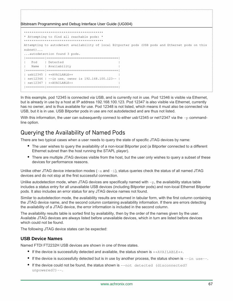
Bitstream Programming and Debug Interface User Guide (UG004)
www.achronix.com 67
******************************************
* Attempting to find all reachable pods: *******************************************
Attempting to autodetect availability of local Bitporter pods (USB pods and Ethernet pods on this
subnet)...
...autodetection found 3 pods.|==========|======================================|
| Pod | Detected || Name | Availability |
|==========|======================================|| usb12345 | ++AVAILABLE++ |
| net12346 | --in use, owner is 192.168.100.123-- || net12347 | ++AVAILABLE++ |
|==========|======================================|
In this example, pod 12345 is connected via USB, and is currently not in use. Pod 12346 is visible via Ethernet, but is already in use by a host at IP address 192.168.100.123. Pod 12347 is also visible via Ethernet, currently has no owner, and is thus available for use. Pod 12348 is not listed, which means it must also be connected via USB, but it is in use. USB Bitporter pods in use are not autodetected and are thus not listed.
With this information, the user can subsequently connect to either usb12345 or net12347 via the command--pline option.
Querying the Availability of Named PodsThere are two typical cases when a user needs to query the state of specific JTAG devices by name:
The user wishes to query the availability of a non-local Bitporter pod (a Bitporter connected to a different Ethernet subnet than the host running the STAPL player).
There are multiple JTAG devices visible from the host, but the user only wishes to query a subset of these devices for performance reasons.
Unlike other JTAG device interaction modes ( and ), status queries check the status of all named JTAG -a -idevices and do not stop at the first successful connection.
Unlike autodetection mode, when JTAG devices are specifically named with , the availability status table -pincludes a status entry for all unavailable USB devices (including Bitporter pods) and non-local Ethernet Bitporter pods. It also includes an error status for any JTAG device names not found.
Similar to autodetection mode, the availability results are returned in tabular form, with the first column containing the JTAG device name, and the second column containing availability information. If there are errors detecting the availability of a JTAG device, the error information is included in the second column.
The availability results table is sorted first by availability, then by the order of the names given by the user. Available JTAG devices are always listed before unavailable devices, which in turn are listed before devices which could not be found.
The following JTAG device states can be expected:
USB Device NamesNamed FTDI FT2232H USB devices are shown in one of three states.
If the device is successfully detected and available, the status shown is .++AVAILABLE++
If the device is successfully detected but is in use by another process, the status shown is .--in use--
If the device could not be found, the status shown is --not detected (disconnected? .unpowered?)--

Bitstream Programming and Debug Interface User Guide (UG004)
www.achronix.com 68
Named Bitporter USB pods are shown in one of two states:
If the pod is successfully found, this means it is available, and its detected availability is be shown as .++AVAILABLE++
Otherwise, when the Bitporter pod is not found, this means it is either not connected to the host, or it is in use by another process. In this case, the pod status is shown as .--in use or not connected--
Ethernet Bitporter Pod NamesThere are several possible states that may be shown for named Bitporter Ethernet pods.
If the pod is successfully detected and is available, the status shown is: ++AVAILABLE++.
If the pod is successfully detected but is not available (it is already in use), the listed status is: --in . The IP address reported is the address of the host currently using use, owner is <ip_address>--
the named Bitporter.
If the pod name contains a serial number, and the pod is not detected, the status is: --No available Achronix Bitporter products with matching serial number found on local subnet.--
Note
Pod names with serial numbers only reach the local Ethernet subnet; pods on a different subnet from the host must be named using their IP address.
If the pod name contained an IP address, and nothing was found at that address, the status is: --No available Achronix Bitporter product found at supplied network address.--.
If the pod name contained an IP address, and the provided address was for something other than a Bitporter pod, the status is something similar to: --Protocol error. Make sure that the device at the supplied network address is an Achronix Bitporter probe.--.
ExampleBelow is an example of a status query for a handful of Bitporter pods: usb10000, usb10001, usb20000, net30000, net30001, net30003, net192.168.100.100, net192.168.100.111, and net192.168.200.222.
% acx_stapl_player -q -pusb10000,usb10001,usb20000,net30000,net30001,net30003,net192.168.100.100,
net192.168.100.111,net192.168.200.222
Achronix STAPL Player (acx_stapl_player)(c) Copyright Achronix Semiconductor Corp. All rights reserved.
contains elements of Jam STAPL Player Version 2.5 (20040526)Copyright (C) 1997-2004 Altera Corporation
********************************************* Attempting to find all reachable pods: *
********************************************Attempting to detect availability of user-specified pods...
WARNING: ...ERROR detecting availability of Ethernet pod net30003 : No available Achronix
Bitporter products with matching serial number found on local subnet. (-2130669535)
WARNING: ...ERROR detecting availability of Ethernet pod net192.168.100.100 : No available
Achronix Bitporter product found at supplied network address. (-2130669534)
|====================|============================================================================
=====================|

Bitstream Programming and Debug Interface User Guide (UG004)
www.achronix.com 69
| Pod |
Detected || Name |
Availability ||====================|============================================================================
=====================|| usb10000 |
++AVAILABLE++ || net30001 |
++AVAILABLE++ || net192.168.100.111 |
++AVAILABLE++ || net30000 | --in use, owner is
192.168.100.141-- || net192.168.200.222 | --in use, owner is
192.168.100.238-- || usb10001 | --in use or not
connected-- |
| usb20000 | --in use or not
connected-- |
| net30003 | --No available Achronix Bitporter products with matching serial number
found on local subnet.-- |
| net192.168.100.100 | --No available Achronix Bitporter product found at supplied network
address.-- |
|====================|============================================================================
=====================|
The example results above show pods usb100000, net30001, and net192.168.100.111 are available. Pods net30000 and net192.168.200.222 are currently not available since they are in use. The USB pods usb10001 and usb20000 were not detected, which means either they are not connected, or are already in use. Finally, the Ethernet pods net30003 and net192.168.100.100 were not detected. For pod net30003, this status could mean the pod with serial number 30000 is not on the local subnet, or that the pod is not powered. Pod net192.168.100.100 is likely not powered, or the user typed the wrong IP address.
Save
Configuring the Bitporter Pod's IP Address (-i* Options)The user may query a pod's current Ethernet IP configuration with the option, set the configuration to -iqdynamic host configuration protocol (DHCP) with the option, or set a static IP with the option.-id -is
Bitporter Pod MAC AddressesWhen adding devices to a network, network administrators frequently need to know the MAC address of the device. Bitporter pods are each shipped with documents describing their MAC address. If the MAC address documentation for a pod is unavailable, the pod's MAC address can be calculated by the following method:
Manual MAC Address CalculationThe MAC address can be manually derived from the pod’s serial number:
MAC address = Manufacturer (prefix) : serial number (suffix) = 00:0F:75:00:30:39
Where:

Bitstream Programming and Debug Interface User Guide (UG004)
www.achronix.com 70
Manufacturer = 00:0F:75 (constant for all Bitporter pods)Serial number = 12345 (decimal) = 0x3039 (hex) = 0x003039 = 00:30:39
Querying the Bitporter Pod's Current Ethernet IP Configuration (-iq)
Note
This option works whether the pod is connected via USB or via Ethernet.
Simply run with the option. If multiple pods are connected, the desired pod name must acx_stapl_player -iqbe specified with the option. If the queried pod is configured for a static IP, the query reports that DHCP is -pturned of, and provides the configured IP address, subnet mask, and gateway.
When querying Ethernet pods from a Linux host, pods that are in DHCP mode does not return their current IP address, subnet mask, or gateway. When querying Ethernet pods that are in DHCP mode from a Windows host, the current IP address, subnet mask, and gateway are reported.
When querying USB pods, regardless of the host OS, if the pod is in DHCP mode, no IP address, subnet mask, or gateway can be reported as these values are dynamically assigned (through DHCP) once the pod is plugged into the Ethernet port.
Example (USB Pod, DHCP is On)To query the IP configuration of a USB pod with serial number 54321:
acx_stapl_player.exe -iq -pusb54321
The command returns:
Achronix STAPL Player (acx_stapl_player)
(c) Copyright Achronix Semiconductor Corp. All rights reserved.contains elements of Jam STAPL Player Version 2.5 (20040526)
Copyright (C) 1997-2004 Altera Corporation********************************************
* Checking current Ethernet configuration: *********************************************Attempting to connect to user-specified pod(s):Successfully opened Bitporter pod usb54321.
Current Bitporter IP Configuration:DHCP = on
Configuring the Bitporter Pod for DHCP (Dynamic IP Address) (-id Option)By default, Bitporter pods are configured to obtain their IP address via DHCP.
Reconfiguring from Static IP to DHCPChanging the Ethernet IP configuration of a pod requires a USB connection. It is not possible to change the IP configuration of a pod while it is currently connected via Ethernet.
Note
Always consult the network administrator to verify that the pod will be allowed to acquire an IP address via DHCP.

Bitstream Programming and Debug Interface User Guide (UG004)
www.achronix.com 71
1.
2.
3.
4.
5.
To change the IP configuration:
Either disconnect the pod from the target or power-down the target. The pod must always be powered when the connected target is powered.
Disconnect the Ethernet cable from the pod.
Disconnect the power cable from the pod.
Connect the USB cable to the host and the pod.
On the host, run with the option.acx_stapl_player -id
For example, to configure a pod with serial number 12345 to obtain its IP address via DHCP, enter the following command:
acx_stapl_player.exe -id -pusb12345
The command returns:
Achronix STAPL Player (acx_stapl_player)
(c) Copyright Achronix Semiconductor Corp. All rights reserved.contains elements of Jam STAPL Player Version 2.5 (20040526)
Copyright (C) 1997-2004 Altera Corporation********************************************
* Checking current Ethernet configuration: *********************************************
Attempting to connect to user-specified pod(s):Successfully opened Bitporter pod usb12345.
Setting new network configuration...Success!
Updated Bitporter IP Configuration:DHCP = on
Configuring the Bitporter Pod to Use a Static IP Address (-is Option)Reconfiguring the pod to use a static IP requires contacting the network administrator to determine the required information:
The pod's new static IP address, for example: 192.168.1.123
The network mask, for example: 255.255.255.0
The gateway IP address, for example: 192.168.1.1

Bitstream Programming and Debug Interface User Guide (UG004)
www.achronix.com 72
1.
2.
3.
4.
5.
6.
1.
Note
Changing the Ethernet IP configuration of a pod requires a USB connection. It is not possible to change the IP configuration of a pod that is currently connected via Ethernet.
To change the pod to use a static IP address:
Either disconnect the pod from the target or power-down the target. The pod must always be powered when the connected target is powered.
Disconnect the Ethernet cable from the pod.
Disconnect the power cable from the pod.
Connect the USB cable to the PC and the pod.
(Optional) Verify that the STAPL player can see the pod over the USB connection:
acx_stapl_player -q
On the host, run with the acx_stapl_player -is,<pod IP>,<network mask>,<gateway IP>option.
For example, to configure a pod with serial number 12345 to use the static IP 192.168.1.123, enter:
acx_stapl_player.exe -is,192.168.1.123,255.255.255.0,192.168.1.1 -pusb12345
This command returns:
Achronix STAPL Player (acx_stapl_player)(c) Copyright Achronix Semiconductor Corp. All rights reserved.
contains elements of Jam STAPL Player Version 2.5 (20040526)Copyright (C) 1997-2004 Altera Corporation
********************************************* Checking current Ethernet configuration: *
********************************************Attempting to connect to user-specified pod(s):
Successfully opened Bitporter pod usb12345.
Setting new network configuration...Success!
Updated Bitporter IP Configuration:DHCP = off
ip = 192.168.1.123mask = 255.255.255.0
gateway = 192.168.1.1
Save
Programming a DeviceOnce the user has generated a bitstream for the design, the following steps are used to program the device from the command prompt (alternately, to use the ACE GUI’s Download view, see “Playing a STAPL File” in ACE
(UG001)):User Guide
Connect the JTAG device to the target systems per or Connecting the Bitporter Pod (see page 14)

Bitstream Programming and Debug Interface User Guide (UG004)
www.achronix.com 73
1.
2.
3.
Connect the JTAG device to the target systems per or Connecting the Bitporter Pod (see page 14).Connecting to the FTDI FT2232H Device (see page 49)
Open a command prompt of the host system (In Windows: , then enter , and click ; Start Run...→ CMD OKor ).Start → All Programs Accessories Command Prompt→ → Locate the directory containing the programming file (the STAPL file), download the bitstream, *.jampassing in the STAPL filename (required), and the desired JTAG connection name (optional)*.jam
acx_stapl_player -aPROGRAM -pusb12345 <design_name>.jam
The program returns:
Example Command-Line Output when Programming a Device. Details Vary per Device and Revsion.
Achronix STAPL Player (acx_stapl_player)
(c) Copyright Achronix Semiconductor Corp. All rights reserved.contains elements of Jam STAPL Player Version 2.5 (20040526)
Copyright (C) 1997-2004 Altera CorporationSuccessfully opened Bitporter pod usb12345.
Entering JTAG programming mode...Performing bulk erase on the device...
Programming the SPD60-FBGA1892 device...Starting user mode...
Exiting JTAG programming mode...Exit code = 0... Success
Troubleshooting the Achronix STAPL PlayerExit CodesWhen an error occurs while using the STAPL player, it is reported with an error code and message. For Bitporter connection and driver-level errors, see . The rest of the errors are Bitporter Connection Errors (see page )briefly discussed in this section.
There are two kinds of errors that can occur when playing STAPL files with the acx_stapl_player: errors reported by the STAPL code and errors from the player executing the STAPL code. All error codes from the STAPL code are positive values, while player errors are negative values. Positive error codes typically indicate problems the JTAG device (Bitporter or FTDI FT2232H) encounters when interacting with the target device via JTAG, while negative error codes typically indicate problems reading the STAPL file or problems communicating with the JTAG device (FTDI FT2232H via USB, or Bitporter via Ethernet or USB).
STAPL Exit CodesThe most frequently seen exit codes when playing a STAPL file are STAPL error codes. These codes are all positive numbers and typically represent problems with the target device or problems encountered by the Bitporter pod when attempting communication with the target device. The official STAPL error codes are in the table below, reproduced from EIA/JEDEC Standard 71 (JESD71), Standard Test and Programming Language
.(STAPL)

Bitstream Programming and Debug Interface User Guide (UG004)
www.achronix.com 74
Table 9: STAPL Exit Codes
Exit Code Description
0 Success
1 Checking chain failure
2 Reading IDCODE failure
3 Reading USERCODE failure
4 Reading UESCODE failure
5 Entering ISP failure
6 Unrecognized device ID
7 Device version is not supported
8 Erase failure
9 Blank check failure
10 Programming failure
11 Verify failure
12 Read failure
13 Calculating checksum failure
14 Setting security bit failure
15 Querying security bit failure
16 Exiting ISP failure
17 Performing system test failure
Further information is provided below for those STAPL exit codes whose underlying problem is easily solved.
Exit code = 6 – Unrecognized Device ID
Most of the actions in ACE-generated STAPL ( ) files perform a quick sanity check before beginning the *.jamoften slow core work of the action. Part of the sanity check is to ensure the device specified in the STAPL file can be found in the connected JTAG scan chain at the expected location. If the device is not found, this error code is displayed along with the expected JTAG ID code and whatever ID code was found instead.
For example:

Bitstream Programming and Debug Interface User Guide (UG004)
www.achronix.com 75
ERROR: Expected device not found at expected location.
Expected idcode:0011 0000000000000001 01100100000 1Found idcode: 0000 0000000000000000 00000000000 0
PROGRAM ERROR: Exit code = 6... Unrecognized device
There are several potential solutions, depending upon the contents of the found ID code:
If the found ID code is all 0s, the JTAG device did not find any target device at the specified location in the JTAG scan chain. Verify that the target device's power supply is plugged in and turned on.
(Bitporter only) If the found ID code is all 1s, the Bitporter pod did not find a valid JTAG connection. Verify that the JTAG ribbon cable is properly connected to both the Bitporter and the target device.
If the found ID code matches the expected ID code except within the four leftmost bits, then an incorrect revision of the specified Achronix Device was found at the specified location. Verify the ACE Implementation Options used to generate this file, or call Achronix Technical Support for assistance. See also the (UG001).ACE User Guide
If the found ID code matches the expected ID code in the twelve rightmost bits but not the 20 leftmost bits (the two bit groups on the right match while some part of the two bit groups on the left do not match), the returned ID code contains the correct Achronix manufacturer code but incorrect device code. The Achronix device found via JTAG at the specified location is not the required device. Verify the ACE Implementation Options used to generate this file, or call Achronix Technical Support for assistance.
If the found ID code does not match the expected ID code in the twelve rightmost bits, the FT2232H or Bitporter found a non-Achronix device at the specified JTAG scan chain location. Verify the Bitporter is connected to the correct JTAG scan chain header, verify the location of the Achronix device in the scan chain, and/or correct the scan chain location specified in the ACE Implementation Options used to generate this STAPL file.
Refer to the (UG001) for details on ACE Implementation Options.ACE User Guide
STAPL Player Exit CodesAll negative exit codes refer to problems originating in itself and not problems reported by acx_stapl_playerthe STAPL code. Typically, these problems are encountered when reading and parsing the STAPL file, or problems during USB or Ethernet communication with the JTAG device (Bitporter or FTDI FT2232H).
Table 10: STAPL Player (acx_stapl_player) Exit Codes
Exit Code Description
-1 Out Of Memory Error: The player had insufficient memory to complete the requested STAPL action. Call Achronix Technical Support.
-2 File Access Error: The player was unable to find or read the specified STAPL ( ) file. Verify the file path *.jamis correct and that file read permissions are enabled.
-3 STAPL Syntax Error(†)
-4 Unexpected End of File(†)
-5 Undefined Symbol(†)

Bitstream Programming and Debug Interface User Guide (UG004)
www.achronix.com 76
Exit Code Description
-6 Redefined Symbol(†)
-7 Integer Overflow(†)
-8 Divide By Zero(†)
-9 CRC Mismatch(†)
-10 Internal Error: Call Achronix Support.
-11 Bounds Error(†)
-12 Type Mismatch(†)
-13 Assignment to Constant(†)
-14 NEXT Unexpected(†)
-15 POP Unexpected(†)
-16 RETURN Unexpected(†)
-17 Illegal Symbol Name(†)
-18 Vector Signal Name Not Found(†)
-19 Execution Cancelled: The user has aborted the execution of the selection STAPL action.
-20 Stack Overflow: Call Achronix Technical Support.
-21 Illegal Instruction Code(†)
-22 Phase Error(†)
-23 Scope Error(†)
-24 Action Not Found: The STAPL action requested by the user was not found in the specified STAPL ( ) *.jamfile. Verify the spelling of the specified action.
-26 Illegal Command-line Arguments: The user included an illegal command-line argument. The legal arguments are shown as part of the error message.

Bitstream Programming and Debug Interface User Guide (UG004)
www.achronix.com 77
Exit Code Description
Table Note
† There is a STAPL code error in the specified STAPL file. Either the file is corrupt, or someone has tried to hand-edit the file. Regenerate the STAPL file in ACE and try again. If the problem persists, contact Achronix Technical Support.
Known Achronix STAPL Player Issues
The acx_stapl_player Does not Work When Executed from Within a Virtual MachineRunning the acx_stapl_player from within a virtual machine is not supported. Adding support for execution within virtual machines is not planned at this time. Unofficially, the has been reported to work in acx_stapl_playerseveral combinations of host OS/VM/client OS.
Need Ability to Specify Scan Chain Variables on acx_stapl_player Command LineUsers wish to use a single jam/STAPL file for multiple Achronix devices regardless where they reside within their scan chains; however, this option is not currently supported.This option is planned for support in a later release
Workaround
Caution!
Be cautious when using these command-line overrides. The STAPL interpretation of these values (as required here) is opposite of the ACE Implementation Options (in the GUI's Options view and in the
Tcl command).set_impl_option
With this workaround, users do need to re-generate bitstreams in order to use the same jam file to program notmultiple devices. Users can pass in the scan chain variables on the command line using acx_stapl_playerthe three options below, :which should all be used at the same time
-dxpostir_val <value> – where is the number of IR bits shifted onto the JTAG scan chain valueafter the IR bits intended for the target device. These bits enter the scan chain after the target device's IR bits, thus these bits are not shifted through the target device. This must be greater than or equal to valuezero and is used for multi-device scan chains in order to pad the IR chain properly with 1s to place the other devices in bypass mode.
-dxpreir_val <value> – where is the number of IR bits shifted onto the JTAG scan chain valuebefore the IR bits intended for the target device. These bits enter the scan chain before the target device's IR bits, thus these bits are shifted through the target device. This must be greater than or equal to valuezero and is used for multi-device scan chains in order to pad the IR chain properly with 1s to place the other devices in bypass mode.
-dtarget_offset <value> – where specifies the offset of the target device from the of the value endJTAG scan chain for multi-device chains. Setting this to 0 selects the last device on the chain; 1 selects the next-to-the-last device on the chain, and so on. This value becomes xpostdr_val in the STAPL file, which represents the number of DR bits shifted into the JTAG scan chain after the target device's DR bits. The value of xpredr_val (the number of DR bits shifted onto the scan chain the target device's DR beforebits) is then calculated from target_offset and the number of devices auto-detected in the scan chain. The predr and postdr bits are all set to zeros.)

Bitstream Programming and Debug Interface User Guide (UG004)
www.achronix.com 78
Save

Bitstream Programming and Debug Interface User Guide (UG004)
www.achronix.com 79
Revision History
Version Date Description
1.0 July 17, 2016 Initial release after port to Confluence from the Bitporter User Guide.
1.1 October 31, 2016 Updated figures and text to make document generic for all Achronix cores.
1.2 December 4, 2016
JTAG Configuration Using the FTDI FT2232H: (see page 36) Populated content for FTDI solution interface and usage.Using the Achronix STAPL Player: (see page 59) Updated descriptions for FTDI use-case.
1.3 May 21, 2017
Bitstream Programming and Debug Interface User Guide (see page 6): Updated details on USB support.JTAG Configuration Using the Bitporter Pod (see page 11):
Removed support for standalone installation of the STAPL player and USB driver.Added note that the Bitporter pod does not work when connected to USB 3.x ports under Linux.
JTAG Configuration Using the FTDI FT2232H (see page 36):
Added note regarding the need for a serial number setting when configuring the FTDI options.Added details regarding lack of support for multi-device chains with the FTDI FT2232H under "Known Limitations."Removed references to standalone STAPL player installer.Added details regarding Linux USB drive installation.Added note regarding USB connections to powered versus unpowered ports.
Using the Achronix STAPL Player (see page 59):
Removed references to standalone STAPL player installer.Added note regarding JTAG auto-detection.
1.4 July 11, 2017
JTAG Configuration Using the FTDI FT2232H: (see page 36) Edited the download instructions for the EEPROM programming template fileConfiguration Overview (see page 6): Added a cautionary note regarding RedHat/CentOS 7 being incompatible with the USB Bitporter.

Bitstream Programming and Debug Interface User Guide (UG004)
www.achronix.com 80
Version Date Description
1.5 July 21, 2017
JTAG Configuration Using the FTDI FT2232H (see page 36):
Added table detailing the pinout required.Add section detailing the need for voltage level shifting between the FT2232H and Speedcore.
1.6 March 4, 2019
Configuration Overview (see page 7): Added support for Bitporter2.Using the Achronix STAPL Player (see page 59): Removed -k, (STAPL-only CRC check) option from the list of supported command options.JTAG Configuration Using the Bitporter2 Pod (see page 52): Provided content in new chapter.JTAG Configuration Using the FTDI FT2232H (see page 36): Updated section on configuring the JTAG connection and multi-device support.
Copyright © 2022 FDOKUMEN