Bipolar Technology and Pebble Stone Artifacts - HARVEST
306
Bipolar Technology and Pebble Stone Artifacts: Experimentation in Stone Tool Manufacture A thesis submitted to the College of Graduate Studies and Research in Partial Fulfillment of the Requirements for the Degree of Master of Arts in the Department of Anthropology and Archaeology University of Saskatchewan Saskatoon, Saskatchewan By Bruce David Low Fall 1997 ( Copyright Bruce David Low, 1997. All rights reserved.)
-
Upload
khangminh22 -
Category
Documents
-
view
4 -
download
0
Transcript of Bipolar Technology and Pebble Stone Artifacts - HARVEST

Bipolar Technology and Pebble Stone Artifacts:
Experimentation in Stone Tool Manufacture
A thesis submitted to the College ofGraduate Studies and Research
in Partial Fulfillment of the Requirementsfor the Degree of Master of Arts in the
Department of Anthropology and ArchaeologyUniversity of Saskatchewan
Saskatoon, Saskatchewan
ByBruce David Low
Fall 1997( Copyright Bruce David Low, 1997. All rights reserved.)

PERMISSION TO USE
In presenting this thesis in partial fulfillment of the
requirements for a Postgraduate degree from the University of
Saskatchewan, I agree that the libraries of this University may
make it freely available for inspection. I further agree that
permission for copying of this thesis in any manner, in whole or in
part, for scholarly purposes may be granted by the professor or
professors who supervised my thesis work or, in their absence, by
the Head of the Department or the Dean of the College in which my
thesis work was done. It is understood that any copying or
publication or use of this thesis or parts thereof for financial gain
shall not be allowed without my written permission. It is also
understood that due recognition shall be given to me and to the
University of Saskatchewan in any scholarly use which may be
made of any material in my thesis.
Requests for permission to copy or to make other use of
material
in this thesis in whole or part should be addressed to:
Head of the Department of Anthropology and Archaeology
University of Saskatchewan
Saskatoon, Saskatchewan (S7N 2AS)
i

ABSTRACT
There is a general lack of research concerning the
technological aspect of pebble stone artifacts throughout the
Northern Plains. As a result, little is known about the manufacture
of these materials except that it is generally accepted that bipolar
technology was the predominant manufacturing technique used
because of the small size of the pebbles. However, research
regarding bipolar technology has also been limited. Furthermore,
many researchers have indicated that this technique is crude, poorly
controlled, and that it only supplies a marginal product.
The research outlined within this thesis examines the
manufacture and archaeological significance of pebble stone
materials. The ultimate aim of this is to provide some clarification
regarding the use of the bipolar method in relation to pebble stone
materials. Therefore, the mode of manufacture of pebble stone
artifacts will be, in part, accomplished by an examination of
experimentally replicated split pebbles using the bipolar technique.
As a final point, considering the obvious wide geographic
distribution and frequency of use of bipolar technology and pebble
stone materials it is unlikely that this technique was thought of so
unfavorably by pre-contact groups or that pebble materials were
considered marginal or used only when superior quality raw
material was not aVailable.
ii

ACKNOWLEDGEMENTS
I would first like to thank my advisor Dr. Urve Linnamae for
her project direction and the invaluable comments and suggestions
regarding my thesis drafts. I would also like to thank my other
committee members, Dr. Ernest Walker and Dr. Margaret Kennedy
for their advice, suggestions and support. I also extend my thanks
to my External Examiner Dr. Alec Aiken and to Dr. David Meyer for
chairing my defence. I also extend my gratitude to Dr. Walker for
allowing me access to the Gowen site materials and to Dr. Bev
Nicholson for providing me with the Pembina Valley artifacts.
A special thanks is extended to a number of individuals for
the time they have taken to correspond or provide me with relevant
literature regarding various aspects of my research. These are
(alphabetically): Bill Fox, Eldon Johnson, Marty Magne, George O'dell,
David Pokotylo, Matthew Root and Michael Shott. In particular I
would like to thank Eldon Johnson for the numerous times he spent
discussing bipolar technology and pebble splitting with me and to
Marty Magne for providing me with numerous bipolar related
references.
Thank you is also given to the Saskatchewan Heritage
Foundation (Project No.: 95-21R, File No.: A1697) and the
Saskatchewan Archaeological Society for providing me with funds
for supplies and the collection of pebble materials to be used for the
various experimental replicative aspects of this project. I also
extend my thanks to Muriel Carlson for the time she has taken to
collect and provide me with additional pebble stone materials,
iii

which was greatly appreciated, and especially for bringing me in
contact with the Marvel Houston Collection.
I would also like to extend my thanks to Terry Gibson and Jim
Finnigan of Western Heritage Services Incorporated for the services
and support they provided including the printing of draft copies and
for providing me with access to scanning equipment. A special
thanks is extended to Shelley McConnell for the time she spent
scanning the majority of the images displayed throughout this thesis
into Photoshop.
Finally, but not least, I would like to thank my family for their
support and understanding of my academic pursuits. In particular
my wife Vera Brandzin-Low for her constant, encouragement and
valued advice throughout the course of my research. Without her
commiseration things would have been much more difficult.
iv

TABLE OF CONTENTS
PERMISSION TO USE i
ABSTRACT ti
ACKNOWLEIX;~ ill
TABLE OF CONTENTS v
LIST OF TABLES xi
LIST OF FIGURES xii
LIST OF ABBREVIATIONS xxi
1.INTRODUCTION 1
1.1 Introduction 1
2.. RESEARCH PARAMFfERS AND THEORETICAL FRAMEWORK 7
2.1 Research Goals and Operationalization 7
2.1.1. Problem 1 7
2.1.2. Problem 2 8
2.1.3. Problem 3 9
2.1.4. Problem 4 9
2.2 Theoretical Framework 10
3. THE TECHNIQUE AND CONTROVERSY OF BIPOLAR
TECHNOLOGY 12
3.1 Technique 12
3.2 Controversy 16
4. METHODOLOGICAL PROCEDURES OF DATA COLLECTION 28
4.1 Application 28
4.2 Tool Selection 37
4.3 Pebble Selection 39
5. BASIC PRINCIPLES OF ROCK FRACTURE 45
5.1 Preliminary statement 45
v

5.2 Fracture Mechanics 46
6. ANALYSIS: EXPERIMENTAL REPLICATION 58
6.1 Analysis of replicative experimental data 58
6.1.1 Analysis of identifiable multivariate attributes
produced during experimental bipolar reduction 59
6.1.1.1 Proximal impact crushing (PIC) 60
6.1.1.2 Distal impact crushing (DIC) 60
6.1.1.3 Percussion lines extending distally
(PLED) 61
6.1.1.4 Proximal bulbs of percussion (PBP) 61
6.1.1.5 Distal bulbs of percussion (DBP) 63
6.1.1.6 An "other" category 64
6.1.2 Analysis of experimental bipolar reduction 64
6.1.2.1 Class 1 64
6.1.2.2 Class 2 78
6.1.2.3 Class 3 101
6.1.2.4 Class 4 117
6.1.2.5 Class 5 121
6.1.2.6 Class 6 123
6.1.2.7 Class 7 123
6.1.2.8 Class 8 135
6.1.2.9 Class 9 136
6.1.2.10 Class 10 154
6.1 Summary 156
7: CURRENT TYPOLOGICAL BIPOLAR ARTIFACT
CLASSIFICATIONS 162
7.1 Archaeological record of the bipolar technique - An
vi
abridged synopsis 162
7.2 Classes of bipolar artifacts 164
7.2.1 Binford and Quimby (1963) bipolar core (outils
ecailles) classification. 164
7.2.1.1 Class 1: Ridge area core. 165
7.2.1.2 Class 2: Point-area core. 165
7.2.1.3 Class 3: Ridge-point core. 165
7.2.1.4 Class 4: Right-angled ridge core. 165
7.2.1.5 Class 5: Opposing ridge core. 168
7.2.1.6 Class 6: Opposing point core. 168
7.2.2 Leaf's (1979a) bipolar core (outils ecailles)
classification. 168
7.2.3 Honea's (1965) bipolar core (outils ecailles)
classification. 172
7.2.3.1 Single-ended. 172
7.2.3.2 Double-ended. 172
7.2.3.3 Multi-platformed. 172
7.2.3.3.1 Plain platform. 174
7.2.3.3.2 Unfaceted platform. 174
7.2.3.3.3 Faceted platform. 174
7.2.3.3.4 Prepared platform. 174
7.2.4 Herbort's (1988) bipolar core (outils ecailles)
classification. 174
7.2.4.1 Tranchette. 174
7.2.4.2 Truncation. 176
7.2.4.3 Spall. 176
7.2.4.4 Double split. 176
vii

7.2.4.5 Longitudinal split. 176
7.2.4.6 lateral split. 176
7.2.5 Root's (1994) bipolar core (outils ecailles)
classification. 177
7.2.5.1 Bipolar cores, not rotated. 177
7.2.5.2 Bipolar cores, rotated. 177
7.2.5.3 Bipolar and freehand cores,
predominantly bipolar. 177
7.2.5.4 Bipolar and freehand cores,
predominantly freehand. 178
7.2.6 Binford and QUimby's (1963) bipolar flake
classification. 178
7.2.6.1 Class 1. 178
7.2.6.1.1 Variety A. 178
7.2.6.1.1 Variety B. 178
7.2.6.2 Class 2. 179
7.2.6.2.1 Variety C. 179
7.2.6.2.2 Variety D. 179
7.2.6.2.3 Variety E. 179
7.2.7 Kobayashi's (1975) bipolar flake classification. 181
7.2.7.1 GroupA. 181
7.2.7.1 Group B. 181
7.2.7.1 Group C. 183
7.2.7.1 GroupD. 183
7.2.8 pieces esquillees 183
7.2.9 spurred end scrapers 189
7.2.10 domed scrapers (domed scraper planes) 189
viii

7.2.11 fabricators 191
8. COMPARISON OF EXPERIMENTALLY REPLICATED
SPECIMENS WITH PREVIOUS BIPOLAR CLASSIFICATIONS 192
8.1 Analysis of previous bipolar core and flake
classifications 192
8.2 Class 1 195
8.2.1. Style 1 197
8.2.2. Style 2 197
8.2.3. Style 3 198
8.2.4. Style 4 198
8.2 Class 2 198
8.2 Class 3 201
8.2 Class 4 203
8.2 Class 5 205
8.2 Class 6 205
8.2 Class 7 208
8.2 Class 8 208
8.2 Class 9 211
8.2 Class 10 213
9. A REVIEW OF SELECT PEBBLE STONE COLLECTIONS 215
9.1 Southern Manitoba 215
9.1.1 Sandhill, Killdeer and Deleurme Sites 218
9.1.2 Merganser, Deleurme East, Valenta, Pelican I,
Pelican II and Smith sites 221
9.1.3 Discussion 221
9.2 Saskatchewan 223
9.2.1 Gowen sites 223
ix

9.2.1.1 Gowen I 224
9.2.1.2 Gowen II 230
9.2.1.3 Discussion 231
9.2.2 Marvel Houston Collection 234
9.2.2.1 Discussion 242
9.3 Summary 245
10. PEBBLE STONE SOURCE AND COLLECTION LOCALES 247
10.1. Source areas of pebble stones collected for experimental
replications 247
10.1.1. Pebble collection locale 1: North Saskatchewan
river Saskatchewan 247
10.1.2. Pebble collection locale 2: Grassy Island lake,
Neutral Hills, Alberta 250
10.1.3. Pebble collection locale 3: Fresno Reservoir,
Montana 255
10.1.4. Summary of source areas. 257
11. SUMMARY AND CONCLUSIONS: SIGNIFICANCE AND
IMPLICATIONS OF STUDY 259
REFERENCES CITED 268
x

LIST OF TABLES
Table 6.1. Abbreviations used in Tables 6.2-6.11. 65
Table 6.2. Class 1 - specimens split into two halves parallel to Z
axis (thickness). 66
Table 6.3. Class 2 - specimens splint into two halves parallel to
the Yaxis (width). 79
Table 6.4. Class 3 - specimens split parallel to Yaxis with one
half complete. 106
Table 6.5. Class 4 - specimens split parallel to Yaxis in three
sections. 118
Table 6.6. Class 5 specimens split in four sections parallel to
Yaxis. 121
Table 6.7. Class 6 - specimens shattered into miscellaneous
variable fragments. 124
Table 6.8. Class 7 - specimens with inadequate pressure..
applied 126
Table 6.9. Class 8 - specimens displaying citrus section.
fractures 137
Table 6.10. Class 9 specimens fractured irregularly. 143
Table 6.11. Class 10 - one section ending in a feather
tenrrrination. 155
Table 7.1. Outline of Leafs (1979a) bipolar core types. 170
Table 9.1. Marvel Houston collection of silicified siltstone split
pebble materials. 236
xi
LIST OF FIGURES
Figure 1.1 Replicated projectile point by Eldon johnson, Saskatoon,
from a split silicified siltstone pebble. 3
Figure 3.1. The bipolar method. 14
Figure 3.2. Methods of bipolar reduction. 15
Figure 4.1. Model for stress definition in three dimensions. 32
Figure 4.2. Pebble stone orientation terminology 34
Figure 4.3. Flake terminations 34
Figure 4.4. Eldon johnson pebble splitting method. 36
Figure 4.5. Stone hammer used dUring experimental
replications 40
Figure 4.6. Quartzite anvil used during experimental
replications 40
Figure 4.7 Classification of pebble shapes 43
Figure 5.1. Direction of applied and rebound force. 48
Figure 5.2. Propagation of spherical longitudinal and shear waves
into an elastic solid. 48
Figure 5.3. Wedging initiation at point of impact. 50
Figure 5.4. Pebble stone compression fractures 50
Figure 5.5. Divergence of spherical wave fronts. 52
Figure 5.6. Pulse wave front. 52
Figure 5.7. Spherical wave movement in an oval shaped body. 54
Figure 5.8. Spherical wave movement in a circular shaped body. 56
Figure 6.1. Class 1 silicified siltstone pebble - split parallel to the
Z axis - Style 2 - (specimen 3). 69
xii

Figure 6.2. Class 1 silicified siltstone pebble - split parallel to the
Z axis - Style 4 - (specimen 1). 70
Figure 6.3. Class 1 silicified siltstone pebble - split parallel to the
Z axis - Style 1 - (specimen 2). 70
Figure 6.4. Class 1 silicified siltstone pebble - split parallel to the
Z axis - Style 1 - (specimen 60). 72
Figure 6.5 Class 1 generic chert pebble - split parallel to the axis -
Z Style 2 - (specimen 137). 74
Figure 6.6. Class 1 silicified siltstone pebble - split parallel to the
Z axis - Style 3 - (specimen 13). 75
Figure 6.7. Class 1 silicified siltstone pebble - split parallel to the
Z axis - Style 3 - (specimen 56). 76
Figure 6.8. Class 1 generic chert pebble - split parallel to the
Z axis - Style 3 - (specimen 136). 77
Figure 6.9. Class 1 generic chert pebble - split parallel to the
Z axis - Style 4 - (specimen 23). 77
Figure 6.10. Class 2 silicified siltstone pebble split parallel to
the Y axis (specimen 32). 87
Figure 6.11. Class 2 silicified siltstone pebble split parallel to
the Y axis (specimen 76). 87
Figure 6.12. Class 2 silicified siltstone pebble split parallel to
the Y axis (specimen 105). 88
Figure 6.13. Class 2 quartzite pebble split parallel to the Y axis
(specimen 182). 89
Figure 6.14. Class 2 quartz pebble split parallel to the Yaxis
(specimen 185). 90
xiii

Figure 6.15. Class 2 silicified siltstone pebble split parallel to
the Y axis (specimen 25). 92
Figure 6.16. Class 2 silicified siltstone pebble split parallel to
the Y axis (specimen 77). 93
Figure 6.17. Class 2 silicified siltstone pebble split parallel to
the Y axis (specimen 94). 94
Figure 6.18. Class 2 generic chert pebble split parallel to the Y
axis (specimen 147). 94
Figure 6.19. Class 2 silicified siltstone pebble split parallel to
the Y axis (specimen 39). 95
Figure 6.20. Class 2 silicified siltstone pebble split parallel to
the Y axis (specimen 40). 97
Figure 6.21. Class 2 silicified siltstone pebble split parallel to
the (specimen 47). 98
Figure 6.22. Class 2 silicified siltstone pebble split parallel to
the Y axis (specimen 82). 98
Figure 6.23. Class 2 generic chert pebble split parallel to the Y
axis Y axis (specimen 143). 99
Figure 6.24 Class 2 generic material pebble split parallel to the
Yaxis (specimen 173). 100
Figure 6.25. Class 2 generic chert pebble split parallel to the Y
axis (specimen 128). 102
Figure 6.26. Class 2 generic chert pebble split parallel to the Y
axis (specimen 155). 102
Figure 6.27. Class 2 silicified siltstone pebble split parallel to
the Y axis (specimen 64). 103
xiv

Figure 6.28. Class 2 silicified siltstone pebble split parallel to
the Yaxis (specimen 65). 104
Figure 6.29. Class 2 generic chert pebble split parallel to the Y
axis (specimen 153). 105
Figure 6.30. Class 2 generic chert pebble split parallel to the Y
axis (specimen 520). 105
Figure 6.31. Class 3 silicified siltstone pebble split parallel to
the Yaxis - one section complete (specimen 516). 110
Figure 6.32. Class 3 silicified siltstone pebble split parallel to
the Yaxis - one section complete (specimen 194). 111
Figure 6.33.Class 3 silicified siltstone pebble split parallel to
the Yaxis - one section complete (specimen 210). 111
Figure 6.34. Class 3 silicified siltstone pebble split parallel to the
Yaxis - one section complete (specimen 230). 112
Figure 6.35. Class 3 silicified siltstone pebble split parallel to the
Yaxis - one section complete (specimen 86). 114
Figure 6.36. Class 3 silicified siltstone pebble split parallel to the
y axis - one section complete (specimen 190). 114
Figure 6.37. Class 3 silicified siltstone pebble split parallel to the
Yaxis - one section complete (specimen 213). 115
Figure 6.38. Class 3 generic material pebble split parallel to the-
y axis one section complete (specimen 233). 115
Figure 6.39. Class 3 quartzite pebble split parallel to the Y axis -
one section complete (specimen 243). 116
Figure 6.40. Class 4 generic material pebble split into three linear
sections (specimen 248). 119
xv

Figure 6.41. Class 4 silicified siltstone pebble split into three linear
sections (specimen 250). 120
Figure 6.42. Class 5 silicified siltstone pebble split into four linear
sections (specimen 251). 122
Figure 6.43. Class 6 shattered silicified siltstone pebble
(specimen 282). 125
Figure 6.44. Class 7 silicified siltstone pebble displaying proximal
chipping - insufficient application of applied pressure
(specimen 322). 131
Figure 6.45. Class 7 silicified siltstone pebble displaying proximal
chipping - insufficient application of applied pressure
(specimen 326). 132
Figure 6.46. Class 7 generic material pebble displaYing proximal
chipping - insufficient application of applied pressure
(specimen 446). 132
Figure 6.47. Class 7 quartzite pebble displaying proximal
chipping - insufficient application of applied pressure
(specimen 472). 133
Figure 6.48. Class 7 quartzite pebble displaying proximal
chipping - insufficient application of applied pressure
(specimen 477). 134
Figure 6.49. Class 8 silicified siltstone pebble displaying citrus
section fracturing (specimen 322). 138
Figure 6.50.Class 8 silicified siltstone pebble displaying citrus
section fracturing (specimen 490). 139
Figure 6.51. Class 8 silicified siltstone pebble displaying citrus
section fracturing (specimen 497). 139
xvi

Figure 6.52. Class 8 silicified siltstone pebble displaying citrus
section fracturing (specimen 501). 140
Figure 6.53. Class 8 quartz pebble displaying citrus section
fracturing (specimen 503). 141
Figure 6.54. Class 8 quartz pebble displaying citrus section
fracturing (specimen 504). 142
Figure 6.55. Class 9 silicified siltstone pebble displaying irregular
fracture (specimen 51 7). 144
Figure 6.56. Class 9 silicified siltstone pebble displaying irregular
fracture (specimen 519). 145
Figure 6.57. Class 9 silicified siltstone pebble displaying irregular
fracture (specimen 518). 147
Figure 6.58. Class 9 quartzite pebble displaying irregular fracture
(specimen 242). 148
Figure 6.59. Class 9 generic chert pebble displaying irregular
fracture (specimen 514), 149
Figure 6.60. Class 9 generic chert pebble displaying irregular
fracture (specimen 515). 150
Figure 6.61. Class 9 quartzite pebble displaying irregular fracture
(specimen 513), 151
Figure 6.62. Class 9 silicified siltstone pebble displaying irregular
fracture (specimen 493). 153
Figure 6.63. Class 10 silicified siltstone pebble displaying a feather
termination (specimen 55). 157
Figure 6.64. Class 10 silicified siltstone pebble displaying a feather
termination (specimen 54). 158
xvii

Figure 6.65. Class 10 silicified siltstone pebble displaying a feather
termination (specimen 91). 159
Figure 6.66. Class 10 silicified siltstone pebble displaying a feather
termination (specimen 212), 160
Figure 7.1. Binford and Quimby's ridge-area bipolar core type. 166
Figure 7.2. Binford and QUimby's point-area bipolar core type. 166
Figure 7.3. Binford and Quimby's ridge point bipolar core type. 167
Figure 7.4. Binford and QUimby's right-angled ridged bipolar
core type. 167
Figure 7.5. Binford and Quimby's opposing ridge bipolar
core type. 169
Figure 7.6. Binford and Quimby's opposing point bipolar
core type. 169
Figure 7.7. Bipolar core types as defined by Leaf. 171
Figure 7.8. Types of cores as defined by Honea. 173
Figure 7.9. Variations of bipolar fracturing. 175
Figure 7.10. Bipolar flakes as defined by Binford and Quimby. 180
Figure 7.11. Bipolar flakes as defined by Kobayashi. 182
Figure 7.12. Two pieces esquillees exhibiting typical
distinguishing attributes. 186
Figure 7.13. A spurred endscraper 190
Figure 7.14. Domed scraping plane. 190
Figure 8.1. Classification of Class 1 pebble shapes 196
Figure 8.2. Classification of Class 2 pebble shapes 200
Figure 8.3. Classification of Class 3 pebble shapes 202
Figure 8.4. Classification of Class 4 pebble shapes 204
Figure 8.5. Classification of Class .5 pebble shapes 206
xviii

Figure 8.6. Classification of Class 6 pebble shapes 207
Figure 8.7. Classification of Class 8 pebble shapes 210
Figure 8.8. Classification of Class 9 pebble shapes 212
Figure 8.9. Classification of Class 10 pebble shapes 215
Figure 9.1. Map of North America showing archaeological site and
pebble collection locales pertinent to this thesis. 217
Figure 9.2. Sample of the Deleurme site (Manitoba) pebble stone
artifacts. 219
Figure 9.3. Sample of the Killdeer site (Manitoba) pebble stone
artifacts. 219
Figure 9.4. Sample of the Sandhill site (Manitoba) pebble stone
artifacts. 220
Figure 9.5. Sample of Early Middle Prehistoric Period projectile
points from the Gowen sites, Saskatchewan. 227
Figure 9.6. Sample of scrapers from the Gowen sites,
Saskatchewan. 229
Figure 9.7. Sample of scrapers from the Gowen sites,
Saskatchewan. 229
Figure 9.8. Typical Gowen.sites anvil used for the bipolar
splitting of silicified siltstone pebbles. 232
Figure 9.9. Miscellaneous silicified siltstone materials from the
Marvel Houston collection. 241
Figure 9.10. Sample of Middle/Late Middle Prehistoric Period
projectile points from the Marvel Houston
collection. 243
Figure 9.11. Sample of initial Late Prehistoric Period Besant
projectile points from the Marvel Houston
xix

collection. 244
Figure 10.1. North Saskatchewan river, Saskatchewan 249
Figure 10.2. Grassy Island Lake, Alberta. 253
Figure 10.3. Fresno Reservoir, Montana. 256
Figure lOA. Upper channel of the Fresno Reservoir, Montana,
showing pebble littered surface. 258
Figure 10.5. North Saskatchewan river terrace littered with
pebble stones. 258
xx

SSP
Qtz-ite
GenMat
NSKR
GIL
FR
V
D
L
R
Lth
W
T
X
Y
Z
Af
Rf
xl
x2
X
n
is
d
LIST OF ABBREVIATIONS
Silicified siltstone pebble stone
Quartzite
Genetic Material
North Saskatchewan River, Saskatchewan
Grassy Island Lake, Alberta
Fresno Reservoir, Montana
Ventral
Dorsal
Left
Right
Length
Width
Thickness
Longitudinal axis
Transverse axis
Axis through pebble thickness (perpendicular to Yaxis)
Applied force
Rebound force
Proximal point of impact
Point of anvil contact
Visible in hand specimen
Not visible in hand specimen
Irregular shear surface
Diffuse
xxi

pr
i
sh
s
h
PIC
DIC
PLED
PBP
DBP
de
dft
dfr
pfr
rlfr
llfr
dfr/p
dfr/d
vfr/d
vfr/p
dvfr/d
vfr/dp
dfr/pd
fr/d
vdfr/d
mm
cm
Pronounced
Negative Inverted
Sheared
Slight damage/barely visible
Hackles
Proximal impact crushing
Distal crushing
Percussion lines extending distally
Proximal bulb of percussion
Distal bulb of percussion
Distal crushing
Distal flake termination
Distal flake removed
Proximal flake removed
Right lateral flake removed
Left lateral flake removed
Dorsal flake removed/proximally
Dorsal flake removed/distally
Ventral flake removed/distally
Ventral flake removed/proximally
Dorsal and ventral flake removed/distally
Ventral flake removed distally and proximally
Dorsal flake removed/proximally and distally
Flake removed/distally
Ventral and dorsal flake removed/distally
Millimeters
Centimeters
xxii

B.P.
VAM
Be
dI
dL
cIS
Relates to time in number of years prior to 1950
vise-anvil-maul
Bipolar core
Intermediate pebble diameter
Longest pebble diameter
Shortest pebble diameter
xxiii

1. INTRODUCTION
1.1 Introduction
Research concerning bipolar technology and the technological
aspect of pebble stone artifacts throughout the Northern Plains has
been limited in the past. Furthermore, research that has been
conducted regarding the bipolar technique has classified it as a
crude and poorly controlled method that supplies only a marginal
product and, therefore, not likely a method favored by pre-contact
groups (Binford and Quimby 1963; Boksenbaum 1980; Hardaker
1979; Haynes 1977; Honea 1965; Knudson 1978; Shafer 1976;
Sollberger and Patterson 1976; Weir 1976; White 1977).
Consequently, there has been little real understanding regarding
the manufacture of artifacts from pebble stone materials except
that it has been generally accepted that bipolar technology was
the predominant manufacturing technique used largely because of
the small size of these materials.
The pebble stone artifacts that I refer to bear no
resemblance to the Paleolithic Oldowan Pebble-Tool tradition as
defined by researchers such as Oakley (1967), Leakey (1971) and
Bordes (1973). Oldowan tools are crudely manufactured all
purpose generalized chopping tools produced from large water
worn pebbles that are large enough to be held firmly in the hand.
1

They are produced by striking several flakes off an end or side of
a large pebble using straight percussion with a hammerstone (as
illustrated by Waldorf 1984: 21). In contrast, the pebble tools
from the Northern Plains are usually quite small and finely
manufactured and bipolar technology is the predominate mode of
their manufacture.
The research conducted here was largely initiated because I
did not agree with previous interpretations that the bipolar
technique is a crude method of stone tool manufacture supplying
only a marginal product. As I alluded above, many bipolar pebble
stone artifacts are very finely crafted implements. A case in point
is illustrated in Figure 1.1., which is a replicated projectile point
crafted by Eldon Johnson of Saskatoon, Saskatchewan. This point
is manufactured from a split silicified siltstone pebble (Johnson
1986) that is only about 2.5 cm. long and 1.2 cm. wide, that clearly
and incontrovertibly illustrates the degree and quality of tools
that can be achieved from split pebble stone materials. In
addition, I felt that given the obvious wide geographic distribution
of bipolar technology, and its frequency of use, it is unlikely that
this technique was thought of so unfavorably by pre-contact
groups.
A number of factors have previously been identified that
can be used to assist in determining the presence of the bipolar
technique within an assemblage. One body of suggestive evidence
is the occurrence of bipolar cores; of course, this is a reasonable
supposition.
2

-"'--_.....I~o 1 2 em.
Figure 1.1. Replicated projee tile pointmade by Eldon Johnson, Saskatoon,from a split silicified siltstone pebble.
3
B,L,

A second indicator of bipolar technology is the presence of
flakes exhibiting a major bulb of percussion on the proximal end
and a minor bulb of percussion on the distal end of the specimen,
although this characteristic (two bulbs of force on the same flake)
has been previously recorded as a rare occurrence. Flakes with
two bulbs of percussion can only be produced through the bipolar
technique when direct primary mechanical force from the
hammerstone and indirect secondary rebounding mechanical force
from the stone anvil is exerted simultaneously on both ends of a
core.
The third indicator of bipolar technology is association of
bipolar materials with stone anvils. Anvils used in the bipolar
manufacture of lithic material are generally flat pieces of stone
large enough to accommodate the article being worked; although,
references are also occasionally made regarding the use of other
items as anvils such as large pieces of bone.
The above factors do not exclusively confirm the presence of
the bipolar technique within an archaeological assemblage,
however, they appear to be the only predominantly recurring
elements that have been associated by previous researchers with
bipolar reduction found in the archaeological record.
In order to interpret, adequately describe, and accurately
classify artifact attributes it seems reasonable to assume that
knowing how they were formed should be a fundamental step in
their classification. It is suggested here that if research goals
concern artifacts derived by a specific manufacturing technique,
for example the bipolar splitting of pebble stones, then it is
4

necessary to look beyond the completed specimens. This
statement does not mean that completed pebble stone artifacts, or
for that matter any other bipolar materials, should not be studied
for their own sake, which would be inconceivable. Rather, I
suggest that to identify the possible function of an artifact itis also
necessary to investigate the process of manufacture of a given
specimen. With bipolar archaeological materials this has not
generally been done other than to indicate that the bipolar
technique employed in their manufacture requires a hammer and
an anvil. Actually, there is even considerable confusion over what
exactly constitutes the method of bipolar reduction although it
seems rational that the use of this technique should be a clear and
straight-forward concept.
This thesis attempts to bring some cohesiveness and
clarification to the bipolar question along with an examination of
the Northern Plains pebble stone technology. Given the obvious
controversial nature of bipolar reduction techniques, and the
present lack of replicative research regarding this method within
North American archaeology, it appeared that what was needed
was to seriously examine the bipolar question at this time. In
particular, I felt that there was a need to expand on a body of
research that examined not only the bipolar method, but classified
the resultant artifacts and discernible attributes produced by this
technology. It is on this basis that the analysis conducted here
was executed. Therefore, research within this thesis concentrated,
in particular, on providing a classification of bipolar technology,
the mode of manufacture of pebble stone artifacts derived through
5

replicative/experimental studies with non-archaeological
materials, and an analysis of the debris created during the bipolar
reduction of pebble materials. The resultant interpretations
derived through the experimental replicative analysis conducted
in this thesis provide a number of significant conclusions within
this much needed area of study.
6

2. RESEARCH PARAMETERS AND THEORETICAL
FRAMEWORK
2.1 Research Goals and Operationalization
The investigations conducted within this thesis concentrate,
in particular, on four archaeological problems regarding bipolar
technology used to produce pebble stone artifacts, as outlined
below.
2.1.1 Problem 1. The first phase was to conduct an
assessment of what constitutes bipolar technology since, although
it has been generally established as a very specific and crude
technique of working lithic material, many authors differ in their
opinion regarding the implementation of this technology.
Although it would seem that the use of the bipolar technique
should be clear and straight forward, as frequently transpires
within archaeological literature, just the opposite is true. For
example, there are those who feel that the archaeological use of
the term bipolar should be dropped entirely. However, much of
the argument concerning this issue appears to be circular. Some of
the bipolar debate is even irrelevant and unnecessarily
argumentative. Chapter 3 of this research reviews the technique
of bipolar reduction and examines the controversy surrounding
this technique in an attempt to provide some clarification
7

regarding the issue and to assist in the determination of what
exactly constitutes the bipolar method of stone tool manufacture.
2.1.2 Problem 2. A major dilemma of lithic researchers is
the recognition of bipolar materials within the archaeological
record. Although current archaeological literature does indicate
that bipolar technology is predominantly used with most pebble
materials. Additionally, several typologies do currently exist for
bipolar cores, for example Binford and Quimby (1963). There is,
however, still much debate within the archaeological literature
concerning what exactly does constitute a bipolar core as opposed
to other items (Goodyear 1993; Hardaker 1979; Hayden 1980;
LeBlanc 1992; Patterson 1979a, Rondeau 1979; Shott 1989;
Sollberger and Patterson 1976).
In order to adequately understand this technique, and to
aptly apply it to pebble stone artifacts, a serious examination of
bipolar stone working technology (what classifies it, its
implementation and what products result from this stone working
process) was undertaken by conducting extensive experimental
replications. In particular, these investigations concentrated on
the potential of pebble stone working techniques. To assist in this
investigation select metric attributes were recorded and a
multivariate attribute analysis was conducted on the resultant by
products created during the experimental replications.
Experimental research is favored by many lithic researchers.
For example, in an evaluation of debitage technology, Prentiss and
Romanski (1989: 96) noted that controlled experimentation was
necessary before generalizations could be demonstrated.
8

Additionally, Magne (1989: 16) stated that lithic experimentation
can assist in legitimizing descriptions. The goal of the analysis
conducted here was to determine if experimentally replicated split
pebble stone materials displayed a series of universal attributes
and whether bipolar specimens displayed attributes distinct from
non-bipolar debitage. This examination provided useful
information concerning attributes of pebble stone debris created
through bipolar technology.
2.1.3 Problem 3. There is a definite need to distinguish
pebble stone materials and bipolar technology, therefore, a
comparison of pebble artifacts from several archaeological
collections and the experimentally-replicated materials was
conducted. This analysis provided useful introductory information
regarding the temporal and spatial extent of pebble stone artifacts
across the Northern Plains. Because of the time and labor involved
in this type of analysis, this portion of the research was restricted
to a general preliminary statement only.
2.1.4 Problem 4. A final set of concerns relates to the
geographic extent, the temporal time frame, and the number of
distinct divisions of bipolar technology. Consequently, a
preliminary analysis of the archaeological literature was
undertaken relating to two main points. One, to assess the
possible overall geographical extent of pebble stone artifacts
within the Northern Plains. Initial information indicates that the
Early Middle Prehistoric period (7500-5000 B. P., as defmed by
Reeves 1973) had a distinctive pebble stone (artifact) component
separate from other pebble stone materials found on the Northern
9

Plains. It should, therefore, be possible to link a distinct pebble
stone component from the Northern Plains with the Early Middle
Prehistoric period.
Second, to determine whether a separate and major pebble
stone component can be defined in the Early Middle Prehistoric
period. Therefore, data were analyzed to see if a temporal pattern
emerged regarding pebble stone artifacts. This research clearly
demonstrates, however, that there are actually several temporally
separated bipolar industries.
2.2 Theoretical framework
The theoretical and interpretative basis that I followed
within this thesis was inductive/deductive research methods
associated with the cultural historical approach. I believe this
provided the best framework upon which to base my
interpretations.
The realization of this research was achieved mainly through
three phases. First, experimental parameters were derived from
the analysis of archaeological pebble stone artifacts. Second, data
were accumulated through the experimental replication of pebble
stone tools and cores from non-archaeological materials. Finally,
accumulated data from the replicated materials were compared to
archaeological artifacts. I believe that the interpretations derived
through the interplay between replicated items and actual
artifacts will lead to a better understanding of the making and
functioning of pebble tools. This point has been previously noted
10

by Amick, et al (1989:1) who stated that "the most effective way
of relating experimental results to the archaeological record is
interactively." The synthesis of these data was used for the
development of general descriptive and classification models used
throughout this thesis regarding bipolar technology on the
Northern Plains.
11

3.
THE TECHNIQUE AND CONTROVERSY OF BIPOLAR
TECHNOLOGY
3.1 Technique
The use of the bipolar technique has a long history. For
example, Semenov (1964) describes mammoth bone dating to
Mousterian times that bear the proportions and traces of wear
indicative of their being used as anvils for stone knapping.
Although a large bone, block of hardwood, the ground, the padded
thigh or even the palm of the stone worker's hand may be
employed as an anvil, the most commonly used material is stone
(Honea 1965).
Binford and Quimby (1963) provided the first description of
bipolar technology in North America as part of an analysis of
several archaeological sites in Northern Michigan. They described
the bipolar flaking technique as a method that produces
distinctive flakes by special use of a hammer and anvil (Binford
and Quimby 1963). Subsequent researchers maintained this basic
description (Crabtree 1972; Honea 1965; Kobayashi 1975; Leaf
1979a).
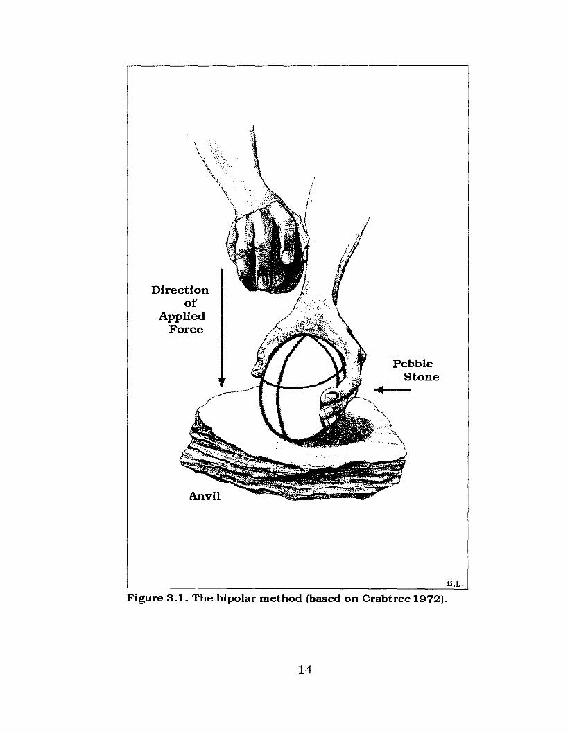
The standard bipolar method is to hold with one hand the
objective piece of material to be manipulated (such as a pebble
12
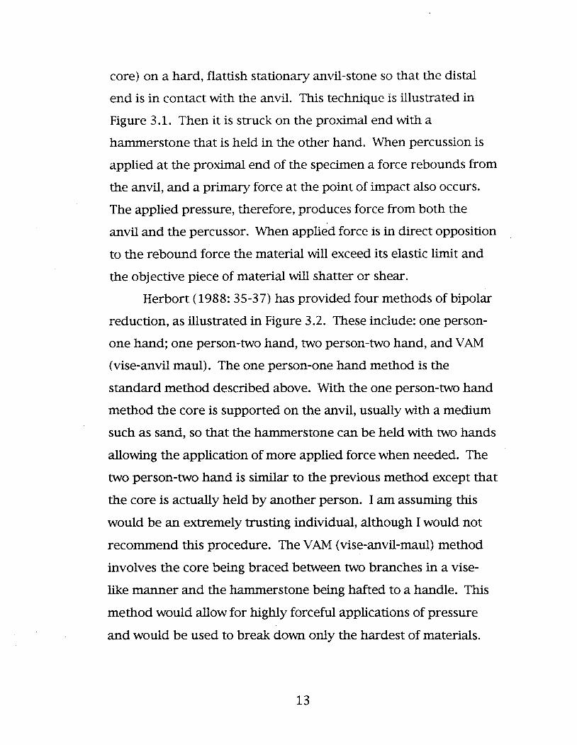
core) on a hard, flattish stationary anvil-stone so that the distal
end is in contact with the anvil. This technique is illustrated in
Figure 3.1. Then it is struck on the proximal end with a
hammerstone that is held in the other hand. When percussion is
applied at the proximal end of the specimen a force rebounds from
the anvil, and a primary force at the point of impact also occurs.
The applied pressure, therefore, produces force from both the
anvil and the percussor. When applied force is in direct opposition
to the rebound force the material will exceed its elastic limit and
the objective piece of material will shatter or shear.
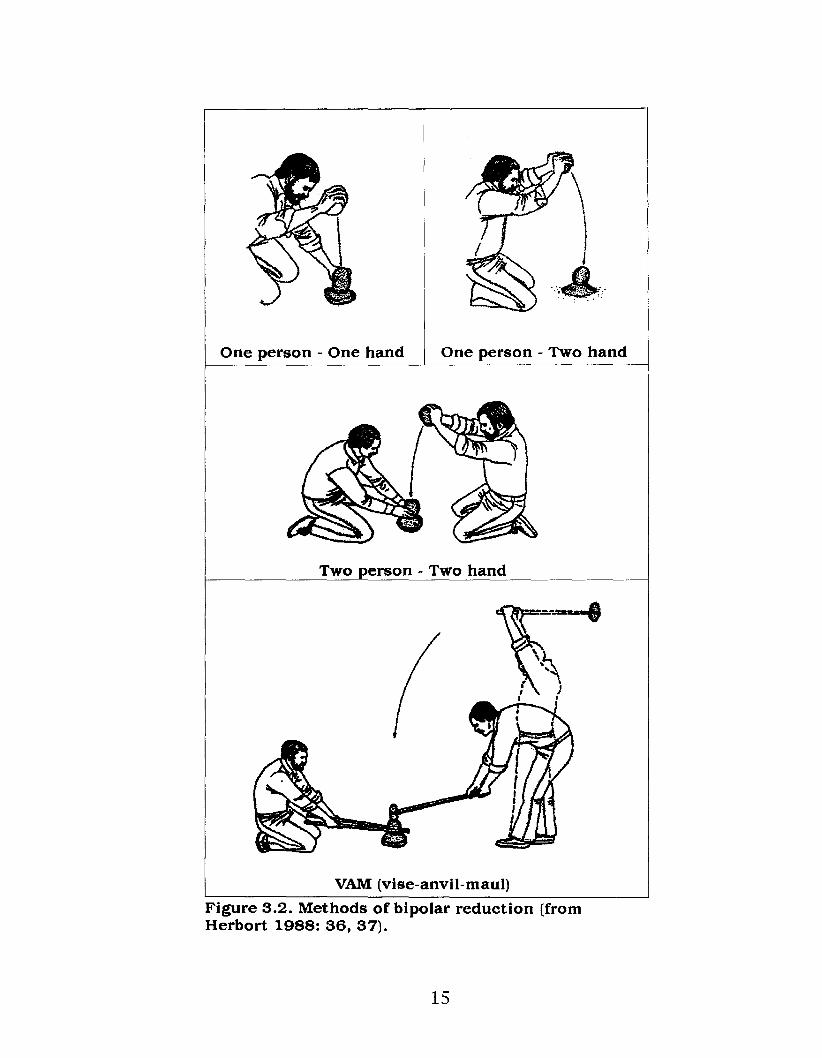
Herbort (1988: 35-37) has provided four methods of bipolar
reduction, as illustrated in Figure 3.2. These include: one person
one hand; one person-two hand, two person-two hand, and YAM
(vise-anvil maul). The one person-one hand method is the
standard method described above. With the one person-two hand
method the core is supported on the anvil, usually with a medium
such as sand, so that the hammerstone can be held with two hands
allowing the application of more applied force when needed. The
two person-two hand is similar to the previous method except that
the core is actually held by another person. I am assuming this
would be an extremely trusting individual, although I would not
recommend this procedure. The YAM (vise-anvil-maul) method
involves the core being braced between two branches in a vise
like manner and the hammerstone being hafted to a handle. This
method would allow for highly forceful applications of pressure
and would be used to break down only the hardest of materials.
13
Directionof
AppliedForce
Anvil
PebbleStone
B.L.
Figure 3.1. The bipolar method (based on Crabtree 1972).
14
One person - One hand One person - Two hand
Two person - Two hand
VAM (vise-anvil-maul)
Figure 3.2. Methods of bipolar reduction (fromHerbort 1988: 36, 37).
15

Obviously, flakes struck off using the bipolar reduction
technique are called bipolar flakes and accordingly cores used in
this process are referred to as bipolar cores. Although, as will be
discussed within subsequent sections of this study, bipolar flakes
and cores can and do vary highly.
3.2 Controversy
Most researchers have noted that the bipolar technique is
used whenever the lithic resources are predominantly small,
because these materials have to be used more efficiently (for
example, Binford and Quimby 1963; Crabtree 1972; Honea 1965;
Kobayashi 1975; Knudson 1978; Leaf 1979a; Sollberger and
Patterson 1976). As a result, the bipolar technique is constantly
reported to be widespread in those parts of the world where the
main sources of flaking materials are theorized to be small, such as
pebble stones. The bipolar technique is quite widespread
throughout the Northern Plains and although small pebble
materials under 5 centimeters in length do occur in abundance
within this region (Ball 1987; Low 1994; Quigg 1977, 1978; Reeves
1972; Walker 1980, 1984, 1992) they certainly are not a
monopoly over other available lithic resources. Many materials
such as Swan River chert are also available throughout the
Northern Plains region (Low 1994, 1995a-d). Additionally, larger
cobbles may (and are) also frequently fractured using this
technique (Herbort 1988). Therefore, it is not reasonable to
16

assume that material size alone determines the types of
technology employed.
In the past, archaeological researchers, such as Honea (1965)
and Kobayashi (1975) indicated that blades made by the bipolar
technique often produced a bulb of force on the ventral surface at
both ends of the detached piece. Other researchers (Crabtree
1972; Sollberger and Patterson 1976) have contradicted this
theory. For example, Crabtree (1972) believed that this technique
sometimes leaves a positive or negative inverted bulb of force scar
on either end, but very rarely on both ends of the same flake or
blade; a point concurred with by Sollberger and Patterson (1976).
Moreover, Sollberger and Patterson (1976) state that though true
bipolar flakes could be produced with two force bulbs on opposite
ends of a flake there is no technical advantage for doing so. They
note that bulbs of percussion at both ends would result in less
available total cutting edge if used as an unretouched flake and if
a true bipolar flake was used as a tool blank, shaping and retouch
flaking would be made at least twice as difficult by the presence
of two bulbs of percussion. First, I do not believe that a double
bulb of percussion was the ultimate technological feature being
sought. Second, considering the generally small size of bipolar
bulbs it is unlikely that shaping or retouching a specimen was
made twice as difficult. (Bipolar attributes are discussed in
Chapter 6).
According to Crabtree (1972) the ideal bipolar fracture is
made by directing one of the forces slightly off-center which will
split or shear the core. Shearing radiates the force waves from
17

one end or the other, usually from the end having the least contact
with the percussor or anvil. He notes that this method usually
does produce only one bulb at the proximal end of a blade or flake
(Binford and Quimby 1963; Crabtree 1972; Hardaker 1979; Honea
1965; Kobayashi 1975; Leaf 1979a; Sollberger and Patterson
1976). Additionally, he states that although a true bulb of force
does not occur on the distal end there is sometimes evidence of
force or damage at the distal end of the flake removed (Crabtree
1972; Sollberger and Patterson 1976).
Several researchers (Carter 1978; Crabtree 1972; Sollberger
and Patterson 1976) contend that anvil-supported cores used to
produce flakes and blades must have the distal working edge of
the core's base free of contact with the anvil, which prohibits a
bulb of force at both ends. Also, they note that when
manufacturing blades the force must be directed tangentially
rather than perpendicularly to the face of the core. As a result the
detached blade will have one bulb of force at the proximal end.
These same researchers further state that anvil-supported cores
produce flatter blades than those that are hand held or placed on a
Yielding support and if the so called "true bipolar technique" is
used for blade making, the force is in direct opposition between
anvil and percussor and the blade will collapse and there will not
be bulbs of percussion on both ends. Therefore, they believe that
although the anvil is useful in many techniques the force is
normally not applied in direct opposition to the anvil (Carter 1978;
Crabtree 1972; Sollberger and Patterson 1976)..
18

Vanderwal (1977) found that mean length and width of
usable bipolar flakes exceed the similar properties of residual
bipolar cores, largely because cores can be reduced while in use to
a point where they are no longer serviceable. Shott (1989) notes
that the small size of archaeologically recovered bipolar artifacts
does not necessarily reflect the size at which they were valued,
merely the size they had reached when discarded after extensive
reduction. Goodyear (1993) adds that bipolar reduction would
actually signal the last possible effort to procure usable flakes
from a nearly exhausted tool kit. Regarding this point, Goodyear
(1979) states that where no other comparable raw material is
nearby, such a practice of intensive recycling is an effective and
rational way of dealing with a tool replacement problem. Honea
(1965) and Shafer (1976) also describe the bipolar technique as
being particularly suited for small pebbles, which would be
difficult to produce flakes with by other techniques. Furthermore,
Goodyear (1993) suggests that bipolar cores reflect a low potential
raw material supply at a given site and that they represent a
strategy of intensive raw material curation based on recycling of
increasingly scarce portable artifacts.
I have stated previously that size availability of raw
material need not completely limit types of flaking techniques
employed. Although the size of raw material to be worked would
certainly be considered in the selection of particular knapping
techniques, the type of lithic material can also greatly influence
the quality of knapping results even more than limitations in size
of raw material. Given the widespread use of bipolar technology,
19

however, I do not believe that this technique can be considered as
a final effort to attain usable materials or was employed because
no other lithic materials were available.
Ingbar (1994: 54) notes that it is the stone tool technology
that needs to be considered not the source. "In essence, we need
to determine how technology "flows through" adaptive behavior"
(Ingbar 1994: 54). In other words, if a group had no particular
use for a raw material then its proximity to it would be
inconsequential (Ingbar 1994: 54). Therefore, it is important to
keep in mind that lithic manufacturing techniques can be linked to
archaeological assemblages without the confirmation of raw
materials source areas (Andrefsky 1994: 21).
As this research will display, the bipolar technique can be a
very efficient method of working stone. This belief is contrary to
the views of lithic researchers such as Sollberger and Patterson
(1976). Although, others such as Root (1992) also consider the
bipolar method to be a effective technique of stone working.
Hardaker (1979) states that bipolar technology is a lithic
manufacturing tradition and because of the peculiar nature
regarding the mechanics of this technique, he can see no other
recourse for the researcher to understand it than that of
replicative studies, a view that has also been presented by
Crabtree (1975: 105). Rondeau (1979) counters that Hardaker's
(1979) statement is an interpretation of the archaeological record
that does not logically follow from any results that can be
produced by experimental replication. Rondeau's (1979)
statement is remarkable given that analogy and experimentation
20

are really the only means that archaeologists have with which to
make inferences. Rondeau's (1979) argument largely appears to
be somewhat circular. At one point he states, "replication
techniques ... may not actually replicate the prehistoric situation"
and then in the same paragraph he adds, that "replication
experiments by this author [Rondeau] support the contention that
useful flake forms can be repeatedly produced with reasonable
efficacy" (Rondeau 1979: 18).
Rondeau (1979) summarizes four points that he states must
be considered when developing interpretations regarding
prehistoric lithic collections. These are:
A. to consider the existing archaeological literature
concerning both the previous interpretations of such
collections as well as previous replication studies;
B. to consider the logic in developing those interpretations;
C. to consider the factors that must be controlled during the
replication study;
D. to consider the archaeology that produced the collection
under study.
He further notes that without the careful consideration of these
elements no amount of lithic replication will aid in correctly
interpreting archaeological collections.
Weir (1976) also argues against the possibility of a bipolar
tradition. He concludes that bipolar flakes in some cases may be
the result of a "generalized" use of anvil stones. This statement is
within the gray realm concerning what does or does not constitute
bipolar technology within the archaeological literature. In other
21

words, many archaeologists debate whether the simple use of an
anvil constitutes bipolar technology. According to Weir (1976) it
does not and this position is strongly concurred with by others, for
example, Sollberger and Patterson (1976).
Carter (1978) states that the use of the term "hard anvil
technique" would be preferable to the use of the term bipolar.
Patterson (1979a: 22) and Sollberger and Patterson (1976) also
states that the "simple use of a hard anvil to obtain simultaneous
flake detachments should ... be given a separate classification,
distinct from true bipolar fracture techniques." Patterson (1979a:
22) adds that "only cases involving true bipolar fractures should
be classified as bipolar flaking." Patterson (1979a) and Sollberger
and Patterson (1976) argues that the use of an anvil does not
necessarily produce bipolar fractures. To them true bipolar
fracture involves initiation of fracture at the proximal end of the
core, where force is applied, and at the distal end of the core
resting on a hard anvil and not simply a detachment of separate
flakes on the striking platform and anvil ends of the core. I do not
believe there is a real distinction here, although, they state that
the latter situation should be termed 'simultaneous flake
detachment' to avoid confusion with technology involving "true
bipolar fracture." The differentiation they present does not,
however, lessen the confusion but rather it adds to the
bewilderment of this technique already in the literature.
Hayden (1980) does not agree with the analysis presented
by Patterson (1979a) and Sollberger and Patterson (1976). He
also notes that they have unfortunately added to the confusion
22

concerning the identification of bipolar cores and that their
interpretation seems to be improbable. Hayden believes that
Patterson (1979a) and Sollberger and Patterson (1976) have
ignored the standard definition of the bipolar core and bipolar
technique and that they have attempted to invent new
terminology. This does appear to be the situation. The attempt to
do this comes from the feeling by Patterson (1979a) and
Sollberger and Patterson (1976) that it is difficult to control
material using the bipolar technique, which leads them to the
conclusion that it cannot be a real technique. However, it is
unjustifiable that we should discount a technique even if it has
been previously classified as being crude solely by modem
standards.
According to Hayden (1980), individuals using bipolar
techniques were minimally concerned with control of the medium
and primarily concerned with simply obtaining usable pieces of
stone for a specific task at hand; a goal that he notes has
surprisingly few constraints. Although I agree with Hayden
regarding the classification of the bipolar technique, I disagree
with him on the point that control of the medium was not a
concern. As far as I have been able to discern, the control of the
material being worked in knapping is of paramount concern to the
flintknapper. It is quite evident within the archaeological
literature that there are many artifact types that could be and
were produced by using the bipolar technique and it is unlikely
that these occurred by chance.
23

Patterson (1979a) adds the names of Crabtree (1972) and
Kobayashi (1975) to his and Sollberger's (Sollberger and Patterson
1976; Patterson and Sollberger 1977) as those who restrict
themselves to the use of the term bipolar flaking to those
instances where true bipolar fractures occur. As previously noted,
however, Crabtree (1972) clearly defines bipolar reduction
technology quite simply and broadly, that is, as a technique of
resting a core or lithic implement on an anvil and striking the core
with a percussor. By this definition bipolar reduction can produce
many flakes of widely varying size and form (Shott 1989).
Goodyear's (1993) description of bipolar reduction is similar to
Crabtree's (1972); bipolar cores are produced from materials that
have been placed on a stone anvil and struck repeatedly with a
hammerstone for the derivation of flakes. On the other hand,
Kobayashi (1975) does maintain that a core must be struck
vertically (at right angles) to the striking platform to produce
bipolar flakes. This view is also held by Jeske and Lurie (1983)
who state that bipolar reduction produces flakes by placing a core
on a stone anvil and striking the core with a stone hammer at a
900 angle (straight down) producing two opposing points of
impact, one on either end of the core.
Haynes (1977) notes that the bipolar technique may simply
involve holding a core against an anvil and pounding it until it
shatters or releases more than one or two flakes. Honea (1965)
and Shafer (1976) believe that the occurrence of some bipolar
flakes may simply be due to random errors within the more
general framework of using a hard anvil. Boksenbaum (1980)
24

notes that bipolar technology may be a variant of smash flaking,
which produces an anomalous class of flakes having resulted from
smashing. Knudson (1978: 45) has expressed the view that the
bipolar technique is often "an accompaniment to more stylized and
complicated technologies within a single cultural system."
Sollberger and Patterson (1976) argue that true bipolar flaking
simply represents errors, accidents, or an unskilled technique by
individual craftworkers. Given the wide geographical range of the
use of this technique and, as I have noted, the diversity and range
of bipolar by-products, these interpretations are extremely
unlikely.
Sollberger and Patterson (1976) further conclude that the
true bipolar flaking technique is not technically advantageous and
probably does not form the basis for specific chipped stone
industries. Their position is often noted within the literature by
many researchers who concur with this interpretation. However,
as the research presented here will demonstrate this
interpretation is also not valid.
Haynes (1977) and White (1977), however, both note that
bipolar flaking, while not a sophisticated knapping technique, may
be the main or only knapping technique found in some Old and
New World assemblages. Sollberger and Patterson (1976),
however, contend that true bipolar techniques may have no
relation to specific cultural traditions. To these researchers the
use of a hard anvil can offer a mechanical advantage by
preventing deflection of the core during percussion giving more
efficient use of applied energy; however, they state that it is
25

hardly the basis for a distinct chipped stone industry. As noted
above, they describe true bipolar flaking as the lack of skill in
flintknapping, rather than as an alternate desirable technique.
Honea (1965) adds that the firm support of a core on an anvil can
be used with a variety of knapping techniques, such as pressure
flaking, not only bipolar reduction. Sollberger and Patterson
(1976) emphasized that the presence of bipolar flaking
characteristics does hot imply a consistent bipolar technique and
that if true bipolar flaking is done, there is some loss of flaking
control on any size core when compared with direct percussion.
Therefore, they note that when the bipolar technique is not
employed use of a hard anvil can produce uniform results.
Carter (1978) suggests the possibility of several bipolar
industries and that one involved the longitudinal splitting of
cobbles between hammer and anvil. He (Carter 1978: 15) notes
that many of the cores produced in this manner have been"split
down to sub-cylindrical nuclei of relatively small diameter."
Flenniken (1981, 1983) provides a further example of a separate
and distinct bipolar industry that he identifies as the Systematic
Bipolar Microlith Technology at the Northwest Coast Hoko River
site, in northern Washington. Flenniken's (1981, 1983) definition
of microliths is that they are not blades but rather small
specialized flakes that are quite short and have at least one
margin that is sharp. He selected the name Systematic Bipolar
Microlith Technology because he feels it involves the systematic
bipolar reduction of the lithic material. That is, rather than
merely striking the anvil supported cobbles with a percussor and
26
retrieving the usable remains the flintknapper systematically
selected how and where to strike a core to achieve particular end
products. The likelihood of there being several bipolar industries
seems reasonable given the diverse types of bipolar artifacts
observed within the archaeological record.
It is quite evident from the above discussion that there is
indeed much controversy regarding what constitutes bipolar
technology, how the technique is put to use, what lithic materials
are favoured and what by-products result from the application of
this unique method of working stone. A great deal of the mis
interpretation with this technology originates from there not being
any in-depth studies regarding the above, or of a sYnthesis of the
bipolar material already in the literature. Therefore, given the
controversial nature of the bipolar technique, and the lack of
replicative research regarding this method, I felt that research
needed to be carried out that describes and classified this
technology, its resultant artifacts and the attributes produced by
this technique. It is on this basis that the following analysis was
executed.
27

4. METHODOLOGICAL PROCEDURES OF DATA COLLECTION
4.1 Application
A noted concern within the archaeological literature
regarding the bipolar splitting of pebble stones exists that has
fundamental implications regarding the study of these materials.
That is, how are pebble stones split using the bipolar technique
without crushing them into useless pieces of shatter? McPherron
(1967), for example, has described this variable outcome of the
bipolar shearing of small pebbles. He has noted that often the
pebble shatters completely, leaving only fragments that may show
percussion wave scars on their cleavage faces. Alternatively, the
pebble may fracture internally, leaving a split pebble with
irregular, angulated cleavage faces. This characteristic is related
to factors such as tool selection, the quality of the material, and
the body form of a pebble. How, then, was the bipolar method
used to produce the abundance of pebble materials evident within
the archaeological record?
Researchers such as Hardaker (1979) have noted that there
are a number of variables that largely control the bipolar
technique. These include the material of the core, the weight of
the percussor relative to the shape and size of the core, and the
intensity of force that is generated by the flintknapper.
28

Furthermore, it is consistently suggested that the derived
elements from a bipolar core have to be studied closely to clarify
and determine the practical limits of this technique. Replicative
experimentation is one method that can assist in the interpretation
of bipolar reduction techniques within the archaeological record.
My primary goals during the experimental stage of this
project were the rudimentary factors that would influence the
shearing of a pebble stone through the application of the bipolar
technique. For example, what caused one pebble to shear cleanly
into two halves while another, apparently similar pebble,
shattered into largely unusable debitage? Additionally, what
ambient factors accounted for the apparent wide range of
variation between these two extremes? Therefore, the initial
experimentation involved assessing not only the bipolar method,
but also the tools that produced the most optimum results in this
procedure that are outlined below. Additionally, the actual
shearing and fracture properties involved in the bipolar process of
pebble splitting was observed and recorded.
Pebble materials used during the initial assessment of the
tools were discarded and are not included in the analysis of the
experimental data. In part I felt that this was a learning process.
More importantly, the major focus at this stage was to assess the
tools and not the pebble materials. Moreover, including these
materials would unacceptably skew the results of the
experimental data.
Once the appropriate hammer and anvil were selected each
replication was conducted in as uniform a manner as possible.
29

First, the dimensions of the pebble were recorded on a numbered
index card. Then, gripping the pebble to be fractured between my
thumb and forefinger of my left hand, I then rested my hand on
the anvil and placed the pebble's distal end in contact with the
anvil (in a vertical position). Gripping the hammerstone in my
right hand I then lightly tapped the top of the pebble. By doing
this I could hear and feel the resonance within the pebble change.
During the initial experimentation an interesting observation
was made. I noted that after some practice I began to feel the
change in resonance being generated within the pebble stone as it
was held on an anvil and lightly tapped with a precussor on the
proximal end. I also began to notice a change in the tone of
resonance generated within the pebble stone during this process.
That is, that as a pebble was held on an anvil and gently tapped,
while rocking the pebble slowly from side to side (as well as
altering the angle that the percussor was being held), it was
possible to feel the resonance and hear the tone change within the
specimen indicating the optimum point at which a pebble should
be struck so that it will more frequently shear, rather than shatter
(Low 1996b).
Once I determined that the pebble was in an optimum
position I then applied a controlled amount of force to the
proximal end of the specimen. Some researchers still note (for
example, Kuijt, et al1995:118) that it is necessary to apply a
massive blow to the objective piece when using a bipolar
technique. However, to do so would render the material useless.
As I note, it is necessary to control the amount of force being
30

applied so as not to shatter the material completely. The smaller
the objective piece being worked the more control must be used
with applying the force.
The debitage resulting from the aforementioned activity was
collected into a small plastic bag with the index card. Specimens
were set aside before the next replication for later analysis. All
replicated specimens where examined using both a hand lens
(lOX) and a standard binocular ~croscope (40X - 100X). The
microscope helped to verify the attributes observed by the hand
lens. The results of this analysis will be discussed later in Section 6
of this thesis.
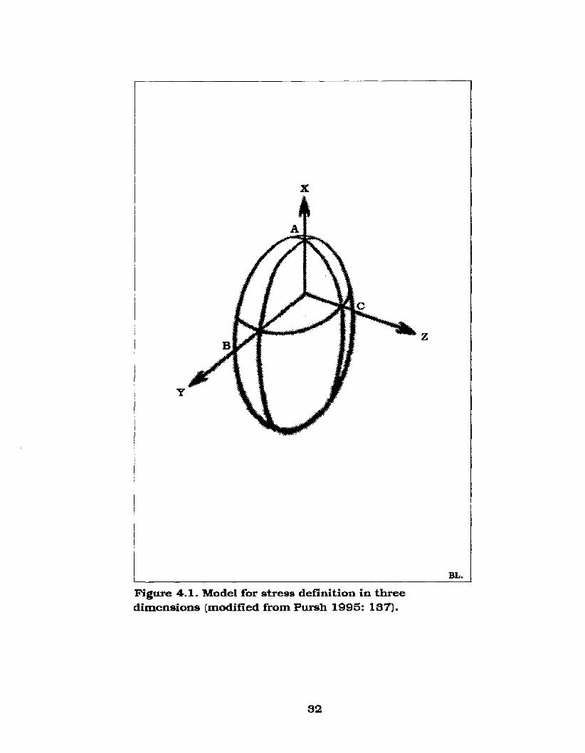
To accurately identify and differentiate between irregular
pebble shears and those through the width and thickness of a
pebble a model of an ellipsoid, with standard X, Yand Z axes, was
used (Figure 4.1), with the Xaxis extending down from proximal to
distal end, the Yaxis extends through the width, and the Z axis
through the thickness of the pebble. Additionally, to differentiate
between the shear face and the pebble axes the letters (A, Band
C) were assigned for the main ventral faces of the split pebble
(Figure 4.1). A pebble face of AB was sheared along the widest
section of the pebble parallel to the Yaxis and down the Xaxis. A
pebble face of AC was sheared along the thinnest (relatively
speaking) section of the pebble parallel to the Z axis and down the
X axis. Several irregular fractures occur and will be dealt with
independently throughout Section 6 except for several pieces that
are referred to as citrus-sections (due to their similarity to orange
wedges). The pebble faces of these specimens are referred to as
31
x
y
z
BL.
Figure 4.1. Model for stress definition in threedimensions (modified from Pursh 1995: 137).
32

Be, that is, they extend down the Xaxis but run irregularly, and at
various angles to the Yand Z axes creating a wedge-shaped
section.
Figure 4.2. outlines the pebble stone orientation terminology
that was used regarding a specimen's ventral, surface, dorsal
surface, proximal end, distal end and longitudinal axis. Figure 4.3.
illustrates the major types of flake termination. Of main concern
here are the feather and axial terminations. In particular, axial
terminations occur on the bulk of the experimentally replicated
materials.
According to the geologic Udden-Wentworth scale that is
used almost universally by sedimentologists for the classification
of lithic debris (Boggs 1987: 107), pebbles range from 4 to 64 mm.
in length. Stones that form individual particles larger than 64 mm
(but less than 256 mm) are classified as cobbles. However, the
application of this classification to pebble stone artifacts, rather
than to individual particles, is unusable for this study. This
determination is based on several factors. First, it is highly
unlikely that split pebble stone artifacts would be found as small
as 4 mm in diameter that had been produced by bipolar reduction.
Second, the use of this classification treats artifacts between 4 mm
and 64 mm as being equivalent in relation to their size. In actual
fact, a preliminary examination of pebble·stone artifacts indicates
that there is a wide range of variation in pebble stone artifacts
that this size classification does not take into account. Therefore,
the use of the Udden-Wentworth scale will not be used to classify
pebble stone artifacts for this research. An arbitrary size
33

ProximalEnd
L ---\- L -0 0
n ng gI A i At X t Xu i u Id s d si In na aI Distal I Dorsal
End Surface
Figure 4.2. Pebble Stone orientation terminology.
Feather Axial
Fieure 4.3. Flake terminations (modified fromCotterell and Kamminga 1987: 684).
34

classification that will be used in this thesis is as follows: small, <3
cm; medium, >3 cm/<6 cm; large, >6 cm. This division should
adequately separate the artifacts that will be examined for
classification and analysis within this thesis.
As a final point, one method for splitting pebble stones has
been previously suggested by Johnson (1991). He suggests that
one pebble be placed on an anvil and another pebble held on top
of the first (Figure 4A). Then the upper pebble is struck with a
hammerstone driving the top one through the lower pebble. Thus
the upper pebble acts as a wedge to force the lower one to split.
Although Johnson (1991) claims to have a reasonably high level of
success in splitting these pebbles in this manner he does admit
that his method requires a bit of manual dexterity.
During the initial stage of the analysis I rejected this method
largely because of the deftness of this technique. For one thing, it
is quite difficult to perfectly align two pebbles, one on top of the
other, so that one of these can be split. The overwhelming result,
using this method, was that one of the pebbles can slip during
percussion resulting in a small chip(s) being broken off near the
touching faces of the two specimens, rather than shearing the
pebbles into halves (Low 1996b). As a result the frequency of
successful pebble splitting was markedly low. The highest
frequency of successful attempts during the bipolar splitting of
pebble stones resulted using single specimens resting upon an
anvil; therefore, that is the method I ultimately used during the
experimental replications.
35

Directionof
AppliedForce
PebbleStones
Anvil
BL.
Figure 4.4. Eldon Johnson pebble splitting method
(based on Crabtree 1972).
36

4.2 Tool Selection
A number of knapping tools were first tested that produced
unsatisfactory results, including a variety of hammerstones of
various sizes, shapes and weights followed by a wide range of
anvils. This process allowed me to eliminate a number of
undesirable variables. This materials selected and the logic
involved in their selection are discussed below.
A major consideration, that appears to have the most
fundamental effect regarding bipolar pebble splitting, is the type
and grade of anvil used (Low 1996b). It was concluded during the
initial testing of tools that the amount of rebound force was not
only related to the amount of pressure applied to the top of the
pebble from the hammerstone, but that it is directly proportional
to the size and density of the anvil as well. Furthermore, it was
discovered that the overall weight of the hammerstone is not as
crucial when compared to the role of the anvil. It was quite
evident during the initial material testing that the anvil obviously
stored a certain amount of the applied force before it rebounded
back into the pebble stone. During experimentation I discovered
that while a small relatively thin anvil would store only small
amounts of energy, a larger anvil with more densely concentrated
and compacted sediments would store considerably higher rates.
This characteristic allows the applied pressure to disperse through
a small anvil and very little to be rebounded.
The relationship of stored energy within an anvil to the
frequency of successful pebble splitting attempts is an essential
37

link connecting success rate to ratio of effort expended. For
example, it was determined that because a relatively small anvil
could only store a small amount of energy it required an extensive
amount of downward force from a precussor to attempt the
shearing of a pebble in two halves. Because more downward force
was applied to a pebble and less energy returned from the anvil
the usual result was the crushing or shattering of the specimen
into numerous pieces. In this instance, a great amount of control of
the experimental replication was lost and the shearing of the
pebble materials was left largely to chance. Moreover, with a
small anvil, pebble materials that should have split into two
sections were most often crushed into numerous pieces of shatter.
Alternatively, when a large anvil was used only a moderate
amount of downward force was needed to be applied to a pebble
stone to shear it as more energy was being rebounded back from
the anvil. The result is that using a large dense anvil with a
moderate amount of applied force results in a very high success
ratio during the bipolar shearing of pebble stone materials (Low
1996b). With a large anvil stone it was discovered that a great
amount of control (to the amount of pressure applied to a pebble
stone) could be attained. As well, a much smaller hammerstone
could be used, and in fact, when used in conjunction with a large
anvil provided much superior results to the larger hammerstones
and smaller anvils.
The materials used for tools during the experimental
replications include a granite hammerstone (L-16.95 cm x W-6.6
cm x T-5.1 cm), and a quartzite anvil (L-25.25 cm x W-17.0 cm x
38
T-I0.45 cm), (Figure 4.5 and 4.6, respectively). This tool
combination proved to be more than adequate for the
experimental portion of this thesis.
The pecking that is visible on both the hammerstone and the
anvil, as illustrated in Figures 4.5 and 4.6, developed as the
replications proceeded and is a typical outcome of bipolar stone
tool manufacture.
Although it was necessary for the hammerstone to have
sufficient density to perform adequately, the hammerstone was
not selected for weight, but rather because of its ease in handling
and its wide broad striking face. The anvil, on the other hand, was
selected mainly for its density because of the amount of energy it
would store from an applied force. The anvil selected possessed
sufficient density for the experimental replications conducted yet
remained small enough to be portable. The above tool
combination allowed for the maximum amount of control during
the experimental replications.
4.3 Pebble Selection
The nature of raw lithic material available in a given area is
likely a prime factor determining not only the practice of certain
stone flaking techniques but also the technological development of
pre-contact cultures. As well, the practice of certain flaking
techniques may be characteristically associated with given stages
in the development of a lithic complex. The occurrence of bipolar
technology on the Plains is an obvious example of the influence of
39

o 5 em.B.L.
Figure 4.5. Stone hammer used during experimentalreplications (L-14.95 em. x W-6.6 em. x T-5.1 em.).
-- -o 5 em.B.L.
Figure 4.6- Quartzite anvil used during experimental replications.
40

the size and form of locally available lithic material used within a
specialized flaking technique. In consideration of the above,
numerous pebble stone materials that included a range of size and
form were tested including quartz, quartzite, a variety of cherts,
some miscellaneous generic materials, and silicified siltstone
pebble stones as defined by Johnson (1986), which are often
referred to as black chert pebbles. While all of these materials
could be split using the bipolar method several factors led to the
selection of the silicified siltstone pebble materials that were
ultimately used as the major material during the experimental
data analysis (although a variety of raw materials were used and
analyzed including chert and quartzite).
First, the form and not the size of the pebble appears to be
the primary factor controlling the shear or shatter tendencies of
the material. This factor was observed during the initial material
testing but was not quantified until the completion of the
experimental replications. It should be noted here that silicified
siltstone pebbles are generally flatter in form while other
materials such as quartzite tends to be rounder in appearance. To
assist in the differentiation of pebble form Zingg indices as
outlined in Blatt, et al, (1980: 80-81) and Mclane (1995: 24-26)
were calculated to determine the oblate (disk), equant, bladed and
prolate (roller) characteristics of the specimens. A specimen that
is oblate in form, also identified as a disk, is thin, flat, narrow,
semi-circular and flattened at the poles, whereas an equant pebble
is round and circular. Bladed materials are generally flattened
narrow and irregular in shape. A prolate or roller form is
41

spheroidal and lengthened in the direction of the poles. It was
essential for this study to make quantitative comparisons
regarding the form of pebbles since this characteristic appeared to
be fundamental to the shearing properties of these materials.
In order to classify the shape of a pebble Zingg indices are
first calculated (dL=longest diameter, dI=intermediate diameter,
dS= shortest diameter). Once the indices are recorded then the
ratios of dI/dL and dS/dI are plotted 'on a chart to determine the
form of the specimen. This classification system accurately
determines the overall size and roundness of a pebble as
illustrated in Figure 4.7. Pebble form will be discussed more fully
in Section 8.
Second, the quality of the material is another fundamental
trait regarding the shear/shatter frequency of a pebble stone.
That is, the finer more evenly grained the knappable material the
high the grade and the better it can be manipulated, thus, the
finer the final product. A poor grade lithic material, one
containing flaws, for example tiny fractures or inclusions of
foreign elements, is very hard to control during the knapping
process.
The pebbles that I selected for this study consisted of fine
grained materials that would clearly display surface features (such
as ventral flake attributes). Quartzite pebbles, for example, split
nicely using the bipolar method but virtually no surface attributes
can be identified even with the aid of a microscope. Silicified
siltstone pebbles, however, also split very well and they have the
additional benefit of being very fine grained. Thus, these
42

Oblate Equant(Disk)
0.8 -2-3
0.6 -dI Prolate- Bladed (Roller)dL
0.4 -
0.2 ~
0.2 0.4 0.6 2-3 0.8
dS-elI
Figure 4.7. Classification of pebble shapes (after Zingg, 1935in Blatt, et al, 1980: 80).
43

materials often (but not always) displayed fracture and surface
attributes such as percussion lines that could be identified.
The third major consideration in the selection of silicified
siltstone pebbles over other pebble materials was their relative
abundance. Although some of the fine grained miscellaneous
pebble cherts also clearly displayed features such as bulbs of
percussion, the silicified siltstone pebbles occur in much greater
frequency and, therefore, were more frequent and easily collected.
This will be discussed more completely in Section 10. This allowed
me to conduct an extensive amount of initial testing before the
actual experiments began. Several miscellaneous materials were
also recorded, however, so that a comparison could be formed
between a variety of lithic types, including the silicified siltstone
specimens. The locales and collection of materials will be
discussed subsequently in Section 9.
One problem in the examination of the replicated specimens
was that the small size of the materials combined with their dark
surfaces meant that all materials had to be analyzed using both a
hand lens and a microscope. This, in itself, was not a problem in
analysis, but creating adequate illustrations from these materials
using standard photographic equipment did not produce
satisfactory results. Additionally, using only microscopic
photographs would have been prohibitively costly. This dilemma
was overcome in part by video scanning, and in part by having
photographic images of specimens placed on a photo-CD. These
illustrations could then be enlarged within Photoshop 3.0. This
allowed the attributes to be clearly illustrated.
44
5. BASIC PRINCIPLES OF ROCK FRACTURE AND FRACTURE
MECHANICS
5.1 Preliminary statement
During the process of splitting a pebble stone using the
bipolar technique it was observed that the type of fracture that
would most frequently occur related to the overall body shape of
the specimen. Thin pebbles of a fairly uniform thickness (relative
to the width of the pebble), even ones with an inferior general
condition that contained flaws, would shear more frequently than
thicker materials (Low 1996b). This is especially true for pebbles
that are quite round, as they have a general tendency to shatter
rather than shear. This occurs because the body shape of the
pebble determines the shear/shatter tendencies in regard to the
processes that occur within the pebble relative to the applied and
rebound forces.
To understand the process of pebble fracturing more clearly
a discussion of fracture mechanics and the basic principles of
spherical wave motion are essential at this point. To begin with,
the variation in the shearing or shattering of a pebble stone is
commensurate with the processes involved in the physics of stress
waves and the fracturing of stone following impact. Cotterell and
Kamminga (1979: 97) note that classical fracture mechanics can
45

therefore be used in lithic studies because flaking is just a
specialized form of fracture.
A brief outline of the physics of fracture mechanics based on
the previous work of several researchers (Cotterell and Kamminga
1979, 1987; Konopinski 1969; Moffat 1981; Pande, Beer, Williams
1990: Pusch 1995: Rinehart 1960; Shott 1994; Speth 1972; Wittke
1990) as it relates to rock stresses, the effects of body shape and
the changes in the shape of a stress wave caused through impacts
is provided here. As noted previously, an awareness of these
processes is necessary to more clearly illustrate why some pebbles
shear cleanly in two halves while other specimens shatter into
numerous highly variable pieces. Discussion will largely be
limited to spherical bodies and stress waves and how the former is
affected by the latter.
5.2 Fracture Mechanics
Flaking or fracturing occurs when a force is applied to a solid
body (Cotterell and Kamminga (1979: 99). Material stability is
largely related to the rate at which force increases or decreases
(Cotterell and Kamminga 1979:98) and the maximum stress
differential acting on the fracture surfaces (Cotterell and
Kamminga (1979: 102). The characteristics of force and stress that
are pertinent to this study are separated here between the
primary directions of force and the secondary or peripheral
stresses that ultimately modify the original specimen.
46

Figure 5.1 outlines the model used to define the primary
directions of force relevant to this study. First, the initiation of the
force applied through impact (At) occurs at point Xl' For this
study, this occurred when the hammerstone struck the proximal
end of a pebble stone at point Xl' This application of pressure
creates a main direction of force that extends down the Xaxis
from points Xl to X2' Second, because this study deals with
bipolar technology there will, therefore, be a second direction of
force referred to as the rebound force (Rf), which is initiated at
point X2. Rebound force (Rf) will occur when the applied force
(Af) emanating down the Xaxis strikes another object, such as the
anvil upon which the pebble stone was in contact, rebounding
some of the force back along the X axis from points X2 to Xl'
The above implies that the processes described refer to a
straight linear longitudinal line of force from the point of impact
on the proximal end of the pebble stone to the point of contact
where the specimen rests on the anvil and back again. This is in
fact, far from the actual processes that take place as the above
applies only to the primary direction of force. Other factors that
control the shearing of a pebble stone are the secondary wave
fronts or stress waves in relation to the specimen's overall
dimensions (the ratio of a pebble's width along its Yaxis to its
thickness along the Z axis and its length along the Xaxis).
Speth (1972: 36-37) notes that stress waves will transmit a
disturbance that is analogous to dropping a pebble on a water
surface. As one would expect, longitudinal waves emanate from
the point of impact in the direction of the wave front (Figure 5.2.).
47

y z
BL.
Figure 5.1. Direction of applied and rebound force(modified from Pursh 1995: 187).
Point of Impact
S - shear waveL - longitudinal waveArrows indicate direction of particle displacement.Shading indicates relative intensity of pulse.
Figure 5.2. Propogatlon of spherical longitudinal andshear waves into an elastic solid (modified from Speth1972:35).
48
BL.

Longitudinal waves cause the displacement of particles in a
direction parallel to the wave front. Speth (1972: 36) states that
"the maximum intensity of stress in the longitudinal wave is
directly along the line of impact."
Alternatively, shear waves travel out from the point of
impact causing the displacement of individual particles within the
specimen perpendicular to the direction of the wave front (Speth
1972: 37). Therefore, "the maximum intensity of the stress in the
shear wave lies along a line perpendicular to the axis of maximum
intensity of the longitudinal wave" (Figure 5.2.). This process has
varying affects, between the cylindrical sYmmetry around the Y
and Z axis of a pebble and the fracture or shear properties of a
specimen. The rounder or more sYmmetrical the specimen the
more frequently it will likely shatter, whereas, a more
asymmetrical pebble will more frequently shear transversely into
two sections longitudinally down the Xaxis and parallel to the Y
axis.
Cotterell and Kamminga (1987: 698-699) have also
described the above phenomenon in relation to pebble stones.
They state that a form of wedging occurs when a nucleus is
subjected to end-loaded compression (Cotterell and Kamminga
1987: 688). In this instance, wedging refers to the surface area
that deforms plastically, or penetrates the specimen, at the point
of impact by a hammerstone creating an indentation, or wedging
action, into the material (Figure 5.3). They state, as illustrated in
Figure 5.4, that "compression-controlled crack propagation occurs
in bipolar flaking and ... the nucleus is usually split into two or
49
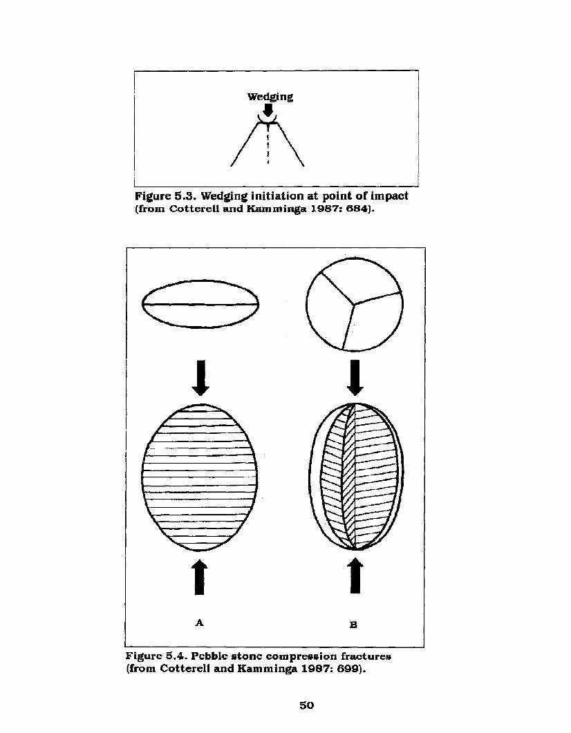
Fieure 5.3. Wedein£ initiation at point of impact(from Cotterell and Kamminga 1987: 684).
--- --,"',", ~
I ~r ,
I -'
\ J~
,""
,'\.. ,
'-. J, .I........ -'-
tA
I
tB
Figure 5.4. Pebble stone compression fractures(from Cotterell and Kamminga 1987: 699).
50
three fragments of roughly equal size" ending in an axial
termination (Cotterell and Kamminga 1987: 698). In this instance
the flat pebble illustrated in Figure 5.4:A has sheared
longitudinally and transversely ending in an axial termination.
The ellipsoid pebble illustrated in Figure 5.4:B displays linear
longitudinal citrus-section fractures (these will be addressed in
Section 6). The third alternative is for the specimen to shatter.
Cotterell and Kamminga (1987: 699-700) further note that the
bipolar technique is one of the rare circumstances were
compression-controlled propagation can occur and that axial
terminations are common.
If we study the process involved in this more closely we can
see, as illustrated in Figure 5.1, that an impact on the top of a
pebble sends a primary line of force longitudinally through the
material along its Xaxis. However, spherical waves also emanate
from the point of impact extending away from the point of
disturbance in wave fronts (Konopinski 1969: 439; Rinehart 1960).
Figure 5.2 and 5.5 illustrate the planar and spherical flow of the
wave fronts as they move away from the point of impact. These
wave fronts are in the form of transverse stress waves that move
along a linear line away from the source of disturbance and
longitudinal waves that form a curvature as they emanate from
the point of impact. Additionally, these waves do not remain
static, but rather pulse or oscillate as illustrated in Figure 5.6. As
outlined, although the general movement of force away from the
point of impact may be in a generally linear direction the force
waves emanating from that point are anything but static.
51

Pointof
hnpact
End ViewSide (Planar) View ~
~ '- ~ /----- ---r- )0(~~ )'-11'.........,lSourae- Waveor J hont, t ~d~ 6
---+ .~ t---- X. X
~-----~-~,
BL.
FigureS.5. Divergence of spherical wave fronts (modifiedfrom Rinehart 1960:4, 177).
BL.
Figure 5.6. Pulse wave front (modifiedfrom Konopinski 1969: 482).
62

The affects of the spherical nature of these wave fronts as
they emanate through the specimen will have a variable outcome
that is dependent on the overall body shape of the material. It
has been noted that with regard to pebbles this outcome would
vary depending on whether the pebble was thin compared to its
width, having a more flattened shape, or if the specimen was quite
round and circular being shaped more like an ellipsoid. If we
observe the first example in more detail, as illustrated in Figure
5.7:A-D, we can see that the major reflection of the spherical wave
front expands across the Yaxis, emanating down from the point of
disturbance, and reaching its maximum extent at the mid-section
of the pebble. To this point, side reflections even across the Yaxis
are small with little peripheral disturbance, however, once the
spherical wave passes through the mid section of the pebble the
frontal portion of the wave decreases in size as it is compressed
into the lower end of the pebble and the rear area of the wave is
reflected back into the specimen (Figure 5.7: E-F). Side reflections
across the Y axis now intensify.
If the above processes are applied to pebble splitting using
the bipolar technique, it was noted that as the head-on force
exited the bottom of the pebble it entered the anvil upon which
the pebble rested, also creating a compression at the point where
the pebble contacted the anvil. This compression is created by the
energy collected within the anvil being rebounded back into the
specimen. With pebbles of a flattened shape the tendency is for
them to shear longitudinally down the Xaxis and transversely
across the Yaxis (Figure 5.4:A and S.7:G). This occurs because,
S3
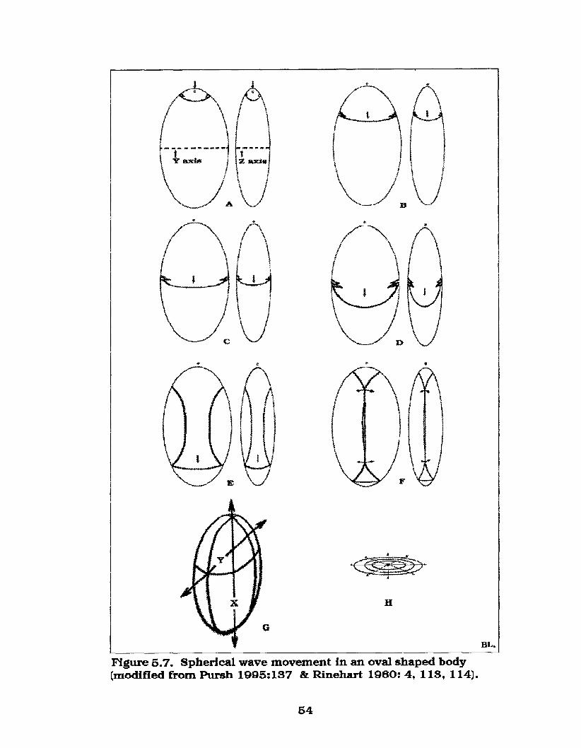
tz axi.
~.A _."
H
BL.
FIgure 5.7. Spherlcal wave movement In an oval shaped body(modified from Pursh 1995:137 & Rinehart 1960: 4, 113, 114).
54
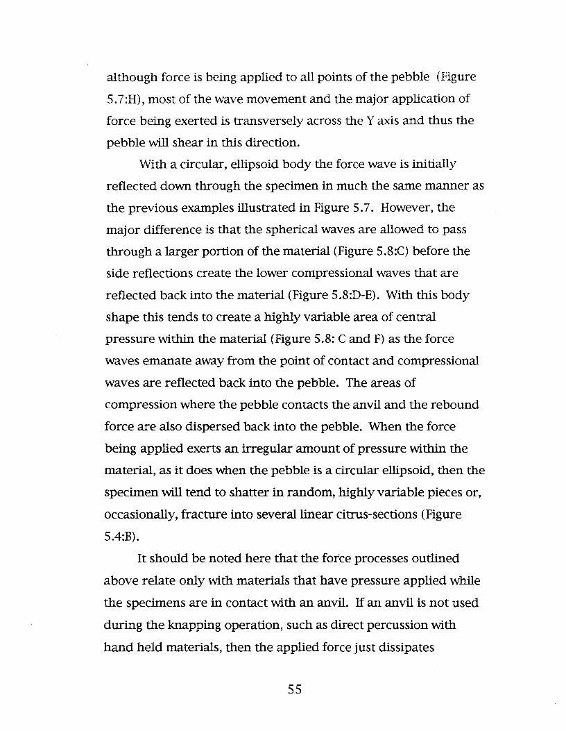
although force is being applied to all points of the pebble (Figure
5.7:H), most of the wave movement and the major application of
force being exerted is transversely across the Yaxis and thus the
pebble will shear in this direction.
With a circular, ellipsoid body the force wave is initially
reflected down through the specimen in much the same manner as
the previous examples illustrated in Figure 5.7. However, the
major difference is that the spherical waves are allowed to pass
through a larger portion of the material (Figure 5.8:C) before the
side reflections create the lower compressional waves that are
reflected back into the material (Figure 5.8:D-E). With this body
shape this tends to create a highly variable area of central
pressure within the material (Figure 5.8: C and F) as the force
waves emanate away from the point of contact and compressional
waves are reflected back into the pebble. The areas of
compression where the pebble contacts the anvil and the rebound
force are also dispersed back into the pebble. When the force
being applied exerts an irregular amount of pressure within the
material, as it does when the pebble is a circular ellipsoid, then the
specimen will tend to shatter in random, highly variable pieces or,
occasionally, fracture into several linear citrus-sections (Figure
5.4:B).
It should be noted here that the force processes outlined
above relate only with materials that have pressure applied while
the specimens are in contact with an anvil. If an anvil is not used
during the knapping operation, such as direct percussion with
hand held materials, then the applied force just dissipates
ss
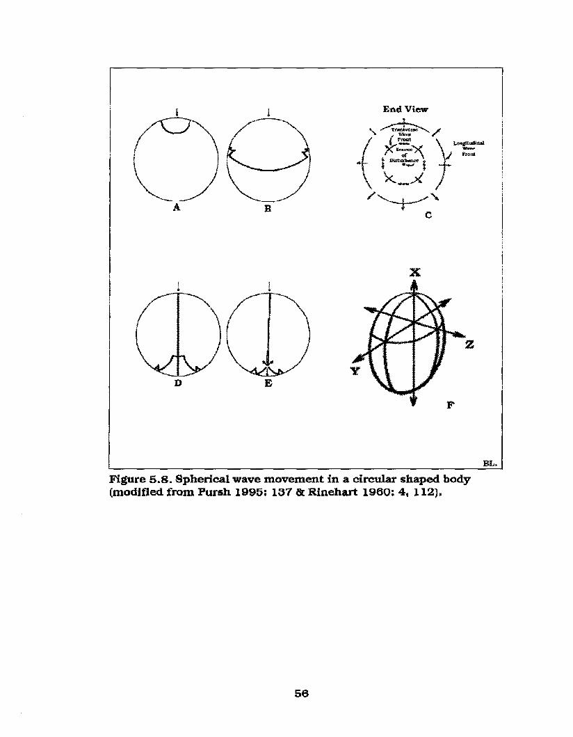
A
D
B
E
x
F
BL.
Figure 5.8. Spherical wave movement in a circular shaped body(modified from Pursh 1995: 137 &: Rinehart 1960: 4, 112).
56

departing out the distal end of the specimen. Additionally, these
processes apply to materials that remain intact while the force
waves pass through the specimen. Occasionally, small proximal
and distal flakes will detach following an impact that alters the
shape of the pebble and thus changes the dispersal pattern of the
applied and rebound force waves.
57

6. ANALYSIS: EXPERIMENTAL REPLICATION
6.1 Analysis of Replicative data
The data base used here for the experimental portion of this
thesis consists of 521 bipolar replications with pebble stones.
Variables recorded include: the original pebble dimensions (length
[X axis], width [Y axis], thickness [Z axis]) and ten technological
classes (identified below).
Multivariate attributes recorded for classes 1-5 include:
proximal impact crushing (PIC), distal impact crushing (DIC),
percussion lines extending distally (PLED), proximal bulb of
percussion (PBP) , distal bulb of percussion (DBP) and other
miscellaneous flake scars. Proximal and distal impact crushing
was noted as readily visible (x), slight damage barely visible (s) or
not visible (n) through a hand lens. Percussion lines were
recorded as pronounced (pr), diffuse (d) or not visible (n). Bulbs
of percussion are identified as being sheared (sh), pronounced
(pr), negative inverted (i) or not visible (n).
Other attributes recorded include irregular sheared surfaces
(is) and flake scars identified by their position (for example, vfr/d
= ventral flake removed/dorsally). Classes 6-10 include shattered
specimens and those that sheared incompletely or fractured
irregularly.
58
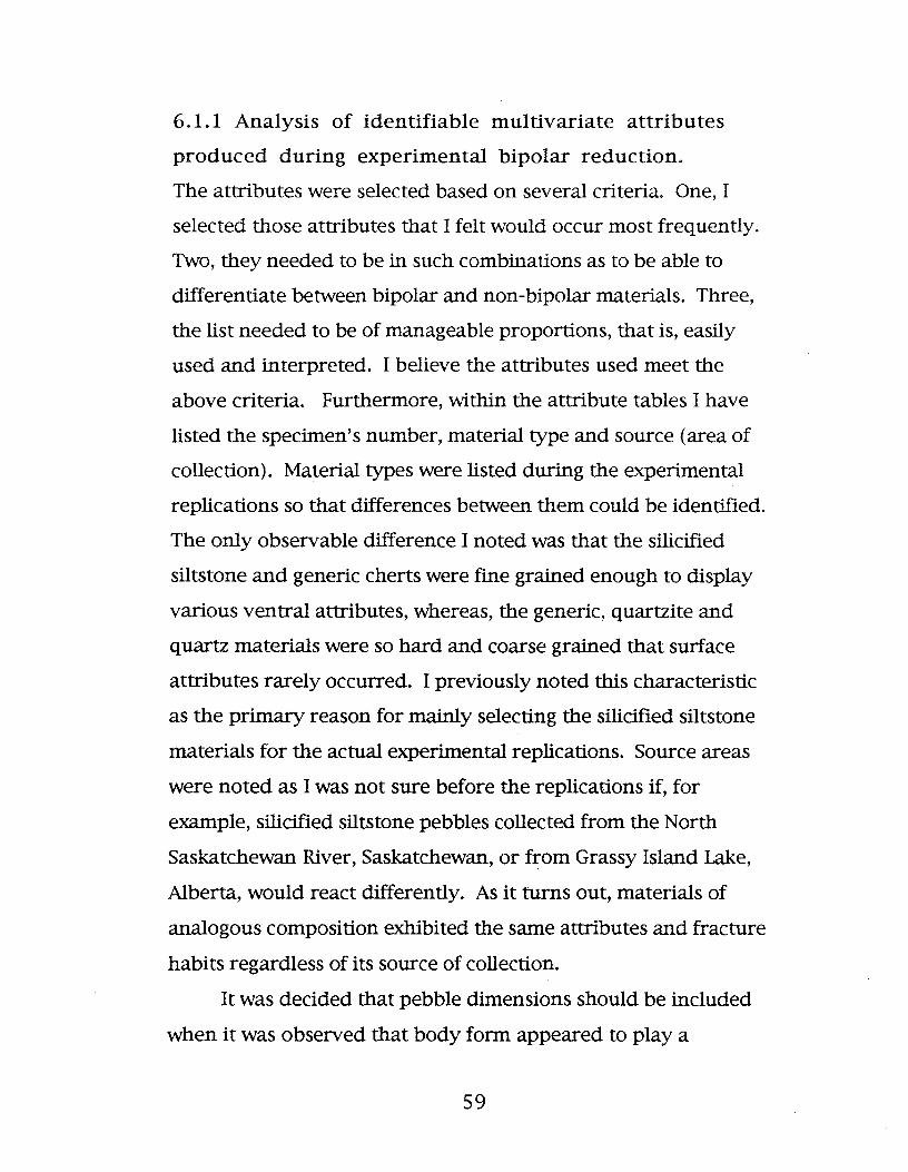
6.1.1 Analysis of identifiable multivariate attributes
produced during experimental bipolar reduction.
The attributes were selected based on several criteria. One, I
selected those attributes that I felt would occur most frequently.
Two, they needed to be in such combinations as to be able to
differentiate between bipolar and non-bipolar materials. Three,
the list needed to be of manageable proportions, that is, easily
used and interpreted. I believe the attributes used meet the
above criteria. Furthermore, within the attribute tables I have
listed the specimen's number, material type and source (area of
collection). Material types were listed during the experimental
replications so that differences between them could be identified.
The only observable difference I noted was that the silicified
siltstone and generic cherts were fine grained enough to display
various ventral attributes, whereas, the generic, quartzite and
quartz materials were so hard and coarse grained that surface
attributes rarely occurred. I previously noted this characteristic
as the primary reason for mainly selecting the silicified siltstone
materials for the actual experimental replications. Source areas
were noted as I was not sure before the replications if, for
example, silicified siltstone pebbles collected from the North
Saskatchewan River, Saskatchewan, or from Grassy Island Lake,
Alberta, would react differently. As it turns out, materials of
analogous composition exhibited the same attributes and fracture
habits regardless of its source of collection.
It was dedded that pebble dimensions should be included
when it was observed that body form appeared to playa
59

significant role in the final product when attempting to split a
pebble using the bipolar technique. Therefore, length, width and
thickness were recorded and assigned the designations of Xaxis
(length), Yaxis (width) and Zaxis (thickness). These data could be
used with future research to determine if there is an optimum
ratio of length, width and thickness at which a pebble will shear,
or for that matter at what ratio the pebble will shatter.
The following characteristics all relate to the ventral surface
attributes of the split pebble stone materials following the
experimental replication. These attributes are recorded for all
complete split pebble sections (for example, within Class 2 these
attributes are recorded for both the left and right split pebble
sections of the specimen). illustrations of these attributes are not
provided here as the figures in the next section, which discuss the
technological classes, will also illustrate and address these
features.
6.1.1.1 Proximal impact crushing (PIC) occurs
when the hammerstone strikes the top of the pebble driving the
force down into the specimen. Even with a controlled strike the
impact of the hammer against the pebble is sufficient to crush a
small amount of the material at the point of impact. Even if no
other attributes are visible this attribute will indicate the point at
which the initial impact occurred. In only a few rare instances
was this attribute not visible through a hand lens.
6.1.1.2 Distal impact crushing (DIC) occurs when
the force of striking the pebble with a hammerstone drives the
specimen into the anvil upon which it rests. The initial force being
60

applied to the pebble results in a small area of the material being
crushed at its point of contact with the anvil. This attribute occurs
almost as frequently as does PIC. When DIC is present, especially
in association with PIC on one specimen, it can be concluded that
the piece in question is a bipolar by-product. This can be stated
because DIC can only occur from a specimen that has been struck
on the proximal end while the distal end was in contact with an
anvil.
6.1.1.3 Percussion lines extending distally
(PLED) were noted as such so that there would be no confusion
that these force lines extended down from the point of impact at
the proximal end of the pebble and not up from the anvil's
rebound force. Originally I had expected that I would need a
category for percussion lines that extended towards the proximal
end, but this characteristic was identified in only three specimens.
Those pieces fractured irregularly and will be discussed in the
next section. Pronounced percussion lines occurred often, although
diffuse force lines did occur more frequently. Regarding the 259
pebbles that had at least one complete surface, pronounced
percussion lines were identified in 48, and diffuse force lines in
71, specimens. One hundred and forty of the replicated specimens
displayed no visible percussion lines.
6.1.1.4 Proximal bulbs of percussion (PBP) occur
on the ventral surfaces of some split pebbles below the point of
impact of the applied force. In a replicative study of lithic
percussion techniques by Herbort (1988: 36) he noted that force
bulbs characteristic of direct percussion do not exist on bipolar
61

materials. Percussion bulbs are positive conchoidal bulges caused
by impact on many siliceous stones. However, the experimental
replicative materials outlined here clearly illustrate that not only
do they form on bipolar materials, but they tended to vary
considerably as well.
Only three specimens with pronounced positive bulbs of
percussion were identified among all the materials experimentally
replicated here. It is likely that the controlled impact I was using
to apply pressure to split the pebbles was insufficient to produce
this attribute. With straight percussion knapping a considerable
amount of force is applied to a piece of raw material. If that
amount of force was applied to a pebble stone in contact with an
anvil the specimen would be crushed into numerous pieces of
shatter.
Diffuse positive proximal bulbs of percussion were recorded
on 43 specimens. Additionally, 108 of the specimens (with at least
one complete section) displayed no visible (n) proximal bulbs of
percussion.
Proximal bulbs of percussion generally can not be used to
distinguish bipolar from straight percussion materials with one
exception. That is, sheared (sh) proximal bulbs of percussion are
distinctly bipolar. This is essentially what Crabtree (1972: 41)
identifies as a split cone. With a sheared bulb of percussion the
tightly compressed percussion lines forming the bulb can be
readily identified but the distinguishing positive bulge is not
present. Rather, the bulb area is flat having been sheared straight
through the feature. Furthermore, sheared bulbs occurred only
62

on the proximal ends of the specimens analyzed here and when it
was identified on one section of a split pebble it was usually
recorded on the other accompanying half. As noted, this attribute
appears to be uniquely a bipolar feature. Sheared bulbs occurred
on 13 of the experimentally replicated materials.
Another attribute that appears quite frequently among the
experimental materials analyzed is a negative inverted bulb of
percussion. With negative inverted bulbs of percussion the typical
positive bulge that would extend out from the ventral surface of a
flake in a small convex mound is concave, or inverted, fading into
the ventral surface of the flake (or in this case the split pebble
half). A negative inverted bulb of percussion frequently occurred
in association with an opposing diffuse positive bulb on the
contrasting section of the opposite split pebble half.
6.1.1.5 Distal bulbs of percussion (DBP)
incontrovertibly identify specimens as being derived from bipolar
technology. This is because a distal bulb of percussion can only be
derived from a force opposite to, or opposing, the applied force,
such as the rebound force emanating back into a pebble stone that
is in contact with an anvil and has had pressure applied to its
proximal end. Only by having opposing waves of force at both
ends of the material can a distal bulb occur. Distal bulbs of
percussion generally truncate the distally extending percussion
lines in an opposing direction. That is, the distal bulb of
percussion extends into the percussion lines truncating them. If
this situation occurs then it is certain that a bulb of percussion is
located on the distal end of the specimen and, in fact, this
63

characteristic occurred in 21 specimens. It is also noteworthy that
in 16 of these cases a positive distal bulb occurred on one half and
a negative inverted bulb on the other. No positive pronounced or
sheared bulbs were present on the distal end of any of the
specimens analyzed.
6.1.1.6 An "other" category was used so that the
numerous miscellaneous flake scars that occurred during the
experimental replications could be identified. These flakes are all
outlined in Table 6.1, which is a summary of the abbreviations
that I used within the other tables. The detachment of flakes
during experimentation was recorded, as noted in Table 6.1, but
since they were subsidiary to the actual analysis I was
undertaking they were given no further consideration other than
noting their location of detachment. For example, vfr/ d refers to a
ventral flake that was removed from the dorsal end of the
specimen during the experimental replication and rlfr refers to the
removal of a flake from the right lateral edge of the pebble stone.
6.1.2 Analysis of experimental bipolar reduction
During the definitive analysis of the 521 experimentally replicated
materials I identified and recorded ten technological classes (these
are identified below).
6.1.2.1 Class 1: Class 1 specimens (Table 6.2) consist
of pebbles that are split longitudinally into two halves down the X
axis and relative to the Z axis (thickness plane) with a ventral
surface of AC (refer to Figure 4.1) and end in an axial termination.
Both lateral halves· are complete, although they are not generally
of equal proportions. In fact, one half of the split pebble tends to
64

Table 6.1. Abbreviations used in Tables 6.2-6.11.SSP Silicified siltstone pebble stoneQtz-ite QuartziteGen Mat Generic MaterialNSKR North Saskatchewan River, SaskatchewanGIL Grassy Island Lake, AlbertaFR Fresno Reservoir, MontanaV VentralD DorsalL LeftR RightL(X) Length (X axis)W(Y) Width (Y axis)
T(Z) Thickness (Z axis)x Visible through a hand lensn Not visible in hand specimenis Irregular shear surfaced Diffusepr Pronouncedi Negative Invertedsh Sheareds Slight damage/barely visibleh Hackles
PIC Proximal impact crushingDIe Distal crushingPLED Percussion lines extending distallyPBP Proximal bulb of percussionDBP Distal bulb of percussion
dft Distal flake termination
dfr Distal flake removed
pfr Proximal flake removed
rlfr Right lateral flake removedllfr Left lateral flake removeddfr/p Dorsal flake removed / proximallydfr/d Dorsal flake removed/distallyvfr/d Ventral flake removed/distally
vfr/p Ventral flake removed/proximally
dvfr/d Dorsal and ventral flake removed/ distally
vfr/dp Ventral flake removed distally and proximally
dfr/pd Dorsal flake removed/proximally and distally
fr/d Flake removed/distallyvdfr/d Ventral and dorsal flake removed/distallydI Intermidiate pebble diameterdL Longest pebble diameterdS Shortest pebble diameter
65

0'\0'\
Table 6.2. Class 1 specimens split into two halves parallel to Z axis (thickness)
SP # Mat. Source Dimensions (em's) PIC DIC PLED PBP DBP Other StyleType Original (means) L R L R L R L R L R L R
L(X) W(Y) T(Z) L(X) IW(Y) IT(Z)
.... 1 SSP NSKR 2.16 1.24 0.82 x x n x n n d i n n 4
....2 SSP NSKR 2.57 2 0.78 x x s s d d d i n n 2
....3 SSP NSKR 3.11 1.76 1.2 s s s s pr pr d n i d dfr/d/p dfr/p 2
....4 SSP NSKR 2.4 1.62 1.05 x x x x d d n n n n dfr/p 1
....5 SSP NSKR 5.86 3.31 2.1 x x x x d d n n n n 1Ifr dfr/p 3
....6 SSP NSKR 3.73 2.31 1.41 x x x x n n n n n n dfr/p 11fr 4
....7 SSP NSKR 2.7 1.53 0.96 x x x x n n n n n n 4252 SSP NSKR 2.21 1.56 1.21 x x x x n n n n n n dfr/d 1253 SSP NSKR 2.25 1.38 0.84 x x x x n n n n n n is is 3254 SSP NSKR 2.6 1.8 0.97 x x x x n n i d n n 1....8 SSP GIL 2.99 1.98 1.01 x x x x n n n n n n 1Ifr 3....9 SSP GIL 3.23 1.7 0.77 x x x x n n n n n n vfr/p vfr/p 3.. 10 SSP GIL 2.81 2 0.57 x x n x d d n n n n 3.. 11 SSP GIL 2.13 1.85 1.02 x x n n d d n n n n 1
.. 12 SSP GIL 3.24 2.01 1.14 x x n n d d n n n n dfr/p 2
.. 13 SSP GIL 3.66 2.12 1.31 Silicified x x n n n n n n n n dfr/p 3
.. 14 SSP GIL 3.15 2.13 1.16 Siltstone x x x x n n n n n n 3
..56 SSP NSKR 4.72 3.49 1.13 Pebbles x x s s pr pr n n n n 3
..60 SSP NSKR 2.35 1.9 0.85 2.3 11.6 10.8 x x n n pr pr n n n n dfr/p dfr/p 1
.. 15 Qtz-ite NSKR 2.8 1.66 0.86 x x x x n n n n n n 4
.. 16 Qtz-ite NSKR 3.14 2.25 0.71 Quartzite x x n x n n n n n n dfr/p dfr/pd 2
.. 17 Qtz-ite NSKR 3.2 2.12 1.05 3 11.9 11 x x x x n n n n n n drf/d dfr/d 1
.. 18 Gen Mat FR 3.56 2.02 1.07 x x x x n n n n n n dfr/p 1
.. 19 Gen Mat FR 4.07 2.75 1.26 Generic Mat. x x n n n n n n n n 3
..20 Gen mat NSKR 3.55 1.85 0.89 3.6 11.9 11 x x x x n n n n n n dfr/d 3vfr/p

Ci'I""-J
Table 6.2. Class 1 specimens split into two halves parallel to Z axis (thickness)
..22 Gen chert GIL 2.65 1.79 1.08 x x s s n n n n n n 3
..23 Gen chert GIL 3.65 1.67 0.87 x x x x n n n n n n 4
..21 Gen chert NSKR 3.01 1.4 1.17 x x n x d d n n n n dfr/p dfr 1136 Gen chert NSKR 2.3 1.7 0.99 Generic chert x x x x pr pr n d n n 3137 Gen chert NSKR 3.18 2.16 1.33 2.9 12 11.2 x x n n pr pr d n n n 2
Grand Total (means) 2.67 1.7 1.08
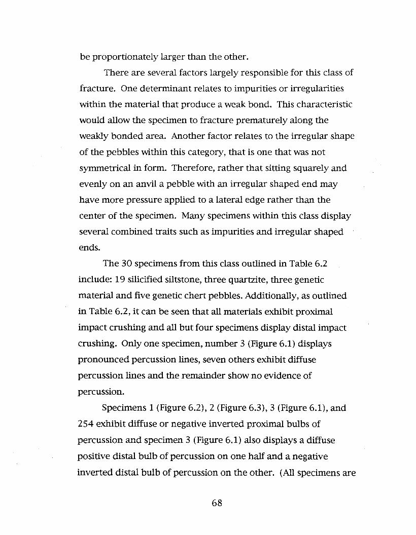
be proportionately larger than the other.
There are several factors largely responsible for this class of
fracture. One determinant relates to impurities or irregularities
within the material that produce a weak bond. This characteristic
would allow the specimen to fracture prematurely along the
weakly bonded area. Another factor relates to the irregular shape
of the pebbles within this category, that is one that was not
symmetrical in form. Therefore, rather that sitting squarely and
evenly on an anvil a pebble with an irregular shaped end may
have more pressure applied to a lateral edge rather than the
center of the specimen. Many specimens within this class display
several combined traits such as impurities and irregular shaped
ends.
The 30 specimens from this class outlined in Table 6.2
include: 19 silicified siltstone, three quartzite, three genetic
material and five genetic chert pebbles. Additionally, as outlined
in Table 6.2, it can be seen that all materials exhibit proximal
impact crushing and all but four specimens display distal impact
crushing. Only one specimen, number 3 (Figure 6.1) displays
pronounced percussion lines, seven others exhibit diffuse
percussion lines and the remainder show no evidence of
percussion.
Specimens 1 (Figure 6.2), 2 (Figure 6.3),3 (Figure 6.1), and
254 exhibit diffuse or negative inverted proximal bulbs of
percussion and specimen 3 (Figure 6.1) also displays a diffuse
positive distal bulb of percussion on one half and a negative
inverted distal bulb of percussion on the other. (All specimens are
68

_1...--_......1o 1 2 em.
BL
Figure 6.1. Class 1 silicified siltstone pebble - split parallelto the Z axis - Style 2 (specimen 3).
69

_L..-__lo I 2 cm.
BL
Figure 6.2. Class I silicified silts tone pebble split parallel to the Z axis - Style 4(specimen I).
• _~_......Io I 2 cm.
BL
Figure 6.3. Class I silicified silts tone pebble - splitparallel to the Z axis - Style I (specimen 2).
70

displayed with the proximal end up).
Additionally, nunlerous small flakes were detached from the
ventral and/or dorsal surfaces on several specimens during the
experimental replications.
Although the general trend within this category is for the
pebble to shear transversely across the Y axis there are actually
four styles of breakage pattern in this class. The first occurs in
specimens that are relatively thin in relation to their width and
have small impurities present. With style 1 specimens the main
body of the pebble remains generally intact with a thin curved
flake being removed from one outer lateral edge. Figures 6.3 and
6.4 exhibit this style. This is an unusual characteristic of bipolar
materials as flakes usually tend to be flat ventrally, an
observation also recorded by Herbort (1988: 36) who noted that
bipolar flakes tended to be flat in cross-section and not curvate.
With the specimen in Figure 6.3 the impurities along the
distal end caused several dorsal flakes to be removed. This
permitted the applied force to be transferred to the lateral edge of
the pebble, thus dislocating the small curved flake from the body
of the specimen.
\I\lith regard to the specimen in Figure 6.4 a similar situation
occurred except that the impurities caused the dorsal flakes to be
removed from the proximal end of the pebble. It is believed that
this caused the same transference of the applied pressure to the
outer edge of the pebble, and therefore, shearing the sITlall curved
flake from the body of the specimen.
71

____Io I 2 em.
Figure 6.4. Class I silicified sUts tone pebble - spJitparallel to the Z axis - Style I (specimen 60).
72
BL

Style 2 specimens also have flakes removed from a lateral
edge but rather than being curved they are quite linear in form
and flat ventrally. As noted above this is the standard form of
cross-section present among the bipolar materials represented
here. Figure 6.1 illustrates one of these that has a number of
visible impurities in the pebble. One long flake was removed from
the lateral edge and several small dorsal flakes removed distally
and proximally. Figure 6.5 is another illustration of one of these
specimens. In this case it is likely the irregular shaped bottom
that allowed the majority of the applied pressure to pass down the
one lateral edge of the pebble removing one long linear flake from
that side of the specimen.
The next style of shear in Class 1 appears to be caused
primarily from material impurities although these specimens also
have irregularly shaped ends. Style 3 specimens all shear
longitudinally, but across the pebble at a slightly diagonal angle to
the Z axis. In all cases represented among the materials here
there is an irregular sheared surface on the ventral faces of the
split pebble halves. This is likely a consequence of the impurities
in the material. Figures 6.6, 6.7 and 6.8 illustrate this shear style.
The final specimens in this class display shears parallel to
the Z axis. Style 4 specimens split the pebble into nearly equal
halves parallel to the Z axis in long straight linear flakes. Figures
6.2 and 6.9 illustrate two of these specimens. It can be seen that
the ventral flake surfaces have sheared irregularly, but relatively
straight through the pebble.
73
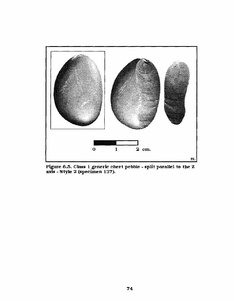
__---IIo I 2 cm.
BL
Figure 6.5. Class I generic chert pebble - split parallel to the Zaxis - Style 2 (specimen 137).
74

_L..-__~
o 1 2 cm.BL
Figure 6.6. Class 1 silicified siIts tone pebble - split parallel tothe Z axis - Style 3 (specimen 13).
75

_'---_Io 1 2 ern. BL
Figure 6.7. Class I silicified siltstone pebble - split parallel to the Zaxis - Style 3 (specimen 56).
76
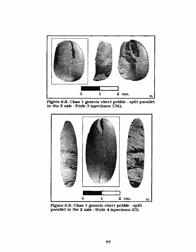
_ ....._-~o I 2 em.
BL
Figure 6.8. Class I generic cher t pebble - split parallelto the Z axis - Style 3 (specimen 136).
_",-_Io I 2 em.
Figure 6.9. Class I generic chert pebble - splitparallel to the Z axis - Style 4 (specimen 23).
77
BL

The ratio of thickness to the width is a little larger with
these specimens and it is believed that this has allowed for
slightly more applied force to be dispersed through the Z axis. The
extra force emanating across the Z axis combined with the
impurities caused the pebble to shear in this manner. Class 1
specimens comprised 5.8% of the total experimental data set.
6.1.2.2 Class 2 materials (Table 6.3) include pebbles
that are split into two halves longitudinally down the Xaxis and
transversely across the Yaxis, ending in an axial termination, with
both halves of the specimen complete. There are a total of 162
specimens in this class consisting of: 96 silicified siltstone, 37
generic chert, 15 generic material, 10 quartzite and 4 quartz
pebbles. All Class 2 specimens display some proximal and distal
impact crushing. Seventy-one (43.6%) of the Class 2 specimens
exhibit percussion lines with 24 (14.8%) of those displaying
pronounced lines of force. Three types of percussion bulbs were
identified among the Class 2 materials: sheared, positive diffuse,
and negative inverted. Strongly pronounced positive bulbs of
force did not occur among the Class 2 materials and, in fact, this
trait occurred among only three of the replications analyzed here.
A frequent attribute occurrence among the Class 2 materials
are two bulbs of percussion on the same section. This
characteristic has been noted by previous researchers as a rarely
occurring bipolar trait, however, with the experimental
replications that I conducted using pebble stone materials this
characteristic occurred on 9.4% of at least one split half of the
overall data set and on 29.6% of the Class 2 materials. It can be
78

-J1..0
Table 6.3. Class 2 specimens split into two halves parallel to the Y axis (width)
SP # Mat. Souree Dimensions (em's) rnrnrnrnrn Other
Type Original (Means) LRL R LRLRLR L R
L(X) W(Y) T(Z) L(X) IW(Y) IT(Z)
..24 SSP NSKR 2.6 2 0.88 x x x x n n n n n n h h
..25 SSP NSKR 2.5 1.6 0.76 x x s n n n i d i d
..26 SSP NSKR 4.31 2.8 1.55 x x n n pr pr i d i d
..27 SSP NSKR 3.32 2.1 1.13 x x s s pr pr i sh i d
..28 SSP NSKR 3.15 2.17 0.75 x s x x pr pr i d n n h h
..29 SSP NSKR 2.53 1.87 0.7 x x s s d d n i i d
..30 SSP NSKR 2.57 2 0.78 x x s s d d d i n n
..31 SSP NSKR 4.1 3.44 1.4 x x n n d d n n i d
..32 SSP NSKR 3.2 2.06 1.46 x x x x n n n n n n
..33 SSP NSKR 2.8 2.4 1.7 x x s x n n d i i d
..34 SSP NSKR 2.85 2.18 1.5 x x x x n n n n n n
..35 SSP NSKR 2.35 2.06 0.87 x x n x d d n n n n
..36 SSP NSKR 2.3 1.85 1.25 x x n n d d n n n n
..37 SSP NSKR 2.51 1.7 0.8 x x n n pr pr i d n n
..38 SSP NSKR 3.24 1.96 1.4 x x x x n n n n n n is is
..39 SSP NSKR 2.4 2.22 1.3 x x x x d d sh sh n n is is
..40 SSP NSKR 2.86 2.19 1.06 x x x x d d n d n n sf/d
..41 SSP NSKR 2.06 1.99 1 x x x x n n n n n n dfr/p
..42 SSP NSKR 3.02 2.4 1.2 x x x x d d n d n n dfr/p
..43 SSP NSKR 2.36 1.8 0.9 x x x x n n n n n n dfr/d
..44 SSP NSKR 2.6 2.3 0.89 x x x x d d n n n n is is
..45 SSP NSKR 3.26 1.56 1.3 x x x x n n n n n n is is
..46 SSP NSKR 3.51 2.7 1.31 x x x x n n n n n n dfr/d

00o
Table 6.3. Class 2 specimens split into two halves parallel to the Y axis (width).. 47 SSP NSKR 2.6 1.85 0.87 s s n n d d i d n n dfr
..48 SSP NSKR 2.19 2.17 0.86 x x x x pr pr d n n n
..49 SSP NSKR 2.92 1.83 1.37 x x n x n n n n n n is is
..50 SSP NSKR 2.5 1.25 1.18 x x x x d n n n n n dfr/p
..51 SSP NSKR 2.6 1.65 0.96 x x x x n n n n n n dvfr/d dft
..52 SSP NSKR 3.6 1.7 1.15 x x n x d d n n n n
..53 SSP NSKR 3.26 4.3 1.65 x x n x d n n d n n
..57 SSP NSKR 2.61 2.2 1.16 x x x x n n n n n n Ilfr rlfr
..58 SSP NSKR 2.64 1.77 0.91 x x n n n n n n n n
..59 SSP NSKR 2.02 1.72 0.85 x x n n n n n n n n dft
..61 SSP NSKR 5.54 2.16 1.49 x x x x d d d i n n dfr/d Ilfr
..62 SSP NSKR 3.61 2.53 1.4 x x x x n n n n n n dfr/d
..63 SSP NSKR 2.51 1.9 1.13 x x x x d d n n n n
..64 SSP NSKR 3.35 1.91 0.86 x x x x pr pr sh sh d d
..65 SSP NSKR 2.23 1.86 0.61 x x x s pr pr sh sh d i
..66 SSP NSKR 2.43 1.41 0.62 x x x n d d n n n n vfr/d vfr/p
..67 SSP NSKR 3.37 1.8 0.9 x x x x d d n i n n vfr/dp vfr/d
..68 SSP NSKR 2.4 1.35 0.68 x x x n d d n i n n
..69 SSP NSKR 2.42 1.37 0.61 x x x x d d n n n n vfr/p
..70 SSP NSKR 3.01 2.14 1.06 x x x x d d n d n i vfr/p
.. 71 SSP NSKR 4.08 3.3 1.31 n n n n n n n n n n is is
..72 SSP NSKR 1.96 1.82 0.71 x x x x n n n n n n
..73 SSP NSKR 3.28 3.01 1.07 x x x s d d n n n n
..74 SSP NSKR 2.36 2 1.02 x x x x n n n n n n is is
..76 SSP NSKR 2.36 1.72 0.86 x x x n n n n n n n vfr/d
..77 SSP NSKR 3.77 1.91 1.5 x x x s n n i d d i vfr/d

00r--<
Table 6.3. Class 2 specimens split into two halves parallel to the Y axis (width)..78 SSP NSKR 3.51 2.9 1.71 x s s x n n d i n d vfr/p
..79 SSP NSKR 3.37 2.22 1.58 x x x x n n n n n n is is
..80 SSP NSKR 2.16 1.73 0.58 x x x x n n n n n n vfr/dp
..81 SSP NSKR 2.44 1.67 0.96 x x x x n n n n n n vfr/pd vfr/p
..82 SSP NSKR 1.94 1.32 0.62 x x x x d d sh sh n n
..83 SSP NSKR 2.59 1.53 1.07 x n x x n n n n n i
..84 SSP NSKR 2.28 1.81 1.04 x x x x n n i d n n
..85 SSP NSKR 2.88 1.55 1.49 x x x x n n d i n n vfr/d vdfr/d
255 SSP NSKR 3.31 2.72 1.92 x x x x n n n n n n rlfr
256 SSP NSKR 2.9 2.8 1.07 x x x x d d i d n n
258 SSP NSKR 2.94 1.82 1.29 x x x x n n n n n n rlfr vfr/d
521 SSP NSKR 2.73 2.39 1.01 x x s s pr pr n n n n
206 SSP NSKR 3.08 2.61 0.77 x x x x pr pr n n n n dfr/p vfr/d
..87 SSP GIL 2.5 1.67 0.74 x x x x n n n n n n
..88 SSP GIL 2.55 1.73 0.64 x x x x d d n n n n
..89 SSP GIL 3.52 4.4 1.5 x x x x d d i d n n dfr/p
..90 SSP GIL 2.8 1.3 1.32 x x x x n n n n n n
..92 SSP GIL 2.85 1.77 1 x x n n n n n n n n
..93 SSP GIL 1.68 1.35 0.57 x x x x pr pr d i n n
..94 SSP GIL 1.46 1.67 0.49 x x x x n n n n n n is is
..95 SSP GIL 1.87 1 0.65 x x n x pr pr i d n n
..96 SSP GIL 2.94 2.17 0.75 x x x x pr pr i d n n
..97 SSP GIL 2.84 1.46 1.15 x x n n d d n n n d dfr/p
..98 SSP GIL 2.73 2.34 1.31 x x x x n n n n n n dfr/d
..99 SSP GIL 2.94 1.77 0.91 x x x x d d d n n n
100 SSP GIL 3.58 2.04 1.41 n n In n n n i d lin n

00N
Table 6.3. Class 2 specimens split into two halves parallel to the Y axis (width)101 SSP GIL 2.58 1.58 0.77 x x x x d d d d n n
102 SSP GIL 2.59 2.21 0.82 x x x n d d n n n n dfr/d
103 SSP GIL 2.44 2.12 0.6 x x x x d d n d n n
104 SSP GIL 2.75 2.21 0.93 x x x x d d n d n n
105 SSP GIL 2.7 2.23 0.94 x x s x n n n n n n
106 SSP GIL 3.26 2.85 1.3 x x x x n n n n n n is is
107 SSP GIL 2.67 1.77 0.59 x x x x pr pr n n n n dfr/p
108 SSP GIL 2.65 1.76 0.73 x x x x n n n d n n
109 SSP GIL 2.46 1.85 0.84 x x n n pr pr n d n n dft
110 SSP GIL 2.84 2.06 1.05 x x x x d d n n n n
111 SSP GIL 2.6 1.75 1.44 x x x x n n n n n n dfr
112 SSP GIL 2.91 1.75 0.75 x x x x pr pr n n n n pfr
113 SSP GIL 2.9 1.95 0.9 x x n x d d n n n n dfr
114 SSP GIL 3.05 2.39 1.16 x x x x pr pr n n n n dfr/p
115 SSP GIL 2.56 1.31 0.8 x x x x pr pr n n n n
116 SSP GIL 2.77 2.31 0.76 x x x x d n n n n n dfr/pd
117 SSP GIL 3.04 2.49 1.02 x x n n n n n n n n
118 SSP GIL 2.59 1.94 0.74 x x x x n n n n n n dfr/d
119 SSP GIL 2.4 0.86 0.81 Silicified Siltstone x x n x n n n n n n
120 SSP GIL 2.4 1.81 1.04 Pebbles x x x x d d n n n n dfr/p
257 SSP GIL 2.45 2.3 0.7 2.53 12.2 10.79 x x x x pr pr n n n n split laterally
121 Gen chert NSKR 3.31 2.07 0.84 x x s s pr pr n n n n
122 Gen chert NSKR 3.1 1.67 0.86 x x x x pr pr n n n n
123 Gen chert NSKR 2.87 1.53 0.87 x x x x d d n n n n
124 Gen chert NSKR 2.41 1.67 0.56 x x n n d d n n n n dfr/d
125 Gen chert NSKR 2.33 1.38 0.76 x x x x d d n n n n dfr/p

00w
Table 6.3. Class 2 specimens split into two halves parallel to the Y axis (width)126 Gen chert NSKR 2.05 1.9 0.9 x x x x d d i d n n vfr/d vdfr/d
127 Gen chert NSKR 3.5 1.48 1 x x x x d d n d n n
128 Gen chert NSKR 2.6 1.2 1.32 x x s n pr pr d i i d
129 Gen chert NSKR 4.05 1.89 1.17 x x x x n n n n n n dfr/d
130 Gen chert NSKR 2.4 1.41 0.89 x x x n n n n n n n is is
131 Gen chert NSKR 2.4 3 0.83 x x x x n n n n n n vfr/d vfr/dp
132 Gen chert NSKR 4.2 2.51 1.36 x x n n d d n n n n
133 Gen chert NSKR 4.15 1.3 1.17 x x x e n n n n n n dfr/p
134 Gen chert NSKR 2.73 2.1 1.26 x x x x n n n n n n rlfr
135 Gen chert NSKR 3.25 3.7 1.27 x x n n n n n n n n dft
138 Gen chert NSKR 2.89 1.94 0.97 x x x x d d n n n n
139 Gen chert NSKR 2.9 2.02 1.19 x x x x d d n n n n dfr/p dfr/p
140 Gen chert NSKR 3.79 1.81 1.06 x x x x d d n n n n dfr
141 Gen chert NSKR 3.57 2.64 1.57 x x x x n n n n n n dfr/d
142 Gen chert NSKR 3.32 1.69 1.34 x x x x d d n n n n dfr/p dfr/p
143 Gen chert NSKR 2.67 1.63 0.76 x x x x n n n n n n
144 Gen chert NSKR 3 2.25 1.26 x x x x n n n n n n rlfr Ilfr
145 Gen chert NSKR 2.82 1.61 0.75 s s s s d d sb sh i d vfr/p
146 Gen chert NSKR 2.8 2.13 1.63 x x x x n n n n n n rlfr
147 Gen chert NSKR 2.92 1.61 1.06 x x x x n n n i n n is is-dfr/p
148 Gen chert NSKR 2.1 1.35 0.43 x x x x n n n n n n fr/d
148 Gen chert NSKR 2.9 1.85 1.52 x x x x n n d i n n is is
150 Gen chert NSKR 3.3 1.51 1.76 x x x x d d n n n n fr/d vfr/pd
151 Gen chert NSKR 3.67 1.88 1.17 x x n n n n d i n n dfr/d
152 Gen chert NSKR 2.35 1.32 0.75 x x x x d d i d n n vfr/d vfr/d
520 Gen chert NSKR 2.76 1.66 0.76 x x x s pr pr sb sh d i

00..j::;...
Table 6.3. Class 2 specimens split into two halves parallel to the Y axis (width)153 Gen chert FR 2.9 1.81 0.69 x x x x pr pr sh sh d i dfr/p
154 Gen chert FR 3.94 2.43 1.76 x x x x n n n n n n vfr/p
155 Gen chert GIL 3.49 2.46 1.1 x x x x pr pr i d d i
156 Gen chert GIL 2.64 2 1.25 x x n n n n n n n n dft
157 Gen chert GIL 2.3 1.77 0.92 Generic chert x x x x d d n n n n
158 Gen chert GIL 4.04 2.71 1.48 3.68 12.4 11.16 x x x x n n n n n n rlfr llfr
159 Gen Mat NSKR 5.49 3.27 1 s s n n n n n n n n
160 Gen Mat NSKR 3.86 3.39 1.22 x x n n n n n n n n
161 Gen Mat NSKR 3 1.75 1.2 x x x x n n n n n n dfr/d
162 Gen Mat NSKR 3.43 2.96 0.7 x x x n n n n n n n dfr/d dft
163 Gen mat NSKR 3.3 2.23 1 x x x x n n n n n n
164 Gen mat NSKR 2.8 2.31 0.67 x x x x n n n n n n
165 Gen mat NSKR 6.4 3.81 1.51 x x x x n n n n n n dfr
166 Gen Mat FR 4.49 2.86 1.7 x x x x n n n n n n dfr/d
167 Gen Mat FR 2.6 2.86 0.7 x x x x n n n n n n
168 Gen Mat FR 3.21 2.85 0.73 x x x x n n n n n n
169 Gen Mat FR 4.42 3.51 1 x x x x n n n n n n dvfr/d vfr/d
170 Gen Mat FR 2.92 2.2 0.91 x x x x n n n n n n dfr/d
171 Gen Mat FR 4.63 3.58 1.78 x x x x n n n n n n rlfr
172 Gen mat GIL 3.85 2.91 0.8 Generic Material x x x x n n n n n n
173 Gen Mat GIL 5 3.52 1.25 5.25 13.4 11.13 x x x x d d i n d n
174 Qtz-ite NSKR 3.55 3.1 1.2 x x x x n n n n n n
175 Qtz-ite NSKR 3.3 3.1 1.3 x x x x n n n n n n
176 Qtz-ite NSKR 4.4 2.9 1.39 x x n n n n n n n n dft
177 Qtz-ite NSKR 5.15 3.36 1.86 x x s x n n d n n n dfr/p dfr/p
178 Qtz-ite NSKR 2.75 2.07 1.1 x x x x n n n n n n dfr/d

00Ul
Table 6.3. Class 2 specimens split into two halves parallel to the Y axis (width)179 Qtz-ite NSKR 2.3 1.9 0.95 x x x x n n i d n n
180 Qtz-ite NSKR 4.91 4.51 1.79 x x n n n n n n n n dft
181 Qtz-ite GIL 2.87 1.27 1.14 x x x x n n n n n n
182 Qtz-ite GIL 5.55 3.95 2.01 Quartzite x x x x n n n n n n dfr/d
183 Qtz-ite GIL 3.81 2.75 1.61 3.68 12.9 11.41 x x x x n n n n n n dfr/d
184 Quartz NSKR 3.8 2.44 2 x x x x n n n n n n
185 Quartz NSKR 2.9 2.05 1.11 x x x x n n n n n n
186 Quartz GIL 2.68 2.17 1.2 Quartz x x x x n n n n n n
187 Quartz GIL 4.07 3.04 1.46 3.94 12.7 11.73 x x x x n n n n n n
Grand Total Means 3.34 2.52 1.17 II

concluded, therefore, that this attribute can hardly be called a rare
occurrence of bipolar technology. Additionally, unlike previous
interpretations, these are rarely both major positive bulbs. The
proximal is always a major bulb and the distal a minor one in
appearance. As with the previous Class 1 materials, there were
numerous small dorsal and ventral flakes removed from several
specimens.
The shear patt~m of the class 2 specimens was the type that
I essentially endeavored to replicate during the experimental
process. There were two major motivations for this rationale. The
first was that if a pebble could be split in two halves across the Y
axis then the minimum of waste would be created and the
maximum of usable material provided. For example, if a knapper
was splitting pebbles to acquire preforms then a pebble split into
two relatively uniform halves would be the most beneficial. The
other reason relates to the surface attributes of a split pebble
stone. That is, with pebbles split in this manner, there are two
ventral surfaces for analysis, one occurring on each split pebble
half, with one the near mirror image of the other. Therefore, these
specimens would provide the greatest opportunity for the
description of bipolar flake features, such as the discriminant
analysis of identifiable multivariate attributes produced during
experimental bipolar reduction.
Figures 6.10,6.11,6.12,6.13 and 6.14 all display classic
transverse shears, through the Yaxis, of the Class 2 specimens.
Unfortunately, the replicated materials in these figures display
little else other than the proximal and distal crushing common in
86

_______I
o I 2 em.
Figure 6.10. Class 2 silicified siltstone pebble split parallel to theY axis (specimen 32).
BL
o I 2 em.BL
Figure 6.11. Class 2 silicified siltstone pebblesplit parallel to the Y axis (specimen 76).
87

_1....-__1o I 2 cm.
Figure 6.12. Class 2 silicified siltstone pebble splitparallel to the Yaxis (specimen lOS).
88
BL

o 1 2 cm.
BL
Figure 6.13. Class 2 quar tzite pebble split parallel to the Y axis(specimen 182).
89
_100.-_'o 1 2 em.
BL
Figure 6.14. Class 2 quartz pebble split parallel to theY axis (speeiInen 185).
90

this class. Actually, this is a common attribute of almost all
bipolar materials. In fact, 74 specimens (45.7%) within Class 2
displayed none of the ventral surface attributes (as outlined in
Table 6.3). This situation depicts the difficulty in identifying
bipolar materials. Additionally, 33 of these specimens were
silicified siltstone, which is a very fine grained material. If these
specimens were not completely split pebble stones displaYing
proximal and distal impact crushing they could easily be
misidentified as straight percussion flakes.
Within Class 2 there are similar materials to the above that
could be separated from direct percussion materials and identified
as bipolar by-products without the evidence of both proximal and
distal impact crushing. For example, Figures 6.15 and 6.16
illustrate two specimens that would fit into this category. Both
specimens in Figures 6.15 and 6.16 display the smooth sheared
surface as in the previous illustrations, but the ventral surfaces
also exhibit alternate positive diffuse and negative inverted bulbs
of percussion on the proximal and distal ends. That is, one end
displays a positive diffuse bulb of percussion and the other a
negative inverted one. Another problem area for the
identification of bipolar attributes on split pebble stones is with
those specimens that have an irregularly sheared surface such as
illustrated in Figures 6.17 and 6.18. Although the specimens from
this class sheared as desired (across the Yaxis) their ventral
surfaces are such that they provide no observable surface
features. Figure 6.19 also displays an irregular ventral surface,
but this specimen has sheared proximal bulbs of percussion on
91

_ ....._-~o 1 2 cm.
Figure 6.15. Class 2 silicified siltstone pebblesplit parallel to the Yaxis (specimen 25).
92
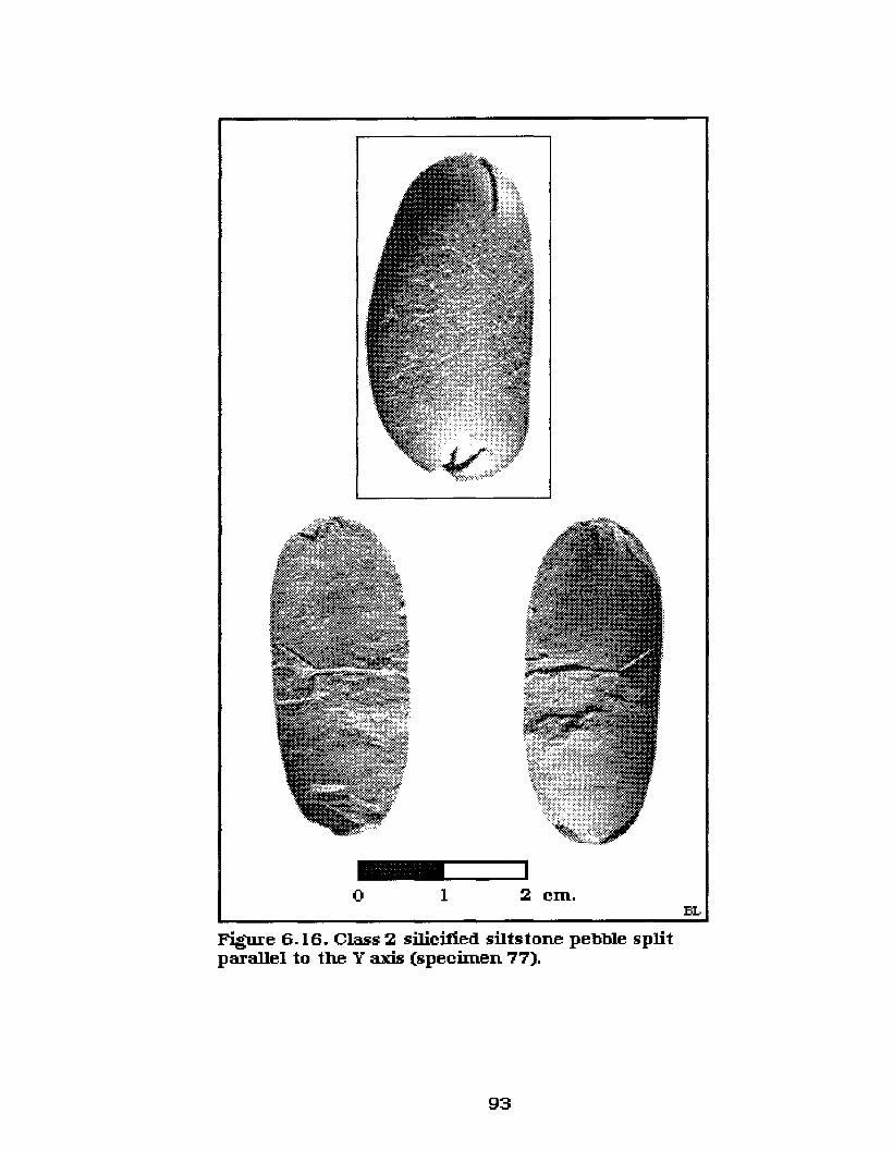
_1....---_1o I 2 cm.
Figure 6.16. Class 2 silicified siIts tone pebble spIitparallel to the Y axis (specimen 77).
93

______.....,jl
o I 2 cm.
Figure 6.17. Class 2 silicified siIts tone pebble splitparallel to the Y axis (specimen 94).
2 cm.
Figure 6.18. Class 2 generic chert pebble splitparallel to the Y axis (specimen 147).
94

___Io I 2 cm.
BL
Figure 6.19. Class 2 silicified siltstone pebble split parallel to theY axis (specimen 39).
95

both sections of the pebble. It is also evident that the coarseness
of the individual sediments of the material in these specimens
resulted in the poor shear.
Several specimens, such as those illustrated in Figures 6.20,
6.21, 6.22, 6.23 and 6.24, display diffuse lines of percussion in
association with one or two other attributes. For example, Figures
6.20, 6.21, 6.23 and 6.24 also display either positive diffuse or
negative inverted bulbs of percussion, or both, and Figures 6.22
and 6.23 are specimens with sheared bulbs. With these specimens
the flow of force through the pebble was visible in the diffuse
percussion lines and the bulbs of percussion could be readily
identified as either distal or proximal. Being able to differentiate
between distal and proximal bulbs is important since distal bulbs
of force are an identifying aspect of bipolar technology.
Figure 6.20 displays a positive diffuse bulb of percussion on
one end of one pebble half and none on the other. It is possible
that the distal end of the other half may have also displayed this
trait but the end of that piece crushed at the time of impact. The
reason this is important is that the one half can be identified as a
bipolar fragment and the other cannot. The fragment on the left
can also be considered a bipolar specimen because the distal bulb
of percussion truncates the opposing percussion lines of force.
This characteristic did not occur frequently, but it did appear on
11 specimens of the Class 2 materials.
The most diagnostic specimens used for the discriminant
analysis of the bipolar technique, and the clearest attributes, were
attained with materials that displayed a very fine grained uniform
96

_10..-__1o I 2 ern.
Figure 6.20. Class 2 silicified siltstone pebble split parallelto the Y axis (specimen 40).
97

__~I__lo 1 2 cm.
Figure 6.21. Class 2 silicified siltstone pebblesplit parallel to the Y a.~ (specimen 47).
__:_........lo 1 2 cm.
Figure 6.22. Class 2 silicified siltstone pebble splitparallel to the Y axis (speciInen 82).
98
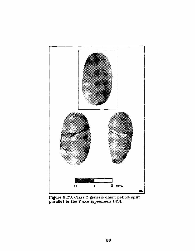
-"---~o 1 2 cm.
Figure 6.23. Class 2 generic chert pebble splitparallel to the Y axis (specimen 143).
99

-
i.. " ""x, ..""... ~•••• I
o 1 BL
Figure 6.24. Class 2 generic material pebble split parallel to the Yaxis (specimen 173).
100

matrix. These specimens frequently produced pronounced
percussion lines along with numerous other attributes on the
ventral surfaces of the experimentally replicated materials. They
also frequently displayed two bulbs of percussion (one on the
proximal end - one on the distal end).
Figures 6.25 and 6.26 illustrates two specimens that have
proximal positive diffuse and distal negative inverted bulbs of
percussion on one section and proximal negative inverted and
distal positive diffuse on the other. The only occurrence of this
characteristic was on these two specimens. Another unique
attribute that occurred, among the specimens with two bulbs of
percussion, was a proximal sheared bulb in conjunction with a
distal positive diffuse or negative inverted bulb of force as
illustrated in Figure 6.27, which displays a specimen with an
upper sheared bulb and a distal positive diffuse bulb of
percussion. Figures 6.28, 6.29 and 6.30 display specimens that
have proximal sheared bulbs and a positive diffuse distal bulb on
one half and an negative inverted distal bulb of percussion on the
other section of the pebble. Class 2 specimens comprised 31.1% of
the total replications.
6.1.2.3 Class 3 includes pebbles that are split
longitudinally down the Xaxis and along the Yaxis, ending in an
axial termination (in the same manner as the Class 2 specimens),
but these specimens have only one complete half (Table 6.4).
During the experimental stage one split pebble section broke
randomly into two or more pieces following the initial impact of
the applied force. A few sections appeared to break as a result of
101

-""""--~o I 2 cm. BL
Figure 6.25. Class 2 generic chert pebble splitparallel to the Y axis (specimen 128).
o I 2 cm. BL
Figure 6.26. Class 2 generic chert pebble split parallel tothe Y axis (specimen 155).
102

_____--IIo 1 2 cm.
BL
Figure 6.27. Class 2 silicified siIts tone pebble splitparallel to the Y axis (specimen 64).
103

___....1o I 2 cm. BL
Figure 6.28. Class 2 silicified silts tone pebble splitparallel to the Y axis (specimen 65).
104

_ ....._-~o I 2 em.
Figure 6.29. Class 2 generic cher t pebble split parallel tothe Y axis (specimen 153).
BL
_____Io I 2 em.
BL
Figure 6.30. Class 2 generic cher t pebble split parallel tothe Y axis (specimen 520).
105

f-'o(j\
Table 6.4. Class 3 specimens split parallel to Y axis with one half completeSP # Material Souree Dimensions (em's) PIC DIC PLED PBP DBP Other
Type Original Means
L(X) W(Y) T(Z) L(X) Iw(Y) IT(Z)
..86 SSP NSKR 2.31 2 0.96 x x pr sh n llfr vfr/d vdfr/d
188 SSP NSKR 2.6 2.01 0.99 x x d n n
189 SSP NSKR 4.11 1.68 1.43 x x d n n
190 SSP NSKR 2.81 1.77 0.99 x x pr sh n
191 SSP NSKR 3.14 1.55 0.77 x x pr n n dfr/p
192 SSP NSKR 3.19 1.57 1.12 x n pr pr n dfr/p
193 SSP NSKR 3.44 1.43 1.01 x x pr d n
194 SSP NSKR 2.27 1.67 0.69 x x pr sh d
195 SSP NSKR 2.61 1.3 0.67 x x pr n n
196 SSP NSKR 3.41 1.5 0.86 x n d d n
197 SSP NSKR 3.25 1.69 1 x n pr n n
198 SSP NSKR 4.65 2.37 2.33 s s n n n
199 SSP NSKR 3.64 3.23 1.63 x n d d n
200 SSP NSKR 2.64 1.85 0.8 x n n n n dfr/p
201 SSP NSKR 3.14 1.89 0.98 x x d d n dfr/d
202 SSP NSKR 2.78 1.95 0.81 x n d n n
203 SSP NSKR 4.18 2.33 1.71 x x n n n
204 SSP NSKR 2.43 2.27 0.69 x n pr d n dfr/d
205 SSP NSKR 5.72 4.41 1.95 x x n n n is dfr/pd
207 SSP NSKR 2.31 2 0.58 x x n n n vfr/d
208 SSP NSKR 3 2.05 0.86 x x n n n
209 SSP NSKR 2.41 1.72 1.22 x x n n n vfr/d dfr/p
210 SSP NSKR 2.17 1.1 0.5 x x d sh i
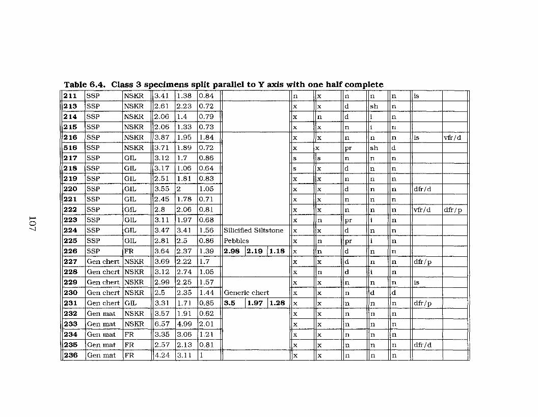
I-'o"'---l
Table 6.4. Class 3 specimens split parallel to Y axis with one half complete211 SSP NSKR 3.41 1.38 0.84 n x n n n is
213 SSP NSKR 2.61 2.23 0.72 x x d sh n
214 SSP NSKR 2.06 1.4 0.79 x n d i n
215 SSP NSKR 2.06 1.33 0.73 x x n i n
216 SSP NSKR 3.87 1.95 1.84 x x n n n is vfr/d
516 SSP NSKR 3.71 1.89 0.72 x x pr sh d
217 SSP GIL 3.12 1.7 0.86 s s n n n
218 SSP GIL 3.17 1.06 0.64 s x d n n
219 SSP GIL 2.51 1.81 0.83 x x n n n
220 SSP GIL 3.55 2 1.05 x x d n n dfr/d
221 SSP GIL 2.45 1.78 0.71 x x n n n
222 SSP GIL 2.8 2.06 0.81 x x n n n vfr/d dfr/p
223 SSP GIL 3.11 1.97 0.68 x n pr i n
224 SSP GIL 3.47 3.41 1.56 Silicified Siltstone x x d n n
225 SSP GIL 2.81 2.5 0.86 Pebbles x n pr i n
226 SSP FR 3.64 2.37 1.39 2.98 12.19 11.18 x n d n n
227 Gen chert NSKR 3.69 2.22 1.7 x x d n n dfr/p
228 Gen chert NSKR 3.12 2.74 1.05 x n d i n
229 Gen chert NSKR 2.99 2.25 1.57 x x n n n is
230 Gen chert NSKR 2.5 2.35 1.44 Generic chert x x n d d
231 Gen chert GIL 3.31 1.71 0.85 3.5 11.97 11.28 x x n n n dfr/p
232 Gen mat NSKR 3.57 1.91 0.62 x x n n n
233 Gen mat NSKR 6.57 4.99 2.01 x x n n n
234 Gen mat FR 3.35 3.06 1.21 x x n n n
235 Gen mat FR 2.57 2.13 0.81 x x n n n dfr/d
236 Gen mat FR 4.24 3.11 1 x x n n n

I--'o00
Table 6.4. Class 3 specimens split parallel to Y axis with one half complete237 Gen mat FR 3.05 2.86 1.09 Generic Material x x n n n
238 Gen mat GIL 3.8 3.22 1.11 3.69 12.57 10.87 x x n n n
239 Quartz NSKR 3.38 1.66 1.17 Quartz x n n n n dfr/p
240 Qtz-ite NSKR 3.42 2.19 1.35 x x pr d n
241 Qtz-ite NSKR 4.53 3.31 1.55 x x n n n
243 Qtz-ite NSKR 3.2 1.74 1.01 x x n n n
244 Qtz-ite NSKR 4.71 3.62 1.45 x x n n n
245 Qtz-ite NSKR 3.35 2.77 1.39 x x n n n
246 Qtz-ite NSKR 2.51 1.73 0.71 Quartzite x x n n n
247 Qtz-ite GIL 3.21 2.99 1.35 3.32 12.59 11.35 x n n n n
Grand Total (average) 2.76 2.5 1.16

impurities within the material, but more frequently the materials
broken seemed to be quite uniform throughout the pebble's
matrix. In these instances the one section of the pebble likely
broke as the result of the application of too much applied or
rebound force within the material, although the other half
remained complete. This is a good example of how I had to use a
very controlled bipolar technique so as not to apply too much
pressure to the pebble, and thus break it, but still have an
adequate amount of force to split the specimen. This class
includes a total of 59 specimens consisting of: 39 silicified
siltstone, 5 generic chert, 7 generic material, 1 quartz and 7
quartzite pebbles.
All but one Class 3 specimen displayed some proximal
impact crushing and 44 showed visible distal impact crushing.
Twenty nine (49.2%) of the Class 3 specimens exhibit percussion
lines with 13 (22.0%) of those displaying pronounced lines of force.
Four types of percussion bulbs were identified among the Class 3
materials: pronounced, sheared, diffuse, negative inverted. The
majority were sheared and diffuse with only one positive
pronounced bulb present. Among the Class 3 materials two bulbs
of percussion on the same section of the complete half occurred on
only four specimens (Figures 6.31,6.32,6.33 and 6.34).
Figures 6.31 and 6.32 both display pebble sections with a
proximal sheared bulb of percussion and a positive diffuse distal
bulb. It is noteworthy that the broken pebble sections of these
specimens also display sheared proximal and positive diffuse
distal bulbs. Because of the presence of these attributes on the
109

_L...-__~
o 1 2 cm.
Figure 6.31. Class 3 silicified siltstone pebble splitparallel to the Yaxis - one section complete(specimen 516).
110
BL

_,,-__J
o 1 2 cm.
Figure 6.32. Class 3 silicified silts tone pebble splitparallel to the Yaxis - one section complete(specimen 194).
BL
_,,--_Io 1 2 cm. BL
Figure 6.33. Class 3 silicified siltstone pebble splitparallel to the Y axis - one section comple te(specimen 210).
III

____Io I 2 em.
BL
Figure 6.34. Class 3 silicified siltstone pebble split parallel to theYaxis - one section complete (specimen 230).
112

broken fragments the proximal ends could be identified as bipolar
flakes even without the accompanying complete sections.
Figure 6.34 displays a pebble section with a proximal
sheared bulb and a distal negative inverted bulb. The upper
section of the broken half also has a proximal sheared bulb and
therefore, on that basis it could be identified as a bipolar flake.
Figure 6.34 is the fourth specimen in this class with the presence
of two bulbs on the complete section. In this case both the
proximal and distal bulbs are small and positive diffuse. Unlike
the previous specimens, however, the broken fragments from this
specimen display no identifiable attributes and it is quite evident
that the impurities in the material are the reason for the irregular
breakage of this specimen.
Fourteen specimens displayed proximal, with no distal, bulbs
of percussion. However, several of these specimens can be
identified as bipolar by-products, as can the broken fragments of
the same specimen, because of the presence of sheared bulbs on
those materials. Figures 6.35, 6.36 and 6.37 illustrate three such
specimens with sheared proximal bulbs on the complete sections,
as well as on the broken fragments.
Unfortunately, as illustrated in Figures 6.38 and 6.39, 29
specimens displayed only distal and proximal crushing with no
other attributes visible. The troublesome thing is that the broken
section of these specimens could easily be misidentified as being
derived from straight percussion materials without the supporting
evidence of the complete, associated, section that does display
both distal and proximal crushing. Class 3 specimens comprised
113
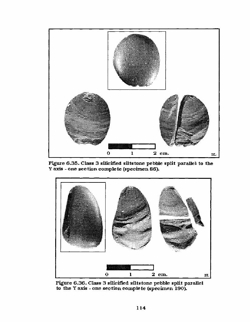
_L...-__Io 1 2 cm. BL
Figuxe 6.35. Class 3 silicified siltstone pebble split parallel to theYaxis - one section complete (specimen 86).
_1...-_......1o 1 2 cm.
~oure 6.36. Class 3 silicified siltstone pebble split parallelto the Yaxis - one section complete (specimen 190).
114
BI.

_1...-_-o I 2 cm. BL
F'ie<fUre 6.37. Class 3 silicified siltstone pebble split parallel to theY axis - one sec tion complete (specimen 213).
o I 2 BL
Figure 6.38. Class 3 generic rnateria! pebble split parallel to theYaxis - one section complete (specimen 233).
115

___Io 1 2 cm.
BL
Figure 6.39. Class 3 quartzite pebble split parallel to theYaxis - one section complete (specimen 243).
116

10.9% of the total experimental replications.
6.1.2.4 Class 4 includes an unusual group of 3
specimens (Table 6.5); 2 generic material and 1 silicified siltstone.
These pebbles are split longitudinally down the Xaxis and
transversely along parallel axes to the Yaxis ending in an axial
termination and producing three complete sections. This
phenomenon of a double split was also recorded by Herbort (1988:
39). During his study he also noted that occasionally a cobble
would double split with the central section displaYing two planar
surfaces. The pebbles within this class are at the large end of
those used here and they all have slightly flatter, wider, ends. It
is likely that the size and body shape of these pebbles were
similar to that of larger cobbles, which allowed the force waves to
disperse down through the specimens unevenly. Therefore,
several wave fronts likely emanated down through the material
simultaneously, thus allowing the pebble to shear in several
parallel transverse directions. Figure 6.40 shows a Class 4 pebble
of generic material. It is quite evident that the pebble sheared
into three fairly uniform sections. Although this specimen
displays proximal and distal crushing no other attributes are
visible.
Figure 6.41 displays a silicified siltstone pebble of Class 4.
This specimen is different from the previous one in that it did not
shear completely evenly into the three sections. The one section
sheared the length of the pebble but snapped at the distal end of
the section. The other section snapped off just before the distal
end of the pebble. It is possible that if I had applied slightly more
117

I--'I--'00
Table 6.5. Class 4 specimens split parallel to Y axis in three sections
SP# Material Souree Dimensions (em's) PIC DIC PLED PBP DBPType Original Means L C R L C R L C R L C R L C R
L{X) W{Y) T{Z) L{X) Iw{Y) IT{Z) V D V D
248 Gen mat Fr 4.17 2.76 1.69 Generic material x x x x x x n n n n n n n n n249 Gen mat Fr 3.03 2.02 1.11 3.6 12.39 11.4 n n n n n n n n n n n n n n n250 SSP GIL 7.71 5.15 2.4 SilkY-ted Siltstone x x x x x x pr pr n i pr n n n n
Grand Totals (Means) 5.94 3.96 2.05

o 1 2 em.
BL
LeftSide
RightSide
l'did-Sec tion
:M:id.-Sec tion
Figure 6.40. Class 4 generic material pebble split into three linearsections (specimen 248).
119

BL
Right Side:M:id.-Section(right side)
2 cm.
Left Side
o 1
Figure 6.41. Class 4 silicified siltstone pebble split into three linearsections (specimen 250).
120

force this section may have sheared completely through the
specimen as well. Only the ventral surfaces of the snapped section
and its associated piece display any attributes. The snapped
section has a pronounced positive proximal bulb and could easily
be mistaken for a straight percussion flake. The associated section
of this flake has a negative inverted proximal bulb of percussion,
but as it displays proximal and distal impact crushing it could
obviously be distinguished as the result of bipolar percussion.
6.1.2.5 Class 5 includes one specimen (Table 6.6) of
silicified siltstone. This specimen is even more unusual than the
Class 4 specimens in that it has been split longitudinally and
transversely into four pieces down the X axis and parallel to the Y
axis that end in axial terminations (Figure 6.42). This pebble was
fairly small, but it had relatively flat ends. It is possible that the
same dispersal of energy took place within this specimen as it
yall Ir . fTable 6.6.CI 5ass speCImen sp. It In our sectIons par e to axIS
SP# Material Souree Dimensions (em's)Type Original
L(X) IW(Y) IT(Z)
251 SSP NSKR1
2.79 1.85 1.5 IrregularFracture/
shear surface
obviously did in the Class 4 materials. Proximal and distal
crushing is evident on the larger sections, but it would not be
possible to identify the smaller piece as a bipolar by-product
without the other associated fragments of the pebble.
121

Left LateralDorsal Side(Planar)
Right LateralDorsal Side(Planar)
Central Section 2(lateral edge view)
Central Section 1(Planar)
_1...-_1o 1 2 cm. BL
Figure 6.42. Class 5 silicified siltstone pebble split into fourlinear sections (specimen 251).
122

6.1.2.6 Class 6 materials are the most undiagnostic of
the experimental replications. This class includes the 39 pebbles
that shattered into highly variable miscellaneous fragments (Table
6.7). Material sources are: 26 silicified siltstone, 11 generic chert,
one generic material and one quartzite specimen. The original
dimensions of these specimens are as listed in Table 6.7 and one
specimen is illustrated in Figure 6.43 .
A major problem with these bipolar materials is that they
could easily be mixed with straight percussion fragments with no
means of being able to differentiate them. Regarding this type of
shatter it is necessary to have the associated fragments and the
presence of anvils with these materials to determine if they may
or may not be bipolar by-products and even then it is largely
speculation.
Several of these materials likely shattered because of their
overall body shape, that is, they were quite round or fairly thick
in relation to their width. As I previously noted this body form
does not shear well and tends to shatter. However, in several
cases it is just as likely that I applied too much force to the
specimen and rather than shearing it, I shattered, or more
appropriately, crushed it by the amount of force applied. Class 6
specimens comprised 8.1% of the total experimental replications.
6.1.2.7 Class 7 specimens (Table 6.8) resulted from
an inadequate amount of applied pressure during the replication
causing the pebble to chip or partially flake at the proximal end.
This left the majority of the pebble intact producing small primary
flakes. These flakes usually exhibited feather terminations,
123

Table 6.7. Class 6 specimens shattered into miscellaneousvariable fragmentsSP # Material Source Dimensions (em's)
Type Original MeansL{X) W(YJ T{Z) L{X) IW(YJ IT{Z)
272 SSP NSKR 2.56 1.76 0.74273 SSP NSKR 2.95 1.71 1274 SSP NSKR 4.71 2.79 1.45275 SSP NSKR 1.74 1.11 0.8276 SSP NSKR 2.87 1.85 0.89277 SSP NSKR 3.22 1.45 0.75278 SSP NSKR 2.6 2.34 0.89279 SSP NSKR 2.67 0.83 0.66280 SSP NSKR 3.59 2.37 1.29281 SSP NSKR 2.96 1.73 0.72282 SSP NSKR 3.01 2.41 1.02283 SSP NSKR 3.86 3.55 2.47284 SSP NSKR 3.21 2.6 1285 SSP NSKR 2.9 2.46 0.71286 SSP NSKR 2.05 1.71 0.73287 SSP NSKR 2.17 1.09 0.4288 SSP NSKR 2.15 1.18 0.86289 SSP NSKR 2.53 1.09 0.68290 SSP NSKR 2.99 2.04 1.22291 SSP GIL 3.44 1.8 1.31292 SSP GIL 2.12 1.41 1.09293 SSP GIL 2.69 2.54 1.05294 SSP GIL 2.86 1.5 0.9295 SSP GIL 2.89 2.15 0.99 Silicified Siltstone296 SSP GIL 2.3 2.2 1.01 Pebbles297 SSP FR 3.49 2.51 0.79 3.03 12.14 10.77259 Gen chert NSKR 5.38 2.55 1.91260 Gen chert NSKR 3.11 1.81 1.16261 Gen chert NSKR 2.96 1.42 0.67262 Gen chert NSKR 3.01 1.56 0.86263 Gen chert NSKR 2.37 1.57 0.71264 Gen chert NSKR 3.95 2.51 1.7265 Gen chert NSKR 2.92 1.36 1.12266 Gen chert GIL 2.14 1.49 0.98267 Gen chert GIL 3.6 2.72 1.27268 Gen chert GIL 2.52 1.81 1.05 Generic chert269 Gen chert GIL 2.85 2.14 0.92 4.12 12.35 11.42270 Gen mat FR 5.14 3.07 1.77 Generic Material271 Qtz-ite NSKR 4.12 3.46 1.3 Quartzite
Grand Total (means) 3.34 2.61 1.02 I
124

_1....-_1o 1 2 cm.
BL
Figure 6.43. Class 6 shattered silicified siltstone pebble(specimen 282).
125

Table 6.8. Class 7 specimens with inadequate pressure appliedsp# Material Type Souree Dimensions (em's)
Original MeansL(X) W(Y) T(Z) L(X) /W(Y) /T(Z)
298 SSP NSKR 2.58 1.14 0.83299 SSP NSKR 3.32 2.6 0.99300 SSP NSKR 3.57 1.81 0.89301 SSP NSKR 2.67 2.15 0.56302 SSP NSKR 2.48 2.06 0.82303 SSP NSKR 3.03 2.1 1304 SSP NSKR 2.98 1.41 0.81305 SSP NSKR 2.37 1.85 0.69306 SSP NSKR 2.72 2.07 1.16307 SSP NSKR 3.38 1.32 0.77308 SSP NSKR 3.94 2.56 1.34309 SSP NSKR 2.96 2.84 1.23310 SSP NSKR 3.21 1.92 0.73311 SSP NSKR 3.21 2.69 1.34312 SSP NSKR 2.56 1.59 0.59313 SSP NSKR 2.54 2.27 1.15314 SSP NSKR 2.19 2.15 0.76315 SSP NSKR 3.3 2.21 1.16316 SSP NSKR 2.67 1.57 1.3317 SSP NSKR 2.5 1.41 1.02318 SSP NSKR 2.6 1.9 1.39319 SSP NSKR 2.51 2.06 1.11320 SSP NSKR 3.35 2.12 0.96321 SSP NSKR 3.07 2.61 1.67322 SSP NSKR 3.31 2.73 1.17323 SSP NSKR 2.96 1.59 0.91324 SSP NSKR 2.94 2.54 0.86325 SSP NSKR 2.86 1.65 1.11326 SSP NSKR 3.29 2.89 1.23327 SSP NSKR 2.46 1.63 0.82328 SSP NSKR 5.55 4.2 1.75329 SSP NSKR 2.99 2.04 1.5330 SSP NSKR 3.05 2.41 1.05331 SSP NSKR 3.36 2.04 1.58332 SSP NSKR 2.51 1.28 0.7333 SSP NSKR 4 2.37 1.41334 SSP NSKR 2.4 1.97 0.91335 SSP NSKR 2.84 1.36 0.93336 SSP NSKR 4.1 2.11 1.39337 SSP NSKR 2.72 1.58 0.83338 SSP NSKR 2.82 2.14 0.62
339 SSP NSKR 5.8 2.61 1.12
340 SSP NSKR 4.01 3.14 1.61
126
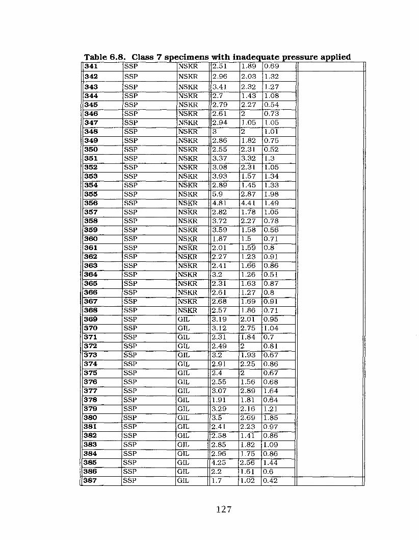
Table 6.8. Class 7 specimens with inadequate pressure applied341 SSP NSKR 2.51 1.89 0.69
342 SSP NSKR 2.96 2.03 1.32
343 SSP NSKR 3.41 2.32 1.27344 SSP NSKR 2.7 1.43 1.08345 SSP NSKR 2.79 2.27 0.54346 SSP NSKR 2.61 2 0.73347 SSP NSKR 2.94 1.05 1.05348 SSP NSKR 3 2 1.01349 SSP NSKR 2.86 1.82 0.75350 SSP NSKR 2.55 2.31 0.52351 SSP NSKR 3.37 3.32 1.3352 SSP NSKR 3.08 2.31 1.05353 SSP NSKR 3.93 1.57 1.34354 SSP NSKR 2.89 1.45 1.33355 SSP NSKR 5.9 2.87 1.98356 SSP NSKR 4.81 4.41 1.49357 SSP NSKR 2.82 1.78 1.05358 SSP NSKR 3.72 2.27 0.78359 SSP NSKR 3.59 1.58 0.56360 SSP NSKR 1.87 1.5 0.71361 SSP NSKR 2.01 1.59 0.8362 SSP NSKR 2.27 1.23 0.91363 SSP NSKR 2.41 1.66 0.86364 SSP NSKR 3.2 1.26 0.51365 SSP NSKR 2.31 1.63 0.87366 SSP NSKR 2.61 1.27 0.8367 SSP NSKR 2.68 1.69 0.91368 SSP NSKR 2.57 1.86 0.71369 SSP GIL 3.19 2.01 0.95370 SSP GIL 3.12 2.75 1.04371 SSP GIL 2.31 1.84 0.7372 SSP GIL 2.49 2 0.81373 SSP GIL 3.2 1.93 0.67374 SSP GIL 2.91 2.25 0.86375 SSP GIL 2.4 2 0.67376 SSP GIL 2.55 1.56 0.68377 SSP GIL 3.07 2.89 1.64378 SSP GIL 1.91 1.81 0.64379 SSP GIL 3.29 2.16 1.21380 SSP GIL 3.5 2.69 1.85381 SSP GIL 2.41 2.23 0.97382 SSP GIL 2.58 1.41 0.86383 SSP GIL 2.85 1.82 1.09384 SSP GIL 2.96 1.75 0.86385 SSP GIL 4.25 2.56 1.44386 SSP GIL 2.2 1.61 0.6387 SSP GIL 1.7 1.02 0.42
127

Table 6.8. Class 7 specimens with inadequate pressure applied388 SSP GIL 2.25 2.27 1.01
389 SSP GIL 2.87 2.34 0.97
390 SSP GIL 2.93 2.2 0.97391 SSP GIL 3.95 1.6 0.96392 SSP GIL 2.22 1.39 0.47393 SSP GIL 2.73 1.37 1.31394 SSP GIL 2.59 2.3 0.74395 SSP GIL 3.56 1.4 1.23396 SSP GIL 2.41 1.9 0.86397 SSP GIL 3.53 2.33 0.96398 SSP GIL 2.72 2.48 1.21399 SSP GIL 2.99 2.51 0.66400 SSP GIL 3.14 2.09 0.85401 SSP GIL 2.59 1.94 0.8402 SSP GIL 2.91 2.25 0.86403 SSP GIL 3.07 2.12 0.7404 SSP GIL 2.84 2.2 1.16405 SSP GIL 3.62 2.17 0.96406 SSP GIL 2.46 1.03 1.2407 SSP GIL 3.6 1.77 0.7408 SSP FR 2.96 2.29 1.03409 SSP FR 2.7 2 0.63410 SSP FR 3.82 2.36 1.07411 SSP FR 3.16 1.67 0.77 Silicified siltstone412 SSP FR 2.56 1.66 0.76 pebbles413 SSP FR 2.99 1.57 1.06 2.79 11.36 10.95414 Gen chert NSKR 2.71 1.44 1.13415 Gen chert NSKR 2.66 1.64 0.91416 Gen chert NSKR 4.06 2.21 1.01417 Gen chert NSKR 2.32 1.96 1.14418 Gen chert NSKR 2.45 2.3 1.23419 Gen chert NSKR 2.36 1.39 0.64420 Gen chert NSKR 4.41 3.51 1.53421 Gen chert NSKR 3.21 2.3 1422 Gen chert NSKR 4.41 1.96 1.41423 Gen chert NSKR 3.27 2.78 0.8424 Gen chert NSKR 3.69 3.56 1.22425 Gen chert NSKR 2.54 1.76 0.96426 Gen chert NSKR 2.41 1.89 0.75427 Gen chert NSKR 2.9 1.42 0.77428 Gen chert NSKR 2.14 1.68 0.78429 Gen chert NSKR 1.97 1.4 0.66430 Gen chert NSKR 3.16 2.21 1.01431 Gen chert NSKR 3.13 1.4 1.34432 Gen chert NSKR 2.91 1.41 0.94433 Gen chert NSKR 2.86 1.45 0.87434 Gen chert NSKR 2.9 2.21 1.39
128

Table 6.8. Class 7 specimens with inadequate pressure applied435 Gen chert GIL 3.07 2.72 1.01
436 Gen chert GIL 4.71 2.53 2.05
437 Gen chert GIL 1.85 1.62 0.59438 Gen chert GIL 2.62 2.47 1.77439 Gen chert GIL 2.22 1.94 0.64440 Gen chert GIL 3.3 2.06 1.43441 Gen chert GIL 2.6 2.19 1.66442 Gen chert GIL 2.92 2.41 1.3443 Gen chert GIL 2.59 2.13 0.7444 Gen chert GIL 3.87 3.46 1.22 Generic chert445 Gen chert FR 2.53 1.91 0.69 2.62 11.68 \0.91446 Gen mat NSKR 4.1 1.75 1.33447 Gen mat NSKR 3.58 3.96 1.21448 Gen mat NSKR 4.19 3.53 1.22449 Gen mat NSKR 2.91 1.64 0.91450 Gen mat NSKR 4.09 2.63 0.8451 Genmat NSKR 4.91 2.96 1.12452 Gen mat NSKR 3 1.71 0.57453 Gen mat NSKR 5.21 4 2.08454 Gen mat NSKR 4.16 2.56 1.58455 Gen mat NSKR 4.89 3.1 1.3456 Gen mat GIL 3.9 2.31 1.2457 Gen mat GIL 3.43 2.3 1.01458 Gen mat GIL 3.95 3.27 1.46459 Gen mat GIL 2.82 2.32 0.89460 Gen mat GIL 2.91 2.54 1.01461 Genmat FR 4.26 3.21 0.92462 Gen mat FR 3.2 1.84 0.72463 Gen mat FR 4.61 3.34 1.62464 Gen mat FR 5.12 2.52 1.17465 Gen mat FR 3.76 2.78 1.39466 Gen mat FR 4.63 2.46 1.17467 Gen mat FR 2.85 2.01 1.49468 Gen Mat FR 5.14 3.11 1.33469 Gen mat FR 4.54 3.5 1.44470 Gen mat FR 3.09 2.11 0.64 Generic material471 Gen mat FR 2.31 2.23 0.62 3.21 11.99 10.98472 Qtz-ite NSKR 6.71 3.54 1.96473 Qtz-ite NSKR 5.85 3.07 2.11474 Qtz-ite NSKR 6.05 3.81 1.41475 Qtz-ite NSKR 3.04 3 1.24476 Qtz-ite NSKR 2.49 2.17 0.89477 Qtz-ite NSKR 6.25 3.99 1.94478 Qtz-ite NSKR 4.27 4.77 1.67479 Qtz-ite NSKR 4.65 4.37 1.11480 Qtz-ite NSKR 3.49 2.41 1.01481 Qtz-ite NSKR 6.68 4.05 1.75
129

r dh· dbi 6 8 ITa e . C ass 7 specimens wit Ina equate pressure apPle482 Qtz-ite NSKR 2.62 1.96 0.85483 Qtz-ite GIL 4.73 3.77 1.45 Quartzite484 Qtz-ite FR 3.54 3.13 1.07 5.13 13.34 11.52
IGRAND Totals (means) 3.06 2.135 0.95 I
although step and hinge types were also produced.
There are several reasons why I identified these materials
as a separate category and assigned them to their own class. First,
once I began the replications, I was trying to precisely control the
application of applied pressure. The problem was that often I did
not apply an adequate amount of force to the specimen so rather
than splitting or shattering the material I was merely chipping it.
However, once this occurred the pebble was now altered from its
original proportions and I felt strongly that it would very likely
react differently should I attempt a second replication of splitting
the specimen. Additionally, I was curious how often this situation
would repeat itself throughout the experimentation process.
Therefore, once I had altered a pebble (in any form) I no longer
attempted to apply further pressure to the specimen.
In total, Class 7 specimens amounted to 186 specimens that
comprised 35.9% of the total experimental replications. These
materials include: 116 silicified siltstone, 32 generic chert, 26
generic material, and 13 quartzite specimens. Figures 6.44, 6.45,
6.46, 6.47 and 6.48 illustrate several of the Class 7 specimens that
have had small flakes chipped from their proximal ends.
130
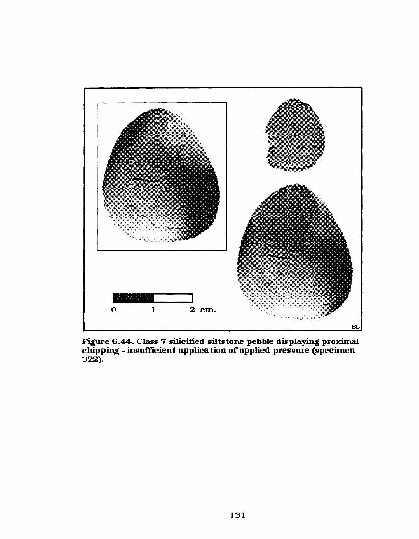
_ ......_ ......1o 1 2 cm.
BL
Figure 6.44. Class 7 silicified siltstone pebble displaying proximalchipping - insuft'icient application of applied pressure (specimen322).
131

_ ...._-o 1 2 cm. BL
Figure 6.45. Class 7 silicified siltstone pebble displaying proximalchipping (specimen 326).
o 1 2 cm. BL
Figure 6.46. Class 7 generic material pebble displayingproximal chipping (specimen 446).
132

o 1 2 em.
BL
Figure 6.47. Class 7 quar tzite pebble displaying proxim.aIchipping - insu11'icient application of applied pressure(specimen 472).
133

o 1 2 cm.BL
Figure 6.48. Class 7 quartzite pebble displaying proxim.alchipping - insufl1.cient application ofappIied pressure(specimen 477).
134
6.1.2.8 Class 8 specimens are another unique class of
bipolar flakes identified here as citrus-section flakes. These
specimens fractured into long linear wedge-shaped fragments that
end in axial terminations. Largely because these specimens all
end in axial terminations they all display some distal, as well as
proximal, impact crushing.
Citrus-section flakes have been previously recorded within
the archaeological record. For example, Meyer (1978:16) noted in
his analysis of the Key Lake Archaeological Survey, Saskatchewan,
that the predominant lithic technology for that study area
consisted of bipolar technology that was used to work cobble
stones. Further, although he recognized a variety of bipolar
materials as being present in the Key Lake area he noted that
linear flakes were quite abundant. One type of linear flake of .
particular interest that he recorded was identified as orange
section linear flakes (Meyer 1978:18), which are identical to the
Class 8 specimens outlined here.
This class of bipolar fracture is directly related to the over
all body form of the material being worked, which is to say that
these flakes derive from a pebble or cobble that is fairly round
with a width to thickness ratio being nearly equal. I have
previously noted that with an ellipsoid-shaped body the spherical
waves pass through a larger portion of a specimen creating a
highly variable area of central pressure within the material as the
force waves emanate through the material. When the applied and
rebound force exerts an equal amount of pressure within the
135

material the specimen will usually either shatter or fracture into
these unusual citrus-section flakes.
If too much pressure is applied or the material contains
impurities the specimen will tend to shatter. However, when the
material in question has a matrix that is fairly dense and compact
throughout the specimen the wedge-shaped citrus section flakes
are the usual end result, in part because of the outer circular
shape of the original specimen, and in part because the material
fractures down through the Xaxis, but at odd angles to the Yand Z
axes. The 26 specimens from this class are listed in Table 6.9.
They include: 16 silicified siltstone, 3 quartz and 7 generic chert
specimens.
Figures 6.49, 6.50, 6.51 and 6.52 illustrate four silicified
siltstone specimens that display the classic citrus-section flake
form. That is, they have a long straight linear ridge between the
two ventral surfaces of the flake, a smooth curved shape along the
exterior dorsal side of the fragments and they end in an axial
termination. Figures 6.53 and 6.54 illustrate two quartz pebbles
of this type. Class 8 specimens comprised 5.0% of the total
replications.
6.1.2.9 Class 9 specimens (Table 6.10) have an
irregular shear that produces two surfaces, apparently caused by
equal (or unequal) amounts of force being exerted towards the
center of the pebble, with one complete half. Whereas the one
section is complete the other half of the specimen is shattered into
numerous pieces. These materials typically display two flake
scars one on both the distal and proximal ends of the ventral
136

Table 6.9.Class 8 specimens displaying citrus section fracturesSP # Material Souree Dimensions (em's)
Original MeansType L(X) W(Y) T(Z) L(X) IW(Y) IT(Z)
485 SSP NSKR 3 2.01 1.44486 SSP NSKR 2.94 1.99 1.71487 SSP NSKR 3.19 2.17 1.6488 SSP NSKR 4.91 2.5 1.96489 SSP NSKR 3.42 2.3 1.54490 SSP NSKR 2.59 1.37 0.95491 SSP NSKR 3.48 2.8 1.46492 SSP NSKR 2.64 1.8 1.06494 SSP NSKR 2.77 1.64 0.94495 SSP NSKR 3.12 1.75 0.78496 SSP GIL 3.43 2.96 1.66497 SSP GIL 2.4 1.35 0.71498 SSP GIL 2.93 1.66 1.11499 SSP GIL 2.51 2.01 1.36 Silicified Siltstone500 SSP GIL 2.38 2.08 1.36 pebbles501 SSP GIL 3.59 2.56 1.12 3.31 2.285 1 1.28502 Quartz NSKR 3.39 2.42 1.81503 Quartz GIL 2.86 2 1.23 Quartz504 Quartz NSKR 3.21 2.27 1.18 3.31 2.345 1 1.495505 Gen chert NSKR 2.5 1.7 1.22506 Gen chert NSKR 3.81 2 1.68507 Gen chert NSKR 2.55 2.09 1.1508 Gen chert NSKR 2.45 2 1.08509 Gen chert NSKR 3.54 2.53 1.55510 Gen chert NSKR 2.98 2.1 1.05 Generic chert511 Gen chert GIL 3.65 2.94 1.47 3.081 2.321 1.345
Grand Totals (Means) I 3.33 2.48 1.461
137
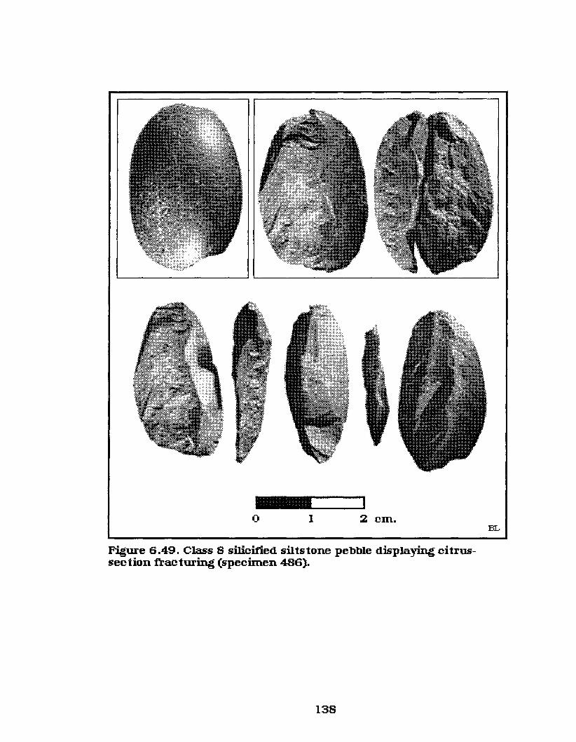
---~o I 2 em.
Figure 6.49. Class 8 silicified silts tone pebble displaying citrussection ftac turing (specimen 486).
138
BL

---~o 1 2 cm. BI..
Figure 6.50. Class 8 silicified siltstone pebbledisplaying citrus-sec tion frac turing (specimen 490).
_________Io 1 2 cm. BL
Figure 6.5 1. Class 8 silicified silts tone pebble displayingcitrus-sec tion frac turing (specimen 497).
139

_0.....-_,o I 2 cm.
Figure 6.52. Class 8 silicified siltstone pebble displaying citrussection fracturing (specimen 501).
140
BL
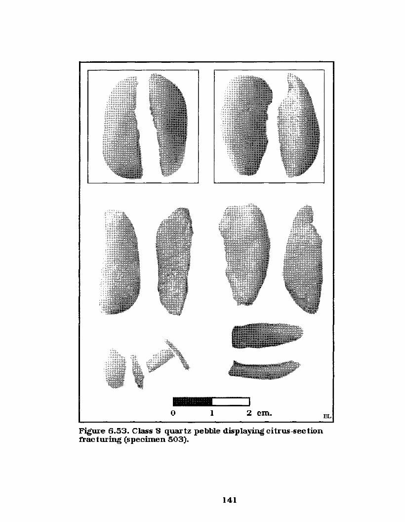
\ _ ....._-~o I 2 cm. BL
Figure 6.53. Class S quartz pebble displaying citrus-sectionfracturing (specimen 503).
141

_ .....__1
o 1 2 em.
Figure 6.54. Class 8 quartz pebble displaying citrus-sectionfracturing (specimen 504).
142
BL

I Id"f9T bl 6 10 CIa e . . ass speCImens racture lrregu ar >1
SP # Material Souree Dimensions (em's)Type Original Means
L(X) WrY) T(Z) L(X) IW(Y) IT(Z)
493 SSP NSKR 3.79 2.51 2.05516 SSP NSKR 3.71 1.89 0.72517 SSP NSKR 2.81 2.09 1.69 Silicified siltstone518 SSP NSKR 2.44 1.56 0.89 pebbles519 SSP GIL 3.91 3.07 1.21 3.81 12.48 10.97242 Qtz-ite NSKR 4.08 2.97 1.51 Quartzite512 Genchert NSKR 2.6 1.96 0.93513 Genchert NSKR 2.81 1.93 0.83 '514 Genchert NSKR 3.39 1.59 0.86 Generic chert515 Genchert NSKR 3.98 2.02 1.35 3.29 11.99 11.14
Grand Totals (means) 3.845 1.955 1.035
surface of the complete pebble section joining at about the mid
point of the specimen. This is evident from the percussion lines
that indicate the force was generated equally from both the dorsal
and proximal impact points and terminating centrally within the
specimen.
This class of materials is perhaps the most difficult of the
classes listed here to analyze, especially since most of the
specimens had a fme grained, uniform matrix. Two exceptions are
illustrated in Figures 6.55 and 6.56, which are conlposed of
silicified siltstone but display a number of impurities. However,
that does not account for the other specimens, or the fact that
these specimens fractured quite differently from other similar
materials, which tended to shatter completely. One explanation
may be that the pebble was not perpendicular with the anvil,
when the force was applied to·its proximal end. Rather than
having the spherical waves pass down through the specimen fairly
143

Dis tal ftagrnents
Proximal ftagments
_~__Io 1 2 cm.
Complete sectionBL
Figure 6.55. Class 9 sili.ci:tted siltstone pebble displayingirregular ftac ture (specimen 517).
144

__----..ilo 1 2 cm.
BL
Figure 6.56. Class 9 si.Iicified silts tone pebble displayingirregular fracture (specimen 518).
145

evenly this may have caused most of the applied pressure to
emanate down one side more strongly than the other. If this was
the case, though, then it would seem reasonable that the rebound
force froin the anvil would apply unevenly to the opposite face
causing a proximal flake to be removed from one face while a
distal flake was removed from the opposite face. However, this
was not the situation as that type of fracture did not occur among
any of the experinlental replications. One specimen as illustrated
in Figure 6.57 is almost of that type, but even in this case the
fractures occurred along the one face of the material. It is also
interesting that the fractures occurred parallel to the Z axis with
this specimen, whereas all others of this class fractured
transversely parallel to the Yaxis.
One consistency with this class is that force did emanate
from the end of the specimen and commonly terminated at the
central point of the pebble. This is very evident through an
examination of Figures 6.55,6.56,6.58,6.59,6.60, and 6.61, which
all display this unique occurrence.
If the amount of applied force was such that the rebound
force equaled it then the spherical waves would come in contact
along the outer, approximately central point of the pebble. The
strain at this point would cause the two flakes, one distal and one
proximal, to detach fronl the main body of the specinlen. If the
pressure within the material had been just slightly greater then it
is likely that the stress within the specimen would have caused it
to completely shatter.
146

_ ...._-~o 1 2 em.
BL
Figure 6.57. Class 9 silicified siltstone pebble displaying irreguIa:rfrac ture (specimen 519).
147

_1....-__1
o 1 2 cm.
BL
Figure 6.58. Class 9 quartzite pebble displaying irregular fracture(specimen 242).
148

_L....__Io I 2 cm.
Figure 6.59. Class 9 generic cher t pebbledisplaying irregular fractme (specimen 514).
149
BL

_ ....._ ......1o 1 2 cm.
BL
Figure 6.60. Class 9 generic cher t pebble displayingirregular fracture (specimen 515).
150
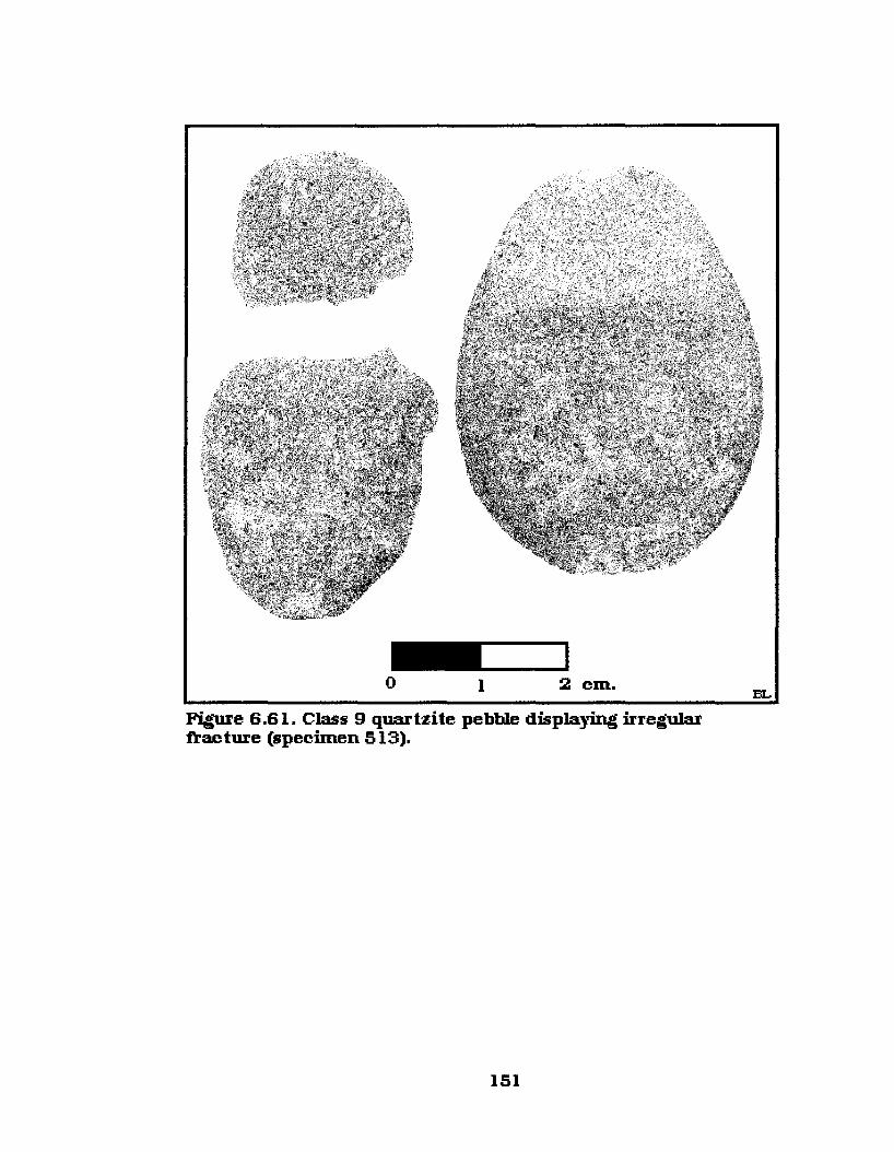
__Io 1 2 cm.
Figure 6.61. Class 9 quartzite pebble displaying irregularfrac ture (specimen 513).
151
BL

Figure 6.62 illustrates another Class 9 specimen, but this one
is again just slightly different from the previous ones. This
specimen also had proximal, distal and lateral flakes detached.
The interesting thing with this specimen is that the complete
section very closely resembles those bipolar pieces know as pieces
esquillees. Pieces esquillees are wedge shaped and typically
exhibit paired flake surfaces. These flake surfaces are created
from the detachment of flakes at opposite ends of the specimens
and morphologically resemble the Class 9 materials. The
difference here is that while pieces esquillees are believed to be
formed primarily through use, the Class 9 specimens were
produced during the bipolar pebble splitting process. Pieces
esquillees will be outlined more fully in Section 7.
There is no difficulty in identifying any of the complete
sections of the Class 9 materials as being bipolar by-products. The
very nature of the specimens with proximal and distal crushing,
and more importantly opposing flake scars, readily identify these
pieces as being derived from bipolar technology. The problenl
arises when trying to differentiate the proximal and distal
detached flakes, or fragments, from non-bipolar materials. That is,
they could not be identified as bipolar materials without the
original associated piece. If any of those slllall flakes were found
out of context or as isolated finds they would surely be identified
as straight percussion flake debris. Unfortunately, this situation
will continue to plague bipolar analysts because without the
associated original pieces or the tools of manufacture, these types
of materials simply cannot be differentiated from straight
152

Complete section_----_Io 1 2 cm. BL
Figure 6.62. Class 9 silicified siltstone pebble displaying irregularft'ac ture (specimen 493).
153

percussion debitage. Class 9 specimens consist of five silicified
siltstone, one quartzite and four generic chert pebbles that
comprise 1.9% of the total experimental replications (Table 6.10).
6.1.2.10 Class 10 specimens(Table 6.11) comprise
the final category of the experimentally replicated bipolar
materials and consist of only five silicified siltstone specimens.
Class 10 specimens are split into two sections down the Xaxis and
transversely parallel to the Yaxis. However, unlike the Class 2
materials that terminate at the distal end of the specimens, these
have one section that ends in a feather termination above the
point of contact with the anvil. Honea (1965:261) described
bipolar flakes similar to these, noting that they had terminated
above the point of anvil contact producing a flake that was about
3/4 of the pebble core length. Sollberger and Patterson (1976: 40)
argued that because these flakes did not terminate at the anvil
contact point they could not be considered true bipolar flakes.
However, the evidence here clearly shows that these flakes can be
and are produced using the bipolar method.
Several reasons may be suggested for this type of fracture.
First, it is likely that there was not enough pressure applied to
these specimens. Second, when force was applied it is possible
that the pebble was slightly off the perpendicular from its contact
with the anvil. These circumstances would have allowed the force
to emanate down the outer portion of the pebble and thus
terminate in a feather termination before the end of the pebble.
Typically,
154
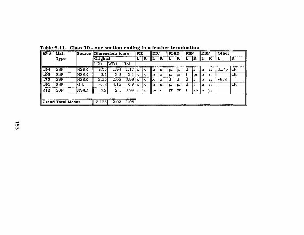
I--'U1U1
- --- - - - - - - - ------ -- - -- - - - - - - -- -- -- -- --------~ --- - - -- -- - - ---- -- ---
SP # Mat. Souree Dimensions (em's) PIC DIC PLED PBP DBP OtherType Original L R L R L R L R L R L R
L(X) W(Y) T(Z)
..54 SSP NSKR 3.05 1.94 1.17 x x n n pr pr d i n n dfr/p dft
..55 SSP NSKR 6.4 3.6 3.1 x x n n pr pr i pr n n dft
..75 SSP NSKR 2.55 2.05 0.98 x x x n d d d i n n vfr/d
..91 SSP GIL 3.13 4.15 0.9 x x n n pr pr d i n n dft
212 SSP NSKR 3.2 2.1 0.99 x x pr i pr pr i sh n n
Grand Total Means 3.125 2.02 1.08

flakes displaying feather terminations commonly occur anlong
straight percussion materials.
Figure 6.63 displays one specimen from the Class 10
materials with a feather termination flake removed from the
pebble core that could not be differentiated from a straight
percussion flake. That is, it displays a fairly positive pronounced
proximal bulb of percussion, pronounced lines of force and a distal
feather termination that are all common straight percussion
attributes. If the other section of this specimen was not associated
with it this would be analyzed as a classic percussion flake rather
than a by-product of bipolar technology; a truly exacerbating
dilemma for lithic analysts. However, although the detached
flakes from the specimens illustrated in Figures 6.64, 6.65 and
6.66 are in essence similar to the one in Figure 6.63, these latter
can be identified as bipolar flakes. The detached flakes in Figures
6,64 and 6.65 both display negative inverted proximal bulbs of
percussion.
The flake in Figure 6.66 has a sheared bulb and as already
noted this is a distinctive bipolar attribute.
6.2 Summary
Of the 521 replications only the Class 6 and Class 7 materials
contained no specimens that displayed any identifying bipolar
attributes. This is not surprising since the Class 6 materials were
reduced to numerous fragments of waste debitage while the Class
7 specimens were incomplete bipolar reductions.
156

o 1 2 em.
Figure 6.63. Class 10 silicified silts tone pebb1e displayinga feather termi:na.tion (specimen 55).
157

-----,o 1 2 cm.
Figure 6.64. Class 10 silicified siltstone pebbledisplaying a feather termination (specimen 54).
158

o I 2 em.
Figure 6.65. Class 10 silicified silts tone pebble displaying a reathertermination (specimen 91).
159

_1--__]o 1 2 cm.
Figure 6.66. Class 10 silicified siltstone pebble displaying a feathertermination (specimen 212).
160
Therefore, if we remove the 39 Class 6 specimens from the data
set, that is, those pieces that completely shattered, this would
leave 482 completed replications. If we then also remove Class 7
from the data set, which includes those specimens that had an
inadequate amount of pressure applied during the replication
causing the pebble to chip or partially flake at the proximal end,
that would leave 296 completed replications; that is, materials that
were successfully split. It is interesting to note that of these
remaining 296 replications only 16 specimens (1 Class 2; 14 Class
3; 1 Class 4) did not have at least one fragment that could be
positively identified as a bipolar by-product.
In order for a specimen to be identified as a bipolar by
product it had to display at least one of the following combination
of attributes:
1. One split pebble half displaying both proximal and distal
impact crushing.
2. One split pebble section displaying both distal and
proximal bulbs of percussion on a single specimen.
3. One split pebble section displaying a positively
identifiable distal bulb of percussion.
Although not every fragment of each specimen displayed these
attributes at least one section of each did. This is quite significant
since 280 or 94.6% of these replications contained identifiable
bipolar traits.
161
7.
CURRENT TYPOLOGICAL BIPOLAR ARTIFACT
CLASSIFICATIONS
7.1 Literature review of the bipolar technique - an
abridged synopsis.
In 1963, Binford and Quimby first described the bipolar
technique in North America. Since that initial identification of this
technology, it has been frequently recorded in a wide range of
assemblages and temporal time frames. For example, Honea
(1965) states that he found evidence suggesting the bipolar
flaking technique occurred in both east-central Texas and north
central New Mexico. The studied artifactual material from Texas
sites came from the McGee Bend Reservoir area and the New
Mexico material was from the Cochiti Reservoir sites to the west
northwest of Santa Fe. He compared the material from these sites
with experimentally replicated bipolar flaking debris using
unworked pebble cores, hammerstones, and stone anvils collected
from the above sites. Losey (1971) noted that a variety of bipolar
pebble and cobble cores were represented within the Stony Plains
Quarry site assemblage and Leaf (1979b) described several
bipolar cores within his report on the El Dorado sites in Kansas.
Leaf (1979b) described these as having surfaces of percussion at
162

opposite ends of a striking axis, a striking platform and a base
with the surface resting on the anvil exhibiting crushing and small
flake scars. Brose (1970), in describing the Summer Island site in
Michigan, noted the presence of 259 bipolar cores with the
recovered assemblage of artifacts. He defined these cores with
reference to the six bipolar types as defined by Binford and
Quimby (1963) and he noted that they all displayed clear evidence
of having been produced by bipolar percussion. Johnson (1987)
described a large number (189) of cores from the Carson Mound
site in northwestern Mississippi. Johnson (1987) stated that most
of the multiple platform cores show edge wear although edge
battering on single platform cores is confined to the platform
rather than the base. Ball (1987) reported bipolar split pebble
stones from a variety of sites in Alberta. Root (1994) noted a
variety of bipolar core types from the Bobtail Wolf site, within the
Knife River flint primary source area in North Dakota, containing
Archaic and late prehistoric artifact deposits. Fox (1979) even
noted that the only core forms represented in an early 17th
century historic Huron Attignawantan lithic assemblage were
bipolar.
The bipolar technique appears to be ubiquitous throughout
North America, as is evident from this very brief review of
archaeological literature. In fact, Knudson (1978) has commented
that the bipolar technique may be one of the most common lithic
reduction techniques represented within North American artifact
assemblages. Therefore, I felt that a review of the previously
identified classifications of bipolar artifacts from the
163

archaeological record should be presented here. However, since
the research outlined here primarily examines pebble stones
rather than bipolar materials, the former will be addressed
separately within the next chapter. The inclusion of the following
classification systems is primarily intended to provide a sYnthesis
of the current information regarding bipolar technology.
7.2 Classes of Bipolar Artifacts
It should be noted that the bipolar core classifications are
based primary upon the examination and study of larger
materials. Small pebble stones such as those examined within this
report are in a class by themselves and do not readily fit into the
above categories. This is directly related to the fact that the
outcome of the application of the bipolar technique, the effect of
this method on pebble stones, and the end products produced are
quite different from what researchers view as materials resulting
from bipolar reduction produced from larger pieces of lithic raw
material.
7.2.1 Binford and Quimby (1963) bipolar core (outils
ecailles) classification. A number of classifications have been
developed for bipolar cores. The first North American
classification of these artifacts was presented by Binford and
Quimby (1963: 289-296) who identified six classes of bipolar cores
based on the morphology of their percussion surfaces as outlined
below.
164

7.2.1.1. Class 1: Ridge area core. This core is
described as having a basal zone of percussion consisting of
unmodified cortex and a series of overlapping cones of percussion
or a ridged impact zone of percussion. Flake scars originate at the
ridge and dominate the cleavage faces while the basal scars tend
to be diminutive and irregular and usually terminate in hinge
fractures (Figure 7.1).
7.2.1.2. Class 2: Point-area core. This core is
characterized by a third cleavage face that is essentially the end of
the core from which flakes originating at the ridge detach. The
core is reduced to a point of percussion at the zone of impact while
the base remains an area (Figure 7.2). In this instance the term
area relates to the surface of the core's distal or proximal end that
retains a flat plane.
7.2.1.3. Class 3: Ridge-point core. With this type
of core the basal zone of percussion is a greatly battered and
bruised point while the impact zone is a ridge of percussion. This
type is thought to be produced by uncontrolled breakage in the
early phases of core manufacture resulting in a cone of percussion
or a point of percussion at the impact zone (Figure 7.3).
7.2.1.4. Class 4: Right-angled ridge core. This
type is somewhat ambiguous in that it is supposed to result from
the failure of producing a core form similar to Class 3. That is,
with a point of percussion as the base, opposed by a ridge of
percussion. However, it appears that this form has opposing
points of percussion and, actually, it is very much like the Class 5
and 6 types below (Figure 7.4).
165

Longitudinalsections
Opposing faces
Fieure 7.1. Binford and Quimby's ridee-area bipolar coretype (from Binford and Quimby 1972: 357).
Longitudinalsection
Opposing faces
Figure 7.2. Binrord and Quimby's point-areabipolar core type (from Binford and Quimby1963: 339).
166

Longitudinalsections
Opposing (aces
Figure 7.S. Binford and Quimby's ridgepoint bipolar core type (from Binford andQuimby 1972: 359, 361).
Lon~tudinalsections
Opposing faces
tJ· Q'~ ..' .. :;~. .,.. .~- .
. .. "
" .
~.~ "~':'... ,
.. ..
Figure 7.4. Binford and Quimby's rightangled ridged bipolar core type (fromBinford and Quimby 1Q6S: 561).
167

7.2.1.5. Class 5: Opposing ridge core. This core
has opposed ridges of percussion in which it is impossible to
determine which ridge served as the base and which served as the
impact zone (Figure 7.5). It is suggested that both ridges variously
served as base and zone of impact.
7.2.1.6. Class 6: Opposing point core. This is
Binford and Quimby's (1963) final bipolar type. This form is
characterized by opposing ridges that are approximately at right
angles to one another. It is apparently produced from the core
originally having a ridge opposite an area. With successive
removal of flakes from both ends of the core the terminal flake
scars eventually converge forming a ridge at right angles to the
upper ridge of percussion Figure 7.6).
7.2.2 Leaf's (1979a) bipolar core (outils ecailles)
classification.
Another classification scheme for bipolar cores was presented by
Leaf (1979a). His model is actually a reworking of the
classification system of Binford and Quimby (1963) with a few
additions. According to Leaf (1979a), Binford and Quimby's
(1963) classification system more strictly defines nine classes of
bipolar cores and not six as they suggested. He proposed his core
reduction model to account for the variation of form in bipolar
cores.
To precisely illustrate the variation in bipolar core forms he
places the three kinds of percussion surfaces, as defined by
Binford and Quimby (1963), within a three way table classification
of the striking surfaces and basal surfaces. His classification
168

Longitudinalsections
Opposing faces
Figure 7.5. Binford and Quimby's opposingridge bipolar core type (from Binford andQuimby 1972: 360).
Longitudinalseotion Opposing faces
Figure 7.6. Binford and QUimby's opposingpoint bipolar core type (from Binford andQUimby 1972: 361).
169

system is outlined in Table 7.1.
Table 7.1. Outline of Leaf's (1979a) Bipolar Core Types
STRIKING PLATFORM
BASEAreaRidgePoint
Area RidgeBC BCBC BCBC BC
PointBCBCBC
Be: Suggested bipolar core forms
As illustrated in Table 7.1, Leaf's (1979a) posited model
defines nine classes of bipolar cores: area-area, area-ridge, area
point, ridge-area, ridge-ridge, ridge-point, point-area, point
ridge,point-point. In this classification scheme Leaf (1979a)
identifies Binford and Quimby's (1963) opposing-ridge and
opposing-point types as ridge-ridge and point-point, respectively.
Leaf's (1979a) ridge-ridge type (among others) is illustrated in
Figure 7.7., although the point-point type is not depicted within
his report.
Leaf's (1979a) data regarding his bipolar core classes are not
well outlined, but apparently inverting ridge-area and point-area
types creates his area-ridge and area-point forms. Additionally,
although he does illustrate the former ridge-area and point-area
types (Figure 7.7.) he does not display all the types that he
proposes. He does explain that his reason for this further
classification is that if large flake scars appear to originate from
the base rather than the point, then, for example, a point-area core
as defined by Binford and Quimby (1963) should be inverted and
classed as an area-point type. It is not entirely clear if this is a
170

Ridge-area
Area-area. Point-area
Point-ridge Ridge-ridge
•••o 0 em.
Figure 7.7. Bipolar core types as defined by Leaf (fromLeaf 1979a).
171

valid change or if it is just an over-classification.
One form of bipolar core Leaf (1979a) proposes that seems
to have validity is the area-area type (Figure 7.7.). The area-area
form is one of the few bipolar cores that Leaf (1979a) proposed
that he does illustrate within his report. This type has opposing
areas in which the zone of percussion is an area of unmodified
cortex, or an area that is relatively flat, from which no flakes have
been struck. Rather, flakes have been detached solely along the
edges. This type was not defined by Binford and Quimby (1963).
The only other bipolar core form illustrated by Leaf (1979a)
is the point-ridge type (Figure 7.7) that is essentially Binford and
Quimby's (1963) ridge-point form.
7.2.3. Honea's (1965) bipolar core (outils ecailles)
classification. Another classification scheme for bipolar cores
was presented by Honea (1965: 262-263). He identified three
main classes of bipolar cores based on the location and number of
primary percussion platforms and the direction of flake removal,
as follows:
7.2.3.1. Single-ended. Flakes have been removed
from only one end of the core (Figure 7.8.).
7.2.3.2. Double-ended. Flakes are alternately
removed from both ends of the core (Figure 7.8.).
7.2.3.3. Multi-platformed. This type is similar to
the double ended classification except that the core has been
rotated so that flakes have been removed from the lateral edges of
the core as well as both ends (Figure 7.8.).
Honea (1965) further divided each of these classes, based on
172

Single-ended
.,Double-ended
1
Multi-platformed
o 1 2 3 em
Figure 7.8. Types of bipolar cores as defined by Honea(from Honea 1965: 262).
178

their platform development into:
7.2.3.3.1. Plain platform. Naturally convex,
concave or plane, cortex covered surface of one end of the core.
7.2.3.3.2. Unfaceted platform. This platform
is the resultant flake scar created by a single flake removed at a
right or slightly oblique angle to the length of the core and
direction of intended primary flaking.
7.2.3.3.3. Faceted platform. This form is
made by striking off a series of roughly parallel flakes from the
top of the core at approximate right angles to the intended
direction of flaking. It is believed to be made less frequently on
pebble cores.
7.2.3.3.4. Prepared platform. Unfaceted and
faceted cores are occasionally prepared in the Levallois fashion.
That is, the cortex is trimmed off the core surfaces by multi
directional, unifacial, or bifacial percussion flaking before
preparation of the platform.
7.2.4 Herbort's (1988) bipolar core (outils ecailles)
classification. Herbort (1988) also classed a number of bipolar
cores, although he based his system primarily on the shearing
tendencies of the material. Herbort (1988: 37-39, 45-46) lists six
main types of core shearing that produce his core classes, these
are: tranchette, truncation, spall, double split, longitudinal and
lateral. Unfortunately, they are not well defined.
7.2.4.1. Tranchette. These shear transversely, but
not longitudinally through the Yaxis, but rather obliquely to it
through the mid -section of the core (Figure 7.9). This appears to
174

Spall cores
1'ranchetteSingle detachment
+
Trunoation
Double splits
Multiple detachments
Longitudinal spilt
Lateral splits
Figure 7.9. Variations of bipolar fracturing (from Herbort1988: 45-46).
175
be an extremely odd fracture pattern.
7.2.4.2. Truncation. This type also shears
transversely, but as above, it does not shear longitudinally
through the Yaxis; it appears to fracture perpendicular to the
point of anvil contact (Figure 7.9).
7.2.4.3. Spall. This core type (Figure 7.9) is produced
by the detachment of flakes that Herbort (1988) calls spalls. The
spalls are removed from any of a number of locations. These cores
in essence are identical to Honea's (1965) multi-platformed type
(Figure 7.8.).
7.2.4.4. Double split. These cores are produced
when the specimen shears longitudinally in the same direction
producing three sections (Figure 7.9).
7.2.4.5. Longitudinal split. These specimens are
produced by the core splitting longitudinally down the X axis and
ending in an axial termination (Figure 7.9.). In this instance the
core was resting on the anvil with the X axis perpendicular to it
with the force being applied at the proximal end of the specimen.
7.2.4.6. Lateral split. These materials are produced
by the core shearing down through the Yaxis producing a laterally
split specimen with an axial termination (Figure 7.9.). In this
instance the core had its lateral edge resting on the anvil with the
Y axis perpendicular to it. Force was then applied at the proximal
end of the specimen's lateral edge. During the initial testing of
materials I attempted both longitudinal and lateral replications.
Although I did manage to split several specimens laterally I found
the pieces harder to hold and I had a lower success ratio of
176

shearing the materials when compared to the longitudinally
replicated ones. Therefore, I preferred the longitudinal rather
than the lateral split for my experimentations.
7.2.5. Root's (1994) bipolar core (outils ecailles)
classification. In a report by Root (1994) on the Bobtail Wolf
site, a multicomponent lithic workshop and campsite in the Knife
River flint primary source area, western North Dakota, he outlines
four classes of bipolar cores. He classified his bipolar cores based
on the reduction technology that characterizes their manufacture
as defined by the types of flake initiation, propagation, and
termination, which he states allows for the distinction between
non-bipolar and bipolar percussion (Root 1994: 44-47). His
classification regarding bipolar cores is as follows (these forms
were not illustrated in the original):
7.2.5.1. Bipolar cores, not rotated. These cores
have a single platform and exhibit areas of crushing and
splintering on opposite ends of the cobble, flat flake scars that
create a multifaceted core form, negative flake scars that often run
the length of the core, no negative bulbs of force, a predominance
of wedging flake initiations, pronounced compression rings on
flake scars from compressed controlled propagation, and axial
flake terminations.
7.2.5.2 Bipolar cores, rotated. These cores exhibit
more than one combination of platform states.
7.2.5.3. Bipolar and freehand cores,
predominantly bipolar. These cores display evidence of bipolar
177
and freehand detachments with the majority by the bipolar
technique.
7.2.5.4. Bipolar and freehand cores,
predominantly freehand. These cores display evidence of
bipolar and freehand detachments with the majority by freehand
methods.
7.2.6. Binford and Quimby's (1963) bipolar flake
classification. Bipolar flakes have the same range of variation as
straight percussion materials, however, they have the added
enigma that they are abundantly more difficult to identify.
Several researchers have attempted classifications of these
materials, for example Binford and Quimby (1963) first identified
two classes with five variations of bipolar flakes. They divided
the classes bases on whether flakes originated at the basal zone of
percussion or the impact zone of percussion. These forms are
outlined as follows:
7.2.6.1. Class 1. These flakes are derived from the
base of the core through contact with the anvil.
7.2.6.1.1. Variety A. Flakes of this type are
derived from the comer of the core having a basal area of
percussion. The overall shape of these flakes is stated to be
triangular in form with little or no bulb of percussion evident on
the ventral surface. These flake types display no positive bulbs of
percussion although some have negative bulbs. There are no
illustrations of this type provided by Binford and Quimby (1963).
7.2.6.1.1. Variety B. These flakes are stated to
originate from the broad lateral face of a core having a basal area
178

of percussion. The ventral faces display moderate positive bulbs
of percussion and the dorsal faces exhibit multiple, parallel,
longitudinally oriented flake scars. These flakes are triangular or
lamellar in form. There are no illustrations of this type provided
by Binford and Quimby (1963).
7.2.6.2. Class 2. These flakes are derived from the
impact zone of percussion of the core.
7.2.6.2.1. Variety C. These flakes are detached
from the lateral core face by the impact of blows at the upper
ridge or point of percussion in which the zone of impact is very
narrow. The ventral surface has a developed positive bulb of
percussion and the dorsal surface displays two or three parallel
scars that converge to form a ridge (Figure 7.10.). There are
generally several hinge fractures near the base of the flake. These
flakes are either lamellar or excurvate in form.
7.2.6.2.2. Variety D. These flakes are detached
in the same manner as Variety C except that it is the basal zone of
percussion that is very narrow. These flakes are small and the
ventral surfaces almost entirely consist of a positive bulb of
percussion. Dorsal surfaces are irregularly scarred near the base
of the flake. Distal ends also commonly display terminal hinge
fractures. These flakes are generally ovate or conchoidal in form.
Figure 7.10. represents the one Variety D bipolar flake that
Binford and Quimby (1963) illustrate.
7.2.6.2.3. Variety E. These flakes are detached
from the end of the core by the impact of blows at the upper ridge
or point of percussion in which the basal zone of percussion is
179

Opposing faces
Cross-seotion
Variety C
Cross-section
Variety DIi tJ;
.f,',;.··.
:" ":', \ ", .. -'
,: - - :'~ :•.: • ~ + ••••
Cross-seotion
variety E
Cross-section
Variety E
Longitudinalsection
DecortificationFllure 7.10. Bipolar flakes as defined by Binfordand Quimby (1968: 854, 868).
180

very narrow. The ventral surfaces have a well-developed positive
bulb of percussion and the dorsal surfaces exhibit a single,
longitudinally oriented flake scar. These flakes are either lamellar
or expanding in form. Binford and Quimby (1963) illustrate two
Variety E bipolar flakes as displayed in Figure 7.10.
Binford and Quimby (1963) outline one other flake type
within their report. These flakes are decortification flakes (Figure
7.10.) that have unmodified cortex and ventral faces that display
scarring. For some reason they have chosen to label this flake
type separately from their other varieties. They indicate that
strong negative bulbs are common on these materials, but that
some specimens also display strong positive bulbs as well.
7.2.7. Kobayashi's (1975) bipolar flake classification.
Kobayashi (1975: 117) classified bipolar flakes into four large
groups, based on their ventral surface attributes as outlined
below. Although his bipolar flake illustrations are not very clear
they are included here for comparison purposes.
7.2.7. 1. Group A. These bipolar flakes to have one
or a twin bulb on the ventral surface at only the proximal end
(Figure 7.11.). Flakes with axial terminations of distal ends,
shattered ends, hinge fractures, or feather edges are included in
this group. Many of these may actually be the upper section of
Kobayaski's (1975) Group
DType.
7.2.7. 1. Group B. Flakes that have one or twin bulbs
at only the distal end where it was in contact with an anvil. These
specimens include those types with shattered striking platforms
181

Group A
Group B
•11Group D
Group C
Figure 7.11. Bipolar flakes as defined by Kobayashi (1075:vi-x).
182

and feather edges (Figure 7.11.). It is possible that these flakes
may be the lower, or distal portions of Kobayashi's (1975( Group D
type.
7.2.7. 1. Group C, are bipolar flakes in which a twin
bulb is found at both the proximal and distal ends (Figure 7.11.).
This type was previously recognized by researchers, such as Honea
(1965), who state that occasionally, a bipolar flake will exhibit a
major positive bulb of percussion on the proximal end and a minor
positive bulb of percussion of the distal end of the ventral surface
of the flake. Honea (1965) indicated that these attributes are
formed when percussion of a combined primary and secondary
force coincide, caused by a mechanical force being applied at both
ends of a core.
7.2.7.1. Group D. Flakes that are removed from the
same core by one percussion blow. Flakes are removed from the
striking platform, and the distal end that was in contact with the
anvil, and two flakes are detached from different faces at the
same time (Figure 7.11.).
As noted with the core classification systems, bipolar flake
varieties also tend to overlap, especially in regard to their
distinguishing attributes. This characteristic is very noticeable in
Section 6 of this thesis where different technological classes
displayed the same or similar attributes, which makes separating
bipolar materials by attributes alone very difficult.
7.2.8. Pieces esquillees or wedges? The use of the
terms pieces esquillees and wedge is not consistent within New
World archaeological literature. Some reports use the term pieces
183
esquillees, to describe a specific artifact, while others appear to
prefer the use of the term wedge to describe fundamentally
similar materials. For example, when one term is used the other is
always associated with it; pieces esquillees (wedge), or wedge
(pieces esquillees). Still others treat the use of these terms within
the literature as non-equivalent. Although this has created
further confusion, it is apparent from a study of the literature that
these specimens do indeed relate to equivalent materials.
Pieces esquillees were first identified in Upper Paleolithic
assemblages by Bardon and Bouysonnie (1906). MacDonald
(1968) first introduced the term pieces esquillees to New World
archaeology in his report on the Debert site in central Nova Scotia.
In the Debert report MacDonald (1968) referred to the bipolar
technique of producing pieces esquillees from pebble cores or
small angular fragments of material. He also noted that they occur
predominantly in industries that use small raw material in
association with pitted anvil stones. This is essentially the same
interpretation for items classed as wedges by other researchers.
Pieces esquillees are defined as being generally rectangular
in form and exhibiting bipolar flaking from paired crushed and
battered surfaces. Primary flakes driven from both faces by
direct percussion exhibit extreme concentric ripples emanating
from the point of percussion. On the edge, opposite the primary
platform, multiple short flakes are driven back on both faces (the
result of the force reflected by a hard anvil). The irregularly
battered or primary edge tends to become concave with extreme
use as a core while the evenly crushed or secondary edge usually
184

maintains a receding straight profile determined by the shape of
the surface that is acting as the anvil. Magne (1985:168) notes
that pieces esquillees are formed through some function that
alludes lithic researchers. However, as the Class 9 specimens in
Section 6 illustrate, this mayor may not entirely be the case.
Many may have been shaped largely through the initial processes
of bipolar reduction. Two specimens from France that exhibit the
typical distinguishing characteristics of pieces esquillees are
illustrated in Figure 7.12 (Hayden 1980).
In the archaeological literature wedges are referred to as
hand wedges or bipolar cortex flakes that are made on flake and
core remnants that are for the most part the products of bipolar
flaking (Ranere 1975). They are generally thought to be used for
removing thin strips of cedar and for working wood, bone and
antler (Flenniken 1981; MacDonald 1968; Hayden 1980; Ranere
1975). Ranere (1975) identifies two types of wedges, one that has
a broad base and another that from a maximum width around
midpoint tapers in both directions to opposing bits, thus being
tabular in form. LeBlanc (1992), identifies Ranere's (1975) latter
form as a pieces esquillees.
According to MacDonald (1968), pieces esquillees differ from
most concepts of a tool, since there is no stage at which they can
be considered finished. They are initially short spalls or blocky
fragments, which rapidly disintegrate through use until they reach
a size that is difficult to hold, at which time they are discarded. To
MacDonald (1968) pieces esquillees represent true tools that were
used for "wedging" and slotting. To be useful as a wedge, a bipolar
185

Figure 7.12. Two pieces esquillees exhlblti~gtypicaldistinguishing attributes (from Hayden 1980: 6).
186

object must be capable of being handled, set in place, and held
effectively (Lothrop and Gramly 1989) and large enough to hold
firm while the blow is delivered. Although they are applied to
soft and relatively elastic materials, the wedges themselves are
usually damaged and worn, either on the edge struck by the
percussor or on both edges (Keeley 1980; Shott 1989).
LeBlanc (1992) sees two major problems with the mixed
interpretations regarding pieces esquillees, wedges and bipolar
cores. These are the misconception of the nature of bipolar
technology in reduction systems and the oversight relating to
other experimental and archaeological information. In a study by
Flenniken (1981) exhausted bipolar cores were used in wedging
and splitting deer and elk bone. Flenniken's (1981) results tend to
support the general utility and prehensility of bipolar objects used
as wedging tools. Brose (1970) remarked that the bipolar cores
represented in the Summer Island site assemblage, Michigan, may
have been employed as wedges or scrapers, but that such usage
was not sufficient to be recognized with the heavily battered ridge
edges resulting from the bipolar technique. Lothrop and Gramly
(1989) described pieces esquillees from the New York Vail sites.
As well, Ellis and Lothrop (1989) noted the presence of pieces
esquillees at the Potts site in New York. They also added that
their function was unimportant at this site and he states that the
precise function of pieces esquillees remains a matter of further
debate. Wright (1972) described a number of wedges from a
number of Shield Archaic sites as displaying distinct bipolar
crushing on at least two opposite edges. Most of the plates Wright
187

(1972) provides are not clear; however, in conjunction with his
description of wedge material he does provide an illustration of
what he refers to as being wedges or pieces esquillees.
Shott (1989) clouds the issue by arguing that wedges are
expediently produced bipolar cores, not wedges. Similarly,
Goodyear (1993) believes that pieces esquillees simply represent
bipolar cores. There is also further debate regarding whether
wedge-shaped objects are pieces esquillees rather than bipolar
reduction cores (Lothrop and Gramly 1989; Morlan 1973; Shott
1989). Morlan (1973) treats these artifacts as being equivalent
and includes in this category all flakes with limited facial as well
as marginal retouch on opposite margins of both faces. Part of the
problem of identification and classificaiton of these materials is
that use-wear often appears on many of these bipolar cores.
Most reports that debate the issue of pieces esquillees,
wedges and bipolar cores do not illustrate the supposed
differences that they observe between these materials. It is likely
that there are justifiably very few if any true differences between
the attributes of these objects. If a piece of material, whether a
bipolar core or merely a chunk of lithic debris, was used for
splitting wood or antler it would be logical that during that process
it would develop the attributes of a pieces esquillees or a wedge.
This evolution of the original piece of lithic material would
essentially transpire during the pounding, turning and bipolar
impacting that would necessarily take place from the use of one of
these specimens during the splitting of the object being
manipulated. It is also clear from an examination of the Class 9
188

specimens outlined in Section 6 of this thesis that the general use
of the bipolar technique during manufacture of the implement also
contributes to the unique shape of these materials.
7.2.9. Spurred end scrapers. Spurred end scrapers have
a lateral pointed projection and are suggested to be artifacts
diagnostic of Paleoindian times (Rogers 1986). This conclusion is
based on the observance by Rogers (1986) that they are located on
Wisconsin, but not Holocene, terraces. A typical spurred
endscraper, which comes from Kansas, is illustrated in Figure 7.13
(Rogers 1986). MacDonald (1968) notes that microscopic
examination illustrates clearly that in every example of a spurred
end scraper the bipolar flakes were removed after the scraper had
been completed and were not part of the manufacturing or
resharpening process. One interpretation of this is that the spur
was fIrst employed to slot material and that in the event that a
wedge was not readily available the scraper itself was hammered
into the slot that likely caused the bipolar removal of flakes.
7.2.10. Domed-scrapers (domed scraper planes).
According to Hardaker (1979) the first step in manufacturing a
domed-scraper is to split a round cobble. This process produces a
dome-shaped core with a flat ventral surface. Next, the distal
surface of the dome-shaped core is placed on an anvil. When the
ventral surface along the lateral edge of the dome shaped core is
struck the flakes originate around the core. A typical scraping
plane is illustrated in Figure 7.14. The types of flakes obtained in
this manner will vary from step flakes to concave-convex flakes to
blades, depending on the shape of the dome preform and its
189

o Scm.
Figure 7.18. A spurred endscraper(from Rogers 19S6: SS9).
I Io 1 em.
Figure 7.14. Domed scraping plane.
190

constantly altered shape.These items frequently display battering
marks on their proximal end as a result of the significant amount
of stress they undergo during their manufacture. Hardaker (1979)
interprets these battering marks as being diagnostic of bipolar
flaking technology since he believes that percussion forms would
not display these attributes. I do not agree with this
interpretation, however, as freehand straight percussion forms
would definitely display proximal battering.
7.2.11. fabricators. Fabricators were thought to be stone
tools used to make other stone tools. White (1968) argues that
many if not all fabricators were bipolar flaked cores used for the
derivation of flakes. These flakes were then used as tools without
further modification. White (1968) reasoned that if fabricators
were tools used to make other stone tools then they should
correlate with formal tools within assemblages, but they did not.
White (1968) re-analyzed the published descriptions of prehistoric
lithic assemblages in certain Australian sites. He then analyzed
the distribution of fabricators in these assemblages from the
perspective that they were cores. It was found that what were
thought to be cores at one site were inversely proportional to the
number of fabricators, indicating to him that the latter were in
reality an alternate type of core. In considering these findings he
proposed that the term fabricator be dropped in favour of the
term scalar core. A scalar core as he defined it is a bipolar core
with opposing ends battered, splintered and bruised. In essence,
the characteristics of scalar cores are identical to and could easily
be placed in a number of the previously noted bipolar core types.
191

8. COMPARISON OF EXPERIMENTALLY REPLICATED
SPECIMENS WITH PREVIOUS BIPOLAR CLASSIFICATIONS
8.1 Analysis and comparison of bipolar core and flake
classifications.
The experimental bipolar materials outlined in Section 6
consist of ten technological classes of replicated split pebble
stones. The analysis of these materials revealed a number of
interesting findings. In order to more clearly outline the
significance of these observations they are compared here
primarily with regard to previous bipolar classification systems.
Pebble stone materials really require a unique classification
system because they do not readily fit into other bipolar flake or
core classes. This is largely because other classification systems
are based on the examination of larger pieces of raw material
unlike the small pebbles analyzed within this study. Many pieces
of larger materials may have been subjected to multiple
applications of force creating numerous flake scars and altering
the specimens considerably from their original shape. The
ultimate outcome, with regard to large cores, was to attain as
much usable material as could be removed from a specimen,
therefore it was repeatedly worked to detach as many flakes as
possible. With the pebble stones that were used in the
192

experimental replications of this study, each specimen was
subjected to only one application of force. Consequently, much of
the original form of a pebble was retained. Furthermore, with the
small pebble stones used for this study, the ultimate goal was also
to attain as much usable material as possible. However, in this
instance that meant shearing the pebble into two sections that
would provide two preforms from which finished tools could then
be manufactured. This was done in an attempt to, as closely as
possible, simulate the archaeological context. Therefore, if pebble
stones were subjected to similar multiple applications of applied
force that were required to reduce a large cobble this would have
diminished the small pebble beyond use.
As I noted previously, the experimentally replicated pebble
stone materials do not fit into the bipolar core classifications of
Binford and Quimby (1963), Leaf (1979a) and Honea (1988).
Those classifications deal with the reduction of larger pieces of
raw material.
The only bipolar core classification system outlined in
Section 7 that has any relationship to the materials outlined here
is that of Herbort (1988). His method of analysis was also a
technological (physics based) one that separated specimens based
on their shear patterning. This is the method used within this
thesis. One restrictive aspect in Herbort's (1988) classification
system is his neglect to separate materials beyond their shearing
pattern. In other words, he considers all specimens displaying a
singular longitudinal split as a single class with the exception of
those pieces that have a double split.
193

Since the majority of experimentally replicated specimens
analyzed within this thesis display longitudinal splits ending in
axial terminations, Herbort's (1988) classification system is
inadequate for this analysis. Of significance in Herbort's (1988)
system is that he listed several classes of bipolar fracturing that
are not represented within the experimental materials of this
thesis. As well, shear patterns presented in the experimental
assemblage are not accounted for in Herbort's (1988) system.
These differences will be addressed within the discussion below of
my specific classes.
Among the bipolar flake classifications of Binford and
Quimby (1963) and Kobayashi (1975) only the latter relates to the
materials defined within section 6. As noted above for the bipolar
cores classified by Binford and Quimby (1963), the bipolar flakes
they identified also relate to a different class of materials than the
pebble stones used here. Therefore, the resultant flake by
products of their study are quite different and do not relate to any
of the experimental materials identified in Section 6.
The system used by Kobayashi (1975) separates bipolar
flakes into four groups and is based on ventral attributes. As a
result, his four groups can be applied to those materials
experimentally replicated in this study. Unfortunately, each of his
groups can be applied to several of my classes of flake materials
since they are not based on technological divisions. Therefore,
their usefulness for this study is quite limited. Specific
comparison will be made in the following sections.
194

Since none of the prior bipolar core or flake classification
systems could be applied to the materials experimentally
replicated in this study, it was necessary to develop a system
unique to these materials. This resulted in 10 technological
classes, as identified in Section 6. Unlike previous classifications
that use attributes to separate each class, my method relies upon
the shear or shatter patterning displayed on the materials.
However, specific attributes are used to define the separate
classifications and, more importantly, to determine if bipolar
materials can be positively identified. I felt that this method was
fundamental to this study because these divisions would best
identify the presence of bipolar techniques when applied to
pebble stone materials.
8.2 Class 1.
As noted in Section 6, although the Class 1 bipolar specimens
all split longitudinally down the Xaxis, relative to the Z axis and
end in an axial termination, they actually consist of four styles of
fracture. As illustrated in Figure 8.1 the Zingg indices produced
two loose and slightly scattered clusters among the Class 1
materials, although there was no distinction between the 4 styles
and all are represented in both groups Class 1. specimens are
about equally represented by oblate and bladed pebble forms.
These indices indicate that these specimens vary in overall shape,
but that they are all relatively thin.
195

0.8
2-30.6
ell-d.L
0.4
0.2
. ,
OblateEquant
~
(Disk) •• •- •• •
• •• , ..- • ~
• .,"- .:• ~
••- • t
~
-... -~
~
- Prolate -maded (Roller)
, , , . ,
0.2 0.4
dB-ell
0.6 2-30.8
Figure 8.1. Classification of Class 1 pebble shapes (Zinggindices after Zingg 1935 in matt, et aI, 1980: 80).
196

8.2.1. Style 1. The Style 1 specimens are probably the
most unique in this class because these specimens are strongly
curvate. The unique fracture of the Style 1 materials was
probably the result of the main applied force exerted upon the
lateral portion of the specimen, shearing the small curvate section
from the body of the pebble stone. Nine pieces within Class 1
displayed a Style 1 fracture, which included 6 silicified siltstone
pebbles, and 1 quartzite, 1 generic material and 1 generic chert
pebble.
Previous interpretations regarding bipolar flaked materials
note that this type of fracture has not been identified. The
problem is that it would be quite difficult to separate these
materials from typical percussion flakes. For example, while this
type of fracture is obviously very rare in bipolar materials it is a
common type of flake form among typical percussion materials.
Only two of the Style 1 specimens of the Class 1 materials
displayed proximal bulbs of percussion. These materials would
fall into Kobayashi's (1975) Group A bipolar flake class. There
were no distal bulbs identified among the Style 1 specimens.
8.2.2. Style 2. Style 2, Class 1, specimens display a form of
fracture common in most bipolar materials. These specimens are
linear and shear longitudinally down the Xaxis and end in an axial
termination. These materials contrast with the other experimental
specimens identified here because they shear transversely. They
split relative to the Z axis longitudinally along a lateral edge of the
pebble stone. Interestingly, only four specimens displaYing this
fracture pattern occurred among the 30 Class 1 replicated
197

materials and only one of these could be positively identified as a
bipolar by-product based on the presence of proximal and distal
bulbs of percussion. This specimen (#3) would be identified by
Kobayashi (1975) as a Group C bipolar flake. Additionally, one
section of specimen 2 would fit into Kobayashi's (1975) GroupA
bipolar flake class.
8.2.3. Style 3. These specimens have a unique fracture
pattern. While the pebbles shear longitudinally down the X axis
ending in an axial termination, they have fractured obliquely to
the Z axis as illustrated in Figures 6.6, 6.7 and 6.8. Style 3
materials also display irregularly sheared surfaces. There are 12
Style 3 specimens in Class 1. Only one section of specimen 136 fits
into Kobayashi's (1975) flake classification as a Group A
component.
8.2.4. Style 4. These specimens display typical bipolar
shear patterns; they split longitudinally down the X axis in a linear
and straight trajectory. These materials are different from the
other classes in that they split parallel to the Z axis. There are five
specimens of this style within the Class 1 materials. Specimen 1
would fit into Group A of the Kobayashi (1975) classification
system; however, the others specimens are amorphous and would
not fit into any other of his categories.
8.2 Class 2.
Class 2 specimens are separated from the previous Class 1
materials on the basis that they shear longitudinally down the X
198

axis, but they are split transversely across the Y axis. These
specimens consist of two complete sections that end in an axial
termination. As I noted previously this type of shear occurs most
often in pebble stones that are relatively narrow and flat. This
interpretation is supported by the Zingg indices, as illustrated in
Figure 8.2, that clearly exhibits among the Class 2 specimens the
strong clustering toward the oblate pebble form.
Specimens that conform to the Class 2 shear pattern are the
most technologically advantageous since these specimens split in a
manner that would provide a maximum amount of usable
material. This shear pattern is the most desirable among
fractured pebble stones because when a pebble stone is split in
this mode it instantly provides the stone worker with two
preforms with which to manufacture both simple and more
elaborate tools. In fact, this point is illustrated by the wide range
of pebble stone artifacts that are represented within the
archaeological record as depicted in Section 9.
Of the 521 replications conducted, 162 specimens, or 30.9%,
consisted of Class 2 specimens. Of these, 35 specimens would be
identified by Kobayashi (1975) as Group A, 3 as Group B, and 15
as Group C bipolar flakes. The remaining materials are all
amorphous and would not fit into any of his bipolar flake classes.
The above identifications based on Kobayashi's (1975)
bipolar flake groups illustrates the previous point made that
separating materials by attributes alone does not take into
consideration their technological divisions. Three of his four flake
groups have been identified within this one technological class.
199

0.8
23
0.6
dI-dL
0.4
0.2
• ... ~
••• .. •• Equant~ • , :..... ,• •• .. ..... •. :- . •- • .... .
Oblate • ..., ., ... 'C\ •• • •(Disk) • • ..• • • ..- •..... ~~ ... ~ -..._.. ...• .- .. I•• •• • .-4 ••• .,11 ..- • • •• • • •• • ••
• • ,.. ••- • • •• • • ••-
•..... • • ~
~ -maded Prolate- (Roller) -
, , . ,
0.2 0.4
d.S-dI
0.6 23
0.8
Figure 8.2. Classification of Class 2 pebble shapes (Zinggindices after Zingg 1935 in matt, et al, 1980: 80).
200
Furthennore, all of the Group A Kobayashi (1975) bipolar
materials could just as easily be identified as straight percussion
specimens since they are based only on the presence of proximal
bulbs of percussion.
Only the materials based on Kobayashi's (1975) Group Band
C classification could positively be identified as bipolar materials if
located out of context. Because the Class 2 materials are based on
complete sections it would be unlikely that these pieces would be
mis-identified as non-bipolar by-products.
8.2 Class 3.
The Class 3 materials resemble the Class 2 materials with
one exception. Although the shear pattern for this class of
materials is the same as for Class 2, only one split pebble section
of the experimentally replicated specimens remained complete
following the replication. The other section either snapped or
shattered following the application of force to the specimen. These
specimens, however, would still provide the stone worker with a
prefonn from the one complete section and the possibility of
several expedient use tools from the broken half of the pebble.
It would be expected that Class 3 specimens should closely
resemble the Class 2 materials. As illustrated by the Zingg indices
outlined in Figure 8.3 this is in fact the case.
Of the 58 specimens within Class 2, 15 pebble sections would
fit into Kobayashi's (1975) Group A and four into his Group C
bipolar flake classification. Only the four specimens based on his
201

0.8
2-30.6
d.I-dL
0.4
0.2
.. ,
• • • Equant~
,• •... • •
- •-Oblate .. • •• •••(Disk) • •- ••.. ..
• •• • •• •- • • -. •• • • •~ •• I • ~
• • • •-•
..
~
- ProlateBladed -(Roller)
, , .0.2 0.4
dS
dI
0.6 23
0.8
Figure 8.3. Classification of Class 3 pebble shapes (Zinggindices after Zingg 1935 in Blatt, et aI, 1980: 80).
202

Group C classification could positively be identified as bipolar.
The remaining Class 3 materials are quite amorphous and if
they were located out of context it would be difficult to identify
them positively as bipolar materials.
8.2 Class 4.
Class 4 specimens are unique in that the pebbles
experimentally replicated fractured along a double split. These
materials shear longitudinally down the Xaxis and transversely
parallel to the Yaxis ending in an axial termination. However,
rather than one transverse split parallel to the Y axis, two shear
planes occurred among the Class 4 specimens. Zingg indices for
the Class 4 specimens clustered along the oblate/bladed interface,
as illustrated in Figure 8.4, indicating that these forms are also
fairly thin in relation to the overall body form.
It is noteworthy that of the previously noted bipolar core
classifications the Class 4 specimens are the only ones among these
experimentally replicated materials that have been formally
identified. Herbort (1988) also noted a double split among the
cobbles within his experimental study. There are only three
specimens within this class. One of these, a section of specimen
250, would fit into Kobayashi's (1975) classification system. In
this instance the section would be identified as a Group A flake;
the remaining pieces are amorphous.
203

0.8
2-30.6
dI-dL
0.4
0.2
,
OblateEquant
~
(Disk)
-
........ ~ ~
-- ~
-...
~
maded Prolate- (Roller) -
, , ,
0.2 0.4
dS
dI
0.6 2-3 0.8
Figure 8.4. Classification of Class 4 pebble shapes (Zinggindices after Zingg 1935 in mat t, et al, 1980: 80).
204
8.2 Class 5.
Only one specimen was placed within this class. The shear
pattern of this specimen was truly unusual and no other reference
could be located for its occurrence. Although the pattern of
shearing for this specimen was essentially the same as the Class 4
materials, this pebble split transversely into four approximately
planar sections. Even though the complete outer section displayed
distal and proximal crushing and could be identified as bipolar,
none of the sections from this pebble fit into Kobayashi's (1975)
classification scheme. It is interesting to note that the Zingg
indices place this specimen on the equant/prolate interface
indicating that this pebble was fairly thick through the midsection,
although this pebble was also one of the larger specimens used in
the experimental replications (Figure 8.5).
8.2 Class 6.
Class 6 materials consist of pebble stone specimens that
shattered during the replication. The Zingg indices as illustrated in
Figure 8.6, indicate that these specimens are scattered among all
four forms. Oddly, however, they are well represented by oblate
and bladed forms. It was initially anticipated that these
specimens would be more strongly represented by the thicker
equant and prolate types.
Of the 521 replicated pieces 42 specimens were placed into
this class. Although it might be possible to identify surface
205
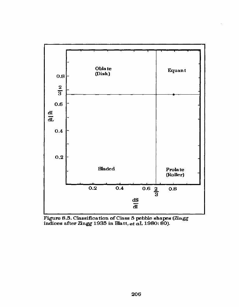
0.8
2-30.6
dI-elL
0.4
0.2
,
~
Oblate Equant(Disk)-
-
- ~
~
~
-.".
.~
~
Bladed Prolate- -(Roller)
, , i
0.2 0.4
dS-dI
0.6 2-30.8
Figure 8.5. Classification of Class 5 pebble shapes (Zinggindices after Zingg 1935 in Blatt, et aI, 1980: 80).
206

0.8
2-30.6
elI-dL
0.4
0.2
, ,• •
• •~
Oblate •(Disk) •• Equant•- •
e\• • •- • ~
..... ... -• ••- • • • • • -••• •- • • ~
• •-
••- ~
~ -Prolate
- (Roller) -Bladed
> . . ;
0.2 0.4
dS
elI
0.6 2-30.8
Figure 8.6. Classification of Class 6 pebble shapes (Zinggindices after Zingg 1935 in Blatt,et al, 1980: 80).
207

attributes on a select number of fragmented pieces, it was not
attempted here. As noted previously, the materials
experimentally replicated were divided based primarily on their
technological divisions and not on the individual surface attributes
that could be identified. Because of the general indistinctive
nature of shatter materials were placed into this class without
further analysis.
8.2 Class 7.
This technological class of materials is based on the
inadequate amount of applied pressure causing a small flake to
detach from the proximal end of the pebble stone.
Morphologically, these specimens could be compared to Herbort's
(1988) single detachment spall cores; however, unlike the
materials he describes, I did not deliberately attempt to produce a
flake. As noted in Section 6, the production of flakes was an
unintentional outcome of the experimental process and developed
because of the lack of applied force. Because I was separating
materials based on technological divisions, once I had altered the
specimen I did not feel that I should attempt to apply force to it a
second time. I felt the pebble would fracture differently because
it had already been altered. Therefore, once the pebble displayed
any alteration it was classified as a replicated specimen. Again,
because classes were based on technological divisions the flaked
materials were not subjected to further analysis and therefore
208
Zingg indices were also not calculated for the Class 7 specimens. A
total of 187 pebbles, or 35.9%, consisted of Class 7 specimens.
8.2 Class 8.
Class 8 specimens consist of pebble stones that fractured
longitudinally down the Xaxis into numerous linear wedge-shaped
sections that end in axial termination's. These materials are
identified as citrus-sections based on their over-all morphology;
the dorsal surface is curvate retaining the original pebble form
and the interior ventral surface is linear and wedge shaped. As
noted in Section 6 the Class 8 specimens developed from round
pebbles because of the highly variable internal forces that exert
pressure within this body shape. As illustrated in Figure 8.7, the
Zingg indices for the Class 8 specimens cluster at the interface of
all four forms. Therefore, these specimens were narrow, thick and
long in relation to the overall bodysize. This class consists of 26
specimens or 5% of the total experimental data set.
An interesting aspect of the Class 8 specimens is that the
physics of the spherical waves involved following impact on the
pebble largely control how that material will shear. In other
words, in trying to split a pebble stone longitudinally and
transversely (if the material is more ellipsoid in shape rather than
flat) this class of fracture will likely occur. The tendency of round
pebble stones is to either produce citrus-section fragments or to
shatter.
As additional interesting aspect of Class 8 materials is that
209

0.8
23
0.6
d.I-dL
0.4
0.2
, •
~
EquantOblate .(Disk) • •
• •,
- •
- • •• • •.. . ... . .- ~• • •• •• •- .
-... .
w .-
maded Prolate- (Roller) ~
> > . •0.2 0.4
dB-d.I
0.6 2-3 0.8
Figure 8.7. Classification of Class 8 pebble shapes (Zinggindices after Zingg 1935 in ma tt, et al, 1980: 80).
210
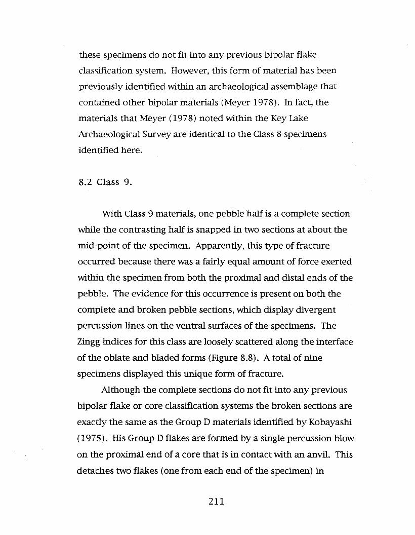
these specimens do not fit into any previous bipolar flake
classification system. However, this form of material has been
previously identified within an archaeological assemblage that
contained other bipolar materials (Meyer 1978). In fact, the
materials that Meyer (1978) noted within the Key Lake
Archaeological Survey are identical to the Class 8 specimens
identified here.
8.2 Class 9.
With Class 9 materials, one pebble half is a complete section
while the contrasting half is snapped in two sections at about the
mid-point of the specimen. Apparently, this type of fracture
occurred because there was a fairly equal amount of force exerted
within the specimen from both the proximal and distal ends of the
pebble. The evidence for this occurrence is present on both the
complete and broken pebble sections, which display divergent
percussion lines on the ventral surfaces of the specimens. The
Zingg indices for this class are loosely scattered along the interface
of the oblate and bladed forms (Figure 8.8). A total of nine
specimens displayed this unique form of fracture.
Although the complete sections do not fit into any previous
bipolar flake or core classification systems the broken sections are
exactly the same as the Group D materials identified by Kobayashi
(1975). His Group D flakes are formed by a single percussion blow
on the proximal end of a core that is in contact with an anvil. This
detaches two flakes (one from each end of the specimen) in
211

0.8
23
0.6
dI-dL
0.4
0.2
~
~
Equant
Oblate
- (Disk) •• • •
- ,. -•- ~
••- •
~
-
- .
~
- Bladed Prolate(Roller) -
, , , . ;
0.2 0.4
d.S-dI
0.6 23
0.8
Figure 8.8. Classification of Class 9 pebble shapes (Zinggindices after Zingg 1935 in Bla11, et all 1980: 80).
212
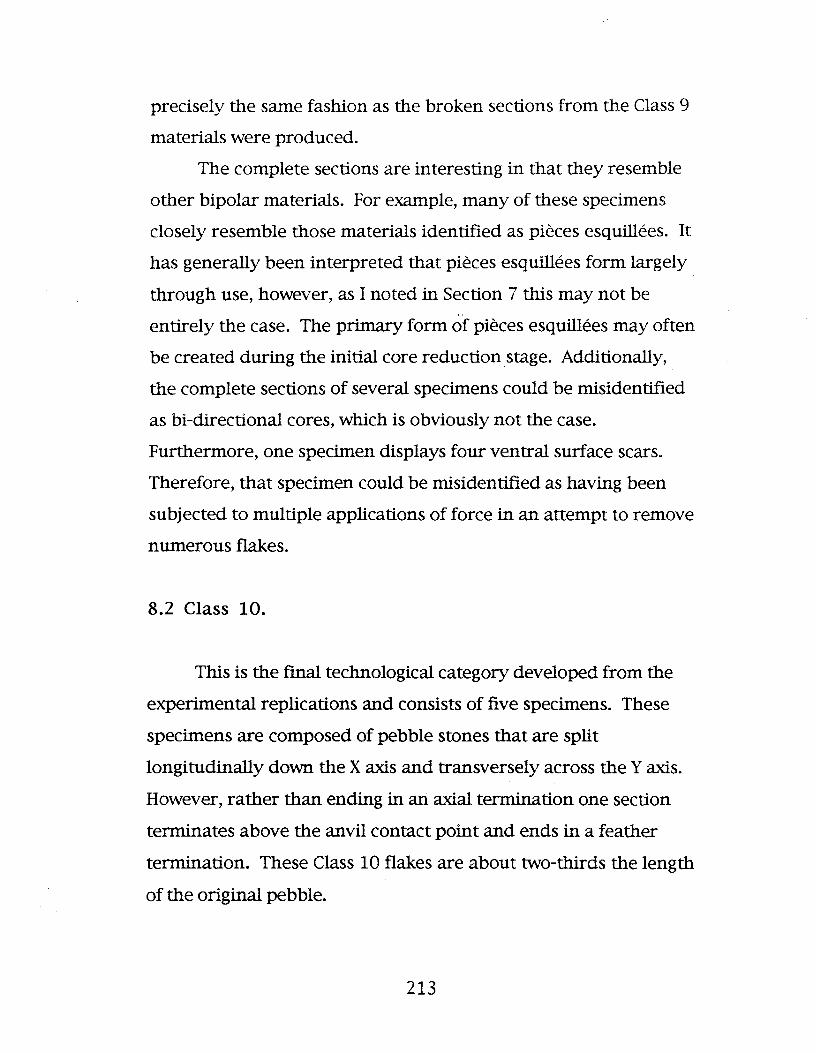
precisely the same fashion as the broken sections from the Class 9
materials were produced.
The complete sections are interesting in that they resemble
other bipolar materials. For example, many of these specimens
closely resemble those materials identified as pieces esquillees. It
has generally been interpreted that pieces esquillees form largely
through use, however, as I noted in Section 7 this may not be
entirely the case. The primary form of pieces esquillees may often
be created during the initial core reduction stage. Additionally,
the complete sections of several specimens could be misidentified
as bi-directional cores, which is obviously not the case.
Furthermore, one specimen displays four ventral surface scars.
Therefore, that specimen could be misidentified as having been
subjected to multiple applications of force in an attempt to remove
numerous flakes.
8.2 Class 10.
This is the fmal technological category developed from the
experimental replications and consists of five specimens. These
specimens are composed of pebble stones that are split
longitudinally down the Xaxis and transversely across the Yaxis.
However, rather than ending in an axial termination one section
terminates above the anvil contact point and ends in a feather
termination. These Class 10 flakes are about two-thirds the length
of the original pebble.
213
Class 10 specimens are separated from the Class 7 materials
because, rather than just chipping the end of the pebble, long
linear flakes were produced. The flakes produced would fit into
Kobayashi's (1975) Group A materials and the complete sections
resemble Herbort's (1988) single detachment spall cores.
However, here again I did not intentionally produce these
materials.
There are actually several possible explanations for this type
of fracture. First, there may have not been enough applied force
to permit the specimen to shear in an axial termination. Second,
there may be flaws within the pebbles that redirected the applied
force causing the flake to detach with a feather termination. More
likely, the application of force was slightly displaced from the
perpendicular causing the force wave to emanate away from the
center line of the specimen. The Zingg indices for the Class 10
specimens is clustered toward the oblate pebble form (Figure 8.9).
214

0.8
2-30.6
dI-dL
0.4
0.2
,
~
Oblate Equant(Disk)
•-•
-.. ...........
•- •- ~
-
....~
~
Prolate- maded (Roller) -
, . . ;
0.2 0.4
dS-dI
0.6 2-30.8
Figure 8.9. Classification of Class 10 pebble shapes (Zinggindices after Zingg 1935 in matt, et al, 1980: 80).
215

9.
A REVIEW OF SELECT PEBBLE STONE COLLECTIONS ON THE
NORTHERN PLAINS
Pebble stone artifacts from the Northern Plains have been
frequently noted within the archaeological literature and are quite
abundant throughout North America (for example, Ball 1987; Low
1994; McPherron 1967, Quigg 1977, 1978; Reeves 1972; Walker
1980, 1984, 1992). The following discussion is not to be
considered an exhaustive review of all Northern Plains pebble
stone collections. They are merely representative of their regional
locations and, as such, they should properly be considered only in
that manner. Their inclusion here is necessary in order to enable
an objective comparison of archaeological materials with the
experimentally replicated specimens analyzed.
9.1 Southern Manitoba
In a study of lithic collections within the Pembina Valley, in
southern Manitoba (Figure 9.1), it was noted that many of the
artifact assemblages were represented by bipolar cores that
largely consisted of pebble stones (Low 1994). The southern
Manitoba pebble stones had been modified by bipolar technology
and are presented here as a comparison to the bipolar silicified
216

o 160 kilometres..:3
o 100 miles
1. Pembina Valley2. Gowen Sites3. Marvel Houslon collection locale4-. North Saskatchewan River COlleCtiOD locale6. Grassy Island Lake collection locale6. Frermo Rellervoir collection locale
Figure 9.1. Map of North America showing archaeological site andpebble collection locales pertinent to this thesis.
217
B.L.

siltstone materials that will be identified within the Gowen sites
and the Marvel Houston collection later in this section.
9.1.1 The Sandhill, Killdeer and Deleurme Sites. Of
the 997 cores identified from the Sandhill, Killdeer and Deleurme
sites 16.5% consist of pebble stone materials. Pebble stone cores
from these sites are all quite amorphous, although several do
display multiple striking platforms (Low 1994: 36, 45, 48). Many
of these striking platforms were created from the shaping of the
pebble core into a tool. As a matter of fact, many of the pebble
cores represented are small (2-4 cm) discoidal artifacts that have
several edges worked forming a bifacial tool (Low 1994: 45).
The important thing is that these specimens do not display
evidence that a great deal of fore-thought went into their
manufacture. These items were chipped using bipolar reduction,
to produce only one or more sharp edges, to be used as an
expedient tool and then very likely discarded. Only in a few cases
were the materials worked beyond the initial fracture. Figures
9.2, 9.3 and 9.4 illustrate the range of the recovered Pembina
Valley bipolar pebble core tools. Most of the specimens, as those
items displayed in Figures 9.2 and 9.3, have had one or two edges
removed only; these are the most common types identified within
this area. However, Figure 9.4 shows two specimens that do
display more planning in their construction. Figure 9.4: A is of a
specimen that has two edges that have been bifacially formed and
Figure 9.4: B has three bifacial edges. The Sandhill site is the only
one in this area at which the more intricately manufactured
specimens manufactured from pebbles were recovered. Pebble
218

o 1 em.
B.L.
Figure 9.2. sample or Deleurme site (Manitoba) pebble stoneartiracts (Low 1994).
i
·····:.:·::x
·::·::.:.:;..::[:ii[i[i~ii!;:~}:~)::::::::· o 1 em.B.L.
Figure 9.3. sample of Killdeer site (Manitoba) pebble stoneartifacts (Low 1994).
219

I
'A
o 1 em.o 1 em. B
=o 1 em.
Figure 0.4. sample of Sandhill site (Manitoba) pebble stoneartifacts (LoW' 1994).
220

stone materials identified from the other locations consisted of
what appear to be randomly constructed items.
9.1.2 Merganser, Deleurme East, Valenta, Pelican I,
Pelican II and Smith sites. Although the Sandhill, Killdeer and
Deleurme sites are the largest of the collection locales identified in
the Pembina Valley, these six sites illustrate that the use of pebble
stone materials was not restricted to one locale, but rather, that
they were used throughout southern Manitoba. These six sites
contained only 105 cores (Low 1994) but of these, 30.5% consist of
pebble stones. The pebble stone specimens from these sites are
also expediently manufactured; they are both rough and
haphazard in their appearance and largely mirror those from the
Sandhill, Killdeer, and Deleurme sites.
9.1.3 Discussion. The Pembina Valley materials consist of
a variety of chert and quartzite pebbles that are quite distinct
from the silicified siltstone materials depicted throughout the
majority of this thesis. Whereas silicified siltstone pebbles are
generally split then worked, the Pembina Valley pebble stones
were not split and usually had several edges bifacially worked so
that they could be used as a tool, leaving the majority of the
specimens intact. That the Pembina Valley specimens are also
bipolar materials is evident from the presence of opposing bipolar
crushing on the majority of the materials. It is also interesting to
note that none of these materials relate to any of my classes as
defined in Section 6.
Most of the pebble stone specimens indicate that this was an
expedient technology, used to supplement other resources, not a
221

main component of the materials used by the people that
produced them.
lithic recoveries from southern Manitoba are composed
almost exclusively of local materials derived and collected within
the glacio-fluvial deposits of this region (Low 1994: 1995d). The
heavy use of the local cryptocrystalline materials within
archaeological sites in this locale attest to the importance of this
area for the pre-contact collection of lithics. For example, the
frequency with which local material has been recovered within
southern Manitoba, and the types of artifact recoveries at these
sites, indicate that pre-contact lithic resources at these sites would
have been quite extensive as evident from the total surface area
of collection (Low 1994: 51). Interestingly, although Swan River
chert occurs throughout southern Manitoba there was an
unmistakable use of pebble stone materials as well (Low 1994,
1995d, 1996a).
Determining the age of the southern Manitoba pebble stone
artifacts is difficult as the materials recovered within the Pembina
Valley sites noted above consist of surface collected lithics and,
therefore, there are no chronometric dates. There are, however,
two bodies of suggestive evidence that can be used. One line of
evidence is the recovery of several Paleoindian projectile point
sections. Unfortunately, as noted above, these were surface
collected and therefore cannot be tied to any firm context.
However, they do indicate antiquity of use of these collection
areas. The other trait that may provide some information is the
degree of patination found on a small percentage of the recovered
222

lithics (Low 1994: 72). Patina is the chemically induced surface
alteration of siliceous stone over time and under certain
environmental conditions (Honea 1964:14). The factors and
conditions generally required for the formation of patina on
cryptocrystalline material are: the permeability of the material,
the type of impurities it contains, its microstructure, and the
conditions of the surrounding soil (Kelly and Hurst 1956:194).
While environmental factors might control the over-all thickness
of patina that will form on a piece of lithic material, they do not
account for the highly variable and mixed levels of patination on a
single specimen. For example, some artifacts recovered from this
locale display one face with heavy patina, the face next to this
may have none, then there will be a face that is thinly patinated,
then another face will be totally covered with patination (Low
1994: 74). What this indicates is an extended and continuous
period of lithic exploitation and re-use within this locale (Low
1994: 75). Furthermore, the type of artifacts and the variation of
patination indicates that the pebble stone materials from the
southern Manitoba collection locales may have been used for
several thousand years (Low 1994: 77).
9.2 Saskatchewan
9.2.1 Gowen sites. Another group of pebble stone
materials that I examined are from the Saskatchewan assemblages
of the Gowen sites (Figure 9.1) that have been analyzed by Walker
(1980,1984.1992). Walker (1992) noted that the Gowen I lithic
223

assemblage consists of 226 stone tools (Walker 1992: 43) and
3767 debitage fragments (Walker 1992: 65). The Gowen II lithic
assemblage contained 350 stone tools (Walker 1992: 71) and
12,935 pieces of lithic debitage (Walker 1992: 93-93). The
differences in numbers of pieces recovered between Gowen I and
Gowen II is thought to be primarily related to the larger area of
excavation that took place at Gowen II (Walker 1992: 91).
It is significant that Walker (1992: 66) notes the Gowen site
locale does not have abundant sources of good quality lithic
resources suitable for stone tool production, although he states
that the proximity of the South Saskatchewan River does provide
access to quartzite cobbles and smaller chert pebbles within the
exposed glacial till. In fact, the highest frequency of bipolar cores
within the Gowen I and II site assemblages are derived from split
silicified siltstone pebbles (Walker 1992). As previously noted,
pebble stones, particularly silicified siltstone materials, are a very
fine grained lithic material that adept flintknappers can use to
manufacture some finely crafted implements. The range and
quality of items made from theses materials should attest to this
observation. The pebble stone materials of these assemblages will
be discussed in the following section.
9.2.1.1 Gowen I. Walker (1992:64) noted that the
most common type of core found at the Gowen 1 site in central
Saskatchewan is the bipolar core that displayed percussion
surfaces at both ends. This is not surprising as five anvils and five
hammerstones were also recovered during excavations at this
location. Additionally, the close proximity of silicified siltstone
224

pebble materials that are ideally suited to the bipolar method of
reduction exposed within the glacial tills of the South
Saskatchewan river further support the use of the bipolar
technique at this location. In addition, a large portion of the lithic
materials at Gowen I is derived from silicified siltstone pebbles,
that Walker (1980,1984,1992) identifies as black chert or pebble
chert materials. Walker (1992: 65) described three end products
of split pebble stone materials: cleanly split pebbles, specimens
with irregular cleavage faces, and lithic debitage. He further notes
that shatter may have been the most common result of producing
these materials based on the amount of angulated black chert
fragments recovered at the site (Walker 1992: 65).
Also, of the 24 recorded bipolar cores at the Gowen I site, 11
are derived from silicified siltstone pebbles. Consequently,
silicified siltstone pebbles represent a total of 45.8% of the bipolar
cores recovered. In addition, 90 stone tools are also made from
silicified siltstone representing 39.8% of the total stone tool
category. These items include: 2 Gowen projectile points, 13
endscrapers (1 spurred/graver tip), 10 gouges(scraping planes), 1
graver, 22 residual retouch materials, and 42 other fragments in
various stages of modification.
Of note among the above tools identified within the Gowen I
site is, first, the wide range of artifacts that were manufactured
from silicified siltstone pebbles. These items include everything
from projectile points to retouch flakes. This is an indication of
the extensive and varied use that this material received at this
site, thus resulting in the frequency with which it occurred.
225

Furthermore, it shows the importance of this material as a valued
lithic resource to the inhabitants of this site. Moreover, a review
of the Gowen materials provides evidence that, at one stage of
lithic reduction, silicified siltstone pebbles were being split to be
used as preforms in the manufacture of such items as projectile
points. Walker (1992: 90) notes that, in fact, it appeared that
successfully split pebble stones were used to fabricate projectile
points. These items would have required a higher level of
technical expertise in their manufacture as well as a larger time
commitment than expedient tools would require. In this situation,
by splitting the pebble into two fairly uniform sections, the
knapper immediately has two preforms available from which to
work. This in itself would decrease the time expended in the
manufacture of projectile points, as the time required to make the
initial preform is much reduced.
All of the projectile points identified at the Gowen I site,
including the two silicified siltstone Gowen specimens, are from
the Early Middle Prehistoric Period (7500 B.P. - 5000 B.P.), as
identified by Walker (1992). Two of these are illustrated in Figure
9.5: A and B.
Many silicified siltstone pebble stone materials at the Gowen
I site were also used to produce implements that required less
technical expertise to manufacture, such as scrapers. In fact, 37%
of the endscrapers are manufactured from split silicified siltstone
pebbles (Walker 1992: 49), which was used more than any other
lithic material to produce scrapers at this site.
A variety of the Gowen I scrapers are illustrated in
226
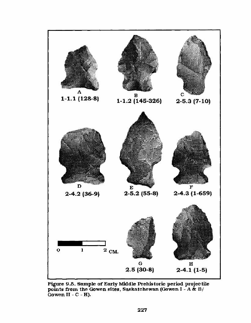
A
1..·1.. 1 (12:8..8)B
1.. :L2 :(145..326)
E2..5.2 :(.55..8)
C
2 ..5.3(7..10)
F2..4.3 :(1..659)
_1..-__'o 1 2 CM.
G2~5 (30..8)
H2",4.1 (1,..5}
Figure 9.5. SaInple of Early Middle Prehis toric period projec tilepoints from the Gowen sites, Saskatchewan (Gowen I - A&. B/Gowen II - C - H).
227

Figures 9.6 and 9.7: A& B. One rather interesting specimen,
among this class of tools, consists of a small distally spurred
endscraper (Figure 9.7: A). Walker (1992: 50) identifies the spur
on this specimen as a graver tip. This specimen is actually
remarkably similar to spur-end scrapers diagnostic of the
Paleoindian period. One major difference with this item, however,
is that rather than the spur extending laterally from the leading,
proximal edge (as they do with Paleoindian materials - Figure 7.2)
the spur on this specimen extends down from the base of the
scraper's distal end, as illustrated in Figure 9.7: A.
MacDonald (1968) noted, after an examination of Paleoindian
spur-end scrapers, that the bipolar flakes were likely removed
after the tool had been manufactured and not during the
manufacturing process. However, this may not be the case with
the Gowen I specimen. For example, the scraper illustrated in
Figure 9.7: A, is composed of silicified siltstone, a relatively soft,
somewhat fragile material, that displays no residual, or secondary
impact scars. In other words, the item appears to have been
purposefully manufactured from a bipolarly split pebble as a
scraper with a distal spur.
A further class of note within the Gowen I assemblage is a
number of scraping planes that Walker (1992) identifies as
gouges. Of these materials, 10 specimens, or 43.5%, are comprised
of silicified siltstone. One of these items is illustrated in Figure 9.7:
C. Generally, these items are manufactured from harder materials
such as quartzite, which lends itself well to this method of
manufacture. The majority of scraping planes identified within
228

o I
J
2 CM.
Figure 9.6. Sample of scrapers trom the Gowen I site,Saskatchewan.
B
2 CM.
2 CM.
I
o I
o I
A
Figure 9.7. :Miscellaneous ar tifac ts trom the Gowen I site,Saskatchewan.
229

the Gowen I site are also manufactured from quartzite. As
previously defined, the first step in manufacturing a scraping
plane is to split a specimen in the same manner as that previously
described for a pebble stone. Once the specimen is sheared the
dorsal end of one split section is placed on an anvil and the ventral
surface struck along and around the outer edge of the specimen as
previously noted in Section 7.2.10.
In addition to the more finely manufactured items,
numerous pieces of silicified siltstone were used as expedient
items as well. These materials consist of 61 residual retouched
fragments. One of these specimens is illustrated in Figure 9.7: D,
which displays the working or retouch on one end of a split
silicified siltstone pebble.
9.2.1.2. Gowen II. Walker (1992: 89) notes that the
lithic artifacts and their reduction sequence at the Gowen II site is
almost identical with that of Gowen I and this is supported by the
present analysis. Observed differences between the assemblages
of these sites is relatively minor. Much of this difference is
because Gowen II was subjected to more extensive excavations,
which as a result, produced a bigger sample.
One surprising difference is that only one anvil and three
hammerstones are recorded for the Gowen II site (Walker 1992:
71). The reason this is surprising is that Gowen II actually has a
larger percentage of bipolar materials per its assemblage than
does Gowen I from which five anvils and five hammerstones were
recovered. At the Gowen I site, for example, 45.8% of the silicified
siltstone pebble cores are bipolar, while at the Gowen II site 59.6%
230

of the cores manufacture from this material are identified as
bipolar. The Gowen II materials manufactured from silicified
siltstone include 26 complete bipolar cores and 39 bipolar core
fragments (Walker 1992: 90). In addition to the above, while
39.8% of the tools within the Gowen I assemblage are
manufactured from silicified siltstone pebbles, 45.5% of the Gowen
II stone tool are composed of this material .
The Gowen II stone tools include items very similar in form
to the Gowen I materials and include: 22 scraping planes (gouges),
9 Gowen projectile points, 12 miscellaneous projectile points, 35
endscrapers,5 side scrapers, 1 perforator, 1 miscellaneous tool,
and 74 residual retouched items (Walker 1992: 71). A variety of
projectile points from this site are illustrated in Figure 9.5: C-H.
9.2.1.3. Discussion. Walker (1992: 65) notes that
the variable outcome of pebble stone materials derived from the
bipolar technique (as represented within the Gowen sites) may be
related to differences in the processing of this material. That is,
whereas the thinner specimens appear to be more susceptible to
transverse breaks, the oblong-shaped pebbles would tend to
shatter. I have previously noted in Section 5 that this
phenomenon is not directly related to the type of applied lithic
reduction, but rather, to the movement of spherical waves within
bodies of differing form. Regarding the body shape of a pebble, as
previously noted, a thin pebble does shear in a transverse break
across the Y axis much more frequently than they tend to shatter.
However, at the Gowen sites all of the anvils used, as illustrated in
Figure 9.8, are small, relatively thin, light specimens averaging
231

.e(,)
u:
.IX)
oiII)
'""6'n.-l- ~
232

2 cm x 8 cm x 15 cm in size. As noted in Section 4.2 (Tool
Selection) small anvils would require the application of much more
applied force on the proximal end of the pebble, thus increasing
the frequency with which pebbles would shatter. This partially
accounts for the high percentage of silicified siltstone debitage
recorded within these sites. Several researchers, (for example,
Cross 1983: 97; Shelley 1990: 192) have noted in similar situations
that it is also necessary to consider that there may have been
individuals with different levels of technological expertise working
with the lithic materials as well.
It is not known why larger, more efficient anvils were not
used, especially considering that the Gowen sites were late
summer/early fall occupations (Walker 1992). Because of the
season of occupation, access to better quality anvils should not
have been a problem. What may be the case is that the anvils
used were all that were available within the local glacial gravels,
although this is not likely and has not been confirmed. As well,
smaller anvils are much more portable.
The high frequency of silicified siltstone materials recorded
at the Gowen sites is noteworthy as the presence of large numbers
of fractured pebble stones (and their associated fragments)
provides further evidence of the extensive use of the bipolar
technique on the Northern Plains. The uniqueness of the Gowen
bipolar materials is largely related to the extensive use of silicified
siltstone pebbles as the major lithic material. In part this is
because of the close proximity of the South Saskatchewan River,
which is one source of this material. In part, it also may actually
233

relate to silicified siltstone pebbles being a preferred lithic
material, rather than their being used only as a last resort.
Frankly, it is quite difficult to imagine that a lithic material that
was so extensively used, not only at the Gowen sites, but across
the Northern Plains, was collected only during extreme
circumstances when "better" material was not available.
Furthermore, Odell (1989: 164-165) notes that where raw
material availability is scarce tools would display evidence of
being more fully used. However, the evidence from the Gowen
sites does not support this as the majority of evidence indicates
the production of new tools was the primary activity and not the
reforming or retouching of completed tools (Walker 1992). The
evidence does support, however, the role that pebble stones
played in the lithic technology of the Gowen site occupants,
especially considering that other lithics are available throughout
the region.
As a final point, both Gowen I and II are recorded as Early
Middle Prehistoric period occupations that were occupied about
6000 B.P. (Walker 1992). This supports the hypothesis (Problem
4) in Section 2 of this thesis, that a distinct bipolar pebble stone
usage may have existed within this time period.
9.2.2. Marvel Houston Collection. Marvel Houston was
an avocationalist who collected and recorded a variety of
archaeological materials around the town of Ruthlinda (Figure 9.1),
in west-central Saskatchewan, over a period of many years. This
collection was brought to my attention in 1995 by Muriel Carlson
who was sorting and cataloging these materials on behalf of the
234
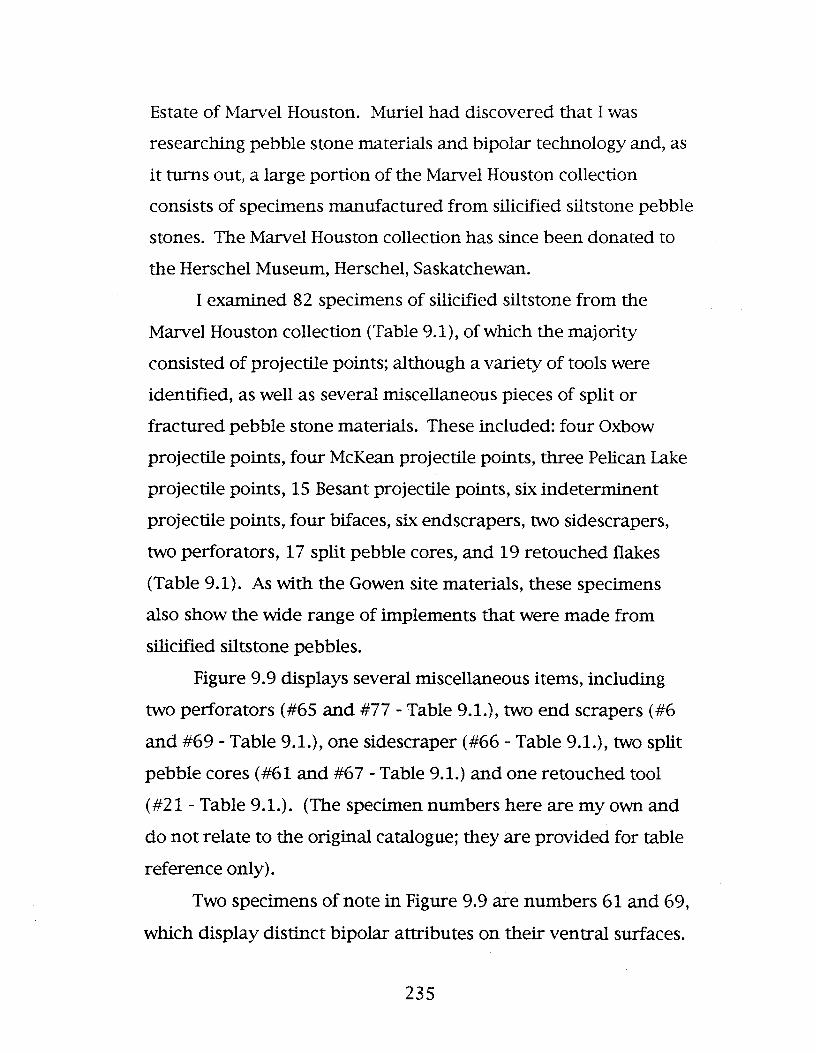
Estate of Marvel Houston. Muriel had discovered that I was
researching pebble stone materials and bipolar technology and, as
it turns out, a large portion of the Marvel Houston collection
consists of specimens manufactured from silicified siltstone pebble
stones. The Marvel Houston collection has since been donated to
the Herschel Museum, Herschel, Saskatchewan.
I examined 82 specimens of silicified siltstone from the
Marvel Houston collection Cfable 9.1), of which the majority
consisted of projectile points; although a variety of tools were
identified, as well as several miscellaneous pieces of split or
fractured pebble stone materials. These included: four Oxbow
projectile points, four McKean projectile points, three Pelican Lake
projectile points, 15 Besant projectile points, six indeterminent
projectile points, four bifaces, six endscrapers, two sidescrapers,
two perforators, 17 split pebble cores, and 19 retouched flakes
(Table 9.1). As with the Gowen site materials, these specimens
also show the wide range of implements that were made from
silicified siltstone pebbles.
Figure 9.9 displays several miscellaneous items, including
two perforators (#65 and #77 - Table 9.1.), two end scrapers (#6
and #69 - Table 9.1.), one sidescraper (#66 - Table 9.1.), two split
pebble cores (#61 and #67 - Table 9.1.) and one retouched tool
(#21 - Table 9.1.). (The specimen numbers here are my own and
do not relate to the original catalogue; they are provided for table
reference only).
Two specimens of note in Figure 9.9 are numbers 61 and 69,
which display distinct bipolar attributes on their ventral surfaces.
235

NW(j\
Table 9.1. Marvel Houston collection of silicified siltstone split pebble materials.
Cat # Specimen Description I.. 1 Biface 2-6mm Working edge/Convex Ret/Thin 2 Workeded edges Ind Break
Ovate Body
..2 Biface 2-6mm Working edge/Convex Ret/Thin 2 Workeded edges Ind BreakOvate Body
.. 3 Projectile point Besant Ovate Body 2-6mm Complete BifacialConvex Base Side Notch Ret/Thin
.. 4 Projectile point Besant Ovate Body 2-6mm Complete BifacialStraight Base Side Notch Ret/Thin
.. 5 Projectile point McKean Ret/Thin 2-6mm Complete BifacialConcave Base Basal Notch
..6 Endscraper Distal End Dnifacial 2-6mm 3 edges Worked
.. 7 Retouched Tool 2-6mm Cortex present
..8 Projectile point Besant Ind Break o -2mm Base / Mid-section BifacialConvex Base Side Notch Ret/Thin
..9 Projectile point Pelican Lake Ind Break o -2mm Base/Mid-section BifacialCorner Notch Ret/Thin
10 Sidescraper Convex Base Retouched Dnifacial 1 worked lateral edge
Ovate Body 2-6mm
11 Projectile point Besant Ovate Body 2-6mm Complete BifacialStraight Base Side Notch Ret/Thin
12 Projectile point Besant Ret/Thin 2-6mm Bifacial Ovate Body
Convex Base Side Notch
13 Endscraper Retouched Distal right lateral edge worked Working end convex
Dnifacial 2-6mm
14 Projectile point Mid-section Ovate Body 2-6mm Bifacial retouch Ind Style

NW'-l
Table 9.1. Marvel Houston collection of silicified siltstone split pebble materials.
15 Biface Triangular Straight working edges o -2mm 2 edges worked Ind BreakRet/Thin
16 Split Pebble Core 2-6mm Cortex present
17 Retouched Tool Unifacial 2-6mm 2 edges worked
18 Split Pebble Core 2-6mm No Cortex
19 Projectile point Ind Style Mid-section/Tip 2-6mm Ret/Thin BifacialTriangular Ind Break
20 Endscraper Triangular 3 edges worked 2-6mm Unifacial Distal EndConvex Base Retouched
21 Retouched Tool Unifacial 1 edge worked
22 Retouched Tool 1 edge worked Distal Fragment 2-6mm Unifacial Ovate Body
23 Projectile point Ind Style Mid-section 2-6mm Ret/Thin Bifacial
24 Split Pebble Core 2-6mm Cortex present
25 Retouched Tool Ovate Body 1 edge worked 2-6mm Retouched Distal Frag
26 Split Pebble Core 2-6mm Cortex present
27 Split Pebble Core 2-6mm Cortex present
28 Projectile point Oxbow Ovate Body 2-6mm Bifacial Ind Break
Concave Base Side Notch Ret/Thin Base/Mid-section
29 Split Pebble Core 2-6mm Cortex present
30 Split Pebble Core 2-6mm Cortex present
31 Retouched Tool o -2mm Cortex present
32 Projectile point Ind Style Base / Mid-section 2-6mm Bifacial Triangular
Ind Base Ind Notch Ret/Thin Ind Break
33 Projectile point Besant Ovate Body 2-6mm Ret/Thin BifacialStraight Base Side Notch Ind Break Base / Mid-section

NW00
Table 9.1. Marvel Houston collection of silicified siltstone split pebble materials.
34 Projectile point Ind Style Mid-section/Tip 2-6mm Ret/Thin BifacialOvate Body Ind Break
35 Biface Ind Break Ovate Body 2-6mm Ret/Thin
36 Retouched Tool 2-6mm Unifacial Ovate Body
37 Split Pebble Core 2-6mm Cortex present
38 Retouched tool Ovate Body 2-6mm Unifacial 3 edges worked
39 Retouched Tool Ovate Body 2-6mm Unifacial 1 edge worked
40 Retouched Tool 2-6mm 1 edge worked
41 Retouched Tool 2-6mm 1 edge worked Unifacial Lateral Fragment Ovate Body
Straight Base
42 Split Pebble Core 2-6mm Cortex present
43 Split Pebble Core 2-6mm Cortex present
44 Retouched Tool 2-6mm Cortex present
45 Endscraper 2-6mm Unifacial Ovate Body Complete
46 Projectile point Ind Style Ind Break 2-6mm Bifacial Triangular
Mid-section Ret/Thin
47 Retouched Tool Working edge Concve/Convex 2-6mm 1 edge worked UnifacialOvate Body
48 Retouched Tool 2-6mm Unifacial Ovate Body
49 Retouched Tool 2-6mm 2 edges worked Bifacial
50 Retouched Tool 2-6mm Unifacial
51 Split Pebble Core 2-6mm Cortex present 2 pieces
52 Retouched Tool 2-6mm Cortex present

NW\,0
Table 9.1. Marvel Houston collection of silicified siltstone split pebble materials.
53 Projectile point Besant Ovate Body 2-6mm Bifacial Ind BreakStraight Base Side Notch Ret/Thin Base / Mid-section
54 Retouched Tool Ovate Body Working edge/Convex 2-6mm 1 edge worked UnifacialInd Break
55 Split Pebble Core 2-6mm Cortex present
56 Split Pebble Core 2-6mm Cortex present
57 Endscraper Ovate Body 2-6mm Distal End 1 edge worked Unifacial
58 Retouched Tool 2-6mm Unifacia1
59 Projectile point Besant Base / Mid-section 2-6mm Bifacia1 Ovate BodyStraight Base Ret/Thin Side Notch
60 Split Pebble Core 2-6mm Cortex present
61 Split Pebble Core 2-6mm Cortex present Inverted diffuse bulb of percussionPartly sheared proximal bulb of percussion with slight inversion at point of impactPronounced ripple lines
62 Projectile point Pelican Lake Base / Mid-section o -2mm Bifacial retouch TriangularStraight Base Corner Notch Ind Break
63 Projectile point Oxbow Triangular 2-6mm Bifacial Complete
Concave Base Side Notch Ret/Thin
64 Projectile point Oxbow Ovate Body 2-6mm Bifacial CompleteConcave Base Side Notch Ret/Thin
65 Perforator Drill Straight working edge 2-6mm Bifacial Complete
Ret/Thin
66 Sidescraper Retouched 1 edge worked 2-6mm Unifacial Convex BaseOvate Body
67 Split Pebble Core 2-6mm Pronounced ripple lines Cortex presen Proximal bulb of percussion
68 Split Pebble Core 2-6mm Diffuse ripple lines Cortex presen Diffuse proximal bulb of percussion
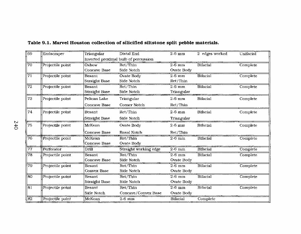
N~o
Table 9.1. Marvel Houston collection of silicified siltstone split pebble materials.
69 Endscraper Triangular Distal End 2-6mm 2 edges worked DnifacialInverted proximal bulb of percussion
70 Projectile point Oxbow Ret/Thin 2-6mm Bifacial CompleteConcave Base Side Notch Ovate Body
71 Projectile point Besant Ovate Body 2-6mm Bifacial CompleteStraight Base Side Notch Ret/Thin
72 Projectile point Besant Ret/Thin 2-6mm Bifacial CompleteStraight Base Side Notch Triangular
73 Projectile point Pelican Lake Triangular 2-6mm Bifacial Complete
Concave Base Corner Notch Ret/Thin
74 Projectile point Besant Ret/Thin 2-6mm Bifacial Complete
Straight Base Side Notch Triangular
75 Projectile point McKean Ovate Body 2-6mm Bifacial Complete
Concave Base Basal Notch Ret/Thin
76 Projectile point McKean Ret/Thin 2-6mm Bifacial CompleteConcave Base Ovate Body
77 Perforator Drill Straight working edge 2-6mm Bifacial Complete
78 Projectile point Besant Ret/Thin 2-6mm Bifacial CompleteConcave Base Side Notch Ovate Body
79 Projectile point Besant Ret/Thin 2-6mm Bifacial CompleteConvex Base Side Notch Ovate Body
80 Projectile point Besant Ret/Thin 2-6mm Bifacial CompleteStraight Base Side Notch Ovate Body
81 Projectile point Besant Ret/Thin 2-6mm Bifacial Complete
Side Notch Concave / Convex Base Ovate Body
82 Projectile point McKean 2-6mm Bifacial Complete

em.
Sidescraper
69
Endscra er
21 6Re touched Tool Endscraper
2 em.1
Perforator
Perforator
Split Pebble Core
o
Figure 9.9. :Miscellaneous silicified siltstone materials from the~velHous ton collec tion.
241

Specimen 61 is a split pebble that displays pronounced percussion
lines and a sheared proximal bulb of percussion with a slight
inversion at the point of impact on its ventral surface. Specimen
69 is an endscraper that has a slightly negative inverted proximal
bulb of percussion on the ventral surface of the tool.
Even more interesting than the miscellaneous materials with
this collection are the wide range of projectile points. The Marvel
Houston collection contains projectile points ranging from the
Middle/Late Middle Prehistoric period, with the Oxbow (4700
3000 B.P.), McKean (4150-3100 B.P.) and Pelican Lake (3800-1850
B.P.) materials, to the initial Late Prehistoric period, represented
by Besant (2000-1200 B.P.). (Figure 9.10 illustrates three Oxbow,
two McKean and two Pelican lake projectile points, and Figure 9.11
illustrates a sample of the Besant points, from the Marvel Houston
collection) .
9.2.2.1 Discussion. In part, I included the Marvel
Houston materials here because they provide further evidence of
the extent of bipolar technology as applied to pebble stone
materials. Additionally, like many of the Gowen site materials,
these specimens are manufactured from silicified siltstone pebble
stones. Finally, these artifacts were collected in west-central
Saskatchewan and, thus, they provide further evidence for a
geographic and temporal movement of bipolar technology across
the Northern Plains. This point will be expanded on more fully in
Section 10.
242

82 :MCKean
62Pelican Lake
o 1
76 :McKean
73Pelican Lake
2 cm.
75:McKean
Figure 9.10. Sample or IYtiddle/Late IYtiddle Prehistoric periodprojectile points :f'.rom the Marvel Houston collection.
243

72 78
81
71
74
80
-----~o 1 2 eM.
79
Figure 9. 1 1. SaIIlple of l\ti.ddle I Late l\ti.ddle Prehis toric periodBesant projectile points from the :Marvel Houston collection.
244

9.3 Summary
An important aspect of the above collections is that the
materials demonstrate a definite time progression of the bipolar
technique regarding the use of pebble stones, from east to west.
The materials illustrated indicate that a movement of this
technology possibly took place from the Early Middle Prehistoric
period in east-central Saskatchewan, to the Middle/Late Middle
Prehistoric period and into the initial Late Prehistoric period in
western Saskatchewan. Also, the types of pebble stones used
appears to have changed as did the application of the bipolar
technique in relation to those materials. The pebble stone artifacts
recovered in Manitoba are a variety of coarse cherts and
quartzites that were primarily used to produce expedient tools.
The Saskatchewan materials are primarily silicified siltstone
pebbles that were used to produce a wide range of implements.
Unlike the majority of the Manitoba materials many of the
specimens in Saskatchewan including those composed of various
cherts or quartzites were subjected to some degree of planning
and fore-thought in their construction.
It must be noted here, that I have personally observed that
silicified siltstone pebbles occur rarely and sporadically within
Manitoba glacial deposits, whereas, they occur with some
frequency within Saskatchewan. I should note this interpretation
is based on observance and not through a quantification of the
actual frequencies. This point, however, does accounts for the
differences in frequencies of this material between Manitoba and
245

Saskatchewan archaeological assemblages. What it does not
account for is the differences in the way pebble stone artifacts are
manufactured between these two regions.
It is quite clear that pebble stone was becoming a major part
of the technology of at least select Northern Plains groups by the
Middle Prehistoric period. However, verification of this
interpretation would require much more extensive study in this
area, in particular, the examination of other assemblages that
contain bipolar and pebble stone materials, although this would be
a immense undertaking. In part, this is related to these materials
not being identified within many of the past archaeological
reports. For example, in a 1970 report Dyck (1970) identified two
Oxbow settlements, the Moon Lake and Harder sites, from central
Saskatchewan. Although he does not discuss bipolar technology or
the occurrence of pebble stone materials within this report it is
quite obvious from an examination of those assemblages that
these materials do occur. This is significant, because the time of
settlement and the geographical location of these occupations
corresponds with those materials previously identified from the
Gowen sites. The next section on source and collection locales
continues to expand on pebble stone materials in the
archaeological record.
246

10. PEBBLE STONE SOURCE AND COLLECTION LOCALES
10.1 Source areas of pebble stones collected for
experimental replications
Several areas were selected for the collection of pebble
materials used within the experimental portion of this thesis so
that a cross representation of specimens from a variety of locales
would be included in the data set. The source areas I sought were
those locales previously recorded, or known, to contain silicified
siltstone pebbles. Although other pebble materials were also
collected, as I have previously noted, silicified siltstone pebbles
were the main materials used and analyzed throughout the course
of this research project. The following briefly describes the areas
from which I collected these materials.
10.1.1. Pebble collection locale 1: North
Saskatchewan River, Saskatchewan~ Several areas within
west-central Saskatchewan are known to contain varYing
frequencies of silicified siltstone pebble stones. For example Eldon
Johnson (1986:83-84) has noted that this lithic material is present
sparsely in west-central Saskatchewan and occurs in Cretaceous
gravels.
One area were silicified siltstones occur is within the glacial
drift along the South Saskatchewan river channel. Pebble stones
247

occur sporadically and in varying degrees of frequency throughout
the length of this channel. It is probable that silicified siltstone
pebbles did occur with some frequency near the Gowen site
locations because of the large numbers of this material with those
assemblages. Although lithic source areas do not need to be in
near proximity to site locations, the dominance of local materials
in the Gowen sites indicates this may have been the case here.
Another area where silicified siltstone pebble stone
materials occur within Saskatchewan and the area of most concern
here is within the glacial gravels of the North Saskatchewan river
channel. At least one locale along this channel appears to contain
silicified siltstone pebble with some degree of frequency. This
area is located north of North Battleford (Figure 9.1) and it is from
here that the majority of specimens used in the experimental data
collection portion of this thesis were gathered. The ground surface
throughout this area is currently littered with pebble stone
materials including silicified siltstones that have either eroded
from the river bank or recently been exposed through activities
within a local gravel pit. I also collected a variety of pebbles that
consisted of generic cherts, quartzite, quartz and generic material.
There are no identifying landmarks or significant geographic
features that make this pebble collection area along the North
Saskatchewan river stand out from the surrounding landscape (as
depicted in Figure 10.1., which is an illustration of this locale). In
fact much of the North Saskatchewan river flows through large
expanses of fairly uniform prairie grassland. Parts of the
248

249
•]:so]I~.cc:-..c
i.c(,1
]
=~

surrounding area does, however, consist of moraines giving the
topography a hummocky appearance with lakes and sloughs
common in low laYing areas. Much of this region is also transected
by numerous creeks. This type of topography is typical of the
majority of locations where silicified siltstone pebbles occur and
from where they were known to have been collected. The
geomorphology of the region, as well as the abundance of glacial
deposits, are the end result of Wisconsin glacial processes.
It appears that the Saskatchewan source areas for silicified
siltstone pebbles were very well known to the various pre-contact
groups that used them in order for this material to occur with the
frequency that it does within many of the regional archaeological
sites. If this is the case, then the collection of this material
provides more evidence for pebble stone materials being used by
some groups on a frequent basis, with frequent trips made to
these collection locales, and not just because other material was
not available. It also further attests to the use of the bipolar
technique especially in relation to pebble stones as being a
widespread and significant aspect of pre-contact lithic technology.
10.1.2. Pebble collection locale 2: Grassy Island
Lake, Neutral Hills, Alberta. Quigg (1977:58) noted that the
primary lithic materials recovered during an archaeological survey
of the Neutral Hills, Alberta, and the subsequent excavations of the
Lazy Dog Tipi Ring site (FbOr-57) and the Buffalo Jump and
Campsite (FbOv-1) in that locale, were pebble cherts. He did not
separate these by type however, but rather by color. It is
noteworthy, that from the illustrations he provides, and from
250

having personally examined several areas around Grassy Island
Lake, it is likely the black and grey varieties of pebble cherts he
describes are silicified siltstones. If the black and grey pebble
chert specimens recorded by Quigg (1977: 59) are silicified
siltstone specimens then this is significant, because of the 2542
pieces of material identified 53.1% would then consist of this
material. Moreover, Quigg (1977: 59) identifies another 14.6% of
the materials collected as a variety of other pebble cherts and
5.7% as quartzite pebbles. In total, pebble stones comprise 73.4%
of the materials that Quigg (1977: 59) recorded for the total
Neutral Hills recoveries. He did note that pebble stone artifacts
recovered during excavations at the Lazy Dog Tipi Ring site (FbOr
57) comprised 90% of the cultural materials (Quigg 1977: 66).
Johnson (1986: 84) observed that silicified siltstone pebbles
occur with "some abundance" along the shores of Grassy Island
Lake. During field reconnaissance of the Grassy Island Lake area
(Figure 9.1) the materials that I noted almost exclusively consisted
of silicified siltstone, although I did not fmd these materials in
abundance (see Johnson 1986: 84). However, there is no doubt
that silicified siltstone pebbles do occur in abundance throughout
the glacial deposits within the Neutral Hills locale based on the
recoveries of this material by Quigg (1977: 59). I did manage to
collect a number of silicified siltstone pebbles from around the
lake, as well as, a variety of other materials including some
generic material, quartzite, quartz and generic cherts.
It is possible that the reason I did not notice silicified
siltstone pebbles in abundance around Grassy Island Lake is
251
because the shoreline of the lake has changed dramatically from
its formation to its present condition. At one point this lake
extended for several kilometres in all directions. Today, it is little
more than a slough that almost totally dries up by the end of the
summer. Moreover, much of the original shoreline around Grassy
Island Lake is now grass covered and therefore it has poor ground
visibility. Figure 10.2 is an illustration of Grassy Island Lake at
dusk. As can be seen this area is very similar to that noted above
for the pebble collection locale around the North Saskatchewan
River in Saskatchewan. In fact, Neutral Hills also largely consist of
fairly uniform prairie grassland interspersed with hummocky
moraines, lakes and sloughs, and is frequently transected by
rivers, creeks and streams. As in Saskatchewan, Wisconsin glacial
processes are responsible for the abundance of glacial deposits in
this region of eastern Alberta.
However, I noticed that while collecting silicified siltstone
pebbles from around the lake, there were many locations that
showed signs where this material had been collected and tested,
based on the anvils and debris littering the ground in those
locations. Johnson (1986: 84) also noted that many pebbles in
this area showed signs of breakage by human action. Therefore, it
is also possible that the majority of pebble materials that were
exposed around this lake had been previously collected.
The frequency that pebble stones were used to manufacture
stonetools within the Neutral Hills clearly illustrates that these
materials, and the use of bipolar technology, was an extremely
important aspectof the pre-contact human groups that occupied
252

253

this region. Based on research conducted at the time, Quigg (1977:
58) interpreted the use of pebble stones in this locale as being an
area-specific phenomenon that he identified as the Neutral Hills
Pebble Industry. However, the research conducted here clearly
affirms that bipolar technology and the use of pebble stone
materials, especially the silicified siltstones, is not area-specific,
but rather it is quite widespread across the Plains. Additionally,
regarding the Neutral Hills Pebble Industry designation, Reeves
(1972) had previously identified a large collection of pebble stone
artifacts from the Pass Creek Valley, in Alberta, which he labeled
as the Rundle Technology.
An important aspect of the Neutral Hills collections is that
these materials also demonstrate a continuation of the use of
bipolar technology and pebble stone by pre-contact groups from
east to west; from southwestern Manitoba, across Saskatchewan
and into eastern Alberta. Additionally, the time progression,
noted for this technology in Manitoba and Saskatchewan appears
to continue into Alberta. In his report Quigg (1977:66,71)
recorded one Plains Side-notched projectile point from each of the
two excavations conducted, the only lithic diagnostics recovered at
the Lazy Dog Tipi Ring site (FbOr-57) and the Buffalo Jump (FbOv
1) and Campsite. Plains Side-notched materials appear in the
archaeological record during the terminal Late Prehistoric period
dating between 550 - 250 B.P. This is somewhat later than the
pebble stone materials that are present during the Paleoindian
period in Manitoba and the Middle/initial Late Prehistoric period
in Saskatchewan. Quigg (1977: 72) also noted, based on ceramic
254

recoveries, that the latest period of occupation at the Buffalo Jump
(FbOv-1) and Campsite is the Old Women's phase (Reeves 1969) of
the Late Prehistoric period.
10.1.3. Pebble collection locale 3: Fresno Reservoir,
Montana. The final area where I collected pebble stone materials
for the experimental portion of this thesis was from around the
Fresno Reservoir in Montana (Figure 9.1). I choose this area based
on its having been recorded to contain abundant pebble materials,
including silicified siltstone. For example, AIt and Hyndman
(1986:343, 377) note that stream rounded pebbles occur in the
Flaxville gravels of the Eagle sandstone in late Cretaceous
sedimentary formations within a variety of locations throughout
Montana. Additionally, when recording source areas for silicified
siltstones, Johnson (1986: 84) noted that Pierce and Hunt (1937:
244) had recorded chert pebbles within the Eagle sandstone and
the Claggett shale of Montana. Therefore I thought it pertinent to
visit the area for the purpose of collecting a number of pebble
stones.
The district surrounding the Fresno Reservoir is very similar
in topography to the areas around the North Saskatchewan river
and the Neutral Hills, noted above, as illustrated in Figure 10.3.
This is not especially surprising since it is also in a comparative
region of the plains.
I did discover that much of the Fresno Reservoir area is
littered with pebble stone materials. Unfortunately, however, the
majority of the pebble stones collected here consisted of generic
material with only a few specimens of silicified siltstone, generic
255

~QlQ)
Figure 10.8. North end of Fresno Reservoir, Montana.
chert, or quartzite. The materials in this area do confirm, though,
that pebble materials suitable for knapping, are geographically
widespread and easily collectable.
10.2 Summary of source areas
Several common factors appear to link the above collection
locales together. One is that the general topography of these areas
is analogous from one locale to the other. Another, is that they are
all adjacent to water sources, including lakes and rivers, and of
course, that the ground surfaces in these locations are littered with
pebble stone materials. In truth, frequent erosion in these areas
would ensure that fresh pebble materials were always exposed on
the surface, and therefore make the identification and collection of
these materials a little less onerous than would quarrying for
them. For example, Figure lOA. illustrates the upper banks of the
Fresno Reservoir channel and Figure 10.5. is an illustration of a
low-lYing area of the North Saskatchewan river. It is clearly
evident that pebbles litter the ground surfaces in these locales and
can be easily observed even amid the grass cover.
A final point regarding these collection locales is that they
(along with the archaeological collections identified in the previous
section) provide evidence for there being a time progression with
bipolar technology and the use of pebble stone materials from east
to west across the Northern Plains. This progression appears to
begin with the Paleoindian period in Manitoba and continue into
the Late Prehistoric period in Alberta.
257

Figure 10.4. Upper channel of the Fresno Reservoir, Montan~showing pebble littered surface.
Figure 10.5. North Saskatchewan river terrace littered with pebblestones.
258

11. SUMMARY AND CONCLUSIONS:
SIGNIFICANCE AND IMPLICATIONS OF STUDY
The examination of bipolar stone working technology within
this thesis was undertaken to investigate several aspects. The
first question was can bipolar technique be applied to pebble
stones so that specimens would shear without crushing them into
useless pieces of shatter? Second, what are the fundamental
variables that essentially control this technique? Additionally, an
appraisal of pebble stone materials and bipolar technology
associations were examined by comparing archaeological materials
with experimentally replicated specimens.
First, many researchers have noted that it is necessary to
apply a forceful blow to the objective piece when using a bipolar
technique. Although this is true with large cobbles, pebble stones
are much more fragile. Controlled applied force is a requisite
when working with small pebbles. Additional considerations
regarding splitting pebbles with the bipolar technique include the
types of required tools. The anvil is of special importance in this
respect. The anvil stores a certain amount of applied force before
it rebounds back. I discovered during experimentation that a
large and dense anvil would store higher amounts of energy. The
relationship of stored energy within an anvil to the frequency of
successful pebble splitting attempts is essential in the success rate
259

related to the number of attempts. When a large anvil is used
only a moderate amount of downward force is needed to shear a
pebble stone, since more energy is being rebounded back from the
anvil. With a larger anvil a greater amount of control over the
bipolar technique could be attained.
Another consideration regarding pebble stones and the
bipolar method is the material, size and (especially) shape of the
core. There is a strong correlation between material quality and
form, such as fine grained and oblate specimens, and success rate.
Another major consideration in the use of pebbles materials is
their relative abundance within a given locale.
The nature of the raw lithic material available in a given
area is likely a prime determinant in both in the use of pebble
technology and its technological importance in pre-contact
cultures. There are several factors that probably led to the
selection of the silicified siltstone pebble materials over other raw
materials on the Northern Plains. First, silicified siltstone pebbles
are much easier to control during the knapping process. Second,
although some fine grained miscellaneous pebble cherts and
quartzite pebbles split well with the bipolar technique, silicified
siltstone pebbles are in more abundant and are readily available
for collection.
Other considerations regarding the bipolar method include
the intensity of resonance that is generated by the flintknapper.
This principal is related to the physics of rock fracture and
fracture mechanics. That is, the variation in the shearing or
shattering of a pebble stone is commensurate with the processes
260

involved in the physics of stress waves and the fracturing of stone
following impact. Furthermore, the spherical nature of wave fronts
as they emanate through a specimen will have a variable outcome
that is dependent on the overall body shape of the material.
During the process of splitting a pebble stone using the bipolar
technique I observed that the overall fracture pattern was related
to the body shape of the pebble. In general, flat pebbles will split
better than round ones.
The examination of existing bipolar flake and core
classification systems indicated that they do not relate very well
to the pebble stone materials used in the experimental analysis
conducted for this study. A unique classification system was
devised to accommodate the experimental sample.
Only in rare instances was proximal and distal impact
crushing not visible through a hand lens. This is largely because
of the stress that occurs at these points on a specimen following
impact causing major alterations. With regard to proximal bulbs
of percussion it was noteworthy that very few specimens
displayed positive bulbs and only three specimens were identified
with pronounced positive bulbs of percussion. This latter attribute
is, however, frequently noted on straight percussion flakes. The
most frequent proximal bulbs were negative inverted and sheared
forms. It is the sheared bulbs that are of the most significance in
this study. This attribute appears to be uniquely a bipolar feature
and when it was identified on one section of a split pebble it was
usually reproduced on the other accompanYing half.
261

Another attribute that incontrovertibly identifies specimens
as derived from bipolar technology is distal bulbs of percussion. A
distal bulb of percussion can only be derived from the rebound
force emanating into a pebble stone that is in contact with an
anvil. Only by having opposing waves of force at both ends of the
material can a distal bulb occur. Additionally, distal bulbs of
percussion truncate the percussion lines in an opposing direction
extending to them.
During the analysis of the pebble stones used for the
experimental replications ten technological classes were
developed. These materials were analyzed in Section 6 and then
compared with existing bipolar classifications in Section 7. What is
interesting is that they do not conform with the previously
developed classifications. Moreover, although many materials
could be classified by Kobayashi's (1975) bipolar flake groupings,
the usefulness of that system is limited. His system does not take
into account the unique technological divisions identified in this
study. Compared to Kobayashi's (1975) four category lumping
system this study established 10 classes.
As previously noted the various shear patterns are directly
related to the physics of the force wave motion within the
specimen. It is very possible, and most likely, that pre-contact
groups were aware of this phenomenon. If that is the case, then
the selectivity of collecting pebble stones would have slowly
developed over time. Since silicified siltstone pebbles are more
frequent than other raw material types, and quite thin in relation
to their width, it seemed that these materials would have been
262

much more sought after. This would account for the large
numbers of these materials within bipolar pebble stone
assemblages, in comparison to other pebble lithics.
During the experimental study, replicated pebbles
frequently sheared transversely in two relatively uniform
sections; although occasionally one split section was broken into
two or more pieces often as a result of impurities within the
material or resulting from the application of too much force on the
material. It was also interesting that double and triple transverse
splits occurred.
One of the more unique classes among the experimental
materials are the Class 8 citrus-section specimens. I say this
because these pieces are often recorded within archaeological
assemblages. It is likely that they have been manufactured as
expedient tools. Their form relates more to the shape of the
pebble and not the method of the stone worker. In fact, this class
of bipolar fracture is directly related to a circular pebble body
form. It is also possible that pre-contact groups were aware that
circular pebbles fractured in this manner and therefore,
deliberately selected them to produce citrus-section materials.
Class 9 specimens are quite unusual although one
consistency within this class is that the applied and rebound force
did emanate from the ends of the specimen and terminated at the
central point of the pebble. This caused both proximal and dorsal
flakes to be detached from one half of the specimen while the
other remained intact. The interesting thing with these materials
263

is that the complete sections closely resemble pieces esquillees, a
common bipolar by-product.
The appraisal of several archaeological collections provided a
comparison of pebble stone materials and bipolar technology and
it resulted in useful information regarding their temporal and
spatial extent. For example, the Pembina Valley materials from
southern Manitoba consist of a variety of pebble types that are
quite distinct from the silicified siltstone materials depicted
throughout the majority of this thesis. Most of these specimens
indicate that they were manufactured as expedient tools used to
supplement other resources and do not form a main lithic
assemblage body. Alternatively, the pebble stones found
throughout Saskatchewan and eastern Alberta are primarily
silicified siltstones and extend from the early Middle Prehistoric
period into the late Prehistoric period.
Of note among the silicified siltstone tools identified within
Saskatchewan is the wide range of products of pebble stone
manufacturing. These items consist of tools that include projectile
points to retouch flakes and indicates the importance and the
extensive use of this material during the pre-contact period. This
was quite evident by the high frequency in which silicified
siltstone materials were recorded at the Gowen sites. This also
provides further evidence of the extensive use of the bipolar
technique on the Northern Plains.
The uniqueness of the Gowen bipolar material is largely
related to the extensive use of silicified siltstone pebbles as the
major lithic resource. It is quite obvious, by the amount of this
264

material, that it was a valued lithic resource. The projectile point
typologies and the dating conducted at the Gowen sites indicates
that this assemblage is an Early Middle Prehistoric period
occupation. The silicified siltstone materials from the Marvel
Houston collection in western Saskatchewan, however, are
associated with the Middle/Late Middle Prehistoric period and the
initial Late Prehistoric period, although, technologically, the
Marvel Houston materials are very similar to the Gowen site
artifacts in that they are made from silicified siltstone pebbles
with the bipolar technique.
The collection of pebble stones around Grassy Island Lake
revealed the dominance of silicified siltstone. This partially
explains the frequency of pebble stone tools within the Neutral
Hills in Alberta, and their apparent importance. A significant
aspect of the Neutral Hills bipolar pebble stone assemblages is that
they also support a spatial/temporal continuation of this
technology from east to west; the latest period of occupation
within the pebble stone occupations of the Neutral Hills is the Old
Women's phase of the Late Prehistoric period.
A very important aspect of the above Northern Plains
collections is that they demonstrate a time progression of the
bipolar technique regarding the use of pebble stones, from east to
west from the Early Middle Prehistoric period in east-central
Saskatchewan into the initial Late Prehistoric period in eastern
Alberta. I previously indicated that silicified siltstones may have
been used in a separate and distinct bipolar pebble stone industry
within the Northern Plains during the early Middle Prehistoric
265

period. While this is true since the Gowen site materials are
obviously contained within that time frame, it is just as evident
that the use of bipolar technology and pebble stones occurred
during several time periods. What is even more evident is that an
apparent time and geographic progression of the bipolar use of
pebble stones existed across the Northern Plains from southern
Manitoba to eastern Alberta.
When the high quality of tools manufactured from pebble
stones is examined and the wide geographic distribution and
frequency of these materials observed, it is evident that bipolar
technology was thought of favorably and as useful by pre-contact
groups. Although some researchers label bipolar technology as a
poor lithic technique the results outlined within this thesis
indicate bipolar technology is an efficient and productive method
within lithic technology systems.
This study attempted to examine bipolar technology as
thoroughly as possible, however, as with all research limits must
be set. For one thing the geographical and temporal expanse of
bipolar technology is much greater that I had originally
anticipated. In spite of that I was able to make some preliminary
observations in this much needed area of study. Even though,
there is still much research that needs to be done regarding
bipolar technology. For one, I would recommend study that
examines how this technology would be represented through the
use and comparison of various raw materials. Additionally,
collections from other areas need to be compared. As I have
previously indicated, we need to expand our localized
266

archaeological interpretations. This can easily be accomplished by
comparing similar materials from a larger geographical area,
which can only provide further clarification of our own overall
rationalizations.
267

REFERENCES CITED
Alt, D. and D. W. Hyndman1986 Roadside GeologyofMontana. Mountain Press,
Missoula.
Amick, D. S. and R. P. Mauldin1989 Comments on Sullivan and Rozens "DebitageAnalysis and Archaeological Interpretation". AmericanAntiquity 54:166-168.
Amick, D.S., R. P. Mauldin and L. R. Binford1989 The Potential of Experiments in lithic Technology.
In Experiments in lithic Technology, edited by D. S. Amickand R. P. Mauldin. BAR International Series 528, England.Pp. 1-14.
Andrefsky, Jr., W.1994 Raw-Material Availability and the Organization of
Technology. American Antiquity 59: 21-34...
Bamforth, D. B.1986 Technological Efficiency and Tool Curation.American Antiquity 51:38-50.
Bardon, L. and A. Bouysonnie1906 Ouills escailles par percussion. Revue de l'Ecole
d'An thropologie de Paris, 16: 170-1 75.
Ball, B. F.1987 Eating Rocks: Pebble Cherts, Fall-Off Curves and
Optimal Diet Theory. In Archaeology in Alberta 1986,edited by Martin Magne. Archaeological Survey of Alberta,Occasional Paper No. 31, 1987, Alberta Culture andMulticulturalism, Historic Resources Division. pp. 140-149.
268

Binford, 1. R1979 Organization and Formation Processes: Looking atCurated Technologies. Journal ofAnthropological Research35: 255-273.
Binford, 1. R. and G. 1. Quimby1963 Indian Sites and Chipped Stone Materials in theNorthern Lake Michigan Area. Fieldiana - Anthropology[1968] 36(12): 277- 307).
Blatt, H., G. Middleton, and R. Murray1980 Origin ofSedimentary Rocks. Prentice-Hall Inc.,
USA.
Boggs, S.1987 Principles ofSedimentology and Stratigraphy.
Merrill Publishing, Columbus, USA.
Boksenbaum, M. W.1980 Basic Mesoamerican stone-working: NoduleSmashing? lithic Technology 9(1): 12-26.
Bordes, F1973 On the Chronology and Contemporaneity of
Different Paleolithic Cultures in France In The explanationofCulture Change: Models in Prehistory, London. Edited byC. Renfrew. Pp. 217-226.
Brose, D.S.1970 The Archaeology ofSummer Island: Changing
Settlement Systems in Northern Michigan. Museum ofAnthropology, University of Michigan, Anthropology PapersNo 41, Ann Arbor.
Cahen, D., 1. H. Keeley and F. 1. Van Noten1979 Stone Tools, Toolkits, and Human Behavior in
Prehistory. Current Anthropology, 20:661-683.
Callahan, E.1979 Editor's Comment. Flintknappers' Exchange,
2( 1):12-13..
269

Carter, G. F.1978 The American Paleolithic. University of Alberta,
Edmonton.
Chandler, S. M and J. A. Ware1976 The Identification of Technological Variabilitythrough Experimental Replication and EmpiricalMultivariate Analysis. Newsletter ofLithic Technology,5(3): 24-26.
Cotterell, B. And J. Kamminga1979 The Mechanics of Flaking. In lithic Use-WearAnalysis, edited by Brian Hayden. Academic Press, U. S. A.,pp.97-112.
1987 The Formation of Flakes. American Antiquity,52:675-708.
Crabtree, D. E.1972 An introduction to flintworking. OccasionalPapers of the Idaho State University Museum 28. Pocatello.
1975 Comments on lithic Technology and ExperimentalArchaeology. In lithic Technology: Making and Using StoneTools, edited by E. Swanson. Mouton Publishers, The Hague,Paris, pp. 105-114.
1976 The Potential of lithic Technology. In PrimitiveArt and Technology, edited by J. S. Raymond, B. Loveseth,C. Arnold and G. Reardon. University of Calgary,Archaeological Association, Calgary. pp. 1-6.
Cresson, J. H.1977 Reply to: The myth of bipolar flaking. J. Sollbergerand 1. Patterson, Newsletter of lithic Technology 5(3): 4042 and 6(3): 27.
Cross,J. R1983 Twigs, Branches, Trees, and Forests: Problems of
Scale in lithic Analysis. In Archaeological Hammers andTheories, edited by James A. Moore and Arthur S. Keene.Academic Press, U. S. A. Pp. 87-106.
270

Dyck, I.1970 Two Oxbow Settlement Types in CentralSaskatchewan. Na'pao: A Saskatchewan AnthropologyJournal. Volume 2, Number 2, edited by H. T. Epp, ]. S.Wilson, and G. C., Short. Department of Anthropology andArchaeology, University of Saskatchewan, Saskatoon,Saskatchewan, Canada.
Ellis, C.]. and]. C. Lothrop (editors)1989 Eastern Paleoindian Lithic Resource Use,
Westview Press, U. S. A.
Ensor, H. B. and E. Roemer, Jr.1989 Comments on Sullivan and Rozen's DebitageAnalysis and Archaeological Interpretation AmericanAntiquity 54:175-178.
Finnegan, ].1985 The Importance of the Quartzite Cobble Industryin Plains Culture History: A View From SouthernSaskatchewan. In Contributions to Plains Prehistory, editedby David Burley. pp. 82-97. Archaeological survey ofAlberta Occasional Paper No. 26.
Flenniken, ]. ].1981 Replicative Systems Analysis: A Model Applied to
the Vein Quartz Artifacts from the Hoko River Site.Washington State University, Laboratory of AnthropologyReport of Investigations No. 59, Pullman, Washington.
1983 Systems Analysis of the lithic Artifacts. In HokoRiver: A 2500 Year Old Fishing Camp on the NorthwestCoast ofNorth America, edited by Dale R. Croes and EricBlinman. Washington State University, Laboratory ofAnthropology, Reports of Investigations No. 58, Pullman,Washington.
Forsman, M. R. A.1976 Bipolar Stone Working Technology. In PrimitiveArt and Technology. edited by]. S. Raymond, B. Loveseth, CArnold and G. Reardon. University of Calgary,Archaeological Association, Calgary. pp. 16-26.
271
Fox, W. A.1979 An Analysis of an Historic Huron AttignawantanUthic Assemblage. OntarioArchaeology, 32:61-88.
Goodyear, A. C1979 A Hypothesis for the Use of Cryptocrystalline Raw
Materials among Paleo-Indian Groups of North America,Research Manuscript Series, 156, University of SouthCarolina, Institute of Archaeology and Anthropology,Columbia.
1993 Tool Kit Entropy and Bipolar Reduction: A Study ofInterassemblage Uthic Variability Among Paleo-IndianSites in the Northeastern United States. North AmericanArchaeologist. 14: 1-23.
GUllll,j. And F. A. Weir1976 Tool Kit Hypothesis: a Case of Numerical
Induction. Newsletter oflithic Technology, 5(3) :31-40.
Hardaker, C1979 Dynamics of the Bi-Polar Technique. FlintknappersExchange. 2(1): 13-16.
Hayden, B.1980 Confusion in the Bipolar World: Dashed Pebblesand Splintered Pieces. lithic Technology. 9(1): 2-7.
Haynes, G.1977 Reply to: The Myth of Bipolar Flaking, by j.Sollberger and 1. Patterson, 1976. lithic Technology 6( 12): 5-6.
Herbort, D. P.1988 Rediscovering the Cobble Industry: A Case Studyon the Northern Plains. Archaeology in Montana 29( 1):23-79.
Honea,K. R1964 The Patination of Stone Artifacts. Plains An thropology
9:14-17.
1965 The bipolar flaking technique in Texas and New
272
Mexico. Texas Archaeological Society, Bulletin. 36: 259-67.
Hurst, Vernon J. and A. R. Kelly1961 Patination of Cultural Flints. Science 134:251-256.
Ingbar, E. E1994 lithic Material Selection and Technological
Organization. In The Organization ofNorth AmericanPrehistoric Chipped Stone Tool Technologies, edited by P. J.Carr. International Monographs in Prehistory,Archaeological Series 7. U.S.A. Pp. 45-56.
Jeske, Rand R. Lurie1983 The Archaeological Visibility of BipolarTechnology: An Example From the Koster Sites.Midcontinental]ournal ofArchaeology 18: 131-160.
Johnson,E1986 Properties and Sources ofsome SaskatchewanLithic Materials ofArchaeological Significance. M.A. Thesis,Department of Anthropology and Archaeology, Universityof Saskatchewan, Saskatoon, Saskatchewan.
1991 Pebble Splitting. Newsletter, SaskatchewanArchaeological Society. Volume 12, Number 5. Pp. 79-81.
Johnson,J. K1987 Cahokia Core Technology in Mississippi: the Viewfrom the South In The Organization ofCore Technology,edited by Jay K.Johnsonand CarolA. Morrow. pp. 187-205.
Keeley, 1. H.1980 Experimental Determination ofStone Tool Uses: AMicrowear Analysis. The University of Chicago Press,Chicago.
Kelly, A. R. and Vernon J. Hurst1956 Patination and Age Relationship in South Georgia Flint.American
Antiquity 22:193-194.
Knudson,R1978 Experimentallithicology: Method and theory
273
lithic Technology, Volume 5(2).
1983 Organizational Variability in Late Paleo-IndianAssemblages. Washington State University. Laboratory ofAnthropology. Reports of Investigations No. 60.
Kobayashi, II.1975 The Experimental Study of Bipolar Flakes. Inlithic Technology: Making and Using Stone Tools, edited byEarl Swanson. Mouton Publishers, The Hague, Paris. pp.115-127.
Konopinski, E. J.1969 Classical description ofmotion: the dynamics ofparticle trajectories, rigid rotations, and elastic waves. W.H. Freeman, USA.
Kuijt, I., W. C. Prentiss and D. L. Pokotylo1995 Bipolar Reduction: an Experimental Study of
Debitage Variability. lithic Technology 20(2):116-127.
Leaf, G.R1979a Variation in the Form of Bipolar Cores. PlainsAnthropologist, 24: 39-50.
1979b Finding, Managing, and Studying Prehistoric CulturalResources at E1 DoradoLake, Kansas (Phase I). Universityof Kansas, Museum of Anthropology, Research Series No.2.
Leakey, M. n1979 Olduvai Gorge. 3. Excavations in Beds I and II,
1960-1963. Cambridge University Press, Cambridge.
LeBlanc, R1992 Wedges, Pieces Esquillees, Bipolar Cores, andOther Things: An Alternative to Shott's View of BipolarIndustries. North American Archaeologist. 13: 1-14.
Losey, T. C1971 The Stony Plain Quarry Site. Plains Anthropologist
16: 138-154.
274

Lothrop, J. c. and R. M. Gramly1989 Pieces Esquillees from the Vail Sites.Archaeology ofEastern North America 10: 1-22.
Low, B. n1994 Lithic Collection Locales: Prehistoric Quarries inSouthwestem Manitoba. B. A. Thesis, Department ofSociology and Anthropology, Brandon University, Brandon,Manitoba.
1995a A Blade-like Lithic Component at the Armit RiverSite (FeMk-1) in East-Central Saskatchewan. SaskatchewanArchaeological Society Newsletter, 16(2): 16-20.
1995b Lithic Technology at the Armit River Site (FeMk-1) - Part 2: A Burin-like Component. SaskatchewanArchaeological Society Newsletter, 16(4): 62-65.
1995c Lithic Technology at the Armit River Site, FeMk-1 - Part 3: Microliths. Saskatchewan Archaeological SocietyNewsletter. 16(5): 95-97.
1995d Southern Manitoba Glaciofluvial OutwashDeposits: An Extensive Source of Swan River Chert andOther Raw Lithic Materials. Manitoba ArchaeologicalJournal 5(1): 80-86.
1996a "Swan River Chert." Plains Anthropologist 41:165-174.
1996b Bipolar Technology: Pebble Stone Artifacts on theNorthern Plains - A Preliminary Statement. In Proceedingsand Abstracts: The 6th Annual APALA Conference:January12-14, 1996. University of Saskatchewan Printing Services,Saskatoon, Saskatchewan. edited by Bruce D. Low and RobWondrasek. pp. 113-117.
MacDonald, G. F.1968 Debert, a Paleo-Indian Site in Central Nova Scotia.
National Museum of Canada,Anthropological Paper 16.
Magne, M.1985 Lithics and Livelihood: Stone Tool Technologies of
275

Central and Southern Interior British Columbia. NationalMuseum of Man. Mercury Series, Archaeological Survey ofCanada Paper No. 133.
1989 Uthic Reduction Stages and AssemblageFormation Processes. In Experiments in Lithic Technology,edited by Daniel S. Amick and Raymond P. Mauldin. BARInternational Series 528. Pp. 15-31.
Meyer, n1978 The Key Lake Archaeological Survey for Uranerz
Exploration and Mining Ltd. Chemistry and Biology Division,Saskatchewan Research Council, Saskatoon, Saskatchewan.
Mclane, M.1995 Sedimentology. Oxford University Press, New
York, USA.
McPherron, A.1967 The jutunen site and the late Woodland prehistoryof the Upper GreatLakes area. University of Michigan,Museum of Anthropology, Ann Arbor ( AnthropologicalPapers No. 30).
Moffat, C.R1981 The Mechanical Basis of Stone Flaking: Problemsand Prospects. Plains Anthropologist 26:195-212.
Morlan,R. E1973 A TechnologicalApproach to Lithic ArtifactsFrom Yukon Territory. Mercury Series. ArchaeologicalSurvey of Canada Paper No.7., Ottawa.
Nance,].1976 On the Theoretical Basis of Artifact Analysis. InPrimitive Art and Technology, edited by ]. S. Raymond, B.Loveseth, C. Arnold and G. Reardon. University of Calgary,Archaeological Association, Calgary. pp. 60-71.
Oakley, K. P.1961 Man the Tool Maker, University of Chicago Press,
Chicago.
276

Odell, G. R1989 Fitting Analytical Techniques to PrehistoricProblems with lithic Data. In Alternative Approaches tolithic Analysis, edited by Donalda. Henry and George ROdell. Archaeological Papers of the AmericanAnthropological Association No.1, U. S. A. pp. 159-182.
Pande, G. N., G Beer and]. R. Williams1990 Numerical Methods in Rock Mechanics. Wiley, NewYork, USA.
Patterson, 1. W.1979a Additional Comments on Bipolar Flaking.Flintknappers Exchange 2(3): 21-22.
1979b Minimum Effort Strategies in lithic Reduction.Flintknappers' Exchange, 2( 1):10-12.
1979 Patterson's Reply to Comment. Flintknappers'Exchange, 2(1):13.
1990 Characteristics of Bifacial-Reduction Flake-SizeDistribution. American Antiquity 55:550-558.
Patterson, 1. W and]. B. Sollberger1977 Reply by Sollberger and Patterson to Comments by
HaYnes and White on Bipolar Flaking. lithic Technology6(3): 26-27.
Pierce, W. G. and C. B. Hunt1937 Geologyand Mineral Resources ofNorth-Central
Chouteau, Western Hill and Eastern liberty CountiesMontana. United States Department of the Interior,
Geological Survey, Bulletin 847-F, Government PrintingOfifice,Washington.
Prentiss, C. W. and E. ]. Romanski1989 Experimental Evaluation of Sullivan and Rozen's
Debitage Typology. In Experiments in lithic Technology,edited by D.S. Amick and R. P. Mauldin. BAR InternationalSeries 528, England. pp. 89-99.
277

Pusch, R1995 Rock Mechanics on a geological base. Elsevier,
New York, USA.
Quigg,J. M.1977 1976 Field Investigations in the Neutral HillsRegions. In Archaeology in Alberta, 1976, edited by J. M.Quigg, Archaeological Survey of Alberta Occasional PaperNo.4, Alberta Culture, Edmonton, pp. 54-73.
1978 Tipi Rings in Southern Alberta: The Lazy Dog TipiRing Site (FbOr-57). Archaeological Survey of AlbertaOccasional Paper No.8, Alberta Culture, Edmonton.
Ranere, A. J.1975 Toolmaking and Tool Use Among the Preceramic
Peoples of Panama, In lithic Technology: Making and UsingStone Tools, (ed.) E. Swanson. Mouton Publishers, TheHague, Paris. pp. 173-209.
Redman, C. L.1978 Multivariate Artifact Analysis: A Basis for
Multidimensional Interpretations. In Social Archaeology:Beyond Subsistence and Dating, edited by Charles L.Redman, Mary Jane Bergman, Edward V. Curtin, William T.Langhorne, Jr., Nina M. Versaggi and Jeffery c. Sanser.Academic Press, U. S. A. pp. 159- 192.
Reeves, B. O. K1969 The Southern Alberta Paleo-Cultural-Paleo
Environmental Sequence In Post-Pleistocene Man and HisEnvironment on the Northern Plains, edited by R. G. Forbis,1. B. Davis, O.A. Christensen and G. Fedirchuk. TheUniversity of Calgary Archaeological Association, TheStudent's Press, Calgary. Pp. 6- 46.
1972 The Archaeology ofPass Creek Valley, WateronLakes National Park, Manuscript Report No. 61. Nationaland Historic Parks Branch, Department of Indian Affairsand Northern Development, Ottawa.
1973 The Concept of the Altithermal Cultural Hiatus inNorthern Plains Prehistory. American Anthropologist
278

75:1221-1253.
Rinehart, ]. S.1960 On Fractures caused by Explosions and Impacts.
Quarterly of Colorado School of Mines. 55(4): 1-155.
Rogers, R. A.1986 Spurred End Scrapers as Diagnostic PaleoindianArtifacts: A Distributional Analysis op Stream Terraces.American Antiquity 51: 338-341.
Rondeau, M. F.1979 Interpretations from Replication of the BipolarTechnique: A Cautionary Statement. FlintknappersEXchange 2(3): 17-18.
Root, M.].1992 The Knife River Flint Quarries: The Organizationof Stone Tool Production. Ph.D. Dissertation, Department ofAnthropology, Washington State University, Pullman,Washington.
1994 Archaeology of the Bobtail Wolf Site (32DU955A):1993-1994 Progress Report. Project Report Number 26.Center for Northwest Anthropology, Department ofAnthropology, Washington State University, Pullman,Washington.
Schick, K. D. And N. Toth1993 Making Silent Stones Speak. Simon and Schuster,
New York, U. S. A.
Seddon, M. T.1992 Sedentism, lithic Technology, and Debitage: AnIntersite Debitage Analysis. Midcontinental Journal ofArchaeology 17(2):198-226.
Semenov, S. A.1964 Prehistoric Technology. Barnes & Noble, London.
Shafer,]. P.1976 The Consideration of lithic Refuse at
Archaeological Sites. La Tierra. 3(2): 8-10.
279

Shelley, P. Ii1990 Variation in lithic Assemblages: An Experiment.Journal ofField Archaeology 17:187-193.
Shott, M. J.1989 Bipolar Industries: Ethnographic Evidence andArchaeological Implications. North American Archaeologist10: 1-24.1994 Size and Form in the Analysis of FlakeDebris: Review and Recent Approaches. Journal ofArchaeological Method and Theory 1: 69-109.
Sollberger, J. B. and 1. W. Patterson1976 The Myth of Bipolar Flaking Industries. NewsletterofLithic Technology. 5(3): 40-42.
1977 Reply by Sollberger and Patterson to comments byHaYnes and White on Bipolar Flaking. Newsletter ofLithicTechnology. 6(3): 26-27.
Speth, F. n1972 Mechanical Basis of Percussion Flaking. AmericanAntiquity 37:34-60.
Stafford, C. R1977 Reply to: The Myth of Bipolar Flaking. J. Sollbergerand 1. Patterson, Newsletter ofLithic Technology 5(3): 4042,1976. Newsletter ofLithic Technology 6(3): 27-28.
Sullivan, A. P. And K. C. Rozen1985 Debitage Analysis and ArchaeologicalInterpretation. American Antiquity, 50:755- 779.
VandeIWal, R. 1.1977 The 'Fabricator' in Australia and New Guinea. In
Stone Tools As Cultural Markers: change, evolution andcomplexity, edited by R. V. S. Wright, Humanities Press, U.S. A., pp. 350-353.
Vaughan,P.C.1985 Use-Wear Analysis ofFlaked Stone Tools. TheUniversity of Arizona Press, Tucson, Arizona.
280

Waldorf, D. C1984 The Art ofFlintknapping, Third Edition. Mound
Builders Books, Branson, MO.
Walker, E. G.1980 The Gowen Site: An Early Archaic Site on the
Northern Plains. Ph. D. Dissertation. Department ofAnthropology, The University of Texas at Austin.
1984 The Gowen Site: Cultural Adaptation on theNorthern Plains During The Altithermal Period. In Man andthe Mid-Holocene Climatic Optimwn. Proceedings of the17th Annual Chacmool Conference, Calgary, Alberta,Canada, Nov. 10-12, 1984. edited by Neil A. McKinnon andG.S.1. Stuart. Pp. 111-122.
1992 The Gowen Sites: Cultural Responses to ClimaticWanning on the Northern Plains (7500-5000).Archaeological Survey of Canada, Mercury Series Paper145, Canadian Museum of Civilization, Q!Iebec.
Weir, F. A.1976 The Myth of Bipolar Flaking Industries. lithic
Technology 7(3)
White, J. P.1968 Fabricators, Ouills Escailles, or Scalar Cores?Mankind 6: 658-666.
1977 Reply to: The Myth of Bipolar Flaking Industries,by J. Sollberger and 1. Patterson, lithic Technology 6(1-2):6.
Whittaker, J. C1994 Flintknapping: Making and Understanding Stone
Tools. University of Texas Press, Austin, U. S. A.
Wittke, W.1990 Rock Mechanics: theory and application with casehistories, Springer-Verlag, New York, USA.
Wright, J. V.1972 The Shield Archaic. Publications in Archaeology,
281

No.3. National Museum of Canada, Ottawa.
Young, D. E. And R. Bonnichsen1984 Understanding Stone Tools: A Cognitive Approach.Peopling of the Americas Process Series: Vol. 1. Center forthe study of Early Man, University of Maine at Orono.
282