Bioprocesses for air pollution control - RUC
38
Bioprocesses for air pollution control Christian Kennes, Eldon R. Rene, María C. Veiga Journal of Chemical Technology & Biotechnology, Volume 84, Issue 10, October 2009 Pages 1419–1436 DOI: 10.1002/jctb.2216 Abstract Bioprocesses have been developed as relatively recent alternatives to conventional, non- biological technologies, for waste gas treatment and air pollution control in general. This paper reviews major biodegradation processes relevant in this field as well as both accepted and major innovative bioreactor configurations studied or used nowadays for the treatment of polluted air, i.e. biofilters, one- and two-liquid phase biotrickling filters, bioscrubbers, membrane bioreactors, rotating biodiscs and biodrums, one- and two- liquid phase suspended growth bioreactors, as well as hybrid reactor configurations. Some of these bioreactors are being used at full-scale for solving air pollution problems, while others are still at the research and development stage at laboratory- or pilot-scale. Keywords: biotechniques; biodegradation; bioremediation; gas-phase bioreactor; waste gases INTRODUCTION Besides classical physical and chemical treatment technologies, bioprocesses have proven to be efficient technologies for the treatment of polluted air. The most popular and oldest bioreactor configuration is the conventional biofilter which has now been used for several decades.1 Its original application was for the removal of odours, mainly at wastewater treatment plants, composting facilities, and similar sources.2 Biofilters have their specific niche of application and are best suited to the removal of relatively low concentrations of pollutants over a wide range of gas flow rates (Fig. 1). Low flow rates are generally better when dealing with high pollutant concentrations. It is usually advised not to work at pollutant concentrations exceeding 5–6 g m −3 air.3 Higher concentrations may be inhibitory to microorganisms. This is not only true for conventional biofilters, but also for most other bioreactor configurations, although recent developments at laboratory-scale allow efficient treatment of somewhat higher concentrations and loads as well.
-
Upload
khangminh22 -
Category
Documents
-
view
1 -
download
0
Transcript of Bioprocesses for air pollution control - RUC

Bioprocesses for air pollution control Christian Kennes, Eldon R. Rene, María C. Veiga Journal of Chemical Technology & Biotechnology, Volume 84, Issue 10, October 2009 Pages 1419–1436 DOI: 10.1002/jctb.2216
Abstract
Bioprocesses have been developed as relatively recent alternatives to conventional, non-biological technologies, for waste gas treatment and air pollution control in general. This paper reviews major biodegradation processes relevant in this field as well as both accepted and major innovative bioreactor configurations studied or used nowadays for the treatment of polluted air, i.e. biofilters, one- and two-liquid phase biotrickling filters, bioscrubbers, membrane bioreactors, rotating biodiscs and biodrums, one- and two-liquid phase suspended growth bioreactors, as well as hybrid reactor configurations. Some of these bioreactors are being used at full-scale for solving air pollution problems, while others are still at the research and development stage at laboratory- or pilot-scale.
Keywords:
biotechniques; biodegradation; bioremediation; gas-phase bioreactor; waste gases
INTRODUCTION
Besides classical physical and chemical treatment technologies, bioprocesses have proven to be efficient technologies for the treatment of polluted air. The most popular and oldest bioreactor configuration is the conventional biofilter which has now been used for several decades.1 Its original application was for the removal of odours, mainly at wastewater treatment plants, composting facilities, and similar sources.2 Biofilters have their specific niche of application and are best suited to the removal of relatively low concentrations of pollutants over a wide range of gas flow rates (Fig. 1). Low flow rates are generally better when dealing with high pollutant concentrations. It is usually advised not to work at pollutant concentrations exceeding 5–6 g m−3 air.3 Higher concentrations may be inhibitory to microorganisms. This is not only true for conventional biofilters, but also for most other bioreactor configurations, although recent developments at laboratory-scale allow efficient treatment of somewhat higher concentrations and loads as well.

Range of gas flow rates and pollutant concentrations suitable in bioreactors for waste gas treatment.
Since the 1980s the use of biofiltration has been extended to new sources and several full-scale plants have been developed and built for the removal of volatile organic and inorganic compounds from industrial waste gases. A new bioreactor configuration was optimized around that same period for air pollution control, namely the biotrickling filter.2 Since then and over the past two decades, extensive studies have been undertaken on the optimization of existing systems and on the development of other new types of bioreactors. The membrane bioreactor and the rotating biological contactor (RBC) are two examples.2 Some of these new reactor configurations have not yet been implemented in full-scale applications.
BIODEGRADATION
Theoretically, any biodegradable pollutant could be removed in bioreactors. Nevertheless, other, non-biological, parameters also do play a key role in the efficiency and suitability of biological reactors for waste gas treatment. For example, carbon monoxide is a readily biodegradable compound; nevertheless its very low solubility in aqueous medium makes its removal from polluted air in bioreactors a challenging task.4, 5 Other parameters, such as the relative humidity in packed bed bioreactors, will also affect the biodegradation efficiency.2
A few decades ago several industrial pollutants were thought not to be biodegradable at all because of their anthropogenic nature (i.e. xenobiotics as chlorinated ethylenes) and because of the presumable lack of microbial enzymes able to attack chemical structures that were rare or even inexistent in nature. However, extensive microbiological research undertaken since the late 1970s has proven that most volatile pollutants are biodegradable to some extent by bacteria or fungi.6, 7
Several different types of volatile air pollutants, either organic or inorganic, may be found in waste gases. Although the accumulation of intermediate metabolites may occasionally take place under high load conditions, this is otherwise not expected to occur and the pollutants are generally completely biodegraded into, basically innocuous, end products.
The overall reactions and the end products formed during biodegradation of chief groups of air pollutants are briefly summarized hereafter.

Most general case
In many cases, the volatile pollutant will only contain carbon and hydrogen atoms as, for example, in toluene (C7H8) or methane (CH4). Additionally, the pollutant may sometimes also contain oxygen, as in the case of methanol (CH3OH) or formaldehyde (CH2O). In both cases, the final end metabolites of aerobic biodegradation will be water and carbon dioxide. If the pollutant is able to sustain growth, new biomass will also be formed, as shown schematically in Fig. 2. The most common formula for biomass composition is C5H7NO2. Formulas such as C5H9NO2.5, and other similar ones, have also been used. This shows that microbial cells are not only formed of carbon, hydrogen and oxygen atoms, but also nitrogen as well as other elements such as phosphorus, among others, not appearing in the simplified formula. Thus, in order for biomass growth to take place and in order to optimize microbial enzymatic activities, the presence or addition of macro- and micro-nutrients (nitrogen, phosphorus, trace elements, etc.) may sometimes be necessary in bioreactors. Biomass growth and composition will depend on different parameters, as the type of microorganism (genus, species) and the environmental conditions.
Pollutant biodegradation pathways.
The overall biodegradation equation in this general case will be
where a, b, c and d are the stoichiometric coefficients and VOC represents the pollutant or volatile organic compound, i.e. CmHn or CmHnOp. An example is given hereafter for toluene, one of the most widely studied air pollutants in bioprocesses:
If biomass growth is taken into account, the following equation would be obtained when using ammonium chloride as nitrogen source:8
It is worth observing that the use of ammonium chloride as nitrogen source will yield hydrogen chloride as an end product and result in medium acidification. Therefore, the use of NH4Cl as nitrogen source may require pH regulation during bioreactor operation, unless acid-tolerant microorganisms, such as fungi, are dominant.7 Other nitrogen sources such as nitrate would allow in maintaining a more stable pH.
The above mentioned equations refer to aerobic biodegradation processes, which is the general case in waste gas treatment. Nevertheless, anaerobic gases may occasionally
also be treated in bioreactors,2 such as the gas generated from the anaerobic treatment of organic waste in landfills.
Halogenated compounds
Several halogenated organic compounds are volatile and may appear in waste gases. Chlorinated compounds are the most common ones, and the most widely studied halogenated air pollutants are chlorobenzenes, dichloromethane, and halogenated ethylenes as trichloroethylene (TCE).9 The biodegradation of such compounds will yield hydrogen chloride, besides water and carbon dioxide, according to the following general equation:
where a, b, c, d and e are the stoichiometric coefficients and R-Cl represents a chlorinated volatile organic pollutant.
Thus, contrary to what happens with non-halogenated pollutants, in the present case acidification of the medium will take place as a result of the pollutants biodegradation, and pH regulation will be necessary if the microbial activity is negatively affected by a pH drop, which is the most common situation.
Two examples are given below for monochlorobenzene, without considering biomass growth:
and with biomass growth, using ammonium nitrate as nitrogen source:
Inorganic sulphur compounds
Hydrogen sulphide is a widely studied and common inorganic sulphur compound in polluted air. As in the case of halogenated pollutants the presence of sulphur in the molecule will generate an acid end-product as shown below and will result in medium acidification:10
The amount of oxygen available plays a key role in the biodegradation process. As shown in the above equations, if oxygen is limiting, elemental sulphur will accumulate. Otherwise, complete conversion to sulphate will take place. Although pH drop may sometimes be inhibitory, above all at very low pHs, several hydrogen sulphide-degrading bacteria tolerate acidic conditions.11
Contrary to what happens with halogenated and non-halogenated VOCs, most H2S degraders are autotrophic organisms, which means that they usually use inorganic

carbon, i.e. usually CO2, as carbon source. Heterotrophic VOC degraders described above are microorganisms generally using the VOC-pollutant itself as carbon and energy source. Nevertheless, in heterotrophic co-metabolic degradation processes, another carbon source may be required besides the pollutant itself. A typical stoichiometric equation considering biomass growth would be as follows for H2S removal:12
OPERATING PARAMETERS OF BIOREACTORS
Bioreactor operation and performance can in most cases be described with the parameters defined hereafter.2
Volumetric loading rate:
Mass loading rate:
Elimination capacity:
Removal efficiency:
In the above equations, Q is the gas flow rate (m3 h−1), V is the volume of the reactor (m3) and Sin and Sout are, respectively, the inlet and outlet pollutant concentrations (g m−3).
Complete biodegradation is often assessed by the carbon dioxide production rate, although it is not always easy to make thorough mass balance calculations as carbon dioxide may also be generated through other processes in bioreactors as, for example, endogenous respiration.
CO2 production rate:
where CO2, out and CO2, in are the outlet and inlet carbon dioxide concentrations (g m−3), respectively.

BIOREACTOR CONFIGURATIONS
Conventional biofilter
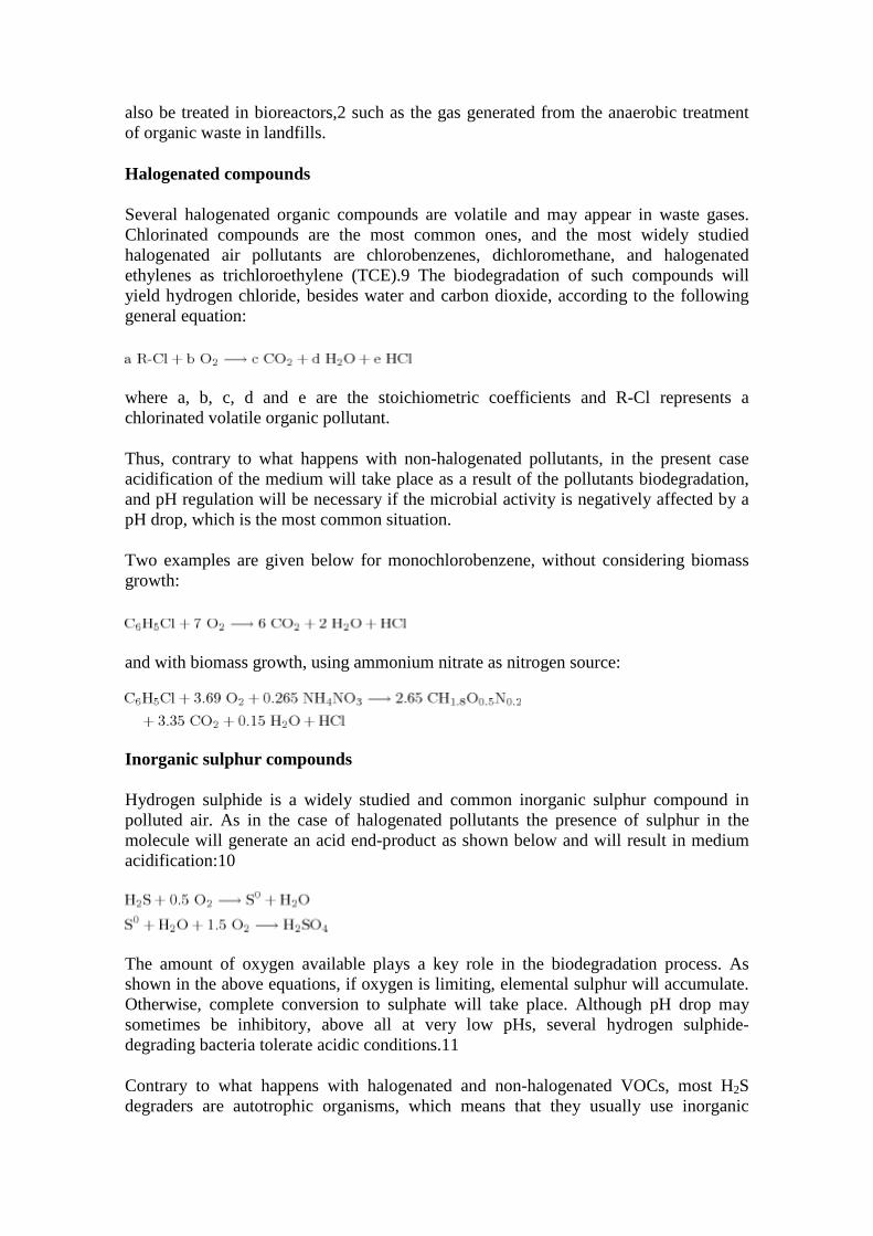
As mentioned earlier, the conventional biofilter is probably the oldest bioreactor configuration used for waste gas treatment. Several review papers and book chapters have focused on that system. Therefore, not too much space will be dedicated here to the fundamentals of that reactor, although some recent data and advances will be presented. In a nutshell, the conventional biofilter is a fixed-film or packed bed bioreactor in which a natural filter bed is most often used (Fig. 3(a)), although recently inert packing materials have proven successful as well (Fig. 3(b)). Polluted air is fed in either a downflow or an upflow mode through the reactor and the pollutants of the waste air are biodegraded by the biocatalyst present in the packed bed. Contrary to what happens with some other reactor configurations, such as the trickling biofilter or the bioscrubber that will be described later, in conventional biofilters there is no continuous feed of a liquid phase. Therefore, this reactor will be especially suitable for the treatment of hydrophobic and poorly water soluble compounds with a Henry's constant up to about 1. Also, because of the absence of a mobile liquid phase, conventional biofilters are not the best choice for treating pollutants, such as, for example, chlorinated compounds, leading to medium acidification. This can clearly be illustrated by comparing the results found in the few studies published on dichloromethane removal in biofilters to those obtained with biotrickling filters in which a mobile liquid phase is present (Table 1). With conventional biofilters, maximum elimination capacities do hardly reach 10 g m−3 h−1 while more than 100 g m−3 h−1 can easily be reached in biotrickling filters. Key elements of a biofilter are described hereafter.
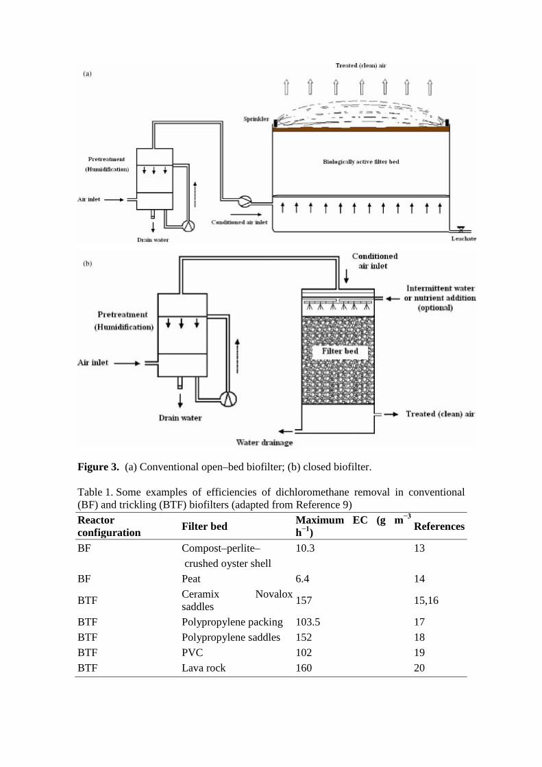
Figure 3. (a) Conventional open–bed biofilter; (b) closed biofilter.
Table 1. Some examples of efficiencies of dichloromethane removal in conventional (BF) and trickling (BTF) biofilters (adapted from Reference 9) Reactor configuration Filter bed Maximum EC (g m−3
h−1) References
BF Compost–perlite– 10.3 13 crushed oyster shell BF Peat 6.4 14
BTF Ceramix Novalox saddles 157 15,16
BTF Polypropylene packing 103.5 17 BTF Polypropylene saddles 152 18 BTF PVC 102 19 BTF Lava rock 160 20

Filter bed
The filter beds used in conventional biofilters were originally exclusively of natural material, i.e. soil, compost or peat.1 Such filter beds are still widely used today, above all for the removal of low odour concentrations, at wastewater treatments plants, municipal solid waste treatment plants or composting facilities, among others. They present some advantages over inert and synthetic materials, such as the natural presence of microorganisms and nutrients, although the latter may not be available in optimal or balanced concentrations. Besides, nutrients will also gradually be consumed and eventually the filter bed may become depleted of essential nutrients. A major drawback of such natural filter beds is their gradual degradation and compaction over time, leading to pressure drop increase and decreased removal efficiencies. In order to minimize head losses, inert or bulking materials have more recently been added to natural filter beds (i.e. perlite) allowing one to control pressure drop more successfully. Humidification of the waste gas is a prerequisite for successful operation of such systems (Fig. 3(a), (b)), as microorganisms need a given level of relative humidity for their optimal activity; while it should be recalled that no continuous liquid phase is added to such conventional biofilters. Filter beds composed exclusively of inert materials are nowadays also being used. In such a case, the intermittent feeding of a liquid solution is compulsory; otherwise filter bed drying will quickly take place, resulting in a drop of performance and eventually reactor failure. Anew, maintaining optimal water content in a biofilter is a key issue. Nowadays moisture control and regulation can easily be done on-line with cost-efficient sensors.21 Water addition can be programmed at a frequency of once or a few times a week. At high loading rates, the frequency of liquid phase addition needs to be increased.22, 23 It should be recalled that biodegradation is an exothermic process generating heat. Thus, the temperature of the filter bed will increase more at higher loading rates.24, 25 Sprinklers are often installed when using natural filter beds in order to maintain optimal conditions with respect to the water content, mainly in open biofilters (Fig. 3(a)) during the summer period when the top layer of the bed may more easily dry out. Some examples of natural and inert filter beds used in laboratory- and pilot- scale biofilters are given in Table 2, together with their main characteristics and the corresponding reactor performance.

Table 2. Comparison of recent results of removal of single pollutants in mesophilic biofilters packed with natural or with inert filter beds. More examples of older results can be found in previous publications1, 2
Pollutant Filter Bed EBRT (s)
Void space (%)
Specific surface area (m2 m−3)
Density (kg m−3)
Maximum EC (g m−3 h−1)
Corresponding RE (%) Ref
Acetone Sintered glass Pall rings 46.8 334 > 99 26
Ammonia Compost 86 61.3 89.5 27
Carbon monoxide
Peat + lava rock (75:25, W/W) 180
50 (lava rock only)
875 (lava rock)
33 85 5
DMS Porous silica packing 40 35 585 0.2 6 28
DMS GAC:Peat (1:1, V/V) 20–50
480 (GAC) 670 (Peat)
90 gS/m3.h ∼90 29
H2S GAC ? 125 98 30 H2S UP20 57 705 920 9 93 31,32 H2S Exhausted AC 4 Up to ∼40 > 95 33
Methanol Porous ceramic shperes 65 40 310 75 94 34
Methanol PP spheres 65 90 280 25 31 34 Methanol Wood chip 30 240–250 90 35 Methanol Lava rock 53.8 875 185 97 36 Mono– Compost 60 70 93 37 Chlorobenzene Styrene Perlite 120 279 78 38 α–Pinene Wood chip 50 45 > 95 35 α–Pinene Lava rock 72 875 143 89 39
Styrene Compost:Shredded plastic (25:75, V/V)
120 54 611 45 75 40
Styrene Perlite 120 260 > 95 41,42 20 196 > 95 Toluene Peat 57 93 80 43 Toluene Coir pith 118 80 606 96.8 80 44
Toluene Compost + Ceramic (1:1, V/V)
42 ∼160 100 45
Toluene Compost + Ceramic beads (6:4, V/V)
24.6 128 49 46
Toluene Compost + sea shells (1:6, W/W) 27 75 82 82 47
Toluene Perlite 30 44 5.3 cm2/cm3 100 ∼30 ∼62 48
Toluene Perlite 80 164.4 100 8
Toluene PU foam 30 56 1.7 cm2/cm3 28 ∼28 ∼58 48

1. UP20 = mixture of CH4N2O, H3PO4, CaCO3 and organic binder (20%), PVA:Polyvinyl alcohol
Biocatalyst
The biocatalyst is another element playing a key role in efficient bioreactor operation. Indeed, microorganisms present in biofilters should possess adequate enzyme systems in order to allow biodegradation to take place. As mentioned above, natural filter beds contain indigenous microorganisms. If the pollutant is a quite readily biodegradable substrate, for example, hydrogen sulphide, suitable indigenous microorganisms will generally be present and will easily develop in the biofilter. In the case of more recalcitrant pollutants, for example, MTBE or some halogenated compounds, inoculation of specialized biocatalysts may become necessary. Inoculation is also a prerequisite when the packing material is inert or of a synthetic nature. Again, if the pollutant is not highly recalcitrant, almost any type of sludge or mixed culture can be inoculated in the biofilter; otherwise, for more recalcitrant pollutants, seeding specialized microorganisms may be required. Although both bacteria and fungi have been found in biofilters, under certain conditions such as at low water contents or a low pH, favouring the growth of fungi may be useful since those organisms are more resistant to such adverse environmental conditions.7 Nevertheless, the presence of filamentous fungi may sometimes lead to a faster increase in pressure drop than in bacterial-dominant systems.
The biomass concentration in biofilters is often not homogenous along the filter bed height, above all in the case of inert carriers, which depend on the addition of nutrients for biomass growth and activity. Although biomass concentration is usually higher near the inlet of the bioreactor, some authors did occasionally observe the opposite, with higher biomass concentrations closer to the outlet.8, 49 Managing to obtain a more even biomass distribution will result in optimization and increased biofilter performance. Different techniques make this possible, among which the use of a directional switching feed50 or the use of a split-feed strategy.51
Several operating and environmental conditions may affect biofilter performance. They are briefly overviewed hereafter.
Environmental conditions
Microorganisms exhibit their optimal activity in a specific range of pH and temperature. In most cases, for pollutants containing carbon, hydrogen and oxygen atoms (CmHn or CmHnOp), the optimal pH is near neutral (pH 6–7), above all when bacteria are the dominant populations in the biofilm. Recent research has shown that when fungi are dominant, the optimal pH will generally be somewhat lower, often around 5.52 Besides, fungal cultures may even remain active at pH values below 4,52, 53 although the biofilter may not reach its optimal performance under such conditions.8 Temperature is also an important parameter affecting performance. Although the temperature effect is often not taken into account when comparing the performance of different mesophilic biofilters operated at laboratory scale, the effect is not negligible. For a biocatalyst exhibiting its optimal activity at 30 °C, removal rates and performance may drop by more than 50% if the temperature is lowered to 20 °C.54

Regarding the treatment of halogenated (mainly chlorinated) pollutants, it was previously mentioned that their aerobic biodegradation will lead to pH drop. Microorganisms degrading halogenated substrates are often quite sensitive to medium acidification. Therefore, as explained above (Table 1) conventional biofilters will not be the best choice in this case. For example, studies undertaken with Hyphomicrobium strains degrading dichloromethane have shown that the optimal pH for that organism is near neutral. At lower pH values, microbial activity will quickly drop. The biodegradation of sulphur compounds such as hydrogen sulphide is also known to release acidic products. Nevertheless, many H2S degraders are resistant to very low pH values. High activities have sometimes even been detected at pH as low as 2 or 3.11
Most biofiltration studies are done under aerobic conditions. Pollutants with a low number of chlorine atoms can rapidly be degraded in such aerobic environments. Nevertheless, highly halogenated compounds are better and more rapidly degraded under anaerobic conditions. Despite extensive research efforts made over the past two decades, some highly chlorinated aliphatic substrates, as perchloroethylene (PCE), have so far been biodegraded only under anaerobic conditions.55, 56
Water content
Much information has been published on the importance of maintaining an optimal water content in biofilters, suggesting that optimal values are between 40 and 60% on a wet basis.1, 2 A too low water content will reduce microbial activity while too much water may lead to pressure drop increase, compaction and the formation of anaerobic zones in the reactor. Biofilters in which fungi are dominant have shown to be somewhat more resistant to low water contents.7 Nevertheless, in some studies it has been observed that optimal conditions are rather similar to those reported for conventional ‘bacterial, biofilters. Fungi will better resist to adverse conditions in terms of water content although such conditions may not be optimal.
Flow rate and inlet concentration
Biofilters are mainly recommended for the treatment of waste gases with concentrations below about 5 g m−3. They are also more suitable for the treatment of relatively low or moderate flow rates, although high flow rates exceeding 100 000 m3 h−1 can occasionally be treated in such reactors as well, provided the pollutant concentrations are not excessively high. Nowadays, full-scale biofilters are able to treat gas loading rates exceeding 200 m3 m−3 h−1, although complete pollutant removal is not always possible at such high loads. Complete pollutant removal can often be reached up to 100 m3 m−3 h−1.57 At inlet concentrations exceeding 5–10 g m−3 and at high flow rates other, non-biological, treatment processes are usually recommended. Under such conditions, the reactor size and footprint for biofilters would be quite high. Besides, biofiltration would, in many cases, not be cost effective anymore compared with physico-chemical technologies. Generally, the empty bed residence time (EBRT) will range between about 10 and 60 s. Theoretically, the shortest residence times should be recommended. However, for the treatment of hydrophobic volatile organic compounds as, for example, α-pinene or styrene, it was shown that the critical load (maximum load allowing near complete pollutant removal, i.e. RE near 100%) in fungal biofilters may significantly decrease when the EBRT is decreased (i.e. gas flow rate is increased) from 1 min or more to less than 25 s.39, 41, 42

Biotrickling filter
The use of biotrickling filters for waste gas treatment has been investigated for over two decades and the number of research studies and industrial applications has increased dramatically since the 1990s. The reactor configuration is similar to that for the conventional closed biofilter (Fig. 4). One major difference is the continuous feed of a liquid trickling phase and the use of inert packing materials in all cases. Some of the packing materials that have been used in biotrickling filters are listed in Table 3, together with their main characteristics and reactor performance.
Figure 4.
Biotrickling filter.

Table 3. Recent examples of inert packing materials used in mesophilic biotrickling filters and performance data for each case
Pollutant Packing material EBRT(s)
Void space (%)
Specific surf. area (m2 m−3)
Density (kg m−3)
Maximum EC (g m−3 h−1)
Corresponding RE (%) Ref.
Ammonia Porous ceramic 37.5 59.9 gN/m3.h 99.8 58
Ammonia Pall rings + Alginate beads
51 4.5 100 59
Dimethyl Sulphide PE rings 60 30 ∼99 60
Ethanol PP spheres 30 90 280 970 60 61
Ethylacetate PP Pall rings 84 319 600 ∼97 62
Formaldehyde Lava rock 46.5 875 68 93.5 63
H2S IOPF (contains Fe2O3)
20–60 53 40.9 (biological + abiotic)
> 95 64
H2S PU foam 15 94 500 218 ∼85 65
H2S PP Pall rings 24 91 350 24 > 99 10
H2S PU foam ∼2 95–105 95 66
H2S (from biogas)
Glass Raschig rings
75/bed 55 95 67,68
H2S (from biogas) PU foam 167 97 600 35 ∼240 ∼90 69
Methanol PP spheres 30 90 280
2160 (biological + abiotic)
58 70
MCB PVC Pall rings 150 14 70 71
NO (from flue gas)
Porous ceramic beads + PP spheres (1:1, V/V)
90
35 (ceramic beads) 90 (PP spheres)
∼30 (abiotic + bio–denitrification)
85–94 72
2–Cl–Phenol Ceramic 120 640 350 81 98 73
Toluene Ceramic 66.5 55–70 3.99 m2/g
1.52 g/cm3 224–229 94–97 74
1. PU:PolyUrethane, PE:PolyEthylene; PP:PolyPropylene; IOPF:Iron Open Pore Foam; MCB:MonoChloroBenzene

Characteristics of the trickling liquid phase and the gas phase
Compared with conventional biofilters, the presence of a mobile liquid phase in biotrickling filters allows, among others, for a much easier pH control, temperature control and removal of accumulated metabolites, if any. It is shown in Table 1, that, generally, a much higher performance can be reached in biotrickling filters than in conventional biofilters treating dichloromethane polluted air. The easy pH regulation in biotrickling filters plays a key role in this, but the removal of inhibitory compounds is also crucial. Indeed, in order to maintain a constant pH, sodium hydroxide is usually added to neutralize hydrogen chloride generated during the biodegradation of dichloromethane. This leads, in this example, to the formation of sodium chloride as shown in the following equation:
Sodium chloride which is inhibitory to DCM-degrading bacteria, as Hyphomicrobium sp., at concentrations exceeding about 200 mmol L−1, can easily be removed from the reactor by regularly renewing part of the trickling liquid solution.
Other key parameters are the gas (G) and liquid (L) flow rates and the (G/L) ratio. Some studies have shown that the flow rate of the trickling phase may affect the overall reactor’s performance under certain conditions. In studies undertaken with pollutants as toluene,75 mono-chlorobenzene,76 and dichloromethane,15, 17 it has been recommended to apply a high superficial liquid flow rate (L), which will result in a low G/L ratio. This would ensure a high degree of wetting, resulting in a high reactor's performance. However, high liquid flow rates also increase operation costs and biofilm sloughing. The influence of the liquid flow rate on performance has been shown to be less significant at low pollutant concentrations than at higher ones.76 This was also confirmed in a study showing that modifying the liquid recirculation rate between 3.63 and 9.55 m h−1 had only a minor effect on the performance of a biotrickling filter treating ethyl ether, at a relatively low load of 38 g m−3 h−1.77 Similarly, at low H2S concentrations (25–150 ppmv), other authors did not found any major influence of the liquid flow rate on the removal of that pollutant when the flow rate was varied between 0.63 and 2.75 m h−1.10 Other work done with H2S demonstrated that the effect of the trickling liquid rate was nil at low gas velocities while it became significant at high gas velocities.78 More recent research on hydrogen sulphide removal showed that the removal efficiency (load not specified) was basically 100% at G/L ratios between 200 and 500.65 At a higher ratio of 1000, the RE dropped to 88%. It also dropped to 97% at a lower G/L ratio of 100. Besides its effect on wetting, other factors may affect the influence of the liquid flow rate on the reactor's performance, such as the type of pollutant (among others its hydrophobic or hydrophilic nature) and its effect on pH stability or product accumulation, as well as the characteristics of the packing material, among others. Plastic packings were used in most of the above mentioned examples. In a research study in which the liquid supply was maintained constant (0.63 m h−1), while the gas flow rate was modified, it appeared that methanol removal (in terms of maximum elimination capacity and critical load) increased when decreasing the superficial gas velocity from 136 m h−1 (G/L = 217) to 31 m h−1 (G/L = 130), i.e. increasing the EBRT from 17 s to 28 s.79

Biotrickling filters are usually operated in either co-current or counter-current mode. In the few studies that compared performance data under both conditions, it was observed that very similar results were obtained irrespective of the mode of operation.12, 15, 16, 80 Cross-flow is also possible, but rather unusual. The optimal G/L ratio was estimated in a horizontal cross-flow biotrickling packed with activated carbon and fed H2S polluted air. G/L values ranging between 32 and 160 were applied, showing that an intermediate range between 60 and 80 yielded optimal conditions in term of bioreactor performance.81
Regarding the gas phase residence time, typical values for the removal of VOCs (aliphatic and aromatic VOCs as formaldehyde or toluene) are between about 15 s and 1 min. Recent studies have shown that the removal of readily biodegradable pollutants such as H2S can be done in biotrickling filters operated at very low residence times, comparable with those used in absorption towers, i.e. 5 s or less.66, 81, 82 However, for more recalcitrant pollutants, higher residence times reaching more than 1 min may be required (Table 4). This was the case, for example, in laboratory-scale studies done with TCE, where EBRT of several minutes were needed even at relatively low loads in order to reach reasonable pollutant removal, although such long residence times may not be feasible nor cost-effective at full-scale.
Table 4. Some selected examples of EBRT used in biotrickling filters for different groups of pollutants (inorganic, organic-aliphatic, organic-aromatic, poly-halogenated)
Pollutant(s) EBRT Maximum EC (g m−3 h−1)
Corres ponding RE (%) References
H2S 1.6–2.2 s 95–105 > 95 66
5 s NR > 90 82 5 s NR > 99 83 4–16 s 113 96 81 Formaldehyde 20.7 s 111.8 78.6 84 Methanol 48 s 173.1 95.1 36 Toluene 45 s 79.4 NR 85 Trichloroethylene 5.6 min 2.8 > 97 86 7.2 min 0.15 30–40 87 20 min NR 98 88
1. NR = Not Reported
Packing material
Inert packing materials are used in biotrickling filters and may play a major role in the performance and long-term stability of the reactor. Such packing is devoid of essential macro- and micro-nutrients, but the trickling phase allows one to continuously provide the essential nutrients in balanced concentrations. Some packing materials commonly used in scrubbers, i.e. plastic rings and saddles, have been tested in biotrickling filters (sometimes called fixed film bioscrubbers).54 Other frequently used filter beds are silicate-based materials such as perlite,8, 22 celite50 or lava rock.63 Materials such as

activated carbon and polyurethane (PU) foam have also been tested.23, 66, 89 The latter has a low water holding capacity compared with the others, which is unfavourable from that specific point of view. Activated carbon presents the advantage of being able to adsorb pollutants and buffer shock loads, thus minimizing microbial inhibition.89 Conversely, the void space (Table 3) is significantly higher in biotrickling filters packed with PU foam and plastic rings, which will slow down clogging problems and pressure drop increase.
Biomass accumulation and clogging
Pollutant biodegradation and the feed of a continuous nutritive trickling solution will lead to biomass growth on the packing material. Biomass accumulation is necessary since sufficiently high biomass concentration will allow fast pollutant removal. Nevertheless, if biomass concentration becomes too high, pressure drop will increase to such a point that it will lead to clogging problems and eventually reactor failure. Under thermophilic conditions, biomass build-up has been observed to be less than under mesophilic conditions.24, 25 The lower overall biomass yields at higher temperatures could result from high maintenance energy requirements or temperature induced growth uncoupling. Besides, biomass distribution along the reactor is often not homogenous, as also mentioned above in the case of conventional biofilters, and significant amounts of non-active microorganisms may be present, which will contribute to increase the pressure drop. As a result of this non-homogenous biomass distribution, as much as 80 or 90% of the pollutant removal may sometimes take place in the first half of the reactor,90 meaning that the other half is under-used compared with the reactor volume closest to the inlet. Different strategies have been suggested to slow down microbial growth or remove excess biomass from the reactor.23 Methods aimed at slowing down biomass accumulation consist in lowering the concentration of one or more essential nutrients in the trickling phase. Generally, studies on nutrient limitation have been done for nitrogen, phosphate or phosphorus. Reducing the availability of such macronutrients does indeed reduce biomass growth. Nevertheless, in all cases this does also negatively affect the reactor's performance, resulting in lower pollutants removal. Other methods consist in removing part of the accumulated biomass once the pressure drop becomes too high. Either biological or non-biological techniques can be used for this purpose. In the case of biological methods, organisms such as, for example, protozoa or nematodes, or mites are added to the reactor and help to control the biofilm thickness and pressure drop.91–93 So far, only little research has been performed on the optimization of predation methods in biotrickling filters. Non-biological methods are mainly backwashing and air sparging. Backwashing consists in feeding water at a relatively high flow rate to the bioreactor. This can be done with or without fluidization of the packing material and with or without addition of specific chemicals. The addition of chemicals and the use of higher water temperatures usually improve biomass removal.23 In air sparging, the bioreactor is filled with water, and air flowing at a high rate through the packed bed allows removal of excess biomass. All these strategies have been described in more details elsewhere.23 Finally, some mechanical methods have been tested as well, consisting in most cases in mixing or stirring the inert packed bed (i.e. plastic rings, polyurethane foam)94, 95 at given time intervals by means of impellers or agitators.

Bioscrubber
Much less research has been undertaken on bioscrubbers than on conventional and trickling biofilters. There are also many fewer full-scale bioscrubbers in operation than packed bed biofilters. The first full-scale plant was installed in German foundries in the 1970s for the removal of amines, phenol, formaldehyde and odours from waste gases.57 Compared with biofilters and biotrickling filters, bioscrubbers can be operated at higher gas loads, up to 3000–4000 m3 m−2 h−1. In biofilters, loads do normally not exceed 500 m3 m−2 h−1.2
It is important to remember that microorganisms need a minimum moisture content to be active and exhibit their microbial activity in the aqueous phase, either in the form of a biofilm or through suspended growth. Thus, biological air pollution control would normally only be possible if the air pollutant is first absorbed in the aqueous phase and then biodegraded. Although some authors have used the words fixed-film bioscrubber for biotrickling filters, in this paper, bioscrubber will refer to its most common definition, i.e. a combination of a suspended growth bioreactor and a scrubber in two separate units. In such a system, polluted air is fed to an absorption tower first (scrubber). By doing so, target compounds are transferred from the gas phase (air) to the liquid phase (water). Clean air is then released to the atmosphere from the scrubber, while polluted water is fed to a bioreactor (Fig. 5), where microorganisms take care of the biodegradation of the pollutant(s) in the aqueous phase. The scrubber may also be placed on top of the bioreactor, in which case the water phase reaches the bioreactor by gravity. A pumping system allows clean water leaving the bioreactor to be reused as absorbent in the scrubber. Bioscrubbers are suitable for the treatment of pollutants that are relatively well soluble in water, as biodegradation is performed by suspended biomass in the bioreactor. Besides, poor water solubility would also negatively affect the absorption rate and efficiency. Therefore, this technology is mainly recommended for pollutants with a Henry's coefficient not exceeding approximately 0.01.1–3
Figure 5.
Bioscrubber.

Absorption can take place either in a spray tower or in a packed bed column. In order to remove volatile, poorly water soluble pollutants, packed-bed absorption towers are often recommended because they generally perform better in terms of removal efficiency. Most often, the absorption tower is randomly packed with a plastic packing material that allows maintainance of a minimal pressure drop, but structured packings are suitable as well. Counter-current operation is the most general case, with (G/L) ratios ranging typically between 300 and 500 and gas residence times not exceeding a few seconds. The presence of a mobile liquid phase allows for an easy control of some parameters as, for example, pH, as was also the case in biotrickling filters. Since pH may affect the optimization of both the scrubbing process and the biodegradation stage, the addition of acid or alkali may be required in either the scrubbing tower or the bioreactor, or both. Bioscrubbers have been used for the removal of inorganic compounds such as, for example, H2S absorbed in alkaline water, and, more recently, SOx absorbed in water containing sodium bicarbonate, as well as NOx.96, 97 Waste gases containing hydrophilic VOCs such as, for example, methanol can also be treated efficiently in bioscrubbers.98 Several full-scale systems have been commercialized worldwide for the desulphurisation (H2S removal) of biogas, landfill gas and natural gas.99 Another process, the BioDeNOx technology, has been tested for NOx removal from flue gas.100 It is based on NOx absorption into an aqueous Fe(II)EDTA2− solution followed by a biological regeneration tank (i.e. bioreactor). So far, the technology has not been tested at full-scale, and it has not been proven to be cost-effective compared with more conventional technologies.101
Different types of bioreactors are potentially suitable for the biodegradation process, but activated sludge units are most commonly used. In bioreactors used specifically for bioscrubbing, the hydraulic retention time is generally higher than in conventional activated sludge reactors used for wastewater treatment, and enough sludge retention is often not a problem, except sometimes for slow growing microorganisms such as nitrifiers.102 In any case, biomass wash out would not occur if the reactor's dilution rate does not exceed the average biomass growth rate. Since microorganisms need adequate concentrations of macro- and micro-nutrients for their activity, it is necessary to make sure those are present in balanced amounts. The addition of nitrogen and phosphorus as the only nutrients is often enough, above all if tap water is used. On the other hand, since the bioreactor is typically a suspended growth reactor, it will not suffer clogging problems, contrary to what may occur in fixed film reactors. Conversely, a major challenge related to biomass growth consists in dealing with sludge accumulation and disposal. Two major alternatives have been suggested to limit sludge accumulation:103 (i) increase the requirement for maintenance energy by increasing the mean cell residence time; (ii) decrease efficiency of energy generation for biomass growth by limiting nutrient supply. A too high biomass concentration in the bioreactor, usually above 15 g L−1, could generate clogging problems in the scrubber. Ideally, biofilm growth should not take place inside the scrubber, although avoiding this is not always easy in practice. High liquid flow rates and the use of packing materials with a high void space allow minimizing biomass growth in packed scrubbers. It is also worth observing that flocs in bioreactors used in bioscrubbers are often smaller than in activated sludge reactors used in wastewater treatment, and sludge separation may thus be more difficult.
In most cases, aerobic microorganisms will take care of the biodegradation stage and enough oxygen should be available for the removal of the corresponding organic

loading rate of the water phase. Co-metabolic aerobic removal of VOCs, such as TCE, needing the presence of a primary carbon source, is more common in bioscrubbers than in packed bed reactors as biofilters or biotrickling filters. One advantage of bioscrubbers is that they can also be used for the anaerobic biodegradation of volatile pollutants. This may be of interest in the case of pollutants that are hardly biodegradable, or even not biodegradable at all, under aerobic conditions, such as the highly chlorinated organic compound tetrachloroethylene (PCE).56
Gas diffusion into suspended-growth bioreactors
Instead of feeding polluted air to a scrubber and then treating the polluted aqueous phase in a suspended growth bioreactor as in bioscrubbers, polluted air can be fed directly to a stirred tank bioreactor. The latter could be an activated sludge reactor already available on-site, for example in case of an industrial plant that needs to treat both wastewaters and waste gases. It can also be a bioreactor built exclusively for the treatment of the waste gas. In such a case, the reactor can be optimized for gas treatment only, since no wastewater is fed. Significantly shallower reactors can then be used, resulting in less pressure drop and much less energy requirements.104 Other types of suspended growth bioreactors such as, for example, the airlift bioreactor, would be suitable as well. A more detailed description of this technology can be found elsewhere.104
Membrane bioreactors
In membrane bioreactors used for air pollution control, both a gas phase and an aqueous phase are fed to the reactor. The two phases are separated by a membrane. The gas phase is polluted air generally containing a carbon source, i.e. the volatile pollutant, while the aqueous phase is a source of nutrients for the biofilm growing on the aqueous side of the surface of the membrane. The membranes are placed inside the reactor either in a tubular configuration or in the form of flat sheets. Most often, the gas phase flows through the lumen, while the aqueous phase is fed through the shell side (Fig. 6). Contrary to what happens in conventional biofilters, where the pollutant is directly transferred from the air to the biofilm, in membrane bioreactors the membrane itself creates an additional resistance to mass transfer. Nevertheless, good mass transfer rates have been reported in the literature.105 Two different types of membranes may be used; dense membranes and microporous membranes,106 but a combination of both is also possible.

Figure 6.
Different parts of a membrane and mass transfer of compounds in liquid and gas phases.
Dense membranes are limited to polymeric materials such as latex or silicone rubber. The mass transfer depends on the solubility and diffusivity of the permeating compound in the dense matrix.106 In the transport mechanism, the gas molecules absorb or dissolve first in the membrane surface,107 before diffusing through the polymeric matrix and being degraded by the attached (i.e. as a biofilm) or suspended biocatalyst on the biofilm side. The biodegrading activity of that biofilm creates a driving force for the continuous transfer of the gas molecules through the membrane.
Microporous membranes provide high gas permeability, but do not allow the transport of water through the membrane,106 avoiding physical contact between both phases. Water molecules are generally unable to cross the membrane because of the hydrophobic nature of such membranes.108 The pollutant is transferred from the gas phase to the aqueous biofilm by diffusion through the pores, mainly as a result of the pressure gradient between both sides of the membrane and depending also on the solubility of the pollutant in the aqueous phase. Composite membranes combine a dense membrane and a porous material.
Comparing the performance of membrane bioreactors with other, mainly packed bed, bioreactors used for waste gas treatment is not easy since elimination capacities are expressed in terms of grams pollutant removed per m3 an hour in both packed bed and suspended-growth bioreactors, while it would be more logical to express performance data in amount pollutant removed per m2 membrane per day in membrane bioreactors (Table 5). In any case, performance of membrane reactors is of the same order of magnitude as for other more conventional bioreactors, and they are, in several cases, able to operate efficiently at relatively low residence times of only a few seconds.

Table 5. Removal of volatile air pollutants in membrane bioreactors
Pollutant Membrane material
Maximum EC (g m−2 d−1)
Corresponding RE (%) References
Benzene PP 2.6 98 109 LR 65 80 109 Butanol PS 471 99 110 PS 1567 38 110 DCE PDMS 0.53 92 111 DMS Zirfon 1.9 74 112 Nitric Oxide PO 0.15 74 113
Propylene PP 3.6 58 114 PP 4.2 26 115 PP 1.3 20 116 TCE PP 0.018 52 117 PP 118 Toluene PS 3.9 84 119 PE 1.6 97 120 PP 3.0 35 121 PVDF 17.7 84 122
1. DCE:DiChloroEthylene; DMS:DiMethylSulphide; TCE:Tri ChloroEthylene; PP:PolyPropylene; LR:Latex rubber; PS:PolySulfone; PDMS:PolyDiMethyl Siloxane; PO:Poly Olefin; PVDF:PolyVinyliDeneFluoride
Since a mobile liquid phase is present in membrane bioreactors, a preliminary humidification step is not necessary. Besides, as in bioscrubbers and biotrickling filters, the aqueous phase allows for easy pH regulation and optimization of nutrients supply. Biodegradation products can easily be removed. Another interesting feature of such reactors is that the transfer of microorganisms from the biofilm to the air can be avoided. This is above all true with microporous membranes, in which the small size of the pores does not allow the migration of microorganisms from the liquid phase to the gas phase. Therefore, their potential use in closed environments such as, for example, spacecraft has been considered.105
Although numerous research data have been published for wastewater treatment in such bioreactors and the full-scale application of this technology is relatively well established in wastewater treatment, no full-scale results have yet been reported for waste gas treatment. The relatively high cost, mainly of the membranes, compared with conventional bioprocesses is one major drawback. Other factors are the lack of information, and possibly lack of stability, of such membrane bioreactors under long-term operation and under unsteady-state conditions such as shock load operation. Another aspect to be considered is excess biofilm growth and membrane fouling resulting in reduced substrate transfer, leading to decreased reactor performance. It has been reported that biofouling problems are usually less significant in dense membranes than in microporous membranes.106 Aging is also an important issue and may result in

a lower permeability of dense membranes with time or gradual porosity problems in microporous membranes. Rotating biodiscs and biodrums Different types of bioreactors containing rotating discs or rotating drums as the main part have recently been developed for waste gas treatment. Rotating biological contactor The rotating biological contactor (RBC) is one example of reactor that has already been implemented at full-scale in a limited number of cases, mainly in Canada.123 RBC have been used for decades in the field of wastewater treatment. They have more recently been adapted to waste gas treatment, maintaining a similar reactor configuration as for wastewater treatment (Fig. 7). An RBC consists of an airtight vessel containing bundles of discs, usually made of polystyrene, PVC or polyethylene, and mounted on a shaft. The diameter of the discs may reach 1–4 m in full-scale reactors. The discs are tightly spaced, in order to maximize the available surface area, and slowly rotating at a constant speed, typically between 1 and 5 rpm. Part of the discs—about 40% of the total surface area—is submerged in a nutritive liquid solution, while the remaining disc surface is in contact with the polluted air stream flowing through the system. A biofilm progressively develops on the surface of the rotating discs, alternating its exposure to soluble nutrients in the aqueous phase and exposure to air and the volatile pollutants present in the gas phase. Part of the biomass is gradually sloughed off and will appear in suspension in the aqueous phase, eventually needing to be separated in a clarifier or sedimentation tank. Similar gas flow rates and pollutant concentrations to those in other bioprocesses can be treated in RBC. An advantage of this system is the absence of clogging, typical of packed bed biofilters. Laboratory-scale studies undertaken with dichloromethane-polluted air showed that the reactor's performance was similar or somewhat lower than with biotrickling filters, when feeding the polluted air stream tangentially to the discs.123 A modified RBC was later used in which the air was fed through the hollow shaft on which the discs were mounted.124 Under such condition, the polluted air flew in a radial direction with respect to the discs (Fig. 8). With such configuration, very good gas–liquid contact is reached and it was observed that a quite constant biofilm thickness was maintained over a long operating period of about 1 year.
Figure 7. Rotating biological contactor (RBC) for waste gas treatment.

Figure 8.
Radial polluted air flow out of the shaft.
Rotor biofilter
In a rotor biofilter, a rotating drum is used instead of a series of rotating discs (Fig. 9).125 The hollow drum is partly filled with a given packing material. As a result of the rotation of the drum, the packing material, with attached biomass, is continuously moving, giving good mixing and avoiding clogging. Water can be continuously trickled over the drum in order to ensure a good humidification level. The polluted air stream may either be fed through the horizontal shaft or through the outer part of the drum, which allows for good contact between the polluted stream and the attached biomass. A similar system was used more recently in which a set of six grid-structured polypropylene drums were spinning in a concentric spiral form around a vertical shaft.126 Nozzles allowed a scheduled trickling liquid supply. In such a reactor, a relatively constant biofilm thickness can be maintained. Periodic removal of excess biomass is by liquid shear stress forces generated by jet nozzles feeding the aqueous phase, which minimizes pressure drop. The efficiency of the rotor biofilter was shown at pilot-scale to reach similar results to those for other types of bioreactors.
Figure 9.
Rotating biofilter.
Rotating drum biofilter
Another related configuration is the rotating drum biofilter (RDB). In such a system, a single drum, made of reticulated polyurethane foam, is rotating around a horizontal shaft.127 The drum itself represents thus the packing or support material for the biomass. Instead of using a trickling aqueous phase as in the rotor biofilter, the polyurethane drum, rotating at a low speed rate, is partly submerged in a nutritive solution (about 30% of the drum) while the remaining part is in contact with air, similarly to the RBC design.128 Operating conditions (flow rate and gas residence time, inlet concentrations) are similar as in other reactor configurations, as well as the reactor performance. The RDB has also been show to be suitable for the anaerobic removal of pollutants as nitric oxide through denitrification.129, 130 Contrary to the RBC and the rotor biofilter, which have been tested in large-scale units, the RDB has only been studied at laboratory-scale so far.
Two-liquid phase bioreactors
In the aforementioned reactors, water is used as single free or moving liquid phase. Studies have been performed over the past two decades on the use of a second, water-immiscible, liquid phase in both biotrickling filters and suspended growth bioreactors. To the best of our knowledge, some of the first research papers on the use of an organic solvent in bioscrubbers for waste gas treatment appeared around the early 1990s.131, 132 The addition of an organic liquid phase is mainly useful for the removal of poorly

water soluble pollutants, although the removal efficiency of less hydrophobic pollutants may also be significantly increased in such systems.20 This type of system presents interesting characteristics and significant advantages under certain conditions. Some of the most important are: (i) as the pollutant is gradually degraded in the aqueous phase, a driving force allows for the continuous and slow release of more pollutant from the highly concentrated organic phase to the poorly concentrated water phase; (ii) as microorganisms are mainly present in the water phase, they will never be exposed to high, inhibitory, pollutant concentrations accumulating in the organic reservoir; (iii) this type of system is potentially highly favourable for the removal of high concentrations and high loads (including shock loads) of very poorly water soluble compounds.
Organic phase
The organic phase should meet the following criteria;102, 131
• (i)immiscible with water • (ii)non-biodegradable • (iii)not-toxic for the biocatalyst • (iv)low vapour pressure • (v)relatively low viscosity • (vi)density different from the density of water • (vii)odourless • (viii)inexpensive.
Although it might not necessarily always be the best choice from a chemical engineering and thermodynamic point of view, silicone oil is the most popular and most commonly used organic phase. It fulfils pretty well the requirements mentioned above. Some authors who tested various solvents among which, silicone oil, hexadecane, tetradecane, 1-decanol, diethyl sebacate, and 2-undecanone, observed that silicone oil was the only non-biodegradable compound and one of the few non-toxic solvents.133, 134 Other organic solvents that have been tested are oleyl alcohol,135 and 1-octadecene.136
Two-liquid phase suspended growth bioreactors
The organic solvent is expected to increase the overall treatment costs and the volume ratio of organic to aqueous phase should generally not exceed 30% in full-scale systems, but ratios ranging between 5 and 50% have been used and reported in the literature for suspended growth laboratory-scale bioreactors. That organic phase should be dispersed in the form of small droplets in the aqueous phase. Small droplets will be more favourable in terms of mass transfer area. However, some researchers reported that when the ratio of organic to aqueous phase exceeds 40%, larger drop sizes are formed and phase inversion may be observed.137, 138 In the presence of an organic solvent, volatile pollutants relatively soluble in aqueous phase will generally not reach high, potentially inhibitory, concentrations in the suspended-growth water phase. Thus, microorganisms in that water phase will not be inhibited. Conversely, in the presence of a single aqueous liquid phase high pollutants concentrations may lead to inhibitory conditions and biomass washout,139 although the toxic effect may be somewhat less significant in such a completely mixed reactor than in packed bed biotrickling filters.20 It was observed that under given operating conditions the biomass concentration in the

reactor will naturally reach and stabilize at a rather constant value.140, 141 Non-steady-state load conditions are not unusual in full-scale operation. In the case of occasional shock loads, the system may become inhibited and may need some time to recover in the case of a single aqueous phase bioreactor. In such a case, the presence of an organic phase has shown to be favourable as it will play a buffering role and avoid or, at least, reduce inhibition.20, 141 A similar effect will also be reached if an organic phase absorber is put in front of a conventional single aqueous phase stirred tank bioreactor, instead of directly mixing both the aqueous and the organic phase in the bioreactor itself.139 Some typical examples of performance data for two-liquid phase stirred tank bioreactors are summarized in Table 6.
Table 6. Removal of volatile air pollutants in two-liquid phase stirred tank bioreactors
Pollutant Organic phase
Organic/water ratio (Vol-%)
Maximum EC (g m−3 h−1)
Corresponding RE (%) References
Benzene n–
hexadecane 33 133 95 142
DCM Silicone oil 10 195 42 20 Hexane Silicone oil 10 140 77 133 Hexane Silicone oil 10 120 67 143 IPB Silicone oil 10 240 61.5 140
Toluene n–hexadecane 33 733 98 144
Toluene n–hexadecane 33 145
1 DCM:DiChloroMethane; IPB:IsoPropylBenzene
Two-liquid phase biotrickling filters
In biotrickling filters, organic to aqueous phase volume ratios fed continuously to lab-scale reactors and reported in the literature, range between 5 and 50%.20, 138, 143, 146 It is not recommended to use higher ratios in full-scale systems, and solvents with high viscosities should be avoided since this would lead to higher energy costs for pumping.138 In some studies, the performance in presence of the organic phase is not systematically compared with control systems without a second liquid phase. However, when such comparison was done, performance appeared always to improve with the addition of an organic solvent, by about 25 to 240%, either in terms of elimination capacity,20 removal efficiency,146 or both.143 In most cases, when the performances of biotrickling filters are compared with those of two-liquid phase stirred tank bioreactors, improvements were generally higher in the latter than in the former.20, 143 It is interesting to note the surprising and unusual result obtained in one study performed with styrene.147 In that study the packing material was only soaked once in silicone oil before starting the experiment, no further addition was done during the continuous reactor operation, and a maximum EC as high as 2900 g m−3 h−1 was reached (Table 7), which is about 10 to 100 times more than in any biofiltration study reported in the literature. In a conventional biofilter packed with perlite partially coated with silicone oil on start-up, a maximum hexane elimination capacity of 167 g m−3 h−1

was reached in that silicone oil amended biofilter compared with 114.9 g m−3 h−1 in a control biofilter without addition of any oil.148
Table 7. Removal of volatile air pollutants in two-liquid phase biotrickling filters
Pollutant Packing material
Organic phase
Organic/water ratio (Vol-%)
Max. EC (g m−3 h−1)
Corresponding RE (%) Ref
DCM Lava rock Silicone
oil 10 195 42 20
Hexane PA structure wire mat
Silicone oil 50 83–97 89 138
Hexane Perlite Silicone oil 5 180 > 90 143
Mixture of polyalkylated benzenes*
PP Ralu rings
Silicone oil 10 33.6 NR** 146
Styrene Lava rock was soaked in silicone oil before starting up the BTF. No more oil was added later on.
2900 97.2 147
* Mainly C9–and C10–compounds (pseudocumene, methylethylbenzenes, diethylbenzene, etc.),
** Calculated RE:42%, DCM = DiChloroMethane
Hybrid and multi-stage systems
The removal of pollutants in two steps has recently been evaluated. It generally consists in using two bioreactors in series in order to achieve a complete or, at least, higher removal of mixtures of target compounds than in a single bioreactor. The reactors may either be the same or two different reactors may be used. In such a way, the activity of different types of microorganisms may be specifically stimulated in each compartment by means of parameters as, for example, pH, moisture content, or nutrients.21 Even more than two reactors could be used. In which case, a coarse filter material in the first stage could separate particles or dust, for example.21
A common example is the use of two biofilters in series for the removal of sulphur compounds such as H2S mixed with VOCs. The optimal pH for bacteria degrading VOCs is generally near neutral, while the biodegradation of sulphur compounds leads to medium acidification and strong pH drop (see above). Some H2S-degrading bacteria are more tolerant of acid conditions than most VOC degraders.11 A pilot-scale facility operated at a wastewater treatment plant showed that combining a first stage low-pH inorganic biofilter with a second stage neutral-pH organic biofilter led to the best results.149, 150 Alternatively, some authors tried to stimulate the growth of acid tolerant organisms, for instance fungi, and acid tolerant H2S-degraders together in single stage low pH bioreactors, to try to eliminate both sulphur compounds and VOC in the same unit. This appeared to be feasible in many situations leading to the development of mixed acid tolerant populations.79, 150

Another example of hybrid system using two different reactors in series has been described recently. When treating pollutants typically found in waste gases from resin- producing industries (mainly formaldehyde and methanol), it has been shown that higher maximal elimination capacities could generally be reached in BTF while higher removal efficiencies were reached in BF.4 When connecting a biotrickling filter in series with a biofilter, it was possible to simultaneously reach higher elimination capacities and higher removal efficiencies than with a single-stage system.4 Still another set-up composed of a bioscrubber–biofilter in series was evaluated for the treatment of odours released at composting facilities.151 The exact nature of the pollutants was not reported, but it was observed that only a small fraction, less than 30%, of the pollutants was removed in the bioscrubber. Most of the remaining odour load was eliminated in the biofilter. The bioscrubber acts as a humidifier for the biofilter and as a potential buffering unit. A similar bioscrubber–biofilter system was built for the treatment of waste gases from fat and oil processing industries.152 Pollutants such as aldehydes and ketones were removed in the bioscrubber. Remaining aliphatic pollutants and aromatic compounds, terpenes and furanes were degraded in the biofilter. The idea of combining a bioscrubber and a biofilter was suggested more than two decades ago in the case of mixed pollutants, in which hydrophilic compounds would be better removed in the bioscrubber, while the biofilter would take care of degrading the more hydrophobic fraction of the load.153
Other bioreactors
A few other reactor configurations have been tested as well, although they will not be described in detail here because in most cases only a limited number of studies and results have been reported so far, mainly at laboratory-scale. Some examples are the external loop airlift bioreactor,154, 155 the spouted bed and fluidized bed bioreactors,156, 157 the monolith bioreactor,158 and the foamed emulsion bioreactor.159 Studies have also been performed, mainly over the past 10 years, on the combination of bioreactors and non-biological processes, i.e. advanced oxidation processes.160, 161
CONCLUSIONS
Biofilters and biotrickling filters are among the most extensively used bioreactors for air pollution control and are highly suitable for many full-scale applications. Recently, new bioreactor configurations have been developed specifically for air treatment, which has allowed a broadening of the range of pollutant concentrations and gas flow rates treatable biologically. New or modified bioreactors have also been studied in an attempt to increase the number of pollutants that could be treated using bioprocesses. This has also widened the fields of application of bioreactors. Present and future research focuses on further broadening the fields and ranges of applications of such bioprocesses. Recent studies have focused on the removal of highly recalcitrant pollutants, very hydrophobic ones, as well as on the removal of pollutants over a wider range of concentrations (from trace odour levels up to several g m−3) and at very low residence times of only a few seconds.

Acknowledgements
The authors would like to thank the Spanish Ministry of Education and Science for financial support through project CTM2007-62700/TECNO, as well as the financial support of this research through European FEDER funds. ERR thanks the Spanish Ministry of Innovation and Science for a Juan de La Cierva research contract at the UDC.
REFERENCES
• 1Kennes C and Thalasso F, Waste gas biotreatment technology. J Chem Technol Biotechnol 72: 303–319 (1998).
• 2Kennes C and Veiga MC, Bioreactors for Waste Gas Treatment. Kluwer Academic Publishers, Dordrecht, The Netherlands, pp. 312, ISBN:9–780792–371908 (2001).
• 3Van Groenestijn JW and Hesselink PGM, Biotechniques for air pollution control. Biodegradation 4: 283–301 (1993).
• 4Prado OJ, Veiga MC and Kennes C, Removal of formaldehyde, methanol, dimethylether and carbon monoxide from waste gases of synthetic resin–producing industries. Chemosphere 70: 1357–1365 (2008).
• 5Jin Y, Guo L, Veiga MC and Kennes C, Optimization of the treatment of carbon monoxide–polluted air in biofilters. Chemosphere 74: 332–337 (2009).
• 6Singleton I, Microbial metabolism of xenobiotics: fundamental and applied research. J Chem Technol Biotechnol 59: 9–23 (1994).
• 7Kennes C and Veiga MC, Fungal biocatalysts in the biofiltration of VOC-polluted air. J Biotechnol 113: 305–319 (2004).
• 8Estévez E, Veiga MC and Kennes C, Biofiltration of waste gases with the fungi Exophiala oligosperma and Paecilomyces variotii. Appl Microbiol Biotechnol 67: 563–568 (2005).
• 9Kennes C, Jin Y and Veiga MC, Fungal and dechlorinating biocatalysts in waste gas treatment. in Waste Gas Treatment for Resource Recovery, ed. by LensPNL, KennesC, Le CloirecP and DeshussesMA. IWA Publishing Co, London, UK, pp. 277–301 (2006).
• 10Jin Y, Veiga MC and Kennes C, Autotrophic deodorization of hydrogen sulphide in a biotrickling filter. J Chem Technol Biotechnol 80: 998–1004 (2005).
• 11Yang Y and Allen ER, Biofiltration control of hydrogen sulphide. 2. Kinetics, biofilter performance and maintenance. J Air Waste Manage Assoc 44: 1315–1321 (1994).
• 12Jin Y, Veiga MC and Kennes C, Effects of pH, CO2 and flow pattern on the autotrophic degradation of hydrogen sulphide in a biotrickling filter. Biotechnol Bioeng 92: 462–471 (2005).
• 13Ergas SJ, Kinney K, Fuller ME and Scow KM, Characterization of a compost biofiltration system degrading dichloromethane. Biotechnol Bioeng 44: 1048–1054 (1994).
• 14Aizpuru A, Malhautier L, Roux JC and Fanlo JL, Biofiltration of a mixture of volatile organic emissions. J Air Waste Manage Assoc 51: 1662–1670 (2001).
• 15Diks RMM and Ottengraf SPP, Verification studies of a simplified model for the removal of dichloromethane from waste gases using a biological trickling filter: Part I. Bioprocess Eng 6: 93–99 (1991).

• 16Diks RMM and Ottengraf SPP, Verification studies of a simplified model for the removal of dichloromethane from waste gases using a biological trickling filter: Part II. Bioprocess Eng 6: 131–140 (1991).
• 17Hartmans S and Tramper J, Dichloromethane removal from waste gases with a trickling bed bioreactor. Bioprocess Eng 6: 83–92 (1991).
• 18Okkerse WJH, Ottengraf SPP, Diks RMM, Osinga–Kuipers B and Jacobs P, Long term performance of biotrickling filters removing a mixture of volatile organic compounds from an artificial waste gas:dichloromethane and methylmethacrylate. Bioprocess Eng 20: 49–57 (1999).
• 19Okkerse WJH, Ottengraf SPP, Osinga–Kuipers B and Jacobs P, Biomass accumulation and clogging in biotrickling filters for waste gas treatment:Evaluation of a dynamic model using dichloromethane as a model pollutant. Biotechnol Bioeng 63: 418–430 (1999).
• 20Bailón L, Nikolausz M, Kästner M, Veiga MC and Kennes C, Removal of dichloromethane from waste gases in one–and two–liquid–phase stirred tank bioreactors and biotrickling filters. Water Res 43: 11–20 (2009).
• 21Sabo F, Prechel S and Schneider T, Latest developments in high efficiency biofiltration. in Proceedings of Ist International Congress on Biotechniques for Air Pollution Control, ed. by KennesC and VeigaMC. University of La Coruña Publisher, La Coruña, Spain, pp. 203–209 (2005).
• 22Prado OJ, Mendoza JA, Veiga MC and Kennes C, Optimization of nutrient supply in a downflow gas–phase biofilter packed with an inert carrier. Appl Microbiol Biotechnol 59: 567–573 (2002).
• 23Kennes C and Veiga MC, Inert filter media for the biofiltration of waste gases—characteristics and biomass control. Rev Environ Sci Bio Technol 1: 201–214 (2002).
• 24Luvsanjamba M, Sercu B, Kerstész S and Van Langenhove H, Thermophilic biotrickling filtration of a mixture of isobutyraldehyde and 2–pentanone. J Chem Technol Biotechnol 82: 74–80 (2007).
• 25Mohammad BT, Veiga MC and Kennes C, Mesophilic and thermophilic biotreatment of BTEX–polluted air in reactors. Biotechnol Bioeng 97: 1423–1438 (2007).
• 26Leethochawalit M, Goodwin JAS, Meeyoo V, Bustard MT and Wright PC, Application of solvent—tolerant microbial consortium for biofiltration of extremely high concentration gaseous solvent streams. Environ Technol 25: 491–499 (2004).
• 27Pagans E, Font X and Sánchez A, Biofiltration for ammonia removal from composting exhaust gases. Chem Eng J 113: 105–110 (2005).
• 28Zhang Y, Liss SN and Allen DG, Enhancing and modelling the biofiltration of dimethyl sulphide under dynamic methanol addition. Chem Eng Sci 62: 2474–2481 (2007).
• 29Shu C-H and Chen C-K, Enhanced removal of dimethyl sulphide from a synthetic waste gas stream using a bioreactor inoculated with Microbacterium sp. NTUT26 and Pseudomonas putida. J Ind Microbiol Biotechnol 36: 95–104 (2009).
• 30Rattanapan C, Boonsawang P and Kantachote D, Removal of H2S in down–flow GAC biofiltration using sulphide oxidizing bacteria from concentrated latex wastewater. Biores Technol 100: 125–130 (2009).

• 31Dumont E, Andrès Y, Le Cloirec P and Gaudin F, Evaluation of a new packing material for H2S removed by biofiltration. Biochem Eng J 42: 120–127 (2008).
• 32Gaudin F, Andrès Y and Le Cloirec P, Packing material formulation for odorous emission biofiltration. Chemosphere 70: 958–966 (2008).
• 33Jiang X, Yan R and Tay JH, Reusing H2S-exhausted carbon as packing material for odor biofiltration. Chemosphere 73: 698–704 (2008).
• 34Avalos-Ramirez A, Bénard S, Giroir-Fendler A, Jones JP and Heitz M, Treatment of methanol vapours in biofilters packed with inert materials. J Chem Technol Biotechnol 83: 1288–1297 (2008).
• 35Mohseni M and Allen DG, Biofiltration of mixtures of hydrophilic and hydrophobic volatile organic compounds. Chem Eng Sci 55: 1545–1558 (2000).
• 36Prado OJ, Veiga MC and Kennes C, Treatment of gas–phase methanol in conventional biofilters packed with lava rock. Water Res 39: 2385–2393 (2005).
• 37Delhoménie MC and Heitz M, Elimination of chlorobenzene vapors from air in a compost–based biofilter. J Chem Technol Biotechnol 78: 588–595 (2003).
• 38Jung I-G and Park C-H, Characteristics of styrene degradation by Rhodococcus pyridinovorans isolated from a biofilter. Chemosphere 61: 451–456 (2005).
• 39Jin Y, Veiga MC and Kennes C, Performance optimization of the fungal biodegradation of α-pinene in gas-phase biofilter. Process Biochem 41: 1722–1728 (2006).
• 40Dehghanzadeh R, Torkian A, Bina B, Poormoghaddas H and Kalantary A, Biodegradation of styrene-laden waste gas stream using a compost-based biofilter. Chemosphere 60: 434–439 (2005).
• 41Rene ER, Veiga MC and Kennes C, Experimental and neural model analysis of styrene removal from polluted air in a biofilter. J Chem Technol Biotechnol 84: 941–948 (2009).
• 42Rene ER, Veiga MC and Kennes C, Performance of a biofilter for the removal of high concentrations of styrene under steady and non–steady state conditions. J Hazard Mater In press, DOI 10.1016/j.hazmat.2009.02.032.
• 43Álvarez-Hornos FJ, Gabaldón C, Martínez-Soria V, Marzal P and Penya-Roja J-M, Biofiltration of toluene in the absence and the presence of ethyl acetate under continuous and intermittent loading. J Chem Technol Biotechnol 83: 643–653 (2008).
• 44Krishnakumar B, Hima AM and Haridas A, Biofiltration of toluene-contaminated air using an agro by-product-based filter bed. Appl Microbiol Biotechnol 74: 215–220 (2007).
• 45Znad HT, Katoh K and Kawase Y, High load toluene treatment in a compost based biofilter using up-flow and down-flow swing operation. J Hazard Mater 141: 745–752 (2007).
• 46Rene ER, Murthy DVS and Swaminathan T, Performance of a compost biofilter treating toluene vapours. Process Biochem 40: 2771–2779 (2005).
• 47Vergara-Fernández A, Molina LL, Pulido NA and Aroca G, Effects of gas flow rate, inlet concentration and temperature on the biofiltration of toluene vapors. J Environ Manage 84: 115–122 (2007).
• 48Prenafeta-Boldú FX, Illa J, Van Groenestijn JW and Flotats X, Influence of synthetic packing materials on the gas dispersion and biodegradation kinetics in fungal air biofilters. Appl Microbiol Biotechnol 79: 319–327 (2008).

• 49Sakuma T, Hattori T and Deshusses MA, Comparison of different packing materials for the biofiltration of air toxics. J Air Waste Manage Assoc 11: 1567–1575 (2006).
• 50Song JH and Kinney KA, Effect of directional switching frequency on toluene degradation in a vapour-phase bioreactor. Appl Microbiol Biotechnol 56: 198–113 (2001).
• 51Mendoza JA, Veiga MC and Kennes C, Biofiltration of waste gases in a reactor with a split-feed. J Chem Technol Biotechnol 78: 703–708 (2003).
• 52Estévez E, Veiga MC and Kennes C, Biodegradation of toluene by the new fungal isolates Paecilomyces variotii and Exophiala oligosperma. J Ind Microbiol Biotechnol 32: 33–37 (2005).
• 53Qi B, Moe WM and Kinney KA, Biodegradation of volatile organic compounds by five fungal species. Appl Microbiol Biotechnol 58: 684–689 (2002).
• 54Jin Y, Guo L, Veiga MC and Kennes C, Fungal biofiltration of α-pinene: effects of temperature, relative humidity and transient loads. Biotechnol Bioeng 96: 433–443 (2007).
• 55Dolfing J and Janssen DB, Estimates of Gibbs free energies of formation of chlorinated aliphatic compounds. Biodegradation 5: 21–28 (1994).
• 56Kennes C, Veiga MC and Bhatnagar L, Methanogenic and perchloroethylene–dechlorinating activity of anaerobic granular sludge. Appl Microbiol Biotechnol 50: 484–488 (1998).
• 57Van Groenestijn JW, Biotechniques for air pollution control: past, present and future trends. in Proceedings of International Congress on Biotechniques for Air Pollution Control, ed. by KennesC and VeigaMC. University of La Coruña Publisher, La Coruña, Spain, pp. 3–12 (2005).
• 58Kanagawa T, Qi HW, Okubo T and Tokura N, Biological treatment of ammonia gas at high loading. Wat Sci Technol 50: 283–290 (2004).
• 59Kim JH, Rene ER and Park HS, Performance of an immobilized cell biofilter for ammonia removal from contaminated air stream. Chemosphere 68: 274–280 (2007).
• 60Sercu B, Boon N, Vander Beken S, Verstraete W and Van Langenhove H, Performance and microbial analysis of defined and non-defined inocula for the removal of dimethyl sulphide in a biotrickling filter. Biotechnol Bioeng 96: 661–672 (2006).
• 61Avalos-Ramirez A, Jones JP and Heitz M, Biotrickling filtration of air contaminated with ethanol. J Chem Technol Biotechnol 82: 149–157 (2007).
• 62Koutinas M, Peeva LG and Livingston AG, An attempt to compare the performance of bioscrubbers and biotrickling filters for degradation of ethylacetate in gas streams. J Chem Technol Biotechnol 80: 1252–1260 (2005).
• 63Prado OJ, Veiga MC and Kennes C, Effect of key parameters on the removal of formaldehyde and methanol in gas–phase biotrickling filters. J Hazard Mater B138: 543–548 (2006).
• 64Goncalves JJ and Govind R, H2S abatement in a biotrickling filter using iron (III) foam media. Chemosphere 73: 1478–1483 (2008).
• 65Chen JM, Jiang LY and Sha HL, Removal efficiency of high-concentration H2S in a pilot-scale biotrickling filter. Environ Technol 27: 759–766 (2006).

• 66Gabriel D and Deshusses MA, Performance of a full-scale biotrickling filter treating H2S at a contact time of 1.6 to 2.2 seconds. Environ Prog 22: 111–118 (2003).
• 67Bailón L, Development of a biotrickling filter for the removal of H2S from biogas. in Proceedings of Ist International Congress on Biotechniques for Air Pollution Control, ed. by KennesC and VeigaMC. University of La Coruña Publisher, La Coruña, Spain, pp. 143–148 (2005).
• 68Bailón L, An innovative biotrickling filter for H2S removal from biogas. in Proceedings of II International Congress on Biotechniques for Air Pollution Control, ed. by KennesC and VeigaMC. University of La Coruña Publisher, La Coruña, Spain, pp. 215–224 (2007).
• 69Fortuny M, Baeza JA, Gamisans X, Casas C, Lafuente J and Deshusses MA et al, Biological sweetening of energy gases mimics in biotrickling filters. Chemosphere 71: 10–17 (2008).
• 70Avalos-Ramirez A, Jones JP and Heitz M, Control of methanol vapours in a biotrickling filter: performance analysis and experimental determination of partition coefficient. Bioresource Technol 100: 1573–1581 (2009).
• 71Bastos FSC, Rangel AOSS, Castro PML and Ferreira-Jorge RM, Biological treatment of a contaminated gaseous emission containing monochlorobenzene. Environ Technol 24: 1537–1544 (2003).
• 72Jiang R, Huang S, Chow AT and Yang J, Nitric oxide removal from flue gas with a biotrickling filter using Pseudomonas putida. J Hazard Mater 164: 432–441 (2009).
• 73Zilli M, Converti A, Fava F and Nicolella C, Control of 2-chlorophenol vapour emissions by a trickling biofilter. J Biotechnol 128: 654–658 (2007).
• 74Li G, He Z, An T, Zeng X, Sheng G and Fu J, Comparative study of the elimination of toluene vapours in twin biotrickling filters using two microorganisms Bacillus cereus S1 and S2. J Chem Technol Biotechnol 83: 1019–1026 (2008).
• 75Pedersen AR and Arvin E, Removal of toluene in waste gases using a biological trickling filter. Biodegradation 6: 109–118 (1995).
• 76Mpanias CJ and Baltzis BC, An experimental and modelling study on the removal of monochlorobenzene vapour in biotrickling filters. Biotechnol Bioeng 59: 328–343 (1998).
• 77Chou MS and Huang YS, Treatment of ethylether in air stream by a biotrickling filter packed with slags. J Air Waste Manage Assoc 49: 533–543 (1999).
• 78Kim S and Deshusses MA, Understanding the limits of H2S degrading biotrickling filters using a differential biotrickling filter. Chem Eng J 113: 119–126 (2005).
• 79Jin Y, Veiga MC and Kennes C, Co-treatment of hydrogen sulphide and methanol in a single-stage biotrickling filter under acidic conditions. Chemosphere 68: 1186–1193 (2007).
• 80Lu CS, Lin M-R and Chu C, Effects of pH, moisture, and flow pattern on trickle-bed air biofilter performance for BTEX removal. Adv Environ Res 6: 99–106 (2002).
• 81Duan H, Koe LCC and Yan R, Treatment of H2S using a horizontal biotrickling filter based on biological activated carbon:reactor setup and performance evaluation. Appl Microbiol Biotechnol 67: 143–149 (2005

• 82Wu L, Loo Y-Y and Koe LCC, A pilot study of a biotrickling filter for the treatment of odorous sewage air. Water Sci Technol 44: 295–299 (2001).
• 83Patria L, Chatelain M, Laurens P and Barbere JP, Odour removal with a trickling filter at a small WWTP strongly influenced by the tourism season. Water Sci Technol 44: 243–249 (2001).
• 84Prado OJ, Veiga MC and Kennes C, Biofiltration of waste gases containing a mixture of formaldehyde and methanol. Appl Microbiol Biotechnol 65: 235–242 (2004).
• 85Cox HHJ and Deshusses MA, Innovative experimental setup for the parallel operation of multiple bench scale biotrickling filters for waste air treatment. Environ Technol 21: 427–435 (2000).
• 86Sukesan S and Watwood ME, Continuous vapour-phase trichloroethylene biofiltration using hydrocarbon-enriched compost as filtration matrix. Appl Microbiol Biotechnol 48: 671–676 (1997).
• 87Cox CD, Woo HJ and Robinson KG, Cometabolic biodegradation of trichloroethylene (TCE) in the gas phase. Water Sci Technol 37: 97–104 (1998).
• 88Lackley LW, Gamble JR and Boles JL, Bench-scale evaluation of a biofiltration system used to mitigate trichloroethylene contaminated air streams. Adv Environ Res 7: 97–102 (2002).
• 89Weber F and Hartmans S, Use of activated carbon as a buffer in biofiltration of waste gases with fluctuating concentrations of toluene. Appl Microbiol Biotechnol 43: 365–369 (1995).
• 90Lu C, Lin M-R and Wey I, Removal of pentane and styrene mixtures from waste gases by a trickle-bed air biofilter. J Chem Technol Biotechnol 76: 820–826 (2001).
• 91Cox HHJ, Nguyen NT and Deshusses MA, Predation of bacteria by the protozoa Tetrahymena pyriformis in toluene-degrading cultures. Biotechnol Lett 21: 235–239 (1999).
• 92Seignez C and Holliger C, Influence of nematodes grazing bacteria on biomass growth in a biotrickling filter treating chlorobenzenes. in Proceedings of International Congress on Biotechniques for Air Pollution Control, ed. by KennesC and VeigaMC. University of La Coruña Publisher, La Coruña, Spain, pp. 361–367 (2005).
• 93Van Groenestijn JW, Van Heiningen WNM and Kraakman B, Biofilters based on the action of fungi. Water Sci Technol 44: 227–232 (2001).
• 94Laurenzis A, Heits H, Wübker S-M, Heinze U, Friedrich C and Werner U, Continuous biological waste gas treatment in stirred trickle-bed reactor with discontinuous removal of biomass. Biotechnol Bioeng 57: 497–503 (1998).
• 95Hwang JW, Choi CY, Park S and Lee EY, Biodegradation of gaseous styrene by Brevibacillus sp. using a novel agitating biotrickling filter. Biotechnol Lett 30: 1207–1212 (2008).
• 96Cetinkaya B, Sahlin RK, Abma WR, Dijkman H, Meyer SF and Kampeter SM, Control FCC flue-gas emission. Hydrocarbon Processing 79: 55–62 (2000).
• 97Arjunagi SSR and Philip L, Development of a novel bioscrubbing process for complete treatment of NOx from flue gases. in Proceedings of II International Congress on Biotechniques for Air Pollution Control, ed. by KennesC and VeigaMC. University of La Coruña Publisher, La Coruña, Spain, pp. 457–468 (2007).

• 98Le Cloirec P, Humeau P and Ramírez-López EM, Biotreatments of odours: control and performances of a biofilter and a bioscrubber. Water Sci Technol 44: 219–226 (2001).
• 99Janssen AJH, van Leerdam R, van den Bosch P, van Zessen E, van Heeringen G and Buisman C, Development of a family of large-scale biotechnological processes to desulfurise industrial gases. in Proceedings of II International Congress on Biotechniques for Air Pollution Control, ed. by KennesC and VeigaMC. University of La Coruña Publisher, La Coruña, Spain, pp. 167–183 (2007).
• 100Van der Maas P, van den Brink P, Utomo S, Klapwijk B and Lens P, Fe(II) EDTA2− regeneration, biomass growth and EDTA degradation in continuous BioDeNOx reactors. in Proceedings of I International Congress on Biotechniques for Air Pollution Control, ed. by KennesC and VeigaMC. University of La Coruña Publisher, La Coruña, Spain, pp. 13–28 (2005).
• 101Jin Y, Veiga MC and Kennes C, Bioprocesses for the removal of nitrogen oxides from polluted air. J Chem Technol Biotechnol 80: 483–494 (2005).
• 102Van Groenestijn JW, Bioscrubbers, Bioreactors for Waste Gas Treatment, ed. by KennesC and VeigaMC. Kluwer Academic Publishers, Dordrecht, The Netherlands, pp. 133–162 (2001).
• 103Burgess JE, Parsons SA and Stuetz RM, Developments in odour control and waste gas treatment biotechnology: a review. Biotechnol Adv 19: 35–63 (2001).
• 104Bielefeldt AR, Activated sludge and suspended growth bioreactors. in Bioreactors for Waste Gas Treatment, ed. by KennesC and VeigaMC. Kluwer Academic Publishers, Dordrecht, The Netherlands, pp. 215–254 (2001).
• 105Hartmans S, Leenen EJTM and Voskuilen GTH, Membrane bioreactor with porous hydrophobic membranes for waste-gas treatment. in Biotechniques for Air Pollution Abatement and Odour Control Policies, ed. by DragtAJ and van HamJ. Elsevier, Amsterdam, The Netherlands, pp. 103–106 (1992).
• 106Ergas SJ, Membrane bioreactors. in Bioreactors for Waste Gas Treatment, ed. by KennesC and VeigaMC. Kluwer Academic Publishers, Dordrecht, The Netherlands, pp. 163–177 (2001).
• 107Kumar A, Dewulf J and Van Langenhove H, Membrane-based biological waste gas treatment. Chem Eng J 136: 82–91 (2008).
• 108Reij MW, Keurentjes JTF and Hartmans S, Membrane bioreactors for waste gas treatment. J Biotechnol 59: 155–167 (1998).
• 109Fitch M, England E and Zhang B, Butanol removal from a contaminated air stream under continuous and diurnal loading conditions. J Air Waste Manage Assoc 52: 1288–1297 (2002).
• 110Fitch M, Neeman J and England E, Mass transfer and benzene removal from air using latex rubber tubing and hollow fiber membrane module. Appl Biochem Biotechnol 104: 199–214 (2003).
• 111Freitas dos Santos LM, Hommerich U and Livingston AG, Dichloromethane removal from gas streams by an extractive membrane bioreactor. Biotechnol Prog 11: 194–201 (1995).
• 112De Bo I, Van Langenhove H and Heyman J, Removal of dimethyl sulfide from waste air in a membrane bioreactor. Desalination 148: 281–287 (2002).
• 113Min KN, Ergas SJ and Harrison JM, Hollow-fiber membrane bioreactor for nitric oxide removal. Environ Eng Sci 19: 575–583 (2002).

• 114Reij MW, de Gooijer KD, de Bont JAM and Hartmans S, Membrane bioreactor with a porous hydrophobic membrane as a gas–liquid contactor for waste gas treatment. Biotechnol Bioeng 45: 107–115 (1995).
• 115Reij MW and Hartmans S, Propene removal from synthetic waste gas using a hollow fiber membrane bioreactor. Appl Microbiol Biotechnol 45: 730–736 (1996).
• 116Reij MW, Hamann EK and Hartmans S, Biofiltration of air containing low concentrations of propene using bioreactor. Biotechnol Prog 13: 380–386 (1997).
• 117Pressman JG, Georgiou G and Speitel JGE, A hollow-fiber membrane bioreactor for the removal of trichloroethylene from the vapour phase. Biotechnol Bioeng 68: 548–556 (2000).
• 118Dolasa AR and Ergas SJ, Membrane bioreactor for cometabolism of trichloroethylene air emissions. J Environ Eng 126: 969–973 (2000).
• 119Parvatiyar MG, Govind R and Bishop DF, Biodegradation of toluene in a membrane biofilter. J Membr Sci 115: 121–127 (1996).
• 120Ergas SJ and McGrath MS, Membrane bioreactor for control of volatile organic compound emission. J Environ Eng 123: 593–598 (1997).
• 121Ergas SJ, Shumway L, Fitch MW and Neemann JJ, Membrane process for biological treatment of contaminated gas streams. Biotechnol Bioeng 63: 431–441 (1999).
• 122Jacobs P, De Bo I, Demeestere K, Verstraete W and Van Langenhove H, Toluene removal from waste air using a flat composite membrane bioreactor. Biotechnol Bioeng 85: 68–77 (2004).
• 123Rudolph von Rohr P and Ruediger P, Rotating biological contactor. in Bioreactors for Waste Gas Treatment, ed. by KennesC and VeigaMC. Kluwer Academic Publishers, Dordrecht, The Netherlands, pp. 201–214 (2001).
• 124Vinage I and Rudolf von Rohr P, Biological waste gas treatment with a modified rotating biological contactor. I. Control of biofilm growth and long-term performance. Bioprocess Biosystem Eng 26: 69–74 (2003).
• 125Sabo F and Fisher K, Entwicklung und Erprobung eines neuartigen Rotor–Biofilters. VDI Berichte 1241: 559–565 (1996).
• 126Gai S, Krüger K, Kanne L and Mohr K-H, The rotary trickle-bed reactor—A new reactor concept for biological gas purification. Eng Life Sci 1: 5–14 (2001).
• 127Yang C, Chen H, Zeng G, Yu G, Liu X and Zhang X, Modelling variations of medium porosity in rotating drum biofilter. Chemosphere 74: 245–249 (2009).
• 128Yang C, Suidan MT, Zhu X and Kim BJ, Comparison of single-layer and multi-layer rotating drum biofilter for VOC removal. Environ Prog 22: 87–94 (2003).
• 129Wang J, Wu C, Chen J and Zhang H, Denitrification removal of nitric oxide in a rotating drum biofilter. Chem Eng J 121: 45–49 (2006).
• 130Jun C, Yifeng J, Haolei S and Jianmeng C, Effect of key parameters on nitric oxide removal by an anaerobic rotating drum biofilter. Environ Technol 29: 1241–1247 (2008).
• 131Césario MT, Beeftink HH, Tramper J, Biological treatment of gases containing poorly-water-soluble pollutants. in Biotechniques for Air Pollution Abatement and Odour Control Policies, ed. by DragtAJ and van HamJ. Elsevier, Amsterdam, The Netherlands, pp. 135–140 (1992).
• 132Poppe W and Schippert E, Das KCH–Biosolv–Verfahren in kombination mit einem Biowäsher herkömmlicher Art–eine Verfahrensentwicklung zur

Abluftreinigung für wasserlösliche und schwer wasserlösliche Schadstoffe. in Biotechniques for Air Pollution Abatement and Odour Control Policies, ed. by DragtAJ and van HamJ. Elsevier, Amsterdam, The Netherlands, pp. 71–76 (1992).
o • 133Muñoz R, Arriaga S, Hernández S, Guieysse B and Revah S, Enhanced
hexane biodegradation in a two phase partitioning bioreactor: overcoming pollutant transport limitations. Process Biochem 41: 1614–1619 (2006).
• 134Muñoz R, Villaverde S, Guieysse B and Revah S, Two-phase partitioning bioreactors for treatment of volatile organic compounds. Biotechnol Adv 25: 410–422 (2007).
• 135Collins LD and Daugulis AJ, BTX degradation, part I: solvent selection and toluene degradation in a two–phase partitioning bioreactor. Appl Microbiol Biotechnol 52: 354–359 (1999).
• 136Yeom SH, Dalm MCF and Daugulis AJ, Treatment of high–concentration gaseous benzene streams using a novel bioreactor system. Biotechnol Lett 22: 1747–1751 (2000).
• 137Déziel E, Comeau Y and Villemur R, Two-liquid-phase bioreactors for enhanced degradation of hydrophobic/toxic compounds. Biodegradation 10: 219–233 (1999).
• 138Van Groenestijn JW and Lake ME, Elimination of alkanes from off-gases using biotrickling filters containing two liquid phases. Environ Prog 18: 151–155 (1999).
• 139Oliveira TAC and Livingston AG, Bioscrubbing of waste gas—substrate absorber to avoid instability induced by inhibition kinetics. Biotechnol Bioeng 84: 552–563 (2003).
• 140Aldric J-M and Thonart P, Performance evaluation of a water/silicone oil two–phase partitioning bioreactor using Rhodococcus erythropolis T902.1 to remove volatile organic compounds from gaseous effluents. J Chem Technol Biotechnol 83: 1401–1408 (2008).
• 141Nielsen DR, Daugulis AJ and McLellan PJ, Transient performance of a two-phase partitioning bioscrubber treating a benzene-contaminated gas stream. Environ Sci Technol 39: 8971–8977 (2005).
• 142Davidson CT and Daugulis AJ, The treatment of gaseous benzene by two–phase partitioning bioreactors:a high performance alternative to the use of biofilters. Appl Microbiol Biotechnol 62: 297–301 (2003).
• 143Arriaga S, Muñoz R, Hernández S, Guieysse B and Revah S, Gaseous hexane biodegradation by Fusarium solani in two-liquid phase packed-bed and stirred-tank bioreactors. Environ Sci Technol 40: 2390–2395 (2006).
• 144Daugulis AJ and Boudreau NG, Removal and destruction of high concentrations of gaseous toluene in a two-phase partitioning bioreactor by Alcaligenes xylosoxidans. Biotechnol Lett 25: 1421–1424 (2003).
• 145Davidson CT and Daugulis AJ, Addressing biofilter limitations: a two-phase partitioning bioreactor process for the treatment of benzene and toluene contaminated gas streams. Biodegradation 14: 415–421 (2003).
• 146Hekmat D and Vortmeyer D, Biodegradation of poorly water-soluble volatile aromatic compounds from waste air. Chem Eng Technol 23: 315–318 (2000).
• 147Djeribi R, Dezenclos T, Pauss A and Lebeault J-M, Removal of styrene from waste gas using a biological trickling filter. Eng Life Sci 5: 450–457 (2005).

• 148Fazaelipoor MH, Shojaosadati SA and Farahani EV, Two liquid phase biofiltration for removal of n-hexane from polluted air. Environ Eng Sci 23: 954–959 (2006).
• 149Chitwood DE, Devinny JS and Reynolds Jr FE, Evaluation of a two-stage biofilter for treatment of POTW waste air. Environ Prog 18: 212–221 (1999).
• 150Devinny JS and Chitwood DE, Two-stage biofiltration of sulfides and VOCs from wastewater treatment plants. Water Sci Technol 42: 411–418 (2000).
• 151Schlegelmilch M, Stresse J, Biedermann W, Herold T and Stegmann R, Odour control at biowaste composting facilities. Waste Manage 25: 917–927 (2005).
• 152Ranau R, Kleeberg KK, Schlegelmilch M, Streese J, Stegmann R and Steinhart H, Analytical determination of the suitability of different processes for the treatment of odorous waste gas. Waste Manage 25: 908–916 (2005).
• 153Beyreitz G, Hübner R and Saake M, Biotechnologische Behandlung lösemittelhaltiger Abluft. Wasser. Luft und Boden 9: 53–57 (1989).
• 154Harding RC, Hill GA and Lin Y-H, Bioremediation of toluene contaminated air using an external loop airlift bioreactor. J Chem Technol Biotechnol 78: 1–6 (2003).
• 155Nikakhtari H and Hill GA, Continuous bioremediation of phenol polluted air in an external loop airlift bioreactor with a packed bed. J Chem Technol Biotechnol 81: 1029–1038 (2006).
• 156Wright PC and Raper JA, Investigation into the viability of a liquid-film three-phase spouted bed biofilter. J Chem Technol Biotechnol 73: 281–291 (1998).
• 157Delebarre A, Andrès Y, Pellerano M, Pero P and García-Munzer DG, Biofiltration of volatile organic compounds by a fluidized bed of sawdust. Inter J Chem React Eng 5: A22 (2007).
• 158Jin Y, Veiga MC and Kennes C, Development of a novel monolith bioreactor for the treatment of VOC-polluted air. Environ Technol 27: 1273–1277 (2006).
• 159Kan E and Deshusses MA, Scale-up and cost evaluation of a foamed emulsion bioreactor. Environ Technol 27: 645–652 (2006).
• 160Van Groenestijn JW, Combined advanced oxidation and biodegradation. in Bioreactors for Waste Gas Treatment, ed. by KennesC and VeigaMC. Kluwer Academic Publishers, Dordrecht, The Netherlands, pp. 179–200 (2001).
• 161Mohseni M and Zhao JL, Coupling ultraviolet photolysis and biofiltration for enhanced degradation of aromatic air pollutants. J Chem Technol Biotechnol 81: 146–151 (2006).