BIONIC - World Radio History
100
liandlscm $2.50 U.S. 2.95 CANADA DECEMBER 1987 O. 48784 tranK THE MAGAZINE FOR TH Build BIONIC EARS Hear every sound in stereo! INCLUDING 12 -PAGE GADO Replace NCd power packs and save SSS FCC sinks high seas radio pirates Software writes your legal will Project detects power -line problems o 11 7890 4878 12 `.00111111 New tricks to color TV adjustment Tips on making one -shot PC boards Lowdown on desk -top publishing at home New scanner sports 100 -channel memory Shooting Gallery uses light beam Check out your TV VCR infrared transmitter FactCards- desktop component reference And much, much more! GERNSBACK PUBLICATION
-
Upload
khangminh22 -
Category
Documents
-
view
1 -
download
0
Transcript of BIONIC - World Radio History

liandlscm $2.50 U.S.
2.95 CANADA DECEMBER
1987
O.
48784 tranK THE MAGAZINE FOR TH
Build BIONIC EARS Hear every sound in stereo!
INCLUDING 12 -PAGE
GADO
Replace NCd power
packs and save SSS
FCC sinks high
seas radio pirates
Software writes your legal will
Project detects power -line problems
o 11
7890 4878
12
`.00111111
New tricks to color TV adjustment
Tips on making
one -shot PC boards
Lowdown on desk -top
publishing at home
New scanner sports 100 -channel memory
Shooting Gallery
uses light beam
Check out your TV VCR
infrared transmitter
FactCards- desktop component reference
And much, much more!
GERNSBACK PUBLICATION

BEGINNERS
RP
I
55 EASY -TO -BUILD
ELECTRONIC PROJECTS Ards Cl ftl Cr.W RFCT061.
SELECT 5 BOOKS for only $3 95
B
(values to $117.70) and get a Free Gift!
ROBOT BUILDER'S BONANZA
10110nn[SrtrROïCIS
2800 523.95
1999P $14.95
117 PRACTICAL
IC PROJECTS l'OC CAN BUILD
1503P 515.95
tlementaru Electric its
Elettroni-:
2753P 516.95
THYRISTOR THEORYI AND APPLICATION
2665 817.95
2645 $16.95 1300P 524.95
IESIG41Ai, KILN.! TESTING MI BMA
SPERM SISTE'
1825P $9.95
1599P 516.95 1625P $14.95
2715 516.95
1977P 518.95
PACKET RADIO
KAMDBOOK
2722P 514.95
2609P 516.95
1897P $13.95
Vir
MASTER
IC
COOI:001( .. 1199P 516.95
2707 $24.95
Electronics projects ... ideas ... the latest technology all at up to 50% off publishers' prices
Membership Benefits Big Savings. In addition to this introductory offer, you keep saving substantially with members' prices of up to 50% off the publishers' prices. Bonus Books. Starting immediately, you will be eligible for our Bonus Book Plan, with savings of up to 80% off publishers' prices. Club News Bulletins. 14 times per year you will receive the Book Club News, describ- ing all the current selections- mains, alternates, extras -plus bonus offers and special sales, with hundreds of titles to choose from. Automatic Order. If you want the Main Selection, do nothing and it will be sent to you automatically. If you prefer another selection, or no books at all, simply indicate your choice on the reply form provided. As a member, you agree to purchase at least 3 books within the next 12 months and may resign at any time thereafter. Ironclad No -Risk Guarantee. If not satisfied with your books, return them within 10 days without obligation! Exceptional Quality. All books are quality publishers' edi- tions especially selected by our Editorial Board. (Publishers Prices Shown)
FREE when you join! Reference Guide to Electronics Manufacturers' Publications A time- and money -saving list of product literature from all the major electronics suppliers.
(o $ti . '15 Solo.)
ELECT-BONES Egli CLUE P.O. Box 10, Blue Ridge Summit, PA 17214
Reference Guide
tu Electronics
Manufacturers'
Publications
Please accept my membership in the Electronics Book Club' and send the 5 volumes listed below, plus my FREE copy of Reference Guide to Electronics Manufacturers' Publications (2683P), billing me $3.95 plus shipping and handling charges. If not satisfied, I may return the books within ten days without obligation and have my membership canceled. I agree to purchase at least 3 books at regu- lar Club prices (plus shipping /handling) during the next 12 months, and may re- sign any time thereafter.
Name
Address
City
State /Zip Phone Valid for new members only Foreign applicants will receive special ordering instructions. Canada must remit in U.S. currency. This order subject to acceptance by the Electronics Book Club'
All books are hardcover unless otherwise end cared RESP 1 287
CIRCLE 13 ON FREE INFORMATION CARD
1553 515.95 1532P 514.95
The
BENCHTOP -
= ELECTRONICS REFERENCE
MANUAL VICTOR F.C. VIM
2785 $34.95 Counts as 2
..4oax a ELECTRICAL NOISE MEASUREMENT AND TECHNOLOGY
1909P $14.95
. Ibaa.aw uaarrw ELECTRON(:
rest EQLIPMEED
..fg.arl "
t r
2802 $39.95
Counts as 2
I Vx1MAVlla.4U 1i. ,a NO MOM
rAB>` - 1669P 5" os 1604P 515 9r,
HEADING SCHEMATICS
2839 $15.95 1536P $8.95

Elect da ._ i It3
29 39
43 61
73
32
59 64
75
78
79
67 69
22
24
26 88 93
96
98
2
4
6
14
37 47 71
Volume 4, No. 12
INCLUDING lf 12 -PAGE GADOt December 1987
CONSTRUCTION Bionic Ears -lets you hear everything in stereo Line Disturbance Monitor -Why be left in the dark about potential AC
power line problems? Catch 'em before they become major catastrophes One -Shot Shooting Gallery -the portable electronic arcade game Audible IR Indicator -checks the operation of your IR transmitter Digital Logic Probe -the kit that you can build in only one evening and
use for a lifetime
FEATURES How To Adjust Your Color TV- little -known tips that can save a bundle on
TV alignment; a sort of video equivalent of an apple a day Rebuild Your Weller Soldering Station-its geared for reconstruction One -Shot PC Boards -a down and dirty way to make one -time -only
printed- circuit boards High Seas Radio Pirate Challenges FCC -some Erroll Flynns of the
electronic age are swashbuckling with big brother himself How To Replace Rechargeable Batteries -you can locate and replace
wired -in NiCd cells and repair the gadgetry they power Learn By Doing -get a firm foundation on data transmission by grounding
yourself in amplitude and frequency modulation
HANDS -ON REPORTS WillWriter Program -use your computer to prepare and update your will Irwin 110 D Tape Backup- tape- backup systems save priceless data
SPECIAL COLUMNS Jensen on DX'ing -the year in review; we prepare for the new year by
reviewing the old Friedman On Computers- computerized newsletter paper or magazine
on disk -going desktop! Ellis on Antique Radio -the readers speak out Saxon On Scanners -a scanner with 100 -channel memory capacity Circuit Circus -a handful of components and a little electronic know how
lets you convert dot bar indicators to numerical displays Carr on Ham Radio -radio -wave skip makes world -wide communications
possible even with relatively low -power equipment Wels' Think Tank -singing the unsung heroes
DEPARTMENTS Editorial-Its gift giving time Letter Box -the electronic request line is open New Products Showcase -fill your equipment shopping list Bookshelf -take a look at electronics reference books FactCards -the desktop reference for component data applications Gadget -the newsletter for grown -up kids Free Information Card -reach out and touch the manufacturer
t
2
The Magazine for the Electronics Activist!
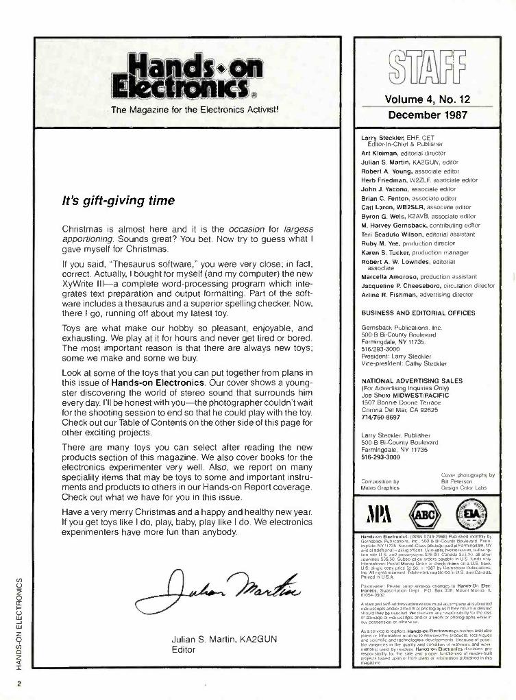
It's gift -giving time
Christmas is almost here and it is the occasion for largess apportioning. Sounds great? You bet. Now try to guess what I
gave myself for Christmas.
If you said, "Thesaurus software," you were very close; in fact, correct. Actually, I bought for myself (and my computer) the new XyWrite III -a complete word -processing program which inte- grates text preparation and output formatting. Part of the soft- ware includes a thesaurus and a superior spelling checker. Now, there I go, running off about my latest toy.
Toys are what make our hobby so pleasant, enjoyable, and exhausting. We play at it for hours and never get tired or bored. The most important reason is that there are always new toys; some we make and some we buy.
Look at some of the toys that you can put together from plans in this issue of Hands -on Electronics. Our cover shows a young- ster discovering the world of stereo sound that surrounds him every day. I'll be honest with you -the photographer couldn't wait for the shooting session to end so that he could play with the toy. Check out our Table of Contents on the other side of this page for other exciting projects.
There are many toys you can select after reading the new products section of this magazine. We also cover books for the electronics experimenter very well. Also, we report on many speciality items that may be toys to some and important instru- ments and products to others in our Hands -on Report coverage. Check out what we have for you in this issue.
Have a very merry Christmas and a happy and healthy new year. If you get toys like I do, play, baby, play like I do. We electronics experimenters have more fun than anybody.
Julian S. Martin, KA2GUN Editor
L
Volume 4, No. 12
December 1987
Larry Steckler. EHF. CET Editor -In -Chief & Publisher
Art Kleiman, editorial director
Julian S. Martin, KA2GUN, editor
Robert A. Young, associate editor
Herb Friedman, W2ZLF. associate editor
John J. Yacono, associate editor
Brian C. Fenton, associate editor
Carl Laron, WB2SLR, associate editor
Byron G. Wels, K2AVB. associate editor
M. Harvey Gernsback, contributing editor
Teri Scaduto Wilson. editorial assistant
Ruby M. Yee, production director
Karen S. Tucker, production manager
Robert A. W. Lowndes, editorial associate
Marcella Amoroso. production assistant
Jacqueline R Cheeseboro, circulation direct(
Arline R. Fishman. advertising director
BUSINESS AND EDITORIAL OFFICES
Gernsback Publications. Inc. 500 -B Bi-County Boulevard Farmingdale. NY 11735. 516 293 -3000 President: Larry Steckler Vice- president: Cathy Steckler
NATIONAL ADVERTISING SALES (For Advertising Inquiries Only) Joe Shere MIDWEST /PACIFIC 1507 Bonnie Doone Terrace Corona Del Mar. CA 92625 714 760 -8697
Larry Steckler. Publisher 500 -B Bi- County Boulevard Farmingdale. NY 11735 516- 293 -3000
Cover photography by :omposdlon by Bill Peterson
'.'rites Design Color Labs
A IA `® ö
Handson Eieetromcs .. 0/43.2968i Pubesnea monthly by Gernsback Pubiicatii.i. .00-B Bi.County Boulevard Farm. ingdaie NY 11735 SG, i, Ass postage paid at Farmingdaie. NY and at additional mailing offices One-year, twelve issues. subscrip- tion rate U S and possessions $28 00. Canada $33 00 all other countries 535 50 Subscription orders payable in U S hind.. . International Postal Money Order or check drawn on a U ` -
U S single copy pone $2 50 r 1987 by Gernsback Pun inc Ali rights reserved Trademark registered in U S and (.., Printed in U S A
Postmaster Please send address changes to Hands -On Elec- tronics, Subscription Dept PO Box 338 Mount Morns '.
61054 -9932
A stamped sell- addressed envelope must accompany all submitted manuscripts and or artwork or photographs it their return is desired should they be reiected We disclaim any responsibility for the loss or damage of manuscripts and Or artwork or photographs while in our possession or otherwise
Asa service to readers. Handson Electronics publishes mailable plans or information relating to newsworthy products. techniques and scientific and technological developments Because of posse ble variances in the quality and condition of materials and work- manship used by readers. Hands-on Electronics disclaims any responsibility for the sale and proper functioning of reader -built protects based upon or from plans or information published in this magazine

DO YOU
REALLY car THE BEST BUY
FROM
THEM? et 's face it: There will always be some outfit that can undercut a published price. They
do it by having no overhead, and no responsibility to you, the consumer.
"So. you want that Jerrold 450 combo? The one that Pact lcCafiN
Ce..1110.. is offering for $199°°? Well, that's a good price, but
here's what I'll do..." What may happen is that you may save a
couple of bucks at the time. But suppose there's a problem (and it happens to the best
of them.) and you call that "Dealer "... This could be what you'll hear: "No, Steve isn't here. He moved out, the bum! And he owes me $43700 on the phone bill! No, I don't
know about any guarantees on your Gerald, who's that? Listen, if you see that creep..." etc. At Pacific Cable Co.. you've got an established company who will be here for you, time after time. We may be tough competitors, but we've
got a soft spot for our clients! Try us, and be treated right -and we'll prove it by giving a one -year warranty on everything we sell.
Check our prices on Scientific Atlanta Units!
ITEM 1
UNIT 10 OR
MORE ITEM
1
UNIT 10 OR
MORE RCA 36 Channel Converter (Ch 3 output only)........ 2900 1800 Minicode(N -12) 8900 58.00 Panasonic Wireless Converter (our best buy) 8800 6900 Minicode (N -12) with Vari Sync 9900 6200 400 or 450 Converter (manual fine tune) 8800 6900 Minicode VariSync with Auto On -Off t4500 10500
'Jerrold 400 Combo 16900 1t900 Econocode (minicode substitute) 7900 5200 Jerrold 400 Hand Remote Control 2900 1800 Econocode with VariSync 8900 5600
'Jerrold 450 Combo 19900 13900 MLD- 1200 -3(Ch 3 output) 9900 5800 'Jerrold 450 Hand Remote Control 2900 1800 MLD -1200 -2 (Ch 2 output) 9900 5800 Jerrold SB- Add -On 8900 5800 'Zenith SSAVI Cable Ready 17500 12500
'Jerrold SB- Add -On with Trimode 9900 7000 Interference Filters (Ch 3 only) 2400 1400 'M-35 B Combo unit ICh 3 output only) 9900 7000 Eagle PD -3 Descrambler (Ch 3 output only) 11900 6500 M -35 B Combo unit with VariSync. 10900 7500 'Scientific Atlanta Add -on Replacement Descrambler 11900 7500
CHECK US OUT -WE'LL MEET OR BEAT THE OTHER'S ADVERTISED WHOLESALE OR RETAIL PRICES!
MaslrCartl VISA
Pacific Cable Co., Inc. 73251/2 Reseda Blvd., Dept. H -1 2
Reseda, CA 91335 (818) 716 -5914 (818) 716 -5140
NO COLLECT CALLS!
IMPORTANT When ordering, please have the make and model number of the equipment used in your area -Thank you!
*Call for availability
Prices subject to change without notice Jerrold is a registered trademark of General Instruments Corp
Quantity Item Output Channel
Price Each
TOTAL. PRICE
Cahforn a Penal Code 9593 -D forbids us from shipping any cable descrambling unit to anyone residing in the state of California. Prices subject to change without notice
PLEASE PRINT
SUBTOTAL
Shipping Add $300 per unit
coo d Credit Cards -Add 5%
TOTAL
Name
Address
State Zip _ Phone Number I
C Cashier's Check C Money Order
Acct 8
Signature
City
C C.O.D
Exp. Date
Visa D Mastercard
FOR OUR RECORDS
DECLARATION OF AUTHORIZED USE - i. the undersigned. do hereby declare under penalty of penury that all products purchased. now and in the future. will only be used on cable TV systems with proper authorization from local officials or cable company officials in accordance with all applicable federal and state laws
Dated Signed
3

L JLJ
Hands -on Electronics, 500B Bi- County Boulevard, Farmingdale, New York 11735
First Time Writer I'd like very much to submit a story to
Hands -on Electronics on how I wired up my home to prevent or detect un- lawful intrusion. I did a good job -that's what my wife and friends say. What I'd like to do is write a story about how I did the job complete with photographs and diagrams. What do I do? -W.F., Waco, TX
Stop writing letters and write the arti- cle. Sounds simple, and it is simple. You had no trouble writing a nice letter (we printed only a portion of it for our read- ers) giving us the details. if you can write a good descriptive letter to a friend. you should try writing for Hands -on Elec- tronics every time you build a project.
Here are some tips to guide you: Look through a recent issue of our magazine. find an article somewhat similar to what you want to write, and follow the style. That is, have a good opening and closing paragraph. Be sure that the parts list in your article is like the ones we publish - in our style. All diagrams should be drawn neatly -you don't have to be a draftsman. just neat. Photographs are important, but for small projects you can ship it to us at our request and we'll do the photography. Above all. be sure that what you build works well and can be duplicated by others. Use hard -to- obtain parts and you'll strike out every time.
So get busy. We'd like to see your article. Be sure to type the manuscript on white paper and double space the lines. If you can put the manuscript in ASCII on an IBM formatted disk. it will help. And, be sure the package is com- plete before you mail it.
He Writes Books Too! This writer. Louis E. Frenzel, Jr. who
writes the "Learn By Doing" articles for Hands -on Electronics is the greatest. I
read his articles in every issue. In par- ticular, I recall his series on "Digital Fun- damentals" a few years back. How can I
get copies of that? -A.S.. Irving, TX
You have a good memory for quality articles. The copies in question are out
of print (that's publishing talk for all sold out). I know that Frenzel has written a few good books. May I suggest that you send a stamped. self- addressed letter to Hands -on Electronics anda short note asking for the titles of Frenzels books. The office crew will forward the mail to Lou and he will find it easy to respond because of your envelope.
May I suggest that you get a subscrip- tion to Hands -on Electronics and save the issues.
Hard on Software Just got two things to tell you. One: tell
your readers not to put books and other heavy objects on top of floppy disks. Three very important diskettes crashed because of that. You see, the sides are compressed at the edged and locked the Mylar disk like a disk brake stops a car. To save the data, I cut away just enough from two sides of the disk cover and slid out the magnetic floppy. Then. I opened my computer's cover to expose the top of the half- height diskette drive. I slid in the floppy (which was very floppy) and got it
spinning. You'll find it easier to serve it
into the drive with one side of the old cover as a platter. It's like serving a pizza in a hurricane, but it worked. I saved two disks.
Every so often the staff reviews a soft- ware program that costs me money. That's right, I buy everything you review. I'm not complaining, but I am asking you to keep it down to one review an issue. It
takes thirty days for my wallet to recover. -FG.. Alfred. NY
Thanks about the tip on diskettes. May I add that the scissor or razor used to trim the edge of the diskette be de- magnetized before you proceed. Of course. what you described is the abso- lute last effort before you give up.
As for our software reviews. We got one this issue that will strengthen your will. Look for it!
Antique Radio You did a disservice to the antique
radio collectors of the world by publish- ing such a beautiful cover on your Oc- tober, 1987 issue. The antique radios
shown on it along with the phony one came out beautifully. I went to a flea mar- ket and one peddler displayed your cover. A sign next to it said "Buy Them Before Everyone Starts Collecting." Are any of the original radios pictured for sale? -K.H.. Dayton, OH
No. You never let go of the valuable family jewels.
Why Not Try It? Your "Circuit Circus" column provides
many exciting and simple diagrams for project builders to use in building proj- ects. Why not come up with a series of sample projects over the next year, so that when they are all interconnected they will function as an IBM XT comput- er? -T.S.. Denver. CO
Oh, boy! That's a big order that will not pan out. For example, once the series of projects begin. the builders are locked in to a year -long project. during which time motherboards for XTs my drop in price to below the cost of parts for the project. In fact, I believe that that is the case now.
That is why you see so few power - amplifier projects in our magazine. At half the price, you can purchase a ready - made unit that works better, and it has a warrantee. We'll stick to the simple and easy.

7 7 _ _ - ____ __,_ 17 C O R P O R A T I O N
1- 800 -344 -4539 AK, Pueno"Rico 218.881 6074 Tele 82827914 FAX 218 -881 -7180 TWA 9103508982 MCI KEY CORP
EACMAC J.N7 MCILIERAAVIDENGNEI MEW' 256K (262,144 x 1) DRAM 150NS $5.7011; $39.9519 éSDCWIND SOTRIDESÁMDEKGE.
E.F., JOHNSON *ATLANTIC SEMICONDUC Factory Firsts ,CACHEMICALOSRIESIEPLESSEDV
INTEGRATED CIRCUITS
00C.43 MAW
SA 7 en
AMOS 74
CMOS
.101.03 .
.
.
-
400 4t C Os
.
. .
..
.
.
.
. '.
.
.33
SOLDER TAIL , DIP SOCKETS .!-'- . ....
' .. aaAsawaTAa ......".. 0 w
Ir or
.
WIRE WRAP .r y DIP SOCKETS 9.4.311...
- _._ .. .
liti
.,. .,r.. .l>v ... P.....
r
r nt
..
.
.
.
o
.
n
.
. ,.
y y" ' ' '
.
' oee
...M......r
.. ...
'
7. 50
w . M., re
.
.
r .
4
20 03
nIR s /0 1315141 7 .. ...ws. au m
, ,
a
13 .. .
16
nr n
.. .
..... ,.. 5495
1 ., ..wu.
t .. ...y ,. 1
1344.1.3 m.. ir.. s
+rrwrsr `wr.Iws .044.4.... . ,. N..w44r.4.ae.. b w..
`ea aa tros00ao
UK KATI 0 sems *stow re
^ It CO
IS ot ...... ra .on .Nm . . SG m
inner w. 1 o us go 4
" m ,m
30 00 -
rEps 1-131
.
-
-. .
-
7. ....eh,.
1., w.ro- 10
l' Mete! Film Fed Reslstors ..w .
1111 I ¡er
' .
rrwa...a.y op..T... 14.. .i r
.`..T . .«, r...P,:w. G IS IMO
r,.. IA 10.
.. m o,n .. An 'r nv..... n. ....
.. .n.
III i... .. Xt. Ir:.Un ...,r-.
....... OM C.A..... .sser..r e. .
CAT ...uu44..44'II 1
Dw
310 DISC CAPACITORS 24'
PANASONIC LS SERIES ..,................,r4.u.a...cn..n.. r . . ....
ur pc .m .o ,.
..
.
4 , ..0
. DD A
Met.RUMPoIT0ste0Caln0itds ,. .. . .
1 01 PO
1 SI 19 1 01
314 XI 24 1 01 v ! IS ' IS A
.=. 5
.A.els '549
_.
22
D f]f
ní
..
..
0o 3.341 n T
`
.my.
4 .4 .y,
.
_
wwnt..
4040,00
m
r r
r. 0r.. o.
..... m m m
:r::.__: .. . 00 ASA 'n
,xu w '
Min V..., .u. o.
rI.m [MOs
. .
.. .... >.
.,
., .
,
. .
..
- .
goo 10 I, nos .o nm .m éñ .n ::. im u i m
.
,m m
PANASONIC V-SERIES sr... , r. c.... ....
P.rr..44r.... +.y. . 0..r".+' ' .iroarrir f `Fwr.t.ruy y a.+ro WO. .mw....
.. ...,,. .... .
NEC Memory Chips ' °e.. w RAM
'° . °. Ñ0°°o Do-o
++errc>d ú..0 °!r Abe tPa.. a. T...
. .ve. nno
"LL 1.413.81
nw ..
.. . .. ..
NEC Microprocessor Chip.
4
.... . e
W °' .w o ° Agn
e ...
-
n .4 ...,.......,,,,,,,, .. st on is
w l.
.
. .
M
r '
rr un 00 0 OS
aMe.. y..,.-' 4aw
r44.... '. . ' r .......
....w : _ .. . . ,
II . ..
. .. .. r
..
oam . r , ..
om
.r. , . 0 O A
10 1 431 14 03 10 1 410 14 40
, m
.
.
r-I 00.010i :a .. .. - .n.
..
.... ..... . ~ . .....
.
swn4.0as..r. - .. wr.44 1 u A w ®
S Am
A 10 3.44.1
GAM
oV 40 A
wu D IS
. ..... ,m.l4.rP m.
......................_, e.
. .
.
.
I
.074 -I._ .107 P. w! 4 >. I, e ®
otí~. .
Pro DO., .
. .
-1 775-rn 1 000-1
. n Asr: .4c.wcrn.. .001004 40or10 Oat. POPULAR CAPACAO. 3995
=11 L 1
053 .210 . 04.3.1... w .. m '...
TM DItLRey.dum d.cum eM l.eu y..r9w..ne4 to PPtT Mm MA. wild by Dip Rey evy G cp...bW tar ..pn. d.cd,nt AMA tM w not 0.cantW4 n mnM.d by tl..AAA 0. ASIOno. demon To don ND Hh.PI -M M.yWPrSr.Emwr..coeddr.ntMU.S.AwGr W44 W..wwMndocedroner >.r.at.p44aadw
oW. odd M non d.Ca.nUtln.m Th. WdtM.M nor on., rosel POO
Dp,Rer oNy.os ppr..tan d. cwemmW U S A4Ya. ma. C.ed r.d Mono WIRE OMDEIIRS ET MOME, CALL I 9N-74441791A1. wll 211411 11741 99 MWL MID TON OIRER TO 0611E9. .0. Mss 177, Thiel BM Fsls WM 51781.
Yeti m.y PA by cha, .wr ad., Mnt. Chrq. VISA a C O D DIOH(EY OYARAMtEE- Anr p.n4 w producIS .tru from ON n.M 133,0 p t. w 3111,43111,4303.03 a.eu^d d d mv.r eeh4490 days Iron tcK vd8 eprA your mu -AMES SUCT TO lemma NOME.'
SERVICE CHARGES 0.00 - 9.99 Add 12.00
s 10 00.125 00 Add 0.75 1 25 00.$49.99 Add 10.50
50.00 -$99.99 Add 10.25 $1000 Up No Char e
VOLUME DISCOUNT 0.00 -t 99.99 NET
1 100 00 9249 99 Loss 10% 250.00$499. N L. 15/.
1 500.00 -$999.99. Less 20% 10008 Up Le 25%
CIRCLE 12 ON FREE INFORMATION CARD 5

6
i\J
Printer Stand The Vertistack Printer Stand supports
an 80- column printer and its paper with- out using any desk space. The user may install the Vertistack Printer Stand four ways: over the monitor, off the side of a
desk or work surface, hanging from an office partition, or fastened to a wall.
CIRCLE 74 ON FREE INFORMATION CARD
All popular types of 80- column printers are accommodated. Slots in the shelves and hase of the stand neatly route the printer paper. power cords, and data ca- bles. Suggested retail price of the Ver - tistack Printer Stand is $75. For additional information contact Vector, 50 Airport Parkway. Suite 64. San Jose. CA '15110: Tel. 408/947 -4621.
Bus Extender Design Breadboard Chenc4 Products Model PC -601 XT
Bus Extender and Breadboard Lab is made tiff designing. testing. and trouble- shooting of circuits to he used with those same XT -style computers.
The PC -601 XT is comprised of a one - half siic buffer expansion card which plugs into an expansion slot in any IBM PC /XT or compatible computer. The card picks up the XT bus signals which are buffered and sent via a 24 - -in. ribbon cable to the Breadboard Lab where they are received and made readily accessible on the front panel. The bus signals are clearly labeled and shown on the lower right side of the PC -60I. The PC -601 has a large - size standard spacing breadboard work area with 3060 tie -points located in the
center of the lab. The work area is used for the building and testing of circuits to be used with an IBM PC /XT computer types. Connections to the breadboard work area, prototype circuit and bus are made using standard AWG #22 wire which can be easily removed and rearranged. Compo- nents are easily inserted. rearranged and removed with ease from the breadboard area.
Included On the front panel of the PC -601 are independent dual line -voltage 12(1 220 -volt powered supplies of +5 V (3A).- 5V(0.5A), +12 V(1 Aland -12 V (0.5 M. All supplies are short- circuit protected.
A 4:1 TTL multiplexer is also included which enables the viewing of 4 logic sig- nals simultaneously on a single -channel oscilloscope. Each signal is alternately DC level displaced or chopped by front - panel switch selection. A SYNC output is made available for oscilloscope trigger- ing. A 60 -pin bus output connector lo- cated on the front end of the lab enables the interconnection of more than one PC -601 for more complex circuits.
CIRCLE 72 ON FREE INFORMATION CARD
The model PC -60I XT Bus Extender retails for $369.95 and includes the one - half size buffer card, ribbon cable, bread- board lab, operating instructions and one year warranty. For further information contact Chencsko Products. Inc.. 21 Ma- ple Street. Centereach, NY 11720: or Tel. 516/736 -7977.
Inspection Light The ACU -\11\ Inspection Light has a
multitude of uses that is ideal for inspec- tion work and may he used for trou-
bleshooting. kit assembly. repair tasks. and many other purposes.
The new ACU -MIN Inspection Light k perfect fòr reaching difficult to see areas deep into a chassis. It features both straight and curved connecting rods. The
CIRCLE 69 ON FREE INFORMATION CARD
straight rod carries the battery -powered light down straight passages. while the curved rod makes it possible to conduct light around corners to reach places not normally or easily seen. A small mirror lits snugly on the end of either attachment rod lòr peek -a -boo viewing. The Amer- ican -Made ACU -MIN Inspection Light is powered by pen -light batteries, and comes complete with a see- through. 4 -1/2
in. X 7- 3/4-in. storage pouch. Moody Tools. Inc., is headquartered at
42 -60 Crompton Avenue. P.O. Box 230, East Gr enwich, RI 02818: Tel. 401/885-0911.
" II reu ,got duo componer .sooner narbe ruar huir nouldn'I hure nu-ned whiie...

Electronics Cleaner The secret to prolonged lite and proper
operation of all electronic and electrical equipment is TEC (Total Electronics Cleaner). TEC is an improved türmula containing a cleaning product that has
been used by professional service techni- cians for years. and is now available to the general public.
TEC is a non -conductive, non -toxic. residue free, anti- static, rapid drying, electronics -grade solvent, that removes dust, dirt, oil, and oxides. It is completely safe for use on computer. video, audio. telephone, and business electronics
Total Electronics Cleaner ,tt,c-ct cr
CIRCLE 95 ON FREE INFORMATION CARD
equipment. In fact, TEC can he used for almost an home or office application re- quiring a high grade electronics cleaner. A two or three second spray is all that it takes.
Available in an 8 -ounce spray can for $8.00 post -paid from Lab Product. 29501 Greenfield Road. Suite 109. Southfield. MI 48076.
Software Circuit Library It usually takes hours to draw schematic
diagram on a computer, but it doesn't have to! Microcomputer Circuit and Symbol Library is a live- diskette software package that contains over limy pre -drawn basic. familiar. high -resolution circuit graphics. A Circuit drawing designer program is
included which can he used to add addi- tional circuits to your library or modify and /or expand existing library graphics. Animated and other programming rou- tines demonstrate and explain how elec- trical circuit graphics can he used in your own Applesoft programs.
The library includes electrical funda- mental programs on basic electrical sym- bols, electrical unit conversions, scien- tific notation, resistor color code. series and parallel circuits and advanced linear circuits.
Diskettes are unprotected. Backups
B
R
A
MICROCOMPUTER
AND SYMBOL LIBRARY
CIRCLE 83 ON FREE INFORMATION CARD
may he made using standard copying pro- cedures. Easy -to -read instructions with keyboard menu card. Price: $159.95 (Softcover) $169.95 (Hardcover. 3 -ring hinder version)
To operate the software package your computer requires 48K RAM. one disk Drive and must be a compatible version of the Apple II computer family including the new IIGS. Available from Computer and Instructional Systems. Box 177. Hol- ly. MI 48442.
ESP HOLD IT ANYWHERE YOU WANT IT!
PanaVise electronic work holding systems allow you to position. tilt ,out n ttttt
your projects without removing them
from their holding devices! With over
30 years experience and made -in -USA
quality, PanaVist ensures reliable, long -
lasting service.
MULTI -PURPOSE WORK CENTER:
Self- Centering Extra Wide Opening
Head (opens to 9" ), famous "split ball"
Standard Base (moves in three planes),
and convenient Tray Base Mount (with
parts ems with ease! Modeli#350. 549.95 5
ELECTRONICS CHASSIS HOLDER:
Hold up to 100 lbs. (45 Kg) with our
sturdy, efficient Chassis Holder. Fea-
tures 9" pivot-center height, positive -
lock detents, and all metal friction
brakes for left /right -hand use. Knobs
are at a natural angle for seated opera-
tor. Rugged, durable and convenient!
Model #60l (with scissor clamps for
odd- shaped chassis). 8199.95. Model
#602 (with self- centering, extra wide
opening heads). $199.95.
CIRCUIT BOARD HOLDER: Eight
position rotation, tilt -angle and
height adjustments plus six positive -
lock positions in the vertical plane
mean convenience and versatility!
Spring -loaded arm holds circuit
boards securely, but allows quick.
easy removal and replacement. Per-
fect for component insertion and sol-
dering: a must for maximum work
efficiency. Model #333. 845.95.
See icctnnuo supplier orcontactPana'isr
for nearest you:
Long Beach. ( A 90/406; 2131 595-7621trceL
CIRCLE 5 ON FREE INFORMATION CARD 7

8
P.O. BOX 567 VAN NUYS, CA 91408
BLACKLIGHT ASSEMBLY Fyn f functioning assembly t, includes ballast, , .c-- ¡,(
on -off switch, = power cord, sockets and F4T5 -BL blacklight. Mounted on a
7 1/8" X 3 1/8" metal plate. Use for special effects lighting or erasing EPROMS. CAT* ALTA $10.00 FACH
1 mA METER
Modutec 0 -1 mA signal strength meter with KLM
'
i'
logo. 1/4" X 1 3/4" X 7/8" deep. CAT* MET -2 $2.00 each
PUSHBUTTON PHONE Spectra -phone Model@ OP -1 VI 1 piece telephone with rotary (pulse) output. + Operates on most rotary or touch tone systems. Features last minute redial and mute liik
button. Includes coil cord with standard modular plug. IVORY. CAT* PHN -1 $8.50 EACH
FOR $15.00
SWITCHING POWER SUPPLY Compact, well regulated switching power supply designed to power Texas Instruments computer equipment. INPUT:14 -25 vac @ 1 amp OUTPUT: +12 vdc @ 350 ma.
+5 vdc @ 1.2 amp i _I -5 vdc @ 200 ma.
SIZE: 4 3/4" square. cs...__i;_, Includes 18 Vac @ 1 amp
wall transformer designed Co power this supply. CATi PS -TX $5.00 / SET
10 FOR $45.00
SLIM LINE FANS TOYON TF92115A New 115 Vac cooling fan. 3 5/8" square X 1" deep. Metal housing. 5 blade impeller. CATI SCFE -115 $8.50 each
t.c 1;11:;04. '
1, ̂_ ' 10 for $75.00
VIC 20 MOTHERBOARD 26 ICs including "'TT* V -' 6502A, 6560. `I1
.
pua - / 2 ea. 6522, tit/ /7 mull ! 2 ea, 8128, _° tf a- 4i 2 ea. 901486, 3 ea. 2114. Not guaranteed but great for replacement or experimentation. CAT if VIC -20 $15.00 each
ELECTRET CONDENSER MIKE Mouser* 25LM044 Highly sensitive,.. mini microphone. 6" wire leads. .39" dia. X .27" high. Omni directional. Operates on 2 -10 Vdc @ less than 1 mA. 1K impedance. 50 to 8 K Hz range. CAT* MKE -1 $1.00 EACH
12VDC. - 4PDT RELAY Guardian@ 1315P 5 amp contact,- -
w-' 150 ohm coil. P.C. terminals. 1, Clear plastic dustcover. 1Vu'.t
CAT* 4PRLY -12PC $3.50 each 10 for $30.00
SEND FOR FREE 48 PAGE
1987 CATALOG
IOUR NEW ADDRESS IS P-O. BOX 567
VAN NUYS, CA 91408 800-826 -5432
TOLL FREE ORDERS n'im y
800 -826 -5432 , +" n; r INFO "(818) 904 -0524 .row; w°1 FAX - (818) 781 -2653 = '"
s ",n,w "T
CIRCLE 9 ON FREE INFORMATION CARD
Cassette Equalizer A popular- priced AM /FM stereo cas-
sette player with a three -band graphic equalizer is being introduced by Spar - komatic. The model SR37, which has a
suggested list price of $69.95, features an illuminated dial. AM /FM. Mono /Stereo and Local /Distance pushbutton selection, and three -band, slide, tone controls.
Other features of the Model SR37 in- clude LED stereo and tape -play indica- tors, tuning and balance controls, and a
fast forward /eject pushbutton. The radio/ cassette player comes complete with mounting hardware.
CIRCLE 97 ON FREE INFORMATION CARD
Audio power specifications are 9 watts at I0r4 (rms) THD. and 7.5 watts at 1 %/r
(rms) THD. The SR37 measures 7- W x I -.1/4- H x 4- 3 /4 -in. D.
For additional information about the SR37. contact Sparkomatic Corporation, Milford, PA 18337: Tel. 800/233 -8831. In Pennsylvania 800/592 -8891.
Satellite Receiver Satellite lechnology Sen.ices. Inc. SR
100 receiver and a companion remote con- trol unit called the Smart Remote Pro- grammable Controller, is an integrated receiver descrambler (IRD) with features that include full stereo, matrix discrete and digital when accessing VideoCipher II descramble channels, full on- screen graphics (not just on VideoCipher II de- scrambled channels) and 34 favorite pro- gram recall. With the capability of storing up to 54 satellite locations and 7 pre- programmed polarity formats, the SR 100 is a C /Ku friendly receiver. All system functions can be operated by the Smart Remote programmable controller.
With the Smart Remote Programmable Controller, users are provided the conve- nient capability of operating every in- frared remote component in their home entertainment system, regardless of brand, with a single remote -control unit. The Smart Remote is capable of learning
CIRCLE 86 ON FREE INFORMATION CARD
the operating codes of different infrared remote control units and it is that unique feature that enables the unit to operate any mix of remote controlled TVs. VCRs, compact disc systems or stereo receivers. The Smart Remote programmable con- troller can be easily programmed by the user Programming and operation is fur- ther simplified with the aid of the Smart Remote's built in liquid -crystal display.
For more information on the SR 100 satellite receiver and Smart Remote pro- grammable controller contact Satellite Technology Services, Inc., 11600 Lilburn Park Road, St. Louis, MS 63146: Tel 314/567- 0304.
Keyboard Voices and Sounds A wide variety of PCM polyphonic,
bass, solo, and background sounds can be combined with abundant PCM rhythm patterns and an array of sound effects in the Technics SX -K700 and SX -K500 key- boards. In addition, there are features such as a tour-channel, multi -track se- quencer, sound edit, and a complete MIDI implementation for added keyboard creativity.
The PCM- sampled presets includes 48- polyphonic voices. That music matrix groups voices into electronic, contempo- rary, and classical.
With sound edit, effects such as attack, release, and delay, vibrato can be added to all polyphonic and solo sounds to create and store an array of sounds in any of 16
CIRCLE 88 ON FREE INFORMATION CARD
.S(nnruN(' .cpill rhu(npu,qnr i(uu i('A
(((U(l(9H -

CIE MAKES THE WORLD OF ELECTRONICS YOURS.
Today's world is the world of elec- tronics. But to be a part of it, you need the right kind of training, the kind you get from CIE, the kind that can take you to a fast growing career in business, medicine, science, government, aerospace, communications, and more.
ecialized training.
You learn best from a specialist, and that's CIE. We're the leader in teaching electronics through independent study, we teach only electronics and we've been doing it for over 50 years. You can put that experience to work for you just like more than 25,000 CIE students are currently doing all around the world.
tactical raining.
You learn best with practical training, so CIE's Auto -Programmed® lessons are designed to take you step -by -step, principle -by- principle You also get valuable hands -on experience at every stage with sophisticated electronics tools CE-designed for teaching. Our
4K RAM Microprocessor Training Laboratory, for example, trains you to work with a broad range of com- puters in a way that working with a single, stock computer simply can't.
rsonalized training.
You learn best with flexible training, so we let you choose from a broad range of courses. You start with what you know, a little or a lot, and you go wherever you want, as far as you want. With CIE, you
can even earn your Associate in Applied Science Degree in Elec- tronics Engineering Technology. Of course, you set your own pace, and, if you ever have questions or problems, our instructors are only a toll -free phone call away.
e first step is yours.
To find out more, mail in the coupon below. Or, if you prefer, call toll -free 1-800-321-2155 (in Ohio, 1-800-523-9109). We'll send you a copy of CIE's school catalog and a complete package of enrollment information. For your convenience, well try to have a representative contact you to answer your questions.
AHO-71 C I E Cleveland Institute of Electronics 1776 East 17th St., Cleveland, Ohio 44114
YES! I want to get started. Send me my CIE school catalog including details abo""t the Associate Degree Program. I am most interested in:
computer repair television /high fidelity service telecommunications medical electronics robotics /automation broadcast engineering
other
Print Name
Address Apt.
City State Zip
Age Area Code /Phone No.
Check box for G.I. Bulletin on Educational Benefits Veteran Active Duty
CIRCLE 6 ON FREE INFORMATION CARD
MAIL TODAY!
11

NEW PRODUCTS internal -memory locations. A total of 64 polyphonic sounds can be played, and ed- ited solo preset sounds can be stored and used polyphonically.
Twenty-four PCM sounds are found in the solo preset section, and a music ma- trix voice grouping eases voice selection. Those can be played as a two -note melody, or mixed with polyphonic presets the solo section to play the top note of the chord. Eight edited solo sounds can be created and stored in the internal memory, as can edited polyphonic preset sounds.
The dynamic PCM bass presets cover eight sounds, ranging from acoustic bass to synthesizer. The SX -K700 also in- cludes a collection of PCM- sampled natu- ral sounds such as a murmuring stream, chirping birds, as well as thunder, bells, and gunshots.
With the four -channel, real or step -time multi -track sequencer, bass accompani- ment, polyphonic, and also parts can be recorded individually, allowing the user to concentrate on playing each part for easy multi -track recordings. Each track can be edited individually. Sixteen preset rhythms, including contemporary, Latin, and pop are available. Three commonly used rock patterns, three pop patterns, and two disco patterns are included, with sound variations making for a total of 32 selections.
A tap on the drums button of the varia- tion section adds additional percussion sounds to each rhythm. The four bass and accompaniment variations complement the rhythm selected, offering a total of 64 different patterns.
Playing horizons are expanded further as world -standard MIDI in /out terminals let the user connect the SXK700 or SX- K500 to MIDI- equipped instruments such as keyboards and synthesizers for ensem- ble play, or to a compatible personal com- puter for high -tech performances. Up to five channels can be driven at once.
The instrument will recognize and re- spond to MIDI velocity information provided by any MIDI compatible ve- locity- sensitive keyboard or a compatible PC with the appropriate software.
For complete information (much more than given here) contact Technics, One Panasonic Way, Secaucus, NJ 07094: Tel. 201/348 -7000.
Radar Detector BEL- Tronics Limited has added anti -
Rashid VRSS circuitry to its model 880 Micro Eye Quantum radar detector. The Quantum is the world's first compact - size, high -performance radar detector of- fering user adjustable selectivity modes to eliminate false alerts with no decrease in sensitivity. The Quantum utilizes a Gal- lium Arenide (GaAs) mixer diode to maintain its long range sensitivity by re-
CIRCLE 81 ON FREE INFORMATION CARD
ducing signal conversion loss at the initial processing stage. BEL has added the new circuitry and a windshield mounting bracket at no increase in the detector's suggested entail price of $329.95.
Circuitry included in the Quantum uses a microprocessor to analyze the incoming K -band signal and to make the fine dis- crimination between the unmodulated po- lice radar signal and the modulated Rashid signal. If the signal is sensed as police radar, the detector instantly gives an alert. If the signal is seen as Rashid, no alert is given, but the detector remains "on watch."
For further information, BEL-Ironies at 800/828 -8804, 800/424 -3201 in New York.
Text -to- Speech Converter Swisscomp's Smart Speaker will con-
nect to any computer having a standard parallel or serial port. It will work with any software that puts out ASCII to drive a printer. It does not require an additional slot or I/O port since it can share the printer port via the built in AB switch. A serial port is also provided for those ap- plications that require RS232 com- patibility.
CIRCLE 99 ON FREE INFORMATION CARD
The Smart Speaker converts ASCII text to speech and speaks it out with an amaz- ing accuracy through it's built -in speaker. Numbers and text separated by spaces or periods are spelled out. Advanced text -to- speech algorithms make it easy to use so that no special software is needed. Ac- cepts data in formats that printers accept. The Smart Speaker does not require any programming or other skills to hook up as it comes complete with a parallel cable ready to be connected to your existing printer.
Additionally, the Smart Speaker, through its line output can drive an exter- nal amplifier, VCR, audio tape recorder, phone answering systems, etc. An exter- nal speaker may be connected.
Smart Speaker is available as a stand alone unit complete with parallel printer cable and DC power supply at $229.95 or
as a package called the Smart Connection for order processing at $549.95. That package is for industrial and office ap- plications bundled with a 1200 baud inter- nal modem for IBM PC /XT /AT and compatibles that recognize touch tones, has a clock calender, an 8K Electronic mail buffer and is Hayes compatible. Smart Connection with an external modem will be available at $599.00
For more information contact Swisscomp Inc., 5312 -56th Street, Tam- pa, FL 33610: Tel. 813/628 -0906.
Morse Code Tutor Program This full feature Morse Code Tutor Pro-
gram for the Commodore C -64 and C -128 not only teaches Morse code but it is also a full pledge iambic keyer and Morse key- board! With the optional $19.95 MFJ -76 interface board you can plug in an external keyer paddle and key a transmitter or transceiver.
: : .. uurna r.rrr
CIRCLE 55 ON FREE INFORMATION CARD
The disk version MFJ -1266 retails for $19.95 and the cartridge version MFJ -1267 retails for $29.95.
The program follows the format of ARRL's "Tune in the World" and can be used with that course, or it can be used with the MFJ supplied code -learning course. The MFJ Morse Code Tutor fea- tures select random -lets you choose the letters you wish to study; complete ran- dom -sends all alphabet, numbers and punctuations randomly; random mes- sage -sends a plain English message ex-
"... Tonight at 2200...118(1 fiar run...pass it on

actly as given on an FCC test or received measurable lower noise and cross -talk. on the air: message store-lets you enter a The Pro -Control Four has the capability message from the keyboard and store kw kw handling up to eight input sources: sending. MDNM /CD Phono. Tuner. Tape I. Tape
Each mode can use the normal CW 2. Vid /Aud I. Vid /Aud 2. and Vid /Aud 3. spacing or the special Farnsworth spacing The sources selected tiff Line Out or Tape that sends characters at a fast pace with Out (or both) are indicated by LED il- longer space between characters.
A copy of a test similar to a FCC lumination. Automatic muting insures elimination of noise during source selec-
Novice license test is included in the man- tion. ual. Eight outputs are available: normal A &
For additional intürmation contact MFJ B line outputs. electronically inverted A Aol
Enterprises. Inc. at P.O. Box 494. Mis- & B line outputs kw tripling the power by sissippi Statc, MS 39762: Tel. bridging. an independently amplified 800/647 -1800 or !,O1/323 -5869. headphone output. and live tape outputs:
tape I. tape 2. Vid /Aud 1.1 and 3. Two Control- Center'Preamplifier additional inputs and outputs are provided CIRCLE 70 ON FREE INFORMATION CARD
The new Pro -Control Four from Sound- tier processing of either line or tape sig- Soldering Desoldering Station craftsmen provides CMOS digital- nais. plus swithchable sub -sonic filters tür The model S --1 Control l :nit is designed control. electronic switching kw noise- both line and tape signals. as well as bass
and treble controls. k) convert any soldering iron into an ad- justable temperature soldering station.
There is also a direct mode (straight The unit works with any I10 -VAC - line) to bypass the external loops, sub- sonic litter, and tone controls. The direct
powered soldering iron up to 1(X) watts in size.
- -
mode selection eliminates all signal pro- Solid -state circuitry is used to produce
CIRCLE 90 ON FREE INFORMATION CARD cessing signal paths to allow tilt the uti- lization of the full capabilities of CD
a spike -free. adjustable. DC voltage and to minimize the possibility of damaging
free recording and listening. All signal players. critical components. routing is accomplished with Sound- The price of the New MOS -TROL Dig- The S -4 Control Unit sells for $48.95. craftsmen's new MOS -TROL circuitry. ital C -MOS Control- Center Preamplifier For further intirmation contact Sybex That allows all Signal Paths to be op- is $699.00. For further intürmation. con- Inc., 1088 Kapp Drive. Clearwater. FL timized and located near the input and tact Soundcraftsmen. 2200 S. Richey. 33575: Tel. 813/441 -8525. output PC -board mounted jacks with Santa Ana, CA 92705 :Tel. 714/556 -6191. /Continued on page IO21
,..
Let MCM Be Your Guide! Your 160 -Page Guide to the parts, accessories and equipment you need!
Unbeatable Selection Competitive Prices Many New Items Convenient Ordering
You can always depend on MCM to keep you headed in the right direction! We back our catalog with courteous sales people, free technical advice plus fast, efficient delivery.
PAS / For your FREE copy, call TOLL -FREE! Ar 1- 800 -543 -4330 ~ Ohio, 1- 800 -762 -4315
FREE CATALOG Alaska and Hawaii, 1- 800 -858 -1849
MCM ELECTRONICS 858 E. CONGRESS PARK DR. CENTERVILLE. OH 45459
A PREMIER Company SOURCE NO. HO -09
CIRCLE 10 ON FREE INFORMATION CARD 13

U D
J
14
BUILD -IT BOOKS FOR EXPERIMENTERS
Modern Op An,I, Protect,
BP106- MODERN OP- AMP PROJECTS .
$5.00. Wide range of build - it projects that use op- amps. Easy to build board layouts provided for most. A variety of projects of all kinds are included.
a 223 -PROJECTS to USING THE CA3130 .... $5.00. 50 different ways to put this op -amp to work in- cluding audio. RF. test equipment, household and miscellaneous projects
IC IMaPrebd.
=ha.
4 BP44 -IC 555 PROJ- ECTS .... $5.95. Included are basic and general timer circuits. automobile and model railroad circuits. alarms and noise makers. as well as a section on 556. 558, and 559 timers.
#224 -50 CMOS IC ilk PROJECTS .... $5.25. These IC's are suitable for an extraordinary range of applications. This book shows you just how much you can do with them
Second Book of cuca IC Projects
/OCMO{IC PtepM.
4 BP59 -2ND BOOK OF CMOS IC PROJECTS... .
$5.00. Still more ways to use these versatile devices. None of these projects over- lap those in book #224. The pair make a wonderful circuit reference set.
BP84- DIGITAL ICI PROJECTS .... $5.25. Both simple and more ad- vanced projects to help the reader develop a knowl- edge of the workings of digi- tal circuits. A number of board layouts are included.
MOM IC Proikooto
MAIL TO: Electronic Technology Today Inc. P.O. Box 240 Massapequa Park, NY 11762 -0240
SHIPPING CHARGES IN USA 8 CANADA $0.01 to $5.00.. . $1.00 $30.01 to 40.00... $4.75 $5.01 to $10.00 ...$1.75 $40.01 to 50.00...$5.75 $10.01 to 20.00... $2.75 $50.01 and above $7.00 $20.01 to 30.00...$3.75
OUTSIDE USA & CANADA Multiply Shipping by 2 for sea mail Multiply Shipping by 4 for air mail
Total price of merchandise $ Shipping (see chart) $
Subtotal $ Sales Tax (NYS only) $
Total Enclosed $
Name
Address
City State Zip
L
r-
How to Build Your Own Solid -State Oscilloscope By F.G. Rayer
The cathode -ray oscilloscope is prob- ably one of the most useful test instru- ments available to the engineer and hob- byist. The scope can give visual insight into what is happening electrically in a
circuit. Although the oscilloscope is, in it-
self, a fairly complex instrument, it can be divided into various sub -sections which may be individually constructed and tested, then finally assembled to complete the instrument. That approach is adopted by the author. Clear and con- cise practical instructions are given - even the inexperienced hobbyist can con- struct a fairly sophisticated instrument with the minimum of difficulty and ex- pense.
CIRCLE 51 ON FREE INFORMATION CARD
Also covered are some basic uses of the oscilloscope as well as the con- struction of a sinewave oscillator.
Hole to build Your Own Solid -State Oscilloscope costs only $5.00 and is
available from Electronics Technology Today, P.O. Box 240, Massapequa, NY
1 1762.
Handbook of Practical IC Circuits By Harry L. Helms
The chapters of this timely tome form a practical compilation of IC circuits. All circuits are actual working designs using popular IC devices and all com- ponent values are included. There are
ti
CIRCLE 53 ON FREE INFORMATION CARD
descriptions of the operation of the cir- cuits showing how to modify and adapt circuits for desired applications. The text includes information on power supplies and circuit interfacing.
Among its key features, the book uses actual working circuit designs, includes popular, readily available IC devices. It describes linear and digital IC de- vices and major families such as TTL and CMOS and high -speed CMOS.
The author does not lose sight of the practical applications encountered in con- temporary electronics, and he explores the history and development of IC fami- lies and compares currently available families.
Handbook of Practical 1C Circuits costs $38.33, and it is available from Prentice Hall, Inc., Englewood, NJ 07632; Tel. 201/767 -5437.
Using Pagemaker On IBM By Diane Burns and Sharyn Venit
Now the power and sophistication of PageMaker (the program that started the desktop publishing revolution) can be yours with this easy -to -use guide. Whether you're a novice or an advanced user, you will benefit instantly with the explanations of PageMaker's many ap- plications and wide range of capabilities. For example, using Pagemaker on the IBM teaches you what font sizes and font styles are available for your par- ticular printers including apple's Las-

CIRCLE 56 ON FREE INFORMATION CARD
erWriter and Hewlett -Packard's Laser - Jet printers and Allied's Linotronic type- setter.
Every facet of PageMaker is detailed and explained for practical. hands -on use: installing PageMaker: creating text and graphics: placing, formatting and editing text. designing page layout. and printing. You will be taught essential typesetting and layout concepts such as
leading, kerning. and copy fitting as
well as ways to save time by using text and graphics from other programs and documents.
In addition to the detailed coverage of PageMaker's features. Using Page - maker on IBM explores design and pro- duction principles to show you how to create professional- l(x)king presentation materials, fliers. ads. overhead trans- parencies, annual reports. and more. If you don't want to start from scratch. you can copy the design specifications of the models in Part Ill. You also can modify those applications for your own needs.
The big bonus is the saving of design and printing costs possible with an amaz- ing desktop publishing program. taught to you the easy way with Using Page - Maker on the IBM.
The book costs $24.95 and is avail- able from Que Corp.. 7999 Knuc Road. Suite 202, Indianapolis. IN 46250: Tel. 317/842 -7162. Essential Theory for the Electronics Hobbyist By G.T. Rubaroe
In any hobby activity a background knowledge of the subject can consider- ably increase the enjoyment and satis- faction one derives from it. That view point applies to electronics in all its phases.
The object of the book is to supply the hobbyist with a background knowl- edge tailored to meet his or her specific requirements and the author has brought together the relevant material and pre- sented it in a readable manner with mini- mum recourse to mathematics.
Essential Theory for the Electronics Hobbyist
CIRCLE 51 ON FREE INFORMATION CARD
Many formulae having a practical bear- ing are presented and purpose -designed examples are employed to illustrate their applications.
Essential Theory f br the Electronics Hobbyist sells for $5.95 and is avail- able from Electronics Technology To- day, P.O. Box 240. Ma'sapequa, NY 11762.
Desktop Publishing Bible Edited by James Stockford
'Nis reference volume tells you what you need to know about desktop pub- lishing -from print production. typog- raphy, and high -end typesetters to copy-
A defense against cancer
can be cooked up in your kitchen.
there LS evldl'nee that diet and cancer are related Follow these m idiBUtkins in your daily diet tt t reduce chances of getting cancer I. Fat more high fiber lot MN such as fruits and L cgctable. and whole grain cereal, 2. Include (lark green and deep yellow fruits and vegeta
-
hies rich in vitamins A and c 3. Include cabbage, het tclult. brussels sprouts, kohlrabi and cauliflower 4. Be nu iderate in t iinsunys nun of salt cured. smoked, and nitrite cured ft uxl S. 1 ul d, sit on total sat ut take from animal .t met es and tats and tills 6_ Avt titi obese 7 He nu xlaratc in a onsunga non tif aktihathc het ,rages
I \ti t one latt'.t uni t'r alt MC
autatrtaw CANCER SocrEr
tktiklupp Publishing Bilk
CIRCLE 60 ON FREE INFORMATION CARD
car
"J. P. keeps coming up with not. It t, t /or his e.t'pensilr (onfputer.'
AG C!
An ETCHED circuit board
from a Printed PAGE
in just 3 Hours
The ER -4 PHOTO ETCH KIT gives you the tools. materials and chemicals to make your own printed circuit boards. The patented Pos -Nee process copies artwork from magazines like this one without damaging the page. Use the circuit patterns. tapes and drafting film to make your own 1X artwork. Or try the Direct Etch' system (also included). to make single circuit boards without artwork. The ER -4 is stocked by many electronic parts distributors, or order direct. postpaid. ER -4 PHOTO ETCH KIT (NJ and CA residents add sales tax) 437.00 DATAK'S COMPLETE CATALOG lists hundreds of printed circuit products and art patterns. Also contains dry transfer letter sheets and electronic title sets for professional looking control panels. WRITE FOR IT NOW!
The DATAK Corporation 3117 Paterson Plank Road North Bergen, NJ 07047
CIRCLE 14 ON FREE INFORMATION CARD 15

CIRCLE 7 ON FREE INFORMATION CARD
EARN YOUR
B.S.E.E. DEGREE I
THROUGH HOME STUDY Our New and Highly Effective Advanced- Place- ment Program for experienced Electronic Tech nicians grants credit for previous Schooling and Professional Experience. and can greatly re- duce the time required to complete Program and reach graduation. No residence schooling re- quired for qualified Electronic Technicians Through this Special Program you can pull all of the loose ends of your electronics background together and earn your B.S.E.E. Degree. Up- grade your status and pay to the Engineering Level. Advance Rapidly! Many finish in 12 months or less. Students and graduates in all 50 States and throughout the World. Established Over 40 Years! Write for free Descriptive Lit- erature.
OOK'S INSTITUT OF ELECTRONICS ENGINEERING
347 RAYMOND ROAD P.O. BOX 20345 JACKSON, MISSISSIPPI 39209
16 CIRCLE 8 ON FREE INFORMATION CARD
right inlornlation, equipment, and soft- ware. In this collection of essays ex- perts from virtually every field of desk- top publishing share their tips, tricks. and techniques.
Topics covered include: fundamen- tals of desktop publishing, computer sys-
tems and the desktop publishing en- vironment. software. copy editing, elec- tronic graphics, and layout, forms, and resumes. Add to that list printing the text, high -end typesetting and text for- matting, and the future of desktop pub- lishing.
Desktop Publishing Bible retails fbr $24.95 at most consumer and college bookstores, or you can write to Howard W. Sams & Co., 4300 W. 62nd Street. Indianapolis, IN 46268; or telephone your order to 31 7'24- 54(X).
The Tao of Programming By Geoffrey James
l he author's intention with this little book is to share with you a few serious thoughts presented on soft pillows o/' warm smiles. To give you an entertain- ing, tongue -in -cheek look at comput- ing through the eyes of the ancient mas- ters. The 33 epigrams presented have
passed through generations since the dawn of the computer age and torm a
philosophy of humor to live by and with which to work.
CIRCLE 63 ON FREE INFORMATION CARD
There are many books about program- ming. but they all deal with mere sur- face issues, such as algorithms and lan- guage constructs. The Tao f Program- ming goes right to the heart of the most important questions that face today's pro- grammers. Questions such as: What is
the meaning of life? Why do I exist' and How can I debug a program that
locks the keyboard'? The Tao of Programming , a must
for computerists who like to laugh. Avail- able from Info Books for $7.95. Info Books, P.O. Box 1018, Santa Monica. CA 90406; Tel. 213/470 -6786.
Top Secret Registry of U.S. Government Radio Frequencies, 6th Edition
fhi' unique scanner station book has become the standard reference source tier frequency and other important in- Ibrmation relating to the communica- tions operations of federal agencies. A partial listing of the agencies included in the 6th Edition: Federal Bureau of Investigation, Secret Service, Immigra- tion Service, Border Patrol. Drug En- lorcement Administration, Customs Serv- ice. Federal Prisons, U.S. Army, Al- cohol, Tobacco & Firearms, Central In- telligence Agency, Postal Service, Bugs & Surveillance Devices, Treasury De- partment. Central Intelligence Agency, U.S. Navy, National Security Agency, White House, Federal Marshals, Na- tional Park Svc.. and National Forests.
CIRCLE 67 ON FREE INFORMATION CARO
The listing keeps on going: NASA. U.S. Mint. Environmental Protection Agency. Dept. of Energy, Federal Avia- tion Agency, U.S. Marine Corps, Postal Service, U.S. Coast Guard, U.S. Air Force. Federal Communications Com- mission, Dept. of Agriculture, Federal Reserve Banks. Dept. of Commerce, Federal Emergency Management Agency, Nuclear Regulatory Commis- sion. Fish & Wildlife Service, General Services Administration, Health & Hu- man Services. Housing & Urban De- velopment. Bureau of Indian Affairs.
"I think t liked it better when he worked lute ut the o/'/'ire."

Dept. of Labor, State Department, Bu- reau of Land Management, NORAD, NOAA, Army Corps of Engineers, Na- tional Science Foundation, National Bu- reau of Standards, Tennessee Valley Authority, Dept. of Transportation,
production techniques for video. It cov- ers time code, electronic editing, digi- tal audio, multi -track audio, and live - broadcast stereo. The text addresses the specific needs of the audio track in video tape production and the new audio -for-
%%Ai11 Satdlhc Almanac Ihr I notplehe r.uhle
e. W.Ai. Ichr
A Ira "atis
-, United Nations, Civil Air Patrol, and E ' 1 6 video standards set for the industry. much more, including many Canadian $ -.7,14
listings! The book costs $17.95 (plus , - = f
--,.
$1.00 postage in the U.S.) direct from CRB Research, P.O. Box 56, Com mack, NY 1 1725.
CIRCLE 60 CARD ON FREE INFORMATION
marset maritime satellite system, Eu- World Satellite Almanac telsat and the European satellite sys- _
r Int
By Mark Long tern, Arabsat satellite system, Palapa 1
This edition has been updated and satellite system, and International Tele- q
expanded to provide a perspective of communication Union regions includ- t
existing and developing technologies in ing I , 2 and 3. CIRCLE 60 ON FREE INFORMATION CARD satellite communications. The book also World Satellite Almanac retails for contains more than 500 charts, maps, $34.95. It's available from Howard W. Topics covered include: The audio
tables, and graphs relating to satellite Sams, 4300 W. 62nd Street, Indian- tape recorder /video tape recorder, syn- footprints. apolis, IN 46268; Tel. 298 -5400. chronization, audio production for
Some of the topics covered include: video, audio post- production for video, Evolution of satellite communications, world video standards, satellite voice
Audio Production Techniques for Video
and introductory electronic editing tech - niques.
and data transmission techniques, in- By David Miles Huber Audio Production Techniques for ternational satellite reception techniques, Bridging the gap between the cur- Video retails for $29.95, from Howard the Intelsat global satellite communica- rently merging technologies of audio W. Sams & Co. Inc., Dept. R40, 4300 Lion system, Intersputnik and the So- and video production, this book out- W. 62nd St., Indianapolis, IN 46268; viet Statsionar satellite system, the In- lines modern audio production and post- Tel. 800 /428 -SAMS.
Rhino Robots Inc., the world leaders in educational robotics, presents the SCORPION, a versatile mobile robot kit designed spe- cifically for the experimentally minded hands- on computer experimenter and enthusiast. It is controlled through an umbilical from the RS -232C serial port of any personal computer. Demonstration software is available on diskette for both the Apple Ile and IBM -PC. The computer talks to the robot and the robot talks back to the computer for full communications. The robot uses a 6502 based on board computer than can be expanded to a full 64K system. The Scorpion controls 4 stepper motors, eight bumper switches, two eyes, a
speaker and two ground trackers. Two of the stepper motors drive the two main wheels on the robot. Each motor may be controlled separately. The other two motors control the optical scanner that is mounted on the robots. The scanner is used by the robot to ex-
plore it's environment and may be used for experiments in navigation, artificial intelligence and pattern recognition. The eyes and the speaker add animation to the machine. The ground trackers can be used to track either dark or light paths on the ground intelligently.
FEATURES: Fully assembled 6502 computer on board. 4 Stepper motors, 2 Large, 2 Small. 2 Independently operable drive wheels. Focussing optical scanner. 2 LED Eyes. 1 Two inch Speaker. 8 Bumper switches around the body. Complete Operating system and Language. 225 Page instruction manual. Expandable to a full 64k computer on board. Needs only 12 VDC at 3.5 amps for power. Can be controlled by any computer through an RS -232C interface. Can control 2 more motors for a total of 6 stepper motors. Can add more I/O with ease using an inexpensive 6522 VIA. QUANTITIES LIMITED. ALL SALES FINAL. CALL FIRST.
Now only $299.00 + freight. A best buy.
4 Color poster only $8.00 postpaid. Manual only $10.00 Postpaid. Rhino Robots Inc., 308 South State Street, Champaign, II. 61820. Tel (217)- 352 -8485
CIRCLE 15 ON FREE INFORMATION CARD
VISA -MASTER CHARGE

REFERENCE BOOKS FOR HOBBYISTS
4 8P62 -THE SIMPLE ELECTRONIC CIRCUIT
$6.50. All the funda- mental theory necessary to get a full understanding of the simple electronic circuit and its main components
BP63- ALTERNATING CURRENT THEORY.... $6.25. Continues with alter- nating current theory. with- out which there can be no transmission of speech. music, radio, TV or even electric power.
Semiconductor Technology
111
rl
BP64- SEMICONDUC- TOR TECHNOLOGY.... $7.50. Follows the basics of all elements of semicon- ductor technology. leading up to transistors and inte- grated circuits.
BP77- MICRO- Ilk PROCESSING SYSTEMS AND CIRCUITS .... $5.95. Comprehensive guide to the elements of mi- croprocess ng systems that really starts at the be- ginning Shows essential fundamentals you must know.
4 8P89- COMMUNICA- TIONS .... $7.50. A look at the fundamentals over the entire communications scene. Includes discus -
sions of modern transmis- sion system techniques including line, microwave submarine. satellite. digital multiplex and more
BP111 -AUDIO .... $8.75. Sound waves, me- chanics of hearing, room acoustics, microphones. loudspeakers, audio sys- tems and electronic music are all thoroughly covered by this text
Audio
1
MAIL TO: Electronic Technology Today Inc. P.O. Box 240 Massapequa Park, NY 11762 -0240
SHIPPING CHARGES IN USA 8 CANADA $0.01 to $5.00....$1.00 $30.01 to 40.00...54.75 $5.01 to $10.00 ...$1.75 $40.01 to 50.00...$5.75 $10.01 to 20.00...$2.75 $50.01 and above $7.00 $20.01 to 30.00...$3.75
OUTSIDE USA & CANADA Multiply Shipping by 2 for sea mail
Ú Multiply Shipping by 4 for air mail
Total price of merchandise $ o Shipping (see chart) $
w Subtotal $
Sales Tax (NYS only) S Lu Total Enclosed $
Name o óAddress
z City State Zip
L. 18
J
ABC's of Electronics By Earl Jacob Waters
This !Mirth edition has been com- pletely revised and a new chapter on computer basics has been included. Its self -instructional format is clear and con- cise yet covers a broad range of topics. The many illustrations and review ques- tions make this an excellent, quick in- troduction to such electronics concepts as atoms and electrons, and magnetic forces, in addition to basic electronic components and their applications.
j CIRCLE 60 ON FREE INFORMATION CARD
Topics covered include: the electron, electricity and magnetism; impedance to current flow; electron tubes; solid - state physics; solid -state diodes; tran- sistors; integrated circuits; basic am- plifier circuits; operational amplifiers; radio -frequency production, radiation of radio- frequency waves; digital cir- cuits; and computer basics. The book conatains 200 pages at $12.95, from Howard W. Sams & Co. Inc., Dept. R40, 4300 W. 62nd St., Indianapolis, IN 46268; Tel. 800 /428 -SAMS.
Under the Apple By Howard Bornstein
If you've got an Apple, how can you separate the software from the fertil- izer? With a good book of course.
Under the Apple explains the con- cept of desk accessories and gives clear, informative instructions for evaluating, acquiring, installing, and using them.
The real power of the book is its evalu- ation of the desk accessories themselves.
Over 100 programs are critically re- viewed. The author personally tested all the programs and impartially pre- sents their advantages and disadvan- tages. Illustrations abound. Actual screen dumps of programs running on the Macintosh show how each acces- sory works.
Under the Apple surveys commer- cial desk accessories, including a spe-
cial chapter of desk -acecssory sets, as
well as shareware and freeware pro- grams.
The programs are presented in ten categories: word processing; graphics; management; calculators; communica- tions; general utilities; disk utilities; pro- grammer's utilities; security; and games.
Each accessory review includes discus- sions of: what it does; what you get; how it works; special features; limita- tions; and product and manufacturer in- formation.
Under the Apple concludes with sev-
eral useful Appendices that describe user groups and sources for shareware ac-
CIRCLE 68 ON FREE INFORMATION CARD
cessories. There are also three indexes listing programs by author, product type, and subject.
The book is 340 pages and priced at $15.95, from Info Books, PO Box 1018, Santa Monica, CA 90406; Tel. 213/470- 6786.
A Correction A mistake appeared in our report of
the book John D. Lenk's Troubleshoot- ing and Repair of Microprocessor Based Equipment in the March 1987 issue. The price quoted for the book was $12.95 instead of the true price of $21.95. We apologize to anyone expe- riencing trouble in ordering that book because of the error.
"There's the problem. Right there' In the lower lumbar region."

NRI Trains You At Home -As You Build Your Own IBM -Compatible Computer
GET THE KNO WHO W TO SERVICE EVERY
COMPUTER ON THIS PAGE Learn the Basics the NRI Way -and Earn Good Money Troubleshooting Any Brand of Computer The biggest growth in jobs between now and 1995, according to Department of Labor estimates, will occur in the computer service and repair business, where demand for trained technicians will actually double.
You can cash in on this opportunity -either as a full -time corporate technician or an inde- pendent service -person -once you've learned all the basics of computers the NRI way. NRI's practical combination of "reason -why " theory and "hands-on" building skills starts you with the funda- mentals of electronics, then guides you through advanced electronic circuitry and on into computer electronics. You also learn to program in BASIC and machine language, the essential languages for troubleshooting and repair.
IBM Is a Registered Trademark of IBM Corporation.
Epson is a Registered Trademark of Epson America. Inc.
Apple and the Apple logo are Registered Trademarks of Apple Computer. Inc.
Compaq Is a Registered Trademark of COMPAQ Computer Corporation.
1985 AT&T Technologies. Inc.
no need to quit your present job until you're ready to make your move. Your training is backed up by your personal NRI instructor and the NRI technical staff,
ready to answer your questions and help you when you need it. You get it all with
ANRI at -home training.
100Page Free Catalog Tells More
Send the postage -paid reply card today for NRI's big, 100 -page,
color catalog on NRI's electronics training,
which gives you ail the facts about NRI courses in Micro- computers, Robotics, Data Com- munications,
TV /Audio/ Video Servicing,
and other growing high -tech career fields.
If the reply card is missing, write to the address below.
Total Computer Systems Training, Only From NRI No computer stands alone... it s part of a total system. To really service computers, you have to understand computer systems. And only NRI includes a powerful corn - puter system as part of your training, centered around the new fully IBM compatible Sanyo 880 Series computer.
You start with the step -by -step assembly of the new, highly rated fully IBM compatible Sanyo 880 Series com- puter. You install and troubleshoot the "intelligent" keyboard. Then you assem- ble the power supply, install the disk drive, and add extra memory to give you a powerful 256K RAM system. The new 880 computer has two operating speeds: standard IBM speed of 4.77 MHz and a remarkable turbo speed of 8 MHz, mak- ing it almost twice as fast as the IBM PC. Next, you'll interface the high -resolution monitor and begin to use the valuable software also included with your com- plete computer system.
AND ORE! M
It all adds up to confidence - building, real -world experience that includes training in program- ming, circuit design, and peripheral maintenance. You'll be learning about, working with, servicing, and trouble- shooting an entire computer system - monitor, keyboard, computer, disk drive, power supply -to ensure that you have all the essential skills you need to succeed as a professional computer service technician.
N o Experience Needed, N RI Builds It In This is the kind ut practical, hands -on experience that makes you uniquely prepared, with the skills and confidence you need for success. You learn at your own convenience in your own home. No classroom pressures, no night school,
Your NRI total systems training includes: NRI Discovery Lab' to design and modify circuits
Your four -function digital multimeter with walk -you- through instructions on audio tape Digital logic probe for visual examination of keyboard circuits The newest Sanyo 880 Series Computer with "intelli- gent" keyboard and 360K double- density, double -sided disk drive High resolution monochrome monitor 8K ROM, 256K RAM Bundled software including OW BASIC, MS -DOS, WordStar, CalcStar Reference manuals, schematics, and bite -sized lessons.
N/SCHOOLS McGraw -Hill Continuing Education Center
3939 Wisconsin Avenue, NW Washington, DC 20016
}We'll Give You Tomorrtns .
21

22
By Don Jensen
e year in review and other things LET'S WRAP UP 1987 BY UPDATING some of the subjects covered in the past 12 months' columns. In November, the focus was sports on shortwave. To the events listed, add Rugby; a rugged sport that originated in Great Britain, but is now attracting a growing number of both play- ers and fans elsewhere in the world, in- cluding the US and Canada.
I've heard live commentary on Rugby's World Cup series on Radio New Zealand with matches played by teams from places such as Lesotho, where there is a definite English sports tradition, and places decid- edly un- British, like Rumania. The sig- nal, while not powerful, was reasonably decent on 15,150 kHz around 0200 UTC.
New stations from the Pacific area were spotlighted in September's column. Here are a couple more-not yet on the air -to look for in 1988. A New Zealand -based religious organization is looking to get Radio Rhema on the air, on shortwave, AM medium -wave and FM, from the is- land republic of Tonga.
According to Radio Rhema vice presi- dent, F.J. Salisbury, the Tonga privy coun- ci1 has agreed to license the station. Negotiations with the International Tele- communications Union, in Geneva, re- garding frequencies and power are proceeding according to Salisbury.
And another missionary broadcasting outfit, Pacific Beacon, has filed data with the Federal Communication Commission in support of its application for a short- wave license to broadcast from American Samoa.
Going back to our July column, the news then was about earlier SWL log - gings of the non -stop, round -the -world flight of Dick Rutan and Jeana Yaeger in the Voyager aircraft. Since then, a number
(Credits: John Tuchscherer, WI; Tom Williamson. Ontario: David Potter, FL: Vashek Korinek, South Africa; Richard D'Angelo, PA; Mike Csorbay, Ontario: Ron Howard. CA: Werner Funken- hauser. Ontario: Terry Krueger, FL: Karlis Jansong. Ontario; Ontario DX Association, P.O. Box 161, Sta- tion A, Willowdale. Ontario, Cana- da M2N 5S8).
RADIO FRANCE INTERNATIONALE
Paris. Calling A f idica r 111 I P.O.B. 9516 - PARIS - FRANCE
Radio France International's attractive red, white and blue sticker is sent to SWL's who report reception. Put that on your bumper and you're sure to get some curious stares at the stoplight.
of lucky listeners received QSL replies from Dick and Jeana to their reception reports.
And a trio of intrepid DX'ers, Mitch Sams, Kirk Allen, and John Bryant met Rutan and Yaeger at Oklahoma State Uni- versity, where the long distance aviators spoke to a college audience. In addition to their verifications, they also got their pho- tos taken with the sky- hopping pair!
In the June edition of Jensen on DX'ing, one of the topics covered was antennas. Another source, and a good one for information both on commercially available "skyhooks" and others that you can build yourself, is a new 32 page "white paper" put out by Radio Database International. It is available for $4 in the US and Canada, $6 overseas by airmail, from RDI White Papers, Box 300, Penn's Park, PA 18943.
1987 turned out to be an interesting year for SWL's. Let's look for continued good listening in the months ahead!
Back To Basics If you think tropical bands refers to the
Desi Arnez and Xavier Cugat orchestras, we need to have a serious talk about short- wave frequencies.
The so- called high frequency or short- wave bands span the range from 3,000 to 30,000 kHz, though practically, SWL's think of the lower -end of the scale as be- ginning about 2,000 kHz. Broadcasting stations, as you've discovered, are not found throughout the whole range. In fact, most SW broadcasters are located in 13 separate band segments within that rather broad chunk of the radio- frequency spectrum.
Those 13 shortwave bands may be loosely grouped into three broad catego- ries, depending on the types of stations operating within their limits and propaga- tional factors. The first of the groupings are the tropical bands, which include the frequencies between 2,300 and 2,500 kHz (120 meter band), 3,200 and 3,400 kHz (90 meter band), 3,900 and 4,000 kHz (75 meter band), and 4,750 and 5,100 kHz (60 meter band).
The stations that inhabit those frequen- cies are almost exclusively local service shortwavers, broadcasting to domestic au- diences in their own languages. Most, though not all, of those stations are in the tropical areas of Latin America, Africa, Asia, and the Pacific region.
Only a few stations -some Brazilians, some Central American, some Indone- sians- broadcast on 120 meters. On 75 meters, amateur -radio territory in the western hemisphere, you'll find a few Lat- in voices and some home -service opera- tions of major European broadcasters.
Both 90 meters and 60 meters are ex- cellent spots to hunt the elusive South and Central Americans, the Africans and south and southeast Asians. All the trop - icals are nighttime bands, producing sig- nals from an hour or so before your sunset until just after dawn, over a path of darkness between your receiving location and the station.
The 49 meter band (5,900 to 6,250 kHz) is terribly crowded, largely because it's shared by both local- service SW out- lets of the same sort found in the tropical bands and by the major international broadcasters of the world. Again look for mostly nighttime reception, though it

tends to open a bit earlier in the afternoon and close down later in the morning.
The next three segments I call the mid- dle hands. They are 7,1(X) to 7,500 kHz (41 meter hand). 9,400 to 10,000 kHz (31 meter hand) and 11,600 to 12.100 kHz (25 meter band).
The 41 meter hand also is shared, by international broadcasters. some local service SW'ers and by hams. Propaga- tionally, its similar to 49 meters. with mostly nighttime openings, but with re- ception possible longer in morning and afternoon.
The remaining seven SW bands are pri- marily used by international broadcasters. those transmitting to listeners outside their respective countries. But there are a
few local- service broadcasting outlets - some Brazilians, for instance -in those hands.
The 31 -meter band may be the best spot for beginners to hunt strong. clear signals from the major international shortwave services of Europe, Africa and Asia. There are lots of signals, many of them in English, and the hand will produce recep- tion nights and for much of the daytime hours. The 25 -meter hand is similar, with the day -night emphasis reversed.
The last five bands. 13.6(X) to 13.900 kHz (22 meters). 15,000 to 15,600 kHz (19- meters). 17,600 to 17,900 kHz (16- meters), 21,450 to 21,850 kHz (13- meters) and 25,600 to 26,100 kHz (II- meters), are primarily for daylight recep- tion.
Only a handful of international stations are operating. so far, in the brand new 22- meter band, and during the current low number of sunspots, when high- frequen- cy shortwave paths are not much good for "long -haul" reception, both 13 and II meters are little used. That leaves the 19- and I6 -meter bands as the real workhorses of daytime shortwave today.
Down The Dial Now well take a look at what can be
heard on the shortwave hands. Your re- ports could be here next month if you let me know what you're hearing: Give the frequency in kHz and the time in UTC (Universal Coordinated Time). Or, if you have any SWL'ing questions, drop me a
line at Jensen On DX'ing, Hands -on Electronics, 500 -B Bi- County Blvd., Farmingdale, NY 11735.
Bolivia -Radio Illinimani in LaPaz has turned up again operating on 4,950 during the North American evening hours, say around 0300 to 0400 hours.
Brazil -I1 ,745; Radio Nacional do Brasil operates with an English service, music and talks, until just before 0300 hours.
Finland -Radio Finland, as this is written, is broadcasting in English on
15,400 at 12(X). 13(X), and 14(X) hours. But their schedules do change. The way to keep current on Radio Finland's frequen- cies and hours is to call the station's toll - free US phone line: 1- 800 -221 -9539. You'll not only get the recorded schedule information, but you can also leave a
taped message or comment on the sta- tion's programming.
Ghana -The Ghana Broadcasting Corp., long gone from shortwave, has popped up again on 3,350 and also on parallel 3,366. Look for regional news from this West African broadcaster at 06(X) hours.
Israel -13,725; The 22 -meter band mentioned earlier? Kol Israel is one of the few stations using that new shortwave band. Listen for English around 2130 to 2200. The station operates parallel fre- quencies at that time too: 9,435, 11.610, 15,485 kHz.
Luxembourg-6,090, you can catch a brief English newscast and the weather from Luxembourg at 0000, but expect some interference from other stations which "bracket" this frequency.
USSR -11,860, Radio Kiev was heard at 0220 with an English language com- mentary on patient health care in the Ukraine. This was several weeks before the nuclear disaster at nearby Chernobyl.
Tahiti -15,171, RFO, Papeete, was heard with pleasant island music and French announcements between 0345 and 0400. The signal was weak but clear.
Canada -6,160, CKZN is one of the smaller shortwave voices of Canada, di- recting programs relayed from medium wave AM station CBN from St. John's, Newfoundland, to domestic Canadian au- diences. Those in eastern North America should be able to hear its "Morning Show" around 1030 or so.
Antarctica -15,474, a very nice log- ging indeed is LRA36, Radio National Arcangle San Gabriel in Argentina Ant- arctic territory. Its signal was logged in Canada around 2330 to 0000.
Solomon Islands -5,020; The Sol- omon Islands Broadcasting Service from Honiara on the island of Guadalcanal is a
nice bit of DX'ing exotica. Get up early to try for this one, around 1100 when it broadcasts English news. Pop music nor- mally follows the newscast.
Swaziland -7,210; Missionary broad- caster Trans World Radio has shortwave stations in a number of countries, world- wide, including this small south African nation. It has been putting in a very nice signal around 0500 hours.
Tanzania -9,684; Radio Tanzania's external service has been logged here at 0400 hours with an English identification by a woman announcer, followed by a
drum interval signal, time "pips" and the news.
Venezuela- 4,850: Radio Capital is located. not surprisingly. in Caracas. the capital of Venezuela. The station can be heard signing on in Spanish just prior to 09(0 hours.
Zaire -3,390: Another African station is Radio Candip, which signs on this fre- quency, and also on 5.066. just before 0330 hours, with French language broad- casts.
LISTENERS' GUIDE In the last issue, we asked a trivia ques-
tion: Who was the first director of the Popular Electronics WPE shortwave pro- gram, and who was the second director? Well, if you guessed Tom Kneitel as its first director, you may very well have a
two- letter call on your old WPE certifi- cate. The second director of that program was none other than Julian Martin (nee Sienkiewicz) who is presently the Editor of Hands -on Electronics. His call is WPE2FY.
There are a number of shortwave clubs out there, which publish monthly bul- letins for members. Those publications keep listeners up to date on when and where to tune for specific stations. They also offer other useful SWL information. I can particularly recommend a column called "Easy Listening" in FRENDX, the monthly magazines of the North Amer- ican Shortwave Association.
Club members, through Alex Batman's column, offer mini -reviews of some of their favorite shortwave programs.
For a sample copy of FRENDX, intòr- mation about joining the club send $1 to NASWA, 45 Wildflower Road, Levit- town, PA 19057. And tell 'em you were sent by Don Jensen.
For Beginners An inexpensive book, The World is
Yours," by Samuel R. Alcorn, published by Gilfer Shortwave, PO Box 239, Park Ridge, NJ 07656, may be a useful guide for the beginner to the shorwave listening hobby. It is priced at $2.95, plus $1 ship- ping.
It is a strictly non -technical approach that shouldn't scare anyone away from the fascinating subject. Included are chapters on how to get started and a useful glossary of most -used terms.
Its purpose, as its subtitle indicates, to help the novice "Enjoy Listening to Inter- national Radio." Look into that guide; it's sure to put on the right track.
I'll be back again next time with more on DX'ing. The place to write with your comments, questions and shortwave log- ging experiences is "Jensen on DX'ing," Hands -on Electronics, Gernsback Pub- lications Inc., 500 -B Bi -County Blvd., Farmingdale, NY 11735.
Letters hear from you!
23

24
newsl r? A newspaper on ,.:.
QAITHOUGH WE'RE ALL FAMILIAR WITH the idea "whose time has finally come," we rarely hear of those that prove to be abject failures because the idea was just plain dumb. Among my list of dumb ideas is anything that attempts to replace the printed page. For almost the entire history of personal computing, we've had an as- sortment of pundits. prognosticators. and philosophers touting that people would rather read a computer screen than the printed page.
So what we ended up with were ency- clopedias edited down to bang -bang cap- sule comments: such as. "George Washington: Commanding General of the Continental Army. First President of the United States. Refused to serve more than two terms as President." Or, we got hun- dreds of words that flashed by line -by -line until our eyes hugged out of their sockets.
The plain truth of the matter is that a
computer screen. particularly one that scrolls in from the bottom. is too slow and cumbersome to substitute for the printed page. Also. it takes phenomenal writing skill to maintain coherent phrasing when trying to work with lines of only 30 or 40 characters (and 80 characters is usually too tiring to read for an extended period of time).
I know. because 1 did it fbr one of the earliest attempts at a computerized maga- zine. and it took months of practice to be able to convey complex thoughts in very short lines. We also discovered that the eye finds it difficult and tiring to track words that are constantly in motion. But the major problem. as we discovered. was that with new data crawling in line by line at the bottom. the reader could not conve- nientfy refer to material that had pre- viously scrolled off and out the top.
Although the venture -doomed from its very inception- failed. we got a tew good insights into what must go into a
computerized magazine or newspaper in- tended for the general public. I. The aver- age reader -not some computer -hacker who freaks out on any screen display -is page -oriented: meaning. they want to see
a page having edge boundaries, and there must he some way to easily access pre- viously read material. 2. The material cannot he excessively wordy -adjectives
disk?
By Herb Friedman
ON COMPUTERS
A computerized
UPTIME is not only page oriented, it has a page boundary that creates the psychological effect of actually reading a page. Note that the screen shows the total number of pages and the page number dis- played. The reader actual- ly thumbs through the magazine a page at a
time -the way one is used to reading.
Cwrreot Ps is t I risal P5 is 1 Nadi Mt - Pul 2
Ir1ONS -Prt2 1g Lee a.wa
In Part 1 of '1isisg IOS," we learned .lost the IOS directory streetst
sod hoe to .se III. IOS has then additional corands for valise directories
which will now De istrodscel.
100 l.hheo.iated 'M ") tel is DOS to aale a Merkel. Ix, "MI PITS-
creates e directory 'PETS.
VAIN ta1rwiat.d "CD") CHsoges Illectories. b: "Cl \RTS%IIOGS' makes
PETSIOÇS the tsCe st 1irectory.
ORI labiles .toe 1111 ") l.Mwes -a lllectsry. t. "U VRSsIOCS" removes
the Itr.ctory %PRSOCS. Yoe most delete all files Fe. a directory lefere
yowl.' It. (ide' II discos, deletìsg shortly.i
Pn I0017--9...... or -m- to scroll PN to Priet wr or di f.r lte=Jl
WTInt forthrt W Irlo OM
Ibn
Micro Market
Our leaders Write
URINE - Under Cover
-01/ Mime s the Heel
This Month's Features
bier Three
Tb. SII M tI. hock
Tesar on Track
Frankly Curt
Don't Sell Your Old PC Yet
IBM - The Seit of the Story
Inside DOS Part 2
Hugh Johnson's Wine Cellar
IN i eM
T L emir, pres, 1pe.Mr or Sehn to select liscl
must be cut -cut -cut: but bang -bang sen- tences of the "See Jack. See Jane" variety is an insult to everyone's intelligence - and deadly boring. 3. The material must be something that cannot be read or learned more conveniently from a news- paper. magazine. or even TV.
Unfortunately, until very recently. vir- tually every computerized version of a
magazine or newspaper suffered from at least two of the three problems. Either that. or they shot their bolt on the first fèw issues -which were dynamite. and then settled down into a routine of deadly -dull material.
One That Really Works Having had some seven years experi-
ence with computerized magazines. must admit that I didn't hold out much hope for UPTIME, a computerized news-
This beats just about any menu used by other computerized magazines. All the main topics are on the left side; the cursor highlight indicates the selected topic. for which a
complete menu appears on the right side. Moving the cursor highlight to the selected subject is all that it takes to bring up the article. advertisement. game. or whatever.
letter /magazine that touts itsell as "The Disk Monthly." Much to my surprise. UPTIME works because either someone took the time to learn what was needed, or had phenomenal luck.
UPTIME is available on disk for the Apple II and Macintosh. the IBM PC- compatible, and the Commodore C64/ Cl28 computers. Basically, it's a small magazine /newsletter that has the latest news on computers (it had one of the most concise yet complete introductions to the new IBM line). some advertising, a user's "classified." and a few programs. First off. UPTIME is completely page -framed. As shown in the photographs, everything appears within a page boundary (the same feature that helped make pfs:WRITE one of the most famous word processors). UP- TIME is also page oriented -which means that there is no automatic scroll-

ing -the user determines when to flip the page forward or backward. That feature allows you to flip back a page or two. using the Page Up key, in order to better integrate new information with previously presented data.
Second. the material is superbly edited for a computer screen. It's neither bang - bang style, or hacker -ese. The three issues I had a chance to view were edited in conversational style, which is probably the easiest style to read off a screen. What's conversational style? It means in the vernacular with inflection added, the way we really speak; such as, "There IS something new under the sun ;" and "BUT: the NON -ID'd disk sys- tem...removed during the ID'ing pro- cess...'"; or, "...not to be poo- poo'ed." (If you like your magazines to read like a
soporific court transcript, you won't take to UPTIME.)
Some Great, Some Aren't fhe lulls who bring u\ UPTIME make
a big point about the number of programs on their disks. As far the programs go. they're just what one would expect. Some are really useful and easy to use. One that I particularly like is called SFIND.COM. It can locate a file in one or more disk subdirectories. A sample screen photo of SFIND locating all the COM- MAND.COM's on my hard disk is shown. (I used SFIND when I upgraded the computer's DOS and had to install several COMMAND.COM's for the new version of DOS.) The photo is a good illustration of how SFIND works.
While UPTIME had other programs as
good or better than SFIND, as you would expect. some were dogs. One interest - calculation program was so convoluted that it was faster to work the problem with pencil and paper. Another program was a
useful Lotus template. (Unfortunately. I'm not into Lotus, but a Lotus "expert" said it did look useful.) Then there are games. I am even less into games than I
am into Lotus. so I can't even guess if they were good or had.
Table Of Contents One problem I have always had with
computerized newspapers and magazines has been the table of contents. or menu in computerese. If there's a way to make finding a subject difficult, that's the one that's usually used. Instead of having disk -file documentation that must printed out. or pull -down or pull -up menus, or multiple -search menus. UPTIME bor- rowed the simple concept of a twin table of contents from one of the notable com- munications programs.
As shown in the screen photograph. the left side of the screen displays the general subjects. while the right side shows all the
E:A>sfInd command. cos
SFind Version 1.82 -X, 82 -28 -87
Searching drive E: for (COMMAND .COMI
COMMAND.COM
COMTIAND. COM
COMMAND. CON
COMMAND. COM
COMMAND. COM
COIMAMD. COM
COMMAND. COn
- E:
- E:\IISDOS\ - E:\DOS\ - E:\SAFETY\ - E:\XTALM\ - E:\XY\ - E:\D0S31\
7 Filets) Found
f:5>
The program SFIND is an example of the kind of freebie software you'(l find in UPTIME. Entering the command SFind command . com produced a
listing of every subdirectory containing COMMAND.COM. It made life much easier when updating all the COMMAND.COM's for the latest version of DOS.
"articles" or programs for whatever gen- eral subject the cursor is on. To select the desired article, the cursor is moved to the right side of the screen and simply posi- tioned on the desired title. There's no guesswork, no referring to separate in- structions (of which none are provided), no printing out pages an pages of docu- mentation. Everything is on the screen right in front of you.
If you get any ideas about getting out an
electronic newspaper or magazine for your school, club, or whatever, the twin table of contents is the way to do it.
Overall, UPTIME does what it set out to do, and does it unusually well. The computer news is reasonably up to date and presented well. The advertising. though, is presently limited in quantity. The reader mail was fun to read; and some of the programs were truly valuable. But more important. if you have any thoughts about getting into computerized publish- ing (No! I don't mean desktop publishing. I mean read it On a screen publishing). UPTIME will show you how to do it the right way -at least most of the time. As with all other magazines, not every article is an award- winner; some are award - losers that should never have been key- boarded.
UPTIME doesn't come cheap. A trial disk is $14.95, six issues are $59, and 12
issues were $69 last time I looked: so I'm not suggesting that you get your order in before making the monthly rent payment on the hacienda. As a wise man once said, "There's no such thing as a free lunch." And if you think there is....I wonder if you still believe in the Tooth Fairy?) But if you're interested in seeing what good computerized publishing is like, write for more information to: UPTIME. PO Box 299. Newport. RI 02840.
State of the Art Kits by Hal -Tronix, Inc.
VARIOUS CLOCK KITS HAL -5314 (Most Famous Clock Kit) $12 95 6 DIGIT ELECTRONIC CLOCK KIT. 12 OR 24 HOUlt FORMAT COMPLETE KIT LESS POWER SUPPLE ADAPTOR AND CASE RUNS OFF ANY 12 VOLT A C SOURCE REQUIRES 250 MA
HAL -5375 (Alarm Clock KN) $1695 6 DIGIT ELECTRONIC CLOCK KIT 12 'OUR FORMAT ONLY OPERATE ON 12 VOLTS A C OR D C HAS TIME BASE ONBOARD COMES COMPLETE LESS POWEP ADAPTOR AND CASE HAL -79 (Student Class Kit) $7.95 4 DIGIT BASIC ELECTRONIC KIT. WITH OPTIONS ANC PROVISIONS TO MAKE IT AN ALARM CLOCK AND A
C OPERATED CLOCK COMPLETE LESS OPTIONS POWER SUPPLY ADAPTOR AND CASE OPTION rt - TO MAKE IT AN ALARM CLOCK $2.95 OPTION r2 - TO MAKE IT A D.C. 12V CLOCK $4 95 CLOCK CASE - Reg. $650 Clock Case-When Bought wash Clock Kit (ONLY) $4.50 12 VOLT A.C. ADAPTOR - Reg. $4.95 - When Bought with Clock Klt (ONLY) $2 95
60HZ TIME BASE Complete 54 95 CRYSTAL TIME BASE KIT USING MM5369 HAL NTSC RF MOD 519.95 BUILD YOUR OWN VIDEO RF MODULATOR A MINI T V TRANSMITTER FOR CHANNELS 30R 4 USING A S A W OUTPUT FILTER KEEPING CO- CHANNEL INTERFEP ENCE AT A MINIMUM COMES COMPLETE LESS CASE POWER SUPPLY AND HARDWARE NOTE: CASE POWER SUPPLY AND HARDWARE ...
ENCLOSE 51295 Extra HAL FG 100 $6995 FUNCTION GENERATOR KIT 1 HZ TO 100 KHZ IN FIVE BANDS. AMPLITUDE AND OFFSET ADJUSTABLE OUT PUT IMP 500 OHMS WAVE FORMS - SINE. SOUARE AND TRIANGULAR AND TTL CLOCK. O TO 5V LEVEL 200 NS RISE AND FALL TIME COMPLETE WITH CASE ANC POWER SUPPLY AND ALL ELECTRNIC PARTS INCLUD- ING MANUAL
SHIPPING INFORMATION: PLEASE INCLUDE 10% OF ORDER FOR SHIPPING AND HANDLING CHARGE_` (MINIMUM 5250 MAXIMUM 510) CANADIAN ORDERS ADD 57 50 IN US FUNDS MICHIGAN RESIDENTS ADD
SALES TAX FOR FREE FLYER. SEND 22C STAME - , SASE
HAL -TRONIX, INC. ° L. ó L 12671 Dix- Toledo Hwy.
P.O. Box 1101. Dept C. Southgate. MI 48195
(313) 281-7773 Hours: 12:00 - 6:00 EST Mon. -Sat
..ru. Im4m. NOW A DEALER FOR TEN TUC AND M F;
CIRCLE 11 ON FREE INFORMATION CARL
STEPPER MOTOR BONANZA
Close out on size 23 stepper motors with 7.5 degree stepping angle. Package includes 2 motors with :wo 4202A IC stepper motor control- lers, detailed spec sheets and in- structions on how to run these mo- tors with your computer. Motors have 0.250 inch shafts. Needs 12DVC, 5VDC and 2 TTL level input signals for each motor.
$35.00 ppd
Detailed how to and specs
[4202
4202
Rhino Robots Inc. 308 South State Street P. O. Box 4010 Champaign, II. 61820. USA Tel (217) 352 -8485 CIRCLE 16 ON FREE INFORMATION CARD

26
fLLl$ ON ANTIqUI
By Marc Ellis
E RADIO
DONE OF THE THINGS I ENJOY THE MOST about writing this column is the reader mail. Every week or so, I receive an enve- lope from Hands -on forwarding what has arrived to date, and opening it is always a
pleasurable experience. The letters come from a broad cross -
section of people, including teenagers just getting started in the hobby and se- niors with first -hand memories of the ear- ly days of broadcasting. I hear foam readers with minimal technical knowl- edge and those who are obviously well - grounded in basic electronics. Some are looking for assistance, some have infor- mation to share, and a few write just to tell me of their interest in the column and the antique -radio hobby. I never know what I'm going to find when I open the enve- lope -but it's always interesting.
Quite a few letters have accumulated since I last had space to acknowledge mail. Enough, in fact, that I'm going to devote this entire column to reader's cares and concerns. Let's start with a question from reader Harvey Montgomery of Elberton, GA.
A
B
Modern Speakers On Old Sets Harvey enjoys listening to an early
model AM /FM radio, but would like to improve the set's speaker -which distorts during high -volume bass passages. He might even like to add a large external - speaker system. The set's schematic calls for a 4 -ohm speaker, but most modern good- quality speakers are 8 ohms. What to do?
Well, Harvey, I don't see much prob- lem from an impedance- matching stand- point. You should be able to drive an B- ohm speaker from a 4 -ohm set with no noticeable loss of power or tonal quality. The hitch might be that the modern ex- tended -range speaker will reproduce hum and/or distortion that you never knew was in the radio and that the set's designers never had to worry about.
If you already have an extended -range, 8 -ohm speaker or speaker system, hook it up to the set temporarily and see what you hear before making a special purchase!
Looking For Old Tubes Emmett Mateer of New Brighton, PA
Shown here are a couple of old -time sets that are under consideration for a pos- sible future restoration column: A is a Grundig Majestic AM FM,LW set; B is a Zenith Transoceanic; C is another Zenith set, and D -guess what this one is.
would like to know where to find early vacuum tubes for set restoration work. He also wonders if original -issue tubes will add to the value of the restored piece.
Tackling the second question first, I'm not sure what Emmett means by "origi- nal- issue" tubes. But I do know that it makes a set more authentic (and hence more valuable to install tubes whose physical size and style is consistent with the set's date of manufacture. For exam- ple, sets built prior to 1932 were probably originally supplied with pear- shaped tubes rather than the later dome -top types. Metal tubes came later.
If your pre-1932 set has some dome -top replacements, try to substitute the earlier pear - shaped versions; save the dome -tops for installation in a later -or less valu- able -set. For more information on early vacuum -tube styles, see Ellis On Antique Radio for February, March, and April, 1987.
Readers looking for old tubes might want to check with fellow -readers Don Diers (4276 North 50th St., Milwaukee, WI 53216) or John G. Vidmosko (3272 West Lake Rd., Genesee, NY 14454). Don writes that he got into radio collect- ing after becoming a reader of this col- umn, and has accumulated a large stock of tubes for repair and resale purposes.
John tells me that he has six or seven thousand tubes, mostly new and in their original boxes. He's putting together a
complete list, which should he ready by the time this issue of Hands -on Elec- tronics hits the stands.
Making New Knobs From Old Ones In the August, 1987 column, I ran a
request from Peter Jelemensky of Sarasota, FL. Peter remembered once reading about a technique for casting du- plicate radio knobs in epoxy. He was hop- ing someone could identify the source and provide additional details.
In response, two gracious, but anony- mous, readers (from Tacoma, WA and Pleasantville, IA) sent in copies of the article Peter must have seen. It was from James Fred's Antique Radio Corner series in the old Elementary Electronics maga- zine (January- February 1980 issue).
The molds were made from silicone

rubber and cast with an epoxy- molding compound. Both Materials were avail- able, at the time, from Emerson and Cum - ing, 869 Washington St., Canton, MA 02021. Jim also mentioned a K. Parry (17557 Horace, Granada Hills, CA 91344) who would duplicate knobs to order. Those leads are a little old, but might well be worth following up.
The Eternal Schematic Search The mailbag always includes many let-
ters from readers who are looking for schematics and servicing information. This crop includes J. Simoes, 802 North - winds Dr., Bryan Mawr, PA 19010 (At- water Kent Model 30); Marc W. Halpert, 245 Fairfax Dr., Stratford, CT 06497 (1941 Philco floor model with short wave, police band and push -button memory); Larry Santos, 92 Pitman St., Fall River, MA 02723 (Grundig #3059/4006 and Fada #209); Karl R. Buck, 1859 Hunting Ave., Manhattan, Kansas (Zenith Model 85647); Edward Brenda, P.O. Box 98, Crab Orchard, KY 40419 (Precision Ap- paratus Co.. Model 920 Electronamic Tube and Set Tester).
The fellows above, and any others inter- ested in schematics, might want to contact reader Gene Corn (3 Barton St., Green- ville, SC 29609). Gene will undertake to supply schematics for $1.00 per copy. When requesting a schematic, be sure to include the name and model number of the set and a S.A.S.E (self -addressed stamped envelope). You might also write John Vidmosko (mentioned earlier in the column as a vacuum tube supplier) -who has a large collection of early schematic diagrams.
The Self- Destructing 35Z5 Edward J. Husarck (I'm not sure if I'm
reading Ed's last name right) of Everett, WA has a question about a Knight -Kit AC /DC radio he built as a kid some 40- years ago. Turning it on recently, he noticed that the pilot light glowed bright- ly, then burned out.
After doing some trouble- shooting, he turned the set on again. This time, the heater of the 35Z5 rectifier tube glowed brightly and burned out. Now the set is dead and he'd like some suggestions on how to fix it. With his question, Ed in- cluded a Xerox of the set's schematic di- agram. Thanks!
The schematic shows the set to be a typical 5 -tube AC -DC design of the period, using a 12SA7, 12SK7, 12SQ7, 50L6 and 35Z5. As illustrated in Fig. I, the tube heaters are connected in series like some types of christmas -tree lights. When one burns out, they all go out. At the same time, if one heater should be- come shorted, excess current would flow through the others, causing possible flare-
up and burn out elsewhere in the circuit. Notice also from Fig. I that the pilot
light is connected across a part of the 35Z5 heater, which is made in two sec- tions to provide a tap for that purpose. Since the only disturbances noticed were in the 35Z5 and pilot light, 1 think we can safely bet that the problem is located in that tube. What might have happened is the half of the 35Z5 heater not associated with the pilot might have momentarily shorted out -causing a current surge through the other half of the heater, with its parallel- connected pilot light.
PILOT LIGHT
SWITCH ON VOLUME CONTROL
117V AC -DC 0--
3525 50L6 12SÁ7 12SK7 12$07
Fig. 1 -The set uses a typical 5 -tube AC -DC design, in which the tube heaters are connected in series like some types of christmas -tree lights. When one burns out, they all go. And should one heater become shorted, excess current would flow through the others, causing possible burn out elsewhere.
The filament of the pilot light, being more fragile than the tube heater, burned out first. When the set was turned on for the second time, the same half of the heat- er shorted out again -this time burning out the other half of the heater and causing the set to go dead permanently. If Ed would simply replace the 35Z5 and pilot light, I believe his troubles would be over.
Parts for the Asking Leo Smith (PO Box 945 Vet Home
Sect., Yountville, CA 94599) has some Stromberg- Carlson parts to give away for the price of shipping. He doesn't say what model the parts came from, but included is a tuning capacitor and dial, coils in cans, chokes, and a I2 -inch "electric - field speaker." Write Leo if you'd like more information.
Memories Wanted Those of you who followed the recently -
concluded Echophone EC-1 restoration probably enjoyed, as much as I did, the stories about the set shared by readers George Pearson, Dan Scheer and George Kasdorff. Pictured here are a couple of radios I'm thinking of covering in future columns. A Grundig Majestic AM -FM- LW set, and that portable-to- beat -all -por- tables, the Zenith Transoceanic. If you've used, collected or restored sets similar to these, how about sharing your experi- ences? I'll compile your comments and include them in the write -up when the time comes! Send your correspondence to Marc Ellis, C/O Hands -on Electronics, 500 -B Bi- county Blvd., Farmingdale, NY 11735.
AMAZING SCIENTIFIC & ELECTRONIC
PRODUCTS PLANS -Build Yourself -All Pans
LC7- BURNING CUTTING CO, LASER RUM-PORTABLE LASER RAY PISTOL
!Mt -3 SEPARATE TESLA COIL
PLANS TO 15 MEV
IOG1 -ION RAY GUN
GRA1- GRAVITY GENERATOR
EML1- ELECTRO MAGNET COIL GUN/LAUNCHER
KITS
S 20 00
20 00
2000 1000 1000 600
MET 1K-FM VOICE TRANSMITTER 3 MI RANGE 49 50 VWPMSK- TELEPHONE TRANSMITTER 3 MI RANGE 39 50
BTC3K- 250,00 VOLT 10-14' SPARK TESLA COIL 199 50
LHCA- SIMULATED MULTICOLOR LASER 39 50 BLSIK- 100.003 WATT BLASTER DEFENSE DEVICE 69 50
ITM1K- 100000 VOLT 20' AFFECTIVE
RANGE INTIMIDATOR
P9411 -TIME VARIANT SHUCK WAVE PISTOL
PTG1K- SPECTACULAR PLASMA
TORNADO GENERATOR
MVPIK SEE IN DARK KIT
ASSEMBLED PG70H- MULTICOLORED VARIABLE
MODE PLASMA GLOBE "7" BTC1O-5O.000 VOLT -WORLD'S SMALLEST
TESLA COIL
6950 5950
149 50 169 50
42580
4.50 LG1140 -1 MW HeNe VISIBLE RED LASER GUN 299 50 TAT20 AUTO TELEPHONE RECORDING DEVICE 24 50 GPV1D -SEE IN TOTAL DARKNESS IR VIEWER 299.50 LISTID- SNOOPER PHONE INFINITY TRANSMITTER 16950 IPG70- INVISIBLE PAIN FIELD GENERATOR - MULTI MODE 74.50
CATALOG CONTAINING DESCRIPTIONS OF ABOVE PLUS HUNDREDS MORE AVAILABLE FOR 51.000R INCLUDED FREE WITH ALL ABOVE ORDERS.
PLEASE INCLUDE $3 00 PH ON ALL KITS AND PRODUCTS PLANS ARE POSTAGE PAID SEND CHECK MO VISA. MC IN
US FUNDS
INFORMATION UNLIMITED P.O. BOX71 6 DEPT. HO AMHERST, NH 03031
You Can Be
One Of The
20,000 Technicians
Certified BY ISCET
The International Society Of Certified Electronics Technicians offers permanent certification by administering the CET exam with the FCC recognized communi- cations option for $20. A second exam on FCC regulations for a $10 fee is re- quired for a Radiotelephone license. Upon passing, technicians receive both a
permanent Radiotelephone Operator Cer. tificate and a CET Certificate issued by ISCET.
ISCET Offers License Renewal
ISCET has developed a program for regís tration of those who currently hold a
valid Radiotelephone Operator License. By sending a completed application, a
photocopy of your FCC License, and $10 your license will be renewed with the assurance of a recognized national tech- nicians association behind it
For More Information Contact.
ISCET 2708 W. Berry, Ft. Worth, TX 76109. (8171 921 9101
27

28
Which Way To YOUR Future? Are you at a crossroads in your career? Have you really thought about it? Are you planning for your future, or perhaps refusing to face the subject? Which way will you go - down the same old road? Or are you ready for something else?
In electronics you can't stand still. If you are not moving ahead, then you're falling behind. At the crossroads of your career, various choices are available - and, yes, decisions have to be made.
Which road will you take - one that doesn't go where you want to be, or one that leads to hard work but also to the better life? Ah, decisions, decisions!
Career decisions are so important that you need all the input you can get before locking -in on one of them. Grantham Col- lege of Engineering offers you one source of input which may help you in making that decision. It's our free catalog.
Ask for our free catalog and you may be surprised to learn how it is easily possible to earn a B.S. degree in electronics without attending traditional classes. Since you are already in electronics (you are, aren't you ?), you can complete your B.S. degree work with Grantham while studying at home or at any convenient place.
But don't expect to earn that degree without hard work. Any degree that's worth your effort can't be had without giving effort to the task. And of course it is what you learn in the process, as much as the degree itself, that makes you stand out above the crowd - that places you in an enviable position, prestige -wise and financially.
Grantham College of Engineering 10570 Humbolt Street
Los Alamitos, California, 90720
This booklet FREE!
This free booklet
explains the
Grantham B.S.
Degree Program,
offered by inde-
pendent study to
those who work
in electronics.
for FREE Booklet CLIP
COUPON
and mail in envelope or paste on postal card.
Put Professional KNOWLEDGE
and a
COLLEGE DEGREE in your
Electronics Career through
HOME STUDY
Grantham offers this program, complete but with- out laboratory, to electronics technicians whose objectives are to upgrade their level of technical employment.
Recognition and Quality Assurance Grantham College of Engineering is accredited by the Accrediting Commission of the National Home Study Council, as a degree -granting institution.
All lessons and other study materials as well as com- munications between the college and students, are in the English language. However, we have students in many foreign countries; about 80% of our students live in the United States of America.
t-
L
Grantham College of Engineering H-12-87
10570 Humbolt Street, Los Alamitos, CA 90720
Please mail me your free catalog which explains your B.S. Degree independent -study program.
Name -Age
Address
City State Zip -J

DECEMBER 1987
BIONIC EARS
When all is said and done you'll tch every word with this device that would put a Doberman's
sense of hearing to shame!
By Charles D. Rakes
[ [AS MERE HOMO SAPIENS OUR SENSES ARE LIMITED IN MANY
ways in comparison to our furred and feathered friends. Our canine pals can out do our sense of hearing and smell, and our national bird can see a small rodent scurrying across a meadow, while soar- ing high in the sky. No, I'm not advocating an ex- change of senses with any of our gifted friends, and who really wants to sniff like Benji, or observe a mouse a mile away? Certainly not I, but it would be fun to enhance our hearing ability so we can listen to those weak and distant sounds that are just out of our normal hearing range.
Ta -da! Our bionic ears can extend our hearing range, and ability to determine the direction of those distant sounds that were only faint whispers before.
You can build a pair of electronic bionic audio boosters that can thrill and excite the brave and curious members of your family who are willing to wear such a marvelous piece of high -tech equipment.
29

30
How Does it Work? A pair of precision solar reflectors, with mini electret -
mike elements located at their focal points, collect the sound and feed their minute signals to U 1 to be amplified. The two ears are separated by a distance of about 8- inches to create a stereophonic effect and are supported by the amplifier's cabinet and stereo earphones.
Here's how the circuit works: Take a gander at the sche- matic diagram in Fig. I, and you'll see that the circuit is a straight- forward, dual audio amplifier designed to drive a pair of low- impedance stereo phones. Both amplifiers are identical in design using the same component values, and share a dual gain -control potentiometer, R15/R16.
Electret mike, MIC I , is supplied an operating current through R5, and the audio signal is coupled to the input of U I -a through C3 and R9. The gain of that stage is set by the ratio of R9 and R11, or 220K/1K, giving a voltage gain of 220. The input of the second amplifier, UI -b, is connected to the wiper of the gain control potentiometer, R15, through coupling capacitor C8 and input resistor R7. The gain of the second stage is 220 also. Theoretically the accumulated gain of both amplifier stages together, with the gain wide open, is near 50K.
The audio output of U1 -b is coupled through C5 to the primary winding of a mini audio -output transformer, T1, with it's secondary driving one earphone through J3. Resis- tors R3 and R4 set the bias of the positive inputs of the four op -amps to about 1/2 of the supply voltage. That biasing arrangement allows each amplifier to obtain an equal posi- tive and negative output swing. The mirror amplifier circuit of U l -c and U I -b operates in the same manner, as the de- scribed amplifier, to drive the other earphone.
cl 220
R1
2.2K /N
tR2 2.2K
JI
Building Your Own A good place to commence is to build up the two sound -
reflector mikes. Refer to the photos and the drawing in Fig. 2. Two Radio Shack solar cigarette lighters are modified to reflect sound by mounting the electret elements at the focal point. A brass pipe fitting with an inside diameter slightly larger than the mike's diameter is used to house each of the mike elements. A .062 -in. diameter, brass rod is cut and
The Bionic Ears require no external amplification. The unit is self- contained and fully portable. Just the thing for the super snooper. (The next company picnic should be revealing!)
RS
1K
R3
2.2 K
C2 +
- 47
J2
RS
1K
C4
6.8
C3+ R9
6.8 1K
R10 1K
4401A
U i-a 1/4 LM324
11
R11
220K Wt.
R15 10K
C8
22
Ul-c
R12
220K .M
1/4 LM324
10 R16 10K
C7 22
Fig. 1 -The circuit contains nothing more than left- and right -channel amplifiers. They are two stage to provide loud output without forcing too much gain from each op -amp.
R7
1K R13 100K
6
R8
1K
Ulb 1/4 LM324
R14 100K
C9 I 2201
13
12
U1 -d
1'4 LM324 4
C5
6.8
0/O SI
81
9V
L
J3

shaped to hold the pipe fitting in the center of the reflector and at the focal point. The rod is soldered to the fitting and kept in place on the reflector with a 6 -32 screw and a 1/22 -in. metal spacer (see Fig. 2). A 12 -in. length of 1 /4 -in. square, brass tubing connects the ears together and to the amplifier's cabinet.
SOLAR REFLECTOR
1/4-INCH SQUARE BRASS TUBING
114" 6 -32 SCREW
1'2' SPACER
2 -01 SOLDER ROD TO FITTING
BRASS PIPE
FITTING
.062" BRASS ROD
TO CLEAR 6 -32 SCREW / Fig. 2- Proper positioning of the microphones is important. Be sure that the mic's are not only centered, but at the focal point of the parabolic dishes as well.
The mikes pickup will be enhanced by proper placement at the parabolic -reflector's focal point. If you haven't got an iron hot enough to solder the rod to the outside of the fitting carefully, then try placing the rod inside the fitting and squeezing the mike into place instead.
With creative placement, the unit can be fitted in a reasonably small cabinet. The authors model was fitted with phono jacks to facilitate its use as a stereo preamp.
PARTS LIST FOR THE BIONIC EARS CAPACITORS C1 ,C9- 220 -µF, 16 -W VDC electrolytic C2- 47 -µF, 16 -WVDC electrolytic C3 C6-6.8 µF, 35 -WVDC, tantalum electrolytic C7,C8- .22 -µF, 100 -WVDC, mylar
RESISTORS (All resistors are '/4 -watt 5% units unless noted
otherwise.) R1R4-2200-ohm R5R10-1000-ohm R11, R12- 220,000 -ohm R13, R14- 100,000 -ohm R15 R16- 10,000 -ohm, dual, mini potentiometer
ADDITIONAL PARTS AND MATERIALS B1 -9 -volt, transistor -radio battery U1 -LM324 quad -op -amp. J1,J2 -RCA phono jack J3-Stereo 1/4-in. jack M1,M2- Electret mike element,
Radio Shack #270 -090 P1,P2 -RCA phono plug S1 -SPST mini toggle switch T1, T2 -1000 -ohm to 8 -ohm mini, audio -output
transformer
Aluminum utility case 1 -9/16 x 4- 34 -in., (2) Solar ciga- rette lighters Radio Shack #61 -2797, (2) small brass pipe fittings, IC socket, perfboard hardware, stereo head- phones etc.
Approximately I I inches of small, shielded. audio cable connects each mike element to an RCA phono plug. Use just enough electrical tape wrapped around the mike element to keep it snugly in place inside the fitting, and take care not to short the positive mike lead to the fitting.
The headphones can he mounted to the bottom of the amplifier's cabinet with a metal or plastic bracket or bolted directly in place with 6 -32 hardware. actually any workable construction scheme. as long as the ears are constructed to pick up the reflected sound. can he used in the physical layout of the project. Build to suit.
Wiring up the circuit. A 3 -=/4 x 4 inch piece of perf board, with a small section cut out to allow a nine volt batter to fit in place hold the amplifier's components. The general com- ponent layout shown in the photo can he followed, or a PC hoard could he made. but in any case the layout isn't critical, so if a good approach is taken no problems should occur.
The perfboard is mounted to the front panel with a "L" bracket made from a scrap piece of aluminum, and a similar small bracket holds the two mike input jacks, J I and .12 on the rear. Drill or punch matching holes in the back panel of the cabinet to allow the two input jacks to stick through about 1,4_ in.
Trying Out the Ears Install a nine -volt battery in place and slide the circuit
into the cabinet and turn on the power. Surrounding sounds should be loud and clear in both earphones. Adjust the gain to match the application and check out the ears for gain balance and overall directivity. If one channel seems to he
more sensitive than the other check to see that both mikes are set at their local point.
The only problem with the bionic ears is in convincing someone over the age of seven to pose for a picture, and just can't see why anyone would mind. can you''
31

CHECK /ADJUST YOUR COLOR TV
USING A CAMCORDER OR VCR There's no reason to have a color TV if the
colors are wrong, but who can afford all the test equipment? Here's a down and dirty solution.
O`CE A STATUS SYMBOL. THE VIDEO- CASSETTE RECORDER IS
now found in a majority of households. The video camcorder is becoming more popular as prices con-
tinue to erode. Either can be used as a pattern generator to check or adjust color convergence of your color TV. If you repair TV from time to time and cannot justify the cost of dot/crosshatch and color bar generators, you can use your camcorder or VCR.
If you don't repair TV, you can keep tabs on the perform- ance of your TV, camcorder, and VCR by playing back the test patterns. You can compare the performance of VCRs and video tapes. The following introduces you to additive - light color basics and details how the color picture tube produces all colors from primary colors red, blue, and green. Also, the construction and use of a color wheel, crosshatch, and color bar patterns is detailed. You will be shown how to adjust the color tracking adjustments of your TV. For the TV technician, use of the color -bar pattern in servicing the chroma sections of the TV is detailed.
Color Basics In the 17the century, Sir Isaac Newton discovered that
sunlight contained all colors of the rainbow. He passed a
narrow beam of sunlight through a glass prism. The light beam separated into bands of red, orange, yellow, green, blue. indigo, and violet light, always arranged in the same order. On recombining individual color bands, he discov- ered that all colors can be created by combining red, green, and blue light in various proportions. Furthermore, equal portions of red, green, and blue light produce white light. Red, green, and blue were identified as the primary colors.
An Illustration of Light The additive -light color wheel shown in Fig. I will help
to illustrate the resulting color when two or more colors are mixed. Although the color wheel shown is sectioned up into twelve colors, it can contain as many colors as we like by subdividing each segment.

YELLOW
CHARTREUSE
BLUE
Fig. 1 -The color wheel provides a good way of viewing how the three primary additive colors combine to produce all the colors available. By increasing the amount of white in a color you can produce lighter shades of it as well.
Note that primary color red is at ten o'clock. primary green al two o'clock and primary blue at six o'clock, thus each are I 20-degrees apart. On combining equal parts of red and green light we obtain yellow light, located half -way between R and G on the periphery of the wheel. Combining red and blue in equal parts yields red -blue RB or magenta. Combining blue and green in equal parts yields blue -green BG or cyan. Combining yellow with red yields RY or or- ange, etc.
Combining equal parts of any pair of opposing colors such as yellow and blue yields white. Any pair of opposing colors are termed complementary colors. If Y and B are unequal, the result is a less saturated color or a tint of the dominating color. We can now think of the color wheel as
white at the center and gradually increasing in color satura- tion as we move outward from the center. As such, any color of any degree of saturation can be produced by adjusting the proportions of red, green, and blue light.
Subtractive Color In art class, you may have learned that a mixture of yellow
and blue paint yields green paint. That does not agree with the additive color wheel. The mixing of paint pigments and the apparent color of surfaces is a subtractive light process. In this case, yellow, cyan, and magenta comprise the sub - tractive -light primaries. A mixture of yellow paint with cyan paint produces green paint. A mixture of yellow, cyan, and magenta produces black. Most of us can mentally picture and visually identify red, blue, green, and yellow but may be uncertain as to cyan and magenta. Magenta immediately suggests the red family but with a noticeable bluish tinge. Cyan immediately suggests the blue family but with a notice- able greenish tinge.
Our discussion of color and light is necessarily limited. Additional details on light, color, and colorimetry are as
close as your public or college library. You may find a copy of the library edition of the Munsell Book of Color which describes the famous Munsell system of color notation and includes industry -standard color charts. Books on oil- and water -color painting, and books on color photography in- clude color wheels and charts.
Color Picture Tube Let us consider color formation in the picture tube. Figure
2 shows the arrangement of a delta -gun, color- picture tube. Three electron guns in the neck of the tube are arranged 120- degrees apart in a delta. The inner glass face of the tube contains thousands of interlaced triads of red -, green -, and blue - phosphor dots also arranged in a delta. A metallic shadow mask situated near the inner face contains holes which allow the electrons beams to pass. When properly focused and converged, the electron beams of the red, green, and blue guns squarely strike the corresponding phosphor dots.
The red, green, and blue phosphors are not equally emis- sive when excited by the electron beams. The human eye is most responsive to the green -yellow wavelengths in the mid- dle of the visible spectrum. Color- separating light filters in the video camera differ in balance. To compensate for those factors, the primary colors are adjusted to 30- percent red, 59- percent green and II- percent blue to produce white or any shade of gray on the color picture tube.
The phosphors emit their respective primary colors which are visually mixed in the human eye and interpreted as a
particular hue depending on the proportions of the primary colors. You can view the phosphor dots using a ten -power magnifier. Turn TV chroma fully down for a monochrome picture and verify that green dots are brightest, the red dots are less bright, and blue dots are dim.
B
ELECTRON GUNS
U B
Fig. 2 -The shadow mask in a CRT (cathode ray tube) ensures the proper focus of electrons hitting the phospher screen. Each gun shoots electrons to the dots of the right color.
Picture tubes in many late model sets use an in -line gun rather than the delta -gun arrangement. The guns are placed side -by -side in a horizontal plane. The phosphors are verti- cal side -by -side stripes. The holes in the shadow mask are small slits. The in -line gun tubes inherently provide superior focus and color convergence.
PHOSPHOR DOTS
SHADOW MASK
Constructing Test Patterns You can easily ni. kc and video -tape assorted test patterns
and play them back on a camcorder or VCR. If you lack a
video camera, you are sure to find one or more among your friends and relatives. Video cameras can be rented for a day at reasonable cost. I taped the patterns using a GE VHS -HQ Movie camcorder with macro lens. Video cameras sans play- back may also be used.
33
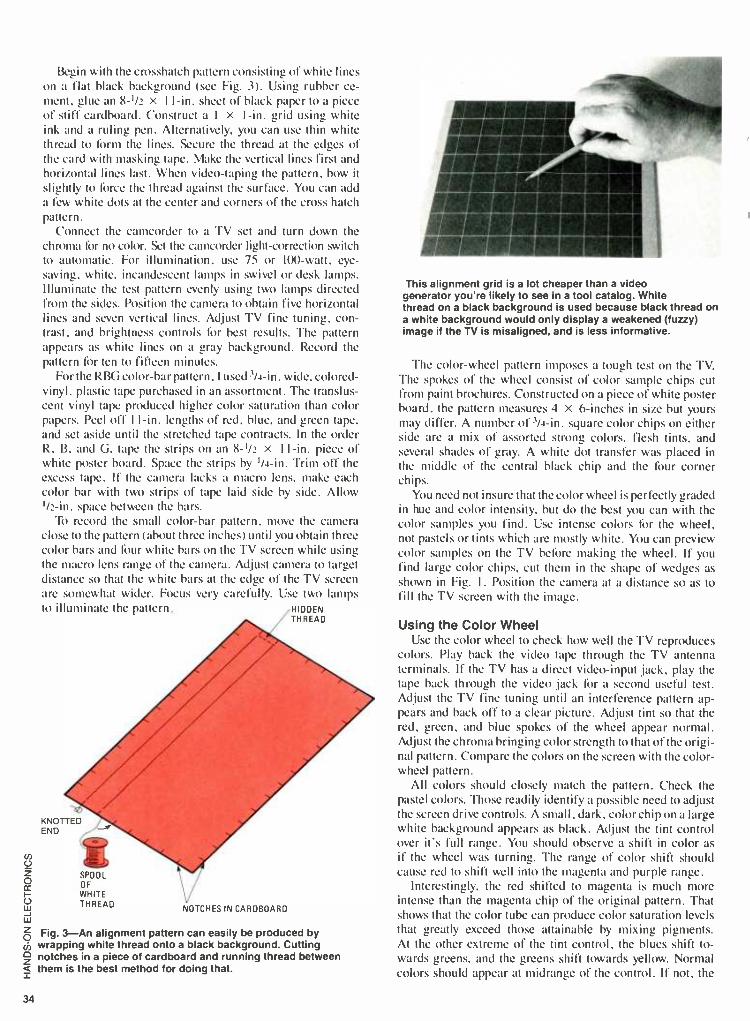
U z O
U w w
Begin with the crosshatch pattern consisting of white lines on a flat black background (see Fig. 3). Using rubber ce- ment, glue an 8 -I /i x I I -in. sheet of black paper to a piece of stiff cardboard. Construct al x I -in. grid using white ink and a ruling pen. Alternatively, you can use thin white thread to form the lines. Secure the thread at the edges of the card with masking tape. Make the vertical lines first and horizontal lines last. When video- taping the pattern, bow it slightly to force the thread against the surface. You can add a few white dots at the center and corners of the cross hatch pattern.
Connect the camcorder to a TV set and turn down the chroma for no color. Set the camcorder light- correction switch to automatic. For illumination, use 75 or 100 -watt, eye - saving. white, incandescent lamps in swivel or desk lamps. Illuminate the test pattern evenly using two lamps directed from the sides. Position the camera to obtain five horizontal lines and seven vertical lines. Adjust TV fine tuning, con- trast, and brightness controls for best results. The pattern appears as white lines on a gray background. Record the pattern for ten to fifteen minutes.
For the RBG color -bar pattern. I used 3 /4 -in. wide, colored - vinyl. plastic tape purchased in an assortment. The translus- cent vinyl tape produced higher color saturation than color papers. Peel off I I -in. lengths of red, blue, and green tape. and set aside until the stretched tape contracts. In the order R. B, and G. tape the strips on an 8 -1/2 x I I -in. piece of white poster board. Space the strips by 1 /4 -in. Trim off the excess tape. If the camera lacks a macro lens, make each color bar with two strips of tape laid side by side. Allow
I /2 -in. space between the bars. To record the small color -bar pattern, move the camera
close to the pattern (about three inches) until you obtain three color bars and four white bars on the TV screen while using the macro lens range of the camera. Adjust camera to target distance so that the white bars at the edge of the TV screen are somewhat wider. Focus very carefully. Use two lamps to illuminate the pattern. HIDDEN
THREAD
KNOTTED END
SPOOL OF WHITE THREAD
NOTCHES IN CARDBOARD
Z Fig. 3 -An alignment pattern can easily be produced by cb wrapping white thread onto a black background. Cutting 0 notches in a piece of cardboard and running thread between a them is the best method for doing that.
34
This alignment grid is a lot cheaper than a video generator you're likely to see in a tool catalog. White thread on a black background is used because black thread on a white background would only display a weakened (fuzzy) image if the TV is misaligned, and is less informative.
The color -wheel pattern imposes a tough test on the TV. The spokes of the wheel consist of color sample chips cut from paint brochures. Constructed on a piece of white poster board, the pattern measures 4 X 6- inches in size but yours may differ. A number of 3/4 -in. square color chips on either side are a mix of assorted strong colors, flesh tints, and several shades of gray. A white dot transfer was placed in the middle of the central black chip and the four corner chips.
You need not insure that the color wheel is perfectly graded in hue and color intensity, but do the best you can with the color samples you find. Use intense colors for the wheel, not pastels or tints which are mostly white. You can preview color samples on the TV before making the wheel. If you find large color chips, cut them in the shape of wedges as shown in Fig. I . Position the camera at a distance so as to fill the TV screen with the image.
Using the Color Wheel Use the color wheel to check how well the TV reproduces
colors. Play back the video tape through the TV antenna terminals. If the TV has a direct video -input jack, play the tape back through the video jack for a second useful test. Adjust the TV fine tuning until an interference pattern ap- pears and back off to a clear picture. Adjust tint so that the red, green, and blue spokes of the wheel appear normal. Adjust the chroma bringing color strength to that of the origi- nal pattern. Compare the colors on the screen with the color - wheel pattern.
All colors should closely match the pattern. Check the pastel colors. Those readily identify a possible need to adjust the screen drive controls. A small, dark, color chip on a large white background appears as black. Adjust the tint control over it's full range. You should observe a shift in color as
if the wheel was turning. The range of color shift should cause red to shift well into the magenta and purple range.
Interestingly. the red shifted to magenta is much more intense than the magenta chip of the original pattern. That shows that the color tube can produce color saturation levels that greatly exceed those attainable by mixing pigments. At the other extreme of the tint control, the blues shift to- wards greens, and the greens shift towards yellow. Normal colors should appear at midrange of the control. If not, the

TV needs repairs. Vary brightness over its range and verify little or no shift in colors.
If playback through the direct -video jack is excellent, but playback through the antenna terminals is poor, the problem resides somewhere in the tuner or video IF stages which precede the chroma sections of the circuit. The set may re- quire tuner or video IF alignment.
Use the color wheel to compare the performance of two VCRs playing to the same TV. A dirty tape head causes signal dropouts which show up as streaks on the TV screen.
Compare the performance of cassettes by playing back the color wheel from both. Surprisingly, a medium- priced tape outperformed a costlier tape. The assorted tapes I checked performed well on color rendition. However, the frequency of dropouts and the background noise varied noticeably. For a fair test, leave the TV controls set to the same place when making comparisons.
Using the Crosshatch Pattern The crosshatch pattern reveals how well the colors are
converged. Place the crosshatch pattern on the TV from the camcorder or VCR. Use the direct -video input jack of the TV if the jack is provided. If the camcorder or VCR delivers a good still image without streaks or jitter, use the PAUSE or STILI. button. Set TV contrast and brightness for sharpest display of the pattern. Turn the TV chroma control down for no color. Carefully examine the crosshatch pattern for any evidence of colors bleeding from the lines and for separate - colored lines.
With sets using the delta -gun picture tube, you can expect to find some color in the remote corners and possibly at the extreme sides of the display. That area contained in a circle equal to the vertical dimension of the tube should show a clean crosshatch pattern. Even slight color bleeding in the middle of the screen ruins the quality of a picture. If the TV exhibits that condition, it requires static convergence in the middle of the screen and dynamic convergence at the edges of the screen.
This test pattern is made inexpensively enough from three pieces of electrical tape on a piece of cardboard. The colors themselves need not be 100% primaries as you will only need to check the screen against the model.
The 'I'V may pass the crosshatch test and still deliver a poor color picture. Usually, the culprit is loss of tracking of the three colors due to uneven aging of both color phos- phors and color guns. Recognizing that problem, the manu- facturer often provides access to the tracking adjustments at the back of the TV. The TV technician does not have to remove the back from the TV to make that commonly needed color correction.
Place the RGB color bar pattern on the screen for a quick check on color tracking. Adjust the tint control and compare the colors with the color bar pattern. Don't expect a perfect match, but it should be close. On varying brightness, the colors should track in relative brightness and hue. Normally, the colors may wash out a bit at maximum brightness.
The color or gray -scale tracking adjustments at the back of your set are for the qualified technician only. However, if you are into electronics, but have not repaired a TV, there is no reason why you should not learn how to adjust those controls if you follow this procedure which cannot make matters worse. For practice, do it on your number two color TV which is older and probably needs a touch -up adjustment.
The general procedure varies slightly from TV to TV. it's well to purchase the H. W. Sams service literature for your set for complete information on all adjustments. A word of warning! Do not remove the back from a TV or poke a metal screwdriver into any hole in the cabinet because that exposes you to a possibly deadly shock hazard. Most sets are "hot chassis" types requiring use of a I:I line -isolation trans- former when servicing the set with the back removed.
i
This color wheel, while not 100% accurate, will help you set your TV's color adjustment to within a razor's edge of perfection. Warning: readjusting your TV for every special broadcast event can be habit forming. Proceed with caution!
Locate the SERVICE: switch labelled VIDEO-RASTER-SERVICE
at the back of the set. If you find that switch, you will also find three access holes labelled RED, BLUE, and GREEN SCREEN.
They are control potentiometers which adjust color gun track- ing. Those may be concealed behind a small removable panel near the CRT socket. Look for two (possibly three) other holes labelled RED and BLUE (and possibly GREEN) DRIVE. Those are control pots which remove any overall tint on a white raster. Tape over any nearby holes to avoid errors. Using a flashlight, look inside each hole, and observe the screw- driver slot. Draw a line at each hole exactly in line with the screwdriver slot so that you can reset the pot to its original setting. Use bits of masking tape if convenient.
Tune in a picture and set the chroma to minimum to re- move color. If present, the CHROMA LOCK switch is turned off. Use a fiber or nylon bladed screwdriver to adjust con- trols. Turn R, G, and B screen controls in that direction
35

36
which causes the screen to go dark. Set the service switch to Service. Advance the R screen pot until a faint red line is visible. Advance the G screen pot until the red line turns yellow (R plus G equal Y). Advance the B screen pot until the line turns white (R plus G plus Y equals white). You may observe some color in the line, but no primary color should prevail. Set the SERVICE switch to RASTER for a clean white raster. If the raster is tinged with red, back off the red drive control a bit, etc. Vary brightness over its range and verify good gray -scale tracking at all levels. Switch back to SERVICE. If the line shows strong primary colors, repeat setting of the screen controls.
Some TVs have a CRT bias pot. In that case, you back off the R, G, and B screen pots fully one direction. The CRT bias pot is backed off and brought up until one of the three colors appear. Then, you bring up the remaining two colors of the screen pots for a faint white line. Follow any vari- ations to this procedure as listed in the service literature for your TV. Lacking literature, and if you encounter problems, reposition all pots back to the original positions.
With aging CRTs, it may be possible to improve color by slightly tweaking the controls. Examine the picture with tint, contrast, chroma, and brightness at normal settings. If red seems to be overpowering, back off the red screen con- trol just a bit. Examine the highlights of the picture. If white highlights appear tinted, tweak the screen drive controls. If all goes awry, repeat the tracking adjustments or reset all pots back to where you found them.
Using the Color -Bar Generator The color -bar generator assists the TV technician when serv- icing the chroma circuits. That requires a familiarity with TV circuits and repair. Service literature and schematics such as those published by H. W. Sams is required. The schematic diagrams show waveforms at key testpoints as
produced by an NTSC standard pattern and color -bar gen- erator. The DC voltages in the chroma circuits depend to some extent on the generator waveforms. With NTSC pat- tern generators beginning at about $1000, the instrument is
found only in a busy, well- equipped shop. In absence of a color bar generator, you use the TV station
as the signal generator when tracing signals in the chroma sections. The observed waveforms and DC voltages change continually. You can't make any judgments much beyond the presence or absence of waveforms. With any kind of color bar generator, you have a stable repetitive pattern pro- ducing waveforms which clearly show the red, blue and green pulses. The DC voltages in the circuit become stable.
Connect the camcorder or VCR RF output to the TV an- tenna terminals. Set the TV chroma and contrast at or near maximum. Adjust the fine tuning and brightness for a bright clean display. Set TV tint to normal. The oscilloscope should have a bandwidth of 4.5 MHz or better in the vertical axis. Pick off the H- blanking pulse at the chroma processor chip and connect it to scope external sync input.
Figure 4 shows a simplified block diagram of the chroma output circuit of a TV with cathode driven CRT. The video - chroma block may consist of vacuum tubes, transistors or integrated circuits ultimately supplying four key signals to the R, G, and B matrix and output driver stages. The Y signal carries picture information in monochrome. Three color differences signals R -Y (R minus Y), G -Y, and B -Y carry information on hue and color saturation. The four sig-
1
TINT
COLOR
VIDEO CHROMA
RY
GY
Y
R
OUTPUT
B
OUTPUT
G
OUTPUT
CRT
Fig. 4 -Tint and colo information are provided to a TV by one of its input stages. That information Mis broken down into four different signals: the three primaries minus yellow and the yellow signal. Yellow is added to the three lacking signals to produce the primaries.
A
C
0 V
BLUE GUN
GREEN GUN
Fig. 5 -When there is an absence of sufficient chromanance signal, the guns tend to be about equal. That condition duplicates the yellow video signal (A). Red. unlike the other primaries. must act alone to produce true red (B) Blue on the other hand requires some red to look "normal." Green needs some blue to appear lively enough (C).
nais are mixed in the matrix and output driver stages which drive the R, G, and B color -gun cathodes. Figure 5 shows drawings of observed waveforms. Figure 5a shows the Y (video or luminance) signal output of the chroma processor chip. The bottom of the pulses at voltage level W corre- sponds with the four white bars for the test pattern. The top of the pulses at voltage level C corresponds with the
(Continued on page 103)

Here are your free
FactCards! Introducing Hands -On-
Electronics FactCards. Each issue, Hands -On-
Electronics will present 3 new FactCards, each deal- ing with one of a variety of electronics topics. Some will deal with electronics basics, some will deal with discrete components, some will deal with IC's, and some will deal with circuits and applications.
All will contain the type of information electronics hob- byists need, but sometimes must search to find. With FactCards, you can find that information in a hurry.
Clip yuì cards, save them, and start building your FactCards library today!
El¢ctron°s K
I-
55 Eretngwr FactCard 4093: Quad 2 -Input NAND Schmitt Trigger
Features Wide supply voltage range Schmitt- trigger on each input with no external components Noise immunity greater than 50% Equal source and sink currents No limit on input rise and fall time Standard B- series output drive Hysteresis voltage (any input) TA - 25 °C
Typical V 5.0V VM - 1.5V VDT, 10V VM - 2.2V Vp 15V VM - 2.7V
Guaranteed VM - 0.1 Voo
3.0V to 15V
Applications Wave and pulse shapers High -noise- environment systems Monostable multivibrators Astable multivibrators NAND logic
Absolute Maximum Ratings
V00 Supply Voltage 0 5 to 18V V,N Input Voltage 0.5 to Vnn 0 5V Ts Storage Temperature Range 65 C to + 150 C PD Package Dissipation 500 mW T, Lead Temperature (Soldering, 10 seconds) 260 C
Recommended Operating Conditions
V Supply Voltage V,N Input Voltage Tv Operating Temperature Range
3 to 15V OtoV V
55°C to +125°C - 40"C to + 85°C
TA S
Unit - ta
Voltage in volts E R r I
Power in watts W E x I
Power in watts W PR (modified formula)
Power in watts (modified formula)
Total series resistance in ohms (It)
W E2 -Ft-_
It R1+R2+R3+
Total parallel resistance in ohms (It) Total parallel resistance in ohms (It) Voltage drop across a resistor in
r
Table of Electronic Formulas I Unit
Instantaneous sinusoidal voltage (AC)
VAC V, sin('
Wavelength in meters
s 3 + 101° cmis Frequency (He)
Frequency 1, 1
-T- Total series inductance
LT L1 + L2 - L3 +
Total parallel inductance
LT 1 1 1
Lt E +I+._ Total current in a parallel circuit
IT IR2+ IX2
Phase angle of a parallel circuit (using current)
8 tan , 1 Tq
Impedance in a parallel circuit
Z V -TT-
Real (true) power
{,!Batts
PA Ir, + EM -..
Iii a°^ rFäctCa rd Thyristor Circuits
S1
SPST
SCR PROXIMITY ALARM CIRCUIT
SONALERT 854 -6500
8Z1
F1
.5A -crxs)-
PLI
_
SCR1 G
C103B
NEI RS-2721100
Cl 20pF
R1 - 5K
R2
100K
METAL PLATE
TO DC POWER
SUPPLY
SCR POWER MONITOR CIRCUIT
11
DC OUTPUT

55 ads «I FactCard 4093: Quad 2 -Input NAND Schmitt Trigger
STATIC ELECTRICAL CHARACTERISTICS
CH AR AC- TERISTIC
CONDITIONS LIMIT at 25'C
(TYP) UNITS
(l (1 (ol Negative Trigger a 5 1.9
T1ralL*J Voltage a 10 3.9
VN Max 15 5.8 V
b 5 2.3
b 10 5.1
b 15 7.3
Flystaests Voltage a 5 0.9
V Max a 10 2.3
a 15 3.5 V
b 5 0.9
b 10 2.3
CHARAC- TERISTIC
CONDITIONS LIMIT at 25 C
(TYP) UNITS VQ
1 Oubescent Device - 0.5 5 0.02
Current. inp - 0,10 10 0.02 IA Max - 0,15 15 0.02
Positive Trigger - a 5 2:9
Threshold Voltage - a 10 5.9
VP Max - a 15 8.8 - b 5 3.3 - b 10 7 - b 15 9.4
ipa d :«I FactCardt Table of Electronic Formulas
TABLE OF ELECTRONIC FORMULAS Unit Symbol Formula
Real power in watts P 12 R
Real power in watts PH VI cos H
Capacitive reactance
Xc 1
2
Series capacitive reactance
Xc Xc, + XC2 + XC3
Parallel capacitive reactance
/Cep 1 + 1 . L..
XC, XC2 XC3 -.-
Resonant frequency
1, 1
21 LC
Q in a resonant circuit (no units)
OR X 1R
Impedance in a parallel resonant circuit
Zp Q X,
Bandwidth in terms of circuit Q
8W f
Bandwidth in terms of frequency
BW / l,2
BLE OF ELNIIMULAS Unit Symbol Formula
Total series capacitance
C, 1 1 1
61 - n n Total parallel capacitance
C, C1 - C2 C3
Voltage across a capacitor in a capacitive voltage divider network (e.g . C11
Vf-, C2 V C 1 C2
Time constant for inductor in series with a resistor
TC R --L-
Time constant for capacitor in series with a resistor
TC R C
Real power PR IF, ER
Real power PR I2R
Real power PR VI cos H
Reactive power- VARS
PR Ix Ex
57 cre=on FactCarl >!a
Thyristor Circuits
ti
SOLAR- TRIGGER SWITCH CIRCUIT
A
PCI
PC 1 -PC2- SMALL SOLAR CELLS
PC2
K
S1
SPST
SCR1 SK3B50
R1 1K
B1
9VDC 1
TO 9VDC LOAD
TO HEADPHONE JACK OF RECEIVER
RECEIVER SIGNAL ALARM
SI SPST
T1
N
A
K
SCR1 C10881
SO 1
(117VAC)
F1
1A
PL 1
(117VAC)
For new ideas in
electronics read Radio- Electronics
During the next 12 months Radio -Electronics will carry up -to -the minute articles on:
hobby computers solid -state technology TV games Video color TV stereo test equipment radio radar detectors industrial electronics servicing
TV- radio -stereo experimenter
circuits exceptional
construction projects
NEW IDEAS AND INNOVATIONS IN
ELECTRONICS
The newest ideas and innovations in
electronics appear in
Radio -Electronics. Keep up to -date!
Subscribe Today!

LINE DIETUNB.NCE MONITON
By Fernando Garcia Viesca
LINE DISTURBANCE MONITOR
Don't be left in the dark about AC -line problems. Enlighten yourself with a device that
detects noise and high/low voltages
YOU'RE READY TO TEST SOME NEW, SOPHISTICATED, ELEC- tronic equipment. After a couple of hours reading the manual and setting up, you are now eagerly enjoying its features. Suddenly, without warning, everything becomes "blocked," and the unit just sits there without accepting any further commands. As you turn the power off and rush for the instruction manual. you wonder if an improper operation or an equipment malfunction has occurred. Sound familiar?
With the advent of digitally -controlled hardware running dishwashers to microcomputers. many of those mysterious crashes may be blamed on other gremlins: AC -line distur- bances. But, unless you have the proper equipment. chasing down those little devils is next to impossible.
There is a subtler side to the problem: most computer users already have so called spike suppressors connected to their equipment! Trouble is. many cheap units are nothing more than a Metal Oxide Varistor (MOV) that do not, in any way, suppress radio -frequency (RF) noise.
In this article. we'll show you how to build an inexpensive AC -Line Disturbance Monitor (LDM), so you'll be able to trace power -related problems, and best of all, to pinpoint their source. With the unit's integrated low /high- voltage detector, it'll warn you of possible equipment failures. And, you'll be able to make a wiser decision to determine if an investment in additional filters, or a voltage regulator, is necessary.
Attenuating and Filtering Figure I shows the detailed circuit for the LDM. The
sensed AC line is attenuated by the voltage divider formed by Rl, R36, and R2. Diodes DI3 and D14 clamp any excess voltage to prevent circuit damage. That low voltage is buff- ered by op -amp UI -a, which feeds a third -order, high -pass made by UI -b. CI thru C3, and R3 thru R5. The corner frequency is 2400 Hz, so the 60 -Hz line frequency is attenu-
This interior view of the line disturbance monitor shows how compact the circuit board layout really is. The little box glued to the bottom of the case is the transducer.
ated over 78 db! Only the RF components of interest are fed to a precision full -wave rectifier, made by UI -c, UI -d, R6, R7, R8, and DI through D4. That rectifier circuit also provides variable gain in the same stage, set by R37.
You may ask why the voltage was first attenuated by the high -pass filter and then amplified. It is because we want to recover only the noise signals that have a much smaller amplitude than the 60 -Hz AC -line frequency and cannot be filtered properly .at their normal levels, because filter overload would occur. Therefore, we drop every signal's amplitude and, after filtering, we recover only the noise signals with a
gain stage. Of course phase shifts in the 60 Hz AC -line can fool the filter but not with a long- duration pulse.
39

40
co
Q Y -
N Y ¢ .--
co p, r
2 O f`-
1
1
¢ U
co c^ e cc" ¢ Ma
o U
p j 0 m, ¢ <
-1A11r11 PIC O
O
f7
1 xx pN
e 8 get Z
Y ^ti cv ¢ r ¢ c 11
ip Y M N ¢ ,Ni
O
J O > Y O
CO
Ñ ¢ N
11
+ CO O Cn ^ Y - 03 M N ¢ .- ¢ .- ¢ N
U <
Fig. 1 -The jumper marked TP1 is only put in place during the testing phase. Don't leave it in your finished project.
p)
U O
eV
O
Z

Detection The processed noise signal is fed to U2 -a. Whenever the
noise peaks exceed 6 volts (As set by biasing resistors R9 and RIO). the coniparator's output swings to a low level. discharg- ing C5 thru R12. and therefore a logic high appears at U2 -h's output. When the noise spike ends. C5 charges slowly thru RII, and then the logical high. appearing at the output of U2 -b is widened. If that pulse- stretching circuit had not been included. short noise bursts wouldn't be noticed at all. As you may already know, most noise is composed of voltage spikes of very short duration but large amplitude.
The logical signal from U2 drives Q2 and lights the warn- ing NOISE LED. It is also oN'ed with the low /high voltage detection signals by U3 -c and U3 -d. which drives, by means of QI, a self -contained piezo buzzer. The buzzer sounds whenever a fault condition is detected.
A Closer Look Lets look at hog the lo%% high voltage sign;il . generated.
The buffered signal from UI -a is fed to a precision half-wave rectifier made by U4. R13 thru R15, D5. D6. and C6. That rectifier is different from the one described in the noise detection circuit. That is because we need to average the signal in the same stage. something that can't be done cas I in a precision full -wave rectifier. The averaged voltage signal is fed to a window comparator made by U2 -c. U2 -d. and R21
thru R26. It is called a window comparator because as long as
the voltage signal stays within a voltage window its output does not change states -in this case, a logical low. The window's low and high trip points are set by potentiometers R38 and R39. respectively with voltage division and decoup- ling performed by C7 and RI6 thru R20.
When the sensed voltage is outside limits set by R38 and
Fig. 2 -The circuit board for the LDM will make construction a lot neater. The foil pattern shown here is full size so direct copies can be used for board production.
OVW TOCTOFT1
//LEM R35
q O TO 11
T1 12
Fig. 3 -Be sure all your polarized parts are properly oriented on the board before soldering them. Testing parts for good tolerances and operation values is a time saver.
away several times a second.
821
the low resistor into the circuit allows you to rapid fire.
41
43

44
The diode between the power and the lamp drops about 0.7 volts, which extends the lamps life. Without the diode the lamp would give bright light bursts, but for such a short time.
The extra battery does give us some benefits. The addi- tional battery lets the timing circuit, R8 and C, rapidly charge up to the firing voltage.
Both systems use a small cheap plastic lens to focus the lamp output on the target. It concentrates the energy into a
relatively small beam. That, coupled with -sensitive photo transistor in the targets, gives either system a more than 20 fort range.
The Targets You can use anything that reflects light for a target. But you
can have more fun when the target tells you that you scored a
hit. The portable, Ibur- transistor target in Fig. 3., gives visual and audible announcements that you scored a hit. The more elaborate model in Fig. 4. includes a simple music syn- thesizer: you can use bells, whistles, or sirens,if you like.
Target Basics The simpler target consists of a photo cell, a pulse ampli-
fier, a pulse stretcher, an LED driver and an LED. As you can see in Fig. 3, the circuit is quite a bit simpler than it sounds.
The LED gives silent visual signals while a piezo buzzer gives audible announcements. The LED stays in the circuit all the time. A switch removes the noise maker fbr those times when silent practice suits the mood of the moment. You can customize the noise maker to get any effect you want.
Design vs. Sensitivity Either a CdS photo cell or photo transistor (Q3) will work
in this circuit. Although the transistor gives greater sen-
sitivity, the circuit operates the same either way.
When light strikes the sensitive surface on the sensor, its
resistance decreases. The brighter the light, the lower the
resistance. The faster the light level changes, the faster the voltage changes across the cell and across R3. Capacitor C2 couples only relatively fast voltage changes to the next stage. That lets the target respond to pulses from the gun, even in a
room with a rather high, but steady, light level. That also means that if you point the target at a TV screen or a
fluorescent light, it will sound oft. The cure for that costs some sensitivity, but nothing that you will miss.
The basic target in the card -file box, has enough sensitivity to respond to a television picture tube more than five feet
away. The synthesizer version of Fig. 4, uses R12 and C5 to
(SEE TEXT)
desensitize itself. The circuit works the same as the system we will describe below for Fig. 3. With the addition of R12 and C5 though, the target has to be less than 24 inches from a
TV to see the picture. despite that, it will still sound off when you hit it with a gun burst from 15 -20 paces.
Earth -Bound Circuit When Q3 detects a light burst, C2 adds a small current
pulse to the base bias supplied by R4. That causes Q4 to conduct less. That allows the current from R5 to flow through diode DI and charge C3. The diode forces C3 to discharge through R6 and Q5 after the pulse ceases.
When the voltage across C3 reaches about 1.2 volts, Q5 -Q6, (the double emitter -follower hook -up known as a
Darlington pair) turns on. When Q6 turns on, it connects R7 and LEDI across the battery. Resistor R7 limits the current to about 9 milliamps. You may adjust the current for a brighter light by changing the size of the resistor. Connecting the noise maker from the battery + to the col lector of Q6 through a switch, lets you control the sound.
Diode DI and capacitor C3 form a pulse stretcher. Rather than carry off dead pulses, that circuit lengthens the short pulses delivered by C2 to Q4. Without the stretcher, the short light burst from the gun would get little more than a quick flicker out of the LED, and a buzzer would give a quick tick. By making R6 bigger, you lengthen the on time for Q6, and therefore the light -on time.
Power Drain Except for the time during which the target responds to
your gun pulses, it draws little current, about one -tenth of a
milliampere. Even the cheaper batteries would have a long life. If you use an extra -loud sound module, or a music synthesizer like that in Fig. 4, you will want to use heavy -duty batteries, or a plug -in power supply.
To add sound, you may use a commercial siren module or you may make a custom noise maker such as the simple synthesizer shown. For heavier loads such as a bell or a
motor, use a relay with its coil connected between + V and the collector of Q6.
The Synthesizing Target The synthesizer in the advanced model is just a non -
symmetrical multivibrator. It changes frequency with changes in voltage as a pulse works its way through the circuit.
Until a pulse starts its journey through the unit, QI2 is
turned off. That lets current flow + through LED2, RI6, and R17, to
S2 keep QI4 turned on, (fully con- o ducting). When a pulse works its way
through to QI1, it turns on QI2 and =D2 LED2. That in turn delivers a short
pulse through the switch Q13 -Q14 to D2, C8, and R19, which supplies turn -on bias to Q15.
1 N4004
Fig. 3- Either a phototransistor or photoresistor (such as a CdS cell) can be used in the circuit as a light sensor. Its signal is stretched and - fed to a switching circuit.

R22. 15K:
Transistors Q15 and Q16 form a simple non -symmetrical multivibrator. It changes frequency with changes in voltage; that, coupled with its lack of symmetry, gives it a somewhat musical sound. The multivibrator can run only during the time that the second pulse stretcher (composed of C8, and R19) turns on Q15. Resistor R24 couples the signal from Q16 to Q17 -Q18, another Darlington pair. They drive the loud- speaker.
While waiting for a pulse, R22 keeps QI6 turned on which keeps Q17 -Q18 off That reduces the standby power drain. The target draws about 13 mA during standby periods and about ten times that when loudly proclaiming a hit. Even heavy duty 9 -volt batteries would have trouble supplying that much current. A small game -module power supply could handle that without trouble. I found it just about as easy to build a small plug -in power supply for the unit. It uses a
transformer, four diodes, and a single filter capacitor. Add a fuse for protection and an on /off switch for convenience as in Fig. 5.
Gun Alignment The gun 1 used came from the as is table at a Radio Shack
store. It had the lens and switch in it. You can probably find a
similar unit at a toy store. My wiring does not always follow formal techniques as the
cut -away view shows. The parts mount directly by their leads in the (plastic) shoot'n' iron. If wiring parts together by their leads doesn't appeal to you, or you can't find a suitable
R11 270K
R13 '1.2M
R12 C6 .01
1 1__ D0
=C5 .1
Q9 T1L414
Q10Q18 ARE 2N2222
R14 10K
D8 1N4004
V+
Selecting a bulb with an on- center filament is the most important step. No amount of adjustment can make up for a poor bulb, so chose it wisely.
plastic gun, then use the case for the Outer Space model. Start either one with the light bulb.
Look at the light bulb befiwe you install it. Some of them have an off-center filament. That kind will shoot crooked. When you find a good bulb, center it at the focal point of the lens. Move the bulb closer to and farther away from the the lens until they are aligned. Con- nect two penlight cells to the bulb and point
the lens and bulb assembly at a wall or other light- reflecting surface. As you adjust the lens, you should see a well -focused spiral pattern indicating proper alignment. Much of the range the instrument has, comes from proper lens alignment. It aligns easier than it sounds though.
Gun Wiring Wire the transistors, resistors and other parts together.
When you complete the gun, point it at a nearby wall and fire it. You should see a short, bright light burst. With only two cells and the slight voltage loss in the transistor switch, the bulb and batteries will live long.
If the Outer Space model is more to your liking, the parts can go into any housing, that gives room fòr the extra parts and allows you to adjust the distance from the lens to the bulb. If you can find a shorter focal -length lens, say one to two inches, you can use a short box.
Mount the lamp socket. Determine where the lens will sit and drill a hole in the case, centered on the lamp. Cement the lens in place. Then focus the lamp as mentioned before. After that, mount the switches, wire the boards, and install them.
Although the batteries in our Outer Space model give long life, you may want to add a flashing pilot light. It can consist of a cross -coupled flip -flop with an LED in one of the collector circuits (see Fig. 6). Since it uses non -electrolytic capacitors, it takes up little space. A pilot light would add little to the battery drain, and would give the system that ready - for -action look.
1118
470012 D9 R20 119914 68K 015
R21,1 1K
SPKR1
R23 1K
R24 15K
Q10 R15
Cl =470047K 017
3 -5
C8
Fig. 4 -The synthesizer added onto this improved version of the circuit, is nothing more than another pulse- stretching stage sending its output to a voltage -controlled oscillator.
45
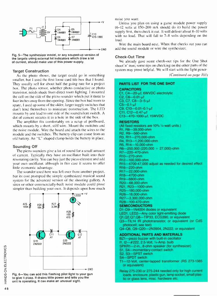
F1 J1
4)1j11 pJ
}0 6V
L1
Q4
1N4001
Q6
1 N4001
05 1 N4001
07 1 N4001
+v
C13 T470-1000
GND
Fig. 5 -The synthesizer model, or any souped -up version of the targets using external hit indicators which draw a lot of current, should make use of this power supply.
Target Construction As the photo shows, the target could go in something
smaller, but I used the first loose card file box that I found. They usually sell for about half the going rate for a project box. The photo sensor, whether photo conductive or photo transistor, neèds shade from direct room lighting. I mounted the cell on the side of the piezo sounder which put it three to four inches away from the opening. Since the box had room to spare, I used up some of the older, larger toggle switches that don't lend themselves to miniature construction. The LED mounts by one lead to one side of the sound /silent switch. A dot of cement secures it in a hole in the side of the box.
The amplifier fits comfortably on a scrap of perfboard, which mounts by a short, stiff wire. Mount the switches and the noise module. Wire the board and attach the wires to the module and the switches. The battery clip can come from an
old battery. An "L" shaped clamp holds the battery in place.
Sounding Off The piezo sounders give a lot of sound for a small amount
of current. Typically they have an oscillator built into their resonating cavity. You can buy just the piezo element and add
your own oscillator, although in this case it seems to offer little economic advantage.
The sounder used here was left over from another project, but its cost prompted the simple synthesized musical sound system for the advanced version of the shooting gallery. A siren or other commercially -built noise module could prove simpler than building your own. It depends upon how much
+v
R25 180K
LED3
R28 100- 470
L
Q19 2N2222
i 471 Ill 1
Q20 2N2222
Fig. 6 -You can add this flashing pilot light to your gun to give it pizaz. It drains little power and tells you the unit is operating. It can make an unusual sight.
noise you want. Unless you plan on using a game module power supply
(6-12 volts at 150 -200 mA should do it) build the power supply first, then check it out. It will deliver about 8 -IO volts with no load. That will fall to 7 -8 volts depending on the load.
Wire the main board next. When that checks out you can
add the sound module or wire the synthesizer.
Check -Out Time We already gave some check -out tips for the One Shot
shoot'n' iron; some tips on checking on the other parts of the system may prove helpful. We will start with the light gener-
/Continued on page 103)
PARTS LIST FOR THE ONE SHOT
CAPACITORS Cl. C4- 20 -1d, 6WVDC electrolytic C2, C6 0.01 -pi C3. C7, 08- 3 -5 -pi C5 0.1 -pi 09, C10- 0.01- 0.1 -µ0 C11. 012- 0.47 -µf C13- 470 -1000 -4 15WVDC
RESISTORS (All fixed resistors are 10 ° %'i4 -watt units.) R1. R8- 39.000 -ohm R2, R9-560 -ohm R3, R11- 270.000 -ohm R4, R13- 1.200,000 -ohm R5, R14- 10,000 -ohm R6- 250.000 (220.000 27,000) -ohm R7- 220 -470 -ohm R10 -270 -ohm R12- 100.000 -ohm R15 -4700- 47,000 adjust as needed for desired effect R16 -220 -ohm R17- 22.000 -ohm R18 -4700 -ohm R19 -6800 -ohm R20- 68,000 -ohm R21. R23- 1000 -ohm R25- 180.000 -ohm R26- 18.000 -ohm R27- 3,300.000 -ohm R28 -100- 470 -ohm SEMICONDUCTORS D1- D9- 1N4004 diodes or equivalent LED1. LED2 -Any color light- emitting diode Q1,Q2.Q7,Q8- TIP33, ECG390, or equivalent 03 -TIL14 IR phototransistor, or equivalent (or CdS
photocell: see text) 04 -06. 09- 020- 2N3904. 2N222. or equivalent
ADDITIONAL PARTS AND MATERIALS BZ1 -plezo buzzer with built -in oscillator 11. 12- #222. 2.5 -Volt. 1/4-Amp. bulb SPKR1- 2 -in., 8 -ohm speaker (for synthesizer) S1, S4- momentary- contact switch S2, S3 -SPST switch S4 -SPDT switch T1 -12 -Volt, center -tapped transformer (RS 273 -1385
or equivalent)
Relay 275 -230 or 275 -244 needed only for high current loads, enclosure, plastic gun. lamp socket, small plas- tic or glass lens, misc. hardware etc.

DECEMBER 1987 THE NEWSLETTER FOR GROWN-UP KIDS
What's Inside. . .
GADGET Newsletter: An Editorial 2
Running Commentary: The Nike Monitor 3
Photographic Mythol- ogy: Canon EOS 4
Olympus Infinity 5
Heady Listening: Beyerdynamic and Panasonic Head- phones 6
Down for the Count: The Calorie Watch 7
Private Ear: Sony Air 7 8
VOLUME XII/NUMBER X
Glasnost ELEKTRONIKA TAPE RECORDER (302 -1). Purchased from: Gum Depart- ment Store, 25th of October St., Mos- cow, U.S.S.R.. Price: 144 rubles ($33 in U.S. currency).
Consumer goods are notoriously an Achilles' heel of the Soviet economy. Yet GADGET's recent examination of a tape recorder from the U.S.S.R., the Elektronika 302 -1, suggests that Soviet execution of this everyday electronic tool leaves little to be desired, provided it's compared with Western and Asian prod- ucts of two decades ago.
Purchased by our publisher at Mos- cow's famed Gum Department Store, the Elektronika indicates there's more than a little truth behind the stereotype of Soviet goods as archaic, ill- designed and shoddy. While the unit's retro- styling might make a big hit with some Western consumers, its equally out- moded technology and relatively high price make it an unlikely candidate for overseas sales.
Measuring 12" x 8'/" x 3 ", in ap- pearance the Elektronika is reminiscent
of portable reel -to -reel recorders of the late '50's and early '60's. With battery pack in place, it weighs in at a hefty 61/2
lbs. Finished in gray (what else ?), the re- corder has two knobs (volume and tone) and the standard cassette player con- trols.
Oddly, its fast controls must be Record, play and ly as counterpart
forward and rewind manually depressed. eject function exact - controls on Western
recorders do. There is no tape counter. The large, round speaker screen sits side - by -side with the cassette compartment.
Jacks on the recorder's side allow use of headphones and a microphone, as well as connection to a hi -fi system or public address unit. Top side, the Elek- tronika also has an archaic level meter (the digital revolution hasn't reached Russia) and a red power indicator light.
It can be powered with a standard Soviet -style plug (marked, in English, "IA. 250V ") or with six "C" batteries. Since we didn't have a voltage converter handy, we used the battery pack, which is when we began to understand the Soviet reputation for poor design. With the battery pack in place, the only way to turn power off was to disconnect the
(Continued on page 9)
47

GADGET: The Story Thus Far
It was still light and surprisingly warm when I left the Haymarket Theatre in London several months ago, having just seen Alan Bates in the wonderful play called Melon. Quickly calculating the time difference between England and the United States, I realized I
would have to hurry if 1 wanted to call my office before everyone left at 6 p.m. There were no available street phones, so I reached into my shoulder bag and pulled out a cellular unit. I
direct dialed my office from a street corner. The connection sounded as
clear and close as if I were one block away. It was an object lesson in the tri- umph of technology.
In the vast majority of cases, as all gadget lovers know, technology trips rather than triumphs. We are constant- ly confronted with poorly executed de- sign and malfunctioning rogue prod- ucts which deviate wildly from their original, advertised conception. But like all romantics who seek unlimited and eternal love, we never give up.
I started GADGET 12 years ago with that sort of romanticism in mind. From the Captain Midnight decoder rings 1 obsessed upon as a school kid in Brooklyn, through my first car to the evermore optimistic purchases I make today, my love of gadgets burgeons as
my buying power grows. I forever hold the hope that the next purchase, the next product, the next gadget will be the "perfect" one. It is very much like seeking the perfect woman, the perfect sexual experience or the perfect meal. It is truly the search for the Holy Grail.
Though perfection is not exactly en- demic to the human condition, pursuit of perfection is. To gadgeteers such as you and me, the search for the perfect product is like the search for the foun- tain of youth, and is something we shall never renounce. Sadly, however, GADGET newsletter too greatly re- sembles the products it describes. It is a great idea badly carried out. In 12
years, it has lost close to one million dollars. GADGET has become a hobby I cannot sustain and a mistress I can no longer afford.
The difficulty with GADGET is that the usual publishing payoffs are just not available to us. We do not, of course, accept advertising, feeling that doing so would dilute our credibility. In addition, another avenue to profit is closed out since we are not a mass - market publication, relying instead on the enthusiasm of aficionados. We fall into an eccentric and totally individual- istic slot, and since most people are relatively unsophisticated about what they buy on a newsstand -relying on splashy headlines and full -color covers to draw their fancy -we can't rely on the public to lay out $1.50 on a 12 -page newsletter.
There may be a real mea culpa at the
heart of the situation, since whatever potential has resided in GADGET has lain undeveloped by yours truly. GAD- GET had a six -month lapse recently, before it was resuscitated by our won- derful colleagues at Gernsback Publi- cations. The year of our association was superbly rewarding, and the Gems- back folks were totally supportive of what we were trying to do. In the end, however, the costs of putting out GADGET put too great a strain on our other enterprises. In fact, if the "sup- port" network for GADGET were tal- lied up- phones, office space, staff time -its deficits would be even higher.
GADGET will thus pass from the scene, a victim of financial imperatives too extreme to ignore. It has been a fabulous dozen years, with each issue offering fascinating glimpses of what has been called "the soul of a new ma- chine." GADGET pioneered an ap- proach to consumer electronics that was as fun as it was rigorous, as wide - ranging as it was enthusiastic -reviews that were readable, laced with a slight tang of irreverence.
We will miss being the conduit for each new technological development that comes down the pike, but I believe we can be justifiably proud of our achievements. Possibly, in some future reformation or alternate incarnation, we will resume our relationship with you, the consummate gadgeteer. Until then, we bid you good -bye, with the added reminder that a gadget is always only as good as the brain behind it. -Al Goldstein
Third Dimension HOLICON HOLOGRAPHIC POR- TRAIT. Manufactured by: The Holi- con Corp., P.O. Box 451, 111 E. Scran- ton Ave., Lake Bluff, IL 60044. Price: $3,800.
Holography is something of a non- starter in consumer technology. Al- though the first holographic products generated enormous interest (GAD-
GET reported on one in its September 1977 edition), these three -dimensional pictures didn't establish themselves in the marketplace. Although some fairly rinky -dink applications of the process have become widespread, and though industrial use has flourished, the orig- inal heady predictions of holographic transformation of everything from tele- vision to home movies have not been born out.
But consumer holography appears to have gotten a second wind. An IIli-
nois company, founded by three pro- fessors at Northwestern University, has perfected a new technique for three - dimensional picture taking.
Holicon's Illinois studio is the only one in the United States. To create a
portrait, subjects are seated in front of a high- resolution photosensitive plate and illuminated by "a diffuse low -in- tensity laser light for twenty billionths of a second." Holicon says "the inten- sity of light is considerably lower than
(Continued on page 9)
Publisher: Al Goldstein Editor: George Arthur Senior Editor: Gil Reavill New Products Editor: Christine Stevens Copy Editor. Danny Jones Art Director. Kevin Hein Associate Art Directors: D. Devins, C. Giordano, Rob Weisberg Production: Bill Mudie Administration: Bonnie Keystone Reader Service: Kathryn Hartman Technical Consultants: Ken Schaffer, Bob Bishop Con- tributing Editors: Philip Eisenberg, Alan Freedman, Jordan Ari Goldstein, Steve Gruberg, John Kois, John Swenson, Ken Swisher, Aaron C. Zimmerman.
GADGET is published by A.G. Consultants, Inc., 116 W. 14th Street, New York, NY 10011, (212) 989 -8001. Copyright ©1987 by A.G. Consultants, Inc. GADGET is a registered trademark of A.G. Consultants, Inc. GADGET is published 12 times a year and appears as an insert in Hands -On Electronics, published by Gernsback Publications, Inc., Farmingdale, NY 11735. For information on subscriptions to Hands -On Electronics, please see the magazine's editorial page. Letters intended for GAD - GET's editorial staff should be sent to the newsletter's address as shown here.
GADGET's sole commitment is to its readers. In order to avoid even the appearance of a conflict of interest, GADGET does not accept advertising nor does GADGET solicit gifts or other benefits from manufacturers and retailers who may be men- tioned in reviews.
48 Page 2/GADGET DECEMBER/1987

Jock's Vox
NINE MONITOR. Manufactured by: Nike, Inc., 3900 S.W. Murray Blvd., Beaverton, OR 97005. Price: $200.
Just when you thought it was safe to go back onto the jogging path, Nike debuts its new Monitor, a fitness gizmo targeted at the serious exercise buff. Something of a Walkman for runners, the device dishes up not radio or taped music but fitness reports, delivered in a soothing digitalized female voice through per- sonal earphones.
Use of the unit is rather straightfor- ward, and it could be employed by hikers and even urban walkers as well as by joggers. Utilizing data from sensors mounted on the front of the Monitor, the battery- operated computer chips that are its guts analyze the pace of the wearer. The sensors operate on Doppler Effect ultrasound, eliminating the need to calibrate the device to the particular stride of the runner. Instead, the sensors beep out bat -like ultrasonic measure- ments of the actual turf passing beneath the runner's feet.
The basic Monitor only has the capac- ity to measure pace and distance cov- ered. Press the "report" button on the unit's top side and a synthesized voice will inform you of the time elapsed since you pushed the "start" button, the dis- tance covered and the average pace - your average miles -per -hour rate. The frequency of the voice synthesized report can be varied with the adjustment of an- other button. Its volume is also variable.
An optional accessory and one that greatly expands the Monitor's potential usefulness is the pulse rate accessory ($25). This is a light, wafer -thin heart monitor mounted on a chest strap and equipped with two electrodes. The gum- like surface of the electrodes are moist- ened and the strap cinched tight. A touch of the "pulse" button, and the user will be informed of his or her heart rate, its beat measured off in mechanical beeps.
There are several obvious benefits from using the Monitor. Freedom from a pre -measured course is a major advan- tage, since the unit will give you an ac- curate distance count no matter what path you take. Feedback about pace is also important, especially to runners training for a specific event, such as a marathon. By adjusting pace and ca-
dence, a runner can maximize the aero- bic benefits of exercise.
As with every accessory sold to the jogger, the primary concern is one of comfort. No matter how beneficial a de- vice is to the exerciser, if it interferes with free and easy movement and becomes an encumbrance, it will simply not be used. Weighing in at a half- pound, the Moni- tor is something more than a minor pres- ence on the jogger's belt. One easy way to determine if you would be comfort- able with the use of a Monitor is to equate it with use of a Walkman while jogging: To some people, the wires and e,tra weight represent a hassle which will preclude its use. This is more to the point w_th the optional pulse rate accessory. Its level of encumbrance is so high as to render the unit an occasional thing at best.
In the airy realms of the true exercise aficionado, no hassle is too great and no price too high to pay for a more immedi- ate monitoring of their progress. Mon- itor fits the bill as a high -tech device tail- ored to the needs of the serious workout. For the less motivated, it is an over -ad- vanced accoutrement, slated to gather dust -right alongside the Nike jogging sh aes. -G. R.
DECEMBER/1987 GADGET/Page 3

EOS Ethos
CANON EOS 620. Canon U.S.A., Inc., One Canon Plaza, Lake Success, NY 11042. Price: $770.
Autofocus cameras have become a staple of the '80's. Some people prefer sure -fire success to potential creative achieve- ment. Being neither owner nor fan of autofocus cameras, we brought a certain amount of negative prejudice to our test- ing of Canon's latest entry into the auto - focus market, the EOS 620.
Our scorn was inflamed by the mar- keting jargon sprinkled throughout the owners' manual. The name, for in- stance, is an acronym for Electro -Opti- cal System. Now there's a concept, we surmised, but were irked to discover that really it was only half the concept -for Canon's hype continues, "further, 'EOS' is the Goddess of Dawn in Greek mythology- heralding the new, genuine AF system generation."
We were grateful that we hadn't wit- nessed the brainstorming session that dragged Greek mythology into the sell- ing of autofocus cameras. We had never considered that Lake Success might be adjacent to Mount Olympus.
That said, we proceeded to our limited test of the EOS in which we were sure, our serious doubts would be born out. Lacking a compatible flash apparatus, we shot ASA 400 color film to give the test as much flexibility as possible, head- ing for the GADGET test site -a week- end at the beach.
Apart from forcing us to pick up and read the cliche- ridden manual, loading the EOS was supremely simple. Powered by a 6V litium battery pack (which was included), the camera loads like any other 35mm camera, but when the cam- era back is closed, the film advances automatically to the first frame.
Encouraged by our loading success, we shot the first half of the roll in rapid succession, wielding the camera with one hand, popping shots like swatting flies. We took photos indoors and out, under bright sun and clouds. We figured this method of shooting would either prove or disprove Canon's claim that the EOS "is equipped with advanced 'evaluative metering' so it automatically recognizes lighting conditions, subject pattern, and even subject size in the picture area."
Since the EOS is touted by Canon as
being a "semi- automatic" camera, we used the second half of the roll to explore the non -automatic possibilities the cam- era might offer. In addition to manual focusing, which required flipping a
switch, we discovered that other semi- automatic features required a mastery of "buttonology."
Canon has not made it easy to be
creative with the EOS. But it is possi- ble. By using the mode selector button (which overrides the auto functions) and the electronic input dial, the photog- rapher may manually select either "Aperture Priority" or "Shutter Priori- ty." In either of these modes, the camera automatically chooses the other function (shutter speed or aperture setting, re- spectively). Also available is the Multiple Exposure button that allows the user to preset a number of exposures (up to three) in a single frame for "a creative effect."
Another aspect of the EOS that we found a trifle confusing was the "main switch." There is only one off position ( "L "), but there are three on positions, each one offering a slightly different function ( "A," ",' "D ").
"A" is simply camera on, though it allows the user to make use of the "manual" functions. "" is on, also allowing use of manual functions with a
short beep included when correct focus is achieved and a longer beep if the "auto-
matically -set shutter speed is too slow to hand -hold..." The "D" position is the full auto position in which no "manual" functions are available to the photog- grapher. Obviously, Canon believes op- tions are the key to consumer happiness.
Equipped with a 50mm f /l.8 lens, Canon has gone to some trouble to make the EOS look like a "real" 35mm camera, rather than the pocket variety. Measuring 5 " / / "x 4'/. "x 234 ", the EOS weights in at a hefty 24"4. oz.
Cutting through our bias against auto - focus cameras and all the marketing mumbo -jumbo touting this particular camera, the bottom line seems to be that the EOS does everything promised by Canon. All 36 exposures on our roll of film printed, making us think that if there is a fool -proof camera, the EOS just might be it. We confess that it's a
pleasure to test an item that, out of the box, performs without reproach.
We still have a hard time uncondition- ally recommending a camera whose in- struction manual declares, "The subject is in focus when the image is not fuzzy." Our advice? Buy the EOS if you must, but save yourself some grief and discard the camera's manual immediately. -D.J.
50 Page 4 /GADGET DECEMBER /1987

Olympian Heights
OLYMPUS INFINITY AUTOFOCUS CAMERA. Manufactured by: Olympus Corp., Crossways Park, Woodbury, NY 11797. Price: $275.
"Anyone, anytime, anywhere" are the bywords of the press campaign launched by Olympus to introduce its latest 35mm autofocus camera, the Infinity. Weigh- ing in a 8.1 oz. (without battery), Infinity is truly a pocket camera, designed by Olympus "to combine total system auto- mation with total user practicality."
In our limited GADGET test of Infin- ity, we'd have to say that Olympus has pretty much succeeded. A snap to use, this camera proved to be about as prac- tical and simple as a camera can get.
Featuring some nice touches like auto film advance and rewind, auto film speed setting, built -in flash and weather- proofing, the Olympus Infinity is virtu- ally foolproof. And with its light weight and dimensions of 4.9 "x2.5 "x1.8 ", the Infinity may be stashed in pocket or purse and taken anywhere.
Weatherproofing rs an especially thoughtful addition to a camera like the Infinity since it enables the user to be
comfortable taking pictures in rain or shine, " ... under any weather situation without fear of damage by water, dust, dirt or sand." With all this freedom, all the user has to worry about is not losing the camera.
The Infinity is outfitted with a Zuiko 35mm f2.8 lens with "special aspheric element" (allowing edge -to -edge image quality) and an ESP Quick Flash. One plus to this flash is that it can compensate for backlit subjects, a shortcoming of many AF cameras.
"Instead of one light sensor to read subject brightness, Infinity has two to take both averaged and spot meter readings to determine the need for flash," quoth Olympus. Powered by a Duracell 6V lithium battery pack (DL223A) which is included, the flash recycles in one second, and battery life "under normal usage" is up to five years.
The folks at Olympus have put a great deal of thought into the development of this little camera, and we're happy to say that it shows. All the AF bases have been covered, with full automation of all camera functions from film loading to power rewind.
And Infinity's modular design is the picture of style and simplicity as well. Just slide the plastic lens cover to the right, and the user is ready to point and shoot. This small feature can be a signifi- cant advantage since it doesn't allow the user to drop or misplace the lens cap.
The Infinity really does all the think- ing for you. Linkage between each of the five "independent internal units" com- prising Infinity is entirely electrical, and "three specially designed integrated cir- cuits assure precise electrical control."
The camera also boasts automatic film speed setting with DX film of ISO 50- 3,200. Film speed is automatically set at 100 for non -DX film and DX film lower than ISO 50.
In our test, Infinity did what it was supposed to- delivered clear, crisp pho- tos in a variety of lighting situations. We still prefer a standard 35mm camera and will have to take Olympus's word for the weatherproofing since we used the cam- era in neither rain or sand.
The instruction manual is clear and as easy to use as the camera. It is delivered in four languages (English, German, French and Spanish), and perhaps the multi -lingual approach is responsible for the clarity of the instructions. Confusing and useless detail is eliminated.
With its suggested retail price of $275, Infinity is a great first camera or vacation camera, and with its many features and simple operation, Olympus has gone a long way toward achieving its goal of photography for "anyone, anytime, any- where." Although we still prefer the lux- ury of hit -and -miss photography that you get with a standard 35mm camera, the Infinity makes a strong case for a compact autofocus camera that delivers. -D.J.
DECEMBER/1987 GADGET /Page 5

Close Listening
BEYERDYNAMIC STEREO HEAD- PHONES (DT 990). Manufactured by: Beyerdynamic, 505 Burns Ave., Hicks- ville, NY 11801. Price: $185. PANASONIC MINI STEREO HEAD- PHONES (EAH -Z70). Manufactured by: Panasonic Co., division of Matsu- shita Electric Corp. of America, One Panasonic Way, Secaucus, NJ 07094. Price: $69.95.
Headphones have a long and curious his- tory as a consumer audio accessory. Early cylinder phonographs utilized what we would identify as headphones. As the phonograph progressed, these were discarded, replaced by the gramo- phone horn and then by more sophisti- cated acoustic systems.
Decades later, headphones surfaced again, this time as an indispensable ac- cessory of early radio reception. Again, they were displaced eventually by more sophisticated audio equipment, electri- cal speakers.
Having twice become obsolete, head- phones made their third appearance on the cutting edge of sophisticated home audio. During the stereo explosion of the 1960's, headphones were de rigueur, proof of serious audio intent on the part of manufacturer and consumer alike.
It was this final consumer resurrection which established that headphones vs. speakers wasn't an either /or choice. In- stead, marketeers came to understand that headphones were a different audio medium, preferred in some listening situ- ations and by some audio enthusiasts.
Since then, the biggest headphone de- velopment has been a small one- in -the- ear mini units developed in conjunction with portable tape players and other on- the-go audio equipment.
Old -style "earmuff" headphones ap- pear nearly archaic today. But as our ex- perience with two very different head- phones indicates, in- the-ear vs. over -the- ear is no more an either /or choice than speakers vs. headphones.
The West German -manufactured Beyerdynamic DT 990s are far more comfortable than any headphone set we wore in years past. The replaceable ear pads are luxurious in their softness, while a sliding mechanism allows the headset to be adjusted for individual fit and com- fort. The DT 990's flexible cord is light- weight enough to be unobtrusive, at least until you try to move beyond its nearly 10 -foot range.
What went on inside the headphones was equally impressive. The DT 990 headphones sustained tremendous audio
Beyerdynamic Stereo Headphones
presence. The music (a densely layered recording by '70's pop group Big Star) was no longer just sound reaching our ear, but rather was experienced more like a three -dimensional recorded perfor- mance.
General and specific clarity was also greatly enhanced, probably as much a re- flection on our system's usual speakers as an indication of the Beyerdynamic's audio fidelity. In all respects, these head- phones made for superb listening, al- though on a short leash.
It may be that changes in the way peo- ple listen to music have contributed to the drop in popularity of this style of headphone. Music is more like sound- track background for many listeners, especially in the current rock- and pop - saturated atmosphere. In contrast, 20 years ago, headphones became a popular audio accessory as listeners sought to im- merse themselves in sound.
Immersion isn't an audio option for mobile listening, hence the appearance of the mini- headphone. These provide full audio without masking completely surrounding noises and sounds. Music may be evoked as a barrier against the unsettling outside world, but for the sake of safety, it can't be an impenetrable one.
The highly sophisticated audio trans- mission that mini -sets provide is nearly taken for granted today. Panasonic, in designing the EAH -Z70 Mini Stereo Headphones, appears to have expended as much engineering energy on the prod- uct's case as on the headphones' audio characteristics.
Not that audio technology isn't granted pride of product name place. According to Panasonic, the EAH -Z70s are nothing less than "Double Drive Digital Ready Mini Stereo Head- phones." Following in the marketing
(Continued on page 9)
Page 131GADGET DECEMBER/1987

R. I. P.
CALORIE WATCH. Manufactured by: Biotechnology, Inc. (address unknown). Price: $49.95.
What began as a test of an intriguing fitness accessory turns out to be an obituary for the product, Biotechnol- ogy, Inc.'s Calorie Watch. Our test model was purchased from Synchronics Catalog, but the firm's customer service department informs us that the mail - order outlet no longer offers the item.
Directory assistance in Miami, Florida has no listing for Biotechnology, Inc., despite an address in that city on the Calorie Watch warranty card. If this is a discontinued item, our grappling with it gave us a fairly clear idea of what did it in.
A little bulkier than an ordinary digital watch, the Calorie Watch, according to its package, is "the weight -loss aid you wear on your wrist." The instrument, programmed with the user's age, weight and gender, is supposed to calculate the number of calories burned in the course of an exercise sequence. Or at least that's the impression given.
Besides this namesake function, the Calorie Watch is also a variable rate pacer, pedometer, odometer, step count- er and speedometer. Despite its billing as a general fitness tool, its functions lean heavily toward running, jogging and walking exercise activities. In addition to regular time keeping, the instrument of- fers stopwatch, calendar and countdown functions.
If our account of the watch's func- tions seems vague, it's no more so than the Calorie Watch's maddeningly im- precise instructions. For example, here in its entirety is what the 27 -page booklet says about the calorie counting func- tions: "Calorimeter can calculate the calorie burnt in the trip." In addition, a "symbols reference chart" indicates that the letters "CA" represent "calorie."
Astoundingly, there are no instruc- tions on how to bring up the calorie count on the watch's face or how to in- terpret the data. Further muddying the Calorie Watch waters, apparently weight information is ir. metric units (from 22 to 227 kg). Although the "weight setting" section only deals in metric measure, an earlier section is devoted to "unit set- ting," selecting either the metric or "British" (that is pounds and ounces) mode.
The instruction's function setting charts are like a maze, leading ever deep- er into the Calorie Watch's functions without providing any way out. In other
CALORIE WATCH
words, the instructions were devoted to how to bring up and adjust various func- tions, but were completely silent on how to backtrack or return to earlier modes. It would seem that users are expected to complete the entire 23 -page mode setting sequence in order to return to first func- tions.
In installing the Calorie Watch's bat- tery, we were lucky enough to encounter a watch repairman who called himself a
"bit of a gadget nut." He was happy to set the correct time and date for the in- strument, an elementary task at which we had failed.
We don't know the story on the Cal- orie Watch, finally. Is it a well- function- ing, well- designed instrument with in- structions which act as a frustrating bar- rier to its use? Is its confused design and scatterbrain execution faithfully re- flected by its instruction booklet? Is it a
piece of engineering genius stymied by
the inability of its designers to verbalize :how to use it?
Our test of the Calorie Watch, we admit, is far from complete. But it is no more incomplete than the instructions which supposedly exist to explain how to ase the gizmo. How can something call- ing itself the Calorie Watch not include information on how to bring up the cal- orie function, read it and interpret it? Even in the sometimes madcap world of consumer gadgetry, this is a bizarre ex- ample of faulty "documentation."
If Biotechnology, Inc. is still out there somewhere, we'd be happy to run a thor- ough test of the Calorie Watch, provided the company can come up with an in- s:ruction booklet that will tell us what to do and how to do it. Until that unlikely event occurs, the Calorie Watch seems a
deserving inhabitant of the gadget grave- yard -the final resting place of good ideas badly executed. -G.A.
DECEMBER /1987 GADGET /Page 7 53

Sky King
SONY AIR 7 RADIO /SCANNER. Manufactured by: Sony Corp. of Japan, Tokyo International, P.O. Box 5100, Tokyo 100 -31, Japan. Price: $269.
Unless you're deeply involved in air traf- fic, the Sony Air 7 is a product in the grand tradition of gadgetry -an elabor- ate, fancy, functional electronic toy with hardly any purpose. The Japanese ver- sion of a Radio /Scanner marketed in the U.S. as the Air 8, the Air 7 facilitates lis- tening to the radio frequencies used by control towers and pilots.
It looks like the heavy -duty walky talkies used by security personnel, right down to a 9" floppy antenna. Features include a liquid- crystal frequency display and built -in speaker. Since this unit was purchased by our publisher in Japan, its instructions are entirely in Japanese. Controls, however, are designated in English, so even without instructions we were able to figure out the Air 7's opera- tion.
The Air 7 features an impressively ac- curate tuner which scans frequencies on both air traffic and PSB bands. In its scanning capabilities, the unit operates much more efficiently than similar func- tions found on consumer items like stereo tuners. The scanner includes a squelch adjustment which makes it ex-
tremely selective in deciding what's a signal and what's merely static.
Another feature is a sophisticated sys- tem for programming up to 10 stations into the Air 7's electronic memory, but we were frustrated in trying to get this memory to function. Perhaps, for this function, English language instructions would have made a difference.
In testing the unit in Manhattan, we got mixed results. At one location it functioned well, but three miles to the south, the Air 7 wasn't able to pick up any signals. An optional roof antenna, connected by cable to the same port in which the floppy portable antenna is fitted, seemed not to have much effect on reception. In this location, either antenna made for perfectly acceptable reception.
Both selectivity and sensitivity (abil- ity to distinguish between and separate adjacent signals and the ability to pull in faint signals) were fully functional in our use of the Air Z The unit also has AM /FM radio reception, but this capa- bility was nothing special. Although the Radio /Scanner is portable and battery operated, we wouldn't recommend it as a novelty portable radio.
Once the Receiver was working, we actually listened to the transmissions it was picking up. Although the electronics function well, we wondered if listening to ground -to -air communications was actually of much interest to many peo- ple. After the initial thrill of electronic
eavesdropping, there didn't seem much point in hearing variations on "permis- sion granted, runway 27 is cleared for landing" at any great length.
Admittedly, consumer confidence in air travel may be at an all -time low, but eavesdropping on control tower commu- nications isn't likely to soothe the ner- vous air traveler. Even in our brief ses- sion, we heard several misunderstand- ings between pilots and tower. As air travelers, we found this slightly discon- certing.
Still, people with a keen interest in air travel and flying (like customers of the mail -order Sporty's Pilot Shop which stocks the Air 8) might find this a wonder- ful toy. But for the rest of us, this would seem to be a device of limited interest. We give the A it Tan "A- plus" for electronics, but a "D" for utility.- A.C.Z.
HOLICON PORTRAIT (Conn. from p. 2)
in conventional flash photography." The resulting image is called a mas-
ter image and can be viewed only via laser illumination. This master is then developed and transferred to a "mas- ter image holographer plate." The final result is a 12" x 16" portrait, un- cannily three -dimensional and view- able under an ordinary spotlight. Seen at various angles, the Ho /icon portrait shows the subject in different perspec- tives and even seemingly in motion. The effect is altogether three - dimensional and more than a little disconcerting.
Besides a technological advance, Hol- icon's process has benefited from ex- cellent promotion. Playboy's 1987
Playmate of the Year, Donna Edmund - son, Chicago Bears coach Mike Ditka, actress Daryl Hannah and (the ulti- mate in publicity) Robin Leach of TV's fawning "Lifestyles of the Rich and Famous" are among those who have either been holographed or are sched- uled to be. Despite its hefty initial price tag, second copies of Holicon portraits
are a mere $800. The company is also continuing research and development in hopes of turning out a product more suitable for the mass market.
None of this description really pre- pares a viewer for the vivid three-
dimensionality of these photographs. The ancient proverb setting the worth of a picture at 1,000 words is also in- adequate. Holicon portraits, compared to conventional images, speak vol- umes.-G.A.
54 Page 8 /GADGET DECEMBER /1987

ELEKTRONIKA RECORDER (Cont. from p. 1)
machine's contact. If there is an on /off switch on this recorder, it would take a counter -intelligence operative to dis- cover it.
Another oddity exists on the back of the machine. Along with the usual serial number, model number, etc., the price of the machine is embossed in the plastic, as well as its date of manufacture (May 1987).
Resolutely monoaural, the Elektroni- ka's sound quality is reminiscent of car radio speakers of 30 years ago -slightly boomy, stolid and bassy. Despite office wisecracks that anything recorded with the machine would play back with a Rus- sian accent, its recording quality and characteristics are pretty much what the Elektronika's other functions lead us to expect.
Again illustrating the reality beneath the U.S.S.R.'s bad reputation in con- sumer goods, the tape recorder is sold without a microphone. When our pub- lisher asked about purchasing a separate mic to use with it, he was told there were no microphones to be had.
We speculate that this lack is either the
result of poor production planning or a reflection of traditional Soviet paranoia regarding unauthorized duplication. In some Soviet bloc countries, for example, typewriters must be registered with the authorities. There have also been reports in the West regarding fears that the wide- spread use of computers in the U.S.S.R. will make it harder for the government to control information.
The microphone jack, a five -pin con- figuration, necessitated purchase of an adapter as well as a microphone. Al- though sold without mic, the Elektron- ika 302 -1 did come equipped with con- nections for use with a public address system and with, we surmised, a phono- graph or other hi -fi equipment.
Also included was the battery case, a lift -out AC power unit and five fuses wrapped in oiled paper. Does this reflect the unit's propensity for blowing fuses, or merely that these items are difficult to find in Soviet stores?
The Elektronika's Russian language instruction booklet appears to be a com- prehensive document, including sche- matic diagrams and a customer survey sheet -an example, perhaps, of the new Soviet policy of "Glasnost" or "open - ess?"
Maybe, but when we asked a friend to translate the survey, we had to wonder how far the policy reaches. "Dear Es- teemed Comrade," it begins and goes on to ask questions Western electronic con- sumers have long been used to. "Are you satisfied with the machine's appearance? Will this be used by itself or to complete a system? Where will it be used, on the job or at home? How do you like its various functions ?"
There were two questions, however, not at all characteristic of consumer sur- veys in this country. "What is your opin- ion of its technical characteristics," and the questionnaire's most un- American question, "was the price satisfactory to you ?" That's a query we never expect to hear from a Western manufacturer of electronic goods. (Maybe there is something to learn from the Soviets in this regard.)
Having asked the consumer his or her opinion of the Elektronika 302 -1, the survey reverted to Soviet stereotype. No- where on the sheet was there any infor- mation on where to send the completed form. "Glasnost," like the U.S.S.R.'s consumer electronics industry, would seem to have its limitations. -G.A. (lin- guistic assistance by Steve Kraus)
HEADPHONES (Cont. from p. 6)
footsteps of scores of other electronic products, these latest Panasonic mini - headphones have done gone digital.
The carrying case, however, is no mere container. Rather, it's a high -tech pod, designed to keep the slender connection cords of the EAH -Z70 headphones un- tangled, and thus less fatigued in the long haul of daily use.
The case folds open and incorporates a capstan which is turned by two finger indentations on the unit's back side. The earpieces when not in use are cradled in- side the capstan, with the cord wrapped around its torso.
This makes for neat storage, but we can imagine owners discarding the case after a time. Rolling the headphones out and up before and after each use is the kind of fussy task some users won't have the patience for -even with a pair of $70 headphones.
One feature which did not impress us is the small fabric stretch cover which fits over the business end of each earpiece. In 1987, Panasonic still knits booties for its headphones. If the company is going this route, it should at least provide a set of replacement covers. We can't imagine the fabric wearing well throughout the life of the headphones.
Although mini in size, these head-
Panasonic Mini Stereo Headphones
phones produce a big, full sound. For use with standard audio equipment, Panasonic provides a full -size adapter for the phones' connecting plug.
We leave it to the glossy audio month- lies to decide how "digital ready" the EA H -Z70s are. By the same token, we gained little from a look at each head- phone set's specification sheet. The Beyerdynamic DT -900s are rated at an impedance of 600 ohms; the Panasonic pair, on the other hand, are rated at 28.
Are we comparing audio apples with oranges? Perhaps in technical terms, but
given that both the Beyerdynamic and Panasonic products are designed to get music to the human ear, use comparisons retain their validity. For stationary lis- tening, we're inclined toward the DT- 900s. For mobile listening, the Pana- sonic EAH -Z70s are easily up to mini - headphones' impressive standards.
But in the final analysis, audio beauty (as well as fidelity) is nearly always in the ear of the beholder. Use, on the other hand, might dictate a choice between these two very satisfactory headphones. -G.A.
DECEMBER /1987 GADGET /Page 9

PhotoVest
Color LCD TV /MonitoT
The Fip
One of the things that dyed -in- the -wool gadgeteers enjoy doing is finding unexpected uses for items. Although the PhotoVest (model 151) from Tamrac (6709 Independence Ave., Canoga Park, CA 91303) is designed for
the professional, or at least serious, photographer, we bet there are lots of
folks who could use this utility garment. It features 11 different pockets, padded with foam, snap -over epaulets and a foam -padded collar for com- fortable wear. The vest is also lined with mesh for cool comfort. The PhotoVest is made of synthetic fabrics in combination with cotton and has a
water -repellent finish. Price: $90.
Ku -band satellite transmissions constitute the latest development in this
exciting communications explosion. But where can a rank -and -file con- sumer get information on this leading edge technology? A firm called Shel-
burn Films (MLE, Inc., P.O. Box 159, Winter Beach, FL 32971) has produced a 60- minute video called The World at 12 GHz designed to "tell the high -tech story of KU -band in an interesting and understandable manner." Although press material calls the tape "a tightly woven, fast paced highly visual and graphic presentation," we found it to be something of a yawner, patched together from file government footage, computer -gen-
erated graphics and shot -on -video interview segments. Still, it was jam - packed with clearly delivered information. Although we dozed over the tape, its price woke us up. The World at 12 GHz is available in VHS, Beta
or U -Matic formats. Price: $151.50.
"Available LCD units are toy -type units with unsatisfactory picture qual- ity." GADGET didn't say it, Toshiba (82 Totowa Rd., Wayne, NJ 07470) did in announcing its 4" Color LCD TV /Monitor. This new tiny TV is 7.1" wide,
5.1" high and 1.10" deep and weighs less than 1.5 lb. Previewed at the winter Consumer Electronics Show this year, Toshiba claims to have gotten on top of the LCD -TV technology via a "thin film transistor which activates 105,600 pixels at 60 fields per second. Thus, the Toshiba LCD TV /Monitor is free from color `cross talk' yet offers high contrast as much as 30 -to -1 with truer color reproduction." This miniature set has audio /video input and output terminals and can be powered with a DC battery or via regular AC. Other features include a fluorescent backlight switch, earphone jack and a
telescoping antenna. Price: to be announced.
The card it's packaged on calls this The World's Smallest Self Con- tained Radio, and we'll grant its distributors, American Technology Corp. (P.O. Box 1403, Poway, CA 92064) the truth of that. About the size of a sewing thimble, this AM radio is designed to be worn in the ear, draws power from a single I.5V silver cell and has two controls, an on /off lever and a tuning dial. American Technology doesn't, how- ever, claim it's the world's smallest good radio. Walking around the streets of Manhattan (the directions specify, "for best reception do not use this radio in steel frame buildings or in cars "), we were able to pick up one station, regardless of how we twisted the dial, and never without a high -pitched whine. In terms of ear comfort, we also wouldn't give this radio very high marks. Available from various mail -order outlets, we doubt the "world's smallest radio" will ever become a threat to the per- sonal stereo market. Price: $12.98.
Flashlights don't seem to have been improved in many years. Enter a new line of lights from Duracell U.S.A. (Berkshire Industrial Park, Bethel, CT 06801). Called The Flip, these lights feature "pivoting heads and a `no -roll' design that allows the user to direct a light beam without having to hold the light itself." Each Flip light has a flat base for maximum stability and a pivoting head. The Pocket Light model and the Handy Light "shine auto- matically when the head is flipped open." The Flip Work Light combines a
powerful beam lantern with a convenient area light, which can be used in tandem or separately. Each light is sold "with the appropriate DuraCell bat- teries included." The trio of Flip lights are sold with a "lifetime product guarantee." Price: $2.74 -$14.49.
Page 10'GADGET DECEMBER /1987

The premise behind this credit card security gizmo puts us in mind of the "Finda -key" devices of a few years ago. From Creative Design (2115 Devon- shire St., Suite 131, Chatsworth, CA 91311), the Secur*Card Wallet is described as "an electronic wallet" with sensors which activate an alarm if credit cards aren't returned to the billfold after a transaction. Power for its "beeping alarm" comes from a battery good for three years. The multi - pocketed wallet is available in brown or black. Price: $22.50.
We doubt this item bears much resemblance to the speed- measuring equipment used by major league baseball in the United States, but it's sure to appeal to seriously baseball- minded kids. Called the Junior Radar Ball, it incorporates an LCD display which indicates miles per hour when the ball is thrown 46 feet, the official distance from mound to plate in Little League Baseball. From the Skilcraft division of Mono- gram Models, Inc. (Morton Grove, IL 60053), the Radar Ball has a cou- ple of serious drawbacks. To start the count, it's necessary to press a particular spot on the ball, which is not the most natural of pitching grips. Our testers found it difficult to hold the ball as indicated, release it and pitch. They also found that it gave different readings when thrown the same distance at approximately the same speed. Finally, its built -in battery can't be replaced. According to the box, the "factory installed battery should last approximately one year." A companion model, the Pro Radar Ball, is used at a distance of 60 feet. Price: $16.95.
Staying organized, while staying informed, in shape and in motion, is a never -ending process, especially in business and professional life. Plus U.S.A. Corp. (10 Reuten Dr., Closter, NJ 07624) has come up with what the firm calls "a completely integrated day organizer." Called Inning, it features a durable plastic case containing a snap -open spiral notebook divided into specific categories, including a calendar, expense ledger, telephone number index, shopping list, check list and a pad of adhesive backed notesheets. All this and "a plastic zip -lock pocket for loose acces- sories." The black matte finished Inning is sold with a ball point pen, mech- anical pencil and highlighter. Price: $49.95.
We'll be hearing a lot about "super VHS" in the months to come, including more announcements like the one from Zenith Electronics Corp. (1000 Milwaukee Ave., Glenview, IL 60025). The firm has just introduced its first Super VHS VCR (VRD700) which, in common with other Super VHS machines, records "the video signal's brightness com- ponent over a wider, higher frequency range" while separating "the brightness and color components of the VCR's video output." Super VHS can provide more than 400 lines of horizontal resolution, in com- parison with the 240 lines of a conventional VCR. The VRD700 features full "high quality" circuitry, improved VHS high fidelity, a new high- speed search system and MTS stereo. The unit can play pre- recorded con- ventional VHS tapes and a switch on the front of the recorder adjusts it to "record to conventional VHS specifications" for playback on non - super equipment. The four -head machine also features on- screen 'pro- gramming and includes infared remote control. Price: $1,100 -$1,300.
"Truly weatherproof... totally seal out weather... impervious to mois- t ure ..." brave words indeed from Altec Lansing Consumer Products (Mil- ford, PA 18337) about the company's new model 55 Indoor /Outdoor Loud- speaker System. The compact acoustic suspension system is housed in what is described as a "thick- walled cabinet constructed of high temperature, glass - filled ABS." Rubber gaskets are said to "totally seal out weather." and the drivers are of material, "impervious to moisture and will withstand temper- ature extremes with no deterioration of performance." Specifications fur - nished include three dB 85 -20 kHz per speaker frequency response, 40 watts nominal 80 watts maximum power capabilities and an impedance rated at four ohms. Price: $250 (per pair).
SecureCari Wallet
Plus U.S.A. Inning
Super VHS VCR
IndoorrOutdoor Loudsoeakers
DECEMBER/1987 .DADGETIPage 11

It may not be a new idea, but CBM America Corp. (2999 Overland Ave., Los Angeles, CA 90064) is offering it at what seems bargain price. The product is an electronic Currency Converter (CBL -110). The pocket -size
Currency Converter
Cigar Lighter /Cutter
Laugh Tracks Video
Worldline Travel Clock
converter win translate Italian urc, cnglisn puuuua, rapancac ycua auu francs of both the French and Swiss variety into its exact U.S. currency equivalent. CBM America says it's "the pefect gift or premium incentive for pleasure travelers or business people." Price: $14.95.
Even as the ranks of cigar smokers continue to thin, the Colibri Co. (50 Park Lane, Providence, RI 02907) brings high tech, or at least new tech, to the cigar accessories market. The new 190 -LTR Cigar Lighter/ Cutter is a sleek, well- balanced, compact butane lighter of the "electro quartz" variety. What makes this model special for devotees of the stogie is its built -in cutter, designed to snip 14" off the end. The cutter is
replaceable, as are most of the Cigar Lighter /Cutter's other parts. The lighter we tested (with excellent results), the 19002, is finished in brushed gold and is one of four models in the 190 -LTR series. Price: $45.
In recent months, interestingly illuminated hanging signs have appeared in scores of retail establishments in New York and, if you're like us, you may have wondered where they came from. The signboards are called Menu -Lites and are manufactured by a company of the same name (Fisher- man's Rd., Box G, Truro, MA 02666). Made up of a transparent Acrylic panel, the company says is "specially formulated to pass light through the
edges, creating brilliant neon -type colors when used with our exclusive cray- ons." They are a striking medium for temporary messages, but we suspect
the product will become a victim of its own success. Menu -Lites come in
two sizes -24" x 22" and 36" x 22 ". Price: $199 -$249.
Did funnyman Albert Brooks have anything to do with this new video product? Years ago Brooks released an LP entitled "Comedy Plus One" in which listeners were invited to get all the laughs by reciting the missing
punch lines to the routines contained on the album. Now, from Humor Us Enterprises (33 N. LaSalle St., Suite 2108, Chicago, IL 60602) comes Laugh Tracks Videos. "Through the new concept of viewer -participation video," the press release explains, "the frustrated would -be comedian in all of us" can make with the japes before a large nightclub audience. The Laugh Track tape shows the audience from the centerstage vantage point. Comedy routine scripts are superimposed across the bottom of the video scene and, bingo, the joke's on you. Or as Humor Us has it, "read the jokes aloud, adding your own comedy techniques and, presto, you are on stage getting laughs." Best of all, there is no cover charge. Price: $24.95.
These are, for many people; insecure times. Perhaps a sign of this massive insecurity is a product offered by United Imports & Mfg. (6846 Pacific St., Omaha, NE 68106). Called, with typical Midwest bluntness, Nuke Alert, this is nothing less than a "personal radiation monitoring unit." Pocket -size, the Nuke Alert will signal the user, warning of the presence of Beta, Gamma or X -ray radiation in the immediate vicinity. The unit's four -way switch generates both silent and audible radiation measure- ments. Price: $99.
Time flies, especially when a traveler is whizzing across international datelines en route to destinations far across the globe. With just such a
clock watcher in mind, Germany's Rowenta Appliances (Rowenta, Inc., 281 Albany St., Cambridge, MA 02139) has produced its Worldline Travel Clock. A sleek, easy -to -read analog face, precision quartz accur- acy and a handy international time -zone chart could ease anyone's chronological confusion. Price: $35.
58 Page 12 /GADGET DECEMBER/1987

REBUILD A
SOLDERING STATION
Unlike most other things, Weller temperature -controlled soldering irons were meant to be rebuilt. And it's easy to do -not even a 30- minute project if you know how it's done.
MOST ELECTRONIC DEVICES MANUFAC- tured today aren't meant to be repaired or rebuilt. If something breaks down you're supposed to throw it in the garbage and get a new one. That's the reason why the cost to replace a TV set's defective 13- inch color -picture tube is at least $20 more than the TV's original selling price. In that way, the manufacturer always makes the money; he doesn't want any of it going to a service technician.
But there is still at least one company that has pride in its product and will provide the experimenter and technician with repair parts for a tool that's more than 20 years old. Who, you ask, is this noble purveyor of things electronic? It's the folks at Weller; the people who gave us the first practical temperature- controlled sol- dering iron: what they call a Soldering Station.
Chances are that if you've been an elec- tronic experimenter or technician from way back when you purchased a Weller Temperature -Controlled Soldering Sta- tion because its iron -clad tips almost nev- er wore or burned out, and it could deliver enough heat to make solder flow under almost any condition, but never so much that it oxidized a connection or caused a printed- circuit foil to lift off its board.
Back when electronic gizmos used vac- uum tubes and a chassis might easily be a hunk of solid steel, we simply installed a %a -inch copper tip, which gave enough
heat to solder wires directly to a metal chassis. When transistors and ICs came along we simply changed to the %x- or !! /p- inch tip so we didn't melt the transistors and ICs along with the solder. Now that we're building and servicing microscopic SMT (Surface Mount Technology) cir- cuits, we again simply change the tip size, this time to less than 1A6 inch.
But all good things must come to an end, and some day your battle -scarred Weller -perhaps with a broken case from being pushed off the bench once too many times -is going to poop out. You'll look down and see the solder hasn't melted, or your favorite soldering tip has turned into a black mass, which is what your color will be when you check the prices for the new state of the art soldering irons and discover that they are priced from $100 and up...up...up.
It Can Be Repaired Fortnately, if you've got a Weller sta-
tion, it's not going to cost much more to repair the iron than it would to buy an ordinary soldering iron.
Besides its base, which houses a 24- volt transformer, the Weller iron consists of a handle that allows replacement of its tip, as shown in photos. The dark sleeve secures the tip inside the business end of the handle. If you disassemble the handle, you'll find the business end really consists of the two pieces. The top piece is a hol-
Jam' The business end of a soldering station's handle looks simple enough. A heating element, a replaceable soldering tip, and a sleeve that holds the tip in place. Circle no. 77 on the Free Information Card.
vimprommil ,.r.rr+i
grars r
Actually, the tip's business end is real- ly a hollow heating element (top) and switch that slides into the element.
low heating element. The lower piece is a magnetic switch that slides inside the heater.
The switch assembly consists of a small switch (indicated by the pointer in the photo) and a magnetic rod tip. The magnet is strong enough to cause screws to cling

60
The switch assembly contains a small switch- indicated by the pointer - and a magnetic tip. Notice the screws held to the tip by a magnetic field. Normally, an iron -base soldering tip rests against the end of the switch.
Easiest way to make a repair, even if you're only replacing either the heater or the switch, is to strip the handle bare. You get everything out of the handle by pulling gently on one end of the wire while pushing on the other (where it enters of the handle).
After the handle is stripped clean, reassemble the heater switch assembly.
to it. Normally, the soldering tip rests against the end of the switch. When the switch is closed by the pull of the magnet- ic field of the rod, the switch applies power to the heating element. When the tip reaches 700° F, or whatever it's rated for, the heat causes the magnetic field to decrease, and the switch pulls open. In this way the switch maintains the solder- ing tip within a narrow temperature range. (A simple system that takes a lot less
circuit hardware than the high -tech solder- ing stations.)
If a Weller iron ever breaks down the problem will most likely be a worn (or burned) switch, or an open heating ele- ment. You only have to replace the defec- tive section, and it's easy enough to discover what's wrong. Simply discon- nect one heating element wire and mea- sure the heater's DC resistance. If there's no resistance the heater is open. If there is
resistance the switch is probably defec- tive. You can double check by opening all the wires and measuring the voltage at the handle's power -supply wires. If it's about 24 volts AC you know the transformer in the base is good, as is the wiring between the base and the handle (they rarely go bad).
Take It All Off Whether you're replacing the heater,
the switch, or both, strip the handle clean. Then slide the heater and switch together,
Now install the heater and switch on the handle. Make certain you use the sup- plied wire nuts and not tape for the con- nections. and be sure you install the small spring shown between the rear of the switch and the bend in the handle's mounting bracket. Several springs come with the repair kit; use the one specified for your particular soldering station.
and install the heater /switch assembly to the handle. Notice that the connections- which must be twisted, not soldered -are secured with small wire nuts, not tape.
New wire nuts are supplied with both the heater and switch assemblies.
Push the heater /switch assembly back
To reassemble the handle you must care- fully slide the heater switch assembly and the wire nuts all the way back into the handle. It's a close fit. so be care- ful not to snag any of the wires.
into the handle, taking care that the wire nuts slide in without stressing their wires. Secure the heater assembly to the handle with its three screws, and then install the
tip. That's it; the soldering station is ready for another 20 years or more of service. It might look somewhat battle -scarred, but
it will perform as good as new.
No! We didn't forget the most impor- tant thing, which is where to get the repair parts. If you just make routine inquiries, most tool retailers will roll their eyes to- wards Heaven, as if to ask "Lord, is this guy for real ?," and then will tell you "There ain't no such thing as repair parts." Nonsense. Find the store that spe- cializes in selling repair parts to TV ser-
vice technicians -things such as tuners, yokes, flyback coils, and the like -a real electronic parts house. Most either stock replacement parts for a Weller Soldering Station, or can order the parts. For more information circle no. 77 on the Free In- formation Card in the back pages of this issue.
Here it is: The repaired Weller soldering station. It is as good as when it was
new. even if it looks the worse for wear. (After all, how many times can you expect a
soldering device to withstand a bench- top drop to a shop's concrete floor ?)

AUDIBLE INFRARED REMOTE INDICATOR Check the operation of all your infrared- remote transmitters with this easy -to -build IR detector
By Homer L. Davidson
OToday just about every electronic device is operated by remote control. Unfortunately, when the device that the re- mote is designed to control fails to respond, which do you blame for the malfunction -the controller or the controllee? Do you take the remote transmitter to a repair shop to have it tested or do you do without it?
If you've ever been faced with such a dilemma, you are probably all too aware of how long your remote can lie around a repair shop before anyone (skilled or unskilled) gets around to testing it.
Well, you don't have to wait for weeks to have the remote - control transmitter tested at an electronic service center -at least not if you're armed with the Audible Infrared- Remote Indicator. All you do is align the remote transmitter with the Audible Infrared -Remote Indicator's infrared detector, press a button, and if the remote control transmits, a piezo buzzer sounds.
Besides checking the TV's remote transmitter, you can test the remote control of a VCR, garage -door opener, or any other infrared -remote device. For under ten bucks, you can build this simple remote tester in one evening.
The Circuit The Audible Infrared -Remote Indicator is a very -simple
series circuit, as shown in Fig. I , consisting of a battery, B I , to drive the sound element (a Piezo buzzer); the buzzer itself; an infrared detector (IR transistor Q1), and a single - pole single -throw switch (S I).
a1 (SEE TEXT)
\\ 2
Fig. 1 -Only five com- ponents are found in this simple infrared - remote indicator cir- cuit. 01 and BZ1 must be connected properly or the indicator will not function. All parts are wired in series.
S1
SPST B1
+9V
PHOTO- TRANSISTOR (01) BOTTOM VIEW
BZ1 PIEZO BUZZER
The circuit's operation is equally simple: In the absence of infrared radiation, the Audible Infrared -Remote Indicator is an open circuit. However, when the infrared -sensitive area of the detector is bombarded by IR radiation, Ql turns on- completing the circuit -causing the buzzer (BZI) to sound. Although the circuit won't indicate whether the trans- mitter is outputting the correct code, it will let you know if the transmitter is at least putting out a signal.
Of course, the indicator won't operate if Q I or BZI are hooked up backwards. The infrared detector (available from Radio Shack) came as part of a matched pair -accompanied by an IR- emitting diode -but you can save the IR emitter for another project. Only terminals I (the emitter) and 2 (the collector)of the IR detector are used in the circuit.
The audible sounding device, a PC -mount Piezo buzzer, was not chosen for its PC- mountability, but for it's small size and pleasant tone. The buzzer, operating from 3 to 20- volt DC source voltage, produces a 2.8 kHz output. The positive pin marked at the rear terminal must connect to the positive terminal of the battery.
Preparing the Cabinet The little Remote Indicator is built inside a plastic experi-
menter box (Radio Shack catalog number 270 -230), with the infrared photodetector mounted at one end and the piezo buzzer at the other. S I , the SPST toggle switch, is mounted on the side. Since there are only a total of five parts, the small 9 -volt battery mounts inside the black plastic case.
Prepare the cabinet by drilling a 1/4-inch hole in one end for mounting the infrared detector. Drill another 1/4-inch hole in the side for the on /off switch. Opposite the infrared indica- tor, drill two 1/s -inch holes to mount the Piezo buzzer. After all holes are drilled, the parts can be mounted.
Mark on the outside plastic case the positive ( + ) terminal for correct hookup. Mount the buzzer by inserting the termi- nals in to the two small holes with a dab of rubber silicone cement between the terminals. Press the buzzer in place. Clean off any excess cement from around the buzzer and case with a tissue. Make sure no cement is left on the buzzer terminals, as that may prevent good soldered connections.
Al

The remote transmitter is placed with its sending end against the IR detector of the Audible Infrared -Remote Indicator. Pressing a control button on the transmitter causes a 2.8 -kHz tone to be output by the buzzer if the remote is operating.
62
PARTS LIST FOR THE AUDIBLE INFRARED - REMOTE INDICATOR
B1 -9 -volt transistor -radic battery BZ1 -Piezo buzzer. PC -board mount (Radio Shack
#273 -065A) 01- Infrared detector (RS # 276 -142) S1- Single -pole. single -throw toggle switch Enclosure (RS #270 -230), 9 -volt battery connector (RS #270 -325). hookup wire. solder. rubber silicone
cement, etc.
Now, turn the case so that the buzzer end is on the top and the mounting hole for the infrared indicator downward. Insert the small IR detector so that it's centered and flush with the outside edge of the plastic case. Apply rubber ce-
ment around the detector to hold it in place. Let the cement
set for a couple of hours. Either black or clear rubber silicone cement will do the job. Make sure terminals I and 2 are free
of any cement for a good soldered connection. Keep the
cement away from the front side of the IR detector.
Wire It Up Be sure to observe the proper polarity when wiring the
infrared detector and Piezo buzzer: it must be done correctly or the unit will not operate. Pin 2 of QI goes directly to the
BZ1 S1
,
B1
Once all of the components are wired up. test the Remote Indicator before placing the battery into the foam base.
negative terminal of the buzzer. The positive terminal of the
Piezo buzzer must be wired to the positive side of the bat- tery. Double check the positive terminal with the mark made
on the outside of the case. Now, connect pin 1 of QI to one side of the on /off switch
(S1). Pin 3 of the IR detector is not used. The red lead of the
9 -volt battery connects to BZI, while the black or negative lead goes to S1. If by chance either Q1 or BZI are wired up backwards, simply reverse the wire connections.
Testing, Testing 1 -2 -3 Double check the wiring and for correct polarity of Q1
and BZI before firing up the indicator. Flip S I to the "on" position and you may hear a small click in the infrared detec- tor If, by chance, you have a 20 -mA meter handy, check the operating current by placing the meter in series with the
circuit (or the test leads across S I with the switch turned off). You should measure less than .01 -.05 mA if the com- ponents are wired correctly.
With an IR signal detected, the indicator may pull from .10 to .50 mA. Suspect QI of being leaky or BZI of being defective if the meter exceeds 2 mA. Double check the wir- ing and polarity of QI and BZI.
Once all of the components are wired up, test the Remote Indicator before placing the battery into the foam base. The Remote Indicator may be checked with the low milliampere range of a VOM or DMM by placing the meter in series with S1
and applying power. The normal operating current ranges from 0.02 mA to about 0.51 mA with a remote signal. Suspect defec- tive wiring or leaky 01 if the current is above 2 mA.
Do not leave the switch on for any length of time if the
unit fails to operate. Actually, Ql and BZI can not be dam- aged when hooked up backwards with the switch turned on
momentarily. Although, the infrared indicator draws hardly any current while operating, a switch was still used to turn it off and on. Usually, the tester is only used when one of your remote -control devices fails to perform.
The remote indicator may be checked by holding the de-
tector up to an incandescent or a fluorescent light. Simply point the indicator at the sun and it will really sound off since light contains infrared rays. Do not have a strong light in
front of the unit at any time when making tests with the
remote transmitter. After the wiring is completed and the Indicator is tested,
cut a piece of foam (using a sharp razor blade), against which the battery will lay when installed inside the plastic case.
(Continued on page 101)

Give a Friend A "Hands -On" Experience for Christmas.. .
Does fighting the crowds at Christmas short - circuit your holiday fun? Don't blow a fuse this year ... for the friend who shares your love of project- oriented electronics - or a youngster who may need only a spark to ignite a life -long interest - give a gift subscription to Hands -On Electronics!
... Because when you give him Hands -On Electronics, you're giving him valuable "Hands - On" experience: month after month of challenging construction projects - including complete plans for testing equipment, electronic worksavers for home and car, add -ons and modifications for hi -fi, computers, radio and TV.
He'll get all the how -to he needs to build exciting, useful projects like these ... a touch light dimmer ... a traveler's theft alarm ... an economy NiCd battery charger ... a voice synthesizer ... a wave form generator ... the ultimate burglar alarm ... a stereo graphic equalizer ... and many, many more!
PLUS ... testbench tips and techniques ... circuit design ... electronics fundamentals ... book reviews and new product news including our new 12 -page "Gadget" section ... regular columns on computers, scanners, dx'ing, ham and antique radio ... the list goes on and on!
SAVE MONEY ... A great gift to receive, Hands -On Electronics is also a great gift for you to give! The Special Holiday Rate saves you $9.00 off the regular subscription price on each gift. You can save another $9.00 when you start or extend your own subscription at the same time. It's our "thank -you" for sharing the Hands -On experience with a friend this Christmas.
Send no money, unless you prefer. We'll be glad to bill you in January, Next Year. Just take a brief moment to go over your gift list and make sure you haven't forgotten anyone who might appreciate the "Hands -On" exper- ience. Then write the names on the attached Gift Certificate and mail it back in the postage -paid reply envelope ... we'll take it from there!
Your friends will receive a handsome gift announcement card signed with your name just before Christmas. And all through the new year they'll remember and appreciate your thoughtful gift of "Hands -On" experience!
So don't blow a fuse ... take it easy and enjoy the holidays. Give Christmas gifts of Hands - On Electronics!
63

ONESHOT PC BOARD You can etch printed- circuit boards for small projects: It's really easy - even if you've never done it before!
By Peter A. Lovelock
.., '
64
IS IT WOK III \1 AhI\( A PRINTED- CIRCUIT BOARD FOR A SINGLE pro - ject when artwork exists? Yes -if you use this simplified method. it will save time over hard wiring components
to a piece of perfhoard, avoid errors and the frustration of debugging, and result in a neater finished product. It is par-
ticularly suited to small projects (one 8 to 16 pin IC. transis- tors and related components).
First you need to gather the necessary materials listed in
Table I. If you have made PC boards before, you may al-
ready have some of them. If not, I suggest that you buy a
small starter kit, such as Radio Shack 276 -1576 or equiva- lent. which includes most of the essentials (resist pen. etchant,
tray, drill hit and copper -clad board für about $10.00). Such
kits have enough supplies to make several small project boards.
Getting Started Now that you've gathered all of the essentials. you are
ready to start a one -shot PC hoard. To illustrate the proce- dure. we'll duplicate an actual project from the July /August 1986 issue of Hands -on Electronics. Stud Finder. The cir- cuit has a small parts- count, which the author chose to lay
out on half of a Global Specialties Type 3(X) Experimenters Board. wired point -to- point. Figs. IA and 1B (respectively) are the schematic and original layout of the project.
What we'll do is create a PC hoard to replace the hard- wired version of the Stud Finder.
Step 1- Lay out the components on a sheet of quadrille paper. starting with the IC (UI ), aligning its eight pins with line junctions on the paper. (Dry -etch transfers and a clear acetate film can also be used.) Draw small circles at line
junctions for lead holes (use drawing template). Position the
pads tòr the components that will connect to U I . so they
will have short lines. Circle line junctions convenient for
lead holes tür each component. Lightly mark in red pencil
TABLE 1 -PC BOARD MATERIALS
Pad of 1'10 inch quadrille ruled paper (0.010 -inch is the stan- dard spacing for PC component pins, such as ICs)
Carbon paper (the kind used for typing copies) Pencils; one red, one green Small ruler (preferably clear plastic) Etch resist pen (Radio Shack 276 -1630 or equivalent) Resist solvent Etching solution Small tube of rubber cement Center punch PC -board drill and #60 or 1.16-inch bit(s) Copper-clad PC blank Small pad of #0000 steel wool Plastic tray for etching the board
connecting Imes hemeen components and UI holes. (Also mark connections on your schematic for confirmation). Po-
sition remaining components. lead circles and light red con- necting lines. Be sure to include lead holes and lines lbr external connections (battery. switch and sensor). Figure 2
depicts the final layout on the quadrille paper. Figure 3 is a
scale -size layout of the components and mounting holes. Step 2 -When you have confirmed. with the marked sche-
matic. that all the holes and red pencil connecting lines are
complete. slip a sheet of carbon paper under the drawing with the carbon in contact with the reverse side. Now care-
fully fill in the hole dots and heavily redraw the red lines
only. Do not redraw any green jumper lines. Remove the
carbon paper and you will find that it has made a reverse
image on the flip -side of the drawing. (See Fig. 4) -This your template für the PCB holes and etch pattern. From that
layout determine the size of your hoard, allowing enough

l R3 4i6 6K
--Lr RI 22052
U 1
.0015
2
3 CS209
8
7
6 C2
0022
-T R2 75052
O LEDI
S 1 C ¡ B1
.01 i 9V
. T
Fig. 1 -To illustrate this simple procedure, we'll duplicate the Stud Finder's printed- circuit board (which appeared in the July, August issue of this publication on pg. 51). Figs. 1A and 1B (respectively) show the schematic diagram and original layout of the project. The circuit, with its small parts- count, was originally built on a Global Specialties 300 Experimenters Board, using point -to -point wiring to complete the circuit.
S1
B1
,9V
T
R3
v
n
clearance for mounting holes (if required) and draw a border line around the pattern. Cut out the double -sided template around the border lines.
Step 3-Cut a piece of copper -clad board the same size as the paper template. Coat the copper side with a thin layer of rubber cement. As it gets tacky, fasten the paper template to it with the carbon -copy of the circuit layout up. Do not coat the paper with rubber cement, or you will have trouble removing it -this is a temporary bond.
Locate each of the hole "dots" on the template and use the center punch to make a drill mark, through the paper, on the copper. When all dots have been punched, carefully peel off the paper template and save it. Remove the residue of the rubber cement by rubbing it with your finger. You now have a copper clad board with punch marks.
ommin me ii. .n pima ton r 1 1111iile 1IIIIIME111
r011111 ai11si rr n IMMININIII
_ N MIMI
_ / MOM 'Ar FO
V 'I Fig. 2 -Layou the components on a sheet of quadrille paper, starting with the IC (U1), aligning its pins with line junc- tions on the paper. Draw circles for the IC pads using an elec- tronic- design template. Position the support component pads close to the IC. Lightly pencil -in connecting lines between the components and IC pins, and include external connections.
R3
o o
o
UI
R1
o 01 Io
R2 o
C3
Fig. 3 -Shown here is the final size layout of the components and mounting holes as situated on the quadrille paper.
1 5 10 15 20 25
C;
A r r rw r r r r r r
C3 Lf'
F r
H
J
1 5 0 15 20 25
C1
L1
Step 4-Drill each punch mark with a #60 bit. When all holes are drilled, remove any burrs and clean the board with #0000 steel wool, dipped in soapy water, until bright and shiny. Rinse the board well for a minute under running water.
Step 5-You are now ready to apply the etch resist. While doing that, do not touch the cleaned copper surface with your fingers-deposited skin oil acts like resist, and you may wind up with some nice etched fingerprints. Finger cots or light -plastic gloves help avoid that -and protect against etchant stains on your hands.
Working with Resist With the hoard on a flat surface, copper side up, refer to
the carbon pattern as a guide and draw lines with the etch resist pen between each of the interconnecting holes. Use enough light pressure to make a reasonably wide line. Draw
#4 MOUNTING HOLES (2)
I
L
P.C.B. BORDER (1-1/2 I
J Fig. 4 -When you've confirmed that all connection lines are complete and correct, slip a sheet of carbon paper under the drawing. With the carbon facing the reverse side of the paper, carefully fill in the component pads and red lines only (not the jumpers). The reverse image serves as the template for the PCB. Allow enough clearance for mounting holes.
a circle around each hole to make a solder pad making sure it has no break with the connecting line. Pads for IC's are a bit more difficult due to their close proximity, but are best made by carrying the lines over the holes, and thickening it with several light strokes so the resist flows around the hole, without overlapping its neighbors.
Where two or more holes join several components, use the pen to make a large donut pad connecting all holes. Don't expect the finished result to have the cosmetic beauty of professional PC -board artwork. What is important here is that the donut pads leave enough copper to make sound solder joints with the component leads; that lines have no breaks and solidly connect with the pads; and that pads and
65

66
Mount the components, and solder them in place. Attach the 9 -volt connector. switch, and sensor. Clip off the excess lead length, and you've completed your one -shot PC board.
lines are sufficiently spaced so as to avoid solder bridges. Your first attempt may bring some mistakes. Lines drawn
between the wrong holes can be removed with a small piece of cloth dipped in resist solvent, followed by light burnish- ing with #0000 steel wool. Pads that are dangerously close together may be shaved with an Xacto knife tip to increase their spacing. See Fig. 5. Carefully inspect the board and when you are sure that all lines and donut pads are in place, you are ready to etch.
The Last Two Steps Step 6 -Since etching the board goes faster when the
etchant is hot, I stand the plastic bottle in an old pan of water, on the stove, heating it to about 160 degrees. Place the board in the tray (resist side up) and pour in enough etchant to cover the board (about 1/2 -inch deep). Rock the tray gently to keep the etchant moving. Typical etching time is 20 -40 minutes. Each 5 minutes lift the board above the etchant to observe progress. When all exposed (unwanted) copper has been etched away, remove the board and rinse with clear cool water. Remove all resist from the pattern with the cloth soaked in resist solvent. Rinse again for a few minutes, dry the board and give the copper pattern a light burnishing with #0000 steel wool to remove any contami- nants and ensure good solder flow.
Step 7 -Mount your components, passing the leads through the correct holes, and solder them in place. Connect and solder external leads for battery, switch, and sensor. Clip off excess lead length. You now have your completed one- shot PC board for the Stud Finder ready to test, as shown in the photos.
General Tips Most PC -board procedures develop a layout first; use some
means (photographic, etc.) of applying it to copper -clad blank (unetched board), etch, and finally drill holes in the board for component and interconnecting leads. This method is
the reverse. By arranging components pads first to make a
paper template, optimum location may be assured. Hand - drawn ink -resist circuitry is adequate for small jobs. For ease of description I used a very -small project. However I
When soldering, make sure that you do not generate solder bridges. And if you do. clean them up quickly, or the project may not work: or worse, you get fried silicon.
',10L IIPI E
CONAI (:110N
o 0_4-7 o
TRANSISTOR PADS
o
o
o
o
DIP
DOUGHNUT PAD
o SHAVED DOUGNUT -PAD
o
o
Fig.5- Carefully inspect the board, and when you're sure that all lines are correct, apply the pattern to it.
have built One -Shots using one or two 16 pin IC's, transis- tors etc., on a Saturday morning and it's faster and more reliable than hand -wiring. If you are careful in handling the paper template, you can make several copies. An alternative is to use the template to punch one board, clamp it to two or three extra blanks, and drill through all of them at the same time.
When making a template for more complex projects, keep IC holes in straight lines for mounting ease. You may have to shuffle some components for best layout, erasing and redrawing those light red lines. The trick is to avoid line cross -overs, which require hardwire jumpers, though some may be unavoidable on larger projects. When jumpers are necessary, draw the connection in green pencil to indicate a jumper to be added to the circuit board.
Figure 5 shows some examples of drawing donut pads with the resist pen. Where two or more holes connect several leads in common, use the pen to make a large pad encom- passing all the holes. If two pads are dangerously close to- gether, they can be shaved with an Exacto knife to increase spacing. Unavoidable jumper wires are mounted at the same time as components, referencing the green lines marked on the template. Sometimes a resistor or capacitor can be lo- cated to bridge a circuit line (see example of Fig. 2, where R2 is mounted to cross over the ground line from C2). After the first, you will find you can layout, make, and assemble a small project board during a Saturday morning. It works for me!

Nolo /Legisoft WillWriter Program Use your computer and printer to
prepare and update your valid will!
GOOD OL' HARRY! HARRY LIVED A full life. He had three wives (one after the other), six children, and step -children that he adopted. He supported two disabled uncles, and gave to charities that took care of animals. Good of Harry died one day while sky diving. Good of Harry left no will. Good of Harry, your name is mud!
What happens if you don't make a will? If you don't leave a will or make some alternative estate plan prior to parting for the hereafter, the law of the state in which you reside will distribute your property to your spouse, children, or other relatives (if you have no spouse or children) as provided by statute (law). It is generally not a good idea to leave the details of how your property will be divided up to the state. That can prove to be a costly and time -consuming process. That is es- pecially true when the distribution may provide equal shares to grown children who do not require equal distribution - one may be wealthy and another down and out, or one has completed college and another is just beginning. Additionally, the state does not know who you want to specify to care for you children should it ever become necessary. Those are some of
PROPERTY YOU CAN LEAVE BY WILL
5 E VSTATE NAME: E
M is a COMMUNITY PROPERTY STATE. A N U Your ESTATE consists of: A
P A R plus all of your SEPARATE FROFERTY
one -half of all COMMUNITY PROPERTY
See Section 5.8 of the manual.
20: PRESS "RETURN" TO GO TO NEXT SCREEN I
(F1wDACh F2.QUIT F3wDEF F4w WHERE')
the reasons why you might consider Will - Writer, a software program with detailed manual that can assist you in the prepara- tion of your will.
Is WillWriter practicing law? I think not. The software lists the proper dis- claimers. Many lawyers throughout the United States consider it a self-help legal software.
What is the Law? Probably the lint thought to come to
your mind will be, "Is the will created with WillWriter valid ?" The answer is yes in every state (except Louisiana) and in the District of Columbia. Fortunately. for the purpose of the relatively simple will produced by WillWriter, the laws of most states are basically the same. Because there are some differences from state to state, WillWriter menu will ask you to designate your state of residence.
WillWriter provisions cover most peo- ple's needs; however, for estates valued at over $1,000.000, or where complex tax planning is required, Nolo Press, the pub- lishers of the software, recommend Will- Writer to produce a stop -gap will until a
more comprehensive estate plan can he
: PERSON TO RECEIVE SPECIFIC PROPERTY
S Enter the name of a beneficiary F to whom you wish to leave PERSONAL .
E or REAL PROPERTY:
A To name more re than one beneficiary N to Jointly receive property you must U separate their names with symbols. A Use F3 or - for help with this.
F
A
R
BEOUEST 1
32: TYPE REQUESTED INFO... THEN "RETURN' I
IF3kDEF F4.WHERE''1
made with the help of a dependable law- yer.
Updating a Will You may need to update your will if you
move from a community -property state to a common -law state (or vice versa). if you acquire or dispose of valuable property mentioned in the will, and if your family circumstances change. Those and other reasons for updating your will are dis- cussed in detail in the WillWriter manual. Of course, if you are a mystery reader, you know about people having second thoughts and then changing their will.
The Test the proof of the program was in the
writing of a will fir a mythical family. some real property was given to this fam- ily, and then the will was drawn. Almost immediately new and startling facts were uncovered. A few are discussed here. Also, screen and text was not packed with legal jargon to cast doubt on your under- standing of what you are doing.
Your will can't be used to leave the proceeds of life insurance where you have named a beneficiary. nor can it leave prop-
FORGIVE DEBT(SI
S Enter the name(sl of one or r
E persons you would like to release E from debt at your death, and
DESCRIBE THE DEBT(sl. M A Example: Hector Smith, 41,000 N loaned on 1/27/61 U A
P A R
et:
: TYPE REQUESTED INFD.L THEN -FETURN" :
IFI.BACY F2 -QUIT F3wDEF F4.WHERE')
Fig. 1 -The menu for state se ection (left) is self explanatory but still indicates to look in the manual for further information. Naming beneficiaries (middle) is as easy as filling in their names. The software even
lets you forgive debtors (right) posthumously. Circle No. 79 on the Free Information Card.
67

68
S E
E
M A N U A
AL
P
R
9
REMAINING PROPERTY
It is essential that you name a beneficiary to tale your RESIDUARY estate (any property not already disposed of by this will nr other estate planning devices).
Do this even if you beleive you have disposed of all your p- operty through specific bequests, gifts, and estate planning devices, such as joint tenancy, living trust, etc.
To name a beneficiary for your residuary estate proceed to the newt screen.
37: PRESS "RETURN" TO GO TO NEXT SCREEN :
(Fl -BACK F2 -OUIT F3 -DEF F4- WHERE7)
: WHAT IF BENEFICIARY PREDECEASES YOU" :
S If the beneficiary you named on the .
E previous screen to receive your E RESIDUARY ESTATE fails to survive
you by 45 days, you have this choice:: M A 1 -have the property pass in equal N shares to the children of the U beneficiary; if there are no such A living children the property L passes to the alternate
Senti is i ar y (ies) P A 2 -have the property pass to the R alternate beneficiary(les) T
B Enter 1 or 2 to mabe your choice.
40: PLEASE ANSWER THE ABOVE QUESTION
(F1 -BACK F2 -QUIT F3 -DEF F4- WHERE ?)
NAME A PERSONAL REPRESENTATIVE
S Enter the name of your first choice :
E
E to be your PERSONAL REPRESENTATIVE
M (executor) to see that your will is .
A
N carried out. (This can be someone U A who receives property in your will.) .
P A R
9
53: TYPE REQUESTED INFO.4 THEN "RETURN" :
: (Fl-BACK F2 -QUIT F3 -DEF F4- WHERE')
Fig. 2 -The most -important part of making a will (naming a beneficiary is handled on a single screen (left), and you are even allowed to name a second beneficiary if the first passes on (middle).
Finally, you can enter the name of the executor executress of you will (as shown on the right).
erty already disposed of by contract or a
trust. You cannot specify conditions such as; "Mary Smith if she is still married." or "My 1958 Chevy unless Carl has a
better car." You can name an alternate beneficiary
should your primary beneficiary not sur- vive you by 45 days. That is very impor- tant when you consider that a married couple travel together. and they may he
injured and killed in the same accident. WillWriter covers such conditions as: a
beneficiary predeceases you. gives you the opportunity to türgive debts, and es- tablish a guardian of your minor children.
There is a whole part on trusts for your children and trustee(s). Another part covers your personal representative (ex- ecutor) to see that your will is carried out. And. there is much more. just too much to he Lotcrcd in this report.
Putting It on Paper Nott for the printout! WillWriter sup-
plies complete menu support tier the printing of the will in correct legal form. There was no need tier erasure or penned - in notations. because the menu- operated WillWriter program permitted rapid cor- rections and alterations, and a ncty,
printout was in the oiling. The final draft teas prepared and presented to an uri-
s E E
CONGRATULATIONS
Your will is done'
In order to: Type:
A Print your will N U Quit A L Review your will
V E
R
t F
"0., \ Y
P Erase your will A and start over /
R T Display your will "S"
on screen
4
O . "Return" N
56:
suspecting lawyer who claimed that. "It is
in good order, but I would have done it in a
different way." The lawyer presented his card and advised an early meeting to dis- cuss other options. This reviewer did not have the heart to tell him that a computer did it all.
A 200 -page Manual? What good is a will that you do not
understand'! The WillWriter manual ex- plains the provisions you write into your will. In addition, making a will is the just the first step in the estate planning pro- cess. The manual helps you to make an
accurate determination of exactly what is
in your estate. how best to minimize taxes and probate tees. and how hest to use wills in the context of a larger estate plan.
Nolo Press. the publisher of the man- ual. provides an update service so that registered users can he notified about changes in the law that might affect their wills and about any improvements in the WillWriter program. You can count on Nolo Press' fifteen year history of produc- ing reliable, high quality self -help law hooks.
Conclusion WillWriter was an impressive package
as I read it and rati it on my IBM -clone
DO YOU WISH TO HAVE YOUR WILL .
: NOTARIZED IN ADDITION TO HAVING IT i
WITNESSED? I
: (WE RECOMMEND THIS IF YOU LIVE IN
: THE STATE OF TEXAS.) -:SEE MANUAL PART 11A FOR DETAILS.
: ENTER: "Y" TO PRINT WILL WITH NOTARY FORM "N" IF YOU DON'T WANT TO NOTARIZE
:> ENTER "R" TO RETURN TO MAIN PROGRAM :`ENTER "0" TO QUIT
(DON'T FORGET "RETURN ")
computer. The disk came with IBM I'm- matted on one side and Apple on the other. Macintosh and Commodore ver- sions can be had on another disk. The software runs for Apple: I I + . Ile. Ilc (64K): IBM: AT, PC. XT, PCjr (128K) and true compatibles (some require 256K )--PC DOS 2.0 or later, BASIC (or Advanced BASIC) 2.0 or later; Macin- tosh Mac and Mac Plus ( 128K); and Com- modore 64 computers. ProDOS (Apple) is supplied on disk. PC -DOS (IBM) and BASIC are not supplied on disk. The IBM disk will run under MS -DOS and BASIC compatible to IBM BASIC (e.g. GWBASIC).
WillWriter software can be copied to a
back -up disk. Do not use the master disk. All the editing is done through the pro- gram rather than through another pro- gram. Essentially, WillWriter is a rule - based system using abstract data struc- tures and a blackboard.
The manual is intürmative, to the point. and easy to read. It's not the kind of text that is put down and stays down. The software is simple to use! But as your needs become diverse, a sufficient array of alternatives and options form the will to tit your needs. What can you say on price when it's only $49.95'? You can write di- rectly to Nolo Press, 950 Parker Street, Berkeley, CA 94710 tür more informa- tion, or circle No. 79 on the Free Informa- tion Card.
Placing an order is just as easy as writ- ing a will. Dial I- 800/992 -NOLO (I- 8(()/992 -NOLO in California). place your order and have your VISA or Master - Charge card handy.
Even the final menu (far left) gives you some choices about what to do next. To round your will off you are asked if you wish your will to be notarized. If so the appropriate lines for the notary will be placed on the print out.

THE IRWIN 110D TAPE BACKUP SYSTEM Being both paranoid and lazy, I was in a real dilemma about the files on my hard disk. I knew that if it crashed, I
could restore all program files from the original distribution disks. But having to re- install and customize them was not something I looked forward to. And what about all my irreplaceable data files?
About once a month I performed back- ups to floppy disks, but as my 20- megabyte hard disk approached the I0- megabyte mark, I needed thirty flop- pies to do a complete backup. The thought of going through sixty floppies per session as my hard disk filled up was unpleasant, to say the least. And retaining duplicate backup copies was simply out of the question.
In short, I needed a better method of backing up my files, but like many people I assumed that devices with real
CIRCLE 92 ON FREE INFORMATION CARD
Does the thought of losing all your hard disk information keep you up at night? The 1 10D can keep you from losing sleep and information.
power and convenience were simply out of my price range. Then a friend showed me a device made by Irwin Magnetics (2101 Commonwealth Blvd., Ann Ar- bor, MI 48105; Tel. 80(1348- 6242), the largest manufacturer of tape- backupsys- tems in the world. I was convinced in short order.
What It Is The Irwin I IOD is a light, compact
unit that mounts in the space normally occupied by a single half- height floppy - disk drive. It runs off the regular floppy - disk controller card, and it uses stan- dard DC I(XX) tape cartridges, each of which can hold about 10 megabytes of data. The tape drive normally replaces floppy -disk drive B:, but by wiring up the appropriate cable, you can connect the I IOD to the 37 -pin D connector on
The 110D fits snug as the proverbial bug in the proverbial rug in a half- height disk bay (not so proverbial). If you prefer, you can connect it for temporary use.
the rear of most floppy -disk controller cards and retain use of both floppy disks. In that case, the tape drive would be selected as the third device. A simple Y adapter supplies power to the Irwin.
As you can see from the photos, in- stalling the I IOD is a snap. Slide out your old drive B:, slide in the Irwin, and connect the cables, which are sup- plied with the unit.
To connect it as the third (or fourth) device, you'll need a special cable. Irwin's technical support staff will be happy to give you the details.
The Software After installing the unit, you run a
program called EZTAPE.EXE. Irwin suggests keeping your memory free of RAM -resident programs (Sidekick, SmartKev. etc.) when rennin. the pro-
EsTax Uertion 1.81 Use the up and down cursor keys to highlight the desired ortio.. Press EIRE to select the option. Press ESC to return to the mi. menu.
^ír
Backup all flies no down C
Select files nod tacks Load a parameter file .d ekmp Edit parameter file ad Ba=ker Go to mail memo
All functions are chosen from menus, like the Backup menu shown here. After selecting a group of files, you can save your selection set as a parameter file for use later.
69

70
gram. Eztape is an amazing piece of software. All choices are made from menus by moving a cursor bar or by
choosing the first letter of a command. Backup and Restore options function almost identically, which cases the learn- ing process.
You can use Eztape in several ways.
If you want simply to backup (or to restore) an entire hard disk. you can
use a batch file (that is supplied with the software) to do so. In that case, you never see Eztape's menus. The program unobtrusively does its thing and lets you know when it's through.
The second way of using Eztape is
to select which files you'd like to hack
up or restore, and which you wouldn't. For example, you might want to ex- clude DOS system files. a spelling checker's dictionary. a thesaurus. eas-
ily restored (from floppy disk) pro- gram files, etc. Doing so decreases
backup time. and allows you to pack useful more data per tape.
Choosing files with Eztape is a
snap. Using the cursor keys, you navi- gate a representation of your hard disk's directory structure. At each level you can select or de- select an entire directory (and its associated subdirec- tories). In addition, you can select (and de- select) files in a particular subdi- rectory in several ways: by name, by
time and date of creation, by whether a file or group of files has been backed up previously, by file type (hidden. read -only. and system), and by file one by one.
For example. you might select your root directory, which automatically se-
lects all subdirectories and all files con- tained therein. Then, in your word - processing subdirectory, you could de- select the .BAK (backup) files many
word processors create. You might also de- select your word processor's .DCT (dictionary) files. Then you might de- select an entire subdirectory containing test data files for a data- base program you're writing in BA- SIC. However, you do want to save
the actual program files. so you select
just the .BAS (BASIC program files) files in that subdirectory. Last. you de- select the entire Microsoft Windows subdirectory. which occupies almost 1.5 megabytes, and is easily regener- ated from floppy disk.
After going through the file selec- tion process, you can save your selec- tions as a parameter file, which you can use later for backup or restora- tion, either from Eztape, or from a
batch file. That's the third way of us-
ing Eztape. The fourth way is with an additional
program called Ezstart, which lets you run backups automatically. As long as
the selected set of files will fit on a
single tape. you needn't be present for the backup to occur. For example, you might configure Ezstart to initiate a
backup at 4:00 am every Sunday morn- ing. Just leave your computer running Saturday night (and in DOS, not an
application program). and by the time you wake up, your hard disk will have
been backed up.
Other Features Eztape has an on -line help system
that works, but is not as informative as it might be. However, most features are so intuitive that help is hardly nec-
essary. The file selection menus (for both backup and restore) have additional functions accessible via the function keys. Some aid the file -selection proc- ess. allowing you select files hy type
ckm Senne irectories
Press o to select, - to UNselect the highlightel directorylsl, ENTER to
display files, (SC to save selections, TAB to change target.
[s ?a Vitrais, 1.11
Selected Directory New
\DBASE
\00S338
\EITAPE
\MMACE
\MANEB
\NORTON
\OUTLINES
\PBRUSH
\PN
\PN\PNTUTOR
\MI\SANPLE
\PIOG
\M06\ASN
1 elp F3 Polit Miss PS Bate 1 The r7 file Types P9 Select User
Utilit Mer f1 agis Mess 6 Archive B Solirecto FIB Ussel S
After choosing "Select files and backup" from the previous menu. you are presented with a list of subdirectories. which can be selected all at once or one by one.
(read -only, hidden, system) and by date and time of last update. In addition, you can choose the files that have been
created or modified since the last backup.
Another function allows you to spec- ify whether subdirectories should be
backed up. Further, the Utility Menu (accessible by pressing the F2 key) gives you several tools to help organize your hard disk.
The I IOD comes with a well -written and easy -to- follow spiral -bound man- ual. It contains a wealth of informa- tion. including installation instructions for several popular machines, complete explanations of all menus and all choices therein. a quick -start guide if you're not
interested in all the details. and a sec-
tion detailing several useful backup strate-
gies. An additional booklet details in- stalling the device on a machine not covered in the main manual: several loose -leaf sheets discuss using Eztape on a network and possible restoration problems.
Conclusions The Irwin I IOD lists for $399, but
is widely sold for under $250. The vast
majority of backup devices cost at least three times that much, so we think it's a steal, especially considering the in- credible flexibility afforded by the Eztape software.
We have no trouble recommending the Irwin I IOD for use with any PC,
XT, or clone. (AT clones require a dif- ferent. higher -priced model. Other ver- sions are available. including an exter- nal drive, and drives of higher capac- ity.) The I IOD provides vastly more convenient, and ultimately more reli- able, backup than floppy disks, and costs less than what a floppy -disk drive alone cost just a few gars agi). f
Somete rilet [ a 1.11 /- Press o to select, - to UNselect the highlighted filets), ESC to
selections, TAB to change target.
Selected File Mue Sise
C:\PBBUSH
PIN!.
Date Time Archive File Type
ATT. DB) 1857 7 -11 -87 21.58 Off
elp
81716x11.FIR
BIT16x16.FMT
B1i5x8.FMT
8IT8x11.FMT
81111X16. FIR
BIT8x8 FAT
81T9x11.FM1
CARDS.DAT
CDLOGO.PCx
CMI.DEU
CM8.DEV
CNQ.DEU
COMPUTER.FMT
7426
8458
1282
3856
4354
2314
7426
809
3760
593
1883
1646
3058
7 -14 -87
7 -11 -87
7 -11 -87
7 -14 -87
7 -14 -87
7 -14 -87
7 -14 -87
7 -14 -87
7 -23-87
7 -14 -87
7 -14 -87
7 -14 -87
7 -14 -87
21:58
21:19
21:58
21:19
21:19
21:19
21'58
21:19
21:Z6
21:58
21:S8
21:58
21 88
Off
Off
Of f
Off
Off
Of f
Off
Off
Off
Off
Off
Off
Off
T3 Priet Mew PS Date I Tine 7 File Types TB Select Spic
ItIIIty Mess 1 triaeis Mess rt. Archive TB SuNiree 11 0tss1
Next you choose the files one by one or by group. Here we first selected all files, and then de- selected severall for demonstration purposes. Using F9 and F10 you can select files by name, using wildcard characters ( ' and ? ).

':..
%4511',
11111
Rompp
DIGITAL 1144
LOGIC PROBE 7 When you need to quickly check the input or output status of logic
gates, a digital logic probe can save you lots of wasted energy.
ONO ONE CAN DISI'Ull:. r11I: USI:I'UI.NISN of a logic probe in detecting malfunction- ing logic gates or other chips. "Why." you might ask. "do I need a logic probe. "" Well, it' you've been furrowing the articles that appear here monthly. the answer would he agonisingly clear. Take. Mr in- stance, this scenario: You've just linished assembling a digital capacitance meter from a magazine article. You've con- scientiously checked your work. looking for cold solder joints. solder bridges. mis- oriented components. and the like.
Confident of the integrity of your work, you crank the circuit up, only to find that the darn thing doesn't work! Your first thought is to call or write to the magazine and give them a piece of your mind. but you soon realize that that won't remedy the situation. So here you arc....out $35 to $40 for parts and other supplies that you've purchased to complete this proj- ect.
Not one to say die. you venture into the mysterious logic labyrinth. armed only with your trusty digital multimeter. You check the power supply for the correct voltage and various pins (as best you can) of the IC's...all seems just fine. But, the circuit still doesn't work and you can't figure out why. It's times like those that you sure could use a logic checker, such as
Tektmn's Digital Logic Probe. The probe comes in kit form and is available from the
supplier given in the Parts List. While many such probes are commercially avail- able ready -built, it's much more infor- mative to build one yourself.
Circuit Operation ligure I shows a schematic diagram of
the Digital Logic Probe. The circuit, con- sisting of two chips -an I.M324 quad op- amp. and a 4013 dual. I) -type flip -flop- and a handful of assorted support compo- nents provides both logic -level indication and pulse detection. The Digital Logic Probe doesn't require its own power sup- ply: instead it relies on the power supply of the ('UT (Circuit- Under -Test).
The input to the probe (at probe tip) is fed along two paths: one flowing to the clock inputs of U2a and Ugh: and the other feeding both the inverting input of Ulc (which is set up as an inverting -mode integrator) and the non -inverting input of Ulh (which is configured as a non- invert- ing unity -gain amplifier).
Through wire clip -leads connected to the points labeled V(.c. and GND in Fig. I. V(.c. is applied to the active elements of the circuit and -via RI, and R2. as a
reference voltage -to pin IO of Ulc. Now let's say. for example, that the probe is
connected in a live circuit and the probe tip is touched to an output pin. Let's fur- ther surmise that that particular output is in a logic -low state.
That h, being below the reference set
at pin 10, causes U Ih's output (at pin 7) to go high. At the sa : time. that low is led to pin 5 of lllh, 'hich (because of its configuration) pre des a low output at
pin K. LEDI and ?l)2 are connected in parallel with. and ,)posits in polarity to. each other across the outputs of U lb and UIc. With U lb outputting a low and rule outputting a high. LEDI is forward biased and bights. LED2, being reverse- biased. remains dark.
Now let's suppose that the logic level on the sanie pin goes high. That high is applied to pin 5oflt lb. causi i its output to be high. At the sane time. that high (applied to pin 9) causes the output of tile at pin K to go low (the inverting effect of its configuration). With Ulf) outputting a
high and tile outputting a low, LED2 is
now fürward- hiascd and lights, while LEDI is reverse -biased and goes dark.
'Ile bias that's applied to pin 10 of U lc is also applied to pin 12 of U Id (which is
configured in the inverting mode). Thus far. the pulse -detection lamp. LED3, has
remained dark, because the first logic level sensed, a low, had no effect on the state of the flip-flop outputs. "ihe second logic level that was sensed. a high, lürces the it output of both flip -flops high. re- verse- biasing both 1)2 and D3. which causes the output of Uld to he low. once again keeping LED3 off.
73

74
+v .
PROBE INPUT o-
GND
R1
12K
01 1N914
R3
R2 100K 5.6K 0E-- 4/0.
4-1A4- R4 100K
RESET Z 4-O 0-o-R6
10 22K *R7 R
0 13
22K
9
Ulh 4
1/4 LM324 7
LEDI LO
U1 -c
1/4 LM324
B
R5
100K
+v
1
12
D2
2
13
1N914
U1-cl
1/4 LM324
11
141 4
R
0 D
U2a 1/2 4013
3 Q
S
11_.6
R8 1 15K ---bVt--
03 1111914
N
:C1
10
14
PULSE
LED3
R9 ?12 12052
Fig. 1 -The Digital Logic Probe, consisting of two chips - an LM324 quad op -amp, and a 4013 dual D -type flip -flop -and a handful of other assorted components, provides both logic - level indication and pulse detection. Its input is fed along two paths: one flowing to the clock inputs of U2a and U2b; and the other feeding both the inverting input of U1c and the non -inverting input of U1b. Because of the configurations of U1b and U1c. their outputs are always opposite in polarity to each other, causing either LED1 or LED2 to light.
Now. let's assume that a clock frequen- cy is sensed at the probe input: LEDI and Ll:D2 alternately light and. depending on the frequency of the signal. may appear constantly lit. That frequency. Which is
also applied to the CIA xI: input of both Hip-Hops. causes the outputs of U2a and U2b to simultaneously alternate between high and low. Each time that the outputs of the two flip -flops go low. the output of [Id k forced high. lighting LED3, in- dicating that a pulse stream has been de- tected.
Probe Assembly The Digital Logic Probe is assembled
on a printed -circuit hoard measuring 5- inches long and Y -inch wide. (The fol- lowing instructions assume that you've purchased the kit from the supplier given in the Parts List. but they generally apply to all electronics construction.) Because of the tight spacing of the printed -circuit traces. extreme care must he taken during
PARTS LIST FOR THE DIGITAL LOGIC PROBE
(All resistors are 1/4 watt, 5% units.) C1 -1011F, 16 -WVDC electrolytic capacitor D1 D3 -1N914 general -purpose, small -signal, silicon
diode LED1 LED3 -Jumbo red light- emitting diode R1- 12,000 -ohm resistor R2- 5600 -ohm resistor R3 R5- 100,000 -ohm resistor R6, R7- 22,000 -ohm resistor R8- 15,000 -ohm resistor R9-120 -ohm resistor S1- Normally -open pushbutton switch U1 -LM324 quad op -amp, integrated circuit U2 -4013 dual, D -type flip -flop, integrated circuit Printed- circuit or perfboard materials, probe tip, length
of twin -lead, alligator clips (red and black jackets), 3/4-
inch clear acrylic tubing, hardware, solder, wire, etc. Note: A complete kit of parts for the Digital Logic Probe
is available from Tektron Equipment Corp., 230 Arvin Ave., Stoney Creek, Ontario, Canada, L8E 2L8 (Tel. 416/662 -7820) priced at $15.00 (including shipping and handling).
Using a low- wattage soldering iron install and solder all components to the printed- circuit board, beginning with the passive components, then moving on to the semiconductors - diodes and ICs first (applying only enough heat to make a good solder joint, but not enough to toast the diode). Afterward. install and solder the LEDs and integrated circuits.
component installation and soldering. Using a low- wattage soldering iron.
place and solder the passive compo- nents- resistors, capacitors -one at a
time. checking for cbld- solder joints. sol- der bridges. and misoriented components as you progress. Thus far, the only polar- ity- dependent components that you need worry about are two electrolytic capaci- tors.
Once all passive components have been installed. move on to the semiconductors. starting with the diodes (applying only enough heat to make a good solder joint, but not enough to toast the diode). check- ing the component's orientation prior to soldering -and for cold solder joints and solder bridges after soldering -the com- ponent in place. After that. install and solder the integrated circuits and LED's.
Next attach a red- jacketed ( + ) and black- jacketed ( ) alligator clip lead. via insulated wire. to the appropriate points on the printed- circuit hoard. SI has a
somewhat unusual installation: instead of having its leads placed through holes in the board and soldered, the leads are first placed through the circuit -board supports and are then tack soldered to the end of the board where the clip leads are attached. To the other end of the hoard. mount the probe tip (as shown in Fig. 2). making sure that the printed -circuit hoard fits snugly into the groove in the PC -board separator.
Checkout and Use With all of the assembly accomplished.
check your work. being mindful of solder bridges. cold -solder joints, misoriented components, etc. Temporarily insert the probe's printed -circuit hoard into a length of acrylic tubing (about '/cinch inner di- ameter cut to about 5- inches long). Con- nect the power (red and black) leads to a
live digital circuit. observing the proper polarity.
(Continued on page 105)

HIGH SEAS RADIO PIRATE
Some Eroll Flynns of the electronic age are swashbuckling with big
brother himself. Will Goliath crush David this time?
By Don Jensen
DIVE OWN NEW YORK!" THE BUCCANEER BROADCASTER boasted proudly.
On that Monday, late last July, he was right. Radio New- york International, an off -shore shipboard station, had taken Gotham by storm. For several days, RNI had been featured on the 11 o'clock news, the city's front pages, national wire services and TV networks. Reporters crowded aboard the rusty fishing vessel with the 110 foot radio antenna. They clamored for details about the unlicensed broadcaster that claimed to offer an alternative to the stagnant local rock stations.
The operation, the Federal Communications Commission said, was completely illegal.
The station begged to differ: "Unbelievable, unstoppable, unboardable, unsinkable, unbeatable," its deep- voiced an- nouncer insisted. "RNI, it's unavoidable!"
"Walk through Manhattan," bragged one of the small band of radio enthusiasts responsible for putting RNI simul- taneously on the air on medium wave, FM, long and short- wave, "and you'll hear us on all the boomboxes! No hype, we really do own New York!"
The Bust That was Monday, July 27. On Tuesday morning it was all
over. Radio Newyork International was silenced, probably for good, at least as far as its unlicensed shipboard operations were concerned. The Radio Ship Sarah was boarded by raiders and two of its crew were clapped in irons -at least temporarily.
The Redmen who first sold Manhattan for $24 worth of beads could have warned them. Nobody owns New York for very long! But for a time, at least, RNI had been riding the crest.
In the Beginning It began, though, 17 years ago, when RNI's Captain, Alan
Weiner, then a teenager, first crossed swords with the FCC.
' "We were pirates," recalled Weiner, who with a friend was
running a small unlicensed basement station from sub-
urban Yonkers. It took the FCC 13 months to
track down the il-

legal station and bust its 18 -year old operator. The FCC hasn't forgotten that embarrassment, claimed
Radi Steele, 30, RNI operations manager and spokesman. "We've tried to get on the air legally, but our applications are
always 'red flagged' by the New York FCC office. It's a
vendetta that goes back to 1970 and that unlicensed station." Undaunted by that, they tried to get around the FCC again, and again, and again, as you will note while reading further.
More of the same But for Weiner, now 34, there were other, more recent
tangles with the feds: In 1984, Weiner, then owner of a pair of licensed stations, WOZW and WOZI in Presque Isle, Maine, figured he had found a loophole to allow him to broadcast to the New York listening audience from Yonkers. He obtained a
special FCC license for station KPF94I to operate on 1622
kHz, just above the normal AM radio bands, as an auxiliary to his Maine stations.
According to the FCC, auxiliary stations are not intended for regular broadcasting. "Obviously, they are designed to be
used as internal two -way types of systems" for assigning news
reporters to stories and the like, said Charles W. Kelley, then chief of the enforcement division of the FCC's mass -media bureau in Washington.
Weiner thought otherwise. There was nothing, he said, that prevented him from running KPF94I like any other broadcasting station. And, like the recent RNI operation, KPF94I broadcast from a frequency just above the top end of the AM dial, close enough to be heard on most any radio.
After just 22 days, during which KPF94I, "the All -Wave 1622," was heard by listeners from Baltimore to Detroit, the FCC shut down the noncommercial, 100 watt station. Weiner also lost his Maine stations because of it.
That was when the idea was hatched for a shipboard station, broadcasting from just outside the three -mile ter-
ritorial limit and, supposedly beyond FCC jurisdiction. In on the scheme were Weiner and about 20 friends and acquain- tances, all with a radio interest, but not necessarily profes- sional experience.
Not Very Original Radio Newyork International was not the first American
station to try to skirt federal licensing regulations by operat- ing from the high seas. That dubious honor belonged to a
station known as RXKR, on the air for several tumultuous months back in the summer of 1933.
RXKR broadcast on 815 kHz from a converted WWI Q Boat, a former Royal Navy convoy sloop originally chris- tened the HMS Mistletoe. After a somewhat checkered post- war career as a Mexican tramp steamer and, later, a gambling ship, she was renamed the City of Panama.
She flew the Panamanian flag and, supposedly, was a
seagoing goodwill ambassador for the export products of that
Central American nation. Actually, the City of Panama was
little more than a floating speakeasy, shuttling tourists from Santa Monica. on wet -your -whistle daytrips beyond the three
mile limit, where Prohibition's ban did not apply. While at sea, the ship's 5,000 watt radio station, un-
licensed by U.S. authorities, pumped out music and commer- cials for Los Angeles businesses to Southern California listeners. But the signals went much further, interfering with legitimate stations as far away as Nova Scotia. In those days of modest radio selectivity, RXKR's programs wiped out com- peting signals from 790 to 840 kHz.
Hitting the Rocks When RXKR's operator began offering to change frequen-
cy for a price, it had gone too far. The federal government couldn't tolerate electronic blackmail. Washington applied pressure to Panama to revoke the ship's registration and, some weeks later, the floating station was shut down and the vessel was towed into port.
RXKR's short unhappy life led, five years later, to the inclusion of a special section inn the regulations drafted at the
1938 Cairo Radio conference. It banned seagoing stations from making direct broadcasts to the general public. The treaty rules were later strengthened by radio conferences in Atlantic City in 1947 and Geneva in 1958. It was on that treaty hook that the FCC hung its legal hat in the crackdown on Radio Newyork International.
More Highseas Frolicking There have been other ship stations over the years, some
licensed, some not. In the late 1930's regular shortwave programs were aired by VK9MI, aboard the Motor Vessel
Kanimbla, and by ZMBJ on the steamship Awatea, both passenger ships that cruised between Australia and New Zealand. Though illegal under the Cairo treaty rules, Aus- tralia and New Zealand allowed them to broadcast.
Beginning in 1958, in the waters off Europe, Danish, Swedish, Dutch and British stations sprang up. They operated without licenses from a small fleet of questionable sea-
worthiness, programming pop music in defiance of the of- ficial state radio monopolies. With varying degrees of suc-
cess, the European governments tried to shut them down or at
least co -opt their youthful audiences by starting their own pop stations. Today's Radio Caroline, off the English coast, is a
survivor of that era.
Message from God American coastlines were free of such naval skirmishing,
except for a single brief foray off Cape May, N.J. in Sep- tember 1973.
Dr. Carl McIntire, religious fundamentalist and outspoken political conservative, got into trouble with the federal gov- ernment for his untempered programming on his two Penn- sylvania AM and FM stations. Stripped of those licenses, he
vowed to set up a new station in international waters aboard a
converted minesweeper. Radio Free America, he called it, and it broadcast briefly,
and poorly, on 1160 kHz, until its high voltage RF feedline arced and nearly set the wooden ship on fire.
McIntire argued that the FCC had no jurisdiction over his high seas station. But a federal judge in Camden, N.J., made a preliminary ruling that supported the federal government's position. An injunction was slapped on McIntire. Though promising to fight it through the courts, McIntire eventually dropped any and all future attempts to return Radio Free
America to the air.
Sarah Strikes Out That's where things stood when Weiner's gang of 20 re-
negades decided to go to sea. They pooled about $100,000 in
savings, according to Steele. and bought a white -hulled 175 -
foot former Japanese fishing vessel, originally -and im- probably called the L. Lopez I1. The ship was renamed Sarah,
Steel said, because "a couple of us have had girlfriends named Sarah and there are a couple of rock songs named
Sarah, so it seemed the logical thing to do."

At a Boston dock, the group quietly began outfitting the ship's station.
"There was no cloak and dagger," said Steele. "We just worked hard, but kept the project to ourselves. We didn't talk to anyone else about it."
The ship was registered to Honduras in early July, though the RNI operator never told the Honduran authorities they planned to broadcast from her.
3...2...1...On the Air Late that month, with an amateur crew of six, the Sarah left
Boston and sailed for the waters off Long Island. Four and a half miles from the coastal town of Long Beach, the ship dropped its five -ton anchor. And on Thursday evening, July 23, Radio Newyork International went on the air.
"Basically it was a collection of old transmitters we got for a song," said Steele.
The best of the lot was a 5,000 -watt Gates transmitter, operating on 1620 kHz, medium wave, feeding an inverted V antenna. Half a continent away, RNI's AM signal sounded like 50,000 watts.
The 10- kilowatt FM transmitter was less successful, being somewhat noisy, local listeners reported.
A 300 -watt military- surplus shortwave transmitter, feeding a longwire antenna strung between the ship's masts, put out a
decent signal on 6,240 kHz. Additionally, RNI experimen- tally broadcast on 190 kHz longwave.
"Our brief test was run with a 1,500 -watt backup AM transmitter on 530 kHz. It was a flop," Steele said.
Finding an Audience It wasn't long before radio listeners who routinely prowl
the frequencies looking for interesting new stations found RNI on both 1620 AM and 6,240 SW. Within a few hours, surprised DXers from Florida to Wisconsin were monitoring RNI's solid signals.
FCC monitors in Fort Lauderdale and Allegan, Michigan, were aware of the station too, and pinpointed its location with direction finding gear.
For six hours Thursday night, and again on Friday, RNI broadcast the mixed bag of music its supporters contended was missing from New York area commercial stations.
Programming Style Radio Newyork International broadcasters called the local
radio scene "stagnant...a conformist black hole." Steele complained that FCC regulations and station guide-
lines made it difficult for a broadcaster to put his own person- al stamp on the music played. DJ Hank Hayes objected that tight playlists on the metropolitan stations, mean oldies and some contemporary groups get little air play. Ivan Rothstein. 25, known as Ivan Jeffreys on the air, promised RNI would offer alternative rock, new -wave music, soul and rhythm and blues.
The shared pacifist philosophy of the pirate broadcasters was reflected in anti -war songs played, said Steele. He cited John Lennon's Give Peace a Chance, Country Joe and Fish's I Feel Like I'm Fixin' to Die, and Bruce Cockburn's If I Had a Rocket Launcher.
In Comes the Heat RNI's trouble started Saturday. The ship was boarded by a
Customs Service agent, an Immigration and Naturalization Service officer and a pair of FCC investigators, who warned
pia
Ivan Rothstein (at left) and DJ Randi Steele (on right) stand beside the broadcast -studio board on their now defunct floating radio station. These guys have guts!
the pirate's crew about operating without a license. "I don't see how they have any jurisdiction over what we
are doing," Weiner responded. "We've broken no laws what- soever."
The feds left. RNI didn't go on the air that day. but returned Sunday, stronger than ever "We're the wet one" an an- nouncer boasted.
Monday morning, government lawyers were seeking legal ways to shut down the station.
Said Sally Lawrence, FCC spokesman "I think the fear is that if we don't act swiftly, it sends a message that it's okay."
Monday night was RNI's final broadcast, though its crew didn't know it then.
In the final minutes, just after midnight. Rothstein swap- ped jibes with several reporters aboard, passed code mes- sages to RNI'ers ashore and asked them to send a few amenities with the next boat out: a fly swatter. a flashlight, some frozen waffles, an electric razor and a couple of six packs.
After the aborted test on 530 kHz, the shipboard station shut down for the night -and for good.
At dawn, Tuesday, July 28, the 95 foot cutter Cape Horn pulled alongside the broadcasting ship. Armed Coast Guard- smen boarded the Sarah and arrested Weiner, Rothstein and a
newspaper reporter who'd made the mistake of staying aboard overnight.
Before the Judge In handcuffs, the pirate pair were brought ashore and taken
before U.S. Magistrate John Caden in Brooklyn federal court. They were charged with conspiring to impede the functions of the FCC.
They complained that the arrests violated their 1st Amend- ment right to free speech.
"If I had my way," Steele said, "the entire FCC would be disbanded and rebuilt from the ground up."
Responded Assistant U.S. Attorney Matthew Fishbein, "These people have thrown down the gauntlet and challenged the FCC's authority. I want the public to be aware that the FCC has the power to enforce these regulations and the intention to do so."
The government wasn't kidding. Weiner and Rothstein were told they faced up to five years in prison and $250,000 in fines if convicted. (Continued on page 101)
77

78
REPLACING RECHARGEABLE BATTERIES
You can find and replace wired -in NiCd cells and repair the valuable gadgets they power!
YOUR FIRST THOUGHT MUST BE THAT THE TITLE FOR THIS
article is a bit screwy! Of course rechargeable batteries are
replaceable, including the nickel- cadmium (NiCd) type that
are wired into home gadgets. Did you ever try to replace the
rechargeable cells in any of those gadgets. I didn't! I always went to the local service dealer with the defective item and
came back another day to pick it up, and leave behind a big check. Good thing I have a plastic credit card.
The other day I went to a camera repair shop and asked the
man behind the counter what it would cost to fix my old electronic flash which I placed on the counter. I knew the
NiCd battery pack was defective -the cells were corroded. Now mind you, just because the guy was 15 years my junior, I
didn't hold that against him. What I did object to was his
cursory inspection of the strobe, and him dropping it onto the
counter, and telling me, "Pop, this strobe is dog meat. Go for a new one; they don't make the parts for this one anymore." Dog meat, my eye!
Back to the Test Bench I put the strobe On my bench and yanked out the battery
pack. Yuk, it didn't look good. 1 tied my variable power supply to it and charged the pack at 20 mA for one hour. A voltage check told me that a rock would have performed better. Now I connected the power supply to the strobe using clip leads. It began to squeal and a few seconds later I was
able to fire the strobe manually. The internal electronics were
healthy, so it paid to replace the batteries in the battery pack. The NiCd batteries in the old pack were smaller that
Don't throw away those rechargeable gadgets until you look inside. The Norelco shaver shown above had two deceased NiCd rechargeable sub -C cells that were easily replaced. Once charged, the author was clean shaven again.
standard C cells. That's when it struck me. Every time I take
my wife to the mall I hang out at a supply shop. It was there
that I spotted some sub -C cells of the NiCd type with metal wiring tabs at each end. By Jove, I think I've got it.
I picked up two packages (four cells) of replaceable NiCd cells, but I played it safe -I took the old battery pack with me
to compare cell sizes. They matched. Plans quickly formed in
my head. (Continued on page 106)

MODULATION AND DEMODULATION
By Louis E. Frenzel. Jr.
Before information passes from point A to point B, it should be conditioned to ensure its
integrity, that's why we modulate, and here's how.
DIN THIS MONTH'S INSTALLMENT OF OUR SI:RII:S, N6 ARI. going to discuss modulation and demodulation. That is the process used in virtually every type of communications sys- tem for transferring information from one place to another. That information may be voice, video, or computer data. Such signals can, in general, be transmitted from one point to another by themselves. However, in many applications such as radio, those signals must ride upon a radio wave in order to make the trip. Those signals will modulate a radio wave which is then demodulated at the receiver and recovered.
In this article we will discuss the basic concepts behind AM (amplitude modulation) and FM (frequency modula- tion). We will also introduce you to several circuits and devices which are widely used in AM and FM practices. As usual, a brief tutorial will outline the background material, while a step -by -step experimental procedure will give you practical. hands -on practice in building and testing modu- lator and demodulator circuits.
Learning Objectives When you complete this experiment, you will be able to:
I. Define the term modulation. 2. Explain the process of AM and FM. 3. Explain the operation of basic AM modulator and demodulator circuits. 4. Explain the operation of basic FM modulator and demodulator circuits.
Background Tutorial Modulation is the process of using one signal to modify the
characteristics of another signal for the purpose of transmit- ting some information over a communications channel. Such
Fig.1- Transmitting information often requires the use of modulation techniques. That is because up to now most information was produced at low speeds. For instance, audio signals would not "fly" very well at audio frequencies.
;I channel is shown in Fig. I. The communications medium may be a wire. free space or
a fiber optics cable. In some cases, the information signal to be transmitted, whether it is voice, video or data, can he transmitted directly. Fvr example, a voice signal can be sent over the telephone lines. However. in most cases. it cannot.
The information signal must ride upon another higher frequency signal called a carrier. The process of modulation causes the carrier signal to vary in accordance with the information signal. The carrier signal which is compatible with the transmission medium gives the information signal a ride to the receiving point. A circuit called a modulator causes the information signal to modify the carrier. At the receiving end, a demodulator or detector circuit removes the carrier and recovers the information signal.
Amplitude Modulation There are two commonly used ways of modifying a carrier
signal. One way is to vary its amplitude and another is to vary its frequency. The first method is referred to as amplitude modulation (denoted AM) while the second is referred to as frequency modulation (FM of course). Both are widely used in communications and other applications.
Figure 2 shows how a lower frequency information signal can amplitude modulate a higher frequency carrier. The car- rier is usually a sinewave, but the information signal can take on any shape. With no modulating signal applied, the carrier amplitude is constant. As the information signal varies, the amplitude of the carrier varies accordingly. The peaks of the carrier sinewaves follow the shape of the modulating signal. The dashed outline of the carrier peaks is called the envelope of the modulated wave.
INFORMATION SIGNAL INPUT
COMMUNICATIONS MEDIA
MODULATOR TRANSMITTER
rR
RECEIVER DEMODULATOR
VOICE, VIDEO, OR
f5 - --; OR DETECTOR
BINARY DATA
WIRE, FIBER OPTIC CABLE, OR FREE SPACE (RADIO) RECOVERED
INFORMATION SIGNAL
79

Fig. 2 -The information signal (sometimes called intelligence) depicted in A, conditions the amplitude of the carrier as shown in B. Note the unmodulated carrier does not have zero amplitude but has a moderate value.
UNMOOULATEU CARRIER
Jlt
UNMODUL
SINUSOIDAL MODULATING WAVE
A
TIME
F n nun ., u un WAVE
e , T F
u ; . Y .. ,
TIME-
v ATED -...u._
CARRIER WAVE
it i
EMIN
EMAX
- -- -- - -- -- -1 -- Percent Modulation
Optimum modulation occurs when the peak -to -peak value
of the modulating signal is equal to the peak value of the
carrier. In that way, the modulating signal causes the carrier amplitude to vary from twice its unmodulated value to zero as
Fig. 3A illustrates. That is called 100% modulation. Of course, 0% modulation occurs when the modulating signal amplitude is O. Other intermediate percentages of modula- tion can be determined by measuring the amplitudes of the
modulated signal as shown in Fig. 3B. The formula below can
then be used to compute the percentage of modulation.
% modulation = 100 X (Emar Emin) /(Emax + Emin)
The most important criterion is to attempt to achieve 100%
modulation but not to exceed it. If the modulating signal
amplitude is greater than the carrier amplitude, over- modula- tion will occur and the information signal will be clearly distorted. Note how the peaks in Fig. 4 are clipped.
B
A
Fig. 3 -The modulation of a
carrier at 100% (A) forces the carrier amplitude to go to zero. That can cause distortion, so modulation is kept below 100% (B). Vertical lines are used to represent sinewaves to simplify the drawing.
B
Fig. 4 -This is a good example of overmodulation (modulation 100 %). Waves like this will produce clipping distortion at the demodulator.

Sidebands I"he modulation process causes new signals, called side-
bands, to be generated. Sidebands are signals that occur above and below the carrier frequency. Figure 5 shows the frequency spectrum with the signals illustrated as vertical lines occurring at their frequency. The length of the vertical I i nes represents the amplitude of the signals. The modulating information signal is not shown.
The main signals of interest are the carrier and the side- bands. The sidebands produced by amplitude modulation process have a frequency that is equal to the carrier frequency (fc) less the modulating frequency (f,,,) and the carrier fre- quency plus the modulating frequency. Those are expressed as:
Ft = f - f,» FL = fc + f,
For example, if a carrier with a frequency of I MHz (1,000 KHz) is modulated by a 5 KHz signal, then sideband signals of:
Ft = 1000 -5 = 995 KHz Fu .= 1000 + 5 = 1005 KHz
If the information signal is a complex one made up of many frequencies, then the amplitude modulated signal will con- tain sidebands at each of those frequencies. As a result, an AM signal occupies a relatively broad portion of the frequen- cy spectrum centered on the carrier frequency (see Fig. 6). The bandwidth of any amplifiers or tuned circuits passing the signal, must be wide enough to accept them all.
AM is very widely used. Of course, AM radio broadcast- ing stations use it. TV pictures are transmitted by AM. CB radios use AM. Amateur radio operators use a modified form of AM called single sideband (SSB) where the carrier and one set (upper or lower) of sidebands is eliminated.
Producing AM A variety of circuits are used to produce amplitude modu-
lation. One of the most common methods is shown in Fig. 7. Here, transistor QI is a Class -C power amplifier used in a radio transmitter. An oscillator generates a signal at the carrier frequency which is amplified by QI and then sent to an antenna. Note that the modulating signal, such as audio from a microphone, is supplied by an amplifier -driving trans- former TI. The secondary of TI is connected in series with the supply voltage (V«). The effective supply voltage varies above and below V« as the modulation varies in amplitude.
Remember that a Class C amplifier only produces pulses of current. Those current pulses will vary in amplitude as the audio signal varies. The pulses drive the LC tank circuit which oscillates at the frequency of operation and completes the final signal.
Figure 8 shows another simple amplitude modulator. In the circuit, the op -amp is connected as a non -inverting amplifier. The feedback resistor, RI, and a field- effect transistor con- nected as a resistor determines the circuit gain. The modulat- ing information signal is applied to the gate of the FET and causes its source -to -drain resistance to vary. As the FET resistance changes, the gain of the op -amp circuit changes. As a result, the amplitude of the carrier signal will vary.
Demodulating AM the demodulation of AM signals is usually accomplished
with a simple diode detector circuit shown in Fig. 9. The AM
LOWER SIDEBAND
CARRIER
UPPER SIDEBANO
FRFDUENCY
Fig. 5 -AM produces sidebands. Those are signals at higher and lower frequencies that result from mixing the intelligence with the carrier to produce beat frequencies.
NECESSARY BANDWIDTH OF
CIRCUITS
Fig. 6-When more than one in '.elligence signal rides on a carrier, several sidebands are produced. A good example of that are the video and audio signals in television.
MI
)I
CLASSC POWER AMPLIFIER (MODULATOR
Ql
T1
V
+vcc
Fig. 7 -This radio transmitter modulates the carrier produced by the oscillator by changing the characteristics of the tank circuit. This effectively shifts the frequency.
signal is applied to the diode detector which rectifies the signal. With the diode connected as shown, only the positive peaks of the AM signal occur across the load resistor. Re- member, the peaks of those signals form the shape of the
81

82
MODULATING SIGNAL
-VG
RF
Fig. 8- Amplitude modulating a carrier is as easy as changing the gain of an output amplifier for the carrier itself. The simplicity is staggering.
AM -01- INPUT
o-
R
A
I C1
T
AM OUTPUT
C2
KKDEMODULATED OUTPUT
SIGNAL ENVELOPE
ORIGINAL SIGNAL
B
Fig. 9-An AM demodulator requires a rectification stage. After that you need only filter out the carrier and amplify.
original modulating signal. To eliminate the high -frequency peaks and to recover only
the envelope shape, a small capacitor is connected across the load resistor. That capacitor has a reactance that is low to the high carrier frequency, but high at the lower modulating frequency. The capacitor acts as a filter which removes the pulses and only the modulating signal appears across the load resistor. It can then be passed through a coupling capacitor to return it to its original AC form.
In the experiment that follows. you will demonstrate two other forms of amplitude modulation. One of them is a
simple diode modulator while the other is a sophisticated function- generator integrated circuit. You will also demon- strate the diode detector just described.
Frequency Modulation In frequency modulation. the information signal varies the
frequency of the carrier. The frequency of the carrier is
proportional to the amplitude of the modulating frequency. Figure 10 shows a frequency -modulated carrier. Note that the
amplitude remains constant but the frequency varies continu- ously as the amplitude of the information signal varies.
Frequency modulation is usually preferred over amplitude modulation because of its superior noise- suppression charac- teristics. Noise on a signal usually appears as sharp spikes of voltage superimposed on the modulated carrier. The spikes occur randomly and have different amplitudes. They interfere with the signal and make intelligible recovery of the intbrma-
A O
B 0
I
CONSTANT FREQUENCY CARRIER
I I
R
1\ 1!
1V
-"CHANGE NO FREQ.
I MAX FREQUENCY
I MAX POSITIVE I AMPLITUDE I
I I
I I
+
CO
A
MIN FREQUENCY
NO I
SIGNAL I
MAX. NEGATIVE
MODULATING SIGNAL AMPLITUDE
Fig. 10 -The constant frequency carrier (A) and modulated output (B) are sinewaves but are shown as triangle waves here for simplicity. Note the constant amplitude in both wave forms even though the modulating signal varies.
tion signal difficult. In frequency modulation, those noise pulses still occur and
ride on the FM signal. However, electronic limiter circuits can be used to clip off the noise pulses. That clipping does not disturb the constant amplitude of an FM signal. Such clip- ping, if used in an AM signal, would, of course, clip off portions of the modulated signal thereby greatly distorting the information or making it totally unintelligible.
FM Sidebands The frequency- modulation process also generates side -
bands. However in FM, multiple sidebands are generated for each modulating frequency. A single -tone sinewave modulat- ing the carrier will produce multiple upper and lower side - bands that are spaced from the carrier, and from each other, by a frequency equal to the modulating frequency. That is illus- trated in Fig. II.
fm
I
Fig. 11 -Note how the multiple sidebands produced by FM vary in amplitude. Sidebands from one FM carrier can interfere with another FM carrier. That is why wide bandwidth is needed, without it stations crowded together would interfere with each other through their sidebands.
"11ìC amplitudes of the generated sidebands varies depend- ing upon the amplitude of the modulating signal and the total frequency deviation. As you can see, the bandwidth for an
FM signal is far greater than the bandwidth for an AM signal, assuming the same modulating frequency. FM signals, there- fore, take more spectrum space and that, of course, is a
disadvantage. Because they do take more spectrum space, FM signals are generally created at high radio frequencies.

FM is also widely used. There are FM radio stations, TV sound is FM. FM is also preferred for most two -way mobile radios and is used in cordless and cellular telephones.
The VCO Them are many different ways of generating an FM signal.
One of the simplest and most straightforward is shown in Fig. 12. Here a Colpitts oscillator is used to generate the main carrier signal. Frequency, of course, is determined by the values of LI, CI, and C2.
To vary the frequency, a varactor diode, also known as a voltage variable capacitor, is connected in parallel with the tuned circuit. When a semiconductor diode is reverse biased, it acts as a small capacitor. The value of capacitance depends upon the magnitude of the reverse -bias voltage applied.
MODULATING SIGNAL IN
-)1-
R
+vcc
VARACTOR DIODE
Fig. 12 -A varactor diode can be used to alter the characteristics of a tank circuit, thus altering frequency. The modulating signal need only change the biasing.
FM OUT
By varying the reverse voltage, the capacitance will change. Increasing the negative bias decreases the capaci- tance. That, in turn, will change the resonant frequency of the LC circuit in the oscillator. The oscillator output frequency. therefore, will change with the amplitude of the input signal. The audio or other information signal is superimposed upon the DC bias of the varactor diode as shown in Fig. 12. The DC reverse bias comes from + V and R while C3 keeps DC oft the tank circuit.
A circuit like that shown in Fig. 12 is generally called a voltage controlled oscillator (VCO for short). That type of oscillator is one whose frequency varies with an applied input voltage. The input voltage may be either DC or AC and its frequency varies linearly with the amplitude of the voltage. Voltage controlled oscillators are made in a variety of ways and many of them are available in integrated- circuit form. They make excellent frequency modulators. You will demon- strate such a VCO in this experiment.
Demodulating FM Demodulating an FM signal is considerably more difficult.
A variety of circuits have been developed over the years for FM demodulation. One of the most popular and widely used today is the phase -locked loop (PLL). A PLL is a closed -loop electronic control system. A typical circuit is shown in Fig. 13. A phase detector with two inputs compares the in- coming FM signal to the output sinewave from a VCO. The whole purpose of the phase detector is to develop an error voltage which is proportional to the frequency difference between the
FM INPUT
PHASE DETECTOR
LOW RECOVERED
PASS -- MODULATING
\ I FILTER SIGNAL
ERROR SIGNAL
vCO I
Fig. 13 -In a PLL the only thing that needs to be done to provide an adequate output while the input is tracked, is to send the control voltage through a low pass filter.
two signals. that error signal is then sent to a low pass filter which produces a signal that is used to operate the voltage controlled oscillator. That is the feedback signal that pro- duces the closed loop operation. The output of the low pass filter is the recovered modulating signal.
If the input signal is a constant frequency, the error signal will be such that the signal produced by the VCO will be equal to that of the input signal. The loop is stabilized at this time and the effective output signal is zero. If the input signal frequency increases, the phase detector will generate an error signal that will cause the VCO output frequency to increase also. If the input signal decreases, the error signal will be such to cause the VCO frequency to decrease. In other words, as the input signal varies in frequency, the VCO output tracks it. The error voltage when filtered is an exact duplication of the information signal modulating the carrier.
In this experiment, you will demonstrate the recovery of FM using an integrated circuit phase- locked loop chip.
Experiment Components The two key parts you will use in the following experiment
are a function -generator chip and a phase- locked loop chip. The function generator is the Exar XR -2206. It contains a VCO whose frequency is set with an external timing capaci- tor and resistor. The VCO can be frequency modulated by an external voltage. The VCO produces sine, triangle, or square output waves. The circuit contains an output -wave shaper that can also be used as an amplitude modulator. Figure 14 shows a simplified block diagram of that chip and the pin -out of its 16 -pin package.
AM INPUT
"-ORN r 2 _ OUTPUT 1
MULT. OUT
+Vcc
.3
4
TIMING CAPACITOR
r- TIMING
RESISTORS 1 --
CURRENT SWITCHES SWITCHES
MULTIPLIER AND SINE SHAPER
16} ---1 SYMETRY ADJ.
15 I J
14
WAVEFORM ADJ.
13 -
1J GROUND
SYNC. OUTPUT
10 BYPASS
FSK INPUT
Fig. 14 -In the XR -2206 function -generator chip you'll find all the sub -units needed for both amplitude, frequency -shift keyed, and frequency modulation demodulation.

84
The phase -locked loop chip is the Signetics 565. It con- tains a VCO, phase detector, and amplifier. An external resistor and capacitor sets the VCO center frequency. An- other capacitor is connected externally to complete the low pass filter. Figure 15 shows the 565 PLL block diagram and
pin -out. Both of those chips have been around quite a while so are
commonly available. You can get them from mail order parts firms such as Digi -Key Corp. (P.O. Box 677, Thief River Falls, MN 56701), Jameco Electronics (1355 Shoreway Road, Belmont, CA 94002). and others. Check the back pages of this issue for other sources.
v+
INPUT
A
B
DEMOD. OUTPUT
REF. OUTPUT
1. V- 2. INPUT 3. INPUT 4. VCO OUTPUT 5. PHASE COMPARATOR VCO INPUT 6. REFERENCE OUTPUT 7. DEMODULATED OUTPUT 8. EXTERNAL R FOR VCO 9. EXTERNAL C FOR VCO
10. V' 11 -14. NC
Fig. 15 -The Signetics 565 PLL (Phase- Locked Loop) locks onto and tracks a frequency by comparing that frequency to a frequency supplied to it by a VCO. The VCO is adjusted by a voltage created by the phase difference between the two waves, thus the VCO is corrected and tracks the wave.
Parts and Equipment Required You will need a breadboarding socket and the parts listed
below to run the experiments described here. In addition. you will need a power supply that will generate + 12 and -12 volts at 1(10 mA or so each. Most important: you will need an
oscilloscope to see the various modulation waveforms. Any low cost scope with a bandwidth of about 5 MHz or more with triggered sweeping will do. You will also need a basic
multimeter of some kind for basic voltage and resistance checks.
Taking the ICs and other semiconductors first. you'll need
two XR -2206 function generators. one 565 PLL. one 741 op- amp. and two silicon diodes (IN4148. IN4149. 1N914. etc.). Resistors (all % watt) are as follows : two I50 -ohm. two 560 -
ohm. tòur 4.7K. one 6.8K. fòur 10K. one 12K. two 47K. and
two 100K. The potentiometers you'll need are: a 1K. one
10K. and one 100K. All capacitors are discs except the two electrolytics: one
.001 -µF, one .0015 -µF, two .002 -11F, one .01 -µF, two .1-R.F.
two I -µF electrolytic. two 10 -µF electrolytic. And, last but not least. get yourself a ImH coil.
First Steps 1. Connect the diode amplitude -modulator circuit shown
in Fig. 16. One of the 2206 ICs is used to generate the carrier while the other is used as the information signal. Both gener-
ate sinewaves. The op -amp summer linearly mixes the two signals and provides gain. The tuned circuit resonates at the
carrier frequency. NOTE: If you own a function generator or other sinewave
signal source, you may substitute it for either of the 2206s thereby saving you some breadboarding time and parts cost.
2. Apply power to the circuit. First check to see that each
2206 is working. Observe the output at pin 2 with an os-
cilloscope. The carrier 2206 should be producing a 35 -KHz output of about 4 volts peak -to -peak. The information or modulating signal from the other 2206 should produce 4 Vpp
(volts peak -to -peak) at about 770 Hz. 3. Adjust the 770 Hz output at the arm of the potentiometer
to approximately IVpp. 4. Now. observe the signal across the tuned circuit. That is
an amplitude -modulated wave. Adjust the IOOK potentiome- ter on the carrier 2206 for maximum signal amplitude. Vary-
ing that potentiometer varies the carrier frequency. Maximum output signal occurs where the carrier frequency equals the
tuned- circuit resonant frequency. 5. Next, using the IK potentiometer on the output of
modulating signal 2206, vary the voltage over its range and
note the effect on the AM signal. Particularly observe the
effect that occurs when you use a very-high amplitude modu- lating signal.
6. Readjust the modulating signal output to I V1,1, using the
IK potentiometer. Then observe the AM output across the
tuned circuit. 7. Using the calibrated scope graticule, measure the ampli-
tudes of the peaks and troughs on the AM signal as shown in
Fig. 3B. Record your data below.
Peaks (En,a,,) V Trough (Emin) \1r PP
8. Use the measurements you recorded above and compute the percentage of modulation.
modulation = %
9. Remove power from the circuit. Construct the diode detector circuit shown in Fig. 17. Build it on the same breadboarding socket near the AM modulator circuit. Con- nect the detector circuit to the modulator output as shown.
10. Reapply power. Again observe the AM signal at the
modulator output. Then move your scope probe to the detec- tor output and observe the recovered signal. Compare it to the
original modulating signal at the arm of the 1K potentiometer. What variations do you notice. other than an amplitude difference'?
H. Remove power. Temporarily modify your circuit as
fol lows: a. Disconnect the .l -µF capacitor from pin 2 of the carrier 2202. b. Disconnect pin I of the carrier 2206 from ground. c. Disconnect the .I -µF from the 1K- potentiometer arm. d. Rewire the circuit as shown in Fig. 18.

15052
+12v 10
002 -q
FREQUENCY 100K
DETERMINING COMPONENTS
15052
+12V
4.7K
47K
3 13 2
10
4.7K 1
14 10
CARRIER OUTPUT (ABOUT 35KHz)
10K
141
OP AMP SUMMER
10K
FREQUENCY DETERMINING COMPONENTS
AM INPUT O
5
12K
MODULATING SIGNAL (ABOUT 770Hz)
RECOVERED SIGNAL
Fig. 17 -This diode detection circuit has one property that should not be overlooked: The input signal must be above the bias voltage of the diode to produce any output current.
1S0`
13
.12V 10
4.7K 4.7K
47K
3
xR-2206 14
5
002 7
100K
+12v 'N* 10K
10
Fig. 18- Amplitude modulation can be achieved with the XR -2206 by applying the modulating voltage to pin 1.
6.8 K
1
1K
AM
OUTPUT -0
AM OUTPUT
MODULATOR DIODE
10K 01 2mH
Fig. 16 -Note that the modulating signal produced by this circuit is at a much lower frequency than the carrier. If that was not the case. then there is no point in modulating. Further sidebands would spread out all over the place.
12. Turn on the power and observe the output of the carrier 2206 at pin 2. You should see an AM wave. Vary the 770 Hz modulating signal with the 1K potentiometer and note the effect on the output. Can you obtain 100% modulation?
13. Return your carrier 2206 to its original form as shown in Fig. 16.
Review of Steps 1 -13 The diode modulator is one of the simplest methods of
generating an AM signal. Let's see how it works. Refer to Fig. 16.
The carrier and modulating signals are linearly mixed in the op -amp summer. The two sinewaves are simply added together so that at the op -amp output (point A), you see a high frequency carrier signal riding on the lower frequency modu- lating signal (see Fig. 19).
The mixed signals are passed through a . I -µF capacitor to remove any DC. Then, the diode rectifies that composite signal, producing current pulses on the positive halfcycles as
Fig. 19D illustrates. Those pulses vary in amplitude with the modulating signal. The current pulses are applied to the tuned circuit.
Whenever a tuned circuit is pulsed, it will "ring" or oscillate at its resonant frequency. That oscillation causes the tuned circuit to convert the pulses into a complete AM wave. The tuned circuit, in effect, supplies the missing half cycles.
In Step 5, you varied the amplitude of the modulating signal and noted the effect on the AM wave. At very high amplitudes, you should have noticed that the envelope of the modulating signal became distorted. The troughs of the wave became clipped or flattened. Reducing the amplitude of the modulating signal produced a clean sinewave envelope. In an AM modulator proper signal level is critical to correct opera- tion.
In Steps 7 and 8, you measured the peaks and troughs so

86
A
B
C
D
E
Fig. 19-Once a modulating signal (A) is added to a carrier (B), the resulting signal (C) must be rectified (D) and then sent to a tuned circuit and turned into complete waves (E).
that you could compute the percentage of modulation. With the carrier at 4 V1,1, and the modulating signal at I V. you should have measured the AM signal peak at about 2.5 V,,1,
and the trough at about I V,l,. That gives a percentage of modulation of:
% = 100 x (Emax - Emin) /(Emax + Emin) % = 100 x (2.5 - I)/(2.5 + I) % = 100 x 1.5/3.5 = 42.8%
Your values may be different due to circuit differences, but they should in general be close to those given here.
In Step 10, you tested the diode detector. That circuit rectifies the AM signal, producing positive pulses across the
IOOK load resistor. A .002 -µF capacitor across the load filters out the carrier variations leaving the original modulating signal, a 770 Hz sinewave. Your output voltage should have
been about .5 Vrr' The thing you should have noticed is that the .002 -iF
capacitor doesn't completely remove all carrier variations. You probably saw some jagged variations on the recovered signal. A larger value of capacitor will better filter out the carrier. But the value should not be made so large as to decrease the amplitude of the recovered signal.
You may have also noted a bit of sinewave distortion. That can be eliminated by reducing the amplitude of the modulat- ing signal with the IK potentiometer.
In Steps 11 and 12, you test the AM capability of the carrier 2206 chip. You modified the circuit to accept the 770 Hr modulating signal at the AM input at pin I. A clean AM signal should have appeared at the pin 2 output. With zero
modulating signal, the carrier output should have been about 1.5 Vt,t,. Varying the 770 Hz signal amplitude changed the percentage of modulation. You should have been able to get
100% modulation with about 2 V r input. Severe clipping and distortion occurred beyond 100% modulation.
Experimental Steps (continued) 14. Disassemble the AM modulator and diode detector
circuits to make room on your breadboard. DO NOT tear down your 2206 signal generators as both will be used in the following steps which cover frequency modulation.
15. Refer to Fig. 20 and make the changes shown to the 35
KHz carrier generator 2206. That modification allows you to frequency modulate the VCO in the 2206. You will apply the output of the other 2206 to that new input as shown to produce FM.
+12V
4.7K
47K* 4.7K
CARRIER 4 OUTPUT
13 (ABOUT35KHz) 0FM OUT
15OS?
f-14 XR-2206
10
5 12
-K- .002
FREQUENCY 1O0K
DETERMINING COMPONENTS
+12V
1O0K
XR-2206 MODULATING SIGNAL
10 (ABOUT 77OHr)
12 -T.1
1
FREQUENCY DETERMINING COMPONENTS
Fig. 20- Frequency modulation can be performed with the XR -2206 by applying the modulating signal to pin seven of the carrier IC. Notice the modulating signal is AC coupled.
16. Apply lunver to the circuit. Connect your scope to view the output of the 2206 carrier at pin 2. Adjust the sweep frequency so that you display several cycles of the output. The output should be a sinewave with an amplitude of about 2
V,, . The 770 Hz modulating signal will be varying the frequency of the carrier above and below the 35 -KHz center frequency. Therefore, the scope display will be fuzzy. Your signal should look like that shown in Fig. 21.
17. Vary the amplitude of the modulating signal by using the one IK potentiometer. At one end of the pot, you will reduce the 770 -Hz input to zero. When that occurs, you will just see the 35 -KHz carrier sinewave. Now, slowly increase
the amplitude and note how the frequency begins to change. Turn the potentiometer so that the full amplitude of the 770 Hz is applied, and see the effect on the carrier frequency. Leave the potentiometer in that position.
18. Turn off the power. Construct the 565 PLL FM- demod- ulator circuit shown in Fig. 22. That circuit accepts the FM input and will reproduce the modulating signal.
19. Reapply power. Connect your scope to look at the PLL

TRIGGERING POINT ON SCOPE
FREQUENCY VARIATIONS /
Fig. 21- Frequency variations look terrible on the scope. The only way to be sure that the circuit is working is to look and see the signal blur on the scope.
+12V
-12V
RECOVERED SIGNAL (770Rí)
Fig. 22 -The PLL is in is glory in applications such as FM demodulation. As long as the components for determining the center frequency are somewhat close to the necessary value, the PLL will track the signal till doomsday.
output at pin 7. While observing the output, adjust the 10K potentiometer in the PLL circuit until you see the 770 -Hz sinewave. Carefully adjust the potentiometer for maximum amplitude and best sinewave shape. Your output will proba- bly be about .5 to .75 Ve,,. Now, vary the modulating signal amplitude with the IK potentiometer and note the effect on the demodulated output.
20. Turn off the power and modify your carrier 2206 circuit to conform to Fig. 23. Add the 10K resistor between pin 8 and ground. Remove the IOOK resistor at pin 7 and the .I -µF capacitor to the IK potentiometer. Also disconnect pin 2 from the 565 circuit. Connect a jumper wire from pin 9 of the 2206 and ground.
21. Turn on the power and connect your scope to observe the 2206 output at pin 2. Measure the output frequency and record it below.
f = KHz
22. Now change the jumper wire connected to pin 9 from ground to + 12. Note the effect on the output frequency. Measure the frequency and record it below.
f = KHz
23. Remove the power and disassemble your circuits.
Review of Steps 14-22 In Step 14, you modified your circuits so that the 770 -Hz
modulating signal would vary the frequency of the VCO in the carrier 2206. The output from the 1K potentiometer was fed through a 100K resistor and .I -µF capacitor to pin 7.
In Step 15 you observed the resulting FM. As the modulat- ing signal goes positive, the carrier frequency increases in proportion. When the modulating signal goes negative, the carrier frequency decreases in proportion.
+12V
4.7K
10
JUMPER WIRE
1 4.7K
47K
4 3 9 13 2 -- - FM OUT
15052 14 10
5 6 7 1 12 1
002 ¡
100K
10K
Fig. 23- Frequency -shift keying can be accomplished by touching pin 9 to ground. That shifts the frequency and the transition represents a logic high or low.
You varied the amplitude of the 770 Hz signal with the 1K potentiometer in Step 17 to see the effect. The greater the amplitude of the modulating signal, you'll find the greater the frequency deviation above and below the 35 KHz carrier center frequency.
As you probably discovered, observing FM on a scope is frustrating. Because of the continuously varying frequency. the horizontal sweep never really locks in even with good triggering. Mostly all you see is a blur. But you can display the waveform in Fig. 21 that effectively illustrates the fre- quency deviation. The broader the blurred part of the wave, the greater the frequency deviation. The blurred area in- creases when you increase the modulating signal amplitude.
In Step 18, you wired up a phase - locked loop demodulator using the 565 PLL chip. The .(X)15.tF capacitor CI and the 10K potentiometer set the VCO center frequency which must he near the 35 -KHz FM- carrier input if the circuit is to operate. The .I -µF capacitor and an internal 3.6K resistor form the PLL low pass tiller. The 0.00I -µF capacitor elimi- nates unwanted oscillations.
In Step 19 you adjusted the 10K potentiometer. In doing so you varied the VCO frequency until the PLL circuit "hiked" on to the FM input. When that occurred, you should have seen the recovered 770 -Hz sinewave at the PLL output (pin 7). That signal should have been about .5 to .7 V.
In Step 20, you modified the carrier 2206 again, but that time so that DC could control the frequency. With pin 9 grounded. you should have measured an output frequency of about 51 KHz. The output should have been about 2 Vp.
Connecting pin 9 to + 12 volts caused a major frequency shift to about 42 KHz, a difference of 9 KHz. The pin 9 input can be used to produce frequency shift keying (FSK), a kind of FM used to transmit binary data. A binary O (ground) is represented by one frequency (i.e. 51 KHz) and a binary I
( + 12 V) by another (i.e. 42 KHz). FSK allows serial. digital data to modulate a carrier for radio or wire transmission. FSK is used in some low -speed computer modems and in several types of satellite data systems.
Well those are the "secrets" of amplitude and frequency modulation. Both have been around a while, but next month we'll look at something relatively new: switched capacitor filters. That interesting technique allows a capacitance to he
switched in and out of a circuit reducing the over -all pans count. while increasing circuit flexibility.
87

88
By Marc Saxon
ER ON SCANNERS
Here's a
. COBHA /DYNAS( AN IIASN I 141.1.N LI.I -- ting the grass grow under its feet since the company entered the scanner marketplace at the beginning of this year. The com- pany. long known for its top flight CB gear. is now tbrging ahead with some nifty scanners.
From their latest offerings. the mini- aturized SR -I5 hand -held caught our eye. It's the first 100 -channel. hand -held scan- ner to offer 100- channel capacity along with five separate, fully- programmable scanning memory banks.
The SR -I5. which is offered at $299.95 suggested retail, features 11 -hand coverage for reception of police, fire, federal, paramedic. government, military. aircraft, business, and ham communica- tions. The SR -15's memory feature-each of the five banks can store up to 20 fre- quencies- enables added monitoring convenience. Channels can be grouped within the banks in any order for faster and easier access. "he memory banks can be monitored one at a time. as well as
together in any combination. The scanner is a mere 6- inches tall and
less than 3- inches wide. Despite its small size, it features a complete array of oper- ating functions to dazzle and delight the most -demanding monitoring enthusiast. That includes a backlit LCD display for frequency /mode information. very -high
hand -held scanner that has a 100- channel capacity
sensitivity. and a durable. (ceather- resls- tant anodized, high -impact aluminum and ABS plastic case. The case, by the way. is black with striking gold accents.
Atop the unit is a BNC connector and a
removable rubberized antenna. With the antenna removed, the SR -I5 can be at- tached to a regular mobile or base station antenna. We think that you'll be im- pressed with this miniaturized full -func- tion scanner. It's made by Cobra Consumer Electronics Corp., Dynascan Corp., 6500 West Cortland Street. Chi- cago. IL 60635.
Cross Country Lawrence Grata, Uniondale, NY was
intrigued by our recent mention of hear- ing distant stations on the 30 to 50 MHz VHF "low band." That inspired him to look for some of the DX stations that can be heard there when ionospheric condi- tions are right. It wasn't long before Law- rence heard police stations in Missouri on 46.06 MHz: the stations came rolling in- Jefferson City, Clinton City, St. Louis, and more! Lawrence has just joined the growing legion of fans search- ing out distant stations in that band.
Here's a hint: a CB or 6 -meter ham - band (50 MHz). omni -directional antenna does an especially fine job in the 30- to 50 -MHz band when hooked to a scanner.
Cobra Dynascan's miniaturized SR -15 100 - channel hand -held scanner offers 100 - channel capacity along with five sepa- rate. fully -programmable scanning memory banks -each capable of storing up to 20 frequencies. Measuring a mere 6- inches tall and less than 3- inches wide. it features 11 bands of coverage. a backlit LCD display. very -high sensitivity. a
durable. weather- resistant anodized. high- impact aluminum and ABS plastic case: a BNC connector and a removable rubberized antenna. which allows the SR -15
to be attached to a regular mobile or base -station antenna.
II ou\e got a bean) antenna for either ut those bands. you can even aim it at the areas that seem to be producing the DX at
any given time. What with the sunspots on the way back after several years in hibernation, look forward to continually improving DX slip conditions at or below 50 MHz.
Not So Secret Service Bands and frequencies used for a par-
ticular radio service in one nation aren't necessarily used that way in other coun- tries. A frequency used for fire depart- ment operations in Brazil might be a
military frequency in Japan. etc. That was driven home in style recently
when Defense Secretary Weinberger and Secretary of State Schultz headed for Aus- tralia. American Secret Service agents went along to provide security. Naturally. the Secret Service agents brought their communications equipment.
The possible differences in frequency usage between here and there never oc- curred to them. It was, therefore, quite a
surprise when drivers and passengers of the Combined Taxis Company in Sydney suddenly heard American Secret Service communications pouring out of the cab radios.
Wayne Hutchings, the taxi dispatcher. commented, "Our drivers got the .shuck
of their lives as they and their passengers listened to the explicit instructions and movement control of "the two American big shots. "
For your own monitoring interest, a few of the many frequencies used by the Se- cret Service are: 165.7875, 165.375, 166.2125, and 164.65 MHz.
Fine Freebie Man readers ask for frequency infor-
mation. and we are always happy to do what we can to help out with the needed data. For frequency freaks. we stumbled onto a really great boon (the Scanner Log), and the price is right. It's absolutely free! This is a listing of 175 scanner fre- quencies between 30 and 465 MHz. They are frequencies used on a national basis for all sorts of purposes including mili- tary. ecology, telephone, paging. aero- nautical. fire. search /rescue. police. and
other things.

Discover-Explore-Experience Today's Electronics With
Now you can meet the challenges of today's electronics quickly and easily. This professional level learning series is as innovative as the circuitry it explains and as fascinating as the experiments you build and explore! And it's for anyone who has an interest in electronics.. .
from the hobbyist to the professional.
Thousands Have Already Experienced the Excitement! Today's high -tech world demands an entirely new and innovative approach to understanding elec- tronics. That's why McGraw -Hill has developed this unique "hands-on" learning method that brings to life the dynamics of the new electronics. It's a unique combination of interactive materials that gets you involved as you build and exper- iment with today's latest electronic circuitry.
Just how well this innovative learning approach meets the challenge of the new electronics is confirmed by those who have already completed the Series ... "You have put me right into the middle of an extraordinary learning experience. With each lab exercise I have gained a new understanding of the intricacies of today's electronics." Or .. .
"For me, the Series was just the answer. I felt confident within my specialty, but my grasp of other areas of electronics was slipping away. Your Series helped me upgrade my knowledge of the latest electronics concepts." Or this from a com?any director of training ... "We manu- facture sophisticated electronic products, with a lot of people in sales, assembly and purchasing. McGraw -Hill has answered a real need in helping our employees see the total picture. They now communicate with customers and each other more effectively."
Your Involvement in the New Electronics Begins Immediately. You master one subject at a time with 15
McGraw -Hill Concept Modules, sent to you one
every 4 to 6 weeks. You waste no time on extraneous materials or outdated history. It's an entertaining, lively, nontraditional approach to the most modern of subject matter.
Your very first module takes you right to the heart of basic circuit concepts and gets you ready to use integrated circuits to build a digital oscillator. Then, you'll verify the operation of different electronic circuits using a light emitting diode (LED).
And each successive module brings you up to speed quickly, clarifying the latest advances in today's electronics .. from digital logic and micro- processors to data communica- tions, robotics, lasers, fiber optics, and more.
Unique Combination of Interactive Instruction Materials Makes Learning Easy. Laboratory experiments, vividly illustrated text and interactive cassette tapes all blend together to give you a dear, simplified understanding of contemporary electronics.
With each module, you receive a McGraw - Hill Action -Audio Cassette that brings to life the facts and makes you feel as if you're partid- pating in a lively dialogue with experts.
Your ability to quickly make this knowledge your own is further aided by strikingly illustrated texts that use diagrams, explanations, illustra- tions, and schematics to drive home and rein-
_
force the meaning of each important point. Carefully indexed binders convenier.tly house all this material, as well as the instruc- tions that will guide you through your "hands-on" lab experiments.
Throughout your Series, laboratory experiments reinforce every significant concept. With this essential "hands-on" experience using actual electronic components, you master prin- ciples that apply all the way up to tomorrow's VLSI (Very Large Scale Integrated) circuitry.
Discover, Explore, Experience for Yourself -
15 -Day Trial. In all ways, the Contem- porary Electronics Series is
an exciting learning experience that offers
you the quickest and least expen- sive method available to master today's
electronics .. .
and the only one with "hands-on"
experience.
To order your first module for a 15-day
trial examination, simply complete the card and send today! If the card is missing, write to us for ordering information.
With your first module, you'll build this solderless breadboarding system. As you add additional boards, you create increasingly complex circuits easily and quickly, bringing today's electronics concepts to life.
McGraw -Hill Continuing Education Center
3939 Wisconsin Avenue, NW Washington, DC 20016
91

92
We have found it an excellent reference guide at our VHF /UHF monitoring sta- tion, especially useful for filling up sev- eral open or little -used channels in our scanner. Get your copy by asking for the free Scanner Log from CRB Research, PO Box 56 -GP, Commack, NY 11725. A fine reference guide to scanner activity!
A Page From History A while back we carried a letter from a
reader commenting on medical radio pag- ing that he'd heard on 152.0075 MHz. We suggested that he might check out 157.74 MHz for similar communications. Little did we know that we would get such a
large amount of mail regarding radio pag- ing, including no less than twelve letters and cards from readers pointing out that 163.25 MHz is also used in some areas for medical paging services. The remaining letters came in from readers who wanted some additional information on radio paging in general and the frequencies used for these services. No sooner said than done!
First, understand that there are several types of paging services. There is voice paging where either the paging- compa- ny's dispatcher or the caller him/herself can be heard over -the -air. This type of paging can often be heard over so- called radio common -carrier channels mixed in with two -way telephone calls.
One -way paging can also be accom- plished by non -voice methods -called data -burst transmissions -which can turn up on most any paging channel, al- though they won't mean much to the casu- al listener not having the proper receiving equipment. The proper equipment usually means a beeper that's capable of making an attention -getting sound, or one that displays (via LCD's) the telephone number to be called, or one that can dis- play a complete message containg more than 100 characters and spaces.
If several different paging services are sharing a single channel, you may well hear a mixture of voice and data transmis- sions. Radio common -carrier paging op- erations normally take place on 35.22, 35.58, 43.22, 43.58, 152.03, 152.06, 152.09, 152.12, 152.15, 152.18, .52.21, 152.24,158.70, 454.025, 454.05, 454.075, 454.10, 454.125, 454.15, 454.175, 454.20, 454.225, 454.25, 454.275, 454.30, 454.325 and 454.35 MHz. Note that on frequencies below 152
MHz, there are no two -way telephone calls mixed in with the paging.
Special Emergency (including medi- cal) paging occurs on: 35.64, 35.68, 43.64, 43.68, 152.0075, 157.45 and 163.25 MHz. Businesses page their own employees on: 152.48, 154.625, 157.74, 158.46, 462.75, 462.775, 462.80, 462.825, 462.85,462.875, 462.90, and 462.925 MHz.
Telephone company paging services
operate on 152.84 and 158.10 MHz. There are also some radio- paging channels in limited use, thus far, between 929.00 and 930.00 MHz (40 channels spaced at 25 kHz intervals). As you can see from the number of frequencies in use, radio pag- ing is quite an active occupant of the VHF /UHF bands.
While you won't be able to compre- hend the non -voice data messages, many paging services use voice transmissions that can be understood by the use of any scanner. Some of the messages are gen- uine dillies, too!
Lost Angeles? From Los Angeles comes a plea for
help from Carl Wernecke. Carl says that he likes to take his handheld scanner to the Los Angeles International Airport to monitor communications between the control tower and arriving and/or depart- ing aircraft. The problem is that he doesn't seem to hear any of the many helicopters there contacting the tower. He wonders if those craft have some special frequency.
It turns out that Carl's guess was cor- rect. At LAX, choppers can be heard talk- ing to the tower on 119.8 and 120.35 MHz. In fact, helicopters and other special types of aircraft seem to have their own desig- nated frequencies at several larger air- ports. For instance, the Atlantic City Airport, in NJ, works only helicopters on 133.6 MHz. At LaGuardia Airport in New York City, the copters operate on 132.85 MHz.
Other good frequencies (nationwide) for monitoring helicopters include 123.025, 123.05, and 123.075 MHz. In Los Angeles, there are many helicopters on 122.75 MHz.
The Corps of the Problem B.J. Howard of Arkansas requests infor-
mation on the frequency used by the Army Corps of Engineers. That's a big order, B.J., since those guys operate on a
rather -wide range of frequencies. A few popular frequencies that you might wish to try on for size include: 163.4125, 163.4375 and 163.5625 MHz.
A Real Sport A reader in Atlanta who wishes to re-
main anonymous asks for the best frequencies to monitor at sport arenas in order to hear crowd control, security, parking, as well as the teams and race car drivers. Again, lots of different frequen- cies might well be in use, but we have found the following to be the best bets for communications: 151.625, 154.57, 154.60, 457.525, 457.55, 457.575 and 457.60 MHz.
Mailbag From out of the mailbag we extract an
inquiry from Wallace Newman of Loui-
siana. Wally asks about the frequencies used by the American Red Cross; says he's seen VHF "low- band" whips on some of their emergency vehicles.
No problem! The ARC can usually be found on 47.42 MHz, a frequency it uses nationwide on a rather exclusive basis. Any time there's a flood, earthquake, hur- ricane, or other major widespread emer- gency, you'd be wise to tune to 47.42 MHz.
Justin Michaels, of Lancaster PA, re- quests our help. Says he takes his hand- held scanner wherever he goes; and while on- the -go in the Keystone state, he picked up transmissions he couldn't identify on 164.425 MHz. Now he wants our help. Normally, we'd say that insufficient data was supplied, but not in this instance. That's because the only operations in Pennsylvania on that frequency come from stations KFB734 and KFB735, both operated by the National Park Service at Valley Forge National Historical Park. Those easy questions are the kind we like best!
"What are the frequencies used by highway callboxes," asks Harry Gottlieb of Illinois. Those callboxes can be li- censed on any of several frequencies. Four that come to mind are 453.025, 453.075, 453.125 and 453.175 MHz. Dull listening though!
Scanner Hero Freelance photographer and vamp (vol-
unteer fireman) Steve Smaldon, 27, of Lindenhurst, NY was listening to his mobile scanner while returning home from taking some news photos. Suddenly, he heard the alarm of a nearby house fire. He rushed to the scene and, grabbing his flame- resistant firefighter's coat from the back of his van, and he found that he had arrived at the scene ahead of the fire de- partment.
Rushing into the house, Smaldon found the occupant unconscious on the floor of a first -floor bedroom. Dragging the victim to safety, Smaldon's hair was
singed, his knee was burned, he had first - degree facial burns, and he suffered smoke inhalation. The resident of the house, although in critical condition, could thank Steve Smaldon for being there fast enough to save his life -all thanks to having a scanner in his van!
If you know of similar instances when scanners have played vital roles in public safety activities, why not let us know? We
are also interested in your questions, pho- tos, comments, suggestions, tips, and techniques. Well, that's about all the space allotted to us for this month; but, let's make a date to meet here the next time around. And let's here from you, OK? Send your correspondence to Marc Saxon, Saxon On Scanners, Hands -on Electronics, 500 -B Bi- County Blvd., Farmingdale, NY 11735.

j(Inl!1 I
L J o
By Charles D. Rakes
Convert from dot and bar indicators to numerical readouts
This month's circus offers two dif- ferent, and hopefully useful, circuits designed around the 3914 dot /bar display driver. That chip is normally used in a
number of circuits where a row of IO LED's or low- current incandescent lamps are used to indicate the analog -voltage level presented to its input.
When a row of LED's are connected to the chip, they can be used to indicate any- thing from a change in temperature to circular motion in RPM's, to voltages, or just about anything that can be measured and indicated through a dot arrangement or a glowing bar of light.
The circuit in Fig.l goes one step beyond the dot /bar display. Using a
number of inexpensive silicon diodes to interface the 3914 to an easier to read seven -segment LED number display, in- stead of counting the number of lit lamps to determine the input level, a numerical value is read out on the seven -segment display. The chip /seven- segment display combination can be used with most exist- ing circuits where a dot or bar display is used.
The display circuit, as shown, can stand alone and operate as a two- range, single - digit DC voltmeter, or can be used strictly as a display- converter circuit. As an easy - to -read, ultra -simple voltmeter, the circuit does a good job.
DoVBar to Numerical Converter The input to UI at pin 5 responds lin-
early to a positive DC voltage. And with the component values shown in the sche- matic diagram, the input voltage range is 0 to 1.2 volts. If a voltage is fed directly to Ul at pin 5, bypassing the multiplier re- sistors (RI and R2), a voltage of about .12 volts generates digit "I" on the display, and a level of 1.2 volts generates a "0" reading. By adding RI or R2 and the cal-
Fig. 1 -The interface circuit, using a 3914 dot/bar display driver coupled with several inexpensive diodes. can be used in circuits where a row of 10 LED's or low- current incandescent lamps are used to indicate an analog voltage level- allowing the dot bar display to be replaced by a numerical readout. And it can stand alone, operating as a two - range, single -digit DC voltmeter.
Cl +47
1 18
2 17
Z
-±C2
R4
.1
50K
R4 R1 $R2 1MEG 11+100K
o o 0- Ov 0 -100V RANGE RANGE
R5 1-11. 10DS2
COMMON ANODE
A
3
16 4
4 15
01
5 3914 14 DOT /BAR
6 DISPLAY 13 DRIVER
R3 --- 12
1K
9
NC
5
10
D42-047 1N914
10
.4-5V 042 II a7
Q1
o 0 0 0 o o A B C D E F
D41 D40 D39 038 037 1N914 1N914 1N914 11%1914 15914
o . G F C B A
030 1331
15914 15914 032 D33 D34 D35 036 1N914 1N914 1N914 1N914 1N914
F E D C B A
1N91414 o B
02 1N91414 o C
03 1 N914 o A
04 1N914 0 B
05 1N91414 o G
06 1N814 N O E
D7 1N91414
OD 08 1N91414
O A 09 1N914
O 010 1N91414
O G
011 1N91414
O C
O 12
1N914 14 O D
013 1N91414
O F
O 14
1N914 O G
015 1N91414
016 1N91414
O C
017 1N91414
O A 018 1N91414
OF 019 1N91414
OG O 20 1591414
O 021 1591414
O D
022 1N914
023 15914
D24 15914
D25 15914
026 15914
027 1N91414
OA D28 1591414
O B
D29 1N91414 O C
93

94
PARTS LIST FOR THE DOT /BAR TO AUDIO CONVERTER
SEMICONDUCTORS 01- 010- 2N3906, 2N3638, 2N4249,
or similar PNP transistor U1 -3914 dot /bar display driver U2 -566 PLL voltage -controlled
oscillator
RESISTORS (All resistors 1/2 watt, 5% units unless
otherwise noted.) R1 -R10 -2700 -ohm R11 -R20, R32- 100,000 -ohm R21 -R30, R36, R40- 16,000 -ohm R31- 1000 -ohm R33- 1- Megohm R34 -1500 -ohm R35- 10,000 -ohm R37 -100 -ohm R38- 47,000 -ohm R39- 27,000 -ohm R41- 8000 -ohm R42 -4700 -ohm R43 -2700 -ohm
R44-1500-ohm R45-1000-ohm R46-470-ohm R47-270-ohm R48-50,000-ohm potentiometer
CAPACITORS C1,C2-220-µF, 16-WVDC C3-47 µF, 16-WVDC C4-0.0015-µF, 100-WVDC C5-0.27 -µF, 100-WVDC
ADDITIONAL PARTS AND MATERIALS
SPKR1- Miniature 2 -inch 8- or 16-
ohm speaker S1-S10-Normally-closed
pushbutton switch S11- Normally -open toggle switch Printed -circuit board or perfboard materials, enclosure, 5 -volt power source, IC sockets, hardware, solder, wire, etc.
ibration potentiometer ( R4), a O to 10 -volt or a O to 100 -volt range is made available for this gadget.
The decimal -to -seven segment decoder (converter) circuit is a handmade, 47 -di- ode ($2.50) non -chip device that converts the decimal information from the ten out- puts of U I to light the proper segments of the display. If. tir example, a two -volt input is fed to pin 5 of U 1. the 3914 pro- duces a "low" output at pin If{.
Five diodes are connected between pin It of UI and the display segments IA, B. I). E. G) to produce the digit "2" when lit. All other digits are produced in the
same manner. In setting up and calibrating the circuit
an accurate DC voltmeter is helpful. To calibrate: the circuit. connect an accurate 1-volt source to the input of R2. and adjust R4 to the point where the readout goes
from a completely dark condition to a "1" reading. This calibration scheme will al- low the readout to change its reading just as the voltage at the input goes from .9 to
C1
220 R1
2.1K
R11
100K
R21
16K
0S O-
5
O 0 10 0-100
V V
R31
1K
R48 50K
9 O- N.C.
U1
3914
= S11
R12 R13 R 14
100K e Q3 100K e
Q4
2N3906 2N3906
S
R2
2.7K
R3 2.7K VM
-T- OS3
R4 2.7K WA
R23 R24
16K 16K
S4
R5
15 2.7K
R15 R16 05 100K Q6
2N3906 2N3906
R25 16K
R6
14 2.7K ^
R7
13 2.7K+
E
O S6
R26 16K
R18 Q7 100K e
2N3906 Q8
-T- 08
12 2. -T- R9
11 2 7K
10
R10 2.7K WÁ
R32 C2 100K 1MEG
R33
_T- 0 O
510
R19 100K
09 h 2N3906,
R29 16K
A R38, 47K O AA A
R39 g 27K 0-MAr-
R40 C 16K O W
R41
p 8K O VM
R42 E 4.7K O W,
R43
F 2.7K 0-4.46-
R44
G 1.5K O Wti
R45 H 1K
O WA R46 47052
o W R41
J 27052 O W`
-+12v
R20 100K e
R30 16K
010 2N3906
C5 ^`.27
8 7
C4 t 03
1.5K .0015
--)1 6
U2 566
3 41
K C3
47
W R35 10K
R36 16K
SPK R1
8 -1652
R37 1005'

1.0 volt, 1.9 to 2.0 volts, and on through O.
As the output of the chip goes from one digit to the next, there's a time when two outputs are in transition and on at the same time. This condition is normal and does not cause any problems with the dot or bar readout function, but when con- nected to our seven- segment readout, causes an incorrect number of segments to be lit during that few millivolt input change. This condition, if known about at the time of transition will cause little or no problem in using the voltmeter, and with a
simple circuit added to sound off when the readout is changing the minor prob- lem is solved.
Transistor QI is connected to monitor the display current through the common anode connection of the LED readout, and with R5 can be calibrated to only activate the piezo sounder when the chip outputs are in a transitional mode. With a
variable DC voltage connected to the cir- cuit's input, and an accurate voltmeter monitoring the output, observe the LED readout as the voltage is increased from one volt to two. At the point of changing over from a readout of "1" to "2," the LED readout will have several erroneous segments lit. Hold that condition and ad- just R5 to produce an output from the piezo sounder. Bring the voltage supply on up to cause a "2" reading on the dis- play and sound should cease. The audio tone is an excellent reminder that a change in input is occurring.
Usually all that you will ever hear out of the sounder is a short beep as the voltage changes at the input, and very seldom will the input voltage ever remain within the very narrow millivolt range to cause the sounder to remain on for any period of time. With or without the audio reminder circuit the simple voltmeter can be a fun project to build and apply to that special need.
DotBar to Audio Converter The second circuit (shown in Fig. 2 and
also built around the 3914 chip) is de- signed to replace the visual readout -be it dot, bar, or digital -with a distinct audio tone for each digit. This output indicator circuit can also be used with other existing 3914 circuits to replace the dot -display arrangement, or as an audio digital volt- meter.
A major reason that that circuit is im- portant to me, and possibly will be to others, is that it can serve as a simple voltmeter that can be a helpful tool for our sightless friends who share our hobby. Also it can be a useful testing tool for anyone who is taking a rough voltage measurement where it is difficult to see both the voltmeter and circuit under test at the same time. Or the circuit can be used as a voltage alarm to sound off if a major voltage change occurs.
The input circuitry is similar to the one in Fig. I, and can be set up and used in the same manner. A VCO PLL IC, a 566, is used to generate the ten different tones. A switch, S11, and capacitor C2 are added to allow the voltage reaching the chip's input to rise slowly so that the output tones can be easily counted to help in using the audio meter. SI -SIO are helpful to deter- mine which tone is being sounded and what digit it represents.
The frequency range of the ten tones is set by the values of C5 and R38 through R47, and with the values given the tone for digit #1 is about 30Hz and #0 near 2400Hz. With practice the tones can auto- matically be heard as a particular digit just
PARTS LIST FOR THE DOT BAR TO NUMERICAL CONVERTER
SEMICONDUCTORS D1- D47 -1N914 silicon signal diode U1 -3914 DOT /BAR display driver DISP1- Seven -segment, common -
anode light- emitting diode display Q1- 2N3906 PNP general -purpose
transistor
RESISTORS (All resistors ' watt. 5 units unless
otherwise noted.) R1- I- Megohm R2- 100.000 -ohm R3- 1000 -ohm R4- 50,000 -ohm potentiometer R5- 100 -ohm potentiometer
CAPACITORS C1- 47 -µF. 16 -WVDC electrolytic C2- 0.1µF. 100 -WVDC Mylar
ADDITIONAL PARTS AND MATERIALS
BZ1 -Solid -state Piezo buzzer Printed -circuit board or perfboard materials, enclosure, 5 volt power source, IC sockets, hardware, solder, wire, etc.
as we learn the International Morse Code. The ten switches, SI through 510, can
be placed in a row to correspond with the digits they represent. If a tone or it's repre- sented number is in doubt the correspond- ing switch can be pushed to confirm or locate the digit. When the correct switch is pressed the tone will cease, indicating the digit being heard.
As you can see, the electronics hobby is one area where no matter how far -fetched or bazaar your idea may seem, it's still worth looking into. Who knows, that un- natural scheme that today is looked upon as hair -brained, may tomorrow be her- alded as the "technological break- through" of the century .
Until next month put that old bean to use and build a circuit or project to help someone with an electronic problem. And may the flow be with you.
IT'S TIME TO GET OUT OF THE DARK.
Open your eyes and see just how many subjects are cov- ered in the new edition of the Consumer Information Catalog. It's free just for the asking and so are nearly half of the 200 federal publications described inside. Booklets on subjects like financial and career planning; eating right, exercising, and staying healthy; housing and child care; federal benefit pro- grams. Just about everything you would need to know. Write today. We'll send you the latest edition of the Consumer Information Catalog, which is updated and published quar- terly. It'll be a great help, you'll see. Just write:
Consumer Information Center
Department TD
Pueblo, Colorado 81009
A public service of this publication and the Consumer Information Center of the U S General Services Administration

96
By Joseph J. Carr, K4IPV
°3 ON HAM RADIO Radio Propagation: the phenomena of "skip"
[,EARLIER IN THIS SERIES, WE TOOK A
look at the basics of radio -wave propaga- tion; particularly, those modes dealing with VHF, UHF and microwave signals. This time around, we will examine the
phenomena of skip. Ionospheric propagation is responsible
for the ability to communicate over great distances with relatively -low power; for example, remote operators using less than 100 -watts to communicate intercontinen- tally through little more than a wire anten- na. And QRP (i.e., low- power) operators, using 5 -watts or less, are sometimes able to communicate coast -to -coast or inter - continentally.
Long -distance amateur -radio commu- nications and broadcasting is carried on
the high -frequency bands (3 -30 MHz). Those frequencies are used because of the skip phenomena. Under that type of prop- agation the Earth's ionosphere acts as if it were a radio -wave mirror.
Although the actual phenomena is
based on refraction (not reflection. as is
frequently believed) the appearance to the
casual observer is that shortwave and low - VHF radio signals are reflected from the ionosphere as though it were a radio mir- ror. The actual situation is a little dif- ferent. but we will deal with that issue in a
moment. The shortwave frequencies were not al-
ways well regarded for radio communica- tions. After the end of World War I, many commercial and government interests coveted our space in the radio spectrum. so when post -war amateur -radio operators put in their claim to space, those interests lobbied to put them on 200- meters and below (which are the shortwave bands).
Within only a couple of years, however. it was discovered by amateurs that proper equipment and technique allowed much greater communications ranges than was
possible on the VLF and MW frequen- cies -which were then in common com- mercial use for radio communications. By the end of the 1920's, transatlantic communications were routine.
The key lies in the fact that a seeming radio mirror is produced by the ionization of the upper atmospheric layer. The upper portion of the atmosphere is called the ionosphere, because it tends to be easily
ionized by solar and cosmic phenomena. The reason for the ease with which that region (30 -300 miles above the surface) ionizes is that the air density is very low.
Energy from the Sun strips away elec- trons from the outer shells of oxygen and
nitrogen molecules. The free electrons are
known as negative electrons, while the
remaining portion of the atom forms positive ions. Because the air is so rarified at those altitudes, the ions can travel great distances before recombining to form electrically -neutral atoms once again.
Several sources of energy cause ioniza- tion of the upper atmosphere. Cosmic ra-
diation from outerspace causes some degree of ionization, but the vast majority of ionization is caused by solar energy. The role of cosmic radiation was first noticed during World War I1 when British radar operators discovered that the dis- tance at which their equipment could de-
tect German aircraft was dependent upon whether or not the Milky Way was above
the horizon. Intergalactic radiation raised the background microwave -noise level: thereby, adversely affecting the signal -to- noise ratio.
Events on the surface of the Sun some- times causes the radio mirror to seem al- most perfect, and makes spectacular propagation possible. At other times. however, solar disturbances disrupt radio communications for days at a time.
There are two principal forms of solar energy that affect shortwave communica- tions: electromagnetic radiation and charged solar particles. Most of the radia- tion is above the visible spectrum in the
ultraviolet and X- ray /gamma ray regions of the spectrum. Because electromagnetic radiation travels at the speed of light, solar events that release radiation cause changes in the ionosphere about eight - minutes later. Charged particles. on the other hand. have finite mass, and so they
travel at a considerably slower velocity, and require two or three days to reach
Earth. Various sources of both radiation and
particles exist on the Sun. Solar flares - which are unpredictable and sporadic - may release huge amounts of both radia- tion and particles. Solar radiation also varies with the rotational period of the
Sun (approximate 27 days), with the same
source of radiation facing the Earth once every 27 days, so events tend to be re- petitive.
Solar and galactic noise affects the re-
ception of weak signals, while solar noise also either affects radio propagation or acts as a harbinger of changes in propaga- tion patterns. Solar noise can be demon- strated by using an ordinary radio receiver and a directional antenna, preferably op- erating in the VHF /UHF regions of the spectrum. Aim the antenna at the sun on the horizon at either sunset or sunrise. A dramatic change in background noise will be noted as the Sun slides across the hori- zon.
Sunspots A principal source of solar radiation,
especially the periodic forms. is sunspots, which can be 70,(X)0 to 80,000 miles in diameter, and generally occurring in clus- ters. The number of sunspots varies over a
period of about II years. although the ac- tual periods since 1750 (when records were first kept) have varied from 9 -14 years. The sunspot number is reported daily as the Zurich Smoothed Sunspot Number, or Wolf Number.
The number of sunspots greatly affects radio propagation via the ionosphere. The low was in the range of 60 (in 1907), while the high was about 200 (1958). Another indicator of the ionospheric- propagation potential is the Solar Flux Index (SFI). SFI measurements are taken in the micro- wave region (wavelength of 10.2 cm, or 2.8 -GHz). at 1700 UT at Ottawa. Canada. The SFI is reported by the National Bu- reau of Standards (NBS) radio stations WWV (Fort Collins, CO) and WWVH (Maui. Hawaii).
Ionospheric Propagation the ionosphere offers different proper-
ties that affect radio propagation at different times. Variations occur not only over the II -year sunspot cycle, but also diurnally (daily) and seasonally. Ob- viously, if the sun affects propagation in a
significant way, then differences between nighttime and daytime, and between sum- mer and winter, must cause variations in the propagation phenomena observed.
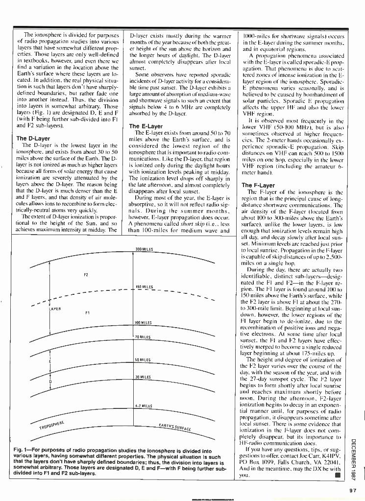
The ionosphere is divided for purposes of radio propagation studies into various layers that have somewhat different prop- erties. Those layers are only well -defined in textbooks, however, and even there we find a variation in the location above the Earth's surface where these layers are lo- cated. In addition, the real physical situa- tion is such that layers don't have sharply - defined boundaries, but rather fade one into another instead. Thus, the division into layers is somewhat arbitrary. Those layers (Ag. I) are designated D, E and F (with F being further sub -divided into FI and F2 sub- layers).
The D -Layer The D -layer is the lowest layer in the
ionosphere, and exists from about 30 to 50 miles above the surface of the Earth. The D- layer is not ionized as much as higher layers because all forms of solar energy that cause ionization are severely attenuated by the layers above the D- layer. The reason being that the D -layer is much denser than the E and F layers, and that density of air mole- cules allows ions to recombine to form elec- trically- neutral atoms very quickly.
The extent of D -layer ionization is propor- tional to the height of the Sun, and so achieves maximum intensity at midday. The
D -layer exists mostly during the warmer months of the year because of both the great- er height of the sun above the horizon and the longer hours of daylight. The D -layer almost completely disappears after local sunset.
Some observers have reported sporadic incidents of D -layer activity for a considera- ble time past sunset. The D -layer exhibits a
large amount of absorption of medium -wave and shortwave signals to such an extent that signals below 4 to 6 MHz are completely absorbed by the D- layer.
The E -Layer The E -layer exists from around 50 to 70
miles above the Earth's surface, and is considered the lowest region of the ionosphere that is important to radio com- munications. Like the D- layer, that region is ionized only during the daylight hours with ionization levels peaking at midday. The ionization level drops off sharply in the late afternoon, and almost completely disappears after local sunset.
During most of the year, the E -layer is absorptive, so it will not reflect radio sig- nals. During the summer months. however, E -layer propagation does occur. A phenomena called short skip (i.e., less than 100 -miles for medium wave and
F2
i F LAYER
F1
tRpPOSPNEPE
300 MILES
150 MILES
100 MILES
70 MILES
50 MILES
30 MILES
4 7 MILES
EAR7Hs SU
rA cr
Fig. 1 -For purposes of radio propagation studies the ionosphere is divided into various layers, having somewhat different properties. The physical situation is such that tha layers don't have sharply defined boundaries; thus, the division into layers is somewhat arbitrary. Those layers are designated D, E and F -with F being further sub- divided into F1 and F2 sub -layers.
10(X) -miles tint shortwave signals) occurs in the E -layer during the summer months. and in equatorial regions.
A propagation phenomena associated with the E -layer is called sporadic -E prop- agation. That phenomena is due to scat- tered zones of intense ionization in the S- layer region of the ionosphere. Sporadic - E phenomena varies seasonally. and is believed to be caused by bombardment of solar particles. Sporadic E propagation affects the upper HF and also the lower VHF region.
It is observed most frequently in the lower VHF (50 -I(X) MHz). but is also sometimes observed at higher frequen- cies. The 2 -meter hands occasionally ex- perience sporadic -E propagation. Skip distances on VHF can reach 5(X) to 15(X) miles on one hop. especially in the lower VHF region (including the amateur 6- meter band).
The F -Layer The F -layer of the ionosphere is the
region that is the principal cause of long - distance shortwave communications. The air density of the F -layer (located from about 100 to 3(X)-miles above the Earth's surface), unlike the lower layers, is low enough that ionization levels remain high all day, and decay slowly after local sun- set. Minimum levels are reached just prior to local sunrise. Propagation in the F -layer is capable of skip distances of up to 2.5(x) - miles on a single hop.
During the day, there are actually two identifiable, distinct sub- layers -desig- nated the FI and F2 -in the F -layer re- gion. The FI layer is tbund around 1(X) to 150 miles above the Earth's surface. while the F2 layer is above FI at about the 270 - to 300 -mile limit. Beginning at local sun- down, however, the lower regions of the FI layer begin to de- ionize, due to the recombination of positive ions and nega- tive electrons. At some time after local sunset. the FI and F2 layers have effec- tively merged to become a single reduced layer beginning at about I75 -miles up.
The height and degree of ionization of the F2 layer varies over the course of the day, with the season of the year, and with the 27 -day sunspot cycle. The F2 layer begins to form shortly after local sunrise and reaches maximum shortly before noon. During the afternoon. F2 -layer ionization begins to decay in an exponen- tial manner until, for purposes of radio propagation, it disappears sometime after local sunset. There is some evidence that ionization in the F -layer does not com- pletely disappear, but its importance to HF -radio communication does.
If you have any questions, tips, or sug- gestions to offer, contact Joe Carr, K4IPV, PO Box 1099, Falls Church, VA 22041. And in the meantime, may the DX be with you.
97

U z o (S
U w J w z o ch
z x 98
By Byron G. Wels
THINK TANK
Singing the unsung heroes... _AIM ENO ONE EVER DOES ANN I RING ALL BY
himself or herself. In testimony to that fact, a very wise man once said "If I have
been able to see farther than my fellows, it is only because I stood on the shoulders of giants."
What I'm leading up to is this: Do you have any idea of how magazines are pro- duced and brought to the newsstands? It's only because of people who aren't afraid of hard work, people who are careful (well, sometimes) and who can produce order out of chaos. They are the unsung heroes.
In almost any magazine, you've got to turn to the masthead page, where the en- tire staff is listed, to find the name of the men or women behind the scene. (But, who cares about them anyway...right ?)
Well the fact remains that if I make a
mistake in my column, it's those unsung heroes that catch and correct the errors, making me look like a hero instead of a
no -go. So, I'm taking this time to thank the boys and girls behind the scenes (that's where all the action is at).
Meanwhile, I'm going to open the of mail bag and see what's going on with you guys!
Electronic Stethoscope I have an "on- and -off" heart condition
that, in typical fashion, never shows up in the doctor's office during my monthly vis- its. The doctor listens with his stethoscope, says "That's fine,' and dis- misses me. But once back home, es- pecially at night, the of ticker starts to do flip -flops.
What I'm looking for is a circuit with a
small amplifier that can pick up and feed heartbeat information to my cassette re- corder, so that I can let the doctor hear what's going on when I'm at home. I tried using a 3- transistor amplifier fed from a
small electret mike, but no dice. Got any ideas? -Jack Baumgarten, New York, NY
Jack, the answer is simply that a micro- phone is not a stethoscope. What you must do is get a stethoscope, even an
inexpensive unit, and remove the acoustic rubber tubing that goes from the head to the "Y" that separates the sound to the ears. Leave the tubing attached to the
stethoscope head, and apply a small
STETHOSCOPE HEAD
ELECTRET
zMIKE
TO CASSETTE RECORDER
ACOUSTIC RUBBER TUBING
Fig. 1 -Take an inexpensive stethoscope and remove the rubber tubing that goes from the head to the "Y" separating the sound to the ears. Leaving the tubing attached to the stethoscope head. apply lubricant to a small electret mike, and slip the mike into the tubing.
amount of lubricant to the sides of a small electret mike, slipping the mike into the tubing (as illustrated in Fig. 1). Now con- nect the mike leads to your amplifier's input, connect the amplifier's output to the cassette recorder's mike input, and you should be able to record all the "flub - dub's" you need.
It really won't work like a Bolter monitor, but it should at least indicate to the doctor that there's more going on than meets the ear, anyway!
Jack, even though you phrased your let- ter as a question, were still going to send you a copy of the Fips book. Sounds as if you could use a good laugh!
Furriners! I recently bought an electronics book
published, unfortunately, in a foreign country. And while there's no mistaking the fact that it's definitely about elec- tronics, that's where any similarity seems to end. The schematic symbols are dif- ferent, so too are parts designations. To top it off, some of the parts, such as IC's and transistors, are not at all available over
Fig. 2 -In this schematic diagram (taken from an English book on electronics) the resistors were originally simple boxes with the normal R1, R2, etc., callouts.
pkC1 47
tR2 6.BK
here! Can you tell me if there are any books available on interchangeability, and
if so where might I get such books? - Frank Brady, Santa Fe, NM
Frank, that situation is an all too com- mon problem, but it is easily overcome. I've got several foreign books on my own shelf that are super- substitution refer- ences -for instance, there's the Master Transistor/IC Substitution Handbook. Al- though my copy of that substitution guide is somewhat dated (printed in 1977), it is
still useful. Perhaps you can find an up- dated version.
As for component designations, they are relatively easy to decipher with the least bit of detective work. What we're accustomed to seeing in schematics is
really not all that different, strange as it might appear. My own way of handling such situations is to simply say "Nutso!" and forge right ahead. In any event, take a
gander at Fig. 2. That schematic diagram is from an English book on electronics. Originally the resistors were simply boxes with our normal Rl, R2, etc., callouts. Regardless of the symbol used, the desig- nation R and the values, 33K, 6.8K, etc., should tell you that you are looking at a
resistor.The same goes for the capacitors, as well as other components.
Then there are times when the answer may not be so obvious. In such instances, the trick is to first determine what the circuit is suppose to do. For example, say
you're looking at a light- dimmer circuit, with a box designated Ql. Is it a tran- sistor?... not hardly.
While there may be some application(s) where a transistor is preferred over a triac, I'd assume that the box represents a good of triac (or in some cases an SCR). From there, distinguishing between the two is a
R4 6.8K
R1
+12v
R5 10K
7 C4
100 R6 U1
47K ICM7555
SPKR1 50 -8012
C3 .01 - GNO

snap. Both have a gate. so there's no in- dication there. But. the triac has two main terminals (designated MTI and MT2). while an SCR has an anode (A) and a
cathode (K). It just that simple. Then there are those components that
have strange -looking callouts; for in- stance TR I VR I , and so forth. Would you believe that both might indicate a tran- sistor. And individually. TR might indi- cate a triac; and VR might indicate a variable resistor, a diode (most often found that way in military- equipment schematics). or even a voltage across a resistor. You figure it out. 'cause that's the way it works.
Anyway Frank. keep an eye on the mails for your copy of the Fips Book. It's on the way!
"Shaddap " Phone! How many times were you doing some-
thing you wanted to give your full attention to when suddenly, the telephone rings? Oh, those people have us trained all right. When the phone rings. you go into a highly -nervous (agitated) state until you answer it. It can be anything from the climax of a TV show that you've invested your time in. to a quiet dinner with some friends. This device simply tells the phone to "Shaddap!" until you are ready to take calls.
See Fig. 3. Anybody that calls gets a
busy signal. While you could accomplish the same thing by taking the phone off hook, we allow you to set a prefixed time, and after the time has run out, your phone goes back to work. And if you finish what you're doing before the time has expired. a reset switch (S2) allows you to manually place the phone hack in service. Nice?
LEDI serves as a visual indication that things are working. And since a resistive
131 ¡
9V=
Fig. 3 -The telephone Shaddap circuit gives a busy indication to all incoming calls, and a reset switch (S2) allows you to manually place the phone back in service. LEDs serves as a visual indication that things are working as they should.
START S1A
load that's equal to the telephone's on -line impedance is thrown in. the system or network won't even he aware that we're using this thing.
A 555 timer is connected so that once the preset time has elapsed. the timer goes off. The 555 is hooked up as a one -shot multivibrator. and activating switch SI powers up pin 8 of the 555. It also grounds the trigger terminal.
The RC time constant set up by resistor R3 and capacitor C3 is now activated. Thu can use the values shown here for a period of about ten minutes. or change them as you see fit for more or less time. By the way. if you think it's worthy, please shoot out one of those Fips books. And I thank you. -Jesse Althrop. Washington. DC
You got it pal. and hey! Thank ym!
Car Stopper Some time ago. when I worked as a
security guard, we busted a guy who made his living by walking down quiet residential streets late at night. looking into car windows with a small flashlight. If he saw any small change on the dashboard or console, he'd pick up a rock
Fig. 4 -The Car Stopper actually allows the would -be thief to start the car, and take off in it, only to find that after a short time, the engine cuts out and will not restart.
01 b 2N3906
RI 10K RESET
S2
C2
¡R2 '10K
8
and smash the car's window to get the money. During the arrest intersless. we learned that he once got a dollar and 35 cents. "Don't you realize." I asked. "that it could cost as much as a hundred bucks to replace that window?" "What do I
care?" he responded. "Ain't my ss in- dow!"
Many people (especially in large. ur- ban areas) have no respect fix property. and the unprotected automobile is a prime target. It converts easily and quickly to cash. and is a simple 'natter to get assay with. Auto burglar alarms usually aren't much help. as their M.O. is well -known to many crooks who can quickly and easily bypass them. I devised this system which actually allows the would -be thief to start the car and take off in it -onIN 1oo find that aller a short time, the engine cuts out and will not restart. Now what would you do in that situation? That's right. Get out of there and look for easier pickings! -Marc Teller. Seattle. WA
Check out Fig. 4. Set the unit by clos- ing SI. Since power conies off the ignition switch, nothing happens until the ignition switch is closed. When power is applied.
D1
1N4001
o +t2V Si ON/OFF
R6 10K
1A/v-
R5 4.7K
R3 10MEG
I11
555
ï
R4 10K b
VA,
R8
100K
R7 4.7K
02 2 N3904
R9
15052
LED' 02 1N4001
04 1N4001
TO PHONE LINE
L1 12
03 1N4001
D5
1N4001

CI is uncharged and the Darlington pair. consisting of QI and Q2 are cut off so no power goes to the relay coil. The car's ignition system works naturally.
Now CI charges through RI and the voltage into the Darlingtons slowly rises. Finally. the relay gets enough voltage to
activate. The contacts close. and whop! they short out the points and the engine "stalls."
Nothing is truly failsafe. and there al- ways is the possibility that this sy stem can
be defeated if the crook just happens to be
an electronics engineer. I suppose that even an electronics engineer could be
motivated to steal cars under some cir- cumstances, but I really don't believe it! Marc. thanks Iirr the circuit and your copy of the hips hook is on the way!
Purposeful Circuit I renumber dearly the Fips stories that
appeared in RE every April. I want my copy! So I started rummaging through the
dusty old attic that I use for a brain, and came up with this venerable relic. It was
the first of the "do- nothing" circuits. and proved to be a lot of fun. All it really does is to sit there and blink... For years! Why. the wife and I once hired a baby sitter who sat in our living room petrified with fear all evening, waiting firr it to "go off!" - Paul Gleason. Santa Fe. NM
Turn your attention to Fig. 5. It's a basic R/C time constant circuit. using a resistor, a capacitor and a neon lamp. The firrmula for the resistor and capacitor is:
RC = TC.
where R is the resistor value in ohms. C is
the capacitance in farads. and of course. TC is the time constant in seconds.
The power source is a 90 -volt "B" bat- tery. You can still get them at the local Radio Shack store as well as other sources. The circuit also works best with an NE2H neon lamp: and don't try to doll it up into some commercial- looking thing. I used to use black friction tape to hold everything together. and if you cut a
broom -handle into 6 -inch lengths and paint 'cm red. you can tape those in place too. and add some loose wire helixes from the top of each piece of wood, they will come off looking like sticks of dynamite. Add an old non- working alarm clock and
90V
T
Fig. 5 -The blinker circuit's time -con- stant is set by a resistor and capacitor. and can be determined from RC TC.
you'll have a convincing piece of artwork. Of course. my spouse. being totally
devoid of anything resembling a sense of humor. couldn't see it.
"I hope this is good enough to get me a
copy of the FIPS book, and I wonder if you remember those special little Christ- mas booklets that Hugo used to send to a
select few friends each year? Are they still available ?"
Paul. your copy of the Fips book is now on the way.
Poppin Wheelies "Ordinarily. I wouldn't write to an
'older guy.' but you seem pretty cool. I'm a biker. and figure you might want to pass
along this idea I had. My main squeeze and I go out on the road every weekend, and I've got a built -in helmet radio. That's nice for me. but it didn't do her a lot of good. So I bought one of those retractable telephone cords and wired up a plug on
each end, straight through. using tour- -pin plugs. I put a four -pin socket on each helmet. and a pair of earphones into her helmet. along with small mini -boom mikes on each one. I also mounted a push - to- talk switch on each helmet. then I at- tacked the radio, which is a small tran- sistor type."
"So OK. I attacked the amplifier of the radio (See Fig. 6) and started by trying to get the radio to play through both helmets at the same time. That was simple. More
RADIO DETECTOR
Fig. 6 -The ampli- fier of the radio was connected to both helmets, and the mikes wired so that at a push of a switch we were able to talk easily without sho hout- ing over the noise.
MICi MIC2
complicated. N(I wiring the mikes through the amplifier so that a push of either switch would enable us to talk easi- ly and comfortably without shouting over the hike's noise. I ought to explain that this circuit really plays havoc with the impedances. but not enough so that you'll notice. But that leaves me with two ques- tions. By: Is this good enough to get me a
copy Of the Fips book. And just what is a
Fips Book anyway ?" -Jerry Snodgrass. Keane. NH.
I used to ride a pan -head Harley myself. Then the of lady refused to climb on the
back unless I took off the sissy bar. First of all. yes. A copy of the Fips hook is on the way to you. and judging from the way you handled your problem. I'd guess you'll enjoy it. For those who might not be
osi
aware. "Mohammed Ulysses Fips" was
the pen name of Hugo Gernsback. found- er of this (and many other) publications. Because he was a top -notch writer. he'd do a tongue -in -cheek article each April (April Fool's Day) that was very con- vincing. but that could never really work. We gathered them into a single volume. and give this as an award to those people who send in their favorite circuits. like you!
Pre -amplifier I firmly believe that when you buy
something. you should buy the best that you can afford, thereby making your lirst expense your last. So on our lirst anniver- sary. I bought my wife. who loves classi- cal music, the best turntable that my money would allow. Money is not some- thing that newlyweds are rolling in. but on
the other side of the coin. a tool knows the
price of everything and the value of nothing. I carefully explained to her that the turntable will work just fine. as soon
as we can afford such minor accessories as
an amplifier and speakers. When I got home the next night, there
she was with her ear close to the stylus. which was tracking in a groove. She could barely hear the music whispering me- chanically out of the thing.
I went up to my attic workshop right after dinner, and threw together this dinky little amplifier. It wasn't much. Lord
VOLUME CONTROL IN RADIO
SPKR1
SPKR2
knows. and certainly wasnt super hi -fi. but it sure did the job.
Now we have a super -duper stereo with window -smashing speakers, compact discs, the works. But I don't think all of that expensive. gold- plated stuff can ever replace this little amp. -Frank Jesso, Hershey. PA.
Thank you Frank, for sharing that per- sonal experience with us. Look mat Fig. 7
and you'll see what Frank is talking about. Build two of them for a stereo sys-
tem, and they can share the common power source.
The I -watt output is more than suffi- cient firr a small room. and you can drive a
nice, 6 -inch speaker with this unit. For a
gain of ten. open pins 2 and 4 and bypass
(Continued on page 102)
100

HIGH SEAS RADIO PIRATES (Continued from page 77
With a promise from the pair that RNI would not return to the air while the cases were pending. Magistrate Caden released them on their own recognizance.
Thursday. they were back aboard the Sarah. They found the shipboard station "a mess," said Steele. The govern- ment made sure we weren't going to broadcast. Our audio hoard was taken apart. equipment was dismantled, cables were pulled out."
A resolution of sorts was reached Friday. The pirate group agreed to abandon plans to resurrect the off -shore station.
It hadn't been just a publicity stunt, Steele insisted. But four days of unlicensed broadcasting got Radio Interna- tional plenty of publicity.
We received about 300 to 4(X) letters from listeners from as far away as California." Steele said.
RNI also caught the attention of the New York area broad- casters it had challenged.
Muriel Horenstein. owner of WNYG. A Babylon, Long Island commercial AM station. offered to let Radio Newyork International use its facilities for one day.
"I don't think they did anything terrible," said Horen- stein. She said the public could decide for itself if it liked RNI's music -talk format. So Steele and six other RNI broad- casters aired their programming on WNYG -legally -for lo hours on August 5. THe phone response, according the the RNI spokesman, was tremendous.
Meanwhile, Weiner and a skeleton crew sailed the Radio Ship Sarah back to Boston for mothballing. The RNI leader said his priority now is to "see everything through the legal process."
Steele had the final word: We are law abiding citizens, and we never had any intention to break the law.
The FCC says we didn't have to do it that way. They said that we can apply for a license to broadcast. We'll see. We want a license and we've been in contact with the American Civil Liberties Union and broadcast lawyers.
We're going to see if the FCC means what it says!"
AUDIBLE IR REMOTE INDICATOR (Continued from page h' )
The Loam helps to keep the battery from sliding around and prevent wires from coming loose. Wedge the foam against the detector and plastic case. Now button -up the enclosure and check for rattles.
Using the Indicator Turn the indicator on and place the transmission end of
the remote transmitter against the detector. Flip SI to the "on'' position. Press any remote- transmitter button. You should hear a clear, chirping tone from the piezo buzzer. Move the infrared indicator in front of the remote until the sound is the loudest. You have now located the infrared diode assem- bly within the remote control.
Check each button of the remote to see if it Operates. You may find one or more buttons will produce higher volume than the others. All buttons should cause a tone to be gener- ated by the Indicator. If not, the button or circuit within the remote may be defective. Some remote transmitters may produce higher volume than others.
You may find some transmitters that operate two or three inches from the detector. While others should he pressed against the indicator for a pleasant tone. Weak sound from the Indicator may suggest a weak battery in the remote or a defective component. When one or more buttons of the re- mote generates a really -weak response, suspect that the prob- lem is a weak battery.
Now, you can check out each of those remote transmitters to determine if the remote or electronic device it controls is defective betitre calling in the electronics surgical team.
NEW IDEAS 42 PROJECTS
COMPLETE PARTS LISTS ONE -EVENING PROJECTS
EASY TO BUILD
NEW IDEAS is packed with 42 practical cir- cuits for the Electronics Experimenter and Proj- ect Builder. In addition to the headlight alarm, the voltage freezer, and the remote telephone ringer, you get complete plans for a simple Tesla coil project that can generate 25,000 -volts AC and draw one -inch sparks. Other interesting projects are: a sound- effects generator, a crys- tal tester, a stereo remote control, and much, much more! Each project was selected for its low cost of parts!
WANT TO EXPAND your knowledge of elec- tronics? Build gadgets that only you can have on your block? Acquire a library of projects? NEW IDEAS is the gold mine of circuits you should own and read. You could start the first night building a project that will have others praising what it can do and admiring you for building it.
THERE ARE PROJECTS for everyone -au- tomotive, household, test equipment, audio and hi -fi, and projects just for fun.
NEW IDEAS -Circuits for Experimenters and Project Builders!
Please send one copy of NEW IDEAS at $3.50. First Class postage and handling $1.00 (U.S. and Canada only). All other countries: $2.00 for sea mail, $3.00 for air mail.
Please send copies of New Ideas. Total cost is sum of copy price and First Class postage and handling cost multiplied by number of issues ordered.
Please print Allow 6 -8 weeks for the material to arrive. Detach and mail today: HANDS -ON ELECTRONICS
(Name) Reprint Department 500 -B Bi- County Boulevard Farmingdale, NY 11735
(Street Address)
go (City) (State)
All Payment must be in U.S. Funds!
(Zip) H 1287 i 101

WELS' THINK TANK (Continued from page 100)
INO- R1
10K4
Fig. 7 -This dinky little amplifier's one -watt output is more than sufficient for a small room and capable of driving a 6 -inch speaker.
Cl 0.1
+14V R2
1052
C2
K 1
10
C4
390
U1
MC1554
4
C3 10
9
C6 250
2 C5
0.1
R3
1052
I(
8E2
SPKR1
pin 5 with a 10p .F capacitor. You can actu- ally get a gain of 35 if you jump pins 2 and
5 and bypass 4. Frank. you will soon be receiving your
copy of the Fips hook. and thanks again.
That's all the space for now. but we do
want your ideas and schematics. Re-
member that the Tank is now interactive, so feed me! Write to By Wels. Hands -on Electronics, 500 -B Bi- County Blvd.. Farmingdale, NY 11735.
Ealádñici° SPI Special Projects #1 (Winter 1980) .... $6.00 SP4 Special Projects #4 (Summer 1982) .. $6.00 SP5 Special Projects #5 (Winter 19831.... $6.00 SP5 Special Projects #6 (Spring 1983).... $6.00 SP7 Special Projects #7 (Summer 1983) .. $6.00 SP8 Special Projects #8 (Fall 1983) $6.00
SP9 Special Projects #9 (Winter 1984). $6.00 S110 Special Projects #10 (Spring 1984) $6.00 111 Hands -On Electronics #1 $5.00 112 Hands -On Electronics #2 $5.00 113 Hands -On Electronics #3 $5.00 114 Hands -On Electronics #4 $5.00 115 Hands -On Electronics #5 $5.00 115A Hands -On Electronics #6 $4.50 116A Hands -On Electronics (Jan -Feb '86) $4.50 116B Hands -On Electronics (Mar/Apr '86) $4.50 116C Hands -On Electronics (May Jun '86) $4.50 1160 Hands -On Electronics (Jul Aug '86) $4.50 116E Hands -On Electronics (Sep Oct '86) $4.50 116K Hands -On Electronics (Nov '86) $4.00 116L Hands -On Electronics (Dec '86) $4.00 117 Hands -On Electronics back issues
(1987) $3.75 Write in issues desired
150 TV Descrambler $3.00 151 Build Your Own Robot $12.00
1 152 8-Ball Satellite TV Antenna $5.00 107 Radio -Electronics back issues (1987) $3.25
1 106 Radio- Electronics back issues (1986) $3.75 Write in issues desired
REPRINT BOOKSTORE
] 105 Radio- Electronics back issues (1985) .$4.25 (Jan. 85 not available) Write in issues desired
104 Radio- Electronics back issues (1984)..$5.25 (December 1984 issue is not available)
Write in issues desired
n 103 Radio -Electronics back issues (1983)....$5.50 (Jan., Aug., Dec. are not available) Write in issues desired
E I 102 Radio -Electronics back issues (1982). $5.75 (Jan. is not available) Write in issues desired
153 Etch your own PC boards $3.00 154 How to Repair VCR's $3.50
155 IBM Typewriter to Computer $3.00 125 Radio -Electronics Annual 1985 $5.95 126 Radio -Electronics Annual 1986 $4.95 156 How to Make PC Boards $2.00 157 All About Kits $2.00
158 Electro Importing Co. Catalog (1918) $5.95 159 Low Frequency Receiving Techniques
Building and using VLF Antennas $6.00 160 New Ideas - 42 Circuits $3.50
Cl 161 Descrambling (Feb., 1984) $3.00 162 Build Your Own Satellite TV Receiver $7.00
Cl 163 Receiving Satellite TV $7.00 164 Modern Electrics (April, 1908) $3.00 165 How to Repair CD Disc Players $5.00
[1 166 Collected Works of Mohammed Ullyses Fips
(62 pages, April Fools Collection) $7.50 167 Designing With IC's $4.00
If you need a copy of an article that is in an issue we
indicate is unavailable you can order it directly from us.
We charge 50C per page. Indicate the issue (month &
year), pages and article desired. Include payment in
full. plus shipping and handling charge. Make checks
payable to Gernsback Publications, Inc.
To order any of the items indicated above, check off the
ones you want. Complete the order form below, include your payment, check or money order (DO NOT SEND
CASH), and mail to Hands -on- Electronics. Reprint De-
partment, P.O. Box 4079, Farmingdale, NY 11735.
Please allow 4 -6 weeks for delivery.
ARTICLE
PAGES MONTH
TOTAL PAGES Ca 50C each
YEAR
TOTAL PRICE
L
102
MAIL TO: Hands -on- Electronics Reprint Bookstore, P.O. Box 4079, Farmingdale NY 11735
SHIPPING CHARGES IN USA & CANADA
$0.01 to $5.00 $1.00 $30.01 to 40.00 . $4.75
$5.01 to $10.00 $1.75 $40.01 to 50.00 . $5.75
$10.01 to 20.00 $2.75 $50.01 and above ... $7.00
$20.01 to 30.00 $3.75 Total price of merchandise $
Sales Tax (New York State Residents only) $
Shipping Charge (see chart) $
All payments must be in U.S. funds
SORRY -WE ONLY
SHIP TO USA & CANADA
Name
Address
City State Zip
Total Enclosed $
H-1287
NEW PRODUCT SHOWCASE (Cominia'(! fr(nt page /3)
Anti -falsing Radar Detector Drivers who arc concerned about hav-
ing enough time to react to speed traps when either X- or K -Band radar is used.
will be interested in a anti -falling radar
detector from Regency that provides sepa-
rate audio tones for both types of radar. When radar is noted. the Regency In-
former RD -I. dual, superhetrodyne, radar
detector alerts drivers with a glowing lamp, plus an audio tone that increases its
pulsing rate as the vehicle gets closer to
CIRCLE 65 ON FREE INFORMATION CARD
the radar source. Separate audio tones are
provided to help the driver distinguish be-
tween X -Band ( I0.525 -GHz) and K -Band (24.150 -GHz) radar.
The radar detector is simple to operate right out of the box. It can be either visor - or dash -mounted, and comes with a de-
tachable cigarette -lighter cord for truly portable operation. A single power /vol- ume control turns the unit on and adjusts the loudness of the warning tone. A power LED reassures the user that the unit is
turned on. To eliminate erroneous signal inter-
ference from nearby microwave relay sta-
tions. door openers, and other radar sources, the detector features discrete log- ic circuitry that assures accurate and relia- ble long -range reception.
The Regency Infiymer RD -I radar de-
tector measures just I -% x 33/u, x 413/in-
in. and comes with a universal mounting bracket for easy installation in any vehi-
cle. plus a detachable cigarette lighter cord. It has a suggested retail price of $99.95.
Additional details are available from Regency Informer radar detector dealers or by writing directly to Regency Elec-
tronics Inc., 7707 Records Street, Indi- anapolis. IN 46226.

ONE SHOT SHOOTING (Continued from page 46)
ator. A resistor connected momentarily from the base of Q7 to plus 3 -4-1/2 volts should cause the lamp to light. If it doesn't, check the diode to see that the band end (the cathode) goes to the amp. Be sure that the + side of C4 goes to the switch and R8 (39,000 ohms).
The target in Fig. 3 may be laid out on a piece of perfboard just about the way it is drawn. That makes it easier to check out. Start with Q5, Q6, and the LED. Touch a resistor (1000 - to 10,000 -ohms) to the base of Q5 and the battery plus. The LED should light, and if you have it in the circuit. the sounder should also tell you that that part of the system is go. If you are not sure about the leads on the LED, connect about 470 -1000 ohms to one side of it and the battery. If it doesn't light reverse the connections to the battery. If it still fails to light try another LED.
To check Q4 and the pulse stretcher, touch a resistor, about 100 -1000 ohms, from the base of Q4 to its emitter. The LED and sounder should fire and fade out about a second or so after you remove resistor.
You may check Q3 by firing a light burst right into its input. If you get no response, try a small resistor (100 -1000 ohms) momentarily across Q3. If that works check the emit- ter/ collector connections to Q3. they are probably reversed. A photoconductive cell will work with the leads connected either way.
Checking the Synthesizer The target in Fig. 4 checks out about the same way; it just
has a few more parts. You can turn on QI5 -Q16 the syn- thesizer, and QI7 -Q18 the speaker amplifier by touching a small resistor from battery plus to either RI9 or R20. If you want to check Q17 -Q18 by themselves, use at east a 15.000 - ohm resistor fro the base of QI7 to battery (power supply)
plus. Make and break the connection rapidly. that will pro- duce loud clicks in the speaker.
The pilot light in Fig. 6 should run if the LED is good. The pilot light uses a basic building block. a multivibrator. With minor modifications it can he used as a music synthesizer. Another popular building block. the Darlington pair serves as the heart of the One Shot. the Outer Space model, and the switches in the targets. Feel free to experiment with those circuits and make your own applications of them.
When all systems are "GO," put the covers on them and your shooting gallery is ready to blast those rainy -day dol- drums into so much cosmic vapor.
MIL When connecting the panel- mounted components to the board, be sure that the starting and termination points coincide with the schematic diagram.
CHECK ADJUST YOUR COLOR TV (Continued from page 36)
three color bars in the same order as they appear on the TV screen. The Y waveform is not affected by TV tint and chroma controls. The voltage levels of the R. B, and G pulses were almost equal indicating that the color saturation of the vinyl tape colors were reasonably matched..
Figure 5 shows waveforms observed at the cathode of the red, blue, and green guns of the CRT. Those waveforms are affected by TV tint and chroma controls. The voltage swing is about 80 to 100 -volts peak -to -peak. With the cathode- driven CRT gun, an increase in cathode voltage decreases electron - beam current with reduction in brightness of the phosphor dot and vice -versa.
Let's show how those waveforms translate into specific colors on the screen. For the red baron the screen, the red gun is near fully on, the blue gun is partially on and the green gun is partly on. The resulting color is blue with a shift towards cyan. For the green bar, the red and blue guns are near cutoff and the green gun is near fully on resulting in green.
Normally, the red, blue, and green pulse levels and the color of the bars should change when you vary the tint control. Also, when you turn chroma fully down, the pulse levels tend to line up as in Fig. 5a and you should have a
monochrome display. If the cathode waveforms seem normal and responsive to chroma and tint adjustments, but the colors are wrong, check the color tracking adjustments before sus- pecting the CRT.
If the cathode waveforms appear abnormal. you check the color -difference signals. Scope displays of the R -Y. B -Y, and G -Y signals in the chroma section similarly show three color - bar pulses which shift when tint and chroma are adjusted. If one of those signals is not responsive. the chroma chip is suspect. Or, you may conclude that one of the matrix and output stages is defective.
The circuit arrangement shown in Fig. 4 is common but variations exist. The CRT grids and cathodes are sometimes used to perform the matrix function. The Y signal connects to the three cathodes, and the red. green, and blue outputs connect to the grids. In a properly working set. you can observe the normal waveforms at the seven checkpoints. note how they are effected by the controls, and use that as a guide when troubleshooting a similar circuit. It does not matter that our color bar generator is not an NTSC pattern generator as long as we know what to look for.
With some thought, you will recognize other technical uses of camcorder and VCR in education and science. Many physical and physiological properties of light and color can be demonstrated and studied.
103

HANDS -ON MARKETPLACE FOR SALE
CABLE -TV converters. New Zenith flash, Scien- tific Atlanta. Jerrold. Oak. Zenith. Hamlin. Many others. "New" VIDEO HOPPER "The copy killer." Visa, M C & Amex. 1 (800) 826 -7623. B &B INC.. 10517 Upton Circle, Bloomington, MN 55431.
APEXR screwdriving bits. Any size. Complimentary illustrated list. H. SHOCKEY'S, 5841 Longford. Dayton. OH 45424. (513) 236 -2983.
IS it true you can buy Jeeps for $44 through the U.S. government? Get the facts today! Call 1 (312) 742 -1142 ext. 7173.
CLASSIFIED AD ORDER FORM
To run your own classified ad, put one word on each of the lines below and send this form along with your check to:
Hands -on- Electronics Classified Ads, 500 -B Bi- County Boulevard, Farmingdale, N.Y. 11735
PLEASE INDICATE in which category of classified advertising you wish your ad to appear. For
special headings, there is a surcharge of $10.00. ( ) Plans Kits ( ) Business Opportunities ( ) For Sale ( ) Education 'Instruction ( ) Wanted ( ) Satellite Television
( )
Special Category: $10.00
PLEASE PRINT EACH WORD SEPARATELY, IN BLOCK LETTERS. (No refunds or credits for typesetting errors can be made unless you clearly print or type your
copy.) Rates indicated are for standard style classified ads only. See below for additional
charges for special ads. Minimum: 15 words.
1 2 3 4 5
6 7 8 9 10
11 12 13 14 15 ($21.00)
16 ($22.40) 17 ($23.80) 18 ($25.20) 19 ($26.60) 20 ($28.00)
21 ($29.40) 22 ($20.80) 23 ($32.20) 24 ($33.60) 25 ($35.00)
26 ($36.40) 27 ($37.80) 28 ($39.20) 29 ($40.60) 30 ($42.00)
31 ($43.40) 32 ($44.80) 33 ($46.20) 34 ($47.60) 35 ($49.00)
We accept MasterCard and Visa for payment of orders. If you wish to use your credit card to pay for your ad fill
in the following additional information (Sorry. no telephone orders can be accepted.):
Card Number Expiration Date
PRINT NAME SIGNATURE
IF YOU USE A BOX NUMBER YOU MUST INCLUDE YOUR PERMANENT ADDRESS AND PHONE
NUMBER FOR OUR FILES. ADS SUBMITTED WITHOUT THIS INFORMATION WILL NOT BE ACCEPTED.
CLASSIFIED COMMERCIAL RATE: (for firms or individuals offering commercial products or services)
$1.40 per word prepaid (no charge for ZIP code)... MINIMUM 15 WORDS. 5 °° discount for same ad in 6
issues within one year: 10 °° discount for 12 issues within one year if prepaid. NON -COMMERCIAL RATE:
(for individuals who want to buy or sell a personal item) $1.15 per word. prepaid . no minimum. ONLY FIRST
WORD AND NAME set in bold caps at no extra charge. Additional bold face (not available as all caps) 25c
per word additional (20% premium). Entire ad in boldface. add 20% premium to total price TINT
SCREEN BEHIND ENTIRE AD: add 25% premium to total price TINT SCREEN BEHIND ENTIRE AD
PLUS ALL BOLD FACE AD: add 45% premium to total price EXPANDED TYPE AD: $1.85 per word
prepaid. All other items same as for STANDARD COMMERCIAL RATE TINT SCREEN BEHIND ENTIRE
EXPANDED TYPE AD: add 25% premium to total price TINT SCREEN BEHIND ENTIRE EXPANDED
TYPE AD PLUS ALL BOLD FACE AD: add 45% premium to total price DISPLAY ADS: 1 2' -
$160 00: 2" ' 2' + -$320 00. 3 2' + - $480.00 General Information: Frequency rates and prepayment
discounts are available. ALL COPY SUBJECT TO PUBLISHERS APPROVAL. ADVERTISEMENTS USING P.O. BOX ADDRESS WILL NOT BE ACCEPTED UNTIL ADVERTISER SUPPLIES PUBLISHER
WITH PERMANENT ADDRESS AND PHONE NUMBER. Hands -on Electronics is published monthly.
therefore copy to be in our hands for Jan. 88. 9 18. Feb. 88. 10 19. Mar 88. 11 18
104
MANUFACTURE electronic equipment in your home for the Army, Navy, Air Force, and NASA. Will supply plan. Inexpensive easy to build equipment. Government pays $4.000. Cost you $900. Profit $3,100. Send $10 to SUBCONTRACT R & D, 136 -31 222nd St.. Laurelton, NY 11413. Attention: Wilner Nau.
GIANT shortwave listener's catalog. Features short- wave receivers, antennas. accessories, radi- oteletype facsimile equipment and books. Free! UNIVERSAL SHORTWAVE RADIO, 1280 Aida Drive. OH. Reynoldsburg. OH 43068.
FREE IBM clone bare motherboards send $6.00 P
& H. DRUIZ, P.O Box 26201 Santa Ana. CA 92799 -6201.
TUBES - 2000 TYPES DISCOUNT PRICES!
Early, hard -to-find, and modern tubes Also transformers, capacitors and parts for tube equipment. Send $2.00 for 20 page wholesale catalog.
ANTIQUE ELECTRONIC SUPPLY 688 W First St Tempe. AZ 85281.602/894-9503
PLANS /KITS BUILD this five -digit panel meter and square wave generator including an ohms. capacitance and fre- quency meter. Detailed instructions $2.50. BAG - NALL ELECTRONICS, 179 May, Fairfield. CT 06430.
STRANGE stuff. Plans, kits, items. Build satellite dish $69.00. Descramblers, bugs. adult toys. Infor- mational photo package $3.00. refundable. DIRIJO CORPORATION. Box 212 -H. Lowell. NC 28098.
CATALOG: Hobby circuits. licensed unlicensed broadcasting, transmitters, antennas. books, scramblers. bugging devices. science projects, more! PANAXIS, Box 130 -H012, Paradise. CA. 95967.
DETECTIVE Equipment micro (voice) transmitter. UHF band (highly sensitive and tuneable). Will fit inside an asprin box, including battery. 1 inch anten- na. Micro (telephone) transmitter FM VHF band (tuneable). Powerful. clip -on type. All parts available at local Radio Shack store. Detail plans $10.00 ea. or $15.00 for both when purchased together. Free catalog listing many other devices of this nature with order. Catalog only. $5.00 (refundable). WILSON. P.O. Box 5264 Augusta. GA 30906.
VOICE disguisers! FM bugs! Telephone transmit- ters! Phone snoops! More! Catalog $1.00 (refunda- ble): XANDI ELECTRONICS. Box 25647. 32H, Tempe. AZ 85282.
COMMODORE 64 128 owners. Design your own custom circuits. power supplies, filters, drafting and more. Just enter specifications and the computer designs the circuit. Free information or send $5.00 for complete line catalog and demonstration disk tape. Refundable with $20.00 purchase. WEASELGRAPHICS, Dept. HB7. 606 Thomasville. Pocahontas. AR 72455.
CRYSTAL radio sets, plans, parts. kits. Catalog S1.00 MIDCO, 660 North Dixie Highway, Hol- lywood. FL 33020.
DIGITAL project: build yourself an electronic car dashboard. Free details. $1 P &H. MODERN LABS, Dept. M. 2900 Ruisseau, St- Elizabeth. OC. JOK 2JO. Canada.
BUILD these ten solar projects. For free info write: DeROY, Box 87551, Canton, MI 48187.
DIGITAL oscilloscope. A unique project. Plans $5.00. MIKE McGLINCHY, 214 Verano Dr., Los Altos. CA 94022.
SURVEILLANCE electronics, debugging. HNOLOGY high -tech. Catalog send $2.00. TECHNOLOGY
SERVICES, 829 Ginette Street. Gretna. LA 70056.

PROJECTION -TV...Convert your TV to project 7 foot picture...Results comparable to $2.500.00 proj- ectors...Total cost less than $30.00... Plans and 8 " lens $21.95...Illustrated information free. MAC - ROCOMA-HD, Washington Crossing, PA 18977. Creditcard orders 24 Hours. (215) 736 -3979.
AMPLIFIER breakthrough -The current amplifier drives loads push -pull without voltage gain. Op amps now drive speakers. Amplifiers are quieter, freer from distortion, easier to construct. Plans for audio amps includes all wattages. $10. AMPLI- FIERS UNLIMITED, Rt 2, Box 139, Highmore. SD 57345.
FREE microprocessors. memory chips, etc. Free electronic magazine subscriptions. Free education in computers. For information write MICRO SAT LLITE CORPORATION, 2401 N.E. Cornell. Bldg. 133 mail stop 140, Hillsboro, OR 97124.
2716/32A Eprom programmer plans plus two addi- tional projects- plus -free oonus! $2.50 plus $1.00 S H. GALLIUM JUNCTION, 540 -C N.E. Northgate Way, Ste 542, Seattle, WA 98125.
FM transmitter kit, matchbox size, super sound sen- sitivity, adjustable frequency, gain. Board, parts. ed- ucational instructions. $14.95. PTS, Box 1951. Fort Worth. TX 76101.
CABLE T.V. "BOXES"
Converters- Descramblers Remote Controls -Accessories
* Guaranteed Best Prices * * 1 Year Warranty-- C.O.D's
* Immediate Shipping * * FREE CATALOG *
Call or Write: TRANS -ORLD CABLE CO.
14C in Box 531 Peguat Lakes, MN 56472
(215) 543-6571
BUSINESS OPPORTUNITIES HOME assembly. Assemble PC boards for video accessories. We supply materials. No experience needed. $7.50 per hour. Send self- addressed, stamped envelope, to: MICRON ELECTRONICS. Box 4716. Akron, OH 44310.
PERSONAL computer owners can earn $1000 to $5000 monthly offering simple services part time. Free list of 100 services. Write: A.I.M.L.K., Box 60369. San Diego, CA 92106.
CABLE EQUIPMENT CABLE -TV Secrets -the outlaw publication the ca- ble companies tried to ban. HBO. Movie Channel. Showtime, descrambles, converters, etc. Sup- pliers list included. $8.95. CABLE FACTS. Box 711- H. Pastaskala. OH 43062.
THIS IS AN EXPANDED -TYPE AD WITH A TINT SCREEN. See how it jumps out on the page. To order your ad in this format calcu- late the cost at 53.75 per word for the ex- panded -type and add 25% for the tint background.
EDUCATIONAL /INST. SATELLITE and cable equipment schematics, ser- vice manuals, booklets, diagrams. information packets, construction manuals. covers converters, receivers, decoders. Catalog $3.00. PONDEROSA COMPANY, 3624 Citadel Drive North #289H, Colo- rado Springs, CO 80909.
COMPUTER troubleshooter: industrial strength PC repair in plain wrapper. Send $9.95. ACC, 149 Thatcher Hill, Flem., NJ 08822.
DIGITAL LOGIC PROBE f ('nnliuu, doom /10,r 7-1 f
lf r¡ `.. .1".
'aaw, .- r .
..
Connect the power (red and black) leads to a digital circuit, observing the proper polarity. Apply power to the circuit, and (referring to a p.nout of the chip) touch the probe tip to an output pin and note the response of the LEDs.
SOLDER
PROBE
ACRYLIC TUBE
BOTTOM VIEW
SOLDER
RETAINING HOLE
Fig. 2 -The Digital Logic Probe Kit is assembled on a printed- circuit board measuring 5- inches long and 3/4-inch wide. Red -jacketed and black - jacketed alligator -clip leads are used to pirate power from the circuit -under -test. S1 is installed with its leads first placed through the circuit -board support and tack soldered to one end of the board. To the other end, the Probe tip is mounted, making sure that the assembly fits snugly into the grove in the PC -board separator.
It you don't have a ready -built circuit that you can play with, but you do have a solderless breadboard, DC power supply handy, and some sort of TTL /CMOS- level signal source (preferably a function generator), and of course a logic chip, you can rig a test circuit with a predictable output. An inverter, for example. or a NANI) gate connected as an inverter makes the perfect test circuit.
Assuming that you've opted to rig a test circuit, apply power to the circuit, and place a jumper from the positive power source to the input of an inverter (or two Inputs to a NAND gate), referring to a pi- nout diagram of the chip to be tested. Then touch the probe tip to the appropri- ate output pin and note the response of the LEDs. Since the input to the inverter is high, LEDI should light, indicating out- put low. Repeat that scenario, this time with the input to the inverter jumpered to ground, and observe the LEDs. LED2 should light.
Finally, apply a signal to the input of the inverter, and the probe tip to the output. LEDI and LED2 should alternately turn off and on (or may appear continually lit), while LED3 toggles on and off in time with the signal frequency.
ADVERTISING INDEX HANDS -ON ELECTRONICS magazine does not assume any responsibility for errors that may appear in the index below.
Free Information No.
7 %1I(' Sales
9 UI Electronics .
Page
x
Amazing Devices '7 Antique Electronic. Suppl Illo
6 II 8 Cook's Institute 16
12 Digi -ke 5
II
Elec. Iltdustr %ssocialion ... C V3
Electronic lech.'IÜda('V4, 14. IK
Electronics Nuuk Club (V2 Grantham ('ul. of Engineering .. 2K
Hal- 'hnmis . 25
15( 'ET .. 27
IO N1('11 Electronics . . 13
N1cGrau Dill Coot. Education 91 - \RI ..21 - Pacific ('able
5 l'ana% i+e 7
15, 16 Rhino Robots . . . 25. 17
14 The Dalak Corporation . . . . . . 15 - 'Frans Nórld 105
105

LINE DISTURBANCE MONITOR (Continued )rnm I))1(' 4'I
106
Fig. 4-Be sure the hot, negative, and ground leads for your project are properly wired. Many houses have non -standard wiring schemes, so be sure to check your houses outlets before finalizing you project.
Brief Description of Line Pollution
Sag: An under-voltage condition. Long sags are sometimes
known as brownouts. That disturbance may be
detected with the Line Disturbance Monitor (LDM). Surge: An over - voltage condition. That may also be
detected with the LDM. Blackout: A complete voltage failure. A blackout is explicit
enough so no detecting apparatus is required. Noise: High frequency components superimposed on the
main AC frequency. They come in two types:
Transverse -mode noise appears only between hot and neutral. Common -mode noise appears between
ground and both hot and neutral. The LDM can be
set to detect both types of noise by connecting the
sensing inputs to the proper terminals. (However. when sensing common -mode noise, the sensing inputs should be connected between ground and hot, since between ground and neutral there exists almost no voltage and the low voltage detector would continuously sound.)
Transients: Very-high voltages spikes of short duration (on the order of microseconds). The transients are easily suppressed by low -cost varistors, so no attempt has
been made in the LDM to detect them.
During a monitoring session with the LDM, you may find several strange things happening to the AC power line. Your hair dryer may cause noise only when connected to a par- ticular outlet. Noise may increase in a particular location. The office elevator will cause a small brownout only if the air conditioning is on. Or, just before 5:00 PM several incidents crop up in succession.
The last thing to ask is, what should I do'? As stated before, it may be as easy to plug in a different outlet. Or check your wiring for bad wires and contacts. Or, to buy a power -line conditioner. Or, to not use the equipment at certain hours. It
all depends on how heavy your problem and how tight your budget are. But there is something of which you may be
certain. You will not feel blindfolded with the Line Distur- bance Monitor nearby to assist in the investigation.
r,. . IF
UY MINN OG. 0/.O
The front panel of the Line Disturbance Monitor is extremely informative. It tells you at a glance if the voltage is too high, too low, or if the power is just plain noisy.
REPLACING RECHARGEABLE BATTERIES
(Continued from page 78)
Compare the old with the new! The steel straps that inter- connected the original cells were for holding purposes and not for high DC currents. The clips that slipped onto the plastic holder and made contact with terminals inside the strobe were removed and added to the new battery pack. Take care here that they align exactly as they did before, otherwise. no contact.
I placed the old battery pack in front of me and quickly stacked the new cells in the same array. Oh, oh! The bright yellow paper covering the cells did not cover the cell *asings completely, especially at the ends. There was a possibility of creating a short circuit when the battery pack was wired. So i
obtained some tape from the garage storage bin. The tape I
used is a clear plastic type that is very thin, thinner than the 7-
mil black electrical tape most experimenters have. The clear tape is used to repair tears in waterproof home products.
I wrapped waterproof tape around the body of the cells at the top and bottom so that there was a slight I/16 -inch overlap which I pressed down onto the end surfaces of the cells. The selection of this type of tape was important, because the volume in which the new battery pack will be placed is snug as it was for the original pack.
i wired the four new cells in series using the tabs on the cells and uninsulated solid No. 22 copper wire. The cells had to be wired so that the connecting wires would shape the final package like the old battery pack. The end clips on the old pack were removed by pulling them off slowly with a pair of long -nose pliers. The clips were then soldered to the cell string in the same position as the the original. My first fitting of the battery pack into its plastic holder was a success.
I charged the new battery pack using the charging wall plug that came with the strobe. It's best to charge the battery pack at least eight to twelve hours before drawing any power. I
couldn't wait. After a one -hour charge, I disconnected the AC line from the strobe and flipped the power switch on. Three seconds later i fired off my first shot of pure white light.
I had an old Norelco battery- powered shaver that wasn't working any more. It took me some time to find it hidden under my underwear in a chest of drawers. I removed two screws and the shaver came apart. Do it slowly! It took me
almost half an hour to get it back together again (the first
time). Inside were two sub -C cells of the NiCd type. I replaced the cells in the defective shaver and it is like new
again. I keep it in my office, because I purchased a new one before I had the idea to fix the old one. And, you know what, the reason i purchased the new shaver was because some kid
told me the old one was dog meat! I have since repaired several shavers, a food mixer, a hand
vacuum, and a remote telephone for my friends; and i picked up another old non -working Honeywell strobe at a flea mar-
ket that's working now. Also, I discovered a few surplus mail -
order houses that sold odd -size NiCd cells. Hey guys, this could turn into an occupation!

The Electronic Industries Association /Consumer Electronics Group has recently completed the first in a
series of videocassette training tapes.
EIA/CEG ANNOUNCES COMPLETION OF NEW "BASIC CAR AUDIO INSTALLATION" VIDEO TAPE
If you are thinking of "cashing in" on the prof- its in the ever growing car audio service business, the troubleshooting -service- installation -and removal of car audio products is a large, non -com- petitive profit center for your service facility. This thirty minute video introduces you to the ever increasing complex world of car stereo installa- tion. It guides the new installer or owner in the correct layout and design of a car stereo installa-
KEY TOPICS COVERED IN THIS VIDEO
The design and layout of a car stereo installa- tion center.
Basic and specialized tools needed for car audio installation work.
Safety in the shop. How to treat the cus-
-tomer's car, from pre- instal- -lation checkout to demon- strating to the customer he completed job.
The proper procedure
tion facility, covering basic as well as specialized tools needed for the installation business.
This informative videotape is also an excellent aid to the electronics technician in that it gives the correct procedure for removing and replacing "any" car radio from the dashboard of any car and shows the installer's, salesperson's and cus- tomer's role in the installation and sale of car audio products.
for installing car audio equipment.
The technical resources available for information about specific types of vehicles, dashboard dis- mantling, speaker sizes and antenna locations.
Speaker wiring types found in the automobile. Common and floating ground systems -how to differentiate. Proper wiring procedures used in the car.
The cost of the videocassette is $30.00. Use the order form below to order yours now! Send to: EIA /CEG, Department PS, P.O. Box 19100, Washington, D.C. 20036
ó
0
Basic Car Audio Installation Videocassette VHS BETA
Name
Title
Firm
Address
City
Quantity Amount $30.00 each
Total Enclosed
State Zip

r
Electronics Paperback Books GREAT ELECTRONICS PAPERBACKS FROM ETT
$ o . ~7y I ti ,
I
p IL;
771 . mm I N Ilia
a .,.. INand
BP125 -25 SIMPLE AMATEUR BAND ANTENNAS $5.00. All are inexpensive to build. yet perform well. Diodes. beams. triangle and even a mini rhombic
BP128 -20 PROGRAMS FOR THE ZX SPECTRUM AND 16K ZX82 $5.75. Included with each program is a flow chart and a description of what happens. Notes for converting programs for use on other computers are also included.
BP235 -POWER SELECTOR GUIDE $10.00. Complete guide to semiconduc- tor power devices More than 1000 power handling devices are included. They are
tabulated in alpha -numeric sequency. by technical specs. Includes power diodes. Thyristors. Trlacs. Power Transistors and FET's.
BP234- TRANSISTOR SELECTOR GUIDE $10.00. Companion volume to
BP235. Book covers more than 1400 JEDEC. JIS. and brand -specific devices. Also
contains listing by case type. and electronic parameters. Includes Darlington transistors. high- voltage devices. high- current devices. high power devices.
BP99- MINI -MATRIX BOARD PROJECTS $5.00. Here are 20 useful circuits that can be built on a mini -matrix board that is lust 24 holes by ten copper -foil strips
BP157 -HOW TO WRITE ZX SPECTRUM AND SPECTRUM GAMES PRO-
GRAMS $5.95. A crystal -clear step -by -step guide to writing your own graphics games programs
BP117- PRACTICAL ELECTRONIC BUILDING BLOCKS -Book 1 $5.75. Oscillators. Timers. Noise Generators. Rectifiers, Comparators. Triggers and more
BP184 -INTRO TO 68000 ASSEMBLY LANGUAGE $6.50. The 68000 is a
great new breed of microprocessor. Programming in assembly language increases the running speed of your programs Hems what you need to know.
BP179- ELECTRONIC CIRCUITS FOR THE COMPUTER CONTROL OF
ROBOTS $5.00. Data and circuits for interfcing the computer to the robot's
motors and sensors.
BP126 -BASIC á PASCAL IN PARALLEL $4.95. Takes these two program- ming languages and develops programs in both languages simultaneously.
224-50 CMOS IC PROJECTS $5.25. Includes sections on mulfiwhrators. amplifiers and oscillators trigger devices. and special devices.
225-A PRACTICAL INTRODUCTION TO DIGITAL IC'S $4.95. Mainly con- cerned with TTL devices. Includes several simple protects plus a logic circuit test set and a digital counter timer.
BP170- INTRODUCTION TO COMPUTER PERIPHERALS $5.95. Shows how to use a variety of co computer add -ons in as non -technical a way as possible.
' 227 -BEGINNERS GUIDE TO BUILDING ELECTRONIC PROJECTS $5.00. How to tackle the practical side of electronics so you can successfully build electronic protects.
BP169 -HOW TO GET YOUR COMPUTER PROGRAMS RUNNING $5.95. Shows how to identify error in program and what to do about them.
BP194- MODERN OPTO DEVICE PROJECTS $6.25. Crammed with great projects for the experimenter. Includes sections on Fiber optics. passive Infra -Red detectors. plus an assortment of miscellaneous protects.
BP180- ELECTRONIC CIRCUITS FOR THE COMPUTER CONTROL OF MODEL RAILROADS $6.25. Its easy to interface home computers to model railroad control. The main problem is in interfacing the computer to the system.
BP110 -HOW TO GET YOUR ELECTRONIC PROJECTS WORKING $5.00. How to find and solve the common problems that can occur when building projects.
tMFalc,ril Boo. M.Nc
lMCrrr.c Gonads... Gwapeart CN wr.
r
BP33- ELECTRONIC CALCULATOR USERS HANDBOOK $5.75. Invaluable book tor all calculator owners Tells how to get the most out of your calculator.
BP36 -50 CIRCUITS USING GERMANIUM, SILICON á ZENER DI- ODES $5.00. A collection of useful circuits you'll want in your library
BP37 -50 PROJECTS USING RELAYS, SCR'S á TRIACS $5.00. Build pri-
ority indicators, light modulators. warning devices. light dimmers and more
BP39 -50 FET TRANSISTOR PROJECTS $5.50. RF amplifiers. test equip- ment. tuners. receivers. tone controls. etc.
BP42- SIMPLE LED CIRCUITS $5.00. A large selection of simple applications for this simple electronic component
BP127 -HOW TO DESIGN ELECTRONIC PROJECTS $5.75. Helps the reader to put protects together from standard circuit blocks with a minimum of trial and error.
BP122 -AUDIO AMPLIFIER CONSTRUCTION $5.75. Construction details for
preamps and power amplifiers up through a 100 -watt DC- coupled FED amplifier
BP92- CRYSTAL SET CONSTRUCTION $5.00. Everything you need to know about building crystal radio receivers.
BP45- PROJECTS IN OPTOELECTRONICS $5.00. Includes infra -red detec- tors. transmitters. modulated light transmission and photographic applications.
BP48- ELECTRONIC PROJECTS FOR BEGINNERS $5.00. A wide range of
easily completed protects for the beginner Includes some no- soldering protects
BP49- POPULAR ELECTRONIC PROJECTS $5.50. Radio. audio. household
and test equipment protects are all Included.
BP51- ELECTRONIC MUSIC AND CREATIVE TAPE RECORDING $5.50. Shows how you can make electronic music at home with the simplest and most inexpensive equipment
BP56- ELECTRONIC SECURITY DEVICES $5.00. Includes both simple and more sophisticated burglar alarm Circuits using light, mira -red, and ultrasonics.
BP59- SECOND BOOK OF CMOS IC PROJECTS $5.00. More circuits show - ing CMOS applications. Most are of a fairly simple design
BP72 -A MICROPROCESSOR PRIMER $5.00. We start by designing a small computer and show how we can overcome its shortcomings
BP74- ELECTRONIC MUSIC PROJECTS $5.95. Provides the experimenter with a variety of practical circuits including a Fuzz Box. Sustain Unit, Reverberation Unit. Tremelo Generator and more
BP91 -AN INTRODUCTION TO RADIO DXING $5.00. How you can tune in on those amateur and commercial broadcasts from around the world in the comfort of
your home.
BP94- ELECTRONIC PROJECTS FOR CARS AND BOATS $5.00. Fifteen simple protects that you can use with your car or boat. All are designed to operate from 12 -volt DC supplies.
Yrypair
I=i
Illeare YYMr.MYM Chw.r. . rr .lmY/ I Vrrrn
ELECTRONIC TECHNOLOGY TODAY INC.
PO Box 240. Massapequa Park, NY 11762 -0240
Name
SHIPPING CHARGES IN
USA & CANADA
$0.01 to $5.00.. $1.00 $5.01 to $10.00.. $1.75 $10 01 to 20.00 $2.75 $20.01 to 30.00. . $3.75 $30.01 to 40.00.. $4.75 $40.01 to 50 00 $5 75
$50 01 and above $7 00
SORRY No orders accepted Number of outside of USA & Canada
Total price of merehandlse Sales Tax (New York State Residents only)
Shipping (see chart)
All payments must Total Enclosed be in U.S. funds
books ordered l
S
Address
S
S
City State Zip S
H1287 J