Bio Medical Instrumentation Notes - ABES Engineering College
329
-
Upload
khangminh22 -
Category
Documents
-
view
3 -
download
0
Transcript of Bio Medical Instrumentation Notes - ABES Engineering College


lntroduction
a Inside this chapter1.1. Background1.2. Development1.3. Specification of Requirement1.4. Man Instrumentation1.5. Problems Encountered in Measuring a Living System1.6. Anatomy and physiological1.7. Summary
BACKGROUND
The prefix bio, means something connected with rife in biomedicalengineering. Biophysics and biochJmistry interdisciplines basic scienceshave been applied to living things. Similarly, Bio-instrumentation meansmeasurement of biological variables, Trre fiela of measurement is referredto as biometrics.one of the major contributions of biomedicar engineering to lifesciences and clinical medicine has been trr.r"?r, boimedicarinstrumentation. Advances in this fierd have resulted in i'n" developmentof new types of biomedicar instruments and the development of numerousclinical approaches, such as electronic patient monitoring, an importantaspect of critical case medicine, as well as varieties of dlvices to assistindividuals with disabilities.Engineering Joint council committee on Engineering Interactionswith Biologz and Medicine recommendated that bio-engineering be derrnedas application of the knowledge gained by a ".J"" fertilization ofengineering and the biorogi"d
"Ji..r"".s so that both will be more fulryStud
y Mate
rial
Page No. 1 of 328.
Fundamentals of Biomedical Instrumentation

2 Fundamentals of Biomedical lnstrumentation
utllized for the beneht of a man. Biomedical engineer is a person workingin research or development in the interface area of medicine andengineering, whereas practioner working with physicians and patients iscalled a clinical engineer. Association for the Advancement of MedicalInstrumentation (AAMI) consists of both engineers and physicians. Aclinical engineer is a professional who brings to health care facilities alevel of education, experience, and accomplishment which will enablehim to responsibly, effectively, and safely manage and interface withmedical devices, instruments, and systems and the use thereof duringpatient care, and who can, because of this level of competence,responsibility and directly serve the patient and physician, nurse, andother health care professional, relative to their use of and other contactwith medical instrumentation. Most clinical engineers go into professionthrough the engineering degree route, but some may start out asphysicists.
Some of the instruments like electrocardiograph were first used bythe end of nineteenth centuiy. But the progress was slow until the endof World War-II. After the war lot of electronic equipments such asamplifiers and recorders became available. Many technicians andengineers started to experiment with and modified existing equipmentfor medical use. The result of development did not yield good resultdueto the lack of unders-tanding of physical parameters andcommunication problem with the medical professionals.
During 1951-60, many instrument manufacturers entered the fieldof medical instrumentation. But development was slow due to high costsof development. The hospital staffs was reluctant to use new equipment.Many times, the medical staff was uncooperative. In view of this, someprogressive companies decided to design instrumentation specifically formedical use instead of modifying the existing hardware.
Help was provided by the US government, in particular by NASA. Alarge number of physiological parameters needed to be monitored for theastronauts. Hence, aerospace medicine programmes were expandedconsiderably, both within NASA facilities, and through grants toUniversities and hospital research units. Some of the concepts andfeatures of patient-monitoring systems presently used in hospitals allover the world is based on astronaut monitoring system. In short, theengineers and technicians started working with medical professionals.
, The biomedical engineering involves communication between theengineer and the medical professional. The language of the physician isquite different from those of the engineer. The physician must understandenough engineering terminologr for him to discuss problems with theengineer. The burden of bridging the communication gap falls on theengineer. The result is that the engineer, must learn the doctor's language,as well as some anatomy and physiologr, in order that the two disciplinescan work effectively together.
DEVELOPMENT
Stud
y Mate
rial
Page No. 2 of 328.
Fundamentals of Biomedical Instrumentation

\
lntroduction 3
REQUIREMENT
Any instrumentation system generally should achieve one of thefollowing major categories for meeting the basic objective.
1. Information gathering : Instrumentation is used to measure naturalphenomena and other variables to aid man in his search forknowledge about himself and the universe in which he lives.
2. Diagnosis : For the detection and, hopefully, the correction of someincorrect behaviour of the system being measured the measuremensare made. This type of instrumentation may be classified as"troubleshooting equipment,,.
3. Evaluation : Measurements hetp to determine the ability of a systemto meet its' functional requirements. These could be classihed as"proof of performance" or ,,quality control,, tests.
4. Monitoring : Instrumentation helps in monitoring some process oroperation in order to obtain continuous or periodic informationabout the state of the system being measured.
5. control : Instrumentation may help control of the operation of asystem based on changes in one or more of the internal parametersor in the output of the system.
Biomedical instrumentation involves all the objectives of the generalinstrumentation system. Instrumentation for biomedical research cangenerally be considered as information gathering instrumentation. Italso includes some monitoring and control devices. Instrumentation helpsthe physician in the diagnosis of disease and other disorders also haswidespread use. Instrumentation is arso used in evaluation of the physicalcondition of patients in routine physical examination. Specialinstrumentation system, are used for monitoring of patients undeigoingsurgery or are kept in intensive care.
Biomedical instrumentation can generally be divided into followingtypes:
1. Clinical instrumentation2. Research instrumentationclinical instrumentation is basicarly used for the diagnosis, care and
treatment of patients. But research instrumentation is used for acquiringnew knowledge pertaining to the various systems that compose the humanorganism. Although some instruments can be used in both areas.
clinical instruments are more rugged and easiar to use. The mainthrust is to obtain a limited set of reliable measurements from a largegroup of patients and on providing the doctor with enough informationto permit him to make clinical decistons.
on the other hand research instrumentation is normally morecomplex, more specialized and is often designed to provide a muchhigher degree of accuracy and resolution.St
udy M
ateria
l
Page No. 3 of 328.
Fundamentals of Biomedical Instrumentation

4 Fundamentals of Biomedical lnstrumentation
Research instruments are generally operated by skilled technologistswhose primary training is in the operation of such instruments.
Biomedical instrumentation is dirrided into two categories: in vivoand in vitro. An in vivo measurement is that is made on or within theliving or€Janism itself. An example would be a device irrserted into theblood stream to measurc pH of the blood directly. An in vitromeasurement is one which is performed outside the body, even thoughit relates to the function of the body. In vitro rneans "in glass" i.e.,the measurements are to be performed in test tubes. The man-instrument system dealt in this book applies mainly to in vivomeasLlrements. However, obtaining appropriate samples for in vitromeasLlrements and in relating these measurements to the living humanbeing is problematic.
1.4. MAN INSTRUMENTATION SYSTEM
Biomedical instrumentation is a set of instruments and equipment utilizedin t1-re measurement of one or more characteristics or phenomena, andthe presentatjon of information obtained from those measurements in aforrl that can be read and interpreted by man. This is the definition ofinstrument from the complete man-instrument system v,-hich must alsoinclude the human or: subject on whom the measurement are beingmacle.
Due to special pi:oblems faced in getting data from living organism,specialll, hr-tman beings, and because of the large amount of interactionbetween 1he instrumentation system and the subject being measured, itis necessary that the person on whom the measurements are beingmade be considered an integral part of the instnrmentation sYstem. Inorder to make sense out of the data obtained from the black box thehumans organism) the internai characteristic of the black box must be
considered in the design and application of any instruments. The overallsvstem, which includes both the organism and the instrumentationrequired for measurement of the human is called the man-instrumentsystem.
Initially, it rvas almost impossible to measure and understand theinternal relationship of the human body. The function of medicalinstrumentation is to aid the medical clinician and researcher in devisingways of obtaining reliable and meaningful measr-rrements from a livinghuman being.
There are problems associated u,ith such measurements. The process
of measuring must not in any way endanger the life of the person on
whom the measurements are being made. It should not cause unduepain, discomfort. This means that many of the measurement techniquesnormally employed in the instrumentation of nonliving systems cannotbe applied in the instrumentation of huuans.
Man instrumentation system involves the measurement of outputsfrom an unkno-rvn s-vstem as they are affected by various combinationsSt
udy M
ateria
l
Page No. 4 of 328.
Fundamentals of Biomedical Instrumentation

\
lntroduction 5
of inputs. The requirement is to understand the nature andcharacteristics of the system. The unknown system is referred as ablack box. It has a variety of configurations for a given combination ofinputs and outputs. The end product of such an exercise is a set ofinput-output equations for the internal functions of the black box.These functions may be simple or extremery complex. The living humanbeing is one of the most complex black boxes. This black box consistsof electrical, mechanical, acoustical, thermal, chemical, optical,hydraulic, pneumatic and many other types of systems. These systemsmay interact with each other. The human being here referred to asblack box may also contain a powerful computer, severar types ofcommunication systems, and a great variety of control systems. However,living black box gives risc to other probrems. Many of the importantvariables to be measured are not readily accessible to measuring devices.The measuring device itself introduces some error.
Some other some problems in obtaining correct measurements are(1) Safety considerations, (2) the environment of the hospital in whichthese measurements are performed (3) the medical personnel usuallyinvolved in the measurements and (4) sometimes even ethical and legalconsiderations.
Basic principle of biomedical instrumentation is shown in figure 1. 1block diagram. Here, any phiological event becomes input of atransducer. Transducer gives transduced electrical signal which issubjected to signal conditioning. Subsequentity, the output signal isdisplayed and or saved.
Fig. 1.1. Basic principle of biomedical instrumentation
A human being as a whole communicates with his environmentmany ways which can be termed as inputs and outputs as shou,nfigure 1.2. These inputs and outputs can be measured and analyzed.a variety of ways.
1n
inin
Stud
y Mate
rial
Page No. 5 of 328.
Fundamentals of Biomedical Instrumentation

6 Fundamentals of Biomedical lnstrumentation
Sm ng
lnhaling
Sensationdue to touching
lntake of Liquid
lntake of Food
HUMAN BODY AS GONTROL SYSTEM OUTPUTS
Speeking
Behaving
Looks
Exhailing
Movementot Body
Liquid inWaste form
Solid inwaste form
Fig. 1"2. Depiction of human communication with the environmentin like a control system
The man-ir-rstrument system block diagram is shown in figure 1.3,
urhich shows the components of the system. Here, a living human being
is a part of the system. The components are as follows:
SignalConditi-
onrngDevice
Transducer-1Body Temperature
Transducer-4Body muscles
Data processing, recordingand transmission
Fig. 1.3. Block diagram of man-instrument systemStud
y Mate
rial
Page No. 6 of 328.
Fundamentals of Biomedical Instrumentation

t
lntroduction 7
1.4.1. Subject
The human being on whom the measurements are made is knor,vnas subject. The subject who makes this system different fromother instrumentation systems are treated in much greater cletaii insection 1.5.
1.4.2. Stimulus
The response to some form of external stimulus is required. Theinstrumentation used to generate and present this stiinulus to the subjectis an essential part of the man-instrument system whenever responsesare measured. Visual (e.g. a flash of light), auditory (e.g., a tone) tactile,or direct electrical stimulation of some part of the nervous system of anysubject.
1.4.3. Transducer
A transducer is defined as a device capabie of converting one formof energ,' or signai to another. In the man-instrument system, eachtransducer is used to produce an electric signal. It is in the form ofanalog signal of the phenomenon being measured. The transducer maymeasure temperature, pressure flow or any of the other variables thatcan be found in the body, but its output is always an electrical signal.As shown in figure 1.3, two or more transducers may be usedsimultaneously to obtain relative variations between phenomena, theexample shows four transducers.
1.4.4. Signal-Conditioning Equipment
The instrumentation system part which amplifies, modifies, or in anyother way changes the electric output of the transducer is called signalconditioning equipment. The purpose of signal conditioning or signalprocessing equipment is to process the signals from the transducers inorder to satisfy the functions of the system and to prepare signalssuitable for operating the display or recording equipment.
1.4.5. Display Equipment
The output of the signal conditioning equipment must be convertedto some form of visual, audible, or possible tactile information. In theman-instrumentation system, the display equipment may include agraphic pen recorder that produces a permanent record of the data.
1.4.6. Recording, Data Proeessing and Transmission Equipment
Recording of the measured information is done for possible later usc:or to transmit it from one location to another, whether within the hospitalor around the worid. Equiprnent for these functions is often an importantpart of the man-instrlrment system. Where automatic storagc or processingis required or where computer control is employed, an on line analog ordigital cornputer is a pnrt of the instrumentation system. The recorderis used in two different contexts in biomedical instrumentation. A graphicpen recorder is actually a display device used to produce a paper recordSt
udy M
ateria
l
Page No. 7 of 328.
Fundamentals of Biomedical Instrumentation
8 Fundamentals of Biomedical lnstrumentation
of analog waveforms' The recording equipment are devices
;;; ;" -recorded for future play back' such as in a
recorder, etc.
by which datamagnetic taPe
1.4.7 . Control Devices
It it is necessary to have automati
instrument sYstem'
PROBLEMS ENCOUNT
and physiological systern of the btdy.d",*11P^"
T:3,T*:ilT'Jlffi'"T.1t1":i';:ffi'#;i;;;;il"'^c'i"k"ltl:;measurement on a human subJect' t.or rllca'-ururrrvrrL rre'
..rpments are done on animal su 'jects' The measuremelltsome measurements are
problems are summ arized as given below :
1.5.1. lnaecessibility of Variables to Measurement
ManY times it is not Possible tsystem. In some cases, such as
.r"t ro.fr"-ical activity in the brain
transducer to make measuremenand someIn using
riable mus ood'
1.5.2. YariabilitY of the Data
Some of the variables measured
variables. In fact such variables s
processes. A stochastic process is-a
in a nondeterministic waY' PhY
deterministic st be rePre
or Probabilist The meas
conditions at not be same und'er ttre same conditions at
another time. The variability from one subject to another is even greater'
1.5.3. Lack of Knowledge About lnterrelationship
The variabilitY in measured val
were known and understood abo
:e
would help use of indirect measure
1.5.4. lnteraction Among Physiological System
Due number of feedb volved in the major
physiolo , a severe degree n exists both within
a given among the maj The result is thatStud
y Mate
rial
Page No. 8 of 328.
Fundamentals of Biomedical Instrumentation

lntroduction 9
stimulation of one part of a given system affects all other parts of that
system in some *ay and oftEn affects other systems as weil'
1.5.5. Effect of the Transducer on the Measurement
Any kind of measurement is affe by the presence
of the measuring transducer' The complex in the-
measurement of living systems' In m sical presence of
the transducer changes the reading significantly'
1.5.6. Artifacts
The term ar s a signal that is extlaneous
to the variable e ajor source of artifacts in
the measuring g ment of the subject'
1.5.7. EnergY Limitation
Some physiological measurement techniques require that a certain
amount of energr ie applitd -to the living system in order to obtain a
measurement.Forexampleresistance-",...,.".entrequiretheflowofelectric current ttrrough the tissues or blood being measured'
1.5.8. SafetY Gonsiderations
There should be no danger to the life of the living being subjected to
rneasuring variables. Extra caution must be must be taken in the design
ofanymeasulementsystemtoprotectthepatient.similarlythe-.."r.i..-ent should not cause undue paiir'
1.6. ANATOMY AND PHYSIOLOGICAL
In order to obtain valicl measurements from a iiving being' it is necessary
to have some of the subject on which the-measurements
are being m e human body one can find electrical'
mechanical, t lic, pneumatic' chernical and various other
types of sys which communicates with an external
environrnent. with the other systems of the bodl'' These
individual systems are orgamzed to perform many complex functions by
means of a multilevel control system and communication network' The
integrated operation of all these sy va
heip to srrstain 1ife. learn to perfo ac
Anatomy of human bodY is sho (a)
humane "Y"t"rr. of the bodY and so cal
i"-irgrt. i.+1tt1. The functional s5rstems of the body are the nervous
"y"iJ-, the cardiovascular system and pulmonary sys-tem' The human
systemComponent".o,,,'...,.,,i"atern,ith",..hoth".aswellaswithexternalenvironment. These inputs ancl outpu be yzed
in a variety of ways. Most are r sibl but
some like speech, behavior ancl are and
interpret needing special -technologres'Stud
y Mate
rial
Page No. 9 of 328.
Fundamentals of Biomedical Instrumentation

10 Fundamentals of Biomedical lnstrumentation
Electro-encephalogram(Nervous system)
Esophagus Temperature
lmpedencePneumography
(lungs)
Phonocardiogram(heart sound)
Electrocardiogram(Heart)
Pulse-RateCardiovascular system
Electro-occulogram(Occular system)
BespiratoryParameter
Pulmanary system
Blood Pressure(Cardiovascular system)
Electromyogram(muscular system)
Blood Flow(cardiovascular
system)
Fig. 1.4. (b) Physicology of human body and sources of biomedicalStud
y Mate
rial
Page No. 10 of 328.
Fundamentals of Biomedical Instrumentation

lntroduction 11
The major role of biomed.ical instrumentation is to make possible themeasurement of information communicated by these various elementsbigger or smaller unit of body such as cellular level or even molecularlevel. If ail the variables at different ievels can be measured and evaluatedthen the functions of the mind and body of man could be clearlyunderstood and could be completely defined by pr-esently known laws ofphysics, chemistry and other sciences. The difficulty is that many of theinputs are not accessible for measurement. The interrelationships amongelements are sometimes very complex ancl involve so many systems thatthe 'laws' and relationships thus clerived are inadequate to define themcompletely. Thus the mathematicai models in use toclay contain so manyassumptions and constraints that their application is often limited.
A brief engineering oriented description of the major physioJogicalsystems oft the body are given below:
1.6.1. Biochemical SystemAn integrated unit of chemical systems that produce eners/ for the
actirzity of the body, messenger agents for communication materials forbody repair and growth, and substances required to carry out the variousbody functions are within the body. A11 operations of this highly efficientchemical factory are managed by a single point of intake tor ruet (food),water and air, all the source materials for numerous chemical reactionsare produced with in the body. The body contains all the monitoringequipment needed to provide the degree of control necessary for eachchemical operation and it also has an efficient waste disposal systemsimilar to a chemical factory.
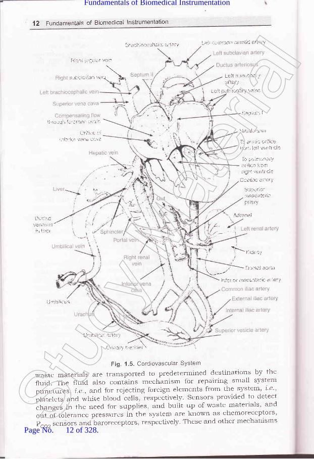
1 .6.2. Cardiovascullar SystemFigure 1.5 shows a cardiovascurar system and figures 1.6 (a) and (b)
show alatomy of heart and a cutview of heart respectively. Cardiovascularsystem can be considered as a complex and closecl hydraulic system withfour-chamber pump the heart connected to flexible elastic tubing bloodvessels. The arteries and arterioles tubing changes its diameter to controlpressure. Reservoirs in the veins changes their volume and characteristicsto satis$r certain control requirements, ancl a system of gates and variablehydraulic resistalces such as vasoconstrictors and vasodilator, continuallyalters the pattern of fluid flow. 'lhe 1bur chamber pump acts as twos5mchronized but functionally isolated two stage pumps. The first stage ofeach pu'.np, i.e. the atrium collects blood from the system and pumps itinto the second stage the ventricle. 'lhe action of the second stage is sotimed that the blood is pumped into the system immediately aftei it hasbeen received from the hrst stage. one of the two stage pumps, 1.e., rightside of heart collects blood from the main hydraulic system, i.e., systeririccirculeLtion and pumps it through an oxTgenation system, Le., lungs. Theother pump i.e., left side of heart receives blood from the oxygenationsystern and pumps it into the main hydraulic system. The speed of thepump, i.e., heart rate and its efficiency, i.e., stroke volume are constalilychanged to meet the overall requirernents of the system. The btood whichflows; in a laminar fashion, acts as a communication and supply networkfor all parts of the system. carriers, i.e., red, blood cells of fuel supplies and
Stud
y Mate
rial
Page No. 11 of 328.
Fundamentals of Biomedical Instrumentation
12 Fundamentals of Biomedical lnstrumentation
ni3hi julJlrlsr veril
:ubcla.Jian "*,\ '
3racil;+cepha!ic 5i Leli L*ll *crir-,*n caroti* arie!-Y
L*lt pr,t}l,tion*tY
ai'le i!'
L.*ii pi.tltttonai'Y v*ti:s
$eplur: I
'f irici.r*i'i fi:ratietr ovaie
{JriJir-,e cii116rial! vat$ faiiii
\litral valtre
la. ,1.,1 i! I O, til e
t()rx lslt ventricls
1-* pi;imli.l+.rY, critire lr*m
riSht v*ritricie
Coeirac aiL{:ry
Sui:erior11:esentaftcprlery
{rirena-.1
!,tf;. ro nresrnle'ir, ar iei I
lJuciilivanoSils
r!l ir:r.r
_'\i'i.i,' ri'-^r'.,
ulmbilict-is
Fig. 1.5. Cordiovascular SYstem
waste materials are transported to predetermined destinations by the
fluid. The f1uid. aiso contains mechanism for repairing small system
punctui:es, i.e., arrd. for rejecting foreign elements from the system' i'e"plrt.t"t" and white blood cells, respectively. Sensors provided to detect
"h"ng"" in the need, for supplies, and built up of waste materials' and
out of tolerance pressures in the system are known as chemoreceptors,
P"o, senSors and baroreceptors, respectively' These and other mechanisms
Lj, tl;irr ll ;lt i;i " -i.,2 \
lJ r irar 1., bl::,:!Cet \
Stud
y Mate
rial
Page No. 12 of 328.
Fundamentals of Biomedical Instrumentation

\
lntrociuction 13
control the pump's speed and efficienc;r, the blood flow pattern throughthe system, tubing diameters, and clther factors. Rs pait of the systemworks against gravity, special one-way varves are piovided to pieventgravity from pulling blood against the direction of flow between pumpc5zcles. The variables of prime importance in this system are the pr-p,i.e., cardiac output and the pressure, flow rate and volume of blood atvarious locations throughout the candiovascular system.
To head
To right arm
To left arm
To left arm
- Pulmonary vein
Left atrium
Valve
Valve *****'***
Aortic arch to body
Lu ngs .-...-....-*"-.*.
Superior vena cava
lnferior venacava from body
Bight ventricle
pulmonary artery
Fig. 1.6(a). Anatomy of heart
Left ventricle
aorta
vena
right atrio /ventricular valve
Pulmonary vein
right ventricle
Fig. 1.6(b). A cut
left ventricle
veiw of heart
venticular valveStud
y Mate
rial
Page No. 13 of 328.
Fundamentals of Biomedical Instrumentation

14 Fundamentals of Biomedical lnstrumentation
1.6.3. RespiratorY SYstem
The card.iovascular system is the major hydraulic system in the
body, the respiratory systlm is the pneuntatic system' At air pump' i'e''
diaphragm, which alternatively creates negative and positive pressllres
ln a sealecl chamber, i.e., tltotacic cavity, be suc
the forced out of a pair of elastic bags, i' ated wi
compartment. The bags are connected to the onment
n p."".g"*ay, i.e., nlsal cavities; pharynx, larynx' trachea' bronchi and
bronchioles,whichatonepointisC)mmonwiththetubirrgthatcarriesliquids and solids to the stomach. A speciai value interrupts the pnematic
;;'."i"- whenever liquid or solid matter passes through the common
region. The passageway divides to carry air into each of the bags' wherein
des m carry ai out f the
air sP ary alve the duel
nasal an alter i'e', h for
use in the event of nasal blockage and for other special purposes' In the
tinyairSpacesofthebagsisamembraneinterfacewiththebody,shydraulic system through which certain gases can diffuse' Oxygen is
taken into the blood fiom the incoming air' and carbon dioxide is
transferred from the fluid to the air, which is exhausted by the force of
the pneumatic pump. The pump operates with a two way override' An
automatic control center, i.L', respiratory center of the brain maintains
rlu is aclequats n and carry
off the sYstem. s of Primary
im resPiratory tory volume
an exPrred air' ativelY fixed
volurnesandcapacitiessuchastidalvolurnethevolumeinspiredorexpired during each normal breath, inspiratory reserve volume the
additional volume that can be inspired after a normal inspiration'
expiratory reserve volume the additlonal amount of air that can be
forcedoutofthelungsafternormalexpiration,residualvolume(amountofairremainingint-helungsafternormalexpiration)residrralvolurne,i.e., amount of air remainin"g in the lungs after all possibie air has been
forced out and vital capacity, i.e., tidal volume, plus inspiratory reserve
volume, plus expiratory reserve volume are contained in the respiratoy
system.
1.6.4. Nervous SYStem
The communication network for the body is the nr:rvous system. Its
centerisaself_adaptingcentralinformationprocessororcomputerthebrain with merno.y, ",i-prtational
power, clecision rnaking capability
ancl many input_o,1iput channels. The brain is self adapting in that if a
certain section is damaged, other sections can adapt and eventually take
over at least in part thJ function of the damagecl section ' By r-lse of the
brainapersonisabletomakedecisions,solvecomplexproblems'createart, poeiry, music, "feel" e informat I
parts of tire body, anC coo Produce I
tehaviour. The brain has nication t
bringsSensoryinformati.onintoancltransmitcontrolinformationoutof
Stud
y Mate
rial
Page No. 14 of 328.
Fundamentals of Biomedical Instrumentation

lntroduction 15
the brain. In general, these lines are not single long lines but oftencomplicated networks with many interconnections that are continuallychanging to meet the needs of the system. By means of the interconnectionpatterns, signals from a large number of sensory devices, which detectlight, sound, pressure, heat, cold and certain chemicals are connectedto the appropriate parts of the computer, where they can be acted upon.Similarly, output control signals are directed to specific motor units ofthe muscles which respond to the signals with some type of motion orforce. Feedback regarding every action controlled by the system is providedto the brain through appropriate sensors. Information is coded in thesystem by rneans of electrochemical pulses nerve action potentials thattravel along the signal nerves. The pulses can be transferred from oneelement of a network to another in one direction only, and frequently thetrensfer takes place only when there is the proper combination of elementsacting on the next element in the chain. Both serial and parallel codingare used sometimes together in the same direction. In addition to thecentral computer, a large number of simple decision-making devicesspinal reflexes are present to control directly certain motor devices fromsome sensory inputs. A number of feedback loops are formed by thismethod. A11 the important decision making is performed by the brain.
Age of Biomedical Engineering: In I974, a society in the name ofAssociation for the Advancement of Medical Instrumentation (AAMI)was formed. It gave the following definition of the clinical engineer.'A clinical engineer is a professional who brings to health care facilitiesa level of education, experience, and accomplishment which will enablehim to responsibly, effectively, and safely manage and interface withmedical devices, instruments, and systems and the use thereof duringpatient care, and who can, because of this level of competence,responsibility and directly serve the patient and physician, nurse,and other health care professional, relative to their use of and othercontact with medical instrumentation."Development of Biomedical Instrumentation: The development ofbio-medical engineering started just after \Alorld War II. With theavailability of discarded electronic circuits like amplifier, oscillators,etc. and availability of skilled manpower due to recession. The realdevelopment started when NASA was launched.The living human being is considered as a black box. This black boxconsists of electrical, mechanical, thermal, chemical and other typeof systems. The function of medical instrumentation is to aid themedical clinican and researcher in devising ways of obtaining reliableand meaningful measurement from a living being.The basic objective of the man instrutlentation system is one ormore of the following objectives:
(rJ Information gathering(ir) Diagnosis
2.
:S
te
vaiete
Ie
Lll
rlrtof St
udy M
ateria
l
Page No. 15 of 328.
Fundamentals of Biomedical Instrumentation

aJ
16 Fundamentals of Biomedical lnstrlrmentation
(lii) Evaluation(iu) Monitoring(u) Control
Specification of Requirement : Instrumentation for biomedicalresearch can generally be vier,ved as information gatheringinstrumentation. Although it sometimes includes some monitoringand control devices.Biomedical instmmentation can generally be classified into followingcategorles:1. Clinical instrumentation2. Research instrumentation
Clinical instr-umentation is bascially used for diagnosis and are ruggedin nature. The research instrumentation is normally more complex,more specialised and designed to provide a much higher degree ofaccuracy, resolution.Measurement in biomedical instrumentation can be further subdividedinto two categories in vivo and in vitro. An in vivo measurement ismade within the living organism. While the invitro measurement isone which is performed outside the body and normally in the testtube.Man Instrument System: The block diagram of the maninstrumentation system can be seen in figure 1.3. The major aspectis the inclusion of human being u.hich is named as a subject.Phisological events of human body give signals to suitable transducer.Electrical output of transducer is passed though signal conditioning.Subsequently, the output can be recor:ded or displayed. The stimulsgiven to the subject may be in the form of visual, auditory or anelectrical impulse.Problems Encountered in Measuring a Living System: The followingproblems are encountered, to measure parameters correctly in aliving system.(a) Inaccessibility of variables to measurement.(b) Variability of the Data.(c) Lack of knowledge about interrelationship.(d) Interaction among physiologica.l system.(e) Effect of transducer on the measurement.
f) Artifacts.(g) trnergz limitator.(h) Safety consideration.
6. Physiological Anatomy of the Body: The functional systems of thebody can be further subdivided into smaller units. The process ofsubdivision can continue upto cellular or molecular level.A brief of the engineering oritented description of the major systemslike biochemical cardiovascular, respiratory and nervous systems aregiven below.
5
Stud
y Mate
rial
Page No. 16 of 328.
Fundamentals of Biomedical Instrumentation

t
lntroduction 17
Biochen'Lical System'. The human body has biochemical systemwhich produces energy for the body, messenger agents forcommunication, materials for growth of the body by a singlepoint intake, i.e., food, water and air.Cctrdiouascular system: Tl:'e caridodvascular system can beexplained as a complex closed hydraulic s).stem with four Chamberpump (heart) connected the blood vessels, ateries and arterioles.the tubing changes its diameter to control pressure. It works asa synchronised pump in which the first stage of each pump(atrium) collects the blood from the system and pumps it into thesecond stage (ventricle). The action of second stage is so timedthat the fluid is pumped into the system immediately after receivingit from the hrst stage. Then the right side of the heart (atrium)is to collects the fluid from the main hydraulic system and pumpit through lungs for oxygenation. The other pump (left side of theheart) received the oxygenated blood and pumps it into the mainhydraulic system to all the organs.Respiratory system is a pneumatic system where the oxygen isinspired in the elastic bags (lungs). The lungs are connected tooutside world by nasal cavities, pharynix, larynx, trachea. Thelungs oxygenate the blood and take out carbon dioxide, whichis expired to the outside world.Neruous system: The nervous system or brain just works like acomputer. Its centre is a self adapting central information systemwith memory, computational power, decision making capabilitiesany many input output channel. The information is generallycoded in the system by means of electrochemical pulses thattravel along the nerves. Both serial and parallel coding are usedsometime in the same direction. A number of feedback loops areformed.
txerciaea
1.1. Explain the various components of physiological system of body.(UPTU-2004\
7.2 Explain the difference between measurement in physiological system andphysical system. (UPTU'MQPI\Discuss the various objectives of a medical instrumentation system.1al -.)_
(UPTU-2OOs\
1,.4. What are the various problems encountered in measuring a living system?Explain ARTIFACTS (LIPTU-2003\
1.5. Explain the difference between the in vivo and in vitro measurement.(UPTU-MQPs)
),.6. Discuss biomedical instrumentation types nameiy for clinical and researchpurposes. How they differ from each other?
(a)
(b)
(c)
la)
AJJStud
y Mate
rial
Page No. 17 of 328.
Fundamentals of Biomedical Instrumentation

Bioelectric Potentials
>- faside this chapter
IntroductionBioelectric PotentialsResting and Action PotentialsPropagation of Action PotentialPhysrological Potentials-trCG, EEG,trnvoked responsesSummary
ERG and EOG
INTRODUCTION
Human cells are too small in size. They can be seen only through amicroscope. Each cell has generally one nucleous and an outer plasmamembrane. Figure 2.1. (al shows a cell in magnihed form which depitsimportant elements.
Various signals are generated by human body in the process ofcarrying out various functions. These generated signals are bioelectricpotentials which relate with nerves muscular activity, heart beat, etc.Bioelectric potentials are consequence of chemical changes in theassociated cells.
The muscle cells can be excited chemically, and mechamically toproduce an action potential that is transmitted along their cell membrane.They have a contractible machinism that is activated by action potential'Muscle is divided into three types-skeleta, cardiac, and smooth. Skeletamuscle makes up the great mass of the somatic musculture has welldeveloped cross siriations does not normally contract in the absence of
l8Stud
y Mate
rial
Page No. 18 of 328.
Fundamentals of Biomedical Instrumentation

I
Bioelectric Potentials 1g
nervous stimulation lacks anotomic
spontancoeusly.Smooth muscre racks cross-striations. The type found in most hoilow
al and contains pacemakers that dischargethe eye and in some other locations is notembles skeletal muscle.
Lysosome
CytoplasmCentrosome
Rough endoplsamicreticulum (RER)
Vacuole
MitochondrionNuclear membrane
Nuclear pores
Chromatin
Microtubule
Smooth endoplasmicreticulum (SEB)
Golgi complex Bibosomes
Agranular endoplsmicreticulum
Cell membrane
Fig. 2.1. (a) A magnified view of a cell
2.2. BIOELECTRIC POTENTIALS
3j"',::l_:'?::^"^o^Tj-","^"9 l: " result :f ,!. electrochemical activity orcertain special type of ce ls are known as bioelecrri" pot..rtiuf ;;#ffiJ.:i3:H.*::":::,"'l_,:it",o-1,:-1,,?rsinto..erect,i""r;i#:;,#";ffii::?::::i:"j:1.1lg i terpreted ,""r,,ny i, ;;;;;?r ;;;;" ;i".l1i:physician in diagnosis and rreatment ,i ";ri;;";ilil:
:.::i::, :r_"::.T:,,^1_,1 I I o o, generate their own monitoring si gnal s*:i._""T:r:"::y:,1:ir various firnctions. rhese signals ;;;:=, #il111:?:i1,;..^1 ^io 1.",, | : ry'
:,io., " tr,.y ; ; ; ;; ".; ;. .d.
J ":["J",1"'j:J,u DrBrriils areionic voltages, i.e., bioelectric potenirats. Bioerectric potentials aregenerated due to nerve concluction, brain activity, heart bea.t, muscleactivity, etc.special type of cerls such as nerve and muscre celrs of human bodyare encased in a semipermeabre membrane. The semipermeable membraneSt
udy M
ateria
l
Page No. 19 of 328.
Fundamentals of Biomedical Instrumentation

20 Fundamentals of Biomedical lnstrumentation
permits some substance to pass through while others are notThis has been established through experiments'
The ions inside the membrane are called Intetnal Cell
the ions outside the membrane calied External cell Fluid as
figure 2.r lb).
ExternalCell Fluid
Semi permeableMembrane
The bioelectric signalsactivity of the large grouPrange of such bioelectric
permitted.
Flui.d arrdshown in
produced in human body are due to coordinatedof excitable cells. The amplitude and frequencysignals are as follows:
Na*
Fig. 2.1. (b) Semipermeable membrane
Whenthesemipermeablemembraneisinnorrnalcondition,thesodium ions (Na*) remains outside the membrane. In the normal condition,
the sodium (Na;) ions cannot pass through the membrane. However,
fotassium (K*) ions can pass through the membrane as permeability of
iotassium iX*l iorr" is too high as compared to sodium (Na*) ions'
If the membrane is stimulated or excited, the characteristics of
nrembrane changes, therefore, the sodium ions can enter as shown in
f,rgure 2.2. once the membrane is stimulated, all the sodium ions can
eiter the membrane. At the same time, potassium (K*) ion try to leave
the cell. The distribution of ions is as follows:
Ions lnternalCell Fluid lons
ExtetnalCell Fluid lons
Na*K*c1-
60t2045
11020
100
Na*
Fig. 2.2. Stimulated Semipermeable Membrane
lnternalCell Fluid
K'
Stud
y Mate
rial
Page No. 20 of 328.
Fundamentals of Biomedical Instrumentation

,\
Bioelectric Potentials 21
Type ofBioelectricPotential
Amplitude Frequency RecordingTechnique
HeartBrain
Muscle
50 pV-5 pV2 pV-100 pV
20 pV-5 pV
0.05-100 Hz1-100 Hz
10 Hz-2 kHz
ECGEtrGEMG
t
t
f
2.3. RESTING AND ACTION POTENTIALS
2.3.1. Resting Potentials
we know that some of the types of celrs of the body are encased ina semipermeable membrane whjch allow some substalces to pass-throughthe membrane whereas others are not allowed to pass through.
we also know that thes-e cells of the body are surrounded by bodyfluids which are conductive solutions containing charge atoms, i.e., ions.The prominent ions are sodium (Na+), potassium (K*), and chloride (c1).The membrane of the cells allow entry of potassium and chloride ionswhereas blocks the entry of sodium ions. various ions seek a balancebetween the inside of the cell and the outside . The sodium is unable topenetrate the. membra.ne. This results in unbalance of ions concentrationand electric charge. The concentration of sodium ions inside the cellbecomes much iower than in the intercellular fluid outside. The sodiumions are positive, therefore, this makes the outside of the cell morepositive than the inside. In an attempt to balance the electric charge, theadditional potassium ions vrhich are positive, enter the cell,
"^r"irlg .higher concentration of potassium on the inside than on the outside (seefigr,rre 2.3(al)
K*
Fig. 2.3. (a) Nerve and muscle cells are encased in a semipermeable membraneSodium ions (Na*) are unable to penetrate
Thus, charge balance cannot be achieved. Hence, equilibrium isachieved with a potential difference across the membranes. The insideof the cell is negative and outside is positive. This membrane potentialscalled the Resting Potential. This potential is maintainecl until some kir-rC
f1
1
e
:dcy St
udy M
ateria
l
Page No. 21 of 328.
Fundamentals of Biomedical Instrumentation

22 Fundamentals of Biomedical lnstrumentation
of disturbance is caused to upset the equilibrium. The resting potentialsrange from - 60 mV to - 1OO mV. The figure 2.3.(b) illustrates the restingpotential. A cell in the resting state is said to be polarized.
-60to-100mV
Fig. 2.3. (b) A polarized with its resting potential
2.3.2. Action Potentials
Na*
Flg. 2.4. (a) Depolarization of a cell
+20 mV
Fig. 2.4. (b) A depolarized cell showing an action potential
The excitation of a section of cell can be by using the flow of ioniccurrent or any externally applied ener5/. This excitation of a section ofSt
udy M
ateria
l
Page No. 22 of 328.
Fundamentals of Biomedical Instrumentation

L
Bioelectric Potentials 23
the cell, causes change in the characteristics of the membrane whichallows some of the sodium ions to enter. The movement of sod.ium ionsinto the cell further accelerates entry of sodium ions. This leads to rushof sodium ions inside the cell whereas potassium ions try to go outsidebut are unable to out that fast. The net result is slightly higher potentialinside the cell. This potential is known as th action potential which canbe about + 20 rnY.In other words, cell which is excited gets depolarizedand leads to action potential. The process of changing from resting stateto action potential is called depolarization. The figure 2 a@) and 2.4(b)illustrate depolarization and depolarized state Action Potential respectively.
2.3.3. Waveform of an Action Potential
Depolarization
t (milliseconds)
(a) A typical cell action potential
000436ContractionPotential
(b) Contraction anci actionpotentials from a guinea pig mycardium
Fig. 2.5. Action potential duration with time(Countery Dr. Mortion Frank George Washington University)
;-20c:_306EE -40Eo- -50
After potentials
-90
Stud
y Mate
rial
Page No. 23 of 328.
Fundamentals of Biomedical Instrumentation

24 Fundanrentals of Biomedical lnstrunlentatioll
When the rush of sodium ions through the cell membrane stops' a
new state of equilibrium is reached and the ionic currents that le-rwered
lhe barometer to sodium ions are nor present; the rnembrarre beharves
in its normal conditiorr i.e., sodium ions are not allowed to enter inside
from outside. At this stage of the process, sodium ions are quickly
tr.ansported from inside of cell to outside of cell and this active process
is known as sodium pump. Once all sodium ions are pumped outside the
cell, the cell reaches its Resting Potential. The process of change fiom
Action Potential to Resting Potential is known as Repolarization' very
little is known about the reason of sodium puirlp, but it can be though
to be balancing effect after ionic currents are renoved'
The waveform of the action potential is shown in figure 2.5" The time
scale depends on the type of cell prorlucing the poiential Nene and
muscle ".11" -ry have 1 m sec duration, ,*'hereas heart muscle duration
may be as high as 3OO m sec. Please note that after repolarization com-
pletion, resting potential is named "after potentials", which reaches restinl'
potential slowlY.
2.4. PROPAGATION OF ACTION POTENTIAL
External Medium
onceacellisexcitedandgeneratedactionpotential,ioniccurrentsbegin to flow. This process excites neighbo
-ring cells o
areas of the same cell. A nerve cell with a lotrg f,rber may h
potential over a small segment of the fiber, but it is propagated in both
directions from the origin"point of excitation. The rate at which an action
potential moves down a fiber or is P
propagation rate. In nerve cells thel4O meters Per second. The ProPslower in the range of O.2 to 0'4 mof the heart have special cells which have propagation rate of as low as
0.05 meter Per second.
The propagation cf action potential is explained further rvith the help
of figure 2.6.
++++
RestingMembrane
DepolarizedMembrane
Local Closeci (solenoidal)Lines of Current Flovr
++++++
+++71++
RepolarizedMembrane
Fig. 2.6. Charge distribution in unmyelinated fiber conducting an impulse
Ionic currents flow if a cell is excitetl ernd generates an action potential'nerve, onlY a small Portionnoted that the membraneactive region is dePolarized
tive region is repolarized membrane'
Thechargedistributionhasclosedpathcurrents.Theflowofthese
+++Active region
Stud
y Mate
rial
Page No. 24 of 328.
Fundamentals of Biomedical Instrumentation

\
Bioelectric Potentials 25
currents depolarizes the membrane in the region ahead of the activeregion so that it becomes activated. The same current pattern flowingbehind the active region is unable to re-excite the membrane in reportingstate where the process is self-exciting. The active state of the membraneis remaining only for short duration of time. After depolarization, themembrane repolarizes completely. 1'his is the way the action potentialpropagates along the length of the fiber.
The myeiin sheath is interrupted at reguiar intervals by nocles knownas nodes of refiner in the case of myeiinated nerve f,rber as shown inlrgure 2.v. Tlne sheath increases the impedances to the current flow. Thesodium ions channel have non-uniform distribution. The density is moreat the nocies.
ActiveNode
1 02Time (msec)-------+
MyelinSheath
Periaxonal --JSpace
The myelin sheath reduces the leakage current and improves thetransmission properties of the fiber.
The figure 2.8 shows the action potential of nerve and muscle. Theaction potential causes a brief contraction and subsequent relaxationand this response is known as Muscle Twitch.
loo1
5101520Time (msec)
-9'"Fig. 2.8. Action potentials muscle of nerves and muscle
The twitch starts abolrt 2 msc after depolarization of the membranebefore repoTarization is complete. The fast muscle for rapid, fine andprecise movement have twitch of duration about 7.5 msec, whereas slowmuscles for strong, gross and sustained movements have twitch durationsup to 1OO msc. It has been found that the action potential in muscletriggers an increase in the permeability of the cell membrane to calcium
.l-
Cell-J \- Node of Ranvier
Fig.2.7. Local current flow in a myelinated nerve fiber
Stud
y Mate
rial
Page No. 25 of 328.
Fundamentals of Biomedical Instrumentation

26 Fundamentals of Biomedical lnstrumentation
ions. The lateral components of triads release calcium ions which liberatesa substance in the muscle which subsequently activates the adenosinetriphosphatase activity of Myosyn. Nerve hbre generated action potentialcan be recorded as per figure 2.9.
AxonRecordingMicro PipetMicroelectrodeElectronic
Simulator
Amplifier
lndifferentElectrode
Fig. 2.9. Recording of action potential of nerve axon
The nerve is excited by an electronic simulator. This gives a shortcurrent pulse to the nerve. Micropipet is used for recording at a downstream print. The action potention waveform is shown in figure 2.10.
vo
A oll-lMembrane I
Potential I
Fig. 2.10. Action potential recording
when the tip of the micropipet is inserted through the membrane, themovement artifact is generated. Recording is done for resting potential. Therecording is done instantaneously as the stimulus artifacts r,,",hen stimulusis applied. The action potential travels along the nerve at a constant speed.The latent period I is recorded as the time taken for the tralsmission of thepotential from stimulating point to the recording point.
Overshoot Potential
Resting
PHYSROLOGICAL POTENTIALS_ECG, EEG, EMG,AND ERG
Transducers are usedA transducer convertsand currents. Such a
to facilitate measurement of bioelectric potentials.ionic potential and currents into electric potentialstransducer consists of two electrodes, which pick-St
udy M
ateria
l
Page No. 26 of 328.
Fundamentals of Biomedical Instrumentation

L
Bioelectric Potentials 27
up the ionic potential difference betu.een their respective point ofapplication. The electric potentials picked up by the transducers throughthe electrodes are basically surface pattern at the electrode points reflectedas a summation of the potentials developed. These biopotentials waveformsare named on the application basis such as ECG (electrocardiogram),EEG (electroencephalogram), EMG (electromyogram), etc.
2.5.1. Electrocardiogram (ECG)
ECG are the biopotentials generated by the muscles of the heart.This is also known as EKG (electrokardiogram in German). The actionpotential in the heart originates near the top of the right Atrium at apoint called the pacemaker or sinoatrial (sA) node. The pacemakers area group of specialized cells that spontaneously generates action potentialsat a regular rate which are controlled by "innervation". The heart beatis the result of the action potentials generated by pacemakers whichpropagate in all directions along the surface of both atria. Recorded ECGwaveforms are is shown in the figure 2.lI (a\.
Fig. 2.11. (a) ECG waveform recordings
The shape and polarity of each of these features vary from the rocationof measuring electrodes with respect to heart. Naturally, a cardiologistbases his diagnosis on the readings taken from several electrode locations.Electrocardiogram signal is a quasi-periodica-l rhythmically repeating signalwhich is synchronised by the function of heart which generated bioelectricSt
udy M
ateria
l
Page No. 27 of 328.
Fundamentals of Biomedical Instrumentation

28 Fundamentals of Biomedical lnstrumentation
signals. The recorded waveforms haveamplitude and phase relationship.abnormality.
been standardized 'uvith respect toAny deviation, is identified as
mV
Fi1.2.11. (b) An ECG waveform
The normal ECG has- PQRS characteristics as shown in the figure2.ll (bl for the chest leads which are scaled. P wave is known as baseline which represents depolarization of the arterial musculator QRSrepresents the repolarization of arteria and depolarization of ventricleswhich occur almost simultaneously. The Twave represents repolarizationof both ventricles. U wave is the result of after potentials in ventricularmuscle. The slope and polarity of each feature varies with the locationof measuring electrodes with respect to the heart. A normal ECG pattenis quantified in the figure 2.12.
P(<0.25 mV)
0.05-1
| 0.12-0.2 I OT Duration I I
Fig.2.12. ECG wave pattern quantified for chest
ECG can diagnose problems of a patient. It can identiff problem ofRhythm disturbance which may be Tachycardias due to fast heart beats,Brady cardial due to slow heart beats or Irregular pulses. The heartproblems may be due to conduction abnormalities such as left bundle
R=5mV
Stud
y Mate
rial
Page No. 28 of 328.
Fundamentals of Biomedical Instrumentation
L
Bioelectric Potentials 29
branch biock, Right bundle branch block, Atrio-Ventricular block. Thepoor blood supply to heart muscle is termed Ischemic Heart Descase andthis leads to Angina pectons (Chest pain) or Myocardial Infarct (HeartAttack) . llypertropy occurs due to enlargement of the heart which maybe left Ventricular, Left Artrial, Right Ventricular or Right Atrial. Themetabolic effects lnay lead to electrolyte abnormalities, wrong medicationor thyroid disease.
2.5.2. Electroencephalogram (EEG)
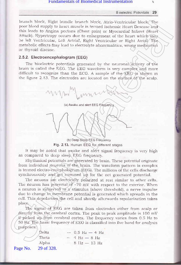
The bioelectric potentiais generated by the neuronal activity of thebrain is called the EEG. The EEG waveform is very complex and moredifhcult to recognize than the ECG. A sample of the EEG is shown inthe figure 2.13. The electrodes are located on the surface of the scalp.
(a)Awake and alert EEG Frequency
(b) Deep Sleep EEG Frequency
Fig. 2"13. Human EEG for different stages
It may be noted that awake and alert signal frequency is very highas compared to deep sleep EEG frequency.
Rhythmical potentials are generated by brain. These potential originatefrom individual neurons of the brain. The waveform pattern is complexis terrned electro-encephalogram (EEG). The rnillions of the cells dischargesynchronously and get summed up for the net generated potential.
The neuons are electrically polarized at rest similar to other cells.The neuron has potential of -70 mV with respect to the exterior. Whena neuron is subjected to a stimulus (above threshold), a nerve impulsedue to change in membrane potential is generated which spreads in thecell. This depolarizes the cell and shortly afterwards repolarization takesplace.
The signal of EEG are taken from electrodes either from scalp ordirectly from the cerebral cortex. The peak to peak amplitude is 100 mVif picked up from cerabral cortex. The frequency varies from 0.5 Hz to50 Hz. The basic frequency of EEG is classified into five band for analysispurposes:
DeltaThetaAlpha
- 0.5H2-4Hz
- 4Hz-8Hz8Hz- 13HzSt
udy M
ateria
l
Page No. 29 of 328.
Fundamentals of Biomedical Instrumentation

30 Fundamentals of Biomedical lnstrumentation
BetaGamma
-13H2-22H222Hz-30HzAlpha rhythm indicates alertness of the
of anesthesia in the operating room. Theas follows:
brain which sen'es as indicatorwaveforms can be summarized
Waveform
Delta waves
Theta waves
Alpha waves
Beta waves
Frequency
o.5-4Hz
4-BHz
Occurence
Premature babies
sleeping adultsChildren andSleePing adults
8 - 73 Hz Normal
13 - 30 Hz Normal
Under normal conditions there is generally inverse relationshipbetween amplitude and frequerrcy, i.e., if frequency reduces, the amplitudeincreases. The increased cerabral activity leads to more desynchronizedactivity of the nerve cells.
Spikes and waves of abnormal shape occur during attacks of epilepsy.The extinction or damping of electrical activity in the cortex can be dueto tumor. The tumor presses on the neurons and destroys them. oxygendeficiency due to circulatory disturbance similar to bleeding would also
cause similar problem. Earlier damages present in the cortex in the formof tumors or scars, may generate abormal electrical activity.
EEG is used for examination of epilepsy, brain damage, brain tumorsand other organic brain injuries. There is occasional use of trEG fordetermination of level of consciousness 1.e., depth of anaesthesia. It canalso establish death of brain.
2.5.3. Electromyogram (EMG)
The muscle activity bioelectric potentials constitute EMG. Suchpotentials are measured at the surface of the body near a muscle ofinterest or directly from the muscle by penetrating the skin with needle
electrodes.EMG signals may be measured at the surface of the body near a
muscle under study or from the muscle by penetrating the strain withneedle electrodes. The amount of muscle activity is indicated in the EMG
rneasurement, the action potential lasting only felv milliseconds. The
potential may range from 50 pv to 5 mV with a duration of 2lo 15 msec.
lfr. BVfC amplitude is the instantaneous sum of all action potentialsgenerated at that instant. A typical EMG waveform is shown infigure 2.14, which looks like random nolse.
Action potential is generated in both positive and negative polaritiesacross a pair of electrodes. These, some times add, sometimessubstract.St
udy M
ateria
l
Page No. 30 of 328.
Fundamentals of Biomedical Instrumentation

31
Fig. 2.14. A typical EMG waveshape
Fig. 2.15. EMG recording arrangement
SpindConductive
Lesion
PeripheralNerve Lesion
Neuro MuscularSynape Diseases
MotorNeuronlesion
MuscularDiseases
Fig. 2.16. Electrical connection of nervous systemStud
y Mate
rial
Page No. 31 of 328.
Fundamentals of Biomedical Instrumentation

32 Fundamentals of Biomedical lnstrumentation
The EMG signals range from 20 pV to 5 mV and in frequency rangefrom 1O Hzlo 2kHz. One method EMG signal is shown in frgure 2.15.
In this case the muscle contraction gives bioelectric potential whichis aneplfied and displayed on the oscilloscope and this is also madeaudible on a loudspeaker.
The muscular "Paralysis" can be due to a lesion in the parts of theneryous system which supply to muscle. The figure 2.16 shows electricalconnection of the nervous system.
2.5.4. Electrogastrogram (EGG)
EGG signal has basically EMG pattern. It is associated with theperistaltic movements of the gastrointestinal tract. When surfaceelectrodes are placed. on the abdomen over the stomach, the signal of thegastric myoelectrical activity is recorded which is electrogastrogram. But,EGG is not enough to diagnose stomach diseases, therefore, it requiresadditional informations.
2.5.5. Electro-oculograph (EOG)
when the bio-potential generated by the movement of the eyeball isrecorded, it is known as electro-oculograph. If a small electrode is puton the skin near the eye, it gives EOG potentials. The signal of thevertical movements of eyeball is piked up by placing one pair of electrodesabove and below the eye. similarly, the horizontal movement signal ispicked up by placing another pair of electrode to the left and right of theeye. EOG is hardly used for any clinical purpose.
2.5.6. Electroretinograph (ERG)
There is an electrical potential difference between the cornea and thebody of the eye. when the eye is illuminated, this potential changes. The
recording of this change of potential is known as electro retinograph(ERG) . For this recording, one electrode is mounted on a contact lenswhich is in direct contact with cornea and the other electrode is put onthe skin adjacent to the outer corner of the eye. If needed, a referenceelectrod.e may be put on the forehead. The magnitude of the signal isdependent on the intensity and the duration of the light falling on theeye. The voltage of signal is in the order of 500 pv.
2.6. ENVOKED RESPONSES
In neurophysioloSr, we are interested in looking at the neurologicalresponse to a particular stimulas. This response js electric in nature,but it is very weak signal with a very poor signal-to-noise ratio. whenthe stimulus is repeated, the same or very similar response repetition isobserved. This is known as envoked response, which becomes basis forbiopotential signal processors which can obtain an enhanced responseby means of repeated application of the stimulus. In short, it is a measureof "disturbance" in EEG pattern that results from external stimuli likeflash light, a click of sound. The figure 2.17 sho',r's some of the envokedresponses.Stud
y Mate
rial
Page No. 32 of 328.
Fundamentals of Biomedical Instrumentation

t
Bioelectric Potentials 33
(a) Awake and alert response
response
(d) Deep sleep response
Fig. 2.17. Envoked responses
1
2.
J
4.
5
6.
7.
8
Biolectric Potential: These are ionic voltages produced as a resultof the electrochemical activity of certain special type of cells.Sources of Bioelectric Potentials: The sources of bioelectric arenerve conduction, brain activity, heart beat, muscle activity, etc.Resting Potentials: The voltage of inside of a cell with respect tooutside of the semipermeable membrane in resting state. This is anegative voltage.Action Potentials: This is a voltage of inside of a cell with respectto outside of the semipermeable membrane in a depolarized state.This is a positive voltage.Depolarization: The process of changing from resting state to actionpotential.Repolarization: The process of change from action potential to restingpotential.After Potentials: After tepolarization completion, the resting potentialis named "after potentials" which reaches resting potential slowly.Propagation Action Potential: The movement of action potentialfrom its origin to neighbouring cells. The nerve cells propagation rateis 2O to 140 meters per second, whereas heart muscle cell propagationrate is slower in the range from O.2 to 0.4 meters per second.ECG: These are the bipotentials generated by the muscles of theheart known as electrocardiogram.
9 Stud
y Mate
rial
Page No. 33 of 328.
Fundamentals of Biomedical Instrumentation

34 Fundamenta!s of Biomedical lnstrumentation
10. EEG: These are the bipotentials generated by neuronal activity of thebrain known as electroence phalogram.
11.EMG: These are bipotentials generated by muscles known aselectromyogram.
12. EGG is the recording of the signal generated due to the gastricmvelectrical activity.
13. EOG is the recording of the signal generated due to the movementof the eye ba11.
14. ERG rs the recording of the signal generated due to the illuminationof the eye.
15. Envoked Responses: These are EtrG signals in the various state ofhumans such as being awake, light sleep, deep sleep, etc.
C(;I€rClded
2.1. What do you understand by bioelectric potential and how is it useful?2.2. How are the bioelectric potentials measured? Name some of the equipments
using such measurement.2.3. What are the sources of bioelectric potentials and why are these present
in the body?2.4. Explain Resting and Action Potentials. (UPTU-2003\2.5. trxplain and draw diagrams for trCG, EtrG and EMG. (UPTU-2004)2.6. Draw an active potentiai waveform and level thq Amplitude and Time
values. (uPru-MQP42.7. Explain polarization, depolarization and repolarization. (UPTU-MQP2)2.8. Explain propagation of active potential. (UPTU-2004\2.9. What is EtrG? Why is it much more difficult to recognize than ECG? How
can certain characteristic EEG waveforms be related to sleep?(UPTU-2004\
trtrtr
Stud
y Mate
rial
Page No. 34 of 328.
Fundamentals of Biomedical Instrumentation

Transducers
a Inside this chdpter
3.1. Introduction3.2. Transducer and Transduction Principles3.3. Active Transducers3.4. Passive Transducers3.5. Transducers For Biomedical Applications3.6. Pulse Sensors3.7. Respiration Sensor3.8. Transducers with Digital Output3.9. Summary
Medical instruments are generally electronic devices, therefore, they requirean electrical signal as an input. A physical event of the body representsa parameter which has a transducible property. This is transformed intoan electrical signal by some device or process which is a transductionprocess. Thus, transducer for of converting the transducible physiologrcalproperty into an electrical signal which can be an input to an instrument.
3.2. TRANSDUCER AND TRANSDUCTION PRINCIPLES
Transducer is a device which converts one form of energr into electricalform. Because of the advantages of electric and electronic method ofmeasurement, it is an usual practice to convert all non electricphenomenon of physiological events into electrical quantities. Numerousmethods suitable to various applications have been developed by applyingbasic principles of physics. Physiological variables occur in many formssuch as hydraulic pressures and flows, mechanical movements,temperature variations, chemical reactions, etc.
3.5
INTRODUCTION
i
-t
Stud
y Mate
rial
Page No. 35 of 328.
Fundamentals of Biomedical Instrumentation

36 Fundamentals of Biomedical lnstrumentation
In Biomedical Instrumentation the main concern is conversion ofBioelectric signal to electric signal. Here transducer is a componentwhich has a nonelectrical variable as its input and an electrical signalas its output. To conduct its function properly, one (or more) parametersof the eiectrical output signal in the form of voltages, current frequencyor pulse width must be a nonambigrious function of the nonelectricalvariables at the input. Ideally the relationship between input and outputshould be linear. A linear relationship is not always possible, but thereiationship between input and output should fo1low some rules likelogarithmic function or square 1aw. As long as the transduction functionis nonambiguous it is possible to detelmine the magnitude of the inputvariable from the electrical output signal at least in principle. Certainother variables may interface with the transduction process such as
hysteresis error, frequency response and base line drift.There are two different principles used to convert nonelectrical
variables into electrical signals. One of these is energy conversiontransducers based on this principle are called active transducers. Theother principle involves control of an excitation voltage or modulationsof a carrier signal. Transducers based on this principle are called passivetransducers. The two transducer types will be described separately inthe following sections.
A11 physical principles can be employed for converting nonelectrical activityin active transducers. But, not all principles are of practical importancein the design of actual transducers, specially for biomedical applications.In active transducers, in some cases the same transduction principleused to convert from a nonelectrical form of ener$i can also be used inreverse direction to covert electrical ener5/ to nonelectrical forms. Say,a magnetic loudspeaker can also be used in the opposite direction as amicrophone. There are severatr names used to refer to the same effect$rhen used in opposite direction because two applications were discoveredby different persons' Few methods of eners/ conversion used in activetranducers are given in table 3.1.
Table 3.1. Few Methods of Energy Conversion Used in Active Transducers
AGTIVE TRANSDUCERS
Energg Form Transduced Form Deuice ar Effect Reuersible
Mechanical
ThermalPressureLight radiationtrlectricalChemicaiElectricalSoundElectric
Electrical
ElectricalElectricaltrlectricalLightElectricalChemicalElectricalSound
N{agnetic inductionElectrical lnductionThermoelectricPiezoelectricPhotoelectricLEDVoltsElectrical polarizationMicrophoneL,oud speaker
Yes
Yes
Yes
No
NoNoNoYes
Yes[ =r"".r- _Stud
y Mate
rial
Page No. 36 of 328.
Fundamentals of Biomedical Instrumentation

Iti3
I
Transducers 37
3.3.1. Magnetic InductionLinear movement of an electricar conductor in a magnetic field in
such a way that the magnetic flux through the conductor is changed, avoltage proportional to the rate of change of magnetic field is induced.If a current is sent through the same conductor, a mechanical force isdeveloped which is proportional to the current and magnetic field. Theresult which depends on the polarities of voltage and current on theelectrical side or the direction of force and motion on the mechanicalside is a conversion from mechanical to electrical energz or vice_versa.A11 electrical motors, generators, solenoids and loudsp"r1..." are basedon this principle of magnetic induction.
Fig. 3.1. lnductive transducers with rotary movement
one basic configuration of transducer that use the principle ofmagnetic induction for the measurement of rotary motion is shown inhgure 3.1. The output voltage in each case is proportional to the linearor angular velocity. The most important biomedical applications are:
(a) Heart Sound Microphones(b) Pulse Transducers(c) Electromagnetic Blood Flow Meters.Magnetic induction has an electrostatic equivalent called electric
induction. condenser microphone based on this principle is not widelyused due to its wide frequency response and high sensitivity.
3.3.2" Thermoelectric EffectTwo wires of different material, i.e., irort and copper are connected
so that they form a closed conducting loop as shown in figure 3.2, thena voltage proportional to the difference in temperature of junction isdeveloped. The polarity depends on which of the junction is warmer. 'rhedevice formed in this fashion is called a thermocouple as shown infigure 3.2.
The sensitivity of a thermocouple is small and amounts to only 40microvolts per degree centrigrade (pv/"c) for a copper-constantan and53 (pv/"c) for an iron-constantan pair (constantan is an alloy of nickeland copper).St
udy M
ateria
l
Page No. 37 of 328.
Fundamentals of Biomedical Instrumentation

38 Fundamentals of Biomedical lnstrumentation
The thermocouple measures the temperature difference between the
two functions. one junction should be kept at o"c. by pr-rtting the junction
in ice bath. Frequently instead. of an ice bath for the reference junction
an electronic compensating circuit is used. The incorivenience of having
to make the whole circuit f?om the two metals used in the thermocouple
can be overcbme by using a double reference junction that connects to
copper conductors as shown in the figure 3'2'
Fig. 3.2. Thermocouple with double reference junction to connect to
measurement circuit using copper wtre
Duetotheirlowsensitivitythermocouplesarenotusedinthemeasurement of physiological temperatures'
The thermoelectric effect to convert from thermal to electrical enerSr
is called the seebeck effect. In the reverse direction it is called the peltier
effect where the flow of current causes one junction to heat and the
other to cool. The peltier effect is sometimes used to cool parts of
instruments.
3.3.3. Piezoelectric Effect
If pressure is applied to certain nonconductive materials so that
d.eformation takes plu."., a charge separation occurs in the materials and
an electrical voltage vp, cant be measured across the material. The natural
material where piezoeiectric effect can be observed are slices from crystals
of q'.artz (Si O2i or Rochelle Salt (Sodium potassium tartrate, KNaCoHoOu'
+rrrol which liave been cut at a certain angle with respect to the crystal
axis. Piezoelectric properties can be introduced into wafers of barium
titanate.
Metal B
Junctions
Transducer
Piezoelectric transducer
Copper
AmPlifier
equivalent circuit connected
Force
Fig. 3.3. to an amplifierStud
y Mate
rial
Page No. 38 of 328.
Fundamentals of Biomedical Instrumentation

\
Transducers 39
------->Time i
Trace 1
Trace 2
Trace 4
Fig. 3.4. Output signal of a piezoelectric transducer under different conditionsTrace 1 : Force at the input of the transducerfrace 2 : Output signal when the product of R and C is much larger than TTrace 3 : Output signal when the product of R and C is much smaller than TTrace 4 : Output signal if the product of R and C is equal to T
The electrical equivalent circuit of a piezoelectric transducer is shownin figure 3.3, is that of avoltage source having avoltage 7p, proportionalto applied mechanical force connected in series with a capacitor, whichrepresent the conductive plates separated by the insulating piezoelectricmaterial. The capacitive properties of the piezoelectric transducerinteracting with the input impedance of the amplifier to which they areconnected effect response of the transducer. This effect is shown infigure 3.4. The trace 1 shows the force applied to the transducer, whichafter time I is removed. While the electrical field generated by thepiezoelectric effect and the internal transducer voltage V, rn trace 2follows due to the applied force. The voltage 7o measured'at the inputof the amplifier depends on the value of transducer. Now, the capacitanceC and the ampiifier input impedance R are subjected to the appliedvoltage Vo for the duration of time L If the product of R and C is muchlonger than 7, then the voltage division between the two can be neglectedand the measured voltage can be considered proportional to the forceapplied. This is shown in trace 2. To meet this conduction for a largeSt
udy M
ateria
l
Page No. 39 of 328.
Fundamentals of Biomedical Instrumentation
40 Fundamentals of Biomedical lnstrumentation
value of I the input imped.ance of the amplifier should be very large. As
an alternative, a capacitor may be connected in parallel with the ampliherinput. This increases the capacity of the ampliher, but decreases thesensitivity of the transducer. In case of piezoelectric transducer where
the output voltage is quite high this approach may be permissible.
If the produet of resistance and capacitance is made much smallerthan T, the voltage at the amplifrer input is proportional to the timederivative of the force at the transducer or proportional to the rate atwhich the applied force changes as shown in trace 3. If the product ofR and c is of the same order as 7, the resulting voltage is a compromisebetween the extreme of two previous traces shown in trace 4. As any
mechanical input may contain various frequencies, a distortion of the
waveform of the resulting signal can occllr, if these relationships are not
taken into account.The piezoelectric principle is used in measurement of heart sound or
other atoustical signals .from within the body. The piezoelectrictransducers are used widely in ultrasonic instruments as transmitterand receiver of ultrasonic signals. Principle of ultrasonic instrument isdiscussed in other chapters of the book.
A d.c excitation voltage or an ac carrier signal ]Jtllize the principle of
controlling passive transducers. The transducer consists of a usuallypassive circuit element which changes its value as a function of the
physicd.l variable to be measured. The transducer is a part of circuitelement, normally an arrangement like Wheatstone bridge, which ispowered by an ac or d.c. excitation, signal. The voltage at the outputieflects the physical variable. There are only three passive circuit elements
which can be utilized as passive transducers namely: resistors, capacitors
and ind.uctors. It may also be noted. that active components like transistorscan also occasionallv be used. The active and passive have differentmeaning in components and transducers. Passive transducers cannot be
operated. in the reverse direction unlike active transducers'
3.4.1. Passive Transducers Using Resistive Elements
Resistive element that changes its resistance as a function of aphysical variable can be used as a transducer for that variable' An
trJirr".y potentiometer for example can be used to convert rotary motionor displaciment into a change of resistance. A special linear potentiometer
can be used to convert linear d.isplacement into a resistance change for
such transducers.In some semiconductor material such as cadmium sulphide the
conductivity is increased by light striking the material. This work as
photo-resisiive cells a form of photoelectric transducer. This has good
sensitivity but bad frequency response. A different type of photoelectrictransduclr is photo diode, which utilises charge carriers generated byincident radiation in a reverse-biased diode function. Although less
s
t(
s
t
PASSIVE TRANSDUCERS
Stud
y Mate
rial
Page No. 40 of 328.
Fundamentals of Biomedical Instrumentation
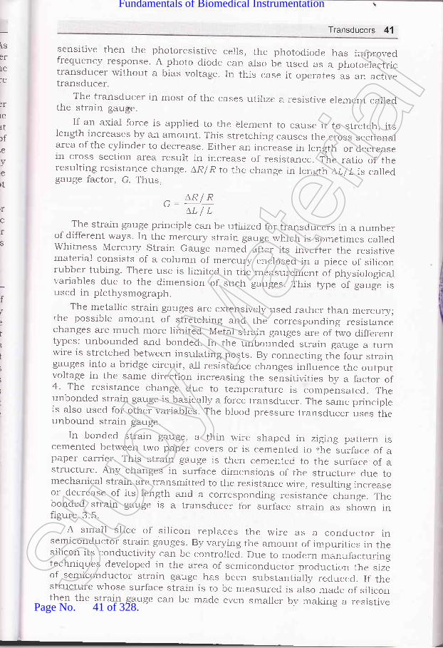
lserlere
lrIC
rtrfie
ve
rt
rf
C
rs
f
t
I
i
i
t
Transducers 41
sensitive then the photoresistive cer1s, the photodiode has improvedfrequency response. A photo diode can aiso be used as a photoelectrictransducer without a bias voltage. In this case it operates as an activetransducer.
The transducer in most of the cases utilize a resistir.e element calledthe strain gauge.
If an axial force is applied to the olement to cause it to stretch, itsiength increases by an amount. This stretching causes the cross sectionalarea of the cylinder to decrease. trither an incr-ease in length or decreasein cross section area result in increase of resistance. ,ihe ratio of theresulting resistance change. AR/R to the change in length LLI L is calledgauge factor, G. Thus,
c _ AR/RLLIL
The strain gauge principle can be utilized for transducers in a numberof different ways. In the mercury strain ga.-rge which is sometimes calledwhitness Mercury Strain Gauge named afier its inverter the resistivematerial consists of a column of mercury enclosed in a piece of siliconrubber tubing. There use is limited in the measurement of physiologicalrzariables due to the dimension of such gauges. This type of g^rg1 i"used in plethysmograph.
The metaliic strain gauges are extensivery used rather than rnercury;the possible amount of stretching and the corresponding resistancechanges are much more limited. Metal strain gauges are of two differenttypes: unbounded and bonded. In the unbounded strain gauge a turnwire is stretched between insulating posts. By connecting the four straingauges into a bridge circuit, all resistance changes influence the or,rtputvoltage in the same direction increasing the sensitivities by a factoi of4. The resistance change due to ter,perature is compensatecl. Theunbonded strain gauge is basicary a force transducer. The same principreis also used for other variables. The blood pressure transducer uses theunbound strain gauge.
In bonded strain gauge, a thin wire shaped in zigi.g pattern iscemented between two paper covers or is cemented to r,he surface of apaper carrier. This strain gauge is then cemented to the surface of astructure. Any changes in surface dimensions of the structure clue tomechanical strain are transrnitted to the resistance wire, resulting increaseor decrease of its length and a corresponding resistance change. Thebonded strain gauge is a transducer for surface strain as shown infigure 3.5.
A small slice of ,silicon replaces the wire as a conductor insemiconductor strain gauges. By varying the amount of impurities in thesilicon its conductivity can be controlled. Due to modern manufacturingtechniques developed in the area of semiconductor production the sizeof semiconductor strain gauge has been substantially reducecl. If tkrestructure whose surface strain is to be measured is also mace of siliconthen the strain gauge can be made even sr,arler by making a resistive
-1L
Stud
y Mate
rial
Page No. 41 of 328.
Fundamentals of Biomedical Instrumentation

Fig. 3.5. Typical
3.4.2. Passive Transducers
42 Fundamentals of Biomedical lnstrumentation
pattern on the silicon surface. Such strain gauge uses photographic anddiffusion techniques which is used in the manufacturing of integratedcircuits. The gauges are isolated from the silicon substrate by reversebiased diode junction. Due to changes in the resistance of thesemiconductor strain gauge due to temperature change, at least twostrain gauges rare used. One strain gauge is used for temperaturecompensation.
Strain Gage WireGrid(this is cementedbetween the bottomand top covers whenassembled)
bonded strain gauge configuration
Using lnductive Elements
The inductance of coil can be changed either by varying its physicaldimension or by changing permeability of its magnetic core. The lattercan be achieved by moving a core having permeability higher than airthrough the coil. This arrangement is similar to that of inductivetransducer. However, in the inductive transducer the core is a permanentmagnet which when moved induces a voltage in the coil. In this passivetransducer the core is made of a soft magnetic material which changesthe inductance of the coil when it is moved inside. The inductance thencan be measured by using an a-c signal.
Fig. 3.6. Differential transformer schematic
Other type of passive transducer involving inductance is the variablereluctance transducer, in which the core remains stationary but the airSt
udy M
ateria
l
Page No. 42 of 328.
Fundamentals of Biomedical Instrumentation

1
Transducers 43
gap in the magnetic path of the core is varied to change the effectivepermeability. The same principle is used in active transducers in whichthe rnagnetic path includes a permanent rrragnet.
The change in inductance in these types of transducers is notrelated linearly to the displacement of the coi1. This difficulty is overcomein the linear variable differential transformer (LVDT) . It consists of atransformer with one prirnary and two secondary windings. Thesecondary windings are connected so that their induced voltages opposeeach other. If the core is in the centre position, the voltages in the twosecondary windings are equal in magnitude and the resulting outputvoltage is zero. If the core is moveci upward as indicated by the arrowin figure 3.6, the voltage in secondary 1 increases while that in secondarydecreases. The magnitude of the output voltage changes with the amountof displacement of the core from its central or neutral position. Itsphase with respect to the voltage at the primarv- winding depends onthe direction of the displacement. The non linearities in the magnitudesof the voltages induced in the two output coils compensate each other,the output voltage of the differential transducer is proportional to thecore movement.
3.4.3. Passive Transducers Using Active Circuit ElementsActive' and passive' distinction when ursed for circuit elements is
based on a different principle than that which is used for transducers.Active circuit elements are those which provide power gain for a signalsas in case of a transistors. The active circuit elements are normally usedin passive transdurcers.
The application of active circuit element in passive transducers is inthe area of photo electric transducers. The efficiency of photo diode canbe increased if we make a photo transistor.
Hall generator is another semiconductor transducer element whichprovides an output voltage that is proportional to both applied currentand any magnetic field in which it is placed.
3.4.4. Passive Transducers Using Capacitive ElementsA plate capacitor capacitance can be changed by varying the physical
dimensions of the plate structure or by varying the dielectric constantof the medium between the capacitor plates. Both effects have occasionallybeen used in the design of transducers for biomedical applications.
TRANSDUCERS FOR BIOMEDICAL APPLICATIONS
In biomedical applications many variables of interest like pressure andfluid or gas flow which can not be measured by standard transducersare converted to one of the variables for u,hich basic transducers areavailable. The basic transducers for biornedical applications are listed inTable 3"2.
3.5.
Stud
y Mate
rial
Page No. 43 of 328.
Fundamentals of Biomedical Instrumentation

44 Fundamentals of Biomedical lnstrumentation
Physical variable Type of Transducer
Force (or pressure)
a
Surface strainVelocityDisplacement
Temperature
Light
Magnetic field
PiezoelectricStrain gaugeStrain gaugeMagnetic inductionVariable resistanceVariable capacitanceVariable inductanceLVDTMercury strain gaugeThermocoupleThermistorPhotovoltaicPhotoresistiveHa1l effect
3.5.1. Force Transducers
Table 3.2. Basic Transducers
A basic design element for conversion of variables is the force bearingmember. The bending of the spring due to force, results in a surfacestrain which can be measured by means of a bonded strain gauge as
shown in figure 3.7. Measurement of the displacement voltage is done
by using a differential transformer transducer is already explained.
Fig. 3.7. Force transducer with bonded straln gauge
3.5.2. Transducers for Displacement Velocity and Aeceleration
Displacement velocity and acceleration are linked. If any one of thethree variables can be measured, it is possible at least in principle to
obtain the other two variables. Both operations can easily be performedby electronic methods operating on either analog or digital signals.
As explained in earlier table, transducers for displacement and velocityare readily available. The principle listed for these measurements, requirethat part of the transducer be attached to the body structure whose
d.isplacement, velocitSr or acceleration is to be measured ald that a referencepoint be available. Since these two conditions cannot always be met inbiomedical applications, indirect methods sometimes have to be used.
contactless methods for measuring displacement and velocity, basedon optical or magnetic principles, are occasionally used. Magnetic methodsusually require that a small magnet or piece of metal be attached to thebody structure. Ultrasonic methods are frequently used in actual practice.St
udy M
ateria
l
Page No. 44 of 328.
Fundamentals of Biomedical Instrumentation

a
Transducers 45
3.5.3. Pressure TransducersPressure transducers are related to force transducers. pressure
transducers utilizing flat diaphrams normally have bonded orsemiconductor strain gauges attached directly to the diaphragms. Flat orcorrugated diaphragms have also occasionally been used in transducerswhich employ tfre variable reluctance or variable capacitance principles.
Each time heart muscle contracts, blood is ejected from the ventricles.consequently, a pulse pressure is transmitted through the circulatorysystem. This pulse causes vessel-wall displacement while travellingthrough the vessels. The displacement is measurable at various pointsof the peripheral circulatory system. The pulse sensing can he clone byplacing finger tip over the radial artery in wrist or some other locationwhere an artery is just below the spin. The pulse pressure can bemeasured by various transducers such as:
(z) Photoelectric pulse transducer.(ir) Piezoelectric arterial pulse receptor.(lir) Strain gauge pulse transducer.
3.6.1. Photoelectric Pulse TransducerPulsatile blood volume changes are detected by photoelectric method
using photo-resistors. The methods used are:(rj Transmittance method.
(izJ Reflectance method.Transmittance method has a miniature lamp and photo-resistor
mounted in an enclosure which files over the tip of subject,s finger. Lightis transmitted through the finger tip of the patient's finger ana tneresistance photo-resistor is determined by the amount of light reachingphoto-resistor. The figure 3.8 shows this method.
Photo-resistor
Lamp
Transmission method of pulse sensing
SENSORS
\rr r
Fis. 3.8.Stud
y Mate
rial
Page No. 45 of 328.
Fundamentals of Biomedical Instrumentation

46 Fundamentals of Biomedical lnstrumentation
Blood is forced to the extremities and the amount of blood in fingerincreases with each contraction of heart. This alter optical density and
consequently the light transmission through the finger reduces and
accordlngly the resistance of the photo-resistor increases. The photo-
resistor is a part of a voltage divider circuit which produces a voltage'
The voltage varies with the amount of blood in the finger. This voltage
closely foilows the pulse pressure and its wave shape can be recorded
or displayed on an oscilloscoPe.In reflectance method, the photo-resistor is placed adjacent to the
exciter lamp. Only a part of light rays, emitted by the lamp, is reflected
and scattered. from the skin and tissue is made to fall on photo-resistor'Figure 3.9 shows the reflectance method. The blood saturation of the
calpillaries determine the quantity of light reflected. The resistance of the
photo-resistor varies due to above. The voltage across the photo-resistorwhich is connected as a voltage divider, varies in proportion to the
volume changes of blood vessels of the body of the subject'
Finger
Photo-resister
Fig. 3.9. Reflectance method of pulse sensing
3.6.2. Piezoelectric Arterial Pulse Receptor
It consists of piezoelectric crystal clamped in a hermetically sealed
capsule which is subjected to the displacement stresSes. The displacement
is iransmitted to the crystal through a soft rubber diaphragm. The pulse
pressure waveform is recorded by connecting the crystal to ECG recorder.
ihe volume of blood in the finger, varies during cardiac cycle whichcause change in the size of the finger. These changes al.e transmitted as
pressure ,r"ri.tior," in the air column inside the plastic tubing. At the
lnd ofthe tube, a piezoelectric transducer converts the Dressure changes
to electrical signal. This electrical signal is amplified and displayed or
recorded.
3.6.3. Strain Gauge Pulse Transducer
Displacement of the vessel wall is transferred to semiconductor straingage uy mans of a feeler pin and a leaf spring. Figure 3.1O shows the
It.li" !.rg" firmly attached to the leaf spring on one side and to feeler
pin on tn" otfr"t side leaf. One ring around the feeler pin of the transducerirelps in minimizing the interference caused by unsteadiness of applicationof transducer to subjects skin. The transducer output range is of 50 mvfor 0.1 mm displacement. The internal resistance and resonant frequency
of undamped mechanical system are 1 kw and 150 Hz respectively.
\tlr
Stud
y Mate
rial
Page No. 46 of 328.
Fundamentals of Biomedical Instrumentation
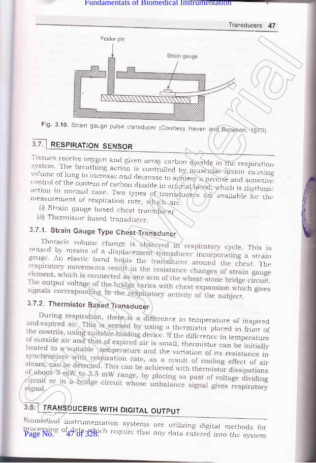
Feeler pin
Transducers 47
Fig' 3'10' Strain gauge purse transducer (courtesy Herren and Beneken,lgTo)
RESPIRATION SENSOR
}HH ;T:,1."-':_r,q:i ii_q_s_t en array.galbon dioxide in the respiratrion
:Sl- ^ll:_1...^lhl"g action is contiolied by musc"t". ;;;;":;';".;
:::y:: E.lf i -1., i":*
3s e and a..,."". to ;"d;"; ;;.
"1 ":";T, ":::i1Tr:: il,T,,:i,*::1.::T T:1 " I _T:"i
a " i- ".,..r"r" o,
",f; , *
" f;,,: .Tff ;l:
:'i:""1 i:::1?1-:T:: 1*o tvpes or ";";;;;;";; ;il;,:'7,.J'1T:
TRANSDUCERS WITH DIGITAL OUTPUT
measurement of respiration rate, which are:(l) Strain gauge based chest transducer
(ir) Thermistor based transducer.
3.7.1. Strain Gauge Type Chest TransducerThor:acic volume change is
sensed by means of a disilace This isgauge. An elastic Uana rrolas the fftfr:
3.7.2. Thermistor Based Transducer
nce in temperature of inspireda thermistor placed in front of
e. If the differencesma1l, thermistorthe variation of it
Biomedicalprocesslng
rnstrumentation systems areof data which require that any
utilizing digital methods fordata entered into the system
Stud
y Mate
rial
Page No. 47 of 328.
Fundamentals of Biomedical Instrumentation

2
48 Fundamentals of Biomedical lnstrumentation
be in digital rather than in analogue form. Analogue to digital converters,can be used to convert an analog transducer output into digital form.
The transducer whose output is in digital form uses encoding disks or
rulers with digital pattern, photographically etched on glass plates. Alight source and an array of photodetectors, usually made up of photo
diodes or phofio transistors are used to obtain a digital signal in parallelformat that indicates the position of the encoding plate and therebyrepresents the displacement being measured.
1. Active Transducers: Transducers can be broadly categorized in two
categories one is active transducers and second is passive transducer'The active transducers convert non electrical activity to electricalactivity. In most of the cases the action is reversible. The importantacrive transducers uses magnetic induction. Under this category thebiomedical applications are :
(o) Heart Sound MicroPhones(b) Pulse Transmitters(c) Electromagnetic Blood Flow Meter
The other effect used. are thermoelectric effect, piezoelectric effect'
Passive Transducers: The passive transducers are those transducerswhich utilize the principle of controlling a dc excitation voltage or an
ac carrier signal.transducer the most important is a resistive element
auge. Usually, two types of strain gauge is unboundedform is used. The gauge factor is defined as the ratio
of resulting resistance change to the change is length G can be
written as
^ _ AR/RL'J- LLIL
The gauge factor for metals is of the order of 2, whereas the gauge
factor for silicon (a crystalline material) is about 120'
Passive transd.ucers also use inductive element as in LVDT, etc.
Transducers for Biomedical Applicatiofls: In biomedical applicationsforce transd.ucer with strain gauge is extensively used. otherparameters velocity and acceleration are related to each other. If one
parameter can be measured then with the help of analogue electronic
circuit other parameter can be calculated.Some transducers using A to D converters are also available. The
transd.ucer whose output is in digital form uses encoding disks on
rulers with digital pattern, photographically etched on glas plates'
t*ercidra
3. 1. Discuss four different types of transducers, explaining what they measures
and their princiPles.
3
Stud
y Mate
rial
Page No. 48 of 328.
Fundamentals of Biomedical Instrumentation

I
Transducers 49
3.2. What do you understand by the term "gauge factor"? (UPTU, MQP-I)3.3. Discuss the relationship among displacement, velocity, acceleration and
force.3.4. What are the various effects of a transdrlcer on various biomedical
measurements? (UPTU-2OO3)3.5. List and {iscuss briefly the various t5rpes of transducers used for Bio-
medica-l applications. (UPTU-2OO4)3.6. What is the difference between active and passive transducer? Explain
working principle of any active transducer. (UPTU-MQP, 1)
3.7.. Write in detail about underlying principles in different types of transducers.Also discuss their function in the Bio-medical instruments.
(uPru-MQP,2)
aa]
Stud
y Mate
rial
Page No. 49 of 328.
Fundamentals of Biomedical Instrumentation

Electrodes
>* fnside this chapter
4. 1. Introduction4.2. Electrode Theory4.3. Biopotential Electrodes4.4. Biochemical Transducers4.5. Exampies of Eiectrodes4.6. Summary
Interface between the body and electronic measuring device is requiredto measure and record bio-potentials. This interface function is achievedthrough electrodes. In order to measure, signal current has to flowthrough the circuit, therefore, electrodes must have capability ofconducting a current across the interface between the electronicmeasuring circuit and the body. The electrode actually carries out atrairSducing function where current flows in the body by ions, along withthe current flow in the electrode by electrons.
The bioelectric potentials generated in the body are ionic potentialsproduced by ionic current flow. Measurement of these ionic potentialsrequire conversion into electronic potentials. Accordingly development ofthe modern noise-free and stable measuring devices are available. Thedevices that convert ionic potentials into electronic potentials are calledelectrodes. The design of electrodes are dependent an understandingbioelectric potentials in general and measurement of pH, Po, and P"o,of the blood in particular.St
udy M
ateria
l
Page No. 50 of 328.
Fundamentals of Biomedical Instrumentation

The measurements of ionic potential and the rneasurement of erectricirrents in body need some interface between the body and the electronic' .casuring instrument. This function is achieved ihrougrr bipotential-:ctrodes. Potential measurement is done through current flow in the-.-:asuring circuit for some time over which the Leasurement is done.- ideal conditionsn, this current should be very small. The electrodes'--ould have the capability of conducting a current across the interface::ween the body and electronic measuring circuit.
The electrode carries rout a transducing function since current is':ried out in the body through ions. It is carried in the erectrodes ancr'' lead wire by electrons. trlectrode has a transducer to change an ionic-rrent into an electric current.
1'he figure 4.1 illustrates the erectrode-electrolyte interface. The.:ctrode to the electrolyte net current flow consists of:iiJ electrons moving in a direction opposite to that of the correction
the electrode.irl Cations i.e., C* moving in the same direction as the current."rl Anictn i.e., A moving in opposite direction of the current.
C-------+<-._-
A
C---_-><-A-
C-
Electrolyte
Fig. 4.1. Electrode_electrolyte interfaceThese are no free electrons for charge to cross the
.e electrons in electrolyte or no free cations or anions-.:refore, chemicai reactions occur at the interface:
interface, i.e., noin the electrode,
Ca)Cn* +ne
Am- -) a-_rr men = Valence of Cm = Valence of A
Acc
It is presumed that the erectrode is made up of some atoms of the:re material as the cations ancl this materiar in the erectrode at the-erface can be oxidized to from a cation and some free electrons. The'ion is discharged into the erectrolyte. The erectron serves as a charge:rier in the electrode.An anion coming to the erectrode-erectroryte interface can be oxidized
-r rreutral atom after giving one or more free electrons to the electrocle.Both reactions are reversible and the these reactions occur evenen no c,rrent is crossing the electrode-electrolyte interface. However,: net transfer of charge across the interfa". i" ,".o as the rate of
C
(_eC
+_eC
(_e
Electrode
{ft?3
ABES LIBRARY
rvhere
Stud
y Mate
rial
Page No. 51 of 328.
Fundamentals of Biomedical Instrumentation

52 Fundamentals of Biomedical lnstrumentation
oxidations reis crossing ththe oxidationdirection, the reduction reactions dominate'
4.2.t
ELECTRODE THEORY
The interface of metallic ions in solutions with their associated metals
gives an electrical potential which is called the electrode potential' The
Electrode potential i" . "ot."qence
of the difference in diffusion rates of
ions into and out of the metai. The formation of a layer of charge at the
interface is created due to equilibriam. It is a double layer charge' The
layer nearest to the metallic is one polarily and the layer next to the
"olrtion is opposite polarity. Hydrogen is non-metalic and this also has
electrode potlntial *h"., it is interfaced with associated ions in solution'
It is not ptssible to determine the absolute electrode potential of a single
electrod,e since measurement of potential across the electrode and itsionic solution would need placement of another metallic interface in the
solution. Hence, all electrode potentials are actually relative values and
accordingly must be stated with respect to some reference. Hydrogen
electrode considered stand.ard is assigned zero volts. The Table 4' 1 gives
electrode potentials.
Table 4.1. Electrode Potentials (examples)
lurust
*rK, +K*
CcL 1_) Ca2*
Na a----+ Yo+
Cr ------>
Cr2*
Zn<-> Zn2*
Cdl----->g4zl
Co7-Co2*
Ni < -> Ni2*
Fe<--> P"3+
H2< +H+
Cu, ---+gu+
Hs< +Hg22 *
Agl- Ag*
Aua-)Au+
- 2.925
- 2.870
- 2.774
- 0.913
- 0.762
- o.402
- 0.277
- 0.250
- 0.036
0.000
+ 0.521
+ 0.789
+ 0.799
+ 1.68Stud
y Mate
rial
Page No. 52 of 328.
Fundamentals of Biomedical Instrumentation

:I
e
IIS
4
Electrodes 53
_ tGT\ (c^, \
E = - [ #,1'" I
" u*.i a bvorts
.or G = gas constant (9.315 x 10⁷ ergs/mole/degree kelvin)7 = Absolute temperature, <J.egrees kelvinn = valance of the ion ie number of electrons added or
subtracted to ionize the atom.F = Faraday constant (96500 coulombs)
ca, cb = two concentrations on both sides of the membrane.fo, fo = respective_ activity coefficients of the ion on both
sides of the membrane.1 standard volt = 108 abovolts.
urement of knowni s electrodes occurs:: an electro ducers-se both membrane barriers and metalelectrolyte interfaces.
: -opotential electrodes have metalelectrolyte interface. Electrode: developed across the interface which is proportional to the- ions between the metal electrolytes of the body.
potentialexchange
l---------og Body ofElectrode
, ,,, Flg,.' 4.2; (a) Equivalent circuit of biopotentiql electrode interfqpe
AdiVit tace witfiiirI n airid S'noise on: ced by trf mhterial
BIOPOTENTIAL ELECTRODES
Stud
y Mate
rial
Page No. 53 of 328.
Fundamentals of Biomedical Instrumentation

54 Fundamentals of Biomedical lnstrumentation
such as coating the electrode by some electrolytic method. Such type of
electrode is prepared by electrolytically coating a piece of pure silver withsilver chloride.
Ror (body fluids)
Fig. 4.2. (b) Equivalent circuit for measurement of biopotentials with two electrodes
The figure a.2@l and (b) represent the impedence of electrodes which
is frequen-cy dependent because of the effect of the capacitance. In addition
both the elecrode potential and the impedence vary due to effect of
polarization. Polarization is due to direct current passing through the
metal-electrolyte interface. The net effect is similar to charging of a
battery u,itJr the polarity of the charge opposing the battery with the
polariiy of the charge opposing the florv of current that generates the
.t ^rg".
If the amplifier to which the electrodes are connected have very
high input impedance, the effect of polarizatl.on is minimized. Larger
etectrodes have lower impedance , i.e., 2 to 1o kQ. The bipolar electrodes
are of three types-micro electrodes, skin surface electrodes and needlr:
electrodes.The interface between the electrorle-electroJyte and the skin should be
understood to have clear picture of the behaviour of electrodes. A
transparent electrolyte gel containing cl- as the principal anion is used
to couple an electrohe to the skin. The gel gives a good contact. Similarl1'
an electrode cream containing C1- rnay also be used. A brief understanding
of skin structure is necessary to understand electrode-electrolyte skin
interface.Figure 4.3 gives a cross sectional diagram the skin. The skin consists
of thiee layers which surround the body to protect it from the
environment. Skin also serves as an appropriate interface. The outermos:
layer known as epiclermis plays dominant role in the electrode-skin
i.nlerface. Layers ctnsists of three sublayers which constantly keep or
revieving itselr. trrus epidermis is a constantly changing layer of the
skin, the outer surface consists of dead material having differen;
characteristics from live tissue.
e
a
The layers do'vn below epidermis layernervous components of the skin in additionducts, and hair follicles. The sweat glandselectrical characteristics on the skin.
contain the vascular and
have sweat glands, swe
do not follow anY uniStud
y Mate
rial
Page No. 54 of 328.
Fundamentals of Biomedical Instrumentation
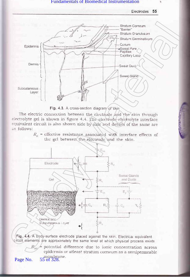
Electrodes 55
-<:*-:-t/ e///t I
',- a /)
Eoidermis {
Ioermis
J
iI
L
Stratum Corneum"Barrier"Stratum Granulosum
Stratum Germinativum
CoriumPore
PapillaeCapillary Loop
Sweat Duct
Sweat Gland
Fig. 4.3. A cross-section diagram of skin
The electric connection between the electrode and the skin through::ectrolyte gel is sho,*,n in figure 4.4. Tihe electrode-electrolyte interface:quivalent circuit is also shown side by side and details of the same are-s follows:
R. = effective resistance associated with interface effects ofthe gel between the electrode and the skin.
Dermrs andSubcutaneous Laryer
Fig. 4.4. A body-surface electrode placed against the skin. Electrical equivalentlircuit elements are approximately the same level at which physical process exists
&" = potential difference due to ionic concentration acrossepidermis or atleast stratum corneum as a semipermeablemembrane.
{
R1
Stud
y Mate
rial
Page No. 55 of 328.
Fundamentals of Biomedical Instrumentation

56 Fundarnentals of Biomedical lnstrumentation
Parallel RC = epiderrnal layer impedanceFor I cm2 skin impedance reduces from 200 kO at I Hz to 200 (l
at 1 MHz.The dermis and the subcutaneous layer behaves as pure resistance.
The effect of the stratum corneum may be reduced by vigrous rubbingwith a pad sbaked in acetone or abrading the stratum corneum withsanclpaper to puncture it. This process shorts 8"., C" and R" for stability.
The fluid secreted by sweat glands contains Na*, K* and Cl- ions andconcentrations differ from those in extra cellular fluid. Hence, there ispotential difference between luman of the swert duct and dermis andsubcutaneous layers. There are also a paraiiel Rrc, combination inseries with this potential that represents the wall of the sweat gland andduct, These components are generally neglected when we considerbiopotential electrodes.
If a polarizable electrode is in contact with electrolyte, a double layerof charge forms at the interface. The movement of electrode with respecrto electrolyte mechanically disturbs the distributjon of potential untilequilibrium can be reestablished. If a part of electrodes is in a electrolyteand one moves whole of the other remains statinary, a potential differerrceappears between the two electrodes during this movement. This potentiaiis called motion artifact which can be a serious cause of interference inthe measurement of bio-potentials.
The motion artifacts results primarily from mechanical disturbancesof the distribution of charge at electrode-electrolyte interface. It isreasonable to expect that motion artifact is minimal for nonpoiatizableelectrodes.
4.3.1. Microelectrodes
These have tips small enough to penetrate a single cell and as suchreadings from within single cell can be obtained. Microelectrodes are oftwo types-metal and micropipet. Metal microelectrodes are constntctedby electrolytically etching the tip of a fine tungsten or stainless steel wireto the ciesired size. Subsequently the wire is coated almost to the tipwith insulating material. Special electolytic processing is also done on
the tip to lower the impedence. The ion-metal interface happens at thepoint of contact betweenmetal tip and the electrolytes either insicle oroutside the cell.
The micropipet type of electrode is actually a glass micr:opipet rr,iththe tip of the desired stze (i.e. about 1 micron).
The micropipet is filled with an electrolyte suitable "vith cellularfluids. Such microelectrode is having dual interface. One interface is
comprised. of a metal wire in contact with the electrolyte solution insidethe micropipet and the other is the interface between eJ.ectrolyte insidethe pippet and the fluids inside or immediately outside the cell.
One microelectrode is shown in figure 4.5.A thin film of precious metal is bonded to the outside of a drawn
glass microelectrode. Such microelectrodes are very reliable and havingStud
y Mate
rial
Page No. 56 of 328.
Fundamentals of Biomedical Instrumentation
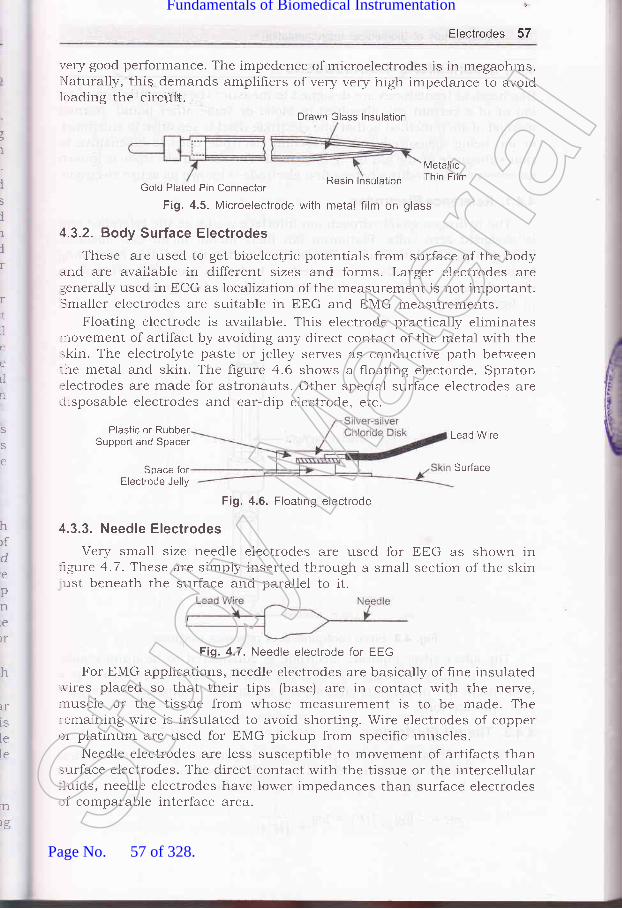
Electrodes 57
very good performance. The impedence)'laturaliy,'this demands amplifiers ofloading the circriit.
of microelectrodes is in megaohms.very very high impedance to avoid
t
I
i5
ilir
rr,]
ii
i'tLl
n
Resin lnsulatron
MetallicThin Film
Gold Plateci Pin Connector
Fig. 4.5. Microelectrode with metal film on glass
4.3.2. Body Surface Electrodes
These are used to get bioelectric potentials from surface of the bodyand are available in different sizes and forms. Larger electrodes aregenerally used in ECG as localZation of the measurement is not important.Smaller electrodes are suitable in EEG and EMG measurements.
Floating electrode is available. This electrode practically eliminates.novement of artifact by avoiding any direct contact of the rnetal with theskin. The electrolyte paste or jelley serves as condnctive path bet.veen:he metal and skin. The ligure 4.6 shows a floating electorde. Spraton:lectrodes are made for astronauts. Other special surface electrodes areiisposable electrodes and ear-dip electrode. etc.
S
S
e
hrfde
pnre
)r
h
IT
1S
lele
Plastic or RubberSupport and Spacer
Space forElectrode Jelly
Fig. 4.6. Floating electrode
4.3.3. Needle Electrodes
Very small size needle electrodes are used for trtrG as shown in:rgure 4.7. These are simply inserted through a small section of the skinust beneath the surface and parallel to it.
For EMG applications, needle electrodes are basically of hne insulated..r'ires placed so that their tips (base) are in contact with the nerve,nuscle or the tissue from whose measurement is to be made. The:emaining wire is insulated to avoid shorting. Wire electrodes of copper:r platinum are used for EMG pickup from specific muscles.
Needle electrodes are less susceptible to movement of artifacts thansurface electrodes. The direct contact with the tissue or the intercellular-1uids, needle electrodes have lower impedances than surface electrodesrf comparable interface area.
Lead Wire
Sudace
'n
rg
Drawn Glass lnsulation
Fig. 4"7. Needle electrode for EEG
Stud
y Mate
rial
Page No. 57 of 328.
Fundamentals of Biomedical Instrumentation

58 Fundamentals of Biomedical lnstrumentation
4.4. BIOCHEMICAL TRANSDUCERS
Biochemical transduces are designed to measure the concentration of anion or of a certain gas dissolved in blood or some other liquid. Normalmethod of such method is that one electrode used is sensitive to substanceor ion being qLeasured and the second electrode used is insensitive tothat substance or the ion being measured. The second electrode is knownas reference electrodue whereas hrst electrode is known as active electrode.
4.4.1. Reference Electrodes
The hydrogen gas/hydrogen ion interface works as the reference andis assigned zero volts. Platimum (an inert metal) metal can absolutehydrogen gas. If platinum is partially immersed in the solution containinghydrogen ions and also is exposed to hydrogen gas, this creates anelectride potential. The reference electrode basic conhguration is shownin figure 4.8.
lnternal Ag/AgClor Colonel
Filling Solution
Liquid Junction
Fig. 4.8. Basic configuration of reference electrode
The silver-silver chloride electrode is considered to be quite stable.r\nother popular reference electrode is Calomel electrode. Calomel is atrade name for mercurous chloride is a chemical combination of mercun'and chloride ions.
4.4.2. The pH Electrode
TkIe pH of blood and other fluids is very important indicator of chemicalbalance. The pH is directly related to the hydrogen ion concentration inthe fluid. It is related as per following formula:
pH : - logro [H*] : fogro pfStud
y Mate
rial
Page No. 58 of 328.
Fundamentals of Biomedical Instrumentation

Electrodes 59
The pH is a measure of the acid-base balance of a fluid. A naturalsolution has a pH of 7.
T}ee pH of normal arterial blood may be from 7.38 to 7.42. A thinglass membrane allows passage of only hydrogen ions as shown in figure4.9. Inside the glass blub a highly acidic buffer solution is put. A silver-silver chlorode e'kctrode is used in this case. The pFr measurement isdone by using glass electrode for pH measurement as shown in thefigure 4.9 along with reference elecrode already described. A combinationelectrode as shown in the figure 4.10 is available having both pH glasselectrode and reference electrode.
The impedences of pH electrodes vary from 50 to 500 MQ. The inputimpedence of ttre meter must have extremely high value for propermeasurement.
To Meter forMeasurement
To Meter forMeasurement
Reference
Ag/AgCIWire ContactpH Glass
BufferedSolution
Fig. 4.9. Glass electrode for Fig. 4.10. Combination electrode forpH measurement pH measurement
4.4.3. BIood Gas Electrodes
The partial pressures of oxygen and carbon dioxide in the blood areimportant physiological chemical measrement. po, (partial pressure ofoxygen)also called o,rygcntension can be measured both in vitro and invivo. The principle of m:asurement is shown in figure 4.Il.If a voltageof approx 0.7 V is applied between the platinum wire and referenceelectrode, reduction of the oxygen takes place at the platinum cathode.This results in an oxidation-reduction current proportional to the partialpressure of the diffused oxygen, which can be measured.
In some applications, measurements of Po, and pao, are combinedinto a single electrode that also includes a common reference half-cell.The combination electrode is shown in figure 4.12.St
udy M
ateria
l
Page No. 59 of 328.
Fundamentals of Biomedical Instrumentation

60 FUndamentals of Biomedical lnstrumentation
i
Microammeter
lnsulatron
Ag/Agcl ReferenceElectrode
Electrolyte Solutionwhere in O, can diffuse
Platinum Wire
Membrane throughwhich C, can Ciffuse
Solution in whichMeasurement is Made
Fig. 4.11. Po, electrode with-platinum cathode demonstrating principle of operation
4.4.4. Practicability in Using Electrodes
No parts of the lead wire should be exposed to the electrolyte all ofthe same material. A third material say solids should not be used toconnect the electrode to its lead wire unless it is certain that thismaterial wiil not be in contact with the electrolyte. The lead wire be
welded to electrodes or from a mechanical bond through crimping or
peening. Dissimilar metals should not be used in contact because theiri,att ce'it potentials are different. An electrochemical rear:tion will be
setup beiween them which can result in additional polarization and
often in corrosion of one of the metals. This tends to make half cells
potential less stable and contributing to increased electric noise from the
eiectrode.In detecting surface potentials on the bodv or internal potentials
within it rvhile using pairs of electrodes for measuring differentials' it isbetter to use same material for each electrode since half cell potentials
are approximately equal. This implies that the net dc potential seen at
the input to amplifier connected to the electrodes is relatively small, may
be zeio. This minimizes possible saturation effects in the case of highgain direct co,;pled amPlifrers.
Electrodes hxed on the skin's surface have a tendency to come off.
This is due to a loss cf effectiveness of the tack on the tape holding them
in place. This is no problem if electrodes are well designed, i"e., lead
wires should be extremely flexible but strong'The point at which electrode lead '"rrire enters the electrode gets
broken due to frequent flexing at this point. Strain relief be provided at
this point. A tapeied region of insulation thai gradually increases from
the diameter of the wire to one cl0ser to that of the electrode reduces
this problem and distributes the flexing forces over a greater portion of
the wire.Stud
y Mate
rial
Page No. 60 of 328.
Fundamentals of Biomedical Instrumentation

Electrodes 6'l
The insulation of the lead rvire and the electrode is aiso a protliern"The environment around electrodes is very humici or continualil, 5o.i."oin extracellular fluid or even in cleaning solution. These insulations aremace of polymeric material so that it can absorb water. It is importantthat the insulation material used with electrode shourd be pr-oper toar.roid such prpblems.
Figure 4.12. shows body surface biopotentiai electrodes. Metal-plateelectrode is used for application to limbs. Metal-disk electrode is usedwith surgicai tape. Disposable foam-pad electrodes are frequently usedwith electrocardiographic monitoring equipments.
The disposable foram-pad type electrode consists of a large disk ofplastic foam material with silver plated disk on one side attached to asilver-plated snap similar to that used on clothing in the center of otherside.
Figure 4.13 shows a metallic suction electrode. It is a modificationof the metal-plate electrode that requires no staps or ad.hesives forholding it in place. It consists of a hollow metallic cylindrical electltodewhich makes contact with the skin at its base.
(Top) (Bottom)
(c)
Metal Disk and Electrolvte
Adhesive Tack onSurface of Foam Pad
Fig. 4.12. Body surface biopotential electrodes (a) Metal-plate electrode,(b) Metai-disk electrode, (c) Disposable foam pads
Figure a.A@l shows floating metai-body surface electrodes. Theseare recessed electrodes with top-hat structure. Cross-sectionai view ofthe electrode is also shown for the same. Another cross-sectional viewof the electrode is also shown in figure 4.14(b). Another cross-sectionalview is given in figure a.74(c) for a disposable recessed electrode of thesimilar general structure. The recess in this electrode is formed from anopen foam disk which is saturated with electrolyte gel and is placed overthe metal electrode.
ELECTRODES
Foam Pad
Stud
y Mate
rial
Page No. 61 of 328.
Fundamentals of Biomedical Instrumentation

62 Fundamentals of Biomedical lnstrumentation
RubberBuib
Lead Wire--rT-"rr-rnal
ContarJS urface
Fig. 4.13. Metallic suction electrode
lnsulatingPackage
Electroyte Gelin Recess
(b)
Snap Coated with Ag-AgClGel-coated Sponge
Plastic Cup Plastic Disk
n nnDead Cellular Material
CaPillary LooPs Germinating LaYer
(c)
Fig. 4.14. Floating metal-body electrodes: (a) Recessed electrode with top-hat
structure, (b) Cross-sectional view of above, (c) Cross-sectional view of a disposablerecessed electrode of similar type
Figure 4.15 shows flexible body-surface electrodes. These ale carbonfilled siticone rubber electrode and flexible thin-film neonatal electrode.cross-sectional view of the thin-film electrode is also shown. A pinconnector is pushed into the lead connector hole of hgure a.15(a). Flexibleelectrodes are important for monitoring premature infants'
Figure 4.16 shows needle and wire electrodes for percutaneousmeasurement of biopotentials. These are insulated needle electrode, coaxialneedle electrode, bipolar coaxial electrode and fine-wire electrodeconnected to hypodermic needle before being inserted. It also showscross-sectional view of the skin and muscle with coiled fine-wire electrode
(a)
il
Stud
y Mate
rial
Page No. 62 of 328.
Fundamentals of Biomedical Instrumentation
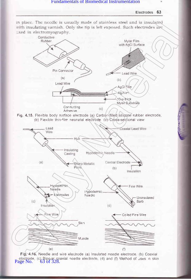
'
Electrodes 63
rn place. The needle is usually rnade of stainless steel and is insulatedrvith insulating varnish. Only the tip is left exposed. Such electrodes areused in electromyography.
Pin Connector
(a)
Lead WireAgCl Film
Ag Film
13-p{hickMylar Substrate
ConductingAdhesive
(c)
Fi9.4.15. Flexible body surfface electrode (a) Carbon-filled silicone rubber electrode,(b) Flexible thin-film neonatal electrode, (c) Cross-sectional view
HypodermicNeedle
Electrodes
(e)
Fig. 4.16. Needle and wireelectrode, (c) Bipolar coaxial
HypodermicNeedle
Skin
Muscle
electrode (a) lnsulated needleneedle electrode, (d) and (f)
Wire
UninsulatedBarb
(0
electrode, (b) CoaxialMethod of uses in skin
(- Coiled Fine Wire
Stud
y Mate
rial
Page No. 63 of 328.
Fundamentals of Biomedical Instrumentation

64 Fundamentals of Biomedical lnstrumentation
Figure 4.17 shows electrodes for cietecting totai electrocardiogramduring labor by means of intracutaneous needles. There are suctionelectro,les whose cross-sectional view of the in place showing penetrationof probe through epidermis. Helical electrode is also shown which isattached to fetal skin by corkscrew type action. The peak amplitude.roltage in such cb.ses is 50-700 pV.
Suction Cup
Electrode
Lead Wire
F tal Skin
Referenc:Electrode
- Electrode
\(b
(c) ""-@during labor (a) Suction electrode,of ahove, (c) Helical electrode
Fig. 4.17. Electrodes used(b) Cross-sectional view
iil
3
1. Electrode: The devices that convert ionic potentials into electronicpotentials.
2. Bioelectric Potential Electrodes: Electrodes used for themeasurement of bioelectric potential.
6
Microelectrodes: Microelectrodes are of two types--metal andmicropipet. Metal electrodes are constructed by electrolytically ethcingthe tip of a fine tungsten or stainless steel wire to the desired size.
The wire is coated almost to the tip with insulating materials.Micropipet type electrode has micropipet filled with an electrodesuitable with cellular fluids. It has dual interface-one is metal wireincontact with electrolyte solution inside of the micropipet and theother is the interface between electrolyte inside the pipet and thefluids inside or immediately outise the cell.
Body Surface Electrodes: These are electrodes which are used toget bioelectric potentials from the surface of the body and are availablein different sizes and forms.Biochemical Transducers: Biochemical transducers measure theconcentr:ation of an ion or of a certain gas dissolved in blood or some
other liquid.Reference Electrodes: The hydrogen gas/hydrogen ion interface worksas the reference and is assigned zero volts.The pH Electrode: The pH rneasurement is done by using glass
electrode along with reference electrode. A combination electrode for
4
Stud
y Mate
rial
Page No. 64 of 328.
Fundamentals of Biomedical Instrumentation

Electrodes 65
8
9
Blood Gas Electrodes: The partial pressures of oxygen andcarbondioxide in the blood are measured using blood gas el:ctrode.Combination electrodes for P"o, and po, are availabie.Practicability in using Electrodes: No parts of the lead rvire shouldbe exposed to the electrolyte all of the same material. A third materialsay solids shduld not be used to connect the electrode to its leaci ""vireunless it is certain that this material will not be in contact with theelectrolyte.
10. Examples of Electrodes: Electrodes used for application limbs,surgical tape,intracutaneouslabour pain are
+.3. What do you understand+.4. What is a glass electrode+.5. What is the hydrogen ion
by the term "reference electrode"?used for?concentration of blood with pH 6.8?
(UPTU-MQP1)+.6. what is the major advantage of floating type skin surface electrode?+.7. why are the partial pressure of oxygen and the partial pressure of carbon
dioxide useful physical parameters? Explain briefly how each can bemeasured.
JJJ
OXerCkle,J
4.1. Differentiate between microelectrodes and body surface electrodes.(UPTU-2004\
4.2. Name the three basic types of electrodes for the measurement of bioelectricpotentials. For a patient, which types of electrode would be least traumatic?
(UPTU-MQP3I
disposable electrodes, electrodes for infants,needle electrodes, and suction electrodes used duringavailable.
Stud
y Mate
rial
Page No. 65 of 328.
Fundamentals of Biomedical Instrumentation

Cardiovascular Measurements
chapter
ioni
'lr
ll1[
,{i
5.2. Cardiovascular System5.3. Electro Cardiography5.4. Blood Pressure Measurement5.5. Measrrrement of Blood Flo,"r, and Cardiac Output5.6. Measurement of Heart Sound5.7. Plethysmography5.8. Sumrnarl'
The use of engineering methods and the development of instrumentationhave contributed significantly in r':ducirrg death from heart diseases.Blood pressure, flo'w and volume.are measured by using engineeringtechniques. The electrocardiograrl, echo cardiogram and continuous ECGrecording (Holter recording) are measured and recorded with electronicinstruments. A Holter machine block diagram and usage is shown infigu.re 5.1. Intensive and coronary care units nol,v available in manyhospitals rely on bioinstrumentation for their working. There are alsocardiac assist devices such as electronic pacemaker and detibrillatorwhich are extensively used in patient care.
66Stud
y Mate
rial
Page No. 66 of 328.
Fundamentals of Biomedical Instrumentation

Cardiovascular Measurements 67
Fig. 5.1. Hofler machine usage and block diagram
CARDIOVASCULAR SYSTEM
re cardiovascular system is known as circulating system. It transports.'ltrients, gases and wastes to and from cells oruoay. The cardiovascular'-"
stem is composed of the heart, brood vessels, cefls and plasma which--ake up the blood. A cardiovascular system is shown in figure 5.2 (a)=:d figure 5.2 (b) shows a basic analogr of cardiovascular system.
The heart is like a two stage pump, physically arranged in parallel: :t with the circulating blood passing through t-he pumps in a series::quence' The right half of the hea't is the pump thal suppries blood to-:--: rest of the system. The circulatory path for blood-flow through the-:-rgs is called the pulmonary circulation and the circulatory system-' at supplies oxygen and nutrients to the cells of the body is cauea tnei stemic circulation. Figure 5.3 shows a cutway view of heart with blood: :ulation.
The systemic circulation is a high resistance circuit with a large:-:ssure gradient between the arteriels and veins. The pump constituting- -. left heart may be considered 6rs a pressure pump. The muscle,: :traction of the left heart is larger ,and stronger than tirat of the right-: :r-t because of the greater pressur€: required for systemic circulation.- - : volume of blood delivered per urft o] ti-" by the two sides is thes'.'::e when measured over a sufficie:ntly long interval. The left heart::-,'elops a pressure head sufficient to cause blood to flow to all the body:':r:s. contraction of the heart muscles surrounding each chamber of--- - heart is the pumping action. Thesr: muscles ,"".ir. their own blood* -:p1y from the coronary arteries.
The pipes which in this case are ar-teries and the veins are not rigid-- t-lexible. They are capable of helpinl3 and controlting blood circulation-reir own muscular action and thei,r ,wn valve and receptor system.'d is not a pure Newtonian fluid; rrrther, it possesses properties thatrot always comply with the rawsi governing hydrauric motion. In
: :.:ion the blood needs the help of the lungs for the supply of oxygen.- -s the system can not be oversiml:rified and could teah to error.Stud
y Mate
rial
Page No. 67 of 328.
Fundamentals of Biomedical Instrumentation

68 Fundamentals of Biomedical lnstrumentation
Jugular vein(also subclavianvein {rom arms)
Carotid arterY(also subclavianartery to arms)
mesentericarteries
renal artery
Pulmonaryartery
Superiorvena cava
lnteriorvena cava
hepatic vein
hepaticportal vein
SU
rhberto--ts
a1s
thi
:11(
ric
:lo'al'r-h
:ell
1.runk and legs
Fig. 5.2. (a) t)ardiovascular systemStud
y Mate
rial
Page No. 68 of 328.
Fundamentals of Biomedical Instrumentation
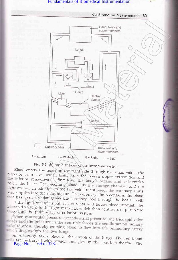
Cardlovascular Measurements 69
A = atrtum V = Ventricle R=Right L=Lefr
Fig. 5.2. (b) Basic analogy of cardiovascular systemBlood enters the heart on the right side through two main veins: the
' -:perior vena-cava, which leads from the body,s *o.. extremities and:- : inferior vena-cava leading from the body, extremities:*.ow the heart. The incommlg Ulood fills the er and the-.ht atrium. In addition to the two veins ment nary sinusl-:c empties into the right atrium. The coronary sinus contains the blood:' :t has been circulating via the coronary loop through the heart itserf.If the right atrium is furl it contracts and forces brood through the*--:uspid valve into the right ventricle, which then contracts to pump the: ::,d into the pulmonary circulation svstem.
\n exchange takes place in the arveoli of the lungs. The red blood-s are recharged with oxygen and give up their carbon dioxide. The
Stud
y Mate
rial
Page No. 69 of 328.
Fundamentals of Biomedical Instrumentation

70 Fundamentais of Biomedical lnstrumentation
pulmonary artery divides many times into smaller and smaller arteries'
which becomes arterioles with extremely small cross sections. These
arterioles supply blood to the alveolar capillaries, in which exchange of
oxygen ,rra .aruo, dioxide takes place. On the other side of the lung
-^i i" a sin-rilar construction in which s fed into tinyveins. The tiny veins combine to form larger n turn combine
until ultimateiy all the oxygenated blood is the pulmonary
vein to the heart.From the pulmonary vein the blood enters the left atrium and from
there it is pr-rmped thrtugh the mitral or bicuspid valve, into the left
ventricle by contraction oithe atrial muscles. when the left ventricular
muscles contract, the pressure prod.uced by the contraction mechanically
closesthemitralvalveandthebuiltupofpressureintheventricleforces the aortic valve to open, causing the blood to rush from the
ventricle into the aorta. It may be noted that this action takes place
synchronously with the right ventricle'Theheartpumpingcycleisdividedintotwomajorparts:systoleand
diastole. Systole is a"fr.t"a as the period of contraction of the heart
muscle, specifrcally the ventricular ruscle at which time blood is pumped
into the pulmonary artery and the aorta. Diastole is the period of
dilation oi tft" heart cavities as they fill with blood'
1
t(
1
t
{I
I
ll
1
S-
f-
8t
br
as
5;
{:h,ritlrrfrth,:n(_f,
Deoxygenatedblood
Superior lungs
To right lungs,J
From rightlungs
Left subclavian arterY
To left lungs
From left lungs
Aorta
Oxygenated blood to arteries/arterioles/capillarY bed(trunk and lower limbs)
LA
De oxygenatedblood
Fig. 5.3. Cutway view of heart with blood circulation
once the blood has been pumped into the arterial system, the hear
relaxes the pressure in the hiart chambers d.ecreases the outlet valves
closes and ln a short time the inlet valve open again to restart the
diastole and initiate a new cycle in the heart'
The b100d reaches the brain and other extremities after
through many bifurcations of the arteries' The last stage ispasslx
Arch of Aorta
graduStud
y Mate
rial
Page No. 70 of 328.
Fundamentals of Biomedical Instrumentation

Cardiovascular Measurements 7'l
decrease in the cross section and the increase in the number of arteriesuntil the smallest type which is called arterioles is reached. These feedrnto the capillaries where oxygen is supplied to the cells and carbondioxide is received from the, cells.'
Some values of interst in the cardiovascular system in engineeringare: the heart beats ab an average rate of 75 beats/minute in a normaladult. The heart rate increases when a person stands up or do some:xercise, decreases when he lies down. The normal range is betweenc0 to 85. on the average it is higher in women. In an infant the heart-ate may be as high as 140 beats per minute under normal conditions.lhre heart rate also increases with heat exposure and other physioiogical.rd psychological factors.
The heart pumps about 5 litres of blood per minute, the average--ood volume in average adult is about 5 to 6litres. Thus approximately--e whole blood is circulated every minute during rest. with exercise the-:culation rate is increased 'considerably. At any given time, about-r-80% of the blood volume is in the veins about 2o./o in arteries and- e remainder jn the capillaries.
Systolic blood pressure in the normal adult is in the range of 95 to:lJ mm of mercury (Hg) with 120 being average. These figures arei -.'cject to much variation with age, climate, eating habits and other'---tors. Normal diastole pressure ranges from 60 to 90 mm of Hg and: mm of Hg being average. This pressure is usually measured in the: -=chial artery in the arm. The normal value of blood pressure is giveni -rvstole pressure/diastoic pressure as l2Ol80.
:;-l E IECTRO CARDIOG RAP HY
.:aphic recording or display of the time-variant voltages produced by: :re&rt during the cardiac cycle the electi:ocardiogram (ECG or EKG).r-:e 5.4 (a) shows a typical normal electrocardiogram. The peRS and' =r'es reflect the rhythmic electrical depolarizatron ancl repolarization--','ocardium associated with the contraction of the atria and ventricles.- electrocardiogram is used clinically in diagnosing various diseases-, :onditions associated with the heart. Figure 5.4(b) showns the origin:art beat and electrical activity of the heart.
10 mm(1 mV)
----------)Time
Fig. 5.4. (a) A typical normal electrocardiogramStud
y Mate
rial
Page No. 71 of 328.
Fundamentals of Biomedical Instrumentation

72 Fundamentals of Biomedical lnstrumentation
Superior vena cava
Sinoatrial node
lnte rnodalpath\i!ays
Atr loveirtricu!ar-j-node
BLINclIE OT HIS
Right bundlebranch
Duration
SA node
Atrial muscle
,AV node
Aotron potential
a 2 0.4 0.6
Time (s)
LAF
Cr:r-nrnoir bunCle
Purl" inje5\rsielr)
I aTi noslci"toria scicle
-..,. I
t,
il;,i
,(
{ll
Fig. 5.4. (b) Original the hearl beat and electrical activity
As already explained, the P wave represents depolarization of the
atrial musculature. The QRS complex is the combined result of the
repolarization of the atria and the d.epolatization of the ventricles whicho"..r, almost simultaneously. The T wave is the wave of ventricularrepalarization whereas the U wave, if present is generally believed to be
the result of after potentials in the ventricular muscle. The P-Q intervalrepresent the time during which the excitation wave is delayed in the
fibers near the AV node.The shape and polarity of each of these features Vary with the location
of the measuring electrodes with respect to heart. In general thecarcliologist looks critically at the various time intervals, polarities and
amplitudes to arrive at his diagnosis.Few normal values for amplitudes and duration of ECG parameters
are given below:Amplitude P wave
R wave
Q WaveT WaveP-R intervalQ-T intervalS-T segrnent
0.26 mY1.50 mV25ok of R Wave0.1 to 0.J mV0.10 to O.2O sec
0.34 to 0.45 sec
0.05 to 0.15 sec
P Wave interval 0.10 sec
QRS interval 0.08 sec
Stud
y Mate
rial
Page No. 72 of 328.
Fundamentals of Biomedical Instrumentation

Cardiovascular Measurements 7i-: AV node. A heart block might be indicated of one or more of the basic:atures are missing in ECG.: fifl:';e,s:h:?:::i:tJ,hffTtriil11i:#iilr.rr.r,"." tr,. .r""tri'"1?T,:t* HsH:I
(whether erect or recumbent)
An instrument used to obtain electrocardiogram is calred anr':ctrocardiograph. The electrocardiograph was tite first electrical/:::tronic device to find widespread rs. i,,medical diagnostics and still-,-.: most important toor for diagnosis of cardiac disoriers. Although it:--r'ides invaluable diagnostic information in case of arrhythmia andtits.Tfor
fJ 1. ECG Amptifiers
-\ormal electronic amplifiers are norma-[y referenced to ground through:-: power supplies. Thrs creates an interference prob[m when such::irfiers are used to measure smal bioelectric potentials. ihe techniquer -ally employed not only in electrocardiography but arso in the'-:surement of other bioelectric signals in the use of a differential::-:fier. The principar of differential amplifier can be explained with the
-- of figure 5.5.
! 5. The differential amplifier:-l common output, (b) as
(a) represent as two amplifiers with separateused for amplificailon of bioelectric signals
mp
Bioelectronic Isrgnal V*
Stud
y Mate
rial
Page No. 73 of 328.
Fundamentals of Biomedical Instrumentation

74 Fundamentals of Biomedical lnstrumentation
TwoamplifierswithseparateinputsbutwithaCommonoutputterminal which delivers the sum of two amplifiers output voltages is a
differential amplifier. Both the amplifiers have the same voltage gain, but
one amplifier ls inverting (outpul voltage is 180" out of phase with
respecttoinput)whiletheotherisnon_inverting(inputandoutput;;ii"g." .r" 1, prrasel. If the two amplifier inputs are connected to the
same input source, the resulting common mode gain should be zeto'
becausethesignalsfromtheinvertingandnon-invertingamplilrerscanceleach other at the common output. However, the gain of the two amplifiers
isnotexactlyequal,thiscancellationisnotcomplete.Asmallresidualcommon mode output remains. when one of the amplifier inputs is
grounded and a ,roliage is applied only input' the
input voltage appears ,t tn" output amp amplifrer'
The ratio of the differential galn to the called the
common mod.e rejection ratio-of the differential amplifier which in modern
amplihers can be as high as 10,OO,OOO:1'
Measurementofbioelectricsignalsthatoccurasapotentialdifferencebetween two electrodes is an input to a differential amplifier' The bioelectric
signals are between the inverting and non-inverting inputs of the amplifrer'
For the interference signal, hotiever, both inputs appear as though they
were connected togeth.i to '' common input source' Much smaller common
moa" gain amplifiers the common mode interference signal'
The electrode impedances R.* and R"- each form a voltage divider
with the input ir.rp.d.r-r"e of thE differeniial amplifier as illustrated in
figure 5.5(b).If the electrod.e impedance are not identical, the interference signals
at the lnpu amPliher
may b egree not take
place. ances qual' the
highcofadifferentialamplilrercanonlyberealize impedance much higher as compared
to the imped.ance of the electrodes to which it is connected'
5.3.2. Electrodes
A num usually five are afixed to the body of the
patientforG.Theelectrod.esareConnectedtotheECCmachine b of electrical wires' These wires which come
from electrodes to the ECG machines are called leads. The electrode
appliedtotherightlegofthepatientforexampleiscalledtheRLleacFor the record.ing of thE electrocardiogram two electrodes or one electrodt
and an interconnected group of electiodes are selected and connected t:
the input of the recording amplifier'Thepumpingactionoftheheartwhichgeneratsthevoltageisactual..
avectorquantitywheremagnitudeaswellasorientationchangeswi--the time because the ECG signal is measured from electrodes applied ::
rhe surface of the body, the"waveform of this signal is very depende:-:
on the placement of the electrode' Some of the segment ot the trace mai
however,alrnostdisappearforcertainelectrodepositionwhereasothgmay show up clearly on the recording' For this reason 1n a norr-Stud
y Mate
rial
Page No. 74 of 328.
Fundamentals of Biomedical Instrumentation

75 Fundamentals of Biomedical lnstrumentation
electrocardiographic examination the electrocardiogram is recorded froma number of different leads, usually 12 to ensure that no importantdetail of the waveform is missed. The placement of the electrodes andthe names and configuration of the leads have become standardized. Thecolour codes are used to identify each electrode
In this experimerrt, Einthoven had found it advantageous to recordthe electrocardiogram from electrodes placed vertically as well ashorizontally on the body of the patient. The leg selected was the left legprobably because it terminates vertically below the heart. The earlyelectrocardiograph machine thus employed that electrodes of which onlytwo are used at one time. With the introduction of electronic amplifieran additional connection to the body was needed as a ground reference.It becomes a convention to use the free right leg as reference althoughan electrode could have been positioned almost any where on the body'
c(Brown)
RL (Green) L (Bed)
Fig. 5.6. (a) Abbreviations and colour codes used for ECG electrodes
5.3.3. Leads
Four electrodes are used to record the electrocardiogram as shown:: hgure 5.6 (a). The electrode on the right leg is only for ground reference.Jtcause the input of the ECG recorder has only two terminals, a selection:-ust be made among the available active electrodes. The 12 standard
=ads used most frequently are shown in figure 5.6 (b). The three bipolar-rb lead selections first introduced by Einthoven shown in the top row.: hgure as given below:
Lead I : Left Arm (LA) and'Right Arm (RA)
Lead II : Left Leg (LL) and Right Arm (RA)
Lead III : Left Leg (LL) and Left Arm (LA)
Above leads are called bipolar because for each lead the.-ectrocardiogram is recorded from two electrodes and the third electrodeSt
udy M
ateria
l
Page No. 75 of 328.
Fundamentals of Biomedical Instrumentation

76 Fundamentals of Biomedical lnstrumentation
is not connected. In each of there positions the QRS of a normal heartis such that the R wave is positive
Bipolar Limb Leads
Lead I Lead ll Lead lll
(Augmented) Unipolar Limb Leads Lead aVF
tttV
V
aEaalfosl
"ii,lr
,l ,,il1il
V, Fourth intercostal space,at right sternal margin.
Vz Fourth intercostal space,
Unipolar chest leads
Vr-Vo
anterior axillary line.
Vo Same level as, V4 on mid-
axillary line.
Fig. 5.6. (b) ECG leadStud
y Mate
rial
Page No. 76 of 328.
Fundamentals of Biomedical Instrumentation

Cardiovascular Measurements 77
Einthoven postulated that at any given instant of the card.iac cycle,:he frontal plane representation of the electrical axis of the heart is a:rvo-dimensional vector. The ECG measured from any one of the threeoasic limb leads is a time variant single dimensional component of that'.-ector. The assumption is made that the heart, i.e., the origin of the'.-ector is near the-,center of an equilateral triangle, the apexes of which,re the right and left shoulder and the crotch. with this assumption the-cG potential at the shoulders are essentially the same as the wristsand that the potentials at' the crotch differ little from those at either.nkle, he let the points of this triangle represent the electrode positions:rrr three limb leads. The triangle known as the Einthoven triangle is:hown in figure 5.7.
Fig. 5.7. The Erainthroven triangle
The three projections of the ECG vector are measured along the sides-:re triangle. The instantaneous voltage measured from any one of the
-- =e limb lead positions is approximately equal to the algebraic sum of
- : other two, or that the vector sum of the projections on all three lines:qual to zero. The polarity of the Lead II measurement must be
=rsed for these statements to actually hold true.-ead II produces the greatest R wave potential. Therefore, when the
-':litudes of three limb leads are meastlred, the R-wave arSrplitude-ead II is equal to the sum of the R-wave amplitudes of Leads I
- . III.- he remaining leads are the unipolar type. For unipolar leads, the
' - -rocardiogram is recorded between a single exploratory and the, :al terminal which has a potential corresponding to the center of- cody. This central terminal is obtained by connecting the three- '.'e limb electrodes together through resistors of equal size. The-.:-tial at the connection point of the resistor corresponds to the
Left Leg
Stud
y Mate
rial
Page No. 77 of 328.
Fundamentals of Biomedical Instrumentation
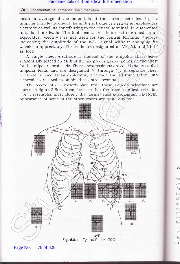
,1,
tlt;\xI
78 Fundamentals of Biomedical lnstrumentation
mean or average of the potentials at the three electrodes. In theunipolar limb leads one of the iimb electrodes is used as an exploratoryelectrode as well as contributing to the central terminal. In augmentedunipolar limb leads. The limb leads, the limb electrode used as anexploratory electrode is not used for the central terminal, therebyincreasing the amplitude of the ECG signal without changing itswaveform appreciably. The leads are designated as VR, VL and VF (Fas foot).
A single chest electrode is instead of the unipolar chest leadssequentially placed on each of the six predesignated points on the chestfor the unipolar chest leads. These chest positions are called the precordialunipolar leads and are designated 7, thrcugh Va. A separate chestelectrode is used as an exploratory electrode and all three active limbelectrodes are used to obtain the central terminal.
The record of electrocardioolam from these 12 lead selections areshown in figure 5.8(a) . It can be seen that the trace from lead selectionI or II resembles most closely the normal electrocardiogram waveform.Appearance of some of the other traces are quite different.
\toVu
5
aVFFig. 5.8. (a) Typical Patient ECG
5.
pe
CA
fr<
1n
str
1S
SC
an
ircSO
of:htInSt
udy M
ateria
l
Page No. 78 of 328.
Fundamentals of Biomedical Instrumentation

Cardiovascular Measurements 79
There are certain additional lead modifications that are of considerableuse in the coronary care unit. The most widely used modification for ongoing ECG monitoring is the modihed chest lead I (MCL1) also called theMarriott lead, named after its inventor. Some practical ECG records areshown in figure 5.8(b), (c) and (d).
Fig. 5.8. (b) ECG recording with regular spreading of the curve with super imposed
Fig. 5.8. (c) Recording with irregular trembling of the ECG trace without wanderingof the base line but otherwise normal ECG trace
Fig. 5.8. (d) ECG trace without wandering of the base line
5.3.4. ECG Recorder Principles
A block diagram of an ECG recorder is shorvn in frgure 5.9. The-- =tient electrodes connecting wires originate at the end of a patient
_. cle, the other end of which plugs into the ECG recorder. The wires-:m the electrodes connect to the lead selector switch, which also'.:orporates the resistors necessary for the unipolar leads. A:-ndard.ization voltage of 1 mV to standardize or calibrate the recorder
. lsed.. An artifact on the recorded trace is introduced by changing the. :ing. From the lead selector switch the ECG signal goes to a pre-
:-.ciiher, a differential amplifier with high common mode rejection. It is:oupled to avoid problems with small dc voltages that may originate
- r polarizatron of the electrodes. A variable sensitivity adjustment,::-.etimes marked as standardization adjustment is provided. By means:ris adjrrstment the sensitivity of the ECG recorder can be set so thatr standardization voltage of 1 mV causes a pen deflection of 10 mm.::odern amplifiers the gain usually remains stable once adjusted, so
50 Hz power line intederence signals
Stud
y Mate
rial
Page No. 79 of 328.
Fundamentals of Biomedical Instrumentation

,rl.
lrrll
\
80 Fundamentals of Biomedical lnstrumentation
that continuously variable gain control is now frequently a screwdriveradjustment at the side or rear of the ECG recorder.
The preamplifier is followed by a power amplifier, which providepower to drive the pen motor that records the actual ECG trace. TheECG recorder can be used to record the output of other devices such aselectromotograph which records the Achilles reflex. A position control onthe pen amplifier makes it possible to center the pen on the recordingpaper.
Heat sensitive paper may be used ald the pen is actually an electricallyheated stylus, the temperature of which can be adjusted with a stylusheat control for optimal recording trace. Normally, electrocardiogramsare recorded at a paper speed of 25 rr,rrrls, but a faster speed of 50 mm/sis provided to allow better resolution of the QRS complex at very highheart rates or when a particular wave form details are required.
The protection of the electrocardiograph from damage duringdefibrillation is a sevore problem. The voltages ihat may be encounteredin this case may be several thousand volts. Thus special protection mustbe provided into the electrocardiograph to prevent burnout of componentsa-nd its damage.
Drivenright legcircuit
Amplifierprotection
circuit
Operatordisplay
ECG analysisprogram
Parallel circuits for slmultaneous recordings from different leads
Fig. 5.9. Electrocardiograph recorder block diagramStud
y Mate
rial
Page No. 80 of 328.
Fundamentals of Biomedical Instrumentation

tr
FF
Ftra
Cardiovascular Measurements 81
Few modern ECG machines do not connect the right leg of thepatient to the chasis, but utilize a "driven right leg lead". This involvesa summing network to obtain the sum of voltages from a-11 other electrodes
and a driving amplifier, the output of which is connected to the right leg
of the patient. This arrangement gives a reference voltage at the right leg
equivalent to the sum of voltages at the other electrodes alongwith a
driver's amplifrer. This arrangement increases the common mode rejectionratio of the overall system and reduces interference. It also has the effectof reducing the current flow in the right leg electrode and thereby makingif safer. An ECG machine mechanism is shown in figure 5.10'
Writeedge orplaten
(a) Block diagram
(b) PMMC galvanometer
Fig. 5.10. ECG machine mechanism (Courtesy
rBIA
ls
D
ladEtts
Permanent magnet
of Hewlett-Packered)Stud
y Mate
rial
Page No. 81 of 328.
Fundamentals of Biomedical Instrumentation

82 Fundamentals of Biomedical lnstrumentation
5.3.5. Types of ECG Recorders
Al through, there are numerous types of ECG recorders and some ofthese are portable units while others are part of permanent installatiops.Only commonly used types are discussed here. On ten patient ECGblcok diagram is shown in figure 5.11.
a*-rOfaoo
5,
T1
br
3a=goo
o) ' qQo-fxoE=E6E
F-----O
o1'6c)JN
r =E'iEdPcE
Satac**grgEu.rE t
BH*o-E =oaE
-E-Ll-
,igEEYir t-coE(!oo
t,,I.t;\;\
= 5EE.oE(6tr0-8
otol-E I60IEE Joo-8q)o-co.p
o
anAnre(tinleaaulpalallsuttoibetheEC(
5.3
:naE
rypf:arcald:SArrthCimtrp1cein:ispJ:acli'hicare i::gni:tect
ooYo-g0)
C0)
(!L
1itr
r-EECIEEop()Eo)Eoo(E(d
EE
0)
E-Jt
o a A\ - , c -.]
=EH#d E EBaH$
-i5H qEe-^ bE ::z L6z= g; P
Ec0)ocoo
=
Fig. 511. Ten patient electrode (12-lead) ECG block diagramStud
y Mate
rial
Page No. 82 of 328.
Fundamentals of Biomedical Instrumentation

Cardiovascular Measurements 83
5.3.5.1. Single Channel Recorderssingle channel ECG recorder is the portable singre channel unit.
rhis ECG recorder is mounted on a cart so that it can be wheeled to theredside of a patient conveniently.
In case, the ECG'of a patient is recorded in the 12 standard lead:onfiguration, the resulting paper strip is from 3 to 6 feet long. It is veryrconvenient for the physicial to analyze the ECG.
5.3.5.2. Three Channel RecordersThe three channel recorder record the output of three leads at a time
':Ld there is automatic switching to record output of next three channels.-.r electrocardiogram with the 12 standard, leads therefore, can be-=corded automatically as a sequence of four groups of three traces. The- re required for actual recording is only 10 seconds. The groups of=ads recorded and the time at which the switching occurs arertomatically identifred by code markings at the margin of the recording
:rDer. At the end of the recording standardizatron pulses are inserted in.-- three channels. Although the actual recording time is reduced;:bstantially compared to single channel recorders, more time is required
apply the electrodes to the patient because separate electrodes must-. used for each chest position. It is much easier to read the output of-.: three channel ECG recorder as compared to single channel:- - G recorder.
5 3.5.3. Vector Electrocardiographs (Vector cardiographs)The voltage generated by the heart is described as a vector where
-.snitude and spatial change with time may be of importance. In the- -: of ECG recorders described above only magnitude is recorded. vector' ciography on the other hand presents an image of both the magnitude
, - : the spatial orientation of the heart vector. The heart vector, however,a three dimensional variable and three "views" or projections on
--:ogonal planes are necessary to describe the variable fully in two': -:nsional figure. Special lead placement systems must be used to pick: -he ECG signals for vector electrocardiograms, the Frank system
:'* ,-g the one most frequently employed. The vectorcardiogram is usually: ':.ayed on a cathode-ray tube similar to those used for patient monitors.I : .:: QRS complex is displayed as a sequence of loops' on this screen,'t' - -'h is then photographed with a polaroid camera. vector-cardiograms
r :lso available that use computer techniques to slow down the ECG---.ils and to allow the recording of the vectorcardiogram with a* :anical X-Y recorder.
!tr.3.5.4. Electrocardiograph Systems for Stress Testing.: the electrocardiogram is taken at rest the coronary insufficiency is- -:flected. In the masters test or two step exercise test, a physiological
rr-':s is imposed on the cardiovascular system by letting the patient"' " .,:edly walk up and down a special pair of a inch high steps prior-':crding his ECG. Based on the same principle is the exercise stressSt
udy M
ateria
l
Page No. 83 of 328.
Fundamentals of Biomedical Instrumentation

84 Fundamentals of Biomedical lnstrumentation
test in which the patient walks at a specifred speed on a tread millwhose inclination can be changed.
Stress test system based on exercises consists of the following parts:
1. A treadmill with automatic capability to change the speed andinclination in order to apply a specific physiological stress'
2. An ECG radiometry system to allow recording of the ECG withoutartifacts while the patient is on treadmill.
3. An ECG monitor with a cathode ray display and heart rate meter.
4. An ECG recorder.5. An automatic or semiautomatic sphygmomanometer for the indirect
measurement of blood Pressure.A dc def,rbriller is usually kept available while the test is being
performed. As the exercise stress test involves risk for patients withknown or suspected cardiac disorders.
5.3.5.5. ECG Clinical ApplicationsECG can determine several defects and damages in human body.
ECG can detect hypertrophy and atrial enlargement, atria-ventricularconduction defect, intraventricular conduction defect, myocardial damage,
myocardia interaction and arrhythmta.Interpretations of unsatisfactory ECG records help diagnosing above
clinical problems. The post-exercise judgements also come under clinicalapplications of ECG. ECG applications for clinical purposes are based on
the following techniques:
(i) Vectror CardiograPh (VCG)
This helps in extracting cardiac activity of heart which is importantdiagnostic information useful to doctors, before treating the patients. In\rCG case, ECG is obtained along three axes at right angles to one
another. Display oL x-a oscilloscope of any of these ECG as a vector is
known as VCG. VCG gives a vectorial representation of the distributiot:of electrical signals generated by the heart and produces loop type patterns
on the cRT screen. Norrnally a photograph is taken of each cardiac
cycle. The magnitude and orientation of P, Q, & S and ?vector loops are
determined from these pictures. The direction of depolatization anirepolarization of the arteria and ventricles can be found out form vcc
vcG is capable of detecting arterial and ventricular hypertrophY
sensitivity in identification of myocardial infraction. It is capable c:
diagnosing multiple interactions in the presence of fascicular and bundlrbranch blocks.
(ii) PhonocardiograPh (PCG)
The oldest method of clinical detection of heart sounds is the acoustica
stethoscope. A better technique but less dependable is the electron:'stethoscope having a microphone, an amplifier and head set'
The phonocardiograph is the latest instrument which records souni.connected with pumping action of heart'
\koS
actcorof<of,conhisTheand:helc(JCAI
_tse(
-: ttle-lec1.ke:n eJO
-.:rh.
tll- 100(
-1VS-
:.OOC
ntr
ory
br
S(
C(
htmdiaF
parelPoCO:
an
5.3
Stud
y Mate
rial
Page No. 84 of 328.
Fundamentals of Biomedical Instrumentation

astrilrE
fd
Cardiovascular Measurements 85
The heart sounds give indication of the heart rate and its rhythmicity.valve action and effectiveness of blood pumping informations are alsoknown from PCG. The heart sound is produced prominently by closureof the ratios between upper and lower chambers of the heart. Thesesounds have the frequencies ranging from 3O Hz to IOO Hz.
one important aspect of PCG is the type of microphones. It is basedon the design such as the contact microphone or the air coupledinicrophone. one of the microphones types can be piezo-electric crystalbased which generate potentials due to mechanical stresses due to heartsounds. The other type of microphone is dynamic type based on a moving:oil having fixed magnetic core inside it. The coil movement is with the:reart sound which produces potential because of its interaction withnagnetic flux. Another acoustic sensor is a polymer based adherentlifferential output sensor having thickness of just 1.0 mm. It can be:pplied to the skin gel and two-sided adhesive material which fits the:atient's body contour. This seirsor detects the motion of the skin which. esults from acoustic energz incident upon it from within the soft tissue.?olyvinylidene fluorrde (PVDF), a piezo-electric polymer is the main sensing, rmponent.
The amplitude used for PCG has a frequency range of 20 Hz to 2 kHz..:rd suitable frequency bands are selected by using appropriate filters.
5 3.5.6. Gontinuous ECG RecordingA normal electrocardiogram represent only a brief sample of cardiac
' tivity, arrhythmias which occur intermittently only under certain-rditions such as emotional stress are frequently rnissed. The technique' continuous ECG recording makes it possible to capture these kinds' arrhythmias. This was introduced by Norman Holter to obtain a:-tinuous ECG the electrocardiogram of a subject is recorded during' s normal daily activity by means of a special magnetic tape recorcler.* --: smallest device of this type can actually be worn in a shirt pocket
- : allows recordings of the ECG for four hours. other recorders about- - size of a camera case are worn over the shoulder and can record' i for upto 24 hours. The recorded tape is analyzed using a special
=:-ning device which plays back the tape at a higher speed than that':: for recording. In this way a 24 lno.ur record can be reviewed in as- : as 12 minutes. During the play back the beat to beat interval of- -rocardiogram is displayed on a cathode ray tube as a picket fence'- lattern in which arrhythmic episodes are clearly visible. once such
, risode has been discovered the tape is backed up and srowed down:tain a normal ECG strip for the time interval during which the' ',thmias occurred.
:,T BLOOD PRESSURE MEASUREMENT
.: pressure which can be quite readily measured is one of the-: -,logical variables to indicate the status of cardiovascular system.- -Jressure may give early indication of several serious diseases. If- .led it can save the patient from severe disease latter.
Stud
y Mate
rial
Page No. 85 of 328.
Fundamentals of Biomedical Instrumentation

86 Fundamentals of Biomedical lnstrumentation
Blood pressure is usually measured by means of an indirect methodusing a sphygmomanometer. The word sphygmomanometer is derivedfrom the Greek worcl sphygmos which means pulse. This method is easy
to note and. can be automated. It has some disadvantages in that it does
not provide a continuous recording of pressure variations and its practical..p"1io.r rate is limited. Furthermore, only systolic and distolic arterialpr.""r.. readings can be obtained with no indication of the details ofih" p."""rre waveform. The ind.irect method is subjective and does notgive proper result if the blood pressure is very low.
Direct blood pressure method of measurement, on the other hand do
provide a continuous read out or recording of the blood pressure waveform
and are co-siderably more accurate than the indirect method. They
require a blood vessel to be punctured in order to introduce the sensor
to proper output. This limits their r-rse to those cases in which the
condition of patients warrants invasion of the vascular system.
5.4.1. lndirect Measurement
The familiar indirect method of measuring blood press!-rre involves
the Llse of sphygmomanometer and a stethoscope' Thesphygmomanometer composed of a inflatable pressure crlff and a
,,-,.r.,-.r,v or aneroid barometer to measure the pressure in the cuff' The
cuff has of a rubber bladder inside an inelastic fabric covering that can
be rvrappe,:l arouncl the upper arm and fastened with either hooks or
a velcro fastcner. The cuff is inflated manually with a rubber bulb and
deflated s1orr,,ly through a needle valve. A walmountedsphygmomanometer is shown in figure 5.12 (a). These devices are also
manufactured as portable units for the ease of usage'
OI
wwlbrthSO
ar
m(prrheberthrbeincrec
/ur
$
Fig. 5.12. (a) Wall mounted sphygmomamometerStud
y Mate
rial
Page No. 86 of 328.
Fundamentals of Biomedical Instrumentation

Cardiovascular Measurements 87
The principle of sphygmomanometer is that when the cuff is placedon the upper arm and inflated, arterial blood can flow past the cuff onlyrvhen the arteriai pressure exceeds the pressure in the cuff. Moreover,rvhen the cuff is inflated to a pressure that only partially occludes thebrachial artery, turbulence is generated in the blood as it spurts throughthe tiny arterial opening during each systole. This turbulence korotkoffsounds generated can be heard through a stethoscope placed over theartery downstream from the cuff of the patient.
A sphygmomanometer and stethoscope method of a blood pressure:rleasurement. The pressure cuff on the upper arm is first inflated to alressure well above the systolic pressure. At this point no sound can beieard through the stethoscope which is placed on the brachial artery,lecause that artery has been collapsed by the pressure of the cuff. When.re pressure is reduced through needle valve korotkoff sounds begin to:e heard throu.gh the stethoscope. The pressure of the cuff that is.::dicated on the manometer when the first korotkoff sound is heard is:corded as the systolic blood pressure.
cuff pressure sYstolic
Drastolic
! Xirr r
t-
Start ofdeflation
Cuff pressure
200
160
120
Diastolic
120
100
80o)rE60E
33-(o
Fig. 5.12. (b) lndirect measurement of blood pressure (courtesy EEIM)Stud
y Mate
rial
Page No. 87 of 328.
Fundamentals of Biomedical Instrumentation
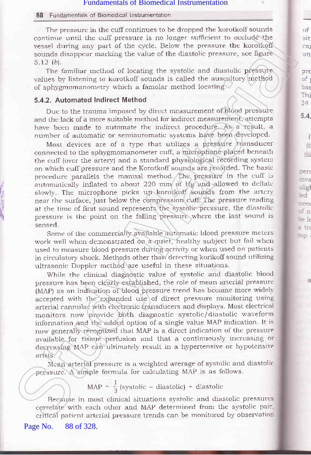
88 Fundamentals of Biomedical lnstrumentation
The pressure in the cuff continues to be dropped the korotkoff soundscontinue until the cuff pressure is no longer sufficient to occlude thevessel during any part of the cycle. Below the pressure the korotkoffsounds disappear marking the value of the diastolic pressure, see hgures.t2 (b\.
The familiar method of locating the systolic and diastolic pressurevalues by listening to korotkoff sounds is called the auscaltory methodof sphygmomanometry which a famolar method locating.
5.4.2. Automated Indirect Method
Due to the trauma imposed by direct measurement of blood pressureand the lack of a more suitable method for indirect measurement, attemptshave been made to automate the indirect procedure. As a result, anumber of automatic or semiautomatic systems have been developed.
Most devices are of a type that utilizes a pressure transducerconnected to the sphygmomanometer cuff, a microphone placed beneaththe cuff (over the artery) and a standard physiological recording systercon which cuff pressure and the Korotkoff sounds are recorded. The trasicproced.ure parallels the manual method. The pressure in the cuff isautomatically inflated to about 22a rnr..;l of Hg and allowed -to dellateslowly. The microphone picks up korotkoff sounds from the arterynear the surface, just below the compression cuff. The pressure readingat the time of first sound represents the systolic pressure, the diastolicpressure is the point on the falling pressure where the last sound issensed.
Some of the cornmercially available automatic blood pressure meterswork well when demonstrated on a quiet, healthy subject but fail whenused to measure blood pressure during activity or when used on patientsin circulatory shock. Methods other than detecting korikoff sound utilizingultrasonic Doppler method are useful in these situations.
While the clinical diagnostic value of systolic and diastolic bloodpressure has been clearly established, the role of mean arterial pressure(MAP) as an indication of blood pressure trend has become more widelr-accepted with the expanded use of direct pressure monitoring usingarterial cannulae with electronic transducers and displays. Most electricalmonitors now provide both diagnostic systolic/diastolic waveforminformation and the added option of a singie value MAP indication. It is
now generally recognized that MAP is a direct indication of the pressllreavailable for tissue perfusion and that a continuously increasing ordecreasing MAP can ultimately result in a hypertensive or hypotensivearls1s.
Mean arterial pressure is a weighted average of systolic and diastolicpressure. A simple formula for calculating MAP is as follows.
MAP = |{.r.,o,t" - cliastolic) + diastolic
Because in most clinical situations systolic and diastolic pressurescorrelate with each other and MAP determined from the systolic pair-critical patient arterial pressure trends can be monitored by observatior-
ofsitcatun
DTC
rfllasThi24
5.4.
,,|
t,I
I,t/$;
r!
Stud
y Mate
rial
Page No. 88 of 328.
Fundamentals of Biomedical Instrumentation

Cardiovascular Measurements 89
rf MAP limits. Adjustable alarm limits as required for a given clinical:ituation can then alert staff of possible patients problem. These units:an be used in operating rooms, recovery rooms and intensive care-rnits.
A system that can measure blood pressure automatically at pre-lrogrammed time on a continuous basis and during the normal activities'l patient. Such machine can measure blood pressure on a continuous:asis for 100 pre-programmed time alongwith a Holter electrocardiograph..:ris way the physician can get information of the patient health on a--1 hours basis.
5.4.3. Direct Measurement
The blood pressure is measured using one of the following methods:(i) Percutaneous insertionii) Catheterization:ii) Implantation of a transducer in a vessel or heart.
Figure 5.13, gives a general idea of both the methods. For a-.::cutaneous insertion a locai anesthetic is injected near the site of-','asion. The vessel is occluded and a hollow needle is inserted at a.ght angle toward the vessel. When the needle is in place a catheter isr through a guide. When the.catheter is in place in the vessel the-:dle and guide are with drawn. For some measurement a typical typereedle attached to an air tight tube is used, so that the needle can
'' .eft in the vessel and the blood pressure sensed directly to by attaching-:ansducer to a tube. Other types have the transducer built into the: of the catheter.
SuperiorVena Cava
light PulmonaryArtery
Right Otrium
Tricuspid Valve
Pulmonary Trunk
Boslic Vein
Fig. 5.13. Cardiac catheterizationThe tube is shown entering the basilic vein in this caseStud
y Mate
rial
Page No. 89 of 328.
Fundamentals of Biomedical Instrumentation

f:/
Tti,
i
90 Fundamentals of Biomedical lnstrumentation
Apart from obtaining blood pressures in the heart chambers andgreat vessels, catherizations technique is a1so used to obtain blood samplesfrom the heart for oxygen-content analysis and to detect the location ofabnormal blood flow pathways. Also catheters are used for investigationswith injection of radio opaque dyes for X-ray studies, coloured dyes forindicated dilution studies and of vasoactive drugs directly into the heartand certain vessels. A catheter is a long tube that is introduced intoheart or a major vessel by way of a superficial vein or artery.
A catheter technique of measurement of blood pressure is done inthe following ways. A sterile saline solution is introduced into a catheterso that the fluid pressure is transmitted to transducers outside thebody. A complete fluid pressure system is set up with provision forchecking against atmospheric pressure and for establishing a referencepoint. The frequency response of this system is a combination of thefrequency response of the transducer and fluid column in the catheter.In the second method the pressure measurements are obtained at thesource. Here the transducer is introduced. into the catheter and pust'edto the point at which the pressure is to be measured or the transduceris mounted at the tip of the catheter. This device is called a catheter Lip
blood pressure transducer. An unbounded strain gauge or a variableinductance transducer is used for mounting catheter tip blood pressuretransducer.
Major surgery is needed for implantation technique. Therefore, thistechnique are normally employed only in research experiments. Theyhave the advantage of keeping the transducer fixed in place in theappropriate vessel for long period.
5.4.4. Specific Direct Measurement Techniques
The four different categories of direct measurement of blood pressureare as follows:
(rJ A catheterization method involving the sensing of blood pressurethrough a liquid column. In this method the transducer is externalto the body and the blood presslrre is transmitted through a salinesolution column in catheter to the transducer. This method usesan unbounded strain gage to sense the pressure or a linear variabledifferential transformer.
(irj A catherterization method involving the placement of the transducerthrough a catheter at the actual site of measurements in thebloodstream, i.e., to the aorta or by rnounting the transducer onthe tip of catheter.
(iirJ Percutaneous methods in which the blood pressure is sensedin the vessel just under the skin by the use of a needle orcatheter.
(iu) Implantation technique in which the transducer is more permanentil-put in the blood vessel or at the heart by surgical methods.
1
1
(
1
\,
E
I\\kupptlol
tt
illblSC
slri:]ISt
udy M
ateria
l
Page No. 90 of 328.
Fundamentals of Biomedical Instrumentation

Cardiovascular Measurements 9:l
-..1 organs of the body require a71 acTecluate blooct sttpply' infact if the
.rod supply to a pariicular organ is not ad.equate then that particular
' g," ^ay not functiott ptop"t5'' The ability to measure blood flow in
:-.- \'essel that supplies Utood to a particular organ would' therefore' be
. great help in diagnosing such diseases' It is not very easy to measure
lod flow.Gasinapipeortherateofflowofaliquidisexpressedasthe
lume of the substance that passes through a pipe in a given unit of
.:^re. Flow rates are, therefore, usually expressed in liters per minute or'..[i.meter per minute (cm3/min).
Physically all the blood flow meters currentiy used in clinical and
.:earch aPPlications are as follow:
liJ Electromagnetic inductionirl Uitrasound transmission or reflection
iiz) Thermal convection.1,) Radiographic PrinciPleu) Indicator, i.e., dye or thermal dilutionMagneticandultrasonicblooclflowmetersmeasurethevelocityof
.. e blood stream. Therefore, these transducers are to be placed in exposed
.-rod vessel, these transducers are mainly used during.-surgery' Detection
,struction of blood vessels where quantitative blood flow measurement
,:e not required can be done by using ultrasounds'Segrrents, can be used to the measure of the flow of blood in the
...,bs-canbeindicatedbyaplethysmographwhichactuailyindicates,Iume changes in bodY.
5.5.1. Magnetic Blood Flow Meters
When an electric conduction is moved through a magnetic f,reld a
Jltage is induced in conductor proportional to the velocity of its motion'-." Ju.-" principal is applicable when the rnoving conductor is not a,,':re,butratheracolumnofconductivefluidthatflowsthroughatubecatedirrthemagneticfield.Figure5.l4showshowthisprincipleis
,.sed in magnetic btod flow meters. A permanent magnet or electromagnet
_ositioned around the blood vessel generates a magnetic field
_"i."ai."lar to the direction of the blood flow. The induced voltage in
.le'moving blood column is measured with stationary electrodes located
.r opposite sides of the blood vessel at proportional to the direction of
re rnagnetic field.The implantable magnetic blood flow probes are shown in
.3ure 5.15. The clip on tne C type is applied by squeezing an excised
:|oodvesseltogetherandslipprrrgitthroughtheslotoftheprobe.In=,:me transducer models the siot is then closed by inserting a keystone
.haped segment of plastic. contact is provicled by two slightly protruding,:iatinum disk thatiouch the wall of the blood vessel. The orihce of the
--robe must fit tightly around the vessel for proper operation'Stud
y Mate
rial
Page No. 91 of 328.
Fundamentals of Biomedical Instrumentation

92 Fundamentals of Biomedical lnstrumentation
,|/,,
Blood Flow
Fig. 5.14. Magnetic blood flow meter principle
Fig.5.15'samplesoflargeandsmallhumandiametersbloodflowprobe
catheter tip transd.ucer used the magnetic blood flow transdllcersprinciple. It is essentially turned 'inside out' with the electromagnet
temgiocated inside the catheter, which has the electrodes at the outside'
Catheter transducer can be calibrated in flow units'A magnetic blood flow transd'ucer is very small, output voltage of
typically in the order of microvolts. For recovering the signal in the
p.""".r." of the error voltage, amplifiers with large dynamic range and
pt r"" sensitive or gated ditectors have to be used' To minimize the
problem several different waveforms have been advocated for the magnet
current as shown in figure 5.16. With a sinusoidal magnet current, the
induced voltage is also sinusoidal but is 90" out of phase with the flow
signal. With ; suitable circuit, similar to a bridge the induced voltage
"""., u" partially balanced. out. with the magnetic current in the form of
" "qrr".L wave the induced voltage shall be zero once the spike from the
polarity reversal has passed. These spikes are often of extremely high
ampttlde and the cir-uitry response tends to extend their effect. As the
use of magnet current having a trapezoidal waveform. A dehnite superiority
is not achieved.
F
TJ
tlaflrofUI
5.5
_o
- -li
_ \)
:ST
':e-: lr" i:J
-'.aStud
y Mate
rial
Page No. 92 of 328.
Fundamentals of Biomedical Instrumentation
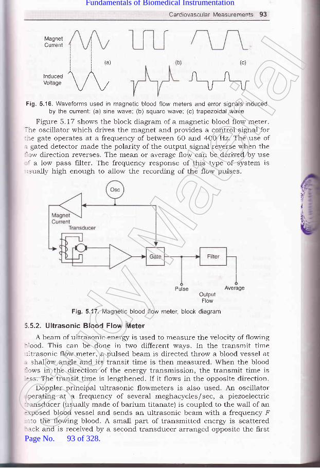
Cardiovascular Measurements 93
MagnetCurrent
ii(a))(c)/'^
\_tu_,Fi9.5.16. Waveforms used in magnetic blood flow meters and error signals induced
by the current: (a) sine wave; (b) square wave; (c) trapezoidal wave
Figure 5.17 shows the block diagram of a magnetic blood flow meter.. he oscillator which drives the magnet and provides a centrol signal for-re gate operates at a frequency of between 60 and 4OO Hz. The use of,.- gated detector made the polarity of the output signal reverse when the'.ow direction reverses. The mean or average flow can be derived by use: a low pass filter. The frequency response of this type of system is
-sually high enough to allow the recording of the flow pulses.
Pulse Averageo.'iI#'
Fig. 5.17. Magnetic blood flow meter, block diagram
5.5.2. Ultrasonic BIood FIow Meter
A beam of ultrasonic energr is used to measure the velocity of flowing-ood. This can be done in two different ways. In the transmit time:ltrasonic flow meter, a pulsed beam is directed throw a blood vessel at, shallow angle and its transit time is then measured. When the blood'.tws in the direction of the energz transmission, the transmit time is.ss. The transit time is lengthened. If it flows in the opposite direction.
Doppler principal ultrasonic flowmeters is also used. An oscillatorcerating at a frequency of several meghacycles/sec, a piezoelectric
-:alsducer (usually made of barium titanate) is coupled to the wall of an-rposed blood vessel and sends an ultrasonic beam with a frequency F.to the flo'wing blood. A small part of transmitted energr is scatteredack and is received by a second transducer arranged opposite the firstSt
udy M
ateria
l
Page No. 93 of 328.
Fundamentals of Biomedical Instrumentation

Cardiovascular Measurements 95
An electric heater is placed between two thermocouples or thermistorsin an another method that are located some distant apart along the axisof the vessel. The temperature difference between the upstream and thedownstream sensors is a measure of the blood velocity. If called athermostromuhr. Thermal convection methods for blood flowdetermination have ceased to exist.
5.5.4. Blood Flow Determination by Radiographic Method
By the injection of a contrast medium into blood vessel, i.e., arriodated organic compound the circulation pattern can be locally visiblervhich is not normally visible on an X-ray image because it has aboutthe same radio density as the surrounding tissue. On a sequential recordof the X-ray image, either photographic or on a videotape recording, theprogress of the constant medium can be followed, obstructions can bedetected and the blood flow in certain blood vessels can be estimated.Ihe techniqtle, known as cine'or video angiography can be used toassess the extent of damage after heart attack or a stroke.
The injection of a radioactive isotope into the blood circulation, whichallows the detection of vascular obstruction i.9., in the lung with an-mage device for nuclear radiation such as a scanner or gamma camera.
Measuring differences in the skin temperature caused by the reduced:irculation the vascular obstructions in the lower extremities cansometimes be directed.
5.5.5. Measurement by Indicator Dilution Methods
This method really measures the blood flow and not the blood'elocity. In principle any substance can be used as an indicator if it::rixes readily with blood and its concentration in the blood can be easilyletermined after mixing. The substance must be stable but should notre retained by the body and side effects must not exist.
Cardiogram an indocyanine dye, used in a isotonic solution was long:avoured as an indicator. Its concentration was determined by measuringhe light absorption with a densitometer (colorimeter). Radioactive isotopes,-.ave also been employed for the purpose. The indicator most::equently used today, however, is isotonic saline, which is injected.t a temperature below the body temperature. A sensitive thermistor-rermometer cietermines the concentration of the saline after mixingrith the blood.
Figure 5.19 is shown the principle of dilution method. The upper-:awing shows a model of a part of blood circulation under the (very
'-mplihed) assumption that the blood is not recirculated. The indicatorr injected into the flow continuously beginning at time t at a constant-fusion rate I grams per minute. A detection measures the concentration
:rwnstream from the injection point. Figure 5.18(a) shows the output of: recorder that is connected to the detector. At a certain time after the..lection, the indicator begin to appear, the concentration increases and-rally it reaches a constant value C, (milligrams per liter). From the-.easures concentration and the known injection rate, I in milligrams.:r minute the flow can be calculated as follows:
Stud
y Mate
rial
Page No. 94 of 328.
Fundamentals of Biomedical Instrumentation

96 Fundamentals of Biomedical lnstrumentation
,{4:
'llittl
F (liters per minute) =I (milligrams per minute)
C" (milligram per liter)
Fig. 5.19. Flow measurement by indication dilution methods, principle.The indicator is injected at time t = i
MEASUREMENT OF HEART SOUND
The heart sound listen by the physician by putting his ear near thechest of the patient. This is taken over by the stethoscope, which is adevice that carriers sound ener5/ from the chest of the patient to the earof the physician via a column of the air. There are many forms ofstethoscope but the familiar conhguration has two earpieced connectedto a common bell of chest piece. The system is strictly acoustical. Onlya small portion of energz of the heart is in audible frequency range.
A graphic record of heart sound is called phonocardiogram is verysuccessful. The instrument for producing this recording is called aphonocardiograph. A pressures, ECG transis and heart sound over timeare shown in figure 5.20.
The transducer used for the phonocardiogram is a microphone havingthe necessary frequency response generally ranging 5 Hz to above 1000Hz. An amplifier with similar response characteristics is required, whichmay offer a selective lowpass filter to allow the high-frequency cut-off tobe adjusted for noise and other considerations. In one instance when theassociated pen recorder is not inadequate to reproduce higher frequenciesan integrator is employed and an envelope of frequencies over 80 Hz isrecorded alongwith actual signal below 80 Hz.
Most pen recorders have a limitation of around 100-200 Hzphotographic or light galvanometric recorders are required for faithfulrecording of heart sounds. However, heart sounds fall well within thefrequency range of pen recorders, however, the high frequency murmersthat are often important in diagnosis require the greater response of thephotographic device.
Stud
y Mate
rial
Page No. 95 of 328.
Fundamentals of Biomedical Instrumentation

Cardiovascular Measurements 97
40o)-EE
of
frroo-t(oo-c
.9cEN
1206IE 100
trE.^qoEo60E(u0)
f,40.c.9)G
20
0
14Or
Maximumejection
Heartsounds
Diastole Systole
Time (s)
Diastole
Fig. 5.20. Pressures ECG trancings, and hear shown opver time
Multichannel physiological recording systems of the phonocardiogram:: one of the measurement is available. With a microphone amplifier::-d a pen recorder to record upto 2OO Hz of frequency.
, 150
4: rzo
E* sog5 60
5E 30
0
0802
Stud
y Mate
rial
Page No. 96 of 328.
Fundamentals of Biomedical Instrumentation

98 Fundamentals of Biomedical lnstrumentation
The high frequency, ri.e., murmers in the phonocardiogram indicatesa possible heart disease. A spectral analysis of heart sounds can providea useful diagnostic tool for diagnosis of normal and abnormal heart. Adigital computer'with a high speed analog to digital conversion capabilityand some form of Fourier transform software is required.
Phonocardiogram are designed to be placed on the chest over theheart using microphone. Heart sounds sometimes measured from otherpoints, for this purpose, special microphone transducers are placed atthe catheter to pick up heart sounds from within the heart chambers orfrom the major blood vessels, near the heart. Frequency responserequirement of these microphones are abor.rt the same as forphonocardiogra ph microphones.
The apex cardiograph and the vibrocardiograph which measure thevibrocardiogram and apex cardiogram respectively also use microphonesas transducers. But, these measurements involve the low frecluencyvibrations of the heart against the chest wall, hence, the measurementis normally one cf the displacement of force rather than sound. Thus themicrophones used must be a good transdr,rcer of force with suitable lowfrequency coupling from the chest wall to the microphone transducer.For the apex cardiogram, the microphone must be coupled to a pointbetween the ribs. Good result for this purpose can be achieved.
Using the apex cardiogram and the vibrocardiogram do not conlainthe high frequency components of the heart sounds, these signals canbe handled by the same type of amplifiers and recorders as theelectrocardiogram. Often these signals are recorded alongwith channel ofECG data to maintain time reference. In this case one channel of amultichannel trCG recorder.
The Korokoff sounds can be recorded used from a partiallv occludedarlery.a microphone is usually placed beneath occueing cuff or over theartery immediately downstream from the cuff. The waveform and frequencycontent of these sound are not as important as the simple identificationof their pressure, so these sounds generally do not require high frequencyresponse specified for the phonocardiogram. Automated indirect-measurement of blood pressure circuitry for these is same.
The measurement of blood flow is the measurement of volume changesin any part of the body which result from the pulsations of blood occurringwith each heartbeat. These measurements are useful in the diagnosis ofarterial obstructions as well as pulse-wave velocity measurements.Instruments measuring volume changes or providing outputs that canbe related to them are called plethysrnographs, and the measurement ofthese volume changes or phenomena related thereto is calledplethysmography. It responds to changes in volume.
It consists of a rigid chamber placed over the limb in which thevolume changes are to be measured as shown in hgure 5.21. The chamberis tightly sealed to the member to be measured so that any changes ofvolume in the limb reflect as pressure changes inside the chamber. Fluidor air can be used to filI the chamber.
clctchprCU
abvew1
be
slolACC
dur
(
(
(
(
(
PLETHYSMOGRAPHY
Stud
y Mate
rial
Page No. 97 of 328.
Fundamentals of Biomedical Instrumentation

Cardiovascular Measurements gg
ToRecorder
Airtight Seat
Fig. 5.21. plethysmograph
re or constant volume within thet thethe
pressure is calibrated by use of a cali linecuff which is ptacea sngttty ,p"tr"ril' ; ,11:above venous pressure, arterial blood , ,fr"*'enous brood cannot leave. As a result the rimb i.r"...s.s its vorume*'ith each heartbeat by the volume of the blood ..rt..irg during thatbeat' The output trace of measurement is shown in figure 5.22.
thetheoff
SUMMARY
Biomedical instrumentation speciarly for cardiovascurar system, herpeda lot in reducing untimely death iue to heart failures.
organs of the body by left ventricle.clearly seen in figures 5.1 and 5.2.contraction of the heart muscles.)rgans then the blood pressure is crf dilation of the heart cavities as
Stud
y Mate
rial
Page No. 98 of 328.
Fundamentals of Biomedical Instrumentation

,t,
r,{lt;
drfrt(\
100 Fundamentals of Biomedical lnstrumentation
Some important average value of blood pressure which in written as
systolic/iistolic is t2Ol80 mm of Hg. Normalty 5 litres out of total
6 lit.." of blood in an adult is circulated per minute. During exercise
the circulation rate increases. At any give to me about 75-8O%o of the
b100d volume is in the veins about200k of the blood is in arteries and
remaining in caPalaries.3. Electrocardiography: The electrocarcliography is used clinically in
diagnosing,..io,"diseasesandconditionsassociatedwiththeheart.tn"trregraphicalrepresentationofECGthePwaverepresentsdepolarizati.on of the artrial musculature' The QRS complex is the
combinedresultoftherepolarizationoftheateriaandtherepolarization of the ventricles which occur almost simultaneously'
The T wave is the wave of ventricular repolarization. In diagnosis of
heart the heart rate should be in the range of 60-100 beats per
minute, the heart rate slower than this is called bradycardia and
higher rate as tachycardia. Physician then see if the cycles are evenly
sp"aced. If the cycles are not evenly spaced then the condition is
called arr -
then O'2 sec' it can suggest
blockade idual ECG remains fairlY'
constant instrument used to obtain
electrocardiogram is called an electrocardiograph'In biomedical electronics we have to measure bio-electric potentials'
For this purpose normal ampliher where the reference is throughground of tn" power supply ari not suitable. In this case a differential
Implifier witkr a frigh input gain and high common mode rejection
ratio of the order of 1O,OO,00O : 1 are used'
To record an ECG a number of electrodes usually five are applied to
thesurfaceofthebody'Theelectrodesappliedtothebodyarenamed as RA, LA, RL, Ll and c. The wires which comes from the
electrodes to the ECG machines are called leads. The four electrodes
except electrode RL (right leg) which is ground are used for the
.".oidi.rg of electrocr.riiog."-. The other system introduced by
Einthroven may be seen in frgure 5'6' The arrangement of leads are
suchthatinatlthepositionstheRwaveofQRSispositive.In the ECG recorder the leads from the patient are connected to the
ECG recorder through a selector switch. A standardization voltage of
1 mV is used for calibration of the recorder. The recording paper
used is a heat sensitive paper where the stylus is electrically heated
For recording.Normally, electro cardiograms are25 mm/sec but faster sPeed of 50
higher speed of 50 mm/sec allowscomplex at very high heart rates'
recorded at a PaPer sPeed ofmm/sec is also available. Thebetter resolution of the QRS
The following types are ECG recorders are available:
(a) Single channel ECG recorder.(b) Three channel ECG recorder(c) Vector electrocardiograPhY(d) Electrocard.iography systems for stress testing'
(e) Continuous ECG recording (Holter Rct'r'rding)'
I
6. 1
I
.T
ir
tLf(is
C
TTtlaIN
MS(
htStud
y Mate
rial
Page No. 99 of 328.
Fundamentals of Biomedical Instrumentation
Cardiovascular Measurements 101
LT":ll,:"",.i#l:"1,^.:s are^used to- determine severat defects anddamages is human toay. ecC-"".i'I,*"'ru,ne several defects andenlargement. ,tJ,,,^h+ri^^r^- :tect hypertrophy and arterial:;ilT""f, :l..ll?":..1j::d;il;il'Jff :::"?lli:X;i::l#:HH1Tl;"*#Ii:,gH1;;+:;;.:"Til,1X8::i,H":'#:::1##,:orheart""a-pCil;T&;,,,ffi :J,j3l,i:,."?,,,applications.
+. Blood pressure M t:indication of sever dipatient from severe nmeasured by means ofsphygmomanometer. There armeasurement one is indirect andof blood pressure.
r In the indirect method the measurwhich consists of a cuff *friJ
d Cardiac. Output: The normally(zJ Erectromagnetic induction
the following types:
(izJ Ultrasound transmission or reflection.(ilzJ Thermal convection(iu) Radiographic principle
meter are normally usedare normally used during
clinical
by surgicalsurgery for
(u) Indicator dilutionThe magnetic blood flow-nplantation. These types:esearch purpose.'-ltrasonic brood flow meter in the transmit/receive mode are used:or the measurement-of blood no* *i".rrement. The other method:s to use ultrasonic flowmeters b";;rthermethodsarebloodfl o*_.r"r;";'.:,?:r,Ij1;:#;r":,;"ection.lhe o.ther important method i" ,raio."tive isotope.lhe blood flow mee':ermporta,,t-.tiJ"l:.t+:"",:::"Hf:T#":f$ffI,,::;,f
= rsotonic sorution was used as an in"drctor. The principal of dilution--.ethod may be seen at figure S.19.lleasurement of Hgart sound: The normal measurement of heart'' und are made with the help of .-","irro""ope. The problems in the-:art sound are measurea with th" h;ip of a phonocardiogram. This
Stud
y Mate
rial
Page No. 100 of 328.
Fundamentals of Biomedical Instrumentation

102 Fundamentals of Biomedical lnstrumentation
uses a microphone having a frequency response between 5 Hz to1OOO Hz. An ampliher with similar freq. response is required. A
photographic or light galvanometer recorder are required for recording
of heart sound.The high frequency sound from heart is known as murmurs indicate, po""ibl" heart disease. For this reason a spectral analysis of heart
sound.s can provide a useful diagnostic tool for diagnosis of normaland abnormal heart.
g. Plethysmography: Plethysmography is used for the measurement of
volume changes in any part of the body that result from the pulsations
of blood occurring with each heart beat, Such measurements are
useful in the diagnosis of arterial obstructions as well as pulse wave
velocity measurement.The plethysmograph consists of a rigid chamber placed over the limbin which the volume changes are to be measured'
txerciae,t
5.1. wirat is electrocardiography? Discuss various characteristic featr-lres of
trCG amplifiers. (UPTU 20031
S 2. Discuss about the electrodes and leads that are fixed to the body of the
patient in order to record an electrocardiogram' (UPTU' 2OO3t
5.3. i)iscr-t: ' 1-wo commonly used ECG recorders briefly' (UPTU' 2OO3'
5.4. I{rrrr. :an electrocardiography be used for stress testing? (UPTU' 2003
5.5. Djo^,.rss an automated indirect method of blood pressure measurement'(UPTU, 200s
5.6. Explain the ultra-sonic method of blooci flow measurement.(UPTU, 2003
5.7. Explain the trCG recorders, (r) three channel, (ir') vector cardiograph'(UPTU, 200/
5.g. Explain briefly the ECG system used for stress testing. (UPTU' 2004
5.9. trxplain a method of heart sound measurement' (UPTU' 2O0t
5.10. Explain main parts of electrocarcliogram. How can you determine the
heart rate? PPTU, MQP '5.1 1. Discuss measurement of blood pressure and possible error due to traumz
or other physiological effect on patient. (UPTU' MQP '5.72. Describe the three methods used to measure the blood pressure.
(UPTU, MQP :5.13. What is the importance of blood flow? Discuss the biomedical instrumen:s
that are used to measure the blood flow' (UPTU' MQP )t5.14. Draw an electrocardiogram (in lead II), labelling the critical features'"
include typical amplitudes and time interval for a nominal person. Expl
the most important part of ECG for determining heart rate'(UPTU, MQP
5.15. Explain the clinical application of a multichannel trCG' (UPTU' 20C
E
,ij|
l:,r$
Jril
[n
\(
(
(
e
c
6
6
6
I
.1e-j lulfse
I_ tcu:- a]
- r:e(T
: -)fr. -..clt
:S€
Stud
y Mate
rial
Page No. 101 of 328.
Fundamentals of Biomedical Instrumentation

Patient Care and Monitoring
.-. fnside this ehapter
6"1. Elements of Intensive-Care Monitoring6.2. Patient \4onitoring Disp1a1,s
6.3. Diagnosis, Calibration and Repairabilir! of Patient-Monitoring Euipment6.4. Other Ins[rr,rmentation for Monitor:ing Patients6.5. Organization of the Hospital for Prrtient-Care Monitoring6.6. Pacemakers6.7. Defibrillators6.8. Summary
Patient monitoring is very familiar part of biomedical instrumentation.ne continuous watch over the patient is possible because of electronic-:uipments" Careful and accurate monitorin,g of the patient in intensive-.se units is feasible due to these electronir: medical instrumentation.
If a heart attack or stroke occurs, serious imbalance in the body-curs, hence, need of patient's monitoring. It may be surgical operation,: all cases continual monitoring of the patient, the problems can be.':iected and remedial action taken.
The biomedical engineer is responsible for not only designingrropriate and safe equipments, but gets tht:se manufactured in quality
- rde. Subsequently, he trains usage, oper-'ation and maintenance of:se biomerlical monitoring equipments.
ELEMENTS OF !NTENSIVE-CARE MOhIITORING
-.: 24-hour nursing for critically illihe essential needs and naturally
103
patien L in the hospitals are somethis c eills for intensive-care andSt
udy M
ateria
l
Page No. 102 of 328.
Fundamentals of Biomedical Instrumentation

104 Fundamentals of Biomedical lnstrumentation
patient monitoring. The technologr advancement have lead to equipmentdesign and manufacturing which are reliable and accurate for extensivecare monitoring of the patient. The nurses have at their disposal powerfultools for acquiring and assimilating infbrmation about the patient. Thisleads to rendering better service to a large number of patients, able toreact promptly and properly to an emergency situation. Such a capabilityprovides an immediate alarm in the event of certain abnormalities. Themonitoring equipment makes it possible to call a physician or nurse intime to administer emergency aid before permanent damage can occur.The availability of electrocardiograrn record just prior to, during, afterthe onset of cardiac difficulty, the prompt monitoring and warning systemenables the physician to give the patient the correct drug rapidly. Inmany cases, their process can b,e automated. There are differences ofopinions about the physiologica.l parameters to be measured amongphysicians. The monitoring of s,everal parameters are very expensive,therefore, it is necessary to choose only essential parameters. However,continuous monitoring of heart tJerough electrocardiogram is quite normalin any intensive care unit. Temperature measurement is quite frequent.There are several parameters sr,rch as blood pressure may be measurednot so frequently. However, if ccrntinuous measurement of blood pressureis the need, it requires catheterization of the patient which requiresexperience of catheterization, arrd also in many cases may affect conditionof the patient. This is also painful to the patient.
The development of electrir: equipments which are capable of reliablemeasurement and display, c:oncept of intensive care-monitoring hasbecome feasible. These unitsr are installed along 'the bed side of thepatient. The facilities inch.rde electrocardiogram, heart rate andinformations from bedside in. all other monitored parameters.
The basic elements of in1:ensive care monitoring unit are:(r) Skin electrodes to pick'up ECG potentials.
(iz) Amplification unit for r:lectrocardiograph.(rfl CRT display for observation of ECG waveforms. The central nurses
station normally can lhave CRT display of several patients on thesame screen.
(lu) A rate meter to indicate heart beat, it can have continuous indicatior:with audible beep or flashing light at each heart beat.
(u) An alarm system is actuated by the rate meter to alert the nurse.(rri) A direct wired-up derrice for electrocardiograph.(uil A memory tape to rer:ord the playback of ECG for 15 to 6O sec.
(uiiz) Additional alarm syst,ern triggered by ECG parameters.(rx) Electrical circuit to indircate that electrode connections have become
disconnected which rrLe5r be due to mechanical failure.(x) A closed circuit monit oring system is also employed to provicie
visual coverage using cameras focused on each patient. Noise alimovement of artifacts may give false alarms sometimes. Specia-measures such as elecl-rode placement patterns can be looked inl:to improve. There is n o standard pattern existing.
E
V
o
JD
-.1 c: ata!::ltr
i; =:tl
;::arl
Stud
y Mate
rial
Page No. 103 of 328.
Fundamentals of Biomedical Instrumentation

Patient Care and Monitoring 105
Patient-monitoring equipments is generally specihed as a system.Sach manufacturer and each hospital staff has its own ideas. A wicle
"'ariety of configurations can be seen in the hospitals. Figure 6.1 shows
rne of the patient care monitoring system block diagram.
MeasuringDevices and its
Analog lntefaceDisplay
AnalogMultiplexeis
Processlnterrupts
VideoProcessor
fuDConverter
I-other -_lI ortprt
I
High pertormanceCPU
SeriallntedaceRAM
RCM Printer
DataStorage
Keyboard
FiE. 6.1. Patient care monitoring system block Diagram
The communiction channel from the central station to each bedside:idirectional so that data and control signals can flow freely in each
: ::ction between micro computers. The patient care stations accept: .-a in general upto eight patients. It may provide single or dual channel
.:-chart recordings.
rll pnleNT MoNrroRlNG DrspLAysi:.-,hful reproduction of ECG, arterial blood pressure and other valuable: :--imeters are essential. The CRT displays are of three types:
' Conventional display: This is conventional CRT with horizontalsweep driven by a slow-speed sweep generator which causes theelectron beam to move from left to right at an predetermined ratesay 25 to 50 mm/sec.
' Bouncing ball display: This is also CRT arrangement wher.einsweep rate is very high such that display appears to be continuousdisplay. Each spot of light seems to be bouncing up, hence, bouncingball display name.' Nonfade display: It also uses CRT display, but the electron beamrapidly scans the entire screen of the CRT in a television like rastercattern. The beam is brightened only when a brightening signal isapplied to CRT by X-axis modulation. This gives trace pattern, i.e.
Analog O/PDisplay Digital
Alarm etc.
{I
i
Stud
y Mate
rial
Page No. 104 of 328.
Fundamentals of Biomedical Instrumentation
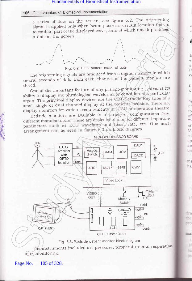
1OO Fundamentals of Biomedical lnstrumentation
a series of dots on the screen, see figure 6.2. Tl'je brightening
signal is applied only rvhen beam passes a certain location that is
tJcorrtain part of the displayed wave, form at which time it produces
a dot on the screen.t
Ee(
ar
It
ttth
t
6
,ltl/l ,'a
a-,'----r' tt.-
I
---/ \'Fig. 6.2. ECG Pattern made of dots
The brightening signals are produced from a digital memory in which
several seclonds ol da-ta from each channel of the patient monitor are
stored.oneoftheimportantfeatureofanypatient-monitoringsystemisits
ability to display the physiological waveforms or condition of a particular
orgat. The principat display devices are thsmall single or dual channel display at thdisplay monitors for various requirements
Biside monitors are available in a variety of conhgurations tror"
d ure gned to monitor different importanr
p as and heart rate' etc' One s"rch
; be 5'3 as block diagram'
hrariocfT}rf\11
:alpnnlr(
::.e.--a_
sh it
,(t'.
t,,
.-{,,,c: I
qnMICBOPROCESSOR BOARD
MtrE--EEEE
F*"t"s'f
E.C.G.Amplifier
withOPTO
lsolation
e,
rate
lkMemory L
rm
Hold
ilE-t1 031
Cr-rcL.o.T.l br
C R.TUBE contr
C R.T. Raster Board
Fig. 6.3. Bedside patient monitor block diagram
The instruments included are pressure, temperature and respiration
rate monitoring.Stud
y Mate
rial
Page No. 105 of 328.
Fundamentals of Biomedical Instrumentation

Patient Care and Monitoring 107
Various signal conditioner units are available in modular constructionand slide into to integrate with the main instru-mentation system as perrequirements.
6.3. DIAGNOSIS, CALIBRATION AND REPAIRABILITY OF PATIENT.MONITORING EQUIPMENT
:ngineers and technicians need to diagnose the problems of monitoring:luipments. It is essential that equipments are operational and calibrated.:curatel5r. Many electronic units are available for calibration purposes.
can have built in calibration leature, i.e., ECG may have 1 mV-.libration voltage avnilability.
Ntlany medium units have built in diagnostic feature to trouble shoot:-e equipmenr malfunctions. Generally these are manufactured such.^at ease of replacement or repair or both exist.
The spread of medical instruments with high degree of complexity..s created a great demand for effective and efficient trouble shooting:--d maintenance. The effective methods of maintenance have been evolved
meet the challenge of complexity. Depending on the conceived scope'lhe maintenance function, needs very because of the technical realities.-.ere are several major activities involved in the process of installationa large expensive biomedical instrumentation such as X-ray, CT scan,
lRI, etc. The installation and cummissining must be well planned with.:h detail. Plan some trials, just after installation. Select and train::rators of the equipments and setups. some basic trouble shooting-,C maintenance training is essential to avoid costly long time-.akdowns.
The manuals must be obtained for installation, operation, and-:rntenance, Critical spares may be procured if backup by supplier is,:d to get Potential maintenance points:
il Environment conditions of the instrumentation would generarly begood, however, temperature, dust, humidity should be in tolerancelimit.
:N No heavy machinery should be around like presses, compressorsand such other machines which generate and transmit vibrations.
-rJ It should not be connected to the same electrical line v,,hich suppliespower to machines drawing heavy intermittent currents.
rhe electrical power supply should be stable, balanced, and preferabryr -.r'r\-nS from the connected secondary of the transformer. To minimize--. effects of electrical noise a separate electrical grounding should be- -. ided for each instrumentation system.
The basic electrical equipments required for installation and-aintenaflce are:
:r Multimeter:rl Oscilloscope:t Temperature controlled soldering equipments, t Extender cards and sparesSt
udy M
ateria
l
Page No. 106 of 328.
Fundamentals of Biomedical Instrumentation

108 Fundamentals of Biomedical lnstrumentation
(u) Digital multimeter and ammeter(uz) Logic probes
Miniaturization of electronic components has reduced the bulk ofelectronic hardware components of the system, thus improving the overallreliability. Modular concept in the system design has further strengthenedthe hands of maintenance engineer
The number of printed circuit board modules have reducedconsiderably due the use of microprocessors as the main processing unitof the instrumentation, and as such better reliability.
Potential maintenance points are continuously monitored andidentified by code numbers. The response of the system to a fault isgoverned by the degree of seriousness. It may be warning or faultindication and or subsequent automatic shutdown.
Real time diagnostic are active during system usage: Though realtime diagnostic gives an indication of the problem, special skill is stillrequired to prqbe further and findout the ultimate caurse.
There are some offline diagnostics which guide the maintenanceengineer through a step-by-step process analysis of the instrumentationsystem. The off-line diagnostic which can be used to call one programmeat a time, like:
- CPU diagnostics
- Memory diagnostics
- CRT diagnostics
- D/A and A/D diagnostics
- I/O diagnosticsRemote diagnostics involve the use of the phone data. A link is
established between the computer in the instrumentation system and tothe main-computer in the hospital. It performs both static and dynamictests. This is an effective tool for solving even intermittent problems.This is used in preventive maintenance also.
Vibration and Oxidation: The biomedical instrumentation suffer whensubjected to excessive vibration:
(zJ Friction connections (circuit board socket or piug socket) can movefrom areas of low resistance (good connectior-rs) to oxidized highresistance (bad connections).
(rzJ Circuit boards can gradually vibrate out of their sockets.(iir') Lead connections can be sheared.
The remedy against vibration is to place vibration-absorbing mountingpads under the sy5fsm control panel or to use rubber-center vibrationisolating bolt mounts.
Oxidized friction contacts may result from simple aging as well asvibration-induced movement. A contact cleaner and deoxidation treatmenthelps. Erasers should not be used to clean connector pins because thel-are likely to abrade away the thin silver or gold plating, thus, ruiningthe conductive surface.
Power-supply conditioning: The most effective action to ensureinstrumentation system reliability is to protect them with new generatior-
S
nti:n1
dr
Str
recirtriCO
orarl
.ai"
lrlr
fr
,il
(i
64
-re:ht
64..
:-ar
I
::lv:,]II
it lJ'_::u
$ 1.2
It; 'r-tTl;F:: D
V .',-e1
' . :::1
f43,
I - : t''Stud
y Mate
rial
Page No. 107 of 328.
Fundamentals of Biomedical Instrumentation

109 FunCamentals of Biomedical lnstrumentation
solid-state transient suppressors. Without such suppressors, transientroise or voltage spikes can enter a system via power supply or signal,:nes and cause both disruption and destruction. Good suppressionretwork, responding 1O to 1OO times faster to transients than older typelevices, are now available.
Even if power supplied to the hospital is relatively clean, voltagercikes and other transients are generated within the hospital itself as a:esult of operating motors; fluorescent lights, solenoids, SCRs, switching:rcuits, etc. As these are switched on and off, surges or spikes are
-:ansmitted to power or signal lines. If these transients get into-:mputerized equipment, they may be misinterpreted as digital commands: other information, therefore, must be avoided. The various devices
: :e:
ll Inductiue-capacitiue filters: Reduction of radio frequency noise of aknown bandwidth but do not clamp fast transients.
iirl Resis/once-capacitance filters: Medium speed and capability, butlike inductive capacitive filters, don't clamp fast transients.
iil Metal-oxide Vaistor (MOV): Suppressor have semifast responsecapability.
iu) Isolation transformer: The main equipments are given supply throughisolation transformer which separates circuits.
44. OTHER INSTRUMENTATION FOR MONITORING PATIENTS
--ere are several other special medical instrumentation in use which are' -rer than bedside of the patient. The important ones are:
E 4.1. Surgical Monitoring System
There are large multichannel oscilloscopes with an EEG record on,art also.
Such equipments have plug-in signal conditioning modules that:-.r'ide versatility and choice of measurement of parameters. These: :nedical signal conditioner units include an universal unit for bioelectric.
=als, an ECG unit, an EEG unit, a biotachometer, a transducer unit,: - integrator, differentiator, and an impedance unit. All these units are
=patible.t rt.2. Arterial Diagnostic Unit (ADU)
It provides automated pressure-cuff inflation for rapidly determiningl,-=:nental pressures and post-exercise pressure trends in non-invasive:*:--pheral arterial evaluations. The strip chart is used for recordingi :pler-flow pulse waveforms, ECG traces and other physiologicalr =','eforms. It has a heated stylus strip-chart recorder, a bidirectional,, :cler-flow meter with external loudspeaker and head phones, an ECG"' :netry transmitter, a non-fade two channel oscilloscope.
fi.r.3. Catheterization Lab
-t is a lab where cardiologists perform diagnostic catheterization. Fori :atient having blockage in one of the coronary arteries, must beSt
udy M
ateria
l
Page No. 108 of 328.
Fundamentals of Biomedical Instrumentation

110 Fundamentals of Biomedical lnstrumentation
brought into the cath lab. Catheterizationinto ihe heart and through this catheterthe cardiac chamber.
catlteterizationisadangerousprocedure,therefore,patientmustbemonitored continuously. Geieralty these are computerized units capable
ofmonitoringallthevariablesusuallynecessaryinthecathlab.Itincludes cardiovascular pressures, cardiac output' and ECG' Multiple
channel of analog data can be recorded on continuous strip charts, ar-rd
computer generated rePorts can*"r"fot-". Calculated resuits, d
practical representation of heartLt..
"u.., be incorPorated in the
patient's name, physiological data-
bCG *u.r.forms are also disPlaYed
or call any data on screen for instant display'
techniques introduce a catheterto inject a radioPaque dYe into
6.5. oRGANIZATIoNoFTHEHoSPITALFoRPATIENT.CAREMONITORING
PAGEMAKERS
Therhythmicactionoftheheartisduetoregularrecurringactlc:potentials originating at natural card.iac pacemaker located at the sinitorj
(
1
I
t(
t(
The technical personnel must be farniliar with the hospital organtzation
suchaswhichdiagnosticequipmentsareavailableinwhatpartoftherr""pit"r. Generally-equipmenti are divided, on the following lines:
(if Surgical equiPmentsThese are placed in the operating room 'uvhere surgery is actually
performed.
(ii) Non-surgical equiPments
The monitoring equipments made available in operation room are
heart d' arterial blood pressures' ECG' EEG' various
respir ' It may also have emergency equipments like
dehbr ers, stimulation equipments' etc'
The in ich is generally post surgical follow-
upcontaiS,nurse,scentralcontrolunitstomonitor p uslY'
Heart-attack patients are placed in coronary care-unit (CCU) and
sometimes called cardiac carelunit (CCU). The monitoring units ma]'
havebloodpressure,heartrateandECGmeasurementequipments.After some recovery CCU patient may mo ediate coronarl'-
c..e unlt (ICCU). This unit may have like telemetq''
equipments to monitor patients from ambul atient has hear:
attackathome,mobileemergencycareunitCoruesintoservice.Thesemay have cardi y resuscitation technique experts rn'ith
equipments and similar to the ones used in the intensive
care units of theStud
y Mate
rial
Page No. 109 of 328.
Fundamentals of Biomedical Instrumentation
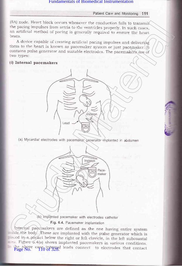
Patient Care and Monitoring 11'l
(SA) node. Heart block occurs whenever the conduction fails to transmitthe pacing impulses from artria to the ventricles properly. In such cases,an artifrcial method of pacing is generally required to ensure the heartbeats.
A device capable of creating artificiar pacing impulses and deliveringthem to the heart is known as pacemaker system or just pacemaker. Iicontains pulse generator and suitable electrodes. The pacemakers are oftwo types;
(if Internal pacemakers
(a) Mycardial generator implanted in abdomen
(b) lmplanted pacemaker with electrodes catheterFig. 6.4. Pacemaker lmplantation
Internal pacemakers as the one=:de the body. These ar with the pul.-:ed in a pocket below left clavicle,-':-r FigLrre 6.a@) shows implanted pacemakers in various conditions.:he above case internal leads connect to electrodes that contact
--t
\_,,
Stud
y Mate
rial
Page No. 110 of 328.
Fundamentals of Biomedical Instrumentation

112 Fundamentals of Biomedical lnstrumentation
inside of the right ventricle or the surface of the myocardium. Animplanted standby pacemaker with catheter electrodes inserted throughthe right cephalic vein are shown in the figure 6.4(b). The frgure 6.5shows pacing electrodes attached to the Myocardium.
(ii) External pacemakersThese are used on patients with temporary heart irregularities. This
may be due to coronary patient and heart blocks. This may also be usedin post operative periods after cardiac surgery. External pacemakersinclude pulse generators located outside body which are normallyconnected through the wires introduced into right ventricle via a cardiaccatheter. The portable pulse generator is hangs on the body fixed withsome straps.
The pacing technr'ques employed are as follows:
Pacing Modes
Competitive
Ventricular programmedfor use in demand or
stand by mode
Arterial programmed
aS
A,
p(hrvethAC
sy1S
CO
twAS
velnofib:atrthelrrffibrrntmol
havappsuffStlIT
:hesubr
=ho<::le ,
:-n e
-r tl:ntii:ehb-=ad:nC
h::teI,rnn
t cal----:ou
': SS I
6
0.
,.t
F
{fi
Demand Stand byB-waveinhibited R-wave
triggered
The block diagram of various functions of
Asynchronousfixed rate for
elderly people
the units are as follows:
SynchronizedP-wave of ECG
Implanted units have lithium-iodine battery which last for 5 years.The sources of electromagnetic ener$/ such as microwave ovens a_ffect
implanted or external pacemakers, i.e., patients are advised to keepaway from sources of electrical interference such as microwave ovens.St
udy M
ateria
l
Page No. 111 of 328.
Fundamentals of Biomedical Instrumentation

Patient Care and Monitoring 113
A pacemaker is shown figureadjustment control. Some of theshown in figure 6.7.
6.6. This is external pace-tnaker showingpacemakers available in the market are
.\ction of the heart muscle fibers if precisely synchronized leads to propercerformance of heart in its pumping function. The two chambers of thereart contract together and pump blood through the two atrioventricular,.-alues into the ventricles due to rapid spread of action potentials over:he surface of the atria. The ventricular muscles are synchronouslyactivated to pump blood through the pulmonary and systemic circulatorys\.stems. The condition under which the necessary synchronism is lost-s known as fibrillation. During this period, the normal rhythmic:ontractions of either the atria or the ventricles become rapid irregular:*,itching of the muscular wall. Fibrillation of artrial muscles is known.s arterial frbrillation, whereas fibrillation of the ventricles is called',.entricular fibrillation. Atrial hbrillation leads to irregular rhythm and:on-synchronized bombardment of electrical stimulation from the:-crillating atria. Most the blood flow into the ventricles occurs before.:rial contraction, therefore, blood for the ventricles to pump is still.rere. The sensation generated by the fibrillating atria and subsequent-egular ventricular action is quite painful for the patent. Ventricular' orillation leads to ventricles inability to pump blood and if not corrected:- time can cause death within few minutes. Such patients need careful:-onitoring of cardiac.
Heart massage (a mechanical method) for defibrillation of patients-:r,e been quite common. However, most successful method is the.:plication of an electric shock to the area of'the heart. In this casei:tficient current is applied for a brief period and then released. Itr:::nulates all musculature of the heart simultaneously which makes all':-e heart muscles fibers to enter refractory periods together and
-: csequently normal heart action may start. The duration of the electricali-.rrck is 0.25 sec to 1 sec at 50 Hz ac at an intensity of about 5 A to-: chest of the patient through appropriate electrodes. This method of, - electrical shock to resynchronize the heart is also called countershock.-. :he event of patient not responding, the electrical shock is repeated- .ril defibrillation starts. This method of defibrillation is called ac:':-:brillation. Attempts to correct artrial hbrillation by ac method may-'d to more serious ventricular flbrillation and, therefore, ac dehbrillation, 10 more used.
ln 1962,Bernzard Lown of the Harward School of Public Health and:- :r Bent Brigham Hospital developed dc defibrillation which has become
=mon these days. A dc defibriliator circuit is shown in figure 6.9.. :apacitor is charged to a high dc voltage which is rapidly discharged-:rugh electrodes across chest of the patient. The dc method requires
'-, s repetitions and is less harmful to the patient.
DEFIBRILLATORS
Stud
y Mate
rial
Page No. 112 of 328.
Fundamentals of Biomedical Instrumentation

'114 Fundamentals of Biomedical lnstrumentation
rll,
It1!
h
Fig. 6.5. Circuit of dc defibriilator
The electrical eners/ discharged by the capacitor may vary between100 to 400 W-sec or ioules anci duration of the effective period ofdischarge may be about 5 m sec. The energz delivered is as shown infigure 6.6. The plot of current Vs time has peak value of current of20 A. The wave is essentially monophasic as most of its excursion isabove baseline.
The peak voltages may be as high as 6000 V which endanger themyocardium and the chest walls. This risk can be reduced by increasingwaveform duration to 10 m sec with dual peak'ulraveform as shown infigure 6.7.
Fig. 6.6. Discharge waveform of dc defibrillator
Time (milliseconds)
Fig. 6.7. Dual peak dc defibrillator discharge waveform
Effective defrbrillation in adults can be achieved in lower energ,-levels 50 W sec to 2OO W sec. The voltage can be further lowered b1-
truncated waveform as shown in figure 6.8.
vardisrkncdiar-{ p,jellyand
swit
--oul:efo:iscl-npl,:efib4.10u
t=:rh]--- su::cm:ust:::SUl- -- \rel
..1:S tr
Pr:-schr:-::plil:,. Che
_-. _tmr:=:lbri
Fis-r , crd..:
_ :laf.-: VOI
Thr:'. Q lr
206q)
g_ 16E(E
=12CI38q):o- 4o_-
o 1200o3 goo0)o)E 600oD 300.ooo-
Charge..-St
udy M
ateria
l
Page No. 113 of 328.
Fundamentals of Biomedical Instrumentation
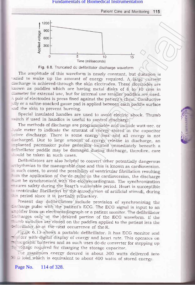
Patient Care and Monitoring 115
1200
900
600
300
0 5 10 15Time (milliseconds)
Fig. 6.8. Truncated dc defibrillator discharge waveform
The amplitude of this waveform is nearly constant, but duration is'aried to make up the amount of energz required. A large current:ischarge is achieved-through the skin electrodes. These electrod.es are':nown as paddles which are having metal disks of 8 to 10 cms in-:ameter for external use, but for internal use smaller paddles are used.-. pair of electrodes is press fixed against the patient's chest. conductive:lly or a saline-soacked gauze pad is applied between each paddle surface.:-ld the skin to prevent burning.
special insulated handles are used to avoid. electric shock. Thumb;'.,.-itch if used in handles is useful to control discharge.
The methods of discharge are programmable and include watt-sec. or. , ule meter to indicate the amount of energz stored in the capacitor- =fore discharge. There is some eners/ loss and all energr is not:-scharged. Due to large amount of eners/ release in discharge, an
-olanted pacemaker pulse generator located immediately beneath a:':-rbrillator paddle may be damaged during discharge, therefore, care, ruld be taken in such cases.
Defibrillators are also helpful to convert other potentially dangerous"--::ythmias to the manageable case and this is known as cardioversion.- such cases, to avoid the possibility of ventricular fibrillation resulting: :r the application of the dc pulse in the cardioversion, the discharger -st be synchronized with the electrocardiogram. The synchronization-'- : lres safety during the heart's vulnerable period. Heart is succeptible'r ','entricular fibrillation by the introduction of artificial stimuli, during:.' = period since it is partially refractory.
Present day defibrillators include provision of synchronizing ther : - narge pulse with the patient's ECG. The ECG signal is input to anu-:liher from an electrocardiograph or a patient monitor. The defibrillatorut' -rarges only at the desired portion of the ECG waveform. If theii ,::',b switches are closed on the paddles applied to the patient lets theu* '-::-illator to at the next occurrence of the R.
::gure 6.13 shows a portable defibrillator. It has ECG monitor and"P :Cer with digital display of energr and heart rate. This operates on?* - -rgeable batteries and as such uses dc-dc converter for stepping up'h' tltage required for charging the storage capacitor.
-:-e maximum ener$/ devered is about 300 watts delivered into
too)
=oD.9a.o_
;r -- road which is equivalent to about 400 watts of stored ener$/.Stud
y Mate
rial
Page No. 114 of 328.
Fundamentals of Biomedical Instrumentation

116 Fundamentals of Biomedical lnstrumentation
Figure 6.9, shows a defibrillator of latest model available in a nearbyhospital.
Fig. 6.9. Latest defibrillator
Figure 6.10 shows electrodes used in cardiac defibrillation. A spoon-shaped internal electrode is shown which is applied directly to the heartwhen it is surgically exposed. It consists of the metal electrode itselfhaving spoon-shape. Side by side a paddle-type electrode is shown whichis applied against the anterior chest wall.
Eleckode
ControlSwitch
lnsulatedHandles
Fig. 6.10. Cardiac defibrillation electrode
1. Intensive Care Monitoring: Critical patients such as pre-heart attaclcpost-heart attack and post-surgical operation require continuous
I:(
ri
:Ilia
-Do.
wSi
lr1o
EC
ar
,!l,l
!ir
y,"21
q;
I\r.
v(r
l1
\\D
;l
I
.ali::].-::
L ter
Stud
y Mate
rial
Page No. 115 of 328.
Fundamentals of Biomedical Instrumentation

Patient Care and Monitoring 117
. Patient Monitoring Displays: Various types of CRT display_conventional bouncing barl and non-fade types, other anarog anddigital display devices are used in patient health care.' Other Instruments for Mo q,,--,^^,arterial diagnostic units and ^l:r:1
equipments'
parameter monitoring inclu equtpments for patient
ing patients: Surgical monitoringit, catheterization lab equipmentsfor monitoring of patients.
' i ircide,J
acemakers and defibrillators.of intensive care monitoring. Also ex
a) Pacemakers
| ,;,'hat part of electrocardiogram is the most usefur for determining heart-.te? trxplain.I l:scuss possibre causes of a patient-monitoring system falsely indicating.:: excessive high heart rate.
:scuss instrumentation and methods for rapid diagnosis and repair ofstrumentation in an intensive_care unit.Stud
y Mate
rial
Page No. 116 of 328.
Fundamentals of Biomedical Instrumentation
118 Fundamentais of Biomedit'l lntt'uT"nt'ti*
6.11.6.12.
6.13.
iagnostic catheterization laboratory?
. Show all rooms in a laYout Plan'
Ystem bY block diagrams'., 1 -- :.^^1.,1^ f-^ilitics
of a smali hospital to include facilities
rgery, and dia[nostics' Specify all the-
necessary, incl-uding the possibility of
f
emergencles.
aaa
\1
1
7
l
t(F'lsq
Stud
y Mate
rial
Page No. 117 of 328.
Fundamentals of Biomedical Instrumentation

Measurements in TheRespiration System
. Inside this chapteri.1. The Physiolory of the Respiratory- 2. Tests and Instrumentation for the-.3. Respir-atory Therapy Equipment- 4. Sumrnary
SystemMechanics of Breathing /o
Respiration is the exchange of gases in any biological process. For: human body must take in o*yg.r, which combines with carbon,lrogen and various. nutrients to produce heat and energu f", tf*-ormance of work. As a result of this proc:ess of metabolism, which'!::s place in the cells, a certain rmou.rt of water is produced along:-r the principal waste product, carbon dioxide (cor)i Respiration is= entire process of inharing in oxygen from th"e environment,:-sporting the oxygen to the cells, removing the CO, from the cells,: exhausting this waste product into the .f-o"pfr.L,
--
rhe tissue cells are generally not in clirect contact with their external' -:onment. Instead the cels are bathed in fluid. The tissue fluid can- cnsidered as the internar environment. of the body. The celrs absorbi 'en from this fluid.. The circulating btood is the
"medium by which,:en is brought to the internal
"r'oiro.,.rrr.nt. The carbon dioxide isr:--ed from the tissue fluids by the same mechanism. Externar respiration:-': exchange of gases between the b100d and the external environment=s place in the lungs.-ungs oxygenate the blood and to::olled manner. During inspiration
eliminate carbon dioxide in afresh air enters the respiratory
119Stud
y Mate
rial
Page No. 118 of 328.
Fundamentals of Biomedical Instrumentation

.$t
Yr,ls,Jr
q
120 Fundamentals of Biomedical lnstrumentation
tract, becomes humidihed and heated to the body temperature, andmixed with the gases already present in trachea and bronchi region.Oxygen diffuses from the alveoli to the pulmonary capillary blood supplywhereas carbon dioxide diffuses from the blood to alveoli. The oxygen iscarried by the lungs and distributed among the various cells of the bodyby the blood circulation system, which also returns the carbon dioxideto the lungs. This whole process of inspiring, expiring air, exchange ofgases, distribution of oxygen to the cells and collection of CO, from thecells form pulmonary function. Pulmonary function test is measuringthe various components of the process are called.
Complete measurement cannot be done by a pulmonary test. Thepulmonary tests are divided into two categories-the Iirst no singlelaboratory is to measure the mechanics of brea[hing and physicalcharacteristics of the lungs, the second category is involved with diffusionof gases in the lungs, the collection of carbon dioxide and the distributionof oxygen.
THE PHYSIOLOGY OF THE RESPIRA-I-ORY SYSTEM
The nasal cavities, larynx, trachea, bronchi and bronchioles as shown infigure 7 .1 are the body parts through which air enters the lungs throughthe air passage which include.
The lungs are like elastic bags locaterd in a closed cavity calledthoracic cavity. The right lung consists of tttree lobes, i.e., upper, middleand lower and left lung has two lobes up[)er and lower.
The larynx, known as the troice box', is connected to bronchi throughthe trachea sometime called the windpipe. Whenever a person swallowsthe food and liquids are directed to the esophagus that is connected tostomach rather than into the larynx and trachea, the laynx hits epiglottis.a valve that closes.
The trachea is about 1.5 to 2.5 cm in diameter and approximatelv11 cm long, extending from the larynx to the upper boundary of thechest. Here it is divided into the right an<I left main stem bronchi. Eachbronchus enters into the corresponding lung and divides like the limbsof a tree into smaller branches. The branch diameter reduces to about0.1 cm, the air-conducting tubes are called bronchioles. As they continueto decrease in size to about 0.05 cm in diameter, they form the termina.Ibronchioles, which branch again into the respiratory bronchioles, wheresome alveoli are attached as small air sacs in the walls of the lungs.After some additional branching, these z:-ir sacs increase in number-becoming the pulmonary alveoli. The alve<tli are each about O.O2 crn indiameter. According to rough estimate some 300 million alveoli are foundin the lungs as shown is figurr: 7.2.
The pleura a thin membrane covers the lungs, which passes from thelung at its root into the interior of the chest wall and upper surface ofthe diaphragm. The two sacs so formed are called the pleural cavities-one on each side of the chest, between the lungs and the thoracicboundaries.St
udy M
ateria
l
Page No. 119 of 328.
Fundamentals of Biomedical Instrumentation

Measurements in The Respiration System 121
Pharynx
Gullet or esophagus
Entrance of air
Larynx
Windpipe or lrachea
Pleura covering the lung
Alveoli
Space occupiedby heart
Left lung cut open
r eural cavity
Righlexternal vievr6!
Fig. 7.1. Respiratony SystemStud
y Mate
rial
Page No. 120 of 328.
Fundamentals of Biomedical Instrumentation
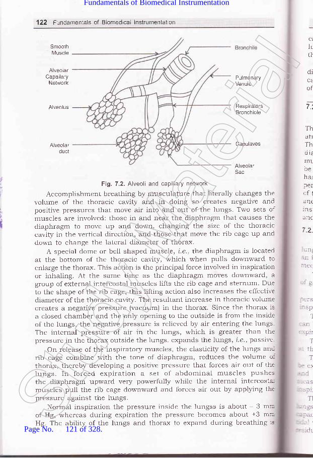
'122 Fundamentals of Biomedical lnstrumentation
SmoothMuscle
AlveolarCapailary
Network
Alveolus
Ci
h,tt
diCA
ofPulmonaryVenule
RespiratorsBronchiole
Alveolarduct
Capulaves
Fi1.7.2. Alveoli and capillary network
Accomplishment breathing by musculature that literally changes thevolume of the thoracic cavity and in doing so creates negative andpositive pressures that move air into and out of the lungs. Two sets ofmuscles are involved: those in and near the diaphragm that causes thediaphragm to move up and down, changing the size of the thoraciccavity in the vertical direction, and those that move the rib cage up anddown to change the lateral diameter of thorax.
A special dome or bell shaped muscle, i.e., the diaphragm is locatedat the bottom of the thoracic cavity, which when pulls downward toenlarge the thorax. This action is the principa-l force involved in inspirationor inhaling. At the same time as the diaphragm moves downward, agroup of external intercostal muscles lifts the rib cage and sternum' Dueto the shape of the rib cage, this lifting action also increases the effectivediameter of the thoracic cavity. The resultant increase in thoracic volumecreates a negative pressure (vacuum) in the thorax. Since the thorax is
a closed chamber and the only opening to the outside is from the insideof the lungs, the negative pressure is relieved by air entering the lungs.The internal pressure of air in the lungs, which is greater than thepressure in the thorax outside the lungs. expands the lungs, i.e., passive-
On release of the inspiratory muscles, the elasticity of the lungs ancrib cage combine with the tone of diaphragm, reduces the volume oIthorax, thereby developing a positive pressure that forces air out of thelungs. In forced expiration a set of abdominal muscles pushesthe diaphragm upward very powerfully while the internal intercosta-muscles pull the rib cage downward and forces air out by applying thtpressure against the lungs.
Normal inspiration the pressure inside the lungss is about - 3 mrof Hg, whereas during expiration the pressure becomes about +3 m=Hg. The ability of the lungs and thorax to expand during breathing :s
Alveo arSac
7.t
ThatrThdizIT1L
behalperof1anc:nslanc
7.2.
--rnl:Il 1
aa:
:9,
-:fS:SP
1
, rIL: '-Dlr
T,: th
T:-: e:.--- C-:-:aS
,-- s p1l
T]
-:.gs::AC'::l ,
..:dr-
Stud
y Mate
rial
Page No. 121 of 328.
Fundamentals of Biomedical Instrumentation

Measurements in The Respiration System 12I
called the compliance, which is expressed as the volume increases in thelungs per unit increase in intra-alveolar pressure. Airway resistance isthe resistance offered to the flow of air into and out of the lungs.
The interchange of the oxygen from the lungs to the blood and thediffusion of carbon dioxide from the blood to the lrrrg. takes place in thecapillary surfaces of the alveoli, The alveolar surface area is about Bo m2cf which more than three fourths is capillary surface.
TESTS AND INSTRUMENTATION FOR THE MECHANICS OFBREATHING
- he ability of a person to bring air into his rungs from the outside,tmosphere and to exhaust air from the lungs the mechanics of breathing.- nis abili[z is affected by the various components of air passages the::aphragm and associated muscles, the rib cage and associated:--usculature and the characteristics of the lungs themselves. Tests can:: performed to assess each of these factors, but no single measurement--as been devised that can adequately and completely evaluate the::rformance of the breathing mechanism. This section rlescribes a number: the most prominent measurements and tests that are used clinically
,::d in research in connection with the mechanics of breathing. The:'.strumentation required for these tests and measurements is d.escribed.:--d considered.
- 2.1. Lung Volumes and GapacitiesIn the basic pulmonary tests are those designed for determination of
-::g volumes and capacities. These parameters, which are a function of. -- :ndividual physical characteristics and the condition of his breathing- -:hanism, are given in figure 7.3.
The tidal uolume (TV), i.e., normal depth of breathing, is the volume"as inspired or expired during each normal quite respiration cycle.
Inspiratory reserue uolume (IRV) is that extra volume of gas that ai*:son can inspire with maximum effort after reaching the normal end-,::ratory level reached at the end of a normal quite inspiration.
-he expiratory reserue uolume (ERV) is that extra voiume of gas that. -- ce expired with maximum effort beyond the expiratory level. The end
"' : -- atory level is the level reached at the end of a normal, quite expiration.-'te residual ualume (RV) is the volume of gas remaining in the lungs
, ' .: end of a maximal expiration.- ee vc or uirtua.l capacitg is the maximum volume of gas that can
r' :i.pelled from the lungs by forceful effort after a maximal inspiration.L: - :he residual volume. This is measured independent of time of: ' : : -lrerr€nt. The vital capacity is also the sum of the tidal volume,,:: :.:atory reserve volume and residualvolume.
. -re TLC or totctl lung capacilg is the amount of gas contained in ther -.- at the end c'rf a maximal inspiration. It is the sum of the vital-r , . ri1- and residual volume. Total lung capacity is also the sum of the
:lume, inspiratory reserve volume, expiratory reserve volume and"' -.--.1 volurne.
Stud
y Mate
rial
Page No. 122 of 328.
Fundamentals of Biomedical Instrumentation
.ti.ari
l' ,',1I'iIy'l
\
124 Fundamentals of Biomedical lnstrumentation
The IC or inspiratory capacity is the maximum amount of gas thatcan be inspired after reaching the end expiratory level. It is the sum ofthe tidal volume and the inspiratory reserve volume.
The FRC or functional residual capacitg is the volume of gas remainingin the lungs at the end of expiratory level. It is the sum of residualvolume and the expiratory reserve volume.
The FRC can also be calculated as the total lung capacity minus theinspiratory capacity and is also considered base line from which othervolume and capacities are determined. The FRC is considered to be morestable than the end inspiratory level.
Several dynamic measures are important because breathing is adynamic process and the rate at which gases can be exchanged with theblood is a direct function of the rate at which it can be inspired orexpired.
The net measure of output of the respiratory system is the respiratoryminute volume. This is a measure of the amount of air inspired duringone minute at rest. It is obtained by multiplying the tidal volume withnumber of respiratory cycles per minute.
Several forced breathing tests are used to assess the muscle powerrequired with breathing and the resistance of the airways. Forced uitalcapacitg (FVC), which is really a vital capacity and measurements aretaken as quickly as possible. As the name suggests the FVC is the totalamount of air that can forcibly be expired as quickly as possible aftertaking the deepest possible breath. If the measurement is made withrespect to the time for the process, it is called a timed vital capacitymeasurement. A measure of the maximum amount of gas that can beexpelled in a given number of seconds is called the forced expiratoryuolume (FEV). This is usually given with a subscript indicating the numberof seconds over which the measurement is made. For example FEV,indicates the amount of air that can be blown out in 1 sec and followinga maximum inspiration, while FEV. is the maximum amount of air thatcan be expired in 3 seconds. FEV is sometimes given as a percentage ofthe forced vital capacity.
The forced vital capacity measurements are many time encumberedby patient hesitation ald the inertia of the instrument, a measure of themaximum midexpiratory flow rate may be taken. This is a flowmeasurement over the middle half of the forced vital capacity (from the25 percent level to the 75 percent level) . The corresponding FEVmeasurement is called FEV2sy _ 7sok.
Flow measurement is the maxima) expiration llow (MEF) rate, whichis the rate during the first liter expired after 2OO ml has been exhaustedat the beginning of the FEV. It differs from the peak flow, which is themaximum rate of airflow attained during a forced expiration.
Maximal breathing capacity (MBC) or maximql uoluntary uentilation(MW) . This is a measure of the maximum amount of air that can bebreathed in and blown out over a sustained interval, such as 15 or 20seconds. A ratio of the maximal breathing capacity to the vital capacityis a-lso of clinical interest.St
udy M
ateria
l
Page No. 123 of 328.
Fundamentals of Biomedical Instrumentation

Measurements in The Respiration System 125
coUJE
c)o_oE
q)
(,)J
E>fiE
(6'd_x
tJJ
uorlelrdsuluorletrdx3
() O(ETL
EE.TU E
_E-" I :eEH Fa*> E-o
trRHE^
)ao\869N(v
trooq
6(o(r) E5$
o 8;e>s8 E.>^aY,.Fg
EEa"
@oEfI
Fo)coo)t
ooJ
olco
a.o.=o(Uo-(Uo
c(U
aoEf
o)c=J
orti-
0II
Stud
y Mate
rial
Page No. 124 of 328.
Fundamentals of Biomedical Instrumentation

,4"r"'i'/
St
#,?.).
q
126 Fundamentals of Biomedical lnstrumentation
An obstruction of the small airways in the lungs, is defected by aprocedure involving measulement of closing volume is often used. The
ilosing volume level is the volume at which certain zones within the lungcease to ventilate.
In the presentation of various respiratory volumes, the term BTPS is
often used. This indicates thqt the measurements tuere made at bodg
temperature and ombient pressure, utith the gas saturated tuith uater,opour. Sometimes to use these values in the reporting of metabolism,
they must be converted to standard temperature and plessure and drymeasurement conditions, indicated by the term STPD'
Most of the air enters the lungs to fill the alveoli after each breath.A certain amount of air is required to fill the various cavities of the airpassages. This air is called tl:re dead-space air, and the space it occupies
i" "atGa
fi:,e d-ead space. The amount of air that actually reaches the
alveolar interface with the blood stream with each branch is the tidalvolume minus the volume of the dead space.
7 .2.2. Mechanical Measurement
compliance or performance which has been dehned as the volume
increase in the iungs per unit increase in lung pressllre, requiresmeasurement of inspired or expired volume of gas and of intrathoracicpressure. Normally compliance is a static measurement. However, inactual practice two types of compliance measurement, static and dynamic
are made. Static compliance is determined by obtaining a ratio of the
difference in lung volume at two different volume levels and the associated
d,ifference in intra-alveolar pressure. For measurement of dynamiccompliance, tidal volume is used as the volume measurement, whileintrathoracic pressure measurements are taken during the time when
the airt'low is zero, which occur at the end inspiratory and expiratorylevels with each breath (refer figure 7.3). The performance or lungcompliance varies with the size of the lungs: a child has a smallercompliance than an adult. Furthermore, the volume-pressure curve 1s
not linear. Therefore, compliance does not remain constant over the
breathing cycle, but tends to d'ecrease as the lungs are inflated'Fortunaiely, over the tidal volume range in which compliancemeasurement are usually performed, the relationship is approximatelylinear and a constant compliance is assumed. Liters per centimeter of
HrO gives the performance or compliance figure'Airway resistance, which is a pneumatic analog of hydraulic electrical
resistancl, and as such, is a ratio of pressure to flow. Thus for the
d.etermination of airway resistance, intra-alveolar pressure and airflow
measuremelts are required. As was the case with compliance, airway
resistance is not constant over the respiratory cycle. As the pressure inthe thoracic cavity becomes more negative, the airways are widened and
the airway resistance is lowered. conversely, during expiration, when
the pressure in the thorax becomes positive, the airways are narrowed
and resistance is increased. The intra-alveolar pressure is given incentimeters of HrO and the flow in liters per second: the airway resistance
is expressed in centimeters of I{rO per liter per second'Stud
y Mate
rial
Page No. 125 of 328.
Fundamentals of Biomedical Instrumentation

Measurements in The Respiration System 127
7.2.3. lnstrumentation for Measuring the Mechanics of Breathing
The measurement of lung volumes at various levels and conditionsof breathing, pressures within the lung and the thorax with respect tooutside air pressure and instantaneous air flow give all the parametersdealing with mechanics of breathing. The complexity of pulmonarymeasurements lies not in the variety required but rather in gainingaccess to sources of these measurements, and in providing suitableconditions to make them meaningful in measurement.
All lung volumes and capacities that can be obtained by measuringthe amount of gas inspired or expired under a given set of conditions orduring a specified time interval can be obtained by the use of thespirometer. The timed vital capacity and forced expiratory volumemeasurement can be obtained with the help of spirometer. The only
"'olume and capacity measurements that cannot be obtained withspirometer are those requiring measurement of gas that cannot be expelled'rom the lungs under any conditions. The residual volume, fr.rnctional:esidual capacity and total lung capacity are included in such:rreasurements. A recording spirometer is shown tn figure 7.4.
Other Signal
Processing
Kymograph
Strip CharlFiecorder
lvlouthpiece
Thermometer forSpirometer Gas
Temperature
Fi1.7.4. A water sealed spirometer
Spirometer composes of a movable bell inverted over a chamber of.ter. Inside the bell, above the water line, is the gas that is to be
: :athed. The bell is counter balanced by a weight to maintain the gas-.s:de at atmospheric pressure so that its height above the water is--:portional to the amount of gas in the bell. A breathing tube connects
- -. mouth of the patient with the gas under the bell. In this case noseStud
y Mate
rial
Page No. 126 of 328.
Fundamentals of Biomedical Instrumentation
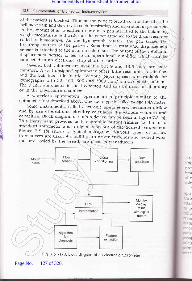
128 Fundarnentals of Biomedical lnstrumentation
of the patient is blocked. Thus as the patient breathes into the tube, thebell moves up and down with each inspiration and expiration in proportionto the amount of air breathed in or out. A pen attached to the balancingweight mechanism and writes on the paper attached to the drum recordercalled a kymograph. As the kymograph rotates, the pen traces thebreathing pattern of the patient. Sometimes a rotational displacementsensor is attached to the drum mechanism. The output of the rotationaldisplacement sensor is fed to an operational amplifier which can beconnected to an electronic strip chart recorder.
Several bell volumes are availabre but 9 and 13.5 liters are mostcommon. A well designed spirometer offers little resistance to air flowand the bell has little inertia. various paper speeds are available for}<ymographs with 32, 160,30o and 19oo mm/min are most common.The 9 liter spirometer is most common and can be used in laboratoryor in the physician's chamber.
A waterless spirometers, operate on a principle similar to thespirometer just described above. one such type is called wedge spirometer.
Some instruments, called electronic spirometers, measures airflowand by use of electronic circuitry calculates the various volumes andcapacities. Block diagram of such a device can be seen in figure 7.5 (a).This instrument provides both a graphic output similar to that of astandard spirometer and a digital read out of the ciesired parameters.Figure 7.5 lb) shows a typical spirogram. Various types of airflowtransducers are used. A small breath driven turbines and heated wiresthat are cooled by the breath are used as transducers.
,.nd--lmlrol::OI,:e: flfl
Signalconditioning
Monitordisplayresult
with digitalreport
Fig. 7.5. (a) A block diagram of an electronic SpirometerStud
y Mate
rial
Page No. 127 of 328.
Fundamentals of Biomedical Instrumentation

Measurements in The Respiration System 129
FJ'.J
MVV FEV, o VC
Medium Fast Slow
Fig. 7.5. (b) A typical Spirogram
.A' broncho-spirometer is a dual spirometer. It measures the volumes.---c capacities of each lung individually. The air input device is a double--:ren tube that dMdes for entry into the airway to each lung and thus
:-:r-ides isolation for differential measurement. The main function of the:r:ncho-spirometer is the pre-operative evaluation of o4ygen consumption:r :ach lung. The usual output of a spirometer is the spirogram. Somer;:ometer, however, provides spirograms with inspiration towards the top.
The patient is asked to breath through the mouthpiece of ther; -:ometer. His nose is blocked with a clip so that all breathing is':- " :'ugh the mouth. The recorder is first set to a slow speed to measure*-'l capacity. The patient breathes quitely for a short time at rest so as'r: :rovide a baseline. He is then asked to exhale completely and to:: -ale as much as he could. This process produced the vital capacityr- -:d at the extreme right of the frgure. with his lungs at the maximal,ri,::rational level the patient held his breath for a short time while thet- :der was shifted to a higher chart speed (e.g. l92O mm/min). The:iii--:nt is then asked to blow out all the air he could as quickly as'us=:ble to produce FEV, (forced expiratory volume after 1 sec.). To;r: '-rlate FEV1, a 1 second interval was measured from the beginning'm --: by extending the maximum slope. Sometime, it is necessary to
==nine the beginning point by extending the maximum slope to theStud
y Mate
rial
Page No. 128 of 328.
Fundamentals of Biomedical Instrumentation

130 Fundamentals of Biomedical lnstrumentation
level of maximum inspiration. This step ensures that the initial frictionand inertia of the spirometer have been overcome and compensates forerror on the part of the patient in performing the test as instructed.
Generally respirometry tests are repeated two or three times, and themaximum values are used to ensure that the patient performed the testto the best of his ability. Although some instruments are calibrated fordirect read out, other require that the height of the tracings be convertedto llters by use of a calibration factor for the instrument, called thespirometer factor.
Output including digital readouts are available particularly fromelectronic types of spirometers. Some instruments even have built incomputational capabilities to calculate automatically the required volumesand capacities from the basic measurements.
7.2.3.1. Measurement of Residual Volume
The outputs spirometer and of some of the other instruments describedabove, all the lung volumes and capacities can be determined except thosethat require measurement of air still remaining in the lungs and airwaysat maximum expiration. These parameters, which include the residualvolume, FRC and total lung volume can be measured through the use offoreign gas mixture. A gas analyzer is required for these tests.
Rebreathing from a spirometer charged with a known volume andconcentration of marker gas, such as hydrogen or helium. Helium isusually used, involves a closed circuit technique. After several minutesof breathing, complete mixing of the spirometer and pulmonary gases isassumed and the residual volume is calculated by a simple proportionof concentrations and gas volumes.
Nitrogen washout the open circuit method involves the inspiration ofpure oxygen and expiration into an oxygen purged-spirometer. If thepatient has been breathing air, the gas remaining in his lungs is78 percent nitrogen. As he begins to breath the pure oxygen, it will mixwith the gas still in his lungs and a certain amount of nitrogen will\rash out' with each breath. By measuring the amount of nitrogen ineach expired breath, a wash out curve is obtained from which the volumeof air initially in the lungs can readily be calculated. The end expiratorl-level is the preferred breathing ievel for beginning this measurement.
Tlre functional residual capacity (FRC) (from which residual volumecan also be calculated by subtracting the expiratory reserve volume) canbe measured by using a plethymograph. This instrument is an airtightbox in which the patient is seated. Utilizing Boyle's law the ratio ofchange in lung volume to change in mouth pressure is used to determinethe thoracic gas volume.
The patient breathes air within the box through a tube which containsa transducer and shutter to close off the tube for certain portion of thetest. Pressure transducer measure the air pressure in the breathing tubeon the patients side of the shutter and inside of box. The amount of airin the box, including that in the patient lungs, remaining constant.since there is no way for air to enter or escape. However, when the
pV
whrnalinisheluchvolat
7.2
,)
rtl
i
,'{
me,ancCire
-hetrei:orn"olu.: tl.r tl: atit- atir:ata,fd
T1,1:ch
::tlV(
=:bO.- rapl- : IfL:1Ce.
r .-eIC
. .::atr
- 3,1.
inl"' '. api,,.Sta
rH ::1ptoISt
udy M
ateria
l
Page No. 129 of 328.
Fundamentals of Biomedical Instrumentation
:atlent compresse" " total body., tlume is reduced,
''''hen the patient in ConverselY-.:s body volume in racic region
The FRC isrLe?Sllr€d with the breathing tube closed. With no air,-lowed to flow the mouth pressure (sensed by the pressure---- the tube) can be assumed to equal the alvetla, p;;";;.". instructed to breathe at the siow rate against the closed
expands and compresses the air in hiss in mouth pressure and correspondinge it is possible to calculate the intrathoraciJ
the end expiratory level. me is equal to FRC' If the test is performed
' 2.3-2. lntraarveorar and rntrathoracic pressure MeasurementIt used to measure intraalveorar and intrathoracic pressures. These. .:a
mportant in the determination of toth compliance] ce, since inaccessibility of tfr""e .hl_bers makesmpossible. For measureme pressure.hutter in the breathing tube is opened to,:he air from within th! closed Uix. Since :i5:Y-' a cl0sed system containing a lixed amount of gas, pressure and=e variations in the box are the inverse of the pi""".r." variations= lungs as the gas within the rungs expands andis compressed due-: positive and negative pressur." i., th" lungs. por cariu.ation the':--:s breathing tube is brocked for a few seconds, during which the:.: is asked to breathe while mouth pressur" i" _.r".rred. These:an be used in calibration of measurement. Since mouth pressure_ ,lng pressure are the same when there is no airflow.
Measurements ir: The Respiration System 131
RESPIRATORY THERAPY EQUIPMENT
r :anical assistance must be provided so that sufficient oxygen is':ed to the organs and tissues of the body and ."""""irr. levels of- - r dioxide are not permrtted to accumulate when a patient is,:able of adequate ventilation by natural proc cedure and. -:mentation involved in providing mechanica and higher:ntration of o>gzgen or other therapeutic gases constitutes''-l known as respiratory- therapy. ,r" instruments for respiratory' -'py are inhalators, ventilators, humidifiers and nebulizer.
- I i. lnhalators
':haiators indicates a device used to supply oxygen or sor,e other-'peutic gas to a patient who is able to u..airrl "poitrr."orsry without>iance' As a rule, inhalators are used when r
"o.r""rrir"1ion of oxygen'- -':r than that of air is required. The inhaiators consist of a source ofapeutic gas, equipment for reducing pressure and controlling theof the gas and a device for administering th" ;; Devices forSt
udy M
ateria
l
Page No. 130 of 328.
Fundamentals of Biomedical Instrumentation
132 Fundamentals of Biomedical lnstrumentation
administering o>grgen to patient include nasal cannulae and cathers,
face masks that cover the nose and mouth. By adjusting the flow of gas
irito the mask, the oxygen concentration presented to patient is controlled.
7.3.2. Respirators and Ventilators
Respirators and ventilators are used interchangeably to describe
equipment that may be employed- continuously intermittently to improve
,r"rrtit.tion of the lungs and to suppty humidity or aerosol medications
to the pulmonary tree. Most of the ventilators.in the clinical settings use
positivL pressure during inhalation to inflate the lungs with various
gu.""" or mixture of gases (air, oxygen, carbon dioxide' helium etc')'
IJnder certain conditions pressure may be applied during the expiratory
phase, but expiration is usually passlve'
Generally respirators in com on use are classified as assistor-
controllers, and can be operated in any of three different modes. These
modes differ in the method by which inspiration is initiated.
Inspiration is triggered by the patient in the assist mode. A pressure
sensor responds to the slight negative pressure that occurs each time
the patient attempts to inhale and triggers the apparatus to begin inflating
the lungs. Thus the respirator helps the patient to inspire when he
wants to breathe. A sensitivity adjustment is provided to select the
amottnt of patient effort required to trigger the machine. The patients
who are able to control their breathing but are unable to inhale a
sufficient amount of air without assistance or for whom breathing require
too much effort the assist mode is used'
A timer set to provide the desired respiration rate is controlled in the
control mode breathing. controlled ventilation is required for patients
who are unable to breathe on their own. In this mode the respirator has
complete control over the patients respiration and does not respond to
any respiratory effort on the part of the patient'
The apparatus is normally triggered by the patient's attempt to breathe
in the assist control mode as in the assist mode. However, if the patient
fails to breathe within a predetermined time, a timer automatica]ly triggers
the device to inflate the lungs. Thus, the patient controls his own breathing
as long as he can, but if he should fail to do so, the machine is able tc
take over for him. This mode is most frequently usel.-t in critical care
settings use this mode quite frequently'Many respirators can be triggered manually by means of a control or-
the panel in addition to above.
once inspiration has been triggered inflation of the lungs continues
unless one of the following condition occurs:
(rJ The delivered gas reaches a predetermined pressure in the proxima-
orupperairways'Aventilatorthatoperatesprimarilyinthismanne:is said to be Pressure-cYcled.
(ii) A predetermined volume of gas has been delivered to the patien:'
This is the primary mode of operation of volume cycled ventilators
(iirJ The air or oxygen has been applied for a predetermined period ftime. Thus the mode of operation for time c1'cled ventilators'
tC
re
tt
'.3.3
T: lrll- -ralr'-^.: a.
Ifi sp€: -lse-, tci
:- cle
1S
br
CI
reVC
l-lIreofve_
de.
P(\eur
Stud
y Mate
rial
Page No. 131 of 328.
Fundamentals of Biomedical Instrumentation

Measurements in The Respiration System 133
use can be categorized by, positive pressure assistorly from a source of gas and
erectricaly powered compressor or carr be used;il"5:B#f," ffiE'i3Xto permit ventilation with ambient air.The volume-cycled ventilator is the second category of respirator. Itis called a volume respirator. This type of device ,_,""" Lith". a piston orbellows to dispense a precisely contio[ea volume for each breath. In thecritical care setting where patients have purmonary abnormalities andrequire predictable volumes and concentrations of g.", this type of;'"11 ffilJT5:i,#tr#:ffii#?i'"#Tr*r:
:esp perated and provide a much greater d_egreerf control over the ventilation than the pr.""r-r.. cycled types. An ICU.'entilator is shown in figure 7-6.Adjustable pressure limit and alarms for safety are available in most:evices of this type.
Trainednetworkweights
Trainingdata andcontrol
Controlsignals
Lungpressure
data
Air pressureTap
Fig. 7.6. An tCU Ventilator
'3 3. Humidifiers and Nebulizers and Aspirators
Pneumalic
Stud
y Mate
rial
Page No. 132 of 328.
Fundamentals of Biomedical Instrumentation

/I
ti
t;:
{
134 Fundamentals of Biomedical lnstrumentation
The ultrasonic nebulizer is more effective and tnore expensive type ofnebulizer. This electronic device produces high-intensity sound ener$/well above the audible range. when applied to water or medication,ultrasonic ener5/ vibrates the substance with such intensity that a high
volume of minute particles is produced. Such equipment usually consists
of two parts, a generator that produces a radio frequency current to
drive the ultrasonic transd.ucer and the nebulizer itself, in which the
transducer generates the ultrasound enerSr and applies it to the water
or medicatlon. ffre ultrasonic unit d.oes not depend on the breathing gas
for operation. The therapeutic agent can be administered during oxygen
therapy or mechanical ventilation procedure'To remove mucus and. other fluids from the airways aspirator and
other types of suction apparatus are used'
7.4. SUMMARY
1. The entire process of inhaling from the atmosphere, transporting the
oxygentothecells,removingtheCO,fromthecellsandexhastingthis waste product into the atmosphere is called the respiration.
In the hr.rman body tissue cells are not in direct cotrtact with their
external environment. The circulating blood is the medir-rm by which
th.eoxyugenisbroughttotheinternalenvironmentandbythesamernechanism carbon dioxide is carried out. The exchange of gases
betweerr the blood and the external environment takes place in the
lungs ancl is known as external expiration'
2.ThePhvsiologyoftheRespiratorySystem:Airentersthelungswhich behaves as elastic bags located in a closed cavity called thoracic
cavi[z through nasal cavities, pharynx, larynx, brochi and bronchioles'
During normal inspiration the pressure inside the lungs is -3 mm ol
ug and during explration it is +3 mm of Hg. The ability of lungs anithe thorax to expand is called the compliance'
The mechanics of breathing is the ability of a person to bring air intc
his lungs from outside atmosphere and to exhaust air from lungs
This ability is affected by the various components of air passages
the diaphram and associated, muscles and the characteristic of thr
lungs.The various capacities of pulmonary system are descrined in deta-
The measuremlnt of these capacities are both static apd dynam:;
The dynamic capacity is forced expiratory volume (FEV) which :s
taken by measuring the air that can be blown out in 1 sec time r':is written as FEV,-. This value can be given as percentage if r:cmeasurement are taken ones the middle half of the forced r','-a']t
capacity from 25oh to the 75o/o level'
Another i nt is maximal expiration flow rate
Other im t is maximum breathing capacity
or maximal voluntary ventilation (MW) This is a measul:e
maximum amount of air that can be breathed in and blownof:
(N{E-tr-
(NI
o\-e:Stud
y Mate
rial
Page No. 133 of 328.
Fundamentals of Biomedical Instrumentation

Measurements in The Respiration System 135
sus al as 15 to 20 second. A ratio of the maximal breathingcap vital capacity is also of clinicar interest.The used for measurement of breathing is a spirometer.The standard spirometer consists of a movabre berl inverted over achamber of water inside the bel,, above the water line, is the gas thatis to be breathed. A pen is attatched to the balancing arrangementis called a Kymograph. Sometimes a rotational dispracement sensoris attatched to the drum mechanism for the output to be connectedto the pen recorders.The other instruments are water ress spirometer known as wedgesprrometer.To produce a spirogram the patient is aksed to breath through themouthpiece. The recorder is first set to a slow speed of 32 mmr/minto measure thpatient is aked ,'Jo'L?,^ ff:.i;::,::i: r[rl.":;rJ::line. He was th xhale completely and to inhale as muchas he could' This process produces thl vital
""p..rty ."cord on thet rb"r"..iJTjl1l"T"";*ffi],,1:
speed of l92O mm/min.r W) record the chart speed is sett r a short rest a few cycles of resting:espiration were recorded then the patient is asked to breath in andrut for 10 seconds producing MV record.i(ow-a-days electronic sparometer are arso available. For calcurating- lnctional residual capacity can be measured from a plethysmograph.Respiratory Therapy Equipment: If a patient is incapabre of edequate':ntilation by natural process, mechanical assistance must be::ovided' so that sufficient oxygen is delivered to the organs and.ssues of the body.' ie instruments for respiratory therapy are inhalaters, ventilators,tmidifiers and neubulizers.' -:e inhalators generalry supply oxygen or other therepeutic gas to a-.iient who is able to breath
"po.rlr.orsly without assistance.:ntilators and respirators are used to improve ventilation of thergs and to supply humidity or aerosol mecrications. Most of thertilators in the crinicar settings use positive pressure during::alation to inflate the lungs with various gases. Expiration is usually' "sive. Most respirators in common use are classified as assitor_:::rolled and can be operated in any of three different modes clehned' assist mode inspiration, control mode breathing and assist control- .te.
., patients or oxygen givenmust be hus, virtually allnd respir y must includeSt
udy M
ateria
l
Page No. 134 of 328.
Fundamentals of Biomedical Instrumentation

136 Fundamentals of Biomedical lnstrumentation
equipment to humidify the air either by heat vapoutization or by
bubbling an air stream through a jet of water.
when therapy requires that water or some type of medication be
suspended in the inspired air as an aerosol, a device called nebulizeris used. In a nebulizer t]rle water or rnedication is picked up by ahigh-velocity jet of oxygen (or some other gas) and thrown against
one or more baffles or other surfaces to break the substance intocontrollable-sized droplets or particles which are then applied to
patient via a respirator.A more effective and more expensive type of nebulizer is the ultrasonicnebulizer. This ultrasonic enerSr produces to produce minute volume
of water or other medication.Aspirators are used to remove muscus and other fluids from the
airways.
7
l,t'
r/I
ii
D\
rt
in lungs? Define the important lung capacities(UPTU-MQPl)
1aw of physics. How does it relate to breathing(UPTU-MQP1)
6xerri,ted
7.1. How many loves are thereand explain them.
7.2. Boyle's law is an imPortantprocess.
7.3. For what measurement spirometer can be used? what basic lung volumes
and capacities cannot be measured with spirometer? Why?(UPTU-MQP1)
7.4. Write in detail about the instrumentation used for measuring the
mechanics of breathing. (UPTU-MQP2)
7.5. Explain d.ifferent respiratory therapy equipment normally used.(UPTU-MQP3)
7.6. Explain the operation of a pulmonary measurement indicator?(UPTU-MQP3)
7.7 . Using the correct anatomical and physical terms, explain the process of
respiration, tracing the taking of a breath of an air through the mouth.(UPTU-MQP3)
7 .8. Explain the physioloSr of a respiratory system. Discuss various parameters
which are a function of individual's physical characteristics and conditionof breathing mechanism. (UPTU-2003t
7.g. what are plethysmographs? How can they be used for measurement of
intrathoracic pressures? Expiain the methods of airway resistancemeasurement
7.10. Discuss various respiratory therapy equipments. what are Nebulizers?
Explain the working principle of ultrasonic nebulizer' (UPTU-2003,
7.11. Explain calibration and repairability of patient monitoring equipment.(UPTU-2004
7.12. Describe and explain humidifiers, nebulizers and aspirators.(UPTU-2004
7.13. Describe and explain physiolory of respiratory system' (UPTU-200'
7.
7.
7.
Stud
y Mate
rial
Page No. 135 of 328.
Fundamentals of Biomedical Instrumentation

-.15. nd physical terms, explainof a breath of air through
_.16. blood in the muscle of aneen death by carbon monoxicledeath by strangulation? Explain.
17' Explain the operation of a purmonary measurement indicator.18' what causes the rungs to expand and contract in breathing inspite of thelungs containing no musculature.
Measurements in The Respiration System 137
14' Describe and explain measurement of breathing mechanics and spirometer.(UPTU-2O04)
the process ofthe mouth forathlete's leg.poisoning and
AJJ
Stud
y Mate
rial
Page No. 136 of 328.
Fundamentals of Biomedical Instrumentation

CO
bcItNC
ob
t'I
It
lr',:
{
Diagonstic Techniques
:r fnside this chapter
Principles of Ultrasonic Measurementllltrasonic ImagingUltrasonic DiagnosisX-Ray and Radio-lsotope InstrumentationsCAT or CT ScanEmission Computerized TomographyMRISummarv
Diagnostic techniques involve measurements to help in detection of somemalfunction of the system of the body. Such instrumentation may alsobe called troubleshooting equipment. The diagnostic equipments andtheir underlying principles related with ultrasonic, X-ray, Radio-isotopic,cAT scan, Emission computerized Tomography and MRI techniques arediscussed here. These techniques of diagnostic does not involve gettinginside the body physically or invading it, therefore, these are known as
Non-invasive diagnostic techniques. The non-invasive diagnostictechniques are not traumatic for the patient and do not have anydeterminental side effects on the patient. The non-invasion techniquesare very sophisticated which offer accurate results without invasion of
the body" Usual method of blood pressure measurement is non-invasivewhich has been around for years.
PRINCIPLES OF ULTRASONIC MEASUREMENT
Ultrasound is sonic ener$/ at frequencies abovegreater than 20 kHz. Ultrasound exists as a
138
8.1.8.2.8.3.8.4.8.5.8.5.6.t.8.8.
:he:TIC
.l t:o
aastol_
lro111
: et'.he-ah
the audible range, i.e.,sequence of alternateSt
udy M
ateria
l
Page No. 137 of 328.
Fundamentals of Biomedical Instrumentation

DiagonsticTechniques 139
:ompressions and rarefactions of a suitable medium, i.e., air, water,rone, tissue, etc. It;is propagated through the medium at some velocity.-t is also frequency (wavelength) and medium density dependent. Inrormal applications, ultrasound is actually focussed into a beam which--beys laws of reflection and refraction as shown in figure 8.1.
Reflected wave
Medition 2 --' Medition 1 Transmitted wave
lntedace
Fig. 8.1. Ultrasound reflection and refraction at an interface betweenmedia of two densities
The reflected energr is dependent on the difference of densities between-: two media and the angle at which the transmitted beam hits the
- :dium. Higher the difference in media, the higher will be the reflection.:he angle of incidence between the beam and the interface is closer90", the reflected portions would be more.If the media difference is high i.e., tissue and bone or tissues and
r:S. rrrost of the energ/ will be reflected and almost no energz willrtinue through the second medium. In other words, ultrasound
: - pagation path must not include bone or any gaseous medium or air." - airless contact is produced through using an aqueous gel or a waterbagr-.rseen the transducer and the skin for application of ultrasound.- -: density and the important properties of materials are shotwn in'-
=:le 8.1(a)
Table.8.1. (a) Ultrasonic characteristics of some selected materials
Materlal Temperature ("Cf Density (S/cme1 Velocity (m/secl'rYater
3rainl,luscle-- at3one
40J/
37J/
o.9921.0307.O70o.971.77
529510570440360
The velocity of sound propagation through a medium is dependent' :ensity of the medium, its elastic properties and the temperature.
-'-'.'elocity of most body fluids is around 1550 m/sec, i.e., higher thanr,'.: The velocity of through bone is 3360 m/sec whereas through fat
.:ch lower l44O m/sec.Stud
y Mate
rial
Page No. 138 of 328.
Fundamentals of Biomedical Instrumentation

140 Fundamentals of Biomedical lnstrumentation
The depth of penetration at whichto half the app'lied amount, is knowni.e., tl:re half-valuer of the medium isof ultrasound energr. The Table 8.capacity of the materials.
the ultrasound energr is attenuatedas half-value layer of the material,the indicator of absortion capacity1(b) shows ultrasound absorption
(iul
spe(meafrorr
82Theof ulasadispJ:larnAVOlC
hfoprtne (
t4 A-
T:r-ans::ace:eflec
F
(b)
rif) M-
Tre:,'lses---,: vers set
E_ 10es:.i1 C(
:1 re
,,,
t
Ii
t:{
Table 8.1. (b) Ultrasound Absorption
Type of material Frequency Half-value Layer (cm)
BloodMuscleFatBone
1.00.80.80.8
35.02.1.).J
o.23
An important characteristic of ultrasound frequency used in biomedicalinstrumentation is the Doppler effect. If the frequency of the reflectedultrasonic eners/ is increased or decreased by a moving interface, thefrequency shift is given as:
Lf=?')t
for / = reflected- wave frequency shiftu = interface velocity)" = transmitted ultrasound wavelength
In other words, the frequency increases if the interface moves towardsthe transducer and decreases when moves away. If ultrasound is reflectedfrom a moving object, the measured frequency shift is proportional tovelocity.
The ultrasound is transmitted in various forms. The modes oftransmission are:
(i) Pulsed UltrasoundIt is transmitted in pulsed form at a frequency from I to 12 kHz
Pulse duration is about 1 p sec. The returning echoes are displayed withrespect to time and echoes are proportional to the distance from thesource to the interface. It is used in most of the irnaging applications
(ii) Continuous DopplerContinuous ultrasound signal is transmitted and a separate receivinE
transducer picks up the returning echoes. The frequency shiftsdue to moving interfaces are detected and the average velocity of thetargets is determined as a function of time. It is used in blood flos-measurements.
('iiif Putsed DopplerSimilar to pulse ultrasound in this case also short pulses of ultrasounc
are transmitted. The returning echoes are received. The frequency shiiis observed. In other words, the velocity and distance of moving targeare measured.St
udy M
ateria
l
Page No. 139 of 328.
Fundamentals of Biomedical Instrumentation

Diagonstic Techniques'141
(iuf Range-ghted pulsed DopplerGating circuit is used for measurement
;:ecific distance from the transducer. The::easured as a function of time and also as:.:m the vessel wall.
of velocityvelocity ofa function
of targets at ablood can be
of the distance
ULTRASONIC IMAGING
Imaging systems are comprised of the pulsed urtrasound or pulsedl ppler mode. The received information is amplified and displayed in: of several display modes:
A-scan displayTransmitted pulses trigger the sweep of an oscilroscope. The
-:rsmitted pulses and echoes are displayed as vertical defections on the.--e. The figure 8.2(a) shows typical A-scan. Ehoes cause vertical:lection of oscilloscope.
Transmittedpulse
(b)
Fig. 8.2. (a) Echoes display as vertical deflectionc) Echoes control brightness of oscilloscope bean
M-scan display
of oscilloscope pattern,corresponding to Fig. (a)
: es. The figure 8.3 shows M-scan of moving and stationary target-- corresponding A-scan. A stationary target trace is a straight line- respect to time.
B-scan displayis a two-dimensional image of a stationary organ or body structure.
:rightness of the oscilloscope is controlled by ieturning Lchoes. The
D4.a
Stud
y Mate
rial
Page No. 140 of 328.
Fundamentals of Biomedical Instrumentation
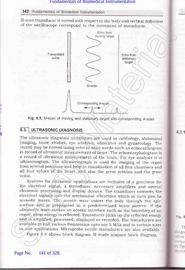
142 Fundamentals of Biomedical lnstrumentation
B-scan tralsducer is moved with respect to the body and vertieal deflectionof the oscilloscope correspond to the movement of transducer.
Echo frommoving target
Transmittedpulse
Echo fromstationary
target
M-scan
/
u
Fig. 8.3. M-scan of moving and stationary target with corresponding A-scan
The ultrasonic diagnosis techniques are used in cardioiogr, abdominalimaging, brain studies, eye analysis, obstetrics and gznaecologr. Therecord may be named using echo or sono words such as echocardiogramis record of ultrasonic measurement of heart. The echoencephalogram isa record of ultrasonic measurement of the brain. For eye analysis it isultrasonogram. The ultrasonograph is used for imaging of the organfrom several positions and help in visualisation of all four chambers andall four values of the heart, and also the great arteries and the greatverns.
systems for ultrasonic applications are inclusive of a generator forthe electrical signal, a transducer, necessary amplifiers and severa-lelectronic processing and display devices. The transducer converts theelectrical signals into the mechanical vibrations which in turn give heacoustic waves. The acostic wave enters the body through the spinsurface and is propagated in a predetermined beam pattern. If theultrasonic wave strikes an acostic interface such as the boundary of anorgan, some ener$/ is reflected. Transducer picks up the reflected eners,-and is amplified, processed, displayed or recorded. The transducers areavailable to suit various frequencies upto say 5 MHz and in various sizesto suit applications. Microprobe needle transducers are also available.
Figure 8.4 shows block diagram M-made scanner block diagram.
4.3.1
=9.8
TI- -Jf
----er
.:lu: ::91
Corresponding A-scan
ULTRASONIC DIAGNOSIS
Stud
y Mate
rial
Page No. 141 of 328.
Fundamentals of Biomedical Instrumentation

Diagonstic Techniques 143
start pulse tor time^sw€eP of
Fig. 8.4. M-mode scanner block diagram
X : '1. Echocardiography
is superimposed on the tracing
-,: echocardiogram finds major application in cardiovascular, -- -sis which utilizes M-scan technique. Movements of the valves and
.- :arts of the heart are displayed as a function of time usually in. rtion with electrocardiogram. A typical electrocardiogram is shown
' :. 8.5. This type of electrocardiogram is useful in interpreting the:nts of the mitral valve with respect to time. The mobility of the
-tr *'
..'.'*l'
Stud
y Mate
rial
Page No. 142 of 328.
Fundamentals of Biomedical Instrumentation

144 Fundamentals of Biomedical lnstrumentation
value is given as the displacement of the echo per unit time. Thetransducer is placed such that the beam crossed the chest wall into theright ventricle, through the septum, into the left ventricle and thenthrough the left atrium. The image of aorta and mitral valve are alsoobtained in this technique.
Echocardiography can be used to detect fluids presence surroundingthe heart due to pericardium inflamation and escape of fluid. It may benoted that transducer selection is depend.ent on the type of investigationto be performed, physical size of the patient, the anatomic area involved,the type of tissue to be encountered and the depth of the organsto be studied.
8.3.2. Echoencephalography
Echoencephalography is ultrasonic imaging using A-scan mode ofdisplay for determination of the location of the midline of the brain. Thetransducer is held against the side of the head to measure the distanceto the midline of the brain. The midline echoes from both sides of thehead are displayed on the oscilloscope simultaneously. one side givesupward deflection of the beam and the other side gives downwarddeflection.
If these two deflections line up, then, distance from the midline toeach side of the head is equal. If it is nonaligned, possibility of tumoror disorder exists. Ultrasound eners/ is upto 1o MHz and pulse rate is1O0O per sec.
8.3.3. Opthalmic Scans
opthalmic scans are used for the eye. An ultrasound machine blockdiagram shown in figure 8.6.
sttlTTpr
(a)
t
(b)
TGC
Spectraldoppler
processrng(D mode)
Fig. 8.6. An ultrasound machine block diagramStud
y Mate
rial
Page No. 143 of 328.
Fundamentals of Biomedical Instrumentation
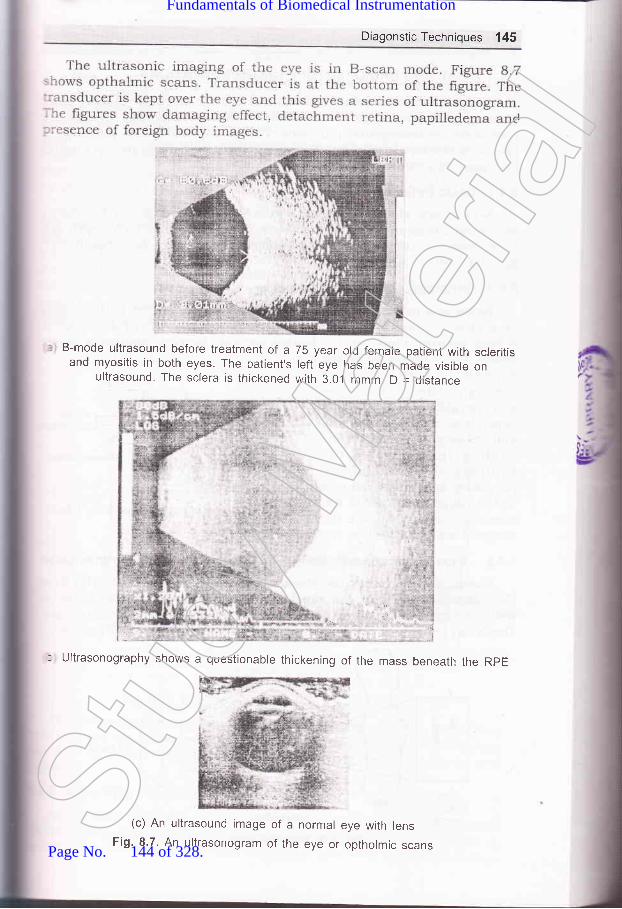
Diagonstic Techniques 145
B-mode ultrasound before treatment of a 75 year old female patient with scleritisand myositis in both eyes. The patient's left eye has been made visible on
ultrasound The sclera is thickened with 3.0.1 mmm D = distance
* .,j!r" ,a
"-. .-,i
: Ultrasonography shows a questionable thickening of the mass beneath the RpE
(c) An ultrasound image of a normal eye with lensFig. 8.7. An ultrasonogram of the eye or optholmic scansStud
y Mate
rial
Page No. 144 of 328.
Fundamentals of Biomedical Instrumentation

146 Fundamentals of Biomedical lnstrumentation
8.4. X.RAY AND RADIO.ISOTOPE INSTRUMENTATIONS
X-rays can penetrate opaque objects and provide an image of their innerstructures. These imagings are used for medical diagnosis. X-rays arealso used for therapeutic purposes. This is the domain of the medicalspeciality known as radiologz. X-ray equiprnents are major part of medicalinstrumentation.
8.4.1. Basic Definitions
X-rays are electromagnetic waves which have a much shorterwavelength than radio waves or visible light. The X-ray wavelength canvary between 10 6 and 10-10 cm, i.e. fre[uen"y..rrg" of betweJn 1010and lO1a MHz.
8.4.2. Generation of lonizing Radiationwhen fast-moving electrons are suddenry decelerated by impinging
on a target, X-rays are generated. Figure g.g shows X-ray tube which isa high vacuum diode with a heated cathod.e located opposite a targetanode. The intensity of X-rays udepends on the currentthrough the tube. Thewavelength of the X-raysdepends on the target materia_land velocity of the electronsholding the target. X-rayequipment for diagnosticpurposes uses target voltagesin the range of 30 tolOo kV,whereas, the current is in therange of several hundred milliamperes.
8.4.3. X-ray lnteraction with Body, Film construction and InstrumentationBones, metallic parts, air-filled cavities have different densities from
the surrounding tissue, therefore, X-ray machines are able to show upwell the high density parts, 1.e., bones, metallic parts, air-filled cavities.The X-ray machines are based on principles shown in the Iigure g.9.
X-rayrmagtngdevice X-rays tube
Fig. 8.9. X-ray film construction
V
Vi
irtinmfo
(,tjt,'
a
h
Heater Anodeconnectors
CO
VE
(cz
thrr 11.
50ishr
T1' :l-le:.. I
: --1O(
l4 4.
Connectors
Glassenvelope
Electronsx-rays
Fig. 8.8. Principle of operation of X-ray tube
Heater with Concentrator
HV supplyStud
y Mate
rial
Page No. 145 of 328.
Fundamentals of Biomedical Instrumentation

once X-rays penetrate a body part, internal part structure absorbs'arying amount of radiation. The radiation thai leaves the body has'arying intensity of images on the screen. The X-rays are visualised for:maging by techniques such as fluoroscopy (radiation effect of certainnetal salts), photographic emulsions (X-ray effects of some films) ; and-mage intensifiers (fluoroscooic image is made brighter). TV camera,=ronitors, tape-recorders and mobile x-ray machineJ are also available:or diagnostic purposes.
Special techn grids (scattered X-rays are absorbed),:ontrast media (fr es of brain with air), angiography (blood.'essels filled with ials by injection), cardiac catheterization:atheter insertion through an artery or vein to diagnose valve defects of
::re heart) and three-dimensional visualization are available in X_ray:-achines. The X-ray naturally, then is also able to diagnose other than:'lnes or metallic parts. A typical block diagram of X-ray machine is:.rown in figure 8.10.
Diagonstic Techniques 147
Mainssupply
Fig. 8.10. Block diagram of a basic X-ray machine
, .ow mA, and high KV potential difference between anode and-- -de.
lne diagostic X-ray machine has high mA large current for heating--:nt, and low exposure time. The therapeuti" pr_,rpos. X_ray machine
r X-ray Film Processingi--:ays have quite shorter wavelength than visible light. It reacts with' : graphic emulsion in a similar fashion as that oi tigt t. once it is'ssed in developing solution, a film that has been exp-osed to X-rays
kV indication
oo=ac.9oCo-c.9)I
Stud
y Mate
rial
Page No. 146 of 328.
Fundamentals of Biomedical Instrumentation

Trr.irtodi
SO
wiTT
by
lis:ntthe
)u
ft
148 Fundamentals of Biomedical lnstrumentation
shows an image of the X-ray intensity. As the X-ray film is insensitive
to X-rays, therefore, sensitivity is improved by first producing a visible
image io which film is exposed. For achieving this, intensifying screens
are used which consist of a layer of fluorescent material bonded toplastic base. The X-ray film is sandwitched between two screens and
i<ept in a light tight cassette. Therefore, the film is exposed to X-rays as
*"jl r" to the ight from the fluorescence of the screen. These are
intensifying screens.The most commonly used material is calcium tungstate which emits
a broad spectrum of light of low intensity in blue wavelength. Before
coming to the actual exposure, the hlm materials must have been kept
in the darkroom during the past 12 hours, this is considered best
preparation. The adaptation to a new temperature is quite fast and
t""Lr." within few minutes. It can take several hours for a f,rlm to get
dimensionally stabilized after a change in relative humidity.
The storage of the hermetically scaled film packages is usually done
in a refrigeru.tor. This maintains the f,rlm characteristics even beyond the
expiry date which usually applies for storage under room conditions at
ZO"C-. If the package is opened, it can be put back into the refrigerator
after sealing again.The developer is as per recommendation of the film manufacturer. All
the parameters during lilm development is kept constant so that a negative
with the same exposure will produce the same quality of negative at
anytime. A bath thermometer is used to check the temperature of the
developer. Temperautre of 20 + 2'C for ordinary developer gives best
resulti if kept constant. At room temperature between 18 and 24"C, the
working solution will maintain its properties in an open tray for just
4 hours. The stack solution, kept in a stoppered bottle will preserve
the properties f<rr 2 months if the bottte is half full and upto 6 months
with a rul uottte. These shelf life figures can be improved by keeping the
solutions in the refrigerator and are reduced at higher temperatures.
A developing tray large enough to enable film handling with ease is
selected sufficient dlveloper is put in the tray such that the Iilm can be
completely covered with it. A11 the handling the film is one by touching
only the comes with suitable forceps. No forceps is changed from one
tray to another.Slide the exposed hlm sheet with emulsion down through the solutior'
and turn it quickly and place it into the solution and start immediatell'
to lift the tray roiationally an each side by about 2 crn. This shoulc
occur in a rhythm of about 5 sec for one full cycle and should continue
for whole developing period. The best development of hlm is done at 20'C
whereas, initially r""t*-.rrded time is to be followed and it is modifi'ec
after sufficient exPerience.After the film development, the film is gripped with the forcep on ont
edge and lifted above the developing tray for about 3 secs. to enable the
"*J""" developer to drop. Soon after that, the frlm is immersed into th:
stop bath, keeping the emulsion side upward to avoid mechanical damages
o.,th. softened emulsion. The stop bath stops the development actior-
pr(t1n
ter
8.4
.{l
a:tcStud
y Mate
rial
Page No. 147 of 328.
Fundamentals of Biomedical Instrumentation

Diagonstic Techniques 149
After washing, a dip in a wetting-:ocess. Drying should take place slo.-::re is about one hour at a relative-::rrperature.
3.4.5. Radioisotope lnstrumentation
s are based on clear: in a radioactiv time. detectors used ilize-_ y radiation in7a
4.
Sample
E
Scientillationdetector
Crystal
photomultipler
o
Window Threshold
Startoo
Fig. 8.11. rnstrumentation system for radioisotope measurement-:r n system ioisotop
| - '. 1. Scintill re used.: gh which passedStud
y Mate
rial
Page No. 148 of 328.
Fundamentals of Biomedical Instrumentation

150 Fundamentals of Biomedical lnstrumentation
The amPlitude of the radiation is
radiation' This helPs to reduceanalyzer. The electronic circuit
itude range. Adjustment in theonlY Pulses from the radioisotoPe
used can Pass.InaradioisotopeScanner,thedet-ectorsarealsoavailable,whichis
slowly moved over the area which is to be examined for images'
RadiationtherapyisanotherareaofX-rayapplication'TheionizingeffectofX_rayisutllizedintreatmentofdeep_seatedtumor.Insuchcases very haid X_rays are generated for case of tumors. Soft X-rays are
used for treatment of skin'
8.4.6. Digital Radiographic Diagnostic and Therapeutic
Radiography has a digital image stored in a computer' This facilitates
niPulations.
Digital X-ray imaging systems comprise of two parts as follows:
(r) iransducer for X-ray imaging or data collection'
(ii) Data slorage, processing and display'
The lransducer for X-ray imaging are of two types:
(r) Image intensifier TV sYstem'
(ii) Radiographic, i.e-, fikn' replacement systems'a
he
::t of soft tissue' Iodine compound is
used as contrast material which is injected through a catherer of diamete;
1 to 3 mm. Radi,ogi"prric images or tn" contrast-filled vessels can be
viewed on a TV """*.t o. '""oid"d
using either film or video'
5.12. (a) X-ray transmlsslon cross-section with contrast
enhanced vessel images superimposed
atr
CO
AC
CO
Ft1
cr(m(siE
sytun
8.4t!tlI
i
tr
allim:ad:helse:nelev:nei
Position
Fig.Stud
y Mate
rial
Page No. 149 of 328.
Fundamentals of Biomedical Instrumentation
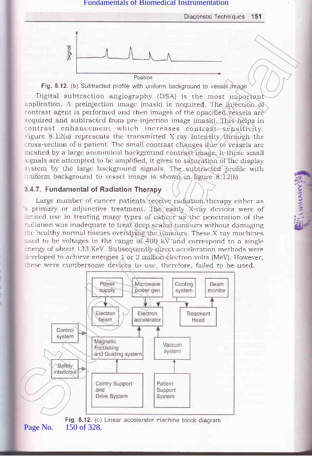
DiagonsticTechniques 151
(6c.?a
Position
Fig. 8.12. (b) Subtracted profile with uniform background to vessel image
Digital subtraction angiography (DSA) is the most importantapplication. A preinjection image (mask) is acquired. The injection of:ontrast agent is performed and then images of the opacified vessels areacquired and subtracted from pre-injection image (mask). This helps in:ontrast enhancement which increases contrast sensitivity.- igure 8.72(a\ represents the transmitted X-ray intensity through the:ross-section of a patient. The small contrast changes due to vessels are:reshed by a large anotomical background contrast image. It these small.ignals are attempted to be amplified, it gives to saturation of the display:r-stem by the large background signals. The subtracted profrle with,-niform background to vessel image is shown in figure 8.12(b\
3 4.7. Fundamental of Radiation Therapy
Large number of cancer patients receive radiation therapy either as. primary or adjunctive treatment. The easily X-ray devices were of.nited use in treating many types of carrcer as the penetration of the-:diation was inadequate to treat deep sealed tumours without damaging
.e healthy normal tissues overslying the tumours. These X-ray machines- sed to be voltages in the range of 400 kV and correspond to a single-::erg/ of about 133 KeV. Subsequently direct acceleration methods were-:r'eloped to achieve energies I or 2 million electron volts (MeV). However,-.ese were cumbersome devices to use, therefore, failed to be used.
4.
::-,
Fig. 8.12. (c) Linear accelerator machine block diagramStud
y Mate
rial
Page No. 150 of 328.
Fundamentals of Biomedical Instrumentation

152 Fundamentals of Biomedical lnstrumentation
Some betatron units were developed which provided electron energiesupto 45 MeV and they had greater penetration through thick body sectionsand were suited for treating tumours of the trunk and pelvis. However,these had serious drawbacks of being larger, heavy and cumbersomedevices.
Cobalt machine was developed which was simple, compact and reliablelow-energr radiation treatment device using a pellet of radioactive cobaltisotope as a source of radiation. This machine survived for 30 years andthey had the tremendous advantage of producing a completely predictable,steady, reliable beam of relative high-energr radiation. It was easy torepair and maintain.
Today, most of the radiotherapy treatments are carried out usingconventional radiotherapy linear accelerations. Linear accelerator portionaccelerates electrons to the required level of ener$/. In short, completemachine is referred as accelerator. It is designed to deliver a mega-voltage X-ray beam suitable for modern radiotherapy techniques. It iscomprised of gantry and stand, treatment couch; and control console. Itproduces ener5/ ranging from 4 to 20 MeV. The block diagram ofaccelerator is shown in figure 8.12(c\
The range of technologies used in the linear accelerator system isvery wide. It requires high power electronics in the order of megawatts.The dose monitoring system has to measure currents of the order ofIA-72 amps. Microprocessor technologr is used. Safety interlocks, gantryand patient, support call high technologr and precision.
Computerized Axial Tomography (CAT) or computed tomorgraphy (CT)
scanning combines X-ray imaging with computer techniques. CAT permitsvisualization of internal organs with greater clarity. The X-ray photographis a shadow of all organs and structures in the path of the rays. Whenevertwo radiopaque objects lie; one behind the other, in the X-ray path.the smaller of the two may be completely hidden by the larger, see
figure 8.12(d).
d\nS
opsl
vlbpr
dIIb.
rn
S1
rll
/,_.,
t/ilI,t
?,:
s
:x';,-i
a-a
-;,_1
:S
-:\t*o=:
Fig. 8.12. (d) X-ray imaging of two objects, one behind the otherStud
y Mate
rial
Page No. 151 of 328.
Fundamentals of Biomedical Instrumentation

DiagonstlcTechniques 153
If the X-ray source and hlm are simultaneously moved in oppositedirections, for a given combination of source and film velocities, objectsrvill appear to remain stationary with respect to the film during thenovement in one single plane perpendicular to the path of the rays. Theshadows of the objects at all other distances from the source will movern the film and produce a blur. See figure 8.13, the sphere lies in the:lane that appears stationary, but cube does not. The shadow of thesphere is hence reinforced as the X-ray vintage point is changed. The,'intage points for axial tomography are taken around the axis of the:ody. A very narrow pencil-like X-ray beam scans a single slice:erpendicular to the body's axis. By scanning two or more slices, a threerimentional representation can be created. The measurement is done by:reans of one or more sodium, iodine or calcium chloride crystal detectors:i- scintillating in proportion to the intensity. The scintillation light is:--easured by photomultiplier tubes. X-ray source and film move..multaneously in opposite direction. One plane appears stationary on---m and small sphere lies on.the same plane.
Fig. 8.13. Linear tomography X-ray source and film move simultaneously inopposite direction. One plane appears stationary on film and small sphere
bias on the same plane
Present day CAT scanners use X-ray sources which provide fan beams-: multiple detectors to simultaneously measure the density across a
, :r position of the slice. The figure 8.14 shows the fastest instruments':.:ng a fan beam that covers the complete width of the slice. Several' -:-dred detectors are used to measure the density pattern of the slice; --- good resolution. The time for co:mplete scanning of a slice is as low
i'/, secs. High scanning rates are feasible which permit scanning-,-1 sections of the body and the p,atient is made to hold the breath
- - ,ie completely still for few seconds in order to complete the scanning.- :hronizing scans with the ECG helps to reconstruct slices of the,.:: in various phases of the cardietc cycle.
lhe CAT scanners can provide irrformation about internal organs' : cody structures which could n,ot be done by conventional X-ray' :-graphs. It is regarded as one of the major developments in medical
':-:mentation.
4.
--
Stud
y Mate
rial
Page No. 152 of 328.
Fundamentals of Biomedical Instrumentation

154 Fundamentals of Biomedical lnstrumentation
Gr
8.6
:]^-:t e
]I:.S.r_-(
.:
47.
f+
)\.
H
X-ray source
Fig. 8.14. Modern cAT Scanners fan beam covers complete cross-section of the- body with large number of detectors
Fig' 8.15. Block diagram of CT scanner
The block diagram of cAT or CT scanner is shown in hgure 8.15. The
X-rayis plathroudetector. The source of made moving or detector or both across the sectior'
of the body. The measurements are rnade at regular intervals. An electron
beam CT scanner is shown in frgure 8'16'Stud
y Mate
rial
Page No. 153 of 328.
Fundamentals of Biomedical Instrumentation

Diagonstic Techniques't55
CrystalFocus coil
Deflect oncorl
3un
!6
Fig. 8.16. An electron-beam CT scanner
EMISSION COMPUTERIZED TOMOGRAPHY
;-. lioactive isotopes of certain elements can be used to trace the-.:abolism, pathways, and concentrations of the body parts. Emission
=puterized tomography can provide detailed three-dimensional: .:ribution map of an isotope which is injected into the body andr .',\-ed to distribute itself. The three-dimensional image is created byr::--fl9 scans of several slices. Naturally instrumentation for emission
::-puterized tomography is very sophisticated. such methods are beingl' tloped for ultrasonic imaging of the heart and abdominal organs.
l: MRt
l{t.i:etic Resonance Imaging (MRI) is based on the nuclear properties ofT- :-rgen atoms in the body. Elements having odd number of protons in'l:'' ,-'-rcleus have magnetic properties. Such elements are hydrogen -1,
:n -13, oxygen -17, sodium -23, Fluorine -19, phosphorus _3 1, etc., gen atom nucleus has a single proton which being odd number
::re property of spin as given in figure 8.17. This works like magnet--. the patient is placed in a strong magnetic field, the magnetic
'l: -:nts of protons align with or against the field lines of the magnet-r,$rn in figure 8.18.St
udy M
ateria
l
Page No. 154 of 328.
Fundamentals of Biomedical Instrumentation

156 Fundamentals of Biomedical lnstrumentation
t
t
tt
t
I
3
II
I
I
I
Fig. 8.17. Spinning of hydrogen protons
-top spinning off its vertical axix
Main magnetic field
Fig. 8.18. Alignment of hYdrogen
protons
align with the field
1I
ap
A small excess of magnetic moments of protonsso that a net magnetic vector NMV is created'
If RF pulses of the same frequency as the precessing nuclei are
applied at right angles to the main static magnetic field, the hydrogen
nuclei tissues get disturbed. They absorb ener$/ and change theirorientation with respect to the magnetic field and are lifted to the highereners/ state. Now, if the held is put off, the hydrogen nuclei go back to
their low ener$/ state after emitting eners/ they had received. All thisprocess is known as nuclear magnetic resonance. The emitted enerry
Lan be detected, digitised, amplified, encoded and transformed by
computer into cross-sectional images. The MRI images are accurate for
visualization of tumours, inflammatory and vascular abnormalities.
MRI scan is a radiologr technique combining magnetism, radio waves
and computer to produce images of organs.
The MRI scan schematic diagram is shown in hgure 8.19. The patient
is in a magnetic field. created by a magnet. The RF transmitter sends
waves through the patient and RF receiver detects the signa-l. The intensifi'of these signals are converted into image.
RE.T)Ureceiver
8
1
lrf,ii'Ilr
91.
H
Fig. 8.19. MRI lnstrumentationStud
y Mate
rial
Page No. 155 of 328.
Fundamentals of Biomedical Instrumentation

Diagonstic Techniques 157
There are several MRI techniques:(4 ECG gated spin echo which provides static images with high signal
to noise ratio for evaluating anatomic problems.(n) ECG referenced gradient echo for dispraying the intimal flap and
the extent of the dissection within aorta.(iif cine gradient echo for assessing cardiac contractile function.(iu) cine MRI gives tomograms of heart beats in a cinematic format.(u) Velocity encoded cine-MRI to estimate heart beat gradient across
valvular stenosis and blow flows in heart.MRI is a noninvasive technique with excellent soft tissue contrast.
l,lRI is a slow process, relatively expensive. It can not image bones. MRIs used for soft tissues-brain, vessels of brain, eyes, inner ear, heart,,rdominal vessels, kidney, etc. Naturally it is able to diagnose related::oblems of the organs.
Non-invasive diagnostic: It does not involve getting inside the bodyphysically or invading it while conducting the diagnostic. These arenot traumatic for the patient and do not have any determinant sideeffects on the patient.
asonic measurements: When sonic energr atKHz (i.e. above audible range), the reflected energre difference of densities between the two media
and the angle at which transmitted beam hits the medium. Higherthe difference in media, the higher will be the reflexion.Doppler effect is an important characteristic of ultrasound frequeuncy.The modes of ultrasound transmission are pulsed ultrasound usedlor imaging applications, continuous doppler used for blood flowneasurement, Pulsed Doppler for measurement of velocity anddistance of moving object and range-gated pulsed doppler used forclood flow rate.ultrasonic Imaging: Ultrasound imaging systems are comprised ofhe pulsed ultrasound or pulsed doppler mode. The information
:eceived is amplified and displays in modes such as A-scan, M-scan,3-scan displays.Llltrasonic Diagnosis: The ultrasonic diagnosis techniques are used:rr heart problems through echocardiogram and similarly brain::oblems through echoencephalogram, used for eye problems through:thalmic scans, etc.
x-ray and Radiostope Instrumentation: X-rays ca, penetrate opaque:iects and provide an image of their inner structure. The medical
- agnosis or therapeutic uses are on X-ray principles. X-rays can.r:ntify bones, metallic parts, air filled cavities, etc.
: -dio isotope techniques are based on counting the number of nuclear' rntegrations that occur in a radioactive sample during a certain:-e interval. The ionizing effect of X-ray is used in treatment of
,4.
SUMMARY
Stud
y Mate
rial
Page No. 156 of 328.
Fundamentals of Biomedical Instrumentation

158 Fundamentals of Biomedical Instrumentation
deep-seated tumour. In such cases very hard X-rays are generatedfor case of tumours. Soft X-rays are used for treatment of skin.CAT or CT Scan: Computerised Axial Tomography (CAT) or computedtomography (CT) scan combines X-ray imaging with computertechniques. The CAT scanners can provide information about internalorgans and body structure which corrld not be done by conventionalX-ray photographs.Emission Computerised Tomography: Radioactive isotopes of certainelements can be used to trace the metabolism, pathways andconcentrations of the body part. It can create 3-dimerrsional imagefor diagnostic purposes.MRI: Magnetic Resonance Imagaing (MRI) is based on nuclearproperties of hydrogen atoms in the body. The MRI images are accuratefor tumors, inflammatory and vascular abnormalities.
6.
7.
8
H
6xercidea
8.1. What do you understand by the term "noninvasive methods"?8.2, What is meant by uitrasonic imaging? Compare ultrasonic diagnosis with
X-ray diagnosis. (UPTU-MQPI)
8.3. What do you mean by diagnosis? Expiain X-ray diagnosis technique.What is the difference between X-ray and radioisotope methods fordiagnosis? (UPTU-MQPI)
8.4. Explain the principle of CAT scan and compare its visualisation methodwith conventional method. (UPTU-MQPL)
8.5. Discuss the principle and use of the ultrasonic measurements in medicaldiagnosis. (UPTU-MQP21
8.6. Write a shot note on the instrumentation for the medical use ofradioisotopes. (UPTU-MQP2)
8.7. Discuss the properties of ultrasound and how ultrasound can be used fordiagnosis. (UPTU-MQP21
8.8. Explain the principle of computerised axial tomography and compare itsmethods of visualisation with conventional X-ray methods. (UPTU-MQP3.r
8.9. What is echocardiography? (UPTU-MQP3I
8.10. Explain the working principle of CT scan with block diagram.(UPTU-200s
8.11. What are the properties of ultrasound? Discuss the basic modes oitransmission of ultrasound? (UPTU-2003
8.12. Discuss various types of ultrasound imaging. Explain its application inophthalmic scans and echoencephalography. (UPTU-2003
8.13. Explain and describe emission computerised tomography. (UPTU-2004
8.14. Explain and describe echo-encephalography. (UPTU-2004
8.15. Explain and describe CAT scan. (UPTU-2004
.'\'h
:-e€
flo(
(r
tll
ttt(r
tu
3.1.
::Ot--:et-:al
-. c€
::t
JiaStud
y Mate
rial
Page No. 157 of 328.
Fundamentals of Biomedical Instrumentation

Biotelemetry
': -Inside this chapter9.1. Introduction to Biotelemetry9.2. Physiological Parameters Adaptable to Biotelemetry9.3. The Components of Biotelemetry System9.4. Implantable Units9.5. Telemetry for ECG Measurements During Exercise9.6. Telemetry for Emergency patient Monitoring9.7. Summary
'henever it is necessary to monitor physiological eve.ts fromof biotelemetry becomes important. The requirements
a distance,which need
iotelemetry are:(rJ Monitoring of astronauts in space by radio-frequency transrnissions.
izr) Monitoring of patients while exercising since conne cting leads arecumbersome and dangerous.
iiz) Monitoring of patient in an ambulance.iLr) Medical data transmission from home or office.tLr) Research on unanesthetized animalsilrJ Isolation of an electrically susceptible patient.
INTRODUCTION TO BIOTELEMETRY
:telemetry is the measurement of biological parameters over a distance..thoscope is the example of biotelemetry of simple nature. In this caseart beats are amplified acoustically and transmitted through a hollor,r,:e system which is picked up by the ear of the physician for inter-
c1f
159Stud
y Mate
rial
Page No. 158 of 328.
Fundamentals of Biomedical Instrumentation
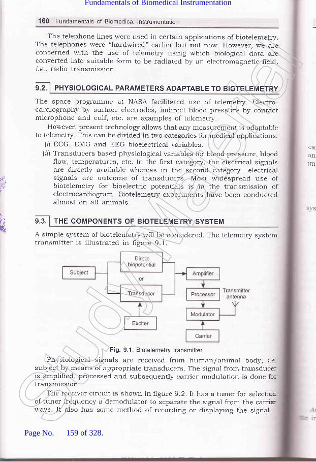
160 Fundamentals of Biomedical lnstrumentation
The telephone lines were used in certain applications of biotelemetry.The telephones were "hardwired" earlier but not now. However, we areconcerned with the use of telemetry using which biological data areconverted into suitable form to be radiated by an electromagnetic field,i. e., radio transmission.
9.2. PHYSIOLOGICAL PARAMETERS ADAPTABLE TO BIOTELEMETRY
The space programme at NASA facilitated use of telemetry. Electro-cardiography by surface electrodes, indirect blood pressure by contactmicrophone and culf, etc. are examples of telemetry.
However, present technologr allows that aly measurement is adaptableto telemetry. This can be divided in two categories for medical applications:
(0 ECG, EMG and EEG bioelectrical variables.(it) Transducers based physiological variables for blood pressure, blood
.tIow, temperatures, etc. In the first category, the electrical signalsare directly available whereas in the second category electricalsignals are outcome of transducers. Most widespread use ofbiotelemetry for bioelectric potentials is in the transmission ofelectrocardiogram. Biotelemetry experiments have been conductedalmost on all animals.
THE COMPONENTS OF BIOTELEMETRY SYSTEM
A simple system of biotelemetry will be considered. The telemetry systemtransmitter is illustrated in figure 9.1.
Fig. 9.1. Biotelemetry transmitter
Physiological signals are received from human/animal body, i.esubject by means of appropriate transducers. The signal from transduce:is amplifred, processed and subsequently carrier modulation is done fo:transmission.
The receiver circuit is shown in figure 9.2.It has a tuner for selectio=of tuner frequency a dernodulator to separate the signal from the carrirwave. It also has some method of recording or displaying the signat.
CA,
anlm
t1
9.3.k
Stud
y Mate
rial
Page No. 159 of 328.
Fundamentals of Biomedical Instrumentation

Biotelemetry 161
Receiver Antenna
Fig. 9.2. Biotelemetry receiver system
Biotelemetry systems use radio transmission. A radio-frequency (RF):arrier is a high frequency sinusoidal signal when applied to appropriate=:rtenna gets propagated in the form of electromagnetic waves. Some---:rportant terminologz are:
R""nge-{he distance the transmitted signal can be received..Modulotion-Process impressing information upon the carrier.Demodulation-Recovery of the signal from RF carrier.The Figure 9.3 shows various stages of the waves and two basic
:'.'stems of modulation.
Signal
Carier wave
Amplitude modulated(AM)
Frequency modulated(FM)
Fig. 9.3. Two basic modulations
Amplitude modulation-Amplitude of the carrier is made to vary withinformation being transmitted.
|1.{-
Stud
y Mate
rial
Page No. 160 of 328.
Fundamentals of Biomedical Instrumentation
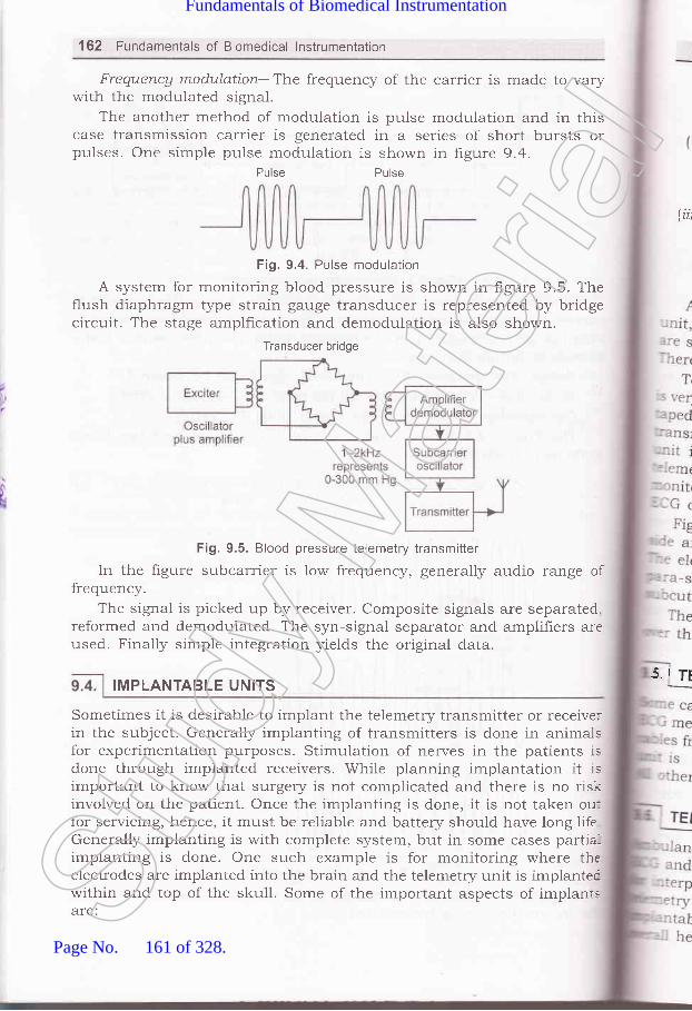
162 Fundamentals of Biomedical lnstrumentation
Frequencg modulation--The frequency of the carrier is made to varywith the modr-rlated signal.
The another method of modulation is pulse modulation and in thiscase transmission carrier is generated in a series of short bursts orpulses. One simple pulse modulation is shown in hgure 9.4.
Pulse Pulse
Fig. 9.4. Pulse modulation
A system for monitoring blood pressure is shown in figure 9.5. Theflush diaphragm type strain gauge transducer is represented by bridgecircuit. The stage amplfication and demodulation is also shown.
Transducer bridge
(iii
Fig. 9.5. Blood pressure telemetry transmitter
In the figure subcarrier is low frequency, generally audio range offrequency.
The signal is picked up by receiver. Composite signals are separated.reformed and demodulated. The syn-signal separator and amplifiers areused. Finally simple integration yields the original data.
Sometimes it is desirable to implant the telemetry transmitter or receiverin the subject. Generally implanting of transmitters is done in animalsfor experimentation purposes. Stimulation of nerves in the patients isdone through implanted receivers. While planning implantation it isimportant to know that surgery is not complicated and there is no riskinvolved on the patient. Once the implanting is done, it is not taken ou:for servicing, hence, it must be reliable and battery should have long lifeGenerally implanting is with complete system, but in some cases partia-implanting is done. One such example is for monitoring where theelectrodes are implanted into the brain and the telemetry unit is implantecwithin and top of the skull. Some of the important aspects of implanrsare:
5.i TI!MPLANTABLE UNITS
Stud
y Mate
rial
Page No. 161 of 328.
Fundamentals of Biomedical Instrumentation

Biotelemetry 163
TELEMETRY FOR ECG MEASUREMENTS DURING EXERCISE
,I1ul'rrrleo on tne belt and the electrodes are fixed on the body.:. requlrements are as described earlier.
-ELEMETRY FOR EMERGENCY PATIENT MONITORING
'' such a disease requiree exerci The connecting' le exerc The transmitter
A complete set of imprantable unit comprises of transducer, transmitter-:i' power source and necessary leads. The implantable units in useurrrLo rrt qJc' : single-channer blood pressure transmitter, temperature transmitter." =:e are several implantations on dogs for experiment.,i,r. prrpo""".rqlyvevo.relemetry of ECGs from extended coronary care for cardiac patients'ry much in use' In this arrangement, each patient has ECG electrodesU UTSU LI ULTCS:'d securely to his chest' The electrodes are connected to a sma,
' -smitter unit having signal conditioning equipments. The transmitteris fastened to a special belt worn -.or-,.rd the patients waist. A':retry receiver for each monitored patient is inciuded as part of-.r:orlng system. The output each receiver is connected to one of the, channels of the patient monito
: e transmitting antenna is a flat disk which is taped on the skin--re subcutaneous receiver by disposable adhesives.
4.
.:-ces need to be equipped with telemetry equipments to allow: other physiol0gical data to be transmitted to near-by hospital::retation' Two way voice transmission in conjunction'witrr bio,-' is used. These transmitters are very powerful compared 1o,:le units. Emergency medical care is an important part of the.alth care system.Stud
y Mate
rial
Page No. 162 of 328.
Fundamentals of Biomedical Instrumentation

164 Fundamentals of Biomedical lnstrumentation
Calvarium4 i- Dura mater
lnsulation
oscilloscoPe.Implantable telemetry units: Implantable telemetry units mussmall, the outercase and wiring must be impervious to body tru
and moisture for this reason plastic potting compounds or siencapsulation is in use. Lithium battery is used as a power
for lor,g life.
WireEvelet(a)
Q)
Cortex
cluster of Fine Ag sphere (b)
Wires, lnsulated
Fig. 9.6. lmplanatable electrodes (a) wire loop electrode, (b) silver-sphere cortical--
surface potential electrode, (c) Multielement depth electrode
SUMMARY
9.1
))
)3.<4-
:6.
*
1 Biotelemetry: Biotelemetry is the measurement of biological param
over a d.istance. Stethoscope is the example of biotelemetry of sin
2.
J.
nature where in heart beats are amplihed acoustically and transmr
through a hollow tube system which is placed up by the ear of
physician for interpretation. Present day, biological data are conve
into suitable form to be radiated by an electromagnetic held,
radio transmission, is the high tech example of biotelemetry use
biomedical instrumentation.Physiological Parameters adaptable to Biotelemetry: ECG'
u.t a BUC bioelectrical variables, also transducer based phy
variables for blood pressure, blood flow, temperature, etc'
Components of Biotelemetry System: It has two maJor F
tranJmitter which comprises of Electrodes Transducer, Amp
Processor, Modulator, Carrier and transmitting antenna, and rece
antenna, tuner, demodulator, tape recorder, chart recorde:
4.Stud
y Mate
rial
Page No. 163 of 328.
Fundamentals of Biomedical Instrumentation

Biotelemetry 165
5.
6.
Telemetry for ECG measurements during excerise: while exercisingon a treadmill, the transmitter unit is Lounted on the belt andelectrodes are fixed on the body.Telemetry,for toring: Ambulances need tooe equtpect w to allow ECG and otherphysiologicalintlrpreta=tion. In addition two way rroi". trrT";r*:ffT ff?*;ii:for the benefrt of the patient.
CO.E
; 1.
:2.
erci,1e,J
what do you mean by bio-telemetry? List the advantages of bio-telemetry.(UPTU_MQP1)
Explain how four physiorogical parameters can be monitored andtelemetered simultaneously. ppfu_Mepl)Discuss telemetry as an emergency tool. ppTu_Mepl)what are the components of a bio-telemetry system? what are theapplications of telemetry in emergency patient monitoring? (upru-MQp2)Pl""]:: various applications ef bio-telemetr5 Explain the working of aBio-LINK PWM transmitting system. (U1TU_20O3)How can telemetry be done for ECG measurements durii! exercise andfrom extended coronary care patients? ppTU_20O3)p1r1"l" the components of a bio-telemetry system with the help of neatlabelled diagram.Draw a block diagram of a system to send an electroca ,orr*r'.!{{r"'rfo^11ambulance to a hospital by telemetry.
9a
JJJ
Stud
y Mate
rial
Page No. 164 of 328.
Fundamentals of Biomedical Instrumentation

calcor
Therapeutic and
Prosthetic Devices
A major use of medical electronics is in diagnostic medicine' Most of
instruments sense various physiological signals' carryout some procesl
The:\'It!
r -.stacl.--e ty-n- the
, -:Toufi1.:le on-.: sizr
r.ater 1
i:,_ n tht-:''- :luid
:* fnside this cll.,c,Ptcr
10.1. Aucliometers and Hearing Aids
10.2. MYoelectric ARM
10.3. LaParoscope10.4. Summar5'
The figure 10.1 shows the anatomy of the human ear' Sound rr
are longitudinal waves in which the motion of each particle of mec^.'^*A alnr
in which the wave is travelling, moves backward and forward aLo
line, in the direction in which the wave is propagated' The pi:"" "!1
:it#-;;;;j., ;"; ai"pr"vt' "Jo'd them' rhere is a class of med
electronic devices that are Lseful therapeutically or as prostheses'1 ----! 1.
examplesareelectricsimulators,incubators'ventilators'heart-lu:machines, artificial kidneys, audiometers' hearing aids,and
. -y:-"-l:t:
;fi;;;t""".p", ","' Rudiometers' hearing aids' myoelectric arms
LaparoscoPe are covered here'
loll] AuDloMETens axo neantxc nlos
10.1.1. Mechanism of Hearing
H;";;;;;;^A"t some of the scattered eners/ enters the a
l'e :he ba.,- sensl
:s ln::lC I
:::crat-::eresi_ -:tg. ,1
:Se O
.r. Ti
t66
Stud
y Mate
rial
Page No. 165 of 328.
Fundamentals of Biomedical Instrumentation

Therapeutic and Prosthetic Devices 167
canal and pushes against the tympanic membrane during a wavecompression.
Semicircular
,, canals
Vestibular
,// nelve
Tympanicmembrane
Eustachian tube
.ft,i.l
-- -
li
a-
Fig. 10.1. Anatomy ()f the human ear
The tympanic membrane separates the ear canal from middle ear:avity which is exposed to atmospheric pressure only through the:ustachian tube, which connects it to the pharynx and nose or mouth.- he tympanic membrane transmits tht: sound ener$/ through the cavity.l the middle air, to the receptor ct:lls in the inner ear, which are.urrounded by fluid. All these are coulrled to the oval window, j.e., total:rrce on the oval window is the same as that on the tympanic membrane.lh.e size of the window is very small , therefore, if experiences much=eater force per unit area. One of the b,ones, known as the stapes, rests-pon the lower end of the cochlea and pzrsses the vibrations directly into:re fluid within. Most of the pressure wer,e received by cochlea transmitted::r ffis basilar membrane surrounding th,e fluid. The membrane contains:-re sensitive receptor cells, which transforms sound ener$/ or pressure;.'aves into action potentials. These potentials are propagated along the:,rostic nerve fibres to the brain with a. speed of 1OO m/sec. The:lpreciation of sound is mainly a cer.ebreil function. Anything which-:terferes with the conduction of sound waves to the cochlea affects:-earing. The defect may be in ear drum., disease of the middle ear or the:rsease of the cochlea itself or its co,nnection in the central nervous=-,-stem. The human ear responds to vil:rations ranging from 20 Hz to 20..lfz. St
udy M
ateria
l
Page No. 166 of 328.
Fundamentals of Biomedical Instrumentation

$
168 Fundamentals of Biomedical lnstrumentation
10.1.2. Audiometer
The device, used to test the auditory response is known as audiometer.A basic audiometer is an oscillator driving a pair of earphone and iscalibrated in terms of frequency and acoustic power, which cart be adjustedover the audio range. Aud.iometer also provided with a calibrator, noise
source and bone-conductor-vibrator. It has two channels-first channelhas pure tone or speech output and the second channel has either.r"..o* band. or wide band marking signal. Independent attenuator and
transducers exist for each channel.Transmission of sound through the external and middle ear to internal
ear is called air conduction. The transmission of sound to the internalear via an electromechanical vibrator applied to the mastoid bone iscalled bone conduction. Bone vibrator contains a piezoelectric transducer.
Loud speakers d.eliver auditory stimuli which converts electrical signals
to audible vibrators. A permanent record of an audiometer is called
audiograph.Audiometers are classified as:
(r) Rrre tone audiometer(ir) Speech audiometer.
10.1.2.1. Pure Tone AudiometerIt generates test tones in octarre steps from 125 Hz to 8 kHz with
signal intensity ranging from 10 dI3 to l2O dB. Hearing loss, associated
*itt -iadte ear disease, can be evsluated with pure tone more accratel]-
than speech test as the frequency and intensity can be controlled withhigh degree of precision. Pure tor:e audiometer is composed of an LC
o"Lillrto. which is controlled to an output current amplifier stage toproduce the necessary power lerrels. Ladder attenuators are used icthese instruments of nominal impedance of 1O ohms. The output signa'
is coupled to a small loudspeaker or an earphone which helps in hearing
by aii conduction and a tone vibrator for hearing by bone conduction
10.1.2.2. Speech AudiometerSpeech audiometer is used in the differential diagnosis of hearing
disorder and in the assessment of social handicap. Pre-recorded speecb
is used, as a test signal. A doubl'a band tape recorder is used to interfaclthe two channel audiometer units. Two head phone of L.S. of 25 warrs,
for each channel are available.
30 to 5o percent sensory cells in the inner ear may have gone
irrepairable structural damage r>r missing. In such circumstances,only choice available for hearing impaired individuals is to wear a hear
aid. Hearing problem is caused. by either loss in sensitivity or loss
;Ior-
ouwit
ofrthato(10.
: :-eC1
T]
MA(
LI
MJ
RIAN
Th- lifl-::stlE:emr::ed:+ -.i'or&l -st(
lhe
'stll---€ r
-E :'lnSllSt
udy M
ateria
l
Page No. 167 of 328.
Fundamentals of Biomedical Instrumentation

Therapeutic and Prosthetic Devices 169
the ability to discriminate different speech sounds or both. Loss ofloudness may be due to increased mechanical impedance between theouter ear and inner ear. Loss of discrimination ability may be associatedrvith damage to the sensory organ.
The invention of semiconductor electronics have enabled developmentof small and efficient integrated circuits which can be packed in a formthat frts behind or in the ear. The primary function of a hearing aid is:o compensate for the 10ss of sensitivity of the impaired ear.10.1.3. 1. Conventional Hearing Aid
A basic hearing aid is shown in frgure 10.2.
Fig. 10.2. Conventional hearing aid and block diagram
The functional parts are:MlC-microphone and associated preamplifier.-\GC-automatic gain control circuit.LPF and HPF-a set of active filter.s, i.e. low pass filter and high pass
:f.
\{ixer-a mixer and power amplifier.REC-a transducer or receiver..\M / PR-audiometer/ programmer.The complete circuit works on a battery. The multiple channel helps:ifferent frequency range which can be adjusted with potentiais.-:st hearing aids are electronically programmable. The programmable
:imeters are downloaded from a computer based system and are:d in digitial registers. The register output helps to switch register
;.orks which control various analog circuitry. The active filters are-sted to provide frequency attenuation since most of the hearing aids.:re high frequency gain.- re microphone is a transducer in the hearing aid. The receiver is
'-ectromagnetic device which drives a miniature cliaphragm to produce-sric output. output is routed through a flexible tubing'---: ear and ponse is altered to boost high frequency:,-:rse. This i tapering its inside diameter from the ear,-.j back to the receiver part end.St
udy M
ateria
l
Page No. 168 of 328.
Fundamentals of Biomedical Instrumentation

170 Fundamentals of Biomedical lnstrumentation
The complete electronic circuitary is packaged in a miniature housingfor htting on the ear. The miniature sized hearing aids can be either putin packet or fixed on the belt and connected to the ear.
However, most comfortable design is to frt behind the ear or insidethe outer ear.
10.1.3.2. Digital Hearing AidIt gives greater dynamic range with less power consumption and
greater complexity. A digital hearing aid block diagram is as shown infigure 10.3.
MIC-microphoneADC-analog to digital converterDSP-digital signal processorREC-receiverAM / PR-audiometer/ programmer
sls1
CI
a1
thulth1n
I
{
\
:_tn(.nd
10.2
1-fmi_ata1- SO
: lra.
: ntle,:eri=:e l
- - ,lol'---p[,::e i
---:cu
$Fig. 10.3. Digital hearing aid and block diagram
The soundwaves are picked up by the microphone which is
transformed into electrical signals. The electrical signals are converteCinto digital form. The digital processing device contains an array to
adders, multipliers and resisters to provide the fundamental operationsfor implementing various digital algorithms. The digital technologr is
implemented with CMOS technologr. The digital hearing aids providecapabilities of ease of fitting and stable superior long term performance
The difference between inanimate and animate objects is that the animatemove, i.e., respond to their environment and show changes in their bodlfunctions. These properties are called behaviour which are controlled [rthe nervous system known as neurologz. The body parts are connecteCto the brain through nerve hbers. Nerves that carry sensory informationfrom the various parts of the body to the brain are called afferent nen-es
and the ones that carry signals from the brain to operate various muscare called efferent nerves.
Countless feedback loops control the action of muscles. The musclthem selves contain stretch and position receptors that permit prec:control over the operation. Many of the routine muscular movementsthe body are not controlled by the brain at all but are reflexes ofSt
udy M
ateria
l
Page No. 169 of 328.
Fundamentals of Biomedical Instrumentation
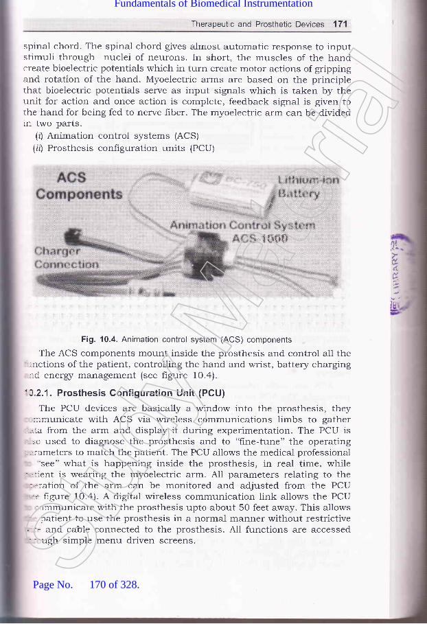
Therapeutic and Prosthetic Devices 171
spinal chord. The spinal chord gives almost automatic response to inputstimuli through nuclei of neurons. In short, the muscles of the handcreate bioelectric potentials which in turn create motor actions of grippingand rotation of the hand. Myoelectric arms are based on the principlethat bioelectric potentials serve as input signals which is taken by theunit for action and once action is complete, feedback signal is given tothe hand for being fed to nerve f,rber. The myoelectric arm can be dividedin two parts.
(zJ Animation control systems (ACS)
(irJ Prosthesis configuration units (PCU)
"l **$$
Fig. 10.4. Animation control system (ACS) components
The ACS components mount inside the prosthesis and control all the'-.nctions of the patient, controlling the hand and wrist, battery charging,:-d energz management (see figure 10.4).
'A.2.1. Prosthesis Gonfiguration Unit (PCU)
The PCU devices are basically a window into the prosthesis, they-irmunicate with ACS via wireless communications limbs to gather
-.^:a from the arm and display it during experimentation. The PCU is, =o used to diagnose the prosthesis and to "fine-tune" the operating; .:ameters to match the patient. The PCU allows the medical professional
'see" what is happening inside the prosthesis, in real time, while; '.rent is wearing the myoelectric arm. All parameters relating to the
.ration of the arm can be monitored and adjusted from the PCU
'.= figure 10.4). A digital wireless communication link allows the PCUr,rmmunicate with the prosthesis upto about 50 feet away. This allows
': patient to use the prosthesis in a normal manner without restrictive' -: and cable connected to the prosthesis. A11 functions are accessed- -rugh simple menu driven screens.
,fl,ir..
d.
6
Stud
y Mate
rial
Page No. 170 of 328.
Fundamentals of Biomedical Instrumentation

172 Fundamentals of Biomedical lnstrumentation
Realtime Monitor
SER 11
Status : Closing
E
tl
H
Fig. 10.5. PCU disPlaY
10.2.2. Animation Control System (ACS)
The ACS monitor and control all the functions related to the operation
of the hand and wrist. These are microcomputer based systems whichinterpret patient commands, determine the best method of operating the
hand and wrist to match the command, and then drive the hand or wristin an energr efficient manner. These are unique methods of interpretingthe patient sensors which allows the system to adapt to virtually anypatient signals. Various control strategies using techniques, algorithmsand strategies of control are pre-programmed in the ACS system and are
used to custom fit the prosthesis operation to the patient'A patient is started with a minimal myoelectric signals, then as the
patieni signal levels increase, the system is moved to voluntary open and
voluntary close with onloff control. Further progression of the patientwould lead to proportional control and ultimately allow hand and wristoperation. nCS is normally designed to operate with lithium-ion and
liihium-polymer batteries to optimize the operation in an ener$/ efficient
marrner.ACS use radio telemetry to transfer information to and from the
prosthesis. The ACS module is round and mechanically designed to snap
into the wrist of a prosthesis designed. A plug-in adapter with gold-
plated connections allows direct contact to the slip-ring contacts on the
hand to canneet to many other hands and wrists.
10.2.3. Rechargeable Lithium Battery
Animate prosthesis use rechargeable lithium battery. The rechargeable
lithium batteries have proved to be the best choice primarily because
they have two to four times more eners/ for a given size and weight thar-
technologies such as nickel cadmium and nickel metal hydride. These
batteries do not have the "dreaded effect" and can be recharged at an1
point of discharge. The recharge time for a fully discharged battery is
abotrt2to3hours.Each time the charge cycle starts, the ACS performs an analysis o:
the battery to determine the proper method of charging. A precisio:charge is applied to the battery to make sure that it will always have tl]t
oF
ac
po'alsma
w(th,thr
1o.
LardifirnnTheare:apa_re
lov(:uII
:re:ld:rot:Inl
'/
&
(i,
(n'l
iit)'l
(0
rnJ
in)
ir)
Stud
y Mate
rial
Page No. 171 of 328.
Fundamentals of Biomedical Instrumentation

Therapeutic and Prosthetic Devices 173
optimal charge. This allows the battery to perform properly daily andachieve its overall life.
The ACS should shut off the battery if it detects a problem thatwould waste ener5/ or otherwise damage the battery. The circuitry insidethe battery provides automatic protection from external problems thatthe ACS can not control that would physically damage the cells.
The charging of the battery is simply pluging the connector from thepower source supplied to with the ACS into the charging part which cana-lso have indicating lights. Small size batteries are available which canmatch the size, weight and energr to the prothesis and patient.
Laparoscopic surgery is very intensive technologically and is completelyCifferent approach to operative intervention. The response to this-nnovative method of instmmentation has revolutionized the medicare.The vigrous research, development and challenging problem solving effortsere continuing in this field. The technological growth in this area is:apidly expanding. The discussion of some of the available equipments
-e being taken up here.Laparoscopy has played a major role in grnological surgcries initially
:overing tubal ectopic pregnancy, but subsequently in wider use in ovarin:-rmors and laparoscopic hysterectomy.
l,aparoscopic surgery reduces post operative pain. Narcotic analgesics
-e seldom required. Padent recovery is fast and he cal be discharged early:-ed can go back to work quickly. It is especially superior and wound::oblems like hematoma, infection, scar h5pertrophy and hernia are--jnimum. The laparoscopic surgery can be for diagnostic purposes such
(r') Diagnosis of occult abdominal parn.ir') Assessment for resectability of tumors.iirJ Assessment of abdominal tramma.The therapeutic uses of laparoscopy:rJ Gynaecological surgery of hyterectomy.iil Thorax video assisted thoracoscoplc surgery.:ir') Retroperitoreal surgery: :') Abdomen----cholecystectomy, appendicectomy, inguinal hernia repair,
fundoplication, small bowel, and large bowel resection, splenectomy,etc.
!0 3.1. Basic lnstrumentation Configuration
The surgical theatre becomes intra-abdominally, therefore, it has toru:.'s 5pzgs for visualization and movement of instruments. It also requiresn.:ging system, manipulating surgery instruments to cut, managementrn :[eeing, stiching techniques, etc. Before going into details of exactrr:-.-.niques of laparoscopic system, it is essential to go through importanturr:tcts of instmmentation and facility development in the field.St
udy M
ateria
l
Page No. 172 of 328.
Fundamentals of Biomedical Instrumentation

174 Fundamentals of Biomedical lnstrumentation
10.3.2. lmaging System
The laproscopic telescope provides the means of acquiring an imageof the abdominal cavity. Light is sent into the abdominal cavity throughthe fiber bundle surrounding the rod lens. The light comes out of thescope as a ring at the tip of the instrument. The diameter of the telescopeused these days are 5 or 10 mm instrument.
The telescopes are either forward viewing or oblique. A O-degreeinstrument provides an image. Oblique viewing scopes have an angle of30 degrees to 45 degrees off the center lines of the instrument. It is usedfor areas not accessible such as over the dome of the liver.
A the proximal end of telescope, there is an eyepiece which is usedas an attachment for the camera.
The adapter, which joins the camera and the telescope by means ofa C-mount, also contains a focusing lens. The telescopes have beendesigned with camera as an integral part. Laparoscopic system withdistal lens washing as well as an irrigation channel directed toward theoperative site are available.
Miniature light weight camera weighing 40 gms or lesser are used.It has CCD chip of size Yz" having 3O0,OOO light sensitive pixels.
Each pixel responds electrically in proportion to the number of photonsto which it is exposed.
Light source is generally either Xenon or metal halide bulb havinglife of approx. 250 hour. The light is provided to the laparoscope througL-hberoptic cable.
10.3.3. lnsufflator and lrrigator
The exposure is achieved by insufflation of the peritoneal cavity wir-gas such as carbon dioxide (CO2) .This permits safe introduction an;manipulation of cannals to accomodate the laparoscopic telescope an:laparoscopic instruments. The flow of carbon dioxide creases automatical-.when a preselected intra-abdominal pressure is achieved. A rearculatir:;pump exchanges and hlters carbon dioxide to remove smoke and debris.It simultaneously maintains stable intra-abdominal distention pressureDisplay of carbon dioxide pressure and flow rates are available.
Management technique of bleeding is done by an effrcient high florirrigator f aspirator unit. It has the ability to direct a forceful fluid strea::coupled with rapid aspiration of clots and fluid. It is best accomplished dol'-gtwo jobs with the same tube by alternating the suction and irrigation fi.mctior-:
Operating rooms are as usual equipped with nitrogen as a pressu=source. The nitrogen powered irrigation system is used for laparoscorr:irrigation which provides a fluid stream from a 80 psi source and is se-effective in hydrodissection. Standard irrigation bags are connectrdthrough the disposable diaphragm pump. Some irrigationi units a-=
structured to accept an electrocautery or laser probe without interpret:
ananele
GearI-{s r
COI
ancThe:Tte(
10.:
.'.itt',,,-itl
.rd_':lto-,:e(
: le(- r-afa- co
1..t--u-
i.1atr: -:cl, _:h
'0.3.
L.-lL
,_rc
Ir'- a(- -'tl- ::I-1
* 1t
r.:11
rl-l I
10
l.e,ex(
k
with the irrigation/suction function.Stud
y Mate
rial
Page No. 173 of 328.
Fundamentals of Biomedical Instrumentation

Therapeutic and Prosthetic Devices 175
10.3.4. Dissecting and Manipulating lnstruments
Laparoscopic surgeon has choice of a several number of instrumentsand many a times in combination to perform the tasks of manipulationand dissection. Many instruments have connectors and are insulated forelectrocantery.
The multipurpose tools are single instrument serving several functions,i e., retraction, aspiration, irrigation, and electrocantery. Instrumentexchange time is minimized and less access ports are required.
Any type of effector tip can be placed at the end of an instrument.General purpose grasers and dissectors have relatively short narrowarms capable of performing with teasing, tearing or streching maneuvers..\ssorted reusable graspers and dissectors with various handle--onfiguration.
Enopath bowel instrument are an Endo Babcock and Allis grasper,:nd an occlusive bowel clamp, a kelly clamp, and a right angle dissector.lhese have features of fiongeitip shaft rotation and a jaw lockingrechanism.
10.3.5. Suturing and Ligation lnstruments
Intracorporeal suturing and knot tying instruments are available;.ith laparostopic system. Absorbable ald non-absorbable suture materials;.ith short ski and straight needles have been made available. A suture.rd need.le combination is either free standing or attached to a disposable,-rot pusher. A single use devices are available which include a curved
-eedle with needle driver and pretied knot.A pretied suture loop can be applied if a free pedicle requires ligation,
r:ecially useful for structures which are not suitable for clipping for:\ample, the appendiceal base or larger blood vessles. The ligature is--corporated into its own plastic holder with a preformed loop'
These devices available for laparoscopic use deliver a large staple-:-d-on in a fashion similar to a skin stapler. The stable crimps to a box::tape, providing a firm non-necrosing approximation of the tissues.: -ich devices are being used for mesentric closure and for hernia repairi -.:h mesh.
'0.3.6. Applications of Laparoscopic System
Laparoscopic equipments are very expensive as surgeon has to operate':::rote from surgical field using imaging system with hand-eye
.rrdination. Naturally, it is still not widely available.
In view of high grade of sophistication and supporting instruments::-:1g fira-rry, the operating room configuration and placement of-.:rumentation for laparoscopic uses are to be decided by surgeon withi-:at caution so that while operating he is able to do manipulation,, .ions skillfully. The figures 10.6 a1;1d lo.7 show such arrangements, - - placements.St
udy M
ateria
l
Page No. 174 of 328.
Fundamentals of Biomedical Instrumentation

176 Fundamentals of Biomedical lnstrumentation
AnesthesiaEquipment
or
FA
HF BipolarCoagulationlrrigationAspiration
Scrub Nurse
lnstrument Table
Fig. 10.7. Laparoscopic appendectomy positioning of team and equipment
Anesthesiologist
A
Video
U Monitor
lnstrument Table
Fig. 10.6. Team members and equipment position for laparoscopic
Laparoscopic cholecy-stectomy is a treatment of gall stone disease.Repair of inguinal hermias, gastro-oesphageal reflux disease affectinggastrointestinal system and haematological disorders, etc. are some moreareas of uses of laparoscopic system. Improvements in suchinstrumentation for the benefit of Bio-medical uses are under continuousdevelopment for the patient care.
I
l
6. 1
IIItlI
cozlnsufilaor
Assistant ^-zsurgeon
1 Surgeon
qOEE
^ 0.1.
'-0.2.
0.3.
- 0.4.
- 4.5._16.
Therapeutic devices are electricetc. The Prosthetic devices are
simulators, incubators, ventilators.hearing aids, myoelectric arms, etcSt
udy M
ateria
l
Page No. 175 of 328.
Fundamentals of Biomedical Instrumentation

l
Therapeutic and Prosthetic Devices 177
Laproscopic system is useful both as therapeutic as well as prostheticdevice.Audiometer is for testenga the audiotory response and hearing aids.Hearing aids compensates for the loss of sensitivity of tne impairedear.conventional hearing aid is These are lithium operated, programmableelectronic circuit which is packaged in a miniature housing for fittingon the ear.Digital hearing aid: gives greater dynamic range with less power
consumption, but with greater complexity. It is cMos technoloSrdevice which fits on the ear'Myoelect ciple that bioelectric potentialserve as by the unit for action' Once
action is iven to the hand for being fed
to nerve fiber. It has two parts namely Animation Control System(ACS) and Prosthesin configuration Units (PCU). It is backed by
rechargeable lithium battery.
pregnancy, overin tumers and laparoscopic hysterectomy, etc'
l.
J-,xerci,le,l
, -) 1. What do you understand by therapeutic and prosthetic devices? Explainin detail.
.).2. Write notes on hearing aids describing all aspects'
_ I 3. what do you understand by myoelectric arms? Explain underlyingprinciple with an examPle.
-) .4. What is Laparoscopy? Describe laparoscopic system use in surgery and
its benefits over normal surgery.
- 5. Describe complete laparoscopic system.
_ 6. Explain the prosthetve devices libe Hearing aid, and Myo-electric Arm.(UPTU, 2006)
aiJ
Stud
y Mate
rial
Page No. 176 of 328.
Fundamentals of Biomedical Instrumentation

Nervous System
:e. fnside this chaPter(:''t'
11.1.tL.2.r 1.3.ll .4.1 1.5.1 1.6.lt.7 .
i 1.8.
IntroductionAnatomy of Nervous SYstem
Central Nervous SYstem
Brain OrganisationNeural CommunicationNeuronal Firing MeasurementsEeg Block Diagram, Rhythms and Eeg Diagnostics
Summary
11.1. INTRODUCTION
The nervous system is responsible for controlling various functions c'i
the body. It coordinates them into an integrated living organism, therefore
,r"*or" system is the most complex of all the systems of the body, set
figure 11.1 (o) and 11 (b).
Nervous system has the following attributes:(r) Consists of brain.
(ir) Numerous sensing devices.(iii) A high-speed communication network which links all parts of re
(iu)(u)
body.Nervous system influences all other systems of body'
It is also responsible for the behaviour of the organism 1.e., abtato learn, remimber, acquire personality, and interact with its sociery
and the environment, see figure 11.1(c).
t78Stud
y Mate
rial
Page No. 177 of 328.
Fundamentals of Biomedical Instrumentation
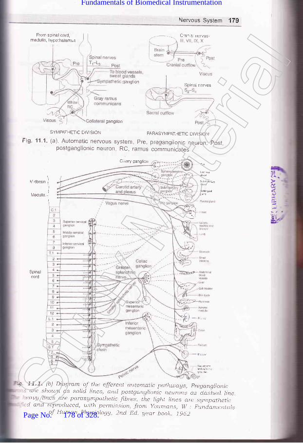
Nervous Systern 179
From spinal cord,nredulla, hypothalamus
ganglion
gangilon
SYMPATHETIC DIVIS]ON PARASYMPATHETIC DIVISION
Fig. 11.1. (a). Automatic nervous system, pre, preganglionic neuron; post.postganglionic neuron, RC, ramus communicates
Clliary ganglion
Midbrain
lvledulla
'il,cl.
E
I
)
I
\
Lg
Spinacord
Cranial nerves
Spinai nerves
T)
4' 11.7. (b) Diaqram of the efferertt autornatic path,u;ays, pregangrionic' : are shou;n as solid rines, and postganglionic neurins as d_aslted line
eaug hnes cre parasAmpathetic fi.bres, the ligltt lines are sympathetic'cl and reproduced, with permi.ssion, from youmans, w : piniamentalsof Huma.n Physiolagg, 2rtd Dcj. uear book. j9d2Stud
y Mate
rial
Page No. 178 of 328.
Fundamentals of Biomedical Instrumentation

180 Fundamentals of Biomedical lnstrumentation
PLAN EXECUTE
Cell body
Fig' 11.1. (c) Control of voluntary movement
li*
Cellnucleus
Axionhillock
FiS. 11.2. Association neuron
The concepts and theories are very much simplified to make
presentation more useful in the study of biomedical instrumenta
Such simplilication also facilitates visualisation of an extremely co-system. Ii provides a better perspective for further detailed s
needed.Axion billock portion immediately next to the cell body'Stud
y Mate
rial
Page No. 179 of 328.
Fundamentals of Biomedical Instrumentation

Nervous System 181
Axonbush
Axonbush
Nissl substances
Mylin (dendrite coatingwith fatty insulatingsubstance)
Coating-mydin sheathFiber - myelenoid
Node of Banvier(nyllin sheath interuptional ofregular intervals) help in speedof transmission of
Nucleas of schwannal
Neurilemma(insulatory material surroundingmyelin sheath)===)--4
-J-_
Hu=:#_-- I---1
-::::--:: ---- I:lis
Fig. 11.3. Spiral motor neuron
Fig. 11.4. Skin related neuronStud
y Mate
rial
Page No. 180 of 328.
Fundamentals of Biomedical Instrumentation

182 Fundamentals of Biomedical lnstrumentation
ANATOMY OF NERVOUS SYSTEM
Neuron is the basic unit of the nervous system. Neuron is also knou.::
as the ,,soma,,. A neuron is a single cell with cell body having one o:
more dendrites input fibres and the axort i.e., a long transmitting fibre
NIany times the axon branches into two or more terminals near ending=
of the axon.Figures I1.2, 11 .3, 11.4, show three different types of neurons. It -=
important to note some of the aspects in the figures.
(r) Axon hillock is the portion of the axon immediately adjacent to ti-:cell bod5r. At this point action potential are generated many times
(rl) Collaterals are the branches which leave the main axon'
(iii) Some types of neurons have axons or denoted coating of a fa:1insulting material known as myelin. This coaiing is known as mye-lsheath and the fiber is considered to be myelinated'
(iu) To hetp the speed of. transmission of information along the nen':in some cases, the myelin sheath is interrupted at regular inten',by the nodes of Ranvier.
(rr) Myelin sheath is surrounded by another insultingneurilemma outside of the central nervous system.mad.e up of thin cells known as Schwann cells.thinner then the myelin sheath and is continuousof Ranvier.
(ui) It is difhcult to identify a dendrite from an axon just by appearr-The function of fibre and the direction in which it comes
information with respect to ceIl body gives the main differe
between a dendrite and an axon.
luii\ A bundle of individual nerve fibres is known as nenre. Nerve {l:are basically axons and dendrites. Sensory information from diffe:parts of the body to the brain are through afferent nerves. Effe:
different nerve signal muscles from the brain for operating'
Myelinated ltbre i.e. axons or dendrites exist in some type:neurons. Myelination is a coating with fatty insulting subs::known as myelin. The coating is known as myelin sheath'
11.3. I CENTRAL NERVOUS SYSTEM
An enlarged collection of celi bodies and fibres inside the skull is kas brain. It is protected from the shocks, light, physical, chemi:;+temperature. The lower end of the brain is connected with the spina-
The spinal cord also comprises of several ceil bodies and fibre bu:
The central nervous system (cNS) and the main divisions of ne:
system comprise of the brain and spinal cord' A summery of ner'system in shown in figure 11.5.(a) . The anatomy of the brain is =
in figure 11.5(b) which is a side view of the brain and spinal chor-figure ll.6(a\ and (b) shows a cutway view of some of the main stn:c
The important aspects of central nervous system (CNS) ':
layer know-r:NeurilemmaThis layer.
over the
I(iil
,i0
tt)
-,-.I
follows:Stud
y Mate
rial
Page No. 181 of 328.
Fundamentals of Biomedical Instrumentation

Nervous System 183
(d Fresh brain cell bodies and smalr fibres are gray in colour and areknown as gray matter.(ifl Larger fibres having the myelin coating look white in colour andare known as white matter.iil) central nervous system has collections of neuronal cell bodies whichare known as ganglia.ru) Most of the structures of the central neryous system are anatomically
duplicated on both sicles 1.e., bilateralry symmetrical. Inspite of thismany functions of CNS in human beings are located non_symmetrically. Some of the functions are crossed over for functionrelationship of left side and right side of the brain.
-J Peripheral nerves are outside the central neryous system. peripheralnerves may have even cel bodies contained *ithi^ the centra]nervous system. Afferent nerves are mixed throughout their length.The nerves that bring sensory informatio.,
"ira contror motorfunctions are known as afferent peripheral nerves.Afferent nerves th-at bring sensory information are called sensorynerves, whereas afferent nerves that control the motor functions ofmuscle are called motor neryes. peripheral nerves reave the sprnarcord at different levers of spinal cord, the nerves that innervate agiven level of the body structure come from a given revel of spinalcord.
- Interconnections occur at or near cerl bodies and it is known assynapses. The mammarian neurons synapse do not touch eachother. They come in crose proximity foi aciivating the axon of onelerve or cell body of another which produces a chemical forstimulating the membrane of a dendrite or cer body. one axonrroduced chemical near another axon may be ror inhibrting thesecond axon from activating a neuron with which it communicatesrormally. It can be seen that chemical flow or communication is-rnidirectional.
?at
6
Stud
y Mate
rial
Page No. 182 of 328.
Fundamentals of Biomedical Instrumentation

184 Fundamentals of Biomedical lnstrumentation
Nervous system (NS)
by thalmus and hypothalmus which formThe cerebrum outer surface is known as
structure of cerebrum.cerebral cortex.
Au cNS Spinal cord
sympathetic NS
Telencephalon
I
+
Cerebral cortexbasal gangiliahippocampusamygdala
Metencephalon MYlencePhalon
llPons cerebellum Medulla
Diencephalon
IiThalamus
hypothalamus
Metencephalon
IiTectum
tegmentum
Cerebrum
uioorain{viobrain ffi
Hindbrain
Cerebellum
Sp na
CocYgea
1
iSpinaljcordi
Fig. 11.5. (a) Summary of Nervous SYstemStud
y Mate
rial
Page No. 183 of 328.
Fundamentals of Biomedical Instrumentation

Nervous System 185
Spinal Cord
Fig. 1'1.5. (b) The brain and spinal cord
' s believed that certain functions are indicated for certain parts of the:-.:n. However, in infant animal by remaining certain parts responsible: - :ertain functions were removed, the animal is able to develop thatr- :tion to some extent. See figure 71.6(a) which shows cut-way sectionri' :.uman brain and hgure 11.6 (b) which shows cerebral cortex for'il--' reference. Figure 11.6 (c) shows cerebrum with trantal, parietel,''lr- eoral and occipital four cobes etc. General functional relationship
' brain parts are as follows:Breathing, heart rate and kidney functions are controlled throughbrain stem and medulla. The figure l7.7(al shows structure oflungs and nerves. The figure lI.7(b) shows respirator action signals.Pons are interconnecting area having many nuclei, ascending andCescending fibre tracts. The pons area is responsible for functionsrf salivation, feeding, and facial expression. It also contains relays:cr the auditory system, spinal motor nellrons and some nuclei for:espiration.
;" lerebellum is a physiological microcomputer. It intercepts sensory=:rd motor nerves to smooth out jerlry muscle motions. It is also:sponsible for ability to maintain balance. The block diagram of
'=edback control is shown in figure 11.8.-:alamus manipulates all sensory information going to cerebrum.'f =^n relay points for the visual, auditing and somatic sensory: -rtems exist here.
,.4I
Stud
y Mate
rial
Page No. 184 of 328.
Fundamentals of Biomedical Instrumentation

186 Fundamentals of Biomedical lnstrumentation
Diencephalon
Super or
I
Infs1i91 +
Peripheral nerve
Ventral
l/ledulla oblongataI Caudal
lnferior
Fig. 11.6. (a) Cut-way view of the human brain
_-e Posterior
Cerebellum
Third ventricle
t.:I*
Pulr
Thalamocortical radiations
Fourth ven
Spinal cord
Fig. 11.6. (b) Ce;'ebrai cortex and sor-ne activlty center thereinStud
y Mate
rial
Page No. 185 of 328.
Fundamentals of Biomedical Instrumentation

Nervous System 187
Prirnary mctorcorlex(precentral
"gyrus)
Post centralgyrus (generalsensory projection
Vision
Visionassociationarea
Hearingassociation area
Fig. 11.6. (c) Cerebrum showing trontal, parietel, temporal,and occipital four lobes, etc.
Pulmonary artery
Vasomotor nervesBronchus
Lymphatics
l-ymphatics
tr
Fig. 11.7. (a) Structure of lungs and nervesStud
y Mate
rial
Page No. 186 of 328.
Fundamentals of Biomedical Instrumentation

188 Fundamentals of Biomedical lnstrumentation
/V/V\/V AAA
Muscular I +force
y-Dynamiccontrolsignal
y-Staticcontrolsignal
Fig. 11.8. Block diagram of peripheral motor control system The dashed lineindicates the non-neural feedback from muscle that limits length and velocity via the
inherent mechanical properties of muscle. rd, dynamic r motor neurons rs, static r
motor neurons
(u) Reticular activation system (RAS) is non-specific sensory portior:which surrounds the thalamus. When aroused, it alerts the cerebria:cortex which makes it sensitive to incoming information. RAS keepsa person awake.
(urJ Centre for emotions hypothalamus area. It contains nucle:responsible for eating, drinking, sexual behaviour, temperatureregulation and emotional behaviour. It also controls automailcnervous system. Specially sympathetic nervous system, see figurc1 1.e(a).
(uii
Fig.
IX
XXI *ll,'r^ ^'Ar\/v
Vagi cut
AAAA /*\
Externalforces
Vagi intact
Fig. 11.7. (b) Respirator action signals
c Controlsignal +
4Sq
(Stud
y Mate
rial
Page No. 187 of 328.
Fundamentals of Biomedical Instrumentation

Nervous System 189
(r,zz) Cerebral cortex has about 9 billion of 12 billion neurons existingin the human brain. All sensory inputs reach the cortex wherecertain regions relate sensory informations. It have several lobessuch as parietal lobe for somatic sensory such as heat, cold,pressure, touch, etc., frontal lobe for primary motor neurons leadingto various muscles of the body, preferential lobe for neurons of eyemovement control, temporal lobe for responding to variousfrequencies of audotory nature.
Apomorphine, digitailsglycosides, copper sulphate
Chemoreceptortrigger zone
Vomitingcenter
Vagalafferents
lrritationof mucosa
Fig. 11.9. (a) Afferent pathways for the vomiting reflex, showing the chemoreceptortrigger zone in the medulla
SENSORY
l0l
{E
v; IJ?iJ
MOTOR
Fig. 11.9. (b) Human sensory and motor functionsStud
y Mate
rial
Page No. 188 of 328.
Fundamentals of Biomedical Instrumentation

I .:'
B
190 Fundamentals of Biomedical lnstrumentation
The spatial distribution of the sensory and motor functions on thecortical surface are shown in figure 119(b). In each case, the figureshows only one-half of the brain in cross-section through the indicatedregion.
11 .s. NEURAL COMMUNICATION
When neurons are excited, they generate action potentials. These actionpotentials are of very short duration and are transmitted in the form ofspike discharge patterns. Figure 11.10(a). shows spike discharge patternfrom a single neuron of a cat. These are responsible for motor functions.The sequence of spikes are transmitted down a particular neural pathway.Figure 11.10(b) shows a burst pattern. Action potential of neuron ispropagated down the axon to the axiom terminals where it can betransmitted to other neurons. The neurons can be transmitted to otherneurons. The neurons can be triggered at any point along the dendrites,cell body or axon. Due to the natural functions of neurons, thecornmunication is only one way. Some of the important aspects of neuralcommunication are as follows:
Fig. 11.10. (a) Spike discharge pattern from a single neuron
There are two types of communication across a synapse-excitaton-and inhibitory. The arrival of an action potential at an axon releasesa chemical acetylcholine which excites the adjacent membrance ofthe receiving neuron. Some act to excite the membrane of thereceiver, while others tend to prevent it from being excited. Theneuron firing depends on the net effect of all the axons interactinEwith it, see figure 11.11(a).Potentials of the receiving neurons are graded and it reaches acertain threshold; the neuron fires and action potential developsThe action potential of a given neurons are same. An excitoq-graded potential is known as excitatory post synaptic potentia-
-eL
's(4
1:u- -1eI
: tt(-,-ar
_ ttf---5
: - -:l(
Fig. 11.10. (b) A burst pattern.
(10 Stud
y Mate
rial
Page No. 189 of 328.
Fundamentals of Biomedical Instrumentation

Nervous System 191
(EPSP). An inhibitory graded potential is known as an inhibitorypost synaptic potential (IPSP), see figure 11.11(b).
1 Action potential arrivesat axon terminal
Postsynapticdendrite membrane
Posteriorpituitary
Fig. 11.11. (b) Neural control mechanisms. ln the two situations on the left,neurotransmitters act at nerve endings on muscles; in the two in the middle,
'reurotransmitters, regulate the secretion of endocrine glands; and in the two on theright, neurons secrete hormones into the hypophysial portal or general circulation.
Inhibitory axon causes a graded potential (IPSP) in the receivingreurons which is more negative than the normal resting potential,.herefore, it requires a greater amount cf excitation than normal resting:otential. Inhibiting axon action is also possible based an excitary::ansmitting axis, instead of after receiving neuron. A premature action:otential in the transmitting axon is setup by inhibiting axon. Eue to,ris, the necessary combination of chemical discharges do not occur in=r-nchronism as it may occur without inhibition. Subsequently, synapse:ehave like multiple input AND and NOR logic gates. Through their
Antagonistic chemicalin gap breaks downtransmitter during refractory period ofmembrane
Unless inhibilited, membr ane potentialchange leads to generation of actionpotential in postsynaptic neuron
ft/otor nerves Motor nerves Juxta-to skeletal to smooth and glomerularmuscle cardiac muscle cells
Chemical transmitteris released fromaxon terminal andquickly fills gap
Arrival of chemical transmitter causes potentialchange in postsynapticdendrite membrane
Fig. 11.11. (a) Sequence of events during chemical transmissionacross a synapse
d
r
Adrenalmedulla
prolactin
Anteriorpituitary
Stud
y Mate
rial
Page No. 190 of 328.
Fundamentals of Biomedical Instrumentation

192 Fundamentals of Biomedical Instrumentation
widely varied patterns of excitary and inhibitory connections, a meansof switching and interconnecting parts of the nervous system isestabilished. It has high grade of complexity which can not be imaginedby human beings.
(lil) The sequence of events during chemical transmission across asynapse is shown in figure 11.11(c). First action potential reachesaxon terminal and chemical transmitter is released from axonterminal and quickly falls gap as shown in the figure. Arrival ofchemical transmitter caltses potential change in post synapticdendrite membrane. The antagonistic chemical in gap breaksdowntransmitter during refractory period of membrane. It is not inhibited,membrane potential change leads to generation of action potentialin post synaptic rreuron.
___-/-\_-EPSPs
(and IPSPs)
Fig. 11.11. (c) EPSP and
Figures lr.l2(a) and 1\.r2(b). show correlation between behaviouralstates; awake and sleeps patterns.
Thalamocortical loop Single cell propertise
Senseorgan
__-r\_Genratorpotential
Awake
Airtl^l1Adt/irt20-80 Hz rhythms
Afferent Synapseneuron
Efferent Neuromuscular Muscleneuron junction
l
I
E
IJIC
S
I
(lr
-,.$/
,\,,1{lr*il
Pyramidal cellsTonic firing
30-50 Hzgamma oscillations
F
itt
'1 .6.
'-,lL
r,_: S
{
, .^ t,
rl- ..fl
.a(
--L.. ,--L
:hr-:--1
Cerebral cortex
Thalamus
Deep sleep
Thalamocortical cell0.54 Hz burst firing Tonic firing
Transition from steps to wakingO.54 Hz rhythms
Fig. 11 .12. (a) Correlation between behavioral states, EEG, and single cellresponses in the cerebral cortex and thalamus.Stud
y Mate
rial
Page No. 191 of 328.
Fundamentals of Biomedical Instrumentation
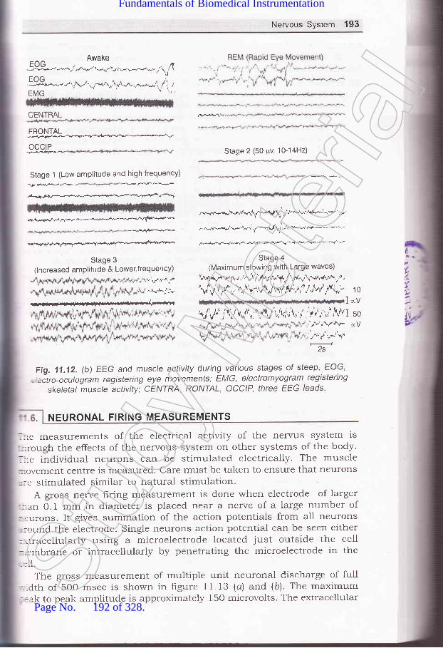
Nervous System 193
Awake
ff*..-.Al-q*^rrf ,f"-,"-"-J,f, 1EMG
CENTRAL
FRONTAL:;;F;+,,..k!e,."r*v ^ '--^v
OCCIP
Stage 1 (Low amplitude and high frequency)
Te..f€* ..k,r$€-
ffi--+r-a.fra
-jt Vf7/,-ff^**--+*-+""(*-"r'*
.d-i.$@
Stage 3
(lncreased amplitude & Lower,frequency)v:,rr.r*j
,if.A.n_!
Stage 2 (50 pv, 10-14H2)
*-."./.*{"fl\r-.g I^f rr"'-w*aryr^'-*'...
,v,.*r'r-.q-ar,V^.-l,r t /u'.*-&! 6',
@,+/Frv+-
Stage 4
(Maximum slowing with Large waves)
\A'rr\nru"f+r,-r^"'t1,,fu.,\1i"rAJ,l'.,ft .rrr{v+!.,-d,
Vf$/v' r/l$.Vh^f,4v,a / o\"1 ti',,- 1 o
IrV\J'lv,t/j\l\(rn' u'tt r'\.,1r,','.r\i 1
j1',i.;;'' l/1I so;F,,\r+v-. €V
',^'',/,,*"S'2s
1"
Fig. 11 .12. (b) EEG and muscle activity during various stages of steep, EOG,
= eitro-oculogram registering eye movements; EMG, electromyogram registeringskeletal muscle activity: CENIRA, RONIAL, OCCIP, three EEG leads
NEURONAL FIRING MEASUREMENTS
lre measurements of the electrical activity of the nervus system is-::rough the effects of the nervous system on other systems of the body.. re individual neurons can be stimulated electrically. The muscle:,ovement Centre is measured. Care must be taken to ensure that neurons
':e stimulated similar to natural stimulationA gross nerve hring measurement is done when electrode of larger
-:.an 0.1 mm in diameter is placed near a nerve of a large number of::urons. It gives summation of the action potentials from all neurons,:ound the electrode. Single neurons action potential can be seen either-]itracellularly using a microelectrode located just outside the cell::-embrane or intracellularly by penetrating the microelectrode in the
rll.
The gross measurement of multiple unit neuronal discharge of full-Ldth of 500 msec is shown in figure 11.13 (a) and (b). The maximum::ak to peak amplitude is approximately 150 microvolts. The extracellularSt
udy M
ateria
l
Page No. 192 of 328.
Fundamentals of Biomedical Instrumentation

194 Fundamentals of Biomedical lnstrumentation
measurement of unit discharge from red nucleus of an animal is shownin Fig. 11.13 (c). The peak to peak height is approximately 170 microvolts.Intracellular measurement of antidrornic spike from abducens nucleus ofan animal. It is a part of motor control system for the eye. The spikeheight is about 60 millivolts. Each division is 0.5 milliseconds. some ofthe important aspects of neuronal firing measurements are as follows:
(z) The penetrating an individual cell is limited to some speciarizedcells involving only large type of cells. The microelectrodes with tipsof about 1o mm in diameter is used for extracellular measurementsand about 1 mm for intracellular measurements are used.
Fig. 11'13. (a) Gross measurement of multiple unit neuronal discharge. Time span is500 msec., having maximum peak to peaks amplitude of 150 microvolts
(li) Neuronal firing measurements range from hundreds microvolts forsingle neuron in extracellular measurements to about 1oo mv forintracellular measurements. Due to the short duration of neurona]spikes, the amplifier should have frequency response from belos-7 Hz to many thousand Hz.
(iid Ordinary pen recorders are used for recording or display. Ar:oscilloscope with a camera for photographing the spike patterns ora high speed light galvanometer or an electrostatic recorder isused for measurements.
[+_ZZOp,sec___,Fig. 11.13. (b) Gross measurement of multiple unit neuronal discharge of
width The peak amplitude is 150 microsecs
iu)tirl
I
l
c
t
ilrlcloclAp
::necr tfat::ctor
Sub!-: ga--:noI
=- po'fror
_:s o---le r--\ens
- ,:plie:m/
s:gnia-e L
--s tir:-: --trol
::2. I::en
:._:ltmr--- ac500:=d tSt
udy M
ateria
l
Page No. 193 of 328.
Fundamentals of Biomedical Instrumentation

Nervous System 195
\
\\
J
Fig. 11.13. (c) Extracellular measurement of unit discharge fromred nucleus of an animal
iu) For nerve condition time or velocity, the nerve is stimulated.Potentials are measured from another nerve or from a muscleactuated by the stimulated nerve. The oscilloscope helps to get thedifference of time between stimulus and the net firing measured onthe oscilloscope.
11.7. EEG BLOCK DIAGRAM, RHYTHMS AND EEG DIAGNOSTICSrr. clock diagram of EEG machine is shown in figure ll.l4.
A pattern of electrodes on the head and the channels where they are:-nected is known as Montage which it is symmetrical. The EEG signals: transmitted from the electrode to the Jackbox and then to montage.:ctor.
Subsequently, each signal is passed through a preamplifier havingr gain and low noise characteristics. The amplrtier should have high:-mon mode-rejection to rninirnize stray interference signals coming
:::r power lines and other electrical equipment being used. It should be= from drip which prevents movement of pen on recorder due to.:ts of temperature changes, etc. It should have a gain if unbalanced:ce resistances exist.Sensitivity control of an EEG machine is the gain of the amplifier:iplied by the sensitivity of the writing unit. If the writer sensitivitycmf v, the amplifier must have an overall gain of 2O,0OO for a 50
signal.lhe undesirable signals such as artefacts, a low pass hlter is used-:rg time constant of 0.03, 0.1 and 1.0 sec. The upper cutoff frequency,ntrolled by the high frequency filter having values 15, 30, TO andHz. EEG machine haves a notch filter tuned at 50 Hz to eliminate
r-erence from the frequency of the main power line. EEG are selected:inimum noise which is specified as peak-to-peak value.rr accurate and stable paper drive mechanism is needed which-Jed by a synchronous motor. Speeds of 15, 30 and 60 mm/sec areSt
udy M
ateria
l
Page No. 194 of 328.
Fundamentals of Biomedical Instrumentation

196 Fundamentals of Biomedical lnstrumentation
needed. Time pulses are usually generated independently of the paper
drive mechanism to avoid. difference in timing mash due changes in
paper speed of the Paper drive'
ce
AI
Fig. 1'1.14. Block diagram of EEG machine
:C(:las...ho,-r tl:ld
lh
An array of many electrodes are used by an electroencelogram rr
helps in recording's.l,.tu'I signals' Each electrode is connected
""p"r^t" amplifiers ancl writing systems' It may have upto 32 cl
although 8 or 16 channels aie quite-common' Figure '-' ':j
"i;'t"#',":;-;;t with 8 channels. Microprocessors are emplol-ed
most EEG machines.EEG machines are mostly PC based with
with storing facility of upto 40 hours to EEG'latest pentium i---9
Analog toDigital lnverter
I tnt<=writins I I Chart I
I oscilloqraPh | 1 drlve I
The colour motor dt:SSt
udy M
ateria
l
Page No. 195 of 328.
Fundamentals of Biomedical Instrumentation

Nervous System 197
can be used having 7280 x lo24 pixels. User interface is through anASCII keyboard.
F = FrontalC = CentralT = TemporalO = OccipitalP = ParietalA = Ear Common
Fig 11.15. clinical instrument with a 8-channel electrode configuration
.:d 64 responses are also shown.
Fig. 11.16. (a) Average of single response of raw EEG
Fig. 11.16. (c) Average of 64 responses
- he signals are low-level, therefore, EEG equipment should havek* --quality differential amplifiers having good-common mode rejection.
, s differential preamplifier and subsequently power amplifier which- -i pen mechanism for each channel. The amplifiers are ac coupled
(L
T5 T6
P3 P4A1
A2c3 c2 C4
F3 F4
FP1 FP2
Fig. 11.16. (b) Average of 8 responses
Stud
y Mate
rial
Page No. 196 of 328.
Fundamentals of Biomedical Instrumentation
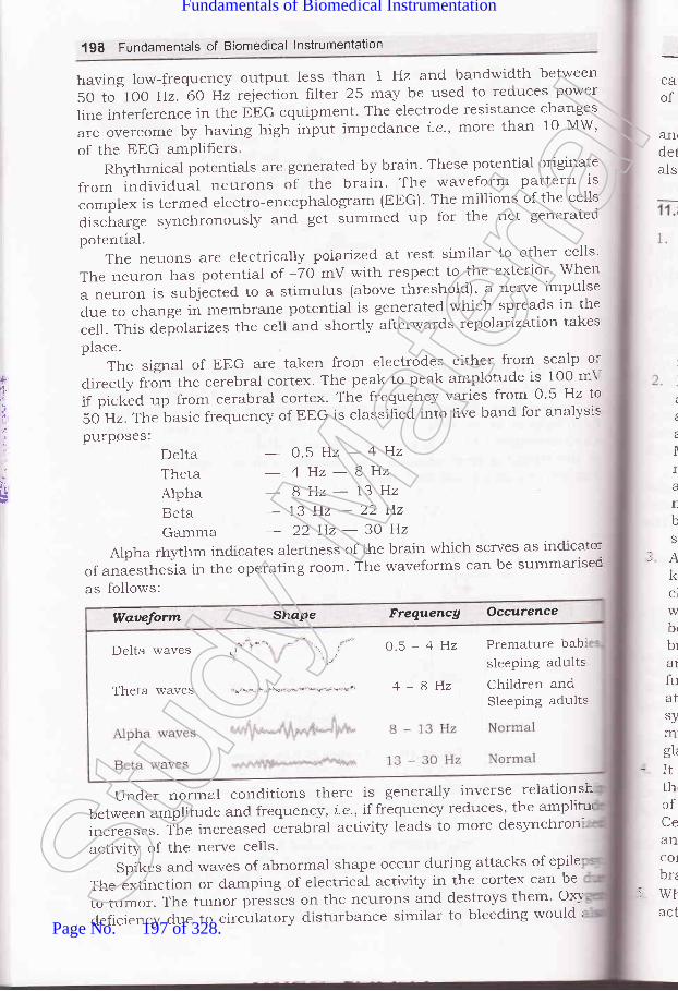
198 Fundamentals of Biomedical lnstrumentation
harring low-frequency output less than 1 Hz and bandwidth between
5O to 1OO Hz. 60 Hz reiection filter 25 rnay be used to reduces power
line interference in the EEG equipment. The electrode resistance changes
areovercomebyhavinghighinputimpedancei.e.,rnorethanloMW,of the EEG amPlifiers.
Rhlthmical potentials are generated by brain. These potential originate
from individual neurons of the brain. The waveform pattern is
complex is termed electro-encephalogram (EEG). The millions of the cells
discirarge synchronousl5' t"6 get summed up for the net generated
potential.The neuons are electrically polarized, at rest similar to other cells'
The neuron has potential of -70 mV with respect to the exterior' When
a neuron is subjected' to a stimulus (above threshold)' a nerve impulse
due to change in membrane potential is generated which spreads in the
celt. This depolarizes the cell and shortly afterwards tepolatization takes
place.The signal of EEG are taken from electrodes either from scalp or
clirectly from ttre cerebral cortex. The peak to peak amplotude is 100 mY
if picked up from cerabral cortex' The frequency varies from 0'5 Hz lo
50 Hz. The basic frequency of EEG is classihed into hve band for analysis
pu-rposes:
ca'of
&flrdetals
t
Ira
L
bS
rAkclwbr
bra1
fuatsymgL
-Itth,ofCeancolbrz
rWtact
,F
t
.t
'l
*i
DeltaThetaAlphaRetaGamma
- 0.5H2-4Hz
- 4Hz-8Hz8Hz-13Hz
-13H2-22H2- 22Hz-30Hz
Alpha rhyttrm indicates alertness of the brain which serves as indicato:
of anaesthe"i" i.r the operating room. The waveforms can be summarisec
as follo'*'s:
Under normal conditions there is generally inverse relationsh
between amplitude and frequertcy, i'e', if frequency reduces' the ampliturr
increases. The increased cirabral activity leads to more desynchron
activity of the nerve cells.
Spikes and waves of abnormal shape occur during attacks of epile
The extinction or damping of electrical activity in the cortex can be
to tumor. The tumor pi""i." on the neurons and destroys them. ox-\'
deficiency due to circulatory disturbance similar to bleeding would I
Waueform Shape Frequencg Occurence
.j\.
Delta waves ,i*'\ " \ , o'5 - 4 Hz Premature bab:-\ !'\"'j
sleePing adults
Theta waves "i.r'\-'i*'\"'\s*')'d"'\*--r\*!''t"* 4 - 8 Hz children andSleePing adults
Stud
y Mate
rial
Page No. 197 of 328.
Fundamentals of Biomedical Instrumentation

Nervous System 199
cause similar problem. Earlier damages present in the cortex in the formof tumors or scars, may generate abormal electrical activity.
EEG is used for examination of epilepsy, brain damage, brain tumorsand other organic brain injuries. There is occassional use of EEG fordetermination of level of consciousness 1.e., depth of anaesthesia. It canalso establish death of brain.
The nervous system is responsible for controlling various functionsof the body. It coordinates them into an integrated living organism,therefore, nervous system is the most compiex of altr the systems ofthe body. Nervous system consists of brain, numerous sensing devices.a high communication network which links all parts of the body. Itis also responsible for the behaviour of the organism leading toautonomy and acquires valious traits which characterise as anindividual.Neuron or soma is the basic unit of the r-r.ervous system. Neuron isa single cell body having one or more dendrites input fibers and theaxon, i.e., a long transmitting Iiber. Some types of neurons haveaxons or denoted coating of a fatty insulating material known asMyelin. The myelin sheath is interrupted at regular intervals by thenodes of Ranvior to help the speed of transmission of informationalong the nerves. A bundle of individual nerve fibers is known asnerve. Sensing information from different parts of the body to thebrain are through different nerves. Different efferent nerve musclesignals inform the brain for operating.An enlarged collection of cell bodies and fibers inside the skull isknown as brain. It is protected from the shocks, light, physical orchemical or temperature. The lower end of the brain is connectedwith the spinal cord. The spinal cord also comprises of several cellbodies and fiber bundles. Control neryous system comprise of thebrain and spinal cord. Afferent nerves which bring sensory informationare called sensory neryes. Afferent nerves which control the motorfunctions of the muscles are called motor nerves. Interactions occurat or near cell bodies which is known as synapses. Automatic nervoussystem is involved with emotional responses controlling smoothing ofmuscles in various parts of the body, heat and secretion of severalglands.It is believed that certain functions are indicated for certain parts ofthe brain. However, it has been found that by removing certain partsof the brain, brain develops corresponding function to some extent.Cerebellum is physiological microcomputer which intercepts sensoryand motor neryes to smooth out jerklr muscle motions. Carebralcortex has about 9 billion of 12 billion neurons existing in the hurnanbrain.When neurons are excited, they generate action potential. Theseaction potentials are of very short duration and are transmitted in
L
c
Stud
y Mate
rial
Page No. 198 of 328.
Fundamentals of Biomedical Instrumentation

6.
200 Fundamentals of Biomedical lnstrumentatlon
7.
the form of spike di There are two types of
communication across ory and inhibitory' Action
potential releases a che which excites the adjacent
membrane of the receiving neuron'
measurements. Ord.inary pen recorders are used'
A pattern of electrodes on the head and the channels where they are
connected is known as Montage which is symmetrical. EEG signals
having 1280 x 1024 Pixels.from va n specla-
hythmic ar brainriginate al in' Tht
tial of - re
EEG is used for examination of epilepsy, brain damage' brain tumors
and other organic brain injuries'
11.1
11.1
11.1
.1.1
-1.1
- i.1
1.1',
1.1t
1.1!
-2Clt
*c
arxerCi,te,J
1 1. 1. Give the anatomYCommunication.
11.2. How neuronal firing
11.3. Give the block diagram of
1,1.4. Give anatomy of nervous system'Describe trMG.
of nervous system. Discuss about Neuror:=([JPTU, 20C'i'
measurements are made? Explain EPSP and IPS?
(UPTU, 20ia'
EtrG. How diagnosis is made with trEG?(uPTU, 20'-1*
What is neuronal commnnicatic---:(LrPTU, 2o.a:
ll.5.trxplaintheworkingprincipleofEEG?DrawablockdiagrarnofEE..(UPTU, IIIC.P
11.6. trxplain EPSP and IPSP. Discuss neuronal firing measurements'(UPTU, 2C'
11,7. What is the difference between alTerent and efferent nerves?
11.8. trxplain the difference between motor nerve and sensory nerve'
i1.9. Draw a sketch of a neuron and 1abel the cel1 body, dendrite, axon
axon hillock-Stud
y Mate
rial
Page No. 199 of 328.
Fundamentals of Biomedical Instrumentation

Nervous System 201
11.10. Explain the way in which a neuronal spike is transmitted from oneneuron to another.
i 1.1 1. What are the nodes of Ranvier and what useful purpose do they serve?11.12. What is a spinal reflex, and how is it related to the functions of the
brain?i 1.13. What are graded potentials?11.14. What is a neuronal spike? Draw a typical spike showing amplitude and
duration.-1.15. How does the action of the synrpathetic nervous system differ from that
of the parasy'rnpathetic system? Quote an example from the body.- i.16. Explain the physiologr of nervous system. Write the factors affecting the
neuronal communication.1.17. Explain with example EPSP
human.
(UPTU. MQP)
and IPSP. Write the applications trMG for(UPTU, MQP)
(UPTU, 20Os)be rneasured? Explain EPSP and
(UPTU, 2OOs)
-1.18. Give the block diagram of EEG. Explain its; Rythms. Ho'.v is it helpful indiagnosis? (UPTU, 2004)
--.19. Explain the neuronal communication. Gitze the autonomy of nervoussystems.Explain neuronal firing and how it canIPSP.
I'
EJAJ
Stud
y Mate
rial
Page No. 200 of 328.
Fundamentals of Biomedical Instrumentation

Opthalmologlr Instruments
:s fnside this chapter
12.1. Anatomy of Vision12.2. Electrophysiological Tests12.3. Ophthalmoscope12.4. Tonometer for Eye Pressure Measurement12.5. Summary
12.1. ANATOMY OF VISION
Eye is an optical systr:m which focuses tight through a lens on phoi:receptors and has a sy,stem of nerves which conducts impulses from thtreceptors to the brain. It is moved within the orbit by six colour musclesThe colour muscles iare rectus and oblique and are inverted by tF-t
oculomotor, trochlear and abducens nerves.
Lens in an eye is a clear biconvex structure behind the pupil he-:by circular lens ligament known as zonule. Cornea is a tansparer-:continuation of sclent over front of the eye and is responsible for rocs
are extremeiy sensitive to light and hence responsible for night visio:-They give no information about colour. Retina is shown in figure 12.),'-*the inner most layer which consists of photoreception (rods and cones
bipolar neurons, ganglion cells, horizontal cells, amercine cells, et:
forming ten layers. T'he image is formed by retraction of light by cornes,
and lens of the eye, €ln inverted image is formed on the retina of the er-t
'lhe rods and cones of photoreceptors consists of rods and cone:These are distinguisleed by their shape and functions. These are shotr=
in figure 12.2.
202arCC
.hStud
y Mate
rial
Page No. 201 of 328.
Fundamentals of Biomedical Instrumentation

Opthalmology lnstruments 203
PosteriorChamber
Anteriorchamber
Visualaxts
Aqueoushumour
Viteroushumour
Fig. 12.1, The eye
Shelves of foldedmembrane
Outersegment
lnnersegment
Synaptic
1o o o -\(a) Rod (b) Cone
Fig. 12.2. Photoreceptors of eye
Colour vision depends on cones which work at high intensity of light.nd are responsible for day vision. There are two kind of inputs to.entral neryous system from the eye input from the rod and input from-re cones. For colour vision red, green and blue cones are used. The
Opticnerve
l-
(
cJ
\/
regron
ooQo
I
b9;oo
/S'_.-'-
Stud
y Mate
rial
Page No. 202 of 328.
Fundamentals of Biomedical Instrumentation

2O4 Fundamentals of Biomedical lnstrumentation
response of a cone depends on how well its pigment absorbs particularlight.
Blue conesGreen cones
500 600
Wavelength (nm)
Fig. 12.3. Absorption spectra for different types of photoreceptor
Optic nerve
Opticchiasma
Optic tract Lateral
100
c)ocC6
-obsoo-oG
.C
:
alol1n
nThre'l
(
(
(
12.
:VE:of.1er;.'itl_-no
:3Ce
:tII--: rt
I1:en
400
a
a
:lOptic
, radjator
:/
Fig. 12.4. Gross anatomy of visual pathways
The percentage of light absorption verses wavelength of differen:colours of cones and rods are given in figure 12.3. lt may be noticed tha:the blue cone light absorption at 44O nm is maximum whole the maximr.r=light absorption at 600 red cone occur at 6OO nm. The maximum lig:;absorption in red and green cone is at 5OO and 550 nm respectivel'.-
Visual Pathways : Each eyeball acts as a camera, it perceives the imagerStud
y Mate
rial
Page No. 203 of 328.
Fundamentals of Biomedical Instrumentation

Opthalmology instruments 205
ELECTROPHYSIOLOGICAL TESTS
and relays the sensations to the brain via visualoptic nerve, optic tract, and optic radiations.in figare 72.4.
pathways which compriseThe pathways are shown
The electrophysiological tests of the eye allow objective evaluation of theretinal functions. These include
(a) Electroretinogrphy (ERG)(b) Electrooculography (EOG)(c) Visually Evoked Response (VER)
12.2.1. Electroretinography (ERG)
Electroretinogram (ERG) is a measure of response of the retina of the:-ve to light i.e., changes in the resting potential of the eye from darkness:o fall of light on the retina. ERG signals are more complex as comparedrerve exon signai because it is the sum of many effects taking place*'ithin the eye. The amplitude range of ERG signal is 0.5 mV to 1 mVend frequency from DC to 20 Hz.
The electroretinogram is composite electrical activity from the photo:eceptors (cones) and poterior poles of the eye and is known as cornea. etinal potential which changes with the action of light on the retina.\t rest the potential difference is 6 mv between cones and poterior pole.
Normal record of ERG consists of the following waves which may be;een in figure i2.5.
. a-wave : Initial negative wave from photoreceptors (rods and cones)
. b-wave : Large cornea-positive wave generated by Miller cells, butrepresents the activity of bipolar cells.
. c-wave : It is also a positive wave with lower amplitude representingmetabolic activity of pigment epithelium.
c-wave(proton getpositive)
Light stumulus
Fig. 12.5. Normal ERG Component
Figure i2.6 ERG component dip in the lower line shown the application:,::nt of light stimulus.
Amplitude of a-wave is measured from the base line to the through:: the a-wave whereas that of b-wave is measured from through of a-,r ,r'e to peak of b-wave. Similarly, whole measuring the sequences in thel?G wave, Latency is the time interval between start of light stimulus
L
)
IoDEo-E
Stud
y Mate
rial
Page No. 204 of 328.
Fundamentals of Biomedical Instrumentation

206 Fundamentals of Biomedical lnstrumentation
and beginning of a-wave is normally of the order of 2 m-sec. The implicittime is from the starts of light stimulus to the minimum of b-wave. Thisis shown in hgure 12.6.
b-wave implicit tim
amplitude
Fig. 12.6. rnc colrponent Dip
In humans the ERG signals are recorded with one electrode is fitedon the cornea and is normally embedded in a contact lens one .otherelectrode is reference electrode made of silver chloride and is placed onthe forehead or ear lobe which is at a potential equal to the potential ofthe back of a eye. The arrangement is shown in figxe 12.7.
Cornea
Transparentcontact lensAnterior chamber
Contact lens electrode
Sclera
Choroid
Fat-bone mediumof eye orbit
Fig. 12.7. The transparent contact lens contains one electrode, shown here on
horizontal section of the right eye. Reference electrode is placed on the right tempe
The arrangement of recording ERG of the eye may be seen ::-
figure 12.8.The ERG is recordeC both in the lights adapted (photopic) and da:L
adapted (scotopic) states. In photopic ERG patient is tested with ligl-:condition to suppress rod response. Only one response (5 to 8 millic-cones) is elicited giving lower amplitude and shorter implicit time. O:
IoEEE-E
-a-Wave +lmpact time
tlwrC
retiretiretiOCC-
it istheisolietc.
12.2
It recharlvhicslgnirang
A:nedi
Tand r
rn th.s at:trai€:ioser
T1.ightray:lOVCI
;hlr
it
itl
Stud
y Mate
rial
Page No. 205 of 328.
Fundamentals of Biomedical Instrumentation

Opthalmology lnstruments 207
the other hand in scotopic ERG with dark adaptation, large amolitudewith longer implicit time is available. Here both cones (6 - g million) androds (125 million) contribute to response.
ReferenceElectrode
ERGsignal
Fig. 12.8. Electroretinography
ERG signals are used in congential retinal dystrophies in whichretina appears normal and detecting functional abnormalities of outerretina. It is used in diagnosis and prognosis of retinal disorders e.g.,retinitis pigmentosa, diabetic retinopathy, retical detachment, vascularocclusions of the retina.
However, since ERG is a function of the first 2 neurons of the retina,it is not useful in diagnosis of disorders affecting the ganglion cells orthe optic nerve, etc. Also since ERG measures diffuse response of retinaisolated diseases like muscular holes, exudates macular haemorrhage,etc. will not be detected by ERG amplitude changes-
12.2.2. Electro Oculogram (EOG)
It records bipotentials generated by the movement of the eyeball, i.e.,changes in the resting potential of the eye existing between corneawhich is positive and back of the retina which is negative. The EoGsignal amplitude range is between 50 pV to 4ooo pv and the frequencyrange is between 0.1 to 1OO Hz.
A pair of electrodes are placed over the orbitar margin near thenedial anct lateral canthi.
The ground or reference electrode is placed on the temple or foreheadand the other surface electrode is placed on the left at right of the eyern the temple and nose. The EoG potential is zero with the eye position-s at oo, that is in the condition when the person is looking (gazing)straight. when the eye ball is shifted to left, the positive cornea becomes:loser to the left electrode which becomes more positive.
There is an almost linear relationship between horizontal angle ofsight and EoG output up to approximately t 30. of arc. The electrodesray also be placed above and below the eye to record. vertical eye:rovements.St
udy M
ateria
l
Page No. 206 of 328.
Fundamentals of Biomedical Instrumentation

208 Fundamentals of Biomedical lnstrumentation
Eye wets0" usualangle
Resting potential of eye
Fig. 12.9. Electro occulogram signal
For recording EOG bipotential a DC amplitude is needed. The outputis in micro volt region hence silver (Ag) or silver chloride AgCl electrodesare needed to prevent drift. The noise present due to the presence ofEEG, EMG signals and due to inaccuracy of recording equipment and isequivalent of 1' of eye movement, hence recording of eye movement ofless than 2' is difficult and eye movement greater than 30' do notproduce bioelectric amplitudes that are strictly proportional to eye position
The EOG response has two components as given in frgure 12.9.Light Peak: It is the potential rise due to light when both rods and
cones contribute. It represent the maximal height of the potential inlight.
Dark Throtrgh: It is light insensitive component and occurs fromRetinal Pigment Epithelium (RPE), photo receptors and inner nuclearlayer. If represent the level of minimal height of the potential in darkness
Normally the resting potential of the eye decreases progressivelr-during dark adaptation reacting to dark through in 8 to 12 minutes. Inthe light the light adaptation the amplitude starts rising and reaches alight peak in 6-9 minutes. The recording is EOG is done at every minutesfor a- period of 12 minutes. The recording is done first in the darkadapted stage and then repeated in light adapted stage.
The results of EOG are interpreted by hnding out the Arden ratio asfollows:
Arden Ratio =Maximum height of light peak x 100
Maximum height of dark through(o) Normal curye values are 185 or more.(b) Subnormal curve values are less than 150.(c) Flat curye values are less than 125.EOG signals shows presynaptic function of the retina any diseas:
that interferes with functional interplay between retinal pigmen:epithelium (RPE) and photoreceptors will produce an abnormal or abser-:
1
(to
V
1i
a1
ofin
frtpr,
1n
reIlocexidiswh1n
plaitr
l
-UITIT
lir
lrl4
iu*
Stud
y Mate
rial
Page No. 207 of 328.
Fundamentals of Biomedical Instrumentation

Opthatmoiogy lnstruments 209
light rise in the EOG. The EOG is affected in diseases such aspigmentation, vitamin A deficiencies, retinal detachment.
EOG is more sensitive in certain conditions but normally it serves assupplementary and complementary to ERG test.
Ophthalmoscope is a clinical examination of the interior of the eye bymeans of an ophthalmoscopy. It is primarily done to assess the conductionof fundus and defect the opacities of ocular media. The cphthalmoscopewas invented by Von Helmholtz in 1850. Three method of examinationare ln use:
(a) Distant Direct Ophthalmoscope (DDO)(b) Direct Ophthalmoscpy(c) Indirect Ophthalmoscopy.
12.3.1. Distant Direct Ophthalmoscopy (DDO)
It should be performed routinely before the direct ophthalmoscopyand gives a lot of useful information. It can be performed with the helpof a self-illuminated ophthalmoscope or a simple plain mirror with a holein the centre.
The light is thrown in the patient's eye siting in a semi-darkroomfrom a distance of 20-25 cm and the features of the red glow in thepupillary area are noted.
With the help of distant direct ophthalmoscopy the following defectsin the eye are detected.
To diagnose the opacities in the refractive media. Any opacity in therefractive media is seen as a black shadow in the red glow. The exactlocation can be determined by observing parallactic displacement. Forexact location of the opacity can be determined by observing the parallacticdisplacement. For this the patient is asked to more the eye up and downwhile the Doctor (observer) is observing the pupillary glow. The opacityin the pupillary plain remain stationary, those in front of the pupillaryplain more in the direction of the movement of the eye and those behindit will move in opposite direction. This maybe seen in figure 12.1.0.
Fig. 12.10. Parallatic displacement in distant direct
Distant direct ophthalmoscopy is to recognizeumour arising from the fundus. A greyish reflex
ophthalmoscopy
detached retina or aseen on the distant
OPHTHALMOSCOPE
Stud
y Mate
rial
Page No. 208 of 328.
Fundamentals of Biomedical Instrumentation

210 Fundamentals of Biomedical lnstrumentation
direct ophthalrnoscopy indicate either a detached retina or a tumourarising from the fundus.
12.3.2. Direct Ophthalmoscopy
If is the most common method for routine fundus examination. Themodern direct ophthalmoscope shown in figure 12.11 works on theoptical principle of glass plate ophthalmoscope invented by Von Helmholtz.Optics of direct ophthalmoscopy is depicted in hgure 12.12.
Fig. 12.11. Direct Ophthalmoscope
A convergent beam of light is reflected to the patient pupil shown bydotted lines in figure 12.12. The emergent rays from any point on thepatient's fundus reach the observer's (Doctor's) retina through the viewinghole in the ophthalmoscope. This is shown by continuous lines in thefigure 12.12. The emergent rays from the patient's eye are paralle1 andbrought to focus on the retina of the patient's eye, when accommodationis relaxed. However if patient orf and the Doct-or is/are amtropic a
correcting lens (equivalent to the sum of the patient's and Doctor'srefractive error) must be interposed (from the system of plus and minuslenses, in built in the modern ophthalmoscope).
The direct ophthalmoscopy should be performed in a semi-darkroorr,with the patient seated and looking straight ahead slightly over to theside of the eye to be examined patient s right eye should be examinedby Doctor's right eye at left eye with the left.
The observer (Doctor) ..should reflect beam of light from theophthalmoscope into patient's pupil. Once the red reflex is seen theobserver's (Doctor) should move as close to the patient's eye as possible.Once the retina is focussed the details should be examined systematicalh-starting from the blood vessels the four quadrants of the genera:background.
12.3.
Irnow
T]righll:hat tasal:ye w
Tt:lagnr-ens,ragnl:i]age
I(St
udy M
ateria
l
Page No. 209 of 328.
Fundamentals of Biomedical Instrumentation
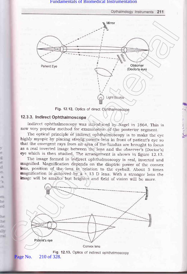
E M rrorE.-E
Patient Eye Observer(Doctor's eye)
\i
Fig. 12.12. Optics of direct Ophthalmoscope
12.3.3. lndirect Ophthalmoscope
Indirect ophthalmoscopy was introduced by Nagel in 7g64. This isnow very popular method for examination of the posterior segment.
The optical principle <if indirect ophtharmoscopy is to make the eyehighly myopic by placing strong convex lens in front of patient,s .y"
"othat the emergent rays from an area of the fundus are brought to iocusas a real inverted image between the lens and the observeris (Doctor,s)tye which is then studied. The arrangement is shown in figure 12.73'.
The image formed in indirect ophthalmoscopy is real, inverted andmagnifred. Magnification depends on the dioptric power of the convexhns, position of the lens in relation to the eyeball. About 5 timesmagnification is achieved by a + 13 D lens. With a stronger lens theimage will be smaller but brighter and field of vision will be more.
+E
Convex lens
Fig. 12.13. Optics of indirect ophthalmoscopy
Patient's eyeStud
y Mate
rial
Page No. 210 of 328.
Fundamentals of Biomedical Instrumentation

lr!
4
212 Fundamentals of Biomedical lnstrumentation
Indirect ophthalmoscopy should be done in a dark room' The pupilof the patient should be dilated.
The patient is mode to lie on the examination table with one pillow.The examiner (Doctor) through the light into patient's eye from an arm'sdistant (with the self illuminated ophthalmoscope).
In practice binocular ophthalmoscope with head band or mounted onthe spectacle frame, is employed most frequently keeping his eyes onthe reflex the examiner then interposes the condensing lens (+20 DS,routinely) in the path of beam of light, close to patient's eye and thenslowly moves the lens away from the eye (towards examiner's or Doctor's)until the image of the retina is clearly seen. The examiner moves aroundthe head of the patient to examine different quadrants of the fundus.
The indirect ophthalmoscopy is essential for the assessment andmanagement of retinal detachment and other retinal problems.
The technique of indirect ophthalmoscopy is difficult and cannot be
mastered without much practice.The advantage of the indirect ophthalmoscopy is the in built
illumination is strong and its intensity can be changed. It allowsstereoscopic view of the image.
12.4. TONOMETER FOR EYE PRESSURE MEASUREMENT
The intraocular pressure (IOP) is measured with the help of an instrumentcalled tonometer. Two basic types of tonometers available are Identation(Schlotz) Tonometer and Applanation (Goldmann) Tonometer.
12.4.1. ldentation (Schlotz) Tonometer
Schlotz tonometer shown in figure 12.14 consist of (a) handle fo:holdings the instrument vertical position on the cornea (b) a foot platewhich rest on the cornea (c) plunger which moves inside the foot plate(d) bent lever whose short lever rest on plunger and long arm acts as
a pointer needle. The degree to which plunger indents the cornea is
indicated by the movement of needle on a scale. (e) 5 gm is permanentlifixed to the plunger and is increased to 7.5 or 1O gm.
The foot plate of Schlotz tonometer and lever of the plunger shoul.c
be sterilized in hot water for 30 minutes.The eye whose intraocular eye pressure is to be measured :s
anesthizing the cornea by 2'k topical xylocane, patient is made to lie c-a couch. The tonometer is held in the left hand and the -ioot plate ;"made to rest on the cornea. The reading on the scale is recorded by r-:tneedle becomes steady.
It is customery to start with a -weight of 5 gm. However if the sca"le
reading is less than 1' then the weight may be increased to 7.5 gm :E
10 gm. If weight is increased then a conversion table should be use:The advantage of using Schlotz tonometer is that it is very hanrt
The main disadvantage is that it cannot be used in abnormal h:!m
pressure.
ub
z 4.2.
Thi::n I
.ofJor
-l: -}
Stud
y Mate
rial
Page No. 211 of 328.
Fundamentals of Biomedical Instrumentation

Opthalmology lnstruments 21g
\''t
':1..'
1.2. Applanation (Goldmann) Tonometerrhis is most popular and accurate tonometer. It consists of a double'n mounted on a slit lamp. The prism applanates the cornea is an- of 3.06 mm diameter.
.-or measuring eye pressure the- o xylocine the patient is asked' .ea and biprisms are illuminated.amp. Biprism is then advanced u
I
l1
{
I5St
udy M
ateria
l
Page No. 212 of 328.
Fundamentals of Biomedical Instrumentation
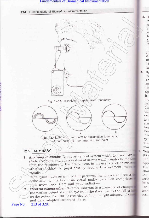
214 Fundamentals of Biomedical lnstrumentation
3.rnpflnbLD1n
pr8AT
T}Nr
+. o1thThanThopItThoplC-iex€quiInistrrfrotDoc1nv(by,ThemarTontEoThe\ppTheshol)o/1 /O
reedfeuThe,:onoltorn(
\\
F
0
1
t,
t
Fig.' 1 2.1 4. Technique of applanatlon tonometry
abcFig. 12.15. Showlng end point of app-lanation tonometry;
(A) too smail; (B) too large; (C) end point
,12.5.1SUMMARY
l.AnatomyofVision:Eyeisanopticalsystemwhichfocusesligh''iphoto receptors and has a system-of nerves *11:^,:"11Y::: '*:ifrom the receptors to the brain' Lens in an eye is a clear bic
structure behind the pupil held by circular lens ligament kno
zonule.Each eyeball acts as a cornea, it pelceives the imSF:" i1*:ii::".rr".tiorr"
to the brain via visual pathways which comp
optic nerve, optic tract and optic radiations'
2. Electroretinographs: Electroretinogram is a measut:,of :lthe resting potentiJ of the eye from the darkness to the fall of
on the retina. The ERG is recorded both in the light adapted (pho
and dark adapted (scotopic) states'Stud
y Mate
rial
Page No. 213 of 328.
Fundamentals of Biomedical Instrumentation

Opthalmology lnstruments 215
3. Electro-Oculogram (EOG): It records bipotential generated by themovement of the eye ball, EOG measures the changes in the restingpotential of the eye between cornea, which is positive and back of theretina which is negative. The EOG of eye movement less than 2' isnot possible. The eye movement of rnore than 30" do not producebioelectric amplitudes that are strictly proportioned to the eye position.Light peak represent the maximal height of the potential in light.Dark through represent the level of minimal height of the potentialin darkness. Normally the resting potential of the eye decreasesprogressively during dark adaptation reaching to dark through in8 to 12 minutes. In the light adaptation the amplitude start risingand reaches a light peak in 6-9 minute.The result of EOG are interpreted by finding out the Arden ratio.Normal Arden values are 185 or more.
a. Ophthalmoscope: The ophthalmoscopy is primarily done to assessthe condition of fundus and detect the opacities of ocular media.There are two types of ophthalmoscopy. The Direct ophthalmoscopyand Indirect ophthalmoscopy.The distant direct ophthalmoscopy is done by self illuminatedophthalmoscopy or a simple plain mirror with a hole in the centre.It is used to detect opacities in the refractive media.This method is also useful to detect detached retina. The directophthalmoscopy is very useful and is routinely done by the Doctor's.C-ice the light beam is focused on the retina the details should beexamined systematically starting from the blood vessels, the formquadrant of the general background.In indirect ophthalmoscopy the eye is made highly myopic by placingstrong convex lens in front of patient's eye so that the emergent raysirom an area is focused as an inverted image between lens and theDoctor's eye. The image formed in indirect ophthalmoscopy is real,:nverted and magnified. Magnihcation is about 5 times and is achievedf,ya+13Dlens.The indirect ophthalmoscopy is essential for the assessment and:rranagement of retinal detachments and other retinal problems.Tonometer for Eye Pressure Measurement: The intraocular pressureEOP) is measured with the help of an instrument called tonometer.-he basic type of tonometer's available are identation (Schlotz\ andrpplanation (Goldmann) tonometer.lhe foot plate and lever of the tonometer should be sterilized and.hould be placed on the cornea of the eye, which is anaesthetizedby-?/o typical 4ylocane. The intraocular pressure is noted when the:-eedle of the tonometer becomes steady. The Schlotz tonometer cannot:e used in abnormally high eye pressure.. he Applanation (Goldmann) tonometer is most popular and accurate-rnometer. It consists of a double prism mounted on a slit lamp. The,lrnea and biprism are illuminated with the cobalt blue lamp.St
udy M
ateria
l
Page No. 214 of 328.
Fundamentals of Biomedical Instrumentation

216 Fundamentals of Biomedical lnstrumentation
oxercded
12.1. Explain Electro Retinogram (ERG).72.2. Dxplain Electrooculogram.12.3. Describe Ophthalmoscope.72.4. Explain Tonometer for eye pressure measurement.12.5. Explain the working principle of Electro-retinogram
(UPTU, 2004)(UPTU, 2OO4)
(UPTU, 200s, 2006)(wTU, 200s, 2006)with block diagram.
)9.
(UPTU-MQP)12.6. Name the instrument for measurement of eye pressure and explain with
diagram in detail. (UPTU-MQPI
AJJ
13
13.
13.
13.
13.
13. r
10 |I U-
l1
.reat i,ud a-Ieat lr-- ihe.L:-d faiqi thebrdv trri-iS 1S
::h thper,
The:lorn3-37
r 3.1.
peraStud
y Mate
rial
Page No. 215 of 328.
Fundamentals of Biomedical Instrumentation

Some General Topics
'i. fnstde this chapter13.1. Body Temperature13.2. Reproduction SystemI3.3. Laser Applications in Medical Field13.4. Diathermy13.5. Clinical Laboratory Instrumentsi3.6. Biomaterials13.7. Stimulators13.8. Summary
:--:at is produced in the body by assimilation of food, muscular exercise::-d all the vital processes that contribr,rte to the basal metabolic rate.:-.:at loss occurs due to conduction, radiation and vapourization of water=- the respiratory, passages and on the skin. Heat is also lost with urinea-.d falces, though in small amount. The body temperature is determined: the delicate balance between heat production and heat loss. Normal:, dy temperature depends upon a relatively constant body temperature.T-ris is so because of the fact that the speed of chemical reactions variesn.:h the temperature and t}:.e enzyrl:e systems of the body have narrowi:nperature ranges in which their function is optimal.
t3.1.1. Normal Body Temperature
The traditional normal value for the orai temperature is 37'C (98.6"F).- normal young adults, the morning oral temperature may vary from
3-37.1'C (97.3-98.8"F). Not all parts of the body are at uniform:rperaturc. The magnitude of the difference in the temperatures of the
)
DI
TEMPERATURE
277
Stud
y Mate
rial
Page No. 216 of 328.
Fundamentals of Biomedical Instrumentation

t
al
g)
2'18 Fundamentals of Biomedical lnstrumentation
various parts of the body varies with environmental temperature. Thetemperature of the serotum is meticulously regulated at 32"C. The rectaltemperature is representative of the temperature at core of the body andvaries least with the changes in the environmental temperature. The oraltemperature is normally 0.5"C lower than the rectal temperature, but itis affected by many factors, including ingestion of hot or cold fluid3, gumchewing, smoking and mouth breathing.
In human, the normal temperature undergoes a regular circadianfluctuation of 0.5-0.7"C. The individuals who sleep at night and areawake during the day, it is the lowest at about 6 AM and highest in theevenings. During sleep it is lowest. It is slightly higher in the awakestate but relaxed state, it rises with activity. In the case of women, owingto ol.ulation, there is an additional monthly cycle of temperature variationcharacterized by a rise in basal temperature. In young children,temperature regulation is less precise and they may normally have atemperature which is about 0.5'C above the established form for adults.The heat produced by muscular contraction gets accumulated in thebody, during exercise, and the rectal temperature rises as high as 40'C(104"F). This rise is due to in part to the inability of the heat dissipatingto handle the greatly increased amount of heat product. But there is anevidence that in addition there is an deviation of body temperature atwhich the heat dissipating mechanisms are activated during exercise.Rise in body temperature can take place by emotional excitement, probabll-owing to unconscious tensing of muscles. Chronic elevation by 0.5"Coccurs when the metabolic rate is high and lowered whether metabolicrate is low. Few normal adults chromically have a temperature above thenormal range.
13.1.2. Heat Production
A variety of chemical reactions contributed to body heat productionat all times. The major source of heat is the contraction of skeletalmuscle. Endocrine mechanisms can vary heat production in the absenceof food intake or muscular exertion. A slowly developing but prolongedincrease in temperature is attributed to thyroid harmones. The sourceof heat in infants, is brown fat. This fat has a high rate of metabolism.it's thermogenic function is like an electric blanket.
13.1.3. Heat Loss
Heat is lost from the body when the environmental temperature isbelow the body temperature. The processes by which heat loss takesplace is listed below in the Table 13.1.
Table 13.1. Body Heat Production and Heat Loss
Body heat is lost by Percentage of heatlost at 21'C
Radiation and conductionVapourization of sweatRespirationUrination and defecation
70
2
I
frrNC
ter1S
alrtrarvhrnd:VC
:lea:ffe-igh
he:emIta.cI:IlVl', apcr:lVli_1e
apo::lV1I::cli' 3.1 .,
T::e 1r
.clur-rSpC
' eict::laf,
- : SpOr
-:losBc
: _:vel:-:c c
MeIncSt
udy M
ateria
l
Page No. 217 of 328.
Fundamentals of Biomedical Instrumentation
Some General Topics 219
Radiation is the transfer of heat by infrared electromagnetic radiationfrom one object to another at a different temperature with which it isnot in contact.
Conduction is heat exch.alge between objects or substalces at different:emperatures that are in contact with one another. when an individual:s in a cold environment, heat is lost by conduction to the surroundingair and by radiation to cool objects in the vicinity. conversely, heat isrransferred to al individual and the heat load is increased by the processes',r'hen the environmental temperature is above body temperature. An:ndividual can feel chilly in a room with cold walls blcause of radiation:ven though the room is relatively warm. on a cold but sunny days the:eat of the sun reflected off bright objects exerts an appreciabll warming:ffect. The heat reflected from the snow makes skin possible in fairly:ght clothes even though the air temperature is below freezing.
The other major heat transfer process in hurnans is vapourization of:ee water in the form of sweat on the skin. vapourization of 1 g of water:.moves about 0.6'c kcal of heat. A certain amount of water is vapourized=tt all times. This water loss amounts to 50 ml/h in humans. ThL degreer which the sweat vapourizes depends upon the humidity of 1ne
=:rvironment, when the sweat secretion is increased. Decreasedapourization of sweat leads one to feel hotter on a humid day. As the
::rvironmental temperature changes, the relative contribution of each of-re processes that transfer heat away from body also changes. Theapourization is a minor component in humans at rest at 21"c. As the
= rvironmental temperature approaches body temperature, radiation losses::cline and vapourization losses increase.
' 3.1.4. Temperature Regulating MechanismsThe reflex and semi-reflex thermoregulatory responses in humans
r--e mechanisms activated by, hot and cold as shown in Table 13.2. They-clude autonomic somatic, endocrine and behavioural changes. ThL-:spcnses which increase heat loss and decrease heat production andi:rich decrease heat loss and increase heat production rnay be grouped'.carately. In general, exposure to heat stimulates the former group of':sponses and inhibits the latter whereas exposure to cold does the--posite.
Body surface exposed to the environment decreases by curring up.:--lvering is an involuntary response of the skeletal muscles, nuicoia,-:o c&uSeS a semiconscious general increase in motor activity.
Mechanism Activated by coldIncrease Heat Production
HungerShiveringIncreased voluntary activityIncreased secretion of morepinephrine and epinephrine.
Table 13.2. Temperature-Regulatory Mechanisms
Stud
y Mate
rial
Page No. 218 of 328.
Fundamentals of Biomedical Instrumentation

220 Fundamentals of Biomedical lnstrumentation
+I
I
j
:
l\
Decrease Heat LossCurling uPHorripilationCutaneous vasoconstriction
Mechanisms Activated BY HeatIncrease Heat Loss
SweatingIncreased respirationCutaneous vasodilation
Decrease Heat ProductionAnorexiaApathy and inerti.a
Examples includ.e dancing up and down and foot stamping on a cold
day. An important end.ocrine response to cold is increased catecholaminesecretion. Thermoregulatory adjustments involve local responses as well
as more general reflex responses. Cutaneous blood vessels become more
sensitive to catecholamines and arterioles and venules constrict when
bloocl vessels are cooled. This local effect of cold directs blood away from
the skin.The reflex responses activated by cold are controlled from the posterior
hypothalamus. Activated by warmth, they are controlled primarily fron:
the interior hypothalamus although some thermoregulation against hea:
still occurs after decerebration at the load of the postal midbrainStimulation of the anterior hypothalamus causes cutaneous vasodilatiorand sweating and lessons in this region cause hyperthermia, with recta-
temperatures sometimes reaching 43"C (109.4'F).
13.1.5. Afferents
The hypothalamus integrates body temperature information fro=sensory receptors (primarily cold creptors) in the skin, deep tissues c:
spinal cord, extra hyperthermic portions of the brain, and hypothalamusitself. Each of these contributes about 2Ook of the information that :s
integrated. Threshold temperatures exists for each of the mai:,
temperature regulating responses, and response begins when ti-.:
threshotd is reached. The threshold temperature for vasoconstriction :s
36.8.C, 36.C for nonflowering thermogenesis, 37'C for sweating a-'-:
vasodilation and 35.5'C for shivering.
13.1.6. Fever
Fever is the most universally known hallmark of disease. Pathogeness
of fever is summarized in the figure 13.1. Toxins from bacteria such -rf,
endotoxin act on monocytes, amorphases and kuffter cells to produ=cytokines that acts as endogenerous pyrogens. This leads to activat::rr
oi th" preoptic area of the hypothalamus. Fever produced by cytokr:-:ris due to local release of prostaglandins in the hypothalamus'
Intra-hypothalamic injection of prostaglandins produces fever. To c'-tflever, antipyretic effect of aspirin is exerted directly on the hypothalar:----r*
refclen-4r11
:tar-oe
::rn::ve
13.1.
13. IS
::i-IC_:Tln
EJ-.:fITSt
udy M
ateria
l
Page No. 219 of 328.
Fundamentals of Biomedical Instrumentation

Some General Topics 221
and aspirin inhibits prostaglandin synthesis. Fever has evolved andpersisted as a response to infections and other diseases, which makesit beneficial. Many microorganisms grow best within a relatively narrowtemperature range, and a rise in temperature inhibits their growth. Inaddition to this, antibody production is increased, when body temperatureis elevated.
Endotoxinlnflammation otherpyrogenetic stimuli
MonocytesMaerophagesKuffler cells
Cytokines
Prepic areaof hypothalamus
Raise temperatureset point
Fever
Prostaglandins
Fig. 13.1. Pathogenesis of fever
Fevers were artificially induced for the treatment of neurosyphilisbefore the advent of antibioties. This proved to be benefrciat. Hyperthermiabenefits individuals infected with pneumococcal, anthrax, leprosy, andi-arious fungal rickettsial and vital diseases. Tumour growth slows down:hanks to hyperthermia. However, very high temperatures over 41.C106'F) are harmful and if it persists for prolonged periods, some
)ermanent brain damage results, when it is over 43"C, heat strokeJevelops and death is common
13.1.7. Temperature Measurement
13.1.7.1. Measurement of Systematic Body TemperatureSystematic temperature is the temperature of the internal regions of
:he body. If continuous recording of temperature is not required, the:nercury thermometer is the standard method of measurement. Thesecevices are inexpensive and sufficiently accurate, therefore, they are in:ommon use.
Electronic thermometers are available as replacement for mercury:hermometer. Two types of electric temperature censoring devices areSt
udy M
ateria
l
Page No. 220 of 328.
Fundamentals of Biomedical Instrumentation

,1
i.
4
1-
:tt
used. They are the thermocouple, a junction, and the thermistor' a
semicond.uctor element whose resistance varies with temperature' withdisposable tips, these instr-uments requirement much less time of reading
and.mucheasiertoreadthanconventionalthermometer.Ifcontinuesrecord.ing and greater accuracy of temperature is needed' more
sophisticated measuring instruments must be used'
Care must be taken to rninimize current through the thermocouple
circuit, for the current not only causes heating at the junction but also
additional error due to the Peltier effect, wherein one junction is warmed
and other is cooled'Inthermistors,therelationshipbet'"lreenresistancechangeand
temperature change is non-linear. To overcome this, the instrumentation
oftenincorporatesspeciallinearizingcircuits'Itmaybeapairofmatchedthermistors as part o f ltnearizatron circuit. Thermistors also have errors
duetoself-heating,hysteresis,aging,therefore,suitablemeasuresaretobe taken to minimrze error. Most thermistors thermometers use a wheat
stone bridge or similar circuit to obtain a voltage output proportional to
temperatu-re variations. The bridge is balanced at some reference
temperatureandcalibratedtoread'variationsaboVeandbelowthatrefeience. Either ac or dc excitation can be used for the bridge.
Lg.|.7.2. Skin Temperature Measurements
Skin temperature can vary several degrees from one point to another'
Therangeisformabout30to35"C(85to95"F).ExposuretoancienttemperJures, the covering of fact over capillary areas' and the local
blood circulation pattern are some of the factors which influence the
distribution of temperatures over the surface of the body. Skin
temperatur" -"."rr.-ents can be used to defect or locate defects in the
circulatory system by showing differences in the pattern from one side
of the bodY to the other.Flat thermistor probes taped to the skin are used for measurements
from specific locations of the body. The simultaneous readings from
several probes provid'e a means of measuring changes in the special
characteristics of the circulatory pattern over a time interval or with agiven stimulus.
Another method is based. on infrared radiation trrrd temperature
measuring device based on this principle are called infrared thermometer
and recording is known as thermograph'Another device known as thermovision, has a scanner that operates
at a rate sufficiently high to permit the image to be shown in real time
on an oscilloscop"' n tfr.t-ovision system has a camera and displal
withbr:ightnessenhancementfacility;andaisohashighresolution'
222. Fundamentals of Biomedical lnstrumentation
13.2. REPRODUCTION SYSTEM
The multiple d.ifferences between males ancl females depend primarily o:a single .hro*o"o-e i.e.' Y-chromosomes and a single pair of endocrir:=
structures, the testes in the male and the ovaries in the female' Th:
s
(
I(
(
tC
1.
r.
t.
)C
l\\Zf(g5aaS
r1
:IS]
a.
:r
Stud
y Mate
rial
Page No. 221 of 328.
Fundamentals of Biomedical Instrumentation

Some General Topics 223
differetiation of the primitive gonads into testes and ovaries in utero isgenetically determined in humans, but the formation of male genitaliadepends upon the preserve of a functionai secreting testes; in the absenceof testicular tissue, development is female. Harmones secreted by thegonads at the time of birth cause the appearance of features typical ofthe adult male or female and onset of the sexual cycle in the female. Theovarian function regresses after a number of years, in femaies andsexual cycles cease, i.e., menopause occurs. In males, there is a slowdeclinein gonadal function with advancing age, but ability to father achild persists.
The gonads have a dual functionality in both the sexes-the secretionof sex hormones and the production of germ cells.
13.2.1. Sex Differentiation and Development
Chromosomes determine the sex. The sex Genetic determination ofsex is done by two chromosomes called the sex chromosomes todistinguish them from the somatic chromosomes. The sex chromosomesare called X and Y chromosomes. The Y chromosome is necessary for theproduction of testes. The tastes determining gene product is called SRY(Sex-determining region of the Y-chromosome). SRY is a DNA(beoxyribanualicacid) i.e., a giant molecule binding regulatory protein. Itbends the DNA and acts as a transcription factor. It initials transcriptionof a cascade of genes necessary for testicular differentiation. It alsoincludes the gene for MIS (Mullerian lnhibiting Substance). With deploidnumber of chromosomes, male cells contain an X and Y chromosomei.e., XY pattern, whereas female cells contain two X chromosomes i.e.,-XX pattern. During gametigonesis, due to meiosis, each normal ovumcontains a single X chromosome. But half the normal sperms contain anX chromosome and half contain a Y chromosome XY pattern resultsrvhen a sperm containing a Y-chromosomes fertilizers an or,,r-rm. Andzvgote develops into a genetic male. XX pattern and a genetic female:esults when fertilization occurs with an X containing sperm. A primitivegonad arises from the genital ridge a condensation of tissue near theadrenal gland on each side of the embryo. The gonad develops a cortex.nd a medulla. These structures are identical in both the sexes until the=rxth week of development. The medulla develops into the testes during.re seventh and eight week. And the cortex regresses. Testosterone and
=-iller ion inhibiting substance are secreted and leydig and Sertoli cells.:art appearing. The cortex, in the case of genetic females develops inton:-r. ovary and the medulla regresses. The embryonic differentiation of
=-a-le and female internal genetical ducts is shown in figure 13.2.
Stud
y Mate
rial
Page No. 222 of 328.
Fundamentals of Biomedical Instrumentation
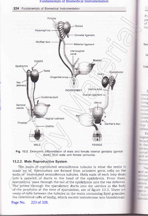
224 Fundamentals of Biomedical lnstrumentation
Mesonephros
Wolffian duct
Gonadal ligament
Mlillerian ligament
Uterovaginalcanal
Bladder
Epididymis
Urogenital sinus
Vasdeferens
INDIFFERENT Uterine tube
GubernaculumOvarian ligament ji
Seminalvesicle
Gartner's ducl
MALE FEMALE
Fig. 13.2. Embryonic differentiation of male and female internal genitalia (genitalducts) from male and female primordia.
13.2.2. Male Reproductive System
The loops of convoluted seminiferous tubules is what the rtestis ismade up of. Spermatora are formed from primitive germ ce[! on thewalls of convoluted seminiferous tubules. Both ends of each lodp drair-into a network of ducts in the head of the epididymis. From there.spermatora pass through the tail of the epididymis into the vas deferensThe yenter through the ejaculatory ducts into the urethra in the bod_,
of the prostrate at the time of ejaculation, see of figure 13.3. There arrnests of cells between the tubules in the testis containing lipid granulesthe interstitial cells of leydig, which secrete testesterone into bloodstrear::-
FopaofC1I
I::eCt: iocl_:.teg
--:1pu::eCt::f 1na
=:al-. I I
,r, ni:=
- '-'t /
-:eth-:eth-_-_at l
:_--l-ert
Erj.i:lTIe
:- JSCI
:- :he:tr::letii. aalir_: 1o.'I:'.'ef
t
? i t-.'e s
:h('E I se(
Sym
Ur
t
- --atStud
y Mate
rial
Page No. 223 of 328.
Fundamentals of Biomedical Instrumentation

Some General Topics 225
Fortons are spermatic arteries to the testes, and blood in them runsparallel but in the opposite direction to blood in the pampiniferm plexusof spermatic veins. This anatomic arrangement may permit countercurrent exchange of heat and testosterone.
Vas deferens Head of epididymis
\Symphysis Prostate
Urethra *Seminiferous
tubules
EpididymisEjaculatory duct
Cowper's./'
',/Tunica albuginea
I - (bulbourethral) gland
Scrotum
(a)
Fig. 13.3(a) Male reproductive system. (b)
Tail of epididymis
(b)
Duct system of the testis FDilation of the arterioles of the penis results in an erection. As the
::ectile tissue of the penis fills with blood, the veins are compressed,-locking outflow and adding to the turgor of the organ. Activation of the,ltegrating centres in the lumbar segments of the spinal cord is done by-npulses in afferents from the genitalia and descending tracts that mediate:rection in response to erotic psychic stimuli. Ejaculation is a two-partspinal reflex involves emission, the movement of the semen into the-rrethra; and ejaculation proper, the propulsion of the semen out of therrethra at the time of orgasm. The touch receptors in the glans penis:hat reach the spinal cord through the internal pudendal nerves, arelifferent pathways which are mostly fibres.
Enumission is a sympathetic response, integrated in the upper lumbarsegments of the spinal cord and effected by contraction of the smoothruscle of the vasa differential and seminal vesicles in response to stimuli:r the hypogastric nerves. Contraction of the bulb cavernous muscle, a.<eletal muscle results in the propulsion of semen from the urethra. The.rinal reflex centres for this part of the reflex are in the upper saral..rd lowest lumbar segments of the spinal cord, and the motor pathways':averse the first to third seral roots and the internal pudendal-:rves.
The semen which is ejaculated at tire time of orgasm contains sperms..:d secretions of the seminal vesicles, prostate lowper's glands, and the-.ethral glands. An average volume for ejaculate is 2.5-3.5 ml after'.,,'eral days of continence. With repeated ejaculation, the volume of::rrrerr and the sperm count decreases. There are normally about
- 0 million sperms per millimeter of semen ion through it takes only::rm to fertilisne the ovum. Movement of human sperms is traced atnm/min through the female genital tract. after 30-60 minutes of:ulation, sperms reach the uterjne tubes.
(,
E
:
Bladder Ureter
Stud
y Mate
rial
Page No. 224 of 328.
Fundamentals of Biomedical Instrumentation

226 Fundamentals of Biomedical lnstrumentation
13.2.3. Female Reproduction SYstem
Figure 13.4 shows the reprod.uctive system of women. Unlike the.rcJunter- part, the Iigure shows regular cyclic changes that teleologically
may be regard.ed as periodic preparations for fertilization and pregnancy'periodic vaginal bleeding, the most conspicuous feature of the menstrualcycle, o""ri" with the shedding of the uterine mucosa (menstruation).
The average figure of the length of the cycle is 28 days from the start
of one menstrual period to the start of the next, but it varies notoriously'The days of the cycle are identihed by number, starting with the first day
of menstruation.Uterine tube Ligament of the ovary Ovarian artery
Uterine tube
, Uterus
\..,, /
.---- Uterine cavity
Broad ligament
Cervix l z' UrethraVagina
Fig. 13.4' The female reproductive system
13.2.3. 1. Ovarian CYcle
There are many primordial follicles under the ovarian capsule fro=the time of birth. Each contains an immature ovum. Several of thesc
follicles enlarge and a cavity forms around the ouum, at the start of eacb
it that is needed for final maturation, is selected to be the domtn
flollicle. Many follicles develop simultaneously when women are g1\'(
hiehly purified human pituitary gonadotropin preparations by injectio
Distended follicle raptures at the 14th day of the cycle, and the ovum
extruded into the abdominal cavity. This process is called evolutic
Fimbriated ends of the uterine tubes picks up the ovum, and
transported to the uterus. And unless fertilization occurs, it passes
through the vagina.
Mean(isrOCC'
lron
\y;i', .,/' F'nd's Bectum
Whrwallglanto stsexuthe Ibuiltautotand ;
:ranslot d
In,han5-'i'ome
=Id a_ uttoc
=rd rr--at-to;
.ctior:he r
Ovary
Ovary
,]
II
I3.2.3Fer
;: the rr- the I
-iiL::lefe.i:-: OVt
The corpus luteum persists and periods doesn't occur, if prel
occurs. If there is no pregnancy, the corpus luteum degenerates
ETIn I::rCOt- 100.--rcid,
iusi-:lin: '.-iral
:..-:des
-ctio' -iDert' ::ent
i -:ida4 days, before the next menses, i'e., 24th day of the cycle' It is eventu
replaced by scar tissue, forming a corpus albicans'Menstrual blood is predominantly arterial. Only 25uk of the
belongs to venous origin. It contains prostaglandins, debris. It :
contains a large amounts of fibrinolysin from endometrial tiss
basStud
y Mate
rial
Page No. 225 of 328.
Fundamentals of Biomedical Instrumentation

Menstrual flow takes about 3-5 days. But it can flow as short as 1 dayand as long as 8 days in normal women blood ross of more than go mlis normal' on the omet of menopause when the evolution does notoccur, bleeding is variable which Lsually occurs in less than 2g daysfrom the last menstrual period.The blood loss flow is arso variable from scanty to reratively profuse.when a woman is sexually excited, fluid is
"""r"t"d onto the vaginalwalls due to release of vasoactive intesti,al polypeptiae 1vre1. vestibularglards secrete lubricating mucus. The upper part oithe vagina is sensitiveto stretch. Tactile stimulation from labia minora and ditiis adds to thesexual excitement- These stimuli are reinforced by tactile stimuri fromthe breasts and, as in men, by auditory and visual stimuli, which may:uilt up to erescendo known as orgasm. During orgasm, there are noautonomically mediated rhythrnic contraction o1 the buluocavernosusand ischiocavernosus muscres. The vaginal contraction may aid sperm:ransport but are not essential for it, since fertilization of the ovum is::ot dependent on orgasm.
In addition to enlargement of breasts, uterus, and vagina, the body.:hanges that develop in- girrs at puberty are due to feminining hormones.''q'omen have narrow shoulders and broad hips, thighs that converge,:nd arms that diverge. The female distribution of fatln the breasts and:uttocks, is also seen in eastrate males and women have ress body hairi:rd more scalp hair, and the pubic hair generally has a characteristic-at-topped pattern.
L3.2.3.2, Fertilization and Implantation
Some General Topics 221
Fusion of the sperm to the ovum membrane is mediated by fertilin.ilin is a protein on the surface of the sperm head that resemblesviral fusion proteins which permits viruses to.attack celrs. Fusion
3lastocyst the
-.-ides a signal that initiates development. The fusion also sets offrction in the membrane potential of the ovum that prevents'.spermy, the fertilization of the ovum by more than one sperm. This--sient potential change is folrowed by structurar change in the zona:cida that provides protecting against polyspermy on"a more long-:. basis.
-rs, in aboutdeveloping embryo moves down the tube into the3 days, during which blastocyst reaches the 1g or
blastocyst becomes surrounded by an outer layer of:ll stage. Thg
Stud
y Mate
rial
Page No. 226 of 328.
Fundamentals of Biomedical Instrumentation

228 Fundamentals of Biomedical lnstrumentation
synchtiotrophoblast a multinucleate mass with no discernible cell
boundaries, and an inner layer of cytotrophoblast mode up of individual
cel1s, once it comes in contact with the endometrium. The blastocyst
burrows into the endometrium as synctiotrophobast erodes it. The dorsal
wall of the uterus is the implantation sit. A placenta then develops, and
the tropoblast remains associated with it'The fetus and,the mother are two genetically distinct individuals'
The fetus is in effect a transplant of foreign tissue in the mother. However'
the transplant is toleraled, and. the rejection reaction that is
characteristically produced when other foreign tissues are transplanteifails to occur.
birC€
Str
inits
13
ltU
\
Egg cytoplasm
Egg cell membrane
emabspotr
exclstinincl'.1'er(
lAS S]
sttm'he1. his1'aVe
r las-:ted_ ratt.:n t
nershur
:_ las.f 1ng
J3. I: rr,-ef-.-ndi
r lt€V
133.I LASER APPLICATIONS IN MEDICAL FIELD
13.3.1. The Laser
The full term of word LASER is "Light Amplification by Stimula .-,e:-:ctirThr
Emission of Radiation". The laser beam has spatial and temp:
coherence and is monochromatic. The beam is highly directiona'l ;
exhibits high density energr which can be timely focussed'
The use of lasers in the medical field is suitable where the::
favourable interaction between the laser radiation and the human tiss-
The merlical use of laser is dependent on radiation wavelength
ability of the tissue to absorb this wavelength, delivered po\rel
treatment area, total eners/ incident on tissue and the area trea
Lasers have been especially successfi.rl in the following areas of mej
treatment:(i) Treatment of detached retina.
(iz') Coagulation of eye in dielectric retinopatthy'(iii) Treatment of tissues in the skull and spine (neuro-surgen-
(iu)Treatmentbycoagulationofthelowergastrointestinaltrac:
m - rrpl
Stud
y Mate
rial
Page No. 227 of 328.
Fundamentals of Biomedical Instrumentation

Some General Topics 2Zg
- Demotrologr for removal of skin defects by laser radiation. The laserbeam has becom :^: -*"-^ '***information cont non pplications' The
can be detected ted d bY structuresstic The most widespread medical application of laser technologz in medicine has occurredin opthalmologr. This is due to the easy accessibility of the human eye,its transparency and the absorptio r properties of its internal tissues.
13.3.2. Principle of Operation of LaserThe laser action depends upon the
emission. In the normal state most atomsabsorption is generally for more likelypopulation inversion could be obtained (
oton of the correct frequency could triggeran avalanche of coherent photons. The
to grow so long as the scattering processesinversion could be maintained.
For generation of raser beam, it is necessary to have arr active mediumas shown in figure 13'6 in which atoms are kept in an excited state andstimulated by an outsid.e photon to emit right in a particular direction.rhe process by means of which a medium is activated is ca,ed pumping.lhis inflates enta,s- erectromagnetic energy into the medium at a;avelength different from the stimulating wavelength.llI
Totalrefractive
mtrror
Resonator
shutter in a precisely controlled manner.
.3. Types of Lasers
\ laser's properties are determined by the gain of the medium, the:ring mechanism, and the resonatioi design.
The active medium is usuary enclosed in a resonator box with highly:. i::,1*-:i:,:* T: ll?r:n_s
rereas ed by the s ti.,,,raie J ._i" "io, und ergom:ltiple reflections and resurts in a coherent *rrr. of g.o*rrrg strength.lF-: laser output is obtained if the resonator box is transparent to the-:rted laser beam. For reflecting the high beam a double mirrored
-' rnating chamber is used to collect high energ, pnotor, ,""umulated.:'rin the system. The high ener$/ stored within resonating chamber
: :*.1:_.,:b:"T_"_1,,hrough the- partially refl ective mirror by releasing
of lasers are e classi{ied according to themodes of op , the pulsed operation suchthe ruby an minum gtass and the continuous
Fig. 13.6. Main element of laser
Stud
y Mate
rial
Page No. 228 of 328.
Fundamentals of Biomedical Instrumentation

230 Fundamentals of Biomedical lnstrumentation
"i .ii- ]..i mm with lo*i enerS' requirement producing less damaE:
Ir
,)
i
wave operation (CW) such as helium-neon argon' krypton' carbon dioxide
lasers.Eachofthesetwoclasseshasspecificareasofapplicationinmedical field.
The types of lesser usually employed in the medical field are as
follows:
13.3.3.1. Pulsed RubY Laser
The ruby laser is usually operated in a short bursts or pulses because
in continuor. *.rr" operation it gets heated up and results in upsetting
the distribution of atoms quantum states. This may cause physical damage
to the crystal.
13.3.3.2. Nd Yag Laser
NdYagLaseraSVeryusefulinmedicalfectionoloSz,alightguideis.,...."".ry-*hich transmits the laser energr at
the same time, is sufficiently flexible to per rk
in various helds like endoscopy, uroloS' neu g.'
dermatologr, dental surgery and general surgery'
13.3.3.3' Helium Neon Laser
AHe_Nelasercanbeused.forthemeasurementofvisualactivityancis very helPful to the oPhthalmologperfoiming cataract surgery on the
ifris appti-ation is in the range ofcan also be used as a scannlng o
and its supporting structure incluunderlying layers. This layer beam c
in case of correction of eye cracks developed in the retina'
13.3.3.4. Argon Laser
Thislaserisnotusedformedicalapplicationasthecathodeemiss::mis severe at high currents. It limits iire life which must be replac*di
occasionally and replacement cost is very high'
with operating microscope'Argon ion photo-coagulator is m9re. suitable
"t Pn*:.:?1i1iil-ltheretinasincetheoutp"utformtheRubylaserisnoteffectivelyabsc:Uibfooa-"essels. The Argon iron laser. can be focrlsea 1,i^:i1T:.
ofthheStISCi
wacorof,canconprerThesavl
,a.:
lhe-93\eC
Ttntr
-:mO
= r:CtII
I
_:on
:3.3.1
Th
i -:nIl Ces'=Tul' . etit
_ NIF. : -eS,
.Di_Di! 1. I
-: tl:e as
the healthy tissue than with xener arc light sensors'Stud
y Mate
rial
Page No. 229 of 328.
Fundamentals of Biomedical Instrumentation

Some General Topics 23'l
13.3.3.6. CO, Laser
^ . The co, laser is used for bloodless surgery. It provides a thin rayer
of heat coagulated tissue immediately around the treatment site whilethe cells beyond this site remain untouched, undisturbed and begin thehealing process promptry. post operative odema is minimal in lasersurgery. The healing is faster with minimum of tissue swelling andscarring and with less post operative pain and discomfort.
The co, laser is high power continuously operating raser and itswavelength is in the infrared region of 10.5 mm. This wavelength iscompletely absorbed by most biological tissues. The most common useof co, laser are in microsurgery. The coherent monochromatic beamcan be exactly focused on arr area approximately 1 mm diameter and iscontrolled through the optical system connected to microscope. A veryprecise micro-manipulator directs the laser light to the treatment area.The laser is now used in selected areas of larynx, pharynx and oralcavity.
13.3.3.7. Excimer LaserThe excimer laser operate primarily in the urtraviolet spectral region.lhe most common excimer lasers are argon-fluoride (ArF) operated at
-93 mm, krypton-fluoride. (Kr F) operated at 24g mm, Xenon-chlorideXecl) operated at 308 mm and Xenon-fluoride XeF operated at 351 mm.
The most important use of excimer laser is improving vision byrontrolled ablation of the cornea with A, F (193 mm) excimer laser andtmoval of anthrochorositic plaque from arteries with Xecl (30g mm)
'rcimer laser one of the area of great clinical interest is laser angioplastye , to open authenosclerotic arteriar narrowings in peripheral andrronary artery.
:3.3.3.8. Semiconductor LaserThe semiconductor lasers are smafl in size and are highly efficient.-1ey are mainly constrrrcted using gallium arsenide/aluminium gallium
':senide indium phosphide/indium, gallium arsenide phosphide. Laser--odes made of Al Gra As and can be convenientry used in photo:agulation. These semriconductor lasers can be used for the treatment: retinal vascular decr.eases.
- - e high frequency elec tric current is used to produce heat in the body:sues. The diathermy in medical applications are used in the following
: :\_s:
1. Diathermy in physriotherapyl. Diathermy in surg;ery.
r 4.1. Diathermy in PhysiotherapyIn the diathermy fi:r physiotherapy the siize of the electrodes are':. as compared to cliathermy for surgical aLpplications.
/
L
i:f
E1l
::r
!diiludlTE&rd':-dl'ilr
rd
Stud
y Mate
rial
Page No. 230 of 328.
Fundamentals of Biomedical Instrumentation

232 Fundamentals of Biomedical lnstrumentation
It is possible to pass higher frequency currents in the range of1OO K Hz through the body and at this frequency neither nerves normuscles are stimulated, but the current of high frequency produce heatby ohmic dissipation in the tissue (diathermy). The diathermy in theearly years used a spark-gap and induction coil giving pulses of 1 MHz
oscillation. Nowaday the diathermy machines uses much higherfrequencies. Since the wavelengths are much higher than the bod-t
dimensions, the mechanism of heating is attributable to the movemen:of ions in the tissue. The clinical objective of diathermy is to heat theinternal tissues without unduly raising the skin temperature and the
heating depends upon the less angle of the tissues and the heat removed
by body circulations. If a greater localized heating of the subcrrtaneousfatty layer is needed, microwave diathermy of 10 cm rvavelength is used
The following type of diathermy equiprment for physiotherapy are
used :
1. Short-wave diathermy2. Microwave diathermY3. Ultrasonic therapy unit.
13.4.2. Short Wave Diathermy
In diathermy for physiotherapy the patient body become a part of thtelectrical circuit and the heat is produced within the bod5r and tralsferenctthrough the skin. It does not produce discomfort to the body as in cas:of externally applied source of hr:at like not towels, infrared lamps anc
electric heating pads.
Powersource
Fig. 13.7. Block diagrerm of a short wave diathermy machine
Another advantage of diathr:,rmy is that the trear.ment can be controlle:precisely. The placement of el,ectrodes permits localization of the heat :---
the region to be treated. The intersect of the 'heat can be regulate:precisely by the control of nnode voltage/control of filament therrn-heating current/adjusting the grid bias by change of grid leak resistanct
The timing that is the duration of treatment is adjusted by providi;-;an independent timing circuit in the machine which rviil contrc-rl the oi--
off time of the machine.The most common use of short wave diathermy is to operate =
capacitor plate method an<l intluctive method ar; shown in figure 13 :In the capacitor plate rnethod the short-wavt: diathermy machine :-"
connected to metal electrocles which are positiont:d on the body over tl-re
region to be treated. These electrodes are called 'P7\DS'in the terminoiogof d.iathermy. The PADS o.r electrodes do not dire'ctly come into conta:
wit.anc
ODape
,S tV.: th: rdS_:twr,ns i
:^sto
Irlnn(
::OUI:t. v:ld i
_:ep-:atir, :na€..:thc
Stud
y Mate
rial
Page No. 231 of 328.
Fundamentals of Biomedical Instrumentation

with the skin. Usually layers of towels are used between the electrodesand the skin.
The PADS on electrodes are praced so that the portion of the bodyto be treated is sandwiched between them. The ariangement is calledcapacitor method as shown in figure 13.s (a) where the metal part actas two electrodes and body tissues to be treated by heat act as dielectricof the capacitor. when the reduce frequency output is applied to thepads, the dielectric loses of the capacitor produce heat in the tissuescetween the electrodes. The dielectric losses may be due to vibration of:ons and rotation of diodes in the tissue fluids (electrolytes) and molecularlistortion in tissues.
In another method the output of the diathermy machine may be:onnected to a flexible cable in stead of pADS. This cable is coiledaround the effected portion in this case the arm as shown in figure 13.ge). when RF current is passed through such a cable, an electrostatic
:leld is set up between its ends and a magnetic field around the centre.)eep heating in the tissues result from electrostatic action whereas the,:eating of the superficial tissues is obtained by eddy currents set up by- magnetic effect. The technique is known as inductothermy linducuvlrethod).
Some General Topics 233
Electrode
Layer of towelbetween electrode
and skin
ElectrodeJoints to be
treated
(a) Capacitor method
(b) lnductive method.Fig. 13.8. Methods of applying electrodes in short-wave diathermy treatment.
IIII
IIIIII
IIIIII
llllllll
III
III
IIII
III
III
ttt!tlttttttltllttttII
IIII
II
ttttttltttrltttttLttlttzI I t t, t
Stud
y Mate
rial
Page No. 232 of 328.
Fundamentals of Biomedical Instrumentation

234 Fundamentals of Biomedical lnstrumentation
The other types of diathermy machines are :
1. Microwave diathermY2. Ultrasonic theraPY unit.
13.4.3. Microwave DiathermY
The microwave range for diathermy purpose is between 3OO-3O,OO0
MHz in frequency and wavelength varying from 10 mm to 1 m' The most
commonly used microwave frequency for heating is 2450 MHz. Microwave
diathermy provides one of the most valuable sources of therapeutic heat
available to physician. In some of the cases the results of microwave
diathermy are same as of short wave diathermy but in some cases the
results of microwave diathermy are better. The technique of applicationof microwave diathermy is very simple. In microwave diathermy no PADS
are required as in case of short wave diathermy. In microwave diatherml-the microwaves are transmitted. from an emitter and are directed towards
the portion of the body to be treated the waves pass through the
intervening one space and one absorbed by the surface of the bodl-
producing the heating effect.A special type of device called magnetron is used for the production
of higtr frequency current of high power. The output enerSr is derived
from the resonant or system by means of a coupling loop. The energ;
packed up by the coupling loop is carried out of the magnet|on in the
tentral conduction of a coaxial output tube through a glass seal to a
director. The director consists of a relaviting element of antenna and a
reflector which direct the enerSr for application to the patient'
13.4.4. Ultrasonic TheraPY Unit
In ultrasonic therapy unit the heating is produced due to th:absorption of ultrasonic enerSr by the tissues. The effect of ultrasor::ener$/ into tissue is high speed mechanical vibration which is nothi::5
but micro massage of soft tissues. As all of us know the massage is useC
to treat tissues the same principle is employed in ultrasonic theraplThe electrical power required in most of the applications is usually less
than 3 W lcrnd of the transducer are that is in contact with the pan dthe body to be treated.
The transducer through which the ultrasonic enerSz is appliecthe patient is made of piezoelectric crystal.
A high frequency alternating current of 0.75 to 3.4 MHz is app:
to a crystal where acoustic vibration causes the mechanical vibratio:-a transducer lead, which itself is located directly in front of the cr-t-s
These mechanical vibration then pass through a metal cap and into
holes tissues though a coupling medium. The therapeutic ultrasc.power varies from 0.5 to 3 W/cm2. Applicator (transducer) range :iO to 130 cm in d.iameter. The larger is the diameter of the applicathe smaller would be the angle of convergence of the beam artc
lesser is the degree of penetration.The electronic current of the ultrasonic therapy equipment is
simple frgure 13.9 shows the block diagram of a ultrasonic therapl'
Tor
pi
fixt
13.4
- -.)::gul::S ST
:-eCt
-1
C
:T
-n. ---n(
r::n::(
Sol_ jel
r0Stud
y Mate
rial
Page No. 233 of 328.
Fundamentals of Biomedical Instrumentation

Some General Topics 235
The heart of the system is a tuned oscillator which produces the electricaloscillation of the required frequency.
The oscillator output is given to the power amplifier which drives theliezoelectric crystal to generate ultrasonic waves.
Ultrasonic Transducer
Fig. 13.9. Block diagram of ultrasonic therapy unit
The patient is given the ultrasonic energz lbr a predetermined periodf-rxed time) by providing a timer circuit in the ultrasound therapy unit.
13.4.5. Diathermy in Surgery
In surgical diathermy the frequency of the current is in the range of-3 MHz. The basic principle of surgical diathermy machine is shown in
:rgure 13.1O. Due to difference in current density between two electrodesissues below passive electrode heat up slightly. The tissues below active
.lectrode is heated to destroy the cell by heating the cell fluid.
i<1/
ActiveElectrode
Body
PassiveElectrode
Fig. 13.10. Basic principle of surgical diathermy machine
Catherization of tissues is caused by the high free current followingrrough the tissue and heating is localiy so that it coagulate from inside.he capillary and other vessels are sealed inductiously preventingrntamination of bacteria"
In the initial stage the electrosurgery machine used a spark gap:chnolog, operating in cut and coagulation mode. In cut mode arntinuous sine wave is used whereas in coagulation made a damped
i ave or chopped sine wave is usedSolid state diathermy machines available commercially provide high..equencies in the range of 250 KHzto I MHz. In cut mode they deliver
- 10-500 W to 500 Q load at a voltage of 2000 V whereas in coagulation-ode around 150 is delivered. In coagulation mode the duration of pulse
RFGenerator
Stud
y Mate
rial
Page No. 234 of 328.
Fundamentals of Biomedical Instrumentation

236 Fundamentals of Biomedical lnstrumentation
of 15 Khz is to a period ofdiatherrny machine is given
10 ps. The block diagram of a solid statein figure 13. 1 1 .
I
The RF generator provides high frequency carrier signal which ismodulated by a tone generator giving waveforms for coagulation andcutting. The RF power is turned onloff with a control circuit connectedto switch which is operated by surgeon. The output circuit couples themodulated RF output to active electrode.
13.5. CLINICAL LABORATORY INSTRUMENTS
Patient specimens analysis is done in the clinical laboratory. It providesrnformation to aid in the diagnosis of disease ald evaluate the effectivenessof therapy. The clinical laboratory is also known as clinical patholorydepartment. Chemistry, hematologr, and microbiologz are the sectionsof the clinical laboratory.
Blood, urine, cerebrospinal fluid and other fluids are analysed in thechemistry section to find the content of various clinically importantsubstances.
The determination of numbers and characteristics of the formedelements in the blood i.e.,red blood cells, white blood cells, and platelets:atrd aiso functions of physiological systems in the blood i.e., blood clotting.etc. are done in the hematologr section. The microbiologz section helpsin studies on various body tissues and fluids to determine whetherpathological microorganisrns are existing.
In a1l above electronic automation arc quite common. Mainframesand minicomputers keep track of salient parameters. The fast response.ihe accuracy and precision are essential requirements.
13.5.1. Spectrophotometry
It is based on the fact that substances of clinical interest selectiveh-absorb or emit electromagnetic enerry at different wavelengths i.e..ultraviolet (200 to 400 nm), r,isible (400-700 nm) or near the infrarec(700 to 800 nm). Most of the instruments operate in the visible range.Figure 13.12 shows the block diagram of a spectrophotometer. It includesphotometer and calorimeters.
,*M
13.
:nt,4.:
:XCl'1'aV(
, rbir
1
_i- ni-ee
1
tlsin:t th
13.5
V- ave,ave
: ISOI
:3.5.A
:I]SSanIt
'3.5.2
It-:lts.-:h'-r-le
'i -ch: _-I1e f
InjrCar
Selector (holds) Detector and read out
Fig. 13.12. Block diagrarn of a spectrophotometer
Fig. 13.11. Block diagram of solid state diathermy machine
Stud
y Mate
rial
Page No. 235 of 328.
Fundamentals of Biomedical Instrumentation

Some General Topics 237
The subsystem details are:Power source = Hydrogen discharge lamp for 200 to 36 nm
range and tungsten filament lamp for 360 to800 nm range.
Wavelength selector = Glass filter and interference filters andmonochromators using prisms and diffraction
CuvetteDetector
gratings.= Holds the substance being antalyzed.= Photometric system.
13.5. 1.1. Flame PhotometersIn this, case the power source and the sample holder are combined
:n the flame. It can determine only the concentrations of pure metals.
13.5. 1.2. Atomic EmissionThe flame photometer, produce about loh of the atoms are raised to
:xcited stage. Only a few elements produce enough power at single,i-avelength when they move from higher ener$/ orbit to lower-energr-,rbit. In view of this, its growth has been for only limited usage.
The sample combined with a solvent is drawn into the flame. Propane-,r natural gas is mixed with compressed air. The solvent evaporates in:re flame, Microscopic particles of the sample are left. These particles:isintegrate giving atoms in very small proportion. When the atoms fall:r the ground state, it release power at their characteristic wavelength.
f 3.5.1.3. Atomic AbsorptionVast majority of atoms in flame absorb ener5/ at characteristic
-,r-avelength. A special power source is used to emit power at characteristic:r-aveiength. A photomultiplier is used as detector. The amount ofibsorption is proportional to the amount of the atom present.
13.5.1.4. FluorometryA number of molecules emit light in a characteristic spectrum the
.nission spectrum-soon after absorbing radiant eners/ and being raised:r an exited state.
It has advantage of better sensitivity.
13.5.2. Chromatology
It is based on separating a mixture of substances into component:arts. These methods are used for the detection of complex substance.:ch as drugs and hormones. Gas-liquid chromotographs (GLC) and--rin-layer chromatographs (TLC) help in determjning which drough orthich drugs have been taken in overdoes. Its components are injector,::rrier gas, column, recorder etc. as shown in figure 13.13.
Injector : Patient sample alongwith solvent is injected.Carrier gas : It is inert gas carrier say N, which sweeps the' evaporated sample and solvent gas down the column.St
udy M
ateria
l
Page No. 236 of 328.
Fundamentals of Biomedical Instrumentation

238 Fundamentals of Biomedical lnstrun,entation
Column
Fig. 13.13. Gas-liquid
sample GLC recordingchromatograph (GLC) block diagram
is shown in figure 13.74.
: It is packed with solid material in 1 m long andabout 6 mm diameter size. It helps in analysis of thesample.
Tem perature controlled
I
minCO
elt
13
bl(col
13
IrILdn
13.A
t,
Detectoroutput
Time
Fig. 13.14. GLC record of analysis of blood
13.5.3. Electrophoresis
It means proteins in plasma and urine etc., to identity antiboides,Electrophoresis is the movement of a solid phase with respect to a liquici.e., buffer solution.
Magnitude of charge: The mobility of particle is directly related tcthe net magnitude of the particle's charge.
Ionic strength buffer of sample and solvent.
Membranedensity
Migration distance
Fig. 13.15. Pattern of serum protein electrophoresis
staGSnelcurmeials<
13J
\trehi
:epl^lvir.
f lorned-ateroiol<rrgaratt:r1ps::om
I:omllhe r
:SarthSt
udy M
ateria
l
Page No. 237 of 328.
Fundamentals of Biomedical Instrumentation

Some General Topics 239
Temperature: Mobility is directly related to temperature' It causes
medium temperature to increase which decreases its resistance whichincreases rate of migration. The evaporation helps in increase ofconcentration of particles.
Time: The distance of migration is directly related to the time ofelectrophoresis.
13.5.4. Hematology
These are devices which measure characteristics formed element-redblood cells, white blood cells and platelets. Electronic devices are quitecommon.
13.5.5. Kymogrpah
Kymograph is an instrument for continuous recording of heart beats,
muscle contraction and respiratory, events. It is comprised of a metaldrum, rotating spinals, electric motor, etc.
13.5.6. Galvanic Skin Resistance (GSR)
It is the change in skin resistance due to sweating. The emotionalstate such as fear, panic or alertness indication can be achieved throughGSR. An active electrode is fixed on the palm of the hand and a secondneutral electrode is placed on the wrist or back of the hand. Constantcurrent of about 10 mA is passed through the electrodes and GSR ismeasured. GSR is in the range of 10 to 500 kw. GSR measurement isalso used in lie detection test.
.L biocompatible material is used to construct artificial organs,rehabilitation devices, or prostheses and replace natural body tissues.
In surgery, a biomaterial is a synthetic or natural material used toreplace part of a living system or to functions in intimate contact withliving tissues.
In the first conserves conference of the European society forbiomaterials a biomaterial was defined as "a nonviable material used inmedical devices, intended to interact with biological systems" but wasIater in second round defined as a "material intended to interface withbiological systems to evaluate, tract, augment or replace any tissue,organ or function of the body." A biomaterial is different from a biologicalmaterial such as bone that is produced by a biological system' Artificialhips, vascular stands, artificial pacemakers, and catheters are all madefrom different biomaterials and comprise different medical devices.
Biomimetic materials are not made by living organism, but have
compositions and properties similar to those made by living organisms.The calcium hydro>ryapatite coating found on many artificial hipe is usedas a bone replacement that allows for easier attachment of the implantto the living system.St
udy M
ateria
l
Page No. 238 of 328.
Fundamentals of Biomedical Instrumentation

240 Fundamentals of Biomedical lnstrumentation
Surface functionalization rnay provide a way to transform a bio_inertmaterial into biomirnetic or even bio-acti..,e material by coupling of proteinlayers on the surface, or coating th.e surface with seli-assernbling peptidescaftolds to lend bioactivity and/cr cell attachment 3-D matrix differentapproaches to functionalizator, of biomaterials exist. plasma processinghas been successfuily applied to chemically inert materials like polymerJor silicon to graft various function groups to the surface of the implantinside living system materials for biological use are classified accordingto their base stnrcture as ceramics composites, metals and players.These are per Table 13.3.
Table 13.3. Classification and Biomaterials
Synthetic polymers constitute the vast majority of biomaterials useiin humans. A polymer is characterized, by repeating submit (rnonomercovalently connected to form a macro_molecule.
Synthetic polymers are made by two processes:(f Addition polyrnerrzation e. g., poryethylen e, polymethyr methacryrate.
poly vinyl chloride and polyethylene_terephtalai.(ii) Condensation polymerization e.g., polyesters, polyamicles anc
pol5rurethanes.The detailed, most commonly used porymers and their applicatior-
are:(i) Polyethylene: Low density - Bags, tubing
High density - Catheter.Ultra high molecular - orthopedic and facial imprants weight
(iif Polymethy-methacrylate : Intraocular lens, dentures.(iii) Pollruinyl chloride (pVC) : Blood bags, catheters.(iu) Polyethylene terephthalate (pET) : Heart valves.(u) Polyesters : Bioresporable sutures, surgical products.
(uff Polyamides (Nylon) : Catheter.Polyurethanes (pU) : Film, coat implants.
Properties of Biomaterial are as follows:(rj Biomaterials for implants should be nontoxic, non-allergen::
functional for its life time and biocompatible.(il) Polymers may loose some of their properties with time, process
called degradation.
13
TT
]Ir.ThThpaanstinelaniextr
13.7
:heJaln:ont:urrspec:frmlefVrterc(
N
.--avlr
- Iz: lua.-.-:dtt
: ltpr:.:Ctf-,:le
S.No. Classification Material example Application1
2
c
4
CeramicsComposites
Metals
Polymers
Aluminium oxideCarbon-carbon hbres
Aluminium, goldtitanium, iron.
Nylon, synthetic rubber
Dental and orthopaedicHeart valves and jointimplants.Joint replacements,pacemakerand electrodesReplacement of softtissues like skin, bloodvessels, cartilage.
Stud
y Mate
rial
Page No. 239 of 328.
Fundamentals of Biomedical Instrumentation

STIMULATORS
Some General Topics 241
(iirJ Pol5mers exhibit reasonable cost and cal be malufactured in variousshapes and sizes having desired mechanical and physical properties.
Biocompatability details are as follows:(tJ Biocompatibiiity is the acceptance of an artificial device by the
surrounding tissues and the body as a whole.(ii) Bulk and surface properties of polymer biomaterial which are
functiom of their molecular structure and organisation, determinetheir interaction with living organisms.
The various type of stimulators are used for pain relief. The electricalimpulses are used to block the pathways of the transmission of pain.The electrical impulses are produced in a battery powered pulse generator.The pulses are passed on to the effected portion of the body through apair of electrodes. The electrical impulses are applied to the skin overlyingany painful area of the body. The electrodes provide mild electricalstimulation. These signals abstract the pain signals travelling along thenerye pathways before they can reach the brain. The result is like takinganalgesic, often for hours after stimulation ends. The pain control isexplained by the following methods:
1. The gate control theory which suggest that by electrically stimulatingsensory nerve receptors, a gate mechanism is closed in a segmentof the spinal cord, preventing pain carrying messages from reachingthe brain and blocking the perception of pain.
2. The endorspin release theory suggests that electrical impulsesstimulate the production of endorspin and enkaphalins in the brain,in a similar fashion to conventional drug therapy, but without thedanger of dependance on drug or any other side effects.
13.7.1. Transcutaneous Electrical Nerve Stimulator (TENS)
TENS provide electrical impulses required for electrotherapy to tractthe pain. The sqr:are wave or spike wave are equally effective relievingpain. In most of the stimulators the adjustable settings are provided forcontrolling amplitude (intensity) of stimulation by the control of voltage,current and the width (duration) of each pulse. Electrodes are placed atspecific sites on the body for treatment of pain. The current in pulsatinglorm travels through the electrodes and into the skin stimulating specificnerve path ways to produce a massaging sensation that reduces thecerception of pain.
Normally the stimulation is based around a 500 ms spike pulse,having an adjustable amplitude of 0 to 75 mA and an adjustable frequencyof 12 to 100 pulses per second. The other type of instrument havingsquare waveform, have a pulse frequency range of 2O-2OO Hz, pr-rlseividth from 0.1 to 1.0 ms and pulse amplitude of 0- 120 V with maximumcutput current of 25 mA. Transcutaneous or skin surface application of:lectrical stimulus is achieved by application of pads to various triggerzone areas or peripheral nerves. Skin irritation at the site of electrodeSt
udy M
ateria
l
Page No. 240 of 328.
Fundamentals of Biomedical Instrumentation

242 Fundamentals of Biomedical lnstrumentation
application is minimized by the use of carbonized rubber electrodesapplied with a tincture of Benzoin interface.
In TENS the electrodes are commonly moulded from silicon rubber,loaded with carbon particles to provide proper conductance. The electrodesare made thin to achieve conformability. Useful carbon_loaded siliconrubbers have a minimum resistivity of 1O e cm.
13.7.2. Muscle StimulatorsThese stimulators are used for physicar therapy for exercising the
muscle to regain function of pararyzed muscles, to gain ability to graspin case of paralytic hand, gaining control of rowei extremities i.2., tostand, walk. The different types of currents are used for differentapplications.
(a) Galvanic CurrentA steady flow of direct current (dc) is passed through the skin (tissue)
producing a chemical effect used in treatment of paralysis and disturbanceof blood flow.
(b) Faradic CurrentA sequence of triangurar pulses with pulse duration of about 1 msto 20 ms is used for treatment of muscle weakness.
(c) Faradic Surging CurrentHer peak current intensity appried to patient increases or decreases
rhythmically at a slow rate. Such currents are used in the treatment offunctional paralysis in spasm and parn.(d) Exponentially progressive Current
Sequence of triangular pulses with pulse duration of .01 to looo msand interval from 1 to 1o,o0o ms. This is used in treatment of severeparalysis by providing selective stimulation.
constant current type of stimulation is advantageous over the constar:voltage t5rpe, because the charge transferred per stimulus pulse is constan:regardless of electrode load impedance. The block diagram of a versatilemuscle stimulation is shown in figure l3.z.l. It givis output curren:waveforms to cover the whole rr.rg1 of applicationl
The Galvanic current is obtained from a dc supply via a variabltpotentiometer. A variable rate murtiprier gives basic siimulus frequenc-.which triggers a monostable multi-vibrator which provides interruptecGalvanic output. A triangular pulse generator provides triangular prl"..with width set by ttre monostable multi-vibrator. Faradic currents rrobtained after modulating surged Faradic currents at frequency set L--,
main free running multi-vibrator in a mlxer.The waveforms generated are serected with the help of a selecr:,--
switch and feel to the muscles through a high impedance (more tha:i00 1(o) constant current stage which is calibrated in mA Isolation of Larstimulus is provided through the opto-coupler.
(
?
13.7.,
::lpllhe
: .:r j
S,-t:e s.:flna- =r,elC: =OOli- phl
Th-:que-: an(-lto
: ::ien.-:atm::nui
i*lr,'ee.::dir
:: j--Sm
_- - -L1
-he
-:atiStud
y Mate
rial
Page No. 241 of 328.
Fundamentals of Biomedical Instrumentation

Some General Topics 243
Highertmp.
Const Currentsource
Monostablemulti-vibrator(Pulse width)
I
(1) Galvanic (2) Galvanoic Interrupt (3) Triangular(4) Surged Faradic (S) Faradic.
Fig. 13.16. Block diagram of a constant current mascle stimurator
13.7.3. Spinal Cord StimutatorSpinal cord stimulation is provided by placing the electrodes crose to::e spinal cord for the relief of pain. The Llectrodes are placed close to
'ainal cord by surgery through skin. The appried erectricar impulses:evelop an electrical field in and around. spinai cord, which then causes:epolarization or activation of a portio, o1 th" neural system resulting--- physiological changes.
ier frequency of 460 kHz.The receiver demodulates the signal and pass them into the:ropriate muscles to produce stimulation.The receiver and transmitter are shown in figure 1&12. The receiver
- -rit is embedded in an epoxy disc coated with siticon rubber for,tissue
The stimulus implant is a RF coupled type and the stimulus purse=equencies ranging from 10 to 15oo Hz, pulse widths from 1oo to 600,rs and controllable amplitude form 1 to 15 mA delivered into a load ofl'-'0 to 15oo o. Spinal cord stimulation has been of great benefit to some:.:tient with multiple selerosis and other neurol"ogical disease. For::atment of this disease the transmitter is designed io generate pulses[:: muscle contraction lasting 1.6 seconds with a-rest p..i-oa of 9 secondsi'::ween contractions. The actual stimulation is burst of pulses consistingcrr :ndividual pulses of 22o ms wide, repeated 33 times per second. Forrr:rsmission through the skew the pulses busts ... -odrlated with a
n':-patibility.Stud
y Mate
rial
Page No. 242 of 328.
Fundamentals of Biomedical Instrumentation

244 Fundamentals of Biomedical lnstrumentation
wicger
131
1.
lmplantableantenna
(a)
Transrnittingantenna
(b)
l
l
s
T
lv
trp
TSt
hF,
c'<
feOI
terhTT
onenferThThrvhRel
LAiThtabi
,f e
: )1I-:ac
Diar:ry: f1t
--:e(
Fig. 13.17. (a) lmplantable radio receiver with leads,
(b) External transmitting unit with an antenna
The receiver with three leads of platinum-iridium are placed ove:
ofspinalmusclesduringSurgery.Thereceiverisplacecous pocket on the converse side of the curve' Thtennaisaflatdiscwhichistapedontheskinoverth:
subcutaneous receiver by disposable adhesive'
'13.7.4. Bladder Stimulators
The bladder stimulators are useful when emtying of bladder is nc:
e-set pulse with 0.2 ms, a pulse to 25 V r::ate of 10 to 50 Hz' T]rre electrod he insulate:wires, 2.5 mm in length, with conical tis-."
2.5 rnm on an epoxy strip. Th are flexib"-
silastic coated and are made of stainless steel and are connected tc e
receiver with a circumference of 3 cm. The receiver is placed in '-u"
subcutaneous tissue on the left or right side of patient's waist.
1 3.7.5. Cerebellar Stimulators
The cerebellar stimulation is useful in the treatment of epilepsr
Stimulation to cerebellum is provided by transcutaneous induc--:
coupling through an antenna fixed subcutaneously on the chest. I:
deliverJ through from pairs of platinum discs fixed on a plate of sil:lcoated mesh. The electrode bearing plate is placed on both the ante:
and posterior cerebellar cortex. Normally the rectangular pulses of IStud
y Mate
rial
Page No. 243 of 328.
Fundamentals of Biomedical Instrumentation

1
Some General Topics 245
width, with a rate of 7-2oo Hz and an intensity of 0.5 to 14 v aregenerally used.
The body temperature is determined by the delicate balance betweenheat production and heat loss. The traditional noimal value for theoral temperature is 37'c (98.6"F). chronic elevation of 0.5"c occurswhen the metabolic rate is high and lowered when metabolic rate islow. Few normal adults chemically have a temperature above thenormal range. The reflex and semi-reflex thermoregulatory responsesin humans are mechanisms activated by hot and cold. The mechanismactivated by cold which increase heat production, are hunger,shivering, increased voluntary activity, increased secretion ofmorepinephrine and curling up, horropilation and cutaneousvasoconstriction decrease the heat. The mechanism's activated byheat such as increased heart loss due to sweating, increasedrespiration and cutaneous vasodilation; and also decreased heatproduction due to anorexia, apathy and inertia.The hypothalamus integrates body temperature information fromsensory receptors in the skin, deep tissues of spinal cord, extrahyperthermic portions of the brain, and hypothalamus itself.Fever is most universally known hall mark of disease. Body temperatecan be measured by the mercury thermometer, but recording is notfeasible. In view of this, electronic thermometers are available basedon the principle of the thermocouple and the thermistor. Skintemperature measurement is done using flat thermistor probethermometer or infrared radiation thermometer.The multiple differences between males and females depend primarityon a single chromosome, i.e. Y-chromosome and single pair ofendocrine structures, the testes in the male and the ovaries in thefemale. Male cells contain an X and y chromosorne, i.e. Xy pattern.The female cells contain two X chromosomes, i.e. Xy pattern.The semen ejaculated by male at the time of orgasm contains spermsrvhich move to ovum in the female to fertlhze. This leads toReproduction of the human race.LASER is Light Amplification by simulated Emission of Radiation.The medical use of laser is dependent on radiation wavelength, theability of the tissue to absorb this wavelength, delivered power ontreatment area, total ener$/ incident on the tissue and the area"reated. It has been in use for treatment of detached retina, coagulationof eye in dielectric retinopathy, treatment of tissues in the skull andspine and treatment by coagulation of the lower gastrointestinal:ract.Diathermy for physiotherapy: The diathermy for physiotherapy is'.-ery useful and advantageous for the patient. The heat by means of','arious methods is applied to the joint or where the heat is required:irectly without discomforting the skin. This means the heat is directly
IIIr
Stud
y Mate
rial
Page No. 244 of 328.
Fundamentals of Biomedical Instrumentation
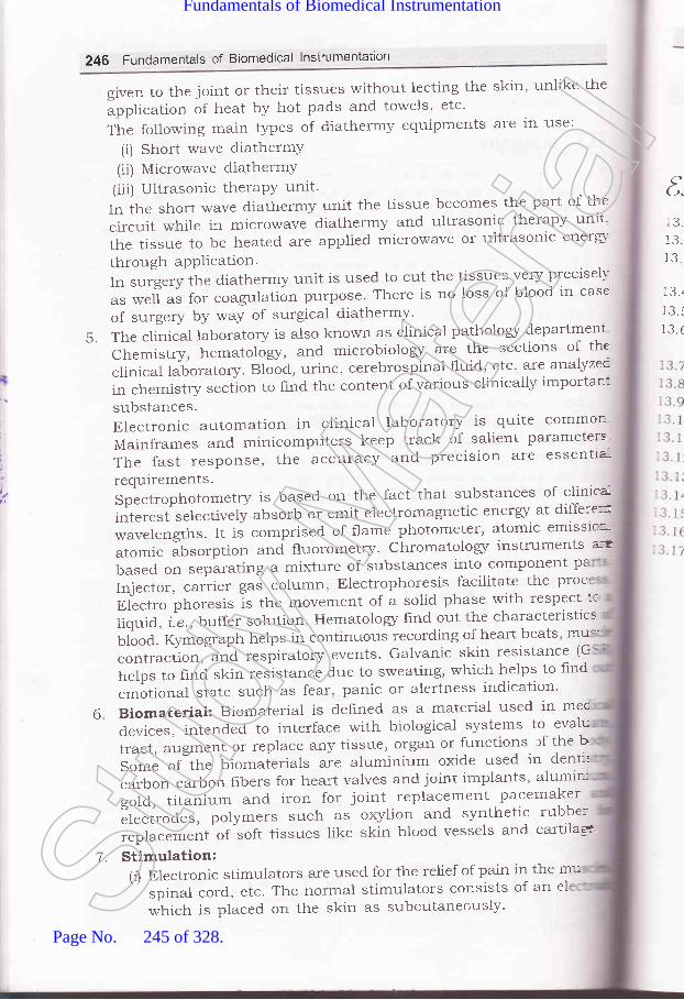
246 Fundamentals of Biomedical lnstrumentation
given to the joint or their tissues without lecting the skin, unlike the
application of heat by hot pads and towels, etc'
The following main types of diathermy equipments are ln use:
(i) Short wave diathermY(ii) Microwave diathermY(iii) Ultrasonic theraPY unit'Intheshortwavediathermyunitthetissuebecomesthepartofthecircuit while in microwave diathermy and ultrasonic therapy unit'
thetissuetobeheated'areappliedmicrowaveorultrasonicenergi-through aPPlication.In surgery the diathermy unit is used to cut the tissues very precisell-
as well as for coagulation purpose' There is no loss of blood in case
of surgery by way of surgical diathermy'
5. The clinical laboratory is also known as clinical pathologr department
Chemistry, hematoloS', and microbiolo5/ are the sections of the
clinical laboratory. Bl;d, urine, cerebrospinal fluid, etc. are analyzec
in chemistry section to find the content of various clinically importan:
substances.Electronic automation in clinical laboratory is quite commor:
Mainframes and minicomputers keep track of salient parameters
The fast response, the accuracy and precision are essentia-
requirements.Spectrophotometryisbasedonthefactthatsubstancesofclinicar]interestselectivelyabsorboremitelectromagneticenerSratdifferemwavelengths. It is comprised of flame ptrotometer' atomic emisstc=
atomic absorption and fluorometry' ChromatoloSr instruments a-=
based on separating a mixture of substances into component pz
Injector, .r..i.. gas column, Electrophoresis,facilitate ll^"^J:'Electro phoresis is the movement of a solid phase with respect tc
liquid, i.e., buffer solution. Hematologz hnd out the characteristics
urfoa.'Kymograph helps in continuous recording of heart beats, mur
contraciion,-and respiratory events' Galvanic skin resistance (G
helps to find skin resistance due to sweating, which helps to find
emotional state such as fear, panic or alertness indication'
Biomaterial:Biomaterialisdef,rnedasamaterialusedinmecdevices,intendedtointerfacewithbiologicalsystemstoevalutract, augment or replace any tissue, organ or functions. lf the bSome of the biomaierials are aluminium oxide used in denr:
carbon-carbon fibers for heart valves and joint implants, alumii--
gold., titanium and iron for joint replacement pacemaker
Electrodes, polymers such as oxylion and synthetic rubbe;
."pt.""t".t t of soft tissues like skin blood vessels and cartilaS"
('(t,
1CIJ.
1a1J.
1C1J-
13..]? I
13. (
!,
6
Stimulation:(r) Electronic stimulators are used for the relief of pain
spinal cord., etc' The normal stimulators consists
which is placed on the skin as subcutaneciusly'
in the mu7.
of an elStud
y Mate
rial
Page No. 245 of 328.
Fundamentals of Biomedical Instrumentation

Some General Topics 241
(a) The stimulators normary generate puises in various shapes andvarious time period and ampiitude (intensity).(iifl The stimulators also find use in emptying of the braclder. Thestimulators are also used to contror ancr correct the epitepsy inthe patient.
txercidea
3. 1.l-o.z.))
3.4.
353.6.
Write short notes or-r bocly temperature.Write short notes on reproduction system.Describe micro'qzave diathermy machine. Discuss electro-diagnostictherapeutic apparatus.Erplain the working of a modern surgical diatherrn}. machine.trxplain the use of diathermy in physiotherapy and surgery.Explain diathermy and defibrillator. Also explain defibrillator analyzers.
(UPTU 2006)7. Write short notes on diathermy. ppTU 2OC:S)8. trxplain the application of laser in medicine. (U7TU 2OO4)9. Discuss with a block diagram the working of a laser system.10. Discuss laser inieraction with tissue.1 1. Differentiate between use of laser in surgery and coagulation.12. Explain laser beam focussing.13. What are biomaterials? trxp1ain. Up,fU 2006)14. What are biomaterials? (U7TU 2OO4)15. Describe various kinds of currents used in muscle stimulators.i6. Write short notes on stimulators. (U7TU 20OS)i7. Explain stimulators. ppTU 2006)
AJJ
ia/
Stud
y Mate
rial
Page No. 246 of 328.
Fundamentals of Biomedical Instrumentation

Monitors and Recorders
> Inside this chapter
14. 1. Biopotential Amplifiers14.2. Monitors14.3. Recorders14.4. Summary
14.1. I BIOPOTENTIAL AMPLIFIERS
Biopotentials are picked up by an electrode or available at the outp:stage of a transducer. Normally the value of such potential is of the lc
order. In recorder the biopotential developed in ECG, EEG, EMG, etc. a--
to be interacted with 50 Hz AC supply. Use of a differential ampltr.rrinirnize the interference of capacitively coupled current. To achithis, the differential amplifiers must have higher Common Mode RejeclRatio (CMMR) . The simple system to measure bioelectric potential u-differential amplifier is shown in figure 14.1.
Grouno -14.1. Bioelectric potential with differential amplifier
248
EI
H gh freqfilter
Fig.Stud
y Mate
rial
Page No. 247 of 328.
Fundamentals of Biomedical Instrumentation

Monitors and Recorders 249
Apart from normal requirement of instrumentation amplifiers the:opotential amplifiers have the following requirements:(a) Input impedance should be high in the order of 10 MW so
that negligible loading is provided to the biorogical system beingmeasured.
1b) Amplifier should have high gain of the order of looo or more sothat weak biological signals of the order of mv or mv are amplified.
1c) These amplifiers should have high CMMR.d) voltage appearing at the amplifier input due to changes in magnetic
fields should be minimised.e) Amplifiers should have isolation ciruitry for the safety of the patient
being studied.Earlier transistorized amplifrers were being used to amplify and operate-: writing device. Now at the input stage the operation amplihers (oA)
.sed on IC technolos/ are being used. The commonly used lC is 741.- --: IC contains 2o transistors and other passive components. The circuiti :graJrr and pin diagram of this IC may be seen in the data books on
In normal practice the operational amplifiers are used as an':trumentation amplifrer. The hrst stage comprise 2 input amplifiersi' and A, connected in non-inverting followers configuration. This
. :s high input impedance. The second stage is a basic differential, ',:liher giving high gain. The circuit diagram is shown in figure 14.2.
Fig. 14.2. lnstrumentation Amplitude
.n this circuit overall voltage gain can be controlled by ad.justmentt..n the circuit:
R"= R.=R,=R-TJOI
e, is input to amplifier A,e, is input to amplifier A,
+m+
m Stud
y Mate
rial
Page No. 248 of 328.
Fundamentals of Biomedical Instrumentation

ll
250 Fundamentals of Biomedical lnstrumentation
If R2 = R, output voltage is given as:
"- = {,-'+} x @r- e1t"s I R,JThe input ampliliers A, and A, act as input buffers with unity gain
I zn^lfor common mode signal e" and. with a gain of
tt.T, I for the differe-
ntial gain. These amplifiers work as biomedical amplifrer due to veryhigh input impedance, high gain and good common mode rejection ratio'
The isolation in bioelectric amplifies are provided by the incorporationof an opto coupler. In the opto coupler there is an LED at the input stage
and a photo-transistors is provided at the output stage.
Normally a transistorized circuit is provided at the output stage to
supply current to the pen coil of the galvanometer. The pen motor is
driven by a dc driven stage feeding a four transistor output stage operatingthe galvanometer. Due to low power efficiency of push pull amplifier a
bridge arrangement is preferred. A circuit diagram may be seen inhgure 14.3.
Fig. 14.3. Output stage using bridge amplifier for driving galvanometer coil in recorom
The current in I, and ?o increases and T, and T. decreases' Tl--
when T, and ?o approximates to short circuits, ?, and Ta are nearly coff and almost all the circuit current passes through the galvano
1,
Msythcirthrar(recofmo
warthedevdislWarv
on,
mordisp
(
bes
coil. t and 71. function as emitter loads, I. and To operate as amplifica:having I, and ?. as collector loads. Resistors R, to Ro provide coc
14.2,
\lare:il0nl
T:lr w-lr aimoo.76=rd h.: teranb
TT_: ho: lwer:ack r:: pov
In- _trsln
=:-t be- ton(
--splay
:-the
biasing to T, and To.Stud
y Mate
rial
Page No. 249 of 328.
Fundamentals of Biomedical Instrumentation

Monitors and Recorders 251
l.lonitors have become essential part of any biomedical instrumentation.r'stem. This is basically similar to the conventional oscilloscope used for:ie display of waveforms in electronic laboratories. They have the usualircuit blocks like vertical and horizontal amplifiers the time base a,ndne EHT (Extra High Tension) for the cathode ray tube. These monitors
,-re of slow speed and long persistence type of screen. The slow speed. equire a long persistence screen so as to enable a conveniept observationf waveforms. Without a long persistence screen one can only see a
:-roving dot of light instead of a continuous trace.The conventional oscilloscope can not be used to display low frequency
,i'aveforms which are generated by various physiological parameters. Forhese purposes non fade monitors using digital memories have beenleveloped to overcome the problem of the fading of slow scanning CRTlisplays. By using this technique it is possible to generate a rolling'.r'aveform display. The display is thus continuous, bright and flicker freeln a normal non-storage CRT.
This means that normal oscilloscopes are not suitable to work asnonitors. A special type of digital storage scope with non-fade type oflisplay may be a suitable choice.
Some of the details of non-fade displays and cardiac monitors mayje seen in the chapter on Patient care and Monitoring.
14.2.'1. Video Monitors
Video monitors are used in intensive care unit and intensive cardiac:are unit. Video monitors are provided as bed side monitors and videolonitors for central monitoring.
The monitor (display) part has two subsections-raster type displayrcr waveforms and a conventional 300 x 260 picture-element but maprcr aplphanumeric display and graphics. To make the waveforms looksmooth, a l2OO line vertical raster is used. The display section also usesa 16 KB word memory, which is used as temporary storage for waveformand hard copy data. ECG waveform for each patient is continually stored,n temporary locations for delayed waveform output for recording. This:an be used to send the waveform of abnormal ECG to a recorder.
The microprocessor based video monitors can hold patient data for14 hour. It contains 6 K words of CMOS RAM which requires very littlerower in the stand by mode and therefore can be connected to a batteryrack up power supply. Thus the potent data may be secure even in caserf power failure.
In the bedside video monitors and video monitors in the central:rursing room a video and audio alarms are provided. The audio alarm,-an be distinguished by varying its pitch, volume, duration and sequencerf tones. Visual alarms can be indicated by varying the colour of thelisplay on the monitor screen. The bed side monitor data can be monitoredrn the central nursing station.
"t
Stud
y Mate
rial
Page No. 250 of 328.
Fundamentals of Biomedical Instrumentation

252 Fundamentals of Biomedical lnstrumentation
The variousplasma display,emitter display
types of display are nowliquid. crystal display (LCD),(sED).
available like CRT display,surface conduction electron
In any instrumentation system one of the important consideration is themethod by which the data acquired is recorded. The recording methodshould be consistent with the typical system. If the signal is analogueand the analogue output is available for recording then we need ananalogue recorder to record the event. On the other hand, if the systemhas a digital output then digital recor:ding system to needed.
/Thus there are two types of recorders are used:(a) Analogue Recorders.(b) Digital Recorders.
Analogue Recorders are of various types. They can be broadly classifiedas under:
(z) Graphic Recorders.(irJ Osicllographic Recorders.
(ifiJ Magnetic Tape Recorders.The Graphic Recorders are devices which display and store a pen
and ink record of some physical event. The basic element of a recorderinclude a chart for displaying and storing the recorded information, achart drive for driving paper with known speed and a suitable couplingfor connecting the source of information. The graphic recorders can befurther classified as follows:
(a) Strip Chart Recorders:A strip chart recorder records one or more variables with respect to
time. Normally it is X verses time (t) recorder.(b) X-Y Recorders:
An X-Y recorder records one or more dependent variables with respectto an independent variable.
14.3.1. Strip Chart Recorder
A basic strip chart recorder may be seen in figure 14.4. A strip charrrecorder consists of:
(r') A long roll of graph paper which moves vertically.(irJ A drive system for driving the paper at some selected speed. -{
speed selector switch is provided for chart speeds of 1 mm/sec tclOO mm/sec.
(iirJ A stylus for making marks on the moving graph paper. The stylusmoves horizontally in proportion to the quantity to be recorded.
(iu) A styles drive system to move proportional to the quantity to btrecorded.
A range selector switch is used so that the recorder drive system i:within the acceptable level.
PaI
elecISL
*.:
papr
Mar
:hatlapll-,r'hic
1ornlsed:tethipee(-he <
:atcl-l op
Mark
Sr. his.:vius,iack.up
-:qUlI
Th.: the: USer
. donStud
y Mate
rial
Page No. 251 of 328.
Fundamentals of Biomedical Instrumentation
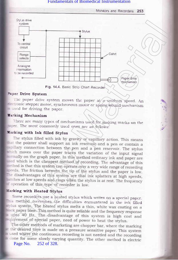
Monitors and Recorders 253
Stylus drivesystem
Stylus
Analognentermation
'- be recorded
Poper drivemechanism
Fig. 14.4. Basic Strip Chart Recorder
. aper Drive System- he paper drive system moves the paper at a uniform speed. An.:-onic stepper motor, synchronous motor or spring wound mechanism..ed for driving the paper.
llirking Mechanism- here are many types of mechanisms used for making marks on ther :r. The most commonly used ones are as follows:
f,arking with Ink filled Stylus
arking with Heated StylusSome recorders ,se a heated stylus which writes on a speciar paper.s method overcomes the difhculties encountered in the ink hlled
:
l Stud
y Mate
rial
Page No. 252 of 328.
Fundamentals of Biomedical Instrumentation

254 Fundamentals of Biomedical lnstrumentation
stylus marking in this method the paper with special coating which issensitive to a current. When the current is passed from the stylus to thepaper a trace appears on the paper. In electrostatic stylus method thestylus produces a high voltage discharge which produces a permanenttrace on an electro-sensitive paper. The other method is optical markingmethod. This method uses a beam of light to write on a photosensitivepaper. This method allows higher frequencies to be recorded and permitsa relatively large chart speed with a good resolution. The disadvantageis the cost of paper which is very high and this is a photographic methodand in this case the paper must be developed before a record is available.This method is not very suitable, where instantaneous monitoring is
required.
Tracing SystemsThere are two types of tracing systems used for producing graphic
representations. In the curvilinear system the stylus is mounted on acentral pivot and moves through an arc. In this system the time base
is curved. lines. The other system is rectiiinear system of tracing. In thesystem a line of constant time is perpendicular tc the time axis andtherefore the system produces a straight line across the width of thechart.
In the biomedical recorders the electrode picks up the bioelectrica-potentials and transducer is used to convert the physiological signal to
be measured into a usable electrical output. The signal conditione:converts the output of the electrode/transducer into an electrical quantiq'suitable for operating the writing system. The writing system provides a
visible graphic representation of the input signal.
1 4.3.2. Galvanometric Recorders
The mechanism of Galvanometric recorder is a modifred form c:
DArsonval meter movement. A cut-away view of the moving coil elemer-:
is shown in figure 14.5. As the current flows through the coil it deflec:=
The deflection of the coil is proportional to the input quantity. Th"t
instrument requires an appreciable torque. For this a large moving cc:lin a stroilg magnetic field is needed. The instrumcnt lnust be criticafdamped so there is no overshoot. But this results in slow respons:-which is being of the order of 0.75 to 1.5 sec. This type of recorder 5not r-rseful for recording fast variations in either current or voltage. T1--:r
is suitable for recording average values.A galvanometer type recorder is shown in figure 14.6.It is a modited
version of PMMC (Permanent Magnet Moving Coil) instrument. the chmay be driven at a constant speed by a clock',riork movement, an electr-motor or stepper motor. The recorder shown in fig. 14'6 uses a rectilsystem of tracing. The galvanometric recorders can work on range fa few mA to several mA or from a few mV to several mV it can wortia low frequency bandwidth of o to lo Hz.It has a sensitivity of 0.4 r:-i"mm. For measurement of smaller voltages iinear amplifier are usedthese recorder the bearing rnust be substantially larger than those uin indicator instrurrnents because of the large mass of cool and sn--St
udy M
ateria
l
Page No. 253 of 328.
Fundamentals of Biomedical Instrumentation

Monitors and Recorders 255
Steel ring
Moving coil
SpirolsSteel core
Fig. 14.5. Cut-away view of moving coil element
lnk reservoir
Moving coilmovement
Rollers
Drive-motor
Curvi-linear chort
Rollers
Fig. 14.6. Galvanometer Recorder System
The ink recording method is very widely used. The trace should bethin, well defined and uninterrupted to allow best resolution ofmeasurements. To achieve this a pressurised ink system is developed.The system uses high pressure, high viscosity ink to overcome inertialeffects within the pen tube and give continuous flow of ink even at highpen velocities. Ink is supplied by a ce,ttral ink reservoir that producesDressure of 15 to 20 psi and forces viscous ink into the microscopicrores on the chart paper surface. The other method of heated stylus-.rriting system in which pointed stylus make a mark on the moving wax
?aper.The usual paper drive is by a synchronous motor with a gear box for
;chieving different chart speeds. The other method of achieving variable
=peed by the use of different crystal frequency is also employed. Normally= time.marker is produced before taking the ECG or other recording.
As already studied by the students in the course on measurement
=:rd Instruments the PMMC instrument using galvanometric principle
Stud
y Mate
rial
Page No. 254 of 328.
Fundamentals of Biomedical Instrumentation
T
256 Fundamentals of Biomedical lnstrumentation
has three forces which act upon the moving system namely (4 thedeflecting force (ir) the controlling force and (lir) the damping force. Thedeflection force results from the current which flows in the coil and issupplied to it from the driving ampliher. This force cause the pen tomove from its zero position. A controlling force applied by the springaction will limit the otherwise indefinite movement of the pen and ensurethat same movement of pen is always achieve by a given value quantityto be recorded. The damping force is necessary in order to bring theposition of pen to rest quickly. In the absence of damping, owing to theinertia of the moving parts, the pen would oscillate about the finaldeflecting position for some time before coming to rest. The main functionof damping is to absorb energz from the oscillating system and to bringit quickly in its equilibrium position. The amount of overshoot of pendepends upon the value of the damping factor. This is taken as unitywhen the galvanometer is critically damped. Under these conditions, thecoil r'rill deflect smoothly and take up its final position in the shortestpossible time.
Potentiometric RecordersPotentiometric recorders are used for recording of low frequencv
phenomena. The basic disadvantage of a galvanometer type of recorderis that it has a low input impedance and a limited sensitivity. Theoperating principle of a potentiometer recorder is shown in figare 14.7A resistive slide wire AB is supplied with a constant current from abattery S. The slide wire is constructed trom a resistance wire of highstability and uniform cross section so that resistance per unit length isconstant. The unknown dc voltage is fed between the moving contact Cand one end A of the slide wire. The moving contact C is adjusted so tha:the current flowing through the detector is zero. At that moment theunknown input voltage is proportional to the length of the wire AC. k-practice the slide wire is calibrated in terms of span voltage being 100.10 or 1 mV. The moving contact of the slide wire is attached with a per:which writes on a caliberated chart.
The balancing of the unknown input voltage with reference to thereference voltage is achieved by using a servo motor. The voltage differencebetween the sliding contact C and the input dc signal is given to achopper type dc amplifier (in place of a galvanometer coil). The coppe:is driven at the mains frequency and convert this voltage difference intca square wave signal. This signal is amplified by the amplifier and the:-applied to the control winding of the servo motor. The servo moto:is a two phase motor whose second winding is supplied with a 50 H_-
mains supply which works as a reference phase winding. The motor -=mechanically coupled to the sliding contact of the potentiometer wher=pen is attached. When signal input or the voltage to be recorded is give:_to the input point, the motor moves the pen and simultaneously varie=the voltage of the sliding contact such that the potential differenc:between the input voltage and reference voltage is zero. The circu-:operates in such a way that the motor revolves in one direction if ti.:voltage increases and operates in the reverse direction if the volta.:
dpa)
hietw.1n
wlmiapapanshno
..:TIC--:ne
..:lp-mj:tl
I,':le
: -:aI'ra
-. iln::.S
:m: '::l:r.:eI]
Pr
:- .ll
Li
vollF
Stud
y Mate
rial
Page No. 255 of 328.
Fundamentals of Biomedical Instrumentation

Monitors and Recorders 257
decreases. The servo motor is shaft-coupled to a techo-generator toprovide the damping to the servo motor. The response slows down as itapproaches balance position. The servo motor used in this arrangementhas two separate stator windings, which are physically perpendicular toeach other. The out of phase alternative currents irr the two statorwindings produce a rotating magnetic field. The rotating magnetic heldinduces a voltage in the rotor and resulting current in the armaturewhich makes the rotor to rotate in the same direction as the rotatingmagnetic fields. For producing a rotating magnetic-field the ac voltageapplied to one stator winding should be 9o' out of phase with the volta[eapplied to the other winding. This can be done either in the po*E,amplifier, which supplies the voltage to control winding or in a prrr""shift network for the line winding. For zero input signai the rotor doesnot turn.
AC servometer
Fig. 14.7. Schematic diagram of a self-balancing potentiometric recorderThe paper chart is driven by a constant speed motor to provide a:-re axis. In this type of recorder the input signal is plotted againsti :re. In the current generation of record.ers the chart is moved with the
F ,ip of a stepper motor. The advantage of using a stepper motor innparison to a synchronous motor is that the speed of chart movement
-:-r be varied.In the earlier recorders the electromechanical contact between slider
liability and, has two hxed- s and one coil on which the pen is htted. The distance is measured
propagat he detail of circuit diagram may beudy by St titled ultrasonic feedback recording, Measure 1980, 131.
?otentiometric recorders are very useful for the record of slowly- -ng physiological signals over a period of 24 hours.
o.0)
o=.Njaa+a)v)-
oo.
Stud
y Mate
rial
Page No. 256 of 328.
Fundamentals of Biomedical Instrumentation

258 Fundamentals of Biomedical lnstrumentation
1 4.3.3. U Itraviolet Recorders
The galvanometric and potentiometric recorders due to the inertia ofwriting system are not suitabte to work when the signal is of higherfrequency. Ultra-violet (UV) recorders record the events with frequenciesfrom zero to several kHz. The writing system of an ultra-violet recorderconsists of an ultra-violet light source and a photosensitive paper. Thetrace becomes variable in 30 sec after the exposure. If the recordings arerequired for permanent storage then after the exposure paper should bechemically treated.
The recorder consists of a number of galvanometer (moving coil)elements mounted in a single magnet block as shown in figure 14.8. A
surface silvered mirror is attached to the galvanometer coil. A papersensitive to r.ltraviolet light is used for producing a trace for the purposeof recording. The ultra-violet light is projected on the paper with the helpor mirror's attached to the galvanometer coil.
UVlight
source
Poper drive mechanism
reelutrpa25disresof,
::em
:,1:pe
:IA
::cII=jllr
ancwirrbarrvoltappJOSlchar:rak:oatr::om
T:i dr.25-:ree
-sed.:'a lel+ -:ctrr._-cxll'li : turi.ir_ lUfi]:fUei4.3.5.
Tht
U V lightSensitive paper
Recorded trace
Timing line
Fig. 14.8. Ultraviolet (u.v.) recorder
The moving (galvanometer) coil is deflected if any current is passed
through its coil, because the coils are under the influence of magnetrcfreld. The ultra violet light falling on it is deflected and is projected cothe u.v. light sensitive paper through a lens and mirror system.paper is clriven past the moving light spot and thus a trace of variauin proportion to the current with respect to time is traced- Tn manv urecorders arrangement are provided to select a suitable paper drirspeed out of as many as 12 difference speeds. Some u.v. recorders h
an arrangement for controlling the speed of paper by applying exte:
voltageUltra-violet recorders may be single channel or multichannel'
dynamic performance of a ultraviolet recorder is determined by chartcharacteristic, its overall frequency response depends on galvanom.performance and its maximum writing speed. The u.v. recordersfrequency response upto 2OO0 Hz are commercially available.
'l 4.3.4. Electrostatic Recorder
The frequency response of penand the recording in UV recorders
type recorders are limitedtake sometime before the
Galvanomescoils
to ferpeSt
udy M
ateria
l
Page No. 257 of 328.
Fundamentals of Biomedical Instrumentation
Monitors and Recorders 2Sg
record oelectro ;iupto s Tpaper for recording and gives250 mm per sec. The electroiisadvantage of stylus inertia, effects such as overshoot or low-frequency'esponse limits, rinkage effects such as non-rinearity, hysteresis effects:,f clogging of ink, etc.
The electrostatic recording co,nd vacuum knife. The imaging,,'ire elements, spaced 4 per mm.ars called shoes. As the paper morltage is applied to the selected:plied to the closest shoes. The pape,sitively charged ink particles aaheie to where the paper had a'arge' A vacuum knife removes arl excess toner and other--king the image with charged particles. when erposed to air theated particles permanentry bond to the paper and the record emerges- in the machine completely dry.
The paper is moved at a speed of 0.25 cord is madedots. At the top speed of 2SO mm/ t spacing of_ r mm. In defining frequency response atic recorder- :e capture, bandwidth and waveform response are, .d. defined as the shortest ar.atio" frlse which can- :ep value of recorder. The peak capture rating of the' ':rostatic recorder is 40 microsecond. ganawiatn is defined as the': ''imum sine wave frequency which can be recorded with a specified' 'racy. The bandwidth of the recording system is sooo Hz with an' ''racy of 2ok or 15 kHz with an accuracy of 2ook No waveform or'' .,-ency analysis will be possible.
'{ 3 5. lnkjet Recorder-re advantage of inkjet recorder is the frequency response of the'n which extend to several hundred cycles. The technfrue consists
light beam
"lt'"Jll,'lu p to t o o o Hz. rh e arra.g.-" r,":"::H :i :.,-::i" h"r,ff l} ",k:
: between the poles of an electromagnet. The coils of this- - nagnet to the output amplifrer and are driven bypiified cylindricai permanent magnet is attached. capilla ns of .r...rrt corresponding to the signalrn in the electromagnet coil produce a varying magnetic field-rteracts with the frerd of the permanent magnet wrricrrls attached
., .ra.ction deflectrm of a nozzleessllre from thepaper and the
Stud
y Mate
rial
Page No. 258 of 328.
Fundamentals of Biomedical Instrumentation

260 Fundamentals of Biomedical lnstrumentation
The filtered ink is frlled in the reservoir. The high pressure for jetrecording in produced by a pump and is adjustable between 20-50atmospheric pressure. The inkjet recorders are suitable for recording athigh frequency due to the absence of any moving assembly. The mass
in this case is comparable to that of UV recorder. In this case theamplitude of 60 mm peak to peak can be traced with the inkjet recorder'It different colour ink is used then the inkjet recorder can work as
multichannel recorder. Since, the inkjet recorder can write on therecording paper without friction, linear tracing is ensured even with ven-
small amplitudes. The inkjet recorder use the normal untreated paper
which is much cheaper as compared to heat sensitive, photographicpaper. This type of recorder is suitable for phonocardiography and
.1""t.o-yography when require recording of signals which is much higher
as compared to Pen tYPe recorder.
14.3.6. Colour Printer
Inkjet printers were introduce in the market in 1980. An inkje:printer places extremely small droplets of ink onto paper to create or-
i*u.g.. The dots are extremely small usually between 50 and 60 micronsin diameter. The dots are thinner than the diameter of human ha-::
(70 microns). The dots are positioned on the paper very precisely, wir-resolution of upto I44O x 720 dots per inch (dpi).
There are several major printer technologies available. Thesttechnologies can be broken down into two main categories with severatypes in each.
A. ImpactThese printers have a mechanism that touches the paper in order ::
create an image. There are two main technologies-. Dot matrix printers use a series of small pins to strike a ribbc-
coated with ink, causing the ink to transfer to the paper at Ltpoint of impact.
. Character printers are basically computerised t5rpewriters' Thgt
have a ball or series of bars with actual characters (letters cr
numbers) embossed on the surface. The appropriate character sstruck against the ink ribbon, transferring the character's image :n'
the paper.
B. Non-ImpactThese printers do not touch the paper when creating an image, inl'-ra
printers are part of this group and includes.
directly on the PaPer.. Laser printers use dry ink (toner), static electricity and hea:
place and bond the ink onto the paper.
Print Head AssemblY
Print head is the core of an inkjet printer. The print head cont
a series of nozzles that are used to spray drops of ink.
Thr:-:thor- -: III€: :his: -:ble::ott':'---s n- crir
InIr
mal
Prir
:arttrr1n_1av(
rr fe
:t1Ovr
-:na€::1e tr
leCOr
-.estr
clet{p
. Inkjet printers which use a series of nozzles to spray drops of : IIOr Crj-:n tl: 1OZ2
-:plaStud
y Mate
rial
Page No. 259 of 328.
Fundamentals of Biomedical Instrumentation

Monitors and Recorders 261
Ink CartridgeIn colour printer the cartridge has three primary colours cyan,
=agenta, yellow and black (CMYK).
Print Head Stepper MotorA stepper motor moves the print head assembly (print head and ink
,rartridges) back and forth across the paper. A belt is used to attach theof the inkjet printers
paper in from the trayead assembly is ready
=--ove the paper in the exact increment need.o ,.1'"::1"" fH',"ffiJ:I::lage is printed. A small but sophisticated amount of circuit is built into:e printers to control all the mechanical aspect of operation, as well astcode the information sent to the printer from the microprocessor based.strument.
lnkreservors
Fig. 14.9. A thermal bubble print head
There are various methods of ink to be put on the paper. The important:thods are heating or vibration. A thermal bubble method is used by: manuthcturer canon and Hewlett Packard as shown in figure 14.9.this tiny resistor create heat, and this heat vaporizes ink to create acble. As the bubble expands, some of the ink is pushed out of a nozzle:o the paper. when the bubble collapses, a vacuum is created. This-ls more ink into the print head from the cartridge. A typical bubbleprint head has 300 on 600 tiny nozzres and all of then can fire a
, plet simultaneously.A piezoelectric print head is patented by Epson as shown in figureI0. A crystal is located at the back of the ink reservoir of each nozzle.
:: crystal receivers a tiny electric charge that causes it to vibrate.:-en the crystal vibrates inward, it forces a tiny amount of ink out of
nozzle. when it vibrates out, it pulls some more ink into the reservoir:eplace the ink sprayed out.
\\1+
Heating
Stud
y Mate
rial
Page No. 260 of 328.
Fundamentals of Biomedical Instrumentation

262 Fundamentals of Biomedical lnstrumentation
C(;A
Fig. 14.10. Piezoelectric inkjet print head
Colour Laser Printerscolour laser printers works the same way as monochrome printers-
except they go through the entire printing process four times, one pasD
Nozzle
D
each for cyan (blue), magenta (red), yellow and black' By combtru-o;
these four colours of toner in varying proportions one can generate thfull spectrum of colour.
There are several different ways of doing this. Some printersfour toner and developer units on a rotating wheel' The' printerdown the electrostatic image of one colour and puts that toner unit iposition, it then applies this colour to the paper and goes throughp.o"."" again for the next colour. Some printers add all the four colo
to a plate before placing the image on the paper'
Some expensive printers actually have a completeas a laser assembly, a drum and a toner system, forpaper simply moves past the different drum heads,colours similar to an assembly line.
printer unit
14.4, I SUMMARY
1. Biopotential Amplifier: The preamplifier and power amplifier is
to drive the pen motors of the recorder.
2. Monitor: The monitor is a display devices to display the im
each colour.collecting all
physiological parameters such as ECG, heart rate, etc' There
u"iior" types of CRT"s such as non fade, bouncing ball etc', u-
are used in the monitors.3. Recorders: The recorders are used to make a hard copy of the
like ECG, EMG, EEG etc. There are various types of recordersas Galvanometric, Potentiometric, Ultra-violet, Electrostatic and
The different types of recorders are suitable for different fuA Galvanometric recorder is simple cheapest and is useful '-Stud
y Mate
rial
Page No. 261 of 328.
Fundamentals of Biomedical Instrumentation

cOE
Monitors and Recorders 263
frequency applications. If the frequenc}, is high, the other type ofrecorders such as Ultra-violet, Electrostatic or inkjet are more suitable.
elcided
1. Discuss requirement of an ideal biopotential2. With a block diagram discuss the various
ampliher OA.3. Explain any two types of recorders with the
1.4. Explain ultra-violet (UV) recorders.-1.5. Discuss inkjet and potentiometric recorders.-.6. Explain monitors and printers.:.7. Discuss different types of displays in a monitor.
amplifrer.stages in an operational
help of suitable diagrams.(UPTU 2OOs)
(UPTU 2006)(UPTU 2006)(UPTU 2006)
JAA\r ,1tt;
7
Stud
y Mate
rial
Page No. 262 of 328.
Fundamentals of Biomedical Instrumentation

Shock Hazards and Prevention
>. fnside this chaPter
r5.1.t5.2.15.3.t5.4.15.5.
Physiological Effects of Electrical CurrentShock Hazards from Electrical EquipmentMethods of Accident PreventionIsolated Power Distribution Si,'stem
Summary
Awareness for safety from shock hazards from medical equipmen:-"is of prime importance. During seventies sensational reports we-published on microshock hazards which was the cause of large numb'rof deaths of patients in intensive-care units. Consequently numero--:s
regulations and standards came into existence to improve electrical safe--
in the hospital. Although some of the requirements have increased ''=cost of health care, but this development has dehnitely contributed lnimproved design of electrical and electronic equipments in medical use
15I. I PHYSIOLOGICAL EFFECTS OF ELECTRICAL CURRENT
The interaction of electrical current with the tissues of the body ca
electrical accidents. If the current of sufficient magnitude flows throthe body in such a way that it impairs the functioning of vital orit is the electrical accident. If three conditions are met simultaneouthe electrical accident occurs:
Two contacts must exist with the bodv and simultaneously voi:
source to drive current through the two contacts should also exist.damaging effects of the current depend on the magnitude and alsc
the current path way through the body, which in turn depends or:
Iocation of the hrst and second contacts, see hgure 15.1.
\Kno\:o tt:lSSL:he 1
:ISSU
.lmit,
.s hi1:he d
:arts:r Fil
-"r(
^lAN- ,h{:, -en$
,,.::Sat
- ,:- Il IU' ::-tra:- COI
.-: Of[264St
udy M
ateria
l
Page No. 263 of 328.
Fundamentals of Biomedical Instrumentation

Shock Hazards and Prevention 265
Heart
Body surface Second contact
Voltage source
First contact
Fig. 15.1. Three necessary conditions of electrical accidents,i.e , voltage source, first contact and second contact
When both contacts are applied to the surface of the body, it isinown as macroshock. In the case when one contact is applied directlyo the heart, it is known as microshock. The electric current effects the
:issue in two different ways. When the electric ener5/ is dissipated in:he tissue it causes temperature rise. A high temperature can damage:issue i.e., burn. In household cases, electrical burns are normally-imited to localized damage near contact points i.e. density of the current-s highest. In the cases of lightening accidents and industrial accidents,:he dissipated electrical energz may be suff,rcient enough to burn larger:arts of the body. A generalized model of an electrical accident is shown.n Figure 15.2, which will be useful in several ways.
Rt
R, = fault resistance
R", = first contact resistanceVoltage R^ = second contact resistancesource Lz
Rb : body resistance
i Fig. 15.2. A gener I of an accidentI
Arir electric current of suffici tude can cause local voltagesn thp sensory and motor ne lving electrochemical action:oten$als. If such electric current passes, it causes "tingling" or "pricking".ensation. If current increases, it becomes unpleasant and sometimes:ainfu[. The stimulation of muscle nerves or motor nerves causes:ontrabtion. If the stimulation is of high intensity, the hbers of muscle.et contracted. The electric current flowing through the body can damage:he organ completely.
\r'j,
Rcz
Stud
y Mate
rial
Page No. 264 of 328.
Fundamentals of Biomedical Instrumentation

266 Fundamentals of Biomedical lnstrumentation
Respiratory paralysis can occur if muscles of thorax are shrunkpermanently. It may also affect heart. The organ most susceptible toelectric current is the heart. when the current density within the heartexceeds a certain value, extra systolic contraction occur. If the currentdensity is increased further, the heart activity stops completely, butstarts if the current is removed within a short time.
The magnitude of electric current required to produce damagingeffect is dependent on several factors. The figure 15.3 shows the currentranges and the resulting effects for 1 sec. exposures to various levels of50 Hz alternating current applied externally to the body.
10A
100 mA
reslas113 r(prolskinreslspast:he icpen-ow,
A:ond::1mt:: on:ault.
15.2.
Maximum '1et go" current
Accepted safe level (5 nrA)
10 mA
Threshold of perception1mA
500 pA
Fig. 15.3. Physiological effects due to electrlcal current from 'l-secexternal contact with body
The maximum current which can be toleratedvoluntarily let go of the conductor is calledexperimentation has proven that the effects ofindependent of frequency up to about IOOO Hz.
by a person andlet-go current.
Sustained myocardialcontraction (followed
by normal heartrhythm if current isremoved in time.
Dangerof ventricular
fibrillation
Pain, fatigue, possiblephysical injury
current are alStud
y Mate
rial
Page No. 265 of 328.
Fundamentals of Biomedical Instrumentation

Shock Hazards and Prevention 267
It may be noted that:
Condition Current
(,4
liil
(4
Level of current which is not
Perception threshold of the skin forlight finger contactFirm grasp of the hand
and painful(iu) Tentanizing effect of muscles,
"let go" of the conductor.
The voltage required to cause current flow depends on the erectricalresistance of the body which can vary from few ohms to several ohmsas it is affected by several factors. The largest part of the body resistance-s represented by the resistance of the skin. The resistance is inverselycroportional to the contact area and also depends on the condition of theskin. If the skin is cut, the skin resistance is effectively bypassed and:esistance is that of tissues, which can be as low as 500 f2. Electrode:aste reduces the resistance of the skin. Many medical activity require:he insertion of the conductive objects in the body, either through naturalrpenings or through the skin. In such cases, because of the resulting.ow, dangerously high current can flow in the event of a fault.
A direct contact to the heart can also take place. If electricaly:onductive catherers are inserted through vein into the heart to applystimulating signals from a very worn pacemaker, this provides resistancerf only few ohms. This may directly effect the heart in case of electrical-ault.
15.2. I SHOCK HAZARDS FROM ELECTRTCAL EQUTpMENT
lhe hospital electric power distribution system gets power suppry in{vs., usually through underground cables. The stepdown transformer inhe building gives 3 Q voltage of 415 V, 50 Hz supply. The single phase.upply is 230 V, 50 Hz for most of the equipments. The supply has one:ve conductor and other neutral as shown in the figure 15.4. The cond.uits::re connected to earth (or ground) to bypass the any electrical power.:akage.
A person must come in contact with both live and neutral conductors.imultaneously or with both live conductors of a 23o v circuit for an.lectrical micro shock ltazard. If the neutral wire is connected to earth,-he same shock hazard exists between live wire and any conductive-bject which is in a way connected to earth. Insulation breakdornn, wear,:nd mechanical damage may cause such sjtuations. Room radiators,','ater pipes or metallic building structure may become live accidently. Inresign, great care is taken such that the person is not exposed to live''ires by choosing proper insulation, distances between conductors ofhe equipments. The figure 15.5 shows one case of an electrical accid.ent.
harmful-unpleasant
making impossible to
500 pA1mA
<5mA20 mA
Stud
y Mate
rial
Page No. 266 of 328.
Fundamentals of Biomedical Instrumentation

268 Fundamentals of Biomedical lnstrumentation
conductor
Neutral conductor
(The ground (or Earth)is connected to conduit) Grounding (or Earthing)
Fig. 15.4. Electric power distribution
230 V
Fig. 15.5. Earth (or Ground) shock hazard
A short between the live wire and the equipment case or box, p230 V on the operator. The exact analysis can be done using hgure 15
R, : fault resistance,.i.e., short between live conductor andcase of the equipment
&, & R", : first and second contact resistances.Rn : body resistanceR, : ground return resistance, i.e., resistance between su
end to the ground.If the six resistances sho"vn in the figure take any combinatios
va-lues such that the current through the body reaches a dvalue, it is essential that measures are taken to avoid such high cu
by manipulation of these resistances.
,|
fntr
(
(i
,u.:
_on(
, ase_-:su
. _rffi
15.3.
T
-lrtr:-acl,5.3.,
In---L-": -ll
.t-^: w-:-_:cu,St
udy M
ateria
l
Page No. 267 of 328.
Fundamentals of Biomedical Instrumentation

Shock Hazards and Prevention 269
15.3. METHODS OF ACClDENT PREVENTION
The protective methods to avoid accidents are:
15.3.1. Earthing (or Grounding)Proper earthing or grounding of equipment is a good protection
method. The ground resistance R, is made so small that the fault currentmost of it flows through it. See "figure 15.6, wherein case is connectedto ground through a conductor.
Fig. 15.6. Protection by introducing equipment earthingProtection against earthing problem is:
(zJ Hospital grade receptacles and plugs-normally marked as a greendot.
(lzj Provision of protection by using tripping of circuit breakers.
15.3.2. Double lnsulation
The equipment case may be made of suitable plastic or whereeverconductive parts exist, they are further insulated from the main box orcase. This is all to ensure R, fault resistance as high as possible. Doubleinsulation is generally uselirl for handled power tools. There should besuffrcient safeguard by making it water proof also.
15.3.3. Protection by Low Voltage
The operation of equipments from batteries is safer, however, it islimited to equipments such as flash lights and rarors. However, largemachines like X-rays, cannot be operated from batteries.
1 5.3.4. Ground-Fault Circuit lnterrupterIn the case of fault of figure 15.5, the body of the operator is conductive
path to ground. Most of the current entering the equipment through thelive wire returns through the neutral wire and part of the current returnsthrough the body of the operator ancl the earth. The ground-fault circuitinterrupter monitors the current flowing from live wiie, through neutral
\' '1t,
Stud
y Mate
rial
Page No. 268 of 328.
Fundamentals of Biomedical Instrumentation

270 Fundamentals of Biomedical lnstrumentation
and also through the earthing path by a differential transformer andelectronic amplifier. If this difference exceeds say 5 mA, the power supplyis interrupted by a circuit breaker very rapidly such that the operatoris saved from large current flow for harmful effects of time duration'
15.3.5. lsolation of Patient-Connected Parts
In the use of ECG machines, the patient is subjected to electrodesor electrical pacemakers. These connections may serve path for faultcurrents in case of malfunctions. In older make ECG machines one ofthe patient leads used to be connected to power line earthing. This wasa potential danger as grounded patient became one of the two connectionsnecessary for an electrical accident. The present day technologr allowsdesigns of circuits which isolate the patient leads from the earth.Figure 15.7(a) shows older ECG machines monitoring and 15.7(b) showspresent day technologr ECG machine monitoring with current limiters'The current limiter behaviour is shown in Iigure 15.7(c)
Fis. 15.7. (a)
Fig. 15.7. (b)
)outout sionals
'l Electrical power
J inout
conacl
AVoltage
I
-1 OpA
+ 10;rA-----+Current
Operatingrange
Fig. 15.7. (c) Current limiter behavtour
In the case of present ECG monitor, amplifiers serve as isolators fcrthe patient from the electrical power source. The part of electricd
<_Limitingrange
+LimitingrangeSt
udy M
ateria
l
Page No. 269 of 328.
Fundamentals of Biomedical Instrumentation

Shock Hazards and Prevention 271
equipment connected to body is isolated through isolation transformersas shown in figure 15.8.
lsolation input amplifier
solatic n transferme-----1 SlQni I
DemodulatorCe rner
Filter
acSUPP Y output signal
Amplifier
Fig. 15.8. Present day ECG machine showing isolation using transformer
In the figure 15.9 shown, the unit connected to the patient iscompletely isolated electrically using isolation transformer from the mainac supply and also measuring/displaying/monitoring equipments.
\,jt
ti
/
ReferenceGround and
Fig. 15.9. Equipotential grounding systemStud
y Mate
rial
Page No. 270 of 328.
Fundamentals of Biomedical Instrumentation

272 Fundamentals of Biomedical lnstrumentation
Figure 15.9 shows principle of an equipotential grounding system inone room of an intensive care unit.
Figure 15.i0 shows isolation could be achieved by optical meanswhere in the patient is neither electrically connected with hospital linenor the ground line. A separate battery operated circuit supplies powerto the patient circuit. The signal is converted into light by light sourceswhich is accurately calibrated in frequency and magnitude. When thislight falls on a photodiode, it convertes the light signal into electricalsignal which has its original frequency, amplitude and linearity.
Fig. 15.10. Optical isolation of patient
Instmments such as ECG, pressure monitors, pressure transduced.pacemakers, etc. are described in this principle. Figure 15.11 shows a
grounding system. A1l the receptacle grounds and conductive surfaces inthe vicinity of the patient are connected to the patient-equipmentgrounding point.
Each patient-equipment grounding point is connected to the referencegrounding point which makes a single connection to the building ground
Figure 15.12 shows an arrangement which helps in removing thepatient ground connection by replacing it with an operational amplifie:in feedback loop. It is presumed that patient ground is floating at sorn:safe level and the same is detected by the ampliher and driven back l:zero level. If the current limitation of the amplifier is exceeded, it ceases
to function, but the patient is not connected to ground. However, if th:patient touches a high voltage, the operating amperage disconnects hi=from ground and no current flows through the patient.
'5.4.
.-, th--
=:-tSI,, -(u|r:lt <
| -eSI: ritrSt
udy M
ateria
l
Page No. 271 of 328.
Fundamentals of Biomedical Instrumentation
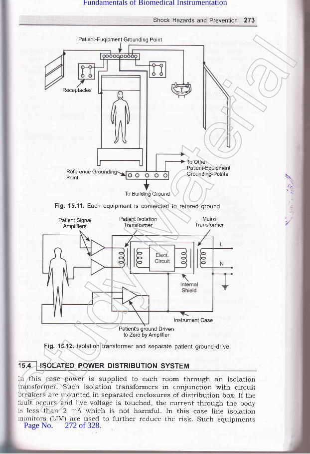
Shock Hazards and Prevention 273
Patient-Euqipment Grounding Poinl
Receptacles
Reference GroundPoint
To Building Ground
Fig. 15.11. Each equipment is connected
To OtherPatient-EquipmentGrounding-Points \
,it,
Patient SignalAmplifiers
Patient lsolationTransformer
to refered ground
MainsTransformer
15.4.
lnstrument Case
Patient's ground Drivento Zero by Amplifier
Fig. 15.12. lsolation transformer and separate patient ground-drive
ISOLATED POWER DISTRIBUTION SYSTEM
In this case power is supplied to each room through an isolationtransformer. Such isolation transformers in conjunction with circuitbreakers are mounted in separated enclosures of distribution box. If thelault occurs and live voltage is touched, the current through the body:s less than 2 mA which is not harmful. In this case line isolationrronitors (LIM) are used to further reduce the risk. Such equipmentsSt
udy M
ateria
l
Page No. 272 of 328.
Fundamentals of Biomedical Instrumentation

274 Fundamentals of Biomedical lnstrumentation
have green lamp to indicate "SAFE" operation of the equipment or reclamp to indicate *HAZ^\RD".
In addition to above receptacles powered from an isolated system a:-tof special locking type. Special high-quality earthing system are made i::such cases. Special plugs are used on the earthing wire. These arcessential requirements of intensive-care units.
1. Physiological effects offlowing through the bodybe noted that:
electrical current: The electriccan damage the organ completely.
currec:It mar (,8€
(r) Perception threshold of the skin forlight finger contact
(ii) Frrm grasp of the hand(iii) Level of current which is not harmful-unpleasant
and painful(iu) Tentanizing effecl of muscles, -making impossible
to "let go" of the conductor.
500 pA
1mA
<5mA20 mA
made of suita
3.'l
-1. I(
5\\)The maximum current which can be tolerated by a person and stil
voluntarily let go of the conductor is called let-go current. Tbexperimentation has proven that the effects of current are almdindependent of frequency up to about IOOO Hz.
2. Shock hazards from electrical equipment: A person rhust come ncontact with both live and neutral wire simultaneously or bothconductors of 23O V circuit for an electrical micro shock hazardthe neutral wire is connected to earth. the same shock hazardbetween live wire and any conductive object which is in aconnected to earth. Insulation breakdown, wear and mecdamage may cause such situations.
3. Methods of Accident Prevention: The protective methods to araccidents are:(o) Earthing or Grounding: Proper earthing or grounding
equipemtn is a good protection method.(b) Double Insulation: The equipment case may be
plastic or wherever conductive parts exist,insulated from the main box or case.
they are furtl
[c) Protection by low voltage: The operation of equipmentsbatteries is safer, however, it is limited to equipments suchflash lights and razors. Large machines like X-rays cannotoperated from batteries.
(@ Ground fault circuit breaker: The ground fault-circuit intemonitors the current flowing from live wire, through neutralalso through the earthing path by differential transformerelectronic ampliher. If this current exceeds 5 mA, the power s
is interrupted by a circuit breaker very rapidly.
rVS
-\fr
Stud
y Mate
rial
Page No. 273 of 328.
Fundamentals of Biomedical Instrumentation

Shock Hazards and prevention 275
parts: The present day technologzisolate the patient leads from tkretransformed and optical isolation
Isolated power distribution system: Each room power supply ismade througnh an isolation transformer. Such isoration transformsin conjunction with circuit breakers are mounted in separateenclosures of distribution box.
-,... ..:.:. r,1..-:
15.1. what are physiorogicar effects of erectrical current? Discuss variousmethods of accident prevention. ppTU_2003)I5.2 Describe and explain shock hazards for electricar equipment and preventionagainst them. ppTU_2004)15 3. what is the difference between erectrical shock and microshock? In whatparts of hospitar microshock hazards are likely to exisi. (upru-MQpl)i5.4' what are different shock hazards that can be generated from erectricalequipment and give prevention against them? UpTU_Mepl)15.5. what is the difference between electrical macroshock and microshock? Inwhat parts of the hospitar are microshock hazards ik;ly to exist?
(UPTU-MQPs)I5'6. what is the basic purpose of safety measures used with erectricarlysusceptible patients?15 7. why is it so important to maintain the integrity of the grounding systemfor protection against microshock?
(e) Isolation of patient-connectedallows designs of circuits whichearth. Current limiters, isolationtechniques are used.
\rLt\.:
aaal
Stud
y Mate
rial
Page No. 274 of 328.
Fundamentals of Biomedical Instrumentation

-_01
t
Microprocessors and ComPutercin Biomedical lnstrumentation
:s. fnside this chaPter
16.1. The Digita-l ComPuter16.2. Computer Hardware16.3. Computer Software1 6.4. I\4icroprocessors16.5. Interfacing of the computer with Medical Instrumentation16.6. Biomedical Computer Applications16.7. Specihc Examples of Biomedical Applications of computer16.8. Summary
.\r-ll-:1n-"1: 1Ilr'-.er
-:^d(
x.- -: pTh
iI:I I
!
,:t lS
-tI'll.{r
. -:f'o-":-rbil'.:-- bt:- triti
Thr:-.:fac
Thr: : --rfmt :-, 30€r' ::r tt_-ttto' _ -*t): rfmi:- - ple
In,,",]le.'
:lav(
Initially computers were used in medical field for the purposes
billing and hospital management, but now computerized ECG and E
analysis, pulmonary function analysis, automated clinical laboratare quite common applications. The development of microprocessor i
boosted medical instrumentation. Microprocessors are incorporatec
Clinical instruments as its capabilities are increased or it is automa:
Patient monitors are now microprocessor based'
The microprocessors and computers have become integral part of
biomedical instrumentation. Hence, basic study of digital compute:
essential.
16.1. I THE DIGITAL COMPUTER
The computer has computational capability. It canenormous amount of information and is capable
store and retr:t
276
of manipulatStud
y Mate
rial
Page No. 275 of 328.
Fundamentals of Biomedical Instrumentation

Microprocessors and Computers in Biomedical lnstrumentation 277
:nstructions based on calculated results.tr a given task is known as a program.
Digital computer can be divided intohe software.
The instruction set sequence
two parts, i.e., hardware and
t'
a6
\ digital computer has the following configuration as shown in frgure 16. 1.
Fig. 16.1. Digital Computer Architecture
An input unit is provided to read the data, the memory unit stores-re inprrt data and the computed values. The processing unit interprets:re instructions and carries out the assigned computational work; andther results. It has the capability to perform arithmetic operations,
,haracter manipulation operations, and logical operations. The output.nit prints, displays or plots the results.
The digital computers have following features:(r') Built to carryout small variety of instructions.
(izJ Instructions are very simple i.e., add, subtract, read a character,write a character, colnpare numbers, characters, etc'
(lii) The instructions can be carried out in less than a millionth of asecond.
(iu) Instructions are carried out without any fuss.
(u) No mistakes in carrying out instructions.A computer may be imagined to be a faithful servant who would
arryout instructions without any hesitations at very high speed without.rhibiting any emotions. In other words computers are machines whichan be programmed to follow instructions without any of their own
:riorities or judgements.The internal working of a digital computer with reference to the
rteraction of its various units are as per hgure 16.2.
The function of a cPU (central Processing unit) is to execute:formation stored in memory. The function of l/O devices such as..:yboard and video monitor is to provide a means of communicating,itrr trre cPU. The cPU, I/o units and the memory unit are connectedrrough strips of wire called a bus. The bus inside a computer carries:-.formation from one place to another similar to street bus carrying,:ople from one place to another.
In order to recognize an If o, the computer has an address for therme. The address assigned are unique and no two devices are allowed
have same address. The cPU puts the address on the bus, and the
:(s
:ll,rc
.:_lrli
COMPUTER HARDWARE
Stud
y Mate
rial
Page No. 276 of 328.
Fundamentals of Biomedical Instrumentation

decoding circuitry findsbus either to get data frbuses serve the Purposindicate if the CPU is a
2?8 Fundamentals of Biomedical lnstrumentation
Central processingunit (CPU)
Flg. 16.2. lnside a digital computer
The memory of a digital computer can be random-access mer.r-
(RAM), read-only memory (ROM), programmable read only mer:^
1enOfrn1, electrically-programmable read-only memory (EPROM), era-programmable read-only memory (EPROM), electrically alterable ::r
only memory (EAROM), etc. The other forms of memory are magr'r
memory such as disk memory (diskette or floppy) , cassette tapes' 3E
-"g.r"ii" bubble memory (MBM), Charge-coupled devices (CCDs), elec:n
beam addressable memories (EBAM), etc. The other memories in use
optical disk, catche, disk catche, compact disk (CD), and registers' Idesign constraints of a computer's memory can be summed up in ::rqrr""1iorr". How much? How fast? How expensive? There is a traitu.*ot g the three characteristics of memory namely, cost, capaciq'
access time. The following relationships hold:
(r) Smaller access time, greater cost per bit.(ir) Greater capacity, smaller cost per minute.(iii) Greater capacity, greater access time.
hi
ir
Inir:3e I
rFS
'r IV
SI
External memorymagnetic tape
(hard drive, high de
Output unitCBT display
printer,modem,network
2 Random aceess hard drive r
I
lnstructionUnit (lU)
Controller(Program)
Controlsignal
generator
Stud
y Mate
rial
Page No. 277 of 328.
Fundamentals of Biomedical Instrumentation

Microprocessors and Computers in Biomedical lnstrumentation 279
A typical hierarchy is illustrated in f,rgure 16.3. As one goes down thehierarchy the following can be observed:
(i) Decreasing cost/bit(itJ Increasing capacity(iir) Increasing access time(iu) Decreasing frequency of access of the memory by the CPU.
Register
Cache
/ Main memory
/ Magnetic Disk
/ Maqnetic Tape
Fig. 16.3. Usual memory hierarchy
The smaller, more expensive, faster memories are supplemented byarger, cheaper, slower memories. The figure 16.4 shows access time vs.:torage capacity of various types of memories.
It\i
ocoo0)aC)
E
ao0)oo
107
10 "
10 "
10
103
'10'
Semiconductor technology
O *or,*o,
Magnetic disk technology
Magnetic tape
10'
10'
101
001 1 10 100 1000Storage capacity (megabytes)
' Fig. 16.4. Memory Comparison
Input/Output devices are often referred as peripheral devices into-.--ree categories:
(z) Human-readable-suitable for communicating with the computer usersuch as video display terminals and pointers.
(il) Machine-readable suitable for communicating with the equipmentsuch as magnetic disk, tape systems, sensors and actuators.St
udy M
ateria
l
Page No. 278 of 328.
Fundamentals of Biomedical Instrumentation
280 Fundamentals of Biomedical lnstrumentation
(iir) Cornmunication-suitable for communicating with remote devices
such as a terminal or another computer.The central processing unit (cPU) consists of the arithmetic anc
control unit. The control unit consists of registers and decoders which-
sequentially access instructions from the memory, interpret eaci--
instruction, send control signals to all parts of the computer to carryou:the program execution.
A11 the described components are common to all computers, but the=implementation can assume a wide variety of forms. It may range fror-a large scale computer to a microcomputer which are low cost bui-:around microprocessors. Latge scale computers often cost in crores '::rupees and are designed to process large amounts of data at high spee:
for a large number of users in batch processing or time sharing bas-.:
The user's terminals in interface with computer can range fro=simple teletypewriter to a very elaborate input-output system which mar
include an analog-to-digital converter for interfacing with a:,
instrumentation system.Computers can communicate with users in an interactive -:
conversational mode. The user may use keyboard and get output frl-computer in display form. Interactive programs guide the users throu;tthe various steps involved in requesting information, obtaining resu,:sThese are very much suitable for the physicians, ntlrses, and o":'a,hospital personnel.
Telephone line is generally a remote terminal. The data are placeC :m
an audio-frequency carrier within the voice-frequency range' l'-modulator-d.emodulator encode the data on the carrier and the Canreceived are decoded by a modem.
An alternative to a remote terminal on a large scale time-shrtdcomputer, a hospital can have one or more smaller computer of its o;irThese may be minicomputers or microcomputers in the form of Pl(Personal Computers).
16.3. I COMPUTER SOFTWARE
Software are the programs used by a computer system. The sofr'icost of a system may be much greater than that of the hardware inYo-:
There are two types of softwares(r') System software: These are supplied by the manufacturer c:
computer for managing the operation of the system, translatin-programs, performing diagnostic checks, etc. These softwaresspecifrc to the computers supplied.
(iz) Application software: These are for carrying out the spcfunctions involved in the user's application. Applicationare generally in the form such that these can be used or:
computer.The basic operation of a computer is known as instruction se:
symbolic rules and instructions are called syntax. All these constir-:eform a programming language. The internal language of a compu:=
;typprcan( SS
Assconrnslma(ope:nti,{n:xe(3AS:nor_tse
,omled. rstr
15.4.
,:le-:\/e:_--1S
:- SO
. t,mllmr
--ave
; ricl-:stn
Stud
y Mate
rial
Page No. 279 of 328.
Fundamentals of Biomedical Instrumentation

Microprocessors and Computers in Biomedical lnstrumentation 281
{nown as machine language which comprises of a numeric code for each:r'pe of operation of the computer. Computers generally have a systemrrograms that accept mnemonic instructions such as "ADD" or "SIJB"and convert each to its machine language. Such programs are calledrssemblers. The mnemonic language is called an assembly language.\ssembly language programming is very easy, but is specific to a:omputer. Most computers have compilers and interpreters which accept:nstructions in languages which are problem oriented which convert intonachine language. These languages use terminologr, symbols, and therperations which are familiar to the user. A compiler goes through the:ntire program and translates every instruction before execution begins.rn interpreter translates the high-level program a step at a time and:xecutes each step as it proceeds. The high level languages are FORTRAN,3ASIC, COBAL, etc. The system software are known as supervisor,:nonitor, executive or operating system. Medical instrumentations maylse specific software which are suitable for the purpose. The same:omputer at user end can have separate software for various applications.ledicated computers and softwares are in use in the case of clinicalnstrumentation and such computers are known as turnkey systems.
. he very large scale integration (VLSI) technologies have brought up thelevelopments such that powerful CPUs are available on single chip andhis has been termed microprocessor. The large scale integration has.Jso happened on RAMs and ROMs also. This has facilitated completeomputer at very low cost with reasonably high speed. Although the
:omplexity of integrated circuits has increased greatly, but the prices:ave decreased. In consequence, complex microcontrollers are availablei'hich are comparable to minicomputers capability-wise. The biomedicalrstrumentation has been enriched by use of microcontrollers.
16.4.1. Types of Microprocessors
The intel's 8O8O microprocessor was the world's hrst general purposericroprocessor. This was an 8 bit machine, with 8-bit data path tolemory. 8086 is 16 bit machine having wider data path and largeregisters, it has instruction cache that perfetches a few instructions:efore they are executed. 80286 is an extension of the 8086 which:nabled addressing a 16 M Byte memory instead of 1 M Byte. 80386 is
-rst 32-bit machine. 80486 introduced the use of much more sophisticatedatche technologr and sophisticated instruction sets.
Pentium introduces the use of superscalar techniques which allowrultiple instructions for execution in parallel.
IBM has introduced power PC serves 60 1, which is 32-bit machine.:03 is again 32-bit machine at lower cost and more efficientnplementation for low-end desktop and portable computers. 604 is.gain 32-bit machine designed for greater performance. 620 is intended'rr high-end users with 64-bit architecture including 64-bit registers
\
Stud
y Mate
rial
Page No. 280 of 328.
Fundamentals of Biomedical Instrumentation

282 Fundamentals of Biomedical lnstrumentation
and data paths. A microprocessor based microcomputer is shown infigure 16.5.
lnputs Processor Outputs
(a) Basic system
Address Data Timing And
tt.
v
I
Air
C(
tl1t
b5
ta
1(
da
16
PowerLines
ClockLines
)r
/tl
(b) Processor signals
(c) Microcomputer system block diagram
Fig. 16.5. A microcomputer block diagram
lorun:ur
16r
lheaenr,r v_:tto
te
16.5
I-ard
- -rffr_: di
f- ata:..ria_--:erl
_-.:u1
., -. I":-.
External
Microprocessor Unit (MPU)
Airthmetic Logic Unit (ALU)
Stud
y Mate
rial
Page No. 281 of 328.
Fundamentals of Biomedical Instrumentation
Microprocessors and Computers in Biomedical lnstrumentation 283
16.4.2 Microprocessors in Biomedical lnstrumentationInitially microprocessor based devices were made for laboratory-
type instrument, but these are now used in biomedical instru-mentation. Microprocessors are used in medical instruments in followingways:
L6.4.2.1. CalibrationSome instruments require zeroing and recalibration every few hours.
A software or hardware timer in a microprocessor system is able toinitiate a calibration cyc1e. Microprocessor based devices performcalibration in digital form as such during calibration offset and gaincorrection factors are determined and stored in memory to be applied tothe rneasured data during the measurement.
16.4.2.2. Table lookupIn analog systems non-linear functions of transducers are corrected
by straight-line approximations. However, in microprocessor-based system,table lookup with interpolation can be used. This offers more accuracy.
L6.4.2.3. AveragingMicroprocessors decrease statistical variations by easily averaging
data over successive measurements
16.4.2.4. Formatting and PrintoutThe microprocessor based medical equipment process data in digital
iorm, therefore, data can be formatted, convert raw data into physicalrnits and printout the results in such form which does not require:urther processing.
16.5. INTERFACING OF THE COMPUTER WITH MEDICALINSTRUMENTATION
-he biomedical instruments which are interfaced with the computer,.enerate analog data in the form of voltages proportional to the parameters: variable represented. For interfacing, the analog signals are converted-rto digital data. In the case of computer output data for display purposes,re digital data has to be converted into analog signal.
'6.5.1. Digital Interfacing RequirementsInterfacing of a biomedical instrument to a computer involves both
ardware and software action. Interfacing hardware formats the data,-rffers the data to hold it temporarily till it is used either in the formdigital or analog.Data arranging in acceptable and recognizabre form is formatting.
.ta may be received or transmitted in the form of serial or parallel.:'ial data transmission is for long distances via telephone lines or
writer or printer orerally in the form o. Therefore, paralle
.a converters are required.Stud
y Mate
rial
Page No. 282 of 328.
Fundamentals of Biomedical Instrumentation

284 Fundamentals of Biomedlcal lnstrumentation
The transmission of data in serial form via telephone line requiresthat the data is in serial form framed with appropriate start and stopbits placed on a carrier signal by modem. The data may be in binary,binary-coded decimal, or American Standard code for InformationInterchange (ASCII), etc.
16.5.2. Analog-to-Digital and Digital-to'Analog Conversion
An analog-to-digital converter receives a continuous analog voltage
signal as input and generates a sequence of digital data which representthe voltage signals. In this case first analog signal is sampled and thenquantized. Analog to digital converters may be voltage to frequencyconverter with a counter or ramper pulse-width converter. It may be adual-slope or up-down integrator converter. Depending on the speed and
cost these are decided.The digital to analog converter can be weighted register type digital-
to-analog converter using operational amplifiers. The other type of digitalto Analog converter can be binary-ladder type again using operationalampliher. Analog filters are also used in such cases'
There section of analog to digital converter or digital to analogconverter depends on the total scheme of the circuitry. It may involve
multiplexing of data circuitry as well.
16.6. BIOMEDICAL COMPUTER APPLICATIONS
The use of digital computer in medicine is very wide and common. The
b4sic capabilities are:
16.6.1. Data Acquisition
The computer automatically reads the instrument by transcribin:the data. The computer scans all input sources and accept data whic:-are produced. If the data is analog. Analog to Digital converter is useiAutomatic calibration and trouble diagnostic are built alongwith.
16.6.2. Storage and Retrieval
The data stored in a hospital in computer can be admission, dischargtinformation, physicians report, laboratory test results, and other patie:--:
related information. Hospital also generates computer data of pharma..-.
records, inventories of all types and accounting records, etc. The digr:'computer not only stores these data, but also retrieves as and whe:-
needed.
16.6.3. Data Reduction and Transformation
The computer generated data is converted into meaning:-informations by analysis and or some transformations like Fou:--t:transformation to obtain frequency spectrLlm of the signal in the case xEEG. Similarly, heart rate information can be deduced from ECG. Infa-*-
such transformation and reduction of data would not have been feas::'cwithout digital computers.
1
1
afrk
1r
alre
1t
1n
qurel
16
ottthesol_
Itr
16.;
TheConitavtsom
16.7
:ech::le I:sed
16.7.
L=bor
_ _ood
Stud
y Mate
rial
Page No. 283 of 328.
Fundamentals of Biomedical Instrumentation

Microprocessors and Computers in Biomedical lnstrumentation 285
16.6.4. Mathematicai Operations
Mathematical operations are essential in many of the physiologicalvariables which are actually deduced from several other test data. Theyare derived from calculations and manipulations. Some respiratoryparameters can be calculated from simple breathing tests. These resultsare made available to the physician while measurements are in progress.
16.6.5. Pattern Recognition
Analysis of the ECG waveform is done by recognition of importantamplitudes and intervals of the ECG. Computer programs are availablefor searching and identiry certain characteristics of ECG. A11 this isknown as pattern recognition technique using digital computers.
16.6.6. Limit Detection
The computerized monitoring and screening helps in identifyingautomatically when limit of a parameter is exceeded. If it is found,rernedial actions can be initiated by system or a physician.
16.6.7. Data Presentation
The measured data can be easily converted by the digital computerin the form of tabular printouts, graphs, and charts to facilitate betterquick understanding of the patient's condition to initial appropriateremedial actions.
16.6.8. Control Functions
The computers are programmed to control physiological, chemical orother measurements from the source of data. The automatic feedbacktheory can be built in the computer such that it can compensate forsome sources of error by altering the process or mathematical adjustment.It may stop if it goes too much errorneous.
16.7. SPECIFIC EXAMPLES OF BIOMEDICAL APPLICATIONS OFCOMPUTER
The Computerised Axial Tomography (CAT) scanners and EmissionComputerized Tomography are important computer applications whichhave already been covered in an elaborate manner. However, there aresome other important applications which need to be covered.
16.7.1. Computer Analysis of the Electrocardiogram
Analog ECG signals are converted into digital form, signal filteringtechniques, pattern recognition programs are used to analyze and givethe result for easy usage by physician. Statistical techniques can also beused in such analysis to establish certain abnormalities.
16.7.2. The Digital Computer in the Clinical LaboratoryIn a well automated system computer participates in clinical
laboratory. The computer accepts test requisitions, prepares lists forblood drawing, schedules for loading sample trays, reads test results,
l1\
t'-
Stud
y Mate
rial
Page No. 284 of 328.
Fundamentals of Biomedical Instrumentation

C
tC
fiirC(
t1
)\
286 Fundamentals of Biomedical lnstrumentation
provides on line quality control of the process, performs calculations,prepares reports and stores data for future usage.
16.7.3. The Digital Computer in Patient Monitoring
Computerized and controlled displays of systolic and diasystolic bloodpressures and heart rate are available for patient monitoring.
A computer based cardiac surgical intensive care unit is shown infigure 16.6(a\.
Fig. 16.6. (a) Computer based cardiac care
Several peripherals of Input/Output including biomedical instru-mentation exist to provide complete integration, processing, displayingand medical manipulation systems. It is real time monitoring, automated.corrective and caring system which is achieved using digital computer'
16.7.4. Computer in the Aid of Handicapped
Computerized automobiles for physically handicapped are available.Microprocessors control wheel chair in limiting speed, acceleration.deceleration and braking. Such equipments can be computerized forhelping patients-for loss of limb, paralysis, speech defects, blindness.etc.
Electromyoelectric limbs are available to provide functions of naturdlimb, which are computerized, may be microprocessor based.Microprocessor based prosthetic hands are available which are describecin the figure 16.6(b).
Here EMG signal is used eight hand motions. Power grasp, hooi;grasp, wrist flexion, etc. The myoelectric controlled prosthesis providebasis of control. The system comprises a CPU, Analog to Digital converte.memory, input/output ports, signal conditioning unit and relay drivescontrol the meters for action.
Detailed discussion on Myoelectric Arm is already covered.
/,/
Computer
Stud
y Mate
rial
Page No. 285 of 328.
Fundamentals of Biomedical Instrumentation

Microprocessors and Computers in Biomedical lnstrumentation 287
Microprocessorbasedsystem
Fig. 16.6. (b) Prosthesis arm
Figure 16.7 shows schematic system which includes a data acquisitionand control system. This is an use of digital computer in surgical intensivecare automation.
Figure 16.8 shows an on-line ECG analysis system. The patient isconnected to a three-channel ECG data acquisition system. ECG fromthe patient site to the cornputer site is transmitted directly overconventional telephone lines.
The system permits the operator to dial the computer center directlyfrom the bedside and 12-lead trCG is transmitted in 3 leads simultaneouslyin analog from to the computer center. The trCG is analyzed at thecomputer center which can be transmitted back to patient location againthrough telephone lines.
VideoTerminalsControllers
Fig. 16.7. Digital computer in surgical intensive care automation
Figure 16.9 shows ECG recording on a magnetic tape at the patientside and then taking it to the computer site. The advantage of thisapproach is that each bedside need not be wired with telephoneconnection. The disadvantage is slower turn around time.
Computer assisted trCG analysis can be profitably utilized in case ofroutine intensive care monitoring of coronary patients.
jI
lBl\l 1800 Process Contro Computer
Stud
y Mate
rial
Page No. 286 of 328.
Fundamentals of Biomedical Instrumentation
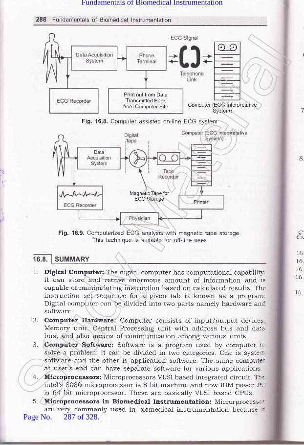
288 Fundamentals of Biomedical lnstrumentation
o_o
Computer (ECG lnterpretativeSystem)
Fig. 16.8. Computer assisted on-line ECG system
Fig. 16.9. Computerized ECG analysis with magnetic tape storageThis technique is suitable for off-line uses
Print out from DataTransmitted Back
from Computer Site
Magnetic Tape forECG Storage
1.
t.16.
16.16.16.
16.
2.
J-
4.
5.
Digital Computer: The digital computer has computational capabilil,It can store and retrive enormous amount of information and iscapable of manipulating instruction based on calculated results. Th€instruction set sequence for a given tab is known as a prograrnDigital computer can be divided into two parts namely hardware ancsoftware.Computer Hardware: Computer consists of input/output devicesMemory unit, Central Processing unit with address bus and daubus; and also means of communication among various units.Computer Software: Software is a program used by computer r:solve a problem. It can be divided in two categories. One is syste::software and the other is application software. The same compute:at user's end can have separate software for various applicationsMicroprocessors: Microprocessors VLSI based integrated circuit. Tl--tinte.l's 8O8O microprocessor is 8 bit machine and now IBM power P-is 64 bit microprocessor. These are basically VLSI based CPUs.Microprocessors in Biomedical Instrumentation: Microrprocess-,:are very commonly used in biomedical instrumentation because .:St
udy M
ateria
l
Page No. 287 of 328.
Fundamentals of Biomedical Instrumentation

6
Microprocessors and Computers in Biomedical lnstrumentation 289
offers case and accuracy in calibration, table look up feature to takecase of non-linearity, data averaging, formatting and printing, etc.
Interfacing of the computer with medical instrumentation: Thebiomedical instruments which are interfaced with the computer,generate analog data in the form of voltage proportional to theparameters or variable represented. For interfacing, the analog signalsare converted into digital data. In the case of computer output datafor display purposes, the digital data has to be converted into analogsignal.Biomedical computer Applications: The use of digitial computer inbiomedical is vety wide and common. The features of computer whichare exploited for biomedical applications are data acquisition, datastorage and retrieval, data reduction ald transformation, mathematicaloperation, pattern recognition, limit detection data presentation,control functions, etc.
Specific exarnples of biomedical applications of computer:Computerized Axil Tomography (CAT) scanners, EmissionComputerized Tomography, Computer analysis of the ECG, digitalcomputer usage in clinical laboratory, digital computer in patientmonitoring, computer in the aid of handicapped, Microprocessor based
Myoelectric arm, Microprocessor based hearing aids, digital computerusage in surgical intensive care automation, computer assisted onlineECG system, etc.
7.
8.
\.\2..
t
txercided
16.1. Describe digital computer with a block diagram.
16.2. What do you understand by computer hardware and software?
16.3. How a microprocessor can be used in biomedical application?16.4. What do you understand by analog to digital and digital to analog
conversion? How these are used in biomedical instrumentation?16.5. Explain use of digital computer in biomedical application and give some
examples.
aaa
Stud
y Mate
rial
Page No. 288 of 328.
Fundamentals of Biomedical Instrumentation

Basic Electronics forBiomedical lnstrumentation
>* fnside thts chapter
17. 1. Operational Amplifiers\7.2. Basic Operational Amplifier Circuit17.3. Details of Commercial Operational Amplifiers17.4. Measurement of Inductance and Capacitance with the Help of
A.C. Bridges17.5. Measurement of Inductance17.6. Measurement of Capacitance17.7. Cat}lode Ray Oscilloscope17.8. Cathode Ray Tube17.9. Measurement with CRO
17.lO. Summary
The details of basic electronic circuit are given in this chapter. Thestdetails are very important for Doctors and paramedical staff using th:sbook.
The basic electronic component like operational amplifier and othe:electronic circuits like bridged and cathode ray oscilloscope are ve-important.
17.1. OPERATIONAL AMPLIFIERS
An operational ampliher abbreviated as op-amp is basically a multistaatvery high gain (typically 2,OO,O0O) direct coupled negative feedba:samplifier that uses voltage-shunt feedback gain. An op-amp has h:i
lnpL(lessfreqrusedampAS ST
etc. Ichancompcircuia.nalorold
T}:s an:num.dvan-'mpe
nzlt, re dil- has
:ASS Ci
Thr-. figur-_fut c
', -tat hWht
t" ---ich c
-,:,iival-'. 'rsist-_ectot
:r--:eren(-1" .:Stan
,:ease----lnv(:,\/hel
:::aselI :-ge I
::tlng
3,/ot- l-afi
:factStud
y Mate
rial
Page No. 289 of 328.
Fundamentals of Biomedical Instrumentation

Basic Electronics for Biomedical lnstrumentation 291
input impedance (exceeding 1OO K ohms) and low output impedance(1ess than 100 ohm) and has capability of amplifying signals havinglrequency ranging zero hertz to 1 MHz. Earlier discrete op-amp wereused but now industrial designers exclusively use IC op-amps. An op-amp was originally designed to perform mathematical operations suchas summation, subtraction, multiplication, differentiation and integrationetc. Now-a-days op-amps are put to a variety of other uses such as sign:hanging, scale changing, phase shifting, voltage regulation, analog,-omputer operations, in instrumentation and control systems, oscillator:ircuits, pulse generators, square, triangular wave generators comparators,a.nalog to digital converters, voitage to current converters, sample androld circuits, etc.
The op-amp manufactured with integrated tralsistors, diodes, resistors:s an extremely versatile device that is found doing countless tasks as:numerated above. The op-amp is a high gain amplifier having theadvantage of an IC such as low cost, small size, high reliabilityemperature stability and low value of offset voitage and current.
17.2. BAS!C OPERATIONAL AMPLIFIER GIRCUIT
lhe differential ampliher is widely employed in integrated circuitry becausehas both good bias stability and high gain without requiring large by
:ass capacitors.The differential amplifier circuit that is used in IC op-amps is given
r lrgure 17 .1(c). This is the circuit which explains a great deal about therput characteristics of the typical iC op-amps. Here is the basic idea of'.'hat happens in this differential amplifier.
When input (i.e., V1l increases the emitter current of Q, increases'.hich causes the voltage at the top of emitter resistance R, to increase-quivalent to decreasing Vr" of transistoy Qz. Reduction in Vru of'.ansistor Q2 means less current in this transistor. The voltage drop inrllector resistance Ra is decreased and output voltage 7or, being the
::fference of collector supply voltage I/." and voltage drop in collector-:sistance R" (i.e.,IaR.) is increased. Thus we see increase in V, causes:-crease in output voltage. That is why the input voltage 7, is called thern-inverting input. The output voltage %.,, i" in phase with 7r.
When input 7, increases, the collector current to transistoy Qz:-creases causing more voltage drop in collector resistance and so outputrltage Vou, to decrease. This is why the input voltage V, is called the-r'erting input. The output voltage Vou, is 180' out of phase with 7r.
DETAILS OF COMMERCIAL OPERATIONAL AMPL!FIERS
5\\.'14
.a
.i
e
s
'1op-amp referred to as the IC 74I has become an industry- .e IC 741 was first designed by Fairchild's corporation is-anufactured by various other manufacturers.
standard.now beingSt
udy M
ateria
l
Page No. 290 of 328.
Fundamentals of Biomedical Instrumentation
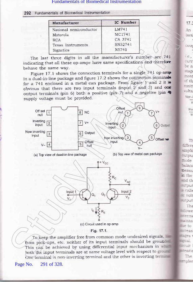
292 Fundamentals of Biomedical lnstrumentation
Manufacturer IC Number
National semiconductorMotorolaRCATexas InstrumentsSignetics
LM74IMC1741cA 3747sN5274 1
N5741
The last three digits in all the manufacturer's number are 74[indicating that alt these op-amps have same specif,rcations and therefore
behave the same waY.
Figure 17.1 shows the connection terminals for a single 741 op-aryin a dual-in-line package and figure 17.2 shows the connection terminabfor a 741 enclosed in a metal can package. From figure 1 and 2 it sobvious that there are two input terminals (input 2 and 3) and ocoutput terminals (pin 6) both a positive (pin 7) and a negative (pin {supply voltage must be Provided.
OffsetnulOff set
null
ofisel dr
17.i
.{nrasi
loul
1.€.,
:urrlea>tag(
=ost:l th::nit1;tlta\on-i
tr
T}::-ferec:pli1lr ':pur.-def,<a-rr(ElaaSU
k-- :heth
:put:alle
: ','olt:cutThetwe
i:rrn(;'rta
to_:eas
:ES \-al.rit l
:ntielhe
nv(-:-tn
NC
lnvertinginput
Now invertinginput
Output
Offsetnull
lnvertinginput
Non invertinginput
(a) Top view of dead-in-line package
V-(b) Top vew of metal can Package
(c) Circuit used in op-amP
Fig. 17.1.
To keep the amplifrer free from common mode undesired signals-
from pick-ups, etc. neither of its input terminals should be groun
This can be achieved by using differential input mechanism inboth the input terminals are at same voltage level with respect toone terminal is non-inverting terminal and the other is inverting
r---:ierStud
y Mate
rial
Page No. 291 of 328.
Fundamentals of Biomedical Instrumentation

Basic Electronics for Biomedical lnstrumentation 293
17.3.1. BIock Diagram of a Typical Operational Amplifier
An operational amplifier being a multistage amplifier, consists of some
basic building blocks as shown in block diagram as in figure 17.2.
The block diagram given in figure 17.2 consists of a four stage directcoupled amplifier in cascade. stagewise explanation is given below.
The first stage is a double ended high-gain (60 db) differential amplifrer1.e., dual-input balanced output differential amplifier with a constantcurrent source. in this stage high gain is desirable so that there wouldbe a negligible effect on the output of any short coming in the followingstages. 1ti" i" the reason why this stage is generally responsible for*o"t of the gain of op-amp. Also this stage determines the input resistanceof the op-amps. output of this stage is taken between collectors of two
emitter biased circuits so that output remains balanced and the dc
Dual input balanced Dual input unbalanced Emitter follows complement symmetry
output defferential output defferential with constant push-pull amplifier
amplifier amplifier current source
Fig. 17.2. Block diagram of a Typical op-amp
The second stage, called the intermediate stage is usually anotherlifferential amplifier, which is driven by the output of frrst stage. In most
arnplifiers the intermediate is dual input, unbalanced (single ended)
rutput differential ampliher in order to increase the gain. The differentialrode voltage gain of such an amplifier is half of the gain of dual input:alanced output type differential amplifier. In this amplifier output is
reasured at the collector of only one of the two transistors w.r.t. ground.
n the quiescent condition some dc voltage exists at the output terminal,nd there is no other collector voltage at output to balance or nullify the
utput dc voltage. This is the reason why this type of unbalalced amplifiers called unbalanced output type differential ampliher. This unbalanced:c voltage present at the output acts as an error voltage in the desired. -rtput signal.
The third stage known as level shifting stage, is usually an emitterrllower circuit in ord.er to shift the dc level at the output of theItermediate stage downward to zero volts w.r.t. ground. It is worth
-aintaining here that error signai is developed in the intermediate stage
-ue to dlrect coupling and gets amplifred in the succeeding stages. This..crease in dc level tends to shift the operating point of the succeeding.ages which also limits the output voltage swing may distort the outputgna1. To overcome these problems, use of a level translator (shifter)
.rcuit becomes necessary to bring this dc level to zero voltage (ground
- rtential).The frnal stage is called the output stage is usually a push-pull
mplementary amplifrer. This stage increases the output voltage swing
\le,
,.
_'
uoltage at output in quiescent condition maintains zero level.
Stud
y Mate
rial
Page No. 292 of 328.
Fundamentals of Biomedical Instrumentation

294 Fundarnentals of Biomedical lnstrumentaticn
and the current A well designed
output stage also utPut of the oP-
.-i i. the voltag stage Push-Puliamplifrer with resPect to ground.
Uses of Operational AmPllfierThe oper with other componen:
are being us , as subtraction' It caf:
be used as i an be used for currec:
to voltage conversion and voltage to current conversron'
17.4.L Generation Equation for Bridge Balance
The four impedance, a detector and 1, an a'c' source balance :s
obtained by adjustment of one or more variable branches of the bridgrand is indicated by zero response of the detector, i.e., points B and D
are at the same potentials at all instances figure 17'3'
lmpedance
Flg. 17.3.
when the points B and D are at the same potential and voltage
between A and B and A and D will be equal'
So, \Zt = \2,In this condition, voltage
also be equaldrop between C and B and C and D
IrZ, = IoZo
Dividing (4 bv (,0
It Zt Is Zz
IzZz - I+Z+
But und.er balance conditions current I, = k and I, -- Io
Hence,
zt 23
Z. ZN
Z. Z" = Z^2,t+zo
eq1S
eq
\
t
anr
17.
17.
rnl:ldfurf,et\
trlc
MEASUREMENT OF INDUGTANCE AND CAPACITANGE WITH T}EHELP OF A.C. BRIDGES
Stud
y Mate
rial
Page No. 293 of 328.
Fundamentals of Biomedical Instrumentation
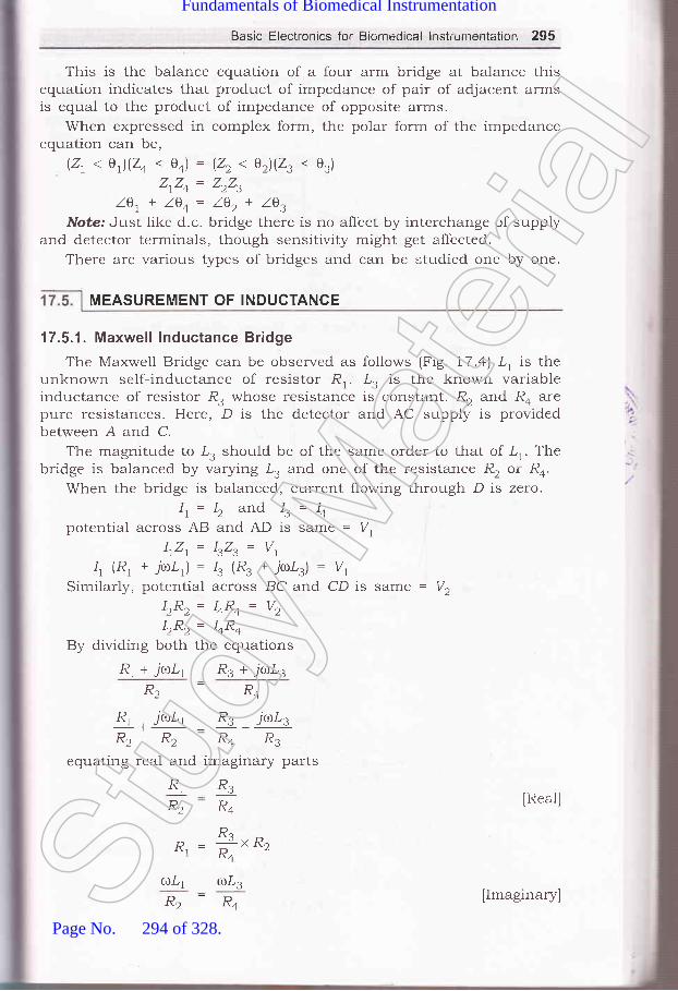
Basic Electronics for Biomedical lnstrcirnentation 295
This is the balance equation of a four arm bridge at balance thisequation indicates that product of impedance of pair of adjacent armsis equal to the product of impedance of opposite arms.
When expressed in complex form, the polar form of the impedanceequation can be,
(21 < e)(24 . 0o) = (22 < e2)(23 < 03)
ZrZo = ZrZ,Z0r+ l0+= l0r+ lg,
Note: Just like d.c. bridge there is no affect by interchange of supplyand detector terminals, though sensitivity might get affected.
There are various types of bridges and can be studied one by one.
17.5.1. Maxwell lnductance Bridge
The Maxwell Bridge can be observed as follows (Fig. 17.a) .L, is theunknown self-inductance of resistor R,.. tr, is the known variableinductance of resistor R. whose resistance is constant. R, and Ro arepure resistances. Here, D is the detector and AC supply is providedbetween A and C.
The magnitude to I, should be of the same order to that of lr. Thebridge is balanced by varying .L. and one of the resistance R, or R*.
When the bridge is balanced, current flowing through D is zero.It= Iz and Is= I+
potential across AB and AD is same = V,lrZ,. -- IrZ, = V,
4 (R1 + 7'(l)/,1) : 13 (R3 + j(UDLs) : Vt
Similarly, potential across BC and CD is same = l/,IzRz= hRo= Vz
LR^ = TRll++By dividing both the equations
R, + jro.L1 R, + jo.L3
R.-R"Rr , juLr R3 jaLzR2 R2 R4 R3
equating real and imaginary parts
R1
R2 IReal]R3
R"
D : *t ^o,"l R"
otrr aLzR2-R4
MEASUREMENT OF INDUCTANGE
IImaginary]Stud
y Mate
rial
Page No. 294 of 328.
Fundamentals of Biomedical Instrumentation

296 Fundamentals of Biomedical lnstrumentation
17r
L.= "3Rn,R+Thus, value of unknown self-inductance can be determined.
l',R', = lrR.Vr=|.,R, = laRo
E -EL3-L4
Vector diagram for Maxwell lnductance BridgeFig. 17.4.
Alternatiuelg
\
E-ELa-Li
L, : Unknown,Ra, Ro = two
Re,I -
-lr.R4
Hr
L, : Yariable, R, = Variablenon-inductive resistance
o : &(R,*r,)"1 R"' '
Fig. 17.5.
Et=Ez
K- E, -+F- E3 +l
F Ez Eo ---N
Et=Ez
---* llrol', =lr,,L,
Stud
y Mate
rial
Page No. 295 of 328.
Fundamentals of Biomedical Instrumentation

Basic Electronics for Biomedical lnstrumentation 297
'17 .5.2. Maxwel l's I nductance'Gapacitance Brid ge
The Maxwell's Inductance-capacitance bridge isunknown inductance'1,'.
From the Fig. 17.6 we see that:1'r : unknown inductanceR, = effective resistance of 'L,
R3, R2 : known, non-inductive resistance
Co = standard variable capacitanceRo = variable resistance
(R^)1R, + jrol,,)i*,id_,J = (R3XR2)
RrR+ * ir,t,LtR+ =R-R.| + jaCaRa 1+ jtrlCaRo z c
used to measure
[Imaginary parts]
Fig. 17.6. Circuit diagram showing Maxwell's lnductance-capacitance Bridge
ZrZo = ZrZ" lBalance equation of a Balanced Bidgel
RrRo * jaLrRo: RzRs 1r + TcoCoRo)
RrR+ * j(r.LrRo = RzRs + jaCoRoRrR,
RrRo = RrR.
p - xzraln"al partl'tl R"
LrR+: C4R4R2R3
L, : COR,R,
Hence, the unknown inducta.nce
L, = CoRrR,
Expression for Q factor:
O=+ =,r,tCa,RcStud
y Mate
rial
Page No. 296 of 328.
Fundamentals of Biomedical Instrumentation
298 Fundamentals of Biomedical lnstrumentation
Advantages:(zJ The two balance equation are independent if we choose Ro and Co
as variable elements.(iz) The frequency does not appear in any equation
(iizJ This bridge yield a simple expression for R, and L,(iu) The Maxwell's inductance and capacitance bridge can be very useful
for measurement of a wide range of inductance at power and audiofrequency.
Disadvantages:(zJ The bridge requires a variable standard capacitance which may be
very expensive if calibrated to a high degree of accuracy. Thereforesometimes a hxed standard capacitor is used, either because avariable capacitor is not available or fixed, is less expensive andhave high degree of accuracy. Then the balance adjustments aredone by:(a) either varying R, and Ro and since R, appears in both balar'..
equation the balance adjustments become difficult.(b) putting an additional resistance in series with the inductan'-.
to be measured and varying Ro.
(izJ The bridge is limited to measurement of low Q coils (1 < Q < 10It is cleat that,
o = 'L, = roR, c,-Rl'ta
Measurement of high Q coils demands a large value for resistancrRo, perhaps 1Os or 106 fl. The resistance boxes of such high values a-very expensive.
Thus, for Q > 10 Maxwell Bridge in unsuitable.The M is also unsuitable for coils less than 1(Q. 1). Qvalues of ti-:s
magnitude occur in inductive resistors or in R.F. coil if measured at icr"rfrequency. The difficulty in measurement occurs on account of labo'sinvolved in obtaining balance
7.€.,
Normally for convenience a fixed capacitor is used, therefore we hto vary R, and Ro. Now' since R, is in both the equation. Therefore itbalance R, and get a balance position, but again when we want toan inductive balance then the resistive balance gets disturbed and hemoves to new values giving slow 'convergence'to balance. This condiis particularly true of lorv Q coil as for which the resistance is promi:
ALQ= ^I\(
From the above discussiohs we conclude that a Maxwell's brideesuited for measurements of only medium Q coils.
L, = RrCoR,
R. R"D^, -
-
,R+
Stud
y Mate
rial
Page No. 297 of 328.
Fundamentals of Biomedical Instrumentation

Basic Electronics for Biomedical lnstrumentation 299
lrRt lR E. = 1.,R.= E,l.
=fr= t*no
Fig. 17.7. Vector diagram
17.5.3. Hay's Bridge
The Hay's bridge is modification of Maxwell bridge. Here we can seefrorn the figure 17.8.
G
E
@L
Fig. 17.8. Circuit diagram showing Hay's Bridge
.L, = unknown resistanceR2, R3, Ro : known non-inductive resistance
Co = standard capacitanceAt balance,
( ; \(R, + jrrrl,l)l Ra +,* I = n"n
1 Jtuee.) "-( ; \
(R, + jrol,)[n+ - fr )= RsRz
RrR+ - j+ + jaL,Ra * *r, = R"R"ac+ @c+
[Equating real and imaginary partlStud
y Mate
rial
Page No. 298 of 328.
Fundamentals of Biomedical Instrumentation

300 Fundamentals of Biomedical lnstrumentation
R,Ro+*=*r*,t-4
.ilLrRo- # = .
- '-[*"R" - lllR, = &L^t^'-co.lcoa2LrRo - Rr = o
a2 coL," -+[.s R+ ' +) = "
olconltrr-Ra *r*! = o
,,1,' co RZ. +l = RsRz
1,, = R3R2laer)
, _ RsRzC+tJt -
a2 cl nl +t
.,: +[* ",-affi;)=?[, eder)
R,:R2,R3l##)Expression for Q factor:
aL. 1
V= & -rcoRo
This expression contains a frequency term, therefore, it appears ttIAthe frequency of the source of supply to the bridge must be accuratelrknown. But it does not hold for inductance when high Q coil is measuredOS,
Lt=
1
[Real part]
[Imaginary part]
Disar
a)
17.5.4
T}re ob
0=Now,rulCaRaSt
udy M
ateria
l
Page No. 299 of 328.
Fundamentals of Biomedical Instrumentation

Basic Electronics for Biomedical lnstrumentation 301
hence,
For the value of e > 10 the t".- -1:@)2
and can be neglected, therefore, equationL, = C*RrR,
would be smaller tfr"r, frreduces to:
lrl.ucCo
Fig. 17.9. Vector diagram
Advantages:(z) This bridge gives a very simple expression for e > 10,
(izJ Also it has simple expression for e factor,
(rr4 If we see Q fa 1Lctor = ,C.R- hence low value of Ro is required for
high Q coils. It's value should be small. Thus, this bridge requiresvery low value of Ro whereas Maxwell's bridge requireds parallelresistor Ro of very high value.
Disadvantages:(t) The Hay's bridge is suited for the measurement of high e inductors,
especially those inductors having a e greater than 10.
17.5.4. Anderson's BridgeThis bridge is also used for measuring inductance from figure lr.lo,
we observe, '
L, = Self-inductance to be measuredR, = Resistance of self-inductorr, = resistance connected in series with I,
r, R2, R4, Ra = known non-inductive resistanceC = fixed standard capacitor.Stud
y Mate
rial
Page No. 300 of 328.
Fundamentals of Biomedical Instrumentation
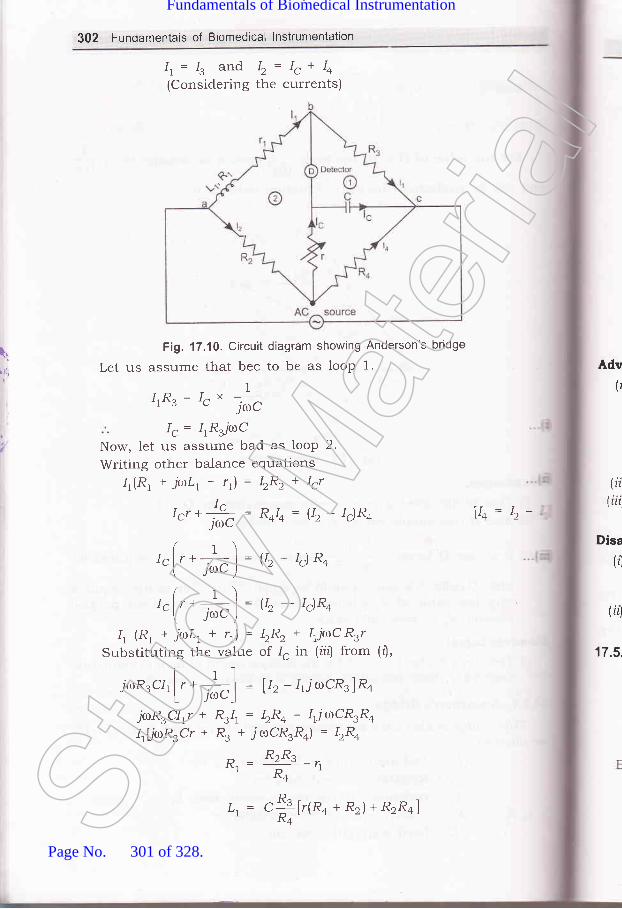
302 Fundamentais of Biomedical lnstrumentation
[1
r 11,
Ir. -- Ie and I, = I, + Io(Considering the currents)
Fig. 17.10. Circuit diagram showing Anderson's bridge
Let us assume that bec to be as loop 1.
1IrRs= 1"" jrc
I, = IrRjt.roC
Now, let us assume bad as looP 2.
Writing other balance equations
4(R1 + jaLr+ 11)= \Rr+ Ir7
tr, *Js; : R+I+ = g, - Ig)R+- JOU
( r ) -lglr+,-l=U2-lg)R*I J") -
( t ) -Iglr+ : I = U2- tc)R4
\ J") -
4 (R1 + jaL, + rr) = IzR, * IrjaC RrrSubstituting the value of 1" in (iitJ from (r'),
jcoR3crl ['- +] = U, -1,jrocR.lRo't JCDC_I
jaRrClrr + R:1r = bRo - lrTrrlCR.Ro
IrLjiur'Rrcr * R. * jroCR.Ra) = IzR+
B' = R:Rs -',R+
Adv(r
Disa
(,)
FA
17.5,
(ii(iii
vo= b-
t, = "X[r(Ra
+ Rr)+ RrRo]Stud
y Mate
rial
Page No. 301 of 328.
Fundamentals of Biomedical Instrumentation

Basic Electronics for Biomedical lnstrumentation 303
E;41 -
l1(R', + r',; E. = 1., R. =,, SFig. 17.11. Vector diagram
Advantages:(f In case adjustments are carried out by manipulating control over
r and r, they become independent of each other. This is a markedsuperiority over sliding balance condition met with low Q coilswhen measuring with Maxwell's bridge. A study of convergencecondition would reveal that it is much easy to obtain balance in thecase of Anderson's bridge than in Maxwell, when Q factor is low.
(fiJ A fixed capacitor can be used instead of variable capacitor.(iiz) This bridge may be used for accurate determination of capacitance
in terms of inductance.
Disadvantages:(zJ The Anderson's bridge is more complex than its prototype Maxwell's.
It's equations are more complex and tedious and hence difficult toobtain.
(ir) An additional junction point increases the difficulty of shielding thebridge.
17.5.5. Owen's Bridge
-L, = unknown self-inductorR, : variable non-inductive resistanceRa = fixed non-inductive resistanceC, : variable capacitanceCo = fixed standard capacitor
Balance equation,Z,Zo : Z,Z,
Zt=Rt+jaL,1
4pi
,l
z^=.iacoStud
y Mate
rial
Page No. 302 of 328.
Fundamentals of Biomedical Instrumentation

304 Fundamentals of Biomedical lnstrumentation
Fig. 17.12. Circuit diagram showing Owen's Bridge
Z, : R,I,( t \ r '-1
1R,j,or,)i#;l = L*-*l*Ll -- R2R3C4
R. = ,R" 91' "cz
Advantages:(rJ Since, C, ar:d R, are in the same branch, convergence to balance
condition is much easier.(irJ Balance equation do not contain any frequency term.(iir) It can be used over wide range of measurement of inductances.
,Disadvantages:(tJ This requires a variable capacitance whose accuracy is about 1o.,;
and is expensive.(ii) The value of capacitance C, tends to become rather large when
measuring high Q coils.
E.=E, = I0U.t
-lzacz
Adr
Er=Eo=l.,Ra = l, Ro
Fig. 17.13. Vector diagramStud
y Mate
rial
Page No. 303 of 328.
Fundamentals of Biomedical Instrumentation

Basic Electronics for Biomedical lnstrumentation 305
17.6. MEASU REMENT OF CAPACITANCE
'17.6.1. De-Sauty's Bridge
Fig. 17.14. Circuit diagram showing De-Sauty's Bridge
C, : unknown capacitanceC, = standard capacitance
R3, R4 = non-inductive resistanceApplying balance equations,
It )*,=l ' l*,[ -lcrro,; I iacz ) '
CzR+."r= &
Hence, the capacitance can be known.
Advantage / Disadvantage
. l,t
|,2,
Fig. 17.15.Stud
y Mate
rial
Page No. 304 of 328.
Fundamentals of Biomedical Instrumentation
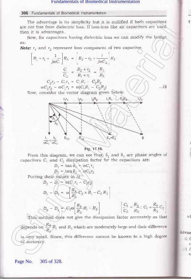
306 Fundamentals of Biomedical lnstrumentation
The advantage is its sirnplicity but it is nullified if both capacitorsare not free from dielectric loss. If loss-less like air capacitors are usedthen it is advantages.
Now, for capacitors having dielectric loss we can modify the bridgeAS:
Note: r, and 12 represent loss component of two capacitor.
I r-1 t "]
l R, *n *--i, lR+ = lRz +rr *.l-ln,L ' ' JoCr I L - - irCz)'
Ct _ Rz+rz _ R+
C2 Rr+1 R3
Czrz- Ctrt= ClRl- C2R2
aCrrr- aCrr, = ro(CrR, - C2R2\
Now, consider the vector diagram given below:
(0
I
lt _ lz Ecr Ecz
toCl roC,
Fig. 17.16.
From this diagram, we can see that, 6, and 6, are phase angles ofcapacitors C, and C, dissipation factor for the capacitors are:
D, = tan 6, = roCrr,D, = tan6r= aCrr,
Putting their values in (tj
Dz - Dt: ro(Crr, - C2r2l
D, - Dr= ,[+ c2 x R, - c, Rr)LR. ')
E.=E" F
Dz - D,= ",[ft*,
- *,] [c, R+ n _Rq.l.........._.__-, ul --v2lcz R3 ' R3
This method does not give the dissipation factor accurately as that
depends or, + R1 and R, which are moderately large and their difference^R3'is very small. Since, this difference cannot be known to a high degreeof accuracy.
rl c
C
:)Ltr
l,ttt lztz lzRz lrRr EzEq
Stud
y Mate
rial
Page No. 305 of 328.
Fundamentals of Biomedical Instrumentation
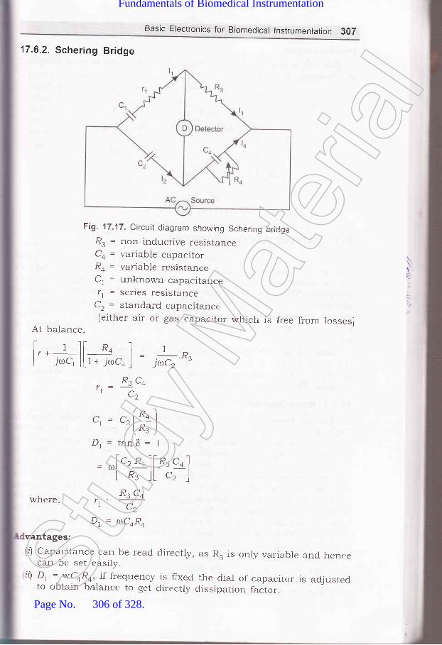
Basic Electronics for Biomedical lnstrumentation 307
17.6.2. Schering Bridge
Fig. 17.17. Circuit diagram showing Schering bridgeR. = non-inductive resistanceCo = variable capacitorRo = variable resistanceC, = unknown capacitancer, = series resistance
C, = standard capacitance[either air or gas capacitor which is free from losses]
At balance,
t 1l[ R4 ] rI r +_ | , | _ _ D
L yrC, _][ t + Tcoco _] -
J0C2 '"3
where,
R" C,,.=u-,CZ
c. = c^ l,*- ')
r zln" I
\ J,/
D, = tanS = 1
= ^l', *ol[o.,
"* ILR.lLc2lRs c+
.1 C2
D, = atCoRo
vantages:(l) Capacitance can be read directly,
can be set easily.il Dt : wCoR4, if frequency is fixed
to obtain balance to get directly
as R. is only variable and hence
the dial of capacitor is adjusteddissipation factor.St
udy M
ateria
l
Page No. 306 of 328.
Fundamentals of Biomedical Instrumentation

308 Fundamentals of Biomedical lnstrumentation
Disadvantages:Since R. appears in both the equations
in obtaining the balance.
17.7.
hence there is some difference
l(
(
.:ho<::fe€-- afft
',=,.r=L E
' @Lz
Fig. 17.18. Vector diagram
CATHODE RAY OSCILLOSCOPE
The cathode ray oscilloscope is an extremelv useful and versati-tinstrument used for study of wave shapes of high frequency as well as
lou, frequency electronic circuits. It is used extensively as monitors :-:-
bio-rned.ical equipments. It electnc=r
signals as a function of used ::rtrouble shooting of biomed t cathairay oscilloscope is most i Pment rall electronic circuits.
Now-a-da1.s two types of cathode ray oscilloscopes are available m
the market. One is digital cathode ray oscilloscope and other one E'
analogue type nf cathode ray oscilloscope. Anaiogue type of cathode :aroscilloscope is commonlY used.
17.7.1. Block Diagram
The instrument employs a cathode ray tube (usually abbreviateccRo) which is the heart of the oscilloscope. It generates the elec:-
beam, accelerates the beam to a high velocit5r, deflects the bea::-
create the image on a phosphor screen where the electron bea=visible. For accomplishing these tasks various electrical signalsvoltageS; are required, which are provided by power supply circuit c:
oscillosb6pe. Low voltages are required, which are provided by the p-
supply circuit of the oscilloscope. Low voltage supply is required fc:heater of the electron gun for generation of electron beam and :voltage of the order of kilovolt is required for cathode ray tube to acce,:
the beam. Normal voltage supp)y of a few hundred volts is tequire':other control circuits of the oscilloscopes.
Horizontal and vertical deflection plates are fitted between el
gun and screen to d.eflect the beam according to input signal' Ei
beam strikes the screen and create a visisble spot. This spot is de:--
on the screen in horizontal direction (X-axis) with constant time deStud
y Mate
rial
Page No. 307 of 328.
Fundamentals of Biomedical Instrumentation

Basic Electronics for Biomedical lnstrumentation 309
rate. This is accomplished by a time base circuit provided in theoscilloscope. The signal to be viewed is supplied to the vertical deflectionplates through the vertical amplifier which increases the potential of theinput signal to a level that will provide usable deflection of the electronbeam. Now electron beam deflects in two direcbions, horizontal on X-axisand vertical on Y-axis. A triggering circuit is provided for synchronizingtwo types of deflections so that horizontal deflection starts at the samepoint of the input vertical signal each time it sweeps. A basic blockdiagram of a general purpose oscilloscope is shown in figure lr.l9.cathode ray tube and its various components are d.iscussed below.
Luminousspot
.a- Screen
Electronbeam
Horizontaldeflection
plates
Fig. 17.19. Block diagram of a general purpose CRO
,1"
:'1
Focusinganode
Y-platesElectron
beam
Fluorescent
Cathode
Acceleratoranodes
X-plates
Fig. 17.20. Cathode ray tube
,athode ray tube essentially consists of an electron gun for producing, stream of electrons, focussing and accelerating anodes for producing: n&rrow and sharply focussed electron beam, horizontal and verticalSt
udy M
ateria
l
Page No. 308 of 328.
Fundamentals of Biomedical Instrumentation

310 Fundamentals of Biomedical lnstrumentation
deflection plates for controlling the bearn pate and an evacuated glass
envelope *1th pho"phorescent screen giving bright spot when struck by
a high velocity electron bean.A cut away view of a cathode ray tube is shown in hgure l7'2O'
17.8.1. Electron Gun AssemblY
Electron gun assembly indirectly heated cathode a c
surrounding the cathode, a focusing anode and an accelera
The sole function of the electron gun assembly is to provide
electron beam which is accelerated, towards the phospher screen' The
cathode is a nickel cylinder coated with an oxide coating and emits
plentyofelectron"*h..'heated.Theemittingsurfaceofthecathode
"fro-.ria be as small as possible. Intr nsitY of electron beam depends on
the cathode current, *^rri.r, can be controlled by the control grid' The
control grid is a metal cylinder covered at one end but with a small hole
in the "orr"..
'fhe grid is kept at negative potential (variable) with respeclemission and so thee hole in the grid is
and concentrate the
the tube. Electron beam comes ou:
from the control grid through a small hole in it and enters a pre-
accelerating anodel which is in the shape of a hollow cylinder and is a:
apotelltial-of.f.*hundredvoltsmorepositivethenthecathodesoasto acceler:ate the electron beam in the electric field. This accelerate-
beam worrlll be scattered now because of variations in enerS' and u'ou-:
produce a broad ill-defined spot on the screen' This am ::
iocussed orr the screen by an electrostatic lens consi mo::
cylindrical anode called ih" fo.'""ing anode and a ano:=
apart from the pre-accelerating ussing and acceleratl:i
anodes may be open or close at f covered' holes must :tprovided in-the anode cover for the e electrons' The funct-:tf th."" anodes is to concentrate and focus the beam on the scfeefl ?i:l
also accelerate the speed of electrons'
An eiectrostatic focussing system is shown in figure 17'-'-
Electrostatic lens consists of three anodes, with the middle anode a: E
iower potential than the other two electrodes'
Focussing Acceleratirrganode
- anode Screen
lt\Itb
T
1
piatplce
plthwiIfuFisaCl
apthetheamofl
inrofr
Pre-acceleratinganode
17.1
prolfluoconlcallr:1me
'he I
1-,\rhe
rn tl: lectamOl
:reera-vlnjl:COf,. hite
.----/':----:l__--J
----l
Fig. 17.21. Electrostatic focussing system of a CRTStud
y Mate
rial
Page No. 309 of 328.
Fundamentals of Biomedical Instrumentation

Basic Electronics for Biomedical lnstrumentation 311
Retering to figure 17 .27, it can be seen that because of middle anodeis at lower potential, electron beam coming from the cathode and passingthrough the hrst concave electrostatic lens tends to become more alignedwith the axis of CRT and when it enters second concave electrostaticiens, formed between two anodes at different potentials, it is focused atthe phospher screen. Focai length of the electrostatic lens can be adjustedby varying potential of middle anode with respect to other tr,,,o anodes.Thus, the electron beam can be made to focus at the screen very precisely.
17.8.2. Deflection Plate AssemblyElectron beam after leaving the electron gun, passes through the two
pair of deflection plates. One pair of deflection plates is mounted verticallyand deflects the beam in horizontal or X-direction and are ca-lled horizontalplates and the other plates are mounted vertically in Y-direction and arecalled Vertical plate and deflects and beam in vertical direction. Theseplates are to deflect the beam according to the voltage applied acrossthem. If the potential difference is applied on horizontal plates the beamwill be deflected in the horizontal direction according to potential applied.If positive potential difference is applied on the vertical plates and theupper plate is positive them the beam will be deflected upward. Thisis correct for the beam to travel left, right or upward and downwardaccording to potential difference applied. In case a sinusoidal voltage isapplied on the horizontal plates and the frequency is more t}ran 16 Llzthe deflection will be a horizontal line. If the potentiai is applied to boththe plates simultaneously, the deflection will be an oblique line. Theamount of deflection is in proportion to the voltage applied to the pairof plates.
We knorv that a force is experienced by an electron when it is keptin a uniform electronic fie1d. This principle is the basis for the deflectionof electron beam owing to deflection plates.
17.8.3. Screen for CRT
It is known that some crystaline materials such as phosphor haveproperty of emitting light when exposed to radiation. This is calledlluorescence characteristic of materials. These fluorescent materialscontinue to emit light even after radiation exposure is cut off. This iscalled the phosphorescence charat:teristic of the materials. The length oftime during which phosphorescence occurs is called the persistence ofthe phosphor.
The end wall of the CRT is ca.lled screen is coated with phosphor.When eiectron beam strikes the CIRT screen, a spot of iight is producedon the screen. The phosphor absorLrs the kinetic enerry of the bombardingelectrons and emits eners/ at a lorn,er frequency in a visual spectrum.-A.mong the fluorescent materials used are zinc orthosilicate giving agreen trace very suitable for visuaLl observations and calciurrr tungstategiving blue and ultra-violet radiations very suitable for photographicrecording. The coating of zinc suLlphide with other materials giving arvhite light suitable for TV, Zinc pkrosphate gives a pronounced after flclwSt
udy M
ateria
l
Page No. 310 of 328.
Fundamentals of Biomedical Instrumentation

\q,
312 Fundamentals of Biomedical lnstrumentation
and is useful when studying transient phenomenon because the tracepersists for short while after the transient has disappeared.
17.8.4. GIass Shell and Base
The whole assembly is protected in a conical highly evacuated glasshousing through suitable supports. The inner wells of the CRT betweenneck and screen are usually coated with a conducting material knownas aquadag and this coating is electrically connected to the acceleratinganode. The coating is provided in order to accelerate the electron beamafter passing between the deflection plates and to collect the electronsproduced by secondary emission when electron beam strikes the screen.Thus the coating prevents formation of negative charge on the screenand state of equilibrium of screen is maintained.
The horizontal and vertical marks are marked on the screen of theCRT to provide user a correct measurement.
17.8.5. Basic Control
Number of controls are required to be provided for adjustment ofbrightness of the spot on the screen. It is accomplished by varying thevoltage between the first and second anodes. The horizontal and verticaiposition controls are provided for moving the beam on any part of thescreen. It is accomplished by applying a dc voltage to horizontal orvertical deflection plates. Other controls are discussed in detail.
A detailed block diagram of CI{O may be seen at figure 17.22.
17.8.6. Vertical Deflection System
The function of the vertica-l deflection system is to provide an amplifiedsignal of the proper level to drive the vertical deflection plates withourintroducing any appreciable distortion into the system.
The input sensitivity of many CRO's is of the order of a few milli-voltsper division and the voltage required lbr deflecting the electron bearr,varies from approximately 10OV (peak to peak) to 500 V depending or-accelerating voltage and the construct-ion of the tube. Thus the vertica-amplifier is required to provide this desired gain from millivolt input tcseveral hundred volt (peak to peak) output. Also the vertical amplifie:should not distort the input wavelbrrn and should have good respons.for entire band of frequencies to be rneasured.
-t'he deflection plates of CRO erct as plates of a capacitor and whe:.the input signal frequency exceeds I MHz, the current required fc:charging and discharging of the capacitor formed by the deflection plate
=
increases. So, the vertical amplifier shr:uld be capable of supplying curre:--enough to charge and discharge the deflection plate capacitor.
As we know that the electrical signal is delayed by a certain amou:-'of time when transmitted through an electronic circuitry. In CRO outp--signal voltage of the vertical amplifie r is fed to the vertical ampliher -s
fed to the vertical plates of CRT and some of its portion is used ::rrtriggering the time base generator cit:cuit, whose output is supplied::the horizontal deflection plates am1rlifier. The whole process, wh:::St
udy M
ateria
l
Page No. 311 of 328.
Fundamentals of Biomedical Instrumentation
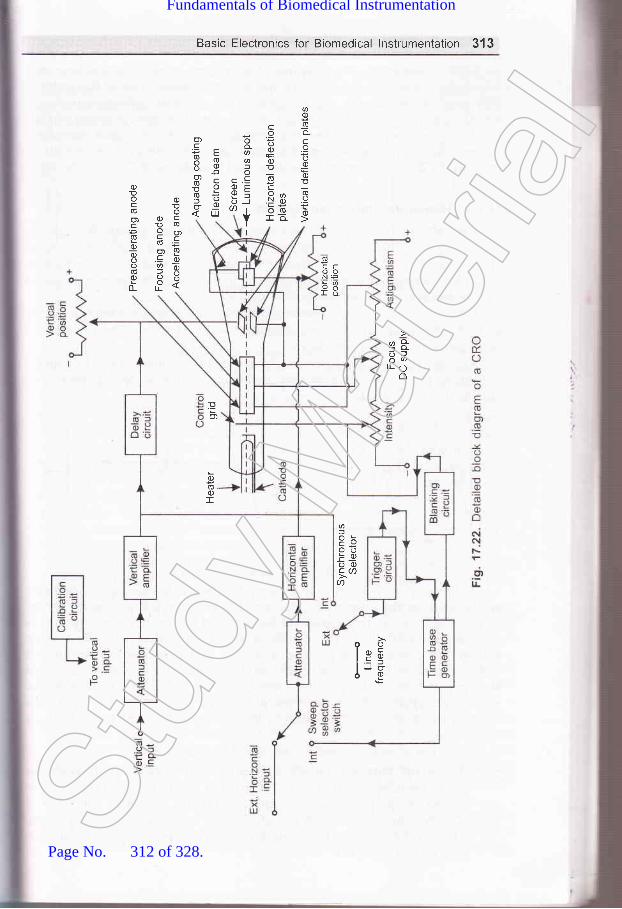
Basic Electronics for Biomedical lnstrumentation 313
ac)oo-c.9o0)Eq)E
,lQo.Y(rb
coooEo)
oC
N
-
o-aofo.cEf)i
I
cqJ
oo
U)
c
F663oo!o-6: o)
6ECooN=
ra
c)!ocoo)C(U
0)0)o
o)DE(E
o) o)c!
ocb(ooY'o.=oa(E=99dlI
q&E;ILO
o
@f,
OotsoooCAa
oolcElJu6E
Eo)
o)(E.oI
Stud
y Mate
rial
Page No. 312 of 328.
Fundamentals of Biomedical Instrumentation

ttvtdiVC
)ofhodirVCI
anSYS
hal
\,ll;
314 Fundamentals of Biomedical lnstrumentation
includes generating and shaping of a trigger pulse and starting of atime-base generator and then its amplification takes time of the order of100 msec or so. So the input signal of the vertical deflection plates ofa CRT is to be delayed by atleast the same or little more amollnt of timeto allow the operator to see the leading edge of the signal waveformunder study on the screen. For this purpose, delay line circuit isintroduced between vertical amplifier and the plates of CRT as shown infigure 17 .22.
17.8.7. Horizontal Deflection System
External signal is applied to horizontal deflection plates through thehorizontal amplifier at the sweep selector switch in EXT position as
shown in figure 17.22. The horizontal amplifier, simila-r to the verticalamplifier increases the amplitude of the input signal to the level requireiby the l:,orizontal deflection plates of CRT.
When the function of time is required to be displayed on the screecof CRT, INT position of sweep selector switch is used. The linear tim:base pattern is described below.
Assume that an ideal saw tooth voltage is supplied to the horizonta-deflection plates, keeping vertical deflection plates at zero potential a.shown in figure 17.23.
A----> B -----------) C
(a) (b)
Fig. 17.23. Linear Time Base
At the starting point A in time, signal voltage is maximum but nega=rso the spot on the screen of CRO is at the extreme left position. Fun:.r=at point B in time, the signal voltage applied to the horizontal plates rzero so the spot is in the centre position on the screen. Now rs::@voltage increases in the positive direction and becomes maximumbefore the point C, the spot on the screen is at extreme right side cf --
screen. Just after the point C, next cycle of saw tooth voltage s-
starts and again voltage becomes maximum negative so the spot =-
back to the extreme left position of the screen from right position :;-time.
From the above discussion we may conclude that:(a) The sport moves from left to right over the same path aga::-
every cycle of saw-tooth voltage applied to the horizontal defle:plates, so a horizontal line appears on the screen of the CR'l
(b) The spot moves from left to right on the screen with uniform s
Thus, it produces a linear time base to display function of ti=,*the screen on CRO.
1np'on
(a
(b
S\TNC
::me
I,:ecelI ase,: th,-r-cu-: thr
It:3asr-re tSt
udy M
ateria
l
Page No. 313 of 328.
Fundamentals of Biomedical Instrumentation

Basic Electronics for Biomedical lnstrumentation 315
To make idea of time base clear let us consider an apprication.Suppose a sine-wave voltage signal 7, of time period ? is applied to thevertical deflection plate and a saw tooth voltage signal vn of time period/is applied to the horizontal deflecticn plates as shown in hgure rr.24.
(a) Voltage signal applied (b) Sawiooth wave voltage signal (c) pattern of signal onto vertical deflection applied to horizontal screen of CRoplates deflection plates
Fig. 17.24.
At zero time, the spot is at extreme left vertically control position onthe screen because of zero value of Id and maximum negative voltage ofvh. At time T l4 the spot is at one fourth way on the screen in horizontaldirection and at maximum positive deflection above the centre line invertical direction because of maximum positive value of Vu. At tine Tl2, values of both VrandVnare zero, so the spot is at the central positionof the screen. At time 3Tl4 tlne spot is at the three fourth way inhorizontal direction and at the maximum negative deflection in verticaldirection. Finally, at the end of time I the spot is at extreme rightvertically central position of the screen and then it moves back to begina new trace. In this way sine-wave voltage applied to the vertical deflectionsystem appears on the screen. If the period of sine-wave is reduced tohalf then two sine-wave cycle appears on the screen.
The following conditions are to be satisfied to get a waveform of theinput signal applied to vertical deflection system as a stationary patternon the screen of the CRO.
(a) both horizontal and vertical signals must start at the same instant.(b) Ratio of frequerrcy of horizontal and vertical signal should be a
rational or fractional number.To satisfy the above condition saw tooth-wave is generated and
synchronized with the vertical input signal by the trigger circuit andtime base generator as shown in figure 17.22 and explained above.
In the INT position of sweep selector switch, horizontal amplifierreceives an input from the tiine base generator, which provides a timebase and controls the rate at which the beam is scanned across the faceof the CRT. Time base generation is triggered or initiated by a triggercircuit which ensures that the horrzontal sweep starts at the same pointof the vertical input signal.
It is necessary to synchronise the sweep with the signal undermeasurement to obtain a stationary pattern. Ratio of the frequency oftime base and the signal under measurement should be a rational number,St
udy M
ateria
l
Page No. 314 of 328.
Fundamentals of Biomedical Instrumentation

316 Fundamentals of Biomedical lnstrumentation
otherwise pattern on the screen will not be stationary. A synchronousselector switch is used as shown in figure 17.22 to select the type ofsynchronisation. In the internal mode of switch the trigger is obtainedfrom the vertical amplifier, input of which is signal under measurement.
In the external position of switch, the trigger is obtained from theexternal source. In the third position of switch, i.e.,line trigger is obtainedfrom the power supply i.e., 23O V and 50 Hz.
Two types of sweep generator are usually used. In the hrst onesawtooth signal of constant frequency is generated whether there is anyinput signal or not. That is why it is called free running type. In this itis essential to adjust the frequency of the sawtooth signal to get stationarypattern. In the second type of sweep generator, sweep is triggered by thesignal under measurement so there is no need for any adjustment forsynchronisation.
17.8.8. Position Control
There are two knobs, one for controlling the horizontal position andanother for controlling the vertical position. The spot can be moved toleft or right, i.e., horizontally with the help of a knob, which regulatesthe dc potential applied to the horizontal deflection plates, in addition tothe usual sawtooth wave. Similarly, the spot can be moved up and down.i.e., vertically with the help of attother knob, which regulates the dcpotential applied to the vertical deflection plates in addition to the signal.
17.8.9. lntensity Control
The potential of the control grid with respect to cathode is controllecwith the help of potentiometer in order to control the intensity o:
brightness of the spot.
17.8.10. Focus Control
In the electron gun of the CRT middle anode is kept at lower potentia--
with respect to other two anodes and it acts like an electrostatic ler-=
and focal length of this lens can be varied by varying the potential of th=
middle anode with respect to other two anodes. So, focusing of a:-
electron beam is done by varying the potential of middle anode with r:.-help of potentiometer as shown in figure 17 .19. By increasing the posit:-" -
potential applied to the focusing anode the electron beam can be nalro\\'-:and the spot on the screen can be made a pin point.
17.8.11. Blanking Circuit
Sawtooth sweep voltage is applied to horizontal deflection platesthe CRT which moves the spot on the screen following a straight horizo:.-.line from left to right during the sweep period. When the spot mc'-slowly so that its rate of movement exceeds the threshold of persiste:.vision, the spot appears as a solid line. Below this threshold limitspot or some portion of line after the spot appears. If the moveme.-the spot is fast, it appears as dim horizontal line or may be invis- -
In figure 17.23(b\ a sawtooth voltage waveform is shown, which -. ,,,:
ideal one. In this waveform retrace time is zero. But in practice it .= -
FtC
V(
u
1i
t
sq
nCRvol
17.t
diff(ellipthean(diffe
,]
reprifigu.Cu ar
'.9.2.
TheCR(
--:ern: tra
'.t of- : tloni
.1av1r
Stud
y Mate
rial
Page No. 315 of 328.
Fundamentals of Biomedical Instrumentation
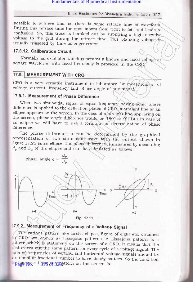
Basic Electronics for Biomedical lnstrumentation 3,17
possible to achieve this, so there rs some retrace time of waveform.During this retrace time the spot moves from right to left and leads toconfusion. So, this trace is blanked out by
"rpptyl.rg a high n_egativevoltage to the grid during the retrace time. This blanking voltage isusually triggered by time base generator.
17.8.12. Caliberation CircuitNormally an oscillator which generates a known
square waveform, with fixed frequency is providedand fixed voltage atin the CRO.
MEASUREMENT WITH GRO
cRo is a very versatile instrument in laboratory for measurement ofvoltage, current, frequency and phase angle of any signal.
17.9.1. Measurement of Phase Differencewhen two sinusoidal signal of equal frequency having some phase
difference is applied to the deflection plates of cRo, a straight line or anellipse appears on the screen. In the case of a straight line appearing onthe screen, phase angle difference would be 1g0" or 0.. But in casl ofan ellipse we will have to use a formula for determination of phasedifference.
The phase difference Q can be determined by the graphicalrepresentation of two sinusoidal wave with the output shown inlrgure 17.25 as an ellipse. The phase difference is measured by measuringdu and Du of the ellipse and can be calculated as follows:
d.phaseangle6=:^u
- lJu
I
(a) (b) (c)
Fig. 11.25.
17.9.2. Measurement of Frequency of a Voltage SignalThe various pattern like circle, ellipse, figure of eight etc. obtained':r cRo are known as Lissajous patterns. A Lissajous pattern is a
attern which is stationary on the screen of a cRo. It means that the;rot traces out the same pattern for every cycle of a voltage signal. The-atio of frequencies of vertical and horizontal voltage signils should be. rational or fractional number to have steady pattern. 5o the conditionr having a Lissajous pattern on the screen ts
Stud
y Mate
rial
Page No. 316 of 328.
Fundamentals of Biomedical Instrumentation

318 Fundamentals of Biomedical lnstrumentation
faAf*B
where A and B are integersLissajous patterns are of two types. Fjrst one is closed Lissajous
pattern and has no free end. The second one is open Lissajous patternand has free ends. Both types are shown in figure 77.26.
In a Lissajous pattern ratio of frequency of vertical signal to thefrequency of horizontal signal is equal to the ratio of positive Y peaks topositive X peaks in that Pattern
^.fa5O,t-Jx
Thus, by counting the positive Y-peaks and X-peaks on a
Lissajous pattern, ratio of frequencies of two voltage signals can be
determined.
(a) Closed Lissajuous patterns (b) Open Lissajous patterns
Fig. 17.26.
17.9.3. Measurement of Voltage and Current
Cathode ray oscilloscope can be used for measurement of voltage ci
any electrical signal as the deflection of the electrostatic beam is direcc--'
proportional to the deflection plate voltage.
For measurement of direct voltage, firstly the spot is centered on ti-rtscreen without applying any voltage signal to the deflection plates. The:d.irect voltage to be measured is applied between a pair of deflectii:plates and deflection of the spot is observed on the screen. The magniru,fu
of deflection multiplied by the deflection factor gives the value of dire"-voltage applied. Normally, the screen is calibrated for fixed operaurgconduction, so by reading the sca1e, voltage can be measured directll- aCRO.
In case of measurement of alternating voltage of sinusoidal '*-arE-
form, it is applied between a pair of deflection plates and the length
Iv
S
1i
1.
pflr
al
\I,t
CCtE
17.7
17.21a )
17.4.17.5.
the straight line is measured. Knowing the deflection sensitivity. :Stud
y Mate
rial
Page No. 317 of 328.
Fundamentals of Biomedical Instrumentation

Basic Electronics for Biomedical lnstrumentation 319
peak to peak value of voltage can be determined. The rms value of ac
voltage applied will be equal to this peak value divided by ZJZ for
sinusoidal waveform.For measurement of current, the current under measurement is
passed through a known non inductive resistance and the voltage dropacross non inductive resistance is usually amplified by a calibratedamplifier.
The operational and amplifier find an extensive use in the field ofinstrumentation specially in biomedicai electronics. Other importantdevice for finding out the value of output of the transducer aredifferent bridges.The cathode ray oscilloscope in a versatile eiectronic instrumentwhich in very useful for research and development as well as inrepair of all biomedical instruments. The cathode ray oscilloscope inparticular useful in the measurement of frequency, voltage current.It can show the resultant effect of various waveshapes. The workingprinciple of analogue type cathoCe ray oscilloscope with the help ofdetailed block diagram is explaineo in this chapter. The working andconstruction of cathode ray tube is also explained. The differentfluorescent materials are quoted on the cathode ray tube. The coatingof zinc orthosilicate gives a green trace which is very suitable forvisual observation. The coating of calciu5 tungstate gives a blue andultra.riolet radiation which is very suitabl'Cfor photographic recording.The coating of zinc sulphide with other materials giving a white lightsuitable for TV.
ercded
17.1. What is an op-amp? Explain working of an op-amp by drawing the blockdiagram.
L7.2. Draw the pin diagram of an op-amp IC 747.17.3. Draw the general block diagram of CRO and explain.17.4. E.xplain with block diagram the various part of a CRT.
17.5. Write short notes on the following:(r) Cathode ray tube(il) Electrostatic focussing(iil) Measurement of phase angle and frequency by a CRO
(iu) Measurement of voltage and current to CRO.
C(t&
e-oltr
SUMMARY
aaaStud
y Mate
rial
Page No. 318 of 328.
Fundamentals of Biomedical Instrumentation
(
l.\
(
Practicals in Biomedica!lnstrumentation
:s. fnside this chapter
BackgroundDevelopmentSpecihcation of RequirementMan InstrumentationProblems Encountered in Measuring a Living SystemAnatomy and PhysiologicalSummary
1.1.r.2.1.3.1.4.1.5.1.6.t.7 .
To Operate and Familiarize the following with Medical ElectronicsInstruments :
(a) B.P. Apparatus(b) ECC machine(c) Ventilator(@ Incubator(e) Boyle's Apparatus(fl Pulse O>rymeter
18.'1.1 B.P. Apparatus
{a) Apparatus(z) Sphygmomanometer.
(izJ Stethoscope
(b) PrincipleThe wall mounted Sphygmomanometer is shown in ligure 18.1 Tht
broncial artery in the hand is blocked by applying pressure higher tha:320
I
(uii,
,ui|Stud
y Mate
rial
Page No. 319 of 328.
Fundamentals of Biomedical Instrumentation

Practical in Biomedical lnstrumentation 3?.1
systolic pressure. The pressure in the cuff is released slowly and whenthe arterial pressure exeeds the pressure in the cuff the blood will startflowing. When the opening in the brachial artery is very small a turbul:nceis generated in the blood. This turbulence korotkoff sounds generatedcan be heard in stetloscope and the pressure by seeing the position ofmercury in sphygmometer is noted. The pressure is further reduced andwhen normal sound is heard the blood pressure is again measured.
(c) Procedure(zJ The cuff is wrapped on the left hand as shown in figure 18.1.
(ii) The cuff is inflated by applying pressure with the help of rubberbulb which work as a hand pressure pump. Before applying pressurethe release valve is opened.
(iiz) The cuff is inflated at least 40 mm of mercury more than thenormal systolic pressure. The normal value is 120 to 150. The cuffis inflated upto 2OO mm of mercury.
(iu) After the pressure reaches 200 mm of Hg the release valve isclosed.
(u) There will not be any sound heard in the stateloscope.(u'i) Slowly open the release valve and listen to the sound in the
stetloscope. When a gusting sound (due to flow of blood from asmall opening) in heard, close the release value and note down thereading from the mercury manometer. This reading shall be systolicblood pressure.
Mercurymanometer
Stethoscope placedat the elbow over thebranchial arteries
Fig. 18.1. Blood pressure measurement by sphygmanometer and stetloscope
(rzi) Open the release valve slowly. When the normal sound is heardclose the valve and note down the reading. This will be the diastollicblood pressure.
(uiiz) The blood pressure is taken 3 times and average value is the bloodpressure. This is written as systollic blood pressure/Diastollic bloodpressure. The normal value is 120/80 mm of Hg.St
udy M
ateria
l
Page No. 320 of 328.
Fundamentals of Biomedical Instrumentation

(14
(ii]4
322 Fundamentals of Biomedrcal lnstrumentation
18.1.2 EGG machine
(af Apparatus(rJ A hot stylus recorder based portable ECG machine with lead
selection switch.Patient Cable.Chart paper jelly tube, electrodeelectrodes for chest.
(b) Procedure(zJ The patient is asked to remove shoes and clothes. Patient is asked
to wear cotton gown which has opening from the front side. Patientis asked to lie on the wooden table.
(ii) Jelly is applied in small dots at the place of contact on the linksand chest positions V, to Vu.
(iii) The colours of the leads I to III are used to connect the electrodesto the hands, feet. The chest leads are connected.
(iu) The ECG machine is switched ON. The caliberation button is pressed,so that the chart paper moves and shows the 1 mv pulse standard.This is necessary to check the machine constancy of the pulse andamplitude.
(u) The lead selection switch is set to lead I position and the ECGpattern is traced on the graph paper. Take 3 or 4 readings.
(ui) The lead selector switch is set lead II and lead III.(uii) The selection switch is set for recording from auxiliary leads VR.
aVL, aVF.(uiizJ Connect the selector switch to V leads and obtain 6 records for V-
to Vu.
(c) Study of resultObserve the QRS complex of each of the 12 leads and observe the
there is no broadening or notched QRS.
18.1.3. Ventilator
(al Apparatus(z) Ventilator
(ir) Mask
(b) PrincipleThe ventilator is a direct transmission type. In this the gas in directll
delivered from the source of compressed gas to the patient throu-q:-mask. The system is shown in figure 18.2.
(c)'ProcedureThe direct power transmission type of ventilator along with patie:--:
mask is studied.
clips for limbs and suction cup
I
ilt,,
j
18.1
(o'l,(i,
(il)
lbl rI,
sunlevel:hroulhe r
(c) Pr
o
(ii)
18.1.5
ra) AlBo
Usi' :nou.:tent':5 ar= flov:ltted
-- prel
ibl PriTh
:,_-,dy p
r:- alfr richr_-.'erse
Stud
y Mate
rial
Page No. 321 of 328.
Fundamentals of Biomedical Instrumentation

Practical in Biomedical lnstrumentation 323
Exhaust
,/
18.1.4. lncubator
la) Apparatus(r) Incubator
(iz') Thermometer
PrincipleIncubators are useful for pre-mature new born babies who require
un light and are to be kept in constant temperature for properevelopment. The incubators are provided with the source of light andnrough a thermocouple ald heaters a constant temperative is maintained.he chamber is a transparent chamber for proper observation.
Procedure(z) Measure the temperature in the Incubator after putting oN the
instrument for some timer.(lzJ The temperature is measured at an interval of 30 minutes for
3-4 times.
8.1.5. Boyle's Apparatus
ApparatusBody plethysmograph
PrincipleThe functional residual capacity (FRC) can be measured by using ay plethysmograph given in figure 18.3. The body plethysmograph is
n air tight box in which the patient is asked to sit. The Boyle's lawhich states that at constant temperature the volume of gas variesr,,ersely with the pressure is used.
Using this law the ratio off the change in lung volume to changemouth pressure is used to determine the thoracic gas volume. Thetient breaties air from within the box through a tube which is fittedth an airflow transducer. A shutter is also provided which can blocke flow of air for some portion of the test pressure transducer whichfitted on the patient side of the tube (before the shutter) measure ther pressure in the breathing tube. The amount of air in the box
Fig. 18.2. Dlrect power transmission type ventilator with patient
Stud
y Mate
rial
Page No. 322 of 328.
Fundamentals of Biomedical Instrumentation

324 Fundamentals of Biomedical lnstrumentation
including the air in the lungairtight. When the patientvolume of patient in reduced
of the patient isexhale air fromand the pressure
constant as the bos -s
his lungs the bc:ris reduced in the bcr-
lb
AT
T}wlthgatal
uslac(tim
(cl
Fig. 18.3. Body plethysmograph using Boyle's apparatus
Conversely when the patient inhales, his body volume increases tincreases the pressure in the box. The functional residual capacitr' iis measured with the shutter in the breathing tube closed. With nnallowed to flow, the mouth pressure which is measured by a transc,can be assumed to be equal to lung pressure. The patient is ask:exhale at slow speed. As he does so the changes in mouth prwhich correspond to change in intrathoracic volume which ca:measured by the change in volume of the box. It is possible to caicintrathoracic volume. If the test is performed at the end of exp::level, the intrathoracic volume is equal to FRC.
(c) Procedure'Ihe experiment is performed
given in the principle. The patientis closed properly.
18.1.6. Pulse Oxymeter
after checking all the transd
(a) ApparatusDigital Handled Pulse Oxymeter
is asked to sit in the box and ti.e
T],::d tialm€
MtEp
:,::jnd
Pro
fhe-.'n.
.helhe:ing.. bl
'- a-uc
Stud
y Mate
rial
Page No. 323 of 328.
Fundamentals of Biomedical Instrumentation

(b) PrincipleThe efficiency of pulmonary gas exchange, the blood gas transport
and tissue oxygenation can be known by noninvasive blood gas monitoring.The normal technique to determine Llood gas is taking arterial bloodwhich are painful and give data which ls vata only for"the time whenthe sample is taken. The continuous monivasive monitoring of bloodgases alow the physician to recognize changes in tissue o>rygenation andtake corrective action at the earliast.
Blood oxygen saturation is measured by finger pulse photo signalusing red and Intra Red light through finger putp. ftrrs does not give veryaccurate result but gives the advantage of not taking arterial utooa -"rrytimes, which is painful and not practical in case oflritically ill patients.(c) Procedure
Practical in Biomedical lnstrumentation 225
{:i"W
18.2. EXPERIMENT 2
Measure the concentration of blood sugar in a Glucometer.Epxerimentation involves measurement of the brood fasting, post
rindial and random blood sugar in blood with the herp of a gluconater.Apparatus
(z) one touch ultra Gluconater of Johnson and Johnson make(ir) Regent strips.
tiir') Launcher
ProcedureThe fasting blood sample is tested after overnight fast. This is donely morning without taking anything.The reagent strip is fitted in the Gluconate as shown in figure 1g.5.The finger is pricked by a rancer on which needre is already fitted.
5-e finger is squeezed so that blood comes out of the finger. The portion:en blood has come out is put near the Grucometer. lt is sucked by
Fig. 18.4. Handled Pulse OximeteryThe finger is placed on the sensor and the reading of So, in percentage
and the pulse per minute may be noted. from the oigitut'Handled pulseoximeter shown in frgure 18.4.
t glucometer as soon as rt comes in contact with the reagent strip.
Stud
y Mate
rial
Page No. 324 of 328.
Fundamentals of Biomedical Instrumentation

326 Fundamentals of Biomedical lnstrumentation
1E
Inrde
(al
(bt
Fig. 18.5. Glucameter
The result is displayed on the glucometer in mg/dl'The range of fasting blood sign for a healthy person is less than 12-
If the blood sugar "*."d" this range then the person may be suffer:6
from diabeties and needs further investigation'The PP blood sugar is taken after takingTS gm of glucose and a::5,
a lapse of 2 hours. rrr" procedure is same as explained above. l-normal range should be between 72O to 150 mm/dl'
The random blood sugar is taken an5,time' The procedure is same
explained above. The normal range should be between l2O to 150 mm
18.3. I EXPERIMENT 3
Vlsual Testing Instruments. The invo:
(i1
(iii
t,i
i
iu)
(u)
,4i4
Study of Audio Meter andoperation and familiarization
(ctl Apparatus(zJ Audiometer(ir) Earphone(zii) Recorder driven by stepper motor'(iu) Response switch for the patient
(b) Procedure(z') The air-conduction earphone is fitted to the patient's ear.
(izJ The andiometer generates a pure-tone signal, which is con:
to the lead of earPhone.
connected to the switch which is connected to the attenuatora continuous record of the patients intensity adjustmenraudiogram chart.
(iu) The aud,iogram gives the response of the ears
frequency. This is irnportant in advising a patientof heaving aid.
with audio meter.-.,,1
:rl'I
.it IStr-q
dE
C
ol:rlCJ
at:hC}:(-Re
(iir) The patient is asked to press a response switch as soon as th:is hlard and release the same when no tone is heard' -{
with reato use -":rtSt
udy M
ateria
l
Page No. 325 of 328.
Fundamentals of Biomedical Instrumentation

I
Practical in Biomedical lnstrumentation 327
EXPERIMENT 4
Operate and. familiarize with defibrillator and bed side monitor. Thisinvolves operation and study of the main features of differents type ofdefrillators and bed side monitors.
(a) Apparatus(rJ Portable defrillator unit
(irJ Bed side monitor with different input transducers and leads.
(b) ProcedureStudy and operate defibrillator :
(z) Study the dehbrillator as per type of discharge, i.e., d.c. defibrillator,dual peak d.c. def,rbrillator truncated. d.c. defibrillator.
(ii) Check whether defibrillator is provided with an ECG monitor.(ifi) Check whether defibrillator is synchronised type. In synchronised
type, the application of the shock pulse of defibrillation is avoidedfor 25-30 ms after the R ware, if exists.
(iu) Check whether the defibrillated is mains operated or only usespower for charging internal batteries. If so remove main beforestarting the operation of defrillator.
(u) Check the type of paddles. Check about the insulation provided onthe cables and paddles.
(uz) Check about the push switches provided on the paddles.(uii) Now charge the unit and connect the paddles on conducting foam
pad kept on a metal plate over on insulating table top. Observe thedischarge sound.
(uiir) Note how long it taken for the charge to build up again for applyinga second shock.
(rx) If the unit is battery operated, remove the mains connection anduse it from battery power. Observe how much battery voltage dropsafter each shock is delivered.
(x) Note the time taken by the batteries to fully charge from the mains.
(c) Study and Operate the bedside monitor :
(r') Study the picture tube of bedside monitor. This has a non tradedisplay. The non fade display is capable of displaying graphs likeECG wareform as well as the information of heart rate in numerals.
(izJ Check that all the transducers like pulse sensor which is clampedon the index finger is fatted. The other transducer connected is tomeasure temperature and indirect measurement of blood press.ure.
(iirJ Check all the leads are connected. The ECG probes are conne-cted at the proper place i.e. on hands, leg and chest after applyingthe gel.
(iu) Check all the parameters are visible on the bed side monitor likeECG, heart rate, temperatory blood pressure and pulse rate.
(u) Remove one of the transduces like pulse rate transducer. Thisaction should sound an alarm is the bed side monior.St
udy M
ateria
l
Page No. 326 of 328.
Fundamentals of Biomedical Instrumentation

328 Fundamentals of Biomedical lnstrumentation
\tlll
i
.t
(ufi rf the heart rate is below 40 and above 150 the bed side monitorshould sound an alarm to check this connect a pulse generatorand vary the pulse from 30 to i6o. The alarm should souncl uptoa pulse of 4o pulse/mm and should not sound between 40 to 150pulse minute. If should again sound if the pulse rate is more than150 pulse/mm.
Measurement of Leakage current with the help of Safety Anaryzer. rtinvolves measurement of the leakage current in the chassis of thebiomedical equipment and patient leads.
(a) Apparatus(l) Digital Multimeter
(lz) A Capacitor
(b) ProcedureThe following procedure is employed for the measurement of leakage
current in the chaise of biomedical equipment :
(z) connect the combination of resistance, capacitor which simulatethe heart as a function of frequency. The capacitor of 0.15 pF inparallel with a resistance of 1k ohm on digital multimeter as shownin figure 18.6.
(li) connect the electromedical equipment to power source (mains) andmeasure leakage without putting the power switch to oN position.
(iir) Measure the leakage by putting the power switch to oN position.(lu) Do the same measurement by reversing the polarity i.e. connectins
phase and neutral in the reverse direction.
Digitalvoltmeter Digital
voltmeter
(a) (b)
Fig. 18.6. (a) Principle of leakage current meter (b) measurement ofchassis leakage Gurrent using leakage meter
(u) The leakage current from the chassis should not exeeC 5OO m -\ rthe equipment is intended to be touched by the patient and sho::,:not exeed 100 mA it is intended to be touched by the patient
The following procedure should be applied to measure leakage curre:ilfor patient connected leads.
(i) The patient leakage current is determined by connecting ::rmeasuring instrument between earth and one of the lead.
;
1g^6
\equil
TPGi (:qultr
oGA
(iil(iu) -
(u) |
tui) 1
,-,ii) Iiia F
r-r) E
-Y) U
-.r) o:l Lt
-:1 Ar-:lIn,rAs.r Ne', Ht
Test point
Stud
y Mate
rial
Page No. 327 of 328.
Fundamentals of Biomedical Instrumentation

Practical in Biomedical lnstrumentation 329
(irJ The leakage currerrt in patient leads should not be more than50 mA.
Visit to hospital for exposure of various medical electronic related:quipment.
The student should be taken in group to sorrre leading hospitals like?GI or any hospital of the Medical college. The main medical electronics:quipment they must see include the following faciJities:
(0 C.A.T. (Computerised Axial Tomography) Scan(r4 MRI (Magnetic Resonance Imaging)(iir) Ultrasound Machine with probes.(iu) X-Ray Machine(u) Stress Thalium Machine
(ut') Trade Mill Testing Machine.uli) Echocardiography MachineiirJ Electro Cardiographrx) Electro Encelephograph(x) Ultrasonic Diathermy Machinerz) Ophthalmoscope,:zi) LASOR Equipment for Ophthalmoscopy.
,rirJ Autoanalyzer for blood test.,ru) Inclubator,:u) Aspirator:d Nebulizer'izJ Humidifier.
aa]
EXPERIMENT 6
Stud
y Mate
rial
Page No. 328 of 328.
Fundamentals of Biomedical Instrumentation