BID NOTICES MUST BE MAILED A MINIMUM OF 10
265
Page 1 of 36 Staff: California Uniform Public Construction Cost Accounting Act Bid Template (NOTE: BID NOTICES MUST BE MAILED A MINIMUM OF 10 DAYS PRIOR TO BID OPENING. THEY DO NOT NEED TO BE ADVERTISED, NOR DO WE NEED PRIOR BOARD APPROVAL.
-
Upload
khangminh22 -
Category
Documents
-
view
3 -
download
0
Transcript of BID NOTICES MUST BE MAILED A MINIMUM OF 10

Page 1 of 36
Staff: California Uniform Public Construction Cost
Accounting Act Bid Template
(NOTE: BID NOTICES MUST BE MAILED A MINIMUM OF 10 DAYS PRIOR TO BID OPENING. THEY DO NOT NEED TO BE
ADVERTISED, NOR DO WE NEED PRIOR BOARD APPROVAL.
Page 2 of 36
STOCKTON UNIFIED SCHOOL DISTRICT
INFORMAL BID PRICING REQUEST
DISTRICT WIDE DIGITAL CABLING, PHASE IV
BID NO. 902
Stockton Unified School District Facilities Planning Department
1944 N. El Pinal Drive Stockton, CA 95205
209-933-7045

Page 3 of 36
STOCKTON UNIFIED SCHOOL DISTRICT (“DISTRICT” or “OWNER”)
DISTRICT WIDE DIGITAL CABLING, PHASE IV, BID NO. 902
TABLE OF CONTENTS
DESCRIPTION Informal Notice to Bidder Instructions to Bidder Proposal Form Noncollusion Declaration Fingerprint Requirements & Certifications Specifications Construction Services Agreement Sub-Contractor Listing Job Reference Listing Performance Bond Payment Bond
Page 4 of 36
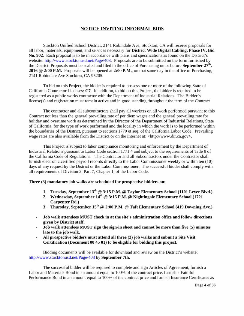
NOTICE INVITING INFORMAL BIDS
Stockton Unified School District, 2141 Robindale Ave, Stockton, CA will receive proposals for all labor, materials, equipment, and services necessary for District Wide Digital Cabling, Phase IV, Bid No. 902. Each proposal is to be in accordance with plans and specifications as found on the District’s website: http://www.stocktonusd.net/Page/403. Proposals are to be submitted on the form furnished by the District. Proposals must be sealed and filed in the office of Purchasing on or before September 27th, 2016 @ 2:00 P.M. Proposals will be opened at 2:00 P.M., on that same day in the office of Purchasing, 2141 Robindale Ave Stockton, CA 95205.
To bid on this Project, the bidder is required to possess one or more of the following State of California Contractor Licenses: C7. In addition, to bid on this Project, the bidder is required to be registered as a public works contractor with the Department of Industrial Relations. The Bidder’s license(s) and registration must remain active and in good standing throughout the term of the Contract.
The contractor and all subcontractors shall pay all workers on all work performed pursuant to this Contract not less than the general prevailing rate of per diem wages and the general prevailing rate for holiday and overtime work as determined by the Director of the Department of Industrial Relations, State of California, for the type of work performed and the locality in which the work is to be performed within the boundaries of the District, pursuant to sections 1770 et seq. of the California Labor Code. Prevailing wage rates are also available from the District or on the Internet at: <http://www.dir.ca.gov>.
This Project is subject to labor compliance monitoring and enforcement by the Department of
Industrial Relations pursuant to Labor Code section 1771.4 and subject to the requirements of Title 8 of the California Code of Regulations. The Contractor and all Subcontractors under the Contractor shall furnish electronic certified payroll records directly to the Labor Commissioner weekly or within ten (10) days of any request by the District or the Labor Commissioner. The successful bidder shall comply with all requirements of Division 2, Part 7, Chapter 1, of the Labor Code. Three (3) mandatory job walks are scheduled for prospective bidders on:
1. Tuesday, September 13th @ 3:15 P.M. @ Taylor Elementary School (1101 Lever Blvd.) 2. Wednesday, September 14th @ 3:15 P.M. @ Nightingale Elementary School (1721
Carpenter Rd.) 3. Thursday, September 15th @ 2:00 P.M. @ Taft Elementary School (419 Downing Ave.)
- Job walk attendees MUST check in at the site’s administration office and follow directions
given by District staff. - Job walk attendees MUST sign the sign-in sheet and cannot be more than five (5) minutes
late to the job walk. - All prospective bidders must attend all three (3) job walks and submit a Site Visit
Certification (Document 00 45 01) to be eligible for bidding this project.
Bidding documents will be available for download and review on the District’s website: http://www.stocktonusd.net/Page/403 by September 7th.
The successful bidder will be required to complete and sign Articles of Agreement, furnish a
Labor and Materials Bond in an amount equal to 100% of the contract price, furnish a Faithful Performance Bond in an amount equal to 100% of the contract price and furnish Insurance Certificates as

Page 5 of 36
set forth. The Board reserves the right to reject any and all bids and/or waive any irregularity in any bid
received.
BOARD OF EDUCATION Stockton Unified School District
By: Steve L. Breakfield
Director, Facilities & Planning
Page 6 of 36
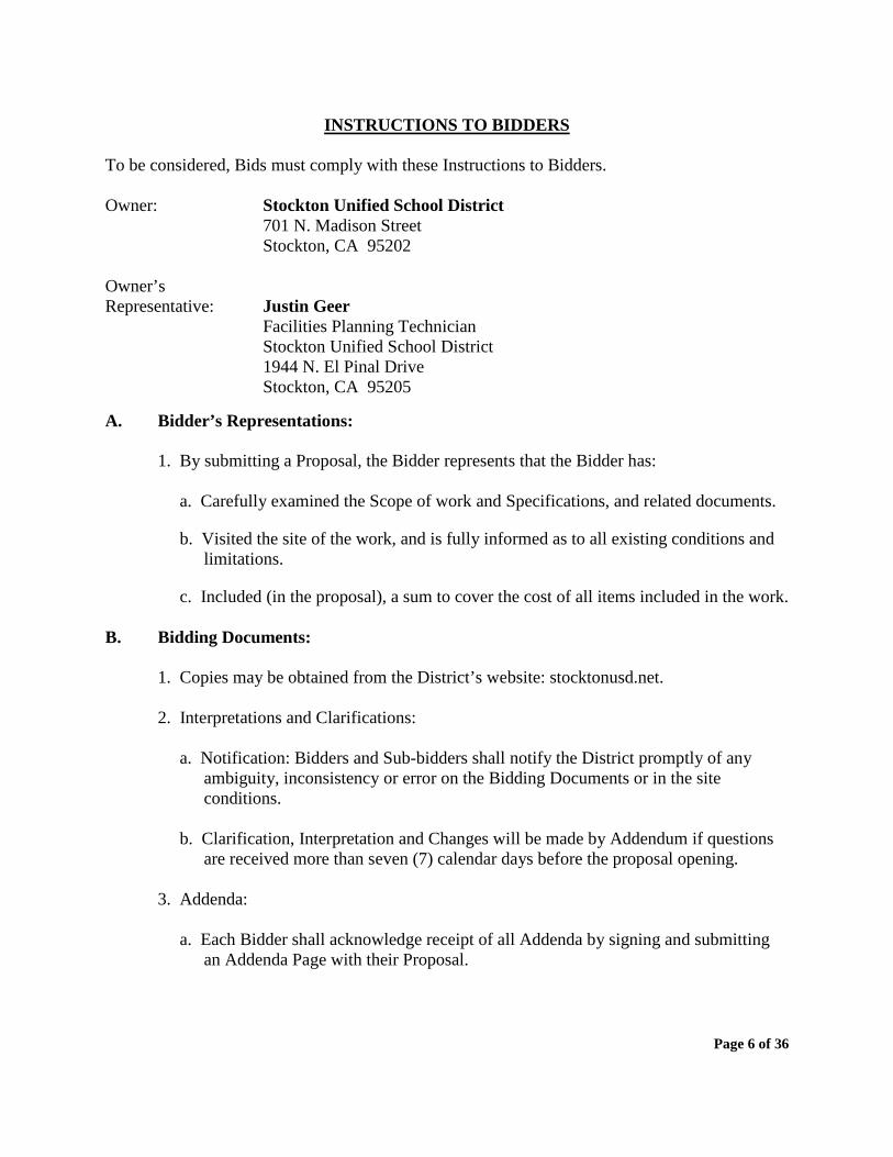
INSTRUCTIONS TO BIDDERS
To be considered, Bids must comply with these Instructions to Bidders. Owner: Stockton Unified School District
701 N. Madison Street Stockton, CA 95202
Owner’s Representative: Justin Geer Facilities Planning Technician
Stockton Unified School District 1944 N. El Pinal Drive Stockton, CA 95205
A. Bidder’s Representations:
1. By submitting a Proposal, the Bidder represents that the Bidder has:
a. Carefully examined the Scope of work and Specifications, and related documents.
b. Visited the site of the work, and is fully informed as to all existing conditions and limitations.
c. Included (in the proposal), a sum to cover the cost of all items included in the work. B. Bidding Documents:
1. Copies may be obtained from the District’s website: stocktonusd.net.
2. Interpretations and Clarifications:
a. Notification: Bidders and Sub-bidders shall notify the District promptly of any ambiguity, inconsistency or error on the Bidding Documents or in the site conditions.
b. Clarification, Interpretation and Changes will be made by Addendum if questions
are received more than seven (7) calendar days before the proposal opening.
3. Addenda:
a. Each Bidder shall acknowledge receipt of all Addenda by signing and submitting an Addenda Page with their Proposal.

Page 7 of 36
C. Bidding Procedure:
1. Proposal Forms: Submit Bids on the “Proposal Form” provided in this Proposal Packet.
a. Blanks: Fill in by typewriter or print in ink.
b. Sums: Show in both words and figures. If there is a discrepancy between the two, the amount written in words shall govern.
c. Additions, alterations or erasures: Must be initialed by the signer of the Proposal.
d. Alternates: If listed, shall be bid. If there is no change to the Base Bid, then enter “No Change”.
e. Bidder’s Legal Name: The Bidder shall be the legal name of the Company name.
f. Type of Organization: Indicate if the Bidder is a sole proprietor, a partnership, a corporation, or some other legal entity.
g. Signature: Person or persons legally authorized to bind the Bidder to a contract. If the Bidder is a corporation, include a corporate resolution authorizing signature of the document.
2. Bid Security:
a. Bidders security (bid bond) is not required.
b. Successful bidder shall provide payment and performance bonds as required. 3. Submission of Proposals:
a. Submit proposal and other documents in a sealed envelope.
b. Deliver to the location designated prior to time and date indicated. Late proposals
will not be considered. Extension may be granted to all bidders by Addendum prior to proposal opening only at District’s discretion.
c. Bidder is responsible for timely delivery of Proposal. d. Oral, telephonic, telegraphic or facsimile bids are invalid and will not be considered.
4. Modification or Withdrawal of Bids:
a. Proposal may not be modified, withdrawn or canceled by the Bidder after the time
given as the deadline for submitting the bids.
Page 8 of 36
D. Consideration of Bids:
1. Opening of Bids: Bids will be opened publicly and read aloud unless it is stated in the Advertisement or Invitation to Bid that Bids will be opened privately.
2. Rejection of Bids: The Owner has the right to reject:
a. Any or all Bids.
b. A Proposal which does not include required data.
c. A Proposal which is incomplete or irregular.
d. A Proposal submitted by a non-responsible bidder.
3. Acceptance of Bids:
a. The Owner intends to award a Contract to the lowest responsive and responsible
Bidder as long as the Proposal has been submitted as per the Proposal Documents and does not exceed the available funds. District rejection rights still apply.
b. The Owner has the right to accept Alternates in any order or combination, and to determine the low Bidder based on the sum of the Base Bid plus accepted Alternates.
E. Post Bid Information:
1. Submittals: a. Within seven (7) days after the notice of award, the Bidder shall submit the
following to the District:
1) A list of work to be performed by the Bidder’s own forces; and 2) A list of work to be performed by the Bidder’s subcontractors.
b. The Bidder must establish the reliability and responsibility of the persons and companies proposed to furnish and perform the Work.
c. If the Owner has a reasonable objection to any proposed persons or companies,
then the Owner will notify the Bidder prior to award of the Contract. If there is an objection, then the Bidder may either:
1) Withdraw the Bid; or
2) Submit an acceptable substitute with an adjustment in the proposal price.
Page 9 of 36
* The owner may accept the adjusted proposal price or disqualify the Bidder.
d. The acceptable proposed persons or companies proposed by the Bidder must be used on the Work, and shall not be changed except with the written consent of the Owner and, if Owner is utilizing an Architect, the Architect.
F. Performance Bond and Labor and Material Payment Bond:
1. Bond Requirements: The Bidder shall furnish bonds as required.
2. Time of Delivery: The Bidder shall deliver the bonds to the Owner prior to the commencement of Work with the executed Contract.
G. Form of Agreement Between Owner and Contractor:
1. Form To Be Used: Requirements included in attached Sample contract must be considered when providing bid.
2. Contractor must provide fully executed agreement, certificate of insurance, and bonds within ten (10) calendar days after Notice of Award.

Page 10 of 36
STOCKTON UNIFIED SCHOOL DISTRICT
BID/PROPOSAL FORM – BID NO. 902 CLOSING DATE: September 27th, 2016 @ 2:00 P.M.
Stockton Unified School District Purchasing Department 2141 Robindale Ave. Stockton, CA 95205 The undersigned, doing business under the firm name of _______________________________, having carefully examined the Notice to Bidders, the Instructions to Bidders, the Sample Construction Agreement, the Specifications, the Fingerprint Requirements, and all of the contract documents for District Wide Digital Cabling Project, Phase IV, Bid No. 902 proposes to perform the contract, including all of its component parts, and to furnish all materials and labor called for by them for the entire order, including all taxes as follows: AMOUNT OF Proposal $ __________________ The undersigned has reviewed the Work outlined in the Contract Documents and fully understands the scope of Work required in this Proposal, understands the construction and project management function(s) is described in the Contract Documents, and that each Bidder who is awarded a contract shall be in fact a prime contractor, not a subcontractor, to the District, and agrees that its Proposal, if accepted by the District, will be the basis for the Bidder to enter into a contract with the District in accordance with the intent of the Contract Documents. The undersigned specifically acknowledges and understands that if it is awarded the Contract, that it shall perform the Work of the Project while complying with all requirements of the Department of Industrial Relations. The undersigned represents that it is competent, knowledgeable, and has special skills with respect to the nature, extent, and inherent conditions of the Work to be performed. The undersigned further acknowledges that there are certain peculiar and inherent conditions existent in the construction of the Work that may create, during the Work, unusual or peculiar unsafe conditions hazardous to persons and property. The undersigned expressly acknowledges that it is aware of such peculiar risks and that it has the skill and experience to foresee and to adopt protective measures to adequately and safely perform the Work with respect to such hazards. Contractors License Number ___________. The License expiration date ___________ . Public Works Contractor Registration Number _______________. I hereby certify under penalty of perjury under the laws of the State of California that the information, representations, and certifications submitted herein is true and correct.
Page 11 of 36
SUBMITTED BY: ____________________________________ ______________________________________ COMPANY NAME ADDRESS ____________________________________ ______________________________________ SIGNATURE TYPE OR PRINT SIGNATURE NAME ____________________________________ ______________________________________ TITLE PHONE NUMBER / FAX NUMBER ____________________________________ TAXPAYER'S IDENTIFICATION NO. ____________________________________ DATE Bidders must submit bids on standardized forms provided in this bid packet.

Page 12 of 36
NONCOLLUSION DECLARATION TO BE EXECUTED BY BIDDER AND SUBMITTED WITH BID
The undersigned declares:
I am the_ of , the party making the foregoing bid. [Title] [Name of Bidder] The bid is not made in the interest of, or on behalf of, any undisclosed person, partnership, company, association, organization, or corporation. The bid is genuine and not collusive or sham. The bidder has not directly or indirectly induced or solicited any other bidder to put in a false or sham bid. The bidder has not directly or indirectly colluded, conspired, connived, or agreed with any bidder or anyone else to put in a sham bid, or to refrain from bidding. The bidder has not in any manner, directly or indirectly, sought by agreement, communication, or conference with anyone to fix the bid price of the bidder or any other bidder, or to fix any overhead, profit, or cost element of the bid price, or of that of any other bidder. All statements contained in the bid are true. The bidder has not, directly or indirectly, submitted his or her bid price or any breakdown thereof, or the contents thereof, or divulged information or data relative thereto, to any corporation, partnership, company, association, organization, bid depository, or to any member or agent thereof, to effectuate a collusive or sham bid, and has not paid, and will not pay, any person or entity for such purpose.
Any person executing this declaration on behalf of a bidder that is a corporation, partnership, joint venture, limited liability company, limited liability partnership, or any other entity, hereby represents that he or she has full power to execute, and does execute, this declaration on behalf of the bidder.
I declare under penalty of perjury under the laws of the State of California that the foregoing is true and correct and that this declaration is executed on , 20__ at , . [City] [State]
Date: Proper Name of Bidder: Signature: Print Name: Title:
Page 13 of 36
FINGERPRINTING
Fingerprinting Requirements The bill known as the Michelle Montoya School Safety Act, added Section 45125.1 to the Education Code. The code section applies to any entity that has a contract with a school district, county board of education, or county superintendent of schools to provide services such as janitorial, administrative, landscape, transportation, food-related or similar services. The inclusion of “similar services” is interpreted as extending application of the section to other types of contract services not expressly listed, where the contractors will be working on school grounds. If the employees of such an entity may have any contact with pupils, those employees shall submit (or have submitted) their fingerprints in a manner authorized by the Department of Justice, together with a fee determined by that department. The Department of Justice shall ascertain whether the individual has been arrested or convicted of any crime. If the Department determines that the individual has been convicted of a violent or serious felony, or has a pending criminal proceeding for such a felony, it must notify you, the employer, of that information. A violent felony is any felony listed in Penal Code Section 667.5(c) and a serious felony is any felony listed in Penal Code Section 1192.7(c).
Important Restrictions An entity to which this law applies may not permit an employee to come in contact with pupils until the Department of Justice has ascertained that the employee has not been convicted of a violent or serious felony. An entity to which this law applies may not permit an employee who has been convicted of a violent or serious felony to come in contact with pupils. Certification to the Governing Board Education Code Section 45125.1(f) provides that the entity must certify in writing to the governing board of the school district that none of its employees who may come in contact with pupils have been convicted of a violent or serious felony. In addition, the entity must provide to the board a list of the names of its employees who may come in contact with pupils, so that the board can provide relevant lists of employee names to the appropriate school sites within its jurisdiction. Exceptions These requirements do not apply to an entity providing services to a school district in an emergency or exceptional situation, such as when pupil health or safety is endangered or when repairs are needed to make school facilities safe and habitable. These requirements do not apply when the school district determines that the employees of the entity will have only limited contact with pupils. In making this determination, the district shall consider the totality of the circumstances, including factors such as the length of time the contractors will be on school grounds, whether pupils will be in proximity with the site where the contractors will be working, and whether the contractors will be working by themselves or with others. Time for Compliance An entity which had a contract with a school district as described above must complete these requirements prior to commencing work on school grounds.
Page 14 of 36
Applicability to Your Entity Our records indicate that your entity currently has a contract with this district to provide services and/or deliver products. For this reason, you must submit Contractor’s Certificate Form, which is attached certifying to the Purchasing Department, that none of your employees who may come in contact with pupils have been convicted of a violent or serious felony, or that one of the exceptions from these requirements apply, and forward to the Purchasing Department for review.
FINGERPRINTING INSTRUCTIONS
The Department of Justice has requested all contractors who require fingerprinting under the Michelle Montoya School Safety Act (Education Code Section 45125.1) to prepare and submit the required documents in the following sequences of events. 1. Complete form entitled “Request for Authorization to Receive State Summary Criminal History Information” and have the School District sign in the area of the form as indicated. The form will be reviewed by the Justice Department, signed and returned to the contractor along with a packet of information and instructions on how “Fingerprints” should be prepared for the Justice Department to process. 2. The Department of Justice will review the form, sign and return to the contractor along with a packet of information and instructions on how to submit fingerprints for approval. 3. The Justice Department will review fingerprints for State Compliance and if approved, will submit for processing. Note: If documents are incomplete, the Justice Department will return them to the contractor for clarification which could delay processing. Calling the Department of Justice at (916) 227-3829 before submitting fingerprints to assure all requirements have been completed would be recommended. 4. The Justice Department will issue a report of fingerprints submitted to the contractor. The contractor will complete the form entitled “Contractor’s Certificate” and attach a list of employees who have been cleared by the Justice Department and submit it to the School District for their files.

Page 15 of 36
STOCKTON UNIFIED SCHOOL DISTRICT CONTRACTOR’S CERTIFICATE
REGARDING FINGERPRINTING REQUIREMENTS Michelle Montoya School Safety Act (Education Code Section 45125.1)
The undersigned does hereby certify to the governing board of the District as follows: That I am a representative of the Contractor currently under contract with the District; that I am familiar with the facts herein certified; and that I am authorized and qualified to execute this certificate on behalf of Contractor. Contractor certifies that it has taken at least one of the following actions with respect to the construction Project that is the subject of the Contract (check all that applies):
The Contractor has complied with the fingerprinting requirements of Education Code section 45125.1 with respect to all Contractor’s employees and all of its Subcontractors’ employees who may have contact with District pupils in the course of providing services pursuant to the Contract, and the California Department of Justice has determined that none of those employees has been convicted of a felony, as that term is defined in Education Code section 45122.1. A complete and accurate list of Contractor's employees and of all of its subcontractors' employees who may come in contact with District pupils during the course and scope of the Contract is attached hereto; and/or
Pursuant to Education Code section 45125.2, Contractor has installed or will install, prior to
commencement of Work, a physical barrier at the Work Site, that will limit contact between Contractor's employees and District pupils at all times; and/or
Pursuant to Education Code section 45125.2, Contractor certifies that all employees will be under the
continual supervision of, and monitored by, an employee of the Contractor who the California Department of Justice has ascertained has not been convicted of a violent or serious felony. The name and title of the employee who will be supervising Contractor's employees and its subcontractors' employees is
Name: Title:
The Work on the Contract is at an unoccupied school site and no employee and/or subcontractor or supplier
of any tier of Contract shall come in contact with the District pupils. Contractor’s responsibility for background clearance extends to all of its employees, Subcontractors, and employees of Subcontractors coming into contact with District pupils regardless of whether they are designated as employees or acting as independent contractors of the Contractor.
Date: Proper Name of Contractor: Signature: Print Name: Title:
(In accordance with Section 45125.1 of the California Education Code, the above certificate must be signed and filed with the awarding body prior to performing any work under this contract.)

Page 16 of 36
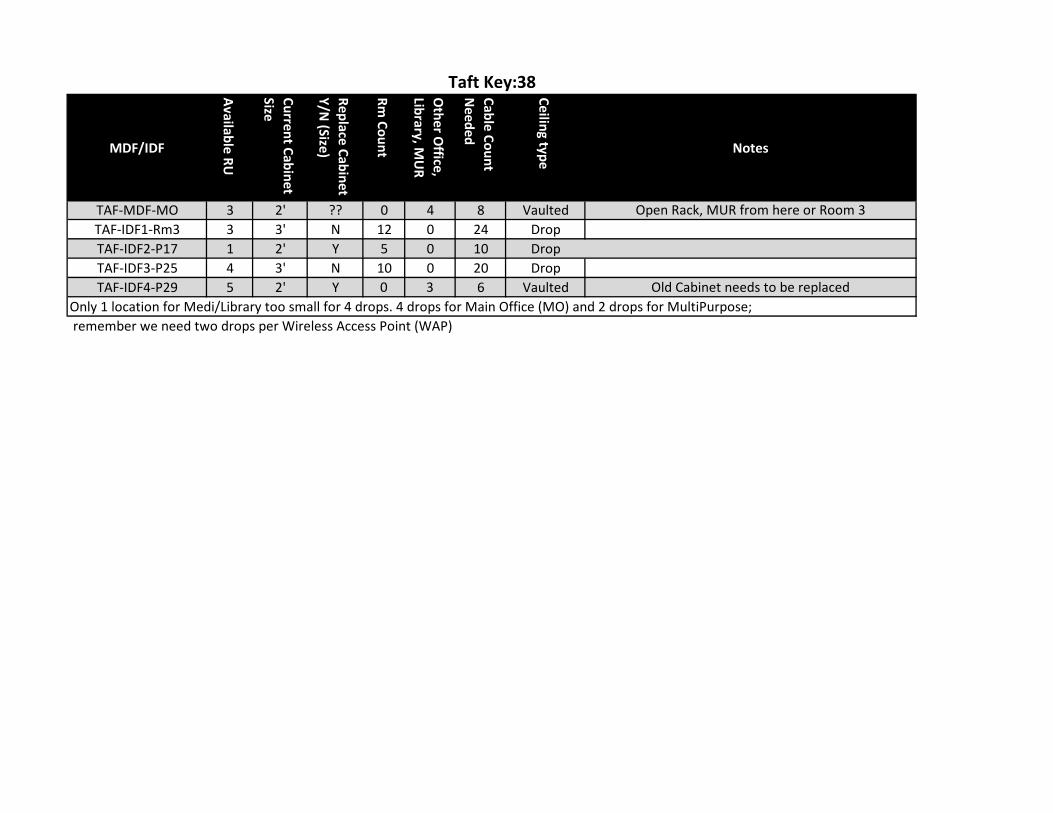
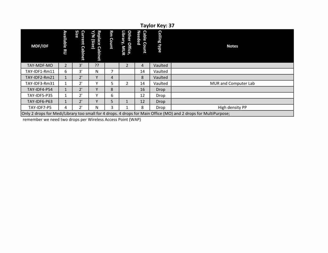
BID NO 902 – SCOPE OF WORK AND SPECIFICATIONS
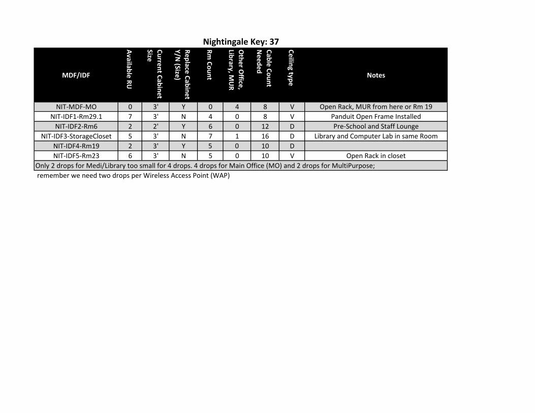
MDF/IDF
Available RU
Current Cabinet Size
Replace Cabinet Y/N
(Size)
Rm Count
Other O
ffice, Library, M
UR
Cable Count N
eeded
Ceiling type Notes
NIT-MDF-MO 0 3' Y 0 4 8 V Open Rack, MUR from here or Rm 19NIT-IDF1-Rm29.1 7 3' N 4 0 8 V Panduit Open Frame Installed
NIT-IDF2-Rm6 2 2' Y 6 0 12 D Pre-School and Staff LoungeNIT-IDF3-StorageCloset 5 3' N 7 1 16 D Library and Computer Lab in same Room
NIT-IDF4-Rm19 2 3' Y 5 0 10 DNIT-IDF5-Rm23 6 3' N 5 0 10 V Open Rack in closet
Only 2 drops for Medi/Library too small for 4 drops. 4 drops for Main Office (MO) and 2 drops for MultiPurpose;
Nightingale Key: 37
remember we need two drops per Wireless Access Point (WAP)
MDF/IDF
Available RU
Current Cabinet Size
Replace Cabinet Y/N
(Size)
Rm Count
Other O
ffice, Library, M
UR
Cable Count N
eeded
Ceiling type Notes
TAF-MDF-MO 3 2' ?? 0 4 8 Vaulted Open Rack, MUR from here or Room 3TAF-IDF1-Rm3 3 3' N 12 0 24 DropTAF-IDF2-P17 1 2' Y 5 0 10 DropTAF-IDF3-P25 4 3' N 10 0 20 DropTAF-IDF4-P29 5 2' Y 0 3 6 Vaulted Old Cabinet needs to be replaced
Only 1 location for Medi/Library too small for 4 drops. 4 drops for Main Office (MO) and 2 drops for MultiPurpose;
Taft Key:38
remember we need two drops per Wireless Access Point (WAP)
MDF/IDF
Available RU
Current Cabinet Size
Replace Cabinet Y/N
(Size)
Rm Count
Other O
ffice, Library, M
UR
Cable Count N
eeded
Ceiling type Notes
TAY-MDF-MO 2 3' ?? 2 4 VaultedTAY-IDF1-Rm11 6 3' N 7 14 VaultedTAY-IDF2-Rm21 1 2' Y 4 8 VaultedTAY-IDF3-Rm31 1 2' Y 5 2 14 Vaulted MUR and Computer LabTAY-IDF4-P54 1 2' Y 8 16 DropTAY-IDF5-P35 1 2' Y 6 12 DropTAY-IDF6-P63 1 2' Y 5 1 12 DropTAY-IDF7-P5 4 2' N 3 1 8 Drop High density PP
Only 2 drops for Medi/Library too small for 4 drops. 4 drops for Main Office (MO) and 2 drops for MultiPurpose;
Taylor Key: 37
remember we need two drops per Wireless Access Point (WAP)
Project Name Architect’s Project # STOCKTON UNIFIED SCHOOL DISTRICT
CONCRETE 03 00 00 - 1 Revised 3/2011
SECTION 03 00 00 – CONCRETE 1. GENERAL 1.1 RELATED DOCUMENTS:
Drawings and general provisions of Contract, including General and Supplementary Conditions and Division 1 Specification Sections, apply to work of this section.
1.2 DESCRIPTION OF WORK:
A. The extent of concrete work shown on drawings includes, but is not limited to:
1. Foundations, footings, grade beams, and slabs. 2. Columns and column bases, and column footings. 3. Concrete fill at metal decking. 4. Outdoor Platform 5. Ground-mounted Equipment pads and Utility slabs.
B. Related work, specified elsewhere:
1. Resilient Flooring - Section 09 65 00.
1.3 QUALITY ASSURANCE:
A. Codes and Standards: Comply with provisions of following codes, specifications and standards, except where more stringent requirements are shown or specified.
1. California Building Code – Title 24, Part 2, CCR-2001 Edition with State of California
2001 Amendments. 2. ACI 301 “Specifications for Structural Concrete for Buildings.” 3. ACI 318 “Building Code Requirements for Reinforced Concrete.”
4. Concrete Reinforcing Steel Institute, “Manual of Standard Practice.”
B. Concrete Testing Service: The Owner shall employ a testing laboratory acceptable to
Architect to perform material evaluation tests. Design of concrete mixes shall be by Contractor (see 2.5).
C. Materials and installed work may require testing and re-testing, as directed by Architect, at
anytime during progress of work. Allow free access to material stockpiles and facilities. Tests, not specifically indicated to be done at Owner’s expense, including re-testing of rejected materials and installed work, shall be paid by Owner, but backcharged to the Contractor.
D. Testing shall be performed per Section 3.14 of these Specifications and Section 1929A, Title
24.
Project Name Architect’s Project # STOCKTON UNIFIED SCHOOL DISTRICT
CONCRETE 03 00 00 - 2 Revised 3/2011
1.4 SUBMITTALS
A. Product Data: Submit manufacturer’s product data with application and installation instructions for proprietary materials and items, including reinforcement and forming accessories, admixtures, patching compounds, waterstops, joint systems, curing compounds, dry-shake finish materials, and others as requested by Architect.
B. Shop Drawings; Reinforcement: Submit shop drawings for fabrication, bending, and
placement of concrete reinforcement. Comply with ACI 315 “Manual of Standard Practice for Detailing Reinforced Concrete Structures” showing bar schedules, stirrup spacing, diagrams of bent bars, and arrangement of concrete reinforcement. Include special reinforcement required and openings through concrete structures.
C. Laboratory Test Reports: Submit laboratory test reports for concrete materials and mix
design test as specified.
D. Material Certificates: Provide materials certificates in lieu of materials laboratory test reports when permitted by Architect. Material certificates shall be signed by manufacturer and Contractor, certifying that each material item complies with, or exceeds specified requirements.
1.5 WARRANTY
A. Full System 10 year labor & material warranty from the manufacturer of the Sealer / Hardener / Curing Compound concrete surface treatment applied the day of the concrete pour.
1. A Creteseal technician(s) will be on site the day of the concrete pour to either apply
or train others in the application, returning on every installation thereafter to document and verify that proper procedures are followed. The presence of the manufacturer’s representative will prevent human error in application and place full responsibility for correct application and product performance.
2. When a floor covering is installed on a below grade, on grade, or above grade
concrete slab treated with Creteseal CS2000 according to manufacturer’s instruction, Creteseal shall warrant the floor covering system against failure due to moisture migration or moisture-born contaminates for a period of (10) years from the date of original installation. The warranty shall cover all labor and materials needed to replace all floor coverings, adhesives, patching compounds that fail due to moisture vapor emission & alkalinity.
2. PRODUCTS 2.1 FORM MATERIALS
A. Forms for exposed finished concrete: Unless otherwise indicated, construct formwork for exposed concrete surfaces with plywood, metal, metal-framed plywood faced or other acceptable panel-type materials, to provide continuous, straight, smooth, exposed surfaces. Furnish largest practicable sizes to minimize number of joints and to conform to joint system shown on drawings. Provide form material with sufficient thickness to withstand pressure of newly-placed concrete without bow or deflection.

Project Name Architect’s Project # STOCKTON UNIFIED SCHOOL DISTRICT
CONCRETE 03 00 00 - 3 Revised 3/2011
1. Use plywood complying with U.S. Product Standard PS-1 “B-B (Concrete Form Plywood,” Class I, Exterior Grade or better, mill-oiled and edge-sealed, with each piece bearing legible inspection trademark.
B. Forms for Unexposed Finish Concrete: Form concrete surfaces which will be unexposed in
finished structure with plywood, lumber, metal or other acceptable material. Provide lumber dressed on at least 2 edges and, one side for tight fit.
C. Forms for Textured Finish (TX-Fn) Concrete: Form textured finished concrete surfaces with
units of face design, size, arrangement and configuration as shown on drawings or as required to match Architect’s control sample. Provide solid backing and form supports to ensure stability of textured form liners.
D. Form Coatings: Provide commercial formulation form-coating compounds that will not bond
with, stain nor adversely affect concrete surfaces, and will not impair subsequent treatments of concrete surfaces.
E. Fiberglass Re-usable Column Forms: 1. Manufacturer: MFG - MOLDED FIBER GLASS CONCRETE FORMS COMPANY (Main Office) (Western Office) 55 Fourth Avenue 9400 Holly Road
Union City, PA 16438 Adelanto, CA 92301 (814) 438-3841 (800) 824-3389
2. Materials: Two-piece re-usable Fiberglass form, custom made, with bolted
steel-reinforced flanges, including hardware. Contractor to determine quantity needed to meet construction schedule. Follow Manufacturer’s recommendations for preparation, set-up, and installation, including form coatings and release agents.
2.2 REINFORCING MATERIALS
A. Reinforcing Bars (ReBar): ASTM A 615, Grade 60, deformed, #4 and larger. For #3 use Grade 40. All weldable reinforcement shall conform to ASTM A-706.
B. Steel Wire: ASTM A 82, plain, cold-drawn, steel.
C. Welded Wire Fabric (WWF): ANSI/ASTM A 185, welded steel wire fabric.
D. Supports for Reinforcement: Provide supports for reinforcement including bolsters, chairs,
spacers and other devices for spacing, supporting and fastening reinforcing bars and welded wire fabric in place. Use wire bar type supports complying with CRSI recommendations, unless otherwise acceptable.
1. For slabs-on-grade, use supports with sand plates or horizontal runners where base
material will not support chair legs. 2. For exposed-to-view concrete surfaces, where legs of supports are in contact with
forms, provide supports with legs which are plastic protected (CRSI, Class 1) or stainless steel protected (CRSI, Class 2).
2.3 CONCRETE MATERIALS:
A. Portland Cements

Project Name Architect’s Project # STOCKTON UNIFIED SCHOOL DISTRICT
CONCRETE 03 00 00 - 4 Revised 3/2011
ASTM C 150 and Section 1903 A.2, Title 24, Type II (low alkali) unless otherwise acceptable to Architect. Use one brand of cement throughout project, unless otherwise acceptable to Architect.
B. Normal Weight Aggregates: ASTM C33 and Section 1903 A.3, Title 24 but also those which
have shown by special test or actual service to produce concrete of adequate strength and durability may be used when acceptable to the Architect and DSA. The nominal maximum size of aggregate shall not exceed one inch.
C. Water: Potable
D. Air-Entraining Admixture: ASTM C 260
E. Calcium chloride not permitted.
2.4 RELATED MATERIALS:
A. Waterstops: Provide flat, dumbbell-type or centerbulb-type waterstops at construction joints and other joints as shown. Size to suit joints. 1. Rubber waterstops: Corps of Engineers CRD-C 513. 2. Polyvinyl chloride (PVC) waterstops: Corps of Engineers CRD-C 572.
B. Moisture Barrier: Provide moisture barrier cover over prepared base material where
indicated. Use only materials which are resistant to decay when tested in accordance with ANSI/ASTM E 154, as follows:
1. Water resistant barrier paper consisting of heavy Kraft papers laminated together
with glass fiber reinforcement and over-coated with black polyethylene on each side, MoistStop, approximate average thickness 12 mil.
C. Chemical Hardener (ChHd-Fn): Colorless aqueous solution containing a blend of
magnesium fluosilicate and zinc fluosilicate combined with a wetting agent, containing not less than 2 ls. of fluosilicates per gallon.
D. Moisture-Retaining Cover: One of the following, complying with ANSI/ASTM C 171.
1. Waterproof paper 2. Polyethylene film
3. Polyethylene-coated burlap
E. Liquid Membrane-Forming Curing Compound: Liquid-type membrane-forming curing
compound complying with ANSI/ASTM C 309, Type I, Class A unless other type acceptable to Architect. Do not use liquid curing compound in areas to receive flooring, roofing, or other finish materials applied directly to concrete.
1. Products: Subject to compliance with requirements, provide one of the following:
Project Name Architect’s Project # STOCKTON UNIFIED SCHOOL DISTRICT
CONCRETE 03 00 00 - 5 Revised 3/2011
“Masterseal;” Master Builders “A-H 3-Way;” Anti-Hydro Waterproofing Co. “Enclosure;” Euclid Chemical Co. “Clear Seal;” W.R. Grace “Sealkure;” Toch Div. – Carboline “Kure-N-Seal;” Sonneborn-Contech. “Polyclear;” Upco Chemical/USM Corp. “L&M Cure;” L&M Construction Chemicals “Klearseal;” Setcon Industries “LR-151;” Protex Industries “Hardtop;” Gifford – Hill
F. Sealer / Hardener / Curing Compound: Concrete surface treatment applied the day of the concrete pour for concrete slabs either on grade, below grade or above grade receiving resilient flooring such as sheet vinyl, vinyl composition tile, rubber, wood flooring, carpet, epoxy coatings and overlays.
1. Product to be compatible with all floor finish materials. Product must fully penetrate into
the concrete surface leaving no product on top of the concrete surface that would interfere with the finish flooring materials to bond directly with the concrete surface.
NOTE: Resin or epoxy type vapor systems are not equal, as they are not compatible with flooring adhesives.
2. Product must have at least 5 years documented successful history in controlling
moisture vapor emission and alkalinity from damaging floor coverings.
3. ASTM C1315 Type 1 Class A, ASTM C309Type 1 Class A, penetrating product to have no less than 34% solids content, leaving no sheen, volatile organic compound (VOC) content rating as required to suit regulatory requirements.
The product Creteseal CS2000 (No known equal) Manufactured by:
CRETESEAL
P.O. Box 26279 Santa Ana, CA 92799 Phone: (800) 278-4273 Fax: (714) 429-9895
G. Epoxy Adhesive: 100% solids, two component material suitable for use on dry or damp
surfaces.
1. Products Subject to compliance with requirements, provide one of the following:
“Thiopoxy;” W.R. Grace “Sikadur Hi-Mod;” Sika Chemical Corp. “Euco Epoxy;” Eulid Chemical Co.
H. Sand Cushion over Moisture Barrier
1. Sand may be “Tracy Sand” which does not contain more than one percent (1 percent) by weight of such deleterious substances, such as clay lumps, shale, schist, alkali, mica, coated grains or soft flaky pieces.

Project Name Architect’s Project # STOCKTON UNIFIED SCHOOL DISTRICT
CONCRETE 03 00 00 - 6 Revised 3/2011
I. Base: ¾-inch crushed rock, No. 4 x ¾-inch gravel, or permeable aggregate complying with
Caltrans Standard Specifications, Section 68, Class 1, Type B.
J. Patching Mortar:
1. Manufacturer: Thoro System Products, Newark CA (510) 796 9911 2. Product: “Thorite”: Apply in strict compliance with manufacturer’s printed
instructions. 2.5 PROPORTIONING AND DESIGN OF MIXES:
A. Prepare design mixes for each type and strength of concrete by either laboratory trial batch or field experience methods as specified in ACI 301 and 1905A.2.3 Method B or Method C, Title 24. If trial batch method used, use an independent testing facility acceptable to Architect for preparing and reporting proposed mix designs. The testing shall not be the same as used for field quality control testing unless otherwise acceptable to Architect.
B. Submit written reports to Architect of each proposed mix for each class of concrete at least
15 days prior to start of work. Do not begin concrete production until mixes have been reviewed by Architect.
C. Design Mixes to provide concrete with the following properties, as indicated on drawings and
schedules, in accordance with Title 24, Section 1905A.2.3, Method B or Method C.
1. Class A & B - 3000 psi 28-day compressive strength. All structural concrete (interior concrete slabs on grade, concrete slabs over metal deck, and foundations).
2. Class C - 3000 psi 28-day compressive strength. Exterior concrete slabs on ground.
D. Adjustment to Concrete Mixes: Mix design adjustments may be requested by Contractor when characteristics of materials, job conditions, weather, test results, or other circumstances warrant; at no additional cost to Owner and as accepted by Architect. Laboratory test data for revised mix design and strength results must be submitted to and accepted by Architect before using in work.
E. Slump Limits: Proportion and design mixes to result in corporate slump at point of
placement as follows:
1. Ramps and sloping surfaces: Not more than 3”. 2. Reinforced foundation systems: Not less than 3” and not more than 4”.
3. Other concrete: Not less than 3” and not more than 4”.
2.6 CONCRETE MIXES
A. Ready-Mix Concrete: Comply with requirements for ANSI/ASTM C 94, and as herein specified.
1. Delete references for allowing additional water to be added to batch for material with
sufficient slump. Addition of water to the batch will not be permitted.
Project Name Architect’s Project # STOCKTON UNIFIED SCHOOL DISTRICT
CONCRETE 03 00 00 - 7 Revised 3/2011
2. During hot weather, or under conditions contributing to rapid setting of concrete, a
shorter mixing time than specified in ANSI/ASTM C 94 may be required.
3. When air temperature is between 85 ° F (30 ° C) and 90° F (32 ° C), reduce mixing and delivery time from 1 ½ hours to 75 minutes, and when air temperature is above 90 ° F (32 ° C), reduce mixing and delivery time to 60 minutes.
3. EXECUTION 3.1 FORMS:
A. Design, erect, support, brace and maintain formwork to support vertical and lateral loads that might be applied until such loads can be supported by concrete structure. Construct formwork so concrete members and structures are of correct size, shape, alignment, elevation and position.
B. Design formwork to be readily removable without impact, shock or damage to cast-in place
concrete and adjacent materials.
C. Construct forms to sizes, shapes, lines and dimensions shown, and to obtain accurate alignment, location, grades, level and plumb work in finished structures. Provide for openings, offsets, sinkages, keyways, recesses, moldings, rustifications, reglets, chamfers, blocking, screeds, bulkheads, anchorages and inserts, and other features required work. Use selected materials to obtain required finishes. Solidly butt joints and provide backup at joints to prevent leakage of cement paste.
D. Fabricate forms for easy removal without hammering or prying against concrete surfaces.
Provide crush plates or where stripping may damage cast concrete surfaces. Provide top forms for inclined surfaces where slope is too steep to place concrete with bottom forms only. Kerf wood inserts for forming keyways, reglets, recesses, and the like, to prevent swelling and for easy removal.
E. Provide temporary openings where interior area of formwork is inaccessible for cleanout, for
inspection before concrete placement. Securely brace temporary openings and set tightly to forms to prevent loss of concrete mortar. Locate temporary openings on forms at inconspicuous locations.
F. Chamfer exposed corners and edges as indicated, using wood, metal PVC or rubber
chamfer strips fabricated to provide uniform smooth lines and tight edge joints.
G. Form Ties: Factory-fabricated, adjustable-length, removable or snap-off metal ties, designed to prevent form deflection, and to prevent spalling concrete surfaces upon removal.
1. Unless otherwise indicated, provide ties so portion remaining within concrete after
removal is at least 1 ½” inside concrete.
H. Provisions for Other Trades: Provide openings in concrete formwork to accommodate work of other trades. Determine size and location of openings, recesses and chases from trades providing such items. Accurately place and securely support items built into forms.
I. Cleaning and Tightening: Thoroughly clean forms and adjacent surfaces to receive
concrete. Remove chips, wood, sawdust, dirt, or other debris just before concrete is placed.

Project Name Architect’s Project # STOCKTON UNIFIED SCHOOL DISTRICT
CONCRETE 03 00 00 - 8 Revised 3/2011
Retightening forms and bracing after concrete placement is required to eliminate mortar leaks and maintain proper alignment.
J. Vapor Barrier: Place vapor barrier per manufacturer’s recommendations. Seal all breaks,
penetrations, and joints of vapor barrier with tape or joint compound over lapped edges as required for airtight condition.
3.2 PLACING REINFORCEMENT:
A. Comply with Concrete Reinforcing Steel Institute’s recommended practice for “Placing
Reinforcing Bars,” for details and methods of reinforcement placement and supports, and as herein specified.
B. Clean reinforcement of loose rust and mill scale, earth, ice, and other materials which reduce
or destroy bond with concrete. C. Accurately position, support and secure reinforcement against displacement by formwork,
construction, or concrete placement operations. Locate and support reinforcing by metal chairs, runners, bolsters, spacers, and hangers, as required.
D. Place reinforcement to obtain at least minimum coverages for concrete protection. Arrange
space and securely tie bars and bar supports to hold reinforcement in position during concrete placement operations. Set wire ties so ends are directed into concrete, not toward exposed concrete surfaces.
E. Install welded wire fabric in as long lengths as practical. Lap adjoining pieces at least one
full mesh and lace splices with wire. Offset end lap in adjacent widths to prevent continuous laps in either direction.
3.3 JOINTS
A. Construction Joints: Locate and install construction joints, which are not shown on drawings, so as not to impair strength and appearance of the structure, as acceptable to Architect. Horizontal construction joints between successive concrete pours shall be properly cleaned by sandblasting 5 days minimum after initial concrete placement.
B. Provide keyways at least 1 ½” deep in construction joints in walls, slabs and between walls
and footings; accepted bulkheads designed for this purpose may be used for slabs.
C. Place construction joints perpendicular to the main reinforcement. Continue reinforcement across construction joints.
D. Contraction (Control) Joints in Slab-on-Ground: Construct contraction joints in slabs-on-
ground to form panels of patterns as shown. Use inserts ¼” wide x ¼ of slab depth, unless otherwise indicated.
E. Form contraction joints by inserting premolded hardboard or fiberboard strip into fresh
concrete until top surface of strip is flush with slab surface. After concrete has cured, remove inserts and clean groove of loose debris.
1. Contraction joints may be formed by saw cuts as soon as possible after slab
finishing as may be safely done without dislodging aggregate.
Project Name Architect’s Project # STOCKTON UNIFIED SCHOOL DISTRICT
CONCRETE 03 00 00 - 9 Revised 3/2011
2. Joint sealant material is specified in Division 7 sections of these specifications. 3.4 INSTALLATION OF EMBEDDED ITEMS:
A. General: Set and build into work anchorage devices and other embedded items required for other work that is attached to, or supported by, cast-in-place concrete. Use setting drawings, diagrams, instructions and directions provided by suppliers of items to be attached thereto.
B. Edge Forms and Screed Strips for Slabs: Set edge forms or bulkheads and intermediate
screed strips for slabs to obtain required elevations and contours in finished slab surface. Provide and secure units sufficiently strong to support types of screed strips by use of strike-off templates or accepted compacting type screeds.
3.5 PREPARATION OF FORM SURFACES:
A. Coat contact surfaces of forms with a form-coating compound before reinforcement is placed.
B. Thin form-coating compounds only with thinning agent of type, and in amount, and under
conditions of form coating compound manufacturer’s directions. Do not allow excess form-coating material to accumulate in forms or to come in contact with concrete surfaces against which fresh concrete will be placed. Apply in compliance with manufacturer’s instructions.
3.6 CONCRETE PLACEMENT:
A. Preplacement Inspection, Notification: Before placing concrete, inspect and complete formwork installation, reinforcing steel, and items to be embedded or cast-in. Notify other crafts to permit installation of their work; cooperate with other trades in setting such work. Notify Architect and DSA by Fax 48 hours in advance of placement. Moisten wood forms immediately before placing concrete where form coatings are not used.
B. Coordinate the installation of joint materials and moisture barriers with placement of forms
and reinforcing steel.
C. General: Comply with ACI 304, and as herein specified. Deposit concrete continuously or in layers of such thickness that no concrete will be placed on concrete which has hardened sufficiently to cause the formation of seams or planes of weakness. If a section cannot be placed continuously, provide construction joints as herein specified. Deposit concrete as nearly as practical to its final location to avoid segregation.
D. Placing Concrete in Forms: Deposit concrete in forms in horizontal layers no deeper than
24” and in a manner to avoid inclined construction joints. Where placements consist of several layers, place each layer while preceding layer is still plastic to avoid cold joints.
E. Consolidate placed concrete by mechanical vibrating equipment supplemented by hand-
spading, rodding or tamping. Use equipment and procedures for consolidation of concrete in accordance with ACI recommended practice.
F. Do not use vibrators to transport concrete inside forms. Insert and withdraw vibrators
vertically at uniformly spaced locations no farther than visible effectiveness of machine. Place vibrators to rapidly penetrate placed layer and at least 6” into preceding layer. Do not insert vibrators into lower layers of concrete that have begun to set. At each insertion, limit
Project Name Architect’s Project # STOCKTON UNIFIED SCHOOL DISTRICT
CONCRETE 03 00 00 - 10 Revised 3/2011
duration of vibration to time necessary to consolidate concrete and complete embedment of reinforcement and other embedded items without causing segregation of mix.
G. Placing Concrete Slabs: Deposit and consolidate concrete slabs in a continuous operation,
within limits of construction joints, until the placing of panel or section is completed.
H. Consolidate concrete during placing operations so that concrete is thoroughly worked around reinforcement and other embedded items and into corners.
I. Bring slab surface to correct level with straightedge and strike off. Use bull floats or darbies
to smooth surface, free humps or hollows. Do not disturb slab surfaces prior to beginning finishing operations.
J. Maintain reinforcing in proper position during concrete placement operations.
K. Cold Weather Placing: Protect concrete work from physical damage or reduced strength
which could be caused by frost, freezing actions, or low temperatures, in compliance with ACI 306 and as herein specified.
When air temperature has fallen to or is expected to fall below 40 ° F (4 ° C), uniformly heat water and aggregates before mixing to obtain a concrete mixture temperature of not less than 50 ° F (10 °C), and not more than 80° F (27 ° C) at point of placement.
L. Do not use frozen materials or materials containing ice or snow. Do not place concrete or
frozen subgrade on subgrade containing frozen materials. M. Do not use calcium chloride, salt and other materials containing antifreeze agents or
chemical accelerators, unless otherwise accepted in mix design.
N. Hot Weather Placing: When hot weather conditions exist that would seriously impair quality and strength of concrete, place concrete in compliance with ACI 305 and as herein specified.
O. Cool ingredients before mixing to maintain concrete temperature at time of placement below
90 ° F (32 ° C). Mixing water may be chilled, or chopped ice may be used to control temperature provided water equivalent of ice is calculated to total amount of mixing.
P. Cover reinforcing steel with water-soaked burlap if it becomes too hot, so that steel
temperature will not exceed the ambient air temperature immediately before embedment in concrete.
Q. Wet forms thoroughly before placing concrete.
3.7 FINISH OF FORMED SURFACES:
A. Rough Form Finish (RFm-Fn): For formed concrete surfaces not exposed-to-view in the finish work or by other construction, unless ortherwise indicated. This is the concrete surface having work having texture imparted by form facing material used, with tie holes and defective areas repaired and patched and fins and other projections exceeding ¼” in height rubbed down or chipped off.
B. Smooth Form Finish (SmFm-Fn): For formed concrete surfaces exposed-to-view, or that are
to be covered with a coating material applied directly to concrete, or a covering material applied directly to concrete, such as waterproofing, dampproofing, painting or other similar

Project Name Architect’s Project # STOCKTON UNIFIED SCHOOL DISTRICT
CONCRETE 03 00 00 - 11 Revised 3/2011
system. This is as-cast concrete surface obtained with selected form facing material, arranged orderly and symmetrically with a minimum of seams. Repair and patch defective areas with fins or other projections completely removed and smoothed.
C. Grout Cleaned Finish (GRTCl-Fn): Provide grout cleaned finish to scheduled concrete
surfaces which have received smooth form finish (SmFm-Fn) treatment.
1. Combine one part portland cement to 1 ½ parts fine sand by volume, and mix with water to a consistency of thick paint. Use of proprietary additives may be used at Contractor’s option. Blend standard portland cement and white portland cement, amount determined by trial patches, so that final color of dry grout will closely match adjacent surfaces.
2. Thoroughly wet concrete surfaces and apply grout to coat surfaces and fill small
holes. Remove excess grout by scraping and rubbing.
D. Related Uniformed Surfaces: At tops of walls, horizontal offsets surfaces occurring adjacent to formed surfaces, strike-off smooth and finish with a texture matching adjacent formed surfaces. Continue final surface treatment of formed surfaces uniformly across adjacent unformed surfaces, unless otherwise indicated.
3.8 MONOLITHIC SLAB FINISHES:
A. Scratch Finish (Scr-Fn): Apply scratch finish to monolithic slab surfaces that are to receive concrete floor topping or mortar setting beds for tile, portland cement, terrazzo, and other bonded applied cementitious finish flooring material, and as otherwise indicated.
After placing slabs, plane surface to a tolerance not exceeding ½” in 10’ when tested with a 10’ straightedge. Slope surfaces uniformly to drains where required. After leveling, roughen surface before final set, with stiff brushes, brooms or rakes.
B. Float Finish (Flt-Fn): Apply float finish to monolithic slab surfaces to receive trowel finish
and other finishes as hereinafter specified, and slab surfaces which are to be covered with membrane or elastic waterproofing, membrane or elastic roofing, or sand-bed terrazzo, and as otherwise indicated.
After screeding, consolidating, and leveling concrete slabs, do not work surface until ready
for floating. Begin floating when surface water has disappeared or when concrete has stiffened sufficiently to permit operation of power-driven floats, or both. Consolidate surfaces with power-driven floats or by hand-floating if area is small or inaccessible to power units. Check and level surface plane to a tolerance not exceeding ¼” to 10’ when tested with a 10’ straightedge. Cut down high spots and fill low spots. Uniformly slope surfaces to drains. Immediately after leveling, refloat surface to a uniform, smooth, granular texture.
C. Trowel Finish (Flt-Fn): Apply trowel finish to monolithic slab surfaces to be exposed to view,
and slab surfaces to be covered with resilient flooring, paint or other thin film finish coating system.
After floating, begin first trowel finish operation using a power-driven trowel. Begin final troweling when surface produces a ringing sound as trowel is moved over surface. Consolidate concrete surface by final hand-troweling operation, free of trowel marks, uniform in texture and appearance, and with a surface plane tolerance not exceeding 1/8” in 10’
Project Name Architect’s Project # STOCKTON UNIFIED SCHOOL DISTRICT
CONCRETE 03 00 00 - 12 Revised 3/2011
when tested with a 10’ straightedge. Grind smooth surface defects which telegraph through applied floor covering system.
D. Non-Slip Broom Finish (NSBrm-Fn): Apply non-slip broom finish to exterior concrete
platforms, steps and ramps, and elsewhere as indicated. Immediately after trowel finishing, slightly roughen concrete surface by brooming with fiber
bristle broom perpendicular to main traffic route. Coordinate required final finish with Architect before application.
E. Chemical-Hardener Finish (Ch-Hd-Fn): Apply chemical-hardener finish to interior concrete
floors where indicated. Apply liquid chemical-hardener after complete curing and drying of the concrete surface. Dilute liquid hardener with water, and apply in three coats; first coat, ½ strength; second coat, ½ strength; third coat, 2/3 strength. Evenly apply each coat, and allow 24 hours for drying between coats. 1. Apply proprietary chemical hardeners, in accordance with manufacturer’s printed
instructions. 2. After final coat of chemical-hardener solution is applied and dried, remove surplus
hardener by scrubbing and mopping with water. 3.9 CONCRETE CURING AND PROTECTION:
A. General: Protect freshly placed concrete from premature drying and excessive cold or hot temperatures. 1. Start initial curing as soon as free water has disappeared from concrete surface after
placing and finishing. Weather permitting; keep continuously moist for not less than 7 days.
2. Begin final curing procedures immediately following initial curing and before
concrete has dried. Continue final curing for at least 7 days in accordance with ACI 301 procedures. Avoid rapid drying at end of final curing period.
B. Curing Methods: Perform curing of concrete by concrete surface treatment, moist curing, by
moisture-retaining cover curing, by curing compound, and by combinations thereof, as herein specified.
C. Concrete Surface Treatment (Creteseal CS2000 / Sealer / Hardener / Curing Compound)
applied the day of the concrete pour prior to any other chemical treatments on concrete slabs either on grade, below grade or above grade receiving resilient flooring such as sheet vinyl, vinyl composition tile, rubber, wood flooring, carpet, epoxy coatings and overlays.
1. Manufacturer technician will be on site the day of the concrete pour to provide technical
services in application, document & return on every application thereafter to verify that proper procedures are followed.
2. Apply CS2000 to the concrete slabs as soon as final finishing operations are complete
and the concrete has hardened sufficiently to sustain foot traffic without damage. Spray Apply CS2000 at the rate of 200 square feet per gallon. If puddling or bird bathing occurs, lightly broom product evenly over the substrate until product has completely penetrated the surface. If within 2 hours after initial application areas are subjected to
Project Name Architect’s Project # STOCKTON UNIFIED SCHOOL DISTRICT
CONCRETE 03 00 00 - 13 Revised 3/2011
heavy rainfall and puddling occurs, reapply CS2000 product to these areas as soon as weather condition allow.
3. If cold weather prevents the application of product the same day of the concrete pour the
product may be applied the following day as directed by Creteseal technician.
D. Provide moisture curing by following methods. (For concrete slabs not receiving resilient flooring, carpet, or epoxy coatings and overlays.) 1. Keep concrete surface continuously wet by covering with water. 2. Continuous water-fog spray.
3. Covering concrete surface with specified absorptive cover, thoroughly saturating
cover with water and keeping continuously wet. Place absorptive cover to provide coverage of concrete surfaces and edges, with a 4” lap over adjacent absorptive covers.
E. Provide moisture-cover curing as follows: (For concrete slabs not receiving resilient flooring,
carpet, or epoxy coatings and overlays.) Cover concrete surfaces with moisture-retaining cover for curing concrete, placed in widest practical widths with sides and ends lapped at least 3” and sealed by waterproof tape or adhesive. Immediately repair any holes or tears during curing period using cover material and waterproof tape.
F. Provide curing compound to slabs as follows: Apply specified curing and sealing compound
to concrete slabs not receiving a floor covering as soon as final finishing operations are complete (within 2 hours). Apply uniformly in continuous operation by power-spray or roller in accordance with manufacturer’s directions. Recoat areas subjected to heavy rainfall within three hours after initial application. Maintain continuity of coating and repair damage during curing period.
WARNING:
Do not use membrane curing compounds on surfaces which are to be covered with coating material applied directly to concrete, liquid floor hardener, waterproofing, damp-proofing, membrane roofing, flooring, painting, and other coatings and finish materials, unless otherwise acceptable to Architect, and is accepted in writing by the installer of the finish material. In the event such curing compounds are installed, the Contractor shall bear all responsibility for non-compatibility of concrete surfaces with finish materials, and the required mitigation.
G. Curing Unformed Surface: Cure unformed surfaces, such as slabs, floor topping, and other
flat surfaces by application of appropriate curing compound.
1. Final cure concrete surfaces to receive liquid floor hardener finish flooring, roofing, or other direct-application, material, by use of moisture-retaining cover, unless otherwise approved per the section above.
3.10 REMOVAL OF FORMS
Project Name Architect’s Project # STOCKTON UNIFIED SCHOOL DISTRICT
CONCRETE 03 00 00 - 14 Revised 3/2011
A. Formwork not supporting weight of concrete, such as sides of beams walls, columns, and similar parts of the work, may be removed after cumulatively curing at not less than 50 ° F (10°C) for 24 hours after placing concrete, provided concrete is sufficiently hard to not be damaged by form removal operations, and provide curing and protection operations are maintained.
B. Formwork supporting weight of concrete, such as beam soffits, joints, slabs and other
structural elements, may not be removed in less than 14 days and until concrete has attained design minimum 28-day compressive strength. Determine potential compressive strength of in-place concrete by testing field-cured specimens representative of concrete location or members.
C. Form facing material may be removed 4 days after placement, only if shores and other
vertical supports have been arranged to permit removal of form material without loosening or disturbing shores and supports.
3.11 RE-USE OF FORMS
A. Clean and repair surfaces of forms to be re-used in work. Split, frayed, delaminated or otherwise damaged form facing material will not be acceptable for exposed surfaces. Apply new form coating compound as specified for new formwork.
B. When forms are extended for successive concrete placement, thoroughly clean surfaces,
remove fins and laitance, and tighten forms to close joints. Align and secure joint to avoid offsets. Do not use “patched” forms for exposed concrete surfaces, except as acceptable to Architect.
3.12 MISCELLANEOUS CONCRETE ITEMS:
A. Filling-In: Fill-in holes and openings left in concrete structures for passage of work by other trades, unless otherwise shown or directed, after work of other trades are in place. Mix, place and cure concrete as herein specified, to blend with in-place construction. Provide other miscellaneous concrete filling shown or required to complete work.
B. Curbs: Provide monolithic finish to interior curbs by stripping forms while concrete is still
green and steel-trowelling surfaces to a hard, dense finish with corners, intersections and terminations slightly rounded.
C. Equipment Bases and Foundations: Provide machine and equipment bases and
foundations, as shown on drawings. Set anchor bolts for machines and equipment to template at correct elevations, complying with certified diagrams or template at correct elevations, complying with certified diagrams or templates of manufacturer furnishing machines and equipment.
D. Steel Pan Stairs: Provide concrete fill for steel pan stair treads and landings and associated
items. Cast-in safety inserts and accessories as shown on drawings. Screed, tamp, and finish concrete surfaces as scheduled.
3.13 CONCRETE SURFACE REPAIRS:
A. Patching Defective Areas: Repair and patch defective areas with cement mortar immediately after removal of form, when acceptable to Architect.

Project Name Architect’s Project # STOCKTON UNIFIED SCHOOL DISTRICT
CONCRETE 03 00 00 - 15 Revised 3/2011
Cut out honeycomb, rock pockets, voids over ¼” in any dimension, and holes left by the rods and bolts, down to solid concrete but in no case to a depth of less than 1”. Make edges of cuts perpendicular to the concrete surface. Thoroughly clean, dampen with water and brush-coat the area to be patched with specified bonding agent. Place patching mortar after bonding compound has dried.
B. For exposed-to-view surfaces, blend white portland cement and standard portland cement so that, when dry, patching mortar will match color surrounding. Provide test areas at inconspicuous location to verify mixture and color match before proceeding with patching. Compact mortar in place and strike-off slightly higher than surrounding surface.
C. Repair of Formed Surfaces: Remove and replace concrete having defective surfaces if
defects cannot be repaired to satisfaction of Architect. Surface defects, such, include color and texture irregularities, cracks spalls, air bubbles, honeycomb, rock pockets, fins and other projections on surface, and stains and other discolorations that cannot be removed by cleaning. Flush out form tie holes, fill with dry pack mortar, or precast cement cone plugs secured in place with bonding agent.
D. Repair concealed formed surfaces, where possible, that contain defects that affect the
durability of concrete. If defects cannot be repaired, remove and replace concrete.
E. Repair of Unformed Surfaces: Test unformed surfaces, such as monolithic slabs, for smoothness and verify surface plane to tolerances specified for each surface and finish. Correct low and high areas as herein specified. Test unformed surfaces sloped to drain to trueness of slope, in addition to smoothness, using a template having required slope.
F. Repair finished unformed surfaces that contain defects which affect durability of concrete.
Surface defects, as such, include crazing, cracks in excess of 0.01” wide or which penetrate to reinforcement or completely through non-reinforced sections regardless of width, spalling, pop-outs, honeycomb, rock pockets, and other objectionable conditions.
G. Correct high areas in unformed surfaces by grinding, after concrete has cured at least fourteen days.
H. Correct low areas in unformed surfaces during, or immediately after completion of surface
finishing operations by cutting out low areas and replacing with fresh concrete. Proprietary patching compounds may be used when acceptable to Architect.
I. Repair defective areas, except random cracks and single holes not exceeding 1” diameter,
by cutting out and replacing with fresh concrete. Remove defective areas to sound concrete with clean, square cuts and expose reinforcing steel with at least ¾” clearance all around. Dampen concrete surfaces in contact with patching concrete and apply bonding compound. Mix patching concrete of same materials to provide concrete of same type or class as original concrete. Cure in same manner as adjacent concrete.
K. Repair isolated random cracks and single holes not over 1” in diameter by dry-pack method.
Groove top of cracks and cut-out holes to sound concrete and clean off dust, dirt and loose particles. Dampen cleaned concrete surfaces and apply bonding compound. Mix dry-pack consisting of one part portland cement to 1-1/2” parts fine aggregate passing a No. 16 mesh sieve, using only enough water as required for handling and placing. Place dry pack after bonding compound has dried. Compact dry-pack mixture in place and finish to match adjacent concrete. Keep patched area continuously moist for not less than 72 hours.
Project Name Architect’s Project # STOCKTON UNIFIED SCHOOL DISTRICT
CONCRETE 03 00 00 - 16 Revised 3/2011
K. Repair methods not specified above may be used, subject to acceptance of Architect.
3.14 QUALITY CONTROL TESTING DURING CONSTRUCTION
A. The Owner will employ a testing laboratory to perform other tests and to submit test reports. Sampling and testing for quality control during placement of concrete may include the following, as directed by Architect.
B. Sampling Fresh Concrete: Per Title 24, Sec 1905A.6 and 1929A; ASTM C 172, except
modified for slump to comply with ASTM C 94.
1. Slump; ASTM C 143; one test for each concrete load at point of discharge; and one test for each set of compressive strength test specimens.
2. Air Content: ASTM C 173, volumetric method for lightweight or normal weight
concrete; ASTM C 231 pressure for normal weight concrete; one for each set of compressive strength test specimens.
3. Concrete Temperature: Test hourly when air temperature is 40 degrees F (4
degrees C) and below, and when 80 degrees F (27 degrees C) and above; and each time a set of compression test specimens are made.
4. Compressive Strength Tests: ASTM C 31; one set of three standard cylinders for
each compressive strength test, unless otherwise directed. Mold and store cylinders for laboratory cured test specimens except when field-cure test specimens are required.
5. When frequency of testing will provide less than 5 strength tests for a given class of
concrete, conduct testing from at least 5 randomly selected batches or from each batch if fewer than 5 are used.
6. When strength of field-cured cylinders, evaluate current operations and provide
corrective procedures for protecting and curing the in-place concrete. 7. Strength level of concrete will be considered satisfactory if averages of all sets of
three consecutive strength test results equal or exceed specified compressive strength, and no individual strength test result falls below specified compressive by more than 500 psi.
C. Comply with Section 1905 A.6, Title 24. The Owner will employ a testing laboratory to
perform other tests and to submit test reports. Sampling and testing for quality control during placement of concrete may include the following, as directed by Architect.
D. Test results will be reported in writing to Architect, DSA (ORS), and Contractor on same day
that tests are made. Reports of compressive strength tests shall contain the project identification name and number, date of concrete placement, name of concrete testing service, concrete type and class, location of concrete batch structure, design compressive strength at 28 days, concrete mix proportions and materials; compressive breaking strength and type of break for both 7-day tests and 28-day tests.
E. Additional Tests: The testing service will make additional tests of in-place concrete when test
results indicate specified concrete strengths and other characteristics have not been attained in the structure, as directed by Architect. Testing service may conduct tests to determine

Project Name Architect’s Project # STOCKTON UNIFIED SCHOOL DISTRICT
CONCRETE 03 00 00 - 17 Revised 3/2011
adequacy of concrete by cored cylinders complying with ASTM C 42, or by other methods as directed. The Owner shall pay for such tests conducted, and any other additional testing as may be required, when unacceptable concrete is verified, but costs will be backcharged to the Contractor.
F. If the strength acceptance criteria are not met, the concrete will be deemed defective and
shall be replaced or adequately strengthened in a manner outlined by the Architect or Structural Engineer.
END OF SECTION

Project Name Architect’s Project # STOCKTON UNIFIED SCHOOL DISTRICT
UNIT MASONRY 04 20 00 - 1 Revised 3/2011
SECTION 04 20 00 – UNIT MASONRY 1. GENERAL 1.1 RELATED DOCUMENTS:
Drawings and general provisions of Contract, including General and Supplementary Conditions and Division 1 Specification Sections, apply to work of this section.
1.2 DESCRIPTION OF WORK:
A. Extent of each type of masonry work is indicated on drawings and schedule. B. Provide and install reinforcing steel as required for reinforcing all masonry walls.
1.3 QUALITY ASSURANCE
A. Retain only those persons experienced and qualified for this type of masonry work. 1.4 SUBMITTALS
A. Samples: Submit, for verification purposes, samples of each exposed masonry unit and colored masonry mortar, if any. Include in each set of samples the full range of exposed colors and textures to be expected in completed work.
B. Shop Drawings; Reinforcement: Submit shop drawings for fabrication, bending, and
placement of concrete reinforcement. Shop drawings shall include but not be limited to bar schedules, stirrup spacing, diagrams of bent bars, and arrangement of masonry reinforcement. Include special reinforcement required and openings through masonry structures.
1.5 JOB CONDITIONS:
A. Protection of Work: During erection, cover top of walls with waterproof sheeting at end of each day’s work. Cover partially completed structures when work is not in progress.
B. Extend cover a minimum of 24 inches down both sides and hold cover securely in place.
C. Do not apply uniform floor or roof loading for at least 12 hours after building masonry walls or
columns.
D. Do not apply concentrated loads for at least 3 days after building masonry walls or columns.
E. Staining: Prevent grout or mortar or soil from staining the face of masonry to be left exposed or painted. Remove immediately grout or mortar in contact with such masonry. Protect base of walls from rain-splashed mud and mortar splatter by means of coverings spread on ground and over wall surface.
F. Perform the following construction procedures while masonry work is progressing.
Temperature ranges indicated below apply to air temperatures existing at time of installation except for grout. For grout, temperature ranges apply to anticipated minimum night temperatures. In heating mortar and grout materials, maintain mixing temperature selected within 10 °F (6 degrees C).
Project Name Architect’s Project # STOCKTON UNIFIED SCHOOL DISTRICT
UNIT MASONRY 04 20 00 - 2 Revised 3/2011
1. 40 °F (4°C) to 32° F (0°C):
a. Mortar: Heat mixing water to produce mortar temperature between 40° F (4° C)
and 120 ° F (49 ° C). b. Grout: Follow normal masonry procedures.
2. 32 ° F (0 ° C) to 32 ° F (0 ° C):
a. Mortar: Heat mixing water and sand to produce mortar temperatures between
40 ° F (4 ° C) and 120 ° F (49° C); maintain temperature of mortar on boards above freezing.
b. Grout: Heat grout materials to 90 ° F (32° C) to produce in place grout
temperature of 70 ° F (21 ° C) at end of workday.
3. 25 ° F (-4 ° C) to 20 ° F (-7 ° C):
a. Mortar: Heat mixing water and sand to produce mortar temperature 40 ° F (4 ° C) and 120 °F (49 ° C); maintain temperature of mortar on boards above freezing.
b. Grout: Heat grout materials to 90° F (32 ° C) to produce in-place grout temperatures of 70 ° F (21 °C) at end of workday. c. Heat both sides of wall under construction using salamanders or other heat
sources.
d. Use windbreaks or enclosures when wind is in excess of 15 mph.
4. 20° F (-7 ° C) and below:
a. Mortar: Heat mixing water and sand to produce mortar temperatures between 40° F (4 °C) and 120 ° F (49 ° C). b. Grout: Heat grout materials to 90 ° F (32 ° C) to produce in place grout
temperature of 70 ° F (21 ° C) at end of workday. No grout shall be placed when the atmospheric temperature falls below 20 ° F.
c. Masonry Units: Heat masonry units so that they are above 20 ° F (-7 ° C at time of lying. d. Provide enclosure and auxiliary heat to maintain an air temperature of at least
40° F (4 ° C) for 24 hours after laying units. Do not heat water for mortar and grout to above 160° F (71 ° C).
G. Protect completed masonry and masonry not being worked on in the following manner.
Temperate ranges indicated apply to mean daily air temperatures except for grout masonry. For grouted masonry temperature ranges apply to anticipated minimum night temperatures.
Project Name Architect’s Project # STOCKTON UNIFIED SCHOOL DISTRICT
UNIT MASONRY 04 20 00 - 3 Revised 3/2011
1. 40° F (4 ° C) to 32 ° F (0 ° C): Protect masonry from rain or snow for at least 48 hours by covering with weather-resistive membrane, if Type I & II cement, 24 hours; if Type III.
2. 32 ° F (0 ° C) to 20 ° F (-7 ° C):
For Type III cement, completely cover masonry with weather-resistive insulating blankets or similar protection for at least 24 hours ; 48 hours for grouted masonry
or Type I & II cement.
3. 20 ° F (-7 °C and below): When using Type III cement, except as otherwise indicated, maintain masonry temperature above 32 ° F (0 ° C) for 24 hours using enclosures and supplementary heat, electric heating blankets, infrared lamps or other methods proven to be satisfactory. For grouted masonry or for Type I & II cement, maintain heated enclosure to 40° F (4 ° C) for 48 hours.
2. PRODUCTS 2.1 MASONRY UNITS, GENERAL:
A. Manufacturer: Obtain masonry units from one manufacturer, of uniform texture and color for each kind required, for each continuous area and visually related areas.
B. Masonry Unit Characteristics: Provide units complying with standards referenced and
requirements indicated on drawings. 2.2 CONCRETE MASONRY UNITS:
A. Size: Manufacturer’s standard units with nominal face dimensions of:
1. 8 x 16 x 8 2. 12 x 16 x 8
B. Finish:
1. Standard Precision Finish
C. Special Shapes: Provide where required for lintels, corners, jambs, sash, control joints, headers, bonding, and other special conditions.
D. Weight Classification: Light weight units unless otherwise indicated (105 lbs. per cu. ft. maximum, oven dry weight of concrete). E. Cure units in a moisture-controlled atmosphere or in an autoclave at normal pressure and
temperature to comply with ASTM C 90, Type 1.
1. Limit moisture absorption during delivery and until time of installation to the maximum percentage specified for Type 1 units for the average annual relative humidity as reported by the U. S. Weather Bureau Station nearest the Project site.
Project Name Architect’s Project # STOCKTON UNIFIED SCHOOL DISTRICT
UNIT MASONRY 04 20 00 - 4 Revised 3/2011
F. Standards: Comply with CBC Section 2102A.
2.3 MATERIALS:
A. Reinforcing Steel: Specification requirement for reinforcing steel shall be as set forth under Reinforcing Steel elsewhere herein.
B. Portland Cement: ASTM C 150, Type I or II, except Type III may be used for cold weather
construction. Provide natural color or white cement as required to produce required mortar color. Use low alkali cement for reactive aggregates.
C. Hydrated Lime: ASTM C-207 Type S. D. Quicklime: ASTM C-5 high calcium.
E. Lime Putty: Made from high calcium quicklime, slaked before using and properly aged,
weighing not less than 83 pounds per cubic foot.
F. Aggregate for Mortar: ASTM C 144, except for joints less than ¼” use aggregate graded with 100% passing the No. 16 sleeve.
G. Aggregate for Grout: ASTM C 404.
H. Colored Mortar Pigments: Natural and synthetic iron oxides, compounded for use in mortar
mixes. Use only pigments with record of satisfactory performance in masonry mortars.
I. Water: CBC Section 2103.A.2.
J. Waterproofing: Mapei “Planiseal 88”, trowel applied 1/16” thick, inside surface of raised planters. Follow manufacturer’s printed instructions for surface preparation, application and curing.
2.4 MORTAR AND GROUT MIXES:
A. Do not lower the freezing point of mortar by use of admixtures or antifreeze agents.
1. Do not use calcium chloride in mortar or grout.
B. Mortar for Unit Masonry: Comply with CBC 2103A.3 and CBC Table 21A-A for Type S mortar. Proportion Specification for types of mortar required, unless otherwise indicated.
C. Colored pigmented mortar: Select and proportion pigments with other ingredients to
produce color required. Do not exceed pigment-to-cement ratio of 1 to 10, by weight.
Mix to match adjacent mortar.
D. Grout for Unit Masonry: Comply with CBC 2103A.4 for grout for use in construction of reinforced and nonreinforced unit masonry, 2000 PSI @ 28 days minimum. Use grout of
Project Name Architect’s Project # STOCKTON UNIFIED SCHOOL DISTRICT
UNIT MASONRY 04 20 00 - 5 Revised 3/2011
consistency indicated or if not otherwise indicated, of consistency (fine or coarse) at time of placement which will completely fill all spaces intended to receive grout.
Project Name Architect’s Project # STOCKTON UNIFIED SCHOOL DISTRICT
UNIT MASONRY 04 20 00 - 6 Revised 3/2011
3. EXECUTION 3.1 PLACING REINFORCEMENT:
A. General: Clean reinforcement of loose rust, mill scale, earth, ice or other materials that will reduce bond to mortar or grout. Do not use reinforcement bar, kinks or bends not shown on drawings or final shop drawings or bars with reduced cross-section due to excessive rusting or other causes.
B. Position reinforcement accurately at the spacing shown. Support and secure vertical bars
against displacement. Horizontal reinforcement may be placed as the masonry work progresses. Where vertical bars are shown in close proximity, provide a clear distance between bars of not less than the nominal bar diameter or 1”, whichever is greater.
C. Splice reinforcement bars where shown; do not splice at other points unless acceptable to
the Architect and Structural Engineer. Provide lapped splices, unless otherwise shown. In splicing vertical bars or attaching to dowels, lap ends, place in contact and wire tie.
1. Provide not less than minimum lap shown or if not shown, as required by governing
code.
D. Weld splices where shown. Comply with the requirements of AWS D1.4 for welding materials and procedures.
E. Embed metal ties in mortar joints as work progresses, with a minimum mortar cover of 5/8”
on exterior face of walls and ½” at other locations.
F. Anchoring: Anchor reinforced masonry work to supporting structure as indicated.
1. At intersections of reinforced masonry walls with nonreinforced masonry, provide anchorage as shown.
3.2 INSTALLATION, GENERAL:
A. Thickness: Build masonry construction to the full thickness shown, except, build single width walls (if any) to the actual thickness of the masonry units, using units of nominal thickness shown or specified.
B. Build chases and recesses as shown and as required for the work of other trades. Provide
not less than 8” of masonry between chase or recess and jamb of openings, and between adjacent chases and recesses.
C. Cut masonry units with mortar-driven saw designed to cut masonry with clean sharp,
unchipped edges. Cut units as required to provide pattern shown and to fit adjoining work neatly. Use full units without cutting wherever possible.
1. Do not wet concrete masonry units.
2. Match coursing, bonding, color and texture of new masonry work with existing work,
where directed.
Project Name Architect’s Project # STOCKTON UNIFIED SCHOOL DISTRICT
UNIT MASONRY 04 20 00 - 7 Revised 3/2011
D. Layout walls in advance for accurate spacing of surface bond patterns, with uniform joint widths and to properly locate openings, movement-type joints, returns and offsets. Avoid the use of less-than-half size units at corners, jambs and wherever possible at other locations.
E. Lay-up walls plumb and with courses level, accurately spaced and coordinated with other
work.
F. Stopping and Resuming Work: Rack back ½ masonry unit length in each course; do not tooth. Clean exposed surfaces of set masonry, wet units lightly (if specified to be wetted), and remove loose masonry units and mortar prior to laying fresh masonry.
G. Built-in work: As the work progresses, build-up items specified under this and other sections
of these specifications. Fill in solidly with masonry around built-in items.
1. Fill space between hollow metal frames and masonry solidly with mortar.
2. Where built-in items are to be imbedded in cores of hollow masonry units, place a layer of metal lath in the joint below and rod mortar or grout into core.
3. Fill CMU cores with grout courses (24”) under bearing plates, beams, lintels, posts,
and similar conditions unless otherwise indicated. 3.3 MORTAR BEDDING AND JOINTING:
A. Lay hollow masonry units with full mortar coverage on horizontal and vertical face shells. Bed webs in mortar in starting course on footings and foundation walls and in all courses of piers, columns and pilasters, and where adjacent to cells or cavities to be reinforced or to be filled with concrete or grout. For starting courses on footings where cells are not grouted, spread out full mortar bed including areas under cells. Prepare concrete to receive masonry by cleaning and sanding per CBC Section 1906 A.4.2.
B. Joints: Maintain joint widths shown, except for minor variations required to maintain bond
alignment. If not otherwise indicated, lay walls with 3/8” joints. Cut joints flush for masonry walls, which are to be concealed or to be covered by other materials. Tool exposed joints slightly concave using a jointer larger than joint thickness. Rake out mortar in preparation for application.
C Remove masonry units disturbed after laying; clean and relay in fresh mortar. Do not pound
corners at jambs to fit stretcher units, which have been set in position. If adjustments are required, remove units, clean off mortar, and reset in fresh mortar.
Mix to match adjacent mortar.
D. Preparation of Grout Spaces: Prior to grouting, inspect and clean grout spaces. Remove
dust, dirt, mortar droppings, loose pieces of masonry and other foreign materials from grout spaces. Clean reinforcement and adjust to proper position. Clean top surface of structural members supporting masonry to ensure bond. After final cleaning and inspection, close cleanout holes and brace closures to resist grout pressures.
E. Do not place grout until entire height of masonry to be grouted has attained sufficient
strength to resist displacement of masonry units and breaking of mortar bond. Install shores and bracing, if required, before starting grouting operations.
Project Name Architect’s Project # STOCKTON UNIFIED SCHOOL DISTRICT
UNIT MASONRY 04 20 00 - 8 Revised 3/2011
F. Place grout by pumping into grout spaces unless alternate methods are acceptable to the Architect.
G. Limit grout pours to sections that can be completed in one working day with not more than
one hour interruption of pouring operation. Place grout in lifts that do not exceed 4’. Allow not less than 30 minutes or more than one hour between lifts of a given pour. Rod or vibrate each grout lift during pouring operation.
H. Low Lift Grouted Construction shall comply with CBC 2104A.6.1.2 and 2104A.6.1.2.2. Units
shall be laid a maximum of 4 feet before grouting, and all overhanging mortar and mortar droppings shall be removed.
Grouting shall follow each 4 feet of construction laid and shall be consolidated so as to completely fill all voids and embed all reinforcing steel. When grouting is stopped for one hour or longer, horizontal construction joints shall be formed by stopping the pour of grout not less than ½ inch nor more than 2 inches below the top of uppermost unit grouted. Horizontal steel shall be fully embedded in grout in an uninterrupted pour.
I. High-lift Grouted Construction: High-lift grouting is not permitted except when approved by the Office of Regulation Services, DSA, and by the Architect. When so approved, DSA Interpretive Regulation IR 21-2 shall be followed.
3.4 REPAIR, POINTING AND CLEANING:
A. Remove and replace masonry units which are loose, chipped, broken, stained or otherwise damaged, or if units do not match adjoining units as intended. Provide new units to match adjoining units and install in fresh mortar or grout, pointed to eliminate evidence of replacement.
B. Pointing: During the tooling of joints enlarge any openings (except weep holes), and
completely fill with mortar. Point-up all joints at corners, openings and adjacent work to provide a neat, uniform appearance, properly prepared for application of caulking or sealant compounds.
C. Clean exposed masonry by dry brushing at the end of each day’s work and after final
pointing to remove mortar spots and droppings. Comply with recommendation in NCMA TEK Bulletin No.
3.5 TESTS AND INSPECTIONS:
Comply with CBC Section 1701A.5 and 2105A. Testing and Inspection shall be performed by an independent testing lab, contracted by the Owner, and approved by the Architect and ORS, DSA.
END OF SECTION
Project Name Architect’s Project # STOCKTON UNIFIED SCHOOL DISTRICT
ROUGH CARPENTRY 06 10 00 - 1 Revised 3/2011
SECTION 06 10 00 – ROUGH CARPENTRY 1. GENERAL 1.1 RELATED DOCUMENTS
Drawings and general provisions of contract, including General and Supplementary Conditions and Division-1 Specification Sections, apply to work of this section.
1.2 DESCRIPTION OF WORK:
A. Definition: Rough carpentry includes carpentry work not specified as part of other sections and which is generally not exposed, except as otherwise indicated.
B. Types: types of work in this section include rough carpentry for:
1. Wood grounds, nailers and blocking. 2. Plywood Backing Panels.
C. Finish Carpentry is specified in another section with Division 6.
1.3 PRODUCT HANDLING:
A. Delivery and Storage: Keep materials under cover and dry. Protect against exposure to weather and contact with damp or wet surfaces. Stack lumber to provide for air circulation within and around stacks and under temporary coverings including polyethylene and similar material.
1.4 PROJECT CONDITIONS:
Coordination: Fit carpentry work to other work; scribe and code as required for accurate fit. Correlate location of furring, nailers, blocking grounds and similar supports to allow attachment of other work.
2. PRODUCTS 2.1 LUMBER, GENERAL:
A. Lumber Standards: Manufacture lumber to comply with PS 20 “American Softwood Lumber Standard” and withapplicable grading rules of inspection agencies certified by American Lumber Standards Committee’s (ALSC) Board of Review.
B. Inspection Agencies: Inspection agencies and the abbreviations used to reference with
lumber grades and species include the following:
1. WCLIB - West Coast Lumber Inspection Bureau. 2. WWPA – Western Wood Products Association.
3. CRA – California Redwood Association.
4. APA – The Engineered Wood Association
Project Name Architect’s Project # STOCKTON UNIFIED SCHOOL DISTRICT
ROUGH CARPENTRY 06 10 00 - 2 Revised 3/2011
C. Grade Stamps: Factory-mark each piece of lumber with grade stamp of inspection agency evidencing compliance with grading rule requirements and identifying grading agency, grade, species, moisture content at time of surfacing, and mill.
D. Nominal sizes are indicated, except as shown by detail dimensions. Provide actual sizes as
required by PS 20, for moisture content specified for each use.
1. Provide dressed lumber, S4S, unless otherwise indicated. 2. Provide lumber with 23% maximum moisture or less content at time of dressing and
shipment. 2.2 MISCELLANEOUS LUMBERS:
Provide wood for support or attachment of other work including cant strips, bucks, nailers, blocking, furring, grounds, stripping and similar members. Provide lumber of sizes indicated worked into shapes shown, and as follows:
A. Moisture content: 23% maximum for lumber items not specified to receive wood
preservative treatment.
Grade: Standard Grade light framing size lumber of any specified or board size lumber as required. No. 3 Common or Standard grade boards per WCLIB or WWPA rules or No. 3 boards per SPIB rules.
2.3 CONSTRUCTION PANELS:
A. Plywood Backing Panels: For mounting electrical or telephone equipment, provide fire-retardant treated plywood panels with grade designation, APA C-D PLUGGED NT with exterior glue, in thickness indicated, or if not otherwise indicated, not less than ½”.
2.4 MISCELLANEOUS MATERIALS:
A. Fasteners and Anchorages: Provide size, type, material and finish as indicated and as recommended by applicable standards, complying with applicable Federal Sepcifications for nails, staples, screws bolts, nuts, washers and anchoring devices.
Where rough carpentry work is exposed to weather, in ground contact, or in area of high relative humidity, provide fasteners and anchorages with a hot-dip zinc coating (ASTM A 153). Use only post hot dip galvanized (HDG) fasteners with preservative-treated lumber.
2.5 WOOD TREATMENT BY PRESSURE PROCESS:
A. Preservative Treatment: Where lumber is indicated as “Trt-Wd” or “Treated,” or is specified herein to be treated, comply with applicable requirements of AWPA and/or ALSC Standards C2 (Lumber) and of AWPB Standards listed below. Mark each treated item with AWPB and/or ALSC Quality Mark Requirements.
a. Wood cants, nailers, curbs, blocking, stripping, and similar members in connection
with roofing, flashing, vapor barriers and waterproofing. b. Wood sills, sleepers, blocking furring, stripping and similar concealed members in
contact with masonry or concrete.

Project Name Architect’s Project # STOCKTON UNIFIED SCHOOL DISTRICT
ROUGH CARPENTRY 06 10 00 - 3 Revised 3/2011
3. EXECUTION 3.1 INSTALLATION, GENERAL:
A. Discard units of material with defects which might impair quality of work, and units which are too small to use in fabricating work with minimum joints or options joint arrangement.
B. Set carpentry work to required levels and lines, with members plumb and true to line and cut
and fitted.
C. Securely attach carpentry work to substrate by anchoring and fastening as shown and as required by recognized standards.
1. Countersink fastener heads on exposed carpentry work and fill holes. 2. Select fasteners of size that will not penetrate members where opposite side will be
exposed to view or will receive finish materials. Make tight connections between members. Install fasteners without splitting of wood; predrill as required.
END OF SECTION
Project Name Architect’s Project # STOCKTON UNIFIED SCHOOL DISTRICT
FINISH CARPENTRY 06 20 00 - 1 Revised 3/2011
SECTION 06 20 00 – FINISH CARPENTRY 1. GENERAL 1.1 RELATED DOCUMENTS:
Drawings and general provisions of Contract, including General and Supplementary Conditions and Division 1 Specifications section, apply to work of this section.
1.2 DESCRIPTION OF WORK:
A. Definition: Finish carpentry includes carpentry work, which is exposed to view, is non-structural, and which is not specified as part of other sections.
B. Types of finish carpentry work in this section include:
1. Interior running and standing trim.
C. Builders hardware and wood doors are specified in Division 8 sections.
D. Architectural woodwork is specified in another Division 6 section. 1.3 QUALITY ASSURANCE:
A. Factory-mark each piece of lumber and plywood with type, grading agency identification; except omit marking from surfaces to receive transparent finish, and submit mill certificate that material has been inspected and graded in accordance with requirements if it cannot be marked on a concealed surface.
B. Fire-Retardant Marking: Mark each unit of fire-retardant treated lumber and plywood with classification marking of Underwriters Laboratory, Inc. or other testing and inspecting agency acceptable to authorities having jurisdiction. Place marking on surfaces, which will not be exposed after installation.
1.4 SUBMITTALS:
A. Samples: Submit samples only when substitutions are being requested.
1. Interior standing and running trim: 2’ – 0” x full board or molding width, unfinished. 1.5 PRODUCT DELIVERY, STORAGE AND HANDLING:
A. Protect finish carpentry materials during transit, delivery, storage and handling to prevent damage, soiling and deterioration.
B. Do not deliver finish carpentry materials, until painting, wet work; grinding and similar operations that could damage, soil or deteriorate woodwork have been completed in installation areas. If, due to unforeseen circumstances, finish carpentry materials must be stored in other than installation areas, store only in areas meeting requirements specified for installation areas.
1.6 JOB CONDITIONS:
A. Conditioning: Installer shall advice contractor of temperature and humidity requirements for finish carpentry installation areas. Do not install finish carpentry until required temperature and relative humidity conditions have been stabilized and will be maintained in installation areas.
Formatted: Footer distance from edge: 0.5"
Project Name Architect’s Project # STOCKTON UNIFIED SCHOOL DISTRICT
FINISH CARPENTRY 06 20 00 - 2 Revised 3/2011
2. PRODUCTS 2.1 WOOD PRODUCT QUALITY STANDARDS
A. Softwood Lumber Standards: Comply with PS 20 and with applicable grading rules of the respective grading and inspecting agency for the species and product indicated.
B. Hardwood Lumber Standards: Comply with National Hardwood Lumber Association (NHLA) rules.
C. Woodworking Standard: Where indicated for a specific product comply with specified provision of the following:
1. Woodwork Institute (WI) “Manual of Millwork.”
D. Glued-up Lumber Standard: Comply with PS 56. 2.2 MATERIALS
A. GENERAL:
1. Nominal sizes are indicated, except as shown by detailed dimensions. Provide dressed or worked and dressed lumber, as applicable, manufactured to the actual sizes as required by PS 20 or to actual sizes and patterns as shown, unless otherwise indicated.
2. Moisture Content of Softwood Lumber: Provide seasoned (KD) lumber having a moisture content from time of manufacture until time of installation not greater than values required by the applicable grading rules of the respective grading and inspecting agency for the species and product indicated.
3. Moisture Content of Hardwood Lumber: Provide kiln-dried (D) lumber having a moisture content from time of manufacture until time of installation within the ranges required in the referenced woodworking standard.
4. Lumber for Transparent Finish (Stained or Clear): Use pieces made of solid lumber stock.
5. Lumber for Painted Finish: At Contractor’s option, use pieces, which are either glued-up lumber or made of solid lumber stock.
6. For exterior finish carpentry work use glued-up lumber complying with PS 56 for “wet use” and certified so by respective grading and inspecting agency for species and product indicated.
B. Interior Finish Carpentry
1. Standing and Running Trim for Transparent Finish: Solid stock Alder manufactured to sizes and patterns (profile) shown from selected First Grade Lumber (NHLA); complying with the following grade requirements of referenced woodworking standard, for quality of materials and manufacture: Grade: Custom.
2. Standing and Running Trim for Painted Finish: Alder.
a. Grade for Standard Sizes and Patterns: Economy Grade.
b. Grade for Special (Custom) Sizes and Patterns: Custom for quality of materials and manufacture as required in referenced woodworking standard.
Project Name Architect’s Project # STOCKTON UNIFIED SCHOOL DISTRICT
FINISH CARPENTRY 06 20 00 - 3 Revised 3/2011
2.3 WOOD TREATMENT
A. Preservative Treatment (Trt-Wd): Following basic fabrication provide 3 minute dip treatment of finish carpentry items indicated to receive preservative treatment in 5 % solution of pentachlorophenol, with vehicle which will not interfere with finish application and will produce minimum effect upon appearance. Apply brush coat on surfaces cut after treatment.
B. Fire Retardant Treated Wood (FRTW): Where wood is indicated as “FRTW,” provide material complying with applicable standards for pressure impregnation with fire-retardant chemicals and with following requirements.
1. AWPA Standard for Lumber: AWPA C 20 except as otherwise indicated.
2. AWPA Standard for Plywood: AWPA C 27 except as otherwise indicated.
C. Surface Burning Characteristics: Provide materials with surface burning characteristics not exceeding those indicated below when tested in accordance with ASTM E 84 for not less than standard time period (10 minutes).
1. Flame Spread and Smoke Density: Less than 25.
D. For FRTW wood used in interior applications not exposed to relative humidities in excess of 92% use treatment chemicals with reduced hygroscopicity which are non-corrosive to metal fasteners, are non-blooming and permit use of transparent oil-based finishes.
1. Available Products: Subject to compliance with requirements, products which may be incorporated in the work include, but are not limited to, the following:
“Dricon,” Koppers Company, Inc.
“Flameproof LHC,” Osmose Wood Preserving Co. of America, Inc.
“Protex,” Hoover Universal Wood Preserving Division.
2. Kiln-dry wood after treatment to a maximum moisture content of 15% for plywood, 19% for lumber.
3. Inspect each piece of lumber and plywood or each unit of finish carpentry after drying; do not use twisted, warped, bowed or otherwise damaged or defective wood.
3. EXECUTION 3.1 PREPARATION
A. Condition wood materials to average prevailing humidity conditions in installation areas prior to installing.
3.2 INSTALLATION
A. Discard units of material which are unsound, warped, bowed, twisted, improperly treated, not adequately seasoned or too small to fabricate work with minimum of joints or optimum jointing arrangements, or which are of defective manufacturer with respect to surfaces, sizes or patterns.
B. Install the work plumb, level, true and straight with no distortions. Shim as required using concealed shims. Install to a tolerance of 1/8” in 8’0” for plumb and level countertops; and with 1/6” maximum offset in flush adjoining 1/8” maximum offsets in revealed adjoining surfaces.
Project Name Architect’s Project # STOCKTON UNIFIED SCHOOL DISTRICT
FINISH CARPENTRY 06 20 00 - 4 Revised 3/2011
C. Scribe and cut work to fit adjoining work, and refinish cut surface or repair damaged finish at cuts.
D. Standing and Running Trim: Install with minimum number of joints possible, using full-length pieces (from maximum lengths of lumber available) to the greatest extent possible. Stagger joints in adjacent and related members. Cope at returns, miter at corners, to produce tight fitting joints with full surface contact throughout length of joint. Use scarf joints for end-to-end joints.
E. Fire Retardant treated Wood (FRTW): Handle, store and install in accordance with manufacturer’s directions and as required to meet required classification or rating. Provide special fasteners, moldings, adhesives and other accessories as tested and listed for type of fire retardant materials indicated.
F. Anchor finish carpentry work to anchorage devices or blocking built-in or directly attached to substrates. Secure to grounds, stripping and blocking with countersunk, concealed fasteners and blind nailing as required for a complete installation. Except where prefinished matching fasteners heads are required, use the finishing nails or flat-head sheet metal screws for exposed nailings, countersunk, and filled flush with finished surface, and matching final finish where transparent is indicated.
3.3 ADJUSTMENT, CLEANING, FINISHING AND PROTECTION
A. Repair damaged and defective finish carpentry work wherever possible to eliminate defects functionally and visually; where not possible to repair properly, replace woodwork. Adjust joinery for uniform appearance.
B. Refer to Division 9 sections for final finishing of installed finish carpentry work.
C. Protection: Installer of finish carpentry work shall advise Contractor of final protection and maintained conditions necessary to ensure that work will be without damage or deterioration at time of acceptance.
END OF SECTION
Project Name Architect’s Project # STOCKTON UNIFIED SCHOOL DISTRICT
ARCHITECTURAL WOODWORK 06 40 00- 1 Revised 3/2011
SECTION 06 40 00 – ARCHITECTURAL WOODWORK 1. GENERAL 1.1 RELATED DOCUMENTS
Drawing and general provisions of Contract, including General and Supplementary Conditions and Division 1 Specification Section, apply to work of this section.
1.2 DESCRIPTION OF WORK
A. Extent of each type of architectural woodwork (A-WdWK) is shown on drawings and in schedules. Woodwork Institute CDS Design numbers are utilized.
B. Types of architectural woodwork include the following:
1. Casework 2. Plastic laminate countertops
3. Decorative Plastic Laminate Wall Panel System
C. Wood Doors are specified within Division 8.
1.3 QUALITY ASSURANCE
A. Qualifications of Fabricators and Installers:
1. For actual fabrication and installation of architectural woodwork, use only personnel who are thoroughly trained and experienced in the products involved and in the recommended methods of their fabrication and installation.
2. In the acceptance or rejection of architectural woodwork, no allowance will be
made for lack of skill on the part of workmen. 1.4 SUBMITTALS:
A. Shop Drawings:
1. Within 35 days after award of contract, and before any architectural woodwork is delivered to job site, submit complete Shop Drawings to the Architect for approval in accordance with the provisions of Section 01340 of these Specifications. Shop drawings are required for this section whether or not substitutions are being requested.
2. The “Certified Compliance Grade Stamp” of the Woodwork Institute may be
requested. If requested, all fees to Woodwork Institute for initial inspection will be paid by Owner. Any re-inspection and/or correction costs will be borne by Contractor.

Project Name Architect’s Project # STOCKTON UNIFIED SCHOOL DISTRICT
ARCHITECTURAL WOODWORK 06 40 00- 2 Revised 3/2011
B. Samples:
Submit Samples of the laminated plastic to the Architect for approval in accordance with the provisions of Section 01340 of these Specifications, and for the Architect’s selection of actual colors and patterns.
C. Mock-up: Provide Full size Mock-up of selected casework (as selected by the architect), which, if approved by the architect, may be installed on the project.
1.5 PRODUCT HANDLING:
A. Protection:
Use all means necessary to protect architectural woodwork before, during and after installation and to protect the installed work and materials of all other trades.
B. Replacements:
In any event of damage, immediately make all repairs and replacements necessary to the approval of the Architect at no additional cost to the Owner.
2. PRODUCTS: 2.1 CABINETS:
A. Wood and Grade: Custom Cabinetwork (WI)
Fabricate all custom cabinets to Woodwork Institute standards for “custom grade modular casework,” using plastic laminate finish on all exposed surfaces.
B. Design:
1. Cabinetwork will be flush overlay design. 2. Number designations on plans refer to Woodwork Institute CDS design numbers.
C. Hardware:
Provide all cabinet hardware as indicated on drawings and specified by Woodwork Institute modular casework standard and as required for a complete installation. Provide heavy-duty full extension drawer guides of all drawer units.
1. Recessed Monitor Kit: Closet Masters, Inc. Nova, fully-recessed retrofit kit for
standard flat panel monitor, including keyboard drawer and viewport glass. 1-800-897-1245 or Closet-Masters.com
2. Coat hook: Ives, Ceiling hook IVBP50A3 (brass) Charles McMurray Co. 1-800-
533-0533 Sacramento, CA 3. Drawer Pulls: U-shaped wire, fully accessible. 4. Hinges: National #B851
Project Name Architect’s Project # STOCKTON UNIFIED SCHOOL DISTRICT
ARCHITECTURAL WOODWORK 06 40 00- 3 Revised 3/2011
D. Finishing:
Site finish or pre-finish all cabinets to the requirements stated in Section 09900 of these Specifications.
2.2 COUNTERTOPS
A. Types and Sizes:
1. Shop fabricate all countertops and splashes to the types and sizes indicated on the Drawings.
2. Provide cove at backsplash and rolled edge at fronts, except as detailed.
3. Provide chemical resistant countertop and backslash where shown on plans and
in all science classrooms.
B. Coverings:
Finish surfaces of all faces, countertops and backsplashes shall be one of the following plastic laminates, or an equal approved in advance by the Architect, in colors and patterns selected by the Architect from the standard range of colors and patterns of the approved manufacturer. 1. ENJAY FIBER & LAMINATES COMPANY
P.O. BOX 1312 LOS GATOS, CALIFORNIA 95030 “NEVAMAR”
2. FORMICA CORPORATION 1753 SABRE ST. HAYWARD, CALIFORNIA 94545 “FORMICA”
3. RALPH WILSON PLASTIC CO.
1753 SABRE ST. HAYWARD, CALIFORNIA 94545 “WISLONART”
C. Plastic Laminates: Provide high-pressure laminated plastic in patterns and colors
selected by the Architect from standard patterns and colors of products approved for use in this Work, and complying with NEMA LD3 in the following minimum thickness.
Horizontal surfaces: 0.050" Vertical surfaces: 0.028" Post forming: 0.042" Self-edge bands: 0.028" Cabinet liners: 0.020" Backing sheets: 0.020"
2.3 PLASTIC LAMINATE DECORATIVE WALL SYSTEM: A. Manufacturers:
1. Construction Specialties, Inc. 725 Twin Oaks Valley Road
Project Name Architect’s Project # STOCKTON UNIFIED SCHOOL DISTRICT
ARCHITECTURAL WOODWORK 06 40 00- 4 Revised 3/2011
San Marcos, CA 92069 (619) 744-0300 / Fax (619) 744-7603 2. Custom Plastics 1128 D Sibley Street
Folsom, CA 95630 (530) 662-0860 (Jeff Miller)
B. Product:
1. Wall Panel System “CP-3”
C. Features: Square-Edge, 4’ x 8’. Install color-matched factory trim in vinyl/acrylic
alloy. Refer to plans for layout and installation details. Anchor per plans, and per Manufacturer’s printed instructions.
D. Finish/color: One color will be selected from standard Wilsonart, Formica, or Nevamar
Plastic Laminate color palette. 2.4 OTHER MATERIALS
All other materials, not specifically described but required for a complete and proper installation of the architectural woodwork, shall be as selected by the Contractor subject to the approval of the Architect.
3. EXECUTION: 3.1 SURFACE CONDITIONS:
A. Field Measurements:
Take all necessary measurements in the field to ensure proper dimensions for cabinets and countertops.
B. Inspection
1. Prior to all work of this Section, carefully inspect the installed work of all other trades and verify that all such work is complete to the point where this portion of the Work may properly commence.
2. Verify that architectural woodwork may be fabricated and installed in complete
accordance with the original design, approved Shop Drawings, and reference standards.
C. Discrepancies:
1. In the event of discrepancy, immediately notify the Architect. 2. Do not proceed with installation in areas of discrepancy until all such
discrepancies have been fully resolved. 3.2 FABRICATION
Project Name Architect’s Project # STOCKTON UNIFIED SCHOOL DISTRICT
ARCHITECTURAL WOODWORK 06 40 00- 5 Revised 3/2011
Fabricate all cabinets and countertops in strict accordance with the approved Shop Drawings and the referenced standards.
3.3 INSTALLATION
A. Install all cabinets and countertops, square plumb, level and firmly anchored for long life under hard use.
3.4 FINAL INSPECTION
A. General:
Prior to final inspection and acceptance by the Architect, completely check each installed item and adjust for proper operation.
B. Compliance:
1. The Owner reserves the right to request and pay for an inspection by a representative of the Woodwork Institute to determine that all work of this Section has been performed in accordance with the referenced standards.
2. In the event such inspection determines that architectural woodwork, or any part
of it, does not comply with the referenced standards, the Contractor shall pay all costs of the initial inspection and all subsequently required re-inspections, and shall immediately remove all non-complying woodwork and replace with new woodwork complying with the referenced standards and these Specifications, all at no additional cost to the Owner.
END OF SECTION
Project Name Architect’s Project # STOCKTON UNIFIED SCHOOL DISTRICT
ARCHITECTURAL WOOD CASEWORK 06 41 00 - 1 Revised 3/2011
SECTION 06 41 00 – ARCHITECTURAL WOOD CASEWORK
PART 1 GENERAL
1.1 SECTION INCLUDES
A. Custom fabricated casework.
1. Countertops.
2. Cabinet hardware.
3. Preparation for installation of equipment and utilities.
1.2 PRODUCTS INSTALLED BUT NOT SUPPLIED UNDER THIS SECTION
A. Section 08 81 00 – Glass Glazing.
1.3 RELATED SECTIONS
A. Section 06 10 00 – Rough Carpentry.
B. Section 07 92 00 – Joint Sealants.
C. Section 09 22 16 – Non-Structural Metal Framing.
D. Section 09 91 00 – Painting.
E. Divisions 21-23 Sections, as applicable to Work of this Section.
F. Divisions 26-28 Sections, as applicable to Work of this Section.
1.4 REFERENCES
A. The publications listed below form a part of this Section to the extent referenced. The publications are referred to in the text by the basic designation only. Refer to Sections 01 42 00 for definitions, acronyms, and abbreviations.
B. Unless otherwise noted, standards, manuals, and codes refer to the latest edition of such standards, manuals, and codes as of the date of issue of this Project Manual.
C. Referenced Standards:
1. ANSI 135.4 – Basic Hardboard.
2. ANSI A208.2 – Medium Density Fiberboard for Interior Applications.
3. ANSI/BHMA 156.9 – Cabinet Hardware.
4. NEMA LD3 – High-Pressure Decorative Laminates.
5. PS 1-95 – Construction and Industrial Plywood.
6. PS 20-99 – American Softwood Lumber Standard.
7. Architectural Woodwork Standards (AWS), 1st Edition, October 1, 2009; Joint Publication of AWI, AWMAC (Canada), and WI (California).
Project Name Architect’s Project # STOCKTON UNIFIED SCHOOL DISTRICT
ARCHITECTURAL WOOD CASEWORK 06 41 00 - 2 Revised 3/2011
1.5 SYSTEM DESCRIPTION
A. Casework design and construction shall be in accordance with Architectural Woodwork Standards (AWS), as follows:
1. Grade: Premium.
2. Construction Style: A – Frameless.
3. Construction Type: Type I – Multiple Self Supporting Units.
4. Door and Drawer Front Style: Flush overlay.
5. Shelves: Conform to AWS requirements, subject to a 50 psf uniformly spaced load not to exceed 200 pounds per shelf.
6. Provide seismic anchorage in accordance with 2007 California Building Code (CBC).
1.6 SUBMITTALS
A. General: Submit in accordance with Section 01 33 00. Begin fabrication only after required approvals have been obtained.
B. Shop Drawings: Comply with Section 1 “Submittals” of Architectural Woodwork. Submit as follows:
1. Submit 2 copies of shop drawings (11 inch by 17 inch minimum size).
2. Drawings indicate form and profile concept only. Submit shop drawings to illustrate Fabricator’s understanding of Drawings and to show intended fabrication details. A photocopy or traced copy of Drawings is not acceptable as shop drawing.
3. Prepare shop drawings using field verified dimensions. Report any major discrepancies between Drawings and field dimensions before fabrication of work.
4. Indicate casework conditions, identified with location, grade, type of finish, and wood species.
5. Show casework in relation to adjacent construction with sectional drawings at full size or at 3 inch to 1 foot scale.
6. Coordinate dimensions of built-in equipment and fixtures. Show casework hardware indicating brand name and model used.
7. Show special accessory components not included in manufacturer’s product data.
8. Show anchoring and attachment method. Show seismic restraint in accordance with CBC. Show method of scribing.
9. Furnish an AWS Certified Compliance Label on shop drawings as specified in this Section.
C. Samples: Submit finish samples as follows:
1. Two 6 inches by 12 inches samples of each cut and species of lumber and plywood.
2. Two 6 inches by 12 inches countertop sample.
3. One sample each of cabinet hardware.
D. Quality Assurance/Control Submittals: Submit the following in accordance with appropriate provisions of this Section:
1. Manufacturer qualifications.
2. Installer qualifications.

Project Name Architect’s Project # STOCKTON UNIFIED SCHOOL DISTRICT
ARCHITECTURAL WOOD CASEWORK 06 41 00 - 3 Revised 3/2011
3. AWS Compliance Certification.
1.7 QUALITY ASSURANCE
A. Owner’s Requirements: Single source fabrication and installation is required for Work of this Section.
B. Qualifications:
1. Manufacturer Qualifications: Firm specializing in manufacturing products specified in this Section with a minimum 5 years experience.
2. Installer Qualifications: Firm specializing in installing work specified in this Section acceptable to manufacturer with experience on at least 5 projects of similar nature in past 3 years.
C. Certification Requirements:
1. AWS Compliance Certification: Submit documentation indicating that millwork products furnished and installed meet all requirements of AWS Grades specified.
2. AWS Certified Compliance Label: Show AWS Certified Compliance Label on first page of each set of shop drawings.
D. Pre-Installation Meetings
1. Conduct pre-installation meeting in accordance with Section 01 30 00.
2. Convene pre-installation meeting prior to commencing work of this Section.
3. Coordinate work in this Section with work in related Sections. Coordinate work with plumbing and electrical rough-in. Ensure orderly and efficient sequencing of installation of interdependent trades, construction elements, and include provisions for future work.
1.8 DELIVERY, STORAGE, AND HANDLING
A. Comply with requirements of Section 01 60 00.
B. Deliver materials and manufactured products only when the area is ready for installation, broom clean, totally enclosed, and relative humidity is 50 percent or less at 70 degrees F.
C. Storage and Protection: Store materials in a dry secure place. Protect from weather, surface contaminants, construction traffic, and other potential damage.
1.9 MAINTENANCE DATA
A. Submit in accordance with Section 01 70 00.
B. Provide cleaning and maintenance information. Include hardware adjustment information.
Project Name Architect’s Project # STOCKTON UNIFIED SCHOOL DISTRICT
ARCHITECTURAL WOOD CASEWORK 06 41 00 - 4 Revised 3/2011
PART 2 PRODUCTS
2.1 LUMBER
A. Lumber: Conform to PS 20; Premium Grade in accordance with Architectural Woodwork Standards, Section 3. Dimensions as shown on Drawings. Properties as follows:
1. Moisture Content: Kiln dried; moisture content 6 percent to 12 percent.
2. Wood Species:
Use Species
Framing, internal construction. Douglas Fir
Standing or running trim casework components. Birch
2.2 WOOD BASED PANELS
A. Formaldehyde emissions of wood-based panels shall not exceed limits established by the Department of Housing and Urban Development (HUD) and 24 CFR, Section 3208.308. Products containing urea-formaldehyde resins shall not be allowed.
B. Hardwood Plywood: Balanced construction, veneer-core plywood: Grade AA in accordance with Architectural Woodwork Standards, Section 4. Nominal thickness shall be as indicated in this Section and as shown on the Drawings.
1. Basis-of-Design Product: Green T Veneer Core hardwood plywood by Timber Products Company, Springfield, OR; 800-547-9520, www.timberproducts.com. Provide named product or accepted equal.
2. Substitutions: Comply with requirements of Section 01 60 00 and 01 81 13. Specified product is critical to achievement of CHPS Goals. Proposed substitutions not meeting CHPS criteria will not be considered.
C. Softwood Plywood: Veneer-core plywood; conforming to PS 1, Exposure 1, Grade A-A, Group 1. Nominal thickness shall be as specified and as indicated on Drawings.
D. Medium Density Fiberboard (MDF): Meets or exceeds ANSI A208.2, Class MD, minimum 45 lbs/ft3.
1. Basis-of-Design Products:
a. Non-Fire Rated Applications: Arreis Sustainable Design Fiberboard by Sierra Pine, Roseville, CA; 800-676-3339, www.sierrapine.com.
b. Fire Rated Applications: Medite II Medium Density Fiberboard by Sierra Pine, Roseville, CA; 800-676-3339, www.sierrapine.com.
c. High Moisture Applications: Medex Medium Density Fiberboard by Sierra Pine, Roseville, CA; 800-676-3339, www.sierrapine.com.
2. Substitutions: Comply with requirements of Section 01 60 00 and 01 81 13. Specified products are critical to achievement of CHPS Goals. Proposed substitutions not meeting CHPS criteria will not be considered.
E. Hardboard: ANSI 135.4, Class 1 – Tempered; smooth-one-side (S1S), minimum 60 lbs/ft3.
Project Name Architect’s Project # STOCKTON UNIFIED SCHOOL DISTRICT
ARCHITECTURAL WOOD CASEWORK 06 41 00 - 5 Revised 3/2011
F. Thermally Fused Melamine: Thermoset decorative overlays pre-laminated to substrate (hardboard or MDF, as specified in this Section) by thermal fusion; meets or exceeds requirements of NEMA LD3, General Purpose Type and Cabinet Liner Type, as applicable.
G. Particle Board: Use of particle board is not permitted in architectural wood casework.
2.3 PLASTIC LAMINATE
A. Manufacturers:
1. Basis-of-Design Products: By Wilsonart International, Temple, TX; 800-433-3222, www.wilsonart.com. Provide products by named manufacturer or accepted equal by one of the following.
a. Nevamar Decorative Surfaces, Odenton, MD; 410-551-5000, www.nevamar.com.
b. Formica Corporation, Cincinnati, OH; 800-729-8956, www.formica.com.
c. Or accepted equal.
2. Substitutions: Conform to Section 01 60 00.
B. High-Pressure Decorative Laminates: NEMA LD3; grades and thickness as follows:
Use/Application NEMA LD3 Grade Min. Thickness
Horizontal surfaces where postforming is not required. HGS or HGL 0.048 inch ± 0.005 inch
Exposed vertical surfaces of casework components where postforming is not required. VGS
0.028 inch ± 0.004 inch
Cabinet liner. CLS 0.020 inch
Backing sheet. Provide at backside of plastic laminated panel substrates to enhance dimensional stability where laminate finish is applied to only one surface.
BK 0.020 inch
C. Colors: As indicated on Drawings, where not indicated, as selected by Architect from manufacturer’s
full range of colors.
2.4 SOLID SURFACING MATERIAL (SSM)
A. Products and Manufacturers:
1. Basis-of-Design Product: Corian® by Corian Solid Surfaces, Terra Collection, a division of DuPont, Wilmington, DE; 800-426-7426, www.corian.com. Provide named product or accepted equal by one of the following:
a. Avonite Solid Surfacing by Aristech Acrylics LLC, Belen, NM; 800-428-6648, www.avonite.com.
2. Substitutions: Conform to Section 01 60 00.
B. Solid Surfacing Material (SSM): Non-porous homogeneous blend of acrylic or polyester alloys and fillers creating a solid surfacing material. Color and pattern shall extend throughout the material.
Project Name Architect’s Project # STOCKTON UNIFIED SCHOOL DISTRICT
ARCHITECTURAL WOOD CASEWORK 06 41 00 - 6 Revised 3/2011
1. Recycled content: Minimum 6 percent pre-consumer.
2. Thickness: 1/2 inch, unless otherwise indicated on Drawings.
3. Color: As indicated on Drawings, if not indicated, to be selected by Architect from manufacturer’s full range of colors.
C. Solid Surfacing Material Accessories:
1. Joint Adhesive: Manufacturer’s standard 2-part adhesive kit to create inconspicuous non-porous joints, with a chemical bond.
2. Panel Adhesive: Manufacturer’s standard neoprene-based panel adhesive.
3. Sealant: Manufacturer’s standard mildew resistant, FDA and UL recognized silicone sealant in color matching or clear formulations.
2.5 ACCESSORIES
A. Acrylonitrile-Butadiene-Styrene (ABS) Edge Banding for Drawer Fronts and Doors:
1. GreenLine™ ABS Edgebanding by Doellken-Woodtape, Mississauga, Ontario, Canada, 800-461-0061, or accepted equal.
a. Width: As indicated on Drawings.
b. Thickness: 1/8 inch.
c. Color: As selected by Architect.
B. Fasteners: Nails, screws, and other fasteners of size and type best suitable for the purpose. Staples, screws or T-nails not permitted at exposed surfaces. Staples and nails not permitted in casework joinery.
C. Adhesives, Caulks, and Sealants:
1. Adhesives and sealants shall meet VOC requirements of local Air Quality Management District.
2. VOC Limits for Installation Adhesives and Glues: Use installation adhesives that comply with the following limits for VOC content when calculated according to 40 CFR 59, Subpart D (EPA Method 24);
a. Wood Glues: 30 g/L.
b. Contact Adhesive: 250 g/L.
3. Adhesives shall be selected for their ability to provide a durable, permanent bond and shall take into consideration such factors as materials to be bonded, expansion and contraction, bond strength, fire rating, and moisture resistance.
4. Wood Joinery: CS 35-61 Type II (water-resistant). Shall withstand cold-soak tests specified in PS 51-71.
5. Laminate Adhesive: Water-based contact adhesive, type recommended by plastic laminate manufacturer.
6. Caulk: 100 percent clear silicone – use to fill voids and joints between laminated components and adjacent surfaces.
7. Sealant: Mold and mildew resistant; type and composition recommended by substrate manufacturer to provide a moisture barrier at sink cutouts and other locations where unfinished substrate edges may be subjected to moisture.
Project Name Architect’s Project # STOCKTON UNIFIED SCHOOL DISTRICT
ARCHITECTURAL WOOD CASEWORK 06 41 00 - 7 Revised 3/2011
D. Glass: Refer to Section 08 81 00.
2.6 CABINET HARDWARE
A. Hardware shall be furnished and installed as required to provide a complete and operable casework installation. Hardware shall conform to ANSI/BHMA 156.9 Grade 2, except where a higher grade is specified.
B. Acceptable Manufacturers:
1. Accuride International, Inc., Santa Fe Springs, CA; 888-459-8624; www.accuride.com.
2. Amerock Corp., Rockford, IL; 800-618-9559; www.amerock.com.
3. CompX Security Products, Mauldin, SC; 864-297-6655, www.compxnet.com; or accepted equal. (Western Distribution Center, Rancho Cucamonga, CA; 909-476-7933.)
4. Doug Mockett & Co., Inc., Manhattan Beach, CA; 800-235-7743; www.mockett.com.
5. EPCO – The Engineered Products Co., Flint, MI; 810-767-2050; www.epcohardware.com.
6. Häfele America Co., Archdale, NC; 336-889-2322; www.haefele.com.
7. Hettich America L.P., Alpharetta, GA; 800-438-8424; www.hettichamerica.com.
8. Grass America, Inc., Kernersville, NC; 800-334-3512; www.grassusa.com.
9. Knape & Vogt Mfg. Co., Grand Rapids, MI; 800-253-1561; www.knapeandvogt.com.
10. CompX International Inc., Dallas, TX; 864-297-6655; www.compx.com.
11. Olympus Lock, Inc., Seattle, WA; 800-525-0954; www.olympus-lock.com.
12. RPC – Rockford Process Control, Rockford, IL; 815-966-2000; www.rockfordprocess.com.
13. Terry Hinge & Hardware, Van Nuys, CA; 800-228-3779; www.terryhinge.com.
14. Substitutions: Conform to Section 01 60 00 requirements.
C. Pocket Door Hinges:
1. Acceptable Products: Accuride Model No. 123, Part No. CB123-22; or accepted equal.
D. 5-Knuckle Overlay Hinges:
1. Chrome; powder coat finish. Product: RPC No. 374-P28-B, Häfele Aximat SM, or accepted equal.
E. Wire Pull: 3-3/4 inch x 1-3/8 inch x 5/16 inch diameter steel wire pull; nickel-plated matt finish. Product: Häfele Cat. No. 116.07.622, or accepted equal.
F. Drawer Slides:
1. Pencil Drawers:
a. Full extension; steel ball bearings; hold-in detent; silenced in and out; low profile; 1/2 inch side space; minimum 50 lbs rated load.
b. Acceptable Products: Accuride Model No. 2632.
2. Box Drawers: 1 inch over travel; steel ball bearings; hold-in detent; progressive movement; 1/2 inch side space; 100 lbs rated load. Product: Accuride Model No. 7432.
Project Name Architect’s Project # STOCKTON UNIFIED SCHOOL DISTRICT
ARCHITECTURAL WOOD CASEWORK 06 41 00 - 8 Revised 3/2011
3. File Drawers (up to 24 inches wide): Minimum 1 inch over travel; steel ball bearings; hold-in detent; progressive movement; 1/2 inch side space; 150 lbs rated load. Product: Accuride Model No. 4032.
a. File Drawer Guide: Product: Accuride Model 3640, load rating 200 lbs.,length to match drawers.
G. Adjustable Shelf Supports: ANSI/BHMA 156.9 Grade 1; nickel plated steel shelf supports.
1. 5mm Steel Pin: MC5MM26.
2. 5mm Steel Earthquake Pin: VASA #2-7875-104.
H. Countertop Bracket: Steel; gray primed; load capacity 1100 lbs per pair. Product: Häfele Hebgo bracket Cat. No. 287.45.4XX, or accepted equal.
I. Cabinet Locks: Each classroom shall have cabinets keyed alike, and differently from cabinets of other classrooms. A master key shall be provided for cabinets of all classrooms.
1. Single Door Locks: Disc tumbler cylinder cam locks. 90 degree cam turn, key removable in both locked and unlocked positions. Cylinder length – 1-3/16 inch. Maximum material thickness – 7/8 inch.
a. Acceptable Products: Olympus 100-26D78MK, dull chrome finish.
2. Double Door Locks: Surface-mounted lock for locking two adjacent doors; 180 degrees cam rotation; turn counter clockwise (CCW) to lock; key removable in both locked and unlocked position. Top cam setback 3/16 inch, top cam extension 29/32 inch, side cam setback 3/32 inch, side cam extension 29/32 inch, and cam throw 1/2 inch.
3. Provide metal magnetic catches at cabinet doors.
J. Cable Grommets: 2-1/2 inch diameter plastic grommet; black color. Product: Doug Mockett & Co. Model EDP (flip-top tab), Häfele Cat. No. 429.99.324 (spring-loaded rotating segment in cover), or accepted equal.
K. Ventilation Grills: 9-1/16 inch wide by 2-11/16 inch high by 8mm deep plastic air ventilation grill with flanged rim; color: chrome plated; Hafele item number: 571.54.248.
L. Wardrobe Rail: 1-15/16-inch diameter by 8 foot long aluminum tube, anodized, matt finish, Hafele item number: 801.42.900.
1. Rail supports: Zinc plated, matt aluminum finish, with two pins for 5mm holes, Hafele item number: 803.56.900.
M. Keyboard Arm Assembly: Black epoxy coated steel keyboard arm, 22-3/4-inch length, with keyboard tray set, gel foam wrist rest and portable mouse tray. Hafele item number: 632.68.331.
N. Table H-Leg Assembly: Black, textured, epoxy coated steel, Hafele item number: 635.73.301.
2.7 FABRICATION
A. Fabricate and assemble casework components at the shop site to the maximum extent possible. Construction and fabrication of cabinets and their components shall meet or exceed AWS grade requirements as indicated in this Section.
B. Closely fit casework at site. Provide filler inserts and trim where necessary, scribe for a tight fit.
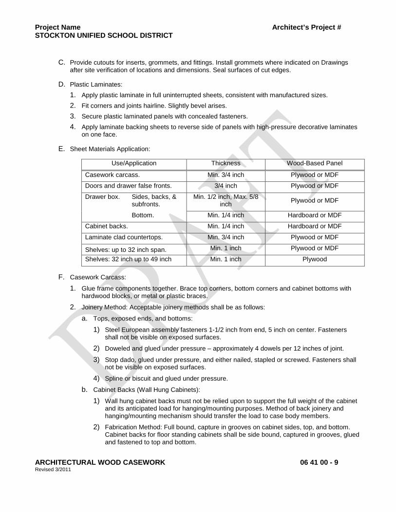
Project Name Architect’s Project # STOCKTON UNIFIED SCHOOL DISTRICT
ARCHITECTURAL WOOD CASEWORK 06 41 00 - 9 Revised 3/2011
C. Provide cutouts for inserts, grommets, and fittings. Install grommets where indicated on Drawings after site verification of locations and dimensions. Seal surfaces of cut edges.
D. Plastic Laminates: 1. Apply plastic laminate in full uninterrupted sheets, consistent with manufactured sizes. 2. Fit corners and joints hairline. Slightly bevel arises. 3. Secure plastic laminated panels with concealed fasteners. 4. Apply laminate backing sheets to reverse side of panels with high-pressure decorative laminates
on one face.
E. Sheet Materials Application:
Use/Application Thickness Wood-Based Panel
Casework carcass. Min. 3/4 inch Plywood or MDF
Doors and drawer false fronts. 3/4 inch Plywood or MDF
Drawer box. Sides, backs, & subfronts.
Min. 1/2 inch, Max. 5/8 inch Plywood or MDF
Bottom. Min. 1/4 inch Hardboard or MDF
Cabinet backs. Min. 1/4 inch Hardboard or MDF
Laminate clad countertops. Min. 3/4 inch Plywood or MDF
Shelves: up to 32 inch span. Min. 1 inch Plywood or MDF
Shelves: 32 inch up to 49 inch Min. 1 inch Plywood
F. Casework Carcass:
1. Glue frame components together. Brace top corners, bottom corners and cabinet bottoms with hardwood blocks, or metal or plastic braces.
2. Joinery Method: Acceptable joinery methods shall be as follows:
a. Tops, exposed ends, and bottoms:
1) Steel European assembly fasteners 1-1/2 inch from end, 5 inch on center. Fasteners shall not be visible on exposed surfaces.
2) Doweled and glued under pressure – approximately 4 dowels per 12 inches of joint.
3) Stop dado, glued under pressure, and either nailed, stapled or screwed. Fasteners shall not be visible on exposed surfaces.
4) Spline or biscuit and glued under pressure.
b. Cabinet Backs (Wall Hung Cabinets):
1) Wall hung cabinet backs must not be relied upon to support the full weight of the cabinet and its anticipated load for hanging/mounting purposes. Method of back joinery and hanging/mounting mechanism should transfer the load to case body members.
2) Fabrication Method: Full bound, capture in grooves on cabinet sides, top, and bottom. Cabinet backs for floor standing cabinets shall be side bound, captured in grooves, glued and fastened to top and bottom.
Project Name Architect’s Project # STOCKTON UNIFIED SCHOOL DISTRICT
ARCHITECTURAL WOOD CASEWORK 06 41 00 - 10 Revised 3/2011
G. Drawer Assembly: 1. Drawer box with drawer false front. 2. Acceptable Joinery Methods:
a. Multiple dovetail (all corners) or French dovetail front/dadoed back, glued under pressure. b. Doweled, glued under pressure. c. Lock shoulder, glued and pin nailed. d. Bottoms shall be set into sides, front, and back, 1/4 inch deep groove, with a minimum 3/8
inch standing shoulder. 3. File Drawers: Unless otherwise indicated, direction of file folders shall be parallel to drawer door.
Provide adequate, clear inside dimensions for hanging file folders. Minimum clear inside drawer dimensions shall be as follows: a. Letter size file folders: Minimum 13-1/4 inch wide by 10-1/2 inch high. b. Legal size file folders: Minimum 16-1/4 inch wide by 10-1/2 inch high.
H. Shelving:
1. Fixed Shelves: Dadoed or doweled into cabinet sides.
2. Adjustable Shelves: 0.197 inch bore holes at 1-1/4 inch on center.
I. Laminate Countertops and Backsplash:
1. Edge Style: 1-1/2-inch waterfall self edge with 1/2-inch radius.
2. 6 inch integral coved backsplash with square edge.
3. Substrate shall be moisture-resistant where countertops receive sinks and lavatories, or are exposed to liquids.
J. Solid Surfacing Material Countertops and Backsplash:
1. Fabricate tops in one piece, unless otherwise indicated. Comply with solid-surfacing-material manufacturer's written recommendations for adhesives, sealers, fabrication, and finishing.
2. Fabricate tops with shop-applied edges of materials and configuration indicated.
3. Fabricate tops with shop-applied backsplashes.
4. Drill holes in countertops for plumbing fittings and cable grommets in shop.
2.8 FINISHES
A. Factory Finishing: To the greatest extent possible, finish architectural woodwork at factory. Defer only final touch-up, cleaning, and polishing until after installation.
1. Comply with Architectural Woodwork Standards, Section 5 requirements.
B. Plastic Laminate Finish: Provide casework finishes as follows:
1. Drawer Box: Thermally fused melamine.
2. Semi-Exposed Surfaces (As defined in Architectural Woodwork Standards, Section 10):
a. Cabinet with Doors: Thermally fused melamine.
b. Cabinets with Open Shelves: High-pressure decorative laminate.
Project Name Architect’s Project # STOCKTON UNIFIED SCHOOL DISTRICT
ARCHITECTURAL WOOD CASEWORK 06 41 00 - 11 Revised 3/2011
3. Exposed Surfaces (as defined in Architectural Woodwork Standards, Section 10): High-pressure decorative laminate with ABS edge banding.
4. Doors and Drawer False Fronts: High-pressure decorative laminate with ABS edge banding.
5. Exposed Interior Surfaces (as defined in Architectural Woodwork Standards, Section 10): High-pressure decorative laminate.
C. Solid Surfacing Material (SSM) Finish: As standard with manufacturer.
PART 3 EXECUTION
3.1 EXAMINATION
A. Verify field measurements, dimensions, location and layout.
B. Verify location and sizes of utility rough-in associated with work of this Section.
C. Verify adequacy of backing and support framing.
D. Report unacceptable conditions to Architect. Begin installation only when unacceptable conditions have been corrected.
3.2 INSTALLATION
A. Install in accordance with accepted shop drawings and with applicable AWS grade requirements as indicated in this Section.
B. Installation shall be done in humidity and temperature controlled environment, in accordance with AWS recommendations.
C. Install fabricated assemblies, level, plumb, square, and true to line, in locations as shown on Drawings. Attach and anchor securely to the floor and walls with mechanical fasteners appropriate for the substrate.
D. Use concealed fasteners to attach and secure casework components, countertops, and plumbing fixtures.
E. Carefully scribe casework abutting other components with a maximum gap of 1/32 inch. Do not use additional overlay trim for this purpose.
F. Install solid surfacing material per manufacturer’s instructions.
1. Align adjacent solid-surfacing-material countertops and form seams to comply with manufacturer's written recommendations using adhesive in color to match countertop. Carefully dress joints smooth, remove surface scratches, and clean entire surface.
G. Install cable grommets in countertops at all casework knee-spaces and where shown on Drawings. Verify locations with Owner.
3.3 ADJUSTING
A. Adjust moving or operating parts for smooth, uniform operation.
B. Drawer slides shall be adjusted such that the drawer does not act as the stop.

Project Name Architect’s Project # STOCKTON UNIFIED SCHOOL DISTRICT
ARCHITECTURAL WOOD CASEWORK 06 41 00 - 12 Revised 3/2011
3.4 CLEANING
A. Clean as recommended by manufacturer. Do not use materials or methods which may damage finish surface or surrounding construction
END OF SECTION
Project Name Architect’s Project # STOCKTON UNIFIED SCHOOL DISTRICT
PLASTIC PANELING 06 64 00 - 1 Revised 3/2011
SECTION 06 64 00 – PLASTIC PANELING
PART 1 GENERAL
1.1 SECTION INCLUDES
A. Glass-fiber reinforced plastic wall paneling.
1. FRL paneling.
2. FRP paneling.
3. Resin panels.
B. Attachment accessories including cable suspension system, adhesives, sealants, fasteners, trim, and moldings.
1.2 RELATED SECTIONS
A. Section 07 92 00 – Joint Sealants.
B. Section 09 29 00 – Gypsum Board.
C. Section 09 65 00 – Resilient Flooring.
D. Section 09 22 16 – Non-Structural Metal Framing.
1.3 REFERENCES
A. The publications listed below form a part of this Section to the extent referenced. The publications are referred to in the text by the basic designation only. Refer to Section 01 42 00 for definitions, acronyms, and abbreviations.
B. Unless otherwise noted, standards, manuals, and codes refer to the latest edition of such standards, manuals, and codes as of the date of issue of this Project Manual.
C. Referenced Standards:
1. ASTM D256 – Standard Test Methods for Determining the Izod Pendulum Impact Resistance of Plastics.
2. ASTM D570 – Standard Test Method for Water Absorption of Plastics.
3. ASTM D638 – Standard Test Method for Tensile Properties of Plastics.
4. ASTM D790 – Standard Test Methods for Flexural Properties of Unreinforced and Reinforced Plastics and Electrical Insulating Materials.
5. ASTM D5319 – Standard Specification for Glass-Fiber Reinforced Polyester Wall and Ceiling Panels.
6. ASTM E84 – Standard Test Method for Surface Burning Characteristics of Building Materials.
Project Name Architect’s Project # STOCKTON UNIFIED SCHOOL DISTRICT
PLASTIC PANELING 06 64 00 - 2 Revised 3/2011
1.4 SUBMITTALS
A. Submit under provisions of Section 01 33 00.
B. Provide product data on panels, trim and adhesive.
C. Submit manufacturer's installation instructions under provisions of Section 01 33 00.
D. Shop Drawings: Shop drawings shall include details and erection data associated with the work of other trades; location; materials, profiles, fastenings and accessories.
E. Samples: Submit samples of all interior and exterior trim materials. Samples shall be finished as specified and submitted for color and material approval prior to delivery and installation.
1. Submit two samples 6 inches by 6 inches in size illustrating panel material, color, and finish.
2. Submit two samples 6 inches long in size illustrating trim material, color and finish.
1.5 QUALITY ASSURANCE
A. Source Limitations: Obtain plastic paneling and trim from a single manufacturer.
B. Regulatory Requirements: Comply with 2007 California Building Code, Chapter 8, “Interior Finishes”, Section 803, “Wall and Ceiling Finishes.”
1. Class A: Flame spread 0-25; smoke-developed 0-450.
C. Surface-Burning Characteristics: As determined by testing identical products according to ASTM E84 by a qualified testing agency. Identify products with appropriate markings of applicable testing agency.
1. Flame-Spread Index: 25 or less.
2. Smoke-Developed Index: 450 or less.
3. Testing Agency: UL.
D. Installation Acceptance: All rejected work shall be removed and replaced at no cost to Owner.
1.6 DELIVERY, STORAGE AND HANDLING
A. Delivery: Do not deliver to the job site until suitable storage space is available.
B. Storage, Handling and Protection: Provide all work or materials necessary to store, cover and protect materials specified and installed under this Section. Store materials under cover in a well-ventilated enclosure and protect against extreme changes in temperature and humidity. Prevent marring of finished surfaces and keep materials clean during handling and installation operations. Protect exposed finish work and materials from damage after installation. Replace damaged items at no cost to Owner.
1.7 PROJECT CONDITIONS
A. Environmental Limitations: Do not install plastic paneling until spaces are enclosed and weathertight and temporary HVAC system is operating and maintaining ambient temperature and humidity conditions at occupancy levels during remainder construction period.
Project Name Architect’s Project # STOCKTON UNIFIED SCHOOL DISTRICT
PLASTIC PANELING 06 64 00 - 3 Revised 3/2011
PART 2 PRODUCTS
2.1 FRL PANELS - FIBER-GLASS REINFORCED PLASTIC LAMINATE (FRL) PANELS
A. Basis-of-Design Product: FRL™ fiber reinforced laminate panels by Panolam Industries International, Inc., Shelton, CT, 888-375-9255, www.panolam.com.
1. Provide the named product or accepted equal.
2. Substitutions: Under provisions of Section 01 60 00.
B. Fiberglass Reinforced Plastic Laminate (FRL) Panel System: Provide factory-finished panels, and accessories.
1. Panel Material: Fiber-glass reinforced plastic panels complying with ASTM D5319.
2. Panel Construction: Thermofused melamine overlay, decorative and fire-resistant phenolic paper with fiber reinforcing.
3. Nominal Thickness: 0.088 inch.
4. Surface Finish: Smooth.
5. Color: As indicated on Drawings, if not indicated, to be selected by Architect from manufacturer’s full range.
6. Panel Properties:
a. Wear Resistance: 3,500 per NEMA LD3, Section 2, Test Method 3.13.
b. Flexural Strength: 25,834 psi per ASTM D790.
c. Tensile Strength: 19,131 psi per ASTM D638.
d. Fire-Resistance Rating: Class “A” per ASTM E84; flame spread 25, smoke developed 30.
C. Accessories: Adhesive, trim, sealant, and accessories, as required, and as standard with manufacturer.
2.2 FRP PANELS - FIBER-GLASS REINFORCED PLASTIC (FRP) PANELS
A. Basis-of-Design Product: Marlite FR Class1/A panels by Marlite, Dover, OH 330-343-6621, www.marlite.com.
1. Provide the named product or accepted equal by one of the following:
a. Glasteel, a division of Stabilt America, Inc., www.glsteel.com.
b. Panolam Industries International, Inc., Shelton, CT; 888-375-9255, www.panolam.com.
c. Crane Composites Kemlite Company, Inc.; www.kemlite.com www.sequentia.com
2. Substitution: Under provisions of Section 01 60 00.
B. Fiberglass Reinforced Plastic (FRP) Panel System: Provide factory-finished panels, trim, sealant, and accessories.
1. Panel Material: Fiberglass reinforced polyester.
Project Name Architect’s Project # STOCKTON UNIFIED SCHOOL DISTRICT
PLASTIC PANELING 06 64 00 - 4 Revised 3/2011
2. Size: 48 inches by 96 or 120 inches by 3/32 inch, as required by design condition; unless otherwise indicated on Drawings.
3. Finish: Gently pebbled, high-gloss.
4. Color: As indicated on Drawings, if not indicated, to be selected by Architect from manufacturer’s full range.
5. Panel Properties:
a. Flexural Strength: 10,000 psi (69 MPa), when tested in accordance with ASTM D790.
b. Tensile Strength: 7,000 psi (48 MPa), when tested in accordance with ASTM D638.
c. Impact Resistance: 7.2 ft-lb/in (1260 N/m), when tested in accordance with ASTM D256, Izod method.
d. Water Absorption: 0.72 percent, when tested in accordance with ASTM D570.
e. Surface Burning Characteristics: Flame spread index of 25 or less, smoke developed index of 450 or less, when tested in accordance with ASTM E84 (Class A/I).
C. Accessories: Manufacturer's standard adhesive, sealant, and joinery trim system that hides vertical joints and exposed edges.
2.3 RESIN PANELS
A. Basis-of-Design Product: Veritas™ ResinArt Panels by Schneller LLC, Pinellas Park, FL; 877-411-8008, www.veritasideas.com.
1. Substitution: Under provisions of Section 01 60 00.
B. Resin Panels: Polyester-resin-based sheets bonded to decorative interlayer materials, suitable for indicated application.
1. Face Sheets: Glycol-modified engineered polyester resin composition.
a. Recycled Content: Not less than 40 percent.
b. Sheet Thickness: As indicated on Drawings for each application.
c. Opacity, Color and Texture: As indicated on Drawings, if not indicated, to be selected by Architect.
d. Interlayer Materials: Compatible with polyester resin sheet and bonding process to create a solid sheet of material when complete.
1) Color, Pattern, and Texture: As indicated on Drawings, if not indicated, to be selected by Architect.
e. Panel Configuration: As indicated on Drawings.
2.4 SUSPENSION SYSTEM FOR RESIN PANELS
A. Basis-of-Design Product: Veritas™ Cable Systemby Schneller LLC, Pinellas Park, FL; 877-411-8008, www.veritasideas.com.
1. Substitution: Under provisions of Section 01 60 00.
B. Components: Provide stainless steel components for suspending resin panels, as standard with manufacturer, and as listed below:
Project Name Architect’s Project # STOCKTON UNIFIED SCHOOL DISTRICT
PLASTIC PANELING 06 64 00 - 5 Revised 3/2011
1. Cable:
2. Clamps: Single and double swivels, internally threaded.
3. Ceiling and Floor Anchors. 6 mm threaded anchors with lock nuts.
2.5 ACCESSORIES
A. Trim and Moldings: Provide metal or PVC trim and moldings, as indicated on Drawings.
1. Metal Trim and Moldings: Aluminum, type as selected by Architect.
a. Acceptable Manufacturer: Nudo Products, Inc., Springfield, IL; 800-826-4132, www.nudo.com; or accepted equal.
b. Finish: Clear, anodized.
2. PVC Trim, Base, and Moldings: Manufacturer's standard trim system, base, and moldings that hide vertical joints and exposed edges.
a. Panel Trim, Molding, and Corners: Extruded PVC; color to match panel color; provide as required.
b. Panel Base: Rigid extruded PVC with integral color; 4 inches wide; color as selected by Architect. Provide connectors, end caps, inside and outside corners as required.
B. Adhesive: As recommended by plastic paneling manufacturer.
C. Sealant: Single-component, mildew-resistant, neutral-curing silicone sealant recommended by plastic paneling manufacturer and complying with applicable requirements in Section 07 92 00.
1. VOC Content: 250 g/L or less when calculated according to 40 CFR 59, Subpart D (EPA Method 24).
2. Acceptable Manufacturer: Color Rite, Inc., Yukon, OK; 405-354-3644, www.colorriteinc.com; or accepted equal.
3. Color: To match panel color.
PART 3 EXECUTION
3.1 EXAMINATION
A. Examine substrates and conditions, with Installer present, for compliance with requirements for installation tolerances and other conditions affecting performance of the Work.
B. Proceed with installation only after unsatisfactory conditions have been corrected.
3.2 PREPARATION
A. Sand substrate high spots and fill low spots as required to provide flat and even surface for panel installation.
B. Clean substrates of substances that could impair bond of adhesive, including oil, grease, dirt, and dust.
Project Name Architect’s Project # STOCKTON UNIFIED SCHOOL DISTRICT
PLASTIC PANELING 06 64 00 - 6 Revised 3/2011
C. Surfaces to receive FRP shall be prepared in strict accordance with manufacturer's printed instructions and as specified herein. Fill pinholes, cracks and other surface imperfections with spackle and scrape off surface splatters and imperfections to leave substrate smooth and free of damage.
D. Condition panels by unpacking and placing in installation space before installation according to manufacturer's written recommendations.
E. Lay out paneling before installing. Locate panel joints as indicated on Drawings.
F. Other trade work that penetrates the substrate shall be completed before beginning FRP panel application.
3.3 INSTALLATION
A. Verify Drawings for panel location, layout, and treatment of perimeter conditions.
B. Install plastic paneling in accordance with manufacturer's printed instructions.
1. Installation with Adhesive: Install panels in a full spread of adhesive. Remove excessive adhesive from exposed and finished surfaces immediately.
2. Installation with Cable, Fasteners, and Fittings: Install panels with cables, fitting, and fasteners, as indicated on Drawings. Layout fitting locations and mark on face of panels so that fittings are accurately aligned.
C. Fill grooves in trim accessories with sealant before installing panels and bed inside corner trim in a bead of sealant, when recommended by panel manufacturer.
D. Install panel system level, plumb, and true.
E. Provide a smooth, straight, solid and clean wall surface.
F. Maintain uniform space between adjacent panels and between panels and floors, ceilings, and fixtures.
G. Install trim as shown and as required for a complete, finished system.
H. Install trim in longest practicable lengths. “Piecing” of trim is not permitted.
I. Ensure positive contact of FRP panels to adhesive and wall surfaces. Remove and replace damaged or improperly applied panels.
3.4 CLEAN-UP
A. General: Keep the premises in a neat, safe and orderly condition uring execution of this portion of the work.
B. Clean-up: Upon completion of the work of this Section, remove all surplus materials, rubbish and debris from the premises and leave it "broom clean."
END OF SECTION
Project Name Architect’s Project # STOCKTON UNIFIED SCHOOL DISTRICT
LATH AND PLASTER 09 24 00 - 1 Revised 3/2011
SECTION 09 24 00 – LATH AND PLASTER 1. GENERAL 1.1 RELATED DOCUMENTS:
Drawings and general provisions of Contract, including General and Supplementary Conditions and Division –1 Specification Section, apply to work of this section.
1.2 DESCRIPTION OF WORK:
A. Types of work includes:
1. Metal furring and lathing
2. Portland cement plaster 1.3 RELATED WORK SPECIFIED ELSEWHERE:
A. Section 05 40 00 – Cold Formed Metal Framing Structural B. Section 06 10 00 – Rough Lumber C. Section 07 20 00 – Insulation
1.4 QUALITY ASSURANCE:
A. Fire Resistance Ratings: Where plastered assemblies with fire-resistance ratings are indicated or are required to comply with governing regulations, provide materials and installations identical with applicable assemblies which have been tested and listed by recognized authorities including UL, Warnock-Hersey, and GA-600.
1. Provide plaster having the same aggregate as specified for similar non-rated work, unless specified aggregate has not been tested and approved by UL for the required rating.
2. Comply with FM “Approval Guide” for rated work.
B. Portland Cement Plastering Standards: ASTM C926
C. Allowable Tolerances: For flat surfaces, do not exceed ¼” in 8’-0” for bow or warp of surface, and for plumb or level.
1.4 SUBMITTALS:
A. Product Data: If a substitution is being requested, submit manufacturer’s product specifications and installation instructions for each material, including other data as may be required to show compliance with these specifications.
1.5 PRODUCT HANDLING:
A. Deliver, store and protect manufactured materials to comply with referenced standards. 1.6 JOB CONDITIONS:
A. Environmental Conditions: Comply with referenced standards.
B. Protect contiguous work from soiling, spattering, moisture deterioration and other harmful effects which might result from plastering.
Project Name Architect’s Project # STOCKTON UNIFIED SCHOOL DISTRICT
LATH AND PLASTER 09 24 00 - 2 Revised 3/2011
2. PRODUCTS 2.1 METAL SUPPORT, FURRING, LATHING AND ACCESSORY MATERIALS:
A. Metal and Finishes: Manufacturer’s standard steel products unless indicated as zinc alloy or other metal. Where not otherwise indicated, provide manufacturer’s standard galvanized finished or steel products except as follows:
1. Metal lath: ASTM C847
2. Heavy Gauge Members: Rust inhibitive paint finish on rolled channels and formed sheet metal of 16 gauge and heavier, except for exterior work and in “High Humidity” areas.
3. Exterior Components: Hot dipped galvanized finish; ASTM A 653 G90 for 28 gauge and lighter formed metal products, ASTM A123 galvanized after fabrication for 16 gauge and heavier products.
4. Exterior Exposed Plastering Accessories: Provide zinc alloy accessories for exterior work and work in “High Humidity” areas, except where fully concealed in plaster
B. Wire Ties: Galvanized soft steel wire.
C. Metal Lathing Materials (MtLth):
1. General: Where not otherwise indicated, comply with MLSFA “Technical Bulletin 101 and ASTM C847 for section of metal lath for each application indicated.
a. Product Standards: comply with FS QQ-L-101c
b. Backing: Where lath is indicated to having backing, and where backing is required for machine application of plaster, provide lath with factory-applied backing of moisture-resistant paper per CBC Sections 1404.2 and 2510.6
2. Paper Backed Woven Wire Fabric Lath: 1 ½” x 17 gauge, ¼” self-furring hexagonal w/ Type 1, Grade “D”, Style 2 Building Paper equal to K-Lath SFB Paperback Netting.
3. Rib lath, 3/8”; 3.4 lbs. per sq. yd, 3/8” rib depth.
D. Metal Plastering Accessories and Reinforcement:
1. General; Coordinate depth of accessory with thickness of and number of coats of plaster to be applied.
2. Small Nose Corner Beads: Expanded type with 2 7/8” wide flanges.
3. Cornerite: Manufacturer’s standard preformed interior corner reinforcement made from 2.5 lb. per sq. yd. diamond mesh lath.
4. Square-edged casing beads: Manufacturer’s standard with expanded or shot flange to suit application.
5. Control joints; Manufacture’s standard roll-formed one piece control joint w/ back flanges providing positive slip joint action and dust barrier. Joint width as shown on drawings.
6. Corner Reinforcement: Special stucco-type woven galvanized wire corner reinforcing strips.
7. Line Wire: 18 gauge soft annealed steel wire
Project Name Architect’s Project # STOCKTON UNIFIED SCHOOL DISTRICT
LATH AND PLASTER 09 24 00 - 3 Revised 3/2011
8. Fasteners: Corrosion resistant (galvanized) self-drilling wafer head screw with washer with length sufficient to have a minimum of 3 threads through metal stud framing.
2.2 PORTLAND CEMENT PLASTER MATERIALS:
A. General: Provide either neat or ready-mixed (where applicable) materials, at Installer’s option, complying with ASTM C926.
B. Base-Coat Cement: Portland cement, ASTM C 150, Type 1A or I.
C. Lime: ASTM C206. In lieu of Lime a Liquid Admixture equal to Gibco’s PRF (ICC ESR-2581-12-08) may be used.
D. Base-Coat Aggregate: Sand, ASTM C35 or ASTM C897
E. Prepared Finish Coat: Factory-prepared natural finish for Portland cement plaster, type recommended by the manufacturer for the texture indicated.
1. Texture: Machine applied sand float finish. 2.3 BONDING MATERIALS:
A. Acid Etch Solution: Muritic acid, mixed one part acid to 6-to-10 parts water.
B. Dash-coat Material: Two parts Portland cement with 3 parts fine sand mixed with water to a mush paste.
C. Bonding Agent: ASTM C932 and MIL-B-19235 2.4 MISCELLANEOUS MATERIALS:
A. Asphalt Saturated Felt: ASTM D 226, 15 lb. type, non-perforated.
B. Plaster Mixes:
1. Mix for exterior Portland Cement Plaster; include bonding additive, in accordance with manufacturer’s instructions.
C. Expansion Screed (Feature joint): Shown on Drawings
D. Water: Fresh, clean and potable, and free from such amounts of mineral and organic substances as would adversely affect the hardening and strength of cement plaster.
3. EXECUTION 3.1 PREPARATION:
A. Plastering:
1. Clean plaster bases and substrates to be plastered, removing loose materials, coatings and other substances, which might impair the work.
2. Apply bonding agent on interior concrete surfaces indicated for direct plastering; comply with manufacturer’s instructions.
Project Name Architect’s Project # STOCKTON UNIFIED SCHOOL DISTRICT
LATH AND PLASTER 09 24 00 - 4 Revised 3/2011
3.1 INSTALLATION OF METAL SUPPORT SYSTEMS:
A. General
1. Isolation: Where lathing and metal support system abuts building structure horizontally, and where partition/wall work abuts overhead structure, isolate the work from structural movement sufficiently to prevent transfer of loading into the work from the building structure. Install slip or cushion type joints to absorb deflections but maintain lateral support.
Frame both sides of control and expansion joints independently, and do not bridge joints with furring and lathing or accessories.
2. Fixture Support Framing: Install supplementary framing, blocking and bracing where work is indicated to support fixtures, equipment, services, casework, heavy trim and furnishings and similar work requiring attachment and support.
B. Metal Furring:
1. Space furring member 16” o.c., except as otherwise indicated.
C. Metal Lathing:
1. Install metal lath to steel stud framing with self-drilling wafer head screws & washers at 6” o.c. (4” o.c. where steel stud framing is 24” o.c.)
2. Install soffit lath as shown on plans.
3. On vertical surfaces (walls) metal lath shall be Woven Wire Fabric Lath
4. On horizontal surfaces (ceilings and soffits) metal lath shall be 3/8” Rib Lath.
D. Plastering Accessories:
1. Anchor each flange of accessories 8” o.c to plaster base.
2. Miter or cope accessory corners, and install with tight joints accurately aligned.
3. Set accessories plumb, level and true to line, with a tolerance of 1/8” in 10’-0”.
4. Install metal corner beads at external corners.
5. Casing Beads:
a. Install casing beads at terminations of plaster work, except where plaster is indicated to pass through other work and be concealed by lapping work, and except where special screens, bases or frames act as casing beads including interior metal door frames.
b. For exterior work, set casing beads ¼” from abutting frames and other work (for application of sealant).
c. Where plaster abuts concrete, set casing bead ¼” from concrete.
d. Where interior plaster abuts exterior masonry, apply waterproof plastic adhesive tape on concealed face of bead.
6. Install prefabricated expansion joints of design as shown on plans. 3.3 INSTALLATION OF PLASTER:
A. Mechanically mix plaster materials at the project site; do not hand mix except where small amounts are needed, using less than one bag of plaster.
Project Name Architect’s Project # STOCKTON UNIFIED SCHOOL DISTRICT
LATH AND PLASTER 09 24 00 - 5 Revised 3/2011
B. Grout hollow metal frames, bases and similar work occurring in plastered areas, with base coat plaster material, and prior to lathing where necessary (PlsGrt). Except where full grouting is indicated or required for fire-resistance rating, grout 6” lengths at each anchorage.
C. Sequence plaster installation properly with the installation and protection of other work, so that neither will be damaged by the installation of the other.
D. Plaster flush with metal frames and other built-in metal items or accessories, which act as a plaster ground, unless otherwise shown. Where plaster is not terminated at metal by casing beads cut base coat free from metal before plaster sets and groove finish coat at the junctures with metal.
E. Apply thickness and number of coats of plaster as indicated; or as required by referenced standards.
1. Provide 3-coat plaster installation.
2. Provide scratch and brown coat bed only, where plans show Ceramic Tile, Brick Tile (Thin Brick Veneer), or Cast Stone veneer.
F. Concealed Plaster: Where plaster application will be concealed by wood paneling, above suspended ceiling and similar locations, finish-coat may be omitted; where concealed behind cabinets and similar furnishings and equipment, apply finish-coat; where used as a base for adhesive application of tile and similar finishes, omit finish-coat and coordinate thickness with overall dimensions as shown, and comply with tolerances specified.
G. Texture of Plaster Finishes: Except as otherwise indicated, apply finish-coat as follows;
1. Exterior Portland Cement Plaster; Texture: Machine applied, sand float finish.
3.4 CURING OF PLASTER:
A. Comply with applicable requirements of ASTM C926. Each coat of cement plaster shall be moist cured by application of fine fog spray. The scratch coat shall be moisture cured a minimum of 48 hours. The brown coat shall be moisture cured a minimum of 10 days. Moistening shall begin as soon as the plaster has hardened sufficiently. Soaking of walls shall be avoided.
B. Apply only as much water as will be readily absorbed. Protect plaster from uneven and excessive evaporation during hot, dry weather. Provide for curing of plaster on Saturdays, Sundays, and holidays, if necessary.
3.5 CUTTING AND PATCHING:
A. Cut, patch, point-up and repair plaster as necessary to accommodate other work and to restore cracks, dents and imperfections. Repair or replace work to eliminate blisters, buckles, excessive cracking and check cracking, dry-outs, efflorescence, sweat-outs and similar defects including areas of the work which do not comply with specified tolerances, and where bond to the substrate has failed.
B. Sand smooth troweled finishes lightly to remove trowel marks and arises. 3.6 CLEANING AND PROTECTION:
Remove temporary protection and enclosure of other work. Promptly remove plaster from door frames, windows, and other surfaces, which are not to be plastered. Repair floors, walls and other surfaces, which have been stained, marred or otherwise damaged during the plastering work. When plastering work is completed, remove unused materials, containers and equipment and clean floors of plaster debris.
Project Name Architect’s Project # STOCKTON UNIFIED SCHOOL DISTRICT
LATH AND PLASTER 09 24 00 - 6 Revised 3/2011
END OF SECTION 09 24 00
Project Name Architect’s Project # STOCKTON UNIFIED SCHOOL DISTRICT 05/10
TILE BACKER BOARD 09 28 16 - 1 Revised 3/2011
SECTION 09 28 16 – TILE BACKER BOARD 1. GENERAL: 1.1 RELATED DOCUMENTS:
Drawings and general provisions of Contract, including Supplementary conditions and Division-1 Specification Sections, apply to work of this section.
1.2 DESCRIPTION OF WORK:
A. Types of work include:
1. Backer board for ceramic tile and untiled installations on walls applied to steel framing and furring.
2. Backer board finishing
B. Related Work Specified Elsewhere:
1. Section 05 40 00 – Cold-formed Metal Framing (Structural)
2. Section 08 11 13 – Steel Doors and Frames
3. Section 09 30 00 – Ceramic Tile
4. Section 09 91 00 – Painting 1.3 QUALITY ASSURANCE:
A. Single-Source Responsibility: Obtain backer board products from a single manufacturer or from manufacturers recommended by the prime manufacturer of the backer board.
1.4 SUBMITTALS:
A. Product Data: submit manufacturer’s product specifications and installation instructions for each gypsum drywall component, including other data as may be required to show compliance with these specifications.
1.5 DELIVERY, STORAGE, AND HANDLING
A. Deliver materials in original packages, containers or bundles bearing brand name and identification of manufacturer or supplier.
B. Store and handle materials to protect against contact with damp and wet surfaces, exposure to weather, breakage and damage to edges. Provide air circulation under covering and around stacks of materials.
1.6 LIMITATIONS:
A. Apply tile only to gray side of DensShield panels
B. Do not use DensShield Tile Backer where there is prolonged exposure to temperatures exceeding 125°F.
C. Do not install vapor retarders directly behind DensShield panels.
D. Do not use DensShield panels as a base for nailing and mechanical fastening.
Project Name Architect’s Project # STOCKTON UNIFIED SCHOOL DISTRICT 05/10
TILE BACKER BOARD 09 28 16 - 2 Revised 3/2011
E. Not for exterior use.
F. Do not use wallboard joint compound or paper tape in wet areas.
2. PRODUCTS 2.1 TILE BACKER BOARD:
A. Acceptable Products: Georgia-Pacific Corporation, 5/8” DensShield Fire Guard Type X Tile Backer.
B. Sheet Size: 4’x8’
C. Edges: Square
D. Composition: Water-resistant treated core with glass mat moisture protectant coating and glass mats, both sides. The face side is surfaced with heat-cured copolymer water-resistant coating.
E. Fire Resistance: Type X when tested in accordance with ASTM E 119, UL Classified.
F. Standards: ASTM C 1178
2.2 METAL SUPPORT MATERIALS:
A. Wall/Partition Support Materials:
1. Studs: See Section 05 40 00. 2. Furring Members: ASTM C 645; 0.0179: min. thickness of base metal, hat-shaped.
3. Fasteners for Furring Members: Type and size recommended by furring
manufacturer for the substrate and application indicated. 2.3 ACCESSORIES:
A. Trim: Galvanized Sheet Steel.
B. Metal Framing Fasteners: Type S-12, bugle or wafer head, rust resistant
2.4 JOINT TREATMENT MATERIALS:
A. Joint Tape: 2” wide 10 x 10 glass mesh tape.
B. Reinforcing Fabric: Balanced, alkali-resistant, open-weave, glass fiber fabric, made from continuous multi-end strands with tensile strength of not less that 120 lbs. and 140 lbs. in warp and fill directions, respectively, per ASTM D 1682 and complying with ASTM D 578, and of 4.30 oz./sq. yd. minimum weight.
C. Setting-type joint compound: Untiled, non-wet areas: ToughRock setting compounds.
D. Tile setting material: Mastic or mortars, organic adhesive ANSI A136.1, dry set ANSI A118.1, latex Portland cement mortar ANSI A118.4.
2.5 HIGH-HUMIDITY AND WET-AREA UNTILED FINISH SYSTEM MATERIALS:
A. Acceptable manufacturers:
1. Dryvit Systems - Genesis® DM, DS174

Project Name Architect’s Project # STOCKTON UNIFIED SCHOOL DISTRICT 05/10
TILE BACKER BOARD 09 28 16 - 3 Revised 3/2011
2. Sto Industries – F-477, Flexyl®
3. Parex - ParFlex®
4. Synergy – Xtra-Stop®
B. Ground Coat: Job-mixed formulation of Portland cement complying with ASTM C 150, Type I, white or natural color, and system manufacturer’s standard polymer-based adhesive designed for use indicated.
C. Primer: System manufacturer’s standard primer.
D. Finish coat for high-humidity areas: System manufacturer’s standard mixture, factory-mixed formulation of polymer emulsion admixture, colorfast mineral pigments, ground stone particles and fillers.
E. Finish coat for wet areas: Water-reducible epoxy coating system specified for wet areas. 3. EXECUTION 3.1 GENERAL:
A. Provide DensShield Tile Backer board where indicated on drawings using fastening systems specified.
B. Use maximum lengths possible to minimize number of joints. Stagger end joints and edge joints. Attach DensShield panels to framing with fasteners recommended by tile backer board manufacturer, spaced 6” oc. Butt ends and edges.
C. Locate control and expansion joints at same locations as substrate and where required by finishes. Expansion joints for tile and non-tile applications: Walls – Expansion joints not to exceed 30 lineal feet of continuous wall or as specified by design authority.
3.2 TILE BACKER:
A. Wall installations: On walls, install DensShield panels vertically or horizontally. Install tile backer in accordance with manufacturer’s recommendations and TCA Handbook for Ceramic Tile Installation, Method W245.
3.3 ACCESSORIES:
A. Install accessories where indicated and in accordance with tile backer manufacturer’s instructions.
3.4 FINISHING:
A. Substrate for tile: Apply glass mesh joint tape over joints. Embed tape in setting material indicated for specified tile finishes. Allow joints to dry prior to installing tile.
B. Substrate for paint and wall coverings, dry areas (untiled): Apply glass mesh joint tape over joints. Embed tape in setting type joint compound specified. Apply skim coat of setting-type joint compound over surface of tile backer for smooth finish.
C. Substrate for high-humidity finish systems (untiled): Apply 6” wide reinforcing fabric over joints. Embed fabric in ground coat. Skin coat backer surface with ground coat for smooth finish. Apply in accordance with finish coat manufacturer’s instructions.
D. Substrate for wet area, water reducible epoxy coating finish (untiled): Apply 6” wide reinforcing fabric over joints. Embed fabric in ground coat. Skim-coat with ground coat and
Project Name Architect’s Project # STOCKTON UNIFIED SCHOOL DISTRICT 05/10
TILE BACKER BOARD 09 28 16 - 4 Revised 3/2011
compatible primer. Apply epoxy coatings specified as finishing step with epoxy coating system specified.
3.5 PROTECTION OF WORK:
A. Provide final protection and maintain conditions, in a manner suitable to Installer, which ensures tile backer work being without damage or deterioration.
END OF SECTION 09 28 16
Project Name Architect’s Project # STOCKTON UNIFIED SCHOOL DISTRICT
GYPSUM BOARD 09 29 00 - 1 Revised 3/2011
SECTION 09 29 00 – GYPSUM BOARD 1. GENERAL: 1.1 RELATED DOCUMENTS:
Drawings and general provisions of Contract, including Supplementary conditions and Division-1 Specification Sections, apply to work of this section.
1.2 DESCRIPTION OF WORK:
A. Types of work include:
1. Gypsum board directly applied to solid (continuous) substrates, including steel decking.
2. Gypsum board applied to steel framing and furring.
3. Gypsum backing boards for application of other finishes.
4. Gypsum board finishing (joint tape-and-compound treatment).
B. Related Work Specified Elsewhere:
1. Section 05 40 00 – Cold-formed Metal Framing (Structural)
2. Section 08 11 13 – Steel Doors and Frames
3. Section 09 91 00 – Painting 1.2 QUALITY ASSURANCE:
A. Fire Resistance Ratings: Where gypsum board systems with fire-resistance ratings are indicated, provide materials and installations which are identical with those of applicable assemblies tested per ASTM E 119 by fire testing laborites acceptable to authorities having jurisdiction.
B. Gypsum Board Terminology Standard: GA-505 by Gypsum Association.
C. Single-Source Responsibility: Obtain gypsum board products from a single manufacturer, or from manufacturers recommended by the prime manufacturer of gypsum boards.
1.4 SUBMITTALS:
A. Product Data: submit manufacturer’s product specifications and installation instructions for each gypsum drywall component, including other data as may be required to show compliance with these specifications.
1.5 DELIVERY
A. Deliver materials in original packages, containers or bundles bearing brand name and identification of manufacturer or supplier.
B. Store materials inside under cover and in manner to keep them dry, protected from weather, direct sunlight, surface contamination, corrosion and damage from construction traffic and other causes. Neatly stack gypsum boards flat to prevent sagging.
C. Handle gypsum boards to prevent damaged edges and ends of surfaces. Protect metal corner beads and trim from being bent or damaged.
Project Name Architect’s Project # STOCKTON UNIFIED SCHOOL DISTRICT
GYPSUM BOARD 09 29 00 - 2 Revised 3/2011
1.6 PROJECT CONDITIONS:
A. Environmental Requirements, General: Comply with requirements of referenced gypsum board application standards and recommendations of gypsum board manufacturer, for environmental conditions before, during and after application of gypsum board.
B. Cold Weather Protection: For installation of gypsum board and finishes, room temperature should be maintained at not less than 40°F for mechanical application of gypsum board and not less than 50°F for adhesive application of gypsum board and for joint treatment, texturing and decoration. Where materials are being mixed and used for joint treatment or the laminating of one layer of board to another, the temperature of the building should be maintained at not less that 50°F for 48 hours before and continuously until applied materials are thoroughly dry. When a temporary heat source is used, the temperature should not exceed 95°F in any given room or area.
C. Ventilation: Ventilate building spaces as required to remove water in excess of that required for drying joint treatment material immediately after it application. Avoid drafts during dry, hot weather to prevent too rapid drying.
2. PRODUCTS 2.1 MANUFACTURER: Subject to compliance with requirements, provide products of one of the
following:
A. Gypsum Board and Related Products:
American Gypsum Co. Georgia-Pacific Corp. Gold Bond Building Products Div., National Gypsum Co. United States Gypsum Co.
2.2 METAL SUPPORT MATERIALS:
A. Ceiling Support Materials and Systems:
1. Joist: See Section 05 40 00.
2. Furring Members: ASTM C 645; 0.0179” min. thickness of base metal, hat-shaped.
1. Fasteners for Furring Members: Type and size recommended by furring manufacturer for the substrate and application indicated.
B. Wall/Partition Support Materials:
2. Studs: See Section 05 40 00. 3. Furring Members: ASTM C 645; 0.0179: min. thickness of base metal, hat-shaped.
4. Fasteners for Furring Members: Type and size recommended by furring
manufacturer for the substrate and application indicated.
Project Name Architect’s Project # STOCKTON UNIFIED SCHOOL DISTRICT
GYPSUM BOARD 09 29 00 - 3 Revised 3/2011
2.3 GYPSUM BOARD:
A Gypsum Board: ASTM C 36, (ASTM C 1395 – Ceilings, ASTM C 931-Exterior) of types, edge configuration and thickness indicated below; in maximum lengths available to minimize end-to-end butt joints.
1. Type: Type X for regular and fire-resistant rated assemblies 2. Edges: Tapered. 3. Thickness: 5/8”, unless otherwise indicated.
2.4 TRIM ACCESSORIES:
A. General: Provide manufacturer’s standard trim accessories of types indicated for drywall work, formed of galvanized steel unless otherwise indicated, with either knurled and perforated or expanded flanges for nailing or stapling, and beaded for concealment of flanges in joint compound. Provide corner beads, L-type edge trim beads, U-type edge trim beads, special L-kerf-type edge trim beads, and one piece control.
1. Semi-finishing type: Manufacturer’s standard trim units which are not to be finished
with joint compound (non-beaded). 2. Plastic Edge Trim: Manufacturer’s standard rigid or semi-rigid PVC moldings of the
semi-finished type, shaped to provide resilient contact of gypsum board edges with other work; friction-fit, or pressure-sensitive adhesive mounting.
3. H-Molding: Manufacturer’s standard extruded aluminum H-molding of height
required for board, designed for combination trim and control joint in exterior gypsum board ceiling/soffit work.
2.5 JOINT TREATMENT MATERIALS:
A. General: ASTM C 475; type recommended by the manufacturer for the application indicated, except as otherwise indicated.
B. Joint Tape: Paper reinforcing tape.
C. Joint Compound: On interior work provide chemical-hardening-type for bedding and filling,
ready-mixed vinyl-type or vinyl-type powder type for topping. 2.6 MISCELLANEOUS MATERIALS:
A. General: Provide auxiliary materials for gypsum drywall work of the type and grade recommended by the manufacturer of the gypsum board.
1. Laminating Adhesive: Special adhesive or joint compound specifically
recommended for laminating gypsum boards. 2. Gypsum Board Screws: comply with ASTM C 954 or ASTM C 1002, and
manufacturer’s listings for fire assemblies.
3. Concealed Acoustical Sealant: Non-drying, non-hardening, non-skinning, non-staining, non-bleeding, gunnable sealant for concealed applications per ASTM C 919.
Project Name Architect’s Project # STOCKTON UNIFIED SCHOOL DISTRICT
GYPSUM BOARD 09 29 00 - 4 Revised 3/2011
4. Exposed Acoustical Sealant: Non-oxidizing skinnable, paintable, gunnable sealant for exposed applications per ASTM C 919.
5. Sound Attenuation Blankets: FS HH-I-521, Type I; semi-rigid mineral fiber blanket
without membrane, Class 25 flame-spread, thickness as indicated.
6. Polyethylene Vapor Retarder: A single polyethylene film, 4.0 mils, thick, with a vapor rating of 0.20 perms per ASTM E 96.
3. EXECUTION 3.1 GENERAL GYPSUM BOARD INSTALLATION REQUIREMENTS:
A. Gypsum Board Application and Finishing Standards: ASTM C 840, GA 216, and manufacturer’s listings for fire-resistant Assemblies.
B. Locate exposed end-butt joints as far from center of walls and ceilings as possible, and
stagger not less than 1’-0” in alternate courses of board.
C. Install ceiling boards in the direction and manner, which will minimize the number of end-butt joints, and which, will avoid end joints in the central area of each ceiling. Stagger end joints at least 1’-0”.
D. Install wall/partition boards vertically to avoid end-butt joints wherever possible. At stairwells
and similar high walls, install boards horizontally with end joints staggered over studs.
E. Install exposed gypsum board with face side out. Do not install imperfect, damaged or damp boards. Butt boards together for a light contact at edges and ends with not more than 1/16” open space between boards. Do not force into place.
F. Locate either edge or end joints over supports, except in horizontal applications or where
intermediate supports or gypsum board back blocking is provided behind end joints. Position boards so that like edges abut, tapered edges against tapered edges and mill cut or field cut ends. Do not place tapered edges against cut edges or ends. Stagger vertical joints over different studs on opposite sides of partitions.
G. Attach gypsum board to supplementary framing and blocking provided for additional support
at openings and cutouts.
H. Form control joints and expansion joints with space between edges of boards, prepared to receive trim accessories.
I. Cover both faces of steel stud partition framing with gypsum board in concealed spaces
(above ceilings, etc.), except in chase walls, which are braced internally.
1. Except where concealed application is required for sound, fire, air or smoke ratings, coverage may be accomplished with scraps of not less than 8-sq. ft. area, and may be limited to not less than 75% of full coverage.
J. Where sound-rated drywall work is indicated (STC rating), including double-layer work and
work on resilient furring, seal the work at perimeters, control expansion joints, openings and penetrations with a continuous bead of acoustical sealant including a bead at both faces of partitions. Comply with ASTM C 919 and manufacturer’s recommendations for location of beads, and close off sound-flanking paths around or through the work, including sealing of partitions above acoustical ceilings.
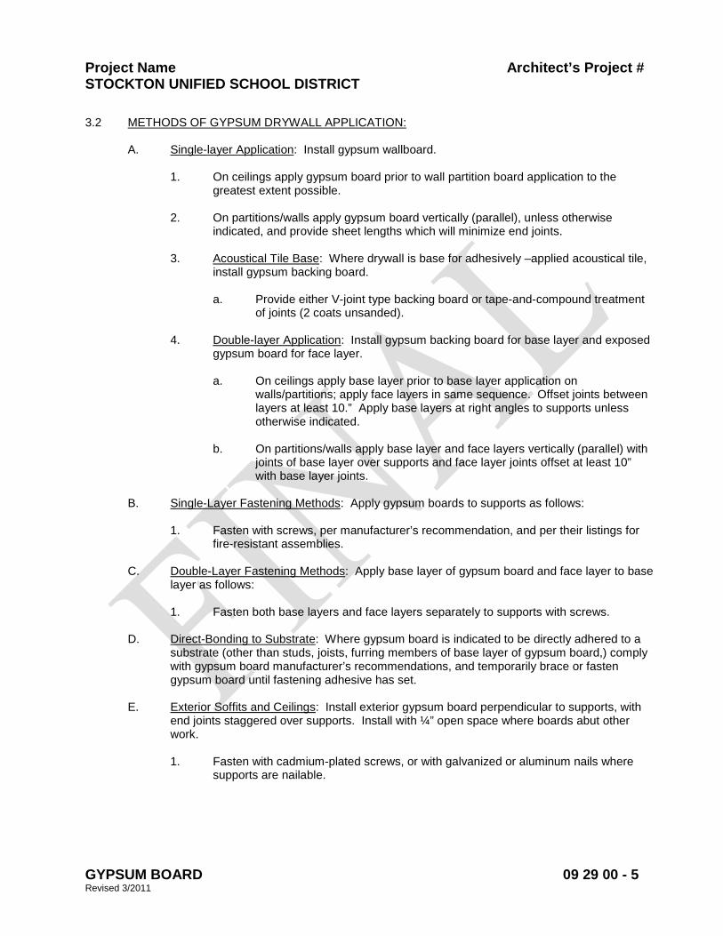
Project Name Architect’s Project # STOCKTON UNIFIED SCHOOL DISTRICT
GYPSUM BOARD 09 29 00 - 5 Revised 3/2011
3.2 METHODS OF GYPSUM DRYWALL APPLICATION:
A. Single-layer Application: Install gypsum wallboard.
1. On ceilings apply gypsum board prior to wall partition board application to the greatest extent possible.
2. On partitions/walls apply gypsum board vertically (parallel), unless otherwise
indicated, and provide sheet lengths which will minimize end joints.
3. Acoustical Tile Base: Where drywall is base for adhesively –applied acoustical tile, install gypsum backing board.
a. Provide either V-joint type backing board or tape-and-compound treatment
of joints (2 coats unsanded).
4. Double-layer Application: Install gypsum backing board for base layer and exposed gypsum board for face layer.
a. On ceilings apply base layer prior to base layer application on
walls/partitions; apply face layers in same sequence. Offset joints between layers at least 10.” Apply base layers at right angles to supports unless otherwise indicated.
b. On partitions/walls apply base layer and face layers vertically (parallel) with
joints of base layer over supports and face layer joints offset at least 10” with base layer joints.
B. Single-Layer Fastening Methods: Apply gypsum boards to supports as follows:
1. Fasten with screws, per manufacturer’s recommendation, and per their listings for fire-resistant assemblies.
C. Double-Layer Fastening Methods: Apply base layer of gypsum board and face layer to base
layer as follows:
1. Fasten both base layers and face layers separately to supports with screws. D. Direct-Bonding to Substrate: Where gypsum board is indicated to be directly adhered to a
substrate (other than studs, joists, furring members of base layer of gypsum board,) comply with gypsum board manufacturer’s recommendations, and temporarily brace or fasten gypsum board until fastening adhesive has set.
E. Exterior Soffits and Ceilings: Install exterior gypsum board perpendicular to supports, with
end joints staggered over supports. Install with ¼” open space where boards abut other work.
1. Fasten with cadmium-plated screws, or with galvanized or aluminum nails where
supports are nailable.
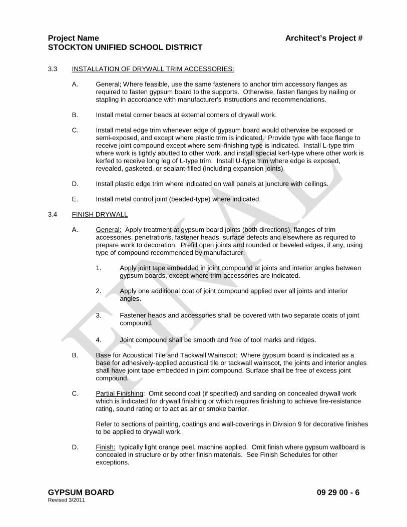
Project Name Architect’s Project # STOCKTON UNIFIED SCHOOL DISTRICT
GYPSUM BOARD 09 29 00 - 6 Revised 3/2011
3.3 INSTALLATION OF DRYWALL TRIM ACCESSORIES:
A. General; Where feasible, use the same fasteners to anchor trim accessory flanges as required to fasten gypsum board to the supports. Otherwise, fasten flanges by nailing or stapling in accordance with manufacturer's instructions and recommendations.
B. Install metal corner beads at external corners of drywall work.
C. Install metal edge trim whenever edge of gypsum board would otherwise be exposed or
semi-exposed, and except where plastic trim is indicated. Provide type with face flange to receive joint compound except where semi-finishing type is indicated. Install L-type trim where work is tightly abutted to other work, and install special kerf-type where other work is kerfed to receive long leg of L-type trim. Install U-type trim where edge is exposed, revealed, gasketed, or sealant-filled (including expansion joints).
D. Install plastic edge trim where indicated on wall panels at juncture with ceilings.
E. Install metal control joint (beaded-type) where indicated.
3.4 FINISH DRYWALL
A. General: Apply treatment at gypsum board joints (both directions), flanges of trim accessories, penetrations, fastener heads, surface defects and elsewhere as required to prepare work to decoration. Prefill open joints and rounded or beveled edges, if any, using type of compound recommended by manufacturer.
1. Apply joint tape embedded in joint compound at joints and interior angles between
gypsum boards, except where trim accessories are indicated. 2. Apply one additional coat of joint compound applied over all joints and interior
angles.
3. Fastener heads and accessories shall be covered with two separate coats of joint compound.
4. Joint compound shall be smooth and free of tool marks and ridges.
B. Base for Acoustical Tile and Tackwall Wainscot: Where gypsum board is indicated as a
base for adhesively-applied acoustical tile or tackwall wainscot, the joints and interior angles shall have joint tape embedded in joint compound. Surface shall be free of excess joint compound.
C. Partial Finishing: Omit second coat (if specified) and sanding on concealed drywall work
which is indicated for drywall finishing or which requires finishing to achieve fire-resistance rating, sound rating or to act as air or smoke barrier.
Refer to sections of painting, coatings and wall-coverings in Division 9 for decorative finishes to be applied to drywall work.
D. Finish: typically light orange peel, machine applied. Omit finish where gypsum wallboard is
concealed in structure or by other finish materials. See Finish Schedules for other exceptions.

Project Name Architect’s Project # STOCKTON UNIFIED SCHOOL DISTRICT
GYPSUM BOARD 09 29 00 - 7 Revised 3/2011
3.5 PROTECTION OF WORK:
A. Provide final protection and maintain conditions, in a manner suitable to Installer, which ensures gypsum drywall work being without damage or deterioration.
END OF SECTION 09 29 00
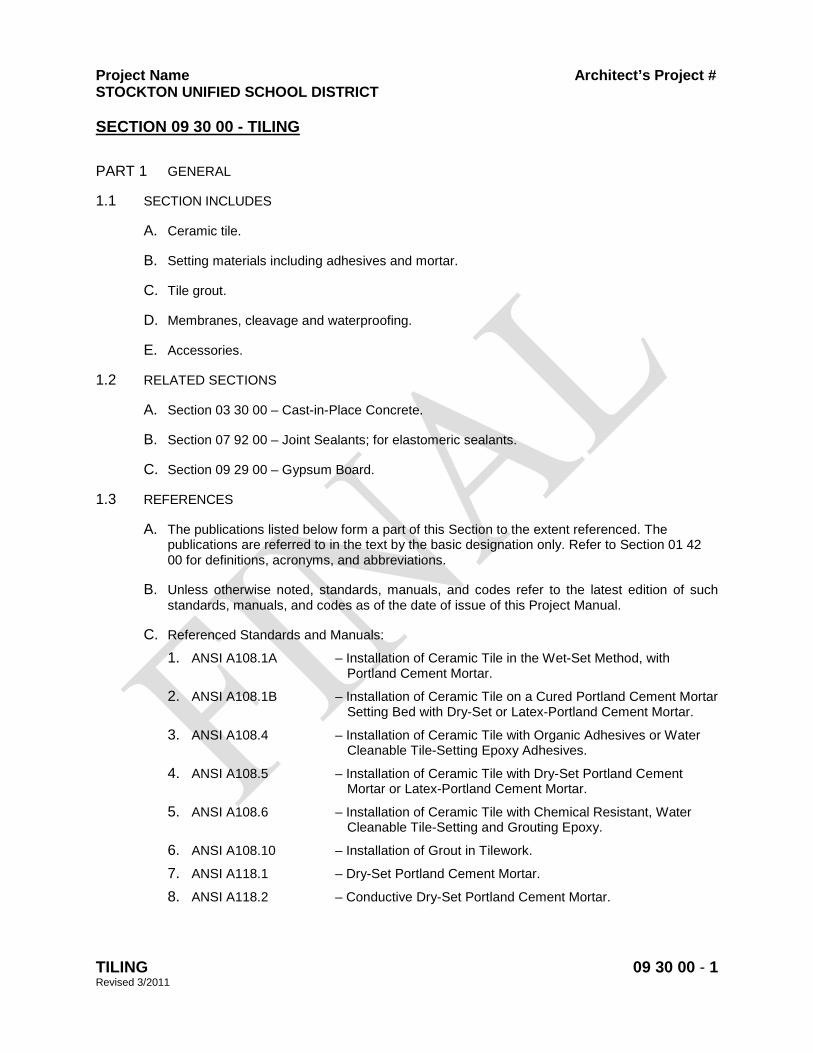
Project Name Architect’s Project # STOCKTON UNIFIED SCHOOL DISTRICT
TILING 09 30 00 - 1 Revised 3/2011
SECTION 09 30 00 - TILING
PART 1 GENERAL
1.1 SECTION INCLUDES
A. Ceramic tile.
B. Setting materials including adhesives and mortar.
C. Tile grout.
D. Membranes, cleavage and waterproofing.
E. Accessories.
1.2 RELATED SECTIONS
A. Section 03 30 00 – Cast-in-Place Concrete.
B. Section 07 92 00 – Joint Sealants; for elastomeric sealants.
C. Section 09 29 00 – Gypsum Board.
1.3 REFERENCES
A. The publications listed below form a part of this Section to the extent referenced. The publications are referred to in the text by the basic designation only. Refer to Section 01 42 00 for definitions, acronyms, and abbreviations.
B. Unless otherwise noted, standards, manuals, and codes refer to the latest edition of such standards, manuals, and codes as of the date of issue of this Project Manual.
C. Referenced Standards and Manuals:
1. ANSI A108.1A – Installation of Ceramic Tile in the Wet-Set Method, with Portland Cement Mortar.
2. ANSI A108.1B – Installation of Ceramic Tile on a Cured Portland Cement Mortar Setting Bed with Dry-Set or Latex-Portland Cement Mortar.
3. ANSI A108.4 – Installation of Ceramic Tile with Organic Adhesives or Water Cleanable Tile-Setting Epoxy Adhesives.
4. ANSI A108.5 – Installation of Ceramic Tile with Dry-Set Portland Cement Mortar or Latex-Portland Cement Mortar.
5. ANSI A108.6 – Installation of Ceramic Tile with Chemical Resistant, Water Cleanable Tile-Setting and Grouting Epoxy.
6. ANSI A108.10 – Installation of Grout in Tilework.
7. ANSI A118.1 – Dry-Set Portland Cement Mortar.
8. ANSI A118.2 – Conductive Dry-Set Portland Cement Mortar.
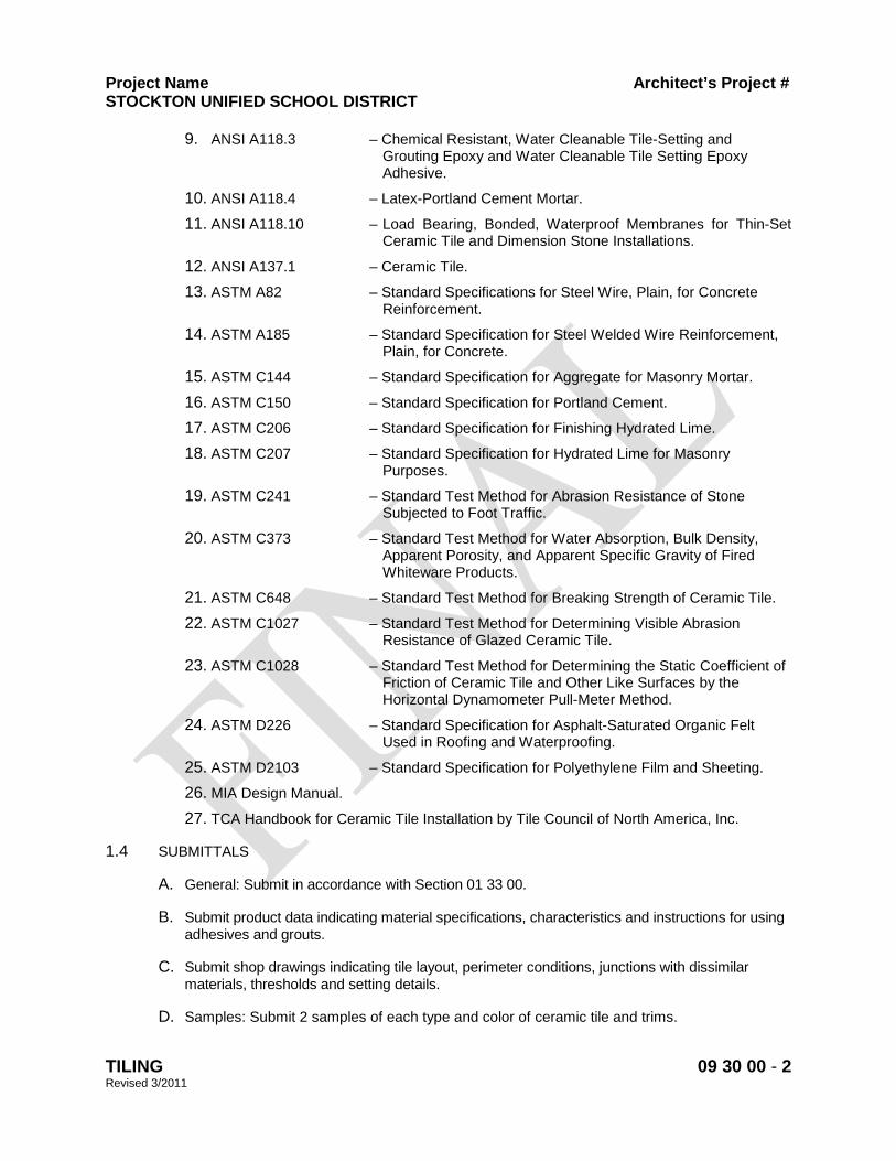
Project Name Architect’s Project # STOCKTON UNIFIED SCHOOL DISTRICT
TILING 09 30 00 - 2 Revised 3/2011
9. ANSI A118.3 – Chemical Resistant, Water Cleanable Tile-Setting and Grouting Epoxy and Water Cleanable Tile Setting Epoxy Adhesive.
10. ANSI A118.4 – Latex-Portland Cement Mortar.
11. ANSI A118.10 – Load Bearing, Bonded, Waterproof Membranes for Thin-Set Ceramic Tile and Dimension Stone Installations.
12. ANSI A137.1 – Ceramic Tile.
13. ASTM A82 – Standard Specifications for Steel Wire, Plain, for Concrete Reinforcement.
14. ASTM A185 – Standard Specification for Steel Welded Wire Reinforcement, Plain, for Concrete.
15. ASTM C144 – Standard Specification for Aggregate for Masonry Mortar.
16. ASTM C150 – Standard Specification for Portland Cement.
17. ASTM C206 – Standard Specification for Finishing Hydrated Lime.
18. ASTM C207 – Standard Specification for Hydrated Lime for Masonry Purposes.
19. ASTM C241 – Standard Test Method for Abrasion Resistance of Stone Subjected to Foot Traffic.
20. ASTM C373 – Standard Test Method for Water Absorption, Bulk Density, Apparent Porosity, and Apparent Specific Gravity of Fired Whiteware Products.
21. ASTM C648 – Standard Test Method for Breaking Strength of Ceramic Tile.
22. ASTM C1027 – Standard Test Method for Determining Visible Abrasion Resistance of Glazed Ceramic Tile.
23. ASTM C1028 – Standard Test Method for Determining the Static Coefficient of Friction of Ceramic Tile and Other Like Surfaces by the Horizontal Dynamometer Pull-Meter Method.
24. ASTM D226 – Standard Specification for Asphalt-Saturated Organic Felt Used in Roofing and Waterproofing.
25. ASTM D2103 – Standard Specification for Polyethylene Film and Sheeting.
26. MIA Design Manual.
27. TCA Handbook for Ceramic Tile Installation by Tile Council of North America, Inc.
1.4 SUBMITTALS
A. General: Submit in accordance with Section 01 33 00.
B. Submit product data indicating material specifications, characteristics and instructions for using adhesives and grouts.
C. Submit shop drawings indicating tile layout, perimeter conditions, junctions with dissimilar materials, thresholds and setting details.
D. Samples: Submit 2 samples of each type and color of ceramic tile and trims.
Project Name Architect’s Project # STOCKTON UNIFIED SCHOOL DISTRICT
TILING 09 30 00 - 3 Revised 3/2011
E. Closeout Submittals: Cleaning and maintenance data.
1.5 QUALITY ASSURANCE
A. Qualifications:
1. Manufacturer Qualifications: Firm specializing in manufacturing products specified in this Section with a minimum 10 years experience.
2. Installer Qualifications: Firm specializing in installing work specified in this Section acceptable to manufacturer with experience on at least 5 projects of similar nature in past 3 years.
B. Perform work in accordance with TCA Handbook for Ceramic Tile Installation and ANSI A108 Series. Provide a copy of TCA Handbook for Ceramic Tile Installation and ANSI A108 Series at the job site.
C. Mock-ups: Provide mock-up in accordance with Section 01 43 39.
D. Pre-Installation Meetings:
1. Conduct pre-installation meeting in accordance with Section 01 30 00.
2. Convene pre-installation meeting prior to commencing work of this Section.
3. Coordinate work in this Section with work in related Sections.
1.6 DELIVERY, STORAGE, AND HANDLING
A. Comply with requirements of Section 01 60 00.
B. Deliver products in manufacturer's original containers, dry and undamaged, with seals and labels intact.
C. Storage and Protection: Store materials in a dry secure place. Protect from weather, surface contaminants, corrosion, construction traffic, and other potential damage. Protect adhesives from freezing or overheating in accordance with manufacturer's instructions.
1.7 ENVIRONMENTAL REQUIREMENTS
A. Perform ceramic tile work when the ambient temperature is at least 50 degrees F (10 degrees C) and rising. Maintain temperature above 50 degrees F (10 degrees C) while the work is being performed for at least 7 days after completion of the work.
B. Do not install adhesives in a closed, unventilated environment.
1.8 WARRANTY
A. Comply with provisions of Section 01 70 00
B. Provide manufacturer’s standard performance warranties that extend beyond a 1-year period.
1.9 MAINTENANCE
A. Extra Materials: Provide 5 percent extra of the total square footage of each type and color of tile installed. Comply with provisions of Section 01 70 00.
Project Name Architect’s Project # STOCKTON UNIFIED SCHOOL DISTRICT
TILING 09 30 00 - 4 Revised 3/2011
B. Operations and Maintenance Data: Submit cleaning and maintenance data in accordance with Section 01 70 00.
PART 2 PRODUCTS
2.1 MANUFACTURERS
A. Acceptable Manufacturers (Ceramic Tile – Interior Walls & Floors):
1. Basis-of-Design Products: By Dal-Tile Corp. Dallas, TX; 800-933-8458, www.daltile.com Interceramic Inc., Garland, TX; 214-503-5500, www.interceramicusa.com. Provide products by named manufacturer, or accepted equal by one of the following:
2. Dal-Tile Corp. Dallas, TX; 800-933-8458, www.daltile.com.
3. United States Ceramic Tile Co. East Sparta, OH; 800-321-0684, www.usctco.com.
a. American Olean Tile Co., Dallas, TX; 214-398-1411, www.aotile.com.
4. Substitutions: Under provisions of 01 60 00.
B. Acceptable Manufacturers (Setting Materials):
1. Laticrete International, Inc., Bethany, CT; 800-243-4788, www.laticrete.com.
2. Mapei Corp., Deerfield Beach, FL; 800-426-2734, www.mapei.com.
C. Acceptable Manufacturers (Grout):
1. Basis-of-Design Product: Quartz-Lock 2 Urethane Grout by StarQuartz Industries, Inc., Baltimore, MD; 866-220-4500, www.starquartz.com.
2. Substitutions: Comply with requirements of Section 01 60 00 and 01 81 13. Specified product is critical to achievement of CHPS goals. Proposed substitutions not meeting CHPS criteria will not be considered.
D. Acceptable Manufacturers (Waterproofing Membrane):
1. Laticrete International, Inc.
2. Mapei Corp.
3. The Noble Company, Grand Haven, MI; 800-878-5788, www.noblecompany.com.
E. Acceptable Manufacturers (Accessories):
1. Metal Accessories: Provide as indicated on Drawings.
a. Schlüter-Systems L.P., Plattsburgh, NY; 800-472-4588, www.schluter.com.
2. Grout Sealers: Provide sealer compatible with grout.
a. AquaMix, Inc., Santa Fe Springs, CA; 800-366-6877, www.aquamix.com.
b. SL-15, Invisible Seal Penetrating Grout and Tile Sealer by Summitville Tiles, Inc.
c. 004, Keraseal Penetrating Sealer for Unglazed Grout and Tile by Mapei Corporation.
F. Single Source Responsibility: Use setting, grout, and waterproofing materials from a single manufacturer to ensure system compatibility and quality; and to comply with manufacturer’s warranty requirements.
Project Name Architect’s Project # STOCKTON UNIFIED SCHOOL DISTRICT
TILING 09 30 00 - 5 Revised 3/2011
G. Substitutions: Conform to Section 01 60 00.
2.2 CERAMIC TILE
A. General: ANSI A137.1, Standard Grade. Packaging shall be grade sealed. Seals shall be marked to correspond with the marks on the signed master grade certificate.
B. Properties:
1. Impact resistant with a minimum breaking strength of 90 lbs (40 kg) for wall tiles and 250 lbs (113 kg) for floor tiles in accordance with ASTM C648.
2. Water absorption shall be 0.50 percent maximum in accordance with ASTM C373.
3. Floor tiles shall have a minimum static coefficient of friction of 0.6 for walking surfaces and 0.8 for ramps in accordance with ASTM C1028.
4. Unless otherwise indicated on Drawings, floor tiles shall be Class IV – Heavy Traffic durability when tested in accordance with ASTM C1027 for abrasion resistance as related to foot traffic.
C. Products: Provide tile types and sizes as indicated on Drawings.
1. Interior Ceramic Mosaic Tiles: Keystones series by Dal-Tile.
a. Nominal Size: 2 inches by 2 inches, unless otherwise indicated on Drawings.
b. Thickness: 1/4 inch.
c. Edge: Square.
d. Surface Finish: Unglazed.
e. Recycled Content: 7 percent, minimum.
f. Colors: As selected by Architect from manufacturer’s full range of colors.
2. Interior Ceramic Wall Tiles: Semi Gloss series by Dal-Tile.
a. Nominal Size: 4-1/4 inch by 4-1/4 inch, unless otherwise indicated on Drawings.
b. Thickness: 5/16 inch.
c. Surface Finish: Glazed.
d. Recycled Content: 34 percent, minimum.
e. Colors: As selected by Architect from manufacturer’s full range of colors.
D. Products: Provide tile types and sizes as indicated on Drawings.
1. Interior Ceramic Mosaic Tiles: Intertech RAL (Vitra) Matte by Interceramic.
a. Nominal Size: 2 inches by 2 inches, unless otherwise indicated on Drawings.
b. Thickness: 1/4 inch.
c. Edge: Square.
d. Surface Finish: Unglazed.
e. Recycled Content: 9 percent.
f. Color: As selected by Architect from manufacturer’s full range of colors.
2. Interior Ceramic Wall Tiles: Intertech RAL (Vitra) Gloss by Interceramic.
Project Name Architect’s Project # STOCKTON UNIFIED SCHOOL DISTRICT
TILING 09 30 00 - 6 Revised 3/2011
a. Nominal Size: 4 inch by 4 inch, unless otherwise indicated on Drawings.
b. Thickness: 5/16 inch.
c. Edge: Cushioned.
d. Surface Finish: Gloss.
e. Recycled Content: 9 percent.
f. Color: As selected by Architect from manufacturer’s full range of colors.
E. Special Shapes (trimmers, angles, bases, caps, stops, and returns): Same nominal size as field tile; rounded concave and convex surfaces; same properties as field tile (moisture absorption, surface finish, and color).
1. Provide radius at all outside vertical and horizontal corner tile.
2. Provide wall base at glazed wall tile.
3. Unless otherwise indicated, at restrooms and locker rooms, wall base shall be 6 inches high with 3/8 inch minimum cove radius.
2.3 SETTING MATERIALS
A. Latex Portland Cement Mortar: Prepackaged, one-part, high performance, latex polymer modified dry-set, thin-set mortar. Meets or exceeds ANSI A118.4.
1. Products:
a. Laticrete 253 Multipurpose Thin-Set Mortar.
b. Mapei Ultra/Flex 3
c. Or accepted equal.
B. Two-Component Latex-Portland Cement Mortar: Premium thin-set mortar mixed with acrylic latex emulsion, for use in water submerged conditions. Meets or exceeds ANSI A118.4.
1. Products:
a. Laticrete 272 Premium Floor N’ Wall Thin-Set Mortar with Laticrete 3701 Mortar Admix.
b. Or accepted equal.
C. Fast-Curing Latex-Portland Cement Mortar: Fast-setting, polymer-modified mortar. Meets or exceeds ANSI A118.4.
1. Products:
a. Laticrete 253 Rapid Gold Multi-Purpose Thin-Set Mortar (Grey or White).
b. Or accepted equal.
D. Mortar Bed.
1. Materials:
a. Cement: Portland cement, ASTM C150 Type I.
b. Aggregate: ASTM C144, clean, graded, and passes a 16-mesh screen.
c. Hydrated Lime: ASTM C206, Type S or ASTM C207, Type S.
d. Water: Clean and potable.
Project Name Architect’s Project # STOCKTON UNIFIED SCHOOL DISTRICT
TILING 09 30 00 - 7 Revised 3/2011
2. Mortar Mix: Comply with ANSI A108.1A Section A-4.1a.2.
2.4 GROUTING MATERIALS
A. Urethane Grout: Quartz based urethane grout, stainless, non-sagging, water cleanable; tested according to procedures of ANSI 118.3 and 118.3 modified.
1. Product: QuartzLock2 urethane grout by StarQuartz Industries, Inc.
2. Properties:
a. Compressive Strength: 3,500 psi.
b. Linear Shrinkage: 0.06 percent.
c. Water Absorption: <1 percent.
3. Color as selected by Architect.
2.5 MEMBRANE
A. Cleavage Membrane: Polyethylene Sheet: ASTM D2103 Type 13300, minimum 4 mil thickness.
B. Waterproofing Membrane: Trowel-applied, liquid, or sheet membrane; load bearing; bonded; conforming to ANSI A118.10.
1. Products:
a. Laticrete 9235 Waterproofing Membrane with Microban. Self-curing liquid elastomeric membrane with reinforcing fabric forming a flexible, seamless waterproof membrane bonded to the substrate. Contains an antimicrobial protection to inhibit growth of mold and mildew.
b. Noble TS. Elastomeric sheet membrane composed of chlorinated polyethylene (CPE), a non-plasticized elastomer with non-woven polyester laminated to both sides.
c. C-Cure Pro-Red Waterproofing Membrane 963. Self-curing liquid elastomeric membrane forming a flexible, seamless waterproof membrane bonded to the substrate.
d. Or accepted equal.
2.6 ACCESSORIES
A. Reinforcing Mesh: ASTM A82 and ASTM A185; galvanized welded wire fabric; 16 gage wire (1.6 mm); 2 inch by 2 inch (50 mm by 50 mm) mesh.
B. Expansion Joint: Dilex-EZ manufactured by Schlüter-Systems L.P., Plattsburgh, NY; 800- 472-4588, www.schluter.com, or accepted equal.
C. Elastomeric Sealants: Refer to Section 07 92 00.
1. Use sealants that have a VOC content of 250 g/L or less when calculated according to 40 CFR 59, Subpart D (EPA Method 24).
PART 3 EXECUTION

Project Name Architect’s Project # STOCKTON UNIFIED SCHOOL DISTRICT
TILING 09 30 00 - 8 Revised 3/2011
3.1 EXAMINATION
A. Examine job site conditions and verify field dimensions. Verify substrate is plumb, level, true to line and square.
B. Substrate surface conditions shall conform to the requirements of ANSI A108.1A and ANSI A108.1B for the type setting bed specified and for workmanship.
C. Maximum surface variation of substrate shall not exceed maximum limits as specified in specific TCA Methods or as follows, whichever is more stringent.
Type Walls Floors Dry-Set Mortar 1/8 inch in 8 feet
1/8 inch in 10 feet
Latex Portland Cement Mortar
1/8 inch in 8 feet
1/8 inch in 10 feet
Epoxy 1/8 inch in 8 feet
1/8 inch in 10 feet
Mortar Bed 1/4 inch in 10 feet
D. Tile work shall not be started until roughing in for mechanical and electrical work has been completed and tested, and built-in items requiring membrane waterproofing has been installed and tested.
E. Report unacceptable conditions to Architect. Begin installation only when unacceptable conditions have been corrected.
3.2 INSTALLATION
A. General:
1. Install in accordance with TCA Handbook for Ceramic Tile Installation and ANSI A108.
2. Install tiles as per accepted shop drawings. Do not interrupt tile pattern through openings.
3. In areas requiring floor and wall tiles, floor tile installation shall not begin until after wall tiles have been installed.
4. Where waterproofing membrane is required, allow waterproofing membrane to cure before flood testing.
5. Cut and fit tile tight to penetrations through tile. Form corners and bases neatly. Align floor, base and wall joints.
6. Place tile joints uniform in width, subject to variance in tolerance allowed in tile size. Make joints watertight, without voids, cracks, excess mortar or excess grout.
7. Provide grout joint spacing in accordance with tile manufacturer’s recommendations.
8. Install movement joints where indicated on Drawings and as specified in this Section.
9. Sound tile after setting. Replace hollow sounding units.
10. Allow tile to set prior to grouting: Minimum of 48 hours for thin-set methods and 78 hours for mortar bed methods.
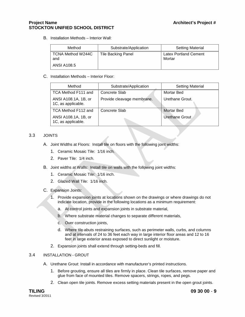
Project Name Architect’s Project # STOCKTON UNIFIED SCHOOL DISTRICT
TILING 09 30 00 - 9 Revised 3/2011
B. Installation Methods – Interior Wall:
Method Substrate/Application Setting Material TCNA Method W244C and ANSI A108.5
Tile Backing Panel Latex Portland Cement Mortar
C. Installation Methods – Interior Floor:
Method Substrate/Application Setting Material TCA Method F111 and ANSI A108.1A, 1B, or 1C, as applicable.
Concrete Slab Provide cleavage membrane.
Mortar Bed Urethane Grout.
TCA Method F112 and ANSI A108.1A, 1B, or 1C, as applicable.
Concrete Slab
Mortar Bed Urethane Grout
3.3 JOINTS
A. Joint Widths at Floors: Install tile on floors with the following joint widths:
1. Ceramic Mosaic Tile: 1/16 inch.
2. Paver Tile: 1/4 inch.
B. Joint widths at Walls: Install tile on walls with the following joint widths:
1. Ceramic Mosaic Tile: 1/16 inch.
2. Glazed Wall Tile: 1/16 inch.
C. Expansion Joints:
1. Provide expansion joints at locations shown on the drawings or where drawings do not indicate location, provide in the following locations as a minimum requirement:
a. At control joints and expansion joints in substrate material,
b. Where substrate material changes to separate different materials,
c. Over construction joints,
d. Where tile abuts restraining surfaces, such as perimeter walls, curbs, and columns and at intervals of 24 to 36 feet each way in large interior floor areas and 12 to 16 feet in large exterior areas exposed to direct sunlight or moisture.
2. Expansion joints shall extend through setting-beds and fill.
3.4 INSTALLATION - GROUT
A. Urethane Grout: Install in accordance with manufacturer’s printed instructions.
1. Before grouting, ensure all tiles are firmly in place. Clean tile surfaces, remove paper and glue from face of mounted tiles. Remove spacers, strings, ropes, and pegs.
2. Clean open tile joints. Remove excess setting materials present in the open grout joints.
Project Name Architect’s Project # STOCKTON UNIFIED SCHOOL DISTRICT
TILING 09 30 00 - 10 Revised 3/2011
3. Mix grout in accordance with manufacturer’s instructions.
4. Ensure mortar is completely dry, and tile is at room temperature.
5. Seal face and sides of porous tile and natural stone before grouting.
6. Apply grout firmly into open joints using a green, sharp-edged, firm rubber float.
7. Work grout grout diagonally across joints, packing joints full.
8. Remove excess grout from tile surface. Remove grout haze as work progresses.
3.5 CLEANING AND PROTECTING
A. Clean as recommended by manufacturer. Do not use materials or methods which may damage finish surface or surrounding construction.
B. Protect installed tile finish surfaces from damage during construction. Provide protective covering as required to ensure installed tile finish will not be damaged by work of other trades.
END OF SECTION
Project Name Architect’s Project # STOCKTON UNIFIED SCHOOL DISTRICT
ACOUSTICAL CEILINGS 09 51 00 - 1 Revised 3/2011
SECTION 09 51 00 – ACOUSTICAL CEILINGS 1. GENERAL 1.1 RELATED DOCUMENTS:
Drawings and general provision of contract, including General and Supplementary Conditions and Division-1 Specification sections, apply to work of this section.
1.2 DESCRIPTION OF WORK:
A. Extent of each type of acoustical ceiling is shown and scheduled on drawings. B. Types of acoustical ceilings specified in this section include the following:
1. Acoustical panel ceilings, exposed suspension.
3. Acoustical Fiber Panels, screw attached to concealed suspension grid.
1.3 QUALITY ASSURANCE:
A. Installer Qualifications: Firm with not less than 3 years of successful experience in installation of acoustical ceilings similar to requirements for this project and which is acceptable to manufacturer of acoustical units, as shown by current written statement from manufacturer. Installer shall be familiar with DSA I.R. 25-2.
B. Fire Performance Characteristics: Provide acoustical ceiling components that are identical
to those tested for the following fire performance characteristics, according to ASTM test method indicated, by UL or other testing and inspecting agency acceptable to authorities having jurisdiction. Identify acoustical ceiling components with appropriate marking of applicable testing and inspecting agency.
1. Surface Burning Characteristics: As follows, tested per ASTM E 84.
Flame Spread: 25 or less Smoke Developed: 50 or less
2. Fire Resistance Ratings: As indicated by reference to design designation in UL “Fire
Resistance Directory” of “FM Approval Guide,” for floor, roof or beam assemblies in which acoustical ceilings function as a fire protective membrane; tested per ASTM E 119. Provide protection materials for lighting fixtures and air ducts to comply with requirements indicated for rated assembly.
C. Coordination of Work: Coordinate layout and installation of acoustical ceiling units and
suspension system components with other work supported by or penetrating through ceilings, including light fixtures, HVAC equipment, fire-suppression system components (if any) and partition system (if any).
1.4 SUBMITTALS:
A. Product Data: Manufacturer’s product specifications and installation instructions for each acoustical ceiling material required and for each suspension system, including certified
Project Name Architect’s Project # STOCKTON UNIFIED SCHOOL DISTRICT
ACOUSTICAL CEILINGS 09 51 00 - 2 Revised 3/2011
laboratory test reports and other data as required to show compliance with these specifications.
1. Include manufacturer’s recommendations for cleaning acoustical unit, including
precautions against materials and methods which may be detrimental to finishes and acoustical performances.
B. Samples: Set of 3 - 4" x 4” square samples for each acoustical unit required, showing full
range of exposed color and texture to be expected in completed work. 1.5 DELIVERY, STORAGE, AND HANDLING:
A. Deliver acoustical ceiling units to project site in original unopened packages and store them in a fully enclosed space where they will be protected against damage from moisture, direct sunlight, surface contamination or other causes.
B. Before installing acoustical ceiling units, permit them to reach room temperature and
stabilized moisture content.
C. Handle acoustical ceiling units carefully to avoid chipping edges or damaging units in any way.
1.6 PROJECT CONDITIONS:
A. Space enclosure: Do not install interior acoustical ceilings until space is enclosed and weatherproof, wet-work in space is completed and nominally dry, work above ceilings is complete, and ambient conditions of temperature and humidity will be continuously maintained at values near those indicated for final occupancy.
2. PRODUCTS 2.1 ACOUSTICAL CEILING UNITS, GENERAL:
A. Colors, Textures, and Patterns: Provide products to match appearance characteristics indicated or, if not otherwise indicated, as selected by Architect from manufacturer’s standard colors, surface textures, and patterns available for acoustical ceiling units and exposed metal suspension system members of quality designated.
2.2 ACOUSTICAL PANELS:
A. Type III Panels (Classrooms), Mineral Composition with Scrubbable Pigmented or Clear Finish:
1. Water Felted Units, Fissured: Form 2, Pattern C D. NRC 0.55, CAC 35, ALR 0.82,
square edge, white 24”x48”x5/8”. 2. Available Products: Subject to compliance with requirements, products which may
be incorporated in the work include, but are not limited to, the following:
a. Non-fire Resistant Rated Panels:
Cortega 769; Armstrong World Industries, Inc. .
Project Name Architect’s Project # STOCKTON UNIFIED SCHOOL DISTRICT
ACOUSTICAL CEILINGS 09 51 00 - 3 Revised 3/2011
B. Type XX Panels (Kitchen) – High Density Ceramic-like Composition: Resistant to heat, moisture, mildew, and corrosive fumes, suitable for kitchen applications; Pattern/NRC as indicated below; CAC 40, square edge, white, 24”x48” x 5/8” or as indicated.
1. Ceramic-Like Composition, Fissured: Pattern G. NRC 0.10, CAC 40, ALR 0.88,
square edge, white 24”x48”x5/8”.
2. Available Products: Subject to compliance with requirements, products which may be incorporated into the work include, but are not limited to, the following:
a. Fine Fissured Ceramaguard 605; Armstrong World Industries, Inc.
2.3 EXPOSED METAL DIRECT-HUNG SUSPENSION SYSTEMS: A. Non-Fire-rated Single Web Steel Suspension System: 1. Structural Classification: Donn Corp., Heavy-Duty System a. Main Tee: DX 26 b. Cross Tee: DXO 216 c. Finish: Painted, White 2.4 ACOUSTICAL FIBER PANELS (Multi-use): A. Manufacturer: TECTUM, INC. B. Product: Ceiling Panel, 1” thick, 24” x 48”, Standard Bevel-Edge (long edge only) C. Finish: Factory Natural
D. Attachment:: #8 x 1 ½” long TEK screw, color matched, face attached through suspension channels (see plans). Provide continuous 3/8” bead of construction adhesive along attachment channels. Measure screw locations to provide visual continuity of exposed fasteners, to pattern shown on plans.
2.5 ACOUSTICAL GLUE UP PANELS (Band/PE Room):
A. Type III Panels Mineral Composition with Scrubbable Pigmented or Clear Finish:
1. Water Felted Units, Fissured: Form 2, Pattern C D. NRC 0.50, ALR 0.86, tongue & groove, white 12”x12”x1/2”. Glue attach to gypsum board.
2. Available Products: Subject to compliance with requirements, products which may
be incorporated in the work include, but are not limited to, the following:
b. Non-fire Resistant Rated Panels:
Fissured 714; Armstrong World Industries, Inc. 2.6 MISCELLANEOUS MATERIALS
A. Tile Adhesive: Comply with ASTM D 1779 or FS MMM-A-00150, type recommended by tile manufacturer, bearing UL label for Class 0-25 flame spread.

Project Name Architect’s Project # STOCKTON UNIFIED SCHOOL DISTRICT
ACOUSTICAL CEILINGS 09 51 00 - 4 Revised 3/2011
B. Acoustical Sealant: Resilient, non-staining, non-shrinking, non-hardening, non-skinning, non-drying, non-sag sealant intended for interior sealing of concealed construction joints.
1. Available Products: Subject to compliance with requirements, products which may
be incorporated in the work include, but are not limited to, the following:
Tremco Acoustical Sealant; Tremco USG Acoustical Sealant; United States Gypsum Co. Chem-Calk 600; Woodmont Products, Inc.
C. Compression Posts: As detailed on drawings 3. EXECUTION 3.1 PREPARATION:
A. Coordination: Furnish layouts for inserts, clips, or other supports required to be installed by other trades for support of acoustical ceilings.
1. Furnish concrete inserts, steel deck hanger clips and similar devices to other trades
for installation well in advance of time needed for coordination of other work.
B. Measure each ceiling area and establish layout of acoustical units to balance border widths at opposite edges of each ceiling. Avoid use of less-than-half width units at borders, and comply with reflected ceiling plans wherever possible.
3.2 INSTALLATION:
A. General: Install materials in accordance with manufacturer’s printed instructions, and to comply with governing regulations, fire-resistance rating requirements as indicated, and industry standards applicable to work.
B. Arrange acoustical units and orient directionally patterned units (if any) in manner shown by
reflected ceiling plans.
C. Install acoustical tile by cementing to substrate, using amount of adhesive and procedure recommended by tile manufacturer. Maintain tight butt joints, aligned in bother directions, and coordinated with ceiling fixtures. Scribe and cut tile to fit accurately at ceiling edges and penetrations.
D. Secure wire hangers by looping and wire-tying, either directly to structures or to inserts, eye-
screws, or other devices which are secure and appropriate for substrate, and which will not deteriorate or fail with age or elevated temperatures. Wires shall be prevented from sliding along framing.
E. Install hangers plumb and free from contact with insulation or other objects with ceiling
plenum which are not part of supporting structural or ceiling suspension system. Splay hangers only where required to miss obstructions and offset resulting horizontal force by bracing, countersplaying or other equally effective means.
F. Install edge moldings of type indicated at perimeter of acoustical ceiling area and at
locations where necessary to conceal edges of acoustical units. 1. Sealant Bed: Apply continuous ribbon of acoustical sealant, concealed on back of
vertical leg before installing molding.

Project Name Architect’s Project # STOCKTON UNIFIED SCHOOL DISTRICT
ACOUSTICAL CEILINGS 09 51 00 - 5 Revised 3/2011
2. Screw-attach moldings to substrate at intervals not over 16” o.c. and not more than
3” from ends leveling with ceiling suspension system to tolerance of 1/8” in 12’-0”. Miter corners accurately and connect securely. Butt splice only.
G. Install acoustical panels in coordination with suspension system, with edges concealed by
support of suspension members. Scribe and cut panels to fit accurately at borders and at penetrations.
1. Install hold-down clips in areas indicated, and areas where required by governing
regulations or for fire-resistance ratings; space as recommended by panel manufacturer, unless otherwise indicated or required.
3.3 ADJUST AND CLEAN:
A. Clean exposed surfaces of acoustical ceilings, including trim, edge moldings, and suspension members; comply with manufacturer’s instructions for cleaning and touch-up of minor finish damage. Remove and replace work which cannot be successfully cleaned and repaired to permanently eliminate evidence of damage.
3.4 EXTRA STOCK: Deliver stock of maintenance material to Owner, furnish maintenance material
matching products installed, packaged with protective covering for storage and identified with appropriate labels.
A. Acoustical Ceiling Units: (lay-in panels and tiles) Furnish quantity of full size units equal to
2%of amount installed. B. Exposed Suspension Components: Furnish quantity of each exposed component required
for actual installation equal to 1% of amount installed.
END OF SECTION

Project Name Architect’s Project # STOCKTON UNIFIED SCHOOL DISTRICT
WALL COVERINGS 09 72 00 - 1 Revised 3/2011
SECTION 09 72 00 - WALL COVERINGS
PART 1 GENERAL
1.1 SECTION INCLUDES
A. Surface Preparation.
B. Vinyl wall covering, with digital printing.
C. Adhesives and Accessories.
1.2 RELATED SECTIONS
A. Section 09 29 00 – Gypsum Board Systems: Wall substrate.
B. Section 09 91 00 – Painting: Preparation and priming of substrate surfaces.
1.3 REFERENCES
A. The publications listed below form a part of this Section to the extent referenced. The publications are referred to in the text by the basic designation only. Refer to Section 01 42 00 for definitions, acronyms, and abbreviations.
B. Unless otherwise noted, standards, manuals, and codes refer to the latest edition of such standards, manuals, and codes as of the date of issue of this Project Manual.
C. Referenced Standards:
1. ASTM E84 – Standard Test Method for Surface Burning Characteristics of Building Materials.
2. ASTM F1141 – Standard Specification for Wallcovering.
3. 2007 California Building Code (CBC).
4. NFPA 255 – Standard Method of Test of Surface Burning Characteristics of Building Materials.
5. UL 723 – Test for Surface Burning characteristics of Building Materials.
1.4 SUBMITTALS
A. Product Data:
1. Submit product data under provisions of Section 01 33 00.
2. Provide product data on each type and color of wall covering and adhesive.
B. Samples:
1. Submit samples under provisions of Section 01 33 00.
2. Submit one full linear yard sample of each type of wall covering selected to illustrate quality, weight, color range and pattern variation. Supply samples from actual production.
Formatted: Footer distance from edge: 0.5"
Project Name Architect’s Project # STOCKTON UNIFIED SCHOOL DISTRICT
WALL COVERINGS 09 72 00 - 2 Revised 3/2011
C. Digital Wallcovering:
1. Submit “mini-mural” of complete finish image printed on actual substrate used for final product.
2. Submit sample section of final image at 100 percent resolution printed on actual substrate used for final product.
3. Panel map of image to be included with shipment of final product.
D. Submittals other than the specified material shall match the appearance and color of the selected material and equal or exceed the quality, total weight, fabric backing, tensile and tear strength, UL fire ratings and mildew resistance of the specified product(s).
E. Submit written evidence that all materials proposed for use conform to recommendations of the wall covering manufacturer for warranted installations.
F. Manufacturer’s Certifications:
1. Submit manufacturer’s written certification that the material shipped to the job site meets all specified physical and performance requirements. Certification from the dealer or distributor will not be acceptable.
2. Copies of test reports and corresponding literature shall accompany the quality level the Contractor proposes to use.
G. Submit manufacturer's installation instructions under provisions of Section 01 33 00, including procedures and perimeter conditions requiring special attention.
1.5 QUALITY ASSURANCE
A. Manufacturer: Company specializing in manufacturing commercial wall fabrics with sufficient documented experience, whose published product literature indicates compliance of wall coverings specified.
B. Applicator: Company specializing in installation of commercial fabric wall covering performed by skilled applicators with sufficient documented experience.
C. Materials Standards: UL rating and labeling, Smoke Toxicity, Fire Detection Characteristics Composition, Physical properties.
D. Field Sample Panels: Install three full-width panels in designated areas. Retain accepted panels as a standard for completed wall covering work.
E. Imperfections such as engraving roller die marks, roller repeat marks, glossy surface appearance, or other features deemed not in conformance with the specified materials will be cause for rejection if evidenced in either the submitted samples or the manufactured material delivered to the job.
F. Each roll of material delivered to the job site shall have UL labels with specified fire-resistance rating.
G. Mockups: Build mockups to verify selections made under sample submittals and to demonstrate aesthetic effects and set quality standards for fabrication and installation.
1. Build mockups for each type of wall covering on each substrate required. Comply with requirements in ASTM F1141.
Project Name Architect’s Project # STOCKTON UNIFIED SCHOOL DISTRICT
WALL COVERINGS 09 72 00 - 3 Revised 3/2011
2. Approved mockups may become part of the completed Work if undisturbed at time of Substantial Completion.
1.6 REGULATORY REQUIREMENTS
A. Conform to California Building Code (CBC), Chapter 8 “Interior Finishes,” requirements for flame spread and smoke density ratings for wall coverings, when tested to ASTM E84; and NFPA 255.
B. Fire-Test-Response Characteristics: As determined by testing identical wall coverings applied with identical adhesives to substrates according to test method indicated below by a qualified testing agency. Identify products with appropriate markings of applicable testing agency.
1. Surface-Burning Characteristics: As follows, per ASTM E84:
a. Flame-Spread Index: 25 or less.
b. Smoke-Developed Index: 450 or less.
1.7 DELIVERY, STORAGE AND HANDLING
A. Deliver products to site under provisions of Section 01 60 00.
B. Store and protect products under provisions of Section 01 60 00.
C. Inspect roll materials on site to verify acceptance.
D. Protect packaged adhesive from temperature cycling and cold temperatures.
E. Do not store roll goods on end.
1.8 ENVIRONMENTAL REQUIREMENTS
A. Provide continuous ventilation and heating facilities to maintain substrate surface and ambient temperatures above 65 degrees F, unless required otherwise by manufacturer's instructions.
B. Do not apply adhesive when substrate surface temperature or ambient temperature is below 65 degrees F or relative humidity is above 40 percent.
C. Maintain these conditions 72 hours before, during and continuously after installation of wall covering and fabric covered tackboard.
D. Lighting: Do not install wall covering until a permanent level of lighting is provided on the surfaces to receive wall covering.
1. Provide lighting level of 80 ft. candles measured mid-height at substrate surfaces to receive wall coverings.
E. Protect adjoining surfaces against damage and soiling.
1.9 WARRANTY
A. Submit warranties in accordance with Section 01 70 00 requirements.
B. Wall Coverings: Submit manufacturer’s written warranty against manufacturing defects for a period of five years, from the date of Substantial Completion.
Project Name Architect’s Project # STOCKTON UNIFIED SCHOOL DISTRICT
WALL COVERINGS 09 72 00 - 4 Revised 3/2011
C. Primer and Adhesive: Submit manufacturer’s written warranty against loss of adhesion and staining for a period of five years, from the date of Substantial Completion.
PART 2 PRODUCTS
2.1 MANUFACTURERS AND PRODUCTS
A. Acceptable Manufacturers and Distributors:
1. Koroseal Interior Products, a Division of RJF International, Inc., Fairlawn, OH; 877-926-3667, www.koroseal.com.
2. MDC Wall Coverings, Elk Grove, IL; 800-621-4006, www.mdcwall.com.
3. Tri Kes Wall Covering, Dallas, TX; 800-200-8120, www.tri-kes.com.
B. Substitutions: Under provisions of Section 01 60 00.
2.2 VINYL WALL COVERING
A. Basis-of-Design Product: Korographics Digital Wallcoverings by Koroseal Interior Products; or accepted equal.
B. Materials: Vinyl wall covering conforming to Federal Specification CCC-W-408A and CFFA-W-101-D, and having the following properties:
1. Fabric: Vinyl, Teflon® protected.
2. Fire Hazard Classification: Class A; as tested in accordance with ASTM E84; flame spread 5, smoke developed 300. Conforms to UL 723 and NFPA 255 requirements.
3. Printing: Single-sided digital printing with eco-solvent and UV inks.
4. Colors: As indicated on Drawings.
2.3 ACCESSORIES
A. Adhesive: Type recommended by wall covering manufacturer in writing, for use with specific wall covering and substrate.
1. Mildew resistant, non-staining adhesive, water-based type.
2. VOC Content: 50 g/L or less, when calculated according to 40 CFR 59 (EPA Method 24).
B. Substrate Filler: As recommended by adhesive and wall covering manufacturers, compatible with substrate.
C. Substrate Primer and Sealer: Mildew-resistant, type as recommended in writing by wall covering manufacturer.
D. Seam Tape: As recommended in writing by wall covering manufacturer.
PART 3 EXECUTION
3.1 INSPECTION
Project Name Architect’s Project # STOCKTON UNIFIED SCHOOL DISTRICT
WALL COVERINGS 09 72 00 - 5 Revised 3/2011
A. Verify that substrate surfaces are dry and ready to receive work, and conform to requirements of the wall covering manufacturer.
B. Verify flatness tolerance of surfaces does not vary more than 1/8 inch in 10 feet nor vary at a rate greater than 1/16 inch per foot.
C. Measure moisture content of substrates using an electronic moisture meter. Do not apply wall coverings unless moisture content of surface is below 12 percent.
D. Beginning of installation means acceptance of existing surfaces.
3.2 PREPARATION
A. Comply with manufacturer's written instructions for surface preparation.
B. Clean substrates of substances that could impair bond of wall covering, including dirt, oil, grease, mold, mildew, and incompatible primers.
C. Correct defects, fill cracks, and smooth irregularities with filler; sand smooth.
D. Concrete Substrate: Wash surfaces with trisodium phosphate, rinse and neutralize; wipe dry.
E. Moisture Content: Maximum of 5 percent on new plaster, concrete, and concrete masonry units, when tested with an electronic moisture meter.
F. Plaster: Allow new plaster to cure. Neutralize areas of high alkalinity. Prime with primer as recommended in writing by primer/sealer manufacturer and wall-covering manufacturer.
G. Metals: If not factory primed, clean and apply metal as recommended in writing by primer/sealer manufacturer and wall-covering manufacturer.
H. Gypsum Board: Prime with primer as recommended in writing by primer/sealer manufacturer and wall-covering manufacturer.
I. Painted Surfaces: Check painted surfaces for pigment bleeding. Sand gloss, semigloss, and eggshell finish with fine sandpaper. Treat areas susceptible to pigment bleeding.
J. Apply primer paint to substrate surfaces as recommended by manufacturer. Allow to dry. Lightly sand smooth.
K. Sand glossy surfaces to remove gloss.
L. Remove electrical, telephone and miscellaneous wall plates and covers and surface-mounted fixtures.
M. Vacuum clean surfaces free of loose particles.
N. Acclimatize wall-covering materials by removing them from packaging in the installation areas not less than 24 hours before installation.
3.3 INSTALLATION
A. General: Comply with wall-covering manufacturers' written installation instructions applicable to products and applications indicated, except where more stringent requirements apply.
Project Name Architect’s Project # STOCKTON UNIFIED SCHOOL DISTRICT
WALL COVERINGS 09 72 00 - 6 Revised 3/2011
B. Cut wall covering materials in manufacture’s consecutive numerical bolt sequence starting with highest number bolt and working to the lowest number bolt.
C. Install strips in same order as cut from roll.
D. Apply adhesive and wall covering in accordance with manufacturer's written instructions.
E. Apply adhesive to wall fabric surface immediately prior to application of wall covering.
F. Razor trim edges on flat worktable. Do not razor cut on gypsum board surfaces.
G. Apply wall covering smoothly, without wrinkles, gaps or overlaps. Eliminate air pockets and ensure full bond to substrate surface. Butt edges tight.
H. Horizontal seams are not acceptable.
I. Do not seam within 6 inches of internal or external corners.
J. Install wall covering before installation of bases, cabinets, hardware or items attached to or spaced slightly away from wall surface. Do not install wall covering more than 1/4 inch below top of resilient base.
K. Cover spaces above and below windows and above doors in pattern sequence from roll.
L. Remove excess wet adhesive from seam before proceeding to next wall covering sheet. Wipe clean with dry cloth.
M. Vertical seams of wall coverings shall be plumb and true.
N. The wall covering shall be smoothed to the hanging surface using a stiff bristled sweep brush or a flexible board-knife to eliminate air bubbles.
3.4 CLEANING
A. Clean wall coverings of excess adhesive, dust, dirt and other contaminants.
B. Remove excessive adhesive from adjacent surfaces as work progresses.
C. Replace wall plates and accessories removed prior to work of this Section.
3.5 PROTECTION
A. Protect finished installation under provisions of Section 01 50 00.
END OF SECTION

MONTEZUMA EXTERIOR PAINT STOCKTON UNIFIED SCHOOL DISTRICT
PAINTING 09 91 00 - 1 Revised 3/2011
SECTION 09 91 00 - PAINTING
PART 1 GENERAL
1.1 SECTION INCLUDES
A. Surface preparation.
B. Painting schedules, including painting of exposed surfaces, interior and exterior, except as otherwise specified or indicated.
1.2 RELATED SECTIONS
A. Section 05 50 00 – Metal Fabrications: Shop Primed Surfaces.
B. Section 07 62 00 – Sheet Metal Flashing and Trim.
C. Section 08 11 13 – Hollow Metal Doors and Frames.
D. Section 08 14 16 – Flush Wood Doors.
E. Section 09 24 00 – Portland Cement Plastering.
F. Section 09 29 00 – Gypsum Board.
G. Divisions 21 – 23 – Mechanical Sections as applicable to the Project.
H. Divisions 25 – 28 – Electrical Sections as applicable to the Project.
1.3 REFERENCES
A. The publications listed below form a part of this Section to the extent referenced. The publications are referred to in the text by the basic designation only. Refer to Section 01 42 00 for definitions, acronyms, and abbreviations.
B. Unless otherwise noted, standards, manuals, and codes refer to the latest edition of such standards, manuals, and codes as of the date of issue of this Project Manual
C. Referenced Standards:
1. ASTM D523 – Standard Test Method for Specular Gloss.
2. The Master Painters Institute, MPI Gloss and Sheen Levels.
1.4 QUALITY ASSURANCE
A. Product Manufacturer: Company specializing in manufacturing quality paint and finish products with sufficient documented experience.
B. Applicator: Company specializing in commercial painting and finishing with sufficient documented experience.
C. Gloss Levels: Per Master Painters Institute (MPI) gloss standards “MPI Gloss and Sheen Levels,” measured in accordance with ASTM D523.
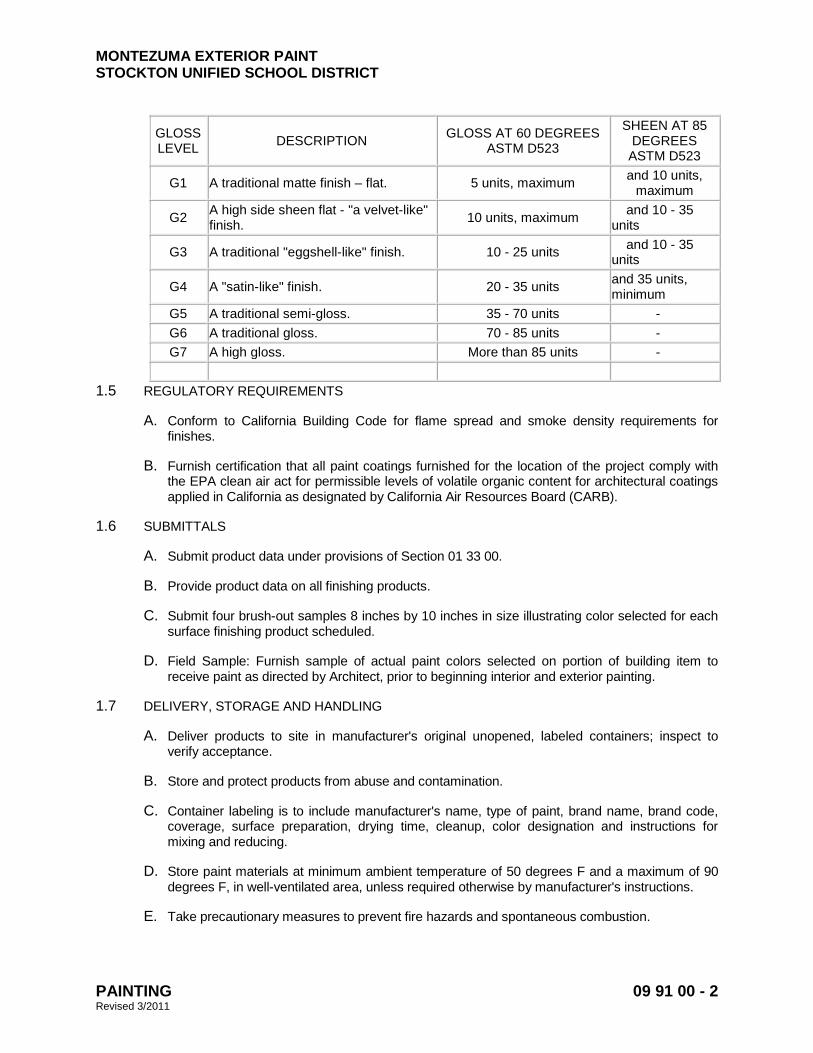
MONTEZUMA EXTERIOR PAINT STOCKTON UNIFIED SCHOOL DISTRICT
PAINTING 09 91 00 - 2 Revised 3/2011
GLOSS LEVEL DESCRIPTION GLOSS AT 60 DEGREES
ASTM D523
SHEEN AT 85 DEGREES ASTM D523
G1 A traditional matte finish – flat. 5 units, maximum and 10 units, maximum
G2 A high side sheen flat - "a velvet-like" finish. 10 units, maximum and 10 - 35
units
G3 A traditional "eggshell-like" finish. 10 - 25 units and 10 - 35 units
G4 A "satin-like" finish. 20 - 35 units and 35 units, minimum
G5 A traditional semi-gloss. 35 - 70 units - G6 A traditional gloss. 70 - 85 units - G7 A high gloss. More than 85 units -
1.5 REGULATORY REQUIREMENTS
A. Conform to California Building Code for flame spread and smoke density requirements for finishes.
B. Furnish certification that all paint coatings furnished for the location of the project comply with the EPA clean air act for permissible levels of volatile organic content for architectural coatings applied in California as designated by California Air Resources Board (CARB).
1.6 SUBMITTALS
A. Submit product data under provisions of Section 01 33 00.
B. Provide product data on all finishing products.
C. Submit four brush-out samples 8 inches by 10 inches in size illustrating color selected for each surface finishing product scheduled.
D. Field Sample: Furnish sample of actual paint colors selected on portion of building item to receive paint as directed by Architect, prior to beginning interior and exterior painting.
1.7 DELIVERY, STORAGE AND HANDLING
A. Deliver products to site in manufacturer's original unopened, labeled containers; inspect to verify acceptance.
B. Store and protect products from abuse and contamination.
C. Container labeling is to include manufacturer's name, type of paint, brand name, brand code, coverage, surface preparation, drying time, cleanup, color designation and instructions for mixing and reducing.
D. Store paint materials at minimum ambient temperature of 50 degrees F and a maximum of 90 degrees F, in well-ventilated area, unless required otherwise by manufacturer's instructions.
E. Take precautionary measures to prevent fire hazards and spontaneous combustion.
MONTEZUMA EXTERIOR PAINT STOCKTON UNIFIED SCHOOL DISTRICT
PAINTING 09 91 00 - 3 Revised 3/2011
1.8 ENVIRONMENTAL REQUIREMENTS
A. Provide continuous ventilation and heating facilities to maintain surface and ambient temperatures above 50 degrees F for 24 hours before, during and 48 hours after application of finishes, unless required otherwise by manufacturer's instructions.
B. Do not apply exterior coatings during rain or snow, or when relative humidity is above 50 percent, unless required otherwise by manufacturer's instructions.
C. Minimum Application Temperatures for Latex Paints: 50 degrees F for exterior work and interior work, unless required otherwise by manufacturer's instructions.
D. Provide lighting level of 80 foot candles measured mid-height at substrate surface.
1.9 EXTRA STOCK
A. Provide a new and unopened five-gallon container of each type, color and sheen to Owner.
B. Label each container with color, in addition to the manufacturer's label.
PART 2 PRODUCTS
2.1 PAINT SYSTEMS, GENERAL
A. Material Compatibility:
1. Provide materials for use within each paint system that are compatible with one another and substrates indicated, under conditions of service and application as demonstrated by manufacturer, based on testing and field experience.
2. For each coat in a paint system, provide products recommended in writing by manufacturers of topcoat for use in paint system and on substrate indicated.
2.2 SUSTAINABLE DESIGN REQUIREMENTS
A. VOC Content of Field-Applied Interior Paints and Coatings: Provide products that comply with the following limits for VOC content, exclusive of colorants added to a tint base, when calculated according to 40 CFR 59, Subpart D (EPA Method 24); these requirements do not apply to paints and coatings that are applied in a fabrication or finishing shop:
1. Flat Paints, Coatings, and Primers: VOC content not more than 50 g/L.
2. Nonflat Paints, Coatings, and Primers: VOC content not more than 50 g/L.
3. Anti-Corrosive and Anti-Rust Paints Applied to Ferrous Metals: VOC content not more than 250 g/L.
4. Floor Coatings: VOC content not more than 50 g/L.
5. Shellacs, Clear: VOC content not more than 730 g/L.
6. Shellacs, Pigmented: VOC content not more than 550 g/L.
B. Chemical Components of Field-Applied Interior Paints and Coatings: Provide topcoat paints and anti-corrosive and anti-rust paints applied to ferrous metals that comply with the following chemical restrictions; these requirements do not apply to paints and coatings that are applied in a fabrication or finishing shop:
MONTEZUMA EXTERIOR PAINT STOCKTON UNIFIED SCHOOL DISTRICT
PAINTING 09 91 00 - 4 Revised 3/2011
1. Aromatic Compounds: Paints and coatings shall not contain more than 1.0 percent by weight of total aromatic compounds (hydrocarbon compounds containing one or more benzene rings).
2. Restricted Components: Paints and coatings shall not contain any of the following:
a. Acrolein.
b. Acrylonitrile.
c. Antimony.
d. Benzene.
e. Butyl benzyl phthalate.
f. Cadmium.
g. Di (2-ethylhexyl) phthalate.
h. Di-n-butyl phthalate.
i. Di-n-octyl phthalate.
j. 1, 2-dichlorobenzene.
k. Diethyl phthalate.
l. Dimethyl phthalate.
m. Ethylbenzene.
n. Formaldehyde.
o. Hexavalent chromium.
p. Isophorone.
q. Lead.
r. Mercury.
s. Methyl ethyl ketone.
t. Methyl isobutyl ketone.
u. Methylene chloride.
v. Naphthalene.
w. Toluene (methylbenzene).
x. 1,1,1-trichloroethane.
y. Vinyl chloride.
2.3 ACCEPTABLE MANUFACTURERS – PAINT
A. Refer to Table at the end of this Section.
B. Substitutions: Under provisions of Section 01 60 00.
2.4 ACCEPTABLE MANUFACTURERS – PRIMER SEALERS
A. Refer to Table at the end of this Section.
B. Substitutions: Under provisions of Section 01 60 00.
MONTEZUMA EXTERIOR PAINT STOCKTON UNIFIED SCHOOL DISTRICT
PAINTING 09 91 00 - 5 Revised 3/2011
2.5 ACCEPTABLE MANUFACTURERS – STAIN AND CLEAR FINISHES
A. Refer to Table at the end of this Section.
B. Substitutions: Under provisions of Section 01 60 00.
2.6 MATERIALS
A. All paint materials shall be provided from a single manufacturer unless noted otherwise in this Section.
B. Coatings: Ready mixed. Process pigments to a soft paste consistency capable of being readily and uniformly dispersed to a homogeneous coating.
C. Coatings: Good flow and brushing properties; capable of drying or curing free of streaks or sags.
D. Accessory Materials: All other materials not specifically indicated but required to achieve the finishes specified, of commercial quality.
E. All Materials specified by brand name or manufacturer shall be delivered unopened at the job in their original containers.
2.7 FINISHES
A. Refer to schedule at end of Section for surface finish schedule. Refer to Drawings for color schedule.
PART 3 EXECUTION
3.1 GENERAL
A. Storage: All materials used by the painting contractor shall be stored and mixed in a place designated by the Owner or the Architect. The storage place must be kept neat and clean at all times. All cloths, waste or other material that might constitute a fire hazard shall be placed in a suitable metal container or shall be removed from the site or destroyed at the end of each day’s work.
3.2 INSPECTION
A. Verify that surfaces are ready to receive work as instructed by the product manufacturer.
B. Examine surfaces scheduled to be finished prior to commencement of work. Report any condition that may potentially affect proper application.
C. Measure moisture content of surfaces using an electronic moisture meter. Do not apply finishes unless moisture content of surfaces are below the following maximums:
1. Plaster; Gypsum Wallboard: 18 percent.
2. Concrete Masonry Units: 10 percent.
3. Interior Located Wood: 15 percent.
4. Exterior Located Wood: 7 percent.

MONTEZUMA EXTERIOR PAINT STOCKTON UNIFIED SCHOOL DISTRICT
PAINTING 09 91 00 - 6 Revised 3/2011
D. Beginning of application constitutes acceptance of existing surfaces.
3.3 PREPARATION
A. Remove electrical plates, hardware, light fixture trim, and fittings prior to preparing surfaces or painting.
B. Correct minor defects and clean surfaces that affect work of this Section.
C. Seal marks that may bleed through surface finishes.
D. Impervious Surfaces: Remove mildew by scrubbing with solution of tri-sodium phosphate and bleach. Rinse with clean water and allow surface to dry.
E. Gypsum Board Surfaces: Latex fill minor defects. Spot-prime defects after repair.
F. Galvanized Surfaces: Remove surface contamination and oils and wash with solvent. Apply coat of etching primer, unless otherwise recommended by finish coating system manufacturer.
G. Shop-Primed Steel Surfaces: Sand and scrape to remove loose primer and rust. Feather edges to make touch-up patches inconspicuous. Clean surfaces as recommended by primer manufacturer. Prime shop-primed steel items with steel primers specified in this Section.
H. Interior Wood Items Scheduled to Receive Finish: Hand sandpaper and wipe off dust and grit prior to priming. Seal knots, pitch streaks and sappy sections with sealer. Fill nail holes and cracks after primer has dried; sand between coats.
1. At woodwork with transparent finish, nail holes, cracks or defects shall be filled with wood filler tinted to match color of stain.
3.4 PROTECTION
A. Protect elements surrounding the work of this Section from damage or disfiguration.
B. Repair damage to other surfaces caused by work of this Section.
C. Furnish drop cloths, shields and protective methods to prevent spray or droppings from disfiguring other surfaces.
D. Remove empty paint containers from site.
3.5 WORKMANSHIP
A. All work shall be performed by experienced mechanics in a skillful manner. All materials shall be evenly applied so as to be free from sags, crawls or other defects. Coats shall be of the proper consistency and well brushed out as to show the minimum brush marks, except varnish and enamel which shall be uniformly applied. Brushes shall be clean and in good condition. All areas with a transparent coat will be repainted at contractor’s expense.
B. All painting shall be by brush, except plaster and gypsum board which shall be by brush and roller. Underside of soffits, covered walks, acoustical panels and screens may be completed by spraying.
C. No work shall be completed under conditions that are unsuitable for the production of good results. No painting shall be completed while plaster is curing, or while wood sawing, sanding or
MONTEZUMA EXTERIOR PAINT STOCKTON UNIFIED SCHOOL DISTRICT
PAINTING 09 91 00 - 7 Revised 3/2011
cleaning is in process. Coats shall be thoroughly dry before the succeeding coat is applied. Finishes shall be uniform as to sheen, shine, color and texture, except when glazing is required.
D. No exterior painting shall be done in rainy, damp, or frosty weather. No Interior painting or finishing shall be permitted until the building has been thoroughly dried out by artificial heat. A minimum temperature of 50 degrees Fahrenheit shall be maintained in areas where the application or drying of paint is occurring.
3.6 APPLICATION
A. Apply products in accordance with manufacturer's instructions.
1. Paint mil thicknesses shall not be less than the minimums recommended by the paint manufacturers.
2. No Paint, varnish or stain shall be reduced or applied in any way except as herin specifically call for, or recommended by the manufacturer.
B. Do not apply finishes to surfaces that are not dry.
C. Apply each coat to uniform finish.
D. Apply each coat of paint slightly darker than preceding coat unless otherwise approved.
E. Sand lightly between coats to achieve required finish.
F. Allow applied coat to dry before next coat is applied.
G. Where clear finishes are required, tint fillers to match wood. Work fillers into the grain before set. Wipe excess from surface.
H. Prime back surfaces of interior and exterior woodwork with primer paint, type as recommended by manufacturer.
I. Prime back surfaces of interior woodwork scheduled to receive stain or varnish finish with gloss varnish reduced 25 percent with mineral spirits.
3.7 FINISHING MECHANICAL AND ELECTRICAL EQUIPMENT
A. See Divisions 21 – 23 and 25 – 28 for other items requiring painting.
B. Paint interior surfaces of air ducts and convector heating cabinets that are visible through grilles and louvers with one) coat of flat black paint, to limit of sight line. Paint dampers exposed behind grilles to match face panels. Paint all new interior and exterior exposed ductwork and ductwork supports. Paint all new conduit, pipes and conduit/pipe supports in exposed interior and exterior locations.
C. Reinstall electrical plates, hardware, light fixture trim, and fittings removed for surface preparation or painting.
D. Do not paint factory-finished mechanical and electrical equipment.
3.8 CLEANING
A. As Work proceeds, promptly remove paint where spilled, splashed or spattered.
MONTEZUMA EXTERIOR PAINT STOCKTON UNIFIED SCHOOL DISTRICT
PAINTING 09 91 00 - 8 Revised 3/2011
B. During progress of Work, maintain premises free of unnecessary accumulation of tools, equipment, surplus materials and debris.
C. Collect cotton waste, cloths, and material which may constitute a fire hazard, place in closed metal containers and remove from site daily.

MONTEZUMA EXTERIOR PAINT STOCKTON UNIFIED SCHOOL DISTRICT
PAINTING 09 91 00 - 9 Revised 3/2011
3.9 PAINTING SCHEDULE – EXTERIOR SURFACES: Descriptions in schedule apply to new surfaces.
A. Ferrous Metal 1st coat – Alkyd Flat Primer 2nd and 3rd coats – 100 percent Acrylic Semi Gloss B. Ferrous Metal (Industrial) 1st coat – Epoxy Flat Primer 2nd and 3rd coats – Aliphatic Urethane Gloss Enamel For use at exterior metal architectural features/exposed structure C. Galvanized Metal (Handrail and Guardrail Assemblies only) 1st coat – Etch Prep 2nd coat – Epoxy Satin Primer 3rd and 4th coats – High Dispersion Pure Acrylic Polymer D. Galvanized Metal and Aluminum (Except Handrail and Guardrail Assemblies) 1st coat – Etch Prep 2nd coat – Acrylic Flat Primer 3rd and 4th coats – 100 percent Acrylic Semi-Gloss E. Exposed Concrete and Cement Plaster System with Cementitious Finish 1st coat – Acrylic Flat Primer 2nd and 3rd coats – Elastomeric Flat
F. Cement Plaster System with Acrylic Finish 1st coat – Acrylic Flat Primer
2nd and 3rd coats – Elastomeric Flat
G. Wood 1st coat – Alkyd Flat Primer 2nd and 3rd coats – 100 percent Acrylic Flat H. Wood 1st coat – Alkyd Flat Primer 2nd and 3rd coats – 100 percent Acrylic Semi-Gloss I. Pressure Treated Wood 1st coat – Alkyd Flat Primer 2nd and 3rd coats – 100 percent Acrylic Satin J. Masonry (CMU) 1st coat – Acrylic Block Filler Primer 2nd and 3rd coats – 100 percent Acrylic Flat
3.10 PAINTING SCHEDULE – INTERIOR SURFACES: Descriptions in schedule apply to new surfaces.
A. Gypsum Board 1st coat – PVA Primer Sealer

MONTEZUMA EXTERIOR PAINT STOCKTON UNIFIED SCHOOL DISTRICT
PAINTING 09 91 00 - 10 Revised 3/2011
Texture by Section 09 29 00 Contractor 2nd coat – PVA Primer Sealer 3rd and 4th coats – Latex Semi-Gloss Enamel Typical paint system at toilet rooms, storage rooms, kitchen. B. Gypsum Board 1st coat – PVA Primer Sealer Texture by Section 09 29 00 Contractor 2nd coat – PVA Primer Sealer 3rd and 4th coats – Latex Eggshell Enamel C. Gypsum Board 1st coat – PVA Primer Sealer Texture by Section 09 29 00 Contractor 2nd coat – PVA Primer Sealer 3rd and 4th coats – Latex Flat Enamel D. Gypsum Board (Whiteboard Finish) 1st coat – PVA Primer Sealer Texture by Section 09 29 00 Contractor 2nd coat – PVA Primer Sealer 3rd coat – 2-Part Solvent Based Dry-Erase Coating E. Wood (Opaque Finish) 1st coat – Alkyd Flat Primer 2nd and 3rd coats – Latex Semi-Gloss Enamel F. Metal 1st coat – Alkyd Flat Primer 2nd and 3rd coats – Latex Semi-Gloss Enamel Typical paint system at all hollow metal doors and pressed metal frames.
G. Concrete 1st coat – Acrylic Flat Primer 2nd and 3rd coats – Latex Semi-Gloss Enamel H. Masonry (CMU) 1st coat – Acrylic Block Filler Primer 2nd and 3rd coats – Latex Semi-Gloss Enamel I. Wood (Transparent Finish) 1st coat – Alkyd Flat Stain 2nd coat – Alkyd Semi-Gloss Sanding Sealer 3rd and 4th coats – Alkyd Satin Polyurethane Varnish J. Galvanized Metal, Zinc Alloy Metal and Aluminum
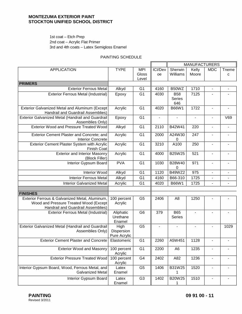
MONTEZUMA EXTERIOR PAINT STOCKTON UNIFIED SCHOOL DISTRICT
PAINTING 09 91 00 - 11 Revised 3/2011
1st coat – Etch Prep 2nd coat – Acrylic Flat Primer 3rd and 4th coats – Latex Semigloss Enamel
PAINTING SCHEDULE
MANUFACTURERS APPLICATION TYPE MPI
Gloss Level
ICI/Devoe
Sherwin Williams
Kelly Moore
MDC Tnemec
PRIMERS Exterior Ferrous Metal Alkyd G1 4160 B50WZ 1710 - -
Exterior Ferrous Metal (Industrial) Epoxy G1 4030 B58 Series
646
7125 - -
Exterior Galvanized Metal and Aluminum (Except Handrail and Guardrail Assemblies)
Acrylic G1 4020 B66W1 1722 - -
Exterior Galvanized Metal (Handrail and Guardrail Assemblies Only)
Epoxy G1 - - - - V69
Exterior Wood and Pressure Treated Wood Alkyd G1 2110 B42W41 220 - -
Exterior Cement Plaster and Concrete; and Interior Concrete
Acrylic G1 2000 A24W300
247 - -
Exterior Cement Plaster System with Acrylic Finish Coat
Acrylic G1 3210 A100 250 - -
Exterior and Interior Masonry (Block Filler)
Acrylic G1 4000 B25W25 521 - -
Interior Gypsum Board PVA G1 1030 B28W400
971 - -
Interior Wood Alkyd G1 1120 B49WZ2 975 - - Interior Ferrous Metal Alkyd G1 4160 B66-310 1725 - -
Interior Galvanized Metal Acrylic G1 4020 B66W1 1725 - - FINISHES
Exterior Ferrous & Galvanized Metal, Aluminum, Wood and Pressure Treated Wood (Except
Handrail and Guardrail Assemblies)
100 percent Acrylic
G5 2406 A8 1250 - -
Exterior Ferrous Metal (Industrial) Aliphatic Urethane Enamel
G6 379 B65 Series
- - -
Exterior Galvanized Metal (Handrail and Guardrail Assemblies Only)
High Dispersion
Pure Acrylic
G5 - - - - 1029
Exterior Cement Plaster and Concrete Elastomeric G1 2260 A5W451 1128 - -
Exterior Wood and Masonry 100 percent Acrylic
G1 2200 A6 1235 - -
Exterior Pressure Treated Wood 100 percent Acrylic
G4 2402 A82 1236 - -
Interior Gypsum Board, Wood, Ferrous Metal, and Galvanized Metal
Latex Enamel
G5 1406 B31W251
1520 - -
Interior Gypsum Board Latex Enamel
G3 1402 B20W251
1510 - -
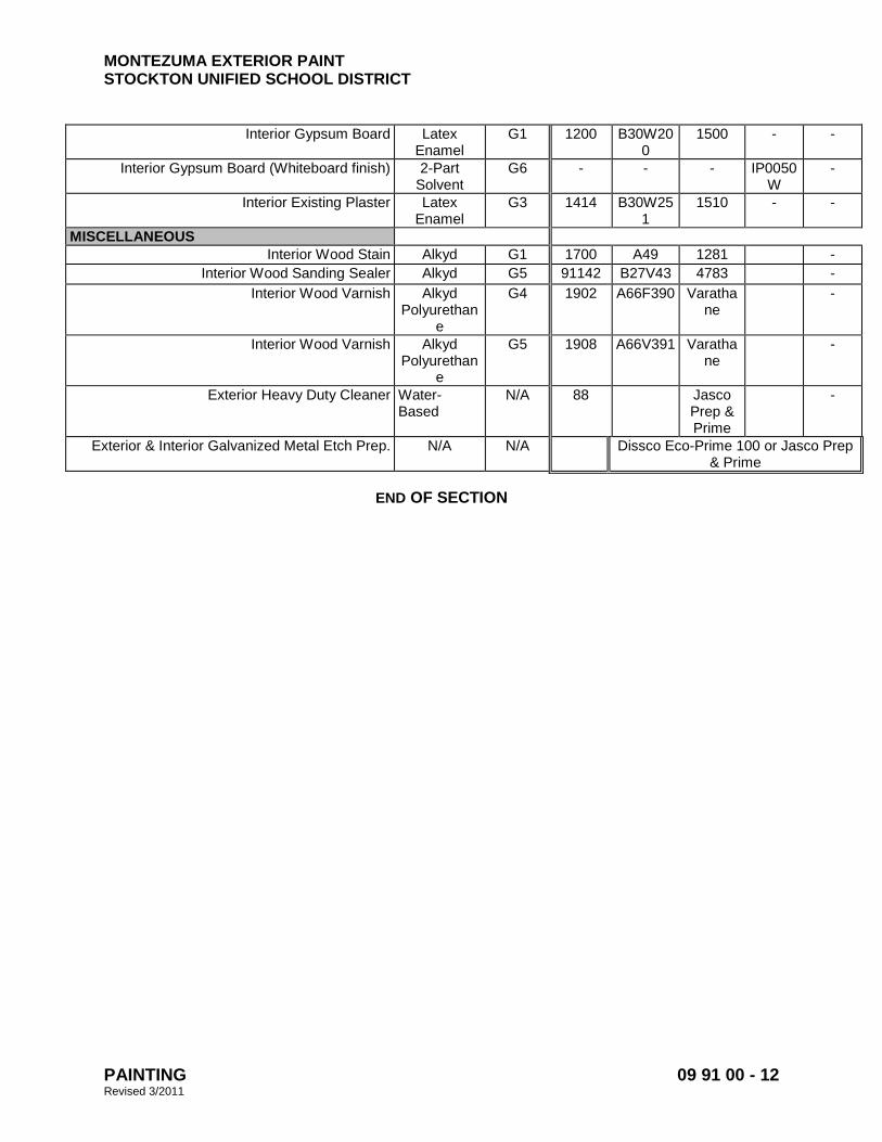
MONTEZUMA EXTERIOR PAINT STOCKTON UNIFIED SCHOOL DISTRICT
PAINTING 09 91 00 - 12 Revised 3/2011
Interior Gypsum Board Latex Enamel
G1 1200 B30W200
1500 - -
Interior Gypsum Board (Whiteboard finish) 2-Part Solvent
G6 - - - IP0050W
-
Interior Existing Plaster Latex Enamel
G3 1414 B30W251
1510 - -
MISCELLANEOUS Interior Wood Stain Alkyd G1 1700 A49 1281 -
Interior Wood Sanding Sealer Alkyd G5 91142 B27V43 4783 - Interior Wood Varnish Alkyd
Polyurethane
G4 1902 A66F390 Varathane
-
Interior Wood Varnish Alkyd Polyurethan
e
G5 1908 A66V391 Varathane
-
Exterior Heavy Duty Cleaner Water-Based
N/A 88 Jasco Prep & Prime
-
Exterior & Interior Galvanized Metal Etch Prep. N/A N/A Dissco Eco-Prime 100 or Jasco Prep & Prime
END OF SECTION
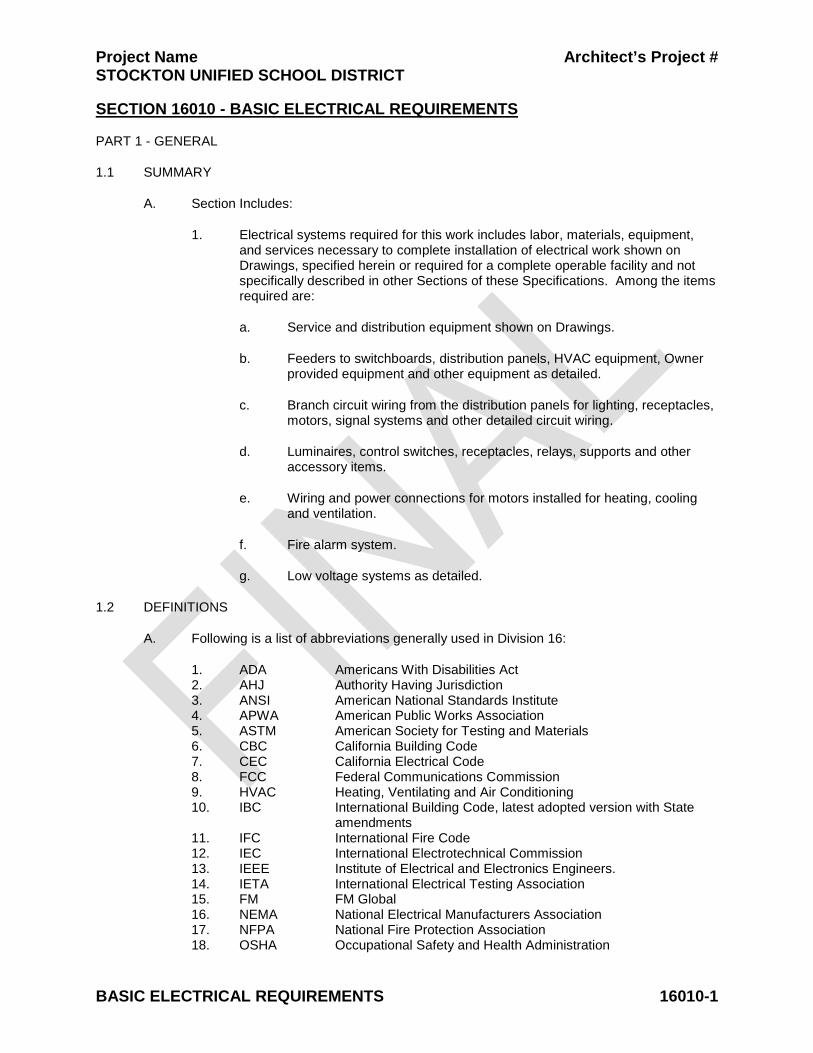
Project Name Architect’s Project # STOCKTON UNIFIED SCHOOL DISTRICT
BASIC ELECTRICAL REQUIREMENTS 16010-1
SECTION 16010 - BASIC ELECTRICAL REQUIREMENTS PART 1 - GENERAL
1.1 SUMMARY
A. Section Includes:
1. Electrical systems required for this work includes labor, materials, equipment, and services necessary to complete installation of electrical work shown on Drawings, specified herein or required for a complete operable facility and not specifically described in other Sections of these Specifications. Among the items required are:
a. Service and distribution equipment shown on Drawings.
b. Feeders to switchboards, distribution panels, HVAC equipment, Owner provided equipment and other equipment as detailed.
c. Branch circuit wiring from the distribution panels for lighting, receptacles, motors, signal systems and other detailed circuit wiring.
d. Luminaires, control switches, receptacles, relays, supports and other accessory items.
e. Wiring and power connections for motors installed for heating, cooling and ventilation.
f. Fire alarm system.
g. Low voltage systems as detailed.
1.2 DEFINITIONS
A. Following is a list of abbreviations generally used in Division 16:
1. ADA Americans With Disabilities Act 2. AHJ Authority Having Jurisdiction 3. ANSI American National Standards Institute 4. APWA American Public Works Association 5. ASTM American Society for Testing and Materials 6. CBC California Building Code 7. CEC California Electrical Code 8. FCC Federal Communications Commission 9. HVAC Heating, Ventilating and Air Conditioning 10. IBC International Building Code, latest adopted version with State
amendments 11. IFC International Fire Code 12. IEC International Electrotechnical Commission 13. IEEE Institute of Electrical and Electronics Engineers. 14. IETA International Electrical Testing Association 15. FM FM Global 16. NEMA National Electrical Manufacturers Association 17. NFPA National Fire Protection Association 18. OSHA Occupational Safety and Health Administration
Project Name Architect’s Project # STOCKTON UNIFIED SCHOOL DISTRICT
BASIC ELECTRICAL REQUIREMENTS 16010-2
19. UL Underwriters Laboratories Inc.
B. Provide: To furnish and install, complete and ready for the intended use.
C. Furnish: Supply and deliver to the project site, ready for unpacking, assembly and installation.
D. Install: Includes unloading, unpacking, assembling, erecting, installation, applying, finishing, protecting, cleaning and similar operations at the project site to complete items of work furnished by others.
1.3 ADDITIONAL REQUIREMENTS TO DIVISION 1
A. Operation and Maintenance Documentation: Provide copies of certificates of code authority acceptance, test data, product data, guarantees, warranties, and the like.
B. Shop Drawings: When requested by individual Sections provide shop drawings which include physical characteristics, electrical characteristics, device layout plans, wiring diagrams, and the like. Refer to individual Specification Sections for additional requirements for the shop drawings.
C. Closeout Documentation: Submit electrical code authority certification of inspection. Include documentation of on-site electrical testing that was performed.
D. Record Drawings:
1. Show changes and deviations from the Drawings. Include written Addendum and change order items.
2. Show exact routes of feeders 100 amp and larger, cable tray, surface metal raceway, conduits for signal systems 2 inches in diameter and larger, and service entrance conduits.
3. Show exact location of switchboards, distribution panelboards, safety disconnects, motor controllers, control panels, terminal cabinets, and the like.
4. Make changes to drawings in electronic format. Obtain electronic copy from Architect, use the same version of AutoCAD to prepare record drawings as was used by the Architect. Provide electronic copy and hard copy to Architect for review.
5. Provide a full size Record Drawing of the one-line power diagram sealed in a plastic coating. Mount on the wall of the electric room or location approved by school district representative.
1.4 QUALITY ASSURANCE
A. Conform to requirements of the CEC, latest adopted version with amendments by local AHJs.
B. Conform to latest adopted version of the IBC with amendments by local AHJs.
C. Obtain and pay for electrical permits, and inspections from local AHJs.
D. Furnish products listed by UL or other testing firm acceptable to AHJ.

Project Name Architect’s Project # STOCKTON UNIFIED SCHOOL DISTRICT
BASIC ELECTRICAL REQUIREMENTS 16010-3
E. Conform to requirements of the serving electric and telephone, and cable television utilities. Obtain and pay for all costs. Costs to be reimbursed by school district.
1.5 SEQUENCING AND SCHEDULING
A. For the proper execution of the work cooperate with other crafts and contracts as needed.
B. To avoid installation conflicts, thoroughly examine the complete set of Contract Documents. Resolve conflicts with Architect prior to installation.
C. Prior to installation of feeders to equipment requiring electrical connections, examine the manufacturer's shop drawings, wiring diagrams, product data, and installation instructions. Verify that the electrical characteristics detailed in the Contract Documents are consistent with the electrical characteristics of the actual equipment being installed. When inconsistencies occur request clarification from Architect.
1.6 COORDINATION DOCUMENTS
A. Prepare and submit layout drawings to coordinate installation and location of lighting, electrical and signal systems. Prepare composite drawings showing all equipment on a single sheet. The architectural floor plans, reflected ceiling plans, and access floor layout plan shall form the base for the coordination drawings. Prior to completion of Drawings, coordinate proposed installation with the Architect, structural requirements, and other trades (including HVAC, plumbing, fire protection, ceiling systems, and raised floor system), and provide required maintenance access. Systems shall include, although not limited to, the following:
1. Occupancy sensors.
2. Electrical equipment enclosures.
3. Control equipment enclosures.
4. Route of feeders 100A and larger.
5. Route of cable tray systems.
6. Conduit rack supports.
7. Transformers and supports.
8. Route of telephone, data and CATV raceways 2 inches and larger.
B. Prepare Drawings as follows:
1. Prepare Drawings, to accurate scale, in latest AutoCAD graphics format printed to media as directed by Architect. Obtain construction document drawing files from the Architect, or Engineer, at cost plus. Drawings are to be same size as Contract Drawings and shall indicate location, size and elevation above finished floor of all wall mounted and suspended devices and equipment.
2. Plans are to incorporate all addenda items and change orders.
3. Distribute plans to all trades and provide additional coordination as needed.
Project Name Architect’s Project # STOCKTON UNIFIED SCHOOL DISTRICT
BASIC ELECTRICAL REQUIREMENTS 16010-4
C. Advise Architect, in event a conflict occurs in location of equipment. Bear all costs for relocation of equipment, resulting from failure to properly coordinate installation or failure to advise Architect of conflict.
D. Provide means of access to all junctions and pull boxes and concealed equipment which may require access, adjustment or servicing.
E. Final coordination drawings, with as-constructed information added, are to be submitted as record drawings at completion of project.
PART 2 - PRODUCTS
2.1 MANUFACTURERS
A. Provide like items from one manufacturer, such as luminaire types, switches, receptacles, breakers, panels, and the like.
2.2 MATERIALS
A. Provide new electrical materials of the type and quality detailed, listed by UL, bearing their label wherever standards have been established. Indicated brand names and catalog numbers are used to establish standards of performance and quality. The description of materials listed herein governs in the event that catalog numbers do not correspond to materials described herein.
B. Provide material and equipment that is acceptable to AHJ as suitable for the use indicated. For example, provide wet labeled equipment in locations that are wet.
C. Include special features, finishes, accessories, and other requirements as described in the Contract Documents regardless of the item's listed catalog number.
D. Provide incidentals not specifically mentioned herein or noted on Drawings, but needed to complete the system, in a safe and satisfactory working condition.
2.3 FIRESTOPPING
A. For additional requirements see Division 7 "Firestopping."
B. Foam Sealant: Foam sealant for use around conduit penetrations to prevent passage of smoke, fire, toxic gas or water. Maintain seal before, during and after fire. In and around conduit for thermal break at penetration of barrier between heated and unheated spaces. Chase Technology Corporation, Fire Foam, Thomas & Betts, or approved.
PART 3 - EXECUTION
3.1 EXAMINATION
A. Construction Documents:
1. Drawings are diagrammatic with symbols representing electrical equipment, outlets, luminaires, and wiring.

Project Name Architect’s Project # STOCKTON UNIFIED SCHOOL DISTRICT
BASIC ELECTRICAL REQUIREMENTS 16010-5
2. Electrical symbols indicating wiring and equipment shown in the Contract Documents are included in the Contract unless specifically noted otherwise.
3. Examine the entire set of Drawings to avoid conflicts with other systems. Determine exact route and installation of electrical wiring and equipment with conditions of construction.
B. Clarification:
1. The Drawings govern in matters of quantity, the Specification in matters of quality. In event of conflict on Drawings or in the Specifications, the greater quantity and the higher quality apply.
2. Should the Electrical Documents indicate a condition conflicting with the governing codes and regulations, refrain from installing that portion of the work until clarified by Architect.
3.2 INSTALLATION
A. Install electrical equipment complete as directed by manufacturer’s installation instructions. Obtain installation instructions from manufacturer prior to rough-in of the electrical equipment, examine the instructions thoroughly. When requirements of the installation instructions conflict with the Contract Documents, request clarification from Architect prior to proceeding with the installation.
B. Do not install electrical equipment in obvious passages, doorways, scuttles or crawl spaces which would impede or block the area passage's intended usage.
C. Earthwork:
1. Refer to Division 2, Section "Earthwork."
2. Perform excavation and backfill required for the installation of electrical work.
D. Noise Control:
1. Do not install outlet boxes back to back. Do not use straight through boxes.
2. Do not place contactors, transformers, starters and similar noise producing devices on walls which are common to occupied spaces unless specifically called for on Drawings. Where such devices must be mounted on walls common to occupied spaces, mount or isolate in such a manner as to effectively prevent the transmission of their inherent noise to the occupied space.
E. Firestopping:
1. Coordinate with the Drawings the location of fire rated walls, ceilings, floors and the like. When these assemblies are penetrated by electrical equipment, seal around the equipment with approved firestopping material.
2. Install firestopping material complete as directed per the manufacturer’s installation instructions.
Project Name Architect’s Project # STOCKTON UNIFIED SCHOOL DISTRICT
BASIC ELECTRICAL REQUIREMENTS 16010-6
3.3 FIELD QUALITY CONTROL
A. Tests:
1. Conduct tests of equipment and systems to demonstrate compliance with requirements specified in Division 16. Refer to individual Specification Sections for required tests. Document tests and include in Closeout Documents.
2. During site evaluations by Engineer, provide an electrician with tools to remove and replace trims, covers, devices, and the like, so that a proper evaluation of the installation can be performed.
3. Provide Megger Test PET, NETA on all feeders at 100A or more, supply written reports.
B. Lighting System Control Testing and Commissioning:
1. Test lighting controls to ensure that control devices, components, equipment and systems are calibrated, adjusted and operate in accordance with Drawings and Specifications. Provide functional testing of sequences of operation to ensure operation in accordance with Drawings and Specifications. Provide complete report of test procedures and results to engineer and insert approved copy into project closeout documents.
2. Testing shall include:
a. Daylight automatic controls.
b. Occupant sensing automatic controls.
c. Automatic time and override controls for interior lighting.
d. Automatic time and photo controls for exterior lighting.
e. Emergency back-up lighting.
3.4 CLEANING
A. Remove dirt and debris caused by the execution of the electrical work.
B. Leave the entire electrical system installed under this Contract in clean, dust-free and proper working order.
C. Vacuum clean interiors of all new and modified electrical signal and communication equipment enclosures.
END OF SECTION
Project Name Architect’s Project # STOCKTON UNIFIED SCHOOL DISTRICT
BASIC MATERIALS AND METHODS 16050-1
SECTION 16050 - BASIC MATERIALS AND METHODS
PART 1 - GENERAL
1.1 SUMMARY
A. Section Includes:
1. Raceways. 2. Wires, cables and connectors. 3. Outlet boxes. 4. Devices and plates. 5. Safety disconnect switches. 6. Identification. 7. Surface raceway system.
1.2 SYSTEM DESCRIPTION
A. Provide raceways, wires, cables, connector, boxes, devices, finish plates and the like for a complete and operational electrical system.
B. Electrical Connections: Connect equipment, whether furnished by Owner or other Divisions of the Contract, electrically complete.
C. Supporting Devices: Safety factor of 4 required for every fastening device or support for electrical equipment installed. Support to withstand four times weight of equipment it supports. Bracing to comply with Seismic Zone 4 requirements.
1.3 SUBMITTALS
A. Provide shop drawings, product data and product selection for the following:
1. Raceways.
2. Wires, cables and connectors.
3. Outlet boxes.
4. Devices and plates.
5. Safety disconnect switches.
6. Identification equipment.
7. Surface raceway system.
8. Submit only one manufacturer per product.
B. Provide the following operating and maintenance instructions from the manufacturer for project closeout, see project closeout requirements in Division 1:
1. Devices and plates. 2. Safety disconnect switches.
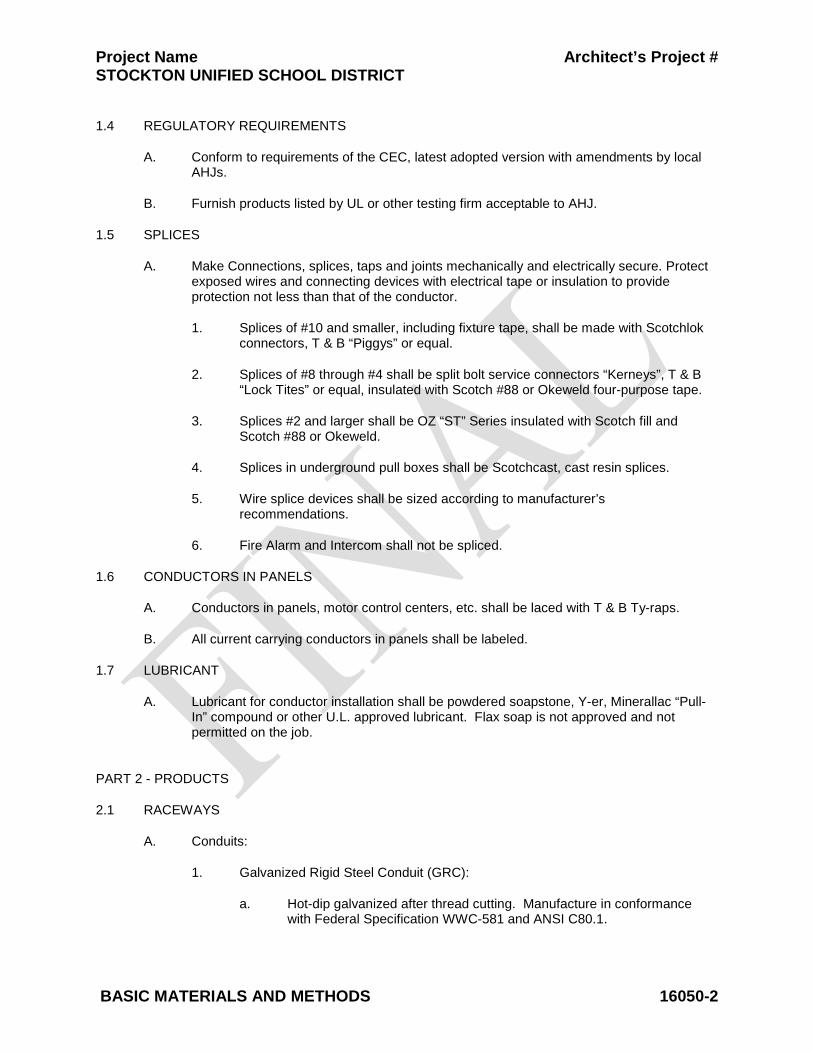
Project Name Architect’s Project # STOCKTON UNIFIED SCHOOL DISTRICT
BASIC MATERIALS AND METHODS 16050-2
1.4 REGULATORY REQUIREMENTS
A. Conform to requirements of the CEC, latest adopted version with amendments by local AHJs.
B. Furnish products listed by UL or other testing firm acceptable to AHJ.
1.5 SPLICES
A. Make Connections, splices, taps and joints mechanically and electrically secure. Protect exposed wires and connecting devices with electrical tape or insulation to provide protection not less than that of the conductor.
1. Splices of #10 and smaller, including fixture tape, shall be made with Scotchlok connectors, T & B “Piggys” or equal.
2. Splices of #8 through #4 shall be split bolt service connectors “Kerneys”, T & B “Lock Tites” or equal, insulated with Scotch #88 or Okeweld four-purpose tape.
3. Splices #2 and larger shall be OZ “ST” Series insulated with Scotch fill and Scotch #88 or Okeweld.
4. Splices in underground pull boxes shall be Scotchcast, cast resin splices.
5. Wire splice devices shall be sized according to manufacturer’s recommendations.
6. Fire Alarm and Intercom shall not be spliced.
1.6 CONDUCTORS IN PANELS
A. Conductors in panels, motor control centers, etc. shall be laced with T & B Ty-raps.
B. All current carrying conductors in panels shall be labeled.
1.7 LUBRICANT
A. Lubricant for conductor installation shall be powdered soapstone, Y-er, Minerallac “Pull-In” compound or other U.L. approved lubricant. Flax soap is not approved and not permitted on the job.
PART 2 - PRODUCTS
2.1 RACEWAYS
A. Conduits:
1. Galvanized Rigid Steel Conduit (GRC):
a. Hot-dip galvanized after thread cutting. Manufacture in conformance with Federal Specification WWC-581 and ANSI C80.1.
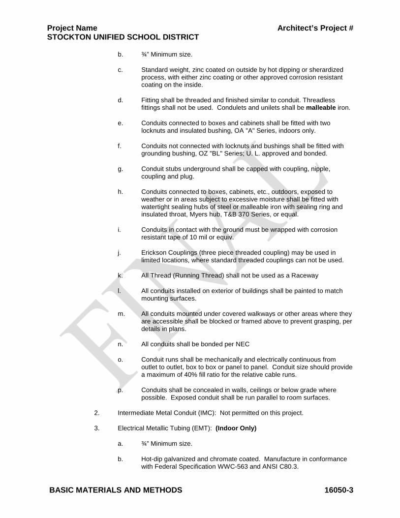
Project Name Architect’s Project # STOCKTON UNIFIED SCHOOL DISTRICT
BASIC MATERIALS AND METHODS 16050-3
b. ¾” Minimum size.
c. Standard weight, zinc coated on outside by hot dipping or sherardized process, with either zinc coating or other approved corrosion resistant coating on the inside.
d. Fitting shall be threaded and finished similar to conduit. Threadless fittings shall not be used. Condulets and unilets shall be malleable iron.
e. Conduits connected to boxes and cabinets shall be fitted with two locknuts and insulated bushing, OA "A" Series, indoors only.
f. Conduits not connected with locknuts and bushings shall be fitted with grounding bushing, OZ "BL" Series; U. L. approved and bonded.
g. Conduit stubs underground shall be capped with coupling, nipple, coupling and plug.
h. Conduits connected to boxes, cabinets, etc., outdoors, exposed to weather or in areas subject to excessive moisture shall be fitted with watertight sealing hubs of steel or malleable iron with sealing ring and insulated throat, Myers hub, T&B 370 Series, or equal.
i. Conduits in contact with the ground must be wrapped with corrosion resistant tape of 10 mil or equiv.
j. Erickson Couplings (three piece threaded coupling) may be used in limited locations, where standard threaded couplings can not be used.
k. All Thread (Running Thread) shall not be used as a Raceway
l. All conduits installed on exterior of buildings shall be painted to match mounting surfaces.
m. All conduits mounted under covered walkways or other areas where they are accessible shall be blocked or framed above to prevent grasping, per details in plans.
n. All conduits shall be bonded per NEC
o. Conduit runs shall be mechanically and electrically continuous from outlet to outlet, box to box or panel to panel. Conduit size should provide a maximum of 40% fill ratio for the relative cable runs.
p. Conduits shall be concealed in walls, ceilings or below grade where possible. Exposed conduit shall be run parallel to room surfaces.
2. Intermediate Metal Conduit (IMC): Not permitted on this project.
3. Electrical Metallic Tubing (EMT): (Indoor Only)
a. ¾” Minimum size.
b. Hot-dip galvanized and chromate coated. Manufacture in conformance with Federal Specification WWC-563 and ANSI C80.3.
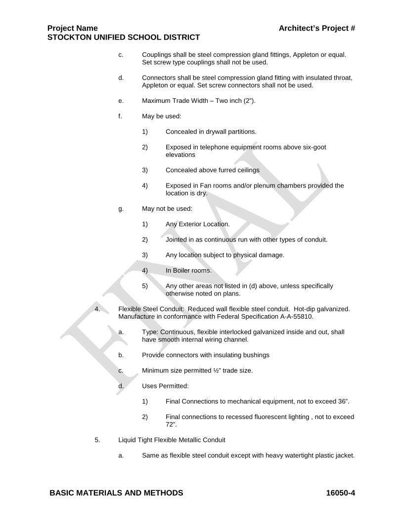
Project Name Architect’s Project # STOCKTON UNIFIED SCHOOL DISTRICT
BASIC MATERIALS AND METHODS 16050-4
c. Couplings shall be steel compression gland fittings, Appleton or equal. Set screw type couplings shall not be used.
d. Connectors shall be steel compression gland fitting with insulated throat, Appleton or equal. Set screw connectors shall not be used.
e. Maximum Trade Width – Two inch (2”).
f. May be used:
1) Concealed in drywall partitions.
2) Exposed in telephone equipment rooms above six-goot elevations
3) Concealed above furred ceilings
4) Exposed in Fan rooms and/or plenum chambers provided the location is dry.
g. May not be used:
1) Any Exterior Location.
2) Jointed in as continuous run with other types of conduit.
3) Any location subject to physical damage.
4) In Boiler rooms.
5) Any other areas not listed in (d) above, unless specifically otherwise noted on plans.
4. Flexible Steel Conduit: Reduced wall flexible steel conduit. Hot-dip galvanized. Manufacture in conformance with Federal Specification A-A-55810.
a. Type: Continuous, flexible interlocked galvanized inside and out, shall have smooth internal wiring channel.
b. Provide connectors with insulating bushings
c. Minimum size permitted ½” trade size.
d. Uses Permitted:
1) Final Connections to mechanical equipment, not to exceed 36”.
2) Final connections to recessed fluorescent lighting , not to exceed 72”.
5. Liquid Tight Flexible Metallic Conduit
a. Same as flexible steel conduit except with heavy watertight plastic jacket.

Project Name Architect’s Project # STOCKTON UNIFIED SCHOOL DISTRICT
BASIC MATERIALS AND METHODS 16050-5
b. Minimum size permitted one half (1/2”) trade size.
c. Uses Permitted: In Outdoor/wet/damp locations for the final connections to mechanical equipment.
d. Shall be used to connect portable / modular buildings between rigid stub up and building.
6. Electric Nonmetallic flexible conduit may not be used.
7. Liquid Tight Non-metallic flexible conduit may not be used.
8. Flexible Conduit, PVC Coated: Hot-dip galvanized steel. PVC chemical resistant jacket extruded to core, up to 1-inch trade size. PVC chemical resistant jacket, tubed over core, up to 4-inch trade size.
9. PVC: Class 40 heavy wall rigid PVC. Rated for use with 90C conductors. Manufacture in conformance with Federal Specification WC1094A and NEMA TC-2.
a. Minimum size permitted one half (3/4”) trade size.
b. Joints shall be solvent cemented in accordance with the recommendations of the manufacturer.
c. All portions shall be below grade, (minimum of 24 inches).
d. Not suitable for conduit stub for future extension.
e. A copper-bonding conductor shall be pulled in each power raceway and bonded to equipment at each end with approved lugs.
f. Continuation of run into the building interior shall be with rigid steel, including elbow or bend.
g. Connection to steel conduit shall be made with approved threaded adapters.
10. AC and MC cable is not permitted on this project.
11. Wireways and Auxiliary Gutters
a. Shall be painted steel or galvanized steel.
b. Shall be the size and/or shape as indicated on the drawings and shall be sized in accordance with reference codes.
c. Wire Retainers not less than 12” on centers.
d. Shall be bonded with listed fitting or at each section of wireway.
B. Surface Receptacle/Signal Raceway Systems:

Project Name Architect’s Project # STOCKTON UNIFIED SCHOOL DISTRICT
BASIC MATERIALS AND METHODS 16050-6
1. Two-Channel Surface Raceway: One channel for power, the other channel for signal. Provide 20 amp multi-circuit as indicated on Drawings. Provide divider between channels. Hubble 400 series, Wiremold 4000 Series, or approved. Raceway shall be metallic.
2. Provide lengths taken from Drawings to a tolerance of 1/2 inch over raceway length between end wall surface. Do not scale from Division 16 Drawings.
3. Provide prewired receptacles every 36 inches unless otherwise noted on Drawings.
4. Provide endcaps, corner joints, tees, transition fittings and hardware for a complete installation.
5. Verify exact mounting height with Drawings.
6. Finish: Shall be of same color of wall or surface it is applied to.
C. Conduit Fittings:
1. Bushings: Malleable iron with plastic insulator lining, 150C rated.
2. Ground Bushings: Malleable iron with plastic insulating liner and aluminum grounding lug rated for copper or aluminum conductor, 150C rated.
3. EMT Connectors and Couplings:
a. Set Screw Type: Not allowed.
b. Compression Type: Zinc plated steel, insulated throat connectors, raintight up to 2 inches. Appleton TWC-S1 series or equal.
c. Fitting shall be threaded and finished similar to conduit. Threadless fittings shall not be used.
d. Conduits connected to boxes and cabinets shall be fitted with two lock nuts and insulated bushings OA “A” series, indoor only.
4. Rigid Steel Conduit Ells: PVC coated or painted with No. 51 bitumastic material, long radius ells, and minimum radius of 36 inches.
5. Expansion/Deflection Fittings:
a. EMT: Use O-Z Gedney Type TX.
b. GRC: Use O-Z Gedney Type AX, DX and AXDX.
2.2 WIRES AND CABLES
A. Copper, 600 volt rated throughout. Branch circuit conductors shall be stranded. Phase color to be consistent at all feeder terminations; A-B-C, top to bottom, left to right, front to back. Conductors 3AWG and larger, minimum insulation rating of 75C. Insulation types THWN or THHN. Minimum insulation rating of 90C for branch circuits. Color code conductors as follows:

Project Name Architect’s Project # STOCKTON UNIFIED SCHOOL DISTRICT
BASIC MATERIALS AND METHODS 16050-7
PHASE 208 VOLT WYE 480 VOLT A Black Brown B Red Orange C Blue Yellow Neutral White Gray Ground Green Green Isolated Ground Green w/yellow trace N/A
B. SO Cable: Annealed copper conductors, 600 volt rated. Minimum Size No. 12, with
ground wire. Maximum of six conductors and ground per cable. 90C rated thermoset jacket.
C. Refer to signal and communications Specification Sections for cable requirements.
D. Conductors shall be as manufactured by Anaconda, General Electric, Rome Cable Co. or approved equal.
E. Deliver to site in unbroken packages, plainly marked with the manufacturer’s name, date of manufacture (not more than six months old), and voltage size and classification number.
2.3 TRANSFORMERS
A. Dry type low loss transformers type "Sorgel" as manufactured by Square D or approved equal.
B. Transformers shall be 150 C temperature rise above 40 C ambient. Insulation shall be in accordance with the latest NEMA standards for a 220 C UL component recognized insulation system.
C. Transformer coils shall be of the continuous wire wound construction and shall be impregnated with non-hygroscopic, thermosetting varnish. Transformer cores shall be construction from high grade, non-aging silicon steel with high magnetic permeability and low losses. The complete core and coil assembly shall be suitably clamped and braced mechanically. Additionally, provide an electrostatic shield enveloping the full height of the winding in case of shielded transformers.
D. Transformers shall be in a heavy gauge, sheet steel enclosure per UL, NEMA and NEC standards. Enclosures shall be totally enclosed type unit.
E. Transformer installed outdoors shall be weatherproof NEMA 3R.
F. Transformers sound levels shall not exceed 46 db.
G. Transformers shall meet or exceed a K-13 rating.
2.4 CONNECTORS
A. Copper Pads: Drilled and tapped for multiple conductor terminals.
B. Lugs: Indent/compression type for use with stranded branch circuit or control conductors. Manufacturers: Anderson, Ilsco, Panduit, Thomas & Betts, or approved.
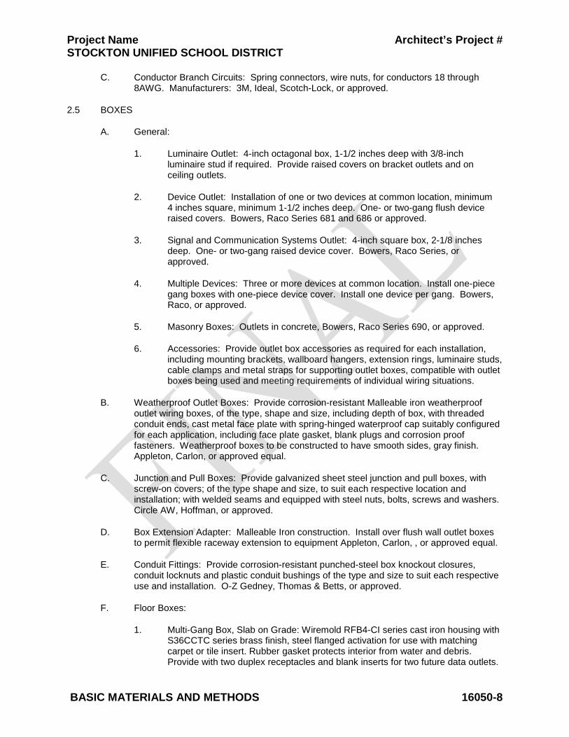
Project Name Architect’s Project # STOCKTON UNIFIED SCHOOL DISTRICT
BASIC MATERIALS AND METHODS 16050-8
C. Conductor Branch Circuits: Spring connectors, wire nuts, for conductors 18 through 8AWG. Manufacturers: 3M, Ideal, Scotch-Lock, or approved.
2.5 BOXES
A. General:
1. Luminaire Outlet: 4-inch octagonal box, 1-1/2 inches deep with 3/8-inch luminaire stud if required. Provide raised covers on bracket outlets and on ceiling outlets.
2. Device Outlet: Installation of one or two devices at common location, minimum 4 inches square, minimum 1-1/2 inches deep. One- or two-gang flush device raised covers. Bowers, Raco Series 681 and 686 or approved.
3. Signal and Communication Systems Outlet: 4-inch square box, 2-1/8 inches deep. One- or two-gang raised device cover. Bowers, Raco Series, or approved.
4. Multiple Devices: Three or more devices at common location. Install one-piece gang boxes with one-piece device cover. Install one device per gang. Bowers, Raco, or approved.
5. Masonry Boxes: Outlets in concrete, Bowers, Raco Series 690, or approved.
6. Accessories: Provide outlet box accessories as required for each installation, including mounting brackets, wallboard hangers, extension rings, luminaire studs, cable clamps and metal straps for supporting outlet boxes, compatible with outlet boxes being used and meeting requirements of individual wiring situations.
B. Weatherproof Outlet Boxes: Provide corrosion-resistant Malleable iron weatherproof outlet wiring boxes, of the type, shape and size, including depth of box, with threaded conduit ends, cast metal face plate with spring-hinged waterproof cap suitably configured for each application, including face plate gasket, blank plugs and corrosion proof fasteners. Weatherproof boxes to be constructed to have smooth sides, gray finish. Appleton, Carlon, or approved equal.
C. Junction and Pull Boxes: Provide galvanized sheet steel junction and pull boxes, with screw-on covers; of the type shape and size, to suit each respective location and installation; with welded seams and equipped with steel nuts, bolts, screws and washers. Circle AW, Hoffman, or approved.
D. Box Extension Adapter: Malleable Iron construction. Install over flush wall outlet boxes to permit flexible raceway extension to equipment Appleton, Carlon, , or approved equal.
E. Conduit Fittings: Provide corrosion-resistant punched-steel box knockout closures, conduit locknuts and plastic conduit bushings of the type and size to suit each respective use and installation. O-Z Gedney, Thomas & Betts, or approved.
F. Floor Boxes:
1. Multi-Gang Box, Slab on Grade: Wiremold RFB4-CI series cast iron housing with S36CCTC series brass finish, steel flanged activation for use with matching carpet or tile insert. Rubber gasket protects interior from water and debris. Provide with two duplex receptacles and blank inserts for two future data outlets.
Project Name Architect’s Project # STOCKTON UNIFIED SCHOOL DISTRICT
BASIC MATERIALS AND METHODS 16050-9
2. Multi-Gang Box, Slab Above Grade: Wiremold RFB4 series steel housing with S36CCTC series brass finish, steel flanged activation for use with matching carpet or tile insert. Rubber gasket protects interior from water and debris. Provide with two duplex receptacles and blank inserts for two future data outlets.
3. Multi-Gang Box, Concrete Finish Floor: Same as above, except use Wiremold S36BBTC series brass finish, steel flanged activation.
4. Single-Gang Box, Slab on Grade: Wiremold 880CM (cast-iron) series with 817 series brass finish flange suitable for both carpet and tile floors, and 828GFI brass finish cover plate insert.
5. Single-Gang Box, Slab Above Grade: Wiremold 880S (stamped steel) series with 817 series brass finish flange suitable for both carpet and tile floors, and 828GFI brass finish cover plate insert.
G. Provide floor boxes sized minimum 3-7 /16 inches deep with 1-inch factory knockouts.
2.6 WIRING DEVICES
A. Wall Switches:
1. Characteristics:
a. Toggle Type: Quiet acting, 20 amp, 120/277 volt, UL listed for motor loads up to 80 percent of rated amperage. Cooper 1221, Leviton 1221, Hubbell 1221, Pass & Seymour 20ACI.
2. Key Switches: 20 amp/120-277 volt, black key guide. Cooper 1991-L, Hubbell 1221-L, Leviton 1221-2L, Pass & Seymour 20ACI-L, or approved.
3. Finish: Ivory.
B. Wall Dimmers: Compatible with type or load controlled (i.e., electronic ballast, low voltage luminaire, and the like). Finish to match wall switches. Size dimmers to accept connected load. Do not cut fins. Where dimmers are ganged together, provide a single multi-gang coverplate. Leviton TN Series, Lutron NT Series, or approved.
C. Receptacles:
1. Finish: Same exposed finish as switches.
2. Duplex Receptacle Characteristics: Straight parallel blade, 125 volt, 2 pole, 3 wire grounding.
a. Commercial Grade: Riveted. Brass ground contact on steel mounting strap. 20 amp. Cooper BR20, Hubbell CR5362, Leviton BR20, Pass & Seymour BR20.
3. Ground Fault Circuit Interrupter (GFCI) Receptacle: Meets or exceeds UL943 (Class A GFCI), UL498. Feed through type, back-and-side wired, 20 amp, 125VAC, Cooper XGF20, Hubbell GF5362, Leviton 8898, and Pass & Seymour 2094.
Project Name Architect’s Project # STOCKTON UNIFIED SCHOOL DISTRICT
BASIC MATERIALS AND METHODS 16050-10
4. UL Wet-Listed Covers While-In-Use: NEMA 3R when closed over energized plug. Vertical mount for duplex receptacle. Provide continuous use cover with cover capable of closing over energized cord cap with bottom aperture for cord exit.
5. Special Purpose Receptacles: Refer to Drawings for NEMA Standard Specification.
6. Receptacles and switches shall be terminated with stakon type fork on ring crimp terminal, on the side of the devices.
D. Finish Plates. Provide telephone/signal system device plates; activated outlets to have coverplates to match modular jack. Cooper, Hubbell S Series, Leviton, Pass & Seymour. Commercial grade thermoplastic, finish to match device finish.
E. Surface Covers:
1. Material: Galvanized or cadmium plated steel, 1/2-inch raised industrial type with openings appropriate for devices installed in surface outlets.
2. Cast Box and Extension Adaptors: Aluminum, with gasket, blank. One gang, Bell 240-ALF, Carlon; two gang, Bell 236-ALF, Carlon, or approved.
2.7 SAFETY DISCONNECTS
A. Toggle Type Disconnect Switches: 120 volt, 1 pole, 20 amp, 1 HP maximum. NEMA 1 enclosure for indoors, NEMA 3R enclosure for outdoors.
B. Manual Motor Starters: Quick-make, quick-break. Thermal overload protection. Device labeled with maximum voltage, current and horsepower. Eaton Electrical, General Electric, Siemens, Square D Class 2510, or approved. Provide NEMA 1 enclosure for indoors, NEMA 3R enclosure for outdoors.
C. Safety Switches: Heavy duty, fused type, dual rated, quick-make, quick-break with fuse rejection feature for use with Class R fuses only, unless other fuse type is specifically noted. Provide NEMA 1 enclosure for indoors, NEMA 3R enclosure for outdoors. Switches clearly marked for maximum voltage, current and horsepower. Equip enclosure with defeatable cover interlock. Switches rated for maximum available fault current. Approved Manufacturers: Eaton Electrical, General Electric or Siemens.
2.8 SUPPORTING DEVICES
A. Hangers: Kindorf B-905-2A channel, H-119-D washer, C105 strap, 3/8-inch rod with ceiling flange. Conduits shall be supported with straps, with galvanized malleable split rings and rod for individual runs or with Kindorf, Unistrut, or equal channel for multiple runs
B. Concrete Inserts: Kindorf D-255, cast in concrete for support fasteners for loads up to 800 lbs.
C. Pipe Straps: Two-hole galvanized or malleable iron.
D. Luminaire Chain: Single jack chain No. 10, 40 lb. working load limit.
2.9 ELECTRICAL IDENTIFICATION

Project Name Architect’s Project # STOCKTON UNIFIED SCHOOL DISTRICT
BASIC MATERIALS AND METHODS 16050-11
A. Engraved Labels: Melamine plastic laminate, white with black core, 1/16 inch thick, manufactured by Lamicoid. Engravers standard letter style, minimum 3/16-inch high letters, all capitals. Drill or punch labels for mechanical fastening except where adhesive mounting is necessary because of substrate. Use self-tapping stainless steel screws.
B. Conductor Numbers: Manufacturers standard vinyl-cloth self-adhesive cable and conductor markers of the wraparound type. Preprinted black numbers on yellow field. Brady, Panduit, or approved.
C. Branch Circuit Panel Schedules: Provide branch circuit identification schedules, typewritten, clearly filled out, to identify load connected to each circuit and location of load. Numbers to correspond to numbers assigned to each circuit breaker pole position.
D. Relay Panel Schedule: Provide typewritten schedule to identify the incoming circuit, the controlled load, and the controlling devices for each relay.
E. Underground Utilities Markers: Inert polyethylene plastic ribbon, 6 inches wide by 4 mil thick. Safety Red for electric power distribution. Safety Alert Orange for telephone, signal, data and cable TV. Imprint over entire length of ribbon in permanent black letters, the system description, selected from manufacturer's standard legend which most accurately identifies the subgrade system. Manufacturers: Allen Systems, Inc., Panduit Corp., or approved.
F. Circuit Breaker Identification: Provide permanent identification number in or on panelboard dead-front adjacent to each circuit breaker pole position.
PART 3 - EXECUTION
3.1 ELECTRICAL CHARACTERISTICS
A. Verify electrical characteristics of equipment prior to installation of conduits and wiring for equipment. Coordinate HVAC voltage requirements with Drawings and equipment submittals prior to rough in.
3.2 MOTOR BRANCH CIRCUIT WIRING
A. Do not install electrical equipment or wiring on mechanical equipment without approval of Architect.
B. Provide moisture tight equipment wiring and switches in ducts or plenums used for environmental air.
C. Connect motor branch circuits complete from panel to motor as required by code and manner herein described.
D. Motor starter, control devices and control wiring provided by other Divisions unless noted on Drawings.
3.3 APPLIANCE/UTILIZATION EQUIPMENT
A. Provide appropriate cable and cord cap for final connection unless equipment is provided with same. Verify special purpose outlet NEMA configuration and ampere rating with equipment supplier prior to ordering devices and coverplates.
B. Freezer and Cooler Box Connections:
Project Name Architect’s Project # STOCKTON UNIFIED SCHOOL DISTRICT
BASIC MATERIALS AND METHODS 16050-12
1. Obtain supplier's shop drawings prior to rough-in and provide complete connections per supplier's shop drawings.
2. Provide connections to electric defrost elements, door heaters, vent heaters, door switches, lights, condensate drain heaters, blower fans, and the like.
C. Kitchen Cooking, Class I, Exhaust Hood:
1. Obtain supplier's shop drawings prior to rough-in and provide complete connections per supplier's shop drawings.
2. Provide connections to hood lights, fire suppression/extinguishing system, hood control panel, and the like.
3. Provide interlocks to exhaust fan, make-up air unit, solenoid valves, and shunt trip breakers/contactors to de-energize electrical equipment located under hood.
Project Name Architect’s Project # STOCKTON UNIFIED SCHOOL DISTRICT
BASIC MATERIALS AND METHODS 16050-13
INSTALLATION
D. Conduit:
1. Conduit Joints: Assemble conduits continuous and secure to boxes, panels, luminaires and equipment with fittings to maintain continuity. Provide watertight joints where embedded in concrete, below grade or in damp locations. Seal PVC conduit joints with solvent cement and metal conduit with metal thread primer. All rigid conduit connections to be threaded, clean and tight (metal to metal).
2. Conduit Placement:
a. Install continuous conduit and raceways for electrical power wiring and signal systems wiring. Conduit runs shall be mechanically and electrically continuous from origination to termination.
b. All thread (running thread) shall not be used as a raceway.
c. Conceal all conduits. Exposed conduits are permitted only in the following areas:
1) Mechanical rooms, electrical rooms or spaces where walls, ceilings and floors will not be covered with finished materials.
2) Where specifically noted on the Drawings.
d. Where exposed conduits are permitted install parallel or at right angles to building lines, tight to finished surfaces and neatly offset into boxes.
e. Do not install conduits or other electrical equipment in obvious passages, doorways, scuttles or crawl spaces which would impede or block the area passage's intended usage.
f. Do not install conduits on surface of building exterior, across roof, on top of parapet walls, or across floors.
g. Route raceway at least 6 inches from hot surfaces above 120F, including non-insulated steam lines, heat ducts, and the like.
3. Below Grade Conduit and Cables: Place a minimum 3-inch cover of sand or clean earth fill around the cable or conduit on a leveled trench bottom. Lay conduit on a smooth level trench bottom, so that contact is made for its entire length. Remove water from trench before electrical conduit is installed. Conduit stubs from underground shall be capped with a coupling, nipple, coupling and manufactured plug until use. Conduits shall be capped during construction.
4. Maximum Bends: Install code sized pull boxes to limit sum of bends in a run of conduit to 270 degrees.
5. Flexible Conduit: Install 12-inch minimum slack loop on flexible metallic conduit and PVC coated flexible metallic conduit. Minimum trade size: one half inch (1/2”)
6. Conduit Size: Size as indicated on Drawings. Where size is not indicated, provide conduit in minimum code permitted size for THW conductors of quantity required for complete operation. Minimum trade size 3/4 inch.
Project Name Architect’s Project # STOCKTON UNIFIED SCHOOL DISTRICT
BASIC MATERIALS AND METHODS 16050-14
7. Fire Alarm Conduit: All fire alarm system wiring shall be in conduit, 3/4 inch minimum.
8. Provide pull cord in all empty conduits that exceed 10 feet in length or the total sum of bends exceed 90 degree radius. Pull wires shall be #12 TW in conduits 1 inch and smaller and 3/16 inch polypropylene rope in conduits 1 1/4 inch and larger.
9. Conduit Use Locations:
a. Underground: PVC.
b. Wet Locations, and Subject to Mechanical Damage: GRC.
c. Damp Locations and Locations Exposed to Rain: GRC only.
d. Cast-In-Place Concrete and Masonry: GRC and PVC. Horizontal runs of conduit in poured-in-place concrete slabs, maximum diameter of conduit is 1.25 inches.
e. Dry, Protected: GRC, EMT.
f. Sharp Bends and Elbows: GRC, EMT use factory elbows.
g. Install pull wire or nylon cord in empty raceways provided for other systems. Secure wire or cord at each end.
h. Elbow for Low Energy Signal Systems: Use long radius factory ells where linking sections of raceway for installation of signal cable.
i. Motors, recessed luminaires and equipment connections subject to movement or vibration, use flexible metallic conduit.
j. Motors and equipment connections subject to movement or vibration and subjected to any of the following conditions; exterior location, moist or humid atmosphere, water spray, oil or grease use PVC coated liquid tight flexible metallic conduit.
10. Branch Circuits: Do not change the intent of the branch circuits or controls without approval. Homeruns for 20 amp branch circuits may be combined to a maximum of six current carrying conductors in a homerun. Apply de-rating factors as required by CEC. Increase conductor size as needed.
11. Feeders: Do not combine or change feeder runs.
12. Unless otherwise indicated, provide raceway systems for lighting, power and Class 1 remote-control and signaling circuits and Class 2 and 3 remote-control signaling and communication circuits.
E. Conduit Fittings:
1. Use compression fittings in dry locations, damp and rain-exposed locations. Maximum size permitted in damp locations and locations exposed to rain is 2 inches in diameter.
Project Name Architect’s Project # STOCKTON UNIFIED SCHOOL DISTRICT
BASIC MATERIALS AND METHODS 16050-15
2. Use threaded type fittings in wet locations, and damp or rain-exposed locations where conduit size is greater than 2 inches.
3. Use PVC coated rigid steel conduit ells for underground power and telephone service entrance conduits to each building. Use 36-inch radius ells for power service conduits and 48-inch radius ells for telephone service conduits make adjustments in trenching accordingly.
4. Telephone and signal conduit bends where required shall have a radius of ten times the conduit trade size, unless otherwise noted.
5. Underground conduit bends shall have a minimum radius of 12 times the conduit trade size, unless otherwise noted.
6. Use insulated type bushings with ground provision at switchboards, panelboards, safety disconnect switches, junction boxes and the like that have feeders 60 amperes and greater.
7. Provide bushing or EMT connector for conduits that do not terminate in box, enclosure, or the like.
8. Conduits shall be capped during construction with manufactured plugs until use. Electrical tape is not acceptable for this use.
a. Provide conduit expansion fittings at building expansion joints and at locations where conduit is exposed to thermal expansion and contraction. Where expansion joints are required over 1” trade size, an expansion fitting shall be used (flexible conduit may not be used). Expansion joints 1” and under may be flexible conduit
9. Condulets and Conduit Bodies: Do not use condulets and conduit bodies in conduits for signal wiring or in feeders 100 amp and larger.
F. Surface Receptacle/Signal Raceway System: Install per manufacturer's installation instructions. Install perpendicular and parallel to building lines.
G. Sleeves and Chases: Provide necessary rigid conduit sleeves, openings and chases where conduits or cables are required to pass through floors, ceiling or walls. Maintain integrity of fire-rated assemblies at penetrations of walls, ceilings or floors.
H. Conductors, Wires and Cables:
1. Conductor Installation: Install conductors in raceways having adequate, code size cross-sectional area for wires indicated. Install conductors with care to avoid damage to insulation. Do not apply greater tension on conductors than recommended by manufacturer during installation. Use of pulling compounds is permitted. Clean residue from exposed conductors and raceway entrances after conductor installation. Do not use pulling compounds for installation of conductors connected to GFI circuit breakers or GFI receptacles.
2. Conductor Size and Quantity: Install no conductors smaller than 12AWG unless otherwise shown. Provide all required conductors for a fully operable system.
3. Provide dedicated neutrals (one neutral conductor for each phase conductor) in the following single phase circuits:
Project Name Architect’s Project # STOCKTON UNIFIED SCHOOL DISTRICT
BASIC MATERIALS AND METHODS 16050-16
a. Dimmer controlled circuits.
b. Isolated ground circuits.
c. Ground fault protected circuits where a GFI breaker is used in a panelboard.
d. Other electronic equipment which produces a high level of harmonic distortion including but not limited to computers, printers, plotters, copy machines, fax machines.
e. There shall be no reduction of the neutral Capacity
4. Conductors in Cabinets: Hold conductors away from sharp metal edges. Cable and tree all wires in panels and cabinets for power and control. Use plastic ties in panels and cabinets. Tie and bundle feeder conductors in wireways of panelboards.
5. Exposed cable is not allowed.
I. Connectors: Retighten lugs and connectors for conductors to equipment prior to Substantial Completion.
J. Boxes:
1. Location: Locate boxes and conduit bodies so as to ensure accessibility of electrical wiring. Boxes shall be located and placed according to architectural and structural requirements.
2. Round Boxes: Avoid using round boxes where conduit must enter through side of box, which would result in a difficult and insecure connection with a locknut or bushing on the rounded surface.
3. Boxes shall be of the shape and size best suited for the particular application and shall be supported directly to the structural members, framing or blocking by means of screws, anchors, and bolts or embedded in masonry.
4. Anchoring: Secure boxes rigidly to the substrate upon which they are being mounted, or solidly embed boxes in concrete or masonry.
5. Special Application: Provide weatherproof outlets for locations exposed to weather or moisture.
6. Knockout Closures: Provide knockout closures to cap unused knockout holes where blanks have been removed.
7. Outlet System: Provide electrical boxes and fittings as required for a complete installation. Include but not limited to outlet boxes, junction boxes, pull boxes, bushings, locknuts, and all other necessary components.
8. Code Compliance: Comply with CEC as applicable to construction and installation of electrical boxes and fittings and size boxes according to CEC, except as noted otherwise.
Project Name Architect’s Project # STOCKTON UNIFIED SCHOOL DISTRICT
BASIC MATERIALS AND METHODS 16050-17
9. Flush Outlets in Finished Spaces: Maintain integrity of insulation and vapor barrier. Surface outlets are only acceptable in areas with surface conduit.
10. Mount center of outlet boxes as required by ADA, or noted on Drawings, the following distance above the floor:
a. Control Switches: 48 inches.
b. Receptacles: 18 inches.
c. Telecom Outlets: 18 inches.
d. Other Outlets: As indicated in other Sections of Specifications or as detailed on Drawings.
11. Coordinate all electrical device locations (switches, receptacles, and the like) with Drawings to prevent mounting devices in mirrors, back splashes, behind cabinets, and the like.
12. Boxes for special equipment shall be suitable for the particular equipment
13. Junction boxes shall be bonded to ground, unless otherwise noted.
14. Conduits entering junction boxes shall be terminated with locknuts or appropriate fittings at the junction boxes.
K. Wiring Devices:
1. Wall-Mounted Receptacles: Install with long dimension oriented vertically at centerline height shown on Drawings or specified herein.
2. Vertical Alignment: When more than one outlet is shown on Drawings in close proximity to each other, but at different elevations, align the outlets on a common vertical center line for best appearance. Verify with Architect.
L. Provide CEC-required disconnect switches whether specifically shown on Drawings or not. Provide disconnect switch in sight of each motor location unless otherwise noted. Provide disconnect switch in site of each motor controller. Motor controller disconnect equipped with lock-out/tag-out padlock provisions do not require a disconnect switch at the controlled motor location. Coordinate fuse ampere rating with installed equipment. Fuse ampere rating variance between original design information and installed equipment, size in accordance with Bussmann Fusetron 40C recommendations. Do not provide fuses of lower ampere rating than motor starter thermal units.
M. Supporting Devices:
1. Verify mounting height of all luminaires or items prior to installation when heights are not detailed.
2. Install vertical support members for equipment and luminaires, straight and parallel to building walls. Provide independent supports to structural member for electrical luminaires, materials, or equipment installed in or on ceiling, walls or in void spaces or over furred or suspended ceilings.
Project Name Architect’s Project # STOCKTON UNIFIED SCHOOL DISTRICT
BASIC MATERIALS AND METHODS 16050-18
3. Do not use other trade's fastening devices as supporting means for electrical equipment, materials or luminaires. Do not use supports or fastening devices to support other than one particular item... Conduits shall be supported independently of one another.
4. Support conduits within 18 inches of outlets, boxes, panels, cabinets and deflections. Maximum distance between supports not to exceed 7 foot spacing.
5. Securely suspend all junction boxes, pull boxes or other conduit terminating housings located above suspended ceiling from the floor above or roof structure to prevent sagging and swaying.
6. Provide seismic bracing per IBC requirements for this building location.
7. Conduits ran on roof shall be fastened to a 4x4x length as required, redwood block set in mastic on roof structure. Unistrut or equal channel shall be installed on the blocks. The Conduit shall be individually strapped to the strut, unless otherwise noted.
8. Conduit straps for individual runs shall be secured by toggle bolts on hollow masonry, expansion shields and machine screws on solid masonry, machine screws or bolts on metal surfaces and wood screws on wood construction. Use of nails to anchor straps on wood construction is prohibited. Straps shall be one or two hole malleable iron or snap type steel with ribbed back, galvanized or cadmium plated. Use of perforated strap or nail type straps is prohibited.
N. Electrical Identification:
1. Graphics: Coordinate names, abbreviations and designations used on Drawings with equipment labels.
2. Underground Utilities Markers: Install continuous tape, 6 to 8 inches below finish grade, for each exterior underground raceway.
3. Conductor Identification: Apply markers on each conductor for power, control, signaling and communications circuits.
4. Install an engraved label on each major unit of electrical equipment, including but not limited to the following items: Disconnect switches, relays, override switches, service disconnects, distribution switches, branch circuit panelboards, and central or master unit of each electrical system including communication/signal systems.
5. Install engraved labels on the inside of flush panels, visible when door is opened. Install label on outside of surface panel.
6. Install signs at locations detailed or, where not otherwise indicated, at location for best convenience of viewing without interference with operation and maintenance of equipment.
7. On the back of receptacle and switch finish plates legibly write with indelible ink pen the circuit that each device is connected to.
Project Name Architect’s Project # STOCKTON UNIFIED SCHOOL DISTRICT
BASIC MATERIALS AND METHODS 16050-19
8. On the front of receptacle and switch finish plates provide label with the circuit that each device is connected to. Label is self-adhesive type with black letters and clear background, 18 point lettering size.
9. Non-ferrous identifying tags or pressure sensitive labels shall be securely fastened to all cables, feeders, and power circuits in pull boxes and manholes. Tags or labels shall be stamped or printed to correspond with markings on drawings or marked so that feeder or cable may be readily indentified.
10. Identify each branch circuit with wire markers. This is inclusive of wires terminated or spliced in switches, receptacles, disconnects, panelboards, switchgear, junction boxes and any other devices in which wires are terminated or spliced.
11. Junction Boxes: Provide identification labels with panel origination and circuit numbers on all junction box and enclosure covers. Four square box covers hidden above the ceiling may be marked with indelible ink marker instead of using printed labels.
O. Equipment Identification:
1. Nameplates shall be installed on electrical equipment. Equipment to be labeled shall include the following:
a. Individual enclosures such as disconnect switches, time switches, pushbuttons, contractors, relays, motor starters, etc.
b. Group mounted equipment such as panelboards, switchboards, and motor control devices.
c. Individual circuit breakers of switchboards.
d. Wall switches for lighting or other use where the control function is not self-evident.
2. Each panel shall be labeled to provide the following information as a minimum:
a. Panel name.
b. Size of feeder feeding the panel.
c. Rated voltage, amps and phases.
d. Panel feeder origination
3. Each main service switchboard and distribution panel shall be labeled to provide the following information as a minimum:
a. Rated voltage, amps and phases.
b. Main switch rating.
c. Feeder circuit breaker rating with name of panel or equipment fed and
size of feeder to this equipment.
Project Name Architect’s Project # STOCKTON UNIFIED SCHOOL DISTRICT
BASIC MATERIALS AND METHODS 16050-20
d. Panel feeder origination.
4. Nameplates shall adequately describe the item and its function or use of the particular equipment involved.
5. Nameplate material shall be laminated phenolic plastic, black front and back with white core. Engraving shall be through the outer layer. Embossed plastic pressure sensitive labels are not acceptable.
6. In lieu of plastic plates, device plates shall be engraved directly with lettering filled with black enamel.
7. Nameplates shall be securely fastened to the equipment with #4 Phillips round cadmium plated steel self-tapping screws, brass bolt, or with a plastic resin adhesive glue, Goodyear "Phiebond" or equal.
P. Building Seismic Joints:
1. Conduit Crossing Building Seismic Joints or covered: Provide box on either side of joint and flexible conduit between the box. Provide for a minimum of 12 inches of movement at the seismic joint. Rigid conduit crossings at seismic joints are not acceptable.
3.4 FIELD QUALITY CONTROL
A. Wiring Device Tests: Test wiring devices to ensure electrical continuity of grounding connections, and after energizing circuitry, to demonstrate compliance with requirements. Test receptacles for line to neutral, line to ground and neutral to ground faults. Correct any defective wiring.
B. Feeder Tests:
1. Test conductor insulation on feeders of 100 amp and greater for conformity with +1000 volt megohmeter. Use Insulated Cable Engineers Association testing procedures. Minimum insulation resistance acceptable is 1 megohm for systems 600 volts and below. Notify Architect if insulation resistance is less than 1 megohm.
2. Test Report: Prepare a typed tabular report indicating the testing instrument, the feeder tested, amperage rating of the feeder, insulation type, voltage, the approximate length of the feeder, conduit type, and the measured resistance of the megohmeter test. Submit report with operating and maintenance manual.
END OF SECTION

Project Name Architect’s Project # STOCKTON UNIFIED SCHOOL DISTRICT 20 Sep 2011 DRAFT
16744 - 1
SECTION 16744 – DATA CABLING AND INFRASTRUCTURE
PART 1 - GENERAL
1.01 SCOPE
A. FURNISH AND INSTALL THE FOLLOWING:
1. Product submittals, construction drawings, Contractor qualifications. 2. All Category 6 data cable (except for patch cables), Category 6 jacks and
related terminations. 3. All fiber optic cable (except for patch cables), jacks, inner duct, and related
terminations. 4. MDF/IDF cabinets complete with necessary Category 6 and fiber optic
terminations. 5. Certification of fiber optic cable and terminations. 6. Certification of Category 6 cable and terminations. 7. Note: Active network devices and equipment shall be the responsibility of
the District.
B. REFERENCES
1. References to Category 6 in this specification shall mean the latest approved version of the EIA/TIA Category 6 standards.
C. WORK IN OTHER SECTIONS
1. Section 16010, 16050 & 16110, electrical, raceways, conduits, pull boxes, cabinets, etc.
2. Section 02222, Excavating, Back-filling, and Compacting.
D. CONTRACTOR QUALIFICATIONS
1. Data/networking systems/cabling Contractors shall have the following qualifications:
a) 5 years experience in the design, installation, testing and maintenance of data communications systems and associated inside and outside network cabling and systems.
b) Contractor must employ full time at least one BICSI certified Registered Communications Distribution Designer (RCDD) who is involved in approving all design work covered by this project.
c) Maintain a local service facility which stocks spare devices and/or components for servicing systems.
d) Possess a full working knowledge of data/networking systems, cabling and infrastructure planning in accordance with EIA/TIA 568 and 569.
Project Name Architect’s Project # STOCKTON UNIFIED SCHOOL DISTRICT 20 Sep 2011 DRAFT
16744 - 2
e) Has performed successful installation and maintenance on at least three (3) projects similar in scope and size.
f) Can provide contact job references on at least three (3) similar projects, including scope of Work, project type, owner/user contact name and telephone number.
g) Holds and maintains a valid California C-7 or C-10 Contractors License and can exhibit validity upon request.
h) Possesses the ability to create AUTOCAD ''as built" documentation, including hard copy and digital media.
i) Possess calibrated acceptance testing equipment as delineated within EIA/TIA 568 Building Wiring Standards for Ethernet network topology and can perform acceptance testing through 1000Mbps.
E. QUALITY ASSURANCE
1. Contractor will provide for each installer proposed for work in the data cabling portion of this project a Panduit Certificate of completion for training in fiber optic and/or Category 6 cabling.
a) Only workers with certificates of fiber optic training may perform Work in that area.
b) Only workers with certificates of Category 6 training may perform Work in that area.
2. The District’s inspector or project manager may ask any or all data cabling Workers to demonstrate their skill level before performing any Work or continuing Work. If in the opinion of the District any worker is found to be deficient in this area, the Contractor must immediately provide necessary training to remove the deficiency or replace the worker with one having the required skills.
3. The Contractor shall place and maintain on the project a sufficient number of skilled workmen who are thoroughly trained and experienced on the necessary crafts and completely familiar with the specified requirements and methods needed for the proper performance and completion of the Work.
4. The Contractor must provide a project manager who has demonstrated the ability to supervise similar projects. The project manager must be available to be interviewed by the District and/or their representative, and must be deemed acceptable by the District and/or their representative. The Project Manager must be available to attend meetings as required.
5. The Work of this section shall conform to California Code of Regulations, and all other applicable codes and standards.
6. Only a qualified Contractor holding licenses required by legally constituted authorities having jurisdiction over the Work shall do the defined Work. The Contractor shall have been engaged in business of supplying and installing the specified type of systems for at least three (3) years and shall be an equipment manufacturers’ certified Contractor for the specified type cabling system.
7. Manufacturer shall warranty availability of spare parts common to proposed

Project Name Architect’s Project # STOCKTON UNIFIED SCHOOL DISTRICT 20 Sep 2011 DRAFT
16744 - 3
system for a period no less than that stipulated within the California Multiple Award Schedule (CMAS) terms and conditions. If no time period is contractually stipulated, the Contractor shall provide a warranty of 15 years.
8. Contractor shall warranty all Certified installations for a period of not less than fifteen (15) years from the date of acceptance. A complete installation warranty will be provided per site with specific details of the coverage. The Contractor shall repair or replace at no expense to the District, any defective material or Workmanship discovered within the warranty period. Any materials, structures or Work damaged thereby that may be displaced in repair or replacement of material and/or Workmanship will be replaced and/or repaired at no cost to the District. Examination of or failure to examine Work by the District shall not relieve Contractor from these obligations.
9. Contractor shall have a service organization capable of responding to warranty service requests within 24 hours of receipt of written notification and resolution within 5 Working days for MDF equipment and 15 Working days for IDF equipment located either in the IDF or computer laboratory. If Contractor fails to repair or replace material or Work indicated above within 15 days of receiving written notice, the District, may at it’s discretion hire a qualified Contractor to make required repairs and assess cost against Contractor. Contractor shall include the telephone number of the customer’s client contact for three (3) completed projects and a letter signed by a corporate officer, partner, or owner of the contracting company describing the service capability of the company and stating the company’s commitment to maintain that service capability through the warranty period. Persons skilled in the trade represented by the required Work, and in accordance with all applicable building codes, shall install the systems in accordance with best trade practices.
10. Contractor shall include in the Material List Submission copies of the manufacturers’ valid certifications that the Contractor is an authorized installer of the submitted manufacturers’ products and has been adequately trained in the installation of those products. This applies to all Category 6 components and cable and all fiber optic components and cable.
F. RULES AND REGULATIONS -- All Work and materials shall be in full accordance with the latest rules and regulations of the following codes, industry standards and references:
1. State of California: a) Title 24, Building Standards, State of California.
b) Occupational Safety and Health Act (OSHA).
c) Title 8, Electrical Safety, State of California.
d) Title 19, California Code of Regulations.
2. Telecommunications Industry Association/Electronics Industry Association (TIA/EIA).
Project Name Architect’s Project # STOCKTON UNIFIED SCHOOL DISTRICT 20 Sep 2011 DRAFT
16744 - 4
a) ANSI/TIA/EIA-STD-RS455, Standard Test Procedures for Fiber Optic Fibers, Transducers, Connecting and Terminating Devices.
b) BICSI-Telecommunications Distribution Methods Manual-1995, or latest version, volumes #1 & 2.
c) Underwriters Laboratories Inc. (UL): Applicable listings and ratings.
d) UL LAN Cable Certification Level 6.
e) National Electric Code.
f) National, State, and Local Occupational Safety and Health Administration (OSHA) building and fire codes.
g) ANSI/TIA/ElA Telecommunications Building Wiring Standards.
h) ANSI/TIA/EIA-568-A and B, Commercial Building Telecommunications Cabling Standard (October 1995)
i) ANSI/TIA/EIA-568-A-2, Corrections and Additions to TLVEIA-568-A-2 (August 1998)
j) ANSI/TIA/EIA-568-A-3, Addendum No. 3 to TIA/EIA-568-A (December 1998)
k) ANSI/TIA/EIA-568-B.2-1, Transmission Performance Specifications for 4-Pair 100 ohm Category 6 Cabling
l) ANSI/TIA/EIA-568-B-3 Optical Fiber Cabling Components Standard (March 2000)
m) ANSI/TIA/EIA-569-A, Commercial Building Standard for Telecommunications Pathways and Spaces (February 1998).
n) ANSI/TIA/EIA-569-A-1 Commercial Building Standard for Telecommunications Pathways and Spaces Addendum 1 - Surface Raceways (March 2000).ANSI/EIA/TIA-598-A, Optical Fiber Cable Color Coding (May 1995)
o) ANSI/TIA/EIA-606, The Administration Standard for the Telecommunications Infrastructure of Commercial Building (February 1993).
p) ANSI/TIA/EIA-607, Commercial Building Grounding and Bonding Requirements for Telecommunications (August 1994).
q) ANSI/TIA/EIA-758, Customer-Owned Outside Plant Telecommunications Cabling Standard (April 1999).
r) ANSI/TIA/EIA-758-1, Addendum No. 1 to TIA/EIA-758, Customer-Owned Outside Plant Telecommunications Cabling Standard (March 1999).
s) TIA/EIA TSB-67, Transmission Performance Specifications for Field Testing of Unshielded Twisted-Pair Cabling Systems (October 1995).
t) TIA/EIA TSB-72, Centralized Optical Fiber Cabling Guidelines (October 1995).
u) Institute of Electrical and Electronic Engineers (IEEE) 802.3 (Ethernet), 802.32 (Gigabit Ethernet over optical fiber), 802.3ab (Gigabit Ethernet over 4 pair category 5 or higher), 802.11 (Wireless LAN).
v) BICSI Telecommunications Distribution Methods Manual (2000 or latest).
w) FCC Part 68.50.
x) National Fire Protection Association (NFPA), NFPA-70.
y) CCR Part 3 - California Electrical Code.
z) CCR Part 2 - Uniform Building Code.
aa) ITU International Telecommunications Union.
Project Name Architect’s Project # STOCKTON UNIFIED SCHOOL DISTRICT 20 Sep 2011 DRAFT
16744 - 5
3. Nothing in the drawings or specifications is to be construed to permit Work not conforming to the codes or standards. These codes or standards are to be considered minimum requirements. Should the plans or specifications call for material, methods or construction of a higher standard, the plans or specifications shall govern.
SUBMITTALS
1.02 CONSTRUCTION SCHEDULE
A. Construction Schedule to be provided by the Contractor and approved by the District prior to Notice to Proceed.
1. Submit a Construction Schedule outlining project milestone in the project as follows:
a) Submittals
b) Conduits & Raceways
c) Racks/Cabinets, and hardware & components
d) Horizontal Cable
e) Fiber Optic Cable
f) Cabling Testing
g) Final Inspection
h) Closeout Documents, as-builts, test records, etc..
1.03 MATERIAL SUBMITTALS
A. Submit manufacturer's literature including product specification, and installation instruction for all hardware, cabinets, racks, components, cable, and materials to be provided for this project.
1. Submit one (1) electronic copy in PDF format and one (1) complete set of Product Submittal as follows:
a) Each set shall be edge bound (not stapled).
b) Each set shall be formatted as follows:
i. Title Page, showing project name & address, owners name, Contractors name & address.
ii. Table of Contents, listing page number of each product in submittal, product manufacturer and model number, in the order as follows:
iii. Fiber optic Cable, with connectors, patch panels, and patch cables.
iv. Category 6 Cable, with connectors, patch panels, and patch
Project Name Architect’s Project # STOCKTON UNIFIED SCHOOL DISTRICT 20 Sep 2011 DRAFT
16744 - 6
cables. v. Racks and Enclosures. vi. Raceways, including all manufacturers factory fittings,
devices boxes, and faceplates, in each size to be used. vii. Conduits, including all fittings, connectors, bushings, and
junction boxes, in each size to be used. viii. Misc. items, fasteners, cable support, sealants, etc.
2. Submit one (1) complete set of Product Submittal above in electronic form (PDF)
1.04 CONSTRUCTION DRAWNGS:
A. Submit one (1) “ANSI B” size reproducible Construction Drawing and one (1) in electronic form (e.g. PDF format).
1. Construction Drawings: as follows: EC0 - Title Sheet
EC0.1,2,3… - Drawing Index/symbol sheet.
EC1.1,2,3… – Site Plans
EC3.1,2,3… - Floor plans. At 1/8” scale, as follows: -Data outlet locations with circuit number. -MDF & IDF locations -Cable pathways -Raceways -Rough in -Mounting height -Conduit size -Wire type -Wire fill
EC4.1,2,3… - Equipment Rooms/Rack Elevations. At scale as required.
EC5.1 – Riser
EC6.1 – Racks
EC7.1,2,3… – Installation Details, as required --Mounting details Stamped and signed by Engineer licensed in jurisdiction for Work of this type. --Show loads, strength of connections, etc --Show calculations -on drawings or in bound volume for review by authorities having jurisdiction.
1.05 SYSTEM SPECIFICATIONS
Project Name Architect’s Project # STOCKTON UNIFIED SCHOOL DISTRICT 20 Sep 2011 DRAFT
16744 - 7
A. CABLE PLANT REQUIREMENTS
1. The cable plant shall be a star configured, unshielded twisted pair system and shall support data rates as required for Category 6 specifications.
2. The drop cable shall run from intermediate distribution frame (IDF(s)) to each classroom and office location as well as other miscellaneous locations defined in the scope of this project.
3. The trunk fiber optic cable shall run between the main distribution frame (MDF) and each IDF location as indicated on the project drawings (if supplied).
4. The cable plant shall meet EIA/TIA-568 “Commercial Building Telecommunications Wiring Standard” and the maximum length of any UTP data drop shall NOT exceed 100 meters including patch cables and future station cables in the classroom.
5. Every IDF location shall have one dedicated 24-strand hybrid multi-mode and single-mode fiber optic cables (dedicated from other MDF for LAN service). There should be 12 strands of single-mode and 12 strands of multimode fiber.
6. Quantity of LAN cable drops shall be as indicated in Figures 1 and 2. Typical classroom cable drop distribution and count, and Typical office drop distribution and count, respectively.
B. Power Requirements
1. IDFs shall be provisioned with a 20A-120V circuit via a 4 gang power outlet. 2. MDFs shall be provisioned with a 30A-120V circuit. A 4 gang power outlet
shall be accessible per cabinet.

Project Name Architect’s Project # STOCKTON UNIFIED SCHOOL DISTRICT 20 Sep 2011 DRAFT
16744 - 8
20'-0"
30'-0
"
2'-6
" 2'-6
"
Standard ClassroomData/Power LayoutModify per site needs10 data drops per standard classroom
POWER and 1 DATA JACK
POWER and 1 DATA JACK
POWER and 2 DATA JACK on
ceiling
POWER and 6 DATA JACKS: 5 DATA JACKS for
STUDENT COMPUTERS & 1 DATA JACK FOR PRINTER
22
2
2
Terminate at MDF/IDF
Figure 1. Typical Classroom
Comment [lg1]: Please review total number of power and data jacks required. The strikethrough font appears as though the numbers are 76 & 65.
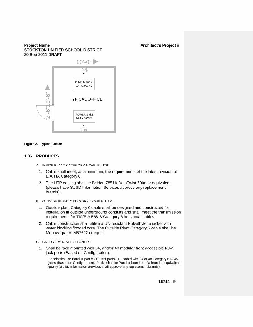
Project Name Architect’s Project # STOCKTON UNIFIED SCHOOL DISTRICT 20 Sep 2011 DRAFT
16744 - 9
10'-0"
10'-6
"2'
-6"
POWER and 2 DATA JACKS
POWER and 2 DATA JACKS
TYPICAL OFFICE
Figure 2. Typical Office
1.06 PRODUCTS
A. INSIDE PLANT CATEGORY 6 CABLE, UTP.
1. Cable shall meet, as a minimum, the requirements of the latest revision of EIA/TIA Category 6.
2. The UTP cabling shall be Belden 7851A DataTwist 600e or equivalent (please have SUSD Information Services approve any replacement brands).
B. OUTSIDE PLANT CATEGORY 6 CABLE, UTP.
1. Outside plant Category 6 cable shall be designed and constructed for installation in outside underground conduits and shall meet the transmission requirements for TIA/EIA 568-B Category 6 horizontal cables.
2. Cable construction shall utilize a UN-resistant Polyethylene jacket with water blocking flooded core. The Outside Plant Category 6 cable shall be Mohawk part# M57622 or equal.
C. CATEGORY 6 PATCH PANELS.
1. Shall be rack mounted with 24, and/or 48 modular front accessible RJ45 jack ports (Based on Configuration).
Panels shall be Panduit part # CP- (#of ports) BL loaded with 24 or 48 Category 6 RJ45 jacks (Based on Configuration). Jacks shall be Panduit brand or of a brand of equivalent quality (SUSD Information Services shall approve any replacement brands).

Project Name Architect’s Project # STOCKTON UNIFIED SCHOOL DISTRICT 20 Sep 2011 DRAFT
16744 - 10
D. WIRE MANAGEMENT
1. Wire management shall be provided for each patch panel and switch installed into the MDF and IDF racks or cabinets.
2. Vertical wire management shall be Panduit Part# WMPV45 or equal 3. Horizontal wire management shall be Panduit Part# NCMH2 or equal.
E. DATA JACKS
1. Data jacks shall meet the requirements of most recent revision of EIA/TIA Category 6 Standard. The data jacks shall be Panduit brand or equivalent quality (SUSD Information Services shall approve any replacement brands).
F. DATA JACK PLATES/HOUSINGS/ENCLOSURES.
1. Data Jack Plates and housings shall be appropriate for jack type and location where they are to be used and shall be labeled using a numbering system specified by the District. Color shall be approved by the District.
G. FIBER OPTIC CABLE.
1. All data backbone/trunk fiber optic shall be 24-strand Ethernet compliant cable.
a) On campuses with existing fiber optic cable that is 62.5/125 micron multimode fiber, the same shall be used and shall be Corning Part# M-RN-12-DN-L-OR-SI or equal.
b) On campuses with no existing fiber optic cable (ie. new school with no existing infrastructure), then a hybrid fiber optic cable with 12 strands of multimode (50/125 micron) and 12 strands of single-mode (9/125 micron) fiber shall be used. Such fiber shall be Corning brand or equivalent. SUSD Information Services shall approve any replacement brands.
c) All data fiber optic cable shall be labeled with sequential strand identification including color scheme, and destination of fiber.
H. FIBER OPTIC PATCH PANEL
1. The fiber patch panel for the MDF location shall be rack mountable with applicable number of LC duplex port connector outlets for termination of
2. All fiber runs (24 strands per IDF). The fiber patch panel for the MDF shall be sized such that the initial installation does not exceed 60% of its capacity.
3. The MDF fiber patch panel shall be Panduit FAP12WAQLCZ for multi-mode and FAP12WBULCZ for single-mode or equal.
4. Panduit part # FAP6WEIDLC or equal mounting plate with 6 duplex LC connectors shall be used to support each IDF. The Panduit FRME72E5BL will support up to 144 strands of fiber or 12 IDF(s). If the configuration exceeds this capacity then the vendor should use comparable substitutions necessary to support the greater capacity.
Project Name Architect’s Project # STOCKTON UNIFIED SCHOOL DISTRICT 20 Sep 2011 DRAFT
16744 - 11
5. The IDF patch panel shall be a Panduit FMD24 loaded with FAP6WEIDLC or equal.
6. NOTE: If current campus configuration utilizes ST or SC type connectors, then above mentioned part numbers shall be adjusted to substitute ST or SC. If the installation is a part of a new campus, and there is no existing fiber optic cable, then LC type terminations and connectors are to be utilized.
I. FIBER OPTIC PATCH CORDS
1. Shall be provided/installed by contractor responsible for active network equipment installation.
2. The Fiber Patch Cords shall be factory constructed using materials that are compliant with the current revision of Fiber Optic Standards
3. .The Fiber Patch Cords shall be Panduit P/N F6D2-3M2 for SC to ST terminations, Panduit P/N F6D3-3M2 for LC to LC terminations. Substitutions for patch cords of equal quality must be approved by district prior to installation. For installations that require 50/125 multimode or 9/125 single mode fiber, vendor must substitute above mentioned part numbers must be adjusted to accommodate 50/125 or 9/125 fiber.
4. NOTE: If current campus configuration utilizes ST or SC type connectors, then above mentioned part numbers shall be adjusted to substitute ST or SC. If the installation is a part of a new campus, and there is no existing fiber optic cable, then LC type terminations and connectors are to be utilized
J. CATEGORY 6 PATCH CABLES
1. Shall be provided/installed by contractor responsible for active network equipment installation.
2. The Category 6 Patch Cables shall be factory constructed using materials that are compliant with the current revision of the Category 6 Standard.
3. The Patch Cables shall be Panduit UTPCH – YL (Yellow) or equal and the length shall be no longer than necessary to accommodate the physical layout of the equipment to be connected.
K. Data Cabinets/Racks The following cabinets/racks shall be used:

Project Name Architect’s Project # STOCKTON UNIFIED SCHOOL DISTRICT 20 Sep 2011 DRAFT
16744 - 12
-Typical use will vary with site. Rack type may be specified by District personnel.
1. Cabinet size shall be chosen such that the initial installation does not exceed 60% of the number of available Rack Units.
2. MDF cabinets shall be the above listed Compaq cabinet unless site conditions
necessitate a different cabinet. Under such circumstances, limiting conditions shall be clearly explained in bid response. Substitution of a different cabinet shall only be considered if the Compaq cabinet is not feasible.
L. INNERDUCT
1. The Inner duct shall be an extruded, corrugated wall, coil able and meet the following additional criteria:
Manufactured of Polyethylene with a density of .944 gm/cc.
One inch diameter.
Orange in color.
Tensile strength: 500 pounds.
Impact Resistance at 32 degrees F: 50 ft. Pounds.
Couplings shall be threaded metallic type.
Shall have factory installed pull-rope.
M. POWER STRIP
1. Power Strip shall be Wiremold #R8BZ-15, six surge suppressed outlets, rear mounted, 19” rack mount. Any specification for a UPS
2. (Uninterruptible Power Supply) negates the need for a power strip, assuming the UPS accommodates a sufficient number of receptacles.
EXECUTION
1.07 WIRING CABINET
Cabinet/Rack Configuration Dimensions *Typical Use Make/Model or Equal
Enclosed Wall Mounted 24"W x 24"D x 24" H Limited Small IDF Locations B-Line # E2WM 242424 R PD BL
Enclosed Wall Mounted 24"W x 24"D x 36" H IDF Locations B-Line # E2WM 362424 R PD BL
Enclosed Wall Mounted 24"W x 24"D x 48"H Small MDF & Large IDF Locations B-Line # E2WM 482424 R PD BL
Enclosed Wall Mounted 24"W x 24"D x 60"H MDF & Large IDF Locations B-Line # E2WM 602424 R PD BL
Enclosed Floor Mounted 84"MDF's in Unsecured Locations Shared with other Equipment
Types
HP 120663-B21Cabinet Side panels 120670-B21
Floor Mounted Open Rack 19"W x 7' H MDF's in Secure Environments Dedicated to MDF

Project Name Architect’s Project # STOCKTON UNIFIED SCHOOL DISTRICT 20 Sep 2011 DRAFT
16744 - 13
A. FOR MDF USE
1. The designated cabinet will serve as the MDF (Main Distribution Frame) and will serve as the connection point for the designated IDF (Intermediate Distribution Frame) cabinets.
2. The cabinet shall provide adequate space to house the necessary network devices and equipment to support the corresponding number of data drops and IDFs with sufficient room for growth for at least one more IDF.
3. To permit connection of the system installed under this contract, to the District’s Wide Area Network (WAN) an RJ-45 jack shall be provided at the WAN location and connected to the MDF wiring cabinet utilizing Category 6 cable.
4. The WAN connection will be existing or will be installed under another contract (not part of this contract).
5. The WAN Connection typically will be near the Telephone Company’s MPOE point. The exact location will be as directed by the District at the time of the Local Area Network installation.
6. The District prefers that the MDF wiring cabinet be installed in the Site’s Administrative area. If no space is available in this area then the cabinet shall be located in a suitable area near the Administration area. The MDF shall be located as specified on the associated drawings (if provided) unless otherwise noted.
B. For IDF Use
1. The designated IDF wiring cabinet shall provide adequate space to house the necessary network devices and equipment that will support the corresponding number of data drops with room for future growth.
2. The IDF shall provide connectivity to the fiber optic backbone and connection to data jacks/outlets in various locations.
3. The IDF shall be located within 90 Meters of all jacks served by the IDF.
C. CABINET MOUNTING
1. Provide the following equipment and materials at the MDF and IDF locations:
a) A plywood ¾” fire rated A-C backboard measuring a minimum of 2’ X 4’ shall be installed on an appropriate wall. The backboard shall be installed in a manner that will allow the designated cabinet to be mounted approximately six inches from the ceiling unless otherwise designated.
b) Floor mount freestanding racks require 30” minimum clearance from walls and obstructions unless otherwise designated. Ladder rack should cross overhead from the wall to the relay rack for free standing systems.
c) The mounting of cabinets and racks shall be done in accordance with all code requirements including earthquake standards for the local area. It is the vendor’s
Project Name Architect’s Project # STOCKTON UNIFIED SCHOOL DISTRICT 20 Sep 2011 DRAFT
16744 - 14
responsibility to fully comply with these requirements to help ensure the safety of the District’s students and employees
2. All cabinets shall be grounded or bonded in accordance with NEC Article 250
D. .CATEGORY 6 CABLE
1. All Category 6 cable installation shall be in accordance with manufacturers recommendations, and as referenced in the TIA/EIA standard, and the following:
a) All cable shall be hand pulled and neatly formed.
b) Provide rigging to allow cable to feed from spools without twists.
c) Pulling tension shall not exceed 25 pounds.
d) Cable runs shall be installed in continuous lengths, without splice.
e) Minimum cable bending radius shall not be less than four times the cable diameter or less than the manufacturers recommendation, both during cable pulling and in the final installation.
f) Individual and group cable runs in accessible ceiling spaces shall be open cable runs supported by “J” hooks attached to the building structure. Cable support spacing shall not be greater than 5 feet. Cables shall not be pulled tight, but shall exhibit a “noticeable” sag.
g) Cables shall not be pulled through “J” Hooks, but shall be pulled using low friction devices such as pulleys or other equipment, then placed into the “J Hooks.”
h) Cable routing shall be positioned to minimize obstruction when accessing the space and to minimize the potential for damage from other building construction or maintenance operations.
i) Cables shall be routed by grouping into a bundle and branching to the final locations with right angle bends.
j) Provide as a minimum 10 foot service loop inside the cabinet for each cable run, neatly formed and mounted to the back of the cabinet.
k) Bundled cables shall be tie wrapped to prevent undue sagging between cable support devices. Tie wraps shall be manually tightened, without tools, to avoid deforming the cable.
l) Cables shall not rest upon “T” bar ceiling or be supported from existing ceiling, fixtures, or air terminal support wires.
m) Provide a 6 to 12 inch length of cable at each jack location, and 10 foot length of cable in the ceiling (if possible), to accommodate future servicing of the jack.
n) All cable in exposed indoor areas shall be installed in an approved plastic raceway system which provides a not to exceed 40% fill ratio. See Section 16050 – 1.02 – F.6 for approved products.
o) Cable routed via concealed, non-accessible spaces shall be installed per Specification Section 16010 or as shown on the drawings.
p) Maintain cable spacing from sources of electromagnetic interference in accordance with TIA/EIA-569.
q) Observe manufacturer’s recommendations for cable stripping and maintenance of
Project Name Architect’s Project # STOCKTON UNIFIED SCHOOL DISTRICT 20 Sep 2011 DRAFT
16744 - 15
pair twists at terminations. Maintain cable jacket to within .5 inches of the point of termination.
r) Cables in Classroom, Offices, etc. shall be installed within wall spaces where possible. Drill through blocking if necessary.
2. PATCH PANELS, CATEGORY 6 a) Install Category 6 patch panels at locations in wiring cabinets as indicated.
b) Cables shall be secured with tie wraps at patch panel cable management support bar to stabilize cable and ensure proper maintenance of bend radius.
c) Each patch panel port shall be labeled with the jack number that it serves. The label on the attached port cable shall provide the information for the port label.
d) Port label shall consist of the MDF/IDF designation followed by the 3-digit drop location number (i.e. A-001, A-002……B-001, B-002……).
e) The lettering color shall be black on a white background.
f) The label shall be machine printed on a “self-laminating”, adhesive material.
g) The label shall be applied in the space provided on the patch panel.
h) Contractor shall demonstrate a clear understanding of the labeling concept before proceeding with label application.
i) Contractor shall submit a sample of the proposed label for written approval by the District.
3. INNERDUCT Any time fiber optic cable penetrates a building or is exposed in a Christy box, it shall be encapsulated in District approved innerduct. If it is not reasonable or feasible to use innerduct due to space limitations or routing issues, then a district representative must be notified.
4. FIBER OPTIC CABLE INSTALLATION a) Fiber optic cable shall be installed only after complete raceway system and inner duct
has been installed.
b) Any observed bending of any fiber optic cable during the installation process which exceeds the manufacturer’s recommended bending radius shall be cause for complete replacement of that cable at the Contractor’s expense. Such bending can cause micro-cracks which are undetectable with normal testing, and which can cause performance problems in later years.
c) Fiber optic cables runs shall be installed in a continuous length, no splice allowed. Additionally, there shall be no cross-connects between any IDF and the MDF, without prior approval.
d) Provide necessary rigging to allow cable to feed from reels without twisting and provide a smooth bending transition of cable outside the raceway.
e) Pulling tension shall be monitored and not exceed the manufacturer’s recommendations.
f) Minimum cable bending radius shall not be less than 20 times the cable diameter during pulling installation and not less than 10 times the cable diameter after installation.
g) All fiber optic cabling installed underground and within buildings shall be installed in an approved raceway. Except, in accessible attic spaces fiber optic cable may be run
Project Name Architect’s Project # STOCKTON UNIFIED SCHOOL DISTRICT 20 Sep 2011 DRAFT
16744 - 16
“open” in “J Hooks” or other approved support system.
h) All fiber optic cabling installed underground shall be rated for outdoor installation and shall be installed in an approved underground raceway.
i) Provide a 36-inch length of buffered fiber at each fiber patch panel or storage tray. Provide at a minimum, a 15 foot service loop of cable at both ends of each cable run, neatly formed and mounted to the back of the cabinet.
j) Individual buffered fibers shall be grouped in pairs and labeled. The fiber pair shall be considered as a single port cable (much the same as a 4 pair, Category 6 cable which is considered a single port cable).
k) When SC connectors shall be installed on the fiber pair, a separate duplexing clip shall be applied to join the connectors as a duplexed pair.
l) SC/ST connector shall be attached to the fiber using an epoxy type cement, or equal. Crimp type connectors are not acceptable.
m) Any cable not meeting District approved specifications shall not be installed.
n) Any cable installation not meeting manufacturer specifications shall be removed and reinstalled.
5. FIBER OPTIC CONNECTORS a) Connectors shall be attached to fiber strands using an epoxy type cement.
b) Crimp type connectors are not acceptable.
c) Connectors with indexing gel are not acceptable.
d) Connectors shall be Panduit or equal. e) Following installation and termination of the cable, conduct the following tests, using
an approved Fluke DSP 4000 or equal:
f) Measure end-to-end attenuation at 850 and 1300 nm for Multimode fiber.
g) Measurement must be made from each end of the cable.
h) Any cable or termination that shows signs of deterioration or failure to meet manufacturers specification shall be replaced.
i) Measurements shall be made in the presence of a District appointed observer.
E. LABELING AND IDENTIFICATION
1. Category 6 Jacks Category 6 jack numbers will be developed by the Contractor using the following information and have the generalized format shown below.
X-ZZZ Where: X=MDF/IDF designation. Will be capital letters beginning with A as the MDF. ZZZ= Jack location # beginning with 001 and ending at 999 (e.g. 001,005,090, etc.) For example; Jack # D-035 indicates: Jack 035, served by IDF-D.
2. Category 6 Cable Cable label information shall appear two times on the cable to facilitate ease of reading.
All cable labels shall have the same orientation.
The label shall be machine printed using an electronic labeling system, Brothers, P-touch 1200 or a laser printer, on appropriately size vinyl or other approved material. Lettering

Project Name Architect’s Project # STOCKTON UNIFIED SCHOOL DISTRICT 20 Sep 2011 DRAFT
16744 - 17
shall be black and printed on a white surface and covered with a clear protective material. A one-piece label is required. Labels shall be placed on each end of the cable, approximately four inches back from the point of termination. Labels shall be computer generated using appropriate software.
Contractor shall submit a sample of the proposed label for written approval before installation.
Hand written labels will not be accepted.
3. Fiber Optic Patch Panel The MDF fiber optic patch panel labeling shall have the following generalized format:
Label on panel shall denote the letter designation of the IDF serviced.
Each strand shall be labeled 1 through 24 and fibers are to be terminated on the patch panel using standard color coding. For example:
Strand 01= BLUE Strand 02= ORANGE Strand 03= GREEN Strand 04= BROWN Strand 05= SLATE Strand 06= WHITE Strand 07= RED Strand 08= BLACK Strand 09= YELLOW Strand 10= VIOLET Strand 11= ROSE Strand 12= AQUA …and so on.
4. Fiber Optic Cable a) Cable Label information shall appear two times on the label to facilitate ease of
reading.
b) Cable Label shall depict the letter designation of the IDF that is serviced by that cable.
c) All Cable Labels shall have the same orientation.
d) The label shall be machine printed, using a laser printer, on appropriately sized Mylar, vinyl or other approved material. Lettering shall be black and printed on a white surface and covered by a clear protective material. A one-piece label is required. Labels shall be placed on each end of the cable, approximately four inches back from the point of termination. Labels shall be computer generated using appropriate software.
e) Contractor shall submit a sample of the proposed label for written approval before installation.
5. Data Jack, Plates/Housings/Enclosures: Each Cat. 6 Jack shall be labeled using information obtained per Section 16744 -3.01 E.1.
6. IDF/MDF Data Cabinets and Racks:
Project Name Architect’s Project # STOCKTON UNIFIED SCHOOL DISTRICT 20 Sep 2011 DRAFT
16744 - 18
The label shall be machine printed, using a laser printer, on appropriately sized Mylar, vinyl or other approved material. Lettering shall be black and printed on a white surface and covered by a clear protective material. A one-piece label is required. Labels shall be computer generated using appropriate software.
7. PLACEMENT AND ADJUSTMENTS OF JACK LOCATIONS a) Contractor shall locate jacks as near as possible to the specified pre-determined
locations.
b) Where jack locations are obstructed by existing construction or Architectural features or to accommodate minor furniture re-arrangement, revise jack locations as directed by the District’s Representative.
c) Any jack location revisions as directed by the Owner shall be accomplished at no change in Contract cost, if re-location is within 20 feet and remains within the room shown on the plans.
8. PLACEMENT OF WIRING CABINET Contractor shall, upon approval of the District representative, remove or modify any items, such as shelves or cabinets, which may prevent the installation of the equipment cabinet.
F. Network Electronics/Equipment and UPS Units
1. It shall be the responsibility of the District to acquire, install, and setup active network electronics/equipment and UPS units, including patch cords.
G. VoIP Phones It shall be the responsibility of the District to configure, deploy, and test VoIP phones.
H. TESTING
1. All Category 6 cable and data jacks shall be tested following installation. Testing shall be in accordance with TIA/EIA TSB-67 for link testing at Category 6 standards and shall meet the following criteria:
a) Field tester shall meet TIA/EIA TSB-67 level IIe accuracy criteria.
b) Field tester shall be Fluke DSP 4000 or equal.
c) The chosen test shall check the following parameters:
i. -Wire Map
ii. -Length
iii. -Attenuation NEXT
iv. -PSNEXT
v. -ELFEXT
vi. -Delay and Delay Skew
vii. -PSELFEXT
viii. -SRL
ix. -PS-NEXT
Project Name Architect’s Project # STOCKTON UNIFIED SCHOOL DISTRICT 20 Sep 2011 DRAFT
16744 - 19
d) Any cable or termination, which fails to test, shall be replaced and retested.
e) Proper cable NVP shall be entered into tester prior to testing, according to cable manufacturer’s specifications.
f) One (1) electronic copy in PDF format of the test results shall be delivered to the Owner prior to project acceptance.
2. Fiber Optic Cable Testing and Certification. a) All fiber optic cable shall be tested using an approved Fluke DSP 4000 or equal.
b) Power Meter measurements shall be made from both ends of the cable.
c) Measured results shall be within cable manufacturers specifications.
d) Cable shall be tested at both 850 nm and 1300 nm for Multimode fiber.
e) Any cable or termination, which does not meet manufacturers specifications, shall be replaced and retested.
f) All power meter testing shall be done in the presence of a District appointed observer.
g) All Testing shall be done in the presence of a District appointed observer.
1.08 AS-BUILT DRAWING & CLOSE-OUT DOCUMENTS
A. As-built drawings shall be an augmentation of existing District As-built drawings whenever the District possesses electronic drawings.
B. As-built Drawings shall be provided in the same format and detail as the Constructions Drawings (see Section 16744 -- 2.03), and shall also show the following:
1. Show wall elevation and wire details on shop drawings. Show equipment function, make and model and wire routing and terminations within rack or cabinet.
2. Show as-built location of all devices on as-built drawings. 3. Provide one (1) set of “ANSI B” size reproducible un-bound drawings.
C. Provide three (3) sets, of bound operation and maintenance manuals, including approved material submittal, and record of field changes.
D. Provide one (1) electronic copy in PDF format of Cat-6 and fiber optic cable test records.
E. Provide complete as built wiring diagrams in AutoCAD 2000 format.
F. Provide one (1) electronic copy in PDF format of test results and wiring maps for owner’s approval, before project acceptance
1.09 Hand-off This section deals with expectations of the vendor before the deliverables are handed off to SUSD.
Project Name Architect’s Project # STOCKTON UNIFIED SCHOOL DISTRICT 20 Sep 2011 DRAFT
16744 - 20
A. Cable Plant The cable plant (Cat 6 or fiber) must have passed all tests and must have met any standard requirements.
B. Documentation & Labeling Network cabinets shall be physically labeled with IDF cabinet locations.
C. Fiber patch cables for the uplink ports at the MDF/IDF should be labeled to reflect the IDF cabinets location
D. Keys: MDF/IDF keys shall be provided to IS.
. Rev. 09/20/2011 (draft)
END OF SECTION 16744
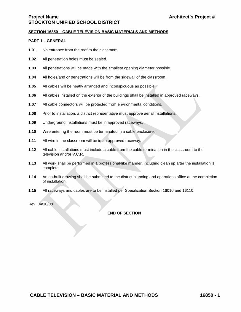
Project Name Architect’s Project # STOCKTON UNIFIED SCHOOL DISTRICT
CABLE TELEVISION – BASIC MATERIAL AND METHODS 16850 - 1
SECTION 16850 – CABLE TELEVISION BASIC MATERIALS AND METHODS PART 1 – GENERAL 1.01 No entrance from the roof to the classroom. 1.02 All penetration holes must be sealed. 1.03 All penetrations will be made with the smallest opening diameter possible. 1.04 All holes/and or penetrations will be from the sidewall of the classroom. 1.05 All cables will be neatly arranged and inconspicuous as possible. 1.06 All cables installed on the exterior of the buildings shall be installed in approved raceways. 1.07 All cable connectors will be protected from environmental conditions. 1.08 Prior to installation, a district representative must approve aerial installations. 1.09 Underground installations must be in approved raceways. 1.10 Wire entering the room must be terminated in a cable enclosure. 1.11 All wire in the classroom will be in an approved raceway. 1.12 All cable installations must include a cable from the cable termination in the classroom to the
television and/or V.C.R. 1.13 All work shall be performed in a professional-like manner, including clean up after the installation is
complete. 1.14 An as-built drawing shall be submitted to the district planning and operations office at the completion
of installation. 1.15 All raceways and cables are to be installed per Specification Section 16010 and 16110. Rev. 04/10/08
END OF SECTION

Project Name Architect’s Project # STOCKTON UNIFIED SCHOOL DISTRICT
ELECTRICAL ACCEPTANCE TESTS 16950 - 1
SECTION 16950 - ELECTRICAL ACCEPTANCE TESTS
PART 1 - GENERAL
1.1 SUMMARY
A. This Section defines the Electrical Acceptance Tests and checks that shall be made on all electrical equipment and wiring to ensure compliance with all applicable Codes and Standards, and with the requirements of the Contract Documents.
B. All electrical equipment testing and related costs shall be included in the Contractor’s bid.
1.2 GENERAL REQUIREMENTS
A. The Contractor shall test equipment of all kinds installed on this project to determine whether it fulfills the requirements of these Specifications. The Contractor shall furnish all labor necessary to adjust the operation of the apparatus and make the connections for the tests. After the tests have been completed, the Contractor shall restore all connections, apparatus, etc., to their original condition.
B. The Contractor shall retain the services of a qualified Independent Testing Agency holding a valid current C-10 License to perform certain tests and prepare reports, as enumerated in the following Articles. The Independent Testing Agency shall be a company that specializes in electrical equipment testing and shall be NETA or NICET certified.
C. Contractor shall obtain approval from the architect of proposed independent testing agency(s) before any testing is started.
D. Electrical systems, equipment and materials shall be tested prior to final acceptance of the work.
1.3 INDEPENDENT TESTING AGENCY REQUIREMENTS
A. The Independent Testing Agency shall furnish personnel acceptable to Engineer to conduct all testing. Supervising engineer shall have a minimum of five years experience in testing of equipment of the type to be tested on this Project.
B. The Independent Testing Agency shall furnish all labor required for and incidental to testing.
C. The Independent Testing Agency shall provide minor field repairs, adjustments, and wiring modifications at the time of inspection and testing.
D. The Independent Testing Agency shall furnish all necessary test equipment to satisfactorily perform all tests specified herein.
E. The Independent Testing Agency shall check all devices for proper operation - checking for wear, tightness, dirt, etc.

Project Name Architect’s Project # STOCKTON UNIFIED SCHOOL DISTRICT
ELECTRICAL ACCEPTANCE TESTS 16950 - 2
F. The Independent Testing Agency shall check for conformance to published curves.
G. The Independent Testing Agency shall notify and coordinate with the Owner’s representative at least 3 working days prior to the commencement of any Electrical Acceptance Testing. Tests shall be witnessed by the Owner’s representative unless such witnessing is waived in writing by the Owner’s Representative.
1.4 CODES AND STANDARDS
A. Current California Electrical Code (CEC).
B. National Electrical Manufacturer’s Association (NEMA).
C. Manufacturer’s Instructions and Maintenance Manual applicable to each particular apparatus.
D. OSHA Rules and Regulation.
E. National Electrical Testing Association (NETA) “Acceptance Testing Specifications”.
F. Procedures as directed by Engineer.
1.5 CARE AND PRECAUTIONS
A. Contractor shall be responsible for any damage to equipment or material due to improper test procedures or test apparatus handling, and shall replace or restore to original condition, any damaged equipment or material.
B. Contractor shall furnish and use safety devices such as rubber gloves and blankets, protective screens, barriers, and danger signs to adequately protect and warn all personnel in the vicinity of the tests.
1.6 EQUIPMENT TO BE TESTED BY CONTRACTOR
A. Perform the visual inspections, manual operations and tests on systems and equipment as described in Part 3, "Execution".
B. Switchboard
C. Molded Case Circuit Breakers Rated Less Than 100A
D. Distribution Transformers
E. Disconnect Switches
F. Lighting
G. Title 24 Acceptance Testing
H. Fire Alarm System
I. Communication System
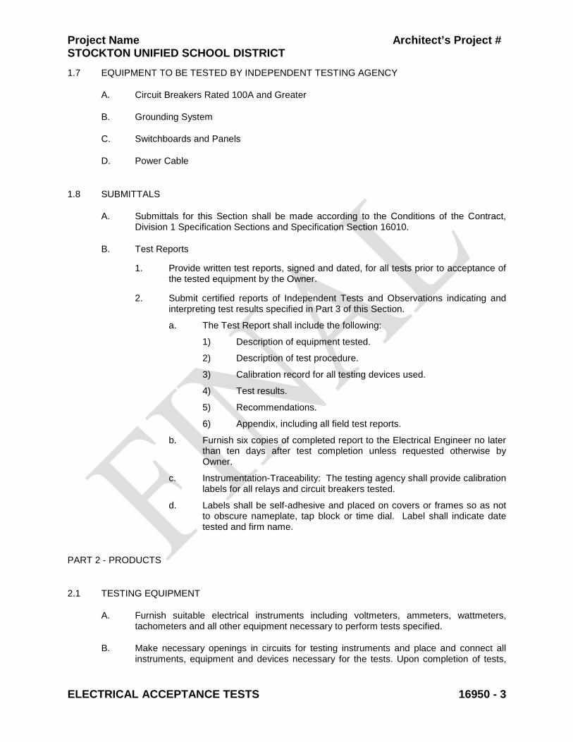
Project Name Architect’s Project # STOCKTON UNIFIED SCHOOL DISTRICT
ELECTRICAL ACCEPTANCE TESTS 16950 - 3
1.7 EQUIPMENT TO BE TESTED BY INDEPENDENT TESTING AGENCY
A. Circuit Breakers Rated 100A and Greater
B. Grounding System
C. Switchboards and Panels
D. Power Cable
1.8 SUBMITTALS
A. Submittals for this Section shall be made according to the Conditions of the Contract, Division 1 Specification Sections and Specification Section 16010.
B. Test Reports
1. Provide written test reports, signed and dated, for all tests prior to acceptance of the tested equipment by the Owner.
2. Submit certified reports of Independent Tests and Observations indicating and interpreting test results specified in Part 3 of this Section.
a. The Test Report shall include the following:
1) Description of equipment tested.
2) Description of test procedure.
3) Calibration record for all testing devices used.
4) Test results.
5) Recommendations.
6) Appendix, including all field test reports.
b. Furnish six copies of completed report to the Electrical Engineer no later than ten days after test completion unless requested otherwise by Owner.
c. Instrumentation-Traceability: The testing agency shall provide calibration labels for all relays and circuit breakers tested.
d. Labels shall be self-adhesive and placed on covers or frames so as not to obscure nameplate, tap block or time dial. Label shall indicate date tested and firm name.
PART 2 - PRODUCTS
2.1 TESTING EQUIPMENT
A. Furnish suitable electrical instruments including voltmeters, ammeters, wattmeters, tachometers and all other equipment necessary to perform tests specified.
B. Make necessary openings in circuits for testing instruments and place and connect all instruments, equipment and devices necessary for the tests. Upon completion of tests,
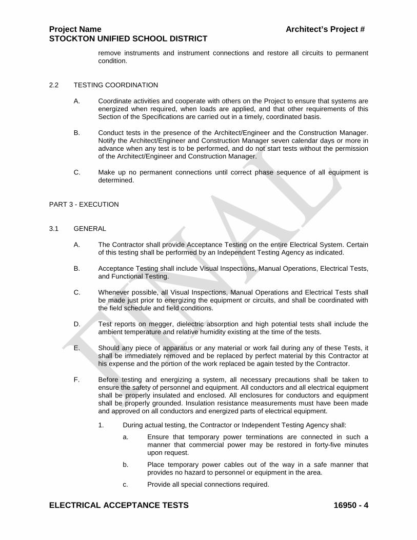
Project Name Architect’s Project # STOCKTON UNIFIED SCHOOL DISTRICT
ELECTRICAL ACCEPTANCE TESTS 16950 - 4
remove instruments and instrument connections and restore all circuits to permanent condition.
2.2 TESTING COORDINATION
A. Coordinate activities and cooperate with others on the Project to ensure that systems are energized when required, when loads are applied, and that other requirements of this Section of the Specifications are carried out in a timely, coordinated basis.
B. Conduct tests in the presence of the Architect/Engineer and the Construction Manager. Notify the Architect/Engineer and Construction Manager seven calendar days or more in advance when any test is to be performed, and do not start tests without the permission of the Architect/Engineer and Construction Manager.
C. Make up no permanent connections until correct phase sequence of all equipment is determined.
PART 3 - EXECUTION
3.1 GENERAL
A. The Contractor shall provide Acceptance Testing on the entire Electrical System. Certain of this testing shall be performed by an Independent Testing Agency as indicated.
B. Acceptance Testing shall include Visual Inspections, Manual Operations, Electrical Tests, and Functional Testing.
C. Whenever possible, all Visual Inspections, Manual Operations and Electrical Tests shall be made just prior to energizing the equipment or circuits, and shall be coordinated with the field schedule and field conditions.
D. Test reports on megger, dielectric absorption and high potential tests shall include the ambient temperature and relative humidity existing at the time of the tests.
E. Should any piece of apparatus or any material or work fail during any of these Tests, it shall be immediately removed and be replaced by perfect material by this Contractor at his expense and the portion of the work replaced be again tested by the Contractor.
F. Before testing and energizing a system, all necessary precautions shall be taken to ensure the safety of personnel and equipment. All conductors and all electrical equipment shall be properly insulated and enclosed. All enclosures for conductors and equipment shall be properly grounded. Insulation resistance measurements must have been made and approved on all conductors and energized parts of electrical equipment.
1. During actual testing, the Contractor or Independent Testing Agency shall:
a. Ensure that temporary power terminations are connected in such a manner that commercial power may be restored in forty-five minutes upon request.
b. Place temporary power cables out of the way in a safe manner that provides no hazard to personnel or equipment in the area.
c. Provide all special connections required.
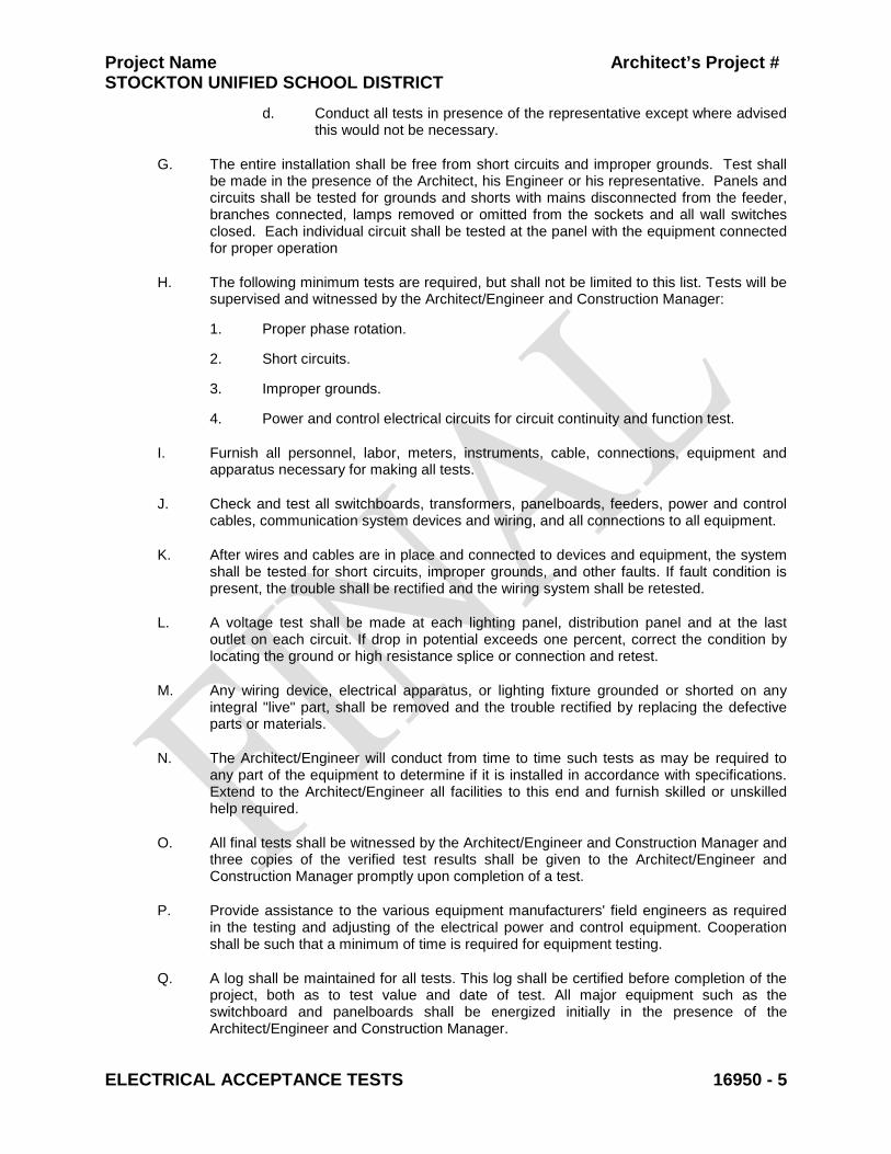
Project Name Architect’s Project # STOCKTON UNIFIED SCHOOL DISTRICT
ELECTRICAL ACCEPTANCE TESTS 16950 - 5
d. Conduct all tests in presence of the representative except where advised this would not be necessary.
G. The entire installation shall be free from short circuits and improper grounds. Test shall be made in the presence of the Architect, his Engineer or his representative. Panels and circuits shall be tested for grounds and shorts with mains disconnected from the feeder, branches connected, lamps removed or omitted from the sockets and all wall switches closed. Each individual circuit shall be tested at the panel with the equipment connected for proper operation
H. The following minimum tests are required, but shall not be limited to this list. Tests will be supervised and witnessed by the Architect/Engineer and Construction Manager:
1. Proper phase rotation.
2. Short circuits.
3. Improper grounds.
4. Power and control electrical circuits for circuit continuity and function test.
I. Furnish all personnel, labor, meters, instruments, cable, connections, equipment and apparatus necessary for making all tests.
J. Check and test all switchboards, transformers, panelboards, feeders, power and control cables, communication system devices and wiring, and all connections to all equipment.
K. After wires and cables are in place and connected to devices and equipment, the system shall be tested for short circuits, improper grounds, and other faults. If fault condition is present, the trouble shall be rectified and the wiring system shall be retested.
L. A voltage test shall be made at each lighting panel, distribution panel and at the last outlet on each circuit. If drop in potential exceeds one percent, correct the condition by locating the ground or high resistance splice or connection and retest.
M. Any wiring device, electrical apparatus, or lighting fixture grounded or shorted on any integral "live" part, shall be removed and the trouble rectified by replacing the defective parts or materials.
N. The Architect/Engineer will conduct from time to time such tests as may be required to any part of the equipment to determine if it is installed in accordance with specifications. Extend to the Architect/Engineer all facilities to this end and furnish skilled or unskilled help required.
O. All final tests shall be witnessed by the Architect/Engineer and Construction Manager and three copies of the verified test results shall be given to the Architect/Engineer and Construction Manager promptly upon completion of a test.
P. Provide assistance to the various equipment manufacturers' field engineers as required in the testing and adjusting of the electrical power and control equipment. Cooperation shall be such that a minimum of time is required for equipment testing.
Q. A log shall be maintained for all tests. This log shall be certified before completion of the project, both as to test value and date of test. All major equipment such as the switchboard and panelboards shall be energized initially in the presence of the Architect/Engineer and Construction Manager.
Project Name Architect’s Project # STOCKTON UNIFIED SCHOOL DISTRICT
ELECTRICAL ACCEPTANCE TESTS 16950 - 6
R. The Owner reserves the right to operate any system or equipment prior to final completion and acceptance of the work. Such preliminary operation shall not be construed as an acceptance of any work. Each piece of equipment and all of the systems shall be adjusted to insure proper functioning and shall be left in first class operating condition.
3.2 VISUAL INSPECTIONS
A. Prior to Manual Operation and Electrical Testing, perform Visual Inspections to verify the following:
1. The equipment is completely and properly installed.
2. The equipment is free from damage and defects.
3. Shipping blocks and restraints have been removed.
4. Electrical terminations have been properly tightened.
5. The equipment has been properly aligned.
6. The equipment has been properly lubricated.
7. The ventilation louvers are open and unobstructed.
8. Voltages and phases have been properly identified.
9. Terminations in control panels have been properly identified.
10. The equipment is ready to be tested
3.3 MANUAL OPERATION
A. Prior to any Electrical Testing, mechanical devices shall be exercised or rotated manually to verify that they operate properly and freely.
3.4 ELECTRICAL TESTS BY CONTRACTOR
A. Switchboard
1. The Contractor shall perform each visual and mechanical inspection and electrical test stated in NETA Acceptance Testing Specification, Sections 7.1, 7.6, 7.9, 7.10, 7.11, and 7.14, as appropriate. Certify compliance with test parameters.
2. Switchboard and completed installation shall be inspected for adequate size, bus spacing, bracing, physical damage, proper alignment, anchorage and grounding.
3. Switchboard frame will be inspected for alignment, level, and anchorage.
4. Check tightness of accessible bolted bus joints using calibrated torque wrench per manufacturer’s recommended torque value. All bus bolts will be torqued to their proper value. A mark to be placed on each tightened bolt to ensure completeness.
5. Switchboard interior will be vacuumed and wiped clean.

Project Name Architect’s Project # STOCKTON UNIFIED SCHOOL DISTRICT
ELECTRICAL ACCEPTANCE TESTS 16950 - 7
6. The following tests and checks shall be performed before placing in operation:
a. Check all new bus and cable connections for proper contact pressure and mark each bolt with a red “dot” of paint to indicate it has been checked.
b. Check all the new equipment for mechanical adjustment, lubrication, and freedom of operation. Remove all shipping blocks.
c. Operate and test trip units for all new breakers.
d. Test all transfer switches and associated control circuits for correct connection and operation.
e. Test all panel feeders and main breakers.
f. Test ground fault systems by operating push-to-test button.
g. Physically test key interlock systems to check for proper functionality.
7. Using a Megger, measure the insulation resistance of each bus section phase-to-phase and phase-to-ground for one minute each, at minimum test voltage of 1000VDC. Minimum acceptable value for insulation resistance is one (1) megohm. Refer to manufacturer’s literature for specific testing procedure.
B. Molded Case Circuit Breakers rated less than 100A
1. Circuit breakers will be operated manually several times to ensure smooth operation.
2. Molded case will be inspected for cracks.
3. Rated current will be passed through each phase and millivolt readings taken across contacts.
4. Time current characteristic tests will be performed by passing 300% rated current through each phase and monitoring trip time.
5. Instantaneous pickup current will be determined by finding the current level at which the breaker trips out in less than 2 cycles.
6. Insulation resistance tests will be performed at 1000 Volts DC.
7. Circuit breaker covers will be removed on unsealed units and checked for cracks. Interphase barriers and arc chutes to be inspected. All bolts and lugs will be tightened. All internal auxiliary devices will be inspected.
8. Contacts, shunts, etc., will be visually inspected for wear and alignment.
9. Inverse trip time, instantaneous pickup current and millivolt drop across contacts, insulation resistance values, as well as deficiencies causing breaker to function outside published limits will be recorded. Times will then be compared with manufacturer’s or NEMA published values.
C. Distribution Transformers
1. Record transformer secondary voltage at each unit for at least 48 hours of typical occupancy period. Adjust transformer taps to provide optimum voltage conditions at secondary terminals. Optimum is defined as not exceeding nameplate voltage plus 10 percent and not being lower than nameplate voltage minus 2.5 percent. Submit recording and tap settings as test results.
Project Name Architect’s Project # STOCKTON UNIFIED SCHOOL DISTRICT
ELECTRICAL ACCEPTANCE TESTS 16950 - 8
2. Adjust buck-boost transformers to provide nameplate voltage of equipment being served, plus or minus 5 percent, at secondary terminals.
3. Prepare a written Output Settings Report recording output voltages and tap settings.
D. Disconnect Switches
1. Check for cleanliness of contacts, operation, etc.
2. Lubricate contacts and mechanical devices.
3. Check fuse-clip tightness.
4. Perform a 1,000-volt megger test on disconnect switches rated for 600V and at 500 volts for disconnect switches rated for 240V.
E. Lighting
1. Upon completion of installation of lighting fixtures and controls, and after building circuitry has been energized, apply electrical energy to demonstrate capability and compliance with requirements. The Contractor shall replace at his expense all noisy ballasts, broken or cracked lenses or other defective items. Where possible, correct malfunctioning units at site, then re-test to demonstrate compliance; otherwise, remove and replace with new units, and proceed with re-testing.
2. At the time of substantial completion, replace lamps in interior lighting fixtures, which are observed to be noticeably dimmed after Contractor’s use and testing, as judged by Architect or Electrical Engineer.
3. Replace defective and burned out fluorescent lamps for a period of one-year following the time of substantial completion
4. Give advance notice of dates and times for field tests.
5. Provide instruments to make and record test results.
6. Tests and Observations
a. Verify normal operation of lighting units after installing fixtures and energizing circuits with normal power source.
b. Check for excessively noisy ballasts.
c. Contractor shall advice Owner at least 72 hours prior to testing emergency lighting system, and shall allow Owner to witness testing.
Interrupt electrical energy to demonstrate proper operation of emergency lighting installation. Include the following information in tests of emergency lighting equipment:
1) Duration of supply
2) Low battery voltage shutdown.
3) Normal transfer to battery source and retransfer to normal.
4) Low supply voltage transfer.
5) Report results of tests in wiring.
Project Name Architect’s Project # STOCKTON UNIFIED SCHOOL DISTRICT
ELECTRICAL ACCEPTANCE TESTS 16950 - 9
F. Title 24 Acceptance Testing
1. Perform tests as outlined in Part 3 of Specification Section 16500.
G. Fire Alarm System
1. Perform testing in accordance with NFPA 72-2002, Chapter 10.
2. Perform tests as outlined in Part 3 of Specification Section 16720.
H. Communication System
1. Perform tests as outlined in Part 3 of Specification Section 16744.
3.5 INDEPENDENT AGENCY TESTING
A. Circuit Breakers rated 100A or greater
1. All circuit breakers, 100 amps or more, shall be tested by an independent testing agency in accordance with NETA specifications and a report submitted to the architect. Any circuit breaker that does not pass the test shall be replaced.
2. Circuit breakers will be operated manually several times to ensure smooth operation.
3. Molded case will be inspected for cracks.
4. Rated current will be passed through each phase and millivolt readings taken across contacts.
5. Time current characteristic tests will be performed by passing 300% rated current through each phase and monitoring trip time.
6. Instantaneous pickup current will be determined by finding the current level at which the breaker trips out in less than 2 cycles.
7. Insulation resistance tests will be performed at 1000 Volts DC.
8. Circuit breaker covers will be removed on unsealed units and checked for cracks. Interphase barriers and arc chutes to be inspected. All bolts and lugs will be tightened. All internal auxiliary devices will be inspected.
9. Contacts, shunts, etc., will be visually inspected for wear and alignment.
10. Inverse trip time, instantaneous pickup current and millivolt drop across contacts, insulation resistance values, as well as deficiencies causing breaker to function outside published limits will be recorded. Times will then be compared with manufacturer’s or NEMA published values.
11. The testing agency shall provide calibration labels for all relays and circuit breakers tested. Labels shall be self-adhesive and placed on covers or frames so as not to obscure nameplate, tap block or time dial. Label shall indicate date tested and firm name.
B. Grounding System
1. Test shall be performed for every new SEPARATELLY DERIVED AC SYSTEM.
Project Name Architect’s Project # STOCKTON UNIFIED SCHOOL DISTRICT
ELECTRICAL ACCEPTANCE TESTS 16950 - 10
2. Ground tests shall meet the requirements of the California Electrical Code and comply with UL 467. The grounding electrode system at the main electrical service equipment shall be tested by an Independent Testing Agency in accordance with the three point fall of potential method as specified in IEEE Standard 81-1983. Maximum ground resistance shall be 5 OHMS. A copy of the test report shall be submitted to the architect and engineer of record.
3. Maximum grounding to resistance values are as follows:
a. Equipment Rated 500 kVA and Less: 5 ohms.
b. Equipment Rated 500 to 1000 kVA: 5 ohms.
c. Equipment Rated More than 1000 kVA: 3 ohms.
4. Tests: Subject the completed grounding system to a megger test at each location where a maximum ground-resistance level is specified, at service disconnect enclosure grounding terminal, and at ground test wells. Measure ground resistance not less than 2 full days after the last trace of precipitation, and without the soil being moistened by any means other than natural drainage or seepage and without chemical treatment or other artificial means of reducing natural ground resistance. Perform tests by the 2-point method according to IEEE 81.
5. The test agency shall remove the test link between the ground and neutral, and test the neutral for any parallel and/or superfluous ground paths. If any are found, a report should be given to the Engineer. No grounds are to be removed unless authorized in writing.
6. Ground electrode resistance shall be taken using a Biddle ground resistance meter and readings given to the report.
7. All ground connections in switchboard as well as that to cold water pipes shall be check for tightness and adequacy.
8. Measure the resistance to ground of each ground rod [in a ground mat] before connection to the other ground rods. The resistance shall not exceed 10 ohms.
9. Measure the resistance to ground of the total ground system with all connections completed. The resistance shall not exceed 2 ohms for primary services or 5 ohms for secondary services.
10. Tests of the resistance to ground shall be made using either the three point method or the fall-of-potential method.
11. Perform a continuity check from equipment ground bus bars and ground lugs to the ground system.
12. Ground rods for manholes and light poles need not be tested.
13. Excessive Ground Resistance: Where resistance to ground exceeds specified values, notify Owner promptly and include recommendations to reduce ground resistance and to accomplish recommended work.
14. Report: Prepare test reports, certified by the testing organization, of ground resistance at each test location. Include observations of weather and other phenomena that may affect test results. Describe measures taken to improve test results.
C. Switchboards and Panels
Project Name Architect’s Project # STOCKTON UNIFIED SCHOOL DISTRICT
ELECTRICAL ACCEPTANCE TESTS 16950 - 11
1. The Independent Testing Agency shall perform each visual and mechanical inspection and electrical test stated in NETA Acceptance Testing Specification, Sections 7.1, 7.6, 7.9, 7.10, 7.11, and 7.14, as appropriate. Certify compliance with test parameters.
2. After Substantial Completion, but not more than 2 months after Final Acceptance, The Independent Testing Agency shall perform an infrared scan of each switchboard and panel.
a. Remove fronts to make joints and connections accessible to a portable scanner.
b. Use an approved infrared-scanning device designed to measure temperature or detect significant deviations from normal values.
c. Provide calibration record for device used.
d. Prepare a certified report identifying switchboards and panels checked and describing results of infrared scanning. Include notation of deficiencies detected, remedial action taken and observations after remedial action.
D. Power Cable
1. The 600-volt insulated wires and cables shall be factory tested prior to shipment in accordance with ICEA Standards for the insulation specified.
2. Perform a continuity check and a 1,000 volt DC megger test on 600 volt power cables No. 6 AWG and larger as outlined in latest version NETA Acceptance Testing Specifications.
3. Phase conductors, if shorted, grounded or at fault shall be removed, shall be replaced and the wiring system shall be retested.
3.6 FUNCTIONAL TESTING
A. All automatic and manual functions shall be checked for proper operation.
B. All indicating circuits, lights and alarms shall be tested for correct operation. Burned out indicators shall be re-lamped.
C. Upon completion of the Work, place the entire installation in operation, test for proper function, and show systems and equipment to be free of defects.
END OF SECTION 16950
Project Name Architect’s Project # STOCKTON UNIFIED SCHOOL DISTRICT
FIRE PROTECTION 21 11 00 - 1 Revised 3/2011
SECTION 21 11 00 - FIRE PROTECTION PART 1 - GENERAL
1.1 SUMMARY
A. This is a bidder design system. Contact Authority Having Jurisdiction (AHJ) prior to bid to verify fire system requirements. Provide design compliant with codes as interpreted by AHJ.
B. Provide the following:
1. Wet-pipe sprinkler system.
2. Private fire service main, including connection to existing utility, and piping to the inlet connection inside the building. Provide required valves, backflow preventer, vaults, and appurtenances.
3. Kitchen range hood sprinkler system connection (hood sprinkler system by others. See Project Manual Section 11 42 00 – Kitchen Hood Fire Suppression System).
4. Heat cable on insulation for risers and mains in unheated areas. Areas include, but are not limited to, Administration Building and Multi-Use Building.
5. Heater Cable Controller. Connected to building fire alarm control panel.
C. Provide tamper, flow, and pressure switches. Coordinate location and type of tamper, flow, and pressure switches with the fire alarm system.
D. Provide all costs for electrical connections and wiring as required for a complete and operable system. Includes, but is not limited to air compressors, sump pumps, fire pumps, jockey pumps, pump controllers, and the like. Coordinate with Division 16.
E. Refer to Architectural, Structural, Mechanical, Plumbing, Electrical, and Civil Drawings for additional information relating to the fire sprinkler system.
1.2 DEFINITIONS
A. Following is a list of abbreviations generally used in Division 21:
1. AHJ Authority Having Jurisdiction
2. AWWA American Water Works Association
3. CBC California Building Code
4. CFC California Fire Code
5. NFPA National Fire Protection Association
6. UL Underwriters Laboratories Inc.
Project Name Architect’s Project # STOCKTON UNIFIED SCHOOL DISTRICT
FIRE PROTECTION 21 11 00 - 2 Revised 3/2011
B. Code: Where this Specification refers to "Code," it indicates any or all of the above listed Codes as applicable to that reference.
C. AHJ: Indicates all reviewing authorities, including the local fire marshal, the Owner's insurance underwriter, Owner's representative, and any other reviewing entity whose approval is required to obtain systems acceptance.
1.3 QUALITY ASSURANCE
A. Qualifications: Company specializing in sprinkler systems of similar type and scope with 3 years experience.
B. Construction Drawings and hydraulic calculations to be signed by a mechanical or fire protection engineer licensed in the state of California. NICET and contractor seals and signatures do not meet this requirement. Construction drawings shall be complete and show information required by NFPA 13.
C. Regulatory Requirements: Provide system per the requirements of the following, except as specifically modified herein. Apply edition as enforced by AHJ unless otherwise stated. Comply with state amendments.
1. UBC and California Building Standards Code, Title 24, all parts, as adopted by AHJ.
2. UFC and California Fire Code, as adopted by AHJ.
3. NFPA 101, Latest Edition, Life Safety Code.
4. NFPA 13, Latest Edition, Standard for the Installation of Sprinkler Systems.
5. NFPA 25, Latest Edition, Standard for Inspection, Testing, and Maintenance of Water-Based Fire Protection Systems.
6. UL Fire Protection Equipment Directory.
7. UL Online Certifications Directory.
8. FM Global Approval Guide.
9. NFPA 24, Latest Edition, Standard for the Installation of Private Fire Service Mains and Their Appurtenances.
10. NFPA 291, Latest Edition, Recommended Practice for Fire Flow Testing and Marking of Hydrants.
11. NFPA 5000, Latest Edition, NFPA Building Construction and Safety Code.
D. Sway brace calculations shall meet minimum requirements of CBC Chapter 16, Par. 1632; and NFPA 13, Par. 9.3.5.6. Brace calculations in UBC Seismic Zone 4 shall be signed by a structural engineer licensed in the state of California. When submitting sway brace calculations, include Building Code Chapter 16 calculations determining force factor (Fp) used in those sway brace calculations.
Project Name Architect’s Project # STOCKTON UNIFIED SCHOOL DISTRICT
FIRE PROTECTION 21 11 00 - 3 Revised 3/2011
1.4 SUBMITTALS
A. Submit the following for review. Include in operations and maintenance manual.
1. Shop drawings, hydraulic calculations, sway brace calculations, and component manufacturer's data sheets (as one complete standalone package) to AHJ, Owner's insurance underwriter, and Engineer. Provide proof of approval by AHJ of installed sprinkler system to Engineer on completion of work. Coordinate sprinkler system design with all other building systems. Plans shall show information required by NFPA 13, Par. 14.1, including room names and occupancy classifications.
2. Project Record Documents indicating record conditions per Division 1, Closeout Requirements.
3. Test Reports: Underground and aboveground piping hydrostatic test, water supply flow test; Code-required acceptance tests; and manufacturer's operation and maintenance data. Include written maintenance data on components of system, servicing requirements, and Record Drawings.
4. Operations and Maintenance Manual: Provide three sets of O&M manuals that include Record Drawings, hydraulic calculations, manufacturer's data sheets and operation and maintenance instructions, servicing requirements, test reports and certificates, Contractor’s Material and Test Certificates for Aboveground Piping/Underground Piping and NFPA 25.
1.5 EXTRA STOCK
A. Provide extra sprinklers per code; provide suitable wrenches for each sprinkler type, and metal storage cabinet in location designated.
1.6 SYSTEM DESCRIPTION
A. Provide coverage for all buildings. Contractor to field verify field conditions prior to submittal of bid. Contractor to make any necessary adjustments to bid in order to provide protection features in accordance with applicable codes and interpretations by AHJ. Provide design and installation based on the more stringent requirements if AHJ requirements differ from Code.
B. Design Parameters:
1. Increase remote design area for sloped roofs and concealed areas per NFPA 13-2002.
2. Building Area: Classrooms, Offices, Gym, Restrooms, Stairs, Corridors, and Conference Rooms.
a. Occupancy Classification: Light.
b. Density: 0.10 GPM per sq.ft. over a 1500 sq.ft. hydraulically most remote design area per NFPA 13.
c. Area per Sprinkler: 225 sq.ft. maximum.
d. Inside Hose Allowance: 0 GPM.

Project Name Architect’s Project # STOCKTON UNIFIED SCHOOL DISTRICT
FIRE PROTECTION 21 11 00 - 4 Revised 3/2011
e. Outside Hose Allowance: 100 GPM.
3. Building Area: Storage, Electrical, Mechanical, Janitor.
a. Occupancy Classification: Ordinary Group 1.
b. Density: 0.15 GPM per sq.ft. over a 1500 sq.ft. hydraulically most remote design area per NFPA 13.
c. Area per Sprinkler: 130 sq.ft. maximum.
d. Inside Hose Allowance: 0 GPM.
e. Outside Hose Allowance: 250 GPM.
4. Building Area: Stage.
a. Occupancy Classification: Ordinary Group 2.
b. Density: .020 GPM per sq.ft. over a 1500 sq.ft. hydraulically most remote design area per NFPA 13.
c. Area per Sprinkler: 130 sq.ft. maximum.
d. Inside Hose Allowance: 0 GPM.
e. Outside Hose Allowance: 250 GPM.
C. Sprinkler system design to include a 10 percent pressure cushion between system demand point and available water supplies.
D. Extend hydraulic calculations from hydraulically most remote design back to location of flow test.
E. Develop cost-effective designs that may include the use of extended coverage sprinklers and design area reductions as allowed by NFPA 13.
1.7 FLOW TEST
A. Provide materials and labor for a new water supply test on the closest nearby fire hydrants per NFPA 13, Par. A.15.2.1 and NFPA 291.
1.8 GUARANTY
A. Guaranty all systems against defective equipment, materials and workmanship for a period of 1 year after Owner's acceptance.
PART 2 - PRODUCTS
2.1 GENERAL
A. Material and equipment listed in current UL Fire Protection Equipment Directory, UL Online Certifications Directory for Fire Protection, or FM Global Approval Guide.
Project Name Architect’s Project # STOCKTON UNIFIED SCHOOL DISTRICT
FIRE PROTECTION 21 11 00 - 5 Revised 3/2011
B. Provide products new and of current manufacture.
2.2 PIPE AND FITTINGS
A. General: Provide per AHJ requirements, and as a minimum per below.
B. Materials: Domestic Manufacture. .
1. Buried Piping: Ductile iron Class 52, AWWA C151 or PVC, SDR-18, AWWA C900.
2. Aboveground Inside Building Piping:
a. Pipe Size 2-Inch Diameter and Smaller: ASTM A53, ASTM A135, or ASTM A795; minimum CRR of 1.00 per UL listing or FM Global approval. Allied BLT/XL is not permitted.
b. Pipe Size 2-1/2-Inch Diameter and Larger: ASTM A53, ASTM A135, or ASTM A795; minimum CRR of 1.00 per UL Testing or FM Global approved, wall thickness greater than Schedule 5 (Schedule 5 not approved).
c. Copper Pipe: ASTM B75, ASTM B88, ASTM B251. Threaded, brazed, solder or mechanical fittings only.
d. Mechanical Couplings: FM Global approved; Victaulic, Gruvlok, or approved.
e. All dry pipe system piping shall be galvanized inside and out. When ambient temperature exceeds 130F, galvanizing shall not be used. Where piping is exposed, fittings shall be galvanized.
f. Exposed pipe 8’-0” or less above finished floor shall be a minimum of Schedule 40.
2.3 SPECIALTIES
A. Fire Department Connection: Free-standing type; ductile iron; brass finish; thread size to suit fire department hardware; two-way threaded dust cap and chain of same material and finish, marked "Sprinkler Fire Department Connection." Provide method of draining piping subject to freezing.
B. Waterflow Detector: Vane-type with SPDT switches and adjustable time delay (0 to 75 seconds). Potter VSR-F, or approved.
C. Tamper Switches: Provide to mount on applicable valve (OS&Y gate, butterfly, or PIV), with SPDT switches to match requirements of fire alarm system. Potter, or approved.
D. Backflow Prevention Device:
1. Two check valves in series with in-line strainer and OS&Y gate valves at each end. Provide detector if required by local utility. Entire assembly must be UL listed or FM Global approved for fire protection service. Approved by local and state authorities, including California State Department of Health.
Project Name Architect’s Project # STOCKTON UNIFIED SCHOOL DISTRICT
FIRE PROTECTION 21 11 00 - 6 Revised 3/2011
2. For Antifreeze Systems: Reduced pressure principle backflow prevention device. OS&Y gate valves on inlet and outlet with indentation for monitoring switch and strainer on inlet. Include two independent operating, spring-loaded check valves with a pressure differential relief valve located between the two checks. Include relief valve air gap drain funnel. Provide detector if required by local utility. Entire assembly must be UL listed or FM Global approved for fire protection service and approved by local authorities and California State Department of Health. Coordinate with Specification Section 15400, Plumbing, for drainage of relief valve. Model 880 by FEBCO, or approved.
E. Inspector's Test Connection: AGF Test-an-Drain, or approved.
F. Alarm Bells Interior: Locate in a normally occupied location. Coordinate with Architect and Division 16.
G. Alarm Bells - Exterior: Exceed 90 dBA at 10 feet. Locate at 8 feet above finished grade. Coordinate with Architect and Division 16. Potter PB 8-inch, or approved.
H. Heater Cable: Nelson LT-3 self-regulating heater cable or approved. Coordinate with Division 16.
I. Heater Cable Controller: Chromalox DL Model RTBC or approved. Coordinate with Division 16.
J. Expansion Chamber: Young Engineering, or approved.
K. Automatic Ball Drip Valve: Viking Model B-1, or approved.
L. High/Low Pressure Alarm Switch: Coordinate electrical requirements with fire alarm system. Potter PS40A, or approved.
M. Air Compressor: Manufactured for fire sprinkler systems. Emglo, Gast, General, or approved.
N. Sectional Control Test/Drain Unit: ASTM A53 pipe, with inspector's test valve, sectional drain valve, sectional isolation valve with tamper switch, restriction union with corrosion resistant orifice equivalent to sprinkler orifice, sight flow connection, and waterflow detector. Tyco F350, or approved.
O. Pressure Switch: Coordinate electrical requirements with fire alarm system. Potter PS10, or approved.
2.4 SPRINKLERS
A. Finished Areas: Glass-bulb, recessed, quick-response pendent with chrome plated finish, and chrome escutcheon.
B. Nonfinished Areas: Glass-bulb, quick-response. Brass finish.
C. Dry: Recessed, glass bulb, quick-response, chrome finish with chrome escutcheon.
D. Provide guards for sprinklers located under ducts or other obstructions or for sprinklers located less than 8’-0” above finished floor or where subject to mechanical injury.
Project Name Architect’s Project # STOCKTON UNIFIED SCHOOL DISTRICT
FIRE PROTECTION 21 11 00 - 7 Revised 3/2011
2.5 VALVES, GENERAL
A. OS&Y Gate:
1. 2-1/2 Inches and Larger: Nibco F-607-0, or approved.
2. 2 Inches and Smaller: Nibco T-104, or approved.
B. NRS Gate: Nonrising stem with post indicator. Nibco M/F-609 with NIP1A or equivalent for yard use and Nibco NIP2 or equivalent for wall use.
C. Swing Check: Iron body, rubber and bronze faced checks. Nibco F-908-W, or approved.
D. Wafer Check: Iron body, rubber seat, spring actuated. Nibco W-900-W, or approved.
E. Butterfly Valves: Ductile iron body, Nibco WD3510-8 with factory-installed tamper switches or approved. Use lug body next to pumps, LD-3510-6 or approved.
PART 3 - EXECUTION
3.1 INSTALLATION
A. Coordinate the work of this Section with other trades and building systems. Provide adequate space for installation.
B. General:
1. Provide post indicator on buried control valves.
2. Provide listed backflow assembly at sprinkler system water source connection. Coordinate with local utility; conform to their installation requirements.
3. Fire Department Connection: Locate with sufficient clearance from walls, obstructions, or adjacent siamese connectors to allow full swing of fire department wrench handle.
4. Install pipe runs to minimize obstruction to other work.
5. Install piping in concealed spaces above finished ceilings. Exposed piping shall be approved by Architect and Engineer.
6. Center sprinklers in the middle or quarter points of suspended ceiling tile.
7. Apply strippable tape or paper cover to ensure sprinklers do not receive field paint finish. Remove upon completion of painting.
8. Provide seismic restraints per NFPA 13, and applicable building codes.
9. Coordinate support of sprinkler pipe 4 inches and larger with structural engineer.
10. Provide clearances around piping per NFPA 13, Par. 9.3.4.
11. Provide flexible couplings at building expansion joints per NFPA 13, Par. 9.3.2.

Project Name Architect’s Project # STOCKTON UNIFIED SCHOOL DISTRICT
FIRE PROTECTION 21 11 00 - 8 Revised 3/2011
12. Sprinkler system control valves to be post indicator valves to be located a minimum of 40 feet from the building.
13. Route water supply flow test connections to a location which can accept the flow under wide-open flow and pressure for a sufficient time to assure a proper test, and which will not cause damage, including to landscaping.
14. Coordinate location and electrical requirements of air compressor with Division 16.
15. Provide access panels for all test valves, test drains and low point drains concealed by structure or finish.
16. Maintain fire rating of all structural assemblies.
17. Provide Schedule 40 zinc-coated pipe sleeves for pipes passing through masonry walls, floors and ceilings. Extend sleeves completely through construction, firmly pack with oakum and caulk both ends with insulating cement or rated fire-stopping compound.
18. Hydraulic calculations shall include all friction losses between the hydraulically most remote design area and the hydrant flow test pressure hydrant.
19. Space pipe hangers no more than 4 feet on center for all exposed sprinkler pipe located 8’-0” or less above finished floor. Limit branch line overhangs to 4 inches or less.
20. For antifreeze systems provide reduced pressure backflow preventer with drain to sanitary sewer and UL listed or FM approved expansion chamber.
21. Route piping to avoid sheet metal ducts as shown on drawings.
22. Coordinate installation with other trades. Route piping as required to avoid building structure, equipment, plumbing piping, HVAC piping, ductwork, lighting fixtures, electrical conduits and bus ducts and similar work. Final location of lighting will have priority over final sprinkler locations. Provide drains to trapped sections of system which result from such routing. Other trades take precedence for installation space.
23. Locate all sprinkler drains within 7 feet of floor. All sprinkler piping shall be capable of being fully drained.
24. At completion of installation, provide permanent signing of substantial construction and permanent inscription, as required by NFPA 13. Tags on antifreeze systems shall identify volume of system and percentage mixture of water and propylene glycol. Hydraulic placards shall be affixed to the sprinkler riser(s) with one placard for each remote area, per NFPA 13, Par. 16.5.
3.2 SYSTEM TESTS
A. Test entire system per code and AHJ. Provide, arrange, and pay for all testing required by code or AHJ in order to obtain complete and final acceptance. Witness tests by AHJ and Engineer. Notify AHJ and Engineer 2 weeks prior to test.
Project Name Architect’s Project # STOCKTON UNIFIED SCHOOL DISTRICT
FIRE PROTECTION 21 11 00 - 9 Revised 3/2011
3.3 FIELD SERVICES
A. Instruct the Owner in the operation of the sprinkler system, including main valve position (open or closed) recognition, system drainage, system testing, and the relation to the fire alarm system.
END OF SECTION
Project Name Architect’s Project # STOCKTON UNIFIED SCHOOL DISTRICT
BASIC MATERIAL & METHODS 26 05 00 - 1
SECTION 26 05 00 - BASIC MATERIALS AND METHODS
PART 1 - GENERAL
1.1 SUMMARY
A. Section Includes:
1. Raceways. 2. Wires, cables and connectors. 3. Outlet boxes. 4. Devices and plates. 5. Safety disconnect switches. 6. Identification. 7. Surface raceway system.
1.2 SYSTEM DESCRIPTION
A. Provide raceways, wires, cables, connector, boxes, devices, finish plates and the like for a complete and operational electrical system.
B. Electrical Connections: Connect equipment, whether furnished by Owner or other Divisions of the Contract, electrically complete.
C. Supporting Devices: Safety factor of 4 required for every fastening device or support for electrical equipment installed. Support to withstand four times weight of equipment it supports. Bracing to comply with Seismic Zone 4 requirements.
1.3 SUBMITTALS
A. Provide shop drawings, product data and product selection for the following:
1. Raceways.
2. Wires, cables and connectors.
3. Outlet boxes.
4. Devices and plates.
5. Safety disconnect switches.
6. Identification equipment.
7. Surface raceway system.
8. Submit only one manufacturer per product.
B. Provide the following operating and maintenance instructions from the manufacturer for project closeout, see project closeout requirements in Division 1:
1. Devices and plates.

Project Name Architect’s Project # STOCKTON UNIFIED SCHOOL DISTRICT
BASIC MATERIAL & METHODS 26 05 00 - 2
2. Safety disconnect switches.
1.4 REGULATORY REQUIREMENTS
A. Conform to requirements of the CEC, latest adopted version with amendments by local AHJs.
B. Furnish products listed by UL or other testing firm acceptable to AHJ.
1.5 SPLICES
A. Make Connections, splices, taps and joints mechanically and electrically secure. Protect exposed wires and connecting devices with electrical tape or insulation to provide protection not less than that of the conductor.
1. Splices of #10 and smaller, including fixture tape, shall be made with Scotchlok connectors, T & B “Piggys” or equal.
2. Splices of #8 through #4 shall be split bolt service connectors “Kerneys”, T & B “Lock Tites” or equal, insulated with Scotch #88 or Okeweld four-purpose tape.
3. Splices #2 and larger shall be OZ “ST” Series insulated with Scotch fill and Scotch #88 or Okeweld.
4. Splices in underground pull boxes shall be Scotchcast, cast resin splices.
5. Wire splice devices shall be sized according to manufacturer’s recommendations.
6. Fire Alarm and Intercom shall not be spliced.
1.6 CONDUCTORS IN PANELS
A. Conductors in panels, motor control centers, etc. shall be laced with T & B Ty-raps.
B. All current carrying conductors in panels shall be labeled.
1.7 LUBRICANT
A. Lubricant for conductor installation shall be powdered soapstone, Y-er, Minerallac “Pull-In” compound or other U.L. approved lubricant. Flax soap is not approved and not permitted on the job.
PART 2 - PRODUCTS
2.1 RACEWAYS
A. Conduits:
1. Galvanized Rigid Steel Conduit (GRC):
a. Hot-dip galvanized after thread cutting. Manufacture in conformance with Federal Specification WWC-581 and ANSI C80.1.

Project Name Architect’s Project # STOCKTON UNIFIED SCHOOL DISTRICT
BASIC MATERIAL & METHODS 26 05 00 - 3
b. ¾” Minimum size.
c. Standard weight, zinc coated on outside by hot dipping or sherardized process, with either zinc coating or other approved corrosion resistant coating on the inside.
d. Fitting shall be threaded and finished similar to conduit. Threadless fittings shall not be used. Condulets and unilets shall be malleable iron.
e. Conduits connected to boxes and cabinets shall be fitted with two locknuts and insulated bushing, OA "A" Series, indoors only.
f. Conduits not connected with locknuts and bushings shall be fitted with grounding bushing, OZ "BL" Series; U. L. approved and bonded.
g. Conduit stubs underground shall be capped with coupling, nipple, coupling and plug.
h. Conduits connected to boxes, cabinets, etc., outdoors, exposed to weather or in areas subject to excessive moisture shall be fitted with watertight sealing hubs of steel or malleable iron with sealing ring and insulated throat, Myers hub, T&B 370 Series, or equal.
i. Conduits in contact with the ground must be wrapped with corrosion resistant tape of 10 mil or equiv.
j. Erickson Couplings (three piece threaded coupling) may be used in limited locations, where standard threaded couplings can not be used.
k. All Thread (Running Thread) shall not be used as a Raceway
l. All conduits installed on exterior of buildings shall be painted to match mounting surfaces.
m. All conduits mounted under covered walkways or other areas where they are accessible shall be blocked or framed above to prevent grasping, per details in plans.
n. All conduits shall be bonded per NEC
o. Conduit runs shall be mechanically and electrically continuous from outlet to outlet, box to box or panel to panel. Conduit size should provide a maximum of 40% fill ratio for the relative cable runs.
p. Conduits shall be concealed in walls, ceilings or below grade where possible. Exposed conduit shall be run parallel to room surfaces.
2. Intermediate Metal Conduit (IMC): Not permitted on this project.
3. Electrical Metallic Tubing (EMT): (Indoor Only)
a. ¾” Minimum size.
b. Hot-dip galvanized and chromate coated. Manufacture in conformance with Federal Specification WWC-563 and ANSI C80.3.
Project Name Architect’s Project # STOCKTON UNIFIED SCHOOL DISTRICT
BASIC MATERIAL & METHODS 26 05 00 - 4
c. Couplings shall be steel compression gland fittings, Appleton or equal. Set screw type couplings shall not be used.
d. Connectors shall be steel compression gland fitting with insulated throat, Appleton or equal. Set screw connectors shall not be used.
e. Maximum Trade Width – Two inch (2”).
f. May be used:
1) Concealed in drywall partitions.
2) Exposed in telephone equipment rooms above six-goot elevations
3) Concealed above furred ceilings
4) Exposed in Fan rooms and/or plenum chambers provided the location is dry.
g. May not be used:
1) Any Exterior Location.
2) Jointed in as continuous run with other types of conduit.
3) Any location subject to physical damage.
4) In Boiler rooms.
5) Any other areas not listed in (d) above, unless specifically otherwise noted on plans.
4. Flexible Steel Conduit: Reduced wall flexible steel conduit. Hot-dip galvanized. Manufacture in conformance with Federal Specification A-A-55810.
a. Type: Continuous, flexible interlocked galvanized inside and out, shall have smooth internal wiring channel.
b. Provide connectors with insulating bushings
c. Minimum size permitted ½” trade size.
d. Uses Permitted:
1) Final Connections to mechanical equipment, not to exceed 36”.
2) Final connections to recessed fluorescent lighting , not to exceed 72”.
5. Liquid Tight Flexible Metallic Conduit
a. Same as flexible steel conduit except with heavy watertight plastic jacket.

Project Name Architect’s Project # STOCKTON UNIFIED SCHOOL DISTRICT
BASIC MATERIAL & METHODS 26 05 00 - 5
b. Minimum size permitted one half (1/2”) trade size.
c. Uses Permitted: In Outdoor/wet/damp locations for the final connections to mechanical equipment.
d. Shall be used to connect portable / modular buildings between rigid stub up and building.
6. Electric Nonmetallic flexible conduit may not be used.
7. Liquid Tight Non-metallic flexible conduit may not be used.
8. Flexible Conduit, PVC Coated: Hot-dip galvanized steel. PVC chemical resistant jacket extruded to core, up to 1-inch trade size. PVC chemical resistant jacket, tubed over core, up to 4-inch trade size.
9. PVC: Class 40 heavy wall rigid PVC. Rated for use with 90C conductors. Manufacture in conformance with Federal Specification WC1094A and NEMA TC-2.
a. Minimum size permitted one half (3/4”) trade size.
b. Joints shall be solvent cemented in accordance with the recommendations of the manufacturer.
c. All portions shall be below grade, (minimum of 24 inches).
d. Not suitable for conduit stub for future extension.
e. A copper-bonding conductor shall be pulled in each power raceway and bonded to equipment at each end with approved lugs.
f. Continuation of run into the building interior shall be with rigid steel, including elbow or bend.
g. Connection to steel conduit shall be made with approved threaded adapters.
10. AC and MC cable is not permitted on this project.
11. Wireways and Auxiliary Gutters
a. Shall be painted steel or galvanized steel.
b. Shall be the size and/or shape as indicated on the drawings and shall be sized in accordance with reference codes.
c. Wire Retainers not less than 12” on centers.
d. Shall be bonded with listed fitting or at each section of wireway.
B. Surface Receptacle/Signal Raceway Systems:
Project Name Architect’s Project # STOCKTON UNIFIED SCHOOL DISTRICT
BASIC MATERIAL & METHODS 26 05 00 - 6
1. Two-Channel Surface Raceway: One channel for power, the other channel for signal. Provide 20 amp multi-circuit as indicated on Drawings. Provide divider between channels. Hubble 400 series, Wiremold 4000 Series, or approved. Raceway shall be metallic.
2. Provide lengths taken from Drawings to a tolerance of 1/2 inch over raceway length between end wall surface. Do not scale from Division 16 Drawings.
3. Provide prewired receptacles every 36 inches unless otherwise noted on Drawings.
4. Provide endcaps, corner joints, tees, transition fittings and hardware for a complete installation.
5. Verify exact mounting height with Drawings.
6. Finish: Shall be of same color of wall or surface it is applied to.
C. Conduit Fittings:
1. Bushings: Malleable iron with plastic insulator lining, 150C rated.
2. Ground Bushings: Malleable iron with plastic insulating liner and aluminum grounding lug rated for copper or aluminum conductor, 150C rated.
3. EMT Connectors and Couplings:
a. Set Screw Type: Not allowed.
b. Compression Type: Zinc plated steel, insulated throat connectors, raintight up to 2 inches. Appleton TWC-S1 series or equal.
c. Fitting shall be threaded and finished similar to conduit. Threadless fittings shall not be used.
d. Conduits connected to boxes and cabinets shall be fitted with two lock nuts and insulated bushings OA “A” series, indoor only.
4. Rigid Steel Conduit Ells: PVC coated or painted with No. 51 bitumastic material, long radius ells, and minimum radius of 36 inches.
5. Expansion/Deflection Fittings:
a. EMT: Use O-Z Gedney Type TX.
b. GRC: Use O-Z Gedney Type AX, DX and AXDX.
2.2 WIRES AND CABLES
A. Copper, 600 volt rated throughout. Branch circuit conductors shall be stranded. Phase color to be consistent at all feeder terminations; A-B-C, top to bottom, left to right, front to back. Conductors 3AWG and larger, minimum insulation rating of 75C. Insulation types THWN or THHN. Minimum insulation rating of 90C for branch circuits. Color code conductors as follows:
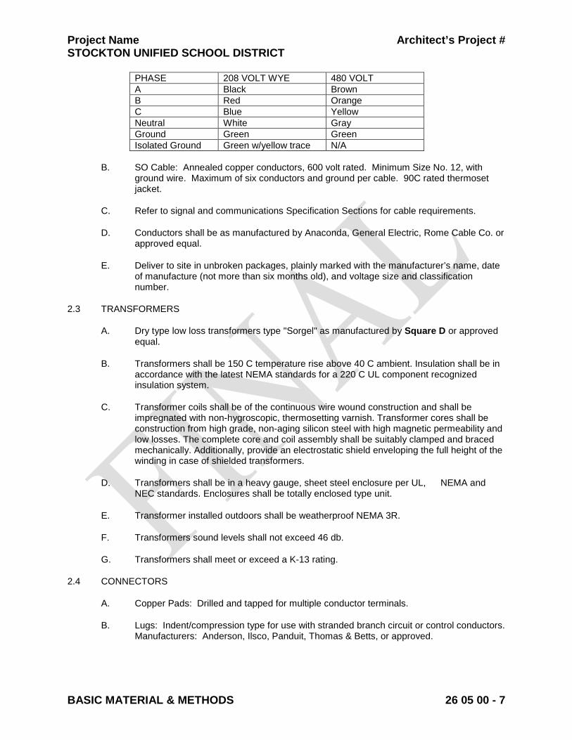
Project Name Architect’s Project # STOCKTON UNIFIED SCHOOL DISTRICT
BASIC MATERIAL & METHODS 26 05 00 - 7
PHASE 208 VOLT WYE 480 VOLT A Black Brown B Red Orange C Blue Yellow Neutral White Gray Ground Green Green Isolated Ground Green w/yellow trace N/A
B. SO Cable: Annealed copper conductors, 600 volt rated. Minimum Size No. 12, with
ground wire. Maximum of six conductors and ground per cable. 90C rated thermoset jacket.
C. Refer to signal and communications Specification Sections for cable requirements.
D. Conductors shall be as manufactured by Anaconda, General Electric, Rome Cable Co. or approved equal.
E. Deliver to site in unbroken packages, plainly marked with the manufacturer’s name, date of manufacture (not more than six months old), and voltage size and classification number.
2.3 TRANSFORMERS
A. Dry type low loss transformers type "Sorgel" as manufactured by Square D or approved equal.
B. Transformers shall be 150 C temperature rise above 40 C ambient. Insulation shall be in accordance with the latest NEMA standards for a 220 C UL component recognized insulation system.
C. Transformer coils shall be of the continuous wire wound construction and shall be impregnated with non-hygroscopic, thermosetting varnish. Transformer cores shall be construction from high grade, non-aging silicon steel with high magnetic permeability and low losses. The complete core and coil assembly shall be suitably clamped and braced mechanically. Additionally, provide an electrostatic shield enveloping the full height of the winding in case of shielded transformers.
D. Transformers shall be in a heavy gauge, sheet steel enclosure per UL, NEMA and NEC standards. Enclosures shall be totally enclosed type unit.
E. Transformer installed outdoors shall be weatherproof NEMA 3R.
F. Transformers sound levels shall not exceed 46 db.
G. Transformers shall meet or exceed a K-13 rating.
2.4 CONNECTORS
A. Copper Pads: Drilled and tapped for multiple conductor terminals.
B. Lugs: Indent/compression type for use with stranded branch circuit or control conductors. Manufacturers: Anderson, Ilsco, Panduit, Thomas & Betts, or approved.
Project Name Architect’s Project # STOCKTON UNIFIED SCHOOL DISTRICT
BASIC MATERIAL & METHODS 26 05 00 - 8
C. Conductor Branch Circuits: Spring connectors, wire nuts, for conductors 18 through 8AWG. Manufacturers: 3M, Ideal, Scotch-Lock, or approved.
2.5 BOXES
A. General:
1. Luminaire Outlet: 4-inch octagonal box, 1-1/2 inches deep with 3/8-inch luminaire stud if required. Provide raised covers on bracket outlets and on ceiling outlets.
2. Device Outlet: Installation of one or two devices at common location, minimum 4 inches square, minimum 1-1/2 inches deep. One- or two-gang flush device raised covers. Bowers, Raco Series 681 and 686 or approved.
3. Signal and Communication Systems Outlet: 4-inch square box, 2-1/8 inches deep. One- or two-gang raised device cover. Bowers, Raco Series, or approved.
4. Multiple Devices: Three or more devices at common location. Install one-piece gang boxes with one-piece device cover. Install one device per gang. Bowers, Raco, or approved.
5. Masonry Boxes: Outlets in concrete, Bowers, Raco Series 690, or approved.
6. Accessories: Provide outlet box accessories as required for each installation, including mounting brackets, wallboard hangers, extension rings, luminaire studs, cable clamps and metal straps for supporting outlet boxes, compatible with outlet boxes being used and meeting requirements of individual wiring situations.
B. Weatherproof Outlet Boxes: Provide corrosion-resistant Malleable iron weatherproof outlet wiring boxes, of the type, shape and size, including depth of box, with threaded conduit ends, cast metal face plate with spring-hinged waterproof cap suitably configured for each application, including face plate gasket, blank plugs and corrosion proof fasteners. Weatherproof boxes to be constructed to have smooth sides, gray finish. Appleton, Carlon, or approved equal.
C. Junction and Pull Boxes: Provide galvanized sheet steel junction and pull boxes, with screw-on covers; of the type shape and size, to suit each respective location and installation; with welded seams and equipped with steel nuts, bolts, screws and washers. Circle AW, Hoffman, or approved.
D. Box Extension Adapter: Malleable Iron construction. Install over flush wall outlet boxes to permit flexible raceway extension to equipment Appleton, Carlon, , or approved equal.
E. Conduit Fittings: Provide corrosion-resistant punched-steel box knockout closures, conduit locknuts and plastic conduit bushings of the type and size to suit each respective use and installation. O-Z Gedney, Thomas & Betts, or approved.
F. Floor Boxes:
1. Multi-Gang Box, Slab on Grade: Wiremold RFB4-CI series cast iron housing with S36CCTC series brass finish, steel flanged activation for use with matching carpet or tile insert. Rubber gasket protects interior from water and debris. Provide with two duplex receptacles and blank inserts for two future data outlets.
Project Name Architect’s Project # STOCKTON UNIFIED SCHOOL DISTRICT
BASIC MATERIAL & METHODS 26 05 00 - 9
2. Multi-Gang Box, Slab Above Grade: Wiremold RFB4 series steel housing with S36CCTC series brass finish, steel flanged activation for use with matching carpet or tile insert. Rubber gasket protects interior from water and debris. Provide with two duplex receptacles and blank inserts for two future data outlets.
3. Multi-Gang Box, Concrete Finish Floor: Same as above, except use Wiremold S36BBTC series brass finish, steel flanged activation.
4. Single-Gang Box, Slab on Grade: Wiremold 880CM (cast-iron) series with 817 series brass finish flange suitable for both carpet and tile floors, and 828GFI brass finish cover plate insert.
5. Single-Gang Box, Slab Above Grade: Wiremold 880S (stamped steel) series with 817 series brass finish flange suitable for both carpet and tile floors, and 828GFI brass finish cover plate insert.
G. Provide floor boxes sized minimum 3-7 /16 inches deep with 1-inch factory knockouts.
2.6 WIRING DEVICES
A. Wall Switches:
1. Characteristics:
a. Toggle Type: Quiet acting, 20 amp, 120/277 volt, UL listed for motor loads up to 80 percent of rated amperage. Cooper 1221, Leviton 1221, Hubbell 1221, Pass & Seymour 20ACI.
2. Key Switches: 20 amp/120-277 volt, black key guide. Cooper 1991-L, Hubbell 1221-L, Leviton 1221-2L, Pass & Seymour 20ACI-L, or approved.
3. Finish: Ivory.
B. Wall Dimmers: Compatible with type or load controlled (i.e., electronic ballast, low voltage luminaire, and the like). Finish to match wall switches. Size dimmers to accept connected load. Do not cut fins. Where dimmers are ganged together, provide a single multi-gang coverplate. Leviton TN Series, Lutron NT Series, or approved.
C. Receptacles:
1. Finish: Same exposed finish as switches.
2. Duplex Receptacle Characteristics: Straight parallel blade, 125 volt, 2 pole, 3 wire grounding.
a. Commercial Grade: Riveted. Brass ground contact on steel mounting strap. 20 amp. Cooper BR20, Hubbell CR5362, Leviton BR20, Pass & Seymour BR20.
3. Ground Fault Circuit Interrupter (GFCI) Receptacle: Meets or exceeds UL943 (Class A GFCI), UL498. Feed through type, back-and-side wired, 20 amp, 125VAC, Cooper XGF20, Hubbell GF5362, Leviton 8898, and Pass & Seymour 2094.
Project Name Architect’s Project # STOCKTON UNIFIED SCHOOL DISTRICT
BASIC MATERIAL & METHODS 26 05 00 - 10
4. UL Wet-Listed Covers While-In-Use: NEMA 3R when closed over energized plug. Vertical mount for duplex receptacle. Provide continuous use cover with cover capable of closing over energized cord cap with bottom aperture for cord exit.
5. Special Purpose Receptacles: Refer to Drawings for NEMA Standard Specification.
6. Receptacles and switches shall be terminated with stakon type fork on ring crimp terminal, on the side of the devices.
D. Finish Plates. Provide telephone/signal system device plates; activated outlets to have coverplates to match modular jack. Cooper, Hubbell S Series, Leviton, Pass & Seymour. Commercial grade thermoplastic, finish to match device finish.
E. Surface Covers:
1. Material: Galvanized or cadmium plated steel, 1/2-inch raised industrial type with openings appropriate for devices installed in surface outlets.
2. Cast Box and Extension Adaptors: Aluminum, with gasket, blank. One gang, Bell 240-ALF, Carlon; two gang, Bell 236-ALF, Carlon, or approved.
2.7 SAFETY DISCONNECTS
A. Toggle Type Disconnect Switches: 120 volt, 1 pole, 20 amp, 1 HP maximum. NEMA 1 enclosure for indoors, NEMA 3R enclosure for outdoors.
B. Manual Motor Starters: Quick-make, quick-break. Thermal overload protection. Device labeled with maximum voltage, current and horsepower. Eaton Electrical, General Electric, Siemens, Square D Class 2510, or approved. Provide NEMA 1 enclosure for indoors, NEMA 3R enclosure for outdoors.
C. Safety Switches: Heavy duty, fused type, dual rated, quick-make, quick-break with fuse rejection feature for use with Class R fuses only, unless other fuse type is specifically noted. Provide NEMA 1 enclosure for indoors, NEMA 3R enclosure for outdoors. Switches clearly marked for maximum voltage, current and horsepower. Equip enclosure with defeatable cover interlock. Switches rated for maximum available fault current. Approved Manufacturers: Eaton Electrical, General Electric or Siemens.
2.8 SUPPORTING DEVICES
A. Hangers: Kindorf B-905-2A channel, H-119-D washer, C105 strap, 3/8-inch rod with ceiling flange. Conduits shall be supported with straps, with galvanized malleable split rings and rod for individual runs or with Kindorf, Unistrut, or equal channel for multiple runs
B. Concrete Inserts: Kindorf D-255, cast in concrete for support fasteners for loads up to 800 lbs.
C. Pipe Straps: Two-hole galvanized or malleable iron.
D. Luminaire Chain: Single jack chain No. 10, 40 lb. working load limit.
Project Name Architect’s Project # STOCKTON UNIFIED SCHOOL DISTRICT
BASIC MATERIAL & METHODS 26 05 00 - 11
2.9 ELECTRICAL IDENTIFICATION
A. Engraved Labels: Melamine plastic laminate, white with black core, 1/16 inch thick, manufactured by Lamicoid. Engravers standard letter style, minimum 3/16-inch high letters, all capitals. Drill or punch labels for mechanical fastening except where adhesive mounting is necessary because of substrate. Use self-tapping stainless steel screws.
B. Conductor Numbers: Manufacturers standard vinyl-cloth self-adhesive cable and conductor markers of the wraparound type. Preprinted black numbers on yellow field. Brady, Panduit, or approved.
C. Branch Circuit Panel Schedules: Provide branch circuit identification schedules, typewritten, clearly filled out, to identify load connected to each circuit and location of load. Numbers to correspond to numbers assigned to each circuit breaker pole position.
D. Relay Panel Schedule: Provide typewritten schedule to identify the incoming circuit, the controlled load, and the controlling devices for each relay.
E. Underground Utilities Markers: Inert polyethylene plastic ribbon, 6 inches wide by 4 mil thick. Safety Red for electric power distribution. Safety Alert Orange for telephone, signal, data and cable TV. Imprint over entire length of ribbon in permanent black letters, the system description, selected from manufacturer's standard legend which most accurately identifies the subgrade system. Manufacturers: Allen Systems, Inc., Panduit Corp., or approved.
F. Circuit Breaker Identification: Provide permanent identification number in or on panelboard dead-front adjacent to each circuit breaker pole position.
PART 3 - EXECUTION
3.1 ELECTRICAL CHARACTERISTICS
A. Verify electrical characteristics of equipment prior to installation of conduits and wiring for equipment. Coordinate HVAC voltage requirements with Drawings and equipment submittals prior to rough in.
3.2 MOTOR BRANCH CIRCUIT WIRING
A. Do not install electrical equipment or wiring on mechanical equipment without approval of Architect.
B. Provide moisture tight equipment wiring and switches in ducts or plenums used for environmental air.
C. Connect motor branch circuits complete from panel to motor as required by code and manner herein described.
D. Motor starter, control devices and control wiring provided by other Divisions unless noted on Drawings.
3.3 APPLIANCE/UTILIZATION EQUIPMENT
E.A. Provide appropriate cable and cord cap for final connection unless equipment is provided with same. Verify special purpose outlet NEMA configuration and ampere rating with equipment supplier prior to ordering devices and coverplates.
Project Name Architect’s Project # STOCKTON UNIFIED SCHOOL DISTRICT
BASIC MATERIAL & METHODS 26 05 00 - 12
F.B. Freezer and Cooler Box Connections:
1. Obtain supplier's shop drawings prior to rough-in and provide complete connections per supplier's shop drawings.
2. Provide connections to electric defrost elements, door heaters, vent heaters, door switches, lights, condensate drain heaters, blower fans, and the like.
G.C. Kitchen Cooking, Class I, Exhaust Hood:
1. Obtain supplier's shop drawings prior to rough-in and provide complete connections per supplier's shop drawings.
2. Provide connections to hood lights, fire suppression/extinguishing system, hood control panel, and the like.
3. Provide interlocks to exhaust fan, make-up air unit, solenoid valves, and shunt trip breakers/contactors to de-energize electrical equipment located under hood.
3.4 INSTALLATION
A. Conduit:
1. Conduit Joints: Assemble conduits continuous and secure to boxes, panels, luminaires and equipment with fittings to maintain continuity. Provide watertight joints where embedded in concrete, below grade or in damp locations. Seal PVC conduit joints with solvent cement and metal conduit with metal thread primer. All rigid conduit connections to be threaded, clean and tight (metal to metal).
2. Conduit Placement:
a. Install continuous conduit and raceways for electrical power wiring and signal systems wiring.Conduit runs shall be mechanically and electrically continuous from origination to termination.
b. All thread (running thread) shall not be used as a raceway.
c. Conceal all conduits. Exposed conduits are permitted only in the following areas:
1) Mechanical rooms, electrical rooms or spaces where walls, ceilings and floors will not be covered with finished materials.
2) Where specifically noted on the Drawings.
d. Where exposed conduits are permitted install parallel or at right angles to building lines, tight to finished surfaces and neatly offset into boxes.
e. Do not install conduits or other electrical equipment in obvious passages, doorways, scuttles or crawl spaces which would impede or block the area passage's intended usage.
f. Do not install conduits on surface of building exterior, across roof, on top of parapet walls, or across floors.

Project Name Architect’s Project # STOCKTON UNIFIED SCHOOL DISTRICT
BASIC MATERIAL & METHODS 26 05 00 - 13
g. Route raceway at least 6 inches from hot surfaces above 120F, including non-insulated steam lines, heat ducts, and the like.
3. Below Grade Conduit and Cables: Place a minimum 3-inch cover of sand or clean earth fill around the cable or conduit on a leveled trench bottom. Lay conduit on a smooth level trench bottom, so that contact is made for its entire length. Remove water from trench before electrical conduit is installed. Conduit stubs from underground shall be capped with a coupling, nipple, coupling and manufactured plug until use. Conduits shall be capped during construction.
4. Maximum Bends: Install code sized pull boxes to limit sum of bends in a run of conduit to 270 degrees.
5. Flexible Conduit: Install 12-inch minimum slack loop on flexible metallic conduit and PVC coated flexible metallic conduit. Minimum trade size: one half inch (1/2”)
6. Conduit Size: Size as indicated on Drawings. Where size is not indicated, provide conduit in minimum code permitted size for THW conductors of quantity required for complete operation. Minimum trade size 3/4 inch.
7. Fire Alarm Conduit: All fire alarm system wiring shall be in conduit, 3/4 inch minimum.
8. Provide pull cord in all empty conduits that exceed 10 feet in length or the total sum of bends exceed 90 degree radius. Pull wires shall be #12 TW in conduits 1 inch and smaller and 3/16 inch polypropylene rope in conduits 1 1/4 inch and larger.
9. Conduit Use Locations:
a. Underground: PVC.
b. Wet Locations, and Subject to Mechanical Damage: GRC.
c. Damp Locations and Locations Exposed to Rain: GRC only.
d. Cast-In-Place Concrete and Masonry: GRC and PVC. Horizontal runs of conduit in poured-in-place concrete slabs, maximum diameter of conduit is 1.25 inches.
e. Dry, Protected: GRC, EMT.
f. Sharp Bends and Elbows: GRC, EMT use factory elbows.
g. Install pull wire or nylon cord in empty raceways provided for other systems. Secure wire or cord at each end.
h. Elbow for Low Energy Signal Systems: Use long radius factory ells where linking sections of raceway for installation of signal cable.
i. Motors, recessed luminaires and equipment connections subject to movement or vibration, use flexible metallic conduit.
j. Motors and equipment connections subject to movement or vibration and subjected to any of the following conditions; exterior location, moist or

Project Name Architect’s Project # STOCKTON UNIFIED SCHOOL DISTRICT
BASIC MATERIAL & METHODS 26 05 00 - 14
humid atmosphere, water spray, oil or grease use PVC coated liquid tight flexible metallic conduit.
10. Branch Circuits: Do not change the intent of the branch circuits or controls without approval. Homeruns for 20 amp branch circuits may be combined to a maximum of six current carrying conductors in a homerun. Apply de-rating factors as required by CEC. Increase conductor size as needed.
11. Feeders: Do not combine or change feeder runs.
12. Unless otherwise indicated, provide raceway systems for lighting, power and Class 1 remote-control and signaling circuits and Class 2 and 3 remote-control signaling and communication circuits.
B. Conduit Fittings:
1. Use compression fittings in dry locations, damp and rain-exposed locations. Maximum size permitted in damp locations and locations exposed to rain is 2 inches in diameter.
2. Use threaded type fittings in wet locations, and damp or rain-exposed locations where conduit size is greater than 2 inches.
3. Use PVC coated rigid steel conduit ells for underground power and telephone service entrance conduits to each building. Use 36-inch radius ells for power service conduits and 48-inch radius ells for telephone service conduits make adjustments in trenching accordingly.
4. Telephone and signal conduit bends where required shall have a radius of ten times the conduit trade size, unless otherwise noted.
5. Underground conduit bends shall have a minimum radius of 12 times the conduit trade size, unless otherwise noted.
6. Use insulated type bushings with ground provision at switchboards, panelboards, safety disconnect switches, junction boxes and the like that have feeders 60 amperes and greater.
7. Provide bushing or EMT connector for conduits that do not terminate in box, enclosure, or the like.
8. Conduits shall be capped during construction with manufactured plugs until use. Electrical tape is not acceptable for this use.
a. Provide conduit expansion fittings at building expansion joints and at locations where conduit is exposed to thermal expansion and contraction. Where expansion joints are required over 1” trade size, an expansion fitting shall be used (flexible conduit may not be used). Expansion joints 1” and under may be flexible conduit
9. Condulets and Conduit Bodies: Do not use condulets and conduit bodies in conduits for signal wiring or in feeders 100 amp and larger.
C. Surface Receptacle/Signal Raceway System: Install per manufacturer's installation instructions. Install perpendicular and parallel to building lines.
Project Name Architect’s Project # STOCKTON UNIFIED SCHOOL DISTRICT
BASIC MATERIAL & METHODS 26 05 00 - 15
D. Sleeves and Chases: Provide necessary rigid conduit sleeves, openings and chases where conduits or cables are required to pass through floors, ceiling or walls. Maintain integrity of fire-rated assemblies at penetrations of walls, ceilings or floors.
E. Conductors, Wires and Cables:
1. Conductor Installation: Install conductors in raceways having adequate, code size cross-sectional area for wires indicated. Install conductors with care to avoid damage to insulation. Do not apply greater tension on conductors than recommended by manufacturer during installation. Use of pulling compounds is permitted. Clean residue from exposed conductors and raceway entrances after conductor installation. Do not use pulling compounds for installation of conductors connected to GFI circuit breakers or GFI receptacles.
2. Conductor Size and Quantity: Install no conductors smaller than 12AWG unless otherwise shown. Provide all required conductors for a fully operable system.
3. Provide dedicated neutrals (one neutral conductor for each phase conductor) in the following single phase circuits:
a. Dimmer controlled circuits.
b. Isolated ground circuits.
c. Ground fault protected circuits where a GFI breaker is used in a panelboard.
d. Other electronic equipment which produces a high level of harmonic distortion including but not limited to computers, printers, plotters, copy machines, fax machines.
e. There shall be no reduction of the neutral Capacity
4. Conductors in Cabinets: Hold conductors away from sharp metal edges. Cable and tree all wires in panels and cabinets for power and control. Use plastic ties in panels and cabinets. Tie and bundle feeder conductors in wireways of panelboards.
5. Exposed cable is not allowed.
F. Connectors: Retighten lugs and connectors for conductors to equipment prior to Substantial Completion.
G. Boxes:
1. Location: Locate boxes and conduit bodies so as to ensure accessibility of electrical wiring. Boxes shall be located and placed according to architectural and structural requirements.
2. Round Boxes: Avoid using round boxes where conduit must enter through side of box, which would result in a difficult and insecure connection with a locknut or bushing on the rounded surface.
Project Name Architect’s Project # STOCKTON UNIFIED SCHOOL DISTRICT
BASIC MATERIAL & METHODS 26 05 00 - 16
3. Boxes shall be of the shape and size best suited for the particular application and shall be supported directly to the structural members, framing or blocking by means of screws, anchors, and bolts or embedded in masonry.
4. Anchoring: Secure boxes rigidly to the substrate upon which they are being mounted, or solidly embed boxes in concrete or masonry.
5. Special Application: Provide weatherproof outlets for locations exposed to weather or moisture.
6. Knockout Closures: Provide knockout closures to cap unused knockout holes where blanks have been removed.
7. Outlet System: Provide electrical boxes and fittings as required for a complete installation. Include but not limited to outlet boxes, junction boxes, pull boxes, bushings, locknuts, and all other necessary components.
8. Code Compliance: Comply with CEC as applicable to construction and installation of electrical boxes and fittings and size boxes according to CEC, except as noted otherwise.
9. Flush Outlets in Finished Spaces: Maintain integrity of insulation and vapor barrier. Surface outlets are only acceptable in areas with surface conduit.
10. Mount center of outlet boxes as required by ADA, or noted on Drawings, the following distance above the floor:
a. Control Switches: 48 inches.
b. Receptacles: 18 inches.
c. Telecom Outlets: 18 inches.
d. Other Outlets: As indicated in other Sections of Specifications or as detailed on Drawings.
11. Coordinate all electrical device locations (switches, receptacles, and the like) with Drawings to prevent mounting devices in mirrors, back splashes, behind cabinets, and the like.
12. Boxes for special equipment shall be suitable for the particular equipment
13. Junction boxes shall be bonded to ground, unless otherwise noted.
14. Conduits entering junction boxes shall be terminated with locknuts or appropriate fittings at the junction boxes.
H. Wiring Devices:
1. Wall-Mounted Receptacles: Install with long dimension oriented vertically at centerline height shown on Drawings or specified herein.
2. Vertical Alignment: When more than one outlet is shown on Drawings in close proximity to each other, but at different elevations, align the outlets on a common vertical center line for best appearance. Verify with Architect.
Project Name Architect’s Project # STOCKTON UNIFIED SCHOOL DISTRICT
BASIC MATERIAL & METHODS 26 05 00 - 17
I. Provide CEC-required disconnect switches whether specifically shown on Drawings or not. Provide disconnect switch in sight of each motor location unless otherwise noted. Provide disconnect switch in site of each motor controller. Motor controller disconnect equipped with lock-out/tag-out padlock provisions do not require a disconnect switch at the controlled motor location. Coordinate fuse ampere rating with installed equipment. Fuse ampere rating variance between original design information and installed equipment, size in accordance with Bussmann Fusetron 40C recommendations. Do not provide fuses of lower ampere rating than motor starter thermal units.
J. Supporting Devices:
1. Verify mounting height of all luminaires or items prior to installation when heights are not detailed.
2. Install vertical support members for equipment and luminaires, straight and parallel to building walls. Provide independent supports to structural member for electrical luminaires, materials, or equipment installed in or on ceiling, walls or in void spaces or over furred or suspended ceilings.
3. Do not use other trade's fastening devices as supporting means for electrical equipment, materials or luminaires. Do not use supports or fastening devices to support other than one particular item. Conduits shall be supported independently of one another.
4. Support conduits within 18 inches of outlets, boxes, panels, cabinets and deflections. Maximum distance between supports not to exceed 7 foot spacing.
5. Securely suspend all junction boxes, pull boxes or other conduit terminating housings located above suspended ceiling from the floor above or roof structure to prevent sagging and swaying.
6. Provide seismic bracing per IBC requirements for this building location.
7. Conduits ran on roof shall be fastened to a 4x4x length as required, redwood block set in mastic on roof structure. Unistrut or equal channel shall be installed on the blocks. The Conduit shall be individually strapped to the strut, unless otherwise noted.
8. Conduit straps for individual runs shall be secured by toggle bolts on hollow masonry, expansion shields and machine screws on solid masonry, machine screws or bolts on metal surfaces and wood screws on wood construction. Use of nails to anchor straps on wood construction is prohibited. Straps shall be one or two hole malleable iron or snap type steel with ribbed back, galvanized or cadmium plated. Use of perforated strap or nail type straps is prohibited.
K. Electrical Identification:
1. Graphics: Coordinate names, abbreviations and designations used on Drawings with equipment labels.
2. Underground Utilities Markers: Install continuous tape, 6 to 8 inches below finish grade, for each exterior underground raceway.
3. Conductor Identification: Apply markers on each conductor for power, control, signaling and communications circuits.
Project Name Architect’s Project # STOCKTON UNIFIED SCHOOL DISTRICT
BASIC MATERIAL & METHODS 26 05 00 - 18
4. Install an engraved label on each major unit of electrical equipment, including but not limited to the following items: Disconnect switches, relays, override switches, service disconnects, distribution switches, branch circuit panelboards, and central or master unit of each electrical system including communication/signal systems.
5. Install engraved labels on the inside of flush panels, visible when door is opened. Install label on outside of surface panel.
6. Install signs at locations detailed or, where not otherwise indicated, at location for best convenience of viewing without interference with operation and maintenance of equipment.
7. On the back of receptacle and switch finish plates legibly write with indelible ink pen the circuit that each device is connected to.
8. On the front of receptacle and switch finish plates provide label with the circuit that each device is connected to. Label is self-adhesive type with black letters and clear background, 18 point lettering size.
9. Non-ferrous identifying tags or pressure sensitive labels shall be securely fastened to all cables, feeders, and power circuits in pull boxes and manholes. Tags or labels shall be stamped or printed to correspond with markings on drawings or marked so that feeder or cable may be readily indentified.
10. Identify each branch circuit with wire markers. This is inclusive of wires terminated or spliced in switches, receptacles, disconnects, panelboards, switchgear, junction boxes and any other devices in which wires are terminated or spliced.
11. Junction Boxes: Provide identification labels with panel origination and circuit numbers on all junction box and enclosure covers. Four square box covers hidden above the ceiling may be marked with indelible ink marker instead of using printed labels.
L. Equipment Identification:
1. Nameplates shall be installed on electrical equipment. Equipment to be labeled shall include the following:
a. Individual enclosures such as disconnect switches, time switches, pushbuttons, contractors, relays, motor starters, etc.
b. Group mounted equipment such as panelboards, switchboards, and motor control devices.
c. Individual circuit breakers of switchboards.
d. Wall switches for lighting or other use where the control function is not self-evident.
2. Each panel shall be labeled to provide the following information as a minimum:
a. Panel name.
Project Name Architect’s Project # STOCKTON UNIFIED SCHOOL DISTRICT
BASIC MATERIAL & METHODS 26 05 00 - 19
b. Size of feeder feeding the panel.
c. Rated voltage, amps and phases.
d. Panel feeder origination
3. Each main service switchboard and distribution panel shall be labeled to provide the following information as a minimum:
a. Rated voltage, amps and phases.
b. Main switch rating.
c. Feeder circuit breaker rating with name of panel or equipment fed and
size of feeder to this equipment.
d. Panel feeder origination.
4. Nameplates shall adequately describe the item and its function or use of the particular equipment involved.
5. Nameplate material shall be laminated phenolic plastic, black front and back with white core. Engraving shall be through the outer layer. Embossed plastic pressure sensitive labels are not acceptable.
6. In lieu of plastic plates, device plates shall be engraved directly with lettering filled with black enamel.
7. Nameplates shall be securely fastened to the equipment with #4 Phillips round cadmium plated steel self-tapping screws, brass bolt, or with a plastic resin adhesive glue, Goodyear "Phiebond" or equal.
M. Building Seismic Joints:
1. Conduit Crossing Building Seismic Joints or covered: Provide box on either side of joint and flexible conduit between the box. Provide for a minimum of 12 inches of movement at the seismic joint. Rigid conduit crossings at seismic joints are not acceptable.
3.5 FIELD QUALITY CONTROL
A. Wiring Device Tests: Test wiring devices to ensure electrical continuity of grounding connections, and after energizing circuitry, to demonstrate compliance with requirements. Test receptacles for line to neutral, line to ground and neutral to ground faults. Correct any defective wiring.
B. Feeder Tests:
1. Test conductor insulation on feeders of 100 amp and greater for conformity with +1000 volt megohmeter. Use Insulated Cable Engineers Association testing procedures. Minimum insulation resistance acceptable is 1 megohm for systems
Project Name Architect’s Project # STOCKTON UNIFIED SCHOOL DISTRICT
BASIC MATERIAL & METHODS 26 05 00 - 20
600 volts and below. Notify Architect if insulation resistance is less than 1 megohm.
2. Test Report: Prepare a typed tabular report indicating the testing instrument, the feeder tested, amperage rating of the feeder, insulation type, voltage, the approximate length of the feeder, conduit type, and the measured resistance of the megohmeter test. Submit report with operating and maintenance manual.
END OF SECTION
Project Name Architect’s Project # STOCKTON UNIFIED SCHOOL DISTRICT
BASIC ELECTRICAL REQUIREMENTS 26 05 00 - 1 Revised 3/2011
SECTION 26 05 00 - BASIC ELECTRICAL REQUIREMENTS PART 1 - GENERAL
1.1 SUMMARY
A. Section Includes:
1. Electrical systems required for this work includes labor, materials, equipment, and services necessary to complete installation of electrical work shown on Drawings, specified herein or required for a complete operable facility and not specifically described in other Sections of these Specifications. Among the items required are:
a. Service and distribution equipment shown on Drawings.
b. Feeders to switchboards, distribution panels, HVAC equipment, Owner provided equipment and other equipment as detailed.
c. Branch circuit wiring from the distribution panels for lighting, receptacles, motors, signal systems and other detailed circuit wiring.
d. Luminaires, control switches, receptacles, relays, supports and other accessory items.
e. Wiring and power connections for motors installed for heating, cooling and ventilation.
f. Fire alarm system.
g. Low voltage systems as detailed.
1.2 DEFINITIONS
A. Following is a list of abbreviations generally used in Division 16:
1. ADA Americans With Disabilities Act 2. AHJ Authority Having Jurisdiction 3. ANSI American National Standards Institute 4. APWA American Public Works Association 5. ASTM American Society for Testing and Materials 6. CBC California Building Code 7. CEC California Electrical Code 8. FCC Federal Communications Commission 9. HVAC Heating, Ventilating and Air Conditioning 10. IBC International Building Code, latest adopted version with State
amendments 11. IFC International Fire Code 12. IEC International Electrotechnical Commission 13. IEEE Institute of Electrical and Electronics Engineers. 14. IETA International Electrical Testing Association 15. FM FM Global 16. NEMA National Electrical Manufacturers Association 17. NFPA National Fire Protection Association 18. OSHA Occupational Safety and Health Administration

Project Name Architect’s Project # STOCKTON UNIFIED SCHOOL DISTRICT
BASIC ELECTRICAL REQUIREMENTS 26 05 00 - 2 Revised 3/2011
19. UL Underwriters Laboratories Inc.
B. Provide: To furnish and install, complete and ready for the intended use.
C. Furnish: Supply and deliver to the project site, ready for unpacking, assembly and installation.
D. Install: Includes unloading, unpacking, assembling, erecting, installation, applying, finishing, protecting, cleaning and similar operations at the project site to complete items of work furnished by others.
1.3 ADDITIONAL REQUIREMENTS TO DIVISION 1
A. Operation and Maintenance Documentation: Provide copies of certificates of code authority acceptance, test data, product data, guarantees, warranties, and the like.
B. Shop Drawings: When requested by individual Sections provide shop drawings which include physical characteristics, electrical characteristics, device layout plans, wiring diagrams, and the like. Refer to individual Specification Sections for additional requirements for the shop drawings.
C. Closeout Documentation: Submit electrical code authority certification of inspection. Include documentation of on-site electrical testing that was performed.
D. Record Drawings:
1. Show changes and deviations from the Drawings. Include written Addendum and change order items.
2. Show exact routes of feeders 100 amp and larger, cable tray, surface metal raceway, conduits for signal systems 2 inches in diameter and larger, and service entrance conduits.
3. Show exact location of switchboards, distribution panelboards, safety disconnects, motor controllers, control panels, terminal cabinets, and the like.
4. Make changes to drawings in electronic format. Obtain electronic copy from Architect, use the same version of AutoCAD to prepare record drawings as was used by the Architect. Provide electronic copy and hard copy to Architect for review.
5. Provide a full size Record Drawing of the one-line power diagram sealed in a plastic coating. Mount on the wall of the electric room or location approved by school district representative.
1.4 QUALITY ASSURANCE
A. Conform to requirements of the CEC, latest adopted version with amendments by local AHJs.
B. Conform to latest adopted version of the IBC with amendments by local AHJs.
C. Obtain and pay for electrical permits, and inspections from local AHJs.
D. Furnish products listed by UL or other testing firm acceptable to AHJ.
Project Name Architect’s Project # STOCKTON UNIFIED SCHOOL DISTRICT
BASIC ELECTRICAL REQUIREMENTS 26 05 00 - 3 Revised 3/2011
E. Conform to requirements of the serving electric and telephone, and cable television utilities. Obtain and pay for all costs. Costs to be reimbursed by school district.
1.5 SEQUENCING AND SCHEDULING
A. For the proper execution of the work cooperate with other crafts and contracts as needed.
B. To avoid installation conflicts, thoroughly examine the complete set of Contract Documents. Resolve conflicts with Architect prior to installation.
C. Prior to installation of feeders to equipment requiring electrical connections, examine the manufacturer's shop drawings, wiring diagrams, product data, and installation instructions. Verify that the electrical characteristics detailed in the Contract Documents are consistent with the electrical characteristics of the actual equipment being installed. When inconsistencies occur request clarification from Architect.
1.6 COORDINATION DOCUMENTS
A. Prepare and submit layout drawings to coordinate installation and location of lighting, electrical and signal systems. Prepare composite drawings showing all equipment on a single sheet. The architectural floor plans, reflected ceiling plans, and access floor layout plan shall form the base for the coordination drawings. Prior to completion of Drawings, coordinate proposed installation with the Architect, structural requirements, and other trades (including HVAC, plumbing, fire protection, ceiling systems, and raised floor system), and provide required maintenance access. Systems shall include, although not limited to, the following:
1. Occupancy sensors.
2. Electrical equipment enclosures.
3. Control equipment enclosures.
4. Route of feeders 100A and larger.
5. Route of cable tray systems.
6. Conduit rack supports.
7. Transformers and supports.
8. Route of telephone, data and CATV raceways 2 inches and larger.
B. Prepare Drawings as follows:
1. Prepare Drawings, to accurate scale, in latest AutoCAD graphics format printed to media as directed by Architect. Obtain construction document drawing files from the Architect, or Engineer, at cost plus. Drawings are to be same size as Contract Drawings and shall indicate location, size and elevation above finished floor of all wall mounted and suspended devices and equipment.
2. Plans are to incorporate all addenda items and change orders.
3. Distribute plans to all trades and provide additional coordination as needed.
Project Name Architect’s Project # STOCKTON UNIFIED SCHOOL DISTRICT
BASIC ELECTRICAL REQUIREMENTS 26 05 00 - 4 Revised 3/2011
C. Advise Architect, in event a conflict occurs in location of equipment. Bear all costs for relocation of equipment, resulting from failure to properly coordinate installation or failure to advise Architect of conflict.
D. Provide means of access to all junctions and pull boxes and concealed equipment which may require access, adjustment or servicing.
E. Final coordination drawings, with as-constructed information added, are to be submitted as record drawings at completion of project.
PART 2 - PRODUCTS
2.1 MANUFACTURERS
A. Provide like items from one manufacturer, such as luminaire types, switches, receptacles, breakers, panels, and the like.
2.2 MATERIALS
A. Provide new electrical materials of the type and quality detailed, listed by UL, bearing their label wherever standards have been established. Indicated brand names and catalog numbers are used to establish standards of performance and quality. The description of materials listed herein governs in the event that catalog numbers do not correspond to materials described herein.
B. Provide material and equipment that is acceptable to AHJ as suitable for the use indicated. For example, provide wet labeled equipment in locations that are wet.
C. Include special features, finishes, accessories, and other requirements as described in the Contract Documents regardless of the item's listed catalog number.
D. Provide incidentals not specifically mentioned herein or noted on Drawings, but needed to complete the system, in a safe and satisfactory working condition.
2.3 FIRESTOPPING
A. For additional requirements see Division 7 "Firestopping."
B. Foam Sealant: Foam sealant for use around conduit penetrations to prevent passage of smoke, fire, toxic gas or water. Maintain seal before, during and after fire. In and around conduit for thermal break at penetration of barrier between heated and unheated spaces. Chase Technology Corporation, Fire Foam, Thomas & Betts, or approved.
PART 3 - EXECUTION
3.1 EXAMINATION
A. Construction Documents:
1. Drawings are diagrammatic with symbols representing electrical equipment, outlets, luminaires, and wiring.
Project Name Architect’s Project # STOCKTON UNIFIED SCHOOL DISTRICT
BASIC ELECTRICAL REQUIREMENTS 26 05 00 - 5 Revised 3/2011
2. Electrical symbols indicating wiring and equipment shown in the Contract Documents are included in the Contract unless specifically noted otherwise.
3. Examine the entire set of Drawings to avoid conflicts with other systems. Determine exact route and installation of electrical wiring and equipment with conditions of construction.
B. Clarification:
1. The Drawings govern in matters of quantity, the Specification in matters of quality. In event of conflict on Drawings or in the Specifications, the greater quantity and the higher quality apply.
2. Should the Electrical Documents indicate a condition conflicting with the governing codes and regulations, refrain from installing that portion of the work until clarified by Architect.
3.2 INSTALLATION
A. Install electrical equipment complete as directed by manufacturer’s installation instructions. Obtain installation instructions from manufacturer prior to rough-in of the electrical equipment, examine the instructions thoroughly. When requirements of the installation instructions conflict with the Contract Documents, request clarification from Architect prior to proceeding with the installation.
B. Do not install electrical equipment in obvious passages, doorways, scuttles or crawl spaces which would impede or block the area passage's intended usage.
C. Earthwork:
1. Refer to Division 2, Section "Earthwork."
2. Perform excavation and backfill required for the installation of electrical work.
D. Noise Control:
1. Do not install outlet boxes back to back. Do not use straight through boxes.
2. Do not place contactors, transformers, starters and similar noise producing devices on walls which are common to occupied spaces unless specifically called for on Drawings. Where such devices must be mounted on walls common to occupied spaces, mount or isolate in such a manner as to effectively prevent the transmission of their inherent noise to the occupied space.
E. Firestopping:
1. Coordinate with the Drawings the location of fire rated walls, ceilings, floors and the like. When these assemblies are penetrated by electrical equipment, seal around the equipment with approved firestopping material.
2. Install firestopping material complete as directed per the manufacturer’s installation instructions.
Project Name Architect’s Project # STOCKTON UNIFIED SCHOOL DISTRICT
BASIC ELECTRICAL REQUIREMENTS 26 05 00 - 6 Revised 3/2011
3.3 FIELD QUALITY CONTROL
A. Tests:
1. Conduct tests of equipment and systems to demonstrate compliance with requirements specified in Division 16. Refer to individual Specification Sections for required tests. Document tests and include in Closeout Documents.
2. During site evaluations by Engineer, provide an electrician with tools to remove and replace trims, covers, devices, and the like, so that a proper evaluation of the installation can be performed.
3. Provide Megger Test PET, NETA on all feeders at 100A or more, supply written reports.
B. Lighting System Control Testing and Commissioning:
1. Test lighting controls to ensure that control devices, components, equipment and systems are calibrated, adjusted and operate in accordance with Drawings and Specifications. Provide functional testing of sequences of operation to ensure operation in accordance with Drawings and Specifications. Provide complete report of test procedures and results to engineer and insert approved copy into project closeout documents.
2. Testing shall include:
a. Daylight automatic controls.
b. Occupant sensing automatic controls.
c. Automatic time and override controls for interior lighting.
d. Automatic time and photo controls for exterior lighting.
e. Emergency back-up lighting.
3.4 CLEANING
A. Remove dirt and debris caused by the execution of the electrical work.
B. Leave the entire electrical system installed under this Contract in clean, dust-free and proper working order.
C. Vacuum clean interiors of all new and modified electrical signal and communication equipment enclosures.
END OF SECTION
PROJECT NAME JOB # STOCKTON UNIFIED SCHOOL DISTRICT 01/12
BASIC ELECTRONIC SAFETY & SECURITY REQUIREMENTS 28 00 00 - 1
SECTION 28 00 00 - BASIC ELECTRONIC SAFETY & SECURITY REQUIREMENTS
PART 1 - GENERAL
1.1 SECTION INCLUDES
A. Work included in 28 00 00 applies to Division 28 work to provide materials, labor, tools, permits, incidentals, and other services to provide and make ready for Owner's use of electronic safety and security systems for proposed project.
B. Contract Documents include, but are not limited to, Specifications including Division 00, Procurement and Contracting Requirements and Division 01, General Requirements, Drawings, Addenda, Owner/Architect Agreement, and Owner/Contractor Agreement. Confirm requirements before commencement of work.
C. Definitions:
1. Provide: To furnish and install, complete and ready for intended use.
2. Furnish: Supply and deliver to project site, ready for unpacking, assembly and installation.
3. Install: Includes unloading, unpacking, assembling, erecting, installing, applying, finishing, protecting, cleaning and similar operations at project site as required to complete items of work furnished.
4. Approved or Approved Equivalent: To possess the same performance qualities and characteristics and fulfill the utilitarian function without any decrease in quality, durability or longevity. For equipment/products defined by the Contractor as "equivalent," substitution requests must be submitted to Engineer for consideration, in accordance with Division 01 requirements, and approved by the Engineer prior to submitting bids for substituted items.
5. Authority Having Jurisdiction (AHJ): Indicates reviewing authorities having jurisdiction, including local fire marshal, Owner's insurance underwriter, Owner's representative, and other reviewing entity whose approval is required to obtain systems acceptance.
1.2 RELATED SECTIONS:
A. Contents of Section applies to Division 28 Contract Documents.
B. Related Work:
1. Additional conditions apply to this Division including, but not limited to:
a. Specifications including Division 00, Procurement and Contracting Requirements and Division 01, General Requirements.
b. Drawings
c. Addenda
d. Owner/Architect Agreement
e. Owner/Contractor Agreement
f. Codes, Standards, Public Ordinances and Permits
C. Contents of Division 26 apply to this section.
D. Comply with related products/systems requirements for IP Communication devices located in Division 27 Sections 27 10 00 and 27 15 00.
PROJECT NAME JOB # STOCKTON UNIFIED SCHOOL DISTRICT 01/12
BASIC ELECTRONIC SAFETY & SECURITY REQUIREMENTS 28 00 00 - 2
1.3 REFERENCES AND STANDARDS
A. References and Standards per Division 00, Procurement and Contracting Requirements and Division 01, General Requirements, individual Division 28 sections and those listed in this section.
B. Codes to include latest adopted editions, including current amendments, supplements and local jurisdiction requirements in effect as of the date of the Contract Document, of/from:
1. State of California:
a. CBC California Building Code
b. CEC California Electrical Code
c. CEC T24 California Energy Code Title 24
d. CFC California Fire Code
e. CMC California Mechanical Code
f. CSFM California State Fire Marshal
g. DSA Division of State Architect Regulations and Requirements
h. OSHPD Office of Statewide Health Planning & Development
C. General: Reference standards and guidelines include but are not limited to the latest adopted editions from:
1. ADA Americans with Disabilities Act
2. ANSI American National Standards Institute
3. ASCE American Society of Civil Engineers
4. ASHRAE American Society of Heating, Refrigerating and Air-Conditioning Engineers
5. ASHRAE Guideline, the Commissioning Process
6. ASME American Society of Mechanical Engineers
7. ASTM ASTM International
8. CFR Code of Federal Regulations
9. CSA CSA International
10. EPA Environmental Protection Agency
11. ETL Electrical Testing Laboratories
12. FM FM Global
13. ISO International Organization for Standardization
14. LEED Leadership in Energy and Environmental Design
15. NEC National Electric Code
16. NEMA National Electrical Manufacturers Association
17. NFPA National Fire Protection Association
18. OSHA Occupational Safety and Health Administration
PROJECT NAME JOB # STOCKTON UNIFIED SCHOOL DISTRICT 01/12
BASIC ELECTRONIC SAFETY & SECURITY REQUIREMENTS 28 00 00 - 3
19. SMACNA Sheet Metal and Air Conditioning Contractors' National Association
20. UL Underwriters Laboratories Inc.
21. USDA United States Department of Agriculture
D. See Division 28 individual sections for additional references.
E. Where code requirements are at variance with Contract Documents, meet code requirements as a minimum requirement and include costs necessary to meet these in Contract.
F. Machinery and equipment are to comply with OSHA requirements, as currently revised and interpreted for equipment manufacturer requirements. Install equipment provided per manufacturer recommendations.
G. Whenever this Specification calls for material, workmanship, arrangement or construction of higher quality and/or capacity than that required by governing codes, higher quality and/or capacity take precedence.
1.4 SUBMITTALS
A. See Division 01, General Requirements for Submittal Procedures.
B. Provide product submittals and shop drawings in one copy in paper format with electronic backup. Electronic format must be submitted via zip file via e-mail. For electronic format, provide one zip file per specification division containing a separate file for each specification section. For paper format, provide one common binder per specification division, with tabbed dividers for each specification section. Individual submittals sent piecemeal in a per Specification Section method will be returned without review or comment. Copy Architect on all transmissions/submissions.
C. Product Data: Provide manufacturer's descriptive literature for products specified in Division 28 sections.
D. Identify/mark each submittal in detail. Note what difference, if any, exist between the submitted item and the specified item. Failure to identify the differences will be considered cause for disapproval. If differences are not identified and/or not discovered during the submittal review process, Contractor remains responsible for providing equipment and materials that meet the specifications and drawings.
1. Label submittal to match numbering/references as shown in Contract Documents. Highlight and label applicable information to individual equipment or cross out/remove extraneous data not applicable to submitted model. Clearly note options and accessories to be provided, including field installed items. Highlight connections by/to other trades.
2. Include technical data, installation instructions and dimensioned drawings for products, equipment and devices installed, furnished or provided. Reference individual Division 28 specification sections for specific items required in product data submittal outside of these requirements.
3. See Division 28 individual sections for additional submittal requirements.
E. Maximum of two reviews of complete submittal package. Arrange for additional reviews and/or early review of long-lead items; Bear costs of additional reviews at Engineer's hourly rates. Incomplete submittal packages/submittals will be returned to contractor without review.
F. Structural/Seismic: Provide weights, dimensions, mounting requirements and like information required for mounting, seismic bracing, and support. Indicate manufacturer's installation and support requirements to meet ASCE 7-05 Chapter 13 requirements for non-structural components. Provide engineered seismic drawings and equipment seismic certification.
PROJECT NAME JOB # STOCKTON UNIFIED SCHOOL DISTRICT 01/12
BASIC ELECTRONIC SAFETY & SECURITY REQUIREMENTS 28 00 00 - 4
Building Occupancy Category III, Seismic Design Category D. Equipment Importance Factor of 1.25.
G. Trade Coordination: Include physical characteristics, electrical characteristics, device layout plans, wiring diagrams, and connections as required per Division 28 Coordination Documents. For equipment with electrical connections, furnish copy of approved submittal for inclusion in Division 28 submittals.
H. Make provisions for openings in building for admittance of equipment prior to start of construction or ordering of equipment.
I. Substitutions and Variation from Basis-of-Design:
1. Basis-of-Design systems, components and controls for equipment are selected and sized based on the equipment specified as the first-named manufacturer, model number and supplemental additional options as indicated in the Contract Documents. If substitutions and/or equivalent equipment/products being proposed, it is the responsibility of parties involved in, and furnishing the substitute and/or equivalent equipment to verify and compare the characteristics and requirements of that furnished to that specified and/or shown. If greater capacity and/or more materials and/or more labor is required for the rough-in, circuitry or connections than for the item specified and provided for, then provide compensation for additional charges required for the proper rough-in, circuitry and connections for the equipment being furnished. No additional charges above the Base Bid will be allowed for such revisions. Coordinate with the requirements of "Submittals". For any product marked "or approved equivalent", a substitution request must be submitted to Engineer for approval prior to purchase, delivery or installation.
2. Where manufacturer equipment or model numbers are indicated with no exceptions, substitutions will be rejected.
J. Shop Drawings: Provide coordinated shop drawings which include physical characteristics of all systems, device layout plans, and control wiring diagrams. Reference individual Division 28 specification sections for additional requirements for shop drawings outside of these requirements.
1. Provide Shop Drawings indicating access panel locations, size and elevation for approval prior to installation.
K. Samples: Provide samples when requested by individual sections.
L. Resubmission Requirements:
1. Make any corrections or change in submittals when required by Architect/Engineer review comments. Provide submittals as specified. The engineer will not be required to edit and/or interpret the Contractor's submittals. Indicate changes for the resubmittal in a cover letter with reference to page(s) changed and reference response to comment. Cloud changes in the submittals.
a. Resubmit for review until review indicates no exceptions taken or "make corrections noted."
b. When submitting drawings for Engineers re-review, clearly indicate changes on drawings and "cloud" any revisions. Submit a list describing each change.
M. Operation and Maintenance Manuals, Owners Instructions:
1. Reference individual Division 28 Specification Sections for additional requirements for operations and maintenance manuals.
2. Submit, at one time, one bound copy and electronic files (PDF format) on CD/DVD of manufacturer's operation and maintenance instruction manuals and parts lists for
PROJECT NAME JOB # STOCKTON UNIFIED SCHOOL DISTRICT 01/12
BASIC ELECTRONIC SAFETY & SECURITY REQUIREMENTS 28 00 00 - 5
equipment or items requiring servicing. Submit data when work is substantially complete and in same order format as submittals. Include name and location of source parts and service for each piece of equipment.
a. Include copy of approved submittal data along with submittal review letters received from Engineer. Data to clearly indicate installed equipment model numbers. Delete or cross out data pertaining to other equipment not specific to this project.
b. Include copy of manufacturer's standard Operations and Maintenance for equipment. At front of each tab, provide routine maintenance documentation for scheduled equipment. Include manufacturer's recommended maintenance schedule and highlight maintenance required to maintain warranty. Furnish list of routine maintenance parts, including part numbers, sizes, quantities, relevant to each piece of equipment.
c. Include copy of complete parts list for equipment. Include available exploded views of assemblies and sub-assemblies.
d. Include Warranty per Division 00, Division 01, Section 28 00 00 and individual sections.
e. Include product certificates of warranties and guarantees.
f. Include copy of startup and test reports specific to each piece of equipment.
g. Include commissioning reports.
h. Engineer will return incomplete documentation without review.
i. Engineer will provide one set of review comments in Submittal Review format. Arrange for additional reviews; Bear costs for additional reviews at Engineer's hourly rates.
3. Thoroughly instruct Owner in proper operation of equipment and systems. Where noted in individual sections, training will include classroom instruction with applicable training aids and systems demonstrations. Field instruction per Section 28 00 00 Article titled "Demonstration".
4. Copies of certificates of code authority inspections, acceptance, code required acceptance tests, letter of conformance and other special guarantees, certificates of warranties, specified elsewhere or indicated on Drawings.
N. Record Drawings:
1. Maintain at site at least one set of drawings for recording “As-constructed” conditions. Indicate on drawings changes to original documents by referencing revision document, and include buried elements and location of concealed items. Include items changed by addenda, field orders, supplemental instructions, and constructed conditions.
2. Record Drawings are to include equipment locations, calculations, and schedules that accurately reflect "as constructed or installed" for project.
3. At completion of project, input changes to original project on CAD Drawings and make one set of black-line drawings created from CAD Files in version/release equal to contract drawings. Submit CAD disk and drawings upon substantial completion.
4. See Division 28 individual sections for additional items to include in record drawings.
1.5 QUALITY ASSURANCE
A. Regulatory Requirements: Work and materials to conform with all local, State, Federal and other applicable laws and regulations.
PROJECT NAME JOB # STOCKTON UNIFIED SCHOOL DISTRICT 01/12
BASIC ELECTRONIC SAFETY & SECURITY REQUIREMENTS 28 00 00 - 6
B. Drawings are intended to be diagrammatic and reflect the Basis-of-Design manufacturers equipment. They are not intended to show every item in its exact dimensions, or details of equipment or proposed systems layout. Verify actual dimensions of systems (e.g. cable tray, panels, etc.) and equipment proposed to assure that systems and equipment will fit in available space. Contractor is responsible for design and construction costs incurred for equipment other than Basis-of-Design, including, but not limited to, architectural, structural, electrical, HVAC, fire sprinkler, and plumbing systems.
C. Manufacturer's Instructions: Follow manufacturer's written instructions. If in conflict with Contract Documents, obtain clarification. Notify Engineer/Architect, in writing, before starting work.
D. Items shown on Drawings are not necessarily included in Specifications or vice versa. Confirm requirements in all Contract Documents.
E. UL and CSA Compliance: Provide products which are UL and CSA Listed
1.6 WARRANTY
A. Provide written warranty covering the work for a period of one year from date of Substantial Completion in accordance with Division 00 and Division 01, Section 28 00 00 and individual Division 28 sections.
B. Sections under this Division can require additional and/or extended warranties that apply beyond basic warranty under Division 01 and the General Conditions. Confirm requirements in all Contract Documents.
1.7 COORDINATION DOCUMENTS
A. Prior to construction, coordinate installation and location of HVAC equipment, ductwork, grilles, diffusers, piping, plumbing equipment/fixtures, fire sprinklers, plumbing, cable trays, lights, and electrical services with architectural and structural requirements, and other trades (including ceiling suspension and tile systems), and provide maintenance access requirements. Coordinate with submitted architectural systems (i.e. roofing, ceiling, finishes) and structural systems as submitted, including footings and foundation. Identify zone of influence from footings and ensure systems are not routed within the zone of influence.
B. Advise Architect in event a conflict occurs in location or connection of equipment. Bear costs resulting from failure to properly coordinate installation or failure to advise Architect of conflict.
C. Verify in field exact size, location, and clearances of existing material, equipment and apparatus, and advise Architect of discrepancies between that indicated on Drawings and that existing in field prior to installation related thereto.
D. Submit final Coordination Drawings with changes as Record Drawings at completion of project.
PART 2 - PRODUCTS
2.1 MANUFACTURERS
A. Provide like items from one manufacturer, including but not limited to panels, devices and equipment unless otherwise specified in individual Division 28 sections.
2.2 MATERIALS
A. Base contract upon furnishing materials as specified. Materials, equipment, and fixtures used for construction are to be new, latest products as listed in manufacturer's printed catalog data and are to be UL approved or have adequate approval or be acceptable by state, county, and city authorities.
B. Articles, fixtures, and equipment of a kind to be standard product of one manufacturer.

PROJECT NAME JOB # STOCKTON UNIFIED SCHOOL DISTRICT 01/12
BASIC ELECTRONIC SAFETY & SECURITY REQUIREMENTS 28 00 00 - 7
C. Names and manufacturer's names denote character and quality of equipment desired and are not to be construed as limiting competition.
D. Hazardous Materials:
1. Comply with local, State of California, and Federal regulations relating to hazardous materials.
2. Comply with Division 00, Procurement and Contracting Requirements and Division 01, General Requirements for this project relating to hazardous materials.
3. Do not use any materials containing a hazardous substance. If hazardous materials are encountered, do not disturb; immediately notify Owner and Architect. Hazardous materials will be removed by Owner under separate contract.
2.3 ACCESS PANELS
A. See Division 01, General Requirements and Division 08 for products and installation requirements.
B. Confirm Access Panel requirements in Division 01, Division 08 and individual Division 28 sections. In absence of specific requirements, Comply with the following:
1. Provide flush mounting access panels for systems and individual components, service of electrical safety and security systems equipment and junction boxes requiring maintenance, inspection or servicing. Where access panels are located in fire-rated assemblies of building, rate access panels accordingly.
a. Ceiling access panels to be minimum of 24-inch by 24-inch required and approved size.
b. Wall access panels to be minimum of 12-inch by 12-inch required and approved size.
c. Provide two keys for each set of keyed cylinder type locks.
1) Drywall: Karp KDW.
2) Plaster: Karp DSC-214PL.
3) Masonry: Karp DSC-214M.
4) 2 hour rated: Karp KPF-350FR.
5) Manufacturers: Milco, Elmdor, Acudor, or approved equivalent.
PART 3 - EXECUTION
3.1 ACCESSIBILITY AND INSTALLATION
A. Confirm Accessibility and Installation requirements in Division 00, Division 01, Section 28 00 00 and individual Division 28 sections.
B. Install equipment having components requiring access (i.e., devices, equipment, electrical boxes, panels, etc.) so that they may be serviced, reset, replaced or recalibrated by service people with normal service tools and equipment. Do not install equipment in obvious passageways, doorways, scuttles or crawlspaces which would impede or block intended usage.
C. Install equipment and products complete as directed by manufacturer's installation instructions. Obtain installation instructions from manufacturer prior to rough-in of equipment and examine instructions thoroughly. When requirements of installation instructions conflict with Contract Documents, request clarification from Architect prior to proceeding with installation. This includes proper installation methods, sequencing and coordination with other trades and disciplines.
PROJECT NAME JOB # STOCKTON UNIFIED SCHOOL DISTRICT 01/12
BASIC ELECTRONIC SAFETY & SECURITY REQUIREMENTS 28 00 00 - 8
D. Confirm Earthwork requirements in Contract Documents. In absence of specific requirements, comply with individual Division 28 sections and the following:
1. Earthwork:
a. Perform excavation, dewatering, shoring, bedding, and backfill required for installation of work in this Division in accordance with related earthwork divisions. Contact utilities and locate existing utilities prior to excavation. Repair any work damaged during excavation or backfilling.
b. Excavation: Do not excavate under footings, foundation bases, or retaining walls.
c. Provide protection of underground systems. Review the project Geotechnical Report for references to corrosive or deleterious soils which will reduce the performance or service life of underground systems materials.
E. Confirm Firestopping requirements in Division 07. In absence of specific requirements, comply with individual Division 28 sections and the following:
1. Firestopping:
a. Coordinate location and protection level of fire and/or smoke rated walls, ceilings, and floors. When these assemblies are penetrated, seal around conduit, raceway and equipment with approved firestopping material. Install firestopping material complete as directed by manufacturer's installation instructions. Meet requirements of ASTM E814, Standard Test Method for Fire Tests of Through-Penetration Fire Stops.
F. Plenums: In plenums, provide plenum rated materials that meet the requirements to be installed in plenums.
3.2 SEISMIC CONTROL
A. Confirm Seismic Control requirements in Division 01, Section 28 00 00 and individual Division 28 sections.
B. General:
1. Seismic Design Category: D Soils.
2. Building Category: III.
3. Importance Factor (l-p): All equipment importance factor of 1.25.
4. Earthquake resistant designs for electronic safety and security systems (Division 28) equipment and distribution, i.e. equipment, etc. conform to regulations of Authority Having Jurisdiction (AHJ).
5. Restraints which are used to prevent disruption of function of piece of equipment because of application of horizontal force to be such that forces are carried to frame of structure in such a way that frame will not be deflected when apparatus is attached to a mounting base and equipment pad, or to structure in normal way, utilizing attachments provided. Secure equipment and distribution systems to withstand a force in direction equal to value defined by Authority Having Jurisdiction (AHJ).
3.3 REVIEW AND OBSERVATION
A. Confirm Review and Observation requirements in Division 00, Division 01, Section 28 00 00 and individual Division 28 Sections.
B. Notify Architect, in writing, at following stages of construction so that Architect may, at their option, visit site for review and construction observation:
1. Underground conduit and wire installation prior to backfilling.
PROJECT NAME JOB # STOCKTON UNIFIED SCHOOL DISTRICT 01/12
BASIC ELECTRONIC SAFETY & SECURITY REQUIREMENTS 28 00 00 - 9
2. Prior to covering walls when electrical, safety and security systems installation is started.
3. Prior to ceiling cover/installation.
4. When main systems, or portions of, are being tested and ready for inspection by AHJ.
5. Final Punch: Costs incurred by additional trips required due to incomplete systems will be the responsibility of the Contractor.
3.4 CONTINUITY OF SERVICE
A. Confirm requirements in Division 00 and Division 01. In absence of specific requirements in Division 01, comply with individual Division 28 sections and the following:
1. During remodeling or addition to existing structures, while existing structure is occupied, current services to remain intact until new construction, facilities or equipment is installed.
2. Prior to changing over to new system, verify that every item is thoroughly prepared. Install new wiring to point of connection.
3. Coordinate transfer time to new service with Owner. If required, perform transfer during off peak hours. Once changeover is started, pursue to its completion to keep interference to a minimum.
a. If overtime is necessary, there will be no allowance made by Owner for extra expense for such overtime or shift work.
4. Organize work to minimize duration of power interruption.
3.5 CUTTING AND PATCHING
A. Confirm Cutting and Patching Requirements in Division 00 and Division 01. In absence of specific requirements, comply with individual Division 28 sections and the following:
1. Proposed floor cutting/core drilling/sleeve locations to be approved by project Structural Engineer. Submit proposed locations to Architect/Project Structural Engineer. Where slabs are of post tension construction, perform x-ray scan of proposed penetration locations and submit scan results including proposed penetration locations to project Structural Engineer/Architect for approval. Where slabs are of waffle type construction, show column cap extent and cell locations relative to proposed penetration(s).
2. Cutting, patching and repairing for work specified in this Division including plastering, masonry work, concrete work, carpentry work, and painting included under this Section and will be performed by skilled craftsmen of each respective trade in conformance with appropriate Division of Work.
3. Additional openings required in building construction to be made by drilling or cutting. Use of jack hammer is specifically prohibited. Patch openings in and through concrete and masonry with grout.
4. Restore new or existing work that is cut and/or damaged to original condition. Where alterations disturb lawns, paving, and walks, repair, refinish and leave in condition matching existing prior to commencement of work.
5. Additional work required by lack of proper coordination will be provided at no additional cost to the Owner.
3.6 EQUIPMENT SELECTION AND SERVICEABILITY
A. Replace or reposition equipment which is too large or located incorrectly to permit servicing, at no additional cost to Owner.
PROJECT NAME JOB # STOCKTON UNIFIED SCHOOL DISTRICT 01/12
BASIC ELECTRONIC SAFETY & SECURITY REQUIREMENTS 28 00 00 - 10
3.7 DELIVERY, STORAGE AND HANDLING
A. Confirm requirements in Division 00 and Division 01. In absence of specific requirements, comply with the individual Division 28 sections and the following:
1. Handle materials delivered to project site with care to avoid damage. Store materials on site inside building or protected from weather, dirt and construction dust.
2. Protect equipment and pipe to avoid damage. Close conduit openings with caps or plugs. Keep motors and bearings in watertight and dustproof covers during entire course of installation.
3. Protect devices, panels and similar items until in service.
4. Products and/or materials that become damaged due to water, dirt and/or dust as a result of improper storage to be replaced before installation.
3.8 DEMONSTRATION
A. Confirm Demonstration requirements in Division 00 and Division 01, Section 28 00 00 and individual Division 28 sections.
B. Upon completion of work and adjustment of equipment, test systems, demonstrate to Owner's Representative, Architect and Engineer that equipment furnished and installed or connected under provisions of these Specifications functions in manner required. Provide field instruction to Owner's Staff as specified in Division 01, Section 28 00 00 and individual Division 28 sections.
C. Manufacturer's Field Services: Furnish services of a qualified factory certified instructor at time approved by Owner, to instruct maintenance personnel, correct defects or deficiencies, and demonstrate to satisfaction of Owner that entire system is operating in satisfactory manner and complies with requirements of other trades that may be required to complete work. Complete instruction and demonstration prior to final job site observations.
3.9 CLEANING
A. Upon completion of installation, thoroughly clean exposed portions of equipment, removing temporary labels and traces of foreign substances. Throughout work, remove construction debris and surplus materials accumulated during work.
3.10 INSTALLATION
A. Confirm Installation requirements in Division 00, Division 01, Section 28 00 00 and individual Division 28 Sections.
B. Install equipment and fixtures in accordance with manufacturer's installation instructions, plumb and level and firmly anchored to building structure. Maintain manufacturer's recommended clearances.
C. Start-up equipment, in accordance with manufacturer's start-up instructions, and in presence of manufacturer's representative. Test controls and demonstrate compliance with requirements. Replace damaged or malfunctioning controls and equipment.
D. Provide miscellaneous supports/metals required for installation of equipment, conduit and wiring.
3.11 PAINTING
A. Confirm Painting requirements in Division 01 and Division 09. In absence of specific requirements, comply with individual Division 28 sections and the following:

PROJECT NAME JOB # STOCKTON UNIFIED SCHOOL DISTRICT 01/12
BASIC ELECTRONIC SAFETY & SECURITY REQUIREMENTS 28 00 00 - 11
1. Ferrous Metal: After completion of work, thoroughly clean and paint exposed supports constructed of ferrous metal surfaces, i.e. hangers, hanger rods, equipment stands, with one coat of black asphalt varnish suitable for hot surfaces.
2. In electrical and mechanical room, on roof or other exposed areas, equipment not painted with enamel to receive two coats of primer and one coat of rustproof enamel, colors as selected by Architect.
3. See individual equipment Specifications for other painting.
4. Structural Steel: Repair damage to structural steel finishes or finishes of other materials damaged by cutting, welding or patching to match original.
5. Conduit: Clean, primer coat and paint interior conduit exposed in finished areas with two coats paint suitable for metallic surfaces. Color selected by Architect.
3.12 ACCESS PANELS
A. Confirm Access Panel requirements in Division 01. In absence of specific requirements, comply with individual Division 28 sections and the following:
1. Coordinate locations/sizes of access panels with Architect prior to work.
3.13 DEMOLITION
A. Confirm requirements in Division 01 and Division 02. In the absence of specific requirements, comply with individual Division 28 sections and the following:
1. Scope:
a. It is the intent of these documents to provide necessary information and adjustments to electronic safety and security system required to meet code, and accommodate installation of new work.
b. Existing Conditions: Determine exact location of existing utilities and equipment before commencing work, compensate Owner for damages caused by failure to exactly locate and preserve underground utilities. Replace damaged items with new material to match existing. Promptly notify Owner if utilities are found which are not shown on Drawings.
c. Coordinate with Owner so that work can be scheduled not to interrupt operations, normal activities, building access, access to different areas. Owner will cooperate to best of their ability to assist in coordinated schedule, but will remain final authority as to time of work permitted.
d. Examination:
1) Determine exact location of existing utilities and equipment before commencing work, compensate Owner for damages caused by failure to locate and preserve utilities. Replace damaged items with new material to match existing.
2) Verify that abandoned wiring and equipment serve only abandoned facilities.
3) Demolition drawings are based on casual field observation and existing record documents.
(a) Verify accuracy of information shown prior to bidding and provide such labor and material as is necessary to accomplish work.
(b) Verify location and number of electrical safety and security system devices, panels, etc. in field.
4) Report discrepancies to Architect before disturbing existing installation.
PROJECT NAME JOB # STOCKTON UNIFIED SCHOOL DISTRICT 01/12
BASIC ELECTRONIC SAFETY & SECURITY REQUIREMENTS 28 00 00 - 12
e. Promptly notify Owner if systems are found which are not shown on Drawings.
f. Execution:
1) Remove existing safety and security equipment, devices and associated wiring from walls, ceilings, floors, and other surfaces scheduled for remodeling, relocation, or demolition unless shown as retained or relocated on Drawings.
2) Provide temporary wiring and connections to maintain electrical continuity of existing systems during construction. Remove or relocate electrical boxes, conduit, wiring and equipment as encountered in removed or remodeled areas in existing construction affected by this work.
3) Remove and restore wiring which serves usable existing outlets clear of construction or demolition.
4) If existing junction boxes will be made inaccessible, or if abandoned outlets serve as feed through boxes for other existing electrical equipment which is being retained, provide new conduit and wire to bypass abandoned outlets.
5) If existing conduits pass through partitions or ceiling which are being removed or remodeled, provide new conduit and wire to reroute clear of construction or demolition and maintain service to existing load.
6) Extend circuiting and devices in existing walls to be furred out.
7) Remove abandoned wiring to source of supply.
8) Remove exposed abandoned conduit, including abandoned conduit above accessible ceiling finishes. Cut conduit flush with walls and floors, and patch surfaces.
9) Disconnect and remove electrical devices and equipment serving utilization equipment that has been removed.
10) Maintain access to existing electrical installations which remain active. Modify installation or provide access panel as appropriate.
11) Existing electrical safety and security systems components are indicated on demolition plans. Verify exact location and number of existing devices and components in field. Only partial existing systems shown. Locations of items shown on Drawings as existing are partially based on Record and other Drawings which may contain errors. Verify accuracy of information shown prior to bidding and provide such labor and material as is necessary to accomplish intent of Contract Documents.
12) Remove abandoned wiring to leave site clean.
13) If existing electrical equipment contains PCBs (Polychlorinated Biphenyl), replace with new non-PCB equipment. Dispose of material containing PCBs as required by federal and local regulations.
14) Repair adjacent construction and finishes damaged during demolition work.
15) Maintain access to existing electrical installations which remain active. Modify installation or provide access panel as appropriate.
g. Existing Fire Alarm System: Maintain existing system in service until new system is accepted. Disable system only to make switchovers and connections.
1) Notify Owner before partially or completely disabling system.
2) Notify local fire service.

PROJECT NAME JOB # STOCKTON UNIFIED SCHOOL DISTRICT 01/12
BASIC ELECTRONIC SAFETY & SECURITY REQUIREMENTS 28 00 00 - 13
3) Make notifications at least 7 working days in advance.
4) Make temporary connections to maintain service in other buildings on campus.
h. Existing Security Systems: Maintain existing systems in service until new system is complete and ready for service. Disable system only to make switchovers and connections.
1) Notify Owner at least 7 working days before partially or completely disabling system.
2) Make temporary connections to maintain service in areas adjacent to work area.
3.14 ACCEPTANCE
A. Confirm requirements in Division 00 and Division 01. In absence of specific requirements, comply with individual Division 28 sections and the following:
1. System cannot be considered for acceptance until work is completed and demonstrated to Architect that installation is in strict compliance with Specifications, Drawings and manufacturer's installation instructions, particularly in reference to following:
a. Cleaning
b. Operation and Maintenance Manuals
c. Training of Operating Personnel
d. Record Drawings
e. Warranty and Guaranty Certificates
f. Start-up/test Documents and Commissioning Reports
3.15 FIELD QUALITY CONTROL
A. Confirm requirements in Division 00 and Division 01. In absence of specific requirements, comply with individual Division 28 sections and the following:
1. Tests:
a. Conduct tests of equipment and systems to demonstrate compliance with requirements specified. Reference individual Specification Sections for required tests. Document tests and include in Closeout Documents.
b. During site evaluations by Architect or Engineer, provide a technician with tools to remove and replace trims, covers, and devices so that proper evaluation of installation can be performed.
3.16 LETTER OF CONFORMANCE
A. Provide Letter of Conformance and copies of manufacturers' warranties and extended warranties with a statement in letter that electronic safety and security systems were installed in accordance with manufacturer's recommendations, UL listings and FM Global approvals. Include Letter of Conformance and copies of manufacturers' warranties and extended warranties in operating and maintenance manuals.
END OF SECTION

Project Name Architect’s Project # STOCKTON UNIFIED SCHOOL DISTRICT
CLEARING AND GRUBBING 31 11 00 - 1 Revised 3/2011
SECTION 31 11 00 - CLEARING AND GRUBBING
PART 1 - GENERAL 1.1 RELATED DOCUMENTS
A. Drawings, General Conditions and Division 1 of the Contract apply to and are a part of this Section
1.2 SECTION INCLUDES
A. Removal of debris and objectionable material.
B. Removal of gravel, aggregate base, paving, concrete, curbs, wheel stops, and walks.
C. Removal of piping, maintenance holes, inlets, valves and valve boxes.
D. Removal of light standards, conduit, pull boxes and electrical cabinets.
E. Removal of trees, shrubs and other plant life.
F. Removal of fencing.
G. Removal of soil. 1.3 REFERENCES
Geotechnical Investigation:
Geotechnical Investigation:
A. Perform on-site Work in accordance with these specifications, (Name Standard) Standard Specifications, San Joaquin County Standard Specifications and CalTrans Standard Specifications.
B. Perform Work within the street right of way in accordance with these specifications, (Name Entity) Standard Specifications, San Joaquin County Standard Specifications and CalTrans Standard Specifications.
1.4 REGULATORY REQUIREMENTS
A. Conform to applicable City, County, State and Federal regulations and/or codes for environmental requirements, handling and disposal of debris, and use of herbicides.
B. Coordinate clearing work with utility companies and the Owner’s representative 48 hours prior to the commencement of work, which will affect existing utilities.
C. (Name Entity) Community Service District is the jurisdictional agency within the public road/street rights-of-ways. An encroachment permit must be obtained from the (Name Entity) Community Service District by the contractor prior to performing any work within the road/street rights-of-ways.
PART 2 - PRODUCTS 2.1 MATERIALS
A. Supply miscellaneous materials in accordance with the provisions of these specifications. PART 3 - EXECUTION
Project Name Architect’s Project # STOCKTON UNIFIED SCHOOL DISTRICT
CLEARING AND GRUBBING 31 11 00 - 2 Revised 3/2011
3.2 PREPARATION
A. Contact Underground Service Alert (USA) at 1-800-227-2600 for the locating of existing utilities.
B. Physically locate all overhead and underground utilities and accurately mark all underground utilities that are to be removed and/or remain.
C. Make all necessary arrangements with all affected utility companies for removing and/or relocating of all utility lines which interfere with the work. Owner will pay for all costs required to relocate said utility lines.
D. Notify all affected utility companies and Owner’s Representative 48 hours prior to beginning Work.
3.3 PROTECTION
A. Locate, identify, and protect from damage existing structures and facilities to remain.
B. Where required, construct protective barriers, barricades, or other devices.
C. Protect excavations by shoring, bracing, sheet piling, underpinning, or other methods, as required to prevent cave-ins or loose dirt from falling into excavations.
D. Protect existing trees and plants designated to remain.
E. Protect bench marks and survey control points from damage or displacement.
F. Use of explosives and burning on site is prohibited.
G. Contractor shall prepare a Storm Water Pollution Prevention Plan in compliance with the NPDES requirements, the general conditions and division 1.
3.4 SALVAGED MATERIALS
A. Carefully remove all materials to be salvaged and deliver to the Owner as directed by Owner’s Representative. Coordinate with the Owner’s Representative during the pre-construction meeting regarding what materials are to be salvaged and the delivery of the salvaged materials.
3.5 CLEARING
A. Clear site as indicated on Drawings and/or directed by Owner’s Representative.
B. Clear areas required for access to site and execution of Work.
C. Trim trees only where it is necessary to clear construction equipment. Trim trees in a manner that meets with the approval of the Owner’s Representative.
D. Remove and properly dispose of all cleared material from the site. 3.6 GRUBBING
A. Grub site as indicated on Drawings and/or directed by Owner’s Representative.
B. Remove trees and shrubs indicated and/or directed by Owner’s Representative. Remove stumps and root system to a minimum depth of 24". Remove all roots larger than ½ inch in diameter. Backfill all excavations created by stump removal as set forth in these specifications.
C. Saw cut asphalt concrete pavement to be removed on a straight line as indicated on Drawings immediately prior to new pavement being installed. Strip existing asphalt and aggregate base from site as indicated on Drawings and/or directed by Owner’s Representative.
D. Saw cut concrete walks, curbs and gutters to be removed at the nearest joint just outside the limits of removal or as indicated on the drawings. Strip existing concrete and bedding material from the site as indicated on Drawings and/or directed by Owner’s Representative.

Project Name Architect’s Project # STOCKTON UNIFIED SCHOOL DISTRICT
CLEARING AND GRUBBING 31 11 00 - 3 Revised 3/2011
E. Strip to a depth of 12 inches below the existing ground or finish grade, which ever is the greater depth, of all vegetative growth such as trees, logs, stumps, roots, brush, grass, weeds, and all other objectionable material including gravel, asphalt, concrete or masonry.
F. Remove and properly dispose of all grubbed and stripped material from the site. Clean stripped material shall be hauled ¼ mile and stockpiled on adjacent county property, as directed by Owner’s Representative.
G. Stockpile topsoil for future use in area on site to be determined by Owner’s Representative. 3.7 CLEANING
A. Immediately clear and sweep clean, existing access roadways of any spilled debris or material. Road closures will not be permitted.
*** END OF SECTION ***
Project Name Architect’s Project # STOCKTON UNIFIED SCHOOL DISTRICT
GRADING 31 22 00 - 1 Revised 3/2011
SECTION 31 22 00 - GRADING PART 1 - GENERAL 1.1 RELATED DOCUMENTS
Drawings and general conditions & Division 1 of the Contract apply to and are a part of this Section
1.2 SECTION INCLUDES
A. Excavating, grading, filling, and compacting the site for the purpose of site improvements.
B. Site structure excavating, backfilling and compacting to subgrade elevations.
C. Excavating, backfilling and compacting under slabs on grade.
D. Excavating, backfilling compacting under paving.
E. Filling and compacting for over excavation.
F. Excavating and exporting excess material.
G. Engineered fill per (Identify Report) report.
1.3 REFERENCES
A. Perform Work in accordance with these specifications, (Name Standard) Standard Specifications, San Joaquin County Standard Specifications and CalTrans Standard Specifications.
B. Geotechnical Investigation:
C. Geotechnical Investigation:
D. Design and provide for adequate shoring, bracing, sloping or other provisions for workers protection in excavations and trenches. All such work shall conform to the requirements of Cal-OSHA. Submit shoring plan to the Owner’s representative for review prior to excavation.
1.4 TOLERANCES
A. Slopes and Other Graded Surfaces: Plus or minus 0.10 foot from required elevation.
B. Unless indicated on the Drawings finish grade to the following limits.
1. Outside structure foundations: 6” below finished floor of the structure.
2. Lawn areas: ¾” below the grade of adjacent pavement, walks, curbs, or headers.
3. Shrub areas: 1-1/2” below the grade of adjacent pavement, walks, curbs, or headers unless otherwise indicated on Drawings.
4. All areas shall be sloped and graded to drain to drainage structures. Slopes shall be constructed with a uniform gradient from high to low points. The minimum gradient for drainage swales shall be 1%.
1.5 SUBMITTALS FOR REVIEW
A. Shoring Plan: Design and provide for adequate shoring, bracing, sloping or other provisions for workers protection in excavations and trenches. All such work shall conform to the requirements of Cal-OSHA Submit shoring plan for review and approval prior to excavation. Plans shall be designed and stamped by a Civil Engineer registered in the State of California.
Project Name Architect’s Project # STOCKTON UNIFIED SCHOOL DISTRICT
GRADING 31 22 00 - 2 Revised 3/2011
PART 2 – PRODUCTS 2.1 MATERIALS
A. Subsoil Fill as set forth in these specifications and as approved by Owner’s representative.
B. Engineered Fill as set forth in these specifications and as approved by Owner’s representative. PART 3 - EXECUTION 3.1 EXAMINATION
A. Verify site conditions under provisions as set forth in these specifications.
B. Verify structural ability of unsupported walls to support imposed loads by the fill.
C. Verify that survey bench mark and intended elevations for the Work are as indicated.
3.2 PREPARATION
A. Identify required lines, levels, contours, and datum locations.
B. Locate, identify, and protect utilities that remain from damage.
C. Notify and coordinate with utility companies to remove and relocate utilities in the way of excavation. Notify the Owner’s representative of such interference as well.
D. Protect benchmarks, survey control points, existing structures, fences, sidewalks, paving, and curbs to remain, from excavating equipment and vehicular traffic.
3.3 EXCAVATING
A. General
1. Excavate to lines and levels required for construction of the work indicated on the Drawings.
2. Scarify subgrade surfaces of areas to be filled to a depth of eight (8) inches. All clods shall be broken and all rocks, hard ribs, and earth lumps over two and one-half (2-1/2) inches in greatest dimension, and other unsuitable materials such as roots shall be removed and disposed. The subgrade material shall be compacted with accepted equipment until compaction of no less than 90 percent of relative compaction is obtained.
3. Replace damaged or displaced subsoil to same requirements as for specified fill.
4. Prevent displacement or loose material from falling into excavation, maintain soil stability.
5. Grade top perimeter of excavation to prevent surface water from draining into excavation.
6. Notify Owner’s representative of unexpected subsurface conditions and discontinue affected Work in area until notified to resume work.
7. Correct areas over excavated in accordance with Filling in this Section.
8. Stockpile excavated material in area designated on site, remove excess or unsuitable material from site or within ¼ mile stockpile on site as directed.
B. Structures
1. Underpin adjacent structures, which may be damaged by excavating work.
2. Excavate subsoil to accommodate site structure foundations and slabs-on-grade

Project Name Architect’s Project # STOCKTON UNIFIED SCHOOL DISTRICT
GRADING 31 22 00 - 3 Revised 3/2011
3. Excavate, backfill, import and compact to lines and levels required for construction of the work indicated on the Drawings and described in the referenced Geotechnical Investigation.
4. Do not interfere with 45 degree bearing splay of foundations.
5. Replace damaged or displaced subsoil to same requirements as for specified fill.
6. Prevent displacement or loose material from falling into excavation, maintain soil stability.
7. Grade top perimeter of excavation to prevent surface water from draining into excavation.
8. Hand trim excavation. Remove loose matter.
9. Notify Owner’s representative of unexpected subsurface conditions and discontinue affected Work in area until notified to resume work.
10. Correct areas over excavated in accordance with Filling in this Section.
11. Remove excess or unsuitable material from site.
.
3.4 FILLING, BACKFILLING
A. All areas to receive fill or backfill shall be inspected by Owner’s representative prior to fill or backfill placement.
B. Perform Work in accordance with these specifications.
C. Compact subgrade to density requirements for subsequent backfill materials as specified in this Section.
D. Cut out soft areas of subgrade not capable of compaction in place. Backfill with Soil Material and compact to density equal to or greater than requirements for subsequent fill material.
E. Scarify subgrade surface to a depth of 6 inches and proof roll to identify soft spots; fill and compact to density requirements specified in this section.
F. Systematically backfill to allow maximum time for natural settlement. Do not backfill over porous, wet, frozen or spongy subgrade surfaces.
G. Employ a placement method that does not disturb or damage other work.
H. Place fill material in continuous layers and compact in accordance with the Schedule at end of this Section.
I. Fill areas to lines and grades indicated.
J. Maintain required moisture content of fill materials at 1% to 5% above optimum to attain required compaction density.
K. Make grade changes gradual. Blend slope into level areas.
L. Allow concrete walls sufficient time to cure prior to backfilling against foundation and retaining walls. Prevent damage to walls from backfill and backfill equipment. Equipment shall maintain a minimum clear distance from foundations and retaining walls of 12 inches.
M. Backfill against supported foundation walls and retaining walls. Verify structural ability of unsupported walls to support imposed loads by the fill prior to backfilling against unsupported foundations and retaining walls.
N. Backfill simultaneously on each side of unsupported walls until supports are in place. Elevation difference between fill on either side of unsupported wall during backfilling shall not exceed 12 inches.
Project Name Architect’s Project # STOCKTON UNIFIED SCHOOL DISTRICT
GRADING 31 22 00 - 4 Revised 3/2011
O. Remove excess or unsuitable material from site
P. Leave site free of excess fill materials.
Q. Engineered fill per Geotechnical Investigation.
3.5 FIELD QUALITY CONTROL
A. Compaction Testing will be provided by the owner’s testing lab and shall be performed in accordance with California Test Method No. 231, Nuclear Gage. Also see Division 1, 01410.
B. If tests indicate Work does not meet specified requirements, remove Work, replace and retest.
C. Frequency of Tests:
1. Field Density Test: One test for every 400 cubic yards placed or as directed by Owner’s representative.
3.6 PROTECTION OF FINISHED WORK
A. Protect finished Work as set forth in these specifications.
B. Reshape and re-compact fills subjected to vehicular traffic.
3.7 SCHEDULES
A. Fill under structures:
1. See referenced Geotechnical Investigation.
B. Fill under asphalt and concrete paving:
1. See referenced Geotechnical Investigation.
2. Fill lifts: Maximum 6 inches loose depth.
3. Compact each lift to density specified in A1 above.
C. Fill in landscape areas:
1. Fill lifts: Maximum 6 inches loose depth.
2. Compact to minimum 90 percent of relative compaction.
*** END OF SECTION ***
Project Name Architect’s Project # STOCKTON UNIFIED SCHOOL DISTRICT
TRENCHING 31 23 16 - 1 Revised 3/2011
SECTION 31 23 16 - TRENCHING PART 1 - GENERAL 1.1 RELATED DOCUMENTS
A. Drawings and general conditions & Division 1 of the Contract apply to and are a part of this Section
1.2 SECTION INCLUDES
A. Excavating trenches for utilities. B. Compacted fill from top of utility initial backfill and bedding to subgrade elevations.
1.3 REFERENCES
A. Perform Work in accordance with these specifications, (Name Standard) Standard Specifications San Joaquin County Standard Specifications and CalTrans Standard Specifications.
1.4 DEFINITIONS
A. Utility: Any buried pipe, duct, conduit, or cable.
1.5 TOLERANCES
A. Top Surface of Backfilling: Plus or minus 0.10 feet from required elevations.
1.6 SUBMITTALS FOR REVIEW
A. Shoring Plan: Design and provide for adequate shoring, bracing, sloping or other provisions for workers protection in excavations and trenches. All such work shall conform to the requirements of Cal-OSHA Submit shoring plan for review and approval prior to excavation. Plans shall be designed and stamped by a Civil Engineer registered in the State of California.
1.7 FIELD MEASUREMENTS
A. Verify that survey bench mark, control point, and intended elevations for the Work are as shown on drawings.
1.8 COORDINATION
A. Verify work associated with lower elevation utilities is complete before placing higher elevation utilities.
PART 2 - PRODUCTS 2.1 FILL MATERIALS
A. Subsoil: Subsoil as specified in Section 31 23 00, “Soil Material”. B. Sand: Sand as specified in Section 31 05 16, “Aggregate Materials”.
Project Name Architect’s Project # STOCKTON UNIFIED SCHOOL DISTRICT
TRENCHING 31 23 16 - 2 Revised 3/2011
C. Pea Gravel: Pea Gravel as specified in Section 31 05 16, “Aggregate Materials”. D. CDF: Controlled Density Fill as specified in Section 31 05 16, “Aggregate Materials”.
PART 3 - EXECUTION 3.1 PREPARATION
A. Identify required lines, levels, contours, and datum locations. B. Protect plant life, lawns, and other features remaining as a portion of final landscaping. C. Protect benchmarks, existing structures, fences, sidewalks, paving, and curbs from excavating
equipment and vehicular traffic. D. Maintain and protect above and below grade utilities, which are to remain. E. Cut out soft areas of subgrade not capable of compaction in place. Backfill with Subsoil and
compact to density equal to or greater than requirements for subsequent backfill material.
3.2 EXCAVATING
A. Excavate subsoil required for utilities. B. Cut trenches sufficiently wide to enable installation and allow inspection. Remove water or
materials that interfere with Work. C. Do not interfere with 45 degree bearing splay of foundations. D. Hand trim excavation. Hand trim for bell and spigot pipe joints. Remove loose matter. E. Remove lumped subsoil, boulders, and rock grater than 3 inches diameter. F. Correct areas over excavated in accordance with Section 02210, “Grading”. G. Stockpile excavated material in area designated on site and remove excess material not being
used, from site or as directed.
3.3 BACKFILLING
A. Backfill trenches to contours and elevations with unfrozen fill materials. B. Systematically backfill to allow maximum time for natural settlement. Do not backfill over porous,
wet, frozen, or spongy subgrade surfaces. C. Soil Fill: Place and compact material in equal continuous layers not exceeding 6 inches
compacted depth. D. Employ a placement method that does not disturb or damage utilities in trench. E. Maintain required moisture content of fill materials at 1% to 5% above optimum to attain required
compaction density. F. Remove surplus fill materials from site or as directed by the Owner Representative.
Project Name Architect’s Project # STOCKTON UNIFIED SCHOOL DISTRICT
TRENCHING 31 23 16 - 3 Revised 3/2011
G. Leave fill material stockpile areas completely free of excess fill materials.
H. Compaction testing will be provided by the owner’s testing lab and shall be performed in
accordance with California Test Method No. 231, Nuclear Gage. Also see Division 1, 01410. I. If tests indicate Work does not meet specified requirements, remove Work, replace, compact,
and retest. J. Frequency of Tests:
1. Field density tests: One test for every 25 lineal feet of trench or as directed by Owner’s representative
3.4 PROTECTION OF FINISHED WORK
A. Reshape and re-compact fills subjected to vehicular traffic during construction.
3.5 SCHEDULE
A. Intermediate Backfill (from 6 inches above the top of pipe to 24 inches below the finish subgrade):
1. Backfill with Subsoil, 6 inch lifts, compacted to 90 percent of relative compaction.
B. Final Backfill ( from 24 inches below finish subgrade to finish subgrade):
1. Backfill with Subsoil 6 inch lifts.
a. Where trench is located under areas to be paved, compact to 95 percent of relative compaction.
b. Where trench is not located under areas to be paved, to 90 percent of relative
compaction.
*** END OF SECTION ***

Project Name Architect’s Project # STOCKTON UNIFIED SCHOOL DISTRICT
ASPHALT CONCRETE PAVING 32 12 16 - 1 Revised 3/2011
SECTION 32 12 16 - ASPHALT CONCRETE PAVING PART 1 – GENERAL 1.1 RELATED DOCUMENTS
A. Drawings, General Conditions and Division 1 of the Contract apply to and are a part of this Section
1.2 SECTION INCLUDES
A. Asphaltic concrete paving, wearing binder or aggregate base course.
B. Adjusting appurtenances to grade
C. Pavement striping and pavement markings
1.3 REFERENCES
A. Perform Work in accordance with these specifications, (Name Standard) Community Service District Standard Specifications, San Joaquin County Standard Specifications and CalTrans Standard Specifications.
1.4 TOLERANCES
A. Flatness: Maximum variation of 1/4 inch measured with 12 foot straight edge.
B. Scheduled Compacted Thickness: Within 1/4 inch.
C. Variation from True Elevation: Within 1/4 inch.
1.5 REGULATORY REQUIREMENTS
A. Conform to applicable City, County, and State regulations and/or codes for paving work on public right of way.
1.6 ENVIRONMENTAL REQUIREMENTS
A. Do not place asphalt when ambient air or base surface temperature is less than 45 degrees F and rising, or surface is wet or frozen.
B. Do not place bitumen mixture when the mixture’s temperature is less than 250 degrees F and not more than maximum specified temperature.
PART 2 - PRODUCTS 2.1 MATERIALS
2.2 Asphalts: In accordance with CalTrans Section 92, Grade: AR-4000.
A. Aggregate for Asphalt Concrete Mix: In accordance with CalTrans Section 39, for 1/2 inch maximum, coarse, Type A.
B. Seal Coat: In accordance with CalTrans Section 37-1.
2.3 Thermoplastic traffic stripes and pavement markings shall conform to CalTrans Section 84.
A. Thermoplastic Traffic stripes and pavement markings shall conform to the most current approved prequalified and tested signing and delineation materials and products list maintained by the California Department of transportation.
2.4 SOURCE QUALITY CONTROL AND TESTS
Project Name Architect’s Project # STOCKTON UNIFIED SCHOOL DISTRICT
ASPHALT CONCRETE PAVING 32 12 16 - 2 Revised 3/2011
A. Test samples in accordance with these specifications, (Name Standard) Standard Specifications, San Joaquin County Standard Specifications and CalTrans Standard Specifications.
PART 3 - EXECUTION 3.1 EXAMINATION
A. Verify that compacted subgrade, granular base is dry and ready to support paving and imposed loads.
B. Verify gradients and elevations of base are correct.
3.2 SUBBASE
A. Section 02231, “Aggregate Base Course”, forms the base construction for work of this section.
3.3 PREPARATION - TACK COAT
A. Apply tack coat to contact surfaces of curbs, gutters and existing pavement at uniform rate of 0.10 gal/sq. yd.
B. Apply in accordance with CalTrans Section 39.
3.4 PLACING ASPHALT PAVEMENT
A. Install Work in accordance with CalTrans Section 39.
B. Place asphalt within two hours of applying primer or tack coat.
C. Install gutter drainage grilles and frames, manhole frames and valve and pullbox covers in correct position and elevation.
D. Compact pavement by rolling to specified density. Do not displace or extrude pavement from position. Hand compact in areas inaccessible to rolling equipment.
E. Perform rolling with consecutive passes to achieve even and smooth finish without roller marks.
F. Construct transverse pavement joints 15 to 30 degrees off the perpendicular to the direction of travel.
3.5 ADJUSTING APPURTENANCES TO GRADE
A. Adjust cleanouts, manholes, monument boxes, valve boxes, and other appurtenances, within the paved area, to correct position and elevation.
1. Adjust valve and monument boxes, cleanouts and other small appurtenances using cast iron locking grade rings or resetting the box.
3.6 APPLYING PAINT STRIPES AND MARKINGS.
A. Apply paint stripes and markings in accordance with CalTrans Section 84-3.05.
B. Thermoplastic material for traffic stripes shall be applied at a minimum thickness of 0.08 inches. Thermoplastic material for pavement legends and markings shall be applied at a minimum thickness of 0.125 inches
C. Place paint stripes and markings at the locations and colors indicated on Drawings or as directed by Owner’s representative.
3.7 REMOVAL OF EXISITNG TRAFFIC STRIPING AND MARKINGS
A. Removal of existing traffic striping and pavement markings shall conform CalTrans Section 15.
Project Name Architect’s Project # STOCKTON UNIFIED SCHOOL DISTRICT
ASPHALT CONCRETE PAVING 32 12 16 - 3 Revised 3/2011
B. Nothing in these Specification shall relieve the Contractor from his responsibilities as provided in CalTrans Section 7-1.09.
C. Conflicting striping and pavement markings shall be removed before the installation of new striping and pavement markings. All traffic striping and pavement markings shall be removed in a rectangular shape. New striping and pavement markings shall be installed within 24 hours of removal of old striping and pavement markings.
D. Where grinding or sand-blasting is used for the removal of existing traffic striping and pavement markings, and such removal operation is being performed within 10 feet of a lane occupied by public traffic, the residue including dust shall be removed immediately after contact between the grinding or sand-blasting material and the surface being treated. Such removal shall be by a vacuum attachment operating concurrently with the grinding or sand-blasting operation. After the removal of existing traffic striping and pavement markings on asphalt concrete pavement, a fog seal coat shall be applied to the surface of grinding or sand-blasting areas in accordance with the provisions in Section 37
3.8 FIELD QUALITY CONTROL
A. Take samples and perform tests in accordance with Mountain House Standard Specifications.
3.9 PROTECTION
A. Immediately after placement, protect pavement from mechanical injury for two days or until surface temperature is less than 140 degrees F.
*** END OF SECTION ***
Project Name Architect’s Project # STOCKTON UNIFIED SCHOOL DISTRICT
PORTLAND CEMENT CONCRETE PAVING 32 13 13 - 1 Revised 3/2011
SECTION 32 13 13 - PORTLAND CEMENT CONCRETE PAVING PART 1 GENERAL 1.1 RELATED DOCUMENTS
A. Drawings, General Conditions and Division 1 of the Contract apply to and are a part of this Section
1.2 SECTION INCLUDES
A. Concrete sidewalks, curbs, and gutters.
B. Aggregate base course.
1.3 REFERENCES
A. CalTrans Standard Specifications and (Name Standard) Community Service District Standard Specifications.
1.4 PERFORMANCE REQUIREMENTS
A. Aggregate size shall conform to CalTrans Standard Specifications Section 73.
B. Concrete strength: 3,000 psi minimum at 28 days
C. Slump range: 4” maximum.
1.5 QUALITY ASSURANCE
A. Perform work in accordance with CalTrans Standard Specifications.
1.6 ENVIRONMENTAL REQUIREMENTS
A. Do not place concrete when base surface temperature is less than 40 degrees F, or surface is wet or frozen.
PART 2 PRODUCTS 2.1 FORM MATERIALS
A. Form Materials: Conform to CalTrans Standard Specifications
B. Joint Filler: Conform to CalTrans Standard Specifications
2.2 REINFORCEMENT
A. Reinforcing Steel and Wire Fabric: Conform to CalTrans Standard Specifications
2.3 CONCRETE MATERIALS
A. Concrete Materials: Conform to CalTrans Standard Specifications
B. Water: Potable, not detrimental to concrete.
2.4 SOURCE QUALITY CONTROL AND TESTS
A. Tests on cement and aggregates will be performed and certified by the supplier to ensure conformance with specified requirements.
B. Test samples in accordance with ACI 301.

Project Name Architect’s Project # STOCKTON UNIFIED SCHOOL DISTRICT
PORTLAND CEMENT CONCRETE PAVING 32 13 13 - 2 Revised 3/2011
PART 3 EXECUTION 3.1 EXAMINATION
A. Verify compacted subgrade is acceptable and ready to support paving and imposed loads.
B. Verify gradients and elevations of base are correct.
3.2 SUBBASE
A. Section 02231 – “Aggregate Base Course” forms the base construction for work of this Section.
3.3 PREPARATION
A. Moisten base to minimize absorption of water from fresh concrete.
3.4 FORMING
A. Place and secure forms to correct location, dimension, profile, and gradient.
B. Assemble formwork to permit easy stripping and dismantling without damaging concrete.
C. Place joint filler vertical in position, in straight lines. Secure to formwork during concrete placement.
3.5 REINFORCEMENT
A. Place reinforcement as indicated.
B. Place dowels to achieve pavement and curb alignment as indicated on Drawings.
3.6 PLACING CONCRETE
A. Place concrete in accordance with CalTrans Standard Specifications
B. Ensure reinforcement, inserts, embedded parts, formed joints and are not disturbed during concrete placement.
3.7 JOINTS
A. Joint types and placement shall conform to CalTrans Standard Specifications Section 73-1.05/1.06.
3.8 FINISHING
A. Sidewalk Paving: Slope less than 6%: Medium Broom. Slope greater than 6%: Heavy Broom.
B. Curbs and Gutters: Light broom. (Path of travel: Slope less than 6%: Medium Broom. Slope greater than 6%: Heavy Broom.)
C. Direction of Texturing: Parallel to pavement direction.
3.9 TOLERANCES
A. Flatness: Maximum variation of 0.01 feet measured with 10 foot straight edge.
B. Scheduled Thickness: Within 0.02 feet.
C. Variation from True Elevation: Within 0.02 feet.
3.10 PROTECTION
A. Immediately after placement, protect pavement from premature drying, excessive hot or cold temperatures, and mechanical injury.
*** END OF SECTION ***
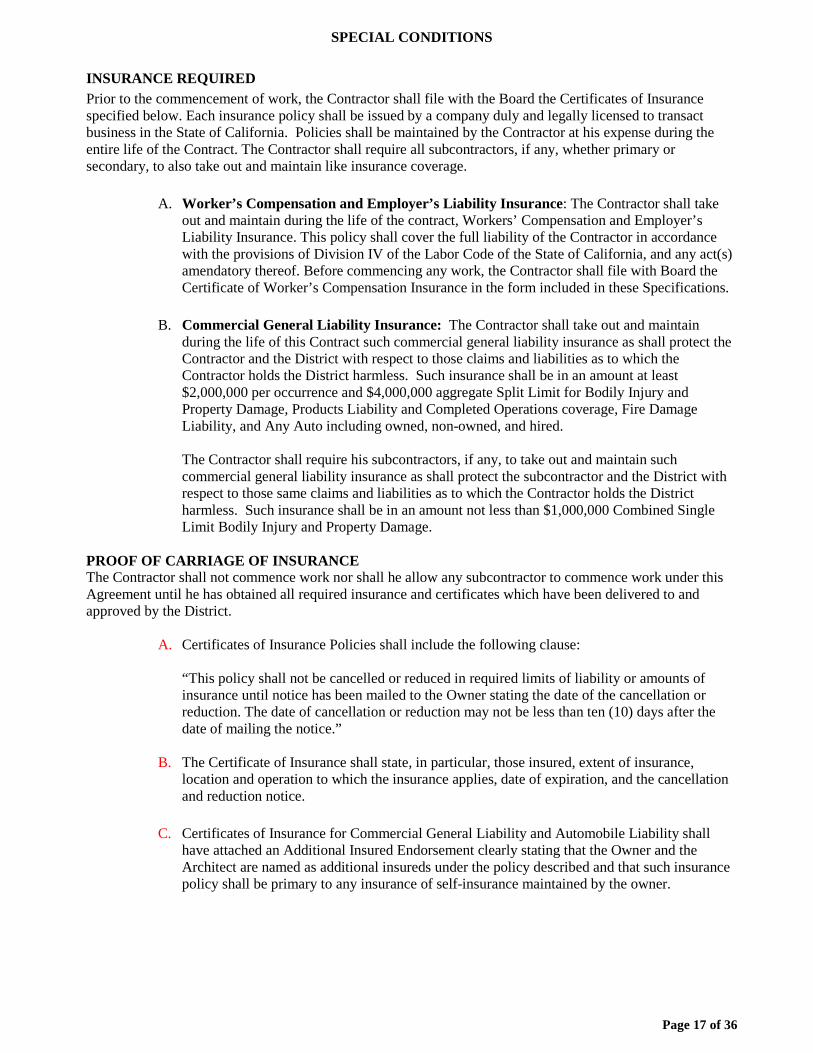
Page 17 of 36
SPECIAL CONDITIONS
INSURANCE REQUIRED Prior to the commencement of work, the Contractor shall file with the Board the Certificates of Insurance specified below. Each insurance policy shall be issued by a company duly and legally licensed to transact business in the State of California. Policies shall be maintained by the Contractor at his expense during the entire life of the Contract. The Contractor shall require all subcontractors, if any, whether primary or secondary, to also take out and maintain like insurance coverage.
A. Worker’s Compensation and Employer’s Liability Insurance: The Contractor shall take out and maintain during the life of the contract, Workers’ Compensation and Employer’s Liability Insurance. This policy shall cover the full liability of the Contractor in accordance with the provisions of Division IV of the Labor Code of the State of California, and any act(s) amendatory thereof. Before commencing any work, the Contractor shall file with Board the Certificate of Worker’s Compensation Insurance in the form included in these Specifications.
B. Commercial General Liability Insurance: The Contractor shall take out and maintain
during the life of this Contract such commercial general liability insurance as shall protect the Contractor and the District with respect to those claims and liabilities as to which the Contractor holds the District harmless. Such insurance shall be in an amount at least $2,000,000 per occurrence and $4,000,000 aggregate Split Limit for Bodily Injury and Property Damage, Products Liability and Completed Operations coverage, Fire Damage Liability, and Any Auto including owned, non-owned, and hired.
The Contractor shall require his subcontractors, if any, to take out and maintain such commercial general liability insurance as shall protect the subcontractor and the District with respect to those same claims and liabilities as to which the Contractor holds the District harmless. Such insurance shall be in an amount not less than $1,000,000 Combined Single Limit Bodily Injury and Property Damage.
PROOF OF CARRIAGE OF INSURANCE The Contractor shall not commence work nor shall he allow any subcontractor to commence work under this Agreement until he has obtained all required insurance and certificates which have been delivered to and approved by the District.
A. Certificates of Insurance Policies shall include the following clause:
“This policy shall not be cancelled or reduced in required limits of liability or amounts of insurance until notice has been mailed to the Owner stating the date of the cancellation or reduction. The date of cancellation or reduction may not be less than ten (10) days after the date of mailing the notice.”
B. The Certificate of Insurance shall state, in particular, those insured, extent of insurance, location and operation to which the insurance applies, date of expiration, and the cancellation and reduction notice.
C. Certificates of Insurance for Commercial General Liability and Automobile Liability shall
have attached an Additional Insured Endorsement clearly stating that the Owner and the Architect are named as additional insureds under the policy described and that such insurance policy shall be primary to any insurance of self-insurance maintained by the owner.

Page 18 of 36
D. Value of Insurance The insurance required of this Article shall be written by a company or companies licensed to do business in the State of California, and shall be written for at least the following, as established by the DISTRICT or greater if required by law:
1. Commercial General Liability (written on an Occurrence Form as opposed to a
Claims Made Form, and including Premises – Operations, Independent CONTRACTOR’s Protective; Contractual Liability; Property Damage; Personal Injury; Products and Completed Operations; Broad Form Property Damage).
a. Split Limit for Bodily Injury and Property Damage:
$2,000,000.00 Each Occurrence; and $4,000,000.00 Aggregate.
b. Property Damage Liability Insurance will provide X, C, or U
coverage as applicable.
2. Comprehensive Automobile Liability
a. Combined Single Limit for Bodily Injury and Property Damage:
$1,000,000.00 Each Occurrence
3. Worker’s Compensation and Employer’s Liability Insurance shall be written by a company licensed to do business in the State of California, and shall be written for not less than the following, as established by the DISTRICT or greater if required by law:
a. $1,000,000.00
RESPONSIBILITY OF CONTRACTOR – INSURANCE The Contractor shall be responsible for:
A. Compliance of the sub-contractor with insurance requirements; and
B. Other insurance coverage, but not limited to, loss, theft, fire, property damage and glass
breakage.
Page 19 of 36
Bid No. 902 District Wide Digital Cabling Project, Phase IV
CONSTRUCTION AGREEMENT
THIS AGREEMENT is entered into as of ____________, 2016 between the STOCKTON UNIFIED SCHOOL DISTRICT, hereinafter referred to as “District”, and _____________ referred to as “Contractor”, with reference to the following:
A. District is a public school district organized and existing under the laws of the State of California.
B. District advertised for bids for public works project and Contractor was the lowest
responsive, responsible bidder for the project. C. Accordingly, District desires to enter into a contract with Contractor to perform the
construction services more particularly described below (“Work”) and Contractor desires to perform such Work on the terms and conditions hereinafter set forth in this Agreement. ACCORDINGLY, IT IS AGREED:
1. THE WORK: Contractor shall perform all of the work specified in the Technical Specifications and Bid documents attached hereto and shall provide all labor, materials, tools, utility services, and transportation to complete in a workmanlike manner all of the work required for District Wide Digital Cabling Project, Phase IV, Bid No. 902.
2. COMMENCEMENT AND COMPLETION: The Work to be performed under this
Agreement shall be commenced within seven (7) calendar days after the date this Agreement is executed by the District. The Work shall be diligently pursued by the Contractor and completed not later than 90 calendar days from the date work is begun, excluding days upon which inclement weather does not permit Contractor to continue the work. Time is of the essence for the performance of all Work under this Agreement.
3 CONTRACT PRICE: Contractor agrees to receive and accept the following lump
sum amount as full compensation for all work and materials embraced in this Agreement; for all costs, losses, or damages arising from the nature of the work, or the action of the elements, or any unforeseen difficulties or obstructions which may arise or be encountered; and for all risks of every description connected with the work until its acceptance by the District, to wit: ___________________________________________________________________ ($ ).
Unit Prices. The Contract Price includes the following unit prices, which Contractor must provide and the District may, at it’s discretion, utilize in valuing additive and/or deductive change orders:
Upon completion of the work and its acceptance by the District, the Contractor may be paid ninety-five percent (95%) of the contract price. The final payment, if undisputed, shall be due thirty-five (35) days after Notice of Completion. District warrants will be issued with lag time as per standard District invoice payment procedures.
4. WITHHOLDING AND DISBURSEMENT: Pursuant to Public Contract Code §7107,
in the event of a dispute between District and Contractor, the Owner may withhold from the final payment an amount not to exceed 150 percent of the disputed amount plus any amounts necessary to cover any filed and unreleased stop payment notices. Except as so withheld, the District shall release
Page 20 of 36
undisputed amounts of the retention within 60 days after the date of completion of the work of improvement pursuant to Public Contract Code § 7107.
5 DEPOSIT OF SECURITIES: Pursuant to Public Contract Code § 22300, Contractor
may elect to enter into an escrow for the deposit of securities and/or funds withheld in lieu of the District withholding from the Contractor a performance retention. Any escrow used shall be established using the “Escrow Agreement for Security Deposits in Lieu of Retention” form developed by District.
6 CONTRACTOR: Contractor acknowledges that he is an independent contractor and
not an employee, agent or representative of District, and in this regard shall supervise and direct the work using Contractor's best skill and attention. The Contractor shall be solely responsible for all construction means, methods, techniques, and procedures and for coordinating all portions of the work under Contract. Contractor represents and warrants to District that all work will be of good quality, free from faults and defects and in conformance with this Contract, and all work not so conforming to these standards may be considered defective. Contractor shall pay all sales, consumer, use and other similar taxes required by law and shall secure and pay for all permits, fees and licenses necessary for the execution of the work. At the completion of the work, Contractor shall remove all waste materials and rubbish in and about the work site. If the Contractor fails to clean-up, the District may do so and charge the cost to the Contractor.
7. INDEMNITY: Contractor shall indemnify, defend and hold harmless District, the
Architect, and their respective directors, officers, agents, employees, engineers, contractors, subcontractors, volunteers or consultants from and against any and all claims, damages, losses, liabilities, penalties, costs, and liability of any kind arising out of the negligence or willful misconduct of Contractor or its directors, officers, agents, employees, engineers, consultants, contractors or subcontractors in connection with the performance of the Work herein, save and except such actions, claims, damages, losses, liabilities, costs and expenses as determined by a court of competent jurisdiction as having arisen from the active negligence or willful misconduct of an indemnified party. The obligations of Contractor herein are in addition to, and not in substitution of Contractor’s obligations as set forth in this agreement. Such indemnification shall extend to all claims, demands, or liabilities occurring after completion of the work as well as during the progress of the work.
8 ENVIROMENTAL INDEMNIFICATION: From and after the execution of this
Agreement, Contractor shall indemnify, defend and hold harmless District and Architect from all losses or damages resulting from injury to or death of any person and damage to property, and any fine which is occasioned by or arises out of any breach of the environmental or toxic warranty, representations or covenants of the Contractor under this Agreement. Contractor further agrees to indemnify, defend, and hold harmless District, Architect, their officers, employees and agents, from and against any and all liability as follows:
a) From all foreseeable and all unforeseeable consequential damages, directly or
in arising out of the use, generation, storage, or disposal of hazardous materials by Contractor; and
b) Without limitation, from the cost of any required or necessary repair, cleanup
or detoxification and the preparation of any closure or other required plans, whether such action is required or necessary prior to or following recording of the Notice of Completion, to the full extent that such action is attributable, directly or indirectly, to the presence or use, generation, storage, release, threatened release or disposal of hazardous materials by any person on the project prior to recording of the Notice of Completion.
Page 21 of 36
This Agreement, as to indemnity and reimbursement as above set forth to be undertaken by the Contractor, shall survive the performance of the remainder of said Agreement and shall remain in full force and effect notwithstanding such performance.
9. LIQUIDATED DAMAGES: Failure to complete the work within the time and in the
manner provided for by this Contract shall subject the Contractor to liquidated damages pursuant to Government Code § 53069.85. The parties understand and agree that the actual occurrence of damages and the amount thereof which the District would suffer if the work is not completed on time is impossible or is extremely difficult to determine. Accordingly, the parties agree that the sum of Five Hundred Dollars ($ 500.00) per day for each and every calendar day of delay beyond the time herein prescribed for finishing the work shall be presumed to be the amount of damages sustained by the District for Contractor's failure to complete the work on time. In the event the Contractor shall become liable for liquidated damages, the District, in addition to all other remedies provided by law, shall have the right to withhold any and all retained percentages which would otherwise become due the Contractor until the liability of the Contractor under this section has been finally determined. In accordance with the provisions of Government Code § 4215, the Contractor shall not be assessed liquidated damages where said delay is caused by the failure of the District, or the owner of any utilities, to provide for the removal or relocation of utility facilities.
10. INSURANCE: Contractor shall secure and maintain the following insurance, which
will protect the parties from claims that may arise out of or result from Contractor's operations or those of any subcontractor in carrying out the Project:
a. Commercial general liability and any auto automobile insurance for personal
injury and property damage with a combined single limit of at $1,000,000 on an occurrence form;
i. Policy shall include Products Liability and Completed Operations
coverage; and ii. Contractor shall provide an endorsement stating that the District is
named as an additional insured. b. Workers’ Compensation Insurance as required by the provisions of Labor
Code Section 3700.
Certificates and insurance policies shall include an endorsement shall also state that Consultant’s insurance policies shall be primary to any insurance or self-insurance maintained by District. An endorsement shall also state that there shall be a waiver of any subrogation.
Certification that such insurance has been obtained will be required to be presented to the
District before the Work is started. (See Appendix B) 11. CORRECTION OF WORK: Contractor guarantees all materials and work for a
period of one (1) year and shall correct any work that fails to conform to the requirements of this Agreement where such failure to conform appears during the progress of the work, and shall remedy any defects due to faulty materials or workmanship which appear within a period of one year from the date of final completion of the Contract.
12. REQUIRED BONDS: Contractor shall furnish to District a Performance Bond in an
amount of 100% of the Contract Price insuring the faithful performance of the Contract, and a Labor and Materials Payment Bond in an amount of 100% of the Contract Price to ensure the payment of all obligations arising hereunder. Contractor shall deliver the bonds to District before the work is
Page 22 of 36
started. All bonds required, whether Bid Bonds, Performance, Payment, or other bonds, shall be issued by a California admitted surety insurer.
13. PREVAILING WAGE RATES: This Project is subject to labor compliance
monitoring and enforcement by the Department of Industrial Relations pursuant to Labor Code § 1771.4 and Title 8 of the California Code of Regulations. Contractor specifically acknowledges and understands that it shall perform the Work of this Agreement while complying with all the applicable provisions of Division 2, Part 7, Chapter 1, of the Labor Code.
Pursuant Labor Code §§ 1770-1780, the Director of the Department of the Industrial
Relations has determined the general prevailing rate of per diem wages in the locality for each craft or type of worker needed to execute the Contract. The Contractor and any subcontractor performing Work under this Agreement shall pay all workers employed on the work not less than the rates determined by the Director of the Department of Industrial Relations. Copies of the prevailing rate of per diem wages are on file at the principal office of the District,.
Pursuant to Labor Code § 1776, the Contractor and each subcontractor is required to keep or
cause to be kept an accurate record showing the names and occupations of all workers in connection with the execution of this Agreement or any subcontracts, and showing also the actual per diem wage paid to each of such workers, which records shall be open at all reasonable hours to inspection by the District, its officers and agents and to representatives of the Division of Labor Standards Enforcement of the State Department of Industrial Relations (“Labor Commissioner”). The certified payroll records are required to be on the Public Works Payroll Reporting Form, including the certification (DIR Form A-1-131 or current version). Contractor and all of its subcontractors shall timely submit complete and accurate electronic certified payroll records directly to the Labor Commissioner weekly and within ten (10) days of any request by the District or the Labor Commissioner or the District may not issue payment.
Pursuant to Labor Code § 1775, the Contractor shall, as a penalty to the District, forfeit not
more than two hundred dollars ($200.00) for each calendar day or portion thereof, for each worker paid less than the prevailing rates as determined by the director for the work or craft in which the worker is employed. The amount of this penalty shall be determined by the Labor Commissioner.
14. WORKING HOURS: Contractor acknowledges that he is familiar with the provisions
of Labor Code §§ 1810-1816 pertaining to working hours, and that he will comply with the requirements provided therein.
15. EMPLOYMENT OF APPRENTICES: Contractor agrees to comply with Labor Code
§§ 1776, 1777.5, 1777.6, and 3077, and applicable regulations. Contractors and subcontractors are required to employ most apprentices and apprenticable occupations in a ratio of not less than one hour of apprentice's work for every five hours of labor performed by a journeyman, unless an exception is granted, and that contractors and subcontractors shall not discriminate among otherwise qualified employees as indentured apprentices on any public work solely on the ground of race, religious creed, color, national origin, ancestry, sex, or age. Only apprentices who are training under written apprenticeship agreements will be employed on public works in apprenticable occupations. The responsibility for compliance with these provisions for all apprenticable occupations rests with Contractor.
16. TRAVEL AND SUBSISTENCE PAYMENTS: The Contractor shall be required to
pay travel and subsistence payments to each worker needed to execute the work, as such travel and subsistence payments are defined in the applicable collective bargaining agreements filed with the Department of Industrial Relations in accordance with the provisions of Labor Code § 1773.8
Page 23 of 36
17. NON-DISCRIMINATION: In connection with the performance of work under this Agreement, the Contractor agrees (as prescribed in the provisions of the California Fair Employment and Housing Act as set forth in Part 2.8 of Division 3 of the Government Code of the State of California, commencing at Section 12900, by Labor Code § 1735, by the Federal Civil Rights Act of 1964, as set forth in Public Law 88-352, and all amendments thereto; Executive Order 11246, and all administrative rules and regulations found to be applicable) not to discriminate against any employee or applicant for employment because of race, religious creed, color, national origin, ancestry, physical disability, mental disability, medical condition, marital status, sex, or age. The aforesaid provisions shall include, but not be limited to, the following: Employment, upgrading, demotion or transfer, recruitment or recruitment advertising, layoff or termination, rates of pay or other forms of compensation, and selection for training, including apprenticeship. The Contractor agrees to post hereafter in conspicuous places, available for employees and applicants for employment, notices setting forth the provisions of this non-discrimination clause. The Contractor further agrees to insert the foregoing provisions in all subcontracts hereunder, except subcontracts for standard commercial supplies of raw materials.
18. IMMIGRATION ACT COMPLIANCE: The Contractor hereby certifies that it is, and
at all times during the performance of work hereunder shall be, in full compliance with the provisions of the federal Immigration Reform and Control Act of 1986 ("IRCA") in the hiring of its employees, and the bidder shall indemnify, hold harmless, and defend the District against any and all actions, proceedings, penalties or claims arising out of the bidder's failure to comply strictly with IRCA.
19. EXISTING UTILITIES: In accordance with the provisions of Government Code §
4215, the District shall assume the responsibility for the timely removal, relocation, or protection of existing main or trunkline utility facilities located on the site of the Work, if such utilities are not identified by the District in the plans and specifications made a part of the invitation for bids. The Contractor shall be compensated for the costs of locating, repairing damage not due to the failure of the Contractor to exercise reasonable care, and removing of relocating such utility facilities if such are not indicated in the plans and specifications with reasonable accuracy, and for equipment on the project necessarily idled during such work. Nothing herein shall be deemed to require the District to indicate the presence of existing service laterals or appurtenances whenever the presence of such utilities on the site of the construction project can be inferred from the presence of other visible facilities, such as buildings, meter and junction boxes, on or adjacent to the site of the construction. If the Contractor while performing the Work discovers utility facilities not identified by the Owner in the plans or specifications, he shall immediately notify the District and utility in writing. The public utility shall have the sole discretion to perform repairs or relocation work or permit the Contractor to do such repairs or relocation work at a reasonable price.
20. LICENSE: Contractors are required by law to be licensed and regulated by the
Contractors’ State License Board, which has jurisdiction to investigate complaints against contractors if a complaint regarding a patent act or omission is filed within four years of the date of the alleged violation. A complaint regarding a latent act or omission pertaining to structural defects must be filed within 10 years of the date of the alleged violation. Any questions concerning a contractor may be referred to the Registrar, Contractor’s State License Board, 3132 Bradshaw Road, Post Office Box 2600, Sacramento, California 95826.
21. REGISTRATION: Contractor and all subcontractors currently are registered as public
works contractors with the Department of Industrial Relations, State of California, in accordance with Labor Code section 1771.4.
22. BUILDING CODES: The provisions of all applicable building codes and ordinances
shall be considered a minimum requirement. Where the requirements of these Contract Documents exceed those of such codes or ordinances, these Contract Documents shall govern.
Page 24 of 36
23. INTERPRETATION OF CONTRACT DOCUMENTS: Should any question arise
concerning the intent or meaning of Contract Documents, including the Drawings or Specifications, the question shall be submitted to the District for interpretation. If a conflict exists in the Contract Documents, modifications, beginning with the most recent, shall control over this Agreement (if any), which shall control over the Special Conditions, which shall control over any Supplemental Conditions, which shall control over the General Conditions, which shall control over the remaining Division 0 documents, which shall control over Division 1 Documents which shall control over Division 2 through Division 18 documents, which shall control over figured dimensions, which shall control over large-scale drawings, which shall control over small-scale drawings. In no case shall a document calling for lower quality and/or quantity material or workmanship control. The decision of the District in the matter shall be final.
24. OWNERSHIP OF PLANS AND SPECIFICATIONS: All plans, specifications and
estimates for the Work shall be and remain the property of the District as required by Education Code §17316.
25. SUBCONTRACTING: Subcontracting under this Agreement shall be governed by
the California 'Subletting and Subcontracting Fair Practices Act', Public Contract Code §§4100 - 4114.
26. RESOLUTION OF CONSTRUCTION CLAIMS: This Agreement is subject to the
provisions of Public Contract Code §§20104 - 20104.8 relating to resolution of construction claims. A copy of these provisions is attached hereto, and they are hereby incorporated by reference into the specifications. If a claim, or any portion thereof, remains in dispute upon satisfaction of all applicable dispute resolution requirements, the Design-Builder shall comply with all claims presentation requirements as provided in Chapter 1 (commencing with section 900) and Chapter 2 (commencing with section 910) of Part 3 of Division 3.6 of Title 1 of Government Code as a condition precedent to the Contractor’s right to bring a civil action against the District. For purposes of those provisions, the running of the time within which a claim must be presented to the District shall be tolled from the time the claimant submits its written claim until the time the claim is denied, including any time utilized by any applicable meet and confer process.
27. ATTORNEY FEES/COSTS: Should litigation be necessary to enforce any terms or provisions of this Agreement, then each party shall bear its own litigation and collection expenses, witness fees, court costs and attorney’s fees.
28. TERMINATION: If Contractor fails to perform the Work to the satisfaction of the
District, or if Contractor fails to fulfill in a timely and professional manner Contractor’s obligations under this Agreement, or if Contractor violates any of the terms or provisions of this Agreement, District shall have the right to terminate this Agreement effective immediately upon the District giving written notice thereof to the Contractor. The Contractor and its performance bond surety, if any, shall be liable for all damages caused to the District by reason of the Contractor’s failure to perform and complete the Agreement. District shall also have the right in its sole discretion to terminate the Contract for its own convenience upon District giving three (3) days written notice thereof to the Contractor. In case of a termination for convenience, Contractor shall be paid for the actual cost for labor, materials, and services performed that is unpaid and can be documented through timesheets, invoices, receipts, or otherwise, and five percent (5%) of the total cost of Work performed as of the date of termination, or five percent (5%) of the value of the Work yet to be performed, whichever is less. This five percent (5%) shall be full compensation for all of Contractor's and its subcontractor(s)’ mobilization and/or demobilization costs and any anticipated loss profits resulting from termination of the Contractor for convenience. Termination shall have no effect upon any of the rights and obligations of the parties arising out of any transaction occurring prior to the effective date
Page 25 of 36
of termination. 29. DISABLED VETERAN BUSINESS ENTERPRISES: To the extent required by law,
the Contractor shall meet all requirements of law relating to the participation of disabled veteran business enterprise contracting goals, and shall comply with Public Contract Code §10115 et seq. and all applicable regulations. Contractor further agrees that, when required, Contractor will ensure compliance by all subcontractors and will complete all forms required by the Office of Local Assistance, the State Allocation Board, or other agencies exercising jurisdiction over the project.
26. ANTITRUST, ASSIGNMENT: In accordance with Section 7103.5(b) of the Public
Contract Code, the Contractor and subcontractors shall conform to the following requirements. In entering into a public works contract or a subcontract to supply goods, services, or materials pursuant to a public works contract, the contractor or subcontractor offers and agrees to assign to the awarding body all rights, title and interest in and to all causes of action it may have under Section 4 of the Clayton Act (15 U.S.C. Sec. 15) or under the Cartwright Act (Chapter 2 commencing with Section 16700 of Part 2 of Division 7 of the Business and Professions Code), arising from purchases of goods, services, or materials pursuant to the public works contract or the subcontract. This assignment shall be made and become effective at the time the awarding body tenders final payment to the Contractor, without further acknowledgment by the parties.
27. COMPLIANCE WITH LAW: Contractor shall provide services in accordance with
applicable Federal, State, and local laws, regulations and directives. 28. GOVERNING LAW: This Agreement shall be interpreted and governed under the
laws of the State of California without reference to California conflicts of law principles. Any litigation arising out of this Agreement shall be brought in San Joaquin County, California. Contractor waives the removal provisions of California Code of Civil Procedure § 394.
29. TITLE 21 AND 24: Contractor shall comply with California Code of Regulations
(CCR), Titles 21 and 24, in addition to all other applicable regulations. Contractor shall keep a copy of the latest edition of Title 21 and Title 24, Part 2, on the job site at all times, and keep it available for reference use. Nothing in these contract documents shall be construed to permit work not conforming to these codes. A copy of stamped contract documents shall be kept on the job site and made available to the District’s Inspector where the requirements of these Contract Documents exceed those of such codes or ordinances, these Contract Documents shall govern. If Contractor observes that any of the Work required by this Contract is at variance with any such laws, ordinance, rules or regulations, Contractor shall notify the District, in writing, and, at the sole option of the District, any necessary changes to the scope of the Work shall be made and this Contract shall be appropriately amended in writing, or this Contract shall be terminated effective upon Contractor’s receipt of a written termination notice from the District. If Contractor performs any work that is in violation of any laws, ordinances, rules or regulations, without first notifying the District of the violation, Contractor shall bear all costs arising therefrom.
30. PUBLIC CONTRACT CODE SECTION 7104: With regard to any work that involves
digging trenches or other excavations that extend deeper than four feet below the surface, the Contractor shall promptly, and before the following conditions are disturbed, notify the District, in writing, of any:
(1) Material that the contractor believes may be material that is hazardous waste,
as defined in Section 25117 of the Health and Safety Code. that is required to be removed to a Class I, Class II, or Class III disposal site in accordance with provisions of existing law.
(2) Subsurface or latent physical conditions at the site differing from those indicated.
Page 26 of 36
(3) Unknown physical condition at the site of any unusual nature, different materially
from those ordinarily encountered and generally recognized as inherent in work of the character provided for in the contract.
In case of such notification, the District shall promptly investigate the conditions, and i
it finds that the conditions do materially so differ, or do involve hazardous waste, and cause a decrease or increase in the Contractor’s cost of, or the time required for, performance of any part of the work, shall issue a change order under the procedures described in this agreement.
In the event that a dispute arises between the District and Contractor whether the
conditions materially differ, or involve hazardous waste, or cause a decrease or increase in the contractor’s cost of, or time required for, performance of any part of the work, the Contractor shall not be excused from any scheduled completion date provided for by this Agreement, but shall proceed with all work to be performed under the Contract Documents. The Contractor shall retain any and all rights provided either by contract or by law which pertain to the resolution of disputes and protests between the parties. 31. CONTRACTOR’S CERTIFICATION REGARDING WORKERS
COMPENSATION: (See Appendix B) 32. FINGERPRINTING REQUIREMENTS:
(A) Pursuant to California Education Code § 45125.1, before any agents or employees of Contractor may enter school grounds where they may have any contact with pupils, Contractor shall submit fingerprints of its employees in a manner authorized by the California Department of Justice, together with a fee determined by the Department of Justice. Contractor shall not permit any employee to come in contact with pupils of District until the Department of Justice has ascertained that the Contractor’s employees have not been convicted of a felony as defined in Education Code §45122.1.
(B) Contractor shall provide District with a written list of the names of its
employees who may come in contact with pupils before commencement of work. Contractor shall certify, in a form provided by District, in writing to the District, under penalty of perjury, that it has complied with the requirements of Education Code § 45125.1, and that none of its employees who may come in contact with pupils have been convicted of a felony as defined in Education Code § 45122.1, based upon the information Contractor has received from the Department of Justice.
(C) If Contractor believes that its employees will have only limited contact with
pupils and should therefore be exempted from these requirements, Contractor must contact the District with its request for exemption with fifteen (15) days prior to the commencement of work. The request for exemption must specify the grounds for such proposed exemption, considering the totality of circumstances, including but not limited to the length of time Contractor will be on school grounds, whether pupils will be in proximity to the site where the Contractor’s employees are working, and whether the Contractor’s employees will be working by themselves or with others. Whether to grant or deny the exemption is within the sole discretion of the District governing board.
(D) The Contractor shall impose the foregoing requirements on any subcontractors or assignees. 33. IDENTIFICATION BADGES: All personnel shall wear identification badges OR

Page 27 of 36
other alternative form of identification while on the school site. It shall be the responsibility of Contractor to verify all workers are wearing their badge/ID while on the school site and to not allow a worker on site without an identification badge.
34. EDD REQUIREMENTS: Contractor must provide information required by State of
California Employment Development Department, Form DE542 - Report of Independent Contractor. This information is mandated by the State of California effective January 1, 2001.
35. NOTICES: Except as may be other required by law, any notice to be given shall be
written and shall be either personally delivered, sent by facsimile transmission, or sent by overnight delivery service, or sent by first class mail, registered or certified mail, postage prepaid, return receipt required, and addressed as follows: DISTRICT: With a Copy To Stockton Unified School District Stockton Unified School District Attn: Construction Manager Attn: Director, Facilities & Planning 2141 Robindale Ave.. 1944 N. El Pinal Ave. Stockton, CA 95205 Stockton, CA 95205 Fax No: (209) 933-7046 Fax No.: (209) 933-7046 CONTRACTOR: Contractor Attn: Contractor’s Address (Fax No.:(XXX) XXX-XXXX/Confirming No.:(XXX) XXX-XXXX)
Notice delivered personally or sent by facsimile transmission is deemed to be received upon receipt. Notice sent by overnight delivery service shall be effective the business day next following delivery to the overnight delivery service. Notice sent by first class mail shall be deemed received on the fourth day after the date of mailing. Either party may change the above address by giving written notice pursuant to this paragraph.
36. DISTRICT WAIVER: District's waiver of any term, condition, covenant or waiver of
a breach of any term, condition or covenant shall not constitute the waiver of any other term, condition or covenant or the waiver of a breach of any other term, condition or covenant.
37. INCORPORATION OF RECITALS AND EXHIBITS: The Recitals and each exhibit
attached hereto are hereby incorporated herein by reference. 38. HEADINGS: Section headings are provided for organizational purposes only and do
not in any manner affect the scope, meaning or intent of the provisions under the headings. No provision of this Contract shall be interpreted for or against a party because that party or its legal representative drafted such provision, and this Agreement shall be construed as if jointly prepared by the parties.
39. INVALID TERM: If any provision of this Agreement is declared or determined by
any court of competent jurisdiction to be illegal, invalid or unenforceable, the legality, validity or enforceability of the remaining parts, terms and provisions shall not be affected thereby, and said illegal, unenforceable or invalid part, term or provision will be deemed not to be a part of this Contract.
40. PROVISIONS REQUIRED BY LAW DEEMED INSERTED: Each and every
provision of law and clause required by law to be inserted in this Contract shall be deemed to be
Page 28 of 36
inserted herein and this Contract shall be read and enforced as though it were included therein. 41. AMENDMENTS: The terms of this Agreement shall not be waived, altered,
modified, supplemented or amended in any manner whatsoever except by written agreement signed by the parties.
42. ENTIRE AGREEMENT: The Contract Documents constitute the entire agreement
between the parties and there are no understandings, agreements, representations or warranties, expressed or implied, not specified herein. The Contract Documents shall include all Bidding Documents and Addenda, this Agreement, the Drawings and Maps, the Technical Specifications, written Modifications, if any, and all Attachments hereto. Contractor, by the execution of this Agreement, acknowledges that he has read this Agreement, understands it and agrees to be bound by its terms.
IN WITNESS WHEREOF, the parties hereto have executed this Agreement on the day first
herein above written. STOCKTON UNIFIED SCHOOL DISTRICT
By _________________________________ Print Name: __________________________ Title: ________________________________ CONTRACTOR
By __________________________________ Print Name: ___________________________ Title _________________________________ Contractor License No.__________________ Expiration Date: _______________________ Classification: _________________________ Registration No.: _______________________

Page 29 of 36
CONTRACTOR’S CERTIFICATE REGARDING WORKERS’ COMPENSATION Labor Code Section 3700, in relevant part, provides that:
“Every employer except the State shall secure the payment of compensation in one or more of the following ways:
(a) By being insured against liability to pay compensation by one or more
insurers duly authorized to write compensation insurance in this State.
(b) By securing from the Director of Industrial Relations a certificate of consent to self-insure, which may be given upon furnishing proof satisfactory to the Director of Industrial Relations of ability to self-insure and to pay any compensation that may become due to his or her employees.
I am aware of the provisions of Section 3700 of the Labor Code which require every employer to be insured against liability for workers’ compensation or to undertake self-insurance in accordance with the provisions of that code, and I will comply with such provisions before commencing the performance of the Work of this Contract.
Date: Proper Name of Contractor: Signature: Print Name: Title: (In accordance with Sections 1860 and 1861 of the Labor Code, the above certificate must be signed and filed with the awarding body prior to performing any Work under this Contract.)

Page 30 of 36
PREVAILING WAGE AND RELATED LABOR REQUIREMENTS CERTIFICATION
I hereby certify that I will conform to the State of California Public Works Contract requirements regarding prevailing wages, benefits, on-site audits with 48-hours notice, payroll records, and apprentice and trainee employment requirements, for all Work on the above Project including, without limitation, the labor compliance monitoring and enforcement by the Department of Industrial Relations. Date: Proper Name of Contractor: Signature: Print Name: Title:
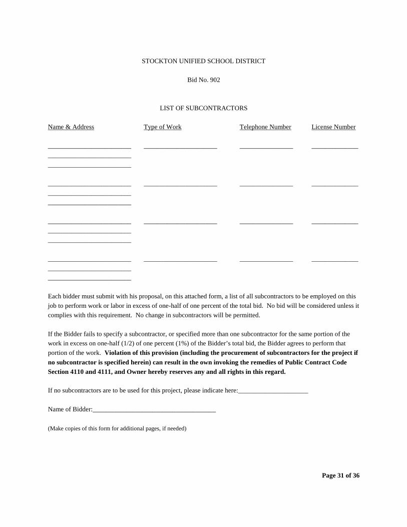
Page 31 of 36
STOCKTON UNIFIED SCHOOL DISTRICT
Bid No. 902
LIST OF SUBCONTRACTORS Name & Address Type of Work Telephone Number License Number _________________________ ______________________ ________________ ______________ _________________________ _________________________ _________________________ ______________________ ________________ ______________ _________________________ _________________________ _________________________ ______________________ ________________ ______________ _________________________ _________________________ _________________________ ______________________ ________________ ______________ _________________________ _________________________ Each bidder must submit with his proposal, on this attached form, a list of all subcontractors to be employed on this job to perform work or labor in excess of one-half of one percent of the total bid. No bid will be considered unless it complies with this requirement. No change in subcontractors will be permitted. If the Bidder fails to specify a subcontractor, or specified more than one subcontractor for the same portion of the work in excess on one-half (1/2) of one percent (1%) of the Bidder’s total bid, the Bidder agrees to perform that portion of the work. Violation of this provision (including the procurement of subcontractors for the project if no subcontractor is specified herein) can result in the own invoking the remedies of Public Contract Code Section 4110 and 4111, and Owner hereby reserves any and all rights in this regard. If no subcontractors are to be used for this project, please indicate here:_____________________ Name of Bidder:_____________________________________ (Make copies of this form for additional pages, if needed)
Page 32 of 36
STOCKTON UNIFIED SCHOOL DISTRICT
Bid No. 902
JOB REFERENCES
Bidders must submit a list of at least three (3) projects of similar dollar volume completed within the last two (2) years for reference purposes. JOB DATE JOB LOCATION CONTACT PERSON PHONE # _________ _______________________________ __________________ _________
_______________________________ _______________________________
_________ _______________________________ __________________ _________
_______________________________ _______________________________
_________ _______________________________ __________________ _________
_______________________________ _______________________________
Name of Bidder: ______________________________________________
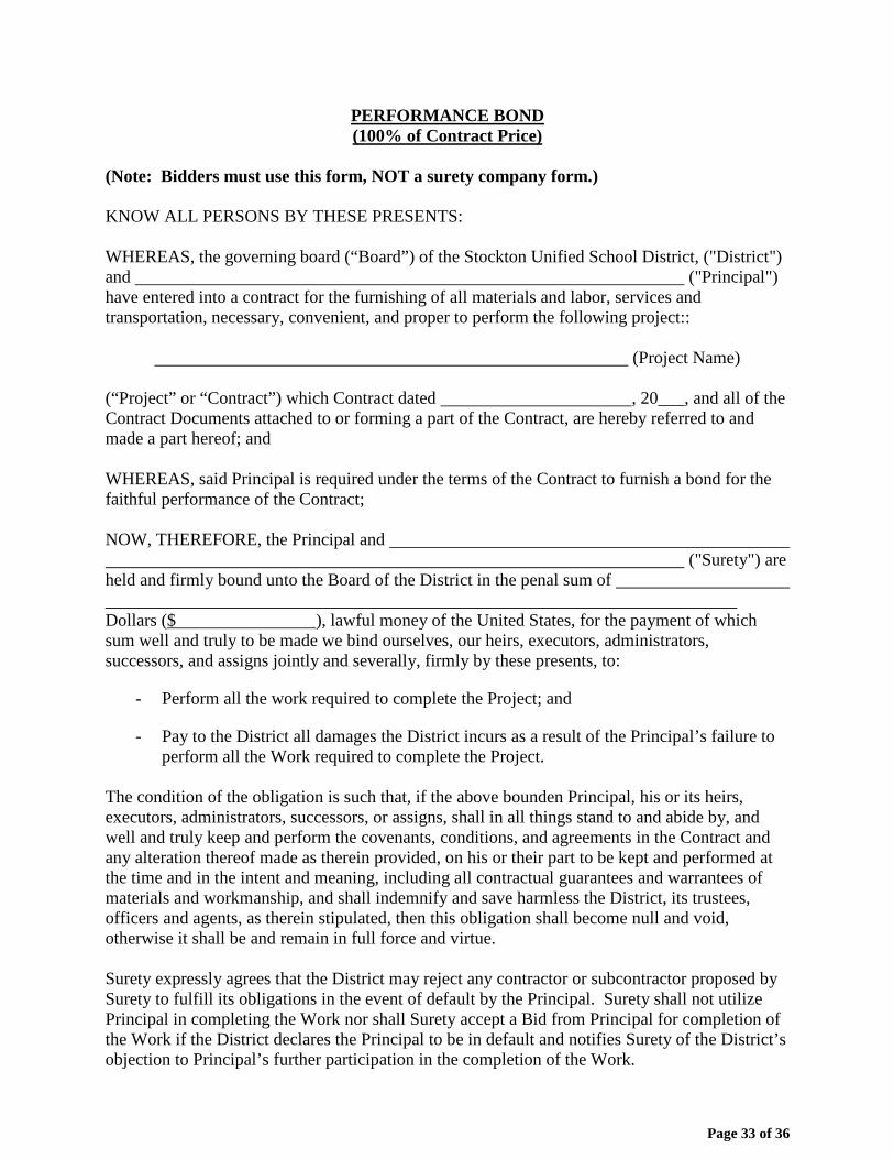
Page 33 of 36
PERFORMANCE BOND (100% of Contract Price)
(Note: Bidders must use this form, NOT a surety company form.) KNOW ALL PERSONS BY THESE PRESENTS: WHEREAS, the governing board (“Board”) of the Stockton Unified School District, ("District") and ("Principal") have entered into a contract for the furnishing of all materials and labor, services and transportation, necessary, convenient, and proper to perform the following project::
(Project Name) (“Project” or “Contract”) which Contract dated , 20___, and all of the Contract Documents attached to or forming a part of the Contract, are hereby referred to and made a part hereof; and WHEREAS, said Principal is required under the terms of the Contract to furnish a bond for the faithful performance of the Contract; NOW, THEREFORE, the Principal and ("Surety") are held and firmly bound unto the Board of the District in the penal sum of Dollars ($ ), lawful money of the United States, for the payment of which sum well and truly to be made we bind ourselves, our heirs, executors, administrators, successors, and assigns jointly and severally, firmly by these presents, to:
- Perform all the work required to complete the Project; and
- Pay to the District all damages the District incurs as a result of the Principal’s failure to perform all the Work required to complete the Project.
The condition of the obligation is such that, if the above bounden Principal, his or its heirs, executors, administrators, successors, or assigns, shall in all things stand to and abide by, and well and truly keep and perform the covenants, conditions, and agreements in the Contract and any alteration thereof made as therein provided, on his or their part to be kept and performed at the time and in the intent and meaning, including all contractual guarantees and warrantees of materials and workmanship, and shall indemnify and save harmless the District, its trustees, officers and agents, as therein stipulated, then this obligation shall become null and void, otherwise it shall be and remain in full force and virtue. Surety expressly agrees that the District may reject any contractor or subcontractor proposed by Surety to fulfill its obligations in the event of default by the Principal. Surety shall not utilize Principal in completing the Work nor shall Surety accept a Bid from Principal for completion of the Work if the District declares the Principal to be in default and notifies Surety of the District’s objection to Principal’s further participation in the completion of the Work.
Page 34 of 36
As a condition precedent to the satisfactory completion of the Contract, the above obligation shall hold good for a period equal to the warranty and/or guarantee period of the Contract, during which time Surety’s obligation shall continue if Contractor shall fail to make full, complete, and satisfactory repair and replacements and totally protect the District from loss or damage resulting from or caused by defective materials or faulty workmanship. The obligations of Surety hereunder shall continue so long as any obligation of Contractor remains. Nothing herein shall limit the District’s rights or the Contractor or Surety’s obligations under the Contract, law or equity, including, but not limited to, California Code of Civil Procedure section 337.15. And the Surety, for value received, hereby stipulates and agrees that no change, extension of time, alteration, or addition to the terms of the contract or to the work to be performed there under or the specifications accompanying the same shall in any way affect its obligation on this bond, and it does hereby waive notice of any such change, extension of time, alteration, or addition to the terms of the Contract or to the work or to the specifications. IN WITNESS WHEREOF, two (2) identical counterparts of this instrument, each of which shall for all purposes be deemed an original thereof, have been duly executed by the Principal and Surety above named, on the day of , 20___. (Affix Corporate Seal)
Principal By
Surety
By
Name of California Agent of Surety
Address of California Agent of Surety
Telephone Number of California Agent of Surety Bidder must attach a Notarial Acknowledgment for all Surety's signatures and a Power of Attorney and Certificate of Authority for Surety. The California Department of Insurance must authorize the Surety to be an admitted surety insurer.
END OF DOCUMENT
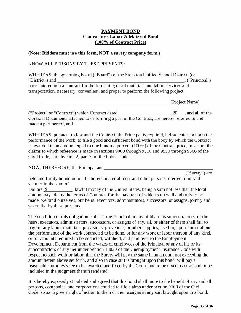
Page 35 of 36
PAYMENT BOND Contractor's Labor & Material Bond
(100% of Contract Price) (Note: Bidders must use this form, NOT a surety company form.) KNOW ALL PERSONS BY THESE PRESENTS: WHEREAS, the governing board (“Board”) of the Stockton Unified School District, (or "District") and , ("Principal") have entered into a contract for the furnishing of all materials and labor, services and transportation, necessary, convenient, and proper to perform the following project:
(Project Name)
(“Project” or “Contract”) which Contract dated , 20___, and all of the Contract Documents attached to or forming a part of the Contract, are hereby referred to and made a part hereof, and WHEREAS, pursuant to law and the Contract, the Principal is required, before entering upon the performance of the work, to file a good and sufficient bond with the body by which the Contract is awarded in an amount equal to one hundred percent (100%) of the Contract price, to secure the claims to which reference is made in sections 9000 through 9510 and 9550 through 9566 of the Civil Code, and division 2, part 7, of the Labor Code. NOW, THEREFORE, the Principal and ("Surety") are held and firmly bound unto all laborers, material men, and other persons referred to in said statutes in the sum of Dollars ($ ), lawful money of the United States, being a sum not less than the total amount payable by the terms of Contract, for the payment of which sum well and truly to be made, we bind ourselves, our heirs, executors, administrators, successors, or assigns, jointly and severally, by these presents. The condition of this obligation is that if the Principal or any of his or its subcontractors, of the heirs, executors, administrators, successors, or assigns of any, all, or either of them shall fail to pay for any labor, materials, provisions, provender, or other supplies, used in, upon, for or about the performance of the work contracted to be done, or for any work or labor thereon of any kind, or for amounts required to be deducted, withheld, and paid over to the Employment Development Department from the wages of employees of the Principal or any of his or its subcontractors of any tier under Section 13020 of the Unemployment Insurance Code with respect to such work or labor, that the Surety will pay the same in an amount not exceeding the amount herein above set forth, and also in case suit is brought upon this bond, will pay a reasonable attorney's fee to be awarded and fixed by the Court, and to be taxed as costs and to be included in the judgment therein rendered.
It is hereby expressly stipulated and agreed that this bond shall inure to the benefit of any and all persons, companies, and corporations entitled to file claims under section 9100 of the Civil Code, so as to give a right of action to them or their assigns in any suit brought upon this bond.
Page 36 of 36
Should the condition of this bond be fully performed, then this obligation shall become null and void; otherwise it shall be and remain in full force and affect.
And the Surety, for value received, hereby stipulates and agrees that no change, extension of time, alteration, or addition to the terms of Contract or the specifications accompanying the same shall in any manner affect its obligations on this bond, and it does hereby waive notice of any such change, extension, alteration, or addition. IN WITNESS WHEREOF, two (2) identical counterparts of this instrument, each of which shall for all purposes be deemed an original thereof, have been duly executed by the Principal and Surety above named, on the day of , 20___. (Affix Corporate Seal)
Principal
By
Surety
By
Name of California Agent of Surety
Address of California Agent of Surety
Telephone Number of California Agent of Surety Bidder must attach a Notarial Acknowledgment for all Surety's signatures and a Power of Attorney and Certificate of Authority for Surety. The California Department of Insurance must authorize the Surety to be an admitted surety insurer.
END OF DOCUMENT