Bi-axial Seismic Activation of Civil Engineering Structures ...
16
JSEE: Spring 2005, Vol. 7, No. 1 / 45 1. Department of Civil Engineering, Vienna University of Technology, Vienna, Austria, email: [email protected] 2. Department of Civil Engineering, Vienna University of Technology, Vienna, Austria, email: [email protected] ABSTRACT: Tuned liquid column dampers (TLCD) considerably increase the effective damping of vibration prone civil engineering structures in horizontal motion. A single-degree-of-freedom (SDOF) basic system with a TLCD attached is analyzed under horizontal and vertical base excitations in order to prove its sensitivity with respect to the vertical parametrical forcing. The main result is cast in a sufficient condition for the linearized damping coefficient of the fluid motion to ensure its stability under the most critical, time harmonic forcing conditions. The output of computer simulations when varying the damping of the TLCD tuned with respect to frequency only, are verified experimentally by means of a novel model setup. The scaled Friuli 1976 earthquake is applied horizontally and vertically to an SDOF-shear frame with optimally tuned TLCD. A three-DOF-bench- mark structure, equipped with two passive TLCD in parallel connection, optimally fine-tuned in state space, is analyzed by nonlinear computer modeling. Two different relevant earthquakes are alternatively applied in both, horizontal and vertical directions. In all cases it is verified, that sealed TLCD, (with the air-spring effect taken into account) are stable, since the optimal linear damping coefficient exceeds by far the required cut-off value of parametric resonance: the vertical component of the earthquake load remains ineffective. Hence, taking into account this sufficient condition with the maximum vertical ground (floor) acceleration assigned and the maximum amplitude of the fluid motion estimated, saves the consideration of the vertical seismic activation at all. Keywords: Vibration absorber; Horizontal-; Vertical excitations; Parametric resonance; Cut-off damping; Bernoulli equation; Tuned mass damper (TMD)-analogy; Den Hartog tuning; State space optimization Bi-axial Seismic Activation of Civil Engineering Structures Equipped with Tuned Liquid Column Dampers M. Reiterer 1 and F. Ziegler 2 1. Introduction Newly developed lightweight building materials and sophisticated numerical algorithms allow the design of tall and highly flexible civil engineering structures. These structures are vulnerable to dynamic loads, such as wind gusts or earthquakes. Hence, the mitigation of structural vibrations has been a major concern amongst structural engineers. One of the effective means to reduce the dynamic response is the applica- tion of dynamic vibration absorbers. The tuned mechanical damper, TMD, is one of the most popular passive control systems and has been broadly studied and applied to many engineering structures [1]. Its substitution by the innovative tuned liquid column damper, TLCD, which has been developed to the practical design stage during the last decade, see [2-6], is most promising. TLCD is a damping device in the extremely low frequency range that relies on the motion of a liquid mass in a rigid U-shaped tube. Its range of applicability can be extended to about 4.0 to 5.0Hz, if the air spring effect in the sealed U-shaped
-
Upload
khangminh22 -
Category
Documents
-
view
2 -
download
0
Transcript of Bi-axial Seismic Activation of Civil Engineering Structures ...

JSEE: Spring 2005, Vol. 7, No. 1 / 45
1. Department of Civil Engineering, Vienna University of Technology, Vienna, Austria,
email: [email protected]
2. Department of Civil Engineering, Vienna University of Technology, Vienna, Austria,email: [email protected]
ABSTRACT: Tuned liquid column dampers (TLCD) considerablyincrease the effective damping of vibration prone civil engineeringstructures in horizontal motion. A single-degree-of-freedom (SDOF)basic system with a TLCD attached is analyzed under horizontal andvertical base excitations in order to prove its sensitivity with respect tothe vertical parametrical forcing. The main result is cast in a sufficientcondition for the linearized damping coefficient of the fluid motion toensure its stability under the most critical, time harmonic forcingconditions. The output of computer simulations when varying thedamping of the TLCD tuned with respect to frequency only, are verifiedexperimentally by means of a novel model setup. The scaled Friuli1976 earthquake is applied horizontally and vertically to anSDOF-shear frame with optimally tuned TLCD. A three-DOF-bench-mark structure, equipped with two passive TLCD in parallelconnection, optimally fine-tuned in state space, is analyzed bynonlinear computer modeling. Two different relevant earthquakes arealternatively applied in both, horizontal and vertical directions. In allcases it is verified, that sealed TLCD, (with the air-spring effecttaken into account) are stable, since the optimal linear dampingcoefficient exceeds by far the required cut-off value of parametricresonance: the vertical component of the earthquake load remainsineffective. Hence, taking into account this sufficient condition withthe maximum vertical ground (floor) acceleration assigned andthe maximum amplitude of the fluid motion estimated, saves theconsideration of the vertical seismic activation at all.
Keywords: Vibration absorber; Horizontal-; Vertical excitations;Parametric resonance; Cut-off damping; Bernoulli equation; Tuned massdamper (TMD)-analogy; Den Hartog tuning; State space optimization
Bi-axial Seismic Activation of Civil Engineering Structures
Equipped with Tuned Liquid Column Dampers
M. Reiterer1 and F. Ziegler2
1. Introduction
Newly developed lightweight building materials andsophisticated numerical algorithms allow the designof tall and highly flexible civil engineering structures.These structures are vulnerable to dynamic loads, suchas wind gusts or earthquakes. Hence, the mitigationof structural vibrations has been a major concernamongst structural engineers. One of the effectivemeans to reduce the dynamic response is the applica-tion of dynamic vibration absorbers. The tunedmechanical damper, TMD, is one of the most popular
passive control systems and has been broadlystudied and applied to many engineering structures[1]. Its substitution by the innovative tuned liquidcolumn damper, TLCD, which has been developed tothe practical design stage during the last decade, see[2-6], is most promising. TLCD is a damping devicein the extremely low frequency range that relies onthe motion of a liquid mass in a rigid U-shaped tube.Its range of applicability can be extended to about 4.0to 5.0Hz, if the air spring effect in the sealed U-shaped

46 / JSEE: Spring 2005, Vol. 7, No. 1
M. Reiterer and F. Ziegler
tube is utilized. For extremely low frequencies,however, the air chambers are connected and aircan flow freely to balance the pressure. The motionof the main system (of the relevant floor of thebuilding) induces a phase-delayed relative motion ofthe liquid mass and, hence, interaction forces (andmoments) to counteract the external force. Further-more, a built-in orifice plate may become necessary,to induce additional turbulent damping and dissipationof kinetic energy in a controlled manner. For optimaltuning of the TLCD the natural circular frequency ω
A
and the linearized damping coefficient ζA have to be
suitably chosen, in analogy to the conventional TMD,for the latter see Den Hartog [7]. Computationally,the tuning of the TLCD is always performed in twosteps. At first, the linearized computer model is tunedwith respect to a selected mode of the main systemusing the simple analogy to TMD-tuning. Hochrainer[5] extensively discussed this simplifying step .Subsequent improvements of the performance in anMDOF -system are achieved by considering theneighboring modes as well in the state spacerepresentation, by minimizing the weighted squaredarea of the frequency response function, see again [5].The second fine-tuning renders the optimalparameters quickly when Den Hartog's parametersare selected for the initial values of the numericalsearch process. Slightly modified parameters result,and, e.g., two TLCD in parallel connection, counter-acting a single selected mode, turn out with differenttuning parameters. This second step leads to anincrease in the robustness of the proposed dampingdevice. Final adjustments are easily performed in thecourse of in-situ testing. The TLCD ideally suited toexcite the main structure in a controlled manner tomeasure its basic frequency, which enters in-situ finetuning. In many respects TLCD exceed by far thecapabilities of other vibration absorbing devices.Their main advantages comprise of low cost ofdesign and maintenance, easy application to newbuildings or in retrofitting existing structures, littleadditional mass since water is stored in buildings forfire protection or water supply and a simple tuningmechanism since the natural frequency and dampingratio can be adjusted by pressurizing the air chambers,adjusting their volume, and selecting a proper orificeplate.
While tuned liquid dampers (TLD) based on thesloshing fluid in the moving container are applied aswell to reduce the vibrations at a well separated
frequency, their reaction to disturbances is foundrather uncontrolled, contrary the sealed tuned liquidcolumn damper (TLCD) is self controlling to overloadsand the fluid motion is controlled in any respect.
Most scientific work concentrated on the suppres-sion of horizontal motions of structures also in caseof earthquake activation and neglected the verticalcomponent. Hence, the objective of this study is todevelop a more general model of civil engineeringstructures with passive TLCD attached and toinvestigate any unwanted influence of the verticalseismic activation on the damping characteristics ofTLCD . It has to be mentioned that parametricresonance also exists for the conventional pendulumtype TMD whose point of suspension movesvertically, see, e.g., Ziegler [8]. In order to preventparametric resonance even under the most criticalconditions of time harmonic excitation, a sufficientcondition for the linearized damping coefficient ofthe TLCD is derived. Various computer models ofoptimally and sub optimally damped TLCD attachedto an SDOF-shear frame, are investigated to studythe sensitivity with respect to the vertical excitation.The outcome of the analysis is verified experimentallyusing a newly designed model set up. In addition totime harmonic forcing under the most criticalconditions of parametric resonance, the scaled Friuli1976 earthquake is applied assuming one and thesame intensity in both directions. The experimentalresults agree well with the computational simulations.The cut-off damping coefficient of parametricresonance was verified. Finally, a three- DOF -structure, based on the benchmark definition paperby Spencer et al [9], is equipped with two passiveoptimally tuned TLCD in parallel connection on topof the building. Fine-tuning is performed in statespace. Both seismograms, the N-S Friuli earthquakeand the N-S El Centro 1940 earthquake, are appliedin horizontal and vertical directions. Theoretical andexperimental investigations indicate that the verticalcomponent of the earthquake loading influences moreor less the TLCD dynamics. However, it is verified,that in case of sealed TLCD, the common values ofthe optimal damping ratio are much larger than thevery small cut-off damping coefficient, and thus, noundesired worsening effects are observed. Hence,after verifying the sufficient condition to preventparametric resonance for the most critical case, thevertical component of any earthquake load must notbe considered any further.

JSEE: Spring 2005, Vol. 7, No. 1 / 47
Bi-axial Seismic Activation of Civil Engineering Structures Equipped with Tuned Liquid Column Dampers
2. Basic System: SDOF-Shear Frame with TLCDAttached
Modal tuning of a TLCD when attached to an MDOF-structure can be approximately reflected by theinteraction of an SDOF-shear frame with a TLCD ontop. Substructure synthesis is applied and illustratedin Figure (1).
inclined pipe section at rest H, the horizontal andinclined cross-sectional areas AB and AH, respectively,and the opening angle of the inclined pipe section,
.2/5/ π≤β≤π The relative and incompressibleflow of the liquid inside the pipe is described bythe liquid surface displacement, u1= u2= u (t). If thepiping system is sealed, the air inside the air chamberis quasi-statically compressed by the liquid surfacein slow motion. Hence, the pressure difference, ∆p =p2 - p1, when properly linearized, influences theundamped circular natural frequency of the TLCD,defined in Eq. (3). Applying the modified Bernoulliequation along the relative non-stationary streamlinein the moving frame and in an instant configuration,Ziegler [8] , yields the nonlinear parametricallyexcited equation of motion of the TLCD, Reiterer [6],
,2
1 22
teffA
tAL wunsi
Lv
uuu &&&&
&&&& κ−=
β
ω+ω+δ+ (1)
where an averaged turbulent damping term, - experi-mentally verified, - has been added. The head losscoefficient δL can be increased by properly selectinga built-in orifice plate. In case of stationary flow, δL istabulated for relevant pipe elements and cross-sections, e.g., sampled, in Ref. [10]. The geometryfactor κ and the effective length Leff of the liquidcolumn, apparent in Eq. (1), are defined by
,2,2
BAA
H L LscoHB
B
Heff
eff+=
β+=κ (2)
see Ref. [5] for detailed derivations. The undampedcircular natural frequency ωA of the sealed TLCDincludes approximately the air-spring effect wherethe pressure difference ∆p = p2 - p1 is linearized withrespect to the equilibrium pressure p0, -an additionalimportant design parameter, - by considering the firstterm of its Taylor series expansion. Assuming a poly-tropic state change, ,4.11,/2)( 0 ≤≤≈ nHupnup a∆results. Consequently, the maximum stroke of aircompression is limited to | u | < 0.3 Ha to assure a goodapproximation of the eigenfrequency, for details seeagain either Ref. [5] or [6],
ρ+β=ω
aeffA H
gpnnsiL
g
/2 0 (3)
In Eq. (3), p0, ρ , g and Ha denote the initial(equilibrium) pressure in the air chamber, the liquiddensity, e.g. for water ρ = 1000kg/m3, the gravityconstant g = 9.81m/s2, and the air spring height,
Figure 1. (a) Symmetrically shaped TLCD under combinedhorizontal and vertical floor excitations. When sealed,air chamber volume modeled by AHHa. Free bodydiagram of the fluid body. (b) Free body diagram ofthe basic SDOF-system with acting interactionforces (and moment) from the TLCD dynamics.Seismic excitation indicated. Soil-structure interactionneglected.
2.1. Free Body Diagram of the Fluid in the TLCD
The TLCD is considered separated from the floor ofthe main structure, under combined in-plane horizon-tal wt and vertical v t floor excitations, see Figure (1a).After choosing the liquid mass mt, the TLCD designparameters are the horizontal length of the liquidcolumn B, the length of the liquid column in the

48 / JSEE: Spring 2005, Vol. 7, No. 1
M. Reiterer and F. Ziegler
respectively. To avoid problems at the fluid-gasinterface related to high speed limits the equilibriumpressure p0 to about five times the atmosphericpressure. Consequently, also Ha is an important designvariable, defining the volume of the air chamber interms of the cross-sectional area AH , see again Eq.(3). The limit ∞→aH refers to ∆p = 0 and thusapplies approximately for TLCD with free flow of airbetween the air chambers, see again Figure (1a).
The time variant stiffness parameter in Eq. (1)contributes parametric excitation caused by thevertical floor acceleration . tv&& Consequently, underspecial conditions of lightly damped TLCD , theinstability phenomenon of parametric resonance isobserved. A detailed study of this phenomenon and asufficient condition to prevent parametric resonanceand its possibly worsening effect on the dampingbehavior of the attached TLCD is presented in section2.3.
In the course of the absorber optimizationprocedure, the turbulent damping in Eq. (1) has to betransformed into its equivalent linear one, .2 uAA &ωζDemanding equally dissipated energy during onecycle (over a vibration period T and without anyvertical excitation) for the nonlinear and the linearTLCD yields the relation
( ) ( ) ,20
2
0
2 tduuutduuuu
T
AAA
T
AL ∫∫ ω+ωζ=ω+δ &&&&& (4)
and, when substituting a time harmonic function, u (t)= U0 cos ωA t, renders the equivalent viscous dampingcoefficient proportional to the amplitude,
πδ
=ζ
LA
U3
4 0 (5)
Under these conditions, Eq. (1) takes on its linearizedform,
,
,2
12
0
22
axm
teffA
tAAA
UUu
wuinsLv
uu
≈≤
κ−=
β
ω+ω+ωζ+ &&
&&&&&
(6)
The value of U0, to be substituted in Eq. (5) ingeneral forced vibrations, is determined by means ofnumerical simulations of the linear coupled SDOF-TLCD system, without vertical excitation, andcommonly chosen as U
0 = Umax.
Considering the conservation of momentum ofthe fluid body, Figure (1a), determines the resultantinteraction forces. The components, acting on thefluid body, relevant in the horizontal x', and, not to
be considered further, in the vertical z' directions,become
11
,2
),(
LAmLoscHB
uwmF Hftfx ρ=β+
=κκ+=′ &&&&
,2
,2
,)(
1
11
21
BAA
HL
LinsHB
uuuH1
vmF
H
B
tfz
+=
β+=κ
+κ+=′ &&&&&
(7)
where κ and 1κ are geometry factors and L1 is a
length, which becomes equal to Leff for constant crosssectional area. Conservation of angular momentumwith respect to the accelerated point of referenceA, see again Figure (1a), yields the dynamic part ofthe undesired moment MA acting on the fluid body,the static moment is ., ugmM fstatA κ= Both momentsand the force zF ′ are commonly neglected in thestructural analysis.
2.2. Substructure Synthesis
The main system with assigned interaction forcesfrom the TLCD dynamics is considered next, seeFigure (1b), with horizontal ,gw&& and vertical ,gv&& groundaccelerations prescribed. The external force resultingfrom wind gusts is not within the scope of this paper.The deformation is given by the displacement w withany time variant P-∆ effect neglected. The movingfloor mass M includes the dead weight m
D = m - mf
of the TLCD and modal masses of the columns.The field stiffness k, with geometric correction ofprestressing by the dead weight taken into account forthe CC-columns, see, e.g., Ref. [8] or Clough andPenzien [11], and light structural proportionaldamping r, are the remaining parameters.
Conservation of momentum of the floor mass Myields the relevant linear equation of motion of themain system
MkMr
FMwwww
S
SS
xgSSS
/,2
,1
2 2
==ζ
−−=+ζ+ ′
ΩΩ
ΩΩ &&&&&
(8)
where ΩS and ζS << 1 denote the undamped circularnatural frequency of the shear frame, and the linearviscous equivalent of its light structural damping,respectively. Inserting the coupling force xF ′ bysubstituting Eq. (7) into Eq. (8) renders, with Eq. (1)considered, the coupled system of equations ofmotion of the resulting two-DOF-system,

JSEE: Spring 2005, Vol. 7, No. 1 / 49
Bi-axial Seismic Activation of Civil Engineering Structures Equipped with Tuned Liquid Column Dampers
.,
,2
1
,2
22
2
gtgt
teffA
tAL
tgSSS
vvwww
wunsiLv
uuu
uwwwww
≈+=
κ−=
β
ω+ω+δ+
κµ−µ−−=+ζ+
&&&&
&&&&
&&&&&&&&& ΩΩ
(9)
The mass ratio of fluid mass to the mass of themain system is denoted
.1<=µ Mm f (10)
In order to provide highest possible transfer ofenergy from the main system to the TLCD, the massratio µ as well as the coupling factors κ and κ shouldbe maximized. However, from the practical point ofview the mass ratio is limited to µ = 0.5-3%. Thefactors κ and κ depend on the geometry of theabsorber, given in Eqs. (2) and (7) and should beclose to one. They turn out equal for constant crosssection of the pipe.
In order to prepare for the equation of motion ofan MDOF-main structure with several, differentlytuned TLCD attached, Eq . (9) is rewritten in itslinearized matrix form and, leaving out parametricexcitation, becomes
,~~~g
fSSS w
mMuw
Kuw
Cuw
M &&&&
&&&&
κ+
−=
+
+
(11)
.0
0~
,20
02~,
1~
2
AS
AA
SSS
ffS
kK
MC
mmMM
ω
=
ωζ
ζ=
κ
κ+=
Ω
2.3. Parametric Forcing of the Fluid by the VerticalExcitation: Cut-Off Damping
Under special conditions and for lightly dampedTLCD , the undesired instability phenomenon ofparametric resonance is observed, see Reiterer andHochrainer [12]. Considering the linearized Eq. (6),the task of this section is to work out a sufficientcondition in the form of a minimum linear dampingratio ζA in order to prevent any worsening effectsfrom the vertical excitation. In absence of anyhorizontal excitation ,tw&& and further neglecting theturbulent and/or any viscous damping term, Eq. (6)further simplifies to the time-variant undampedoscillator equation,
02
1 22 =
β
ω+ω+ uins
Lv
u
effA
tA
&&&& (12)
Assigning a time-harmonic vertical excitation v t =v t 0cos ωz t, Eq. (12) becomes a special type of Hill´sdifferential equation, namely the Mathieu equation[13],
.02
1 2022 =
ω
ωβ
ω+ω+ utoscLinsv
u
zeffA
tzA&& (13)
Classically, Mathieu equation is the equation ofmotion of a plane pendulum with vertically movingpoint of suspension, see, e.g., Ziegler [8], whichapplies also to the conventional pendulum type ofTMD, e.g. discussed by Soong and Dargush [1].Dynamic stability of its solution has extensively beenstudied in the last century, for a recent review seeNayfeh and Mook [13]. The standard form of Eq.(13) requires substitution of the non-dimensional timeτ = ωz t, and, with its appropriate transformationresults in
[ ] ,,0 τ=′=τγ+λ+′′
d
uduuscou (14)
where λ and γ are identified as the non-dimensionalstability parameters
.2
-, 02
2
nsiLv
eff
t
z
A
β=γωω
=λ (15)
The domains of stability for the solution of theMathieu equation are cast in the Ince-Strutt diagram,Figure (2) , where the stable domains are shaded.Inspection of Figure (2) identifies the most criticalfrequency ratio at λ = 1/4, (the domain of instabilityat this value is quite large) and also that dampingstrongly influences the occurrence of parametricresonance: If linear viscous damping of the dynamicsystem is taken into account, the domains of stabilityincrease in the Ince-Strutt map, as indicated byhyperbolic curves in Figure (2). Hence, withsufficient damping of the dynamic system understood,parametric resonance does not occur. Nayfeh andMook [13] derived the cut-off value of linear dampingto prevent parametric resonance even under themost critical conditions at λ = 1/4. The sufficientcondition to safely avoid parametric resonance even inthis most critical case becomes, finally expressed interms of the maximum vertical floor and/or groundacceleration,

50 / JSEE: Spring 2005, Vol. 7, No. 1
M. Reiterer and F. Ziegler
Hochrainer [5] compared the reduced Eq . (6)(putting )0=tv&& of the linearized TLCD with theequation of motion of a TMD and identified thefollowing analogy by defining proper transformations.In Eqs. (17) and (18), the conjugate TMD mass ratioµ* depends on the geometry factors κ and , κ whichare defined in Eqs. (2) and (7), respectively, and wasidentified in Ref. [5],
.,)1(1*
**
Mm
Mm f
=µκκ−µ+
µκκ==µ (19)
It is evident that every TLCD setup behaves like aTMD with absorber mass m* attached to a movingfloor mass M*. The remaining mass m
f - m* has to be
regarded as dead weight and thus, is added to the floormass M*. Thus, defining the equivalent TMD massratio µ*, Eq. (19), renders the optimal values of thetuning parameters of the equivalent TMD-problem, δ*and .*
Aζ Subsequently, the inverse transformation tothe TLCD-problem is applied, see again Hochrainer[5] , rendering the optimal frequency ratio slightlymodified and keeping the optimal linear damping ratiounchanged,
.,)1(1
**
AAS
A
ζ=ζ
κκ−µ+
δ=
ω=δ Ω (20)
4. Bi-Axial, Time Harmonic and TransientExcitations of the Basic SDOF-System
The basic SDOF-system of Figure (1) is excited tosteady state vibrations under the most critical forcingconditions and the influence of parametric excitationby the vertical motion is studied in a computer modeland verified experimentally. Determination of the
Figure 2. Parametric forcing of the linearized absorber model: domains of stability (shaded) and instability in the Ince-Strutt diagram,,22
Aλζ=δ Klotter [14].
./
14
23
40,
0
00A
a
g
eff
tLA
nsiHgpn
g
vxmansiL
vU ζ=
β
ρ+
=β>πδ
=ζ&&
(16)
Note the reduction of the cut-off value by the airspring effect in sealed TLCD. If the optimal lineardamping coefficient of the TLCD is larger than thecut-off value ζA,0, no worsening effect of its dampingbehavior of the horizontal vibrations occurs. Thecondition is subsequently confirmed experimentallyand by numerical simulations. The vertical excitationcan be safely neglected in Eq. (1) if the inequality(16) holds true.
3. Den Hartog (Modal) Tuning in Analogy toTMD: Horizontal Vibrations
For modal (SDOF) tuning of a classical TMD, thedesign parameters, denoted by a star, *** / SA Ωω=δ and
*Aζ have to be suitably chosen. Classically Den Hartog
[7], for time harmonic force excitation and undampedmain system, ,0* =ζS derived these relations. Thus, incase of base acceleration, the non dimensional totalacceleration of the floor mass, ,/1 gww &&&&+ is minimizedby these TMD parameters, see, e.g., Ref. [1],
****
*
** /,
)1(83
,1
1Mm
*optopt =µ
µ+µ
=ζµ+
=δ (17)
Slightly different parameters result for small massratios, when minimizing the relative floor acceleration,
,/2gww &&ω
)2/1()1(83
,1
2/1**
*
*
**
µ−µ+µ
=ζµ+
µ−=δ
*optopt (18)

JSEE: Spring 2005, Vol. 7, No. 1 / 51
Bi-axial Seismic Activation of Civil Engineering Structures Equipped with Tuned Liquid Column Dampers
cut-off value of damping of the TLCD is the maingoal. Further, the turbulent damping of the fluidmotion has to be verified. The basic SDOF-systemwith an optimized TLCD attached is exposed to thebi-axial transient forcing by the strong motionseismogram of the N-S Friuli 1976 earthquake,verifying the sufficient condition based on the cut-offdamping.
4.1. Test Structure
A front view of the small scale testing facility in theAuthors' laboratory is shown in Figure (3), consistingof a plane SDOF-pendulum with vertically movingsuspension. The dynamic vertical forces are reducedsince the dead weight is counter-balanced by a pulleymechanism. The lower rigid bar represents the floorof the main SDOF -structure. The open TLCD(free flow of air) consists of a Plexiglas pipe withrectangular cross section filled with colored water.Horizontal excitation is provided by an electromagneticshaker of Br üel&Kjaer, Type 4808, connected to thelower rigid bar by a coil spring whose stiffness modelsthe elastic columns of an equivalent SDOF-shearframe, shown in Figure (1b). The amplitude is limitedto .004.00 mwg ≤ A second actuator of the same type,forces the vertical motion with its stroke magnifiedby a simple lever construction to v g0 = 0.016m.Software LabView 7.0 provides the time-harmonicsignals. Contact-less optical laser transducers,Type optoNCDT 1605, measure displacements asshown in Figure (3). The vertical acceleration is
recorded by the piezoelectric accelerometer ofBrüel&Kjaer Type4367. The latter is connected to acharge amplifier and an implemented integrator, totransform the measured accelerations into equivalentdisplacements. All measured signals are recorded bymeans of the software BEAM-DMCplusV3.7 throughthe board of Digital Amplifier System DMCplus(Hottinger Baldwin Messtechnik, HBM). A novelsensor, consisting of two pairs of wire electrodeswhose resistance depends on the water level,measures the motion of the liquid surface, Reitererand Hochrainer [15]. To compensate for severalnonlinearities, the electrodes are in series connection.For further processing, the electronic signal isband-pass-filtered, in order to reduce the static driftand any high frequency noise. The measured signalis recorded again by the software BEAM-DMCplusV3.7, whereby the measured changes ofresistance are transformed into the equivalentdisplacement of the liquid surface by means of anonlinear transfer function, obtained by calibrating thefluid motion in the TLCD.
The parameters of TLCD and SDOF basic-systemare selected according to the laboratory model. Theratio of fluid mass m
f to the moving floor mass of
the main system M is chosen rather high, µ = mf /M =0.071. Hence, with floor mass M = 2.96kg, the watermass is mf = 0.21kg. The dimensions of the openTLCD in Figure (1a) are: β = π/4, AH = AB = 0.0005m2,
mLL eff 42.0,84.0 1===κ=κ in Eq. (3) , renderingf
A = ωA /2π = 0.90Hz. The TLCD is tuned to frequency,
by adjusting the natural frequency of the SDOF -basic system which is simpler done in the laboratory.Selecting Eq. (18), Eq . (20) yields the optimalfrequency ratio δopt= ωA / ΩS,opt = 0.94 and hence, fS,opt
= fA / δo p t= 0.96Hz. The optimal equivalent lineardamping becomes ζA,opt = 0.11.
Free vibration tests of main system and TLCDwere performed to determine and verify the naturalfrequencies and damping coefficients. Dampingis stepwise increased to the final optimal value. Thelightest linearized viscous damping terms, ζA = 0.045and ζS = 0.01, have been observed by inspection ofthe decay rates of free vibration in laboratory testing.ζA is the mean value of a number of free vibrationtests within an amplitude range of U0 = 40-60mm.
The cut-off value of parametric resonance, definedin Eq. (16), relevant for the laboratory testing is
=ζ>
=ζ<=β=ζ
nsiL
v
A
optA
eff
gA
045.011.0
054.02 ,0
0, (21)Figure 3. Front view of the experimental model set-up, equiva-lent to the basic SDOF-system.

52 / JSEE: Spring 2005, Vol. 7, No. 1
M. Reiterer and F. Ziegler
The results of the numerical simulations arecompared with the experimental output in section 4.2.
4.2. Experimental and Numerical Results of SteadyState Vibrations. TLCD Tuned to Frequency.Verification of Cut-Off and Turbulent Damping
The experimentally and numerically obtained resultsin a time window under time harmonic critical forcingare shown in Figures (4a) and (4b). The verticalforcing frequency ωz = 2ωA (stability parameter λ =1/4), and the amplitude vg 0 = 0.016m are kept constantwithin the range of simulations. The bold linerepresents the steady state vibration without anyvertical excitation and the thin line indicates theinfluence of the assigned vertical excitation. It isimportant to emphasize that the chosen combinationof the values f z = 1.80Hz and vg0 = 16mm leads toparametric resonance for the light damping assigned,as predicted by Eq. (21). The beat phenomenondiscussed in Ref. [16] can be seen in Figures (4a)and (4b) that shows an excellent agreement betweenexperimental and predicted theoretical results, withaveraged turbulent damping δL = 1.33 considered.However, the solution of the linearized equation ofmotion with equivalent linear damping ζA = 0.045 keptconstant, grows beyond bounds. Thus, the linearizedmodel turns out to be insufficient for numericalsimulation, see Figure (4c), and note the different scalein Figure (4b). In order to obtain good agreementbetween numerical and experimental results, thesimulated TLCD must be always considered with anaveraged turbulent damping assigned. Consequently,the various linear viscous damping coefficients aretransformed to their turbulent equivalent, by means ofthe relation given in Eq. (5), δL = 3 π ζA / 4 U0 where U0
is determined by numerical simulations of thelinearized coupled system without vertical excitation,considering the steady state vibration at a discretehorizontal forcing frequency ωx, and subsequently bychoosing U0 = Umax. The Dynamic MagnificationFactor (DMF) for the parametrically excited coupledmain system/TLCD is determined at discrete valuesof the horizontal forcing frequency fx,i. Thereby, thefrequency dependent turbulent damping term δL,i hasto be varied over the frequency range of interest. Inorder to determine the appropriate values defined inEq. (5), U0,i must be specified as the maximum valueof the vibration amplitude, i.e., U0,i = Umax,i calculatedin the linearized model without vertical excitationunder steady state conditions. DMFi at the forcing
Figure 4. Steady state response of the basic SDOF-system.Horizontal and vertical forcing frequencies, fx = 1.00Hz and fz = 1.80Hz . TLCD tuned to frequency. Lightturbulent damping 33.1=δ→ L constant. (a) Experi-mental results. (b) Numerical results, light turbulentdamping (c) Numerical results for equivalently lineardamped TLCD 045.0=ζ→ A = constant. Insufficientmodeling.
frequency fx,i is defined by
,0
g
imax,i w
wDMF = (22)
where wmax,i is defined by the steady state response ofthe nonlinear, parametrically excited coupled system.
JSEE: Spring 2005, Vol. 7, No. 1 / 53
Bi-axial Seismic Activation of Civil Engineering Structures Equipped with Tuned Liquid Column Dampers
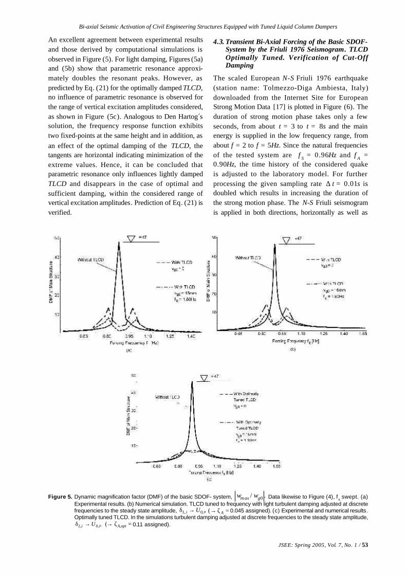
Figure 5. Dynamic magnification factor (DMF) of the basic SDOF- system, ./ 0 gaxm ww Data likewise to Figure (4), fx swept. (a)
Experimental results. (b) Numerical simulation. TLCD tuned to frequency with light turbulent damping adjusted at discretefrequencies to the steady state amplitude, ,,0, iiL U→δ =ζ→ A( 0.045 assigned). (c) Experimental and numerical results.Optimally tuned TLCD. In the simulations turbulent damping adjusted at discrete frequencies to the steady state amplitude,
,,0, iiL U→δ =ζ→ optA,( 0.11 assigned).
An excellent agreement between experimental resultsand those derived by computational simulations isobserved in Figure (5). For light damping, Figures (5a)and (5b) show that parametric resonance approxi-mately doubles the resonant peaks. However, aspredicted by Eq. (21) for the optimally damped TLCD,no influence of parametric resonance is observed forthe range of vertical excitation amplitudes considered,as shown in Figure (5c). Analogous to Den Hartog´ssolution, the frequency response function exhibitstwo fixed-points at the same height and in addition, asan effect of the optimal damping of the TLCD, thetangents are horizontal indicating minimization of theextreme values. Hence, it can be concluded thatparametric resonance only influences lightly dampedTLCD and disappears in the case of optimal andsufficient damping, within the considered range ofvertical excitation amplitudes. Prediction of Eq. (21) isverified.
4.3. Transient Bi-Axial Forcing of the Basic SDOF-System by the Friuli 1976 Seismogram. TLCDOptimally Tuned. Verification of Cut-OffDamping
The scaled European N-S Friuli 1976 earthquake(station name: Tolmezzo-Diga Ambiesta, Italy)downloaded from the Internet Site for EuropeanStrong Motion Data [17] is plotted in Figure (6). Theduration of strong motion phase takes only a fewseconds, from about t = 3 to t = 8s and the mainenergy is supplied in the low frequency range, fromabout f = 2 to f = 5Hz. Since the natural frequenciesof the tested system are f S = 0.96Hz and f A =0.90Hz, the time history of the considered quakeis adjusted to the laboratory model. For furtherprocessing the given sampling rate ∆ t = 0.01s isdoubled which results in increasing the duration ofthe strong motion phase. The N-S Friuli seismogramis applied in both directions, horizontally as well as

54 / JSEE: Spring 2005, Vol. 7, No. 1
M. Reiterer and F. Ziegler
vertically with one and the same strength. Againnonlinear turbulent damping is taken into account inthe equation of motion of the TLCD, which ensures astable motion even in case of light damping. Estimat-ing Umax = 80mm yields together with ζA,opt = 0.11 thenonlinear optimal turbulent damping coefficient, Eq.(5), δL = 3.24.
Furthermore, the sufficient condition to preventthe influence of vertical excitation has to be checked,Eq. (16) with , aH ∞→
,11.009.04 ,0,
optAg
A gvxma
=ζ<==ζ&&
(23)
where the maximum vertical base acceleration is
Figure 6. N-S Friuli 1976 earthquake (station name: Tolmezzo-Diga Ambiesta, Italy) in time and frequency domain. Source: EU-funded European Strong Motion Data [17].
Figure 7. Relative acceleration of the floor mass of the basic SDOF-system forced by the N-S Friuli 1976 earthquake. (a) Bi-axialexcitations, identical seismograms applied. Optimally tuned TLCD (turbulent damping =δ→ L 3.24 = constant). Note the50% reduction of maximum peak. (b) Responses under bi-axial excitations (note the different scale in Figure (7a) andunder uni-axial horizontal excitation. Cut-off damping verified by inspection.
given by ,36.0,, gvw axmgaxmg == &&&& see again Figure (6).
Thus, the optimal linearized damping ratio ζA,opt
exceeds the cut-off value ζA,0 and no worseningeffect of parametric resonance is expected.
Simulations of the nonlinear, parametricallyexcited system are performed using Simulink's timeintegration tool, which is smoothly integrated intothe MATLAB scientific computing environment.Figure (7a) illustrates the time history response of themain structure with and without TLCD in nonlinearmodeling attached, under combined horizontal andvertical seismic excitations.
In Figure (7b), the time history responses of thecoupled system with and without vertical seismicactivation taken into account are shown. Both lines

JSEE: Spring 2005, Vol. 7, No. 1 / 55
Bi-axial Seismic Activation of Civil Engineering Structures Equipped with Tuned Liquid Column Dampers
nearly coincide and thus confirm, that due to thevertical base excitation no undesired influence onthe optimal damping behavior of the TLCD isobservable.
5. State Space Optimization of Multiple TLCDAttached to MDOF-Systems
In case of multiple TLCD attached to MDOF-systemsthe tuning process is best performed in two steps.At first, the linearized computer model is tuned withrespect to a selected mode of the main system usingthe TLCD-TMD analogy, as presented in section 3.Subsequent improvements of the performancein MDOF -systems are achieved by consideringthe neighboring modes as well in a state spacerepresentation, by minimizing the weighted squaredarea of the frequency response function (FRF) .Hence, the coupled equations of motion have to betransformed to the state space. The N-DOF mainsystem with a number of n<<N TLCD installed atproper locations, is described by the set of matrixequations, in a hyper matrix formulation,
,~
~~~
~0~0~~
~0~0~~
~
gfS
ffS
wi
iMLrM
uw
KK
uw
CC
uwM
&&vvv
vv
&v&v
&&v&&v
κ+−=
+
+
(24)
set up in extending Eq. (11). The sparse positionmatrix with dimension N x n,
TLCD
DOFL
ofnumber
influenced be to
000
010
101
~
↑
←
=MMM
MMM
(25)
apparent in Eq. (24), enters the generalized massmatrix as well,
.~~~
~~~~~~~~
ILMLLMLMM f
Tf
S
κκ+= (26)
C M~
,~ and K
~ are mass, damping and stiffness matrixof the main system and the following diagonal matri-ces are self explanatory,
[ ][ ],2,...,2
~
,,...,~
11
1
AnAnAAf
fnff
diagC
mmdiagM
ωζωζ=
=
[ ][ ]
[ ].,...,~
,,...,~
,,...,~
1
1
221
n
n
AnAf
diag
diag
diagK
κκ=κ
κκ=κ
ωω=
(27)
together with the static influence vector ,~S r which, for
the single point base excitation is [ ] .1...111 T S i r ==
vv
Eq. (24) is easily converted to a first order statespace representation by introducing the new statevector [ ] ,
T u w u wz &v&vvvv = and its time derivative
( )
,~
~~~~00
,~~~
1T
fSSg
gg
iiMLrMMe
wez RBAz
κ+=
−+=
− vvvvvv
&&vv&v
(28)
to render the standard form of control theory. Thesystem matrix ,
~~~ RBA+ apparent in Eq. (28), should
be kept separated since, at this stage, only the elementsof A
~ and ,~
B
=
=
IIM-
IIM-
I I
B
CM-KM-
I I
A
SS
SS
~0~0~~~
~0~0~~~
~0~
0~
0~
0~~
0~
0~
~
,
0~0~0~~~
0~0~0~~~
~0~
0~
0~
0~~
0~
0~
~
1-1-
1-1-
(29)
are known, whereas R~ contains the unknown linearTLCD design parameters,
.~
0~
0~
0~
0~0~0~0~0~0~~0~0~
0~
0~
0~
~
f
f
C
KR
= (30)
The steady-state solution in frequency space is
( )[ ] .~~~)(1
geRBAIiz
vv −
+−ω=ω (31)
In order to find the optimal tuning parameters ofTLCD it is common practice to minimize a suitableperformance index, e.g., defined by the infiniteintegral of the weighted sum of quadratic statevariables of the main system ,Szv in the frequencydomain, see e.g. Müller and Schiehlen [15],

56 / JSEE: Spring 2005, Vol. 7, No. 1
M. Reiterer and F. Ziegler
,~
2)(~
)( inmePedzSzJ gTgS
TS →π=ωωω= ∫
∞
∞−
vvvv (32)
where P~ is the solution of the algebraic Lyapunov
matrix equation,
( ) ( ) .~~~~~~~~~ S RBAPPRBA
T
−=+++ (33)
S~ is a symmetric, positive semi-definite weighing
matrix, which offers the possibility to emphasize theimportance of selected components of the state spacevector. The matrix solution P
~ of Eq. (33) is numeri-cally evaluated by means of the software MATLAB.The minimum search in the Eq. (32) is best performedby the MATLAB optimization toolbox, "fminsearch",when substituting Den Hartog´s modal tuningparameters, as discussed in section 3, as start values.The modal analysis of the main system with separatedeigenfrequencies understood, is classical and notfurther discussed here.
6. A Three-DOF-Benchmark Structure underCombined Earthquake Loadings
The effectiveness of passive TLCD in vibration reduc-tion is demonstrated for a plane three-DOF-benchmarktest structure under earthquake loading, which hasalso been studied by Hochrainer [5] taking intoaccount the horizontal seismic activation only.Subsequently the vertical excitation is considered andthe TLCD is split into two TLCD in parallelconnection. Based on a benchmark definition paper,see Spencer et al [9], a scale model of the originalstructure was built at the National Center ofEarthquake Engineering (NCEER) at Buffalo, N.Y.,which requires the mass reduction by 1:16 withrespect to the original structure, time shortened by1:2 and the displacement scale of 1:4, the accelerationthus, remains unchanged. In the current numericalstudy the structural model with a total mass of2943kg is equipped with two, sealed passive TLCD inparallel connection on the 3rd top floor, as illustrated inFigure (8). Splitting a single passive TLCD in twoTLCD in parallel connection requires fine-tuning inthe state space. Modal (SDOF) tuning as discussedabove is performed in a first step.
Hochrainer [5] , provided the ortho-normalizedeigenvectors and the well-separated undampednatural frequencies,
Hzf Hzf Hzf SSS
,29.12,44.7,38.2
,2662.0
6555.07067.0
,5189.0
5204.06782.0
,8123.05472.02015.0
321
321
===
−
−=φ
−=φ
=φ
vvv
(34)
of the main test system. The light modal dampingratios are set to ζ S1 = 1%, ζ S2 = 2% and ζ S 3 = 3%,respectively. The attached, necessarily sealed TLCDwill be tuned with respect to the fundamental naturalfrequency of the model choosing the mass ratio 2%with respect to the modal mass of the fundamentalmode, .1531*
1 kgM = Thus, the total fluid mass is mf =30kg.
6.1. Optimal Design of Two, Sealed TLCD, Tuned tothe Basic Mode
Subsequently, the total fluid mass is split in twoTLCD in parallel connection, mf 1 = mf 2 = 15k g.The following design parameters are chosen, seeFigure (1a): horizontal and inclined lengths of theliquid column, B = 1.5m and H = 0.5m, constantcross-sectional areas AH = AB = 0.012m2, angle ofthe inclined pipe section β = 40o. Hence, the effectivelength of the liquid column and the geometry factors,determined in Eqs. (2) and (7), become Leff = L1 = B+2H = 2.5m and .91.0=κ=κ
In a first step, the optimal absorber frequenciesωAi and the linearized viscous damping ζAi,i = 1, 2are determined using the TLCD-TMD analogyand considering the fundamental modal coordinateto be optimized. Eq. (19) yields 0081.0*
2*1 =µ=µ to be
Figure 8. Scaled three-DOF-benchmark test structure undercombined horizontal and vertical earthquake loads,with two, sealed passive TLCD in parallel connectionon the top floor.

JSEE: Spring 2005, Vol. 7, No. 1 / 57
Bi-axial Seismic Activation of Civil Engineering Structures Equipped with Tuned Liquid Column Dampers
substituted in Eq. (17). Evaluating Eq. (20) rendersidentical optimal design parameters of both TLCD:fA1= fA2= 2.36Hz, ζA1 = ζA2 = 0.055. Improvementsof their performance are achieved by minimizing thefrequency domain based quadratic performance indexin the state space representation. The state vector ofthe main system, ,],,,,,[ 321321
T S
wwwwwwz &&&v = to be
substituted in Eq. (32), contains the TLCD quantities,e.g., the liquid surface displacement and velocity notexplicitly. However, the damping effect of the modallytuned TLCD is hidden in the system's dynamics, Eq.(31), and thus in the structural response vector .Szv
The relevant matrices, BA~
,~ and ,
~ R Eqs. (29) and (30),
for the plane frame with TLCD on top, Figure (8),have standard form, explicitly derived in Ref. [5],and are not repeated here. Having chosen theweighing matrix, ,]101010111[
~ diagS = the numerical
minimization of the performance index is startedwith Den Hartog´s modal tuning parameters. Calling"fminsearch" within the MATLAB optimizationtoolbox renders the new optimal tuning parameterssignificantly changed: fA1= 2.25Hz, ζA1 = 0.039, fA2=2.46Hz, ζA2 = 0.042. It is noticed that fA1 is smallerand fA 2 is larger than the fundamental naturalfrequency f S1 = 2.38Hz to be influenced by theTLCD. This fact increases the robustness of theattached damping device in view of expected changesof model parameters (mass, stiffness) during theoperating life. The maximum gain through the actionof the two optimally tuned passive TLCD in parallelconnection at the fundamental frequency of themain structure is indicated with about 30dB in Figure(9).
In order to realize the optimal natural frequenciesof the TLCD in practice, the air spring effect can beactivated. Eq. (3) is solved for the height Ha,
,2
,2
220
Aeffeff
effAa
insgLL
L
pnH
ωβ
−=ωρ
= ∆∆ (35)
where ∆Le f f defines the difference of the effectivelengths of the liquid column with and without theair-spring effect taken into account. Subsequently,assuming the polytropic index n = 1.2 and assigningjust the initial atmospheric pressure in equilibrium toeach TLCD, p0 = 105Pa , the air chamber heights,Ha1 = 0.49m and Ha2 = 0.41m result.
6.2. Combined Earthquake Loadings by the N-S Friuli1976 and the El Centro Seismograms. Verifica-tion of Cut-Off Damping
Since the system under consideration is still a scaledmodel, the time scale of the acceleration input isincreased by a factor of two, i.e., the simulated strongmotion occurs in half of the recorded time. TheN-S Friuli 1976 earthquake, defined in Figure (6) isconsidered properly scaled next. The correspondingcut-off values of the linearized damping coefficientsfor the sealed TLCD are determined by Eq. (16),
,042.00019.0/
14
,039.00023.0/14
2
2
02,0,
1
1
01,0,
A
L
gA
A
L
gA
nsiHgpn
g
vxma
nsiHgpng
vxma
=ζ<=
β
ρ+
=ζ
=ζ<=
β
ρ+=ζ
&&
&&
(36)
and, consequently, no worsening effects on theoptimal damping behavior of the sealed TLCD areexpected. The numerical simulations are performedusing MATLAB /Simulink, considering the TLCDwith turbulent damping, Eq . (1) holds true. Theaveraged optimal turbulent damping terms, determinedby Eq. (5), are δL1 = 0.61 and δL2 = 0.65, assigning themaximum vibration amplitudes (forecast by uni-axiallyexciting the linear model) Umax,1 = Umax,2 = 0.15m. Theresults for the horizontal top floor displacementw3, with and without two TLCD with turbulentdamping, under combined and assigned horizontaland vertical seismic activation by the N-S Friuli quakeare illustrated in Figure (10a). A large reduction ofthe maximum vibration amplitude is observed, thus thepassive action of the TLCD seems to be well suited to
Figure 9. Frequency response functions, FRF, of the sum ofweighted absolute state space variables of the three-DOF-test structure. Uni-axial, horizontal time harmonicforcing. Damping of the two, optimally tuned TLCD isconsidered equivalently linear viscous and indepen-dent of the forcing frequency. Damping characteristiczoomed and compared to a single TLCD action.

58 / JSEE: Spring 2005, Vol. 7, No. 1
M. Reiterer and F. Ziegler
counteract the combined earthquake loadings.Nevertheless, a transient vibration peak remainsnearly unaffected during the early part of the strongmotion phase, see again Figure (10a). A significantreduction of these early transient peaks requiresactive control of the air spring, by proper externalpressure supply from a pressurized gas-reservoir,rendering the active TLCD (ATLCD). Hochrainer [5]performed detailed investigations of ATLCD. Thetop floor displacements are illustrated in Figure(10b) with and without vertical seismic activationtaken into account. The time records indicate novisible influence of the vertical earthquake loadingverifying the condition based on the cut-off damping,Eq. (36). The seismogram of the N-S El Centroearthquake with a peak ground acceleration of
gw xmag 35.0, =&& is applied alternatively, again in both,
horizontal and vertical directions, with the same
strengths, illustrated in Figure (11). Since the systemunder consideration is still the scaled model, the timescale of the acceleration input is increased by thefactor of two. The numerical simulations areanalogously performed using MATLAB /Simulinkand considering the TLCD with turbulent damping.Since the sufficient condition, Eq. (16), is againverified, no worsening effect of the vertical excitationis expected,
.042.00019.0/
14
,039.00022.0/14
2
2
02,0,
1
1
01,0,
A
L
gA
A
L
gA
nsiHgpn
g
vxma
nsiHgpng
vxma
=ζ<=
β
ρ+
=ζ
=ζ<=
β
ρ+=ζ
&&
&&
(37)
Figure 10. Top floor displacements of the scaled three-DOF-test structure forced by the scaled N-S Friuli seismogram. (a) Bi-axialexcitations, identical seismograms applied. Two optimally tuned TLCD in parallel connection (turbulent damping =δ→ 1L0.61= constant, =δ→ 2L 0.65= constant). Note the possibly insufficient reduction of the maximum peak in thetransient regime by ≈ 20%. (b) Responses under bi-axial excitations (note the different scale in Figure (10a)) andunder uni-axial horizontal excitation. Cut-off damping verified by inspection.
Figure 11. N-S El Centro earthquake in time and frequency domain. Source: University of Notre Dame, http://www.nd.edu/~quake.

JSEE: Spring 2005, Vol. 7, No. 1 / 59
Bi-axial Seismic Activation of Civil Engineering Structures Equipped with Tuned Liquid Column Dampers
Figure 12. Top floor displacements of the three-DOF-teststructure forced by the scaled N-S El Centroseismogram. (a) Bi-axial excitations, identicalseismograms applied. Two optimally tuned TLCDin parallel connection (turbulent damping =δ→ 1L0.61= constant, =δ→ 2L 0.65= constant). Note themuch higher reduction of the maximum peak, ≈ 40%,when compared to Figure (10a). (b) Responsesunder bi-axial excitations (note the different scalein Figure (12a)) and under uni-axial horizontalexcitation. Cut-off damping verified by inspection.
The numerically obtained results of the timehistory response of the main system, with and withouttwo TLCD with turbulent damping attached, undercombined action of the N-S El Centro earthquake areillustrated in Figure (12a). The efficient gain ineffective structural vibration, which is solely due tothe installation of the two optimally tuned TLCD, isseen in Figure (12a) by the large reduction of themaximum vibration amplitudes, also when comparedwith Figure (10a). Furthermore, Figure (12b) showsno identifiable difference in the time history responseof the main system with TLCD and turbulentdamping, with and without consideration of thevertical excitation, similar to Figure (10b).
In practical applications, Eq. (35) influences theair chamber design twofold: the equilibrium pressure
p0 is assigned and the height Ha is determined. Theremaining volume, say AH (Ha -2Umax) can beredesigned with a larger cross-sectional area if Ha >3Umax. In the model benchmark problem consideredabove, ,3 axma
UH ≈ leaving the design of the airchambers unchanged.
7. Conclusions
Tuning of the linearized TLCD with respect to aselected mode of the main system is simple since ageometric analogy exists to Den Hartog's optimalparameters of a TMD. Subsequent fine-tuning instate space is recommended, using the relevant toolsof MATLAB. The outcome of computer simulationscompare well with experimentally derived results ifan averaged turbulent damping of the relative fluidmotion is considered. Using an air-spring effect insealed pressurized air chambers can extend thefrequency range of application of TLCD. Forextremely low frequency tuning, the air chambers ofthe U-shaped piping system remain connected, toallow for a free flow of the air when compressed bythe slow fluid motion.
TLCD considerably increase the effectivestructural damping of "horizontal" vibrations, e.g.,forced by wind gusts or by the horizontal componentof earthquakes. The vertical component of the lattermay however produce unwanted parametricexcitation of the fluid motion. A detailed study ofthis effect is performed by computer simulationand verified experimentally. The cut-off value of theequivalent linear damping coefficient of the fluidmotion for the most critical case of parametricresonance has been checked experimentally togetherwith the sufficient condition of requiring even higherdamping values. If such a condition holds, it wasproven that no worsening effect of the resultingeffective structural damping is observable undercombined seismic loads. In conclusion, under theseconditions, the vertical excitation can be neglectedat all with respect to the TLCD-performance. The airspring effect in sealed TLCD reduces the cut-off valueof the linear damping coefficient and renders therequired insensitivity with the optimal dampingapplied.
A three story benchmark structure with two sealedTLCD in parallel connection, tuned to the basic modeand attached on top, illustrate the benefits of theproposed analysis and confirmed the sufficientcondition based on the cut-off damping of parametricresonance. TLCD tuned to higher modes can be either

60 / JSEE: Spring 2005, Vol. 7, No. 1
M. Reiterer and F. Ziegler
located on top or at the floor of the main structurewith maximum drift. An application in combinationwith base isolation is discussed in Ref. [18]. Dampingof long span bridges is considered in Refs. [6] and[19].
Acknowledgement
Funding of the laboratory testing at TU-Vienna bythe City of Vienna research grant"Hochschuljubiläumsstiftung der Stadt Wien", isgratefully acknowledged.
References
1. Soong, T.T. and Dargush, G.F. (1997). “PassiveEnergy Dissipation Systems in StructuralEngineering”, John Wiley&Sons, New York.
2. Sakai, F., Takaeda, S., and Tamaki, T. (1989).“Tuned Liquid Column Damper-New TypeDevice for Suppression of Building Vibrations”,Proc. Conference on High-rise Buildings,Nanjing, China, 926-931.
3. Hitchcock, P.A., Kwok, K.C.S., Watkins, R.D.,and Samali, B. (1997). “Characteristics of LiquidColumn Vibration Absorbers (LCVA)-I”,Engineering Structures, 19, 126-134.
4. Hitchcock, P.A., Kwok, K.C.S., Watkins, R.D.,and Samali, B. (1997). “Characteristics of LiquidColumn Vibration Absorbers (LCVA)-II”,Engineering Structures, 19, 135-144.
5. Hochrainer, M.J. (2001). “Control of Vibrationsof Civil Engineering Structures with SpecialEmphasis on Tall Buildings”, Dissertation (inEnglish), TU-Wien, A-1040 Vienna, Austria.
6. Reiterer, M. (2004). “Damping of Vibration-ProneCivil Engineering Structures with Emphasis onBridges”, Dissertation (in German), TU-Wien,A-1040, Vienna, Austria.
7. Den Hartog, J .P. (1956). “Mechanical Vibrations”,Reprint of 4th ed., McGraw-Hill, New York.
8. Ziegler, F. (1998). “Mechanics of Solids andFluids”, 2nd ed., Vienna-New York: SpringerVerlag.
9. Spencer, B.F. Jr., Dyke, S.J., Deoskar, H.S. (1997).“Benchmark Problems in Structural Control, PartII: Active Tendon System”, In: Proc. of the 1997
ASCE Structures Congress, Portland, Oregon,http://www.nd.edu/~quake.
10. Idelchick, I.E. (1960). “Handbook of HydraulicResistance, Coefficient of Local Resistance andof Friction”, Available from the U.S. Departmentof Commerce, Springfield.
11. Clough, R.W. and Penzien, J. (1975). “Dynamicof Structures”, McGraw-Hill, New York.
12. Reiterer, M. and Hochrainer, M.J . (2003) .“Investigation of Parametric Resonance in TunedLiquid Column Dampers”, PAMM, 3, 122-123,www.gamm-proceedings.com.
13. Nayfeh, A.H. and Mook, D.T. (1979). “NonlinearOscillations”, John Wiley & Sons.
14. Klotter, K. (1978). “Technische Schwingungs-lehre”, 1, 3rd ed., Berlin: Springer Verlag.
15. Reiterer, M. and Hochrainer, M.J . (2004) .“Parametric Resonance in Tuned Liquid ColumnDampers: An Experimental Investigation”,ÖIAZ - Österreichische Ingenieur undArchitektenzeitschrift, (in Press).
16. Yalla, S.K. and Kareem, M. (2000). “On the BeatPhenomenon in Coupled Systems”, Proc. 8th
ASCE Specialty Conference on ProbabilisticMechanics and Structural Reliability, New York,1-5.
17. Ambraseys, N., Smit, P., Sigbjörnsson, R.,Suhadolc, P. , and Margaris, B. (2001) .“Internet-Site for European Strong-Motion Data”,http://www.isesd.cv.ic.ac.uk, EuropeanCommission, Directorate-General XII,Environmental and Climate Program, Bruxelles,Belgium.
18. Hochrainer, M. and Ziegler, F. (2004). “TunedLiquid Column Damper-a Cheap Device forControl of Tall Building Vibrations”, Proc. 3rd
European Conference on Structural Control,Schriftenreihe der TU-Wien, (in Press),ISBN-3-901167, S1-179-S1-182.
19. Reiterer, M. (2004). “Control of Pedestrian-Induced Bridge Vibrations by Tuned LiquidColumn Dampers”, Proc. 3rd European conf. onStructural Control, Schriftenreihe der TU-Wien,(in Press), ISBN-3-901167, S6-16-S6-19.