BHU46SY FITTING INSTRUCTIONS HYUNDAI TERRACAN ...
10
. © Copyright – ECB Pty Ltd – 2018 1 BHU46SY FITTING INSTRUCTIONS HYUNDAI TERRACAN 11/01on and HIGHLANDER10/04on BIG TUBE™ PROTECTION BAR VEHICLE FRONTAL PROTECTION SYSTEM (VFPS) FOR AIR BAG & ADR COMPLIANT VEHICLES Check installation hardware before commencing. 1. Lift bonnet. 2. Remove one plastic clip in centre top of bumper cover. 3. Remove indicators, one PK screw in top of headlight. Lift tab over headlight and pull straight out. See figure 1. TIP: If indicator is stuck on lower push in-out stud, remove three accessible headlight bolts and wriggle headlight to loosen. 4. Remove four bolts securing each headlight, remove headlight, locate one plastic clip under each headlight and remove. See figure 2. 5. Remove one 10mm nut (each side) from under indicator. See figure 3. 6. Remove one 10mm head bolt (each side) from top of bumper side returns. 7. Remove two 10mm head bolts, one PK plastic clip and one 10m head self-tapper (each side) from plastic inner guard. Remove one 10mm head bolt and one 10mm nut (each side) on steel bracket for bumper cover side return (access from top). Disconnect O.E fog lights (if fitted). 8. Loosen only two 10mm head bolts on steel bracket side returns where it bolts to steel inner guard. 9. Remove two 10mm head bolts from lower central bumper cover. NOTE: For 10/04- Highlander models remove two 12mm head bolts located behind plastic cover. Pull plastic cover outwards to access. See figure 4. 10. Pull bumper cover side returns out from locators and slide bumper cover off vehicle. 11. Remove plastic under guard from vehicle. Four 12mm head bolts and four plastic PK clips. See figure 5. 12. Working on one side at a time, remove one 17mm head bolt and one 17mm nut from steel bumper cover support. 13. Place two ½ flat washers (supplied) over stud where 17mm nut was removed (see figure 6), then install ECB steel mounting bracket (supplied) to where bolt and nut were removed. NOTE: On some vehicles, edge of chassis may require sanding, so steel mounting bracket will sit level. See figure7. Treat exposed metal with a rust inhibitor. Use original bolts and washers (supplied). See figures 8 and 9. TIGHTEN BOLT AND NUT EVENLY ENSURING STEEL-MOUNTING BRACKET REMAINS SQUARE and LEVEL AT TOP. See figure 10. 14. Repeat for other side. Ensure steel mounting brackets are aligned with each other and are set at correct measurement for protection bar to be installed with protection bar brackets on outside of steel mounting brackets. REPLACES: 24.02.10 REVISED: 24.01.18
-
Upload
khangminh22 -
Category
Documents
-
view
1 -
download
0
Transcript of BHU46SY FITTING INSTRUCTIONS HYUNDAI TERRACAN ...

. © Copyright – ECB Pty Ltd – 2018 1
BHU46SY
FITTING INSTRUCTIONS
HYUNDAI TERRACAN 11/01on and HIGHLANDER10/04on BIG TUBE™ PROTECTION BAR
VEHICLE FRONTAL PROTECTION SYSTEM (VFPS) FOR AIR BAG & ADR COMPLIANT VEHICLES
Check installation hardware before commencing.
1. Lift bonnet.
2. Remove one plastic clip in centre top of bumper cover.
3. Remove indicators, one PK screw in top of headlight. Lift tab over headlight and pull straight out. See figure 1.
TIP: If indicator is stuck on lower push in-out stud, remove three accessible headlight bolts and wriggle headlight
to loosen.
4. Remove four bolts securing each headlight, remove headlight, locate one plastic clip under each headlight and
remove. See figure 2.
5. Remove one 10mm nut (each side) from under indicator. See figure 3.
6. Remove one 10mm head bolt (each side) from top of bumper side returns.
7. Remove two 10mm head bolts, one PK plastic clip and one 10m head self-tapper (each side) from plastic inner
guard. Remove one 10mm head bolt and one 10mm nut (each side) on steel bracket for bumper cover side return
(access from top). Disconnect O.E fog lights (if fitted).
8. Loosen only two 10mm head bolts on steel bracket side returns where it bolts to steel inner guard.
9. Remove two 10mm head bolts from lower central bumper cover. NOTE: For 10/04- Highlander models remove
two 12mm head bolts located behind plastic cover. Pull plastic cover outwards to access. See figure 4.
10. Pull bumper cover side returns out from locators and slide bumper cover off vehicle.
11. Remove plastic under guard from vehicle. Four 12mm head bolts and four plastic PK clips. See figure 5.
12. Working on one side at a time, remove one 17mm head bolt and one 17mm nut from steel bumper cover support.
13. Place two ½ flat washers (supplied) over stud where 17mm nut was removed (see figure 6), then install ECB steel
mounting bracket (supplied) to where bolt and nut were removed. NOTE: On some vehicles, edge of chassis may
require sanding, so steel mounting bracket will sit level. See figure7. Treat exposed metal with a rust inhibitor.
Use original bolts and washers (supplied). See figures 8 and 9. TIGHTEN BOLT AND NUT EVENLY
ENSURING STEEL-MOUNTING BRACKET REMAINS SQUARE and LEVEL AT TOP. See figure 10.
14. Repeat for other side. Ensure steel mounting brackets are aligned with each other and are set at correct
measurement for protection bar to be installed with protection bar brackets on outside of steel mounting brackets.
REPLACES: 24.02.10
REVISED: 24.01.18

. © Copyright – ECB Pty Ltd – 2018 2
15. Drill three 10mm holes (each side) through chassis using steel mounting bracket as a guide. See figure 11. Note:
Place a piece of alloy or steel in between chassis and oil cooler for front holes to avoid damage to oil cooler from
drill bit. NOTE: Exercise care when drilling all holes; ensure area is clear of any fluid lines etc. See figure
12. Treat all holes with rust inhibitor. For front holes use 3/8x 4 bolts, nuts and washers (supplied) with
50 x 30 x 6 steel plate (supplied) on inside of chassis. For driver’s side middle hole use 3/8x 1½ bolts, nuts and
washers (supplied) through tie down bracket. For passenger side middle hole use 3/8 x 2 ½ bolt, nut and washers
(supplied) with 50 x 30 x 6 steel plate (supplied) on inside. For rear holes use 3/8 x 3 ½ bolts, nuts and washers
(supplied). See figures 13, 14 and 15. TIGHTEN ALL BOLTS/NUTS.
16. Hold plastic under guard against steel mounting brackets and mark where trimming is needed. Trim and refit to
vehicle.
17. Connect ECB indicator / park light and fog light wiring to original wiring. Use cable locks (supplied). Remove
original fog lights from bumper cover, as this is where wiring is feed to protection bar.
18. Reinstall bumper cover, headlight and indicators, do not fit lower centre bolts in bumper cover at this stage. For
Highlander models mesh grille is to be cut to allow protection bar steel mounts to protrude through. See figure
16. For other model bumper cover is to be cut to fit around steel mounting brackets. See figure 17.
19. Attach ECB fog light bracket only to protection bar. Place M6 x 20 bolts, spring washers (supplied) through light
mount from inside and attach nut to top. Slide assembly into light mount in Protection bar and centralize light to
hole. FINGER TIGHTEN ONLY. See figure 18.
20. Fit ECB LED indicator / park lights (supplied) into protection bar as per instructions supplied with the LED
indicator kit. NOTE: Ensure park light is to outside. See figure 19.
21. Fit 6mm black clip lock trim (supplied) to rear of protection bar. NOTE: Trim off lower edge on an angle so trim
will sit flush with end of protection bar. See figures 20, 21 and 22.
22. Remove plastic air vents in lower protection bar skirt (if fitted).
23. Install ECB protection bar to outside of steel mounting brackets. Use ½ x 1 ½ bolts, nuts and washers (supplied).
FINGER TIGHTEN ONLY. Access through fog light and oval airflow cut outs in protection bar.
24. Align protection bar with vehicle. See figure 23 for side view and figure 24 for front view. TIGHTEN ALL
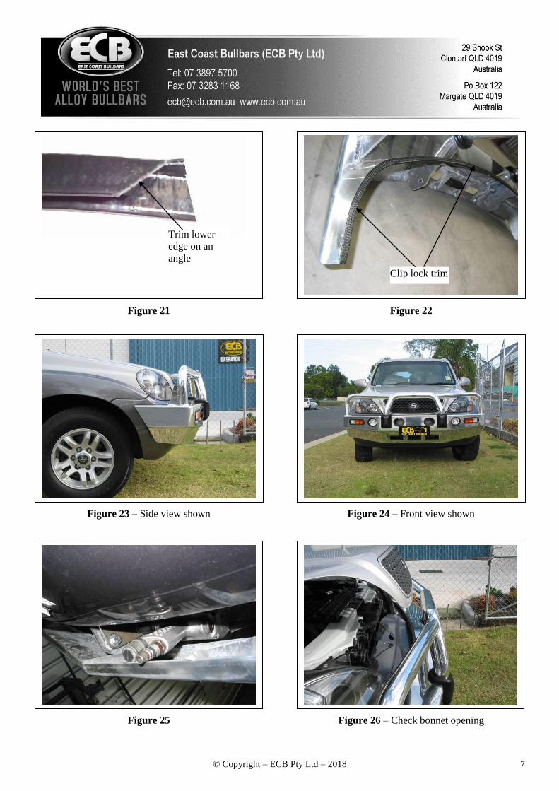
BOLTS. NOTE: For impact wrench, access from under skirt, push bumper cover back to fit impact wrench in.
See figure 25. Refit two lower bumper cover bolts.
25. Replace plastic air vents in lower skirt. NOTE: Ensure ECB logo is to bottom, as this position will direct air onto
cooler.
26. Fit fog lights to protection bar. TIGHTEN FIRM ONLY. Connect wiring and check operation. Aim with low
beam. TIGHTEN BOLTS. Fit fog light surrounds (supplied) wider part to inside.
27. Connect indicator / park light wiring and check operation.
28. Tidy all wiring.
NOTE: If fitting spotlights check depth of light for bonnet opening first. See figure 26.

. © Copyright – ECB Pty Ltd – 2018 3
Plastic PK clip
ENSURE NUMBER PLATE IS CLEARLY VISABLE
Note: When fitting/refitting the licence plate to the vehicle, ensure there is no obstruction to licence plate vision in
accordance with local authorities. If required relocate licence plate to an alternate location.
Further VFPS Notes:
a) Do not attach VFPS to the vehicle using anchorages not intended for this purpose (e.g. engine mounting bolts).
b) Do not use this product for any vehicle make or model, other than those specified by the VFPS manufacturer.
c) Do not remove the plaque or label from the VFPS.
d) Do not modify the structure of the VFPS in any way.
e) No accessory or fitment should project forward of the VFPS forward profile.
f) ENSURE THESE INSTRUCTIONS ARE LEFT WITH VEHICLE OWNER AND/OR OPERATOR.
IMPORTANT INFORMATION
Periodically check bolts and nuts for correct tightness, especially if travelling on rough roads
FITTING KIT
2 – ECB steel mounting brackets 6 – 3/8 spring washers.
3 – 50 x 30 x 6 steel plates with 10mm hole in centre 1 – 2230 length 6mm clip lock trim.
6 – ½ x 1 ½ bolts and nuts. 1 – ECB LED Indicator / Park light kit.
16 – ½ flat washers. 2 – ECB fog lights and wiring.
6 – ½ spring washers. 2 – M6 x 20 bolts.
2 – 3/8 x 4 bolts and nuts. 2 – M6 nuts
2 – 3/8 x 3½ bolts and nuts. 2 – M6 flat washers.
1 – 3/8 x 2¾ bolt and nut. 2 – M6 spring washers.
1 – 3/8 x 1 ½ bolt and nut. 4 – Fog Light surrounds.
12 – 3/8 flat washers. 10 – Cable locks.
Figure 1
PK screw
Figure 2 – Passenger side shown

. © Copyright – ECB Pty Ltd – 2018 4
Figure 3
Figure 5
Figure 4 – Highlander model shown
Two – ½ flat washers over stud
10mm Nut for bumper cover
Remove plastic
under guard
Figure 6 – Passenger side shown
Figure 7
Lip on chassis may require slight sanding
Figure 8 – Passenger side shown
Original bolt

. © Copyright – ECB Pty Ltd – 2018 5
Figure 9 – Passenger side shown Figure 10 - Level off top edge
Original stud
and nut
Figure 11
Shown drilling rear hole on passenger side chassis
Figure 12 Piece of angle used to
protect cooler
Drill
Figure 13 – Drivers side shown 3/8 x 4
bolt/nut with
chassis plate
3/8 x 1 ½
bolt/nut
Figure 14 – Passenger side shown
3/8 x 2½ bolt/nut
with chassis plate
3/8 x 4 bolt/nut
with chassis plate

. © Copyright – ECB Pty Ltd – 2018 6
Figure 17
Figure 15 - Drivers side shown
Cut out bumper cover
Figure 16
Cut mesh grille
Rear 3/8 x 3½
bolt/nut
Figure 18 M6 Bolt
Figure 19
Stainless steel self-tappers
Top
6mm Black clip lock trim
Figure 20
. © Copyright – ECB Pty Ltd – 2018 7
Figure 24 – Front view shown
Figure 26 – Check bonnet opening
Trim lower
edge on an
angle
Figure 21
Figure 22
Clip lock trim
Figure 23 – Side view shown
Figure 25

. © Copyright – ECB Pty Ltd – 2018 8
We value your comments
Dear Fitter,
ECB would like to know how you went with the installation of this product. We value your comment and may need to
contact you to clarify some details so please complete your contact details clearly.
We would appreciate if you could complete as many of the following details as possible.
Your Name:
Your contact No.
Product Part No.
Product Invoice No.
Product Description:
Make, model, and year of vehicle:
Product Work Order No.
Company your from/Company product purchased from:
Date of fitment: ____/____/____ Yes No
Was the fitting hardware supplied complete?
If no what was not supplied
______________________________________________________________________________________
______________________________________________________________________________________
______________________________________________________________________________________ Yes No
Did the installation go well?
Please provide comments
______________________________________________________________________________________
______________________________________________________________________________________
______________________________________________________________________________________
______________________________________________________________________________________ Please draw diagrams if you need to.
Post to Fax to
Reply Paid 122 (07) 3283 1168
PO Box 122
Margate QLD 4019

. © Copyright – ECB Pty Ltd – 2018 9
DESPATCH CHECKLIST BHU46SY
ICZBKCHU46 *ICZBKCHU46*
Work Order #
Finish:
Transport:
Due Date:
OC…..2 – ECB steel mounting brackets
BK…..3 – 50 x 30 x 6 steel mounting plates with 10 mm hole in centre (in kit)
BK…..1 – Bolt Kit
BK…..1 – ECB LED Indicator / Park light kit.
BK…..1 – Pair ECB Fog lights.
BK…..4 – Fog light surrounds.
BK…..1 – 2230mm length 6mm clip lock trim
OC…..2 – ECB Overriders – Fitted to bar
OC…..3 – 3mm Air Scoops – Fitted to bar
All parts checked and completed by:
Nut and bolts: __________________________Date__/__/__
Order control: __________________________Date__/__/__
Final wrap check: __________________________Date__/__/__
Is this product “the best it can be” Yes ______/______ Wrapper’s initials / Checker initials
If NO fix before continuing
See other side of
this page for
photos of all
mounts

. © Copyright – ECB Pty Ltd – 2018 10
______________/______________
Wrappers initials / Checkers initials