introduction - Bay Port Valve & Fitting
15
Product Data Sheet VK Series Ball Valves introduction IPEX VK Series Ball Valves are ideal for industrial and automated applications. These high quality valves feature a compact double block design, and full port bi-directional operation. A patented seat stop carrier allows for in-line micro-adjustment of the ball seating, and provides o-ring cushioning to minimize wear and prevent seizing. The true union design allows the valve to be easily removed from the piping system while the removable tool allows for simple ball seat adjustment. VK Series Ball Valves are part of our complete systems of pipe, valves, and fittings, engineered and manufactured to our strict quality, performance, and dimensional standards. < STANDARDS > ANSI B1.20.1 ANSI B16.5 Valve Availability Body Material: PVC, CPVC, PP, PVDF Size Range: 1/2" through 6" (PVC, CPVC), 1/2" through 2" (PP, PVDF) Pressure: 232 psi (1/2" to 2"), 150 psi (2 1/2" to 6") 150 psi (all sizes of PP) Seats: Teflon ® (PTFE) Seals: EPDM, or Viton ® (FPM) End Connections: Socket (IPS), Threaded (FNPT), Flanged (ANSI 150), Socket (Metric) 1 of 15 www.ipexinc.com Canada Toll Free: 866-473-9462 U.S. Toll Free: 800-463-9572 ASTM D1784 ASTM D4101-86 ASTM D3222 ASTM D2466 ASTM D2467 ASTM F439 ASTM D2464 ASTM F437 ASTM F1498 ISO 3609 ISO 10931
-
Upload
khangminh22 -
Category
Documents
-
view
1 -
download
0
Transcript of introduction - Bay Port Valve & Fitting
Product Data Sheet VK Series Ball Valves
introductionIPEX VK Series Ball Valves are ideal for industrial and automated applications. Thesehigh quality valves feature a compact double block design, and full port bi-directionaloperation. A patented seat stop carrier allows for in-line micro-adjustment of the ballseating, and provides o-ring cushioning to minimize wear and prevent seizing. The trueunion design allows the valve to be easily removed from the piping system while theremovable tool allows for simple ball seat adjustment. VK Series Ball Valves are part ofour complete systems of pipe, valves, and fittings, engineered and manufactured toour strict quality, performance, and dimensional standards.
< S T A N D A R D S >
ANSI B1.20.1ANSI B16.5
Valve Availability
Body Material: PVC, CPVC, PP, PVDF
Size Range: 1/2" through 6" (PVC, CPVC), 1/2" through 2" (PP, PVDF)
Pressure: 232 psi (1/2" to 2"), 150 psi (2 1/2" to 6")150 psi (all sizes of PP)
Seats: Teflon® (PTFE)
Seals: EPDM, or Viton® (FPM)
End Connections: Socket (IPS), Threaded (FNPT), Flanged (ANSI 150), Socket (Metric)
1 of 15
www.ipexinc.com Canada Toll Free: 866-473-9462 U.S. Toll Free: 800-463-9572
ASTM D1784ASTM D4101-86
ASTM D3222ASTM D2466ASTM D2467ASTM F439
ASTM D2464ASTM F437ASTM F1498
ISO 3609ISO 10931

VK Series Ball Valves
2 of 15
Sample Specification
www.ipexinc.com Canada Toll Free: 866-473-9462 U.S. Toll Free: 800-463-9572
1.0 Ball Valves - VK
1.1 Material
• The valve body, stem, ball and unions shall be made of PVC compound which shall meet orexceed the requirements of cell classification 12454 according to ASTM D1784.
or The valve body, stem, ball and unions shall be made of Corzan® CPVC compound whichshall meet or exceed the requirements of 23447 according to ASTM D1784.
or The valve body, stem, ball and unions shall be made of stabilized PP homopolymercompound, also containing a RAL 7032 pigment, which shall meet or exceed therequirements of Type I Polypropylene according to ASTM D4101-86.
or The valve body, stem, ball and unions shall be made of virgin, non-regrind PVDF compoundwhich shall meet or exceed the requirements of Table 1 according to ASTM D3222.
• These compounds shall comply with standards that are equivalent to NSF Standard 61 forpotable water.
1.2 Seats
• The ball seats shall be made of Teflon® (PTFE) which shall comply with standards that areequivalent to NSF Standard 61 for potable water.
1.3 Seals
• The o-ring seals shall be made of EPDM which shall comply with standards that areequivalent to NSF Standard 61 for potable water.
or The o-ring seals shall be made of Viton® (FPM) which shall comply with standards that areequivalent to NSF Standard 61 for potable water.
1.4 All other wetted and non-wetted parts of the valves shall comply with standards that are equivalent to NSF Standard 61 for potable water.
2.0 Connections
2.1 Socket style
• The IPS socket PVC end connectors shall conform to the dimensional standards ASTM D2466 and ASTM D2467.
or The IPS socket CPVC end connectors shall conform to the dimensional standard ASTM F439.
or The Metric socket PP end connectors shall conform to the dimensional standard ISO 3609.
or The Metric socket PVDF end connectors shall conform to the dimensional standard ISO 10931.
2.2 Threaded style
• The female NPT threaded PVC end connectors shall conform to the dimensional standardsASTM D2464, ASTM F1498, and ANSI B1.20.1.
or The female NPT threaded CPVC end connectors shall conform to the dimensionalstandards ASTM F437, ASTM F1498, and ANSI B1.20.1.
or The female NPT threaded PP end connectors shall conform to the dimensional standardsASTM F1498, and ANSI B1.20.1.
or The female NPT threaded PVDF end connectors shall conform to the dimensionalstandards ASTM F1498, and ANSI B1.20.1.
2.3 Flanged style
• The ANSI 150 flanged PVC end connectors shall conform to the dimensional standard ANSI B16.5.
VK Series Ball Valves
3 of 15
Sample Specification (cont’d)
www.ipexinc.com Canada Toll Free: 866-473-9462 U.S. Toll Free: 800-463-9572
or The ANSI 150 flanged CPVC end connectors shall conform to the dimensional standardANSI B16.5.
or The ANSI 150 flanged PP end connectors shall conform to the dimensional standard ANSI B16.5.
or The ANSI 150 flanged PVDF end connectors shall conform to the dimensional standardANSI B16.5.
3.0 Design Features
• The valve shall be double blocking with union ends.
• All sizes 1/2" through 4" shall be full port.
• All sizes shall allow for bi-directional flow.
• The valve body shall be single end entry with a threaded carrier (ball seat support).
• The threaded carrier shall be adjustable with the valve installed.
• The valve body shall have an expansion and contraction compensating groove on themolded end.
• The valve body, union nuts, and carrier shall have deep square style threads for increased strength.
• The ball shall be machined smooth to minimize wear on valve seats.
• All valve seats shall have o-ring backing cushions to compensate for wear and preventseizure of the ball.
• The stem design shall feature a shear point above the o-ring to maintain system integrityin the unlikely event of a stem breakage.
• The handle shall incorporate a removable tool for adjustment of the threaded carrier.
• All sizes 2 1/2" through 6" shall have integrally molded mounting pads for actuation.
3.1 Pressure Tested
• All valves shall have been pressure tested in both the open and closed positions by the manufacturer.
3.2 Pressure Rating
• Valve sizes 1/2" through 2" shall be rated at 232 psi at 73°F (PVC, CPVC, PVDF)
• Valve sizes 1/2" through 2" shall be rated at 150 psi at 73°F (PP).
• Valve sizes 2 1/2" through 6" shall be rated at 150 psi at 73°F (PVC, CPVC).
• All sizes of flanged valves shall be rated at 150 psi at 73°F.
3.3 Markings
• All valves shall be marked to indicate size, material designation, and manufacturers nameor trade mark.
3.4 Color Coding
• All PVC valves shall be color-coded dark gray.
or All CPVC valves shall be color-coded light gray.
or All PP valves shall be color-coded beige gray.
or All PVDF valves shall not be color-coded and be white in appearance.
4.0 All valves shall be Xirtec® 140, Corzan®, PP or PVDF by IPEX or approved equal.
VK Series Ball Valves
4 of 15
Valve Selection
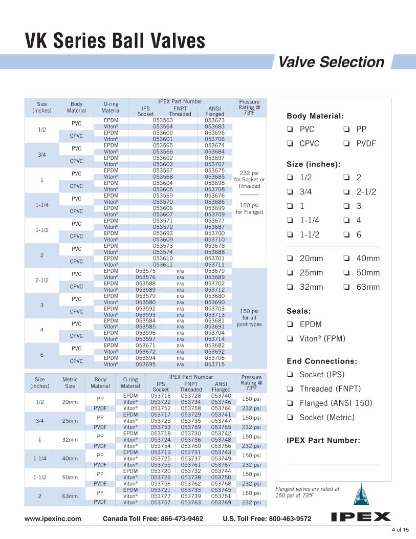
Size(inches)
Body Material
O-ringMaterial
IPEX Part Number PressureRating @
73ºFIPS
SocketFNPT
ThreadedANSI
Flanged
1/2PVC EPDM 053563 053673
232 psi for Socket or
Threaded_______
150 psi for Flanged
Viton® 053564 053683
CPVC EPDM 053600 053696Viton® 053601 053706
3/4PVC EPDM 053565 053674
Viton® 053566 053684
CPVC EPDM 053602 053697Viton® 053603 053707
1PVC EPDM 053567 053675
Viton® 053568 053685
CPVC EPDM 053604 053698Viton® 053605 053708
1-1/4PVC EPDM 053569 053676
Viton® 053570 053686
CPVC EPDM 053606 053699Viton® 053607 053709
1-1/2PVC EPDM 053571 053677
Viton® 053572 053687
CPVC EPDM 053693 053700Viton® 053609 053710
2PVC EPDM 053573 053678
Viton® 053574 053688
CPVC EPDM 053610 053701Viton® 053611 053711
2-1/2PVC EPDM 053575 n/a 053679
150 psi for all
joint types
Viton® 053576 n/a 053689
CPVC EPDM 053588 n/a 053702Viton® 053589 n/a 053712
3PVC EPDM 053579 n/a 053680
Viton® 053580 n/a 053690
CPVC EPDM 053592 n/a 053703Viton® 053593 n/a 053713
4PVC EPDM 053584 n/a 053681
Viton® 053585 n/a 053691
CPVC EPDM 053596 n/a 053704Viton® 053597 n/a 053714
6PVC EPDM 053671 n/a 053682
Viton® 053672 n/a 053692
CPVCEPDM 053694 n/a 053705Viton® 053695 n/a 053715
❏ PVC
❏ CPVC
❏ PP
❏ PVDF
Body Material:
❏ 1/2
❏ 3/4
❏ 1
❏ 1-1/4
❏ 1-1/2
❏ 2
❏ 2-1/2
❏ 3
❏ 4
❏ 6
Size (inches):
❏ EPDM
❏ Viton® (FPM)
Seals:
❏ Socket (IPS)
❏ Threaded (FNPT)
❏ Flanged (ANSI 150)
❏ Socket (Metric)
End Connections:
_______________________
IPEX Part Number:
❏ 20mm
❏ 25mm
❏ 32mm
❏ 40mm
❏ 50mm
❏ 63mm
Size(inches)
Metric Size
BodyMaterial
O-ringMaterial
IPEX Part Number PressureRating @
73ºFIPS
SocketFNPT
ThreadedANSI
Flanged
1/2 20mm PP EPDM 053716 053728 053740 150 psiViton® 053722 053734 053746PVDF Viton® 053752 053758 053764 232 psi
3/4 25mm PP EPDM 053717 053729 053741 150 psiViton® 053723 053735 053747PVDF Viton® 053753 053759 053765 232 psi
1 32mm PP EPDM 053718 053730 053742 150 psiViton® 053724 053736 053748PVDF Viton® 053754 053760 053766 232 psi
1-1/4 40mm PP EPDM 053719 053731 053743 150 psiViton® 053725 053737 053749PVDF Viton® 053755 053761 053767 232 psi
1-1/2 50mm PP EPDM 053720 053732 053744 150 psiViton® 053726 053738 053750PVDF Viton® 053756 053762 053768 232 psi
2 63mm PP EPDM 053721 053733 053745 150 psiViton® 053727 053739 053751PVDF Viton® 053757 053763 053769 232 psi
www.ipexinc.com Canada Toll Free: 866-473-9462 U.S. Toll Free: 800-463-9572
Flanged valves are rated at150 psi at 73ºF
VK Series Ball Valves
5 of 15
Technical Data
www.ipexinc.com Canada Toll Free: 866-473-9462 U.S. Toll Free: 800-463-9572
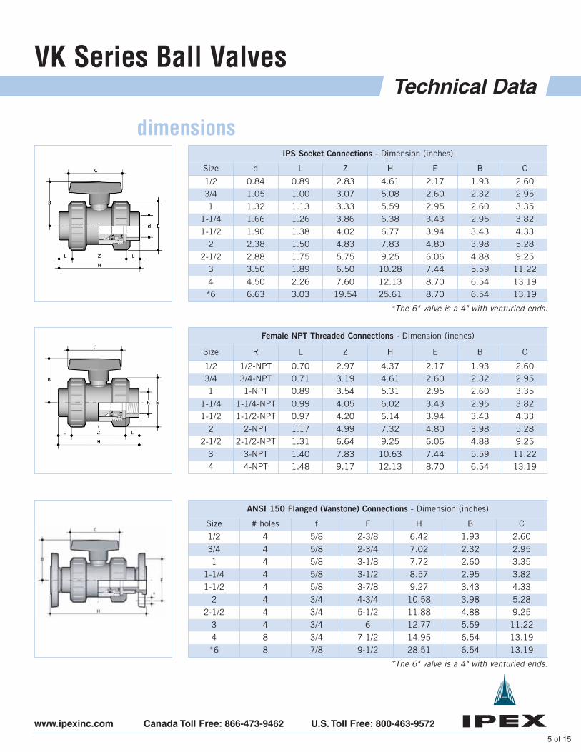
IPS Socket Connections - Dimension (inches)
Size d L Z H E B C
1/2 0.84 0.89 2.83 4.61 2.17 1.93 2.603/4 1.05 1.00 3.07 5.08 2.60 2.32 2.951 1.32 1.13 3.33 5.59 2.95 2.60 3.35
1-1/4 1.66 1.26 3.86 6.38 3.43 2.95 3.821-1/2 1.90 1.38 4.02 6.77 3.94 3.43 4.33
2 2.38 1.50 4.83 7.83 4.80 3.98 5.282-1/2 2.88 1.75 5.75 9.25 6.06 4.88 9.25
3 3.50 1.89 6.50 10.28 7.44 5.59 11.224 4.50 2.26 7.60 12.13 8.70 6.54 13.19*6 6.63 3.03 19.54 25.61 8.70 6.54 13.19
Female NPT Threaded Connections - Dimension (inches)
Size R L Z H E B C
1/2 1/2-NPT 0.70 2.97 4.37 2.17 1.93 2.603/4 3/4-NPT 0.71 3.19 4.61 2.60 2.32 2.951 1-NPT 0.89 3.54 5.31 2.95 2.60 3.35
1-1/4 1-1/4-NPT 0.99 4.05 6.02 3.43 2.95 3.821-1/2 1-1/2-NPT 0.97 4.20 6.14 3.94 3.43 4.33
2 2-NPT 1.17 4.99 7.32 4.80 3.98 5.282-1/2 2-1/2-NPT 1.31 6.64 9.25 6.06 4.88 9.25
3 3-NPT 1.40 7.83 10.63 7.44 5.59 11.224 4-NPT 1.48 9.17 12.13 8.70 6.54 13.19
ANSI 150 Flanged (Vanstone) Connections - Dimension (inches)
Size # holes f F H B C
1/2 4 5/8 2-3/8 6.42 1.93 2.603/4 4 5/8 2-3/4 7.02 2.32 2.951 4 5/8 3-1/8 7.72 2.60 3.35
1-1/4 4 5/8 3-1/2 8.57 2.95 3.821-1/2 4 5/8 3-7/8 9.27 3.43 4.33
2 4 3/4 4-3/4 10.58 3.98 5.282-1/2 4 3/4 5-1/2 11.88 4.88 9.25
3 4 3/4 6 12.77 5.59 11.224 8 3/4 7-1/2 14.95 6.54 13.19*6 8 7/8 9-1/2 28.51 6.54 13.19
*The 6" valve is a 4" with venturied ends.
*The 6" valve is a 4" with venturied ends.
dimensions
VK Series Ball Valves
6 of 15
Technical Data (cont’d)
www.ipexinc.com Canada Toll Free: 866-473-9462 U.S. Toll Free: 800-463-9572
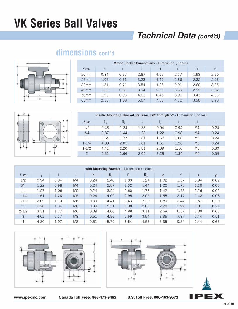
Metric Socket Connections - Dimension (inches)
Size d L Z H E B C
20mm 0.84 0.57 2.87 4.02 2.17 1.93 2.6025mm 1.05 0.63 3.23 4.49 2.56 2.32 2.9532mm 1.31 0.71 3.54 4.96 2.91 2.60 3.3540mm 1.66 0.81 3.94 5.55 3.39 2.95 3.8250mm 1.90 0.93 4.61 6.46 3.90 3.43 4.3363mm 2.38 1.08 5.67 7.83 4.72 3.98 5.28
Plastic Mounting Bracket for Sizes 1/2" through 2" - Dimension (inches)
Size E1 B1 C I1 I J h
1/2 2.48 1.24 1.38 0.94 0.94 M4 0.243/4 2.87 1.44 1.38 1.22 0.98 M4 0.241 3.54 1.77 1.61 1.57 1.06 M5 0.24
1-1/4 4.09 2.05 1.81 1.61 1.26 M5 0.241-1/2 4.41 2.20 1.81 2.09 1.10 M6 0.39
2 5.31 2.66 2.05 2.28 1.34 M6 0.39
with Mounting Bracket - Dimension (inches)
Size I1 I J h E1 B B1 e f x y
1/2 0.94 0.94 M4 0.24 2.48 1.93 1.24 1.02 1.57 0.94 0.023/4 1.22 0.98 M4 0.24 2.87 2.32 1.44 1.22 1.73 1.10 0.081 1.57 1.06 M5 0.24 3.54 2.60 1.77 1.42 1.93 1.26 0.06
1-1/4 1.61 1.26 M5 0.24 4.09 2.95 2.05 1.65 2.17 1.42 0.081-1/2 2.09 1.10 M6 0.39 4.41 3.43 2.20 1.89 2.44 1.57 0.20
2 2.28 1.34 M6 0.39 5.31 3.98 2.66 2.28 2.99 1.81 0.242-1/2 3.31 1.77 M6 0.39 4.06 4.88 3.11 2.68 6.57 2.09 0.63
3 4.02 2.17 M8 0.51 4.96 5.59 3.94 3.35 7.87 2.44 0.514 4.80 1.97 M8 0.51 5.79 6.54 4.53 3.35 9.84 2.44 0.63
dimensions cont’d
VK Series Ball Valves
7 of 15
Technical Data (cont’d)
www.ipexinc.com Canada Toll Free: 866-473-9462 U.S. Toll Free: 800-463-9572
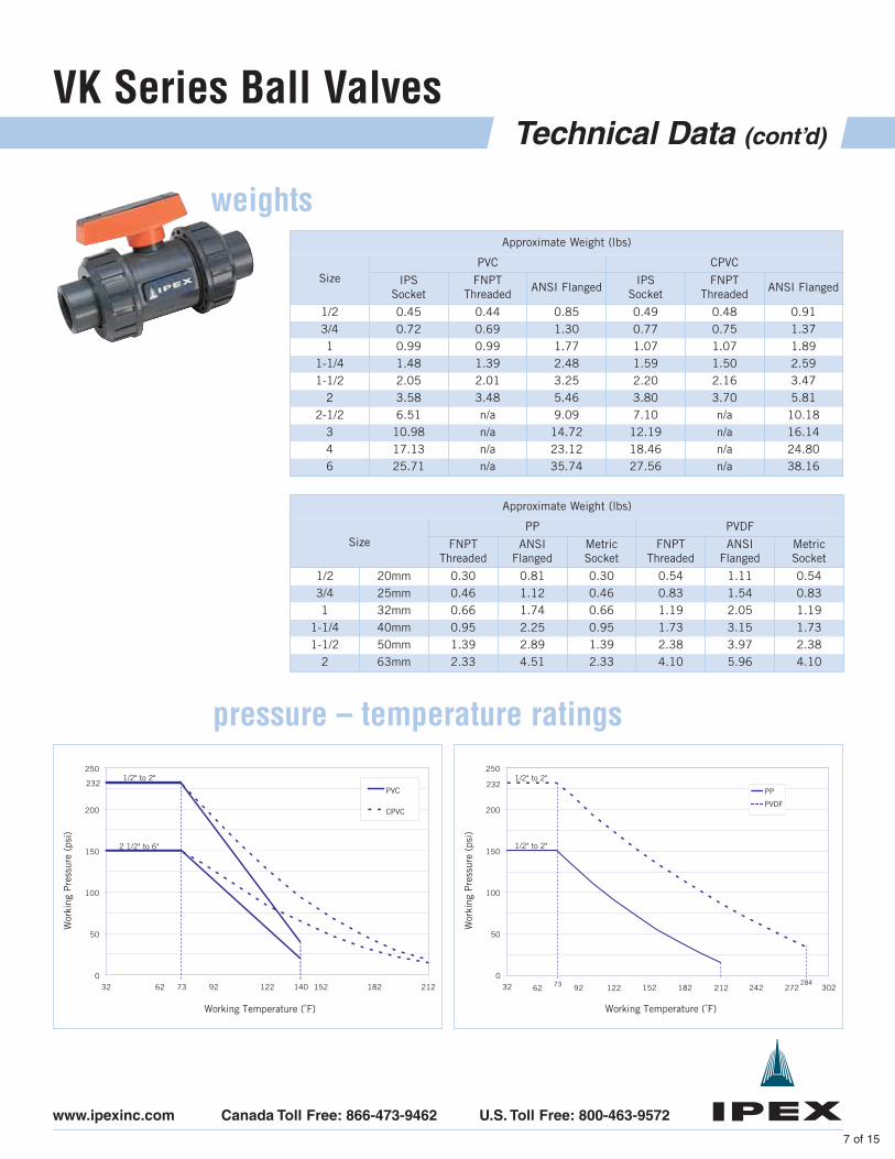
weightsApproximate Weight (lbs)
SizePVC CPVC
IPSSocket
FNPTThreaded
ANSI FlangedIPS
SocketFNPT
ThreadedANSI Flanged
1/2 0.45 0.44 0.85 0.49 0.48 0.913/4 0.72 0.69 1.30 0.77 0.75 1.371 0.99 0.99 1.77 1.07 1.07 1.89
1-1/4 1.48 1.39 2.48 1.59 1.50 2.591-1/2 2.05 2.01 3.25 2.20 2.16 3.47
2 3.58 3.48 5.46 3.80 3.70 5.812-1/2 6.51 n/a 9.09 7.10 n/a 10.18
3 10.98 n/a 14.72 12.19 n/a 16.144 17.13 n/a 23.12 18.46 n/a 24.806 25.71 n/a 35.74 27.56 n/a 38.16
Approximate Weight (lbs)
SizePP PVDF
FNPTThreaded
ANSIFlanged
MetricSocket
FNPTThreaded
ANSIFlanged
MetricSocket
1/2 20mm 0.30 0.81 0.30 0.54 1.11 0.543/4 25mm 0.46 1.12 0.46 0.83 1.54 0.831 32mm 0.66 1.74 0.66 1.19 2.05 1.19
1-1/4 40mm 0.95 2.25 0.95 1.73 3.15 1.731-1/2 50mm 1.39 2.89 1.39 2.38 3.97 2.38
2 63mm 2.33 4.51 2.33 4.10 5.96 4.10
0
50
100
150
200
250
32 62 122 212 302
Working Temperature (˚F)
Wor
king
Pre
ssur
e (p
si)
PP
PVDF
232
152 182 242 272
1/2" to 2"
73
1/2" to 2"
28492
pressure – temperature ratings
0
50
100
150
200
250
32 62 92 122 152 182 212
Working Temperature (˚F)
Wor
king
Pre
ssur
e (p
si)
PVC
CPVC
2 1/2" to 6"
1/2" to 2"
73 140
232
VK Series Ball Valves
8 of 15
Technical Data (cont’d)
www.ipexinc.com Canada Toll Free: 866-473-9462 U.S. Toll Free: 800-463-9572
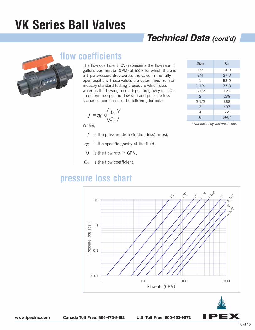
flow coefficientsThe flow coefficient (CV) represents the flow rate ingallons per minute (GPM) at 68°F for which there isa 1 psi pressure drop across the valve in the fullyopen position. These values are determined from anindustry standard testing procedure which useswater as the flowing media (specific gravity of 1.0).To determine specific flow rate and pressure lossscenarios, one can use the following formula:
Size CV
1/2 14.03/4 27.01 53.9
1-1/4 77.01-1/2 123
2 2382-1/2 368
3 4974 6656 665*
Where,
f is the pressure drop (friction loss) in psi,
sg is the specific gravity of the fluid,
Q is the flow rate in GPM,
CV is the flow coefficient.
2
VC
Qx= sgf
0.01
0.1
1
10
1 10 100 1000
Pre
ssur
e lo
ss (
psi)
Flowrate (GPM)
1/2" 3/4"
1" 1 1/
4"1
1/2"
2"
2 1/
2"
3"4"
& 6
"
pressure loss chart
* Not including venturied ends.
VK Series Ball Valves
8 of 15
Components
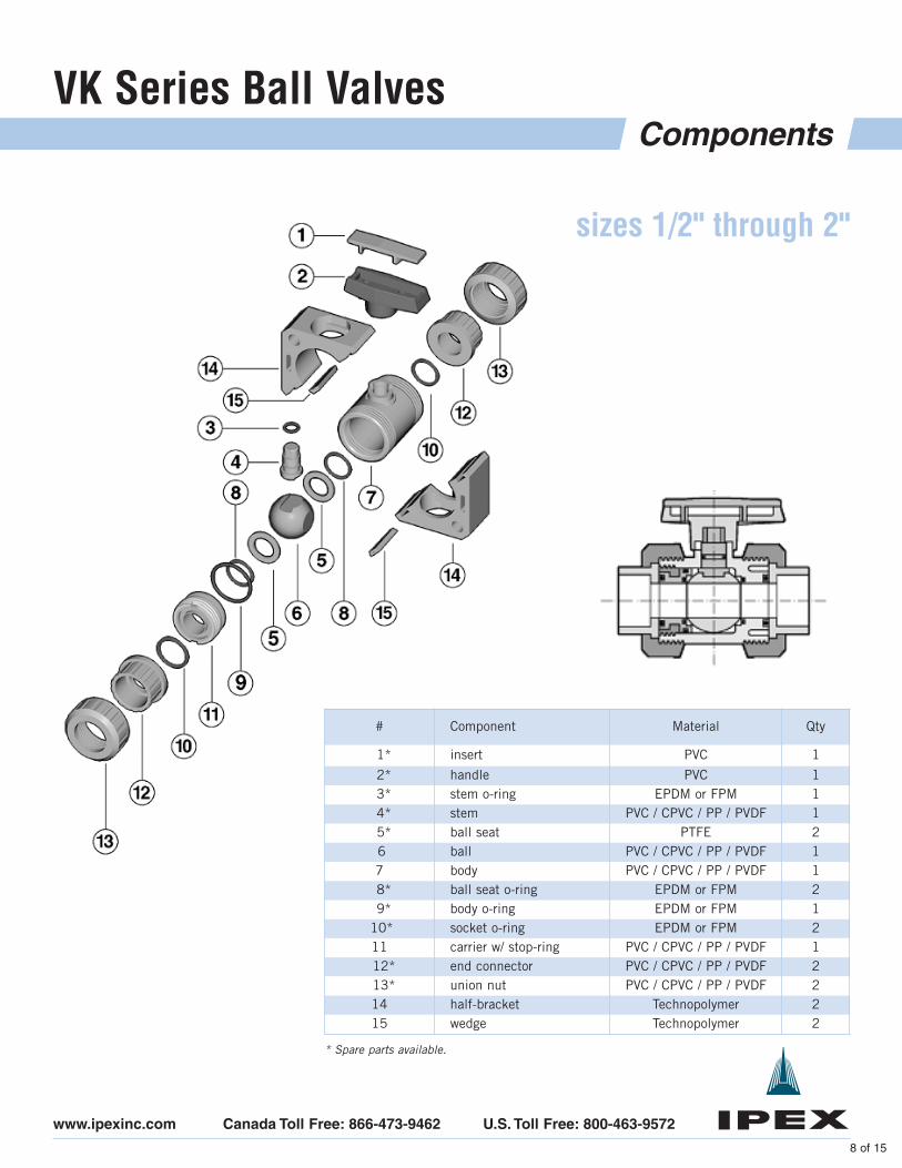
# Component Material Qty
1* insert PVC 1
2* handle PVC 13* stem o-ring EPDM or FPM 14* stem PVC / CPVC / PP / PVDF 15* ball seat PTFE 26 ball PVC / CPVC / PP / PVDF 17 body PVC / CPVC / PP / PVDF 18* ball seat o-ring EPDM or FPM 29* body o-ring EPDM or FPM 1
10* socket o-ring EPDM or FPM 211 carrier w/ stop-ring PVC / CPVC / PP / PVDF 112* end connector PVC / CPVC / PP / PVDF 213* union nut PVC / CPVC / PP / PVDF 214 half-bracket Technopolymer 215 wedge Technopolymer 2
sizes 1/2" through 2"
www.ipexinc.com Canada Toll Free: 866-473-9462 U.S. Toll Free: 800-463-9572
* Spare parts available.
VK Series Ball Valves
10 of 15
Components (cont’d)
www.ipexinc.com Canada Toll Free: 866-473-9462 U.S. Toll Free: 800-463-9572
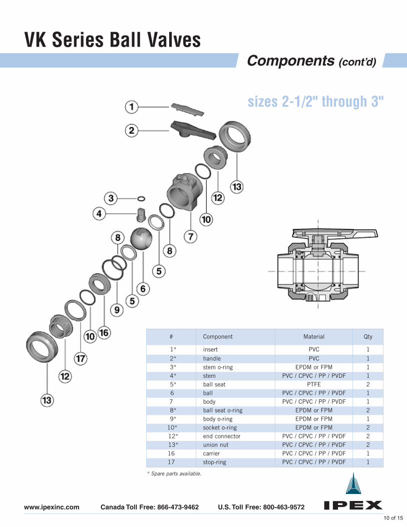
# Component Material Qty
1* insert PVC 1
2* handle PVC 13* stem o-ring EPDM or FPM 14* stem PVC / CPVC / PP / PVDF 15* ball seat PTFE 26 ball PVC / CPVC / PP / PVDF 17 body PVC / CPVC / PP / PVDF 18* ball seat o-ring EPDM or FPM 29* body o-ring EPDM or FPM 1
10* socket o-ring EPDM or FPM 212* end connector PVC / CPVC / PP / PVDF 213* union nut PVC / CPVC / PP / PVDF 216 carrier PVC / CPVC / PP / PVDF 117 stop-ring PVC / CPVC / PP / PVDF 1
sizes 2-1/2" through 3"
* Spare parts available.
VK Series Ball Valves
11 of 15
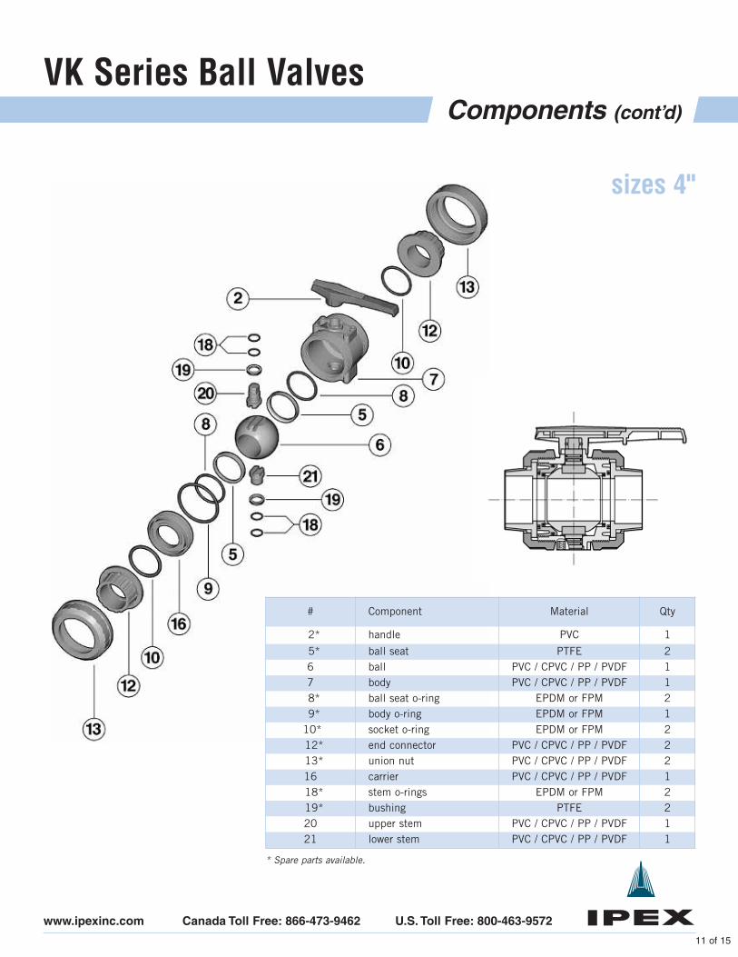
Components (cont’d)
www.ipexinc.com Canada Toll Free: 866-473-9462 U.S. Toll Free: 800-463-9572
# Component Material Qty
2* handle PVC 1
5* ball seat PTFE 26 ball PVC / CPVC / PP / PVDF 17 body PVC / CPVC / PP / PVDF 18* ball seat o-ring EPDM or FPM 29* body o-ring EPDM or FPM 1
10* socket o-ring EPDM or FPM 212* end connector PVC / CPVC / PP / PVDF 213* union nut PVC / CPVC / PP / PVDF 216 carrier PVC / CPVC / PP / PVDF 118* stem o-rings EPDM or FPM 219* bushing PTFE 220 upper stem PVC / CPVC / PP / PVDF 121 lower stem PVC / CPVC / PP / PVDF 1
sizes 4"
* Spare parts available.
VK Series Ball Valves
12 of 15
Installation Procedures
www.ipexinc.com Canada Toll Free: 866-473-9462 U.S. Toll Free: 800-463-9572
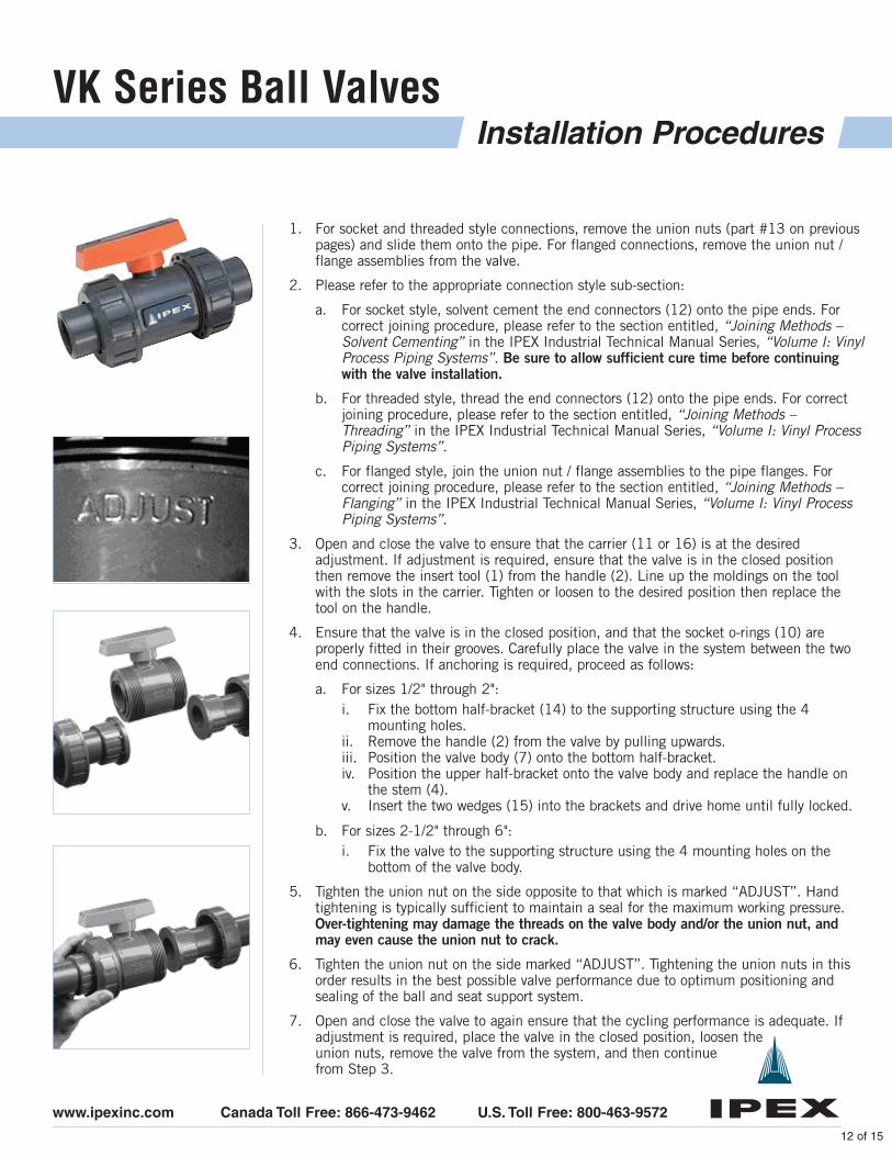
1. For socket and threaded style connections, remove the union nuts (part #13 on previouspages) and slide them onto the pipe. For flanged connections, remove the union nut /flange assemblies from the valve.
2. Please refer to the appropriate connection style sub-section:
a. For socket style, solvent cement the end connectors (12) onto the pipe ends. Forcorrect joining procedure, please refer to the section entitled, “Joining Methods –Solvent Cementing” in the IPEX Industrial Technical Manual Series, “Volume I: VinylProcess Piping Systems”. Be sure to allow sufficient cure time before continuingwith the valve installation.
b. For threaded style, thread the end connectors (12) onto the pipe ends. For correctjoining procedure, please refer to the section entitled, “Joining Methods –Threading” in the IPEX Industrial Technical Manual Series, “Volume I: Vinyl ProcessPiping Systems”.
c. For flanged style, join the union nut / flange assemblies to the pipe flanges. Forcorrect joining procedure, please refer to the section entitled, “Joining Methods –Flanging” in the IPEX Industrial Technical Manual Series, “Volume I: Vinyl ProcessPiping Systems”.
3. Open and close the valve to ensure that the carrier (11 or 16) is at the desiredadjustment. If adjustment is required, ensure that the valve is in the closed positionthen remove the insert tool (1) from the handle (2). Line up the moldings on the toolwith the slots in the carrier. Tighten or loosen to the desired position then replace thetool on the handle.
4. Ensure that the valve is in the closed position, and that the socket o-rings (10) areproperly fitted in their grooves. Carefully place the valve in the system between the twoend connections. If anchoring is required, proceed as follows:
a. For sizes 1/2" through 2":i. Fix the bottom half-bracket (14) to the supporting structure using the 4
mounting holes.ii. Remove the handle (2) from the valve by pulling upwards.iii. Position the valve body (7) onto the bottom half-bracket.iv. Position the upper half-bracket onto the valve body and replace the handle on
the stem (4).v. Insert the two wedges (15) into the brackets and drive home until fully locked.
b. For sizes 2-1/2" through 6":i. Fix the valve to the supporting structure using the 4 mounting holes on the
bottom of the valve body.
5. Tighten the union nut on the side opposite to that which is marked “ADJUST”. Handtightening is typically sufficient to maintain a seal for the maximum working pressure.Over-tightening may damage the threads on the valve body and/or the union nut, andmay even cause the union nut to crack.
6. Tighten the union nut on the side marked “ADJUST”. Tightening the union nuts in thisorder results in the best possible valve performance due to optimum positioning andsealing of the ball and seat support system.
7. Open and close the valve to again ensure that the cycling performance is adequate. Ifadjustment is required, place the valve in the closed position, loosen the union nuts, remove the valve from the system, and then continue from Step 3.
VK Series Ball Valves
13 of 15
Valve Maintenance
www.ipexinc.com Canada Toll Free: 866-473-9462 U.S. Toll Free: 800-463-9572
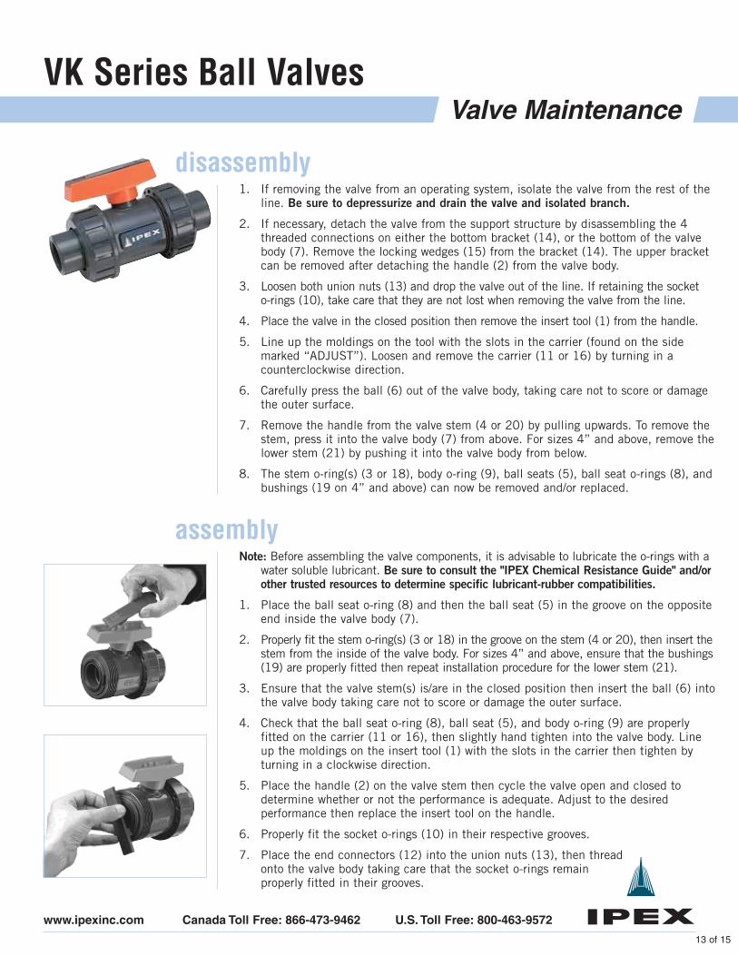
disassembly1. If removing the valve from an operating system, isolate the valve from the rest of the
line. Be sure to depressurize and drain the valve and isolated branch.
2. If necessary, detach the valve from the support structure by disassembling the 4threaded connections on either the bottom bracket (14), or the bottom of the valvebody (7). Remove the locking wedges (15) from the bracket (14). The upper bracketcan be removed after detaching the handle (2) from the valve body.
3. Loosen both union nuts (13) and drop the valve out of the line. If retaining the socket o-rings (10), take care that they are not lost when removing the valve from the line.
4. Place the valve in the closed position then remove the insert tool (1) from the handle.
5. Line up the moldings on the tool with the slots in the carrier (found on the sidemarked “ADJUST”). Loosen and remove the carrier (11 or 16) by turning in acounterclockwise direction.
6. Carefully press the ball (6) out of the valve body, taking care not to score or damagethe outer surface.
7. Remove the handle from the valve stem (4 or 20) by pulling upwards. To remove thestem, press it into the valve body (7) from above. For sizes 4” and above, remove thelower stem (21) by pushing it into the valve body from below.
8. The stem o-ring(s) (3 or 18), body o-ring (9), ball seats (5), ball seat o-rings (8), andbushings (19 on 4” and above) can now be removed and/or replaced.
assemblyNote: Before assembling the valve components, it is advisable to lubricate the o-rings with a
water soluble lubricant. Be sure to consult the "IPEX Chemical Resistance Guide" and/orother trusted resources to determine specific lubricant-rubber compatibilities.
1. Place the ball seat o-ring (8) and then the ball seat (5) in the groove on the oppositeend inside the valve body (7).
2. Properly fit the stem o-ring(s) (3 or 18) in the groove on the stem (4 or 20), then insert thestem from the inside of the valve body. For sizes 4” and above, ensure that the bushings(19) are properly fitted then repeat installation procedure for the lower stem (21).
3. Ensure that the valve stem(s) is/are in the closed position then insert the ball (6) intothe valve body taking care not to score or damage the outer surface.
4. Check that the ball seat o-ring (8), ball seat (5), and body o-ring (9) are properlyfitted on the carrier (11 or 16), then slightly hand tighten into the valve body. Lineup the moldings on the insert tool (1) with the slots in the carrier then tighten byturning in a clockwise direction.
5. Place the handle (2) on the valve stem then cycle the valve open and closed todetermine whether or not the performance is adequate. Adjust to the desiredperformance then replace the insert tool on the handle.
6. Properly fit the socket o-rings (10) in their respective grooves.
7. Place the end connectors (12) into the union nuts (13), then thread onto the valve body taking care that the socket o-rings remain properly fitted in their grooves.

VK Series Ball Valves
14 of 15
Testing and Operating
www.ipexinc.com Canada Toll Free: 866-473-9462 U.S. Toll Free: 800-463-9572
The purpose of system testing is to assess the quality of all joints and fittings toensure that they will withstand the design working pressure, plus a safety margin,without loss of pressure or fluid. Typically, the system will be tested and assessed insub-sections as this allows for improved isolation and remediation of potentialproblems. With this in mind, the testing of a specific installed valve is achieved whilecarrying out a test of the overall system.
An onsite pressure test procedure is outlined in the IPEX Industrial Technical ManualSeries, “Volume I: Vinyl Process Piping Systems” under the section entitled,“Testing”. The use of this procedure should be sufficient to assess the quality of avalve installation. In any test or operating condition, it is important to never exceedthe pressure rating of the lowest rated appurtenance in the system.
Important points:
• Never test thermoplastic piping systems with compressed air or other gasesincluding air-over-water boosters.
• When testing, do not exceed the rated maximum operating pressure ofthe valve.
• Avoid the rapid closure of valves to eliminate the possibility of water hammerwhich may cause damage to the pipeline or the valve.
For safety reasons, please contact IPEX customer service and technical support whenusing volatile liquids such as hydrogen peroxide (H202) and sodium hypochlorite(NaCIO). These liquids may vaporize causing a potentially dangerous pressureincrease in the dead space between the ball and the valve body. Special VK ballvalves are available for these types of critical applications.
Please contact IPEX customer service and technical support with regard to anyconcern not addressed in this data sheet or the technical manual.
VK Series Ball Valves
15 of 15© 2005 IPEX DAINVLIP050801
About IPEX
www.ipexinc.com Canada Toll Free: 866-473-9462 U.S. Toll Free: 800-463-9572
WARRANTY: All IPEX products are guaranteed against defects resulting from faulty workmanship or materials. If any suchproduct is found to be defective by reason of faulty workmanship or materials, upon written notice and return of theproduct, the defective product will be replaced by IPEX free of charge, including shipping charges for the replacementproduct. Claims for labour costs and other expenses required to replace such defective product or to repair any damageresulting from the use thereof will not be allowed by IPEX. Our liability is limited to the price paid for the defectiveproduct. IPEX will not be bound by any warranty, other than the above set forth, unless such warranty is in writing.
This literature is published in good faith and is believed to be reliable. However, IPEX does not represent and/orwarrant in any manner the information and suggestions contained in this brochure. Data presented is the result oflaboratory tests and field experience.
IPEX maintains a policy of ongoing product improvement. This may result in modification of features and/orspecifications without notice.
IPEX is a leading supplier of thermoplastic piping systems. We provide our customers with one of the world’slargest and most comprehensive product lines. All IPEX products are backed by over 50 years of experience.With state-of-the-art manufacturing facilities and distribution centers across North America, the IPEX name issynonymous with quality and performance.
Our products and systems have been designed for a broad range of customers and markets. Contact us for information on:
• PVC, CPVC, PP, FR-PVDF, ABS, PEX and PE pipe and fittings (1/4" to 48")
• Industrial process piping systems
• Double containment systems
• Acid waste systems
• High purity systems
• Industrial, plumbing and electrical cements
• Municipal pressure and gravity piping systems
• Plumbing and mechanical pipe systems
• Electrical systems
• Telecommunications systems
• Irrigation systems
• PE Electrofusion systems for gas and water
• Radiant heating systems