kona.pdf - Hyundai
452
$#! !#!!# #! All information in this Owner's Manual is current at the time of publication. However, Hyundai Motor India Limited reserves the right to make changes at any time without prior notice and without obligation to incorporate such changes so that our policy of continual product improvement may be carried out. This manual applies to all variants of this vehicle and includes descriptions and explanations of optional as well as standard equipment. As a result, you may find material in this manual that does not apply to your specific vehicle.
-
Upload
khangminh22 -
Category
Documents
-
view
0 -
download
0
Transcript of kona.pdf - Hyundai

All information in this Owner's Manual is current at the time of publication. However, Hyundai Motor India Limited reserves the right to make changes at any time without prior notice and without obligation to incorporate such changes so that our policy of continual product improvement may be carried out.
This manual applies to all variants of this vehicle and includes descriptions and explanations of optional as well as standard equipment. As a result, you may find material in this manual that does not apply to your specific vehicle.

Your HYUNDAI vehicle should not be modified in any way. Such modifications may adversely affect the performance, safety or durability of your HYUNDAI vehicle nd may, in addition, violate conditions of the limited warranties covering the vehicle. Certain modifications may also be in vio-lation of regulations established by the Department of Transportation and other governmentagencies in your country.
Your vehicle is equipped with electronic components. It is possible for an improperlyinstalled/adjusted two-way radio or cellular telephone to adversely affect electronic systems.For this reason, we recommend that you carefully follow the radio manufacturer's instructionsor consult your HYUNDAI dealer for precautionary measures or special instructions if youchoose to install one of these devices.
CAUTION: MODIFICATIONS TO YOUR HYUNDAI
TWO-WAY RADIO OR CELLULAR TELEPHONE INSTALLATION

This manual includes information titled as DANGER, WARNING, CAUTION and NOTICE.These titles indicate the following:
SAFETY AND VEHICLE DAMAGE WARNING
DANGER indicates a hazardous situa-tion which, if not avoided, will result indeath or serious injury.
DANGER
WARNING indicates a hazardous situa-tion which, if not avoided, could result indeath or serious injury.
CAUTION indicates a hazardous situa-tion which, if not avoided, could result inminor or moderate injury.
CAUTION
NOTICE indicates a situation which, if notavoided, could result in vehicle damage.
NOTICEWARNING
FFOREWORD
Congratulations, and thank you for choosing HYUNDAI vehicle. We are pleased to welcome you to the growing numberof discerning people who drive HYUNDAI vehicle. We are very proud of the advanced engineering and high-quality con-struction of each HYUNDAI vehicle we build.Your Owner’s Manual will introduce you to the features and operation of your new HYUNDAI vehicle. To become famil-iar with your new HYUNDAI vehicle, so that you can fully enjoy it, read this Owner’s Manual carefully before driving yournew vehicle.This manual contains important safety information and instructions intended to familiarize you with your vehicle’s con-trols and safety features so you can safely operate your vehicle.This manual also contains information on maintenance designed to enhance safe operation of the vehicle. It is recom-mended that all service and maintenance on your car be performed by an authorized HYUNDAI dealer.HYUNDAI deal-ers are prepared to provide high-quality service, maintenance and any other assistance that may be required.This Owner’s Manual should be considered a permanent part of your vehicle, and should be kept in the vehicle so youcan refer to it at any time. The manual should stay with the vehicle if you sell it to provide the next owner with importantoperating, safety and maintenance information.
HYUNDAI MOTOR INDIA LIMITED
Copyright 2021 HYUNDAI Motor India Limited. All rights reserved. No part of this publication may be reproduced, stored in any retrieval system or transmitted in any form or by any means without the prior written permission ofHYUNDAI Motor IndiaLimited.
Severe vehicle damage may result from the use of poor quality lubricants that do not meet HYUNDAI specifica-tions. You must always use high quality lubricants that meet the specifications listed on Page 10-6 in the VehicleSpecifications chapter of the Owner's Manual.
CAUTION

We want to help you get the greatestpossible driving pleasure from yourvehicle. Your Owner’s Manual canassist you in many ways. We strong-ly recommend that you read theentire manual. In order to minimizethe chance of death or injury, youmust read the WARNING and CAU-TION sections in the manual.Illustrations complement the wordsin this manual to best explain how toenjoy your vehicle. By reading yourmanual, you will learn about fea-tures, important safety information,and driving tips under various roadconditions.The general layout of the manual isprovided in the Table of Contents.Use the index when looking for aspecific area or subject; it has analphabetical listing of all informationin your manual.Sections: This manual has eightchapters plus an index. Each chapterbegins with a brief list of contents soyou can tell at a glance if that sectionhas the information you want.
Your safety, and the safety of others,is very important. This Owner'sManual provides you with many safe-ty precautions and operating proce-dures. This information alerts you topotential hazards that may hurt youor others, as well as damage to yourvehicle.Safety messages found on vehiclelabels and in this manual describethese hazards and what to do toavoid or reduce the risks.Warnings and instructions containedin this manual are for your safety.Failure to follow safety warnings andinstructions can lead to serious injuryor death.
Throughout this manual DANGER,WARNING, CAUTION, NOTICE andthe SAFETY ALERT SYMBOL willbe used.
This is the safety alert sym-bol. It is used to alert you topotential physical injury haz-ards. Obey all safety mes-sages that follow this symbolto avoid possible injury ordeath. The safety alert sym-bol precedes the signal wordsDANGER, WARNING andCAUTION.
DANGER indicates a hazardoussituation which, if not avoided, willresult in death or serious injury.
DANGER
WARNING indicates a hazardoussituation which, if not avoided,could result in death or seriousinjury.
WARNING

NNOTICE indicates a situation which,if not avoided, could result in vehicledamage.
• This vehicle should not be modi-fied. Modification of your vehiclecould affect its performance, safetyor durability and may even violategovernmental safety and vehicleregulations.In addition, damage or perform-ance problems resulting from anymodification may not be coveredunder warranty.
• If you use unauthorized electronicdevices, it may cause the vehicle tooperate abnormally, wire damage,battery discharge and fire. For yoursafety, do not use unauthorizedelectronic devices.
NOTICE
CAUTION indicates a hazardoussituation which, if not avoided,could result in minor or moderateinjury.
CAUTION

Infotainment System


H3
Electric VehicleAn electric vehicle is driven using abattery and an electric motor. Whilegeneral vehicles use an internalcombustion engine and gasoline asfuel, electric vehicles use electricalenergy that is charged inside thehigh voltage battery. As a result,electric vehicles are eco-friendly inthat they do not require fuel and donot emit exhaust gases.
Characteristics of ElectricVehicles1.It is driven using the electrical
energy that is charged inside thehigh voltage battery. This methodprevents air pollution since fuel,like gasoline, is not required,negating the emission of exhaustgases.
2.A high performance motor is usedin the vehicle as well. Compared tostandard, internal combustionengine vehicles, engine noise andvibrations are much more minimalwhen driving.
3.When decelerating or drivingdownhill, regenerative braking isutilized to charge the high voltagebattery. This minimizes energy lossand increases the distance toempty.
4.When the battery charge is not suf-ficient, AC charge, DC charge andtrickle charge are available. (Referto “Charge Types for ElectricVehicle” for details.)
Information What does regenerative braking do?
It uses an electric motor when deceler-ating and braking and transformskinetic energy to electrical energy inorder to charge the high voltage bat-tery. (Torque is applied in the oppositedirection when decelerating to gener-ate braking force and electric energy.)
Battery Information• The vehicle is composed of a high
voltage battery that drives themotor and air-conditioner, and anauxiliary battery (12 V) that drivesthe lamps, wipers, and audio sys-tem.
• The auxiliary battery is automati-cally charged when the vehicle is inthe ready ( ) mode or the highvoltage battery is being charged.
i

H4
• Do not intentionally remove ordisassemble high voltage com-ponents and high voltage bat-tery connectors and wires. Also,be careful not to damage highvoltage components and thehigh voltage battery. It maycause serious injury and signifi-cantly impact the performanceand durability of the vehicle.
• When inspection and mainte-nance is required for high volt-age components and the highvoltage battery, we recommendthat you contact an authorizedHYUNDAI dealer.
WARNING Main Components of Electric Vehicle• On-Board Charger (OBC) : A device that charges the high voltage battery
by converting AC power of the power grid to DC power.• Inverter : Transforms direct current into alternate current to supply power to
the motor, and transforms alternate current into direct current to charge thehigh voltage battery.
• LDC : Transforms power from the high voltage battery to low voltage (12 V)to supply power to the vehicle (DC-DC).
• Motor : Uses electrical energy stored inside the high voltage battery todrive the vehicle (functions like an engine in a standard vehicle).
• Reduction gear : Delivers rotational force of the motor to the tires at appro-priate speeds and torque.
• High voltage battery (lithium-ion polymer) : Stores and supplies power nec-essary for the electric vehicle to operate (12 V auxiliary battery providespower to the vehicle features such as lights and wipers).
❈ OBC : On-Board Charger❈ LDC : Low Voltage DC-DC Converter

H5
High Voltage Battery (lithium-ion polymer)• The charge amount of the high
voltage battery may graduallydecrease when the vehicle is notdriving.
• The battery capacity of the highvoltage battery may decreasewhen the vehicle is stored inhigh/low temperatures.
• Distance to empty may varydepending on the driving condi-tions, even if the charge amount isthe same. The high voltage batterymay expend more energy whendriving at high-speed or uphill.These actions may reduce the dis-tance to empty.
• The high voltage battery is usedwhen using the air-conditioner /heater. This may reduce the dis-tance to empty. Make sure to setmoderate temperatures whenusing the air-conditioner/heater.
• Natural degradation may occurwith the high voltage batterydepending on the number of yearsthe vehicle is used. This mayreduce the distance to empty.
• When the charge capacity and dis-tance to empty keep falling, werecommend that you contact anauthorized HYUNDAI dealer forinspection and maintenance.
• If the vehicle will not be in use foran extended period of time, chargethe high voltage battery once everythree months to prevent it from dis-charging. Also, if the chargeamount is not enough, immediatelycharge to full and store the vehicle.
• AC charge is recommended tokeep the high voltage battery inoptimal condition.If the high voltage battery chargeamount is below 20%, you cankeep the high voltage battery per-formance in optimal condition ifyou charge the high voltage batteryto 100%. (Once a month or more isrecommended.)

H6
High Voltage Battery WarmerSystemThe high voltage battery warmersystem prevents reduction of batteryoutput when battery temperature islow. If the charging connector is con-nected, the warmer system automat-ically operate according to the bat-tery temperature. Charging time may shorten compareto vehicles without the high voltagebattery warmer system. But, electric-ity charge may increase because ofhigh voltage battery warmer systemoperation.
• Make sure to use a designatedcharger when charging the highvoltage battery. Using differenttypes of chargers may have aserious impact on vehicle dura-bility.
• Make sure that the high voltagebattery charger gauge does notreach ''L (Low) or 0". If the vehi-cle is kept at ''L (Low) or 0" for along period, it may damage thehigh voltage battery and the highvoltage battery may have to bereplaced depending on the levelof degradation.
• If the vehicle is in a collision, werecommend that you contact anauthorized HYUNDAI dealer toinspect whether the high voltagebattery is still connected.
CAUTION
The high voltage battery warmersystem operates when the chargingconnector is connected to the vehi-cle.However, the high voltage warmersystem may not operate when bat-tery temperature drops below -35°C(-31°F).
CAUTION

H7
If you select the "EV" menu at thehome screen you can enter EVmode. For details on EV Mode, refer to theMultimedia manual that is providedseparately.*Navigation option is not applicablefor India
The EV mode has a total of 3 menus,Energy information, Charge man-agement and ECO driving.
❈ EV mode menu may vary depend-ing on which functions are applica-ble to your vehicle.
Energy Information
Select ‘EV → Energy information’ onthe screen.You can check battery informationand energy consumption.

H8
Battery information
You can check the reachable range,total battery power remaining, andexpected charging time for eachcharge type.• The distance to empty is calculat-
ed based on the real-time fuel effi-ciency while driving. The distancemay change if the driving patternchanges.
• The distance to empty may varyaccording to the change of thedriving pattern even if the sametarget battery charge level is set.
Charge Management
Select ‘EV → Charge management’on the screen. You can set the dateand time of when to charge the bat-tery, climate control temperature,location-based charging options andother various functions. *EV settings option are not applica-ble for India.
Charging and climate
You can set the date and time ofwhen to charge the battery and theclimate control temperature. Also,you may select the time to startcharging using the off-peak time set-ting.*Charging location option is notapplicable for India.
H9
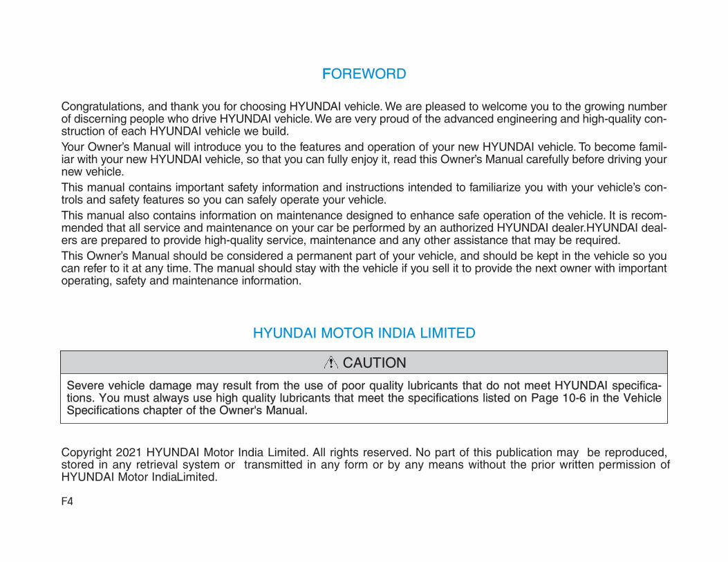
Departure time
1. Set anticipated departure time forscheduled charging and targettemperature.
2. Select the day of the week to acti-vate scheduled charging and targettemperature for departure time.
Target temperature settings
1. Set target temperature.
Off-peak time settings
1. If selected, starts charging only onthe designated off-peak time Ifdeselected, starts charging onlyon the scheduled time
2. Set the most inexpensive time tocomplete charging
3. • Off-peak tariffs priorised: Ifselected, starts charging at off-peak time (may keep on chargingpass off-peak time to charge100%)
• Off-peak tariffs only: If selected,charges only within off-peak time(may not charge 100%)

H10
Charging limit
• The target battery charge level canbe selected when charged with ACcharger or DC charger
• The charging level can be changedby 10%.
• If the target battery charge level islower than the high voltage batterycharge level, the battery will not becharged.
Charging current
• You can adjust the charging cur-rent for an AC charger. Select anappropriate charging current forthe charger used.
• If the charging process does notstart or abruptly stops in the mid-dle, re-select another proper cur-rent and re-try charging the vehi-cle.
• Charging time varies depending onwhich charging current is selected
ECO Driving
Select ‘EV → ECO Driving’ on thescreen. You can check the CO2reduction and ECO driving history.

H11
CO2 reduction
You can check CO2 reduction infor-mation compared to the gasolinevehicle of similar size.
Driving history
You can check the date, driving dis-tance and the energy efficient ratingof the previous driving trips. The datewith the highest energy efficient driv-ing is marked with a star shapedicon.

H12
Charging Information• AC Charge :
The electric vehicle is charged byplugging into a AC charger installedin your home or a public chargingstation. (For further details, refer tothe 'AC Charge'.)
• DC Charge :You can charge at high speeds atpublic charging stations. Refer tothe respective company's manualthat is provided for each DC charg-er type.Battery performance and durabilitycan deteriorate if the DC charger isused constantly.Use of DC charge should be mini-mized in order to help prolong highvoltage battery life.
• Trickle Charge :The Electric vehicle can be chargedby using household electricity. Theelectrical outlet in your home mustcomply with regulations and cansafely accommodate the Voltage /Current (Amps) / Power (Watts) rat-ings specified on the portablecharge.
Charging Time Information
Charging type Economical battery type Extended battery type
AC chargeTakes approx. 6 hours 10minutes at room temperature
when charged to 100%.
Takes approx. 9 hours 35minutes at room temperaturewhen charged to 100%.
DC charge
100 kWcharger
Takes about 54 minutes atroom temperature whencharged to 80%. Can becharged to 100%.
Takes about 54 minutes atroom temperature whencharged to 80%. Can becharged to 100%.
50 kWcharger
Takes about 57 minutes atroom temperature whencharged to 80%. Can becharged to 100%.
Takes about 75 minutes atroom temperature whencharged to 80%. Can becharged to 100%.
Trickle chargeTakes approx. 19 hours atroom temperature whencharged to 100%.
Takes approx. 31 hours atroom temperature whencharged to 100%.
Information Depending on the condition and durability of the high voltage battery, chargerspecifications, and ambient temperature, the time required for charging thehigh voltage battery may vary.
i

H13
Charging Types
Category Charging inlet(Vehicle) Charging connector Charging outlet How to charge
AC Charge Use AC charger installed in homes orpublic charging station
DC Charge Use the DC charger at public chargingstation
TrickleCharge Use household current
• Depending on the condition and durability of the high voltage battery, charger specifications, and ambient temper-ature, the time required for charging the high voltage battery may vary.
• Actual charger image and charging method may vary in accordance with the charger manufacturer.
OAEEQ016078LOOSEVQ018003L
OOSEVQ018004L
OOSEVQ018003L
OAEEQ016022L OAEEQ016023
OAEEQ016024
OLFP0Q5007K
OAEEQ016078L

H14
Charging Status
When charging the high voltage bat-tery, the charge level can be checkedfrom outside the vehicle.
OOSEVQ018005L
Lamp status Details
Charging door open (charging standby)
white ON
Charging
green ON
Scheduled charging set
green blink
Charging error (charging system malfunction)
red blink
Charging 12 V auxiliary battery or scheduledair conditioner/heater is operating
yellow ON
➀ Charging status

H15
Lamp statusDetailsBefore charging
(illuminate)While charging
(blink)
High voltage battery levelvery low
yellow yellow
High voltage battery level low
green green
High voltage battery levelmiddle
green green
High voltage battery level high
green green
Lamp status Details
High voltage electricity flowing (Charging 12V auxiliary battery or scheduled air condi-tioner/heater is operating)
Lamp status Details
Scheduled charging deactivation buttonPress to charge immediately.
➁ Charging level ➂ High voltage warning
➃ Immediate charging

H16
Charging Connector AUTO/LOCK Mode
You may select when the chargingconnector can be locked andunlocked in the charging inlet. Press the button to changebetween AUTO mode and LOCKmode.
Information The charging inlet is locked duringthe DC charge regardless ofAUTO/LOCK mode. After charging iscomplete the locked charging inlet isunlocked.
When the Charging Connector IsLocked
• LOCK mode (button indicator off) :The connector locks when thecharging connector is plugged intothe charging inlet. The connector islocked until all doors are unlockedby the driver. This mode can beused to prevent charging cabletheft.- If the charging connector is
unlocked when all doors areunlocked, but the charging cableis not disconnected within 15 sec-onds, the connector will be auto-matically locked again.
- If the charging connector isunlocked when all doors areunlocked, but all doors are lockedagain, immediately, the connectorwill be automatically lockedagain.
• AUTO mode (button indicator on) :The connector locks when charg-ing starts. The connector unlockswhen charging is complete. Thismode can be used when chargingin a public charging station.
i
LOCK AUTO
Before charging O X
While charging O O
Finished charging O X
OOSEVQ018006R

H17
Scheduled Charging(if equipped)• You can set-up a charging sched-
ule for your vehicle using the Audioor Navigation screen or Blue Linkapplication.Refer to the Multimedia manual orthe Blue Link manual for detailedinformation about setting sched-uled charging.
• Scheduled charging can only bedone when using a AC charger orthe portable charger (ICCB: In-Cable Control Box).
• When scheduled charging is setand the AC charger or the portablecharger (ICCB: In-Cable ControlBox) is connected for charging, theindicator lamp blinks in green (1)for 3 minutes to indicate thatscheduled charging is set.
• When scheduled charging is set,charging is not initiated immediate-ly when the AC charger or portablecharger (ICCB: In-Cable ControlBox) is connected. When immedi-ate charging is required, use theAudio or Navigation screen todeactivate the scheduled chargesetting or press schedule chargingdeactivation button (2) for 3 sec-onds.
• If you press the scheduled charg-ing deactivation button (2) toimmediately charge the battery,charging must be initiated 3 min-utes after the charging cable hasbeen connected.When you press the scheduledcharging deactivation button (2) forimmediate charging, the scheduledcharge setting is not completelydeactivated. If you need to com-pletely deactivate the scheduledcharge setting, use the Audio orNavigation screen to finalize thedeactivation.
Refer to "AC Charge (Station) orTrickle Charge" for details about con-necting the AC charger and theportable charger (ICCB: In-CableControl Box).
OOSEVQ018007L

H18
Charging Precautions
Actual charger image and chargingmethod may vary in accordance withthe charger manufacturer.
• Electromagnetic waves that aregenerated from the charger canseriously impact medical electricdevices such as an implantablecardiac pacemaker.When using medical electricdevices such as an implantablecardiac pacemaker, make sure toask the medical team and manu-facturer whether charging yourelectric vehicle will impact theoperation of the medical electricdevices such as an implantablecardiac pacemaker.
• Check to make sure there is nowater or dust on the chargingcable connector and plug beforeconnecting to the charger andcharging inlet. Connecting whilethere is water or dust on thecharging cable connector andplug may cause a fire or electricshock.
WARNING
• Be careful not to touch thecharging connector, chargingplug, and the charging inletwhen connecting the cable tothe charger and the charginginlet on the vehicle.
• Comply with the following inorder to prevent electrical shockwhen charging: - Use a waterproof charger. - Be careful when touching the
charging connector and charg-ing plug with your hands wet,or when standing in water orsnow while connecting thecharging cable.
- Be careful when there is light-ning.
- Be careful when the chargingconnector and plug is wet.
WARNING
OLFP0Q5007K
■ AC Charger
OAEEQ016023
■ DC Charger

H19
• Immediately stop charging whenyou find abnormal symptoms(odor, smoke).
• Replace the charging cable ifthe cable coating is damaged toprevent electrical shock.
• When connecting or removingthe charging cable, make sureto hold the charging connectorhandle and charging plug.If you pull the cable itself (with-out using the handle), the inter-nal wires may disconnect or getdamaged. This may lead toelectric shock or fire.
WARNING
• Always keep the charging con-nector and charging plug in cleanand dry condition. Be sure tokeep the charging cable in a con-dition where there is no water ormoisture.
• Make sure to use the designatedcharger for charging the electricvehicle. Using any other chargermay cause failure.
• Before charging the battery, turnthe vehicle OFF.
• When the vehicle is switchedOFF while charging, the coolingfan inside the motor compart-ment may automatically operate.Do not touch the cooling fanwhile charging.
• Be careful not to drop the charg-ing connector. The charging con-nector can be damaged.
CAUTION

H20
AC Charge
Actual charger image and chargingmethod may vary in accordance withthe charger manufacturer.
How to Connect AC Charger1.Depress the brake pedal and apply
the parking brake. 2.Turn OFF all switches, shift to P
(Park), and turn OFF the vehicle. If charging is initiated without thegear in P (Park), the charging willstart after the gear is automaticallyshifted to P (Park).
3. Push the charging door where theicon is located to open. The charg-ing door opens only when the dooris unlocked.
Information If you cannot open the charging doordue to freezing weather, tap lightly orremove any ice near the chargingdoor. Do not try to forcibly open thecharging door.
i
OLFP0Q5007K
■ AC Charger
OOSEVQ018008L

H21
4. Remove the charging inlet cover(1).
5. Check if there is dust on thecharging connector and charginginlet.
6. Hold the charging connector han-dle and connect it to the vehiclecharging inlet. Push the connectorall the way in. If the charging con-nector and charging terminal arenot connected properly, this maycause a fire.
Information Charging connector AUTO/LOCKmode
The charging connector is locked inthe inlet at a different period accord-ing to which mode is selected.
• LOCK mode : The connector lockswhen the charging connector isplugged into the charging inlet.
• AUTO mode : The connector lockswhen charging starts.
For more details, refer to “ChargingConnector AUTO/ LOCK Mode” inthis chapter.
7. Connect the charging plug to theelectric outlet at a AC chargingstation to start charging.
i
OOSEVQ018009 OLFP0Q5007K
■ AC Charger

H22
8. Check if the charging indicatorlight of the high voltage battery inthe instrument cluster is turnedON. Charging is not done whenthe charging indicator lamp isOFF. When the charging connector andcharging plug are not connectedproperly, reconnect the chargingcable to charge.
Information • During AC charging, the radio
reception may be bad.
• During charging, the gear cannot beshifted from P (Park) to any othergear.
9. After charging has started, theestimated charging time is dis-played on the instrument clusterfor about 1 minute.
If you open the driver seat doorwhile charging, the estimatedcharging time is also displayed onthe instrument cluster for about 1minute. When scheduled chargingor scheduled air conditioner/heateris set, the estimated charging timeis displayed as “--" .
Information Depending on the condition and dura-bility of the high voltage battery,charger specifications, and ambienttemperature, the time required forcharging the battery may vary.
i
i
OOSEVQ018010 OOSEV048133L

H23
Checking Charging Status
When charging the high voltage bat-tery, the charge level can be checkedfrom outside the vehicle.
OOSEVQ018050L
Lamp statusDetailsBefore charging
(illuminate)While charging
(blink)
High voltage battery levelvery low
yellow yellow
High voltage battery level low
green green
High voltage battery levelmiddle
green green
High voltage battery level high
green green

H24
How to Disconnect AC Charger
1.When charging is complete, removethe charging plug from the electricaloutlet of the AC charging station.
2.Hold the charging connector han-dle and pull it out.
Information To prevent charging cable theft, thecharging connector cannot be discon-nected from the inlet when the doorsare locked. Unlock all doors to discon-nect the charging connector from theinlet.
However, if the vehicle is in the charg-ing connector AUTO mode, the charg-ing connector automatically unlocksfrom the inlet when charging is com-pleted.
For more details, refer to “ChargingConnector AUTO/ LOCK Mode” inthis chapter.
i
OOSEVQ018046L
OLFP0Q5007K
■ AC Charger

H25
3. Make sure to install the charginginlet cover.
4. Make sure to completely close thecharging door.
Unlock Charging Connector inEmergency
If the charging connector does notdisconnect due to battery dischargeand failure of the electric wires, openthe hood and slightly pull the emer-gency cable. The charging connectorwill then disconnect.
OOSEVQ018013
OOSEVQ018014

H26
DC Charge
You can charge at high speeds atpublic charging stations. Refer to therespective company's manual that isprovided for each DC charger type.Battery performance and durabilitycan deteriorate if the DC charger isused constantly.Use of DC charge should be mini-mized in order to help prolong highvoltage battery life.
Actual charger image and chargingmethod may vary in accordance withthe charger manufacturer.
Information If you use a DC charger when thevehicle is already fully charged, someDC chargers will send out an errormessage. When the vehicle is fullycharged, do not charge the vehicle.
How to Connect DC Charger1.Depress the brake pedal and apply
the parking brake.2.Turn OFF all switches, shift to P
(Park), and turn OFF the vehicle.
i
OAEEQ016023
■ DC Charger

H27
3. Push the charging door where theicon is located to open. The charg-ing door opens only when the dooris unlocked.
Information If you cannot open the charging doordue to freezing weather, tap lightly orremove any ice near the chargingdoor. Do not try to forcibly open thecharging door.
4. Remove the charging inlet cover(1).
5. Check whether there is dust or for-eign substances inside the charg-ing connector and charging inlet.
6. Hold the charging connector han-dle and connect it to the vehiclecharging inlet. Push the connectorall the way in. If the charging con-nector and charging terminal arenot connected properly, this maycause a fire.Refer to the manual for each typeof DC charger for how to chargeand remove the charger.
7. Check if the charging indicatorlight of the high voltage battery inthe instrument cluster is turnedON. Charging is not done whenthe charging indicator lamp isOFF.When the charging connector isnot connected properly, reconnectthe charging cable to charge itagain. During cold weather, DC chargingmay not be available to preventhigh voltage battery degradation.
i
OOSEVQ018016L OOSEVQ018010OOSEVQ018008L

H28
Information To control the temperature of the highvoltage battery while charging, the airconditioner is used to cool down thebattery which may generate noisefrom operation of the air conditionercompressor and cooling fan.
Also, the air conditioner’s perform-ance may be degraded during summerdue to operation of the cooling systemfor the high voltage battery.
Information During charging, the gear cannot beshifted from P (Park) to any othergear.
8. After charging has started, theestimated charging time is dis-played on the instrument clusterfor about 1 minute.If you open the driver seat doorwhile charging, the estimatedcharging time is also displayed onthe instrument cluster for about 1minute.
Information Depending on the condition and dura-bility of the high voltage battery,charger specifications, and ambienttemperature, the time required forcharging the battery may vary.
Checking Charging Status
When charging the high voltage bat-tery, the charge level can be checkedfrom outside the vehicle.
i
i
i
OOSEV048198L
OOSEVQ018050L

H29
How to Disconnect DC Charger1.Remove the charging connector
when DC charging is completed, orafter you stop charging using theDC charger. Refer to each respec-tive DC charger manual for detailsabout how to disconnect the charg-ing connector.
2.Make sure to install the charginginlet cover.
3.Make sure to completely close thecharging door.
OOSEVQ018013
Lamp statusDetailsBefore charging
(illuminate)While charging
(blink)
High voltage battery level very low
yellow yellow
High voltage battery level low
green green
High voltage battery level middle
green green
High voltage battery level high
green green

H30
Trickle Charge
(1) Code and Plug (Code set) (2) Control Box(3) Charging Cable and Charging
Connector
Trickle Charge can be used when ACCharge or DC Charge is not avail-able by using household electricity.
How to Set the Charge Level ofthe Portable Charger
1. Check the rated current of theelectric outlet prior to connectingthe plug to the outlet.
2. Connect the plug to a householdelectric outlet.
3. Check the display window on thecontrol box.
4. Press the button (1) on the back ofthe control box for more than 1second to adjust the charge level.(Refer to charging cable type andexample for setting the chargelevel.)
5. The charge level on the displaywindow of the control box changesevery time you press the button(1).
6. When setting the charge level iscomplete, start charging accord-ing to the trickle charge procedure.
OOSIEVQ019047OOSIEVQ019103
OOSEVQ018054
■ Portable Charger

H31
How to Connect Portable Charger(ICCB: In-Cable Control Box)1.Connect the plug to a household
electric outlet.
OOSIEVQ019103
❈ Example for setting the ICCB charge levelThe example is only for reference and may vary according to the surround-ing environment.
Outlet current ICCB charge level Control box display window
14-16A 12A
13-12A 10A
11-10A 8A
9-8A 6AOOSEVQ018055

H32
2.Check if the power lamp (green)illuminates on the control box.
3.Depress the brake pedal and applythe parking brake.
4.Turn OFF all switches, shift to P(Park), and turn OFF the vehicle.If charging is initiated without thegear in P (Park), the charging willstart after the gear is automaticallyshifted to P (Park).
5. Push the charging door where theicon is located to open. The charg-ing door opens only when the dooris unlocked.
Information If you cannot open the charging doordue to freezing weather, tap lightly orremove any ice near the chargingdoor. Do not try to forcibly open thecharging door.
6. Remove the charging inlet cover(1).
7. Check if there is dust on thecharging connector and charginginlet.
8. Hold the charging connector han-dle and connect it to the vehiclecharging inlet. Push the connectorall the way in. If the charging con-nector and charging terminal arenot connected properly, this maycause a fire.
i
OOSEVQ018008L OOSEVQ018009OOSEVQ018056

H33
Information Charging connector AUTO/LOCKmode
The charging connector is locked inthe inlet at a different period accord-ing to which mode is selected.
• LOCK mode : The connector lockswhen the charging connector isplugged into the charging inlet.
• AUTO mode : The connector lockswhen charging starts.
For more details, refer to “ChargingConnector AUTO/ LOCK Mode” inthis chapter.
9. Charging starts automatically(charging lamp blinks).
10. Check if the charging indicatorlight of the high voltage battery inthe instrument cluster is turnedON. Charging is not done whenthe charging indicator lamp isOFF.When the charging connector isnot connected properly, recon-nect the charging cable tocharge it again.
Information During charging, the gear cannot beshifted from P (Park) to any othergear.
i
i
OOSEVQ018057 OOSEVQ018010

H34
11. After charging has started, theestimated charging time is dis-played on the instrument clusterfor about 1 minute.If you open the driver seat doorwhile charging, the estimatedcharging time is also displayed onthe instrument cluster for about 1minute. When scheduled charg-ing or scheduled air condition-er/heater is set, the estimatedcharging time is displayed as “--" .
Information Depending on the condition and dura-bility of the high voltage battery,charger specifications, and ambienttemperature, the time required forcharging the battery may vary.
Checking Charging Status
When charging the high voltage bat-tery, the charge level can be checkedfrom outside the vehicle.
i
OOSEV048133L
OOSEVQ018050L

H35
Lamp statusDetailsBefore charging
(illuminate)While charging
(blink)
High voltage battery level very low
yellow yellow
High voltage battery level low
green green
High voltage battery level middle
green green
High voltage battery level high
green green

H36
Charging Status Indicator Lamp for Portable Charger
Control Box Indicator Details
PLUG
On : Power on Blink : Plug temperature sensor failure
On : Plug high temperature protectionBlink : Plug high temperature warning
POWER On : Power on
CHARGE Blink : Charging In power saving mode, only the CHARGE indicator is illuminated.
FAULT Blink : Charging interrupted
CHARGE LEVEL
Type A Type B Type CThe charging currentchanges (3 level)whenever the button(1) is pressed for 1sec with the chargerplugged into anelectrical outlet butnot the vehicle.
12 A 10 A 8 A
10 A 8 A 7 A
8 A 6 A 6 A
VEHICLE
Charging connector plugged
Charging
Blink : Charging impossible
(Green)
(Green)
(Blue)
(Red)
(Red)
❈ Back of the control box

H37
Charging Status Indicator Lamp for Portable Charger
NO Control Box Status / Diagnosis / Countermeasure NO Control Box Status / Diagnosis / Countermeasure
1
• Charging connector plugged into vehicle(Green ON)
• Plug temperature sensor failure (Green blink)
• Plug high temperature protection (Red blink)
• Plug high temperature warning (Red ON)
We recommend that you contact an author-ized HYUNDAI dealer.
2- Charging connector plugged into
vehicle (Green ON)
3
- While charging• Charge indicator (Green blink)• Vehicle indicator (Blue ON)
4
- Before plugging charging connectorinto vehicle (Red blink)• Abnormal temperature• ICCB (In-Cable Control Box) failure
We recommend that you contact anauthorized HYUNDAI dealer.

H38
NO Control Box Status / Diagnosis / Countermeasure NO Control Box Status / Diagnosis / Countermeasure
5
- Plugged into vehicle (Red blink)• Diagnostic device failure• Current leakage• Abnormal temperature
We recommend that you contact an author-ized HYUNDAI dealer.
6
- After plugging charging connectorinto vehicle (Red blink)• Communication failure
We recommend that you contact anauthorized HYUNDAI dealer.
7
• Plug temperature sensor failure (Green blink)
• Plug high temperature protection (Red blink)
• Plug high temperature warning (Red ON)
We recommend that you contact an author-ized HYUNDAI dealer.
8
- Power saving mode• 3 minutes after charging starts
(Green blink)
Charging Status Indicator Lamp for Portable Charger

H39
How to Disconnect PortableCharger (ICCB: In-Cable ControlBox)
1.Hold the charging connector han-dle and pull it out.
Information To prevent charging cable theft, thecharging connector cannot be discon-nected from the inlet when the doors arelocked. Unlock all doors to disconnectthe charging connector from the inlet.
However, if the vehicle is in the chargingconnector AUTO mode, the chargingconnector automatically unlocks fromthe inlet when charging is completed.
For more details, refer to “ChargingConnector AUTO/ LOCK Mode” inthis chapter.
2. Make sure to install the charginginlet cover.
3. Make sure to completely close thecharging door.
i
OOSEVQ018046L
OOSEVQ018013

H40
4.Disconnect the plug from thehousehold electric outlet. Do notpull the cable when disconnectingthe plug.
5.Close the protective cover for thecharging connector so that foreignmaterial cannot get into the termi-nal.
6.Put the charging cable inside thecable compartment to protect it.
Unlock Charging Connector inEmergency
If the charging connector does notdisconnect due to battery dischargeand failure of the electric wires, openthe hood and slightly pull the emer-gency cable. The charging connectorwill then disconnect .
Precautions for Portable Charger(ICCB: In-Cable Control Box)• Use the portable charger that is
certified by HYUNDAI Motors.• Do not try to repair, disassemble,
or adjust the portable charger. • Do not use an extension cord or
adapter. • Stop using immediately when fail-
ure occurs. • Do not touch the plug and charging
connector with wet hands. • Do not touch the terminal part of
the AC charging connector and theAC charging inlet on the vehicle.
• Do not connect the charging con-nector to voltage that does notcomply with regulations.
• Do not use the portable charger if itis worn out, exposed, or thereexists any type of damage on theportable charger.
OOSEVQ018014
OOSIEVQ019103

H41
• If the ICCB case and AC chargingconnector is damaged, cracked, orthe wires are exposed in any way,do not use the portable charger.
• Do not let children operate or touchthe portable charger.
• Keep the control box free of water. • Keep the normal charging connec-
tor or plug terminal free of foreignsubstances.
• Do not step on the cable or cord.Do not pull the cable or cord anddo not twist or bend it.
• Do not charge when there is light-ning.
• Do not drop the control box orplace a heavy object on the controlbox.
• Do not place an object that cangenerate high temperatures nearthe charger when charging.
• Charging with the worn out or dam-aged household electric outlet canresult in a risk of electric shock. Ifyou are in doubt to the householdelectric outlet condition, have itchecked by a licensed electrician.
• Stop using the portable chargerimmediately if the household elec-tric outlet or any components isoverheated or you notice burntodors.

H42
Action to be taken when charging stops abruptly
When the high voltage battery does not charge, check the followings:
1. Check the charging setting for the vehicle. Refer to “Charge Management”, in this chapter (e.g. When scheduled charging is set, charging is not initiated immediately when the AC charger or portablecharger (ICCB: In-Cable Control Box) is connected.)
2. Check the operation status of AC charger, portable charger and DC charger.(Charging Status Indicator Lamp for Portable Charger, refer to “Checking Charging Status” for trickle charge inthis chapter.)❈ Actual method for indicating the charging status may vary in accordance with the charger manufacturer.
3. When the vehicle does not charge and a warning message appears on the cluster, check the corresponding mes-sage. Refer to “LCD Display Messages”, in this chapter.
4. If the vehicle is properly charged when charged with another normally working charger, contact the charger man-ufacturer.
5. If the vehicle does not charge when charged with another normally working charger, we recommend that you con-tact an authorized HYUNDAI dealer for inspection.

H43
How to Start the Vehicle1.Holding the smart key, sit in the dri-
ver's seat. 2.Fasten the seat belt before starting
the vehicle. 3.Make sure to engage the parking
brake. 4.Turn OFF all electrical devices. 5.Make sure to depress and hold the
brake pedal. 6.While depressing the brake pedal,
shift to P (Park).7.Depress and hold the brake pedal
while pressing the START/STOPbutton.
8.When the " " indicator is ON,you can drive the vehicle.When the " " indicator is OFF,you cannot drive the vehicle. Startthe vehicle again.
9.Depress and hold the brake pedaland shift to the desired position.
Information While the charging cable is connected,the gear cannot be shift from P (Park)to any other gear for safety reasons.
10.Release the parking brake andslowly release the brake pedal.Check if the vehicle slowly movesforward, then depress the accel-erator pedal.
i
OOSEVQ018017

H44
How to Stop the Vehicle1. Hold down the brake pedal while
the vehicle is parked. 2. While depressing the brake pedal,
shift to P (Park).3. While depressing the brake pedal,
engage the parking brake. 4. While depressing the brake pedal,
press the START/STOP buttonand turn off the vehicle.
5. Check if the " " indicator isturned OFF on the instrumentcluster.When the " " indicator is ONand the gear is in a position otherthan P (Park), the driver can acci-dently depress the acceleratorpedal, causing the vehicle to moveunexpectedly.
Virtual Engine Sound System
The Virtual Engine Sound Systemgenerates engine sound for pedestri-ans to hear vehicle sound becausethere is no sound while the ElectricVehicle (EV) is operating.• The VESS may be turned ON or
OFF by pressing the VESS button.(if equipped)
• If the vehicle is in the ready ( )mode and the gear is not in P(Park), the VESS will operation.
• When the gear is shifted to R(Reverse), an additional warningsound will be heard.
OOSEVQ018018
OOSEVQ018045R

H45
Distance to Empty
The distance to empty is displayeddifferently according to the selecteddrive mode in the Drive ModeIntegrated Control System.
For more information, refer to “DriveMode Integrated Control System” inchapter 5.
When destination is not set• On average, a vehicle can drive
about 241 km (Economical type) /400 km (Extended type). Under certain circumstanceswhere the air conditioner/heater isON, the distance to empty isimpacted, resulting in a possibledistance range from 175~340 km(Economical type) / 335~500 km(Extended type). When using theheater during cold weather or driv-ing at high speed, the high voltagebattery consumes a lot more elec-tricity. This may reduce the dis-tance to empty significantly.
• After “---” has been displayed, thevehicle can drive an additional 3~8km (2~5 miles) depending on driv-ing speed, heater/air conditioner,weather, driving style, and otherfactors.
OOSEV049108/OOSEV049180
■ COMFORT mode ■ SPORT/ECO/ECO+ mode• For safety reasons, do not turn
off the VESS system. If you arein a situation that the systemneeds to be turned off, checkwhether there are pedestriansaround the vehicle.
• The vehicle is much quieterwhilst driving than a convention-al gasoline-powered vehicle. Beaware of your surroundings andalways drive safely.
• After you park the vehicle orwhilst you are waiting at a trafficlight, check whether there arechildren or obstacles around thevehicle.
• Check if there is somethingbehind the vehicle when drivingin reverse. Pedestrians may nothear the sound of the vehicle.
CAUTION
H46
• Distance to empty that is displayedon the instrument cluster aftercompleting a recharge may varysignificantly depending on previ-ous operating patterns. When previous driving patternsinclude high speed driving, result-ing in the high voltage batteryusing more electricity than usual,the estimated distance to empty isreduced. When the high voltagebattery uses little electricity in ECOmode, the estimated distance toempty increases.
• Distance to empty may depend onmany factors such as the chargeamount of the high voltage battery,weather, temperature, durability ofthe battery, geographical features,and driving style.
• Natural degradation may occurwith the high voltage batterydepending on the number of yearsthe vehicle is used. This mayreduce the distance to empty.
When destination is setWhen the destination is set, the dis-tance to empty may change. The dis-tance to empty is recalculated usingthe information of the destination.However, the distance to empty mayvary significantly based on trafficconditions, driving habits, and condi-tion of the vehicle.
Tips for Improving Distance toEmpty• If you operate the air conditioner
/heater too much, the driving bat-tery uses too much electricity. Thismay reduce the distance to empty.Therefore, it is recommended thatyou set the cabin temperature to22°C AUTO. This setting that hasbeen certified by various assess-ment tests to maintain optimalenergy consumption rates whilekeeping the temperature fresh.Turn OFF the heater and air condi-tioner if you do not need them.
• When the heater or air conditioningsystem is on the energy consump-tion is reduced if recirculationmode is selected instead of select-ing the fresh mode. The freshmode requires large amount ofenergy consumption as the outsideair has to be re-heated or cooled.
• When using the heater or air con-ditioning system use the DRIVERONLY or scheduled air conditioner/heater function.

H47
• Depress and hold the acceleratorpedal to maintain speed and driveeconomically.
• Gradually depress and release theaccelerator pedal when accelerat-ing or decelerating.
• Always maintain specified tirepressures.
• Do not use unnecessary electricalcomponents while driving.
• Do not load unnecessary items inthe vehicle.
• Do not mount parts that mayincrease air resistance.
Power/Charge Gauge
The Power/Charge Gauge shows theenergy consumption rate of the vehi-cle and the charge/discharge statusof the regenerative brakes.• POWER : It shows the energy consumption rateof the vehicle when driving uphill oraccelerating. The more electric ener-gy is used, the higher the gauge level.• CHARGE :It shows the charging status of thebattery when it is being charged bythe regenerative brakes (decelerat-ing or driving on a downhill road).The more electric energy is charged,the lower the gauge level.
State of charge (SOC) gauge forhigh voltage battery
• The SOC gauge shows the charg-ing status of the high voltage bat-tery."L (Low)" position on the indicatorindicates that there is not enoughenergy in the high voltage battery."H (High)" position indicates thatthe driving battery is fully charged.
• When driving on highways ormotorways, make sure to check inadvance if the driving battery ischarged enough.
OOSEVQ018001
OOSEV048102

H48
When there are 2 gauge bars (nearthe "L (Low)" area) on the SOCgauge, the warning lamp turns ON toalert you of the battery level.When the warning lamp turns ON,the vehicle can drive an additional20~30 km (12~18 miles) dependingon the driving speed, heater/air con-ditioner, weather, driving style, andother factors. Charging is required.
When there are 1-2 gauge bars left forthe high voltage battery, the vehiclespeed is limited and then eventuallythe vehicle will turn OFF. Charge thevehicle immediately.
Warning and Indicator Lights(related to electric vehicle)Ready Indicator
This indicator illuminates :
When the vehicle is ready to be driven.- ON : Normal driving is possible.- OFF : Normal driving is not possible,
or a problem has occurred.- Blinking : Emergency driving.
When the ready indicator goes OFFor blinks, there is a problem with thesystem. In this case, we recommendthat you have your vehicle inspectedby an authorized HYUNDAI dealer.
Service Warning Light
This warning light illuminates :
• When the START/STOP button isin the ON position.- It illuminates for approximately 3
seconds and then goes off.• When there is a problem with relat-
ed parts of the electric vehicle con-trol system, such as sensors, etc.
When the warning light illuminateswhile driving, or does not go OFFafter starting the vehicle, we recom-mend that you have your vehicleinspected by an authorized HYUNDAIdealer.
NOTICE
OOSEV048103

H49
Power Down WarningLight
This warning light illuminates :
• When the START/STOP button isin the ON position.- It illuminates for approximately 3
seconds and then goes off.• When the power is limited for the
safety of the electric vehicle. The power is limited for the follow-ing reasons.- The high voltage battery level is
below a certain level or voltage isdecreasing
- The temperature of the motor orhigh voltage battery is too high ortoo low
- There is a problem with the cool-ing system, or a failure that mayinterrupt normal driving
• Do not accelerate or start the vehi-cle suddenly when the power downwarning light is ON.
• When the high voltage batterylevel is low, the power down warn-ing illuminates and the power out-put from the vehicle is limited.Charge the battery immediatelysince your vehicle may not driveuphill or skid on a slope with thewarning light ON.
Charging Indicator Light
This warning light illuminates :
• When charging the high voltagebattery.
High Voltage BatteryLevel Warning Light
This warning light illuminates :
• When the high voltage battery levellow.When the warning light turns ON,charge the battery immediately.
NOTICE
(red)

H50
Regenerative BrakeWarning Light
This warning light illuminates :
When the regenerative brake doesnot operate and the brake does notperform well. This causes the BrakeWarning light (red) and RegenerativeBrake Warning Light (yellow) to illu-minate simultaneously.In this case, drive safely and we rec-ommend that you have your vehicleinspected by an authorized HYUNDAIdealer.The operation of the brake pedal maybe more difficult than normal and thebraking distance can increase.
LCD Display MessagesShift to P to charge
This message is displayed if youconnect the charging cable withoutthe gear in the P (Park) position. Shift to P (Park) before connectingthe charging cable.
Remaining time
This message is displayed to notifythe remaining time to charge the bat-tery to the selected target batterycharge level.
(yellow)
OOSEV048119L
OOSEV048133L/OOSEV048198L
■ AC charge ■ DC charge

H51
Unplug vehicle to start
This message is displayed when youstart the vehicle without unpluggingthe charging cable. Unplug thecharging cable, and then turn on thevehicle.
Charging door open
This message is displayed when thevehicle is driven with the chargingdoor opened. Close the chargingdoor and then start driving.
Charging stopped. Check the AC/DC charger
• This warning message is displayedwhen charging is stopped for thereasons below:- There is a problem with the exter-
nal AC charger or DC chargercharger
- The external AC charger stoppedcharging
- The charging cable is damagedIn this case, check whether there isany problem with the external AC orDC charger and charging cable.
OOSEV048129L OOSEV048130LOOSEV048131L/OOSEV048132L
■ AC charge ■ DC charge

H52
If the same problem occurs whencharging the vehicle with a normallyoperating AC charger or genuineHYUNDAI portable charger, we rec-ommend that you have your vehicleinspected by an authorized HYUNDAIdealer.
Charging stopped. Check the cable connection
This warning message is displayedwhen charging is stopped becausethe charging connector is not correct-ly connected to the charging inletIn this case, separate the chargingconnector and re-connect it andcheck whether there is any problem(external damage, foreign sub-stances, etc.) with the charging con-nector and charging inlet.If the same problem occurs whencharging the vehicle with a replacedcharging cable or genuine HYUNDAIportable charger, we recommend thatyou have your vehicle inspected byan authorized HYUNDAI dealer.
Check regenerative brakes / Stop vehicle and check brakes
This warning message is displayedwhen the regenerative brake systemdoes not work properly.In this case, we recommend that youhave the vehicle inspected by anauthorized HYUNDAI dealer.
OOSEV048196L OOSEV048118L/OOSEV048117L

H53
Low battery
When the high voltage battery levelreaches below approximately 8%,this warning message is displayed. The warning light on the instrumentcluster ( ) will turn ON simultane-ously. Charge the high voltage batteryimmediately.
Charge immediately. Power limited
When the high voltage battery levelreaches below approximately 3%,this warning message is displayed. The warning light on the instrumentcluster ( ) and the power downwarning light ( ) will turn on simul-taneously.The vehicle’s power will be reducedto minimize the energy consumptionof the high voltage battery. Chargethe battery immediately.
Low outside temp. may limit poweroutput. Charge EV battery/ Lowbattery temperature.Power limited
[A] : Displays when turning off vehicle.[B] : Displays when turning on vehicle.
Both warning messages are dis-played to protect electric vehicle sys-tem when outside temperature islow. If the high voltage battery charg-ing level is low and parked outside inlow temperature for a long time, vehi-cle power could be limited. Charging the battery before drivinghelps increase power.
OOSEV048122L
OOSEV048121L
OOSEV048199L/OOSEV048126L

H54
If this warning message is still dis-played even after the ambient tem-perature has increased, we recom-mend that you have the vehicleinspected by an authorizedHYUNDAI dealer.
Battery overheated! Stop safely
This warning message is displayedto protect battery and electric vehiclesystem when the high voltage bat-tery temperature is too high.Turn off the START/STOP button andstop the vehicle so that the batterytemperature decreases.
Power limited
In the following cases, this warningmessage is displayed when the vehi-cle’s power is limited for safety.• When the high voltage battery is
below a certain level, or voltage isdecreasing.
• When the temperature of the motoror high voltage battery is too highvery high.
• When there is a problem with thecooling system or a failure thatmay interrupt normal driving.
NOTICE
OOSEV048213L OOSEV048125L
H55
• When this warning message is dis-played, do not accelerate or startthe vehicle suddenly.
• When the high voltage batterylevel is low, the power down warn-ing illuminates and the power out-put from the vehicle is limited.Charge the battery immediatelysince your vehicle may not driveuphill or skid on a slope with thewarning light ON.
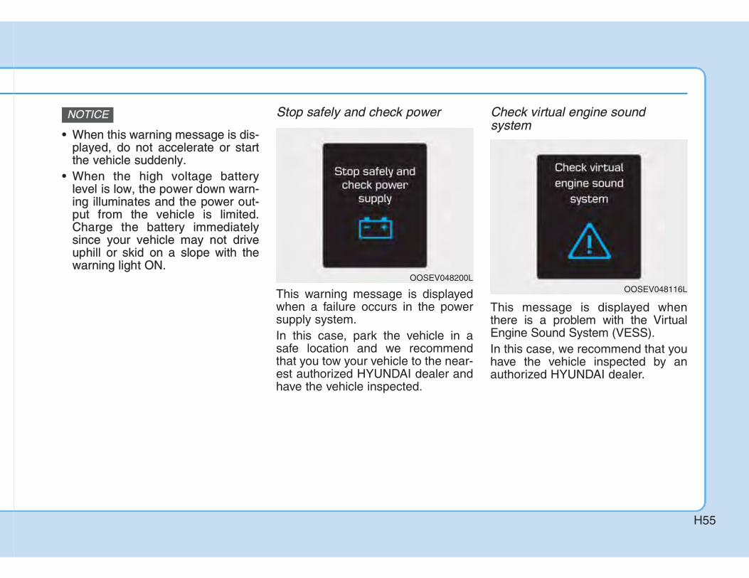
Stop safely and check power
This warning message is displayedwhen a failure occurs in the powersupply system.In this case, park the vehicle in asafe location and we recommendthat you tow your vehicle to the near-est authorized HYUNDAI dealer andhave the vehicle inspected.
Check virtual engine sound system
This message is displayed whenthere is a problem with the VirtualEngine Sound System (VESS).In this case, we recommend that youhave the vehicle inspected by anauthorized HYUNDAI dealer.
NOTICE
OOSEV048200LOOSEV048116L

H56
Check electric vehicle system
This warning message is displayedwhen there is a problem with theelectric vehicle control system.Refrain from driving when the warn-ing message is displayed. In this case, we recommend that youhave the vehicle inspected by anauthorized HYUNDAI dealer.
Energy flow The electric vehicle system informsthe drivers its energy flow in variousoperating modes. While driving, thecurrent energy flow is specified in 3modes.
Vehicle Stop
The vehicle is stopped.(No energy flow)
OOSEV048124L OOSEV048139L

H57
EV Propulsion
Only the motor power is used to drivethe vehicle. (Battery ➞ Wheel)
Regeneration
The high-voltage battery is chargedup by the regenerative brake system. (Wheel ➞ Battery)
Aux. Battery Saver+The Aux. Battery Saver+ is a functionthat monitors the charging status ofthe 12 V auxiliary battery.If the auxiliary battery level is low, themain high voltage battery chargesthe auxiliary battery.
Information The Aux. Battery Saver+ function willbe ON when the vehicle is delivered. Ifthe function is not needed, you mayturn it off in the Users Settings modeon the cluster. For more information,refer to the following page.
i
OOSEV048140L OOSEV048141L

H58
Mode• Cycle Mode :When the START/STOP button is inthe OFF position with all doors, hoodand tailgate closed, the Aux. BatterySaver+ periodically activates accord-ing to the auxiliary battery status. • Automatic Mode : When the START/STOP button is inthe ON position with the chargingconnector plugged in, the functionactivates according to the auxiliarybattery status to prevent overdis-charge of the auxiliary battery.
Information • The Aux. Battery Saver+ activates
maximum of 20 minutes. If the Aux.Battery Saver+ function activatesmore than 10 times consecutively, inthe Automatic Mode the functionwill stop activating, judging thatthere is a problem with the auxiliarybattery. In this case, drive the vehi-cle for some period of time. Thefunction will start activating if theauxiliary battery returns to normal.
• The Aux. Battery Saver+ functioncannot prevent battery discharge ifthe auxiliary battery is damaged,worn out, used as a power supply orunauthorized electronic devises areused.
System Setting
The driver can activate the Aux.Battery Saver+ function by placingthe START/STOP button to the ONposition and by selecting:'User settings → Other features →Aux. Battery Saver+'
The Aux. Battery Saver+ functiondeactivates, when the driver cancelsthe system setting.
i
OOSEVQ018019L

H59
Utility ModeThe high voltage battery is usedinstead of the 12V auxiliary batteryfor operating the convenient featuresof the vehicle. When driving is notnecessary such as while camping orwhen stopping the vehicle for a longtime, it is possible to use the electri-cal devices (audio, lights, etc.) forlong hours.
System Setting and Activation
System setting
The driver can activate the UtilityMode function when the followingconditions are satisfied.• The vehicle is in the ready ( )
mode and the gear is shifted to P(Park).
• The EPB (Electronic ParkingBrake) is applied.
• 'User Settings → Utility Mode‘ isselected in the cluster.
When the function is activating theindicator lamp will illuminate andhigh voltage electricity will be flow-ing in the vehicle. Do not touch thehigh voltage electric wire (orange),connector, and all electric compo-nents and devices. This maycause electric shock and lead toinjuries. Also, do not modify yourvehicle in any way. This mayaffect your vehicle performanceand lead to an accident.
WARNING
OOSEVQ018048L OOSEV048208L

H60
System Activation
When the system is activated:• The indicator will turn off and
the indicator will illuminate onthe cluster.
• All electric devices are usable butthe vehicle cannot be driven.
• The EPB can be cancelled bypressing the EBP switch.
• Gear cannot be shifted out of P(Park). If a shift attempt is made, amessage “Shifting conditions notmet” will be displayed on the clus-ter.
SSystem DeactivationThe Utility Mode can be deactivatedby pressing the START/STOP buttonto the OFF position. The functioncannot be deactivated from the UserSettings mode.

H61
If an Accident Occurs
• When a vehicle accident occurs,move the vehicle to a safe place,turn OFF the vehicle and removethe auxiliary battery (12 V) termi-nal to prevent high voltage elec-tricity from flowing.
• If electric wires are exposedfrom inside or outside the vehi-cle, do not touch the wires.Also, do not touch the high volt-age electric wire (orange), con-nector, and all electric compo-nents and devices. This maycause electric shock and lead toinjuries.
WARNING • When a vehicle accident occursand the high voltage battery isdamaged, harmful gas and elec-trolytes may leak. Be careful notto touch the leaked liquid.When you suspect leakage ofinflammable gas and otherharmful gases, open the win-dows and evacuate to a safeplace. If any leaked fluid comesin contact with your eyes or skin,immediately clean the affectedarea thoroughly with tap wateror saline solution and have doc-tors inspect it as soon as possi-ble.
WARNING
• If a small scale fire occurs, use afire extinguisher (ABC, BC) thatis meant for electrical fires. If it isimpossible to extinguish the firein the early stage, remain a safedistance from the vehicle andimmediately call your local fireemergency responders. Also,advise them that an electricvehicle is involved.If the fire spreads to the highvoltage battery, large amount ofwater is needed to put out thefire. Using small amount ofwater or fire extinguishers notmeant for electrical fires couldcause serious injury or deathfrom electrical shocks.
WARNING

H62
• If you tow the vehicle while thefront wheels are touching theground, the vehicle motor maygenerate electricity and themotor components may be dam-aged or a fire may occur.
• When a vehicle fire occurs dueto the battery, there is a risk of asecond fire. Contact the firedepartment when towing thevehicle.
WARNING
OOS067022
If you cannot put out the fireimmediately, the high voltage bat-tery may explode. Evacuate to asafe place and do not let otherpeople approach the site. Contact the fire department andnotify them of an electric vehiclefire. • If the vehicle is flooded with
water, immediately turn OFF thevehicle and evacuate to a safeplace. Contact the fire depart-ment or an authorizedHYUNDAI dealer.
WARNING
• If towing is required, lift all fourwheels off the ground and towthe vehicle. If you must tow thevehicle using only two wheels,lift the front wheels off theground and tow the vehicle.
WARNING
OOSEV068009
• Flatbed Towing
• Tires Locked Towing
Dolly• Tires Locked Towing
Dolly

H63
Other Precautions for ElectricVehicle• When you paint or apply heat treat-
ment to the vehicle as a result ofan accident, the performance ofthe high voltage battery can bereduced.If heat treatment is required, werecommend that you contact anauthorized HYUNDAI dealer.
• When you clean the motor com-partment, do not use high pressurewater to wash. This may cause anelectric shock due to a discharge inhigh voltage electricity, or damagethe vehicle's electric system.
• Do not use, remodel, or install non-genuine parts. This may damagethe electric power system.
Service Interlock Connector
In case of emergency, cut the serviceinterlock connector cable to isolatethe high voltage of the battery.
Service Plug
OOSEVQ018022OOSEV078067L
Never touch the service plugunder the rear seat.The service plug is attached to thehigh voltage battery system.Touching the service plug willresult in death or serious injury.Service personnel should followprocedures in service manual.
DANGER


21


Hyundai Motor India Limited here-inafter called "HMIL", warrants thateach new Hyundai vehicle sold shallbe free from any defects in materialand workmanship, under normal useand maintenance, subject to the fol-lowing terms and conditions.
1. Warranty period
This warranty shall exist for a periodof 36 months from the date of delivery to the first purchaser irrespective of the mileage. However, the warranty for hyundai vehicle being used for commercial purpose such as Taxi/Tourist operation is 36 months/100,000 kilometers from thedate of delivery which soever is ear-lier. The warranty on High VoltageBattery shall exist for a period of 96months/160,000 kms whichever isearlier from the date of delivery to the first purchaser.The warranties are transferable to subsequent owner for the remaining warranty period. The warranties are applicable only in India and not transferable to any other country.
2. What is covered
Except as provided in paragraph 3hereof, our Authorized Dealers shalleither repair or replace, any Hyundaigenuine part that is acknowledgedby HMIL to be defective in material orworkmanship within the warrantyperiod stipulated above, at no cost tothe owner of the Hyundai vehicle forparts or labour. Such defective partswhich have been replaced willbecome the property of HMIL.
3. What is not covered
This warranty shall not apply to:o Normal maintenance services
other than the three free services,including without limitation, clean-ing and polishing, minor adjust-ments,
filters replenishment, fastener retightening, wheel balanc-ing, wheel alignment and tyre rotation etc.
o If the degree of degradation of thehigh-voltage battery is within thenormal aging level according tothe use of the vehicle.
- The criterion for normal aging ofhigh-voltage battery conforms toour internal quality standards.
o Replacement of parts as a resultof normal wear and tear such as
brake pads andlinings,filters, wiper blades, bulbs,fuses, etc.
o Damage or failure resulting from:� Negligence of proper mainte-
nance as required in thisOwner's Manual and ServiceBooklet.
� Misuse, abuse, accident, theft,flooding or fire.
� Use of improper batterycharger, fluids or lubricants.
� Use of parts other thanHyundai Genuine Parts.
� Any device and/or accessoriesnot supplied by HMIL.
� Modifications, alterations,tampering or improper repair.
� Parts used in applications ofwhich they were not designedor not approved by HMIL.
� Slight irregularities not recog-nised as affecting quality orfunction of the vehicle or parts,such as slight noise or vibra-tions, or items consideredcharacteristic of the vehicle.
� Airborne "fallout", Industrialfall out, acid rain, hail and windstorms, or other Acts of God.
Hyundai Warranty Policy

� Paint scratches, dents or sim-ilar paint or body damage.
v Action of road elements (sand,gravel, dust or road debris)which results in stone chippingof paint or glass.
o Incidental or consequential dam-ages, including without limitation,loss of time, inconvenience, lossof use of vehicle or commercialloss.
This warranty is the entire warrantygiven by HMIL for Hyundai vehiclesand no dealer or its or his agent oremployee is authorized to extend orenlarge this warranty and no dealeror its or his agent or employee isauthorized to make any oral warran-ty on HMIL's behalf.HMIL reserves the right to make anychange in design or make anyimprovement on the vehicle at any
time without any obligation to makethe same change on vehicles previ-ously sold. HMIL reserves the right for the finaldecision in all warranty matters.
Owner's Responsibilitieso Proper use, maintenance and
care of vehicle in accordance withthe instructions contained in thisOwner's Manual and ServiceBooklet. If the vehicle is subject tosevere usage conditions, such asoperation in extremely dusty,rough, more repeated short dis-tance driving or heavy city trafficduring hot weather, maintenanceof vehicle should be done morefrequently as mentioned in thisOwner's Manual and ServiceBooklet.
o Retention of maintenance servicerecords. It may be necessary forthe customer to show that therequired maintenance has beenperformed, as specified in thisOwner's Manual and ServiceBooklet.
o Delivery of the vehicle during reg-ular service business hours toany authorized Hyundai Dealer to
obtain warranty service.o In order to maintain the validity of
this Basic Warranty, the vehiclemust be serviced by HyundaiAuthorized workshop in accor-dance to the Owner’s Manual andService Booklet.
Hyundai Motor India Limited here-inafter called "HMIL", warrants thateach new Hyundai Genuine replace-ment part purchased from andinstalled by Hyundai AuthorizedDealer shall be free from any defectsin material or workmanship, undernormal use and maintenance, sub-ject to the following terms and condi-tions.
1. Warranty period
This warranty shall exist for a periodof 6 months or until the vehicle hasbeen driven for a distance of 10,000Kilometers from the date of installa-tion of replacement part by HyundaiAuthorized Dealer, whichever occursfirst.
2. What is covered
Audio Video System, AuxillaryBatteries, Tyres & Tubes and Audio Systems, originally equipped on Hyundai vehicles are warranted directly by the respective manufacturers and not by HMIL.

Except as provided in paragraph 3hereof, our Authorized Dealer whohad sold and installed the replace-ment part earlier shall either repair orreplace the said Hyundai genuinepart that is acknowledged by HMIL tobe defective in material or workman-ship within the warranty period stipu-lated above, at no cost to the ownerof the Hyundai vehicle for parts orlabour.
33. What is not covered
This warranty shall not apply to:o Normal maintenance services of
parts such as cleaning, adjust-ment or replacement.
o Parts that fail due to abuse, mis-use, neglect, alteration or acci-dent or which have been improp-erly lubricated or repaired.
o Parts used in applications forwhich they were not designed orapproved by HMIL.
o Failure due to normal wear ofparts.
o Direct or indirect failures causedby misuse and improper mainte-nance of vehicle and installationof non-Hyundai parts on the vehi-
cle.o Any vehicle on which the odome-
ter reading has been altered sothat mileage cannot be accurate-ly determined.
o Incidental or consequential dam-ages, including without limitation,loss of time, inconvenience, lossof use of vehicle or commercialloss.
This warranty is the entire warrantygiven by HMIL for Hyundai replace-ment parts and no dealer or its or hisagent or employee is authorized toextend or enlarge this warranty andno dealer or its or his agent oremployee is authorized to make anyoral warranty on HMIL's behalf.HMIL reserves the right for the finaldecision in all warranty matters.
Owner's Responsibilitieso Proper use, maintenance and
care of the vehicle in accordancewith the instructions contained inthe Owner's Manual and ServiceBooklet.
o Retention of maintenance servicerecords. It may be necessary forthe customer to show that the
required maintenance has beenperformed, as specified in thisOwner's Manual and ServiceBooklet.
o Retention of the customer's copyof the original repair order and itsinvoice/bill against which the partwas replaced.
o Delivery of the vehicle during reg-ular service business hours to thesame Hyundai Authorized Dealerwho had sold and installed thereplacement part.
o In order to maintain the validity ofthis Parts replacement Warranty,the vehicle must be serviced byHyundai Authorized workshop inaccordance to the Owner’sManual and Service Booklet.i
Hyundai Warranty Policy
HYUNDAI EXTENDEDWARRANTY*HMIL offers optional paid extend-ed warranty on selected models, inaddition to the basic new vehiclewarranty. For more details onHyundai Extended Warrantyplease call the nearest dealer orour toll free number 1-800-11-4645*Conditions apply

dealer
: Road traffic accident covered for vehicles sold after 1st March 2014

RO NumberDealer/HASC code
RO NumberDealer/HASC code
RO NumberDealer/HASC code


OOSEV018001AU
The actual shape may differ from the illustration.
1. Hood ..................................................5-33
2. Front lamps........................................9-51
3. Tires and wheels ......................9-25, 10-4
4. Outside rearview mirror .....................5-19
5. Sunroof ..............................................5-28
6. Charging door....................................5-37
7. Front windshield wiper blades ...........9-18
8. Windows ............................................5-23

1. Antenna ...............................................6-3
2. Doors ...................................................5-9
3. Rear lamps ........................................9-56
4. High mounted stop lamp ...................9-59
5. Tailgate ..............................................5-34
6. Rear view monitor .............................5-99
7. Rear window wiper blades ................9-20
OOSEV018002R
The actual shape may differ from the illustration.

1. Door lock/unlock button ....................5-102. Outside rearview mirror folding
switch ................................................5-213. Outside rearview mirror control
switch ................................................5-194. Central door lock switch ....................5-115. Power window lock switch ................5-266. Power window switches ....................5-237. Headlight leveling device ..................5-908. Instrument panel illumination
control switch ......................................5-399. ESC OFF button................................7-4110. AUTO/LOCK mode selection button ..H1811. VESS (Vehicle Engine Sound System)
button ..............................................H4612. Hood release lever ........................5-3313. Fuse box..........................................9-3614. Steering wheel ................................5-1515. Seat ..................................................4-4
OOSIEV019003The actual shape may differ from the illustration.

The actual shape may differ from the illustration.
1. Instrument cluster ....................................5-382. Horn .........................................................5-173. Driver's front air bag ................................4-484. START/STOP button ..................................7-55. Light control/Turn signals.........................5-856. Wiper/Washer ..........................................5-957. Infotainment system ..................................6-58. Hazard warning flasher..............................8-29. Automatic climate control system ............5-10910. Passenger's front air bag.......................4-4811. Glove box.............................................4-12612. Reduction gear (shift button) ................ 7-1113. Wireless cellular phone charging
system..................................................5-13114. AUX, USB and iPod® port ........................6-215. Seat warmer/Air ventilation seat....4-21/4-2216. Drive mode button .................................7-4717. Heated steering wheel ...........................5-1718. Auto hold ...............................................7-3519. Parking Distance Warning
(Reverse/Forward) ON button/.............5-104Parking Distance Warning (Reverse) OFF button...........................................5-100
20. EPB (Electronic Parking brake) .............7-3021. Cup holder ...........................................5-12822. Cruise controls.......................................7-4823. Steering wheel audio controls/ ................6-3
Bluetooth® wireless technology hands-free controls ..................................6-5
OOSIEV019004

1. Coolant reservoir ..............................9-13
2. Brake fluid reservoir..........................9-14
3. Fuse box ...........................................9-36
4. Battery (12 volt) ...............................9-21
5. Coolant reservoir cap........................9-13
6. Windshield washer fluid reservoir .....9-15
OOSEV078001
The actual motor compartment in the vehicle may differ from the illustration.

This chapter provides you with important information about how to protect yourself and your passengers.It explains how to properly use your seats and seat belts, and how your air bags work. Additionally, this chapter explains how to properly restrain infants and children in your vehicle.

You will find many safety precautionsand recommendations throughoutthis section, and throughout this man-ual. The safety precautions in this sec-tion are among the most important.
AAlways wear your seat belt A seat belt is your best protection inall types of accidents. Air bags aredesigned to supplement seat belts,not replace them. So even thoughyour vehicle is equipped with air bags,ALWAYS make sure you and yourpassengers wear your seat belts, andwear them properly.
Restrain all children All children under age 13 should ridein your vehicle properly restrained ina rear seat, not the front seat. Infantsand small children should berestrained in an appropriate ChildRestraint System. Larger childrenshould use a booster seat with thelap/shoulder belt until they can usethe seat belt properly without abooster seat.
Air bag hazards While air bags can save lives, theycan also cause serious or fatalinjuries to occupants who sit tooclose to them, or who are not prop-erly restrained. Infants, young chil-dren, and short adults are at thegreatest risk of being injured by aninflating air bag. Follow all instruc-tions and warnings in this manual.
Driver distraction Driver distraction presents a seriousand potentially deadly danger, espe-cially for inexperienced drivers. Safetyshould be the first concern whenbehind the wheel and drivers need tobe aware of the wide array of potentialdistractions, such as drowsiness,reaching for objects, eating, personalgrooming, other passengers, andusing cellular phones.Drivers can become distracted whenthey take their eyes and attention offthe road or their hands off the wheelto focus on activities other than driv-ing. To reduce your risk of distractionand an accident:• ALWAYS set up your mobile devices
(i.e., MP3 players, phones, naviga-tion units, etc.) when your vehicle isparked or safely stopped.
• ONLY use your mobile device whenallowed by laws and conditions per-mit safe use. NEVER text or emailwhile driving. Most countries havelaws prohibiting drivers from texting.Some countries and cities also pro-hibit drivers from using handheldphones.

• NEVER let the use of a mobile devicedistract you from driving. You have aresponsibility to your passengers andothers on the road to always drivesafely, with your hands on the wheelas well as your eyes and attention onthe road.
CControl your speed Excessive speed is a major factor incrash injuries and deaths. Generally,the higher the speed, the greater therisk, but serious injuries can alsooccur at lower speeds. Never drivefaster than is safe for current condi-tions, regardless of the maximumspeed posted.
Keep your vehicle in safe condi-tion Having a tire blowout or a mechanicalfailure can be extremely hazardous. Toreduce the possibility of such prob-lems, check your tire pressures andcondition frequently, and perform allregularly scheduled maintenance.

OOSEV038026R
Front seat
(1) Forward and backward
(2) Seatback angle
(3) Seat cushion height*
(4) Lumbar support (Driver’s seat)*
(5) Seat warmer */ Air ventilation seat *
(6) Headrest
Rear seat
(7) Armrest*
(8) Seatback angle and folding
(9) Headrest
* : if equipped
[A] : Front seat, [B] : Rear seat

SSafety precautions Adjusting the seats so that you are sit-ting in a safe, comfortable positionplays an important role in driver andpassenger safety together with theseat belts and air bags in an accident.
Air bags You can take steps to reduce the riskof being injured by an inflating airbag. Sitting too close to an air baggreatly increases the risk of injury inthe event the air bag inflates. Moveyour seat as far back as possiblefrom front air bags, while still main-taining control of the vehicle.
Do not use a cushion that reducesfriction between the seat and thepassenger. The passenger's hipsmay slide under the lap portion ofthe seat belt during an accident ora sudden stop.Serious or fatal internal injuriescould result because the seat beltcannot operate properly.
WARNING
rim with hands at the 9 o’clockand 3 o’clock positions to mini-mize the risk of injuries to yourhands and arms.
• NEVER place anything or any-one between the air bag.
• Do not allow the front passengerto place feet or legs on the dash-board to minimize the risk of leginjuries.
To reduce the risk of serious injuryor death from an inflating air bag,take the following precautions:• Adjust the driver’s seat as far to
the rear as possible maintainingthe ability to control of the vehi-cle.
• Adjust the front passenger seatas far to the rear as possible.
• Hold the steering wheel by the
WARNING

SSeat beltsAlways fasten your seat belt beforestarting any trip. At all times, passengers should situpright and be properly restrained.Infants and small children must berestrained in appropriate ChildRestraint Systems. Children whohave outgrown a booster seat andadults must be restrained using theseat belts.
Front seatsThe front seat can be adjusted byusing the control lever or switcheslocated on the outside of the seatcushion. Before driving, adjust theseat to the proper position so thatyou can easily control the steeringwheel, foot pedals and controls onthe instrument panel.
Take the following precautionswhen adjusting your seat belt:• NEVER use one seat belt for
more than one occupant.• Always position the seatback
upright with the lap portion of theseat belt snug and low acrossthe hips.
• NEVER allow children or smallinfants to ride in a passenger’slap.
• Do not route the seat belt acrossyour neck, across sharp edges,or reroute the shoulder strapaway from your body.
• Do not allow the seat belt tobecome caught or jammed.
WARNING Take the following precautionswhen adjusting your seat:• NEVER attempt to adjust the
seat while the vehicle is moving.The seat could respond withunexpected movement and maycause loss of vehicle controlresulting in an accident.
• Do not place anything under thefront seats. Loose objects in thedriver’s foot area could interferewith the operation of the footpedals, causing an accident.
• Do not allow anything to inter-
WARNING

MManual adjustment (if equipped)
Forward and rearward adjustment
To move the seat forward or rearward:1. Pull up the seat slide adjustment
lever and hold it.2. Slide the seat to the position you
desire.3. Release the lever and make sure
the seat is locked in place. Moveforward and rearward without usingthe lever. If the seat moves, it is notlocked properly.
To prevent injury:
• Do not adjust your seat whilewearing your seat belt. Moving the seat cushion forwardmay cause strong pressure onyour abdomen.
• Do not allow your hands or fin-gers to get caught in the seatmechanisms while the seat ismoving.
CAUTIONfere with the normal position andproper locking of the seatback.
• Do not place a cigarette lighteron the floor or seat. When youoperate the seat, gas may exitout of the lighter causing a fire.
• Use extreme caution when pick-ing small objects trapped underthe seats or between the seatand the center console. Yourhands might be cut or injured bythe sharp edges of the seatmechanism.
• If there are occupants in the rearseats, be careful while adjustingthe front seat position.
• Make sure that the seat islocked in place after the adjust-ment. If not, the seat mightmove unexpectedly resulting inan accident.
OOSEV038039R

Seatback angle
To recline the seatback:1. Lean forward slightly and lift up the
seatback lever.2. Carefully lean back on the seat
and adjust the seatback to theposition you desire.
3. Release the lever and make surethe seatback is locked in place.(The lever MUST return to its orig-inal position for the seatback tolock.)
RReclining seatbackSitting in a reclined position whenthe vehicle is in motion can be dan-gerous. Even when buckled up, theprotections of your restraint system(seat belts and/or air bags) is greatlyreduced by reclining your seatback.
Seat belts must be snug against yourhips and chest to work properly.When the seatback is reclined, theshoulder belt cannot do its jobbecause it will not be snug againstyour chest. Instead, it will be in frontof you. During an accident, you couldbe thrown into the seat belt, causingneck or other injuries.The more the seatback is reclined,the greater chance the passenger’ships will slide under the lap belt orthe passenger’s neck will strike theshoulder belt.
OOSEV038040RNEVER ride with a reclined seat-back when the vehicle is moving.Riding with a reclined seatbackincreases your chance of seriousor fatal injuries in the event of acollision or sudden stop.Drivers and passengers shouldALWAYS sit well back in theirseats, properly belted, and withthe seatbacks upright.
WARNING
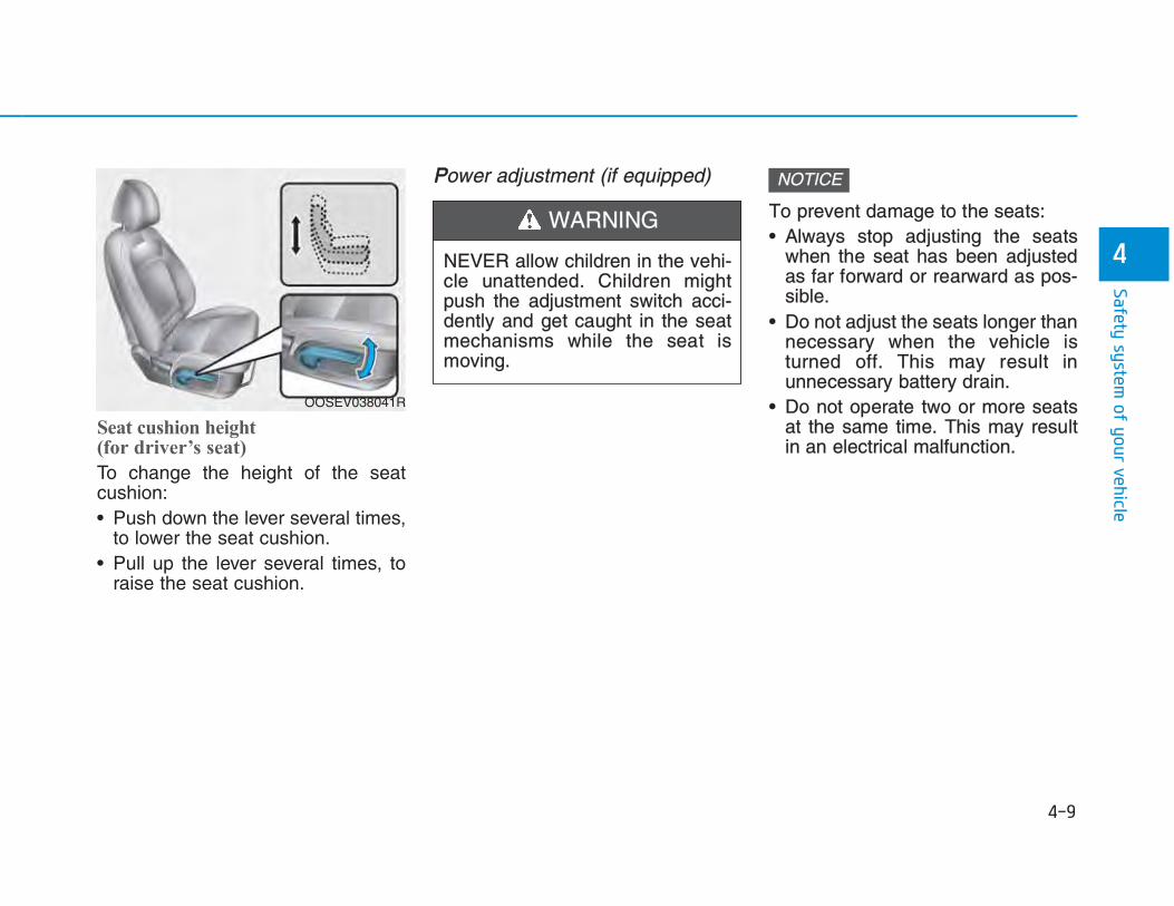
Seat cushion height (for driver’s seat)
To change the height of the seatcushion:• Push down the lever several times,
to lower the seat cushion.• Pull up the lever several times, to
raise the seat cushion.
PPower adjustment (if equipped)
To prevent damage to the seats: • Always stop adjusting the seats
when the seat has been adjustedas far forward or rearward as pos-sible.
• Do not adjust the seats longer thannecessary when the vehicle isturned off. This may result inunnecessary battery drain.
• Do not operate two or more seatsat the same time. This may resultin an electrical malfunction.
NOTICE
OOSEV038041R
NEVER allow children in the vehi-cle unattended. Children mightpush the adjustment switch acci-dently and get caught in the seatmechanisms while the seat ismoving.
WARNING

Forward and rearward adjustment
To move the seat forward or rearward:1. Push the control switch forward or
rearward.2. Release the switch once the seat
reaches the desired position.
Seatback angle
To recline the seatback:1. Push the control switch forward or
rearward.2. Release the switch once the seat-
back reaches the desired position.
RReclining seatbackSitting in a reclined position whenthe vehicle is in motion can be dan-gerous. Even when buckled up, theprotections of your restraint system(seat belts and air bags) is greatlyreduced by reclining your seatback.
OOSEV038042R OOSEV038043R

Seat belts must be snug against yourhips and chest to work properly.When the seatback is reclined, theshoulder belt cannot do its jobbecause it will not be snug againstyour chest. Instead, it will be in frontof you. During an accident, you couldbe thrown into the seat belt, causingneck or other injuries.The more the seatback is reclined,the greater chance the passenger’ships will slide under the lap belt orthe passenger’s neck will strike theshoulder belt.
Seat cushion tilt (1, if equipped)
To change the angle of the front partof the cushion:Push the front portion of the controlswitch up to raise or down to lower thefront part of the seat cushion.Release the switch once the seatreaches the desired position.
Seat cushion height (2, if equipped)
To change the height of the seatcushion:Push the rear portion of the controlswitch up to raise or down to lowerthe height of the seat cushion.Release the switch once the seatreaches the desired position.
NEVER ride with a reclined seat-back when the vehicle is moving.Riding with a reclined seatbackincreases your chance of seriousor fatal injuries in the event of acollision or sudden stop.Driver and passengers shouldALWAYS sit well back in theirseats, properly belted, and withthe seatbacks upright.
WARNING
OOSEV038001R

Lumbar support (for driver’s seat, if equipped)
To adjust the lumbar support:1. Press the front portion of the
switch (1) to increase support orthe rear portion of the switch (2) todecrease support.
2. Release the switch once it reach-es the desired position.
SSeatback pocket (if equipped)
The seatback pocket is provided onthe back of the front seatbacks.
Rear seats
Folding the rear seat The rear seatbacks can be folded tofacilitate carrying long items or toincrease the luggage capacity of thevehicle.
Do not put heavy or sharp objectsin the seatback pockets. In anaccident they could come loosefrom the pocket and injure occu-pants.
CAUTION
OOS037017
OOS037008R• Never allow passengers to sit on
top of the folded down seatbackwhile the vehicle is moving. Thisis not a proper seating positionand no seat belts are availablefor use. This could result in seri-ous injury or death in case of anaccident or sudden stop.
• Objects carried on the foldeddown seatback should notextend higher than the top of thefront seatbacks. This could allowcargo to slide forward and causeinjury or damage during suddenstops.
WARNING

To fold down the rear seatback:1. Set the front seatback to the upright
position.2. Lower the rear headrests down(2)
pushing the adjusting button(1).
3.Locate the seatbelt toward the out-board position before folding downthe seatback. If not, the seatbeltsystem may be interfered by theseatback.
4.Remove the belt from the guide (1)and pull up the seatback foldinglever (2), then fold the seat towardthe front of the vehicle.
OOS037019 OOS037020 OOS037021
OOS037023

5.To use the rear seat, lift and pushthe seatback rearward.Push the seatback firmly until itclicks into place. Make sure theseatback is locked in place.Return the belt in the guide.
AArmrest
The armrest is located in the centerof the rear seat. Pull the armrestdown by using the strap from theseatback to use it.
OOS037022
Do not place objects in the rearseats, since they cannot be prop-erly secured and may hit vehicleoccupants in a collision causingserious injury or death.
WARNING
When returning the rear seatbackfrom a folded to an upright posi-tion, hold the seatback and returnit slowly. Ensure that the seatbackis completely locked into itsupright position by pushing on thetop of the seatback. In an accidentor sudden stop, the unlocked seat-back could allow cargo to moveforward with great force and enterthe passenger compartment,which could result in serious injuryor death.
WARNING
OOS037024

HHeadrest The vehicle’s front and rear seats haveadjustable headrests. The headrestsprovide comfort for passengers, butmore importantly they are designed tohelp protect passengers from whiplashand other neck and spinal injuries dur-ing an accident, especially in a rearimpact collision.
To prevent damage, NEVER hit orpull on the headrests.
NOTICE
To reduce the risk of serious injuryor death in an accident, take thefollowing precautions whenadjusting your headrests:• Always properly adjust the
headrests for all passengersBEFORE starting the vehicle.
• NEVER let anyone ride in a seatwith the headrest removed orreversed.
•
Adjust the headrests so the mid-dle of the headrests is at thesame height as the height of thetop of the eyes.
• NEVER adjust the headrestposition of the driver’s seatwhen the vehicle is in motion.
• Adjust the headrest as close tothe passenger’s head as possi-ble. Do not use a seat cushionthat holds the body away fromthe seatback.
• Make sure the headrest locksinto position after adjusting it.
WARNING
OLF034072N
When there is no occupant in therear seats, adjust the height of theheadrest to the lowest position.The rear seat headrest can reducethe visibility of the rear area.
CAUTION

FFront seat headrests
The driver’s and front passenger’sseats are equipped with adjustableheadrests for the passengers safetyand comfort.
Adjusting the height up and down
To raise the headrest:1. Pull it up to the desired position (1).
To lower the headrest:1. Push and hold the release button
(2) on the headrest support.2. Lower the headrest to the desired
position (3).
Forward and rearward adjustment(for driver’s seat)
The headrest may be adjusted for-ward to 3 different positions bypulling the headrest forward to thedesired detent. To adjust the head-rest to it’s furthest rearwards posi-tion, pull it fully forward to the farthestposition and release it.
OOSEV038012L
OOS037061 OOS037010

IIf you recline the seatback towardsthe front with the headrest and seatcushion raised, the headrest maycome in contact with the sunvisor orother parts of the vehicle.
Removal/Reinstall
To remove the headrest:1. Recline the seatback (2) with using
the seatback angle lever or switch(1).
2. Raise headrest as far as it can go.3. Press the headrest release button
(3) while pulling the headrest up (4).
NOTICE
OOSEV038002R
OOSEV038003R
■ Type A
■ Type BOLF034015
NEVER allow anyone to travel in aseat with the headrest removed.
WARNING

To reinstall the headrest :1. Recline the seatback.2. Put the headrest poles (2) into the
holes while pressing the releasebutton (1).
3. Adjust the headrest to the appropri-ate height.
4. Recline the seatback (4) with theseatback angle lever or switch (3).
RRear seat headrests
The rear seats are equipped withheadrests in all the seating positionsfor the passenger’s safety and com-fort.
Always make sure the headrestlocks into position after reinstallingand adjusting it properly.
WARNING
OOSEV038004R
OOSEV038005R
■ Type A
■ Type BOOSEV038030L

Adjusting the height up and down
To raise the headrest:1. Pull it up to the desired position (1).
To lower the headrest:1. Push and hold the release button
(2) on the headrest support.2. Lower the headrest to the desired
position (3).
Removal/Reinstallation
To remove the headrest:1. Raise the headrest as far as it can
go.2. Press the headrest release button
(1) while pulling the headrest up (2).To reinstall the headrest:1. Put the headrest poles into the
holes (3) while pressing therelease button (1).
2. Adjust the headrest to the appro-priate height.
OOS037018
• Adjust the headrests so the mid-dle of the headrest is at thesame height as the height of thetop of the eyes.
• When sitting on the rear seat, donot adjust the height of theheadrest to the lowest.
CAUTION
OOSEV038029

SSeat warmers and air ventilationseatsFront seat warmers (if equipped) Seat warmers are provided to warmthe seats during cold weather.
• Fatigued individuals.• Intoxicated individuals.• People taking medication that
can cause drowsiness or sleepi-ness.
NEVER place anything on the seatthat insulates against heat whenthe seat warmer is in operation,such as a blanket or seat cushion.This may cause the seat warmer tooverheat, causing a burn or dam-age to the seat.
WARNING The seat warmers can cause aSERIOUS BURN, even at lowtemperatures and especially ifused for long periods of time.Passengers must be able to feel ifthe seat is becoming too warm sothey can turn it off, if needed.People who cannot detect temper-ature change or pain to the skinshould use extreme caution, espe-cially the following types of pas-sengers:• Infants, children, elderly or dis-
abled persons, or hospital out-patients.
• People with sensitive skin orwho burn easily.
WARNING
Make sure the headrest locks inposition after adjusting it to prop-erly protect the occupants.
WARNING
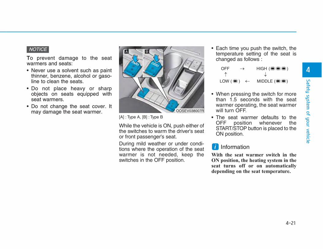
TTo prevent damage to the seatwarmers and seats:• Never use a solvent such as paint
thinner, benzene, alcohol or gaso-line to clean the seats.
• Do not place heavy or sharpobjects on seats equipped withseat warmers.
• Do not change the seat cover. Itmay damage the seat warmer.
[A] : Type A, [B] : Type B
While the vehicle is ON, push either ofthe switches to warm the driver's seator front passenger's seat.During mild weather or under condi-tions where the operation of the seatwarmer is not needed, keep theswitches in the OFF position.
• Each time you push the switch, thetemperature setting of the seat ischanged as follows :
• When pressing the switch for morethan 1.5 seconds with the seatwarmer operating, the seat warmerwill turn OFF.
• The seat warmer defaults to theOFF position whenever theSTART/STOP button is placed to theON position.
Information With the seat warmer switch in theON position, the heating system in theseat turns off or on automaticallydepending on the seat temperature.
NOTICE
i
OOSEV038007R
OFF HIGH ( )
LOW ( ) MIDDLE ( )
→
→
→
→

FFront air ventilation seat(if equipped)
The air ventilation seats are providedto cool the front seats by blowing airthrough small vent holes on the sur-face of the seat cushions and seat-backs. When the operation of the air ventila-tion seat is not needed, keep theswitches in the OFF position.While the vehicle is ON, push theswitch to cool the driver's seat or thefront passenger's seat (if equipped).
• Each time you push the switch, theairflow changes as follows:
• When pressing the switch for morethan 1.5 seconds with the air venti-lation seat operating, the operationwill turn OFF.
• The air ventilation seats defaultsto the OFF position whenever theSTART/STOP button is placed tothe ON position.
To prevent damage to the air ventila-tion seat:• Use the air ventilation seat ONLY
when the climate control system ison. Using the air ventilation seatfor prolonged periods of time withthe climate control system offcould cause the air ventilation seatto malfunction.
• Never use a solvent such as paintthinner, benzene, alcohol or gaso-line to clean the seats.
• Avoid spilling liquids on the surfaceof the front seats and seatbacks;this may cause the air vent holes tobecome blocked and not workproperly.
• Do not place materials such asplastic bags or newspapers underthe seats. They may block the airintake causing the air vents to notwork properly.
• Do not change the seat covers. Itmay damage the air ventilationseat.
• If the air vents do not operate,restart the vehicle. If there is nochange, we recommend that youhave your vehicle inspected by anauthorized HYUNDAI dealer.
NOTICE
OFF HIGH ( )
LOW ( ) MIDDLE ( )
→
→
→
→
OOSEV038008R

This section describes how to use theseat belts properly. It also describessome of the things not to do whenusing seat belts.
SSeat belt safety precautions Always fasten your seat belt andmake sure all passengers have fas-tened their seat belts before startingany trip. Air bags (if equipped) aredesigned to supplement the seat beltas an additional safety device, butthey are not a substitute. Most coun-tries require all occupants of a vehicleto wear seat belts.
Seat belts must be used by ALLpassengers whenever the vehicleis moving. Take the following pre-cautions when adjusting andwearing seat belts:• Children under the age of 13
should be properly restrained inthe rear seats.
• Never allow children to ride inthe front passenger seat, unlessthe air bag is deactivated. If achild is seated in the front pas-senger seat, move the seat asfar back as possible and proper-ly restrain them in the seat.
• NEVER allow an infant or childto be carried on an occupant’slap.
• NEVER ride with the seatbackreclined when the vehicle ismoving.
• Do not allow children to share aseat or seat belt.
WARNING • Do not wear the shoulder beltunder your arm or behind yourback.
• Never wear a seat belt overfragile objects. If there is a sud-den stop or impact, the seat beltcan damage it.
• Do not use the seat belt if it istwisted. A twisted seat belt willnot protect you properly in anaccident.
• Do not use a seat belt if the web-bing or hardware is damaged.
• Do not latch the seat belt intothe buckles of other seats.
• NEVER unfasten the seat beltwhile driving. This may causeloss of vehicle control resultingin an accident.
• Make sure there is nothing in thebuckle interfering with the seatbelt latch mechanism. This mayprevent the seat belt from fas-tening securely.
• No modifications or additions

SSeat belt warning light Seat belt warning
Driver’s seat belt warning
As a reminder to the driver, the seatbelt warning light will illuminate forapproximately 6 seconds each timethe START/STOP button is turnedON regardless of belt fastening.If the seat belt is not fastened whenthe START/STOP button is turned onor if it is disconnected after theSTART/STOP button is turned on,the seat belt warning light will illumi-nate until the belt is fastened.
Damaged seat belts and seat beltassemblies will not operate prop-erly. Always replace:• Frayed, contaminated, or dam-
aged webbing.• Damaged hardware.• The entire seat belt assembly
after it has been worn in an acci-dent, even if damage to webbingor assembly is not apparent.
WARNING should be made by the userwhich will either prevent the seatbelt adjusting devices from oper-ating to remove slack, or pre-vent the seat belt assembly frombeing adjusted to remove slack.
OOSEV038009R
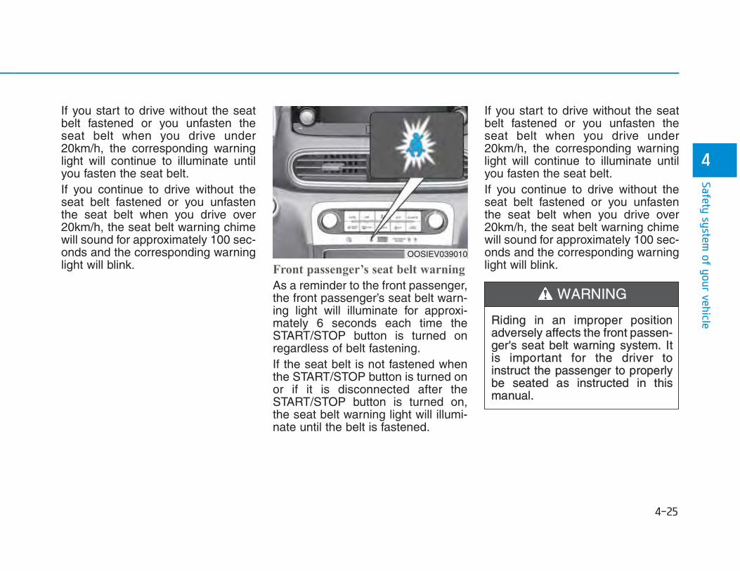
If you start to drive without the seatbelt fastened or you unfasten theseat belt when you drive under20km/h, the corresponding warninglight will continue to illuminate untilyou fasten the seat belt.If you continue to drive without theseat belt fastened or you unfastenthe seat belt when you drive over20km/h, the seat belt warning chimewill sound for approximately 100 sec-onds and the corresponding warninglight will blink. Front passenger’s seat belt warning
As a reminder to the front passenger,the front passenger’s seat belt warn-ing light will illuminate for approxi-mately 6 seconds each time theSTART/STOP button is turned onregardless of belt fastening.If the seat belt is not fastened whenthe START/STOP button is turned onor if it is disconnected after theSTART/STOP button is turned on,the seat belt warning light will illumi-nate until the belt is fastened.
If you start to drive without the seatbelt fastened or you unfasten theseat belt when you drive under20km/h, the corresponding warninglight will continue to illuminate untilyou fasten the seat belt.If you continue to drive without theseat belt fastened or you unfastenthe seat belt when you drive over20km/h, the seat belt warning chimewill sound for approximately 100 sec-onds and the corresponding warninglight will blink.
Riding in an improper positionadversely affects the front passen-ger's seat belt warning system. Itis important for the driver toinstruct the passenger to properlybe seated as instructed in thismanual.
WARNING
OOSIEV039010

IInformation • You can find the front passenger’s
seat belt warning light on the centerfascia panel.
• Although the front passenger seat isnot occupied, the seat belt warninglight will blink or illuminate for 6seconds.
• The front passenger's seat beltwarning may operate when luggageis placed on the front passenger seat.
Seat belt restraint system Lap/shoulder belt
To fasten your seat belt:
Pull it out of the retractor and insertthe metal tab (1) into the buckle (2).There will be an audible "click" whenthe tab locks into the buckle.
You should place the lap belt (1) por-tion across your hips and the shoulderbelt (2) portion across your chest. The seat belt automatically adjusts tothe proper length after the lap belt por-tion is adjusted manually so that it fitssnugly around your hips. If you leanforward in a slow, easy motion, the beltwill extend and move with you. If there is a sudden stop or impact,the belt will lock into position. It willalso lock if you try to lean forward tooquickly.
i
OJS038068AU
OJS038069AU

IIf you are not able to smoothly pullenough of the seat belt out from theretractor, firmly pull the seat belt outand release it. After release, you willbe able to pull the belt out smoothly.
NOTICE
OTM038098R
Improperly positioned seat beltsmay increase the risk of seriousinjury in an accident. Take the fol-lowing precautions when adjustingthe seat belt:
WARNING
• Position the lap portion of theseat belt as low as possibleacross your hips, not on yourwaist, so that it fits snugly. Thisallows your strong pelvic bonesto absorb the force of the crash,reducing the chance of internalinjuries.
• Position one arm under theshoulder belt and the other overthe belt, as shown in the illustra-tion.
• Always position the shoulderbelt anchor into locked positionat the appropriate height.
• Never position the shoulder beltacross your neck or face.

Height adjustment
You can adjust the height of theshoulder belt anchor to one of thefour different positions for maximumcomfort and safety.The shoulder portion should beadjusted so it lies across your chestand midway over your shoulder near-est the door, not over your neck.
To adjust the height of the seat beltanchor, lower or raise the heightadjuster into an appropriate position.To raise the height adjuster, pull it up(1). To lower it, push it down (3) whilepressing the height adjuster button(2).Release the button to lock theanchor into position. Try sliding theheight adjuster to make sure that ithas locked into position.
To release your seat belt:
Press the release button (1) in thelocking buckle.When it is released, the belt shouldautomatically draw back into theretractor. If this does not happen,check the belt to be sure it is nottwisted, then try again.
OOS037060
■ Front seat
OJS038070AU

RRear center seatbelt (3-point rear center seat belt)
When using the rear center seat belt,the buckle with the “CENTER” markmust be used.
Information If you are not able to pull out the safe-ty belt from the retractor, firmly pullthe belt out and release it. Afterrelease, you will be able to pull the beltout smoothly.
Pre-tensioner seat belt
Your vehicle is equipped with Pre-tensioner Seat Belts (RetractorPretensioner). The purpose of thepre-tensioner is to make sure theseat belts fit tightly against the occu-pant's body in certain frontal colli-sions. The pre-tensioner seat beltsmay be activated in crashes wherethe frontal collision is severe enough,together with the air bags.
i
OOSEV038031L
OJS038071AU
Make sure that the seatback islocked in place when using therear center seat belt. If not, the seatback may movewhen there is a sudden stop orcollision, which could result in seri-ous injury.
WARNING

When the vehicle stops suddenly, orif the occupant tries to lean forwardtoo quickly, the seat belt retractor willlock into position. In certain frontalcollisions, the pre-tensioner will acti-vate and pull the seat belt into tightercontact against the occupant's body.If the system senses excessive ten-sion on the driver or passenger'sseat belt when the pre-tensioner sys-tem activates, the load limiter (ifequipped) inside the retractor pre-tensioner will release some of thepressure on the affected seat belt.
• Always wear your seat belt andsit properly in your seat.
• Do not use the seat belt if it isloose or twisted. A loose ortwisted seat belt will not protectyou properly in an accident.
• Do not place anything near thebuckle. This may adverselyaffect the buckle and cause it tofunction improperly.
• Always replace your pre-ten-sioners after activation or anaccident.
• NEVER inspect, service, repairor replace the pre-tensionersyourself. This must be done byan authorized HYUNDAI dealer.
• Do not hit the seat belt assem-blies.
WARNING
Do not touch the pre-tensionerseat belt assemblies for severalminutes after they have been acti-vated. When the pre-tensionerseat belt mechanism deploys dur-ing a collision, the pre-tensionercan become hot and can burnyou.
WARNING
Body work on the front area of thevehicle may damage the pre-ten-sioner seat belt system.Therefore, we recommend thesystem to be serviced by anauthorized HYUNDAI dealer.
CAUTION

The Pre-Tensioner Seat Belt Systemconsists mainly of the following com-ponents. Their locations are shown inthe illustration above:(1) SRS air bag warning light(2) Front retractor pre-tensioner
(3) SRS control module(4) Rear retractor pre-tensioner
TThe sensor that activates the SRScontrol module is connected with thepre–tensioner seat belts. The SRSair bag warning light on the instru-ment panel will illuminate for approx-imately 6 seconds after theSTART/STOP button is placed to theON position, and then it should turnoff.If the pre-tensioner is not workingproperly, the warning light will illumi-nate even if the SRS control moduleis not malfunctioning. If the warninglight does not illuminate when thevehicle is turned ON, stays illuminat-ed or illuminates when the vehicle isbeing driven, we recommend thepre-tensioner seat belts and/or SRSair bags be inspected by an author-ized HYUNDAI dealer as soon aspossible.
Information • Both the driver's and front passen-
ger's pre-tensioner seat belts may beactivated in certain frontal or sidecollisions.
• The pre-tensioners will be activatedeven if the seat belts are not worn atthe time of the collision.
• When the pre-tensioner seat beltsare activated, a loud noise may beheard and fine dust, which mayappear to be smoke, may be visiblein the passenger compartment.These are normal operating condi-tions and are not hazardous.
• Although it is non-toxic, the fine dustmay cause skin irritation and shouldnot be breathed for prolonged peri-ods. Wash all exposed skin areasthoroughly after an accident in whichthe pre-tensioner seat belts were acti-vated.
i
NOTICE
OJS038072AU
OOSEV038032L

AAdditional seat belt safety pre-cautions Seat belt use during pregnancy The seat belt should always be usedduring pregnancy. The best way toprotect your unborn child is to protectyourself by always wearing the seatbelt.Pregnant women should always weara lap-shoulder seat belt. Place theshoulder belt across your chest, rout-ed between your breasts and awayfrom your neck. Place the lap beltbelow your belly so that it fits SNUGLYacross your hips and pelvic bone,under the rounded part of the belly.
Seat belt use and children Infant and small children
Most countries have Child RestraintSystem laws which require childrento travel in approved Child RestraintSystem devices, including boosterseats. The age at which seat beltscan be used instead of ChildRestraint System differs amongcountries, so you should be aware ofthe specific requirements in yourcountry, and where you are travel-ling. Infant and Child RestraintSystem must be properly placed andinstalled in a rear seat. For more information refer to the “ChildRestraint Systems” in this chapter.
ALWAYS properly restrain infantsand small children in a ChildRestraint System appropriate forthe child’s height and weight.To reduce the risk of serious injuryor death to a child and other pas-sengers, NEVER hold a child inyour lap or arms when the vehicleis moving. The violent forces cre-ated during an accident will tearthe child from your arms and throwthe child against the interior of thevehicle.
WARNING
To reduce the risk of serious injuryor death to an unborn child duringan accident, pregnant womenshould NEVER place the lap por-tion of the seat belt above or overthe area of the abdomen wherethe unborn child is located.
WARNING

Small children are best protectedfrom injury in an accident when prop-erly restrained in the rear seat by aChild Restraint System that meetsthe requirements of the SafetyStandards of your country. Beforebuying any Child Restraint System,make sure that it has a label certify-ing that it meets Safety Standard ofyour country. The Child RestraintSystem must be appropriate for yourchild's height and weight. Check thelabel on the Child Restraint Systemfor this information. Refer to “ChildRestraint Systems” in this chapter.
Larger children
Children under age 13 and who aretoo large for a booster seat shouldalways occupy the rear seat and usethe available lap/shoulder belts. Aseat belt should lie across the upperthighs and be snug across the shoul-der and chest to restrain the childsafely. Check belt fit periodically. Achild's squirming could put the beltout of position. In the event of anaccident, children are afforded thebest safety restrained by a properChild Restraint System in the rearseats.If a larger child over age 13 must beseated in the front seat, the childmust be securely restrained by theavailable lap/shoulder belt and theseat should be placed in the rear-most position.If the shoulder belt portion slightlytouches the child’s neck or face, tryplacing the child closer to the centerof the vehicle. If the shoulder belt stilltouches their face or neck, they needto be returned to an appropriatebooster seat in the rear seat.
• Always make sure larger chil-dren’s seat belts are worn andproperly adjusted.
• NEVER allow the shoulder beltto contact the child’s neck orface.
• Do not allow more than onechild to use a single seat belt.
WARNING

SSeat belt use and injured peopleA seat belt should be used when aninjured person is being transported.Consult a physician for specific rec-ommendations.
One person per belt Two people (including children) shouldnever attempt to use a single seat belt.This could increase the severity ofinjuries in case of an accident.
Do not lie down Sitting in a reclined position whenthe vehicle is in motion can be dan-gerous. Even when buckled up, theprotections of your restraint system(seat belts and/or air bags) is greatlyreduced by reclining your seatback.Seat belts must be snug against yourhips and chest to work properly. During an accident, you could bethrown into the seat belt, causingneck or other injuries.
The more the seat back is reclined,the greater the chance for the pas-senger's hips to slide under the lapbelt or the passenger's neck to strikethe shoulder belt.
Care of seat belts Seat belt systems should never bedisassembled or modified. In addi-tion, care should be taken to assurethat seat belts and belt hardware arenot damaged by seat hinges, doorsor other abuse.
Periodic inspectionAll seat belts should be inspectedperiodically for wear or damage ofany kind. Any damaged parts shouldbe replaced as soon as possible.
Keep belts clean and dry Seat belts should be kept clean anddry. If belts become dirty, they can becleaned by using a mild soap solutionand warm water. Bleach, dye, strongdetergents or abrasives should not beused because they may damage andweaken the fabric.
When to replace seat belts The entire seat belt assembly orassemblies should be replaced if thevehicle has been involved in an acci-dent. This should be done even if nodamage is visible. We recommend thatyou consult an authorized HYUNDAIdealer.
• NEVER ride with a reclinedseatback when the vehicle ismoving.
• Riding with a reclined seatbackincreases your chance of seri-ous or fatal injuries in the eventof a collision or sudden stop.
• Driver and passengers shouldalways sit well back in theirseats, properly belted, and withthe seatbacks upright.
WARNING

OOur recommendation:Children always in the rear
Children under age 13 should alwaysride in the rear seats and mustalways be properly restrained to min-imize the risk of injury in an accident,sudden stop or sudden maneuver. According to accident statistics, chil-dren are safer when properlyrestrained in the rear seats than inthe front seat. Children too large for aChild Restraint System must use theseat belts provided.
Most countries have regulationswhich require children to travel inapproved Child Restraint Systems.The laws governing the age orheight/weight restrictions at whichseat belts can be used instead ofChild Restraint System differsamong countries, so you should beaware of the specific requirements inyour country, and where you are trav-elling.Child Restraint Systems must beproperly installed in the vehicle seat.Always use a commercially availableChild Restraint System that meetsthe requirements of your country.
Child Restraint System (CRS) Infants and younger children must berestrained in an appropriate rear-ward-facing or forward-facing CRSthat has first been properly securedto the seat of the vehicle. Read andcomply with the instructions forinstallation and use provided by themanufacturer of the Child RestraintSystem.
Always properly restrain childrenin the vehicle. Children of all agesare safer when riding in the rearseats. Never place a rearward-facing Child Restraint System onthe front passenger seat, unlessthe air bag is deactivated.
WARNING • Always follow the Child RestraintSystem manufacturer’s instruc-tions for installation and use.
• Always properly restrain yourchild in the Child RestraintSystem.
• Do not use an infant carrier or achild safety seat that “hooks”over a seatback, it may not pro-vide adequate protection in anaccident.
• After an accident, we recom-mend a HYUNDAI dealer tocheck the Child RestraintSystem, seat belts, ISOFIXanchorages and top-tetheranchorages.
WARNING

SSelecting a Child RestraintSystem (CRS) When selecting a Child RestraintSystem for your child, always:• Make sure the Child Restraint
System has a label certifying that itmeets applicable Safety Standardsof your country.A Child Restraint System may onlybe installed if it was approved inaccordance with the requirements ofECE-R44 or ECE-R129.
• Select a Child Restraint Systembased on your child’s height andweight. The required label or theinstructions for use typically pro-vide this information.
• Select a Child Restraint Systemthat fits the vehicle seating positionwhere it will be used.
• Read and comply with the warn-ings and instructions for installationand use provided with the ChildRestraint System.
Child Restraint System types There are three main types of ChildRestraint Systems: rearward-facing,forward-facing and booster ChildRestraint Systems.They are classified according to thechild’s age, height and weight.
Rearward-facing Child RestraintSystem
A rearward-facing Child RestraintSystem provides restraint with theseating surface against the back ofthe child. The harness system holdsthe child in place, and in an accident,acts to keep the child positioned in theChild Restraint Systems and reducethe stress to the fragile neck and spinalcord.
OOS037028
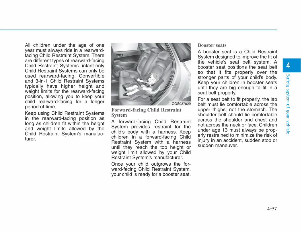
All children under the age of oneyear must always ride in a rearward-facing Child Restraint System. Thereare different types of rearward-facingChild Restraint Systems: infant-onlyChild Restraint Systems can only beused rearward-facing. Convertibleand 3-in-1 Child Restraint Systemstypically have higher height andweight limits for the rearward-facingposition, allowing you to keep yourchild rearward-facing for a longerperiod of time.Keep using Child Restraint Systemsin the rearward-facing position aslong as children fit within the heightand weight limits allowed by theChild Restraint System's manufac-turer.
Forward-facing Child RestraintSystem
A forward-facing Child RestraintSystem provides restraint for thechild’s body with a harness. Keepchildren in a forward-facing ChildRestraint System with a harnessuntil they reach the top height orweight limit allowed by your ChildRestraint System’s manufacturer.Once your child outgrows the for-ward-facing Child Restraint System,your child is ready for a booster seat.
Booster seats
A booster seat is a Child RestraintSystem designed to improve the fit ofthe vehicle’s seat belt system. Abooster seat positions the seat beltso that it fits properly over thestronger parts of your child’s body.Keep your children in booster seatsuntil they are big enough to fit in aseat belt properly. For a seat belt to fit properly, the lapbelt must lie comfortable across theupper thighs, not the stomach. Theshoulder belt should lie comfortableacross the shoulder and chest andnot across the neck or face. Childrenunder age 13 must always be prop-erly restrained to minimize the risk ofinjury in an accident, sudden stop orsudden maneuver.
OOS037029

IInstalling a Child RestraintSystem (CRS)
After selecting a proper Child RestraintSystem for your child and checkingthat the Child Restraint System fitsproperly on the seating position, thereare three general steps for a properinstallation: • Properly secure the Child Restraint
System to the vehicle. All ChildRestraint Systems must be securedto the vehicle with the lap belt or lappart of a lap/shoulder belt or withthe ISOFIX top-tether and/or ISOFIXanchorage and/or with the supportleg.
• Make sure the Child RestraintSystem is firmly secured. Afterinstalling a Child Restraint Systemto the vehicle, push and pull theseat forward and from side-to-sideto verify that it is securely attachedto the seat. A Child RestraintSystem secured with a seat beltshould be installed as firmly aspossible. However, some side-to-side movement can be expected.
When installing a Child RestraintSystem, adjust the vehicle seat andseatback (up and down, forward andrearward) so that your child fits inthe Child Restraint System in a con-fortable manner.
• Secure the child in the ChildRestraint System. Make sure thechild is properly strapped in theChild Restraint System accordingto the Child Restraint System man-ufacturer’s instructions.
Before installing your ChildRestraint System always:Read and follow the instructionsprovided by the manufacturer ofthe Child Restraint System.Failure to follow all warnings andinstructions could increase the riskof the SERIOUS INJURY orDEATH if an accident occurs.
WARNING
If the vehicle headrest preventsproper installation of a ChildRestraint System, the headrest ofthe respective seating positionshall be readjusted or entirelyremoved.
WARNING
A Child Restraint System in aclosed vehicle can become veryhot. To prevent burns, check theseating surface and bucklesbefore placing your child in theChild Restraint System.
CAUTION

CRS categoriesSeating positions
Seating position1 2 3 4 5 6
Universal belted CRS - -Yes1)
F, RYes F, R
Yes2)
F, RYesF, R
i-size CRS - - NoYes F, R
NoYes F, R
ISOFIX infant CRS (i.e. CRS for a baby)
ISOFIX ( R1 )
- - No Yes R No Yes R
Carry cot(ISOFIX lateral facing CRS)
ISOFIX ( L1,L2 )
- - No No No No
ISOFIX toddler CRS - small ISOFIX
( F2,F2X, R2X )- - No
Yes F, R
NoYes F, R
ISOFIX toddler CRS – large* (* : not booster seats)
ISOFIX ( F3, R3 )
- - NoYes3)
F, RNo
Yes3)
F, R
Booster Seat – reduced Width ISO CRF : B2 - - No Yes No Yes
Booster Seat – full Width ISO CRF : B3 - - No No No No
Suitability of each seating position for belted & ISOFIX Child Restraint Systems according to UN regulations(Information for vehicle users and CRS manufacturers)• Yes : Suitable for fitment of the designated category of CRS • No : Not suitable for fitment of the designated category of CRS• ''-'' : Not applicable • The table is based on LHD vehicle. Except for the front passenger seat, the table is valid for RHD vehicle. For RHD
vehicle front passenger seat, please use information for the seating position number 3.
OOSEV038035L
F : Forward facingR : Rearward facing
Seat number Position in the vehicle Seat number Position in the vehicle 1 Front left 4 2nd row left2 Front center 5 2nd row center3 Front right 6 2nd row right

Note1) : You should adjust seatback or seat pumping(if equipped) properly.
Note2) : The seating position(number 5) is not suitable for fitment of child restraint system with support leg.
Note3) : For fitment of ISOFIX toddler’s rearward facing large CRS - Driver’s seat : Seat pumping should be adjusted to appropriate height. - Front passenger seat : Seat sliding should be adjusted to appropriate position.
❈ Never place a rearward facing Child Restraint System on the front passenger seat, unless the passenger air bag is deactivated.
❈ For semi-universal or vehicle specific CRS (ISOFIX or belted CRS), please see the vehicle list provided in the manual of CRS.
❈ It is recommended to remove the head restraint, when CRS is unstable due to head restraint

IISOFIX anchorage and top-tetheranchorage (ISOFIX anchorage sys-tem) for children The ISOFIX system holds a ChildRestraint System during driving and inan accident. This system is designed tomake installation of the Child RestraintSystem easier and reduce the possi-bility of improperly installing yourChild Restraint System. The ISOFIXsystem uses anchors in the vehicleand attachments on the ChildRestraint System. The ISOFIX sys-tem eliminates the need to use seatbelts to secure the Child RestraintSystem to the rear seats.ISOFIX anchorages are metal barsbuilt into the vehicle. There are twolower anchors for each ISOFIX seat-ing position that will accommodate aChild Restraint System with lowerattachments.To use the ISOFIX system in your vehi-cle, you must have a Child RestraintSystem with ISOFIX attachments. The Child Restraint System manu-facturer will provide you with instruc-tions on how to use the ChildRestraint System with its attach-ments for the ISOFIX anchorages.
ISOFIX anchorages have been pro-vided in the left and right outboardrear seating positions. Their locationsare shown in the illustration.
OOSEV038012
Do not attempt to install a ChildRestraint System using ISOFIXanchorages in the rear centerseating position. There are noISOFIX anchorages provided forthis seat. Using the outboard seatanchorages, for the CRS installa-tion on the rear center seatingposition, can damage the anchor-ages.
WARNING

[A] : ISOFIX Anchorage Position Indicator, [B] : ISOFIX Anchorage
ISOFIX anchorages are locatedbetween the seatback and the seatcushion of the rear seat left and rightoutboard seating positions, indicatedby the symbols .
SSecuring a Child Restraint Systemwith the ''ISOFIX AnchorageSystem'' To install an ISOFIX-compatible ChildRestraint System in either of the rearoutboard seating positions:1. Move the seat belt buckle away
from the ISOFIX anchorages.2. Move any other objects away from
the anchorages that could preventa secure connection between theChild Restraint System and theISOFIX anchorages.
3. Place the Child Restraint Systemon the vehicle seat, then attach theseat to the ISOFIX anchoragesaccording to the instructions provid-ed by the Child Restraint Systemmanufacturer.
4. Follow the instructions of the ChildRestraint System's manufacturerfor proper installation and connec-tion of the ISOFIX attachments onthe Child Restraint System to theISOFIX anchorages.
OOS037076
Take the following precautionswhen using the ISOFIX system:• Read and follow all installation
instructions provided with yourChild Restraint System.
• To prevent the child from reach-ing and taking hold of unretract-ed seat belts, buckle all unusedrear seat belts and retract theseat belt webbing behind thechild. Children can be strangledif a shoulder belt becomeswrapped around their neck andthe seat belt tightens.
• NEVER attach more than oneChild Restraint System to a sin-gle anchorage. This could causethe anchor or attachment tocome loose or break.
• Always have the ISOFIX systeminspected by your dealer afteran accident. An accident candamage the ISOFIX system andmay not properly secure theChild Restraint System.
WARNING

SSecuring a Child Restraint Systemseat with “Top-tether Anchorage”system
Top-tether anchorages for ChildRestraint Systems are located on therear of the seatbacks.
1. Route the Child Restraint Systemtop-tether strap over the seatback.Placing the top tether strap, pleasefollow the instructions of the ChildRestraint System manufacturer.
2. Connect the top-tether strap to thetop-tether anchorage, then tightenthe top-tether strap according to theinstructions of your Child RestraintSystem's manufacturer to firmlyattach the Child Restraint System tothe seat.
OOSEV038027
OOS037032
Take the following precautionswhen installing the top-tether:• Read and follow all installation
instructions provided with yourChild Restraint System.
• NEVER attach more than oneChild Restraint System to a sin-gle ISOFIX top-tether anchor-age. This could cause theanchorage or attachment tocome loose or break.
• Do not attach the top-tether toanything other than the correcttop-tether anchorage. It may notwork properly if attached tosomething else.
• Child Restraint System anchor-ages are designed to withstandonly those loads imposed bycorrectly fitted Child RestraintSystem.Under no circumstances arethey to be used for adult seatbelts or harnesses or for attach-ing other items or equipment tothe vehicle.
WARNING

SSecuring a Child Restraint Systemwith a lap/shoulder beltWhen not using the ISOFIX system,all Child Restraint Systems must besecured to a rear seat with the lappart of a lap/shoulder belt.
Installing a Child Restraint Systemwith a lap/shoulder belt
To install a Child Restraint Systemon the rear seats, do the following:1. Place the Child Restraint System
on a rear seat and route the lap/shoulder belt around or through theChild Restraint System, followingthe Child Restraint System manu-facturer’s instructions.
Information When using the rear center seat belt,you should also refer to the “RearCenter Seat Belt” in this chapter.
2. Make sure to insert the belt intothe guide (1) and check that theseat belt is not twisted.
i
OLMB033044 OOS037030

3. Fasten the lap/shoulder belt latchinto the buckle. Listen for the dis-tinct “click” sound.
IInformationPosition the release button so that it iseasy to access in case of an emergency.
4. Remove as much slack from thebelt as possible by pushing downon the Child Restraint Systemwhile feeding the shoulder beltback into the retractor.
5. Push and pull on the ChildRestraint System to confirm thatthe seat belt is holding it firmly inplace.
If your Child Restraint System manu-facturer recommends the use of atop-tether with the lap/shoulder belt,see page 2-47.
To remove the Child Restraint System,press the release button on the buckleand then pull the lap/shoulder belt outof the Child Restraint System andallow the seat belt to retract fully.
i
OLMB033045 OLMB033046

MMass Group Co-Driver 2nd Row LH 2nd Row RH 2nd Row Centre IntermediateCentre
Group 0(Up to 10 kg) X U U U -
Group 0+(Up to 13 kg) X U U U -
Group I(9 to 18 kg) UF U U U -
Group II(15 to 25 kg) UF U U U -
Group III(22 to 36 kg) UF U U U -
Key of letters to be inserted in the above table :
U = Suitable for “universal” category restraints approved for use in this mass group.
UF = Suitable for forward-facing “universal” category restraints approved for use in this mass group.
X = Seat position not suitable for children in this mass group.
LH = Left Hand, RH = Right HandRemarks:- Front LH Seat upright. Rearmost position. Seat belt shoulder anchorage to lowest position.
Child seat restraint suitability for seat position using the seat belt Use child safety seats that have been officially approved and are appropriate for your children. When using the child safety seats,refer to the following table.

OOS037034R/OOS037070EThe actual air bags in the vehicle may differ from the illustration.
1. Driver’s front air bag
2. Passenger’s front air bag
3. Side air bag
4. Curtain air bag
5. Front passenger air bag ON/OFFswitch

The vehicles are equipped with aSupplemental Air Bag System for thedriver’s seat and front passenger’sseats.The front air bags are designed tosupplement the three-point seatbelts. For these air bags to provideprotection, the seat belts must beworn at all times when driving.You can be severely injured or killedin an accident if you are not wearinga seat belt. Air bags are designed tosupplement seat belts, but do notreplace them. Also, air bags are notdesigned to deploy in every collision.In some accidents, the seat belts arethe only restraint protecting you.
AIR BAG SAFETY PRECAUTIONS
ALWAYS use seat belts Child Restraint Systems - every trip, every time,everyone! Even with air bags, you can be seriously injured or killed in a col-lision if you are improperly belted or not wearing your seat belt when theair bag inflates.NEVER place a child in any Child Restraint System or booster seat in thefront passenger seat, unless the air bag is deactivated.An inflating air bag could forcefully strike the infant or child causing seriousor fatal injuries.ABC - Always Buckle Children under age 13 in the back seat. It is thesafest place for children of any age to ride. If a child age 13 or older mustbe seated in the front seat, he or she must be properly belted and the seatshould be moved as far back as possible.All occupants should sit upright with the seatback in an upright position,centered on the seat cushion with their seat belt on, legs comfortablyextended and their feet on the floor until the vehicle is parked and the vehi-cle is turned off. If an occupant is out of position during an accident, therapidly deploying air bag may forcefully contact the occupant causing seri-ous or fatal injuries.You and your passengers should never sit or lean unnecessarily close tothe air bags or lean against the door or center console.Move your seat as far back as possible from front air bags, while still main-taining control of the vehicle.
WARNING

WWhere are the air bags?
To reduce the risk of serious injuryor death from inflating front airbags, take the following precau-tions:• Seat belts must be worn at all
times to help keep occupantspositioned properly.
• Move your seat as far back aspossible from front air bags,while still maintaining control ofthe vehicle.
• Never lean against the door orcenter console.
• Do not allow the front passengerto place their feet or legs on thedashboard.
WARNING
OOSEV038013R
■ Driver’s front air bag
OOS037039R
■ Passenger’s front air bag
Driver’s and passenger’s front air bags
Your vehicle is equipped with a Supplemental Restraint System (SRS) andlap/shoulder belts at both the driver and passenger seating positions.The SRS consists of air bags which are located in the center of the steer-ing wheel, and the passenger's side front panel pad above the glove box.The purpose of the SRS is to provide the vehicle's driver and front passen-gers with additional protection than that offered by the seat belt systemalone in case of a frontal impact of sufficient severity.

Passenger’s front air bag ON/OFFswitch (if equipped)
The purpose of the switch is to dis-able the passenger’s front air bag inorder to transport occupants who areat increased risk for air bag-relatedinjury due to age, size, or medicalcondition.
To deactivate the passenger’s frontair bag:Insert the key or a similar rigid deviceinto the passenger’s front air bagON/OFF switch and turn it to theOFF position. The passenger air bagOFF indicator ( ) will illuminate andstay on until the passenger’s front airbag is reactivated.
OOSEV038036R OOSIEV039033
• No objects (such as crash padcover, cellular phone holder, cupholder, perfume or stickers)should be placed over or nearthe air bag modules on thesteering wheel, instrumentpanel, windshield glass, and thefront passenger's panel abovethe glove box. Such objectscould cause harm if the vehicleis in a crash severe enough tocause the air bags to deploy.
• Do not attach any objects onfront windshield and inside mir-ror.

To reactivate the passenger’s frontair bag:Insert the key or a similar rigid deviceinto the passenger’s front air bagON/OFF switch and turn it to the ONposition. The passenger air bag ONindicator ( ) will illuminate and stayon for 60 seconds.
IInformation The passenger’s front air bag ON/OFFindicator illuminates for about 4 sec-onds after the START/STOP button isplaced in the ON position.
i
Never allow an adult passenger toride in the front passenger seatwhen the passenger air bag OFFindicator is illuminated. During acollision, the air bag will not inflateif the indicator is illuminated. Turnon the passenger’s front air bag orhave your passenger move to therear seat.
WARNING
If the passenger’s front air bagON/OFF switch malfunctions, thefollowing conditions may occur:• The air bag warning light ( )
on the instrument panel willilluminate.
• The passenger air bag OFF indi-cator ( ) will not illuminate andthe ON indicator ( ) will comeon and go off after approximate-ly 60 seconds. The passenger’sfront air bag will inflate in afrontal impact even though thepassenger’s front air bagON/OFF switch is set to the OFFposition.
• We recommend that an author-ized HYUNDAI dealer inspectthe passenger’s front air bagON/OFF switch and the SRS airbag system as soon as possible.
WARNING
OOSIEV039034

SSide air bags
Your vehicle is equipped with a side airbag in each front seat.
The purpose of the air bag is to providethe vehicle’s driver and the front pas-senger with additional protection thanthat offered by the seat belt alone.The side air bags are designed todeploy during certain side impact col-lisions, depending on the crashseverity.The side air bags are not designed todeploy in all side impact situations.
To reduce the risk of serious injuryor death from an inflating side airbag, take the following precau-tions:• Seat belts must be worn at all
times to help keep occupantspositioned properly.
• Do not allow passengers to leantheir heads or bodies ontodoors, put their arms on thedoors, stretch their arms out ofthe window, or place objectsbetween the doors and seats.
WARNING OOS037040
OOS037041
• Hold the steering wheel at the 9o’clock and 3 o’clock positions,to minimize the risk of injuries toyour hands and arms.
• Do not use any accessory seatcovers. This could reduce orprevent the effectiveness of thesystem.
• Do not hang other objectsexcept clothes on the clotheshanger. In an accident it maycause vehicle damage or per-sonal injury especially whenairbag is inflated.
• Do not place any objects overthe air bag or between the airbag and yourself. Also, do notattach any objects around thearea the air bag inflates such asthe door, side door glass, frontand rear pillar.
• Do not place any objectsbetween the door and the seat.They may become dangerousprojectiles if the side air baginflates.

CCurtain air bags
Curtain air bags are located alongboth sides of the roof rails above thefront and rear doors.
They are designed to help protect theheads of the front seat occupantsand the rear outboard seat occupantsin certain side impact collisions.The curtain air bags are designed todeploy during certain side impactcollisions, depending on the crashseverity.The curtain air bags are not designedto deploy in all side impact situations.
• Do not install any accessorieson the side or near the side airbags.
• Do not put any objects betweenthe side airbag label and seatcushion. It could cause harm ifthe vehicle is in a crash severeenough to cause the air bags todeploy.
• Do not cause impact to thedoors when the START/STOPbutton is in the ON position orthis may cause the side air bagsto inflate.
• If the seat or seat cover is dam-aged, we recommend that thesystem be serviced by anauthorized HYUNDAI dealer.
OOS037042
OOS037043
To reduce the risk of serious injuryor death from an inflating curtainair bags, take the following pre-cautions:• All seat occupants must wear
seat belts at all times to helpkeep occupants positionedproperly.
• Properly secure Child RestraintSystem as far away from thedoor as possible.
WARNING

HHow does the air bags systemoperate?
The SRS consists of the followingcomponents:(1) Driver's front air bag module(2) Passenger's front air bag module(3) Side air bag modules(4) Curtain air bag modules(5) Rear retractor pre-tensioner
assemblies (6) Front retractor pre-tensioner(7) Air bag warning light(8) SRS control module (SRSCM)(9) Front impact sensors
(10) Side impact sensors(11) Side pressure sensors(12) Passenger’s front air bag
ON/OFF indicator (front pas-senger's seat only)
(13) Passenger’s front air bagON/OFF switch
The SRSCM continually monitors allSRS components while theSTART/STOP button is ON to deter-mine if a crash impact is severeenough to require air bag deploy-ment or pre-tensioner seat beltdeployment.
• Do not place any objects overthe air bag. Also, do not attachany objects around the area theair bag inflates such as the door,side door glass, front and rearpillar, roof side rail.
• Do not hang other objectsexcept clothes, especially hardor breakable objects on theclothes hanger. In an accident, itmay cause vehicle damage orpersonal injury.
• Do not allow passengers to leantheir heads or bodies ontodoors, put their arms on thedoors, stretch their arms out ofthe window, or place objectsbetween the doors and seats.
• Do not open or repair the sidecurtain air bags.
OOS037063E

SRS warning light
The SRS (Supplement RestraintSystem) air bag warning light on theinstrument panel displays the air bagsymbol depicted in the illustration. Thesystem checks the air bag electricalsystem for malfunctions. The light indi-cates that there is a potential problemwith your air bag system.
During a moderate to severe frontalcollision, sensors will detect the vehi-cle’s rapid deceleration. If the rate ofdeceleration is high enough, the con-trol unit will inflate the front air bags,at the time and with the force need-ed.The front air bags help protect thedriver and front passenger byresponding to frontal impacts inwhich seat belts alone cannot pro-vide adequate restraint. When need-ed, the side air bags help provideprotection in the event of a sideimpact by supporting the side upperbody area. • Air bags are activated (able to
inflate if necessary) only when theSTART/STOP button is in the ONposition.
• Air bags inflate in the event of cer-tain frontal or side collisions to helpprotect the occupants from seriousphysical injury.
If your SRS malfunctions, the airbag may not inflate properly dur-ing an accident increasing the riskof serious injury or death.If any of the following conditionsoccur, your SRS is malfunctioning:• The light does not turn on for
approximately six seconds whenthe START/STOP button is inthe ON position.
• The light stays on after illuminat-ing for approximately six sec-onds.
• The light comes on while thevehicle is in motion.
• The light blinks when the vehicleis running.
We recommend that an author-ized HYUNDAI dealer inspect theSRS as soon as possible if any ofthese conditions occur.
WARNING

• There is no single speed at whichthe air bags will inflate. Generally,air bags are designed to inflatebased upon the severity of a colli-sion and its direction. These twofactors determine whether the sen-sors produce an electronic deploy-ment/inflation signal.
• The front air bags will completelyinflate and deflate in an instant. It isvirtually impossible for you to seethe air bags inflate during an acci-dent. It is much more likely that youwill simply see the deflated airbags hanging out of their storagecompartments after the collision.
• To help provide protection, the airbags must inflate rapidly. Thespeed of air bag inflation is a con-sequence of extremely short timein which to inflate the air bagbetween the occupant and thevehicle structures before the occu-pant impacts those structures. Thisspeed of inflation reduces the riskof serious or life-threateninginjuries and is thus a necessarypart of air bag design.However, the rapid air bag inflationcan also cause injuries which caninclude facial abrasions, bruisesand broken bones because theinflation speed also causes the airbags to expand with a great deal offorce.
• There are even circumstancesunder which contact with the airbag can cause fatal injuries, espe-cially if the occupant is positionedexcessively close to the air bag.
You can take steps to reduce the riskof being injured by an inflating airbag. The greatest risk is sitting tooclose to the air bag. An air bag needsspace to inflate. It is recommendedthat drivers sit as far as possiblebetween the center of the steeringwheel and the chest while still main-taining control of the vehicle.

When the SRSCM detects a suffi-ciently severe impact to the front ofthe vehicle, it will automaticallydeploy the front air bags.
Upon deployment, tear seams mold-ed directly into the pad covers willseparate under pressure from theexpansion of the air bags. Furtheropening of the covers allows fullinflation of the air bags.A fully inflated air bag, in combina-tion with a properly worn seat belt,slows the driver's or the front pas-senger's forward motion, reducingthe risk of head and chest injury.
After complete inflation, the air bagimmediately starts deflating, enablingthe driver to maintain forward visibili-ty and the ability to steer or operateother controls.
OIK037082R
■ Driver’s front air bag (2)
OIK037083R
■ Driver’s front air bag (3)
OIK037084R
■ Passenger’s front air bagOIK037081R
■ Driver’s front air bag (1)

WWhat to expect after an air baginflates After a frontal or side air bag inflates,it will deflate very quickly. Air baginflation will not prevent the driverfrom seeing out of the windshield orbeing able to steer. Curtain air bagsmay remain partially inflated forsome time after they deploy.
After an air bag inflates, take thefollowing precautions:• Open your windows and doors
as soon as possible after impactto reduce prolonged exposure tothe smoke and powder releasedby the inflating air bag.
• Do not touch the air bag storagearea’s internal componentsimmediately after an air bag hasinflated. The parts that comeinto contact with an inflating airbag may be very hot.
• Always wash exposed skinareas thoroughly with cold waterand mild soap.
• We recommend that an author-ized HYUNDAI dealer replacethe air bag immediately afterdeployment. Air bags aredesigned to be used only once.
WARNING
To prevent objects from becomingdangerous projectiles when thepassenger's air bag inflates:• Do not install or place any
objects (drink holder, CD holder,stickers, etc.) on the front pas-senger's panel above the glovebox where the passenger's airbag is located.
• Do not install a container of liq-uid air freshener near the instru-ment cluster or on the instru-ment panel surface.
WARNING

NNoise and smoke from inflating airbag When the air bags inflate, they makea loud noise and may producesmoke and powder in the air inside ofthe vehicle. This is normal and is aresult of the ignition of the air baginflator. After the air bag inflates, youmay feel substantial discomfort inbreathing because of the contact ofyour chest with both the seat belt andthe air bag, as well as from breathingthe smoke and powder. The powdermay aggravate asthma for somepeople. If you experience breathingproblems after an air bag deploy-ment, seek medical attention imme-diately.Though the smoke and powder arenontoxic, they may cause irritation tothe skin, eyes, nose, throat, etc. Ifthis is the case, wash and rinse withcold water immediately and seekmedical attention if the symptomspersist.
Do not install a Child RestraintSystem on the front passengerseat
Never install a Child RestraintSystem in the front passenger seat,unless the air bag is deactivated
OYDESA2042
NEVER use a rearward facingChild Restraint on a seat protect-ed by an ACTIVE AIRBAG in frontof it, DEATH or SERIOUSINJURY to the CHILD can occur.
WARNING

WWhy didn't my air bag go off in acollision?There are certain types of accidentsin which the air bag would not beexpected to provide additional pro-tection. These include rear impacts,second or third collisions in multipleimpact accidents, as well as lowspeed impacts. Damage to the vehi-cle indicates a collision energyabsorption, and is not an indicator ofwhether or not an air bag shouldhave inflated.
Air bag collision sensors
To reduce the risk of an air bagdeploying unexpectedly and caus-ing serious injury or death:• Do not hit or allow any objects to
impact the locations where airbags or sensors are installed.
• Do not perform maintenance onor around the air bag sensors. Ifthe location or angle of the sen-sors is altered, the air bags maydeploy when they should not ormay not deploy when theyshould.
• Do not install bumper guards orreplace the bumper with a non-genuine part. This may adverse-ly affect the collision and air bagdeployment performance.
• Place the START/STOP buttonto the OFF position, when the
WARNING
vehicle is being towed to pre-vent inadvertent air bag deploy-ment.
• We recommend that all air bagrepairs are conducted by anauthorized HYUNDAI dealer.

1. SRS control module
2. Front impact sensor
3. Side pressure sensor (front door)
4. Side impact sensor (B-pillar)
OOSEV038015R/OOSEV038016R/OOSEV038017R/OOS037047R/OOS037077R

AAir bag inflation conditions
Front air bags
Front air bags are designed to inflatein a frontal collision depending onthe severity of impact of the front col-lision.
Side and curtain air bags
Side and curtain air bags aredesigned to inflate when an impact isdetected by side collision sensorsdepending on the severity of impactresulting from a side impact collision.
Although the driver’s and front pas-senger’s air bags are designed toinflate in frontal collisions, they alsomay inflate in other types of colli-sions if the front impact sensorsdetect a sufficient impact. Side andcurtain air bags are designed toinflate in side impact collisions, butthey may inflate in other collisions ifthe side impact sensors detect a suf-ficient impact. If the vehicle chassis is impacted bybumps or objects on unimprovedroads, the air bags may deploy. Drivecarefully on unimproved roads or onsurfaces not designed for vehicletraffic to prevent unintended air bagdeployment.
OOSEV038019
OOSEV038028
OOSEV038018

AAir bag non-inflation conditions
In certain low-speed collisions the airbags may not deploy. The air bagsare designed not to deploy in suchcases because they may not providebenefits beyond the protection of theseat belts.
Front air bags are not designed toinflate in rear collisions, becauseoccupants are moved backward bythe force of the impact. In this case,inflated air bags would not provideany additional benefit.
Front air bags may not inflate in sideimpact collisions, because occupantsmove in the direction of the collision,and thus in side impacts, front air bagdeployment would not provide addi-tional occupant protection.However, side and curtain air bagsmay inflate depending on the severityof the impact.
OOSEV038020
OOSEV038021
OOSEV038022

In an angled collision, the force ofimpact may direct the occupants in adirection where the air bags wouldnot be able to provide any additionalbenefit, and thus the sensors maynot deploy any air bags.
Just before impact, drivers oftenbrake heavily. Such heavy brakinglowers the front portion of the vehiclecausing it to “ride” under a vehiclewith a higher ground clearance. Airbags may not inflate in this "under-ride" situation because decelerationforces that are detected by sensorsmay be significantly reduced by such“underride” collisions.
Front air bags may not inflate inrollover accidents because front airbag deployment would not provideadditional occupant protection.
IInformation The side and/or curtain air bags mayinflate when the vehicle is rolled overby a side impact collision, if the vehi-cle is equipped with side and/or cur-tain air bags.
i

Air bags may not inflate if the vehiclecollides with objects such as utilitypoles or trees, where the point ofimpact is concentrated and the colli-sion energy is absorbed by the vehi-cle structure.
SSRS care The SRS is virtually maintenance-free and there are no parts you cansafely service by yourself. If the SRSair bag warning light does not illumi-nate when the START/STOP buttonis in the ON position, or continuouslyremains on, we recommend that thesystem be immediately inspected byan authorized HYUNDAI dealer.We recommend any work on the SRSsystem, such as removing, installing,repairing, or any work on the steeringwheel, the front passenger's panel,front seats and roof rails be performedby an authorized HYUNDAI dealer.Improper handling of the SRS system
may result in serious personal injury.
To reduce the risk of serious injuryor death take the following pre-cautions:• Do not attempt to modify or dis-
connect the SRS components orwiring, including the addition ofany kind of badges to the padcovers or modifications to thebody structure.
• Do not place objects over ornear the air bag modules on thesteering wheel, instrument
OTL035069 OOSEV038023 OTL035068

AAdditional safety precautions Passengers should not move out of orchange seats while the vehicle is mov-ing. A passenger who is not wearing aseat belt during a crash or emergencystop can be thrown against the insideof the vehicle, against other occu-pants, or be ejected from the vehicle.Do not use any accessories on seatbelts. Devices claiming to improveoccupant comfort or reposition theseat belt can reduce the protectionprovided by the seat belt and increasethe chance of serious injury in a crashDo not modify the front seats.Modification of the front seats couldinterfere with the operation of the sup-plemental restraint system sensingcomponents or side air bags.
panel, and the front passenger'spanel above the glove box.
• Clean the air bag pad coverswith a soft cloth moistened withplain water. Solvents or cleanerscould adversely affect the airbag covers and proper deploy-ment of the system.
• We recommend that inflated airbags be replaced by an author-ized HYUNDAI dealer.
• If components of the air bag sys-tem must be discarded, or if the

DDo not place items under the frontseats. Placing items under the frontseats could interfere with the opera-tion of the supplemental restraint sys-tem sensing components and wiringharnesses.Do not cause impact to the doors.Impact to the doors when theSTART/STOP button is in the ON posi-tion may cause the air bags to inflate.
Adding equipment to or modifying
your air bag equipped vehicleIf you modify your vehicle by chang-ing your vehicle's frame, bumper sys-tem, front end or side sheet metal orride height, this may affect the oper-ation of your vehicle's air bag sys-tem.
Air bag warning labels Air bag warning labels are attachedto alert the passengers of potentialrisks of the air bag system. Be sure to read all of the informationabout the air bags that are installedon your vehicle in this Owner’sManual.
OAE036060


SSmart key
Your HYUNDAI uses a Smart Key,which you can use to lock or unlocka door (and tailgate) and even startthe vehicle.1. Door Lock 2. Door Unlock3. Tailgate Unlock
Locking
To lock : 1. Close all doors, hood and tailgate. 2. Either press the door handle but-
ton or press the Door Lock button(1) on the smart key.
3. The hazard warning lights andchime will blink once. Also, the out-side rearview mirror will fold, if theoutside rearview mirror foldingswitch is in the AUTO position (ifequipped).
4. Make sure the doors are locked bychecking the position of the doorlock button inside the vehicle.
Information The door handle button will onlyoperate when the smart key is within0.7~1 m (28~40 in.) from the outsidedoor handle.
i
OOSEV048063ROPDE046044

Even though you press the outsidedoor handle button, the doors will notlock and the chime will sound forthree seconds if any of the followingoccur:• The Smart Key is in the vehicle.• The START/STOP button is in ON
position.• Any door except the tailgate is open.
UUnlocking
To unlock:1. Carry the Smart Key. 2. Either press the door handle but-
ton or press the Door Unlock but-ton (2) on the smart key.
3. The doors will unlock. The hazardwarning lights will blink two times.Also, the outside rearview mirrorwill unfold, if the outside rearviewmirror folding switch is in the AUTOposition (if equipped).
Information • The door handle button will only
operate when the smart key is with-in 0.7~1 m (28~40 in.) from the out-side door handle. Other people canalso open the doors without thesmart key in possession.
• After unlocking the doors, the doorswill lock automatically after 30 sec-onds unless a door is opened.
i
OOSEV048063RDo not leave the Smart Key inyour vehicle with unsupervisedchildren. Unattended childrencould press the START/STOPbutton and may operate powerwindows or other controls, or evenmake the vehicle move, whichcould result in serious injury ordeath.
WARNING

TTailgate unlocking To unlock:1. Carry the smart key. 2. Either press the tailgate handle
button or press the Tailgate Unlockbutton (3) on the smart key formore than one second.
3. The hazard warning lights andchime will blink two times.
Once the tailgate is opened and thenclosed, the tailgate will lock automat-ically.
Information After unlocking the tailgate, the tail-gate will lock automatically after 30seconds unless the tailgate is opened.
Start-upYou can start the vehicle withoutinserting the key. For detailed infor-mation, refer to the START/STOPbutton in chapter 5.
To prevent damaging the smart key:• Keep the smart key away from
water or any liquid and fire. If theinside of the smart key gets damp(due to drinks or moisture), or isheated, internal circuit may mal-function, excluding the car from thewarranty.
• Avoid dropping or throwing thesmart key.
• Protect the smart key fromextreme temperatures.
i
NOTICE

MMechanical key If the Smart Key does not operatenormally, you can lock or unlock thedoor by using the mechanical key.
Move the release lever in the direc-tion of the arrow (1) and then removethe mechanical key (2). Insert themechanical key into the key hole onthe door. To reinstall the mechanical key, putthe key into the hole and push it untila click sound is heard.
Loss of a smart key A maximum of two smart keys canbe registered to a single vehicle. Ifyou happen to lose your smart key, itis recommended that you shouldimmediately take the vehicle andremaining key to your authorizedHYUNDAI dealer or tow the vehicle,if necessary.
Smart key precautionsThe smart key will not work if any ofthe following occur:• The smart key is close to a radio
transmitter such as a radio stationor an airport which can interferewith normal operation of the trans-mitter.
• The smart key is near a mobile twoway radio system or a cellularphone.
• Another vehicle’s smart key isbeing operated close to your vehi-cle.
When the smart key does not workcorrectly, open and close the doorwith the mechanical key. If you havea problem with the smart key, it isrecommended that you contact anauthorized HYUNDAI dealer.If the smart key is in close proximityto your mobile phone, the signalcould be blocked by your mobilephones normal operational signals.This is especially important when thephone is active such as making andreceiving calls, text messaging,and/or sending/receiving emails. Avoid placing the smart key and yourmobile phone in the same pants orjacket pocket and always try to main-tain an adequate distance betweenthe two devices.
OPD046045

IInformation Changes or modifications not express-ly approved by the party responsiblefor compliance could void the user’sauthority to operate the equipment. Ifthe keyless entry system is inoperativedue to changes or modifications notexpressly approved by the partyresponsible for compliance, it will notbe covered by your manufacturer’svehicle warranty.
Keep the smart key away from elec-tromagnetic materials that blockselectromagnetic waves to the keysurface.
Always have the smart key with youwhen leaving the vehicle. If the smartkey is left near the vehicle, the vehi-cle battery may be discharged.
Battery replacement
If the Smart Key is not working prop-erly, try replacing the battery with anew one.Battery Type: CR2032To replace the battery:1. Remove the mechanical key.2. Use a slim tool to pry open the
rear cover of the smart key.3. Remove the old battery and insert
the new battery. Make sure thebattery position is correct.
4. Reinstall the rear cover of thesmart key.
If you suspect your smart key mighthave sustained some damage, oryou feel your smart key is not work-ing correctly, it is recommended thatyou contact an authorized HYUNDAIdealer.
Information An inappropriately disposedbattery can be harmful to theenvironment and human health.Dispose of the battery accordingto your local law(s) and regula-tion.
i
NOTICE
NOTICE
i
OPDE046046

IImmobilizer system The immobilizer system protects your vehicle from theft. If an improperly coded key (or other device) is used, the power system is disabled.When the START/STOP button is placed in the ON position, the immo-bilizer system indicator should come on briefly, then go off. If the indicator starts to blink, the system does not recognize the coding of the key.Place the START/STOP button to the OFF position, then place the START/STOP button to the ON posi-tion again.The system may not recognize your key’s coding if another immobilizer key or other metal object (i.e., key chain) is near the key. The vehicle may not start because the metal may interrupt the transponder signal from transmitting normally.If the system repeatedly does not recognize the coding of the key, it is recommended that you contact your HYUNDAI dealer.
Do not attempt to alter this system oradd other devices to it. Electricalproblems could result that may makeyour vehicle inoperable.
The transponder in your key is an important part of the immobilizer sys-tem. It is designed to give years of trouble-free service, however you should avoid exposure to moisture, static electricity and rough handling. Immobilizer system malfunction could occur.
Disclaimer:The system is designed in such a way that it makes vehicle theft difficult if its circuit and battery connection is uninterrupted.
NOTICE
In order to prevent theft of yourvehicle, do not leave spare keysanywhere in your vehicle. Yourimmobilizer password is a cus-tomer unique password andshould be kept confidential.
WARNING
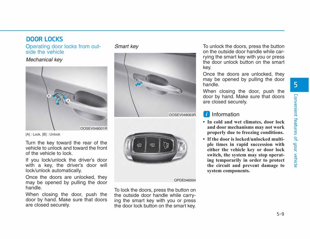
OOperating door locks from out-side the vehicle Mechanical key
[A] : Lock, [B] : Unlock
Turn the key toward the rear of thevehicle to unlock and toward the frontof the vehicle to lock.If you lock/unlock the driver's doorwith a key, the driver’s door willlock/unlock automatically.Once the doors are unlocked, theymay be opened by pulling the doorhandle.When closing the door, push thedoor by hand. Make sure that doorsare closed securely.
Smart key
To lock the doors, press the button onthe outside door handle while carry-ing the smart key with you or pressthe door lock button on the smart key.
To unlock the doors, press the buttonon the outside door handle while car-rying the smart key with you or pressthe door unlock button on the smartkey.Once the doors are unlocked, theymay be opened by pulling the doorhandle. When closing the door, push thedoor by hand. Make sure that doorsare closed securely.
Information • In cold and wet climates, door lock
and door mechanisms may not workproperly due to freezing conditions.
• If the door is locked/unlocked multi-ple times in rapid succession witheither the vehicle key or door lockswitch, the system may stop operat-ing temporarily in order to protectthe circuit and prevent damage tosystem components.
i
OOSEV048001R
OOSEV048063R
OPDE046004

OOperating door locks from insidethe vehicle With the door lock button
• To unlock a door, pull the door lockbutton (1) to the “Unlock” position.The red mark (2) on the door lockbutton will be visible.
• To lock a door, push the door lockbutton (1) to the “Lock” position. Ifthe door is locked properly, the redmark (2) on the door lock buttonwill not be visible.
• To open a door, pull the door han-dle (3) outward.
• Doors cannot be locked if thesmart key is in the vehicle and anydoor is open.
Information If a power door lock ever fails to func-tion while you are in the vehicle tryone or more of the following tech-niques to exit:
Operate the door unlock featurerepeatedly (both electronic and manu-al) while simultaneously pulling on thedoor handle.
Operate the other door locks and han-dles, front and rear.
Lower a front window and use themechanical key to unlock the doorfrom outside.
With the door handleFront door
If the inner door handle is pulled whenthe door is locked, the door will unlockand open.
Rear door
If the inner door handle is pulled oncewhen the door is locked, the door willunlock.If the inner door handle is pulled oncemore, the door will open.
i
OOSEV048002R

WWith the central door lock switch
• When pressing the ( ) portion (1)of the switch, all vehicle doors willlock.- If the smart key is in the vehicle
and any door is opened, thedoors will not lock even thoughthe lock button (1) of the centraldoor lock switch is pressed.
• When pressing the ( ) portion (2)of the switch, all vehicle doors willunlock.
OOSEV048048R
Do not leave children or animalsunattended in your vehicle. Anenclosed vehicle can becomeextremely hot, causing death orserious injury to unattended chil-dren or animals who cannotescape the vehicle. Children mightoperate features of the vehiclethat could injure them, or theycould encounter other harm, pos-sibly from someone gaining entryto the vehicle.
WARNING
Always secure your vehicle
Leaving your vehicle unlockedincreases the potential risk to youor others from someone hiding inyour vehicle.To secure your vehicle, whiledepressing the brake, shift to theP (Park) position, engage theparking brake, and place theSTART/STOP button in the OFFposition, close all windows, lock alldoors, and always take the keywith you.
WARNING
• The doors should always befully closed and locked while thevehicle is in motion. If the doorsare unlocked, the risk of beingthrown from the vehicle in acrash is increased.
• Do not pull the inner door handleof driver’s or passenger’s doorwhile the vehicle is moving.
WARNING
If you stay in the vehicle for a longtime while the weather is very hotor cold, there are risks of injuriesor danger to life. Do not lock thevehicle from the outside whensomeone is in the vehicle.
WARNING

AAuto door lock/unlock features Impact sensing door unlock sys-tem (if equipped)All doors will be automaticallyunlocked when an impact causes theair bags to deploy.
Speed sensing door lock system (ifequipped)All doors will be automatically lockedwhen vehicle speed exceeds 15km/h (9 mph).
You can activate or deactivate theAuto Door Lock/Unlock features fromthe User Settings Mode on the LCDdisplay. For more details, refer to"LCD Display" in this chapter.
Child-protector rear door locks
The child safety lock is provided tohelp prevent children seated in therear from accidentally opening therear doors. The rear door safety locksshould be used whenever childrenare in the vehicle. The child safety lock is located onthe edge of each rear door. When thechild safety lock is in the lock posi-tion, the rear door will not open if theinner door handle (2) is pulled.
Opening a door when somethingis approaching may cause dam-age or injury. Be careful whenopening doors and watch for vehi-cles, motorcycles, bicycles orpedestrians approaching the vehi-cle in the path of the door.
WARNING
OOSEV048003

To lock the child safety lock, insert akey (or screwdriver) (1) into the holeand turn it to the lock position.To allow a rear door to be openedfrom inside the vehicle, unlock thechild safety lock.
If children accidently open the reardoors while the vehicle is inmotion, they could fall out of thevehicle. The rear door safety locksshould always be used wheneverchildren are in the vehicle.
WARNING

This system helps to protect yourvehicle and valuables. The horn willsound and the hazard warning lightswill blink continuously if any of thefollowing occurs: - A door is opened without using the
smart key.- The tailgate is opened without
using the smart key.- The hood is opened.The alarm continues for 30 seconds,then the system resets. To turn offthe alarm, unlock the doors with thesmart key. The Theft Alarm System automati-cally sets 30 seconds after you lockthe doors and the tailgate. For thesystem to activate, you must lock thedoors and the tailgate from outsidethe vehicle with the smart key or bypressing the button on the outside ofthe door handles with the smart keyin your possession.The hazard warning lights will blinkand the chime will sound once toindicate the system is armed.
Once the security system is set, open-ing any door, the tailgate, or the hoodwithout using the smart key will causethe alarm to activate.The Theft Alarm System will not set ifthe hood, the tailgate, or any door isnot fully closed. If the system will notset, check the hood, the tailgate, orthe doors are fully closed.Do not attempt to alter this system oradd other devices to it.
IInformation • Do not lock the doors until all pas-
sengers have left the vehicle. If the remaining passenger leaves the vehicle when the system is armed, the alarm will be activated.
• If the vehicle is not disarmed with the smart key, open the doors by using the mechanical key, start the vehicle and wait for 30 seconds.
• When the system is disarmed but a door or tailgate is not opened within 30 seconds, the system will be rearmed.
Disclaimer:The system is designed in such a way that it makes vehicle theft difficult if its circuit and battery connection is uninterrupted.
Information Vehicles equipped with a theft alarmsystem will have a label attached tothe vehicle with the following words:
1. WARNING
2. SECURITY SYSTEM
iiOJC040170

EElectric power steering (EPS)The system assists you with steeringthe vehicle. If the vehicle is off or ifthe power steering system becomesinoperative, the vehicle may still besteered, but it will require increasedsteering effort.Also, the steering effort becomesheavier as the vehicle’s speedincreases and becomes lighter asthe vehicle’s speed decreases forbetter control of the steering wheel.Should you notice any change in theeffort required to steer during normalvehicle operation, we recommendthat the system be checked by anauthorized HYUNDAI dealer.
• If the Electric Power SteeringSystem does not operate normally,the warning light ( ) will illumi-nate or blink on the instrumentcluster. The steering wheel maybecome difficult to control or oper-ate. Take your vehicle to anauthorized HYUNDAI dealer andhave the system checked as soonas possible.
• When abnormality is detected inthe electric power steering system,to prevent a deadly accident, thesteering assist function will stop. Atthis time, the warning light turns onor blinks on the cluster. The steer-ing wheel may become difficult tocontrol or operate. Have your vehi-cle checked immediately, aftermoving the vehicle to a safe zone.
Information The following symptoms may occurduring normal vehicle operation:
• The steering effort may be highimmediately after placing theSTART/STOP button in the ONposition.
This happens as the system per-forms the EPS system diagnostics.When the diagnostics is completed,the steering wheel will return to itsnormal condition.
• A click noise may be heard from theEPS relay after the START/STOPbutton is in the ON or OFF position.
• Motor noise may be heard when thevehicle is at a stop or at a low driv-ing speed.
• When you operate the steeringwheel in low temperature, abnormalnoise may occur. If temperaturerises, the noise will disappear. Thisis a normal condition.
iNOTICE

• When the vehicle is stationary, ifyou turn the steering wheel all theway to the left or right continuously,the steering wheel effort increases.This is not a system malfunction. Astime passes, the steering wheeleffort will return to its normal con-dition.
TTilt steering / Telescope steering
Information After adjustment, sometimes the lock-release lever may not lock the steeringwheel.
It is not a malfunction. This occurswhen two gears are not engaged cor-rectly. In this case, adjust the steeringwheel again and then lock the steeringwheel.
To change the steering wheel angleand height: 1. Pull down the lock-release lever (1).2. Adjust the steering wheel to the
desired angle (2) and height (3).Move the steering wheel, so itpoints toward your chest, nottoward your face. Make sure youcan see the instrument panelwarning lights and gauges. Afteradjusting, pull up the lock
3. Pull up the lock-release lever tolock the steering wheel in place.
Push the steering wheel both up anddown to be certain it is locked inposition.
i
Never adjust the steering wheelwhile driving. You may lose steer-ing control and cause severe per-sonal injury, death or accidents.
WARNING
OOSEV048064R

HHeated steering wheel (if equipped)
When the vehicle is ON, press theheated steering wheel button towarm the steering wheel. The indica-tor on the button will illuminate.To turn the heated steering wheel off,press the button again. The indicatoron the button will turn off.
Information The heated steering wheel will turn offautomatically approximately 30 min-utes after the heated steering wheel isturned on.
Do not install any cover or accesso-ry on the steering wheel. This coveror accessory could cause damage tothe heated steering wheel system.
Horn
To sound the horn, press the areaindicated by the horn symbol on yoursteering wheel. The horn will operateonly when this area is pressed.
Do not strike the horn severely tooperate it, or hit it with your fist. Donot press on the horn with a sharp-pointed object.
NOTICE
NOTICE
i
OOSEV048004R
OOS047008

IInside rearview mirrorBefore you start driving, adjust therearview mirror to the center on theview through the rear window.
When cleaning the mirror, use apaper towel or similar material damp-ened with glass cleaner. Do notspray glass cleaner directly on themirror as that may cause the liquidcleaner to enter the mirror housing.
Day/night rearview mirror (if equipped)
[A] : Day, [B] : Night
Make this adjustment before youstart driving and while the day/nightlever is in the day position.Pull the day/night lever toward you toreduce glare from the headlights ofthe vehicles behind you during nightdriving.Remember that you lose somerearview clarity in the night position.
NOTICEMake sure your line of sight is notobstructed. Do not place objects inthe rear seat, cargo area, orbehind the rear headrests whichcould interfere with your visionthrough the rear window.
WARNING
To prevent serious injury duringan accident or deployment of theair bag, do not modify the rearviewmirror and do not install a widemirror.
WARNING
NEVER adjust the mirror whiledriving. This may cause loss ofvehicle control resulting in an acci-dent.
WARNING
OOSEV048005

EElectric Chromic Mirror (ECM) (if equipped)The electric rearview mirror automati-cally controls the glare from the head-lamp of the car behind you in night-time or low light driving conditions.When the vehicle is ON, the glare isautomatically controlled by the sen-sor mounted in the rearview mirror.The sensor detects the light levelaround the vehicle, and automatical-ly adjusts to control the headlampglare from vehicles behind you.Whenever the gear is shifted to R(Reverse), the mirror will automati-cally go to the brightest setting inorder to improve the drivers viewbehind the vehicle.
[A] : Indicator
To operate the electric rearviewmirror:
• Press the ON/OFF button (1) toturn the automatic dimming func-tion off. The mirror indicator lightwill turn off.Press the ON/OFF button (1) toturn the automatic dimming func-tion on. The mirror indicator lightwill illuminate.
• The mirror defaults to the ON posi-tion whenever the START/STOPbutton is in the ON position.
Outside rearview mirror
Be sure to adjust mirror anglesbefore driving.Your vehicle is equipped with bothleft-hand and right-hand outsiderearview mirrors.The mirror can be adjusted remotelywith the remote switch.The mirror heads can be folded toprevent damage during an automaticcar wash or when passing through anarrow street.
OOSEV048006L
OOS047012

•• Do not scrape ice off the mirrorface; this may damage the surfaceof the glass.
• If the mirror is jammed with ice, donot adjust the mirror by force. Usean approved spray de-icer (notradiator antifreeze) spray, or asponge or soft cloth with verywarm water, or move the vehicle toa warm place and allow the ice tomelt.
Adjusting the rearview mirrors
1. Press either the L (left side) or R(right side) button (1) to select therearview mirror you would like toadjust.
2. Use the mirror adjustment control(2) to position the selected mirrorup, down, left or right.
3. After adjustment, put the buttoninto neutral (center) position toprevent inadvertent adjustment.
NOTICE
• The right outside rearview mirroris convex. In some countries,the left outside rearview mirror isalso convex. Objects seen in themirror are closer than theyappear.
• Use your interior rearview mirroror turn your head and look todetermine the actual distance offollowing vehicles when chang-ing lanes.
WARNING
Do not adjust or fold the outsiderearview mirrors while driving.This may cause loss of vehiclecontrol resulting in an accident.
WARNING
OOSEV048007R

•• The mirrors stop moving whenthey reach the maximum adjustingangles, but the motor continues tooperate while the switch ispressed. Do not press the switchlonger than necessary, the motormay be damaged.
• Do not attempt to adjust the out-side rearview mirror by hand or themotor may be damaged.
Folding the outside rearview mir-ror
Manual type (if equipped)
To fold the outside rearview mirror,grasp the housing of the mirror andthen fold it toward the rear of thevehicle.
Electric type (if equipped)
Left : The mirror will unfold.Right : The mirror will fold.Center (AUTO) : The mirror will foldor unfold automatically as follows:- The mirror will fold or unfold when
the door is locked or unlocked bythe smart key.
- The mirror will fold or unfold whenthe door is locked or unlocked bythe button on the outside door han-dle.
- The mirror will unfold when thevehicle is approached with thesmart key and ‘Welcome mirror’ inthe User Setting mode on the LCDdisplay is selected (if equipped).
NOTICE
OOS047014
OOS047015R

TThe electric type outside rearviewmirror operates even though theSTART/STOP button is in the OFFposition. However, to prevent unnec-essary battery discharge, do notadjust the mirrors longer than neces-sary while the vehicle is not in theready ( ) mode.
Do not fold the electric type outsiderearview mirror by hand. It couldcause motor failure.
NOTICE
NOTICE

PPower windows (1) Driver’s door power window
switch(2) Front passenger’s door power
window switch(3) Rear door (right) power window
switch(4) Rear door (left) power window
switch(5) Window opening and closing(6) Automatic power window*(7) Power window lock switch
* : if equipped
OOS047017R

The START/STOP button must be inthe ON position to be able to raise orlower the windows. Each door has aPower Window switch to control thatdoor's window. The driver has aPower Window Lock switch whichcan block the operation of passengerwindows. The power windows willoperate for approximately 10 min-utes after the START/STOP button isplaced in the ACC or OFF position.However, if the front doors areopened, the Power Windows cannotbe operated even within the 10 min-utes period.
IInformation • In cold and wet climates, power win-
dows may not work properly due tofreezing conditions.
• While driving with the rear windowsdown or with the sunroof (ifequipped) opened (or partiallyopened), your vehicle may demon-strate a wind buffeting or pulsationnoise. This noise is normal and canbe reduced or eliminated by takingthe following actions. If the noiseoccurs with one or both of the rearwindows down, partially lower bothfront windows approximately 2.5 cm.If you experience the noise with thesunroof open, slightly close the sun-roof.
Window opening and closing
To open: Press the window switch down to thefirst detent position (5). Release theswitch when you want the window tostop.
To close: Pull the window switch up to the firstdetent position (5). Release the win-dow switch when you want the win-dow to stop.
i
To avoid serious injury or death,do not extend your head, arms orbody outside the windows whiledriving.
WARNING
OOSEV048066R
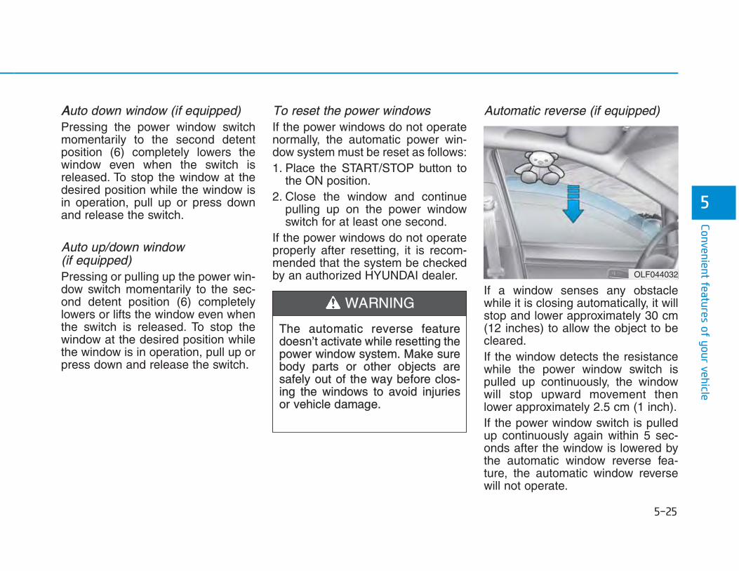
AAuto down window (if equipped) Pressing the power window switchmomentarily to the second detentposition (6) completely lowers thewindow even when the switch isreleased. To stop the window at thedesired position while the window isin operation, pull up or press downand release the switch.
Auto up/down window (if equipped)Pressing or pulling up the power win-dow switch momentarily to the sec-ond detent position (6) completelylowers or lifts the window even whenthe switch is released. To stop thewindow at the desired position whilethe window is in operation, pull up orpress down and release the switch.
To reset the power windowsIf the power windows do not operatenormally, the automatic power win-dow system must be reset as follows:1. Place the START/STOP button to
the ON position.2. Close the window and continue
pulling up on the power windowswitch for at least one second.
If the power windows do not operateproperly after resetting, it is recom-mended that the system be checkedby an authorized HYUNDAI dealer.
Automatic reverse (if equipped)
If a window senses any obstaclewhile it is closing automatically, it willstop and lower approximately 30 cm(12 inches) to allow the object to becleared.If the window detects the resistancewhile the power window switch ispulled up continuously, the windowwill stop upward movement thenlower approximately 2.5 cm (1 inch). If the power window switch is pulledup continuously again within 5 sec-onds after the window is lowered bythe automatic window reverse fea-ture, the automatic window reversewill not operate.
OLF044032
The automatic reverse featuredoesn’t activate while resetting thepower window system. Make surebody parts or other objects aresafely out of the way before clos-ing the windows to avoid injuriesor vehicle damage.
WARNING

IInformation The automatic reverse feature is onlyactive when the “Auto Up” feature isused by fully pulling up the switch tothe second detent.
Do not install any accessories on thewindows. The automatic reverse fea-ture may not operate.
Power window lock switch
The driver can disable the powerwindow switches on the rear passen-gers' doors by pressing the powerwindow lock switch.
When the power window lock switchis pressed: • The driver's master control can
operate all the power windows.• The front passenger's control can
operate the front passenger's powerwindow.
• The rear passenger's control can-not operate the rear passengers'power window.
• To prevent possible damage to thepower window system, do notopen or close two windows ormore at the same time. This willalso ensure the longevity of thefuse.
• Never try to operate the mainswitch on the driver's door and theindividual door window switch inopposite directions at the sametime. If this is done, the window willstop and cannot be opened orclosed.
NOTICE
NOTICE
i
Make sure body parts or otherobjects are safely out of the waybefore closing the windows toavoid injuries or vehicle damage.Objects less than 4 mm (0.16inch) in diameter caught betweenthe window glass and the upperwindow channel may not bedetected by the automatic reversewindow and the window will notstop and reverse direction.
WARNING
OOS047019R
Do not allow children to play withthe power windows. Keep the dri-ver’s door power window lockswitch in the LOCK position.Serious injury or death can resultfrom unintentional window opera-tion by a child.
WARNING

• NEVER leave the keys in yourvehicle with unsupervised chil-dren, when the vehicle is ON.
• NEVER leave any child unat-tended in the vehicle. Even veryyoung children may inadvertent-ly cause the vehicle to move,entangle themselves in the win-dows, or otherwise injure them-selves or others.
• Always double check to makesure all arms, hands, head andother obstructions are safely outof the way before closing a win-dow.
• Do not allow children to play
with the power windows. Keepthe driver’s door power windowlock switch in the LOCK position(pressed). Serious injury canresult from unintentional windowoperation by the child.
• Do not extend your head, armsor body outside the windowswhile driving.
WARNING

If your vehicle is equipped with asunroof, you can slide or tilt yoursunroof with the sunroof controlswitch located on the overhead con-sole.
The sunroof can be opened, closed,or tilted when the START/STOP but-ton is in the ON position.The sunroof can be operated forapproximately 10 minutes after theSTART/STOP button is in the ACC orOFF position.However, if the front door is opened,the sunroof cannot be operated evenwithin 10 minutes period.
IInformation • In cold and wet climates, the sun-
roof may not work properly due tofreezing conditions.
• After the vehicle is washed or in arainstorm, be sure to wipe off anywater that is on the sunroof beforeoperating it.
i
OOSEV048046
• Never adjust the sunroof or sun-shade while driving. This couldresult in loss of control and anaccident that may cause death,serious injury, or property dam-age.
• Make sure heads, other bodyparts or objects are out of theway before using the sunroof.
• Do not extend your head, armsor body outside the sunroofwhile driving, to avoid seriousinjury.
• Do not leave the vehicle on andthe key in your vehicle withunsupervised children.Unattended children could oper-ate the sunroof, which couldresult in serious injury.
• Do not sit on the top of the vehi-cle. It may cause injuries orvehicle damage.
WARNING

•• Do not continue to move the sun-roof control lever after the sunroofis fully opened, closed, or tilted.Damage to the motor or systemcomponents could occur.
• Make sure the sunroof is closedfully when leaving your vehicle.If the sunroof is open, rain or snowmay leak through the sunroof andwet the interior as well as allowtheft.
Sunroof opening and closing
To open:Press the sunroof control lever back-ward to the first detent position.Release the switch when you wantthe sunroof to stop.To close:Press the sunroof control lever for-ward to the first detent position.Release the switch when you wantthe sunroof to stop.
Sliding the sunroofPressing the sunroof control leverbackward or forward momentarily tothe second detent position complete-ly opens or closes the sunroof evenwhen the switch is released. To stopthe sunroof at the desired positionwhile the sunroof is in operation,press the sunroof control lever back-ward or forward and release theswitch.
Information To reduce wind noise while driving, itis recommended that you drive withthe sunroof slightly closed (stop thesunroof about 7 cm before the maxi-mum slide open position).
i
NOTICE
OOSEV048054L

AAutomatic reverse (if equipped)
If the sunroof senses any obstaclewhile it is closing automatically, it willreverse direction then stop to allowthe object to be cleared.The auto reverse function does notwork if a small obstacle is betweenthe sliding glass and the sunroofsash. You should always check that all pas-sengers and objects are away fromthe sunroof before closing it.
Tilting the sunroof
Tilt the sunroof open:Push the sunroof control leverupward until the sunroof moves tothe desired position.
To close the sunroof:Press the sunroof lever forward untilthe sunroof moves to the desiredposition.
OLFC044035CN OOSEV048053L
Small objects that can get caughtbetween the sunroof glass and thefront glass channel may not bedetected by the automatic reversesystem. In this case, the sunroofglass will not detect the object andreverse direction.
WARNING

•• Periodically remove any dirt thatmay accumulate on the sunroofguide rail or between the sunroofand roof panel, which can make anoise.
• Do not try to open the sunroofwhen the temperature is belowfreezing or when the sunroof iscovered with snow or ice, other-wise the motor could be damaged.In cold and wet climates, the sun-roof may not work properly.
Sunshade
The sunshade will open automatical-ly with the sunroof when the glasspanel moves. If you want it closed,move the sunshade manually.
The sunroof is made to slide togeth-er with the sunshade. Do not leavethe sunshade closed while the sun-roof is open.
Resetting the sunroofThe sunroof may need to be reset ifthe following conditions occur:- Battery is discharged or disconnect-
ed or the related fuse has beenreplaced or disconnected
- The one-touch sliding function of thesunroof does not normally operate
To reset the sunroof, perform the fol-lowing steps:1. Place the START/STOP button to
the ON position or when the vehi-cle is in the ready ( ) mode. It isrecommended to reset the sunroofwhile the vehicle is in the ready( ) mode.
2. Push the control lever forward. Thesunroof will close completely or tiltdepending on the condition of thesunroof.
3. Release the control lever until thesunroof does not move.
NOTICE
NOTICE
OAD045037

4. Push the control lever forwardabout 10 seconds. - When the sunroof is in the close
position :The glass will tilt and slightly moveup and down.
- When the sunroof is in the tilt posi-tion: The glass will slightly move upand down.
Do not release the lever until theoperation is completed.If you release the lever during opera-tion, try again from step 2.
5. Within 3 seconds, push the controllever forward until the sunroofoperates as follows:
Tilt down → Slide Open → SlideClose.
Do not release the lever until theoperation is completed.If you release the lever during opera-tion, try again from step 2.
6. Release the sunroof control leverafter all operation has completed.The sunroof system has beenreset.
IInformation • If the sunroof does not reset when
the vehicle battery is disconnectedor discharged, or related fuse isblown, the sunroof may not operatenormally.
• For more detailed information, werecommend that you contact anauthorized HYUNDAI dealer.
Sunroof open warning(if equipped)• If the driver turns off the vehicle
when the sunroof is not fullyclosed, the warning chime willsound for approximately 3 secondsand the open sunroof warningappear on the LCD display.
• If the driver turns off the vehicleand opens the door when the sun-roof is not fully closed, the opensunroof warning will appear on theLCD display until the door is closedor the sunroof is fully closed.
Close the sunroof securely whenleaving your vehicle.
i

HHoodOpening the hood
1. Park the vehicle and set the park-ing brake.
2. Pull the release lever to unlatchthe hood. The hood should popopen slightly.
3. Go to the front of the vehicle, raisethe hood slightly, push the second-ary latch up (1) inside of the hoodcenter and lift the hood (2).
4. Pull out the support rod.
5. Hold the hood opened with thesupport rod (3).
OOSEV048010
• Grasp the support rod in thearea wrapped in rubber. Therubber will help prevent youfrom being burned by hot metal.
• The support rod must be insert-ed completely into the hole pro-vided whenever you inspect themotor compartment. This willprevent the hood from fallingand possibly injuring you.
WARNING
OOSEV038038
OOSEV048068R
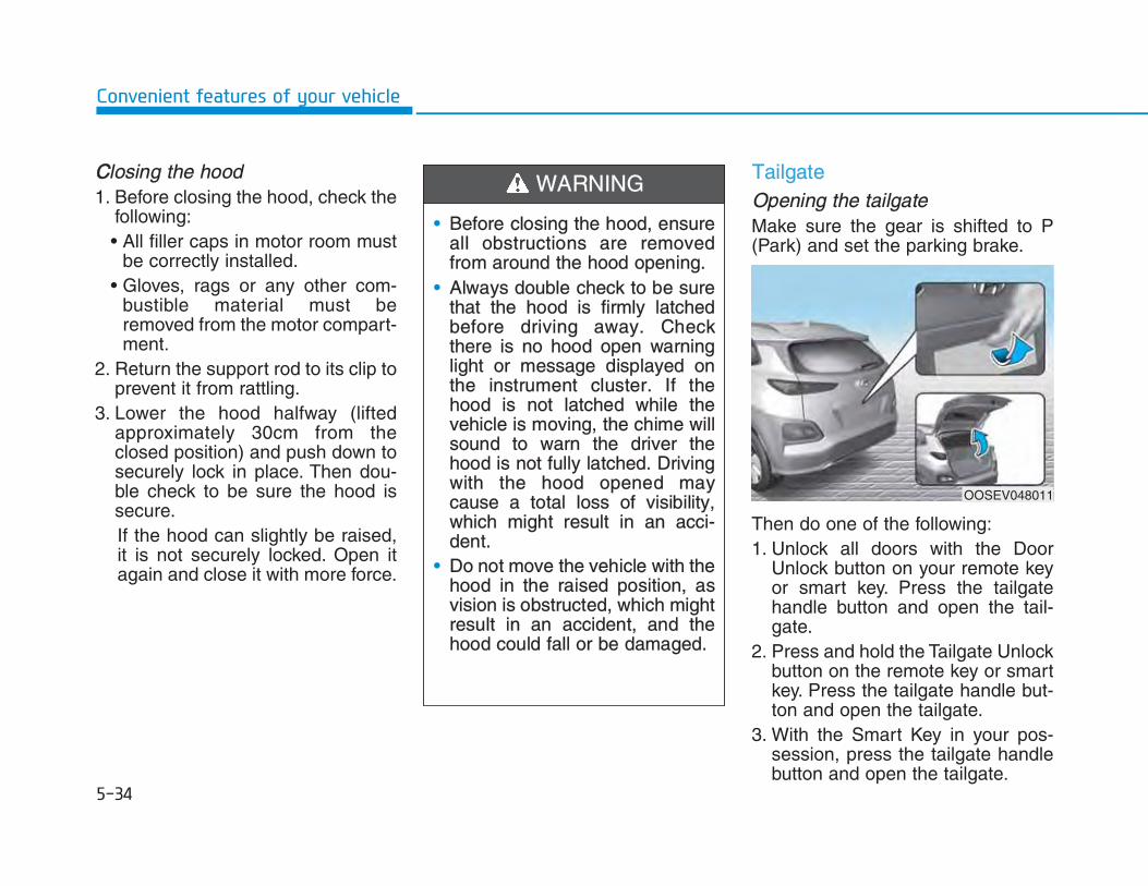
CClosing the hood1. Before closing the hood, check the
following:• All filler caps in motor room must
be correctly installed.• Gloves, rags or any other com-
bustible material must beremoved from the motor compart-ment.
2. Return the support rod to its clip toprevent it from rattling.
3. Lower the hood halfway (liftedapproximately 30cm from theclosed position) and push down tosecurely lock in place. Then dou-ble check to be sure the hood issecure.If the hood can slightly be raised,it is not securely locked. Open itagain and close it with more force.
TailgateOpening the tailgateMake sure the gear is shifted to P(Park) and set the parking brake.
Then do one of the following:1. Unlock all doors with the Door
Unlock button on your remote keyor smart key. Press the tailgatehandle button and open the tail-gate.
2. Press and hold the Tailgate Unlockbutton on the remote key or smartkey. Press the tailgate handle but-ton and open the tailgate.
3. With the Smart Key in your pos-session, press the tailgate handlebutton and open the tailgate.
OOSEV048011
• Before closing the hood, ensureall obstructions are removedfrom around the hood opening.
• Always double check to be surethat the hood is firmly latchedbefore driving away. Checkthere is no hood open warninglight or message displayed onthe instrument cluster. If thehood is not latched while thevehicle is moving, the chime willsound to warn the driver thehood is not fully latched. Drivingwith the hood opened maycause a total loss of visibility,which might result in an acci-dent.
• Do not move the vehicle with thehood in the raised position, asvision is obstructed, which mightresult in an accident, and thehood could fall or be damaged.
WARNING

CClosing the tailgate
Lower the tailgate lid and press downuntil it locks. To be sure the tailgatelid is securely fastened, alwayscheck by trying to pull it up again.
InformationTo prevent damage to the tailgate liftcylinders and the attached hardware,always close the tailgate before driv-ing.
In cold and wet climates, tailgatelock and tailgate mechanisms maynot work properly due to freezingconditions.
i
NOTICE
Do not hold the part (gas lifter)that supports the tailgate. Beaware that the deformation of thepart may cause vehicle damageand a risk of safety accident.
WARNING
OHYK047009OOSEV048012

EEmergency tailgate safety releaseYour vehicle is equipped with the
emergency tailgate safety releaselever located on the bottom of thetailgate. When someone is inadver-tently locked in the luggage compart-ment. The tailgate can be opened bydoing as follows:1. Insert the key into the hole.2. Push the release lever to the right
by a key.3. Push up the tailgate.
• NEVER allow anyone to occupythe tailgate of the vehicle at anytime. If the luggage compart-ment is partially or totallylatched and the person is unableto get out, serious injury ordeath could occur due to lack ofventilation and rapid heat build-up, or because of exposure tocold weather conditions. Theluggage compartment is also ahighly dangerous location in theevent of a crash because it isnot a protected occupant spacebut is a part of the vehicle’scrush zone.
• Your vehicle should be keptlocked and keys should be keptout of the reach of children.Parents should teach their chil-dren about the dangers of play-ing in luggage compartment.
WARNING
OOSEV048013
• For emergencies, be fully awareof the location of the emergencytailgate safety release lever inthe vehicle and how to open thetailgate if you are accidentallylocked in the luggage compart-ment.
• No one should be allowed tooccupy the luggage compart-ment of the vehicle at any time.The luggage compartment is avery dangerous location in theevent of a crash.
• Use the release lever for emer-gencies only. Use with extremecaution, especially while thevehicle is in motion.
WARNING

CCharging doorOpening the charging door
1.Depress the brake pedal and applythe parking brake.
2.Turn OFF all switches, shift to P(Park), and turn OFF the vehicle.
3.Push the charging door where theicon is located to open. The charg-ing door opens only when the dooris unlocked.
Information If you cannot open the charging doordue to freezing weather, tap lightly orremove any ice near the chargingdoor. Do not try to forcibly open thecharging door.
Closing the charging door
1. After recharging, install the charg-ing inlet cover.
2. Close the charging door until it islatched securely.
For more details, refer to the ElectricVehicle Guide provided in the front ofthe owner’s manual.
i
OOSEVQ018013
OOSEVQ018008L

OOSEV048100L
The actual cluster in the vehiclemay differ from the illustration.For more details, refer to the"Gauges and meters" in this chap-ter.
1. Power/Charge gauge
2. Speedometer
3. Warning and indicator lights
4. LCD display (including Trip computer)
5. Battery SOC (State of Charge) gauge
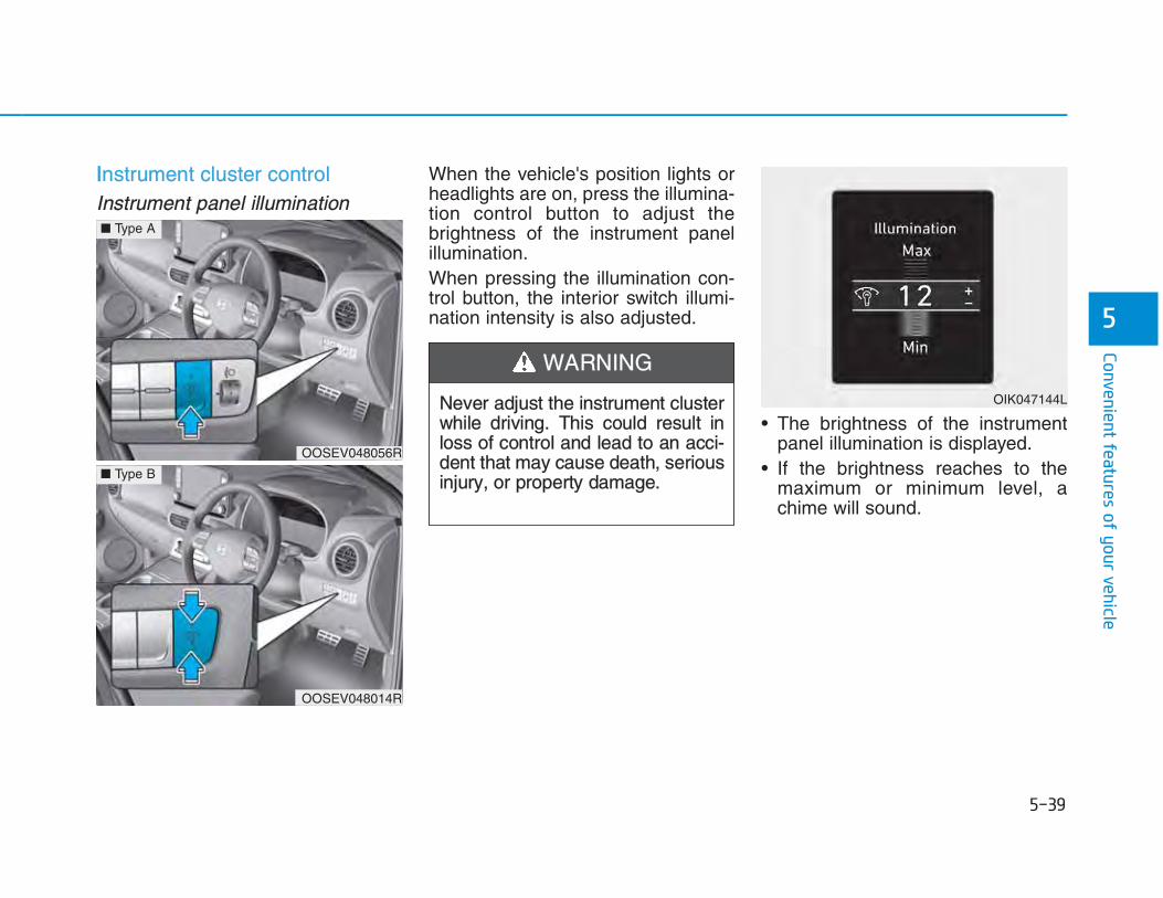
IInstrument cluster controlInstrument panel illumination
When the vehicle's position lights orheadlights are on, press the illumina-tion control button to adjust thebrightness of the instrument panelillumination.When pressing the illumination con-trol button, the interior switch illumi-nation intensity is also adjusted.
• The brightness of the instrumentpanel illumination is displayed.
• If the brightness reaches to themaximum or minimum level, achime will sound.
Never adjust the instrument clusterwhile driving. This could result inloss of control and lead to an acci-dent that may cause death, seriousinjury, or property damage.
WARNING
OOSEV048056R
■ Type A
OOSEV048014R
■ Type B
OIK047144L

GGauges and metersSpeedometer
The speedometer indicates thespeed of the vehicle and is calibratedin kilometers per hour (km/h) and/ormiles per hour (MPH).The speedometer is displayed differ-ently according to the selected drivemode in the Drive Mode IntegratedControl System. For more details, refer to “DriveMode Integrated Control System” inchapter 5.
Sub speedometer
The sub speedometer is displayedon the cluster when you select ‘Otherfeatures → Speedometer subscale’ inthe User Settings mode. The subspeedometer is not displayed if youdeselect it in the User Setting mode.
For more details, refer to “LCDDisplay Mode” in this chapter.
OOSEV048174
■ COMFORT mode
OOSEV048177
■ SPORT mode
OOSEV048167
■ ECO/ECO+ mode
OOSEV048187

TToque gauge
The torque gauge shows the real-time torque value while driving whenSPORT mode is selected by press-ing the DRIVE MODE button.
Power/Charge gauge
The Power/Charge gauge shows theenergy consumption rate of the vehi-cle and the charge/discharge statusof the regenerative brakes.
• POWER : It shows the energy consumption rateof the vehicle when driving uphill oraccelerating. The more electric ener-gy is used, the higher the gauge level.
• CHARGE :It shows the charging status of thebattery when it is being charged bythe regenerative brakes (decelerat-ing or driving on a downhill road).The more electric energy is charged,the lower the gauge level.
OOSEVQ018001OOSEV048192

SState of Charge (SOC) gauge forhigh voltage battery
The SOC gauge shows the chargingstatus of the high voltage battery."L (Low)" position on the indicatorindicates that there is not enoughenergy in the high voltage battery. "H(High)" position indicates that thedriving battery is fully charged.When driving on highways or motor-ways, make sure to check in advanceif the driving battery is chargedenough.
When there are 2 gauge bars (nearthe “L (Low) or 0" area) on the SOCgauge, the warning lamp turns ON toalert you of the battery level.When the warning lamp turns ON,the vehicle can drive an additional20~30 km (12~18 miles) dependingon the driving speed, heater/air con-ditioner, weather, driving style, andother factors. Charging is required.
When there are 1-2 gauge bars left forthe high voltage battery, the vehiclespeed is limited and then eventuallythe vehicle will turn OFF. Charge thevehicle immediately.
Outside temperature gauge
This gauge indicates the current out-side air temperatures either inCelsius (°C) or Fahrenheit.- Temperature range :
-40°C ~ 60°C (-40°F ~ 140°F)The outside temperature on the dis-play may not immediately changelike a general thermometer not todistract the driver.The temperature unit (from °C to °For from °F to °C) can be changed by:
NOTICE
OOSEV048102
OOSEV048103
OOSEV048104

- User Settings mode in the Cluster :You can change the temperatureunit in the “Other Features -Temperature unit” .
- Automatic climate control system :While pressing the OFF button,press the AUTO button for 3 sec-onds or more.
The temperature unit of the instrumentcluster and climate control system willchange at once.
OOdometer
The odometer indicates the total dis-tance that the vehicle has been driv-en and should be used to determinewhen periodic maintenance shouldbe performed.
Distance to empty
• The distance to empty is the esti-mated distance the vehicle can bedriven with remaining level of thehigh voltage battery.For more details, refer to “Distanceto Empty” in the Electric VehicleGuide in front of the owner’s man-ual.
• The distance to empty is displayeddifferently according to the selecteddrive mode in the Drive ModeIntegrated Control System. Formore details, refer to “Drive ModeIntegrated Control System” in chap-ter 5.
OOSEV048107 OOSEV049108/OOSEV049180
■ COMFORT mode ■ SPORT/ECO/ECO+mode

AAdditional Distance to Empty fromRegenerative Braking
The additional distance to emptywhich is converted from the energyregenerated by the regenerativebraking is displayed if theECO/ECO+ mode is selected bypressing the Drive Mode button. Thedisplay is initialized to 0 if the regen-erative braking stops because ofacceleration, etc.
Reduction gear shift indicator
This indicator displays which gear isselected.
Shift indicator pop-up (if equipped)
The pop-up indicates the currentgear position displayed in the clusterfor about 2 seconds when shiftinginto other positions (P/R/N/D).The shift indicator pop-up functioncan be activated or deactivated fromthe User Settings mode in the clusterLCD display.
OOSEV048105
OOSEV048106
OOSEV048168

RRegenerative braking level indica-tor
While using the regenerative brakes,you may select the regenerativebraking level from 0 to 3 by pullingthe paddle shifter.
For more details, refer to“Regenerative Braking System” inchapter 5.
Smart ECO pedal guide
The Smart Eco Pedal Guide is dis-played to lead to eco-driving whenyou press the DRIVE MODE buttonand select ECO/ECO+ mode. (1 ) Eco-driving guide(2 ) The driver’s acceleration pedal-
ing level(3) Section beyond the eco-driving
guide
• Guides slow acceleration whendriving at low speed.
• Guides driving considering theoptimal fuel economy when drivingat medium speed.
• Guides constant speed drivingand deceleration when driving athigh speed.
OOSEV048169
OOSEV048109L

WWarning and indicator lights
Information Make sure that all warning lights areOFF after starting the vehicle. If anylight is still ON, this indicates a situa-tion that needs attention.
Ready Indicator
This indicator illuminates:
When the vehicle is ready to be driven.- ON : Normal driving is possible.- OFF : Normal driving is not possible,
or a problem has occurred.- Blinking : Emergency driving.
When the ready indicator goes OFFor blinks, there is a problem with thesystem. In this case, we recommendthat you have your vehicle inspectedby an authorized HYUNDAI dealer.
Service Warning Light
This warning light illuminates:
• When the START/STOP button isin the ON position.- It illuminates for approximately 3
seconds and then goes off.• When there is a problem with relat-
ed parts of the electric vehicle con-trol system, such as sensors, etc.
When the warning light illuminateswhile driving, or does not go OFFafter starting the vehicle, we recom-mend that you have your vehicleinspected by an authorized HYUNDAIdealer.
Power Down WarningLight
This warning light illuminates:
• When the power is limited for thesafety of the electric vehicle. The power is limited for the follow-ing reasons.- The high voltage battery level is
below a certain level or voltage isdecreasing
- The temperature of the motor orhigh voltage battery is too high ortoo low
- There is a problem with the cool-ing system, or a failure that mayinterrupt normal driving
i

•• Do not accelerate or start the vehi-cle suddenly when the power downwarning light is ON.
• When the high voltage batterylevel is low, the power down warn-ing illuminates and the power out-put from the vehicle is limited.Charge the battery immediatelysince your vehicle may not driveuphill or skid on a slope with thewarning light ON.
Charging Indicator Light
This warning light illuminates:
• When charging the high voltagebattery.
High Voltage Battery Low LevelWarning Light
This warning light illumi-nates:
• When the high voltage battery levelis low. When the warning light turnsON, charge the battery immediately.
Air Bag Warning Light
This warning light illuminates:
• When the START/STOP button isin the ON position.- It illuminates for approximately 6
seconds and then goes off.• When there is a malfunction with
the SRS.In this case, we recommend thatyou have the vehicle inspected byan authorized HYUNDAI dealer.
Seat Belt Warning Light
This warning light informs the driverthat the seat belt is not fastened.
For more details, refer to the “SeatBelts” in chapter 2.
NOTICE
(red)

PParking Brake & BrakeFluid Warning Light
This warning light illuminates:
• When the START/STOP button isin the ON position.- It illuminates for approximately 3
seconds- It remains on if the parking brake
is applied.• When the parking brake is applied.• When the brake fluid level in the
reservoir is low.- If the warning light illuminates
with the parking brake released, itindicates the brake fluid level inreservoir is low.
• When the regenerative brake doesnot operate.
If the brake fluid level in the reser-voir is low:
1. Drive carefully to the nearest safelocation and stop your vehicle.
2. With the vehicle turned off, checkthe brake fluid level immediatelyand add fluid as required (For moredetails, refer to “Brake Fluid” inchapter 7). After adding brake fluid,check all brake components forfluid leaks. If a brake fluid leak isfound, or if the warning lightremains on, or if the brakes do notoperate properly, do not drive thevehicle. We recommend you tohave the vehicle inspected by anauthorized HYUNDAI dealer.
Dual-diagonal braking system
Your vehicle is equipped with dual-diagonal braking systems. Thismeans you still have braking on twowheels even if one of the dual sys-tems should fail.With only one of the dual systemsworking, more than normal pedaltravel and greater pedal pressure isrequired to stop the vehicle.
Also, the vehicle will not stop in asshort a distance with only a portionof the brake system working.
Parking Brake & Brake FluidWarning Light
Driving the vehicle with a warninglight ON is dangerous. If theParking Brake & Brake FluidWarning Light illuminates with theparking brake released, it indi-cates that the brake fluid level islow.In this case, we recommend thatyou have the vehicle inspected byan authorized HYUNDAI dealer.
WARNING
(red)

RRegenerative BrakeWarning Light
This warning light illuminates:
When the regenerative brake doesnot operate and the brake does notperform well. This causes the BrakeWarning light (red) and RegenerativeBrake Warning Light (yellow) to illu-minate simultaneously.In this case, drive safely and we rec-ommend that you have your vehicleinspected by an authorized HYUNDAIdealer.The operation of the brake pedal maybe more difficult than normal and thebraking distance can increase.
Anti-lock Brake System(ABS) Warning Light
This warning light illuminates:
• When the START/STOP button isin the ON position.- It illuminates for approximately 3
seconds and then goes off.• When there is a malfunction with
the ABS (The normal braking sys-tem will still be operational withoutthe assistance of the anti-lockbrake system).In this case, we recommend thatyou have the vehicle inspected byan authorized HYUNDAI dealer.
Electronic Brake ForceDistribution (EBD)System Warning Light
These two warning lights illuminateat the same time while driving:
• When the ABS and regular brakesystem may not work normally.In this case, we recommend thatyou have the vehicle inspected byan authorized HYUNDAI dealer.
Electronic Brake ForceDistribution (EBD) SystemWarning Light
When both ABS and ParkingBrake & Brake Fluid WarningLights are on, the brake systemwill not work normally and youmay experience an unexpectedand dangerous situation duringsudden braking.
WARNING
(yellow)

IInformation - Electronic BrakeForce Distribution (EBD)System Warning Light
When the ABS Warning Light is on orboth ABS and Parking Brake & BrakeFluid Warning Lights are on, thespeedometer, odometer, or tripmetermay not work. Also, the EPS WarningLight may illuminate and the steeringeffort may increase or decrease.
In this case, we recommend you havethe vehicle inspected by an authorizedHYUNDAI dealer as soon as possible.
Electric Power Steering(EPS) Warning Light
This warning light illuminates:
• When the START/STOP button isin the ON position.- It illuminates for approximately 3
seconds and then goes off.• When there is a malfunction withthe EPS.In this case, we recommend thatyou have the vehicle inspected byan authorized HYUNDAI dealer.
Charging SystemWarning Light (for 12-volt battery)
This warning light illuminates:
• When the 12-volt battery level islow or a failure occurs on thecharging system such as LDC.
• If the warning light turns on whiledriving, move the vehicle to a safelocation, turn off and turn on thevehicle again, and check if thewarning light turns off. If the warninglight remains on, we recommendthat you have the vehicle inspectedby an authorized HYUNDAI dealer.
• Even if the warning light turns off,we recommend that you have thevehicle inspected by an authorizedHYUNDAI dealer.If you drive the vehicle while thewarning light is on, vehicle speedmay be limited and the 12-volt bat-tery may be discharged.
❈ LDC : Low voltage DC-DC Converter.
i
In this case, avoid high speed driv-ing and abrupt braking.We recommend you have thevehicle inspected by an author-ized HYUNDAI dealer as soon aspossible.

MMaster Warning Light
This indicator light illuminates:
• When there is a malfunction in opera-tion in any of the following systems:- LED headlamp malfunction (if
equipped)- Forward Collision-Avoidance Assist
system malfunction (if equipped)- Forward Collision-Avoidance Assist
radar blocked (if equipped)- Blind-Spot Collision Warning sys-
tem malfunction (if equipped)- Blind-Spot Collision Warning radar
blocked (if equipped)- Smart Cruise Control with Stop &
Go malfunction (if equipped)- Smart Cruise Control with Stop &
Go radar blocked (if equipped)- Lamp malfunction- High Beam Assist malfunction (if
equipped)
- Tire Pressure Monitoring System(TPMS) malfunction
To identify the details of the warn-ing, look at the LCD display.
Low Tire PressureWarning Light
This warning light illuminates:
• When the START/STOP button isin the ON position.- It illuminates for approximately 3
seconds and then goes off.• When one or more of your tires are
significantly underinflated.
For more details, refer to “Tire Pressure Monitoring System(TPMS)” in chapter 6.
This warning light remains ONafter blinking for approximately 60seconds, or repeatedly blinks ONand OFF in 3 second intervals:
• When there is a malfunction withthe TPMS.In this case, we recommend thatyou have the vehicle inspected byan authorized HYUNDAI dealer assoon as possible.
For more details, refer to “Tire Pressure Monitoring System(TPMS)” in chapter 6.
Safe Stopping
• The TPMS cannot alert you tosevere and sudden tire damagecaused by external factors.
• If you notice any vehicle instabili-ty, immediately take your foot offthe accelerator pedal, apply thebrake pedal gradually with lightforce, and slowly move to a safeposition off the road.
WARNING

EElectronic Parking Brake(EPB) Warning Light
This warning light illuminates:
• When the START/STOP button isin the ON position.- It illuminates for approximately 3
seconds and then goes off.• When there is a malfunction with
the EPB.In this case, we recommend thatyou have the vehicle inspected byan authorized HYUNDAI dealer.
Information The Electronic Parking Brake (EPB)Warning Light may illuminate whenthe Electronic Stability control (ESC)Indicator Light comes on to indicatethat the ESC is not working properly(This does not indicate malfunction ofthe EPB).
Forward Collision-Avoidance Assist (FCA)System Warning Light (if equipped)
This indicator light illuminates:
• When the START/STOP button isin the ON position.- It illuminates for approximately 3
seconds and then goes off.• When there is a malfunction with
the FCA.In this case, we recommend that youhave the vehicle inspected by anauthorized HYUNDAI dealer.
For more details, refer to "ForwardCollision-Avoidance Assist (FCA)System" in chapter 5.
Lane Keeping Assist(LKA) System IndicatorLight (if equipped)
This indicator light illuminates:
• [Green] When the system operat-ing conditions are satisfied.
• [White] The system operating con-ditions are not satisfied.
• [Yellow] When there is a malfunc-tion with the lane keeping assistsystem.In this case, we recommend thatyou have your vehicle inspected byan authorized HYUNDAI dealer.
For more details, refer to "LaneKeeping Assist (LKA) System" inchapter 5.
i

IIcy Road Warning Light(if equipped)
This warning light is to warn the driverthe road may be icy.When the temperature on the out-side temperature gauge is approxi-mately below 4°C (40°F), the IcyRoad Warning Light and OutsideTemperature Gauge blinks and thenilluminates. Also, the warning chimesounds 1 time.The Icy Road Warning function canbe activated or deactivated from theUser Settings mode in the clusterLCD display.
Information If the icy road warning light appearswhile driving, you should drive moreattentively and safely, refraining fromover-speeding, rapid acceleration, sud-den braking or sharp turning, etc.
AUTO HOLD IndicatorLight
This indicator light illuminates:
• [White] When you activate the autohold system by pressing the AUTOHOLD switch.
• [Green] When you stop the vehiclecompletely by depressing thebrake pedal with the auto hold sys-tem activated.
• [Yellow] When there is a malfunc-tion with the auto hold system.In this case, we recommend thatyou have the vehicle inspected byan authorized HYUNDAI dealer.
For more details, refer to “Auto Hold”in chapter 5.
Electronic StabilityControl (ESC) IndicatorLight
This indicator light illuminates:
• When the START/STOP button isin the ON position.- It illuminates for approximately 3
seconds and then goes off.• When there is a malfunction with
the ESC system.In this case, we recommend thatyou have the vehicle inspected byan authorized HYUNDAI dealer.
This indicator light blinks:
• While the ESC is operating.
For more details, refer to “ElectronicStability Control (ESC)” in chapter 5.
i

EElectronic StabilityControl (ESC) OFFIndicator Light
This indicator light illuminates:
• When the START/STOP button isin the ON position.- It illuminates for approximately
3 seconds and then goes off.• When you deactivate the ESC sys-
tem by pressing the ESC OFF but-ton.
For more details, refer to “ElectronicStability Control (ESC)” in chapter 5.
Immobilizer IndicatorLight
This indicator light illuminates forup to 30 seconds:
• When the vehicle detects thesmart key in the vehicle with theSTART/STOP button in the ACC orON position.- At this time, you can start the
vehicle.- The indicator light goes off after
starting the vehicle.
This indicator light blinks for a fewseconds:
• When the smart key is not in thevehicle.- At this time, you cannot start the
vehicle.
This indicator light illuminates for2 seconds and goes off:
• If the smart key is in the vehicleand the START/STOP button isON, but the vehicle cannot detectthe smart key.In this case, we recommend thatyou have the vehicle inspected byan authorized HYUNDAI dealer.
This indicator light blinks:
• When the battery voltage of thesmart key is low.- At this time, you can not start the
vehicle. However, you can startthe vehicle if you press theSTART/STOP button with thesmart key. (For more details, referto "Starting the vehicle" in chap-ter 5).
• When there is a malfunction withthe immobilizer system.In this case, we recommend thatyou have the vehicle inspected byan authorized HYUNDAI dealer.
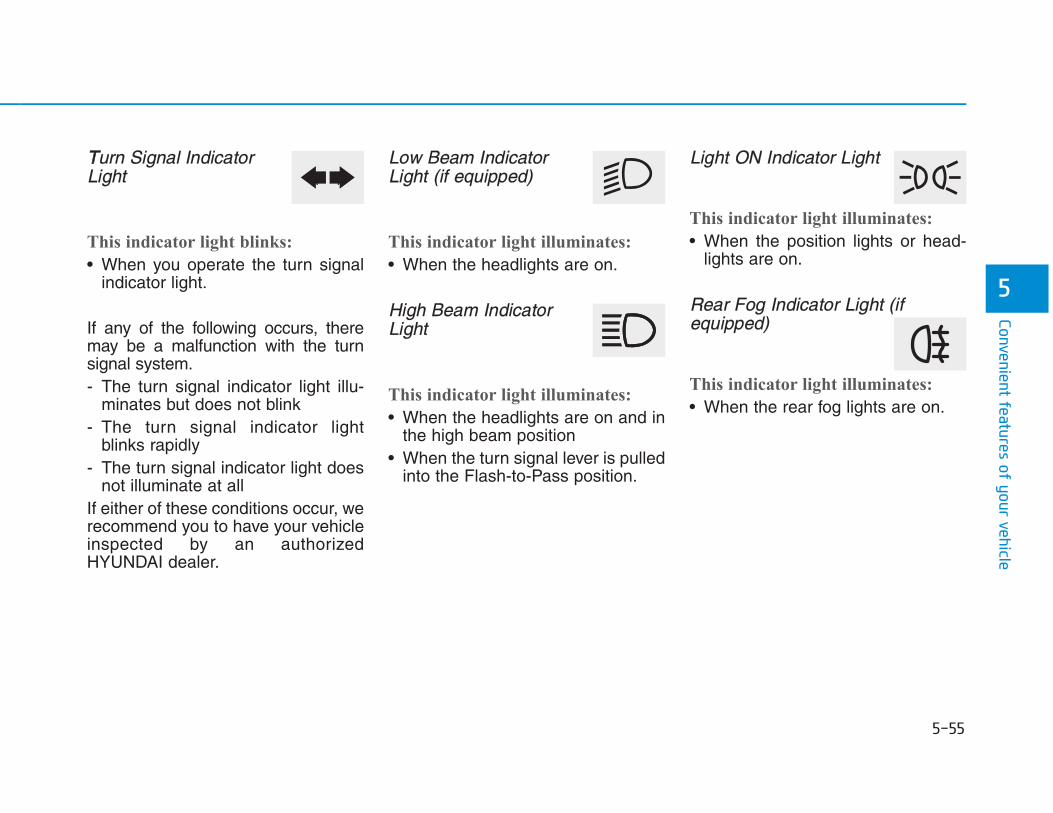
TTurn Signal IndicatorLight
This indicator light blinks:
• When you operate the turn signalindicator light.
If any of the following occurs, theremay be a malfunction with the turnsignal system.- The turn signal indicator light illu-
minates but does not blink- The turn signal indicator light
blinks rapidly- The turn signal indicator light does
not illuminate at allIf either of these conditions occur, werecommend you to have your vehicleinspected by an authorizedHYUNDAI dealer.
Low Beam IndicatorLight (if equipped)
This indicator light illuminates:
• When the headlights are on.
High Beam IndicatorLight
This indicator light illuminates:
• When the headlights are on and inthe high beam position
• When the turn signal lever is pulledinto the Flash-to-Pass position.
Light ON Indicator Light
This indicator light illuminates:
• When the position lights or head-lights are on.
Rear Fog Indicator Light (ifequipped)
This indicator light illuminates:
• When the rear fog lights are on.

LLED Headlamp WarningLight (if equipped)
This warning light illuminates:
• When the START/STOP button isin the ON position.- It illuminates for approximately 3
seconds and then goes off.• When there is a malfunction with
the LED headlamp.In this case, we recommend that youhave the vehicle inspected by an anauthorized HYUNDAI dealer.
This warning light blinks:
When there is a malfunction with aLED headlamp related part.In this case, we recommend that youhave the vehicle inspected by an anauthorized HYUNDAI dealer.
Continuous driving with the LEDHeadlamp Warning Light on or blink-ing can reduce LED headlamp life.
Cruise Indicator Light(if equipped)
This indicator light illuminates:
• When the cruise control system isenabled.
For more details, refer to “CruiseControl System” in chapter 5.
SPORT Mode IndicatorLight
This indicator light illuminates:
• When you select "SPORT" modeas drive mode.
For more details, refer to "DriveMode Integrated Control System" inchapter 5.
ECO Mode IndicatorLight (if equipped)
This indicator light illuminates:
• When you select "ECO" mode asdrive mode.
For more details, refer to "DriveMode Integrated Control System" inchapter 5.
ECO+ Mode Indicator
This indicator light illuminates:
• When you select "ECO" mode asdrive mode.
For more details, refer to "DriveMode Integrated Control System" inchapter 5.
NOTICE

UUTIL (Utility) ModeIndicator
This indicator light illuminates:
• When Utility mode is activatedfrom the User Settings mode.
For more details, refer to the ElectricVehicle Guide provided in the front ofthe owner’s manual.
LCD display messages Driving Info display
At the end of each driving cycle, theDriving Info message is displayed.This display shows the trip distance(1), average vehicle speed (2), driv-ing time (3), charging time status (4)and climate time status (5).This information is displayed for a fewseconds when you turn off the vehi-cle, and then goes off automatically.The information is calculated for eachtime the vehicle is turned on.
Information • If sunroof open warning is displayed
in the cluster, the Driving Info mes-sage will not be displayed.
• To set the charging time and/or cli-mate time, refer to a separately sup-plied Multimedia System manualfor detailed information.
i
OOSEV048134L

SShift to PThis warning message is displayed ifyou try to turn off the vehicle with thegear in the N (Neutral) position. At this time, the START/STOP buttonchanges to the ACC position (If youpress the START/STOP button oncemore, it will turn to the ON position).
Low key batteryThis warning message is displayed ifthe battery of the smart key is dis-charged while changing theSTART/STOP button to the OFFposition.
Press START/STOP button whileturning wheel This warning message is displayed ifthe steering wheel does not unlocknormally when the START/STOPbutton is pressed.You should press the START/STOPbutton while turning the steering wheelright and left.
Check steering wheel lock systemThis warning message is displayed ifthe steering wheel does not lock nor-mally while the START/STOP buttonchanges to the OFF position.
Press brake pedal to start vehicleThis warning message is displayed ifthe START/STOP button changes tothe ACC position twice by pressingthe button repeatedly withoutdepressing the brake pedal.You can start the vehicle by depress-ing the brake pedal.
Key not in vehicleThis warning message is displayed ifthe smart key is not in the vehiclewhen you press the START/STOPbutton.When attempting to start the vehicle,always have the smart key with you.
Key not detected This warning message is displayed ifthe smart key is not detected whenyou press the START/STOP button.
Press START/STOP button againThis message is displayed if youwere unable to start the vehicle whenthe START/STOP button waspressed.If this occurs, attempt START/STOPbutton again.If the warning message appearseach time you press theSTART/STOP button, we recom-mend you to have your vehicleinspected by an authorizedHYUNDAI dealer.

PPress START/STOP button withkey This warning message is displayed ifyou press the START/STOP buttonwhile the warning message “Key notdetected” is displayed.At this time, the immobilizer indicatorlight blinks.
Check BRAKE SWITCH fuseThis warning message is displayed ifthe brake switch fuse is disconnected.You need to replace the fuse with anew one before starting the vehicle.If that is not possible, you can start thevehicle by pressing the START/STOPbutton for 10 seconds in the ACC posi-tion.
Shift to P to start vehicleThis warning message is displayed ifyou try to start the vehicle withoutshifting to the P (Park) position.
Low washer fluid (if equipped)This warning message is displayed ifthe washer fluid level in the reservoiris nearly empty.Have the washer fluid reservoirrefilled.
12V battery discharging due toadditional electrical devicesThis warning message is displayed ifthe 12V battery discharge is detect-ed due to use of unauthorized elec-trical/electronic devices. Some vehi-cle functions will not be able to useand the 12V battery may discharge.If the message continues to appeareven though the external electrical/electronic device is removed, we rec-ommend that the vehicle be inspect-ed by an authorized HYUNDAI deal-er.
Door, Hood, Tailgate open
This warning is displayed indicatingwhich door, or hood, or tailgate isopen.
OOSEV048113
Before driving the vehicle, youshould confirm that the door/hood/tailgate is fully closed. Also,check there is no door /hood/tail-gate open warning light or mes-sage displayed on the instrumentcluster.
CAUTION

SSunroof open (if equipped)
This warning is displayed if you turnoff the vehicle when the sunroof isopen.
Low pressure (if equipped)
This warning message is displayed ifthe tire pressure is low. The corre-sponding tire on the vehicle will beilluminated.
For more details, refer to "TirePressure Monitoring System(TPMS)" in chapter 6.
Turn on FUSE SWITCH
This warning message is displayed ifthe fuse switch located on the fusebox under the steering wheel is OFF. You should turn the fuse switch on.
For more details, refer to “Fuses” inchapter 7.
OIK057165LOOSEV048114 OOSEV048111L

LLights mode
This indicator displays which exteriorlight is selected using the lightingcontrol.
Wiper mode
This indicator displays which wiperspeed is selected using the wipercontrol.
Parking distance warning system malfunction (if equipped)
This warning is displayed if there is aproblem with the Parking DistanceWarning system. We recommendthat you have the vehicle inspectedby an authorized dealer ofHYUNDAI.
For more details, refer to “ParkingDistance Warning system” in chapter3.
■ Front and rear■ Rear
OOSEV048190L/OOSEV048189L
OIK047145L OIK047146L

CCheck headlamp LED (if equipped)This warning message is displayed ifthere is a problem with the LEDheadlamp. We recommend that youhave the vehicle inspected by anauthorized HYUNDAI dealer.
Check headlamp FAN (if equipped)This warning message is displayed ifthere is a problem with headlampfan. We recommend that you havethe vehicle inspected by an author-ized HYUNDAI dealer.
Check headlight (if equipped)This warning message is displayed ifthe headlamps are not operatingproperly. The headlamp bulb mayneed to be replaced.
InformationMake sure to replace the burned outbulb with a new one of the same wattagerating.
Check brake light (if equipped)This warning message is displayed ifthe stop lamps are not operatingproperly. A lamp may need to bereplaced.
Check turn signal (if equipped)This warning message is displayed ifthe turn signal lamps are not operat-ing properly. A lamp may need to bereplaced.
Check cornering lamp (if equipped)This warning message is displayed ifthe cornering lamps are not operat-ing properly. A lamp may need to bereplaced.
Heated steering wheel turned Off(if equipped)This message is displayed if you turnoff the heated steering wheel.
For more details, refer to “HeatedSteering Wheel” in this chapter.
Check HBA (High Beam Assist)systemThis warning message is displayed ifthere is a problem with the HighBeam Assist (HBA) System. We rec-ommend that you have the vehicleinspected by an authorizedHYUNDAI dealer.
For more details, refer to “High BeamAssist (HBA) System” in chapter 3.
Check FCA (Forward CollisionAvoidance Asst.) (if equipped)This warning message is displayed ifthere is a problem with the ForwardCollision-Avoidance Assist (FCA)system. We recommend that youhave the vehicle inspected by anauthorized HYUNDAI dealer.
For more details, refer to "ForwardCollision-Avoidance Assist (FCA)system" in chapter 5.i

CCheck SLW (Speed Limit Warning)systemThis warning message is displayed ifthere is a problem with the IntelligentSpeed Limit Warning (ISLW) system.We recommend that you have thevehicle inspected by an authorizedHYUNDAI dealer.
For more details, refer to “IntelligentSpeed Limit Warning (ISLW)” inchapter 5.
Check SCC (Smart CruiseControl) system (if equipped)This warning message is displayed ifthere is a problem with the SmartCruise Control system. We recom-mend that you have the vehicleinspected by an authorized HYUNDAIdealer.
For more details, refer to "SmartCruise Control with Stop & Go" inchapter 5.
Check LKA (Lane Keep Assist)system (if equipped)This warning message is displayed ifthere is a problem with the LaneKeeping Assist (LKA) system. Werecommend that you have the vehicleinspected by an authorized HYUNDAIdealer.
For more details, refer to “LaneKeeping Assist (LKA) system” inchapter 5.
Check DAW (Driver AttentionWarning) system (if equipped)This warning message is displayed ifthere is a problem with the DriverAttention Warning (DAW) system. Werecommend that you have the vehicleinspected by an authorized HYUNDAIdealer.
For more details, refer to “DriverAttention Warning (DAW) system” inchapter 5.
Shift to P to charge
This message is displayed if youconnect the charging cable withoutthe gear in the P (Park) position. Shift to P (Park) before connectingthe charging cable.
OOSEV048119L

RRemaining time
This message is displayed to notifythe remaining time to charge the bat-tery to the selected target batterycharge level.
Unplug vehicle to start
This message is displayed when youstart the vehicle without unpluggingthe charging cable. Unplug thecharging cable, and then turn on thevehicle.
Charging door open
This message is displayed when thevehicle is driven with the chargingdoor opened. Close the chargingdoor and then start driving.
OOSEV048130LOOSEV048129LOOSEV048133L/OOSEV048198L
■ AC charge ■ DC charge

CCharging stopped. Check the AC/DC charger
• This warning message is displayedwhen charging is stopped for thereasons below:- There is a problem with the exter-
nal AC charger or DC chargercharger
- The external AC charger stoppedcharging
- The charging cable is damagedIn this case, check whether there isany problem with the external AC orDC charger and charging cable.
If the same problem occurs whencharging the vehicle with a normallyoperating AC charger or genuineHYUNDAI portable charger, we rec-ommend that you have your vehicleinspected by an authorized HYUNDAIdealer.
Charging stopped. Check the cable connection
This warning message is displayedwhen charging is stopped becausethe charging connector is not correct-ly connected to the charging inletIn this case, separate the chargingconnector and re-connect it andcheck whether there is any problem(external damage, foreign sub-stances, etc.) with the charging con-nector and charging inlet.
OOSEV048196LOOSEV048131L/OOSEV048132L
■ AC charge ■ DC charge

If the same problem occurs whencharging the vehicle with a replacedcharging cable or genuine HYUNDAIportable charger, we recommend thatyou have your vehicle inspected byan authorized HYUNDAI dealer.
CCheck regenerative brakes / Stop vehicle and check brakes
This warning message is displayedwhen the regenerative brake systemdoes not work properly.In this case, we recommend that youhave the vehicle inspected by anauthorized HYUNDAI dealer.
Low battery
When the high voltage battery levelreaches below approximately 8%,this warning message is displayed. The warning light on the instrumentcluster ( ) will turn ON simultane-ously. Charge the high voltage batteryimmediately.
OOSEV048121L
OOSEV048118L/OOSEV048117L

CCharge immediately. Power limited
When the high voltage battery levelreaches below approximately 3%,this warning message is displayed. The warning light on the instrumentcluster ( ) and the power downwarning light ( ) will turn on simul-taneously.The vehicle’s power will be reducedto minimize the energy consumptionof the high voltage battery. Chargethe battery immediately.
Low outside temp. may limit poweroutput. Charge EV battery/ Lowbattery temperature.Power limited
[A] : Displays when turning off vehicle.[B] : Displays when turning on vehicle.
Both warning messages are dis-played to protect electric vehicle sys-tem when outside temperature islow. If the high voltage battery charg-ing level is low and parked outside inlow temperature for a long time, vehi-cle power could be limited. Charging the battery before drivinghelps increase power.
If this warning message is still dis-played even after the ambient tem-perature has increased, we recom-mend that you have the vehicleinspected by an authorizedHYUNDAI dealer.
Battery overheated! Stop safely
This warning message is displayedto protect battery and electric vehiclesystem when the high voltage bat-tery temperature is too high.Turn off the START/STOP button andstop the vehicle so that the batterytemperature decreases.
NOTICE
OOSEV048213L
OOSEV048122L
OOSEV048199L/OOSEV048126L
BA

PPower limited
In the following cases, this warningmessage is displayed when the vehi-cle’s power is limited for safety.• When the high voltage battery is
below a certain level, or voltage isdecreasing.
• When the temperature of the motoror high voltage battery is very high.
• When there is a problem with thecooling system or a failure thatmay interrupt normal driving.
• When this warning message is dis-played, do not accelerate or startthe vehicle suddenly.
• When the high voltage batterylevel is low, the power down warn-ing illuminates and the power out-put from the vehicle is limited.Charge the battery immediatelysince your vehicle may not driveuphill or skid on a slope with thewarning light ON.
Stop safely and check power sup-ply
This warning message is displayedwhen a failure occurs in the powersupply system.In this case, park the vehicle in asafe location and we recommendthat you tow your vehicle to the near-est authorized HYUNDAI dealer andhave the vehicle inspected.
NOTICE
OOSEV048200L
OOSEV048125L

CCheck Active Air Flap System
This warning message is displayedin the following situations:- There is a malfunction with the
actuator flap - There is a malfunction with the
actuator air flap controller - The air flap does not open
When all of the above conditions arefixed, the warning will disappear.
Check virtual engine sound system
This message is displayed whenthere is a problem with the VirtualEngine Sound System (VESS).In this case, we recommend that youhave the vehicle inspected by anauthorized HYUNDAI dealer.
Check electric vehicle systemThis warning message is displayed
when there is a problem with theelectric vehicle control system.Refrain from driving when the warn-ing message is displayed. In this case, we recommend that youhave the vehicle inspected by anauthorized HYUNDAI dealer.
OOSEV048124L
OOSEV048201L
OOSEV048116L

LLCD display controlThe LCD display modes can bechanged by using the control buttons.
(1) : MODE button for changingmodes
(2) , : MOVE switch forchanging items
(3) OK : SELECT/RESET button forsetting or resetting the select-ed item
OOSEV048015
■■ TTyyppee AA
■■ TTyyppee BB

MModes Symbol Explanation
Trip Computer This mode displays driving information like the tripmeter, energy consumption, etc.For more details, refer to "Trip Computer" in this chapter.
Turn By Turn (TBT) (if equipped)
This mode displays the state of the navigation.
AssistThis mode displays the state of :- Tire PressureFor more details, refer to "Tire Pressure Monitoring System (TPMS)" in chapter 6.
User SettingsThe User Settings mode provides user options for a variety of settings including doorlock/unlock features, convenience features, driver assistance settings, etc.
WarningThe Master Warning mode displays warning messages related to the vehicle when oneor more systems is not operating normally.
The information provided may differ depending on which functions are applicable to your vehicle.
LCD display modes

TTrip computer mode
The trip computer mode displaysinformation related to vehicle drivingparameters including energy con-sumption, trip meter information andvehicle speed.
For more details, refer to "TripComputer" in this chapter.
Turn By Turn (TBT) mode
This mode displays the state of thenavigation.
Tire Pressure
This mode displays information relat-ed to Tire Pressure.
For more details, refer to "TirePressure Monitoring System(TPMS)“ in chapter 6.
OOSEV048135L OIK047147
OOSEV048112L

MMaster warning modeThis warning informs the driver thefollowing situations.- LED headlamp malfunction
(if equipped)- Lamp malfunction- Tire Pressure Monitoring System
(TPMS) malfunction
The Master Warning Light illumi-nates if one or more of the abovewarning situations occur. At this time,the LCD Modes Icon will changefrom ( ) to ( ).If the warning situation is solved, themaster warning light will be turnedoff and the LCD Modes Icon will bechanged back to its previous icon ( ).
User settings mode
In this mode, you can change thesettings of the instrument cluster,doors, lamps, etc.1. Door2. Lights3. Sound4. Convenience 5. Service interval6. Other features7. Utility mode8. Language9. Reset
Shift to P to edit settings
This warning message appears ifyou try to adjust the User Settingswhile driving.For your safety, change the UserSettings after parking the vehicle,applying the parking brake and shift-ing to P (Park).
OOSIEV049218
OOSEV048172L
Quick guide help
This mode provides quick guides forthe systems in the User Settingsmode.Select an item, press and hold theOK button.
FFor more details, about each system,refer to this Owner’s Manual.

IItems Explanation
Auto lock
- Disable: The auto door lock operation will be canceled.- Enable on speed: All doors will be automatically locked when the vehicle speed exceeds 15 km/h
(9.3 mph).- Enable on shift: All doors will be automatically locked if the vehicle is shifted from the P (Park)
position to the R (Reverse), N (Neutral), or D (Drive) position.
Auto unlock
- Disable: The auto door unlock operation will be canceled.- Vehicle Off: All doors will be automatically unlocked when the START/STOP button is set to
the OFF position.- On shift to P: All doors will be automatically unlocked if the gear is shifted to the P (Park) posi-
tion.
Two press unlock
- Off: The two press unlock function will be deactivated. Therefore, all doors will unlock if thedoor unlock button is pressed.
- On: Only the driver's door will unlock if the door unlock button is pressed. When the doorunlock button is pressed again within 4 seconds, the remaining doors will unlock.
1. Door
❈ The information provided may differ depending on which functions are applicable to your vehicle.

IItems Explanation
One touch turn indicator
- Off: The one touch turn signal function will be deactivated.- 3, 5, 7 Flashes: The turn signal indicator will blink 3, 5, or 7 times when the turn signal lever is
moved slightly.
For more details, refer to "Lighting" in this chapter.
Head lamp delayTo activate or deactivate the headlight delay function.
For more details, refer to "Lighting" in this chapter.
Items Explanation
Volume for PDW (Parking Distance Warning)To adjust the Parking Distance Warning system volume.- Level 1 / Level 2 / Level 3
3. Sound
2. Lights
❈ The information provided may differ depending on which functions are applicable to your vehicle.

IItems Explanation
Welcome mirror
To activate or deactivate the welcome mirror function. When activated, the outside rearview mirrors are unfolded if approached with the smart key.
For more details, refer to ''Outside Rearview Mirror'' in this chapter.
Wireless charging systemTo activate or deactivate the wireless charging system in the front seat.
For more details, refer to "Wireless Cellular Phone Charging System" in this chapter.
Wiper/Lights displayTo activate or deactivate the Wiper/Light mode.When activated, the LCD display shows the selected Wiper/Light mode whenever you changethe mode.
Auto rear wiper (reverse) To activate or deactivate the rear wiper while the vehicle is in reverse with the front wiper ON.
Gear position pop-upTo activate or deactivate the gear position pop-up.When activated, the gear position will be displayed in the cluster LCD display.
Smart recuperation
To activate or deactivate the Smart Recuperation function. When activated, the recuperationlevel is adjusted automatically according to the current driving situation.
For more details, refer to “Smart Recuperation System” in chapter 5.
Icy road warning To activate or deactivate the Icy Road Warning function.
4. Convenience
❈ The information provided may differ depending on which functions are applicable to your vehicle.

IItems Explanation
Service interval To activate or deactivate the service interval function.
Adjust interval If the service interval menu is activated, you may adjust the time and distance.
5. Service interval
If the service interval is activated and the time and distance is adjusted, messages are displayed in the followingsituations each time the vehicle is turned on.- Service in: Displayed to inform the driver the remaining mileage and days to service.- Service required: Displayed when the mileage and days to service has been reached or passed.
Information If any of the following conditions occur, the mileage and number of days to service may be incorrect.
- The battery cable is disconnected.
- The fuse switch is turned off.
- The battery is discharged.
i
❈ The information provided may differ depending on which functions are applicable to your vehicle.

IItems Explanation
Aux. Battery Saver+
To activate or deactivate the Aux. Battery Saver+ function.When activated, the high voltage battery is used to keep the 12V battery charged.
For more details, refer to “Aux. Battery Saver+” in the Electric Vehicle Guide in front of the owner’smanual.
Energy consumption auto reset
- Off: The average energy consumption will not reset automatically.- After ignition: The average energy consumption will reset automatically whenever it has
passed 4 hours after turning OFF the vehicle.- After recharging : The energy consumption will reset automatically after recharging.
For more details, refer to "Trip Computer" in this chapter.
Speedometer subscale
To activate or deactivate the display of a secondary speedometer.When activated, it is displayed underneath the main speedometer.
For more details, refer to “Gauges and Meters" in this chapter.
Consumption unitTo select the fuel economy unit.- km/kWh / kWh/100km
Temperature unitTo select the temperature unit.- °C / °F
Tire pressure unitTo select the tire pressure unit.- psi / kPa / bar
6. Other features
❈ The information provided may differ depending on which functions are applicable to your vehicle.

IItems Explanation
Language To select language.
8. Language
Items Explanation
Switch to utility mode?
To activate the utility mode.
When activated, electric devices in the vehicle is operated using the high voltage battery.
For more details, refer to “Utility Mode” in the Electric Vehicle Guide in front of the owner’s man-ual.
7. Utility mode
Items Explanation
ResetYou can reset the menus in the User Settings mode. All menus in the User Settings mode arereset to factory settings, except language and service interval.
9. Reset
❈ The information provided may differ depending on which functions are applicable to your vehicle.

The trip computer is a microcomputer-controlled driver information systemthat displays information related todriving.
Information Some driving information stored in thetrip computer resets if the battery isdisconnected.
Trip modes
To change the trip mode, toggle the“ , ” switch on the steering wheel.
i
OOSEV048015
■■ TTyyppee AA
■■ TTyypp ee BB
• Tripmeter
• Average energy consumption
• Elapsed time
Drive Info
• Tripmeter
• Average energy consumption
• Elapsed time
Accumulated Info
• Average energy consumption
• Instant energy consumption
Consumption Info
Digital Speedometer
Driving Style

CConsumption info display
Average energy consumption (1)
• The average energy consumptionis calculated by the total driving dis-tance and the high voltage batteryconsumption since the last averageenergy consumption reset.
• The average energy consumptioncan be reset both manually andautomatically.
Manual reset
To clear the average energy con-sumption manually, press the OK but-ton on the steering wheel for morethan 1 second when the averageenergy consumption is displayed.
Automatic reset
To automatically reset the averageenergy consumption select eithermenu from the ‘Energy consumptionauto reset’ in the User Settings modeon the LCD display.- After ignition: The average energy
consumption will reset automatical-ly whenever it has passed 4 hoursafter turning OFF the vehicle.
- After recharging: The average ener-gy consumption will reset automati-cally when driving speed exceeds 1km/h, after recharging more than10%.
Instant energy consumption (2)
• This mode displays the instanta-neous energy consumption whiledriving.
Accumulated info display
This display shows the accumulatedtrip distance (1), the average energyconsumption (2), and the total driv-ing time (3).The information is accumulatedstarting from the last reset.To manually reset the information,press and hold the OK button whenviewing the Accumulated driving info.The trip distance, the average ener-gy consumption, and total drivingtime will reset simultaneously.
OOSEV048135L OOSEV048136L

The accumulated driving informationwill continue to be counted while thevehicle is in the ready ( ) mode(for example, when the vehicle is intraffic or stopped at a stop light).
IInformation The vehicle must be driven for a min-imum of 300 meters (0.19 miles) sincethe last ignition key cycle before theaccumulated driving information isrecalculated.
Drive Info display
This display shows the trip distance(1), the average energy consumption(2), and the total driving time (3).The information is combined for eachignition cycle. However, when thevehicle has been OFF for 4 hours orlonger the Drive Info screen will reset.To manually reset the information,press and hold the OK button whenviewing the Drive Info. The trip dis-tance, the average energy consump-tion, and total driving time will resetsimultaneously.
The driving information will continueto be counted while the vehicle is inthe ready ( ) mode (for example,when the vehicle is in traffic orstopped at a stop light.)
Information The vehicle must be driven for a min-imum of 300 meters (0.19 miles) sincethe last ignition key cycle before thedriving information is recalculated.
ii
OOSEV048137L

DDigital speedometer
This digital speedometer displayshows the speed of the vehicle(km/h, MPH).
Energy flow
The electric vehicle system informsthe drivers its energy flow in variousoperating modes. While driving, thecurrent energy flow is specified in 3modes.
For more details, refer to “EnergyFlow” in the Electric Vehicle Guideprovided in front of the owner’s man-ual.
Driving style
This display shows whether the dri-ver's driving style is Economical(1),Normal (2) or Aggressive (3).
OOSEV048139LOIK047151 OOSEV048138L

EExterior lightsLighting control
To operate the lights, turn the knob atthe end of the control lever to one ofthe following positions:(1) OFF (O) position(2) AUTO light position (3) Position lamp position(4) Headlamp position
AUTO light position
When the light switch is in the AUTOposition, the position lamp and head-lamp will be turned ON or OFF auto-matically depending on the amountof light outside the vehicle.Even with the AUTO light feature inoperation, it is recommended tomanually turn ON the lamps whendriving at night or in a fog, or whenyou enter dark areas, such as tun-nels and parking facilities.
• Do not cover or spill anything onthe sensor (1) located on theinstrument panel.
• Do not clean the sensor using awindow cleaner, the cleanser mayleave a light film which could inter-fere with sensor operation.
• If your vehicle has window tint orother types of metallic coating onthe front windshield, the AUTOlight system may not work proper-ly.
NOTICE
OOS047050AU
OAE046448R

Position lamp position ( )
The position lamp, license plate lampand instrument panel lamp are turnedON.
Headlamp position ( )
The headlamp, position lamp, licenseplate lamp and instrument panellamp are turned ON.
IInformation The START/STOP button must be inthe ON position to turn on the head-lamp.
High beam operation
To turn on the high beam headlamp,push the lever away from you. Thelever will return to its original posi-tion. The high beam indicator will lightwhen the headlamp high beams areswitched on.To turn off the high beam headlamp,pull the lever towards you. The lowbeams will turn on.
i
OAE046468R OAE046466R
OAE046452R

To flash the high beam headlamp,pull the lever towards you, thenrelease the lever. The high beamswill remain ON as long as you holdthe lever towards you.
TTurn signals and lane change sig-nals
To signal a turn, push down on thelever for a left turn or up for a rightturn in position (A). To signal a lanechange, move the turn signal leverslightly and hold it in position (B).The lever will return to the OFF posi-tion when released or when the turnis completed.If an indicator stays on and does notflash or if it flashes abnormally, one ofthe turn signal bulbs may be burnedout and will require replacement.
Do not use high beam when thereare other vehicles approachingyou. Using high beam couldobstruct the other driver's vision.
WARNING
OAE046454R
OAE046456R

One-touch turn signal function
To activate an one-touch turn signalfunction, move the turn signal leverslightly and then release it. The lanechange signals will blink 3, 5 or 7times.You can activate or deactivate theOne Touch Turn Signal function orchoose the number of blinking (3, 5,or 7) from the User Settings Mode onthe LCD display. FFor more details,refer to "LCD Display Modes" in thischapter.
Rear fog lamp
To turn on the rear fog lamp:Position the light switch in the head-lamp position, and then turn the lightswitch (1) to the rear fog lamp position.
To turn the rear fog lamps off, do oneof the following:• Turn off the headlamp switch.• Turn the light switch to the rear fog
lamp position again.
Battery saver functionThe purpose of this feature is to pre-vent the battery from being dis-charged. The system automaticallyturns off the position lamp when thedriver turns the vehicle off and opensthe driver-side door.With this feature, the position lampswill turn off automatically if the driverparks on the side of road at night.If necessary, to keep the lamps onwhen the vehicle is turned off, performthe following:1) Open the driver-side door.2) Turn the position lamps OFF and
ON again using the light switch onthe steering column.
OPD047067E

HHeadlamp delay function (if equipped)If you place the START/STOP buttonto the ACC or OFF position with theheadlamps ON, the headlamps(and/or position lamps) remain on forabout 5 minutes. However, with thevehicle off if the driver’s door isopened and closed, the headlamps(and/or position lamps) are turned offafter 15 seconds.The headlamps (and/or positionlamps) can be turned off by pressingthe lock button on the smart keytwice or turning the light switch to theOFF or AUTO position. However, ifyou turn the light switch to the AUTOposition when it is dark outside, theheadlamps will not be turned off.You can activate or deactivate theHeadlamp Delay function from theUser Settings Mode in the LCD dis-play. For more details, refer to "LCDDisplay Modes" in this chapter.
If the driver exits the vehicle throughanother door besides the driver door,the battery saver function does notoperate and the headlamp delayfunction does not turn OFF automati-cally.This may cause the battery to dis-charge. To avoid battery discharge,turn OFF the headlamps manuallyfrom the headlamp switch beforeexiting the vehicle.
Daytime running light (DRL) The Daytime Running Lights (DRL)can make it easier for others to seethe front of your vehicle during theday, especially after dawn and beforesunset.The DRL system will turn the dedi-cated lamp OFF when: 1. The headlamps are in the ON
position. 2. The vehicle is turned off.
NOTICE

HHeadlight leveling device
Manual type
To adjust the headlight beam levelaccording to the number of the pas-sengers and loading weight in theluggage area, turn the beam levelingswitch.The higher the number of the switchposition, the lower the headlightbeam level. Always keep the head-light beam at the proper levelingposition, or headlights may dazzleother road users.
Listed below are examples of appro-priate switch settings for varyingloads. For loading conditions otherthan those listed, adjust the switchposition to the most similar situation.
Automatic type
It automatically adjusts the head-lamp beam level according to thenumber of passengers and loadingweight in the luggage area.It also adjusts to the appropriate head-lamp beam level for various situations.
OOSEV048059R
Loading conditionSwitchposition
Driver only 0
Driver + Front passenger 0
Full passengers (including driver) 1
Full passengers (including driver)+ Maximum permissible loading
2
Driver + Maximum permissibleloading
3
If the function does not work prop-erly, we recommend that the sys-tem be inspected by an authorizedHYUNDAI dealer. Do not attemptto inspect or replace the wiringyourself.
WARNING

LLow Beam Assist-Static light (if equipped)While driving a corner, for greatervisibility and safety, either the left orright side Low Beam Assist-Staticlight will turn on automatically.
Welcome system (if equipped)Headlamp and position lampWhen the headlamp (lamp switch inthe headlamp or AUTO position) ison and all doors (and tailgate) arelocked and closed, the position lampand headlamp will come on for 15seconds when the door unlock but-ton is pressed on the smart key.At this time, if you press the door lockor unlock button, the position lampand headlamp will turn off immedi-ately.
Interior lampWhen the interior lamp switch is inthe DOOR position and all doors(and tailgate) are closed and locked,the room lamp will come on for 30seconds if any of the below is per-formed.• When the door unlock button is
pressed on the smart key.• When the button of the outside
door handle is pressed.
At this time, if you press the door lockor unlock button, the room lamp willturn off immediately.
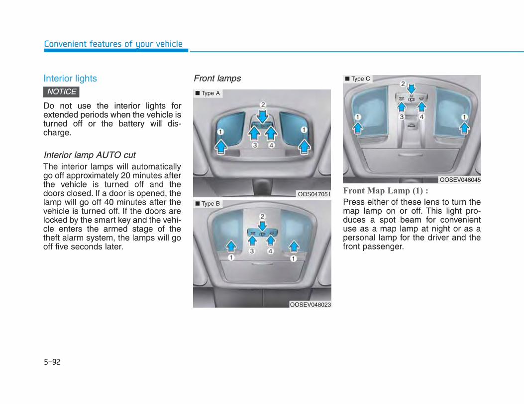
IInterior lights
Do not use the interior lights forextended periods when the vehicle isturned off or the battery will dis-charge.
Interior lamp AUTO cutThe interior lamps will automaticallygo off approximately 20 minutes afterthe vehicle is turned off and thedoors closed. If a door is opened, thelamp will go off 40 minutes after thevehicle is turned off. If the doors arelocked by the smart key and the vehi-cle enters the armed stage of thetheft alarm system, the lamps will gooff five seconds later.
Front lamps
Front Map Lamp (1) :
Press either of these lens to turn themap lamp on or off. This light pro-duces a spot beam for convenientuse as a map lamp at night or as apersonal lamp for the driver and thefront passenger.
NOTICE
OOS047051
■ Type A
OOSEV048023
■ Type B
OOSEV048045
■ Type C
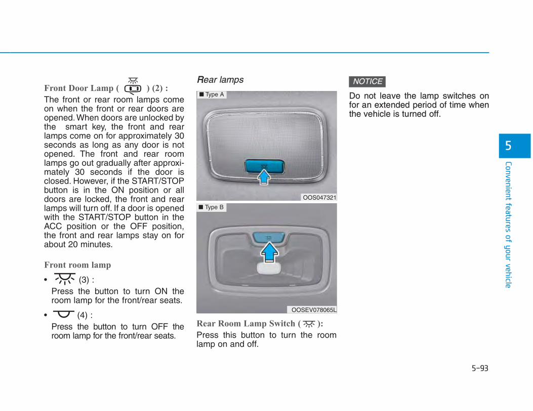
Front Door Lamp ( ) (2) :
The front or rear room lamps comeon when the front or rear doors areopened. When doors are unlocked bythe smart key, the front and rearlamps come on for approximately 30seconds as long as any door is notopened. The front and rear roomlamps go out gradually after approxi-mately 30 seconds if the door isclosed. However, if the START/STOPbutton is in the ON position or alldoors are locked, the front and rearlamps will turn off. If a door is openedwith the START/STOP button in theACC position or the OFF position,the front and rear lamps stay on forabout 20 minutes.
Front room lamp
• (3) : Press the button to turn ON theroom lamp for the front/rear seats.
• (4) :Press the button to turn OFF theroom lamp for the front/rear seats.
RRear lamps
Rear Room Lamp Switch ( ):
Press this button to turn the roomlamp on and off.
Do not leave the lamp switches onfor an extended period of time whenthe vehicle is turned off.
NOTICE
OOS047321
OOSEV078065L
■ Type B
■ Type A

VVanity mirror lamp
Push the switch to turn the light on oroff.• : The lamp will turn on if this
button is pressed.• : The lamp will turn off if this
button is pressed.
Always have the switch in the offposition when the vanity mirror lampis not in use. If the sunvisor is closedwithout the lamp off, it may dis-charge the battery or damage thesunvisor.
Luggage compartment lamp
The luggage compartment lampcomes on when the tailgate is opened.
The luggage compartment lampcomes on as long as the tailgate isopen. To prevent unnecessarycharging system drain, close the tail-gate securely after using the tailgate.
NOTICE
NOTICE
OOSEV048025OOS047055R

AA : Wiper speed control· MIST – Single wipe· OFF – Off· AUTO – Auto control wipe
(if equipped)INT – Intermittent wipe
· LO – Low wiper speed· HI – High wiper speed
* : if equipped
B : Auto control wipe time adjust-ment
C : Wash with brief wipes (front)(pull lever towards you)
D : Rear wiper control*· HI – High wiper speed· LO – Low wiper speed · OFF – Off
E : Wash with brief wipes (rear)(push lever away from you)
* : if equipped
Front windshield wipers Operates as follows when theSTART/STOP button is in the ONposition.MIST : For a single wiping cycle, push
the lever upward (or down-ward) and release. The wiperswill operate continuously if thelever is held in this position.
OFF : Wiper is not in operation.INT : Wiper operates intermittently at
the same wiping intervals.Tovary the speed setting, turn thespeed control knob (B).
AUTO : The rain sensor located onthe upper end of the wind-shield glass senses theamount of rainfall and con-trols the wiping cycle for theproper interval. The more itrains, the faster the wiperoperates. When the rainstops, the wiper stops.Tovary the speed setting, turnthe speed control knob (B).
LO : The wiper runs at a lowerspeed.
HI : The wiper runs at a higher speed.
OPD047455L
■ Front windshield wiper/washer
OTLE045511R
■ Rear windshield wiper/washer

IInformation If there is heavy accumulation of snowor ice on the windshield, defrost thewindshield for about 10 minutes, oruntil the snow and/or ice is removedbefore using the windshield wipers toensure proper operation.
If you do not remove the snow and/orice before using the wiper and washer,it may damage the wiper and washersystem.
AUTO (Automatic) control The rain sensor located on the upperend of the windshield glass sensesthe amount of rainfall and controlsthe wiping cycle for the proper inter-val. The wiper operation time will beautomatically controlled depends onrainfall.When the rain stops, the wiper stops.To vary the speed setting, turn thespeed control knob (1). If the wiper switch is set in AUTOmode when the START/STOP buttonis in the ON position, the wiper willoperate once to perform a self-checkof the system. Set the wiper to OFFposition when the wiper is not in use.
i
To avoid personal injury from thewindshield wipers, when the vehi-cle is in the ready ( ) mode andthe windshield wiper switch isplaced in the AUTO mode:• Do not touch the upper end of
the windshield glass facing therain sensor.
• Do not wipe the upper end of thewindshield glass with a damp orwet cloth.
• Do not put pressure on the wind-shield glass.
WARNING

•• When washing the vehicle, set thewiper switch in the OFF position tostop the auto wiper operation. Thewiper may operate and be dam-aged if the switch is set in theAUTO mode while washing thevehicle.
• Do not remove the sensor coverlocated on the upper end of thepassenger side windshield glass.Damage to system parts couldoccur and may not be covered byyour vehicle warranty.
Front windshield washers
In the OFF position, pull the levergently toward you to spray washerfluid on the windshield and to run thewipers 1-3 cycles. The spray andwiper operation will continue untilyou release the lever. If the washerdoes not work, you may need to addwasher fluid to the washer fluidreservoir.
NOTICE
OTL045280R
When the outside temperature isbelow freezing, ALWAYS warmthe windshield using the defrosterto prevent the washer fluid fromfreezing on the windshield andobscuring your vision which couldresult in an accident and seriousinjury or death.
WARNING
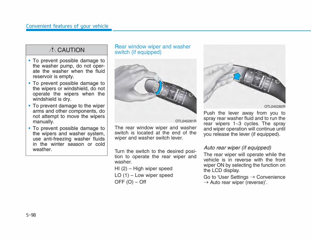
RRear window wiper and washerswitch (if equipped)
The rear window wiper and washerswitch is located at the end of thewiper and washer switch lever.
Turn the switch to the desired posi-tion to operate the rear wiper andwasher.HI (2) – High wiper speedLO (1) – Low wiper speed OFF (O) – Off
Push the lever away from you tospray rear washer fluid and to run therear wipers 1~3 cycles. The sprayand wiper operation will continue untilyou release the lever (if equipped).
Auto rear wiper (if equipped)The rear wiper will operate while thevehicle is in reverse with the frontwiper ON by selecting the function onthe LCD display.Go to ‘User Settings → Convenience→ Auto rear wiper (reverse)’.
• To prevent possible damage tothe washer pump, do not oper-ate the washer when the fluidreservoir is empty.
• To prevent possible damage tothe wipers or windshield, do notoperate the wipers when thewindshield is dry.
• To prevent damage to the wiperarms and other components, donot attempt to move the wipersmanually.
• To prevent possible damage tothe wipers and washer system,use anti-freezing washer fluidsin the winter season or coldweather.
CAUTION
OTL045281R
OTL045282R

RRear view monitor (if equipped)
The Rear View Monitor will activatewhen the vehicle is in the ready ( )mode and the gear is in the R(Reverse) position.
This is a supplemental system thatshows behind the vehicle through theaudio or AVN screen while backing-up.
The Rear View Monitor is not asafety device. It only serves toassist the driver in identifyingobjects directly behind the middleof the vehicle. The camera doesNOT cover the complete areabehind the vehicle.
WARNING
• Never rely solely on the rearcamera display when backing-up.
• ALWAYS look around your vehi-cle to make sure there are noobjects or obstacles before mov-ing the vehicle in any direction toprevent a collision.
• Always pay close attention whenthe vehicle is driven close toobjects, particularly pedestrians,and especially children.
WARNING
OOSEV048020
OOSEV048021R

•• Do not spray the camera or its sur-rounding area directly with a highpressure washer. Shock appliedfrom high pressure water maycause the device to not operatenormally.
• Do not use any cleanser contain-ing acid or alkaline detergentswhen cleaning the lens. Use only amild soap or neutral detergent, andrinse thoroughly with water.
Information Always keep the camera lens clean. Thecamera may not work normally if thelens is covered with dirt, water or snow.
Parking Distance Warning(Reverse) system (if equipped)
[B] : Sensor
The Parking Distance Warning(Reverse) system assists the driverduring reverse movement of the vehi-cle by chiming if any object is sensedwithin the distance of 120 cm (50inches) behind the vehicle.This system is a supplemental sys-tem that senses objects within therange and location of the sensors, itcannot detect objects in other areaswhere sensors are not installed.
NOTICE
i OOSEV048017
• ALWAYS look around your vehi-cle to make sure there are notany objects or obstacles beforemoving the vehicle in any direc-tion to prevent a collision.
• Always pay close attention whenthe vehicle is driven close toobjects, particularly pedestrians,and especially children.
• Be aware that some objectsmay not be visible on the screenor be detected by the sensors,due to the objects distance, sizeor material, all of which can limitthe effectiveness of the sensor.
WARNING

OOperation of the Parking DistanceWarning (Reverse) systemOperating condition
• This system will activate whenbacking up with the START/STOPbutton in the ON position. However,if vehicle speed exceeds 5 km/h (3mph), the system may not detectobjects.
• If vehicle speed exceeds 10 km/h(6 mph), the system will not warnyou even though objects aredetected.
• When more than two objects aresensed at the same time, the clos-est one will be recognized first.
Types of warning sound and indicator
Types of warning sound Indicator
When an object is 120 cm to 60 cm (47 in. to 24 in.) from the rearbumper : Buzzer beeps intermittently.
When an object is 60 cm to 30 cm (24 in. to 12 in.) from the rearbumper : Buzzer beeps more frequently.
When an object is within 30 cm (12 in.) of the rear bumper : Buzzer beeps continuously.
• The indicator may differ from the illustration depending on objects or sen-sors status. If the indicator blinks, we recommend that you have your vehi-cle checked by an authorized HYUNDAI dealer.
• If the audible warning does not sound or if the buzzer sounds intermittent-ly when shifting into R (Reverse) position, this may indicate a malfunctionwith Parking Distance Warning (Reverse) system. If this occurs, we rec-ommend that you have your vehicle checked by an authorized HYUNDAIdealer as soon as possible.
NOTICE

TTo turn off the Parking DistanceWarning (Reverse) system(if equipped)
Push the button to turn off theParking Distance Warning (Reverse)system. The indicator light on thebutton will turn on.
Non-operational conditions ofParking Distance Warning(Reverse) systemThe Parking Distance Warning(Reverse) system may not operatenormally when:
• Moisture is frozen to the sensor.• Sensor is covered with foreign mat-
ter, such as snow or water, or thesensor cover is blocked.
There is a possibility of the ParkingDistance Warning (Reverse) systemmalfunction when:
• Driving on uneven road surfacessuch as unpaved roads, gravel,bumps, or gradient.
• Objects generating excessive noisesuch as vehicle horns, loud motor-cycle engines, or truck air brakescan interfere with the sensor.
• Heavy rain or water spray is present.• Wireless transmitters or mobile
phones are present near the sensor.• The sensor is covered with snow.• Any non-factory equipment or acces-
sories have been installed, or if thevehicle bumper height or sensorinstallation has been modified.
OOSEV048060R

Detecting range may decrease when:
• Outside air temperature is extreme-ly hot or cold.
• Undetectable objects smaller than1 m (40 inches) and narrower than14 cm (6 inches) in diameter.
The following objects may not berecognized by the sensor:
• Sharp or slim objects such asropes, chains or small poles.
• Objects, which tend to absorb sen-sor frequency such as clothes,spongy material or snow.
PParking Distance Warning(Reverse) system precautions• The Parking Distance Warning
(Reverse) system may not soundconsistently depending on the speedand shapes of the objects detected.
• The Parking Distance Warning(Reverse) system may malfunction ifthe vehicle bumper height or sensorinstallation has been modified ordamaged. Any non-factory installedequipment or accessories may alsointerfere with the sensor perform-ance.
• The sensor may not recognizeobjects less than 30 cm (11 in.) fromthe sensor, or it may sense an incor-rect distance. Use caution.
• When the sensor is frozen or stainedwith snow, dirt, or water, the sensormay be inoperative until the stainsare removed using a soft cloth.
• Do not push, scratch or strike thesensor with any hard objects thatcould damage the surface of thesensor. Sensor damage could occur.
Your new vehicle warranty doesnot cover any accidents or dam-age to the vehicle or injuries to itsoccupants related to a ParkingDistance Warning (Reverse) sys-tem. Always drive safely and cau-tiously.
WARNING
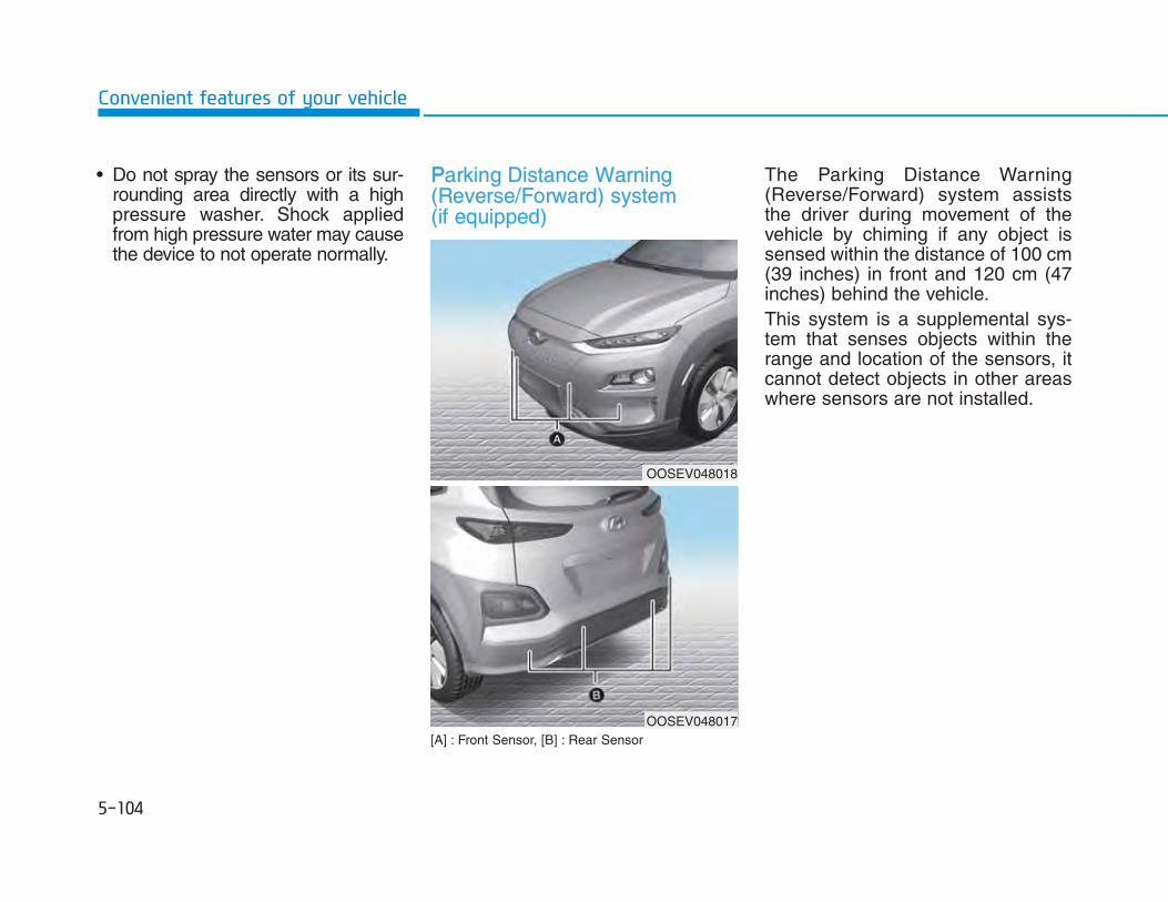
• Do not spray the sensors or its sur-rounding area directly with a highpressure washer. Shock appliedfrom high pressure water may causethe device to not operate normally.
PParking Distance Warning(Reverse/Forward) system (if equipped)
[A] : Front Sensor, [B] : Rear Sensor
The Parking Distance Warning(Reverse/Forward) system assiststhe driver during movement of thevehicle by chiming if any object issensed within the distance of 100 cm(39 inches) in front and 120 cm (47inches) behind the vehicle. This system is a supplemental sys-tem that senses objects within therange and location of the sensors, itcannot detect objects in other areaswhere sensors are not installed.
OOSEV048018
OOSEV048017

OOperation of the Parking DistanceWarning (Reverse/Forward) sys-tem
Operating condition
• This system will activate when theParking Distance Warning (Reverse/Forward) system button is pressedwith the vehicle in the ready ( )mode.
• The Parking Distance Warning(Reverse/Forward) system buttonturns on automatically and acti-vates the Parking DistanceWarning (Reverse/Forward) sys-tem when the gear is in R(Reverse) position. However, ifvehicle speed exceeds 10 km/h (6mph), the system will not warn youeven though objects are detected,and if vehicle speed exceeds 20km/h (12 mph), the system will turnoff automatically. To turn on thesystem, press the ParkingDistance Warning(Reverse/Forward) system button.
• When more than two objects aresensed at the same time, the clos-est one will be recognized first.
• ALWAYS look around your vehi-cle to make sure there are noobjects or obstacles before mov-ing the vehicle in any direction toprevent a collision.
• Always pay close attention whenthe vehicle is driven close toobjects, particularly pedestrians,and especially children.
• Be aware that some objectsmay not be visible on the screenor be detected by the sensors,due to the objects distance, sizeor material, all of which can limitthe effectiveness of the sensor.
WARNING
OOSEV048019R

NNon-operational conditions ofParking Distance Warning(Reverse/Forward) systemParking Distance Warning(Reverse/Forward) system may notoperate normally when:
• Moisture is frozen to the sensor. • Sensor is covered with foreign mat-
ter, such as snow or water, or thesensor cover is blocked.
• The indicator may differ from the illustration depending on objects or sen-sors status. If the indicator blinks, we recommend that the system bechecked by an authorized HYUNDAI dealer.
• If the audible warning does not sound or if the buzzer sounds intermittent-ly when shifting into R (Reverse) position, this may indicate a malfunctionwith the Parking Distance Warning (Reverse/Forward) system. If thisoccurs, we recommend that you have your vehicle checked by an author-ized HYUNDAI dealer as soon as possible.
NOTICE
Distance from object
Warning indicatorWarning soundWhen driving
forwardWhen driving
rearward
61 ~ 100(24 ~39)
Front -Buzzer beeps intermittently
61 ~ 120(24 ~47)
Rear -Buzzer beeps intermittently
31 ~ 60(12 ~24)
FrontBuzzer beeps
frequently
Rear -Buzzer beeps
frequently
30 (12)
FrontBuzzer sounds continuously
Rear -Buzzer sounds continuously
Types of warning sound and indicator cm (in)

There is a possibility of ParkingDistance Warning (Reverse/Forward)system malfunction when:
• Driving on uneven road surfacessuch as unpaved roads, gravel,bumps, or gradient.
• Objects generating excessivenoise such as vehicle horns, loudmotorcycle engines, or truck airbrakes can interfere with the sen-sor.
• Heavy rain or water spray is pres-ent.
• Wireless transmitters or mobilephones are present near the sen-sor.
• The sensor is covered with snow.• Any non-factory equipment or
accessories have been installed,or if the vehicle bumper height orsensor installation has been modi-fied.
Detecting range may decrease when:
• Outside air temperature isextremely hot or cold.
• Undetectable objects smaller than1 m and narrower than 14 cm indiameter.
The following objects may not berecognized by the sensor:
• Sharp or slim objects such asropes, chains or small poles.
• Objects, which tend to absorb sen-sor frequency such as clothes,spongy material or snow.
Your new vehicle warranty doesnot cover any accidents or dam-age to the vehicle or injuries to itsoccupants related to a ParkingDistance Warning(Reverse/Forward) system. Always drive safely and cautious-ly.
WARNING

PParking Distance Warning(Reverse/Forward) system precautions• The Parking Distance Warning
(Reverse/Forward) system may notsound consistently depending onthe speed and shapes of theobjects detected.
• The Parking Distance Warning(Reverse/Forward) system maymalfunction if the vehicle bumperheight or sensor installation hasbeen modified or damaged. Anynon-factory installed equipment oraccessories may also interfere withthe sensor performance.
• The sensor may not recognizeobjects less than 30 cm (11 in.)from the sensor, or it may sense anincorrect distance. Use caution.
• When the sensor is frozen orstained with snow, dirt, or water,the sensor may be inoperative untilthe stains are removed using a softcloth.
• Do not push, scratch or strike thesensor. Sensor damage couldoccur.
• Do not spray the sensors or its sur-rounding area directly with a highpressure washer. Shock appliedfrom high pressure water maycause the device to not operatenormally.

OOSEV048300
1. Temperature control knob
2. Fan speed control knob
3. AUTO (automatic control) button
4. OFF button
5. Mode selection button
6. Air conditioning button
7. Climate control information screenselection button
8. Driver only button
9. Front windshield defroster button
10. Rear window defroster button
11. HEAT button
12. Air intake control button

AAutomatic heating and air condi-tioning
1. Press the AUTO button.The modes, fan speeds, air intakeand air-conditioning will be controlledautomatically according to the tem-perature setting.
2. Turn the temperature control knobto set the desired temperature.
Information • To turn the automatic operation off,
select any button of the following:
- Mode selection button
- Front windshield defroster button(Press the button one more time todeselect the front windshielddefroster function. The 'AUTO'sign will illuminate on the infor-mation display once again.)
- Fan speed control button
The selected function will be con-trolled manually while other func-tions operate automatically.
• For your convenience, use theAUTO button and set the tempera-ture to 22°C (72°F).
i
OOSEV048302
OOSEV048301

IInformation To control the temperature of the highvoltage battery while charging, the airconditioner is used to cool down thehigh-voltage battery which may gener-ate noise from operation of the air con-ditioner compressor and cooling fan.
Also, the air conditioner’s perform-ance may be reduced during summerdue to operation of the cooling systemfor the high voltage battery.
Information Never place anything near the sensorto ensure better control of the heatingand cooling system.
Manual heating and air condi-tioningThe heating and cooling system can becontrolled manually by pushing buttonsother than the AUTO button. In thiscase, the system works sequentiallyaccording to the order of buttons select-ed. When pressing any button exceptthe AUTO button while using automaticoperation, the functions not selectedwill be controlled automatically.1.Start the vehicle.2.Set the mode to the desired position.
For improving the effectiveness ofheating and cooling;- Heating: - Cooling:
3.Set the temperature control to thedesired position.
4.Set the air intake control to the out-side (fresh) air position.
5.Set the fan speed control to thedesired speed.
6.If air conditioning is desired, turnthe air conditioning system on.
Press the AUTO button in order toconvert to full automatic control ofthe system.
i
iOOSEV048026
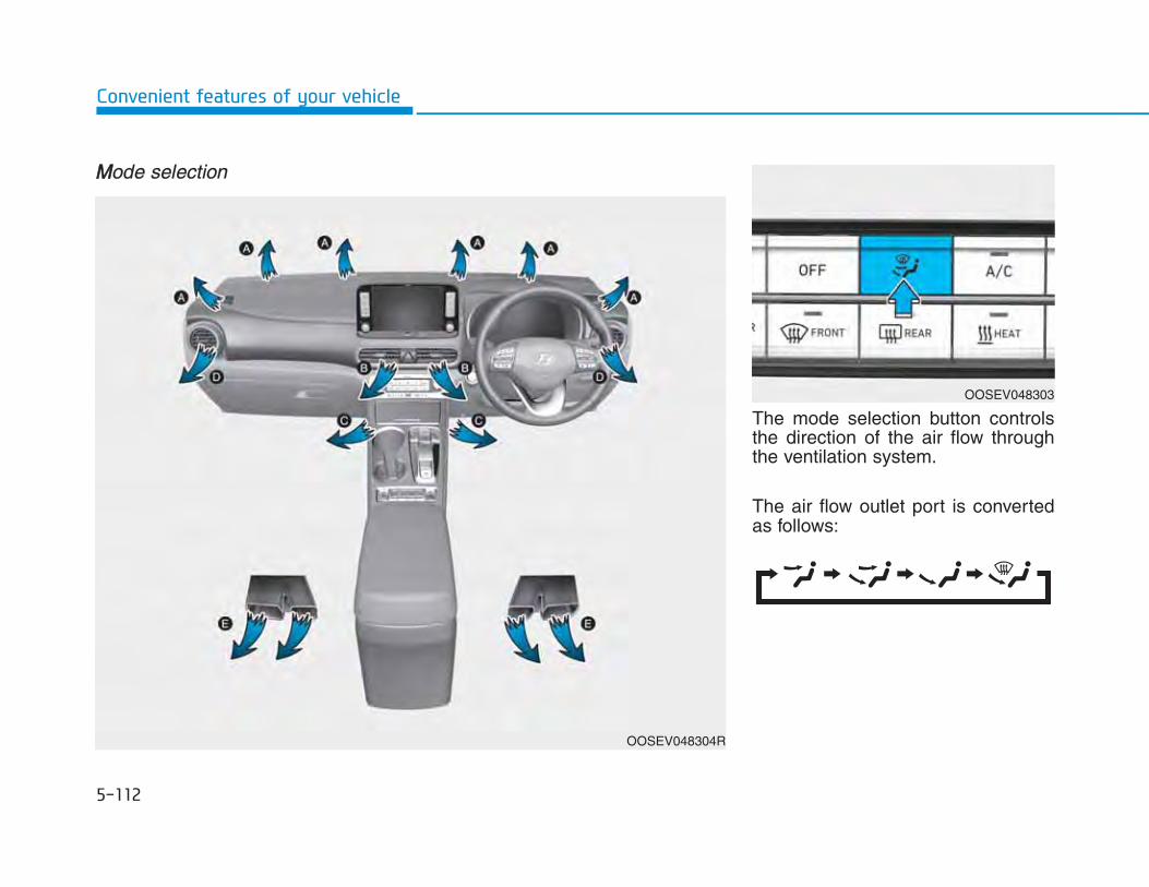
MMode selection
The mode selection button controlsthe direction of the air flow throughthe ventilation system.
The air flow outlet port is convertedas follows:
OOSEV048304R
OOSEV048303

Face-Level (B, D)
Air flow is directed toward the upperbody and face. Additionally, eachoutlet can be controlled to direct theair discharged from the outlet.
Bi-Level (B, C, D, E)
Air flow is directed towards the faceand the floor.
Floor & Defrost (A, C, D, E)
Most of the air flow is directed to thefloor and the windshield with a smallamount directed to the side windowdefrosters.
Floor-Level (A, C, D, E)
Most of the air flow is directed to thefloor, with a small amount of the airbeing directed to the windshield andside window defrosters.
Defrost-Level (A)
Most of the air flow is directed to thewindshield with a small amount of airdirected to the side window defrosters.
Instrument panel vents
The outlet vents can be opened orclosed ( ) using the vent controllever.Also, you can adjust the direction ofair delivery from these vents usingthe vent control lever as shown.
OOSEV048305 OOSEV048306R

TTemperature control
The temperature will increase byturning the knob to the right. Thetemperature will decrease by turningthe knob to the left.The temperature will increase ordecrease by 0.5°C (1°F) for eachincremental location. When set to thelowest temperature setting, the airconditioning will operate continuously.
Temperature conversion
If the battery has been discharged ordisconnected, the temperature modedisplay will reset to Centigrade.To change the temperature unit from°C to °F or °F to °C :- Automatic climate control system
Press the AUTO button for 3 sec-onds while pressing the OFF button.
- Instrument clusterGo to User settings → Other fea-tures → Temperature unit.
The temperature unit on both thecluster LCD display and the climatecontrol screen will change.
Air intake control
The air intake control button is usedto select either Fresh mode (outsideair) or Recirculation mode (cabin air).
Recirculation mode
When Recirculationmode is selected, airfrom the passengercompartment will berecirculated through thesystem and heated orcooled according to thefunction selected.
OOSEV048302 OOSEV048315

Fresh mode
When Fresh mode isselected, air enters thevehicle from outside andis heated or cooledaccording to the functionselected.
IInformation Using the system primarily in Freshmode and Recirculation mode onlywhen needed is recommended for bestresults.
Prolonged operation of the heater inRecirculation mode and without theA/C ON can cause fogging of the wind-shield.
In addition, prolonged use of the A/CON in Recirculation mode may resultin excessively dry, dehumidified air inthe cabin.
Fan speed control
The fan speed can be set to thedesired speed by turning the fanspeed control knob.More air is delivered with higher fanspeeds.Pressing the OFF button turns off thefan.
Operating the fan speed when theSTART/STOP button is in the ONposition could cause the battery todischarge. Operate the fan speedwhen the vehicle is in the ready () mode.
NOTICE
i
• Continued use of the climatecontrol system operation inRecirculation mode for a pro-longed period of time may causedrowsiness to the occupants inthe cabin. This may lead to lossof vehicle control which maylead to an accident.
• Continued use of the climatecontrol system operation inRecirculation mode with the A/COFF may allow humidity toincrease inside the cabin.This may cause condensation toaccumulate on the windshieldand obscure visibility.
• Do not sleep in your vehicle orremain parked in your vehiclewith the windows up and eitherthe heater or the air conditioningON for prolonged periods oftime. Doing so may increase thelevels of carbon dioxide in thecabin which may lead to seriousinjury or death.
WARNING
OOSEV048307

DDriver only
If you press the DRIVER ONLY but-ton( ) and the indicator lightilluminates, cold air mostly blows inthe direction of the driver’s seat.However, some of the cold air maycome out of other seating positionducts to keep indoor air pleasant. If you use the button with no passen-ger in the front passenger seat, ener-gy consumption will be reduced.
DRIVER ONLY button will be turnedoff under the following conditions:1) Defrost on2) DRIVER ONLY button re-push
Air conditioning
Push the A/C button to turn the airconditioning system on (indicatorlight will illuminate). Push the button again to turn the airconditioning system off.
DRIVER ONLY
OOSEV048314 OOSEV048308

HHEAT button
Push the HEAT button to turn theheater on (indicator light will illumi-nate).Push the button again to turn theheater off.
The air conditioner and heater usesenergy from the battery. If you usethe heater or air conditioner for toolong, distance to empty can bereduced due to too much power con-sumption.Turn off the heater and air conditionerif you do not need them.
Climate control information screenselection button
Push the climate control informationscreen selection button to display cli-mate control information on the audioor AVN screen.
OFF mode
Push the OFF button to turn the cli-mate control system off. However,you can still operate the mode and airintake buttons as long as theSTART/STOP button is in the ONposition.
OOSEV048310
OOSEV048309
OOSEV048311
SSystem operationVentilation1. Select the Face Level mode.2. Set the air intake control to fresh
mode.3. Set the temperature control to the
desired position.4. Set the fan speed control to the
desired speed.
Heating1. Select the Floor Level mode.2. Set the air intake control to fresh
mode.3. Set the temperature control to the
desired position.4. Set the fan speed control to the
desired speed.5. If desired, turn the air conditioning
ON with the temperature controlknob set to heat in order to dehu-midify the air before it enters intothe cabin.
If the windshield fogs up, select theFloor & Defrost mode or pressthe Front Defrost mode.
Operation Tips
• To keep dust or unpleasant fumesfrom entering the vehicle throughthe ventilation system, temporarilyset the air intake control to therecirculation mode. Be sure toreturn the control to fresh modeposition when the irritation haspassed to keep fresh air in thevehicle. This will help keep the driv-er alert and comfortable.
• To prevent interior fog on the wind-shield, set the air intake control tofresh mode and fan speed to thedesired position, turn on the airconditioning system, and adjustthe temperature control to desiredtemperature.
Air conditioningHYUNDAI Air Conditioning Systemsare filled with R-134a or R1234yfrefrigerant.1. Start the vehicle. 2. Push the air conditioning button.3. Select the Face Level mode.4. Set the air intake control to
Recirculation mode temporarily toallow the cabin to cool quickly.When the desired temperature inthe cabin is reached, change theair intake control back to Freshmode.
5. Adjust the fan speed control andtemperature control to maintainmaximum comfort.

•• The refrigerant system should onlybe serviced by trained and certifiedtechnicians to insure proper andsafe operation.
• The refrigerant system should beserviced in a well-ventilated place.
• The air conditioning evaporator(cooling coil) shall never berepaired or replaced with oneremoved from a used or salvagedvehicle and new replacement MACevaporators shall be certified (andlabeled) as meeting SAE StandardJ2842.
Information When opening the windows in humidweather air conditioning may createwater droplets inside the vehicle.Since excessive water droplets maycause damage to electrical equipment,air conditioning should only be usedwith the windows closed.
Air conditioning system operationtips
• If the vehicle has been parked indirect sunlight during hot weather,open the windows for a short timeto let the hot air inside the vehicleescape.
• After sufficient cooling has beenachieved, switch back from recircu-lation mode to fresh mode.
• To help reduce moisture inside ofthe windows on rainy or humiddays, decrease the humidity insidethe vehicle by operating the air con-ditioning system with the windowsand sunroof closed.
• Use the air conditioning systemevery month for a few minutes toensure maximum system perform-ance.
• If you operate the air conditionerexcessively, the difference betweenthe temperature of the outside airand that of the windshield couldcause the outer surface of the wind-shield to fog up, causing loss of vis-ibility. In this case, set the modeselection button to the positionand set the fan speed control knobto the lowest speed setting.
System maintenanceClimate control air filter
[A] : Outside air, [B] : Recirculated air[C] : Climate control air filter, [D] : Blower[E] : Evaporator core, [F] : Heater core
This filter is installed behind theglove box. It filters the dust or otherpollutants that enter the vehiclethrough the heating and air condi-tioning system.
i
NOTICE
OIK047401L

We recommend that the climate con-trol air filter be replaced by anauthorized HYUNDAI dealer accord-ing to the maintenance schedule. Ifthe vehicle is being driven in severeconditions such as dusty or roughroads, more frequent climate controlfilter inspections and changes arerequired. If the air flow rate suddenly decreas-es, we recommend the system bechecked at an authorized HYUNDAIdealer.
IInformation • Replace the filter according to the
Maintenance Schedule.
If the car is being driven in severeconditions such as dusty, roughroads, more frequent climate con-trol air filter inspections andchanges are required.
• When the air flow rate suddenlydecreases, we recommend that thesystem be checked by an authorizedHYUNDAI dealer.
Checking the amount of air condi-tioner refrigerant and compressorlubricantWhen the amount of refrigerant islow, the performance of the air con-ditioning is reduced. Overfilling alsohas a bad influence on the air condi-tioning system.Therefore, if abnormal operation isfound, we recommend that the sys-tem be inspected by an authorizedHYUNDAI dealer.
We recommend the air conditioningsystem be serviced by an authorizedHYUNDAI dealer.
iVehicles equipped with R-134a
Because the refriger-ant is at very high pres-sure, the air condition-ing system should onlybe serviced by trained
and certified technicians. It isimportant that the correct type andamount of oil and refrigerant isused. Otherwise, it may cause damage tothe vehicle and personal injury.
WARNING
Vehicles equipped with R-1234yf
Because the refrigerantis mildly inflammable atvery high pressure, theair conditioning systemshould only be servicedby trained and certifiedtechnicians. It is impor-tant that the correcttype and amount of oil
and refrigerant is used. Otherwise, it may cause damageto the vehicle and personal injury.
WARNING

• For maximum defrost perform-ance, set the temperature controlknob to the highest temperaturesetting (rotated all the way to theright) and the fan speed control tothe highest setting.
• If warm air to the floor is desiredwhile defrosting or defogging, set themode to the floor-defrost position.
• Before driving, clear all snow andice from the windshield, rear win-dow, outside rear view mirrors, andall side windows.
• Clear all snow and ice from thehood and air inlet in the cowl grill toimprove heater and defroster effi-ciency and to reduce the probabili-ty of fogging up inside of the wind-shield.
TTo defog inside windshield
1. Select desired fan speed.2. Select desired temperature.3. Press the defroster button ( ).4. Fresh mode will be selected auto-
matically.Check to make sure the air intakecontrol is in Fresh mode. If the airintake control indicator light is illumi-nated, press the button once toenable Fresh mode (indicator lightOFF).If the position is selected, the fanspeed is automatically increased.
Windshield heating
Do not use the or positionduring cooling operation inextremely humid weather. The dif-ference between the temperatureof the outside air and that of thewindshield could cause the outersurface of the windshield to fogup, causing loss of visibility. In thiscase, set the mode selection knobor button to the position andfan speed control knob or buttonto lower speed.
WARNING
OOSEV048312

TTo defrost outside windshield
1. Set fan speed to the (extremeright) highest position.
2. Set temperature to the extremehot (HI) position.
3. Press the defroster button ( ).4. Fresh mode will be selected auto-
matically.Check to make sure the air intakecontrol is in Fresh mode. If the airintake control indicator light is illumi-nated, press the button once toenable Fresh mode (indicator lightOFF).If the position is selected, the fanspeed is automatically increased.
Defogging logic To reduce the probability of foggingup the inside of the windshield, theair intake or air conditioning are con-trolled automatically according tocertain conditions such as or position. To cancel or return thedefogging logic, do the following.
1. Turn the START/STOP button tothe ON position.
2. Press the defroster button ( ).3. While pressing the air conditioning
button (A/C), press the air intakecontrol button at least 5 times with-in 3 seconds.
The air intake control button indicatorwill blink 3 times. It indicates that thedefogging logic is canceled.
If the battery has been discharged ordisconnected, it resets to the defoglogic status.
Defroster
To prevent damage to the conduc-tors bonded to the inside surface ofthe rear window, never use sharpinstruments or window cleaners con-taining abrasives to clean the window.
Information If you want to defrost and defog thefront windshield, refer to “WindshieldDefrosting and Defogging” in thischapter.
i
NOTICE
OOSEV048313

RRear window defroster
The defroster heats the window toremove frost, fog and thin ice fromthe interior and exterior of the rearwindow, while the vehicle is in theready ( ) mode.• To activate the rear window
defroster, press the rear windowdefroster button located in the cen-ter facia switch panel. The indicatoron the rear window defroster but-ton illuminates when the defrosteris ON.
• To turn off the defroster, press therear window defroster button again.
Information • If there is heavy accumulation of
snow on the rear window, brush it offbefore operating the rear defroster.
• The rear window defroster automati-cally turns off after approximately 20minutes or when the START/STOPbutton is in the OFF position.
Auto defogging system
Auto defogging reduces the possibil-ity of fogging up the inside of thewindshield by automatically sensingthe moisture of inside the windshield.The auto defogging system operateswhen the heater or air conditioning ison.
Information The auto defogging system may notoperate normally, when the outsidetemperature is below -10 °C.
i
i
OOSEV048027OOSEV048316

When the Auto DefoggingSystem operates, the indi-cator will illuminate.
If a high amount of humidity isdetected in the vehicle, the AutoDefogging System will be enabled.The following steps will be performedautomatically:Step 1) The A/C button will turn ON.Step 2) The air intake control will
change to Fresh mode.Step 3) The mode will be changed to
defrost to direct airflow to thewindshield.
Step 4) The fan speed will be set toMAX.
If the air conditioning is off or recircu-lated air position is manually selectedwhile Auto Defogging System is ON,the Auto Defogging System Indicatorwill blink 3 times to signal that themanual operation has been canceled.
To cancel the auto defogging system
1. Press the START/STOP button tothe ON position.
2. Press the front defroster buttonover 3 seconds.
3. The front defroster button indicatorwill blink 3 times and then ADSOFF will illuminate on the climatecontrol information screen whenthe auto defogging system is can-celed.
To reactivate the auto defogging sys-tem
1. Press the START/STOP button tothe ON position.
2. Press the front defroster buttonover 3 seconds.
3. The front defroster button indicatorwill blink 6 times and then ADS OFFwill go out on the climate controlinformation screen when the autodefogging system is reactivated.
IInformation • When the air conditioning is turned
on by Auto defogging system, if youtry to turn off the air conditioning, theindicator will blink 3 times and the airconditioning will not be turned off.
• To maintain the effectiveness andefficiency of the Auto DefoggingSystem, do not select Recirculationmode while the system is operating.
• When the Auto Defogging System isoperating, the fan speed adjustmentknob, the temperature adjustmentknob, and the air intake control but-ton are all disabled.
Do not remove the sensor coverlocated on the upper end of thewindshield glass. Damage to system parts could occurand may not be covered by yourvehicle warranty.
NOTICE
i

AAutomatic ventilationThe system automatically selects thefresh mode when the climate controlsystem operates over a certain peri-od of time (approximately 30 min-utes) in low temperature with therecirculation mode selected.
To cancel or reactivate the Automatic VentilationWhen the air conditioning system ison, select Face Level mode andpress the air recirculation mode but-ton for 3 seconds.When the automatic ventilation iscanceled, the indicator blinks 3 times.When the automatic ventilation isactivated, the indicator blinks 6 times.

TTo avoid possible theft, do not leavevaluables in the storage compart-ments.
Center console storage
To open :Grab and hold the latch (1) on thearm rest then lift the lid.
Glove box
To open:Pull the lever (1).
NOTICE
Never store cigarette lighters,propane cylinders, or other flam-mable/explosive materials in thevehicle. These items may catchfire and/or explode if the vehicle isexposed to hot temperatures forextended periods.
WARNING
ALWAYS keep the storage com-partment covers closed securelywhile driving. Items inside yourvehicle are moving as fast as thevehicle. If you have to stop or turnquickly, or if there is a crash, theitems may fly out of the compart-ment and may cause an injury ifthey strike the driver or a passen-ger.
WARNING OOSEV048028
ALWAYS close the glove box doorafter use.An open glove box door can causeserious injury to the passenger inan accident, even if the passengeris wearing a seat belt.
WARNING
OOS047057R

SSunglass holder (if equipped)
To open:Push and release the cover and theholder will slowly open. Place yoursunglasses in the compartment doorwith the lenses facing out.To close:Push back into position.Make sure the sunglass holder isclosed while driving.
OOSEV048029
• Do not keep objects except sun-glasses inside the sunglassholder. Such objects can bethrown from the holder in theevent of a sudden stop or anaccident, possibly injuring thepassengers in the vehicle.
• Do not open the sunglass holderwhile the vehicle is moving. Therear view mirror of the vehiclecan be blocked by an open sun-glass holder.
• Do not put the glasses forciblyinto a sunglass holder. It maycause personal injury if you tryto open it forcibly when theglasses are jammed in holder.
WARNING

Cup holder
Cups or small beverages cups maybe placed in the cup holders.
RearPull the armrest down to use the cupholders.
• Keep your drinks sealed while driv-ing to prevent spilling your drink. Ifliquid spills, it may get into thevehicle's electrical/electronic sys-tem and damage electrical/elec-tronic parts.
• When cleaning spilled liquids do notuse hot air to blow out or dry the cupholder. This may damage the interi-or.
NOTICE
• Avoid abrupt starting and brak-ing when the cup holder is in useto prevent spilling your drink. Ifhot liquid spills, you could beburned. Such a burn to the driv-er could cause loss of vehiclecontrol resulting in an accident.
• Do not place uncovered orunsecured cups, bottles, cans,etc., in the cup holder containinghot liquid while the vehicle is inmotion. Injuries may result in theevent of sudden stop or colli-sion.
• Only use soft cups in the cupholders. Hard objects can injureyou in an accident.
WARNING
OOSEV048031R
■ Front
OOS047061
■ Rear
Keep cans or bottles out of directsun light and do not put them in ahot vehicle. It may explode.
WARNING

SSunvisor
To use a sunvisor, pull it downward.To use a sunvisor for a side window,pull it downward, unsnap it from thebracket (1) and swing it to the side (2).To use the vanity mirror, pull down thesunvisor and slide the mirror cover (3).Adjust the sunvisor forward or back-ward (4) as needed (if equipped).Use the ticket holder (5) to hold tickets.Close the vanity mirror cover secure-ly and return the sunvisor to its origi-nal position after use.
Do not put several tickets in the tick-et holder at one time. This couldcause damage to the ticket holder.
Power outlet (if equipped)
The power outlet is designed to pro-vide power for mobile telephones orother devices designed to operatewith vehicle electrical systems. Thedevices should draw less than 180W(Watt) with the vehicle in the ready( ) mode.
NOTICE
OOSEV048070R
For your safety, do not block yourview when using the sunvisor.
WARNING
OOSEV048032R
Avoid electrical shocks. Do notplace your fingers or foreignobjects (pin, etc.) into a power out-let or touch the power outlet with awet hand.
WARNING

TTo prevent damage to the PowerOutlets :• Use the power outlet only when the
vehicle is in the ready ( ) modeand remove the accessory plugafter use. Using the accessoryplug for prolonged periods of timewith the vehicle off could cause thebattery to discharge.
• Only use 12V electric accessorieswhich are less than 180 W(Watt) inelectric capacity.
• Adjust the air-conditioner or heaterto the lowest operating level whenusing the power outlet.
• Close the cover when not in use.• Some electronic devices can
cause electronic interference whenplugged into a vehicle’s power out-let. These devices may causeexcessive audio static and mal-functions in other electronic sys-tems or devices used in your vehi-cle.
• Push the plug in as far as it will go.If good contact is not made, theplug may overheat and the fusemay open.
• Plug in battery equipped electri-cal/electronic devices with reversecurrent protection. The currentfrom the battery may flow into thevehicle's electrical/electronic sys-tem and cause system malfunc-tion.
USB charger (if equipped)
The USB charger is designed torecharge batteries of small size elec-trical devices using a USB cable. The electrical devices can berecharged when the START/STOPbutton is in the ACC, ON or STARTposition.The battery charging state may bemonitored on the electrical device.
NOTICE
OOSEV048033R

Disconnect the USB cable from theUSB port after use.• A smart phone or a tablet PC may
get warmer during the re-chargingprocess. It does not indicate anymalfunction with the charging sys-tem.
• A smart phone or a tablet PC,which adopts a different re-charg-ing method, may not be properlyre-charged. In this case, use anexclusive charger of your device.
• The charging terminal is only torecharge a device. Do not use thecharging terminal either to turn ONan audio or to play media on theAVN.
WWireless cellular phone chargingsystem (if equipped)
[A]: Indicator light, [B]: Charging pad
There is a wireless cellular phonecharger inside the front console.To use the wireless cellular phonecharging system, open the front con-sole cover by pressing the lower partof the cover (1). After use, to close the cover, slightlypull down the cover. The system is available when all doorsare closed, and when theSTART/STOP button is in the ACC,ON or START position.
To charge a cellular phone The wireless cellular phone chargingsystem charges only the Qi-enabledcellular phones ( ). Read the labelon the cellular phone accessorycover or visit your cellular phonemanufacturer’s website to checkwhether your cellular phone supportsthe Qi technology. The wireless charging process startswhen you put a Qi-enabled cellularphone on the wireless charging unit.
1. Remove other items, including thesmart key, from the wireless charg-ing unit. If not, the wireless charg-ing process may be interrupted.Place the cellular phone on thecenter of charging pad.
2. The indicator light is orange whenthe cellular phone is charging. Theindicator light turns green whenphone charging is complete.
3. You can turn ON or OFF the wire-less charging function in the UserSettings mode on the instrumentcluster. For further information, referto the “LCD Display Modes” in thischapter.
OOSEV048034R

If your cellular phone is not charging:- Slightly change the position of the
cellular phone on the charging pad.- Make sure the indicator light is
orange.
The indicator light will blink orangefor 10 seconds if there is a malfunc-tion in the wireless charging system.In this case, temporarily stop thecharging process, and re-attempt towirelessly charge your cellular phoneagain. The system warns you with a mes-sage on the LCD display if the cellularphone is still on the wireless chargingunit after the vehicle is turned OFFand the front door is opened.
IInformation For some manufacturers' cellularphones, the system may not warn youeven though the cellular phone is lefton the wireless charging unit. This isdue to the particular characteristic ofthe cellular phone and not a malfunc-tion of the wireless charging.
• The wireless cellular phone charg-ing system may not support certaincellular phones, which are not ver-ified for the Qi specification ( ).
• When placing your cellular phoneon the charging mat, position thephone in the middle of the mat foroptimal charging performance. Ifyour cell phone is off to the side,the charging rate may be less andin some cases the cell phone mayexperience higher heat conduc-tion.
• In some cases, the wireless charg-ing may stop temporarily when theSmart Key is used, either whenstarting the vehicle orlocking/unlocking the doors, etc.
• When charging certain cellularphones, the charging indicator maynot change to green when the cellphone is fully charged.
• The wireless charging processmay temporarily stop, when tem-perature abnormally increasesinside the wireless cellular phonecharging system. The wirelesscharging process restarts, whentemperature falls to a certain level.
• The wireless charging processmay temporarily stop when there isany metallic item, such as a coin,between the wireless cellularphone charging system and a cel-lular phone.
• For certain cellular phones withtheir own protection, the wirelesscharging speed may decrease andthe wireless charging may stop.
• If the cellular phone has a thickcover, the wireless charging maynot be possible.
i
NOTICE

•• If the cell phone is not completelycontacting the charging pad, wire-less charging may not operateproperly.
• Some magnetic items like creditcards, phone cards or rail ticketsmay be damaged if left with thecellular phone during the chargingprocess.
• If the cellular phone without thewireless charging function or themetallic items are placed on thecharging pad, it may cause slightnoise. This noise does not affectthe cellular phone and the vehicle,because this noise is an operatingsound during determining the itemon the charging pad.
• If the START/STOP button is OFF,the charging also stops.
Clock Vehicles with Audio systemSelect the Settings menu on theAudio screen ➟ Select [Date/Time].• Set time: Set the time displayed on
the audio screen.• Time format: Choose between 12-
hour and 24-hour time formats.
Vehicles with Navigation systemSelect the Settings menu on the AVNscreen ➟ Select [Date/Time].• GPS time: Displays time according
to the received GNSS time.• 24-hour: Switches to 12 hour or 24
hour.
For more details, please refer to theseparate manual that was suppliedwith your vehicle.
Do not adjust the clock while driv-ing. You may lose your steeringcontrol and cause severe personalinjury or accidents.
WARNING

CClothes hanger (if equipped)
These hangers are not designed tohold large or heavy items.
Floor mat anchor(s) (if equipped)
ALWAYS use the Floor Mat Anchorsto attach the front floor mats to thevehicle. The anchors on the frontfloor carpet keep the floor mats fromsliding forward.
OOS047067
OOS047065
Do not hang other objects such ashangers or hard objects exceptclothes. Also, do not put heavy,sharp or breakable objects in theclothes pockets. In an accident orwhen the curtain air bag is inflat-ed, it may cause vehicle damageor personal injury.
WARNING
OOS047066

LLuggage net (holder) (if equipped)
To keep items from shifting in thecargo area, you can use the fourholders located in the cargo area toattach the luggage net.If necessary, we recommend that youcontact your authorized HYUNDAIdealer to obtain a luggage net.
The following must be observedwhen installing ANY floor mat tothe vehicle.• Ensure that the floor mats are
securely attached to the vehi-cle's floor mat anchor(s) beforedriving the vehicle.
• Do not use ANY floor mat thatcannot be firmly attached to thevehicle's floor mat anchors.
• Do not stack floor mats on top ofone another (e.g. all-weatherrubber mat on top of a carpetedfloor mat). Only a single floormat should be installed in eachposition.
IMPORTANT - Your vehicle wasmanufactured with driver's sidefloor mat anchors that aredesigned to securely hold the floormat in place. To avoid any inter-ference with pedal operation,HYUNDAI recommends that theHYUNDAI floor mat designed foruse in your vehicle be installed.
WARNING
OOSEV048036
To avoid eye injury, DO NOT over-stretch the luggage net. ALWAYSkeep your face and body out of theluggage net’s recoil path. DO NOTuse the luggage net when thestrap has visible signs of wear ordamage.
WARNING
To prevent damage to the goodsor the vehicle, care should betaken when carrying fragile orbulky objects in the luggage com-partment.
CAUTION
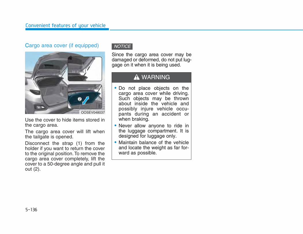
CCargo area cover (if equipped)
Use the cover to hide items stored inthe cargo area.The cargo area cover will lift whenthe tailgate is opened. Disconnect the strap (1) from theholder if you want to return the coverto the original position. To remove thecargo area cover completely, lift thecover to a 50-degree angle and pull itout (2).
Since the cargo area cover may bedamaged or deformed, do not put lug-gage on it when it is being used.
NOTICE
OOSEV048037
• Do not place objects on thecargo area cover while driving.Such objects may be thrownabout inside the vehicle andpossibly injure vehicle occu-pants during an accident orwhen braking.
• Never allow anyone to ride inthe luggage compartment. It isdesigned for luggage only.
• Maintain balance of the vehicleand locate the weight as far for-ward as possible.
WARNING

RRoof rack (if equipped)
If the vehicle has a roof rack, you canload cargo on top of your vehicle.
If the vehicle is equipped with a sun-roof, be sure not to position cargoonto the roof rack in such a way thatit could interfere with sunroof opera-tion.
• When carrying cargo on the roofrack, take the necessary precau-tions to make sure the cargo doesnot damage the roof of the vehicle.
• When carrying large objects on theroof rack, make sure they do notexceed the overall roof length orwidth.
NOTICE
NOTICE
OOSEV048035
• The following specification is themaximum weight that can beloaded onto the roof rack.Distribute the load as evenly aspossible onto the roof rack andsecure the load firmly.
Loading cargo or luggage inexcess of the specified weightlimit on the roof rack may dam-age your vehicle.
• The vehicle center of gravity willbe higher when items areloaded onto the roof rack. Avoidsudden starts, braking, sharpturns, abrupt maneuvers or highspeeds that may result in loss ofvehicle control or rollover result-ing in an accident.
• Always drive slowly and turncorners carefully when carryingitems on the roof rack. Severewind updrafts, caused by pass-ing vehicles or natural causes,can cause sudden upward pres-sure on items loaded on the roofrack. This is especially truewhen carrying large, flat itemssuch as wood panels or mat-tresses. This could cause theitems to fall off the roof rack andcause damage to your vehicle orothers around you.
• To prevent damage or loss ofcargo while driving, check fre-quently before or while driving tomake sure the items on the roofrack are securely fastened.
WARNING
ROOF 80 kg (176 lbs.)RACK EVENLY DISTRIBUTED


IInformation • If you install an aftermarket HID
headlamp, your vehicle’s audio andelectronic devices may malfunction.
• Prevent chemicals such as perfume,cosmetic oil, sun cream, hand clean-er, and air freshener from contact-ing the interior parts because theymay cause damage or discoloration.
AUX, USB and iPod® port
You can use an AUX port to connectaudio devices and an USB port toplug in an USB and an iPod® port.To use the AUX, USB and iPod®,open the front console cover byslightly pressing the lower part of thecover (1).After use, to close the cover, slightlypull down the cover.
Information When using a portable audio deviceconnected to the power outlet, noisemay occur during playback. If thishappens, use the power source of theportable audio device.
❈ iPod® is a trademark of Apple Inc.
ii
OOSEV048038R

AAntennaRoof antenna
The roof antenna receives transmit-ted data. (For example : AM/FM)
Rotate the roof antenna in a counter-clockwise direction to remove it.Rotate it in a clockwise direction toreinstall it.
• Before entering a place with lowheight clearance or a car wash,remove the antenna by rotating itcounterclockwise. If not, the anten-na may be damaged.
• When reinstalling your antenna, itis important that it is fully tightenedand adjusted to the upright positionto ensure proper reception.
Steering wheel audio controls (ifequipped)
The steering wheel audio controlswitches are installed for your conven-ience.
NOTICE
OOS047071 OOSIEV049425

DDo not operate audio remote controlbuttons simultaneously.
VOLUME (VOL + / - ) (1)• Move the VOLUME toggle switch
up to increase volume.• Move the VOLUME toggle switch
down to decrease volume.
SEEK/PRESET ( / ) (2)If the SEEK/PRESET toggle switchis moved up or down and held for 0.8seconds or more, it will function inthe following modes.
RADIO mode
It will function as the AUTO SEEKselect switch. It will SEEK until yourelease the switch.
MEDIA mode
It will function as the FF/REW switch.
If the SEEK/PRESET toggle switchis moved up or down, it will functionin the following modes.
RADIO mode
It will function as the PRESET STA-TION UP/DOWN switch.
MEDIA mode
It will function as the TRACK UP/DOWN switch.
MODE ( ) (3)Press the MODE button to selectVarious Available Media sources likeRadio, USB, AUX and BT audio.
MUTE ( ) (4) • Press the button to mute the
sound.• Press the button again to activate
the sound.
Information Detailed information is described in aseparately supplied manual.
i
NOTICE

BBluetooth® Wireless Technologyhands-free
You can use the phone wirelessly byusing the Bluetooth® WirelessTechnology.
(1) Call / Answer button(2) Call end button(3) Microphone
• Audio : For detailed information,refer to “AUDIO” in this chapter.
• Detailed information for theBluetooth® Wireless Technologyhands-free is described in the man-ual supplied separately.
Audio system (if equipped)Detailed information for the Audiosystem is described in a separatelysupplied manual.
OOSEV048043
OOSEV048050R


BBefore entering the vehicle • Be sure all windows, outside mir-
ror(s), and outside lights are cleanand unobstructed.
• Remove frost, snow, or ice.• Visually check the tires for uneven
wear and damage.• Check under the vehicle for any
sign of leaks.• Be sure there are no obstacles
behind you if you intend to back up.
Before starting • Make sure the hood, the tailgate,
and the doors are securely closedand locked.
• Adjust the position of the seat andsteering wheel.
• Adjust the inside and outsiderearview mirrors.
• Verify all the lights work.• Fasten your seat belt. Check that
all passengers have fastened theirseat belts.
• Check the gauges and indicators inthe instrument panel and the mes-sages on the instrument displaywhen the START/STOP button is inthe ON position.
• Check that any items you are car-rying are stored properly or fas-tened down securely.
To reduce the risk of SERIOUSINJURY or DEATH, take the fol-lowing precautions:• ALWAYS wear your seat belt.
All passengers must be properlybelted whenever the vehicle ismoving. For more information,refer to "Seat Belts" in chapter 2.
• Always drive defensively.Assume other drivers or pedes-trians may be careless andmake mistakes.
• Stay focused on the task of driv-ing. Driver distraction can causeaccidents.
• Leave plenty of space betweenyou and the vehicle in front ofyou.
WARNING

NEVER drink or take drugs anddrive.Drinking or taking drugs and driv-ing is dangerous and may result inan accident and SERIOUSINJURY or DEATH.Drunk driving is the number onecontributor to the highway deathtoll each year. Even a smallamount of alcohol will affect yourreflexes, perceptions and judg-ment. Just one drink can reduceyour ability to respond to changingconditions and emergencies andyour reaction time gets worse witheach additional drink.Driving while under the influenceof drugs is as dangerous or moredangerous than driving under theinfluence of alcohol.You are much more likely to have
WARNING a serious accident if you drink ortake drugs and drive. If you aredrinking or taking drugs, don'tdrive. Do not ride with a driver whohas been drinking or taking drugs.Choose a designated driver or calla taxi.
To reduce the risk of SERIOUSINJURY or DEATH, take the fol-lowing precautions:• NEVER allow children or any
person who is unfamiliar withthe vehicle to touch theSTART/STOP button or relatedparts. Unexpected and suddenvehicle movement can occur.
• NEVER reach through the steer-ing wheel for the START/STOPbutton or any other control,while the vehicle is in motion.The presence of your hand orarm in this area may cause aloss of vehicle control resultingin an accident.
WARNING

Whenever the front door is opened,the START/STOP button will illumi-nate and will go off 30 seconds afterthe door is closed.
OOSIEV059002
To turn the vehicle off in an emer-gency:Press and hold the START/STOPbutton for more than two secondsOR Rapidly press and release theSTART/STOP button three times(within three seconds).If the vehicle is still moving, youcan restart the vehicle withoutdepressing the brake pedal bypressing the START/STOP buttonwith the gear in the N (Neutral)position.
WARNING
• NEVER press the START/STOPbutton while the vehicle is inmotion except in an emergency.This will result in the vehicleturning off and loss of powerassist for the steering and brakesystems. This may lead to lossof directional control and brakingfunction, which could cause anaccident.
• Before leaving the driver's seat,always make sure the gear is inthe P (Park) position, set theparking brake, press theSTART/STOP button to the OFFposition, and take the Smart Keywith you. Unexpected vehiclemovement may occur if theseprecautions are not followed.
WARNING

SSTART/STOP button positions
Button Position Action Notice
OFF To turn off the vehicle, press theSTART/STOP button with the gear in P(Park).Also, the vehicle will turn off when the START/STOP button is pressed with the gear in D (Drive) or R (Reverse) because the gear automatically shifts to the P (Park) position. But, when it is pressed in N (Neutral), the START/STOP button will go to the ACC posi-tion.The steering wheel locks up.
If the steering wheel is not locked properlywhen you open the driver's door, the warningchime will sound.
ACC Press the START/STOP button when thebutton is in the OFF position withoutdepressing the brake pedal.Some of the electrical accessories areusable.The steering wheel unlocks.
If the steering wheel doesn't unlock properly,the START/STOP button will not work. Pressthe START/STOP button while turning thesteering wheel right and left to release ten-sion.

BButton Position Action Notice
ON Press the START/STOP button while it is inthe ACC position without depressing thebrake pedal.The warning lights can be checked beforethe vehicle is started.
Do not leave the START/STOP button in theON position when the vehicle is not in theready ( ) mode to prevent the battery fromdischarging.
START To start the vehicle, depress the brake pedaland press the START/STOP button with thegear in the P (Park) position.
If you press the START/STOP button withoutdepressing the brake pedal, the vehicle doesnot start and the START/STOP buttonchanges as follows:OFF → ACC → ON → OFF or ACC

SStarting the vehicle Information • The vehicle will start by pressing the
START/STOP button, only whenthe smart key is in the vehicle.
• Even if the smart key is in the vehi-cle, and when it is far away from thedriver, the vehicle may not start.
• When the START/STOP button is inthe ACC or ON position, any door isopen, the system checks for thesmart key. When the smart key isnot in the vehicle, the " " indica-tor will blink and the warning "Keynot in vehicle" will come on. Whenall doors are closed, the chime willalso sound for about 5 seconds.Keep the smart key in the vehiclewhen in the ACC position or if thevehicle is in the ready ( ) mode.
1. Always carry the smart key withyou.
2. Make sure the parking brake isapplied.
3. Make sure the gear is in P (Park). 4. Depress the brake pedal. 5. Press the START/STOP button. If
the vehicle starts, the " " indi-cator will come on.
Information • Always start the vehicle with your
foot on the brake pedal. Do notdepress the accelerator while start-ing the vehicle.
• If ambient temperature is low, the" " indicator may remain illumi-nated longer than the normal amountof time.
i
i
• Always wear appropriate shoeswhen operating your vehicle.Unsuitable shoes, such as highheels, ski boots, sandals, flip-flops, etc., may interfere withyour ability to use the brake andaccelerator pedals.
• Do not start the vehicle with theaccelerator pedal depressed. The vehicle can move and leadto an accident.
WARNING

TTo prevent damage to the vehicle: • If the " " indicator turns off while
you are in motion, do not attemptto shift to the P (Park) position.If traffic and road conditions per-mit, you may shift to the N(Neutral) position while the vehicleis still moving and press theSTART/STOP button in an attemptto restart the vehicle.
• Do not push or tow your vehicle tostart the vehicle.
To prevent damage to the vehicle: Do not press the START/STOP but-ton for more than 10 seconds exceptwhen the stop lamp fuse is blown.When the stop lamp fuse is blown,you cannot normally start the vehi-cle. Replace the fuse with a newone. If you are not able to replace thefuse, you can start the vehicle bypressing and holding theSTART/STOP button for 10 secondswith the START/STOP button in theACC position. For your safety always depress thebrake pedal before starting the vehi-cle.
Information If the smart key battery is weak or thesmart key does not work correctly,you can start the vehicle by pressingthe START/STOP button with thesmart key in the direction of the pic-ture above.
i
NOTICENOTICE
OOSIEV059003

TTuring off the vehicle1. Depress the brake pedal fully.2. Shift to P (Park).3. Apply the parking brake.4. Press the START/STOP button to
turn the vehicle off.5. Make sure the " " indicator
light on the instrument cluster isturned off.
If the " " indicator light on theinstrument cluster is still on, thevehicle is not turned off and canmove when the gear is in anyposition except P (Park).
CAUTION

RReduction gear operation
Select gear positions by pressing theshift button.For your safety, always depress thebrake pedal while shifting to anothergear.
Gear position
The indicator in the instrument clus-ter displays the gear position whenthe START/STOP button is in the ONposition.
To reduce the risk of serious injuryor death:• ALWAYS check the surrounding
areas near your vehicle for peo-ple, especially children, beforeshifting a vehicle into D (Drive)or R (Reverse).
• Before leaving the driver's seat,always make sure the gear is inthe P (Park) position, then setthe parking brake, and place theSTART/STOP button in the OFFposition. Unexpected and sud-den vehicle movement canoccur if these precautions arenot followed.
WARNING
OOSEV058004R
OOSEV048105

P (Park)
Always come to a complete stopbefore shifting into P (Park).To shift the gear from R (Reverse), N(Neutral) or D (Drive) to P (Park),press the [P] button.If you turn off the vehicle in D (Drive)or R (Reverse), the gear automatical-ly shifts to P (Park).• With the vehicle on, the gear auto-
matically shifts to P (Park) if youopen the driver's door when thegear is in N (Neutral), R (Reverse)or D (Drive) and the following con-ditions are met:- The brake/accelerator pedal is
not depressed- Seat belt is unfastened- The vehicle speed is below 0.6
km/h• When the vehicle is over a certain
speed, the gear does not shift to P(Park) when the P button ispressed.
R (Reverse)
Use this position to drive the vehiclebackward.To shift to R (Reverse), press the [R]button while depressing the brakepedal.
N (Neutral)
The wheels and gear are notengaged. To shift to N (Neutral), press the [N]button while depressing the brakepedal.Always depress the brake pedalwhen you are shifting from N(Neutral) to another gear.In N (Neutral), if the driver attemptsto turn off the vehicle, the gearremains in N (Neutral) and theSTART/STOP button will be in theACC position.To turn off the vehicle from the ACCposition, press the START/STOPbutton to the ON position, press the[P] button, and press theSTART/STOP button to the OFFposition.
• Shifting into P (Park) while thevehicle is in motion may causeyou to lose control of the vehi-cle.
• After the vehicle has stopped,always make sure the gear is inP (Park), apply the parkingbrake, and turn the vehicle off.
• Do not use the P (Park) positionin place of the parking brake.
WARNING

When the driver’s door is openedwithin 3 minutes with theSTART/STOP button in the ACCposition and the gear in N (Neutral),the vehicle is automatically turnedOFF and shifted to the P (Park) posi-tion.
D (Drive)
This is the normal driving position. To shift to D (Drive), press the [D]button while depressing the brakepedal.
SShift-lock system For your safety, your vehicle has ashift-lock system which preventsshifting the gear from P (Park) or N(Neutral) into R (Reverse) or D(Drive) unless the brake pedal isdepressed.To shift from P (Park) or N (Neutral)into R (Reverse) or D (Drive), from R(Reverse) into D (Drive) or from D(Drive) into R (Reverse) :1. Depress and hold the brake pedal.2. Start the vehicle or place the
START/STOP button in the ONposition.
3. Press the R (Reverse) or D (Drive)button.
Information For your safety, you cannot shift thegear while the charging cable is con-nected.
When the battery (12 V) is dis-chargedYou cannot shift the gear when thebattery is discharged. Jump start your vehicle (refer to"Jump Starting" in chapter 6) or werecommend that you contact anauthorized HYUNDAI dealer.
i

PParkingAlways come to a complete stop andcontinue to depress the brake pedal.Shift to the P (Park) position, applythe parking brake, and place theSTART/STOP button in the OFFposition. Take the Key with you whenexiting the vehicle.
LCD display messagesShifting conditions not met
The message appears on the LCDdisplay in the following conditions: 1. When driving speed is too fast to
shift the gear.Decrease the vehicle speed orslow down before shifting thegear.
2. When the gear is shifted while thevehicle is in utility mode.
Press brake pedal to change gearThe message appears on the LCD
display, when the brake pedal is notdepressed while shifting the gear.Depress the brake pedal and thenshift the gear.
OOSEV058006R OOSEV058008R

SShift to P after stopping
The message appears on the LCDdisplay when the gear is shifted to P(Park) while the vehicle is moving. Stop the vehicle before shifting to P(Park).
PARK engaged
The message appears on the LCDdisplay when the P (Park) position isengaged.
NEUTRAL engaged
The message appears on the LCDdisplay when the N (Neutral) positionis engaged.
OIK057051LOIK057046L OIK057052L

TThis gear is already selected
The message appears on the LCDdisplay when the selected gear but-ton is pressed again.
PARK button error! Engage park-ing brake when parking vehicle
The message is displayed when
there is a problem with functionengaging P (Park) position. We recommend that you Immediatelyhave the vehicle inspected by anauthorized HYUNDAI dealer.
D button error! Shifting back to Dnot possible if gear changed orvehicle Off
The message is displayed whenthere is a problem with the D button. If this message is displayed, do notshift the gear or turn the vehicle offwhile driving. If the driver shifts thegear to P/R/N position or turns off theengine, it is impossible to shift backto D (Drive).
OOSEV058007R
OOSEV058009L OOSEV058013L

CCheck P button
The message appears on the LCDdisplay when there is problem withthe P button.We recommend that you immediate-ly have the vehicle inspected by anauthorized HYUNDAI dealer.
Check shift controls
The message appears on the LCDdisplay when there is problem withthe shift buttons. We recommend that you immediate-ly have the vehicle inspected by anauthorized HYUNDAI dealer
Shift button is stuck
The message appears on the LCDdisplay when the shift button is con-tinuously pressed or there is problemwith the button. Make sure that there is no object overthe shift button. If the problem per-sists, we recommend that you imme-diately have the vehicle inspected byan authorized HYUNDAI dealer
OOSEV058010ROOSEV058012L OOSEV058014R

GGood driving practices • Never shift to P (Park) or N
(Neutral) to any other position withthe accelerator pedal depressed.
• Never shift to P (Park) when thevehicle is in motion. Be sure the vehicle is completelystopped before you attempt to shiftinto R (Reverse) or D (Drive).
• Do not shift to N (Neutral) whendriving. Doing so may result in anaccident.
• Do not drive with your foot restingon the brake pedal. Even light, butconsistent pedal pressure canresult in the brakes overheating,brake wear and possibly evenbrake failure.
• Always apply the parking brakewhen leaving the vehicle. Do notdepend on placing the gear in P(Park) to keep the vehicle frommoving.
• Exercise extreme caution whendriving on a slippery surface. Beespecially careful when braking,accelerating or shifting gears. On aslippery surface, an abrupt changein vehicle speed can cause thedrive wheels to lose traction andmay cause loss of vehicle controlresulting in an accident
• Optimum vehicle performance andeconomy is obtained by smoothlydepressing and releasing theaccelerator.
To reduce the risk of SERIOUSINJURY or DEATH:• ALWAYS wear your seat belt. In
a collision, an unbelted occu-pant is significantly more likelyto be seriously injured or killedthan a properly belted occupant.
• Avoid high speeds when corner-ing or turning.
• Do not make quick steering
WARNING
wheel movements, such assharp lane changes or fast,sharp turns.
• The risk of rollover is greatlyincreased if you lose control ofyour vehicle at highway speeds.
• Loss of control often occurs iftwo or more wheels drop off theroadway and the driver oversteers to reenter the roadway.
• In the event your vehicle leavesthe roadway, do not steersharply. Instead, slow downbefore pulling back into the trav-el lanes.
• HYUNDAI recommends you fol-low all posted speed limits.

RRegenerative braking (Paddle shifter)
The paddle shifter is used to adjustthe regenerative braking level from 0to 3 during decelerating or braking.• Left side ( ): Increases regener-
ative braking and deceleration.• Right side ( ): Decreases
regenerative braking and decelera-tion.
• Pull and hold the left side paddleshifter for more than 0.5 secondsand One Pedal Driving function isoperated, increasing the regenera-tive braking. In this case, stoppingthe vehicle is possible by keep onpulling the paddle shifter.
Refer to the following pages on"One Pedal Driving".
• With the Smart RecuperationSystem activated, pull and hold theright side paddle shifter for over 1second to turn on and off the auto-matic change of the regenerativebraking. However, nothing will hap-pen if the Smart RecuperationSystem is not activated from theUser Settings mode. To activate ordeactivate the function go to 'Usersettings → Convenience → Smartrecuperation'. Refer to the follow-ing pages on "Smart RecuperationSystem".
Information The paddle shifter does not operatewhen:
• The [ ] and [ ] paddleshifters are pulled at the same time.
• The vehicle is decelerating bydepressing the brake pedal.
• The Cruise Control system or SmartCruise Control system is activated.
The selected regenerative brakinglevel is displayed on the instrumentcluster.
i
OOSEV048109L
OOS057006

Initial setting of the regenerativebraking level and adjustable rangevary according to the selected Drivemode.
FFor more details, refer to "DriveMode Integrated Control System" inthis chapter.
One pedal drivingThe driver can stop the vehicle bypulling and holding the left side pad-dle shifter.
Operating ConditionsThe system enters the operatingcondition when the conditions beloware met:• The driver's door is closed.• The driver's seat belt is fastened.
To operate:
• Pull and hold the left side paddleshifter while coasting.
• When the vehicle speed is above 3km/h, release the paddle shifter toreturn to the previously set level.
• When the vehicle speed is below 3km/h, the function maintains con-trol to stop the vehicle even thoughthe paddle shifter is released.
• While the One pedal driving is inactivation, the driver can controlthe vehicle stopping position usingthe accelerator pedal.
Automatic engagement of EPB After the vehicle is stopped by theOne Pedal Driving function, EPB isautomatically engaged when any ofthese conditions occur:• The driver's door is open • The driver's seatbelt is unfastened.• The hood is open • The tailgate is open.• 5 minutes have passed after the
vehicle has stopped.• The system operation is limited
due to other reasons.
Drive mode Initial settingAdjustable
Range
ECO+ 2 0-3
ECO 2 0-3
COMFORT 1 0-3
SPORT 1 0-3
Stopping the vehicle may not bepossible according to the vehicleand road conditions. Pay attentionto the road condition ahead andapply the brake if necessary.
WARNING

The Smart Recuperation Systemcontrols the regenerative brakingautomatically according to the roadgradient and driving condition of thevehicle in front. The system mini-mizes the unnecessary operation ofthe brake and acceleration pedal,improving the fuel efficiency andassisting the driver.
SSystem setting
The Smart Recuperation Systementers the ready status when:The gear is in P (Park) and select'User settings → Convenience →Smart recuperation' on the UserSettings mode.The setting is maintained when thevehicle is restarted.
To activate Smart RecuperationSystemWith 'AUTO' for the regenerativebraking level displayed on the clus-ter, the regenerative braking level iscontrolled automatically when vehi-cle speed is above 10 km/h (6 mph)and one of the condition below ismet. - The road gradient changes- Distance from the vehicle ahead
reduces or increases- Speed of the vehicle ahead
reduces or increases
OOSEV048205L
When vehicle speed is under 10km/h (6 mph), the SmartRecuperation System is can-celled. The driver must adjust thevehicle speed by depressing theaccelerator or brake pedal accord-ing to the road condition aheadand driving condition.
WARNING

When the system is turned on fromthe User Settings mode, but the frontradar doesn't recognize the vehiclein front, 'AUTO' is displayed in white.
If the front radar recognizes the vehi-cle in front, 'AUTO' is displayed inblue. The regenerative braking levelis automatically controlled depend-ing on the driving condition of thevehicle in front and the level is indi-cated with arrows. However, current regenerative brak-ing level is maintained if the driverdepresses the brake pedal while thesystem is in activation. Also, the sys-tem is cancelled temporarily if theaccelerator pedal is depressed.
OOSEV058097L OOSEV058001L
The Smart Recuperation Systemwhich automatically controls theregenerative braking level whencoasting is only a supplementalsystem for the driver's conven-ience. The system cannot com-pletely stop the vehicle nor avoidall collisions. The brake controlmay be insufficient depending onthe speed of the vehicle in frontand when the vehicle in front sud-denly stops, a vehicle cuts in sud-denly and there is a steep slope.Always look ahead cautiously toprevent unexpected and suddensituations from occurring.
WARNING

SSmart Recuperation System willbe temporarily cancelled when:• Cancelled manually
Pulling and holding the right sidepaddle shifter for more than 1 sec-ond. The Smart Recuperation Systemturns off temporarily and AUTO forthe regenerative braking level dis-appears from the cluster.
• Cancelled automatically- The vehicle is shifted to N
(Neutral), R (Reverse) or P(Park).
- The Cruise Control System(including the Smart CruiseControl system) is in activation.
- The ESC (Electronic StabilityControl) or ABS is operating.
To resume Smart RecuperationSystemTo re-activate the Smart RecuperationSystem while driving, pull and hold theright side paddle shifter for more than1 second again. Then, AUTO for theregenerative braking level will appearon the cluster.
To turn Smart RecuperationSystem offTo turn off the system, shift to P(Park) and deselect 'User settings →Convenience → Smart recuperation'on the User Settings mode.
Vehicle-to-Vehicle Distancerecognition sensor (Front radar)In order for the Smart RecuperationSystem to operate properly, alwaysmake sure the radar sensor cover isclean and free of dirt, snow, anddebris. Dirt, snow, or foreign sub-stances on the lens may adverselyaffect the sensing performance ofthe sensor. In this case, the systemoperation may stop temporarily andnot operate normally.
• Do not apply license plate frameor foreign objects such as abumper sticker or a bumperguard near the radar sensor.Doing so may adversely affectthe sensing performance of theradar.
• Always keep the radar sensorand lens cover clean and free ofdirt and debris.
CAUTION
When the Smart RecuperationSystem is cancelled automatically,adjust the vehicle speed directlyby depressing the accelerator orbrake pedal according to the roadcondition ahead and driving condi-tion.
WARNING

SSystem malfunction
Check smart recuperation system
The message will appear when thesystem is not functioning normally.The system will be cancelled and theword 'AUTO' on the cluster will dis-appear and instead display regener-ative braking level. Check for foreignsubstances on the front radar.Remove any dirt, snow, or foreignmaterial that could interfere with theradar sensors. If the system still doesnot operate normally, we recommendthat you take your vehicle to anauthorized HYUNDAI dealer andhave the system checked.
Limitations of the systemThe Smart Recuperation Systemmay not operate properly in certainsituations when the driving conditionis beyond the performance of thefront radar sensor.Driver's attention is required in suchcases when the system does notreact properly or operate uninten-tionally.
• Use only a soft cloth to wash thevehicle. Do not spray pressur-ized water directly on the sensoror sensor cover.
• Be careful not to apply unneces-sary force on the radar sensor orsensor cover. If the sensor isforcibly moved out of properalignment, the SmartRecuperation System may notoperate correctly. In this case, awarning message may not bedisplayed. We recommend thatthe vehicle be inspected by anauthorized HYUNDAI dealer.
• If the front bumper becomesdamaged in the area around theradar sensor, the SmartRecuperation System may notoperate properly. We recom-mend that the vehicle beinspected by an authorizedHYUNDAI dealer.
• Use only genuine HYUNDAIparts to repair or replace a dam-aged sensor or sensor cover.Do not apply paint to the sensorcover.
OOSEV048204L

OOn curves
When coasting on the curve, the sys-tem may not detect the vehicle inyour lane and the regenerative brak-ing level will reduce automatically,making you feel that the vehicle isaccelerating. Also, if the system suddenly recog-nizes the vehicle in front, the regen-erative braking level will increaseautomatically, making you feel thatthe vehicle is decelerating.The driver must maintain a safe brak-ing distance, and if necessary,depress the brake pedal to reduceyour driving speed in order to main-tain a safe distance.
Your vehicle speed can be reduceddue to a vehicle in the adjacent lane.Apply the accelerator pedal andselect the appropriate speed. Checkto be sure that the road conditionspermit safe operation of the SmartRecuperation System.
On inclines
When coasting on an uphill or down-hill, the system may not detect thevehicle in your lane and the regener-ative braking level will reduce auto-matically, making you feel that thevehicle is accelerating. Also, if the system suddenly recog-nizes the vehicle in front, the regen-erative braking level will increaseautomatically, making you feel thatthe vehicle is decelerating.The driver must maintain a safe brak-ing distance, and if necessary,depress the brake pedal to reduceyour driving speed in order to main-tain a safe distance.
OTM058117R
OTM058073R
OOS057073

LLane changing
• A vehicle which moves into yourlane from an adjacent lane cannotbe recognized by the sensor until itis in the sensor's detection range.
• The radar may not detect immedi-ately when a vehicle cuts in sud-denly. Always pay attention to thetraffic, road and driving conditions.
Vehicle recognition
Some vehicles in your lane cannotbe recognized by the sensor:- Narrow vehicles such as motorcy-
cles or bicycles- Vehicles offset to one side- Slow-moving vehicles or sudden-
decelerating vehicles - Stopped vehicles (When the vehi-
cle ahead drives away, the systemmay not detect a stopped vehicle.)
- Vehicles with small rear profilesuch as trailers with no loads
A vehicle ahead cannot be recog-nized correctly by the sensor if any offollowing occurs:- When the vehicle is pointing
upwards due to overloading in theluggage compartment
- While the steering wheel is operat-ing
- When driving to one side of thelane
- When driving on narrow lanes oron curves
Apply the brake or accelerator pedalif necessary.
OTM058122ROTM058074R

TThe Smart Recuperation Systemmay not operate temporarily due to: • Electrical interference• Modifying the suspension• Differences of tire abrasion or tire
pressure • Installing different type of tires
NOTICEwith a frequent lane change maycause a delay in the system'sreaction or may cause the sys-tem to react to a vehicle actuallyin an adjacent lane. Alwaysdrive cautiously to prevent unex-pected and sudden situationsfrom occurring.
• The Smart RecuperationSystem may not recognize com-plex driving situations so alwayspay attention to driving condi-tions and control your vehiclespeed.
When using the SmartRecuperation System take the fol-lowing precautions:• If an emergency stop is neces-
sary, you must apply the brakes. • Keep a safe distance according
to road conditions and vehiclespeed. If the vehicle to vehicledistance is too close during ahigh-speed driving, a seriouscollision may result.
• Always maintain sufficient brak-ing distance and decelerate yourvehicle by applying the brakes ifnecessary.
• The Smart RecuperationSystem cannot recognize astopped vehicle, pedestrians oran oncoming vehicle. Alwayslook ahead cautiously to preventunexpected and sudden situa-tions from occurring.
• Vehicles moving in front of you
WARNING

PPower brakes Your vehicle has power-assistedbrakes that adjust automaticallythrough normal usage.If power is not supplied to your vehiclesuch as when the battery is dis-charged or the vehicle is turned offwhile driving, the power assist for thebrakes will not work. You can still stopyour vehicle by applying greater forceto the brake pedal than typical. Thestopping distance, however, will belonger than with power brakes.Do not pump the brake pedal whenthe power assist has been interrupted.
Take the following precautions:• Do not drive with your foot rest-
ing on the brake pedal. This willcreate abnormal high brake tem-peratures, excessive brake lin-ing and pad wear, andincreased stopping distances.
• When descending down a longor steep hill, use the paddleshifter (left side lever) toincrease regenerative braking inorder to control your speed with-out using the brake pedal exces-sively. Applying the brakes con-tinuously will cause the brakesto overheat and could result in atemporary loss of braking per-formance.
• Wet brakes may impair the vehi-
cle's ability to safely slow down;the vehicle may also pull to oneside when the brakes areapplied. Applying the brakeslightly will indicate whether theyhave been affected in this way.Always test your brakes in thisfashion after driving throughdeep water. To dry the brakes,lightly tap the brake pedal toheat up the brakes while main-taining a safe forward speeduntil brake performance returnsto normal. Avoid driving at highspeeds until the brakes functioncorrectly.
WARNING
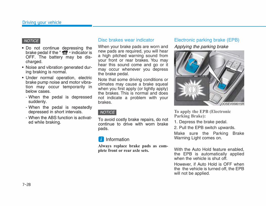
•• Do not continue depressing thebrake pedal if the " " indicator isOFF. The battery may be dis-charged.
• Noise and vibration generated dur-ing braking is normal.
• Under normal operation, electricbrake pump noise and motor vibra-tion may occur temporarily inbelow cases.- When the pedal is depressed
suddenly.- When the pedal is repeatedly
depressed in short intervals.- When the ABS function is activat-
ed while braking.
Disc brakes wear indicator When your brake pads are worn andnew pads are required, you will heara high pitched warning sound fromyour front or rear brakes. You mayhear this sound come and go or itmay occur whenever you depressthe brake pedal.Note that some driving conditions orclimates may cause a brake squealwhen you first apply (or lightly apply)the brakes. This is normal and doesnot indicate a problem with yourbrakes.
To avoid costly brake repairs, do notcontinue to drive with worn brakepads.
Information Always replace brake pads as com-plete front or rear axle sets.
Electronic parking brake (EPB)Applying the parking brake
To apply the EPB (ElectronicParking Brake):
1. Depress the brake pedal.2. Pull the EPB switch upwards.Make sure the Parking BrakeWarning Light comes on.
With the Auto Hold feature enabled,the EPB is automatically appliedwhen the vehicle is shut off.However, if Auto Hold is OFF whenthe the vehicle is turned off, the EPBwill not be applied.
i
NOTICE
NOTICE
OOSEV058015R

RReleasing the parking brake
To release the EPB (ElectronicParking Brake), press the EPBswitch in the following condition:
• Have the START/STOP button inthe ON position.
• Depress the brake pedal.Make sure the Parking BrakeWarning Light goes off.
To release EPB (Electronic ParkingBrake) automatically:
• Gear in P (Park)With the vehicle in the ready ( )mode depress the brake pedal andshift out of P (Park) to R (Reverse)or D (Drive).
• Gear in N (Neutral)With the vehicle in the ready ( )mode depress the brake pedal andshift out of N (Neutral) to R(Reverse) or D (Drive).
• Under the following conditions1. Start the vehicle.2. Fasten the driver's seat belt. 3. Close the driver's door, hood
and tailgate.4. Depress the accelerator pedal
while the gear is in D (Drive) orR (Reverse).
The Parking Brake Warning Lightshould be turned off when the EPB isreleased.
To reduce the risk of SERIOUSINJURY or DEATH, do not oper-ate the parking brake while thevehicle is moving except in anemergency situation. It could dam-age the brake system and lead toan accident.
WARNING
OOSEV058016R

IInformation • For your safety, you can engage the
EPB even though the START/STOPbutton is in the OFF position, butyou cannot release it.
• For your safety, depress the brakepedal and release the parking brakemanually with the EPB switch whenyou drive downhill or when backingup the vehicle.
• If the parking brake warning light isstill on even though the EPB hasbeen released, we recommend thatthe system be checked an author-ized HYUNDAI dealer.
• Do not drive your vehicle with theEPB applied. It may cause exces-sive brake pad and brake rotorwear.
EPB (Electronic Parking Brake)may be automatically appliedwhen:
• Requested by other systems• If the driver turns the vehicle off
while Auto Hold is operating, EPBwill be automatically applied.
Warning messages
To release EPB, close the doors,hood and tailgate and fasten seat-belt
A warning will sound and a messagewill appear in the following condi-tions.• If you try to drive with the EPB
applied.• If the driver's seat is not fastened,
and you try to release EPB.• If the driver's door is opened, and
you try to release EPB.• If the hood is opened with the gear
in D (Drive)/R (Reverse) and youtry to release EPB.
NOTICE
i
OOSEV058094L

• If the tailgate is opened with thegear in D (Drive)/R (Revers) andyou try to release EPB.
• If there is a problem with the vehi-cle.
If the situation occurs, depress thebrake pedal and release EPB bypressing the EPB switch.
•• A click sound may be heard whileoperating or releasing the EPB, butthese conditions are normal andindicate that the EPB is functioningproperly.
• When leaving your keys with aparking lot attendant or valet,make sure to inform him/her howto operate the EPB.
• The EPB may malfunction if youdrive with the EPB applied.
• When you automatically releaseEPB by depressing the acceleratorpedal, depress it slowly.
Deactivating AUTO HOLD...Press brake pedal
When the conversion from Auto Holdto EPB is not working properly awarning will sound and a messagewill appear.
NOTICE
• To prevent unintentional move-ment when stopped and leavingthe vehicle, do not use the P(Park) position in place of theparking brake. Set the parkingbrake and make sure the vehicleis securely positioned in P(Park).
• Never allow anyone who is unfa-miliar with the vehicle to touchthe parking brake. If the parkingbrake is released unintentional-ly, serious injury may occur.
• All vehicles should always have
the parking brake fully engagedwhen parking to avoid inadver-tent movement of the car whichcan injure occupants or pedes-trians.
WARNING OOSEV058098L

Parking brake automaticallyapplied
If the EPB is applied while Auto Holdis activated, a warning will sound anda message will appear.
EEPB malfunction indicator
This warning light illuminates if theSTART/STOP button is changed tothe ON position and goes off inapproximately 3 seconds if the sys-tem is operating normally.If the EPB malfunction indicatorremains on, comes on while driving,or does not come on when theSTART/STOP button is changed tothe ON position, this indicates thatthe EPB may have malfunctioned.If this occurs, we recommend thatthe system be checked by an author-ized HYUNDAI dealer.
The EPB malfunction indicator mayilluminate when the ESC (ElectronicStability Control) indicator comes onto indicate that the ESC is not work-ing properly, but it does not indicate amalfunction of the EPB.
• If the EPB warning light is still on,we recommend that the system bechecked by an authorizedHYUNDAI dealer.
• If the parking brake warning lightdoes not illuminate or blinks eventhough the EPB switch was pulledup, the EPB may not be applied.
• If the parking brake warning lightblinks when the EPB warning lightis on, press the switch, then pull itup. Once more press it back to itsoriginal position and pull it back up.If the EPB warning does not go off,we recommend that the system bechecked by an authorizedHYUNDAI dealer.
NOTICE
OOSEV058099L
OOSEV058017

EEmergency brakingIf there is a problem with the brakepedal while driving, emergency brak-ing is possible by pulling up andholding the EPB switch. Braking ispossible only while you are holdingthe EPB switch. However, brakingdistance will be longer than normal.
InformationDuring emergency braking, the park-ing brake warning light will illumi-nate to indicate that the system isoperating.
If you continuously notice a noise orburning smell when the EPB is usedfor emergency braking, we recom-mend that the system be checked byan authorized HYUNDAI dealer.
When the EPB (Electronic ParkingBrake) does not release
If the EPB does not release normal-ly, we recommend that you contactan authorized HYUNDAI dealer byloading the vehicle on a flatbed towtruck and have the system checked.
Parking brake warning lightCheck the ParkingBrake Warning Lightby placing theSTART/STOP buttonto the ON position( indicator off).
This light will be illuminated when theparking brake is applied with theSTART/STOP button in the START orON position.Before driving, be sure the parkingbrake is released and the BrakeWarning Light is OFF.If the Parking Brake Warning Lightremains on after the parking brake isreleased while the vehicle is in theready ( ) mode, there may be amalfunction in the brake system.Immediate attention is necessary.If at all possible, cease driving thevehicle immediately. If that is not pos-sible, use extreme caution whileoperating the vehicle and only con-tinue to drive the vehicle until youcan reach a safe location.
NOTICE
i
Do not operate the parking brakewhile the vehicle is moving exceptin an emergency situation. It coulddamage the brake system andlead to a severe accident.
WARNING

AAuto holdThe Auto Hold maintains the vehiclein a standstill even though the brakepedal is not depressed after the driv-er brings the vehicle to a completestop by depressing the brake pedal.
To apply :
1. With the driver's door, hood andtailgate closed, depress the brakepedal and then press the [AUTOHOLD] switch. The white AUTOHOLD indicator will come on andthe system will be in the standbyposition.
2. When you stop the vehicle com-pletely by depressing the brakepedal, the Auto Hold maintains thebrake pressure to hold the vehiclestationary. The indicator changesfrom white to green.
3. The vehicle will remain stationaryeven if you release the brakepedal.
4. If EPB is applied, Auto Hold will bereleased.
OOSEV058018R
OOSEV058019R
WWhh ii tt ee
GGrreeee nn

TTo release :• If you press the accelerator pedal
with the gear in D (Drive) or R(Reverse), the Auto Hold will bereleased automatically and thevehicle will start to move. TheAUTO HOLD indicator changesfrom green to white.
• If the vehicle is restarted using thecruise control toggle switch (RES+or SET-) while Auto Hold and cruisecontrol is operating, the Auto Holdwill be released regardless ofaccelerator pedal operation. TheAUTO HOLD indicator changesfrom green to white (if equippedwith cruise control system).
To cancel :
1. Depress the brake pedal.2. Press the [AUTO HOLD] switch.The AUTO HOLD indicator will turnoff.
Information• The Auto Hold does not operate
when:
- The driver's door is opened
- The hood is opened
- The tailgate is opened
- The gear is in P (Park)
- The EPB is applied
• For your safety, the Auto Hold auto-matically switches to EPB in suchcases:
- The driver's door is opened
- The hood is opened
- The tailgate is opened
- The vehicle stops for more than 10minutes
- The vehicle stands on a steep slope
- The vehicle moves several times
i
OOSEV058020R
LLiigg hhtt oo ff ff
When the AUTO HOLD is auto-matically released by depressingthe accelerator pedal, always takea look around your vehicle.Slowly depress the acceleratorpedal for a smooth start.
WARNING
To prevent, unexpected and sud-den vehicle movement, ALWAYSpress your foot on the brake pedalto cancel Auto Hold before you:- Drive downhill.- Park the vehicle.
WARNING

In these cases, the parking brakewarning light comes on, the AUTOHOLD indicator changes from greento white, and a warning sounds anda message will appear to inform youthat EPB has been automaticallyengaged. Before driving again,depress the brake pedal, check thesurrounding area near your vehicleand release the parking brake man-ually with the EPB switch.
• While operating Auto Hold, you mayhear mechanical noise. However, it isnormal operating noise.
IIf the AUTO HOLD indicator changesto yellow, the Auto Hold is not work-ing properly. We recommend thatyou contact an authorized HYUNDAIdealer.
If there is a malfunction with the dri-ver's door or hood open detectionsystem, the Auto Hold may not workproperly.We recommend that you contact anauthorized HYUNDAI dealer.
Warning messages
Parking brake automaticallyapplied
When the EPB is applied from AutoHold, a warning will sound and amessage will appear.
NOTICE
NOTICE
• Depress the accelerator pedalslowly when you start the vehi-cle.
• For your safety, cancel the AutoHold when you drive downhill,back up the vehicle or park thevehicle.
WARNING
OOSEV058099L

Deactivating AUTO HOLD...Press brake pedal
When the conversion from Auto Holdto EPB is not working properly awarning will sound and a messagewill appear. When this message is displayed, theAuto Hold and EPB may not operate.For your safety, depress the brakepedal.
Press brake pedal to deactivateAUTO HOLD
If you did not apply the brake pedalwhen you release the Auto Hold bypressing the [AUTO HOLD] switch, awarning will sound and a messagewill appear.
AUTO HOLD conditions not met.Close door, hood and tailgate
When you press the [AUTO HOLD]switch, if the driver's door, hood andtailgate are not closed, a warning willsound and a message will appear onthe LCD display. Press the [AUTO HOLD] switch afterclosing the driver's door, hood andtailgate.
OIK057080L OOSEV058076LOOSEV058098L

AAnti-lock Brake System (ABS)
ABS is an electronic braking systemthat helps prevent a braking skid.ABS allows the driver to steer andbrake at the same time.
Using ABS To obtain the maximum benefit fromyour ABS in an emergency situation,do not attempt to modulate yourbrake pressure and do not try topump your brakes. Depress yourbrake pedal as hard as possible.When you apply your brakes underconditions which may lock thewheels, you may hear sounds fromthe brakes, or feel a correspondingsensation in the brake pedal. This isnormal and it means your ABS isactive.ABS does not reduce the time or dis-tance it takes to stop the vehicle.Always maintain a safe distance fromthe vehicle in front of you.ABS will not prevent a skid thatresults from sudden changes indirection, such as trying to take acorner too fast or making a suddenlane change. Always drive at a safespeed for the road and weather con-ditions.
face is pitted or has differentsurface height.
• Tire chains are installed on yourvehicle.
The safety features of an ABS orESC equipped vehicle should notbe tested by high speed driving orcornering. This could endangerthe safety of yourself or others.
An Anti-Lock Braking System(ABS) or an Electronic StabilityControl (ESC) system will not pre-vent accidents due to improper ordangerous driving maneuvers.Even though vehicle control isimproved during emergency brak-ing, always maintain a safe dis-tance between you and objectsahead of you. Vehicle speedsshould always be reduced duringextreme road conditions. Thebraking distance for cars equippedwith ABS or ESC may be longerthan for those without these sys-tems in the following road condi-tions.Drive your vehicle at reducedspeeds during the following condi-tions:• Rough, gravel or snow-covered
roads.• On roads where the road sur-
WARNING

ABS cannot prevent a loss of stabili-ty. Always steer moderately whenbraking hard. Severe or sharp steer-ing wheel movement can still causeyour vehicle to veer into oncomingtraffic or off the road.On loose or uneven road surfaces,operation of the anti-lock brake sys-tem may result in a longer stoppingdistance than for vehicles equippedwith a conventional brake system.The ABS warning light ( ) will stayon for several seconds after theSTART/STOP button is in the ONposition. During that time, the ABSwill go through self-diagnosis and thelight will go off if everything is nor-mal. If the light stays on, you mayhave a problem with your ABS. Werecommend that you contact anauthorized HYUNDAI dealer as soonas possible.
WWhen you drive on a road havingpoor traction, such as an icy road,and apply your brakes continuously,the ABS will be active continuouslyand the ABS warning light ( ) mayilluminate. Pull your car over to asafe place and turn the vehicle off.Restart the vehicle. If the ABS warn-ing light is off, then your ABS systemis normal. Otherwise, you may have a problemwith your ABS system. We recom-mend that you contact an authorizedHYUNDAI dealer as soon as possi-ble.
Information When you jump start your vehiclebecause of a drained battery, the ABSwarning light ( ) may turn on at thesame time. This happens because ofthe low battery voltage. It does notmean your ABS is malfunctioning.Have the battery recharged beforedriving the vehicle.
i
NOTICE
If the ABS warning light ( ) is onand stays on, you may have aproblem with the ABS. Your powerbrakes will work normally. Toreduce the risk of serious injury ordeath, we recommend that youcontact your HYUNDAI dealer assoon as possible.
WARNING

EElectronic Stability Control (ESC)The Electronic Stability Control
(ESC) system helps to stabilize thevehicle during cornering maneuvers. ESC checks where you are steeringand where the vehicle is actuallygoing. ESC applies braking pressureto any one of the vehicle's brakesand intervenes in the electric vehiclecontrol system to assist the driverwith keeping the vehicle on theintended path. It is not a substitutefor safe driving practices. Alwaysadjust your speed and driving to theroad conditions.
ESC operation ESC ON condition
When the START/STOP button is inthe ON position, the ESC and theESC OFF indicator lights illuminatefor approximately three seconds.After both lights go off, the ESC isenabled.
Never drive too fast for the roadconditions or too quickly when cor-nering. The ESC system will notprevent accidents. Excessive speed in turns, abruptmaneuvers, and hydroplaning on wetsurfaces can result in severe accidents.
WARNING
OOSEV058077R

When operating
When the ESC is in opera-tion, the ESC indicator lightblinks:
• When you apply your brakes underconditions which may lock thewheels, you may hear sounds fromthe brakes, or feel a correspondingsensation in the brake pedal. This isnormal and it means your ESC isactive.
• When the ESC activates, the vehi-cle may not respond to the acceler-ator as it does under routine condi-tions.
• If the Cruise Control was in usewhen the ESC activates, the CruiseControl automatically disengages.The Cruise Control can be reen-gaged when the road conditionsallow. SSee "Cruise Control System"later in this chapter (if equipped).
ESC OFF condition
To cancel ESC operation :
• State 1
Press the ESC OFF button briefly.The ESC OFF indicator light andmessage "Traction Control disabled"will illuminate. In this state, the trac-tion control function of ESC is dis-abled, but the brake control functionof ESC still operates.
• State 2
Press and hold the ESC OFF buttoncontinuously for more than 3 sec-onds. The ESC OFF indicator lightand message "Traction & StabilityControl disabled" illuminates and awarning chime sounds. In this state,both the traction control function ofESC and the brake control functionof ESC are disabled.If the START/STOP button is placedto the OFF position when ESC is off,ESC remains off. Upon restarting thevehicle, the ESC will automaticallyturn on again.
OIK057082L
OIK057084L

IIndicator lights
When the START/STOP button ispressed to the ON position, the ESCindicator light illuminates, then goesoff if the ESC system is operatingnormally.The ESC indicator light blinks when-ever the ESC is operating.If the ESC indicator light stays on,your vehicle may have a malfunctionwith the ESC system. When thiswarning light illuminates we recom-mend that the vehicle be checked byan authorized HYUNDAI dealer assoon as possible.The ESC OFF indicator light comeson when the ESC is turned off withthe button.
Driving with wheels and tires with dif-ferent sizes may cause the ESC sys-tem to malfunction. Before replacingtires, make sure all four tires andwheels are the same size. Neverdrive the vehicle with different sizedwheels and tires installed.
ESC OFF usageWhen Driving
The ESC OFF mode should only beused briefly to help free the vehicle ifstuck in snow or mud, by temporarilystopping operation of the ESC, tomaintain wheel torque.To turn ESC off while driving, pressthe ESC OFF button while driving ona flat road surface.
NOTICE
When the ESC is blinking, thisindicates the ESC is active:Drive slowly and NEVER attemptto accelerate. NEVER turn theESC off while the ESC indicatorlight is blinking or you may losecontrol of the vehicle resulting in anaccident.
WARNING ■ ESC indicator light (blinks)
■ ESC OFF indicator light (comes on)

•• Do not allow wheel(s) of one axleto spin excessively while the ESC,ABS, and parking brake warninglights are displayed. The repairswould not be covered by the vehi-cle warranty. Reduce vehiclepower and do not spin the wheel(s)excessively while these lights aredisplayed.
• When operating the vehicle on adynamometer, make sure the ESCis turned off (ESC OFF light illumi-nated).
Information Turning the ESC off does not affectABS or standard brake system opera-tion.
Vehicle Stability Management(VSM)The Vehicle Stability Management(VSM) is a function of the ElectronicStability Control (ESC) system. Ithelps ensure the vehicle stays stablewhen accelerating or braking sud-denly on wet, slippery and roughroads where traction over the fourtires can suddenly become uneven.
VSM operationVSM ON condition
The VSM operates when: • The Electronic Stability Control
(ESC) is on.• Vehicle speed is approximately
under 150 km/h (93 mph) when thevehicle is braking on rough roads.
When operating
When you apply your brakes underconditions which may activate theESC, you may hear sounds from thebrakes, or feel a corresponding sen-sation in the brake pedal. This is nor-mal and it means your VSM is active.i
NOTICE
Take the following precautionswhen using the Vehicle StabilityManagement (VSM):• ALWAYS check the speed and
the distance to the vehicleahead. The VSM is not a substi-tute for safe driving practices.
• Never drive too fast for the roadconditions. The VSM system willnot prevent accidents.Excessive speed in bad weath-er, slippery and uneven roadscan result in severe accidents.
WARNING

IInformation The VSM does not operate when:
• Driving on a banked road such as agradient or incline.
• Driving in reverse.
• The ESC OFF indicator light is on.
• The EPS (Electric power steering)warning light ( ) is on or blinks.
Driving with wheels and tires with dif-ferent sizes may cause the ESC sys-tem to malfunction. Before replacingtires, make sure all four tires andwheels are the same size. Neverdrive the vehicle with different sizedtires and wheels installed.
Hill-Start Assist Control (HAC)The Hill-Start Assist Control (HAC)helps prevent the vehicle from rollingbackwards when starting a vehiclefrom a stop on a hill. The systemoperates the brakes automatically forapproximately 5 seconds and releas-es the brake after 5 seconds or whenthe accelerator pedal is depressed.
Information • The HAC does not operate when the
gear is in P (Park) or N (Neutral).
• The HAC activates even when theESC (Electronic Stability Control) isoff. However, it does not activate,when the ESC does not operate nor-mally.
i
NOTICEi
If the ESC indicator light ( ) orEPS warning light ( ) stays onor blinks, your vehicle may have amalfunction with the VSM system.When the warning light illuminateswe recommend that the vehicle bechecked by an authorizedHYUNDAI dealer as soon as pos-sible.
WARNING Always be ready to depress theaccelerator pedal when starting offon a incline. The HAC activatesonly for approximately 5 seconds.
WARNING

GGood braking practices
Wet brakes can be dangerous! Thebrakes may get wet if the vehicle isdriven through standing water or if itis washed. Your vehicle will not stopas quickly if the brakes are wet. Wetbrakes may cause the vehicle to pullto one side.
To dry the brakes, apply the brakeslightly until the braking action returnsto normal. If the braking action doesnot return to normal, stop as soon asit is safe to do so and we recommendthat you call an authorized HYUNDAIdealer for assistance.DO NOT drive with your foot restingon the brake pedal. Even light, butconstant pedal pressure can result inthe brakes overheating, brake wear,and possibly even brake failure.If a tire goes flat while you are driv-ing, apply the brakes gently andkeep the vehicle pointed straightahead while you slow down. Whenyou are moving slowly enough for itto be safe to do so, pull off the roadand stop in a safe location.Keep your foot firmly on the brakepedal when the vehicle is stopped toprevent the vehicle from rolling for-ward.
Whenever leaving the vehicle orparking, always come to a com-plete stop and continue to depressthe brake pedal. Shift to the P(Park) position, then apply theparking brake, and place theSTART/STOP button in the OFFposition. Vehicles parked with the parkingbrake not applied or not fullyengaged may roll inadvertentlyand may cause injury to the driverand others. ALWAYS apply theparking brake before exiting thevehicle.
WARNING

DDrive mode
The drive mode may be selectedaccording to the driver's preferenceor road condition.• The mode changes, as below,
whenever the DRIVE MODE but-ton is pressed.
• Press and hold the DRIVE MODEbutton to select ECO+ mode.
OOSEV058022R
COMFORT
SPORT
ECO
Initial setting for each Drive Mode
Drive mode COMFORT SPORT ECO ECO+ *1
FeatureNormal driving
modeSporty driving
modeOptimal for eco- driving
Ultra power saving driving
mode
Button activation Press Press Press Press and hold
Indicator on thecluster
-
Air conditioner/heater system
control
COMFORT(ECO/
COMFORT) *2
COMFORT(ECO/
COMFORT) *2
ECO Off
Speed limit-
(90~120 km/h) *2- - Below 90 km/h
Regenerative braking level
1 (1~3) *2 1 (1~3) *2 2 (1~3) *2 2
*1 : Change to ECO+ mode- Distance to empty may not change when the air conditioner/heater system is off. However,
actual distance may be extended.- Air conditioner/heater system turns off (except the defroster) but you may turn it on if nec-
essary.- When the drive mode is switched from the ECO+ mode to a different mode, it is changed to
air conditioner/heater operation status of the ECO mode.- The speed limit is automatically deactivated when the Smart Cruise Control system is in acti-
vation or the accelerator pedal is depressed to the end. If speed limit function is deactivatedby depressing the accelerator pedal, the speed limit function will reactivate when vehiclespeed is lower than the set speed limit. Also, the speed is changed to the speed set at ECOmode when the drive mode switches from the ECO+ mode to ECO mode.
*2 : It is possible to set the driving condition for each drive mode (except the ECO+ mode) at thedrive mode setting in the Audio and AVN system. For more information, refer to the sepa-rately supplied manual.
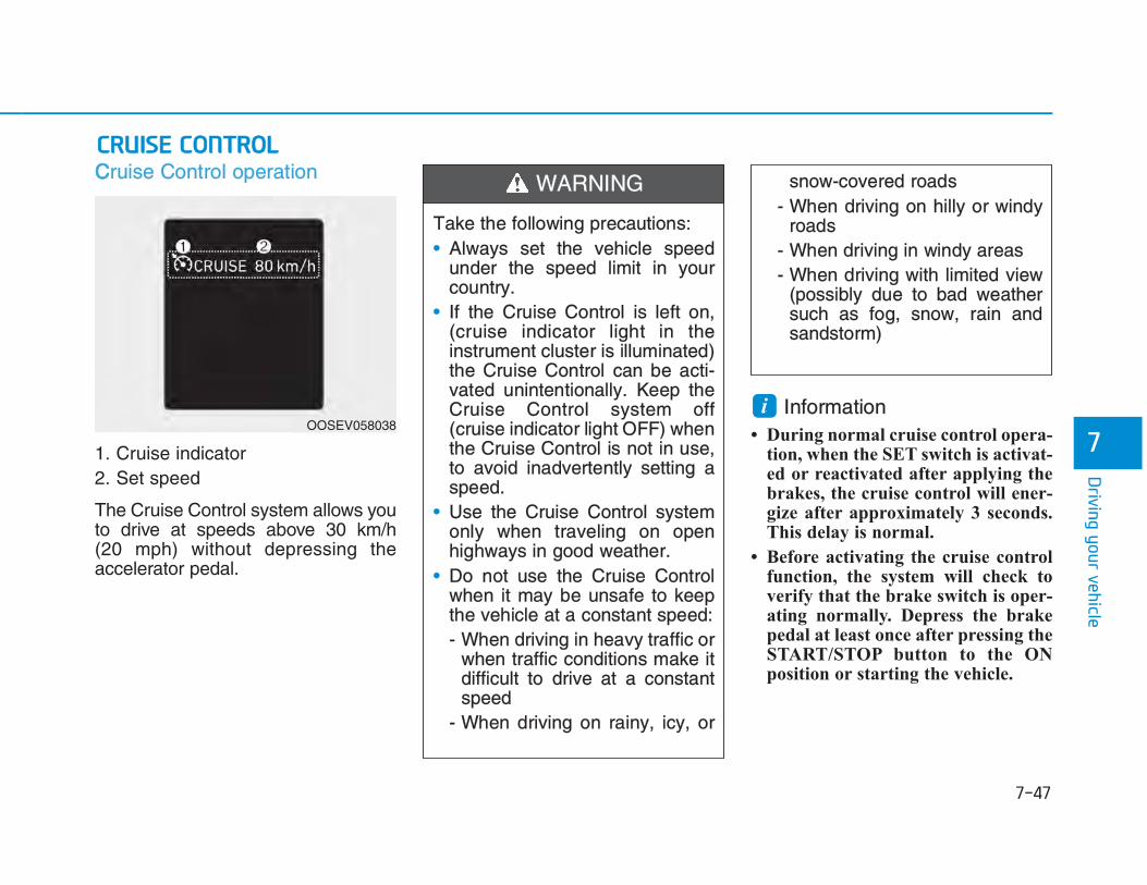
CCruise Control operation
1. Cruise indicator2. Set speed
The Cruise Control system allows youto drive at speeds above 30 km/h (20 mph) without depressing theaccelerator pedal.
Information• During normal cruise control opera-
tion, when the SET switch is activat-ed or reactivated after applying thebrakes, the cruise control will ener-gize after approximately 3 seconds.This delay is normal.
• Before activating the cruise controlfunction, the system will check toverify that the brake switch is oper-ating normally. Depress the brakepedal at least once after pressing theSTART/STOP button to the ONposition or starting the vehicle.
i
Take the following precautions:• Always set the vehicle speed
under the speed limit in yourcountry.
• If the Cruise Control is left on,(cruise indicator light in theinstrument cluster is illuminated)the Cruise Control can be acti-vated unintentionally. Keep theCruise Control system off(cruise indicator light OFF) whenthe Cruise Control is not in use,to avoid inadvertently setting aspeed.
• Use the Cruise Control systemonly when traveling on openhighways in good weather.
• Do not use the Cruise Controlwhen it may be unsafe to keepthe vehicle at a constant speed:- When driving in heavy traffic or
when traffic conditions make itdifficult to drive at a constantspeed
- When driving on rainy, icy, or
snow-covered roads- When driving on hilly or windy
roads- When driving in windy areas- When driving with limited view
(possibly due to bad weathersuch as fog, snow, rain andsandstorm)
WARNING
OOSEV058038

CCruise control switch
: Changes Cruise controlmode.
RES+ : Resumes or increasesspeed limit control speed.
SET- : Sets or decreases speed limitcontrol speed.
CANCEL : Cancels set speed limit.
To set Cruise Control speed
1. Press the button on thesteering wheel to turn the systemon. The cruise indicator will illumi-nate.
2. Accelerate to the desired speed,which must be more than 30 km/h(20 mph).
3. Push the toggle switch (1) down(SET-), and release it. The setspeed on the LCD display will illu-minate.
4. Release the accelerator pedal.
Information On a steep slope, the vehicle mayslightly slow down or speed up, whiledriving uphill or downhill.
i
System off Cruise Control
OOSIEV059083 OOSEV058084L
OOSEV058085L

TTo increase Cruise Control speed • Push the toggle switch (1) up
(RES+) and hold it, while monitor-ing the set speed on the instrumentcluster.Release the toggle switch whenthe desired speed is shown andthe vehicle will accelerate to thatspeed.
• Push the toggle switch (1) up(RES+) and release it immediately.The cruising speed will increase1.0 km/h (1.0 mph) each time thetoggle switch is operated in thismanner.
• Depress the accelerator pedal.When the vehicle attains thedesired speed, push the toggleswitch (1) down (SET-).
To decrease Cruise Control speed • Push the toggle switch (1) down
(SET-) and hold it. Your vehicle willgradually slow down. Release thetoggle switch at the speed youwant to maintain.
• Push the toggle switch (1) down(SET-) and release it immediately.The cruising speed will decrease1.0 km/h (1.0 mph) each time thetoggle switch is operated in thismanner.
OOSEV058086L OOSEV058085L

• Lightly tap the brake pedal. Whenthe vehicle attains the desiredspeed, push the toggle switch (1)down (SET-).
TTo temporarily accelerate with theCruise Control ON Depress the accelerator pedal. Whenyou take your foot off the accelerator,the vehicle will return to the previ-ously set speed.If you push the toggle switch down(SET-) at the increased speed, theCruise Control will maintain theincreased speed.
Cruise Control will be canceledwhen:
• Depressing the brake pedal.• Pressing the O (CANCEL) button
located on the steering wheel.• The vehicle is shifted into N
(Neutral).• Decreasing the vehicle speed to
less than the memory speed byapproximately 20 km/h (12 mph).
• Decreasing the vehicle speed toless than approximately 30 km/h(20 mph).
• The ESC (Electronic StabilityControl) is operating.
Information Each of the above actions will cancelCruise Control operation (the setspeed on the instrument cluster will gooff), but only pressing thebutton will turn the system off. If youwish to resume Cruise Control opera-tion, push the toggle switch up (RES+)located on your steering wheel. Youwill return to your previously presetspeed, unless the system was turnedoff using the button.
i
OOSIEV059087

TTo resume preset Cruising speed Push the toggle switch (1) up
(RES+). If the vehicle speed is over30 km/h (20 mph), the vehicle willresume the preset speed.
To turn Cruise Control off
• Press the button (The indi-cator light will go off.). - With the Cruise Control on,
pressing the button once will turnOff the Cruise Control and turnon the Speed Limit Control.
- With the Cruise Control off andSpeed Limit Control on, pressingthe button will turn off both sys-tem.
InformationThe mode changes, as below, whenev-er the button is pressed.
i
OOSEV058086L
OOSEV058084L
System off Cruise Control

The severe weather conditions ofwinter quickly wear out tires andcause other problems. To minimizewinter driving problems, you shouldtake the following suggestions:
IInformation Information for Snow Tires and TireChains in the national language(Bulgarian, Hungarian, Icelandic,Polish) is provided in the Appendix.
Snow or icy conditionsYou need to keep sufficient distancebetween your vehicle and the vehiclein front of you.Apply the brakes gently. Speeding,rapid acceleration, sudden brakeapplications, and sharp turns arepotentially very hazardous practices.During deceleration, use the paddleshifter (left side lever) to increaseregenerative braking, but avoidadjusting it to level 3 (steering maybe difficult). Sudden brake applica-tions on snowy or icy roads maycause the vehicle to skid.
To drive your vehicle in deep snow, itmay be necessary to use snow tiresor to install tire chains on your tires.Always carry emergency equipment.Some of the items you may want tocarry include tire chains, tow strapsor chains, a flashlight, emergencyflares, sand, a shovel, jumper cables,a window scraper, gloves, groundcloth, coveralls, a blanket, etc.
Snow tires
If you mount snow tires on your vehi-cle, make sure to use radial tires ofthe same size and load range as theoriginal tires. Mount snow tires on allfour wheels to balance your vehicle’shandling in all weather conditions.The traction provided by snow tireson dry roads may not be as high asyour vehicle's original equipmenttires. Check with the tire dealer formaximum speed recommendations.
Information Do not install studded tires without firstchecking local and municipal regula-tions for possible restrictions againsttheir use.
i
i
Snow tires should be equivalent insize and type to the vehicle's stan-dard tires. Otherwise, the safetyand handling of your vehicle maybe adversely affected.
WARNING

TTire chains
Since the sidewalls of radial tires arethinner than other types of tires, theymay be damaged by mounting sometypes of tire chains on them.Therefore, the use of snow tires isrecommended instead of tire chains.Do not mount tire chains on vehiclesequipped with aluminum wheels; ifunavoidable use a wire type chain. Iftire chains must be used, use gen-uine HYUNDAI parts and install thetire chain after reviewing the instruc-tions provided with the tire chains.Damage to your vehicle caused byimproper tire chain use is not cov-ered by your vehicle manufacturer’swarranty.
Information • Install tire chains only in pairs and
on the front tires. It should be notedthat installing tire chains on thetires will provide a greater drivingforce, but will not prevent sideskids.
• Do not install studded tires withoutfirst checking local and municipalregulations for possible restrictionsagainst their use.
i
OOSEV058066
The use of tire chains mayadversely affect vehicle handling:• Drive less than 30 km/h (20
mph) or the chain manufactur-er's recommended speed limit,whichever is lower.
• Drive carefully and avoidbumps, holes, sharp turns, andother road hazards, which maycause the vehicle to bounce.
• Avoid sharp turns or lockedwheel braking.
WARNING

Chain Installation
When installing tire chains, follow themanufacturer's instructions andmount them as tightly possible. Driveslowly (less than 30 km/h (20 mph))with chains installed. If you hear thechains contacting the body or chas-sis, stop and tighten them. If they stillmake contact, slow down until thenoise stops. Remove the tire chainsas soon as you begin driving oncleared roads.When mounting snow chains, parkthe vehicle on level ground awayfrom traffic. Turn on the vehicleHazard Warning Flasher and place atriangular emergency warning devicebehind the vehicle (if available).Always place the vehicle in P (Park),apply the parking brake and turn offthe vehicle before installing snowchains.
WWhen using tire chains:• Wrong size chains or improperly
installed chains can damage yourvehicle's brake lines, suspension,body and wheels.
• Use SAE "S" class or wire chains.• If you hear noise caused by chains
contacting the body, retighten thechain to prevent contact with thevehicle body.
• To prevent body damage, retightenthe chains after driving 0.5~1.0 km(0.3~0.6 miles).
• Do not use tire chains on vehiclesequipped with aluminum wheels. Ifunavoidable, use a wire typechain.
• Use wire chains less than 12 mm(0.47 in) thick to prevent damageto the chain's connection.
Winter precautionsCheck battery and cablesThe winter temperature increasesthe battery consumption. Inspect thebattery and cables, as specified inthe chapter 7. The battery charginglevel can be checked by an author-ized HYUNDAI dealer or in a servicestation.
Change to "winter weight" oil if nec-essaryIn some regions during winter, it isrecommended to use the "winterweight" oil with lower viscosity. Forfurther information, refer to the chap-ter 8. When you are not sure about atype of winter weight oil, consult anauthorized HYUNDAI dealer.
NOTICE

TTo prevent locks from freezingTo prevent the locks from beingfrozen, spray approved de-icing fluidor glycerin into key holes. When alock opening is already covered withice, spray approved de-icing fluidover the ice to remove it. When aninternal part of a lock freezes, try tothaw it with a heated key. Carefullyuse the heated key to avoid an injury.
Use approved window washer anti-freeze solution in systemTo prevent the window washer frombeing frozen, add authorized windowwasher anti-freeze solution, as spec-ified on the window washer contain-er. Window washer anti-freeze solu-tion is available from an authorizedHYUNDAI dealer, and so are themost vehicle accessory outlets. Donot use coolant or other types of anti-freeze solution to prevent any dam-age to the vehicle paint.
Do not let your parking brake freezeUnder some conditions your parkingbrake can freeze in the engagedposition. This is most likely to happenwhen there is an accumulation ofsnow or ice around or near the rearbrakes or if the brakes are wet. Whenthere is the risk that your parkingbrake may freeze, temporarily shift toP (Park). Also, block the rear wheelsin advance, so the vehicle may notroll. Then, release the parking brake.
Do not let ice and snow accumulateunderneathUnder some conditions, snow andice can build up under the fendersand interfere with the steering. Whendriving in such conditions during thesevere winter, you should checkunderneath the vehicle on a regularbasis, so that moving the frontwheels and the steering componentsis unblocked.
Carry emergency equipmentIn accordance with weather condi-tions, you should carry appropriateemergency equipment, while driving.Some of the items you may want tocarry include tire chains, tow strapsor chains, flashlight, emergencyflares, sand, shovel, jumper cables,window scraper, gloves, groundcloth, coveralls, blanket, etc.
Do not place objects or materials inthe motor compartmentPutting objects or materials in themotor compartment may cause anvehicle failure, because those mayblock cooling the parts in the motorcompartment. Such damage will notbe covered by the manufacturer'swarranty.

Two labels on your driver’s door sillshow how much weight your vehiclewas designed to carry: the Tire andLoading Information Label and theCertification Label.Before loading your vehicle, familiar-ize yourself with the following termsfor determining your vehicle's weightratings, from the vehicle's specifica-tions and the Certification Label:
BBase Curb WeightThis is the weight of the vehicleincluding a full tank of fuel and allstandard equipment. It does notinclude passengers, cargo, or option-al equipment.
Vehicle Curb WeightThis is the weight of your new vehiclewhen you picked it up from your deal-er plus any aftermarket equipment.
Cargo WeightThis figure includes all weight addedto the Base Curb Weight, includingcargo and optional equipment.
GAW (Gross Axle Weight)This is the total weight placed oneach axle (front and rear) - includingvehicle curb weight and all payload.
GAWR (Gross Axle Weight Rating)This is the maximum allowableweight that can be carried by a singleaxle (front or rear). These numbersare shown on the Certification Label.The total load on each axle mustnever exceed its GAWR.
GVW (Gross Vehicle Weight)This is the Base Curb Weight plusactual Cargo Weight plus passen-gers.
GVWR (Gross Vehicle WeightRating)This is the maximum allowableweight of the fully loaded vehicle(including all options, equipment,passengers and cargo). The GVWRis shown on the Certification Labellocated on the driver’s door sill.
Overloading
The Gross Axle Weight Rating(GAWR) and the Gross VehicleWeight Rating (GVWR) for yourvehicle are on the CertificationLabel attached to the driver's (orfront passenger’s) door.Exceeding these ratings cancause an accident or vehicle dam-age. You can calculate the weightof your load by weighing the items(and people) before putting themin the vehicle. Be careful not tooverload your vehicle.
WARNING

We do not recommend using this vehicle for trailer towing.


The hazard warning flasher serves asa warning to other drivers to exerciseextreme caution when approaching,overtaking, or passing your vehicle. It should be used whenever emer-gency repairs are being made orwhen the vehicle is stopped near theedge of a roadway.
To turn the hazard warning flasheron or off, press the hazard warningflasher button with the START/STOPbutton in any position. The button islocated in the center fascia panel. Allturn signal lights will flash simultane-ously.• The hazard warning flasher oper-
ates whether your vehicle is run-ning or not.
• The turn signals do not work whenthe hazard flasher is on.
IIf the vehicle stalls while driving• Reduce your speed gradually,
keeping a straight line. Move cau-tiously off the road to a safe place.
• Turn on your hazard warning flasher.• Try to start the vehicle again. If
your vehicle will not start, we rec-ommend that you contact anauthorized HYUNDAI dealer.
If the vehicle stalls at a cross-road or crossing If the vehicle stalls at a crossroad orcrossing, if safe to do so, shift to theN (Neutral) position and then pushthe vehicle to a safe location.
OOSEV068001R

IIf you have a flat tire while driv-ing If a tire goes flat while you are driv-ing:• Take your foot off the accelerator
pedal and let the vehicle slowdown while driving straight ahead.Do not apply the brakes immedi-ately to slow down the vehicle, butuse the paddle shifter (left sidelever) to increase regenerativebraking control. Also, do notattempt to pull off the road as thismay cause loss of vehicle controlresulting in an accident. When thevehicle has slowed to such aspeed that it is safe to do so, brakecarefully and pull off the road.Drive off the road as far as possibleand park on firm, level ground. Ifyou are on a divided highway, donot park in the median areabetween the two traffic lanes.
• When the vehicle is stopped, pressthe hazard warning flasher button,shift to P (Park), apply the parkingbrake, and place the START/STOPbutton in the OFF position.
• Have all passengers get out of thevehicle. Be sure they all get out onthe side of the vehicle that is awayfrom traffic.
• Follow the instructions providedlater in this chapter. (Refer to "IfYou Have a Flat Tire" provided inthis chapter.)

CConfirm the EV battery is not lowon the charge gauge• Be sure the gear is in P (Park). The
vehicle starts only when the gear isin P (Park).
• Check the 12-volt battery connec-tions to be sure they are clean andtight.
• Turn on the interior light. If the lightdims or goes out when you operatethe starter, the battery is drained.
Do not push or pull the vehicle tostart it. This could cause damage toyour vehicle. See instructions for"Jump Starting" provided in thischapter.
Jump starting can be dangerous ifdone incorrectly. Follow the jumpstarting procedure in this section toavoid serious injury or damage toyour vehicle. If in doubt about how toproperly jump start your vehicle, westrongly recommend that you have aservice technician or towing servicedo it for you.
To prevent SERIOUS INJURY orDEATH to you or bystanders,always follow these precautionswhen working near or handling thebattery:
Always read and followinstructions carefully whenhandling a battery.Wear eye protectiondesigned to protect theeyes from acid splashes.Keep all flames, sparks, orsmoking materials awayfrom the battery.Hydrogen is always pres-ent in battery cells, is high-ly combustible, and mayexplode if ignited. Keep batteries out ofreach of children.
WARNING

TTo prevent damage to your vehicle:• Only use a 12-volt power supply
(battery or jumper system) to jumpstart your vehicle.
• Do not attempt to jump start yourvehicle by push-starting.
InformationAn inappropriately disposedbattery can be harmful to theenvironment and humanhealth. Dispose of the batteryaccording to your local law(s)or regulations.
i
NOTICEBatteries contain sulfuricacid which is highly corro-sive. Do not allow acid tocontact your eyes, skin orclothing.
If acid gets into your eyes, flushyour eyes with clean water for atleast 15 minutes and get immedi-ate medical attention. If acid getson your skin, thoroughly wash thearea. If you feel pain or a burningsensation, get medical attentionimmediately.• When lifting a plastic-cased bat-
tery, excessive pressure on thecase may cause battery acid toleak. Lift with a battery carrier orwith your hands on opposite cor-ners.
• Do not attempt to jump startyour vehicle if your battery isfrozen.
Pb
• NEVER attempt to recharge thebattery when the vehicle’s bat-tery cables are connected to thebattery.
• The electrical ignition systemworks with high voltage. NEVERtouch these components withthe " " indicator ON or whenthe START/STOP button is inthe ON position.
• Do not allow the (+) and (-)jumper cables to touch. It maycause sparks.
• The battery may rupture orexplode when you jump startwith a low or frozen battery.

JJump starting procedure 1. Position the vehicles close enough
that the jumper cables will reach,but do not allow the vehicles totouch.
2. Avoid fans or any moving parts inthe motor compartment at alltimes, even when the vehicles areturned off.
3. Turn off all electrical devices suchas radios, lights, air conditioning,etc. Put the vehicles in P (Park)and set the parking brakes. Turnboth vehicles OFF.
4. Connect the jumper cables in theexact sequence shown in the illus-tration. First connect one jumpercable to the red, positive (+)jumper terminal of your vehicle(1).
5. Connect the other end of thejumper cable to the red, positive(+) battery/jumper terminal of theassisting vehicle (2).
6. Connect the second jumper cableto the black, negative (-) battery/chassis ground of the assistingvehicle (3).
7. Connect the other end of the sec-ond jumper cable to the black,negative (-) chassis ground ofyour vehicle (4).Do not allow the jumper cables tocontact anything except the cor-rect battery or jumper terminals orthe correct ground. Do not leanover the battery when makingconnections.
8. Start the engine of the assistingvehicle and let it run at approxi-mately 2,000 rpm for a few min-utes. Then start your vehicle.
If your vehicle will not start after afew attempts, it probably requiresservicing. In this event please seekqualified assistance. If the cause ofyour battery discharging is notapparent, have your vehicle checkedby an authorized HYUNDAI dealer.
1VQA4001

Disconnect the jumper cables in theexact reverse order you connectedthem:1. Disconnect the jumper cable from
the black, negative (-) chassisground of your vehicle (4).
2. Disconnect the other end of thejumper cable from the black, neg-ative (-) battery/chassis ground ofthe assisting vehicle (3).
3. Disconnect the second jumpercable from the red, positive (+)battery/jumper terminal of theassisting vehicle (2).
4. Disconnect the other end of thejumper cable from the red, positive(+) jumper terminal of your vehicle(1).
1. Pull off the road and stop as soonas it is safe to do so.
2. Shift to P (Park) and set the park-ing brake. If the air conditioning ison, turn it off.
3. If coolant is running out under thevehicle or steam is coming outfrom the hood, stop the vehicle.Do not open the hood until thecoolant has stopped running orthe steaming has stopped. If thereis no visible loss of coolant and nosteam, leave the vehicle runningand check to be sure the coolingfan is operating. If the fan is notrunning, turn the vehicle off.
4. Check for coolant leaking from theradiator, hoses or under the vehi-cle. (If the air conditioning hadbeen in use, it is normal for coldwater to be draining from it whenyou stop).
5. If coolant is leaking out, turn offthe vehicle immediately and werecommend that you call anauthorized HYUNDAI dealer forassistance.
6. If you cannot find the cause of theoverheating, wait until the radiatortemperature has returned to nor-mal. Then, if coolant has beenlost, call an authorized HYUNDAIdealer for assistance.
SSerious loss of coolant indicatesthere is a leak in the cooling systemand we recommend that the systembe checked by an authorizedHYUNDAI dealer.
NOTICE

(1) Low Tire Pressure Telltale/TPMS Malfunction Indicator
(2) Low Tire Pressure PositionTelltale and Tire Pressure Telltale (Shown on the LCD display)
CCheck tire pressure (if equipped)
• You can check the tire pressure inthe Assist mode on the cluster.Refer to the "LCD display modes"in chapter 3.
• Tire pressure is displayed after afew minutes of driving after initialvehicle start up.
• If tire pressure is not displayedwhen the vehicle is stopped, "Driveto display" message will appear.After driving, check the tire pres-sure.
• The displayed tire pressure valuesmay differ from those measuredwith a tire pressure gauge.
• You can change the tire pressureunit in the User Settings mode onthe LCD display.- psi, kpa, bar (Refer to the "User
Settings Mode" in chapter 3).
OOSEV048112R
OOSEV068014R
OOSEV048110L

TTire pressure monitoring systemEach tire should be checked monthly
when cold and inflated to the inflationpressure recommended by the vehi-cle manufacturer on the vehicle plac-ard or tire inflation pressure label. (Ifyour vehicle has tires of a differentsize than the size indicated on thevehicle placard or tire inflation pres-sure label, you should determine theproper tire inflation pressure forthose tires.)
As an added safety feature, yourvehicle has been equipped with a tirepressure monitoring system (TPMS)that illuminates a low tire pressuretelltale when one or more of yourtires is significantly under-inflated.Accordingly, when the low tire pres-sure telltale illuminates, you shouldstop and check your tires as soon aspossible, and inflate them to theproper pressure. Driving on a signifi-cantly under-inflated tire causes thetire to overheat and can lead to tirefailure. Under-inflation also reduces fuel effi-ciency and tire tread life, and mayaffect the vehicle's handling andstopping ability.Please note that the TPMS is not asubstitute for proper tire mainte-nance, and it is the driver’s responsi-bility to maintain correct tire pres-sure, even if under-inflation has notreached the level to trigger illumina-tion of the TPMS low tire pressuretelltale.
Your vehicle has also been equippedwith a TPMS malfunction indicator toindicate when the system is notoperating properly. The TPMS mal-function indicator is combined withthe low tire pressure telltale. Whenthe system detects a malfunction,the telltale will flash for approximate-ly one minute and then remain con-tinuously illuminated. This sequencewill continue upon subsequent vehi-cle start-ups as long as the malfunc-tion exists. When the malfunction indicator is illu-minated, the system may not be ableto detect or signal low tire pressureas intended. TPMS malfunctions mayoccur for a variety of reasons, includ-ing the installation of replacement oralternate tires or wheels on the vehi-cle that prevent the TPMS from func-tioning properly. Always check the TPMS malfunctiontelltale after replacing one or moretires or wheels on your vehicle toensure that the replacement or alter-nate tires and wheels allow the TPMSto continue to function properly.
Over-inflation or under-inflationcan reduce tire life, adverselyaffect vehicle handling, and leadto sudden tire failure that maycause loss of vehicle controlresulting in an accident.
WARNING

IIf any of the below happens, havethe system checked by an author-ized HYUNDAI dealer.1. The Low Tire Pressure Telltale/
TPMS Malfunction Indicator doesnot illuminate for 3 seconds whenthe START/STOP button is placedto the ON position or the vehicle isON ( indicator ON).
2. The TPMS Malfunction Indicatorremains illuminated after blinkingfor approximately 1 minute.
3. The Low Tire Pressure PositionTelltale remains illuminated.
Low tire pressure tell-tale
Low tire pressure position and tirepressure telltale
When the tire pressure monitoringsystem warning indicators are illumi-nated and warning message dis-played on the cluster LCD display,one or more of your tires is signifi-cantly under-inflated. The Low TirePressure Position Telltale will indi-cate which tire is significantly under-inflated by illuminating the corre-sponding position light.
If either telltale illuminates, immedi-ately reduce your speed, avoid hardcornering and anticipate increasedstopping distances. You should stopand check your tires as soon as pos-sible. Inflate the tires to the properpressure as indicated on the vehi-cle’s placard or tire inflation pressurelabel located on the driver’s side cen-ter pillar outer panel. If you cannot reach a service stationor if the tire cannot hold the newlyadded air, replace the low pressuretire with the spare tire. The Low Tire Pressure Telltale willremain on and the TPMS MalfunctionIndicator may blink for one minuteand then remain illuminated (whenthe vehicle is driven approximately10 minutes at speed above 25 km/h(15.5 mph)) until you have the lowpressure tire repaired and replacedon the vehicle.
NOTICE
OOSEV048111L

TTPMS (Tire PressureMonitoring System)malfunction indicator
The TPMS Malfunction Indicator willilluminate after it blinks for approxi-mately one minute when there is aproblem with the Tire PressureMonitoring System.We recommend that the system bechecked by an authorized HYUNDAIdealer as soon as possible.
If there is a malfunction with theTPMS, the Low Tire PressurePosition Telltale will not be displayedeven though the vehicle has anunder-inflated tire.
NOTICE
In winter or cold weather, the LowTire Pressure Telltale may be illu-minated if the tire pressure wasadjusted to the recommended tireinflation pressure in warm weath-er. It does not mean your TPMS ismalfunctioning because thedecreased temperature leads to aproportional lowering of tire pres-sure. When you drive your vehicle froma warm area to a cold area or froma cold area to a warm area, or theoutside temperature is greatlyhigher or lower, you should checkthe tire inflation pressure andadjust the tires to the recommend-ed tire inflation pressure.
CAUTION
Low pressure damage
Significantly low tire pressuremakes the vehicle unstable andcan contribute to loss of vehiclecontrol and increased braking dis-tances.Continued driving on low pressuretires can cause the tires to over-heat and fail.
WARNING

TThe TPMS Malfunction Indicatormay illuminate after blinking for oneminute if the vehicle is near electricpower supply cables or radio trans-mitters such as police stations, gov-ernment and public offices, broad-casting stations, military installa-tions, airports, transmitting towers,etc. Additionally, the TPMS MalfunctionIndicator may illuminate if snowchains are used or electronic devicessuch as computers, chargers, remotestarters, navigation, etc. This mayinterfere with normal operation of theTPMS.
Changing a tire with TPMSIf you have a flat tire, the Low TirePressure and Position telltales willcome on. We recommend that theflat tire be repaired by an authorizedHYUNDAI dealer as soon as possi-ble or replace the flat tire with thespare tire.
Once the original tire equipped witha tire pressure monitoring sensor isreinflated to the recommended pres-sure and reinstalled on the vehicle,the Low Tire Pressure Telltale andTPMS Malfunction Indicator will gooff within a few minutes of driving.
If the indicators do not extinguishafter a few minutes, please visit anauthorized HYUNDAI dealer.Each wheel is equipped with a tirepressure sensor mounted inside thetire behind the valve stem. You mustuse TPMS specific wheels. It is rec-ommended that you always haveyour tires serviced by an authorizedHYUNDAI dealer.You may not be able to identify a tirewith low pressure by simply lookingat it. Always use a good quality tirepressure gauge to measure. Pleasenote that a tire that is hot (from beingdriven) will have a higher pressuremeasurement than a tire that is cold. A cold tire means the vehicle hasbeen sitting for 3 hours and driven forless than 1.6 km (1 mile) in that 3hour period.Allow the tire to cool before measur-ing the inflation pressure. Always besure the tire is cold before inflating tothe recommended pressure.
NOTICE
It is recommended that you do notuse a puncture-repairing agent notapproved by a HYUNDAI dealer torepair and/or inflate a low pressuretire. Tire sealant not approved by aHYUNDAI dealer may damage thetire pressure sensor.
CAUTION

• The TPMS cannot alert you tosevere and sudden tire damagecaused by external factors suchas nails or road debris.
• If you feel any vehicle instability,immediately take your foot offthe accelerator, apply thebrakes gradually with light force,and slowly move to a safe posi-tion off the road.
WARNING
Tampering with, modifying, or dis-abling the Tire Pressure MonitoringSystem (TPMS) components mayinterfere with the system's ability towarn the driver of low tire pressureconditions and/or TPMS malfunc-tions. Tampering with, modifying,or disabling the Tire PressureMonitoring System (TPMS) com-ponents may void the warranty forthat portion of the vehicle.
WARNING
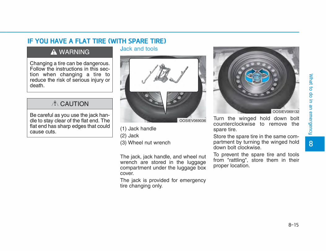
JJack and tools
(1) Jack handle(2) Jack(3) Wheel nut wrench
The jack, jack handle, and wheel nutwrench are stored in the luggagecompartment under the luggage boxcover.The jack is provided for emergencytire changing only.
Turn the winged hold down boltcounterclockwise to remove thespare tire.Store the spare tire in the same com-partment by turning the winged holddown bolt clockwise. To prevent the spare tire and toolsfrom "rattling", store them in theirproper location.
OOSIEV069036
OOSIEV069132
Changing a tire can be dangerous.Follow the instructions in this sec-tion when changing a tire toreduce the risk of serious injury ordeath.
WARNING
Be careful as you use the jack han-dle to stay clear of the flat end. Theflat end has sharp edges that couldcause cuts.
CAUTION

If it is hard to loosen the tire hold-down wing bolt by hand, you canloosen it easily using the wheel nutwrench.Turn the tire hold-down wing boltcounterclockwise with the wheel nutwrench.
IInstall and remove the jack
Mount the jack after being fastenedthe spare tire to the bar when youinstall the jack.You should mount the jack followingthe guide line.Stop the jack when it touches thebracket.You should fit the jack in a suitableposition to support the load of thetire.
Changing tires
A vehicle can slip or roll off of ajack causing serious injury ordeath to you or those nearby.Take the following safety precau-tions:• Do not get under a vehicle that
is supported by a jack.• NEVER attempt to change a tire
in the lane of traffic. ALWAYSmove the vehicle completely offthe road on level, firm groundaway from traffic before trying tochange a tire. If you cannot finda level, firm place off the road,call a towing service for assis-tance.
• Be sure to use the jack providedwith the vehicle.
• ALWAYS place the jack on thedesignated jacking positions onthe vehicle and NEVER on thebumpers or any other part of thevehicle for jacking support.
• Do not start or run the engine
WARNING
OOSIEV069040
OOSIEV069051

Follow these steps to change yourvehicle's tire:1. Park on a level, firm surface. 2. Move the shift lever into P (Park,
for dual clutch transmission vehi-cle) or neutral (for manual trans-mission vehicle), apply the park-ing brake, and place the ignitionswitch in the LOCK/OFF position.
3. Press the hazard warning flasherbutton.
4. Remove the wheel lug nut wrench,jack, jack handle, and spare tirefrom the vehicle.
[A] : Block
5. Block both the front and rear of thetire diagonally opposite of the tireyou are changing.
6. Loosen the wheel lug nuts coun-terclockwise one turn each in theorder shown above, but do notremove any lug nuts until the tirehas been raised off of the ground.
while the vehicle is on the jack.• Do not allow anyone to remain
in the vehicle while it is on thejack.
• Keep children away from theroad and the vehicle.
OOSIEV069016 OOSIEV069017

7. Place the jack at the designatedjacking position under the frameclosest to the tire you are chang-ing. The jacking positions areplates welded to the frame withtwo notches. Never jack at anyother position or part of the vehi-cle. It may damage the side sealmolding.
8. Insert the jack handle into the jackand turn it clockwise, raising thevehicle until the tire clears theground. Make sure the vehicle isstable on the jack.
9. Loosen the lug nuts with the wheellug nut wrench and remove themwith your fingers. Remove thewheel from the studs and lay it flaton the ground out of the way.Remove any dirt or debris fromthe studs, mounting surfaces, andwheel.
10. Install the spare tire onto thestuds of the hub.
11. Tighten the lug nuts with your fin-gers onto the studs with thesmaller end of the lug nuts clos-est to the wheel.
12. Lower the vehicle to the groundby turning the jack handle coun-terclockwise.
OOSIEV069020OOSIEV069018
■ Front ■ Rear

13. Use the wheel lug nut wrench totighten the lug nuts in the ordershown. Double-check each lugnut until they are tight. Afterchanging tires, we recommendthat an authorized HYUNDAIdealer tighten the lug nuts to theirproper torque as soon as possi-ble. TThe wheel lug nut should betightened to 11~13 kgf·m (79~94lbf·ft).
If you have a tire gauge, check thetire pressure (see "Tires andWheels" in chapter 8 for tire pressureinstructions.). If the pressure is loweror higher than recommended, driveslowly to the nearest service stationand adjust it to the recommendedpressure. Always reinstall the valvecap after checking or adjusting tirepressure. If the cap is not replaced,air may leak from the tire. If you losea valve cap, buy another and install itas soon as possible. After changingtires, put the flat tire in its place andreturn the jack and tools to theirproper storage locations.
• Check the tire pressure as soon aspossible after installing a sparetire. Adjust it to the recommendedpressure.
• Check and tighten the wheel lugnuts after driving over 50 km if tiresare replaced. Re-check the tirewheel lug nuts after driving over1,000 km.
If any of the equipment such as thejack, lug nuts, studs, or other equip-ment is damaged or in poor condi-tion, do not attempt to change thetire and call for assistance.
NOTICE
OOS067019L
Your vehicle has metric threadson the studs and lug nuts. Makecertain during tire changing thatthe same nuts that were removedare reinstalled. If you have toreplace your lug nuts make surethey have metric threads to avoiddamaging the studs and ensurethe wheel is properly secured tothe hub. We recommend that youconsult an authorized HYUNDAIdealer for assistance.
CAUTION

UUse of compact spare tires (if equipped) Compact spare tires are designed foremergency use only. Drive carefullyon the compact spare tire andalways follow the safety precautions.
When driving with the compact sparetire mounted to your vehicle:• Check the tire pressure after
installing the compact spare tire.The compact spare tire should beinflated to 420 kPa (60 psi).
• Do not take this vehicle through anautomatic car wash while the com-pact spare tire is installed.
• Do not use the compact spare tireon any other vehicle because thistire has been designed especiallyfor your vehicle.
• The compact spare tire's tread life isshorter than a regular tire. Inspectyour compact spare tire regularlyand replace worn compact sparetires with the same size and design,mounted on the same wheel.
• Do not use more than one compactspare tire at a time.
• Do not tow a trailer while the com-pact spare tire is installed.
When the original tire and wheel arerepaired and reinstalled on the vehi-cle, the lug nut torque must be setcorrectly. The correct lug nut tighten-ing torque is 11~13 kgf·m (79~94lbf·ft).
NOTICE
To prevent compact spare tire fail-ure and loss of control possiblyresulting in an accident:• Use the compact spare tire only
in an emergency.• NEVER operate your vehicle
over 80 km/h (50 mph).• Do not exceed the vehicle’s
maximum load rating or the loadcarrying capacity shown on thesidewall of the compact sparetire.
• Do not use the compact sparetire continuously. Repair orreplace the original tire as soonas possible to avoid failure ofthe compact spare tire.
WARNING

JJack label
To prevent damaging the compactspare tire and your vehicle:• Drive slowly enough for the road
conditions to avoid all hazards,such as a potholes or debris.
• Avoid driving over obstacles.The compact spare tire diameteris smaller than the diameter of aconventional tire and reducesthe ground clearance approxi-mately 25 mm (1 inch).
• Do not use tire chains on thecompact spare tire. Because ofthe smaller size, a tire chain willnot fit properly.
• Do not use the compact sparetire on any other wheels, norshould standard tires, snowtires, wheel covers or trim ringsbe used with the compact sparewheel.
CAUTION■ Example
OOS067043
1. Model Name2. Maximum allowable load3. When using the jack, set your
parking brake.4. When using the jack, stop the
engine.5. Do not get under a vehicle that is
supported by a jack.6. The designated locations under
the frame7. When supporting the vehicle, the
base plate of jack must be verticalunder the lifting point.
8. Shift into Reverse gear on vehicleswith manual transmission or movethe shift lever to the P position onvehicles with dual clutch transmis-sion.
9. The jack should be used on firmlevel ground.
10. Jack manufacture11. Production date12. Representative company and
address
The actual Jack label in the vehicle may differ from the illustration. For more detailed specifications, refer to the label attached to the jack.

TTowing service
If emergency towing is necessary,we recommend having it done by anauthorized HYUNDAI dealer or acommercial tow-truck service. Proper lifting and towing proceduresare necessary to prevent damage tothe vehicle. The use of wheel dolliesor flatbed is recommended.
It is acceptable to tow the vehiclewith the rear wheels on the ground(without dollies) and the front wheelsoff the ground.If any of the loaded wheels or sus-pension components are damagedor the vehicle is being towed with thefront wheels on the ground, use atowing dolly under the front wheels.When being towed by a commercialtow truck and wheel dollies are notused, the front of the vehicle shouldalways be lifted, not the rear.
OOSEV068009Dolly
Dolly
• Do not tow the vehicle with thefront wheels on the ground asthis may cause damage to thevehicle.
• Do not tow with sling-type equip-ment. Use wheel lift or flatbedequipment.
CAUTION
OOS067021
OOS067022

When towing your vehicle in anemergency without wheel dollies: 1. While depressing the brake pedal
shift to the N (Neutral) positionand turn the vehicle off. TheSTART/STOP button will be in theACC position.
2. Release the parking brake.
FFailure to shift to N (Neutral) maycause internal damage to the vehi-cle.
Removable towing hook
1. Open the tailgate and remove thetowing hook from the tool case.The tool case is placed under theluggage tray.
2. Remove the hole cover by press-ing the lower part of the cover onthe bumper.
NOTICE
OOSEV068010
OOSEV068011
OOSEV068012
■ Front
■ Rear

3. Install the towing hook by turning itclockwise into the hole until it isfully secured.
4. Remove the towing hook andinstall the cover after use.
EEmergency towing If towing is necessary, we recom-mend you have it done by an author-ized HYUNDAI dealer or a commer-cial tow truck service.If towing service is not available in anemergency, your vehicle may betemporarily towed using a cable orchain secured to the emergency tow-ing hook at the front (or rear) of thevehicle.Use extreme caution when towingthe vehicle with a cable or chain. Adriver must be in the vehicle to steerit and operate the brakes.Towing in this manner may be doneonly on hard-surfaced roads for ashort distance and at low speeds.Also, the wheels, axles, power train,steering and brakes must all be ingood condition.
Always follow these emergency tow-ing precautions:• While depressing the brake pedal
shift to the N (Neutral) position andturn the vehicle off. TheSTART/STOP button will be in theACC position.
• Release the parking brake.• Depress the brake pedal with more
force than normal since you willhave reduced braking perform-ance.
• More steering effort will be requiredbecause the power steering systemwill be disabled.
• Use a vehicle heavier than yourown to tow your vehicle.
The driver must be in the vehiclefor steering and braking opera-tions when the vehicle is beingtowed. Passengers other than thedriver must not be in the vehicle.
CAUTION

• The drivers of both vehicles shouldcommunicate with each other fre-quently.
• Before emergency towing, checkthat the hook is not broken or dam-aged.
• Fasten the towing cable or chainsecurely to the hook.
• Do not jerk the hook. Apply steadyand even force.
• Use a towing cable or chain lessthan 5 m (16 feet) long. Attach awhite or red cloth (about 30 cm (12inches) wide) in the middle of thecable or chain for easy visibility.
• Drive carefully so the towing cableor chain remains tight during tow-ing.
• Before towing, check the reductiongear for fluid leaks under your vehi-cle. If the reduction gear fluid isleaking, flatbed equipment or a tow-ing dolly must be used.
AAccelerate or decelerate the vehiclein a slow and gradual manner whilemaintaining tension on the tow ropeor chain to start or drive the vehicle,otherwise tow hooks and the vehiclemay be damaged.
To avoid damage to your vehicle andvehicle components when towing:• Always pull straight ahead when
using the towing hooks. Do not pullfrom the side or at a vertical angle.
• Do not use the towing hooks to pulla vehicle out of mud, sand or otherconditions from which the vehiclecannot be driven out under its ownpower.
• Limit the vehicle speed to 15 km/h (10 mph) and drive lessthan 1.5 km (1 mile) when towingto avoid serious damage to thereduction gear.
NOTICE
NOTICE
OOS067027


1. Coolant reservoir
2. Brake fluid reservoir
3. Fuse box
4. Battery (12 volt)
5. Coolant reservoir cap
6. Windshield washer fluid reservoir
OOSEV078001
The actual motor compartment in the vehicle may differ from the illustration.

You should exercise the utmost careto prevent damage to your vehicleand injury to yourself whenever per-forming any maintenance or inspec-tion procedures. We recommend you have your vehi-cle maintained and repaired by anauthorized HYUNDAI dealer. Anauthorized HYUNDAI dealer meetsHYUNDAI’s high service qualitystandards and receives technicalsupport from HYUNDAI in order toprovide you with a high level of serv-ice satisfaction.
Owner’s responsibilityMaintenance service and record reten-tion are the owner’s responsibility. You should retain documents thatshow proper maintenance has beenperformed on your vehicle in accor-dance with the scheduled mainte-nance service charts shown on thefollowing pages. You need this infor-mation to establish your compliancewith the servicing and maintenancerequirements of your vehicle war-ranties. Detailed warranty information is pro-vided in your Service Passport.Repairs and adjustments required asa result of improper maintenance ora lack of required maintenance arenot covered.
Owner maintenance precautionsInadequate, incomplete or insuffi-cient servicing may result in opera-tional problems with your vehicle thatcould lead to vehicle damage, anaccident, or personal injury. Thischapter provides instructions only forthe maintenance items that are easyto perform. Several procedures canbe done only by an authorizedHYUNDAI dealer with special tools.Your vehicle should not be modifiedin any way. Such modifications mayadversely affect the performance,safety or durability of your vehicleand may, in addition, violate condi-tions of the limited warranties cover-ing the vehicle.
Improper owner maintenance duringthe warranty period may affect warran-ty coverage. For details, read the sep-arate Service Passport provided withthe vehicle. If you’re unsure about anyservice or maintenance procedure,have it done by an authorizedHYUNDAI dealer.
NOTICE

The following lists are vehicle checksand inspections that should be per-formed by the owner or an authorizedHYUNDAI dealer at the frequenciesindicated to help ensure safe,dependable operation of your vehicle.Any adverse conditions should bebrought to the attention of your deal-er as soon as possible.These Owner Maintenance vehiclechecks are generally not covered bywarranties and you may be chargedfor labor, parts and lubricants used.
Owner maintenance scheduleWhen you stop for charging:• Check coolant level in the coolant
reservoir.• Check the windshield washer fluid
level.• Check for low or under-inflated
tires.
Performing maintenance work ona vehicle can be dangerous. If youlack sufficient knowledge andexperience or the proper tools andequipment to do the work, have itdone by an authorized HYUNDAIdealer. ALWAYS follow these pre-cautions for performing mainte-nance work:• Park your vehicle on level
ground, shift to P (Park) posi-tion, apply the parking brake,place the START/STOP buttonin the OFF position.
• Block the tires (front and back)to prevent the vehicle from mov-ing.Remove loose clothing or jewel-ry that can become entangled inmoving parts.
• Keep flames, sparks, or smok-ing materials away from the bat-tery related parts.
WARNING
Be careful when checking yourcoolant level when the parts in themotor compartment are hot. Thismay result in coolant being blownout of the opening and cause seri-ous burns and other injuries.
WARNING

WWhile operating your vehicle:• Check for vibrations in the steering
wheel. Notice if there is anyincreased steering effort or loose-ness in the steering wheel, orchange in its straight-ahead posi-tion.
• Notice if your vehicle constantlyturns slightly or “pulls” to one sidewhen traveling on smooth, levelroad.
• When stopping, listen and checkfor unusual sounds, pulling to oneside, increased brake pedal travelor “hard-to-push” brake pedal.
• If any slipping or changes in theoperation of your reduction gearoccurs, check the reduction gearfluid level.
• Check the reduction gear P (Park)function.
• Check the parking brake.• Check for fluid leaks under your
vehicle (water dripping from the airconditioning system during or afteruse is normal).
At least monthly:• Check coolant level in the coolant
reservoir.• Check the operation of all exterior
lights, including the stoplights, turnsignals and hazard warning flashers.
• Check the inflation pressures of alltires including the spare for tiresthat are worn, show uneven wear,or are damaged.
• Check for loose wheel lug nuts.
At least twice a year: (i.e., every Spring and Fall)• Check radiator, heater and air condi-
tioning hoses for leaks or damage.• Check windshield washer spray
and wiper operation. Clean wiperblades with clean cloth dampenedwith washer fluid.
• Check headlamp alignment.• Check the seat belts for wear and
function.
At least once a year: • Clean body and door drain holes.• Lubricate door hinges and hood
hinges.• Lubricate door and hood locks and
latches.• Lubricate door rubber weather
strips.• Check the air conditioning system.• Inspect and lubricate reduction
gear linkage and controls.• Clean the battery and terminals.• Check the brake fluid level.

Follow Normal Maintenance Schedule if the vehicle is usually operated where none of the following conditions apply. If anyof the following conditions apply, you must follow the Maintenance Under Severe Usage Conditions. • Repeated driving short distance of less than 8 km (5 miles) in normal temperature or less than 16 km (10miles) in
freezing temperature• Low speed driving for long distances• Driving on rough, dusty, muddy, unpaved, graveled or salt-spread roads• Driving in areas using salt or other corrosive materials or in very cold weather• Driving in heavy dust condition• Driving in heavy traffic area• Driving on uphill, downhill, or mountain road repeatedly• Towing a trailer or using a camper, or roof rack• Driving as a patrol car, taxi, other commercial use of vehicle towing• Driving over 170 km/h (106 miles/h)• Frequently driving in stop-and-go condition
If your vehicle is operated under the above conditions, you should inspect, replace or refill more frequently than thefollowing Normal Maintenance Schedule. After the periods or distance shown in the chart, continue to follow the pre-scribed maintenance intervals.

NNormal maintenance schedule The following maintenance services must be performed to ensure good vehicle performance.
Keep receipts for all vehicle services to protect your warranty. Where both mileage and time are shown, the frequen-
Number of months or driving distance, whichever comes first
Months 12 24 36 48 60 72 84 96
Years 1 2 3 4 5 6 7 8
Km×1,000 10 20 30 40 50 60 70 80
Cooling systemInspect "Coolant level and leak" every day
At first, inspect 60,000 km (40,000 miles) or 48 months after that, inspect every 30,000 km (20,000 miles) or 24 months
Coolant *1 Replace every 60,000km (40,000 miles) or 36 months *2
Reduction gear fluid I I
Battery conditionFor Middle East Inspect 10,000 km (6,200 miles) or 6 months
Except Middle East I I I I I I I I
Brake lines, hoses and connections I I I I I I I I
Brake pedal I I I I
Parking brake I I I I
MAINTENANCEINTERVALS
MAINTENANCEITEM
I : Inspect and if necessary, adjust, correct, clean or replace.R : Replace or change.*1 : When replacing or adding coolant, we recommend that you visit an authorized HYUNDAI dealer. *2 : For your convenience, it can be replaced prior to it's interval when you do maintenance of other items.

NNormal maintenance schedule
Number of months or driving distance, whichever comes first
Months 12 24 36 48 60 72 84 96
Years 1 2 3 4 5 6 7 8
Km×1,000 10 20 30 40 50 60 70 80
Brake fluid I R I R I R
Brake discs and pads I I I I I I I I
Steering gear rack, linkage and boots I I I I I I I I
Driveshaft and boots I I I I
Tire (pressure & tread wear) I I I I I I I I
Front suspension ball joints I I I I I I I I
Bolt and nuts on chassis and body I I I I I I I I
Air conditioner refrigerant I I I I I I I I
Air conditioner compressor I I I I I I I I
Climate control air filter R R R R R R R R
MAINTENANCEINTERVALS
MAINTENANCEITEM
I : Inspect and if necessary, adjust, correct, clean or replace.R : Replace or change.
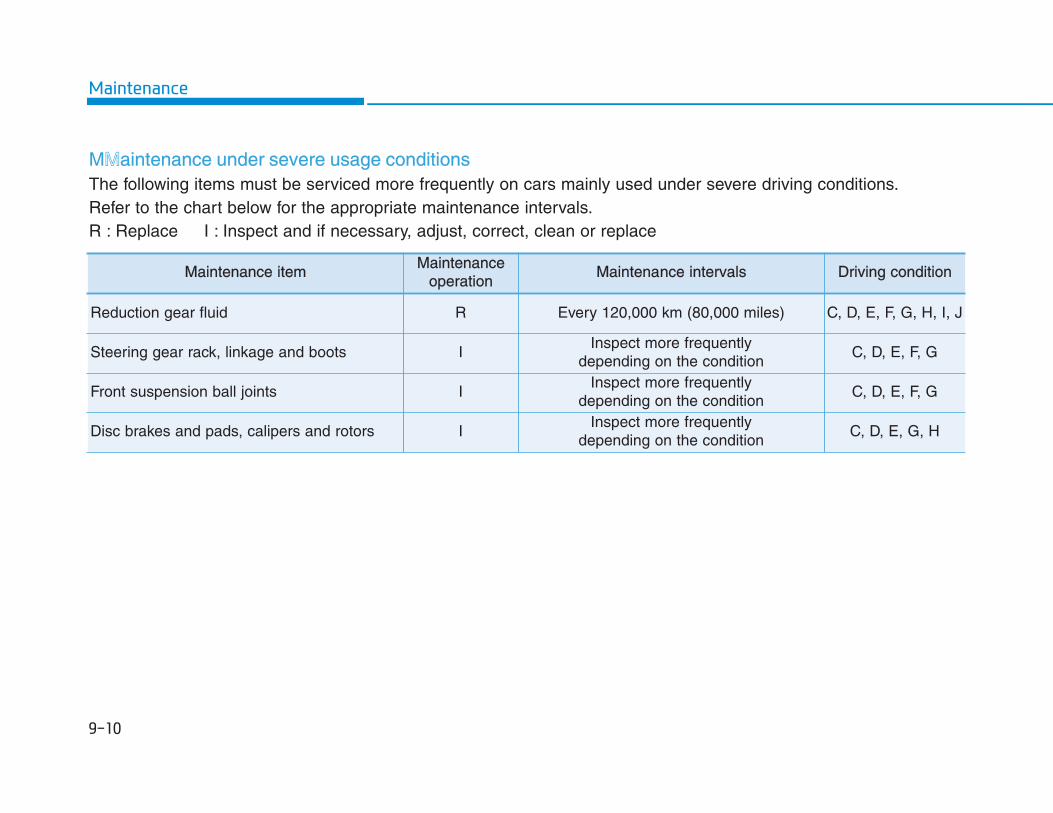
MMaintenance under severe usage conditionsThe following items must be serviced more frequently on cars mainly used under severe driving conditions. Refer to the chart below for the appropriate maintenance intervals.R : Replace I : Inspect and if necessary, adjust, correct, clean or replace
Maintenance itemMaintenance
operationMaintenance intervals Driving condition
Reduction gear fluid R Every 120,000 km (80,000 miles) C, D, E, F, G, H, I, J
Steering gear rack, linkage and boots IInspect more frequently
depending on the conditionC, D, E, F, G
Front suspension ball joints IInspect more frequently
depending on the conditionC, D, E, F, G
Disc brakes and pads, calipers and rotors IInspect more frequently
depending on the conditionC, D, E, G, H

MMaintenance itemMaintenance
operationMaintenance intervals Driving condition
Driveshaft and boots IInspect more frequently
depending on the conditionC, D, E, F, G, H, I
Climate control air filter RReplace more frequently
depending on the conditionC, E
Maintenance under severe usage conditions
Severe driving conditionsA : Repeatedly driving short distance of less than 8 km (5 miles)
in normal temperature or less than 16 km (10 miles) in freez-ing temperature
B : Low speed driving for long distances
C : Driving on rough, dusty, muddy, unpaved, graveled or saltspread roads
D : Driving in areas using salt or other corrosive materials or invery cold weather
E : Driving in heavy dust condition
F : Driving in heavy traffic area
G : Driving on uphill, downhill, or mountain roads repeatedly
H : Towing a trailer, or using a camper or roof rack
I : Driving as a patrol car, taxi, other commercial use or vehicletowing
J : Driving over 170 km/h (106 mile/h)
K : Frequently driving in stop-and-go conditions

Cooling systemCheck cooling system components,such as radiator, coolant reservoir,hoses and connections for leakageand damage. Replace any damagedparts.
CoolantThe coolant should be changed atthe intervals specified in the mainte-nance schedule.
Reduction gear fluidThe reduction gear fluid should beinspected according to the intervalsspecified in the maintenance sched-ule.
Brake hoses and linesVisually check for proper installation,chafing, cracks, deterioration andany leakage. Replace any deteriorat-ed or damaged parts immediately.
Brake fluid Check brake fluid level in the brake fluid reservoir. The level should be between the MIN and the MAX marks on the side of the reservoir. Use only hydraulic brake fluid con-forming to DOT 4 specification.
Brake discs, pads, calipers and rotorsCheck the pads, the disc, and the rotor for any excessive wear-out. Inspect calipers for any fluid leakageFor more information on checking the pads or lining wear limit, refer to the HYUNDAI web site.(http://service.hyundai-motor.com)
Suspension mounting bolts Check the suspension connections for looseness or damage. Retighten to the specified torque.
Steering gear box, linkage &boots/lower arm ball jointWith the vehicle stopped and thehybrid system off, check for exces-sive free-play in the steering wheel.Check the linkage for bends or dam-age. Check the dust boots and balljoints for deterioration, cracks, ordamage. Replace any damaged parts.
Drive shafts and bootsCheck the drive shafts, boots andclamps for cracks, deterioration, ordamage. Replace any damagedparts and, if necessary, repack thegrease.
Air conditioning refrigerantCheck the air conditioning lines andconnections for leakage and damage.

Check the condition and connectionsof all cooling system hoses andheater hoses. Replace any swollenor deteriorated hoses.The coolant level should be filledbetween the MAX and the MINmarks on the side of the coolantreservoir when the parts in the motorcompartment is cool.If the coolant level is low, have yourvehicle inspected by an authorizedHYUNDAI dealer. Use only designat-ed coolant water for electric vehicles,adding other types of water orantifreeze can damage the vehicle.
The electric motor for the cooling fanis controlled by coolant temperature,refrigerant pressure and vehiclespeed. As the coolant temperaturedecreases, the electric motor willautomatically shut off. This is a nor-mal condition.
OOSEV078002
Since specific coolant water isapplied for electric vehicles,replenishment of other antifreezeor water may cause problems tothe vehicle.
WARNING
The electric motor forthe cooling fan maycontinue to operate orstart up when the vehi-cle is not operating and
can cause serious injury. Keep hands, clothing and toolsaway from the rotating fan blades ofthe cooling fan.
WARNING

Checking the brake fluid level
Check the fluid level in the reservoirperiodically. The fluid level should bebetween MAX and MIN marks on theside of the reservoir.Before removing the reservoir capand adding brake fluid, clean thearea around the reservoir cap thor-oughly to prevent brake fluid contam-ination.
If the level is low, add the specifiedbrake fluid to the MAX level. The levelwill fall with accumulated mileage.This is a normal condition associatedwith the wear of the brake linings. Ifthe fluid level is excessively low, werecommend that the brake systembe checked by an authorizedHYUNDAI dealer.
Information • Use only the specified brake fluid.
Refer to “Recommended lubricantsand capacities” in chapter 8.
• Before removing the brake fillercap, read the warning on the cap.
• Clean the filler cap before remov-ing. Use only DOT3 or DOT4 brakefluid from a sealed container.
i
OOSEV078003
If the brake system requires fre-quent additions of fluid this couldindicate a leak in the brake sys-tem. We recommend that the vehi-cle be inspected by an authorizedHYUNDAI dealer.
WARNING
Do not allow brake fluid to come incontact with your eyes. If brakefluid comes in contact with youreyes, flush your eyes with cleanwater for at least 15 minutes andget immediate medical attention.
WARNING

•• Do not allow brake fluid to contactthe vehicle’s body paint, as paintdamage will result.
• Brake fluid, which has beenexposed to open air for an extend-ed time should NEVER be used asits quality cannot be guaranteed. Itshould be disposed of properly.
• Do not use the wrong kind of brakefluid. A few drops of mineral basedoil, such as engine oil, in yourbrake system can damage brakesystem parts.
Checking the washer fluid levelCheck the fluid level in the washer
fluid reservoir and add fluid if neces-sary. Plain water may be used if wash-er fluid is not available. However, usewasher solvent with antifreeze char-acteristics in cold climates to preventfreezing.
NOTICE
OOSEV078004
To prevent serious injury or death,take the following safety precau-tions when using washer fluid:• Do not use coolant or antifreeze
in the washer fluid reservoir.Coolant can severely obscurevisibility when sprayed on thewindshield and may cause lossof vehicle control resulting in anaccident or damage to paint andbody trim.
• Do not allow sparks or flame tocontact the washer fluid or thewasher fluid reservoir. Washerfluid may contain alcohol andcan be flammable.
• Do not drink washer fluid andavoid contact with skin. Washerfluid is poisonous to humansand animals.
• Keep washer fluid away fromchildren and animals.
WARNING

Filter inspectionThe climate control air filter should bereplaced according to the MaintenanceSchedule. If the vehicle is operated inseverely air-polluted cities or ondusty rough roads for a long period,it should be inspected more fre-quently and replaced earlier. Whenyou replace the climate control air fil-ter, replace it performing the follow-ing procedure, and be careful toavoid damaging other components.
1. With the glove box open, removethe stoppers on both sides.
2. Remove the support rod (1).OOS077017ROOS077018R

3. Press and hold the lock (1) on theright side of the cover.
4. Pull out (2) the cover.
5. Replace the climate control air filter.6. Reassemble in the reverse order
of disassembly.
IInstall a new climate control air filterin the correct direction with the arrowsymbol (↓) facing downwards.Otherwise, the climate control effectsmay decrease, possibly with a noise.
NOTICE
OPD076026OOSEV078005R

Blade inspectionContamination of either the wind-shield or the wiper blades with for-eign matter can reduce the effective-ness of the windshield wipers. Common sources of contaminationare insects, tree sap, and hot waxtreatments used by some commer-cial car washes. If the blades are notwiping properly, clean both the win-dow and the blades with a goodcleaner or mild detergent, and rinsethoroughly with clean water.
To prevent damage to the wiperblades, arms or other components,do not:• Use gasoline, kerosene, paint thin-
ner, or other solvents on or nearthem.
• Attempt to move the wipers manu-ally.
• Use non-specified wiper blades.
Information Commercial hot waxes applied byautomatic car washes have beenknown to make the windshield diffi-cult to clean.
Information Wiper blades are a consumable itemand normal wear of the wipers maynot be covered by your vehicle war-ranty.
Blade replacement When the wipers no longer cleanadequately, the blades may be wornor cracked, and require replacement.
• In order to prevent damage to thehood and the wiper arms, the wiperarms should only be lifted when inthe top wiping position.
• Always return the wiper arms tothe windshield before driving.
Front windshield wiper bladeType A
1. Raise the wiper arm and turn thewiper blade assembly to exposethe plastic locking clip.
NOTICE
i
i
NOTICEOOS077072R

2. Press the clip (1) and slide theblade assembly downward (2).
3. Lift it off the arm.4. Install a new wiper blade assem-
bly in the reverse order of removal. 5. Return the wiper arm on the wind-
shield.
Type B
1. Raise the wiper arm.
2. Lift up the wiper blade clip (1).Then pull down the blade assem-bly and remove it (2).
OOS077073R OOS077074R
OJS078073AU
OLF074018R

3. Install the new blade assembly inthe reverse order of removal.
4. Return the wiper arm on the wind-shield.
RRear window wiper blade
1. Raise the wiper arm and then turnthe wiper blade assembly (1).
2. Pull out the wiper blade assembly(2).
3. Install the new blade assembly byinserting the center part into theslot in the wiper arm until it clicksinto place (3).
4. Make sure the blade assembly isinstalled firmly by trying to pull itslightly.
To prevent damage to the wiper armsor other components, we recom-mend that the wiper blades bereplaced by an authorized HYUNDAIdealer.
OIK077068R
OOSEV078007
OOSEV078008

To prevent SERIOUS INJURY orDEATH to you or bystanders,always follow these precautionswhen working near or handling thebattery:
Always read and followinstructions carefully whenhandling a battery.Wear eye protectiondesigned to protect theeyes from acid splashes.Keep all flames, sparks, orsmoking materials awayfrom the battery.Hydrogen is always pres-ent in battery cells, is high-ly combustible, and mayexplode if ignited. Keep batteries out ofreach of children.
WARNING Batteries contain sulfuricacid which is highly corro-sive. Do not allow acid tocontact your eyes, skin orclothing.
If acid gets into your eyes, flushyour eyes with clean water for atleast 15 minutes and get immedi-ate medical attention. If acid getson your skin, thoroughly wash thearea. If you feel pain or a burningsensation, get medical attentionimmediately.• When lifting a plastic-cased bat-
tery, excessive pressure on thecase may cause battery acid toleak. Lift with a battery carrier orwith your hands on opposite cor-ners.
• Do not attempt to jump startyour vehicle if your battery isfrozen.
• NEVER attempt to recharge thebattery when the vehicle’s bat-tery cables are connected to thebattery.
• The electrical ignition switchworks with high voltage. NEVERtouch these components withthe “ ” indicator ON or whenthe START/STOP button is inthe ON position.

•• When you do not use the vehiclefor a long time in a low temperaturearea, disconnect the battery andkeep it indoors.
• Always charge the battery fully toprevent battery case damage inlow temperature areas.
For best battery service
• Keep the battery securely mounted.• Keep the battery top clean and dry.• Keep the terminals and connec-
tions clean, tight, and coated withpetroleum jelly or terminal grease.
• Rinse any spilled acid from the bat-tery immediately with a solution ofwater and baking soda.
Battery capacity label
❈ The actual battery label in the vehiclemay differ from the illustration.
1. AGM60L-DIN : The HYUNDAImodel name of battery
2. 12V : The nominal voltage3. 60Ah(20HR) : The nominal capacity
(in Ampere hours)4. 100RC : The no minal reserve
capacity (in min.)5. 640CCA : The cold-test current in
amperes by SAE6. 512A : The cold-test current in
amperes by EN
NOTICE
OOSEV078035 OLMB073072
■ Example

BBattery rechargingBy battery chargerYour vehicle has a maintenance-free,calcium-based battery.• If the battery becomes discharged
in a short time (because, for exam-ple, the headlights or interior lightswere left on while the vehicle wasnot in use), recharge it by slowcharging (trickle) for 10 hours.
• If the battery gradually dischargesbecause of high electric load whilethe vehicle is being used, rechargeit at 20-30A for two hours.
Always follow these instructionswhen recharging your vehicle’sbattery to avoid the risk of SERI-OUS INJURY or DEATH fromexplosions or acid burns:• Before performing maintenance
or recharging the battery, turnoff all accessories and place theSTART/STOP button to the OFFposition.
• Keep all flames, sparks, orsmoking materials away fromthe battery.
• Always work outdoors or in anarea with plenty of ventilation.
• Wear eye protection whenchecking the battery duringcharging.
• The battery must be removedfrom the vehicle and placed in awell ventilated area.
WARNING • Watch the battery during charg-ing, and stop or reduce thecharging rate if the battery cellsbegin boiling violently.
• The negative battery cable mustbe removed first and installedlast when the battery is discon-nected. Disconnect the batterycharger in the following order:(1) Turn off the battery charger
main switch.(2) Unhook the negative clamp
from the negative battery ter-minal.
(3) Unhook the positive clampfrom the positive battery ter-minal.
• Always use a genuine HYUNDAIapproved battery when youreplace the battery.

BBy jump starting After a jump start from a good bat-tery, drive the vehicle for 20-30 min-utes before it is shutoff. The vehiclemay not restart if you shut it offbefore the battery had a chance toadequately recharge. See “JumpStarting” in chapter 6 for more infor-mation on jump starting procedures.
Information An inappropriately disposedbattery can be harmful tothe environment and humanhealth. Dispose of the bat-tery according to your locallaw(s) or regulation.
Reset featuresSome items need to be reset afterthe battery has been discharged orthe battery has been disconnected. • Power Windows• Trip Computer• Climate Control System• Clock• Audio System• Sunroofi

Tire careFor proper maintenance, safety, andmaximum fuel economy, you mustalways maintain recommended tireinflation pressures and stay within theload limits and weight distribution rec-ommended for your vehicle.
show uneven wear, or are dam-aged. Worn tires can cause lossof braking effectiveness, steer-ing) control, or traction.
• ALWAYS replace tires with thesame size as each tire that wasoriginally supplied with this vehi-cle. Using tires and wheels otherthan the recommended sizescould cause unusual handlingcharacteristics, poor vehiclecontrol, or negatively affect yourvehicle’s Anti-Lock BrakeSystem (ABS) resulting in a seri-ous accident.
Tire failure may cause loss ofvehicle control resulting in an acci-dent. To reduce risk of SERIOUSINJURY or DEATH, take the fol-lowing precautions:• Inspect your tires monthly for
proper inflation as well as wearand damage.
• The recommended cold tirepressure for your vehicle can befound in this manual and on thetire label located on the driver’sside center pillar. Always use atire pressure gauge to measuretire pressure. Tires with toomuch or too little pressure wearunevenly causing poor handling.
• Check the pressure of the spareevery time you check the pres-sure of the other tires on yourvehicle.
• Replace tires that are worn,
WARNING

All specifications (sizes and pres-sures) can be found on a labelattached to the driver’s side centerpillar.
RRecommended cold tire inflationpressures All tire pressures (including thespare) should be checked when thetires are cold. “Cold tires” means thevehicle has not been driven for atleast three hours or driven less than1.6 km (one mile).Warm tires normally exceed recom-mended cold tire pressures by 28 to41 kPa (4 to 6 psi). Do not release airfrom warm tires to adjust the pres-sure or the tires will be under-inflat-ed. For recommended inflation pres-sure, refer to “Tire and Wheels” inchapter 8.
Recommended pressures mustbe maintained for the best ride,vehicle handling, and minimumtire wear.Over-inflation or under-inflationcan reduce tire life, adverselyaffect vehicle handling, and leadto sudden tire failure that couldresult in loss of vehicle controlresulting in an accident.Severe under-inflation can lead tosevere heat build-up, causingblowouts, tread separation andother tire failures that can result inthe loss of vehicle control resultingin an accident. This risk is muchhigher on hot days and when driv-ing for long periods at highspeeds.
WARNING
OOS087002R

CCheck tire inflation pressureCheck your tires, including the sparetire, once a month or more.
How to checkUse a good quality tire pressuregauge to check tire pressure. Youcan not tell if your tires are properlyinflated simply by looking at them.Radial tires may look properly inflat-ed when they are under-inflated.Remove the valve cap from the tirevalve stem. Press the tire gauge firm-ly onto the valve to get a pressuremeasurement. If the cold tire inflationpressure matches the recommendedpressure on the tire and loadinginformation label, no further adjust-ment is necessary. If the pressure islow, add air until you reach the rec-ommended pressure. Make sure toput the valve caps back on the valvestems. Without the valve cap, dirt ormoisture could get into the valvecore and cause air leakage. If a valvecap is missing, install a new one assoon as possible.
If you overfill the tire, release air bypushing on the metal stem in thecenter of the tire valve. Recheck thetire pressure with the tire gauge. Besure to put the valve caps back onthe valve stems. Without the valvecap, dirt or moisture could get intothe valve core and cause air leakage.If a valve cap is missing, install a newone as soon as possible.
• Under-inflation results in exces-sive wear, poor handling andreduced fuel economy. Wheeldeformation is also possible.Keep your tire pressures at theproper levels. If a tire frequentlyneeds refilling, we recommend itbe checked by an authorizedHYUNDAI dealer.
• Over-inflation produces a harshride, excessive wear at the cen-ter of the tire tread, and agreater possibility of damagefrom road hazards.
CAUTION

TTire rotation To equalize tread wear, HYUNDAIrecommends that the tires be rotatedevery 10,000 km (6,000 miles) orsooner if irregular wear develops.During rotation, check the tires forcorrect balance.When rotating tires, check for unevenwear and damage. Abnormal wear isusually caused by incorrect tire pres-sure, improper wheel alignment, out-of-balance wheels, severe braking orsevere cornering. Look for bumps orbulges in the tread or side of tire.Replace the tire if you find either ofthese conditions. Replace the tire iffabric or cord is visible. After rotation,be sure to bring the front and rear tirepressures to specification and checklug nut tightness (proper torque is 11~13 kgf·m [79~94 lbf·ft]).
Disc brake pads should be inspectedfor wear whenever tires are rotated.
InformationThe outside and inside of the unsym-metrical tire is distinguishable. Wheninstalling an unsymmetrical tire, besure to install the side marked "out-side" face the outside. If the sidemarked "inside" is installed on theoutside, it will have a bad effect onvehicle performance.
i
• Do not use the compact sparetire for tire rotation.
• Do not mix bias ply and radialply tires under any circum-stances. This may cause unusu-al handling characteristics thatmay cause loss of vehicle con-trol resulting in an accident.
WARNING ODH073802

WWheel alignment and tire bal-anceThe wheels on your vehicle werealigned and balanced carefully at thefactory to give you the longest tire lifeand best overall performance.In most cases, you will not need tohave your wheels aligned again.However, if you notice unusual tirewear or your vehicle pulling one wayor the other, the alignment may needto be reset.If you notice your vehicle vibratingwhen driving on a smooth road, yourwheels may need to be rebalanced.
Improper wheel weights can damageyour vehicle’s aluminum wheels. Useonly approved wheel weights.
Tire replacement
If the tire is worn evenly, a tread wearindicator will appear as a solid bandacross the tread. This shows there isless than 1.6 mm (1/16 in.) of treadleft on the tire. Replace the tire whenthis happens.Do not wait for the band to appearacross the entire tread before replac-ing the tire.
NOTICE
OLMB073027
Tread wear indicator To reduce the risk of DEATH orSERIOUS INJURY:• Replace tires that are worn,
show uneven wear, or are dam-aged. Worn tires can cause lossof braking effectiveness, steer-ing control, and traction.
• Always replace tires with thesame size as each tire that wasoriginally supplied with this vehi-cle. Using tires and wheels otherthan the recommended sizescould cause unusual handlingcharacteristics, poor vehiclecontrol, or negatively affect yourvehicle’s Anti-Lock BrakeSystem (ABS) resulting in a seri-ous accident.
• When replacing tires (or
WARNING

WWheel replacementWhen replacing the metal wheels forany reason, make sure the newwheels are equivalent to the originalfactory units in diameter, rim widthand offset.
Tire traction Tire traction can be reduced if youdrive on worn tires, tires that areimproperly inflated or on slipperyroad surfaces. Tires should bereplaced when tread wear indicatorsappear. To reduce the possibility oflosing control, slow down wheneverthere is rain, snow or ice on the road.
Tire maintenanceIn addition to proper inflation, correctwheel alignment helps to decreasetire wear. If you find a tire is wornunevenly, have your dealer check thewheel alignment.When you have new tires installed,make sure they are balanced. Thiswill increase vehicle ride comfort andtire life. Additionally, a tire shouldalways be rebalanced if it is removedfrom the wheel.
Tire sidewall labelingThis information identifies anddescribes the fundamental charac-teristics of the tire and also providesthe tire identification number (TIN)for safety standard certification. TheTIN can be used to identify the tire incase of a recall.
wheels), it is recommended toreplace the two front or two reartires (or wheels) as a pair.Replacing just one tire can seri-ously affect your vehicle’s han-dling.
• Tires degrade over time, evenwhen they are not being used.Regardless of the remainingtread, HYUNDAI recommendsthat tires be replaced after six(6) years of normal service.
• Heat caused by hot climates orfrequent high loading conditionscan accelerate the agingprocess. Failure to follow thiswarning may cause sudden tirefailure, which could lead to aloss of vehicle control resultingin an accident.

11. Manufacturer or brand nameManufacturer or brand name isshown.
2. Tire size designationA tire’s sidewall is marked with a tiresize designation. You will need thisinformation when selecting replace-ment tires for your car. The followingexplains what the letters and num-bers in the tire size designationmean.
Example tire size designation:(These numbers are provided as anexample only; your tire size designa-tor could vary depending on yourvehicle.)215/55 R17 94V
215 - Tire width in millimeters.55 - Aspect ratio. The tire’s section
height as a percentage of itswidth.
R - Tire construction code (Radial).17 - Rim diameter in inches.94 - Load Index, a numerical code
associated with the maximumload the tire can carry.
V - Speed Rating Symbol. See thespeed rating chart in this sectionfor additional information.
Wheel size designation
Wheels are also marked with impor-tant information that you need if youever have to replace one. The follow-ing explains what the letters andnumbers in the wheel size designa-tion mean.Example wheel size designation:7.0J x 177.0 - Rim width in inches.J - Rim contour designation.17 - Rim diameter in inches.
OLMB073028
1
1
23
4
5,6
7

Tire speed ratings
The chart below lists many of the dif-ferent speed ratings currently beingused for passenger car tires. Thespeed rating is part of the tire sizedesignation on the sidewall of thetire. This symbol corresponds to thattire’s designed maximum safe oper-ating speed.
33. Checking tire life (TIN : TireIdentification Number)
Any tires that are over six years old,based on the manufacturing date,(including the spare tire) should bereplaced by new ones. You can findthe manufacturing date on the tiresidewall (possibly on the inside of thewheel), displaying the DOT Code.The DOT Code is a series of num-bers on a tire consisting of numbersand English letters. The manufactur-ing date is designated by the last fourdigits (characters) of the DOT code.
DOT : XXXX XXXX OOOO
The front part of the DOT means aplant code number, tire size andtread pattern and the last four num-bers indicate week and year manu-factured.For example:DOT XXXX XXXX 1519 representsthat the tire was produced in the 15thweek of 2019.
4. Tire ply composition and materi-al
The number of layers or plies of rub-ber-coated fabric in the tire. Tiremanufacturers also must indicate thematerials in the tire, which includesteel, nylon, polyester, and others.The letter "R" means radial ply con-struction; the letter "D“ means diago-nal or bias ply construction; and theletter "B" means belted-bias ply con-struction.
5. Maximum permissible inflationpressure
This number is the greatest amountof air pressure that should be put inthe tire. Do not exceed the maximumpermissible inflation pressure. Referto the Tire and Loading Informationlabel for recommended inflationpressure.
SpeedRatingSymbol
Maximum Speed
S 180 km/h (112 mph)T 190 km/h (118 mph)H 210 km/h (130 mph)V 240 km/h (149 mph)Z Above 240 km/h (149 mph)

66. Maximum load ratingThis number indicates the maximumload in kilograms and pounds thatcan be carried by the tire. Whenreplacing the tires on the vehicle,always use a tire that has the sameload rating as the factory installedtire.
7. Uniform tire quality gradingQuality grades can be found whereapplicable on the tire sidewallbetween tread shoulder and maxi-mum section width.For example: TREADWEAR 200TRACTION AATEMPERATURE A
Tread wear
The tread wear grade is a compara-tive rating based on the wear rate ofthe tire when tested under controlledconditions on a specified govern-ment test course. For example, a tiregraded 150 would wear one-and-a-half times (1½) as well on the gov-ernment course as a tire graded 100. The relative performance of tiresdepends upon the actual conditionsof their use, however, and maydepart significantly from the normdue to variations in driving habits,service practices and differences inroad characteristics and climate.These grades are molded on thesidewalls of passenger vehicle tires.The tires available as standard oroptional equipment on your vehiclemay vary with respect to grade.
Traction - AA, A, B & C
The traction grades, from highest tolowest, are AA, A, B and C. Thosegrades represent the tire’s ability tostop on wet pavement as measuredunder controlled conditions on spec-ified government test surfaces ofasphalt and concrete. A tire markedC may have poor traction perform-ance.
The traction grade assigned to thistire is based on straight-aheadbraking traction tests, and doesnot include acceleration, corner-ing, hydroplaning, or peak tractioncharacteristics.
WARNING

Temperature - A, B & C
The temperature grades are A (thehighest), B and C representing thetire’s resistance to the generation ofheat and its ability to dissipate heatwhen tested under controlled condi-tions on a specified indoor laboratorytest wheel.Sustained high temperature cancause the material of the tire todegenerate and reduce tire life, andexcessive temperature can lead tosudden tire failure. Grades B and Arepresent higher levels of perform-ance on the laboratory test wheelthan the minimum required by law.
The temperature grade for this tireis established for a tire that isproperly inflated and not over-loaded. Excessive speed, under-inflation, over-inflation, or exces-sive loading, either separately orin combination, can cause heatbuild-up and possible sudden tirefailure. This may cause loss ofvehicle control resulting in an acci-dent.
WARNING

A vehicle’s electrical system is pro-tected from electrical overload dam-age by fuses.This vehicle has 2 (or 3) fuse panels,one located in the driver’s side panelbolster, the other in the motor com-partment.
If any of your vehicle’s lights, acces-sories, or controls do not work, checkthe appropriate circuit fuse. If a fusehas blown, the element inside thefuse will be melted or broken.If the electrical system does notwork, first check the driver’s sidefuse panel. Before replacing a blownfuse, turn the vehicle and all switch-es off, and then disconnect the neg-ative battery cable. Always replace ablown fuse with one of the same rat-ing.If the replacement fuse blows, this indi-cates an electrical problem. Avoidusing the system involved and immedi-ately consult an authorized HYUNDAIdealer.
InformationThree kinds of fuses are used: bladetype for lower amperage rating, car-tridge type, and multi fuse for higheramperage ratings.
i■ Blade type
Normal Blown
Normal
■ Cartridge type
Blown
■ Multi fuse
NormalBlown
OTM078035
Do not use a screwdriver or anyother metal object to remove fusesbecause it may cause a short cir-cuit and damage the system.
CAUTION
NEVER replace a fuse with any-thing but another fuse of the samerating.• A higher capacity fuse could
cause damage and possiblycause a fire.
• Do not install a wire or aluminumfoil instead of the proper fuse -even as a temporary repair. Itmay cause extensive wiringdamage and possibly a fire.
WARNING

IInstrument panel fuse replace-ment
1. Turn the vehicle off.2. Turn all other switches off.3. Open the fuse panel cover.4. Refer to the label on the inside of
the fuse panel cover to locate thesuspected fuse location.
5. Pull the suspected fuse straightout. Use the removal tool providedin the motor compartment fusespanel.
6. Check the removed fuse; replace itif it is blown. Spare fuses are pro-vided in the instrument panel fusepanels (or in the motor compart-ment fuse panel).
7. Push in a new fuse of the samerating, and make sure it fits tightlyin the clips. If it fits loosely, we rec-ommended that you consult anauthorized HYUNDAI dealer.
In an emergency, if you do not havea spare fuse, use a fuse of the samerating from a circuit you may notneed for operating the vehicle, suchas the cigarette lighter fuse.If the headlamps or other electricalcomponents do not work and thefuses are OK, check the fuse panelin the motor compartment. If a fuse isblown, it must be replaced with thesame rating.
OOSEV078015R
OOSEV078014

FFuse switch
Always, place the fuse switch to theON position.If you move the switch to the OFFposition, some items such as theaudio system and digital clock mustbe reset and the smart key may notwork properly.
Information
If the fuse switch is OFF, “Turn onFUSE SWITCH” message will appear.
• Always place the fuse switch in theON position while driving the vehi-cle.
• Do not move the transportationfuse switch repeatedly. The fuseswitch may be damaged.
Motor compartment panel fusereplacement
1. Turn the vehicle off.2. Turn all other switches off.
NOTICE
i
OOSEV078012R OIK057165L
OOSEV078010
■ Blade type fuse
OOSEV078011
■ Cartridge type fuse

3. Remove the fuse panel cover bypressing the tap and pulling up.
4. Check the removed fuse; replace itif it is blown. To remove or insertthe fuse, use the fuse puller in themotor compartment fuse panel.
5. Push in a new fuse of the samerating, and make sure it fits tightlyin the clips. If it fits loosely, consultan authorized HYUNDAI dealer.
AAfter checking the fuse panel in themotor compartment, securely installthe fuse panel cover. You may heara clicking sound if the cover issecurely latched. If it is not securelylatched, electrical failure may occurfrom water contact.
Multi fuse
If the multi fuse is blown, we recom-mend that you consult an authorizedHYUNDAI dealer.
Fuse/relay panel descriptionInstrument panel fuse panel
Inside the fuse/relay box cover, youcan find the fuse/relay label describ-ing fuse/relay name and capacity.
Information Not all fuse panel descriptions in thismanual may be applicable to yourvehicle; the information is accurate atthe time of printing. When you inspectthe fuse box on your vehicle, refer tothe fuse box label.
i
NOTICEOOSEV078009
OOSEV078013R

OOSEV078039L
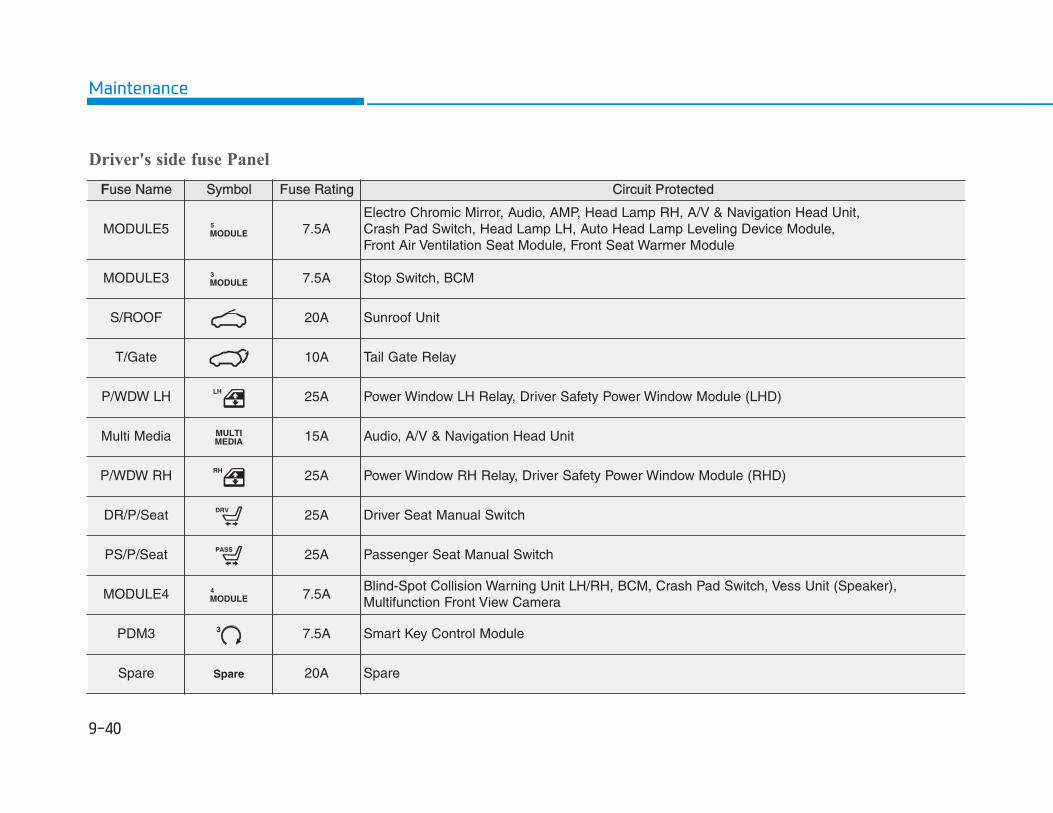
Driver's side fuse Panel
FFuse Name Symbol Fuse Rating Circuit Protected
MODULE5 MODULE5 7.5A
Electro Chromic Mirror, Audio, AMP, Head Lamp RH, A/V & Navigation Head Unit, Crash Pad Switch, Head Lamp LH, Auto Head Lamp Leveling Device Module, Front Air Ventilation Seat Module, Front Seat Warmer Module
MODULE3 MODULE3 7.5A Stop Switch, BCM
S/ROOF 20A Sunroof Unit
T/Gate 10A Tail Gate Relay
P/WDW LH LH 25A Power Window LH Relay, Driver Safety Power Window Module (LHD)
Multi Media MULTIMEDIA 15A Audio, A/V & Navigation Head Unit
P/WDW RH RH 25A Power Window RH Relay, Driver Safety Power Window Module (RHD)
DR/P/Seat DRV 25A Driver Seat Manual Switch
PS/P/Seat PASS 25A Passenger Seat Manual Switch
MODULE4 MODULE4 7.5A
Blind-Spot Collision Warning Unit LH/RH, BCM, Crash Pad Switch, Vess Unit (Speaker),Multifunction Front View Camera
PDM3 3 7.5A Smart Key Control Module
Spare Spare 20A Spare

Driver's side fuse Panel
FFuse Name Symbol Fuse Rating Circuit Protected
INTERIOR LP 7.5AVanity Lamp LH/RH, Room Lamp, Overhead Console Lamp, Wiresess Charger Unit, Luggage Lamp
MEMORY2 2MEMORY 7.5A Vess Unit (Speaker), Electronic Refrigerant Reduced Pressure Valve
B/Alarm 10A ICM Relay Box (Burglar Alarm Horn Relay)
MEMORY 1 10A A/C Control Module, Head Up Display, Instrument Cluster, BCM, Rain Sensor
Spare Spare 20A Spare
AMP AMP 30A AMP
MODULE6 MODULE6 7.5A Smart Key Control Module, BCM
MDPS 1 7.5A MDPS Unit
MODULE1 MODULE1 7.5A
Active Air Flap, ICM Relay Box (Outside Mirror Folding/Unfolding Relay),Hazard Switch, Data Link Connector
MODULE7 MODULE7 7.5A Front Air Ventilation Seat Module, Front Seat Warmer Module
A/BAG IND IND 7.5A Instrument Cluster, A/C Control Modulee
BRAKESWITCH
BRAKESWITCH 7.5A Stop Lamp Switch, Smart Key Control Module

Driver's side fuse Panel
FFuse Name Symbol Fuse Rating Circuit Protected
START 7.5A Smart Key Control (With Smart Key), EPCU
CLUSTER CLUSTER 7.5A Head Up Display, Instrument Cluster
DR/LOCK 20A Door Lock Relay, Door Unlock Relay, ICM Relay Box (Dead Lock Relay)
PDM2 2 7.5A Start/Stop Button Switch
FCA 10A Forward Collision Avoidance Assist Unit
S/HTR 20A Front Seat Warmer Module, Front Air Ventilation Seat Module
Spare Spare 20A Spare
A/CON A/C 7.5A A/C Control Module
PDM1 1 15A Smart Key Control Module
E-SHIFTER E-SHIFTER 10A Shift Select Switch (SBW), Front Console Switch
A/BAG 15A SRS Control Module
IG1 IG1 25A PCB Block (FUSE : F9, F11)

Driver's side fuse Panel
FFuse Name Symbol Fuse Rating Circuit Protected
MODULE2 MODULE2 10A
Wiresess Charger Unit, Smart Key Control Module, BCM, Audio, A/V & Navigation Head Unit, USB charger, AMP, Power Outside Mirror Switch
Washer 15A Muntifunction Switch
WiperLO/HI
10A BCM
R/Wiper 15A Rear Wiper Relay, Rear Wiper Motor
F/WiperFRT
25A Front Wiper Motor, Motor Room Junction Block (Front Wiper (Low) Relay)
RR HTD 10A Driver Power Outside Mirror, A/C Control Module
P/OUTLET 20A Power Outlet
SPARE Spare 15A Spare
HTD STRG 15A BCM

MMotor compartment fuse panel
Inside the fuse/relay box cover, youcan find the fuse/relay label describ-ing fuse/relay name and capacity.
Information Not all fuse panel descriptions in thismanual may be applicable to yourvehicle; the information is accurate atthe time of printing. When you inspectthe fuse panel in your vehicle, refer tothe fuse panel label.
i
OOSEV078016
OOSEV078040L

Motor compartment fuse panel
RRelay No. Symbol Relay Name
RLY.3 E632(IG1) PDM #2 (IG1) Relay
RLY.5 E65 1
IG3 IG3 #1 Relay
RLY.6 E663(IG2) PDM #3 (IG2) Relay
RLY.7 E67 2
IG3 IG3 #2 Relay
RLY.8 E681(ACC) PDM #1 (ACC) Relay
RLY.9 E69 Cooling Fan Relay
RLY.10 E70 Blower Relay
RLY.11 E71 E-SHIFTER E-Shifter Relay
RLY.12 E72 Rear Defogger Relay

Motor compartment fuse panel
TType Fuse Name Symbol Fuse Rating Circuit Protected
MULTIFUSE-1
MAIN MAIN 150A Motor Room Junction Block (Fuse - F24, F26, F28), EPCU (LDC)
MDPS 1 80A MDPS Unit
MULTIFUSE-2
BATT55
60A PCB Block (Fuse - F7, F8, F14, F16), Ignition3 MAIN Relay
BATT22
60A IGPM ((Fuse - F30), IPS0, IPS1, IPS2)
BATT33
60A IGPM (IPS3, IPS4 IPS5, IPS6, IPS7, IPS8)
BATT44
50A IGPM (Fuse - F3, F4, F5, F7, F8, F9, F15, F18)
C/FAN 60A Motor Room Junction Block (RLY.9)
RR DEFOG 40A Motor Room Junction Block (RLY.12)
IG1 IG1 40A Motor Room Junction Block (RLY.3, RLY.8)
IG2 IG2 40A Motor Room Junction Block (RLY.6)
MULTIFUSE-3
IEB4 IEB4 40A Electronic Brake Control Module
BLOWER 40A Motor Room Junction Block (RLY.10)

Motor compartment fuse panel
TType Fuse Name Symbol Fuse Rating Circuit Protected
FUSE
OBC OBC 10A OBC
CHARGER2 CHARGER2 10A ICM Relay Box (Charge Lock/Unlock Relay), CCM Unit
IG3 5 IG35 20A Motor Room Junction Block (RLY.5, RLY.7)
BATT11
40A IGPM ((Fuse - F21, F24, F27, F28, F33) Leak Current Autocut Device)
E-SHIFTER E-SHIFTER 40A Motor Room Junction Block ((Fuse - F34) RLY.11))
CHARGER1 CHARGER1 10A Charge Connector Door Module
IEB1 IEB1 40A Electronic Brake Control Module, Multipurpose Check Connector
IEB2 IEB2 40A Electronic Brake Control Module

Motor compartment fuse panel
TType Fuse Name Symbol Fuse Rating Circuit Protected
FUSE
IG3 3 3IG3 10A
Motor Room Junction Block (RLY.9, RLY.10), Electronic A/C Compressor, 3Way Coolant Control Valve LH/RH
E-SHIFTER3 E-SHIFTER3 10A SCU
IG3 1 1IG3 15A Motor Room Junction Block (RLY.5, RLY.7)
ELECTRICALWATER PUMP
ELECTRICALWATERPUMP
15A Electronic Water Pump
IG3 2 2IG3 10A BMU, OBC, EPCU
EPCU1 EPCU1 15A EPCU
H/LAMP 10A Head Lamp (High) Relay
EPCU2 EPCU2 10A EPCU
IEB 3 3IEB 10A Electronic Brake Control Module, Multipurpose Check Connector
IG3 4 4IG3 15A
Active Air Flap, CCM Unit, Charge Connector Door Module, Air Conditioning PTC Heater, Crash Pad Switch, A/C Control Module, Audio, A/V & Navigation Head Unit, Instrument Cluster, IGPM
BATTERY MAN-AGEMENT
BATTERYMANAGEMENT 10A BMU
HORN 15A Horn Relay

MMotor compartment fuse panel(Battery terminal cover)
Inside the fuse/relay box cover, youcan find the fuse/relay label describ-ing fuse/relay name and capacity.
InformationNot all fuse panel descriptions in thismanual may be applicable to yourvehicle; the information is accurate atthe time of printing. When you inspectthe fuse panel in your vehicle, refer tothe fuse panel label.
i
OOSEV078019
OPD076065
After checking the fuse panel in the motor compartment, securely install thecover. If it is not securely latched, electrical failure may occur from water con-tact.
NOTICE

Consult an authorized HYUNDAIdealer to replace most vehicle lightbulbs. It is difficult to replace vehiclelight bulbs because other parts of thevehicle must be removed before youcan get to the bulb. This is especiallytrue for removing the headlampassembly to get to the bulb(s).Removing/installing the headlampassembly can result in damage tothe vehicle.
Be sure to replace the burned-outbulb with one of the same wattagerating. Otherwise, it may cause dam-age to the fuse or electrical wiringsystem.
InformationAfter heavy driving rain or washing,the lamps could appear frosty. Thiscondition is caused by the tempera-ture difference between the lampinside and the outside temperature.This is similar to the condensation onyour windows inside your vehiclewhen raining and doesn’t indicate aproblem with your vehicle. If thewater leaks into the light bulb circuit-ry, have your vehicle checked by anauthorized HYUNDAI dealer.
Information• A normally functioning lamp may
flicker momentarily to stabilize thevehicle’s electrical control system.However, if the lamp goes out afterflickering momentarily, or contin-ues to flicker, we recommend thesystem be checked by an authorizedHYUNDAI dealer.
• The position lamp may not turn onwhen the position lamp switch isturned on, but the position lampand headlamp switch may turn onwhen the headlamp switch is turnedon. This may be caused by networkfailure or vehicle electrical controlsystem malfunction. If this occurs,we recommend the system bechecked by an authorizedHYUNDAI dealer.
NOTICE i
i
• Prior to working on a light,depress the foot brake, shift to P(Park), apply the parking brake,place the START/STOP buttonin the OFF position and take thekey with you when leaving thevehicle to avoid sudden move-ment of the vehicle and to pre-vent possible electric shock.
• Be aware the bulbs may be hotand may burn your fingers.
WARNING

IInformation The headlamp aiming should beadjusted after an accident or after theheadlamp assembly is reinstalled at anauthorized HYUNDAI dealer.
Headlamp, daytime running light(DRL), position lamp, turn signal lamp and static lampbulb replacementType A
(1) Headlamp (High)(2) Headlamp (Low)(3) Daytime running light (DRL)/
Position lamp(4) Turn signal lamp
Headlamp
1. Open the hood.2. Disconnect the negative battery
cable.
i
OOSEV078020
OOSEV078021
■ High beam
OOSEV078022
■ Low beam

3. Remove the bulb cover by turningit counterclockwise.
4. Remove the bulb socket from theheadlamp assembly by turning itcounterclockwise
5. Disconnect the bulb socket-con-nector.
6. Reinstall in the reverse order ofremoval.
• Always handle them carefully, andavoid scratches and abrasions. Ifthe bulbs are lit, avoid contact withliquids.
• Never touch the glass with barehands. Residual oil may cause thebulb to overheat and burst when lit.
• A bulb should be operated onlywhen installed in a headlamp.
• If a bulb becomes damaged orcracked, replace it immediatelyand carefully dispose of it.
Daytime running light (DRL)/Position lamp
If the lamp (LED) does not operate, werecommend that the system bechecked by an authorized HYUNDAIdealer.The LED lamps cannot be replacedas a single unit because it is an inte-grated unit. The LED lamps has to bereplaced with the unit.A skilled technician should check orrepair the LED lamp, for it may dam-age related parts of the vehicle.
• Handle halogen bulbs with care.Halogen bulbs contain pressur-ized gas that will produce flyingpieces of glass that could causeinjuries if broken.
• Wear eye protection whenchanging a bulb. Allow the bulbto cool down before handling it.
WARNING
OIG076039

Turn signal lamp
1. Open the hood.2. Disconnect the negative battery
cable.3. Remove the socket from the
assembly by turning the socketcounterclockwise until the tabs onthe socket align with the slots onthe assembly.
4. Remove the bulb from the socketby pressing it in and rotating itcounterclockwise until the tabs onthe bulb align with the slots in thesocket. Pull the bulb out of thesocket.
5. Insert a new bulb by inserting itinto the socket and rotating it untilit locks into place.
6. Install the socket into the assem-bly by aligning the tabs on thesocket with the slots in the assem-bly.
7. Push the socket into the assemblyand turn the socket clockwise.
TType B
(1) Static lamp (Low beam assist)(2) Headlamp (Low/High)(3) Daytime running light (DRL)/
Position lamp(4)Turn signal lamp
OOSEV078025
OOSEV078023

Static lamp (Low beam assist)
1. Open the hood.2. Disconnect the negative battery
cable.3. Remove the bulb cover by turning
it counterclockwise.4. Remove the bulb socket from the
headlamp assembly by turning itcounterclockwise
5. Disconnect the bulb socket-con-necter.
6. Reinstall in the reverse order ofremoval.
• Always handle them carefully, andavoid scratches and abrasions. Ifthe bulbs are lit, avoid contact withliquids.
• Never touch the glass with barehands. Residual oil may cause thebulb to overheat and burst when lit.
• A bulb should be operated onlywhen installed in a headlamp.
• If a bulb becomes damaged orcracked, replace it immediatelyand carefully dispose of it.OOSEV078037
• Handle halogen bulbs with care.Halogen bulbs contain pressur-ized gas that will produce flyingpieces of glass that could causeinjuries if broken.
• Wear eye protection whenchanging a bulb. Allow the bulbto cool down before handling it.
WARNING
OIG076039
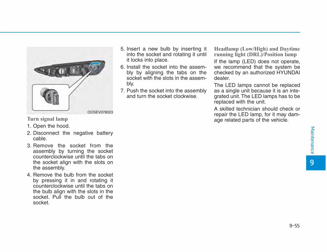
Turn signal lamp
1. Open the hood.2. Disconnect the negative battery
cable.3. Remove the socket from the
assembly by turning the socketcounterclockwise until the tabs onthe socket align with the slots onthe assembly.
4. Remove the bulb from the socketby pressing it in and rotating itcounterclockwise until the tabs onthe bulb align with the slots in thesocket. Pull the bulb out of thesocket.
5. Insert a new bulb by inserting itinto the socket and rotating it untilit locks into place.
6. Install the socket into the assem-bly by aligning the tabs on thesocket with the slots in the assem-bly.
7. Push the socket into the assemblyand turn the socket clockwise.
Headlamp (Low/High) and Daytimerunning light (DRL)/Position lamp
If the lamp (LED) does not operate,we recommend that the system bechecked by an authorized HYUNDAIdealer.The LED lamps cannot be replacedas a single unit because it is an inte-grated unit. The LED lamps has to bereplaced with the unit.A skilled technician should check orrepair the LED lamp, for it may dam-age related parts of the vehicle.
OOSEV078023

SSide repeater lamp replacementIf the lamp (LED) (1) does not oper-
ate, we recommend that the systembe checked by an authorizedHYUNDAI dealer.The LED lamps cannot be replacedas a single unit because it is an inte-grated unit. The LED lamps has to bereplaced with the unit.A skilled technician should check orrepair the LED lamp, for it may dam-age related parts of the vehicle.
Rear combination lamp bulbreplacementType A
(1) Stop/Tail lamp(2) Tail lamp(3) Turn signal lamp(4) Fog lamp(5) Backup lamp
Stop and Tail lamp
1. Turn off the vehicle.2. Open the tailgate.3. Loosen the lamp assembly retain-
ing screws with a cross-tip screw-driver.
OOSEV078024
OOSEV078026L
OOSEV078027

4. Remove the rear combinationlamp assembly from the body ofthe vehicle.
5. Remove the socket from theassembly by turning the socketcounterclockwise until the tabs onthe socket align with the slots on theassembly.
6.- Stop lamp (A)Remove the bulb from the socket bypressing it in and rotating it counter-clockwise until the tabs on the bulbalign with the slots in the socket. Pullthe bulb out of the socket.- Tail lamp (B)Remove the bulb from the socketby pulling out the bulb.
7. Reinstall in the reverse order ofremoval.
Tail lamp
1. Turn off the vehicle.2. Open the tailgate.3. Remove the service cover using a
flat-blade screwdriver.
OOS077068L OOSEV078028 OOSEV078030

4. Remove the socket from theassembly by turning the socketcounterclockwise until the tabs onthe socket align with the slots onthe assembly.
5. Remove the bulb from the socketby pulling out the bulb.
6. Reinstall in the reverse order ofremoval.
Turn signal lamp, fog lamp andbackup lamp
If the lamp does not operate, we rec-ommend that you have the vehiclechecked by an authorized HYUNDAIdealer.
TType B
(1) Stop/tail lamp(2) Stop/tail lamp(3) Turn signal lamp(4) Fog lamp(5) Backup lamp
OOSEV078029
OOSEV078031L

Stop/tail lamp
If the lamp (LED) does not operate,we recommend that the system bechecked by an authorized HYUNDAIdealer.The LED lamps cannot be replacedas a single unit because it is an inte-grated unit. The LED lamps has to bereplaced with the unit.A skilled technician should check orrepair the LED lamp, for it may dam-age related parts of the vehicle.
Turn signal lamp, fog lamp andbackup lamp
If the lamp does not operate, we rec-ommend that you have the vehiclechecked by an authorized HYUNDAIdealer.
HHigh mounted stop lamp bulbreplacement
If the lamp (LED) (1) does not oper-ate, we recommend that the systembe checked by an authorizedHYUNDAI dealer.The LED lamps cannot be replacedas a single unit because it is an inte-grated unit. The LED lamps has to bereplaced with the unit.A skilled technician should check orrepair the LED lamp, for it may dam-age related parts of the vehicle.
License plate light bulb replace-ment
1. Loosen the lens retaining screwswith a philips head screwdriver.
2. Remove the lens.3. Remove the socket by turning it
counterclockwise. 4. Remove the bulb by pulling it
straight out.5. Install a new bulb.6. Reinstall in the reverse order of
removal.
OOSEV078032 OOSEV078033

IInterior light bulb replacement
If the lamp (LED) does not operate,we recommend that the system bechecked by an authorized HYUNDAIdealer.The LED lamps cannot be replacedas a single unit because it is an inte-grated unit. The LED lamps has to bereplaced with the unit.A skilled technician should check orrepair the LED lamp, for it may dam-age related parts of the vehicle.
OOSEV078066
■ Map lamp
OOSEV078036
■ Room lamp
Map lamp, room lamp and luggage compartment lamp (LED type)
OOSEV078038
■ Luggage compartment lamp

1. Using a flat-head screwdriver,gently pry the lens from the interi-or light housing.
2. Remove the bulb by pulling itstraight out.
3. Install a new bulb into the socket.4. Align the lens tabs with the interior
light housing notches and snapthe lens into place.
UUse care not to dirty or damage lens-es, lens tabs, and plastic housings.
NOTICE
OOS077054
■ Room lamp
OOS077046
■ Vanity mirror lamp
OOSEV078034
■ Luggage compartment lamp
OOS077053
■ Map lamp• Type A
OOSEV048047
• Type B
Map lamp, room lamp, vanity mirror lamp and luggage compartment lamp (Bulb type)

Exterior careExterior general caution It is very important to follow the labeldirections when using any chemicalcleaner or polish. Read all warningand caution statements that appearon the label.
High-pressure washing• When using high-pressure wash-
ers, make sure to maintain suffi-cient distance from the vehicle.Insufficient clearance or excessivepressure can lead to componentdamage or water penetration.
• Do not spray the camera, sensorsor its surrounding area directly witha high pressure washer. Shockapplied from high pressure watermay cause the device to not oper-ate normally.
• Do not bring the nozzle tip close toboots (rubber or plastic covers) orconnectors as they may be dam-aged if they come into contact withhigh pressure water.
Protecting your vehicle's finishWashing
To help protect your vehicle’s finishfrom rust and deterioration, wash itthoroughly and frequently at leastonce a month with lukewarm or coldwater. If you use your vehicle for off-roaddriving, you should wash it after eachoff-road trip. Pay special attention tothe removal of any accumulation ofsalt, dirt, mud, and other foreignmaterials. Make sure the drain holesin the lower edges of the doors androcker panels are kept clear andclean.Insects, tar, tree sap, bird droppings,industrial pollution and similardeposits can damage your vehicle’sfinish if not removed immediately. Even prompt washing with plainwater may not completely remove allthese deposits. A mild soap, safe foruse on painted surfaces, should beused.After washing, rinse the vehicle thor-oughly with lukewarm or cold water.Do not allow soap to dry on the finish.
After washing the vehicle, test thebrakes while driving slowly to seeif they have been affected bywater before getting on the road. Ifbraking performance is impaired,dry the brakes by applying themlightly while maintaining a slowforward speed.
WARNING

•• Do not use strong soap, chemicaldetergents or hot water, and do notwash the vehicle in direct sunlightor when the body of the vehicle iswarm.
• Be careful when washing the sidewindows of your vehicle. Especially, with high-pressurewater, water may leak through thewindows and wet the interior.
• To prevent damage to the plasticparts, do not clean with chemicalsolvents or strong detergents.
• To prevent damage to the chargingdoor, make sure to close and lockthe vehicle doors when washing(high-pressure washing, automaticcar washing, etc.) the vehicle.
• Water washing in the motor com-partment including high pressurewater washing may cause the fail-ure of electrical circuits located inthe motor compartment.
• Never allow water or other liquidsto come in contact withelectrical/electronic componentsinside the vehicle as this may dam-age them.
Waxing
A good coat of wax is a barrierbetween your paint and contaminate.Keeping a good coat of wax on yourvehicle will help protect it. Wax the vehicle when water will nolonger bead on the paint.Always wash and dry the vehiclebefore waxing. Use a good qualityliquid or paste wax, and follow themanufacturer’s instructions. Wax allmetal trim to protect it and to main-tain its luster.Removing oil, tar, and similar materi-als with a spot remover will usuallystrip the wax from the finish. Be sureto re-wax these areas even if the restof the vehicle does not yet need wax-ing.
NOTICE
NOTICE
OOSEV078041L

•• Wiping dust or dirt off the body witha dry cloth will scratch the finish.
• Do not use steel wool, abrasivecleaners, or strong detergents con-taining highly alkaline or causticagents on chrome-plated oranodized aluminum parts. Thismay result in damage to the pro-tective coating and cause discol-oration or paint deterioration.
Repairing your vehicle's finishDeep scratches or stone chips in thepainted surface must be repairedpromptly. Exposed metal will quicklyrust and may develop into a majorrepair expense.
If your vehicle is damaged andrequires any metal repair or replace-ment, be sure the body shop appliesanti-corrosion materials to the partsrepaired or replaced.
Bright-metal maintenance• To remove road tar and insects,
use a tar remover, not a scraper orother sharp object.
• To protect the surfaces of bright-metal parts from corrosion, apply acoating of wax or chrome preser-vative and rub to a high luster.
• During winter weather or in coastalareas, cover the bright metal partswith a heavier coating of wax orpreservative. If necessary, coat theparts with non-corrosive petroleumjelly or other protective compound.
Underbody maintenanceCorrosive materials used for ice andsnow removal and dust control maycollect on the underbody. If thesematerials are not removed, acceler-ated rusting can occur on underbodyparts such as the fuel lines, frame,floor pan and exhaust system, eventhough they have been treated withrust protection.
NOTICE
NOTICE

Thoroughly flush the vehicle under-body and wheel openings with luke-warm or cold water once a month,after off-road driving and at the endof each winter. Pay special attentionto these areas because it is difficultto see all the mud and dirt. It will domore harm than good to wet downthe road grime without removing it.The lower edges of doors, rockerpanels, and frame members havedrain holes that should not beallowed to clog with dirt; trappedwater in these areas can cause rust-ing.
AAluminum wheel maintenance The aluminum wheels are coatedwith a clear protective finish.
• Do not use abrasive cleaner, pol-ishing compound, solvent, or wirebrushes on aluminum wheels.
• Clean the wheel when it hascooled.
• Use only a mild soap or neutraldetergent, and rinse thoroughlywith water. Also, clean the wheelsafter driving on salted roads.
• Do not wash the wheels with high-speed car wash brushes.
• Do not use any cleaners contain-ing acid or alkaline detergents.
Corrosion protectionProtecting your vehicle from corro-sion
By using the most advanced designand construction practices to combatcorrosion, HYUNDAI produces vehi-cles of the highest quality. However,this is only part of the job. To achievethe long-term corrosion resistanceyour vehicle can deliver, the owner’scooperation and assistance is alsorequired.
Common causes of corrosion
The most common causes of corro-sion on your vehicle are:• Road salt, dirt and moisture that is
allowed to accumulate underneaththe vehicle.
• Removal of paint or protectivecoatings by stones, gravel, abra-sion or minor scrapes and dentswhich leave unprotected metalexposed to corrosion.
NOTICE
After washing the vehicle, test thebrakes while driving slowly to seeif they have been affected bywater. If braking performance isimpaired, dry the brakes by apply-ing them lightly while maintaininga slow forward speed.
WARNING

High-corrosion areas
If you live in an area where your vehi-cle is regularly exposed to corrosivematerials, corrosion protection isparticularly important. Some of thecommon causes of accelerated cor-rosion are road salts, dust controlchemicals, ocean air and industrialpollution.
Moisture breeds corrosion
Moisture creates the conditions inwhich corrosion is most likely tooccur. For example, corrosion isaccelerated by high humidity, partic-ularly when temperatures are justabove freezing. In such conditions,the corrosive material is kept in con-tact with the vehicle surfaces bymoisture that is slow to evaporate.Mud is particularly corrosive becauseit is slow to dry and holds moisture incontact with the vehicle. Although themud appears to be dry, it can stillretain moisture and promote corro-sion.
High temperatures can also acceler-ate corrosion of parts that are notproperly ventilated so the moisturecan be dispersed. For all these rea-sons, it is particularly important tokeep your vehicle clean and free ofmud or accumulations of other mate-rials. This applies not only to the vis-ible surfaces but particularly to theunderside of the vehicle.
To help prevent corrosion
Keep your vehicle cleanThe best way to prevent corrosion isto keep your vehicle clean and freeof corrosive materials. Attention tothe underside of the vehicle is partic-ularly important.
• If you live in a high-corrosion area— where road salts are used, nearthe ocean, areas with industrialpollution, acid rain, etc.—, youshould take extra care to preventcorrosion. In winter, hose off theunderside of your vehicle at leastonce a month and be sure to cleanthe underside thoroughly whenwinter is over.
• When cleaning underneath thevehicle, pay particular attention tothe components under the fendersand other areas that are hiddenfrom view. Do a thorough job; justdampening the accumulated mudrather than washing it away willaccelerate corrosion rather thanprevent it. Water under high pres-sure and steam are particularlyeffective in removing accumulatedmud and corrosive materials.
• When cleaning lower door panels,rocker panels and frame members,be sure that drain holes are keptopen so that moisture can escapeand not be trapped inside to accel-erate corrosion.

Keep your garage dryDon’t park your vehicle in a damp,poorly ventilated garage. This cre-ates a favorable environment for cor-rosion. This is particularly true if youwash your vehicle in the garage ordrive it into the garage when it is stillwet or covered with snow, ice ormud. Even a heated garage can con-tribute to corrosion unless it is wellventilated so moisture is dispersed.
Keep paint and trim in good condi-tionScratches or chips in the finishshould be covered with "touch-up"paint as soon as possible to reducethe possibility of corrosion. If baremetal is showing through, the atten-tion of a qualified body and paintshop is recommended.Bird droppings are highly corrosiveand may damage painted surfaces injust a few hours. Always remove birddroppings as soon as possible.
IInterior careInterior general precautions Prevent caustic solutions such asperfume and cosmetic oil, from con-tacting the interior parts becausethey may cause damage or discol-oration. If they do contact the interiorparts, wipe them off immediately.See the instructions for the properway to clean vinyl.
• Never allow water or other liquidsto come in contact withelectrical/electronic componentsinside the vehicle as this may dam-age them.
• When cleaning leather products(steering wheel, seats etc.), useneutral detergents or low alcoholcontent solutions. If you use highalcohol content solutions or acid/alkaline detergents, the color of theleather may fade or the surfacemay get stripped off.
Cleaning the upholstery and interi-or trim Vinyl (if equipped)
Remove dust and loose dirt fromvinyl with a whisk broom or vacuumcleaner. Clean vinyl surfaces with avinyl cleaner.
Fabric (if equipped)
Remove dust and loose dirt from fab-ric with a whisk broom or vacuumcleaner. Clean with a mild soap solu-tion recommended for upholstery orcarpets. Remove fresh spots imme-diately with a fabric spot cleaner. Iffresh spots do not receive immediateattention, the fabric can be stainedand its color can be affected. Also, itsfire-resistant properties can bereduced if the material is not proper-ly maintained.
Using anything but recommendedcleaners and procedures may affectthe fabric’s appearance and fire-resistant properties.
NOTICE
NOTICE

Leather (if equipped)
• Features of seat leather- Leather is made from the outer
skin of an animal, which goesthrough a special process to beavailable for use. Since it is a nat-ural product, each part differs inthickness or density.Wrinkles may appear as a naturalresult of stretching and shrinkingdepending on the temperatureand humidity.
- The seat is made of stretchablefabric to improve comfort.
- The parts contacting the body arecurved and the side supportingarea is high which provides driv-ing comfort and stability.
- Wrinkles may appear naturallyfrom usage. It is not a fault of theproducts.
•• Wrinkles or abrasions whichappear naturally from usage arenot covered by warranty.
• Belts with metallic accessories,zippers or keys inside the backpocket may damage the seat fab-ric.
• Make sure not to wet the seat. Itmay change the nature of naturalleather.
• Jeans or clothes which couldbleach may contaminate the sur-face of the seat covering fabric.
• Caring for the leather seats- Vacuum the seat periodically to
remove dust and sand on theseat. It will prevent abrasion ordamage of the leather and main-tain its quality.
- Wipe the natural leather seatcover often with dry or soft cloth.
- Use of proper leather protectormay prevent abrasion of thecover and helps maintain thecolor. Be sure to read the instruc-tions and consult a specialistwhen using leather coating orprotective agent.
- Light colored (beige, creambeige) leather is easily contami-nated and the stain is noticeable.Clean the seats frequently.
- Avoid wiping with wet cloth. It maycause the surface to crack.
NOTICE

• Cleaning the leather seats- Remove all contaminations
instantly. Refer to instructionsbelow for removal of each con-taminant.
- Cosmetic products (sunscreen,foundation, etc.)Apply cleansing cream on a clothand wipe the contaminated spot.Wipe off the cream with a wetcloth and remove water with a drycloth.
- Beverages (coffee, soft drink,etc.)Apply a small amount of neutraldetergent and wipe until contami-nations do not smear.
- OilRemove oil instantly withabsorbable cloth and wipe withstain remover used only for natu-ral leather.
- Chewing gumHarden the gum with ice andremove gradually.
CCleaning the seat belt webbing Clean the belt webbing with any mildsoap solution recommended forcleaning upholstery or carpet. Followthe instructions provided with thesoap. Do not bleach or re-dye thewebbing because this may weakenthe seat belt.
Cleaning the interior window glass If the interior glass surfaces of thevehicle become fogged (that is, cov-ered with an oily, greasy or waxyfilm), they should be cleaned withglass cleaner. Follow the directionson the glass cleaner container.
Do not scrape or scratch the insideof the rear window. This may resultin damage to the rear windowdefroster grid.
NOTICE


Items mm (in)
Overall length 4180 (164.6)
Overall width 1800 (70.9)
Overall height 1570 (61.8)
Front tread 1564 (61.6)
Rear tread 1575 (62.0)
Wheelbase 2600 (102.4)
OBC : On-Board Battery Chargers
*If
Items Economy typeExtended
type*
Motor
Max. output 100 kW 150 kW
Max. torque 395 Nm 395 Nm
Battery (Lithium-ion Polymer)
Capacity 39.2 kWh 64 kWh
Power output 104 kW 170 kW
Voltage 327 V 356 V
Charger (OBC) Max. Output 7.2 kW 7.2 kW

Light bulb Bulb type Wattage
Front
Type A HeadlampLow H7 55
High H7 55
Type BHeadlamp Low/High LED LED
Static lamp (Low beam assist) H7 55
Turn signal lamp PY21W 21
Daytime running light (DRL)/Position lamp LED LED
Side repeater lamp LED LED
Rear
Type ATail/Stop lamp P21W/5W Tail: 5 / Stop: 21
Tail lamp W5W 5
Type B Tail/Stop lamp LED LED
Turn signal lamp PY21W 21
Backup lamp P21W 21
Fog lamp PR21W 21
License plate lamp W5W 5
High mounted stop lamp LED LED
Interior
Map lampType A W10W 10
Type B LED LED
Room lampType A FESTOON 8
Type B LED LED
Vanity mirror lamp FESTOON 5
Luggage compartment lampType A FESTOON 10
Type B LED LED

Item Tire sizeWheelsize
Inflation pressure, bar (kPa, psi) Wheel lug nuttorque
kgf·m (lbf·ft, N•m)Normal load *1 Maximum load
Front Rear Front Rear
Full size tire 215/55 R17 7.0J X 172.5 (250, 36)
11~13(79~94, 107~127)
Spare tire T135/80 D17 4T X 17
When replacing tires, use the same size originally supplied with the vehicle.Using tires of a different size can damage the related parts or not work properly.
CAUTION
*1 : Normal load : Up to 3 persons
• It is permissible to add 20 kPa (3 psi) to the standard tire pressure specification if colder temperatures are expect-ed soon. Tires typically lose 7 kPa (1 psi) for every 7°C (12°F) temperature drop. If extreme temperature variationsare expected, recheck your tire pressure as necessary to keep them properly inflated.
• An air pressure generally decreases, as you drive up to a high-altitude area above sea level. Thus, if you plan todrive a high-altitude area, check the tire pressures in advance. If necessary, inflate them to a proper level (Air infla-tion per altitude: +10 kPa/1 km (+2.4 psi/1 mile).
• Spare tire are intended for emergencey purpose only.• Spare tire can be from any manufacturer. Only Steel wheel will be provided as the Spare tire.
NOTICE

Min : Behind rear seat to roofMax : Behind front seat to roof
Gross vehicle weight Luggage volume
2020 kg (4453 lbs.)Min. Max.
332 l (11.7 cu ft) 1114 l (39.3 cu ft)
Items Weight of volume Classification
Refrigerantg (oz.)
With standard climatecontrol system
550 ±25 (19.4 ± 0.9)R-1234yf
R-134a
With inner condenser 650 ± 25 (22.9 ± 0.9)R-1234yf
R-134a
With heat pump 1000 ±25 (35.3 ± 0.9)R-1234yf
R-134a
Compressor lubricant g (oz.) 180 ± 10 (6.34 ± 0.35) POE
Contact an authorized HYUNDAI dealer for more details.

To help achieve proper vehicle performance and durability, use only lubricants of the proper quality. These lubricants and fluids are recommended for use in your vehicle.
Lubricant Volume Classification
Reduction gear fluid1.0 ~ 1.1 l
70W, API GL-4, TCGO-9(MS517-14)
Coolant
Economicaltype
without heat pump 10.3 ~ 10.7 l
Designated coolant water for electric vehicles only from Hyundai Specialised EV Workshops
with heat pump 10.7 ~ 11.2 l
Extendedtype
without heat pump 12.5 ~13 l
with heat pump 13 ~13.4 l
Brake fluid 0.7 ~ 0.8 l

The vehicle identification number(VIN) is the number used in register-ing your vehicle and in all legal mat-ters pertaining to its ownership, etc.The number is punched on the floorunder the passenger's (or driver's)seat. To check the number, open thecover.
The VIN is also on a plate attachedto the top of the dashboard. Thenumber on the plate can easily beseen through the windshield fromoutside.
The vehicle certification labelattached on the driver’s (or front pas-senger’s) side center pillar gives thevehicle identification number (VIN).
OOS087006L
■ VIN label (if equipped)
OOS087001
■ Frame number
OOS087002R

The tires supplied on your new vehi-cle are chosen to provide the bestperformance for normal driving.The tire label located on the driver's(or passenger's) side center pillargives the tire pressures recommend-ed for your vehicle.
The motor number is stamped on themotor block as shown in the drawing.The motor number can be seen fromunder the vehicle.
A compressor label informs you thetype of compressor your vehicle isequipped with such as model, suppli-er part number, production number,refrigerant (1) and refrigerant oil (2).
OOSEV088002
OOSEV088001
OOS087003R