Bernoulli's Principle Demonstration - Experiment Instructions
15
Experiment Instructions HM 150.07 Bernoulli’s Principle Demonstrator
-
Upload
khangminh22 -
Category
Documents
-
view
2 -
download
0
Transcript of Bernoulli's Principle Demonstration - Experiment Instructions
Experiment Instructions
HM 150.07 Bernoulli’s Principle Demonstrator
10/2009
HM 150.07 BERNOULLI’S PRINCIPLE DEMONSTRATOR
i
All
right
s re
serv
ed, G
.U.N
.T. G
erät
ebau
, Bar
sbüt
tel,
Ger
man
y 10
/200
9
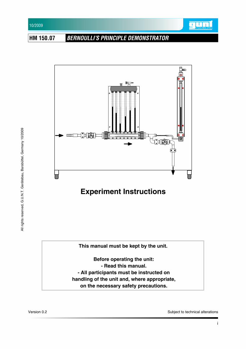
Experiment Instructions
This manual must be kept by the unit.
Before operating the unit: - Read this manual.
- All participants must be instructed on handling of the unit and, where appropriate,
on the necessary safety precautions.
Version 0.2 Subject to technical alterations
10/2009
HM 150.07 BERNOULLI’S PRINCIPLE DEMONSTRATOR
ii
All
right
s re
serv
ed, G
.U.N
.T. G
erät
ebau
, Bar
sbüt
tel,
Ger
man
y 10
/200
9
Table of Contents
1 Introduction . . . . . . . . . . . . . . . . . . . . . . . . . . . . . . . . . . . . . . . . . . . . . . . . . 1
1.1 Intended Use . . . . . . . . . . . . . . . . . . . . . . . . . . . . . . . . . . . . . . . . . . . . 1
2 Unit Description . . . . . . . . . . . . . . . . . . . . . . . . . . . . . . . . . . . . . . . . . . . . . . 2
3 Experiments . . . . . . . . . . . . . . . . . . . . . . . . . . . . . . . . . . . . . . . . . . . . . . . . . 3
3.1 Performance of Experiment. . . . . . . . . . . . . . . . . . . . . . . . . . . . . . . . . 3
3.2 Assessment of Experiment . . . . . . . . . . . . . . . . . . . . . . . . . . . . . . . . . 5
3.2.1 Velocity Profile in the Venturi Nozzle . . . . . . . . . . . . . . . . . . . 7
3.2.2 Pressure Distribution Venturi Nozzle . . . . . . . . . . . . . . . . . . . 9
3.2.3 Determination of Flow Rate Factor . . . . . . . . . . . . . . . . . . . . 11
4 Technical Data . . . . . . . . . . . . . . . . . . . . . . . . . . . . . . . . . . . . . . . . . . . . . . 12
10/2009
HM 150.07 BERNOULLI’S PRINCIPLE DEMONSTRATOR
1 Introduction 1
All
right
s re
serv
ed, G
.U.N
.T. G
erät
ebau
, Bar
sbüt
tel,
Ger
man
y 10
/200
9
1 Introduction
The HM 150.07 is used to investigate Bernoulli’slaw. The measurement object is a Venturi nozzlewith six pressure measurement points.
The six static pressures are displayed on a boardwith six water pressure gauges.
The overall pressure can also be measured atvarious locations in the Venturi nozzle and indi-cated on a second water pressure gauge. Meas-urement is by way of a probe which can be movedaxially with respect to the Venturi nozzle. Theprobe is sealed by way of a compression gland.
Water is supplied either from the HM 150 FluidMechanics Basic Module or from the laboratorymains.
The HM 150 enables a closed water circuit to beconstructed.
Possible experiments:
• Demonstration of Bernoulli’s law
• Pressure measurements along Venturi nozzle
• Determination of flow rate factor K
1.1 Intended Use
The unit is to be used only for teaching purposes.
10/2009
HM 150.07 BERNOULLI’S PRINCIPLE DEMONSTRATOR
2 Unit Description 2
All
right
s re
serv
ed, G
.U.N
.T. G
erät
ebau
, Bar
sbüt
tel,
Ger
man
y 10
/200
9
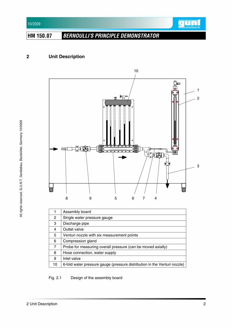
2 Unit Description
Fig. 2.1 Design of the assembly board
1 Assembly board
2 Single water pressure gauge
3 Discharge pipe
4 Outlet valve
5 Venturi nozzle with six measurement points
6 Compression gland
7 Probe for measuring overall pressure (can be moved axially)
8 Hose connection, water supply
9 Inlet valve
10 6-fold water pressure gauge (pressure distribution in the Venturi nozzle)
10
1
2
3
4598 6 7
10/2009
HM 150.07 BERNOULLI’S PRINCIPLE DEMONSTRATOR
All
right
s re
serv
ed, G
.U.N
.T. G
erät
ebau
, Bar
sbüt
tel,
Ger
man
y 10
/200
9
3 Experiments
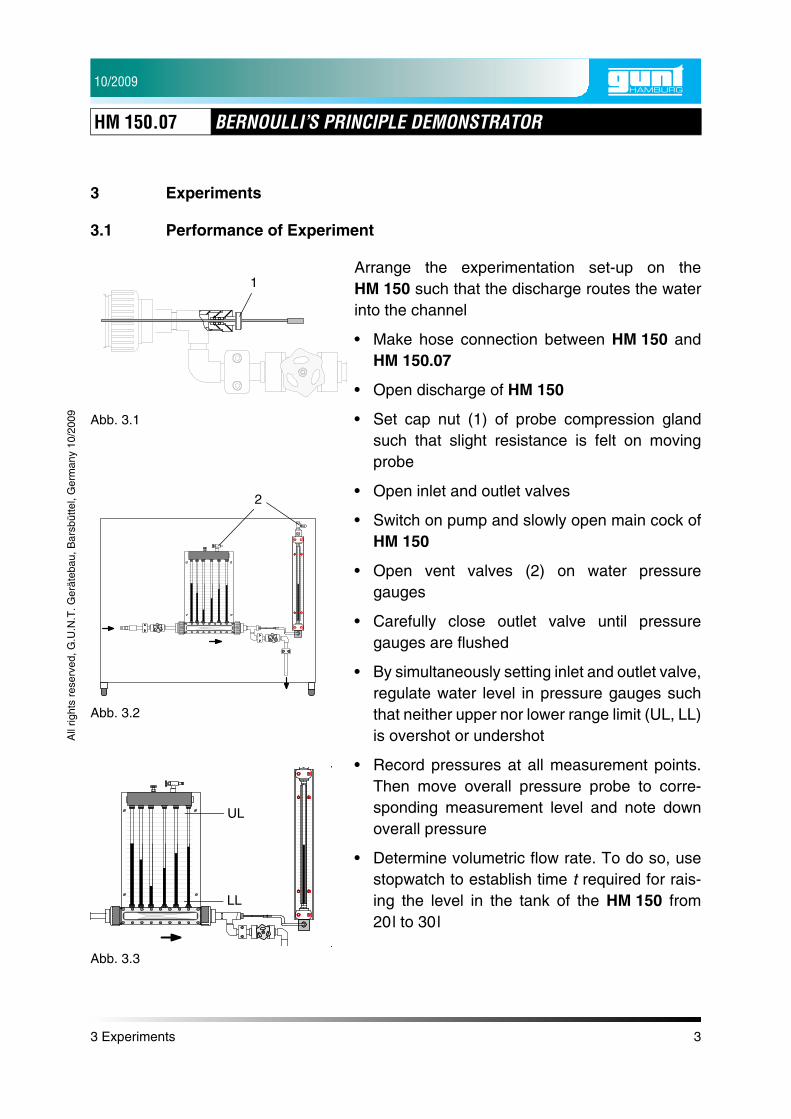
3.1 Performance of Experiment
Arrange the experimentation set-up on theHM 150 such that the discharge routes the waterinto the channel
• Make hose connection between HM 150 andHM 150.07
• Open discharge of HM 150
• Set cap nut (1) of probe compression glandsuch that slight resistance is felt on movingprobe
• Open inlet and outlet valves
• Switch on pump and slowly open main cock ofHM 150
• Open vent valves (2) on water pressuregauges
• Carefully close outlet valve until pressuregauges are flushed
• By simultaneously setting inlet and outlet valve,regulate water level in pressure gauges suchthat neither upper nor lower range limit (UL, LL)is overshot or undershot
• Record pressures at all measurement points.Then move overall pressure probe to corre-sponding measurement level and note downoverall pressure
• Determine volumetric flow rate. To do so, usestopwatch to establish time t required for rais-ing the level in the tank of the HM 150 from20l to 30l
Abb. 3.1
1
Abb. 3.2
2
Abb. 3.3
UL
LL
3 Experiments 3

10/2009
HM 150.07 BERNOULLI’S PRINCIPLE DEMONSTRATOR
All
right
s re
serv
ed, G
.U.N
.T. G
erät
ebau
, Bar
sbüt
tel,
Ger
man
y 10
/200
9
NOTICEThe experimental set-up should be arrangedabsolutely plane to avoid falsification of measure-ment results (use of spirit level recommended).
NOTICEFor taking pressure measurements, the tank ofthe HM 150 must be empty and the outlet valveopen, as otherwise the delivery head of the pumpwill change as the water level in the tankincreases. This results in fluctuating pressureconditions. A constant pump delivery pressure isimportant with low flow rates to prevent biasing ofthe measurement results.
NOTICEBoth valves must be reset whenever the flowchanges to ensure that the measured pressuresare within the display ranges.
3 Experiments 4
10/2009
HM 150.07 BERNOULLI’S PRINCIPLE DEMONSTRATOR
All
right
s re
serv
ed, G
.U.N
.T. G
erät
ebau
, Bar
sbüt
tel,
Ger
man
y 10
/200
9
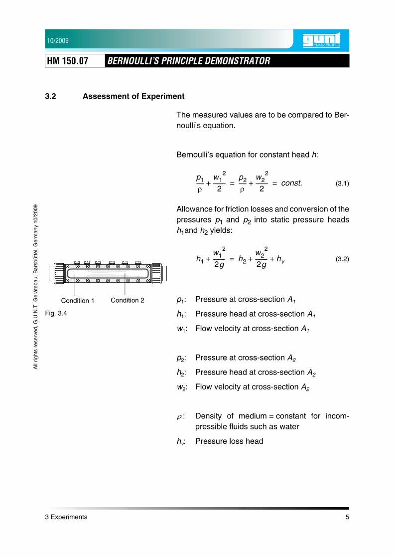
3.2 Assessment of Experiment
The measured values are to be compared to Ber-noulli’s equation.
Bernoulli’s equation for constant head h:
(3.1)
Allowance for friction losses and conversion of thepressures p1 and p2 into static pressure headsh1and h2 yields:
(3.2)
p1: Pressure at cross-section A1
h1: Pressure head at cross-section A1
w1: Flow velocity at cross-section A1
p2: Pressure at cross-section A2
h2: Pressure head at cross-section A2
w2: Flow velocity at cross-section A2
: Density of medium = constant for incom-pressible fluids such as water
hv: Pressure loss head
p1
ρ------
w12
2---------+
p2
ρ------
w22
2---------+ const.= =
Fig. 3.4
Condition 1 Condition 2
h1w1
2
2g---------+ h2
w22
2g--------- hv+ +=
ρ
3 Experiments 5

10/2009
HM 150.07 BERNOULLI’S PRINCIPLE DEMONSTRATOR
All
right
s re
serv
ed, G
.U.N
.T. G
erät
ebau
, Bar
sbüt
tel,
Ger
man
y 10
/200
9
The mass flow is constant in closed systems.
(3.3)
Given
(3.4)
(3.5)
(3.6)
Given
(3.7)
(3.8)
Fig. 3.5
1m· 2m·
m1· m2
·=
m· V· ρ⋅=
V1· ρ⋅ V2
· ρ⋅=
V· 1 V2·
=
V· A w⋅=
A1 w1⋅ A2 w2⋅ V· const.= = =
3 Experiments 6

10/2009
HM 150.07 BERNOULLI’S PRINCIPLE DEMONSTRATOR
All
right
s re
serv
ed, G
.U.N
.T. G
erät
ebau
, Bar
sbüt
tel,
Ger
man
y 10
/200
9
3.2.1 Velocity Profile in the Venturi Nozzle
The Venturi nozzle used has six measurementpoints.
The table below shows the standardised refer-ence velocity . This parameter is derived fromthe geometry of the Venturi nozzle.
(3.9)
Multiplying the reference velocity values with astarting value, the student can calculate the theo-retical velocity values wcalc at the six measuringpoints of the Venturi nozzle.
At constant flow rate, the starting value for calcu-lating the theoretical velocity is found as:
(3.10)
w
wiA1
Ai------=
Fig. 3.6
2 3 41 5 6
Point i A
in
Reference velocity in
1 3,38 1,00
2 2,33 1,45
3 0,846 4,00
4 1,70 2,00
5 2,55 1,33
6 3,38 1,00
Tab. 3.1
m2 10 4–⋅ w
w1V·
A1------=
3 Experiments 7
10/2009
HM 150.07 BERNOULLI’S PRINCIPLE DEMONSTRATOR
All
right
s re
serv
ed, G
.U.N
.T. G
erät
ebau
, Bar
sbüt
tel,
Ger
man
y 10
/200
9
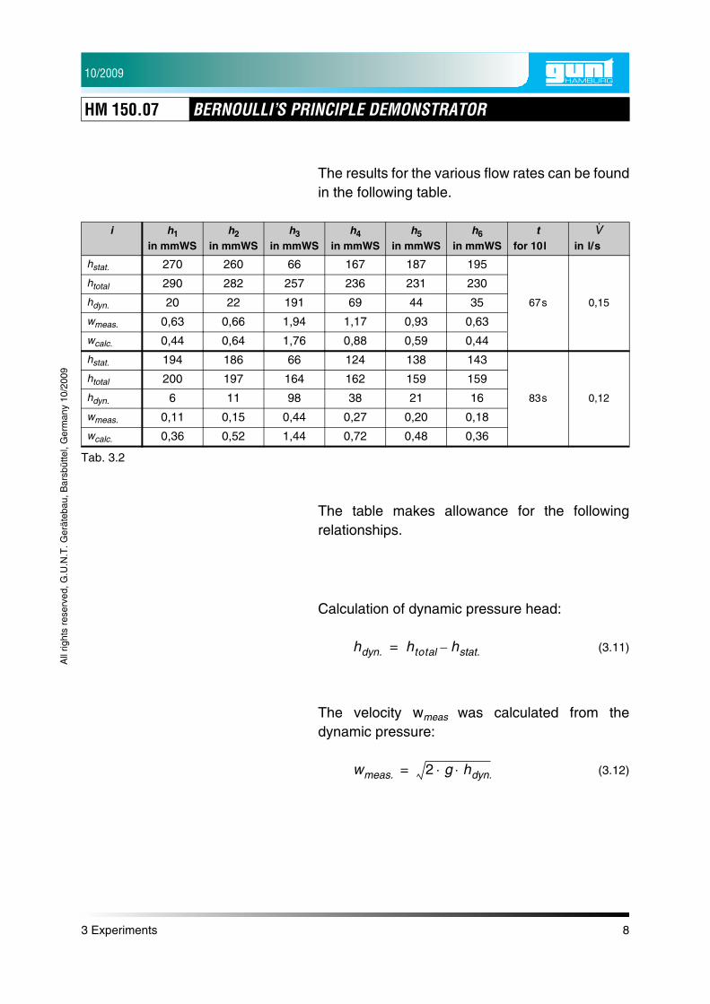
The results for the various flow rates can be foundin the following table.
The table makes allowance for the followingrelationships.
Calculation of dynamic pressure head:
(3.11)
The velocity wmeas was calculated from thedynamic pressure:
(3.12)
i h1
in mmWSh2
in mmWSh3
in mmWSh4
in mmWSh5
in mmWSh6
in mmWSt
for 10l in l/s
hstat. 270 260 66 167 187 195
67s 0,15
htotal 290 282 257 236 231 230
hdyn. 20 22 191 69 44 35
wmeas. 0,63 0,66 1,94 1,17 0,93 0,63
wcalc. 0,44 0,64 1,76 0,88 0,59 0,44
hstat. 194 186 66 124 138 143
83s 0,12
htotal 200 197 164 162 159 159
hdyn. 6 11 98 38 21 16
wmeas. 0,11 0,15 0,44 0,27 0,20 0,18
wcalc. 0,36 0,52 1,44 0,72 0,48 0,36
Tab. 3.2
V·
hdyn. htotal hstat.–=
wmeas. 2 g hdyn.⋅ ⋅=
3 Experiments 8
10/2009
HM 150.07 BERNOULLI’S PRINCIPLE DEMONSTRATOR
All
right
s re
serv
ed, G
.U.N
.T. G
erät
ebau
, Bar
sbüt
tel,
Ger
man
y 10
/200
9
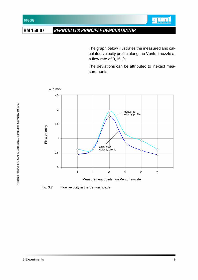
The graph below illustrates the measured and cal-culated velocity profile along the Venturi nozzle ata flow rate of 0,15 l/s.
The deviations can be attributed to inexact mea-surements.
Fig. 3.7 Flow velocity in the Venturi nozzle
w in m/s
Measurement points i on Venturi nozzle
measured velocity profile
calculated velocity profile
Flo
w v
eloc
ity
1 2 3 4 5 6
3 Experiments 9

10/2009
HM 150.07 BERNOULLI’S PRINCIPLE DEMONSTRATOR
All
right
s re
serv
ed, G
.U.N
.T. G
erät
ebau
, Bar
sbüt
tel,
Ger
man
y 10
/200
9
3.2.2 Pressure Distribution Venturi Nozzle
The pressure changes in the Venturi nozzle canbe represented in a graph directly:
The graph shows, that the equation
(3.13)
is fullfilled at every point in the Venturi nozzle.
Furthermore, it becomes clear, that there is aslight overall pressure loss (htotal) in the Venturinozzle.
Fig. 3.8 Pressure distribution Venturi nozzle
Measurement points i on Venturi nozzle
h dyn
in m
mW
S
htotalhstat.hdyn.
1 2 3 4 5 6
hdyn. htotal hstat.–=
3 Experiments 10
10/2009
HM 150.07 BERNOULLI’S PRINCIPLE DEMONSTRATOR
All
right
s re
serv
ed, G
.U.N
.T. G
erät
ebau
, Bar
sbüt
tel,
Ger
man
y 10
/200
9
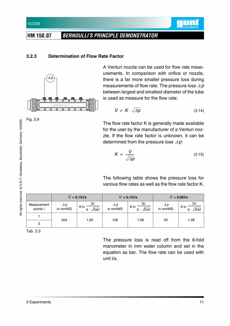
3.2.3 Determination of Flow Rate Factor
A Venturi nozzle can be used for flow rate meas-urements. In comparison with orifice or nozzle,there is a far more smaller pressure loss duringmeasurements of flow rate. The pressure loss pbetween largest and smallest diameter of the tubeis used as measure for the flow rate:
(3.14)
The flow rate factor K is generally made availablefor the user by the manufacturer of a Venturi noz-zle. If the flow rate factor is unknown, it can bedetermined from the pressure loss p:
(3.15)
The following table shows the pressure loss forvarious flow rates as well as the flow rate factor K.
The pressure loss is read off from the 6-foldmanometer in mm water column and set in theequation as bar. The flow rate can be used withunit l/s.
Fig. 3.9
pΔ
Δ
V· K Δp⋅=
Δ
K V·
Δp-----------=
= 0,15l/s = 0,12l/s = 0,08l/s
Measurement points i
pin mmWS
K in p
in mmWSK in
pin mmWS
K in
1204 1,05 128 1,06 55 1,08
3
Tab. 3.3
V· V· V·
Δ ltr
s bar⋅--------------------- Δ ltr
s bar⋅--------------------- Δ ltr
s bar⋅---------------------
3 Experiments 11
10/2009
HM 150.07 BERNOULLI’S PRINCIPLE DEMONSTRATOR
4 Technical Data 12
All
right
s re
serv
ed, G
.U.N
.T. G
erät
ebau
, Bar
sbüt
tel,
Ger
man
y 10
/200
9
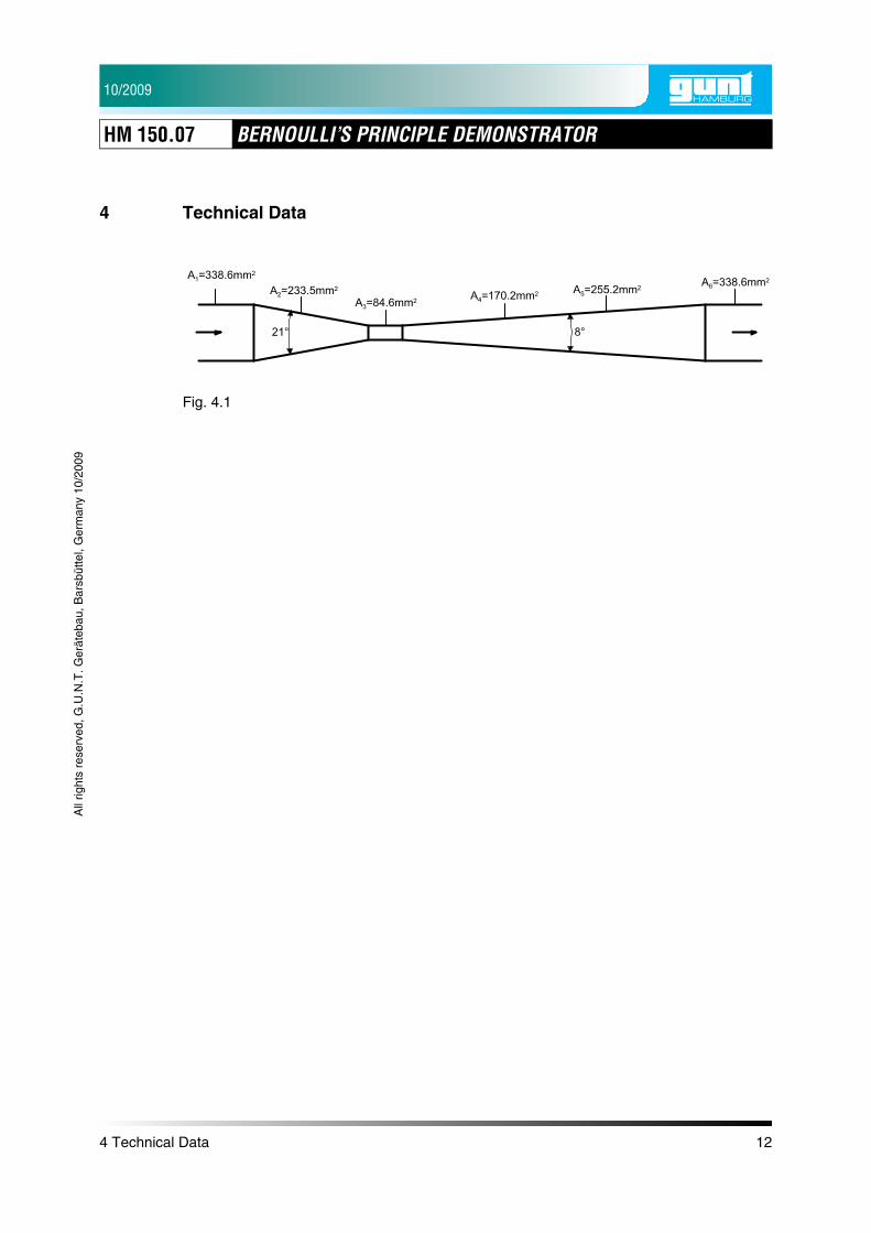
4 Technical Data
Fig. 4.1