
Belt Filter Press Siemens BPF 2000 BSX-S7-LH-P60 and ...
123
JOHN YOUNG (KELVINHAUGH) PTY LTD rouNG Order No. 049945 - GOODNA WASTEWATER CENTRE SUPPLY OF BELT FILTER PRESS BPF 2000 BSX -S7 - L-H P60 AND GRAVITY TABLE GT2000 BSX OPERATION AND MAINTENANCE MANUAL - GRAVITY TABLE GT 2000 BSX JOHN YOUNG (KELVINHAUGH) P/L 7, Widemere Road, Wetherill Park NSW 2164. Ph - 02 9609 1622. Fx - 02 9604 8657 odna STP STP - Belt Filter Press Siemens BPF 2000 BSX-S7-L-H-P60 and Gravity Table GT2000 BSX - Operation and Maintenance Manual - Ven Q-Pulse Id TMS1356 Active 29/07/2015 Page 1 of 123
-
Upload
khangminh22 -
Category
Documents
-
view
0 -
download
0
Transcript of Belt Filter Press Siemens BPF 2000 BSX-S7-LH-P60 and ...

JOHN YOUNG (KELVINHAUGH) PTY LTD
rouNG Order No. 049945 - GOODNA WASTEWATER CENTRE
SUPPLY OF BELT FILTER PRESS BPF 2000 BSX -S7 - L-H P60 AND GRAVITY TABLE GT2000 BSX
OPERATION AND MAINTENANCE MANUAL
- GRAVITY TABLE GT 2000 BSX
JOHN YOUNG (KELVINHAUGH) P/L 7, Widemere Road, Wetherill Park NSW 2164. Ph - 02 9609 1622. Fx - 02 9604 8657
ST41 Goodna STP STP - Belt Filter Press Siemens BPF 2000 BSX-S7-L-H-P60 and Gravity Table GT2000 BSX - Operation and Maintenance Manual - Vendor Manual
Q-Pulse Id TMS1356 Active 29/07/2015 Page 1 of 123

JOHN YOUNG (KELVINHAUGH) PTY LTD
,
__M._ i - M
Order No. 049945 - GOODNA WASTEWATER CENTRE
SUPPLY OF BELT FILTER PRESS BPF 2000 BSX -S7 - L-H P60 AND GRAVITY TABLE GT2000 BSX
CONTACT
MR.PETER OLDFIELD JOHN YOUNG (KELVINHAUGH) P/L 7, WIDEMERE ROAD, WETHERILL PARK, NSW 2164. PH - 02 9609 1622 FX - 02 9604 8657
E -Mail - poldfield @jyk.com.au
ST41 Goodna STP STP - Belt Filter Press Siemens BPF 2000 BSX-S7-L-H-P60 and Gravity Table GT2000 BSX - Operation and Maintenance Manual - Vendor Manual
Q-Pulse Id TMS1356 Active 29/07/2015 Page 2 of 123
SIEMENS Sernagiotto Products
OPERATION AND MAINTENANCE
MANUAL
GT 2000 BSX
Serial number 60407977070001 Year built 2007
Siemens Water Technologies S.p.A. Sernagiotto Products Via Torino, 114 27045 CASTEGGIO (PV) ITALY
ST41 Goodna STP STP - Belt Filter Press Siemens BPF 2000 BSX-S7-L-H-P60 and Gravity Table GT2000 BSX - Operation and Maintenance Manual - Vendor Manual
Q-Pulse Id TMS1356 Active 29/07/2015 Page 3 of 123

SIEMENS - GT 2000 BSX
TABLE OF CONTENTS
Enclosed drawings:
Right hand assembly 60407977a Cascade 60407976a Pneumatic diagram 60119890 -la Electrical diagram 68400687 rev. A Instrument and Motor list
PREFACE 1
1. INTRODUCTION 2
1.1. Aims and limits of this manual 1.2. Where and how to store this manual 1.3. Manual updates 1.4. Co- operation with users 1.5. Liability exclusion
2. GENERAL INFORMATION 4
2.1 Manufacturer 2.2. Identification label 2.3. Allowed uses of the machine 2.4. Uses not permitted for the machine ,
2.5. General safety instructions
3. STORAGE 6
4. PROCESS DESCRIPTION 7
5. IDENTIFICATION OF THE BLOCKS 9
6. SAFETY DEVICES 12
7. TECHNICAL DATA 13
7.1. Environment for the installation of the machine
8. HANDLING AND TRANSPORT 14
9. ASSEMBLY AND INSTALLATION 16
9.1. Choice of the location where the machine is installed 9.2. Positioning
10. CONNECTIONS 18
11. CONNECTIONS AND REGULATION 20 11.1. Electrical connections 11.2. Pneumatic connections and regulation 11.3. Regulation of the belt drive 11.4. Hydraulic connections 11.5. Belt tensioning
ST41 Goodna STP STP - Belt Filter Press Siemens BPF 2000 BSX-S7-L-H-P60 and Gravity Table GT2000 BSX - Operation and Maintenance Manual - Vendor Manual
Q-Pulse Id TMS1356 Active 29/07/2015 Page 4 of 123

SIEMENS - GT 2000 BSX
11.6. Belts tracking device adjustment 11.7. Adjustment of doctor blades 11.8. Connection and adjustment of belts washing boxes 11.9. Belt installation /replacement 11.10. Installing instructions for synthetic fabrics with clipper seam
12. START -UP AND TESTING 32 12.1. Preliminary checks
13. START -UP, OPERATION AND SHUT -DOWN 35 13.1. Command systems 13.2. Safety 13.3. Alarm system 13.4. Checks before machine start -up 13.5. Optimization of operations
14. TROUBLE SHOOTING 37
15. MAINTENANCE 39 15.1 Cleaning 15.2 Ordinary maintenance 15.3 Special maintenance 15.4. Inspections
16. DEMOLITION, DECONTAMINATION AND SORTING OF MATERIALS 45
17. RESIDUAL RISKS 46
18. TRAINING OF PERSONNEL 47
19. SPARE PARTS 48
Instructions of the commercial components:
Appendix A - BELT DRIVE
Appendix B - INSTRUMENT CUT SHEETS
ST41 Goodna STP STP - Belt Filter Press Siemens BPF 2000 BSX-S7-L-H-P60 and Gravity Table GT2000 BSX - Operation and Maintenance Manual - Vendor Manual
Q-Pulse Id TMS1356 Active 29/07/2015 Page 5 of 123

1
1
t
1
1
1
1
1
1
1
1
I
á
w wáút.)c°.rcmiwci >
á
n
o d v N
yy
f0
Ç
f~.7 j }
-sE F E
: ñav
g.j_:' pRpp
gi LbICL
Z
_
¿y b +F
.. _ ") ^ N
a% ^ Q ö CO
f= gp
m
$
2
i LL
vGEI .. N .. du .. ° c $
R ä
2
° `
°` n
°
o u
P
: .
- -
Y°i
u c
ò è a:
° d
n
_ _
\ : a .-
.2
p O n
u°f
\ á ° ;z^s T.
LLU
¢ - V .+
O
L `~¿ 4 5
N ¢
B
R
-...1 UI
m
m
-
Coi
t W
a , ..,
N
II
il
" IÌ
¡I
ÍI
M
il
_- -,II.
I
I IM -3 I -
I`II:
--
I N" N
N
N Ñ¡I M
1
N
iM
N
N
!N
1/
-
L.
Ú
_
m
°
- 0 m ,n m?g.:
"ii e^ o Z E
o ti
\ _
( - =co x ° d
_ I
° A
° gti
m
-_
-
t. _
-°
_
_ _ A ° e
,., ,,
11 , . p
8 _
E á
- o
á
y .
Wea a.a m á
d á °
.
i :
h:I ç ¡I
31;E°L=° '''1jy;
ó:ai1 01.11_. WO
;A'E`8
' i+s1v! 8¡3I;+
oh I=te.Sa.
1i.I
S ' = g°8 :RI;
ióc '3 ill
l i- 69É
i
-
]
7
!L ` '11 II._!Ip
a : a x o m > n , , F:-t:s° -=g 11:'i: 81r.1
AIM, ..
.''
... ;_: .It o
Q I65 v ,..
0002
°m
.
S9C r. 'i/\i+
1 ..:i.. o m
iii IFI
ii'i - I - 5j+1il
I
N N
,.
:
7 I
I+'l II I } j I
N
N = 3
IIIGI
U
T
T
i 1 m ti I I I
_ (.' I'
`ri'
.IiI , ' 1 ,
1
m
N N
- - _ -. -_
I
- --- - I
I
..
i
I
i .
-Ì' I
s
; / v
t t
b
- 1- I
I
1 au I°A.
II/.
b ..
O '+ / +, O ' , I OM- m [3 ,
. 006
iV82
ST41 Goodna STP STP - Belt Filter Press Siemens BPF 2000 BSX-S7-L-H-P60 and Gravity Table GT2000 BSX - Operation and Maintenance Manual - Vendor Manual
Q-Pulse Id TMS1356 Active 29/07/2015 Page 6 of 123

o
o
n
IS
1
-
- l
. -f`Y r:
} = 4
,1
_ 3 :111'11 I A sr, _ ,. 1 t%r
,
'' miltim....o r/j ', i 1._
OS
I
I
r.
i
Ifl II
EEM;;ZSZA ;* ÿ 1
i'9===1:111
4
-I
Qf
o o tD
te_ éló
®.ME fiaT
r
nand
\\\\\\\
'
NEE
11
II :' 4,
ST41 Goodna STP STP - Belt Filter Press Siemens BPF 2000 BSX-S7-L-H-P60 and Gravity Table GT2000 BSX - Operation and Maintenance Manual - Vendor Manual
Q-Pulse Id TMS1356 Active 29/07/2015 Page 7 of 123

6
Q
' 04
ST41 Goodna STP STP - Belt Filter Press Siemens BPF 2000 BSX-S7-L-H-P60 and Gravity Table GT2000 BSX - Operation and Maintenance Manual - Vendor Manual
Q-Pulse Id TMS1356 Active 29/07/2015 Page 8 of 123

-
,..; (u o 7. --o TA LI (13
i 171 0 E ioc vi co _c 12 c as c - o _c k., t..,
LI o - -o- -E 0;
1.1 4, cc =c ,...., tri L.)
0. 2 -.c. c x. LU >. 03 2 = C'
14-1 0 :,T14 6°. -I ri.1 rn cc Li
1.1.1 - ' I
VV ...71 <C <C cn ET1 ri..1 OA 43 03.: -0:3 x x
i 40 1 EE °' 013
1 1
U-I LLI M EE i I
;
1
i
H.
1 !
!
IN !
-I I !
_c
e _ vi 'a)
E .o = En -.- en C RI a,
c c .70
E - c Er. co
C o E
cL 1 :0
CO >
o
.- CO ,
< <
E E
o o
0_
0
Cif
o o z o o o
LJ 0-
i !
i !
i ,- ! i
s,:2 -..---, i , ,i. . e
i -e -
;
i in r i
.. i i IL
,7,'
i
lt-) i
X 0,0
o X !
U)
N o X
N
o X Cf) N
r-1
27_3.0....
CN
e.
001: 0:
j
<3
7 V)
fi Cs4
--, o
o -*E
E o
o o
112
o o
I=1
LU
bid
Ca
IB Ca Lid CC
Cn
cm .
cc
ILI LU
0 o 6, ca o n
o° E90 Flo mg 0 Mg Mg o 02 Dzi . ot rea . ow CO] 0 Bm ga 0 rig
00) > o 1P- o 1-0
(To 9,1-8
o C1 OD
9
4/
o o
L-5
'E .g2
o l
o o o
w
co
w
o Ql
C.)
LU
Wi
Ql C/) C/3 LU O- W
0 C 01 O. E -
o g o
0 2 zo
a < 2
CC
cc
o cc a.
a
5 a
8 I
ai; 21 o
< il <
a
tit w
0 C.) o E 1
J al
! w
cl) ix 0)1:I H
111
cr) LU o 1 -3
ST41 Goodna STP STP - Belt Filter Press Siemens BPF 2000 BSX-S7-L-H-P60 and Gravity Table GT2000 BSX - Operation and Maintenance Manual - Vendor Manual
Q-Pulse Id TMS1356 Active 29/07/2015 Page 9 of 123
1
1
1
1
1
1
1
1
1
I-.
J 0 o Z 4 Z Q I Z W Z
' =
°
° N
c ó
ó
m
° " O
m a F
F-
á m ° G1 L lQ
w o 5 w u)
ZO
H fn O a
a .. Cï
,
C U :3
_N
E
._.
a)
a)
rn
Ñ
m
C7 ,
w. a) w
`ó c cm CO (v m U o t 3a=)ç n pan N wp
Ñ
ái fl `- m
C Zi
o U m E o
c >,
C
.
w V > w (I)
Ó H ln o a
Ó
o u_ > - 0 > cß
`' Ñ a)
o C p a) a y
U) I > ° ° a)
Ç m.
N
Li.)
ó N c0 C_
E E o (Ni
M
a) o1 C c`a
a°)
ñ u) V a)
a) E E 0
. v Qj
Z
J w Ó 2
.- QO -
m
V' U) rt J
ç ' J
, N <
ó < J X
aC w a. Q. O (/)
J O -J C 0 N LL j Ó Q m a)
m Ó
Q
ix w
? N
O ce 2
W
<
Q
O
ui
C=7
á o
J H Lu
z úi
J n Ú z
á
U-
a Ix
M
a X E ß
G >
N
óá L M !n N
N
ó M N
`
m 0 Ñ
N =w á J O a 9
M p
H o < I- z O U
V C
o C
o C e-
d 2 Q
l ir) ao v
. W
n Ñ
z
}, -co
JÑ=ÉáÑ
Ú`) -a C3 C QN m rn'
a)
-co ._.
, a. w
a
N i
Q Z
c r- N 0000 >< XX CO U) NN22
N
V) U)
N- 0 -) U) n-
. CD
F..
Ó J
O O C9
Ç
C)
w z_
= <
co
ó N
O I-
m
ó N I- O
co
ó (V I- O
w
= Q
m
ó Ñ
C)
ST41 Goodna STP STP - Belt Filter Press Siemens BPF 2000 BSX-S7-L-H-P60 and Gravity Table GT2000 BSX - Operation and Maintenance Manual - Vendor Manual
Q-Pulse Id TMS1356 Active 29/07/2015 Page 10 of 123

PREFACE
SIEMENS - GT 2000 BSX
This manual contains all the information necessary to transport, to install, start up, use, maintain and dismantle the GT. This manual must be read carefully by the personnel responsible for the management of the machine before proceeding; only by following carefully the instructions described within, will the machine be able to provide over a long period, the performance for which it has been constructed.
SPARE PARTS
To constantly ensure a correct functioning of the GT, it is advised not to wait for consumable components of the machine to wear out before undertaking their replacement. A component replaced at the right time will ensure better performance, avoiding greater costs. Only the use of original parts can guarantee the maintenance of the characteristics and the designed performances.
TECHNICAL ASSISTANCE
SIEMENS is able to provide all information regarding the use and the maintenance of its machines. For technical assistance the address to refer to is the following:
SIEMENS WATER TECHNOLOGIES S.P.A. Sernagiotto Products
via Torino 114 - 27045 Casteggio (PV) - ITALY - phone # + +39- 0383806711 - fax # + +39- 038383782
e -mail: sernagiotto.water @siemens.com web site: www.sernagiotto.it
Page 1
ST41 Goodna STP STP - Belt Filter Press Siemens BPF 2000 BSX-S7-L-H-P60 and Gravity Table GT2000 BSX - Operation and Maintenance Manual - Vendor Manual
Q-Pulse Id TMS1356 Active 29/07/2015 Page 11 of 123

SIEMENS - GT 2000 BSX
1. INTRODUCTION
1.1. AIMS AND LIMITS OF THIS MANUAL
This manual is intended for the use of the operators interested in moving, installing, operating, maintaining and running the GT from start up until the final dismantling.
The purpose of this manual is to provide information regarding :
operation of the machine as intended in the original project; technical characteristics; transportation; installation, assembly and dismantling; safety devices and their setting; operation; maintenance; training of personnel; spare parts;
This manual does not in any way replace the specific preparation that operators must have achieved previously on similar equipment or that they will be able to achieve under the direct supervision of previously trained personnel.
The operator must have a proven capability and aptitude and must be provided with the necessary knowledge for the operation and for the normal maintenance of the mechanical and electrical components.
It is necessary to underline that the instructions regarding the assembly, the dismantling and the operation of the machine are provided only as reminders, because these operations must always be carried out by skilled and properly prepared installers. In the event that the installers are not those indicated by SIEMENS itself, the user is advised to check their capabilities before commencing installation.
SIEMENS disclaims any responsibility due to the use of non -qualified installers. SIEMENS is able to take care of the installation of the machine and to give training courses for this purpose.
The correct use of the machine depends on both the instructions contained in this manual and the observance of the safety measures according to the specific legislation in force in the country where the machine is installed.
1.2. WHERE AND HOW TO STORE THIS MANUAL The instruction manual must always be available for reference in the plant where the GT is installed. We suggest to entrust the manual to the person responsible for the plant who should store it in a location protected from the environment. In case of damage that endangers even partially, the readability, the user should acquire a new copy of the manual by requesting exclusively directly to the manufacturer.
1.3. MANUAL UPDATES
This manual represents the state of the art at the moment of commercialization of the machine to which it refers; it should not be considered inadequate due to successive updates based on further experience. SIEMENS reserves the right to modify its production
Page 2
ST41 Goodna STP STP - Belt Filter Press Siemens BPF 2000 BSX-S7-L-H-P60 and Gravity Table GT2000 BSX - Operation and Maintenance Manual - Vendor Manual
Q-Pulse Id TMS1356 Active 29/07/2015 Page 12 of 123

SIEMENS - GT 2000 BSX
and the relating manuals without being obliged to update previously released material. Possible manual updates that SIEMENS will consider to release to users should be stored together with the original manual to which they form an integral part.
1.4. CO- OPERATION WITH USERS
SIEMENS is at the disposal of their clients to provide further information and will consider proposals of improvement to make this manual more and more in accordance with the requirements for which it has been prepared. In the event of sale of the machine to a third party, the user is kindly requested to inform SIEMENS of the address of the new owner to permit the mailing of eventual updates of this manual.
1.5. LIABILITY EXCLUSION
SIEMENS, as constructor, disclaims any direct or indirect responsibility due to :
improper use of the machine; use by unqualified personnel; use not in accordance with the regulations in force in the country of installation; defective electrical power supply; defective maintenance; modifications or repairs not authorized by the constructor; use of non -original spare parts; complete or partial non -observance of the directions contained in this manual; exceptional events.
Page 3
ST41 Goodna STP STP - Belt Filter Press Siemens BPF 2000 BSX-S7-L-H-P60 and Gravity Table GT2000 BSX - Operation and Maintenance Manual - Vendor Manual
Q-Pulse Id TMS1356 Active 29/07/2015 Page 13 of 123
SIEMENS - GT 2000 BSX
2. GENERAL INFORMATION
2.1. MANUFACTURER
SIEMENS WATER TECHNOLOGIES S.p.A. Sernagiotto Products Via Torino, 114 - 27045 CASTEGGIO (PV) - ITALY phone # + +39 0383806711; Fax # + +39 038383782 e -mail: sernagiotto.water @siemens.com Web site: www.sernagiotto.it
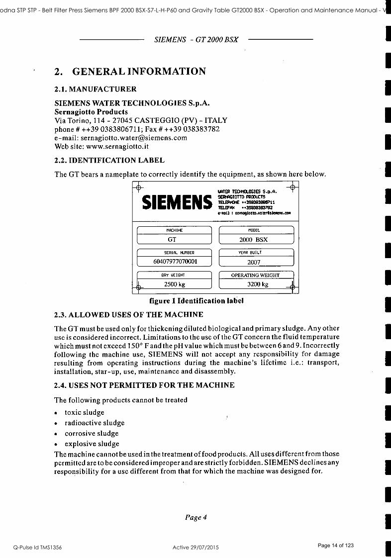
2.2. IDENTIFICATION LABEL
The GT bears a nameplate to correctly identify the equipment, as shown here below.
WITS/ TECFMOLOCIE$ S.P.A.
TELEPHONE SIEMENS TELEF 398383837821 e-reil s eemegiotto.eeeeleiuene.oa
-+
MACHINE
GT
SERIAL NUMBER
60407977070001
DRY WEIGHT
2500 kg
MODEL
2000 BSX
YEAR BUILT
2007
OPERATING WEIGHT
3200 kg
figure 1 Identification label
2.3. ALLOWED USES OF THE MACHINE
The GT must be used only for thickening diluted biological and primary sludge. Any other use is considered incorrect. Limitations to the use of the GT concern the fluid temperature which must not exceed 150° F and the pH value which must be between 6 and 9. Incorrectly following the machine use, SIEMENS will not accept any responsibility for damage resulting from operating instructions during the machine's lifetime i.e.: transport, installation, star -up, use, maintenance and disassembly.
2.4. USES NOT PERMITTED FOR THE MACHINE
The following products cannot be treated
toxic sludge radioactive sludge corrosive sludge explosive sludge
The machine cannot be used in the treatment of food products. All uses different from those permitted are to be considered improper and are strictly forbidden. SIEMENS declines any responsibility for a use different from that for which the machine was designed for.
Page 4
ST41 Goodna STP STP - Belt Filter Press Siemens BPF 2000 BSX-S7-L-H-P60 and Gravity Table GT2000 BSX - Operation and Maintenance Manual - Vendor Manual
Q-Pulse Id TMS1356 Active 29/07/2015 Page 14 of 123

SIEMENS - GT 2000 BSX
2.5. GENERAL SAFETY INSTRUCTIONS
At the moment of using the machine, we recommend that the legal regulations in operation in the country in which the machine is installed are strictly followed. It is the responsibility of the proprietor to maintain and use the machine and components supplied by SIEMENS in a manner compatible with the laws for health and safety of the operator.
Attention : The safety must be considered as a basic component for the functioning of the machine for all phases of its life. Adopting appropriate measures of safety and use prevents the risk of incidents and damage to operators. Here is a list of basic safety indications:
For safety means it is advisable to adopt a program of training of personnel and a program of ordinary and extraordinary maintenance. The personnel proposed should be advised of the location and the functioning of the devices for safety and emergencies. The machine can only be used after controlling that all the safety devices are in position and are securely fixed. In the event of inspection, maintenance and installation, be sure that the motors have been stopped by the control panel and its restart is blocked. The operator can only be restarted after the guards and safety devices are in place. The voltage of the electrical motor can cause risk to personnel , and can cause permanent damage. We recommend to use only qualified personnel for the installation, operation and maintenance. Install the machine in an ambient with an ideal lighting. Do not overload the machine or use it for different uses from which it was designed.
Page 5
ST41 Goodna STP STP - Belt Filter Press Siemens BPF 2000 BSX-S7-L-H-P60 and Gravity Table GT2000 BSX - Operation and Maintenance Manual - Vendor Manual
Q-Pulse Id TMS1356 Active 29/07/2015 Page 15 of 123

3. STORAGE
SIEMENS - GT 2000 BSX
In the event that the GT is not immediately installed, it is necessary to.
Store in a closed location, protected from bad weather conditions. The minimum temperature should not be less than 40 °F and the relative humidity should be less than 70 %. Low temperature can damage the rolls covering. Avoid the direct exposition to sunlight especially for the rolls covering. The electric motor has to be protected with particular care regarding the formation of condensation. In particular every 3 -4 months, dismantle the motor cover up and turn manually the fan for at least 20 turns. When finished close and put the protection covers in place. The motor reducer should be kept filled with lubricant as is usually supplied. In any case, we recommend that verification of the level and the filling up if required. The cushions, located in the roll support have to the greased and rotated at least one time per month to avoid any possibility of the accumulation of condensation that could compromise the efficiency. We recommend particular attention to the conservation of the accessories sent separately and listed in the expedition documents.
Page 6
ST41 Goodna STP STP - Belt Filter Press Siemens BPF 2000 BSX-S7-L-H-P60 and Gravity Table GT2000 BSX - Operation and Maintenance Manual - Vendor Manual
Q-Pulse Id TMS1356 Active 29/07/2015 Page 16 of 123

SIEMENS - GT 2000 BSX
4. PROCESS DESCRIPTION GT is a gravity table for biological and primary sludge thickening. It works according to the principle of continuous mechanical filtration. The dewatering process takes place exclusively for gravity.
Polyelectrolyte solution
Dilueted sludge
Direction of belt movement
Plows
Filtrate Washing water
Cake
figure 2 Description of the process The filtration of the biological sludge is performed after conditioning the material to be thickened with agglomerative substances (e.g. polyelectrolyte). The special configuration of the sludge inlet box allows a uniform distribution of the sludge on the belt. During the movement of the belt along the gravity zone, the liquid separated from the sludge particles passes through the polyester filtering belt, while the solids thicken at the end of the gravity zone. The drainage of the liquid is improved by the action of the plows and of the sludge levelling plate. The thickening plows allow sludge opening, so that water can drain without stagnation on sludge surface. The sludge levelling plate makes easier the drainage of water in the final part of the gravity zone, just before the discharge of the cake. By regulating the levelling plate an increase of the cake dryness can be obtained. The cake of thickened sludge is removed by the doctor blade, that is in contact with the belt surface. The sludge discharge box, connected to the side skirts, prevents any lateral loss of the cake. The liquid passing through the belt falls into the collecting tray. Bars of HDPE material placed under the belt avoid the adhesion of liquid to the belt due to viscosity, breaking the superficial tension. The side skirts prevent the material from running out of the belt. Before returning to the gravity zone, the belt is cleaned by means of the nozzles contained in the washing box. The nozzles spray pressured water on the belt surface removing the solid particles. The washing box is placed in the descending part of the belt. A rotating brush removes the particles which can clog the nozzles. The parameters which affect the Gravity performance are:
the inlet sludge concentration the sludge flow the polyelectrolyte dosing the belt speed.
The sludge concentration affects both the cake dryness and the sludge flow that the machine car treat. As the sludge flow increases, the cake dryness tends to decrease. A
Page 7
ST41 Goodna STP STP - Belt Filter Press Siemens BPF 2000 BSX-S7-L-H-P60 and Gravity Table GT2000 BSX - Operation and Maintenance Manual - Vendor Manual
Q-Pulse Id TMS1356 Active 29/07/2015 Page 17 of 123

SIEMENS - GT 2000 BSX
suitable polyelectrolyte dosing in necessary to maintain the performance of the machine. This parameter is related to the sludge quality (TS concentration, VS concentration). The belt speed has a clear influence on the sludge flow and the cake dryness. Increasing the speed reduces the time the sludge is kept on the filtering surface. In these conditions the cake dryness tends to decrease while, on the contrary, the sludge flow tends to increase.
Applications
The GT is used to thicken diluted biological or primary sludge from wastewater treatment plants. Any other use is considered incorrect. The main areas of use of the GT are listed below:
sludge from municipal treatment plants sludge from paper industry wastewater treatment plants
The GT is equipped with covers which ensure adequate protection from the moving parts.
NOTE: safety covers cannot be removed when the machine is in operation. The GT is a standard machine, which is not designed to be installed in hazardous areas where gas or explosives atmosphere could be present.
Page 8
ST41 Goodna STP STP - Belt Filter Press Siemens BPF 2000 BSX-S7-L-H-P60 and Gravity Table GT2000 BSX - Operation and Maintenance Manual - Vendor Manual
Q-Pulse Id TMS1356 Active 29/07/2015 Page 18 of 123

!
1
1
1
SIEMENS - GT 2000 BSX
5. IDENTIFICATION OF THE BLOCKS
19
.iAli+!üavüiaiiA::.a..a.+ia
*, /Ill -
I
I
I
_._
L -i-J1
\ II I
I I
I I
I
I I
il
_.11- I II
I
I
I,
I I I
I II
I
.-. I I
I 'i
I
I I
' I. 11
I
1I LJ i I
i I
'I
1
I I
i
i
I
..--
I - Hl. .
,;
I
II
r
r , ---
I
'
I
, -- . _.._ r. m - i:
_ - . .. - _ -- . ; _ -..__. .
üIiÄü !mum'
figure 3 Identification of the blocks
Page 9
ST41 Goodna STP STP - Belt Filter Press Siemens BPF 2000 BSX-S7-L-H-P60 and Gravity Table GT2000 BSX - Operation and Maintenance Manual - Vendor Manual
Q-Pulse Id TMS1356 Active 29/07/2015 Page 19 of 123

SIEMENS - GT 2000 BSX
Pos. Description Pos. Description
1 Belt 13 Drive roll 2 Sludge retention tank 14 Doctor blade 3 Sludge discharge box 15 Pneumatic control devices 4 Gravity zone 16 Belt overtravel sensor (limit switch) 5 Frame 17 Safety stop limit switches 6 Collecting tray 18 Gravity zone skirts 7 Tensioning roll 19 Sludge leveller 8 Belts tensioning device 20 Chicane 9 Belt washing box 21 Belt tracking roll 10 Sensor paddle 22 Belt spray pipe 11 Belt tracking device 12 Belt Drive
This machine consists of:
Belt (1)
The belt is made of plastic fabric. The filtering capacity varies depending on the type of product to be treated. Sludge retention tank (2)
The inlet box, made of stainless steel, consists of a chamber that provides turbulence so that the polyelectrolyte can react with the sludge.
Sludge discharge box (3)
This box, located at the end of the gravity zone, avoids sludge splashing when the sludge .
is discharge on the receiving system. Gravity zone (4)
The dehydration of the product takes place using only the force of gravity; most interparticle liquids drain through the belts. The pressure forces in this area are around a
few milli p.s.i. The belt winds around 3 parallel rolls: a belt tracking roll (21), a drive roll (13) and a tensioning roll (7). The drive roll and the tensioning roll form an horizontal table (gravity zone). Under the belt, in the gravity zone, HDPE bars are placed in order to facilitate the liquid drainage. The rolls consist of very thick seamless pipes and rotate on self aligning bearings. All the rolls are coated with BUNA rubber. The housing of the roll bearings are made of cast iron. Frame (5)
The frame is realized with UPN beams connected by crossbars. The particular design of the frame allows minimum stress and deflection that is necessary to guarantee high performances. In the standard version the frame is protected through hot dip galvanizing. Collecting tray (6)
This is made of stainless steel and bolted to the frame for collecting the filtrate coming from the sludge thickening and they convey it to the drains. Belts tensioning device (8)
The GT is provided with a belt tensioning device. This device supplies the necessary force to maintain the belt in tension. Belt washing box (9)
The washing box consist of two stainless steel halves boxes, equipped with a spray pipe (22) provided with spray nozzles and with an internal cleaning brush externally operated
Page 10
1
1
ST41 Goodna STP STP - Belt Filter Press Siemens BPF 2000 BSX-S7-L-H-P60 and Gravity Table GT2000 BSX - Operation and Maintenance Manual - Vendor Manual
Q-Pulse Id TMS1356 Active 29/07/2015 Page 20 of 123

SIEMENS - GT 2000 BSX
through an handwheel. The spray pipe, supplied by pressured water, removes the solids that pass through the belt. The connection to the hydraulic supply system should be carried out through a hose that can be supplied under request.
Belts tracking device (11)
This is a pneumatically supplied device that maintain the belt in a centered position in respect to the rolls center line. If the belt deviates from a central position, a sensor paddle (10) activates the tracking roll bringing the belt back into the correct working position.
Drive (12)
This is made of an electrical motor and a gearbox. The speed variation is obtained through an inverter (VFD, not included in the standard supply) and therefore possible only when the machine is in operation.
Doctor blades (14)
The doctor blade remove the sludge from the belt in correspondence to the drive roll (13). A system of counterweights provides the necessary loads to the blade to scrape the roll. Beside this device another is provided for cleaning the tensioning roll (7).
Pneumatic control (15)
Installed on board and includes all the instruments necessary to control and provide the pneumatic energy necessary to operate the belt tracking device.
Belt over travel proximity switches (16)
These switches stop the machine in case the belt slips sideways beyond a safety value factory adjusted.
Safety stop limit switches (17)
These safety limit switches can be manually activated pulling the wire located on each side so that the machine can be stopped in case of emergency.
ATTENTION: the electrical control panel of the GT (not supply by SIEMENS) must be equipped with a local reset push button to be activated in case of the intervention of these switches.
Sludge leveller (19) and skirts (18)
The sludge leveller is made of bent St.St. sheet assembled transversally to the belt, at the end of the gravity zone. The side skirts (18) are made of bent St.St. sheet and are equipped with anti wear synthetic seals.
Chicane (20)
These are made of elements called `plows' that gently remove the sludge, scraping the belt in gravity zone, to enhance the solid -liquid separation increasing the efficiency of the drain.
Page 11
ST41 Goodna STP STP - Belt Filter Press Siemens BPF 2000 BSX-S7-L-H-P60 and Gravity Table GT2000 BSX - Operation and Maintenance Manual - Vendor Manual
Q-Pulse Id TMS1356 Active 29/07/2015 Page 21 of 123
SIEMENS - GT 2000 BSX
6. SAFETY DEVICES
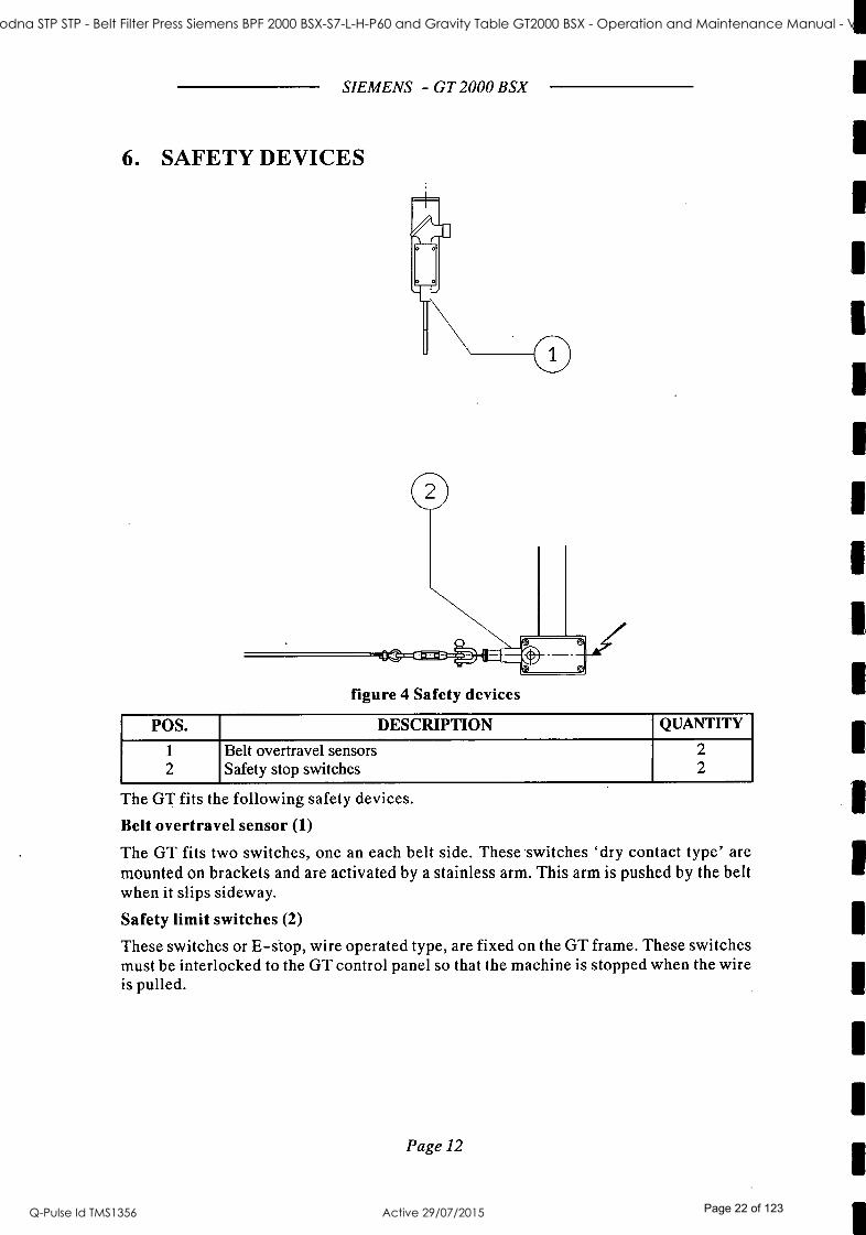
figure 4 Safety devices
POS. DESCRIPTION QUANTITY
1
2 Belt overtravel sensors Safety stop switches
2 2
The GT fits the following safety devices.
Belt overtravel sensor (1)
The GT fits two switches, one an each belt side. These switches `dry contact type' are mounted on brackets and are activated by a stainless arm. This arm is pushed by the belt when it slips sideway.
Safety limit switches (2)
These switches or E -stop, wire operated type, are fixed on the GT frame. These switches must be interlocked to the GT control panel so that the machine is stopped when the wire is pulled.
Page 12
1
ST41 Goodna STP STP - Belt Filter Press Siemens BPF 2000 BSX-S7-L-H-P60 and Gravity Table GT2000 BSX - Operation and Maintenance Manual - Vendor Manual
Q-Pulse Id TMS1356 Active 29/07/2015 Page 22 of 123

SIEMENS - GT 2000 BSX
7. TECHNICAL DATA
Weight of the machine (empty) : 2500 kg
Weight of the machine (working) : 3200 kg
Dimensions (L, H, W) : 4700x1300x3130 Belt dimensions (LxW) : 2100x9080 mm
Belt speed : 5.3 -20 m /min (20 -75 Hz by VFD) Water pressure for belt washing : 6 bar Water consumption for belt washing : 8.7 m3 /h Air pressure : 6 bar Air consumption : 5 Nm3 /h Belt motor power :2.2 kW Power supply : 415V 50Hz 3 phase Noise level : < 85 dB(A)
7.1. ENVIRONMENT FOR THE INSTALLATION OF THE MACHINE
The GT is designed and constructed to be installed in a normal environment. We recommend that the machine is not used in areas or environments considered dangerous for the presence of gas or explosive power or corrosive substances. In the case that the machine has to be installed in dangerous environments, consider that the motors, electrical supply, etc. are not constructed to be installed and operated in these conditions. In these circumstances we recommend that, to avoid any inconvenient, you consult directly to SIEMENS. In the event that GT is not immediately installed:
1) Store in a closed location, protected from bad weather conditions. The minimum temperature should not be less than 40° F and the relative humidity should be less than 70 %. Low temperature can damage the rolls covering.
2) Avoid the direct exposition to sunlight especially for the rolls covering. 3) The electric motor has to be protected with particular care regarding the formation
of condensation. In particular every 3 -4 months, dismantle the motor cover and turn manually the fan for at least 20 turns. When finished close and put the protection covers in place.
4) The gearbox should be kept filled with lubricant as is usually supplied. In any case, we recommend that verification of the level and the filling up if required.
5) The bearings, located in the roll housing have to the greased and rotated at least one time per month to avoid any possibility of the accumulation of condensation that could compromise the efficiency.
6) We recommend particular attention to the conservation of the accessories sent separately and listed in the expedition documents.
Page 13
ST41 Goodna STP STP - Belt Filter Press Siemens BPF 2000 BSX-S7-L-H-P60 and Gravity Table GT2000 BSX - Operation and Maintenance Manual - Vendor Manual
Q-Pulse Id TMS1356 Active 29/07/2015 Page 23 of 123

SIEMENS - GT 2000 BSX
8. HANDLING AND TRANSPORT In the phase of handling, the GT has to be lifted with cables or chains, using a crane in order to render the operation secure for the operators and for the structural integrity of the machine. For the lifting an adjustable four points hooking should be used. From the motor side shorten the chain to ensure that the machine is lifted perfectly horizontally.
The correct machine hooking is depicted in figure 5. The lifting cables or chains must be hooked to the lugs welded on the upper part of the machine, at the for corners.
The position of the lugs is shown in figure 5. It is necessary to verify the compatibility of the weight of the machine and the maximum load that can be lifted by the crane.
For a safety transport in addition verify that the load does not exceed the maximum value that is recommended for the means of transport that you wish to use. The machine should be positioned on the platform of the means of transport, at an equal distance from the sides and should be fixed with steel cables to ensure the necessary stability during transport.
The lifting must be carried out using a crane, or a means of lifting fitted with a mobile arm of a homologated type. SIEMENS disclaim any responsibility for damage to people or the machine due to the use of lifting equipment of any other type.
Page 14
ST41 Goodna STP STP - Belt Filter Press Siemens BPF 2000 BSX-S7-L-H-P60 and Gravity Table GT2000 BSX - Operation and Maintenance Manual - Vendor Manual
Q-Pulse Id TMS1356 Active 29/07/2015 Page 24 of 123

SIEMENS - GT 2000 BSX
ATTENTION: as a function of the weight reported adopt the means of lifting most suitable in order to allow the maximum safety for the personnel involved. Before starting the operation, make sure that the personnel involved are competent.
figure 5 Handling
Page 15
ST41 Goodna STP STP - Belt Filter Press Siemens BPF 2000 BSX-S7-L-H-P60 and Gravity Table GT2000 BSX - Operation and Maintenance Manual - Vendor Manual
Q-Pulse Id TMS1356 Active 29/07/2015 Page 25 of 123
SIEMENS - GT 2000 BSX
9. ASSEMBLY AND INSTALLATION The preparation of the foundation plate to bear the GT are not included in the SIEMENS supply and must be provided by the user and must be completed before the delivery of the machine. The user is responsible for the preparation of the foundation pad, the electrical connections and the planning of the space necessary for operation and maintenance of the machine.
9.1. CHOICE OF THE LOCATION WHERE THE MACHINE IS INSTALLED
The machine should be installed in a room sufficiently large to allow the operation of maintenance and cleaning in a safety manner. Allow at least a distance of lm on all sides of the machine plus the room necessary for belt replacement. In the event that other machines are installed in the area, locate the GT in such a manner to eliminate possible interference.
9.2. POSITIONING
The GT requires a fixed positioning by anchoring to the foundation. The following are required; a concrete pad or equivalent depending on the dimensions shown on the drawing of the foundation supplied within. The handling of the GT for the positioning on the foundation should be carried out using a mobile or fixed crane depending on the access to the area. The choice of crane should be based on the dimensions and weight indicated in the drawing with technical data included within. We recommend the use a lifting equipment with a loading capacity (at full arm) at least 20% greater then the GT. The lifting, using cables or chains, must be carried out using exclusively the lugs provided as shown in the figure. Adjust the length of the cables or chains to maintain the load centered and to avoid dangerous unbalancements. In the event that a crane is not available, or that the dimension of the area does not allow the use of a crane, the GT can be moved along a flat surface using trolleys or sliding rollers. If this solution is adopted do not pull or push the GT using force applied on a foot or sustaining column. Apply pushing or pulling force using the lifting lugs or distribute the force on the frame of the means of wood table.
ATTENTION: After positioning the GT on the relevant foundation plate and before fixing the baseplates it is necessary to verify the levels of the GT and of the inlet box. This control must be carried out using a spirit level with a grade of precision of 0.004 inch /foot. The bubble level should be positioned at the summit of the tensioning roll (fig 5 pos 1) or on the drive roller (fig 5 pos 3) and on the frame (fig 5 pos 2). The maximum value of dislevel acceptable is 1 notch per foot of the total length considered. If necessary use shims. Do the same for the inlet box.
Page 16
ST41 Goodna STP STP - Belt Filter Press Siemens BPF 2000 BSX-S7-L-H-P60 and Gravity Table GT2000 BSX - Operation and Maintenance Manual - Vendor Manual
Q-Pulse Id TMS1356 Active 29/07/2015 Page 26 of 123
SIEMENS - GT 2000 BSX
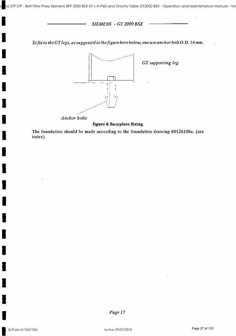
To fix to the GT legs, as suggested in the figure here below, one use anchor bolt O.D. 16 mm.
GT supporting leg
Anchor bolts figure 6 Baseplate fixing
The foundation should be made according to the foundation drawing 60126106a. (see index)
Page 17
ST41 Goodna STP STP - Belt Filter Press Siemens BPF 2000 BSX-S7-L-H-P60 and Gravity Table GT2000 BSX - Operation and Maintenance Manual - Vendor Manual
Q-Pulse Id TMS1356 Active 29/07/2015 Page 27 of 123

10. CONNECTIONS
SIEMENS - GT 2000 BSX
With reference to the enclosed figure, the GT is supplied with the following connections:
Pos Description Q.ty Type Needs
1 Product inlet 1 Flange 150 NB PN10
2 Compressed air inlet supply 1 1/4" GAS Female 5 Nm3 /h
3 Belts wash water inlet 1 2" GAS male 8,7 m3 /h
4 Belts wash water outlet 2 PIPE 75 O.D. -
5 Electric motor 1 Cable gland
6 Filtrate discharge 2 PIPE 160 O.D. -
7 Discharge produced cake 1
8 Wash water pipe outlet 1 PIPE 50 O.D.
9 Auxiliary terminal box 1 Cable gland -
10 Sludge tank drain outlet 1 PIPE 50 O.D.
See figure 7.
Before proceeding with the connections it is necessary to verify that:
the pipes have suitable diameter and thickness; the conveyor placed after the GT are able to remove all the cake;
the ducting pipes are equipped with adequate devices for the interception and sectioning for the operations of maintenance and washing; the washing water flow has the capacity and pressure required; the water for belt washing is effectively "clean ";
Further instructions can be found in the following section "CONNECTIONS AND REGULATIONS ".
Page 18
1
1
ST41 Goodna STP STP - Belt Filter Press Siemens BPF 2000 BSX-S7-L-H-P60 and Gravity Table GT2000 BSX - Operation and Maintenance Manual - Vendor Manual
Q-Pulse Id TMS1356 Active 29/07/2015 Page 28 of 123

1
t 1
1
1
1
SIEMENS - GT 2000 BSX
*, 1
;
1
I i
I
, I
.
I I;
I
i i
I I
I I
I I
I
1
''
i
1
I
, I
I
I
11
Ì
i
!
'
,
I
I
J$
1
¡ I
I
;;
i1 I
1
i ;
I
I II. _11 II I ln
r
1
,
i
I
I¡
I;
II
ü U}LI
figure 7 Summary of the connections
Page 19
ST41 Goodna STP STP - Belt Filter Press Siemens BPF 2000 BSX-S7-L-H-P60 and Gravity Table GT2000 BSX - Operation and Maintenance Manual - Vendor Manual
Q-Pulse Id TMS1356 Active 29/07/2015 Page 29 of 123

SIEMENS - GT 2000 BSX
11. CONNECTIONS AND REGULATION 11.1. ELECTRICAL CONNECTIONS
The connections should be carried out following the attached electrical diagram. Before proceeding it is necessary to perform the following controls:
The section of the cables should be adequate for the installed power. The GT must be earthed. The three -phase voltage is correct. The voltage and frequency of the power available are in accordance with the data on the plate of the electrical motors. The main control circuit is fitted with adequate protection devices and they are functioning efficiently.
CONNECTIONS TO THE TERMINAL BOARD All the electrical devices on board mounted, except for the motor, are wired to a single junction box (terminal board). The cables from the control panel should be connected to the above mentioned terminal board. The minimum cross -section recommended for the cables is AWG 16.
CONNECTION OF THE BELT MOTOR The power cables of the electrical motors should be connected to the relevant junction boxes of the motor. The dimension of the cables should be based on the nominal currents of the motor and on the distances from the control panel.
EARTHING The earthing of the machine should be carried out on the basement or the frame using the special screws shown on the relative plate. The choice of the conductor must respect the laws and regulations of the country where the machine in installed.
Proceed with the connections. The electrical motors must be directly connected. Before starting up the machine it is necessary to:
verify the action of the security devices by manual activating when the machine is stopped. verify the correct direction of rotation of the electrical motors, using power impulses, as in the sense indicated by the adhesive arrows.
WARNING: Pay particular attention to the presence of foreign bodies before starting up the GT.
verify the functioning of the GT with respect to the logic or the sequence of the plant to which it belongs.
11.2. PNEUMATIC CONNECTIONS AND REGULATION
These should be realized on the pneumatic panel installed at the side of the machine. Before proceeding verify the following:
the source of compressed air must guarantee a minimum flow of clean air of 8 Nm3 /h. at a minimum pressure of 6 bar. the production system for the compressed air should be fitted with an oil separator and an anti -condensation filter with automatic discharge. the existence of a pressure gauge, on the supply line, to allow the control of the value supplied.
Page 20
ST41 Goodna STP STP - Belt Filter Press Siemens BPF 2000 BSX-S7-L-H-P60 and Gravity Table GT2000 BSX - Operation and Maintenance Manual - Vendor Manual
Q-Pulse Id TMS1356 Active 29/07/2015 Page 30 of 123

SIEMENS - GT 2000 BSX
Next continue with the connection: Connect the line to the pos. 1. We recommend a 10 /8mm hose with single head junctions. Verify the oil level in the lubricator (3). If necessary top up with PARKER oil, for pneumatic components or an equivalent. The quantity of oil (drops per minute) can be regulated during operation by adjusting the screw (3) accordingly. The number of drops can be checked through the sight -glass. The oil level in the fag lubricator should not exceed the relevant mark and should be replenished before the minimum level is reached. Lift and rotate clockwise the knob for regulating the pressure (4). Set the working pressure on the belts tracking device at 3 BAR. The pressure switch (5) is factory set at 2.5 BAR. To provide an alarm in case of pressure drop.
w ir a o -- _::_: rli- ii- m '°- `' mi AIR INLET /
TO THE BELT
TRACKING DEVICE
figure 8 Pneumatic connections
11.3. REGULATION OF THE BELT DRIVE
BELT DRIVE As previously explained, the belt drive consists of an electrical motor (1) and an oil filled gearbox (2). Usually the gearbox are supplied filled with oil. Anyhow, before starting, we recommend to verify the level. See the maintenance chapter. The speed adjustment is possible only through a VFD (VFD not included in the standard supply). The expected speed range varies from 5.3 (20 Hz) to 20 (75 Hz) m /min. We recommend the installation of an inverter with a nominal power greater than power indicated on the nameplates of the motor. The drive is connected to the drive roll. WARNING: The starting up of the belt drive is allowed only after the belt tensioning.
Since the electric motor is not equipped with an independent cooling fan do not operate the machine below the specified minimum speed.
Page 21
ST41 Goodna STP STP - Belt Filter Press Siemens BPF 2000 BSX-S7-L-H-P60 and Gravity Table GT2000 BSX - Operation and Maintenance Manual - Vendor Manual
Q-Pulse Id TMS1356 Active 29/07/2015 Page 31 of 123

SIEMENS - GT 2000 BSX
IL
1
J 7_-. '4:
- ----- ----...-.-._ I
í : :,'
figure 9 Belt drive The use and maintenance instructions of the drive are contained in appendix.
11.4. HYDRAULIC CONNECTIONS
BELT SPRAY PIPE The machine is supplied with hose for washing the belt complete with threaded joints 2" BSP male. Plan the ducting piping considering the following data:
Washing water flow: 8.7 m3 /h Washing water pressure: 6 BAR
We recommend to install, on the supply line, a pressure gauge to control the supply pressure and an intercept valve. The inlet is made of an hose to allow the adjustment of the washing box position which has to be centered with respect to the belt.
DISCHARGE PIPES FOR BELT CLEANING WATER
Control that: the diameter of the pipe is equal to 75 mm.
then: connect the discharge pipe using a hose; connect the discharge to a collecting system.
After the connection and adjustment, start the water flow into the spray pipe and activate the machine for about half an hour. In the mean time it is recommended that the water is left flowing in the sludge pipeline to clean the whole system.
In addition control that: the pipes have a suitable diameter; the conveyor below the machine are able to remove completely the cake produced.
Then: Pipe for feeding sludge into the inlet tank (not supplied): We recommend to place the pipe with a slight inclination (1 -2 %) from horizontal in the sense of transport and fit a discharge valve at the lowest points. To clean the tube it is necessary to fit a joint on the side of the sludge pump, after the intercept /inlet valve for the product to be treated.
Page 22
t
1
1
t
ST41 Goodna STP STP - Belt Filter Press Siemens BPF 2000 BSX-S7-L-H-P60 and Gravity Table GT2000 BSX - Operation and Maintenance Manual - Vendor Manual
Q-Pulse Id TMS1356 Active 29/07/2015 Page 32 of 123

SIEMENS - GT 2000 BSX
The cleaning of the pump and of the pipes starts after the valve that intercepts the product has been closed and clean water has entered into the tube. Then open the discharge stop valves placed on the lowest side of the tube to empty it.
Pipes for flocculation (not supplied): The flocculant must be added before entering the inlet tank. The type of flocculant, depends on the type of sludge to treat. Cake discharge: It is necessary to provide a conveyor for the dehydrated material. Filtrate discharge: The filtrate is collected in the trays located under the machine and is discharged through the drainage tube located on both sides.
11.5. BELT TENSIONING
The tension of the belt is achieved by a couple of stainless steel racks partially housed in sliding guides. Each rack is manually adjustable through a tie rod to provide the axial trust to the tensioning roll.
Before starting up the machine the belt must be tensioned as per the following instructions:
loose the nut A tight the nut B so that the rack C push out the tensioning roller. repeat the same regulations an the apposite rack so that the belt is tensioned.
WARNING: take care that the distance "x" are equal on both sides to ensure that the tension roller is parallel to others.
4 x RIGHT =LEFT O
figure 10
11.6. ADJUSTMENT OF BELTS CENTERING DEVICE
Working principle The pneumatically activated system includes a sensor paddle (1) with a distributor or a 3
way pneumatic valve (2) that checks the position of the belt (3) feeding the pneumatic cylinder (4) that, in its turn, moves the centering roll (5) in such a way to maintain the position of the tracked belt according to the position of "zero" or "neutral" of the pneumatic valve itself (2).
Page 23
ST41 Goodna STP STP - Belt Filter Press Siemens BPF 2000 BSX-S7-L-H-P60 and Gravity Table GT2000 BSX - Operation and Maintenance Manual - Vendor Manual
Q-Pulse Id TMS1356 Active 29/07/2015 Page 33 of 123

SIEMENS - GT 2000 BSX
o o ©
I o II
%,ï III ,J. I I l_ i.IC__ o
figure 11 Working principle
How to verify the correct installation. When the paddle of the valve touches the belt and has an inclination of 22, both the cylinder chambers are supplied with the same pressure. To correct or adjust this inclination it is necessary to slide the driving bars (6). ATTENTION: in this position, called "zero" or "neutral" position, the pneumatic cylinder (4) must be stationary (not fed).
figure 12 Correct installation Start -up and checks
Carry out the following checks before undertaking the starting up:
the oil in the lubricator situated in the pneumatic cabinet is at the maximum level. the belts centering reducer is adjusted in such a way that the corresponding pressure gauge indicates 3 BAR.
the pneumatic connections between the paddle distributor or tester and the cylinders are correct as shown in the figure.
figure 13 Starting up and checks
Verify the functioning of the slide as follows: by moving the paddle away from the belt the slide goes in one direction (until it reaches the end of stroke) and also by pushing the paddle towards the belt this occurs but with a slide shift in the opposite direction. The slide movement must take place when a side - shifting of the belt that causes a paddle inclination of 5 is simulated. To verify whether the pneumatic connections are correct:
Page 24
ST41 Goodna STP STP - Belt Filter Press Siemens BPF 2000 BSX-S7-L-H-P60 and Gravity Table GT2000 BSX - Operation and Maintenance Manual - Vendor Manual
Q-Pulse Id TMS1356 Active 29/07/2015 Page 34 of 123

SIEMENS - GT 2000 BSX
figure 14 System behavior
Assuming that the belt slides from left to right and that the sensor paddle and the pneumatic slide are assembled on the same side of the BPF (FS side), pushing the paddle towards the belt the end of the centering roll supported by the pneumatic slide must move towards the left. Obviously the observation point must be from the FS side. The three figures show the system behavior in the three possible positions which are respectively: belt shifting towards the right, centered position of non -intervention and belt shifting towards the left. If the results of the system are the opposite then the position of the incoming pipes on the pneumatic cylinder must be inverted.
the belts must be properly wet with water the motor rolls must be moving dragging the corresponding belts.
If the two belts do not move perfectly overlapping and at the center of the motor rolls (leaving uncovered equal surfaces of rubber on the two ends of the rolls) it is necessary to undertake the following steps:
loosen the clamping screws of the supporting bars (6) of the pneumatic valve (2) slide the valve (2) towards the part where we want to move the belt forwards or backwards.
The width of the forwards or backwards shift must be EQUAL to the one required by the belt to move to the optimal position. The belts are perfectly centered. Once the belts are centered the guide of the centering roll must stop in the central position.
11.7. ADJUSTMENT OF DOCTOR BLADES
Verify that: The doctor blades are aligned with the belts surface and subjected to an uniform pressure.
figure 15 Doctor blades positioning To adjust the alignment it is necessary:
Loosen the screws (3) that block the blade.
Page 25
ST41 Goodna STP STP - Belt Filter Press Siemens BPF 2000 BSX-S7-L-H-P60 and Gravity Table GT2000 BSX - Operation and Maintenance Manual - Vendor Manual
Q-Pulse Id TMS1356 Active 29/07/2015 Page 35 of 123

SIEMENS - GT 2000 BSX
Manually push the blade- carrier so that the doctor blade (1) lies uniformly on the belt. Tighten the screws (3).
To adjust the pressure or working load: Loosen the grains (2) so that the counterweights can run freely. Position them in the direction to increase or decrease of the lever arm depending on whether you wish to increase or reduce the pressure exerted on the blade. Tighten the grains (2).
We advise you to maintain the counterweights in a centered position with respect to the supporting arms.
WARNING: do not overload the blades to avoid short lifetime and belt seam damage.
DOCTOR BLADE FOR TENSIONING ROLL
Beside these device another is provided for cleaning the tensioning roll. To adjust the alignment it is necessary:
Loosen the screws (6) that hold the blade. Manually push the blade so that the doctor blade (5) lies uniformly on the roll. Tighten the screws (6).
figure 16 Doctor blades adjustment
Page 26
ST41 Goodna STP STP - Belt Filter Press Siemens BPF 2000 BSX-S7-L-H-P60 and Gravity Table GT2000 BSX - Operation and Maintenance Manual - Vendor Manual
Q-Pulse Id TMS1356 Active 29/07/2015 Page 36 of 123

SIEMENS - GT 2000 BSX
11.8. CONNECTIONS AND ADJUSTMENT OF BELTS WASHING BOXES
Preliminary verifications: The position of the extended belt must be perfectly centered, in the middle with respect to the seals (5) without touching metallic parts. The spraying water must be clean and must have a the required pressure and flow. The nozzles (2) are perpendicularly oriented towards the belt. The seals (5) are in the right place.
Washing box adjustment: Loosen the clasping screws (6) on the bracket (7). Let the box itself run in height so that the seals (5) are perfectly centered compared to the belt. Tighten the screws (6).
This operation is necessary when water leaks or overflows occur through the seals (5).
Spray pipe position adjustment: Slightly open the clamps (9) loosening the screws (8). Rotate the pipe (4) so that the nozzles are perpendicular to the belt. Tighten the screws (8).
Nozzles cleaning: The washing pipes supplied are provided with an internal brush (3) to clean the nozzles (2). The cleaning operation must be carried out during the washing phase.
Turn counter clockwise the hand wheel (11), that controls the internal brush (3), to open the discharge valve (10) located inside the pipe until the handwheel stops. The removed particles are cleared out with the same water flow and are discharged to the water outlet, at the side of the handwheel. Turn clockwise the handwheel (11) until the inside valve (10) is closed and make sure that the reference notches (12) are aligned.
Page 27
ST41 Goodna STP STP - Belt Filter Press Siemens BPF 2000 BSX-S7-L-H-P60 and Gravity Table GT2000 BSX - Operation and Maintenance Manual - Vendor Manual
Q-Pulse Id TMS1356 Active 29/07/2015 Page 37 of 123

SIEMENS - GT 2000 BSX
PIPE C.L.
NOZZLES POSITIONING DETAIL
figure 17 Connection and regulation of the belts wash box
Page 28
ST41 Goodna STP STP - Belt Filter Press Siemens BPF 2000 BSX-S7-L-H-P60 and Gravity Table GT2000 BSX - Operation and Maintenance Manual - Vendor Manual
Q-Pulse Id TMS1356 Active 29/07/2015 Page 38 of 123

SIEMENS - GT 2000 BSX
11.9. BELT INSTALLATION /REPLACEMENT Before assembling or replacing the belt, make sure to:
Activate the procedure for washing the machine. When the clipper seam reaches the right position stop the GT by the safety switch. No foreign matter is present inside the machine The new belt are not damaged Discharge the air pressure from the bellows of the tensioning devices by operating on the discharge valve placed on the pneumatic control cabinet
ATTENTION: The smooth part of the belt must be in contact with the product to treat. This side is marked with the sign while the arrow indicates the running direction. Dimensions must correspond to the original ones.
a) First Installation Lift the chicanes (1) using the handles provided. Lift the doctor blade (3). Disassemble the lower part (4) of the belt- cleaning box. Put the belt (5) on the tensioning roll (6) and let it slide so as to wind it up on the gravity zone (7) until it reaches the motor roll (8). Pull the opposite side so as to make it adhere first on roll 9, until it approaches the opposite side (8). Approach the edges and insert the junction metallic wire. Do not let the wire protrude freely or the wire could damage the doctor blades.
Twist or sew it on the belt side.
ATTENTION: Center the belt with respect to the centerline of the rolls.
Assemble again the disassembled parts following the reverse way.
b) Belt Replacement
Follow the indications reported at the beginning of the paragraph. Stop the machine so that the belt junction is in correspondence to, for example, the motor rolls. Open the belt junction, who needs to be replaced, with a new belt, join one edge with a corresponding one.-Pay attention to the working side and to the sliding direction as previously mentioned in the attached instructions. Start the machine manually at the lowest speed while all the auxiliary devices must not be working. (sludge pump, washing water, etc.). Let it move until the old belt is completely deposited on the floor. Close the seam.
Page 29
ST41 Goodna STP STP - Belt Filter Press Siemens BPF 2000 BSX-S7-L-H-P60 and Gravity Table GT2000 BSX - Operation and Maintenance Manual - Vendor Manual
Q-Pulse Id TMS1356 Active 29/07/2015 Page 39 of 123
SIEMENS - GT 2000 BSX
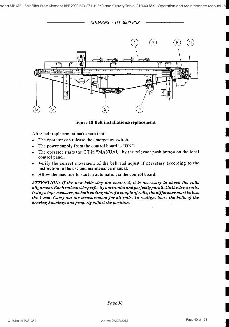
figure 18 Belt installations /replacement
After belt replacement make sure that: The operator can release the emergency switch. The power supply from the control board is "ON ".
The operator starts the GT in "MANUAL" by the relevant push button on the local control panel. Verify the correct movement of the belt and adjust if necessary according to the instruction in the use and maintenance manual. Allow the machine to start in automatic via the control board.
ATTENTION: if the new belts stay not centered, it is necessary to check the rolls alignment. Each roll must be perfectly horizontal and perfectly parallel to the drive rolls. Using a tape measure, on both ending side of a couple of rolls, the difference must be less the 1 mm. Carry out the measurement for all rolls. To realign, loose the bolts of the bearing housings and properly adjust the position.
Page 30
ST41 Goodna STP STP - Belt Filter Press Siemens BPF 2000 BSX-S7-L-H-P60 and Gravity Table GT2000 BSX - Operation and Maintenance Manual - Vendor Manual
Q-Pulse Id TMS1356 Active 29/07/2015 Page 40 of 123
SIEMENS - GT 2000 BSX
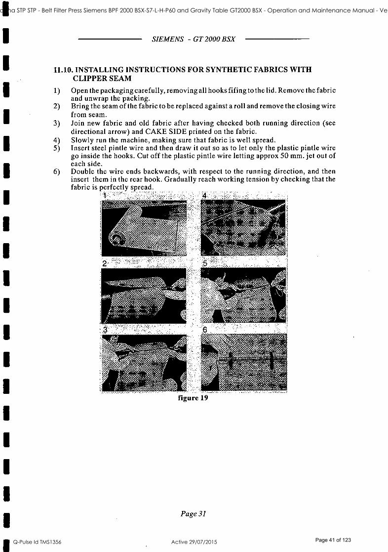
11.10. INSTALLING INSTRUCTIONS FOR SYNTHETIC FABRICS WITH CLIPPER SEAM
1) Open the packaging carefully, removing all hooks fifing to the lid. Remove the fabric and unwrap the packing.
2) Bring the seam of the fabric to be replaced against a roll and remove the closing wire from seam.
3) Join new fabric and old fabric after having checked both running direction (see directional arrow) and CAKE SIDE printed on the fabric.
4) Slowly run the machine, making sure that fabric is well spread. 5) Insert steel pintle wire and then draw it out so as to let only the plastic pintle wire
go inside the hooks. Cut off the plastic pintle wire letting approx 50 mm. jet out of each side.
6) Double the wire ends backwards, with respect to the running direction, and then insert them in the rear hook. Gradually reach working tension by checking that the fabric is perfectly spread.
4
Page 31
ST41 Goodna STP STP - Belt Filter Press Siemens BPF 2000 BSX-S7-L-H-P60 and Gravity Table GT2000 BSX - Operation and Maintenance Manual - Vendor Manual
Q-Pulse Id TMS1356 Active 29/07/2015 Page 41 of 123

SIEMENS - GT 2000 BSX
12. START -UP AND TESTING
12.1. PRELIMINARY CHECKS
Checking tightness of nuts and bolts
The machine bolts are fastened during assembly at the factory using a torque wrench. During transport and handling of the machine it is possible that some loosening of the nuts and bolts may occur. Before starting the machine it is necessary to make a preliminary check of the coupling of the nuts and bolts using a torque wrench.
In order to simplify this operation it is advisable to check:
Roller support bearings Gravity zone skirts and sludge inlet box
Frame joints (base, columns and crossbeams)
Bolt Tightness Check Table
St. St. BOLTS
RESISTANCE CLASS
50 70 80
SIZE TORQUE (Nm) TORQUE (Nm) TORQUE (NM)
M 6x 1.00 3.5 7.3 10 M8x1.25 8.5 18 24 M 10x 1.50 17 36 48 M 12x 1.75 29 62 82 M 16x 2.00 71 152 203 M 20x 2.50 137 293 391 M 24x 3.00 234 502 670
8G GALVANIZED BOLTS
SIZE TORQUE (Nm)
M 1Ox 1.5 50 M 12x 1.75 87 M 16x 2 210 M 20x2.5 412 M 24x 3 710 M27x3 1040 M 30x3:5 1400
The values reported are valid for pressed, rolled and unlubricated bolts for a friction coefficient of 0.14.
Page 32
1
1
1
1
1
1
1
1
ST41 Goodna STP STP - Belt Filter Press Siemens BPF 2000 BSX-S7-L-H-P60 and Gravity Table GT2000 BSX - Operation and Maintenance Manual - Vendor Manual
Q-Pulse Id TMS1356 Active 29/07/2015 Page 42 of 123

SIEMENS - GT 2000 BSX
The resistance class of each screw or bolt is stamped on the head. When replacing any of the machine bolts we recommend the use of anti -seizing grease such as NEVER -SEEZ or equivalent for which it is necessary to reduce the torque by 20% with respect to the values shown above.
ATTENTION: for the support bearings it is necessary to use the values specified reduced by 20 %.
Checks to be performed with the machine stationary After checking the belt tightness continue as explained below with the following operations (all operations to be performed with the machine stationary):
1) Verify that the machine is perfectly level. 2) Make certain that all the following connections are made:
Sludge supply Polyelectrolyte supply Cleaning water supply Electrical power supply Compressed air supply Earth Connection Filtrate discharge system Dehydrated sludge discharge system
3) Ensure that no tools or other objects have been left inside or on the machine. Manually check the belt tension.
4) Manually operate the compressed air supply panel corresponding to the belt to ensure that the distributor and the belt tracking roller are functioning correctly: moving the paddle towards you should cause the piston to move in whilst pushing the paddle away from you should cause it to move out.
5) Check that cleaning water supply is available. 6) Check that the valves on the sludge and polyelectrolyte lines are in the open position. 7) Purge the wash pipe line by running water through the system to drain. Rotate the
spray pipe handwheel to avoid clogging up the nozzles. Allow to purge until the water leaving the system is clean and then return the spray pipe handwheel to its original position.
Checks to be performed before loading the machine WARNING: The checks to be performed with the machine running must be carried out in complete safety for the operator and with extreme caution, paying particular attention to avoid contact with moving parts.
The checks listed below are to be performed one by one by placing the selector switch relative to each single system in the "manual" position.
1) Check that the transport system for the dehydrated sludge is working. 2) Raise the doctor blades and verify the direction of rotation of the belt. This operation
should be carried out for brief spells only to avoid unnecessary belt friction. 3) With the machine running check the belt tracking by inspecting the sides of the doctor
blades to see if the belt is centered with respect to the traction roller. 4) Adjust the leveller, leaving a space of about 15 -20 mm between the belt and the
leveller.
Page 33
ST41 Goodna STP STP - Belt Filter Press Siemens BPF 2000 BSX-S7-L-H-P60 and Gravity Table GT2000 BSX - Operation and Maintenance Manual - Vendor Manual
Q-Pulse Id TMS1356 Active 29/07/2015 Page 43 of 123
SIEMENS - GT 2000 BSX
Checks to be performed in sequence
This check consists of verifying that the starting sequence of the various systems is consistent with the operating logic of the control panel.
The operating logic must, as a rule, be the following:
1) Start -up of dehydrated sludge transport system 2) Start -up of compressed air system 3) Start -up of belt washing system 4) Start -up of belt traction 5) Start -up of sludge pump 6) Start -up of polyelectrolyte pump Checks to be performed with the machine loaded
Start to the sludge feed to the machine:
1) Start -up the machine by switching on all systems according to the logical sequence of the control panel.
2) Verify complete flocculation of the sludge and that it is distributed correctly and evenly on the belt in the gravity zone.
3) Check the belt tracking in the presence of the sludge. If the belt are not centered proceed as set out in section `ADJUSTMENT OF BELTS TRACKING DEVICE'.
WARNING: Given the type of material being treated, the use of personal protective gear (gloves, safety goggles and facemask) is recommended. These must conform to all local safety regulations and State laws applicable.
Page 34
ST41 Goodna STP STP - Belt Filter Press Siemens BPF 2000 BSX-S7-L-H-P60 and Gravity Table GT2000 BSX - Operation and Maintenance Manual - Vendor Manual
Q-Pulse Id TMS1356 Active 29/07/2015 Page 44 of 123

SIEMENS - GT 2000 BSX
13. START -UP, OPERATION AND SHUT -DOWN
13.1. COMMAND SYSTEMS
With regard to the logic of the command system the recommendations laid out in section `STAR -UP AND TESTING' of this manual for the setting -up of the control devices are advised.
13.2. SAFETY
The GT has been designed and built to conform to the community regulations in force. All procedures related to installation, start -up, operation and maintenance must be performed under the responsibility of the user and in compliance with the regulations in operation regarding accident prevention, with the exception of specific exemptions otherwise defined in the purchase contract.
The location, facilities connections and method of operation must be fully in compliance with the instructions provided in this manual. The GT is supplied with two emergency stops, one on each side, to shut off the machine. Each emergency stop can be operated manually by pulling on a metal cord which is suspended longitudinally along the side of the machine, as already described.
13.3. ALARM SYSTEMS
The machine is equipped with the following alarm systems:
BELT TRACKING LIMIT SWITCHES The upper and lower belts are provided with limit switches which operate if a fault should occur in the belts tracking. In -fact side ways movement of the belts either too far to the right or left, activate the sensor element of the limit switch. The shut -off of the machine and all its component systems should be automatically triggered.
EMERGENCY STOP SYSTEMS
On both right and left side of the machine there is a device, operated by means of a stainless steel wire, which functions as an emergency stop. Each wire is connected to a pull- switch with a manual reset button. When the wire is pulled, the switch must shuts off the machine and its component systems. Operation is to be restarted from the control panel, after removing the cause of the stop.
13.4. CHECKS BEFORE MACHINE START -UP
Before starting up the machine check the following points:
No extraneous objects are present in the machine, particularly between the belts or rollers. All safety guards are bolted to the machine. The air supply pressure is correct. The pressure gauge for the belt tracking system shows 3 bar. The sensor paddle of the belt tracking rotates freely and operates the tracking roller. The water supply pressure for the belt spray pipe is correct. The safety devices are unlocked. The belt are adequately wetted. The filtrate discharge pipes are perfectly connected.
Page 35
ST41 Goodna STP STP - Belt Filter Press Siemens BPF 2000 BSX-S7-L-H-P60 and Gravity Table GT2000 BSX - Operation and Maintenance Manual - Vendor Manual
Q-Pulse Id TMS1356 Active 29/07/2015 Page 45 of 123

SIEMENS - GT 2000 BSX
The cake conveyor system is working. The running direction of the belt is correct. Before rotating the selector to the "ON" position, to start the product feed system, turn on the water supply to the belt wash system and run the machine for about half -an -hour. In the meantime it is advisable to pump water through the sludge piping in order to clean the whole line. The filtrate drainage pipes are perfectly connected to the collecting trays. The other systems up- and down -stream of the GT are working efficiently.
After carrying out all these checks, start up the GT in accordance with the following sequence of operation already described.
Some instruments could be not included in the scope of supply. Refer to the P.O. specifications.
13.5. OPTIMIZATION OF OPERATIONS
1) Regulate the belt speed to medium values. 2) Regulate the feeding of the product to a quantity below the maximum capacity of the
machine. 3) Check that the filtrate drains through the belt. 4) Check the sludge flocculation and polyelectrolyte dosing. Optimization of operations is obtained when:
A) The product supplied to the machine is not discharged from the lateral seals. B) The product reaches the correct thickness in the gravity zone. C) No product is discharged in the filtrate. ATTENTION: The various characteristics of different types of sludge for dehydration do not always guarantee that all of the above conditions will be met.
Page 36
ST41 Goodna STP STP - Belt Filter Press Siemens BPF 2000 BSX-S7-L-H-P60 and Gravity Table GT2000 BSX - Operation and Maintenance Manual - Vendor Manual
Q-Pulse Id TMS1356 Active 29/07/2015 Page 46 of 123

SIEMENS - GT 2000 BSX
14. TROUBLE SHOOTING If a fault should occur during the operation of the machine proceed according to the information supplied in the attached table.
ATTENTION: Given that the procedures for fixing faults and malfunctions may require one to approach the machine, we recommend that the tightest safety measures be followed during the whole course of the operation. In particular: 1) If a fault should occur, shut down the machine and all other systems connected to it
before beginning the analysis of the problem. 2) Before approaching the machine to carry out any checks make sure that you are
wearing appropriate personal protection (gloves, mask, etc.). 3) After eliminating the fault, replace all guards where they have been removed for any
necessary examination. 4) After checking that all guards are in position start the machine to verify that the
corrective action has eliminated the fault.
Page 37
ST41 Goodna STP STP - Belt Filter Press Siemens BPF 2000 BSX-S7-L-H-P60 and Gravity Table GT2000 BSX - Operation and Maintenance Manual - Vendor Manual
Q-Pulse Id TMS1356 Active 29/07/2015 Page 47 of 123

SIEMENS - GT 2000 BSX
PROBLEM CAUSE REMEDY
A. Limit switch triggered Lack of compressed air in track- ing system Reduced tension on belt
Check air supply and valves Check air supply and valves Check conditioning of the sludge
B. Pressure switch triggered Reduced air pressure Check the air supply and ensure that there are no leaks in the sys- tem
C. Outflow of sludge in gravity zone
Lack of polyelectrolyte Increase flow -rate of polyelec- trolyte
D. Poor drainage in gravity zone Poor flocculation Belts clogged
See problem E See problem P
E. Poor flocculation Too much or too little polyelectro- lyte Incorrect mixer speed Incorrect quantity of added water
Check flow -rate of polyelectro- lyte Change speed of mixer Change quantity of water
F. Rollers become blocked Lack of correct lubrication Bearings worn
Lubricate Replace bearings
G. Belt slips on traction roller Belt tension too low Pressure zone overloaded
Increase belt tension Reduce sludge inflow rate
H. Cake sticks to belt Poor flocculation Doctor blades worn Belt speed too high
See problem E Replace blades Reduce belt speed
I. Doctor blades wear out rapidly Doctor blades misaligned
Blade pressure on belt too high
Realign doctor blades and ensure contact between blades and belt Reduce loading on doctor blades
L. Drive overheats Lack of oil Top up oil
M. Belt slides out continually Leak in air tubing Tracking system not working cor- rectly Sensitivity of tracking system inadequate Tracking system dirty Belt is stretched or is of non- uni- form length
Replace air tubing See section on belt tracking Raise point of contact of belt using the appropriate paddle on the air distributor Clean rack and air system Regulate tracking system or replace belt
N. Belts clogged Nozzles blocked up Water pressure too low Belt tension too high Poor flocculation
Clean nozzles Check water supply pressure Reduce belt tension See problem E
O. Belt wrinkled or folded Sludge poorly distributed See problem R
P Sludge poorly distributed Sludge supply rate too low Increase inflow rate of sludge and polyelectrolyte Regulate height of sludge leveller at the end of the gravity zone
Q. Motor overload switch cuts in Motor not connected correctly Motor overloaded Ingress of water into motor
Check electrical connections Reduce belt speed Dismantle motor, clean and check connections
Page 38
1
1
1
ST41 Goodna STP STP - Belt Filter Press Siemens BPF 2000 BSX-S7-L-H-P60 and Gravity Table GT2000 BSX - Operation and Maintenance Manual - Vendor Manual
Q-Pulse Id TMS1356 Active 29/07/2015 Page 48 of 123

15. MAINTENANCE
15.1. CLEANING
SIEMENS - GT 2000 BSX
Only water is to be used for cleaning the machine. Use of detergents or solvent is not recommended as they may damage the various parts of the machine. The use of steam cleaning at 100 ° C for plastic parts is not recommended. Cleaning of the machine must be performed as follows:
1) CLEANING OF THE MACHINE DURING OPERATION Cleaning of the machine during operation is allowed only for the upper section of the machine. Clean the belts, skirts and all other accessible parts with a jet of water. If hot water is used its maximum temperature must be 50 °C.
2) CLEANING OF THE MACHINE WHEN SHUT DOWN Shut down the machine then remove or open the guards. Continue by cleaning the rollers, doctor blades, washing boxes and all remaining parts. Once the machine is completely clean replace the guards, restart the machine (including the cleaning water system) and allow to run for several minutes to effect complete removal of sludge residues.
WARNING: Given the type of material being treated, the use of personal protective means (gloves, safety goggles and facemask) is recommended. These must conform to all local safety regulations and State laws applicable.
15.2. ORDINARY MAINTENANCE
All operations are summarized in the attached table. Respect the recommended frequencies. Drawings and component references are contained in the spare parts section.
Page 39
ST41 Goodna STP STP - Belt Filter Press Siemens BPF 2000 BSX-S7-L-H-P60 and Gravity Table GT2000 BSX - Operation and Maintenance Manual - Vendor Manual
Q-Pulse Id TMS1356 Active 29/07/2015 Page 49 of 123

SIEMENS - GT 2000 BSX
Úóo zr W
V
(
z 0 h a+
U Ci) W Q
,--1
b . a) a a 7 c 0
4-(
aa:
0 0t ..= .
a) a. U -. a .11-.) Úá
X
X X X
z ÿ
" on H N , aE
P E a, o á ó ó
Q
O o c <
>, ,. 8
Q d .O O U O g 1:4
.
F-> ,- x W x
< x Q U cn a.
0 © M . = O
C N Ó
0 0 CI
s o 0 ó o .=
© M
o L o O 0 (-1
CD O 00 0 O 0
O O t O O
-= 0 O
0 " L Ñ
-
X
X
X
X X X
,--..
a .0 cd
~O
a V
° a ° o
ó wó p o
Q) ._
o 0 UUd3x
, y ..
U 0
p v
á a
L. o
w
p 4- b
a .0
,- .r a, a .° Ú
ó °ñ c
ß Ó ..
o
<1.) .4 b é a a -o a
^.
CL)
w.a .
.i o a ai
a) ó-d
b
a, a.. cd
,» 1'd
< X
Q.
ca
c
k
el
óo
a
O
a a
a
3
á .b C.3 ° 4. O óY b O
.,a ÿ u ó a >x>xOUcnUGt7a,xaC7v
p t Ó
cu- C.) i a a>
Á
Ú
` o
á .. Q >, ;° Q.
° ó b Ñ.
a
a .
a, a>
.4
a r+
ó, . a >,
CL
ó
(6
CL)
E a
Ó
a cd
.4 3
°'w ° 'C ` ava a
a
O a >,
á
CO a
,u
.1-
a) .0
° O a
a a
a
y
N
Á
á .
a
.0
ó° ' a
w w
CL)
a) 0
- Ñ O a
á
CL)
Cl. a)
Ñ
a) 4.
á-d a
O
av O
b w° Ú a.)
b a :b on
O
1 a C
.
a
V
G a o
0Ñ a
on
p CL) . a a)
c ó . . a " á ó ná a 0
b a e cd
A x p N >,
cd +.
)
O
C
:
Q)
N
'oo b .r a °4-
cd a)
Ú
o 10 ao
:
i ó a)
-74 a ° a° a) cna.UUa:U
a, ^,
c ; ó c> , O `'
a) .0
a)
a )
11 .4
a) u.
Á ..+0
b a o °" , p a on C b a (L) i a
bá
v
04 a)
bb a
.4 .r á o
n
ó
ÿ a
a) a
Page 40
1
t
1
1
1
ST41 Goodna STP STP - Belt Filter Press Siemens BPF 2000 BSX-S7-L-H-P60 and Gravity Table GT2000 BSX - Operation and Maintenance Manual - Vendor Manual
Q-Pulse Id TMS1356 Active 29/07/2015 Page 50 of 123

SIEMENS - GT 2000 BSX
15.2.1 Lubrication and greasing
BELT DRIVE GEARBOXES
Oil must be checked every 3000 hours and the replacement must be performed every 10.000 hours or at least once two years in case the machine is used only from time to time. The operations to change the oil both in the reducer and in the variator are the following ones:
drip the oil by unscrewing the oil drain plug screw again the oil drain plug and remove the filling plug fill up slowly and check the oil plug level screw again the filling plug.
Additional instruction are given in appendix.
BEARINGS The roller bearings must be greased only when the GT is out of operation. Open the guards. Inject the grease, through the opening provided in the safety guards, by means the grease fitting.
Grease fitting
: ¡ ., ac ç .. Ylrìïvi i.
figure 20
The grease frequency is every 200 hours or at least half -yearly. The recommended grease is CASTROL OPTIMOL OPTIPIT or equiv., with an oil viscosity of 1300 cSt. The bearing grease must be completely replaced every 20,000 hours opening the relevant housing.
Page 41
ST41 Goodna STP STP - Belt Filter Press Siemens BPF 2000 BSX-S7-L-H-P60 and Gravity Table GT2000 BSX - Operation and Maintenance Manual - Vendor Manual
Q-Pulse Id TMS1356 Active 29/07/2015 Page 51 of 123

SIEMENS - GT 2000 BSX
BELT TENSIONING Every 50 hours and always after machine washing, manually apply with a brush, the same grease used for the bearings on the tensioning rack, where indicated by the arrows.
Om
B
figure 21
WARNING: a correct lubrication allow low friction for better belts tensioning and preserve the bar from corrosion. A lack of lubrication can reduce the tensioning capability and compromise the bar smoothness.
WARNING: Do not dispose of used oil into the environment; for disposal adhere strictly to the appropriate regulations in force in the country in which the machine is installed.
15.3. SPECIAL MAINTENANCE
15.3.1 Replacement of doctor blades
The main reason for poor separation of cake from the belt is due to worn doctor blades. Replacement of doctor blades is done by removing broken blades from the bracket and replacing it wit a new one. It is important to mount the doctor blades parallel to the doctor bar. After mounting the doctor blade, the counter weight must be adjusted again (see adjustment of doctor blades).
15.3.2 Replacement of bearings
As with most bearings, damage occurs primarily due to the lack of lubrication. Conscientious adherence to the lubrication instructions will minimize maintenance requirements and optimize machine performance.
15.3.3 Replacement of seals
The seals of the belt press are easily changed. All seals use a slide in type holder, simply pull the old seal out. Place a small amount of lubricant or light grease on the `FAT' side of the new seal and slide in into place.
15.3.4 Replacement of rolls
First clean the GT and clear a space on one side of the machine equal to the roller length. An overhead crane or other lifting device will be required for this operation.
Page 42
ST41 Goodna STP STP - Belt Filter Press Siemens BPF 2000 BSX-S7-L-H-P60 and Gravity Table GT2000 BSX - Operation and Maintenance Manual - Vendor Manual
Q-Pulse Id TMS1356 Active 29/07/2015 Page 52 of 123

SIEMENS - GT 2000 BSX
Remove the belt, roll them up and set aside
Lay 2 appropriate size boards or padded steel braces below the roll across the lower frame (high pressure section only)
Attach a nylon sling to one end of the roller and cinch up with the overhead hoist until the slack is gone
Remove the bolts from the bearing housing assembly to the mounting plate, sling side only
Lower the roller down onto the braces
Repeat operation for the other side of this roll
The roll should be laying on the braces
Attach the nylon sling around the roller and braces
Lift slightly and using the hoist, pull the roller side ways out to the machine. NOTE: the roller may have to be lowered onto supports and the sling readjusted several times in order to keep the roller balanced as it is being removed
The new roller is replaced in the reverse of the previous steps
On roll such as the tensioning roll the removal is much simpler. There will not be any obstructions to keep from lifting the roll out of the GT frame.
15.3.5 Common mechanical problems
SLUDGE FEEDPUMP FOULING. Positive displacement type sludge pumps are designed to handle a nominal amount of irregular solids found in sludge excluding items such as beverage cans, stones, twigs and bottle caps. This objects will foul ball check valves or severely wear pump stators or rotary lobes. Macerators can be used to reduce the size of these problems but may also produce sharp -edged pieces that could puncture press belts. These kinds of materials should be removed at the treatment plant headworks. Operators should examine the treatment plant's headworks to see what corrective measures can be taken to keep these materials from entering the plant.
WASH WATER NOZZLE FOULING. This problem often can be found at plants that recycle effluent for wash water. Minute fibers and solids can block or totally plug the nozzle orifice. Even installations that use potable water for belt washing may experience this problem if the water is corrosive and attacks steel piping. Simple Wye trap strainers (set in parallel) offer an inexpensive initial solution. Perforated plate stainless steel strainer elements should always be used because these are much more durable than wire mesh elements. Perforation openings should compromise less than 5% of the nozzle orifice area. Strainers should be able to remove scale from internal pipe corrosion. If strainers alone cannot correct nozzle fouling problems, then a wash -water cartridge filtering system should be installed or potable water, if available. should be used for belt washing. If a switch is made to potable water, an appropriate back flow preventer should be installed upstream of the wash header according to applicable pumping codes.
SHORT BELT LIFETIMES. Generally, the average run time for a GT should be about 3.000 hours. In the quest for maximum cake dryness, however, operators frequently run belt filter presses at maximum belt tension. The woven belts must absorb this tension, which stretches belt fibers and may cause premature wear especially at belt seams. An alternate
Page 43
ST41 Goodna STP STP - Belt Filter Press Siemens BPF 2000 BSX-S7-L-H-P60 and Gravity Table GT2000 BSX - Operation and Maintenance Manual - Vendor Manual
Q-Pulse Id TMS1356 Active 29/07/2015 Page 53 of 123

SIEMENS - GT 2000 BSX
strategy for maintaining dryness is to use reduced belt tension but a slower belt speed to produce the same time -pressure product. This remedy may require a reduction in feed rate which in turn reduces solids throughput to the press. Doctor blades also may cause premature belt wearing by being set too close to the belt. If proper scraping action requires the blade to rub against the belt surface, then a softer blade material should be installed that will wear in preference to the belt fabric. Belt fabric suppliers may offer some guidance in selecting a new blade material.
15.3.6 Miscellaneous items
Periodic leak inspections of pneumatic systems for overtravel adjustment are necessary. Air leaks can be conveniently detected with a solution of mild soap and water. Belt wear at the edges (fraying) indicates failure of the belt overtravel paddle adjuster which should then be immediately replaced. Spray wash headers should be checked daily to ensure that all nozzles are discharging properly.
Check the rollers for wear and make sure that they are parallel. Contact the Technical Assistance Service of SIEMENS if a visit from our technical staff is desired. For other problems consult our technical staff from SIEMENS.
15.4. INSPECTIONS
Whenever the machine is operated continuously for 24 hours a day it is recommended that it be halted once a week to carry out the checks necessary for preventive maintenance. The assemblies which require periodic inspection are:
Drive units Wash system assembly
For the gearbox drive unit check the external cleanliness of the casing; dirt could impair cooling efficiency. In addition check the oil level and identify any possible leaks from either the reducer or variator if any. On an annual basis it is advisable to tighten up the gearbox fixing bolts. After turning off the motor wait for it to cool down before performing this operation. Correct operation of the belt wash system is fundamental to the efficiency of the process. It is important to check periodically that the pressurized water is sprayed from the nozzles without obstruction due to clogging of the nozzles themselves. To verify this, the operator should proceed as follows:
Stop the sludge feed and belt drive. Start the belt wash system.
Whilst performing this check the operator must wear gloves, safety glasses and a face mask. Once the wash system has beèn activated verify that the water is sprayed from the nozzles without impediment due to blockages. If problems are found it is necessary to clean the nozzles, rotating the brush spindle several times in order to remove extraneous material which may be the cause of the obstruction.
Page 44
ST41 Goodna STP STP - Belt Filter Press Siemens BPF 2000 BSX-S7-L-H-P60 and Gravity Table GT2000 BSX - Operation and Maintenance Manual - Vendor Manual
Q-Pulse Id TMS1356 Active 29/07/2015 Page 54 of 123

SIEMENS - GT 2000 BSX
16. DEMOLITION, DECONTAMINATION AND SORTING OF MATERIALS
When the time comes to dismantle the GT remember that it is composed of:
machinery and structural framework in iron oil and greasy lubricants electric motors plastic materials
If the dismantling is to be entrusted to a third party, ensure that it is a company authorized for the disposal of the above -mentioned substances. If the dismantling is to be carried out by the user it is important to sort the materials by type and then entrust the disposal to a company or companies with the relevant authority for this purpose. Disposal must be executed in full observance of the regulations in force in the company in which it is carried out.
WARNING: If the remnants of the machine are abandoned in an area to which general access is not prohibited they constitute a serious danger the public. In such cases the entire responsibility lies with the owner of the machine.
Page 45
ST41 Goodna STP STP - Belt Filter Press Siemens BPF 2000 BSX-S7-L-H-P60 and Gravity Table GT2000 BSX - Operation and Maintenance Manual - Vendor Manual
Q-Pulse Id TMS1356 Active 29/07/2015 Page 55 of 123
SIEMENS - GT 2000 BSX
17. RESIDUAL RISKS The user must be fully aware that the use of a GT, which is intended entirely for professional applications, results in exposure to residual dangers arising directly from the machine itself; dangers which cannot be eliminated or sufficiently reduced by design and against which protection is not, or at most not entirely, efficient.
The GT is adequately fitted with guards, along the sides, to protect the operator from moving parts. It is stressed that under no circumstances must the guards supplied be removed whilst the machine is operating. It is repeated once again that, whilst carrying out cleaning procedures, the operator must wear personal protective clothing. The same precautions must be taken during assembly and dismantling.
The operator must avoid every form of contact with the drive assembly when the machine is running and must perform all maintenance and lubrication only after switching off the motor and waiting for it to cool down.
It is recommended that adequate space be provided around the machine to allow the operator to move freely and under conditions of safety, and that effective measures be taken to limit access of personnel to the outlet where the dehydrated cake is discharged and collected.
Page 46
ST41 Goodna STP STP - Belt Filter Press Siemens BPF 2000 BSX-S7-L-H-P60 and Gravity Table GT2000 BSX - Operation and Maintenance Manual - Vendor Manual
Q-Pulse Id TMS1356 Active 29/07/2015 Page 56 of 123

SIEMENS - GT 2000 BSX
18. TRAINING OF PERSONNEL As already mentioned in the preface and in paragraph 1.1 this manual must be read carefully by all personnel before commencing any "hands on" experience with the machine.
However, the manual cannot act in any way as a substitute for the training which the operator should have received previously on similar machinery or on this machine under the guidance of trained personnel.
The operator must be a person of proven ability and aptitude and equipped with the necessary knowledge for the operation and normal maintenance of mechanical and electrical components.
For the stages of assembly and maintenance procedures no particular recommendations are offered insofar as they are reserved for specialized personnel.
In the choice of operator one must consider:
A) Physical characteristics Sight and hearing
Absence of effects of alcohol or drug abuse
B) Psychological aspects Behavior under stress
Mental stability
Sense of responsibility
Page 47
ST41 Goodna STP STP - Belt Filter Press Siemens BPF 2000 BSX-S7-L-H-P60 and Gravity Table GT2000 BSX - Operation and Maintenance Manual - Vendor Manual
Q-Pulse Id TMS1356 Active 29/07/2015 Page 57 of 123
19. SPARE PARTS
SIEMENS - GT 2000 BSX
This section is integral part of the operation and maintenance handbook and list the spare parts we recommend to purchase and keep in stock to reduce the working availability of the machine. These spare parts are wear and tear components which require approx. 2 to 8 weeks for their production, depending on the raw material availability. It is highly recommended to use only SIEMENS original spare parts, especially the belts, which are selected on the basis of specific working conditions. The use of original belts supplied by SIEMENS, or type approved by SIEMENS, enables the best performance and operation of the whole system along the time.
PROCEDURE FOR THE SPARE PART REQUEST
This section deals with the procedure for a proper identification and purchase of the spare parts. The given quantity are suggested for a convenient stock. We underline the importance to replace worn items with original spares parts. Pls refer to the enclosed drawings to identify the items listed in the following tables. The drawing position, the code and the relevant description are indispensable elements for the correct identification. We enclosed copy of the form for the purchase. Please fill it with the requested details to help us in the supply. The form lists the following:
Type of the machine Serial number Number of the drawing which shows the requested part and its revision index Spare part position and code Description Quantity
The type of the machine and the serial number can be easily found on the nameplate with the data of the machine itself. When filled with the requested details, the form can be sent either by mail or by fax to the following address;
SIEMENS WATER TECHNOLOGIES S.P.A. Sernagiotto Products
via Torino 114 - 27045 Casteggio (PV) - ITALY - phone # + +39- 0383806711 - fax # + +39- 038383782
e -mail: sernagiotto.water @siemens.com web site: www.sernagiotto.it
Page 48
ST41 Goodna STP STP - Belt Filter Press Siemens BPF 2000 BSX-S7-L-H-P60 and Gravity Table GT2000 BSX - Operation and Maintenance Manual - Vendor Manual
Q-Pulse Id TMS1356 Active 29/07/2015 Page 58 of 123

SIEMENS - GT 2000 BSX
MACHINE NAMEPLATE
This plate is fixed with rivets on the machine frame near the belt drive.
Page 49
ST41 Goodna STP STP - Belt Filter Press Siemens BPF 2000 BSX-S7-L-H-P60 and Gravity Table GT2000 BSX - Operation and Maintenance Manual - Vendor Manual
Q-Pulse Id TMS1356 Active 29/07/2015 Page 59 of 123

SIEMENS - GT 2000 BSX
TYPE OF THE MACHINE
SERIAL NUMBER
N.of the dwg. Rev Pos Code Description Qty
Page 50
ST41 Goodna STP STP - Belt Filter Press Siemens BPF 2000 BSX-S7-L-H-P60 and Gravity Table GT2000 BSX - Operation and Maintenance Manual - Vendor Manual
Q-Pulse Id TMS1356 Active 29/07/2015 Page 60 of 123

SIEMENS WATER TECHNOLOGIES S.P.A. SPARE PARTS LIST
60407977 A2 GT 2000 BSX CASCADE
Revision : A
Date printed : 07.12.19 Date written : 2007/12/19 Page 1
DWG
60304478
Pos
Rev. DWG Title
Part No. Description
B BRUSH DRIVE GROUP
Unit measure
Installed Suggested quantity quantity
01 11434057 GASKET OR 4118 # 1,000 2,000 10 60115116 BRUSH DRIVING SHAFT # 1,000 1,000
60305609 B BREAST ROLL GROUP
01 10411059 STOP RING C72 U3653 50E # 2,000 2,000 02 10830072 BEARING 22210 CC # 2,000 2,000 03 10860024 LOCKING CIRCLIP FRB 9.0/90 P # 2,000 2,000 04 10860052 COVER ASNA 512/610 # 2,000 2,000 05 10860510 DOUBLE LIP SEAL TSN210G SKF # 1,000 2,000 06 11800100 GREASE FITTING D1/8 # 2,000 2,000 07 60121648 BEARING HOUSING SNL210 # 2,000 2,000 09 11800101 GREASE RELIEF VALVE D1/8 GAS 1112000 DROPSA # 2,000 2,000
60306364 D PNEUMATIC CONTROL VALVE WITH BRACKET
04 60405580 PNEUMATIC CONTROL VALVE 99 # 1,000 2,000 05 60209869 SENSOR PADDLE # 1,000 2,000
60307579 A DRIVE ROLL GROUP
02 10830074 BEARING 222 13 C # 2,000 2,000 04 60112220 PILLOW BLOCK WITH GR.FITTING # 2,000 2,000 05 11431052 V -RING SEAL V- 75S # 2,000 2,000 07 11800100 GREASE FITTING D1/8 # 2,000 2,000 09 10860034 COVER ASNA 513/611 # 1,000 1,000 10 10860036 DOUBLE LIP SEAL TSNA 513G # 1,000 1,000
60309137 B BELT TRACKING ROLL GROUP
02 60121790 BEARING HOUSING SNL507 # 1,000 1,000 03 10830126 BEARING 222 07 W33 /C # 1,000 1,000 04 11431010 ROTARY SHAFT GAS.RING 45.60.7 # 1,000 1,000 06 10860022 COVER ASNA 507/606 # 1,000 1,000 07 10411083 LOCKING CIRCLIP C72 U3653 35E # 2,000 2,000 09 11431031 SEAL V RING V-45S # 1,000 1,000 10 60122959 WHEEL # 1,000 1,000
60309947 B COLLAR AND GASKET FOR SPRAY PIPE
01 60122763 COLLAR # 2,000 13,000 02 60122764 GASKET # 1,000 13,000
60310854 A BELT SPRAY PIPE
09 60309947 COLLAR AND GASKET FOR SPRAY PIPE # 21,000 21,000 10 14200066 NOZZLE TYPE GEQ1490 ST.ST.PNR # 21,000 10,000 11 60207033 WASHING PIPE BRUSH # 1,000 1,000
60311128 A BELT EMERGENCY GROUP
5 38000211 LIMIT SWITCH D4B -1181 # 2,000 2,000
60311132 A SAFETY STOP SWITCH ASSEMBLY
06 19900142 STAINLESS STEEL WIRE PLASTIC COVERED MT 6,000 6,000 09 52911011 SAFETY STOP LIMIT SWITCH LIFELINE LRS-4 -13044 MASTERGUARD # 1,000 1,000
60312087 A X -FLOW TANK
05 60127415 HORIZONTAL GASKET # 1,000 1,000
ST41 Goodna STP STP - Belt Filter Press Siemens BPF 2000 BSX-S7-L-H-P60 and Gravity Table GT2000 BSX - Operation and Maintenance Manual - Vendor Manual
Q-Pulse Id TMS1356 Active 29/07/2015 Page 61 of 123

SIEMENS WATER TECHNOLOGIES S.P.A. SPARE PARTS LIST
60407977 A2 GT 2000 BSX CASCADE
DWG Rev. DWG Title
Pos Part No. Description
Revision : A
Date printed :
Date written :
Page
07.12.19 2007/12/19 2
Unit Installed Suggested measure quantity quantity
60312304
60407054
60407231
60407233
60407234
60407235
60407250
60407251
60407255
60407256
60407257
06 60127417 SEAL HOLDING PLATE
A BEARING HOUSING TYPICAL
Only for reference
A BELT WASHING BOX
11 60214141 SEAL 13 60123394 SIDE SEAL
A TRACKING DEVICE
01 12600249 CYLINDER 100 25 100 02 12600345 PN HINGE POS.MP2 CODE 9301 0542.06 CYLIND.D100 04 60123555 PIN MACHINED 05 10860535 ROD ENDS UCHA -205 D25 FIL.F.3 /4 GAS SEALS TYPE B FYH
A DRIVE ROLL DOCTOR BLADE
02 60116252 ROBADUR DOCTOR BLADE MACHINING
A BELT WASHING BOX
09 60111375 HOSE
A DRIVE
01 15810501 REDUCER A503 NH50 1 81,5 P100 B8 BONF 02 15400420 ELECTRIC MOTOR ABB P4 B5 KW 2.2 100L IP56
A BELT TENSIONER
06 10880005 ANTIFRICTION BEARING MB60.60 D
A TENSIONING ROLLER SCRAPER
08 60116252 ROBADUR DOCTOR BLADE MACHINING
A ROLLS
Only for reference
A LIFTING CHICANES
03 60124889 PLOW 09 14800026 SPHERICAL HANDLE PL. 40 M 10
C PNEUMATIC SYSTEM
02 12600436 FILTER 05 05F 16 BA 1(1/4 "GAS) PARKER 04 12600163 PRESSURE GAUGE MAN 10/40 1/8 05 12850060 MALE L- FITTING MC 16.06.14 06 14050016 PIPE RILSAN NA06 /B D6 X 4 10 12600424 PNEUMATIC REDUCER PARKER 05- 05R113AD1 (1/4 "GAS) 12 12600423 LUBRICATOR PARKER 05- 15L12NA1(1/4" GAS) 21 12600179 VALVE MV 24 0014 22 12600502 PRESSURE SWITCH XMLA010 A2S11 ART.BT60417
60407982 A GRAVITY ZONE SKIRTS
# 1,000 1,000
# 4,000 4,000 # 2,000 2,000
# 1,000 1,000 # 1,000 1,000 # 1,000 1,000 # 1,000 1,000
# 1,000 1,000
# 1,000 1,000
# 1,000 1,000 # 1,000 1,000
# 4,000 4,000
# 1,000 1,000
# 36,000 10,000 # 4,000 4,000
# 1,000 1,000 # 1,000 2,000 # 4,000 2,000
MT 7,000 5,000 # 1,000 1,000 # 1,000 1,000 # 1,000 1,000 # 1,000 1,000
ST41 Goodna STP STP - Belt Filter Press Siemens BPF 2000 BSX-S7-L-H-P60 and Gravity Table GT2000 BSX - Operation and Maintenance Manual - Vendor Manual
Q-Pulse Id TMS1356 Active 29/07/2015 Page 62 of 123

SIEMENS WATER TECHNOLOGIES S.P.A. SPARE PARTS LIST
60407977 A2 GT 2000 BSX CASCADE
DWG Rev. DWG Title
Revision : A
Date printed : 07.12.19 Date written : 2007/12/19 Page 3
Pos Part No. Description Unit Installed Suggested measure quantity quantity
05 60126097 SIDE SEAL # 2,000 2,000
ST41 Goodna STP STP - Belt Filter Press Siemens BPF 2000 BSX-S7-L-H-P60 and Gravity Table GT2000 BSX - Operation and Maintenance Manual - Vendor Manual
Q-Pulse Id TMS1356 Active 29/07/2015 Page 63 of 123

zzzzzz
a W h
m
iy5_W$gg; &,yasWO?$- a s__=- ti
,. da?$G_
9bkSSéYW? á..b...-wg
O O) op r, (D Ul V m N PYb* - ág@'ti =r=_aacr-g@ig
ST41 Goodna STP STP - Belt Filter Press Siemens BPF 2000 BSX-S7-L-H-P60 and Gravity Table GT2000 BSX - Operation and Maintenance Manual - Vendor Manual
Q-Pulse Id TMS1356 Active 29/07/2015 Page 64 of 123
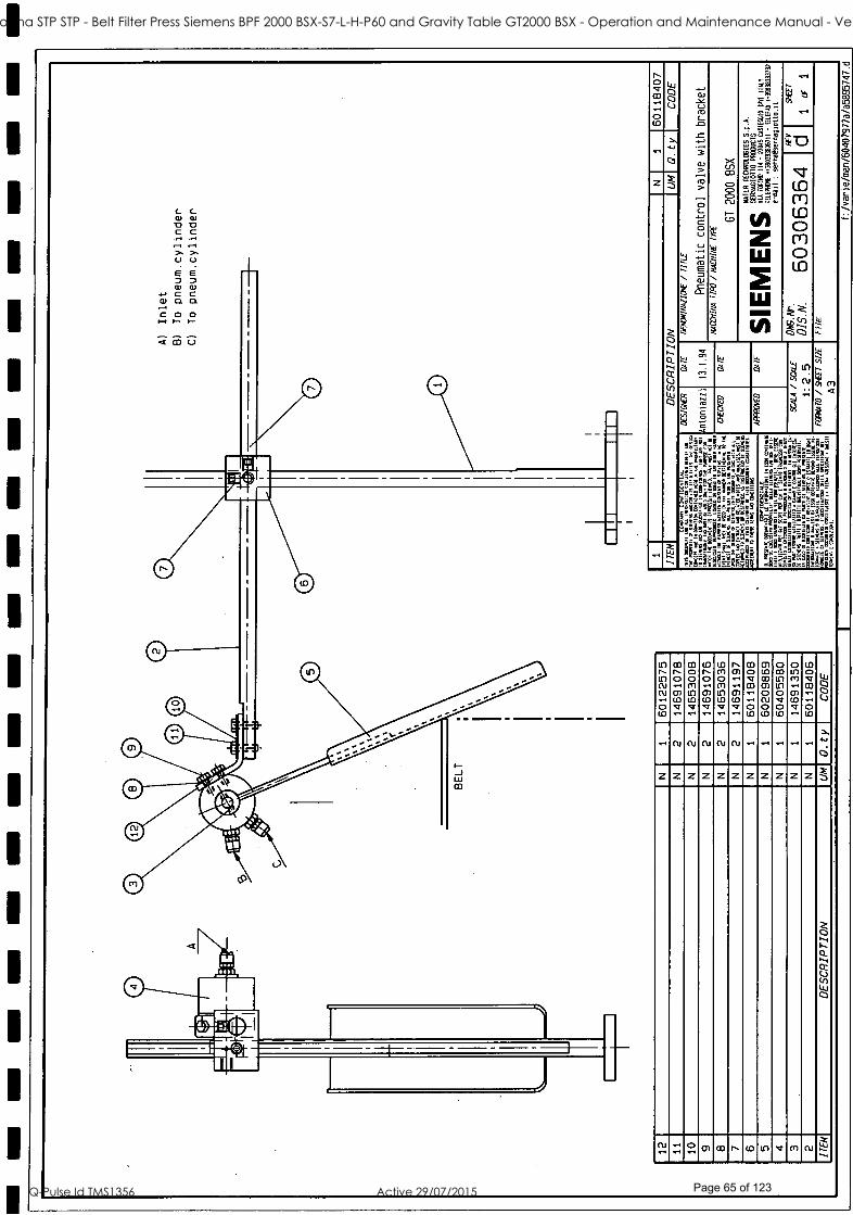
1
1
1
Q m U
ó Ú
z z
E;.4
óá :543
ti rn
Ó a
W ti
g N \ <
IC) I-- u') N N .+ 0 up
CO r 0 01 (O
m(D O 0 m lC) (D
N 0 .... CD tD
(0 m 0 m.r+mrnin )f) (D
I 01
01 I0
03 0 V ++ + O ID
O1 ID m(!l O CU O to
O m(r)
O V O (D
O m
01 (D
IO O y wo .+ O ID
W
CO.1
+ - + N N N N n j . -. . . -, . . . , . . . -. +" >, i O
Z Z Z Z Z Z Z Z Z 2 Zx
Ó ti ti R ti
Ú W O
° Q1 CD r\ (O LLl R(+l N ti
ST41 Goodna STP STP - Belt Filter Press Siemens BPF 2000 BSX-S7-L-H-P60 and Gravity Table GT2000 BSX - Operation and Maintenance Manual - Vendor Manual
Q-Pulse Id TMS1356 Active 29/07/2015 Page 65 of 123

O LO Crl o m in to Q rl
Lo o o Q to Q rl
N Ql
ti D7 Lo Q
o N 111
N o LO
Q lD n N N o
() tD n CU N o
Ó V
N ti ti ti a-I N O
Z Z Z Z Z Z z
Q
W
ó
C
74 Ñ t
>
m
O
ti ti
%
LO Cr) N
ti
,cc
Q CL
T C-
íä
ó a-+
CIJ
N CO
ro
O1
CO
O C-)
Cr.
¢ 5Oy
1
ST41 Goodna STP STP - Belt Filter Press Siemens BPF 2000 BSX-S7-L-H-P60 and Gravity Table GT2000 BSX - Operation and Maintenance Manual - Vendor Manual
Q-Pulse Id TMS1356 Active 29/07/2015 Page 66 of 123
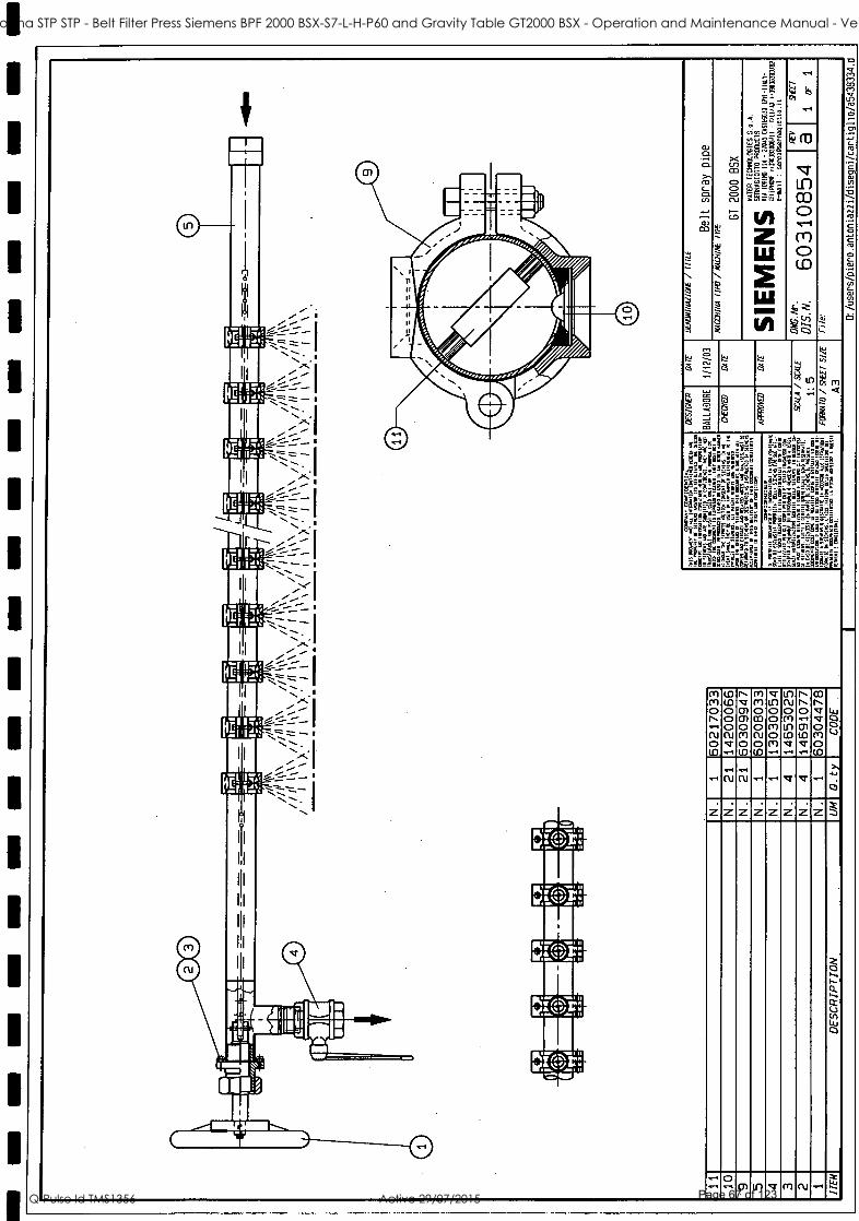
L
.m :iIIIIi ,II.i e,.
ó a
a ¢ á El
w m
r
óó
m M o N N o to.
(D (O o o o (U
N V Q)
o m o
m m o m o CV o (o
V U o o (*)
o m
U7. N o M Ul (a V
n n o O1 (D V
m n V V o (n o (n
Ó Ú
N N V V 4.1
Z Z Z Z Z Z z
o .ti Q) U') V fr1 (l) W
ti
ST41 Goodna STP STP - Belt Filter Press Siemens BPF 2000 BSX-S7-L-H-P60 and Gravity Table GT2000 BSX - Operation and Maintenance Manual - Vendor Manual
Q-Pulse Id TMS1356 Active 29/07/2015 Page 67 of 123
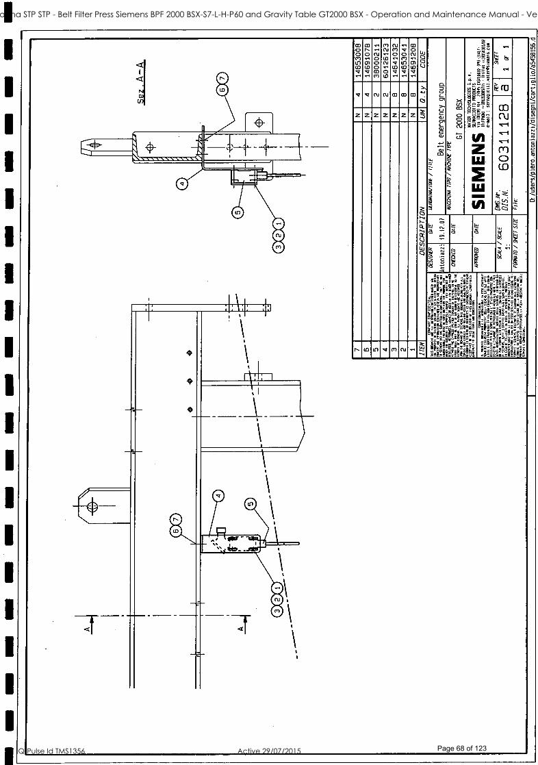
i
w.
O. 0 L
W y
ST41 Goodna STP STP - Belt Filter Press Siemens BPF 2000 BSX-S7-L-H-P60 and Gravity Table GT2000 BSX - Operation and Maintenance Manual - Vendor Manual
Q-Pulse Id TMS1356 Active 29/07/2015 Page 68 of 123

1
1
1
CO C O) O) O D C
U 6) C C C L W C a) ". +.) U W E U O) D .-) y E .-) t0 C. D w . O fA E a) tO .-) X 0 E (N W C W W f/) ,- L X y tp Y Cl) .-. W D N C 113
L W + L CO CO D_ L D W > 111 C X 1.0 t0 C
N t0 tY0 e .+ N W y C O W W C O
U D L C . U C , O O t0 + D N O C 2 W N C O. 7. 0 .+ W L U E 2
C L O t0 O N y C O E O. D tG W .--.
.. ,-W-, D W C
.C- y D
W W W V) C O )O W E C a C ÿ to U
O W o -, D . N Y C Of C. D Q W D t/) U C U C W C O. Q W O t0 2 O CA t0 O o. +-) a ^ O t!I C W v)
CO tJ) D CO .-) O L W D Q) D W)-t Q W C L W N N Q O W O. + O O +-) W W W O C
O C U L ....3
L .N.
L D fl] W W O
.-W-, C ^, ^
O. .- D C Cl t0 W O C O++ O C L C O CO u W C CO
O. tp T O C N N N L E`..- C U W +-) N W W 0 t0 tO C C T W L E E U t0 t0 ., j L W
U W L C 0 > C W .,-. W Q W U C W C 2 L O O. tO O W y f- )- N O. L O E U m
Ill m 0 V (D .,:r
n m 0 CI I[7 (D ..:r
-+ 01 0 O) (D V(U .-)
-- - 0 - O1
7
m co
Ol (D
.V.
01 co 0 0 0 N ..... - .-)
N
0 0 O) 01
V m(D 0 0 O1 01
Cl
0 O Ol 01
CO m O 0(D O ru -- ,.-)
O m(D
N -- O (D
CO
N. rn
-- 0 (D
O O U
V V V - V-- (D N N N- -- L Cl
.... Z Z Z Z Z Z X Z Z Z Z Z
O H 1\ 4 ti V W O
CU : ° 01 m n(D 117 V N.. ti
ST41 Goodna STP STP - Belt Filter Press Siemens BPF 2000 BSX-S7-L-H-P60 and Gravity Table GT2000 BSX - Operation and Maintenance Manual - Vendor Manual
Q-Pulse Id TMS1356 Active 29/07/2015 Page 69 of 123

In ID CO CO m v m LO 01 v CO --. ID n In o N In v , , immNomrnomninNN---omvv W , N N O O O O o 0 0 0 0 0 R V V I m m m _ rnm.-m-oom.rnnNinooa I .+ al D) In V Dl In C ID m ID V N N N N N N N V g--.T.
ID lD lD ID lD (CI lD CO O lD ID N N e 2 .y o Q V V V Q V V N m Q V 0 0 0 0 0 0 0 ".
y all' ID ID ID ID ID ID ID lD
m >.
e (O
.. N m m R Q m.-, .. N N.. .. .. .. m.r u O Y X
gig! = cr,
m =°
N Z Z Z Z Z Z Z Z Z Z Z Z Z Z Z Z Z Z Z p `' ¡My J ; p Fg;a W O Ñ iffiC=ú Q L ¡>I
. . \ lJ X f' ¡_ Z l'!
CT) CO ^ ID
,. W Q cD \
% s 2 W a z
o ao 4
.... a e W
Qa a a g U ` m
WO
cc Q;;a o i g o ó g 4
e e
o
ST41 Goodna STP STP - Belt Filter Press Siemens BPF 2000 BSX-S7-L-H-P60 and Gravity Table GT2000 BSX - Operation and Maintenance Manual - Vendor Manual
Q-Pulse Id TMS1356 Active 29/07/2015 Page 70 of 123

r
iÿ5g _ g.gtl
átlpp'YMw_Cáë
yy---e__gaEs
s_sib'_b:3Ñ 6 9ebß
-_zbs.w
3saaae 81,4!
ST41 Goodna STP STP - Belt Filter Press Siemens BPF 2000 BSX-S7-L-H-P60 and Gravity Table GT2000 BSX - Operation and Maintenance Manual - Vendor Manual
Q-Pulse Id TMS1356 Active 29/07/2015 Page 71 of 123

ST41 Goodna STP STP - Belt Filter Press Siemens BPF 2000 BSX-S7-L-H-P60 and Gravity Table GT2000 BSX - Operation and Maintenance Manual - Vendor Manual
Q-Pulse Id TMS1356 Active 29/07/2015 Page 72 of 123

D1 (*) V.. O Ul III n Ul D) R. UD CU CU V 1n CO (Tl lf1 V V V -NS " C1OOOCUnU7U1(*1 (''')(U (u gl. g U)(TI++NOC7000 O - g
tS OU) V Q)Q)(UUD(UOOO O Cn(D(DUDU)ti(D.-1UDU)UD V LL?C wA O V V V V O O O CU CU CU (D .y .-. .+ .r UJ ...... (D .+ .ti .., _
ú --7 r0 + %, V (U (U V °'
O CD m áó$='" c1 zzzzzzzzzzz rn 00 (n c `=iK5W (1J (U - Y A CJ H
Vii 1 `
(O U I-
I
Ñ
O .,.tiQ1[n(, U)gf) V 01 CU
a
ST41 Goodna STP STP - Belt Filter Press Siemens BPF 2000 BSX-S7-L-H-P60 and Gravity Table GT2000 BSX - Operation and Maintenance Manual - Vendor Manual
Q-Pulse Id TMS1356 Active 29/07/2015 Page 73 of 123
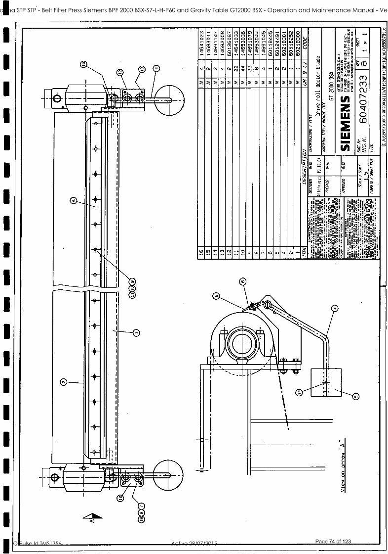
m-r 03 01, No § G 3 R$§ S R 3
'7 'V q q G m e a a e G G Q G G Cr) Æ a R Z2§
(13 U3 -U3 U3 o m (0 - - N -N u k b !2 - - -- 3 G` VV G G 2 G G \ :Æ
cu m V cu @ Ñ -æ x §)§ \ 2 §@" -
2 22 2 k 2 k k2 22 2 2 2 2§ ;&2» (11 o
in NimN o § m- æ CO e mA Itira
wow
ST41 Goodna STP STP - Belt Filter Press Siemens BPF 2000 BSX-S7-L-H-P60 and Gravity Table GT2000 BSX - Operation and Maintenance Manual - Vendor Manual
Q-Pulse Id TMS1356 Active 29/07/2015 Page 74 of 123

1
1
I
m co fT
óómm°Nm°t0n°Ó mm-
N w
CO CO n N
mtmot°omtmovÚ O tt) m
V .+ o N
V V
ñ el f)1
V V
N CO V m
V O m
Úl
O m
C i
yy
m
^
5
pó N
6
>p*
}
ß
:I L
=1E+ Ge_ e : t!ryl
á _g ñhi!! - ¢yy°4v ig 3L
III
W = ,/.
^ b
.-
CU
Q¡ W
gli
6. I Ii NMI I
r MN : © O
w..wmmvvvNw O 22222222222 j
_ ó
R Ñ
1 ,A \\ _ - - -
IgillQ
I1I''
I11
('I
:;; III
I_II"
I7ii_
i. ii
11.-, F'u_
Ç11_
I 1.
I_'
I1.-
I I
_ NI
11:,
I
--_
,
' _--
^ b .^., a - ..
W
à
,
W
à u?
N :+
rp
N
:oo=
t. =5==(b'
`6s ' - i !3éme i,11g- !
: 6Ê : ;¡ 9 ' Ii ¡ ' E
hi : a =d :.' =SPG' Ì 'i'@¡
1:g1 Á'a' !é4 =-`F-
Qy .I4 ?' mt. °'6 !i¡'r<
// . .' Ci-pájp 1 8e`,t..l
H- i
II2@ I I
, ^ 2 " m m n m to v m Cu
.. ß'E /` j . a9 é :
t ag3 i1i
c---,
-` 1J
_
I 11,
11.-,
7.1I,,
11
III I I"
H
1-, IIS '
... :.
__-
if -I
[" =t} 1`1 0
0 0
a o ú Ñ
a
I_II_
I_l
I_11_
I_11_
I`II
I
-1-.--1
-47 4..4.1
-I 1.--..1
[ 6.-.1 6.-.1
C." =f
.
J no A
(,.+ ':
+ --"i
1 O
© C)
I
- ST41 Goodna STP STP - Belt Filter Press Siemens BPF 2000 BSX-S7-L-H-P60 and Gravity Table GT2000 BSX - Operation and Maintenance Manual - Vendor Manual
Q-Pulse Id TMS1356 Active 29/07/2015 Page 75 of 123

ominomvinmmn v minommm0., R. ti in -, VM.-, m N N-. m in N m v o --( N O O O O m r 0 0 0 0.. 0 0 0 0 0+ m V 1l7 W W O N m N m.+ m.+ -. m-+ .-. m-+ (D a) O o O : ty Ly O N If1 m N Ifl m I!7 V m LL'1 m V lf) m N O O Of N lD lD m-. ID ID (D ID ID lD ID m m m- N V m C1 .-I O O V V V V V V V O O LLl Ul -_.
r + ti <+ ID lD ID ti ti
-( .-i V.-( ti '+ V V V N fU V V Vm+ r+ '+ O
2 2 2 2 2 2 2 2 2 2 2 2 2 2 2 2 2 2 2% > cuco
l
- U L
M ó 22_i (n,i
O 3 N .
M C C O N M I D V M N m m n ID U7 V m N-+ ti
ST41 Goodna STP STP - Belt Filter Press Siemens BPF 2000 BSX-S7-L-H-P60 and Gravity Table GT2000 BSX - Operation and Maintenance Manual - Vendor Manual
Q-Pulse Id TMS1356 Active 29/07/2015 Page 76 of 123

1
1
I_ L
r-j 1
1
F==a L ' 1
I 1 I- 1
..d
1n1
1111
F==a L_. I
i 1
_I I
1- 1 t.=d
F--a L_. I T1
m: v \\
I _ _
1
I
t==d
F-_g L_. I ¡I 1__I
1
I I
.=d I
I A
4
-- F==a L__ I TI 1-- I
1 .=d
I
F = = q Í
L_. I
i1 I : 0
1
I
1-_ 1
==d u
v CV
03 ó N C.1
O (D
ID ln V f'1 N
ST41 Goodna STP STP - Belt Filter Press Siemens BPF 2000 BSX-S7-L-H-P60 and Gravity Table GT2000 BSX - Operation and Maintenance Manual - Vendor Manual
Q-Pulse Id TMS1356 Active 29/07/2015 Page 77 of 123

m o m u( (D V
n n o rn (D V
Cu N m N o (D
N m m N o (D
m N m CO
N o (D
v o o m (D V
m o rn (D V
V Ó
N N N N ar N V V
2 Z Z Z Z Z 2 Z J
n
- ati
(D LLl V m N ti
N rn
a
v
ST41 Goodna STP STP - Belt Filter Press Siemens BPF 2000 BSX-S7-L-H-P60 and Gravity Table GT2000 BSX - Operation and Maintenance Manual - Vendor Manual
Q-Pulse Id TMS1356 Active 29/07/2015 Page 78 of 123

,ums AII J Ili
LJ
\
/
V O) CO O) O) V N 0 (*) N ([) V 0 0 0 0 0 0 N(Umm CD CO ü) LLl O) O) ID (O ID LL) ID U] VV V V V V
rn rn
LO
0m m 0 0 (O (O
: "r"
V r b
V V V ID V(D ti ti L ,V H
17 p_,. E m Y' - : in O.1
Z z z Z Z Z Z Z Z Ñ 00 w 111 2 o N 0 CU sc_.
N
¢ Z q-
0) CO n (O (D V R) N
ST41 Goodna STP STP - Belt Filter Press Siemens BPF 2000 BSX-S7-L-H-P60 and Gravity Table GT2000 BSX - Operation and Maintenance Manual - Vendor Manual
Q-Pulse Id TMS1356 Active 29/07/2015 Page 79 of 123

_|! `
tO 11:1 LO CO LO CO cu cu |/
--- æ;=22G22 :- ; !;! m_-,=,,,,,,m ÆÆ
zzzzzzzzzzzzzz ee § LI-) E w / \° Z ?
! §
! ! . é
è| ª
| kÑ) %\ eeÑ
Ñ :::-' a eil-514; : @ § Ç; G a
m æ . F
® Ito, $
]
|
v « m v v
ST41 Goodna STP STP - Belt Filter Press Siemens BPF 2000 BSX-S7-L-H-P60 and Gravity Table GT2000 BSX - Operation and Maintenance Manual - Vendor Manual
Q-Pulse Id TMS1356 Active 29/07/2015 Page 80 of 123

CO N o m to
(n m o rn (D
In N o o N 0 N
Cu V o o (D Cu
co ol o o In m Cu
V N V 0 0 (D N
(n R1 o V (D V
n n 0 rn (D V
m 0 o c*1
In (D V
Ln
o o In o V
o to o o W N
m
0 0 (D N
to N V 0 0 (D N
Cr) V 0 0 (D N
(U Cu m N N V n V Cu
2 2 2 2 2 2 2 2 2 2 2 2 2 2 2 2 2 j
a
W n (D If) .-c
m O1 CD n ID Ill V N N ti
r,
N O In O O (D N ..
O) n o o to N
o)
O Ill N N
N
Z Z 2 2
m N N N N
O N
O1
ST41 Goodna STP STP - Belt Filter Press Siemens BPF 2000 BSX-S7-L-H-P60 and Gravity Table GT2000 BSX - Operation and Maintenance Manual - Vendor Manual
Q-Pulse Id TMS1356 Active 29/07/2015 Page 81 of 123

o ó m
Ó m
0 O ID
Q Q
o o
b
N o
b N O ID
N m CO ID m Q N Ñ N N ID N O
3
S m
m ID Ot m ID v m N ti
ST41 Goodna STP STP - Belt Filter Press Siemens BPF 2000 BSX-S7-L-H-P60 and Gravity Table GT2000 BSX - Operation and Maintenance Manual - Vendor Manual
Q-Pulse Id TMS1356 Active 29/07/2015 Page 82 of 123
c,
A ST41 Goodna STP STP - Belt Filter Press Siemens BPF 2000 BSX-S7-L-H-P60 and Gravity Table GT2000 BSX - Operation and Maintenance Manual - Vendor Manual
Q-Pulse Id TMS1356 Active 29/07/2015 Page 83 of 123

SIEMENS - GT 2000 BSX
APPENDIX A
BELT DRIVE
Electric motor ABB model: 2.2 kw 4P B5 415V/50/3
Gearbox BONFIGLIOLI model: A503 NH50 i81,5 P100 B8
Ref.spare parts section dwg 60407235 item 2 and 1
ST41 Goodna STP STP - Belt Filter Press Siemens BPF 2000 BSX-S7-L-H-P60 and Gravity Table GT2000 BSX - Operation and Maintenance Manual - Vendor Manual
Q-Pulse Id TMS1356 Active 29/07/2015 Page 84 of 123

Low Voltage Motors
Manual for Low Voltage Motors
- '7, ----
1';:- es, -
, Installationi operatton and-, -, -'" ,T . ' ' ' .: '''', s: .= '
cnImnfenance manual \s,'''k V :GEV,' 3 . .. .
... ,, *,,,, -, ,-,, , ,..,- ,v- ,,. " zt 55.0 , ; ,,, 5.5 , ,
-= ,s- ''' ' - , 4.,
"; ,' ' :4-ss,''', s:k ... ' '
5555555 14:-
45'5';.^471:::15.5
.,,
t ' -
. .. x
, , ,
z. 4, ""' T . ,t, t4 , ..».
F ' '..t"' '.' 1 -i 4' 44 - 4 ' Vt 4,'"agg, IN ,,,.: . v
' St' t ' t N,, > ' 'i .1 ' ,,,,, , ',.. P 1 ' '
t 7 ' t
e
°
1 -
s",- s 1, 4,"
fr, -' 4 S .5,
ssA SS
4
SS
,"
°
vt,, 44, .
ItstSSSSS SS
'
'S
* t *
1
, t
SS
Svj.
. ,
S- " ,
.5 ,5
`. ,, ,.. , ' s 0. " ' ' ' - ,-, 'e 55 '
55," 4'.' »,....4,-.: 43- . , ' . s 4, , 5' 4,2, '
',5'44' ' ,. ..,, 4 55 :5 , . .
75, ,s,s's.. 5 . ',. \ v 55." '.2 '4'
I 5-'
44 5 ' '4 ' +. .
SS
A III 1111 "IPI,
ST41 Goodna STP STP - Belt Filter Press Siemens BPF 2000 BSX-S7-L-H-P60 and Gravity Table GT2000 BSX - Operation and Maintenance Manual - Vendor Manual
Q-Pulse Id TMS1356 Active 29/07/2015 Page 85 of 123

Example of the Declaration of Conformity given by ABB.
A It I! Pl ff EC Declaration of Conformity
The Manufacturer :- (Name and address of the manufacturer)
hereby declares that
The Products :- (Product identification)
are in conformity with provisions of the following Council Directives :
Low Voltage Directive 73/23/EEC (amended by 93/68/EEC),
and, as components, with the essential requirements of the following :
EMC Directive 89/336/EEC (amended by 92/31/EEC and 93/68/EEC), regarding the intrinsic characteristics to emission and immunity levels,
and are in conformity with :
EN 60 034 -1
Additional Information :-
By design, the machines, considered as components, comply with the essential requirements of
Machinery Directive 98/37/EEC provided that the installation be correctly realised by the manufacturer of the machinery (for example : in compliance with our Installation Instructions and EN 60 204 "Electri- cal Equipment of Industrial Machines ").
Certificate of Incorporation (Directive 98/37/EEC, Art 4.2 and Annex II, Sub B) :
The machines above must not be put into service until the machinery into which they have been incorporated have been declared in conformity with the Machinery Directive.
Year of CE marking : CE00.
Signed by
Title
Date
Translations into other languages are available from ABB.
GB-2 ABB / Low Voltage Motors / Manual 12 -2004
ST41 Goodna STP STP - Belt Filter Press Siemens BPF 2000 BSX-S7-L-H-P60 and Gravity Table GT2000 BSX - Operation and Maintenance Manual - Vendor Manual
Q-Pulse Id TMS1356 Active 29/07/2015 Page 86 of 123

1. General
NOTE! These instructions must be followed to ensure safe and proper installation, operation and maintenance of the motor. They should be brought to the attention of anyone who installs, operates or maintains this equipment. Ignoring the instruction may invalidate the warranty.
1.1 Declaration of Conformity Declarations of Conformity with respect to the Low voltage Directive 73/23/EEC amended by Directive 93/68 EEC are issued separately with individual machines. The Declaration of Conformity also satisfies the requirements of a Declaration of Incorporation with respect to the Machinery Directive 98/37/EEC, Art 4.2 Annex II, sub B
1.2 Validity The instructions are valid for the following ABB electrical machine types, in both motor and generator operation.
series MT *, MBT *, MXMA, series M2A * /M3A *, M2B * /M3B *, M2C * /M3C *, M2F * /M3F *, M2L * /M3L *, M2M * /M3M *, M2Q *, M2R * /M3R *, M2V * /M3V*
in frame sizes 56 - 450.
There is a separate manual for e.g. Ex motors 'Low voltage motors for hazardous areas: Installation, operation and maintenance Manual' (Low Voltage Motors /Manual for Ex- motors).
Additional information is required for some machine types due to special application and /or design considerations. Additional information is available for the following motors:
- roller table motors - water -cooled motors - open drip proof motors - smoke venting motors - brake motors - permanent magnet motors
GB-4
2. Installation
2.1 Putting into service (starting)
2.1.1 Reception check Immediately upon receipt check the machine for external damage and if found, inform the forwarding agent without delay.
Check all rating plate data, especially voltage and winding connection (star or delta). The type of bearing is specified on the rating plate of all motors except the smallest frame sizes.
Remove transport locking if employed.Turn shaft by hand to check free rotation.
Do not exceed permissible loading values of bearings stated in the product catalogue.
Motors equipped with roller bearings: Running the motor with no radial force applied to the shaft may damage the roller bearing.
Motors equipped with angular contact bearing: Running the motor with no axial force applied in the right direction to the shaft may damage the angular contact bearing.
Motors equipped with regreasing nipples: When starting the motor for the first time, or after long storage of the motor, apply the specified quantity of grease until grease is forced out of the grease outlet.
For details see section "Manual lubrication" on page 9.
2.1.2 Insulation resistance check Measure insulation resistance before commissioning and when winding dampness is suspected.
Resistance, measured at 25 °C, shall exceed the reference value, i.e. 10 M ohm (measured with 500 V dc Megger)
=WÁRÑIÑG '
-VVirïdings-shôûid besdischá,rged'ImmediäteÍÿáfteee, measurement tó_avotd.nsk.of electric shóck.'_`
Insulation resistance reference value is halved for each 20 °C rise in ambient temperature.
If the reference resistance value is not attained, the winding is too damp and must be oven dried. Oven temperature should be 90 °C for 12 -16 hours followed by 105 °C for 6 -8 hours.
ABB / Low Voltage Motors / Manual 12 -2004
ST41 Goodna STP STP - Belt Filter Press Siemens BPF 2000 BSX-S7-L-H-P60 and Gravity Table GT2000 BSX - Operation and Maintenance Manual - Vendor Manual
Q-Pulse Id TMS1356 Active 29/07/2015 Page 87 of 123

Drain hole plugs, if fitted, must be removed and closing valve, if fitted, must be opened during heating.
Windings drenched in seawater normally need to be rewound.
2.1.3 Direct -on -line or star /delta starting
The terminal box on standard single speed machines normally contains 6 winding terminals and at least one earth terminal.
Earthing must be carried out according to local regulations before the machine is connected to the supply voltage.
The voltage and connection are stamped on the rating plate.
Direct -on -line starting (DOL): Y or D winding connections may be used.
e.g. 660 VY, 380 VD indicates Y- connection for 660 V
and D- connection for 380 V.
Star /Delta starting (Y /D): The supply voltage must be equal to the rated voltage of the machine in D- connection.
Remove all connection links from the terminal block.
For two- speed, single phase and special machines, supply connection must follow the instructions inside the terminal box.
If direct -on -line starting lasts for more than 10 seconds or Y/D starting more than 30 seconds, consult ABB Sales Office or see the publication The Motor Guide' (also available on the internet on www.abb.com/ motors &drives).
2.1.4 Terminals and direction of rotation
Direction of rotation is clockwise when viewing the shaft face at the machine drive end, when the line phase sequence L1, L2, L3 is connected to the terminals as shown in the figure 1.
To alter the direction of rotation, interchange the connection of any two line cables.
If the machine has a uni -directional fan, ensure that the direction of rotation is according to the arrow marked on the machine.
ABB / Low Voltage Motors / Manual 12 -2004
2.2 Handling
2.2.1 Storage The machine should always be stored indoors, in dry, vibration free and dust free conditions.
Unprotected machined surfaces (shaft-ends and flanges) should be protected with anti -corrosive treatment.
It is recommended that shafts be rotated periodically by hand to prevent grease migration.
Anti condensation heaters, if fitted, should preferably be
energised.
The characteristics of electrolytic capacitors, if fitted to single -phase motors, will require "reforming" following periods of storage exceeding 1 -2 years. Contact ABB Sales Office for details.
2.2.2 Transportation Machines fitted with cylindrical -roller and /or angular contact bearings must be fitted with locking devices during transport.
2.2.3 Lifting Lift the motor using the lifting lugs only, if not otherwise stated in the separate lifting instruction.
The center of gravity of motors with the same frame may vary due to different outputs, mounting arrangements and auxiliary equipment.
Check that eyebolts or the lifting lugs integrated with the motor frame are undamaged before lifting. Damaged lifting lugs must not be used.
Lifting eyebolts must be tightened before lifting. If needed the position of the eyebolt must be adjusted with suitable washers.
Ensure that proper lifting equipment is used and that the sizes of the hooks are suitable for the lifting lugs.
Care must be taken not to damage auxiliary equipment and cables attached to the motor.
5 -GB
ST41 Goodna STP STP - Belt Filter Press Siemens BPF 2000 BSX-S7-L-H-P60 and Gravity Table GT2000 BSX - Operation and Maintenance Manual - Vendor Manual
Q-Pulse Id TMS1356 Active 29/07/2015 Page 88 of 123

1
1
2.2.4 Machine weights Total machine weight can vary within the same frame size (center height) depending on different output, mounting arrangements and added features.
The following table shows estimated maximum weights for machines in their basic versions as a function of frame material.
The actual weight of all our motors is stated on the rating plate except the smallest frame sizes.
Frame size
Aluminum
Weight kg
Add. for brake
Cast iron
Weight kg
Steel
Weight kg
56 4.5 - - -
63 6 - - -
71 8 5 13 -
80 12 8 20 -
90 17 10 30 -
100 25 16 40 - 112 36 20 50 - 132 63 30 90 -
160 110 30 175 -
180 160 45 250 -
200 220 55 310 -
225 295 75 400 -
250 370 75 550 -
280 405 - 800 600 315 - - 1700 1000 355 - - 2700 2200 400 - - 3500 3000 450 - - 5000 4500
Table 1
2.3 Installation
2.3.1 'Cooling Normal ambient temperatures should not exceed 40 °C (marine standard +45 or +50 °C) if standard performance is to be achieved. Check that the motor has sufficient airflow. Ensure that no nearby equipment, surfaces or direct sunshine, radiate additional heat to the motor. For more information about higher ambient temperatures and cooling, see "the Motor Guide" or contact ABB Sales Office.
2.3.2 Foundation The purchaser bears full responsibility for preparation of the foundation.
Metal foundations should be painted to avoid corrosion.
Foundations must be even, and sufficiently rigid to withstand possible short circuit forces. They shall be dimensioned as to avoid the occurrence of vibration due to resonance.
GB-6
Before mounting the motor, the foundation surface for the shims or for the feet must be clean from thick paint, paint drops and dirt. Then it should be checked in order to discover any height differences between the individual foot locations. Also, the smoothness within each footprint area has to be checked. The requirements are noted in the figure below.
Note! Height difference shall not exceed ± 0,1 mm referred to any other motor foot location
.4 `,i.,....` ..á,+ ._ h¡'
Foot location
Foundation studs Bolt the foundation studs tó the feet of the motor and place a 1 -to -2 mm shim between the stud and the feet.
Align the motor directly using appropriate means. Grout the studs with concrete, check alignment and drill holes for locating pins.
Drain holes Always check that open drain holes face downward.
In extremely dusty environments, all drain holes should be closed.
2.3.3 Alignment Correct alignment is essential to avoid bearing failures, vibrations and possible fractured shaft extensions.
2.3.4 Slide rails and belt drives - Fasten the machine to the slide rails as shown in
figure 2.
- Place the slide rails horizontally on the same level. - Check that the machine shaft is parallel with driven,
or driving, shaft. - Any belt must be tensioned according to the
supplier's instructions.
WARNING ' °` ``' ` ' ;+.71,%7:, °' Excessive bélttensóñ will-dàrñáge,b-Orings' árid cári'çausêshaft=breàkágé'F °; ; á=` ..__. .
Do not exceed the maximum belt forces (i.e. radial bearing loading) stated in the relevant product catalogues.
ABB / Low Voltage Motors / Manual 12 -2004
ST41 Goodna STP STP - Belt Filter Press Siemens BPF 2000 BSX-S7-L-H-P60 and Gravity Table GT2000 BSX - Operation and Maintenance Manual - Vendor Manual
Q-Pulse Id TMS1356 Active 29/07/2015 Page 89 of 123

2.4 Connection Normal machine design has the terminal box on top with cable entry possible from both sides.
Some machines are available with top mounted terminal boxes rotatable 4 x 90 °, and some with side mounted terminal boxes.
Availability of these solutions is described in the product catalogues.
Unused cable entries must be closed.
As well as main winding and earthing terminals, the terminal box can also contain connections for thermistors, standstill heating elements, bimetallic, switches, or PT 100 resistance elements.
a.. . ̂ , s 'm' r . .. . - . _. ,
WARNING .
.,. b Voltage márbë cáñrlëcted at stándstiÌÍ^inside the 4, terminal box#òr heating eÌeméñts°ár diect winding_':
A, heätiñg: ' , : .
`
Connection diagrams for auxiliary elements are found inside the terminal box cover or in additional labels on the frame of the machine.
.47 , . . , <- 4.7 WARNING ^ :04,.:iThe:çápácítor mysingté-phásé motórs can_retam _ mlìarge,that=appeársgaérossithe motor terminals, .
evéñ'whenthé motór--has,reáchéd standstill:.,:.,,-
2.4.1 Connection for variable speed drive
Variable speed drives cause higher voltage stresses than the sinusoidal supply on the winding of the motor and may cause high frequency shaft voltages and bearing currents. Therefore the winding and the bearing insulation of the motor as well as the filter at the converter output must be dimensioned according to "Selection rules for VSD applications /Insulation" (3GZF500930 -2), available on request from ABB.
In variable speed drives the motor (Pn > 30 kW) must be cabled by using shielded symmetrical cables and cable glands providing 360° bonding (also called EMC glands). More information can be found in ABB's manual "Grounding and cabling of the drive system" (3AFY61201998).
In frequency converter applications motor frame external earthing must be used for equalising the potential between the motor frame and the driven machine, unless the two machines are mounted on the same metallic base.
For motor frame sizes above IEC 280, use 0.75 x
70 mm flat conductor or at least two 50 mm2 round conductors. The distance of the round conductors must be at least 150 mm from each other.
This arrangement has no electrical safety function; the purpose is to equalise the potentials. When the motor and the gearbox are mounted on a common steel fundament, no potential equalisation is required.
ABB / Low Voltage Motors / Manual 12 -2004
To comply with EMC -requirements, use only cables and connectors approved for this purpose. (See instruction for frequency converters.)
The highest permissible rotational speed of a cast iron motor used in variable speed drive (M2BA/M3BP) must not exceed maximum permissible speeds as stated in
the table 2 below or the speed stamped on the rating plate. For information on the highest permissible rotational speed for other motor sizes and types, please contact ABB. Bearing lubrication should follow the directions mentioned later.
Frame size
Speed r /min 2 pole 4 pole
280 3600 2600
315 3600 2300
355 3600 2000
400 3600 1800
450 3600 1800
Table 2
If there is uncertainty concerning the suitability of the motor for the variable speed drive, please contact ABB.
WÂFiNING C
Theiñáximurñ ó .
pé átiñg teriipérát'uré ,of thé ' -° -
-grease-arid bearings nbt be ëxcéedéd'
s.
2.5 Balancing The rotor of the machine is dynamically balanced.
As standard, balancing has been carried out using half key, and the shaft is marked with a RED tape, with the text "Balanced with half key ". In case of motors delivered without any tape defining the type of balancing, these motors are also balanced with half key.
To avoid vibration the coupling -half or pulley must be balanced with half key after the keyway has been machined.
In the event of balancing with full key the shaft is marked with a YELLOW tape, with the text "Balanced with full key ".
In case balancing without key, the shaft is marked with a BLUE tape, with the text "Balanced without key ".
7 -GB
ST41 Goodna STP STP - Belt Filter Press Siemens BPF 2000 BSX-S7-L-H-P60 and Gravity Table GT2000 BSX - Operation and Maintenance Manual - Vendor Manual
Q-Pulse Id TMS1356 Active 29/07/2015 Page 90 of 123

3. Operating
111 \3.1 Use :m (j 3.1.1 Operating conditions a, yy The machines are intended for use in industrial drive
applications. Normal ambient temperature limits are -20° to +40 °C. Maximum altitude 1000 m above sea level.
3.2 Safety considerations The machine is intended for installation and use by qualified personnel, familiar with relevant safety requirements.
Safety equipment necessary for the prevention of accidents at the installation and operating site must be provided in accordance with the local regulations.
ÀRNING mall motors with supply cúrr>ent:dìecttjr=
>switélìéd by tFiermaltyséñsitivé, switche_s'_ç_ an,^o
stárt àütomáticállÿ' ' '
3.2.1 Points to observe 1. Do not use the machine to step on. 2. The temperature of the outer casing of the
machine may be hot to the touch during normal operation.
3. Some special machine applications require special instructions (e.g. using frequency converter supplies).
4. Lifting lugs must only be used for lifting the motor. They must not be used to lift the motor when it is
attached to other equipment.
GB-8
3.3 Assembly and dismantling
3.3.1 General Dismantling and assembly of machines must be carried out by qualified personnel using only suitable tools and working methods. All repairs must be carried out according to the standard IEC- 60079 -19.
3.3.2 Bearings Special care should be taken with the bearings. These must be removed using pullers and fitted by heating or using special tools for the purpose.
How to replace bearings is described in detail in a separate instruction leaflet available from ABB Sales Office.
3.3.3 Fitting coupling halves and pulleys
Coupling halves and pulleys must be fitted using suitable equipment and tools that do not damage the bearings.
Never fit a coupling half or pulley by hammering into place or remove it using a lever pressed against the body of the machine.
Mounting accuracy of coupling half:
check that the clearance b is less than 0.05 mm and that the difference al to a2 is also less than 0.05 mm. See figure 3.
ABB / Low Voltage Motors / Manual 12 -2004
ST41 Goodna STP STP - Belt Filter Press Siemens BPF 2000 BSX-S7-L-H-P60 and Gravity Table GT2000 BSX - Operation and Maintenance Manual - Vendor Manual
Q-Pulse Id TMS1356 Active 29/07/2015 Page 91 of 123
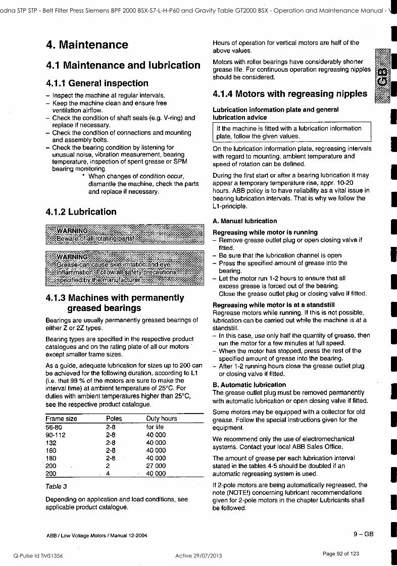
4. Maintenance
4.1 Maintenance and lubrication
4.1.1 General inspection - Inspect the machine at regular intervals. - Keep the machine clean and ensure free
ventilation airflow. - Check the condition of shaft seals (e.g. V -ring) and
replace if necessary. - Check the condition of connections and mounting
and assembly bolts. - Check the bearing condition by listening for
unusual noise, vibration measurement, bearing temperature, inspection of spent grease or SPM bearing monitoring.
* When changes of condition occur, dismantle the machine, check the parts and replace if necessary.
4.1.2 Lubrication
WÄRÌVING,- , °_ Bewárë óf=all rotating párts!
WARNING .
z
-_
Grease -can` cause kiekk skin irritation and eye '
iriflámmäUón:Fôllów -all sáféfÿprécäu #ions,`'
specified by thé mäñufactürer. °
,j
4.1.3 Machines with permanently greased bearings
Bearings are usually permanently greased bearings of either Z or 2Z types.
Bearing types are specified in the respective product catalogues and on the rating plate of all our motors except smaller frame sizes.
As a guide, adequate lubrication for sizes up to 200 can be achieved for the following duration, according to L1
(i.e. that 99 % of the motors are sure to make the interval time) at ambient temperature of 25 °C. For duties with ambient temperatures higher than 25 °C,
see the respective product catalogue.
Frame size Poles Duty hours 56 -80 2 -8 for life 90 -112 2 -8 40 000 132 2 -8 40 000 160 2 -8 40 000 180 2 -8 40 000 200 2 27 000 200 4 40 000
Table 3
Depending on application and load conditions, applicable product catalogue.
ABB / Low Voltage Motors / Manual 12 -2004
see
Hours of operation for vertical motors are half of the above values.
Motors with roller bearings have considerably shorter grease life. For continuous operation regreasing nipples should be considered.
4.1.4 Motors with regreasing nipples
Lubrication information plate and general lubrication advice
If the machine is fitted with a lubrication information plate, follow the given values.
On the lubrication information plate, regreasing intervals with regard to mounting, ambient temperature and speed of rotation can be defined.
During the first start or after a bearing lubrication it may appear a temporary temperature rise, appr. 10 -20 hours. ABB policy is to have reliability as a vital issue in
bearing lubrication intervals. That is why we follow the L1- principle.
A. Manual lubrication
Regreasing while motor is running - Remove grease outlet plug or open closing valve if
fitted. - Be sure that the lubrication channel is open - Press the specified amount of grease into the
bearing. - Let the motor run 1 -2 hours to ensure that all
excess grease is forced out of the bearing. Close the grease outlet plug or closing valve if fitted.
Regreasing while motor is at a standstill Regrease motors while running. If this is not possible, lubrication can be carried out while the machine is at a standstill. - In this case, use only half the quantity of grease, then
run the motor for a few minutes at full speed. - When the motor has stopped, press the rest of the
specified amount of grease into the bearing. After 1 -2 running hours close the grease outlet plug or closing valve if fitted.
B. Automatic lubrication The grease outlet plug must be removed permanently with automatic lubrication or open closing valve if fitted.
Some motors may be equipped with a collector for old grease. Follow the special instructions given for the equipment.
We recommend only the use of electromechanical systems. Contact your local ABB Sales Office.
The amount of grease per each lubrication interval stated in the tables 4 -5 should be doubled if an automatic regreasing system is used.
If 2 -pole motors are being automatically regreased, the note (NOTE!) concerning lubricant recommendations given for 2 -pole motors in the chapter Lubricants shall be followed.
9 -GB
1
mI "5 1
1
1
1
1
1
1
1
1
1
1
1
1
1
ST41 Goodna STP STP - Belt Filter Press Siemens BPF 2000 BSX-S7-L-H-P60 and Gravity Table GT2000 BSX - Operation and Maintenance Manual - Vendor Manual
Q-Pulse Id TMS1356 Active 29/07/2015 Page 92 of 123

4.1.5 Lubrication intervals and amounts
Frame Amount 3600 3000 1800 1500 size of grease r /min r /min r/min r /min r /min r /min
g/bearing
Ball bearings Lubrication Intervals in duty hours
Factors influencing the lubrication intervals Lubrication intervals for vertical machines are half of the above values.
1000 500 -900 The lubrication intervals are based on bearing operating temperature 80 °C (ambient temperature of about + 25 °). Note! An increase in the ambient temperature raises the temperature of the bearings correspondingly. The values should be halved for 15 °C increase in bearing temperature and may be doubled for 15 °C decrease in bearing temperature.
112 10 10000 13000 18000 21000 25000 28000 132 15 9000 11000 17000 19000 23000 26500 160 25 7000 9500 14000 17000 21000 24000 180 30 6000 8000 13500 16000 20000 23000 200 40 4000 6000 11000 13000 17000 21000 225 50 3000 5000 10000 12500 16500 20000 250 60 2500 4000 9000 11500 15000 18000 280 70 2000') 3500') 8000 10500 14000 17000 315 90 1) 1) 6500 8500 12500 16000 355 120 1> ') 4200 6000 10000 13000 400 120 1) 1) 4200 6000 10000 13000 400 M3BP 130 1) 1) 2800 4600 8400 12000 450 140 2400 4000 8000 8800
Table 4
Roller bearings Lubrication intervals in duty hours
160 25 3500 4500 7000 8500 10500 12000 180 30 3000 4000 7000 8000 10000 11500 200 40 2000 3000 5500 6500 8500 10500 225 50 1500 2500 5000 6000 8000 10000 250 60 1300 2200 4500 5700 7500 9000 280 70 10001) 2000') 4000 5300 7000 8500 315 90 I)
1) 3300 4300 6000 8000 355 120 1) I) 2000 3000 5000 6500 400 120 1) I) 2000 3000 5000 6500 400 M3BP 130 '> ') 1400 2300 4200 6000 450 140 1200 2000 4000 4400
Table 5
')Values for IEC sizes 280 to 450 (cast iron and steel motors) in certain motor types (3600 and 3000 r /min), see tables 6 -7.
Lubrication intervals and amounts, 2 -pole, IEC frame sizes 280 to 450 Frame size
Amount
of grease
glbearing
3600 3000 r/min r/min
Ball bearings Lubrication intervals in duty hours
280 M2B *, M2C *, M36* 35 2000 3500 315 M26 *, M2C *, M38* 35 2000 3500 355 M2B *, M2C* 45 1200 2000 355 M3B* 35 1200 2000 400 M2B *, M2C* 45 1200 2000 400 M3B* 40 1000 1600 450 M3B* 40 1000 1600
Table 6
Roller bearings Lubrication intervals in duty hours
280 M2B*, M2C*, M3B* 35 1000 1800
315 M2B*, M2C*, M3B* 35 1000 1800 355 M2B*, M2C* 45 600 1000 355 M3B* 35 600 1000 400 M2B*, M2C* 45 600 1000 400 M3B* 40 500 800 450 M3B* 40 500 800
Table 7
GB-10
WARNINGt,,i The maximum óperatirig témpératúrë-of,the greas_é`
r=, and,bearmgs must nót',bé exçeedëd x_,r
4.1.6 Lubricants ' ik:-.
WARNING:` - Do nöt-mix diffërent types öf grease..'-' -Ircömpatible lubricants'may.calisé.beannge damage:
, á> , When regreasing, use only special ball bearing grease with the following properties: - good quality grease with lithium complex soap and
with mineral- or PAO -oil - base oil viscosity 100 -160 cST at 40 °C - consistency NLGI grade 1.5 - 3 *) - temperature range -30 °C - +120 °C, continuously.
*) For vertical mounted motors or in hot conditions a
stiffer end of scale is recommended.
Grease with the correct properties is available from all major lubricant manufacturers.
Admixtures are recommended, but a written guarantee must be obtained from the lubricant manufacturer especially concerning EP admixtures, that admixtures do not damage bearings or the properties of lubricants at the operating temperature range.
WARNING Lúbricänts cóntaining,EP' admixtúr'esare nót -x _ -
récommërided'írï high béarlñg témpérattáres;irt frame sizes 280,to 450 1,
If the ambient temperature is below -25 °C or above +55 °C, or bearing temperature is above 110 °C, consult ABB Sales Office regarding suitable grease.
The following high performance grease can be used
- Esso Unirex N2, N3 or S2 (lithium complex base) - Mobil Mobilith SHC 100 (lithium complex base) - Shell Albida EMS 2 (lithium complex base) - SKF LGHQ 3 (lithium complex base) - Klüber Klüberplex BEM 41 -132
(special lithium base) - FAG Arcanol TEMP110 (lithium complex base)
Lubrication intervals for other grease fullfilling the required properties, contact your local ABB Sales Office.
ABB / Low Voltage Motors / Manual 12 -2004
ST41 Goodna STP STP - Belt Filter Press Siemens BPF 2000 BSX-S7-L-H-P60 and Gravity Table GT2000 BSX - Operation and Maintenance Manual - Vendor Manual
Q-Pulse Id TMS1356 Active 29/07/2015 Page 93 of 123

NOTE! Always use high speed grease for high speed machines and some other models, e.g. M2BA 355 and 400 2 -pole machines, where the speed factor is higher than 400 000 (calculated as Dm x n where Dm = average bearing diameter, mm; n = rotational speed, r /min).
The following grease can be used: - FAG L69 (polyurea base) - Klüber Klüber quiet BH 72 -102 (polyurea base) - Lubcon Turmogrease PU703 (polyurea base)
If other lubricants are used, check with the manufacturer that the qualities correspond to those of the above mentioned lubricants, or if the compatibility of the lubricant is uncertain, contact your local ABB Sales Office.
WARNING. =
Ëspéçiallÿ'iiï-higffrótätiónal ̀ spééd'(thé speêd-,, -factor:"> 400000),over greásing=may çause
aíriáge :x ; , 9 ,
a , R
4.1.7 Frequency converter drives Higher speed operation, e.g. in frequency converter applications, or lower speed with heavy load will require shorter lubrication intervals. Consult your local ABB Sales Office in such cases.
Typically a doubling of speed will require a reduction of lubrication intervals to approx. 40 % of values tabulated above.
'WARNING The'cónstructioñálWmaximùm:spéedsof:thé.motor-4; "'
must,ñót bé°excééded"(seé table 2) =
Suitability of bearings for high speed operation must be checked.
4.1.8 Spare parts When ordering spare parts, the full type designation and product code, as stated on the rating plate, must be specified.
If the machine is stamped with a serial manufacturing number, this should also be given.
For more information, please visit our web site www.abb.com/partsonline.
4.1.9 Rewinding Rewinding should always be carried out by qualified repair shops.
Smoke venting and other special motors should not be rewound without first contacting ABB.
ABB / Low Voltage Motors / Manual 12 -2004
5. Environmental requirements
5.1 Noise levels Most of our motors have a sound pressure level not exceeding 82 dB(A) refer to 50 Hz sinusoidal supply conditions, tolerance ± 3 dB(A).
Values for specific machines can be found in the relevant product catalogues.
For sound pressure levels for 60 Hz sinusoidal supply and with non -sinusoidal supplies, contact ABB Sales Office.
Sound pressure levels for all machines having separate cooling systems and for series M2F * /M3F *, M2L * /M3L *, M2R * /M3R *, M2BJ /M3BJ and M2LJ /M3LJ are indicated in separate Manuals.
11 - GB
ST41 Goodna STP STP - Belt Filter Press Siemens BPF 2000 BSX-S7-L-H-P60 and Gravity Table GT2000 BSX - Operation and Maintenance Manual - Vendor Manual
Q-Pulse Id TMS1356 Active 29/07/2015 Page 94 of 123

1 6. Troubleshooting I \\ These instructions do not cover all details or variations in equipment nor provide for every possible condition to be met in connection with installation, operation or maintenance. Should additional information required, please
CO contact the nearest ABB Sales Office.
t.,Ilk Motor troubleshooting chart Your motor service and any troubleshooting must be handled by qualified persons with proper tools and equipment.
1
1
1
1
1
TROUBLE CAUSE WHAT TO DO
Motor fails to start Blown fuses Replace fuses with proper type and rating.
Overload trips Check and reset overload in starter.
Improper power supply Check to see that power supplied agrees with motor rating plate and load factor.
Improper line connections Check connections with diagram supplied with motor.
Open circuit in winding or control switch
Indicated by humming sound when switch is closed. Check for loose wiring connections. Also, ensure that all control contacts are closed.
Mechanical failure Check to see if motor and drive turn freely. Check bearings and lubrication.
Short circuited stator Poor stator coil connection
Indicated by blown fuses. Motor must be rewound. Remove end bells, locate with test lamp.
Rotor defective Look for broken bars or end rings.
Motor may be overloaded Reduce load.
Motor stalls One phase may be open Check lines for open phase.
Wrong application Change type or size. Consult manufacturer.
Overload Reduce load.
Low voltage Ensure the rating plate voltage is maintained. Check connection.
Open circuit Fuses blown, check overload relay, stator and push buttons.
Motor runs and then dies down
Power failure Check for loose connections to line, to fuses and to control.
Motor does not come up to speed
Not applied properly Consult supplier for proper type.
Voltage too low at motor terminals because of line drop
Use higher voltage or transformer terminals or reduce load. Check connections. Check conductors for proper size.
Starting load too high Check load motor is supposed to carry at start.
Broken rotor bars or loose rotor Look for cracks near the rings. A new rotor may be required, as repairs are usually temporary.
Open primary circuit Locate fault with testing device and repair.
Motor takes too long to accelerate and /or draws high amp
Excessive load Reduce load.
Low voltage during start Check for high resistance. Adequate wire size.
Defective squirrel cage rotor Replace with new rotor.
Applied voltage too low Get power company to increase power tap.
Wrong rotation Wrong sequence of phases Reverse connections at motor or at switchboard.
ABB / Low Voltage Motors / Manual 12 -2004
ST41 Goodna STP STP - Belt Filter Press Siemens BPF 2000 BSX-S7-L-H-P60 and Gravity Table GT2000 BSX - Operation and Maintenance Manual - Vendor Manual
Q-Pulse Id TMS1356 Active 29/07/2015 Page 95 of 123

TROUBLE CAUSE WHAT TO DO
Motor overheats while running underloaded
Overload Reduce load.
Frame or bracket vents may be clogged with dirt and prevent proper ventilation of motor
Open vent holes and check for a continuous stream of air from the motor.
Motor may have one phase open Check to make sure that all leads are well connected.
Grounded coil Locate and repair.
Unbalanced terminal voltage Check for faulty leads, connections and transformers.
Motor vibrates Motor misaligned Realign.
Weak support Strengthen base.
Coupling out of balance Balance coupling.
Driven equipment unbalanced Rebalance driven equipment.
Defective bearings Replace bearings.
Bearings not in line Line up properly.
Balancing weights shifted Rebalance motor.
Contradiction between balancing of rotor and coupling (half key - full key)
Rebalance coupling or motor.
Polyphase motor running single phase
Check for open circuit.
Excessive end play Adjust bearing or add shim.
Scraping noise Fan rubbing fan cover Remove interference.
Fan striking insulation Clear fan.
Motor loose on bedplate Tighten holding bolts.
Noisy operation Airgap not uniform Check and correct bracket fits or bearing.
Rotor unbalance Rebalance.
Hot bearings ball Bent or sprung shaft Straighten or replace shaft.
Excessive belt pull Decrease belt tension.
Pulleys too far away Move pulley closer to motor bearing.
Pulley diameter too small Use larger pulleys.
Misalignment Correct by realignment of drive.
Insufficient grease Maintain proper quality of grease in bearing.
Deterioration of grease or lubricant contaminated
Remove old grease, wash bearings thoroughly in kerosene and replace with new grease.
Excess lubricant Reduce quantity of grease, bearing should not be more than 1/2 filled.
Overloaded bearing Check alignment, side and end thrust.
Broken ball or rough races Replace bearing, first clean housing thoroughly.
ABB / Low Voltage Motors / Manual 12 -2004 13 -GB
I m
1
1
1
ST41 Goodna STP STP - Belt Filter Press Siemens BPF 2000 BSX-S7-L-H-P60 and Gravity Table GT2000 BSX - Operation and Maintenance Manual - Vendor Manual
Q-Pulse Id TMS1356 Active 29/07/2015 Page 96 of 123

L1 7/2-U v2-1 i
i 4--11'
U2 L2 L1 L2 L3 PE
L3
L1
U1 ..:2-.72-1 I
.11--. i I i i p-.Ii, l® i! 9 9 4i; L_U1 . vL.vY1_l lU1L_ V.l .liA/].,_. i :
L1 L2 L3 PE
PE L1 L2 L3 I
i
L2
Figure 1. Connection diagram
Bild 1. Anschlußdiagram
Figure 1. Connection
Figura 1. Conexión
Figura 1. Collegamento
Figur 1. Anslutningdiagramm
Kuva 1. Kytkentäkaavio
/ o \
'FP
/ o \
\ o /
-Ev -
\ o /
Figure 2. Belt drive
Bild 2. Riementrieb
Figure 2. Glissières et entraînements à courroie
Figure 2. Carriles tensores y correas
Figura 2. Slitte tendicinghia e pulegge
Figur 2. Remdrift
Kuva 2. Hihnakäyttö
86 ABB / Low Voltage Motors / Manual 12 -2004
ST41 Goodna STP STP - Belt Filter Press Siemens BPF 2000 BSX-S7-L-H-P60 and Gravity Table GT2000 BSX - Operation and Maintenance Manual - Vendor Manual
Q-Pulse Id TMS1356 Active 29/07/2015 Page 97 of 123

Figure 3. Mounting of half -coupling or pulley
Bild 3. Anbau von Kupplungshälften und Riemenscheiben
Figure 3. Montage des demi -accouplements et des poulies
Figura 3. Montaje de mitades de acoplamiento y poleas
Figura 3. Montaggio di semigiunti e pulegge
Figur 3. Montering av kopplinshalvor och drivskivor
Kuva 3. Kytkinpuolikkaan ja hihnapyörän asennus
ABB / Low Voltage Motors / Manual 12 -2004 87
ST41 Goodna STP STP - Belt Filter Press Siemens BPF 2000 BSX-S7-L-H-P60 and Gravity Table GT2000 BSX - Operation and Maintenance Manual - Vendor Manual
Q-Pulse Id TMS1356 Active 29/07/2015 Page 98 of 123

BONFIGLIOLI RIDUTTORI
,
Vf-
%VmstmlammO&fm
....,r0C=10111.221403ft.VX
....41.-011111011111102SZSZIWIS4* 4y,t- At
AS AT-1 .s5Ass NTISZ-Vs.
" MATTNIAIMTIMINk.,-,Wa
RIASASS.1."7,
1 -
-száik"v,4
7
.13 ti
COD BONFIGLIOLI
ST41 Goodna STP STP - Belt Filter Press Siemens BPF 2000 BSX-S7-L-H-P60 and Gravity Table GT2000 BSX - Operation and Maintenance Manual - Vendor Manual
Q-Pulse Id TMS1356 Active 29/07/2015 Page 99 of 123
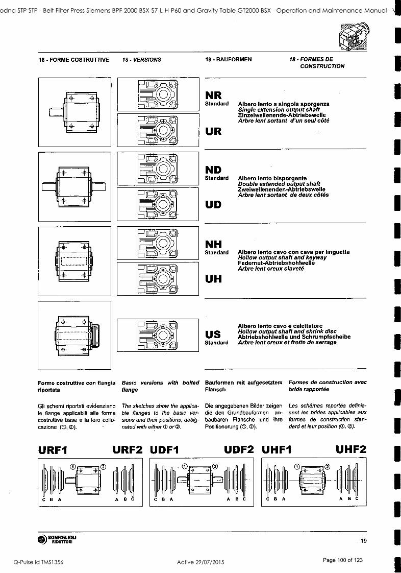
18 - FORME COSTRUTTIVE 18 - VERSIONS
Forme costruttive con flangia riportata
Gli schemi riportati evidenziano le flange applicabili alle forme costruttive base e la loro collo- cazione (O, G).
URF1
Basic versions with bolted flange
The sketches show the applica- ble flanges to the basic ver- sions and their positions, desig- nated with either 0 ore.
URF2 UDF1
18- BAUFORMEN 18 - FORMES DE CONSTRUCTION
NR Standard
UR
Albero lento a singola sporgenza Single extension output shaft E i nzelwe l lenende- Abtriebswelle Arbre lent sortant d'un seul côté
ND Standard
UD
Albero lento bisporgente Double extended output shaft Zwe iwel len enden- Abtriebswelle Arbre lent sortant de deux côtés
NH Standard
UH
Albero lento cavo con cava per linguetta Hollow output shaft and keyway Federnut-Abtriebshohlwelle Arbre lent creux claveté
US Standard
Albero lento cavo e calettatore Hollow output shaft and shrink disc Abtriebshohlwelle und Schrumpfscheibe Arbre lent creux et frette de serrage
Bauformen mit aufgesetztem Flansch
Die angegebenen Bilder zeigen die den Grundbauformen an- baubaren Flansche und ihre Positionerung (0, 0).
Formes de construction avec bride rapportée
Les schémas reportés definis- sent les brides applicables aux formes de construction stan- dard et leur position (0, ED).
UDF2 UHF1 UHF2
hl Di
C B A
. .. }
A B C
BONFIGLIOLI RIDUTTORI 19
ST41 Goodna STP STP - Belt Filter Press Siemens BPF 2000 BSX-S7-L-H-P60 and Gravity Table GT2000 BSX - Operation and Maintenance Manual - Vendor Manual
Q-Pulse Id TMS1356 Active 29/07/2015 Page 100 of 123
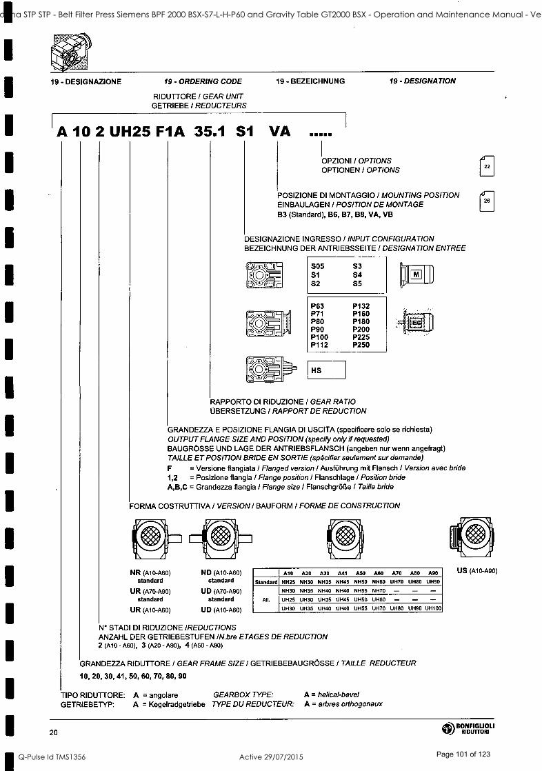
1
1
1
1
1
1
1
1
1
19 - DESIGNAZIONE 19 - ORDERING CODE
RIDUTTORE / GEAR UNIT GETRIEBE I REDUCTEURS
19 - BEZEICHNUNG 19 - DESIGNATION
A 10 2 UH25 F1A 35.1 S1 VA
OPZIONI l OPTIONS OPTIONEN / OPTIONS
POSIZIONE DI MONTAGGIO / MOUNTING POSITION EINBAULAGEN / POSITION DE MONTAGE B3 (Standard), B6, B7, B8, VA, VB
DESIGNAZIONE INGRESSO / INPUT CONFIGURATION BEZEICHNUNG DER ANTRIEBSSEITE / DESIGNATION ENTREE
S05 S1 S2
S3 S4 S5
P63 P132 P71 P160 P80 P180 P90 P200 P100 P225 P112 P250
HS
RAPPORTO DI RIDUZIONE / GEAR RATIO ÜBERSETZUNG I RAPPORT DE REDUCTION
GRANDEZZA E POSIZIONE FLANGIA DI USCITA (specificare solo se richiesta) OUTPUT FLANGE SIZE AND POSITION (specify only if requested) BAUGRÖSSE UND LAGE DER ANTRIEBSFLANSCH (angeben nur wenn angefragt) TAILLE ET POSITION BRIDE EN SORTIE (spécifier seulement sur demande)
F = Versione flangiata / Flanged version / Ausführung mit Flansch / Version avec bride 1,2 = Posizione flangia / Flange position I Flanschlage / Position bride A,B,C = Grandezza flangia / Flange size I Flanschgröße / Taille bride
FORMA COSTRUTTIVA / VERSION I BAUFORM / FORME DE CONSTRUCTION
NR (Al0 -A60) ND (Al 0-A60) standard standard
UR (A70 -A90) UD (A70 -A90) standard standard
UR (Al 0-A60) UD (A10-A60)
A10 A20 A30 A41 A50 A60 A70 A80 A90
Standard NH2S NH30 NH35 NH45 NH50 NH60 UH70 UH80 UH90
Alt.
NH30 NH35 NH40 NH40 NH55 NH70 - - - UH25 UH30 UH35 UH45 UH50 UH60 - - - UH30 UH35 UH40 UI-140 UH55 UH70 UH80 UH90 UH100
N° STADI DI RIDUZIONE IREDUCTIONS ANZAHL DER GETRIEBESTUFEN /N.bre ETAGES DE REDUCTION 2 (A10 - A60), 3 (A20 - A90), 4 (A50 - A90)
GRANDEZZA RIDUTTORE / GEAR FRAME SIZE I GETRIEBEBAUGRÖSSE / TAILLE REDUCTEUR
10, 20, 30, 41, 50, 60, 70, 80, 90
TIPO RIDUTTORE: A = angolare GEARBOX TYPE: A = helical -bevel GETRIEBETYP: A = Kegelradgetriebe TYPE DU REDUCTEUR: A = arbres orthogonaux
US (A10-A90)
BONFIGLIOLI 20 RIDUTTORI
ST41 Goodna STP STP - Belt Filter Press Siemens BPF 2000 BSX-S7-L-H-P60 and Gravity Table GT2000 BSX - Operation and Maintenance Manual - Vendor Manual
Q-Pulse Id TMS1356 Active 29/07/2015 Page 101 of 123

Designazione motore Motor designation Motor bezeichnung Designation moteur
MOTORE / MOTOR FRENO / BRAKE MOTOR / MOTEUR BREMSE / FREIN
IM 1 LA 4 230/400 -50 IP54 CLF .... W FD 7 5 R SB 220 SA .. .
OPZIONI OPTIONS OPTIONEN OPTIONS
ALIMENTAZ. FRENO BRAKE SUPPLY BREMSVERSORGUNG ALIMENTATION FREIN
TIPO ALIMENTATORE RECTIFIER TYPE GLEICHRICHTERTYP TYPE ALIMENTATERR NB, SB, NBR, SBR
LEVA DI SBLOCCO FRENO BRAKE HAND RELEASE BREMSENTHANDLÜFTUNG LEVIER DE DEBLOCAGE FREIN R, RM
COPPIA FRENANTE / BRAKE TORQUE BREMSMOMENT/ COUPLE FREIN
TIPO FRENO / BRAKE TYPE BREMSENTYP / TYPE DE FREIN FD ( freno c.c./ d.c. brake / G.S. Bremse / frein c.c.) FA, BA ( freno c.a./ a.c. brake I W.S. Bremse / frein c.a.)
POSIZIONE MORSETTIERA / TERMINAL BOX POSITION KLEMMENKASTENLAGE / POSITION BOITE A BORNE W (default), N, E, S
FORMA COSTRUTTIVA / MOTOR MOUNTING BAUFORM / FORM DE CONSTRUCTION - (motore integrato / compact motor/ kompaktes Motor / moteur compact) B5 (motore IEC / IEC - motor/ IEC Motor / moteur CEI)
CLASSE ISOLAMENTO / INSULATION CLASS SOLIERUNGSKLASSE / CLASSE ISOLATION CL F standard CL H option
GRADO DI PROTEZIONE / DEGREE OF PROTECTION SCHUTZART / DEGRE DE PROTECTION IP55 standard (IP54 - autofr./brake motor/ Bremssmotor / moteur frein)
TENSIONE - FREQUENZA I VOLTAGE - FREQUENCY SPANNUNG - FREQUENZ i TENSION - FREQUENCE
NUMERO DI POLI / POLE NUMBER l POLZAHL / N.bre POLES
2, 4, 6, 2/4, 2/6, 2/8, 2/12
GRANDEZZA MOTORE / MOTOR SIZE / MOTOR -BAUGRÖSSE / TAILLE MOTEUR
05B - 5LA (motore integrato / compact motor / kompaktes Motor / moteur compact) 63A - 250M (motore IEC / IEC motor I IEC - motor l moteur CEI)
TIPO MOTORE/ MOTOR TYPE I MOTORTYP / TYPE MOTEUR M = trifase integrato / compact 3 -phase I kompaktes Dreiphasen / 3 phasé compact BN = trifase IEC / IEC 3 -phase / IEC Dreiphasen l 3 phasè CEI
AAh1 BONFIGLIOLI !!l RIDUTTORI 21
ST41 Goodna STP STP - Belt Filter Press Siemens BPF 2000 BSX-S7-L-H-P60 and Gravity Table GT2000 BSX - Operation and Maintenance Manual - Vendor Manual
Q-Pulse Id TMS1356 Active 29/07/2015 Page 102 of 123

e) Avviamenti orari
Per servizi diversi da S1, con un numero rilevante di inserzioni /ora si dovrà tener conto di un fattore Z (deter- minabile con le indicazioni riportate nel capitolo dei mo- tori) il quale definisce il nu- mero max. di avviamenti specifico per l'applicazione in oggetto.
13 - INSTALLAZIONE
E molto importante, per l'insta- llazione del riduttore, attenersi alle seguenti norme:
a) Assicurarsi che il fissaggio del riduttore, sia stabile onde evitare qualsiasi vi- brazione. Installare (se si prevedono urti, sovraccari- chi prolungati o possibili bloccaggi) giunti idraulici, frizioni, limitatori di coppia, ecc.
b) Durante la verniciatura si dovrànno proteggere i piani lavorati e il bordo esterno degli anelli di tenuta per evitare che la vernice ne essichi la gomma, pregiudi- cando la tenuta del paraolio stesso.
c) Gli organi che vanno calet- tati sugli alberi di uscita del riduttore devono essere la- vorati con tolleranza ISO H7 per evitare accoppia- menti troppo bloccati che, in fase di montaggio potreb- bero danneggiare irrepara- bilmente il riduttore stesso. Inoltre, per il montaggio e lo smontaggio di tali organi si consiglia l'uso di adeguati tiranti ed estrattori utilizzan- do il foro filettato posto in testa alle estremità degli al- beri.
d) Le superfici di contatto do- vranno essere pulite e trat- tate con adeguati protettivi prima del montaggio, onde evitare l'ossidazione e il con- seguente bloccaggio delle parti.
e) Starts per hour
For duties featuring a high number of switches the ac- tual starting capability in loaded condition (Z] must be calculated. Actual number of starts per hour must be lower than value so calculated.
13 - INSTALLATION
e) Schaltungen /Stunde
Bei anderen Betriebsarten als S1 mit einem hohen Wert für die Schaltun- gen /Stunde muß der Faktor Z berücksichtigt werden (er kann mit Hilfe der Angaben im Kapitel Motoren be- stimmt werden), der die max. zulässige Anzahl von Schalten für eine bestimmte Anwendung definiert.
13 - INSTALLATION
The following installation in- Für die Installation des Getrie- structions must be observed: bes ist es äußerst wichtig, daß
folgende Normen beachtet wer- den:
a) Make sure that the gear- a) box is correctly secured to avoid vibrations. If shocks or overloads are expected, install hydraulic couplings, clutches, torque limiters, etc.
b) Before being paint coated, b) the machined surfaces and the outer face of the oil seals must be protected to prevent paint drying out the rubber and jeopardising the sealing function.
c) Parts fitted on the gearbox c) output shaft must be ma- chined to /SO H7 tolerance to prevent interference fits that could damage the gear- box itself. Further, to mount or remove such parts, use suitable pullers or extraction devices using the tapped hole located at the top of the shaft extension.
d) Mating surfaces must be d) cleaned and treated with suitable protective products before mounting to avoid oxidation and, as a result, seizure of parts.
Sicherstellen, daß die Be- festigung des Getriebes sta- bil ist, damit keine Schwin- gungen entstehen. Wenn es voraussichtlich zu Stößen, längerdauernden Überlas- ten oder zu Blockierungen kommen kann, sind entspre- chende Schutzelemente wie hydraulische Kupplungen, Kupplungen, Rutschkupp- lungen usw. zu installieren.
Beim Lackieren die bear- beiteten Flächen und die Dichtringe schützen, damit der Anstrichstoff nicht dem Kunststoff angreift und so- mit die Dichtigkeit der Ölab- dichtungen in Frage gestellt wird.
Die Organe, die mit einer Keilverbindung auf der Ab- triebswelle des Getriebes befestigt werden, müssen mit einer Toleranz ISO H7 gearbeitet sein, um allzu fest blockierte Verbindun- gen zu vermeiden, die even- tuell zu einer irreparablen Beschädigung des. Getrie- bes während des Einbaus führen könnten. Außerdem sind beim Ein- und Ausbau dieser Organe geeignete Zugstangen und Abzieher zu verwenden, wobei die Gewindebohrung an den Kopfen der Wellen zu ver- wenden ist.
Die Berührungsflächen müs- sen sauber sein und vor der Montage mit einem geeigne- ten Schutzmittel behandelt werden, um Oxidierung und die daraus folgende Blockie- rung der Teile zu verhindern.
e) Démarrages/heure
Pour les services différents de SI, avec un nombre im- portant d'insertions/heure, il faudra prendre en considé- ration un facteur Z (détermi- né à l'aide des informations reportées dans le chapitre des moteurs) qui définit le nombre maximum de dé- marrages spécifique pour l'application concernée.
13 - INSTALLATION
Il est très important, pour l'installation du réducteur, de se conformer aux règles suivantes:
a) S'assurer que la fixation du réducteur soit stable afin d'éviter toute vibration. Installer (en cas de chocs, de surcharges prolongées ou de blocages) des cou- pleurs hydrauliques, des embrayages, des limiteurs de couple etc...
b) En phase de peinture, il fau- dra protéger les plans usi- nés et le bord extérieur des bagues d'étanchéité pour éviter que la peinture ne dessèche le caoutchouc, ce qui risque de nuire à l'efficacité du joint.
c) Les organes qui sont calés sur les arbres de sortie du réducteur doivent être réali- sés avec une tolérance ISO H7 pour éviter les accouple- ments trop serrés qui, en phase de montage, pour- raient endommager irrémé- diablement le réducteur. En outre, pour le montage et le démontage de ces organes, nous conseillons d'utiliser un outillage et des extrac- teurs appropriés en utilisant le trou taraudé situé en ex- tremité d' arbre.
d) Les surfaces de contact de- vront être propres et traitées avec des produits de protec- tions appropriés avant le montage afin d'éviter l'oxydation et par suite le blocage des pièces.
4I;!0 B RID 15
ST41 Goodna STP STP - Belt Filter Press Siemens BPF 2000 BSX-S7-L-H-P60 and Gravity Table GT2000 BSX - Operation and Maintenance Manual - Vendor Manual
Q-Pulse Id TMS1356 Active 29/07/2015 Page 103 of 123
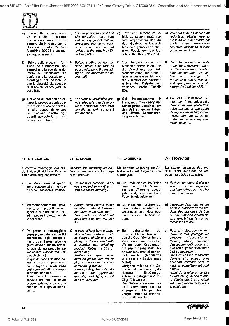
e) Prima della messa in servi - zo del riduttore accertarsi che la macchina che lo in- corpora sia in regola con le disposizioni della Direttiva Macchine 89/392 e succes- sivi aggiornamenti.
f) Prima della messa in fun- zione della macchina, ac- certarsi che la posizione del livello del lubrificante sia conforme alla posizione di montaggio del riduttore e che la viscosità sia adegua- ta al tipo del carico (vedi ta- bella B3).
g) Nel caso di istallazione al- l'aperto prevedere adegua- te protezioni e/o carteratu- re allo scopo di evitare l'esposizione diretta agli agenti atmosferici e alla radiazione solare.
14 - STOCCAGGIO
Il corretto stoccaggio dei pro- dotti ricevuti richiede l'esecu- zione delle seguenti attività:
a) Escludere aree all'aperto, zone esposte alle intempe- rie o con eccessiva umidità.
b) Interporre sempre tra il pavi- mento ed i prodotti, pianali lignei o di altra natura, atti ad impedire il diretto contat- to col suolo.
c) Per periodi di stoccaggio e soste prolungate le superfici interessate agli accoppia- menti quali flange, alberi e giunti devono essere protet- te con idoneo prodotto an- tiossidante (Mobilarma 248 o equivalente). In questo caso i riduttori do- vranno essere posizionati con il tappo di sfiato nella posizione più alta e riempiti interamente d'olio. Prima della loro messa in servizio nei riduttori dovrà essere ripristinata la corretta quantità, e il tipo di lubrifi- cante.
e) Prior to putting the gear unit into operation make sure that the equipment that in- corporates the same com- plies with the current revision of the Machines Di- rective 89/392.
f) Before starting up the ma- chine, make sure that oil level conforms to the mount- ing position specified for the gear unit.
g) For outdoor installation pro- vide adequate guards in or- der to protect the drive from rainfalls as well as direct sun radiation.
14 - STORAGE
Observe the following instruc- tions to ensure correct storage of the products:
e) Bevor das Getriebe im Be- trieb zu setzen, muß man sich vergewissern daß die das Getriebe einbauende Maschine gemäß den aktu- ellen Regelungen der Ma- schine Richtlinie 89/392 ist.
f) Vor Inbetriebnahme der Maschine sicherstellen, daß die Anordnung der Füll - standschraube der Einbau- lage angemessen ist, und die Viskosität des Schmier- mittels der Belastungsart entspricht (siehe Tabelle B3).
g) Bei Inbetriebnahme in Frein, muß man geeigneten Schutzgeräte vorsehen, um das Antrieb gegen Regen und direkte Sonnenstrah- lung zu schutzen.
14 - LAGERUNG
Die korrekte Lagerung der An- triebe erfordert folgende Vor- kehrungen:
a) Do not store outdoors, in ar- a) eas exposed to weather or with excessive humidity.
b) Always place boards, wood b) or other material between the products and the floor. The gearboxes should not have direct contact with the floor.
c) In case of long -term storage c) all machined surfaces such as flanges, shafts and cou- plings must be coated with a suitable rust inhibiting product (Mobilarma 248 or equivalent). Furthermore gear units must be placed with the fill plug in the highest position and filled up with oil. Before putting the units into operation the appropriate quantity, and type, of oil must be restored.
Die Produkte nicht im Freien lagern und nicht in Räumen, die der Witterung ausge- setzt sind, oder eine hohe Feuchtigkeit aufweisen.
Die Produkte nie direkt auf dem Boden, sondern auf Unterlagen aus Holz oder einem anderen Material la- gern.
Bei anhaltenden La- ger -und Haltszeiten müs- sen die Oberflächen für die Verbindung, wie Flansche, Wellen oder Kupplungen mit einem geeigneten Oxi- dationsschutzmittel behan- delt werden (Mobilarma 248 oder ein äquivalentes Mittel). Übrigens müssen die Ge- triebe mit nach oben geh - richteter Entlüftungs- schraube gelagert und mit Öl gefüllt werden. Die Getriebe müssen vor ihrer Verwendung mit der angegeben Menge des vorgesehenen Schmiermit- tels gefüllt werden.
e) Avant la mise en service du réducteur, vérifier que la machine où il est monté est conforme aux normes de la Directive Machines 89/392 et ses mises à jour.
o Avant la mise en marche de la machine, s'assurer que la position du niveau du lubri- fiant soit conforme à la posi- tion de montage du réducteur et que la viscosité soit appropriée au type de charge (voir tableau B3).
g) En cas d'installation en plein air, il est nécessaire d'appliquer des protections et/ou des caches appropriés de façon à éviter l'exposition directe aux agents atmos- phériques et aux rayonne- ments solaires.
14 - STOCKAGE
Un correct stockage des pro- duits reçus nécessite de res- pecter les règles suivantes:
a) Exclure les zones à ciel ou- vert, les zones exposées aux intempéries ou avec hu- midité excessive.
b) Interposer dans tous les cas entre le plancher et les pro- duits des planches de bois ou des supports d'autre na- ture empêchant le contact direct avec le sol.
c) Pour une stockage de long durée il faut protéger les surfaces d'accouplement (brides, arbres, manchon d'accouplement) avec pro- duit anti oxydant ( Mobilarma 248 ou equivalent). Dans ce cas les réducteurs devront être placés avec bouchon reniflard vers le haut et complètement repli d'huile. Avant de la mise en service du réducteur, la bon quanti- té d'huile devrà etre rétabli selon la quantité indiqué sur le catalogue.
16 Q!b BONFIGLIOU V RIDUTTORI
ST41 Goodna STP STP - Belt Filter Press Siemens BPF 2000 BSX-S7-L-H-P60 and Gravity Table GT2000 BSX - Operation and Maintenance Manual - Vendor Manual
Q-Pulse Id TMS1356 Active 29/07/2015 Page 104 of 123

15 - CONDIZIONI DI FORNITURA
I riduttori vengono forniti come segue:
a) già predisposti per essere installati nella posizione di montaggio come definito in fase di ordine;
b) collaudati secondo specifi- che interne;
c) le superfici di accoppiamen- to non sono verniciate;
d) provvisti di dadi e bulloni per montaggio motori per la ver- sione IEC;
e) dotati di protezioni in plasti- ca sugli alberi;
f) provvisti di golfare di solle- vamento (dove previsto).
16 - SPECIFICHE DELLA VERNICE
Le specifiche della vernice ap- plicata sui riduttori (dove previ- sto) potranno essere richieste alle filiali o ai distributori che hanno fornito i gruppi.
15 - CONDITIONS OF SUPPLY 15 - LIEFERBEDINGUNGEN 15 - CONDITIONS DE LIVRAISON
Gear units are supplied as fol- lows:
a) configured for installation in the mounting position specified when ordering;
b) tested to manufacturer spec- ifications;
c) mating machined surfaces come unpainted;
d) nuts and bolts for mounting motors are provided;
e) shafts are protected during transportation by plastic caps;
I) supplied with lifting lug (where applicable).
16 - PAINT SPECIFICATIONS
Specifications for paint applied to gearboxes (where applica- ble) may be obtained from the branches or dealers that sup- plied the units.
Die Getriebe werden in folgen- dem Zustand geliefert:
a) schon bereit für die Monta- ge in der bei Bestellung festgelegten Einbaulage;
b) nach werksinternen Spezifi- kationen geprüft;
c) die Verbindungsflächen sind nicht lackiert;
d) ausgestattet mit Schrauben und Muttern für die Montage der Motoren (Version mit Adapter für IEC- Motoren);
e) alle Getriebe werden mit Kunststoffschutz auf den Wellen geliefert;
f) mit Transportierring zum An heben (falls vorgesehen).
16 - ANGABEN ZU DEN ANSTRICHSTOFFE
Die Spezifikationen des Lackes, der auf den Getriebe (wo erfor- derlich) verwendet wurde, kön- nen bei den Filialen oder Verkaufsstellen, die die Grup- pen geliefert haben, angefor- dert werden.
Les réducteurs sont livrés comme suit:
a) déjà prédisposés pour être installés dans la position de montage comme défini en phase de commande;
b) testés selon les spécifica- tions internes;
c) les surfaces de liaison ne sont pas peintes;
d) équipés d'écrous et de bou- lons pour le montage des moteurs normalisés pour la version CEI;
e) embouts de protections en plastique sur les arbres;
f) dotés d'un crochet de le- vage (quand cela est prévu).
16 - SPECIFICATIONS DE LA PEINTURE
Les spécification de la peinture appliquée sur les réducteurs pourront, le cas échéant, être demandées aux filiales ou aux distributeurs ayant foumi les groupes.
BONFIGLIOLI RIDUTTORI 17
ST41 Goodna STP STP - Belt Filter Press Siemens BPF 2000 BSX-S7-L-H-P60 and Gravity Table GT2000 BSX - Operation and Maintenance Manual - Vendor Manual
Q-Pulse Id TMS1356 Active 29/07/2015 Page 105 of 123
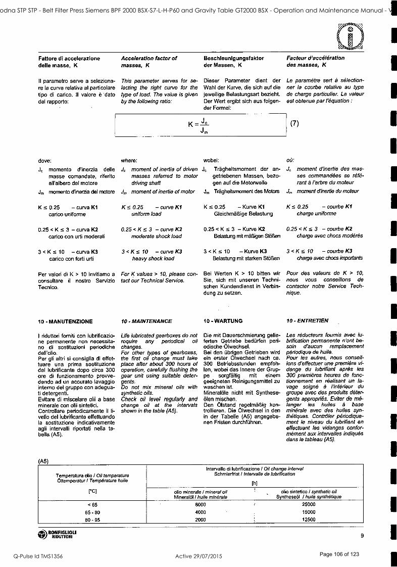
Fattore di accelerazione delle masse, K
II parametro serve a seleziona- re la curva relativa al particolare tipo di carico. Il valore è dato dal rapporto:
Acceleration factor of masses, K
This parameter serves for se- lecting the right curve for the type of load. The value is given by the following ratio:
Beschleunigungsfaktor der Massen, K
Dieser Parameter dient der Wahl der Kurve, die sich auf die jeweilige Belastungsart bezieht. Der Wert ergibt sich aus folgen- der Formel:
K = ° Jm
dove:
Jc momento d'inerzia delle masse comandate, riferito all'albero del motore
Jrr, momento d'inerzia del motore
K <- 0.25 - curva K1
carico uniforme
0.25 <K- <3- curva K2 carico con urti moderati
3 < K s 10 - curva K3 carico con forti urti
Per valori di K > 10 invitiamo a consultare il nostro Servizio Tecnico.
10 - MANUTENZIONE
I riduttori forniti con lubrificazio- ne permanente non necessita- no di sostituzioni periodiche dell'olio. Per gli altri si consiglia di effet- tuare una prima sostituzione del lubrificante dopo circa 300 ore di funzionamento provve- dendo ad un accurato lavaggio interno del gruppo con adegua- ti detergenti. Evitare di miscelare olii a base minerale con olii sintetici. Controllare periodicamente il li- vello del lubrificante effettuando la sostituzione indicativamente agli intervalli riportati nella ta- bella (A5).
A5
where:
Je moment of inertia of driven masses referred to motor driving shaft
J, moment of inertia of motor
K .s 0.25 - curve K1 uniform load
0.25 < K s 3 - curve K2 moderate shock load
3 <K <- 10 -curve K3 heavy shock load
For K values > 10, please con- tact our Technical Service.
10 - MAINTENANCE
Life lubricated gearboxes do not require any periodical oil changes. For other types of gearboxes, the first oil change must take place after about 300 hours of operation, carefully flushing the gear unit using suitable deter- gents. Do not mix mineral oils with synthetic oils. Check oil level regularly and change oil at the intervals shown in the table (A5).
wobei:
J Trägheitsmoment der an- getriebenen Massen, bezo- gen auf die Motorwelle
J,n Trägheitsmoment des Motors
K <- 0.25 - Kurve K1
Gleichmäßige Belastung
0.25 < K <- 3 - Kurve K2 Belastung mit mäßigen Stößen
3 <K < -10 -Kurve K3 Belastung mit starken Stößen
Bei Werten K > 10 bitten wir Sie, sich mit unseren Techni- schen Kundendienst in Verbin- dung zu setzen.
10 - WARTUNG
Die mit Dauerschmierung gelie- ferten Getriebe bedürfen peri- odische Ölwechsel. Bei den übrigen Getrieben wird ein erster Ölwechsel nach ca. 300 Betriebsstunden empfoh- len, wobei das Innere der Grup- pe sorgfältig mit einem geeigneten Reinigungsmittel zu waschen ist. Mineralöle nicht mit Synthese- ölen mischen. Den Ölstand regelmäßig kon- trollieren. Die Ölwechsel in den in der Tabelle (A5) angegebe- nen Fristen durchführen.
Facteur d'accélération des masses, K
Le paramètre sert à sélection- ner la courbe relative au type de charge particulier. La valeur est obtenue par l'équation :
(7)
où:
Jc moment d'inertie des mas- ses commandées se réfé- rant à l'arbre du moteur
J, moment d'inertie du moteur
K <- 0.25 - courbe K1 charge uniforme
0.25 <K < -3 - courbe K2 charge avec chocs modérés
3 < K s 10 - courbe K3 charge avec chocs importants
Pour des valeurs de K > 10,
nous vous conseillons de contacter notre Service Tech- nique.
10 - ENTRETIEN
Les réducteurs fournis avec lu- brification permanente n'ont be- soin d'aucun remplacement périodique de huile. Pour les autres, nous conseil- lons d'effectuer une première vi- dange du lubrifiant après les 300 premières heures de fonc- tionnement en réalisant un la- vage soigné à l'intérieur du groupe avec des produits déter- gents appropriés. Eviter de mé- langer les huiles à base minérale avec des huiles syn- thétiques. Contrôler périodique- ment le niveau du lubrifiant en effectuant les vidanges confor- mément aux intervalles indiqués dans le tableau (A5).
Temperatura dio / Oil temperature Oltemperatur / Température huile
CCl
Intervallo di lubrificazione / Oil change interval Schmierfrist / Intervalle de lubrification
[h]
olio minerale l mineral oil Mineralöl / huile minérale
olio sintetico / synthetic oil Syntheseöl / huile synthétique
< 65
65 - 80
80 - 95
8000
4000
2000
25000
15000
12500
BONFIGLIOLI RIDUTTORI 9
1
1
1
1
ST41 Goodna STP STP - Belt Filter Press Siemens BPF 2000 BSX-S7-L-H-P60 and Gravity Table GT2000 BSX - Operation and Maintenance Manual - Vendor Manual
Q-Pulse Id TMS1356 Active 29/07/2015 Page 106 of 123

1
1
1
1
1
20 - LUBRIFICAZIONE
Gli organi interni dei riduttori Bonfiglioli sono lubrificati con un sistema misto di immersione e sbattimento dell'olio.
I gruppi A10, A20 e A30 sono normalmente consegnati con ca- rica di lubrificante dalla fabbrica, o dalla rete di vendita ufficiale.
Per questi stessi gruppi, nell'esecuzione predisposta per motorizzazione normalizzata IEC, un tappo di sfiato é fornito a corredo e dovrà essere instal- lato ad esclusione della posizio- ne di montaggio V5, prima della messa in esercizio del riduttore.
I gruppi di grandezza A41 e su- periore sono normalmente forniti privi di lubrificante, e sarà cura dell'utilizzatore riempirli di olio prima della messa in servizio.
Le tavole che seguono sono da riferimento nell'interpretazione delle posizioni di montaggio, della collocazione dei tappi di servizio e delle quantità di lubri- ficante.
Queste ultime sono indicative, e per il corretto riempimento si
dovrà fare riferimento alla mez- zeria dei tappo, o dell'astina di livello, se presente. Rispetto a questa condizione la quantità di lubrificante ri- portata in tabella può presen- tare scostamenti, occasional- mente anche rilevanti.
II lubrificante "long life" fornito di serie è di natura sintetica e,
a meno di contaminazione dall'esterno, non richiede so- stituzioni periodiche per tutto l'arco di vita del riduttore. Lo stesso lubrificante consente inoltre funzionamenti a tempe- rature ambiente 0 < ta < 50 °C.
Per funzionamento a tempera- ture inferiori consultare il ns. Servizio Tecnico.
(B3)
20 - LUBRICATION
The inner parts of Bonfiglioli gear units are oil -bath and splash lubricated.
Frame sizes A10, A20 and A30 are supplied by the factory, or by the authorized dealers, al- ready filled with oil.
For same units configured with the IEC- normalized motor mounting flange a breather plug is also supplied. With the excep- tion of the V5 mounting position, the breather must replace the closed plug supplied for trans- portation purposes, prior to putt- ing the gear unit into operation.
Unless otherwise specified, units size A41 and larger are usually supplied unlubricated at it will be the customer care to fill them with oil prior to putting them into operation.
The charts here after must be referred to as for the mounting position pattern and the corre- sponding oil plugs, if applicable, and related lubricant quantity.
Values for the oil quantity are indicative with the proper fill- ing always represented by the center of the sight glass or the dipstick, when this is supplied. In some cases, discrepancies, occasionally also substancial, versus the oil quantities listed in the chart may be noticed.
The "long life" poliglycol -based lubricant supplied by the fac- tory, in the absence of contam- ination, does not require peri- odical oil changes throughout the life of the gear unit. Opera- tion at an ambient temperature 0 < to < 50 °C is allowed.
Should the gear unit operate at temperature below 0 °C, please consult Bonfiglioli Technical Service Dept. for advise.
20 - SCHMIERUNG
Die Schmierung der Getriebe von Bonfiglioli erfolgt durch eine Kombination aus Ölbad- und Tauchschmierung.
Die Getriebegroßen A10, A20 und A30 sind ab Werk mit einer Le-
bensdauerschmierung versehen.
Wenn diese Baugrößen mit einem IEC -Eingang ausgeliefert werden, dann gehört ein Lüfter zum Liefer-
umfang, außer bei der Einbaulage V5. Während des Transports wird anstatt des Lüfters ein Stopfen verwendet Vor dem Einsatz des Getriebes muss dieser Stopfen durch den Lüfter ersetzt werden.
Die Getriebe ab der Größe A41 werden ohne Ölfüllung ausge- liefert. Vor der Inbetriebnahme muss deshalb auf das Einfüllen der richtigen Ölfüllmenge ge- achtet werden !
Bitte beachten Sie dazu auch die nachfolgenden Kapitel über die Positionen der Stopfen und Ölschaugläser und den ent- sprechenden Ölfüllmengen.
Die im Katalog angegeben Öl- füllmengen sind Anhaltswertel Maßgebend ist, das der Ölstand bis Mitte des Ölschauglas für die entsprechende Einbaulage aufgefüllt wird. Auf Abweichun- gen gegen0ber den in der Ta- belle angegebenen Ölmengen, gelegentlich nicht unwesentli- che, wird hingewiesen.
Die mit Lebensdauerschmie- rung gelieferten Serien sind mit synthetischem CA auf Polygly- kolbasis gefüllt. Falls dieses Öl nicht verunreinigt wird, ist wäh- rend der Lebensdauer des Ge- triebes kein Ölwechsel nötig. Die zulässige Umgebungstem- peratur für den Betriebe liegt im
Bereich von 0 < ta < 50 °C.
Falls ein Antrieb bei Temperatu- ren unterhalb von 0° betrieben werden soll, kontaktieren sie bit-
te unseren technischen Service für weitere Anweisungen.
20 - LUBRIFICATION
Les organes internes des réduc- teurs Bonfiglioli sont lubrifiés avec un système mixte d'immer- sion et de battement de l'huile.
Les groupes A 10, A 20 et A 30 sont normalement livré avec charge de lubrifiant de l'usine, ou du réseau de vente officielle.
Pour ces mêmes groupes, dans l'exécution prevue pour motori- sation normalisée IEC, un bou- chon de reniflard est fourni et devra être installé, sauf position de montage V5, avant la mise en service du réducteur.
Les groupes de grandeur A41 et supérieur sont normalement fournis sans lubrifiant, et sera par l'utilisateur le remplissage d'huile avant la mise en service.
Les tables suivantes sont de ré- férence dans l'interpretation des positions de montage, du placement des bouchons de service et de la quantité de lu- brifiant.
Ces dernières sont indicati- ves, et pour le correct rem- plissage Il faut faire référence au bouchon de niveau ou à la
Jauge à huile, si présent. Par rapport à cette condition la quantité de lubrifiant indi- qué dans le tableau peut pré- senter des écartement, occa- sionnellement considérables. Le lubrifiant "long life" ; fourni de série est de nature synthé- tique et, à moins de contami- nation par l'extérieur, il ne de- mande pas des remplace- ments périodiques pour tout l'arc de vie du réducteur. Le même lubrifiant permet fonc- tionnements à des températu- res ambient 0 < ta < 50 °C.
Pour fonctionnement à des tem- pératures inférieures consulter notre Service Technique.
Tipo di carico / Type of duty
Art der Belastung / Type de charge
ta 0 °C -20 °C
ta 20 °C -40 °C
Olio minerale Mineral oil Mineralöl
Huile minérale ISO VG
Olio sintetico Synthetic oil Syntheseöl
Huile synthétique ISO VG
Olio minerale Mineral oil Mineralöl
Huile minérale ISO VG
Olio sintetico Synthetic oil Syntheseöl
Huile synthétique
ISO VG
Carico leggero / Light duty / Leicht / Charge légère
Carico medio / Medium duty / Normal / Charge moyenne
Carico pesante / Heavy duty / Schwer / Charge lourde
150
150
200
150
150
200
220
320
460
220
220
320
24 BONFIGLIOU
RIDUTTORI
ST41 Goodna STP STP - Belt Filter Press Siemens BPF 2000 BSX-S7-L-H-P60 and Gravity Table GT2000 BSX - Operation and Maintenance Manual - Vendor Manual
Q-Pulse Id TMS1356 Active 29/07/2015 Page 107 of 123
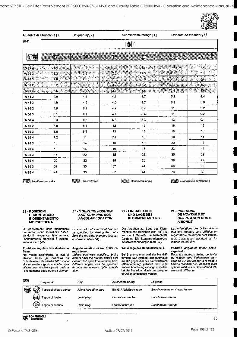
Quantità di lubrificante [ I ] Oil quantity (I Schmiermittelmenge [ I ] Quantité de lubrifiant il ] (B4)
(UV(
, , [q
Lr%t'ti',. ¡¡ , \v" C
';' .- i
'
, . , za.
. t
-> ,= ;_ ° -
à` `_', , a.
u
3e
` « ,
-zo -æ ,.. ,. ° ì,;
: wa
m-KY =., . f
.
x .. g u"`'
....
.
° -.- g ì #q -,as
,....'
A102 1.4 1.4 1:4 1.4' ° ,1.4 1.4
A20'2 , ' .2.3 ,.23 23 2.3 23 .I 23
A203 ' 26 26 2=6' 26 ,26 26
'A302 32 , 32 32 _' 32 , , '32 32
A303, . ' 36, , 36 36 36 36 ° 36,
A 41 2 4.0 4.1 4.1 4.7 5.2 4.4
A 41 3 4.0 4.0 4.0 4.7 6.1 3.9
A 50 2 4.9 8.1 4.7 8.4 11 9.2
A 50 3 5.1 8.1 4.7 8.4 11 9.2
A 50 4 6.3 8.2 5.3 8.3 13 9.1
A 60 2 6.8 8.1 12 15 18 15
A 60 3 6.8 8.1 12 . 15 18 15
A 60 4 7.2 11 7.4 16 19 14
A 70 3 10 14 10 15 20 14
A 70 4 13 14 10 15 23 14
A 80 3 15 22 15 26 35 22
A 80 4 20 22 15 26 39 22
A 90 3 31 35 37 44 66 39.
A 90 4 41 35 37 44 73 39
Lubrificazione a vita
21 - POSIZIONI Dl MONTAGGIO E ORIENTAMENTO MORSETTIERA
Gli orientamenti delle morsettiere dei motori sono identificati osser- vando il motore dal lato ventola; l'orientamento standard è eviden- ziato in nero (W).
Posizione angolare leva di sblocco freno. Nei motori autofrenanti, la leva di sblocco freno (se richiesta) ha l'orientamento standard a 90° rispetto alla morsettiera (posizione AB); spe- cificare con relative opzioni qualora l'orientamento desiderato sia diverso.
(B5)
Life lubricated Dauerschmierung
21 - MOUNTING POSITION 21 - EINBAULAGEN AND TERMINAL BOX UND LAGE DES ANGULAR LOCATION KLEMMENKASTENS
Location of motor terminal box can be specified by viewing the motor from the fan side; standard location is shown in black (l49.
Angular location of the brake re- lease lever. Unless otherwise specified, brake motors have the manual device side located, 90° apart from terminal box. Different angles can be specified through the relevant options avail- able.
Die Angaben zur Lage des Klem- menkastens beziehen sich auf das von der Lüfterseite her betrachtete Getriebe. Die Standardorientierung ist schwarz hervorgehoben (W).
Winkellage des Handlüfterhebels.
Bei Bremsmotoren wird der Handlüf- terhebel (auf Anfrage) standardmäßig auf 90° gegenüber des Klemmkastens (AB- Anordnung) geliefert; wird eine andere Anordnung verlangt, muß dies bei der Bestellung durch das geeigne- te Option angegeben werden.
Lubrification permanente
21 - POSITIONS DE MONTAGE ET ORIENTATION BOITE A BORNE
Les orientations des boites à bor- nes des moteurs sont définies en regardant le moteur du côté ventila- teur. L'orientation standard est in- diquée en noir (W).
Position angulaire levier déblo- cage frein. Dans les moteurs freins, ce levier (si requis) aura l'orientation stan- dard de 90° par rapport à la boite à bornes (position AB); spécifier avec options relatives si l'orientation de- sirée est différente.
Legenda: Key: Zeichenerklärung: Légende:
Tappo di sfiato / canco Filling / breather plug Einfüll / Ablaßschraube Bouchon de event / remplissage
Tappo di livello Level plug Ölstandsschraube Bouchon de niveau
Tappo di scarico Drain plug Ölablaßschraube Bouchon de vidange
BONFIGLIOLI RIDUTTORI 25
1
1
t
1
ST41 Goodna STP STP - Belt Filter Press Siemens BPF 2000 BSX-S7-L-H-P60 and Gravity Table GT2000 BSX - Operation and Maintenance Manual - Vendor Manual
Q-Pulse Id TMS1356 Active 29/07/2015 Page 108 of 123

s
HS P (SEC)
W = Default
W = Default
prq
W = Default
3x,
26 (3.1) BONFIGLIOLI
RIDUTTORI
ST41 Goodna STP STP - Belt Filter Press Siemens BPF 2000 BSX-S7-L-H-P60 and Gravity Table GT2000 BSX - Operation and Maintenance Manual - Vendor Manual
Q-Pulse Id TMS1356 Active 29/07/2015 Page 109 of 123

,
<4"' TneP
:, ": II4
P (IEC)
w
W = Default
3x
ITOBONFIGLIOLI RIDUTTORI 27
ST41 Goodna STP STP - Belt Filter Press Siemens BPF 2000 BSX-S7-L-H-P60 and Gravity Table GT2000 BSX - Operation and Maintenance Manual - Vendor Manual
Q-Pulse Id TMS1356 Active 29/07/2015 Page 110 of 123
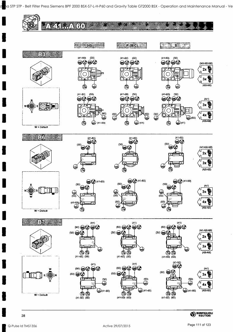
It A A 4
713 (ItC) °
W E
W = Default
(41-60) (50)
(41-60) (50)
(41-60) (50)
(41-60) (50) (41-60) (50)
(A41-A50-A60)
MAR
. 4
(41-60)
(41-60) (41-60)
(41-60)
(A41-ASO-ASO)
2x fit
3x
(A50-A60)
(A41)
44 (ASO-ASO)
W = Default
(50)
(50)
(41)
(41-60) (50)
(41)
(41-50) (60)
(50)
(50)
(4 )
(41-60) (50)
(41)
(41-50) (60)
(50)
(41)
(41-60) (50)
(41-50
(60)
(50)
NEI )
(41-50) (60)
(A41-0.50-A60)
3x It' (ASO-A60)
(A41)
(41-60) (A50-A60)
28 t' BONFIGLIOU
RIDUTTORI
ST41 Goodna STP STP - Belt Filter Press Siemens BPF 2000 BSX-S7-L-H-P60 and Gravity Table GT2000 BSX - Operation and Maintenance Manual - Vendor Manual
Q-Pulse Id TMS1356 Active 29/07/2015 Page 111 of 123

4, 5 ° o o
HS _P (IEC) ,
678
(50-60) (50-60)
(41)
(50-60)
(41)
S (50-60)
W = Default
W
(50) (41-60) (50) (41-60)
(50) (41-60) (50) (41-60) (50) (41-60)
ri R11741
E
E
1.
W = Default
(60)
r"1
(41-50) (50-60) AIN
AIN "10
(41) (50-60) (41)
(A50-A60)
(A41)
(A50-A60)
LI W = Default
Alk
(50)
111111r
te
(60)
(50) ì1.1
(60)
1I
(50)
(60)
(A41-A50-A60)
2 t 3x
(A50-A60)
(Ml)
3x 11
44 (A50-A60)
BONFIGLIOLI RIDUTTORI 29
ST41 Goodna STP STP - Belt Filter Press Siemens BPF 2000 BSX-S7-L-H-P60 and Gravity Table GT2000 BSX - Operation and Maintenance Manual - Vendor Manual
Q-Pulse Id TMS1356 Active 29/07/2015 Page 112 of 123

W = Default
W = Default'
(80) ` _a;
30 L\ BONFIGLIOLI RIDUTTORI
ST41 Goodna STP STP - Belt Filter Press Siemens BPF 2000 BSX-S7-L-H-P60 and Gravity Table GT2000 BSX - Operation and Maintenance Manual - Vendor Manual
Q-Pulse Id TMS1356 Active 29/07/2015 Page 113 of 123

w W = Default
-44
W = Default
(70-80)
(90 P63...P132)
r00 1.*
(90)
4x
BONFIGLIOLI RIDUTTORI 31
ST41 Goodna STP STP - Belt Filter Press Siemens BPF 2000 BSX-S7-L-H-P60 and Gravity Table GT2000 BSX - Operation and Maintenance Manual - Vendor Manual
Q-Pulse Id TMS1356 Active 29/07/2015 Page 114 of 123

INDICE DELLE REVISIONI (R) INDEX OF REVISIONS (R) LISTE DER ÄNDERUNGEN (R) INDEXDES RÉvisioNs (R)
R10
Descriziòne Description. Beschreibung Description.
17-- 72 Rimossa predisposizione Dropped P132 input, for Aufhebung der Anbaumög- Oté Prédisposition moteur 95 P132 per A 604. A 604. lichkeit P132 fürlos A 604. .P132 poùrA 604.
Questa pubblicazione annulla. e sosti túisce ogni precedente edizione o rivi -. scone. Ci riserviamo' il diritto di appor- tare modifithii senza preavviso. E vie-. tata la produzione anche parziale sen za, autorizzazione.
This publication supersedes end re- plaçes any previous edition and revi- sion. We reserve the right to implement modifications without no- tice. This dátálogue .cannot be repro- duced, even partially, without prior consent.
Diese Veröffentlichïing annuliért "und
ersetzt jeder hergehende Edition odèr Revision :. BONFIGLIOLI behält sich das Recht vor, Anderungen ,ohne vor- herige Infomialiónen':durchzuführeñ.
Cette publication annule 'et remplace toutes les autres précédentes. Nous nous te,servons:le droihdapporter tou- tes modifications à_nos. produits: La re-
production et le publication partielle ou 'totale ,de ce catalogue est interdite sans notre autorisation;
174 COD. 1041 R10 BONFIGLIOU
RIDUTTORI
ST41 Goodna STP STP - Belt Filter Press Siemens BPF 2000 BSX-S7-L-H-P60 and Gravity Table GT2000 BSX - Operation and Maintenance Manual - Vendor Manual
Q-Pulse Id TMS1356 Active 29/07/2015 Page 115 of 123

B
ST41 Goodna STP STP - Belt Filter Press Siemens BPF 2000 BSX-S7-L-H-P60 and Gravity Table GT2000 BSX - Operation and Maintenance Manual - Vendor Manual
Q-Pulse Id TMS1356 Active 29/07/2015 Page 116 of 123

SIEMENS - GT 2000 BSX
APPENDIX B
INSTRUMENT CUT SHEETS
E -stop Lifeline LRS4 ref. dwg. 60311132a item 9
Limit switch for belt overtravel OMRON model: D4B1181 ref.: dwg. 60311128a item 5
ST41 Goodna STP STP - Belt Filter Press Siemens BPF 2000 BSX-S7-L-H-P60 and Gravity Table GT2000 BSX - Operation and Maintenance Manual - Vendor Manual
Q-Pulse Id TMS1356 Active 29/07/2015 Page 117 of 123

Lifeline 4 Installation Instructions I nstal lationsanleitung Notice d'installation Istruzioni per l'installazione Instrucciones de instalación
Installation must be in accordance with the following steps and stated specifications and should be carried out by suitably competent personnel, Adherence to the recommended maintenance instructions forms part of the warranty.
WARNING: Do not defeat, tamper, remove or bypass this unit. Severe injury to personnel could result.
Bei der Installation müssen die im Folgenden beschriebenen Anweisungen und angegebenen Spezifikationen eingehalten werden. Zudem dart die Installation nur von entsprechend qualifizierten Mitarbeitern ausgeführt werden. Werden die empfohlenen Wartungsanweisungen nicht eingehalten, entfällt die Gewährleistung.
WARNUNG: Nehmen Sie niemals Eingriffe am Gerät vor, und zerlegen, entfernen oder überbrücken Sie das Gerät nicht. Andernfalls können schwere Körperverletzungen die Folge sein.
L'installation doit étre effectuée par un personnel qualifié conformément aux étapes et aux spécifications suivantes. Le respect des instructions de maintenance recommandée est l'une des conditions de la garantie.
AVERTISSEMENT: ne pas entraver le fonctionnement de cet interrupteur, ne pas le modifier, le retirer ni le contourner au risque de s'exposer à de graves blessures.
in Allen- Bradley
Guardlmarter
Le operazioni di Installazione devono essere eseguite da personale competente conformemente alle fasi qui di seguito illustrate nonché alle specifiche stabilite. Il rispetto delle istruzioni di manutenzione raccomandate costituisce pane della garanzia.
ATTENZIONE: non forzare, manomettere, rimuovere o bypassare questa unità. Pericolo di gravi lesioni alle persone.
Drg. No: 14'í45 Issue 1
La instalación debe realizarse según los pasos siguientes y las especificaciones establecidas, y debe ser realizada por personal debidamente capacitado. El cumplimiento de las Instrucciones de mantenimiento recomendadas forma parte de la garantía.
ADVERTENCIA: No cambie ni manipule indebidamente, ni desmonte u omite esta unidad. Esto podría causar lesiones personales graves.
ST41 Goodna STP STP - Belt Filter Press Siemens BPF 2000 BSX-S7-L-H-P60 and Gravity Table GT2000 BSX - Operation and Maintenance Manual - Vendor Manual
Q-Pulse Id TMS1356 Active 29/07/2015 Page 118 of 123
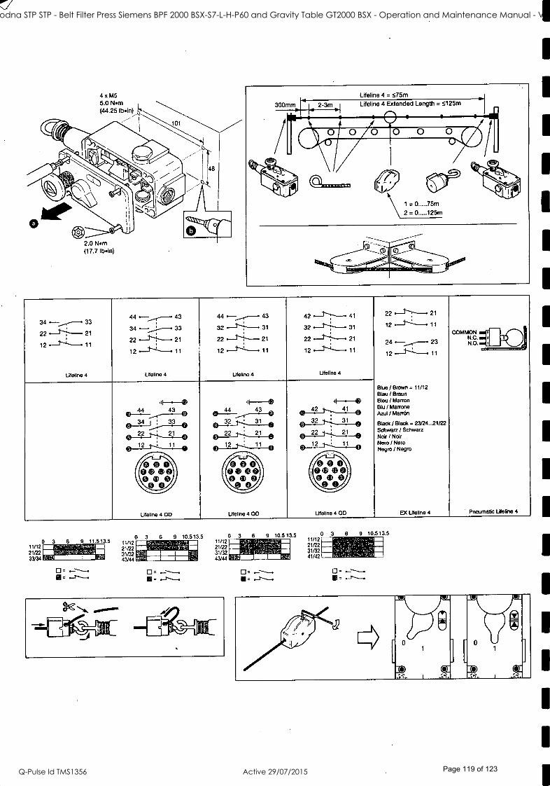
4 X M5
5.0 Nm (44.25 Ibin)
2.0 Minn (17.7 Ibin)
44 r--__...r-- 43 44 -__.,----- 43 42 - -- 41 22 - - 21
22 21 34 33 32 - --1`------ 31 32 . - - 31 12 - --- 11
12 - 11 22 ` 21 22 -- -1-1"--- 22 21 24 --...---- 23 Ñ.O. ,DOI 12.--1"--"---- 11 12- -.11 12- X11 12 --1.-1---11
Lifeline 4 Lifeline 4 Lifeline 4 Lifeline 4
Blue / Brown = 11/12 Blau / Braun
,lF ---Q II-.--0 4- --- - Bleu / Marton
e 44 44 43 iti,42_1--.I___410 Blu I Marrane Azul / Martón
34 l 3
v 32 31 32 31 Black / Black = 23/24...21/22
r7 --222 21 22 21 22 21 Schwarz / Schwarz
6 4 6 _ Noir / Noir
12 11 12 11 12 11 Nero / Nero Negro / Negro
Q ®Q, QQQ QQQ 0 ®©' e ®Q Q0 ''0
©Q a o Q© ©Q
Lifeline 4 OD Lifeline 4 OD Lifeline 4 OD EX Lifeline 4 Pneumatic Lifeline 4
hI 0 0
CI_
0 3 11/12 21 /22 33/34
0 11/12 21/22 31/32 43/44
3 6 9 10.513.5 0 11/12 21/22 31/32 43/44
3 6 9 10.5 13.5 11/12 21/22 31/32 41/42
i: . 1 441r ..4. I
1
ST41 Goodna STP STP - Belt Filter Press Siemens BPF 2000 BSX-S7-L-H-P60 and Gravity Table GT2000 BSX - Operation and Maintenance Manual - Vendor Manual
Q-Pulse Id TMS1356 Active 29/07/2015 Page 119 of 123

1
1
1
1
1
1
1
1
1
1
1
Maintenance Every Week Check the correct operation of the switching circuit Also check for signs of abuse or tampering. Inspect the switch casing for damage. Of particular importance is damage which causes loss of sealing at the lid or conduit entry. At !east every 6 months Isolate all power! Remove the lid. Inspect all terminals for tightness. Clean out any accumulation of fine dirt etc. Check for any sign of wear or damage, e.g. cam assembly wear, contact oxidisation and replace if apparent. Replace covers & tighten screws to specified settings. Reinstate the power & check for correct operation. Re -apply lamper evident varnish or similar compound to fixings.
Repair
if there is any malfunction or damage, no attempts at repair should be made. The unit should be replaced before machine operation Is allowed. DO NOT DISMANTLE THE UNIT.
Information In regard to UL5g8 When used in elevated ambient', temperature rating of field wiring shall not be less than amblent Electrical spec of rating code: A600 Currant, Max: 120V AC -make 60A, break 8A 240V AC - make 30A, break 3A Max. WA: make 7200, break 720 Use copper conductors only. Use polymeric conduit only Use one conduit entrance for field connections.
ICE Declaration of Conformity This is to declare that the products shown on this document conforms with the Essential Health and Safety Requirements (EHSR's) of the European Machinery Directive (98/37/EC), the relevant requirements of the Low Voltage Directive (73/23/EEC as amended by 93/68/EEC). These products also conform to EN 60947.5 -1, EN 1088, EN 292, EN 60204 -1 and have Third Party Approval.
For a comprehensive certificate iplease visit: www.ab.com/safety
Wartung Jede Woche Auf ordnungsgemäße Funktion des Schaltkrelses kontrollieren. Außerdem auf Anzeichen von Missbrauch oder Manipulation untersuchen. Das Schaltergehäuse auf Beschädigung kontrollieren. Dabei ist besonders auf Beschädigungen zu achten, die Undichtigkeit am Deckel oder Kabelrohreingang verursachen kánnten. Mindestens alle 6 Monate Alle Stromversorgungen trennenl Den Deckel abnehmen. Alle Klemmen auf Festigkeit kontrollieren. Etwaige Ansammlungen feiner Schmutzteilchen etc. entfernen. Auf Anzeichen von Verschleiß und Beschädigungen untersuchen, z.B. Nockenbaugruppenverschleiß oder Kontaktoxidation, und ersetzen, wenn diese aufgetreten sind. Deckel wieder anbringen & Schrauben auf die vorgegebenen Werte anziehen. Strom wieder anschließen & auf ordnungsgemäßen Betrieb kontrollieren. Manipulation - anzeigenden Lack oder ein ähnliches Mittel neu auf die Befestigungsteile auftragen.
Reparatur Bei Fehlfunktion oder Beschädigung dürfen keine Reparaturversuche unternommen werden. Die Einheit muss ersetzt werden. bevor weiterer Betrieb der Maschine zugelassen wird.
DIE EINHEIT DARF NICHT AUSEINANDERGEBAUT WERDEN.
Information betreffs UL508 Bei Einsatz In höheren Umgebungstemperaturen darf die Nenntemperatur für die Feldverdrahtung nicht niedriger sein als die Umgebungstemperatur. Elektrische Spezifikation des Nennwertcodes: A600 Strom, Max: 120V AC - Schließen 60A, Öffnen 6A 240V AC - Schließen 30A, Öffnen 3A Max. V /A: Schließen 7200, Öffnen 720 Nur Kupferleiter benutzen. Nur poymerische Leitungsrohre benutzen. Einen Leltungsrohreingang fiu die Feldanschlüsse benutzen.
CE KonformhtAtserldärung Hiermit wird bescheinigt dass die auf diesem Dokument aufgeführten Produkte die grundlegenden Gesundheits- und Sicherheitsanforderungen (EHSR's) der Europäischen Maschinenrichtlinie (98/37/EC), die relevanten Anforderungen der Niederspannungsrichtlinie (73/23/EEC gemäß Anderung durch 93/68/EEC) erfüllen. Diese Produkte entsprechen auch EN 60947.5 -1, EN 1088, EN 292, EN 60204 -1 und sind für Dritte zugelassen. Fis ein aima/Nvicles ZerßBkat besuchen Sie bine: wwwaà mmisafely
Maintenance Toutes les semaines Vérifier le bon fonctionnement du circuit de commutation. Chercher également les signes d'un éventuel tripatouillage. Vérifier l'état du bottier, en particulier au niveau de l'étanchéité du couvercle ou de rentrée du conduit. Tous les 6 mois au minimum Couper l'alimentation ! Déposer le couvercle. Vérifier le serrage de toutes les bornes. Éliminer la poussière, etc. Vérifier l'état et l'usure (usure de la came, oxydation des contacts, etc.) et remplacer si nécessaire. Remettre les emmerdes en place en serrant les vis au couple spécifié. Rétablir l'alimentation et vérifier le bon fonctionnement. Appliquer sur les vis une nouvelle couche de vernis témoin ou de tout autre produit similaire.
Réparation En cas de défaut de fonctionnement ou d'endommagement, ne jamais essayer de réparer le dispositif. Il doit être remplacé avant de remettre la machine en service.
NE JAMAIS DÉMONTER LE DISPOSITIF.
informations relatives au dispositif UL508 Lorsque le dispositif est utilisé dans des températures ambiantes élevées. le cäblage utilisé doit être prévu pour supporter des températures supérieures à celle de l'application. Spécifications électriques du code :
A600 Tension maxi. :
120Vce- fsrnetue60A, c mirtre6A 240V ça - farneere 30A ouverture 3A WA moud.: fermeture 7200, ouvahse 720 Utiliser des conducteurs en cuivre uniquement. Utiliser des conduits en polymère uniquement. Utiliser une seule entrée pour la connexion sur site.
CE Déclaration de conformité Nous déclarons par la présente que les produits mentionnés dans ce document sont conformes aux prescriptions essentielles d'hygiène et de sécurité de la directive européenne sur les machines (98/37 /CEE), aux prescriptions pertinentes de la directive sur les basses tensions (73/23/CEE amendée par la directive 93/68/CEE). Ces produits sont également conformes aux normes EN 60947.5 -1, EN 1088, EN 292, EN 60204-1 et bénéficient de l'homologation tierce partie.
Pour le certificat complet, consulter le site : www.ab.com/safety
Manutenzione Ogni settimana Controllare che il circuito di commutazione funzioni come richiesto. Sincerarsi anche che non esistano indicazioni di un uso non autorizzato o di manomissioni. Esaminare l'involucro deirinterndtore per verificare che non sia danneggiato. È di particolare importanza ogni danno che possa determinare la perdita della tenuta sul coperchio o all'ingresso del tubo protettivo. Almeno ogni 6 mesi Isolare tutte le alimentazioni di corrente! Rimuovere il coperchio. Controllare che tutte le morsettiere siano ben strette. Rimuovere ogni tracis di polvere ecc. che si sia accumulata. Sincerarsi che non esistano segni di usure o danno, ad es. usura del gruppo camme, ossidazione dei contatti, e sostituire in caso di usura o danno. Rimettere al loro posto i coperchi e serrare le viti con le coppie specificate. Riconnettere l'alimentazione elettrica e verificare il
corretto funzionamento. Applicare nuovamente vernice tamper evident o un composto simile al punti di fissaggio.
Riparazione In caso di funzionamento anomalo o di danno, non si deve cercare di effettuare una riparazione. L'unità deve éssére sostituita prima dl ricornlnclare a far funzionare la macchina. NON SMONTARE L'UNITÀ.
Informazioni su UL508 Per un utilizzo in temperature ambientali elevate, il cablaggio di campo dovrà essere dimensionato per limiti d'impiego a temperature non inferiori a quelle ambientali Specifica elettrica del codice delle prestazioni nominali: A600 Corrente massima: 120V ca. - chiusura 60A, apertura 6A 240V c.a. - chiusura 30A, apertura 3A Max. VA: chiusura 7200, apertura 720 Utilizzare solo conduttori di rame. Utilizzare solo tubi protettivi polimerici. Utilizzare una entrata del condotto protettivo per le connessioni di campo.
CE Dichiarazione dl conformità Con la presente si dichiara che i
prodotti Illustrati su questo documento sono conformi ai Requisiti essenziali per la salute e la sicurezza (EHSR) della Direttiva europea sui macchinari (98/37 /CE), ai requisiti pertinenti della Direttiva per la bassa tensione (73/23/CEE come modificata da 93 /68/CEE). Questi prodotti sono anche conformi alle normative EN 60947 -5-1, EN 1088, EN 292, EN 60204 -1 e sono approvati per un uso da parte di terzi. Per visuallaere un certificato completo, sl prega dl visitare II sito: www.ab.conl/safety
Mantenimiento Cada semana Compruebe que el circuito de conmutadén fondona correctamente. Compruebe también que no haya signos de uso incorrecto o manipuladén no autorizada Compruebe que la carcasa no presente daños. Fijase especialmente de que no haya daños que pudieren provocar una pérdida de estanqueidad en la tapa o la entrada del conducto. Cada 6 meses, como minimo Aisle toda entrada de corriente. Retire la tapa. Compruebe el ajuste de todos los terminales. Umpie cualquier acumulación de polvo, etc. Compruebe si hubiera signos de desgaste o daños en el conjunto de la leva, óxido en los contados, etc., y haga los cambios pertinentes. Vuelva a colocar las tapas y apriete los tomillos con los ajustes correspondientes. Vuelva a conectar la toma de contente y compruebe que funciona correctamente. Vuelva a aplicar a las sujeciones un barniz revelador de Intentos de apertura o compuesto similar.
Reparación Si hubiera algún defecto o averla, no intente repararlos. Sustituya la unidad antes de autorizar el funcionamiento de ta maquina NO DESMONTE LA UNIDAD.
Información referente a U1-508
Si se utiliza en entornos elevados, la temperatura efectiva del tableado del inductor no deberé ser inferior a la temperatura ambiente. Especificaciones eléctricas de servicio: A600 Corriente, max: 120V CA - apertura BOA, cierre 6A 240V CA - apertura 30A, dame 3A V/A MAX.: aperture 7200, dente 720 Use solamente hilos conductores de cobre. Use solamente conductos poliméricos. Use una entrada de conducto para las conexiones inductoras.
CE Declaración de conformidad Los productos que aparecen en este documento cumplen los requisitos esenciales de seguridad e higiene de la Directiva Europea de Maquinaria (98/37/EC) y los requisitos pertinentes de la Directiva de Bajo Voltaje (73/23/EEC, enmendada por 93/68/EEC). Asimismo, los productos cumplen la normativa EN 60947.5.1, EN 1088, EN 292, EN 60204.1 y cuentan con el sello Third Party Approval.
Para obtener toda la Información acerca de seguridad, visite: www.ab.com/aafety
ST41 Goodna STP STP - Belt Filter Press Siemens BPF 2000 BSX-S7-L-H-P60 and Gravity Table GT2000 BSX - Operation and Maintenance Manual - Vendor Manual
Q-Pulse Id TMS1356 Active 29/07/2015 Page 120 of 123

Safety Contacts 2 N.C. or 3 N.C. or 4 N.C. *ect opening action
DesignatonIUtilization Cat
P600 /AC-15 (Uale) 60U//12A50W/IAA240V/3A120//6A N6ß0 / DG13 (1eie) 60ßJ /0.4A500V/055A240111.1A120i//22A
Thermal Current 10 A
Current, Min. 5V 5 mA
Auxiliary Contacts 1 N.O. or 2 N.O.
Operation Force <125 N (28.1 lb) (300 mm cable deflection)
Tensioning Force to Run Position 103 N (23.17 lb) typical
Tensioning Force to Lockout 188 N (42.3 lb) typical
Rope Span, Max. 75 m (246 ft) standard modal 75 m...125 m extended length model
Actuator Material Cable (Rope): Steel cable with polypropelene sheath
Ingress Protection Rating 1P67
Operating Temperature ( -25 °C... +80 °C), ( -13 °F... +176 °F)
Mechanical Ufe 1,000,000 operations
Electrical Lite 1,000,000 operations
Torque Settings, Max. 5.0 Nm (44.251bIn)fixing bolts 2.0 Nm (17.7 Ibin) lid screws 1.0 Nm (8.85 Ibin) terminal screws
Note: The safety contacts of these products are described as normally closed (N.C.), ie. with the guard closed. actuator in place (where relevant) and the machine able to be started.
Contacts de sécurité 2 N.F. ou 3 N.F. ou 4 N.F. ouverture d'uectev
Désignation utilisation
P800 /AG15 (tJale) 60W/12A500/1.4A290//3A120V/6A N600 / DG13 (U91e)
600V/0.4A500V/055A240V/1.1 A 120V/22A
Intensité thermique 10 A
Intensité minimale 5V 5 mA
Contacts auxiliaires 1 N.O. ou 2 N.O.
Force d'activation < 125 N (déplacement du câble de 300 mm)
Tension jusqu'A la position de fonctionnement 103 N (typique)
Tension de déclenchement 188 N (typique)
Longueur.maxi. de cáble 75 m (246 ft) Modèle standard 75 m...125 m Modèle á longeur étendue
Actionneur Cible en acier avec gaine polypropylène
Protection IP67
Plage de températures de service -25 °C... +80 °C
Durée de vie mécanique 1 million de cycles
Durée de vie électrique 1 million de cycles
Couples de serrage Vis de fixation 5,0 Nm Vis du couvercle 2,0 Nm Vis des bornes 1,0 Nm
Remarque : Les contacts de sécurité de ces produits sont décrits comme normalement fermés
(NF), c'est -a-dire lorsque la protection est fermée, l'actionneur en place (si applicable) et la
machine en état de démarrer.
Contatti di sicurezza 2 N.C. 03 N.C.0 4 N.C. ad ariete dra ie d spettro
Designazione / Cot. di utilizzazione
A6ß0 / c.a -15 (Utile) 600V / 12 A 500V/1,4A 240V/3A, 120V/6A N600 /c.c.-13 pale) 6ßW /0,4A50/ /0,55A24W/1,1A 12OV/22A
Corrente termica 10 A
Corrente, min. 5V 5 mA
Contatti ausiliari 1 N.O. o 2 N.O.
Forza di funzionamento <125 N (deflessione del cavo 300 mm)
Forza di regol. tensione alla posiz. di corsa 103 N (valore tipico)
Forza di tensione a bloccaggio 188 N (valore tipico)
ampata cavo (corda), massima Campata 75 m (246 ft) Modello standard 75 m...125 m Modello a lunghezza estesa
Materiale attuatorev Cavo (corda): cavo d'acciaio con rivestimento di polipropilene
Classificazione IP IP67
Temperature d'esercizio -25 °C...+80 °C
Durata meccanica 1.000.000 di funzionamene
Durata elettrica 1.000.000 di funzionamenti
Regolazioni coppia, massima 5,0 Nm per i bulloni di fissaggio 2,0 Nm per le vie del coperchio 1,0 Nm per le viti dei morsetti
NB: i contatti di sicurezza di questi prodotti sono descritti come normalmente chiusi (NC), vale
e dire con la protezione chiusa, l'attuatore in funzione (ove sia richiesto) e la macchina in
condizione di avviamento..
Sicherheitskontakte 2 N.C. oder 3 N.C. oder 4 N.C. direkte Öffnung
Designation IUtlizationCat
/1800 /AG15 (Uale) 80ß//12A50W/1AA240J/3Al2OJ/6A N3CO /C -13(Uale) etJWl0.4A500V/055A240.//1.1 A 12W/22A
Warmestrom 10 A
Strom, Min. 5V 5 mA
Hilfskontakte 1 N.O. oder 2 N.O.
Betriebskraft <125 N (28,1 lb) (300 mm Kabetabbiegung)
Spannkraft für Betriebsposition 103 N (23,17 lb) Normalwert
Spannkraft für Sperrung 188 N (42,3 lb) Normalwert
Kabel- (Seil -) Spannweite. Max. 75 m (246 ft) Standardmodell 75 m...125 m vertangertes Modell
Betätigungselement-Material Kabel (Seil): Stahlkabel mit Pdypropylenummantelung
Eindringen- Schutzgrad IP67
Betriebstemperatur ( -25 °C... +80 °C), ( -13 °F... +176 °F)
Mechanische Lebensdauer 1.000.000 Betatigungen
Elektrische Lebensdauer 1.000.000 Betatigungeov
Drehmomenteinstellungen, Max 5.0 Nm (44.25 lbin) Befestigungsschrauben 2.0 Nm (17.7 Ibin) Deckelschrauben 1.0 Nm (8.85lbin) Klemmenschrauben
Hinweis: Die Sicherheitskontakte dieser Produkte sind als normalerweise geschlossen (N.C.)
beschrieben, d.h. bei geschlossener Schutzvorrichtung, Betatigungselement in Position (falls
zutreffend) und Maschine etartflhig.
Contactos de seguridad 2 N.C. 0 3 N.C. 0 4 N.C. acción de apakw dreda
Cat. designación / utilizaciónv.
A611ß /AG15 Paie) 6ßW / 12A 93(7.//1.4A 240//3 A 12W /6A N6ß0 /CC -131 Jets) 6ß0V /0.4A 500/ /055A 240V/1.1A 120//22A
Comente térmica 10 A
Corriente, min 5V 5 mA
Contactos auxiliares 1 N.O. o 2 N.O.
Fuerza operativa <125 N (28.1 lb) (300 mm desviación del cede)
Fuerza de tensión a la positón de ejecución 103 N (23.17 lb) tipicav
Fuerza de tensión a bloqueo 188 N (19.19 kg) típica
Longitud del cable (cordón), max 75 m (246 ft) Modelo estándar 75 m...125 m Modelo extralargo
Material del accionador Cable (cordón): Cable de acero recubierto de polipropileno
Protección contra el Ingresov IP67
Temperatura operativa ( -25 °C...+80 °C), ( -13 °F... +176 °F)
Vida mecánica 1.000,000 operaciones
Vida eléctrica 1.000,000 operaciones
Ajustes de par, máx.
5.0 Nm (44.25 Ibtin) tornillos de sujeción 2.0 Nm (17.7 Ibin) tomillos de la tapa 1.0 Nm (8.85 Ibin) tornillos terminales
Nota Los contactos de seguridad de estos productos se describen como normalmente
cerrados (o N.C.), es decir, con el protector cerrado, el accionador en su lugar (si procede) y la
máquina en condiciones de arrancar.
1
1
1
1
1
1
1
ST41 Goodna STP STP - Belt Filter Press Siemens BPF 2000 BSX-S7-L-H-P60 and Gravity Table GT2000 BSX - Operation and Maintenance Manual - Vendor Manual
Q-Pulse Id TMS1356 Active 29/07/2015 Page 121 of 123

1
1
1
1
1
1 I
r
1
1
1
1
1
Model D 4 B -
Ot11ROtl
N Safety Limit Switch
Instruction Sheet
Please read all instructions before using to ensure proper use and application of the switch. Save this instruction
sheet for future reference.
4.
0685887 -7C
OMRON Corporation
NOTICE 1. Connect the fuse to the switch in series to prevent it from short -
circuit damage. The value of the breaking current of the fuse must be calculated by multiplying rated current by 150 to 200%. When using the switch with EN ratings, use 10A fuse, Type gl or gG that complies with IEC269.
2. Do not use the'switch where explosive gas, ignitable gas, or any other harmful gases may be present.
3. Keep the electrical load below the rated value.
4. The life expectancy of the switch is seriously affected by the number of electrical and mechacal actuations. Evaluate the switch under actual working conditions before permanent installation. Be sure to keep the frequency of operations within specifications.
5. Never wire to a wrong termimaL
6. Do not drop the switch. Excessive shock and vibration can cause malfunction or other damage to switch characteristics. Do not disassemble the internal switch, there are no user serviceable parts inside.
7. Environment
7.1 Make sure to check influence of the environment when using the switch under the ambient condition of oil and chemicals. Kinds of oil and chemicals produce an effect on sealing property which causes faulty contacts, faulty insulation, electric leak, and fire.
7.2 Do not use the switch under any of the conditions mentioned below. Frequent temperature changes. High humidity or where dew condensation may be generated. Where. the switch is subjected to severe vibration.
0 Warning
A potentially hazardous situation, by misuse, could result in
death or serious injury, or minor or moderate injury.
Warning
Please connect grounding wire. Electrical shock hazard may be caused -by non -connection.
Do not touch the live switch terminal.
Electrical shock hazard may be caused.
Do not disassemble or touch inside under power -on.
Electrical shock hazard may be caused.
8. Mounting
The switch must be fastened with two M 5 Philips screws and washers. To mount three -conduit models, the D4B-DN switches have two through holes on the upper part of the body and
two holes on the back lower part for two mounting studs. The
mounting stud holes are 5 _0.15 min dia. , and 5 mm max height.
<Mounting Holes)
<Standard> Unit : mm
Note : Accommodates EN50041 mounting dimensions.
<3- conduit) Two, M5
59.3201 o
5n, da. holes. max. 5 reign
ST41 Goodna STP STP - Belt Filter Press Siemens BPF 2000 BSX-S7-L-H-P60 and Gravity Table GT2000 BSX - Operation and Maintenance Manual - Vendor Manual
Q-Pulse Id TMS1356 Active 29/07/2015 Page 122 of 123
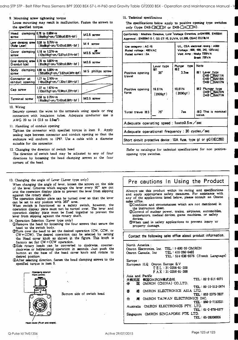
9. Mounting screw tightening torque Loose mounting may result in malfunction. Fasten the screws to
the specified torque.
Head clamping screw
0.78 to 0.88Nm { 8to9kgfan /0.58to0.65ftIbf )
M3 5 screw
Lever damping saw (Roller Lever)
0.59 to 0.78Nm { 6to8kgf cm /0.43to0.58ft lbf }
M 4 screw
Cover clamping screw
1.18 to 1.37Nm 1
112tol4kgfcm /0.87to1.01ftlbf 1
M3.5 scam
Cover damping screw
(3-conduit type) 0.78 to 0.88Nm 18to9kgfan /0.58to0.65ft Ibf }
M3.5 screw
Body clamping screw
4.90 to 5.88Nm { 50to60kgfcm /3.62to4.34ftIbf } M 5 phillips screw
Connector at conduit opening
1.77 to 2.16Nm 118to22kgfcm /1.30to1.59ftIbf }
Cap screw 1.27 to 1.67Nm { 13tol7kgfan /0.94to1.23ftIbf }
Terminal screw 0.59 to O.78Nm I6to8kgfcm /0.43to0.58ftIbf I M3.5 screw
10. Wiring Securely connect the wires to the terminals using spade or ring
connectors with insulation tubes. Adequate conductor size is
AWG 20 to 14 (0.5 to 2.5mm2).
11. Handling of conduit opening Tighten the connector with specified torque in item 9. Apply sealing tape between connector and conduit opening so that the
enclosure will conform to IP67. Use a cable with a diameter
suitable for the connector.
12. Changing the direction of switch head
The direction of switch head may be adjusted to any of four directions by loosening the head clamping screws at the four corners of the head.
15. Technical specificaions
The specifications below apply to positive opening type switches
only (type D413-0500N or D4B- OAOON).
Conformity : Machine Directive, LoW` Voltage Directive. prEN1088, EN50041
Approval : EN60947 -5 -1, GS- ET -15, SUVA. UL508. CSAC 22.28114
Use category : AC -15
Rated voltage : 400VAC
Rated current : 2A
UL, CSA electrical rating : A600
Voltage : 600. 480, 240. 120VAC
Volt Amp : Make 7200VA
Break 720VA
Positive opening travel
Positive opening force
Total travel 03
Lever type 31
35°
19.61N
12000gí)
75° -
Plunger type 02
3.2mm
19.61N { 2000gf }
7mm
Note
33E1 Lever type D45-05W)11 N D48-05W16N 048-05(A)17 N
03E2 Plunger type D4B-05%)70N D48-05W71 N
ßr3 This is nominal value.
Adequate operating speed : lmmto0.5m /sec
Adequate operational frequency : 30 cycles /sec
Short circvit protective device : 10A fuse, type gl or gG(IEC269)
Refer to catalogue for technical specifications for non positive -
opening type switches.
13. Changing the angle of Lever (Lever type only) When changing the angle of lever. loosen the screws on the side
of the lever. Grooves which engage the lever every 90° are cut into the operation display plate to prevent the lever from slipping against the rotary shaft. The operation display plate can be turned over so that the lever
can be set to any postion with 360° area. When switch is functioned as a safety switch, however. the operation display plate must not be turned over. The lever and operation. display plate must be fixed together to prevent the lever from slipping against the rotary shaft.
14. Operation Selection (Lever type only) ©Remove the head by loosening the four screws that secure the
head to the switch body. (Turn over the head to set the desired operation (CW. CCW, or
CW +CCW). The desired operation can be selected by setting the Head cover knob as shown in the figure. This knob is
factory set for CW +CCW operation. C )Side rotary heads can be converted to clockwise, counter-
clockwise. or bidirectional operation in seconds. Just push the button at the base of the head cover knob and rotate to desired position.
®After selecting direction, fasten the head clamping screws to the specified tarque in item 9.
Operating position marts (arrow)
Meals cover (Pusn and rotate)
Bottom side of switch head
Pre cautions I n Using the Product
Always use this product within its rating and specifications and apply appropriate safety measures. For assistance with any of the applications listed below, please consult an Omron sales office.
©Condition and circumstances which are not mentioned in
the instruction sheet. ©Control of nuclear power, trains, airplanes. automobiles,
incinerators, medical devices, game machines. or safety devices. When used in safety applications to prevent injury or property damage.
Contact the following sales office about product information.
North America :
Omron Electronics. Inc. TEL :1-800-55 -OMRON Omron Canada, Inc TEL : 416 -286-6465
TEL : 514-636-6676 (French Language)
Europe :
European H.Q Omron Europe B.V TEL : 31- 2356-81-300 FAX : 31-2356-81-388
Asia and Pacific MIME * ®OMRONI*At t TEL : 82-2-511-6071
43 ® OMRON (CHINA) CO..LTD. TEL: 86-10-513 -0674 : if OMRON ELECTRONICS ASIA LTD. TEL : 852- 2375 -3827
P NI OMRON TAIWAN ELECTRONICS INC. TEL : 886 -2-7153331
Australia OMRON ELECTRONICS PTY. LTD. TEL : 61-2-878-6377
Singapore OMRON SINGAPORE PTE LTD. TEL : 65-28300006
1
1
1
1
1
1
1
1
1
1
1
1
1
ST41 Goodna STP STP - Belt Filter Press Siemens BPF 2000 BSX-S7-L-H-P60 and Gravity Table GT2000 BSX - Operation and Maintenance Manual - Vendor Manual
Q-Pulse Id TMS1356 Active 29/07/2015 Page 123 of 123