
behaviour of c-shaped angle shear connectors in high
119
i BEHAVIOUR OF C-SHAPED ANGLE SHEAR CONNECTORS IN HIGH STRENGTH CONCRETE ALI SHARIATI THESIS SUBMITTED IN FULLFILMENT FOR THE REQUIREMENTS FOR THE DEGREE OF MASTER OF ENGINEERING SCIENCE FACULTY OF ENGINEERING UNIVERSITY OF MALAYA KUALA LUMPUR 2014
-
Upload
khangminh22 -
Category
Documents
-
view
2 -
download
0
Transcript of behaviour of c-shaped angle shear connectors in high
i
BEHAVIOUR OF C-SHAPED ANGLE SHEAR CONNECTORS IN HIGH STRENGTH CONCRETE
ALI SHARIATI
THESIS SUBMITTED IN FULLFILMENT FOR THE REQUIREMENTS
FOR THE DEGREE OF MASTER OF ENGINEERING SCIENCE
FACULTY OF ENGINEERING UNIVERSITY OF MALAYA
KUALA LUMPUR
2014

ii
UNIVERSITY OF MALAYA
ORIGINAL LITERARY WORK DECLARATION
Name of Candidate: Ali Shariati
I.C/Passport No:
Registration/Matric No: KGA110023
Name of Degree: MASTER OF ENGINEERING SCIENCE
Title of Project Paper/Research Report/Dissertation/Thesis (“this Work”):
Behaviour of angle shear connectors in high strength concrete
Field of Study: Structural Engineering & Materials
I do solemnly and sincerely declare that: (1) I am the sole author/writer of this Work; (2) This Work is original; (3) Any use of any work in which copyright exists was done by way of fair dealing
and for permitted purposes and any excerpt or extract from, or reference to or reproduction of any copyright work has been disclosed expressly and sufficiently and the title of the Work and its authorship have been acknowledged in this Work;
(4) I do not have any actual knowledge nor do I ought reasonably to know that the making of this work constitutes an infringement of any copyright work;
(5) I hereby assign all and every rights in the copyright to this Work to the University of Malaya (“UM”), who henceforth shall be owner of the copyright in this Work and that any reproduction or use in any form or by any means whatsoever is prohibited without the written consent of UM having been first had and obtained;
(6) I am fully aware that if in the course of making this Work I have infringed any copyright whether intentionally or otherwise, I may be subject to legal action or any other action as may be determined by UM.
Candidate’s Signature Date
Ali Shariati
Subscribed and solemnly declared before,
Witness’s Signature Date
Name:
Designation:

iii
UNIVERSITI MALAYA
PERAKUAN KEASLIAN PENULISAN
Nama: Ali Shariati
No. K.P/Pasport:
No. Pendaftaran/Matrik: KGA110023
Nama Ijazah: MASTER OF ENGINEERING SCIENCE
Tajuk Kertas Projek/Laporan Penyelidikan/Disertasi/Tesis (“Hasil Kerja ini”):
Behaviour of angle shear connectors in high strength concrete
Bidang Penyelidikan: Structural Engineering & Materials
Saya dengan sesungguhnya dan sebenarnya mengaku bahawa: (1) Saya adalah satu-satunya pengarang/penulis Hasil Kerja ini; (2) Hasil Kerja ini adalah asli; (3) Apa-apa penggunaan mana-mana hasil kerja yang mengandungi hakcipta telah
dilakukan secara urusan yang wajar dan bagi maksud yang dibenarkan dan apa-apa petikan, ekstrak, rujukan atau pengeluaran semula daripada atau kepada mana-mana hasil kerja yang mengandungi hakcipta telah dinyatakan dengan sejelasnya dansecukupnya dan satu pengiktirafan tajuk hasil kerja tersebut dan pengarang/penulisnyatelah dilakukan didalam Hasil Kerja ini;
(4) Saya tidak mempunyai apa-apa pengetahuan sebenar atau patut semunasabahnya tahu bahawa penghasilan Hasil Kerja ini melanggar suatu hakcipta hasil kerja yang lain;
(5) Saya dengan ini menyerahkan kesemua dan tiap-tiap hak yang terkandung di dalam hakcipta Hasil Kerja ini kepada Universiti Malaya (“UM”) yang seterusnya mula darisekarang adalah tuan punya kepada hakcipta di dalam Hasil Kerja ini dan apa-apa pengeluaran semula atau penggunaan dalam apa jua bentuk atau dengan apa juga carasekalipun adalah dilarang tanpa terlebih dahulu mendapat kebenaran bertulis dari UM;
(6) Saya sedar sepenuhnya sekiranya dalam masa penghasilan Hasil Kerja ini saya telahmelanggar suatu hakcipta hasil kerja yang lain sama ada dengan niat atau sebaliknya,saya boleh dikenakan tindakan undang-undang atau apa-apa tindakan lainsebagaimanayang diputuskan oleh UM.
Tandatangan Calon Tarikh Ali Shariati
Diperbuat dan sesungguhnya diakui di hadapan,
Tandatangan Saksi Tarikh Nama:
Jawatan:

iv
DEDICATION
This thesis is kindly devoted to my adorable brother MOJTABA. Much obliged to you for your sponsorship and support without which this
couldn't be conceivable. I adore you for all that you are and everything that you have accomplished for me.

v
ABSTRACT
The most commonly used types of shear connectors in steel-concrete composite
structures are headed shear stud and Perfobond shear connectors. Due to the limitations
in the performance of headed studs and Perfobond shear connectors, the use of C-
shaped shear connectors as an alternative has been recommended. Furthermore,
manufacturing of the C-shaped shear connectors is easier compared to the other
connectors since in most steel shops, commercial standard sizes for hot rolled steel
profiles of C-shaped shear connectors are available. Moreover, by simply cutting in
their long steel profiles, these types of connectors can be easily prepared and the
manufacturing cost and time for making C-shaped connectors are significantly low. C-
shaped connectors show higher shear capacity and with the use of the conventional
reliable welding system, it could be welded easily to steel beam.
The angle connectors, as compared to channel connectors, could be cheaper and
more economical due to the absence of bottom flange which ultimately saves more
steel. The results of investigation of behavior of C-shaped angle shear connector is not
included in previous research yet. In this thesis, the results of twenty four experimental
push-out tests on angle shear connectors are presented. The connectors were embedded
in a solid slab with High Strength Concrete (HSC) and were tested under monotonic and
low cyclic fatigue loading. Based on the results, angle shear connectors showed good
behavior in terms of shear strength but not in ductility as the main criterion for the
behavior of shear connectors. Connector fracture types of failure was seen and less
sensitivity to flange thickness and height of connectors was reported for angle
connectors in terms of shear strength. Longer connectors exhibit more ductility
compared to shorter connectors. The details of angle shear connector behavior have
been discussed in detail as well.
vi
ABSTRAK
Jenis-jenis penyambung ricih yang biasa digunakan dalam keluli-konkrit struktur
komposit yang diketuai stud ricih dan Perfobond penyambung ricih. Oleh kerana
keterbatasan dalam pelaksanaan diketuai kancing dan Perfobond penyambung ricih,
penggunaan penyambung ricih berbentuk C sebagai alternatif telah disyorkan.
Tambahan pula, peughasilan penyambung ricih berbentuk C adalah lebih mudah
berbanding penyambung lain sejak di kedai-kedai yang paling keluli, saiz standard
komersial untuk profil keluli tergelek panas penyambung ricih berbentuk C boleh
didapati. Selain itu, dengan hanya memotong dalam profil keluli panjang mereka, ini
jenis penyambung boleh dengan mudah disediakan dan kos pengeluaran dan masa untuk
membuat penyambung C-berbentuk ketara rendah. Penyambung C berbentuk
menunjukkan kapasiti yang lebih tinggi dan dengan menggunakan sistem kimpalan
dipercayai konvensional, ia boleh dikimpal mudah kepada rasuk keluli.
Penyambung sudut, berbanding dengan penyambung saluran, boleh menjadi lebih
murah dan lebih menjimatkan kerana ketiadaan bahagian bawah bebibir yang akhirnya
menjimatkan keluli lebih. Hasil siasatan ke atas tingkah laku C berbentuk sudut
penyambung ricih tidak termasuk dalam penyelidikan sebelumnya. Dalam tesis ini, hasil
daripada dua puluh empat eksperimen menolak keluar ujian ke atas penyambung ricih
sudut dibentangkan. Penyambung telah tertanam dalam papak yang kukuh dengan
kekuatan konkrit Tinggi (HSC) dan telah diuji di bawah ekanada dan rendah kitaran
keletihan muatan. Berdasarkan keputusan, penyambung ricih sudut menunjukkan
tingkah laku yang baik dari segi kapasiti ricih tetapi tidak dalam kemuluran sebagai
kriteria utama untuk tingkah laku penyambung ricih. Jenis patah penyambung
kegagalan dilihat dan sensitiviti yang kurang untuk ketebalan bebibir dan ketinggian
penyambung dilaporkan untuk penyambung sudut dari segi keupayaan ricih.
Penyambung lagi mempamerkan lebih kemuluran berbanding penyambung pendek.

vii
Acknowledgments
It gives me great pleasure in expressing my gratitude to all those people who
have supported me and had their contributions in making this thesis possible.
First and foremost, I must acknowledge and thank The Almighty Allah for
blessing, protecting and guiding me throughout this period. I could never have
accomplished this without the faith I have in the Almighty.
I express my profound sense of reverence to my supervisors and promoters
Associate Prof. Dr. Nor Hafizah Binti Ramli Sulong and Dr. Meldi Suhatril for their
constant guidance, support, motivation and untiring help during the course of my
study.
Besides my supervisor, I would like to thank my advisor, Professor Dr. Shervin
Maleki from Department of Civil Engineering, Sharif University of Technology,
Tehran, Iran, for his in-depth knowledge on the topic of my thesis which has been
extremely beneficial for me.
I would like to thank Dr. Mohammadmehdi Arabnejad Khanouki for helping
me in all process of doing my research and being available to guide me in all my
projects and publications. Being a professional, especially in finite element analysis, I
always find his comments, questions and suggestions in the manuscripts very
challenging and I always felt very relaxed after answering his concerns.
Special thanks to Dr. Mehrdad Mahoutian from Department of Civil
Engineering and Applied Mechanics, McGill University, Montreal, Canada who have
always been very helpful for strengthening our manuscripts.
I also thank Karim Nouri, Sina Mirzapour Mounes, Kambiz Yousefi Talooki,
and Hamed Khatibi for being very good friends and brilliant collaborators.
The great and help of my great nephew, Morteza for their precious help for
doing most of my experimental push-out test during my study.

viii
I would also like to thank especially my uncle Saeed, who supports me
financially and emotionally and motivates me for doing my postgraduate studies and
unfortunately passed away during the time as a student.
I would like to acknowledge the financial support of University Malaya for
doing my experimental program and the staff members of the department of civil
engineering, especially the technicians, Mr. Sreedharan, Mr. Mansor Hitam and Mr.
Azhar Arshad and supplier Mr. Eugene Lai for their cooperation in doing my
experimental program.
Last but not the least important, I owe more than thanks to my family members
which includes my parents, my brothers and their family for their support and
encouragement throughout my life. Very especial thanks to my elder brothers,
Mojtaba and Mahdi for all of their emotional and financial support, motivation and
efforts. Without their support, it is impossible for me to start my post graduate
education seamlessly. I owe you too much in my life and am sure that can’t
compensate what you did for me. I am thankful to the Almighty for having such a
family and brothers and hope they will have a great life in the future together with
their family.
Finally, I would like to devote this work to my wife, Fatemeh, who I just found
her in my life. I hope we will have a lovely life for ever.
I share the credit of my work with my family for their honest support during the
research. I cannot find words to express my thankfulness to my family for their love,
support, encouragement, patience, and understanding.
Ali Shariati
University of Malaya
September 2014

ix
LIST OF CONTENTS
ABSTRACT iv
ABSTRAK vi
LIST OF CONTENTS ix
LIST OF TABLES xii
LIST OF FIGURES xiiiii
LIST OF ABBREVIATIONS xiii
LIST OF APPENDIXES xv
Chapter 1: INTRODUCTION 1
1.1 Preface 2
1.2 Problem statements 4
1.3 Objectives of the study 4
1.4 Scope of work 5
1.5 Outline of the thesis 5
Chapter 2: LITERATURE REVIEW 7
2.1 Preface 8
2.2 Headed studs 8
2.3 Perfobond Ribs 10
2.4 T-rib connector 11
2.5 T-Connectors 12
2.6 C-shaped shear connector 13
2.6.1 C-shaped channels 16
2.6.2 C-shaped angles 20
2.7 Concuding remarks 23
Chapter 3: RESEARCH METHODOLOGY 24
3.1 General 25
3.2 Experimental test procedure 26
3.2.1 Introduction 26
3.2.2 Concrete materials 28
3.2.3 Concrete compression test 29
3.2.4 Test setup 30
3.2.5 Specimens’ symbolization 31
3.2.6 Loading and test procedure 31

x
3.3 Finite element analysis 34
3.3.1 Introduction 34
3.3.2 General descriptions 36
3.3.3 Material properties 36
3.3.3.1 Steel 36
3.3.3.2 Concrete 37
3.3.4 Modelling of the specimens 41
3.3.5 Element type 43
3.3.6 Element Interaction 45
3.3.6.1 Embedded element 46
3.3.6.2 Contact interaction 46
3.3.7 Contact properties 46
3.3.8 Loading and boundary condition 48
3.3.9 Analysis solution 49
Chapter 4: RESULTS AND DISCUSSION 51
4.1 Preface 52
4.2 Experimental test results 52
4.2.1 Load-slip analysis for monotonic loading 52
4.2.2 Load-slip analysis for reversed cyclic loading 56
4.2.3 Failure mode of shear connectors 58
4.2.4 Effect of connector dimensions on shear capacity 62
4.2.5 Evaluation of design codes for the shear capacity of angle 63
4.2.6 Summary of experimental results 64
4.3 Finite element results 66
4.3.1 Verification of finite element results 66
4.3.2 Parametric investigations based on finite element method 70
4.3.2.1 Preface 70
4.3.3 Summary of finite element results 72
Chapter 5: CONCLUSION 74
5.1 Introduction 75
5.2 Investigation of behaviour of angle shear connectors 75
5.3 Investigation of parameters affecting the connector’s behaviour 76
5.4 Comparison between experimental and finite element analysis 76
5.5 Evaluation of design equations 76
5.6 Recommendations for Future Research 77

xi
REFERENCES 78
AWARDS 89
LIST OF PUBLICATION 90
RESEARCH FUND 92
APPENDIX A 93
APPENDIX B 99

xii
LIST OF TABLES
Table 3.1. The angle geometric properties ..................................................................... 26
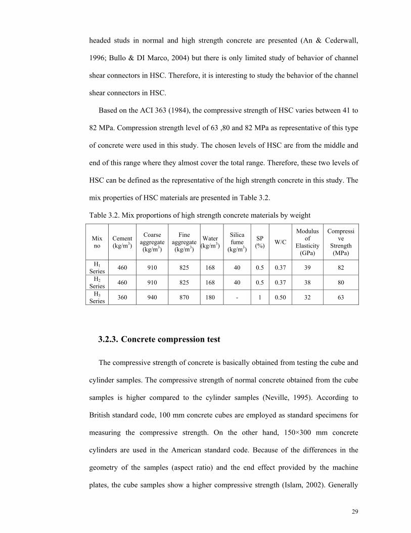
Table 3.2. Mix proportions of high strength concrete materials by weight ................... 29
Table 4.1. Monotonic test results for angle connectors embedded in HSC ................... 53
Table 4.2. Ductility factor for angle specimens embedded in HSC slab ....................... 56
Table 4.3. Cyclic test results for similar pair to pair specimens .................................... 57
Table 4.4. Comparison of test results with code for angle connectors in HSC .............. 64
Table 4.5. The results of finite element and experimental for HSC. ............................. 71
Table 4.6. Comparison of the ultimate strengths obtained from the finite element
against the equation in reinforced concrete. ................................................ 72

xiii
LIST OF FIGURES
Figure 1.1. Shear connectors in a composite beam .......................................................... 2
Figure 1.2. Typical C-shaped channel and angle shear connectors ................................. 3
Figure 2.1. Headed stud shear connector ......................................................................... 8
Figure 2.2. Perfobond Ribs shear connector .................................................................. 11
Figure 2.3. T-Rib shear connector.................................................................................. 12
Figure 2.4. T shear connector ......................................................................................... 13
Figure 2.5. Typical angle shear connector ..................................................................... 15
Figure 2.6. Typical channel shear connector ................................................................. 15
Figure 2.7. Typical L-shaped angle shear connector [Eurocode 4; CEN 2001] ............ 16
Figure 3.1. Details of connectors’ specifications ........................................................... 27
Figure 3.2. Details of typical push-out test specimen .................................................... 31
Figure 3.3. Universal testing machine used to apply loading ........................................ 33
Figure 3.4. Specific support used for loading the slabs ................................................. 33
Figure 3.5. Stress-strain relationship for steel materials ................................................ 37
Figure 3.6. Stress-strain relationship for compression behaviour of concrete ............... 38
Figure 3.7. Stress-strain relationship for tensile behaviour of concrete ......................... 40
Figure 3.8. Exponential function of tension softening model ........................................ 40
Figure 3.9. Typical view of the specimens in the experimental test .............................. 41
Figure 3.10. Separate parts of assembly (angle and concrete slab) ............................... 42
Figure 3.11. Placement of steel connector in concrete slab ........................................... 42
Figure 3.12. Typical geometric modeling of the specimens .......................................... 43
Figure 3.13. Typical steel part with angle in specimen.................................................. 43
Figure 3.14. Typical meshing of concrete part in specimen .......................................... 44
Figure 3.15. Typical meshing of steel part in specimen with angle shear connector .... 45
Figure 3.16. Typical meshing of whole the half push-out specimen ............................. 45
Figure 3.17. Angle surfaces which are contacted to concretes ...................................... 46
Figure 3.18. Softened pressure-over closure relationship – Geometry scaling.............. 48
Figure 3.19. Boundary condition in the specimen ......................................................... 49
Figure 4.1. Load-slip curves of angle connectors embedded in in high strength
reinforced concrete under monotonic loading ............................................. 53
Figure 4.2. Definition of ductility factor ........................................................................ 55
Figure 4.3. Cyclic load-slip curves of angle shear connectors specimen H210030-
C embedded in HSC slab ............................................................................ 57

xiv
Figure 4.4. Connector fracture of failure ....................................................................... 59
Figure 4.5. Failure of concrete crushing splitting .......................................................... 59
Figure 4.6. Combined failure mode of concrete and connector ..................................... 60
Figure 4.7. Typical fracture of angle shear connector for specimen with ...................... 61
Figure 4.8. Typical fracture of angle shear connector for specimen with high ............. 61
Figure 4.9. Typical comparison of load-slip between FEA and experimental ............... 67
Figure 4.10. Typical comparison of load-slip between FEA and experimental ............. 67
Figure 4.11. Typical comparison of load-slip between FEA and experimental ............. 68
Figure 4.12. Typical Von Mises stress for specimen H110050 ..................................... 68
Figure 4.13. Typical plastic strain for specimen H110050 (Perspective) ...................... 69
Figure 4.14. Typical plastic strain for specimen H110050 ............................................ 69

xv
LISTS OF ABBREVIATIONS
Q Shear strength of one channel shear connector (N) Flange thickness of channel shear connector (mm) Web thickness of channel shear connector (mm) Length of channel shear connector (mm) ′ Specified 28 days cylinder strength of concrete (MPa) Modulus of elasticity of concrete (MPa) Specified compressive strength of concrete (MPa)
Q Nominal strength of one channel shear connector (N)
Web thickness of the channel (mm)
Length of the channel (mm) Height of the channel
The is the width to depth ratio of the rib of the metal deck
P Load carrying capacity of the connector (kgf) Ultimate shear force in the shear failure mode or by concrete crush (N)
Height of shear connector (mm) i: Segment member Initial scale factor
Default stiffness
r Over closure factor Element lengt
d Over closure measure S Geometric scale factor
P Shear strength of the connector (kgf)
t Web thickness of connector (cm)
L Length of connector (cm)
f Concrete compressive strength (kgf/cm2)

xvi
LIST OF APPENDIXES
APPENDIX A 93
APPENDIX B 99

1
1 INTRODUCTION

2
1.1. Preface
Shear connectors between concrete slabs and steel beams in composite construction
can play an important role in the seismic response of a structure. They provide the
necessary shear connection for composite action in flexure, and can be used to distribute
the large horizontal inertial forces in the slab to the main lateral load resisting elements
of the structure as shown in Figure 1.1.
Connecting the existing concrete slab and steel girders is a potential economic way
to strengthen these floor systems as it allows for composite action to be developed. As
opposed to the original non-composite condition, composite action allows the existing
steel girder and the concrete slab to act together more efficiently. In non-composite
girders, the steel girders and the concrete slab act separately in flexure. Hence, by using
shear connectors, girders can be increased by more than 50% as compared to that of
non-composite girders (Peiris & Harik, 2011). By connecting the steel girder to the
concrete slab, it allows the transmission of shear forces at the steel concrete interface,
thus, enabling the benefits of composite actions to be achieved. Prior to casting of the
concrete slab, shear connectors are welded to the top of the steel girder in order to
develop composite action in the construction of new bridges (Kwon et al., 2009).
Figure 1.1. Shear connectors in a composite beam

Headed
connector
because of
d stud and
s while the
f some limi
Perfobond
application
tations for t
Fig. 1.2 Typi
shear conn
n of C-shape
the use of h
a) C-shaped
b) C-shaped c
ical C-shaped
nectors are t
ed shear con
eaded studs
angle shear c
channel shear
d channel and
the most co
nnectors (Fi
s and Perfob
connector
connector
angle shear co
ommon typ
igure 1.2) is
bond shear c
onnectors
3
pes of shear
s increasing
connectors.
3
r
g

4
To achieve the behavior of angle shear connectors in composite beam with high
strength concrete slab, primary experimental push-out test on these connectors have
been conducted. The results of these tests in case of shear capacity and ductility were
compared and discussed.
1.2. Problem statements
C-shaped channel and angle shear connectors were used in previous research as
reviewed in literature review when they were embedded in different kinds of concrete.
The application of angle shear connectors in High Strength Concrete (HSC) is not well
studied up to date. Consequently, the behavior of these shear connectors in high strength
concrete is of interest.
The objective of this thesis was aimed at better understanding of the behavior of
angle shear connectors in HSC and fulfil the recommendation of previous researchers.
Evaluation of the reliability of the existing equations in predicting the shear capacity of
angle shear connectors in high strength concrete is another objective of this study.
1.3. Objectives of the study
The objective of the study is listed as below:
1. To assess the behavior of C-shaped angle shear connectors embedded in high
strength concrete slab under monotonic and fully reversed cyclic loading.
2. To investigate several parameters affecting the behavior of C-shaped angle shear
connectors such as connector’s geometric properties and concrete strength.
3. To evaluate the reliability of the existing equations in predicting the shear
capacity of the C-shaped angle shear connectors in high strength concrete.

5
1.4. Scope of work
The scope of this study is to improve the design of C-shaped angle shear connectors
in composite beam. Available guidelines are limited to the design of the isolated angle
shear connectors. No equation is currently available for the design of angle shear
connectors embedded in high strength concrete slab. There is a definite need to develop
new formulations for the design of angle shear connectors in slabs with high strength
concrete. The results of monotonic push-out tests are used to calibrate a proposed
nonlinear finite element model were used to evaluate the accuracy of available
equations for the prediction of angle shear connectors in HSC.
There are only a few references available to estimate the shear capacity of angle
shear connectors in reinforced concrete slab. Based on the results of this thesis, the
existing design equations seem to be inaccurate. The evaluation of these equations was
the scope of this thesis as well. Future research on angle shear connectors were
proposed as well.
1.5. Outline of the thesis
In this thesis, a literature review on C-shaped angle shear connectors are discussed in
Chapter Two. After the literature review of existing studies on C-shaped shear
connectors, the objective of this study was proposed.
Chapter Three describes the design and the method of experimental push-out test and
parametric finite element analysis of push-out tests on angle shear connectors. The test
setup, experimental test specimens and procedures of Finite Element Analysis (FEA)
are presented in this chapter. Twenty four push-out test specimens were selected for
experimental testing. The finite element analysis was employed to show the behavior of
the experimental push-out tests, for obtaining more details on different size of the
connectors and different types of concrete. In addition, the FEA result can be used for a

6
wider investigation of the connectors’ behavior for the future works after verification
with the test results.
In Chapter Four, the experimental test and finite element results in the behavior of
the angle shear connectors are presented and discussed. The behavior of shear
connectors in case of shear capacity under monotonic loading, strength degradation
under low cyclic fatigue loading and their relative ductility was discussed.
Chapter Five summarizes the findings of the study and suggests a few
recommendations for future works.

7
2 LITERATURE REVIEW

2.1. Pre
In this
connector
shaped she
shaped sh
their repr
studies, w
applicabili
connector
composite
2.2. He
To res
structures,
the Nelson
prevents
simultaneo
head.
eface
s chapter, a
s including
ear connect
ear connect
esentative j
which have b
ity and the
s for headed
e structures
aded Stu
sist horizon
, the most c
n stud (Figu
uplift. It
ously, after
an attempt
g the comm
tor used in c
tors that are
journal pub
been conduc
efficiency
d stud conn
were discus
uds
ntal shear a
commonly u
ure 2.1). Thi
is designe
the weldin
Figure 2
has been
monly used
composite s
e the most r
blications t
cted by seve
of C-shaped
nectors whic
ssed and a s
and vertica
used types o
is type of co
ed to wor
ng, it then a
2.1. Headed
made to
one and th
structures. T
relevant to
that are rel
eral researc
d shear con
ch are comm
summary of
al uplift for
of shear con
onnector co
rk with an
cts as the re
stud shear c
review diff
heir main a
This review
composite
lated to thi
chers, were
nnectors. Th
monly used
f their behav
rces in com
nnector is th
ontributes to
n arc wel
esisting con
connector
fferent type
alternatives
tries to iden
structures a
is topic. C
covered to
he represent
as shear co
vior was inc
mposite ste
he head stud
o the shear t
lding elect
nnector with
8
es of shear
s means C-
ntify the C-
and reviews
Comparative
address the
tative shear
onnectors in
cluded.
eel-concrete
d, known as
transfer and
trode, and,
h a suitable
8
r
-
-
s
e
e
r
n
e
s
d
,
e

9
Many researches have been carried out on headed stud connectors and various
equations have been proposed to estimate the strength of headed studs (Gelfi and
Marini, 2002; Lee et al., 2005; Ollgaard et al., 1971; Viest, 1956a). Viest (1956a )
carried out the initial studies on headed stud shear connectors, where full-scale push out
specimens were tested with various sizes and spacing of the headed studs. The push-out
and composite beam tests were used to evaluate the shear capacity of the headed stud. In
order to investigate the behavior of headed stud connectors in solid slabs, an accurate
nonlinear finite element model was developed by Ellobody (2002), and Lam and
Ellobody (2005).
Validations against test results and comparison with data specified in the current
Codes of Practice, such as BS5950 (1994), and AISC (2005), was carried out using the
effective numerical model by Lam and Lobody (2001). The results of the experiment
conducted by these authors are comparable with the results obtained from the finite
element analysis. The finite element model offered accurate predictions on the capacity
of the shear connection, the load slip behavior of the headed studs and the failure
modes.
Ellobody (2002) conducted another finite element model by considering the linear
and non-linear behavior of the materials in order to simulate the structural behavior of
headed stud connectors. The use of the model in examining variations in concrete
strength and headed stud diameter in parametric studies was also presented.
Consequently, it was found that the finite element results suggested by BS5950 (1994)
may overestimate the headed stud’s shear capacity.
The experimental tests to assess the behavior of the shear connection between the
steel and lightweight concrete that were carried out at the University of Minho were
described in another work by Valente and Cruz (2004). The behavior of headed stud
connectors embedded in ECC (Engineered Cementitious Composites) was investigated

10
by Li et al. (2006), while, in order to examine the capacity of large headed stud shear
connectors embedded in a solid slab, an accurate nonlinear finite element model of the
push-out specimen was performed by Nguyen and Kim (2009).
The AISC (2005), CSA (2001) and Eurocode (2004) standards currently provide
design equations for the calculation of the resistance of a headed stud shear connector.
The investigation of the headed stud’s capacity has been conducted thoroughly and
tabulated values can be found in BS 5950: Part 3 (1990) and BS 5400 : Part 5 (1983) as
well.
The headed stud’s root is functioned to transmit the horizontal shear force acting at
the steel-concrete interface, while the head is provided for preventing uplift of the slab.
The cross-sectional area of a headed stud connector is directly proportional to its shear
strength and its ultimate shear strength is influenced largely by the concrete’s
compressive strength and modulus of elasticity.
2.3. Perfobond Ribs
In the late 1980s, Leonhardt et al. (1987) developed a new type of connector called
the Perfobond rib (1987). This connector was introduced in recognition of the
unsatisfactory behavior of headed studs in which resulting from fatigue problems
caused by live loads on composite bridges. Developed in Germany, this connector
consists of a welded steel plate, with a number of holes (Figure 2.2) (Lee et al., 2010).
The flow of concrete through the rib holes formed dowels that provided resistance in
both the vertical and horizontal directions. This shear connector is a viable alternative to
the headed stud connector, as signified in the experimental studies conducted
previously (Ahn, et al., 2010) and recently (Jumaat et al., 2011; Kisa et al., 2011), This
connector was initially used in building structures (Ferreira et al., 1998). The fact that
not only it ensures the concrete steel bond but also enabled a better anchorage of the
internal columns hogging moment has encouraged its adoption. By passing through the

Perfobond
would allo
indicated t
mm diame
diameter’s
2.4. T-r
In the
alternative
researcher
and a limi
acted as a
created. T
ductility a
was a mot
In ord
connector
d web holes
ow these ba
that a one m
eter’s heade
s headed stu
rib conn
scope of a
e connector
r also provid
ited number
a block, the
The need to
and uplift r
tivating fact
er to preve
detail shou
or simply b
ars to be anc
meter length
ed studs wh
uds which w
Figure 2.2
ector
study on Pe
r for head
ded a comp
r of T-Perfo
e derivation
combine th
resistance ar
tor for the d
ent a prem
uld minimiz
by being sup
chored. A st
h of Perfobo
hich were d
were dispose
2. Perfobond
erfobond co
ded studs,
parative stud
obond conne
n of this co
he large str
rising from
developmen
mature loss
ze the pryin
perimposed
tudy, which
ond connect
disposed in
ed in three l
d Ribs shear
onnectors, V
called the
dy between
ectors. By a
onnector fro
rength of a
m the holes
t of this T-P
of stiffne
ng action ef
d to the trans
h had been d
tor was com
two lines o
lines.
r connector
Vianna et a
T-Perfobon
n the behavi
adding a flan
om the Perf
block type
in the Perf
Perfobond c
ss in the
ffect (Ferrei
sverse reinf
done by Zel
mparable to e
or twenty f
r
al. (2009) pr
nd (Figure
ior of these
nge to the p
fobond con
e connector
fobond con
connector.
connection,
ira, 2000).
11
forcing bars
llner (1987)
eighteen 22
four 19 mm
resented an
2.3). The
connectors
plate, which
nnector was
with some
nector web
, the T-rib
As leftover
s
)
2
m
n
e
s
h
s
e
b
b
r

12
rolled sections can be used to produce the T-rib connectors, it can reduce cost and
minimize welding work. The four steps involved in the fabrication process of the T-rib
connectors are: (i) initial profile, (ii) web holes, (iii) flange holes, (iv) opposite flange
saw cut are as shown in Figure 2.3.
For similar longitudinal plate geometries, the resistance and stiffness of T-Perfobond
connectors are higher than that of Perfobond connectors. In addition to this advantage,
the use of T-Perfobond connectors offers benefits in terms of saving material and labor,
as they are produced by ordinary laminated I or H sections.
Figure 2.3. T-Rib shear connector
2.5. T-Connectors
This connector is a section of a standard T-section welded to the H or I section with
two fillet welds Figure 2.4. T-connectors evolved from the observation by Oguejiofor
and Hosain (1997) they stated that a large part of the bearing capacity of a
Perfobondstrip was the result of the direct bearing of the concrete at the front end of the
(discontinuous) Perfobondstrip. Therefore, a T section, which has a larger cross section
than a single strip, and its shape, was potentially able to prevent vertical separation
between the steel-section and the concrete, seemed to be a good alternative.

13
The behavior of the T-connector is very favorable. The bearing stress on the front of
the T is very high, which is a result of the relatively small area. Local concrete crushing
occurs, which results in a quasi-plastic performance (Zingoni, 2001). The load capacity
for T-connectors are similar to that of the oscillating Perfobondstrip, however, the
ductility of these connectors is much larger (Rodera, 2008). When theses connectors are
used in concrete with fibers, lightweight concrete or a higher strength concrete, there is
a notable increase in the load capacity and ductility of this type of connector. In the case
of the T-shape connectors, the strength of the connector itself is vital and the concrete is
no longer decisive. Disregarding the Perfobondstrip, the resistance characteristic of the
T-shape connectors is considered as the highest and its failure mode varies according to
different concrete strengths.
Figure 2.4. T shear connector
2.6. C-shaped shear connector
Due to the limitations for the use of headed studs and Perfobond shear connectors in
composite construction, the use of C-shaped shear connectors may be a recommended
alternative, especially in developing countries. Some restrictions on the fatigue behavior
of headed studs have been reported such as the commencement of fatigue cracks in

14
welds under cyclic loading, the necessity of specific welding equipment and high power
generators on site (Chromiak et al., 2006). Also for the Perfobond shear connector,
problems will appear when the steel bars need to cross the connector openings and it is
difficult to position the slab for lower reinforcement (Ver´ıssimo et al., 2006).
In addition, the manufacturing of headed studs and Perfobond shear connectors is not
as easy as C-shaped shear connectors due to the special shape of the headed studs and
the need of making holes in Perfobond shear connectors, which is a time consuming and
an expensive procedure.
There are commercially available standard sized hot rolled steel profiles of C-shaped
shear connectors mostly in the steel industry. It is also easy to prepare these types of
connectors by simply cutting their plain steel profiles. One may also notice that
manufacturing cost and time to manufacture C-shaped connectors are significantly
lower compared to the headed stud and Perfobond connectors.
Also, the C-shaped connectors have high load carrying capacity and can be welded
to steel beam by using the conventional reliable welding system. Some inspections, like
bending test which is needed for headed stud connectors, are not necessary for these
types of shear connectors and also positioning the slab for bottom reinforcement, may
not be a challenge when C-shaped shear connectors are employed (Ciutina & Stratan,
2008). Generally speaking, C-shaped shear connectors are preferred as they overcome
the constraints and difficulties of using the headed studs and Perfobond shear
connectors in composite beams.
The C-shaped shear connectors can be made with both angle and channel profiles as
shown in Figures 2.5 to 2.7. The angular profiles can also include L-shaped shear
connectors in addition to the C-shaped one as well. Since angle connectors in the
absence of bottom flange in comparison to channels, they could be cheaper and more
economical than channel connectors. A hoop reinforcement should be provided for L-

15
shaped angle connector to prevent uplift of concrete in the composite system (Eurocode
4, 2004), a similar problem also occurs in the case of Perfobond connectors when the
steel bars need to cross the connector openings. Therefore, it is better to use the C-
shaped angle shear connector than the L-shaped connector in composite beams.
Figure 2.5. Typical angle shear connector
Figure 2.6. Typical channel shear connector

16
Figure 2.7. Typical L-shaped angle shear connector [Eurocode 4; CEN 2001]
Although channel shear connectors, as one of the popular C-shaped shear connectors,
are used more in structures because of their accepted well-behaved performance. Angle
shear connectors without bottom flange could be cheaper and more economical than
channel shear connectors by saving more steel material in composite beams. The
convenient welding process of angle connectors compared to channel connectors is a
further advantage.
2.6.1. C-shaped channels
Channel shear connectors were used in the scale-model of composite bridges and
initially tested at the University of Illinois by Viest et al. (1952). The test results of a
preliminary study of channel shear connectors were presented by Slutter and Driscoll
(1965) and Pashan (2006) to identify their behavior and assess the possibility of using
this steel profile as a shear connector. From the above studies, some equations were
derived to calculate the capacity of channel shear connectors in a solid concrete slab.

17
Those equations were adopted into building codes, such as the National Building Code
of Canada (NBC) (2005) and the American Institute of Steel Construction (AISC)
(2005).
In order to assess the accuracy of the design code equations for the strength of
channel shear connectors, an experimental study using specimens with different channel
sizes and lengths under monotonic loading was conducted by Pashan (2006). Several
researchers presented the behavior of channel shear connectors embedded in a solid
concrete material slab based on an experimental study conducted under monotonic and
low-cycle fatigue loading and proposed an effective numerical model using the finite
element method to simulate the push-out test of channel shear connectors as described
in following.
A series of tests were carried out on push-out specimens made of plain concrete,
reinforced concrete (RC), fiber reinforced concrete (FRC) and engineered cementitious
composite (ECC) by Maleki and Bagheri (2008a, 2008b). Based on the results, the
reversed cyclic shear strength of most specimens is lower than their monotonic strength
by about 10% – 23%. The results also indicated that the shear strength and load-
displacement behavior of the specimens was slightly affected by the use of the
polypropylene fibers (FRC specimens). However, a considerable increase in the
ultimate strength and ductility of channel shear connectors was achieved by the use of
the polyvinyl alcohol fibers (ECC specimens) (Maleki & Bagheri, 2008a).
A validation against experimental test results and a comparison with the data given
in North American design codes was carried out for additional research on the shear
capacity of channel shear connectors embedded in a solid reinforced concrete slab under
monotonic loading by using the finite element analysis. To investigate the variations in
concrete strength, channel dimensions and the orientation of the channel, parametric
studies by using nonlinear finite element analysis were performed. It was found that to

18
determine the ultimate strength of channel shear connectors, the significant parameters
included the strength of concrete, the web and flange thicknesses of the channel and the
length of the channel, whereas the height of the channel section was regarded else.
Moreover, a change in the stiffness and the ultimate strength of the shear connector
could be caused by changing the orientation of the channel (Maleki & Bagheri, 2008b).
Other similar push-out tests have been performed by Shariati et al. (2011) for
channel connectors after embedding in high strength concrete (HSC).
In other research, Maleki and Mahoutian (2009) investigated the shear strength of
channel shear connectors embedded in normal and polypropylene concrete both
experimentally and analytically. Before a prediction for the shear capacity of channel
connectors in polypropylene concrete could be reached, an extensive parametric study
was performed. An equation was suggested for the shear strength of these connectors
when used in polypropylene concrete, which was included in design codes.
Generally, Viest et al. (1952), Pashan (2006), Ollgaard et al. (1971), Viest (1960)
and Johnson (1970) reported on a literature review of composite beam research from
1920 to 1958 and 1960 to 1970 for headed stud and channel shear connectors that are
embedded in normal concrete. Their results of the push-out test showed that the strength
of the composite system could be affected by other factors apart from the concrete
strength, which include the flange thickness, web thickness and channel length. Several
equations for obtaining the channel shear connector capacity were proposed based on
these investigations.
Years later, building codes adopted some of these equations. The current Canadian
code (2005), for instance, suggests the use of the following equation for the calculation
of the shear capacity of a channel shear connector embedded in a solid concrete slab.

19
In order to calculate the nominal strength, Q , for a channel shear connector
embedded in a concrete slab, the following equation has been provided by the current
American Standards (AISC) (2005).
= 0.3( +0.5 ) ′ 2.1
Where:
Q Shear strength of one channel shear connector (N)
E = Modulus of elasticity of concrete (MPa).
t = Flange thickness of channel shear connector (mm)
t = Web thickness of channel shear connector (mm)
L = Length of channel shear connector (mm)
f′ = Specified 28 days cylinder strength of concrete (MPa).
Meanwhile, the National Building Code (NBC) (2005) of Canada suggests the
following equation which can be implemented for calculating the shear capacity of a
channel shear connector embedded in a solid concrete slab,
36.5 0.5 2.2
Where:
Q Nominal strength of one channel shear connector (N)
t Flange thickness of channel shear connector (mm)
t Web thickness of channel shear connector (mm)
L Length of channel shear connector (mm)
f′ = Specified compressive strength of concrete (MPa)
In addition, modified equations for the prediction of the shear capacity of channel
shear connectors embedded in polypropylene (PP) concrete were suggested by Maleki
and Mahoutian (2009).
27.2 0.5 f′ 2.3

20
Pashan and Hosain (2009) used the test results of the eighteen push-out specimens
with solid concrete slabs to perform a regression analysis for the development of a new
equation. They believed that the original equation, which provided excellent correlation
with the test results, was deemed to be too complex. The following simplified version of
this equation was developed at the expense of some accuracy:
Q 336 5.24 2.4
Where:
Q Nominal strength of one channel shear connector (N)
L = Length of the channel (mm)
w = Web thickness of the channel (mm)
= Specified compressive strength of concrete (MPa)
H = Height of the channel.
The next equation was proposed by them for the shear capacity of channel
connectors in metal deck slabs as well.
Q 1.7 275.4 2.5
Where:
The is the width to depth ratio of the rib of the metal deck
2.6.2. C-shaped angles
The primary results of the push out tests on specimens with several shear connectors
including channel and L-shaped angle shear connectors were reported by Rao (1970).
The results indicated that the C-shaped channel shear connectors provided considerable
flexibility and showed greater load carrying capacity than other shear connectors.
In a research carried out by Ciutina and Stratan (2008), five different types of shear
connectors which comprised of L-shaped angle shear connectors subjected to cyclic and

21
monotonic loading, were investigated through a limited number of push-out tests. It was
concluded that the cyclic loading makes 10% – 40% reductions in shear resistance for
all connectors including L-shaped angle shear connector compared to the corresponding
monotonic loading.
L-shaped angle shear connectors can be used in some other structural members too.
For example, in extended connections, the L shaped angle connector can be applied as
single or double angle bolted shear connections. A research conducted by Higgins
(2005) discussed on the design of bolted extended double angle, single angle, and tee
shear connections and covered the design of the extended connections by using these
connectors.
Being a shear connector embedded in concrete foundation can be considered as
another application of this connector. An equation for shear capacity of angle shear
connector embedded in concrete foundation is suggested by ASCE (2000).
Also a few studies have been conducted on the behavior of C-shaped angle shear
connectors. Kiyomiya and Yokota (1987) investigated the ultimate strength and
deformation of various kinds of shear connectors, including C-shaped angles, channels,
and T-shaped shear connectors, in composite members. It was concluded that the shapes
and directions of shear connectors and concrete strength greatly affect the mode of
failure of specimens in the push-out test.
In a research by Choi et al. (2008), the fatigue strength of a welded joint between C-
shaped angle shear connectors and bottom plate in steel-concrete composite slabs was
investigated through fatigue tests and finite element analysis. The results confirmed that
the stress level at the welded joint was low and considerably less than the fatigue limit
of this connector based on Eurocode 4 (Eurocode 4, 2004).
Another research, done by Fukazawa et al.(2002), undertook the wheel trucking test
on the composite slab, applying C-shaped angle shear connectors, in order to explain

22
their applicability to continuous composite steel girder bridges and their performance
under moving load conditions. Their results showed that the composite slab has the
sufficient fatigue durability and stiffness.
In a research carried out by Saidi et al. (2008), the relationship between transfers
shear force and relative displacement on the C-shaped angle shear connectors and T-
shaped shear connectors, utilized in steel-concrete sandwich beam, was studied and a
numerical model was presented. In this model, the rotation at the edge of the shear
connector and the horizontal movement of it were presumed to be the boundary
condition of the angle and the T shaped shear connectors.
A new test method was developed by Ros and Shima (2009), in order to examine the
shear load-slip relationship of C-shaped angle shear connectors. The conclusions of
their study showed that the direction of the shear force of the shear connector influences
the shear strength of the shear connector.
Empirical equations were developed by Kiyomiya and Yokota (1987) that predicted the
load-carrying capacity of some shear connectors including of angle connectors.
P=65 2.6
Where:
P = Load carrying capacity of the connector (kgf)
Web thickness of connector (cm)
= Length of connector (cm)
= Concrete compressive strength (kgf/cm2)
Another equation was also proposed by Ros (2011) that can predict the ultimate
shear capacity of angle shear connectors based on either the connector failure or
concrete crush.
= × × 2.7
63 ⁄ 160 2.8

23
Where:
= Ultimate shear force in the shear failure mode or by concrete crush (N),
= Length of connector (mm),
= Height of shear connector (mm),
= Thickness of shear connector (mm),
= Concrete compressive strength (MPa),
2.7. Concluding Remarks
C-shaped shear connectors is recommended, as an alternative, especially in
developing countries. Because of some advantages. There are commercial standard sizes
for hot rolled steel profiles of C-shaped shear connectors in most steel shops. It is also
easy to prepare these types of connectors by simply cutting in their profiles. One may
also notice that their manufacturing cost and time for C-shaped connectors are much
lower compared to other common connectors. Generally speaking, C-shaped shear
connectors are preferred as they overcome the restraints and difficulties of using
common shear connectors like the headed studs and Profobond shear connectors in
composite beams.
The C-shaped shear connectors can be made with both angle and channel. Since the
use of C-shaped shear connector could be efficient in composite beams and the authors
could not find any relevant investigation on the behavior of C-shaped angle shear
connectors under fully reversed cyclic loading embedded in high strength concrete,
current research was conducted to investigate the efficiency of the C-shaped angle shear
connectors in the above mentioned conditions.

24
3 RESEARCH METHODOLOGY

25
3.1. General
The experimental push-out tests provide current knowledge of the load-slip behavior
of the shear connectors in composite beams. Numerous researches on push-out tests,
also called composite beam tests, have been conducted. Full-scaled experimental tests
are widely known as very expensive and time-consuming option for investigation.
Analytical methods to predict the nonlinear reaction and the ultimate shear capacity of
the shear connectors in composite beams are definitely valuable alternatives. The results
of the analytical methods should be validated against accurate experimental results.
The three-dimensional nonlinear behavior of push-out specimens and the interaction
between steel shear connectors and concrete slab make the mathematical modelling of
such specimens very complex. Some limited studies are available for modelling the
push-out specimen on C-shaped shear connectors. On the other hand, the finite element
method has become, in recent years, a powerful and useful tool for the analysis of a
wide range of engineering problems. A comprehensive finite element model permits a
considerable reduction in the number of experiments.
Nevertheless, in a complete investigation of any structural system, the experimental
phase is essential. Taking into account that numerical models should be based on
reliable test results, experimental and numerical/theoretical analyses complement each
other in the investigation of a particular structural phenomenon. The methodology of
this research has been divided into experimental and analytical studies. Push-out tests
using specimens of angle connectors in high strength concrete under monotonic and
cyclic loading completed the experimental investigations.
In analytical study, a three-dimensional finite element model using ABAQUS
environment used to simulate the behaviour of angle shear connectors. The push-out test
arrangement is modelled and all linearity and nonlinearity behavior of all the

26
components is taken into consideration to establish the modes of failure, the ultimate
strength, and the load-slip behavior of the shear connectors. The results of the finite
element model are compared with selected push-out test results and the tabulated values
given in the current equation of practice. Parametric studies using this model were
carried out to investigate the variations in concrete strength and shear connector’s
dimensions.
3.2. Experimental test procedure
3.2.1. Introduction
The experimental program involved the testing of twenty four push-out specimens
with angle shear connectors embedded in high strength concrete with different
geometric properties under monotonic and cyclic loadings.
Twelve specimens were tested under monotonic loading and a similar number of
specimens were tested under low cyclic loading. All specimens consist of the connector
with a height of 100 and 75 mm with different thickness of flange and web as shown in
Table 3.1.
Table 3.1. The angle geometric properties
Specimen Height (h)
(mm)
Length (Lc)
(mm)
Web (tw)
thickness(mm)
Flange thickness
(tf)(mm)
A10050 100 50 6 8.5 A7550 75 50 5 7.5
A10030 100 30 6 8.5A7530 75 30 5 7.5
Using HSC in composite construction enables more slender structures and increases
their load carrying capacity where durability and strength are important concerns
(Portolés et al., 2011). The use of HSC along with using shear connectors in composite
beams is becoming more common. Some results from push-out tests of headed studs in
normal and high strength concrete are presented (An & Cederwall, 1996; Bullo &

27
Marco, 2004) but there is no study on the behavior of angle shear connectors in HSC.
Therefore, it is interesting to study the behavior of the angle shear connectors in HSC.
The aim of this thesis is to investigate the behavior and effects of different sizes of
angle shear connectors in HSC under monotonic and low cycle fatigue loading.
Ultimately, the load capacities of angle connectors in this type of concretes can be
determined and evaluated with current design codes.
There has been limited study of the behavior of angle shear connectors in composite
beams. Choi et al. (2008) and Choi et al. (2011) investigated the fatigue strength of
welded joints between angle shear connectors and the bottom plate in steel-concrete
composite slabs through fatigue tests. The research confirmed that the stress level at the
welded joint was small and much lesser than the fatigue limit.
Empirical equation 2.6 was developed by Kiyomiya and Yokota (1987) and
suggested by Kiyomiya and Yokota (1986) to predict the load-carrying capacity of the
C-shaped shear connectors including angle connectors (Figure 3.1).
In this study, the suggested equations which predict the shear capacity of channel
and angle connectors are also evaluated.
Figure 3.1. Details of connectors’ specifications

28
3.2.2. Concrete materials
Air-dry condition aggregates were used in all the concrete mixes. The fine aggregate
was graded silica sand with a maximum nominal size of 4.75 mm and the coarse
aggregate was crushed granite with a maximum nominal size of 10 mm. The cement
used in all mixes was Ordinary Portland Cement (OPC) corresponding to ASTM C150
(2005). To attain acceptable workability, super plasticizer (SP) was used in the concrete
mix. The slump test results for different concrete mix designs were achieved to be
between 75-100 mm for H1 to H3 mix designs (Figure. A.2. in APPENDIX A). The
slump records were measured before the concrete pour.
Both concrete slabs were cast in the horizontal position, as is done for composite
beams in practice. A reliable quality of concrete for both sides of the specimen slabs
was assumed. All specimens were cured in water at least for 28 days before testing.
Using high strength concrete elements became a common trend in modern
construction (Shah & Ribakov, 2011). Using HSC in composite construction enables
more slender structures and increases their load carrying capacity where durability and
strength are important concerns (Portolés et al., 2011). Also, the use of high strength
concrete substantially changes the ratio between maximum slip requirement and
connection deformation capacity and demands direct connection ductility checking
(Bullo & Di Marco, 2004). In respect of the enhanced material properties of HSC,
which increases service loads, it is obvious that the fatigue limit state becomes more
significant compared to the common material strength. In addition, use of HSC makes
more cost-effective products and offer a feasible technical solution or a combination of
both. For the application of HSC to composite beams, the properties of specific ductility
and its load carrying capacities are of particular interest as well as its fatigue behavior.
The use of HSC along with using channel and headed stud shear connectors in
composite beams is becoming more common. Some results from push-out tests of
29
headed studs in normal and high strength concrete are presented (An & Cederwall,
1996; Bullo & DI Marco, 2004) but there is only limited study of behavior of channel
shear connectors in HSC. Therefore, it is interesting to study the behavior of the channel
shear connectors in HSC.
Based on the ACI 363 (1984), the compressive strength of HSC varies between 41 to
82 MPa. Compression strength level of 63 ,80 and 82 MPa as representative of this type
of concrete were used in this study. The chosen levels of HSC are from the middle and
end of this range where they almost cover the total range. Therefore, these two levels of
HSC can be defined as the representative of the high strength concrete in this study. The
mix properties of HSC materials are presented in Table 3.2.
Table 3.2. Mix proportions of high strength concrete materials by weight
Mix no
Cement (kg/m3)
Coarse aggregate (kg/m3)
Fine aggregate (kg/m3)
Water (kg/m3)
Silica fume
(kg/m3)
SP (%)
W/C
Modulus of
Elasticity (GPa)
Compressive
Strength (MPa)
H1 Series
460 910 825 168 40 0.5 0.37 39 82
H2 Series
460 910 825 168 40 0.5 0.37 38 80
H3 Series
360 940 870 180 - 1 0.50 32 63
3.2.3. Concrete compression test
The compressive strength of concrete is basically obtained from testing the cube and
cylinder samples. The compressive strength of normal concrete obtained from the cube
samples is higher compared to the cylinder samples (Neville, 1995). According to
British standard code, 100 mm concrete cubes are employed as standard specimens for
measuring the compressive strength. On the other hand, 150×300 mm concrete
cylinders are used in the American standard code. Because of the differences in the
geometry of the samples (aspect ratio) and the end effect provided by the machine
plates, the cube samples show a higher compressive strength (Islam, 2002). Generally

30
speaking, the compressive strength of the cylinder samples is 5% to 25% lower
compared to the cube samples for a given concrete mix. It is worth noting that the
difference between the cube and cylinder samples decreases with an increase in the
concrete strength (Neville, 1995). A factor of 1.2 (BS 1881: Part 120 (1983)) is usually
applied to convert the compressive strength of the cylinder samples to the cube samples
for normal strength concrete. In this study, both cylinder and cube concrete samples
were tested based on the ASTM C39 (2005) and BS 1881: Part 120 (1983). The
presented results of the compressive strength in this thesis are achieved by taking the
average of compressive strength of both types of samples where the shape factor 1.2
was implemented for the cylinder samples.
All the push-out specimens and the relevant standard cylinder and cubic specimens
were cured in water for at least 28 days before testing. Push-out test and concrete
compression test specimens were tested on the same day for accurate results.
3.2.4. Test setup
The push-out specimens vary based on the size of the connector in the concrete slabs.
As many specimens were considered under monotonic loading, also the similar ones
then were considered under fully reversed low cycle fatigue loading. Push-out
specimens consist of a steel I beam with two slabs attached to each flange of the beam
(Figure 3.2). One connector was welded to each beam flange and for those specimens
with reinforced concrete slabs, two layers of steel bars with four 10 mm diameter steel
bar hoops were applied in two perpendicular directions for all slabs. All the details of
push-out specimens followed those of Maleki and Bagheri (2008) and Maleki and
Mahoutian (2009). Four types of angle connectors with 75 and 100 mm in height and 30
and 50 mm in length were used.

31
The preparation of specimens for the test and the procedure of push-out test from the
specimen’s concrete casting to the fracture of specimens in this study is shown in
Appendix A.
Figure 3.2. Details of typical push-out test specimen
3.2.5. Specimens’ symbolization
In the symbolization of the specimens, the first letter/s indicates the type of concrete
referring to its series. The first two/three digits indicate the height and the last two/three
digits indicate the length of the shear connector in the concrete slabs. The letters M and
C specify monotonic and cyclic loading. Figure 3.2 shows the details of a typical
specimen used in push-out test.
3.2.6. Loading and test procedure
Shear connectors are used to develop composite action in a beam. The connectors
should be able to transfer shear forces even under severe load reversals that can take
place in the beam during strong earthquakes. Consequently, it is expected that shear
connectors experience extreme cyclic shear reversals (McMullin et al., 1993). In this
case low cycle fatigue load is important.

32
The interested objective of this thesis is in order to develop additional data and to
understand the performance of angle shear connectors subjected to low cycle fatigue
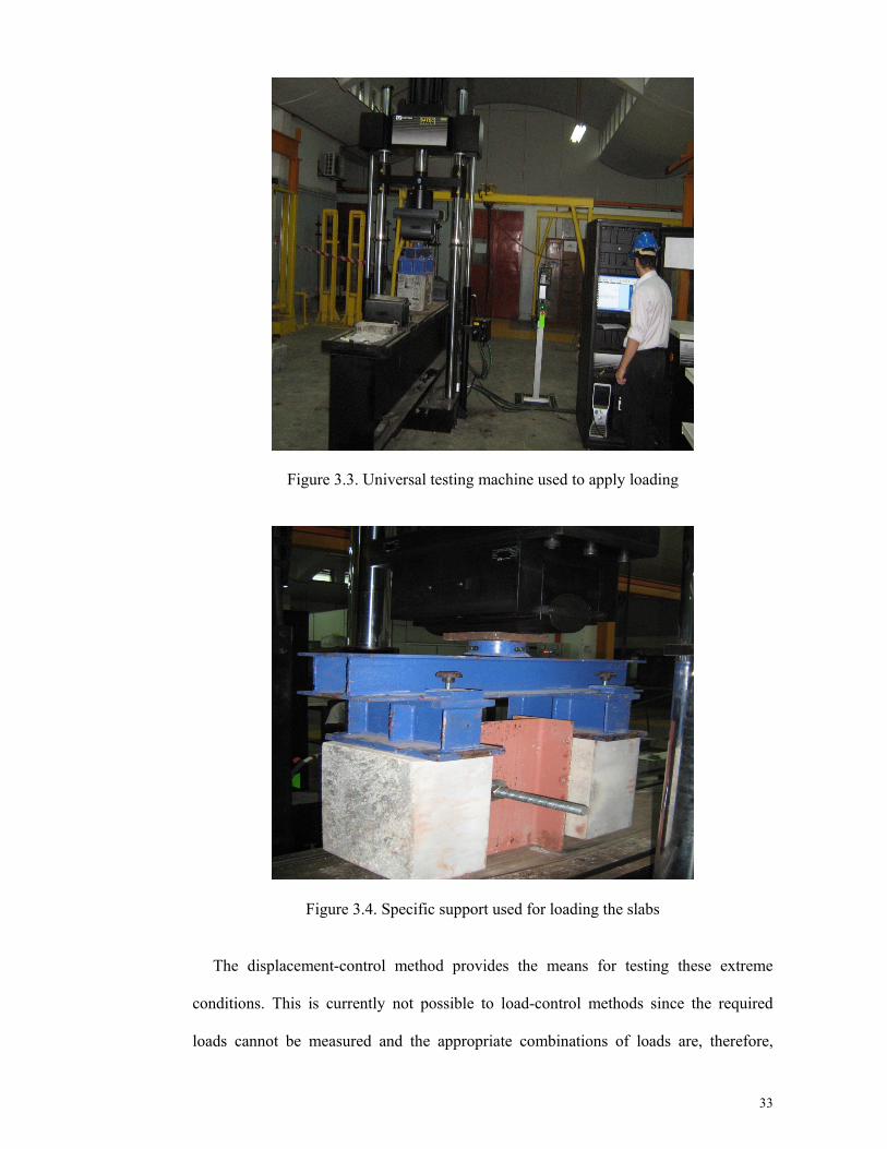
loading. The load was applied using a 600 kN capacity universal testing machine
(Figure 3.3). Specific support was applied for loading the slabs (Figure 3.4) and the
cyclic loading procedure is similar to Civjan and Singh (2003), and also Maleki and
Bagheri (2008a).
Due to the unidirectional nature of the load test frame, specimens were rearranged
earlier to every loading procedure when turning the specimen and loading the upper
concrete faces. Monotonic loading involved slow increment of the loading until failure.
Pseudo-dynamic loading involved of three cycles at ±1/3 M, ±2/3 M, and ± M, where M
is the static yield capacity of the control specimen, as determined from the load-slip
curve of monotonic loading. The static yield capacity of each specimen was used to
compare with the results of reversed cyclic loading after three cycles. This phenomenon
helps to understand the amount of shear strength reduction after cyclic tests.
Generally two methods of loading can employ for applying mechanical test
conditions: load-control and displacement-control. It is not possible to precisely
maintain test conditions using the load-control method because in these situations the
displacements can change with no change in the load input. The most important cases in
which this occurs are at lower loads that the slope of the load-slip curve is small and for
some specimens may approach zero. Also at the other extreme, the fracture of a
specimen results in a sudden decrease in load with increasing displacement (slope of the
load - slip curve becomes negative).
33
Figure 3.3. Universal testing machine used to apply loading
Figure 3.4. Specific support used for loading the slabs
The displacement-control method provides the means for testing these extreme
conditions. This is currently not possible to load-control methods since the required
loads cannot be measured and the appropriate combinations of loads are, therefore,

34
undefined (Goel et al., 1998). In this thesis, the displacement-control was used
throughout with a rate of 0.04 mm/s similar to other researches (Maleki & Bagheri,
2008a; Maleki & Mahoutian, 2009).
The steel I beams were placed on universal test machine deck. Since varying the
connector orientation makes a variation in the ultimate strength of the connector and
relative stiffness (Maleki & Bagheri, 2008b), this matter was considered in the push-out
test and then, the same orientation for connectors was considered in the first half cycle
loading of all specimens (Figure 3.2). The practical load and relative slip between the I
beam and the concrete block was automatically recorded at each time step by the
universal test machine. To obtain a hysteresis loop record for the low cycle fatigue test,
the load-slip behavior was carefully recorded in each half cycle of the test during
reversing the specimen. The practical load and relative slip between the I beam and the
concrete slab were automatically recorded at each time step by the universal test
machine in each half cycle of the test. Using these data a hysteresis loop record for the
low cycle fatigue test was achieved.
Due to the unidirectional nature of the load test frame, specimens were rearranged
earlier to every loading procedure when turning the specimen and loading the upper
concrete faces.
3.3. Finite element analysis
3.3.1. Introduction
In this section an effective numerical model is proposed using finite element method
to simulate the push-out test of angle shear connectors. The focus is on the shear
strength of angle shear connectors embedded in high strength concrete slab under
monotonic loading. The models have been validated against test results presented in the
experimental tests. The models then compared with data given by equations for the

35
prediction of shear capacity of shear connectors. Parametric studies using this nonlinear
model are performed to investigate the variations in concrete strength and connector
dimensions.
The detailed Finite Element Analysis (FEA) also used to evaluate and compare the
results of the push-out tests. Actually, the purpose of this part is to find the difference
between reality and the simulation of push-out test results in the first stage and to make
the shear strength of the push-out test as the results of the parametric study in the second
stage. Consequently, the results of shear strength for shear connectors can be estimated
by changing the different effective parameter of connector’s capacity without doing
expensive push-out tests. In addition, the parametric modelling could help to achieve
certain results that would not be observed through experimental testing. This objective
is achieved once the accurate modelling considers the parameters like nonlinear
materials and geometries (i.e. concrete crushing and cracking, contact interaction),
suitable elements to model the interaction between the steel and concrete. In addition,
the modelling must provide appropriate solutions to overcome the convergence
problem.
The specimens modelled in finite element analysis were chosen from the specimens
in the experimental tests and developed in the finite element program (ABAQUS). A
good finite element model can predict the shear strength close to the values obtained
from tests. Therefore, by using this model, the effects of various parameters such as
flange and web thickness, height and length of shear connectors and different concrete
properties could be effectively predicted as well.
In this parametric study, evaluation of the available equations for the prediction of
angle shear connector’s capacity was aimed. At first, the finite element models
matching the properties of experimental specimens. Then they were developed and the
extended results were compared to the push-out test results. After adopting the

36
appropriate material model, mesh sizing and interface boundary conditions, the model is
considered accurate enough to predict the shear strength of angle shear connectors
embedded in their relative concrete. In the next step, the evaluation of the equations for
estimation of shear capacity of angle shear connector embedded in concrete slab was
aimed. This phenomena helps to realize the accuracy of the equations for estimation of
angle’s capacity in high strength concrete.
3.3.2. General descriptions
Nonlinear three-dimensional finite element analysis of push-out test was engaged. In
addition, the effect of some parameters, such as the flange and web thickness, height
and length of shear connectors and different concrete properties was investigated to
develop the connection behavior. General contact using the ABAQUS explicit program
was proposed to model the interaction between the shear connector and concrete.
Satisfactory agreement was achieved between the results in terms of the load-slip
relationship and shear strength of the connectors. The details of finite element
modelling for specimens are described in the following sections.
3.3.3. Material properties
3.3.3.1. Steel
The kinematic bilinear stress-strain relationship with full plastic stress was
considered for the shear connectors and steel reinforcing bar in the concrete slab.
Figure 3.5 shows the stress-strain relationship for the steel materials. The von Mises
yield criterion was used to define the material yield surface, and an associated flow rule
was used to determine the plastic deformation. For all steel materials, the elasticity
modulus , density (γ) and Poisson ratio (υ) were assumed to be 205 GPa, 7800

37
kg/m3 and 0.3, respectively. The yield and ultimate strength of steel components were
achieved from the steel coupon testing as described in Appendix B.
Figure 3.5. Stress-strain relationship for steel materials (BS 5950, 1990)
3.3.3.2. Concrete
The stress-strain relationship, according to the EC2 (Eurocode 2, 2002), was used to
define the behavior of the concrete material. Figure 3.6 shows an equivalent uniaxial
stress-strain curve to consider the nonlinear behavior of concrete in compression. The
compression curve is divided into three parts including the elastic range, the nonlinear
parabolic portion and the descending slope. The value of the first part is the proportional
limit stress of 0.4 (Eurocode 2,2002), where is defined as the concrete strength
of the cylinder specimen and is equal to 0.8 , while cu is the concrete strength of the
cubic specimen. The strain (Ɛ ) in relation to is equal to 0.0022. The stress for

38
nonlinear parabolic part can be obtained as given in Equations 3.1 and 3.2 (Eurocode 2,
2002),:
3.1
Where:
1.1
Figure 3.6. Stress-strain relationship for compression behavior of concrete (BS 5950,
1990)
The descending part can be used to define the post failure for concrete compression
behavior in specimens in which concrete crushing occurred. The descending slope
ceases at a stress value of r . Here r is the reduction factor obtained by Ellobody et al.,
2006). The range of r can be between 1 to 0.5 equivalents to the concrete cube strength
with a range of 30 to 100 MPa. The ultimate strain of concrete at failure (Ɛ ) is equal
toαƐ . According to EC2 (Eurocode 2, 2002) and BS 8110 (1997) Ɛ is equal to
0.0035, which means that here α is equal to 1.75 and Poisson ratio (υ) were assumed to

39
be, 2,350 kg/m3 and 0.2, respectively. The elasticity module (E ), was obtained from
EC2 (Eurocode 2,2002) given in Equation 3.2
9.5 8 E inGPaandf inMPa 3.2
The nonlinear behavior of concrete in tension using the uniaxial stress-strain curve is
shown in Figure 3.7. The tensile stress in concrete increases linearly to the strain before
the concrete cracks and decreases to zero once the concrete cracks. Cracking can be
defined in three ways, i.e. linear, bilinear and exponential function when there are no
reinforcing bars or only a few reinforcing bars in the concrete (ABAQUS). The
exponential function type (Cornelissen et al., 1986) was used to define the tension
softening in this analysis. Figure 3.8 shows the tension stress-crack displacement
relationship. In the models, damage for concrete cracking was defined for the
specimens.
The concrete damage plasticity model presumes a non-associated potential plastic
flow. The Drucker-Prager hyperbolic function was used as the flow potential. The
material dilation angle (Ψ) and eccentricity ( ) were taken as 15o and 0.1, respectively.
The ratio of biaxial compressive strength to uniaxial compressive strength was
taken as 1.16.

40
Figure 3.7. Stress-strain relationship for tensile behavior of concrete (Cornelissen, et al., 1986)
Figure 3.8. Exponential function of tension softening model (Cornelissen, et al., 1986)

41
3.3.4. Modelling of the specimens
To obtain appropriate results using the ABAQUS software, all components including
the steel I beam, shear connectors, reinforcing bars and concrete slab were modelled. To
model the interaction between the components, general contact with the ABAQUS
explicit program was employed. This is a very important part in the analysis and needs
more attention as inappropriate interaction may cause a convergence problem. The
geometry of the specimens was described earlier. The geometric models consist of three
main parts: 1) Steel includes steel I beam and the shear connector, which are merged
together and made one part, 2) Concrete slab and 3) Reinforcing bars.
The geometry of the parts in a typical specimen is shown in Figure 3.9. Figure 3.10
shows the steel and concrete parts modelled in software separately and Figure 3.11
displays the placement of steel angle connectors in concrete slab for reference.
Figures 3.12 to 3.13 show the details of angle shear connectors used in this study.
Figure 3.9. Typical view of the specimens in the experimental test

42
Figure 3.10. Separate parts of assembly (angle and concrete slab)
Figure 3.11. Placement of steel connector in concrete slab

43
Figure 3.12. Typical geometric modeling of the specimens
Figure 3.13. Typical steel part with angle in specimen
3.3.5. Element type
Figures 3.14 to 3.16 show the typical finite element mesh of the specimens to model

44
the geometry of the test specimen. The mesh size was selected such that it satisfies a
good accuracy and a reasonable computational time. The types of element used in the
finite element modelling are presented as follows.
1. The eight-node solid element (C3D8R) was used to model the steel beam and the
shear connector and the concrete slab, which has three translational degrees of
freedom at each node. This element can consider concrete cracking and crushing in
three orthogonal directions at each integration point.
2. The truss element (T3D2) was used for modelling the reinforcing bars. This
element has three translational degrees of freedom (translation in the x, y and z
directions) at each node.
Figure 3.14. Typical meshing of concrete part in specimen
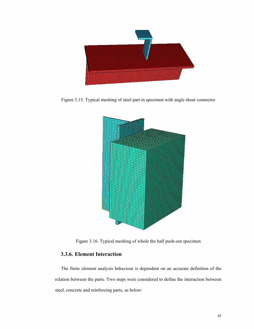
45
Figure 3.15. Typical meshing of steel part in specimen with angle shear connector
Figure 3.16. Typical meshing of whole the half push-out specimen
3.3.6. Element Interaction
The finite element analysis behaviour is dependent on an accurate definition of the
relation between the parts. Two steps were considered to define the interaction between
steel, concrete and reinforcing parts, as below:

46
3.3.6.1. Embedded element
The interaction between the reinforcing bars and the concrete slab was assumed to be
full bond with no slip between them. Consequently, the embedded element was used for
this purpose. For assigning the embedded element, the part of the concrete slab, which
was close to the reinforcing bars, was defined as the embedded.
3.3.6.2. Contact interaction
General contact was chosen to define the contact interaction between the steel and
concrete parts. To define general contact, some text comment, such as *CONTACT
CLEARANCE ASSIGNMENT and *CONTACT CONTROL ASSIGNMENT were
defined in the ABAQUS explicit program. Figure 3.17 shows the connector’s surfaces
contacted to concrete surface for angle shear connectors.
Figure 3.17. Angle surfaces which are contacted to concretes
3.3.7. Contact properties
Both the normal and tangential contacts were considered in the contact interaction.
Geometry scaling, which is a softened pressure-over closure relationship was used to
model the normal contact between the steel and concrete. This model provides a simple
interface to increase the default contact stiffness when a critical penetration is exceeded
as shown in Figure 3.18. The penetration measure, d, is defined either directly or as a
fraction, r, of the minimum element length, in the contact region. Each time the

47
current penetration exceeds a multiple of this penetration measure, the contact stiffness
are scaled by a factor, S. The initial stiffness is given in Equation 3.3
. 3.3
Where:
i: Segment member
S: Geometric scale factor
: Default stiffness
r: Over closure factor
: Element length
d = r. : Over closure measure
: Initial scale factor
In this analysis, parameters like S0, S and d are considered as below:
3< S0 <10 1.05 < S <1.1 1 10-6 < d <1 10-7m
Tangential contact was used to define the friction contact between the steel and the
concrete. The coulomb friction model was used to model the friction contact between
the steel and concrete. The friction coefficient between the steel and the concrete was
assumed to be 0.3.
Angle surfaces contact separately with the corresponding surface of the concrete slab
in shape of surface to surface contact. In all cases, the contact surfaces of the slab act as
master and Angle surface act as slave.

48
Figure 3.18. Softened pressure-over closure relationship – Geometry scaling (ABAQUS
manual, 2011)
3.3.8. Loading and boundary condition
The similar loading of the test specimen was considered for the loading in the finite
element analysis. A vertical velocity loading was applied to the concrete slab. The load
direction is downward. Velocity controlled loading provides a more stable system in
the nonlinear stage rather than force controlled loading. A special 0.04 mm/s rate of
velocity was monotonically used for the loading rate. This rate was achieved by
comparing the kinematic energy with the internal energy when the effect of dynamic
analysis could be neglected. The real rate, which is much smaller than this rate, results
in longer time analysis with little effect on the accuracy of the results. As shown in
Figure 3.19 all nodes of I beam section on the symmetric plan were constrained against
displacement on the X, Y and Z direction axis to simulate boundary conditions for the
specimens.

49
Figure 3.19. Boundary condition in the specimen
The loading step is the next procedure after the assembling of the parts. In this
analysis, linear loading was considered. This loading is similar to the experimental
loading procedure in push-out test when the it was applied instantly. Since the ultimate
load cannot be realized in parametric analysis, 1.5 times of real shear strength of any
specimens considered for maximum loading.
The next step is obtaining the output results of the software such as stress, strain, and
boundary conditions.
3.3.9. Analysis solution
Available analysis, such as general static in the ABAQUS Standard was used for
initial analysis; however, it caused a convergence problem and stopped the analysis
even at the beginning of the analysis. The results of the RIKS method also resulted in a
convergence problem (Kim & Nguyen, 2010). Consequently, ABAQUS explicit was
employed for analysis, which is suitable for nonlinear materials and geometry, large

50
deformation and concrete damage and discontinuous parts (ABAQUS). Reduced
integration, second accuracy and enhanced control were considered in the analysis for
solid element.

51
4 RESULTS AND DISCUSSION

52
4.1. Preface
This chapter is composed of two parts to present the results and discussion of this
study. Results and discussion on the experimental test of the specimens is described in
the first part. In the second part, results and discussion on the finite element analysis are
provided to verify the finite element analysis results against experimental test results
where ever applicable.
4.2. Experimental test results
This section comprises of the experimental results related to the push-out specimens
along with a description of observed failure mechanisms. The main test results are
shown in the form of load-slip curves. In all the load slip graphs shown in this section,
the abscissa represents the average slip in mm at the interface of the steel section and
the concrete slab. The ordinate represents the load per connector in kN.
4.2.1. Load-slip analysis for monotonic loading
Static strength is necessary for shear connector design and ductility is an essential
assumption in the design which is confirmed throughout ultimate slip (Shim, 2004). The
load-slip curve for one shear connector is used to extract the mechanical properties of
the shear connector. The slip occurs between the I beam and the concrete block. The
static curve is used to see if there is sufficient ductility for shear connectors as well.
In the result of universal testing machine under monotonic loading, the applied load had
a slip increment record on non-linear stage. The reason for this testing was to define the
load - slip curve more accurately and to record the distortion of the specimens at failure.
It is hardly possible to record readings for many examples with connector rupture
failure that cause the sudden failure of shear connector. Failures of concrete specimens,
were accompanied by a significant amount of load beyond the ultimate load level.

53
The load-slip curve for all specimens with angle shear connector embedded in
reinforced concrete high strength slab was drawn and presented in Figure 4.1. The load-
slip curve of specimens with the failure of the connector fracture type came to a sudden
end. Table 4.1 presents the results of the push-out tests for angle shear connectors
embedded in high strength reinforced concrete under monotonic loading.
Figure 4.1. Load-slip curves of angle connectors embedded in in high strength reinforced concrete under monotonic loading
Table 4.1. Monotonic test results for angle connectors embedded in high strength reinforced concrete
Analyzing the load-slip curves of specimens with angle shear connectors show that
when they are subjected to the monotonic load, the connector yielded in the maximum
Specimen Failure Load (kN) Maximum Slip (mm) Failure type H110050-M 178.3 0.5 Connector fracture H17550-M 152.9 1.0 Connector fracture H110030-M 112.7 2.0 Connector fracture H17530-M 103.7 2.0 Connector fracture H210050-M 180.0 1.0 Connector fracture H27550-M 145.9 1.0 Connector fracture H210030-M 92.7 2.0 Connector fracture H27530-M 63.7 2.0 Connector fracture H310050-M 160.5 1.0 Connector fracture H37550-M 130.7 2.0 Connector fracture H310030-M 83.1 1.5 Connector fracture H37530-M 44.8 1.5 Connector fracture

54
slip and shear load capacity. The load-slip curve for one shear connector was employed
to extract the mechanical properties of that connector. The slip occurred between the
steel I-beam and the concrete block. Based on Eurocode 4 (Eurocode 4, 2004), a
connector may be taken as ductile if the characteristic slip capacity is at least 6 mm. It
can be concluded that angle shear connectors are not sufficiently ductile in the peak load
for the monotonic loading while they are embedded in HSC since the relative slip was
measured as 0.5 – 2.0 mm, for all connectors. In all specimens, a sudden termination of
the load-slip curve was observed. Almost all angle specimens do not experience a yield
plateau, which results in an increase in the slip while the load reaches its peak.
The load-slip curves provide the opportunity to assess the ductility factor of shear
connectors. Considering these curves, the ductility of the connectors can be evaluated
by using a ductility factor, μ, which is defined in terms of an equivalent elastoplastic
load-deflection curve, as shown in Figure 4.2. The load-deflection curve of a shear
connector was idealized by two straight lines representing the initial stiffness and the
maximum strength. The intersection of those two lines was taken as the equivalent yield
displacement, Δy.

55
Figure 4.2. Definition of ductility factor
The maximum deflection, Δmax, was defined as the deflection at the condition which
the shear connector failed. The corresponding ductility factor was then calculated as
Δmax/Δy. A higher ductility factor shows a more ductile composite system. In general,
the greater the ductility factor of a particular system, the greater the amount of inelastic
redistribution of applied load (Kwon et al., 2011). Ductility enhances safety in
structures by both providing warning of impending before failure and by allowing
redistribution of loads to adjacent beams. The calculated ductility factor for each
specimen is presented in Table 4.2.
The results of the ductility factor show that longer connectors exhibit more ductility
compared to while for shorter connectors.

56
Table 4.2. Ductility factor for angle specimens embedded in HSC slab
The results indicate that although the angle shear connector shows good behavior in
terms of the ultimate shear strength, but the ductility criteria of the Eurocode 4
(Eurocode 4, 2004) which define a ductile connector when it has a slip of more than 6.0
mm, is not satisfied. This is due to the resistance of the angle connectors falls below
90% of the maximum load for a slip of less than 2.0 mm. The resistance would drop
more intensely and suddenly with the increase of height in angle connectors.
4.2.2. Load-slip analysis for reversed cyclic loading
Generally speaking, by checking the monotonic tested specimens’ results against the
cyclic tested specimens, it was observed that the capacities are reduced when fully
reversed cyclic loading is introduced after a certain number of load cycles. To prevent
failure of the connector, this number of load cycles should be used as the shear strength
under cyclic loading. That is why cyclic testing of these levels of stresses is needed to
ensure sufficient fatigue life under reversed load cycles (Maleki & Bagheri, 2008a). The
load-slip curves of the cyclic loadings of the push-out test specimens are examined in
this part.
Specimen Δmax Δy μ H110050-M 13.0 4.0 3.3 H17550-M 8.0 2.0 4.0 H110030-M 10.0 3.0 3.3 H17530-M 7.5 3.0 2.5 H210050-M 10.0 2.5 4.0 H27550-M 4.5 1.5 3.0 H210030-M 5.0 2.0 2.5 H27530-M 4.0 2.5 1.6 H310050-M 9.0 2.0 4.5 H37550-M 5.0 1.0 5.0 H310030-M 10.5 4.0 2.6 H37530-M 3.5 0.5 7.0

57
Figure 4.3 shows the typical load-slip curves, for a specimen when subjected to the
cyclic loading. A summary of the results can be also seen in Table 4.3.
Figure 4.3. Cyclic load-slip curves of angle shear connectors specimen H210030-C embedded in HSC slab
Table 4.3. Cyclic test results for similar pair to pair specimens
Pair to pair similar specimen
Failure Load (kN)
Strength degradation (%)
Maximum Slip (mm)
H110050-M 178.3 1.4
0.5 H110050-C 175.8 1.0 H17550-M 152.9
1.4 1.0
H17550-C 150.8 2.5 H110030-M 112.7
0.4 2.0
H110030-C 112.3 1.5 H17530-M 103.7
0.1 2.0
H17530-C 103.8 2.0 H210050-M 141.0
0.6 1.0
H210050-C 140.2 1.5 H27550-M 109.6
0.6 1.0
H27550-C 109.0 2.5 H210030-M 77.9
0.5 2.0
H210030-C 78.3 1.5 H27530-M 69.6
0.1 2.0
H27530-C 69.5 2.5 H310050-M 111.3
1.3 1.0
H310050-C 109.9 1.5 H37550-M 106.1
1.1 2.0
H37550-C 104.9 2.0 H310030-M 105.2
0.3 1.5
H310030-C 104.9 1.5 H37530-M 99.0
1.4 1.5
H37530-C 97.6 2.0

58
All push-out specimens resisted for the first and the second half cycles of loading, at
1/3M and 2/3M (M is considered to be the failure load of the same specimen, under
monotonic loading) and then fractured, at the first half cycle of the whole load (M). This
failure is indicated as the cyclic failure in Table 4.2. In summary, angle shear
connectors resisted 98.6% – 99.9% of their monotonic capacity when embedded in a
reinforced concrete slab and subjected to the fully reversed cyclic loading. A decrease in
capacity is understood to occur, after a certain number of load cycles.
One may conclude that all angle shear connector specimens, under reversed cyclic
loading embedded in HSC, showed 0.1% – 1.4% strength degradation compared to
monotonic cases where the failure type did not change. It can be clearly noticed that the
capacities of specimens when subjected to the fully reversed cyclic loading were
reduced. So under cyclic load conditions, there is no significant change on the failure
loads as compared to the monotonic loading.
The strength degradation can be described due to the crushing of the concrete, on the
compressive face of the slabs and due to the large slip and the plastic yielding at this
region.
4.2.3. Failure mode of shear connectors
Basically two types of failure are defined in the push-out specimens. The first type is
connector fracture (Figure 4.4) and the second type is concrete crushing splitting
(Figure 4.5) (Maleki & Bagheri, 2008a; Shariati et al., 2010). In some test results of
previous researches a combination of both failure modes was reported as well
(Figure 4.6). In all tests reported in this thesis, the connector fracture was observed.
The type of failure greatly influences the strength, ductility and loading response.
After the testing, the specimens were crushed in order to observe the effect of loading
on the concrete slab, connector and reinforcement.

59
Figure 4.4. Connector fracture of failure
Figure 4.5. Failure of concrete crushing splitting

60
Figure 4.6. Combined failure mode of concrete and connector
All the push-out specimens experienced connector fracture mode of failure, under
both monotonic and low cyclic fatigue loads (Fig. 4.7 and 4.8). Although the same type
of failure was seen in monotonic and cyclic loading for all specimens, the failure in the
low cycle test was less ductile compared to the monotonic loading.

61
Figure 4.7. Typical fracture of angle shear connector for specimen with high strength concrete (Fractured angle in slab)
Figure 4.8. Typical fracture of angle shear connector for specimen with high strength concrete (Fractured angle attached to steel I beam)

62
4.2.4. Effect of connector dimensions on shear capacity
It can be seen that the behavior of the 30 mm long angles differs from that of the 50
mm long. For specimens with longer angle connector, concrete cracking occurred on the
sides of the slabs while such cracking was not observed in specimens with shorter angle.
Hence, it can be concluded that longer angle connector contributes to more cracking in
concrete. The same phenomenon was also observed for the channel shear connectors as
reported by Maleki and Bagheri (2008), Maleki and Mahoutian (2008) and Shariati et
al. (2011).
In this study, the height of the connectors varied from 75 mm to 100 mm.
Considering the load slip curves of monotonic loading for specimens with the angle
length of 50 mm, it can be observed that the specimens with 100 mm high angle
connectors carried slightly higher load compared to the specimens with 75 mm high
angle connectors.
This corresponds to an increase in the ultimate load capacity of 16.6%. Similarly, for
specimens with the angle length of 30 mm, the angle with 100 mm height carried higher
load as compared to that specimen by the 75 mm high angles. In this case, a 33%
increase in the angle height raised the ultimate load capacity by 8.7%.
The fact that angle connectors with, lower height have a tendency of concentrating
the applied load on a smaller area might be the cause of this conclusion. The curves also
showed that the specimens with 75 mm high angles demonstrated higher flexibility
compared to those with 100 mm high angles. A 2.0 mm slip at the ultimate load level
was recorded for the 75 mm high angles as compared to 0.5 – 1.0 mm slip for angles
with 100 mm height.

63
4.2.5. Evaluation of design codes for the shear capacity of angle
connectors based on experimental tests
The actual shear strength of angle shear connectors obtained from push-out tests was
compared with the Equation 4.1 suggested by Kiyomiya and Yokota (1986) which was
modified by Kiyomiya and Yokota (1987) and Equation 4.2 proposed by Ros (2011).
P=65√t L f 4.1
Where:
P = Shear strength of the connector (kgf)
t Web thickness of connector (cm)
L = Length of connector (cm)
f = Concrete compressive strength (kgf/cm2)
V = f × L × and =63× + .60 4.2
Where:
= Ultimate shear force in the shear failure mode or by concrete crush (N),
L = Length of connector (mm),
= Height of shear connector (mm),
= Thickness of shear connector (mm),
f = Concrete compressive strength (MPa),
The relative amount of strength of the connectors based on the push-out results and
the standard codes are presented in Table 4.4.

64
Table 4.4. Comparison of test results with code prediction for angle connectors in HSC
In the Table 4.4, the ratio of strength of shear connector based on test results and
available equations for their shear capacity is given to compare the strength of
connectors. It is seen that the equation recommended by Kiyomiya and Yokota (1987)
(Equation 4.1) is conservative while the equation suggested by Ros (2011) (Equation
4.2) gives unconservative capacities. Based on the results of angle shear connector’s
capacity, more research for obtaining further accurate equation for capacity of angle
shear connectors is needed.
4.2.6. Summary of experimental results
In this chapter the experimental investigations of the push-out specimens with angle
shear connectors embedded in the HSC in composite beams was conducted. The test
experimental program involved the testing of twenty four push-out specimens under
monotonic and low cyclic fatigue loading when using slab with HSC. The behavior of
the angle shear connectors embedded in solid concrete slabs with high strength concrete
was the objective of the experimental tests to understand the effect of several
parameters on the shear capacity and ductility of these types of shear connectors.
Specimen Failure load (kN) Eq 4.1 (kN) Test/ Eq. 4.1 Eq 4.2 (kN) Test/ Eq. 4.2 H110050-M 178.3 73.5 2.4 243.6 0.7 H17550-M 152.9 44.1 3.5 146.2 1.0
H110030-M 112.7 67.1 1.7 197.0 0.6 H17530-M 103.7 40.3 2.6 118.2 0.9
H210050-M 180.0 72.6 2.5 240.6 0.7 H27550-M 145.9 43.6 3.3 144.4 1.0
H210030-M 92.7 66.3 1.4 194.5 0.5 H27530-M 63.7 39.8 1.6 116.7 0.5
H310050-M 160.5 64.4 2.5 213.5 0.8 H37550-M 130.7 38.7 3.4 128.1 1.0
H310030-M 83.1 58.8 1.4 172.6 0.5H37530-M 44.8 35.3 1.3 103.6 0.4

65
Generally, there are three different types of failure mechanisms mean, crushing-
splitting of concrete, connector fracture and a combination of these two failures. Only
the connector fracture of failure was observed in the experimental investigations. The
shear capacity and the ductility of angle shear connectors as main parameters in the
behavior of shear connectors were discussed as well.
The details of the experimental results were fully-described in summary as follows;
1. The connectors in reinforced concrete have a relative slip of 0.5–2.5 mm under
monotonic loading embedded in HSC.
2. Based on Eurocode 4, the angle shear connectors are not sufficiently ductile in
the peak load for the monotonic loading.
3. The connectors in reinforced concrete under low cyclic fatigue loading, all push-
out specimens fractured at the first half cycle of the whole load (M) and resisted
98.6% – 99.9% of their monotonic capacity.
4. One may conclude that all angle shear connector specimens, under reversed
cyclic loading, showed 0.1% – 1.4% strength reduction compared to those
monotonic cases where the failure type did not change
5. All the push-out specimens experienced connector fracture mode of failure,
under both monotonic and low cyclic fatigue loads.
6. Although the same type of failure was seen in monotonic and cyclic loading for
all specimens, the failure in the low cycle test was less ductile compared to the
monotonic load.
7. One may conclude that higher angle connectors resist less shear once the length
of the connector increases compared to lower connectors once their length
increases.
8. For specimens with the higher length of connectors, cracks were observed at the
top surface of the slab when the maximum load was applied.

66
9. For specimens with shorter connectors in the slabs, small cracks at the top
surface had a tendency to develop around the center of the slabs; however,
overall these specimens did not experience severe cracking.
10. The equation recommended by Kiyomiya and Yokota (1987) (Equation 4.1) is
unconservative while the equation suggested by Ros (2011) (Equation 4.2) gives
conservative capacities.
4.3. Finite element results
Effective numerical analyses were proposed using finite element method to simulate
the push-out test of angle shear connectors. The shear strength prediction of connectors
under monotonic loading embedded in HSC is the aim of this study. The models have
been validated against experimental test results. Parametric studies using these
nonlinear models are performed to investigate the variations in concrete strength and
connector dimensions. Generating an evaluation for accuracy of the available equations
for the prediction of shear capacity of angle connectors in high strength concrete is the
target.
4.3.1. Verification of finite element results
The finite element results should be verified using experimental test results to ensure
the accuracy of the modelling. Comparison of the load-slip relationship between the
finite element results and the experimental results are shown in Figures 4.9 to 4.11. The
von misses stress and plastic strains of the specimens are shown in the Figures 4.12 to
4.14 as well. According to the results, the finite element analysis is able to exhibit the
accurate elastic and inelastic behavior of the connections.
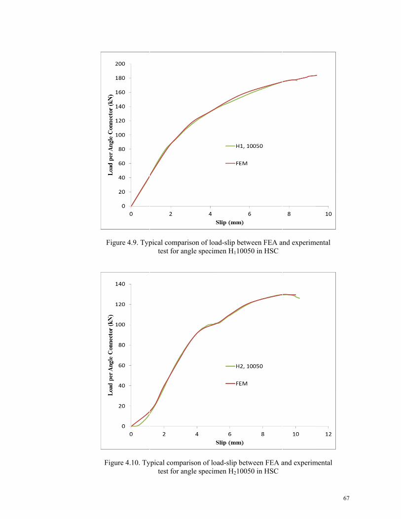
Figu
Figu
ure 4.9. Typ
ure 4.10. Ty
pical compatest for a
ypical comptest for a
arison of loaangle specim
arison of loangle specim
ad-slip betwmen H11005
oad-slip betwmen H21005
ween FEA a50 in HSC
ween FEA a50 in HSC
and experim
and experim
67
mental
mental
7

68
Figure 4.11. Typical comparison of load-slip between FEA and experimental test for angle specimen H310050 in HSC
Figure 4.12. Typical Von Mises stress for specimen H110050

F
Figure 4.13.
Figur
Typical pla
re 4.14. Typ
astic strain f
pical plastic
for specime
strain for sp
en H110050
pecimen H1
(Perspectiv
110050
69
ve)
9

70
4.3.2. Parametric investigations based on finite element method
4.3.2.1. Preface
The finite element model was used to perform a parametric study by using concrete
with various compressive strengths and various dimensions of connectors. After
verification of the finite element results against the experimental test, the shear
capacities of angle shear connectors obtained from finite element analysis were
evaluated and discussed. The discussion deliberated mostly on the shear capacity
alterations under monotonic loading while different dimensions of shear connector and
compression strength of high strength concrete were used.
As mentioned earlier, the shear strength for the angle shear connectors embedded in
reinforced concrete slab can be estimated by using Equations 4.1 by Kiyomiya and
Yokota (1987) and 4.2 by Ros (2011). The results of these equations were compared
with the nonlinear finite element results to check the accuracy of these formulae for the
HSC.
Table 4.6 presents the results of finite element analysis for specimens with angle
shear connectors embedded in high strength concrete under monotonic loading. Table
4.6 compares the ultimate strengths obtained from finite element analysis against the
Equations 4.1 and 4.2 to check the accuracy of these equations as well. From the ratio
achieved from the last column of the table, it can be concluded that for those specimens
which have ratios of more than 1, the shear capacity estimated by the equation is
conservative and for those with ratios less than 1, the capacity estimation is
unconservative.
These results confirm that there is a need for more research to find a comprehensive
formula for the prediction of shear capacity for angle shear connectors in composite
slab.

71
Table 4.5. The results of finite element and experimental study for angle connectors embedded HSC.
Specimens with HSC
mix fc (MPa)
Angle Connector Specification (mm) Shear Capacity (kN)
Length Height Thickness
FE Analysis Experimental Web Flange
H1 series 82
50 75 5 7.5 150.2 152.9 50 100 6 8.5 174.4 178.3 50 120 7 9 189.3 - 50 140 7 10 201.2 - 50 160 7.5 10.5 217.5 -
H1 series 82
30 75 5 7.5 107.0 103.7 30 100 6 8.5 116.2 112.7 30 120 7 9 160.8 - 30 140 7 10 166.8 - 30 160 7.5 10.5 188.1 -
H2 series 80
50 75 5 7.5 145.5 145.9 50 100 6 8.5 180.6 180.0 50 120 7 9 188.2 - 50 140 7 10 199.3 - 50 160 7.5 10.5 201.1 -
H2 series 80
30 75 5 7.5 63.1 63.7 30 100 6 8.5 91.9 92.7 30 120 7 9 108.9 - 30 140 7 10 127.0 - 30 160 7.5 10.5 143.8 -
H3 series 63
50 75 5 7.5 131.3 130.7 50 100 6 8.5 158.8 160.5 50 120 7 9 167.1 - 50 140 7 10 170.7 - 50 160 7.5 10.5 183.8 -
H3 series 63
30 75 5 7.5 44.9 44.830 100 6 8.5 80.6 83.1 30 120 7 9 86.9 - 30 140 7 10 97.1 - 30 160 7.5 10.5 105.1 -

72
Table 4.6. Comparison of the ultimate strengths obtained from the finite element against the equation in reinforced concrete.
From the results, one may conclude that the equation recommended by Kiyomiya
and Yokota (1987) (Equation 4.1) is conservative while the equation suggested by Ros
(2011) (Equation 4.2) gives unconservative shear capacities. Meanwhile, it is believed
that further investigations are inevitable in order to propose new equations for
estimating the shear capacity of angle shear connectors.
4.3.3. Summary of finite element results
Effective numerical analyses were proposed by using the finite element method to
simulate the push-out test of angle shear connectors. The finite element results were
Specimens with HSC
mix
Shear Capacity (kN) Comparison
FE Analysis Equation (1) Equation (2) FE/Eq1 FE/Eq2
H1 series
150.2 82.2 329.8 1.8 0.5 174.4 79.4 301.1 2.2 0.6 189.3 79.4 286.6 2.4 0.7 201.2 73.5 243.6 2.7 0.8 217.5 67.1 200.6 3.2 1.1
H1 series
107.0 49.3 197.9 2.2 0.5 116.2 47.6 180.7 2.4 0.6 160.8 47.6 172.0 3.4 0.9 166.8 44.1 146.2 3.8 1.1 188.1 40.3 120.3 4.7 1.6
H2 series
145.5 81.2 325.8 1.8 0.4 180.6 78.4 297.4 2.3 0.6 188.2 78.4 283.1 2.4 0.7 199.3 72.6 240.6 2.7 0.8 201.1 66.3 198.1 3.0 1.0
H2 series
63.1 48.7 195.5 1.3 0.3 91.9 47.1 178.4 2.0 0.5
108.9 47.1 169.9 2.3 0.6 127.0 43.6 144.4 2.9 0.9 143.8 39.8 118.9 3.6 1.2
H3 series
131.3 72.0 289.1 1.8 0.5 158.8 69.6 263.9 2.3 0.6 167.1 69.6 251.2 2.4 0.7 170.7 64.4 213.5 2.7 0.8 183.8 58.8 175.8 3.1 1.0
H3 series
44.9 43.2 173.5 1.0 0.380.6 41.8 158.3 1.9 0.5 86.9 41.8 150.7 2.1 0.6 97.1 38.7 128.1 2.5 0.8
105.1 35.3 105.5 3.0 1.0

73
verified by using experimental test results to ensure the accuracy of the modelling. The
von misses stress and plastic strains of the specimens were shown. According to the
results, the finite element analysis is able to exhibit the accurate elastic and inelastic
behavior of the connections.
Using the finite element model by concrete with various compressive strengths of
HSC and various dimensions of connectors, a parametric study was conducted. After
verification of the finite element results against the experimental test, the shear
capacities of angle shear connectors obtained from finite element analysis were
evaluated.
The finite element results confirmed the results of experimental tests and show that:
1. The equation recommended by Kiyomiya and Yokota (1987) (Equation 4.1) is
conservative while the equation suggested by Ros (2011) (Equation 4.2) gives
unconservative shear capacities.
2. The angle shear connectors are not sufficiently ductile in the peak load for the
monotonic loading.
3. Higher angle connectors resist less shear once the length of the connector
increases compared to lower connectors once their length increases

74
5 CONCLUSION
75
5.1. Introduction
This thesis presents the experimental and parametric investigations of push-out
specimens with angle shear connectors embedded in high strength concrete in
composite beams. The experimental test program involved the testing of twenty four
push-out specimens. The specimens were designed to study the effect of several
parameters on the shear capacity of angle shear connectors under monotonic and low
cyclic fatigue loading.
The only type of failure mechanisms were observed in experimental investigations
was connector fracture. The shear capacity and the ductility of angle shear connectors as
main parameters in the behavior of shear connectors were discussed as well.
Design equations (Equations 4.1 and 4.2) are the general equaions for the shear
capacity of angle shear connector in normal reinforced concrete. These equations were
evaluated for estimation of the shear capacity of angle connectors in high strength
concrete using the parametric study.
Generally, by referring to the results, angle shear connectors showed good behavior
in terms of shear capacity but exhibited limited ductility behavior. The details of the
results were described as follows.
5.2. Investigation of behavior of angle shear connectors
Based on Eurocode 4, the angle shear connectors are not sufficiently ductile in the
peak load for the monotonic loading in HSC. These results have been confirmed by
finite element results as well.
The angle connectors in high strength reinforced concrete under low cyclic fatigue
loading, fractured at the first half cycle of the whole load (M) in all push-out specimens.
In all cases, the failure mode of angle shear connectors was connector fracture.

76
5.3. Investigation of parameters affecting the connector’s
behavior
Limited ductility was observed for angle shear connectors, where a slip of less than
2.5 mm was recorded.
Higher angle connectors resist less shear compared to lower connectors once their
length increases. These results have been confirmed by finite element results as well.
For specimens with the higher length of angle connectors, cracks were observed at the
top surface of the slab when the maximum load was applied. For angle specimens with
shorter connectors in the slabs, small cracks at the top surface had a tendency to develop
around the center of the slabs.
5.4. Comparison between experimental and finite element
analysis
The shear capacity obtained from the finite element results for specimens with angle
connector embedded in high strength concrete have a considerable difference with the
results of experimental tests. The experimental test results and finite element results for
channels are in perfect agreement for the specimens embedded in HSC slab.
5.5. Evaluation of design equations
From the results it was concluded that the Equation 4.1 proposed by Kiyomiya and
Yokota (1987) is more conservative than the Equation 4.2 proposed by Ros (2011) for
estimation of the angle shear capacity in HSC. For the specimens with high strength
concrete, the strength prediction in Equation 4.2 is underestimated for the test results of
all specimens. In the case of HSC, this formula is unconservative since the experimental
results of angle shear capacity is less than or equal to the capacities obtained from the
design equation.

77
5.6. Recommendations for future research
Based on research presented in this thesis, the following recommendations can be
made:
1. It is believed full scale tests for investigation of the behavior of angle shear
connectors in composite beam can complete the investigation. Experimental
and parametric studies using finite element analysis of full scale test for angle
shear connectors are suggested.
2. Since it was understood that both the available equations for estimation of shear
capacity for angle shear connectors (Equations 4.1 and 4.2) are not accurate, it
is recommended that further research on angle connectors with different
dimensions should be carried out in order to develop a numerical equation
which would be able to predict the shear capacity of the these connectors with
different dimensions.

78
REFERENCES
ACI committee 363. (1984). State of the art report on high-strength concrete. ACI Journal Proceedings. 81(4). ACI.
AISC 360-05 (2005) Specification for structural steel buildings, American Institute of Steel Construction. Inc., Chicago (IL).
AASHTO, LRFD. (2007). Bridge design specifications. American Association of State Highway and Transportation Officials, Washington, DC.
ABAQUS. (2011). Abaqus doqumentation version 6.10.
Ahn, J., Lee, C., Won, J. & Kim, S. (2010). Shear resistance of the Perfobond-rib shear connector depending on concrete strength and rib arrangement. Journal of Constructional Steel Research. 66 (10), 1295–1307.
ANSI/AISC360-10. (2010). Specification for structural steel buildings.Chicago (IL): American Institute of Steel Construction, Inc.
Al-Darzi, S., Chen, A. & Liu, Y. (2007). Finite element simulation and parametric studies of perfobond rib connector. American Journal of Applied Sciences, 4(3), 122-127.
Al-Darzi S., Chen A. & Liu. Y. (2007). Development of new hole shape of perfobond shear connectors, parametric study. Roceedings of the 2nd international symposium on connection between steel & concrete. University of Stuttgart, Germany, 1401-1413.
An, L., & Cederwall, K. (1996). Push-out tests on studs in high strength and normal strength concrete. Journal of Constructional Steel Research, 36(1), 15-29.
ASCE. (2000). Design of latticed steel transmission structures.
ASTM. C39. (2004). Standard test method for compressive strength of cylindrical concrete specimens. Annual Book of ASTM Standards.
Badie, S., Tadros, M., Kakish, H., Splittgerber, D. & Baishya, M. (2002). Large shear studs for composite action in steel bridge girders. Journal of Bridge Engineering, 7(3), 195-203.
Bathon, L., & Graf, M. (2000). A continuous wood-concrete-composite system.
British Standards Institution, BS 5400: Part 5. (1983). Steel, concrete and composite bridges. code of practice for design of composite bridges.
British Standards Institution, BS 5950: Part 3. (1990): Structural use of steelwork in building. Section 3.1. Code of practice for design of simple and continuous composite beams.

79
British Standards Institution, BS 1881. Part 120. (1983). Method for determination of the compressive strength of cores. London.
British Standards Institution, BS 8110. Parts 1 & 2. (1997). Code of practice for design and construction. London.
British Standards Institution,Standard, BS5950. (1994). Structural use of steelwork in building. Part4: Code of practice for design of composite slabs with profiled steel sheeting.
Bullo, S. & Di Marco, R. (2004). A simplified method for assessing the ductile behaviour of stud connectors in composite beams with high strength concrete slab. Journal of Constructional Steel Research, 60(9), 1387-1408.
Candido-Martins, J., Costa-Neves, L. & Vellasco, P. (2010). Experimental evaluation of the structural response of Perfobond shear connectors. Engineering Structures, 32(8). 1976-1985.
Chatterjee, S., & Kumar, K. (2009). Effective electronic waste management and recycling process involving formal and non-formal sectors. International Journal of Physical Sciences, 4(13), 893-905.
Choi, S. M. (2011). Fatigue resistance of angle shape shear connector used in steel-concrete composite slab. PhD Thesis, Graduate School of Engineering of Nagoya University, Japan.
Choi, S. M., Tateishi, K., Uchida, D., Asano, K. & Kobayashi, K. (2008). Fatigue strength of angle shape shear connector used in steel-concrete composite slab. International Journal of Steel Structures, 8(3), 199-204.
Chromiak, P. & Studnicka, J. (2006). Computer model of perfobond connector, Proceedings SDSS, Lisbon.
Ciutina, A. L. & Stratan, A. (2008). Cyclic performances of shear connectors. In: Comp constr steel concrete VI conference, 52–64.
Civjan, S. A. & Singh, P. (2003). Behavior of shear studs subjected to fully reversed cyclic loading. Journal of Structural Engineering, 129(11), 1466-1474.
Committee, A., Institute, A. C. & Standardization, I. O. f. (2008). Building code requirements for structural concrete (ACI 318-02).
Cornelissen, H., Hordijk, D. & Reinhardt, H. (1986). Experimental determination of crack softening characteristics of normal weight and lightweight concrete. Heron, 31(2), 45-56.
Crisinel, M. (1990). Partial-interaction analysis of composite beams with profiled sheeting and non-welded shear connectors. Journal of Constructional Steel Research, 15(1-2), 65-98.
CSA. CAN/CSA-S16-01. (2001). Limit states design of steel structures. Rexdale (Ontario). Canadian Standard Association.

80
Davies, C. (1967). Small-scale push-out tests on welded stud shear connectors. Journal Concrete, 311-316.
De Andrade, S. (2007). Semi-rigid composite frames with perfobond and T-rib connectors Part 2: Design models assessment. Journal of Constructional Steel Research, 63(2), 280-292.
Dedic, D., & Klaiber, F. (1984). High-strength bolts as shear connectors in rehabilitation work. Concrete International, 6(7), 41-46.
Dogan, O., & Roberts, T. Comparing experimental deformations of steel-concrete-steel sandwich beams with full and partial interaction theories. International Journal of Physical Sciences. 5(10), 1544-1557.
Dogan, O., & Roberts, T. (2010). Comparison of experimental internal forces with full and partial interaction theories in steel-concrete-steel sandwich beams. International Journal of Physical Sciences, 5(15), 2322-2334.
Driscoll, G., & Slutter, R. Research on composite design at Lehigh University.
Ellobody E. (2002). Finite element modeling of shear connection for steel concrete composite girders. Ph.D. thesis. Leeds: School of Civil Engineering, The University of Leeds.
Ellobody, E., Young, B., & Lam, D. (2006). Behaviour of normal and high strength concrete-filled compact steel tube circular stub columns. Journal of Constructional Steel Research, 62(7), 706-715.
Eurocode 4, Part 1.1. (2004). Design of composite steel and concrete structures-: General rules and rules for buildings. Brussels: European Committee for Standardization.
Eurocode 2: CEN 1-1. (2002). Design of concrete structures, general rules and rules for building.
Faggiano, B., Marzo, A., Mazzolani, F.M. & Calado, L. (2009). Experimental analysis of rectangular-shaped collar connectors for composite timber-steel-concrete floors: push-out tests. Journal of Civil Engineering and Management, Vilnius Gediminas Technical University, ISSN 1392-3730, 47-58.
Ferreira, L. (2000). Semi-rigid systems for composite building construction. Ph.D. Thesis. Brazil: Pontifícia Universidade Católica do Rio de Janeiro.
Ferreira, L., de Andrade, S. & Vellasco, P. (1998). A design model for bolted composite semi-rigid connections. Stability and ductility of steel structures, 293.
Fisher, J., Kim, S. & Slutter, R. (1967). Tests of lightweight concrete composite beams and pushout specimens with cellular steel deck. Report 200.67. 438.1, Fritz Laboratory, Lehigh University, United State.
Fukazawa, K., Sakai, M., Sudou, N. & Kobayashi, K. (2002). Fatigue durability of steel-concrete composite slab, MELAB and application to continuous composite steel girder bridge. Mitsui Zosen Technical Review, 6, 8-18.

81
Galjaard, H. & Walraven, J. (2000). Behaviour of shear connector devices for lightweight steel-concrete composite structures: results, observations and comparisons of static tests. Paper presented at the Second international symposium on structural lightweight aggregate concrete, Kristiansand, Norway.
Galjaard, H., Walraven, J. & Eligehausen, R. (2001). Static tests on various types of shear connectors for composite structures. In: International symposium on connections between steel and concrete. vol. 2. 1313–22
Gelfi, P. & Marini, A. (2002). Stud shear connection design for composite concrete slab and wood beams. Journal of Structural Engineering, 128 (12). 544–1550.
Goel, V.K., et al., (1995) Controversy Biomechanical Testing of the Spine: Load-Controlled Versus Displacement-Controlled Analysis. Spine,. 20 (21): p. 2354-2357.
Gutkowski, R., Brown, K., Shigidi, A. & Natterer, J. (2008). Laboratory tests of composite wood-concrete beams. Construction and Building Materials, 22(6), 1059-1066.
Hawkins, N. & Mitchell, D. (1984). Seismic response of composite shear connections. Journal of Structural Engineering, 110(9), 2120-2136.
Hegger, J., Rauscher, S., Goralski, C. & Russell, H. (2005). Push-out Tests on Headed Studs in High-Strength Concrete. Special Publication, 228, 769-786.
Hegger, J., Sedlacek, G., Döinghaus, P. & Trumpf, H. (2001). Studies on the ductility of shear connectors when using high-strength concrete. International Symposium on Connections between Steel and Concrete, University of Stuttgart, vol. 2. 1025–45.
Higgins, A. (2005). Design of all-bolted extended double angle, single angle, and tee shear connections. MS Thesis, University of Florida, Gainesville, Florida.
Hosain, M., & Pashan, A. (2009). New design equations for channel shear connectors in composite beams. Canadian Journal of Civil Engineering, 36, 1435-1443.
Hosain, M. U. & Pashan, A. (2006). Channel Shear Connectors in Composite Beams: Push-Out Tests, Kruger National Park, Berg-en-Dal, Mpumalanga, South Africa.
Hosaka, T., Mitsuki, K., Hiragi, H., Ushijima, Y., Tachibana, Y. & Watanabe, H. (2000). An Experimental Study on Shear Characteristics of Perfobond Strip and it’s Rational Strength Equations. Journal of Structural Engineering, 46(3), 1593-1604.
Hungerford, B. (2004). Methods to Develop Composite Action in Non-Composite Bridge Floor Systems: Part II. MS Thesis, Department of Civil, Architectural and Environmental Engineering, University of Texas at Austin, United State.
Islam, M. (2002). Interpretation of concrete strength for nonstandard specimens. Journal of materials in Civil Engineering, 14, 151.

82
Iwasaki H, Fujii K, Fukada K, Toyota T & H., N. (2005). A consideration on slip test methods for perforated rib shear connector focusing on concrete confinements. first international conference on advances in experimental structural engineering, 871-876.
Jeong, Y., Kim, H. & Koo, H. (2009). Longitudinal shear resistance of steel-concrete composite slabs with Perfobond shear connectors. Journal of Constructional Steel Research, 65(1), 81-88.
Johnson, R. (1970). Research on steel-concrete composite beams. Journal of the Structural Division, 96(3), 445-459.
Jumaat, M., Rahman, M., Alam, M. & Rahman, M. (2011). Premature failures in plate bonded strengthened RC beams with an emphasis on premature shear: A review. International Journal of Physical Sciences, 6(2), 156-168.
Kayir, H. (2006). Methods to Develop Composite Action in Non-Composite Bridge Floor Systems: Fatigue Behavior of Post-Installed Shear Connectors. MS Thesis, Department of Civil, Architectural and Environmental Engineering, University of Texas at Austin, United State.
Kim, B., Wright, H. & Cairns, R. (2001). The behaviour of through-deck welded shear connectors: an experimental and numerical study. Journal of Constructional Steel Research, 57(12), 1359-1380.
Kim, H. & Jeong, Y. (2006). Experimental investigation on behaviour of steel-concrete composite bridge decks with Perfobond Ribs. Journal of Constructional Steel Research, 62(5), 463-471.
Kim, S. E. & Nguyen, H. T. (2010). Finite element modelling and analysis of a hybrid steel-PSC beam connection. Engineering Structures, 32(9), 2557-2569.
Kisa, M. (2011). Vibration and stability of multi-cracked beams under compressive axial loading. International Journal of Physical Sciences, 6(11), 2681–2696.
Kiyomiya, O. & Yokota, H. (1986). Strength of shear connector by shape steel in composite member with steel and concrete. Paper presented at the Proc. of Symposium on Research and Application of Composite Constructions, JSCE.
Kiyomiya, O. & Yokota, H. (1987). Load carrying capacity of shear connectors made of shape steel in steel-concrete composite members. Structures division subaqueous tunnels and pipelines laboratory, PARI Techinical Note 0595.
Kraus, D. & Wurzer, O. (1997). Nonlinear finite-element analysis of concrete dowels. Computers & Structures, 64(5-6), 1271-1279.
Kwon, G. (2008). Strengthening existing steel bridge girders by the use of post-installed shear connectors. Ph.D. dissertation. USA: Department of Civil, Architectural and Environmental Engineering, University of Texas at Austin
Kwon, G., Engelhardt, M. & Klingner, R. (2009). Behavior of post-installed shear connectors under static and fatigue loading. Journal of Constructional Steel Research. 66(4), 532–41.

83
Kwon, G., Engelhardt, M. D. & Klingner, R. E. (2012). Parametric Studies and Preliminary Design Recommendations on the Use of Post‐Installed Shear Connectors for Strengthening Non‐Composite Steel Bridges. Journal of Bridge Engineering. 17(2), 310-317
Lam, D. & EI-Lobody, E. (2001). Finite element modelling of headed stud shear connectors in steel-concrete composite beam. In: Structural Engineering, Mechanics and Computation, 401-408.
Lam, D. & El-Lobody, E. (2005). Behavior of headed stud shear connectors in composite beam. Journal of Structural Engineering, ASCE, 131 (1), 96–107.
Lee, K. & Han, J. (1998). Fatigue behavior of composite beams with pyramidal shear connectors under repeated loading. KSCE Journal of Civil Engineering, 2(2), 119-128.
Lee, P., Shim, C. & Chang, S. (2005). Static and fatigue behavior of large stud shear connectors for steel-concrete composite bridges. Journal of Constructional Steel Research, 61(9), 1270-1285.
Leonhardt, E., Andra, H. & Harre, W. (1987). New Improved Shear Conector with High Fatigue Strength for Composite Structure. Neues vorteilhaftes Verbundmittel fur stahlverbund-Tragwerke mit hoher Danerfestigkeit), Beton-Und Stahlbetoubau, vol. 12, 325-331.
Leonhardt, E., Andra, W., Andra, H.-P. & W. Harre. (1987). New improved shear connector with high fatigue strength for composite structures Beron-und Stahlbetonbau Heft 12.
Leonhardt, E., Andrä, W., Andrä, H. & Harre, W. (1987). Neues, vorteilhaftes Verbundmittel für Stahlverbund-Tragwerke mit hoher Dauerfestigkeit. Beton-und Stahlbetonbau, 82(12), 325-331.
Li, L., Guo, Y., Liu, F. & Bungey, J. (2006). An experimental and numerical study of the effect of thickness and length of CFRP on performance of repaired reinforced concrete beams. Construction and Building Materials, 20(10), 901-909.
Machacek, J. & Studnicka, J. (2002). Perforated shear connectors. Steel & Composite Structures, 2(1), 51-66.
Maleki, S. & Bagheri, S. (2008a). Behavior of channel shear connectors, Part I: Experimental study. Journal of Constructional Steel Research, 64 1333-1340.
Maleki, S. & Bagheri, S. (2008b). Behavior of channel shear connectors, Part II: Analytical study. Journal of Constructional Steel Research, 64 1341-1348.
Maleki, S. & Mahoutian, M. (2009). Experimental and analytical study on channel shear connectors in fiber-reinforced concrete. Journal of Constructional Steel Research, 65(8-9), 1787-1793.
Marecek J, Samec J. & J, S. (2004). Numerical analysis of Perfobond shear connector. The 4th international conference on advanced engineering design.

84
Marecek J, Samec J. & J. S. (2005). Perfobond shear connector behaviour. In: Eurosteel, 4th European conference on steel and composite structures, v. B. 2005 4.3.1-8.
Masao Y & Kiyomiya, O. (1986). Experimental study on the loading capacity of L-shape and headed stud shear connectors for composite structures. Port and Harbour Research Institute. Ministry of Transport japan.
Matsui, S. (1984). A Study on Fatigue and Design Method of Concrete Slabs of the Road Bridges. The thesis of Osaka University.
Matus, R. & Jullien, J. (1996). An experimental and analytical study of a new shear connector for composite steel-concrete beams. Advances in Steel Structures ICASS '96: 2-Volume Set
McMullin, K., Astaneh-Asl, A., Fenves, G. & Fukazawa, E. (1993). Innovative semi-rigid steel frames for control of the seismic response of buildings: Report no. UCB/CE-steel-93/02. Berkeley: University of California..
Medberry, S. & Shahrooz, B. (2002). Perfobond shear connector for composite construction. Engineering Journal, 39(1), 2-12.
Mungwa, M., Jullien, J., Foudjet, A., & Hentges, G. (1999). Experimental study of a composite wood-concrete beam with the INSA-Hilti new flexible shear connector. Construction and Building Materials, 13(7), 371-382.
Natterer, J., Hamm, J., & Favre, P. (1996). Composite wood-concrete floors for multi-story buildings. In: Proceedings of the international wood engineering conference, New Orleans, Louisiana.
NBC. (2005). National Building Code of Canada.
Neville, A. (1995). Properties of Concrete, 4th: Pearson Education Limited, Essex, England.
Nguyen, H., & Kim, S. (2009). Finite element modeling of push-out tests for large stud shear connectors. Journal of Constructional Steel Research, 65(10-11), 1909-1920.
Nishido T, & Iwasaki, H. (2005). Experimental study on rigidly connected steel pipe in girder and concrete pier with perfobond rib shear connectors. Eurosteel 2005, 4th European conference on steel and composite structures, 4.2.7-14.
Nor, N. M., Zaidi, A. A. M. A., Abdullah, S., Yusof, M. A., & Sohaimi, R. M. (2011). Static analysis and design of sandwiched composite long-span portable beam. International Journal of Physical Sciences. 6(27), 6323 - 6328
Oguejiofor, E., & Hosain, M. (1992). Behaviour of perfobond rib shear connectors in composite beams: full-size tests. Canadian Journal of Civil Engineering, 19(2), 224-235.
Oguejiofor, E., & Hosain, M. (1994). A parametric study of perfobond rib shear connectors. Canadian Journal of Civil Engineering, 21(4), 614-625.

85
Oguejiofor, E., & Hosain, M. (1997). Numerical analysis of push-out specimens with perfobond rib connectors. Computers & Structures, 62(4), 617-624.
Oguejiofor, E. C. (1994). Perfobond rie shear connectors for composite beams. Doctor of philosophy dissertation submitted touniveirsity of saskatchewan.
Ollgaard, J., Slutter, R., & Fisher, J. (1971). Shear strength of stud connectors in lightweight and normal-weight concrete. AISC Engineering Journal, 8(2), 55-64.
Park, R., & Paulay, T. (1975). Reinforced concrete structures: John Wiley & Sons Inc.
Pashan, A. (2006). Behaviour of channel shear connectors: push-out tests. MS Thesis, Department of Civil Engineering, University of Saskatchewan, Canada.
Peiris, A., & Harik, I. (2011). Innovative retrofit for upgrading reinforced concrete decks on non-composite steel girder bridges. In 36th Conference on Our World in Concrete & Structures, Singapore.
Poot, S., & Eligehausen, R. (2001). Perfo-bond connection and tests. In: Eligehausen R, editor. Proceedings of international RILEM symposium on connections between steel and concrete. Paris: RILEM; 1095-1104.
Portolés, J. M., Romero, M. L., Bonet, J. L., & Filippou, F. C. (2011). Experimental study of high strength concrete-filled circular tubular columns under eccentric loading. Journal of Constructional Steel Research, 67(4), 623-633.
Rao, S. N. (1970). Composite construction-tests on small-scale shear connectors. Journal of the Institution of Engineers, Australia. 12:106–15.
Rodera García, A. (2008). Design of composite beams using light steel sections.
Ros, S. (2011). Formulation for shear force-relative displacement relationship of l-shape shear connector in steel-concrete composite structures. Engineering Structures 46, 581–592
Ros, S., & Shima, H. (2009). A new beam type test method for load-slip relationship of L-shape shear connector. Paper presented at the 8th symposium on research and application of hybrid and composite structures.
Saidi, T., Furuuchi, H., & Ueda, T. (2008). The transferred shear force-relative displacement relationship of the shear connector in steel-concrete sandwich beam and its model. Doboku Gakkai Ronbunshuu E, 64(1), 122-141.
Sajedi, F. (2011). Mechanical activation of cement-slag mortars. Construction and Building Materials, 26(1), 41–48.
Sajedi, F., & Razak, H. A. (2010a). The effect of chemical activators on early strength of ordinary Portland cement-slag mortars. Construction and Building Materials, 24(10), 1944-1951.
Sajedi, F., & Razak, H. A. (2010b). Effects of curing regimes and cement fineness on the compressive strength of ordinary Portland cement mortars. Construction and Building Materials. 25(4), 2036–2045.

86
Sajedi, F., & Razak, H. A. (2011). Comparison of different methods for activation of ordinary Portland cement-slag mortars. Construction and Building Materials, 25(1), 30-38.
Sal, R., & Ferreira, D. (2007). Semi-rigid composite frames with perfobond and T-rib connectors Part 1: Full scale tests. Journal of Constructional Steel Research, 63(2), 263–279.
Schaap, B. (2004). Methods to develop composite action in non-composite bridge floor systems: part I. MS Thesis, Department of Civil, Architectural and Environmental Engineering, University of Texas at Austin, United State.
Sedlacek, G., Hoffmeister, B., Trumpf, H., Kühn, B., Stötzel, J., Hechler, O. (2003). Composite bridge design for small and medium spans. EUR(20583), 1-525.
Shah, A. A. & Ribakov, Y. (2011). Recent trends in steel fibered high-strength concrete. Materials & Design, 32(8-9), 4122-4151.
Shariati, M., Ramli Sulong, N. H. & Arabnejad K, M. M. (2011). Experimental assessment of channel shear connectors under static and fully reversed cyclic loading in high strength concrete. Materials & Design, 34, 325–331
Shariati, M., Ramli Sulong, N. H., Sinaei, H., Arabnejad Kh, M. M. & Shafigh, P. (2010). Behavior of channel shear connectors in normal and light weight aggregate concrete (experimental and analytical study). Advanced Materials Research, 168 - 170, 2303-2307.
Shim, C. (2004). Experiments on limit state design of large stud shear connectors. KSCE Journal of Civil Engineering, 8(3), 313-318.
Shim, C., Kim, J., Chang, S. & Chung, C. (2000). The behaviour of shear connections in a composite beam with a full-depth precast slab. Proceedings of the Institution of Civil Engineers-Structures and Buildings, 140(1), 101-110.
Shim, C., Lee, P. & Chang, S. (2001). Design of shear connection in composite steel and concrete bridges with precast decks. Journal of Constructional Steel Research, 57(3), 203-219.
Shim, C., Lee, P. & Yoon, T. (2004). Static behavior of large stud shear connectors. Engineering Structures, 26(12), 1853-1860.
Slutter, R. & Driscoll, G. (1962). Test results and design recommendations for composite beams. Lehigh University, Fritz Engineering Laboratory, Report, 279(10).
Slutter, R. & Driscoll, G. C. (1965). Flexural strength of steel-concrete composite beams. Journal of Structural Engineering, ASCE, 71-99.
Topkaya, C., Yura, J., & Williamson, E. (2004). Composite shear stud strength at early concrete ages. Journal of Structural Engineering, 130, 952.
Ushijima, Y., Hosaka, T., Mitsuki, K., Watanabe, H., Tachibana, Y. & Hiragi, H. (2001). An experimental study on shear characteristics of perfobond strip and its rational strength equations. Proceedings of the international symposium on

87
connections between steel and concrete. Stuttgart: University of Stuttgart. 1066–1075
Valente, I. & Cruz, P. (2004). Experimental analysis of Perfobond shear connection between steel and lightweight concrete. Journal of Constructional Steel Research, 60(3-5), 465-479.
Valente, I., & Cruz, P. (2009). Experimental analysis of shear connection between steel and lightweight concrete. Journal of Constructional Steel Research, 65(10-11), 1954-1963.
Valente, M., & Cruz, P. (2004). Experimental studies on shear connection between steel and lightweight concrete. Proceedings of second international conference on bridge maintenance, safety and management. (CD Rom)
Veldanda, M., & Hosain, M. (1992). Behavior of perfobond rib shear connectors: push-out tests. Canadian Journal of Civil Engineering, 19, 1–10.
Vellasco, P., de Andrade, S., Ferreira, L., & de Lima, L. (2007). Semi-rigid composite frames with perfobond and T-rib connectors Part 1: Full scale tests. Journal of Constructional Steel Research, 63(2), 263-279.
Ver´ıssimo GS., Valente MIB, Paes J, Cruz P. (2006). Design and experimental analysis of a new shear connector for steel and concrete composite structures. 3rd international conference on bridge maintenance, safety and management.
Veríssimo, GS. (2004). Desenvolvimento de um conector de cisalhamento em chapa dentada para estruturas mistas de aço e concreto e estudo do seu comportamento. Belo Horizonte: Universidade Federal de Minas Gerais-Programa de Pós-graduação em Engenharia de Estruturas.
Veríssimo, GS., Paes, J., Valente, M., Cruz, P. & Fakury, R. (2006). Design and experimental analysis of a new shear connector for steel and concrete composite structures. Taylor and Francis Group, editor. Proceedings of the 3rd international conference on bridge maintenance, safety and management.
Verissimo GS. (2007). Development of a shear connector plate gear for composite structures of steel and concrete and study their behavior. Ph.D. thesis. Universidade Federal de Minas Gerais Belo Horizonte; Portugal.
Vianna, J. (2008). Structural behaviour of T-Perfobond shear connectors in composite girders: An experimental approach. Engineering Structures, 30(9), 2381-2391.
Vianna, J. d. C., Costa-Neves, L. F., da S. Vellasco, P. C. G. & de Andrade, S. A. L. (2009). Experimental assessment of Perfobond and T-Perfobond shear connectors' structural response. Journal of Constructional Steel Research, 65(2), 408-421.
Viest, I. (1956a). Investigation of stud shear connectors for composite concrete and steel t-beams. Journal of the ACI, 27 (8), 875–891
Viest, I. (1956b). Test of Stud Shear Connectors Parts I, II, III y IV. Test Data, Nelson Stud Welding, Lorain, Ohio.

88
Viest, I. (1960). Review of research on composite steel-concrete beams. Journal of the Structural Division, 86, 1-21.
Viest, I., Colaco, J., Furlong, R., Griffis, L., Leon, R. & Wyllie, L. (1997). Composite construction design for buildings. McGraw-Hill, New York.
Viest, I., Siess, C., Appleton, J. & Newmark, N. (1952). Full-scale tests of channel shear connectors and composite t-beams. Bulletin Series, 405.
Viest, I. M., Siessr, C. P., Appleton, J. H. & Newmark, N. M. (1952). Full scale test of channel shear connectors and composite T-beams. Urbana (IL): University of Illinois Bulletin;.405.
Withiam, J. L., Voytko, E. P., Barker, R. M., Duncan, J. M., Kelly, B. C., Musser, S. C. and Elias V. (2001). Load and resistance factor design (LRFD) for highway bridge substructures. FHWA HI-98-032, National Highway Institute.
WF, C., RF, L. & B, K. (1993). Semi-rigid connections in steel frames. Council on Tall Buildings and Urban Habitat. McGraw-Hill.
Zellner, W. (1987). Recent designs of composite bridges and a new type of shear connectors. Processing of ASCE/IABSE engineering foundation conf. composite construction in steel and concrete, Henniker, New Hampshire. 240–252
Zingoni, A. (2001). Behaviour of different types of shear connectors for steel-concrete structures. Structural Engineering, Mechanics, and Computation: Proceedings of the International Conference on Structural Engineering, Mechanics, and Computation, Cape Town, South Africa. Vol. 1. Elsevier Science Ltd.

89
AWARDS
1. Silver Medal (2012)
Mahdi Shariati, N.H. Ramli Sulong, Meldi Suhatril, Ali Shariati, "Innovative Angle-
Shape Shear Connector in Steel-Concrete Composite Beam", International Trade Fair,
iENA 2012, Nuremberg, Germany, International Federation of Inventors Associations,
2012.

90
LIST OF PUBLICATION
Shariati, A., Shariati, M.; Ramli Sulong, NH; Suhatril, M.; Arabnejad Khanouki, M.M.; Mahoutian, M. (2014) Experimental assessment of angle shear connectors under monotonic and fully reversed cyclic loading in high strength concrete. Construction and Building Materials 52 276-283 Elsevier.
Shariati, A., Ramli Sulong, N. H., Suhatril, M., & Shariati, M. (2012a). Investigation of
channel shear connectors for composite concrete and steel T-beam. International Journal of Physical Sciences, 7 (11), 1828-1831.
Shariati, A., Ramli Sulong, N. H., Suhatril, M., & Shariati, M. (2012b). Various types
of shear connectors in composite structures: A review. International Journal of Physical Sciences, 7 (22), 2876-2890.
Shariati, M.; Ramli Sulong, NH; Suhatril, M.; Shariati, A.; Arabnejad Khanouki,
M.M.; Sinaei, H. (2013) Comparison of behaviour between channel and angle shear connectors under monotonic and fully reversed cyclic loading. Construction and Building Materials 38 582-593 Elsevier.
Shariati, M.; Ramli Sulong, N.H.; Suhatril, M.; Shariati, A.; Arabnejad Khanouki,
M.M.; Sinaei, H. (2012) Behavior of C-shaped angle shear connectors under monotonic and fully reversed cyclic loading: An experimental study. Materials & Design 41 67–73 Elsevier.
Shariati, M.; Shariati, A., Ramli Sulong, N.H.; Suhatril, M.; Arabnejad Khanouki,
M.M.; Fatigue energy dissipation and failure analysis of angle shear connectors embedded in high strength concrete. Engineering Failure Analysis. 41. 124-134 Elsevier.
Shariati, M.; Ramli Sulong, N.H.; Arabnejad Khanouki, M.M.; Shariati, A. (2011)
Experimental and numerical investigations of channel shear connectors in high strength concrete. Proceedings of the 2011 World Congress on Advances in Structural Engineering and Mechanics (ASEM’11+), Seoul.
Shariati, M., Ramli Sulong, N., Suhatril, M., Shariati, A., Arabnejad Khanouki, M., &
Sinaei, H. (2012). Fatigue energy dissipation and failure analysis of channel shear connector embedded in the lightweight aggregate concrete in composite bridge girders. Paper presented at the Fifth International Conference on Engineering Failure Analysis 1-4 July 2012, Hilton Hotel, The Hague, The Netherlands.
Sinaei, H., Shariati, M., Abna, A., Aghaei, M., & Shariati, A. (2012). Evaluation of
reinforced concrete beam behaviour using finite element analysis by ABAQUS. Scientific Research and Essays, 7 (21), 2002-2009.
Arabnejad Khanouki, M.M.; Ramli Sulong, N.H.; Shariati, M.; Shariati, A. (2011)
Behaviour of Steel Beam to Concrete Filled Steel Tubular Column (CFSTC) Connections. Proceedings of the 2011 World Congress on Advances in Structural Engineering and Mechanics (ASEM’11+), Seoul.

91
Daie, M.; Jalali, A.; Suhatril, M.; Shariati, M.; Arabnejad Khanouki, M.M.; Shariati,
A.; Kazemi Arbat. P. (2011) A new finite element investigation on pre-bent steel strips as damper for vibration control. International Journal of Physical Sciences 6 (36) 8044 – 8050 Academic Journals.

92
RESEARCH FUND
1. Shariati, A., Ramli Sulong, N.H. Behavior of steel-concrete composite beam using
shear connector under fully reversed cyclic loading, IPPP grant no PV083-2012A,
University of Malaya, Kuala Lumpur, Malaysia.

93
APPENDIX A
SPECIMENS PREPARATION AND TEST
PROCEDURES
This appendix presents the preparation of specimens for the test and the procedure of
push-out test on angle shear connectros embedded in high strength concrete.

94
Figure. A.1. Concrete preparation
Figure. A.2. Slump test for concrete
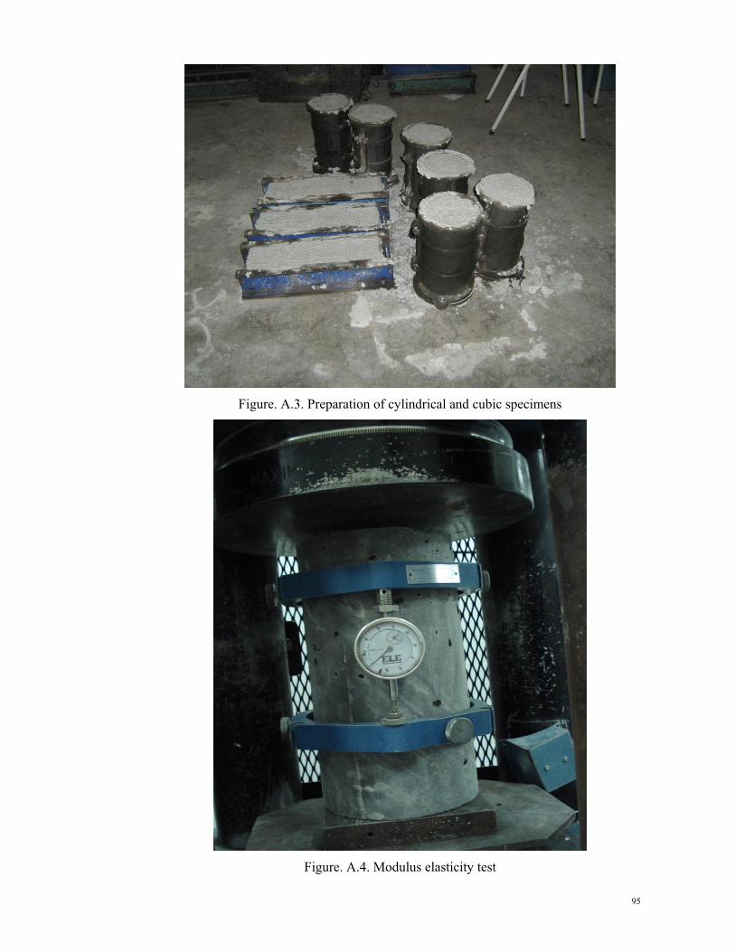
95
Figure. A.3. Preparation of cylindrical and cubic specimens
Figure. A.4. Modulus elasticity test

Figure
F
e. A.5. Typi
Figure. A.6
ical specime
. Specimen
ens ready fo
s ready for
or concrete
push-out te
casting
st
96
6

97
Figure. A.7. Settelment of special support on specimen's slabs
Figure. A.8. Specimen ready for loading

Figure. A.99. Typical sspecimens aafter fracturee
98
8

99
APPENDIX B
STEEL COUPON TEST
This appendix presents the steel coupon testing of steel component in this study.
ASTM 370 specification was used in preparing and testing of the specimens. Three
specimens for each test were tested from flange. and web of channel and angle steel
profiles Following figures and tables shows the procedure of the steel coupon testing.

Fiigure. B.1. S
Figure
Standard me
e. B.2. Spec
ethod accor
cimen’s dim
rding to AST
mension
TM
100
0
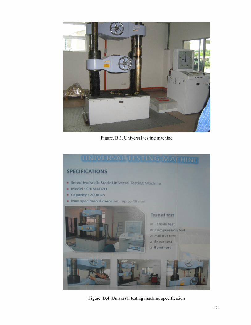
Fig
Figure.
gure. B.4. U
B.3. Unive
Universal tes
rsal testing
sting machin
machine
ne specificaation
101
1

Figu
Figu
ure. B.5. Co
ure. B.6. Sp
upon test sa
pecimen’s in
amples befo
nstallation f
ore tensile te
for tensile te
esting
esting
102
2

103
Figure. B.6. Coupon test samples after tensile testing
Table B.1. Coupon tensile test result
Specimens 1 2 3 F (MPa) 338.8 341.85 340.00 F (MPa) 493.86 495.03 495.77
Elongation (%) 24.23 23.74 24.16 F Average (MPa) 340.22 F Average (MPa) 494.89
Elongation Average (%) 24.04
F
F 1.45