
Distribution Connectors (Combined) - Hubbellcdn.Com
269
www.hubbellpowersystems.com & ™ DISTRIBUTION CONNECTORS
-
Upload
khangminh22 -
Category
Documents
-
view
1 -
download
0
Transcript of Distribution Connectors (Combined) - Hubbellcdn.Com

ANDERSON™ HUBBELL®POWERSYSTEMS FARGO® November2017
These terms and conditions of sales (“terms and conditions”) apply to the purchase by Buyer of any and all Hubbell Power Systems, Inc. (“HPS”) products. HPS hereby gives notice of its rejection to any different or additional terms and conditions other than as stated herein. Buyer’s acceptance of the provisions of HPS’s terms and conditions as recited herein shall be conclusively presumed upon Buyer’s receipt of the product(s), or if no written objection is received by HPS within fifteen (15) days from the date on HPS’s order acknowledgment, whichever event shall first occur.
PRICINGRefer to appropriate Price Schedule, unless otherwise quoted.
TERMSPayment terms are net 30 days. Invoices will be dated the day of shipment. A service charge of 1-1/2% per month or, if such rate exceeds the maximum lawful rate, the maximum lawful rate shall be assessed on all past due accounts and shall be payable on demand.
QUOTATIONSUnless otherwise stated in writing, HPS’ quotations are subject to acceptance by the Buyer within thirty (30) days from the date of issue.
SALES AND SIMILAR TAXESPrices do not include any sales, use, excise or similar taxes. Consequently, in addition to the price specified herein, the amount of any present or future sales, use, excise or other similar tax applicable to the sale or use of the equipment hereunder, shall be paid by the Buyer, or in lieu thereof the Buyer shall provide HPS with a tax exemption certificate ac-ceptable to the taxing authorities.
ACCEPTANCE OF ORDERSAll orders are subject to final acceptance by HPS. Any other terms proposed by Buyer are rejected unless expressly ac-cepted in writing. Orders shall be deemed to be executed in the State of Missouri and shall be construed and performed in accordance with the laws of that State. Acceptance of any order is subject to availability of product and the ability of HPS to deliver. Orders will be billed at prices in effect at time of shipment unless otherwise agreed. Unless otherwise stated in writing, HPS reserves the right to ship plus or minus 10% of specified quantity for special products that are made to order.
SALES BY AGENTSSales by agents or through overseas representatives shall be at prices, terms and conditions of sale specified by HPS. All invoices will be issued by and payment remitted to HPS.
DELAYHPS will use reasonable efforts to meet shipment or delivery dates specified by HPS, but such dates are estimates only. In no event shall be liable for any delay or nondelivery if caused directly or indirectly by Acts of God, fire, flood, strike or lockout or other labor dispute, accident, civil commotion, riot, war, governmental regulation or order, whether or not it later proves to be invalid, or from any other cause or causes (whether or not similar to any of the foregoing) beyond HPS’s control. In no case will HPS be liable for loss of profits or any special or consequential damages on account of any delay in delivery or nondelivery whether or not excused hereunder.
SHIPPING DEFERMENTBuyer requests for shipping deferment must be approved by HPS and are subject to price negotiation.
LIMITED WARRANTY AND LIMITATION OF LIABILITYHPS warrants to Buyer that the products sold will be free of defects in workmanship or material for a period of one (1) year (or as otherwise specified) from the date of original shipment by HPS when stored, installed, operated or main-tained in accordance with recommendations of HPS and standard industry practice and when used under proper and normal use. HPS shall in no event be responsible or liable for modifications, alterations, misapplication or repairs made to its products by Buyer or others, or for damage caused thereto by negligence, accident or improper use by Buyer or oth-ers. This warranty does not include reimbursement for the expenses of labor, transportation, removal or reinstallation of the products. This warranty shall run only to the first Buyer of a product from HPS, from HPS’ Buyer, or from an original equipment manufacturer reselling HPS’ product, and is non-assignable and non-transferable and shall be of no force and effect if asserted by any person other than such first Buyer.
Hubbell Power Systems, INC. Terms & Conditions of Sales

ANDERSON™ HUBBELL®POWERSYSTEMS FARGO® November2017
APPLICATION: HPS does not warrant the accuracy of and results from product or system performance recommendations resulting from any engineering analysis or study. This applies regardless of whether a charge is made for the recommenda-tion, or if it is provided free of charge. Responsibility for selection of the proper product of application rests solely with the Buyer. In the event of errors or inaccuracies determined to be caused by HPS, its liability will be limited to the re-perfor-mance of any such analysis or study.
BUYER INSPECTIONS: Tests, inspections and acceptance of all material must be made at the factory. Buyer’s inspectors are welcome at the factories and are provided with the necessary facilities for carrying out their work. Name and phone number of who should be contacted for inspection should be given to HPS no later than two weeks prior to scheduled shipment date.
DISCLAIMER OF WARRANTY: THE FOREGOING WARRANTY IS EXCLUSIVE AND IN LIEU OF ALL OTHER WARRANTIES WHETHER WRITTEN, ORAL, EXPRESSED OR IMPLIED. THERE ARE NO WARRANTIES OF MERCHANTABILITY OR FIT-NESS OF ANY PRODUCT FOR A PARTICULAR PURPOSE.
EXCLUSIVE REMEDY: Any claim by Buyer that a product is defective or non-conforming shall be deemed waived by Buy-er unless submitted to HPS in writing within thirty (30) days from the date Buyer discovered, or by reasonable inspection should have discovered the alleged defect or non-conformity. Any warranty claim must be brought within one year of discovery of the alleged defect or non-conformity. Upon prompt written notice by the Buyer that a product is defective or non-conforming, HPS’ liability shall be limited to repairing or replacing the product, at HPS’ option.
LIMITATION OF LIABILITY: IN NO EVENT AND UNDER NO CIRCUMSTANCES SHALL HPS BE LIABILE TO BUYER OR TO ANY OTHER PERSON FOR ANY INDIRECT, SPECIAL, CONSEQUENTIAL OR INCIDENTAL LOSSES OR DAMAGES, IN-CLUDING, WITHOUT LIMITATION, DAMAGE TO OR LOSS OF USE OF ANY PRODUCT, LOST SALES, OR PROFITS, OR DE-LAY OR FAILURE TO PERFORM THIS WARRANTY OBLIGATION, OR CLAIMS OF THIRD PARTIES AGAINST PURCHASER, ARISING OUT OF OR IN CONNECTION WITH THE SALE, INSTALLATION, USE OF, INABILITY TO USE, OR THE REPAIR OR REPLACEMENT OF, HPS’ PRODUCTS. As stated herein, the term “person” shall include without limitation, any individ-ual proprietorship, partnership, corporation or entity.
FREIGHT ALLOWANCE and F.O.B. POINTAll shipments are F.O.B. origin. Risk of loss and title of products shall pass to Buyer upon delivery to the designated carrier. Freight is prepaid and allowed on all HPS shipments of products with a net order value of $5,000 and above to destinations within the Continental U.S.A and Canada, with the exception of USCO brand products. Freight is prepaid and allowed on all shipments of USCO brand products with a net order value of $20,000 and above. An 8% shipping and handling charge will be added to all standard shipments under the minimum net order value. Customer expedited orders will be billed at actual freight cost plus $50.00 handling. Shipments to Alaska and Hawaii are F.O.B. Pacific Coast docks, collect beyond. Tool trailers will be F.O.B. HPS’ dock – no freight allowed.HPS reserves the right to route all qualified freight allowed shipments via least expensive surface route within the Conti-nental United States and Canada. Buyer will assume all charges for transportation specified via more expensive means. Acceptance of a specified routing does not constitute a guarantee of ship date, transit time or arrival date. HPS will not be responsible for any cartage or storage charges at destination.HPS’ responsibility for exception-free delivery ceases when the transportation company receives shipment in good con-dition. Claims for loss or damage must be reported directly to the carrier. HPS’s willingness to assist does not indicate liability for claim or replacement.
PARTIAL RELEASEIf an order has multiple releases specified by the Buyer, each release will be treated as individual orders, relative to freight allowance and minimum billing.
BACK ORDERSBack orders that are the responsibility of HPS will be shipped F.O.B. factory or point of shipment with freight prepaid and allowed via the most cost effective method, providing the original order qualified for freight allowance.
MINIMUM BILLINGStandard Orders -- $750 net per order. Tools -- $100 net per order. Parts -- $100 net per order.

ANDERSON™ HUBBELL®POWERSYSTEMS FARGO® November2017
ORDER ADD-ON POLICYHPS’ “Add-On” policy allows you to add items to an existing unshipped order for up to fifteen (15) days from the entry date of the original order. The minimum value for added products is $250. Addition of tools or parts must be $100.
DELIVERY SCHEDULEShipping dates provided by HPS are estimates only. HPS shall make every reasonable effort to meet Buyer’s shipping re-quirements provided HPS promptly receives all necessary information from Buyer and approved drawings if required by HPS. HPS will not assume liability because of delayed shipment for any reason. HPS’s responsibility ceases upon accep-tance of shipment by carrier.
CANCELLATIONSCancellation of an order for current stock product requires a minimum of five (5) days’ notice prior to actual ship date. Stock product orders shipped after cancellation notice is received, but before expiration of the five-day requirement, will be subject to all standard returned product conditions, noted below. Cancellation on non-stock products may be made only if no work has been performed or material purchased. If cancellation is requested after work is in progress, there will be a cancellation charge as established by HPS. Orders may not be cancelled unless HPS gives its written consent, and then only upon agreement as to applicable cancellation charges.
RETURNED PRODUCTGENERAL CONDITIONS applying to all transactions:1. Product is not returnable without the written consent of HPS.2. Request for permission to return product must be made in writing within one year from date of shipment, and Buyer
must provide original HPS invoice number.3. Product to be returned must be considered standard product by HPS.4. HPS reserves the right to refuse returns of any special or made-to-order product, regardless of condition.5. All returned products must be in excellent, resaleable condition and packaged in the original carton. Products will
be inspected upon return; and any service or repair needed to place them in first class, saleable condition will be charged and added to the restocking charge.
6. A 25% restocking charge will be deducted from all credits issued on authorized returns.7. Return Goods Authorization (RGA) Packing List, supplied by the factory, must accompany the return shipment.8. Return freight must be prepaid. Product must be received by HPS within sixty (60) days of issuance of RGA.9. Net value of the return must not be less than $250.10. HPS reserves the right to deduct for any damage sustained in transit.11. Unauthorized returns will be refused. Equipment returned without proper authorization from HPS will, at the sole
option of HPS, be returned to the Buyer freight collect, or scrapped immediately with no issuance of credit. Unautho-rized product included in a return will not be credited.
BROKEN PACKAGE POLICYShipments will be made in standard package quantities or multiples thereof. HPS Customer Service will notify the Buyer of any orders that do not comply with this policy. The Buyer must authorize an adjustment to comply with standard package quantities before the order will be entered.
DROP SHIPMENT POLICYA 10% net order value drop shipment charge will be added to all purchase orders requesting delivery to a location other than a recognized Buyer stocking warehouse, with the exception of full truckload and/or project material. This is in addi-tion to any other charges to the net order.
QUOTATION PRICE PROTECTIONAll prices shown in the price lists are subject to change without notice. All quotations on special products or modifica-tions to catalog products are binding only if confirmed in writing by the factory for the period shown on the quotation. Price protection will be provided for a period of thirty (30) days from date of quotation from HPS.
ORDERSAll orders are taken and prices quoted only with the understanding that each order shall be subject to the acceptance of HPS upon such terms as we may specify when order is received. Prices to cover amount of any sales or excise tax which now or hereinafter may be imposed by any taxing authority upon this product or the sale or manufacture thereof.

ANDERSON™ HUBBELL®POWERSYSTEMS FARGO® November2017
PRODUCT SPECIFICATIONHPS reserves the right to discontinue products, modify designs, and change specifications or prices without incurring obligation.
INVOICINGAll invoices are due and payable per the standard terms stated herein. In the case of an apparent discrepancy in a line item charge, Buyer is obligated to advise HPS Customer Service in writing of the nature of the claimed discrepancy within five (5) days of receipt of the invoice. This includes all requests for proof of delivery. A claim of discrepancy does not relieve Buyer of the absolute obligation to pay the remaining balance of the invoice in accordance with the standard terms of payment. Upon review, HPS will have sole discretion to resolve the discrepancy; and the Buyer expressly agrees to abide by HPS’ decision. HPS will promptly advise Buyer of its decision regarding any disputed items or charges.
OSHAHPS warrants that at time of shipment, the products will conform to the applicable occupational safety and health stan-dards promulgated pursuant to the Federal Occupational Safety and Health Act of 1970, which are in effect on the date that HPS enters its acknowledgment of Buyer’s order. The Buyer’s exclusive remedy and HPS’ liability for breach of this warranty is limited to replacement of the nonconforming products.
FAIR LABOR STANDARDS ACT AS AMENDEDHPS represents that any goods to be delivered hereunder will be produced in compliance with the requirements of the Fair Labor Standards Act of 1938, as amended.
NOTEThese Terms and Conditions supersede all those published and previously issued by The A.B. Chance Company, The Ohio Brass Company, Anderson Electrical Products, Inc., Fargo Manufacturing Company, Inc., Chardon Electrical Components, USCO Power Equipment Corporation, Hubbell Canada LP and Hubbell Power Systems, Inc.
Effective January 1, 2011

ANDERSON™ HUBBELL®POWERSYSTEMS FARGO® November2017
DISTRIBUTION CONNECTORSDeadends
Overhead Line Splices
Overhead Primary Taps
General Use — Bolted Connectors
Formed Wire
Compression Connectors, Splices, Taps, Tees and Terminals
Distribution Tools
Telecom & Grounding Connectors
Other Distribution Products
Reference Data
DA
DB
DC
DD
DE
DF
DG
DH
DI
DJ

ANDERSON™ HUBBELL®POWERSYSTEMS FARGO® November2017
CATALOG TYPE PAGE NO. CATALOG TYPE PAGE NO. CATALOG TYPE PAGE NO.
155 - INHIBITOR DI-8 BSC / BSCG DA-24 GC5000 DH-1
60064* DI-18 BSCG DA-24 GC8000 DD-17
97642* DI-18 BSD DA-25 GD100 DA-1
270650* DI-23 BSG DA-23 GD100R DA-1
7850*2000 DA-27 BXS DD-12 GD100Z DA-1
8****2000 DA-27 C203x DD-6 GD400 DA-2/3
81460* DI-22 CBC DC-14 GD400Z DA-2/3
82860* DI-22 CC101 DI-3 GD500 DA-1
876*2000 DA-20 CC101 / CC170 DI-3 GD500 / GD100 DA-1
AAC DI-18 CC170 DI-3 GD900 DA-12
ACF DF-10/11 CCLS DF-12/13 GDE5100 DA-7
ADES DA-14 CCLS - TOOL & DIE DF-14 GDE5200 DA-8
ADET DA-28 CE14 DC-5 GDW DA-5
ADEZ DA-11 CBC / CPBC DC-14 GDW2000 DA-6
ADEZ / ADSO DA-11 CPBC DC-14 GF - INHIBITOR DI-7
ADS DA-13 DDC DA-27 GH1000 DC-8
ADSB DA-10 DDT DA-28 GH100A DC-3
ADSO DA-11 DE DA-18 GH1010 DC-11
AH DC-1 DGFW DE-7/8 GH200 DC-9
AHF DC-11 DGFW CROSS REF DE-45 GH200/GO370/GC207LA DC-9
AHL DF-5 DSC DI-12 GH200A DC-4
AHLS DC-12 ESC DC-13 GH200L DC-4
APD DD-11 ESCB DC-19 GH275 DC-5
AR1 DA-19 FTA DB-17 GH27x - STIRRUPS DC-5
AR1 / AR2 DA-19 FTR DB-18 GH280 DC-6
AR2 DA-19 FWDE DE-2 GH280AL DC-17
ASOD DA-9 FWDE CROSS REF DE-40 GJ600 DE-36
ATL DF-6 FWLS DE-5 GJ600 / 700 DE-38
AWDE DE-4 FWLS CROSS REF DE-43 GJ800 / 810 DE-37
AWDE CROSS REF DE-42 GA100*L DC-2 GJ85 / 86 DE-34
AXS DD-12 GA100SL DC-16 GL - BI-METALLICS DB-6
AXS / BXS DD-12 GA600 DD-20 GL*KR DB-4
BC DC-7 GA9000, 1-BOLT DD-1 GL - REDUCING DB-5
BC / BH DC-7 GA9000, 1-BOLT DD-5 GL100 DB-1
BDE DA-22 GA9000, 2-BOLT DD-2 GL1000 DB-2
BDE9000 SERIES DE-3 GA9000L DH-3 GL100M - METRIC DB-1
BDE9000 CROSS REF DE-41 GC DD-6 GL1300A DB-3
BH4 DC-7 GC / C203 DH-4 GL1400A DB-3
BHF DC-11 GC100 / GC200 DD-4/5 GL400 DB-2/3
BHLS DC-18 GC100 / GC200 DH-3 GLS - REDUCING DB-8
BP18CC129ACSR DG-7 GC100 / GC200 DH-5 GLS5000 DB-7
BR1 DA-26 GC200 DD-7 GLT DB-3
BR1 / BR2 DA-26 GC200 DH-2 GM100 DA-31
BR2 DA-26 GC207LA DC-9 GM100A DA-29
BRS DI-20 GC207LA DD-10 GM128 DA-30
BSC DA-24 GC5000 DD-3 GM300 DI-13
ALPHA-NUMERIC INDEX

ANDERSON™ HUBBELL®POWERSYSTEMS FARGO® November2017
CATALOG TYPE PAGE NO. CATALOG TYPE PAGE NO. CATALOG TYPE PAGE NO.
GO32 DD-13 LC522AXB DH-3 PTH DF-4
GO37x DC-9 LC52AXB DH-3 PTR DB-16
GO53 DI-14 LC60 DD-20 QWSP DE-31/32
GO53 / GO54 DI-14 LC60 / GA600 DD-20 QWSP CROSS REF DE-73/74
GO54 DI-14 LC600 DD-18 QWSTC DE-23
GP - WRENCHES DG-1/2 LC70 DD-20 QWSTC CROSS REF DE-64/65
GP3458 DG-3 LC80 DD-19 QWSTF DE-24/25
GPDE DG-4 LC800 DD-19 QWSTF CROSS REF DE-66/67
GPHP DG-4 LCC DD-18 REFERENCE DATA SECT DJ
GS900 DE-35 LCU10 DD-21 RG100 DI-4
GS SERIES DI-1/2 LCU700 DD-22 S1500 / AH DC-1
GTCL DD-8 LDIC DE-9/10 S1500A DC-1
GTCS DD-8 LDIC CROSS REF DE-46/47/48 S1500C DC-7
GUY DEADEND H'WARE; DE-1 LDID0 SERIES DE-15/16 SBN DD-24
GWB1R DI-23 LDID0 CROSS REF DE-56 SBS DD-23
GWB1S DI-22 LDID2 SERIES DE-17/18 SD DA-15
HAC DI-17 LDID2 CROSS REF DE-57 SDT2 DA-16
HAS DI-15 LDIF DE-11/12 SEC DB-10
HAST2 DI-28 LDIF CROSS REF DE-49/50/51 SGFW DE-6
HLS DC-20 LDIJ DE-13 SGFW CROSS REF DE-44
HLSA DC-15 LDIJ CROSS REF DE-52/53 SLQ DA-17
HLSB DC-15 LLAC DE-19/20 ST DD-24
HTJC - CHART DI-11 LLAC CROSS REF DE-58/59/60 STT DE-33
HTJC - INHIBITOR DI-6 LLAF DE-21/22 SW DA-4
J3LS2 DC-5 LLAF CROSS REF DE-61/62/63 SWDE DA-21
I220 - INHIBITOR DI-10 LLDU4 SERIES DE-26/27 SWDE / MD DA-21
ING - INHIBITOR DI-10 LLDU4 CROSS REF DE-68 T2 CLAMP INFO DI-24/25/26
INHIBITOR GUIDE DI-5 LLDU5 SERIES DE-28 T2 FW TIES CHART DE-39
K DD-25 LLDU5 CROSS REF DE-69 TSC DI-16
KA*H DD-30 LRO DE-29/30 TSCDT2 DI-27
K*L DD-25 LRO CROSS REF DE-70/71/72 TSCT2 DI-27
K2S DD-9 LU DD-29 TSCT2 / TSCDT2 DI-27
KR DD-25 LU2 / LU3 DD-29 TTF / TTFJ DE-14
KR*L DD-25 MD DA-21 TTF / TTFJ CROSS REF DE-54/55
KS DD-9 MDE DA-20 TTSB DA-32
KS / K2S DD-9 MS DI-21 UJC - CHART DI-11
LAT DD-10 MSE DA-32 UJC - INHIBITOR DI-6
LC1000 DD-26 MSNT DA-31 UTSB DD-15
LC1100 DD-26 P1500A DC-1 UTZB DD-16
LC1600 DD-28 P1500C DC-7 VACL DF-2/3
LC400 DD-28 PG DA-18 VACL - TOOL & DIE DF-16/17
LC50 DD-19 PG / DE DA-18 VACS DB-9
LC50 DH-3 PT DF-4 VACS - TOOL & DIE DB-23/24
LC50 / LC80 DD-19 PT / PTH DF-4 VACT DC-24
LC500 DD-19 PTA DB-15 VACT - TOOL & DIE DC-30/31
LC500 / LC800 DD-19 PTC DD-31 VANS DB-13
ALPHA-NUMERIC INDEX
ANDERSON™ HUBBELL®POWERSYSTEMS FARGO® November2017
CATALOG TYPE PAGE NO. CATALOG TYPE PAGE NO. CATALOG TYPE PAGE NO.
VAUL DF-7/8 VCP DC-23
VAUL / VAULH DF-7/8 VCR DB-19
VAULH DF-7/8 VCRC DC-29
VAUS DB-11/12 VCSE DB-10
VAUS / VAUSH DB-11/12 VCSN DB-13
VAUSH DB-11/12 VCT DC-26
VC*A DB-19 VCTL DF-9
VC*A / VC*AR DB-19 VCU DC-27
VC*AR DB-19 VCUC DC-29
VC*R DB-19 VERSA-CRIMP® INFO DG-5/6
VC2T DC-25 VF DD-14
VC3BN DG-13 VHS DB-21
VC63SP DG-9 VHS - TOOL & DIE DB-26
VC6FTSP DG-9 VHSS DB-20
VC6FTR DG-11 VHSS - TOOL & DIE DB-25
VC6R DG-11 VS - INHIBITOR DI-9
VC7SP DG-10 VS / VSG - INHIBITOR DI-9
VC7FTSP DG-10 VSG - INHIBITOR DI-9
VC7FTR DG-12 XP DD-27
VC7R DG-11 YAAC DI-19
VC8C DG-12 ZLN - INHIBITOR DI-8
VC8U DG-12
VCA DB-19
VCA / VCAR DB-19
VCAR DB-19
VCBP63 DG-7
VCBP6FT DG-8
VCC DB-22
VCCT DC-28
VCCT - TOOL & DIE DC-32
VCEL DF-1
VCEL - TOOL & DIE DF-15
VCELC DF-18
VCELC - TOOL & DIE DF-19
VCFF DG-13
VCHFF DG-13
VCHFM DG-13
VCHM DG-13
VCHTG DG-14
VCJS*R DB-14
VCL DC-25
VCLPG DG-14
VCLS DC-21
VCLSC DC-22
VCMM DG-13
VCO DG-14

ANDERSON™ HUBBELL®POWERSYSTEMS FARGO® November2017
DISTRIBUTION CONNECTORS
OVERHEAD DEADENDSAutomatic Wedge
Aluminum AutomaticCopper AutomaticAluminum Bolted
Bronze BoltedDuctile Iron Bolted
Guy Wire AutomaticAluminum Compression
SE
CT
ION
DA

DA1
ANDERSON™ HUBBELL®POWERSYSTEMS FARGO® November2017
CATALOG NUMBER CONDUCTOR RANGE
APPROXIMATE CONDUCTOR O.D.
INCHES (MM)CLEVIS
BAILZ
BAILFLEXBAIL
SEMI-FLEXBAIL
COPPER COPPERWELD
SOLIDASTM-B258
STRANDASTM-B8 STRAND
- - GD110 - 8 - - .12-.13 (3.1-3.3)
GD511* GD111Z GD111 GD111R 6 - - .16-.17 (4.0-4.4)
GD512* GD112Z GD112 GD112R 4 - 8A .19-.20 (4.9-5.2)
GD513* GD113Z GD113 GD113R 3 4 6A .22-.23 (5.7-5.9)
GD514 GD114Z GD114 GD114R 2 3 5A .25-.26 (6.3-6.6)
GD515* GD115Z GD115 GD115R 1 2 4A .28-.29 (7.2-7.4)
GD516 GD116Z GD116 GD116R 1/0 1 3A .32-.33 (8.1-8.3)
GD517 GD117Z GD117 GD117R 2/0 1/0 2A .36-.37 (9.1-9.3)
GD518 GD118Z GD118 GD118R 3/0 2/0 - .40-.41 (10.2-10.5)
GD519 GD119Z GD119 GD119R 4/0 3/0 - .45-.46 (11.5-11.8)
GD520 GD120Z GD120 GD120R - 4/0 - .52-.53 (13.2-13.4)
GD521 GD121Z GD121 GD121R - 250 KCMIL - .57-.58 (14.4-14.7)
GD523 - - - - 300 KCMIL - .62-.63 (15.8-16.1)
DEADENDSAUTOMATIC COPPER
COPPER
GD500/GD100
• Fastest method of deadending Copper and Copperweld® conductor.• Flared mouth of gripping unit permits easy conductor installation.• Four segment jaw is precision machined and automatically adjusts
to the contour of the wire.• High strength alloy copper tube for gripping Copperweld®
conductors• Available with galvanized steel stirrup clevis or stainless steel Z bail
for primary applications.
Material: Shell – High Strength Copper Alloy Jaws – Copper Alloy Clevis Bail – Galvanized Steel Z Bail – Stainless Steel, Formed Wire Flex Bail – Braided Stainless Steel Semi-flex Bail – Stainless Steel, Formed Wire
*RUS ListedCopperweld® is a registered trademark of Fushi Copperweld Inc.
Product Data & Conductor Size

DA2
ANDERSON™ HUBBELL®POWERSYSTEMS FARGO® November2017
CATALOGNUMBER BAIL TYPE
STD. COND.SIZES
DIMENSIONS OTHER INFORMATION APPROX.WT. EACHLBS. (KG)A B C
DIA. RANGE IN. (MM)
COLORCODE
GD442A* CLEVIS#4 ACSR (6/1)
#4 AAAC
#4 AAC
11.0 5.0 -
.225-.250
(5.59-6.35)ORANGE
0.56 (.25)
GD402AZ* SS Z 10.4 5.0 - 0.43 (.19)
GD402A* SS FLEX 12.8 5.0 2.0 0.20 (.09)
GD462A* SEMI-FLEX 12.0 5.0 2.2 0.24 (.10)
GD4442A* CLEVIS#4 - #2 ACSR
#4 - #2 AAAC
#4 - #2 AAC
12.9 7.0 -
.220-.320
(5.59-8.13)
RED-
ORANGE
0.63 (.29)
GD4042AZ* SS Z 12.0 7.0 - 1.00 (.45)
GD4042A* SS FLEX 13.7 7.0 2.0 0.34 (.15)
GD4642A* SEMI-FLEX 14.4 7.0 2.2 0.38 (.17)
DEADENDSAUTOMATIC ALUMINUM
ALUMINUM
GD400
• Fastest method of deadending ACSR, AAAC, and AAC conductor
• Color coded funnel guide for easy identification. Flared conductor funnel guides ease installation.
• Aluminum alloy shell and inhibitor protected aluminum jaws assure corrosion resistance.
• Available with galvanized steel stirrup clevis or stainless steel Z bail for primary applications. Flexible or semiflexible stainless steel bails can be used on secondary applications.
• See GDW Series for range-taking automatic deadends. Note: For neoprene covered Flex or Semi-flex bail add
suffix “N”. Example GD402AN Add suffix “TA” for pulling eye. Example GD4442ATA (Fig #1)
Material: Shell – High Strength Aluminum Alloy Jaws – Aluminum Alloy Clevis Bail – Aluminum Alloy or Galvanized Steel Z Bail – Stainless Steel, Formed Wire Flex Bail – Braided Stainless Steel Semi-flex Bail – Stainless Steel, Formed Wire Pulling Eye – Aluminum Alloy
*RUS Listed
Product Data & Conductor Size
Z Bail Clevis Bail
Flex Bail Semi-flex Bail
Pulling Eye
Fig #1
Gripping UnitRetaining Washer
Clevis WasherCotter Pin
Clevis
C
A
B
A
B
C
C
AB
Retaining Washer Clevis
Cotter Pin
Gripping Unit
Clevis Washer(GD447 only) Clevis
Washer
Clevis Pin
AB
Bail
YokeCotter Pin
Gripping Unit
Retaining WasherClevis Pin

DA3
ANDERSON™ HUBBELL®POWERSYSTEMS FARGO® November2017
DEADENDSAUTOMATIC ALUMINUM
(CONTINUED)
*Maximum design rating 10,000 Lb./4535 kg.**RUS Listed(1) Includes compact conductor of each size(2) For neoprene covered bail add suffix “N” Ex. GD406AN.
CATALOGNUMBER BAIL TYPE
STD. COND.SIZES
DIMENSIONS OTHER INFORMATION APPROX.WT. EACHLBS. (KG)A B C
DIA. RANGE IN. (MM)
COLORCODE
GD446A** CLEVIS1/0 ACSR
1/0 AAAC
1/0 AAC
12.3 6.4 -
.355-.400
(9.02-10.16)YELLOW
1.02 (.46)
GD406AZ** SS Z 14.2 6.4 - 0.20 (.09)
GD406A** SS FLEX 15.3 6.4 2.0 0.40 (.18)
GD466A** SEMI-FLEX 15.8 6.4 2.2 0.30 (.14)
GD447** CLEVIS2/0 ACSR
2/0 AAAC
2/0 AAC
17.8 9.3 -
.400-.470
(10.15-11.94)GRAY
2.23 (1.01)
GD407Z** SS Z 17.6 9.3 - 1.40 (.64)
GD407** SS FLEX 15.5 9.3 2.0 0.76 (.35)
GD467** SEMI-FLEX 18.4 9.3 2.2 1.10 (.49)
GD448** CLEVIS3/0 ACSR
3/0 AAAC
3/0 AAC
18.9 10.0 -
.450-.530
(11.43-13.46)BLACK
2.40 (1.09)
GD408Z** SS Z 18.0 10.0 - 1.40 (.63)
GD408** SS FLEX 17.6 10.0 2.0 1.16 (.53)
GD468** SEMI-FLEX 19.0 10.0 2.2 1.10 (.50)
GD449A** CLEVIS4/0 ACSR
4/0 AAC
4/0 AAAC
17.5 9.0 -
.505-.595
(12.83-15.11)PINK
2.43 (1.10)
GD409AZ** SS Z 17.2 9.0 - 1.40 (.63)
GD409A** SS FLEX 17.6 9.0 2.0 1.00 (.45)
GD469A** SEMI-FLEX 18.0 9.0 2.2 1.00 (.45)
GD5205A CLEVIS
266.8 AAC
11.6 4.6 -
.518-.595
(13.16-15.11)-
1.32 (.59)
GD1205AZ SS Z 12.8 4.6 - 1.00 (.45)
GD1205A SS FLEX 13.6 4.6 2.0 0.64 (.29)
GD1205AR SEMI-FLEX 14.4 4.6 2.2 0.66 (.29)
GD450* CLEVIS 266.8 (18/1)
ACSR
312.8 AAAC
336.4 AAC(1)
18.5 9.6 -
.603-.666
(15.32-16.92)BROWN
2.70 (1.22)
GD410Z* SS Z 20.4 9.6 - 1.80 (.82)
GD410* SS FLEX 16.9 9.6 2.0 1.20 (.54)
GD470* SEMI-FLEX 17.8 9.6 1.9 1.40 (.64)
GD451* CLEVIS 336.4 (18/1)
ACSR
394.5 AAAC
397.5 AAC(1)
18.9 10.5 -
.659-.724
(16.74-18.39)GREEN
2.0 (.90)
GD411Z* SS Z 20.8 10.5 - 2.10 (.95)
GD411* SS FLEX 17.7 10.5 2.0 1.80 (.82)
GD471* SEMI-FLEX 18.6 10.5 1.9 1.70 (.77)
- CLEVIS 397.5 (18/1)
ACSR
465.4 AAAC
477 AAC (1)
- - -
.722-.795
(18.34-20.19)BLUE
-
GD412Z* SS Z 19.6 11.3 - 2.40 (1.08)
GD412* SS FLEX 19.0 11.3 2.0 2.00 (.91)
GD472* SEMI-FLEX 19.3 11.3 1.9 2.00 (9.1)
ALUMINUM
GD400
Product Data & Conductor Size

DA4
ANDERSON™ HUBBELL®POWERSYSTEMS FARGO® November2017
DEADENDSAUTOMATIC WEDGE
SERVICE ENTRANCE/DROP ALUMINUMALUMINUM
SW
• For deadending and stress relief of service entrance/drop installations.
• For use with ACSR, AAC, & AAAC conductors.• Service wedge to be attached to bare neutral.• Rigid stainless steel bails are for use with eye hooks and insulators
with diameters larger than 1.5” in diameter.• Flexible bails are for use with hooks and small eyes.• Design allows for easy sag adjustments.• Service wedges are not full tension devices (see tensile rating).
May be used in slack span applications.†• Each wedge has two tape bands. • The warning label is always orange (outside band).• The size indicator is color coded as listed below (inside band,
closest to bail).• Locking mechanism secures latch on the rigid bail to prevent
opening during installation.
Material: Body and Keeper – Aluminum Alloy Bail – Solid: Stainless Steel Flex: Covered Stainless Wire Braid (FL Suffix)
CATALOGNUMBER DESCRIPTION
CONDUCTOR SIZEDIA
RANGEIN (MM)
DIMENSIONSMECH. STR.
LBS. (kN)
SIZE IN-DICATOR COLORACSR AAC AAAC A B C
SW7195LB WEDGE w/RIGID SS BAIL
#6 - #2 #6 sol - #1 str #6 -#2.160 - .332
(4.1-8.4)
6
(150)
12
(300)
2-1/2
(64)1000
(4.45)800 max for
#6 ASCR
Orange
SW7195FL WEDGE w/FLEXIBLE BAIL10-1/4
(260)
16-1/8
(410)Flex
SW7187LB WEDGE w/RIGID SS BAIL
#4 - 1/0 #2 sol - 2.0 str #4 - 1/0.248 - .414
(6.3-10.5)
5 - 7/8
(145)
12 - 1/4
(310)
2 - 1/2
(64)1200
(5.34)900 max for
#4 ACSR
Blue
SW7187FL WEDGE w/FLEXIBLE BAIL10 - 1/2
(265)
17
(430) Flex
SW7197LB* WEDGE w/RIGID SS BAIL
2/0 - 4/0 2/0 - 4/0 2/0 - 4/0.414 - .565
(6.3-14.4)
5 - 3/4
(145)
13
(325)
2 - 3/4
(69) 1600
(7.12)Red
SW7197FL* WEDGE w/FLEXIBLE BAIL10 - 1/8
(255)
17 - 1/4
(435)Flex
Add “I” for anodized version*Can also be used with 1/0 (6/1) ACSR to 1600 lb max†Slack span is defined as weight of conductor only.
Product Data & Conductor Size
Gripping unit gentle on conductor
DA5
ANDERSON™ HUBBELL®POWERSYSTEMS FARGO® November2017
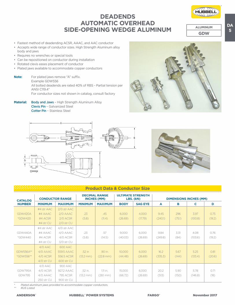
DEADENDS AUTOMATIC OVERHEAD
SIDE-OPENING WEDGE ALUMINUM ALUMINUM
GDW
• Fastest method of deadending ACSR, AAAC, and AAC conductor• Accepts wide range of conductor sizes. High Strength Aluminum alloy
body and jaws• Requires no wrenches or special tools• Can be repositioned on conductor during installation• Rotated clevis eases placement of conductor• Plated jaws available to accommodate copper conductors
Note: For plated jaws remove “A” suffix. Example GDW556 All bolted deadends are rated 40% of RBS - Partial tension per
ANSI C119.4” For conductor sizes not shown in catalog, consult factory
Material: Body and Jaws – High Strength Aluminum Alloy Clevis Pin – Galvanized Steel Cotter Pin – Stainless Steel
* Plated aluminum jaws provided to accommodate copper conductors.** RUS Listed
CATALOG NUMBER
CONDUCTOR RANGEDECIMAL RANGE
INCHES (MM)ULTIMATE STRENGTH
LBS. (kN) DIMENSIONS INCHES (MM)
MINIMUM MAXIMUM MINIMUM MAXIMUM BODY SAG EYE A B C D
GDW420A
*GDW420
#4 str AAC
#4 AAAC
#4 ACSR
#4 str CU
2/0 str AAC
2/0 AAAC
2/0 ACSR
2/0 str CU
.23
(5.8)
.45
(11.4)
6,000
(26.69)
4,000
(17.79)
9.45
(240.1)
296
(75.1)
3.97
(100.8)
0.75
(19.2)
GDW440A
*GDW440
#4 str AAC
#4 AAAC
#4 ACSR
#4 str CU
4/0 str AAC
4/0 AAAC
4/0 ACSR
3/0 str CU
.23
(5.8)
.57
(14.5)
9,000
(40.03)
6,000
(26.69)
9.84
(249.8)
3.31
(84)
4.08
(103.6)
0.76
(19.2)
GDW556A**
*GDW556**
4/0 AAC
4/0 AAAC
4/0 ACSR
4/0 str CU
600 AAC
559.5 AAAC
556.5 ACSR
600 str CU
.52 in
(13.2 mm)
.90 in.
(22.8 mm)
10,000
(44.48)
6,000
(26.69)
16.2
(335.3)
5.67
(144)
5.25
(133.4)
0.81
(20.6)
GDW795A
GDW795
4/0 AAC
4/0 ACSR
4/0 AAAC
250 str CU
900 AAC
927.2 AAAC
795 ACSR
900 str CU
.52 in.
(13.2 mm)
1.11 in.
(28.1 mm)
15,000
(66.72)
6,000
(26.69)
20.2
(513)
5.90
(150)
5.78
(146.8)
0.71
(18)
Product Data & Conductor Size
DA6
ANDERSON™ HUBBELL®POWERSYSTEMS FARGO® November2017
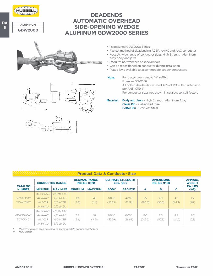
DEADENDS AUTOMATIC OVERHEAD SIDE-OPENING WEDGE
ALUMINUM GDW2000 SERIESALUMINUM
GDW2000
• Redesigned GDW2000 Series• Fastest method of deadending ACSR, AAAC and AAC conductor • Accepts wide range of conductor sizes. High Strength Aluminum
alloy body and jaws• Requires no wrenches or special tools• Can be repositioned on conductor during installation• Plated jaws available to accommodate copper conductors
Note: For plated jaws remove “A” suffix. Example GDW556 All bolted deadends are rated 40% of RBS - Partial tension
per ANSI C119.4” For conductor sizes not shown in catalog, consult factory
Material: Body and Jaws – High Strength Aluminum Alloy Clevis Pin – Galvanized Steel Cotter Pin – Stainless Steel
CATALOG NUMBER
CONDUCTOR RANGEDECIMAL RANGE
INCHES (MM)ULTIMATE STRENGTH
LBS. (kN)DIMENSIONSINCHES (MM)
APPROX.WEIGHT EA. LBS
(KG)MINIMUM MAXIMUM MINIMUM MAXIMUM BODY SAG EYE A B C
GDW2010A**
*GDW2010**
#4 str AAC
#4 AAAC
#4 ACSR
#4 str CU
2/0 str AAC
2/0 AAAC
2/0 ACSR
2/0 str CU
.23
(5.8)
.45
(11.4)
6,000
(26.69)
4,000
(17.79)
7.5
(190.5)
2.0
(50.8)
4.5
(114.3)
1.5
(.07)
GDW2040A**
*GDW2040**
#4 str AAC
#4 AAAC
#4 ACSR
#4 str CU
4/0 str AAC
4/0 AAAC
4/0 ACSR
3/0 str CU
.23
(5.8)
.57
(14.5)
8,000
(35.59)
6,000
(26.69)
8.0
(203.2)
2.0
(50.8)
4.9
(124.5)
2.0
(0.9)
* Plated aluminum jaws provided to accommodate copper conductors.** RUS Listed
Product Data & Conductor Size

DA7
ANDERSON™ HUBBELL®POWERSYSTEMS FARGO® November2017
DEADENDSAUTOMATIC GUY WIRE
ALUMINUM
GDE5100
NOTE: Suffix “L” Denotes Extended Bail.
CATALOGNUMBER
PRIMARY STRANDAPPLICATION
TO BE USED WITH:
RANGE IN. (MM)
DIMENSIONS IN. (MM)
EHSAW/
AWACHS, COM, S-M,
UTIL, BELL A B C
GDE5100 1/4” HS, Com, S-M, Util, Bell •0.240-0.253
(6.11-6.44)
9.2
(234)
5.7
(145)
1.4
(36)
GDE5100L 1/4” HS, Com, S-M, Util, Bell •0.240-0.253
(6.11-6.44)
12.7
(234)
9.2
(234)
1.4
(36)
GDE5101 5/16” HS, Com, S-M, Util, Bell •0.310-0.335
(7.89-8.53)
9.3
(236)
5.6
(142)
1.5
(38)
GDE5101L 5/16” HS, Com, S-M, Util, Bell •0.310-0.335
(7.89-8.53)
13.1
(333)
9.5
(241)
1.5
(38)
GDE5102 3/8” HS, Com, S-M, Util, Bell •0.360-0.405
(9.16-10.31)
11.5
(292)
7.1
(180)
2.0
(51)
GDE5102L 3/8" HS, Com, S-M, Util, Bell •0.360-0.405
(9.16-10.31)
16.5
(419)
12.0
(305)
2.0
(51)
Fargo GDE5100 Series Automatic deadends are designed for use on High Strength, Common, Siemens-Martin, Utilities and Bell System Strand.
Rating: 90% of conductor breaking strength
Note: Consult factory for information on other applications.
Material: Gripping Unit – Stainless Steel Yoke – Aluminum Alloy Bail – Stainless Steel
Product Data & Conductor Size
DA8
ANDERSON™ HUBBELL®POWERSYSTEMS FARGO® November2017
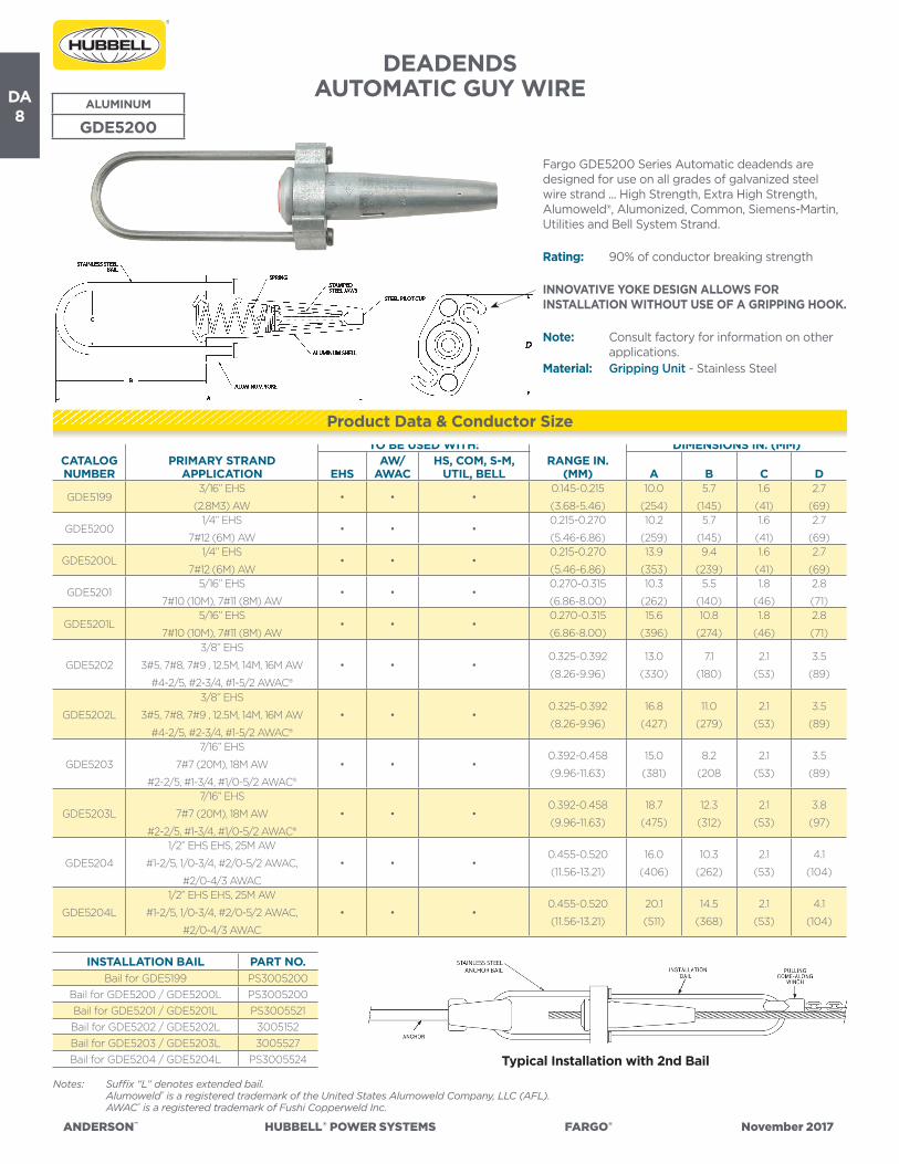
DEADENDSAUTOMATIC GUY WIRE
ALUMINUM
GDE5200
Fargo GDE5200 Series Automatic deadends are designed for use on all grades of galvanized steel wire strand ... High Strength, Extra High Strength, Alumoweld®, Alumonized, Common, Siemens-Martin, Utilities and Bell System Strand.
Rating: 90% of conductor breaking strength
INNOVATIVE YOKE DESIGN ALLOWS FOR INSTALLATION WITHOUT USE OF A GRIPPING HOOK.
Note: Consult factory for information on other applications.
Material: Gripping Unit - Stainless Steel
INSTALLATION BAIL PART NO.Bail for GDE5199 PS3005200
Bail for GDE5200 / GDE5200L PS3005200Bail for GDE5201 / GDE5201L PS3005521Bail for GDE5202 / GDE5202L 3005152Bail for GDE5203 / GDE5203L 3005527Bail for GDE5204 / GDE5204L PS3005524
Notes: Suffix “L” denotes extended bail. Alumoweld® is a registered trademark of the United States Alumoweld Company, LLC (AFL). AWAC® is a registered trademark of Fushi Copperweld Inc.
CATALOGNUMBER
PRIMARY STRANDAPPLICATION
TO BE USED WITH:RANGE IN.
(MM)
DIMENSIONS IN. (MM)
EHSAW/
AWACHS, COM, S-M,
UTIL, BELL A B C D
GDE51993/16” EHS
(2.8M3) AW• • •
0.145-0.215
(3.68-5.46)
10.0
(254)
5.7
(145)
1.6
(41)
2.7
(69)
GDE52001/4” EHS
7#12 (6M) AW• • •
0.215-0.270
(5.46-6.86)
10.2
(259)
5.7
(145)
1.6
(41)
2.7
(69)
GDE5200L1/4” EHS
7#12 (6M) AW• • •
0.215-0.270
(5.46-6.86)
13.9
(353)
9.4
(239)
1.6
(41)
2.7
(69)
GDE52015/16” EHS
7#10 (10M), 7#11 (8M) AW• • •
0.270-0.315
(6.86-8.00)
10.3
(262)
5.5
(140)
1.8
(46)
2.8
(71)
GDE5201L5/16” EHS
7#10 (10M), 7#11 (8M) AW• • •
0.270-0.315
(6.86-8.00)
15.6
(396)
10.8
(274)
1.8
(46)
2.8
(71)
GDE5202
3/8” EHS
3#5, 7#8, 7#9 , 12.5M, 14M, 16M AW
#4-2/5, #2-3/4, #1-5/2 AWAC®
• • •0.325-0.392
(8.26-9.96)
13.0
(330)
7.1
(180)
2.1
(53)
3.5
(89)
GDE5202L
3/8” EHS
3#5, 7#8, 7#9 , 12.5M, 14M, 16M AW
#4-2/5, #2-3/4, #1-5/2 AWAC®
• • •0.325-0.392
(8.26-9.96)
16.8
(427)
11.0
(279)
2.1
(53)
3.5
(89)
GDE5203
7/16” EHS
7#7 (20M), 18M AW
#2-2/5, #1-3/4, #1/0-5/2 AWAC®
• • •0.392-0.458
(9.96-11.63)
15.0
(381)
8.2
(208
2.1
(53)
3.5
(89)
GDE5203L
7/16” EHS
7#7 (20M), 18M AW
#2-2/5, #1-3/4, #1/0-5/2 AWAC®
• • •0.392-0.458
(9.96-11.63)
18.7
(475)
12.3
(312)
2.1
(53)
3.8
(97)
GDE5204
1/2” EHS EHS, 25M AW
#1-2/5, 1/0-3/4, #2/0-5/2 AWAC,
#2/0-4/3 AWAC
• • •0.455-0.520
(11.56-13.21)
16.0
(406)
10.3
(262)
2.1
(53)
4.1
(104)
GDE5204L
1/2” EHS EHS, 25M AW
#1-2/5, 1/0-3/4, #2/0-5/2 AWAC,
#2/0-4/3 AWAC
• • •0.455-0.520
(11.56-13.21)
20.1
(511)
14.5
(368)
2.1
(53)
4.1
(104)
Product Data & Conductor Size
Typical Installation with 2nd Bail

DA9
ANDERSON™ HUBBELL®POWERSYSTEMS FARGO® November2017
DEADENDS BOLTED STRAIGHT-LINE
SPRING-LOADED – SIDE OPENING ALUMINUM
ALUMINUM
ASOD
Fig. 1 Fig. 2
For distribution and light transmission construction with AAC, AAAC and ACSR conductors. The vertical spring-loaded keeper provides the easiest installation of any current bolted strain clamp.
Material: Body and Keeper – 356-T6 Aluminum Alloy Hardware – Galvanized Steel Sockets and Clevises – Ductile Iron, Galvanized Spring and Cotter Pin – Stainless Steel
NOTES: (1) Recommended torque on U-bolts: 3/8”–25 lb.-ft., 1/2”–45 lb.-ft. (2) Add Suffix “C” for Clevis Fitting (Type CA) (3) Add Suffix “S” for Socket Eye Fitting (Type SA)
CATALOGNUMBER
U-BOLTS CLAMPING RANGEULT. STR. LBS. (kN) DIMENSIONS IN
INCHES
NO. SIZE
ACSR ALUMINUM INCHES
BODYSAG EYEMIN. MAX. MIN. MAX. MIN. MAX. A B C
ASOD3981N 1 3/8 #6 (6/1) 2/0 (6/1) #4 (7) 2/0 (19) 0.19 0.486000 (26.69)
6000 (26.69)
8.00 1.00 3.62
ASOD5701N 1 1/2 #6 (6/1) 4/0 (6/1) #4 (7) 4/0 (19) 0.19 0.578000 (35.59)
8000 (35.59)
8.62 1.00 3.75
ASOD6841N 1 1/2 #4 (6/1) 336.4 (18/1) #2 (7) 350 (37) 0.25 0.698000 (35.59)
8000 (35.59)
9.00 1.00 4.50
ASOD8581N 1 1/2 #4 (6/1) 556.5 (18/1) #2 (7) 556.5 (37) 0.25 0.898000 (35.59)
8000 (35.59)
9.62 1.00 4.75
ASOD8582N 2 1/2 3/0 (6/1) 556.5 (18/1) 4/0 (7) 556.5 (37) 0.50 0.8912000
(53.38)
9000
(40.03) 14.50 1.00 6.00
ASOD11602N 2 1/2 336.4 (18/1) 900 (54/7) 350 (37) 954 (61) 0.69 1.1612000
(53.38)
9000
(40.03) 16.75 1.50 7.75
ASOD12592N 2 1/2 336.4 (18/1) 1113 (45/7)336.4
(19 STR)1200
(91 STR)0.666 1.263
15000 (66.72)
11250 (50.04)
16.56 1.5 6.9
Product Data & Conductor Size
(4) All bolted deadends are rated 40% of RBS - Partial tension per ANSI C119.4”(5) For conductor sizes not shown in catalog, consult factory

DA10
ANDERSON™ HUBBELL®POWERSYSTEMS FARGO® November2017
DEADENDSSINGLE BOLT STRAIGHT-LINE
SPRING-LOADED – SIDE-OPENINGBOLTED QUADRANT STRAIN CLAMP
ALUMINUM
ALUMINUM
ADSB
NOTES: For Socket or Clevis fitting replace the “N” suffix with “S” or “C” * For optional stainless steel lifting eye, add “E” to catalog number
CATALOGNUMBER
FIG. NO.
BOLTS CLAMPING RANGEULT. STR. LBS. (KN)
DIMENSIONS IN INCHES(MM) RECOM-
MENDED TORQUE
WRENCH FLATNO. SIZE ACSR
ALUMI-NUM
INCHES (MM) BODY
SAG EYE A B C K
ADSB48N* 1
1 1/2
#6 (6/1)
To
2/0 (6/1)
#4 (7 STR)
To
2/0 (19
STR)
0.19 - 0.48
(4.8 - 12.2)
6000
(26.69)
6000
(26.69)
9.6
(244)
1.13
(29)
4.63
(118)N/A
45 LB-F
(61 Nm)
3/4”
(19mm)SLQ48N 2
8000
(35.59)
6000
(26.69)
3.65
(93)
4.62
(117)
0.75
(19)
0.95
(24)
• For distribution construction using ACSR, AAC, and AAAC conductors
• Side loading conductor groove, in both a quadrant and straight line design, makes installation quicker than conventional side loading u-bolt style clamps
• Spring-loaded design holds keeper out of the way for easy conductor installation
• High strength ½" bolt, allows for quick installation with hand, battery pack, or hydraulic tools
• ANSI C119.4 Class 1A, normal tension connector (60% of rated conductor strength)
Material: Body and Keeper – High Strength Aluminum Alloy Hardware – Galvanized Steel Spring and Cotter Pin – Stainless Steel
Product Data & Conductor Size
C
Ø.63
B
A
J
K
ANGLE
R
Fig. 2
Fig. 1
DA11
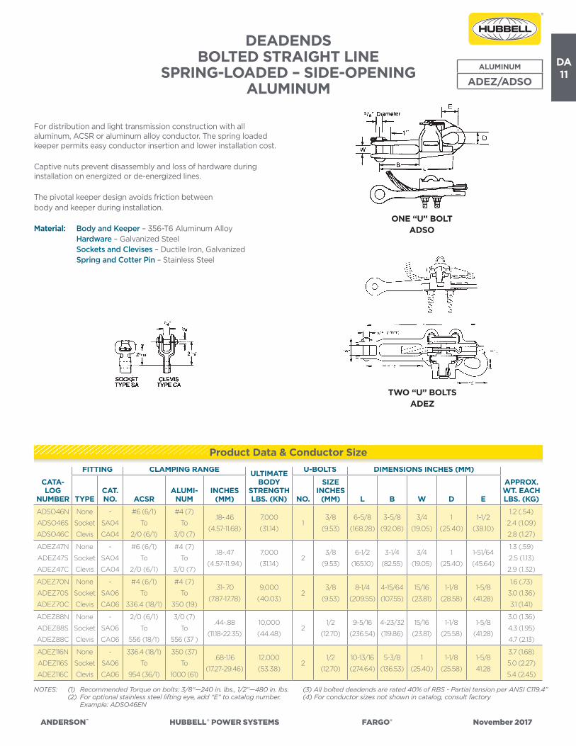
ANDERSON™ HUBBELL®POWERSYSTEMS FARGO® November2017
DEADENDSBOLTED STRAIGHT LINE
SPRING-LOADED – SIDE-OPENING ALUMINUM
ALUMINUM
ADEZ/ADSO
NOTES: (1) Recommended Torque on bolts: 3/8”—240 in. lbs., 1/2”—480 in. lbs. (2) For optional stainless steel lifting eye, add “E” to catalog number. Example: ADSO46EN
CATA-LOG
NUMBER
FITTING CLAMPING RANGE ULTIMATE BODY
STRENGTH LBS. (KN)
U-BOLTS DIMENSIONS INCHES (MM)
APPROX.WT. EACH LBS. (KG)TYPE
CAT. NO. ACSR
ALUMI-NUM
INCHES (MM) NO.
SIZE INCHES
(MM) L B W D E
ADSO46N
ADSO46S
ADSO46C
None
Socket
Clevis
-
SA04
CA04
#6 (6/1)
To
2/0 (6/1)
#4 (7)
To
3/0 (7)
.18-.46
(4.57-11.68)
7,000
(31.14)1
3/8
(9.53)
6-5/8
(168.28)
3-5/8
(92.08)
3/4
(19.05)
1
(25.40)
1-1/2
(38.10)
1.2 (.54)
2.4 (1.09)
2.8 (1.27)
ADEZ47N
ADEZ47S
ADEZ47C
None
Socket
Clevis
-
SA04
CA04
#6 (6/1)
To
2/0 (6/1)
#4 (7)
To
3/0 (7)
.18-.47
(4.57-11.94)
7,000
(31.14)2
3/8
(9.53)
6-1/2
(165.10)
3-1/4
(82.55)
3/4
(19.05)
1
(25.40)
1-51/64
(45.64)
1.3 (.59)
2.5 (1.13)
2.9 (1.32)
ADEZ70N
ADEZ70S
ADEZ70C
None
Socket
Clevis
-
SA06
CA06
#4 (6/1)
To
336.4 (18/1)
#4 (7)
To
350 (19)
.31-.70
(7.87-17.78)
9,000
(40.03)2
3/8
(9.53)
8-1/4
(209.55)
4-15/64
(107.55)
15/16
(23.81)
1-1/8
(28.58)
1-5/8
(41.28)
1.6 (.73)
3.0 (1.36)
3.1 (1.41)
ADEZ88N
ADEZ88S
ADEZ88C
None
Socket
Clevis
-
SA06
CA06
2/0 (6/1)
To
556 (18/1)
3/0 (7)
To
556 (37 )
.44-.88
(11.18-22.35)
10,000
(44.48)2
1/2
(12.70)
9-5/16
(236.54)
4-23/32
(119.86)
15/16
(23.81)
1-1/8
(25.58)
1-5/8
(41.28)
3.0 (1.36)
4.3 (1.95)
4.7 (2.13)
ADEZ116N
ADEZ116S
ADEZ116C
None
Socket
Clevis
-
SA06
CA06
336.4 (18/1)
To
954 (36/1)
350 (37)
To
1000 (61)
.68-1.16
(17.27-29.46)
12,000
(53.38)2
1/2
(12.70)
10-13/16
(274.64)
5-3/8
(136.53)
1
(25.40)
1-1/8
(25.58)
1-5/8
41.28
3.7 (1.68)
5.0 (2.27)
5.4 (2.45)
For distribution and light transmission construction with all aluminum, ACSR or aluminum alloy conductor. The spring loaded keeper permits easy conductor insertion and lower installation cost.
Captive nuts prevent disassembly and loss of hardware during installation on energized or de-energized lines.
The pivotal keeper design avoids friction betweenbody and keeper during installation.
Material: Body and Keeper – 356-T6 Aluminum Alloy Hardware – Galvanized Steel Sockets and Clevises – Ductile Iron, Galvanized Spring and Cotter Pin – Stainless Steel
Product Data & Conductor Size
(3) All bolted deadends are rated 40% of RBS - Partial tension per ANSI C119.4”(4) For conductor sizes not shown in catalog, consult factory
ONE “U” BOLTADSO
TWO “U” BOLTSADEZ

DA12
ANDERSON™ HUBBELL®POWERSYSTEMS FARGO® November2017
DEADENDSBOLTED STRAIGHT LINE
DEADEND STRAIN CLAMPSWING AWAY ALUMINUM
ALUMINUM
GD900
NOTE: (1) Recommended Torque on bolts: 3/8”—240 in. lbs., 1/2”—480 in. lbs. (2) All bolted deadends are rated 40% of RBS - Partial tension per ANSI C119.4” (3) For conductor sizes not shown in catalog, consult factory** RUS Listed.
CATALOGNUMBER
CLAMPING RANGE ULTIMATE BODY
STRENGTH LBS. (kN)
BOLTSIZE
INCHES (MM)
DIMENSIONS INCHES (MM)APPROX.WT. EACH LBS. (KG)ACSR ALUMINUM
INCHES (MM) L B W D E
GD961A**
#6 (6/1)
To
2/0 (6/1)
#6 (7)
to
3/0 (7)
.18-.47
(4.57-11.94)
7,000(31.14)
3/8
(9.53)
6-5/8
(168.4)
3
(76.2)
3/4
(19.05)
7/8
(22.22)–
1.1
(0.5)
GD963A
#4 (6/1)
to
397.5 (30/7)
#4 (7)
to
477 (37)
.25-.81
(6.35-20.57)
10,000(44.48)
1/2
(12.70)
10
(254)
5
(127)
3/4
(19.05)
1
25.4
7/8
(22.22)
2.0
(0.9)
GD965A
3/0 (6/1)
to
556.5 (18/1)
4/0 (7)
to
556.5 (37)
.50-.88
(12.7-22.35)
10,000(44.48)
1/2
(12.70)
10-1/8
(257.17)
5-1/4
(133.35)
3/4
(19.05)
1
25.4
7/8
(22.22)
3.3
(1.5)
GD967A
300 (26/7)
to
954 (36/1)
336.4 (19)
to
954 (61)
.68-1.15
(17.27-29.21)
10,000(44.48)
1/2
(12.70)
16-1/2
(419.1)
10
(254)
1-1/4
(31.75)
1-1/8
25.58
7/8
(22.22)
3.8
(1.7)
For distribution and light transmission construction. The angle beam pressure pad effectively converts torque to maximum pressure and spreads this force over the total contact area.
The compressive forces are combined with the modified parabolic “V” groove of the body to provide maximum conductor encirclement and increased holding ability.
The large pulling eye makes it convenient to connect and disconnect the “come-along” hook.
SWING AWAY DESIGN
The pressure pad is easily lifted and swung clear of the cable groove permitting convenient top loading of the conductor without disassembly.
Material: Body and Keeper – 356-T6 Aluminum Alloy Hardware – Galvanized Steel Cotter Pin – #302 Stainless Steel
Product Data & Conductor Size

DA13
ANDERSON™ HUBBELL®POWERSYSTEMS FARGO® November2017
DEADENDSBOLTED STRAIGHT LINE STRAIN CLAMP
ALUMINUM ALUMINUM
ADS
For distribution and light transmission construction with all aluminum, ACSR or aluminum alloy conductor. These clamps have high holding power and large range taking ability. (Straight Contoured Groove)
Material: Body and Keeper – 356-T6 Aluminum Alloy Hardware – Galvanized Steel Sockets and Clevises – Ductile Iron, Galvanized Cotter Pin – #302 Stainless Steel
NOTES: (1) Recommended Torque on bolts: 3/8”—240 in. lbs., 1/2”—480 in. lbs., 5/8”—720 in.-lbs. (2) Lifting eye is standard on keeper for hot line work. (3) All bolted deadends are rated 40% of RBS - Partial tension per ANSI C119.4” (4) For conductor sizes not shown in catalog, consult factory
*Extra length clamps for greater insulator clearance.** RUS Listed.
CATALOGNUMBER
FITTING CLAMPING RANGE ULTIMATE BODY
STRENGTH LBS. (kN)
U-BOLTS DIMENSIONS INCHES (MM)APPROX.WT. EACH LBS. (KG)TYPE
CAT. NO. ACSR ALUMINUM
INCHES (MM) NO.
SIZE INCHES
(MM) L B WADS47NADS47SADS47C
NoneSocketClevis
-SA04CA04
#6 (6/1)To
2/0 (6/1)
#6-7 Str.To
3/0-19 Str.
.18-.47(4.57-11.94)
7,000(31.14)
11/2
(12.70)5-3/8
(136.52)2-1/8
(53.98)11/16
(17.46)
1.1 (.50)2.4 (1.09)2.7 (1.22)
*ADS47LN*ADS47LS*ADS47LC
NoneSocketClevis
-SA04CA04
#6 (6/1)To
2/0 (6/1)
#6-7 Str.To
3/0-19 Str.
.18-.47(4.57-11.94)
7,000(31.14)
11/2
(12.70)6-3/4
(171.45)3-1/2
(88.90)11/16
(17.46)
1.3 (.59)2.6 (1.15)2.9 (1.32)
ADS48N**ADS48SADS48C
NoneSocketClevis
-SA04CA04
#6 (6/1)To
3/0 (6/1)
#6-7 Str.To
3/0-19 Str.
.18-.502(4.57-12.75)
7,000(31.14)
23/8
(9.53)7-5/8
190.50)3-7/8
(98.43)11/16
(17.46)
1.6 (.73)2.9 (1.32)3.2 (1.46)
ADS60N**ADS60SADS60C
NoneSocketClevis
-SA04CA04
#6 (6/1)To
266.8 (18/1)
#4-7 Str.To
266.8-19 Str.
.19-.60(4.83-15.24)
8,000(35.59)
21/2
(12.70)8-1/4
(209.55)4
(101.60)3/4
(19.05)
2.0 (.91)3.2 (1.45)3.6 (1.63)
*ADS60LN*ADS60LS*ADS60LC
NoneSocketClevis
-SA04CA04
#6 (6/1)To
266.8 (18/1)
#4-7 Str.To
266.8-19 Str.
.19-.60(4.83-15.24)
8,000(35.59)
21/2
(12.70)10-5/8
(269.88)6
(152.40)3/4
(19.05)
2.2 (1.00)3.4 (1.54)3.8 (1.72)
ADS88NADS88SADS88C
NoneSocketClevis
-SA06CA06
#2 (6/1)To
556.5 (18/1)
#1-7 Str.To
556.5-37 Str.
.31-.88(7.87-22.35)
10,000(44.48)
21/2
(12.70)9
(228.60)4-1/2
(114.30)15/16
(23.81)
2.2 (1.00)3.5 (1.59)3.9 (1.77)
*ADS88LN*ADS88LS*ADS88LC
NoneSocketClevis
-SA06CA06
#2 (6/1)To
556.5 (18/1)
#1-7 Str.To
556.5-37 Str.
.31-.88(7.87-22.35)
10,000(44.48)
21/2
(12.70)12
(304.80)7-1/2
(190.50)15/16
(23.81)
2.4 (1.09)3.7 (1.68)4.1 (1.86)
ADS116NADS116SADS116C
NoneSocketClevis
-SA07CA06
#2 (6/1)To
954 (36/1)
#1-7 Str.To
1000-61 Str.
.31-1.16(7.87-29.46)
15,000(66.72)
21/2
(12.70)10-1/2
(266.70)5-1/2
(139.70)1
(25.40)
2.9 (1.32)4.2 (1.91)
4.6 (2.09)ADS130NADS130SADS130C
NoneSocketClevis
-SA07CA06
266.8 (26/7)To
1192.5 (45/7)
336.4-19 Str.To
1272-61 Str.
.64-1.30(16.26-33.02)
15,000(66.72)
21/2
(12.70)10-1/2
(266.70)5-1/2
(139.70)1
(25.40)
3.0 (1.36)4.3 (1.95)4.7 (2.13)
ADS155NADS155SADS155C
NoneSocketClevis
-SA07CA06
336.4 (26/7)To
1590.5 (54/19)
397.5-19 Str.To
1800-127 Str.
.72-1.55(18.3-39.9)
15,000(66.72)
25/8
(15.9)11-3/4
(298.5)6
(152.4)1
(25.40)
4.4 (2.0)5.8 (2.6)6.1 (2.8)
Product Data & Conductor Size

DA14
ANDERSON™ HUBBELL®POWERSYSTEMS FARGO® November2017
DEADENDSBOLTED STRAIGHT LINE STIRRUP CLAMP
ALUMINUMALUMINUM
ADES
For distribution construction with all aluminum, ACSR or aluminum alloy conductor. This clamp is a combination deadend and stirrup or tap clamp. The stirrup permits tapping energized conductors without arching damage to the conductor.
Material and installation costs are less with the ADES combination clamp than with other equivalent methods of deadending and tapping a conductor.
Material: Body and Keeper – 356-T6 Aluminum Alloy Hardware – Galvanized Steel Sockets and Clevises – Ductile Iron, Galvanized Cotter Pin – #302 Stainless Steel Stirrup – Copper
NOTES: (1) Recommended Torque on U-bolts: 3/8”—240 in. lbs., 1/2”—480 in. lbs. (2) Lifting eye is standard on keeper for hot line work. (3) All bolted deadends are rated 40% of RBS - Partial tension per ANSI C119.4” (4) For conductor sizes not shown in catalog, consult factory
CATALOGNUMBER
FITTING CLAMPING RANGE ULTIMATE BODY
STRENGTH LBS. (kN)
U-BOLTSLOOP DIA. DIMENSIONS INCHES (MM) APPROX.
WT. EACH
LBS. (KG)TYPECAT. NO. ACSR ALUMINUM
INCHES (MM) NO.
SIZE INCHES
(MM) E L B W DADES46N
ADES46S
ADES46C
None
Socket
Clevis
-
SA04
CA04
#6 (6/1)
To
2/0 (6/1)
#6-7 Str.
To
2/0-19 Str.
.18-.46
(4.57-11.68)
6,000
(26.69)2
3/8
(9.53)
.289
(7.3)
#1
7-1/2
(190.50)
4
(101.60)
3/4
(19.05)
2
(50.80)
1.8 (0.82)
3.0 (1.36)
3.4 (1.54)ADES60N
ADES60S
ADES60C
None
Socket
Clevis
-
SA04
CA04
1/0 (6/1)
To
266.8 (18/1)
1/0-7 Str.
To
266.8-19 Str.
.36-.60
(9.14-15.24)
8,000
(35.59)2
1/2
(12.70)
.325
(8.3)
1/0
9-5/8
(244.48)
4
(101.60)
3/4
(19.05)
3-1/16
(77.79)
2.8 (1.3)
4.0 (1.81)
4.4 (2.00)ADES70N
ADES70S
ADES70C
None
Socket
Clevis
-
SA04
CA04
3/0 (6/1)
To
336.4 (18/1)
3/0-7 Str.
To
350-37 Str.
.46-.70
(11.68-17.78)
8,000
(35.59)2
1/2
(12.70)
.325
(8.3)
1/0
10-3/4
(273.05)
4-31/32
(126.21)
3/4
(19.05)
2-1/8
53.98)
3.0 (1.40)
4.2 (1.91)
4.7 (2.13)
Product Data & Conductor Size

DA15
ANDERSON™ HUBBELL®POWERSYSTEMS FARGO® November2017
DEADENDSBOLTED QUADRANT STRAIN CLAMP
ALUMINUM ALUMINUM
PG/DE
For distribution and light transmission construction with all aluminum, ACSR or aluminum alloy conductor.
Material: Body and Keeper – 356-T6 Aluminum Alloy Hardware – Galvanized Steel Sockets and Clevises – Ductile Iron, Galvanized Cotter Pin – #302 Stainless Steel
NOTE: (1) Recommended Torque on U-bolts: 3/8”—240 in. lbs., 1/2”—480 in. lbs. (2) All bolted deadends are rated 40% of RBS - Partial tension per ANSI C119.4” (3) For conductor sizes not shown in catalog, consult factory** RUS Listed
CATALOGNUMBER
FITTING CLAMPING RANGE ULTIMATE BODY
STRENGTH LBS. (kN)
U-BOLTS
GROOVEANGLE
APPROX.WT. EACH LBS. (KG)TYPE
CAT. NO. ACSR ALUMINUM
INCHES (MM) NO.
SIZE INCHES
(MM)
DE46N
DE46S
DE46C
None
Socket
Clevis
--
SA04
CA04
#6 (6/1)
To
3/0 (6/1)
#6 -7 Str.
To
3/0-19 Str.
.18-.52
(4.57-13.21)
8,000
(35.59)1
1/2
(12.70)85°
1.2 (.54 )
2.2 (1.00)
2.2 (1.00)
PG46N**
PG46S
PG46C
None
Socket
Clevis
--
SA04
CA04
#6 (6/1)
To
3/0 (6/1)
#6 -7 Str.
To
3/0-19 Str.
.18-.52
(4.57-13.21)
8,000
(35.59)2
3/8
(9.53)90°
1.1 (.50)
2.4 (1.08)
2.7 (1.22)
PG57N**
PG57S
PG57C
None
Socket
Clevis
--
SA04
CA04
#4 (6/1)
To
4/0 (6/1)
#3-7 Str.
To
4/0-19 Str.
.25-.57
(6.35-14.48)
10,000
(44.48)2
1/2
(12.70)90°
2.0 (.91)
3.2 (1.45)
3.6 (1.63)
PG70N
PG70S
PG70C
None
Socket
Clevis
--
SA04
CA04
101.8 (12/7)
To
336.4 (26/7)
3/0-7 Str.
To
400-37 Str.
.46-.73
(11.68-18.54)
15,000
(66.72)2
1/2
(12.70)85°
2.5 (1.13)
3.8 (1.72)
4.1 (1.86)
PG86LN
PG86LS
PG86LC
None
Socket
Clevis
--
SA07
CA06
134.6 (12/7)
To
556.5 (18/1)
4/0-7 Str.
To
556.5-37 Str.
.52-.88
(13.21-22.35)
15,000
(66.72)2
1/2
(12.70)70°
2.9 (1.32)
4.2 (1.91)
4.6 (2.09)
PG100LN
PG100LS
PG100LC
None
Socket
Clevis
--
SA10
CA101
3/0 (6/1)
To
666.6 (24/7)
4/0-7 Str.
To
750-61 Str.
.50-1.00
(12.70-25.40)
18,000
(80.07)2
1/2
(12.70)60°
4.5 (2.04)
5.9 (2.68)
6.2 (2.81)
CATALOGNUMBER
DIMENSIONS INCHES (MM)
L W H K
DE463-7/8
(98.30)
11/16
(17.46)
3-13/16
(96.84)
7/8
(22.10)
PG464-1/16
(103.18)
11/16
(17.46)
4-3/4
(120.65)
1
(25.40)
PG575-1/2
(139.7)
11/16
(17.46)
5-5/16
(134.87)
1
(25.40)
PG706-7/16
(163.51)
25/32
(19.84)
7
(177.80)
1-1/8
(28.58)
PG86L6-9/16
(166.69)
1-1/16
(26.99)
7-7/16
(188.91)
1
(25.40)
PG100L9-7/8
(250.83)
1-3/16
(30.16)
9-5/16
(236.54)
1-1/4
(31.75)
Product Data & Conductor Size

DA16
ANDERSON™ HUBBELL®POWERSYSTEMS FARGO® November2017
DEADENDS BOLTED STRAIGHT LINE STRAIN CLAMP
FERROUSDUCTILE IRON
MDE
For deadending static wires.
May be used to deadend copper or Copperweld® phase conductors. Magnetic induction heating will occur.
Material: Body and Keeper – Galvanized Ductile Iron Hardware – Galvanized Steel Sockets and Clevises – Ductile Iron, Galvanized Cotter Pin – #302 Stainless Steel
CATALOGNUMBER
FITTING
CLAMPING RANGE
INCHES (MM)
ULTIMATE BODY
STRENGTH LBS. (KN)
U-BOLTS DIMENSIONS INCHES (MM)
APPROX.WT. EACH LBS. (KG)TYPE
CAT. NO. NO.
SIZE INCHES
(MM) L W A X B
MDE40N
MDE40S
MDE40C
None
Socket
Clevis
-
SA04
CA04
.16-.40
(4.06-10.16)
5,000
(22.24)1
1/2
(12.70)
6-3/16
(157.16)
13/16
(20.6)
7/8 x 1-1/4
(22.2 x 31.8)
2.1 (.95)
3.4 (1.54)
3.7 (1.68)
MDE46N
MDE46S
MDE46C
None
Socket
Clevis
-
SA04
CA04
.18-.46
(4.57-11.68)
6,000
(26.69)2
3/8
(9.53)
7-1/2
(190.5)
3/4
(19.05)
7/8 x 1-1/4
(22.2 x 31.8)
2.5 (1.13)
3.8 (1.72)
4.1 (1.86)
MDE60N
MDE60S
MDE60C
None
Socket
Clevis
-
SA04
CA04
.36-.60
(9.14-15.24)
8,000
(35.59)2
1/2
(12.70)
8-15/16
(227.01)
3/4
(19.05)
7/8 x 1-1/4
(22.2 x 31.8)
3.8 (1.72)
5.0 (2.27)
5.4 (2.45)
876722000 None —.46-.86
(11.68-21.84)
10,000
(44.48)2
1/2
(12.70)
9-1/4
(234.95)
3/4
(19.05)
1 x 1-7/16
(25.4 x 36.5)3.8 (1.72)
876822000 None —.65-1.25
(16.51-31.75)
10,000
(44.48)2
1/2
(12.70)
11
(279.40)
3/4
(19.05)
1 x 1-13/16
(25.4 x 46.0)5.5 (2.49)
876922000 None —.86-1.55
(21.84-39.37)
10,000
(44.48)2
3/8
(9.53)
12.5
(317.50)
3/4
(19.05)
1-1/16 x 2-1/8
(27.0 x 54.0)7.9 (3.58)
NOTES: (1) Recommended Torque on U-bolts: 3/8”—240 ins. lbs., 1/2”—480 in. lbs., 5/8”—720 in. lbs. (2) Lifting eye is standard on MDE type clamps. (3) 87600 series without lifting eye.
Copperweld® is a registered trademark of Fushi Copperweld Inc.
Product Data & Conductor Size
(4) All bolted deadends are rated 40% of RBS - Partial tension per ANSI C119.4”(5) For conductor sizes not shown in catalog, consult factory
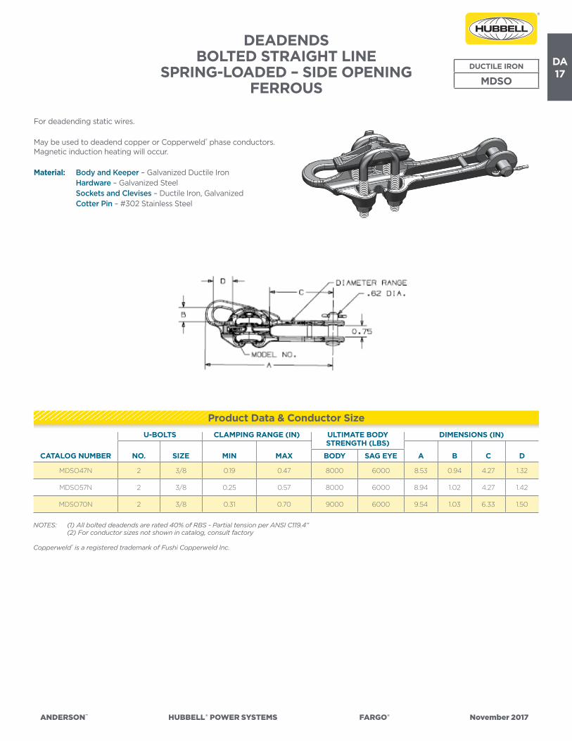
DA17
ANDERSON™ HUBBELL®POWERSYSTEMS FARGO® November2017
CATALOG NUMBER
U-BOLTS CLAMPING RANGE (IN) ULTIMATE BODY STRENGTH (LBS)
DIMENSIONS (IN)
NO. SIZE A B C DMIN MAX BODY SAG EYE
MDSO47N 2 3/8 0.19 0.47 8000 6000 8.53 0.94 4.27 1.32
MDSO57N 2 3/8 0.25 0.57 8000 6000 8.94 1.02 4.27 1.42
MDSO70N 2 3/8 0.31 0.70 9000 6000 9.54 1.03 6.33 1.50
NOTES: (1) All bolted deadends are rated 40% of RBS - Partial tension per ANSI C119.4” (2) For conductor sizes not shown in catalog, consult factory
Copperweld® is a registered trademark of Fushi Copperweld Inc.
DEADENDS BOLTED STRAIGHT LINE
SPRING-LOADED – SIDE OPENING FERROUS
DUCTILE IRON
MDSO
For deadending static wires.
May be used to deadend copper or Copperweld® phase conductors. Magnetic induction heating will occur.
Material: Body and Keeper – Galvanized Ductile Iron Hardware – Galvanized Steel Sockets and Clevises – Ductile Iron, Galvanized Cotter Pin – #302 Stainless Steel
Product Data & Conductor Size
(4) All bolted deadends are rated 40% of RBS - Partial tension per ANSI C119.4”(5) For conductor sizes not shown in catalog, consult factory
DA18
ANDERSON™ HUBBELL®POWERSYSTEMS FARGO® November2017
DEADENDS BOLTED QUADRANT STRAIN CLAMP
FERROUSDUCTILE IRON
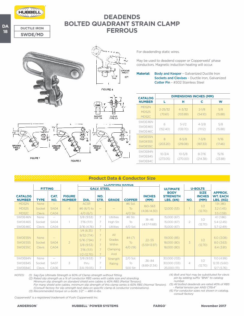
SWDE/MD
For deadending static wires.
May be used to deadend copper or Copperweld® phase conductors. Magnetic induction heating will occur.
Material: Body and Keeper – Galvanized Ductile Iron Sockets and Clevises – Ductile Iron, Galvanized Cotter Pin – #302 Stainless Steel
NOTES: (1) Sag Eye Ultimate Strength is 60% of Clamp strength without fitting. (2) Rated slip strength as a % of conductor RBS varies with cable size and stranding. Minimum slip strength on standard shield wire cables is 40% RBS (Partial Tension). For many shield wire cables, minimum slip strength of this clamp series is 60% RBS (Normal Tension). (Consult factory for slip strength test data on specific clamp & conductor combinations). (3) Recommended torque on u-bolts: 1/2” -- 480 in-lbs.
Copperweld® is a registered trademark of Fushi Copperweld Inc.
CATALOGNUMBER
FITTING
FIGURE NUMBER
CLAMPING RANGEULTIMATE
BODY STRENGTH LBS. (kN)
U-BOLTSAPPROX.WT. EACH LBS. (KG)
GALV. STEEL
COPPERINCHES
(MM)TYPECAT. NO. DIA.
NO. STR. GRADE NO.
SIZE INCHES
(MM)MD52N
MD52S
MD52C
None
Socket
Clevis
--
SA04
CA04
4
ACSR
#6 (6/1) to
4/0 (6/1)
— —
#6 Sol.
To
4/0 Str.
.160-.563
(4.06-14.30)12,000 (53) 1
1/2
(12.70)
1.9 (.86)
3.2 (1.45)
3.5 (1.59)SWDE46N
SWDE46S
SWDE46C
None
Socket
Clevis
--
SA04
CA04
1
3/8 (9.53)
7/16 (11.11)
3/16 (4.76)
7
7
7
Utilities
High Str.
Utilities
#6 Str.
To
4/0 Sol.
.18-.46
(4.57-11.68)
15,000 (67)
15,000 (67)
15,000 (67)
21/2
(12.70)
4.1 (1.86)
5.4 (2.45)
5.7 (2.49)
SWDE55N
SWDE55S
SWDE55C
None
Socket
Clevis
--
SA04
CA04
2
1/4 (6.35)
9/32 (7.14)
5/16 (7.94)
3/8 (9.53)
7/16 (11.11)
1/2 (12.70)
7
7
7
7
7
7
All
Grades
Within
Clamping
And
Strength
Rating
#4 (7)
To
4/0 (19)
.22-.55
(5.59-13.97)
19,000 (85)
18,000 (80)
18,000 (80)
31/2
(12.70)
6.0 (3.08)
8.0 (3.63)
8.4 (3.81)
SWDE84N
SWDE84S
SWDE84C
None
Socket
Clevis
--
SA07
CA06
3
3/8 (9.53)
thru
3/4 (19.05)
7
7
7
2/0 Sol.
To
500 Str.
.36-.84
(8.89-21.34)
30,000 (133)
30,000 (133)
25,000 (111)
41/2
(12.70)
11.0 (4.99)
12.35 (5.60)
12.7 (5.76)
CATALOGNUMBER
DIMENSIONS INCHES (MM)
L H C W
MD52N
MD52S
MD52C
2-25/32
(70.61)
4-3/32
(103.89)
2-1/8
(54.10)
5/8
(15.88)
SWDE46N
SWDE46S
SWDE46C
6
(152.40)
5-1/2
(139.70)
4-3/8
(111.12)
5/8
(15.88)
SWDE55N
SWDE55S
SWDE55C
8
(203.20)
8-5/8
(219.08)
7-3/8
(187.33)
11/16
(17.46)
SWDE84N
SWDE84S
SWDE84C
10-3/4
(273.05)
10-5/8
(270.00)
8-7/16
(214.38)
15/16
(23.88)
Product Data & Conductor Size
(4) Bolt and Nut may be substituted for clevis pin by adding suffix “BNK” to catalog number.(5) All bolted deadends are rated 40% of RBS - Partial tension per ANSI C119.4”(6) For conductor sizes not shown in catalog, consult factory

DA19
ANDERSON™ HUBBELL®POWERSYSTEMS FARGO® November2017
DEADENDS BOLTED STRAIGHT LINE STRAIN CLAMP
BRONZE BRONZE
BDE
For distribution and light transmission construction with copper or Copperweld® conductor. Power loss, corrosion and heat rise are all reduced to a minimum due to the nonferrous construction
Material: Body – High Strength Aluminum Bronze Alloy or Red Brass Keeper – Electrical Bronze Hardware – Galvanized Steel Sockets and Clevises – Ductile Iron, Galvanized Cotter Pin – #302 Stainless Steel
CATALOGNUMBER
FITTING CLAMPING RANGE ULTIMATE BODY
STRENGTH LBS. (kN)
U-BOLTS DIMENSIONS INCHES (MM)APPROX.WT. EACH LBS. (KG)TYPE
CAT. NO. NO.
SIZE INCHES
(MM) L W KCOPPERINCHES
(MM)BDE46N
BDE46S
BDE46C
None
Socket
Clevis
--
SA04
CA04
#6 Sol.
To
4/0 Sol.
.16-.46
(4.06-11.68)
6,000(26.69)
23/8
(9.53)
7-1/4
(184.15)
3/4
(19.05)
7/8
(22.23)
3.2 (1.45)
4.4 (2.00)
4.8 (2.18)BDE60N
BDE60S
BDE60C
None
Socket
Clevis
--
SA04
CA04
2/0 Sol.
To
250 MCM
.36-.60
(9.14-15.24)
8,000(35.59)
21/2
(12.70)
8-3/4
(222.25)
3/4
(19.05)
7/8
(22.23)
5.6 (2.54)
6.9 (3.13)
7.2 (3.27)BDE70N
BDE70S
BDE70C
None
Socket
Clevis
--
SA04
CA04
4/0 Sol.
To
350 MCM
.46-.70
(11.68-17.78)
8,000(35.59)
21/2
(12.70)
10-3/4
(273.05)
3/4
(19.05)
15/16
(23.81)
6.5 (2.95)
7.8 (3.54)
8.1 (3.67)BDE86N
BDE86S
BDE86C
None
Socket
Clevis
--
SA06
CA06
4/0-7 Str.
To
550 MCM
.52-.86
(13.21-21.84)
8,000(35.59)
21/2
(12.70)
11
(279.40)
15/16
(23.81)
15/16
(23.81)
7.0 (3.18)
8.3 (3.76)
8.7 (3.95)BDE98N
BDE98S
BDE98C
None
Socket
Clevis
--
SA06
CA06
350-37 Str.
To
700 MCM
.68-.98
(17.27-24.89)
9,000
(40.03)2
1/2
(12.70)
11-5/8
(295.28)
1-1/16
(26.99)
15/16
(23.81)
7.4 (3.36)
8.7 (3.95)
9.1 (4.13)
NOTES: (1) Recommended Torque on U-bolts: 3/8”—240 ins. lbs., 1/2”—480 in. lbs. (2) Lifting eye is standard on keeper for hot line work. (3) All bolted deadends are rated 40% of RBS - Partial tension per ANSI C119.4” (4) For conductor sizes not shown in catalog, consult factory
Copperweld® is a registered trademark of Fushi Copperweld Inc.
Product Data & Conductor Size

DA20
ANDERSON™ HUBBELL®POWERSYSTEMS FARGO® November2017
Product Data & Conductor Size
DEADENDS BOLTED STRAIGHT LINE SPRING-LOADED
SIDE OPENING BRONZEBRONZE
BSOD
For distribution and light transmission construction with copper or Copperweld® conductor. Power loss, corrosion and heat rise are all reduced to a minimum due to the nonferrous construction
Material: Body and Keeper – Bronze Alloy 112 Hardware – Galvanized Steel Sockets and Clevises – Ductile Iron, Galvanized Cotter Pin and Spring Clip – Stainless Steel
CATALOG NUMBER
U-BOLTS CLAMPING RANGE (IN)ULTIMATE BODY STRENGTH (LBS) DIMENSIONS (IN)
NO. SIZE A B C
COPPER INCHES (MM)
BODY SAG EYEMIN MAX MIN MAX
BSOD5701N 1 0.50 #6 (SOL)4/0
(19 STR)
0.16 (4.06)
0.57
(11.68)8000 8000 8.62 1 3.75
NOTES: (1) All bolted deadends are rated 40% of RBS - Partial tension per ANSI C119.4” (2) For conductor sizes not shown in catalog, consult factory
Copperweld® is a registered trademark of Fushi Copperweld Inc.

DA21
ANDERSON™ HUBBELL®POWERSYSTEMS FARGO® November2017
DEADENDS BOLTED STRAIGHT LINE STRAIN CLAMP
BRONZE BRONZE
BSG
These compact strain clamps are ideal for pole type substations and other short span deadending requirements with copper or Copperweld® conductor.
Because of non-ferrous construction, corrosion and heat rise on heavy current secondary circuits are reduced to a minimum. The threads do not protrude and all surfaces are rounded for quick, efficient taping.
Material: Body and Keeper – High Strength Aluminum Bronze Alloy Hex Head Bolts and Lock Washers – Silicon Bronze Sockets and Clevises – Ductile Iron, Galvanized Clevis Pin – Galvanized Steel Cotter Pin – #302 Stainless Steel
CATALOGNUMBER
FITTING CLAMPING RANGE ULTIMATE BODY
STRENGTH LBS. (kN)
HEX-HEAD BOLTS
DIMENSIONS INCHES (MM)
APPROX.WT. EACH LBS. (KG)TYPE
CAT. NO. NO.
SIZE INCHES
(MM) L W RCOPPERINCHES
(MM)
BSG050N
BSG050S
BSG050C
None
Socket
Clevis
--
SA04
CA04
2/0 Sol.
To
550 MCM
.36-.875
(9.14-22.23)
5,500
(24.47)4
1/2
(12.70)
6-1/2
(165.1)
11/16
(17.46)
4
(101.60)
3.5 (1.59)
4.8 (2.18)
4.8 (2.18)
BSG100N
BSG100S
BSG100C
None
Socket
Clevis
--
SA04
CA04
500
To
1000 MCM
.81-1.25
(20.57-31.75)
7,500
(33.36)4
1/2
(12.70)
7-1/2
(190.5)
11/16
(17.46)
6
(152.40)
4.7 (2.13)
6.0 (2.72)
6.3 (2.86)
NOTE: (1) Recommended Torque on bolts: 1/2”—480 in. lbs. (2) All bolted deadends are rated 40% of RBS - Partial tension per ANSI C119.4” (3) For conductor sizes not shown in catalog, consult factory
Copperweld® is a registered trademark of Fushi Copperweld Inc.
Product Data & Conductor Size

DA22
ANDERSON™ HUBBELL®POWERSYSTEMS FARGO® November2017
DEADENDSBOLTED STRAIGHT LINE STRAIN CLAMP
BRONZEBRONZE
BSC
These clamps are recommended for copper or Copperweld® conductor. Type BSCG is supplied with a standoff guide to assure clearance between conductor and insulator disc when clamps are used as a through type deadend or strain.
Material: Body – High Strength Aluminum Bronze Alloy Keeper and Guide – Electrical Bronze Hardware – Galvanized Steel Sockets and Clevises – Ductile Iron, Galvanized Cotter Pin – #302 Stainless Steel
CATALOGNUMBER
FITTING CLAMPING RANGEULTIMATE
BODY STRENGTH LBS. (KN)
U-BOLTSDIMENSIONS INCHES (MM) APPROX.
WT. EACH LBS. (KG)TYPE CAT. NO. NO.
SIZE INCH-ES (MM) L WCOPPER INCHES (MM)
BSC024N
BSC024S
BSC024C
None
Socket
Clevis
--
SA04
CA04
#2 Sol.
To
4/0 Str.
.258-.528
(6.55-13.41)
8,000(35.59)
21/2
(12.70)
9-1/8
(231.78)
11/16
(17.46)
3.1 (1.41)
4.4 (2.00)
4.4 (2.00)BSC050N
BSC050S
BSC050C
None
Socket
Clevis
--
SA04
CA04
4/0 Str.
To
550 MCM
.52-.875
(13.21-22.23)
8,000(35.59)
21/2
(12.70)
9-5/8
(244.48)
11/16
(17.46)
3.8 (1.72)
5.1 (2.31)
5.1 (2.31)BSC100N
BSC100S
BSC100C
None
Socket
Clevis
--
SA04
CA04
500
To
1000 MCM
.81-1.25
(20.57-31.75)
10,000
(44.48)3
1/2
(12.70)
13-1/8
(333.38)
13/16
(20.64)
6.9 (3.13)
8.2 (3.72)
8.2 (3.72)
NOTES: (1) Recommended Torque on U-bolts: 3/8”—240 ins. lbs., 1/2”—480 in. lbs. (2) To obtain silicon bronze hardware add suffix—“ED”. Example, BSC024NED. (3) All bolted deadends are rated 40% of RBS - Partial tension per ANSI C119.4” (4) For conductor sizes not shown in catalog, consult factory
Copperweld® is a registered trademark of Fushi Copperweld Inc.
Product Data & Conductor Size

DA23
ANDERSON™ HUBBELL®POWERSYSTEMS FARGO® November2017
DUCTILE DEADEND THIMBLETYPE DDT
DUCTILE IRON
DDT
Provides a convenient and efficient means for loop deadending of steel static wire and bare or insulated aluminum or copper phase wires. Magnetic induction heating will occur.
Material: Body – Ductile Iron, Galvanized Clevis Pin – Galvanized Steel Cotter Pin – #302 Stainless Steel
CATALOGNUMBER
CONDUCTOR RANGE
INCHES (MM)
ULTIMATE BODY
STRENGTH LBS. (kN)
DIMENSIONS INCHES (MM)APPROX.WT. EACH LBS. (KG)L B W H PD
DDT070-.875
(0-22.23)40,000 (178)
5-3/8
(136.53)
2-5/16
(58.74)
7/8
(22.23)
3-1/4
(82.55)
3/4
(19)
2.5
(1.13)
DDT12*0-1.0
(0-25.40)60,000 (267)
7-13/16
(45.97)
3-3/4
(95.25)
1-5/16
(33.27)
3-3/4
(95.25)
1
(25)*
5.7
(2.5)
*Bolt, Nut & Cotter Pin are standard.
DEADENDSALUMINUM DEADEND THIMBLE
TYPE ADETALUMINUM
ADET
Provides a convenient and efficient means for loop deadending of steel static wire and bare or insulated aluminum or copper phase wires. Magnetic induction heating will occur.
Material: Body – Ductile Iron, Galvanized Clevis Pin – Galvanized Steel Cotter Pin – #302 Stainless Steel
CATALOGNUMBER
CONDUCTOR RANGEINCHES (MM)
RATED STRENGTH LBS. (kN) DIMENSIONS INCHES (MM)
ACSRGUYWIRE THIMBLE EYE A B C D E F
ADET75 #6 – 336.4 3/16 – 5/1610,000
(44.48)
6,000
(26.69)
0.75
(19)
1.5
(38.1)
2.12
(53.8)
0.63
(16)
3
(76.2)
4.81
(122.2)
ADET88 #6 – 477 3/16 – 3/812,000
(53.38)
7,000
(31.14)
0.88
(22.4)
1.5
(38.1)
2.12
(53.8)
0.63
(16)
3
(76.2)
4.81
(122.2)
Product Data & Conductor Size
Product Data & Conductor Size

DA24
ANDERSON™ HUBBELL®POWERSYSTEMS FARGO® November2017
CATALOG NUMBER FIG. NO.
CLAMPING RANGE INCHES (MM)
ULTIMATE BODY
STRENGTH LBS. (kN)
MAX. TAKE- OFF ANGLE DIMENSIONS INCHES (MM)
APPROX. WT. EACH LBS. (KG)o L W H
AAC301 2.198-.732
(5.03-18.59)
7,000
(31)45˚
4-1/4
(107.95)
11/16
(17.46)
2-7/8
(73.02)
1.25
(.57)
AAC302 1.198-.732
(5.03-18.59)
7,000
(31)45˚
4-1/4
(107.95)
11/16
(17.46)
2-7/8
(73.02)
1.25
(.57)
AAC104N 1.50-1.10
(12.70-27.94)
12,000
(53)60˚
5-1/4
(133.35)
11/16
(17.46)
4-1/8
(104.77)
2.3
(1.04)
AAC10490N 2.50-1.10
(12.70-27.94)
12,000
(53)60˚
5-1/4
(133.35)
11/16
(17.46)
4-1/8
(104.77)
2.2
(1)
NOTES: (1) Sockets and clevises can be supplied by adding “S” or “C” to catalog number. Example, AAC10490S. (2) Recommended torque on 1/2” J-bolts: 300 in.-lbs.
SUSPENSIONALUMINUM ANGLE CLAMP
Intended for angle construction with all aluminum, ACSR or aluminum alloy conductor.
Material: Body and Keeper – 356-T6 Aluminum Alloy Hardware – Galvanized Steel Cotter Pin – #302 Stainless Steel
ALUMINUM
AAC
Ordering Information
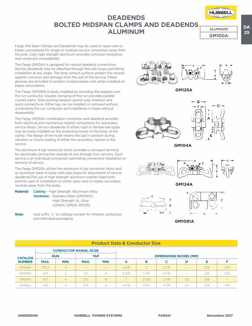
DA25
ANDERSON™ HUBBELL®POWERSYSTEMS FARGO® November2017
DEADENDSBOLTED MIDSPAN CLAMPS AND DEADENDS
ALUMINUM
Fargo Mid Span Clamps and Deadends may be used on open wire or triplex secondaries for single or multiple service connectors away from the pole. Cast, high strength aluminum provides corrosion resistance and conductor compatibility.
The Fargo GM104A is designed for neutral deadend connections. Service deadends may be attached through the side loops permitting installation at any angle. The long contact surfaces protect the neutral against corrosion and damage from the pull of the service. Fitted grooves are provided to protect covered phase wire when installed on triplex secondaries.
The Fargo GM1091A is easily installed by swiveling the keepers over the run conductor. Double clamping of the run provides parallel current paths. Side opening keepers permit easy insertion and quick connections. Either tap can be installed or removed without unclamping the run conductor and installation is made without disassembly.
The Fargo GM124A combination connector and deadend provides both electrical and mechanical neutral connections for secondary service drops. Service deadends of either rigid or flexible bail types may be easily installed on the projecting hooks of the body of the clamp. The design of the hook retains the bail in position during vibration or shock loading of either the secondary neutral or the service.
The aluminum 4 tap connector block provides a compact terminal for electrically joining the neutrals of one through four services. Each service is an individual connection permitting convenient installation or removal of service.
The Fargo GM125A utilizes the aluminum 4 tap connector block and an aluminum base or body with side loops for attachment of service deadends.The use of high strength aluminum washer head bolts permits ease of installation on either open wire or triplex secondary neutrals away from the poles.
Material: Casting – High Strength Alluminum Alloy Hardware – Stainless Steel (GM1091A) High Strength AL Alloy (GM104, GM124, GM125)
Note: Add suffix “L” to catalog number for inhibitor protection and individual packaging.
ALUMINUM
GM100A
CATALOGNUMBER
CONDUCTOR RANGE, ACSR
DIMENSIONS INCHES (MM)RUN TAP
MAX. MIN. MAX. MIN. A B C D E F
GM104A 336.4 4 — — 4-1/8 2 2-1/8 — 3/8 5/8
GM1091A 4/0 2 1/0 6 3-3/8 1-7/8 2-1/16 — 3/8 5/8
GM124A 4/0 4 2/0 6 7 2-5/8 2-7/8 1/2 3/8 —
GM125A 4/0 4 2/0 6 4-1/8 2-1/4 2-7/8 1/2 3/8 5/8
Product Data & Conductor Size
GM125A
GM104A
GM124A
GM1091A
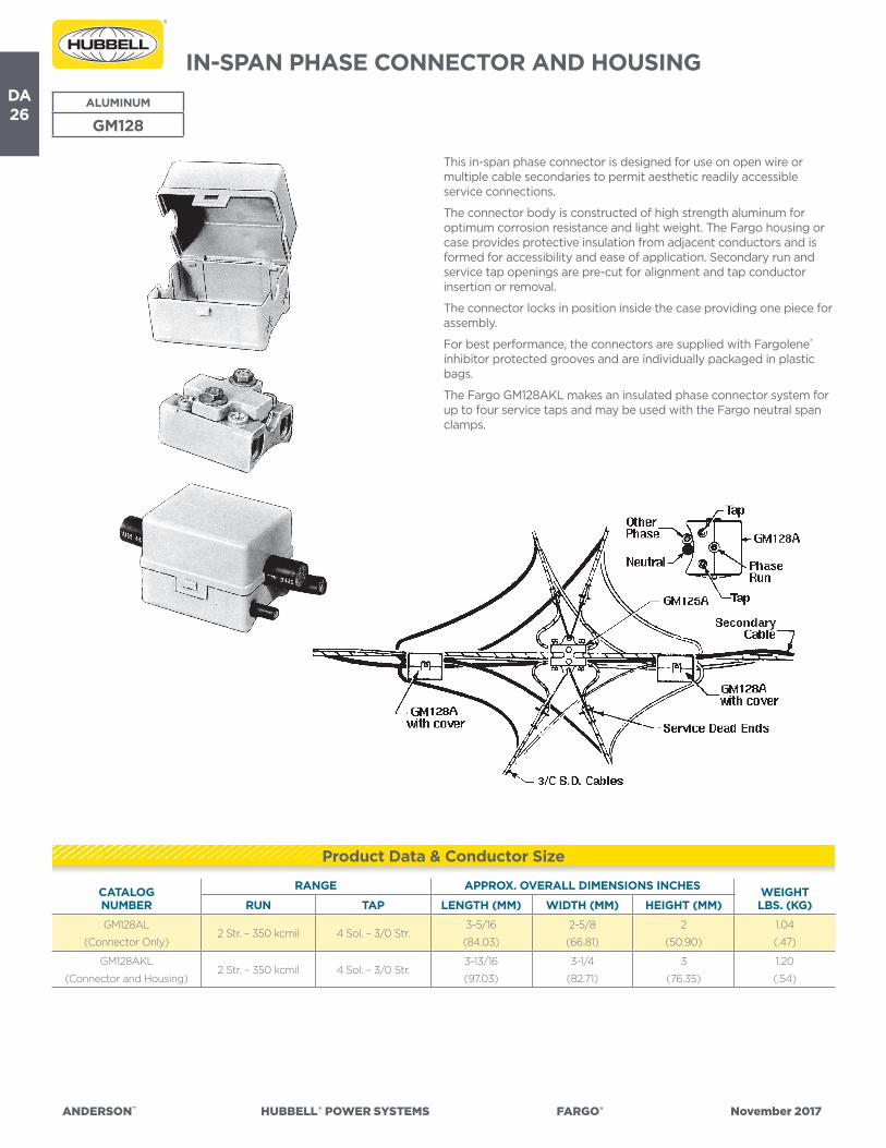
DA26
ANDERSON™ HUBBELL®POWERSYSTEMS FARGO® November2017
IN-SPAN PHASE CONNECTOR AND HOUSING
This in-span phase connector is designed for use on open wire or multiple cable secondaries to permit aesthetic readily accessible service connections.
The connector body is constructed of high strength aluminum for optimum corrosion resistance and light weight. The Fargo housing or case provides protective insulation from adjacent conductors and is formed for accessibility and ease of application. Secondary run and service tap openings are pre-cut for alignment and tap conductor insertion or removal.
The connector locks in position inside the case providing one piece for assembly.
For best performance, the connectors are supplied with Fargolene® inhibitor protected grooves and are individually packaged in plastic bags.
The Fargo GM128AKL makes an insulated phase connector system for up to four service taps and may be used with the Fargo neutral span clamps.
ALUMINUM
GM128
CATALOGNUMBER
RANGE APPROX. OVERALL DIMENSIONS INCHES WEIGHT LBS. (KG)RUN TAP LENGTH (MM) WIDTH (MM) HEIGHT (MM)
GM128AL
(Connector Only)2 Str. – 350 kcmil 4 Sol. – 3/0 Str.
3-5/16
(84.03)
2-5/8
(66.81)
2
(50.90)
1.04
(.47)
GM128AKL
(Connector and Housing)2 Str. – 350 kcmil 4 Sol. – 3/0 Str.
3-13/16
(97.03)
3-1/4
(82.71)
3
(76.35)
1.20
(.54)
Product Data & Conductor Size

DA27
ANDERSON™ HUBBELL®POWERSYSTEMS FARGO® November2017
DEADENDSBOLTED IN-SPAN NEUTRAL TAPS
ALUMINUM
Fargo in-span taps offer a wide range of neutral connections on open wire or multiple cable secondaries.
• A wide angle bell mouth opening permits tap offs up to 45° in either direction from the center line of the clamp.
• Constructed of high strength aluminum alloy these clamps provide a minimum holding power of 1250 pounds.
• Long contoured contact surfaces protect the neutral from the pull of the service.
• Using less parts than conventional units, these taps are available for one, two or four service dead end connections.
• Material: Body Casting – Aluminum Alloy Hardware – Stainless Steel
Note: Add suffix “L” to catalog number for inhibitor protection and individual packs. Ex. – GM102AL
ALUMINUM
GM100
CATALOGNUMBER
RUN TAP
NO. OF TAPS
APPROX. OVERALL DIMENSIONS INCHES
MAX. MIN. MAX. MIN.LENGTH
(MM) WIDTH (MM)HEIGHT
(MM)
GM102A 4/0 ACSR 1/0 ACSR 2 ACSR 6 ACSR 13-3/8
(85.72)
1-1/2
(38.1)
2-3/4
(69.85)
ALUMINUM MID-SPAN CONNECTORTYPE MSNT
For aluminum or ACSR triplex conductor. Has a double take-off loop. Bolts are peened to make nut captive.
Material: Body – Top Member-Aluminum Alloy Bottom Member – Bronze Alloy-Tin Plated Hardware – Galvanized Steel
ALUMINUM
MSNT
CATALOGNUMBER
CONDUCTOR RANGE (AWG) DIMENSIONS INCHES (MM) APPROX.WEIGHT LBS. (KG)NEUTRAL PHASE L J DIA.
MSNT2 1/0-4/0 ACSR #6-1/0 AAC OR ACSR4-11/16
(119.09)
3/8
(9.52)
7/8
(22.22)
.64
(.29)
Product Data & Conductor Size
Product Data & Conductor Size

DA28
ANDERSON™ HUBBELL®POWERSYSTEMS FARGO® November2017
ALUMINUM MID-SPAN CONNECTORTYPE MSE
For aluminum or ACSR triplex or quadruplex conductor.
Material: Body – Aluminum Alloy Hardware – Plated Steel
ALUMINUM
MSE
ALUMINUM SUPPORT BRACKETTYPE TTSB
(TRIPLEX SUSPENSION)For aluminum or ACSR triplex conductor. Can be mounted to a flat surface or to a wood pole. 5/8-11T galvanized thru-bolt is not furnished.
Material: Aluminum Alloy
ALUMINUM
TTSB
CATALOGNUMBER
CONDUCTOR RANGE (AWG OR MCM)
DIMENSIONS INCHES (MM) APPROX.WEIGHT LBS. (KG)L W H
TTSB416671 #2 ACSR-477 MCM (AAC)2-5/16
(58.72)
2-3/8
(60.32)
3-5/16
(84.12)
.38
(.17)
CATALOGNUMBER
CONDUCTOR RANGE (AWG OR MCM) DIMENSIONS INCHES (MM) APPROX.WEIGHT LBS. (KG)NEUTRAL PHASE L J DIA.
MSE416981 #4-4/0 ACSR #6-1/0 AAC OR ACSR4-1/8
(104.78)
3/8
(9.52)
3/4
(19.05)
.46
(.21)
Product Data & Conductor Size
Product Data & Conductor Size

ANDERSON™ HUBBELL®POWERSYSTEMS FARGO® November2017
DISTRIBUTION CONNECTORS
SPLICESAluminum Automatic
Copper AutomaticAluminum Compression
Copper Compression
SE
CT
ION
DB

ANDERSON™ HUBBELL® POWER SYSTEMS FARGO® November 2017
DB1
OVERHEAD LINE SPLICESAUTOMATIC COPPER
• Fastest method of splicing copper & copperweld conductor• Inhibitor protected for optimum long term performance• Individually bagged to seal out dirt before use
*RBS = Rated Breaking StrengthMaterial: Shell – Drawn Copper Tube Jaw – Bronze Alloy
+RUS Listed
COPPER
GL100
CATALOG NUMBER
CONDUCTOR RANGE APPROXIMATE CONDUCTOR O.D. DIMENSIONS INCHES (MM)
COPPER
COPPERWELDSTRAND
MIN/MAXINCHES
MIN/MAXMM A B
SOLIDASTM-B258
STRANDASTM-B8
GL110 8 – – .12-.13 3.1-3.3 3.4 (86) .50 (13)
GL111+ 6 – 3 #12 .16-.17 4.0-4.4 3.4 (86) .50 (13)
GL112+ 4 – 8A .19-.20 4.9-5.2 3.5 (89) .56 (14)
GL113 3 4 (7) 6A .22-.23 5.7-5.9 3.5 (89) .56 (14)
GL114 2 3 (7), 4 (3) 5A .25-.26 6.3-6.6 4.4 (110) .75 (19)
GL1140 2 or 3 3 (7), 4 (7) – .22-.26 5.7-6.6 6.5 (160) .75 (19)
GL115+ 1 2 (7) 4A .28-.29 7.2-7.4 4.4 (110) .75 (19)
GL116 1/0 1 (7), 2 (3) 3A .32-.33 8.1-8.3 4.4 (110) .75 (19)
GL117+ 2/0 1/0 (7), 1 (3) 2A .36-.37 9.1-9.3 5.5 (140) .94 (24)
GL118+ 3/0 2/0 (7) – .40-.41 10.2-10.5 5.5 (140) .94 (24)
GL119+ 4/0 3/0 (7) – .45-.46 11.5-11.8 6.9 (180) 1.2 (30)
GL120+ – 4/0 (7,19) – .52-.53 13.2-13.4 6.9 (180) 1.2 (30)
GL121 – 250 (19,37) – .57-.58 14.4-14.7 6.9 (180) 1.2 (30)
GL123 – 300 (19,37) – .62-.63 15.8-16.1 8.6 (220) 1.5 (38)
GL125 – 350 (19) – .67-.68 17.0-17.2 8.6 (220) 1.5 (38)
GL127 – 400 (19,37) – .71-.73 18.1-18.5 8.6 (220) 1.5 (38)
GL128 – 450 (37) – .76-.77 19.4-19.6 8.6 (220) 1.5 (38)
GL130 – 500 (19,37) – .80-.81 20.4-20.7 8.6 (220) 1.5 (38)
CATALOG NUMBER CONDUCTOR
APPROXIMATE CONDUCTOR O.D. DIMENSIONS INCHES (MM)
MIN/MAX INCHES MIN/MAX MM A B
GL110M 6 mm2 .10-.14 2.6-3.5 4.20 (107) .51 (13)
GL111M 10 mm2 .14-.17 3.4-4.3 4.20 (107) .51 (13)
GL112M 16 mm2 Sol. .17-.20 4.2-5.2 4.36 (111) .55 (14)
GL113M 16 mm2 Str. .20-.22 5.0-5.8 4.36 (111) .55 (14)
GL114M 25 mm2 .22-.26 5.8-6.6 5.46 (139) .71 (18)
GL115M 35 mm2 .25-.30 6.5-7.6 5.46 (139) .71 (18)
GL117M 50 mm2 .31-.37 7.9-9.4 6.48 (165) .90 (23)
GL118M 70 mm2 .37-.43 9.4-10.9 6.48 (165) .90 (23)
GL119M 95 mm2 .44-.50 11.3-12.6 7.98 (203) 1.22 (31)
GL120M 120 mm2 .50-.56 12.6-14.2 7.98 (203) 1.22 (31)
Splices for Metric Conductor
Product Data & Conductor Size
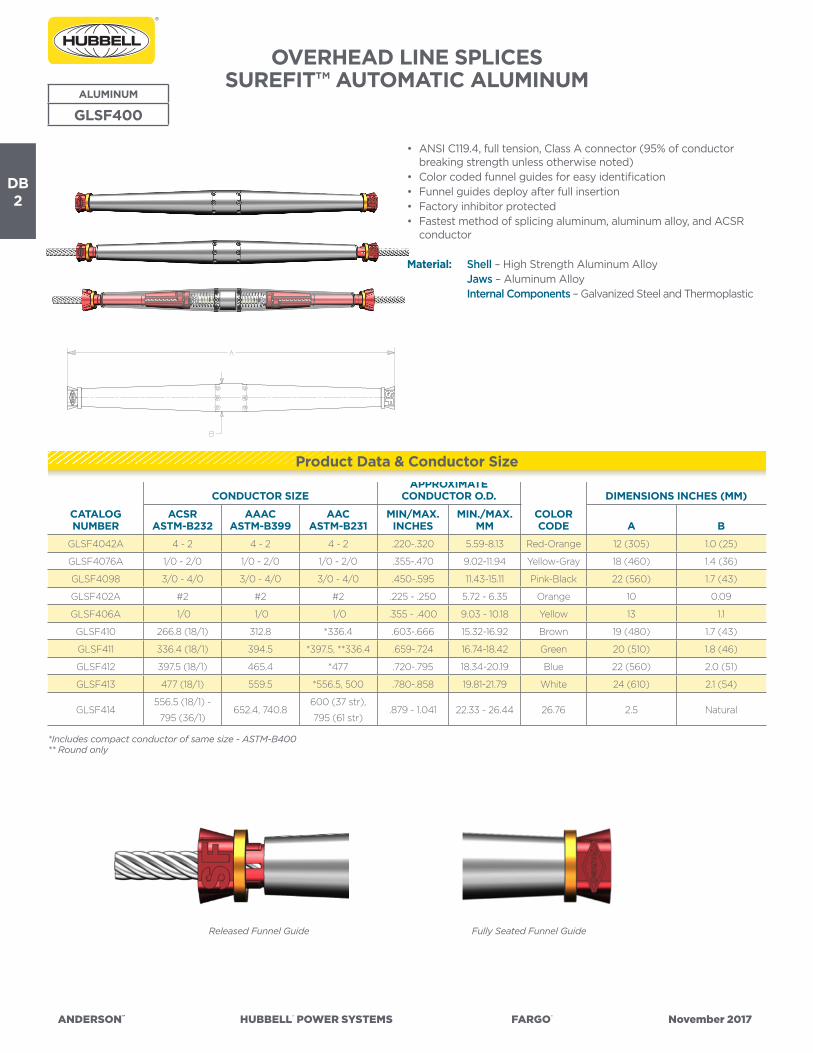
ANDERSON™ HUBBELL® POWER SYSTEMS FARGO® November 2017
DB2
OVERHEAD LINE SPLICESSUREFIT™ AUTOMATIC ALUMINUM
• ANSI C119.4, full tension, Class A connector (95% of conductor breaking strength unless otherwise noted)
• Color coded funnel guides for easy identification• Funnel guides deploy after full insertion• Factory inhibitor protected• Fastest method of splicing aluminum, aluminum alloy, and ACSR
conductor
Material: Shell – High Strength Aluminum Alloy Jaws – Aluminum Alloy Internal Components – Galvanized Steel and Thermoplastic
*Includes compact conductor of same size - ASTM-B400** Round only
Released Funnel Guide Fully Seated Funnel Guide
ALUMINUM
GLSF400
CATALOG NUMBER
CONDUCTOR SIZEAPPROXIMATE
CONDUCTOR O.D.
COLORCODE
DIMENSIONS INCHES (MM)
ACSRASTM-B232
AAACASTM-B399
AACASTM-B231
MIN/MAX.INCHES
MIN./MAX.MM A B
GLSF4042A 4 - 2 4 - 2 4 - 2 .220-.320 5.59-8.13 Red-Orange 12 (305) 1.0 (25)
GLSF4076A 1/0 - 2/0 1/0 - 2/0 1/0 - 2/0 .355-.470 9.02-11.94 Yellow-Gray 18 (460) 1.4 (36)
GLSF4098 3/0 - 4/0 3/0 - 4/0 3/0 - 4/0 .450-.595 11.43-15.11 Pink-Black 22 (560) 1.7 (43)
GLSF402A #2 #2 #2 .225 - .250 5.72 - 6.35 Orange 10 0.09
GLSF406A 1/0 1/0 1/0 .355 - .400 9.03 - 10.18 Yellow 13 1.1
GLSF410 266.8 (18/1) 312.8 *336.4 .603-.666 15.32-16.92 Brown 19 (480) 1.7 (43)
GLSF411 336.4 (18/1) 394.5 *397.5, **336.4 .659-.724 16.74-18.42 Green 20 (510) 1.8 (46)
GLSF412 397.5 (18/1) 465.4 *477 .720-.795 18.34-20.19 Blue 22 (560) 2.0 (51)
GLSF413 477 (18/1) 559.5 *556.5, 500 .780-.858 19.81-21.79 White 24 (610) 2.1 (54)
GLSF414556.5 (18/1) -
795 (36/1)652.4, 740.8
600 (37 str),
795 (61 str).879 - 1.041 22.33 - 26.44 26.76 2.5 Natural
Product Data & Conductor Size
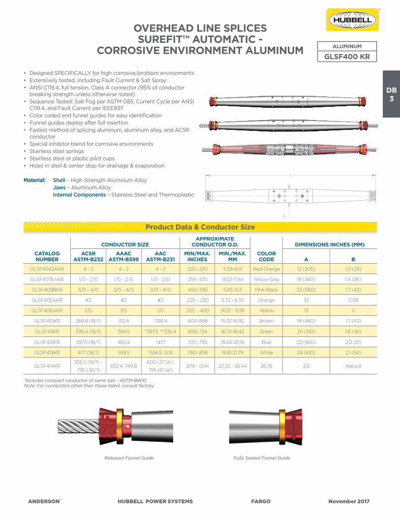
ANDERSON™ HUBBELL® POWER SYSTEMS FARGO® November 2017
DB3
OVERHEAD LINE SPLICESSUREFIT™ AUTOMATIC -
CORROSIVE ENVIRONMENT ALUMINUM
Released Funnel Guide Fully Seated Funnel Guide
*Includes compact conductor of same size - ASTM-B400Note: For conductors other than those listed, consult factory.
ALUMINUM
GLSF400 KR
CATALOG NUMBER
CONDUCTOR SIZEAPPROXIMATE
CONDUCTOR O.D.
COLORCODE
DIMENSIONS INCHES (MM)
ACSRASTM-B232
AAACASTM-B399
AACASTM-B231
MIN/MAX.INCHES
MIN./MAX.MM A B
GLSF4042AKR 4 - 2 4 - 2 4 - 2 .220-.320 5.59-8.13 Red-Orange 12 (305) 1.0 (25)
GLSF4076AKR 1/0 - 2/0 1/0 - 2/0 1/0 - 2/0 .355-.470 9.02-11.94 Yellow-Gray 18 (460) 1.4 (36)
GLSF4098KR 3/0 - 4/0 3/0 - 4/0 3/0 - 4/0 .450-.595 11.43-15.11 Pink-Black 22 (560) 1.7 (43)
GLSF402AKR #2 #2 #2 .225 - .250 5.72 - 6.35 Orange 10 0.09
GLSF406AKR 1/0 1/0 1/0 .355 - .400 9.03 - 10.18 Yellow 13 1.1
GLSF410KR 266.8 (18/1) 312.8 *336.4 .603-.666 15.32-16.92 Brown 19 (480) 1.7 (43)
GLSF411KR 336.4 (18/1) 394.5 *397.5, **336.4 .659-.724 16.74-18.42 Green 20 (510) 1.8 (46)
GLSF412KR 397.5 (18/1) 465.4 *477 .720-.795 18.34-20.19 Blue 22 (560) 2.0 (51)
GLSF413KR 477 (18/1) 559.5 *556.5, 500 .780-.858 19.81-21.79 White 24 (610) 2.1 (54)
GLSF414KR556.5 (18/1) -
795 (36/1)652.4, 740.8
600 (37 str),
795 (61 str).879 - 1.041 22.33 - 26.44 26.76 2.5 Natural
• Designed SPECIFICALLY for high corrosive/problem environments• Extensively tested, including Fault Current & Salt Spray.• ANSI C119.4, full tension, Class A connector (95% of conductor
breaking strength unless otherwise noted)• Sequence Tested: Salt Fog per ASTM G85, Current Cycle per ANSI
C119.4, and Fault Current per IEEE837• Color coded end funnel guides for easy identification• Funnel guides deploy after full insertion• Fastest method of splicing aluminum, aluminum alloy, and ACSR
conductor• Special inhibitor blend for corrosive environments• Stainless steel springs• Stainless steel or plastic pilot cups• Holes in shell & center stop for drainage & evaporation
Material: Shell – High Strength Aluminum Alloy Jaws – Aluminum Alloy Internal Components – Stainless Steel and Thermoplastic
Product Data & Conductor Size

ANDERSON™ HUBBELL® POWER SYSTEMS FARGO® November 2017
DB4
OVERHEAD LINE SPLICESAUTOMATIC ALUMINUM
• ANSI C119.4, Class 1, full tension connector (95% of conductor breaking strength unless otherwise noted)
• ANSI C119.4, full tension, Class A connector (95% of conductor breaking strength unless otherwise noted)
• Color coded end funnel guides for easy identification• Factory inhibitor protected• Fastest method of splicing aluminum, aluminum alloy and ACSR
conductor
Material: Shell – High Strength Aluminum Alloy Jaws – Aluminum Alloy
*Includes compact conductor of same size - ASTM-B400Note: For conductors other than those listed, consult factory.
ALUMINUM
GL400
CATALOG NUMBER
CONDUCTOR SIZEAPPROXIMATE
CONDUCTOR O.D.
COLORCODE
DIMENSIONS INCHES (MM)
ACSRASTM-B232
AAACASTM-B399
AACASTM-B231
MIN/MAX.INCHES
MIN./MAX.MM A B
GL401 6 - 4 6 - 4 6 - 4 .184-.263 4.68-6.70 Blue 14 (360) 1.0 (25)
GL402A 4 4 4 .225-.250 5.72-6.35 Orange 9 (230) 0.9 (23)
GL404A 2 2 2 .280-.320 7.11-8.13 Red 12 (305) 1.0 (25)
GL4042A 4 - 2 4 - 2 4 - 2 .220-.320 5.59-8.13 Red- Orange 12 (305) 1.0 (25)
GL406A 1/0 1/0 1/0 .355-.400 9.02-10.16 Yellow 12 (305) 1.1 (28)
GL4076A 1/0-2/0 1/0-2/0 1/0-2/0 .355-.470 9.02-11.94 Yellow-Gray 18 (460) 1.4 (36)
GL407 2/0 2/0 2/0 .400-.470 10.16-11.94 Gray 18 (460) 1.4 (36)
GL408 3/0 3/0 3/0 .450-.530 11.43-13.46 Black 20 (510) 1.6 (41)
GL4098 3/0-4/0 3/0-4/0 3/0-4/0 .450-.595 11.43-15.11 Pink-Black 22 (560) 1.7 (43)
GL409A 4/0 4/0 4/0 .505-.595 12.83-15.11 Pink 17 (430) 1.6 (41)
GL1205A – – *4/0-266.8 .518-.595 13.16-15.11 Natural 9 (230) 1.2 (31)
Product Data & Conductor Size

ANDERSON™ HUBBELL® POWER SYSTEMS FARGO® November 2017
DB5
OVERHEAD LINE SPLICES AUTOMATIC ALUMINUM
(MULTIPLE LAYER STRAND CONDUCTORS)
• Automatic for larger multiple layer stranded conductor used in primary distribution and transmission
• ANSI C119.4, full tension, Class A connector (95% of conductor breaking strength unless otherwise noted)
• Color coded end funnel guides for easy identification• Factory inhibitor protected• Fastest method of splicing aluminum, aluminum alloy and ACSR
conductor
Material: Shell – Seamless High Strength Aluminum Alloy Jaws – High Strength Aluminum Alloy
Note: For conductors other than those listed, consult factory.
ALUMINUM
GL400
*Includes compact conductor of same size - ASTM-B400+Maximum design rating 10,000 lb./44.5 kN**Round only
MULTIPLE LAYER STRAND CONDUCTORS-KCMIL SIZES
CATALOG NUMBER
CONDUCTOR SIZEAPPROXIMATE
CONDUCTOR O.D.
COLORCODE
DIMENSIONS INCHES (MM)
ACSRASTM-B232
AAACASTM-B399
AACASTM-B231
MIN/MAX.INCHES
MIN./MAX.MM A B
GL410 266.8 (18/1) 312.8 *336.4 .603-.666 15.32-16.92 Brown 19 (480) 1.7 (43)
GL411 336.4 (18/1) 394.5 *397.5,**336.4 .659-.724 16.74-18.39 Green 20 (510) 1.8 (46)
GL412 397.5 (18/1) 465.4 *477 .720-.795 18.29-20.19 Blue 22 (560) 2.0 (51)
GL413 477 (18/1) 559.5 *556.5, 500 .780-.858 19.81-21.79 White 24 (610) 2.1 (54)
GLT1316A 266.8 (26/7) – – – – Natural 36 (916) 2.2 (56)
GLT1317B 336.4 (26/7) – – – – Green 22 (560) 2.0 (51)
GLT1319A 477 (26/7) – – – – White 36 (916) 2.2 (56)
GL1333A+ 556.5 (18/1) Consult Fargo 636 .840-.920 21.34-23.37 Natural 15 (380) 2.0 (51)
GL1351A+ 556.5 (26/7) Consult Fargo 652.8 .927-.940 23.55-23.88 Natural 16 (410) 2.0 (51)
GL1355A+ Consult Fargo Consult Fargo 700, 715 .940-.976 23.88-24.80 Natural 16 (410) 2.0 (51)
GL1385A+ Consult Fargo Consult Fargo 795 .996-1.031 25.30-26.19 Natural 16 (410) 2.0 (51)
GL1441A+ Consult Fargo Consult Fargo 954 1.100-1.140 27.94-28.96 Red 16 (410) 2.0 (51)
Product Data & Conductor Size

ANDERSON™ HUBBELL® POWER SYSTEMS FARGO® November 2017
DB6
†† Includes compact conductor of same size.+ Maximum design rating 10,000 lbs (44.5kN)** Round OnlyNote: For conductor other than those listed, consult factory.
ALUMINUM
GL*KR
• Designed SPECIFICALLY for high corrosive/problem environments• Extensively tested, including Fault Current & Salt Spray.• ANSI C119.4, Class 1, full tension connector (95% of conductor
breaking strength unless otherwise noted)• ANSI C119.4 Class A, temperature rated connector• Sequence Tested: Salt Fog per ASTM G85, Current Cycle per ANSI
C119.4, and Fault Current per IEEE837• Color coded end funnel guides for easy identification• Fastest method of splicing aluminum, aluminum alloy, and ACSR
conductor• Special inhibitor blend for corrosive environments• Stainless springs• Stainless or plastic pilot cups• Holes in shell & center stop for drainage & evaporation• Positive conductor insertion, look in the holes
Material: Shell – Seamless High Strength Aluminum Alloy Jaws – High Strength Aluminum Alloy Internal Components – Stainless Steel or Plastic
CATALOG NUMBER
CONDUCTOR SIZE††
APPROXIMATE CONDUCTOR O.D.
INCHES (MM) COLOR CODE
DIMENSIONS,INCHES (MM)
ACSR AAAC AAC MIN MAX A B
GL402AKR #4 #4 #4 0.225 (5.72) 0.250 (6.35) Orange 9 (230) 0.9 (23)
GL404AKR #2 #2 #2 0.280 (7.11) 0.320 (8.13) Red 12 (305) 1.0 (25)
GL4042AKR #4 - #2 #4 - #2 #4 - #2 0.220 (5.59) 0.320 (8.13) Red-Orange 12.8 (325) 1.0 (25)
GL406AKR 1/0 1/0 1/0 0.355 (9.02) 0.400 (10.16) Yellow 12 (305) 1.1 (28)
GL4076AKR 1/0 - 2/0 1/0 - 2/0 1/0 - 2/0 0.355 (9.02) 0.470 (11.94) Yellow-Gray 18 (460) 1.4 (36)
GL407KR 2/0 2/0 2/0 0.400 (10.16) 0.470 (11.94) Gray 18 (460) 1.4 (36)
GL408KR 3/0 3/0 3/0 0.450 (11.43) 0.530 (13.46) Black 20 (510) 1.6 (41)
GL409AKR 4/0 4/0 4/0 0.505 (12.83) 0.595 (15.11) Pink 17 (430) 1.6 (41)
GL410KR 266.8 (18/1) 312.8 336.4 0.603 (15.32) 0.666 (16.92) Brown 19 (480) 1.7 (43)
GL411KR 336.4 (18/1) 394.5 397.5, 336.4** 0.659 (16.74) 0.724 (18.39) Green 20 (510) 1.8 (46)
GL412KR 397.5 (18/1) 465.4 477 0.720 (18.29) 0.795 (20.19) Blue 22 (560) 2.0 (51)
GL413KR 477 (18/1) 559.5 556.5, 500 0.780 (19.81) 0.858 (21.79) White 24 (610) 2.1 (54)
GL1333AKR+ 556.5 (18/1) Consult Factory 636 0.840 (21.34) 0.920 (23.37) Natural 16.5 (420) 2.0 (51)
GL1351AKR+ 556.5 (27/7), 636 (18/1) Consult Factory 652.8 0.927 (23.55) 0.940 (23.88) Natural 16 (410) 2.0 (51)
GL1355AKR+ Consult Factory Consult Factory 700, 715 0.940 (23.88) 0.976 (24.79) Natural 16 (410) 2.0 (51)
GL1385AKR+ Consult Factory Consult Factory 795 0.996 (25.30) 1.031 (26.19) Natural 16 (410) 2.0 (51)
GL1441AKR+ 795 (26/7) Consult Factory 954 1.100 (27.94) 1.140 (28.96) Red 16 (410) 2.0 (51)
OVERHEAD LINE SPLICESAUTOMATIC - CORROSIVE ENVIRONMENT
ALUMINUM
Product Data & Conductor Size
Conductor Strands
After 2000 hours of Salt Fog, 1000 hours of Heat Cycle, and Three Rounds of Fault Current Testing
Corrosion Resistant Splice (KR)

ANDERSON™ HUBBELL® POWER SYSTEMS FARGO® November 2017
DB7
OVERHEAD LINE SPLICESAUTOMATIC REDUCING
• Allows easy splicing from one size conductor to another size conductor• Allows utilities the option of not stocking old conductor that isn’t
used anymore• Splice provides full strength of the weaker of the two conductors
and a resistance lower than the equivalent conductor• Same design philosophy and material as used in the copper and
aluminum automatic splices.
Material: Copper Shell – Drawn Copper Tube Jaws – Bronze Alloy Aluminum Shell – Aluminum Alloy Jaws – Aluminum Alloy
COPPER REDUCING SPLICES
CATALOG NUMBER
CONDUCTOR SIZE DIMENSIONS INCHES (MM)
LARGE END SMALL END
A BSOLID STRAND SOLID STRAND
GL150 4 – 6 – 4 (100) .56 (14)
GL151 3 4 6 – 4 (100) .56 (14)
GL152 3 4 4 – 4 (100) .56 (14)
GL153 2 3 6 – 5 (130) .75 (19)
GL154 2 3 4 – 5 (130) .75 (19)
GL155 1 2 6 – 5 (130) .75 (19)
GL156 1 2 4 – 5 (130) .75 (19)
GL157 1 2 3 4 5 (130) .75 (19)
GL158 1 2 2 3 5 (130) .75 (19)
GL159 1/0 1 3 4 5 (130) .75 (19)
GL160 1/0 1 2 3 5 (130) .75 (19)
GL161 1/0 1 1 2 5 (130) .75 (19)
GL162 2/0 1/0 3 4 6 (150) .94 (24)
GL163 2/0 1/0 2 3 6 (150) .94 (24)
GL164 2/0 1/0 1 2 6 (150) .94 (24)
GL165 2/0 1/0 4 – 6 (150) .94 (24)
GL166 2/0 1/0 1/0 1 6 (150) .94 (24)
GL167 3/0 2/0 3 4 6 (150) .94 (24)
GL168 3/0 2/0 2 3 6 (150) .94 (24)
GL169 3/0 2/0 1 2 6 (150) .94 (24)
GL170 3/0 2/0 1/0 1 6 (150) .94 (24)
GL171 3/0 2/0 2/0 1/0 6 (150) .94 (24)
GL172 4/0 3/0 3/0 2/0 7.4 (190) 1.3 (33)
GL173 – 4/0 2/0 1/0 7.4 (190) 1.3 (33)
GL174 – 4/0 3/0 2/0 7.4 (190) 1.3 (33)
GL175 – 4/0 4/0 3/0 7.4 (190) 1.3 (33)
GL176 – 250 – 4/0 7.4 (190) 1.3 (33)
ACSR REDUCING SPLICES
GL406A4042A 1/0 4 - 2 12.1 (307) 1.2 (30)
GL412411 397.5 336.4 21 (530) 2.0 (51)
REDUCING
GL
Product Data & Conductor Size
Copper
ACSR
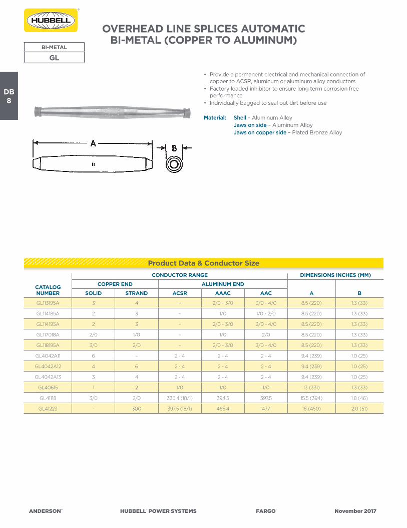
ANDERSON™ HUBBELL® POWER SYSTEMS FARGO® November 2017
DB8
OVERHEAD LINE SPLICES AUTOMATICBI-METAL (COPPER TO ALUMINUM)
• Provide a permanent electrical and mechanical connection of copper to ACSR, aluminum or aluminum alloy conductors
• Factory loaded inhibitor to ensure long term corrosion free performance
• Individually bagged to seal out dirt before use
Material: Shell – Aluminum Alloy Jaws on side – Aluminum Alloy Jaws on copper side – Plated Bronze Alloy
BI-METAL
GL
CATALOG NUMBER
CONDUCTOR RANGE DIMENSIONS INCHES (MM)
COPPER END ALUMINUM END
A BSOLID STRAND ACSR AAAC AAC
GL113195A 3 4 – 2/0 - 3/0 3/0 - 4/0 8.5 (220) 1.3 (33)
GL114185A 2 3 – 1/0 1/0 - 2/0 8.5 (220) 1.3 (33)
GL114195A 2 3 – 2/0 - 3/0 3/0 - 4/0 8.5 (220) 1.3 (33)
GL117018A 2/0 1/0 – 1/0 2/0 8.5 (220) 1.3 (33)
GL118195A 3/0 2/0 – 2/0 - 3/0 3/0 - 4/0 8.5 (220) 1.3 (33)
GL4042A11 6 – 2 - 4 2 - 4 2 - 4 9.4 (239) 1.0 (25)
GL4042A12 4 6 2 - 4 2 - 4 2 - 4 9.4 (239) 1.0 (25)
GL4042A13 3 4 2 - 4 2 - 4 2 - 4 9.4 (239) 1.0 (25)
GL40615 1 2 1/0 1/0 1/0 13 (331) 1.3 (33)
GL41118 3/0 2/0 336.4 (18/1) 394.5 397.5 15.5 (394) 1.8 (46)
GL41223 – 300 397.5 (18/1) 465.4 477 18 (450) 2.0 (51)
Product Data & Conductor Size

ANDERSON™ HUBBELL® POWER SYSTEMS FARGO® November 2017
DB9
SPLICESAUTOMATIC GUY WIRE
• For splicing applications with overhead or support guy wires• Fargo GLS500x series automatic splices are designed for use on
High Strength (HS), Common (Com), Siemens-Martin (SM), Utilities (Util) and Bell System strand
• Fargo GLS504x series automatic splices are designed for use on all guy wire types listed above, plus Extra High Strength (EHS) and Alumoweld (AW)
• All GLS automatic splices will hold a minimum of 90% of the guy wire rated breaking strength
Material: Shell – High Strength Aluminum Alloy Jaws – Plated Steel
ALUMINUM
GLS
CATALOG NUMBER
PRIMARY STRAND APPLICATION
TO BE USED WITH:
RANGE (IN.)
RANGE (MM)
DIMENSIONS INCHES (MM)
EHSAW/
AWAC
HS, COM,S-M, UTIL,
BELL A B
GLS5000 1/4” HS, Com, S-M, Util, Bell l 0.240 - 0.253 6.11 - 6.446.4
(163)
0.9
(23)
GLS5001 5/16” HS, Com, S-M, Util, Bell l 0.310 - 0.335 7.89 - 8.537.4
(189)
1.1
(28)
GLS5002 3/8” HS, Com, S-M, Util, Bell l 0.360 - 0.405 9.16 - 10.319.00
(229)
1.3
(33)
GLS5039 3/16 STR EHS, AW l l l 0.145 - .215 3.86 - 5.458.6
(219)
1.13
(29)
GLS50401/4” EHS
7#12 (6M) AWl l l 0.215 - 0.270 5.46 - 6.86
8.3
(211)
1.13
(28)
GLS50415/16” EHS
7#10 (10M), 7#11 (8M) AWl l l 0.270 - 0.315 6.86 - 8.00
9.4
(239)
1.22
(31)
GLS5042
3/8” EHS
3#5, 7#8, 7#9, 12.5M, 14M, 16M AW
#4-2/5, #2-3/4, #1-5/2 AWAC
l l l 0.325 - 0.392 8.26 - 9.9610.0
(260)
1.48
(38)
GLS5043
7/16” EHS
7#7 (20M), 18M AW
#2-2/5, #1-3/4, #1/0-5/2 AWAC
l l l 0.392 - 0.458 9.96 - 11.6311.0
(280)
1.60
(41)
GLS5044
1/2” EHS, 25M AW,
#1-2/5, #1/0-3/4, #2/0-5/2 AWAC
#2/0-4/3 AWAC
l l l 0.455 - 0.520 11.56 - 13.2110.8
(273)
1.70
(43)
Product Data & Conductor Size
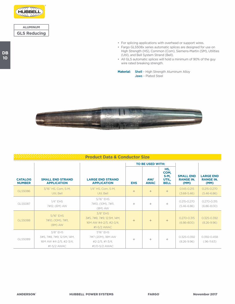
ANDERSON™ HUBBELL® POWER SYSTEMS FARGO® November 2017
DB10
ALUMINUM
GLS Reducing
• For splicing applications with overhead or support wires.• Fargo GLS508x series automatic splices are designed for use on
High Strength (HS), Common (Com), Siemens-Martin (SM), Utilities (Util), and Bell System Strand (Bell).
• All GLS automatic splices will hold a minimum of 90% of the guy wire rated breaking strength.
Material: Shell – High Strength Aluminum Alloy Jaws – Plated Steel
CATALOG NUMBER
SMALL END STRAND APPLICATION
LARGE END STRAND APPLICATION
TO BE USED WITH:
SMALL END RANGE IN.
(MM)
LARGE END RANGE IN.
(MM)EHSAW/
AWAC
HS, COM,S-M, UTIL,BELL
GLS50863/16” HS, Com, S-M,
Util, Bell
1/4” HS, Com, S-M,
Util, Belll l l
0.145-0.215
(3.68-5.46)
0.215-0.270
(5.46-6.86)
GLS50871/4” EHS
7#12, (6M) AW
5/16” EHS
7#10, (10M), 7#11,
(8M) AW
l l l0.215-0.270
(5.46-6.86)
0.270-0.315
(6.86-8.00)
GLS5088
5/16” EHS
7#10, (10M), 7#11,
(8M) AW
3/8” EHS
3#5, 7#8, 7#9, 12.5M, 14M,
16M AW #4-2/5, #2-3/4,
#1-5/2 AWAC
l l l0.270-0.315
(6.86-800)
0.325-0.392
(8.26-9.96)
GLS5089
3/8” EHS
3#5, 7#8, 7#9, 12.5M, 14M,
16M AW #4-2/5, #2-3/4,
#1-5/2 AWAC
7/16” EHS
7#7 (20M), 18M AW
#2-2/5, #1-3/4,
#1/0-5/2 AWAC
l l l0.325-0.392
(8.26-9.96)
0.392-0.458
(.96-11.63)
Product Data & Conductor Size
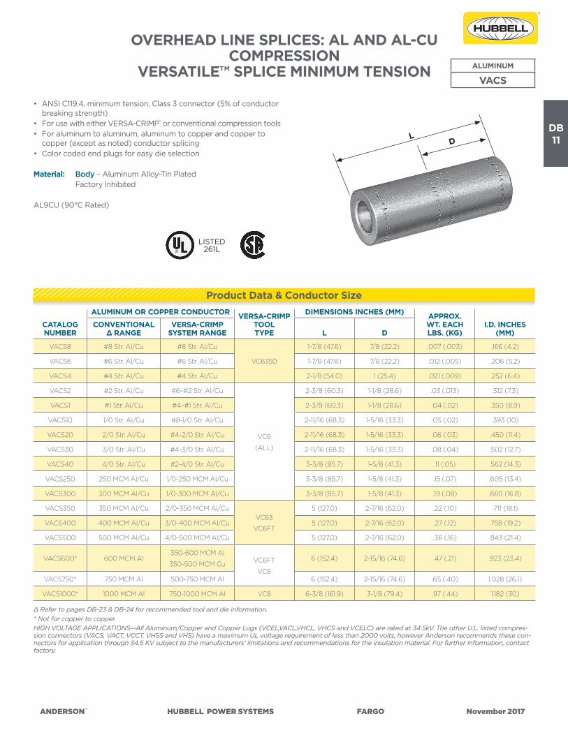
ANDERSON™ HUBBELL® POWER SYSTEMS FARGO® November 2017
DB11
OVERHEAD LINE SPLICES: AL AND AL-CUCOMPRESSION
VERSATILE™ SPLICE MINIMUM TENSION
• ANSI C119.4, minimum tension, Class 3 connector (5% of conductor breaking strength)
• For use with either VERSA-CRIMP® or conventional compression tools• For aluminum to aluminum, aluminum to copper and copper to
copper (except as noted) conductor splicing• Color coded end plugs for easy die selection
Material: Body – Aluminum Alloy-Tin Plated Factory Inhibited
AL9CU (90°C Rated)
ALUMINUM
VACS
CATALOG NUMBER
ALUMINUM OR COPPER CONDUCTOR VERSA-CRIMPTOOLTYPE
DIMENSIONS INCHES (MM) APPROX.WT. EACHLBS. (KG)
I.D. INCHES (MM)
CONVENTIONAL ∆ RANGE
VERSA-CRIMPSYSTEM RANGE L D
VACS8 #8 Str. Al/Cu #8 Str. Al/Cu
VC6350
1-7/8 (47.6) 7/8 (22.2) .007 (.003) .166 (4.2)
VACS6 #6 Str. Al/Cu #6 Str. Al/Cu 1-7/8 (47.6) 7/8 (22.2) .012 (.005) .206 (5.2)
VACS4 #4 Str. Al/Cu #4 Str. Al/Cu 2-1/8 (54.0) 1 (25.4) .021 (.009) .252 (6.4)
VACS2 #2 Str. Al/Cu #6–#2 Str. Al/Cu
VC6
(ALL)
2-3/8 (60.3) 1-1/8 (28.6) .03 (.013) .312 (7.3)
VACS1 #1 Str. Al/Cu #4–#1 Str. Al/Cu 2-3/8 (60.3) 1-1/8 (28.6) .04 (.02) .350 (8.9)
VACS10 1/0 Str. Al/Cu #8-1/0 Str. Al/Cu 2-11/16 (68.3) 1-5/16 (33.3) .05 (.02) .393 (10)
VACS20 2/0 Str. Al/Cu #4-2/0 Str. Al/Cu 2-11/16 (68.3) 1-5/16 (33.3) .06 (.03) .450 (11.4)
VACS30 3/0 Str. Al/Cu #4-3/0 Str. Al/Cu 2-11/16 (68.3) 1-5/16 (33.3) .08 (.04) .502 (12.7)
VACS40 4/0 Str. Al/Cu #2-4/0 Str. Al/Cu 3-3/8 (85.7) 1-5/8 (41.3) .11 (.05) .562 (14.3)
VACS250 250 MCM Al/Cu 1/0-250 MCM Al/Cu 3-3/8 (85.7) 1-5/8 (41.3) .15 (.07) .605 (13.4)
VACS300 300 MCM Al/Cu 1/0-300 MCM Al/Cu 3-3/8 (85.7) 1-5/8 (41.3) .19 (.08) .660 (16.8)
VACS350 350 MCM Al/Cu 2/0-350 MCM Al/CuVC63
VC6FT
5 (127.0) 2-7/16 (62.0) .22 (.10) .711 (18.1)
VACS400 400 MCM Al/Cu 3/0-400 MCM Al/Cu 5 (127.0) 2-7/16 (62.0) .27 (.12) .758 (19.2)
VACS500 500 MCM Al/Cu 4/0-500 MCM Al/Cu 5 (127.0) 2-7/16 (62.0) .36 (.16) .843 (21.4)
VACS600* 600 MCM Al350-600 MCM Al
350-500 MCM Cu VC6FT
VC8
6 (152.4) 2-15/16 (74.6) .47 (.21) .923 (23.4)
VACS750* 750 MCM Al 500-750 MCM Al 6 (152.4) 2-15/16 (74.6) .65 (.40) 1.028 (26.1)
VACS1000* 1000 MCM Al 750-1000 MCM Al VC8 6-3/8 (161.9) 3-1/8 (79.4) .97 (.44) 1.182 (30)
∆ Refer to pages DB-23 & DB-24 for recommended tool and die information.* Not for copper to copper.HIGH VOLTAGE APPLICATIONS—All Aluminum/Copper and Copper Lugs (VCEL,VACL,VHCL, VHCS and VCELC) are rated at 34.5kV. The other U.L. listed compres-sion connectors (VACS, VACT, VCCT, VHSS and VHS) have a maximum UL voltage requirement of less than 2000 volts, however Anderson recommends these con-nectors for application through 34.5 KV subject to the manufacturers’ limitations and recommendations for the insulation material. For further information, contact factory.
Product Data & Conductor Size
DL
LISTED261L
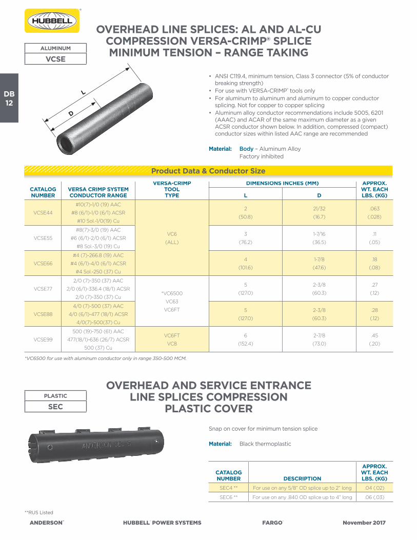
ANDERSON™ HUBBELL® POWER SYSTEMS FARGO® November 2017
DB12
OVERHEAD AND SERVICE ENTRANCELINE SPLICES COMPRESSION
PLASTIC COVER
OVERHEAD LINE SPLICES: AL AND AL-CUCOMPRESSION VERSA-CRIMP® SPLICEMINIMUM TENSION – RANGE TAKINGALUMINUM
VCSE
• ANSI C119.4, minimum tension, Class 3 connector (5% of conductor breaking strength)
• For use with VERSA-CRIMP® tools only• For aluminum to aluminum and aluminum to copper conductor
splicing. Not for copper to copper splicing• Aluminum alloy conductor recommendations include 5005, 6201
(AAAC) and ACAR of the same maximum diameter as a given ACSR conductor shown below. In addition, compressed (compact) conductor sizes within listed AAC range are recommended
Material: Body – Aluminum Alloy Factory inhibited
PLASTIC
SEC
Snap on cover for minimum tension splice
Material: Black thermoplastic
*VC6500 for use with aluminum conductor only in range 350-500 MCM.
**RUS Listed
CATALOG NUMBER DESCRIPTION
APPROX.WT. EACHLBS. (KG)
SEC4 ** For use on any 5/8” OD splice up to 2” long .04 (.02)
SEC6 ** For use on any .840 OD splice up to 4” long .06 (.03)
CATALOG NUMBER
VERSA CRIMP SYSTEMCONDUCTOR RANGE
VERSA-CRIMPTOOLTYPE
DIMENSIONS INCHES (MM) APPROX.WT. EACHLBS. (KG)L D
VCSE44
#10(7)-1/0 (19) AAC
#8 (6/1)-1/0 (6/1) ACSR
#10 Sol.-1/0(19) Cu
VC6
(ALL)
2
(50.8)
21/32
(16.7)
.063
(.028)
VCSE55
#8(7)-3/0 (19) AAC
#6 (6/1)-2/0 (6/1) ACSR
#8 Sol.-3/0 (19) Cu
3
(76.2)
1-7/16
(36.5)
.11
(.05)
VCSE66
#4 (7)-266.8 (19) AAC
#4 (6/1)-4/0 (6/1) ACSR
#4 Sol.-250 (37) Cu
4
(101.6)
1-7/8
(47.6)
.18
(.08)
VCSE77
2/0 (7)-350 (37) AAC
2/0 (6/1)-336.4 (18/1) ACSR
2/0 (7)-350 (37) Cu*VC6500
VC63
VC6FT
5
(127.0)
2-3/8
(60.3)
.27
(.12)
VCSE88
4/0 (7)-500 (37) AAC
4/0 (6/1)-477 (18/1) ACSR
4/0(7)-500(37) Cu
5
(127.0)
2-3/8
(60.3)
.28
(.12)
VCSE99
500 (19)-750 (61) AAC
477(18/1)-636 (26/7) ACSR
500 (37) Cu
VC6FT
VC8
6
(152.4)
2-7/8
(73.0)
.45
(.20)
Product Data & Conductor Size
D
L

ANDERSON™ HUBBELL® POWER SYSTEMS FARGO® November 2017
DB13
OVERHEAD LINE SPLICES: AL AND AL-CUCOMPRESSION
VERSAtile™ REDUCING SPLICEMINIMUM TENSION
• ANSI C119.4, minimum tension, Class 3 connector (5% of conductor breaking strength)
• For use with either VERSA-CRIMP® or conventional compression tools—4 standard die sizes
• For aluminum to aluminum or aluminum to copper conductor splicing. Not for copper to copper connections.
• Color coded end caps for quick conductor sizing thru 4/0
Material: Aluminum Alloy Factory Inhibited with Non-Petroleum Sealant
ALUMINUM
VAUS
Continued on next page.**RUS Listed
DIELESS VERSA-CRIMP: VC6 5/8” DIE SIZE: STD. TOOLS
CATALOG NUMBER
VERSA CRIMP VC6 SERIES(ALL) TOOLING RANGES
INSIDE DIAM.
(INCHES)A/B ENDS
CONVENTIONAL DIE-TYPECONDUCTOR RANGES
STANDARDDIE SETS
A/BCOLORCODEDENDS
APPROX.WT.
EACHLBS. (KG)
VAUS68**#8 Str.–#4 Sol. Al/Cu & #6 ACSR
#8 Str. Al & #8 Str.– #6 Sol. Cu.233-.186
#6 Str.–#4 Sol. Al/Cu & #6 ACSR
#8 Str. Al & #8 Str.–#6 Sol. Cu
EE
I-8A
Bur
ndy
BG
Inde
x 24
3
Kea
rney
5/8
”
T&B
/Bla
ckbu
rn T
U52
Blue
Green
.058
(.026)
VAUS66** #8 Str.–#4 Sol. Al/CU & #6 ACSR .233-.233 #6 Str.–#4 Sol. Al/Cu & #6 ACSR Blue .057 (.026)
VAUS48**#8 Str.–#2 Sol. Al/Cu & #6–#4 ACSR
#8 Str. Al & #8 Str.–#6 Sol. Cu.281-.186
#4 Str.–#2 Sol. Al/Cu & #4 ACSR
#8 Str. Al & #8 Str.–#6 Sol. Cu
Orange
Green
.057
(.026)
VAUS46**#8 Str.–#2 Sol. Al/Cu & #6–#4 ACSR
#8 Str.–#4 Sol. Al/Cu & #6 ACSR.281-.233
#4 Str.–#2 Sol. Al/Cu & #4 ACSR
#6 Str.–#4 Sol. Al/Cu & #6 ACSR
Orange
Blue
.056
(.025)
VAUS44** #8 Str.–#2 Sol. Al/Cu & #6–#4 ACSR .281-.281 #4 Str.–#2 Sol. Al/Cu & #4 ACSR Orange .048 (.022)
VAUS18**#8–#1 Str. Al/Cu & #6–#2 ACSR
#8 Str. Al & #8 Str.–#6 Sol. Cu.355-.186
#2–#1 Str. Al/Cu & #2 ACSR
#8 Str. Al & #8 Str.–#6 Sol. Cu
Red
Green
.053
(.024)
VAUS16**#8–#1 Str. Al/Cu & #6–#2 ACSR
#8 Str.–#4 Sol. Al/Cu  ACSR.355-.233
#2–#1 Str. Al/Cu & #2 ACSR
#6 Str.–#4 Sol. Al/Cu & #6 ACSR
Red
Blue
.052
(.024)
VAUS14**#8–#1 Str. Al/Cu & #6–ACSR
#8 Str.–#2 Sol. Al/Cu & #6–#4 ACSR355-.281
#2–#1 Str. Al/Cu & #2 ACSR
#4 Str.–#2 Sol. Al/Cu & #4 ACSR
Red
Orange
.051
(.023)
VAUS11** #8–#1 Str. Al/Cu & #6–#2 ACSR .355-.355 #2–#1 Str. Al/Cu & #2 ACSR Red .048 (.022)
VAUS108**#8–1/0 Str. Al/Cu/ACSR
#8 Str. Al & #8 Str.–#6 Sol. Cu.421-.186
1/0 Str. Al/Cu/ACSR
#8 Str. Al & #8 Str. –#6 Sol. Cu
Yellow
Green
.049
(.022)
VAUS106**#8–1/0 Str. Al/Cu/ACSR
#8 Str.–#4 Sol. Al/Cu & #6 ACSR.421-.233
1/0 Str. Al/Cu/ACSR
#6 Str.–#4 Sol. Al/Cu & #6 ACSR
Yellow
Blue
.048
(.022)
VAUS104**#8–1/0 Str. Al Cu/ASCR
#8 Str.–#2 Sol. Al/Cu & #6–#4 ACSR.421-.281
1/0 Str. Al/Cu/ACSR
#4 Str.–#2 Sol. Al/Cu & #4 ACSR
Yellow
Orange
.047
(.021)
VAUS101**#8–1/0 Str. Al/Cu/ASCR
#8–#1 Str. Al/Cu & #6–#2 ACSR.421-.355
1/0 Str. Al/Cu/ACSR
#2–#1 Str. Al/Cu & #2 ACSR
Yellow
Red
.043
(.020)
VAUS1010** #8–1/0 Str. Al/Cu/ASCR .421-.421 1/0 Str. Al/Cu/ACSR Yellow .039 (.018)
DIELESS VERSA-CRIMP: VC6 .840” DIE SIZE: STD. TOOLS
VAUSH101**#4–1/0 Str. Al/Cu/ACSR
#6–#1 Str. AI/CU & #6–#2 ACSR.421-.355
1/0 Str. Al/Cu/ACSR-2/0 Comp
#2–#1 Str. Al/Cu & #2 ACSR–#1–1/0 Comp.
EE
I-IIA
Bur
ndy
K84
0/2
49
Yellow
Red
.240
(.11)
VAUSH1010**#4–1/0 Str. Al/Cu/ACSR
#4–1/0 Str. Al/Cu/ACSR.421-.421
1/0 Str. Al/Cu/ACSR–2/0 Comp.
1/0 Str. Al/Cu/ACSR–2/0 Comp.Yellow
.240
(.11)
VAUS206**#4–2.0 Str. Al/Cu/ACSR
#8 Str.–#4 Sol. Al/Cu & #6 ACSR.469-.233
2/0 Str. Al/Cu/ACSR–3/0 Comp
#6 Str.–#4 Sol. Al/Cu & #6 ACSR
Gray
Blue
.213
(.097)
VAUS204**#4–2/0 Str. Al/Cu/ACSR
#8 Str.–#2 Sol. Al/Cu & #6–#4 ACSR.469-.289
2/0 Str. Al/Cu/ACSR-3/0 Comp.
#4 Str.–#2 Sol. Al/Cu & #4 ACSR
Gray
Orange
.210
(.095)
Product Data & Conductor Size
2”
15/16”15/16”
5/8” DIE SIZE.650
4”
1-7/8”
1-7/8”
.840” DIE SIZE.906
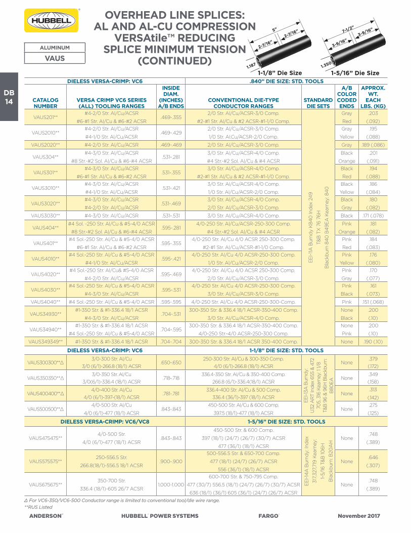
ANDERSON™ HUBBELL® POWER SYSTEMS FARGO® November 2017
DB14
ALUMINUM
VAUS
∆ For VC6-350/VC6-500 Conductor range is limited to conventional tool/die wire range.**RUS Listed
DIELESS VERSA-CRIMP: VC6 .840” DIE SIZE: STD. TOOLS
CATALOG NUMBER
VERSA CRIMP VC6 SERIES(ALL) TOOLING RANGES
INSIDE DIAM.
(INCHES)A/B ENDS
CONVENTIONAL DIE-TYPECONDUCTOR RANGES
STANDARDDIE SETS
A/B COLORCODEDENDS
APPROX.WT.
EACHLBS. (KG)
VAUS201**#4-2/0 Str. Al/Cu/ACSR
#6-#1 Str. Al/Cu & #6-#2 ACSR.469-.355
2/0 Str. Al/Cu/ACSR-3/0 Comp.
#2-#1 Str. Al/Cu & #2 ACSR-#1-1/0 Comp.
EE
I-11A
Bur
ndy
K84
0 In
dex
249
T&B
TX
76
76H
Bla
ckbu
rn 8
40
B49
EA
Kea
rney
: 84
0
Gray
Red
.203
(.092)
VAUS2010**#4-2/0 Str. Al/Cu/ACSR
#4-1/0 Str. Al/Cu/ACSR.469-.429
2/0 Str. Al/Cu/ACSR-3/0 Comp.
1/0 Str. Al.Cu/ACSR-2/0 Comp.
Gray
Yellow
.195
(.088)
VAUS2020** #4-2/0 Str. Al/Cu/ACSR .469-.469 2/0 Str. Al/Cu/ACSR-3/0 Comp. Gray .189 (.086)
VAUS304**#4-3/0 Str. Al/Cu/ACSR
#8 Str.-#2 Sol. Al/Cu & #6-#4 ACSR.531-.281
3/0 Str. Al/Cu/ACSR-4/0 Comp.
#4 Str.-#2 Sol. Al/Cu & #4 ACSR
Black
Orange
.201
(.091)
VAUS301**#4-3/0 Str. Al/Cu/ACSR
#6-#1 Str. Al/Cu & #6-#2 ACSR.531-.355
3/0 Str. Al/Cu/ACSR-4/0 Comp.
#2-#1 Str. Al/Cu & #2 ACSR-#1-1/0 Comp.
Black
Red
.194
(.088)
VAUS3010**#4-3/0 Str. Al/Cu/ACSR
#4-1/0 Str. Al/Cu/ACSR.531-.421
3/0 Str. Al/Cu/ACSR-4/0 Comp.
1/0 Str. Al/Cu/ACSR-2/0 Comp.
Black
Yellow
.186
(.084)
VAUS3020**#4-3/0 Str. Al/Cu/ACSR
#4-2/0 Str. Al/Cu/ACSR.531-.469
3/0 Str. Al/Cu/ACSR-4/0 Comp.
2/0 Str. Al/Cu/ACSR-3/0 Comp.
Black
Gray
.180
(.082)
VAUS3030** #4-3/0 Str. Al/Cu/ACSR .531-.531 3/0 Str. Al/Cu/ACSR-4/0 Comp. Black .171 (.078)
VAUS404**#4 Sol. -250 Str. Al/Cu & #5-4/0 ACSR
#8 Str.-#2 Sol. Al/Cu & #6-#4 ACSR.595-.281
4/0-250 Str. Al/Cu/ACSR-250-300 Comp.
#4 Str.-#2 Sol. Al/Cu & #4 ACSR
Pink
Orange
.181
(.082)
VAUS401**#4 Sol.-250 Str. Al/Cu & #5-4/0 ACSR
#6-#1 Str. Al/Cu & #6-#2 ACSR.595-.355
4/0-250 Str. Al/Cu 4/0 ACSR 250-300 Comp.
#2-#1 Str. Al/Cu/ACSR-#1-1/0 Comp.
Pink
Red
.184
(.083)
VAUS4010**#4 Sol.-250 Str. Al/Cu & #5-4/0 ACSR
#4-1/0 Str. Al/Cu/ACSR.595-.421
4/0-250 Str. Al/Cu 4/0 ACSR-250-300 Comp.
1/0 Str. Al/Cu/ACSR-2/0 Comp.
Pink
Yellow
.176
(.080)
VAUS4020**#4 Sol.-250 Str. Al/Cu& #5-4/0 ACSR
#4-2/0 Str. Al/Cu/ACSR.595-.469
4/0-250 Str. Al/Cu 4/0 ACSR 250-300 Comp.
2/0 Str. Al/Cu/ACSR-3/0 Comp.
Pink
Gray
.170
(.077)
VAUS4030**#4 Sol.-250 Str. Al/Cu & #5-4/0 ACSR
#4-3/0 Str. Al/Cu/ACSR.595-.531
4/0-250 Str. Al/Cu 4/0 ACSR-250-300 Comp.
3/0 Str. Al/Cu/ACSR-3/0 Comp.
Pink
Black
.161
(.073)
VAUS4040** #4 Sol.-250 Str. Al/Cu & #5-4/0 ACSR .595-.595 4/0-250 Str. Al/Cu 4/0 ACSR-250-300-Comp. Pink .151 (.068)
VAUS34930**#1-350 Str. & #1-336.4 18/1 ACSR
#4-3/0 Str. Al/Cu/ACSR.704-.531
300-350 Str. & 336.4 18/1 ACSR-350-400 Comp.
3/0 Str. Al/Cu/ACSR-4/0 Comp.
None
Black
.200
(.10)
VAUS34940**#1-350 Str. & #1-336.4 18/1 ACSR
#4 Sol.-250 Str. Al/Cu & #5-4/0 ACSR.704-.595
300-350 Str. & 336.4 18/1 ACSR-350-400 Comp.
4/0-250 Str.-4/0 ACSR-250-300 Comp.
None
Pink
.200
(.10)
VAUS349349** #1-350 Str. & #1-336.4 18/1 ACSR .704-.704 300-350 Str. & 336.4 18/1 ACSR 350-400 Comp. None .190 (.10)
DIELESS VERSA-CRIMP: VC6 1-1/8” DIE SIZE: STD. TOOLS
VAUS300300**∆3/0-300 Str. Al/Cu
3/0 (6/1)-266.8 (18/1) ACSR.650-.650
250-300 Str. Al/Cu & 300-350 Comp.4/0 (6/1)-266.8 (18/1) ACSR
EEI-1
3A B
urnd
y:U
32 A
RT
Inde
x 65
5 &
472
705,
316
Kea
rney
: 1 1/
8T&
B 9
6 &
96H
Bla
ckbu
rn:
B80
EA
None.379(.172)
VAUS350350**∆3/0-350 Str. Al/Cu
3/0(6/1)-336.4 (18/1) ACSR.718-.718
336.4-350 Str. Al/Cu & 350-400 Comp.266.8 (6/1)-336.4(18/1) ACSR
None.349(.158)
VAUS400400**∆4/0-400 Str. Al/Cu
4/0 (6/1)-397-(18/1) ACSR.781-.781
336.4-400 Str. Al/Cu & 500 Comp.336.4 (36/1)-397 (18/1) ACSR
None.313
(.142)
VAUS500500**∆4/0-500 Str. Al/Cu
4/0 (6/1)-477 (18/1) ACSR.843-.843
450-500 Str. Al/Cu & 600 Comp.
397.5 (18/1)-477 (18/1) ACSRNone
.275
(.125)
DIELESS VERSA-CRIMP: VC6/VC8 1-5/16” DIE SIZE: STD. TOOLS
VAUS475475**4/0-500 Str.
4/0 (6/1)-477 (18/1) ACSR.843-.843
450-500 Str. & 600 Comp.
397 (18/1) (24/7) (26/7) (30/7) ACSR
477 (36/1) (18/1) ACSR
EE
I-14
A B
urnd
y: In
dex
317,
327,
719
Kea
rney
:
1-5/
16 T
&B
106H
Bla
ckbu
rn: B
20A
H
None.748
(.389)
VAUS575575**250-556.5 Str.
266.8(18/1)-556.5 18/1 ACSR.900-.900
500-556.5 Str. & 650-700 Comp.
477 (18/1) (24/7) (26/7) ACSR
556 (36/1) (18/1) ACSR
None.646
(.307)
VAUS675675**350-700 Str.
336.4 (18/1)-605 26/7 ACSR1.000-1.000
600-700 Str. & 750-795 Comp.
477 (30/7) 556.5 (18/1) (24/7) (26/7) (30/7) ACSR
636 (18/1) (36/1) 605 (36/1) (24/7) (26/7) ACSR
None.748
(.389)
OVERHEAD LINE SPLICES: AL AND AL-CU COMPRESSION
VERSAtile™ REDUCING SPLICE MINIMUM TENSION
(CONTINUED)1-1/8” Die Size
5”
2-7/16”2-7/16”
1.187
1-5/16” Die Size
7-1/2”
3-9/16”3-9/16”
1.350

ANDERSON™ HUBBELL® POWER SYSTEMS FARGO® November 2017
DB15
OVERHEAD LINE SPLICES: AL/ACSRCOMPRESSION VERSA-CRIMP® SPLICE
PARTIAL TENSION
• ANSI C119.4, partial tension, Class 2 connector (40% of conductor breaking strength)
• For use with VERSA-CRIMP® Type VC6 (all) tools only• For Aluminum or ACSR messenger-neutrals of triplex service drop
cables and loop jumper use
Material: Body – Aluminum Alloy Factory Inhibited
ALUMINUM
VCSN
CATALOG NUMBER
ALUMINUM CONDUCTOR RANGE VERSA-CRIMPTOOLTYPE
DIMENSIONSINCHES (MM) APPROX.
WT. EACH LBS. (KG)MAIN TAP L D
VCSN44#4 (7)-1/0 (19) AAC
#6 (6/1)-1/0 (6/1) ACSR
#4 (7)-1/0 (19) AAC
#6 (6/1) - 1/0 (6/1) ACSR
VC6
(ALL)
3-9/16
(90.5)
1-3/4
(44.45)
.12
(.05)
OVERHEAD LINE SPLICES COMPRESSIONVERSAtile™ TRIPLEX NEUTRAL SPLICE
PARTIAL TENSION
• For use with VERSA-CRIMP® or conventional tools.• Connectors have partial tension (40%) rating when used with
Aluminum and ACSR conductors.• Connectors have minimum tension (5%) rating when used with
copper conductors.• Connectors are for splicing ACSR/Aluminum conductors to ACSR/
Aluminum or ACSR/Aluminum to copper. Not for copper to copper.
Material: Aluminum Alloy Factory Inhibited with Non-Rubber Swelling Inhibitor and Sealed With Color Coded Caps
ALUMINUM
VANS
CATALOG NUMBER
ALUMINUM OR COPPER CONDUCTOR
COLOR CODED
END
DIMENSIONS INCHES (MM)
WT. EACH
LBS. (KG)VERSA-CRIMP SYSTEMCONDUCTOR RANGE
VERSA-CRIMPTOOLTYPE
CONVENTIONAL WIRE RANGE
CONVEN-TIONAL
TOOL-DIES L D
VANS66#8 Str.-#4 Sol. Al/Cu
#6 ACSR
VC6
(ALL)
#6 Str.-#4 Sol. Al/Cu
#6 ACSR
EEI-8A
Burndy:
BG
Index 243
OH-25
Kearney:
5/8 Nose
Somerset:
TU, 52
Blackburn:
5/8 Nose
Blue4-1/4
(107.95)
2-1/16
(52.39)
.123
(.055)
VANS44#8 Str.-#2 Sol. Al/Cu
#6-#4 ACSR
#4-#2 Sol. Al/Cu
#4 ACSROrange
4-1/4
(107.95)
2-1/16
(52.39)
.115
(.052)
VANS11#8-#1 Str. Al/Cu
#6-#2 ACSR
#2-#1 Str. Al/Cu
#2 ACSRRed
4-1/4
(107.95)
2-1/16
(52.39)
.093
(.044)
VANS1010 #8-1/0 Str. Al/Cu/ACSR 1/0 Str. Al/Cu/ACSR Yellow5
(127.0)
2-7/16
(61.91)
.097
(.044)
L
D
L
D
Product Data & Conductor Size
Product Data & Conductor Size

ANDERSON™ HUBBELL® POWER SYSTEMS FARGO® November 2017
DB16
OVERHEAD LINE SPLICES: AAC AND ACSRCOMPRESSION VERSA-CRIMP® SPLICEPARTIAL TENSION – RANGE TAKINGALUMINUM
VCJSR
• For use with VERSA-CRIMP® tools only• For aluminum, ACSR, compact, 5005, 6201 and ACAR partial
tension (40% tension rating) conductor jumper splicing• Aluminum alloy conductor recommendations include 5005 and
ACAR having the same diameter as a given ACSR conductor shown below. In addition, compressed (compact) conductor sizes within the same decimal conductor range are recommended
• Use 800 series connectors only, if 6201 (AAAC) aluminum alloy conductor is involved
Material: Body – Aluminum Alloy Factory inhibited
CATALOG NUMBER
CONDUCTOR RANGE – VERSA CRIMP TOOLSVERSA-CRIMPTOOLTYPE
DIMENSIONSINCHES (MM) APPROX.
WT. EACH LBS. (KG)AAC ACSR L D
VCJS36R#6 (7), #4 (7), #3 (7),
#2 (19, 7)
#6 (6/1), #4 (7/1), (6/1),
#2 (7/1), (6/1)
VC6
(ALL)
4-5/8
(117.5)
2-1/4
(57.2)
.13
(.06)
VCJS50R#2 (19, 7), #1 (19, 7), 1/0 (19, 7),
2/0 (19, 7)
#2 (7/1, 6/1), #1 (6/1), 1/0 (6/1),
2/0 (6/1)
6
(152.4)
2-15/16
(74.6)
.25
(.11)
VCJS61R1/0 (19, 7), 2/0 (19, 7), 3/0 (19, 7), 4/0
(19, 7)
1/0 (6/1), 2/0 (6/1), 3/0 (6/1),
4/0 (6/1)
7-3/8
(187.3)
3-5/8
(92.1)
.45
(.20)
VCJS85R
4/0 (19, 7), 250 (37, 19), 266.8 (19, 7)
300 (37, 19), 336.4 (19), 350 (37, 19),
397.5 (19), 400 (37), 450 (37, 19),
477 (37, 19), 500 (37, 19)
4/0 (6/1), 266.8 (18/1)
336.4 (18/1, 36/1),
397.5 (18/1, 36/1), 477 (18/1, 36/1)
VC6
VC6FT
7-3/8
(187.3)
3-5/8
(92.1)
.54
(.24)
VCJS831R
250 (37, 19), 266.8 (19, 7), 300 (37),
336.4 (19), 350 (37,19), 397.5 (19),
400 (37), 450 (37, 19), 477 (37, 19)
500 (37, 19), 556.5 (37, 19)
266.8 (30/7, 26/7, 24/7, 18/1),
366.4 (30/7, 26/7, 24/7, 18/1),
397.5 (26/7, 24/7, 18/1),
477 (26/7, 24/7,18/1)
VC8
11-1/8
(282.6)
5-1/2
(139.7)
1.3
(.59)
VCJS832R 556.5 (37), 636 (37)477 (26/7), 556.5 (26/7, 24/7),
636 (18/1, 36/1)
12-7/8
(327.0)
6-3/8
(161.9)
1.6
(.72)
VCJS833R700 (61), 715.5 (61, 37)
795 (61, 37)
605 (26/7, 24/7), 636 (26/7, 24/7, 18/1),
666.6 (24/7) , 795 (36/1)
12-7/8
(327.0)
6-3/8
(161.9)
1.7
(.77)
VCJS834R 900 (61, 37)715 (26/ 7),
795 (26/7, 54/7, 24/7, 45/7, 36/1)
14-5/8
(371.5)
7-1/4
(184.2)
2.1
(.95)
VCJS835R954 (61, 37), 1000 (61),
1,033.5 (61, 37)
1,033.5 (61, 37), 1,000 (61)
954 (54/7, 45/7)
900 (54/7, 45/7)
795 (26/7)
14-5/8
(371.5)
7-1/4
(184.2)
2.2
(1.00)
Product Data & Conductor Size
LD

ANDERSON™ HUBBELL® POWER SYSTEMS FARGO® November 2017
DB17
OVERHEAD LINE SPLICES: AACCOMPRESSION
PARTIAL-TENSION SPLICES – AAC ALUMINUM
PTA
• For use with VERSA-CRIMP® or standard die-type compression tools• Prefilled with tension compound• Installed with popular compression dies from several manufacturers• Shorter barrel requires fewer crimps than higher strength splices for
alloyed conductors• Meets industry requirements for partial tension (40% of conductor
breaking strength) splicing per ANSI C119.4, Class 2
Material: Aluminum
Note: Refer to type PTR partial tension sleeves for splicing higher strength alloyed aluminum condutors and single core ACSR.
CATALOG NUMBER
CONDUCTOR RANGE CONVENTIONAL DIES DIELESSTOOL:
ANDER-SON
LLENGTHINCHES
(MM)
APPROX.WT. 100
LBS. (KG)AAC COMPACT
STR. INCHES (MM)BURNDYINDEX KEARNEY T & B
EEIDIES
PTA10 1/0 (7,19) Str..336-.373
(8.53-9.47)BG, 243
5/8
5/8-152 8A
VC6
(ALL)
3.25
(83)
8
(4)
PTA40 4/0 (7,19) Str..475-.528
(12.06-13.41)249 840 76 11A
VC6
(ALL)
4.00
(102)
16
(7)
PTA337336.4
19 or 37 Str.
.603-.666
(15.31-16.91)
321, 705,
655
1-1/8-1
1-1/8-296 —
VC6
(ALL)
4.50
(114)
27
(12)
PTA350350
19, 36, 61 Str.
.616-.681
(15.64-17.29)
490,
547
1-1/8-1
1-1/8-296 — VC6FT
6.50
(165)
42
(19)
PTA477477 or 500
19 or 37 Str.
.722-.814
(18.33-20.68)
317, 327
4261-1/8-2 106 14A VC6FT
6.25
(159)
45
(20)
PTA556556.5
19 or 37 Str.
.780-.858
(19.81-21.79)
261,
3181-5/16 115 15A VC8
8.75
(222)
93
(42)
PTA636636
37 Str.
.835-.918
(21.20-23.31)469 1-1/2 125 — VC8
7.50
(191)
87
(39)
PTA795750-800
37 or 61 Str.
.998-1.031
(23.67-26.18)342 1-5/8 140 — VC8
10.5
(267)
151
(68)
Product Data & Conductor Size
L

ANDERSON™ HUBBELL® POWER SYSTEMS FARGO® November 2017
DB18
OVERHEAD LINE SPLICES: AAC AND ACSRCOMPRESSION
PARTIAL-TENSION SPLICES – ACSRALUMINUM
PTR
• For use with VERSA-CRIMP® or standard die-type compression tools• Positive center stop• Installed with popular compression dies from several manufacturers• Prefilled with tension compound• Meets industry requirements for partial tension (40% of conductor
breaking strength) splicing per ANSI C119.4, Class 2
Material: Aluminum
Note: Refer to type PTA partial tension sleeves for AAC application only.
CATALOG NUMBER
CONDUCTOR RANGE CONVENTIONAL DIESDIELESSTOOL:
ANDERSON
LLENGTHINCHES
(MM)
APPROX.WT. 100
LBS. (KG)TYPES& SIZES INCHES (MM)
BURNDYINDEX
KEARNEYREF.
EEIDIES
PTR25
2 ACSR (7/1)
2 ACSR (6/1)
2 AAAC (7)
2 AAC (7)
.268-.325
(6.80-8.25)
C, 167, 247
or 702
737
or
747
10AVC6
(ALL)
5.00
(127)
22
(10)
PTR10
1/0 ACSR (6/1)
1/0 AAAC (7)
1/0 AAC (7)
.338-.398
(8.58-10.10)
C, 167, 660
247 or 702
737
or
747
10AVC6
(ALL)
6.25
(159)
25
(11)
PTR205
2/0 ACSR (6/1)
2/0 AAAC (7)
2/0 AAC (7)
.381-.447
(9.67-11.35)659 3/4 —
VC6
(ALL)
5.62
(143)
25
(11)
PTR30
3/0 ACSR (6/1)
3/0 AAAC (7)
3/0 AAC (7)
.426-.503
(10.82-12.77)658 840 11A
VC6
(ALL)
5.25
(133)
25
(11)
PTR40
4/0 ACSR (6/1)
4/0 AAAC (7)
4/0 AAC (7)
.480-.565
(12.19-14.35)654
1.00
1-212A
VC6
(ALL)
5.25
(133)
34
(15)
PTR336336.4 ACSR (18/1)
336.4 AAC (19)
.607-.684
(15.41-17.37)655
1-1/8-1
or
1-1/8-2
13AVC6-3
VC6-FT
5.25
(133)
37
(17)
PTR477447 ACSR (18/1)
477 & 500 AAC
.754-.814
(19.15-20.67)720 1-5/16 15A VC8
9.00
(227)
86
(39)
PTR795795 ACSR (36/1)
795 AAC Rd. Str.
.997-1.042
(25.32-26.46)342 1-1/2 — VC8
11.00
(279)
143
(65)
Product Data & Conductor Size
L

ANDERSON™ HUBBELL® POWER SYSTEMS FARGO® November 2017
DB19
OVERHEAD LINE SPLICESCOMPRESSION
FULL TENSION SPLICES-AAC ALUMINUM
FTA
• Positive center stop and tapered ends• Installed with popular compression tools and dies from several
manufacturers, or VERSA-CRIMP® dieless system• Prefilled with tension joint compound• Meets industry requirements for full tension (95% of conductor
breaking strength) splicing per ANSI C119.4, Class 1
Material: Aluminum
Note: Refer to type FTR—full tension sleeves for splicing higher strength alloyed aluminum conductors and single core ACSR.
FTR splices may also substitute for FTA splice installations.
CATALOG NUMBER
(1) CONDUCTOR RANGE CONVENTIONAL DIES LLENGTH
INCHES (MM)
APPROX.WT. 100
LBS. (KG)ALUMINUM INCHES (MM)BURNDYINDEX
KEARNEYREF.
EEIDIES
FTA10 1/0 (7, 19) Str..336-.373
(8.53-9.47)BG, 243
5/8
5/8-18A
7.25
(184)
16
(7)
FTA20 2/0 (7, 19) Str..376-.419
(9.55-10.64)245
5/8
5/8-19A
9.25
(234)
25
(11)
FTA40 4/0 (7, 19) Str..475-.528
(12.06-13.41)249 840 11A
10.50
(266)
40
(18)
FTA337336.4
19 or 37 Str.
.603-.666
(15.31-16.91)
321, 705,
655
1-1/8-1
1-1/8-2—
9.87
(251)
58
(26)
FTA350350
19, 36, 61 Str.
.616-.681
(15.64-17.29)
490,
547
1-1/8-1
1-1/8-2—
11.00
(279)
70
(32)
FTA397397.5
19 Str.
.659-.724
(16.73-18.38)468, 655
1-1/8-1
1-1/8-213A
12.25
(311)
84
(38)
FTA477477 or 500
19 or 37 Str.
.722-.814
(18.33-20.68)317, 327, 426 1-1/8-2 14A
12.75
(324)
113
(51)
FTA556556.5
19 or 37 Str.
.780-.858
(19.81-21.79)261, 318 1-5/16 15A
12.75
(324)
138
(63)
FTA795*750-800
37 or 61 Str.
.998-1.031
(23.67-26.18)342
1-1/2
1-5/8—
13.62
(346)
199
(90)
(1) Compact strand sizes within the O.D. inch range may be used.*Consult factory; FTR795 option also available.
Product Data & Conductor Size
L

ANDERSON™ HUBBELL® POWER SYSTEMS FARGO® November 2017
DB20
OVERHEAD LINE SPLICES COMPRESSIONFULL TENSION “JIFFY SPLICES” –
ACSR (and AAC)ALUMINUM
FTR
• Positive center stop and tapered ends• Installed with popular compression tools and dies from several
manufacturers• Prefilled with tension joint compound• Meets industry requirements for full tension (95% of conductor
breaking strength) splicing per ANSI C119.4, Class 1
Material: Aluminum
Note: Refer to type FTA—full tension sleeves for AAC application only.
CATALOG NUMBER
(1) CONDUCTOR RANGE CONVENTIONAL DIES LLENGTH
INCHES (MM)
APPROX.WT. 100
LBS. (KG)TYPES &
SIZES INCHES (MM)BURNDYINDEX
KEARNEYREF.
EEIDIES
FTR4**
4 ACSR (7/1)
4 ACSR (6/1)
4 AAAC (7)
4 AAC (7)
.182-.257
(4.62-6.52)BG,
243
or
687
5/8
5/8-1 or 635
8A12.00
(305)
37
(17)
FTR2**
2 ACSR (6/1)
2 AAAC (7)
2 AAC (7)
.268-.325
(6.80-8.25)9A
10.25
(260)
28
(13)
FTR25**
2 ACSR (7/1)
2 ACSR (6/1)
2 AAAC (7)
2 AAC (7)
.268-.325
(6.80-8.25)
C
167, 247, 702737
74710A
13.00
(330)
56
(25)
FTR10**
1/0 ACSR (6/1)
1/0 AAAC (7)
1/0 AAC (7)
.338-.398
(8.58-10.10)
C
167, 660,
247, 702
14.75
(375)
59
(26)
FTR205**
2/0 ACSR (6/1)
2/0 AAAC (7)
2/0 AAC (7)
.381-.447
(9.67-11.35)659
781
or
3/4
—16.00
(406)
70
(32)
FTR30**
3/0 ACSR (6/1)
3/0 AAAC (7)
3/0 AAC (7)
.426-.503
(10.82-12.77)658 840 11A
18.25
(468)
88
(40)
FTR40**
4/0 ACSR (6/1)
4/0 AAAC (7)
4/0 AAC (7)
.480-.565
(12.19-14.35)654
1.00
or
1-2
12A18.50
(470)
120
(54)
FTR336336.4 ACSR (18/1)
336.4 AAC (19)
.607-.684
(15.41-17.37)655 1-1/8-1
or
1-1/8-2
13A19.25
(489)
137
(62)
FTR397397.5 ACSR (18/1)
350 & 397.5 AAC
.681-.743
(17.29-18.87)327 14A
22.00
(559)
154
(70)
FTR477477 ACSR (18/1)
447 & 500 AAC
.754-.814
(19.15-20.67)720 1-5/16 15A
23.00
(582)
220
(100)
FTA795795 ACSR (36/1)
795 AAC
.997-1.042
(25.32-26.46)342 1-1/2 —
25.00
(635)
325
(147)
(1) Compact and 5005 cable sizes within the O.D. range may be used.**RUS Listed
Product Data & Conductor Size
L

ANDERSON™ HUBBELL® POWER SYSTEMS FARGO® November 2017
DB21
VERSA-CRIMP® ALUMINUM COMPRESSION SPLICE
TYPES VC-A, VC-AR, VC-RFULL TENSION-AAC and ACSR
ALUMINUM
VCA, VCAR, VCR
• ANSI C119.4, full tension, Class 1 connector (95% of conductor breaking strength)
• For use with VERSA-CRIMP® tools only• For aluminum, single core ACSR, 5005, 6201 and compact
conductor splicing• Compressed (compact) conductor sizes within the same decimal
conductor range are recommended• One piece splice eliminates cutting back the aluminum strands on
ACSR conductors, except on VC90R which requires the outside layer (aluminum strands) to be cut back 5” on each side
Material: Body – Aluminum Alloy Factory inhibited
CATALOG NUMBER
CONDUCTOR RANGE – VERSA CRIMP TOOLS VERSA-CRIMPTOOL
TYPE ∆
DIMENSIONSINCHES (MM)
APPROX.WT.
EACH LBS. (KG)AAC ACSR 5005 OR AAAC (6201) L D
VC36R** #4 (19), #4 (7), #2 (7) #4 (7/1, 6/1), #2 (7/1, 6/1) 48.69 (7), 77.47 (7)
VC6
(ALL)
13-1/8
(333.4)
6-1/2
(165.1)
.32
(.14)
VC410A #4 (7), #2 (7), 1/0 (7) — —6-1/4
(158.8)
3-1/16
(77.8)
.16
(.07)
VC44R #2 (7), 1/0 (19), 1/0 (7) #2 (7/1, 6/1), 1/0 (6/1) 77.47 (7), 123.3 (7)15-7/8
(403.2)
7-7/8
(200.0)
.55
(.25)
VC50R**#2 (7), 1/0 (19,7), 2/0
(19,7)
#2 (6/1, 7/1), 1/0 (6/1),
2/0 (6/1)123.3 (7), 155.4 (7)
17-1/4
(438.2)
8-9/16
(217.5)
.65
(.29)
VC58A1/0 (7), 2/0 (7), 3/0 (7),
4/0 (7)— —
7-5/8
(193.7)
3-3/4
(95.3)
.35
(.16)
VC61R**1/0 (19,7), 2/0 (7), 3/0 (7),
4/0 (7)
1/0 (6/1), 2/0 (6/1), 3/0
(6/1),
4/0 (6/1)
155.4 (7), 195.7 (7),
246.9 (7)
19-7/8
(504.8)
9-3/4
(247.7)
1.1
(.50)
VC70A4/0 (7), 266.8 (19,7),
336.4 (19)— —
9
(228.6)
4-716
(112.7)
.48
(.22)
VC80R**4/0 (7), 226.8 (19,7),
336.4 (19), 397.5 (19)
4/0 (6/1), 226.8 (18/1),
336.4 (18/1), 397.5 (18/1)—
22-7/8
(581.0)
11-3/8
(288.9)
1.6
(.72)
VC85A336.4 (19), 397.5 (19),
477 (37,19)— —
ALL
except VC6350
11-3/4
(298.5)
5-13/16
(147.6)
.81
(.37)
VC90R — 397.5 (18/1), 477 (18/1) —
VC8
22-7/8
(581.0)
11-3/8
(288.9)
1.7
(.77)
*VC813AR — — 652.4 (19), 740.8 (37)21-5/8
(549.3)
10-3/4
(273.0)
2.5
(1.13)
* Three end crimps are factory formed to minimize vibration damage to conductor.** RUS Listed∆ For VC6350/VC6500 connector and conductor recommendations, see application label in top of tool case.
Product Data & Conductor Size
LD
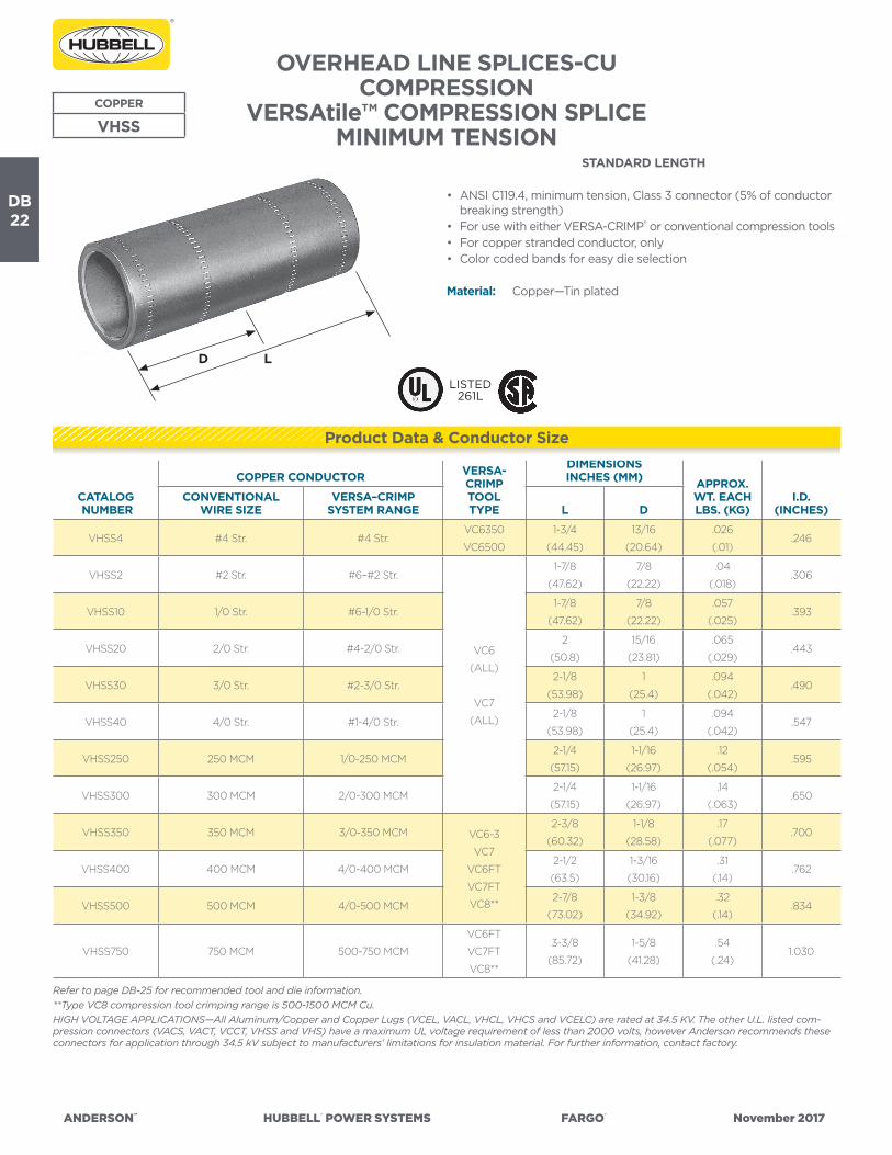
ANDERSON™ HUBBELL® POWER SYSTEMS FARGO® November 2017
DB22
OVERHEAD LINE SPLICES-CUCOMPRESSION
VERSAtile™ COMPRESSION SPLICEMINIMUM TENSION
COPPER
VHSS
STANDARD LENGTH
• ANSI C119.4, minimum tension, Class 3 connector (5% of conductor breaking strength)
• For use with either VERSA-CRIMP® or conventional compression tools• For copper stranded conductor, only• Color coded bands for easy die selection
Material: Copper—Tin plated
CATALOG NUMBER
COPPER CONDUCTOR VERSA-CRIMPTOOLTYPE
DIMENSIONSINCHES (MM) APPROX.
WT. EACH LBS. (KG)
I.D.(INCHES)
CONVENTIONALWIRE SIZE
VERSA–CRIMPSYSTEM RANGE L D
VHSS4 #4 Str. #4 Str.VC6350
VC6500
1-3/4
(44.45)
13/16
(20.64)
.026
(.01).246
VHSS2 #2 Str. #6–#2 Str.
VC6
(ALL)
VC7
(ALL)
1-7/8
(47.62)
7/8
(22.22)
.04
(.018).306
VHSS10 1/0 Str. #6-1/0 Str.1-7/8
(47.62)
7/8
(22.22)
.057
(.025).393
VHSS20 2/0 Str. #4-2/0 Str.2
(50.8)
15/16
(23.81)
.065
(.029).443
VHSS30 3/0 Str. #2-3/0 Str.2-1/8
(53.98)
1
(25.4)
.094
(.042).490
VHSS40 4/0 Str. #1-4/0 Str.2-1/8
(53.98)
1
(25.4)
.094
(.042).547
VHSS250 250 MCM 1/0-250 MCM2-1/4
(57.15)
1-1/16
(26.97)
.12
(.054).595
VHSS300 300 MCM 2/0-300 MCM2-1/4
(57.15)
1-1/16
(26.97)
.14
(.063).650
VHSS350 350 MCM 3/0-350 MCM VC6-3
VC7
VC6FT
VC7FT
VC8**
2-3/8
(60.32)
1-1/8
(28.58)
.17
(.077).700
VHSS400 400 MCM 4/0-400 MCM2-1/2
(63.5)
1-3/16
(30.16)
.31
(.14).762
VHSS500 500 MCM 4/0-500 MCM2-7/8
(73.02)
1-3/8
(34.92)
.32
(.14).834
VHSS750 750 MCM 500-750 MCM
VC6FT
VC7FT
VC8**
3-3/8
(85.72)
1-5/8
(41.28)
.54
(.24)1.030
Refer to page DB-25 for recommended tool and die information.**Type VC8 compression tool crimping range is 500-1500 MCM Cu.HIGH VOLTAGE APPLICATIONS—All Aluminum/Copper and Copper Lugs (VCEL, VACL, VHCL, VHCS and VCELC) are rated at 34.5 KV. The other U.L. listed com-pression connectors (VACS, VACT, VCCT, VHSS and VHS) have a maximum UL voltage requirement of less than 2000 volts, however Anderson recommends these connectors for application through 34.5 kV subject to manufacturers’ limitations for insulation material. For further information, contact factory.
Product Data & Conductor Size
LD
LISTED261L

ANDERSON™ HUBBELL® POWER SYSTEMS FARGO® November 2017
DB23
OVERHEAD LINE SPLICES-CUCOMPRESSION, VERSAtile™ SPLICE
MINIMUM TENSION, HEAVY DUTY LENGTH
• ANSI C119.4, minimum tension, Class 3 connector (5% of conductor breaking strength)
• For use with either VERSA-CRIMP® or conventional compression tools• For copper stranded conductor, only• Color coded bands for easy die selection
Material: Copper—Tin plated
CATALOG NUMBER
COPPER CONDUCTOR VERSA-CRIMPTOOLTYPE
DIMENSIONSINCHES (MM) APPROX.
WT. EACH LBS. (KG)
I.D.(INCHES)
CONVENTIONALWIRE SIZE
VERSA–CRIMPSYSTEM RANGE L D
VHS6** #6 Str. #6 Str.VC6350
VC6500
2-3/8
(60.32)
1-1/8
(28.58)
.03
(.01).198
VHS4** #4 Str. #4 Str.2-3/8
(60.32)
1-1/8
(28.58)
.03
(.01).246
VHS2** #2 Str. #6–#2 Str.
VC6
(ALL)
VC7
(ALL)
2-3/8
(60.32)
1-1/4
(31.75)
.05
(.02).306
VHS1** #1 Str. #6-#1 Str.2-7/8
(73.02)
1-3/8
(34.92)
.06
(.027).358
VHS10** 1/0 Str. #6-1/0 Str.2-7/8
(73.02)
1-3/8
(34.92)
.08
(.036).393
VHS20** 2/0 Str. #4-2/0 Str.3-1/8
(79.38)
1-1/2
(38.1)
.09
(.04).443
VHS30** 3/0 Str. #2-3/0 Str.3-1/8
(79.38)
1-1/2
(38.1)
.11
(.05).490
VHS40** 4/0 Str. #1-4/0 Str.3-3/8
(85.72)
1-5/8
(41.28)
.15
(.068).547
VHS250** 250 MCM 1/0-250 MCM3-3/8
(85.72)
1-5/8
(41.28)
.18
(.082).595
VHS300** 300 MCM 2/0-300 MCM4-1/8
(104.78)
2
(50.8)
.25
(.11).650
VHS350** 350 MCM 3/0-350 MCM VC6-3
VC7
VC6FT
VC7FT
VC8***
4-1/8
(104.78)
2
(50.8)
.29
(.13).700
VHS400** 400 MCM 4/0-400 MCM4-3/8
(111.12)
2-1/8
(53.98)
.37
(.17).762
VHS500** 500 MCM 4/0-500 MCM4-5/8
(117.48)
2-1/4
(57.15)
.50
(.23).834
VHS600** 600 MCM 250-600 MCM VC6FT
VC7FT
VC8***
5-1/2
(139.7)
2-11/16
(68.26)
.78
(.35).923
VHS750** 750 MCM 500-750 MCM5-7/8
(149.22)
2-7/8
(73.02)
.94
(.43)1.030
VHS1000** 1000 MCM 750–1000 MCM VC8***6-1/8
(155.58)
3
(76.2)
1.30
(.59)1.172
Refer to page DB-26 for recommended tool and die information.** RUS Listed*** Type VC8 tool crimping range is 500-1500 MCM Cu.HIGH VOLTAGE APPLICATIONS—All Aluminum/Copper and Copper Lugs (VCEL, VACL, VHCL, VHCS and VCELC) are rated at 34.5 KV. The other U.L. listed com-pression connectors (VACS, VACT, VCCT, VHSS and VHS) have a maximum UL voltage requirement of less than 2000 volts, however Anderson recommends these connectors for application through 34.5 KV subject to the manufacturers’ limitations and recommendations for the insulation material. For further information, contact factory.
COPPER
VHS
Product Data & Conductor Size
LISTED261L
LD

ANDERSON™ HUBBELL® POWER SYSTEMS FARGO® November 2017
DB24
Cat
alog
Num
ber
VAC
L (3
)
VAC
S (4
)
VAC
T (4
)
AN
DER
SON
™ V
ERSA
-CR
IMP®
CO
MPR
ESSI
ON
TO
OLS
(Cri
mps
per
Con
nect
ion)
CO
NV
ENTI
ON
AL
CO
MPR
ESSI
ON
DIE
TO
OLI
NG
(Cri
mps
per
Con
nect
ion)
V-C
Too
lsW
ireR
ange
(AW
G o
rM
CM
)
VER
SA-C
RIM
P To
ols
(Num
ber
of C
rim
ps)
Wire
Size
(AW
Gor
MC
M)
Die
Col
orC
ode
(2)
Bur
ndy
(Cri
mps
)B
urnd
y In
dent
or T
ools
(1 C
rim
p)
*VC
650
0V
C6
350
VC
6(1
)
VC
6FT (1
)
VC
8A
LN
IBS
Die
Inde
xN
o.
Tool
Y34
A
Tool
sY
35Y
39To
olY
34B
Tool
Y4
8BTo
olY
486
RB
Tool
MY-
29
Tool
Y34
A(I
nden
-to
r)
Tool
Y34
B(I
nden
-to
r)
Tool
Y4
8B(I
nden
-to
r)
Tool
Y4
86R
B(I
nden
-to
r)D
ieD
ieD
ieD
ieD
ieD
ieN
est
Nes
tN
est
Nes
t
-8#
8 A
L/C
U1
1#
8A
L/C
UB
lue
374
U8C
AB
T(2
)#
8 (1)
-6#
6 A
L/C
U1
1#
6A
L/C
UG
ray
346
A6C
AB
(1)
U6C
AB
T(1
)B
6CD
(1)
#6 (1)
A4
CD
(Y34
PA)
B4
CD
(Y34
PA)
-4#
4 A
L/C
U2
2#
4A
L/C
UG
reen
375
A4
CA
B(1
)U
4C
AB
T*
(1)
B4
CD
(1)
C4
CA
B(1
)#
4 (1)
A1C
D(Y
34PA
)B
1CD
(Y34
PA)
-2#
6-#
2 A
L/C
U2
22
2#
2A
L/C
UP
ink
348
A2C
AB
(1)
U2C
AB
T(1
)B
2CD
(1)
#2
(2)
A26
D(Y
34PA
)B
26D
(Y34
PA)
-1#
8-#
1 AL/
CU
22
22
#1
AL/
CU
Tan
296
A25
AR
(1)
U25
AR
T*
(1)
B1C
D(1
)#
1(2
)A
27D
(Y34
PR
-5)
B27
D(Y
34P
R-5
)
-1/0
#8-
1/0
AL/
CU
22
22
1/0
AL/
CU
Tan
296
A25
AR
(1)
U25
AR
T*
(1)
B25
D(1
)1/
0(2
)A
27D
(Y34
PR
-5)
B27
D(Y
34P
R-5
)
-2/0
#4
-2/0
AL/
CU
22
22
2/0
AL/
CU
Oliv
e29
7A
26A
R(2
)U
26A
RT
(2)
B26
D(1
)2/
0(2
)A
29D
(Y34
PR
-5)
B29
D(Y
34P
R-5
)
-3/0
#4
-3/0
AL/
CU
22
22
3/0
AL/
CU
Rub
y4
67A
27A
R(2
)U
27A
RT
(2)
B27
D(1
)3/
0(2
)A
30D
(Y34
PR
-5)
B30
D(Y
34P
R-5
)
-4/0
#2-
4/0
AL/
CU
33
22
4/0
AL/
CU
Whi
te29
8A
28A
R(2
)U
28A
RT
(2)
B28
D(1
)C
28A
R(1
)F2
8AR
(1)
4/0
(2)
A31
D(Y
34P
R-5
)B
31D
(Y34
PR
-5)
-250
1/0
-250
AL/
CU
33
22
250
AL/
CU
Red
324
A29
AR
(2)
U29
AR
T(2
)B
29D
(1)
C29
AR
(1)
F29A
R(1
)A
32D
(Y34
PR
-5)
B32
D(Y
34P
R-5
)
-30
01/
0-3
00
AL/
CU
33
22
300
AL/
CU
Blu
e47
0A
30A
R(2
)U
30A
RT
(2)
B30
D(2
)C
30A
R(1
)F3
0A
R(1
)A
34D
(Y34
PR
-11)
No
Die
C34
D(Y
48P
R-1
)F3
4D
(Y4
8PR
-1)
-350 (1)
2/0
-350
AL/
CU
43
335
0A
L/C
UB
row
n29
9U
31A
RT
(2)
B31
D(2
)C
31A
R(1
)F3
1AR
(1)
C35
D(Y
48P
R-1
)F3
5D(Y
48P
R-1
)
-40
0(1
)3/
0-4
00
AL/
CU
54
O’la
p4
O’la
p4
00
AL/
CU
Gre
en47
2U
32A
RT
(4)
B32
D(2
)C
32A
R(2
)F3
2AR
(2)
C36
D(Y
48P
R-1
)F3
6D(Y
48P
R-1
)
-50
0(1
)4/
0-5
00
AL/
CU
74
O’la
p4
O’la
p50
0A
L/C
UG
reen
472
U32
AR
T(4
)
No
Die
Req
uire
d(2
)
C32
AR
(2)
F32A
R(2
)
-60
035
0 -
60
0 A
L35
0 -
50
0 C
U4
360
0 A
LP
ink
300
U34
AR
T(4
)C
34A
R(2
)F3
4A
R(2
)
-750
500
- 7
50 A
L50
0 C
U4
375
0 A
LP
ink
300
U34
AR
T(4
)C
34A
R(2
)F3
4A
R(2
)
-10
00
750
-10
00
AL
310
00
AL
Bro
wn
302
C4
4A
R(2
)F4
4A
R(2
)C
46D
(Y4
8PR
-1)
F46D
(Y4
8PR
-1)
+ TB
M-8
Too
l ON
LYH
A
nder
son
HC
-12
Die
s, B
urnd
y’s
Y-35
Die
s an
d B
lack
bur
n’s
JB-1
2 D
ies
are
inte
rcha
ngea
ble
.(1
) “V
AC
L” L
ug s
izes
-35
0 t
o -5
00
tak
e 1 l
ess
crim
p (
VC
6 To
ols)
tha
n sh
own.
(2)
Col
or c
ode
is fo
r A
nder
son
and
Bur
ndy
die
s on
ly. U
se t
he r
ecom
men
ded
die
num
ber
(N
OT
die
col
or)
for
Bla
ckb
urn,
Kea
rney
& T
&B
Hyd
. Too
ls/D
ies.
(3)
The
“VA
CL”
lug
s ar
e q
ualifi
ed fo
r U
L “H
V”
app
licat
ions
.(4
) Th
e “V
AC
S” s
leev
es a
nd “
VAC
T” t
ee c
onne
ctor
s ar
e fo
r A
L to
AL
or A
L to
CU
con
nect
ions
ON
LY. (
NO
T fo
r C
U t
o C
U c
onne
ctio
ns).
* N
ot U
L Li
sted
-pen
din
g c
omp
letio
n of
tes
t.
VA
CL/
VA
CS/
VA
CT—
And
erso
n/B
urnd
y
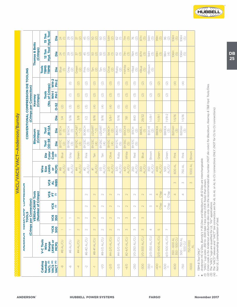
ANDERSON™ HUBBELL® POWER SYSTEMS FARGO® November 2017
DB25
Cat
alog
Num
ber
VAC
L (3
)
VAC
S (4
)
VAC
T (4
)
AN
DER
SON
™ V
ERSA
-CR
IMP®
CO
MPR
ESSI
ON
TO
OLS
(Cri
mps
per
Con
nect
ion)
CO
NV
ENTI
ON
AL
CO
MPR
ESSI
ON
DIE
TO
OLI
NG
(Cri
mps
per
Con
nect
ion)
V-C
Too
lsW
ireR
ange
(AW
G o
rM
CM
)
VER
SA-C
RIM
P To
ols
(Num
ber
of C
rim
ps)
Wire
Size
(AW
Gor
MC
M)
Die
Col
orC
ode
(2)
Bla
ckbu
rn(C
rim
ps)
Kea
rney
(Cri
mps
)Th
omas
& B
etts
(Cri
mps
)
*VC
650
0V
C6
350
VC
6(1
)
VC
6FT (1
)
VC
8A
LN
IBS
Tool
OD
-58
Tool
JB-1
2A
Die
Tool
s(N
o. o
f Cri
mps
)
Tool
sTB
M5
TBM
812
Ton
H
yd. T
ool
15 T
on
Hyd
. Too
l
Die
Die
O-5
2W
H-1
PH-1
WH
-2PH
-2D
ieD
ieD
ie
-8#
8 A
L/C
U1
1#
8A
L/C
UB
lue
BY
17C
(2)
B73
CH
(1)
1/4
(2)
Blu
e(1
)24 (1
)24 (1
)
-6#
6 A
L/C
U1
1#
6A
L/C
UG
ray
BY
19C
(3)
B74
CH
(1)
5/16
(3)
(1)
(1)
Gra
y(2
)29 (2
)29 (2
)
-4#
4 A
L/C
U2
2#
4A
L/C
UG
reen
BY
21C
(3)
U4
CA
BT
* (1
)3/
8(3
)(2
)(2
)G
reen
(2)
37 (2)
37 (2)
-2#
6-#
2 A
L/C
U2
22
2#
2A
L/C
UP
ink
BY
23C
(3)
BO
6CH
(1)
1/2
(3)
(2)
(2)
Pin
k(2
)4
5(2
)4
5(2
)
-1#
8-#
1 AL/
CU
22
22
#1
AL/
CU
Tan
BY
23C
(4)
U25
AR
T*
(1)
9/16
(4)
(2)
(2)
Tan
(2)
50 (2)
50 (2)
-1/0
#8-
1/0
AL/
CU
22
22
1/0
AL/
CU
Tan
BY
25C
(4)
U25
AR
T*
(1)
9/16
(4)
(2)
(2)
Tan
(2)
50 (2)
50 (2)
-2/0
#4
-2/0
AL/
CU
22
22
2/0
AL/
CU
Oliv
eB
Y31
C(4
)B
09C
H(2
)5/
8-1
(4)
(3)
(3)
Oliv
e(2
)54 (1
)54
H(2
)
-3/0
#4
-3/0
AL/
CU
22
22
3/0
AL/
CU
Rub
yB
Y27
C(5
)B
26C
H(2
)11/
16(5
)(3
)(3
)R
uby
(2)
62 (1)
62 (1)
-4/0
#2-
4/0
AL/
CU
33
22
4/0
AL/
CU
Whi
teB
Y35
C(5
)B
10C
H1
(2)
781
(5)
(3)
(3)
+Whi
te(4
)71
H(3
)71
H(3
)
-250
1/0
-250
AL/
CU
33
22
250
AL/
CU
Red
BY
37C
(5)
B11C
H(2
)84
0(5
)(3
)(3
)+R
ed(5
)76
H(3
)76 (2
)
-30
01/
0-3
00
AL/
CU
33
22
300
AL/
CU
Blu
eB
61E
A(1
)29
/32
(2)
(2)
+Blu
e(5
)87
H(3
)87
H(3
)
-350 (1)
2/0
-350
AL/
CU
43
335
0A
L/C
UB
row
nB
12C
H1
(2)
1-1/
8-1
(2)
(2)
+Bro
wn
(5)
94H
(3)
94H
(3)
-40
0(1
)3/
0-4
00
AL/
CU
54
O’la
p4
O’la
p4
00
AL/
CU
Gre
enB
80E
A(2
)1-
1/8-
1(2
)(2
)99
H(3
)99
H(3
)
-50
0(1
)4/
0-5
00
AL/
CU
74
O’la
p4
O’la
p50
0A
L/C
UG
reen
B80
EA
(3)
1-1/
8-2
(2)
(2)
96H
(4)
96 (2)
-60
035
0 -
60
0 A
L35
0 -
50
0 C
U4
360
0 A
LP
ink
B20
AH
(3)
1-5/
16(4
)10
6H (5)
106H (5)
-750
500
- 7
50 A
L50
0 C
U4
375
0 A
LP
ink
B20
AH
(3)
1-5/
16(4
)10
6H (5)
106H (5)
-10
00
750
-10
00
AL
310
00
AL
Bro
wn
+ TB
M-8
Too
l ON
LYH
A
nder
son
HC
-12
Die
s, B
urnd
y’s
Y-35
Die
s an
d B
lack
bur
n’s
JB-1
2 D
ies
are
inte
rcha
ngea
ble
.(1
) “V
AC
L” L
ug s
izes
-35
0 t
o -5
00
tak
e 1 l
ess
crim
p (
VC
6 To
ols)
tha
n sh
own.
(2)
Col
or c
ode
is fo
r A
nder
son
and
Bur
ndy
die
s on
ly. U
se t
he r
ecom
men
ded
die
num
ber
(N
OT
die
col
or)
for
Bla
ckb
urn,
Kea
rney
& T
&B
Hyd
. Too
ls/D
ies.
(3)
The
“VA
CL”
lug
s ar
e q
ualifi
ed fo
r U
L “H
V”
app
licat
ions
.(4
) Th
e “V
AC
S” s
leev
es a
nd “
VAC
T” t
ee c
onne
ctor
s ar
e fo
r A
L to
AL
or A
L to
CU
con
nect
ions
ON
LY. (
NO
T fo
r C
U t
o C
U c
onne
ctio
ns).
* N
ot U
L Li
sted
-pen
din
g c
omp
letio
n of
tes
t.
VA
CL/
VA
CS/
VA
CT—
And
erso
n/B
urnd
y

ANDERSON™ HUBBELL® POWER SYSTEMS FARGO® November 2017
DB26
Cat
a-lo
gN
um-
ber
VH
SSV
HC
S
AN
DER
SON
™ V
ERSA
-CR
IMP®
CO
MPR
ESSI
ON
TO
OLS
(Cri
mps
per
Con
nect
ion)
CO
NV
ENTI
ON
AL
CO
MPR
ESSI
ON
DIE
TO
OLI
NG
(Cri
mps
per
Con
nect
ion)
Con
duc-
tor
Insu
lati
onSt
rip
Leng
ths
(Min
.)(1
)
V-C
Too
lsW
ire
Ran
geA
WG
or
MC
MSt
rand
ed(C
oppe
r O
nly)
VER
SA-C
RIM
P® T
ools
(Num
ber
of C
rim
ps)
Cop
per
Wire
Size
AW
Gor
MC
MST
R
Die
Col
orC
ode
Bur
ndy
(Cri
mps
)B
urnd
y Lo
ngit
udin
al In
dent
(Cri
mps
)K
earn
ey(C
rim
ps)
Thom
as &
Bet
ts(C
rim
ps)
*VC
6-5
00
VC
6-3
50V
C6
(1)
VC
6FT
VC
7V
C7
FT
VC
8A
LN
IBS
Tool
MY
29-3
Tool
Y34
AIn
dent
orY
34PR
Tool
Y34
BIn
dent
orY
34PR
Tool
Y4
4B
Inde
ntor
Y4
4PR
Tool
Y4
8BIn
den-
tor
Y4
8PR
Tool
Y4
86R
BIn
dent
orY
48P
R
Tool
sY
35Y
39Y
45†
Tool
s“O
”To
ols
“WH
”
Tool
sTB
M5
TBM
8
Hyd
. To
ols
12, 1
520
&
40
Ton
Nes
tSe
ttin
gN
est
Nes
tN
est
Nes
tN
est
Die
Die
Die
Die
Die
-6#
61
1#
6B
lue
#6 (1)
A6C
D(1
)B
6CD
(1)
U5C
RT
(1)
Blu
e(2
)24 (1
)15
/16”
-4#
41
1#
4G
ray
#4 (1)
A4
CD
(1)
B4
CD
(1)
U4
CR
T(1
)5/
16(3
)5/
16 (1)
Gra
y(2
)29 (1
)15
/16”
-2#
6-#
21
11
11
1#
2B
row
n#
2 (1)
A2C
D(1
)B
2CD
(1)
U2C
RT
(1)
3/8
(3)
3/8
(1)
Bro
wn
(2)
33 (1)
1”
-1#
6-#
11
11
11
1#
1G
reen
#1
(1)
A1C
D(1
)B
1CD
(1)
U1C
RT
(1)
Gre
en(2
)37 (1
)1”
-1/0
#6-
1/0
11
11
11
1/0
Pin
k1/
0 (1)
A25
D(1
)B
25D
(1)
E25
D(1
)U
25R
T(1
)1/
2(3
)1/
2(1
)P
ink
(2)
42H
(2)
42(
1)1”
-2/0
#4
-2/0
11
11
11
2/0
Bla
ck2/
0(1
)A
26D
(1)
B26
D(1
)E
26D
(1)
U26
RT
(1)
9/16
(3)
9/16 (1)
Bla
ck(2
)4
5 (1)
1-1/
16”
-3/0
#2-
3/0
22
2O
’lap
2O
’lap
22
3/0
Ora
nge
3/0
(1)
A27
D(1
)B
27D
(1)
E27
D(1
)U
27R
T(1
)9/
16(3
)9/
16(2
)O
rang
e(2
)50 (1
)1-
1/8”
-4/0
#1-
4/0
22
2O
’lap
2O
’lap
22
4/0
Pur
ple
4/0
(1)
A28
D(1
)B
28D
(1)
E28
D(1
)C
28D
(1)
F28D (1)
U28
RT
(1)
5/8-
1(3
)5/
8-1
(2)
Pur
ple
(2)
54 (1)
1-1/
8”
-250
1/0
-250
22
2O
’lap
2O
’lap
22
250
Yello
w25
0(1
)A
29D
(1)
B29
D(1
)E
29D
(1)
C29
D(1
)F2
9D (1)
U29
RT
(1)
11/16
(3)
11/16
(2)
Yello
w(2
)60
(1)
62(1
)1-
3/16
”
-30
02/
0-3
00
22
2O
’lap
2O
’lap
22
300
Whi
teA
30D
(1)
B30
D(1
)E
30D
(1)
C30
D(1
)F3
0D
(1)
U30
RT
(1)
781
(3)
781
(2)
+Whi
te(2
)66
H(2
)66
(1)
1-3/
16”
-350
3/0
-350
3O
’lap
2O
’lap
2O
’lap
22
350
Red
A31
D(1
)B
31D
(1)
E31
D(1
)C
31D
(1)
F31D (1)
U31
RT
(1)
840
(3)
840
(2)
+Red
(2)
71H
(2)
71(1
)1-
1/4
”
-40
04/
0-4
00
3O
’lap
2O
’lap
2O
’lap
22
40
0B
lue
A32
D(1
)B
32D
(2)
E32
D(1
)C
32D
(1)
F32D (1)
U32
RT
(1)
+Blu
e(2
)76
H(2
)76
(1)
1-5/
16”
-50
04/
0-5
00
4O
’lap
22
22
1 (2)
500
Bro
wn
A34
D(1
)
No
Die
Req
uire
d(1
)
E34
D(1
)C
34D
(1)
F34
D(1
)U
34R
T(2
)
1 or
1-2 (2
O’la
p)
+Bro
wn
(2)
87H
(2)
87(1
)1-
1/2”
-60
025
0-6
00
22
1 (3)
600
Gre
enE
36D
(1)
C36
D(1
)F3
6D (1)
U36
RT
(2)
94H
(2)
94(1
)1-
1/2”
-750
500
-750
3O
’lap
32
O’la
p75
0B
lack
E39
D(1
)C
39D
(1)
F39D (1)
106H
(2)
106(
1)1-
3/4
”
-80
050
0-8
00
2O
’lap
800
E4
0D
(1)
C4
0D
(1)
F40
D(1
)10
7H(2
)10
7(1)
1-3/
4”
-10
00
750
-10
00
210
00
No
Die
Req
uire
d(1
)
C4
4D
(1)
F44
D(1
)12
5H(2
)12
5(1)
2”
-150
010
00
-150
02
150
0C
46
D(1
)F
46
D(1
)2-
1/8
”
+ TB
M-8
ON
LY†
Bur
ndy
Y4
5 he
ad r
equi
res
an a
dap
ter
for
use
with
“U
” se
ries
die
s.(1
) U
sers
of
VC
6 an
d V
C7
tool
s m
ust
strip
off
an
extr
a 1-
5/8
” of
insu
latio
n fr
om o
ne e
nd o
f ca
ble
to
per
mit
rem
oval
of
tool
ove
r co
nduc
tor
size
s 25
0 M
CM
and
larg
er o
n “V
HSS
” sl
eeve
s.(2
) V
C8
too
l crim
ps
500
MC
M O
NLY
.(3
) V
C8
too
l crim
ps
500
-60
0 M
CM
ON
LY.
* N
ot U
L Li
sted
-pen
din
g c
omp
letio
n of
tes
t.
VH
SS &
VH
CS

ANDERSON™ HUBBELL® POWER SYSTEMS FARGO® November 2017
DB27
Cat
alog
Num
-be
rV
HS
VH
CL
AN
DER
SON
™ V
ERSA
-CR
IMP®
CO
MPR
ESSI
ON
TO
OLS
(Cri
mps
per
Con
nect
ion)
CO
NV
ENTI
ON
AL
CO
MPR
ESSI
ON
DIE
TO
OLI
NG
(Cri
mps
per
Con
nect
ion)
Con
duc-
tor
Insu
la-
tion
Stri
pLe
ngth
s(M
in.)
(1)
V-C
Too
lsW
ire
Ran
geA
WG
or
MC
MSt
rand
ed(C
oppe
r O
nly)
VER
SA-C
RIM
P® T
ools
(Num
ber
of C
rim
ps)
Cop
per
Wire
Size
AW
Gor
MC
MST
R
Die
Col
orC
ode
Bur
ndy
(Cri
mps
)B
urnd
y Lo
ngit
udin
al In
dent
(Cri
mps
)K
earn
ey(C
rim
ps)
Thom
as &
Bet
ts(C
rim
ps)
*VC
6-5
00
VC
6-3
50V
C6
(1)
VC
6FT
VC
7V
C7
FT
VC
8A
LN
IBS
Tool
MY
29-3
Tool
Y34
AIn
den-
tor
Y34
PR
Tool
Y34
BIn
den-
tor
Y34
PR
Tool
Y4
4B
Inde
n-to
rY
44
PR
Tool
Y4
8BIn
den-
tor
Y4
8PR
Tool
Y4
86R
BIn
dent
orY
48P
R
Tool
sY
35Y
39Y
45†
Tool
s“O
”To
ols
“WH
”
Tool
sTB
M5
TBM
8
Hyd
. To
ols
12, 1
520
&
40
Ton
Nes
tSe
ttin
gN
est
Nes
tN
est
Nes
tN
est
Die
Die
Die
Die
Die
-6#
62
2#
6B
lue
#6 (1)
A6C
D(1
)B
6CD
(1)
U5C
RT
(2)
Blu
e(2
)24 (1
)1-
1/4
”
-4#
42
2#
4G
ray
#4 (1)
A4
CD
(1)
B4
CD
(1)
U4
CR
T(2
)5/
16(5
)5/
16(2
)G
ray
(2)
29 (1)
1-1/
4”
-2#
6-#
22
2O
’lap
2O
’lap
22
#2
Bro
wn
#2 (1)
A2C
D(1
)B
2CD
(1)
U2C
RT
(2)
3/8
(5)
3/8
(2)
Bro
wn
(2)
33 (1)
1-3/
8”
-1#
6-#
13
32
22
2#
1G
reen
#1
(1)
A1C
D(1
)B
1CD
(1)
U1C
RT
(1)
Gre
en(2
)37 (1
)1-
1/2”
-1/0
#6-
1/0
33
22
22
1/0
Pin
k1/
0 (1)
A25
D(1
)B
25D
(1)
E25
D(1
)U
25R
T(2
)1/
2(5
)1/
2(2
)P
ink
(2)
42H
(2)
42(
1)1-
1/2”
-2/0
#4
-2/0
33
22
22
2/0
Bla
ck2/
0(1
)A
26D
(1)
B26
D(1
)E
26D
(1)
U26
RT
(2)
9/16
(5)
9/16
(3)
Bla
ck(2
)4
5 (1)
1-5/
8”
-3/0
#2-
3/0
33
22
22
3/0
Ora
nge
3/0
(1)
A27
D(1
)B
27D
(1)
E27
D(1
)U
27R
T(2
)9/
16(5
)9/
16(3
)O
rang
e(2
)50 (1
)1-
5/8”
-4/0
#1-
4/0
33
22
22
4/0
Pur
ple
4/0
(1)
A28
D(1
)B
28D
(1)
E28
D(1
)C
28D
(1)
F28D (1)
U28
RT
(2)
5/8-
1(5
)5/
8-1
(3)
Pur
ple
(2)
54 (1)
1-3/
4”
-250
1/0
-250
33
22
22
250
Yello
w25
0(1
)A
29D
(1)
B29
D(1
)E
29D
(1)
C29
D(1
)F2
9D (1)
U29
RT
(2)
11/16
(5)
11/16
(3)
Yello
w(2
)60
(1)
62(1
)1-
3/4
”
-30
02/
0-3
00
44
33
33
300
Whi
teA
30D
(2)
B30
D(2
)E
30D
(2)
C30
D(2
)F3
0D
(2)
U30
RT
(2)
781
(5)
781
(3)
+Whi
te(4
)66
H(4
)66
(2)
2-1/
8”
-350
3/0
-350
53
33
335
0R
edA
31D
(2)
B31
D(2
)E
31D
(2)
C31
D(2
)F3
1D(2
)U
31R
T(2
)84
0(5
)84
0(3
)+R
ed(4
)71
H(4
)71
(2)
2-1/
8”
-40
04/
0-4
00
63
33
34
00
Blu
eA
32D
(2)
B32
D(2
)E
32D
(2)
C32
D(2
)F3
2D (2)
U32
RT
(2)
+Blu
e(4
)76
H(4
)76
(2)
2-1/
4”
-50
04/
0-5
00
64
O
’lap
4O
’lap
44
2 (2
)50
0B
row
nA
34D
(2)
No
Die
Req
uire
d(2
)
E34
D(2
)C
34D
(2)
F34
D(2
)U
34R
T(4
)
1 or
1-2
(3)
+Bro
wn
(4)
87H
(4)
87(2
)2-
3/8”
-60
025
0-6
00
44
3 (3
)60
0G
reen
E36
D(2
)C
36D
(2)
F36D (2)
U36
RT
(5)
94H
(4)
94(2
)2-
13/1
6”
-750
500
-750
4O
’lap
43
750
Bla
ckE
39D
(2)
C39
D(2
)F3
9D (2)
106H
(4)
106(
2)3”
-80
050
0-8
00
380
0E
40
D(2
)C
40
D(2
)F4
0D
(2)
107H
(4)
107(
2)3-
1/16
”
-10
00
750
-10
00
4O
’lap
100
0N
o D
ieR
equi
red
(2)
C4
4D
(2)
F44
D(2
)12
5H(4
)12
5(2)
3-1/
8”
-150
010
00
-150
04
O’la
p15
00
C4
6D(2
)F4
6D (2)
3-5/
16”
+ TB
M-8
ON
LY†
Bur
ndy
Y4
5 he
ad r
equi
res
an a
dap
ter
for
use
with
“U
” se
ries
die
s.(1
) U
sers
of
VC
6 an
d V
C7
tool
s m
ust
strip
off
an
extr
a 1-
5/8
” of
insu
latio
n fr
om o
ne e
nd o
f ca
ble
to
per
mit
rem
oval
of
tool
ove
r co
nduc
tor
size
s 25
0 M
CM
and
larg
er o
n “V
HS”
sle
eves
.(2
) V
C8
too
l crim
ps
500
MC
M O
NLY
.(3
) V
C8
too
l crim
ps
500
-60
0 M
CM
ON
LY.
* N
ot U
L Li
sted
-pen
din
g c
omp
letio
n of
tes
t.
VH
S &
VH
CL

ANDERSON™ HUBBELL®POWERSYSTEMS FARGO® November2017
DISTRIBUTION CONNECTORS
TAP & STIRRUP CLAMPSAluminum Tap Clamps
Bronze Tap ClampsAluminum & Bronze Bolted Stirrup Clamps
Aluminum Compression Tees & Stirrup ClampsCopper Compression Tees & Stirrup Clamps
SE
CT
ION
DC

ANDERSON™ HUBBELL® POWER SYSTEMS FARGO® November 2017
DC1
OVERHEAD PRIMARY TAPSHOT LINE TAP CLAMPS
ALUMINUM
• For Aluminum and ACSR conductor.• Designed for standard “hot stick” application.
Material: Body and Keeper – Aluminum Alloy Eyebolt – Bronze Alloy – Tin Plated Eyestem – Bronze Alloy, Forged or Stainless Steel Spring (on eyestem) – Stainless Steel
For Factory greased and bagged clamps, see notes below table.
* Replace Prefix “S” with “P” for factory greased and bagged part (i.e. P1534AGP).**Add “XB” Suffix for factory greased and bagged part (i.e. AH7GPXB).#RUS Listed+ Aluminum/Copper bimetallic washer in eyebolt.
ALUMINUM
AH/S1500
CATALOG NUMBER
MAINLINE TAP
FIG.NO. PLATING
CONDUCTOR RANGE (AWG OR KCMIL) DIMEN-SIONS
INCHES (MM) TAP NUT
(ACROSSFLATS)
AP-PROX.
WT.EACHLBS.(KG).
MAIN TAP
AAC ACSR AAC/CU ACSR L H
*S1520AA AL AL1
None#8 – 2/0
Str.n/a #8 – 1/0 n/a
#8 Sol. –
2/0 Str.#8 – 1/0
1.0
(25.4)
5.25
(133)
9/16
(14.3)
0.4
(0.18)*S1520AGP AL AL/CU Tin plated
–––0.128 - 0.414–––
(3.25 - 10.54)
AH4** (#) AL AL1
None#6 Sol. –
600
#6 Str. –
3/0 Str.
#8 – 556.5
(18/1)#6 – 3/0
#6 Sol. –
266.8#8 – 4/0
1.75
(44)
7.75
(196)
9/16
(14.3)
0.8
(0.36)AH4GP** (#) AL AL/CU Tin plated
––– 0.157 - 0.905 –––
(4.00 - 23.03)
––– 0.157 - 0.593 –––
(4.00 - 15.07)*S1530AA (#) AL AL
2
None#6 Sol –
400
#6 Str. –
2/0
Str.
#6 – 397.5
(18/1)#4 – 1/0
#6 Sol. –
4/0 Str.#6 – 3/0
1.75
(44)
7.13
(181)
11/16
(17.5) 0.64
(0.29)
*S1530AC (#) AL CU AC Trans+
*S1530AGP AL AL/CU Tin plated––– 0.162 - 0.745 –––
(4.12 - 18.96)
–––0.162 - 0.547–––
(4.12 - 13.92)*S1534AGP AL AL/CU Tin plated3/4
(19)
*S1535AA AL AL3
None#3 Str. –
477
#4 – 3/0
Str.#4 – 397.5 #4 – 2/0
#4 Str. –
477
#8 –
397.5 1.50
(38)
7.75
(196)
3/4
(19)
0.88
(0.40)*S1535AGP AL AL/CU Tin plated
––– 0.250 - 0.806 –––
(6.36 - 20.51)
–––0.204 - 0.806–––
(5.19 - 20.51)
*S1540AC (#) AL CU2
AC Trans+4/0 Str. –
800
#4 Str. –
4/0
3/0 (6/1) –
636 (30/19)
#4 –
266.8
#4 Sol. –
350
#6 –
266.8 1.81
(46)
7.31
(186)
3/4
(19)
0.98
(0.45)*S1540AGP AL AL/CU Tin plated
––– 0.502 – 1.031 –––
(12.78 - 26.24)
–––0.198 - 0.703–––
(5.03 - 17.89)
AH7** (#) AL AL2
None4/0 Str. –
800
#4 Str.-
4/0
3/0 (6/1) –
636 (30/19)
#4 –
266.8
#4 Sol. –
350
#6 –
266.8 1.81
(46)
7.31
(186)
3/4
(19)
0.98
(0.45)AH7GP** (#) AL AL/CU Tin plated
––– 0.502 – 1.031 –––
(12.78 - 26.24)
–––0.198 - 0.703–––
(5.03 - 17.89)
*S1545AA AL AL2
None700 Str. –
1500
266.8 –
715.5
556.5
(30/7)
– 1510 45/7
266.8 –
556.5
#4 Sol. –
300
#6 –
266.8 2.19
(56)
9.63
(245)
3/4
(19)
1.35
(0.61)*S1545AGP AL AL/CU Tin plated
––– 0.939 – 1.490 –––
(23.90 - 37.92)
–––0.198 - 0.703–––
(5.03 - 17.89)
Product Data & Conductor SizeFIGURE 1
S1520 S1535AH4
FIGURE 2
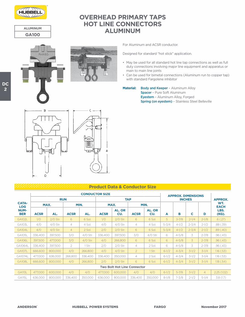
ANDERSON™ HUBBELL® POWER SYSTEMS FARGO® November 2017
DC2
OVERHEAD PRIMARY TAPSHOT LINE CONNECTORS
ALUMINUM
For Aluminum and ACSR conductor.
Designed for standard “hot stick” application.
• May be used for all standard hot line tap connections as well as full duty connections involving major line equipment and apparatus or main to main line joints
• Can be used for bimetal connections (Aluminum run to copper tap) with standard Fargolene inhibitor
Material: Body and Keeper – Aluminum Alloy Spacer – Pure Soft Aluminum Eyestem – Aluminum Alloy, Forged Spring (on eyestem) – Stainless Steel Belleville
ALUMINUM
GA100
CATA-LOG NUM-BER
CONDUCTOR SIZE APPROX. DIMENSIONSINCHES APPROX.
WT.EACHLBS.(KG).
RUN TAP
MAX. MIN. MAX. MIN.
A B C DACSR AL. ACSR AL. ACSRAL. OR
CU. ACSRAL. OR
CU.
GA102L 1/0 2/0 Str. 6 6 Sol. 1/0 2/0 Str. 6 6 Sol. 5 3-7/8 2-1/4 2-1/8 .6 (.27)
GA103L 4/0 4/0 Str. 4 4 Sol. 4/0 4/0 Str. 4 4 Sol. 5-3/4 4-1/2 2-3/4 2-1/2 .88 (.39)
GA104L 4/0 4/0 Str. 4 2 Sol. 2/0 2/0 Str. 6 6 Sol. 5-3/4 4-1/2 2-3/4 2-1/2 .89 (.40)
GA105L 336,400 397,500 3/0 4/0 Str. 336,400 397,500 3/0 4/0 Str. 6 4-5/8 3 2-7/8 .96 (.43)
GA106L 397,500 477,000 3/0 4/0 Str. 4/0 266,800 6 6 Sol. 6 4-5/8 3 2-7/8 .96 (.43)
GA1064L 336,400 397,500 2 1 Str. 2/0 2/0 Str. 4 2 Sol. 6 4-5/8 3 2-7/8 .96 (.43)
GA107L 666,600 800,000 4/0 266,800 4/0 4/0 Str. 2 1 Str. 6-1/2 4-3/4 3-1/2 3-1/4 1.16 (.53)
GA1074L 477,000 636,000 266,800 336,400 336,400 350,000 4 2 Sol. 6-1/2 4-3/4 3-1/2 3-1/4 1.16 (.53)
GA108L 666,600 800,000 4/0 266,800 2/0 2/0 Str. 6 6 Sol. 6-1/2 4-3/4 3-1/2 3-1/4 1.18 (.54)
Two Bolt Hot Line Connector
GA113L 477,000 600,000 4/0 4/0 477,000 600,000 4/0 4/0 6-1/2 5-7/8 3-1/2 4 2.25 (1.02)
GA115L 636,000 800,000 336,400 350,000 636,000 800,000 336,400 350,000 8-1/8 7-3/8 2-1/2 5-1/4 3.8 (1.7)
Product Data & Conductor Size
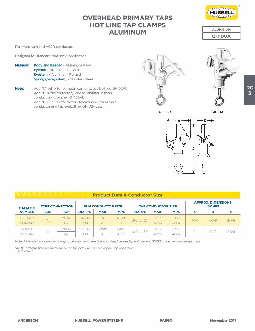
ANDERSON™ HUBBELL® POWER SYSTEMS FARGO® November 2017
DC3
OVERHEAD PRIMARY TAPSHOT LINE TAP CLAMPS
ALUMINUM
For Aluminum and ACSR conductor.
Designed for standard “hot stick” application.
Material: Body and Keeper – Aluminum Alloy Eyebolt – Bronze – Tin Plated Eyestem – Aluminum, Forged Spring (on eyestem) – Stainless Steel
Note: Add “C” suffix for bi-metal washer to eye bolt, ex. GH102AC Add “L” suffix for factory loaded inhibitor in main
conductor groove, ex. GH102AL Add “LBE” suffix for factory loaded inhibitor in main
conductor and tap eyebolt, ex GH102ALBE
ALUMINUM
GH100A
Note: All above have aluminum body, forged aluminum eye bolt and plated bronze tap bolt, except, GH103A have cast bronze eye stem.
*All “AC” clamps have a bimetal spacer on tap bolt. For use with copper tap conductor.**RUS Listed
CATALOG NUMBER
TYPE CONNECTION RUN CONDUCTOR SIZE TAP CONDUCTOR SIZEAPPROX. DIMENSIONS
INCHES
RUN TAP DIA. IN. MAX. MIN. DIA. IN. MAX. MIN. A B C
GH102A**
*GH102AC**Al.
Al/Cu. 1.075 to
.490
795
Al.
4/0 Str.
Al..610 to .152
250
Al/Cu.
6 Sol.
Al/Cu.7-1/4 4-3/8 2-5/8
Cu.
GH103A
*GH103ACAl.
Al/Cu. 1.795 to
.980
2,000
Al.
666.6
ACSR.610 to .152
250
Al/Cu.
6 Sol.
Al/Cu.9 4-1/2 2-5/8
Cu.
Product Data & Conductor Size

ANDERSON™ HUBBELL® POWER SYSTEMS FARGO® November 2017
DC4
OVERHEAD PRIMARY TAPSHOT LINE TAP CLAMPS
HOT LINE TAPS FOR MOUNTING CURRENT LIMITING FUSES ALUMINUM
BRONZE
CATALOG NUMBER
RANGEAPPROX. DIMENSIONS
INCHESAP-
PROX.WT.
EACHLBS.(KG.)RUN TAP A B C
GH201L** #4 Str. – 2/0 Str. Copper #6 Sol.-2/0 Str. Or C.L. Fuse Spade/Pin Terminal 4-1/4 4-1/8 1-3/4 .82 (.37)
ALUMINUM
GH202AL 795-4/0 AL #8 Sol. – 2/0 Str. Or C.L. Fuse Spade/Pin Terminal 5-1/4 5-1/2 3 .80 (.36)
GH201 Series Hot Line Taps are specifically designed tomount current limiting fuses directly on the line conductor eliminating the need for increased pole height to maintain adequate clearances.
• Fuse replacement can be readily accomplished using standard hot stick techniques
• Accommodates either spade or pin terminals of current limiting fuses as well as conventional solid or stranded tap conductors
• Tap position is located to provide adequate room for installation tools as well as vertical fuse alignment.Permanent contact pressure is maintained by the use of a heavy duty stainless steel Belleville spring. Long “duck-bill” provides a guide for easy initial contact with run conductor
• Forged eyebolts provide consistent strength and uniform expansion under loading conditions
Material: Body and Keeper 201 – Bronze Body and Keeper 201A – Aluminum Alloy Eyebolt – Bronze – Tin Plated Eyestem – Bronze Alloy, Forged Spring (on eyestem) – Stainless Steel Belleville
Note: Add “L” suffix for factory loaded inhibitor in main conductor groove, ex. GH201AL
Add “LBE” suffix for factory loaded inhibitor in main conductor and tap eyebolt, ex GH201ALBE
**RUS Listed
ALUM/BRONZE
GH200A
Product Data & Conductor Size
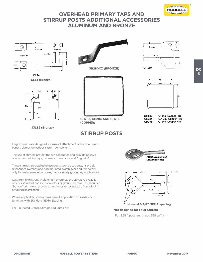
ANDERSON™ HUBBELL® POWER SYSTEMS FARGO® November 2017
DC5
OVERHEAD PRIMARY TAPS ANDSTIRRUP POSTS ADDITIONAL ACCESSORIES
ALUMINUM AND BRONZE
STIRRUP POSTS
Fargo stirrups are designed for ease of attachment of hot line taps or bypass clamps on various system components.
The use of stirrups protect the run conductor, and provide positive contact for hot line taps, recloser connections, and “pig tails.”
These stirrups are applied on products such as cut-outs, riser pole disconnect switches and pad mounted switch gear and temporary-only for maintenance purposes, not for safety grounding applications.
Cast from high strength aluminum or bronze the stirrup rod readily accepts standard hot line connectors or ground clamps. The shoulder “button” on the end prevents the clamps or connectors from slipping off during installation.
Where applicable, stirrup holes permit application on spades or terminals with Standard NEMA Spacing.
For Tin-Plated Bronze Stirrups add Suffix “P.”Not designed for Fault Current
Holes at 1-3/4” NEMA spacing
* For 5.25”” post length add 525 suffix
GH280CX (BRONZE)
CE14 (Bronze)
J3LS2 (Bronze)
GH282, GH284 AND GH286(COPPER)
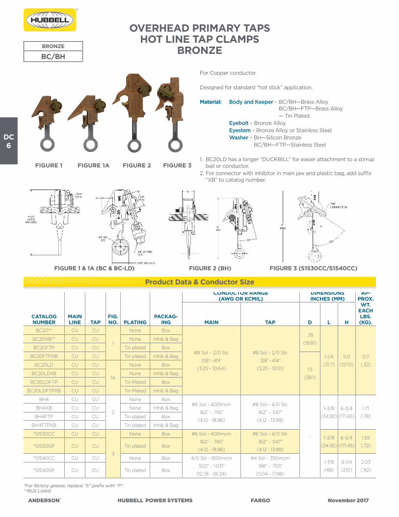
ANDERSON™ HUBBELL® POWER SYSTEMS FARGO® November 2017
DC6
OVERHEAD PRIMARY TAPSHOT LINE TAP CLAMPS
BRONZEBRONZE
BC/BH
For Copper conductor.
Designed for standard “hot stick” application.
Material: Body and Keeper – BC/BH—Brass Alloy BC/BH—FTP—Brass Alloy
— Tin Plated Eyebolt – Bronze Alloy Eyestem – Bronze Alloy or Stainless Steel Washer – BH—Silicon Bronze BC/BH—FTP—Stainless Steel
1. BC20LD has a longer “DUCKBILL” for easier attachment to a stirrup bail or conductor.
2. For connector with inhibitor in main jaw and plastic bag, add suffix “XB” to catalog number.
*For factory grease, replace “S” prefix with “P”.**RUS Listed
CATALOG NUMBER
MAINLINE TAP
FIG.NO. PLATING
PACKAG-ING
CONDUCTOR RANGE (AWG OR KCMIL)
DIMENSIONS INCHES (MM)
AP-PROX.
WT.EACHLBS.(KG).MAIN TAP D L H
BC20** CU CU
1
None Box
#8 Sol – 2/0 Str.
.128”-.419”
(3.25 - 10.64)
#8 Sol – 2/0 Str.
.128”-.414”
(3.25 - 10.51)
.78
(19.81)
1-1/4
(31.7)
5.0
(127.0)
0.7
(.32)
BC20XB** CU CU None Inhib & Bag
BC20FTP CU CU Tin plated Box
BC20FTPXB CU CU Tin plated Inhib & Bag
1.5
(38.1)
BC20LD CU CU
1A
None Box
BC20LDXB CU CU None Inhib & Bag
BC20LDFTP CU CU Tin Plated Box
BC20LDFTPXB CU CU Tin Plated Inhib & Bag
BH4 CU CU
2
None Box#6 Sol – 400mcm
.162” - .745”
(4.12 - 18.96)
#6 Sol – 4/0 Str.
.162” - .547”
(4.12 - 13.89)
-
1-3/8
(34.92)
6-3/4
(171.45)
1.71
(.78)
BH4XB CU CU None Inhib & Bag
BH4FTP CU CU Tin plated Box
BH4FTPXB CU CU Tin plated Inhib & Bag
*S1530CC CU CU
3
None Box #6 Sol – 400mcm
.162” - .745”
(4.12 - 18.96)
#6 Sol – 4/0 Str.
.162” - .547”
(4.12 - 13.89)
1-3/8
(34.92)
6-3/4
(171.45)
1.59
(.72)*S1530GP CU CU Tin plated Box
*S1540CC CU CU None Box 4/0 Str. - 800mcm
.502” - 1.031”
(12.78 - 26.24)
#4 Sol – 350mcm
.198” - .703”
(5.04 - 17.98)
1-7/8
(48)
8-1/4
(210)
2.03
(.92)*S1540GP CU CU Tin plated Box
Product Data & Conductor Size
FIGURE 1 FIGURE 1A FIGURE 2 FIGURE 3
FIGURE 1 & 1A (BC & BC-LD) FIGURE 2 (BH) FIGURE 3 (S1530CC/S1540CC)

ANDERSON™ HUBBELL® POWER SYSTEMS FARGO® November 2017
DC7
OVERHEAD PRIMARY TAPSLIGHTNING ARRESTER ACCESSORIES
ALUMINUM AND BRONZE ALUM/BRONZE
GH200/GO370
The arrester line connectors allow installation of lightning arrester directly on the line, which conserves pole space and the cost of mounting hardware.
• GH201D (bronze) and GH202AD (aluminum) versions are designed to accommodate the stud of the arrester in the rear extension of the connector.
• GO370 series Bronze Arrester Connectors thread onto the stud of an arrester. Side loading feature provides flexibility in application. Hot stick feature allows for change out of an arrester without interruption of service.
• This connector is intended primarily for bottom termination of lightning arresters to ground. May also be employed on top connections.
• GS580 Wildlife Protector is designed to be mounted on the top of a lightning arrester, and accommodates any of the GO370 series arrester connections. Hinged design allows easy access to connector. Track resistant polypropylene with ultraviolet inhibitors.
Material: Body and Keeper GH201D & GO300 Series – Bronze Body and Keeper 202AD – Aluminum Alloy Eyestem 201D – Bronze Alloy, Forged Eyestem 202AD – Aluminum Alloy, Forged Spring (on eyestem) – Stainless Steel Belleville
Note: Add “P” suffix for tin plating, ex GH201DP Add “L” suffix for factory loaded inhibitor in main
conductor groove, ex. GH201DPL
CATALOG NUMBER
MAINLINE
FIG.NO. PLATING
CONDUCTOR RANGE DIMENSIONS INCHES (MM) APPROX.WT.
EACHLBS.(KG).
PACKAG-ING COPPER ALUMINUM A B C
GH201D CU 1 None Box #8 Sol – 2/0 Str. n/a 4 (102) 1 (25) n/a .74 (.34)
GH202AD AL 2 None Box n/a 4/0 – 795 AAC
.522 – 1.028
6.5 (165) 1.5 (38) n/a .72 (.33)
GH202ADL AL/CU 2 None Box 4/0 Str. - 750 6.5 (165) 1.5 (38) n/a .72 (.33)
GO375 CU 3 None Box #6 – 1/0 Str
.184 - .373
n/a
3.9 (99) 0.9 (23) 1.9 (48) .48 (.22)
GO375P CU 3 Tin plated Box 3.9 (99) 0.9 (23) 1.9 (48) .50 (.23)
GO376 CU 3 None Box 2/0 – 350 Str.
.414 - .710
4.3 (109) 0.9 (23) 2.3 (59) .59 (.27)
GO376P CU 3 Tin plated Box 4.3 (109) 0.9 (23) 2.3 (59) .60 (.27)
GC207LA CU 4 None Box #6 Sol-1/0 Str. 1.25 (32) 0.75 (19) 1.77 (48) .22 (.99)
Product Data & Conductor Size
See also: Page DD-10 GC207LA & LAT
GH202ADGH201D
GO370 SERIES
GC207LAFIGURE 3FIGURE 4
FIGURE 2 FIGURE 1
B
A AOpen
3/8-16UNC 2B
B
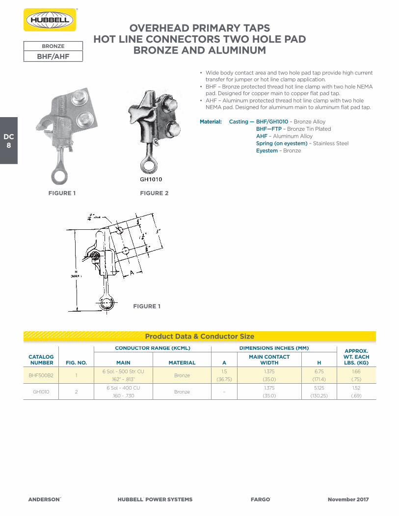
ANDERSON™ HUBBELL® POWER SYSTEMS FARGO® November 2017
DC8
OVERHEAD PRIMARY TAPSHOT LINE CONNECTORS TWO HOLE PAD
BRONZE AND ALUMINUM
• Wide body contact area and two hole pad tap provide high current transfer for jumper or hot line clamp application.
• BHF – Bronze protected thread hot line clamp with two hole NEMA pad. Designed for copper main to copper flat pad tap.
• AHF – Aluminum protected thread hot line clamp with two hole NEMA pad. Designed for aluminum main to aluminum flat pad tap.
Material: Casting — BHF/GH1010 – Bronze Alloy BHF—FTP – Bronze Tin Plated AHF – Aluminum Alloy Spring (on eyestem) – Stainless Steel Eyestem – Bronze
BRONZE
BHF/AHF
CATALOG NUMBER FIG. NO.
CONDUCTOR RANGE (KCML) DIMENSIONS INCHES (MM) APPROX.WT. EACH LBS. (KG)MAIN MATERIAL A
MAIN CONTACT WIDTH H
BHF500B2 16 Sol. - 500 Str. CU
.162” - .813”Bronze
1.5
(36.75)
1.375
(35.0)
6.75
(171.4)
1.66
(.75)
GH1010 26 Sol – 400 CU
.160 - .730Bronze –
1.375
(35.0)
5.125
(130.25)
1.52
(.69)
Product Data & Conductor Size
FIGURE 1 FIGURE 2
FIGURE 1

ANDERSON™ HUBBELL® POWER SYSTEMS FARGO® November 2017
DC9
OVERHEAD PRIMARY TAPSSTIRRUP CLAMPS
ALUMINUM
For aluminum or ACSR conductor.
Eyestem is at 30º angle from the stirrup.
Material: Body – Aluminum Alloy Eyestem – Bronze Alloy—Tin Plated or Stainless Steel Stirrup – Copper-un-plated
Notes: Tin plated stirrup available by adding suffix “TB” to catalog number. Examples, AHLS022016ETB, AHLS954022EWBTB
Factory inhibited and bagged, add “XB”
CATALOG NUMBER
FIGURENO.
CONDUCTOR RANGE(AWG OR MCM) COPPER
LOOPSIZE
(INCHES)
BOLTS DIMENSIONS INCHES (MM)APPROX.
WT. EACH LBS. (KG)AAC ACSR NO. SIZE L B H
AHLS022016E 2 & 5 #6 Sol.-2/0 Str. #8-2/0 Str.#4
(.204)1
3/8
(9.52)
1-13/16
(46.04)
2-3/8
(60.32)
4-1/32
(102.39)
.53
(.24)
AHLS022019E 2 & 5#6 Sol.-2/0 Str. #8-2/0 Str.
#1
(.289)1
3/8
(9.52)
1-13/16
(46.04)
2-3/8
(60.32)
4-3/16
(106.36)
.67
(.30)
AHLS022019EWB 4 & 54-1/2
(114.3)
5-1/16
(128.59)
.71
(.32)
AHLS024019E 1 & 5 #2-4/0 Str. #4-4/0 Str.#1
(.289)2
3/8
(9.52)
3-1/2
(88.9)
4
(101.6)
4-1/16
(103.19)
1.19
(.54)
AHLS024021E 1 & 5#2-4/0 Str. #4-4/0 Str.
1/0
(.325)2
3/8
(9.52)
3-1/2
(88.9)
4
(101.6)
4-1/32
(103.19)
1.25
(.57)
AHLS024021EWB 3 & 56
(152.4)
4-29/32
(124.62)
1.29
(.59)
AHLS397021E 1 & 5 1/0-500 MCM 1/0-397.5 MCM1/0
(.325)2
7/16
(11.18)
3-11/16
(93.66)
4
(101.6)
4-3/32
(103.99)
1.56
(.71)
AHLS397022E 1 & 51/0-500 MCM 1/0-397.5 MCM
2/0
(.365)2
7/16
(11.18)
3-11/16
(93.66)
4
(101.6)
4-3/32
(103.99)
1.65
(.75)
AHLS397022EWB 3 & 56
(152.4)
4-31/32
(126.21)
1.91
(.87)
AHLS954022E 1 & 5336.4-1033.5 MCM 336.4-954 MCM
2/0
(.365)2
1/2
(12.7)
4-1/4
(107.95)
4-1/2
(114.3)
4-3/16
(106.36)
2.30
(1.04)
AHLS954022EWB 3 & 56
(152.4)
5-1/16
(128.59
2.41
(1.09)
AHLS954024E 1 & 5 336.4-1033.5 MCM 336.4-954 MCM4/0
(.460)2
1/2
(12.7)
4-1/4
(107.95)
4-1/2
(114.3)
4-3/16
(106.36)
2.49
(1.13)
ALUMINUM
AHLS
Product Data & Conductor Size
FIGURE 5FIGURE 2FIGURE 1 FIGURE 4FIGURE 3

ANDERSON™ HUBBELL® POWER SYSTEMS FARGO® November 2017
DC10
OVERHEAD PRIMARY TAPSSPRING LOADED “LINE SNAPPER”
STIRRUP CLAMPSALUMINUM
ALUMINUM
ESC
CATALOG NUMBER
MAINCONDUCTOR RANGE
STIRRUPNOM. WIRE
SIZE
DIMENSIONS INCHES (MM) APPROX.WT. EACH LBS. (KG)A B C J
ESC202
6 Sol.-2/0 Str.
#6 ACSR-2/0 ACSR
.162”-.447” O.D.
2 Sol.3-3/8
(85.8)
3-1/4
(82.5)
4
(101.6)
3/8
(9.6)140 (63)
ESC50020
2/0 Str.-500 Str.
1/0 ACSR-477(18/1)ACSR
.398”-.814” O.D
2/0 Sol.4
(101.6)
3-1/2
(88.9)
4-1/2
(114.3)
1/2
(12.7)247 (112)
• Two bolt stirrups have clip type springs to apply moderate pressure on the jaws as they are pushed onto the line. This pressure is enough to allow the assembly to support its own weight on the line while one of the eyestems is snugged down.
• Lifting eyes are provided on both jaws and eyestems are standard.• The angular relationship between stirrup and tightening bolts is an
easy approach position for making installation leaving the stirrup hanging straight down.
Material: Castings – Aluminum Alloy Stirrups – Copper Rod—Tin Plated Eyestems – Bronze Alloy Tin Plated or Stainless Steel Spring – Stainless Steel
Note: Factory inhibited and bagged, add “XB”
Product Data & Conductor Size
PEENED THREADS TOPREVENT DISASSEMBLY

ANDERSON™ HUBBELL® POWER SYSTEMS FARGO® November 2017
DC11
OVERHEAD PRIMARY TAPSWIDE JAW STIRRUP CLAMPS
ALUMINUM AND BRONZE ALUM/BRONZE
HLSA/HLSB
• Heavy duty wide range stirrup clamp covers a broad cable range. One eyestem with long contact keeper provides easy installation.
• HLSA aluminum body designed for use on aluminum main.
Material: Castings – Aluminum Alloy Stirrup – Un-plated Copper Eyestem – Bronze Alloy Tin Plated
• HLSB bronze body designed for use on copper main.
Material: Castings – Bronze Alloy Stirrup – Un-plated Copper Eyestem – Bronze Alloy Tin Plated
Note: Factory inhibited and bagged, add “XB”.
CATALOG NUMBER
MAIN LINECONDUCTOR RANGE MATERIAL
STIRRUP NOM. WIRE
SIZE
DIMENSIONS INCHES (MM) APPROX.WT. 100
LBS. (KG)A B C
HLSA4002 6 Sol. - 400 Str.
#6 ACSR - 397.5 (18/1) ACSR
.162” - .743” O.D.
Aluminum2 Sol. (.258)
3-1/8
(79.4)
3-3/8
(85.8)
2-3/4
(69.8)
116 (52)
HLSA40010 1/0 Sol. (.365) 136 (62)
HLSB40026 Sol. - 400 Str. Cu.
.162” - .728” O.D.Bronze 2 Sol. (.258)
3-1/8
(79.4)
3-3/8
(85.8)
2-3/4
(69.8)220 (99.8)
Product Data & Conductor Size
PEENED THREADS TOPREVENT DISASSEMBLY

ANDERSON™ HUBBELL® POWER SYSTEMS FARGO® November 2017
DC12
OVERHEAD PRIMARY TAPSSTIRRUP CONNECTOR
ALUMINUMALUMINUM
GA100SL
• GA100S Series Hot Line Stirrup Connector provides a convenient method to install tap connections which must be removed and re-installed frequently.
• Easily installed with standard Hot Stick equipment, and are recommended for uses on aluminum or ACSR run conductors in conjunction with a bronze hot line tap on the stirrup bail.
• Long term performance is assured by the field proven design incorporating, a large connector mass, vise-type interlocking components, and a short low resistance current transfer through a soft, pure aluminum spacer.
• The #2 Sol. hard drawn copper stirrup is positioned for adequate clearance. Additional stirrup sizes are available. Factory loaded with inhibitor
Material: Body Casting – Aluminum Alloy Eyestem – Forged Aluminum
CATALOG NUMBER
COPPER LOOP SIZEIN (MM)
CONDUCTOR RANGE(AWG OR KCMIL)
APPROX.WT. EACH LBS. (KG)
GA102S*L #2 Sol. (.258) #6 Sol. - #2/0 ACSR .96 (.44)
GA104S*L #2 Sol. (.258) #4 ACSR - #4/0 ACSR 1.24 (.56)
GA106S*L #2 Sol. (.258) #2/0 ACSR – 397.5 ACSR 1.32 (.60)
GA108S*L #2 Sol. (.258) #4/0 ACSR – 954 ACSR 1.44 (.65)
*For 2/0 Sol Stirrup Add Suffix “6” (e.g. GA108S6L)For Plated Stirrup Add Suffix “P”Suffix “L” indicates Inhibitor Protected as Standard.
Product Data & Conductor Size
2.84(72)
8.58(217)
#250C(.258”)
5.25(133)
5.25(133)
1.88(47)

ANDERSON™ HUBBELL® POWER SYSTEMS FARGO® November 2017
DC13
OVERHEAD PRIMARY TAPSSTIRRUP CLAMPS
ALUMINUM ALUMINUM
GH280AL
GH280AL Series Aluminum Stirrup Clamps provide a convenient method of making copper connections and taps to ACSR, AAC and AAAC where connections are frequently installed and removed.
• Wide bail configuration provides easy installation for one or two hot-line taps.
• High-strength aluminum alloy body and pressure pad form permanent connection with low contact resistance.
• Forged aluminum eye bolt assures consistency of strength along with compatible thermal expansion/contraction characteristics and corrosion resistance.
• Serrated conductor groove prevents rotation on run conductor.• Modified parabolic V-groove design encircles the run conductor
maximizing contact area and ensuring efficient current transfer.• Wrought aluminum alloy body provides elongation characteristics
for consistent compression to copper stirrup.• Crimped copper stirrup provides high conductivity to maintain low
operating temperature.• Meets or exceeds all ANSI-C119.4 Class A current cycle requirements.• Factory inhibited and bagged
Material: Body & Pad – Extruded Aluminum Stirrup – Copper Eyestem – Forged Aluminum
CATALOG NUMBER
RANGE APPROX. DIMENSIONS INCHES APPROX.WT. EACH LBS. (KG)
CONDUCTOR (AWG OR KCMIL) O.D. A B C D E
GH282AL 4-4/0 ACSR.250 - .563 in.
6.4 – 14.3 mm5-1/4 4-1/2 3-1/2 1-3/4 1/4 .64(.29)
GH284AL 1/0 397.5 ACSR.398 - .806 in.
10.1 – 20.5 mm6 5-1/2 4 2-7/16 3/8 1.16(.53)
GH286AL 4/0 ACSR – 795 ACSR.563 – 1.081 in.
14.3 – 27.4 mm6-1/2 5-1/2 4-3/8 2-7/16 3/8 1.32(.60)
Product Data & Conductor Size
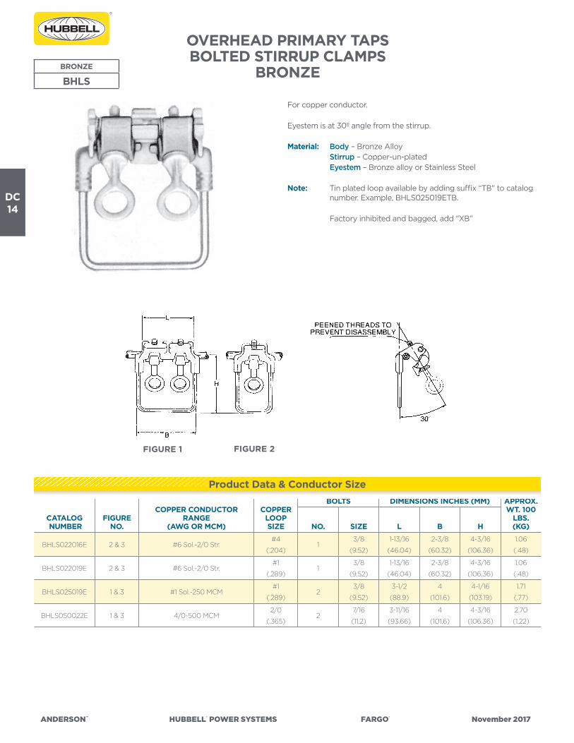
ANDERSON™ HUBBELL® POWER SYSTEMS FARGO® November 2017
DC14
OVERHEAD PRIMARY TAPSBOLTED STIRRUP CLAMPS
BRONZEBRONZE
BHLS
For copper conductor.
Eyestem is at 30º angle from the stirrup.
Material: Body – Bronze Alloy Stirrup – Copper-un-plated Eyestem – Bronze alloy or Stainless Steel
Note: Tin plated loop available by adding suffix “TB” to catalog number. Example, BHLS025019ETB.
Factory inhibited and bagged, add “XB”
CATALOG NUMBER
FIGURENO.
COPPER CONDUCTOR RANGE
(AWG OR MCM)
COPPERLOOPSIZE
BOLTS DIMENSIONS INCHES (MM) APPROX.WT. 100
LBS. (KG)NO. SIZE L B H
BHLS022016E 2 & 3 #6 Sol.-2/0 Str.#4
(.204)1
3/8
(9.52)
1-13/16
(46.04)
2-3/8
(60.32)
4-3/16
(106.36)
1.06
(.48)
BHLS022019E 2 & 3 #6 Sol.-2/0 Str.#1
(.289)1
3/8
(9.52)
1-13/16
(46.04)
2-3/8
(60.32)
4-3/16
(106.36)
1.06
(.48)
BHLS025019E 1 & 3 #1 Sol.-250 MCM#1
(.289)2
3/8
(9.52)
3-1/2
(88.9)
4
(101.6)
4-1/16
(103.19)
1.71
(.77)
BHLS050022E 1 & 3 4/0-500 MCM2/0
(.365)2
7/16
(11.2)
3-11/16
(93.66)
4
(101.6)
4-3/16
(106.36)
2.70
(1.22)
Product Data & Conductor Size
FIGURE 2FIGURE 1

ANDERSON™ HUBBELL® POWER SYSTEMS FARGO® November 2017
DC15
HEAVY DUTY COMPRESSION STIRRUPTYPE HLS
ALUMINUM
HLS
• For use with Versa-Crimp® or standard compression tools.• Stirrups protect primary lines from arcing damage by allowing hot
line clamp connections to be made without contacting the main line. The HLS design offers convenient installation because it can be lifted and placed on the line using the crimping tool jaws as a holding device.
• Wide stance of crimping segments gives good stability when striking bail with a hot line clamp. All sizes have side opening line slots.
• Stirrups can be used on either aluminum or copper lines. Contact grooves are prefilled with electrical joint compound. Individually packaged in poly bags to prevent contamination.
Material: Castings – Aluminum Alloy Stirrup – Copper Rod—Tin Plated
CATALOG NUMBER
CONDUCTOR RANGE (AL OR CU)
STIRRUPWIRE SIZE
CRIMPDIE
SIZES
HINCHES
(MM)
APPROX.WT. EACH LBS. (KG)AWG & KCMIL ACSR
DIAMETER(INCHES)
HLS42P 6 Sol.-4 Str. 6 .162-.236
2 Sol.
Burndy
Kearney
Etc.
“O” Die
3.25
(82)50 (22.7)HLS22P 2 Sol.-2 Str. 4-2 .250-.325
HLS102P 1/0 Str. 1-1/0 .355-.398
HLS302P 2/0 & 3/0 Str. 2/0-3/0 .414-.517
2 Sol.
EEI-13A
Burndy
316,655 & 705
Kearney
1-1/8
3.25
(82)
60 (27.2)HLS2662P 4/0-266 Str. 4/0-266 18/1 .522-.609
HLS3502P336-350 Str.
266-26/7
336-18/1
336-26/7
.607-.721HLS35020P 2/0 Sol. 81 (36.7)
HLS50010P
397.5-500 Str.
397.5-18/1
397.5-36/1
477-18/1
477-36/1
.720-.814
1/0 Sol.Kearney
1-5/16
3.75
(95)
82 (37.2)
HLS50020P 2/0 Sol. 91 (41.3)
HLS65010P500-650 Str.
477-18/1
556-18/1
636-36/1
.811-.9301/0 Sol.
Kearney
1-1/2
3.75
(95)
95 (43.1)
HLS65020P 2/0 Sol. 105 (47.6)
HLS80010P
700-800 Str.
636-18/1
636-36/1
666.6-36/1
795-36/1
.930-1.040
1/0 Sol.
Kearney
1-1/2
3.75
(95)
92 (41.7)
HLS80020P 2/0 Sol. 102 (46.3)
HLS80040P 4/0 Sol. 122 (55.3)
Product Data & Conductor Size

ANDERSON™ HUBBELL® POWER SYSTEMS FARGO® November 2017
DC16
VERSA-CRIMP® ALUMINUM COMPRESSION STIRRUP TAP TYPE VCLS
• For use with VERSA-CRIMP® Type VC6 (all) tools only.
Material: Body – Aluminum Alloy Stirrup – Un-plated Copper Factory inhibited (See notes below)
CATALOG NUMBER
FIG-URENO.
CONDUCTOR RANGELOOPSIZE
VERSA- CRIMP
TOOL TYPE
DIMENSIONS INCHES (MM) APPROX.WT. EACH LBS. (KG)AAC ACSR COPPER L B H
VCLS3018 1 #6 (7)—#2(19) #6 (6/1)—#2 (7/1) #6 Sol.-#2 (7) #2 Sol.
VC6
(ALL)
8-5/8
(219.1)
4
(101.6)
3-7/16
(87.3)
.44
(.20)
*VCLS5018 1 #6 (7)—2/0 (19) #6 (6/1)—2/0 (6/1) — #2 Sol.7-7/8
(200.0)
4
(101.6)
3-7/16
(87.3)
.48
(.22)
*VCLS6021 1 #4 (7)—266.8 (19) #4 (6/1)—4/0(6/1) — 1/0 Sol.8
(203.2)
4
(101.6)
3-1/2
(88.9)
.65
(.29)
VCLS9022 2 3/0 (7)—556.5 (19)3/0 (6/1)—477
(30/7)—
2/0
Sol.
VC6-3
VC6-FT
9-15/16
(252.41)
4-7/16
(112.7)
5-11/16
(144.5)
.80
(.36)
Note: Tin plated loop available by adding suffix “TB” to catalog number. Example, VCLS3018TB.* For deep throated bail, add suffix “DB” to catalog number. Example, VCLS5018DB.
ALUMINUM
VCLS
Product Data & Conductor Size
FIGURE 1

ANDERSON™ HUBBELL® POWER SYSTEMS FARGO® November 2017
DC17
OVERHEAD PRIMARY TAPSCOMPRESSION VERSA-CRIMP® COPPER COMPRESSION STIRRUP TAP COPPER COPPER
VCLSC
• For use with VERSA-CRIMP® Type VC6 nd VC7 series tools only.• For copper conductor.
Material: Body – Cast Copper Alloy Stirrup – Un-plated Copper
CATALOG NUMBER COPPER CONDUCTOR RANGE
LOOPSIZE
VERSA-CRIMP
TOOL TYPE
DIMENSIONS INCHES (MM) APPROX.WT. EACH LBS. (KG)L B H
VCLSC3018 #6.Sol.–#2/(7)#2 Sol.
Cu.VC7
VC6
(ALL)
5-1/2
(139.7)
5
(127.0)
5-11/32
(17.46)
.80
(.36)
VCLSC5021 #2 Sol.–2/0 (19)1/0 Sol.
Cu.
5-9/16
(141.3)
5
(127.0)
5-15/16
(150.81)
.96
(.44)
VCLSC6022 1/0 (7)–4/0(19)2/0 Sol.
Cu.
5-9/16
(141.3)
5
(127.0)
6-15/16
(176.21)
1.20
(.54)
Product Data & Conductor Size
B
L
H

ANDERSON™ HUBBELL® POWER SYSTEMS FARGO® November 2017
DC18
VERSA-CRIMP® ALUMINUM COMPRESSION TAPALUMINUM
VCP
• For use with VERSA-CRIMP® Type VC6 (all) tools, except VC6350 and VC6500.
• For aluminum to aluminum or aluminum to copper conductor taps.• For AAC or ACSR loop deadending on slack span construction
when installed in tandem.
Material: Body – Aluminum Alloy Factory inhibited and packaged in individual boxes.
CATALOG NUMBER
CONDUCTOR RANGE (AWG)VERSA-CRIMP
TOOL TYPE
LENGTHINCHES
(MM)
APPROX.WT. EACH LBS. (KG)
MAIN TAP
AAC ACSR COPPER AAC ACSR COPPER
VCP44
2/0 (19, 7)
1/0 (19, 7)
#1 (19, 7)
#2 (19, 7)
#3 (7), #4 (7)
#6 (7)
1/0 (6/1)
#1 (6/1)
#2 (7/1, 6/1)
#4 (7/1, 6/1)
#6 (6/1)
#2 (7/1)
#4 (7/1)
#6 (7/1)
1/0 (19,7)
#1 (19,7)
#2 (19,7)
#3 (7)
#4 (7)
#6 (7)
1/0 (6/1)
#1 (6/1)
#2 (7/1 6/1)
#4 (7/1,6/1)
#6 (6/1)
#2 (7, 1)
#4 (7, 1)
#6 (7, 1)
VC6
(ALL)
∆∆
1-7/8
(47.6)
.10
(.05)
∆∆ For use with all VERSA-CRIMP Type VC6 four (4) nib tool only.
Product Data & Conductor Size
L
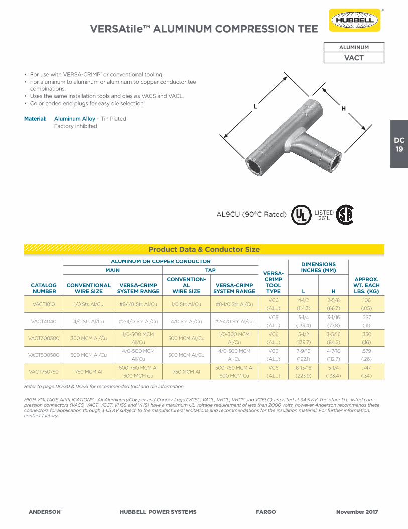
ANDERSON™ HUBBELL® POWER SYSTEMS FARGO® November 2017
DC19
VERSAtile™ ALUMINUM COMPRESSION TEEALUMINUM
VACT
• For use with VERSA-CRIMP® or conventional tooling.• For aluminum to aluminum or aluminum to copper conductor tee
combinations.• Uses the same installation tools and dies as VACS and VACL.• Color coded end plugs for easy die selection.
Material: Aluminum Alloy – Tin Plated Factory inhibited
CATALOG NUMBER
ALUMINUM OR COPPER CONDUCTOR
VERSA-CRIMPTOOLTYPE
DIMENSIONS INCHES (MM)
APPROX.WT. EACH LBS. (KG)
MAIN TAP
CONVENTIONALWIRE SIZE
VERSA-CRIMPSYSTEM RANGE
CONVENTION-AL
WIRE SIZEVERSA-CRIMP
SYSTEM RANGE L H
VACT1010 1/0 Str. Al/Cu #8-1/0 Str. Al/Cu 1/0 Str. Al/Cu #8-1/0 Str. Al/CuVC6
(ALL)
4-1/2
(114.3)
2-5/8
(66.7)
.106
(.05)
VACT4040 4/0 Str. Al/Cu #2-4/0 Str. Al/Cu 4/0 Str. Al/Cu #2-4/0 Str. Al/CuVC6
(ALL)
5-1/4
(133.4)
3-1/16
(77.8)
.237
(.11)
VACT300300 300 MCM Al/Cu1/0-300 MCM
Al/Cu300 MCM Al/Cu
1/0-300 MCM
Al/Cu
VC6
(ALL)
5-1/2
(139.7)
3-5/16
(84.2)
.350
(.16)
VACT500500 500 MCM Al/Cu4/0-500 MCM
Al/Cu500 MCM Al/Cu
4/0-500 MCM
Al-Cu
VC6
(ALL)
7-9/16
(192.1)
4-7/16
(112.7)
.579
(.26)
VACT750750 750 MCM Al500-750 MCM Al
500 MCM Cu750 MCM Al
500-750 MCM Al
500 MCM Cu
VC6
(ALL)
8-13/16
(223.9)
5-1/4
(133.4)
.747
(.34)
Refer to page DC-30 & DC-31 for recommended tool and die information.
HIGH VOLTAGE APPLICATIONS—All Aluminum/Copper and Copper Lugs (VCEL, VACL, VHCL, VHCS and VCELC) are rated at 34.5 KV. The other U.L. listed com-pression connectors (VACS, VACT, VCCT, VHSS and VHS) have a maximum UL voltage requirement of less than 2000 volts, however Anderson recommends these connectors for application through 34.5 KV subject to the manufacturers’ limitations and recommendations for the insulation material. For further information, contact factory.
Product Data & Conductor Size
LISTED261LAL9CU (90°C Rated)
L H

ANDERSON™ HUBBELL® POWER SYSTEMS FARGO® November 2017
DC20
VERSA-CRIMP® ALUMINUM COMPRESSION TAP
ALUMINUM
VCL
• For use with VERSA-CRIMP® Type VC6 (all) tools only.• For aluminum to aluminum or aluminum to copper conductor
connections.• Aluminum alloy conductor recommendations include 5005, 6201
(AAAC) and ACAR which are of the same diameter as a given ACSR conductor shown below.
Material: Aluminum Alloy Factory inhibited
CATALOG NUMBER
CONDUCTOR RANGE VERSA-CRIMPTOOLTYPE
DIMENSIONS INCHES (MM) APPROX.WT. EACH LBS. (KG)MAIN TAP L H
VCL54
#6 (7)—2/0 (19) AAC
#6 (6/1)—2/0 (6/1) ACSR
#6 (7)—#1 (19) Cu
#8 (7)-1/0 (19) AAC
#8 (6/1)—1/0 (6/1) ACSR
#10 Sol.—#2 (7) Cu
VC6
(ALL)
2-11/16
(68.26)
2-1/2
(63.5)
.17
(.08)
VCL64
#4 (7)—4/0 (19) AAC
#4 (6/1)—4/0 (6/1) ACSR
#4 (7)—2/0 (19) Cu
#8 (7)—1/0 (19) AAC
#8 (6/1)— 1/0 (6/1) ACSR
#10 Sol.— #2 (7) Cu
2-23/32
(69.06)
2-33/64
(63.90)
.19
(.09)
VCL66
#4 (7)—4/0 (19) AAC
#4 (6/1)—4/0 (6/1) ACSR
#4 (7)—2/0 (19) Cu
#4 (7)—4/0 (19) AAC
#4 (6/1)—4/0 (6/1) ACSR
#4 Sol.—2/0 (19) Cu
2-31/32
(75.41)
3-19/64
(83.74)
.26
(.12)
VERSA-CRIMP® ALUMINUM COMPRESSION TAPALUMINUM
VC2T
• For use with VERSA-CRIMP® Type VC6 (all) tools only.• For aluminum to aluminum or aluminum to copper conductor
connections.• Aluminum alloy conductor recommendations include 5005, 6201
(AAAC) and ACAR which are of the same diameter as a given ACSR conductor shown below.
Material: Aluminum Alloy Factory inhibited
CATALOG NUMBER
CONDUCTOR RANGE (AWG) VERSA-CRIMPTOOLTYPE
DIMENSIONS INCHES (MM) APPROX.WT. EACH LBS. (KG)MAIN TAP L H
VC2T66
#4 Sol.—4/0 (19) AAC
#4 (6/1)—4/0 (6/1) ACSR
# 4 Sol.—2/0 (19) Cu
#4 Sol.—4/0 (19) AAC
#4 (6/1)— 4/0 (6/1) ACSR
#4 Sol.—2/0 (19) Cu
VC6
(ALL)
3-1/8
(79.4)
5-7/16
(138.1)
.40
(.18)
Product Data & Conductor Size
Product Data & Conductor Size
L
H
L
H

ANDERSON™ HUBBELL® POWER SYSTEMS FARGO® November 2017
DC21
VERSA-CRIMP® ALUMINUM COMPRESSION TEE
ALUMINUM
VCT
• For use with VERSA-CRIMP® Type VC6 (all) tools only.• For aluminum to aluminum or aluminum to copper conductor tee
connections.• Aluminum alloy conductor recommendations include 5005, 6201
(AAAC) and ACAR having the same diameter as a given ACSR conductor shown below.
Material: Aluminum Alloy Factory inhibited
CATALOG NUMBER
FIGURENO.
CONDUCTOR RANGE (AWG OR MCM) VERSA-CRIMP
TOOL TYPE
DIMENSIONS INCHES (MM) APPROX.WT. EACH LBS. (KG)MAIN TAP L H
VCT55 1#6 (7)-2/0 (19) AAC
#6 (6/1)-2/0 (6/1) ACSR
#6 (7)-2/0 (19) AAC
#6 (6/1)-2/0 (6/1) ACSR
#6 Sol.-#1 (19) Cu
VC6
(ALL)
4-1/16
(103.2)
2-7/8
(73.0)
.55
(.25)
VCT95 23/0 (7)-500 (37) AAC
3/0 (6/1)-477 (18/1) ACSR
#6 (7)-2/0 (19) AAC
#6 (6/1)-2/0 (6/1) ACSR
#6 Sol.-1/0 (19) Cu
VC63
VC6FT
5-5/16
(134.9)
4-7/16
(112.7)
.93
(.42)
VCT96 23/0 (7)-500 (37) AAC
3/0 (6/1)-477 (18/1) ACSR
1/0 (7)-4/0 (19) AAC
1/0 (6/1)-4/0 (6/1) ACSR
1/0 (7)-3/0 (19) Cu
VC63
VC6FT
5-5/16
(134.9)
4-7/16
(112.7)
.97
(.44)
VCT99 23/0 (7)-500 (37) AAC
3/0 (6/1)-477 (18/1) ACSR
4/0 (7)-350 (37) AAC
4/0 (6/1)-477 (18/1) ACSR
4/0 (7)-350 (37) Cu
VC63
VC6FT
5-5/16
(134.9)
6-7/16
(163.5)
1.20
(.54)
Product Data & Conductor Size
FIGURE 1
L
H
FIGURE 2

ANDERSON™ HUBBELL® POWER SYSTEMS FARGO® November 2017
DC22
VERSA-CRIMP® ALUMINUM COMPRESSION TAP
ALUMINUM
VCU
• For use with VERSA-CRIMP® Type VC6 (all) tools.• For aluminum to aluminum or aluminum to copper conductors.• Aluminum alloy conductor recommendations include 5005, 6201
(AAAC) and ACAR which are of the same diameter as a given ACSR conductor shown below.
Material: Aluminum Alloy Factory inhibited
CATALOG NUMBER
CONDUCTOR RANGE VERSA-CRIMP
TOOL TYPE
DIMENSIONS INCHES (MM) APPROX.WT. EACHLBS. (KG)MAIN TAP L H
VCU55
#6 (7)-2/0 (19) AAC
#6 (6/1)-2/0 (6/1) ACSR
#8 (7)-#4 (7) Cu
#6 (7)-2/0 (19) AAC
#6 (6/1)-2/0 (6/1) ACSR
#8 (7)-#4 (7) Cu
VC6
(ALL)
3-1/8
(79.38)
3-1/8
(79.38)
.18
(.08)
VCU65
#4 (7)-4/0 (19) AAC
#4 (6/1)-4/0 (6/1) ACSR
#4 (7)-2/0 (19) Cu
#6 (7)-2/0 (19) AAC
#6 (6/1)-2/0 (6/1) ACSR
#8 (7)-#4 (7) Cu
3-3/16
(80.96)
3-1/8
(79.38)
.20
(.09)
VCU66
#4 (7)-4/0 (19) AAC
#4 (6/1)-4/0 (6/1) ACSR
#4 (7)-2/0 (19) Cu
#4 (7)-4/0 (19) AAC
#4 (6/1)-4/0 (6/1) ACSR
#4 (7)-2/0 (19) Cu
3-3/16
(80.96)
3-3/16
(80.96)
.24
(.11)
Product Data & Conductor Size
L
H

ANDERSON™ HUBBELL® POWER SYSTEMS FARGO® November 2017
DC23
Cat
alog
Num
ber
VAC
L (3
)
VAC
S (4
)
VAC
T (4
)
AN
DER
SON
™ V
ERSA
-CR
IMP®
CO
MPR
ESSI
ON
TO
OLS
(Cri
mps
per
Con
nect
ion)
CO
NV
ENTI
ON
AL
CO
MPR
ESSI
ON
DIE
TO
OLI
NG
(Cri
mps
per
Con
nect
ion)
V-C
Too
lsW
ireR
ange
(AW
G o
rM
CM
)
VER
SA-C
RIM
P To
ols
(Num
ber
of C
rim
ps)
Wire
Size
(AW
Gor
MC
M)
Die
Col
orC
ode
(2)
Bur
ndy
(Cri
mps
)B
urnd
y In
dent
or T
ools
(1 C
rim
p)
*VC
650
0V
C6
350
VC
6(1
)
VC
6FT (1
)
VC
8A
LN
IBS
Die
Inde
xN
o.
Tool
Y34
A
Tool
sY
35Y
39To
olY
34B
Tool
Y4
8BTo
olY
486
RB
Tool
MY-
29
Tool
Y34
A(I
nden
-to
r)
Tool
Y34
B(I
nden
-to
r)
Tool
Y4
8B(I
nden
-to
r)
Tool
Y4
86R
B(I
nden
-to
r)D
ieD
ieD
ieD
ieD
ieD
ieN
est
Nes
tN
est
Nes
t
-8#
8 A
L/C
U1
1#
8A
L/C
UB
lue
374
U8C
AB
T(2
)#
8 (1)
-6#
6 A
L/C
U1
1#
6A
L/C
UG
ray
346
A6C
AB
(1)
U6C
AB
T(1
)B
6CD
(1)
#6 (1)
A4
CD
(Y34
PA)
B4
CD
(Y34
PA)
-4#
4 A
L/C
U2
2#
4A
L/C
UG
reen
375
A4
CA
B(1
)U
4C
AB
T*
(1)
B4
CD
(1)
C4
CA
B(1
)#
4 (1)
A1C
D(Y
34PA
)B
1CD
(Y34
PA)
-2#
6-#
2 A
L/C
U2
22
2#
2A
L/C
UP
ink
348
A2C
AB
(1)
U2C
AB
T(1
)B
2CD
(1)
#2
(2)
A26
D(Y
34PA
)B
26D
(Y34
PA)
-1#
8-#
1 AL/
CU
22
22
#1
AL/
CU
Tan
296
A25
AR
(1)
U25
AR
T*
(1)
B1C
D(1
)#
1(2
)A
27D
(Y34
PR
-5)
B27
D(Y
34P
R-5
)
-1/0
#8-
1/0
AL/
CU
22
22
1/0
AL/
CU
Tan
296
A25
AR
(1)
U25
AR
T*
(1)
B25
D(1
)1/
0(2
)A
27D
(Y34
PR
-5)
B27
D(Y
34P
R-5
)
-2/0
#4
-2/0
AL/
CU
22
22
2/0
AL/
CU
Oliv
e29
7A
26A
R(2
)U
26A
RT
(2)
B26
D(1
)2/
0(2
)A
29D
(Y34
PR
-5)
B29
D(Y
34P
R-5
)
-3/0
#4
-3/0
AL/
CU
22
22
3/0
AL/
CU
Rub
y4
67A
27A
R(2
)U
27A
RT
(2)
B27
D(1
)3/
0(2
)A
30D
(Y34
PR
-5)
B30
D(Y
34P
R-5
)
-4/0
#2-
4/0
AL/
CU
33
22
4/0
AL/
CU
Whi
te29
8A
28A
R(2
)U
28A
RT
(2)
B28
D(1
)C
28A
R(1
)F2
8AR
(1)
4/0
(2)
A31
D(Y
34P
R-5
)B
31D
(Y34
PR
-5)
-250
1/0
-250
AL/
CU
33
22
250
AL/
CU
Red
324
A29
AR
(2)
U29
AR
T(2
)B
29D
(1)
C29
AR
(1)
F29A
R(1
)A
32D
(Y34
PR
-5)
B32
D(Y
34P
R-5
)
-30
01/
0-3
00
AL/
CU
33
22
300
AL/
CU
Blu
e47
0A
30A
R(2
)U
30A
RT
(2)
B30
D(2
)C
30A
R(1
)F3
0A
R(1
)A
34D
(Y34
PR
-11)
No
Die
C34
D(Y
48P
R-1
)F3
4D
(Y4
8PR
-1)
-350 (1)
2/0
-350
AL/
CU
43
335
0A
L/C
UB
row
n29
9U
31A
RT
(2)
B31
D(2
)C
31A
R(1
)F3
1AR
(1)
C35
D(Y
48P
R-1
)F3
5D(Y
48P
R-1
)-4
00
(1)
3/0
-40
0 A
L/C
U5
4O
’lap
4O
’lap
40
0A
L/C
UG
reen
472
U32
AR
T(4
)B
32D
(2)
C32
AR
(2)
F32A
R(2
)C
36D
(Y4
8PR
-1)
F36D
(Y4
8PR
-1)
-50
0(1
)4/
0-5
00
AL/
CU
74
O’la
p4
O’la
p50
0A
L/C
UG
reen
472
U32
AR
T(4
)
No
Die
Req
uire
d(2
)
C32
AR
(2)
F32A
R(2
)
-60
035
0 -
60
0 A
L35
0 -
50
0 C
U4
360
0 A
LP
ink
300
U34
AR
T(4
)C
34A
R(2
)F3
4A
R(2
)
-750
500
- 7
50 A
L50
0 C
U4
375
0 A
LP
ink
300
U34
AR
T(4
)C
34A
R(2
)F3
4A
R(2
)
-10
00
750
-10
00
AL
310
00
AL
Bro
wn
302
C4
4A
R(2
)F4
4A
R(2
)C
46D
(Y4
8PR
-1)
F46D
(Y4
8PR
-1)
+ TB
M-8
Too
l ON
LYH
A
nder
son
HC
-12
Die
s, B
urnd
y’s
Y-35
Die
s an
d B
lack
bur
n’s
JB-1
2 D
ies
are
inte
rcha
ngea
ble
.(1
) “V
AC
L” L
ug s
izes
-35
0 t
o -5
00
tak
e 1 l
ess
crim
p (
VC
6 To
ols)
tha
n sh
own.
(2)
Col
or c
ode
is fo
r A
nder
son
and
Bur
ndy
die
s on
ly. U
se t
he r
ecom
men
ded
die
num
ber
(N
OT
die
col
or)
for
Bla
ckb
urn,
Kea
rney
& T
&B
Hyd
. Too
ls/D
ies.
(3)
The
“VA
CL”
lug
s ar
e q
ualifi
ed fo
r U
L “H
V”
app
licat
ions
.(4
) Th
e “V
AC
S” s
leev
es a
nd “
VAC
T” t
ee c
onne
ctor
s ar
e fo
r A
L to
AL
or A
L to
CU
con
nect
ions
ON
LY. (
NO
T fo
r C
U t
o C
U c
onne
ctio
ns).
* N
ot U
L Li
sted
-pen
din
g c
omp
letio
n of
tes
t.
VA
CL/
VA
CS/
VA
CT—
And
erso
n/B
urnd
y

ANDERSON™ HUBBELL® POWER SYSTEMS FARGO® November 2017
DC24
Cat
alog
Num
ber
VAC
L (3
)
VAC
S (4
)
VAC
T (4
)
AN
DER
SON
™ V
ERSA
-CR
IMP®
CO
MPR
ESSI
ON
TO
OLS
(Cri
mps
per
Con
nect
ion)
CO
NV
ENTI
ON
AL
CO
MPR
ESSI
ON
DIE
TO
OLI
NG
(Cri
mps
per
Con
nect
ion)
V-C
Too
lsW
ireR
ange
(AW
G o
rM
CM
)
VER
SA-C
RIM
P To
ols
(Num
ber
of C
rim
ps)
Wire
Size
(AW
Gor
MC
M)
Die
Col
orC
ode
(2)
Bla
ckbu
rn(C
rim
ps)
Kea
rney
(Cri
mps
)Th
omas
& B
etts
(Cri
mps
)
*VC
650
0V
C6
350
VC
6(1
)
VC
6FT (1
)
VC
8A
LN
IBS
Tool
OD
-58
Tool
JB-1
2A
Die
Tool
s(N
o. o
f Cri
mps
)
Tool
sTB
M5
TBM
8
12 T
on
Hyd
. To
ol
15 T
on
Hyd
. To
ol
Die
Die
O-5
2W
H-1
PH-1
WH
-2PH
-2D
ieD
ieD
ie
-8#
8 A
L/C
U1
1#
8
AL/
CU
Blu
eB
Y17
C
(2)
B73
CH
(1)
1/4
(2)
Blu
e
(1)
24 (1)
24 (1)
-6#
6 A
L/C
U1
1#
6
AL/
CU
Gra
yB
Y19
C
(3)
B74
CH
(1)
5/16
(3)
(1)
(1)
Gra
y
(2)
29 (2)
29 (2)
-4#
4 A
L/C
U2
2#
4
AL/
CU
Gre
enB
Y21
C
(3)
U4
CA
BT
* (1
)3/
8(3
)(2
)(2
)G
reen
(2)
37 (2)
37 (2)
-2#
6-#
2 A
L/C
U2
22
2#
2
AL/
CU
Pin
kB
Y23
C
(3)
BO
6CH
(1)
1/2
(3)
(2)
(2)
Pin
k
(2)
45
(2)
45
(2)
-1#
8-#
1 AL/
CU
22
22
#1
AL/
CU
Tan
BY
23C
(4)
U25
AR
T
* (1
)9/
16(4
)(2
)(2
)Ta
n
(2)
50 (2)
50 (2)
-1/0
#8-
1/0
AL/
CU
22
22
1/0
AL/
CU
Tan
BY
25C
(4)
U25
AR
T
* (1
)9/
16(4
)(2
)(2
)Ta
n
(2)
50 (2)
50 (2)
-2/0
#4
-2/0
AL/
CU
22
22
2/0
AL/
CU
Oliv
eB
Y31
C
(4)
B0
9CH
(2)
5/8-
1(4
)(3
)(3
)O
live
(2)
54 (1)
54H
(2)
-3/0
#4
-3/0
AL/
CU
22
22
3/0
AL/
CU
Rub
yB
Y27
C
(5)
B26
CH
(2)
11/16
(5)
(3)
(3)
Rub
y
(2)
62 (1)
62 (1)
-4/0
#2-
4/0
AL/
CU
33
22
4/0
AL/
CU
Whi
teB
Y35
C
(5)
B10
CH
1
(2)
781
(5)
(3)
(3)
+Whi
te
(4)
71H
(3)
71H
(3)
-250
1/0
-250
AL/
CU
33
22
250
AL/
CU
Red
BY
37C
(5)
B11C
H
(2)
840
(5)
(3)
(3)
+Red
(5)
76H
(3)
76 (2)
-30
01/
0-3
00
AL/
CU
33
22
300
AL/
CU
Blu
eB
61E
A
(1)
29/3
2(2
)(2
)+B
lue
(5)
87H
(3)
87H
(3)
-350 (1)
2/0
-350
AL/
CU
43
335
0
AL/
CU
Bro
wn
B12
CH
1
(2)
1-1/
8-1
(2)
(2)
+Bro
wn
(5)
94H
(3)
94H
(3)
-40
0(1
)3/
0-4
00
AL/
CU
54
O’la
p
4
O’la
p
40
0
AL/
CU
Gre
enB
80E
A
(2)
1-1/
8-1
(2)
(2)
99H
(3)
99H
(3)
-50
0(1
)4/
0-5
00
AL/
CU
74
O’la
p
4
O’la
p
500
AL/
CU
Gre
enB
80E
A
(3)
1-1/
8-2
(2)
(2)
96H
(4)
96 (2)
-60
035
0 -
60
0 A
L
350
- 5
00
CU
43
600
AL
Pin
kB
20A
H
(3)
1-5/
16(4
)10
6H (5)
106H (5)
-750
500
- 7
50 A
L
500
CU
43
750
AL
Pin
kB
20A
H
(3)
1-5/
16(4
)10
6H (5)
106H (5)
-10
00
750
-10
00
AL
310
00
AL
Bro
wn
+ TB
M-8
Too
l ON
LYH
A
nder
son
HC
-12
Die
s, B
urnd
y’s
Y-35
Die
s an
d B
lack
bur
n’s
JB-1
2 D
ies
are
inte
rcha
ngea
ble
.(1
) “V
AC
L” L
ug s
izes
-35
0 t
o -5
00
tak
e 1 l
ess
crim
p (
VC
6 To
ols)
tha
n sh
own.
(2)
Col
or c
ode
is fo
r A
nder
son
and
Bur
ndy
die
s on
ly. U
se t
he r
ecom
men
ded
die
num
ber
(N
OT
die
col
or)
for
Bla
ckb
urn,
Kea
rney
& T
&B
Hyd
. Too
ls/D
ies.
(3)
The
“VA
CL”
lug
s ar
e q
ualifi
ed fo
r U
L “H
V”
app
licat
ions
.(4
) Th
e “V
AC
S” s
leev
es a
nd “
VAC
T” t
ee c
onne
ctor
s ar
e fo
r A
L to
AL
or A
L to
CU
con
nect
ions
ON
LY. (
NO
T fo
r C
U t
o C
U c
onne
ctio
ns).
* N
ot U
L Li
sted
-pen
din
g c
omp
letio
n of
tes
t.
VA
CL/
VA
CS/
VA
CT—
And
erso
n/B
urnd
y

ANDERSON™ HUBBELL®POWERSYSTEMS FARGO® November2017
DISTRIBUTION CONNECTORS
GENERAL USE CONNECTORSAluminum Vise-Type
Bronze Vise-TypeBronze Grounding Clamps
Bronze Grounding PostAluminum Parallel Groove
Bonding ClmapsBronze Parallel Groove
Bronze Set-ScrewCopper Set-Screw
Aluminum/Bronze Transformer SURDAlumimum Specialty
SE
CT
ION
DD
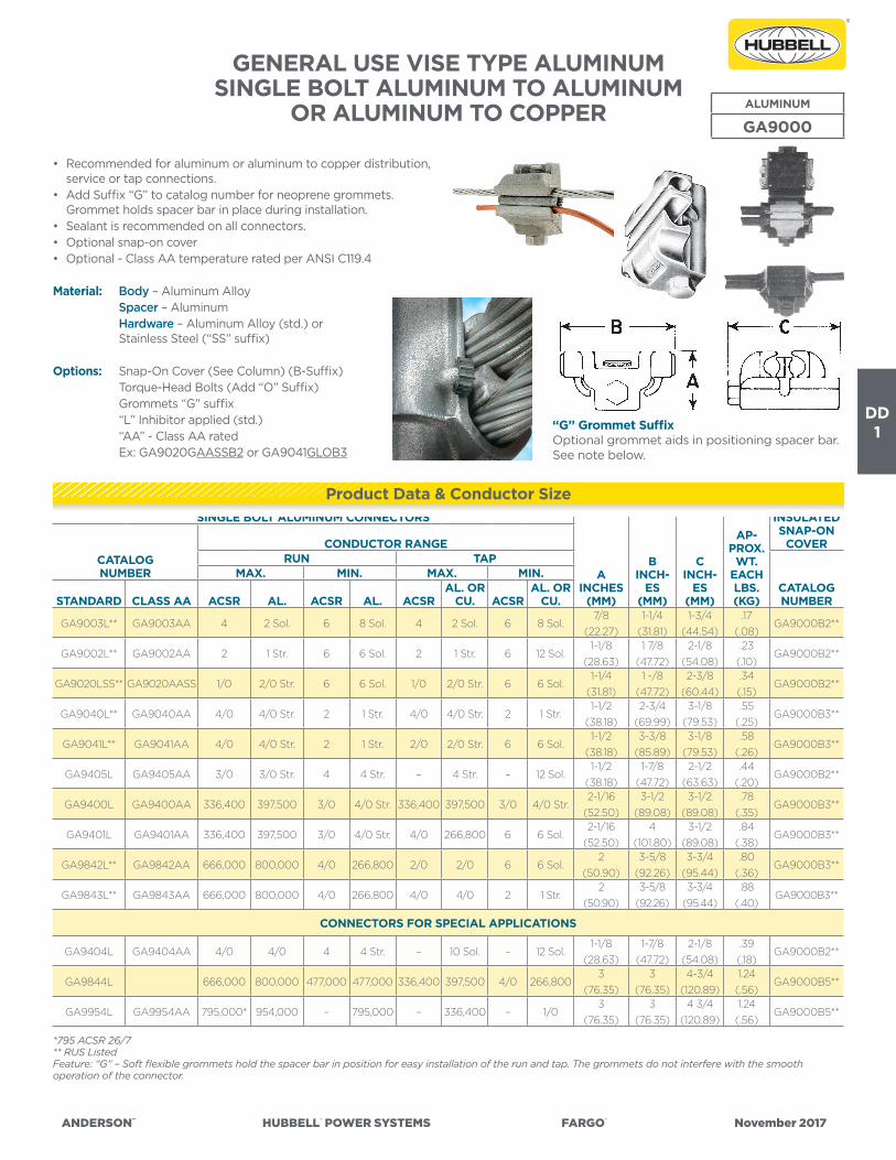
DD1
ANDERSON™ HUBBELL® POWER SYSTEMS FARGO® November 2017
GENERAL USE VISE TYPE ALUMINUM SINGLE BOLT ALUMINUM TO ALUMINUM
OR ALUMINUM TO COPPER
• Recommended for aluminum or aluminum to copper distribution, service or tap connections.
• Add Suffix “G” to catalog number for neoprene grommets. Grommet holds spacer bar in place during installation.
• Sealant is recommended on all connectors.• Optional snap-on cover• Optional - Class AA temperature rated per ANSI C119.4
Material: Body – Aluminum Alloy Spacer – Aluminum Hardware – Aluminum Alloy (std.) or
Stainless Steel (“SS” suffix)
Options: Snap-On Cover (See Column) (B-Suffix) Torque-Head Bolts (Add “O” Suffix) Grommets “G” suffix “L” Inhibitor applied (std.) “AA” - Class AA rated Ex: GA9020GAASSB2 or GA9041GLOB3
*795 ACSR 26/7** RUS ListedFeature: “G” – Soft flexible grommets hold the spacer bar in position for easy installation of the run and tap. The grommets do not interfere with the smooth operation of the connector.
ALUMINUM
GA9000
“G” Grommet SuffixOptional grommet aids in positioning spacer bar. See note below.
SINGLE BOLT ALUMINUM CONNECTORS
AINCHES
(MM)
BINCH-
ES(MM)
CINCH-
ES(MM)
AP-PROX.
WT.EACHLBS.(KG)
INSULATEDSNAP-ON
COVERCATALOG NUMBER
CONDUCTOR RANGERUN TAP
CATALOGNUMBER
MAX. MIN. MAX. MIN.
STANDARD CLASS AA ACSR AL. ACSR AL. ACSRAL. OR
CU. ACSRAL. OR
CU.
GA9003L** GA9003AA 4 2 Sol. 6 8 Sol. 4 2 Sol. 6 8 Sol.7/8
(22.27)1-1/4
(31.81)1-3/4
(44.54).17
(.08)GA9000B2**
GA9002L** GA9002AA 2 1 Str. 6 6 Sol. 2 1 Str. 6 12 Sol.1-1/8
(28.63)1 7/8
(47.72)2-1/8
(54.08).23
(.10)GA9000B2**
GA9020LSS** GA9020AASS 1/0 2/0 Str. 6 6 Sol. 1/0 2/0 Str. 6 6 Sol.1-1/4
(31.81)1 -/8
(47.72)2-3/8
(60.44).34(.15)
GA9000B2**
GA9040L** GA9040AA 4/0 4/0 Str. 2 1 Str. 4/0 4/0 Str. 2 1 Str.1-1/2
(38.18)2-3/4
(69.99)3-1/8
(79.53).55
(.25)GA9000B3**
GA9041L** GA9041AA 4/0 4/0 Str. 2 1 Str. 2/0 2/0 Str. 6 6 Sol.1-1/2
(38.18)3-3/8
(85.89)3-1/8
(79.53).58
(.26)GA9000B3**
GA9405L GA9405AA 3/0 3/0 Str. 4 4 Str. – 4 Str. – 12 Sol.1-1/2
(38.18)1-7/8
(47.72)2-1/2
(63.63).44
(.20)GA9000B2**
GA9400L GA9400AA 336,400 397,500 3/0 4/0 Str. 336,400 397,500 3/0 4/0 Str.2-1/16
(52.50)3-1/2
(89.08)3-1/2
(89.08).78
(.35)GA9000B3**
GA9401L GA9401AA 336,400 397,500 3/0 4/0 Str. 4/0 266,800 6 6 Sol.2-1/16
(52.50)4
(101.80)3-1/2
(89.08).84
(.38)GA9000B3**
GA9842L** GA9842AA 666,000 800,000 4/0 266,800 2/0 2/0 6 6 Sol.2
(50.90)3-5/8
(92.26)3-3/4
(95.44).80
(.36)GA9000B3**
GA9843L** GA9843AA 666,000 800,000 4/0 266,800 4/0 4/0 2 1 Str.2
(50.90)3-5/8
(92.26)3-3/4
(95.44).88
(.40)GA9000B3**
CONNECTORS FOR SPECIAL APPLICATIONS
GA9404L GA9404AA 4/0 4/0 4 4 Str. – 10 Sol. – 12 Sol.1-1/8
(28.63)1-7/8
(47.72)2-1/8
(54.08).39(.18)
GA9000B2**
GA9844L 666,000 800,000 477,000 477,000 336,400 397,500 4/0 266,8003
(76.35)3
(76.35)4-3/4
(120.89)1.24(.56)
GA9000B5**
GA9954L GA9954AA 795,000* 954,000 – 795,000 – 336,400 – 1/03
(76.35)3
(76.35)4 3/4
(120.89)1.24(.56)
GA9000B5**
Product Data & Conductor Size

DD2
ANDERSON™ HUBBELL® POWER SYSTEMS FARGO® November 2017
GENERAL USE VISE TYPE, TWO- BOLT EXTENDED RANGE ALUMINUM
ALUMINUM TO ALUMINUM OR ALUMINUM TO COPPER
• Heavy duty construction for aluminum to aluminum or aluminum to copper conductor connections.
• Sealant is recommended for all connections.
Material: Body – Aluminum Alloy Spacer – Aluminum Hardware – Aluminum Alloy (std.) or
Stainless steel (“SS” Suffix)
ALUMINUM
GA9000
“G” Grommet SuffixOptional grommet aids in positioning spacer bar. See note below.
* For insulated Snap-On Cover – order Catalog No. GA9000B4.† 26/7 ACSRFeature: “G” – Soft flexible grommets hold the spacer bar in position for easy installation of the run and tap. The grommets do not interfere with the smooth opera-tion of the connector.
CATALOG NUMBER
CONDUCTOR RANGEAPPROX. DIMENSIONS
INCHES (MM) AP-PROX.
WT.EACHLBS.(KG)
RUN TAP(NOMI-NAL)
A(MM)
B(MM)
C(MM)
MAX. MIN. MAX. MIN.
STAN-DARD CLASS AA ACSR AL. ACSR AL. ACSR
AL. OR CU. ACSR
AL. OR CU.
GA9520GL* GA9520GAA* 477,000 600,000 4/0 4/0 477,000 600,000 4/0 4/04
(101.80)
4-1/4
(108.16)
2-1/2
(63.63)
1.44
(.65)
GA9521GL* GA9521GAA* 477,000 600,000 4/0 250,000 4/0 266,800 4 4 Str.4
(101.80)
4-1/4
(108.16)
2-1/2
(63.63)
1.52
(.69)
GA9820GL GA9820GAA 795,000† 800,000 336,400 477,000 795,000† 800,000 336,400 477,0005-1/2
(139.98)
4-1/2
(114.53)
2-3/4
(69.99)
2.40
(1.09)
GA9821GL GA9821GAA 795,000† 800,000 336,400 477,000 397,500† 477,000 3/0 4/05-1/2
(139.98)
4-1/2
(114.53)
2-3/4
(69.99)
2.30
(1.04)
GA9100GL GA9100GAA 1,272,000 1,500,000 636,000 795,000 1,272,000 1,500,000 636,000 795,0005-3/4
(146.34)
6-1/4
(159.06)
2-7/8
(73.17)
4.50
(2.04)
GA9101GL GA9101GAA 1,272,000 1,500,000 636,000 795,000 636,000 795,000 336,400 336,4005-3/4
(146.34)
6-1/4
(159.06)
2-7/8
(73.17)
4.60
(2.09)
“A” Dimension depends on boltextension/conductor size opening.
GA9000Bx Series Snap-On Cover
Product Data & Conductor Size

DD3
ANDERSON™ HUBBELL® POWER SYSTEMS FARGO® November 2017
GENERAL USEVISE TYPE BRONZE COPPER TO COPPER BRONZE
GC5000 SERIES
* SH suffix indicates a slotted hex-head bolt.**RUS ListedFor tin-plated bronze connectors, add suffix “P” to catalog number (not available on GC5006S, GC5006SH and GC5008SH)Note: All connectors will accept one or two of the conductors listed and any combination in between.
• For copper connections-Splice, Loop deadend or service entrance tap or grounding connections
• One piece design for easier, faster installation• Bolt head design for use with standard ratchet wrench• Vise design achieves high connector pressure with low wrench force
Material: Body – Copper Alloy Hardware – Stainless Steel or Silicon Bronze Alloy
Options: Suffix “P” Tin-plated
TOPVIEW
SIDEVIEW
CATALOG NUMBER
CONDUCTOR RANGE
DIA. RANGE(2 COND. COMBO.)
A(MM)
B(MM)
C(MM)
WT. EA.LB
(KG)
BOLTHEAD(HEX.)
MAX. 2 CONDUCTORS
MIN. 2 CONDUCTORS
DIA. EA. COND.MIN. - MAX.
GC5008SH* #8 STR. #11 SOL. .091”-.146”
(2.32-3.72)
7/8”
(22.7)
5/8”
(15.91)
5/8”
(15.91)
.06
(.03) 3/8”
(10)GC5006**#6 SOL. #10 SOL.
.101”-.162”
(2.57-4.12)
1”
(25.45)
3/4”
(19.09)
.09
(.04)GC5006SH*
GC5004** #4 STR. #8 SOL..128”-.232”
(3.26-5.9)
1-1/4”
(31.81)
7/8”
(22.27)
.16
(.07)
9/16”
(14)
GC5002** #2 SOL. #6 SOL.. 162”-.286”
(4.12-7.28)
1-3/8”
(34.99)
3/4”
(19.09)
1”
(25.45)
.18
(.08)GC5002S** #2 STR. #5 SOL.
.181”-.320”
(4.61-8.14)
1-5/8”
(41.36)
GC5020** 1/0 STR. #4 SOL..204”-.390”
(5.19-9.93)
1-7/8”
(47.72)
1-1/8”
(28.63) .28
(.13)GC5020S** 2/0 STR. #3 SOL.
.229”-.438”
(5.83-11.15)
2”
(50.90)
7/8”
(22.27)
1-1/4”
(31.81)
GC5040** 4/0 STR. #1 SOL..289”-.552”
(7.36-14.05)
2-1/8”
(54.08)
1”
(25.45)
1-3/8”
(34.99)
.48
(.22)
Product Data & Conductor Size

DD4
ANDERSON™ HUBBELL® POWER SYSTEMS FARGO® November 2017
GENERAL USE — GROUNDING AND BONDINGVISE TYPE BRONZE
CATALOG NUMBER
RANGE APPROX. DIMENSIONS INCHES
WT LB(KG)
CONDUCTORCOMBINATIONS CABLE
SHEATHBONDING
A(MM)
B(MM)
C(MM)
BOLT
RUN TAP DIA. WRENCH
GC271*†4-6
4 Sol – 6 Str.14-6 1 to 3 2 pair
1
(25.45)
5/8
(15.90)
3/4
(19.08)
1/4
(6.36)
3/8
(10)
.08
(.04)
GC5006SH*† 6 14-6 1 to 3 2 pair1
(25.45)
5/8
(15.90)
3/4
(19.08)
1/4
(6.36)
3/8
(10)
.09
(.04)
GC5006†** 6 14-6 1 to 3 2 pair1
(25.45)
5/8
(15.90)
3/4
(19.08)
1/4
(6.36)
3/8
(10)
.09
(.04)
GC5004†** 4 8-41 to 3 2 pair 1-1/4
(31.81)
5/8
(15.90)
7/8
(22.26)
5/16
(7.95)
9/16
(14)
.16
(.07)1 5 pair
GC5002** 2 6-2 – –1-3/8
(35.00)
3/4
(19.08)
1
(25.45)
5/16
(7.95)
9/16
(14)
.18
(.08)
For copper to copper connections or conductor to conductor and conductor/cable sheath to bar.
Material: – Copper Alloy – Stainless Steel or Silicon Bronze slotted head hex
* Slotted Head Bolt† Complies with UL-467 and ETL listed**RUS Listed
BRONZE GC SERIES
GC100/ 200/5000
GC167
For Figure 8 or IM Cable – Insulation PiercingThe piercing teeth of the connector puncture the messenger insulation during tightening to form a positive ground without skinning.
CATA-LOG
NUMBER
DIAMETER APPROX. DIMENSIONS INCHES
WT LB(KG)
MESSENGER(MM)
GROUNDTAP (MM)
A(MM)
B(MM)
C(MM)
BOLT
DIA. WRENCH
GC167.146” - .312”
(3.71-7.94)
.146” - .312”
(3.71-7.94)
1-5/8
(41.36)
1-1/4
(31.81)
1
(25.45)
5/16
(7.95)
9/16
(14)
.21
(.10)GC167P
*Suffix P – Tin-Plated Bronze
Product Data & Conductor Size
Product Data & Conductor Size
GC5000 Series

DD5
ANDERSON™ HUBBELL® POWER SYSTEMS FARGO® November 2017
GENERAL USE – GROUNDING AND BONDING VISE TYPE
BRONZE
GC164
CATALOG NUMBER
BONDING RIBBON OR BRAID APPROX. DIMENSIONS INCHES
WT LB(KG)CONNECT TO
A(MM)
B(MM)
C(MM)
BOLT
DIA. WRENCH
GC164
GC164P†
Ribbon
or Braid
Ribbon, Braid, #6
or Bus
1
(25.45)
5/8
(15.90)
1
(25.45)
1/4
(6.36)
3/8
(10)
.12
(.05)
† Plated Bronze
CATALOG NUMBER
RANGE APPROX. DIMENSIONS INCHES
WT LB(KG)
ROD DIA. INCHES
(MM)CONDUC-
TORA
(MM)B
(MM)C
(MM)
BOLT
DIA. WRENCH
GC268†1/4 – 5/8
(6.36-15.90)6-1/0
2
(50.80)
1
(25.45)
1-3/8
(35.00)
3/8
(9.54)
9/16
(14)
.43
(.19)
* Torque head bolts available for tamperproof, removeable connection.†Complies with UL-467 and ETL listed GC268
For Lashing WireConnect small diameter lashing wires to messengers.
GC166
CATALOG NUMBER
MESSENGERDIAMETER
RANGELASHING
WIRE APPROX. DIMENSIONS INCHES
WT LB(KG)
CONNECT(MM) TO
A(MM)
B(MM)
C(MM)
BOLT
DIA. WRENCH
GC166
GC166P
.245” - .500”
(6.23-12.73)All Sizes
1-1/2
(38.18)
7/8
(22.26)
1
(25.45)
1/4
(6.36)
3/8
(10)
.16
(.07)
Suffix P- Plated Bronze
CATALOG NUMBER
STRANDRANGE (IN.)
(MM)CONDUCTOR
RANGE
APPROX. DIMENSIONS INCHES
WT LB(KG)
A(MM)
B(MM)
C(MM)
GA9003L**1/4
(6.36)4-8
7/8
(22.26)
1-1/4
(31.81)
1-3/4
(44.54)
.17
(.08)
GA9002L**1/4 – 3/8
(6.36-9.54)4-8
1-1/8
(28.63)
1-7/8
(47.72)
2-1/8
(54.08)
.23
(.10)
PARALLEL GROOVE TYPE
LC52AXB* **
LC522AXB†**
1/4 – 3/8
(6.36-9.54)2/0 – 8
2-3/8
(60.44)
1-5/8
(41.36)
1-3/8
(35.00)
.20
(.09)
* Inhibitor Protected and Individually Packaged – Standard† Bimetallic Liner on Tap Side – Copper**RUS Listed
LC50 Series
For Guy StrandAluminum bodied connectors for connecting galvanized or aluminum clad strand to copper conductors. Vise Type Parallel Connector.
For Ground Rods
For Bonding Ribbon, Braid and TapeBonding ribbon or braid to bonding ribbon, braid, conductor, or bus and tape to messenger.
GA9000 Series
Product Data & Conductor Size
Product Data & Conductor Size
Product Data & Conductor Size
Product Data & Conductor Size

DD6
ANDERSON™ HUBBELL® POWER SYSTEMS FARGO® November 2017
KUL Clamp - Tin-Plated Bronze Clamp
with Interlocking JawsBRONZE
KUL
KUL14716BG (Top)KUL14716 (Bottom)
• Tin plated for corrosion protection• High strength copper alloy• Half-inch hex head silicon bronze bolt
Application:• 1/4” - 7/16” strand• #8 - #2/0 copper wire
*GC209 is furnished with bronze jam nut on stud.+Add Suffix “P” for Tin-plated Version (Minimum purchase quantities may apply)**RUS Listed
Provides a permanent vibration proof connection. The large flat surface of the male casting provides secure mounting, while the “V” shaped conductor groove as-sures alignment of grounding connector.
CATALOG NUMBER DESCRIPTION PACKAGING
KUL14716 100% tin plated Standard Packaging: 100/box. No Minimum Order
KUL14716BG Tin plated with one bare bronze groove Standard Packaging: 100/box. No Minimum Order
Product Data & Conductor Size

DD7
ANDERSON™ HUBBELL® POWER SYSTEMS FARGO® November 2017
BRONZE
GC/C203
BRONZE GROUNDING CONNECTORWIRE TO ROD OR PIPE
Bronze alloy ground clamp for grounding copper cable parallel to a ground rod or tube.
• Suitable for Direct Burial
Material: GC–Casting – Bronze Alloy Hardware – Stainless Steel C203–Casting – Galvanized Steel Hardware – Zinc Plated
LISTED261L
CATALOG NUMBER COPPER CABLE RANGE
RODDIA.
DIMENSIONS INCHES (MM) APPROX.WT. EACH LBS. (KG)L H W J
GC4 #8 Sol.—#4 Str. 1/25/8
(15.88)
1-7/8
(47.62)
13/16
(20.64)
3/8
(9.52)
.09
(.04)
GC5G5 #10 Sol.—#2 Str. 5/85/8
(15.88)
1-19/32
(40.39)
29/32
(23.11)
3/8
(9.52)
.11
(.05)
C2030344
Heavy Duty#8 Sol.—2/0 Str. 5/8
1-1/8
(28.6)
2-7/8
(73.0)
1-15/32
(37.3)
1/2
(12.7)
.34
(.15)
C2030345
Heavy Duty#8 Sol.—2/0 Str. 3/4
1-1/8
(28.6)
2-7/8
(73.0)
1-15/32
(37.3)
1/2
(12.7)
.30
(.14)
Product Data & Conductor Size
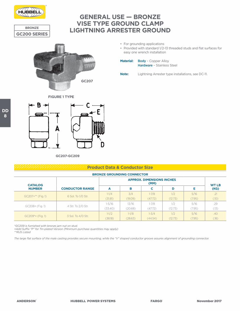
DD8
ANDERSON™ HUBBELL® POWER SYSTEMS FARGO® November 2017
GENERAL USE — BRONZEVISE TYPE GROUND CLAMP
LIGHTNING ARRESTER GROUNDBRONZE
GC200 SERIES
FIGURE 1 TYPE
GC207
GC207-GC209
• For grounding applications • Provided with standard 1/2-13 threaded studs and flat surfaces for
easy one wrench installation
Material: Body – Copper Alloy Hardware – Stainless Steel
Note: Lightning Arrester type installations, see DC-11.
*GC209 is furnished with bronze jam nut on stud.+Add Suffix “P” for Tin-plated Version (Minimum purchase quantities may apply)**RUS Listed
The large flat surface of the male casting provides secure mounting, while the “V” shaped conductor groove assures alignment of grounding connector.
BRONZE GROUNDING CONNECTOR
CATALOG NUMBER CONDUCTOR RANGE
APPROX. DIMENSIONS INCHES (MM) WT LB
(KG)A B C D E
GC207+** (Fig. 1) 6 Sol. To 1/0 Str.1-1/4
(31.81)
3/4
(19.09)
1-7/8
(47.72)
1/2
(12.73)
5/16
(7.95)
.21
(.10)
GC208+ (Fig. 1) 4 Str. To 2/0 Str.1-5/16
(33.40)
13/16
(20.68)
1-7/8
(47.72)
1/2
(12.73)
5/16
(7.95)
.29
(.13)
GC209*+ (Fig. 1) 3 Sol. To 4/0 Str.1-1/2
(38.18)
1-1/8
(28.63)
1-3/4
(44.54)
1/2
(12.73)
5/16
(7.95)
.40
(.18)
Product Data & Conductor Size

DD9
ANDERSON™ HUBBELL® POWER SYSTEMS FARGO® November 2017
BRONZE GROUND CLAMPCONDUCTOR TO TRANSFORMER TANK
TYPE GTCL: 90° GROUND CONDUCTOR MOUNT
BRONZE
GTCL
• Bronze alloy ground clamp for tapping copper conductor to transformer tank
• Tapered threads at base of stud ensure positive locking and electrical contact without lockwashers
Material: – Bronze Alloy – Bronze Alloy – Silicon Bronze Alloy or Stainless Steel
Add suffix “TP” for tin-plated version.
*RUS Listed
CATALOG NUMBER
COPPER CABLERANGE
APPROX. DIMENSIONS INCHES (MM) APPROX. WT.
EACH LBS. (KG)L H W J
GTCL23A* #10 Sol. – #1 Str.7/8
(22.22)
1-1/2
(38.1)
1-3/8
(34.92)
3/8
(9.52)
.20
(.09)
GTCL34A* #8 Sol. – 2/0 Str.1
(25.4)
1-7/8
(47.62)
1-17/32
(38.89)
3/8
(9.52)
.25
(.11)
GROUND CLAMPCONDUCTOR TO TRANSFORMER TANK
TYPE GTCS: 90° OR STRAIGHT GROUND MOUNT
BRONZE
GTCS
• Bronze alloy ground clamp for tapping copper conductor to transformer tank
• Tapered thread at base of stud ensures positive locking and electrical contact without lockwashers. Hex wrenching surface above tapered thread provides easy installation.
Material: Casting – Bronze Alloy Eyebolt – Bronze Alloy Hardware – Silicon Bronze Alloy or Stainless Steel
Add suffix “TP” for tin-plated version.
CATALOG NUMBER
COPPER CABLERANGE
APPROX. DIMENSIONS INCHES (MM) APPROX. WT.
EACH LBS. (KG)L H W J
GTCS21 #10 Sol. – #1 Str.1-1/8
(28.58)
1-5/8
(41.28)
1-7/8
(47.62)
3/8
(9.52)
.29
(.13)
GTCS34A #8 Sol. – 2/0 Str.1-1/4
(31.75)
1-7/8
(47.62)
2-1/4
(57.27)
3/8
(9.52)
.34
(.15)
GTCS41 #6 Sol.—250 MCM1-5/8
(41.28)
2-3/8
(60.32)
2-1/2
(63.5)
1/2
(12.7)
.45
(.20)
Product Data & Conductor Size
Product Data & Conductor Size

DD10
ANDERSON™ HUBBELL® POWER SYSTEMS FARGO® November 2017
LIGHTNING ARRESTER GROUNDING TERMINALS TYPE LAT AND GC207LA
BRONZE DISTRIBUTION ARRESTER TERMINALS(See also Page DC7)BRONZE
LAT, GC207LA • This versatile bronze connector can be mounted to a drilled plate, structure or bar using a 3/8”-16 cap screw. It can also be screwed onto a 3/8”-16 bushing stud and secured in place with the included jam nut. The eyebolt can be positioned within the body to allow either vertical or horizontal conductor entrances.
Material: Casting – Bronze Alloy Eyebolt – Bronze Alloy Hardware – Silicon Bronze Alloy – Brass jam nut
Add suffix “TP” for tin-plated connector
CATALOG NUMBER
STUDSIZE
CONDUCTORRANGE O.D.
LENGTH INCHES
(MM)APPROX. WT.
EACH LBS. (KG)
LAT20 3/8” - 168 Sol. - 2/0 Str.
.12” - .42” O.D.
1.69
(43)
40
(18)
• This connector is intended primarily for bottom termination of lightning arresters to ground. May also be employed on top connections.
Material: Casting – Bronze Alloy Eyebolt – Bronze Alloy Hardware – Stainless Steel
Note: See pages DC-9 – DC-10 for application details.
CATALOG NUMBER
STUDSIZE
CONDUCTORRANGE
O.D.APPROX. WT. 100
LBS. (KG)
GC207LA 3/8” - 16
#6 Sol. - 1/0 Str.
.162” - .373”
(4.1 - 9.5) mm
22 (9.9)
Add suffix “P” for tin-plated connector
Product Data & Conductor Size
Product Data & Conductor Size

DD11
ANDERSON™ HUBBELL® POWER SYSTEMS FARGO® November 2017
TYPE APD ARC PROTECTION FOR COVERED PRIMARY CONDUCTOR
ALUMINUM
APD
• The APD helps prevent lightning induced burndowns of covered overhead aluminum primary conductors and allows users to comply with Article 276 of the National Electric Safety Code, 1981 Edition.
• The device protects covered conductor by shielding it from the usual concentration of arc energy generated during a lightning strike. Without the device, such arcs can puncture the conductor cover and ground to the neutral leaving a short section of conductor strands that are either completely destroyed or badly eroded and seriously weakened. (Conventional overcurrent protection equipment does not operate fast enough to protect these lightning exposed conductors.) APD lightning protectors add mass of the correct shape to the conductor in the area where it absorbs the terminus of arc energy. It is thus a partially sacrificed component during each strike yet retains enough of its original mass and configuration to accommodate several strikes without losing effectiveness or allowing the adjacent line insulator to be splattered with damaging metallic particles.
• APD lightning protectors are both laboratory tested and field proven with the same successful results. They are offered in two models. The high energy APD-80 model is designed to withstand multiple operations at 21,000 amperes fault current for ten (10) cycles without conductor damage. A low-energy APD-57 model is available for applications where fuses limit the destructive energy by clearing the fault more rapidly than circuit breakers.
Material: Castings – Aluminum Alloy Hardware—APD57 – Galvanized Steel APD80 – Stainless Steel
Note: A radial circuit requires an APD protector on the load side of the insulator only, while other circuit configurations, such as loops, require that they be installed on both sides of the line insulator. In both situations, they must be installed on all conductor phases and positioned outside the end of a tie wire. The covering must be stripped away over this distance including the area within the confines of a tie wire. Since an arc from one phase to the neutral will often expand to fault all three phases, the device must be installed on all three phases.
(1) This item is suitable for use on fused circuits only. Specifically, it should not be installed on lines protected by circuit breakersbecause of their relatively slow interrupting rate.
CATALOGNUMBER(WITH
INHIBITOR)MAX. O.D. OF CABLE
JACKET—INCHES
CONDUCTORRANGE O.D.IN INCHES
DIMENSIONB—INCHES
(MM)
APPROX.WT. 100
LBS. (KG)
(1)
APD57XB
(Fused circuits)
0.906
#1-4/0 STR. AAC
#2-4/0 ACSR
0.31-0.57
1.06
(27)
24
(11)
APD80XB 1.200
2/0-556.5 Str. AAC
1/0-477 (18/1) ACSR
0.39-0.86
1.87
(48)
66
(30)
Product Data & Conductor Size

DD12
ANDERSON™ HUBBELL® POWER SYSTEMS FARGO® November 2017
TINNED ALUMINUM OR BRONZE TRANSFORMER SPADE TERMINALS
TYPE AXS & BXSALUMINUM
AXS
CATALOG NUMBER
X’FORMERSTUD SIZE
GENERAL DESCRIPTION& FIELD APPLICATION
DIMENSIONS INCHES (MM) APPROX.WT. 100
LBS. (KG)LENGTH WIDTH HEIGHT
BXS582N 5/8”-11 Two Holes in Line NEMA Spaced
For Use With One Hole Lugs
5.12 (130) 1.37 (35) 0.31 (8) 70 (32)
BXS102N 1”-14 5.06 (129) 1.93 (49) 0.34 (9) 142 (64)
BXS584N 5/8”-11
Four Holes in Line NEMA Spaced
For Use With One Hole Lugs
8.50 (216) 1.37 (35) 0.31 (8) 120 (54)
BXS104N 1”-14 8.56 (218) 1.93 (49) 0.34 (9) 215 (98)
AXS584NTP 5/8”-11 8.50 (216) 1.37 (35) 0.31 (8) 36 (16)
AXS104NTP 1”-14 8.56 (218) 2.00 (50) 0.34 (9) 65 (29)
BXS582BN 5/8”-11
Two Sets of NEMA Spaced Holes
Mounts Up to 4 Two-Holed Lugs
5.37 (136) 3.50 (89) 0.25 (6) 132 (60)
BXS102BN 1”-14 5.87 (149) 3.50 (89) 0.37 (9) 260 (118)
AXS582BNTP 5/8”-11 5.37 (136) 3.50 (89) 0.25 (6) 39 (18)
BXS583BN 5/8”-11
Three Sets of NEMA Spaced Holes
Mounts Up to 6 Two-Holed Lugs
6.62 (168) 3.50 (89) 0.37 (9) 256 (116)
BXS103BN 1”-14 7.00 (178) 3.50 (89) 0.37 (9) 315 (143)
AXS103BNTP 1”-14 7.00 (178) 3.50 (89) 0.37 (9) 94 (43)
BXS584BN 5/8”-11 Four Sets of NEMA Spaced Holes
Mounts Up to 8 Two-Holed Lugs
8.37 (213) 3.50 (89) 0.37 (9) 330 (150)
BXS104BN 1”-14 8.75 (222) 3.50 (89) 0.37 (9) 362 (164)
BXS123BN 1-1/4”-12
Three Sets of NEMA Spaced Holes
Mounts Up to 6 Two-Holed Lugs Or
Up to 12 Two-Holed Lugs If Stacked
7.12 (181) 3.50 (89) 0.37 (9) 345 (156)
BXS124BN 1-1/4”-12
Four Sets of NEMA Spaced Holes
Mounts Up to 8 Two-Holed Lugs Or
Up to 16 Two-Holed Lugs If Stacked
9.12 (232) 3.50 (89) 0.37 (9) 445 (202)
BXS126BN 1-1/4”-12
Six Sets of NEMA Spaced Holes
Mounts Up to 12 Two-Holed Lugs Or
Up to 24 Two-Holed Lugs If Stacked
14.00 (356) 4.00 (102) 0.50 (13) 970 (440)
BXS128BN 1-1/4”-12
Eight Sets of NEMA Spaced Holes
Mounts Up to 16 Two-Holed Lugs Or
Up to 32 Two-Holed Lugs If Stacked
17.50 (445) 4.00 (102) 0.50 (13) 1300 (590)
BRONZE
BXS• Secured by jam nut to bushing stud.• Recommended when copper terminals are connected
(Use “AXS” style for aluminum terminals.)• Terminal lug mounting holes are 9/16” diameter with 1-3/4”
NEMA spacing. Jam nuts are usually supplied by the transformer manufacturer and are not furnished unless specified.
Material: - Bronze Alloy (tin-plated) - Aluminum Alloy (tin-plated)
Notes: (1) Terminals for 1-1/4” – 12 bushing studs can be furnished with a 1/4” – 20 tapped hole in the outer end to attach an insulated suspension support rod for mechanical support. Add suffix “-MS” for this option.
(2) Add suffix “JN” to specify a factory applied brass jam nut.
Product Data & Conductor Size

DD13
ANDERSON™ HUBBELL® POWER SYSTEMS FARGO® November 2017
OVERHEAD TRANSFORMER PAD ADAPTER CONNECTORS
TIN-PLATED BRONZE FLAG ADAPTERSUSE W/EYEBOLT (GTCL/GTCS) TYPE SECONDARY BUSHING TERMINALS
BRONZE
VF
• Bronze terminal adapter for connecting a flat pad to NEMA secondary transformer terminal
• Optional for use with Type GTCL or GTCS terminals.
Material: – Bronze Alloy (tin-plated)
CATALOG NUMBER
NEMA DRILLED PAD & RODDESCRIPTION
TRANSFORMERSIZE RATING
(SINGLE PHASE)
DIMENSIONS INCHES (MM) APPROX.
WT. 100 LBS. (KG)L DIA.
VF440 4 Hole 4” x 4” x 1/4” Pad5-15 KVA
2.25
(57)
.50
(13)
165 (75)
VF640 6 Hole 3” x 5-1/4” x 1/4” Pad 180 (82)
VF4350 4 Hole 4” x 4” x 1/4” Pad25-50 KVA
2.75
(70)
.75
(20)
216 (98)
VF6350 6 Hole 3” x 5-1/4” x 1/4” Pad 231 (105)
VF4500 4 Hole 4” x 4” x 1/4” Pad75 KVA
4.00
(102)
.81
(21)
245 (111)
VF6500 6 Hole 3” x 5-1/4” x 1/4” Pad 260 (118)
VF41000 4 Hole 4” x 4” x 1/4” Pad100 KVA
4.00
(102)
1.00
(25)
312 (142)
VF61000 6 Hole 3” x 5-1/4” x 1/4” Pad 327 (148)
Product Data & Conductor Size

DD14
ANDERSON™ HUBBELL® POWER SYSTEMS FARGO® November 2017
SET SCREW BARTRANSFORMER CONNECTORS
TOGGLE LATCHALUMINUM
UTSB
• For connecting secondary underground applications to transformer studs.
• Innovative “Toggle Latch” mechanism provides unmatched ease of installation, along with superior electrical performance.
• One part accepts both 5/8”-11 and 1”-14 threads.• Reduced inventory; one part accepts both 5/8”-11 and 1”-14 thread
transformer studs. • Oxide Inhibiting Compound provided as standard in stud and tap
holes.• 5/16” allen set screws provide constant pressure on conductors.• Testing meets or exceeds ANSI C119.6 Class “A” tests.• Redundant ground ports provided for use on neutral phase
connections.• Toggle nut is 3/4” across flats, fits standard GP223 Speed Wrench.
Material: Body – Aluminum Alloy Hardware – High Strength Steel Boot/Cover – Poly-vinyl Chloride (PVC)
Note: Not suitable for submersible installations.
CATALOG NUMBER
TRANS-FORMER
STUD SIZES
CONDUCTOR RANGE
MAINPORTS
STREETLIGHTPORTS
GROUNDPORTS
PACKAGING PERBOX
MAIN PORTSSTREET LIGHT
PORTREDUNDANT
GROUND UNITSWEIGHT
(LBS)
UTSB8500L5/8”-11 &
1”-14”
#6 SOL - 500 MCM #12 SOL - 1/0 SOL #12 SOL - #2 SOL8 1 2 12 36
0.162” - 0.813” 0.081” - 0.325” 0.081” - 0.258”
NOTE: Add suffix “C” for clear PVC cover included in package “UTSB8500CL. Factory applied inhibitor (HTJC) included standard. Cover Part Number: CTL8500
Product Data & Conductor Size

DD15
ANDERSON™ HUBBELL® POWER SYSTEMS FARGO® November 2017
SET SCREW BARTRANSFORMER CONNECTORS
TOGGLE LATCH ALUMINUM
UTZB
• For connecting secondary underground applications to transformer studs.
• Innovative “Toggle Latch” mechanism provides unmatched ease of installation, along with superior electrical performance.
• Reduced inventory; one part accepts both 5/8”-11 and 1”-14 thread transformer studs.
• Oxide Inhibiting Compound provided as part of standard in stud and tap holes.
• Allen head set screws (fits 5/16” allen wrench) provide constant pressure on conductors.
• Meets or exceeds ANSI C119.6 Class “A” tests.• Toggle nut is 3/4” across flats, fits standard GP223 Speed Wrench.
Material: Body – Aluminum Alloy Set Screws – Aluminum Alloy Hardware – High Strength Steel Boot/Cover – Poly-vinyl Chloride (PVC)
Note: Not suitable for submersible installations.
CATALOG NUMBER
TRANSFORMERSTUD SIZES
CONDUCTOR RANGE
MAINPORTS
STREETLIGHTPORTS
PACKAGING PERBOX
MAIN PORTSSTREET LIGHT
PORT UNITSWEIGHT
(LBS)
UTZB6500L5/8”-11 &
1”-14”
#6 SOL - 500 MCM #12 SOL - 1/0 SOL6 1 12 32
0.162” - 0.813” 0.081” - 0.325”
NOTE: Add suffix “C” for kit with stud bar & clear PVC cover (UTZB6500CL). Factory applied inhibitor (HTJC) included standard. Cover Part Number: CZTL6500
Units are expressed in inches (millimeters)
Product Data & Conductor Size
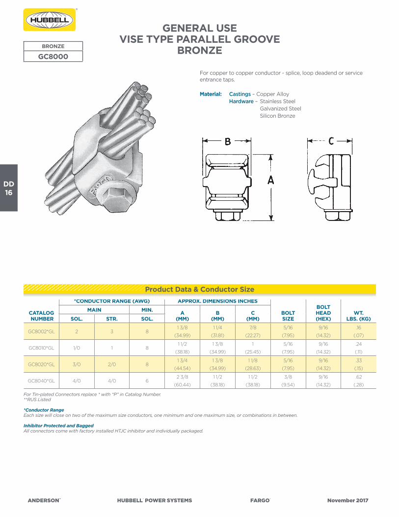
DD16
ANDERSON™ HUBBELL® POWER SYSTEMS FARGO® November 2017
GENERAL USEVISE TYPE PARALLEL GROOVE
BRONZEBRONZE
GC8000
For copper to copper conductor - splice, loop deadend or service entrance taps.
Material: Castings – Copper Alloy Hardware – Stainless Steel Galvanized Steel Silicon Bronze
CATALOG NUMBER
*CONDUCTOR RANGE (AWG) APPROX. DIMENSIONS INCHES
BOLTSIZE
BOLTHEAD(HEX)
WT.LBS. (KG)
MAIN MIN. A(MM)
B(MM)
C(MM)SOL. STR. SOL.
GC8002*GL 2 3 81 3/8
(34.99)
1 1/4
(31.81)
7/8
(22.27)
5/16
(7.95)
9/16
(14.32)
.16
(.07)
GC8010*GL 1/0 1 81 1/2
(38.18)
1 3/8
(34.99)
1
(25.45)
5/16
(7.95)
9/16
(14.32)
.24
(.11)
GC8020*GL 3/0 2/0 81 3/4
(44.54)
1 3/8
(34.99)
1 1/8
(28.63)
5/16
(7.95)
9/16
(14.32)
.33
(.15)
GC8040*GL 4/0 4/0 62 3/8
(60.44)
1 1/2
(38.18)
1 1/2
(38.18)
3/8
(9.54)
9/16
(14.32)
.62
(.28)
For Tin-plated Connectors replace * with “P” in Catalog Number.**RUS Listed
*Conductor RangeEach size will close on two of the maximum size conductors, one minimum and one maximum size, or combinations in between.
Inhibitor Protected and BaggedAll connectors come with factory installed HTJC inhibitor and individually packaged.
Product Data & Conductor Size

DD17
ANDERSON™ HUBBELL® POWER SYSTEMS FARGO® November 2017
GENERAL USE PARALLEL GROOVE ALUMINUMTHREE CENTER BOLTS WITH COPPER LINER
GENERAL USE PARALLEL GROOVE ALUMINUMMULTIPLE U-BOLTS WITH COPPER LINER
ALUMINUM
LCC
CATALOG NUMBER
FIGURE NUM-BER
CONDUCTOR RANGEDIMENSIONSINCHES (MM) APPROX.
WT. EACH LBS. (KG)MAIN TAP L W H
LCC111XB 1#6 Sol.—2/0 Str. AAC
#8 Sol.—2/0 (6/1) ACSR#8 Sol.—2/0 Str. CU
2
(50.80)
2-5/16
(58.74)
3-1/2
(88.90)
.77
(.35)
LCC221XB 11/0 Str.—400 MCM AAC
1/0 (6/1)—397.5 (18/1)ACSR#4 Sol.—4/0 Str. CU
2-1/2
(63.50)
2-11/16
(68.26)
4
(101.60)
1.11
(.50)
LCC222XB 21/0 Str.—400 MCM AAC
1/0 (6/1)—397.5 (18/1) ACSR#4 Sol.—4/0 Str. CU
3-7/8
(98.43)
2-3/4
(69.85)
4
(101.60)
1.68
(.76)
LCC231XB 11/0 Str.—400 MCM AAC
1/0 (6/1)—397.5 (18/1) ACSR1/0 Str.—500 MCM CU
2-1/2
(63.50)
2-11/16
(68.26)
4
(101.60)
1.24
(.56)
LCC242XB 21/0 Str.—400 MCM AAC
1/0 (6/1)—397.5 (18/1) ACSR400—800 MCM CU
4-1/8
(104.78)
2-11/16
(68.26)
4-1/4
(107.95)
2.10
(.95)
LCC332XB 2336.4—954 MCM AAC
300—795 MCM ACSR1/0 Str.—400 MCM CU
4-5/8
(117.48)
3-1/16
(77.79)
4-5/8
(117.48)
2.88
(1.31)
For aluminum to copper conductor connections only. Sealant (XB) is recommended on all connections.
Material: Body – Top member 356-T6 Aluminum Alloy Spacer – Aluminum Alloy with a metallurgically bonded
Copper liner Bottom Member – High Strength Bronze Hardware – Galvanized Steel
FIGURE 2
For aluminum to copper conductor connections only. Sealant (XB suffix) is recommended on all connections.
Material: Body – 356-T6 Aluminum Alloy Hardware – Hot Dip Galvanized Steel Tap Liner – Copper, Metallurgically Bonded
CATALOG NUMBER
CONDUCTOR RANGEDIMENSIONSINCHES (MM) APPROX.
WT. EACH LBS. (KG)MAIN TAP L W H J
LC677XB1/0 (19)—336.4 MCM AAC
1/0—300 MCM ACSR1/0 (7)—250 Str. CU
4-3/8
(111.13)
2-5/16
(58.74)
2-1/2
(63.5)
1/2
(12.7)
1.35
(.61)
FIGURE 1
ALUMINUM
LC600
Product Data & Conductor Size
Product Data & Conductor Size

DD18
ANDERSON™ HUBBELL® POWER SYSTEMS FARGO® November 2017
Product Data & Conductor Size
GENERAL USE – PARALLEL GROOVE – ALUMINUMSINGLE CENTER BOLT WITH COPPER LINER
GENERAL USE – PARALLEL GROOVE – ALUMINUM SINGLE CENTER BOLT
ALUMINUM
LC50 & LC80For aluminum to aluminum and aluminum to copper conductor splice/tap connections. Sealant (XB) is recommended on all connections.
Material: Body – Aluminum Alloy Hardware – Galvanized Steel
Notes: 1) For connectors without sealant, delete suffix “XB.” 2) Add suffix “GP” for a tin-plated connector. 3) Plastic Cover Available. (See Type PTC Cover)FIGURE 2
CATALOG NUMBER
FIGURE NUMBER
CONDUCTOR RANGEDIMENSIONSINCHES (MM) APPROX.
WT. EACH LBS. (KG)MAIN TAP L W H J
LC51AXB** 1#8 Sol.—1/0 Str. AAC
#8—1/0 ACSR
#8 Sol.—#2 Str. AAC
#8—#2 ACSR
#8 Sol.—#2 Str. Cu
1-1/8
(28.58)
1-13/32
(35.72)
1-1/2
(38.10)
5/16
(8.0)
.14
(.06)
LC51CXB** 1#8 Sol.—1/0 Str. AAC
#8—1/0 ACSR
#8 Sol.—1/0 Str. AAC
#8—1/0 ACSR
#8 Sol.—1/0 Str. Cu
1-1/4
(31.76)
1-17/32
(38.89)
2
(50.80)
3/8
(9.53)
.19
(.09)
LC52AXB** 1#8 Sol.—2/0 Str. AAC
#8—2/0 ACSR
#8 Sol.—2/0 Str. AAC
#8—2/0 ACSR
#8 Sol.—2/0 Str. Cu
1-3/8
(34.93)
1-21/32
(42.07)
2
(50.80)
3/8
(9.53)
.22
(.10)
LC52CXB** 1#1 Sol. —400 MCM AAC
#1—336.4 MCM ACSR
#8 Sol.—2/0 Str. AAC
#8—2/0 ACSR
#8 Sol.—2/0 Str. Cu
2
(50.80)
2-11/32
(51.60)
2-1/4
(57.15)
3/8
(9.53)
.28
(.13)
LC53AXB** 2#1 Sol. —400 MCM AAC
#1—336.4 MCM ACSR
#1 Sol. —400 MCM AAC
#1—336.4 MCM ACSR
#1 Sol.—400 MCM Cu
2
(50.80)
2-11/32
(59.53)
2-1/2
(63.50)
1/2
(12.70)
.41
(.19)
LC83AXB** 2397.5—954 MCM AAC
336.4—795 MCM ACSR
#8 Sol.—2/0 Str. AAC
#8—2/0 ACSR
#8 Sol.—2/0 Str. Cu
1-1/2
(38.1)
2-17/32
(64.29)
2-3/4
(69.85)
1/2
(12.70)
.54
(.24)
**RUS Listed
For aluminum to copper conductor connections only. Sealant (XB) is recommended on all connections.
Material: Body – Aluminum Alloy Hardware – Galvanized Steel Tap Liner – Copper metallurgically bonded
CATALOG NUMBER
FIGURE NUMBER
CONDUCTOR RANGEDIMENSIONSINCHES (MM) APPROX.
WT. EACH LBS. (KG)MAIN TAP L W H J
LC511AXB** 1#6 Sol.—1/0 Str. AAC
#8—1/0 ACSR#8 Sol.—#2 Str. Cu
1-1/8
(28.58)
1-5/16
(33.34)
1-1/2
(38.10)
5/16
(8.0)
.14
(.06)
LC522AXB** 1#6 Sol.—1/0 Str. AAC
#8—1/0 ACSR#8 Sol.—1/0 Str. Cu
1-3/8
(34.93)
1-21/32
(42.07)
2
(50.80)
3/8
(9.53)
.22
(.10)
LC542XB 1#6 Sol.—1/0 Str. AAC
#8—1/0 ACSR1/0 Str.—4/0 Str. Cu
1-3/16
(30.16)
1-25/32
(45.24)
2
(50.80)
3/8
(9.53)
.24
(.11)
LC811AXB** 1#1 Sol.—400 MCM AAC
#1—336.4 MCM ACSR#8 Sol.—1/0 Str. Cu
1-1/4
(31.75)
2-1/32
(51.59)
2-1/4
(57.15)
3/8
(9.53)
.29
(.13)
LC822XB 2#1 Sol.—400 MCM AAC
#1—336.4 MCM ACSR#8 Sol.—2/0 Str. Cu
2-1/4
(57.15)
2-7/32
(56.36)
2-1/2
(63.50)
1/2
(12.70)
.46
(.21)
LC833XB** 2397.5—954 MCM AAC
336.4—795 MCM ACSR#8 Sol.—2/0 Str. Cu
2-1/2
(63.50)
2-17/32
(64.29)
2-3/4
(69.85)
1/2
(12.70)
.54
(.24)**RUS Listed
FIGURE 1FIGURE 2
ALUMINUM
LC500 & LC800
Product Data & Conductor Size

DD19
ANDERSON™ HUBBELL® POWER SYSTEMS FARGO® November 2017
GENERAL USE PARALLEL GROOVE – ALUMINUM MULTIPLE CENTER BOLTS
ALUMINUM
LC60/GA600
CATALOG NUMBER
FIGURENO.
CONDUCTOR RANGEDIMENSIONSINCHES (MM) APPROX.
WT. EACH LBS. (KG)MAIN TAP L W H J
GA670L 11/0—400 AAC
1/0—336.4 (18/1) ACSR
1/0—400 AAC
1/0—336.4 (18/1) ACSR
3-1/4
(82.71)
2-1/4
(57.26)
2-3/4
(69.85)
3/8
(9.53)
.60
(.27)
LC66AXB 11/0 (19)—400 MCM AAC
1/0—397.5 (18/1) ACSR
1/0 (19)—400 MCM AAC
1/0—397.5 (18/1) ACSR
1/0 Sol.—400 MCM Cu
3-1/2
(88.90)
2-3/8
(60.44)
2-3/4
(69.85)
1/2
(12.70)
1.10
(.50)
LC67AXB 25-1/4
(133.35)
2-5/8
(66.80)
2-1/2
(63.5)
1/2
(12.70)
1.30
(.59)
LC68AXB 2350 —556.5 MCM AAC
336.4 (18/1)—477 (30/7) ACSR
350—556.5 MCM AAC
336.4 (18/1)—477 (30/7) ACSR
350—550 MCM Cu
5-1/4
(133.35)
2-13/16
(71.44)
2-1/2
(63.5)
1/2
(12.70)
1.90
(.86)
FIGURE 2
FIGURE 1
For aluminum to aluminum and aluminum to copper conductor splice/tap connectors. Sealant (XB) is recommended on all connections.
Material: Body – Aluminum Alloy Hardware – Galvanized Steel
Notes: 1) For connectors without sealant, delete suffix “XB.” 2) Add suffix “GP” for a tin-plated connector.
GENERAL USE PARALLEL GROOVE – ALUMINUM SINGLE U-BOLT
ALUMINUM
LC70
For aluminum to aluminum and aluminum to copper conductor splice/tap connections and also aluminum or ACSR loop dead-ends. Sealant (XB) is recommended on all connections, except loop dead-ends.
Material: Body – Top, spacer & bottom members—Aluminum Alloy Hardware – Galvanized Steel
**RUS Listed
Product Data & Conductor Size
CATALOG NUMBER
CONDUCTOR RANGEDIMENSIONSINCHES (MM) APPROX.
WT. EACH LBS. (KG)MAIN TAP L W H J
LC71B**#6 Sol.—2/0 Str. AAC
#8—2/0 ACSR
#6 Sol.—2/0 Str. AAC
#8—2/0 ACSR
2
(50.80)
2
(50.80)
3-1/4
(82.55)
3/8
(9.53)
.43
(.20)
LC72B#6 Sol.—2/0 Str. AAC
#8—2/0 ACSR
#6 Sol.—2/0 Str. AAC
#8—2/0 ACSR
2-1/4
(57.15)
2-1/4
(57.15)
3-3/8
(85.73)
1/2
(12.70)
.77
(.35)
LC73B1/0 Sol.—400 MCM AAC
1/0—336.4 MCM ACSR
#6 Sol.—1/0 Str. AAC
#8—1/0 ACSR
2-3/4
(69.85)
2-5/8
(66.68)
4
(101.60)
1/2
(12.70)
1.12
(.51)
LC74B**1/0 Sol.—400 MCM AAC
1/0—336.4 MCM ACSR
1/0 Sol.—400 MCM AAC
#2—336.4 MCM ACSR
2-3/4
(69.85)
2-5/8
(66.68)
4
(101.60)
1/2
(12.70)
1.21
(.55)
LC75B336.4—954 MCM AAC
300—795 MCM ACSR
#6 Sol.—1/0 Str. AAC
#8—1/0 ACSR
3-1/4
(82.55)
3
(76.20)
4-5/8
(117.48)
1/2
(12.70)
1.43
(.65)
LC77B336.4—1033.5 MCM AAC
300—954 (45/7) ACSR
336.4—1033.5 MCM AAC
300—954 (45/7) ACSR
3-1/2
(88.90)
3-3/8
(85.73)
5-3/8
(136.53)
5/8
(15.88)
1.97
(.89)
Product Data & Conductor Size

DD20
ANDERSON™ HUBBELL® POWER SYSTEMS FARGO® November 2017
GENERAL USE PARALLEL GROOVE – ALUMINUM TWO U-BOLT
ALUMINUM
LCU10
For aluminum to aluminum and aluminum to copper conductor splice/tap connections. Sealant (XB) is recommended on all connections.
Material: Body – Top, spacer & bottom members—Aluminum Alloy Hardware – Aluminum Alloy
Note: For connectors without sealant, delete suffix “XB.”
CATALOG NUMBER
CONDUCTOR RANGEDIMENSIONSINCHES (MM) APPROX.
WT. EACH LBS. (KG)MAIN TAP L W H J
LCU13XB1/0 Str.—400 MCM AAC
1/0—397.5 (18/1) ACSR
1/0 Str.—400 MCM AAC
1/0—397.5 (18/1) ACSR
1/0 Str.—400 MCM Cu
4-1/8
(104.78)
2-11/16
(68.26)
4-1/2
(114.30)
1/2
(12.70)
1.07
(.49)
LCU15XB
336.4—954 MCM AAC
300—795 MCM ACSR
1/0 Str.—400 MCM AAC
1/0—397.5 (18/1) ACSR
1/0 Str.—400 MCM Cu
4-5/8
(117.48)
3-1/16
(77.79)
4-7/8
(123.83)
1/2
(12.70)
1.84
(.83)
LCU16XB
336.4—954 MCM AAC
300—795 MCM ACSR
350—900 MCM Cu
4-5/8
(117.48)
3-7/16
(87.31)
5-1/2
(139.70)
5/8
(15.88)
1.86
(.84)
Product Data & Conductor Size

DD21
ANDERSON™ HUBBELL® POWER SYSTEMS FARGO® November 2017
GENERAL USE PARALLEL GROOVE – ALUMINUM 3 U-BOLT
ALUMINUM
LCU700
For aluminum to aluminum and aluminum to copper conductor splice/tap connections. Sealant (XB) is recommended on all connections.
Material: Body – Top, spacer & bottom members—Aluminum Alloy Hardware – Aluminum Alloy
CATALOG NUMBER
CONDUCTOR RANGEDIMENSIONSINCHES (MM) APPROX.
WT. EACH LBS. (KG)MAIN TAP L W H J
LCU70055XB450—800 MCM AAC
397.5—715.5 MCM ACSR
450—800 MCM AAC
397.5—715.5 MCM ACSR
5-7/8
(149.23)
3-1/8
(79.38)
4-11/16
(119.06)
5/8
(15.88)
2.87
(1.30)
LCU70063XB
750—1033.5 MCM AAC
605—900 MCM ACSR
4/0 Sol. — 350 MCM AAC
3/0 — 336.4 (18/1) ACSR
6-3/4
(171.45)
3-5/16
(84.14)
5-1/8
(130.18)
5/8
(15.88)
3.25
(1.47)
LCU70064XB350—477 MCM AAC
336.4—397.5 MCM ACSR
6-3/4
(171.45)
3-5/16
(84.14)
5-1/8
(130.18)
5/8
(15.88)
3.25
(1.47)
LCU70065XB450—715.5 MCM AAC
397.5 — 605 MCM ACSR
6-3/4
(171.45)
3-5/16
(84.14)
5-1/8
(130.18)
5/8
(15.88)
3.50
(1.59)
LCU70066XB750—1033.5 MCM AAC
605—900 MCM ACSR
6-3/4
(171.45)
3-5/16
(84.14)
5-1/2
(139.70)
5/8
(15.88)
3.50
(1.59)
LCU70074XB
1113—1351.5 MCM AAC
954—1192.5 MCM ACSR
350—477 MCM AAC
336.4—397.5 MCM ACSR
8
(203.20)
3-7/8
(98.43)
6
(152.40)
3/4
(19.05)
6.35
(2.88)
LCU70076XB750—1033.5 MCM AAC
605—900 MCM ACSR
8
(203.20)
3-7/8
(98.43)
6
(152.40)
3/4
(19.05)
6.50
(2.95)
LCU70077XB1113—1351.5 MCM AAC
954—1192.5 MCM ACSR
8
(203.20)
3-7/8
(98.43)
6-3/8
(161.93)
3/4
(19.05)
6.50
(2.95)
LCU70085XB
1431—1750 MCM AAC
1272—1590 MCM ACSR
450—715.5 MCM AAC
397.5 — 605 MCM ACSR
9-3/4
(231.78)
4-1/8
(104.78)
5-3/4
(146.05)
3/4
(19.05)
8.50
(3.86)
LCU70086XB750—1033.5 MCM AAC
605—900 MCM ACSR
9-3/4
(231.78)
4-1/8
(104.78)
6-3/8
(161.93)
3/4
(19.05)
8.50
(3.86)
LCU70087XB1113—1351.5 MCM AAC
954—1192.5 MCM ACSR
9-3/4
(231.78)
4-1/8
(104.78)
6-3/8
(161.93)
3/4
(19.05)
8.75
(3.97)
LCU70088XB1431—1750 MCM AAC
1272—1590 MCM ACSR
9-3/4
(231.78)
4-1/8
(104.78)
6-3/8
(161.93)
3/4
(19.05)
8.75
(3.97)
LCU7001006XB
2000—2500 MCM AAC
1780—2156 ACSR
750—1033.5 MCM AAC
605—900 MCM ACSR
10
(254.0)
4-3/8
(111.12)
7
(177.8)
3/4
(19.05)
7.85
(3.53)
LCU7001007XB1113—1351.5 MCM AAC
954—1192.5 MCM ACSR
10
(254.0)
4-3/8
(111.12)
7
(177.8)
3/4
(19.05)
7.85
(3.53)
LCU7001010XB2000—2500 MCM AAC
1780—2156 MCM ACSR
10
(254.0)
4-3/8
(111.12)
7
(177.8)
3/4
(19.05)
6.85
(3.08)
Product Data & Conductor Size

DD22
ANDERSON™ HUBBELL® POWER SYSTEMS FARGO® November 2017
GENERAL USESPLIT BOLT WITH SEPARATOR BAR:
ALUMINUM AND BRONZEBRONZE/ALUMINUM
SBS
For copper to copper conductors.
Material: Copper Alloy, Electro Tin-Plated
Note: VERSA-SEAL® oxide inhibiting compound is recommended for use with Al/Cu parallel connectors.
* Hex Head design for maximum tool ease of use.
CATALOG NUMBER
CONDUCTOR RANGE OF EQUAL MAIN & TAP (AWG OR MCM) MIN. TAP WITH
ONE MAX. MAIN BOLT SIZE
DIMENSIONSINCHES (MM) APPROX.
WT. EACH LBS. (KG)MIN. MAX. F W H
SBS6 8 6* 14 7/165/8
(15.88)
.49
(12.45)
1.06
(26.92)
0.06
(.03)
SBS4 8 4 10 1/213/16
(20.63)
.71
(18.03)
1.24
(31.5)
0.09
(.04)
SBS2 6 2 14 9/167/8
(22.22)
.75
(19.05)
1.44
(36.58)
0.12
(.05)
SBS10 4 1/0 10 11/1615/16
(23.81)
.79
(20.07)
1.73
(43.94)
0.18
(.08)
SBS20 2 2/0 8 3/41-1/16
(26.97)
.87
(22.10)
1.71
(43.43)
0.21
(.10)
SBS30 1 3/0 8 7/81-1/4
(31.75)
1.10
(27.94)
2.13
(54.10)
0.35
(.16)
SBS250 1 250 8 11-3/8
(34.93)
1.10
(27.94)
2.22
(56.39)
0.39
(.18)
SBS350 2/0 350 1/0 1-1/21-1/2
(38.01)
1.22
(30.99)
2.56
(65.02)
0.60
(.27)
SBS500 300 500 2/0 1-5/81-3/4
(44.45)
1.34
(34.04)
2.95
(74.93)
0.85
(.39)
*AL9CU (90° C Rated)•• Not UL Listed or CSA certified for aluminum to copper connections. UL listed for copper connections only.
LISTED261L
Product Data & Conductor Size
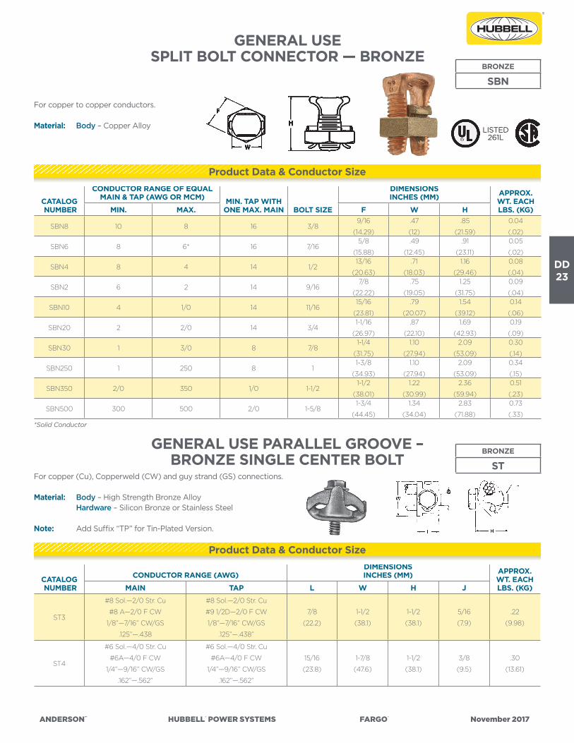
DD23
ANDERSON™ HUBBELL® POWER SYSTEMS FARGO® November 2017
GENERAL USESPLIT BOLT CONNECTOR — BRONZE
BRONZE
SBN
For copper to copper conductors.
Material: Body – Copper Alloy
*Solid Conductor
CATALOG NUMBER
CONDUCTOR RANGE OF EQUAL MAIN & TAP (AWG OR MCM) MIN. TAP WITH
ONE MAX. MAIN BOLT SIZE
DIMENSIONSINCHES (MM) APPROX.
WT. EACH LBS. (KG)MIN. MAX. F W H
SBN8 10 8 16 3/89/16
(14.29)
.47
(12)
.85
(21.59)
0.04
(.02)
SBN6 8 6* 16 7/165/8
(15.88)
.49
(12.45)
.91
(23.11)
0.05
(.02)
SBN4 8 4 14 1/213/16
(20.63)
.71
(18.03)
1.16
(29.46)
0.08
(.04)
SBN2 6 2 14 9/167/8
(22.22)
.75
(19.05)
1.25
(31.75)
0.09
(.04)
SBN10 4 1/0 14 11/1615/16
(23.81)
.79
(20.07)
1.54
(39.12)
0.14
(.06)
SBN20 2 2/0 14 3/41-1/16
(26.97)
.87
(22.10)
1.69
(42.93)
0.19
(.09)
SBN30 1 3/0 8 7/81-1/4
(31.75)
1.10
(27.94)
2.09
(53.09)
0.30
(.14)
SBN250 1 250 8 11-3/8
(34.93)
1.10
(27.94)
2.09
(53.09)
0.34
(.15)
SBN350 2/0 350 1/0 1-1/21-1/2
(38.01)
1.22
(30.99)
2.36
(59.94)
0.51
(.23)
SBN500 300 500 2/0 1-5/81-3/4
(44.45)
1.34
(34.04)
2.83
(71.88)
0.73
(.33)
LISTED261L
GENERAL USE PARALLEL GROOVE – BRONZE SINGLE CENTER BOLT
BRONZE
STFor copper (Cu), Copperweld (CW) and guy strand (GS) connections.
Material: Body – High Strength Bronze Alloy Hardware – Silicon Bronze or Stainless Steel
Note: Add Suffix “TP” for Tin-Plated Version.
Product Data & Conductor Size
CATALOG NUMBER
CONDUCTOR RANGE (AWG)DIMENSIONSINCHES (MM) APPROX.
WT. EACH LBS. (KG)MAIN TAP L W H J
ST3
#8 Sol.—2/0 Str. Cu
#8 A—2/0 F CW
1/8”—7/16” CW/GS
.125”—.438
#8 Sol.—2/0 Str. Cu
#9 1/2D—2/0 F CW
1/8”—7/16” CW/GS
.125”—.438”
7/8
(22.2)
1-1/2
(38.1)
1-1/2
(38.1)
5/16
(7.9)
.22
(9.98)
ST4
#6 Sol.—4/0 Str. Cu
#6A—4/0 F CW
1/4”—9/16” CW/GS
.162”—.562”
#6 Sol.—4/0 Str. Cu
#6A—4/0 F CW
1/4”—9/16” CW/GS
.162”—.562”
15/16
(23.8)
1-7/8
(47.6)
1-1/2
(38.1)
3/8
(9.5)
.30
(13.61)
Product Data & Conductor Size

DD24
ANDERSON™ HUBBELL® POWER SYSTEMS FARGO® November 2017
CATALOG NUMBER
CONDUCTOR RANGE (AWG)DIMENSIONSINCHES (MM) APPROX.
WT. EACH LBS. (KG)MAIN TAP L W H J
K1 #4 Str.—1/0 Str. Cu #8 Sol.—1/0 Str. Cu15/16
(23.81)
1-5/16
(33.34)
1-5/16
(33.34)
5/16
(7.94)
.125
(.06)
K2 #3 Str.—2/0 Str. Cu #8 Sol.—2/0 Str. Cu1-1/16
(26.99)
1-5/8
(41.28)
1-21/32
(42.07)
3/8
(9.53)
.29
(.13)
K3 #1 Str.—4/0 Str. Cu #8 Sol.—4/0 Str. Cu1-1/8
(28.58)
1-3/4
(44.45)
1-15/16
(49.21)
3/8
(9.53)
.40
(.18)
K41 2/0 Str.—350 MCM Cu #8 Sol.—350 MCM Cu1-3/8
(34.93)
2-1/8
(53.98)
2-3/8
(60.33)
1/2
(12.70)
.655
(.30)
K5 3/0 Str.—500 MCM Cu #8 Sol.—500 MCM Cu1-1/2
(38.10)
2-1/4
(57.15)
2-11/16
(68.26)
1/2
(12.70)
.80
(.36)
K6 350—800 MCM Cu #8 Sol.—800 MCM Cu1-5/8
(41.28)
2-1/2
(63.50)
3-3/16
(80.96)
1/2
(12.70)
1.00
(.45)
K7 500—1000 MCM Cu #8 Sol.—1000 MCM Cu2
(50.80)
3
(76.70)
3-11/16
(93.66)
5/8
(15.88)
2.13
(.97)
BRONZE
K, K_LFor copper to copper conductor connections.
Material: Body – High Strength Bronze Alloy Retaining Ring – Neoprene Rubber Hardware – Silicon Bronze
Note: “TP” = Tin-Plated Version.
CATALOG NUMBER
CONDUCTOR RANGE (AWG OR MCM)DIMENSIONSINCHES (MM) APPROX.
WT. EACH LBS. (KG)MAIN TAP L W H J
KR1 #4 Str.—1/0 Str. Cu #8 Sol.—1/0 Str. Cu15/16
(23.81)
1-5/16
(33.34)
1-1/2
(38.10)
5/16
(7.94)
.18
(.08)
KR2 #3 Str.—2/0 Str. Cu #6 Sol.—2/0 Str. Cu1-1/16
(26.99)
1-5/8
(41.28)
1-25/32
(45.24)
3/8
(9.53)
.35
(.16)
KR3 #1 Str.—4/0 Str. Cu #6 Sol.—4/0 Str. Cu1-1/8
(28.58)
1-3/4
(44.45)
2-1/8
(53.98)
3/8
(9.53)
.43
(.19)
KR4 2/0 Str.—350 MCM Cu #4 Sol.—350 MCM Cu1-3/8
(34.93)
2-1/8
(53.98)
2-9/16
(65.09)
1/2
(12.70)
.78
(.35)
KR5 3/0 Str.—500 MCM Cu #4 Sol.—500 MCM Cu1-1/2
(38.10)
2-1/4
(57.15)
2-15/16
(74.61)
1/2
(12.70)
.86
(.39)
KR6 350—800 MCM Cu #2 Str.—800 MCM Cu1-5/8
(41.28)
2-1/2
(63.50)
3-7/16
(87.31)
1/2
(12.70)
1.25
(.57)
KR7 450—1000 MCM Cu 1/0 Str.—1000 MCM Cu2
(50.80)
3
(76.70)
4
(101.60)
5/8
(15.88)
2.45
(1.11)
GENERAL USE – PARALLELBRONZE WITH SEPARATORBRONZE
KR
LISTED261L
LISTED261L
GENERAL USE – PARALLELBRONZE
* For equal length bolts (Separable), Add “L” Suffix.For Tin-Plating, add “TP” Suffix - Consult Factory.
* For equal length bolts (Separable), Add “L” Suffix.For Tin-Plating, add “TP” Suffix - Consult Factory.
For copper to copper conductor connections.
Material: Body – High Strength Bronze Alloy Separator – Copper Alloy Retaining Ring – Neoprene Rubber Hardware – Silicon Bronze
Product Data & Conductor Size
Product Data & Conductor Size
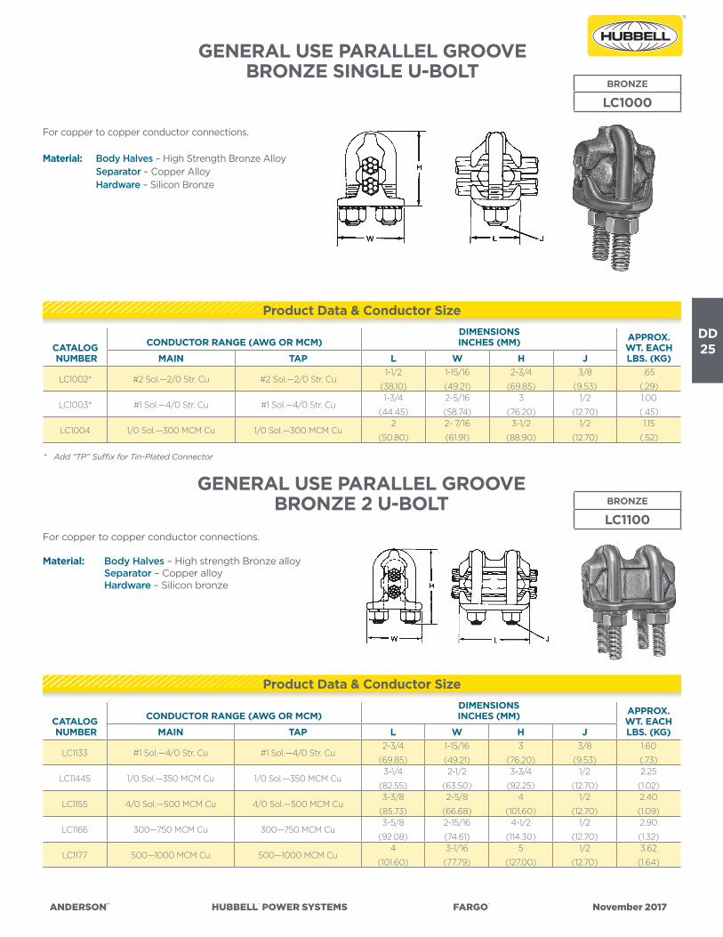
DD25
ANDERSON™ HUBBELL® POWER SYSTEMS FARGO® November 2017
GENERAL USE PARALLEL GROOVEBRONZE SINGLE U-BOLT
For copper to copper conductor connections.
Material: Body Halves – High Strength Bronze Alloy Separator – Copper Alloy Hardware – Silicon Bronze
* Add “TP” Suffix for Tin-Plated Connector
GENERAL USE PARALLEL GROOVEBRONZE 2 U-BOLT BRONZE
LC1100For copper to copper conductor connections.
Material: Body Halves – High strength Bronze alloy Separator – Copper alloy Hardware – Silicon bronze
BRONZE
LC1000
CATALOG NUMBER
CONDUCTOR RANGE (AWG OR MCM)DIMENSIONSINCHES (MM) APPROX.
WT. EACH LBS. (KG)MAIN TAP L W H J
LC1133 #1 Sol.—4/0 Str. Cu #1 Sol.—4/0 Str. Cu2-3/4
(69.85)
1-15/16
(49.21)
3
(76.20)
3/8
(9.53)
1.60
(.73)
LC11445 1/0 Sol.—350 MCM Cu 1/0 Sol.—350 MCM Cu3-1/4
(82.55)
2-1/2
(63.50)
3-3/4
(92.25)
1/2
(12.70)
2.25
(1.02)
LC1155 4/0 Sol.—500 MCM Cu 4/0 Sol.—500 MCM Cu3-3/8
(85.73)
2-5/8
(66.68)
4
(101.60)
1/2
(12.70)
2.40
(1.09)
LC1166 300—750 MCM Cu 300—750 MCM Cu3-5/8
(92.08)
2-15/16
(74.61)
4-1/2
(114.30)
1/2
(12.70)
2.90
(1.32)
LC1177 500—1000 MCM Cu 500—1000 MCM Cu4
(101.60)
3-1/16
(77.79)
5
(127.00)
1/2
(12.70)
3.62
(1.64)
Product Data & Conductor Size
CATALOG NUMBER
CONDUCTOR RANGE (AWG OR MCM)DIMENSIONSINCHES (MM) APPROX.
WT. EACH LBS. (KG)MAIN TAP L W H J
LC1002* #2 Sol.—2/0 Str. Cu #2 Sol.—2/0 Str. Cu1-1/2
(38.10)
1-15/16
(49.21)
2-3/4
(69.85)
3/8
(9.53)
.65
(.29)
LC1003* #1 Sol.—4/0 Str. Cu #1 Sol.—4/0 Str. Cu1-3/4
(44.45)
2-5/16
(58.74)
3
(76.20)
1/2
(12.70)
1.00
(.45)
LC1004 1/0 Sol.—300 MCM Cu 1/0 Sol.—300 MCM Cu2
(50.80)
2- 7/16
(61.91)
3-1/2
(88.90)
1/2
(12.70)
1.15
(.52)
Product Data & Conductor Size
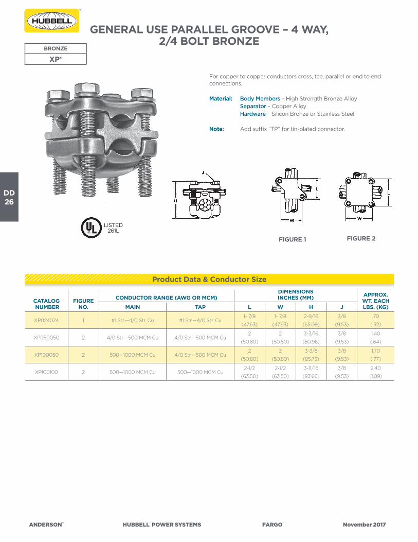
DD26
ANDERSON™ HUBBELL® POWER SYSTEMS FARGO® November 2017
GENERAL USE PARALLEL GROOVE – 4 WAY, 2/4 BOLT BRONZE
BRONZE
XP®
CATALOG NUMBER
FIGURENO.
CONDUCTOR RANGE (AWG OR MCM)DIMENSIONSINCHES (MM) APPROX.
WT. EACH LBS. (KG)MAIN TAP L W H J
XP024024 1 #1 Str.—4/0 Str. Cu #1 Str.—4/0 Str. Cu1- 7/8
(47.63)
1- 7/8
(47.63)
2-9/16
(65.09)
3/8
(9.53)
.70
(.32)
XP050050 2 4/0 Str.—500 MCM Cu 4/0 Str.—500 MCM Cu2
(50.80)
2
(50.80)
3-3/16
(80.96)
3/8
(9.53)
1.40
(.64)
XP100050 2 500—1000 MCM Cu 4/0 Str.—500 MCM Cu2
(50.80)
2
(50.80)
3-3/8
(85.73)
3/8
(9.53)
1.70
(.77)
XP100100 2 500—1000 MCM Cu 500—1000 MCM Cu2-1/2
(63.50)
2-1/2
(63.50)
3-11/16
(93.66)
3/8
(9.53)
2.40
(1.09)
FIGURE 2FIGURE 1
For copper to copper conductors cross, tee, parallel or end to end connections.
Material: Body Members – High Strength Bronze Alloy Separator – Copper Alloy Hardware – Silicon Bronze or Stainless Steel
Note: Add suffix “TP” for tin-plated connector.
LISTED261L
Product Data & Conductor Size
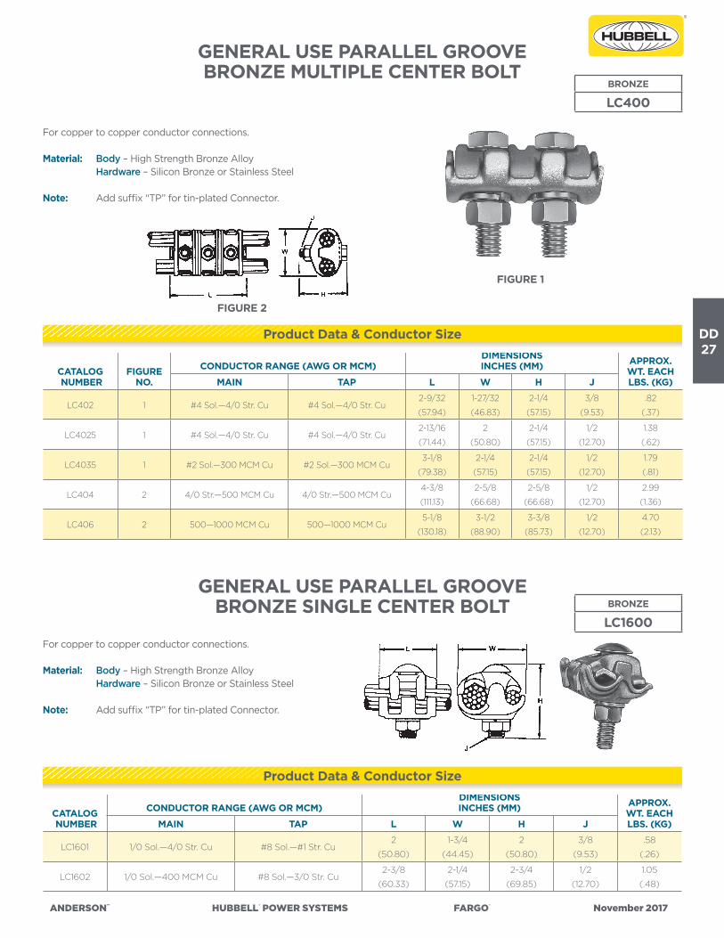
DD27
ANDERSON™ HUBBELL® POWER SYSTEMS FARGO® November 2017
GENERAL USE PARALLEL GROOVEBRONZE MULTIPLE CENTER BOLT
CATALOG NUMBER
FIGURENO.
CONDUCTOR RANGE (AWG OR MCM)DIMENSIONSINCHES (MM) APPROX.
WT. EACH LBS. (KG)MAIN TAP L W H J
LC402 1 #4 Sol.—4/0 Str. Cu #4 Sol.—4/0 Str. Cu2-9/32
(57.94)
1-27/32
(46.83)
2-1/4
(57.15)
3/8
(9.53)
.82
(.37)
LC4025 1 #4 Sol.—4/0 Str. Cu #4 Sol.—4/0 Str. Cu2-13/16
(71.44)
2
(50.80)
2-1/4
(57.15)
1/2
(12.70)
1.38
(.62)
LC4035 1 #2 Sol.—300 MCM Cu #2 Sol.—300 MCM Cu3-1/8
(79.38)
2-1/4
(57.15)
2-1/4
(57.15)
1/2
(12.70)
1.79
(.81)
LC404 2 4/0 Str.—500 MCM Cu 4/0 Str.—500 MCM Cu4-3/8
(111.13)
2-5/8
(66.68)
2-5/8
(66.68)
1/2
(12.70)
2.99
(1.36)
LC406 2 500—1000 MCM Cu 500—1000 MCM Cu5-1/8
(130.18)
3-1/2
(88.90)
3-3/8
(85.73)
1/2
(12.70)
4.70
(2.13)
FIGURE 2
FIGURE 1
For copper to copper conductor connections.
Material: Body – High Strength Bronze Alloy Hardware – Silicon Bronze or Stainless Steel
Note: Add suffix “TP” for tin-plated Connector.
CATALOG NUMBER
CONDUCTOR RANGE (AWG OR MCM)DIMENSIONSINCHES (MM) APPROX.
WT. EACH LBS. (KG)MAIN TAP L W H J
LC1601 1/0 Sol.—4/0 Str. Cu #8 Sol.—#1 Str. Cu2
(50.80)
1-3/4
(44.45)
2
(50.80)
3/8
(9.53)
.58
(.26)
LC1602 1/0 Sol.—400 MCM Cu #8 Sol.—3/0 Str. Cu2-3/8
(60.33)
2-1/4
(57.15)
2-3/4
(69.85)
1/2
(12.70)
1.05
(.48)
GENERAL USE PARALLEL GROOVEBRONZE SINGLE CENTER BOLT BRONZE
LC1600
BRONZE
LC400
For copper to copper conductor connections.
Material: Body – High Strength Bronze Alloy Hardware – Silicon Bronze or Stainless Steel
Note: Add suffix “TP” for tin-plated Connector.
Product Data & Conductor Size
Product Data & Conductor Size

DD28
ANDERSON™ HUBBELL® POWER SYSTEMS FARGO® November 2017
SNAP TAP™ PLASTIC COVERPLASTIC
PTC
PTC2 Snap-on covers for aluminum compression taps.PTC51 & 52 Snap-on covers for mechanical center bolt taps.
Material: Black Plastic
PTC51 PTC2
CATALOG NUMBER DESCRIPTION
APPROX. WT. EACHLBS. (KG)
PTC2**For use on “D” die AC’s or any H-frame connectors up to 2 1/2” long, VCP-43A,
VCP-44 VAC-1040 and VAC-4040.070 (.0318)
PTC51** For use on center bolt connectors LC-51A, LC-51C, LC52A, LC511A and LC-522A .052 (.0236)
PTC52** For use on center bolt connectors LC-52C, LC-81A, LC-811A, LC-542 .082 (.0372)
**RUS Listed
Product Data & Conductor Size

ANDERSON™ HUBBELL®POWERSYSTEMS FARGO® November2017
DISTRIBUTION CONNECTORS
FORMED WIREGuy Dead Ends
Overhead Dead EndsTop Ties
Side TiesSpool Ties
Super Top TiesComposite Ties
SE
CT
ION
DE
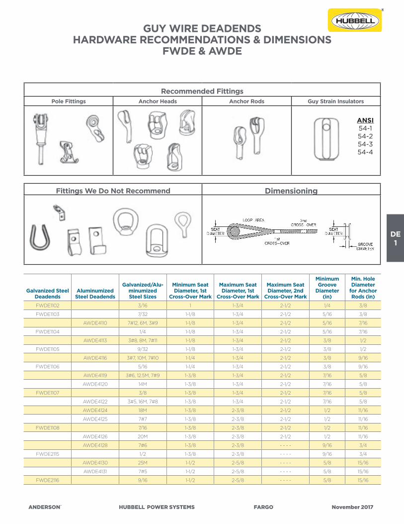
ANDERSON™ HUBBELL® POWER SYSTEMS FARGO® November 2017
DE1
GUY WIRE DEADENDSHARDWARE RECOMMENDATIONS & DIMENSIONS
FWDE & AWDE
Galvanized Steel Deadends
Aluminumized Steel Deadends
Galvanized/Alu-minumized Steel Sizes
Minimum Seat Diameter, 1st
Cross-Over Mark
Maximum Seat Diameter, 1st
Cross-Over Mark
Maximum Seat Diameter, 2nd
Cross-Over Mark
Minimum Groove
Diameter (in)
Min. Hole Diameter
for Anchor Rods (in)
FWDE1102 3/16 1 1-3/4 2-1/2 1/4 3/8
FWDE1103 7/32 1-1/8 1-3/4 2-1/2 5/16 3/8
AWDE4110 7#12, 6M, 3#9 1-1/8 1-3/4 2-1/2 5/16 7/16
FWDE1104 1/4 1-1/8 1-3/4 2-1/2 5/16 7/16
AWDE4113 3#8, 8M, 7#11 1-1/8 1-3/4 2-1/2 3/8 1/2
FWDE1105 9/32 1-1/8 1-3/4 2-1/2 3/8 1/2
AWDE4116 3#7, 10M, 7#10 1-1/4 1-3/4 2-1/2 3/8 9/16
FWDE1106 5/16 1-1/4 1-3/4 2-1/2 3/8 9/16
AWDE4119 3#6, 12.5M, 7#9 1-3/8 1-3/4 2-1/2 7/16 5/8
AWDE4120 14M 1-3/8 1-3/4 2-1/2 7/16 5/8
FWDE1107 3/8 1-3/8 1-3/4 2-1/2 7/16 5/8
AWDE4122 3#5, 16M, 7#8 1-3/8 1-3/4 2-1/2 7/16 5/8
AWDE4124 18M 1-3/8 2-3/8 2-1/2 1/2 11/16
AWDE4125 7#7 1-3/8 2-3/8 2-1/2 1/2 11/16
FWDE1108 7/16 1-3/8 2-3/8 2-1/2 1/2 11/16
AWDE4126 20M 1-3/8 2-3/8 2-1/2 1/2 11/16
AWDE4128 7#6 1-3/8 2-3/8 - - - - 9/16 3/4
FWDE2115 1/2 1-3/8 2-3/8 - - - - 9/16 3/4
AWDE4130 25M 1-1/2 2-5/8 - - - - 5/8 15/16
AWDE4131 7#5 1-1/2 2-5/8 - - - - 5/8 15/16
FWDE2116 9/16 1-1/2 2-5/8 - - - - 5/8 15/16
Recommended FittingsPole Fittings Anchor Heads Anchor Rods Guy Strain Insulators
Fittings We Do Not Recommend Dimensioning
ANSI54-154-254-354-4

DE2
ANDERSON™ HUBBELL® POWER SYSTEMS FARGO® November 2017
DEADENDS FORMED WIREGUY WIRE
• For deadend applications of support guy wires.• Fargo FWDE series formed wire deadends are designed for use
on all types of galvanized guy wire (EHS, High Strength, Common, Siemens-Martin, Utilities and Bell System Strand).
• FWDE will hold a minimum of 100% of the guy wire rated breaking strength.
Note: Consult factory for information on other applications. Left hand lay standard.
Material: Wire – EHS Steel, Zinc-plated to cover Class “B” coating per ASTM A641.
For Class “C” coating, add C suffix. For FWDE1104LA, LA suffix denotes Class “A” coating.
NOTES: All dimensions: inches (mm) unless otherwise noted. Rated at full tension of guy strand RBS for EHS, HS, Siemens-Martin, Common and Utility Grades. ** RUS Technically Accepted.
CATALOGNUMBER
NOMINAL SIZE
MAXIMUM RBS LB (KN)
NOMINAL LENGTH (L)DIAMETER RANGE IN
(MM)
COLOR CODE
PACKAGING PER BOX
IN MM MIN MAX UNITSWEIGHT LBS. (KG)
FWDE1102 3/16” 3,990 (17.7) 20 508 0.174 (4.41) 0.203 (5.16) Red 150 30 (13.6)
FWDE1103 7/32” 5,400 (24.0) 24 610 0.204 (5.18) 0.230 (5.84) Green 50 19 (8.6)
FWDE1104** 1/4” 6,650 (29.6) 25 635 0.231 (5.87) 0.259 (6.58) Yellow 50 24 (10.9)
FWDE1104LA 1/4” 6,650 (29.6) 25 635 0.231 (5.87) 0.259 (6.58) Yellow 50 24 (10.9)
FWDE1105 9/32” 8,950 (39.8) 28 711 0.260 (6.60) 0.291 (7.39) Blue 50 26 (11.8)
FWDE1106** 5/16” 11,200 (49.8) 31 787 0.292 (7.42) 0.336 (8.53) Black 50 41 (18.6)
FWDE1107** 3/8” 15,400 (68.5) 35 891 0.337 (8.56) 0.394 (10.01) Orange 50 53 (24.0)
FWDE1108** 7/16” 20,800 (92.5) 38 965 0.395 (10.03) 0.474 (12.04) Green 25 36 (16.3)
FWDE2115 1/2” 26,900 (119.7) 49 1245 0.475 (12.07) 0.515 (13.08) Blue 20 67 (30.4)
FWDE2116 9/16” 35,000 (155.7) 55 1397 0.516 (13.11) 0.570 (14.48) Yellow 10 48 (21.8)
GALVANIZED STEEL
FWDE
FWDE

ANDERSON™ HUBBELL® POWER SYSTEMS FARGO® November 2017
DE3
DEADENDS FORMED WIREGUY WIRE BEZINAL®
• For deadend applications for support of guy wires.• Fargo BDE series formed wire deadends are designed for use on
Bezinal® strand.• BDE will hold a minimum of 100% of the guy wire rated breaking
strength.
Note: Left hand lay standard.
BEZINAL® COATED STEEL
BDE
NOTES: All dimensions: inches (mm) unless otherwise noted. Bezinal is a registered trademark of Bekaert Company
CATALOGNUMBER
NOMINALSIZE
MAXIMUMRBS
LB (KN)
NOMINAL LENGTH (L)DIAMETER RANGE IN
(MM)
COLOR CODE
PACKAGING PER BOX
IN MM MIN MAX UNITSWEIGHT LBS (KG)
BDE9102 3/16” 3,900 (17.3) 20 508 0.174 (4.41) 0.203 (5.16) Red 100 30 (13.6)
BDE9103 7/32” 5,400 (24.0) 24 610 0.204 (5.18) 0.230 (5.84) Green 50 19 (8.6)
BDE9104 1/4” 6,650 (29.6) 25 635 0.231 (5.87) 0.259 (6.58) Yellow 50 23 (10.5)
BDE9105 9/32” 8,950 (39.8) 28 711 0.260 (6.60) 0.291 (7.39) Blue 50 26 (11.8)
BDE9106 5/16” 11,200 (49.8) 31 787 0.292 (7.42) 0.336 (8.53) Black 50 39 (17.7)
BDE9107 3/8” 15,400 (68.5) 35 891 0.337 (8.56) 0.394 (10.01) Orange 50 51 (23.2)
BDE9108 7/16” 20,800 (92.5) 38 965 0.395 (10.03) 0.474 (12.04) Green 25 40 (18.2)
BDE9115 1/2” 26,900 (119.7) 49 1245 0.475 (12.07) 0.515 (13.08) Blue 20 67 (30.4)
BDE9116 9/16” 35,000 (155.7) 55 1397 0.516 (13.11) 0.570 (14.48) Yellow 10 48 (21.8)
BDE

DE4
ANDERSON™ HUBBELL® POWER SYSTEMS FARGO® November 2017
DEADENDS FORMED WIREGUY WIRE ALUMOWELD®
• For deadend applications of support guy wires.• Fargo AWDE series formed wire deadends are designed for use on
Alumoweld® type guy wire.• AWDE will hold a minimum of 100% of the guy wire rated breaking
strength.
Note: Consult factory for information on other applications. Left hand lay standard.
NOTES: All dimensions: inches (mm) unless otherwise noted. Rated at 100% of guy strand RBS for Alumoweld®. Alumoweld is a registered trademark of AFL Corporation. ** RUS Technically Accepted.
ALUMINUM/STEEL
AWDE
CATALOGNUMBER
NOMINALSIZE
MAXIMUMRBS LB (KN)
NOMINAL LENGTH (L)DIAMETER RANGE IN
(MM)
COLOR CODE
PACKAGING PER BOX
IN MM MIN MAX UNITSWEIGHT LBS (KG)
AWDE4108 4M, 3#10 4532 (20.1) 21 533 .204 (5.18) .230 (5.842) Green 50 16 (7.3)
AWDE4110 ** 6M, 3#9 6,000 (26.7) 22 559 0.231 (5.87) 0.259 (6.58) Yellow 50 20 (9.1)
AWDE4113 ** 3#8, 8M 8,000 (35.6) 24 610 0.260 (6.60) 0.291 (7.39) Blue 50 20 (9.1)
AWDE4116 ** 3#7, 10M, 7#10 10,000 (44.5) 26 660 0.292 (7.42) 0.336 (8.53) Black 50 30 (13.6)
AWDE4119 ** 3#6, 12.5M, 7#9 12,500 (55.6) 29 737 0.337 (8.56) 0.360 (9.14) Yellow 50 33 (14.8)
AWDE4120 ** 14M 14,000 (62.3) 31 787 0.361 (9.17) 0.384 (9.75) Blue 50 53 (24.0)
AWDE4122 ** 3#5, 16M, 7#8 16,000 (71.2) 32 813 0.385 (9.78) 0.410 (10.41) Orange 50 55 (25.0)
AWDE4124 18M 18,000 (80.1) 34 864 0.411 (10.44) 0.430 (10.92) Black 25 29 (132)
AWDE4125 7#7 20,000 (89.0) 36 914 0.431 (10.95) 0.474 (12.04) Green 25 32 (14.5)
AWDE4126 ** 20M 20,000 (89.0) 36 914 0.431 (10.95) 0.474 (12.04) Yellow 10 22 (10.0)
AWDE4128 7#6 22,730 (101.1) 40 1016 0.475 (12.07) 0.515 (13.08) Blue 10 23 (10.5)
AWDE4130 25M 25,000 (111.2) 43 1092 0.516 (13.11) 0.535 (13.59) Red 10 31 (14.1)
AWDE4131 7#5 27,030 (120.2) 45 1143 0.536 (13.61) 0.570 (14.48) Yellow 10 32 (14.5)
AWDE

ANDERSON™ HUBBELL® POWER SYSTEMS FARGO® November 2017
DE5
SPLICES FORMED WIREGUY WIRE
• For repairing damaged or severed guy wire or messenger cable.• Do not use FWLS splices on overhead shield wires.• Fargo FWLS series formed wire are designed for use on all types of
galvanized guy wire (EHS, High Strength, Common, Siemens-Martin, Utilities, and Bell System Strand).
• FWLS will hold a minimum of 100% of the guy wire rated breaking strength (ultimate strength) when centered over the severed or point of damage.
Note: Consult factory for information on use if damaged area exceeds length of splice. Left hand lay standard.
NOTES: All dimensions: inches (mm) unless otherwise noted. Rated at full tension of guy strand RBS for EHS, HS, Siemens-Martin, Common, and Utility Grades.
GALVANIZED STEEL
FWLS
CATALOGNUMBER NOMINAL SIZE
MAXIMUM RBS
LB (KN)
NOMINAL LENGTH (L)
DIAMETER RANGE IN (MM) NUMBER
OF SUB-SETS
COLOR CODE
PACKAGING PER BOX
IN MM MIN MAX UNITS
WEIGHT LBS. (KG)
FWLS2102 3/16” (3W & 7W) 3,990 (17.7) 27 685 0.174 (4.41) 0.203 (5.16) 2 Red 100 30 (13.6)
FWLS2103 7/32” (7W) 5,400 (24.0) 29 737 0.204 (5.18) 0.230 (5.84) 2 Green 100 36 (16.3)
FWLS2104 1/4” (3W & 7W) 6,650 (29.6) 35 889 0.231 (5.87) 0.259 (6.58) 2 Yellow 50 34 (15.4)
FWLS2105 9/32” (7W) 8,950 (39.8) 38 965 0.260 (6.60) 0.291 (7.39) 2 Blue 50 36 (16.3)
FWLS2106 5/16” (3W & 7W) 11,200 (49.8) 42 1067 0.292 (7.42) 0.336 (8.53) 2 Black 50 46 (20.8)
FWLS2107 3/8” (3W & 7W) 15,400 (68.5) 50 1270 0.337 (8.56) 0.394 (10.01) 3 Orange 25 38 (17.2)
FWLS2108 7/16” (7W) 20,800 (92.5) 56 1422 0.395 (10.03) 0.474 (12.04) 3 Green 25 58 (26.3)
FWLS2109 1/2” (7W & 19W) 26,900 (119.7) 63 1600 0.475 (12.07) 0.515 (13.08) 3 Blue 10 36 (16.3)
FWLS2110 9/16” (7W & 19W) 35,000 (155.7) 71 1803 0.516 (13.11) 0.570 (14.48) 3 Yellow 10 52 (23.5)
FWLS

DE6
ANDERSON™ HUBBELL® POWER SYSTEMS FARGO® November 2017
DEADENDS FORMED WIRESERVICE GRIP
• For deadend applications of neutral messengers used in making service drops.
• Fargo SGFW series formed wire deadends are designed for use on self supporting cables (ACSR, AAC, AAAC).
• SGFW deadends will hold a minimum of 50% of the cable (RBS) rated breaking strength.
Note: Consult factory for information on other applications. Right hand lay standard.
ALUMINUM/STEEL
SGFW
ALL DIMENSIONS: INCHES (MM) UNLESS OTHERWISE NOTED. ** RUS Technically Accepted.
CATALOGNUMBER
NOMINAL CONDUCTOR SIZE DIAMETER RANGE NOMINAL DIMENSIONSPACKAGING
PER BOXCOLORCODEACSR AAC AAAC COMP. MIN MAX DIM 1 DIM 2
NECKDIA. UNITS
WEIGHTLBS (KG)
SGFW4500 #6 (6/1) #6 (7str) #6 (7str)
#6 (6/1)
#6 (7str)
#5 (sol)
0.169
(4.29)
0.198
(5.04)
11
(280)
0.40
(10.2)
2.0
(50)300
24
(10.9)BLUE
SGFW4501 #5 (6/1) #4 (sol) #5 (7str)#4 (7str)
#4 (sol)
0.199
(5.05)
0.224
(5.70)
12
(305)
0.40
(10.2)
2.0
(50)300
25
(11.4)WHITE
SGFW4502 **#4 (6/1)
#4 (7/1)#4 (7w) #4 (7str)
#4 (6/1)
#4 (7/1)
0.225
(5.71)
0.257
(6.54)
13
(330)
0.40
(10.2)
2.0
(50)300
32
(14.5)ORANGE
SGFW4503 #3 (6/1) #3 (7str) #3 (7str)
#3 (6/1)
#2 (7str)
#2 (sol)
#1 (sol)
0.258
(6.55)
0.289
(7.35)
14
(355)
0.40
(10.2)
2.0
(50)200
24
(10.9)BLACK
SGFW4504 **#2 (6/1)
#2 (7/1)#2 (7str) #2 (7str) #2 (7str)
0.290
(7.35)
0.325
(8.27)
15
(381)
0.40
(10.2)
2.0
(50)200
32
(14.5)RED
SGFW4505 #1 (6/1) #1 (7str) #1 (7str)
#1 (6/1)
1/0 (7str)
1/0 (19str)
0.326
(8.28)
0.360
(9.15)
17
(432)
0.40
(10.2)
2.0
(50)200
28
(12.7)GREEN
SGFW4506 ** 1/0 (6/1) 1/0 (7str) 1/0 (7str) 1/0 (7str)0.361
(9.16)
0.400
(10.17)
19
(483)
0.40
(10.2)
2.0
(50)100
29
(13.2)YELLOW
SGFW4507 ** 2/0 (6/1) 2/0 (7str) 2/0 (7str) 2/0 (7str)0.401
(10.18)
0.450
(11.44)
21
(533)
0.40
(10.2)
2.0
(50)100
34
(15.5)BLUE
SGFW4508 3/0 (6/1) 3/0 (7str) 3/0 (7str)
3/0 (6/1)
4/0 (7str)
4/0 (19str)
0.451
(11.45)
0.511
(12.97)
12
(585)
0.40
(10.2)
2.0
(50)100
31
(14.1)ORANGE
SGFW4509 ** 4/0 (6/1) 4/0 (7str) 4/0 (7str) 4/0 (6/1)0.511
(12.97)
0.580
(14.74)
26
(660)
0.40
(10.2)
2.0
(50)100
41
(18.6)RED
SGFW

ANDERSON™ HUBBELL® POWER SYSTEMS FARGO® November 2017
DE7
DEADENDS FORMED WIREDISTRIBUTION GRIP
• For deadending bare or plastic jacketed conductor on primaries, secondaries, and substation feeder applications.
• Fargo DGFW series formed wire deadends are designed for use with ACSR, AAC, AAAC, Compacted ACSR and AWAC®.
• DGFW deadends will hold a minimum of 60% of the cable (RBS) rated breaking strength..
Note: Consult factory for information on other applications. Right hand lay standard.
NOTES: All dimensions: inches (mm) unless otherwise noted. Dimension “X” equals 1.0” (25.4 mm) in all cases. Neck (open helix loop) diameter equals 2” (50 mm) in all cases. AWAC is a registered trademark of Copperweld Co.
CATALOG NUMBER
NOMINAL CONDUCTOR SIZE DIAMETER RANGEPACKAGING
PER BOX
LENGTH COLORACSR AAC AAACCOMP ACSR AWAC® MIN MAX UNITS
WT LBS (KG)
DGFW4554 #6 (6/1) #6, 7W #6, 7W #6 (6/1)0.182
(4.62)
0.203
(5.15)100
13.4
(6.1)
16
(406)BLUE
DGFW4541#4 (6/1)
#4 (7/1)#4, 7W #4, 7W #4 (6/1) #4 (6/1)
0.229
(5.81)
0.257
(6.53)100
17.9
(8.1)
16.9
(430)ORANGE
DGFW4542#2 (6/1)
#2 (7/1) #2, 7W #2, 7W #2 (6/1)
#2 (6/1),
#3 (5/2)
0.290
(7.36)
0.325
(8.27)100
30.6
(13.9)
24
(610)RED
DGFW4543 #1 (6/1) #1, 7W #1, 7W #1 (6/1)#1 (6/1),
#2 (5/2).326 (8.28) .364 (9.25) 50 25.5 (11.6) 26 (660) GREEN
DGFW4544 1/0 (6/1) 1/0, 7W 1/0, 7W 1/0 (6/1)1/0 (6/1),
#1 (5/2)
0.365
(9.27)
0.409
(10.40)50
27.2
(12.4)
26.4
(671)YELLOW
DGFW4545 2/0 (6/1) 2/0, 7W 2/0, 7W 2/0 (6/1)2/0 (6/1),
1/0 (5/2)
0.410
(10.41)
0.460
(11.69)50
29.2
(13.3)
27.9
(710)BLUE
DGFW4546 3/0 (6/1) 3/0, 7W 3/0, 7W 3/0 (6/1)3/0 (6/1),
2/0 (5/2)
0.461
(11.70)
0.516
(13.12)25
21.0
(9.5)
32.5
(825)ORANGE
DGFW4547 4/0 (6/1) 4/0, 7W 4/0, 7W 4/0 (6/1)4/0 (6/1),
3/0 (5/2)
0.517
(13.13)
0.577
(14.67)25
60.0
(27.3)
34.0
(865) RED
DGFW4548
266.8 (18/1)
266.8 (26/7)
300 (18/1)
266.8 19W
266.8 37W
300 19W
300 37W
266.8 19W300 (18/1)
336.4 (18/1)266.8 (18/1) .578 (14.68)
.653
(16.60)25 34.0 (865) 35 (889) BLACK
DGFW4549
300 (26/7)
300 (30/7)
336.4 (18/1)
336.4 (36/1)
336.4 (26/7)
397.5 (36/1)
336.4 19 W,
336.4 37W,
350 19W,
350 37W,
397.5 19W,
397.5 37W,
400 19W,
400 37W
336.4, 7W 397.5 (18/1) 336.4 (18/1)0.654
(16.61)
0.739
(18.77)25
52.7
(24.0)
38.6
(980)GREEN
ALUMINUM/STEEL
DGFW
DGFW
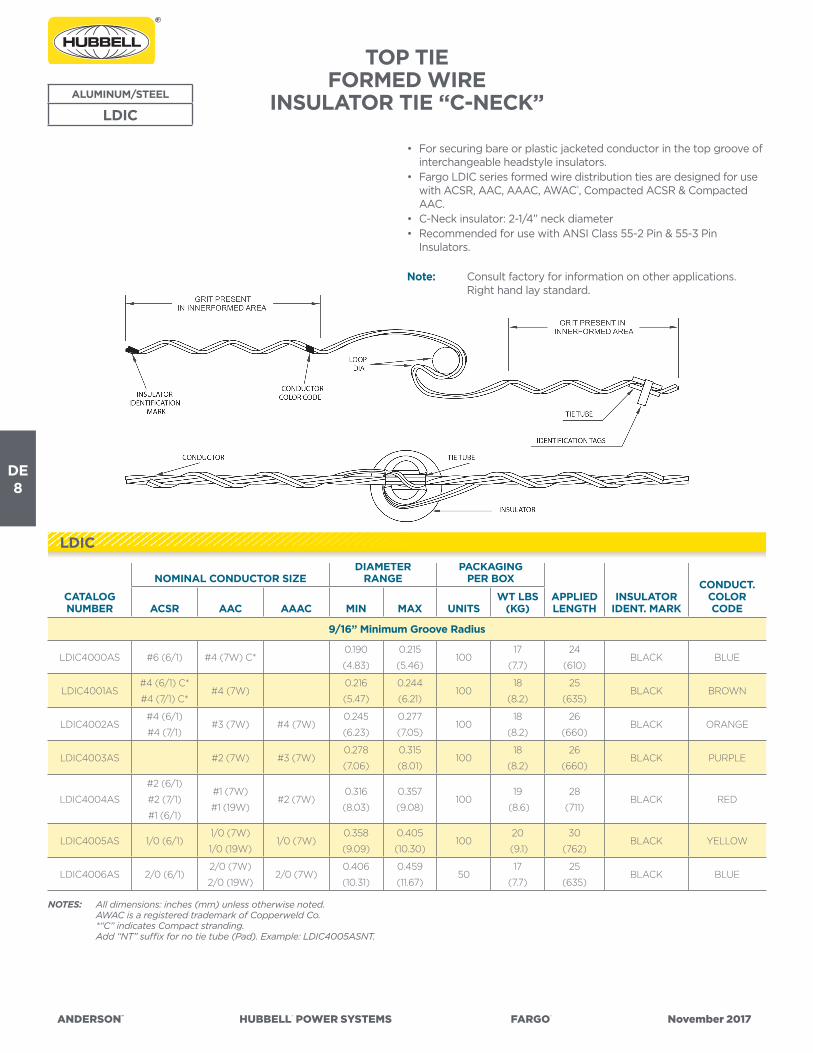
DE8
ANDERSON™ HUBBELL® POWER SYSTEMS FARGO® November 2017
TOP TIE FORMED WIRE
INSULATOR TIE “C-NECK”
NOTES: All dimensions: inches (mm) unless otherwise noted. AWAC is a registered trademark of Copperweld Co. *“C” indicates Compact stranding. Add “NT” suffix for no tie tube (Pad). Example: LDIC4005ASNT.
ALUMINUM/STEEL
LDIC
CATALOG NUMBER
NOMINAL CONDUCTOR SIZEDIAMETER
RANGEPACKAGING
PER BOX
APPLIED LENGTH
INSULATOR IDENT. MARK
CONDUCT.COLORCODEACSR AAC AAAC MIN MAX UNITS
WT LBS (KG)
9/16” Minimum Groove Radius
LDIC4000AS #6 (6/1) #4 (7W) C*0.190
(4.83)
0.215
(5.46)100
17
(7.7)
24
(610)BLACK BLUE
LDIC4001AS#4 (6/1) C*
#4 (7/1) C*#4 (7W)
0.216
(5.47)
0.244
(6.21)100
18
(8.2)
25
(635)BLACK BROWN
LDIC4002AS#4 (6/1)
#4 (7/1)#3 (7W) #4 (7W)
0.245
(6.23)
0.277
(7.05)100
18
(8.2)
26
(660)BLACK ORANGE
LDIC4003AS #2 (7W) #3 (7W)0.278
(7.06)
0.315
(8.01)100
18
(8.2)
26
(660)BLACK PURPLE
LDIC4004AS
#2 (6/1)
#2 (7/1)
#1 (6/1)
#1 (7W)
#1 (19W)#2 (7W)
0.316
(8.03)
0.357
(9.08)100
19
(8.6)
28
(711)BLACK RED
LDIC4005AS 1/0 (6/1)1/0 (7W)
1/0 (19W)1/0 (7W)
0.358
(9.09)
0.405
(10.30)100
20
(9.1)
30
(762)BLACK YELLOW
LDIC4006AS 2/0 (6/1)2/0 (7W)
2/0 (19W)2/0 (7W)
0.406
(10.31)
0.459
(11.67)50
17
(7.7)
25
(635)BLACK BLUE
• For securing bare or plastic jacketed conductor in the top groove of interchangeable headstyle insulators.
• Fargo LDIC series formed wire distribution ties are designed for use with ACSR, AAC, AAAC, AWAC®, Compacted ACSR & Compacted AAC.
• C-Neck insulator: 2-1/4” neck diameter• Recommended for use with ANSI Class 55-2 Pin & 55-3 Pin
Insulators.
Note: Consult factory for information on other applications. Right hand lay standard.
LDIC

ANDERSON™ HUBBELL® POWER SYSTEMS FARGO® November 2017
DE9
NOTES: All dimensions: inches (mm) unless otherwise noted. AWAC is a registered trademark of Copperweld Co. “C” indicates Compact stranding. Add “NT” suffix for no tie tube (Pad). Example: LDIC4005ASNT.
TOP TIE FORMED WIRE
INSULATOR TIE “C-NECK”(CONTINUED)
ALUMINUM/STEEL
LDIC
CATALOG NUMBER
NOMINAL CONDUCTOR SIZEDIAMETER
RANGEPACKAGING
PER BOX
APPLIED LENGTH
INSULATORIDENT. MARK
CONDUCT.COLOR CODEACSR AAC AAAC MIN MAX UNITS
WT LBS (KG)
9/16” Minimum Groove Radius (Continued)
LDIC4007AS 3/0 (6/1)3/0 (7W)
3/0 (19W)3/0 (7W)
0.460
(11.68)
0.520
(13.21)50
17
(7.7)
25
(635)BLACK ORANGE
LDIC4008AS 4/0 (6/1)
4/0 (7W)
4/0 (19W)
266.8 (7W)
4/0 (7W)0.521
(13.23)
0.588
(14.95)50
18
(8.2)
28
(711)BLACK RED
LDIC4009AS266.8 (18/1)
266.8 (26/7)
2668 (19W)
266.8 (37W)
336.4 (19W)
0.589
(14.95)
0.665
(16.90)50
18
(8.2)
30
(762)BLACK PURPLE
LDIC4010AS
336.4 (18/1)
336.4 (26/7)
397.5 (18/1)
350 (19W)
397.5 (37W)
0.666
(16.91)
0.755
(19.19)50
19
(8.6)
31
(787)BLACK BROWN
LDIC4011AS
397.5 (24/7)
397.5 (26/7)
477 (18/1)
477 (24/7)
477 (26/7)
450 (19W)
477 (19W)
477 (37W)
500 (19W)
500 (37W)
556.5 (19W)
556.5 (37W)
0.756
(19.20)
0.858
(21.79)50
19
(8.6)
32
(813)BLACK RED
5/8” Minimum Groove Radius
LDIC4012AS
556.5 (18/1)
556.5 (24/7)
556.5 (26/7)
636 (18/1)
636 (37W)
700 (37W)
700 (61W)
0.859
(21.81)
0.968
(24.60)50
20
(9.1)
34
(864)BLACK BLUE
3/4” Minimum Groove Radius
LDIC4013AS
636 (24/7)
636 (26/7)
715.5 (24/7)
795 (36/1)
795 (45/7)
795 (54/7)
795 (37W)
795 (61W)
0.969
(24.61)
1.096
(27.85)50
21
(9.5)
37
(940)BLACK GREEN
LDIC4014AS
795 (26/7)
954 (36/1)
954 (54/7)
1033.5
(45/7)
1033.5
(54/7)
1033.5 (37W)
1033.5 (61W)
1.097
(27.86)
1.240
(31.50)50
22
(10.0)
40
(1016)BLACK YELLOW
LDIC

DE10
ANDERSON™ HUBBELL® POWER SYSTEMS FARGO® November 2017
TOP TIE FORMED WIRE
INSULATOR TIE “F-NECK”
• For securing bare or plastic jacketed conductor in the top groove of interchangeable headstyle insulators.
• Fargo LDIF series formed wire distribution ties are designed for use with ACSR, AAC, AAAC, AWAC®,
• Compacted ACSR & Compacted AAC.• F-Neck insulator: 2-7/8” neck diameter• Recommended for use with ANSI Class 55-4 Pin, 55-5 Pin, 57-1 Pin,
57-2 Pin & 57-3 Pin Insulators.
Note: Consult factory for information on other applications. Right hand lay standard.
NOTES: All dimensions: inches (mm) unless otherwise noted. AWAC is a registered trademark of Copperweld Co. *“C” indicates Compact stranding. Add “NT” suffix for no tie tube (Pad). Example: LDIF4505ASNT.
ALUMINUM/STEEL
LDIF
CATALOG NUMBER
NOMINAL CONDUCTOR SIZEDIAMETER
RANGEPACKAGING
PER BOXAPPLIED LENGTH
INSULATOR IDENT. MARK
CONDUCT.COLORCODEACSR AAC AAAC MIN MAX UNITS
WT LBS (KG)
9/16” Minimum Groove Radius
LDIF4500AS #6 (6/1) #4 (7W) C*0.190
(4.83)
0.215
(5.46)100
18
(8.2)
25
(635)YELLOW BLUE
LDIF4501AS#4 (6/1) C*
#4 (7/1) C*#4 (7W)
0.216
(5.47)
0.244
(6.21)100
19
(8.6)
26
(660)YELLOW BROWN
LDIF4502AS#4 (6/1)
#4 (7/1)#3 (7W) #4 (7W)
0.245
(6.23)
0.277
(7.05)100
19
(8.6)
27
(686)YELLOW ORANGE
LDIF4503AS #2 (7W) #3 (7W)0.278
(7.06)
0.315
(8.01)100
20
(9.1)
29
(737)YELLOW PURPLE
LDIF4504AS
#2 (6/1)
#2 (7/1)
#1 (6/1)
#1 (7W)
#1 (19W)#2 (7W)
0.316
(8.03)
0.357
(9.08)100
20
(9.1)
31
(787)YELLOW RED
LDIF4505AS 1/0 (6/1)1/0 (7W)
1/0 (19W)1/0 (7W)
0.358
(9.09)
0.405
(10.30)100
21
(9.5)
32
(813)YELLOW YELLOW
LDIF4506AS 2/0 (6/1)2/0 (7W)
2/0 (19W)2/0 (7W)
0.406
(10.31)
0.459
(11.67)50
18
(8.2)
25
(635)YELLOW BLUE
LDIF4507AS 3/0 (6/1)3/0 (7W)
3/0 (19W)3/0 (7W)
0.460
(11.68)
0.520
(13.21)50
18
(8.2)
27
(686)YELLOW ORANGE
LDIF4508AS 4/0 (6/1)
4/0 (7W)
4/0 (19W)
266.8 (7W)
4/0 (7W)0.521
(13.23)
0.588
(14.95)50
19
(8.6)
29
(737)YELLOW RED
LDIF

ANDERSON™ HUBBELL® POWER SYSTEMS FARGO® November 2017
DE11
TOP TIE FORMED WIRE
INSULATOR TIE “F-NECK”(CONTINUED)
ALUMINUM/STEEL
LDIF
NOTES: All dimensions: inches (mm) unless otherwise noted. AWAC is a registered trademark of Copperweld Co. “C” indicates Compact stranding. Add “NT” suffix for no tie tube (Pad). Example: LDIF4505ASNT.
CATALOG NUMBER
NOMINAL CONDUCTOR SIZEDIAMETER
RANGEPACKAGING
PER BOXAPPLIED LENGTH
INSULATOR IDENT. MARK
CONDUCT.COLORCODEACSR AAC AAAC MIN MAX UNITS
WT LBS (KG)
9/16” Minimum Groove Radius (Continued)
LDIF4509AS266.8 (18/1)
266.8 (26/7)
266.8 (19W)
266.8 (37W)
336.4 (19W)
0.589
(14.96)
0.665
(16.95)50
19
(8.6)
32
(813)YELLOW PURPLE
LDIF4510AS
336.4 (18/1)
336.4 (26/7)
397.5 (18/1)
350 (19W)
397.5 (37W)
0.666
(16.91)
0.755
(19.19)50
20
(9.1)
32
(813)YELLOW BROWN
LDIF4511AS
397.5 (24/7)
397.5 (26/7)
477 (18/1)
477 (24/7)
477 (26/7)
450 (19W)
477 (19W)
477 (37W)
500 (19W)
500 (37W)
556.5 (19W)
556.5 (37W)
0.756
(19.20)
0.858
(21.79)50
20
(9.1)
33
(838)YELLOW RED
5/8” Minimum Groove Radius
LDIF4512AS
556.5 (18/1)
556.5 (24/7)
556.5 (26/7)
636 (18/1)
636 (37W)
700 (37W)
700 (61W)
0.859
(21.81)
0.968
(24.60)50
21
(9.5)
35
(889)YELLOW BLUE
3/4” Minimum Groove Radius
LDIF4513AS
636 (24/7)
636 (26/7)
715.5 (24/7)
795 (36/1)
795 (45/7)
795 (54/7)
795 (37W)
795 (61W)
0.969
(24.61)
1.096
(27.85)50
22
(10.0)
38
(965)YELLOW GREEN
LDIF4514AS
795 (26/7)
954 (36/1)
954 (54/7)
1033.5 (45/7)
1033.5 (54/7)
1033.5 (37W)
1033.5 (61W)
1.097
(27.86)
1.240
(31.50)50
23
(10.5)
41
(1041)YELLOW YELLOW
LDIF

DE12
ANDERSON™ HUBBELL® POWER SYSTEMS FARGO® November 2017
TOP TIE FORMED WIRE
INSULATOR TIE “J-NECK”
NOTES: All dimensions: inches (mm) unless otherwise noted. AWAC is a registered trademark of Copperweld Co. “C” indicates Compact stranding. Add “NT” suffix for no tie tube (Pad). Example: LDIJ4605ASNT.
ALUMINUM/STEEL
LDIJ
CATALOG NUMBER
NOMINAL CONDUCTOR SIZEDIAMETER
RANGEPACKAGING
PER BOXAPPLIED LENGTH
INSULATOR IDENT. MARK
CONDUCT.COLORCODEACSR AAC AAAC MIN MAX UNITS
WT LBS (KG)
9/16” Minimum Groove Radius
LDIJ4602AS#4 (6/1)
#4 (7/1)#3 (7W) #4 (7W)
0.245
(6.23)
0.277
(7.05)100
25
(11.4)
28
(711)GREEN ORANGE
LDIJ4604AS
#2 (6/1)
#2 (7/1)
#1 (6/1)
#2 (7W)0.316
(8.03)
0.357
(9.08)100
29
(13.2)
32
(813)GREEN RED
LDIJ4605AS 1/0 (6/1) 1/0 (7W) 1/0 (7W)0.358
(9.09)
0.405
(10.30)100
31
(14.1)
33
(838)GREEN YELLOW
LDIJ4609AS266.8 (18/1)
266.8 (26/7)
266.8 (37W)
336.4 (19W)
0.589
(14.96)
0.685
(16.95)50
22
(10.0)
33
(838)GREEN PURPLE
LDIJ4610AS
336.4 (18/1)
336.4 (26/7)
397.5 (18/1)
350 (19W)
397.5 (37W)
0.666
(16.91)
0.755
(19.19)50
23
(10.5)
33
(838)GREEN BROWN
LDIJ4611AS
397.5 (24/7)
397.5 (26/7)
477 (18/1)
477 (24/7)
477 (26/7)
450 (19W)
477 (19W)
477 (37W)
500 (19W)
500 (37W)
556.5 (19W)
556.5 (37W)
0.756
(19.20)
0.858
(21.79)50
27
(12.3)
34
(864)GREEN RED
5/8” Minimum Groove Radius
LDIJ4612AS
556.5 (18/1)
556.5 (24/7)
556.5 (26/7)
636 (18/1)
636 (37W)
700 (37W)
700 (61W)
0.859
(21.81)
0.968
(24.60)50
27
(12.3)
36
(914)GREEN BLUE
• For securing bare or plastic jacketed conductor in the top groove of interchangeable headstyle insulators.
• Fargo LDIJ series formed wire distribution ties are designed for use with ACSR, AAC, AAAC,
• Compacted ACSR, Compacted AAC & AWAC®.• J-Neck insulator: 3-1/2” neck diameter• Recommended for use with ANSI Class 55-6, 55-7 & 56-1 Pin Insulators.
Note: Consult factory for information on other applications. Right hand lay standard.
LDIJ

ANDERSON™ HUBBELL® POWER SYSTEMS FARGO® November 2017
DE13
TWIN TIE FORMED WIREINSULATOR TIE
• Twin Ties are used in applications where the conductor is aligned to sit in the top groove of the insulator. This type of tie can be used on line angles up to 10 degrees with the insulator in a vertical orientation. Larger angles can be accomodated by modifying the cant of the insulator off vertical. A combination of tie styles can affect line angles as well.
• Fargo TTFJ series formed wire twin ties are designed for use with ACSR, AAC, AAAC, Compacted ACSR, Compacted AAC & AWAC®.
• TTFJ: F-Neck (2-7/8” neck diameter) and J-Neck (3-1/2” neck diameter) interchangeable headstyle insulators.
• Recommended for use with ANSI Class 55-4 Pin, 55-5 Pin, 57-1 Pin, 57-2 Pin, 57-3 Pin, 55-6 Single Skirt Pin, 55-7 Single Skirt Pin & 56-1 Double Skirt Pin Insulators.
Note: Consult factory for information on other applications. Right hand lay standard.
ALUMINUM/STEEL
TTF/TTFJ
All dimensions: inches (mm) unless otherwise noted.AWAC® is a registered trademark of Copperweld Co.
CATALOG NUMBER
NOMINAL CONDUCTOR SIZEDIAMETER
RANGEPACKAGING
PER BOX APPROX. APPLIED LENGTH
INSULATOR IDENT. MARK
CONDUCT.COLORCODEACSR AAC AAAC MIN MAX UNITS
WT LBS (KG)
9/16” Minimum Groove Radius
TTFJ205 1/0 (6/1)1/0 (7W)
1/0 (19W)1/0 (7W)
0.358
(9.09)
0.405
(10.30)50
27
(12.3)
27
(686)
YELLOW/
GREENYELLOW
TTFJ206 2/0 (6/1)2/0 (7W)
2/0 (19W)2/0 (7W)
0.406
(10.31)
0.459
(11.66)50
28
(12.7)
28
(711)
YELLOW/
GREENBLUE
TTFJ208 4/0 (6/1)
4/0 (7W)
4/0 (19W)
266.8 (7W)
4/0 (7W)0.521
(13.23)
0.588
(14.95)50
30
(13.6)
30
(762)
YELLOW/
GREENRED
TTFJ210336.4 (18/1)
336.4 (26/7)
397.5 (19W)
400 (19W)
400 (37W)
0.666
(16.91)
0.755
(19.19)50
33
(15.0)
33
(838)
YELLOW/
GREENBROWN
TTF/TTFJ

DE14
ANDERSON™ HUBBELL® POWER SYSTEMS FARGO® November 2017
DOUBLE SUPPORT TIE FORMED WIRE
INSULATOR TIE “C-NECK” & “F-NECK”
• Double Support Ties are used in applications where the conductor is aligned to sit in the top groove of the insulator. This type of tie should not be used on line angles over 10 degrees with the insulator in a vertical orientation.
• Fargo LDID series formed wire double support ties are designed for use with ACSR, AAC, AAAC, Compacted ACSR, Compacted AAC & AWAC®.
• C-Neck (2-1/4” neck diameter) & F-Neck (2-7/8” neck diameter) interchangeable headstyle insulators.
• Recommended for use with ANSI Class 55-2 Pin, 55-3 Pin, 55-4 Pin, 55-5 Pin, 57-1 Post, 57-2 Post, & 57-3 Post Insulators.
Note: Consult factory for information on other applications. Right hand lay standard.
NOTES: All dimensions: inches (mm) unless otherwise noted. AWAC is a registered trademark of Copperweld Co.
ALUMINUM ALLOY
LDID0xxx
CATALOG NUMBER
NOMINAL CONDUCTOR SIZEDIAMETER
RANGEPACKAGING
PER BOX APPROX.APPLIED LENGTH
INSULATOR IDENT. MARK
CONDUCT.COLORCODEACSR AAC AAAC MIN MAX UNITS
WT LBS (KG)
9/16” Minimum Groove Radius
LDID0004#4 (6/1)
#4 (7/1)#3 (7W) #4 (7W)
0.245
(6.23)
0.277
(7.05)50
11
(5.0)
13
(330)
“C”-BLACK &
“F”-YELLOWORANGE
LDID0001
#2 (6/1)
#2 (7/1)
#1 (6/1)
#1 (7W)
#1 (19W)#2 (7W)
0.316
(8.03)
0.357
(9.08)50
15
(6.8)
14
(356)
“C”-BLACK &
“F”-YELLOWRED
LDID0010 1/0 (6/1)1/0 (7W)
1/0 (19W)1/0 (7W)
0.358
(9.09)
0.405
(10.30)50
16
(7.3)
14
(356)
“C”-BLACK &
“F”-YELLOWYELLOW
LDID0020 2/0 (6/1)2/0 (7W)
2/0 (19W)2/0 (7W)
0.406
(10.31)
0.459
(11.66)50
16
(7.3)
14
(356)
“C”-BLACK &
“F”-YELLOWBLUE
LDID0030 3/0 (6/1)3/0 (7W)
3/0 (19W)3/0 (7W)
0.460
(11.68)
0.520
(13.21)50
23
(10.5)
16
(406)
“C”-BLACK &
“F”-YELLOWORANGE
LDID0040 4/0 (6/1)
4/0 (7W)
4/0 (19W)
266.8 (7W)
4/0 (7W)0.521
(13.23)
0.588
(14.95)50
23
(10.5)
17
(432)
“C”-BLACK &
“F”-YELLOWRED
LDID0266266.8 (18/1)
266.8 (26/7)
266.8 (19W)
266.8 (37W)
336.4 (19W)
0.589
(14.96)
0.665
(16.89)50
26
(11.8)
17
(432)
“C”-BLACK &
“F”-YELLOWPURPLE
LDID0xxx

ANDERSON™ HUBBELL® POWER SYSTEMS FARGO® November 2017
DE15
DOUBLE SUPPORT TIE FORMED WIRE
INSULATOR TIE “C-NECK” & “F-NECK” (CONTINUED)
ALUMINUM ALLOY
LDID0xxx
CATALOG NUMBER
NOMINAL CONDUCTOR SIZEDIAMETER
RANGEPACKAGING
PER BOX APPROX.APPLIED LENGTH
INSULATOR IDENT. MARK
CONDUCT.COLORCODEACSR AAC AAAC MIN MAX UNITS
WT LBS (KG)
9/16” Minimum Groove Radius (Continued)
LDID0336
336.4 (18/1)
336.4 (26/7)
397.5 (18/1)
350 (19W)
397.5 (37W)
0.666
(16.91)
0.755
(19.19)50
28
(12.7)
18
(457)
“C”-BLACK &
“F”-YELLOWBROWN
LDID0477
397.5 (24/7)
397.5 (26/7)
477 (18/1)
477 (24/7)
477 (26/7)
450 (19W)
477 (19W)
477 (37W)
500 (19W)
500 (37W)
556.5 (19W)
556.5 (37W)
0.756
(19.20)
0.858
(21.79)50
30
(13.6)
20
(568)
“C”-BLACK &
“F”-YELLOWRED
5/8” Minimum Groove Radius
LDID0556
477 (30/7)
556.5 (18/1)
556.5 (24/7)
556.5 (26/7)
636 (18/1)
636 (37W)
700 (37W)
700 (61W)
0.859
(21.81)
0.968
(24.60)50
30
(13.6)
21
(533)
“C”-BLACK &
“F”-YELLOWBLUE
3/4” Minimum Groove Radius
LDID0795
636 (24/7)
636 (26/7)
715.5 (24/7)
795 (36/1)
795 (45/7)
795 (54/7)
795 (37W)
795 (61W)
0.969
(24.61)
1.096
(27.84)50
30
(13.6)
22
(762)
“C”-BLACK &
“F”-YELLOWGREEN
NOTES: All dimensions: inches (mm) unless otherwise noted. AWAC is a registered trademark of Copperweld Co.
LDID0xxx
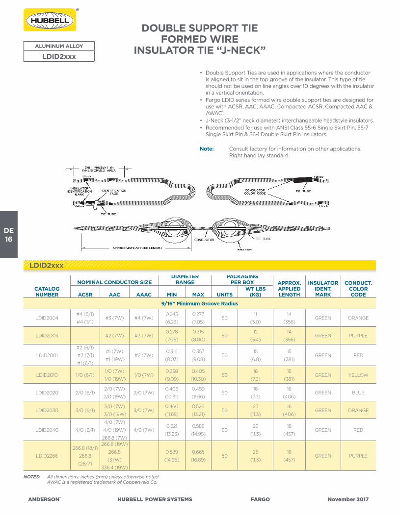
DE16
ANDERSON™ HUBBELL® POWER SYSTEMS FARGO® November 2017
DOUBLE SUPPORT TIE FORMED WIRE
INSULATOR TIE “J-NECK”
• Double Support Ties are used in applications where the conductor is aligned to sit in the top groove of the insulator. This type of tie should not be used on line angles over 10 degrees with the insulator in a vertical orientation.
• Fargo LDID series formed wire double support ties are designed for use with ACSR, AAC, AAAC, Compacted ACSR, Compacted AAC & AWAC®.
• J-Neck (3-1/2” neck diameter) interchangeable headstyle insulators.• Recommended for use with ANSI Class 55-6 Single Skirt Pin, 55-7
Single Skirt Pin & 56-1 Double Skirt Pin Insulators.
Note: Consult factory for information on other applications. Right hand lay standard.
ALUMINUM ALLOY
LDID2xxx
NOTES: All dimensions: inches (mm) unless otherwise noted. AWAC is a registered trademark of Copperweld Co.
CATALOG NUMBER
NOMINAL CONDUCTOR SIZEDIAMETER
RANGEPACKAGING
PER BOX APPROX.APPLIED LENGTH
INSULATORIDENT. MARK
CONDUCT.COLOR CODEACSR AAC AAAC MIN MAX UNITS
WT LBS (KG)
9/16” Minimum Groove Radius
LDID2004#4 (6/1)
#4 (7/1)#3 (7W) #4 (7W)
0.245
(6.23)
0.277
(7.05)50
11
(5.0)
14
(356)GREEN ORANGE
LDID2003 #2 (7W) #3 (7W)0.278
(7.06)
0.315
(8.00)50
12
(5.4)
14
(356)GREEN PURPLE
LDID2001
#2 (6/1)
#2 (7/1)
#1 (6/1)
#1 (7W)
#1 (19W)#2 (7W)
0.316
(8.03)
0.357
(9.08)50
15
(6.8)
15
(381)GREEN RED
LDID2010 1/0 (6/1)1/0 (7W)
1/0 (19W)1/0 (7W)
0.358
(9.09)
0.405
(10.30)50
16
(7.3)
15
(381)GREEN YELLOW
LDID2020 2/0 (6/1)2/0 (7W)
2/0 (19W)2/0 (7W)
0.406
(10.31)
0.459
(11.66)50
16
(7.7)
16
(406)GREEN BLUE
LDID2030 3/0 (6/1)3/0 (7W)
3/0 (19W)3/0 (7W)
0.460
(11.68)
0.520
(13.21)50
25
(11.3)
16
(406)GREEN ORANGE
LDID2040 4/0 (6/1)
4/0 (7W)
4/0 (19W)
266.8 (7W)
4/0 (7W)0.521
(13.23)
0.588
(14.95)50
25
(11.3)
18
(457)GREEN RED
LDID2266
266.8 (18/1)
266.8
(26/7)
266.8 (19W)
266.8
(37W)
336.4 (19W)
0.589
(14.96)
0.665
(16.89)50
25
(11.3)
18
(457)GREEN PURPLE
LDID2xxx

ANDERSON™ HUBBELL® POWER SYSTEMS FARGO® November 2017
DE17
ALUMINUM ALLOY
LDID2xxx
DOUBLE SUPPORT TIE FORMED WIRE
INSULATOR TIE “J-NECK”(CONTINUED)
CATALOG NUMBER
NOMINAL CONDUCTOR SIZEDIAMETER
RANGEPACKAGING
PER BOX APPROX.APPLIED LENGTH
INSULATOR IDENT. MARK
CONDUCT.COLORCODEACSR AAC AAAC MIN MAX UNITS
WT LBS (KG)
9/16” Minimum Groove Radius (Continued)
LDID2336
336.4 (18/1)
336.4 (26/7)
397.5 (18/1)
350 (19W)
397.5 (37W)
0.666
(16.91)0.755 (19.19) 50
30
(13.6)
19
(483)GREEN BROWN
LDID2477
397.5 (24/7)
397.5 (26/7)
477 (18/1)
477 (24/7)
477 (26/7)
450 (19W)
477 (19W)
477 (37W)
500 (19W)
500 (37W)
556.5 (19W)
556.5 (37W)
0.756
(19.20)0.858 (21.79) 50
33
(15.0)
21
(533)GREEN RED
5/8” Minimum Groove Radius
LDID2556
477 (30/7)
556.5 (18/1)
556.5 (24/7)
556.5 (26/7)
636 (18/1)
636 (37W)
700 (37W)
700 (61W)
0.859
(21.81)
0.968
(24.60)50
34
(15.5)
22
(559)GREEN BLUE
3/4” Minimum Groove Radius
LDID2795
636 (24/7)
636 (26/7)
715.5 (24/7)
795 (36/1)
795 (45/7)
795 (54/7)
795 (37W)
795 (61W)
0.969
(24.61)1.096 (27.84) 50
37
(16.8)
23
(584)GREEN GREEN
NOTES: All dimensions: inches (mm) unless otherwise noted. AWAC is a registered trademark of Copperweld Co.
LDID2xxx

DE18
ANDERSON™ HUBBELL® POWER SYSTEMS FARGO® November 2017
SIDE TIE FORMED WIRE
INSULATOR TIE “C-NECK”
• For securing bare and plastic covered conductor in the side groove of interchangeable headstyle insulators.
• Fargo LLAC series formed wire distribution ties are designed for use with ACSR, AAC, AAAC, ACAR, Compacted ACSR, & AWAC®.
• C-Neck insulator: 2-1/4” neck diameter.• Recommended for use with ANSI Class 55-2 and 55-3 Post
Insulators.
Note: Consult factory for information on other applications. Right hand lay standard.
ALUMINUM COATED STEEL
LLAC
CATALOG NUMBER
NOMINAL CONDUCTOR SIZEDIAMETER
RANGEPACKAGING
PER BOX
APPLIED LENGTH
INSULATOR IDENT. MARK
CONDUCT.COLORCODEACSR AAC AAAC MIN MAX UNITS
WT LBS (KG)
9/16” Minimum Groove Radius
LLAC4052AS#4 (6/1)
#4 (7/1)#3 (7W) #4 (7W)
0.245
(6.23)
0.277
(7.05)100
22
(10.0)
19
(483)BLACK ORANGE
LLAC4054AS
#2 (6/1)
#2 (7/1)
#1 (6/1)
#1 (7W)
#1 (19W)#2 (7W)
0.316
(8.03)
0.357
(9.08)50
16
(7.3)
24
(610)BLACK RED
LLAC4055AS 1/0 (6/1)1/0 (7W)
1/0 (19W)1/0 (7W)
0.358
(9.09)
0.405
(10.30)50
17
(7.7)
26
(660)BLACK YELLOW
LLAC4057AS 3/0 (6/1)3/0 (7W)
3/0 (19W)3/0 (7W)
0.460
(11.68)
0.520
(13.21)50
21
(9.5)
31
(787)BLACK ORANGE
LLAC4058AS 4/0 (6/1)
4/0 (7W)
4/0 (19W)
266.8 (7W)
4/0 (7W)0.521
(13.23)
0.588
(14.95)50
22
(10.0)
32
(813)BLACK RED
NOTES: All dimensions: inches (mm) unless otherwise noted. AWAC is a registered trademark of Copperweld Co. “C” indicates Compact stranding. Add “NT” suffix for no tie tube (Pad). Example: LLAC4055ASNT.
LLAC

ANDERSON™ HUBBELL® POWER SYSTEMS FARGO® November 2017
DE19
SIDE TIE FORMED WIRE
INSULATOR TIE “C-NECK”(CONTINUED)
NOTES: All dimensions: inches (mm) unless otherwise noted. AWAC is a registered trademark of Copperweld Co. “C” indicates Compact stranding. Add “NT” suffix for no tie tube (Pad). Example: LLAC4055ASNT.
CATALOG NUMBER
NOMINAL CONDUCTOR SIZEDIAMETER
RANGEPACKAGING
PER BOX
APPLIED LENGTH
INSULATOR IDENT. MARK
CONDUCT.COLORCODEACSR AAC AAAC MIN MAX UNITS
WT LBS (KG)
9/16” Minimum Groove Radius (Continued)
LLAC4060AS
336.4 (18/1)
336.4 (26/7)
397.5 (18/1)
336.4 (37W)
397.5 (19W)
0.666
(16.91)
0.755
(19.19)50
26
(11.8)
25
(635)BLACK BROWN
LLAC4061AS
397.5 (24/7)
397.5 (26/7)
477 (18/1)
477 (24/7)
477 (26/7)
450 (19W)
477 (19W)
477 (37W)
500 (19W)
500 (37W)
556.5 (19W)
556.5 (37W)
0.756
(19.20)
0.858
(21.79)50
28
(12.7)
26
(660)BLACK RED
5/8” Minimum Groove Radius
LLAC4062AS
556.5 (18/1)
556.5 (24/7)
556.5 (26/7)
636 (18/1)
636 (37W)
700 (37W)
700 (61W)
0.859
(21.81)
0.968
(24.60)50
30
(13.6)
28
(711)BLACK BLUE
ALUMINUM COATED STEEL
LLAC
LLAC

DE20
ANDERSON™ HUBBELL® POWER SYSTEMS FARGO® November 2017
SIDE TIE FORMED WIRE
INSULATOR TIE “F-NECK”
• For securing bare and plastic covered conductor in the side groove of interchangeable headstyle insulators.
• Fargo LLAF series formed wire distribution ties are designed for use with ACSR, AAC, AAAC, ACAR, Compacted ACSR, & AWAC®.
• F-Neck insulator: 2-7/8” neck diameter.• Recommended for use with ANSI Class 55-4 Pin, 55-5 Pin, 57-1 Post,
57-2 Post, & 57-3 Post Insulators.
Note: Consult factory for information on other applications. Right hand lay standard.
ALUMINUM/STEEL
LLAF
CATALOG NUMBER
NOMINAL CONDUCTOR SIZEDIAMETER
RANGEPACKAGING
PER BOX
APPLIED LENGTH
INSULATOR IDENT. MARK
CONDUCT.COLORCODEACSR AAC AAAC MIN MAX UNITS
WT LBS (KG)
9/16” Minimum Groove Radius
LLAF4550AS #6 (6/1) #4 (7W) C*0.190
(4.83)
0.215
(5.46)100
16
(7.3)
16
(406)YELLOW BLUE
LLAF4551AS#4 (6/1) C*
#4 (7/1) C*#4 (7W)
0.216
(5.47)
0.244
(6.21)100
17
(7.7)
17
(432)YELLOW BROWN
LLAF4552AS#4 (6/1)
#4 (7/1)#3 (7W) #4 (7W)
0.245
(6.23)
0.277
(7.05)100
19
(8.6)
19
(483)YELLOW ORANGE
LLAF4553AS #2 (7W) #3 (7W)0.278
(7.06)
0.315
(8.01)50
12
(5.5)
21
(533)YELLOW PURPLE
LLAF4554AS
#2 (6/1)
#2 (7/1)
#1 (6/1)
#1 (7W)
#1 (19W)#2 (7W)
0.316
(8.03)
0.357
(9.08)50
17
(7.7)
24
(610)YELLOW RED
NOTES: All dimensions: inches (mm) unless otherwise noted. AWAC is a registered trademark of Copperweld Co. *“C” indicates Compact stranding. Add “NT” suffix for no tie tube (Pad). Example: LLAF4555ASNT.
LLAF
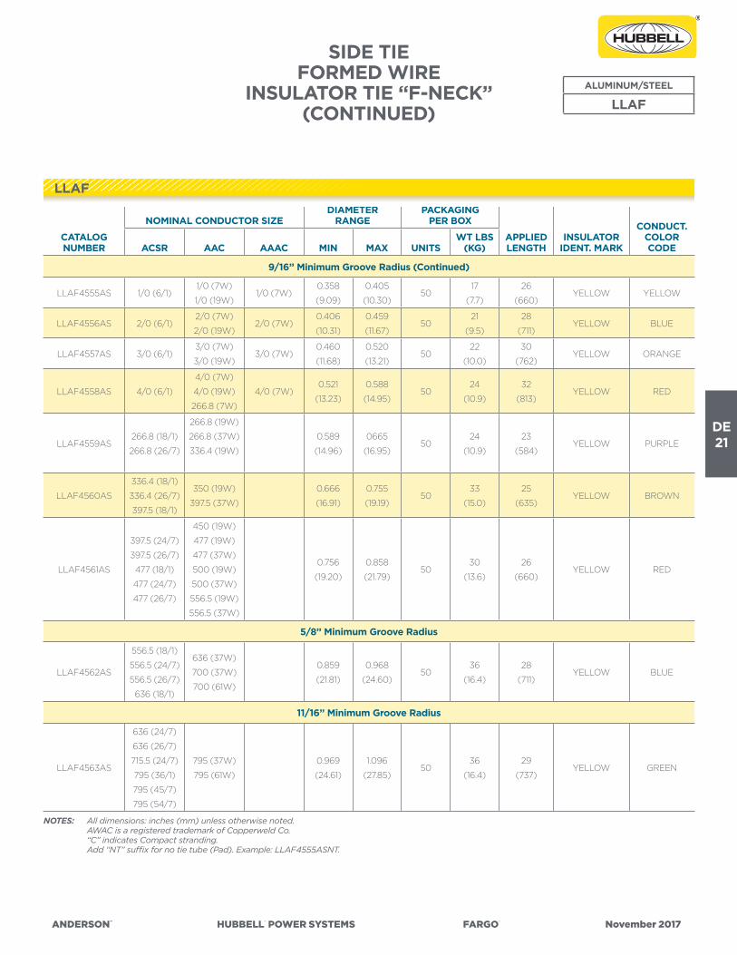
ANDERSON™ HUBBELL® POWER SYSTEMS FARGO® November 2017
DE21
SIDE TIE FORMED WIRE
INSULATOR TIE “F-NECK”(CONTINUED)
NOTES: All dimensions: inches (mm) unless otherwise noted. AWAC is a registered trademark of Copperweld Co. “C” indicates Compact stranding. Add “NT” suffix for no tie tube (Pad). Example: LLAF4555ASNT.
CATALOG NUMBER
NOMINAL CONDUCTOR SIZEDIAMETER
RANGEPACKAGING
PER BOX
APPLIED LENGTH
INSULATOR IDENT. MARK
CONDUCT.COLORCODEACSR AAC AAAC MIN MAX UNITS
WT LBS (KG)
9/16” Minimum Groove Radius (Continued)
LLAF4555AS 1/0 (6/1)1/0 (7W)
1/0 (19W)1/0 (7W)
0.358
(9.09)
0.405
(10.30)50
17
(7.7)
26
(660)YELLOW YELLOW
LLAF4556AS 2/0 (6/1)2/0 (7W)
2/0 (19W)2/0 (7W)
0.406
(10.31)
0.459
(11.67)50
21
(9.5)
28
(711)YELLOW BLUE
LLAF4557AS 3/0 (6/1)3/0 (7W)
3/0 (19W)3/0 (7W)
0.460
(11.68)
0.520
(13.21)50
22
(10.0)
30
(762)YELLOW ORANGE
LLAF4558AS 4/0 (6/1)
4/0 (7W)
4/0 (19W)
266.8 (7W)
4/0 (7W)0.521
(13.23)
0.588
(14.95)50
24
(10.9)
32
(813)YELLOW RED
LLAF4559AS266.8 (18/1)
266.8 (26/7)
266.8 (19W)
266.8 (37W)
336.4 (19W)
0.589
(14.96)
0665
(16.95)50
24
(10.9)
23
(584)YELLOW PURPLE
LLAF4560AS
336.4 (18/1)
336.4 (26/7)
397.5 (18/1)
350 (19W)
397.5 (37W)
0.666
(16.91)
0.755
(19.19)50
33
(15.0)
25
(635)YELLOW BROWN
LLAF4561AS
397.5 (24/7)
397.5 (26/7)
477 (18/1)
477 (24/7)
477 (26/7)
450 (19W)
477 (19W)
477 (37W)
500 (19W)
500 (37W)
556.5 (19W)
556.5 (37W)
0.756
(19.20)
0.858
(21.79)50
30
(13.6)
26
(660)YELLOW RED
5/8” Minimum Groove Radius
LLAF4562AS
556.5 (18/1)
556.5 (24/7)
556.5 (26/7)
636 (18/1)
636 (37W)
700 (37W)
700 (61W)
0.859
(21.81)
0.968
(24.60)50
36
(16.4)
28
(711)YELLOW BLUE
11/16” Minimum Groove Radius
LLAF4563AS
636 (24/7)
636 (26/7)
715.5 (24/7)
795 (36/1)
795 (45/7)
795 (54/7)
795 (37W)
795 (61W)
0.969
(24.61)
1.096
(27.85)50
36
(16.4)
29
(737)YELLOW GREEN
ALUMINUM/STEEL
LLAF
LLAF

DE22
ANDERSON™ HUBBELL® POWER SYSTEMS FARGO® November 2017
SIDE TIE FORMED WIRE
QUIK-WRAP™ INSULATOR TIE “C-NECK”
• For securing bare or plastic jacketed conductor in the side groove of interchangeable headstyle insulators.
• Fargo QWSTC series formed wire distribution ties are designed for use with ACSR, AAC, AAAC, AWAC®, Compacted ACSR & Compacted AAC.
• C-Neck insulator: 2-1/4” neck diameter• Recommended for use with ANSI Class 55-2 Pin & 55-3 Pin
Insulators.
Note: Consult factory for information on other applications. Right hand lay standard.
NOTES: All dimensions: inches (mm) unless otherwise noted. AWAC is a registered trademark of Copperweld Co. “C” indicates Compact stranding. Add “NT” suffix for no tie tube (Pad). Example: QWSTC274NT.
ALUMINUM/STEEL
QWSTC
CATALOG NUMBER
NOMINAL CONDUCTOR SIZEDIAMETER
RANGEPACKAGING
PER BOX
APPLIED LENGTH
INSULATOR IDENT. MARK
CONDUCT.COLORCODEACSR AAC AAAC MIN MAX UNITS
WT LBS (KG)
9/16” Minimum Groove Radius
QWSTC274
#2 (6/1)
#2 (7/1)
#1 (6/1)
#1 (7W)
#1 (19W)#2 (7W)
0.316
(8.03)
0.357
(9.08)100
19
(8.6)
25
(635)BLACK RED
QWSTC275 1/0 (6/1)1/0 (7W)
1/0 (19W)1/0 (7W)
0.358
(9.09)
0.405
(10.30)100
21
(9.5)
23
(584)BLACK YELLOW
QWSTC278 4/0 (6/1)
4/0 (7W)
4/0 (19W)
266.8 (7W)
4/0 (7W)0.521
(13.23)
0.588
(14.95)100
30
(13.6)
28
(711)BLACK RED
QWSTC281
397.5 (24/7)
397.5 (26/7)
477 (18/1)
477 (24/7)
477 (26/7)
450 (19W)
477 (19W)
477 (37W)
500 (19W)
500 (37W)
556.5 (19W)
556.5 (37W)
0.756
(19.20)
0.858
(21.79)50
29
(13.2)
35
(889)BLACK RED
5/8” Minimum Groove Radius
QWSTC282
556.5 (18/1)
556.5 (24/7)
556.5 (26/7)
636 (18/1)
636 (37W)
700 (37W)
700 (61W)
0.859
(21.81)
0.968
(24.60)50
36
(914)
36
(914)BLACK BLUE
QWSTC

ANDERSON™ HUBBELL® POWER SYSTEMS FARGO® November 2017
DE23
SIDE TIE FORMED WIRE
QUIK-WRAP™ INSULATOR TIE “F-NECK”
• For securing bare or plastic jacketed conductor in the side groove of interchangeable headstyle insulators.
• Fargo QWSTF series formed wire distribution ties are designed for use with ACSR, AAC, AAAC, AWAC®, Compacted ACSR & Compacted AAC.
• F-Neck insulator: 2-7/8” neck diameter• Recommended for use with ANSI Class 55-4 Pin, 55-5 Pin, 57-1 Pin,
57-2 Pin & 57-3 Pin Insulators.
Note: Consult factory for information on other applications. Right hand lay standard.
ALUMINUM/STEEL
QWSTF
CATALOG NUMBER
NOMINAL CONDUCTOR SIZEDIAMETER
RANGEPACKAGING
PER BOX
APPLIED LENGTH
INSULATOR IDENT. MARK
CONDUCT. COLOR CODEACSR AAC AAAC MIN MAX UNITS
WT LBS (KG)
9/16” Minimum Groove Radius
QWSTF172#4 (6/1)
#4 (7/1)#3 (7W) #4 (7W)
0.245
(6.23)
0.277
(7.05)100
18
(8.2)
23
(584)YELLOW ORANGE
QWSTF174
#2 (6/1)
#2 (7/1)
#1 (6/1)
#1 (7W)
#1 (19W)#2 (7W)
0.316
(8.03)
0.357
(9.08)100
19
(8.6)
25
(635)YELLOW RED
QWSTF175 1/0 (6/1)1/0 (7W)
1/0 (19W)1/0 (7W)
0.358
(9.09)
0.405
(10.30)100
21
(9.5)
23
(584)YELLOW YELLOW
QWSTF176 2/0 (6/1)2/0 (7W)
2/0 (19W)2/0 (7W)
0.406
(10.31)
0.459
(11.67)100
22
(10.0)
25
(635)YELLOW BLUE
QWSTF177 3/0 (6/1)3/0 (7W)
3/0 (19W)3/0 (7W)
0.460
(11.68)
0.520
(13.21)100
24
(10.9)
27
(686)YELLOW ORANGE
QWSTF178 4/0 (6/1)
4/0 (7W)
4/0 (19W)
266.8 (7W)
4/0 (7W)0.521
(13.23)
0.588
(14.95)100
30
(13.6)
28
(711)YELLOW RED
QWSTF180
336.4 (18/1)
336.4 (26/7)
397.5 (18/1)
350 (19W)
3/0 (19W)
0.666
(16.91)
0.755
(19.19)100
34
(15.5)
34
(864)YELLOW BROWN
QWSTF181
397.5 (24/7)
397.5 (26/7)
477 (18/1)
477 (24/7)
477 (26/7)
450 (19W)
477 (19W)
477 (37W)
500 (19W)
500 (37W)
556.5 (19W)
556.5 (37W)
0.756
(19.20)
0.858
(21.79)50
54
(24.5)
36
(914)YELLOW RED
NOTES: All dimensions: inches (mm) unless otherwise noted. AWAC is a registered trademark of Copperweld Co. “C” indicates Compact stranding. Add “NT” suffix for no tie tube (Pad). Example: QWSTF172NT.
QWSTF

DE24
ANDERSON™ HUBBELL® POWER SYSTEMS FARGO® November 2017
SIDE TIE FORMED WIRE
QUIK-WRAP™ INSULATOR TIE “F-NECK”(CONTINUED)
ALUMINUM/STEEL
QWSTF
CATALOG NUMBER
NOMINAL CONDUCTOR SIZEDIAMETER
RANGEPACKAGING
PER BOX
APPLIED LENGTH
INSULATOR IDENT. MARK
CONDUCT. COLOR CODEACSR AAC AAAC MIN MAX UNITS
WT LBS (KG)
5/8” Minimum Groove Radius
QWSTF182
556.5 (18/1)
556.5 (24/7)
556.5 (26/7)
636 (18/1)
636 (37W)
700 (37W)
700 (61W)
0.859
(21.81)
0.968
(24.60)50
36
(16.4)
37
(940)YELLOW BLUE
11/16” Minimum Groove Radius
QWSTF183
636 (24/7)
636 (26/7)
715.5 (24/7)
795 (36/1)
795 (45/7)
795 (54/7)
795 (37W)
795 (61W)
0.969
(24.61)
1.096
(27.85)50
39
(17.7)
39
(991)YELLOW GREEN
3/4” Minimum Groove Radius
QWSTF184
795 (26/7)
954 (36/1)
954 (54/7)
1033.5 (45/7)
1033.5 (54/7)
954 (37W)
1033.5 (37W)
1033.5 (61W)
1113 (61W)
1.097
(27.86)
1.240
(31.50)50
40
(18.2)
40
(1016)YELLOW YELLOW
NOTES: All dimensions: inches (mm) unless otherwise noted. AWAC is a registered trademark of Copperweld Co. “C” indicates Compact stranding. Add “NT” suffix for no tie tube (Pad). Example: QWSTF172NT.
QWSTF

ANDERSON™ HUBBELL® POWER SYSTEMS FARGO® November 2017
DE25
DOUBLE SIDE TIE FORMED WIRE
INSULATOR TIE “C-NECK” & “F-NECK”
• Double Side Ties are used on double arm construction in applications where the conductor is aligned to sit in the side groove of interchangeable headstyle insulators. This type of tie is typically for use in applications where the line angles are larger than double support ties. This series is for use on vertically mounted insulators (at double insulator locations) with line angles between (0°) zero degrees and (80°) eighty degrees with no more than a (40°) forty degree angle at each insulator.
• Fargo LLDU series formed wire double support ties are designed for use with ACSR, AAC, AAAC, Compacted ACSR & AWAC®.
• C-Neck (2-1/4” neck diameter) & F-Neck (2-7/8” neck diameter) interchangeable headstyle insulators.
• Recommended for use with ANSI Class 55-2 Pin, 55-3 Pin, 55-4 Pin, 55-5 Pin, 57-1 Post, 57-2 Post, & 57-3 Post Insulators.
Note: Consult factory for information on other applications. Right hand lay standard.
ALUMINUM/STEEL
LLDU4xxx
NOTES: All dimensions: inches (mm) unless otherwise noted. AWAC is a registered trademark of Copperweld Co.
CATALOG NUMBER
NOMINAL CONDUCTOR SIZEDIAMETER
RANGEPACKAGING
PER BOX APPROX.APPLIED LENGTH
INSULATOR IDENT. MARK
CONDUCT.COLORCODEACSR AAC AAAC MIN MAX UNITS
WT LBS (KG)
9/16” Minimum Groove Radius
LLDU4152AS#4 (6/1)
#4 (7/1)#3 (7W) #4 (7W)
0.245
(6.23)
0.277
(7.05)50
21
(9.5)
16
(406)
“C”-BLACK &
“F”-YELLOWORANGE
LLDU4153AS #2 (7W) #3 (7W)0.278
(7.06)
0315
(8.00)50
21
(9.5)
16
(406)
“C”-BLACK &
“F”-YELLOWPURPLE
LLDU4154AS
#2 (6/1)
#2 (7/1)
#1 (6/1)
#1 (7W)
#1 (19W)#2 (7W)
0.316
(8.03)
0.357
(9.08)50
21
(9.5)
16
(406)
“C”-BLACK &
“F”-YELLOWRED
LLDU4155AS 1/0 (6/1)1/0 (7W)
1/0 (19W)1/0 (7W)
0.358
(9.09)
0.405
(10.30)50
21
(9.5)
17
(432)
“C”-BLACK &
“F”-YELLOWYELLOW
LLDU4156AS 2/0 (6/1)2/0 (7W)
2/0 (19W)2/0 (7W)
0.406
(10.31)
0.459
(11.66)50
21
(9.5)
18
(457)
“C”-BLACK &
“F”-YELLOWBLUE
LLDU4157AS 3/0 (6/1)3/0 (7W)
3/0 (19W)3/0 (7W)
0.460
(11.68)
0.520
(13.21)50
36
(16.4)
19
(483)
“C”-BLACK &
“F”-YELLOWORANGE
LLDU4158AS 4/0 (6/1)
4/0 (7W)
4/0 (19W)
266.8 (7W)
4/0 (7W)0.521
(13.23)
0.588
(14.95)50
36
(16.4)
19
(483)
“C”-BLACK &
“F”-YELLOWRED
LLDU4xxx

DE26
ANDERSON™ HUBBELL® POWER SYSTEMS FARGO® November 2017
NOTES: All dimensions: inches (mm) unless otherwise noted. AWAC is a registered trademark of Copperweld Co.
CATALOG NUMBER
NOMINAL CONDUCTOR SIZEDIAMETER
RANGEPACKAGING
PER BOX APPROX.APPLIED LENGTH
INSULATOR IDENT. MARK
CONDUCT.COLORCODEACSR AAC AAAC MIN MAX UNITS
WT LBS (KG)
9/16” Minimum Groove Radius (Continued)
LLDU4159AS266.8 (18/1)
266.8 (26/7)
266.8 (19W)
266.8 (37W)
336.4 (19W)
0.589
(14.96)
0.665
(16.89)50
38
(17.3)
20
(508)
“C”-BLACK &
“F”-YELLOWPURPLE
LLDU4160AS
336.4 (18/1)
336.4 (26/7)
397.5 (18/1)
350 (19W)
397.5 (37W)
0.666
(16.92)
0.755
(19.18)50
39
(17.7)
20
(508)
“C”-BLACK &
“F”-YELLOWBROWN
LLDU4161AS
397.5 (24/7)
397.5 (26/7)
477 (18/1)
477 (24/7)
477 (26/7)
450 (19W)
477 (19W)
477 (37W)
500 (19W)
500 (37W)
556.5 (19W)
556.5 (37W)
0.756
(19.20)
0.858
(21.79)50
39
(17.7)
20
(508)
“C”-BLACK &
“F”-YELLOWRED
5/8” Minimum Groove Radius
LLDU4162AS
556.5 (18/1)
556.5 (24/7)
556.5 (26/7)
636 (18/1)
636 (37W)
700 (37W)
700 (61W)
0.859
(21.81)
0.968
(24.60)50
42
(19.1)
22
(762)
“C”-BLACK &
“F”-YELLOWBLUE
11/16” Minimum Groove Radius
LLDU4163AS
636 (24/7)
636 (26/7)
715.5 (24/7)
795 (36/1)
795 (45/7)
795 (54/7)
795 (37W)
795 (61W)
0.969
(24.61)
1.096
(27.84)50
44
(20.0)
24
(610)
“C”-BLACK &
“F”-YELLOWGREEN
3/4” Minimum Groove Radius
LLDU4164AS
795 (26/7)
954 (36/1)
954 (54/7)
1033.5 (45/7)
954 (37W)
1033.5 937W)
1033.5 (61W)
1113 (61W)
1.097
(27.86)
1.240
(31.50)50
44
(20.0)
24
(610)
“C”-BLACK &
“F”-YELLOWYELLOW
DOUBLE SIDE TIEFORMED WIRE
INSULATOR TIE “C-NECK” & “F-NECK”(CONTINUED)
ALUMINUM/STEEL
LLDU4xxx
LLDU4xxx
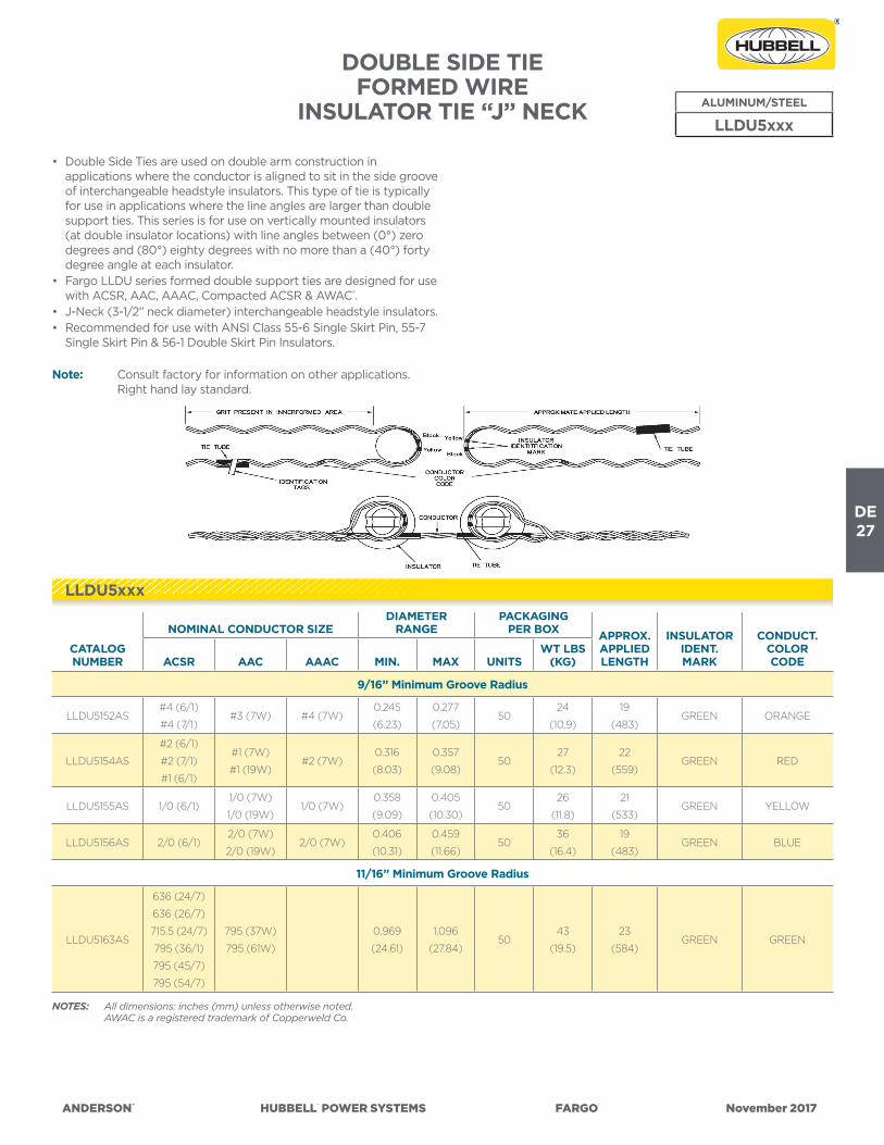
ANDERSON™ HUBBELL® POWER SYSTEMS FARGO® November 2017
DE27
DOUBLE SIDE TIEFORMED WIRE
INSULATOR TIE “J” NECK
• Double Side Ties are used on double arm construction in applications where the conductor is aligned to sit in the side groove of interchangeable headstyle insulators. This type of tie is typically for use in applications where the line angles are larger than double support ties. This series is for use on vertically mounted insulators (at double insulator locations) with line angles between (0°) zero degrees and (80°) eighty degrees with no more than a (40°) forty degree angle at each insulator.
• Fargo LLDU series formed double support ties are designed for use with ACSR, AAC, AAAC, Compacted ACSR & AWAC®.
• J-Neck (3-1/2” neck diameter) interchangeable headstyle insulators.• Recommended for use with ANSI Class 55-6 Single Skirt Pin, 55-7
Single Skirt Pin & 56-1 Double Skirt Pin Insulators.
Note: Consult factory for information on other applications. Right hand lay standard.
ALUMINUM/STEEL
LLDU5xxx
CATALOG NUMBER
NOMINAL CONDUCTOR SIZEDIAMETER
RANGEPACKAGING
PER BOX APPROX.APPLIED LENGTH
INSULATORIDENT. MARK
CONDUCT.COLORCODEACSR AAC AAAC MIN. MAX UNITS
WT LBS(KG)
9/16” Minimum Groove Radius
LLDU5152AS#4 (6/1)
#4 (7/1)#3 (7W) #4 (7W)
0.245
(6.23)
0.277
(7.05)50
24
(10.9)
19
(483)GREEN ORANGE
LLDU5154AS
#2 (6/1)
#2 (7/1)
#1 (6/1)
#1 (7W)
#1 (19W)#2 (7W)
0.316
(8.03)
0.357
(9.08)50
27
(12.3)
22
(559)GREEN RED
LLDU5155AS 1/0 (6/1)1/0 (7W)
1/0 (19W)1/0 (7W)
0.358
(9.09)
0.405
(10.30)50
26
(11.8)
21
(533)GREEN YELLOW
LLDU5156AS 2/0 (6/1)2/0 (7W)
2/0 (19W)2/0 (7W)
0.406
(10.31)
0.459
(11.66)50
36
(16.4)
19
(483)GREEN BLUE
11/16” Minimum Groove Radius
LLDU5163AS
636 (24/7)
636 (26/7)
715.5 (24/7)
795 (36/1)
795 (45/7)
795 (54/7)
795 (37W)
795 (61W)
0.969
(24.61)
1.096
(27.84)50
43
(19.5)
23
(584)GREEN GREEN
NOTES: All dimensions: inches (mm) unless otherwise noted. AWAC is a registered trademark of Copperweld Co.
LLDU5xxx

DE28
ANDERSON™ HUBBELL® POWER SYSTEMS FARGO® November 2017
CATALOG NUMBER
NOMINAL CONDUCTOR SIZEDIAMETER
RANGEPACKAGING
PER BOX APPROX.APPLIED LENGTH
CONDUCT.COLORCODEACSR AAC AAAC
PLASTIC JACKETED MIN. MAX UNITS
WT LBS(KG)
LRO4006AS#4 (6/1)
#4 (7/1)#3 (7W) #4 (7W)
#6 (7W) 2/64s
#6 Solid 3/64s
#6 (6/1) 2/64s
0.245
(6.22)
0.277
(7.05)100
16
(7.3)
19
(483)ORANGE
LRO4010AS #2 (7W) #3 (7W)
#6 (6/1) 3/64s
#4 Solid 3/64s
#4 (6/1) 2/64s
0.278
(7.06)
0.315
(8.00)100
17
(7.7)
21
(533)PURPLE
LRO4012AS
#1 (6/1)
#2 (6/1)
#2 (7/1)
#1 (7W)
#1 (19W)#2 (7W)
#4 (6/1) 3/64s
#4 (7/1) 3/64s
#2 (7W) 3/64s
0.316
(8.03)
0.357
(9.08)100
23
(10.5)
24
(610)RED
LRO4018AS 1/0 (6/1)1/0 (7W)
1/0 (19W)1/0 (7W)
#3 (7W) 4/64s
#2 (7W) 3/64s
#4 (7W) 5/65s
0.358
(9.09)
0.405
(10.29)100
24
(10.9)
26
(660)YELLOW
LRO4020AS 2/0 (6/1)2/0 (7W)
2/0 (19W)2/0 (7W)
#2 (6/1) 3/64s
#2 (7W) 4/64s
#1 (7W) 4/64s
0.406
(10.31)
0.459
(11.67)100
28
(12.7)
28
(711)BLUE
SPOOL TIEFORMED WIRE
SPOOL INSULATOR TIE
• Spool Ties are used in applications where the spool insulator is mounted either horizontally or vertically and the conductor is alligned to sit in the groove of the insulator.
• Fargo LRO series formed wire spool ties are designed for use with ACAR, ACSR, AAC, AAAC, Compacted ACSR, & AWAC®.
• For 1-3/4” neck diameter interchangeable headstyle insulators.• Recommended for use with ANSI Class 53-1, 53-2 & 53-3 Spool
Insulators.
Note: Consult factory for information on other applications. Right hand lay standard.
ALUMINUM ALLOY
LRO
NOTES: All dimensions: inches (mm) unless otherwise noted. AWAC is a registered trademark of Copperweld Co. Add “NT” suffix for no tie tube (Pad). Example: LRO4018ASNT.
LRO

ANDERSON™ HUBBELL® POWER SYSTEMS FARGO® November 2017
DE29
NOTES: All dimensions: inches (mm) unless otherwise noted. AWAC is a registered trademark of Copperweld Co. Add “NT” suffix for no tie tube (Pad). Example: LRO4018ASNT.
CATALOG NUMBER
NOMINAL CONDUCTOR SIZEDIAMETER
RANGEPACKAGING
PER BOX APPROX.APPLIED LENGTH
CONDUCT.COLORCODEACSR AAC AAAC
PLASTIC JACKETED MIN. MAX UNITS
WT LBS(KG)
LRO4022AS 3/0 (6/1)3/0 (7W)
3/0 (19W)3/0 (7W)
#4 (7W) 8/64s
#1 (6/1) 4/64s
#1 (7W) 5/64s
#1 (19W) 5/64s
1/0 (7W) 4/64s
0.460
(11.68)
0.520
(13.21)100
32
(14.5)
31
(787)ORANGE
LRO4024AS 4/0 (6/1)
4/0 (7W)
4/0 (19W)
266.8 (7W)
4/0 (7W)
1/0 (6/1) 4/64s
1/0 (7W) 5/64s
2/0 (7W) 4/64s
1/0 (6/1) 5/64s
0.521
(13.23)
0.588
(14.94)50
18
(457)
32
(813)RED
LRO4025AS266.8 (18/1)
266.8 (26/7)
266.8 (19W)
266.8 (37W)
336.4 (19W)
3/0 (7W) 4/64s
3/0 (19W) 4/64s
3/0 (6/1) 4/64s
4/0 (7W) 4/64s
4/0 (19W) 4/64s
3/0 (6/1) 5/64s
0.589
(14.96)
0.665
(16.89)50
19
(8.6)
23
(584)PURPLE
LRO4027AS
336.4 (18/1)
336.4 (26/7)
397.5 (18/1)
350 (19W)
397.5 (19W)
4/0 (7W) 5/64s
3/0 (6/1) 6/64s
4/0 (61/) 5/64s
266.8 (19W) 5/64s
0.666
(16.91)
0.755
(19.18)50
24
(10.9)
25
(635)BROWN
LRO4030AS
397.5 (24/7)
397.5 (26/7)
477 (18/1)
477 (24/7)
477 (26/7)
450 (19W)
477 (19W)
477 (37W)
500 (19W)
500 (37W)
556.5 (19W)
556.5 (37W)
266.8 (18/1) 5/64s
336.4 (19W) 4/64s
336.4 (37W) 6/64s
0.756
(19.20)
0.858
(21.80)50
25
(11.4)
26
(660)RED
LRO4031AS
556.5 (18/1)
556.5 (24/7)
556.5 (26/7)
636 (18/1)
636 (37W)
700 (19W)
700 (37W)
350 (37W) 6/64s
336.4 (19W) 8/64s
450 (37W) 5/64s
477 (37W) 5/64s
0.859
(21.81)
0.968
(24.60)50
26
(11.8)
28
(711)BLUE
SPOOL TIEFORMED WIRE
SPOOL INSULATOR TIE(CONTINUED)
ALUMINUM ALLOY
LRO
LRO
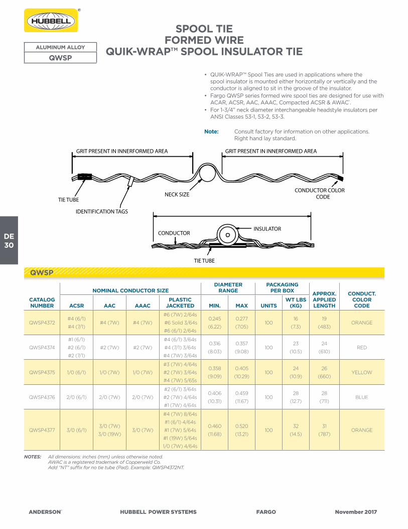
DE30
ANDERSON™ HUBBELL® POWER SYSTEMS FARGO® November 2017
SPOOL TIEFORMED WIRE
QUIK-WRAP™ SPOOL INSULATOR TIE
• QUIK-WRAP™ Spool Ties are used in applications where the spool insulator is mounted either horizontally or vertically and the conductor is aligned to sit in the groove of the insulator.
• Fargo QWSP series formed wire spool ties are designed for use with ACAR, ACSR, AAC, AAAC, Compacted ACSR & AWAC®.
• For 1-3/4” neck diameter interchangeable headstyle insulators per ANSI Classes 53-1, 53-2, 53-3.
Note: Consult factory for information on other applications. Right hand lay standard.
ALUMINUM ALLOY
QWSP
NOTES: All dimensions: inches (mm) unless otherwise noted. AWAC is a registered trademark of Copperweld Co. Add “NT” suffix for no tie tube (Pad). Example: QWSP4372NT.
CATALOG NUMBER
NOMINAL CONDUCTOR SIZEDIAMETER
RANGEPACKAGING
PER BOX APPROX.APPLIED LENGTH
CONDUCT.COLORCODEACSR AAC AAAC
PLASTIC JACKETED MIN. MAX UNITS
WT LBS(KG)
QWSP4372#4 (6/1)
#4 (7/1)#4 (7W) #4 (7W)
#6 (7W) 2/64s
#6 Solid 3/64s
#6 (6/1) 2/64s
0.245
(6.22)
0.277
(7.05)100
16
(7.3)
19
(483)ORANGE
QWSP4374
#1 (6/1)
#2 (6/1)
#2 (7/1)
#2 (7W) #2 (7W)
#4 (6/1) 3/64s
#4 (7/1) 3/64s
#4 (7W) 3/64s
0.316
(8.03)
0.357
(9.08)100
23
(10.5)
24
(610)RED
QWSP4375 1/0 (6/1) 1/0 (7W) 1/0 (7W)
#3 (7W) 4/64s
#2 (7W) 3/64s
#4 (7W) 5/65s
0.358
(9.09)
0.405
(10.29)100
24
(10.9)
26
(660)YELLOW
QWSP4376 2/0 (6/1) 2/0 (7W) 2/0 (7W)
#2 (6/1) 3/64s
#2 (7W) 4/64s
#1 (7W) 4/64s
0.406
(10.31)
0.459
(11.67)100
28
(12.7)
28
(711)BLUE
QWSP4377 3/0 (6/1)3/0 (7W)
3/0 (19W)3/0 (7W)
#4 (7W) 8/64s
#1 (6/1) 4/64s
#1 (7W) 5/64s
#1 (19W) 5/64s
1/0 (7W) 4/64s
0.460
(11.68)
0.520
(13.21)100
32
(14.5)
31
(787)ORANGE
CONDUCTOR COLOR
CODETIE TUBE
IDENTIFICATION TAGS
NECK SIZE
INSULATOR
CONDUCTOR
TIE TUBE
GRIT PRESENT IN INNERFORMED AREAGRIT PRESENT IN INNERFORMED AREA
QWSP

ANDERSON™ HUBBELL® POWER SYSTEMS FARGO® November 2017
DE31
SPOOL TIEFORMED WIRE
QUIK-WRAP™ SPOOL INSULATOR TIE(CONTINUED)
ALUMINUM ALLOY
QWSP
NOTES: All dimensions: inches (mm) unless otherwise noted. AWAC is a registered trademark of Copperweld Co. Add “NT” suffix for no tie tube (Pad). Example: QWSP4372NT.
CATALOG NUMBER
NOMINAL CONDUCTOR SIZEDIAMETER
RANGEPACKAGING
PER BOX APPROX.APPLIED LENGTH
CONDUCT.COLORCODEACSR AAC AAAC
PLASTIC JACKETED MIN. MAX UNITS
WT LBS(KG)
QWSP4378 4/0 (6/1) 4/0 (7W) 4/0 (7W)
1/0 (6/1) 4/64s
1/0 (7W) 5/64s
2/0 (7W) 4/64s
1/0 (6/1) 5/64s
0.521
(13.23)
0.588
(14.94)50
18
(457)
32
(813)RED
QWSP4380
336.4 (18/1)
336.4 (26/7)
397.5 (18/1)
350 (19W)
397.5 (19W)
4/0 (7W) 5/64s
3/0 (6/1) 6/64s
4/0 (6/1) 5/64s
266.8 (19W) 5/64s
0.666
(16.91)
0.755
(19.18)50
24
(10.9)
25
(635)BROWN
QWSP4381477 (18/1)
477 (24/7)
477 (19W)
477 (37W)
556.5 (19W)
477 (19W)
477 (37W)
556.5 (19W)
266.8 (18/1) 5/64s
336.4 (19W) 4/64s
336.4 (37W) 6/64s
0.756
(19.20)
0.858
(21.80)50
25
(11.4)
32
(813)RED
QWSP

DE32
ANDERSON™ HUBBELL® POWER SYSTEMS FARGO® November 2017
SUPER TOP-TIELINE TIES FOR PIN, POST AND SPOOL INSULATORS
Made of aluminum-clad steel compatible with aluminum, aluminum-alloy and ACSR conductors in the top grooves of vertical-mounted *ANSI C, F, J and many non-standard pin and post insulators (single- or double-support) or on *ANSI 53-2 spool insulators (horizontal or vertical).
High-density polyethylene hooks provide the wide application range and ensure proper installation. If used over armor rods (not required), select tie size based on total conductor/armor diameter. Semiconductor-rubber pad and high-density polyethylene on loops protect against abrasion of insulator, conductor and tie. Fit is resilient and provides superior performance under galloping and aeolian vibration. Install by hand or with hot-line tools.
LEFT-HAND LAY STANDARD• Applied Length: 29” - 48” (Depends on insulator make and conductor size).• Strength: Exceeds Rule 261E.2 (A) of National Electrical Safety Code.• RUS accepted.
ALUMINUM/STEEL
STT
CATALOG NUMBER
ALUMINUM-TYPE CONDUCTORS, TYPICAL SIZES
DIAMETER RANGE INCHES (MM) STD.
PKG.
WT PER 100 LBS
(KG)
CONDUCT.COLORCODEACSR AAC AAAC MIN MAX
STT10 #6 (6/1) #6 (7W) #6 (7W) 0.184 (4.67) 0.220 (5.59) 50 28 (12.7) NONE
STT20 #4 (6/1) #4 (7W) #4 (7W) 0.221 (5.61) 0.257 (6.53) 50 28 (12.7) ORANGE
STT40 #2 (6/1) #2 (7W) #2 (7W) 0.290 (7.37) 0.325 (8.26) 50 28 (12.7) RED
STT50 #1 (6/1) #1 (7W) #1 (7W) 0.326 (8.28) 0.360 (9.14) 50 28 (12.7) GRAY
STT60 1/0 (6/1) 1/0 (7W) 1/0 (7W) 0.361 (9.17) 0.409 (10.39) 50 32 (14.5) YELLOW
STT70 2/0 (6/1) 2/0 (7W) 2/0 (7W) 0.410 (10.41) 0.460 (11.68) 50 32 (14.5) BLUE
STT80 3/0 (6/1) 3/0 (7W) 3/0 (7W) 0.461 (11.71) 0.516 (13.11) 50 32 (14.5) BLACK
STT90 4/0 (6/1) 4/0 (7W) 4/0 (7W) 0.517 (13.13) 0.584 (14.83) 50 32 (14.5) PINK
STT100 266.8 (18/1) 266.8 (19W) 266.8 (19W) 0.585 (14.86) 0.664 (16.87) 50 32 (14.5) GREEN
STT110 336.4 (18/1) 336.4 (19W) 336.4 (19W) 0.665 (16.89) 0.755 (19.18) 50 40 (18.1) BROWN
STT120 477 (18/1) 477 (19W) 477 (19W) 0.756 (19.20) 0.859 (21.82) 50 40 (18.1) VIOLET
STT130 556.5 (18/1) 636 (37W) 556.5 (19W) 0.860 (21.84) 0.977 (24.82) 50 40 (18.1) GOLD
*Super Top-Tie STT10 - STT130 also fit many foreign or reclaimed pin and post insulators with neck sizes 2-1/4” – 3-1/2.
Consult Hubbell Power Systems, Inc. for use on pins and posts outside these dimensions.
POSTINSULATOR
PININSULATOR
NON-STANDARDINSULATOR
ANSI 53-2SPOOL
STT

ANDERSON™ HUBBELL® POWER SYSTEMS FARGO® November 2017
DE33
FORMED WIRECOMPOSITE CABLE RISER TIE
COMPOSITE TIE
GJ85/86
Designed for use as vertical support for cable risers on jacketed conductors.
Made from non-conductive, 3/8” diameter PVC.
Tie can be easily installed at any point on a cable thanks to the side-opening feature inherent in the design. No need to thread the conductor.
The long bearing surface provides for a uniform holding strength.
Typical holding strength on 4/0 insulated conductor is 350 pounds (160 kg).
Ties are color-coded for each conductor range.
Ties are designed for use with a maximum hardware diameter of 1/2 inch (13mm).
CATALOG NUMBER
CABLE RANGE INCHES (MM)
OVERALL LENGTH WEIGHT LBS (KG)COLORCODEMIN MAX
GJ851 0.25 (6.35) 0.40 (10.16) 14 (355.60) .21 (.10) WHITE
GJ852 0.40 (10.16) 0.56 (14.22) 14 (355.60) .22 (.10) GREEN
GJ853 0.56 (14.22) 0.72 (18.29) 14 (355.60) .23 (.10) BLUE
GJ854 0.72 (18.29) 0.92 (23.37) 14 (355.60) .28 (.13) ORANGE
GJ855 0.92 (23.37) 1.13 (28.70) 14 (355.60) .31 (.14) RED
GJ856 1.13 (28.70) 1.50 (38.10) 15 (381.00) .34 (.15) BLACK
GJ857 1.50 (38.10) 1.80 (45.72) 16 (406.40) .37 (.17) PINK
GJ858 1.81 (45.97) 2.10 (53.34) 16 (406.40) .38 (.17) YELLOW
GJ859 2.00 (50.80) 2.60 (66.04) 16 (406.40) .39 (.18) GRAY
GJ860 2.50 (63.50) 3.10 (78.74) 17 (431.80) .57 (.26) BLACK
GJ861 3.00 (76.20) 3.60 (91.44) 17 (431.80) .71 (.32) WHITE
NOTES: All dimensions: inches (mm) unless otherwise noted. Add suffix “8” for aluminum mounting bracket. Example: GJ8528
GJ856 GJ8568
GJ85/86

DE34
ANDERSON™ HUBBELL® POWER SYSTEMS FARGO® November 2017
FORMED WIRECOMPOSITE SPACER TIE
COMPOSITE TIE
GS900
Designed to maintain the between conductor spacing on long spans, compensate for lines where sag has been lost, and hold conductors apart protecting them from flashovers due to contacts caused by wind or ice where the conductor covering is worn or loose, The one piece factory formed design provides ease of installation and neat appearance with a firm positive grip on the conductor.
• Rigid black poly-vinyl chloride is completely non-conductive to provide a safely installed, track-resistant spacer.
• Dielectric strength of 100 volts/mil assures long life as a spcacer on all secondary construction.
• Tensile strength of 5800 psi to provide positive mechanical spacing under all but the most extreme conditions.
• No tools required for installation.• The one piece, light weight design provides for easy handling by
construction and repair crews.
Material: Rigid PVC
CATALOG NUMBER
DIAMETER RANGE INCHES (MM) CONDUCTOR
SPACING INCHES (MM)
APPROX. DIMENSIONS INCHES (MM) WT PER 100 LBS
(KG)COLORCODEMIN MAX A B C D
GS931 0.162 (3.21) 0.398 (10.13) 8” (203.60)8-1/2
(216.33)
16-3/4
(426.29)
3/8
(9.54)
8
(203.60).23 (.10) WHITE
GS932 0.257 (6.54) 0.523 (13.31) 8” (203.60)8-1/2
(216.33)
16-7/8
(429.60)
3/8
(9.54)
8
(203.60).23 (.10) BLACK
GS951 0.162 (3.21) 0.398 (10.13) 12” (305.40)8-1/2
(216.33)
24-3/4
(629.89)
3/8
(9.54)
12
(305.40).30 (.14) WHITE
GS952 0.257 (6.54) 0.523 (13.31) 12” (305.40)8-1/2
(216.33)
24-7/8
(533.20)
3/8
(9.54)
12
(305.40).30 (.14) BLACK
GS900
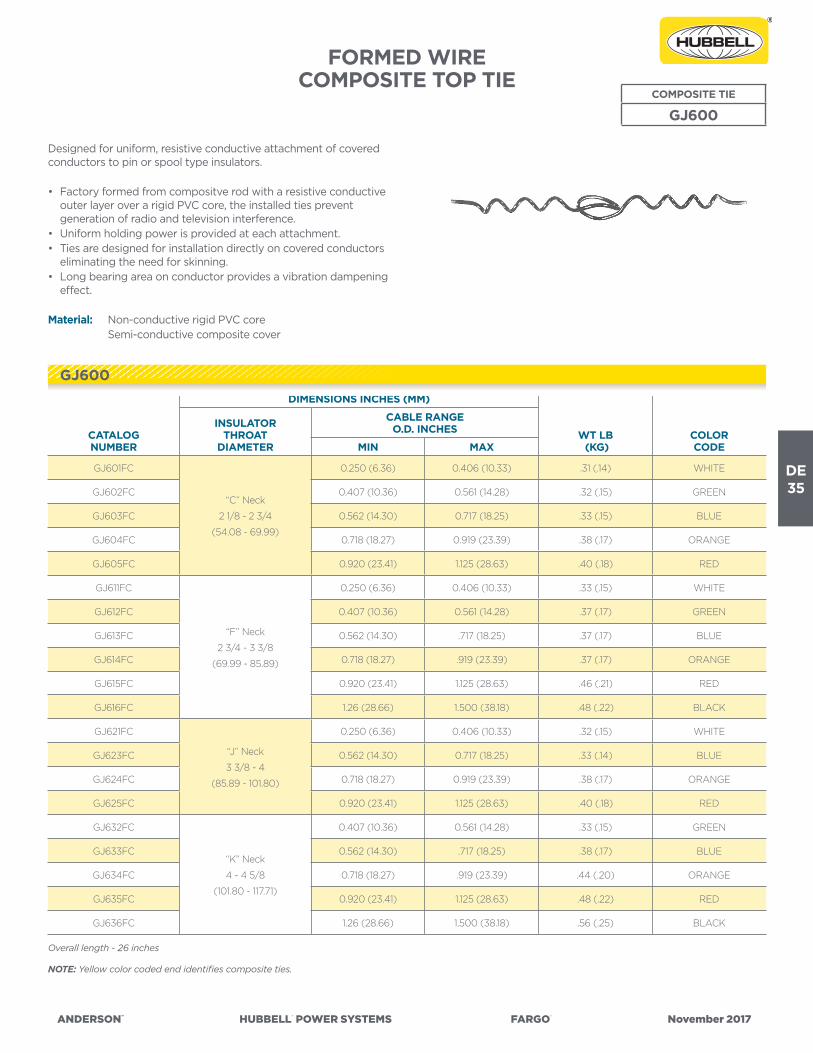
ANDERSON™ HUBBELL® POWER SYSTEMS FARGO® November 2017
DE35
FORMED WIRECOMPOSITE TOP TIE
COMPOSITE TIE
GJ600
Designed for uniform, resistive conductive attachment of covered conductors to pin or spool type insulators. • Factory formed from compositve rod with a resistive conductive
outer layer over a rigid PVC core, the installed ties prevent generation of radio and television interference.
• Uniform holding power is provided at each attachment.• Ties are designed for installation directly on covered conductors
eliminating the need for skinning.• Long bearing area on conductor provides a vibration dampening
effect.
Material: Non-conductive rigid PVC core Semi-conductive composite cover
CATALOG NUMBER
DIMENSIONS INCHES (MM)
WT LB (KG)
COLORCODE
INSULATORTHROAT
DIAMETER
CABLE RANGEO.D. INCHES
MIN MAX
GJ601FC
“C” Neck
2 1/8 - 2 3/4
(54.08 - 69.99)
0.250 (6.36) 0.406 (10.33) .31 (.14) WHITE
GJ602FC 0.407 (10.36) 0.561 (14.28) .32 (.15) GREEN
GJ603FC 0.562 (14.30) 0.717 (18.25) .33 (.15) BLUE
GJ604FC 0.718 (18.27) 0.919 (23.39) .38 (.17) ORANGE
GJ605FC 0.920 (23.41) 1.125 (28.63) .40 (.18) RED
GJ611FC
“F” Neck
2 3/4 - 3 3/8
(69.99 - 85.89)
0.250 (6.36) 0.406 (10.33) .33 (.15) WHITE
GJ612FC 0.407 (10.36) 0.561 (14.28) .37 (.17) GREEN
GJ613FC 0.562 (14.30) .717 (18.25) .37 (.17) BLUE
GJ614FC 0.718 (18.27) .919 (23.39) .37 (.17) ORANGE
GJ615FC 0.920 (23.41) 1.125 (28.63) .46 (.21) RED
GJ616FC 1.26 (28.66) 1.500 (38.18) .48 (.22) BLACK
GJ621FC
“J” Neck
3 3/8 - 4
(85.89 - 101.80)
0.250 (6.36) 0.406 (10.33) .32 (.15) WHITE
GJ623FC 0.562 (14.30) 0.717 (18.25) .33 (.14) BLUE
GJ624FC 0.718 (18.27) 0.919 (23.39) .38 (.17) ORANGE
GJ625FC 0.920 (23.41) 1.125 (28.63) .40 (.18) RED
GJ632FC
“K” Neck
4 - 4 5/8
(101.80 - 117.71)
0.407 (10.36) 0.561 (14.28) .33 (.15) GREEN
GJ633FC 0.562 (14.30) .717 (18.25) .38 (.17) BLUE
GJ634FC 0.718 (18.27) .919 (23.39) .44 (.20) ORANGE
GJ635FC 0.920 (23.41) 1.125 (28.63) .48 (.22) RED
GJ636FC 1.26 (28.66) 1.500 (38.18) .56 (.25) BLACK
Overall length - 26 inches
NOTE: Yellow color coded end identifies composite ties.
GJ600

DE36
ANDERSON™ HUBBELL® POWER SYSTEMS FARGO® November 2017
FORMED WIRECOMPOSITE DOUBLE PIN TIE
COMPOSITE TIE
GJ800/810
• Designed for use at intersections or slight angles where space or double arm construction does not permit use of the straight tie.
• Secures the conductor in position to the insulator for through or continuous run applications.
• Recommended for use with non-radio-free insulators for all system voltages, particularly above 5kV.
• Semi-conductive surface provides uniform electric field around attachment point, eliminating voltage concentrations and preventing TV/Radio interference.
• Long tie design provides a vibration dampening effect.
Material: Non-conductive rigid PVC core Semi-conductive composite cover
CATALOG NUMBER
INSULATORTHROAT
DIAMETER INCHES (MM)
CABLE RANGEO.D. INCHES (MM) OVERALL
LENGTHINCHES (MM)
WT. LBS (KG)
COLORCODEMIN MAX
GJ801FC“C” Neck
2 1/8 - 2 3/4
(54.08 - 69.99)
0.250 (6.36) 0.406 (10.33)
13”
(330.85)
.31 (.14) WHITE
GJ802FC 0407 (10.36) 0.561 (14.28) .33 (.15) GREEN
GJ804FC 0.718 (18.27) 0.919 (23.39) .37 (.17) ORANGE
GJ811FC
“F” Neck
2 3/4 - 3 3/8
(69.99 - 85.89)
0.250 (6.36) 0.406 (10.33)
13 1/4”
(337.21)
.34 (.15) WHITE
GJ812FC 0.407 (10.368) 0.561 (14.28) .35 (.16) GREEN
GJ813FC 0.562 (14.30) 0.717 18.25) .36 (.16) BLUE
GJ814FC 0.718 (18.27) 0.919 (23.39) .40 (.18) ORANGE
GJ815FC 0.920 (23.41) 1.125 (28.63) .43 (.20) RED
GJ816FC 1.26 (28.66) 1.500 (38.18) .50 (.23) BLACK
NOTE: Yellow color coded end identifies composite ties.
GS800/810

ANDERSON™ HUBBELL® POWER SYSTEMS FARGO® November 2017
DE37
FORMED WIRECOMPOSITE SIDE TIE
COMPOSITE TIE
GJ600/700
FIGURE 1
FIGURE 2
• For attachment of covered conductors to pin or spool type insulators.
• Semi-conductive tie surface provides uniform electic field around attachment point, elimination voltage concentrations, preventing TV/Radio interference.
• Long tie design provides vibration dampening effect.
Material: Non-conductive rigid PVC core Semi-conductive composite covering
CATA-LOG NUM-BER
DIMENSIONS INCHES (MM)
WT LB (KG)
COLORCODE
INSULATORTHROAT
DIAMETER
CABLE RANGEO.D. INCHES
MIN MAX
GJ651FC
“C” Neck
2-1/8 - 2-3/4
(54.08 - 69.99)
0.250 (6.36) 0.406 (10.33) .28 (.13) WHITE
GJ652FC 0.407 (10.36) 0.561 (14.28) .28 (.13) GREEN
GJ653FC 0.562 (14.30) 0.717 (18.25) .30 (.14) BLUE
GJ654FC 0.718 (18.27) 0.919 (23.39) .32 (.15) ORANGE
GJ655FC 0.920 (23.41) 1.125 (28.63) .34 (.16) RED
GJ662FC
“F” Neck
2-3/4 - 3-3/8
(69.99 - 85.89)
0.407 (10.36) 0.561 (14.28) .29 (.13) GREEN
GJ663FC 0.562 (14.30) .717 (18.25) .32 (.15) BLUE
GJ664FC 0.718 (18.27) .919 (23.39) .34 (.16) ORANGE
GJ665FC 0.920 (23.41) 1.125 (28.63) .39 (.18) RED
GJ666FC 1.26 (28.66) 1.500 (38.18) .39 (.18) BLACK
GJ672FC
“J” Neck
3-3/8 - 4
(85.89 - 101.80)
0.407 (10.36) 0.561 (14.28) .30 (.14) GREEN
GJ682FC
“K” Neck
4 - 4-5/8
(101.80 - 117.71)
0.407 (10.36) 0.561 (14.28) .34 (.16) GREEN
GJ683FC 0.552 (14.30) .717 (18.25) .36 (.16) BLUE
GJ684FC 0.718 (18.27) .919 (23.39) .39 (.16) ORANGE
GJ685FC 0.920 (23.41) 1.125 (28.63) .36 (.16) RED
GJ686FC 1.26 (28.66) 1.500 (38.18) .43 (.20) BLACK
CATA-LOG NUM-BER
DIMENSIONS INCHES (MM)
WT LB (KG)
COLORCODE
INSULATORTHROAT
DIAMETER
CABLE RANGEO.D. INCHES
MIN MAX
GJ751FC“C” Neck
2-1/8 - 2-3/4
(54.08 - 69.99)
0.250 (6.36) 0.406 (10.33) .28 (.13) WHITE
GJ753FC 0.562 (14.30) 0.717 (18.25) .28 (.13) BLUE
GJ754FC 0.718 (18.27) 0.919 (23.39) .30 (.14) ORANGE
GJ762FC
“F” Neck
2-3/4 - 3-3/8
(69.99 - 85.89)
0.407 (10.36) 0.561 (14.28) .32 (.15) GREEN
GJ763FC 0.562 (14.30) .717 (18.25) .34 (.16) BLUE
GJ764FC 0.718 (18.27) .919 (23.39) .29 (.13) ORANGE
GJ765FC 0.920 (23.41) 1.125 (28.63) .32 (.15) RED
GJ766FC 1.26 (28.66) 1.500 (38.18) .34 (.16) BLACK
GJ784FC “K” Neck
4 - 4-5/8
(101.80 - 117.71)
0.718 (18.27) .919 (23.39) .39 (.18) ORANGE
GJ785FC 0.920 (23.41) 1.125 (28.63) .39 (.18) RED
Overall length - 25 inches
GJ600/700 FIGURE 1 GJ600/700 FIGURE 2

DE38
ANDERSON™ HUBBELL® POWER SYSTEMS FARGO® November 2017
TIES FOR T2 CONDUCTORFORMED WIRE
VARIOUS INSULATOR TIES
Fargo formed wire ties are designed for use with ACSR, AAC, AAAC, Compacted ACSR, Compacted AAC & AWAC®.
T2 CONDUCTORSDISTRIBUTION
(TOP) TIES
DOUBLE SUP-PORT
(TOP) TIES SIDE TIES DOUBLE SIDE TIES SPOOL TIESQUIK-WRAP™ SPOOL TIES
2 x #4
(6/1) ACSR
(7/1) ACSR
(7W) AAC/
AAAAC
LDIC4006AS
LDIF4506AS
LDID0020 (C&F)
LDID2020 (J)LLAF4556AS
LLDU4156AS (C&F)
LLDU516AS (J)LRO4020AS QWSP4376
2 x #3 (6/1) ACSRLDIC4007AS
LDIF4507AS
LDID0030 (C&F)
LDID2030 (J)
LLAC4057AS
LLAF4557ASLLDU4157AS (C&F) LRO4022AS QWSP4376
2 x #2
(6/1) ACSR
(7/1) ACSR
(7W) AAC/
AAAAC
LDIC4008AS
LDIF4508AS
LDID0040 (C&F)
LDID2040 (J)
LLAC4058AS
LLAF4558ASLLDU4158AS (C&F) LRO4024AS -----
2 x #1 (7W) AAAAC
LDIC4009AS
LDIF4509AS
LDIJ4609AS
LDID0266 (C&F)
LDID2266 (J)LLAF4559AS LLDU4159AS (C&F) LRO4025AS QWSP4378
2 x 1/0
(6/1) ACSR
(7W) AAC/
AAAAC
LDIC4010AS
LDIF4510AS
LDIJ4610AS
LDID0336 (C&F)
LDID2336 (J)
LLAC4060AS
LLAF4560ASLLDU4160AS (C&F) LRO4027AS -----
2 x 2/0
(6/1) ACSR
(7W) AAC/
AAAAC
LDIC4011AS
LDIF4511AS
LDIJ4611AS
LDID0477 (C&F)
LDID2477 (J)
LLAC4061AS
LLAF4561ASLLDU4161AS (C&F) LRO4030AS -----
2 x 3/0
(6/1) ACSR
(7W) AAC/
AAAAC
LDIC4012AS
LDIF4512AS
LDIJ4612AS
LDID0556 (C&F)
LDID2556 (J)
LLAC4062AS
LLAF4562ASLLDU4162AS (C&F) LRO4031AS QWSP4381
2 x 4/0 (6/1) ACSR
LDIC4012AS
LDIF4512AS
LDIJ4612AS
LDID0556 (C&F)
LDID2556 (J)LLAF4563AS LLDU4162AS (C&F) LRO4031AS -----
2 x 266.8(18/1) ACSR
(26/7) ACSR
LDIC4013AS
LDIF4513AS
LDID0795 (C&F)
LDID2795 (J)LLAF4563AS
LLDU4163AS (C&F)
LLDU5163AS (J)** **
2 x 336.4 (18/1) ACSRLDIC4013AS
LDIF4513AS
LDID0795 (C&F)
LDID2795 (J)-----
LLDU4163AS (C&F)
LLDU5163AS (J)** **
2 x 336.4 (26/7) ACSRLDIC4014AS
LDIF4514AS
LDID0795 (C&F)
LDID2795 (J)----- LLDU4164AS (C&F) ** **
2 x 397.5 (19W) AACLDIC4014AS
LDIF4514AS
LDID0795 (C&F)
LDID2795 (J)----- LLDU4164AS (C&F) ** **
** Insulator groove too small for these sizes of T2

ANDERSON™ HUBBELL® POWER SYSTEMS FARGO® November 2017
DE39
GALVANIZED STEEL GUY WIRE DEADENDSFWDE CROSS REFERENCE
JANUARY, 2014
Size HPS PLP Dulmison Alcoa Helical Helix ColorCode
3/16” FWDE1102 GDE-1102 SGG-0470 GYDEGB047 HG205 3/16 40101 Red
7/32” FWDE1103 GDE-1103 SGG-0550 GYDEGB055 HG206 7/32 40151 Green
1/4” FWDE1104 GDE-1104 SGG-0610 GYDEGB061 HG207 1/4 40201 Yellow
9/32” FWDE1105 GDE-1105 ----- ----- HG208 9/32 ----- Blue
5/16” FWDE1106 GDE-1106 SGG-0790 GYDEGB079 HG209 5/16 40301 Black
3/8” FWDE1107 GDE-1107 SGG-0915 GYDEGB091 HG210 3/8 40351 Orange
7/16” FWDE1108 GDE-1108 SGG-1105 GYDEGB110 HG211 7/16 40401 Green
1/2” FWDE2115 BG-2115 SGG-1255 GYDEGB125 ----- 40451 Blue
9/16” FWDE2116 BG-2116 SGG-1435 GYDEGB143 ----- ----- Yellow
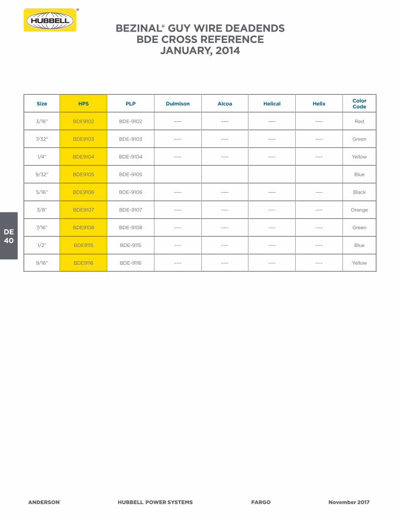
DE40
ANDERSON™ HUBBELL® POWER SYSTEMS FARGO® November 2017
BEZINAL® GUY WIRE DEADENDSBDE CROSS REFERENCE
JANUARY, 2014
Size HPS PLP Dulmison Alcoa Helical Helix ColorCode
3/16” BDE9102 BDE-9102 ––– ––– ––– ––– Red
7/32” BDE9103 BDE-9103 ––– ––– ––– ––– Green
1/4” BDE9104 BDE-9104 ––– ––– ––– ––– Yellow
9/32” BDE9105 BDE-9105 Blue
5/16” BDE9106 BDE-9106 ––– ––– ––– ––– Black
3/8” BDE9107 BDE-9107 ––– ––– ––– ––– Orange
7/16” BDE9108 BDE-9108 ––– ––– ––– ––– Green
1/2” BDE9115 BDE-9115 ––– ––– ––– ––– Blue
9/16” BDE9116 BDE-9116 ––– ––– ––– ––– Yellow
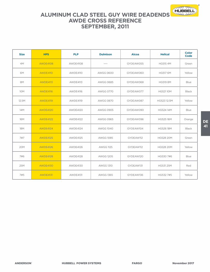
ANDERSON™ HUBBELL® POWER SYSTEMS FARGO® November 2017
DE41
Size HPS PLP Dulmison Alcoa Helical Color Code
4M AWDE4108 AWDE4108 ––– GYDEAW055 HG515 4M Green
6M AWDE4110 AWDE4110 AWGG 0600 GYDEAW060 HG517 6M Yellow
8M AWDE4113 AWDE4113 AWGG 0685 GYDEAW068 HG519 8M Blue
10M AWDE4116 AWDE4116 AWGG 0770 GYDEAW077 HG521 10M Black
12.5M AWDE4119 AWDE4119 AWGG 0870 GYDEAW087 HG523 12.5M Yellow
14M AWDE4120 AWDE4120 AWGG 0905 GYDEAW090 HG524 14M Blue
16M AWDE4122 AWDE4122 AWGG 0965 GYDEAW096 HG525 16M Orange
18M AWDE4124 AWDE4124 AWGG 1040 GYDEAW104 HG526 18M Black
7#7 AWDE4125 AWDE4125 AWGG 1085 GYDEAW112 HG528 20M Green
20M AWDE4126 AWDE4126 AWGG 1125 GYDEAW112 HG528 20M Yellow
7#6 AWDE4128 AWDE4128 AWGG 1205 GYDEAW120 HG530 7#6 Blue
25M AWDE4130 AWDE4130 AWGG 1310 GYDEAW131 HG531 25M Red
7#5 AWDE4131 AWDE4131 AWGG 1365 GYDEAW136 HG532 7#5 Yellow
ALUMINUM CLAD STEEL GUY WIRE DEADENDSAWDE CROSS REFERENCE
SEPTEMBER, 2011

DE42
ANDERSON™ HUBBELL® POWER SYSTEMS FARGO® November 2017
GALVANIZED STEEL GUY WIRE SPLICESFWLS CROSS REFERENCE
JANUARY, 2014
Size HPS PLP Dulmison Alcoa Helical Helix ColorCode
3/16” FWLS2102 GLS-2102 SGS-0470 ––– HS305 3/16 50100 Red
7/32” FWLS2103 GLS-2103 SGS-0550 ––– HS306 7/32 50150 Green
1/4” FWLS2104 GLS-2104 SGS-0610 ––– HS307 1/4 50200 Yellow
9/32” FWLS2105 GLS-2105 SGS-0710 ––– HS308 9/32 50250 Blue
5/16” FWLS2106 GLS-2106 SGS-0790 ––– HS309 5/16 50300 Black
3/8” FWLS2107 GLS-2107 SGS-0915 ––– HS310 3/8 50350 Orange
7/16” FWLS2108 GLS-2108 SGS-1105 ––– HS311 7/16 50400 Green
1/2” FWLS2109 GLS-2109 SGS-1255 ––– HS312 1/2 50450 Blue
9/16” FWLS2110 GLS-2110 SGS-1435 ––– HS313 9/16 50500 Yellow
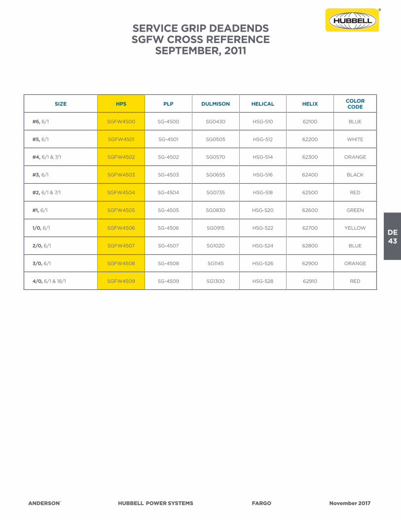
ANDERSON™ HUBBELL® POWER SYSTEMS FARGO® November 2017
DE43
SERVICE GRIP DEADENDSSGFW CROSS REFERENCE
SEPTEMBER, 2011
SIZE HPS PLP DULMISON HELICAL HELIX COLORCODE
#6, 6/1 SGFW4500 SG-4500 SG0430 HSG-510 62100 BLUE
#5, 6/1 SGFW4501 SG-4501 SG0505 HSG-512 62200 WHITE
#4, 6/1 & 7/1 SGFW4502 SG-4502 SG0570 HSG-514 62300 ORANGE
#3, 6/1 SGFW4503 SG-4503 SG0655 HSG-516 62400 BLACK
#2, 6/1 & 7/1 SGFW4504 SG-4504 SG0735 HSG-518 62500 RED
#1, 6/1 SGFW4505 SG-4505 SG0830 HSG-520 62600 GREEN
1/0, 6/1 SGFW4506 SG-4506 SG0915 HSG-522 62700 YELLOW
2/0, 6/1 SGFW4507 SG-4507 SG1020 HSG-524 62800 BLUE
3/0, 6/1 SGFW4508 SG-4508 SG1145 HSG-526 62900 ORANGE
4/0, 6/1 & 18/1 SGFW4509 SG-4509 SG1300 HSG-528 62910 RED

DE44
ANDERSON™ HUBBELL® POWER SYSTEMS FARGO® November 2017
DIS
TRIB
UTI
ON
GR
IP D
EAD
END
FO
RM
ED W
IRE
PRO
DU
CTS
DG
FW4
500
SER
IES
CR
OSS
REF
EREN
CE
SEPT
EMB
ER, 2
011
NO
M. S
IZE
DIA
. RA
NG
E
(inc
hes)
HPS
PLP
Dul
mis
onH
elic
alH
elix
Col
or C
ode
#6
.182
- .2
03
DG
FW
455
4D
G-4
554
AW
DG
050
5H
D-5
1032
010
Blu
e
#4
.229
- .2
57D
GF
W4
541
DG
-454
1A
WD
G0
635
HD
-514
320
12O
rang
e
#2
.29
0 -
.325
DG
FW
454
2D
G-4
542
AW
DG
080
5H
D-5
1832
015
Red
#1
.326
- .3
64
DG
FW
454
3D
G-4
543
AW
DG
09
00
HD
-520
320
16G
reen
1/0
.36
5 -
.40
9D
GF
W4
544
DG
-454
4A
WD
G0
99
0H
D-5
2232
020
Yello
w
2/0
.410
- .4
60
DG
FW
454
5D
G-4
545
AW
DG
1135
HD
-524
320
22B
lue
3/0
.461
- .5
16D
GF
W4
546
DG
-454
6A
WD
G12
75H
D-5
2632
030
Ora
nge
4/0
.517
- .5
77D
GF
W4
547
DG
-454
7A
WD
G14
30H
D-5
2832
033
Red
266
.8.5
78 -
.653
DG
FW
454
7D
G-4
548
AW
DG
1470
HD
-530
320
40
Bla
ck
336
.4.6
54 -
.739
DG
FW
454
9D
G-4
549
AW
DG
166
0H
D-5
3332
06
0G
reen
477
.74
0 -
.837
----
-D
G-4
550
AW
DG
1880
HD
-534
320
65
Ora
nge
556
.5.8
38 -
.947
----
-D
G-4
551
AW
DG
2130
HD
-535
320
70B
lue
795
.94
8 -
1.071
----
-D
G-4
552
AW
DG
2410
----
-32
080
Bro
wn
954
1.072
- 1.
212
----
-D
G-4
553
AW
DG
2730
----
-32
09
0O
rang
e

ANDERSON™ HUBBELL® POWER SYSTEMS FARGO® November 2017
DE45
DIS
TRIB
UTI
ON
TIE
S -
C N
ECK
INSU
LATO
RS
LDIC
SER
IES
CR
OSS
REF
EREN
CE
JAN
UA
RY,
20
14
GR
OU
PPO
PULA
R C
ON
DU
CTO
R S
IZE
HPS
PLP
DU
LMIS
ON
HEL
ICA
LA
CSR
AA
CA
AA
C
Dis
trib
utio
n Ti
e -
C N
eck
#6
(6/
1)#
4 (
7W)
Co
mp
LDIC
40
00
AS
UTC
-110
0D
TC 0
485
PH
DTC
010
Dis
trib
utio
n Ti
e -
C N
eck
No
Tie
Tub
e (P
ad)
#6
(6/
1)#
4 (
7W)
Co
mp
LDIC
40
00
ASN
TU
TC-1
115T
DTC
04
85T
– –
– –
–
Dis
trib
utio
n Ti
e -
C N
eck
#4
(6/
1) C
om
p
#4
(7/
1) C
om
p#
4 (
7W)
LDIC
40
01A
SU
TC-1
101
DTC
055
0P
HD
TC 0
12
Dis
trib
utio
n Ti
e -
C N
eck
No
Tie
Tub
e (P
ad)
#4
(6/
1) C
om
p
#4
(7/
1) C
om
p#
4 (
7W)
LDIC
40
01A
SNT
UTC
-111
6T
DTC
055
0T
– –
– –
–
Dis
trib
utio
n Ti
e -
C N
eck
#4
(6/
1)
#4
(7/
1)#
3 (7
W)
#4
(7W
)LD
IC4
00
2AS
UTC
-110
2D
TC 0
620
PH
DTC
014
Dis
trib
utio
n Ti
e -
C N
eck
No
Tie
Tub
e (P
ad)
#4
(6/
1)
#4
(7/
1)#
3 (7
W)
#4
(7W
)LD
IC4
00
2ASN
TU
TC-1
117T
DTC
06
20T
– –
– –
–
Dis
trib
utio
n Ti
e -
C N
eck
#2
(7W
)#
3 (7
W)
LDIC
40
03A
SU
TC-1
103
DTC
070
5PH
DTC
016
Dis
trib
utio
n Ti
e -
C N
eck
No
Tie
Tub
e (P
ad)
#2
(7W
)#
3 (7
W)
LDIC
40
03A
SNT
UTC
-111
8TD
TC 0
705T
– –
– –
–
Dis
trib
utio
n Ti
e -
C N
eck
#2
(6/1
)
#2
(7/1
)
#1 (
6/1)
#1 (
7W)
#1 (
19W
)#
2 (7
W)
LDIC
40
04
AS
UTC
-110
4D
TC 0
805P
HD
TC 0
18
Dis
trib
utio
n Ti
e -
C N
eck
No
Tie
Tub
e (P
ad)
#2
(6/1
)
#2
(7/1
)
#1 (
6/1)
#1 (
7W)
#1 (
19W
)#
2 (7
W)
LDIC
40
04
ASN
TU
TC-1
119
TD
TC 0
805T
– –
– –
–
Dis
trib
utio
n Ti
e -
C N
eck
1/0
(6/
1)1/
0 (
7W)
1/0
(19
W)
1/0
(7W
)LD
IC4
00
5AS
UTC
-110
5D
TC 0
910
PH
DTC
022
Dis
trib
utio
n Ti
e -
C N
eck
No
Tie
Tub
e (P
ad)
1/0
(6/
1)1/
0 (
7W)
1/0
(19
W)
1/0
(7W
)LD
IC4
00
5ASN
TU
TC-1
120
TD
TC 0
910
T–
– –
– –

DE46
ANDERSON™ HUBBELL® POWER SYSTEMS FARGO® November 2017
DIS
TRIB
UTI
ON
TIE
S -
C N
ECK
INSU
LATO
RS
LDIC
SER
IES
CR
OSS
REF
EREN
CE
JAN
UA
RY,
20
14
GR
OU
PPO
PULA
R C
ON
DU
CTO
R S
IZE
HPS
PLP
DU
LMIS
ON
HEL
ICA
LA
CSR
AA
CA
AA
C
Dis
trib
utio
n Ti
e -
C N
eck
2/0
(6/
1)2/
0 (
7W)
2/0
(19
W)
2/0
(7W
)LD
IC4
00
6A
SU
TC-1
106
DTC
1030
PH
DTC
024
Dis
trib
utio
n Ti
e -
C N
eck
No
Tie
Tub
e (P
ad)
2/0
(6/
1)2/
0 (
7W)
2/0
(19
W)
2/0
(7W
)LD
IC4
00
6A
SNT
UTC
-112
1TD
TC 10
30T
– –
– –
–
Dis
trib
utio
n Ti
e -
C N
eck
3/0
(6/
1)3/
0 (
7W)
3/0
(19
W)
3/0
(7W
)LD
IC4
00
7AS
UTC
-110
7D
TC 11
70P
HD
TC 0
26
Dis
trib
utio
n Ti
e -
C N
eck
No
Tie
Tub
e (P
ad)
3/0
(6/
1)3/
0 (
7W)
3/0
(19
W)
3/0
(7W
)LD
IC4
00
7ASN
TU
TC-1
122T
DTC
1170
T–
– –
– –
Dis
trib
utio
n Ti
e -
C N
eck
4/0
(6/
1)4
/0 (
7W)
4/0
(19
W)
4/0
(7W
)LD
IC4
00
8AS
UTC
-110
8D
TC 13
25P
HD
TC 0
28
Dis
trib
utio
n Ti
e -
C N
eck
No
Tie
Tub
e (P
ad)
4/0
(6/
1)4
/0 (
7W)
4/0
(19
W)
4/0
(7W
)LD
IC4
00
8ASN
TU
TC-1
123T
DTC
1325
T–
– –
– –
Dis
trib
utio
n Ti
e -
C N
eck
266
.8 (
18/1
)
266
.8 (
26/7
)
266
.8 (
37W
)
336
.4 (
19W
)LD
IC4
00
9A
SU
TC-1
109
DTC
1495
PH
DTC
031
Dis
trib
utio
n Ti
e -
C N
eck
No
Tie
Tub
e (P
ad)
266
.8 (
18/1
)
266
.8 (
26/7
)
266
.8 (
19W
)
266
.8 (
37W
)
336
.4 (
19W
)
LDIC
40
09
ASN
TU
TC-1
124
TD
TC 14
95T
– –
– –
–
Dis
trib
utio
n Ti
e -
C N
eck
336
.4 (
18/1
)
397.
5 (1
8/1)
350
(19
W)
397.
5 (1
9W
)LD
IC4
010
AS
UTC
-111
0D
TC 16
95P
HD
TC 0
33
Dis
trib
utio
n Ti
e -
C N
eck
No
Tie
Tub
e (P
ad)
336
.4 (
18/1
)
397.
5 (1
8/1)
350
(19
W)
397.
5 (1
9W
)LD
IC4
010
ASN
TU
TC-1
125T
DTC
1695
T–
– –
– –
Dis
trib
utio
n Ti
e -
C N
eck
477
(18/
1)
477
(24
/7)
477
(26
/7)
450
(19
W)
477
(19
W)
477
(37W
)
556
.5 (
19W
)
LDIC
40
11A
SU
TC-1
111
DTC
1920
PH
DTC
036
Dis
trib
utio
n Ti
e -
C N
eck
No
Tie
Tub
e (P
ad)
477
(18/
1)
477
(24
/7)
477
(26/
7)
450
(19
W)
477
(19
W)
477
(37W
)
556
.5 (
19W
)
LDIC
40
11A
SNT
UTC
-112
6T
DTC
1920
T–
– –
– –

ANDERSON™ HUBBELL® POWER SYSTEMS FARGO® November 2017
DE47
DIS
TRIB
UTI
ON
TIE
S -
C N
ECK
INSU
LATO
RS
LDIC
SER
IES
CR
OSS
REF
EREN
CE
JAN
UA
RY,
20
14
GR
OU
PPO
PULA
R C
ON
DU
CTO
R S
IZE
HPS
PLP
DU
LMIS
ON
HEL
ICA
LA
CSR
AA
CA
AA
C
Dis
trib
utio
n Ti
e -
C N
eck
556
.5 (
18/1
)
556
.5 (
24/7
)
636
(18
/1)
700
(37
W)
700
(61
W)
LDIC
40
12A
SU
TC-1
112
DTC
217
5PH
DTC
038
Dis
trib
utio
n Ti
e -
C N
eck
No
Tie
Tub
e (P
ad)
556
.5 (
18/1
)
556
.5 (
24/7
)
636
(18
/1)
70
0 (
37W
)
700
(61
W)
LDIC
40
12A
SNT
UTC
-112
7TD
TC 2
175T
– –
– –
–
Dis
trib
utio
n Ti
e -
C N
eck
636
(24
/7)
795
(54
/7)
795
(37W
)
795
(61W
)LD
IC4
013
AS
UTC
-111
3D
TC 2
46
0P
HD
TC 0
42
Dis
trib
utio
n Ti
e -
C N
eck
No
Tie
Tub
e (P
ad)
636
(24
/7)
795
(54
/7)
795
(37W
)
795
(61W
)LD
IC4
013
ASN
TU
TC-1
128T
DTC
24
60
T–
– –
– –
Dis
trib
utio
n Ti
e -
C N
eck
795
(26/
7)
954
(36
/1)
954
(54
/7)
1033
.5 (
37W
)
1033
.5 (
61W
)LD
IC4
014
AS
UTC
-111
4D
TC 2
785P
– –
– –
–
Dis
trib
utio
n Ti
e -
C N
eck
No
Tie
Tub
e (P
ad)
795
(26/
7)
954
(36
/1)
954
(54
/7)
1033
.5 (
37W
)
1033
.5 (
61W
)LD
IC4
014
ASN
TU
TC-1
129
TD
TC 2
785T
– –
– –
–

DE48
ANDERSON™ HUBBELL® POWER SYSTEMS FARGO® November 2017
DIS
TRIB
UTI
ON
TIE
S -
F N
ECK
INSU
LATO
RS
LDIF
SER
IES
CR
OSS
REF
EREN
CE
JAN
UA
RY,
20
14
GR
OU
PPO
PULA
R C
ON
DU
CTO
R S
IZE
HPS
PLP
DU
LMIS
ON
HEL
ICA
LA
CSR
AA
CA
AA
C
Dis
trib
utio
n Ti
e -
F N
eck
#6
(6/
1)#
4 (
7W)
Co
mp
LDIF
450
0A
SU
TF-1
200
DTF
04
85P
HD
TF 0
10
Dis
trib
utio
n Ti
e -
F N
eck
No
Tie
Tub
e (P
ad)
#6
(6/
1)#
4 (
7W)
Co
mp
LDIF
450
0A
SNT
UTF
-121
5TD
TF 0
485
T–
– –
– –
Dis
trib
utio
n Ti
e -
F N
eck
#4
(6/
1) C
om
p
#4
(7/
1) C
om
p#
4 (
7W)
LDIF
450
1AS
UTF
-120
1D
TF 0
550
PH
DTF
012
Dis
trib
utio
n Ti
e -
F N
eck
No
Tie
Tub
e (P
ad)
#4
(6/
1) C
om
p
#4
(7/
1) C
om
p#
4 (
7W)
LDIF
450
1ASN
TU
TF-1
216
TD
TF 0
550
T–
– –
– –
Dis
trib
utio
n Ti
e -
F N
eck
#4
(6/
1)
#4
(7/
1)#
3 (7
W)
#4
(7W
)LD
IF4
502A
SU
TF-1
202
DTF
06
20P
HD
TF 0
14
Dis
trib
utio
n Ti
e -
F N
eck
No
Tie
Tub
e (P
ad)
#4
(6/
1)
#4
(7/
1)#
3 (7
W)
#4
(7W
)LD
IF4
502A
SNT
UTF
-121
7TD
TF 0
620
T–
– –
– –
Dis
trib
utio
n Ti
e -
F N
eck
#2
(7W
)#
3 (7
W)
LDIF
450
3AS
UTF
-120
3D
TF 0
705P
HD
TF 0
16
Dis
trib
utio
n Ti
e -
F N
eck
No
Tie
Tub
e (P
ad)
#2
(7W
)#
3 (7
W)
LDIF
450
3ASN
TU
TF-1
218T
DTF
070
5T–
– –
– –
Dis
trib
utio
n Ti
e -
F N
eck
#2
(6/1
)
#2
(7/1
)
#1 (
6/1)
#1 (
7W)
#1 (
19W
)#
2 (7
W)
LDIF
450
4A
SU
TF-1
204
DTF
080
5PH
DTF
018
Dis
trib
utio
n Ti
e -
F N
eck
No
Tie
Tub
e (P
ad)
#2
(6/1
)
#2
(7/1
)
#1 (
6/1)
#1 (
7W)
#1 (
19W
)#
2 (7
W)
LDIF
450
4A
SNT
UTF
-121
9T
DTF
080
5T–
– –
– –
Dis
trib
utio
n Ti
e -
F N
eck
1/0
(6/
1)1/
0 (
7W)
1/0
(19
W)
1/0
(7W
)LD
IF4
505A
SU
TF-1
205
DTF
09
10P
HD
TF 0
22
Dis
trib
utio
n Ti
e -
F N
eck
No
Tie
Tub
e (P
ad)
1/0
(6/
1)1/
0 (
7W)
1/0
(19
W)
1/0
(7W
)LD
IF4
505A
SNT
UTF
-122
0T
DTF
09
10T
– –
– –
–
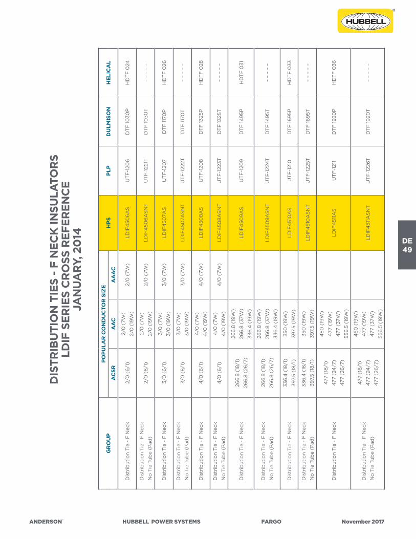
ANDERSON™ HUBBELL® POWER SYSTEMS FARGO® November 2017
DE49
DIS
TRIB
UTI
ON
TIE
S -
F N
ECK
INSU
LATO
RS
LDIF
SER
IES
CR
OSS
REF
EREN
CE
JAN
UA
RY,
20
14
GR
OU
PPO
PULA
R C
ON
DU
CTO
R S
IZE
HPS
PLP
DU
LMIS
ON
HEL
ICA
LA
CSR
AA
CA
AA
C
Dis
trib
utio
n Ti
e -
F N
eck
2/0
(6/
1)2/
0 (
7W)
2/0
(19
W)
2/0
(7W
)LD
IF4
506
AS
UTF
-120
6D
TF 10
30P
HD
TF 0
24
Dis
trib
utio
n Ti
e -
F N
eck
No
Tie
Tub
e (P
ad)
2/0
(6/
1)2/
0 (
7W)
2/0
(19
W)
2/0
(7W
)LD
IF4
506
ASN
TU
TF-1
221T
DTF
1030
T–
– –
– –
Dis
trib
utio
n Ti
e -
F N
eck
3/0
(6/
1)3/
0 (
7W)
3/0
(19
W)
3/0
(7W
)LD
IF4
507A
SU
TF-1
207
DTF
1170
PH
DTF
026
Dis
trib
utio
n Ti
e -
F N
eck
No
Tie
Tub
e (P
ad)
3/0
(6/
1)3/
0 (
7W)
3/0
(19
W)
3/0
(7W
)LD
IF4
507A
SNT
UTF
-122
2TD
TF 11
70T
– –
– –
–
Dis
trib
utio
n Ti
e -
F N
eck
4/0
(6/
1)4
/0 (
7W)
4/0
(19
W)
4/0
(7W
)LD
IF4
508A
SU
TF-1
208
DTF
1325
PH
DTF
028
Dis
trib
utio
n Ti
e -
F N
eck
No
Tie
Tub
e (P
ad)
4/0
(6/
1)4
/0 (
7W)
4/0
(19
W)
4/0
(7W
)LD
IF4
508A
SNT
UTF
-122
3TD
TF 13
25T
– –
– –
–
Dis
trib
utio
n Ti
e -
F N
eck
266
.8 (
18/1
)
266
.8 (
26/7
)
266
.8 (
19W
)
266
.8 (
37W
)
336
.4 (
19W
)
LDIF
450
9A
SU
TF-1
209
DTF
1495
PH
DTF
031
Dis
trib
utio
n Ti
e -
F N
eck
No
Tie
Tub
e (P
ad)
266
.8 (
18/1
)
266
.8 (
26/7
)
266
.8 (
19W
)
266
.8 (
37W
)
336
.4 (
19W
)
LDIF
450
9A
SNT
UTF
-122
4T
DTF
1495
T–
– –
– –
Dis
trib
utio
n Ti
e -
F N
eck
336
.4 (
18/1
)
397.
5 (1
8/1)
350
(19
W)
397.
5 (1
9W
)LD
IF4
510
AS
UTF
-121
0D
TF 16
95P
HD
TF 0
33
Dis
trib
utio
n Ti
e -
F N
eck
No
Tie
Tub
e (P
ad)
336
.4 (
18/1
)
397.
5 (1
8/1)
350
(19
W)
397.
5 (1
9W
)LD
IF4
510
ASN
TU
TF-1
225T
DTF
1695
T–
– –
– –
Dis
trib
utio
n Ti
e -
F N
eck
477
(18/
1)
477
(24
/7)
477
(26/
7)
450
(19
W)
477
(19
W)
477
(37W
)
556
.5 (
19W
)
LDIF
451
1AS
UTF
-121
1D
TF 19
20P
HD
TF 0
36
Dis
trib
utio
n Ti
e -
F N
eck
No
Tie
Tub
e (P
ad)
477
(18/
1)
477
(24
/7)
477
(26/
7)
450
(19
W)
477
(19
W)
477
(37W
)
556
.5 (
19W
)
LDIF
451
1ASN
TU
TF-1
226
TD
TF 19
20T
– –
– –
–
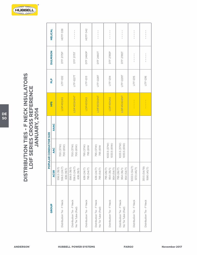
DE50
ANDERSON™ HUBBELL® POWER SYSTEMS FARGO® November 2017
DIS
TRIB
UTI
ON
TIE
S -
F N
ECK
INSU
LATO
RS
LDIF
SER
IES
CR
OSS
REF
EREN
CE
JAN
UA
RY,
20
14
GR
OU
PPO
PULA
R C
ON
DU
CTO
R S
IZE
HPS
PLP
DU
LMIS
ON
HEL
ICA
LA
CSR
AA
CA
AA
C
Dis
trib
utio
n Ti
e -
F N
eck
556
.5 (
18/1
)
556
.5 (
24/7
)
636
(18
/1)
700
(37
W)
700
(61
W)
LDIF
451
2AS
UTF
-121
2D
TF 2
175P
HD
TF 0
38
Dis
trib
utio
n Ti
e -
F N
eck
No
Tie
Tub
e (P
ad)
556
.5 (
18/1
)
556
.5 (
24/7
)
636
(18
/1)
700
(37
W)
700
(61
W)
LDIF
451
2ASN
TU
TF-1
227T
DTF
217
5T–
– –
– –
Dis
trib
utio
n Ti
e -
F N
eck
636
(24
/7)
795
(54
/7)
795
(37W
)
795
(61W
LDIF
451
3AS
UTF
-121
3D
TF 2
46
0P
HD
TF 0
42
Dis
trib
utio
n Ti
e -
F N
eck
No
Tie
Tub
e (P
ad)
636
(24
/7)
795
(54
/7)
795
(37W
)
795
(61W
LDIF
451
3ASN
TU
TF-1
228T
DTF
24
60
T–
– –
– –
Dis
trib
utio
n Ti
e -
F N
eck
795
(26/
7)
954
(36
/1)
954
(54
/7)
1033
.5 (
37W
)
1033
.5 (
61W
)LD
IF4
514
AS
UTF
-121
4D
TF 2
785P
– –
– –
–
Dis
trib
utio
n Ti
e -
F N
eck
No
Tie
Tub
e (P
ad)
795
(26/
7)
954
(36
/1)
954
(54
/7)
1033
.5 (
37W
)
1033
.5 (
61W
)LD
IF4
514
ASN
TU
TF-1
229
TD
TF 2
785T
– –
– –
–
Dis
trib
utio
n Ti
e -
F N
eck
1033
.5 (
54/7
)
1272
(4
5/7)
– –
– –
–U
TF-1
215
– –
– –
––
– –
– –
Dis
trib
utio
n Ti
e -
F N
eck
351.5
(54
/19
)
159
0 (
45/
7)–
– –
– –
UTF
-121
6–
– –
– –
– –
– –
–

ANDERSON™ HUBBELL® POWER SYSTEMS FARGO® November 2017
DE51
DIS
TRIB
UTI
ON
TIE
S -
J N
ECK
INSU
LATO
RS
LDIJ
SER
IES
CR
OSS
REF
EREN
CE
JAN
UA
RY,
20
14
GR
OU
PPO
PULA
R C
ON
DU
CTO
R S
IZE
HPS
PLP
DU
LMIS
ON
HEL
ICA
LA
CSR
AA
CA
AA
C
Dis
trib
utio
n Ti
e -
J N
eck
#6
(6/
1)#
4 (
7W)
Co
mp
– –
– –
–U
TJ-1
300
DTJ
04
85P
HD
TJ 0
10
Dis
trib
utio
n Ti
e -
J N
eck
#4
(6/
1) C
om
p
#4
(71
) C
om
p#
4 (
7W)
– –
– –
–U
TJ-1
301
DTJ
055
0P
HD
TJ 0
12
Dis
trib
utio
n Ti
e -
J N
eck
#4
(6/
1)
#4
(7/
1)#
3 (7
W)
#4
(7W
)LD
IJ4
60
2AS
UTJ
-130
2D
TJ 0
620
PH
DTJ
014
Dis
trib
utio
n Ti
e -
J N
eck
#4
(6/
1)
#4
(7/
1)#
3 (7
W)
#4
(7W
)LD
IJ4
60
2ASN
TU
TJ-1
302-
TD
TJ 0
620
T–
– –
– –
Dis
trib
utio
n Ti
e -
J N
eck
#2
(7W
)#
3 (7
W)
– –
– –
–U
TJ-1
303
DTJ
070
5PH
DTJ
016
Dis
trib
utio
n Ti
e -
J N
eck
#2
(6/1
)
#2
(7/1
)
#1 (
6/1)
#1 (
7W)
#1 (
19W
)#
2 (7
W)
LDIJ
46
04
AS
UTJ
-130
4D
TJ 0
805P
HD
TJ 0
18
Dis
trib
utio
n Ti
e -
J N
eck
No
Tie
Tub
e (P
ad)
#2
(6/1
)
#2
(7/1
)
#1 (
6/1)
#1 (
7W)
#1 (
19W
)#
2 (7
W)
LDIJ
46
04
ASN
TU
TJ-1
319
TD
TJ 0
805T
– –
– –
–
Dis
trib
utio
n Ti
e -
J N
eck
1/0
(6/
1)1/
0 (
7W)
1/0
(19
W)
1/0
(7W
)LD
IJ4
60
5AS
UTJ
-130
5D
TJ 0
910
PH
DTJ
022
Dis
trib
utio
n Ti
e -
J N
eck
No
Tie
Tub
e (P
ad)
1/0
(6/
1)1/
0 (
7W)
1/0
(19
W)
1/0
(7W
)LD
IJ4
60
5ASN
TU
TJ-1
320
TD
TJ 0
910
T–
– –
– –
Dis
trib
utio
n Ti
e -
J N
eck
2/0
(6/
1)2/
0 (
7W)
2/0
(19
W)
2/0
(7W
)–
– –
– –
UTJ
-130
6D
TJ 10
30P
HD
TJ 0
24
Dis
trib
utio
n Ti
e -
J N
eck
3/0
(6/
1)3/
0 (
7W)
3/0
(19
W)
3/0
(7W
)–
– –
– –
UTJ
-130
7D
TJ 11
70P
HD
TJ 0
26
Dis
trib
utio
n Ti
e -
J N
eck
4/0
(6/
1)4
/0 (
7W)
4/0
(19
W)
4/0
(7W
)–
– –
– –
UTJ
-130
8D
TJ 13
25P
HD
TJ 0
28

DE52
ANDERSON™ HUBBELL® POWER SYSTEMS FARGO® November 2017
DIS
TRIB
UTI
ON
TIE
S -
J N
ECK
INSU
LATO
RS
LDIJ
SER
IES
CR
OSS
REF
EREN
CE
JAN
UA
RY,
20
14
GR
OU
PPO
PULA
R C
ON
DU
CTO
R S
IZE
HPS
PLP
DU
LMIS
ON
HEL
ICA
LA
CSR
AA
CA
AA
C
Dis
trib
utio
n Ti
e -
J N
eck
266
.8 (
18/1
)
266
.8 (
26/7
)
266
.8 (
19W
)
266
.8 (
37W
)
336
.4 (
19W
)
LDIJ
46
09
AS
UTJ
-130
9D
TJ 14
95P
HD
TJ 0
31
Dis
trib
utio
n Ti
e -
J N
eck
266
.8 (
18/1
)
266
.8 (
26/7
)
266
.8 (
19W
)
266
.8 (
37W
)
336
.4 (
19W
)
LDIJ
46
09
ASN
TU
TJ-1
309
-TD
TJ 14
95T
– –
– –
–
Dis
trib
utio
n Ti
e -
J N
eck
336
.4 (
18/1
)
397.
5 (1
8/1)
350
(19
W)
397.
5 (1
9W
)LD
IJ4
610
AS
UTJ
-131
0D
TJ 16
95P
HD
TJ 0
33
Dis
trib
utio
n Ti
e -
J N
eck
336
.4 (
18/1
)
397.
5 (1
8/1)
350
(19
W)
397.
5 (1
9W
)LD
IJ4
610
ASN
TU
TJ-1
310
-TD
TJ 16
95T
– –
– –
–
Dis
trib
utio
n Ti
e -
J N
eck
477
(18/
1)
477
(24
/7)
477
(26/
7)
450
(19
W)
477
(19
W)
477
(37W
)
556
.5 (
19W
)
LDIJ
461
1AS
UTJ
-131
1D
TJ 19
20P
HD
TJ 0
36
Dis
trib
utio
n Ti
e -
J N
eck
477
(18/
1)
477
(24
/7)
477
(26/
7)
450
(19
W)
477
(19
W)
477
(37W
)
556
.5 (
19W
)
LDIJ
461
1ASN
TU
TJ-1
311-
TD
TJ 19
20T
– –
– –
–
Dis
trib
utio
n Ti
e -
J N
eck
556
.5 (
18/1
)
556
.5 (
24/7
)
636
(18
/1)
700
(37
W)
700
(61
W)
LDIJ
461
2AS
UTJ
-131
2D
TJ 2
175P
HD
TJ 0
38
Dis
trib
utio
n Ti
e -
J N
eck
556
.5 (
18/1
)
556
.5 (
24/7
)
636
(18
/1)
700
(37
W)
700
(61
W)
LDIJ
461
2ASN
TU
TJ-1
312-
TD
TJ 2
175T
– –
– –
–
Dis
trib
utio
n Ti
e -
J N
eck
636
(24
/7)
795
(54
/7)
795
(37W
)
795
(61W
)–
– –
– –
UTJ
-131
3D
TJ 2
46
0P
HD
TJ 0
42
Dis
trib
utio
n Ti
e -
J N
eck
795
(26/
7)
954
(36
/1)
954
(54
/7)
1033
.5 (
37W
)
1033
.5 (
61W
)–
– –
– –
UTJ
-131
4D
TJ 2
785P
– –
– –
–

ANDERSON™ HUBBELL® POWER SYSTEMS FARGO® November 2017
DE53
QU
IK-W
RA
P™ T
WIN
TIE
S -
F N
ECK
INSU
LATO
RS
(2-7
/8”)
A
ND
J N
ECK
INSU
LATO
RS
(3-1
/2”)
TTFJ
AN
D T
TJ S
ERIE
S C
RO
SS R
EFER
ENC
EJA
NU
AR
Y, 2
014
GR
OU
PPO
PULA
R C
ON
DU
CTO
R S
IZE
HPS
PLP
DU
LMIS
ON
HEL
ICA
LA
CSR
AA
CA
AA
C
Qui
k-W
rap
™ T
win
Tie
: F &
J N
eck
#4
(6/
1)
#4
(7/
1)#
3 (7
W)
#4
(7W
)–
– –
– –
TTFJ
-20
2–
– –
– –
– –
– –
–
Qui
k-W
rap
™ T
win
Tie
: F &
J N
eck
#2
(7W
)#
3 (7
W)
– –
– –
–TT
FJ-2
03
– –
– –
––
– –
– –
Qui
k-W
rap
™ T
win
Tie
: F &
J N
eck
#2
(6/1
)
#2
(7/1
)
#1 (
6/1)
#1 (
7W)
#1 (
19W
)#
2 (7
W)
– –
– –
–TT
FJ-2
04
– –
– –
––
– –
– –
Qui
k-W
rap
™ T
win
Tie
: F &
J N
eck
1/0
(6/
1)1/
0 (
7W)
1/0
(19
W)
1/0
(7W
)TT
FJ-2
05
TTFJ
-20
5–
– –
– –
– –
– –
–
Qui
k-W
rap
™ T
win
Tie
: F &
J N
eck
2/0
(6/
1)2/
0 (
7W)
2/0
(19
W)
2/0
(7W
)TT
FJ-2
06
TTFJ
-20
6–
– –
– –
– –
– –
–
Qui
k-W
rap
™ T
win
Tie
: F &
J N
eck
3/0
(6/
1)3/
0 (
7W)
3/0
(19
W)
3/0
(7W
)TT
FJ-2
07
TTFJ
-20
7–
– –
– –
– –
– –
–
Qui
k-W
rap
™ T
win
Tie
: F &
J N
eck
4/0
(6/
1)4
/0 (
7W)
4/0
(19
W)
4/0
(7W
)TT
FJ-2
08
TTFJ
-20
8–
– –
– –
– –
– –
–
Qui
k-W
rap
™ T
win
Tie
: F &
J N
eck
266
.8 (
18/1
)
266
.8 (
26/7
)
266
.8 (
19W
)
266
.8 (
37W
)
336
.4 (
19W
)
– –
– –
–TT
FJ-2
09
– –
– –
––
– –
– –
Qui
k-W
rap
™ T
win
Tie
: F &
J N
eck
336
.4 (
18/1
)
397.
5 (1
8/1)
350
(19
W)
397.
5 (1
9W
)TT
FJ-2
10TT
FJ-2
10–
– –
– –
– –
– –
–

DE54
ANDERSON™ HUBBELL® POWER SYSTEMS FARGO® November 2017
QU
IK-W
RA
P™ T
WIN
TIE
S -
F N
ECK
INSU
LATO
RS
(2-7
/8”)
A
ND
J N
ECK
INSU
LATO
RS
(3-1
/2”)
TTFJ
AN
D T
TJ S
ERIE
S C
RO
SS R
EFER
ENC
EJA
NU
AR
Y, 2
014
GR
OU
PPO
PULA
R C
ON
DU
CTO
R S
IZE
HPS
PLP
DU
LMIS
ON
HEL
ICA
LA
CSR
AA
CA
AA
C
Qui
k-W
rap
™ T
win
Tie
: F &
J N
eck
477
(18/
1)
477
(24
/7)
477
(26/
7)
450
(19
W)
477
(19
W)
477
(37W
)
556
.5 (
19W
)
– –
– –
–TT
FJ-2
11–
– –
– –
– –
– –
–
Qui
k-W
rap
™ T
win
Tie
: F &
J N
eck
556
.5 (
18/1
)
556
.5 (
24/7
)
636
(18
/1)
700
(37
W)
700
(61
W)
– –
– –
–TT
FJ-2
12–
– –
– –
– –
– –
–
Qui
k-W
rap
™ T
win
Tie
: F &
J N
eck
636
(24
/7)
795
(54
/7)
795
(37W
)
795
(61W
)–
– –
– –
TTFJ
-213
– –
– –
––
– –
– –
Qui
k-W
rap
™ T
win
Tie
: F &
J N
eck
795
(26/
7)
954
(36
/1)
954
(54
/7)
1035
.5 (
37W
)
1035
.5 (
61W
)–
– –
– –
TTFJ
-214
– –
– –
––
– –
– –
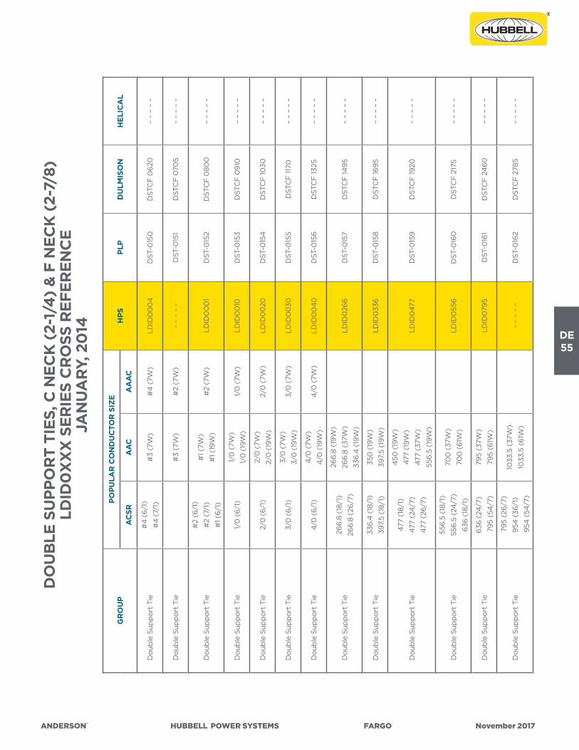
ANDERSON™ HUBBELL® POWER SYSTEMS FARGO® November 2017
DE55
DO
UB
LE S
UPP
OR
T TI
ES, C
NEC
K (
2-1/
4)
& F
NEC
K (
2-7/
8)LD
ID0
XX
X S
ERIE
S C
RO
SS R
EFER
ENC
EJA
NU
AR
Y, 2
014
GR
OU
PPO
PULA
R C
ON
DU
CTO
R S
IZE
HPS
PLP
DU
LMIS
ON
HEL
ICA
LA
CSR
AA
CA
AA
C
Do
uble
Sup
po
rt T
ie#
4 (
6/1)
#4
(7/
1)#
3 (7
W)
#4
(7W
)LD
ID0
00
4D
ST-0
150
DST
CF
06
20–
– –
– –
Do
uble
Sup
po
rt T
ie#
3 (7
W)
#2
(7W
)–
– –
– –
DST
-015
1D
STC
F 0
705
– –
– –
–
Do
uble
Sup
po
rt T
ie
#2
(6/1
)
#2
(7/1
)
#1 (
6/1)
#1 (
7W)
#1 (
19W
)#
2 (7
W)
LDID
00
01
DST
-015
2D
STC
F 0
800
– –
– –
–
Do
uble
Sup
po
rt T
ie1/
0 (
6/1)
1/0
(7W
)
1/0
(19
W)
1/0
(7W
)LD
ID0
010
DST
-015
3D
STC
F 0
910
– –
– –
–
Do
uble
Sup
po
rt T
ie2/
0 (
6/1)
2/0
(7W
)
2/0
(19
W)
2/0
(7W
)LD
ID0
020
DST
-015
4D
STC
F 10
30–
– –
– –
Do
uble
Sup
po
rt T
ie3/
0 (
6/1)
3/0
(7W
)
3/0
(19
W)
3/0
(7W
)LD
ID0
030
DST
-015
5D
STC
F 11
70–
– –
– –
Do
uble
Sup
po
rt T
ie4
/0 (
6/1)
4/0
(7W
)
4/0
(19
W)
4/0
(7W
)LD
ID0
04
0D
ST-0
156
DST
CF
1325
– –
– –
–
Do
uble
Sup
po
rt T
ie26
6.8
(18
/1)
266
.8 (
26/7
)
266
.8 (
19W
)
266
.8 (
37W
)
336
.4 (
19W
)
LDID
026
6D
ST-0
157
DST
CF
1495
– –
– –
–
Do
uble
Sup
po
rt T
ie33
6.4
(18
/1)
397.
5 (1
8/1)
350
(19
W)
397.
5 (1
9W
)LD
ID0
336
DST
-015
8D
STC
F 16
95–
– –
– –
Do
uble
Sup
po
rt T
ie
477
(18/
1)
477
(24
/7)
477
(26/
7)
450
(19
W)
477
(19
W)
477
(37W
)
556
.5 (
19W
)
LDID
047
7D
ST-0
159
DST
CF
1920
– –
– –
–
Do
uble
Sup
po
rt T
ie
556
.5 (
18/1
)
556
.5 (
24/7
)
636
(18
/1)
700
(37
W)
700
(61
W)
LDID
055
6D
ST-0
160
DST
CF
217
5–
– –
– –
Do
uble
Sup
po
rt T
ie63
6 (
24/7
)
795
(54
/7)
795
(37W
)
795
(61W
)LD
ID0
795
DST
-016
1D
STC
F 2
46
0–
– –
– –
Do
uble
Sup
po
rt T
ie
795
(26
/7)
954
(36
/1)
954
(54
/7)
1033
.5 (
37W
)
1033
.5 (
61W
)–
– –
– –
DST
-016
2D
STC
F 2
785
– –
– –
–

DE56
ANDERSON™ HUBBELL® POWER SYSTEMS FARGO® November 2017
GR
OU
PPO
PULA
R C
ON
DU
CTO
R S
IZE
HPS
PLP
DU
LMIS
ON
HEL
ICA
LA
CSR
AA
CA
AA
C
Do
uble
Sup
po
rt T
ie#
4 (
6/1)
#4
(7/
1)#
3 (7
W)
#4
(7W
)LD
ID20
04
DST
-035
0D
STJ
06
20–
– –
– –
Do
uble
Sup
po
rt T
ie#
3 (7
W)
#2
(7W
)LD
ID20
03
DST
-035
1D
STJ
070
5–
– –
– –
Do
uble
Sup
po
rt T
ie
#2
(6/1
)
#2
(7/1
)
#1 (
6/1)
#1 (
7W)
#1 (
19W
)#
2 (7
W)
LDID
200
1D
ST-0
352
DST
J 0
800
– –
– –
–
Do
uble
Sup
po
rt T
ie1/
0 (
6/1)
1/0
(7W
)
1/0
(19
W)
1/0
(7W
)LD
ID20
10D
ST-0
353
DST
J 0
910
– –
– –
–
Do
uble
Sup
po
rt T
ie2/
0 (
6/1)
2/0
(7W
)
2/0
(19
W)
2/0
(7W
)LD
ID20
20D
ST-0
354
DST
J 10
30–
– –
– –
Do
uble
Sup
po
rt T
ie3/
0 (
6/1)
3/0
(7W
)
3/0
(19
W)
3/0
(7W
)LD
ID20
30D
ST-0
355
DST
J 11
70–
– –
– –
Do
uble
Sup
po
rt T
ie4
/0 (
6/1)
4/0
(7W
)
4/0
(19
W)
4/0
(7W
)LD
ID20
40
DST
-035
6D
STJ
1325
– –
– –
–
Do
uble
Sup
po
rt T
ie26
6.8
(18
/1)
266
.8 (
26/7
)
266
.8 (
19W
)
266
.8 (
37W
)
336
.4 (
19W
)
LDID
226
6D
ST-0
357
DST
J 14
95–
– –
– –
Do
uble
Sup
po
rt T
ie33
6.4
(18
/1)
397.
5 (1
8/1)
350
(19
W)
397.
5 (1
9W
)LD
ID23
36D
ST-0
358
DST
J 16
95–
– –
– –
Do
uble
Sup
po
rt T
ie
477
(18/
1)
477
(24
/7)
477
(26/
7)
450
(19
W)
477
(19
W)
477
(37W
)
556
.5 (
19W
)
LDID
2477
DST
-035
9D
STJ
1920
– –
– –
–
Do
uble
Sup
po
rt T
ie
556
.5 (
18/1
)
556
.5 (
24/7
)
636
(18
/1)
700
(37
W)
700
(61
W)
LDID
2556
DST
-036
0D
STJ
2175
– –
– –
–
Do
uble
Sup
po
rt T
ie63
6 (
24/7
)
795
(54
/7)
795
(37W
)
795
(61W
)LD
ID27
95D
ST-0
361
DST
J 24
60
– –
– –
–
Do
uble
Sup
po
rt T
ie
795
(54
/7)
954
(36
/1)
954
(54
/7)
1033
.5 (
37W
)
1033
.5 (
61W
)–
– –
– –
DST
-036
2D
STJ
2785
– –
– –
–
DO
UB
LE S
UPP
OR
T TI
ES, J
NEC
K (
3-1/
2)
LDID
2XX
X S
ERIE
S C
RO
SS R
EFER
ENC
EN
OV
EMB
ER, 2
013

ANDERSON™ HUBBELL® POWER SYSTEMS FARGO® November 2017
DE57
GR
OU
PPO
PULA
R C
ON
DU
CTO
R S
IZE
HPS
PLP
DU
LMIS
ON
HEL
ICA
LA
CSR
AA
CA
AA
C
Sid
e Ti
e: 2
-1/4
Nec
k#
6 (
6/1)
#4
(7W
) C
om
p–
– –
– –
STC
-125
0-P
STC
04
85P
HST
C 0
10
Sid
e Ti
e: 2
-1/4
Nec
k
No
Tie
Tub
e (P
ad)
#6
(6/
1)#
4 (
7W)
Co
mp
– –
– –
–ST
C-1
250
-TST
C 0
485
T–
– –
– –
Sid
e Ti
e: 2
-1/4
Nec
k#
4 (
6/1)
Co
mp
#4
(7/
1) C
om
p#
4 (
7W)
– –
– –
–ST
C-1
251-
PST
C 0
550
PH
STC
012
Sid
e Ti
e: 2
-1/4
Nec
k
No
Tie
Tub
e (P
ad)
#4
(6/
1) C
om
p
#4
(7/
1) C
om
p#
4 (
7W)
– –
– –
–ST
C-1
251-
TST
C 0
550
T–
– –
– –
Sid
e Ti
e: 2
-1/4
Nec
k#
4 (
6/1)
#4
(7/
1)#
3 (7
W)
#4
(7W
)LL
AC
40
52A
SST
C-1
252-
PST
C 0
620
PH
STC
014
Sid
e Ti
e: 2
-1/4
Nec
k
No
Tie
Tub
e (P
ad)
#4
(6/
1)
#4
(7/
1)#
3 (7
W)
#4
(7W
)LL
AC
40
52A
SNT
STC
-125
2-T
STC
06
20T
– –
– –
–
Sid
e Ti
e: 2
-1/4
Nec
k#
2 (7
W)
#3
(7W
)–
– –
– –
STC
-125
3-P
STC
070
5PH
STC
016
Sid
e Ti
e: 2
-1/4
Nec
k
No
Tie
Tub
e (P
ad)
#2
(7W
)#
3 (7
W)
– –
– –
–ST
C-1
253-
TST
C 0
705T
– –
– –
–
Sid
e Ti
e: 2
-1/4
Nec
k
#2
(6/1
)
#2
(7/1
)
#1 (
6/1)
#1 (
7W)
#1 (
19W
)#
2 (7
W)
LLA
C4
054
AS
STC
-125
4-P
STC
080
5PH
STC
018
Sid
e Ti
e: 2
-1/4
Nec
k
No
Tie
Tub
e (P
ad)
#2
(6/1
)
#2
(7/1
)
#1 (
6/1)
#1 (
7W)
#1 (
19W
)#
2 (7
W)
LLA
C4
054
ASN
TST
C-1
254
-TST
C 0
805T
– –
– –
–
Sid
e Ti
e: 2
-1/4
Nec
k1/
0 (
6/1)
1/0
(7W
)
1/0
(19
W)
1/0
(7W
)LL
AC
40
55A
SST
C-1
255-
PST
C 0
910
PH
STC
022
Sid
e Ti
e: 2
-1/4
Nec
k
No
Tie
Tub
e (P
ad)
1/0
(6/
1)1/
0 (
7W)
1/0
(19
W)
1/0
(7W
)LL
AC
40
55A
SNT
STC
-125
5-T
STC
09
10T
– –
– –
–
SID
E TI
ES, C
NEC
K (
2-1/
4)
LLA
C S
ERIE
S C
RO
SS R
EFER
ENC
EJA
NU
AR
Y, 2
014

DE58
ANDERSON™ HUBBELL® POWER SYSTEMS FARGO® November 2017
SID
E TI
ES; C
NEC
K (
2-1/
4)
LLA
C S
ERIE
S C
RO
SS R
EFER
ENC
EJA
NU
AR
Y, 2
014
GR
OU
PPO
PULA
R C
ON
DU
CTO
R S
IZE
HPS
PLP
DU
LMIS
ON
HEL
ICA
LA
CSR
AA
CA
AA
C
Sid
e Ti
e; 2
-1/4
Nec
k2/
0 (
6/1)
2/0
(7W
)
2/0
(19
W)
2/0
(7W
)–
– –
– –
STC
-125
6-P
STC
1030
PH
STC
024
Sid
e Ti
e; 2
-1/4
Nec
k
No
Tie
Tub
e (P
ad)
2/0
(6/
1)2/
0 (
7W)
2/0
(19
W)
2/0
(7W
)–
– –
– –
STC
-125
6-T
STC
1030
T–
– –
– –
Sid
e Ti
e; 2
-1/4
Nec
k3/
0 (
6/1)
3/0
(7W
)
3/0
(19
W)
3/0
(7W
)LL
AC
40
57A
SST
C-1
257-
PST
C 11
70P
HST
C 0
26
Sid
e Ti
e; 2
-1/4
Nec
k
No
Tie
Tub
e (P
ad)
3/0
(6/
1)3/
0 (
7W)
3/0
(19
W)
3/0
(7W
)LL
AC
40
57A
SNT
STC
-125
7-T
STC
1170
T–
– –
– –
Sid
e Ti
e; 2
-1/4
Nec
k4
/0 (
6/1)
4/0
(7W
)
4/0
(19
W)
4/0
(7W
)LL
AC
40
58A
SST
C-1
258-
PST
C 13
25P
HST
C 0
28
Sid
e Ti
e; 2
-1/4
Nec
k
No
Tie
Tub
e (P
ad)
4/0
(6/
1)4
/0 (
7W)
4/0
(19
W)
4/0
(7W
)LL
AC
40
58A
SNT
STC
-125
8-T
STC
1325
T–
– –
– –
Sid
e Ti
e; 2
-1/4
Nec
k26
6.8
(18
/1)
266
.8 (
26/7
)
266
.8 (
19W
)
266
.8 (
37W
)
336
.4 (
19W
)
– –
– –
–ST
C-1
259
-PST
C 14
95P
HST
C 0
31
Sid
e Ti
e; 2
-1/4
Nec
k
No
Tie
Tub
e (P
ad)
266
.8 (
18/1
)
266
.8 (
26/7
)
266
.8 (
19W
)
266
.8 (
37W
)
336
.4 (
19W
)
– –
– –
–ST
C-1
259
-TST
C 14
95T
– –
– –
–
Sid
e Ti
e; 2
-1/4
Nec
k33
6.4
(18
/1)
397.
5 (1
8/1)
350
(19
W)
397.
5 (1
9W
)LL
AC
40
60
AS
STC
-126
0-P
STC
1695
PH
STC
033
Sid
e Ti
e; 2
-1/4
Nec
k
No
Tie
Tub
e (P
ad)
336
.4 (
18/1
)
397.
5 (1
8/1)
350
(19
W)
397.
5 (1
9W
)LL
AC
40
60
ASN
TST
C-1
260
-TST
C 16
95T
– –
– –
–
Sid
e Ti
e; 2
-1/4
Nec
k
477
(18/
1)
477
(24
/7)
477
(26/
7)
450
(19
W)
477
(19
W)
477
(37W
)
556
.5 (
19W
)
LLA
C4
061
AS
STC
-126
1-P
STC
1920
PH
STC
036
Sid
e Ti
e; 2
-1/4
Nec
k
No
Tie
Tub
e (P
ad)
477
(18/
1)
477
(24
/7)
477
(26/
7)
450
(19
W)
477
(19
W)
477
(37W
)
556
.5 (
19W
)
LLA
C4
061
ASN
TST
C-1
261-
TST
C 19
20T
– –
– –
–

ANDERSON™ HUBBELL® POWER SYSTEMS FARGO® November 2017
DE59
SID
E TI
ES; C
NEC
K (
2-1/
4)
LLA
C S
ERIE
S C
RO
SS R
EFER
ENC
EJA
NU
AR
Y, 2
014
GR
OU
PPO
PULA
R C
ON
DU
CTO
R S
IZE
HPS
PLP
DU
LMIS
ON
HEL
ICA
LA
CSR
AA
CA
AA
C
Sid
e Ti
e; 2
-1/4
Nec
k
556
.5 (
18/1
)
556
.5 (
24/7
)
636
(18
/1)
700
(37
W)
700
(61
W)
LLA
C4
06
2AS
STC
-126
2-P
STC
217
5PH
STC
038
Sid
e Ti
e; 2
-1/4
Nec
k
No
Tie
Tub
e (P
ad)
556
.5 (
18/1
)
556
.5 (
24/7
)
636
(18
/1)
700
(37
W)
700
(61
W)
LLA
C4
06
2ASN
TST
C-1
262-
TST
C 2
175T
– –
– –
–
Sid
e Ti
e; 2
-1/4
Nec
k63
6 (
24/7
)
795
(54
/7)
795
(37W
)
795
(61W
)–
– –
– –
STC
-126
3-P
STC
24
60
PH
STC
04
2
Sid
e Ti
e; 2
-1/4
Nec
k
No
Tie
Tub
e (P
ad)
636
(24
/7)
795
(54
/7)
795
(37W
)
795
(61W
)–
– –
– –
STC
-126
3-T
STC
24
60
T–
– –
– –
Sid
e Ti
e; 2
-1/4
Nec
k
795
(26/
7)
954
(36
/1)
954
(54
/7)
1033
.5 (
37W
)
1033
.5 (
61W
)–
– –
– –
STC
-126
4-P
STC
278
5P–
– –
– –
Sid
e Ti
e; 2
-1/4
Nec
k
No
Tie
Tub
e (P
ad)
795
(26/
7)
954
(36
/1)
954
(54
/7)
1033
.5 (
37W
)
1033
.5 (
61W
)–
– –
– –
STC
-126
4-T
STC
278
5T–
– –
– –

DE60
ANDERSON™ HUBBELL® POWER SYSTEMS FARGO® November 2017
SID
E TI
ES; F
NEC
K (
2-7/
8)LL
AF
SER
IES
CR
OSS
REF
EREN
CE
JAN
UA
RY,
20
14
GR
OU
PPO
PULA
R C
ON
DU
CTO
R S
IZE
HPS
PLP
DU
LMIS
ON
HEL
ICA
LA
CSR
AA
CA
AA
C
Sid
e Ti
e; 2
-7/8
Nec
k#
6 (
6/1)
#4
(7W
) C
om
pLL
AF
455
0A
SST
F-1
150
-PST
F 0
485
PH
STF
010
Sid
e Ti
e; 2
-7/8
Nec
k
No
Tie
Tub
e (P
ad)
#6
(6/
1)#
4 (
7W)
Co
mp
LLA
F4
550
ASN
TST
F-1
150
-TST
F 0
485
T–
– –
– –
Sid
e Ti
e; 2
-7/8
Nec
k#
4 (
6/1)
Co
mp
#4
(7/
1) C
om
p#
4 (
7W)
LLA
F4
551A
SST
F-1
151-
PST
F 0
550
PH
STF
012
Sid
e Ti
e; 2
-7/8
Nec
k
No
Tie
Tub
e (P
ad)
#4
(6/
1) C
om
p
#4
(7/
1) C
om
p#
4 (
7W)
LLA
F4
551A
SNT
STF
-115
1-T
STF
055
0T
– –
– –
–
Sid
e Ti
e; 2
-7/8
Nec
k#
4 (
6/1)
#4
(7/
1)#
3 (7
W)
#4
(7W
)LL
AF
455
2AS
STF
-115
2-P
STF
06
20P
HST
F 0
14
Sid
e Ti
e; 2
-7/8
Nec
k
No
Tie
Tub
e (P
ad)
#4
(6/
1)
#4
(7/
1)#
3 (7
W)
#4
(7W
)LL
AF
455
2ASN
TST
F-1
152-
TST
F 0
620
T–
– –
– –
Sid
e Ti
e; 2
-7/8
Nec
k#
2 (7
W)
#3
(7W
)LL
AF
455
3AS
STF
-115
3-P
STF
070
5PH
STF
016
Sid
e Ti
e; 2
-7/8
Nec
k
No
Tie
Tub
e (P
ad)
#2
(7W
)#
3 (7
W)
LLA
F4
553A
SNT
STF
-115
3-T
STF
070
5T–
– –
– –
Sid
e Ti
e; 2
-7/8
Nec
k
#2
(6/1
)
#2
(7/1
)
#1 (
6/1)
#1 (
7W)
#1 (
19W
)#
2 (7
W)
LLA
F4
554
AS
STF
-115
4-P
STF
080
5PH
STF
018
Sid
e Ti
e; 2
-7/8
Nec
k
No
Tie
Tub
e (P
ad)
#2
(6/1
)
#2
(7/1
)
#1 (
6/1)
#1 (
7W)
#1 (
19W
)#
2 (7
W)
LLA
F4
554
ASN
TST
F-1
154
-TST
F 0
805T
– –
– –
–
Sid
e Ti
e; 2
-7/8
Nec
k1/
0 (
6/1)
1/0
(7W
)
1/0
(19
W)
1/0
(7W
)LL
AF
455
5AS
STF
-115
5-P
STF
09
10P
HST
F 0
22
Sid
e Ti
e; 2
-7/8
Nec
k
No
Tie
Tub
e (P
ad)
1/0
(6/
1)1/
0 (
7W)
1/0
(19
W)
1/0
(7W
)LL
AF
455
5ASN
TST
F-1
155-
TST
F 0
910
T–
– –
– –

ANDERSON™ HUBBELL® POWER SYSTEMS FARGO® November 2017
DE61
SID
E TI
ES; F
NEC
K (
2-7/
8)LL
AF
SER
IES
CR
OSS
REF
EREN
CE
JAN
UA
RY,
20
14
GR
OU
PPO
PULA
R C
ON
DU
CTO
R S
IZE
HPS
PLP
DU
LMIS
ON
HEL
ICA
LA
CSR
AA
CA
AA
C
Sid
e Ti
e; 2
-7/8
Nec
k2/
0 (
6/1)
2/0
(7W
)
2/0
(19
W)
2/0
(7W
)LL
AF
455
6A
SST
F-1
156
-PST
F 10
30P
HST
F 0
24
Sid
e Ti
e; 2
-7/8
Nec
k
No
Tie
Tub
e (P
ad)
2/0
(6/
1)2/
0 (
7W)
2/0
(19
W)
2/0
(7W
)LL
AF
455
6A
SNT
STF
-115
6-T
STF
1030
T–
– –
– –
Sid
e Ti
e; 2
-7/8
Nec
k3/
0 (
6/1)
3/0
(7W
)
3/0
(19
W)
3/0
(7W
)LL
AF
455
7AS
STF
-115
7-P
STF
1170
PH
STF
026
Sid
e Ti
e; 2
-7/8
Nec
k
No
Tie
Tub
e (P
ad)
3/0
(6/
1)3/
0 (
7W)
3/0
(19
W)
3/0
(7W
)LL
AF
455
7ASN
TST
F-1
157-
TST
F 11
70T
– –
– –
–
Sid
e Ti
e; 2
-7/8
Nec
k4
/0 (
6/1)
4/0
(7W
)
4/0
(19
W)
4/0
(7W
)LL
AF
455
8AS
STF
-115
8-P
STF
1325
PH
STF
028
Sid
e Ti
e; 2
-7/8
Nec
k
No
Tie
Tub
e (P
ad)
4/0
(6/
1)4
/0 (
7W)
4/0
(19
W)
4/0
(7W
)LL
AF
455
8ASN
TST
F-1
158-
TST
F 13
25T
– –
– –
–
Sid
e Ti
e; 2
-7/8
Nec
k26
6.8
(18
/1)
266
.8 (
26/7
)
266
.8 (
19W
)
266
.8 (
37W
)
336
.4 (
19W
)
LLA
F4
559
AS
STF
-115
9-P
STF
1495
PH
STF
031
Sid
e Ti
e; 2
-7/8
Nec
k
No
Tie
Tub
e (P
ad)
266
.8 (
18/1
)
266
.8 (
26/7
)
266
.8 (
19W
)
266
.8 (
37W
)
336
.4 (
19W
)
LLA
F4
559
ASN
TST
F-1
159
-TST
F 14
95T
– –
– –
–
Sid
e Ti
e; 2
-7/8
Nec
k33
6.4
(18
/1)
397.
5 (1
8/1)
350
(19
W)
397.
5 (1
9W
)LL
AF
456
0A
SST
F-1
160
-PST
F 16
95P
HST
F 0
33
Sid
e Ti
e; 2
-7/8
Nec
k
No
Tie
Tub
e (P
ad)
336
.4 (
18/1
)
397.
5 (1
8/1)
336
.4 (
19W
)
397.
5 (1
9W
)LL
AF
456
0A
SNT
STF
-116
0-T
STF
1695
T–
– –
– –
Sid
e Ti
e; 2
-7/8
Nec
k
477
(18/
1)
477
(24
/7)
477
(26/
7)
450
(19
W)
477
(19
W)
477
(37W
)
556
.5 (
19W
)
LLA
F4
561A
SST
F-1
161-
PST
F 19
20P
HST
F 0
36
Sid
e Ti
e; 2
-7/8
Nec
k
No
Tie
Tub
e (P
ad)
477
(18/
1)
477
(24
/7)
477
(26/
7)
450
(19
W)
477
(19
W)
477
(37W
)
556
.5 (
19W
)
LLA
F4
561A
SNT
STF
-116
1-T
STF
1920
T–
– –
– –

DE62
ANDERSON™ HUBBELL® POWER SYSTEMS FARGO® November 2017
SID
E TI
ES; F
NEC
K (
2-7/
8)LL
AF
SER
IES
CR
OSS
REF
EREN
CE
JAN
UA
RY,
20
14
GR
OU
PPO
PULA
R C
ON
DU
CTO
R S
IZE
HPS
PLP
DU
LMIS
ON
HEL
ICA
LA
CSR
AA
CA
AA
C
Sid
e Ti
e; 2
-7/8
Nec
k
556
.5 (
18/1
)
556
.5 (
24/7
)
636
(18
/1)
700
(37
W)
700
(61
W)
LLA
F4
562A
SST
F-1
162-
PST
F 2
175P
HST
F 0
38
Sid
e Ti
e; 2
-7/8
Nec
k
No
Tie
Tub
e (P
ad)
556
.5 (
18/1
)
556
.5 (
24/7
)
636
(18
/1)
700
(37
W)
700
(61
W)
LLA
F4
562A
SNT
STF
-116
2-T
STF
217
5T–
– –
– –
Sid
e Ti
e; 2
-7/8
Nec
k63
6 (
24/7
)
795
(54
/7)
795
(37W
)
795
(61W
)LL
AF
456
3AS
STF
-116
3-P
STF
24
60
PH
STF
04
2
Sid
e Ti
e; 2
-7/8
Nec
k
No
Tie
Tub
e (P
ad)
636
(24
/7)
795
(54
/7)
795
(37W
)
795
(61W
)LL
AF
456
3ASN
TST
F-1
163-
TST
F 2
46
0T
– –
– –
–
Sid
e Ti
e; 2
-7/8
Nec
k
795
(26/
7)
954
(36
/1)
954
(54
/7)
1033
.5 (
37W
)
1033
.5 (
61W
)–
– –
– –
STF
-116
4-P
STF
278
5P–
– –
– –
Sid
e Ti
e; 2
-7/8
Nec
k
No
Tie
Tub
e (P
ad)
795
(26/
7)
954
(36
/1)
954
(54
/7)
1033
.5 (
37W
)
1033
.5 (
61W
)–
– –
– –
STF
-116
4-T
STF
278
5T–
– –
– –

ANDERSON™ HUBBELL® POWER SYSTEMS FARGO® November 2017
DE63
GR
OU
PPO
PULA
R C
ON
DU
CTO
R S
IZE
HPS
PLP
DU
LMIS
ON
HEL
ICA
LA
CSR
AA
CA
AA
C
Sid
e Ti
e; 2
-1/4
Nec
k#
6 (
6/1)
#4
(7W
) C
om
p–
– –
– –
EZ
STC
-270
– –
– –
––
– –
– –
Sid
e Ti
e; 2
-1/4
Nec
k#
4 (
6/1)
Co
mp
#4
(7/
1) C
om
p#
4 (
7W)
– –
– –
–E
ZST
C-2
71–
– –
– –
– –
– –
–
Sid
e Ti
e; 2
-1/4
Nec
k#
4 (
6/1)
#4
(7/
1)#
3 (7
W)
#4
(7W
)–
– –
– –
EZ
STC
-272
– –
– –
––
– –
– –
Sid
e Ti
e; 2
-1/4
Nec
k#
2 (7
W)
#3
(7W
)–
– –
– –
EZ
STC
-273
– –
– –
––
– –
– –
Sid
e Ti
e; 2
-1/4
Nec
k
#2
(6/1
)
#2
(7/1
)
#1 (
6/1)
#1 (
7W)
#1 (
19W
)#
2 (7
W)
QW
STC
274
EZ
STC
-274
– –
– –
––
– –
– –
Sid
e Ti
e; 2
-1/4
Nec
k1/
0 (
6/1)
1/0
(7W
)
1/0
(19
W)
1/0
(7W
)Q
WST
C27
5E
ZST
C-2
75–
– –
– –
– –
– –
–
Sid
e Ti
e; 2
-1/4
Nec
k2/
0 (
6/1)
2/0
(7W
)
2/0
(19
W)
2/0
(7W
)–
– –
– –
EZ
STC
-276
– –
– –
––
– –
– –
Sid
e Ti
e; 2
-1/4
Nec
k3/
0 (
6/1)
3/0
(7W
)
3/0
(19
W)
3/0
(7W
)–
– –
– –
EZ
STC
-277
– –
– –
––
– –
– –
Sid
e Ti
e; 2
-1/4
Nec
k4
/0 (
6/1)
4/0
(7W
)
4/0
(19
W)
4/0
(7W
)Q
WST
C27
8E
ZST
C-2
78–
– –
– –
– –
– –
–
Sid
e Ti
e; 2
-1/4
Nec
k26
6.8
(18
/1)
266
.8 (
26/7
)
266
.8 (
19W
)
266
.8 (
37W
)
336
.4 (
19W
)
– –
– –
–E
ZST
C-2
79–
– –
– –
– –
– –
–
QU
IK-W
RA
P™ S
IDE
TIES
, C N
ECK
INSU
LATO
RS
(2-1
/4)
QW
STC
SER
IES
CR
OSS
REF
EREN
CE
JAN
UA
RY,
20
14

DE64
ANDERSON™ HUBBELL® POWER SYSTEMS FARGO® November 2017
GR
OU
PPO
PULA
R C
ON
DU
CTO
R S
IZE
HPS
PLP
DU
LMIS
ON
HEL
ICA
LA
CSR
AA
CA
AA
C
Sid
e Ti
e; 2
-1/4
Nec
k33
6.4
(18
/1)
397.
5 (1
8/1)
350
(19
W)
397.
5 (1
9W
)–
– –
– –
EZ
STC
-280
– –
– –
––
– –
– –
Sid
e Ti
e; 2
-1/4
Nec
k
477
(18/
1)
477
(24
/7)
477
(26/
7)
450
(19
W)
477
(19
W)
477
(37W
)
556
.5 (
19W
)
QW
STC
281
EZ
STC
-281
– –
– –
––
– –
– –
Sid
e Ti
e; 2
-1/4
Nec
k
556
.5 (
18/1
)
556
.5 (
24/7
)
636
(18
/1)
700
(37
W)
700
(61
W)
QW
STC
282
EZ
STC
-282
– –
– –
––
– –
– –
Sid
e Ti
e; 2
-1/4
Nec
k63
6 (
24/7
)
795
(54
/7)
795
(37W
)
795
(61W
)–
– –
– –
EZ
STC
-283
– –
– –
––
– –
– –
Sid
e Ti
e; 2
-1/4
Nec
k
795
(26/
7)
954
(36
/1)
954
(54
/7)
1033
.5 (
37W
)
1033
.5 (
61W
)–
– –
– –
EZ
STC
-284
– –
– –
––
– –
– –
QU
IK-W
RA
P™ S
IDE
TIES
, C N
ECK
INSU
LATO
RS
(2-1
/4)
QW
STC
SER
IES
CR
OSS
REF
EREN
CE
JAN
UA
RY,
20
14

ANDERSON™ HUBBELL® POWER SYSTEMS FARGO® November 2017
DE65
GR
OU
PPO
PULA
R C
ON
DU
CTO
R S
IZE
HPS
PLP
DU
LMIS
ON
HEL
ICA
LA
CSR
AA
CA
AA
C
Sid
e Ti
e; 2
-7/8
Nec
k#
6 (
6/1)
#4
(7W
) C
om
p–
– –
– –
EZ
STF
-170
– –
– –
––
– –
– –
Sid
e Ti
e; 2
-7/8
Nec
k#
4 (
6/1)
Co
mp
#4
(7/
1) C
om
p#
4 (
7W)
– –
– –
–E
ZST
F-1
71–
– –
– –
– –
– –
–
Sid
e Ti
e; 2
-7/8
Nec
k#
4 (
6/1)
#4
(7/
1)#
3 (7
W)
#4
(7W
)Q
WST
F17
2E
ZST
F-1
72–
– –
– –
– –
– –
–
Sid
e Ti
e; 2
-7/8
Nec
k#
2 (7
W)
#3
(7W
)–
– –
– –
EZ
STF
-173
– –
– –
––
– –
– –
Sid
e Ti
e; 2
-7/8
Nec
k
#2
(6/1
)
#2
(7/1
)
#1 (
6/1)
#1 (
7W)
#1 (
19W
)#
2 (7
W)
QW
STF
174
EZ
STF
-174
– –
– –
––
– –
– –
Sid
e Ti
e; 2
-7/8
Nec
k1/
0 (
6/1)
1/0
(7W
)
1/0
(19
W)
1/0
(7W
)Q
WST
F17
5E
ZST
F-1
75–
– –
– –
– –
– –
–
Sid
e Ti
e; 2
-7/8
Nec
k2/
0 (
6/1)
2/0
(7W
)
2/0
(19
W)
2/0
(7W
)Q
WST
F17
6E
ZST
F-1
76–
– –
– –
– –
– –
–
Sid
e Ti
e; 2
-7/8
Nec
k3/
0 (
6/1)
3/0
(7W
)
3/0
(19
W)
3/0
(7W
)Q
WST
F17
7E
ZST
F-1
77–
– –
– –
– –
– –
–
Sid
e Ti
e; 2
-7/8
Nec
k4
/0 (
6/1)
4/0
(7W
)
4/0
(19
W)
4/0
(7W
)Q
WST
F17
8E
ZST
F-1
78–
– –
– –
– –
– –
–
Sid
e Ti
e; 2
-7/8
Nec
k26
6.8
(18
/1)
266
.8 (
26/7
)
266
.8 (
19W
)
266
.8 (
37W
)
336
.4 (
19W
)
– –
– –
–E
ZST
F-1
79–
– –
– –
– –
– –
–
QU
IK-W
RA
P™ S
IDE
TIES
, F N
ECK
INSU
LATO
RS
(2-7
/8)
QW
STF
SER
IES
CR
OSS
REF
EREN
CE
JAN
UA
RY,
20
14

DE66
ANDERSON™ HUBBELL® POWER SYSTEMS FARGO® November 2017
GR
OU
PPO
PULA
R C
ON
DU
CTO
R S
IZE
HPS
PLP
DU
LMIS
ON
HEL
ICA
LA
CSR
AA
CA
AA
C
Sid
e Ti
e; 2
-7/8
Nec
k33
6.4
(18
/1)
397.
5 (1
8/1)
350
(19
W)
397.
5 (1
9W
)Q
WST
F18
0E
ZST
F-1
80–
– –
– –
– –
– –
–
Sid
e Ti
e; 2
-7/8
Nec
k
477
(18/
1)
477
(24
/7)
477
(26/
7)
450
(19
W)
477
(19
W)
477
(37W
)
556
.5 (
19W
)
QW
STF
181
EZ
STF
-181
– –
– –
––
– –
– –
Sid
e Ti
e; 2
-7/8
Nec
k
556
.5 (
18/1
)
556
.5 (
24/7
)
636
(18
/1)
70
0 (
37W
)
700
(61
W)
QW
STF
182
EZ
STF
-182
– –
– –
––
– –
– –
Sid
e Ti
e; 2
-7/8
Nec
k63
6 (
24/7
)
795
(54
/7)
795
(37W
)
795
(61W
)Q
WST
F18
3E
ZST
F-1
83–
– –
– –
– –
– –
–
Sid
e Ti
e; 2
-7/8
Nec
k
795
(26/
7)
954
(36
/1)
954
(54
/7)
1033
.5 (
37W
)
1033
.5 (
61W
)Q
WST
F18
4E
ZST
F-1
84–
– –
– –
– –
– –
–
QU
IK-W
RA
P™ S
IDE
TIES
, F N
ECK
INSU
LATO
RS
(2-7
/8)
QW
STF
SER
IES
CR
OSS
REF
EREN
CE
JAN
UA
RY,
20
14

ANDERSON™ HUBBELL® POWER SYSTEMS FARGO® November 2017
DE67
DO
UB
LE S
IDE
TIES
, C N
ECK
(2-
1/4
) &
F N
ECK
(2-
7/8)
LLD
U4
XX
X S
ERIE
S C
RO
SS R
EFER
ENC
EJA
NU
AR
Y, 2
014
GR
OU
PPO
PULA
R C
ON
DU
CTO
R S
IZE
HPS
PLP
DU
LMIS
ON
HEL
ICA
LA
CSR
AA
CA
AA
C
Do
uble
Sid
e Ti
e, 2
-1/4
& 2
-7/8
Nec
k#
4 (
6/1)
#4
(7/
1)#
3 (7
W)
#4
(7W
)LL
DU
415
2AS
DB
ST-1
100
DB
ST 0
620
– –
– –
–
Do
uble
Sid
e Ti
e, 2
-1/4
& 2
-7/8
Nec
k#
2 (7
W)
#3
(7W
)LL
DU
415
3AS
DB
ST-1
101
DB
ST 0
705
– –
– –
–
Do
uble
Sid
e Ti
e, 2
-1/4
& 2
-7/8
Nec
k
#2
(6/1
)
#2
(7/1
)
#1 (
6/1)
#1 (
7W)
#1 (
19W
)#
2 (7
W)
LLD
U4
154
AS
DB
ST-1
102
DB
ST 0
805
– –
– –
–
Do
uble
Sid
e Ti
e, 2
-1/4
& 2
-7/8
Nec
k1/
0 (
6/1)
1/0
(7W
)
1/0
(19
W)
1/0
(7W
)LL
DU
415
5AS
DB
ST-1
103
DB
ST 0
910
– –
– –
–
Do
uble
Sid
e Ti
e, 2
-1/4
& 2
-7/8
Nec
k2/
0 (
6/1)
2/0
(7W
)
2/0
(19
W)
2/0
(7W
)LL
DU
415
6A
SD
BST
-110
4D
BST
1030
– –
– –
–
Do
uble
Sid
e Ti
e, 2
-1/4
& 2
-7/8
Nec
k3/
0 (
6/1)
3/0
(7W
)
3/0
(19
W)
3/0
(7W
)LL
DU
415
7AS
DB
ST-1
105
DB
ST 11
70–
– –
– –
Do
uble
Sid
e Ti
e, 2
-1/4
& 2
-7/8
Nec
k4
/0 (
6/1)
4/0
(7W
)
4/0
(19
W)
4/0
(7W
)LL
DU
415
8AS
DB
ST-1
106
DB
ST 13
25–
– –
– –
Do
uble
Sid
e Ti
e, 2
-1/4
& 2
-7/8
Nec
k26
6.8
(18
/1)
266
.8 (
26/7
)
266
.8 (
19W
)
266
.8 (
37W
)
336
.4 (
19W
)
LLD
U4
159
AS
DB
ST-1
107
DB
ST 14
95–
– –
– –
Do
uble
Sid
e Ti
e, 2
-1/4
& 2
-7/8
Nec
k33
6.4
(18
/1)
397.
5 (1
8/1)
350
(19
W)
397.
5 (1
9W
)LL
DU
416
0A
SD
BST
-110
8D
BST
1695
– –
– –
–
Do
uble
Sid
e Ti
e, 2
-1/4
& 2
-7/8
Nec
k
477
(18/
1)
477
(24
/7)
477
(26/
7)
450
(19
W)
477
(19
W)
477
(37W
)
556
.5 (
19W
)
LLD
U4
161A
SD
BST
-110
9D
BST
1920
– –
– –
–
Do
uble
Sid
e Ti
e, 2
-1/4
& 2
-7/8
Nec
k
556
.5 (
18/1
)
556
.5 (
24/7
)
636
(18
/1)
70
0 (
37W
)
700
(61
W)
LLD
U4
162A
SD
BST
-111
0D
BST
217
5–
– –
– –
Do
uble
Sid
e Ti
e, 2
-1/4
& 2
-7/8
Nec
k63
6 (
24/7
)
795
(54
/7)
795
(37W
)
795
(61W
)LL
DU
416
3AS
DB
ST-1
111
DB
ST 2
46
0–
– –
– –
Do
uble
Sid
e Ti
e, 2
-1/4
& 2
-7/8
Nec
k
795
(26/
7)
954
(36
/1)
954
(54
/7)
1033
.5 (
37W
)
1033
.5 (
61W
)LL
DU
416
4A
SD
BST
-111
2D
BST
278
5–
– –
– –

DE68
ANDERSON™ HUBBELL® POWER SYSTEMS FARGO® November 2017
GR
OU
PPO
PULA
R C
ON
DU
CTO
R S
IZE
HPS
PLP
DU
LMIS
ON
HEL
ICA
LA
CSR
AA
CA
AA
C
Do
uble
Sid
e Ti
e, 3
-1/2
Nec
k#
4 (
6/1)
#4
(7/
1)#
3 (7
W)
#4
(7W
)LL
DU
5152
AS
DB
ST-1
300
DB
STJ
06
20–
– –
– –
Do
uble
Sid
e Ti
e, 3
-1/2
Nec
k#
2 (7
W)
#3
(7W
)–
– –
– –
DB
ST-1
301
DB
STJ
070
5–
– –
– –
Do
uble
Sid
e Ti
e, 3
-1/2
Nec
k
#2
(6/1
)
#2
(7/1
)
#1 (
6/1)
#1 (
7W)
#1 (
19W
)#
2 (7
W)
LLD
U51
54A
SD
BST
-130
2D
BST
J 0
805
– –
– –
–
Do
uble
Sid
e Ti
e, 3
-1/2
Nec
k1/
0 (
6/1)
1/0
(7W
)
1/0
(19
W)
1/0
(7W
)LL
DU
5155
AS
DB
ST-1
303
DB
STJ
09
10–
– –
– –
Do
uble
Sid
e Ti
e, 3
-1/2
Nec
k2/
0 (
6/1)
2/0
(7W
)
2/0
(19
W)
2/0
(7W
)LL
DU
5156
AS
DB
ST-1
304
DB
STJ
1030
– –
– –
–
Do
uble
Sid
e Ti
e, 3
-1/2
Nec
k3/
0 (
6/1)
3/0
(7W
)
3/0
(19
W)
3/0
(7W
)–
– –
– –
DB
ST-1
305
DB
STJ
1170
– –
– –
–
Do
uble
Sid
e Ti
e, 3
-1/2
Nec
k4
/0 (
6/1)
4/0
(7W
)
4/0
(19
W)
4/0
(7W
)–
– –
– –
DB
ST-1
306
DB
STJ
1325
– –
– –
–
Do
uble
Sid
e Ti
e, 3
-1/2
Nec
k26
6.8
(18
/1)
266
.8 (
26/7
)
266
.8 (
19W
)
266
.8 (
37W
)
336
.4 (
19W
)
– –
– –
–D
BST
-130
7D
BST
J 14
95–
– –
– –
Do
uble
Sid
e Ti
e, 3
-1/2
Nec
k33
6.4
(18
/1)
397.
5 (1
8/1)
350
(19
W)
397.
5 (1
9W
)–
– –
– –
DB
ST-1
308
DB
STJ
1695
– –
– –
–
Do
uble
Sid
e Ti
e, 3
-1/2
Nec
k
477
(18/
1)
477
(24
/7)
477
(26/
7)
450
(19
W)
477
(19
W)
477
(37W
)
556
.5 (
19W
)
– –
– –
–D
BST
-130
9D
BST
J 19
20–
– –
– –
Do
uble
Sid
e Ti
e, 3
-1/2
Nec
k
556
.5 (
18/1
)
556
.5 (
24/7
)
636
(18
/1)
700
(37
W)
700
(61
W)
– –
– –
–D
BST
-131
0D
BST
J 21
75–
– –
– –
Do
uble
Sid
e Ti
e, 3
-1/2
Nec
k63
6 (
24/7
)
795
(54
/7)
795
(37W
)
795
(61W
)LL
DU
5163
AS
DB
ST-1
311
DB
STJ
246
0–
– –
– –
Do
uble
Sid
e Ti
e, 3
-1/2
Nec
k
795
(26/
7)
954
(36
/1)
954
(54
/7)
1033
.5 (
37W
)
1033
.5 (
61W
)–
– –
– –
DB
ST-1
312
DB
STJ
2785
– –
– –
–
DO
UB
LE S
IDE
TIES
, J N
ECK
(3-
1/2)
LLD
U5X
XX
SER
IES
CR
OSS
REF
EREN
CE
JAN
UA
RY,
20
14

ANDERSON™ HUBBELL® POWER SYSTEMS FARGO® November 2017
DE69
SPO
OL
TIES
, 1-3
/4”
NEC
K D
IAM
ETER
INSU
LATO
RS
LRO
SER
IES
CR
OSS
REF
EREN
CE
JAN
UA
RY,
20
14
GR
OU
PPO
PULA
R C
ON
DU
CTO
R S
IZE
HPS
PLP
DU
LMIS
ON
HEL
ICA
LA
CSR
AA
CA
AA
CPL
AST
IC
JAC
KET
ED
Spo
ol T
ie#
4 (
6/1)
#4
(7/
1)#
3 (7
W)
#4
(7W
)
#6
(7W
) 2/
64
s,
#6
So
lid 3
/64
s,
#6
(6/
1) 2
/64
s
LRO
40
06
AS
SPL-
1352
-PSP
L 0
620
PH
SPT
014
Spo
ol T
ie
No
Tie
Tub
e (P
ad)
#4
(6/
1)
#4
(7/
1)#
3 (7
W)
#4
(7W
)
#6
(7W
) 2/
64
s,
#6
So
lid 3
/64
s,
#6
(6/
1) 2
/64
s
LRO
40
06
ASN
T–
– –
– –
SPL
06
20T
– –
– –
–
Spo
ol T
ie#
2 (7
W)
#3
(7W
)
#6
(6/
1) 3
/64
s,
#4
So
lid 3
/64
s,
#4
(6/
1) 2
/64
s,
LRO
40
10A
SSP
L-13
53-P
SPL
070
5PH
SPT
016
Spo
ol T
ie
No
Tie
Tub
e (P
ad)
#2
(7W
)#
3 (7
W)
#6
(6/
1) 3
/64
s,
#4
So
lid 3
/64
s,
#4
(6/
1) 2
/64
s,
LRO
40
10A
SNT
– –
– –
–SP
L 0
705T
– –
– –
–
Spo
ol T
ie
#2
(6/1
)
#2
(7/1
)
#1 (
6/1)
#1 (
7W)
#1 (
19W
)#
2 (7
W)
#4
(6/
1) 3
/64
s,
#2
(7W
) 3/
64
s,
#4
(7/
1) 3
/64
s
LRO
40
12A
SSP
L-13
54-P
SPL
080
0P
HSP
T 0
18
Spo
ol T
ie
No
Tie
Tub
e (P
ad)
#2
(6/1
)
#2
(7/1
)
#1 (
6/1)
#1 (
7W)
#1 (
19W
)#
2 (7
W)
#4
(6/
1) 3
/64
s,
#2
(7W
) 3/
64
s,
#4
(7/
1) 3
/64
s
LRO
40
12A
SNT
– –
– –
–SP
L 0
800
T–
– –
– –
Spo
ol T
ie1/
0 (
6/1)
1/0
(7W
)
1/0
(19
W)
1/0
(7W
)
#2
(7W
) 3/
64
s,
#3
(7W
) 4
/64
s,
#4
(7W
) 5/
65s
LRO
40
18A
SSP
L-13
55-P
SPL
09
10P
HSP
T 0
22
Spo
ol T
ie
No
Tie
Tub
e (P
ad)
1/0
(6/
1)1/
0 (
7W)
1/0
(19
W)
1/0
(7W
)
#2
(7W
) 3/
64
s,
#3
(7W
) 4
/64
s,
#4
(7W
) 5/
65s
LRO
40
18A
SNT
– –
– –
–SP
L 0
910
T–
– –
– –
Spo
ol T
ie2/
0 (
6/1)
2/0
(7W
)
2/0
(19
W)
2/0
(7W
)
#2
(6/1
) 3/
64
s,
#2
(7W
) 4
/64
s,
#1 (
7W)
4/6
4s
LRO
40
20A
SSP
L-13
56-P
SPL
1030
PH
SPT
024
Spo
ol T
ie
No
Tie
Tub
e (P
ad)
2/0
(6/
1)2/
0 (
7W)
2/0
(19
W)
2/0
(7W
)
#2
(6/1
) 3/
64
s,
#2
(7W
) 4
/64
s,
#1 (
7W)
4/6
4s
LRO
40
20A
SNT
– –
– –
–SP
L 10
30T
– –
– –
–

DE70
ANDERSON™ HUBBELL® POWER SYSTEMS FARGO® November 2017
SPO
OL
TIES
, 1-3
/4”
NEC
K D
IAM
ETER
INSU
LATO
RS
LRO
SER
IES
CR
OSS
REF
EREN
CE
JAN
UA
RY,
20
14
GR
OU
PPO
PULA
R C
ON
DU
CTO
R S
IZE
HPS
PLP
DU
LMIS
ON
HEL
ICA
LA
CSR
AA
CA
AA
CPL
AST
IC
JAC
KET
ED
Spo
ol T
ie3/
0 (
6/1)
3/0
(7W
)
3/0
(19
W)
3/0
(7W
)
#4
(7W
) 8/
64
s,
#1 (
6/1)
4/6
4s,
#1 (
7W)
5/6
4s,
#1 (
19W
) 5/
64
s,
1/0
(7W
) 4
/64
s
LRO
40
22A
SSP
L-13
57-P
SPL
1170
PH
SPT
026
Spo
ol T
ie
No
Tie
Tub
e (P
ad)
3/0
(6/
1)3/
0 (
7W)
3/0
(19
W)
3/0
(7W
)
#4
(7W
) 8/
64
s,
#1 (
6/1)
4/6
4s,
#1 (
7W)
5/6
4s,
#1 (
19W
) 5/
64
s,
1/0
(7W
) 4
/64
s
LRO
40
22A
SNT
– –
– –
–SP
L 11
70T
– –
– –
–
Spo
ol T
ie4
/0 (
6/1)
4/0
(7W
)
4/0
(19
W)
4/0
(7W
)
1/0
(6/
1) 4
/64
s,
1/0
(7W
) 5/
64
s,
2/0
(7W
) 4
/64
s,
1/0
(6/
1) 5
/64
s
LRO
40
24A
SSP
L-13
58-P
SPL
1325
PH
SPT
028
Spo
ol T
ie
No
Tie
Tub
e (P
ad)
4/0
(6/
1)4
/0 (
7W)
4/0
(19
W)
4/0
(7W
)
1/0
(6/
1) 4
/64
s,
1/0
(7W
) 5/
64
s,
2/0
(7W
) 4
/64
s,
1/0
(6/
1) 5
/64
s
LRO
40
24A
SNT
– –
– –
–SP
L 13
25T
– –
– –
–
Spo
ol T
ie26
6.8
(18
/1)
266
.8 (
26/7
)
266
.8 (
19W
)
266
.8 (
37W
)
336
.4 (
19W
)
3/0
(7W
) 4
/64
s,
3/0
(19
W)
4/6
4s,
3/0
(6/
1) 4
/64
s,
4/0
(7W
) 4
/64
s,
4/0
(19
W)
4/6
4s,
3/0
(6/
1) 5
/64
s
LRO
40
25A
SSP
L-13
59-P
SPL
1495
PH
SPT
031
Spo
ol T
ie
No
Tie
Tub
e (P
ad)
266
.8 (
18/1
)
266
.8 (
26/7
)
266
.8 (
19W
)
266
.8 (
37W
)
336
.4 (
19W
)
3/0
(7W
) 4
/64
s,
3/0
(19
W)
4/6
4s,
3/0
(6/
1) 4
/64
s,
4/0
(7W
) 4
/64
s,
4/0
(19
W)
4/6
4s,
3/0
(6/
1) 5
/64
s
LRO
40
25A
SNT
– –
– –
–SP
L 14
95T
– –
– –
–

ANDERSON™ HUBBELL® POWER SYSTEMS FARGO® November 2017
DE71
SPO
OL
TIES
, 1-3
/4”
NEC
K D
IAM
ETER
INSU
LATO
RS
LRO
SER
IES
CR
OSS
REF
EREN
CE
JAN
UA
RY,
20
14
GR
OU
P
POPU
LAR
CO
ND
UC
TOR
SIZ
E
HPS
PLP
DU
LMIS
ON
HEL
ICA
LA
CSR
AA
CA
AA
CPL
AST
IC
JAC
KET
ED
Spo
ol T
ie33
6.4
(18
/1)
397.
5 (1
9W
)
350
(19
W)
397.
5 (1
9W
)
4/0
(7W
) 5/
64
s,
3/0
(6/
1) 6
/64
s,
4/0
(6/
1) 5
/64
s,
266
.8 (
19W
) 5/
64
s
LRO
40
27A
SSP
L-13
60
-PSP
L 16
95P
HSP
T 0
33
Spo
ol T
ie
No
Tie
Tub
e (P
ad)
336
.4 (
18/1
)
397.
5 (1
9W
)
350
(19
W)
397.
5 (1
9W
)
4/0
(7W
) 5/
64
s,
3/0
(6/
1) 6
/64
s,
4/0
(6/
1) 5
/64
s,
266
.8 (
19W
) 5/
64
s
LRO
40
27A
SNT
– –
– –
–SP
L 16
95T
– –
– –
–
Spo
ol T
ie
477
(18/
1)
477
(24
/7)
477
(26/
7)
450
(19
W)
477
(19
W)
477
(37W
)
556
.5 (
19W
)
266
.8 (
18/1
) 5/
64
s,
336
.4 (
19W
) 4
/64
s,
336
.4 (
37W
) 6/
64
s
LRO
40
30A
SSP
L-13
61-P
SPL
1920
PH
SPT
036
Spo
ol T
ie
No
Tie
Tub
e (P
ad)
477
(18/
1)
477
(24
/7)
477
(26/
7)
450
(19
W)
477
(19
W)
477
(37W
)
556
.5 (
19W
)
266
.8 (
18/1
) 5/
64
s,
336
.4 (
19W
) 4
/64
s,
336
.4 (
37W
) 6/
64
s
LRO
40
30A
SNT
– –
– –
–SP
L 19
20T
– –
– –
–
Spo
ol T
ie
556
.5 (
18/1
)
556
.5 (
24/7
)
636
(18
/1)
700
(37
W)
700
(61
W)
336
.4 (
19W
) 8/
64
s,
350
(37
W)
6/6
4s,
450
(37
W)
5/6
4s,
477
(37W
) 5/
64
s
LRO
40
31A
SSP
L-13
62-
PSP
L 21
75P
HSP
T 0
38
Spo
ol T
ie
No
Tie
Tub
e (P
ad)
556
.5 (
18/1
)
556
.5 (
24/7
)
636
(18
/1)
700
(37
W)
700
(61
W)
336
.4 (
19W
) 8/
64
s,
350
(37
W)
6/6
4s,
450
(37
W)
5/6
4s,
477
(37W
) 5/
64
s
LRO
40
31A
SNT
– –
– –
–SP
L 21
75T
– –
– –
–

DE72
ANDERSON™ HUBBELL® POWER SYSTEMS FARGO® November 2017
GR
OU
P
NO
MIN
AL
CO
ND
UC
TOR
SIZ
E
HPS
PLP
DU
LMIS
ON
HEL
ICA
LA
CSR
AA
CA
AA
CPL
AST
IC J
AC
KET
ED
Spo
ol T
ie, 1
-3/4
Nec
k#
4 (
6/1)
#4
(7/
1)#
3 (7
W)
#4
(7W
)
#6
(7W
) 2/
64
s,
#6
So
lid 3
/64
s,
#6
(6/
1) 2
/64
s
QW
SP4
372
EZ
SP-4
372
QSP
L 0
620
PH
SPT
014
Spo
ol T
ie, 1
-3/4
Nec
k
#2
(6/1
)
#2
(7/1
)
#1 (
6/1)
#1 (
7W)
#1 (
19W
)#
2 (7
W)
#4
(6/
1) 3
/64
s
#4
(7W
) 3/
64
s
#4
(7/
1) 3
/64
s
QW
SP4
374
EZ
SP-4
374
QSP
L 0
705P
HSP
T 0
16
Spo
ol T
ie, 1
-3/4
Nec
k1/
0 (
6/1)
1/0
(7W
)
1/0
(19
W)
1/0
(7W
)
#2
(7W
) 3/
64
s
#3
(7W
) 4
/64
s
#4
(7W
) 5/
65s
QW
SP4
375
EZ
SP-4
375
QSP
L 0
910
PH
SPT
022
Spo
ol T
ie, 1
-3/4
Nec
k2/
0 (
6/1)
2/0
(7W
)
2/0
(19
W)
2/0
(7W
)
#2
(6/1
) 3/
64
s
#2
(7W
) 4
/64
s
#1 (
7W)
4/6
4s
QW
SP4
376
EZ
SP-4
376
QSP
L 10
30P
HSP
T 0
24
Spo
ol T
ie, 1
-3/4
Nec
k3/
0 (
6/1)
3/0
(7W
)
3/0
(19
W)
3/0
(7W
)
#4
(7W
) 8/
64
s
#1 (
6/1)
4/6
4s
#1 (
7W)
5/6
4s
#1 (
19W
) 5/
64
s
1/0
(7W
) 4
/64
s
QW
SP4
377
EZ
SP-4
377
QSP
L 11
70P
HSP
T 0
26
Spo
ol T
ie, 1
-3/4
Nec
k4
/0 (
6/1)
4/0
(7W
)
4/0
(19
W)
4/0
(7W
)
1/0
(6/
1) 4
/64
s
1/0
(7W
) 5/
64
s
2/0
(7W
) 4
/64
s
1/0
(6/
1) 5
/64
s,
QW
SP4
378
EZ
SP-4
378
QSP
L 13
25P
HSP
T 0
28
Spo
ol T
ie, 1
-3/4
Nec
k26
6.8
(18
/1)
266
.8 (
26/7
)
266
.8 (
19W
)
266
.8 (
37W
)
336
.4 (
19W
)
3/0
(7W
) 4
/64
s
3/0
(19
W)
4/6
4s
3/0
(6/
1) 4
/64
s
4/0
(7W
) 4
/64
s
4/0
(19
W)
4/6
4s
3/0
(6/
1) 5
/64
s
– –
– –
–E
ZSP
-437
9Q
SPL
1495
PH
SPT
031
QU
IK-W
RA
P™ S
POO
L TI
ES, 1
-3/4
” D
IAM
ETER
NEC
K IN
SULA
TOR
SQ
WSP
SER
IES
CR
OSS
REF
EREN
CE
JAN
UA
RY,
20
14

ANDERSON™ HUBBELL® POWER SYSTEMS FARGO® November 2017
DE73
GR
OU
P
NO
MIN
AL
CO
ND
UC
TOR
SIZ
E
HPS
PLP
DU
LMIS
ON
HEL
ICA
LA
CSR
AA
CA
AA
CPL
AST
IC
JAC
KET
ED
Qui
k-W
rap
™ S
po
ol T
ie33
6.4
(18
/1)
397.
5 (1
8/1)
350
(19
W)
397.
5 (1
9W
)
4/0
(7W
) 5/
64
s
3/0
(6/
1) 6
/64
s
4/0
(6/
1) 5
/64
s
266
.8 (
19W
) 5/
64
s
QW
SP4
380
EZ
SP-4
380
QSP
L 16
95P
HSP
T 0
33
Qui
k-W
rap
™ S
po
ol T
ie
477
(18/
1)
477
(24
/7)
477
(26/
7)
450
(19
W)
477
(19
W)
477
(37W
)
556
.5 (
19W
)
266
.8 (
18/1
) 5/
64
s
336
.4 (
19W
) 4
/64
s
336
.4 (
37W
) 6/
64
s
QW
SP4
381
EZ
SP-4
381
QSP
L 19
20P
HSP
T 0
36
Qui
k-W
rap
™ S
po
ol T
ie
556
.5 (
18/1
)
556
.5 (
24/7
)
636
(18
/1)
700
(37
W)
700
(61
W)
336
.4 (
19W
) 8/
64
s
350
(37
W)
6/6
4s
450
(37
W)
5/6
4s
477
(37W
) 5/
64
s
– –
– –
–E
ZSP
-438
2Q
SPL
2175
PH
SPT
038
QU
IK-W
RA
P™ S
POO
L TI
ES, 1
-3/4
” D
IAM
ETER
NEC
K IN
SULA
TOR
SQ
WSP
SER
IES
CR
OSS
REF
EREN
CE
JAN
UA
RY,
20
14

ANDERSON™ HUBBELL®POWERSYSTEMS FARGO® November2017
DISTRIBUTION CONNECTORS
COMPRESSION TERMINALSAluminum Compression Lugs
Aluminum Bi-Metal Pin TerminalsCopper Compression Lugs
SE
CT
ION
DF
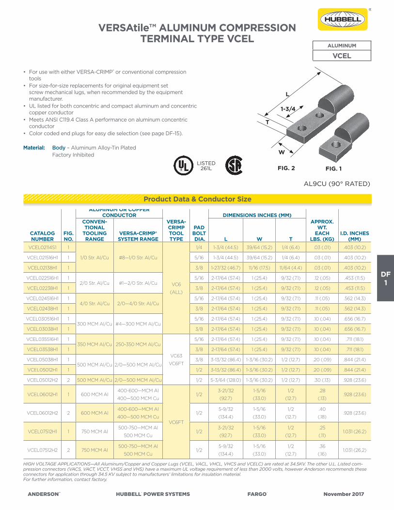
ANDERSON™ HUBBELL® POWER SYSTEMS FARGO® November 2017
DF1
VERSAtile™ ALUMINUM COMPRESSION TERMINAL TYPE VCEL
• For use with either VERSA-CRIMP® or conventional compression tools
• For size-for-size replacements for original equipment set screw mechanical lugs, when recommended by the equipment manufacturer.
• UL listed for both concentric and compact aluminum and concentric copper conductor
• Meets ANSI C119.4 Class A performance on aluminum concentric conductor
• Color coded end plugs for easy die selection (see page DF-15).
Material: Body – Aluminum Alloy-Tin Plated Factory Inhibited
ALUMINUM
VCEL
CATALOG NUMBER
FIG.NO.
ALUMINUM OR COPPER CONDUCTOR
VERSA-CRIMPTOOLTYPE
PAD BOLT DIA.
DIMENSIONS INCHES (MM)APPROX.
WT.EACH
LBS. (KG)I.D. INCHES
(MM)
CONVEN-TIONAL
TOOLING RANGE
VERSA-CRIMP®SYSTEM RANGE L W T
VCEL02114S1 1
1/0 Str. Al/Cu #8—1/0 Str. Al/Cu
VC6
(ALL)
1/4 1-3/4 (44.5) 39/64 (15.2) 1/4 (6.4) .03 (.01) .403 (10.2)
VCEL021516H1 1 5/16 1-3/4 (44.5) 39/64 (15.2) 1/4 (6.4) .03 (.01) .403 (10.2)
VCEL02138H1 1 3/8 1-27/32 (46.7) 11/16 (17.5) 11/64 (4.4) .03 (.01) .403 (10.2)
VCEL022516H1 12/0 Str. Al/Cu #1—2/0 Str. Al/Cu
5/16 2-17/64 (57.4) 1 (25.4) 9/32 (7.1) .12 (.05) .453 (11.5)
VCEL02238H1 1 3/8 2-17/64 (57.4) 1 (25.4) 9/32 (7.1) .12 (.05) .453 (11.5)
VCEL024516H1 14/0 Str. Al/Cu 2/0—4/0 Str. Al/Cu
5/16 2-17/64 (57.4) 1 (25.4) 9/32 (7.1) .11 (.05) .562 (14.3)
VCEL02438H1 1 3/8 2-17/64 (57.4) 1 (25.4) 9/32 (7.1) .11 (.05) .562 (14.3)
VCEL030516H1 1300 MCM Al/Cu #4—300 MCM Al/Cu
5/16 2-17/64 (57.4) 1 (25.4) 9/32 (7.1) .10 (.04) .656 (16.7)
VCEL03038H1 1 3/8 2-17/64 (57.4) 1 (25.4) 9/32 (7.1) .10 (.04) .656 (16.7)
VCEL035516H1 1350 MCM Al/Cu 250-350 MCM Al/Cu
VC63
VC6FT
5/16 2-17/64 (57.4) 1 (25.4) 9/32 (7.1) .10 (.04) .711 (18.1)
VCEL03538H1 1 3/8 2-17/64 (57.4) 1 (25.4) 9/32 (7.1) .10 (.04) .711 (18.1)
VCEL05038H1 1500 MCM Al/Cu 2/0—500 MCM Al/Cu
3/8 3-13/32 (86.4) 1-3/16 (30.2) 1/2 (12.7) .20 (.09) .844 (21.4)
VCEL05012H1 1 1/2 3-13/32 (86.4) 1-3/16 (30.2) 1/2 (12.7) .20 (.09) .844 (21.4)
VCEL05012H2 2 500 MCM Al/Cu 2/0—500 MCM Al/Cu 1/2 5-3/64 (128.0) 1-3/16 (30.2) 1/2 (12.7) .30 (.13) .928 (23.6)
VCEL06012H1 1 600 MCM Al400-600—MCM Al
400—500 MCM Cu
VC6FT
1/23-21/32
(92.7)
1-5/16
(33.0)
1/2
(12.7)
.28
(.13).928 (23.6)
VCEL06012H2 2 600 MCM Al400-600—MCM Al
400—500 MCM Cu1/2
5-9/32
(134.4)
1-5/16
(33.0)
1/2
(12.7)
.40
(.18).928 (23.6)
VCEL07512H1 1 750 MCM Al500-750—MCM Al
500 MCM Cu1/2
3-21/32
(92.7)
1-5/16
(33.0)
1/2
(12.7)
.25
(.11)1.031 (26.2)
VCEL07512H2 2 750 MCM Al500-750—MCM Al
500 MCM Cu1/2
5-9/32
(134.4)
1-5/16
(33.0)
1/2
(12.7)
.36
(.16)1.031 (26.2)
HIGH VOLTAGE APPLICATIONS—All Aluminum/Copper and Copper Lugs (VCEL, VACL, VHCL, VHCS and VCELC) are rated at 34.5KV. The other U.L. Listed com-pression connectors (VACS, VACT, VCCT, VHSS and VHS) have a maximum UL voltage requirement of less than 2000 volts, however Anderson recommends these connectors for application through 34.5 KV subject to manufacturers’ limitations for insulation material.For further information, contact factory.
AL9CU (90° RATED)
LISTED261L FIG. 2 FIG. 1
L
1-3/4
W
T
Product Data & Conductor Size

ANDERSON™ HUBBELL® POWER SYSTEMS FARGO® November 2017
DF2
VERSAtile™ ALUMINUM COMPRESSION TERMINAL TYPE VACL
• For use with either VERSA-CRIMP® or conventional compression tools.
• UL listed for aluminum or copper conductors.• Factory inhibited• Color coded end plugs for easy die selection (see page DF-16 and
DF-17).
Material: Body – Aluminum Alloy-Tin Plated
ALUMINUM
VACL
CATALOG NUMBER
NO.PAD
HOLES
ALUMINUM OR COPPER CONDUCTOR
VERSA-CRIMPTOOLTYPE
PAD BOLT DIA.
DIMENSIONS INCHES (MM)APPROX.
WT.EACH
LBS. (KG)
I.D. INCHES
(MM)
CONVENTION-AL TOOLING
RANGEVERSA-CRIMP®SYSTEM RANGE L D W T
VACL414 1
#4 Str. Al/Cu #4 Str. Al/Cu VC6350
1/42-5/16
(58.7)
1
(25.4)
13/16
(20.6)
1/8
(3.2)
.02
(.01)
.252
(6.4)
VACL438 1 3/82-5/16
(58.7)
1
(25.4)
13/16
(20.6)
1/8
(3.2)
.02
(.01)
.252
(6.4)
VACL214 1
#2 Str. Al/Cu #6—#2 Str. Al/Cu
VC6
(ALL)
1/42-1/2
(63.5)
1-1/8
(28.4)
7/8
(22.2)
3/16
(4.8)
.04
(.02)
.312
(7.9)
VACL2516 1 5/162-1/2
(63.5)
1-1/8
(28.4)
7/8
(22.2)
3/16
(4.8)
.04
(.02)
.312
(7.9)
VACL238 1 3/82-1/2
(63.5)
1-1/8
(28.4)
7/8
(22.2)
3/16
(4.8)
.04
(.02)
.312
(7.9)
VACL1516 1
#1 Str. Al/Cu #4—#1 Str. Al/Cu
5/162-3/4
(69.9)
1-1/8
(28.4)
3/4
(19.0)
3/16
(4.8)
.05
(.02)
.350
(8.9)
VACL138 1 3/82-3/4
(69.9)
1-1/8
(28.4)
3/4
(19.0)
3/16
(4.8)
.05
(.02)
.350
(8.9)
VACL1038 1
1/0 Str. Al/Cu #8—1/0 Str. Al/Cu
3/82-15/16
(74.6)
1-5/16
(33.3)
13/16
(20.6)
3/16
(4.8)
.05
(.02)
.393
(10.0)
VACL1012 1 1/23-1/8
(79.4)
1-5/16
(33.3)
13/16
(20.6)
3/16
(4.8)
.05
(.02)
.393
(10.0)
VACL1012BN 2 1/24-7/8
(128.8)
1-5/16
(33.3)
13/16
(20.6)
3/16
(4.8)
.05
(.02)
.393
(10.0)
VACL2038 1
2/0 Str. Al/Cu #4—2/0 Str. Al/Cu
3/82-15/16
(74.6)
1-5/16
(33.3)
15/16
(23.8)
1/4
(6.3)
.07
(.03)
.450
(11.4)
VACL2012 1 1/23-1/8
(79.4)
1-5/16
(33.3)
15/16
(23.8)
1/4
(6.3)
.07
(.03)
.450
(11.4)
VACL2012BN 2 1/24-7/8
(128.8)
1-5/16
(33.3)
15/16
(23.8)
1/4
(6.3)
.12
(.05)
.450
(11.4)
Continued on next page.
HIGH VOLTAGE APPLICATIONS—All Aluminum/Copper and Copper Lugs (VCEL, VACL, VHCL, VHCS and VCELC) are rated at 34.5KV. The other U.L. Listed com-pression connectors (VACS, VACT, VCCT, VHSS and VHS) have a maximum UL voltage requirement of less than 2000 volts, however Anderson recommends these connectors for application through 34.5 KV subject to manufacturers’ limitations for insulation material.
AL9CU (90° RATED)
LD
W
T
LISTED261L
Product Data & Conductor Size

ANDERSON™ HUBBELL® POWER SYSTEMS FARGO® November 2017
DF3
TYPE VACL ALUMINUM COMPRESSION TERMINAL (CONTINUED)
CATALOG NUMBER
NO.PAD
HOLES
ALUMINUM OR COPPER CONDUCTOR
VERSA-CRIMPTOOLTYPE
PAD BOLT DIA.
DIMENSIONS INCHES (MM)APPROX.
WT.EACH
LBS. (KG)
I.D. INCHES
(MM)
CONVENTION-AL TOOLING
RANGEVERSA-CRIMP®SYSTEM RANGE L D W T
VACL3038 1
3/0 Str. Al/Cu #4—3/0 Str. Al/Cu
VC6
(ALL)
3/83
(76.2)
1-5/16
(33.3)
1-1/16
(26.99)
1/4
(6.3)
.10
(.04)
.502
(12.8)
VACL3012 1 1/23-3/16
(81.0)
.10
(.04)
.502
(12.8)
VACL3012BN 2 1/24-15/16
(125.4)
.16
(.07)
.502
(12.8)
VACL4038 1
4/0 Str. Al/Cu #2—4/0 Str. Al/Cu
3/83-15/16
(84.1)
1-1/2
(38.1)
1-1/4
(31.7)
1/4
(6.3)
.13
(.06)
.562
(14.3)
VACL4012 1 1/23-1/2
(88.9)
.13
(.06)
.562
(14.3)
VACL4012BN 2 1/25-1/4
(133.3)
.20
(.09)
.562
(14.3)
VACL25012 1
250 MCM Al/Cu 1/0—250 MCM Al/Cu
1/23-9/16
(90.5) 1-1/2
(38.1)
1-1/4
(31.7)
5/16
(7.9)
.16
(.07)
.605
(15.4)
VACL25012BN 2 1/25-5/16
(134.9)
.25
(.11)
.605
(15.4)
VACL30012 1
300 MCM Al/Cu 1/0—300 MCM Al/Cu
1/23-3/4
(95.2) 1-1/2
(38.1)
1-3/8
(34.9)
3/8
(90.5)
.19
(.09)
.660
(16.8)
VACL30012BN 2 1/25-1/2
(139.7)
.31
(.14)
.670
(17.0)
VACL35012 1
350 MCM Al/Cu 2/0—350 MCM Al/Cu
VC63
VC6FT
1/24-1/16
(103.2) 1-5/8
(41.3)
1-1/2
(38.1)
3/8
(9.5)
.31
(.14)
.711
(18.1)
VACL35012BN 2 1/25-13/16
(147.6)
.36
(.16)
.711
(18.1)
VACL40012BN 2 400 MCM Al/Cu 3/0—400 MCM Al/Cu 1/26
(152.4)
1-13/16
(46.0)
1-5/8
(41.3)
7/16
(11.1)
.45
(.20)
.758
(19.3)
VACL50012 1
500 MCM Al/Cu 4/0—500 MCM Al/Cu
1/24-11/16
(119.0) 2-5/16
(58.7)
1-11/16
(42.9)
3/8
(9.5)
.44
(.20)
.843
(21.4)
VACL50012BN 2 1/26-7/16
(163.5)
.62
(.28)
.843
(21.4)
VACL60012BN 2 600 MCM Al350—-600 MCM Al
350-500 MCM Cu
VC6FT
VC8
1/27-1/8
(180.98)
2-5/16
(74.6)
1-7/8
(47.7)
7/16
(11.1)
.72
(.33)
.923
(23.4)
VACL75012 1
750 MCM Al500—750 MCM Al
500 MCM Cu
1/25-3/8
(136.52) 2-5/16
(74.6)
1-15/16
(49.2)
5/16
(7.9)
.85
(.38)
1.028
(26.1)
VACL75012BN 2 1/27-1/8
(180.98)
.98
(.44)
1.028
(26.1)
VACL100012BN 2 1000 MCM Al 750—1000 MCM Al VC8 1/27-13/16
(198.4)
2-3/4
(69.8)
2-5/8
(.667)
11/16
(17.5)
1.42
(.64)
1.182
(30.0)
Refer to pages DF-16 and DF-17 for recommended tool and die information.
Note: All two hole terminals are on NEMA 1-3/4” centers.
HIGH VOLTAGE APPLICATIONS—All Aluminum/Copper and Copper Lugs (VCEL, VACL, VHCL, VHCS and VCELC) are rated at 34.5KV. The other U.L. Listed com-pression connectors (VACS, VACT, VCCT, VHSS and VHS) have a maximum UL voltage requirement of less than 2000 volts, however Anderson recommends these connectors for application through 34.5 kV subject to manufacturers’ limitations for conductor insulation material.
Product Data & Conductor Size

ANDERSON™ HUBBELL® POWER SYSTEMS FARGO® November 2017
DF4
BI-METALLIC PIN TERMINALS FOR JOININGALUMINUM CONDUCTORS TO
COPPER EQUIPMENT TYPES PT & PTHALUMINUM
PT & PTH
• For use with VERSA-CRIMP® or die-type tooling• Sleeve connector is factory compressed over knurled surface of
tinned annealed copper rod.• Provides a compatible bi-metallic transition for joining aluminum
conductor to copper based transformer or other equipment terminals. Installed with popular dies.
• Prefilled with rubber compatible electrical joint compound and plugged.
Material: Aluminum Copper Rod Tin Plated
CATALOG NUMBER
CONDUCTOR RANGERECOMMENDEDCRIMPING DIE
CODES/VC-TOOLS
APIN
(DIA.)
LINCHES
(MM)
BINCHES
(MM)COLORCODE
CONVENTIONAL COMPRESSION VERSA CRIMP
ALUM ACSR INCHES ALUM INCHES
PT64254 Sol., 6 Str.
& 6 Comp6 .167-.206
#8 Str. - #4 Sol. Al.
#6 ACSR.146-.206
ANDERSON-VC6
(ALL)
EEI8A
BURNDY-BG,243
KEARNEY-5/8
ALCOA-08AH
T&B-TU 52
BLACKBURN-5/8
4 Sol.
(.204”)
2-1/2
(63.5)
1
(25.4)BLUE
PT44252 Sol., 3-4 Str.
& 4 Comp4 .204-.258
#8 Str. - #2 Sol. Al.
#6-#4 ACSR.146-.258
4 Sol.
(.204”)
2-1/2
(63.5)
1
(25.4)
OR-
ANGE
PT24251-2 Str. 1/0 Sol.
2 Comp Str.2 .268-.328
#8-#1 Str. Al.
#6-#2 ACSR.146-.328
4 Sol.
(.204”)
2-1/2
(63.5)
1
(25.4)RED
PT2261-2 Str. 1/0 Sol.
2 Comp Str.2 .268-.328
#8-#1 Str. Al.
#6-#2 ACSR.146-.328
2 Sol.
(.258”)
6
(152.4)
1
(25.4)RED
PTH2261-2 Str. 1/0 Sol.
2 Comp Str.2 .268-.328
#8-#1 Str. Al.
#6-#2 ACSR.146-.328
2 Sol.
(.258”)
6
(152.4)
1-3/4
(44.4)RED
PT102S251/0 Str.
1/0 Comp1/0 .336-.398
#8-1/0 Str. Al.
#8-1/0 ACSR.146-.398
2 Sol.
(.258”)
2-1/2
(63.5)
1
(25.4)YELLOW
PT102S61/0 Str.
1/0 Comp1/0 .336-.398
#8-1/0 Str. Al.
#8-1/0 ACSR.146-.398
2 Sol.
(.258”)
6
(152.4)
1
(25.4)YELLOW
PTH10261/0 Str.
1/0 Comp1/0 .336-.398
#8-1/0 Str. Al.
#8-1/0 ACSR.146-.398
2 Sol.
(.258”)
6
(152.4)
1-3/4
(44.4)YELLOW
PT10261/0 Str.
1/0-2/0 Comp1/0 .336-.398
#4-1/0 Str. Al.
#4-1/0 ACSR.232-.398
ANDERSON-VC6
(ALL)
EEI11A
BURNDY-249,840
KEARNEY-840
ALCOA-11AH
T&B-TX 76
BLACKBURN-840
or B49 ea.
2 Sol.
(.258”)
6
(152.4)
1-7/8
(47.75)YELLOW
PT2010252/0 Str.
3/0 Comp2/0 .414-.448
#4-2/0 Str. Al.
#4-2/0 ACSR.232-.448
1/0 Sol.
(.325”)
2-1/2
(63.5)
1-7/8
(47.75)GRAY
PT201062/0 Str.
3/0 Comp2/0 .414-.448
#4-2/0 Str. Al.
#4-2/0 ACSR.232-.448
1/0 Sol.
(.325”)
6
(152.4)
1-7/8
(47.75)GRAY
PT301063/0 Str.
4/0 Comp3/0 .464-.502
#4-3/0 Str. Al.
#4-3/0 ACSR.232-.502
1/0 Sol.
(.325”)
6
(152.4)
1-7/8
(47.75)BLACK
PT402064/0-250 Str.
250-300 Comp4/0 .522-.575
#4-250 Str. Al.
#5-4/0 ACSR.232-.575
2/0 Sol.
(.365”)
6
(152.4)
1-7/8
(47.75)PINK
PT349406300-350 Str.
350-400 Comp336-18/1 .618-.684
#1-350 Str.
#1-336-18/1.328-.684
4/0 Sol.
(.460”)
6
(152.4)
1-7/8
(47.75)NONE
PT300506250-300 Str.
300-350 Comp.
4/0
266-18/1.564-.630
3/0-300 Str.
3/0-266.8-18/1.464-.630
ANDERSON-VC6FT
VC6500 & VC63
EEI13A; ALCOA-13AH
BURNDY-316,655,705
KEARNEY-1-1/8
T&B-96
BLACKBURN
B80 ea.
4/0 Sol.
(.460”)
6
(152.4)
2-7/8
(73.15)NONE
PT350506300-350 Str.
350-400 Comp.
266-6/7
336-18/1.616-.684
3/0-350 Str.
3/0-336.4-18/1.464-.684
4/0 Sol.
(.460”)
6
(152.4)
2-7/8
(73.15)NONE
PT400506336-400 Str.
500 Comp. Str.
336-36/1
397-18/1.666-.743
4/0-400 Str.
4/0-397-18/1.522-.743
4/0 Sol.
(.460”)
6
(152.4)
2-7/8
(73.15)NONE
PT500506450-500 Str.
600 Comp. Str.
397-18/1
477-18/1.743-.814
4/0-500 Str.
4/0-477-18/1.522-.814
4/0 Sol.
(.460”)
6
(152.4)
2-7/8
(73.15)NONE
PT800756700-800 Str.
1000 Comp. Str.
605-26/7
715-36/1.964-1.031
600-800 Str.
605-36/1-715-36/1.891-1.031
ANDERSON VC8
BURNDY 301, 342, 608,
724, 786
KEARNEY-1 1/2
ALCOA-24 AH
T&B-125
3/4
(.750”)
6
(152.4)
2-7/8
(73.15)NONE

ANDERSON™ HUBBELL® POWER SYSTEMS FARGO® November 2017
DF5
VERSAtile™ ALUMINUM COMPRESSION TERMINAL TYPE VAUL
ALUMINUM
VAUL
• For use with either VERSA-CRIMP® or conventional compression tools.
• Meets ANSI C 119.4 Class A performance on aluminum and ACSR conductor, minimum tension.
• Meets ANSI C 119.4 Class C performance on copper conductor, minimum tension.
• Connector barrels are prefilled with “Versa-Seal®” rubber compatible inhibitor and sealed with color coded (thru 4/0) end caps.
• Metal marked to indicate recommended conductors and crimp dies.
Material: Aluminum
Note: Add Suffix “TP” for tin plated lugs.
CATALOG NUMBER
FIG. NO.
CONDUCTOR RANGE AWF OR MCM
CRIMPDIES/
VC-TOOLCOLORCODE
DIMENSIONS INCHES (MM)
AP-PROX.
WT.EACHLBS.(KG.)
I.D. INCH-
ES (MM)
VERSA-CRIMP® SYSTEM CONVENTIONAL TOOLING RANGEINCH-
ESDIA.
RANGE CABLE RANGE
INCH-ES
DIA.RANGE ACSR
STRAND-ED
(SOLID)COM-PACT L W D T
VAUL812 1
.146
thru
.162
#8 STR AL-CU
(#6 SOL)
.146
thru
.162
—#8 AL-CU
(#6 SOL)—
VC6350
VC6
VC6FT
EEI8A
BURNDY
BG. 243
KEARNEY
5/8
T&B
TU.52
BLACK-
BURN
5/8
GREEN3.06
(77.7)
.90
(22.8)
1.25
(31.7)
.27
(6.8)
.087
(0.04)
.186
(4.8)
VAUL612 1
.146
thru
.204
#8 STR #4 SOL
AL-CU
#6 ACSR
.184
thru
.204
#6 (6/1)#6 AL-CU
(#4 SOL)— BLUE
3.06
(77.7)
.90
(22.8)
1.25
(31.7)
.27
(6.8)
.076
(0.04)
.233
(5.9)
VAUL412 1 .146
thru
.268
#8 STR - #2 SOL
AL-CU
#6-#4 ACSR
#6-#2 COMP
.232
thru
.268
#4 (6/1),
(7/1)
#4 AL-CU
(#2 SOL)#2
OR-
ANGE
3.06
(77.7)
.90
(22.8) 1.25
(31.7)
.27
(6.8)
.074
(0.03)
.281
(7.1)
VAUL412BN 24.80
(121.9)
1.00
(25.4)
.31
(7.8)
.129
(0.06)
.281
(7.1)
VAUL112 1 .146
thru
.332
#8 STR. #1 STR
AL-CU
#6-#2 ACSR
#6-#1 COMP
.292
thru
.332
#2 (6/1),
(7/1)#2-#1 AL-CU #1 RED
3.06
(77.7)
.90
(22.8) 1.25
(31.7)
.27
(6.8)
.069
(0.03)
.355
(9.0)
VAUL112BN 24.80
(121.9)
1.00
(25.4)
.31
(7.8)
.129
(0.06)
.355
(9.0)
VAUL1012 1 .146
thru
.398
#8 STR-1/0 STR
AL-CU
#6-1/0 ACSR
#6-2/0 COMP
.336
thru
.398
1/0 (6/1) 1/0 AL-CU 1/0-2/0YEL-
LOW
3.06
(77.7)
.90
(22.8) 1.25
(31.7)
.27
(6.8)
.065
(0.03)
.416
(10.6)
VAUL1012BN 24.80
(121.9)
1.00
(25.4)
.31
(7.8)
.120
(0.05)
.416
(10.6)
VAULH612 1
.146
thru
.204
#8 STR. #4 SOL
AL-CU
#6 ACSR
.169
thru
.204
#6 (6/1)#6 AL-CU
(#4 SOL)#6 VC6350
VC6
VC6FT
EEI11A
BURNDY
K840
249
KEARNEY
840
T&B
TX, 76
BLACK-
BURN
840
B49EA
BLUE3.25
(82.5)
.96
(24.2)
1.43
(36.3)
.25
(6.4)
.135
(0.06)
.218
(5.5)
VAULH412 1
.146
thru
.258
#8 STR-#2 SOL
AL-CU
#6-#4 ACSR
#6-#4 COMP
.213
thru
.258
#4 (6/1),
(7/1)
#4 AL-CU
(#2 SOL)#4
OR-
ANGE
3.25
(82.5)
.96
(24.2)
1.43
(36.3)
.25
(6.4)
.132
(0.06)
.272
(6.9)
VAULH112 1 .146
thru
.332
#8 STR-#1 AL-CU
#6-#2 ACSR
#6-#1 COMP
.268
thru
.332
#2 (6/1),
(7/1)#2-#1 AL-CU #2 - #1 RED
3.25
(82.5)
.96
(24.2)
1.43
(36.3)
.25
(6.4)
.127
(0.06)
.340
(8.6)
VAULH112BN 25.75
(146.0)
1.25
(31.7)
1.87
(47.5)
.25
(6.4)
.224
(0.10)
.340
(8.6)
VAULH1012 1 .213
thru
.398
#4 STR-1/0 AL-CU
#4-1/0 ACSR
#4-2/0 COMP
.336
thru
.398
1/0 (6/1) 1/0 AL-CU 1/0-2/0YEL-
LOW
3.25
(82.5)
.96
(24.2)
1.43
(36.3)
.25
(6.4)
.121
(0.05)
.412
(10.5)VAUL-
H1012BN2
5.75
(146.0)
1.25
(31.7)
1.87
(47.5)
.25
(6.4)
.217
(0.10)
.412
(10.5)
VAUL2012 1 .213
thru
.447
#4 STR-2/0 AL-CU
#4-2/0 ACSR
#4-3/0 COMP
.414
thru
.447
2/0(6/1) 2/0 AL-CU 3/0 GRAY
3.25
(82.5)
.96
(24.4)
1.43
(36.3)
.25
(6.4)
.116
(0.05).472
VAUL2012BN 25.75
(146.0)
1.25
(31.7)
1.87
(47.5)
.25
(6.4)
.209
(0.09).472
Continued on next page.
Product Data & Conductor Size

ANDERSON™ HUBBELL® POWER SYSTEMS FARGO® November 2017
DF6
TYPE VAUL ALUMINUM COMPRESSION TERMINAL (CONTINUED)
CATALOG NUMBER
FIG. NO.
CONDUCTOR RANGE AWF OR MCM
CRIMPDIES/
VC-TOOLCOLORCODE
DIMENSIONS INCHES (MM)
AP-PROX.WT.
EACHLBS.(KG.)
I.D. INCH-
ES (MM)
VERSA-CRIMP® SYSTEM CONVENTIONAL TOOLING RANGEINCHES
DIA.RANGE CABLE RANGE
INCHESDIA.
RANGE ACSRSTRANDED
(SOLID)COM-PACT L W D T
VAUL3012 1 .213thru.502
#4 STR-3/0 AL-CU#4-3/0 ACSR#4-4/0 COMP
.464thru.502
3/0 (6/1) 3/0 AL-CU 4/0
VC6350VC6
VC6FTEEI11A
BURNDYK840249
KEARNEY840T&B
TX, 76BLACKBURN
840B49EA
BLACK
3.25(82.5)
.96(24.4)
1.43(36.3)
.25(6.4)
.109(0.05)
.534
VAUL3012BN 25.75
(146.0)1.25
(31.7)1.87
(47.5).25
(6.4).200
(0.09).534
VAUL4012 1
.213thru.575
#4 STR-250 AL-CU#5-4/0 ACSR#4-300 COMP
.520thru.575
4/0 (6/1)4/0-250 AL-CU
250-300 PINK
3.25(82.5)
.96(24.4)
1.43(36.3)
.25(6.4)
.101(0.05)
.595
VAUL4012BN 25.75
(146.0)1.25
(31.7)1.87
(47.5).25
(6.4).190
(0.09).595
VAUL25012 1 .336thru.575
1/0-250 STR AL-CU1/0-4/0 ACSR1/0-300 COMP
.563thru.575
4/0 (6/1) 250 AL-CU 300
VC6350VC6
VC6FTEEI12A
BURNDY251
KEARNEY29/32T&B
TH,87BLACKBURN
B61EA
—
4.59(116.6)
1.25(31.7)
2.44(62.0)
.37(9.4)
.260(0.12)
.605
VAUL25012BN 26.34
(161.0)1.25
(31.7)2.44
(62.0).37
(9.4).339(0.15)
.605
VAUL30012 1 .376thru.630
2/0-300 STR AL-CU2/0-266.8 (18/1) ACSR
2/0-350 COMP
.609thru.630
266.8 (18/1)
300 AL-CU 350 —
4.59(116.6)
1.25(31.7)
2.44(62.0)
.37(9.4)
.247(0.11)
.660
VAUL30012BN 26.34
(161.0)1.25
(31.7)2.44
(62.0).37
(9.4).326(0.15)
.660
VAUL35012 1 .376thru.684
2/0-350 STR AL-CU2/0-336.4 (18/1) ACSR
2/0-400 COMP
.659thru.684
336.4 (18/1)
336-350 AL-CU
400 —
4.59(116.6)
1.25(31.7)
2.44(62.0)
.37(9.4)
.234(0.11)
.711
VAUL35012BN 26.34
(161.0)1.25
(31.7)2.44
(62.0).37
(9.4).312
(0.14).711
VAUL36012 1.475thru.684
4/0-350 STR AL-CU4/0-336.4 (18/1) ACSR
4/0-400 COMP
.609thru.684
266.8 (18/1), (26/7)336.4 (18/1)
300-350 AL-CU
350-400 VC6VC6FTEEI13A
BURNDY316, 472655, 705
KEARNEY1-1/8T&B96
BLACKBURNB80EA
—
4.444(112.8)
1.25(31.7)
2.37(60.2)
.37(9.4)
.273(0.12)
.738
VAUL36012BN 26.18
(157.0)1.25
(31.7)2.37
(60.2).37
(9.4).344(0.16)
.738
VAUL40012 1.475thru.743
4/0-400 STR AL-CU4/0-397.5 (18/1) ACSR
4/0-500 COMP
.679thru.743
336.4 (18/1), (26/7), (30/7)
397.5(18/1)
350-400 AL-CU
450-500 —
4.444(112.8)
1.25(31.7)
2.37(60.2)
.37(9.4)
.258(0.12)
.791
VAUL40012BN 26.18
(157.0)1.25
(31.7)2.37
(60.2).37
(9.4).329(0.15)
.791
VAUL50012 1.520thru.814
4/0-500 STR AL4/0-477 (18/1) ACSR
250-600 COMP
.772thru.814
397.5 (24/7), (26/7)
477 (18/1), (36/1)
450-500 AL 550-600 —
4.444(112.8)
1.25(31.7)
2.37(60.2)
.37(9.4)
.243(0.11)
.843
VAUL50012BN 26.18
(157.0)1.50
(38.1)2.88(73.1)
.37(9.4)
.390(0.18)
.843
VAUL60012BN 2.609thru.879
300-600 STR AL266.8-556.5 (18/1) ACSR
350-700 COMP
.845thru.893
477 (24/7), (26/7)556.5 (36/1), (18/1)
550-600 AL 650-700
VC6FTVC8
EEI14ABURNDY317, 327,
719KEARNEY
1-5/16T&B106
BLACKBURNB20AH
—6.87
(174.5)1.37
(34.8)3.00(76.2)
.56(14.2)
.550(0.25)
.924
VAUL75012BN 2.806thru.988
500-750 STR AL477-715.5 (36/1) ACSR
600-800 COMP
.908thru.998
556.5 (30/7)
636 (18/1)605 (24/7),
(26/7)715.5 (36/1)
700-750 AL 750-800 —6.87
(174.5)1.37
(34.8)3.00(76.2)
.56(14.2)
.503(0.23)
1.028
VAULH50012BN 2.520thru.814
4/0-500 STR AL-CU4/0-477 (18/1) ACSR
250-600 COMP
.743thru.814
397.5 (18/1), (24/7),(27/7), (30/7)
477 (36/1), (18/1)
450-500 AL-CU
550-600
VC8BURNDY
301,724, 786
KEARNEY1-1/2T&B140
ALCOA24AH
—7.25
(184.2)1.60
(40.6)3.19
(81.0).63
(16.0).898(0.41)
.843
VAULH70012BN 2.659thru.966
350-700 STR AL336.4-666.6 (18/1) ACSR
400-800 COMP
.891thru.966
556.5 (24/7), (26/7)
605 (24/7), (26/7), (36/1)
636 (18/1), (36/1)
600-700 AL 750-800 —7.25
(184.2)1.60
(40.6)3.19
(81.0).63
(16.0).827
(0.38)1.000
VAUL80012BN 2.806thru1.031
500-800 STR AL477-715.5 (36/1) ACSR
600-900 COMP
.964thru1.031
636 (24/7), (26/7)666.6 (24/7)
715.5 (36/1)
700-800 AL 900 —7.25
(184.2)1.60
(40.6)3.19
(81.0).63
(16.0).796
(0.36)1.062
VAUL100012BN 2.908thru1.152
650-1000 STR AL836-954 (36/1) ACSR
750-1000 COMP
1.092thru1.152
795 (24/7), (26/7)
900 (45/7)954 (36/1)
900-1000 AL — —7.25
(184.2)1.60
(40.6)3.19
(81.0).63
(16.0).726
(0.33)1.188
Product Data & Conductor Size

ANDERSON™ HUBBELL® POWER SYSTEMS FARGO® November 2017
DF7
CatalogNumber
VCEL
ANDERSON™ VERSA-CRIMP® COMPRESSION TOOLS(Crimps per Connection)
CONVENTIONAL COMPRESSION DIE TOOLING(Crimps per Connection)
V-C ToolsWire
Range
VERSA-CRIMP® Tools(Number of Crimps)
WireSize
kDie
Color*Code
Burndy Longi-tudinal Indent
(Crimps)Kearney(Crimps)
Thomas & Betts(Crimps)
†VC6500 VC6350VC6 j
VC6FT
VC8AL
NIBS
ToolsY35Y39Y45
Tools“WH”
ToolsTBM5TBM8
Hyd. Tools12, 15
20 & 40 Ton
Die Die Die Die
-021#8-1/0 Str.
AL/CU2 2 1 1
1/0 Str.
AL/CUTan U25ARTj (1)
Tan
(2
O’lap)
45
(1)
-022#1-2/0 Str.
AL/CU3
3
O’lap
2
O’lap
2
O’lap
2/0 Str.
AL/CUBlue U30ART (1)
29/32
or 1
† (1)
76H or
83H
(2)
-024
2/0-4/0
Str.
AL/CU
33
O’lap
2
O’lap
2
O’lap
4/0 Str.
AL/CUBlue U30ART (1)
29/32
or 1
† (1)
76H or
83H
(2)
-030
#4-300
MCM AL/
CU
33
O’lap
2
O’lap
2
O’lap
300
MCM
AL/CU
Blue U30ART (1)
29/32
or 1
† (1)
76H or
83H
(2)
-035250-350
MCM AL3 O’lap
2
O’lap
2
O’lap
350
MCM
AL
Blue U30ART (1)29/32
† (1)
76H
(2)
-050
2/0 - 500
MCM AL/
CU
4 O’lap 2 2
500
MCM
AL/CU
GreenU32 ART
(2)
1-1/8 - 1
(2 O’lap)
or 1-1/8 - 2
†(2)
94H
(3)
-060
400-600
MCM AL
500
MCM CU
2 2
600
MCM
AL
PinkUM or U34ART
(2)
1-1/4
+ † (2)
†106H
(3)
-075
500-750
MCM AL
500
MCM CU
2 2
750
MCM
AL
PinkU34ART
(2)
1-1/4
+ † (2)
† 106H
(3)
-100750-1000
MCM AL3
1000
MCM
AL
None
BURNDY TOOLS/DIES (VCEL - 100 ONLY)
Y48B Tool Y486RB Tool
DieNest
IndentorDie
NestIndentor
C44AR (2)C46D (1)
Y48PR-1
F44AR
(2)
F46D (1)
Y48PR-1
+ WH-2 Tool ONLY† Before making first crimp, make certain that the edge of the die block is located to clear the back edge of the “VCEL” tongue.j Partial crimp. Crimp dies extend beyond the end of the crimp barrel.k Color code is for Anderson and Burndy dies only. Use the recommended die number (NOT die color) for Kearney & T&B Hyd. Tools/Dies.* Not UL Listed-pending completion of test.
Crimping Die Information VCEL

ANDERSON™ HUBBELL® POWER SYSTEMS FARGO® November 2017
DF8
Cat
alog
Num
ber
VAC
L (3
)
VAC
S (4
)
VAC
T (4
)
AN
DER
SON
™ V
ERSA
-CR
IMP®
CO
MPR
ESSI
ON
TO
OLS
(Cri
mps
per
Con
nect
ion)
CO
NV
ENTI
ON
AL
CO
MPR
ESSI
ON
DIE
TO
OLI
NG
(Cri
mps
per
Con
nect
ion)
V-C
Too
lsW
ireR
ange
(AW
G o
rM
CM
)
VER
SA-C
RIM
P To
ols
(Num
ber
of C
rim
ps)
Wire
Size
(AW
Gor
MC
M)
Die
Col
orC
ode
(2)
Bur
ndy
(Cri
mps
)B
urnd
y In
dent
or T
ools
(1 C
rim
p)
*VC
650
0V
C6
350
VC
6(1
)
VC
6FT (1
)
VC
8A
LN
IBS
Die
Inde
xN
o.
Tool
Y34
A
Tool
sY
35Y
39To
olY
34B
Tool
Y4
8BTo
olY
486
RB
Tool
MY- 29
Tool
Y34
A(I
nden
-to
r)
Tool
Y34
B(I
nden
-to
r)
Tool
Y4
8B(I
nden
-to
r)
Tool
Y4
86R
B(I
nden
-to
r)D
ieD
ieD
ieD
ieD
ieD
ieN
est
Nes
tN
est
Nes
t
-8#
8 A
L/C
U1
1#
8A
L/C
UB
lue
374
U8C
AB
T(2
)#
8 (1)
-6#
6 A
L/C
U1
1#
6A
L/C
UG
ray
346
A6C
AB
(1)
U6C
AB
T(1
)B
6CD
(1)
#6 (1)
A4
CD
(Y34
PA)
B4
CD
(Y34
PA)
-4#
4 A
L/C
U2
2#
4A
L/C
UG
reen
375
A4
CA
B(1
)U
4C
AB
T*
(1)
B4
CD
(1)
C4
CA
B(1
)#
4 (1)
A1C
D(Y
34PA
)B
1CD
(Y34
PA)
-2#
6-#
2 A
L/C
U2
22
2#
2A
L/C
UP
ink
348
A2C
AB
(1)
U2C
AB
T(1
)B
2CD
(1)
#2
(2)
A26
D(Y
34PA
)B
26D
(Y34
PA)
-1#
8-#
1 AL/
CU
22
22
#1
AL/
CU
Tan
296
A25
AR
(1)
U25
AR
T*
(1)
B1C
D(1
)#
1(2
)A
27D
(Y34
PR
-5)
B27
D(Y
34P
R-5
)
-1/0
#8-
1/0
AL/
CU
22
22
1/0
AL/
CU
Tan
296
A25
AR
(1)
U25
AR
T*
(1)
B25
D(1
)1/
0(2
)A
27D
(Y34
PR
-5)
B27
D(Y
34P
R-5
)
-2/0
#4
-2/0
AL/
CU
22
22
2/0
AL/
CU
Oliv
e29
7A
26A
R(2
)U
26A
RT
(2)
B26
D(1
)2/
0(2
)A
29D
(Y34
PR
-5)
B29
D(Y
34P
R-5
)
-3/0
#4
-3/0
AL/
CU
22
22
3/0
AL/
CU
Rub
y4
67A
27A
R(2
)U
27A
RT
(2)
B27
D(1
)3/
0(2
)A
30D
(Y34
PR
-5)
B30
D(Y
34P
R-5
)
-4/0
#2-
4/0
AL/
CU
33
22
4/0
AL/
CU
Whi
te29
8A
28A
R(2
)U
28A
RT
(2)
B28
D(1
)C
28A
R(1
)F2
8AR
(1)
4/0
(2)
A31
D(Y
34P
R-5
)B
31D
(Y34
PR
-5)
-250
1/0
-250
AL/
CU
33
22
250
AL/
CU
Red
324
A29
AR
(2)
U29
AR
T(2
)B
29D
(1)
C29
AR
(1)
F29A
R(1
)A
32D
(Y34
PR
-5)
B32
D(Y
34P
R-5
)
-30
01/
0-3
00
AL/
CU
33
22
300
AL/
CU
Blu
e47
0A
30A
R(2
)U
30A
RT
(2)
B30
D(2
)C
30A
R(1
)F3
0A
R(1
)A
34D
(Y34
PR
-11)
No
Die
C34
D(Y
48P
R-1
)F3
4D
(Y4
8PR
-1)
-350 (1)
2/0
-350
AL/
CU
43
335
0A
L/C
UB
row
n29
9U
31A
RT
(2)
B31
D(2
)C
31A
R(1
)F3
1AR
(1)
C35
D(Y
48P
R-1
)F3
5D(Y
48P
R-1
)-4
00
(1)
3/0
-40
0 A
L/C
U5
4O
’lap
4O
’lap
40
0A
L/C
UG
reen
472
U32
AR
T(4
)B
32D
(2)
C32
AR
(2)
F32A
R(2
)C
36D
(Y4
8PR
-1)
F36D
(Y4
8PR
-1)
-50
0(1
)4/
0-5
00
AL/
CU
74
O’la
p4
O’la
p50
0A
L/C
UG
reen
472
U32
AR
T(4
)
No
Die
Req
uire
d(2
)
C32
AR
(2)
F32A
R(2
)
-60
035
0 -
60
0 A
L35
0 -
50
0 C
U4
360
0 A
LP
ink
300
U34
AR
T(4
)C
34A
R(2
)F3
4A
R(2
)
-750
500
- 7
50 A
L50
0 C
U4
375
0 A
LP
ink
300
U34
AR
T(4
)C
34A
R(2
)F3
4A
R(2
)
-10
00
750
-10
00
AL
310
00
AL
Bro
wn
302
C4
4A
R(2
)F4
4A
R(2
)C
46D
(Y4
8PR
-1)
F46D
(Y4
8PR
-1)
+ TB
M-8
Too
l ON
LYH
A
nder
son
HC
-12
Die
s, B
urnd
y’s
Y-35
Die
s an
d B
lack
bur
n’s
JB-1
2 D
ies
are
inte
rcha
ngea
ble
.(1
) “V
AC
L” L
ug s
izes
-35
0 t
o -5
00
tak
e 1 l
ess
crim
p (
VC
6 To
ols)
tha
n sh
own.
(2)
Col
or c
ode
is fo
r A
nder
son
and
Bur
ndy
die
s on
ly. U
se t
he r
ecom
men
ded
die
num
ber
(N
OT
die
col
or)
for
Bla
ckb
urn,
Kea
rney
& T
&B
Hyd
. Too
ls/D
ies.
(3)
The
“VA
CL”
lug
s ar
e q
ualifi
ed fo
r U
L “H
V”
app
licat
ions
.(4
) Th
e “V
AC
S” s
leev
es a
nd “
VAC
T” t
ee c
onne
ctor
s ar
e fo
r A
L to
AL
or A
L to
CU
con
nect
ions
ON
LY. (
NO
T fo
r C
U t
o C
U c
onne
ctio
ns).
* N
ot U
L Li
sted
-pen
din
g c
omp
letio
n of
tes
t.
VA
CL/
VA
CS/
VA
CT—
And
erso
n/B
urnd
y

ANDERSON™ HUBBELL® POWER SYSTEMS FARGO® November 2017
DF9
Cat
alog
Num
ber
VAC
L (3
)
VAC
S (4
)
VAC
T (4
)
AN
DER
SON
™ V
ERSA
-CR
IMP®
CO
MPR
ESSI
ON
TO
OLS
(Cri
mps
per
Con
nect
ion)
CO
NV
ENTI
ON
AL
CO
MPR
ESSI
ON
DIE
TO
OLI
NG
(Cri
mps
per
Con
nect
ion)
V-C
Too
lsW
ireR
ange
(AW
G o
rM
CM
)
VER
SA-C
RIM
P To
ols
(Num
ber
of C
rim
ps)
Wire
Size
(AW
Gor
MC
M)
Die
Col
orC
ode
(2)
Bla
ckbu
rn(C
rim
ps)
Kea
rney
(Cri
mps
)Th
omas
& B
etts
(Cri
mps
)
*VC
650
0V
C6
350
VC
6(1
)
VC
6FT (1
)
VC
8A
LN
IBS
Tool
OD
-58
Tool
JB-1
2A
Die
Tool
s(N
o. o
f Cri
mps
)
Tool
sTB
M5
TBM
8
12 T
on
Hyd
. To
ol
15 T
on
Hyd
. To
ol
Die
Die
O-5
2W
H-1
PH-1
WH
-2PH
-2D
ieD
ieD
ie
-8#
8 A
L/C
U1
1#
8A
L/C
UB
lue
BY
17C
(2)
B73
CH
(1)
1/4
(2)
Blu
e(1
)24 (1
)24 (1
)
-6#
6 A
L/C
U1
1#
6A
L/C
UG
ray
BY
19C
(3)
B74
CH
(1)
5/16
(3)
(1)
(1)
Gra
y(2
)29 (2
)29 (2
)
-4#
4 A
L/C
U2
2#
4A
L/C
UG
reen
BY
21C
(3)
U4
CA
BT
* (1
)3/
8(3
)(2
)(2
)G
reen
(2)
37 (2)
37 (2)
-2#
6-#
2 A
L/C
U2
22
2#
2A
L/C
UP
ink
BY
23C
(3)
BO
6CH
(1)
1/2
(3)
(2)
(2)
Pin
k(2
)4
5(2
)4
5(2
)
-1#
8-#
1 AL/
CU
22
22
#1
AL/
CU
Tan
BY
23C
(4)
U25
AR
T*
(1)
9/16
(4)
(2)
(2)
Tan
(2)
50 (2)
50 (2)
-1/0
#8-
1/0
AL/
CU
22
22
1/0
AL/
CU
Tan
BY
25C
(4)
U25
AR
T*
(1)
9/16
(4)
(2)
(2)
Tan
(2)
50 (2)
50 (2)
-2/0
#4
-2/0
AL/
CU
22
22
2/0
AL/
CU
Oliv
eB
Y31
C(4
)B
09C
H(2
)5/
8-1
(4)
(3)
(3)
Oliv
e(2
)54 (1
)54
H(2
)
-3/0
#4
-3/0
AL/
CU
22
22
3/0
AL/
CU
Rub
yB
Y27
C(5
)B
26C
H(2
)11/
16(5
)(3
)(3
)R
uby
(2)
62 (1)
62 (1)
-4/0
#2-
4/0
AL/
CU
33
22
4/0
AL/
CU
Whi
teB
Y35
C(5
)B
10C
H1
(2)
781
(5)
(3)
(3)
+Whi
te(4
)71
H(3
)71
H(3
)
-250
1/0
-250
AL/
CU
33
22
250
AL/
CU
Red
BY
37C
(5)
B11C
H(2
)84
0(5
)(3
)(3
)+R
ed(5
)76
H(3
)76 (2
)
-30
01/
0-3
00
AL/
CU
33
22
300
AL/
CU
Blu
eB
61E
A(1
)29
/32
(2)
(2)
+Blu
e(5
)87
H(3
)87
H(3
)-3
50 (1)
2/0
-350
AL/
CU
43
335
0A
L/C
UB
row
nB
12C
H1
(2)
1-1/
8-1
(2)
(2)
+Bro
wn
(5)
94H
(3)
94H
(3)
-40
0(1
)
3/0
-40
0 A
L/C
U5
4O
’lap
4O
’lap
40
0A
L/C
UG
reen
B80
EA
(2)
1-1/
8-1
(2)
(2)
99H
(3)
99H
(3)
-50
0(1
)
4/0
-50
0 A
L/C
U7
4O
’lap
4O
’lap
500
AL/
CU
Gre
enB
80E
A(3
)1-
1/8-
2(2
)(2
)96
H(4
)96 (2
)
-60
035
0 -
60
0 A
L35
0 -
50
0 C
U4
360
0 A
LP
ink
B20
AH
(3)
1-5/
16(4
)10
6H (5)
106H (5)
-750
500
- 7
50 A
L50
0 C
U4
375
0 A
LP
ink
B20
AH
(3)
1-5/
16(4
)10
6H (5)
106H (5)
-10
00
750
-10
00
AL
310
00
AL
Bro
wn
+ TB
M-8
Too
l ON
LYH
A
nder
son
HC
-12
Die
s, B
urnd
y’s
Y-35
Die
s an
d B
lack
bur
n’s
JB-1
2 D
ies
are
inte
rcha
ngea
ble
.(1
) “V
AC
L” L
ug s
izes
-35
0 t
o -5
00
tak
e 1 l
ess
crim
p (
VC
6 To
ols)
tha
n sh
own.
(2)
Col
or c
ode
is fo
r A
nder
son
and
Bur
ndy
die
s on
ly. U
se t
he r
ecom
men
ded
die
num
ber
(N
OT
die
col
or)
for
Bla
ckb
urn,
Kea
rney
& T
&B
Hyd
. Too
ls/D
ies.
(3)
The
“VA
CL”
lug
s ar
e q
ualifi
ed fo
r U
L “H
V”
app
licat
ions
.(4
) Th
e “V
AC
S” s
leev
es a
nd “
VAC
T” t
ee c
onne
ctor
s ar
e fo
r A
L to
AL
or A
L to
CU
con
nect
ions
ON
LY. (
NO
T fo
r C
U t
o C
U c
onne
ctio
ns).
* N
ot U
L Li
sted
-pen
din
g c
omp
letio
n of
tes
t.
VA
CL/
VA
CS/
VA
CT—
And
erso
n/O
ther
s
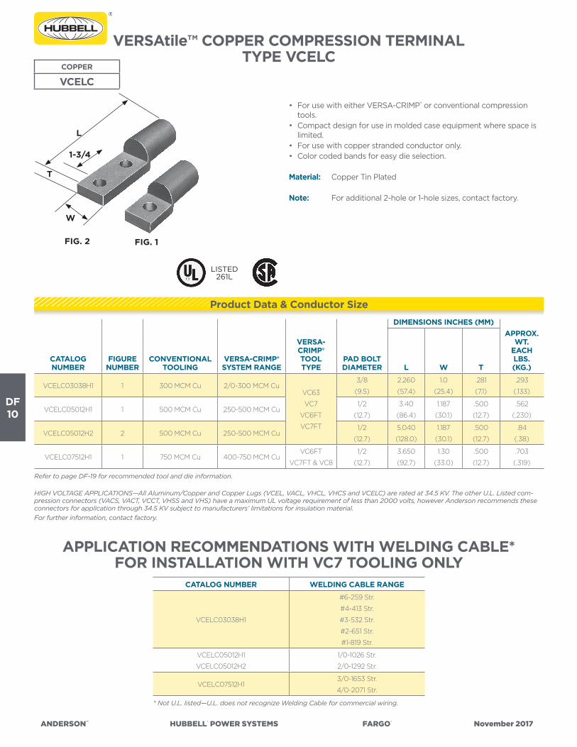
ANDERSON™ HUBBELL® POWER SYSTEMS FARGO® November 2017
DF10
VERSAtile™ COPPER COMPRESSION TERMINALTYPE VCELC
COPPER
VCELC
• For use with either VERSA-CRIMP® or conventional compression tools.
• Compact design for use in molded case equipment where space is limited.
• For use with copper stranded conductor only.• Color coded bands for easy die selection.
Material: Copper Tin Plated
Note: For additional 2-hole or 1-hole sizes, contact factory.
Refer to page DF-19 for recommended tool and die information.
HIGH VOLTAGE APPLICATIONS—All Aluminum/Copper and Copper Lugs (VCEL, VACL, VHCL, VHCS and VCELC) are rated at 34.5 KV. The other U.L. Listed com-pression connectors (VACS, VACT, VCCT, VHSS and VHS) have a maximum UL voltage requirement of less than 2000 volts, however Anderson recommends these connectors for application through 34.5 KV subject to manufacturers’ limitations for insulation material.For further information, contact factory.
CATALOG NUMBER
FIGURENUMBER
CONVENTIONALTOOLING
VERSA-CRIMP®SYSTEM RANGE
VERSA-CRIMP®TOOLTYPE
PAD BOLTDIAMETER
DIMENSIONS INCHES (MM)APPROX.
WT.EACHLBS.(KG.)L W T
VCELC03038H1 1 300 MCM Cu 2/0-300 MCM CuVC63
VC7
VC6FT
VC7FT
3/8
(9.5)
2.260
(57.4)
1.0
(25.4)
.281
(7.1)
.293
(.133)
VCELC05012H1 1 500 MCM Cu 250-500 MCM Cu1/2
(12.7)
3.40
(86.4)
1.187
(30.1)
.500
(12.7)
.562
(.230)
VCELC05012H2 2 500 MCM Cu 250-500 MCM Cu1/2
(12.7)
5.040
(128.0)
1.187
(30.1)
.500
(12.7)
.84
(.38)
VCELC07512H1 1 750 MCM Cu 400-750 MCM CuVC6FT
VC7FT & VC8
1/2
(12.7)
3.650
(92.7)
1.30
(33.0)
.500
(12.7)
.703
(.319)
APPLICATION RECOMMENDATIONS WITH WELDING CABLE*FOR INSTALLATION WITH VC7 TOOLING ONLY
* Not U.L. listed—U.L. does not recognize Welding Cable for commercial wiring.
CATALOG NUMBER WELDING CABLE RANGE
VCELC03038H1
#6-259 Str.
#4-413 Str.
#3-532 Str.
#2-651 Str.
#1-819 Str.
VCELC05012H1
VCELC05012H2
1/0-1026 Str.
2/0-1292 Str.
VCELC07512H13/0-1653 Str.
4/0-2071 Str.
FIG. 2 FIG. 1
L
1-3/4
W
T
LISTED261L
Product Data & Conductor Size

ANDERSON™ HUBBELL® POWER SYSTEMS FARGO® November 2017
DF11
CATALOG NUMBERVCELC
ANDERSON™ VERSA-CRIMP® COMPRECONVENTIONAL COMPRESSION DIE TOOLING
(Crimps Per Connection)
V-C ToolsWire Range
(Copper Only)
VERSA-CRIMP® Tools(Number of Crimps)A
CopperWireSize
DieColorCode
Burndy(Crimps)
Burndy(Crimps)
Kearney(Crimps) Thomas & Bet
VC6VC6-FT VC7
VC7-FT
VC8AL
NIBS
ToolY35 and
Y39Die
ToolMD-6Die
Tools“WH”
Die
ToolsTBM5TBM8Die
Hyd.Tools12, 15
20 & 40TonDie
030 2/0-300 MCM2
Overlap
2
Overlap
3
Overlap
3
Overlap300MCM Blue
U30ART
◊ (1)
29/32 or 1
(1)
76H or
83H
(2)
050 250-500 MCM 2 2 3 2 500 MCM GreenU32ART
◊ (2)
1-1/8-1 +
◊ (2 O’lap)
1-1/8-2+
◊ (2)
94H
(3)
075 400-750 MCM 2 2 2 750 MCM Pink
U-M or
U34ART
◊ (2)
1-1/4
(2)
106H
(3)
Note 2* Not U.L. Listed—U.L. does not recognize Welding Cable for commercial wiring.
APPLICATION RECOMMENDATIONS WITH WELDING CABLE *FOR INSTALLATION WITH VC7 TOOLING ONLY
CATALOGNUMBER
NUMBEROF
CRIMPS
WELDINGCABLERANGE
CATALOGNUMBER
NUMBEROF
CRIMPS
WELDINGCABLERANGE
VCELC03038H13
Overlap
#6-259 STR
#4-413 STR
#3-532 STR
#2-651 STR
#1-819 STR
VCELC05012H1 31/0-1026 STR
2/0-1292 STR
VCELC07512H1 33/0-1653 STR
4/0-2071 STR
Note 1+ WH-2 Tool only.◊ Before making first crimp, make certain that the edge of the die block is located to clear the back edge of the “VCELC” tongue.* Partial crimp. Crimp dies extend beyond the end of the crimp barrel.NOTE: “VCELC” copper equipment terminals cannot be used with type VC6350 tools.
VCELC

ANDERSON™ HUBBELL®POWERSYSTEMS FARGO® November2017
DISTRIBUTION CONNECTORS
TOOLSFargo “Speed” Hand WrenchesCable Reel Grounding Systems
Anderson® Versa-Crimp® Tools & Accessories
SE
CT
ION
DG

ANDERSON™ HUBBELL® POWER SYSTEMS FARGO® November 2017
DG1
DISTRIBUTION TOOLS SERIES GP FARGO CONNECTOR WRENCHES
• Design optimized for lineman use – handle separates both ends. (GP201-204 & GP216 are 1 piece style – see note)
• Specially constructed for proper and fast installation of mechanical connectors in utility distribution applications
Sturdy polypropylene handle provides protection from incidental end-to-end or energized line contact (all models except as noted).
Nine available wrench heads.
TOOLS
GP WRENCHES
CATALOG NUMBER
“A”END
DESCRIPTION FIGUREC
INCHES (MM)
“B”END
DESCRIPTION FIGURE
C INCHES
(MM)
LAPPROX.INCHES
(MM)WT. LB. (KG)
GP201* 3/8” Ratchet 1 one piece 9/16” Ratchet 1 one piece 6.75 (171.79) 0.75 (0.34)
GP203* 9/16” Ratchet 1 one piece 3/4” Ratchet 1 one piece 6.25 (159.06) 0.75 (0.34)
GP2031* 1/2” Ratchet 1 one piece 9/16” Ratchet 1 one piece 6.75 (171.79) 0.75 (0.34)
GP204* 11/16” Ratchet 1 one piece 15/16” Ratchet 1 one piece 9.25 (235.41) 0.75 (0.34)
GP216* 11/16” Ratchet 1 one piece 15/16” Ratchet 1 one piece 9.25 (235.41) 0.75 (0.34)
GP209 3/8” Allen Ratchet 4 1.21 (30.79) Eye Loop 9 1.00 (25.45) 7.50 (190.88) 0.75 (0.34)
GP2090P 3/8” Allen Ratchet 4 1.21 (30.79) Penta Socket 6 2.00 (50.90) 8.75 (222.69) 1.00 (0.45)
GP2090P4 3/8” Allen Ratchet 4 1.71 (43.52) Penta Socket 6 2.00 (50.90) 8.75 (222.69) 1.00 (0.45)
GP2090P90 3/8” Allen Ratchet 4 1.21 (30.79) 90° Penta Socket 7 2.50 (63.63) 9.25 (235.41) 1.00 (0.45)
GP2091P Penta Socket 6 1.91 (48.61) Eye Loop 9 1.00 (25.45) 7.50 (190.88) 0.75 (0.34)
GP2091P90 90 Penta Socket 7 2.37 (60.32) Eye Loop 9 1.00 (25.45) 8.00 (203.60) 0.75 (0.34)
GP2092M 3/8” Allen Ratchet 4 1.21 (30.79) 3/8” Allen Bar 3 1.25 (31.81) 8.00 (203.60) 0.75 (0.34)
GP2093 5/16” Allen Ratchet 4 1.46 (37.16) Eye Loop 9 1.00 (25.45) 7.75 (197.24) 0.75 (0.34)
GP2093P 5/16” Allen Ratchet 4 1.46 (37.16) Penta Socket 6 2.00 (50.90) 9.00 (229.05) 1.00 (0.45)
GP2093P90 5/16” Allen Ratchet 4 1.46 (37.16) 90° Penta Socket 7 2.50 (63.63) 9.25 (235.41) 1.00 (0.45)
GP209375P90 5/16” Allen Ratchet 4 0.75 (19.09) 90° Penta Socket 7 2.50 (63.63) 9.25 (235.41) 1.00 (0.45)
Figure 3Allen Bar
* These wrenches do not have polypropylene handle.
Figure 6Penta Socket
Figure 890° Penta Ratchet
Figure 2Rev. Ratchet
Figure 1Ratchet
Figure 4Allen Ratchet
Figure 790° Penta Socket
Figure 5Rev. Allen Ratchet
Figure 9Eye Loop
C
C
CC
C
C
CC
C
Fargo Available Wrench Combinations:
GP223

ANDERSON™ HUBBELL® POWER SYSTEMS FARGO® November 2017
DG2
DISTRIBUTION TOOLSSERIES GP FARGO
CONNECTOR WRENCHES (CONTINUED)
CATALOG NUMBER
“A”END
DESCRIPTION FIGUREC
INCHES (MM)
“B”END
DESCRIPTION FIGURE
C INCHES
(MM)
LAPPROX.
INCHES (MM)WT. LB. (KG)
GP210 3/16” Allen Bar 3 1.25 (31.81) Eye Loop 9 1.00 (25.45) 6.75 (171.79) 0.50 (0.23)
GP2101 1/4” Allen Bar 3 1.88 (47.85) Eye Loop 9 1.00 (25.45) 7.38 (187.82) 0.50 (0.23)
GP211 3/8” Allen Bar 3 1.25 (31.81) Eye Loop 9 1.00 (25.45) 6.75 (171.79) 0.50 (0.23)
GP212 5/16” Allen Bar 3 1.25 (31.81) Eye Loop 9 1.00 (25.45) 6.75 (171.79) 0.50 (0.23)
GP221 3/8” Ratchet 1 2.25 (57.26) 9/16” Ratchet 1 2.25 (57.26) 9.00 (229.05) 0.75 (0.34)
GP2210 3/8” Ratchet 1 2.25 (57.26) 7/16” Ratchet 1 2.25 (57.26) 9.00 (229.05) 0.75 (0.34)
GP2212 1/2” Ratchet 1 2.25 (57.26) 9/16” Ratchet 1 2.25 (57.26) 9.00 (229.05) 0.75 (0.34)
GP2213 5/16” Ratchet 1 2.00 (50.90) 3/8” Ratchet 1 2.00 (50.90) 8.50 (216.33) 0.75 (0.34)
GP2213AR 3/8” Allen Ratchet 4 1.21 (30.79) 5/16” Allen Ratchet 4 1.21 (30.79) 9.00 (229.05) 0.75 (0.34)
GP2214 3/8” Ratchet 1 2.00 (50.90) 1/2” Ratchet 1 2.00 (50.90) 8.50 (216.33) 0.75 (0.34)
GP2215P 3/8” Reversible Ratchet 2 2.25 (57.26) Penta Socket 6 2.00 (50.90) 8.75 (222.69) 1.00 (0.45)
GP223 9/16” Ratchet 1 2.25 (57.26) 3/4” Ratchet 1 2.25 (57.26) 9.00 (229.05) 0.75 (0.34)
GP2231 9/16” Ratchet 1 2.25 (57.26) 11/16” Ratchet 1 2.25 (57.26) 9.00 (229.05) 0.75 (0.34)
GP2232 3/4” Ratchet 1 2.25 (57.26) 11/16” Ratchet 1 2.25 (57.26) 9.00 (229.05) 0.75 (0.34)
GP2233 9/16” Ratchet 1 2.25 (57.26) 5/8” Ratchet 1 2.25 (57.26) 9.00 (229.05) 0.75 (0.34)
GP2234 1/2” Ratchet 1 2.25 (57.26) 5/8” Ratchet 1 2.25 (57.26) 9.00 (229.05) 0.75 (0.34)
GP2235 5/8” Ratchet 1 2.25 (57.26) 11/16” Ratchet 1 2.25 (57.26) 9.00 (229.05) 0.75 (0.34)
GP2236 5/8” Ratchet 1 2.25 (57.26) 13/16” Ratchet 1 2.75 (69.99) 9.50 (241.78) 0.75 (0.34)
GP2237 5/8” Ratchet 1 2.25 (57.26) 3/4” Ratchet 1 2.25 (57.26) 9.00 (229.05) 0.75 (0.34)
GP2238 3/4” Ratchet 1 2.25 (57.26) 13/16” Ratchet 1 2.75 (69.99) 9.50 (241.78) 0.75 (0.34)
GP224 3/4” Ratchet 1 2.25 (57.26) 7/8” Ratchet 1 2.75 (69.99) 9.50 (241.78) 1.00 (0.45)
GP2240 13/16” Ratchet 1 2.75 (69.99) 7/8” Ratchet 1 2.75 (69.99) 10.00 (254.50) 1.00 (0.45)
GP2241P90 13/16” Ratchet 1 2.75 (69.99) 90° Penta Socket 7 2.50 (63.63) 9.75 (248.14) 1.00 (0.45)
GP2242 11/16” Ratchet 1 2.25 (57.26) 15/16” Ratchet 1 2.75 (69.99) 9.50 (241.78) 1.00 (0.45)
GP2243 13/16” Ratchet 1 2.75 (69.99) 15/16” Ratchet 1 2.75 (69.99) 10.00 (254.50) 1.00 (0.45)
GP2245 7/8” Ratchet 1 2.75 (69.99) 15/16” Ratchet 1 2.75 (69.99) 10.00 (254.50) 1.00 (0.45)
GP239 5/16” Rev. Allen Ratchet 5 1.00 (25.45) 5/16” Rev. Allen Ratchet 5 1.00 (25.45) 9.00 (229.05) 1.00 (0.45)
GP240 5/16” Rev. Allen Ratchet 5 1.50 (38.18) 3/8” Rev. Allen Ratchet 5 1.38 (35.12) 9.00 (229.05) 1.00 (0.45)
GP240P1 3/8” Rev. Allen Ratchet 5 1.00 (25.45) Penta Socket 6 2.00 (50.90) 8.75 (222.69) 1.00 (0.45)
GP241P 5/16” Rev. Allen Ratchet 5 1.50 (38.18) Penta Socket 6 2.00 (50.90) 8.75 (222.69) 1.00 (0.45)
GP241P1 5/16” Rev. Allen Ratchet 5 2.00 (50.90) Penta Socket 6 2.00 (50.90) 8.75 (222.69) 1.00 (0.45)
GP241P2 5/16” Rev. Allen Ratchet 5 1.00 (25.45) Penta Socket 6 2.00 (50.90) 8.75 (222.69) 1.00 (0.45)
GP241P3 5/16” Rev. Allen Ratchet 5 2.50 (63.63) Penta Socket 6 2.00 (50.90) 8.75 (222.69) 1.00 (0.45)
GP241P90 5/16” Rev. Allen Ratchet 5 1.50 (38.18) 90° Penta Socket 7 2.50 (63.63) 9.25 (235.41) 1.00 (0.45)
GP241PS58 5/16” Rev. Allen Ratchet 5 0.63 (15.91) Penta Socket 6 2.00 (50.90) 8.75 (222.69) 1.00 (0.45)
GP241S 5/16” Rev. Allen Ratchet 5 1.50 (38.18) Eye Loop 9 1.00 (25.45) 7.75 (197.24) 0.75 (0.34)
GP241S2 5/16” Rev. Allen Ratchet 5 1.00 (25.45) Eye Loop 9 1.00 (25.45) 9.00 (229.00) 0.75 (0.34)
GP241S3GP 3/8” Rev. Allen Ratchet 5 1.00 (25.45) Eye Loop 9 1.00 (25.45) 9.00 (229.00) 0.75 (0.34)
GP241S58 5/16” Rev. Allen Ratchet 5 0.63 (15.91) Eye Loop 9 1.00 (25.45) 7.75 (197.24) 0.75 (0.34)
GP242P 5/16” Rev. Allen Ratchet 5 1.75 (44.54) 90° Penta Rev. Ratchet 8 2.75 (69.99) 9.00 (229.00) 1.00 (0.45)
GP242P1 3/8” Rev. Allen Ratchet 5 1.38 (35.12) 90° Penta Rev. Ratchet 8 2.75 (69.99) 9.00 (229.00) 1.00 (0.45)
GP242P2 5/16” Rev. Allen Ratchet 5 2.00 (50.90) 90° Penta Rev. Ratchet 8 2.75 (69.99) 9.00 (229.00) 1.00 (0.45)
GP243P 5/16” Rev. Allen Ratchet 5 1.00 (25.45) 90° Penta Socket 7 2.50 (63.63) 9.25 (235.41) 1.00 (0.45)
GP516A 5/16" Rev. Allen Ratchet 5 2.5 (63.5) 5/16" Allen Bar 3 2.36 (59.9) 9.11 (231.39) 0.50 (0.23)
TOOLS
GP WRENCHES
Fargo Available Wrench Combinations:

ANDERSON™ HUBBELL® POWER SYSTEMS FARGO® November 2017
DG3
“THE NUT RUNNER” —LINEMAN’S RATCHET WRENCH
CAT. NO’S. GP3458 AND GP345812FARGO DISTRIBUTION TOOLS
Features• Unique bolt thru socket• 2 in 1 combination square socket (GP3458) fits nuts for both 5/8” &
3/4” machine bolts• 3 in 1 combination square socket (GP345812 & GP345812C) fits nuts
for 1/2”, 5/8” & 3/4” machine bolts• Reversible ratchet• Heavy duty construction
Benefits• Eliminate the need to use slower open-end wrenches.• Quick and easy to use. No more inconvenient re-positioning.• Ensures a dependable and long field life.
The Fargo “Nut Runner” Lineman’s Ratchet Wrench provides a safe and easier way to tighten down long machine bolts. Developed to install equipment mounting bolts on utility poles, this tool makes slower, non-mechanical openend wrenches antiquated.
TOOLS
GP3458“Nut Runner”
CATALOG NUMBER
DIMENSIONS INCHES (MM) WT. LB. (KG)L W H T
GP345812.00
(304.8)
2.06
(52.3)
.81
(20.6)
.56
(14.2)
2.45
(1.11)
GP34581212.00
(304.8)
2.06
(52.3)
.81
(20.6)
.56
(14.2)
2.53
(1.15)
GP345812C9.36
(237.7)
2.06
(52.3)
.78
(19.8)
1.0
(25.4)
1.53
(0.69)

ANDERSON™ HUBBELL® POWER SYSTEMS FARGO® November 2017
DG4
DISTRIBUTION TOOLSFARGO CONNECTOR WRENCHES
PAD MOUNT TRANSFORMER WRENCH
DISTRIBUTION TOOLSFARGO CONNECTOR WRENCHES
PAD MOUNT TRANSFORMER WRENCH
TOOLS
GPHP
TOOLS
GPDE
• For use with pad mount transformers.• Penta socket to open the transformer and the hex wrench for
miscellaneous hardware inside.• The head is pinned to prevent spreading of the side plates.• Reversable ratcheting design.• Heavy duty construction.• Torque tested to 90 lb-ft.• Comfortable handle shape.
• Multi-Task wrench in popular sizes• 3 in 1 combination square socket (Nut Runner).• Unique bolt-through square socket fits nuts for 3/4", 5/8" and 1/2"
machine bolts.• 2 in 1 combination hex socket on opposite end. Hex socket for nuts
on 3/8" or 1/2" bolts.• Available in two lengths: standard and long.• GPDE3812L is longer which allows more leverage for problematic
hardware servicing.
CATALOG NUMBER
END DESCRIPTION PHYSICAL WRENCH DIM, IN (MM)WT. LB. (KG)A B L W H
GPHP34 3/4” Hex Socket 7/8” Security Penta Socket 8.13 (206) 1.56 (40) 7.38 (187) 1.8 (0.8)
CATALOG NUMBER
END DESCRIPTIONPHYSICAL WRENCH
DIM, IN (MM)WT. LB. (KG)A B C D L W H
GPDE3812 1/2” Square Nuts 5/8” & 3/4” Square Nuts 9/16”, 12 pt Hex Socket 3/4”, 12 pt Hex Socket 9.25 (235) 2.06 (52) 2.65 (67) 2.4 (1.1)
GPDE3812L 1/2” Square Nuts 5/8” & 3/4” Square Nuts 9/16”, 12 pt Hex Socket 3/4”, 12 pt Hex Socket 12.25 (311) 2.06 (52) 2.65 (67) 2.8 (1.3)
GPHP
GPDE

ANDERSON™ HUBBELL® POWER SYSTEMS FARGO® November 2017
DG5
ANDERSON® VERSA-CRIMP® COMPRESSION SYSTEM
VERSA-CRIMP BENEFITS:• One tool covers an entire range; simplified tool programs.• No dies or die sets required; less tooling cost.• ANSI C119.4 highest strength crimps, for Versa-Crimp and standard lugs, splices and terminals.
Anderson compression tools embody the only real innovation in compression tools since 1961. Prior to the introduction of VERSACRIMP® tools, all compression systems were die-type which required the matching of dies, connectors and conductors for suitable connections.
Instead of die-type “distance travel” systems, the VERSACRIMP pressure-response system utilizes four self-contained crimping nibs. These nibs advance from:
in a continuous action, until the combined pressure of conductor and connector mass interacts upon a pre-set hydraulic valve.
This difference in design principle, means only VERSA-CRIMP tools can handle the complete job of the entire tool range without changing compression die-sets.
The VERSA-CRIMP VC6FTSP tool, for example, performs in a very wide range of #10AL Str. through 750 MCM Al, with no change of die-sets or tool alterations.
All tools have heads which rotate 360° for ease of application in any position. The pump block and handles are neoprene covered to help protect tool from accidental “brush” contact with energized conductors covered crimp heads are also available.
Extensive research and testing have developed a full complement of accessories which assure you of a dependable compatible system to satisfy your requirements. Miniaturization and the use of light weight alloy materials wherever practical, facilitate the utmost in versatility. All tools are covered by a two- or three-year limited warranty and we maintain an experienced staff to provide maintenance and repair with minimum inconvenience. Warranty details and maintenance requirements are supplied with each tool.
the largest opening the smallest opening,
from this large this small
to
to

ANDERSON™ HUBBELL® POWER SYSTEMS FARGO® November 2017
DG6
COMPRESSION CONNECTORSANDERSON® VERSA-CRIMP®
RANGE-TAKING SYSTEM
Along with a full line of range taking tools, Anderson manufactures a comprehensive line of range taking and extended range compression connectors for both utility distribution systems and construction/industrial requirements. All of these connectors are rigidly tested to meet the respective requirements of NEMA and Underwriter’s Laboratory, as well as ANSI C119.4 standards. Our exhaustive testing assures you product reliability and quality.
The unique action of VERSA-CRIMP® compression tools, and our range-taking system design of connectors, makes possible the application of a variety of conductor sizes within one common connector. VERSA-CRIMP is the only compression system which can provide comparable range-taking conveniences in compression connections previously limited to only mechanical set-screw lugs or bolted connections.
This VCSE44 aluminum sleeve typifies the VERSA-CRIMP system’s range-taking capabilities. It has a conductor range of #10 solid (crimped on right) through 1/0 STR. AAC, ACSR or Cu. (at left).
Not only do we manufacture connectors for our unique VERSA-CRIMP tool, but we also manufacture connectors for conventional die type tooling as well. Our unique range-taking system offers versatility unmatched in the industry. This versatile system offers users flexibility in application and inventory, which translates into real-world benefits..
VERSAtile™ compression connectors have also been tested and are in compliance with NEMA or U.L. and ANSI C119.4 standards for compression connections when used with most Anderson, Blackburn, Burndy, Kearney and Thomas & Betts die or indent type tools (of course VERSA-CRIMP tools also) as listed.
Our continuous research and development assure you of a system as modern and flexible tomorrow as it is today.

ANDERSON™ HUBBELL® POWER SYSTEMS FARGO® November 2017
DG7
ANDERSON® VERSA-CRIMP® BATTERY POWERED ACSR CUTTING TOOL
TYPE BP18CC129ACSR TOOL
BP18C-C129ACSR
For Use On: • Copper Cable- up to 1.29 “(32.7 mm)• Aluminum cable- up to 1.29”(32.7 mm)• ACSR - up to 1113 ACSR• Standard Guy Wire-up to 1/2 (12.7 mm)• EHS Guy Wire-up to 3/8” (9.5 mm)• Ground Rod-up to 5/8”(15.8 mm)• Rebar- up to 1/2”(12.7 mm)• Soft Steel Bolts- up to 5/8”(15.8 mm)• 18 volt Lithium-Ion rechargeable batteries• Latch type head rotates 180 degrees• Comfortable overmolded handle balanced for one hand operation
Includes:• 18-volt battery powered cable cutter tool • Two 18-volt Lithium-Ion batteries• AC charger - 30 minutes recharge• High impact plastic case - ergonomic carrying design with storage.• Lanyard strap• Instruction manual and warranty card• 5-year limited warranty on tool (excludes blades) with 1-year on
batteries and charger
Approx. Wt. Each:1 lbs. (4.9 kg) with Battery
Kit Shipping Wt.:23 lbs. (10.s kg) ANDERSON® VERSA-CRIMP®
HYDRAULIC COMPRESSION TOOLBATTERY OPERATED TYPE VCBP63
• 18-volt Lithium-Ion rechargeable batteries• Open head design allows for direct access to the connector in
restricted areas.• Four-nib dieless head with 360 degree rotation• Crimps range-taking Versa-Crimp and Versatile connectors• Comfortable overmolded handle balanced for one hand operation
Includes:• 18-volt battery powered dieless crimp tool • Two 18-volt 3.0 Ah Lithium-Ion batteries• AC charger - 30 minutes recharge• High impact plastic case - ergonomic carrying design with storage.• Lanyard strap• Instruction manual and warranty card• 5-year limited tool warranty with 1-year on batteries and charger
Conductor Range:#10 Str. - 750 MCM Al/Cu
Approx. Weight Each:13.2 lbs. (5.9 kg.) with Battery
Kit Shipping Wt.:25 lbs. (11.1 kg)
Type VCBP63
TOOL
VCBP63AL/CU
ACCESSORIESBattery:(3.0 AH) Hi-capacity Cat.# BAT18VLI
Chargers:120V-AC Cat.# PATCHGR-LI12/24-DC Cat.# PATCHGR-LIDC240/250V-AC Cat.# PATCHGR-LI250V
Lanyard: Cat.# PT208620
ACCESSORIESBattery:(3.0 AH) Hi-capacity Cat.# BAT18VLI
Chargers:120V-AC Cat.# PATCHGR-LI12/24-DC Cat.# PATCHGR-LIDC240/250V-AC Cat.# PATCHGR-LI250V
Lanyard: Cat.# PT208620

ANDERSON™ HUBBELL® POWER SYSTEMS FARGO® November 2017
DG8
VERSA-CRIMP® HYDRAULIC COMPRESSION TOOL
BATTERY OPERATED TYPE VCBP6FTTOOL
VCBP6FT
• 18-volt Lithium-Ion rechargeable batteries• The flip-top latch provides clear and easy removal from larger
connectors in limited areas• Four-nib dieless head with 360 degree rotation• Crimps range-taking Versa-Crimp and Versatile connectors• Comfortable overmolded handle balanced for one hand operation
Includes:• 18-volt battery powered dieless crimp tool • Two 18-volt 3.0 Ah Lithium-Ion batteries• AC charger - 30 minutes recharge• High impact plastic case - ergonomic carrying design with storage.• Lanyard strap• Instruction manual and warranty card• 5-year limited tool warranty with 1-year on batteries and charger
Conductor Range:#10 Str. - 750 MCM Al/Cu
Approx. Wt. Each:12.8 lbs. (5.7 kg.) with Battery
Kit Shipping Wt.:24.5 lbs. (10.9 kg.)
ACCESSORIESBattery:(3.0 AH) Hi-capacity Cat.# BAT18VLI
Chargers:120V-AC Cat.# PATCHGR-LI12/24-DC Cat.# PATCHGR-LIDC240/250V-AC Cat.# PATCHGR-LI250V
Lanyard: Cat.# PT208620
Type VCBP6FT

ANDERSON™ HUBBELL® POWER SYSTEMS FARGO® November 2017
DG9
VERSA-CRIMP® HYDRAULIC COMPRESSION TOOLHAND OPERATED TYPE VC63SP
VERSA-CRIMP® HYDRAULIC COMPRESSION TOOLHAND OPERATED TYPE V6FTSP
TOOL
VC6FTSPAL/CU
• Open Head design allows direct access to the connector in restricted areas.
• Two Stage Pump Design allows nibs to travel from full open to full close much faster.
• Ergonomic Case has handle at balance point making tool much easier to carry.
• Range: #10 stranded to 750 MCM AL/CU• Head rotates 360°• Repair parts available in kit form• Direct Reading Pressure Gauge available• 2-Year Warranty
What’s in the Box:Versa-Crimp® ToolErgonomic CaseInstruction/Parts Manual
Approx. Weight:15.6 lbs. Gross12.0 lbs. Tool Only
TOOL
VC63SPAL/CU
• The flip-top latch provides clear and easy removal from larger connectors in limited areas.
• Two Stage Pump Design allows nibs to travel from full open to full close much faster.
• Ergonomic Case has handle at balance point making tool much easier to carry.
• Range: #10 stranded to 750 MCM Al/CU• Head rotates 360°• Repair parts available in kit form• Direct Reading Pressure Gauge available• 2-Year Warranty
What’s in the Box:Versa-Crimp® ToolErgonomic CaseInstruction/Parts Manual
Approx. Weight:15.6 lbs. Gross12.0 lbs. Tool Only

ANDERSON™ HUBBELL® POWER SYSTEMS FARGO® November 2017
DG10
VERSA-CRIMP® HYDRAULIC COMPRESSION TOOL
HAND OPERATED TYPE VC7SP
VERSA-CRIMP® HYDRAULIC COMPRESSION TOOL HAND OPERATED TYPE VC7FTSP
TOOL
VC7SPCU ONLY
• Open Head design allows direct access to the connector in restricted areas.
• Two Stage Pump Design allows nibs to travel from full open to full close much faster.
• Ergonomic Case has handle at balance point making tool much easier to carry.
• Range: #10 stranded to 750 MCM COPPER ONLY• Head rotates 360°• For compresing multi-strand/rope lay copper cable in mining,
marine and industrial applications• Copper label denotes copper connectors use only• Repair parts available in kit form• Direct Reading Pressure Gauge available• 2-Year Warranty
Note: Due to high point pressure developed by this tool, it is not to be used on aluminum conductor or cable
What’s in the Box:Versa-Crimp® ToolErgonomic CaseInstruction/Parts Manual
Approx. Weight:15.6 lbs. Gross12.0 lbs. Tool Only
TOOL
VC7FTSPCU ONLY
• The flip-top latch provides clear and easy removal from larger connectors in limited areas.
• Two Stage Pump Design allows nibs to travel from full open to full close much faster.
• Ergonomic Case has handle at balance point making tool much easier to carry.
• Range: #10 stranded to 750 MCM Al/CU• Head rotates 360°• For compresing multi-strand/rope lay copper cable in mining,
marine and industrial applications• Copper label denotes copper connectors use only• Repair parts available in kit form• Direct Reading Pressure Gauge available• 2-Year Warranty• Note: Due to high point pressure developed by this tool, it is not
to be used on aluminum conductor or cable
What’s in the Box:Versa-Crimp® ToolErgonomic CaseInstruction/Parts Manual
Approx. Weight:15.6 lbs. Gross12.0 lbs. Tool Only

ANDERSON™ HUBBELL® POWER SYSTEMS FARGO® November 2017
DG11
VERSA-CRIMP® HYDRAULIC COMPRESSION TOOL
REMOTE-POWER OPERATED TYPE VC6FTR
• 750 MCM Al/Cu Max. Range• Flip-top latch provides clear and easy removal from larger
connectors and in limited spaces.
Includes:• 3/8” male quick coupler• High impact plastic carrying and shipping case• Service manual• 2-Year Warranty
Note: Operates from hydraulic pump delivering 10,400 psi.
Conductor Range:#10 Str. – 750 MCM Al/Cu
Approx. Weight Each:6 lbs. (2.7 kg.)
TOOL
VC6FTRSPAL/CU
Type VC6FTR
VERSA-CRIMP® HYDRAULIC COMPRESSION TOOL
REMOTE-POWER OPERATED TYPE VC6R
• Open head design allows for direct access to the connector in restricted areas.
• Readily adaptable for energized line use.• 750 MCM Al/Cu max.
Includes:• 3/8” male quick coupler• High impact plastic carrying and shipping case• Service manual• 2-Year Warranty
Note: Operates from hydraulic pump delivering 10,400 psi
Conductor Range:#10 Str.—750 MCM Bare Al#10 Str.—750 MCM Bare Cu
Approx. Weight Each:5.5 lbs. (2.5 kg.)
TOOL
VC6RSPAL/CU
Type VC6R

ANDERSON™ HUBBELL® POWER SYSTEMS FARGO® November 2017
DG12
VERSA-CRIMP® HYDRAULIC COMPRESSION TOOL
REMOTE-POWER OPERATED TYPE VC7FTR
• The flip-top latch provides clear and easy removal from larger connectors and in limited spaces.
• For compressing multi-strand/rope lay copper cable in mining, marine and industrial applications.
• Copper color label denotes use with copper connectors, only.
Includes:• 3/8” male quick coupler• Service manual• High impact plastic carrying and shipping case• 2 year warranty
Notes: 1) Due to high point pressure developed by this tool, it is not to be used on aluminum connector or cable.
2) Operates from hydraulic pump delivering 10,400 psi.
Conductor Range:#10 Str.—750 MCM Cu
Approx. Weight Each:6 lbs. (2.7 kg.)
TOOL
VC7FTRSPCopper
Type VC7FTR
VERSA-CRIMP® HYDRAULIC COMPRESSION TOOL
REMOTE-POWER OPERATED TYPE VC7R
• Open head design allows for direct access to the connector in restricted areas.
• 750 MCM Max. Cu.• For compressing multi-strand/rope lay copper cable in mining,
marine and industrial applications.• Copper color label denotes use with copper connectors, only.
Includes:• 3/8” male quick coupler• High impact plastic carrying and shipping case• Service manual• 2-Year Warranty
Notes: 1) Due to high point pressure developed by this tool, it is not to be used on aluminum connector or cable.
2) Operates from hydraulic pump delivering 10,400 psi.
Conductor Range:#10 Str.—750 MCM Cu only
Approx. Weight Each:5.5 lbs. (2.5 kg.)
TOOL
VC7RSPFor Copper
Type VC7R

ANDERSON™ HUBBELL®POWERSYSTEMS FARGO® November2017
DISTRIBUTION CONNECTORS
TELECOM & GROUNDING CONNECTORS
Bronze Vise-Type GroundingBolted Grounding
SE
CT
ION
DH

ANDERSON™ HUBBELL® POWER SYSTEMS FARGO® November 2017
DH1
TELECOM & GROUND CONNECTORSVISE TYPE BRONZE
• For copper connections-splice, loop deadend or service entrance tap• One piece design for easier, faster installation• Bolt head design for use with standard ratchet wrench• Vise design achieves high connector pressure with low wrench force• Easily installs with live line and standard tools
Material: Body – Copper Base Alloy Hardware – Stainless or Silicon Bronze Alloy Note: For Tin Plated Connector, add “P” Suffix (See Notes).
* SH suffix indicates a slotted hex-head bolt.Note: All connectors will accept one or two of the conductors listed and any combination in between.For tin plated bronze connectors, add suffix “P” to catalog number (not available on GC5008SH, GC5006S & GC5006SH).† For “Torque Head” bolts for permanent ground or concentric neutral applications, add suffix “O” to catalog number.
BRONZE
GC5000
CATALOG NUMBER
CONDUCTOR RANGEDIA. RANGE
(2 COND. COMBO.) DIMENSIONS INCHES (MM)
WT. LB. (KG)
BOLT HEAD (HEX)
MAX. 2 CONDUC-
TORS
MIN. 2 CONDUC-
TORSDIA. EA. COND.
MAX. – MIN. A B C
GC5008SH* #8 STR. #11 SOL..146” - .091”
(3.72-2.32)
7/8”
(22.7)
5/8”
(15.91)
5/8”
(15.91)
.06
(.03) 3/8”
(10)GC5006#6 SOL. #10 SOL.
.162”-.101”
(4.12-2.57)
1”
(25.45)
3/4”
(19.09)
.09
(.04)GC5006SH*
GC5004† #4 STR. #8 SOL..232”-.128”
(5.9-3.26)
1-1/4”
(31.81)
7/8”
(22.27)
.16
(.07)
9/16”
(14)
GC5002† #2 SOL. #6 SOL..286”-.162”
(7.28-4.12)
1-3/8”
(34.99)
3/4”
(19.09)
1”
(25.45)
.18
(.08)GC5002S† #2 STR. #5 SOL.
.320”-.181”
(8.14-4.61)
1-5/8”
(41.36)
GC5020† 1/0 STR. #4 SOL..390”-.204”
(9.93-5.19)
1-7/8”
(47.72)
1-1/8”
(28.63) .28
(.13)GC5020S† 2/0 STR. #3 SOL.
.438”-.229”
(11.15-5.83)
2”
(50.90)
7/8”
(22.27)
1-1/4”
(31.81)
GC5040† 4/0 STR. #1 SOL..552”-.289”
(14.05-7.36)
2-1/8”
(54.08)
1”
(25.45)
1-3/8”
(34.99)
.48
(.22)
Product Data & Conductor Size

ANDERSON™ HUBBELL® POWER SYSTEMS FARGO® November 2017
DH2
GROUNDING STUD, VISE TYPEBRONZE
Provides a permanent vibration proof connection. The large flat surface of the male casting provides secure mounting, while the “V” shaped conductor groove assures alignment of grounding connector.
• For grounding applications conductor to conductor or mounting plate to conductor.
• Provided with standard 1/2-13 thread studs and flat surfaces for easy one wrench installation.
Material: Body – Copper Alloy Hardware – Stainless Steel
*GC209 is furnished with bronze jam nut on stud.Fargo recommends bronze connectors (GC207 though GC209) for copper ground conductors, and aluminum connectors.+Add Suffix “P” for Tin Plated Connector.NOTE: GA220 available for aluminum ground conductors.
BRONZE/ALUMINUM
GC200
BRONZE GROUNDING CONNECTOR
CATALOG NUMBER CONDUCTOR RANGE
DIMENSIONS INCHES (MM)
WT. LB. (KG)A B C D E
GC207+ 6 Sol. To 1/0 Str.1-1/4
(31.81)
3/4
(19.09)
1-7/8
(47.72)
1/2
(12.73)
5/16
(7.95)
.21
(.10)
GC208+ 4 Str. To 2/0 Str.1-5/16
(33.40)
13/16
(20.68)
1-7/8
(47.72)
1/2
(12.73)
5/16
(7.95)
.29
(.13)
GC209*+ 3 Sol. To 4/0 Str.1-1/2
(38.18)
1-1/8
(28.63)
1-3/4
(44.54)
1/2
(12.73)
5/16
(7.95)
.40
(.18)
GC207, GC209
GC207
Product Data & Conductor Size

ANDERSON™ HUBBELL® POWER SYSTEMS FARGO® November 2017
DH3
TELECOM CONNECTORSVISE TYPE BRONZE
For Bonding Ribbon, Braid and TapeBonding ribbon or braid to bonding ribbon, braid, conductor, or bus and tape to messenger.
* Torque head bolts available for tamperproof, removeable connection.† Complies with UL-467 and ETL listed
BRONZE/ALUMINUM
GC100/GC200
CATALOG NUMBER
BONDING RIBBON OR BRAID DIMENSIONS INCHES (MM)
WT. LB. (KG)CONNECT TO A B C
BOLT
DIA. WRENCH
GC164
GC164P†
Ribbon
or Braid
Ribbon,
Braid, #6
or Bus
1
(25.45)
5/8
(15.90)
1
(25.45)
1/4
(6.36)
3/8
(10)
.12
(.05)
For Ground RodsConductor to ground rods, using vise-type compression connector.
CATALOG NUMBER
RANGE DIMENSIONS INCHES (MM)
WT. LB. (KG)
ROD DIA. IN. (MM)
CONDUC-TOR A B C
BOLT
DIA. WRENCH
GC268†1/4 – 5/8
(6.36-15.90)6-1/0
2
(50.80)
1
(25.45)
1-3/8
(35.00)
3/8
(9.54)
9/16
(14)
.43
(.19)
For Lashing WireConnect small diameter lashing wires to messengers.
CATA-LOG NUM-BER
MESSEN-GER
DIAMETERRANGE
LASHINGWIRE DIMENSIONS INCHES (MM)
WT. LB.
(KG)CONNECT
(MM) TO A B C
BOLT
DIA. WRENCH
GC166
GC166P
.245” - .500”
(6.23-12.73)All Sizes
1-1/2
(38.18)
7/8
(22.26)
1
(25.45)
1/4
(6.36)
3/8
(10)
.16
(.07)
Suffix P- Plated Bronze
For Guy StrandAluminum bodied connectors for connecting galvanized or aluminum clad strand to copper conductors. Vise Type Parallel Connector.
* Inhibitor Protected and Individually Packaged – Standard† Bimetallic Liner on Tap Side – Copper** RUS Listed
CATALOG NUMBER
STRANDRANGE (IN.)
(MM)CONDUCTOR
RANGE
DIMENSIONS INCHES (MM)WT. LB. (KG)A B C
GA9003L**1/4
(6.36)4-8
7/8
(22.26)
1-1/4
(31.81)
1-3/4
(44.54)
.17
(.08)
GA9002L**1/4 – 3/8
(6.36-9.54)4-8
1-1/8
(28.63)
1-7/8
(47.72)
2-1/8
(54.08)
.23
(.10)
PARALLEL GROOVE TYPE
LC52AXB* **
LC522AXB†**
1/4 – 3/8
(6.36-9.54)2/0 – 8
2-3/8
(60.44)
1-5/8
(41.36)
1-3/8
(35.00)
.20
(.09)
GC164
GC268
GC166
GA9000 Series
LC50 Series

ANDERSON™ HUBBELL® POWER SYSTEMS FARGO® November 2017
DH4
* For silicon bronze bolt, order as “GC5”.
BRONZE GROUNDING CONNECTORWIRE TO ROD OR PIPE
Bronze alloy ground clamp for grounding copper cable parallel to a ground rod or tube.
• Suitable for Direct Burial
Material: GC–Casting – Bronze Alloy Hardware – Stainless Steel C203–Casting – Galvanized Steel Hardware – Zinc Plated
BRONZE
GC/C203
CATALOG NUMBER COPPER CABLE RANGE
RODDIA.
DIMENSIONS INCHES (MM)
WT. LB. (KG)L H W J
GC4 #8 Sol.—#4 Str. 1/2”5/8
(15.88)
1-7/8
(47.62)
13/16
(20.64)
3/8
(9.52)
.09
(.04)
GC5G5 #10 Sol.—#2 Str. 5/8”5/8
(15.88)
1-19/32
(40.39)
29/32
(23.11)
3/8
(9.52)
.11
(.05)
GC6 #8 Sol.—#4 Str. 3/4”3/4
(19.05)
2-1/8
(53.98)
1-1/32
(26.19)
3/8
(9.52)
.13
(.06)
C2030344
Heavy Duty#8 Sol.—2/0 Str. 5/8”
1-1/8
(28.6)
2-7/8
(73.0)
1-15/32
(37.3)
1/2
(12.7)
.34
(.15)
C2030345
Heavy Duty#8 Sol.—2/0 Str. 3/4”
1-1/8
(28.6)
2-7/8
(73.0)
1-15/32
(37.3)
1/2
(12.7)
.30
(.14)
LISTED261L
Product Data & Conductor Size

ANDERSON™ HUBBELL® POWER SYSTEMS FARGO® November 2017
DH5
SPECIAL TELECOMVISE TYPE BRONZE
GROUNDING APPLICATIONS BRONZE
GC100/GC200/GC5000
For copper to copper connections or conductor to conductor and conductor/cable sheath to bar.
Material: Body – Copper Alloy Bolt – Stainless Steel or Silicon Bronze Slotted Head Hex
* Slotted Head Bolt† Complies with UL-467 and ETL listed** RUS Listed
CATALOG NUMBER
RANGE DIMENSIONS INCHES (MM)
WT. LB.
(KG)
CONDUCTORCOMBINATIONS CABLE
SHEATHBONDING A B C
BOLT
RUN TAP DIA. WRENCH
GC271*†4-6
4 Sol - 6 Str.6-14 1 to 3 2 pair
1
(25.45)
5/8
(15.90)
3/4
(19.08)
1/4
(6.36)
3/8
(10)
.08
(.04)
GC5006SH*† 6 6-14 1 to 3 2 pair1
(25.45)
5/8
(15.90)
3/4
(19.08)
1/4
(6.36)
3/8
(10)
.09
(.04)
GC5006†** 6 6-14 1 to 3 2 pair1
(25.45)
5/8
(15.90)
3/4
(19.08)
1/4
(6.36)
3/8
(10)
.09
(.04)
GC5004†** 4 4-81 to 3 2 pair 1-1/4
(31.81)
5/8
(15.90)
7/8
(22.26)
5/16
(7.95)
9/16
(14)
.16
(.07)1 5 pair
GC5002** 2 2-6 — —1-3/8
(35.00)
3/4
(19.08)
1
(25.45)
5/16
(7.95)
9/16
(14)
.18
(.08)
For Figure 8 or IM Cable – Insulation PiercingThe piercing teeth of the connector puncture the messenger insulation during tightening to form a positive ground without skinning.
Material: Body – Copper Alloy Hardware – Stainless Steel
CATALOG NUMBER
DIAMETER DIMENSIONS INCHES (MM)
WT. LB. (KG)
MESSENGER(MM)
GROUNDTAP(MM) A B C
BOLT
DIA. WRENCH
GC167.146” - .312”
(3.71-7.94)
.146” - .312”
(3.71-7.94)
1-5/8
(41.36)
1-1/4
(31.81)
1
(25.45)
5/16
(7.95)
9/16
(14)
.21
(.10)
GC167P.21
(.10)
* Suffix P — Tin-Plated Bronze
GC5000 Series
GC167

ANDERSON™ HUBBELL®POWERSYSTEMS FARGO® November2017
DISTRIBUTION CONNECTORS
OTHER DISTRIBUTIONPRODUCTS
Wildlife ProtectorsSealants & Inhibitor Compounds
Duct Sealing CompoundsTamperproof Equipment Locks
Secondary Line SpacersReference Tables
Suspension Clamps
SE
CT
ION
DI

ANDERSON™ HUBBELL® POWER SYSTEMS FARGO® November 2017
DI1
OTHER DISTRIBUTIONONE PIECE WILDLIFE PROTECTOR
• Designed to provide protection for equipment bushing from accidental contact by squirrels, birds or other wildlife.
• Hinged construction for easy installation or retrofit on a variety of bushing insulators. Equipment tap wire does not have to be disconnected during installation.
• Flexible “fingers” on cable entry ports close around tap conductor and cover unused ports.
• Flexible “fingers” at base of protector provide a snug fit on various size bushings.
Material: Track resistant polypropylene stabilized with UV inhibitors for long term performance. Munsell gray color.
Note: GS565 is polyethylene with UV inhibitors. Munsell gray color.
POLYPROPYLENE
GS Series
CATALOG NUMBER
FIGURE NO.
BUSHINGACCOMMODATED LATCH TYPE
DIMENSIONS INCHES (MM)
WT. LB. (KG)D H
NOMINAL INSULATOR SKIRT DIAMETER
GS555H 1Distribution and
Transformer Bushings2 Washboard-Peg
5.38
(136.92)
6.18
(156.97)
3.75” to 5.25”
(95.44 to 133.61)
.28
(.13)
GS560H 2Distribution and
Transformer Bushings
2 Pinch Latches,
One Top Clasp
4.88
(124.20)
10.59
(268.99)
3.75” to 4.75”
(95.44 to 120.59)
.48
(.21)
GS565 3 Transformer Bushings1 Piece Slot Design-
Snap Joint
4.25
(108.16)
9.75
(248.14)
3.25” to 4.25”
(82.71 to 108.16)
.40
(.18)
GS565 Series ∆
Figure 3
GS560 Series
Figure 2
GS555 Series
Figure 1
H
I
D
Ordering Information
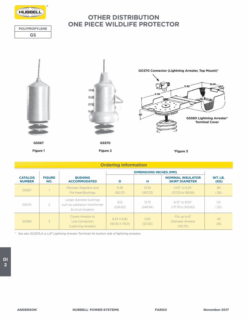
ANDERSON™ HUBBELL® POWER SYSTEMS FARGO® November 2017
DI2
OTHER DISTRIBUTIONONE PIECE WILDLIFE PROTECTOR
POLYPROPYLENE
GS
CATALOG NUMBER
FIGURE NO.
BUSHINGACCOMMODATED
DIMENSIONS INCHES (MM)
WT. LB. (KG)D H
NOMINAL INSULATOR SKIRT DIAMETER
GS567 1Recloser, Regulator and
Pot Head Bushings
6.38
(162.37)
10.50
(267.23)
5.00” to 6.25”
(127.25 to 159.06)
.80
(.36)
GS570 2
Larger diameter bushings
such as substation transformer
& circuit breakers
8.12
(206.65)
13.75
(349.94)
6.75” to 8.00”
(171.79 to 203.60)
1.21
(.55)
GS580 3
Covers Arrestor to
Line Connection
(Lightning Arrester)
6.34 X 6.92
(161.35 X 176.11)
5.00
(127.25)
Fits up to 6”
DIameter Arrestor
(153.70)
.40
(.18)
*Figure 3
GS570
Figure 2
GS567
Figure 1
* See also GC207LA or LAT Lightning Arrester Terminals for bottom side of lightning arresters.
GO370 Connector (Lightning Arrester, Top Mount)*
GS580 Lightning Arrester*Terminal Cover
Ordering Information

ANDERSON™ HUBBELL® POWER SYSTEMS FARGO® November 2017
DI3
OTHER DISTRIBUTIONONE PIECE WILDLIFE PROTECTOR
• Designed to provide protection of cutouts from accidental contact by squirrels, birds or other wildlife.
• Universal one-piece design for easy installation or retrofit.• Fits Chance® and other major manufacturer’s cutouts. See sizes
below.• Fits both Polymer and Porcelain type cutouts.• Has hot stick eye .• Gray color
Material: Proprietary low track PVC that is UV stabilized for long-term performance.
NOT INTENDED FOR USE AS A SAFETY DEVICE.
VINYL
CC101/CC170
* For Eyebolt version add “EB” suffix
CC101 CC170
CC101EB
CATALOG NUMBER
FITS CUTOUTSIZES (KV) BIL RATING
HOT-STICKEYE (Y/N)
DIMENSIONS INCHES (MM) GROSS WEIGHTLBS (KG)LENGTH WIDTH HEIGHT
CC101* 15, 27 150 Y11
(279.4)
5
(127)
7
(177.8)
1.31
(.59)
CC170 15, 27, 36 170 Y12
(304.8)
5
(127)
7
(177.8)
1.48
(.67)
Ordering Information

ANDERSON™ HUBBELL® POWER SYSTEMS FARGO® November 2017
DI4
OTHER DISTRIBUTIONWILDLIFE PROTECT
VINYL
RG100 series
• For use as raptor guard on insulators.• For wildlife protection only.• Each piece includes non-metallic fasteners for additional mechanical
strength.
Material: Body – Proprietary, UV stabilized low track vinyl kits come pre-packaged in plastic bags.
CATALOG NUMBER INSULATOR SIZE LENGTH INCHES (MM) WEIGHT EA. LBS (KG)
RG101C C-neck 24 (609) 1.1 (.50)
RG102F F-neck 24 (609) 1.5 (.68)
RG103J J-neck 26 (660) 5.5 (2.48)
RG101CK C-neck 66 (1676) 4.1 (1.85)
RG102FK F-neck 66 (1676) 4.5 (2.03)
RG103JK J-neck 68 (1739) 8.5 (3.83)
RGE100 extension 23 (584) 1.5 (.68)
“K” suffix - Kit consists of insulator cover, two RGE100 extensions and fasteners
Ordering Information

ANDERSON™ HUBBELL® POWER SYSTEMS FARGO® November 2017
DI5
DISTRIBUTION/TRANSMISSION/SUBSTATIONELECTRICAL JOINT COMPOUND/INHIBITOR
Anderson Versa-Seal® High Temperature Joint Compound (HTJC) is a synthetic-based, gritted, high-temperature compound developed for use on two-piece compression fittings on ACSS conductors rated 250° C.
HTJC employs conductive grit and thermally conductive filler to reduce connection resistance and allows connectors to operate at cooler temperatures.
This electrically and thermally conductive compound is also ideal for use on standard aluminum conductor (AAC and ACSR) fittings including Fargo Uni-Grip® deadends, splices and terminals.
HTJC fills internal voids in compression and bolted joints, sealing out moisture. HTJC is also an excellent choice for pad-to-pad applications as the grit is very fine and conductive.
See table labeled “Joint Compound Required” for Fargo transmission fittings.
HTJCNG utilizes the same synthetic base of HTJC without the grit.
• HTJCNG is recommended for flat-to-flat and grooved/bolted connections
• Helps prevent corrosion and oxidation by sealing out air and water• Amber in color
DESCRIPTION
INHIBITORS
HTJC
HTJCNG
CAT. NUMBER TRADE NAME DESC/SIZE SERVICE TEMP.
TO BE USED ON:
COLORCOMPRESSIONGROOVE/BOLTED PAD
VS8HTJC ANDERSON8 OZ. PLASTIC
BOTTLE
-40°F to +480°F
(-40°C to 250°C)● ● ● GRAY
HTJC16 ANDERSON CAULK TUBE-40°F to +480°F
(-40°C to 250°C)● ● ● GRAY
HTJC Inhibitor
CAT. NUMBER DESC/SIZE SERVICE TEMP.
TO BE USED ON:
COLORCOMPRESSIONGROOVE/BOLTED PAD
HTJCNG4B 4 oz Bottle -40 to 400 F ● ● AMBER
HTJCNG8B 8 oz Bottle -40 to 400 F ● ● AMBER
HTJCNGQC Quart can -40 to 400 F ● ● AMBER
HTJCNG Inhibitor

ANDERSON™ HUBBELL® POWER SYSTEMS FARGO® November 2017
DI6
DISTRIBUTION/TRANSMISSION/SUBSTATIONELECTRICAL JOINT COMPOUND/INHIBITOR
DESCRIPTION
INHIBITORS
VERSA-SEAL®VS/VG
VS type Anderson VERSA-SEAL®, non-gritted electrical joint compound is UL listed for all aluminum and copper applications, such as pad-to-pad surfaces.
VSG type Anderson Versa-Seal®, gritted electrical joint compound is UL listed for all aluminum and copper compression connections. It is not recommended for use as a lubricant on threaded fittings as improper torque values or thread galling may occur.
• VS is a non-petroleum, non-toxic, non-gritted compound for use where EPDM, natural rubber, as well as polyethylene insulating products, may come in contact with the sealant.
• VSG is a non-petroleum, non-toxic gritted compound for use where EPDM, natural rubber, as well as polyethylene insulating products, may come in contact with the sealant.
• VS is recommended for bolted joints, flat-to-flat contact surfaces, terminal and lug tongues, grooves of bolted parallel connectors or hot-line clamps, lubricating insulating sleeves and caps, and for improving electrical conductivity on all metallic conduit threads.
• VSG is recommended for NEMA minimum tension compression terminals. VSG helps break oxide films on contact surfaces while enhancing conductivity between conductor strands with its conductive grit. Also for two-piece full tension dead-ends and sleeves.
• Yellow tint for VS identification.• Blue tint for VSG identification.
CAT. NUMBER
TRADE NAME
DESC/SIZE
SERVICE TEMP.
TO BE USED ON: BASE OIL GRIT TYPE
COLORCOMP-
RESSIONGROOVE/BOLTED PAD
SYNTH./VEG.
PET-ROL.
FINE CON-DUCT GRITTED
NON GRIT-TED
VS8B ANDERSON VERSA-SEAL
8 OZ. PLASTIC BOTTLE
-40°F to +300°F(-40°C to 149°C) ● ● ● ● YELLOW
VSG8B ANDERSON VERSA-SEAL
8 OZ. PLASTIC BOTTLE
-40°F to +300°F(-40°C to 149°C) ● ● ● BLUE
VS/VSG Inhibitor
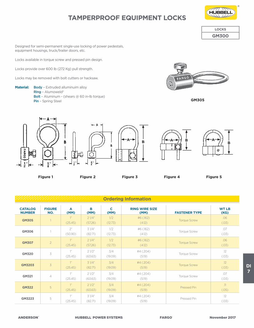
ANDERSON™ HUBBELL® POWER SYSTEMS FARGO® November 2017
DI7
TAMPERPROOF EQUIPMENT LOCKSLOCKS
GM300
GM305
Figure 3Figure 2Figure 1 Figure 5Figure 4
Designed for semi-permanent single-use locking of power pedestals, equipment housings, truck/trailer doors, etc.
Locks available in torque screw and pressed pin design.
Locks provide over 600 lb (272 Kg) pull strength.
Locks may be removed with bolt cutters or hacksaw.
Material: Body – Extruded alluminuim alloy Ring – Alumoweld® Bolt – Aluminum - (shears @ 60 in-lb torque) Pin – Spring Steel
A B A B AB
CATALOG NUMBER
FIGURE NO.
A(MM)
B(MM)
C(MM)
RING WIRE SIZE(MM) FASTENER TYPE
WT LB(KG)
GM305 11”
(25.45)
2 1/4”
(57.26)
1/2
(12.73)
#6 (.162)
(4.12)Torque Screw
.06
(.03)
GM306 12”
(50.90)
3 1/4”
(82.71)
1/2
(12.73)
#6 (.162)
(4.12)Torque Screw
.07
(.03)
GM307 21”
(25.45)
2 1/4”
(57.26)
1/2
(12.73)
#6 (.162)
(4.12)Torque Screw
.06
(.03)
GM320 31”
(25.45)
2 1/2”
(63.63)
3/4
(19.09)
#4 (.204)
(5.19)Torque Screw
.12
(.03)
GM3203 31”
(25.45)
3 1/4”
(82.71)
3/4
(19.09)
#4 (.204)
(5.19)Torque Screw
.12
(.03)
GM321 41”
(25.45)
2 1/2”
(63.63)
3/4
(19.09)
#4 (.204)
(5.19)Torque Screw
.07
(.03)
GM322 51”
(25.45)
2 1/2”
(63.63)
3/4
(19.09)
#4 (.204)
(5.19)Pressed Pin
.11
(.05)
GM3223 51”
(25.45)
3 1/4”
(82.71)
3/4
(19.09)
#4 (.204)
(5.19)Pressed Pin
.12
(.03)
Ordering Information

ANDERSON™ HUBBELL® POWER SYSTEMS FARGO® November 2017
DI8
OTHER DISTRIBUTIONLINE SPACERS
For Triplex and Quadruplex Conductors• Provides simple and permanent spacing of secondary triplex or
quadruplex conductor to ease installation of connectors or taps.• Molded from high density polyethylene and stabilized with ultra
violet inhibitors for superior long term performance.• Wide radius conductor positions accommodate a range of triplex
and quadruplex conductors. Diameter 0.75” each (both styles).• Eyelet provides convenient attachment for service drop dead ends.
POLYETHYLENE
LINE SPACER
GO54GO53
CATALOG NUMBER NO. CONDUCTORS
DIMENSIONS INCHES (MM) WT LB(KG)L W H
GO53 35-1/2
(139.98)
1-1/2
(38.18)
5
(127.25)
.27
(.12)
GO54 45-1/2
(139.98)
1-1/2
(38.18)
5 1/2
(139.98)
.28
(.13)
Ordering Information

ANDERSON™ HUBBELL® POWER SYSTEMS FARGO® November 2017
DI9
CATALOG NUMBER
FITTING CLAMPING RANGE INCHES
(MM)
ULTIMATE BODY STRENGTH LBS. (KN)
MAX. TAKE-OFF ANGLE DIMENSIONS INCHES (MM) APPROX.
WT. EACH LBS. (KG)TYPE CAT. NO. o L W H
BRS60N
BRS60S
BRS60C
None
Socket
Clevis
—
SA04
CA04
.20-.60
(5.08-15.24)
16,000
(71)15˚
6-1/2
(165.10)
3/4
(19.05)
2-1/4
(57.15)
2.9 (1.32)
4.4 (1.90)
4.5 (2.04)
BRS83N
BRS83S
BRS83C
None
Socket
Clevis
—
SA06
CA06
.40-.83
(10.16-21.08)
18,000
(80)15˚
7-1/4
(184.15)
31/32
(24.6)
2-3/8
(60.33)
3.7 (1.68)
5.0 (2.27)
5.4 (2.45)
BRS100N
BRS100S
BRS100C
None
Socket
Clevis
—
SA07
CA101
.625-1.00
(15.88-25.40)
22,000
(98)15˚
8
(203.20)
1-1/8
(28.58)
2-1/2
(63.50)
4.5 (2.04)
5.9 (2.68)
6.3 (2.81)
BRS118N
BRS118S
BRS118C
None
Socket
Clevis
—
SA11
CA101
.70-1.18
(17.78-29.97)
25,000
(111)20˚
8
(203.20)
1-9/32
(32.55)
2-1/2
(63.50)4.9 (2.22)
BRONZE
BRS
SUSPENSIONBRONZE CLAMP
For use with copper or Copperweld® cable.
Through the use of these clamps hysteresis and eddy current power losses are reduced to a minimum. Liners are not required.
Material: Body – High Tensile Bronze Alloy Keeper – Electrical Bronze *Hardware – Galvanized Steel Socket and Clevis – Ductile Iron, Galvanized Cotter Pin – #302 Stainless Steel
NOTE: Recommended torque on U-bolts; 1/2”—480 in. lbs.* Bronze U-bolts, nuts and washers can be furnished by adding suffix “ED” to catalog number. Example, BRS60NED.
Product Data & Conductor Size
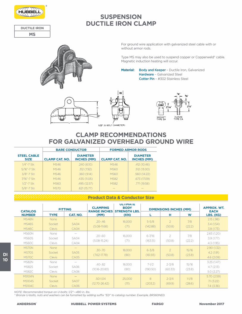
ANDERSON™ HUBBELL® POWER SYSTEMS FARGO® November 2017
DI10
CATALOGNUMBER
FITTING CLAMPING RANGE INCHES
(MM)
ULTIMATE BODY
STRENGTH LBS. (KN)
DIMENSIONS INCHES (MM) APPROX. WT. EACH
LBS. (KG)TYPE CAT. NO. L H WMS46N
MS46S
MS46C
None
Socket
Clevis
—
SA04
CA04
.20-.46
(5.08-11.68)
16,000
(71)
5-5/8
(142.88)
2
(50.8)
7/8
(22.2)
2.15 (.98)
3.4 (1.54)
3.8 (1.73)
MS60N
MS60S
MS60C
None
Socket
Clevis
—
SA04
CA04
.20-.60
(5.08-15.24)
16,000
(71)
6-7/16
(163.51)
2
(50.8)
7/8
(22.2)
2.65 (1.20)
3.9 (1.77)
4.3 (1.95)
MS70N
MS70S
MS70C
None
Socket
Clevis
—
SA05
CA05
.30-.70
(7.62-17.78)
18,000
(80)
6-3/8
(161.93)
2
(50.8)
15/16
(23.8)
2.90 (1.32)
4.2 (1.91)
4.6 (2.09)
MS82N
MS82S
MS82C
None
Socket
Clevis
—
SA06
CA06
.40-.82
(10.16-20.83)
18,000
(80)
7-1/2
(190.50)
2-3/8
(60.33)
15/16
(23.8)
3.25 (1.47)
4.7 (2.13)
5.0 (2.27)
MS104N
MS104S
MS104C
None
Socket
Clevis
—
SA07
CA06
.50-1.04
(12.70-26.42)
25,000
(111)
8
(203.2)
2-3/4
(69.9)
1-1/8
(28.6)
5.70 (2.59)
7.1 (3.22)
7.4 (3.36)
DUCTILE IRON
MS
SUSPENSIONDUCTILE IRON CLAMP
For ground wire application with galvanized steel cable with or without armor rods.
Type MS may also be used to suspend copper or Copperweld® cable. Magnetic induction heating will occur.
Material: Body and Keeper – Ductile Iron, Galvanized Hardware – Galvanized Steel Cotter Pin – #302 Stainless Steel
NOTE: Recommended torque on U-bolts; 1/2”—480 in. lbs.* Bronze U-bolts, nuts and washers can be furnished by adding suffix “ED” to catalog number. Example, BRS60NED.
CLAMP RECOMMENDATIONSFOR GALVANIZED OVERHEAD GROUND WIRE
STEEL CABLE SIZE
BARE CONDUCTOR FORMED ARMOR RODS
CLAMP CAT. NO.DIAMETER
INCHES (MM) CLAMP CAT. NO.DIAMETER
INCHES (MM)1/4”-7 Str.
5/16”-7 Str.
3/8”-7 Str.
7/16”-7 Str.
1/2”-7 Str.
5/8”-7 Str.
MS46
MS46
MS46
MS46
MS60
MS70
.240 (6.10)
.312 (7.92)
.360 (9.14)
.435 (11.05)
.495 (12.57)
.621 (15.77)
MS46
MS60
MS60
MS82
MS82
—
.412 (10.46)
.512 (13.00)
.560 (14.22)
.673 (17.09)
.771 (19.58)
—
Product Data & Conductor Size
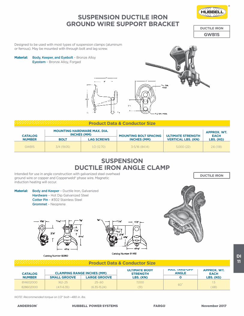
ANDERSON™ HUBBELL® POWER SYSTEMS FARGO® November 2017
DI11
CATALOG NUMBER
MOUNTING HARDWARE MAX. DIA. INCHES (MM) MOUNTING BOLT SPACING
INCHES (MM)ULTIMATE STRENGTH VERTICAL LBS. (KN)
APPROX. WT. EACH
LBS. (KG)BOLT LAG SCREWS
GWB1S 3/4 (19.05) 1/2 (12.70) 3-5/16 (84.14) 5,000 (22) 2.6 (1.18)
DUCTILE IRON
GWB1S
Designed to be used with most types of suspension clamps (aluminum or ferrous). May be mounted with through bolt and lag screw.
Material: Body, Keeper, and Eyebolt – Bronze Alloy Eyestem – Bronze Alloy, Forged
SUSPENSION DUCTILE IRONGROUND WIRE SUPPORT BRACKET
SUSPENSIONDUCTILE IRON ANGLE CLAMP
NOTE: Recommended torque on 1/2” bolt—480 in. lbs.
Intended for use in angle construction with galvanized steel overhead ground wire or copper and Copperweld® phase wire. Magnetic induction heating will occur.
Material: Body and Keeper – Ductile Iron, Galvanized Hardware – Hot Dip Galvanized Steel Cotter Pin – #302 Stainless Steel Grommet – Neoprene
DUCTILE IRON
Product Data & Conductor Size
CATALOG NUMBER
CLAMPING RANGE INCHES (MM)ULTIMATE BODY
STRENGTH LBS. (KN)
MAX. TAKE-OFF ANGLE
APPROX. WT. EACH
LBS. (KG)SMALL GROOVE LARGE GROOVE 0814602000
828602000
.162-.25
(4.11-6.35)
.25-.60
(6.35-15.24)
7,000
(31)60˚
1.5
(.68)
Product Data & Conductor Size

ANDERSON™ HUBBELL® POWER SYSTEMS FARGO® November 2017
DI12
CATALOG NUMBER
MOUNTING HARDWARE MAX. DIA. INCHES (MM) MOUNTING BOLT
SPACING INCHES (MM)ULTIMATE STRENGTH VERTICAL LBS. (KN)
APPROX. WT. EACH
LBS. (KG)BOLT LAG SCREW
GWB1R 5/8 (15.88) 1/2 (12.70) 3-1/4 (82.55) 5,000 (22) 3.1 (1.40)
CATALOG NUMBER
CLAMPING RANGE INCHES (MM)
ULTIMATE BODY STRENGTH LBS. (KN)
DIMENSIONS INCHES (MM) APPROX. WT. EACH LBS. (KG)L W J
2706503001.25-.56
(6.13-14.2)
2,800
(12)
5-1/4
(133.3)
3-7/8
(98.4)
1/2
(12.7)2.50 (1.13)
2706513001.50-1.06
(12.7-26.9)
2,800
(12)
5-1/4
(133.3)
3-7/8
(98.4)
1/2
(12.7)2.75 (1.24)
27065230011.06-1.50
(26.9-38.1)
2,800
(12)
5-1/4
(133.3)
3-7/8
(98.4)
1/2
(12.7)3.00 (1.36)
SUSPENSIONDUCTILE IRON TRUNNION
SUSPENSION CLAMP
For ground wire applications with galvanized steel cable.
Designed for use on tangent suspension spans with horizontal or vertical post insulators.
Keeper is reversible for proper fit on different size conductors.
Material: Body and Keeper – Ductile Iron, Galvanized Hardware – Galvanized Steel Anti-static spring – #302 Stainless Steel (See Note 2)
NOTES: (1) Recommended torque on bolts; 1/2”—480 in. lbs. (2) Anti-static spring can be supplied by adding “ARIV” to catalog number. Example, TSCHT150ARIV.
SUSPENSIONDUCTILE IRON GROUND WIRE SUPPORT BRACKET
DUCTILE IRON
GWB1R
Designed to accommodate most (aluminum or ferrous) trunnion type clamps. May be mounted with one bolt and lag screw or two bolts.
Material: Ductile Iron, Galvanized
NOTE: Mounting hardware by others.
DUCTILE IRON
Product Data & Conductor Size
Product Data & Conductor Size

ANDERSON™ HUBBELL®POWERSYSTEMS FARGO® November2017
DISTRIBUTION CONNECTORS
REFERENCE DATA
SE
CT
ION
DJ

DJ1
ANDERSON™ HUBBELL®POWERSYSTEMS FARGO® November2017
ALUMINUM AND BRONZE CONNECTORSALLOYS, CONNECTORS, HARDWARE & INSTALLATION
In over 100 years of serving the electrical industry, Anderson has earned a reputation for being a creative leader in the design and manufacture of electrical connectors, fittings and related accessories. The Anderson acceptance of these responsibilities is best exemplified through our wholly self-sufficient facilities. Design Engineering, Testing and Metallurgical Laboratories, and all facets of Manufacturing are geared for research, development and production of a full line of quality bronze, aluminum and ductile iron products.
The following information conveys helpful reference for material composition, installation, standardization and definitions ap-plying to connectors and fittings as developed during our years of experience.
ALUMINUM CONNECTORS Aluminum Alloys:Connectors and fittings requiring high mechanical proper-ties are cast from aluminum alloy 356. Sand cast 356 is heat treated to the T6 temper, and permanent mold castings are heat treated to the T61 temper. The 356 alloy is a 7 per cent silicon—0.3 per cent magnesium-aluminum alloy. The alloy is not susceptible to stress corrosion or season cracking. Its volume conductivity is approximately 39 per cent, I.A.C.S.
Cast compression connectors requiring a soft high conductiv-ity aluminum are supplied from 99 plus per cent pure alu-minum. Other aluminum compression connectors are made from commercially pure high conductivity wrought aluminum.
Installation Recommendations For Aluminum Connectors
Select type of connector from those listed below and follow the indicated procedure.
CONNECTOR TYPE INSTALLATION PROCEDURE
Bolted ....................................................Procedure #1Welded ..................................................Procedure #2Compression ......................................Procedure #3Welded and Bolted Procedure #2 followed by Procedure #1Compression and Bolted Procedure #3 followed by Procedure #1Welded and Compression Procedure #2 followed by Procedure #3
PROCEDURE #1—BOLTED CONNECTIONSA. For aluminum to aluminum connections and aluminum to
copper connections without a copper lined contact.1. Vigorously clean all contact surfaces of the connector
and conductor with a stiff stainless steel wire brush to remove oxides. A typically bright aluminum surface should be obtained. Do Not Wire Brush Plated Contact Surfaces.
2. Immediately coat these contact areas with a liberal amount of contact sealant.
3. Install fitting with bolts finger tight. If a generous bead of compound does not appear, remove the conductor and add more sealant.
4. Alternately (criss-cross) and evenly tighten bolts with a torque wrench to the values shown on page 4.
5. Excess sealant squeezed out of joint can be left as is or can be lightly smoothed along contact line.
6. All excess sealant must be removed from EHV Connec-tors and entirely from cable insulation.
B. For Aluminum connectors with a copper liner to copper connection.1. For maximum corrosion protection of the joint, the
steps given in A-1 to A-5 should be followed.
PROCEDURE #2—WELDED CONNECTIONSA. For cable connections:
1. Remove all oil, grease and water in vicinity of surfaces to be welded. Vigorously clean the conductor and connec-tor welding areas with a stainless steel brush.
2. Slide the conductor into the weldment cavity until it is within 1/8” to 3/16” of the rear of the welding barrel.
3. Prior to welding the connection, a test bead should be made upon an aluminum casting to test the weld set-tings.
4. Begin welding by “burning into” the inner wall of the casting and proceeding toward the conductor center. Wire brush the original weld if more than one weld pass is required.
B. For tubular connections:1. Remove all oil, grease and water in vicinity of surfaces
to be welded. Vigorously clean the conductor and con-nector welding areas with a stainless steel brush.
2. Align the tubular bus and connector groove. Begin welding by “burning into” the inner wall of the cast-ing and proceeding toward the conductor center. Wire brush the original weld if more than one weld pass is required.
3. Prior to welding the connection, a test bead should be made upon an aluminum casting to test the weld set-tings.
4. Due to the manufacturing tolerances on aluminum tubular bus, it is recommended that the tube be posi-tioned in the weldment cavity and tack welded before starting final weld.

DJ2
ANDERSON™ HUBBELL®POWERSYSTEMS FARGO® November2017
C. For welded connectors with a copper lined contact:1. Firmly bolt the copper lined contact section of con-
nector to the mating contact surface or to a suitable heat sink prior to welding. This prevents damage to the bonded liner.
2. Weld the aluminum connection in accordance with steps A or B above. If a heat sink is used, allow con-nector to cool before removing. The connector may be cooled by quenching in water.
PROCEDURE #3—COMPRESSION CONNECTIONS1. Vigorously clean the conductor contact area with a
stainless steel brush. Do not attempt to clean connec-tor barrel. It is not necessary to apply sealant to the conductor. All connectors will have sealant applied at the factory.
2. Fully insert the conductor into the barrel and crimp. Crimping should begin nearest the center of sleeve type connectors. For closed barrel type connectors crimp-ing should begin at the end and work toward the open end. Excess sealant squeezed out of the joint may be smoothed out around the mouth of the barrel. All ex-cess sealant must be removed from EHV Connectors or any cable insulation.
Installation Recommendations for Aluminum toCopper Connections Using Aluminum Connectors
Connectors with contact sealant—Aluminum connectors can be used for making aluminum to copper connections if the proper installation care is observed. This includes the use of a sealant in accordance with practices outlined above. Use of a sealant protects the connection from oxide formation and electrolytic corrosion for as long as it remains present in the connection completely coating the surfaces and sealing out moisture.
Added protection in addition to sealants is available. Alumi-num distribution connectors can be supplied with plating or with copper lined contacts.
Bi-Metallic Transition Plates—Aluminum to copper con-nections between flat NEMA drilled tongues and bars can be made using transition plates (Type TP). These plates are formed from sheets of 80% aluminum 20% copper which are molecularly bonded together. Best results are obtained by us-ing contact sealant. Always position the aluminum conductor above the copper conductor.
Tin Plating—Tin plating can be furnished on certain connec-tors. See catalog page for appropriate suffix designation.
Hardware—Anodized Aluminum Clamping Bolts are standard with most Aluminum Power Connectors and may be supplied
at extra cost with other connectors. The bolts are fabricated 2024-T4 aluminum and are anodized. After anodizing, the coating is sealed with a dichromate solution which imparts a yellow-green finish.
Standard nuts furnished on aluminum bolts are 6061 T6 dry waxed coated.
Insulator attachment hardware for bus supports is galvanized steel.
BRONZE AND COPPER CONNECTORSCopper Casting Alloys
Our modern, all electric furnaces provide copper alloy cast-ings of the highest quality possible. The alloy used will vary according to the requirement of the component.
Connectors requiring high tensile strength and corrosion resistance in application are cast from Anderson Alloy 112 (ASTM B-30 Alloy No. C95500). The 112 alloy is a 10% alu-minum, 4.5% nickel copper alloy with a minimum tensile strength of 90,000 PSI.
Connectors requiring current-carrying abilities and reasonable strength are cast from Anderson Alloy 123 (ASTM B-30 Al-loy No. C84400). The 123 metal is a 81% copper—3% tin—7% lead—9% zinc alloy.
For heavy duty copper compression connectors CDA 110 cop-per is used. This 110 alloy is 99.9% pure copper.
Other copper compression connectors are made from com-mercially pure high conductivity wrought copper.
Conductivity is purposely omitted in the above descriptions because it is often confused with current-carrying capacity. While connector alloys may vary in conductivity, design pa-rameters are applied in each case to assure adequate capac-ity to meet the particular application.
Installation Recommendations for Bronze and Copper Con-nectors
Bronze Bolted Connectors—Contact sealants are not normal-ly required in copper connections. However, the use of sealant is recommended in severe corrosive environments and direct burial applications such as ground grids.
Vigorously clean the conductor and connector contact sur-faces with a stainless steel wire brush.
Alternately and evenly tighten bolts with a torque wrench to the values shown in Recommended Torque Values table.
Hardware—Silicon bronze hardware is normally supplied for all conductor clamping bronze components. Stainless steel hardware may be substitued where and when necessary.

DJ3
ANDERSON™ HUBBELL®POWERSYSTEMS FARGO® November2017
Copper Compression Connections—Vigorously cleanthe conductor contact surfaces with a stainless steel wirebrush. Do not attempt to clean connector barrel. In general it is not necessary to apply sealant to the conductor or connec-tors. Copper connectors requiring sealant have the sealant applied at the factory. The use of sealant is recommended in severe corrosive environments and direct burial applications such as ground grids. Sealants may be designated for a cop-per connector by adding the appropriate suffix to the basic catalog number.
Installation Recommendations for Copper toAluminum Connectors Using Copper Connectors
When making copper to aluminum connections, using bronze or copper connectors, best results will be obtained by using the following methods.
1. Tin plate the copper base connection and use sealant between the aluminum and copper. (Tin plating may be specified by adding the appropriate suffix to the basic catalog number.)
2. Copper pad connectors may be attached directly to an aluminum pad if sealant is freely used.
3. The use of an aluminum conductor in a standard copper base connector (plated or unplated), is not recommended.
4. An aluminum to copper cable transition may be made directly using an aluminum connector as covered in the preceding section on Aluminum Connectors.
Note With Any Transition Method:Do Not Position The Aluminum Member In Such A Way That Would Allow Water To Drain From The Copper Connector Over (Or Into) The Aluminum Connection Point.
General Information on Bronze or Copper Connectors
In regard to bolted connectors; components to be in con-tact with cable and tube are supplied with “as cast” surfaces. Conductor grooves for cables are designed with ample radii to prevent conductor damage.
Connector Design—In all of our bronze and aluminumpower connectors, the temperature rise of the connector shall not exceed the temperature rise of the conductor with which it is intended to be used. The temperature rise of an electric power connector which connects conductors of varying sizes shall not exceed the temperature rise of the conductor having the highest temperature rise. All temperatures are based on the conductor being rated at 30 degrees rise over a 40 de-grees ambient, indoors, in still but unconfined air. Our bronze and aluminum connectors conform to one of the following as applicable:
Latest release of the following:
NEMA ANSI (C119) Underwriters Lab (U.L.)
Contact Sealants—Various sealant formulations have been developed to provide improved electrical and mechanical per-formance as well as environmental protection to the contact area. Non-petroleum base sealants are provided for under-ground applications and other applications where natural or synthetic rubber goods might be adversely affected.
The use of sealants are recommended for aluminum to alumi-num or aluminum to copper connections which are subjected to severe corrosive environments and when used in direct burial applications such as ground grids.
Non-gritted sealants are recommended for flat connections and as a groove sealant in bolted connectors.
Our gritted sealants are primarily used in compression con-nectors. Aluminum compression connectors have sealant applied at the factory.
Aluminum stud connectors are supplied with factory applied sealant in the threaded portion. To obtain factory applied sealant in other connectors add the desired sealant suffix des-ignation to the basic catalog number. Example: ACF-6-C-XB
“-XB” for petroleum based sealant

DJ4
ANDERSON™ HUBBELL®POWERSYSTEMS FARGO® November2017
ALUMINUM CONNECTORS
Aluminum Connector (Clamping Hardware)
2024-T4 with #205 Alumilite Finish Aluminum-Bolt
7075-T6 Aluminum Lockwasher, Etch Finish 6061-T6 Plain Aluminum Nut, Wax Finish
RECOMMENDED TYPES OF HARDWARE AND INSTALLATION MOUNTING
HARDWARE FOR JOINING LIKE OR UNLIKE METALS BRONZE CONNECTORS
Bronze Connector (Clamping Hardware)
*Reduced torque limits apply when replacing aluminum clamping hardware with steel in bolted aluminum connectors.
NOTE: All eyestems have a recommended torque of 200 lb.—inches.
BOLTDIA.
RECOMMENDED TORQUENON-LUBRICATEDSTEEL & SILICON BRONZE HDWE.
LB. INCHES
RECOMMENDED TORQUE
LUBRICATED HDWE.
& ALUMINUM HDWE.
LB. INCHES*
5/16” 180 120
3/8” 240 168
1/2” 480 300
5/8” 660 480
3/4” 840 720
RECOMMENDED TORQUE VALUES FORBOLTED CONNECTORS
Tightening Force Applied to Hardware: Following areANDERSON’S recommended torque values applying to all clamping hardware used in connectors and fittings.
Note:Care should be taken to prevent sealant from being applied to hardware since torque values will be affected if the hardware becomes lubricated with sealant.
Bronze To Copper Assemblies (Tongue Mounting Hardware)
KEY:Si-Br—Silicon Bronze GS—Galvanized Steel
SS—Stainless Steel AL—Aluminum
(1) denotes preferred hardware usage.
Note:Contact sealant should be used between Aluminum to Alumi-num and Aluminum to Copper connections.
Aluminum To Copper Assemblies(Tongue Mounting Hardware)
2024-T4 with #205 Alumilite Finish Aluminum- Bolt
7075-T6 Aluminum Flatwasher
7075-T6 Aluminum Lockwasher, Etch Finish 6061-T6 Plain Aluminum Nut, Wax Finish
Aluminum To Aluminum Assemblies(Tongue Mounting HardwareAs Assembled At Factory)
Silicon Bronze Bolt
Silicon Bronze Lockwasher Silicon Bronze Nut
Galvanized Steel BoltGalvanized Steel Flatwasher
Stainless Steel Belleville WasherGalvanized Steel Nut
Aluminum
Copper
Silicon Bronze Bolt
Silicon Bronze FlatwasherSilicon Bronze LockwasherSilicon Bronze Nut
Bronze
Copper

DJ5
ANDERSON™ HUBBELL®POWERSYSTEMS FARGO® November2017
LETTER SUFFIX DESIGNATIONS TO STANDARD CATALOG NUMBER FOR SPECIAL FEATURES
*This suffix will appear on the connector or fitting as part of the catalog number. Other suffix designations above will not appear as part of the catalog number un-less specifically specified in which case there may be an extra charge to cover the stamping or marking operation.
When more than one suffix is required to designate more than one special feature, they should be arranged in alphabetical order except when the suffix is published as part of the catalog number.
A suffix added to a catalog number denotes that a change or modification is to be made to the standard catalog item. The suffixes listed below are for the convenience of our customers. The list does not include special modifications made for one customer only but those having general application.
CATALOGNO.
SUFFIXDESCRIPTION OF CHANGE
OR MODIFICATION
AAluminum loop will be supplied instead of copper loop.
AHAdvance handle only—VCF and VCF6 hot stick as-semblies.
ASAluminum hardware will be supplied instead of the usual (or standard) hardware.
BNKBolt, nut and cotter key will be supplied instead of usual clevis pin.
BNNBolt, nut and jam nut will be supplied instead of usual clevis pin.
BWBelleville washers will be supplied instead of usual washers.
CA clevis fitting will be supplied with strain, suspen-sion and dead end clamps.
CFCenter-formed tongue will be supplied on lugs where side formed tongues are standard on bronze and aluminum items.
CRF Corona free strain clamp.
EAn eyestem will be supplied instead of the usual hex head bolt. (This applies generally to stirrup and cable clamps).
EDEverdur (silicon bronze) hardware will be supplied instead of the usual hardware.
FTPFlowed-tin plating will be supplied on bronze items. (.0001-.0003 thick and flowed)
FWA flatwasher will be supplied instead of a lock-washer.
G A guide will be supplied on expansion connectors.
GAGalvanized hardware will be supplied instead of usual hardware.
GP Tin plating will be supplied on aluminum items.
HPHexagon clevis pin furnished instead of standard clevis pin.
CATALOGNO.
SUFFIXDESCRIPTION OF CHANGE
OR MODIFICATION
HWHexagon head bolt with a flat washer under the head will be supplied instead of the usual bolts.
LWA lockwasher will be supplied instead of a flat-washer.
NNeither socket nor clevis fittings will be supplied with suspension, or dead end clamps.
NSB No spacer bar on straight line dead end clamps.
SA socket will be supplied with suspension and dead end clamps.
SEA static eliminator spring will be supplied on bus supports.
SFSide formed tongue will be supplied when a center formed tongue is standard.
SpecialThe catalog number specified is to be modified for particular requirements which the item will not otherwise fill.
TB Electro-tin plate loop (bail) .0002”-.0004”.
TPTin plating will be supplied on bronze items, (Electro-tin .0002”-.0004” thick).
U U-bolts may be supplied on these items.
UDAn undrilled tongue will be supplied on terminals or lugs.
XBThe connector will be supplied with the grooves coated with a petroleum base sealant and enclosed in a polyethylene bag.
XY Contact surface finished on both sides of tongue.

DJ6
ANDERSON™ HUBBELL®POWERSYSTEMS FARGO® November2017
KEY SYMBOLS TO ANDERSON ELECTRICAL CONNECTORS CATALOG NUMBERSAluminum Connectors for Cable*
*Threads per inch are added at the end of completed catalog number as”-12,” “-16,” etc. Smooth studs are specified by adding “-0.”
CODENO.
DIAMETERIN INCHES*
01020304050607101112131415161720212223242630323436405060
1/81/43/81/25/83/47/81
1-1/81-1/41-3/81-1/21-5/81-3/41-7/8
22-1/82-1/42-3/82-1/22-3/4
33-1/43-1/23-3/4
456
**Multi-Range is accomplished by reversing the clamping cap.*The Decimal Range is to be considered as the final criteria for application. The ACSR and Aluminum Cable Ranges will not necessarily fall within the Decimal Range for all standings.
CONDUCTOR RANGE
CATALOGNUMBER
CODE
ALUMINUMCOPPER
AWG-MCMACSR
AWG-MCM
DECIMALRANGE INCHES
6**7911131516182122
#4—1/0— 250—400350—600600—900900—12501250—16001500–2000
2000—25002500—3000
—
#4—1/0—4/04/0—336.4336.4—477
556.5—795.5715.5—11131113—1272
1272—1590*Decimal Range
.232—.398
.368—.575
.563—.744.681—.893.870—1.1081.081—1.2931.289—1.4591.382—1.6321.632—1.8241.824—2.0002.000—2.200
BRONZE REVERSIBLE CABLE CAPS
Unless otherwise indicated all bronze cable connectors have cable sections designed to accommodate a range of con-ductors. Their wide application flexibility offers the distinct advantages of reducing stock inventory, and possibility of errors of misapplication. There is no sacrifice of either electri-cal or mechanical efficiency when using reversible cable caps. This design is field proven by years of trouble free service in locations where severe operating conditions exist.
Our four bolt reversible cable cap design is adequate for high current capacity conductors, yet priced in line with standard duty connectors.
LARGE GROOVE SMALL GROOVE
Bronze Connectors for CableVERSA-
GROOVECAP
NUMBER
CABLE RANGEDECIMALRANGE INCHES
SMALL GROOVE LARGE GROOVE
MIN. MAX. MIN. MAX.
022025050080100150200
#6#4
1/0 Sol.2/0 Sol.4/0 Str.
250500
#21/0
4/0 Str.500 MCM750 MCM750 MCM1500 MCM
#22/02505007507501500
2/0250 MCM500 MCM800 MCM1000 MCM1500 MCM2000 MCM
.162—.419.204—.575.325—.813.365—1.031.522—1.152.474—1.412.811—1.632
Copper or Aluminum Threaded Studs
*Bar thickness & spacing (if same) are added at end of completed catalog number as “-1/4,” “-1/2,” etc.
CODENO.
WIDTHIN INCHES*
10142024303440506080100120
11-1/2
22-1/2
33-1/2
45681012
Copper or Aluminum Flat Bar
CODENO.
IPSDIAMETER
020304061012142024303440445060
1/43/81/23/4
11-1/41-1/2
22-1/2
33-1/2
44-1/2
56
Copper or Aluminum IPS Tubing
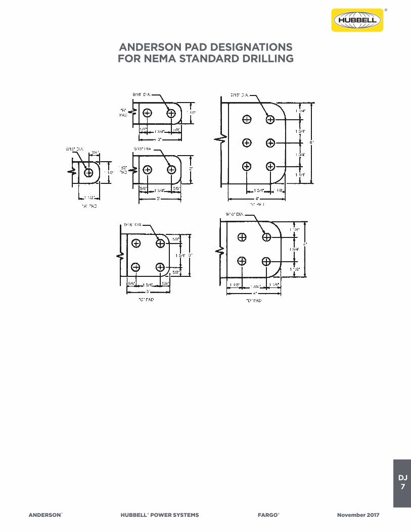
DJ7
ANDERSON™ HUBBELL®POWERSYSTEMS FARGO® November2017
ANDERSON PAD DESIGNATIONS FOR NEMA STANDARD DRILLING

DJ8
ANDERSON™ HUBBELL®POWERSYSTEMS FARGO® November2017
NEMA CONSTRUCTION STANDARDS ELECTRIC POWER CONNECTORS
CC 1-4.06 NUMBER AND DIAMETER OF BOLTS FOR CONNECTORSType of Conductor For Copper Conductors For Aluminum or ACSR Conductors
StandardPipe Size,
InchesCopper Cable,
kcmil
Aluminum orACSR Cable
OutsideDiameter,
Inches
StudDiameter,
Inches
Single SizeStandard Duty
Bolts PerConductor
Single SizeHeavy Duty
Bolts PerConductor
Range TakingBolts Per
Conductor
RangeTaking*
Bolts Per Con-ductor
Single SizeBolts Per
Conductor
NumberDia.
Inches NumberDia.
Inches NumberDia.
Inches NumberDia.
Inches NumberDia.
Inches
3/8
1/2
3/4 thru 1
1-1/4 thru 2
2-1/2
3 thru 4
4-1/2 thru 6
#4 thru 2/0
3/0 thru 500
550 thru 800
900 thru 2000
900 thru 2000
2250 thru 3000
. . .
0.200 thru 0.399
. . .
. . .
0.400 thru 1.412
0.400 thru 1.412
1.413 thru 1.850
. . .
1/2
5/8 thru 1-1/8
. . .
1-1/4 thru 2-1/2
. . .
2-3/4 thru 5
. . .
2
3
3
3
3
3
. . .
3/8
3/8
3/8
1/2
1/2
5/8
. . .
3
3
4
4
4
4
. . .
3/8
3/8
3/8
1/2
1/2
5/8
. . .
4
4
4
4
4
4
. . .
3/8
3/8
3/8
1/2
1/2
5/8
. . .
2
4
4
4
4
4
. . .
1/2
1/2
1/2
1/2
1/2
5/8
. . .
2
4
4
4
4
4
6
1/2
1/2
1/2
1/2
1/2
5/8
5/8
* Applies to cable only.NOTE I—Each U bolt is counted as two bolts.NOTE II—For shackle design (single casting wrap-around conductor), each bolt counts as two bolts.NOTE III—When two different sizes of conductors are involved, the bolts specified for the smallest conductor may be used.NOTE IV—When three bolts are specified, the following exceptions apply:a. Terminal lugs shall have a minimum of four bolts or the equivalent for a single conductor.b. Stud connectors shall have minimum of four bolts or the equivalent for the stud portion.NOTE V—Bronze alloy bolts shall have a minimum tensile strength of 70,000 pounds per square inch and aluminum alloy boltsshall have a minimum tensile strength of 55,000 pounds per square inch.NOTE VI—Nominal torque values shall be:
Diameter of Bolts,Inches
Nominal Torque Values
Foot/Pound Inch/Pound
3/81/25/8
3/8L1/2L5/8L
204055152540
240480660180300480
L—Lubricated
EXAMPLES ILLUSTRATING THE USE OFTHE TABLE IN CC 1-4.06
EXAMPLE NO. 1—A straight coupler connector or a 90-degree elbow connector is used to connect a conductor of 1-1/2 inchpipe to another conductor of 1-1/2-inch pipe. After locating the proper line for the 1-1/2-inch pipe in the first column of thetable, the total number of bolts required can be determined from the information given for the connectors, as follows:
For standard-duty connectors—
Three 1/2-inch-diameterbolts per conductor
x 2 (number ofconductors)
= a total of six 1/2-inch-diameterbolts per fitting
For heavy-duty connectors—
Four 1/2-inch-diameterbolts per conductor
x 2 (number ofconductors)
= a total of eight 1/2-inch-diameterbolts per fitting

DJ9
ANDERSON™ HUBBELL®POWERSYSTEMS FARGO® November2017
NEMA CONSTRUCTION STANDARDS ELECTRIC POWER CONNECTORS—continued
EXAMPLE NO. 2—A single-size “T” connector is used to connect a 3-inch Schedule 40 aluminum main to a 397.5 kcmil ACSR tap (outside diameter = 0.743 inch).
After locating the proper line for the 3-inch pipe in the first column of the table, it will be seen that the connectors require four5/8-inch-diameter bolts per conductor.
After locating the proper line for the 0.743-inch-outside diameter ACSR tap in the third column of the table, it will be seen thatthe connectors require four 1/2-inch-diameter bolts per conductor.
In this case and in accordance with Note III following the table, the manufacturer has the choice of using either four 1/2-inch diameter bolts per conductor of four 5/8-inch-diameter bolts per conductor.
EXAMPLE NO.3—A copper stud connector having a 1-1/8”-12 thread is connected to copper cable ranging from 400 to 800kcmil in size. Using the fourth column for the stud and the second column for the copper cable, it will be seen that the connec-tors require the following bolts:
1. Four 3/8-inch-diameter bolts per conductor for the stud.2. Four 1/2-inch-diameter bolts per conductor for the cable.
In this case and in accordance with Note III following the table, the manufacturer has the choice of using either four 3/8-inch diameter bolts per conductor or four 1/2-inch-diameter bolts per conductor.

DJ10
ANDERSON™ HUBBELL®POWERSYSTEMS FARGO® November2017
CONDUCTOR QUICK REFERENCE CHART
Con-duc-torDia
ACSR ALL ALUMINUM
HIGH STRENGHALL ALUMINUM(6201 ALLOY)
HIGH STRENGHALL ALUMINUM(5005 ALLOY) ALUMOWELD COPPER
Con-duc-torDia.
Cable Size
A.W.G.or C.M.
No.of
Strs.
RatedUlti-mate
Cable Size
A.W.G.or
C.M.
No.of
Strs.
RatedUlti-mate
Cable Size
A.W.G.or C.M.
No.of
Strs.
RatedUlti-mate
Cable Size
A.W.G.or C.M.
No.of
Strs.
RatedUlti-mate
Cable Size
A.W.G.
No.of
Strs.
RatedUlti-mate
Cable Size
A.W.G.or C.M.
No.of
Strs.
RatedUlti-mate
.102 — — — — — — — — — — — — 10 Sol. 1590 10 Sol. 530 .102
.114 — — — — — — — — — — — — 9 Sol. 2005 9 Sol. 661 .114
.128 — — — — — — — — — — — — 8 Sol. 2529 8 Sol. 826 .128
.146 — — — — — — — — — — — — — — — 8 7 778 .146
.158 8 6/1 745 — — — — — — — — — — — — — — — .158
.162 — — — — — — — — — — — — 6 Sol. 3608 6 Sol. 1280 .162
.169 — — — — — — — — — — — — — — — — — — .169
.174 — — — — — — — — — 30,420 Sol. 777 — — — — — — .174
.182 — — — — — — — — — — — — 5 Sol. 4290 — — — .182
.184 — — — 6 7 555 — — — — — — — — — 6 7 1228 .184
.197 — — — — — — 30,200 7 1069 — — — — — — — — — .197
.198 6 6/1 1170 — — — — — — 30,580 7 912 — — — — — — .198
.204 — — — — — — — — — — — — 4 Sol. 5081 4 Sol. 1970 .204
.213 — — — — — — — — — — — — — — — — — — .213
.220 — — — — — — — — — 48,370 Sol. 1,197 10 3 4532 — — — .220
.221 — — — — — — 38,090 7 1349 — — — — — — — — — .221
.223 5 6/1 1460 — — — — — — — — — — — — — — — .223
.229 — — — — — — — — — — — — — — — — — — .229
.232 — — — 4 7 870 — — — — — — — — — 4 7 1938 .232
.236 — — — — — — — — — — — — — — — — — — .236
.242 — — — — — — — — — — — — 12 7 6301 — — — .242
.247 — — — — — — — — — — — — 9 3 5715 — — — .247
.248 — — — — — — 48,040 7 1701 — — — — — — — — — .248
.250 4 6/1 1830 — — — — — — 48,690 7 1,415 — — — — — — .250
.257 4 7/1 2288 — — — — — — — — — — — — — — — .257
.258 — — — — — — — — — — — — — — — 2 Sol. 3002 .258
.260 — — — 3 7 1022 — — — — — — — — — — — — .260
.268 — — — — — — — — — — — — — — — — — — .268
.272 — — — — — — — — — — — — 11 7 7945 — — — .272
.277 — — — — — — — — — — — — 8 3 7206 — — — .277
.279 — — — — — — 60,560 7 2148 — — — — — — — — — .279
.281 — — — — — — — — — — — — — — — — — — .281
.289 — — — — — — — — — — — — — — — 1 Sol. 3688 .289
.290 — — — — — — — — — — — — — — — — — — .290
.292 — — — 2 7 1335 — — — — — — — — — 2 7 3045 .292
.298 — — — — — — — — — — — — — — — — — — .298
.301 — — — — — — — — — — — — — — — — — — .301
.306 — — — — — — — — — — — — 10 7 10,020 — — — .306
.311 — — — — — — — — — — — — 7 3 8621 — — — .311
.314 — — — — — — 76,380 7 2707 — — — — — — — — — .314
.316 2 6/1 2790 — — — — — — 77,470 7 2,195 — — — — — — .316
.325 2 7/1 3525 — — — — — — — — — — — — 0 Sol. 4518 .325
.326 — — — — — — — — — — — — — — — — — — .326
.328 — — — 1 7 1625 — — — — — — — — — 1 7 3804 .328
.332 — — — 1 19 1685 — — — — — — — — — 1 19 3899 .332
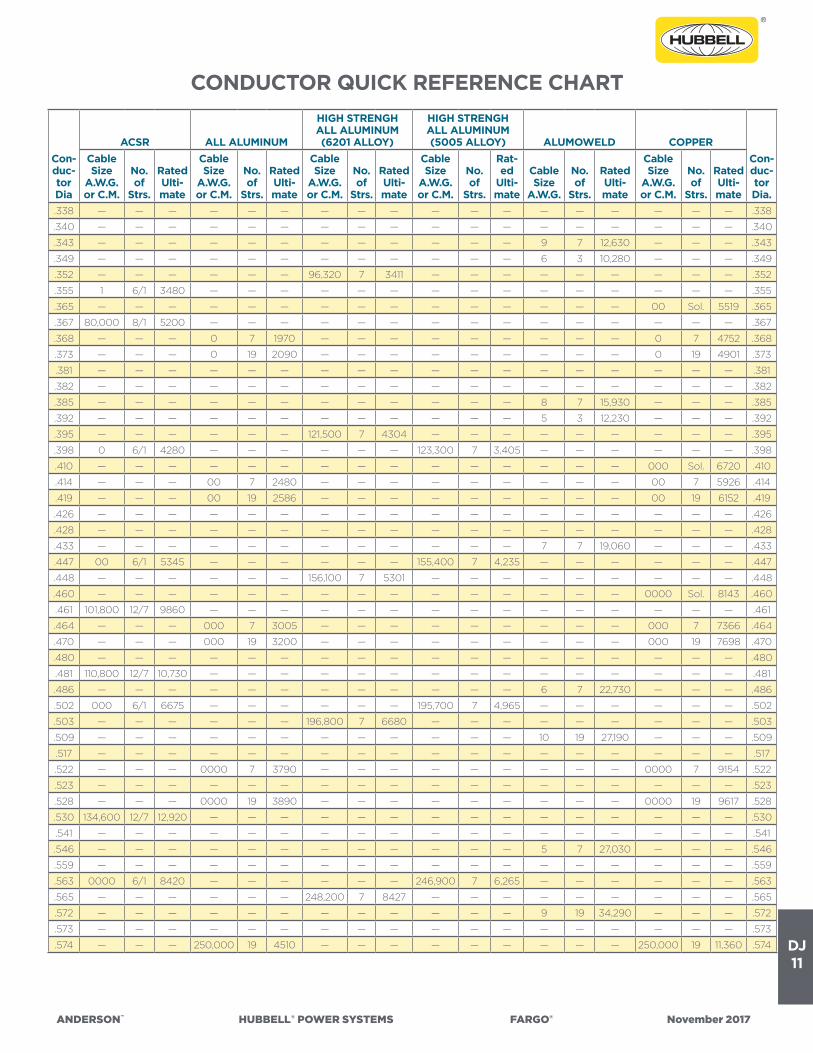
DJ11
ANDERSON™ HUBBELL®POWERSYSTEMS FARGO® November2017
CONDUCTOR QUICK REFERENCE CHART
Con-duc-torDia
ACSR ALL ALUMINUM
HIGH STRENGHALL ALUMINUM(6201 ALLOY)
HIGH STRENGHALL ALUMINUM(5005 ALLOY) ALUMOWELD COPPER
Con-duc-torDia.
Cable Size
A.W.G.or C.M.
No.of
Strs.
RatedUlti-mate
Cable Size
A.W.G.or C.M.
No.of
Strs.
RatedUlti-mate
Cable Size
A.W.G.or C.M.
No.of
Strs.
RatedUlti-mate
Cable Size
A.W.G.or C.M.
No.of
Strs.
Rat-ed
Ulti-mate
Cable Size
A.W.G.
No.of
Strs.
RatedUlti-mate
Cable Size
A.W.G.or C.M.
No.of
Strs.
RatedUlti-mate
.338 — — — — — — — — — — — — — — — — — — .338
.340 — — — — — — — — — — — — — — — — — — .340
.343 — — — — — — — — — — — — 9 7 12,630 — — — .343
.349 — — — — — — — — — — — — 6 3 10,280 — — — .349
.352 — — — — — — 96,320 7 3411 — — — — — — — — — .352
.355 1 6/1 3480 — — — — — — — — — — — — — — — .355
.365 — — — — — — — — — — — — — — — 00 Sol. 5519 .365
.367 80,000 8/1 5200 — — — — — — — — — — — — — — — .367
.368 — — — 0 7 1970 — — — — — — — — — 0 7 4752 .368
.373 — — — 0 19 2090 — — — — — — — — — 0 19 4901 .373
.381 — — — — — — — — — — — — — — — — — — .381
.382 — — — — — — — — — — — — — — — — — — .382
.385 — — — — — — — — — — — — 8 7 15,930 — — — .385
.392 — — — — — — — — — — — — 5 3 12,230 — — — .392
.395 — — — — — — 121,500 7 4304 — — — — — — — — — .395
.398 0 6/1 4280 — — — — — — 123,300 7 3,405 — — — — — — .398
.410 — — — — — — — — — — — — — — — 000 Sol. 6720 .410
.414 — — — 00 7 2480 — — — — — — — — — 00 7 5926 .414
.419 — — — 00 19 2586 — — — — — — — — — 00 19 6152 .419
.426 — — — — — — — — — — — — — — — — — — .426
.428 — — — — — — — — — — — — — — — — — — .428
.433 — — — — — — — — — — — — 7 7 19,060 — — — .433
.447 00 6/1 5345 — — — — — — 155,400 7 4,235 — — — — — — .447
.448 — — — — — — 156,100 7 5301 — — — — — — — — — .448
.460 — — — — — — — — — — — — — — — 0000 Sol. 8143 .460
.461 101,800 12/7 9860 — — — — — — — — — — — — — — — .461
.464 — — — 000 7 3005 — — — — — — — — — 000 7 7366 .464
.470 — — — 000 19 3200 — — — — — — — — — 000 19 7698 .470
.480 — — — — — — — — — — — — — — — — — — .480
.481 110,800 12/7 10,730 — — — — — — — — — — — — — — — .481
.486 — — — — — — — — — — — — 6 7 22,730 — — — .486
.502 000 6/1 6675 — — — — — — 195,700 7 4,965 — — — — — — .502
.503 — — — — — — 196,800 7 6680 — — — — — — — — — .503
.509 — — — — — — — — — — — — 10 19 27,190 — — — .509
.517 — — — — — — — — — — — — — — — — — — .517
.522 — — — 0000 7 3790 — — — — — — — — — 0000 7 9154 .522
.523 — — — — — — — — — — — — — — — — — — .523
.528 — — — 0000 19 3890 — — — — — — — — — 0000 19 9617 .528
.530 134,600 12/7 12,920 — — — — — — — — — — — — — — — .530
.541 — — — — — — — — — — — — — — — — — — .541
.546 — — — — — — — — — — — — 5 7 27,030 — — — .546
.559 — — — — — — — — — — — — — — — — — — .559
.563 0000 6/1 8420 — — — — — — 246,900 7 6,265 — — — — — — .563
.565 — — — — — — 248,200 7 8427 — — — — — — — — — .565
.572 — — — — — — — — — — — — 9 19 34,290 — — — .572
.573 — — — — — — — — — — — — — — — — — — .573
.574 — — — 250,000 19 4510 — — — — — — — — — 250,000 19 11,360 .574

DJ12
ANDERSON™ HUBBELL®POWERSYSTEMS FARGO® November2017
CONDUCTOR QUICK REFERENCE CHART
Con-duc-torDia
ACSR ALL ALUMINUM
HIGH STRENGHALL ALUMINUM(6201 ALLOY)
HIGH STRENGHALL ALUMINUM(5005 ALLOY) ALUMOWELD COPPER
Con-duc-torDia.
Cable Size
A.W.G.or C.M.
No.of
Strs.
RatedUlti-mate
Cable Size
A.W.G.or C.M.
No.of
Strs.
RatedUlti-mate
Cable Size
A.W.G.or C.M.
No.of
Strs.
RatedUlti-mate
Cable Size
A.W.G.or C.M.
No.of
Strs.
RatedUlti-mate
Cable Size
A.W.G.
No.of
Strs.
RatedUlti-mate
Cable Size
A.W.G.or C.M.
No.of
Strs.
RatedUlti-mate
.575 — — — 250,000 37 4860 — — — — — — — — — — — — .575
.576 159,000 12/7 15,200 — — — — — — — — — — — — — — — .576
.586 — — — 266,800 7 4525 — — — — — — — — — — — — .586
.593 — — — 266,800 19 4800 — — — — — — — — — — — — .593
.607 176,900 12/7 16,400 — — — — — — — — — — — — — — — .607
.609 266,800 18/1 6840 — — — — — — 281,400 19 7,365 — — — — — — .609
.618 — — — — — — — — — — — — — — — — — — .618
.628 — — — — — — — — — — — — — — — — — — .628
.629 — — — 300,000 37 5830 — — — — — — — — — 300,000 19 13,510 .629
.630 — — — — — — — — — — — — — — — 300,000 37 13,870 .630
.631 190,800 12/7 17,730 300,000 61 5940 — — — — — — — — — — — — .631
.633 266,800 6/7 9645 — — — — — — — — — — — — — — — .633
.636 — — — — — — 307,100 19 10,420 — — — — — — — — — .636
.642 266,800 26/7 11,250 — — — — — — 312,800 19 8,180 8 19 43,240 — — — .642
.646 300,000 18/1 7990 — — — — — — — — — — — — — — — .646
.663 211,300 12/7 19,640 — — — — — — — — — — — — — — — .663
.666 — — — 336,400 19 5940 — — — — — — — — — — — — .666
.677 336,400 36/1 7630 — — — — — — — — — — — — — — — .677
.679 — — — 350,000 19 6180 — — — — — — — — — 350,000 19 15,590 .679
.680 300,000 26/7 12,650 — — — — — — — — — — — — — — — .680
.681 — — — 350,000 37 6680 — — — — — — — — — 350,000 37 16,060 .681
.684 336,400 18/1 8625 — — — — — — 355,100 19 9,285 — — — — — — .684
.713 — — — — — — — — — — — — 10 37 52,950 — — — .713
.714 203,200 16/19 27,500 — — — — — — — — — — — — — — — .714
.721 336,400 26/7 14,050 — — — 394,600 19 12,830 394,500 19 10,180 7 19 51,730 — — — .721
.724 — — — 397,500 19 6880 — — — — — — — — — — — — .724
.726 — — — — — — — — — — — — — — — 400,000 19 17,810 .726
.728 — — — 400,000 37 7350 — — — — — — — — — 400,000 37 18,320 .728
.736 397,500 36/1 8740 — — — — — — — — — — — — — — — .736
.741 336,400 30/7 17,040 — — — — — — — — — — — — — — — .741
.743 397,500 18/1 10,040 — — — — — — 419,600 19 10,820 — — — — — — .743
.772 397,500 24/7 14,690 450,000 37 8110 — — — — — — — — — 450,000 37 20,450 .772
.783 397,500 26/7 16,190 — — — — — — 465,400 37 11,840 — — — — — — .783
.784 — — — — — — 466,300 19 15,160 — — — — — — — — — .784
.793 — — — 477,000 19 8090 — — — — — — — — — — — — .793
.795 — — — 477,000 37 8600 — — — — — — — — — — — — .795
.801 — — — — — — — — — — — — 9 37 66,770 — — — .801
.806 397,500 30/7 19,980 — — — — — — — — — — — — — — — .806
.806 477,000 36/1 10,320 — — — — — — — — — — — — — — — .806
.810 — — — — — — — — — — — — 6 19 61,700 — — — .810
.811 — — — 500,000 19 8480 — — — — — — — — — 500,000 19 21,950 .811
.813 — — — 500,000 37 9010 — — — — — — — — — 500,000 37 22,510 .813
.814 477,000 18/1 11,870 — — — — — — 503,600 19 12,100 — — — — — — .814
.846 477,000 24/7 17,200 — — — — — — — — — — — — — — — .846
.853 — — — — — — — — — — — — — — — 550,000 37 24,760 .853
.855 — — — 550,000 61 10,490 — — — — — — — — — 550,000 61 25,230 .855
.856 — — — 556,000 19 9440 — — — — — — — — — — — — .856

DJ13
ANDERSON™ HUBBELL®POWERSYSTEMS FARGO® November2017
CONDUCTOR QUICK REFERENCE CHART
Con-ductor
Dia
ACSR ALL ALUMINUM
HIGH STRENGHALL ALUMINUM(6201 ALLOY)
HIGH STRENGHALL ALUMINUM(5005 ALLOY) ALUMOWELD COPPER
Con-ductor
Dia.
Cable Size
A.W.G.or C.M.
No.of
Strs.
RatedUlti-mate
Cable Size
A.W.G.or C.M.
No.of
Strs.
RatedUlti-mate
Cable Size
A.W.G.or C.M.
No.of
Strs.
RatedUlti-mate
Cable Size
A.W.G.or C.M.
No.of
Strs.Rated
Ultimate
Cable Size
A.W.G.
No.of
Strs.
RatedUlti-mate
Cable Size
A.W.G.or C.M.
No.of
Strs.
RatedUlti-mate
.858 477,000 26/7 19,430 556,500 37 9830 599,600 19 18,200 559,500 19 13,450 — — — — — — .858
.870 556,000 36/1 11,800 — — — — — — — — — — — — — — — .870
.879 556,000 18/1 13,850 — — — — — — 597,200 19 14,120 — — — — — — .879
.883 477,000 30/7 23,300 — — — — — — — — — — — — — — — .883
.891 — — — 600,000 37 10,600 — — — — — — — — — 600,000 37 27,020 .891
.893 — — — 600,000 61 11,450 — — — — — — — — — 600,000 61 27,530 .893
.899 — — — — — — — — — — — — 8 37 84,200 — — — .899
.907 605,000 36/1 12,800 — — — — — — — — — — — — — — — .907
.910 — — — — — — — — — — — — 5 19 73,350 — — — .910
.914 556,600 24/7 19,850 — — — — — — — — — — — — — — — .914
.918 — — — — — — — — — — — — — — — 636,000 37 11,240 .918
.927 556,500 26/7 22,600 650,000 37 29,130 652,800 19 21,230 652,400 19 15,680 — — — — — — .927
.929 — — — 650,000 61 29,770 — — — — — — — — — 650,000 61 11,940 .929
.930 636,000 36/1 13,450 — — — — — — — — — — — — 650,000 91 12,630 .930
.940 636,000 18/1 15,830 — — — — — — — — — — — — — — — .940
.953 556,500 30/7 27,200 — — — — — — — — — — — — — — — .953
.953 605,000 24/7 21,500 — — — — — — — — — — — — — — — .953
.953 653,900 18/3 14,850 — — — — — — — — — — — — — — — .953
.953 666,600 36/1 14,100 — — — — — — — — — — — — — — — .953
.964 — — — 700,000 61 31,820 — — — — — — — — — 700,000 61 12,860 .964
.966 605,000 26/7 24,100 — — — — — — — — — — — — — — — .966
.974 — — — — — — — — — — — — — — — 715,500 37 12,640 .974
.975 — — — — — — — — — — — — — — — 715,500 61 13,150 .975
.977 636,000 24/7 22,600 — — — — — — — — — — — — — — — .977
.987 715,500 36/1 14,900 — — — — — — — — — — — — — — — .987
.990 636,000 26/7 25,000 — — — — — — 740,800 37 37 19,110 — — — — — — .990
.994 605,000 30/19 30,000 — — — 746,100 37 24,266 — — — — — — — — — .994
.998 — — — 750,000 61 13,510 — — — — — — — — — 750,000 61 34,090 .998
1.000 666,600 24/7 23,700 — — — — — — — — — — — — — — — 1.000
1.010 — — — — — — — — — — — — 7 37 100,700 — — — 1.010
1.019 636,000 30/19 31,500 — — — — — — — — — — — — — — — 1.019
1.026 — — — 795,000 37 13,770 — — — — — — — — — — — — 1.026
1.028 — — — 795,000 61 14,330 — — — — — — — — — — — — 1.028
1.031 — — — 800,000 61 14,410 — — — — — — — — — 800,000 61 36,360 1.031
1.036 715,500 54/7 26,300 — — — — — — — — — — — — — — — 1.036
1.040 795,000 36/1 16,540 — — — — — — — — — — — — — — — 1.040
1.051 715,500 26/7 28,100 — — — — — — — — — — — — — — — 1.051
1.063 795,000 45/7 22,900 — — — — — — — — — — — — 850,000 61 38,270 1.063
1.077 — — — 874,500 37 14,830 — — — — — — — — — — — — 1.077
1.078 — — — 874,500 61 15,760 — — — — — — — — — — — — 1.078
1.081 715,500 30/19 34,600 — — — — — — — — — — — — — — — 1.081
1.092 795,000 24/7 27,900 900,000 37 15,270 — — — — — — — — — 900,000 37 39,510 1.092
1.093 795,000 54/7 28,500 900,000 91 17,180 — — — — — — — — — — — — 1.093
1.094 — — — 900,000 61 15,900 — — — — — — — — — 900,000 61 40,520 1.094
1.108 795,000 26/7 31,200 — — — — — — 927,200 37 23,590 — — — — — — 1.108
1.112 — — — — — — 932,600 37 30,300 — — — — — — — — — 1.112
1.124 — — — 954,000 37 16,180 — — — — — — — — — — — — 1.124

DJ14
ANDERSON™ HUBBELL®POWERSYSTEMS FARGO® November2017
CONDUCTOR QUICK REFERENCE CHART
Con-ductor
Dia
ACSR ALL ALUMINUM
HIGH STRENGHALL ALUMINUM(6201 ALLOY)
HIGH STRENGHALL ALUMINUM(5005 ALLOY) ALUMOWELD COPPER
Con-ductor
Dia.
Cable Size
A.W.G.or C.M.
No.of
Strs.
RatedUlti-mate
Cable SizeA.W.G.or C.M.
No.of
Strs.
RatedUlti-mate
Cable Size
A.W.G.or C.M.
No.of
Strs.
RatedUlti-mate
Cable Size
A.W.G.or C.M.
No.of
Strs.
RatedUlti-mate
Cable Size
A.W.G.
No.of
Strs.
RatedUlti-mate
Cable Size
A.W.G.or C.M.
No.of
Strs.
RatedUlti-mate
1.126 — — — 954,000 61 16,860 — — — — — — — — — — — — 1.126
1.131 900,000 45/7 25,400 — — — — — — — — — 6 37 120,200 — — — 1.131
1.140 795,000 30/19 38,400 — — — — — — — — — — — — — — — 1.140
1.140 954,000 36/1 19,520 — — — — — — — — — — — — — — — 1.140
1.146 874,500 54/7 31,400 — — — — — — — — — — — — — — — 1.146
1.152 — — — 1,000,000 61 17,670 — — — — — — — — — 1,000,000 61 45,030 1.152
1.162 900,000 54/7 32,300 — — — — — — — — — — — — — — — 1.162
1.165 954,000 45/7 26,900 — — — — — — — — — — — — — — — 1.165
1.170 — — — 1,033,500 37 17,530 — — — — — — — — — — — — 1.170
1.172 — — — 1,033,500 61 18,260 — — — — — — — — — — — — 1.172
1.186 1,033,500 36/1 21,100 — — — — — — — — — — — — — — — 1.186
1.196 954,000 54/7 34,200 — — — — — — — — — — — — — — — 1.196
1.209 — — — 1,100,000 91 20,210 — — — — — — — — — — — — 1.209
1.213 1,033,500 45/7 28,900 — — — — — — — — — — — — — — — 1.213
1.216 — — — 1,113,000 61 19,660 — — — — — — — — — — — — 1.216
1.246 1,033,500 54/7 37,100 — — — — — — — — — — — — — — — 1.246
1.258 — — — 1,192,500 61 21,000 — — — — — — — — — — — — 1.258
1.259 1,113,000 45/7 30,900 — — — — — — — — — — — — — — — 1.259
1.263 — — — 1,200,000 91 21,630 — — — — — — — — — — — — 1.263
1.270 — — — — — — — — — — — — 5 37 142,800 — — — 1.270
1.288 — — — — — — — — — — — — — — — 1,250,000 61 55,670 1.288
1.289 — — — 1,250,000 91 22,530 — — — — — — — — — 1,250,000 91 56,280 1.289
1.293 1,113,000 54/9 40,200 — — — — — — — — — — — — — — — 1.293
1.300 — — — 1,272,000 61 22,000 — — — — — — — — — — — — 1.300
1.302 1,192,500 45/7 33,200 — — — — — — — — — — — — — — — 1.302
1.314 — — — 1,300,000 91 23,430 — — — — — — — — — — — — 1.314
1.333 1,192,500 54/19 43,100 — — — — — — — — — — — — — — — 1.333
1.340 — — — 1,351,500 61 23,400 — — — — — — — — — — — — 1.340
1.345 1,272,000 45/7 35,400 — — — — — — — — — — — — — — — 1.345
1.364 — — — 1,400,000 91 24,750 — — — — — — — — — — — — 1.364
1.379 — — — 1,431,000 61 24,300 — — — — — — — — — — — — 1.379
1.382 1,272,000 54/19 44,800 — — — — — — — — — — — — — — — 1.382
1.385 1,351,500 45/7 37,600 — — — — — — — — — — — — — — — 1.385
1.386 — — — — — — — — — — — — — — — — — — 1.386
1.411 — — — — — — — — — — — — — — — 1,500,000 61 65,840 1.411
1.412 — — — 1,500,000 91 26,500 — — — — — — — — — 1,500,000 91 67,540 1.412
1.417 — — — 1,510,500 61 25,600 — — — — — — — — — — — — 1.417
1.424 1,351,500 54/19 47,600 — — — — — — — — — — — — — — — 1.424
1.427 1,431,000 45/7 39,800 — — — — — — — — — — — — — — — 1.427
1.454 — — — 1,590,00061
91
27,000
28,100— — — — — — — — — — — — 1.454
1.459 — — — 1,600,000 127 28,840 — — — — — — — — — — — — 1.459
1.465 1,431,000 54/19 50,400 — — — — — — — — — — — — — — — 1.465
1.466 1,510,500 45/7 41,600 — — — — — — — — — — — — — — — 1.466
1.502 1,590,000 45/7 43,800 — — — — — — — — — — — — — — — 1.502
1.504 — — — 1,700,000 127 30,630 — — — — — — — — — — — — 1.504
1.506 1,510,500 54/19 53,200 — — — — — — — — — — — — — — — 1.506
1.526 — — — — — — — — — — — — — — — 1,750,000 91 77,930 1.526

DJ15
ANDERSON™ HUBBELL®POWERSYSTEMS FARGO® November2017
CONDUCTOR QUICK REFERENCE CHART
Con-ductor
Dia
ACSR ALL ALUMINUM
HIGH STRENGHALL ALUMINUM(6201 ALLOY)
HIGH STRENGHALL ALUMINUM(5005 ALLOY) ALUMOWELD COPPER
Con-ductor
Dia.
Cable Size
A.W.G.or C.M.
No.of
Strs.
RatedUlti-mate
Cable Size
A.W.G.or C.M.
No.of
Strs.
RatedUlti-mate
Cable Size
A.W.G.or C.M.
No.of
Strs.
RatedUlti-mate
Cable Size
A.W.G.or C.M.
No.of
Strs.
RatedUlti-mate
Cable Size
A.W.G.
No.of
Strs.
RatedUlti-mate
Cable Size
A.W.G.or C.M.
No.of
Strs.
RatedUlti-mate
1.526 — — — 1,750,000 127 16,860 — — — — — — — — — 1,750,000 127 78,800 1.526
1.545 1,590,000 54/19 56,000 — — — — — — — — — — — — — — — 1.545
1.548 — — — 1,800,000 127 32,450 — — — — — — — — — — — — 1.548
1.590 — — — 1,900,000 127 33,570 — — — — — — — — — — — — 1.590
1.602 1,780,000 84/19 53,600 — — — — — — — — — — — — — — — 1.602
1.630 — — — 2,000,000 91 34,600 — — — — — — — — — 2,000,000 91 87,790 1.630
1.632 — — — 2,000,000 127 35,340 — — — — — — — — — 2,000,000 127 90,050 1.632
1.737 2,167,000 72/7 50,900 — — — — — — — — — — — — — — — 1.737
1.762 2,156,000 84/19 63,400 — — — — — — — — — — — — — — — 1.762
1.823 — — — 2,500,000 91 42,000 — — — — — — — — — 2,500,000 91 109,600 1.823
1.824 — — — 2,500,000 127 43,300 — — — — — — — — — 2,500,000 127 111,300 1.824
1.996 — — — 3,000,000 127 50,800 — — — — — — — — — — — — 1.996
1.998 — — — — — — — — — — — — — — — 3,000,000 127 131,700 1.998
1.998 — — — 3,000,000 169 53,010 — — — — — — — — — 3,000,000 169 134,400 1.998
2.158 — — — 3,500,000 127 59,400 — — — — — — — — — 3,500,000 127 153,400 2.158

DJ16
ANDERSON™ HUBBELL®POWERSYSTEMS FARGO® November2017
ALUMINUM CONDUCTOR STEEL REINFORCEDACSR
CODEWORD
CIR MILSOR AWG STRANDING
DIAMETER (INCHES)
ULTIMATESTRENGTH WT/1000 FT.BARE FORMED TAPERED
FORMEDLINE
GUARDS
Turkey 6 6/1 .198 .440 — .440 1170 36.1
Swan 4 6/1 .250 .542 — .492 1830 57.4
Swanate 4 7/1 .257 .549 — .499 2288 67.1
Sparrow 2 6/1 .316 .588 — .588 2790 91.3
Sparate 2 7/1 .325 .597 — .567 3525 106.7
Robin 1 6/1 .355 .647 — .597 3480 115.2
Raven 1/0 6/1 .398 .732 — .630 4280 145.2
Quail 2/0 6/1 .447 .781 .835 .689 5345 183.1
Pigeon 3/0 6/1 .502 .836 .938 .744 6675 230.9
Penguin 4/0 6/1 .563 .927 1.051 .805 8420 291.1
Waxwing 266800 18/1 .609 .973 1.125 .901 6840 289.7
Owl 266800 6/7 .633 .997 1.179 .925 9645 343.3
Partridge 266800 26/7 .642 1.006 1.188 .934 11250 367.3
Ostrich 300000 26/7 .680 1.088 1.258 .972 12650 412.9
Merlin 336400 18/1 .684 1.092 1.262 .976 8625 365.3
Linnet 336400 26/7 .721 1.129 1.349 1.013 14050 463.0
Oriole 336400 30/7 .741 1.149 1.369 1.033 17040 527.1
Chickadee 397500 18/1 .743 1.151 1.371 1.035 10040 431.0
Brandt 397500 24/7 .772 1.180 — 1.064 14690 512.1
Ibis 397500 26/7 .783 1.283 1.447 1.075 16190 547.2
Lark 397500 30/7 .806 1.306 1.490 1.098 19980 622.8
Pelican 477000 18/1 .814 1.314 1.518 1.106 11870 518.0
Flicker 477000 24/7 .846 1.346 1.570 1.138 17200 614.5
Hawk 477000 26/7 .858 1.358 1.602 1.150 19430 656.6
Hen 477000 30/7 .883 1.383 1.649 1.175 23300 747.3
Osprey 556500 18/1 .879 1.379 1.623 1.213 13850 604.0
Parakeet 556500 24/7 .914 1.414 1.702 1.248 19850 717.0
Dove 556500 26/7 .927 1.427 1.715 1.261 22400 766.0
Eagle 556500 30/7 .953 1.453 1.763 1.287 27200 872.0
Peacock 605000 24/7 .953 1.453 1.763 1.287 21500 779.0
Duck 605000 54/7 .953 1.453 — 1.287 22500 779.0
Squab 605000 26/7 .966 1.466 1.798 1.330 24100 833.0
Teal 605000 30/19 .994 1.614 1.850 1.358 30000 939.0
Swift 636000 36/1 .930 1.430 1.718 1.264 13450 644.0
Kingbird 636000 18/1 .940 1.440 — 1.274 15830 691.0
Rook 636000 24/7 .977 1.597 1.809 1.341 22600 819.0
Grosbeak 636000 26/7 .990 1.610 1.846 1.354 25000 875.0
Egret 636000 30/19 1.019 1.639 1.901 1.383 31500 988.0
Flamingo 666000 24/7 1.000 1.620 1.856 1.364 23700 859.0
Gannet 666000 26/7 1.014 1.634 — 1.378 26200 918.0

DJ17
ANDERSON™ HUBBELL®POWERSYSTEMS FARGO® November2017
ALUMINUM CONDUCTOR STEEL REINFORCEDACSR (CONTINUED)
CODEWORD
CIR MILSOR AWG STRANDING
DIAMETER (INCHES)
ULTIMATESTRENGTH WT/1000 FT.BARE FORMED TAPERED
FORMEDLINE
GUARDS
Crow 715500 54/7 1.036 1.656 1.918 1.400 26300 921.0
Stilt 715500 24/7 1.036 1.656 1.918 1.400 25500 921.0
Starling 715500 26/7 1.051 1.671 1.959 1.459 28100 985.0
Redwing 715500 30/19 1.081 1.701 2.013 1.489 34600 1111.0
Coot 795000 36/1 1.040 1.660 1.922 1.448 16550 885.0
Tern 795000 45/7 1.063 1.683 1.971 1.471 22900 896.0
Cuckoo 795000 24/7 1.092 1.712 — 1.500 27900 1024.0
Condor 795000 54/7 1.093 1.713 2.025 1.501 28500 1024.0
Drake 795000 26/7 1.108 1.728 2.040 1.608 31200 1094.0
Mallard 795000 30/19 1.140 1.760 2.128 1.640 38400 1235.0
Ruddy 900000 45/7 1.131 1.766 2.153 1.631 25400 1015.0
Canary 900000 54/7 1.162 1.782 2.150 1.662 32300 1159.0
Catbird 954000 36/1 1.140 1.760 — 1.640 19520 966.0
Rail 954000 45/7 1.165 1.785 2.153 1.665 26900 1075.0
Cardinal 954000 54/7 1.196 1.816 1.984 1.696 34200 1229.0
Tanager 1033500 36/1 1.140 1.760 — 1.640 21100 1046.0
Ortolan 1033500 45/7 1.213 1.943 2.023 1.713 28900 1165.0
Curlew 1033500 54/7 1.246 1.976 2.078 1.746 37100 1331.0
Bluejay 1113000 45/7 1.259 1.989 2.091 1.759 30900 1255.0
Finch 1113000 54/19 1.293 2.023 2.149 1.793 40200 1431.0
Bunting 1192500 45/7 1.302 2.032 2.158 1.802 33200 1344.0
Grackle 1192500 54/19 1.338 2.068 2.220 1.833 43100 1533.0
Skylark 1272000 36/1 1.316 2.046 2.198 1.816 — 1434.0
Bittern 1272000 45/7 1.345 2.075 2.227 1.845 35400 1434.0
Pheasant 1272000 54/19 1.382 2.112 2.290 1.882 44800 1635.0
Dipper 1351500 45/7 1.385 2.115 2.152 1.886 37600 1523.0
Martin 1351500 54/19 1.424 2.296 2.190 2.044 47600 1737.0
Bobolink 1431000 45/7 1.427 2.229 2.215 2.047 39800 1613.0
Plover 1431000 54/19 1.465 2.337 2.253 2.085 50400 1840.0
Nuthatch 1510500 45/7 1.466 2.338 2.276 2.086 41600 1702.0
Parrot 1510500 54/19 1.506 2.378 2.316 2.126 53200 1942.0
Lapwing 1590000 45/7 1.502 2.374 2.312 2.122 43800 1792.0
Falcon 1590000 54/19 1.545 2.417 2.377 — 56000 2044.0
Chukar 1780000 84/19 1.602 2.474 2.472 — 53600 2074.0
Bluebird 2156000 84/19 1.762 2.634 2.462 — 63400 2511.0
Kiwi 2167000 72/7 1.737 2.609 2.437 — 50900 2303.0
Thrasher 2312000 76/19 1.802 2.786 — — 56700 2526.0
Joree 2515000 76/19 1.802 2.786 — — 61700 2749.0

DJ18
ANDERSON™ HUBBELL®POWERSYSTEMS FARGO® November2017
ALL-ALUMINUM CONDUCTOR
CODEWORD
CIR MILSOR AWG
STRAND-ING
DIAMETER (INCHES)
ULTIMATESTRENGTH
WT/1000 FT.BARE FORMED TAPERED
FORMEDLINE
GUARDSPeachbell 6 7 .184 .426 — .388 528 24.6
Rose 4 7 .232 .474 — .474 826 39.2
Iris 2 7 .292 .584 — .534 1266 62.3
Pansy 1 7 .328 .620 — .570 1537 78.5
Poppy 1/0 7 .368 .660 — .610 1865 99.1
Aster 2/0 7 .414 .706 — .656 2350 124.9
Phlox 3/0 7 .464 .798 .864 .706 2845 157.5
Oxlip 4/0 7 .522 .856 .970 .764 3590 198.6
Daisy 266800 7 .586 .950 1.095 .828 4525 250.4
Laurel 266800 19 .593 .957 1.095 .885 4800 250.4
Peony 300000 19 .629 .993 1.153 .921 5301 281.6
Tulip 336400 19 .666 1.030 1.228 .958 5940 315.8
Canna 397500 19 .724 1.132 1.352 1.016 6880 373.2
Comos 477000 19 .793 1.293 1.479 1.085 8090 447.8
Syringa 477000 37 .795 1.295 1.479 1.087 8600 447.8
Zinnia 500000 19 .812 1.312 — 1.104 8482 469.4
Dahlia 556500 19 .856 1.356 1.600 1.148 9440 522.4
Mistletoe 556500 37 .858 1.358 1.600 1.150 9830 522.4
Orchid 636000 37 .918 1.418 1.706 1.252 11240 597.0
Violet 715500 37 .974 1.474 1.807 1.338 12640 671.6
Nasturtium 715500 61 .975 1.475 1.807 1.339 13150 671.6
Petunia 750000 37 .997 1.617 — 1.361 12440 704.0
Cattail 750000 61 .998 1.618 — 1.362 13510 704.0
Arbutus 795000 37 1.026 1.646 1.910 1.390 13770 746.3
Lilac 795000 61 1.028 1.648 1.910 1.392 14330 746.3
Anemone 874500 37 1.077 1.697 2.010 1.485 14830 821.0
Crocus 874500 61 1.078 1.698 2.010 1.486 15760 821.0
Magnolia 954000 37 1.124 1.744 2.058 1.624 16180 895.5
Goldenrod 954000 61 1.126 1.746 2.058 1.626 16860 895.5
Bluebell 1033500 37 1.170 1.790 1.960 1.670 17530 970.1
Larkspur 1033500 61 1.172 1.792 1.960 1.672 18260 970.1
Marigold 1113000 61 1.216 1.946 2.026 1.716 19660 1045.0
Narcissus 1272000 61 1.300 2.030 2.156 1.800 22000 1193.0
Carnation 1431000 61 1.379 2.109 2.287 1.879 24300 1343.0
Coreopsis 1590000 61 1.454 2.184 2.242 2.073 27000 1493.0
Dogwood 1590000 91 1.454 — 2.242 2.073 28100 1493.0

DJ19
ANDERSON™ HUBBELL®POWERSYSTEMS FARGO® November2017
SELF-DAMPING ALUMINUM CONDUCTORSTEEL REINFORCED ACSR/SD
CODEWORD TYPE KCMIL
DIAMETER (INCHES)
RatedStrengthPounds
ReelDesigna-
tion
Foot-agePerReel
WEIGHT POUNDSPERCENT OFTOTAL WT.PER 1,000 FEET PER MILE
Com-plete
Conduc-tor
SteelCore TOTAL ALUM. STEEL TOTAL ALUM. STEEL ALUM. STEEL
Titmouse/SD 5 266.8 0.593 0.117 6920 RM 66.32 14,000 286.9 250.6 36.3 1515 1323 192 87.3 12.7
Eider/SD 7 266.8 0.601 0.136 7610 RM 66.32 14,000 299.4 250.6 48.8 1581 1323 258 83.7 16.3
Spoonbill/SD 10 266.8 0.610 0.162 8450 RM 66.32 14,000 320.0 250.6 69.4 1689 1323 366 78.3 21.7
Partridge/SD 16 266.8 0.645 0.236 11350 RM 66.32 13,000 367.0 251.4 115.6 1937 1327 610 68.5 31.5
Cowbird/SD 5 336.4 0.667 0.132 8500 RM 66.32 12,000 361.9 316.1 45.8 1911 1669 242 87.3 12.7
Hummingbird/SD
7 336.4 0.664 0.153 9130 RM 66.32 12,000 377.7 316.1 61.6 1994 1669 325 83.7 16.3
Woodcock/SD 10 336.4 0.688 0.206 11000 RM 66.32 11,000 404.5 316.7 87.8 2136 1672 464 78.3 21.7
Linnet/SD 16 336.4 0.716 0.265 14300 RM 68.38 13,000 462.4 317.0 145.4 2442 1674 768 68.5 31.5
Erne/SD 5 397.5 0.717 0.143 9740 RM 66.32 10,000 427.7 373.5 54.2 2258 1972 286 87.3 12.7
Longspur/SD 7 397.5 0.725 0.166 10600 RM 68.38 13,000 446.1 373.4 72.7 2355 1972 383 83.7 16.3
Stork/SD 10 397.5 0.750 0.224 12900 RM 68.38 12,000 477.9 374.0 103.9 2523 1975 548 78.3 21.7
Ibis/SD 16 397.5 0.771 0.288 16400 RM 68.38 12,000 546.5 374.6 171.9 2886 1978 908 68.5 31.5
Kestrel/SD 5 477 0.787 0.157 11700 RM 68.38 11,000 513.3 448.4 64.9 2710 2367 343 87.3 12.7
Jackdaw/SD 7 477 0.798 0.182 12800 RM 68.38 11,000 535.9 448.6 87.3 2830 2369 461 83.7 16.3
Toucan/SD 10 477 0.824 0.245 15300 RM 68.38 10,000 573.4 448.9 124.5 3027 2370 657 78.3 21.7
Flicker/SD 13 477 0.843 0.282 17200 RMT 84.36 12,000 613.5 449.0 164.5 3240 2371 869 73.2 26.8
Hawk/SD 16 477 0.860 0.316 19500 RMT 84.36 11,000 655.8 449.4 206.4 3463 2373 1090 68.5 31.5
Blackbird/SD 5 556.5 0.843 0.169 13600 RM 68.38 10,000 599 523 76 3163 2761 402 87.3 12.7
Sunbird/SD 7 556.5 0.863 0.222 15500 RMT 84.36 11,000 625 523 102 3300 2761 539 83.7 16.3
Sapsucker/SD 10 556.5 0.882 0.265 17800 RMT 84.36 11,000 669 524 145 3532 2767 765 78.3 21.7
Parakeet/SD 13 556.5 0.901 0.305 20000 RMT 84.36 10,000 716 524 192 3781 2767 1014 73.2 26.8
Dove/SD 16 556.5 0.919 0.341 22600 RMT 84.36 10,000 765 524 241 4039 2767 1272 68.5 31.5
Pipit/SD 5 636 0.894 0.181 15600 RMT 84.36 11,000 685 598 87 3617 3157 460 87.3 12.7
Killdeer/SD 7 636 0.917 0.238 17700 RMT 84.36 10,000 715 598 117 3775 3157 618 83.6 16.4
Goldfinch/SD 10 636 0.935 0.284 20100 RMT 84.36 10,000 765 599 166 4039 3163 876 78.3 21.7
Rook,/SD 13 636 0.955 0.326 22900 RMT 84.36 9,000 818 599 219 4319 3163 1156 73.2 26.8
Grosbeak/SD 16 636 0.975 0.365 25400 RMT 84.36 9,000 874 599 275 4615 3163 1452 68.5 31.5
Macaw/SD 5 795 0.999 0.229 19800 EMR 90.45 14,000 856 747 109 4520 3944 576 87.3 12.7
Tern/SD 7 795 1.013 0.266 21900 RMT 90.45 13,000 893 747 146 4715 3944 771 83.6 16.4
Puffin/SD 10 795 1.034 0.317 25100 RMT 90.45 13,000 956 748 208 5048 3950 1098 78.3 21.7
Condor/SD 13 795 1.055 0.364 28200 RMT 90.45 12,000 1023 749 274 5401 3954 1447 73.2 26.8
Drake/SD 16 795 1.077 0.408 31800 RMT 90.45 11,000 1093 749 344 5771 3955 1816 68.5 31.5
Phoenix/SD 5 954 1.088 0.251 23700 RMT 90.45 11,000 1027 897 130 5423 4736 687 87.3 12.7
Rail/SD 7 954 1.103 0.291 26100 RMT 90.45 11,000 1073 897 176 5665 4736 929 83.6 16.4
Cardinal/SD 13 954 1.147 0.399 33500 RMT 90.45 10,000 1227 898 329 6478 4741 1737 73.2 26.8
Snowbird/SD 5 1033.5 1.185 0.261 25900 RMT 90.45 10,000 1115 974 141 5887 5143 744 87.3 12.7
Ortolan/SD 7 1033.5 1.145 0.303 28100 RMT 90.45 10,000 1161 971 190 6130 5127 1003 83.6 16.4
Curlew/SD 13 1033.5 1.191 0.415 36300 RMT 90.45 9,000 1329 973 356 7017 5137 1880 73.2 26.8
Avocet/SD 5 1113 1.226 0.271 27500 RMT 90.45 9,000 1200 1048 152 6336 5533 803 87.3 12.7
Bluejay/SD 7 1113 1.242 0.315 30300 RMT 90.45 9,000 1254 1049 205 6621 5539 1082 83.7 16.3
Finch/SD 3 1113 1.233 0.431 39100 RMT 90.45 9,000 1424 1048 376 7519 5533 1985 73.6 26.4
Oxbird/SD 5 1192.5 1.266 0.281 29500 RMT 90.45 9,000 1286 1123 163 6790 5929 861 87.3 12.7

DJ20
ANDERSON™ HUBBELL®POWERSYSTEMS FARGO® November2017
SELF-DAMPINGALUMINUM CONDUCTOR STEEL REINFORCED
ACSR/SD (CONTINUED)
CODEWORD TYPE KCMIL
DIAMETER (INCHES)
RatedStrengthPounds
ReelDesigna-
tion
Foot-agePerReel
WEIGHT POUNDSPERCENT OFTOTAL WT.PER 1,000 FEET PER MILE
Com-plete
Conduc-tor
SteelCore TOTAL ALUM. STEEL TOTAL ALUM. STEEL ALUM. STEEL
Bunting/SD 7 1192.5 1.284 0.326 32400 RMT 90.45 8,000 1343 1124 219 7091 5935 1156 83.7 16.3
Grackle/SD 13 1192.5 1.274 0.446 41900 RMT 90.45 8,000 1526 1123 403 8057 5929 2128 73.6 26.4
Scissortail/SD 5 1272 1.305 0.290 31400 RMT 96.60 12,000 1372 1198 174 7244 6325 919 87.3 12.7
Bittern/SD 7 1272 1.323 0.336 34600 RMT 96.60 12,000 1433 1199 234 7567 6331 1236 83.7 16.3
Pheasant/SD 13 1272 1.378 0.461 44100 RMT 96.60 12,000 1631 1202 429 8611 6347 2265 73.7 26.3
Ringdove/SD 5 1351.5 1.344 0.299 33400 RMT 96.60 12,000 1458 1273 185 7698 6721 977 87.3 12.7
Dipper/SD 7 1351.5 1.361 0.347 36700 RMT 96.60 12,000 1522 1274 248 8036 6727 1309 83.7 16.3
Frigate/SD 10 1351.5 1.389 0.413 41700 RMT 96.60 11,000 1629 1276 353 8601 6737 1864 78.3 21.7
Martin/SD 13 1351.5 1.417 0.475 46800 RMT 96.60 11,000 1733 1277 456 9150 6742 2408 73.7 26.3
Popinjay/SD 5 1431 1.381 0.308 35300 RMT 96.60 11,000 1544 1348 196 8152 7117 1035 87.3 12.7
Bobolink/SD 7 1431 1.398 0.357 38900 RMT 96.60 11,000 1612 1349 263 8511 7122 1389 83.7 16.3
Plover/SD 13 1431 1.448 0.489 49600 RMT 96.60 11,000 1835 1352 483 9689 7139 2550 73.7 26.3
Ratite/SD 5 1590 1.463 0.325 39100 RMT 96.60 10,000 716 1498 218 9060 7909 1151 87.3 12.7
Lapwing/SD 7 1590 1.463 0.376 42600 RMT 96.60 10,000 1791 1499 292 9456 7914 1542 83.7 16.3
Falcon/SD 13 1590 1.521 0.515 55100 RMT 96.60 9,000 2039 1502 537 10766 7931 2835 73.7 26.3
Smew/SD 5 1780 1.531 0.343 43600 RMT 96.60 9,000 1921 1677 244 10143 8855 1288 87.3 12.7
Chukar/SD 8 1780 1.565 0.437 51100 RMT 96.60 9,000 2068 1681 387 10919 8876 2043 81.3 18.7
Cockatoo/SD 5 2156 1.731 0.378 52500 RMT 96.60 7,500 2331 2036 295 12308 10750 1558 87.3 12.7
Bluebird/SD 8 2156 1.716 0.481 60700 RMT 96.60 7,500 2504 2036 468 13221 10750 2471 81.3 18.7
Kiwi/SD 4 2167 1.725 0.347 50700 RMT 96.60 7,000 2296 2047 249 12123 10808 1315 89.2 10.8
Meets latest revision of ASTM B232 where applicable, and ASTM B498

DJ21
ANDERSON™ HUBBELL®POWERSYSTEMS FARGO® November2017
ALUMINUM CONDUCTOR ALLOY REINFORCEDACAR
CIR MILSOR AWG STRANDING
DIAMETER (INCHES)ULTIMATESTRENGTH WT/1000 FT.BARE FORMED ROD
355,000 15/4 0.684 1.572 8,095 333.3
355,000 12/7 0.684 1.572 8,940 333.3
503,600 15/4 0.814 1.878 11,200 472.7
503,600 12/7 0.814 1.878 12,430 472.7
653,100 15/4 0.927 2.104 14,500 613.1
653,800 12/7 0.927 2.104 16,100 613.1
739,800 33/4 0.990 2.290 14,850 694.5
739,800 30/7 0.990 2.290 16,400 694.5
739,800 24/13 0.990 2.290 18,250 694.5
739,800 18/19 0.990 2.290 20,100 694.5
819,200 30/7 1.042 2.394 18,150 768.9
840,200 24/13 1.055 2.420 20,500 788.7
853,700 30/7 1.063 2.436 18,650 801.4
853,700 24/13 1.063 2.436 20,840 801.4
853,700 18/19 1.063 2.436 23,030 801.4
862,700 18/19 1.069 2.448 23,300 809.7
927,200 30/7 1.108 2.526 20,300 870.4
927,200 24/13 1.108 2.526 22,600 870.4
927,200 18/19 1.108 2.526 25,000 870.4
983,100 30/7 1.141 2.592 21,450 922.8
1,012,200 24/13 1.158 2.626 24,700 950.2
1,024,500 30/7 1.165 2.640 22,381 961.6
1,024,500 24/13 1.165 2.640 25,010 961.6
1,024,500 18/19 1.165 2.640 27,700 961.6
1,081,000 30/7 1.196 2.702 23,620 1015.0
1,081,000 24/13 1.196 2.702 26,330 1015.0
1,081,000 18/19 1.196 2.702 29,160 1015.0
1,109,000 30/7 1.212 2.789 24,200 1041.0
1,109,000 24/13 1.212 2.789 27,050 1041.0
1,109,000 18/19 1.212 2.789 29,900 1041.0
1,172,000 33/4 1.246 2.857 23,100 1100.0
1,172,000 30/7 1.246 2.857 25,600 1100.0
1,172,000 24/13 1.246 2.857 28,600 1100.0
1,172,000 18/19 1.246 2.857 31,630 1100.0
1,198,000 30/7 1.259 2.883 26,180 1124.0
1,198,000 24/13 1.259 2.883 29,250 1124.0
1,198,000 18/19 1.259 2.883 32,320 1124.0
1,280,000 30/7 1.302 2.969 27,960 1201.0
1,280,000 24/13 1.302 2.969 31,250 1201.0
1,280,000 18/19 1.302 2.969 34,530 1201.0

DJ22
ANDERSON™ HUBBELL®POWERSYSTEMS FARGO® November2017
ALUMINUM CONDUCTOR ALLOY REINFORCEDACAR (CONTINUED)
CIR MILSOR AWG STRANDING
DIAMETER (INCHES)ULTIMATESTRENGTH WT/1000 FT.BARE FORMED ROD
1,361,000 54/7 1.345 3.055 27,450 1278.0
1,361,000 42/19 1.345 3.055 32,750 1278.0
1,703,000 54/7 1.504 3.444 35,220 1599.0
1,703,000 48/13 1.504 3.444 37,860 1599.0
1,703,000 42/19 1.504 3.444 40,520 1599.0
1,933,000 54/7 1.602 3.640 39,900 1814.0
1,933,000 48/13 1.602 3.640 42,960 1814.0
1,933,000 42/19 1.602 3.640 45,970 1814.0
2,267,000 54/7 1.735 3.906 44,750 2127.0
2,267,000 48/13 1.735 3.906 50,000 2127.0
2,267,000 42/19 1.735 3.906 53,350 2127.0
2,338,000 54/7 1.762 3.960 46,140 2194.0
2,338,000 48/13 1.762 3.960 51,600 2194.0
2,338,000 42/19 1.762 3.960 55,000 2194.0
2,493,000 72/19 1.821 4.078 55,200 2341.0
2,493,000 63/28 1.821 4.078 59,100 2341.0
2,493,000 54/37 1.821 4.078 63,000 2341.0

DJ23
ANDERSON™ HUBBELL®POWERSYSTEMS FARGO® November2017
ALUMOWELD CONDUCTOR
NO. AND SIZEOF WIRES
CIR.MILS
DIAMETER (INCHES)ULTIMATESTRENGTH WT/1000 FT.BARE FORMED ROD
Solid Wire12
6,530 .08081 — 1,000 14.65
11 8,234 .09074 — 1,261 18.47
10 10,380 .1019 — 1,590 23.29
9 13,090 .1144 — 2,005 29.37
8 16,510 .1285 — 2,529 37.03
7 20,820 .1443 — 3,025 46.69
6 26,250 .1620 — 3,608 58.88
5 33,100 .1819 — 4,290 74.25
4 41,740 .2043 — 5,081 93.63
Strand3 No. 10
31,150 .220 .424 4,532 70.43
3 No. 9 39,280 .247 .451 5,715 88.81
3 No. 8 49,530 .277 .505 7,206 112.0
3 No. 7 62,450 .311 .539 8,621 141.2
3 No. 6 78,750 .349 .577 10,280 178.1
3 No. 5 99,310 .392 .648 12,230 224.5
7 No. 12 45,710 .242 .446 6,301 103.6
7 No. 11 57,640 .272 .500 7,945 130.6
7 No. 10 72,680 .306 .534 10,020 164.7
7 No. 9 115,600 .343 .571 12,630 207.6
7 No. 8 115,600 .385 .641 15,930 261.8
7 No. 7 145,700 .433 .689 19,060 330.0
7 No. 6 183,800 .486 .774 22,730 416.3
7 No. 5 231,700 .546 .870 27,030 524.9
19 No. 10 197,300 .509 — 27,190 448.7
19 No. 9 248,800 .572 — 34,290 565.8
19 No. 8 313,700 .642 — 43,240 713.5
19 No. 7 395,500 .721 — 51,730 899.5
19 No. 6 498,800 .810 — 61,700 1134.0
19 No. 5 628,900 .910 — 73,350 1430.0
37 No. 10 384,200 .713 — 52,950 879.0
37 No. 9 484,400 .801 — 66,770 1108.0
37 No. 8 610,900 .899 — 84,200 1398.0
37 No. 7 770,300 1.01 — 100,700 1762.0
37 No. 6 971,300 1.13 — 120,200 2222.0
37 No. 5 1,225,000 1.27 — 142,800 2802.0

DJ24
ANDERSON™ HUBBELL®POWERSYSTEMS FARGO® November2017
GALVANIZED STEEL GUY WIRE
CONDUCTORSIZE
NUMBEROF
STRANDS
DIAMETER (INCHES) ULTIMATE STRENGTH POUNDS
WT/1000 FT.BAREFORMED
RODCOMMONGRADE
SIEMENSMARTINGRADE
HIGH-STRENGTH
GRADE
EXTRAHIGH
STRENGTHGRADE
UTILITIESGRADE
1/8 7 .123 — 540 910 1330 1830 — 31.8
5/32 7 .156 — 870 1470 2140 2940 — 51.3
3/16 7 .186 —1150—
1900—
2850—
3990—
—2400
72.980.3
7/32 7 .216 — 1540 2560 3850 5400 — 98.3
1/4337
.259
.259
.240
.431
.431
.412
——
1900
——
3150
——
4750
——
6650
31504500
—
116.7116.7121.0
9/32 7 .279 — 2570 4250 6400 8950 4600 164.0
5/16377
.312
.312.327
.512
.512.527
—3200
—
—5350
—
—8000
—
—11200
—
6500—
6000
170.6205.0225.0
3/837
.356
.360.556.560
—4250
—6950
—10800
—15400
850011500
220.3273.0
7/16 7 .435 .733 5700 9350 14500 20800 18000 399.0
1/2719
.495.500
.771.776
74007620
1210012700
1880019100
2690026700
25000—
517.0504.0
9/16719
.564
.565—
96007620
1570012700
2450019100
3500026700
—671.0504.0
5/8719
.621.625
—1600011000
1910018100
2960028100
4240040200
—813.0796.0
3/4 19 .750 — 16000 26200 40800 58300 — 1155.0
7/8 19 .885 — 21900 35900 55800 79700 — 1581.0
11937
1.0001.001
—2870028300
4700046200
7320071900
104500102700
—2073.02057.0
1-1/8 37 1.127 — 28300 58900 91600 130800 — 2691.0
1-1/4 37 1.253 — 44600 73000 113600 162200 — 3248.0

www.hubbellpowersystems.com
Because Hubbell has a policy of continuous product improvement. We reserve the right to change design and specifications without notice.
©Copyright 2017 Hubbell IncorporatedPrinted in U.S.A. 11/17 QG 2.5M Catalog DIST-1
About Hubbell Power SystemsHubbell Power Systems (HPS) manufactures a wide variety of transmission, distribution, substation, OEM and telecom-munications products used by utilities. HPS products are also used in the civil construction, transportation, gas and water industries. Our product line includes construction and switch-ing products, tools, insulators, arresters, pole line hardware, cable accessories, test equipment, transformer bushings and polymer precast enclosures and equipment pads.