Behavior of rigid-porous layers at high levels of continuous acoustic excitation: Theory and...
11
Behavior of rigid-porous layers at high levels of continuous acoustic excitation: Theory and experiment O. Umnova, K. Attenborough, a) E. Standley, and A. Cummings Department of Engineering, University of Hull, Cottingham Road, Hull HU7 6RX, United Kingdom ~Received 5 February 2003; revised 20 June 2003; accepted 23 June 2003! A model for the propagation of high amplitude continuous sound through hard-backed rigid-porous layers has been developed which allows for Forchheimer’s correction to Darcy’s law. The nonlinearity associated with this is shown to be particularly important in the range of frequencies around layer resonance. The model is based on the introduction of particle velocity dependent flow resistivity into the equivalent fluid model expression for complex tortuosity. Thermal effects are accounted for by means of a linear complex compressibility function. The model has been used to derive analytical expressions for surface impedance and reflection coefficient as a function of incident pressure amplitude. Depending on the material parameters, sample thickness, and frequency range the model predicts either growth or decrease of reflection coefficient with sound amplitude. Good agreement between model predictions and data for three rigid-porous materials is demonstrated. © 2003 Acoustical Society of America. @DOI: 10.1121/1.1603236# PACS numbers: 43.25.Ed, 43.25.Jh, 43.25.Ba @MFH# LIST OF SYMBOLS v Angular sound frequency p Pressure in sound wave v Particle velocity in sound wave d Porous sample thickness c 0 Sound speed in air r 0 Density of air h Viscosity of air g Adiabatic constant N Pr Prandtl number d ( v ) 5A 2 h / vr 0 viscous layer thickness a~v! Complex tortuosity C ( v ) Complex compressibility a ‘ Tortuosity f Volume porosity s dc flow resistivity j Forchheimer’s nonlinearity pa- rameter L Characteristic viscous length k 0 8 Thermal permeability L 8 Characteristic thermal length Q’0.675(1 2f ) Cell model parameter k ( v ) 5k 8 ( v ) 1ik 9 ( v ) Wave number v 6 ( x ) Slow varying amplitudes of par- ticle velocity in direct and back- ward propagating waves inside the pores respectively p 6 ( x ) Slow varying amplitudes of pres- sure in direct and backward propagating waves inside the pores, respectively v i , r Particle velocity amplitudes in in- cident and reflected waves in air p i , r 56v i , r r 0 c 0 Pressure amplitudes in incident and reflected waves in air Z 0 ( v ) 5Z 0 8 ( v ) 1iZ 0 9 ( v ) Relative characteristic impedance of porous material Z ( v ) Relative surface impedance of hard backed porous sample R ( v ) Absolute value of the reflection coefficient of hard backed porous sample v res Resonant frequency of hard backed porous sample I. INTRODUCTION Acoustical properties of rigid porous media at high lev- els of continuous sound have been studied for more than a decade. 1–6 It has been shown that due to strong dispersion in such a medium the shock generation in an initially sinusoidal wave is mostly suppressed. 1 The dominating nonlinearity as- sociated with growth of flow resistivity with flow velocity leads to an excess sound attenuation inside the material which has been observed in highly porous fibrous materials and porous ceramics. Forchheimer’s correction has been used to extend a rigid frame theory ~assuming cylindrical pores! of sound propagation in porous materials by adding a velocity dependent term to the imaginary part of complex density. 2 An interesting result was found that at some fre- quencies the absorption coefficient of a 9.25 cm hard-backed layer of open-cell foam first increases with pressure, peaks, and then drops off. This result was confirmed numerically. An analytical model for nonlinear surface and flow imped- ance, which takes account only of a nonlinear term in the imaginary part of complex density, and a numerical model, which accounts of nonlinearity in both real and imaginary parts, have been presented 4–5 and tested using a standing a! Author to whom correspondence should be addressed; electronic mail: [email protected] 1346 J. Acoust. Soc. Am. 114 (3), September 2003 0001-4966/2003/114(3)/1346/11/$19.00 © 2003 Acoustical Society of America
Transcript of Behavior of rigid-porous layers at high levels of continuous acoustic excitation: Theory and...

Behavior of rigid-porous layers at high levels of continuousacoustic excitation: Theory and experiment
O. Umnova, K. Attenborough,a) E. Standley, and A. CummingsDepartment of Engineering, University of Hull, Cottingham Road, Hull HU7 6RX, United Kingdom
~Received 5 February 2003; revised 20 June 2003; accepted 23 June 2003!
A model for the propagation of high amplitude continuous sound through hard-backed rigid-porouslayers has been developed which allows for Forchheimer’s correction to Darcy’s law. Thenonlinearity associated with this is shown to be particularly important in the range of frequenciesaround layer resonance. The model is based on the introduction of particle velocity dependent flowresistivity into the equivalent fluid model expression for complex tortuosity. Thermal effects areaccounted for by means of a linear complex compressibility function. The model has been used toderive analytical expressions for surface impedance and reflection coefficient as a function ofincident pressure amplitude. Depending on the material parameters, sample thickness, andfrequency range the model predicts either growth or decrease of reflection coefficient with soundamplitude. Good agreement between model predictions and data for three rigid-porous materials isdemonstrated. ©2003 Acoustical Society of America.@DOI: 10.1121/1.1603236#
PACS numbers: 43.25.Ed, 43.25.Jh, 43.25.Ba@MFH#
-
-
e
-
e
t
e
f
s
d
v-ni
ida-
eria
een
g alexe-kedks,
lly.d-theel,ryg
ma
LIST OF SYMBOLS
v Angular sound frequencyp Pressure in sound wavev Particle velocity in sound waved Porous sample thicknessc0 Sound speed in airr0 Density of airh Viscosity of airg Adiabatic constantNPr Prandtl numberd(v)5A2h/vr0 viscous layer thicknessa~v! Complex tortuosityC(v) Complex compressibilitya` Tortuosityf Volume porositys dc flow resistivityj Forchheimer’s nonlinearity pa
rameterL Characteristic viscous lengthk08 Thermal permeabilityL8 Characteristic thermal lengthQ'0.675(12f) Cell model parameter
I. INTRODUCTION
Acoustical properties of rigid porous media at high leels of continuous sound have been studied for more thadecade.1–6 It has been shown that due to strong dispersionsuch a medium the shock generation in an initially sinusowave is mostly suppressed.1 The dominating nonlinearity associated with growth of flow resistivity with flow velocityleads to an excess sound attenuation inside the matwhich has been observed in highly porous fibrous mater
a!Author to whom correspondence should be addressed; [email protected]
1346 J. Acoust. Soc. Am. 114 (3), September 2003 0001-4966/2003/1
k(v)5k8(v)1 ik9(v) Wave numberv6(x) Slow varying amplitudes of par
ticle velocity in direct and back-ward propagating waves insidthe pores respectively
p6(x) Slow varying amplitudes of pressure in direct and backwardpropagating waves inside thpores, respectively
v i ,r Particle velocity amplitudes in in-cident and reflected waves in air
pi ,r56v i ,rr0c0 Pressure amplitudes in incidenand reflected waves in air
Z0(v)5Z08(v)1 iZ09(v) Relative characteristic impedancof porous material
Z(v) Relative surface impedance ohard backed porous sample
R(v) Absolute value of the reflectioncoefficient of hard backed porousample
v res Resonant frequency of harbacked porous sample
anl
ialls
and porous ceramics. Forchheimer’s correction has bused to extend a rigid frame theory~assuming cylindricalpores! of sound propagation in porous materials by addinvelocity dependent term to the imaginary part of compdensity.2 An interesting result was found that at some frquencies the absorption coefficient of a 9.25 cm hard-baclayer of open-cell foam first increases with pressure, peaand then drops off. This result was confirmed numericaAn analytical model for nonlinear surface and flow impeance, which takes account only of a nonlinear term inimaginary part of complex density, and a numerical modwhich accounts of nonlinearity in both real and imaginaparts, have been presented4–5 and tested using a standinil:
14(3)/1346/11/$19.00 © 2003 Acoustical Society of America

nftenn
d’susthux-
ityme
tioththero
rsizaarang
re
lyuaedse
rehean
onace
edurt
n-m
addrdouprth
lar
a-i-
,
tori-g a
m-,
re-
h
wave method.3 Good agreement between numerical solutioand surface~or flow! impedance data was demonstrated afitting the data for the nonlinear parameters. A differeapproach6 has used the equivalent fluid model of Johnso7
with effective flow resistivity values dependent on Reynolnumber to explain the nonlinear behavior of rigid poromaterials. Thermal effects were included by means ofcomplex compressibility function introduced by Champoand Allard8 and Lafarge.9 In general the resulting model requires six linear parameters~porosity, tortuosity, dc flow re-sistivity, characteristic viscous length, thermal permeabiland thermal length! and nonlinear parameters derived fromeasurement of the dc flow resistivity dependence on Rnold’s number~or velocity!. This approach6 assumes thaflow through the sample is constant. While this assumptwas applicable to the experimental situation described inpaper, i.e., transmission measurements on relativelysamples, it cannot be used for hard backed layers becausparticle velocity in the pores is not uniform and has zevalue at the impervious backing. The present paper offedevelopment of this approach based on the ‘‘nonlineartion’’ of the equivalent fluid model. The resulting nonlinemodel enables prediction of the acoustical properties of hbacked porous layers at high intensities and includes chaof the particle velocity in the pores.
It has been established that the dependence of flowsistivity on flow velocity is quadratic when Reynolds numb@defined as Re5avr0 /h, wherea is characteristic pore size,vis flow velocity in pores,r0 is air density,h is air viscosity#is less than one and is linear~Forchheimer’s law! for higherReynolds numbers.10 However in the present paper onForchheimer’s correction is considered and the initial qdratic dependence of flow resistivity on velocity is neglectThis assumption is shown to be valid for the materials uin the experiment which have relatively big~i.e., bigger than1 mm! pores.
In Sec. II A the model for nonlinear impedance andflection coefficient is described. It allows predictions for twhole range of frequencies. It is based on modification ofequivalent fluid model to include a flow velocity-dependeflow resistivity. As a result of this an analytical expressifor the dependence of the reflection coefficient and surfimpedance of a layer on the incident pressure amplitudobtained.
In Sec. II B particular attention is given to the predictchange of reflection coefficient with incident sound presslevel near layer resonance where nonlinear effects arestrongest. An analytical criterion is derived which distiguishes between two types of behavior based on linearterial parameters and layer thickness.
In Sec. III, results are compared with data. Surfacemittance and reflection coefficient have been measuredifferent levels of continuous acoustic excitation for habacked layers of lead balls, porous aluminum, and porconcrete. Data are compared with the nonlinear modeldictions at different frequencies, particularly those nearlayer resonances.
J. Acoust. Soc. Am., Vol. 114, No. 3, September 2003 Um
srt
e
,
y-
neinthe
a-
rdes
e-r
-.d
-
nt
eis
ehe
a-
-at-s
e-e
II. THE MODEL
A. Surface impedance dependence on soundamplitude
By introducing dimensionless complex tortuositya~v!and complex compressibilityC(v) of the fluid contained inrigid porous material, the equations for pressurep and par-ticle velocityv variations in the plane sound wave of angufrequencyv can be written in the following form:
2 iva~v!r0v52dp
dx, 2 iv
C~v!
r0c02
p52dvdx
, ~1!
herec0 is sound speed.The dynamic~complex! tortuositya~v! is approximated
by the following function:7
a~v!5a`1sf
2 ivr0A11~2 iv!
4a`2 r0h
s2f2L2, ~2!
wherea` is the tortuosity,s is the flow resistivity,L is thecharacteristic viscous length,f is the volume porosity, andhis the coefficient of dynamic viscosity for air. The drag prameters (a` , s, andL! for granular materials can be estmated if the particle radius and porosity are known.11
Similarly, the dynamic compressibilityC(v) is approxi-mated by8,9
C~v!
5g2g21
S 11hf
2 ivr0k08NPr
A11~2 iv!r04k08
2NPr
hL82f2 D ,
~3!
whereg is the adiabatic constant,NPr is the Prandtl numberk08 is the thermal permeability, andL8 is the characteristicthermal length. The number of parameters necessarymodel sound propagation in materials with straight cylindcal pores or in granular materials can be reduced by usinsimilarity relationship between complex density and coplex compressibility functions.12,13 For a packing of spheresthe relationship has the following form.13
C~v!5g2g21
~ 23~12Q!~a~vNPr!2a`!11!
, ~4!
where Q'0.675(12f). It is equivalent to the followingrelationships between thermal permeability and dc flowsistivity:
k0853
2~12Q!
h
s, ~5!
and between viscous and thermal characteristic lengths:
L853
2a`~12Q!L. ~6!
It is assumed that flow resistivity grows linearly witparticle velocity amplitude in the sound wave:
s5s0~11jfuvu!, ~7!
1347nova et al.: Behavior of porous layers at high levels of sound

anrea
ftheer
s-x
rm
lees
t-tia
the
n-
us
re-
nd
n--the
wherej is Forchheimer’s nonlinearity parameter which cbe measured in standard flow resistivity tests. The factoporosity in Eq. ~7! allows for the difference between thvelocity in pores and flow velocity measured outside the mterial in flow resistivity tests.
Expression~7! is substituted in Eq.~2! to get the veloc-ity dependent complex tortuositya(v,v):
a~v,v !5a`1s0f~11jfuvu!
2 ivr0
3A11~2 iv!4a`
2 r0h
s02f2L2~11jfuvu2!
.
The solution of Eq.~1! is performed by the method oslow varying amplitudes. This method assumes thatchanges in wave amplitude due to the presence of nonlinity remain small when wave travels a distance comparablits wavelength. Consequently the following derivations avalid only at relatively low values of incident sound presure. First the dispersion relation is found in linear appromation
k~v!5v
c0Aa~v!C~v!. ~8!
Then a solution of nonlinear equations is sought in the fo
v~x!5v1~x!eik~v!x1v2~x!e2 ik~v!x,
p~x!5r0c0
2
ivC~v!
dvdx
, ~9!
where v6(x) are the slow varying amplitudes of particvelocity in the forward and backward propagating wavExpression~9! is now substituted into Eq.~1! with secondderivatives ofv6(x) neglected. This leads to a pair of firsorder nonlinear differential equations describing spachanges inv6 :
dv1
dx52M ~v!SA11 i
vc
v~11jfuvu!2
2A11 ivc
v D v1 ,
~10!dv2
dx5M ~v!SA11 i
vc
v~11jfuvu!2
2A11 ivc
v D v2 ,
1348 J. Acoust. Soc. Am., Vol. 114, No. 3, September 2003
of
-
ear-toe
i-
.
l
where
M ~v!5~12 i !a`v2C~v!
c02k~v!
d~v!
2L, vc5
s02f2L2
4a`2 r0h
,
andd(v)5A2h/vr0 is the viscous layer thickness.To determine the normalized surface impedance of
layer Z5(1/r0c0)@p(0)/fv(0)#, Eq. ~10! has to be solvedwith boundary condition of flux continuity and pressure cotinuity on the material surface
v i1v r5pi2pr
r0c05fv~0!5f~v1~0!1v2~0!!, ~11!
pi1pr5p~0!5r0c0Aa~v!
C~v! S v1~0!2v2~0!
11
ik~v! S dv1
dx1
dv2
dx D Ux50
D ~12!
and the condition of zero particle velocity on an imperviohard backing:
v~d!5v1~d!eik~v!d1v~d!e2 ik~v!d50, ~13!
whered is porous layer thickness. The amplitude of theflection coefficient follows from
R5Upr
piU5U12Z
11ZU,wherepi andpr are pressure amplitudes in the incident areflected waves, respectively.
This is equivalent to the following expression~whichwill be used later!:
R5A124Re~Z!
11ZZ* 12 Re~Z!. ~14!
The solution of Eq.~10! has been performed using the meafield approximation.14 This leads to the following relationships between the velocity amplitudes on both sides oflayer:
v1~d!'v1~0!expF 2M ~v!SA11 ivc
v~11jfuv~0!u!21A11 i
vc
v~11jfuv~d!u!2
22A11 i
vc
vD dG ,
~15!
v2~d!5v2~0!v1~0!
v1~d!.
Umnova et al.: Behavior of porous layers at high levels of sound
ebe
ce
thin
en
e-all
By combining this with boundary conditions~11!–~13!the following transcendental equation for the dependencsurface impedance on incident pressure amplitude hasobtained:
Z~v!51
fAa~v!
C~v! S 12M ~v!
ik~v!G~U~v!! D
3cothS 2 ik~v!dS 12M ~v!
2ik~v!G~U~v!! D D ,
~16!
U~v!52upi u
fu11Z~v!ur0c0,
where
G~x!5A11 ivc
v~11jfx!22A11 i
vc
v.
B. Reflection coefficient at resonance: Dependenceon sound amplitude
The following derivations are valid for
vc
v,1, ~17!
i.e., for frequencies higher thanvc . It will be shown in Sec.III that the approximation is valid for the layer resonanfrequencies of the tested samples.
The following expressions are used to approximatecomplex density and complex compressibility functionsthis frequency range:
pan
tth
J. Acoust. Soc. Am., Vol. 114, No. 3, September 2003 Um
ofen
e
a~v!'a`S 11~11 i !d~v!
L S 11vc
22iv D D ,
C~v!'11g21
ANPr
~11 i !d~v!
L8.
Consequently the propagation constantk and characteristicimpedanceZ0 can be approximated by
k~v!'Aa`v
c0F S 11
d~v!
2L12
d~v!
2L
vc
2v D1 i S d~v!
2L11
d~v!
2L
vc
2v D G ,Z0~v!'
Aa`
f F S 11d~v!
2L22
d~v!
2L
vc
2v D1 i S d~v!
2L21
d~v!
2L
vc
2v D G ,whereL1,2 are functions of the characteristic lengths givby
1
L1,25
1
L6
g21
ANPrL8.
It is assumed in the following derivation that in the frquency range of interest the viscous layer depth is smcompared withL2 ,
Aa`
2f
d~v!
L2,1. ~18!
By using expression~14! the following approximate ex-pression for the reflection coefficient~linear! can be derived:
R~v!5A124Z08~v!~12e24k9~v!d!
~11Z08~v!2!~11e24k9~v!d!12Z08~v!~12e24k9~v!d!12e24k9~v!d~Z08~v!221!cos~2k8~v!d!,
ay
where k8(v)5Re(k(v)), k9(v)5Im(k(v)), Z08(v)5Re(Z0(v)).
In the approximation adopted here the real part of progation constantk8(v) shows the strongest frequency depedence of all functions involved inR(v). Due to this fact, thefirst resonant frequencyv res where reflection coefficienreaches its minimum can be found approximately fromcondition:
2k8~v res!d5p.
Retaining only the linear invc /v terms the followingexpression for the resonant frequency is derived:
--
e
v res5v res~0!F 11
vc
2v res~0!
d res~0!
2L
1
11d res
~0!
4L1
G , ~19!
where
d res~0!5d~v res
~0!!,
v res~0!5
1
4 SA 2pc
Aa`d1
h
2r0L122A h
2r0L12D 2
.
The value of the reflection coefficient at this frequency mbe approximated by
1349nova et al.: Behavior of porous layers at high levels of sound

Rres5R~v res!' 124Aa`
f
S 12e22n expS 22l S vc
v res~0!D D D
Aa v Aa 2, ~20!
! S S 11`f D 2e2n expS 2 l S c
v res~0!D D S `
f21D D
sulinnade
inn
ce
ath
enin
t
a-
sose
-lex
5.1ud-
ate-id
thecm.ntsed
ent
where
n5d res
~0!
L1
Aa`v res~0!
c0d, l 5n
L1
L.
The above-presented results have been obtained asing that sound amplitude is low and material behavesearly. To obtain the approximate dependence of the resovalue of reflection coefficient on incident sound amplituwe have to replace the parametervc in Eq. ~20! with aneffective value that depends on the sound amplitude. Takinto account the results of the previous section, at resonavc can be approximated by
vceff5vcS 11j
2upi ur0c0u11Zresu
D 2
,
whereZres is the ~linear! impedance at the layer resonanfrequency.
The first derivative ofRres with respect topi is
dRres~ upi u!d~ upi u!
52AF S 11Aa`
f D e2n expS 2 l S vceff
v res~0!D D
2SAa`
f21D G ,
whereA is a positive constant.This means that reflection coefficient at resonance
ways grows with incident pressure amplitude as long asfollowing inequality is valid:
S 11j2upi u
r0c0u11ZresuD 2
.v res
~0!
vcl S lnS 11Aa`
f
Aa`
f21D 2nD .
~21!
This suggests that two types of behavior are possible deping on the material parameters. If the right-hand side ofequality ~21! is less than one, i.e., if
vc.Lc0
Aa`d res~0!d
lnS 11Aa`
f
Aa`
f21D 2v res
~0!L
L1, ~22!
then the reflection coefficient at layer resonance grows asincident pressure increases.@Fig. 1~a!#. This behavior is char-acteristic for fairly resistive materials. For materials with prameters such that Eq.~22! is not obeyed, the reflection coefficient decreases when pressure amplitude is less thancritical valuepcr . For higher amplitudes, the initial decreais followed by subsequent growth@Fig. 1~b!#. This behavior
1350 J. Acoust. Soc. Am., Vol. 114, No. 3, September 2003
m--nt
gce
l-e
d--
he
-
me
is predicted for low flow resistivity materials.It follows from Eq. ~21! that pcr is higher for materials
with weak nonlinearity~i.e., relatively low values of parameterj!. Note that due to the approximate nature of comptortuosity function~2! only the two first terms in its highfrequency expansion are exact. Consequently, criterion~22!should not be treated as a precise result.
III. COMPARISON WITH DATA
A. Lead shot
Impedance measurements have been carried out, incm ~inner! diameter tubes connected to a 400 W Fane lospeaker using the transfer function method.3 A vertical 70-cm-long tube was used for measurements on granular mrials, and a horizontal 3-m-long tube was used for rigporous materials. Two14 in. Bruel & Kjaer microphones wereplaced 20 cm apart in the tube. The distance betweensample surface and the closest microphone was about 10A metallic sample holder with an acoustically transparemesh designed to fit the vertical impedance tube was u
FIG. 1. The two types of reflection coefficient dependence on the incidpressure amplitude predicted by the model.
Umnova et al.: Behavior of porous layers at high levels of sound

anoinsf
ao
alscbjuea
a
fohin
eslyh
defo
rs
icith
s agth
effi-a
on,
ofbe-
ictedepre-el.the
fo
ad-ata,
for the unconsolidated materials. The porous aluminumporous concrete samples were specially manufactured tin the horizontally installed tube. To investigate possibleterference of nonlinear effects inside the tube, the tranfunction has been measured in the absence of sampleswith a rigid termination. It has proved to be independentamplitude.
The flow resistivities of the tested rigid-porous materihave been deduced from measurements of volume veloand pressure drop across samples of known thickness suto compressed air in a tube. As with the impedance measments, a vertical sample holder was used for measuremon loose materials and a horizontal one for rigid-porous mterials. The inner diameter of the flow resistivity tubes wclose to 50 mm.
The model has been tested against impedance data15 cm layer of lead shot with mean radius of 1.89 mm. Tmaterial consists of nearly identical spherical particles ashows strongs(v) dependence even at relatively low valuof flow velocity ~Fig. 2! but the dependence is approximatelinear. This approximation was used to determine Forchimer’s nonlinearity parameterj and dc flow resistivity values0 . The value of dc flow resistivity~1373 Pa s/m2! deducedfrom data is fairly close to that predicted~1465 Pa s/m2! by acell model for identical spherical particles.11 The character-istic viscous length was estimated by using the cell moalso. The tortuosity was estimated using the empiricalmula a51/Af'1.615 as use of the value~1.8! predicted bythe cell model11 gives slightly incorrect values for the layeresonance frequencies. Values of parameters of the leadpacking are given in Table I. Relationship~4! has been usedto determine the complex compressibility function. Predtions of the linear equivalent fluid model are compared w
FIG. 2. The dependence of flow resistivity on flow velocity measuredlead shot and its straight line approximation.
TABLE I. Parameters for lead shot and their method of determination.
Porosityf 0.385 MeasuredFlow resistivitys0 ~Pa s/m2!
1373 Measured
Characteristic viscouslengthL ~m!
5.531024 Cell modela
Tortuositya` 1.6 Empirical formulab
Forchheimer’s parameterj ~s/m!
3.7 Measured
aReference 11.bReference 15.
J. Acoust. Soc. Am., Vol. 114, No. 3, September 2003 Um
dfit-erndf
ityectre-nts-
s
r asd
e-
lr-
hot
-
data in Fig. 3. It should be noted that the cell model hatendency to overestimate the characteristic viscous lenvalue for denser packings.11 This might explain the slightdisagreement between theory and data. The reflection cocient of a layer achieves its minimum value of 0.11 atfrequency of approximately 415 Hz. In the resonant regiboth inequalities~17! and ~18! are valid: vc /v res'0.2,(Aa`/2f)@d(v res)/L2#'0.2. This means that the resultsprevious section can be used to describe any nonlinearhavior at resonance. Indeed the resonant frequency predby Eq. ~19! is 403 Hz, which is close to that shown in thdata. The value of the reflection coefficient at resonancedicted by Eq.~20! is approximately 0.2, which is very closto the value~0.23! given by the linear equivalent fluid modeHowever both are higher than the measured value forabove-mentioned reasons.
Since, for this material, condition~22! is not satisfied,i.e.,
vc'378 Hz,
Lc0
Aa`d res~0!d
lnS 11Aa`
f
Aa`
f21D 2v res
~0!L
L1'2408 Hz,
r
FIG. 3. The frequency dependence of reflection coefficient and surfacemittance for low amplitude sound for lead shot. Points—white noise dline—Johnson/Champoux/Allard/Lafarge linear model.
1351nova et al.: Behavior of porous layers at high levels of sound

du
ancfr
icith
retioituea
sedeen
5 cmid
eat
eata,
for
the reflection coefficient at resonance should experiencecrease followed by subsequent growth as the incident soamplitude is increased.
To study the nonlinear behavior of the material, mesurements have been carried out at different values of ident pressure amplitude using pure tone signals in thequency range between 375 and 600 Hz.
Figures 4 and 5 show that the nonlinear model predthe observed variation of the reflection coefficient and admtance with the incident pressure. Growth or decrease ofreflection coefficient is predicted depending on the fquency. At the first layer resonance frequency, the refleccoefficient is observed to decrease as the pressure amplincreases to 266 Pa. As predicted by the theory, this decr
FIG. 4. The reflection coefficient as a function of the pressure amplitudthe incident wave at four different frequencies for lead shot. Points—dlines—model.~a! 385 Hz,~b! 415 Hz,~c! 450 Hz,~d! 500 Hz.
1352 J. Acoust. Soc. Am., Vol. 114, No. 3, September 2003
e-nd
-i-e-
tst-e
-ndese
is followed by growth as the pressure amplitude is increafurther. It should be noted that these predictions have bobtained with no adjustable parameters.
B. Porous aluminum
Impedance measurements have been made on a 1sample of aluminum foam which is a highly porous rig
ofa,
FIG. 5. The surface admittance 1/Z as a function of the pressure amplitudof the incident wave at four different frequencies for lead shot. Points—dlines—model.~a! 385 Hz,~b! 415 Hz,~c! 450 Hz,~d! 500 Hz.
FIG. 6. The dependence of flow resistivity on flow velocity measuredporous aluminum and its straight-line approximation.
Umnova et al.: Behavior of porous layers at high levels of sound

heite
ecth
hom
poar
fer-ghtling
re-elyent
ingoef-
pli-to
re isfor
ver
sus—el.
ofies.
mi
material. The value of porosity obtained by weighing tsample is 0.93. Its flow resistivity is low and shows qustrong dependence on flow velocity~Fig. 6!. The character-istic viscous length and tortuosity of the material have bededuced to fit the low intensity characteristic impedandata. To account for thermal effects it has been assumedthe rigid inclusions are spherical as in the case of lead sOf course this ideal microstructure does not reflect the coplicated pore geometry of the foam. However, the highrosity of this material means that the thermal effects
FIG. 7. The frequency dependence of the reflection coefficient and theface admittance for low amplitude sound for porous aluminum. Pointwhite noise data, lines—Johnson/Champoux/Allard/Lafarge linear mod
TABLE II. Parameters for porous aluminum and their method of deternation.
Porosityf 0.93 Measureddc flow resistivitys0 ~Pa s/m2!
204.6 Measured
Characteristic viscous lengthL ~m!
7.731024 Deduced by fitting~linear!characteristic impedance data
Tortuositya` 1.07 Deduced by fitting~linear!characteristic impedance data
Forchheimer’s parameterj~s/m!
2.9 Measured
J. Acoust. Soc. Am., Vol. 114, No. 3, September 2003 Um
neatt.--e
weak, so predictions are not much affected by use of difent idealizations of the microstructure, for instance straicylindrical pores. Values of parameters used in the modeare summarized in Table II.
Figure 7 shows that the first layer resonance in theflection coefficient is not very sharp and lies approximatbetween 600 and 700 Hz. The value of reflection coefficiat resonance is close to 0.75.
Conditions~17! and~18! are valid for the material sincevc /v res'0.07 and (Aa`/2f)@d(v res)/L2#'0.04. The ap-proximate resonant frequency predicted by Eq.~19! is 511Hz, which is close to the frequency of the zero axis crossof the measured reactance. The value of the reflection cficient at resonance predicted by Eq.~20! is 0.75, which isclose to the data. Condition~20! is not valid for porous alu-minum since
vc'215 Hz,
Lc0
Aa`d res~0!d
lnS 11Aa`
f
Aa`
f21D 2v res
~0!L
L1'47 060 Hz,
This means that growth of the incident pressure amtude should result in reflection coefficient behavior similarthat observed in lead shot. Figures 8 and 9 show that thea good agreement between data and model predictionsthe reflection coefficient and admittance behavior. Howe
r-
FIG. 8. The reflection coefficient of porous aluminum as a functionpressure amplitude in the incident wave at four different frequencPoints—data, lines—model.~a! 400 Hz,~b! 550 Hz,~c! 650 Hz,~d! 700 Hz.
-
1353nova et al.: Behavior of porous layers at high levels of sound
thth
byu
a
nbh
theall
a--thetion
nti-
so-ely
by
eie
fo
therete.ear
ina-
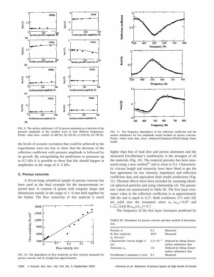
the levels of acoustic excitation that could be achieved inexperiments were too low to show that the decrease ofreflection coefficient with pressure amplitude is followedits growth. By extrapolating the predictions to pressuresto 6.5 kPa it is possible to show that this should happenamplitudes in the range of 4–5 kPa.
C. Porous concrete
A 10-cm-long cylindrical sample of porous concrete hbeen used as the final example for the measurementsported here. It consists of grains with irregular shape adimensions mainly in the range of 1–6 mm held togetherthe binder. The flow resistivity of this material is muc
FIG. 9. The surface admittance 1/Z of porous aluminum as a function of thpressure amplitude in the incident wave at four different frequencPoints—data, lines—model.~a! 400 Hz,~b! 550 Hz,~c! 650 Hz,~d! 700 Hz.
FIG. 10. The dependence of flow resistivity on flow velocity measuredporous concrete and its straight-line approximation.
1354 J. Acoust. Soc. Am., Vol. 114, No. 3, September 2003
ee
pat
sre-dy
higher than that of lead shot and porous aluminum andmeasured Forchheimer’s nonlinearity is the strongest ofthe materials~Fig. 10!. The material porosity has been mesured using a new method16 and is close to 0.3. Characteristic viscous length and tortuosity have been fitted to getbest agreement for low intensity impedance and refleccoefficient data and equivalent fluid model predictions~Fig.11!. Thermal effects have been included by assuming idecal spherical particles and using relationship~4!. The param-eter values are summarized in Table III. The first layer renance value in the reflection coefficient is at approximat500 Hz and is equal to 0.27. Both conditions~17! and ~18!are valid near the resonance sincevc /v res'0.07 and(Aa`/2f)@d(v res)/L2#'0.7.
The frequency of the first layer resonance predicted
s.
r
FIG. 11. The frequency dependence of the reflection coefficient andsurface admittance for low amplitude sound incident on porous concPoints—white noise data, lines—Johnson/Champoux/Allard/Lafarge linmodel.
TABLE III. Parameters for porous concrete and their method of determtion.
Porosityf 0.3 Measureddc flow resistivitys0 ~Pa s/m2!
3619 Measured
Characteristic viscous lengthL~m!
2.231024 Deduced by fitting~linear!surface admittance data
Tortuositya` 1.8 Deduced by fitting~linear!surface admittance data
Forchheimer’s parameterj ~s/m! 8.3 Measured
Umnova et al.: Behavior of porous layers at high levels of sound
tard
rehi
co-redn-tionen-
tystedkedusf
igh
tionma-de-is
vedat
d onela-
e-y.
reat
nata,
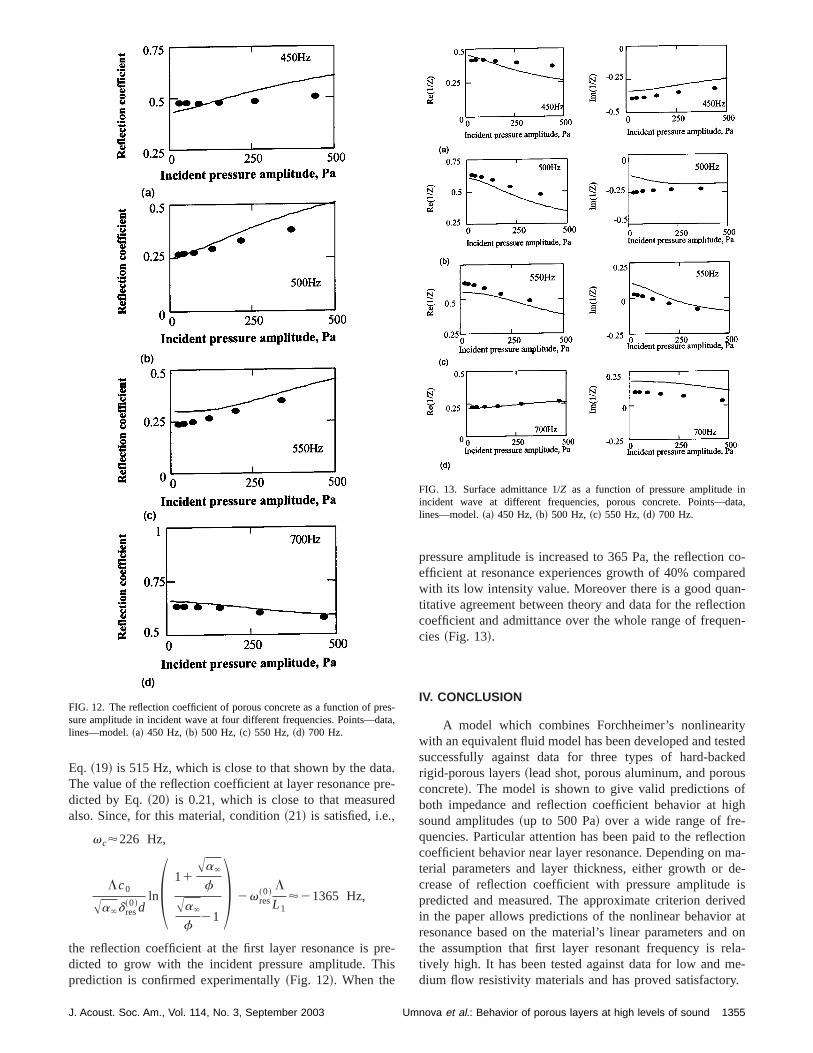
Eq. ~19! is 515 Hz, which is close to that shown by the daThe value of the reflection coefficient at layer resonance pdicted by Eq.~20! is 0.21, which is close to that measurealso. Since, for this material, condition~21! is satisfied, i.e.,
vc'226 Hz,
Lc0
Aa`d res~0!d
lnS 11Aa`
f
Aa`
f21D 2v res
~0!L
L1'21365 Hz,
the reflection coefficient at the first layer resonance is pdicted to grow with the incident pressure amplitude. Tprediction is confirmed experimentally~Fig. 12!. When the
FIG. 12. The reflection coefficient of porous concrete as a function of psure amplitude in incident wave at four different frequencies. Points—dlines—model.~a! 450 Hz,~b! 500 Hz,~c! 550 Hz,~d! 700 Hz.
J. Acoust. Soc. Am., Vol. 114, No. 3, September 2003 Um
.e-
-s
pressure amplitude is increased to 365 Pa, the reflectionefficient at resonance experiences growth of 40% compawith its low intensity value. Moreover there is a good quatitative agreement between theory and data for the refleccoefficient and admittance over the whole range of frequcies ~Fig. 13!.
IV. CONCLUSION
A model which combines Forchheimer’s nonlineariwith an equivalent fluid model has been developed and tesuccessfully against data for three types of hard-bacrigid-porous layers~lead shot, porous aluminum, and poroconcrete!. The model is shown to give valid predictions oboth impedance and reflection coefficient behavior at hsound amplitudes~up to 500 Pa! over a wide range of fre-quencies. Particular attention has been paid to the refleccoefficient behavior near layer resonance. Depending onterial parameters and layer thickness, either growth orcrease of reflection coefficient with pressure amplitudepredicted and measured. The approximate criterion deriin the paper allows predictions of the nonlinear behaviorresonance based on the material’s linear parameters anthe assumption that first layer resonant frequency is rtively high. It has been tested against data for low and mdium flow resistivity materials and has proved satisfactor
s-a,
FIG. 13. Surface admittance 1/Z as a function of pressure amplitude iincident wave at different frequencies, porous concrete. Points—dlines—model.~a! 450 Hz,~b! 500 Hz,~c! 550 Hz,~d! 700 Hz.
1355nova et al.: Behavior of porous layers at high levels of sound

Slls
al
ete
pa,’’
gholu
ghst.
r
bil
in
-st.
to
fAm.
ndss-
-
d
ty
ACKNOWLEDGMENTS
The work is supported in part by USARSDG~UK!,Contract No. R7D 8901-EN-01 with funds from the UArmy ERDC BT-25 Program. We are grateful to Marshaplc. for supplying porous concrete samples.
1H. L. Kuntz and D. T. Blackstock, ‘‘Attenuation of intense sinusoidwaves in air-saturated, bulk porous materials,’’ J. Acoust. Soc. Am.81,1723–1731~1987!.
2D. K. Wilson, J. D. McIntosh, and R. F. Lambert, ‘‘Forchheimer-typnonlinearity for high intensity propagation of pure tones in air—saturaporous media,’’ J. Acoust. Soc. Am.84, 350–359~1988!.
3J. D. McIntosh, M. T. Zorusky, and R. F. Lambert, ‘‘Standing wave apratus for measuring fundamental properties of acoustic materials in airAcoust. Soc. Am.88, 1929–1938~1990!.
4J. D. McIntosh and R. F. Lambert, ‘‘Nonlinear wave propagation throurigid porous materials. I. Nonlinear parametrization and numerical stions,’’ J. Acoust. Soc. Am.88, 1939–1949~1990!.
5R. F. Lambert and J. D. McIntosh, ‘‘Nonlinear wave propagation throurigid porous materials. II. Approximate analytical solutions,’’ J. AcouSoc. Am.88, 1950–1959~1990!.
6Y. Auregan and M. Pachebat, ‘‘Measurement of the nonlinear behaviouacoustical rigid porous materials,’’ Phys. Fluids11, 1342–1345~1999!.
7D. L. Johnson, J. Koplik, and R. Dashen, ‘‘Theory of dynamic permea
1356 J. Acoust. Soc. Am., Vol. 114, No. 3, September 2003
d
-J.
-
of
-
ity and tortuosity in fluid-saturated porous media,’’ J. Fluid Mech.176,379–402~1987!.
8Y. Champoux and J.-F. Allard, ‘‘Dynamic tortuosity and bulk modulusair-saturated porous media,’’ J. Appl. Phys.70, 1975–1979~1991!.
9D. Lafarge, P. Lemariner, J.-F. Allard, and V. Tarnow, ‘‘Dynamic compressibility of air in porous structures at audible frequencies,’’ J. AcouSoc. Am.102, 1995–2006~1997!.
10M. Firdaouss, J.-L. Guermond, and P. LeQuere, ‘‘Nonlinear correctionDarcy’s law at low Reynold’s numbers,’’ J. Fluid Mech.343, 331–350~1997!.
11O. Umnova, K. Attenborough, and K. M. Li, ‘‘Cell model calculations othe dynamic drag parameters in packings of spheres,’’ J. Acoust. Soc.107, 3113–3119~2000!.
12M. R. Stinson, ‘‘The propagation of plane sound waves in narrow awide circular tubes, and generalization to uniform tubes of arbitrary crosectional shape,’’ J. Acoust. Soc. Am.89, 550–558~1989!.
13O. Umnova, K. Attenborough, and K. M. Li, ‘‘A cell model for the acoustical properties of packings of spheres,’’ Acta Acust.87, 226–235~2001!.
14H. M. Gibbs,Optical Bistability, Controlling Light by Light~Academic,Orlando, 1985!.
15K. Attenborough, ‘‘Models for the acoustical characteristics of air fillegranular materials,’’ Acta Acust.1, 213–226~1993!.
16P. Leclaire, O. Umnova, K. V. Horoshenkov, and L. Maillet, ‘‘Porosimeasurements by comparison of air volumes,’’ Rev. Sci. Instrum.74,1366–1370~2003!.
Umnova et al.: Behavior of porous layers at high levels of sound