Basic Stap 1 App Notes - Mouser Electronics
126
Parallax, Inc. • BASIC Stamp Programming Manual 1.9 • Page 71 BASIC Stamp I Application Notes 1 1: LCD User-Interface Terminal Introduction. This application note presents a program in PBASIC that enables the BASIC Stamp to operate as a simple user-interface terminal. Background. Many systems use a central host computer to control remote functions. At various locations, users communicate with the main system via small terminals that display system status and accept inputs. The BASIC Stamp’s ease of programming and built-in support for serial communications make it a good candidate for such user- interface applications. The liquid-crystal display (LCD) used in this project is based on the popular Hitachi 44780 controller IC. These chips are at the heart of LCD’s ranging in size from two lines of four characters (2x4) to 2x40. How it works. When power is first applied, the BASIC program initializes the LCD. It sets the display to print from left to right, and enables an underline cursor. To eliminate any stray characters, the program clears the screen. After initialization, the program enters a loop waiting for the arrival of a character via the 2400-baud RS-232 interface. When a character arrives, it is checked against a short list of special characters (backspace, control-C, and return). If it is not one of these, the program prints it on the display, and re-enters the waiting-for-data loop. If a backspace is received, the program moves the LCD cursor back one Schematic to accompany program TERMINAL. BAS. PIC16C56 0 1 2 3 4 5 6 7 +5V Vin GND BASIC STAMP EEPROM (C) 1992 Parallax, Inc. PC 2 3 1 10k (contrast) 6 5 7 8 9 10 +5 10k 1k SWITCHES 0–3 22k 1k 4 14 13 12 11 SERIAL IN SERIAL OUT Vdd Vo R/W Vss DB4 DB5 DB6 DB7 DB0 DB1 DB2 DB3 E RS
-
Upload
khangminh22 -
Category
Documents
-
view
0 -
download
0
Transcript of Basic Stap 1 App Notes - Mouser Electronics

Parallax, Inc. • BASIC Stamp Programming Manual 1.9 • Page 71
BASIC Stamp I Application Notes
1
1: LCD User-Interface Terminal
Introduction. This application note presents a program in PBASIC thatenables the BASIC Stamp to operate as a simple user-interface terminal.
Background. Many systems use a central host computer to controlremote functions. At various locations, users communicate with themain system via small terminals that display system status and acceptinputs. The BASIC Stamp’s ease of programming and built-in supportfor serial communications make it a good candidate for such user-interface applications.
The liquid-crystal display (LCD) used in this project is based on thepopular Hitachi 44780 controller IC. These chips are at the heart ofLCD’s ranging in size from two lines of four characters (2x4) to 2x40.
How it works. When power is first applied, the BASIC programinitializes the LCD. It sets the display to print from left to right, andenables an underline cursor. To eliminate any stray characters, theprogram clears the screen.
After initialization, the program enters a loop waiting for the arrival ofa character via the 2400-baud RS-232 interface. When a characterarrives, it is checked against a short list of special characters (backspace,control-C, and return). If it is not one of these, the program prints it onthe display, and re-enters the waiting-for-data loop.
If a backspace is received, the program moves the LCD cursor back one
Schematic to accompany program TERMINAL.BAS.
PIC16C56
01234567
+5V Vin
GNDBASIC STAMP
EEPROM
(C) 1992 Parallax, Inc.
PC
2 3 1
10k(contrast)
65 7 8 9 10
+510k
1k
SWITCHES 0–3
22k1k
414
131211
SERIAL IN
SERIAL OUT
Vdd Vo R/WVss
DB4DB5DB6DB7
DB0 DB1 DB2 DB3ERS

Page 72 • BASIC Stamp Programming Manual 1.9 • Parallax, Inc.
BASIC Stamp I Application Notes
space, prints a blank (space) character to blot out the character that wasthere, and then moves back again. The second move-back step isnecessary because the LCD automatically advances the cursor.
If a control-C is received, the program issues a clear instruction to theLCD, which responds by filling the screen with blanks, and returningthe cursor to the leftmost position.
If a return character is received, the program interprets the message asa query requiring a response from the user. It enters a loop waiting forthe user to press one of the four pushbuttons. When he does, theprogram sends the character (“0” through “3”) representing the buttonnumber back to the host system. It then re-enters its waiting loop.
Because of all this processing, the user interface cannot receive charac-ters sent rapidly at the full baud rate. The host program must put a littlebreathing space between characters; perhaps a 3-millisecond delay. Ifyou reduce the baud rate to 300 baud and set the host terminal to 1.5 or2 stop bits, you may avoid the need to program a delay.
At the beginning of the program, during the initialization of the LCD,you may have noticed that several instructions are repeated, instead ofbeing enclosed in for/next loops. This is not an oversight. Watching thedownloading bar graph indicated that the repeated instructions actu-ally resulted in a more compact program from the Stamp’s point ofview. Keep an eye on that graph when running programs; it a goodrelative indication of how much program space you’ve used. Theterminal program occupies about two-thirds of the Stamp’s EEPROM.
From an electronic standpoint, the circuit employs a couple of tricks.The first involves the RS-232 communication. The Stamp’s processor, aPIC 16C56, is equipped with hefty static-protection diodes on its input/output pins. When the Stamp receives RS-232 data, which typicallyswings between -12 and +12 volts (V), these diodes serve to limit thevoltage actually seen by the PIC’s internal circuitry to 0 and +5V. The22k resistor limits the current through the diodes to prevent damage.
Sending serial output without an external driver circuit exploits an-other loophole in the RS-232 standard. While most RS-232 devices
1: LCD User-Interface Terminal

Parallax, Inc. • BASIC Stamp Programming Manual 1.9 • Page 73
BASIC Stamp I Application Notes
1
expect the signal to swing between at least -3 and +3V, most will acceptthe 0 and +5V output of the PIC without problems.
This setup is less noise-immune than circuits that play by the RS-232rules. If you add a line driver/receiver such as a Maxim MAX232,remember that these devices also invert the signals. You’ll have tochange the baud/mode parameter in the instructions serin and seroutto T2400, where T stands for true signal polarity. If industrial-strengthnoise immunity is required, or the interface will be at the end of a mile-long stretch of wire, use an RS-422 driver/receiver. This will require thesame changes to serin and serout.
Another trick allows the sharing of input/output pins between the LCDand the pushbuttons. What happens if the user presses the buttonswhile the LCD is receiving data? Nothing. The Stamp can sink enoughcurrent to prevent the 1k pullup resistors from affecting the state of itsactive output lines. And when the Stamp is receiving input from theswitches, the LCD is disabled, so its data lines are in a high-impedancestate that’s the next best thing to not being there. These facts allow theLCD and the switches to share the data lines without interference.
Finally, note that the resistors are shown on the data side of theswitches, not on the +5V side. This is an inexpensive precaution againstdamage or interference due to electrostatic discharge from the user’sfingertips. It’s not an especially effective precaution, but the price isright.
Program listing. These programs may be downloaded from our Internetftp site at ftp.parallaxinc.com. The ftp site may be reached directly orthrough our web site at http://www.parallaxinc.com.
' PROGRAM: Terminal.bas' The Stamp serves as a user-interface terminal. It accepts text via RS-232 from a' host, and provides a way for the user to respond to queries via four pushbuttons.
Symbol S_in = 6 ' Serial data input pinSymbol S_out = 7 ' Serial data output pinSymbol E = 5 ' Enable pin, 1 = enabledSymbol RS = 4 ' Register select pin, 0 = instructionSymbol keys = b0 ' Variable holding # of key pressed.Symbol char = b3 ' Character sent to LCD.
1: LCD User-Interface Terminal

Page 74 • BASIC Stamp Programming Manual 1.9 • Parallax, Inc.
BASIC Stamp I Application Notes
Symbol Sw_0 = pin0 ' User input switchesSymbol Sw_1 = pin1 ' multiplexed w/LCD data lines.Symbol Sw_2 = pin2Symbol Sw_3 = pin3
' Set up the Stamp’s I/O lines and initialize the LCD.begin: let pins = 0 ' Clear the output lines
let dirs = %01111111 ' One input, 7 outputs.pause 200 ' Wait 200 ms for LCD to reset.
' Initialize the LCD in accordance with Hitachi’s instructions for 4-bit interface.i_LCD: let pins = %00000011 ' Set to 8-bit operation.
pulsout E,1 ' Send data three timespause 10 ' to initialize LCD.pulsout E,1pause 10pulsout E,1pause 10let pins = %00000010 ' Set to 4-bit operation.pulsout E,1 ' Send above data three times.pulsout E,1pulsout E,1let char = 14 ' Set up LCD in accordance withgosub wr_LCD ' Hitachi instruction manual.let char = 6 ' Turn on cursor and enablegosub wr_LCD ' left-to-right printing.let char = 1 ' Clear the display.gosub wr_LCDhigh RS ' Prepare to send characters.
' Main program loop: receive data, check for backspace, and display data on LCD.main: serin S_in,N2400,char ' Main terminal loop.
goto bkspout: gosub wr_LCD
goto main
' Write the ASCII character in b3 to LCD.wr_LCD: let pins = pins & %00010000
let b2 = char/16 ' Put high nibble of b3 into b2.let pins = pins | b2 ' OR the contents of b2 into pins.pulsout E,1 ' Blip enable pin.let b2 = char & %00001111 ' Put low nibble of b3 into b2.let pins = pins & %00010000 ' Clear 4-bit data bus.let pins = pins | b2 ' OR the contents of b2 into pins.pulsout E,1 ' Blip enable.return
' Backspace, rub out character by printing a blank.
1: LCD User-Interface Terminal

Parallax, Inc. • BASIC Stamp Programming Manual 1.9 • Page 75
BASIC Stamp I Application Notes
1
bksp: if char > 13 then out ' Not a bksp or cr? Output character.if char = 3 then clear ' Ctl-C clears LCD screen.if char = 13 then cret ' Carriage return.if char <> 8 then main ' Reject other non-printables.gosub backlet char = 32 ' Send a blank to displaygosub wr_LCDgosub back ' Back up to counter LCD’s auto-
' increment.goto main ' Get ready for another transmission.
back: low RS ' Change to instruction register.let char = 16 ' Move cursor left.gosub wr_LCD ' Write instruction to LCD.high RS ' Put RS back in character mode.return
clear: low RS ' Change to instruction register.let b3 = 1 ' Clear the display.gosub wr_LCD ' Write instruction to LCD.high RS ' Put RS back in character mode.goto main
' If a carriage return is received, wait for switch input from the user. The host' program (on the other computer) should cooperate by waiting for a reply before' sending more data.cret: let dirs = %01110000 ' Change LCD data lines to input.loop: let keys = 0
if Sw_0 = 1 then xmit ' Add one for each skipped key.let keys = keys + 1if Sw_1 = 1 then xmitlet keys = keys + 1if Sw_2 = 1 then xmitlet keys = keys + 1if Sw_3 = 1 then xmitgoto loop
xmit: serout S_out,N2400,(#keys,10,13)let dirs = %01111111 ' Restore I/O pins to original state.goto main
1: LCD User-Interface Terminal

Page 76 • BASIC Stamp Programming Manual 1.9 • Parallax, Inc.
BASIC Stamp I Application Notes

Parallax, Inc. • BASIC Stamp Programming Manual 1.9 • Page 77
BASIC Stamp I Application Notes
1
2: Interfacing an A/D Convertor
Introduction. This application note presents the hardware and soft-ware required to interface an 8-bit serial analog-to-digital converter tothe Parallax BASIC Stamp.
Background. The BASIC Stamp's instruction pot performs a limitedsort of analog-to-digital conversion. It lets you interface nearly any kindof resistive sensor to the Stamp with a minimum of difficulty. However,many applications call for a true voltage-mode analog-to-digital con-verter (ADC). One that’s particularly suited to interfacing with theStamp is the National Semiconductor ADC0831, available from Digi-Key, among others.
Interfacing the ’831 requires only three input/output lines, and of these,two can be multiplexed with other functions (or additional ’831’s). Onlythe chip-select (CS) pin requires a dedicated line. The ADC’s range ofinput voltages is controlled by the VREF and VIN(–) pins. VREF sets thevoltage at which the ADC will return a full-scale output of 255, whileVIN(–) sets the voltage that will return 0.
In the example application, VIN(–) is at ground and VREF is at +5;however, these values can be as close together as 1 volt without harmingthe device’s accuracy or linearity. You may use diode voltage referencesor trim pots to set these values.
PIC16C56
01234567
+5V Vin
GNDBASIC STAMP
EEPROM
(C) 1992 Parallax, Inc.
PC
1k
ADC0831
1
2
3
4
8
7
6
5
CS
Vin(+)
Vin(–)
GND
Vcc
CLK
DO
Vref
0Ð5V in
SERIAL OUT
Schematic to accompany program AD_CONV.BAS.

Page 78 • BASIC Stamp Programming Manual 1.9 • Parallax, Inc.
BASIC Stamp I Application Notes
' PROGRAM: ad_conv.bas' BASIC Stamp program that uses the National ADC0831 to acquire analog data and' output it via RS-232.
Symbol CS = 0Symbol AD = pin1Symbol CLK = 2Symbol S_out = 3Symbol data = b0Symbol i = b2
setup: let pins = 255 ' Pins high (deselect ADC).let dirs = %11111101 ' S_out, CLK, CS outputs; AD
' input.
loop: gosub conv ' Get the data.serout S_out,N2400,(#b0,13,10) ' Send data followed by a return
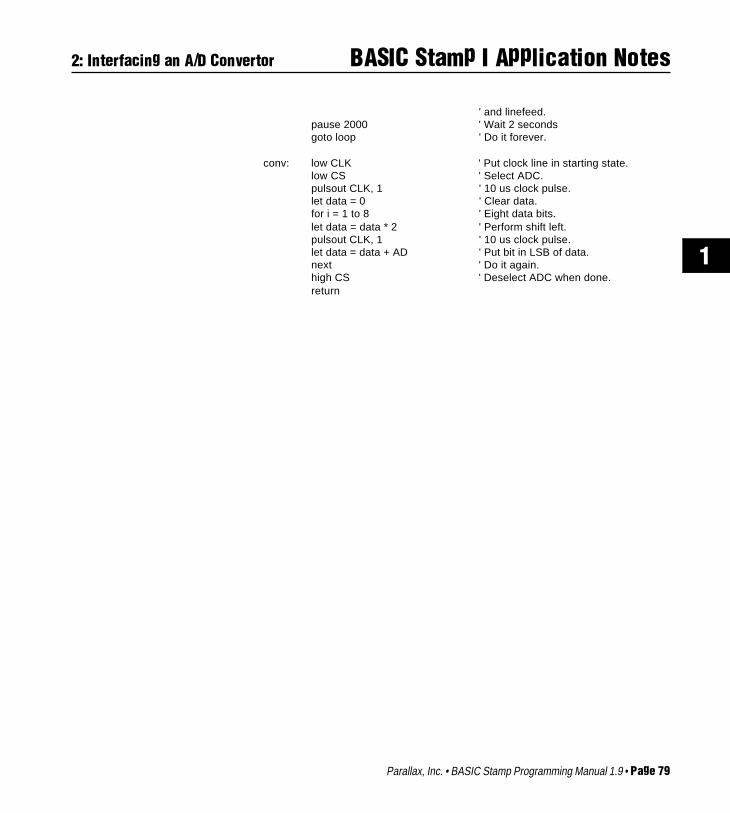
How it works. The sample program reads the voltage at the ’831’s inputpin every 2 seconds and reports it via a 2400-baud serial connection. Thesubroutine conv handles the details of getting data out of the ADC. Itenables the ADC by pulling the CS line low, then pulses the clock (CLK)line to signal the beginning of a conversion. The program then enters aloop in which it pulses CLK, gets the bit on pin AD, adds it to the receivedbyte, and shifts the bits of the received byte to the left. Since BASICtraditionally doesn’t include bit-shift operations, the program multi-plies the byte by 2 to perform the shift.
When all bits have been shifted into the byte, the program turns off theADC by returning CS high. The subroutine returns with the conversionresult in the variable data. The whole process takes about 20 millisec-onds.
Modifications. You can add more ’831’s to the circuit as follows:Connect each additional ADC to the same clock and data lines, butassign it a separate CS pin. Modify the conv subroutine to take theappropriate CS pin low when it needs to acquire data from a particularADC. That’s it.
Program listing. This program may be downloaded from our Internetftp site at ftp.parallaxinc.com. The ftp site may be reached directly orthrough our web site at http://www.parallaxinc.com.
2: Interfacing an A/D Convertor
Parallax, Inc. • BASIC Stamp Programming Manual 1.9 • Page 79
BASIC Stamp I Application Notes
1
' and linefeed.pause 2000 ' Wait 2 secondsgoto loop ' Do it forever.
conv: low CLK ' Put clock line in starting state.low CS ' Select ADC.pulsout CLK, 1 ' 10 us clock pulse.let data = 0 ' Clear data.for i = 1 to 8 ' Eight data bits.let data = data * 2 ' Perform shift left.pulsout CLK, 1 ' 10 us clock pulse.let data = data + AD ' Put bit in LSB of data.next ' Do it again.high CS ' Deselect ADC when done.return
2: Interfacing an A/D Convertor

Page 80 • BASIC Stamp Programming Manual 1.9 • Parallax, Inc.
BASIC Stamp I Application Notes

Parallax, Inc. • BASIC Stamp Programming Manual 1.9 • Page 81
BASIC Stamp I Application Notes
1
3: Hardware Solution for Keypads
Introduction. This application note presents a program in PBASIC thatenables the BASIC Stamp to read a keypad and display keypresses ona liquid-crystal display.
Background. Many controller applications require a keypad to allowthe user to enter numbers and commands. The usual way to interface akeypad to a controller is to connect input/output (I/O) bits to row andcolumn connections on the keypad. The keypad is wired in a matrixarrangement so that when a key is pressed one row is shorted to onecolumn. It’s relatively easy to write a routine to scan the keypad, detectkeypresses, and determine which key was pressed.
The trouble is that a 16-key pad requires a minimum of eight bits (fourrows and four columns) to implement this approach. For the BASICStamp, with a total of only eight I/O lines, this may not be feasible, evenwith clever multiplexing arrangements. And although the program-ming to scan a keypad is relatively simple, it can cut into the Stamp’s 255bytes of program memory.
An alternative that conserves both I/O bits and program space is to usethe 74C922 keypad decoder chip. This device accepts input from a 16-key pad, performs all of the required scanning and debouncing, and
PIC16C56
01234567
+5V Vin
GNDBASIC STAMP
EEPROM
(C) 1992 Parallax, Inc.
PC
2 3 1
10k(contrast)
65 7 8 9 10
+5
414
131211
10kall
+5Matrix keypad (pressing
a key shorts a row connection to a column)
available
1x16-character LCD module, Hitachi 44780 controller
Vdd Vo R/WVss
DB4DB5DB6DB7
DB0 DB1 DB2 DB3ERS
.1µF
1µF
74C922
1
2
3
4
5
6
7
8
9
18
17
16
15
14
13
12
11
10
row 3
row 4
scan
debounce
col 4
col 3
gnd
d0
d1
d2
d3
out enable
data avail
col 1
col 2
Vccrow 1
row 2
Schematic to accompanyprogram KEYPAD.BAS.

Page 82 • BASIC Stamp Programming Manual 1.9 • Parallax, Inc.
BASIC Stamp I Application Notes 3: Hardware Solution for Keypads
outputs a “data available” bit and 4 output bits representing thenumber of the key pressed from 0 to 15. A companion device, the74C923, has the same features, but reads a 20-key pad and outputs 5data bits.
Application. The circuit shown in the figure interfaces a keypad andliquid-crystal display (LCD) module to the BASIC Stamp, leaving twoI/O lines free for other purposes, such as bidirectional serial communi-cation. As programmed, this application accepts keystrokes from 16keys and displays them in hexadecimal format on the LCD.
When the user presses a button on the keypad, the corresponding hexcharacter appears on the display. When the user has filled the displaywith 16 characters, the program clears the screen.
The circuit makes good use of the electrical properties of the Stamp, theLCD module, and the 74C922. When the Stamp is addressing the LCD,the 10k resistors prevent keypad activity from registering. The Stampcan easily drive its output lines high or low regardless of the status ofthese lines. When the Stamp is not addressing the LCD, its lines areconfigured as inputs, and the LCD’s lines are in a high-impedance state(tri-stated). The Stamp can then receive input from the keypad withoutinterference.
The program uses the button instruction to read the data-available lineof the 74C922. The debounce feature of button is unnecessary in thisapplication because the 74C922 debounces its inputs in hardware;however, button provides a professional touch by enabling delayedauto-repeat for the keys.
Program listing. This program may be downloaded from our Internetftp site at ftp.parallaxinc.com. The ftp site may be reached directly orthrough our web site at http://www.parallaxinc.com.
' PROGRAM: Keypad.bas' The Stamp accepts input from a 16-key matrix keypad with the help of' a 74C922 keypad decoder chip.Symbol E = 5 ' Enable pin, 1 = enabledSymbol RS = 4 ' Register select pin, 0 = instruction

Parallax, Inc. • BASIC Stamp Programming Manual 1.9 • Page 83
BASIC Stamp I Application Notes
1
3: Hardware Solution for Keypads
Symbol char = b1 ' Character sent to LCD.Symbol buttn = b3 ' Workspace for button command.Symbol lngth = b5 ' Length of text appearing on LCD.Symbol temp = b7 ' Temporary holder for input character.
' Set up the Stamp's I/O lines and initialize the LCD.begin: let pins = 0 ' Clear the output lines
let dirs = %01111111 ' One input, 7 outputs.pause 200 ' Wait 200 ms for LCD to reset.let buttn = 0let lngth = 0gosub i_LCDgosub clear
keyin: let dirs = %01100000 ' Set up I/O directions.loop: button 4,1,50,10,buttn,0,nokey ' Check pin 4 (data available) for
' keypress.lngth = lngth + 1 ' Key pressed: increment position
counter.let temp = pins & %00001111 ' Strip extra bits to leave only key data.if temp > 9 then hihex ' Convert 10 thru 15 into A thru F (hex).let temp = temp + 48 ' Add offset for ASCII 0.
LCD: let dirs = %01111111 ' Get ready to output to LCD.if lngth > 16 then c_LCD ' Screen full? Clear it.
cont: let char = temp ' Write character to LCD.gosub wr_LCD
nokey: pause 10 ' Short delay for nice auto-repeat' speed.
goto keyin ' Get ready for next key.
hihex: let temp = temp + 55 ' Convert numbers 10 to 15 into A - F.goto LCD
c_LCD: let lngth = 1 ' If 16 characters are showing on LCD,gosub clear ' clear the screen and print at left edge.goto cont
' Initialize the LCD in accordance with Hitachi's instructions' for 4-bit interface.i_LCD: let pins = %00000011 ' Set to 8-bit operation.
pulsout E,1 ' Send above data three timespause 10 ' to initialize LCD.pulsout E,1pulsout E,1let pins = %00000010 ' Set to 4-bit operation.pulsout E,1 ' Send above data three times.pulsout E,1pulsout E,1let char = 12 ' Set up LCD in accordance w/

Page 84 • BASIC Stamp Programming Manual 1.9 • Parallax, Inc.
BASIC Stamp I Application Notes
gosub wr_LCD ' Hitachi instruction manual.let char = 6 ' Turn off cursor, enablegosub wr_LCD ' left-to-right printing.high RS ' Prepare to send characters.return
' Write the ASCII character in b3 to the LCD.wr_LCD: let pins = pins & %00010000
let b2 = char/16 ' Put high nibble of b3 into b2.let pins = pins | b2 ' OR the contents of b2 into pins.pulsout E,1 ' Blip enable pin.let b2 = char & %00001111 ' Put low nibble of b3 into b2.let pins = pins & %00010000 ' Clear 4-bit data bus.let pins = pins | b2 ' OR the contents of b2 into pins.pulsout E,1 ' Blip enable.return
' Clear the LCD screen.clear: low RS ' Change to instruction register.
let char = 1 ' Clear display.gosub wr_LCD ' Write instruction to LCD.high RS ' Put RS back in character mode.return
3: Hardware Solution for Keypads

Parallax, Inc. • BASIC Stamp Programming Manual 1.9 • Page 85
BASIC Stamp I Application Notes
1
4: Controlling and Testing Servos
Introduction. This application note presents a program in PBASIC thatenables the BASIC Stamp to control pulse-width proportional servosand measure the pulse width of other servo drivers.
Background. Servos of the sort used in radio-controlled airplanes arefinding new applications in home and industrial automation, movieand theme-park special effects, and test equipment. They simplify thejob of moving objects in the realworld by eliminating much of themechanical design. For a given sig-nal input, you get a predictableamount of motion as an output.
Figure 1 shows a typical servo. Thethree wires are +5 volts, ground,and signal. The output shaft acceptsa wide variety of prefabricated disksand levers. It is driven by a geared-down motor and rotates through 90to 180 degrees. Most servos can ro-tate 90 degrees in less than a half second. Torque, a measure of theservo’s ability to overcome mechanical resistance (or lift weight, pullsprings, push levers, etc.), ranges from 20 to more than 100 inch-ounces.
To make a servo move, connect it to a 5-volt power supply capable ofdelivering an ampere or more of peak current, and supply a positioning
Figure 1. A typical servo.
Figure 2. Schematic to accompany program SERVO.BAS.
PIC16C56
01234567
+5V Vin
GNDBASIC STAMP
EEPROM
(C) 1992 Parallax, Inc.
PC
2 3 1
10k(contrast)
65 7 8 9 10
+510k
1k
Toggle Function
414
131211
Servo signal in
Servo signal out
1x16-character LCD module, Hitachi 44780 controller
Vdd Vo R/WVss
DB4DB5DB6DB7
DB0 DB1 DB2 DB3ERS

Page 86 • BASIC Stamp Programming Manual 1.9 • Parallax, Inc.
BASIC Stamp I Application Notes
signal. The signal is generally a 5-volt, positive-going pulse between 1and 2 milliseconds (ms) long, repeated about 50 times per second. Thewidth of the pulse determines the position of the servo. Since servos’travel can vary, there isn’t a definite correspondence between a givenpulse width and a particular servo angle, but most servos will move tothe center of their travel when receiving 1.5-ms pulses.
Servos are closed-loop devices. This means that they are constantlycomparing their commanded position (proportional to the pulse width)to their actual position (proportional to the resistance of a potentiom-eter mechanically linked to the shaft). If there is more than a smalldifference between the two, the servo’s electronics will turn on themotor to eliminate the error. In addition to moving in response tochanging input signals, this active error correction means that servoswill resist mechanical forces that try to move them away from acommanded position. When the servo is unpowered or not receivingpositioning pulses, you can easily turn the output shaft by hand. Whenthe servo is powered and receiving signals, it won’t budge from itsposition.
Application. Driving servos with the BASIC Stamp is simplicity itself.The instruction pulsout pin, time generates a pulse in 10-microsecond(µs) units, so the following code fragment would command a servo toits centered position and hold it there:
servo: pulsout 0,150pause 20goto servo
The 20-ms pause ensures that the program sends the pulse at thestandard 50 pulse-per-second rate.
The program listing is a diagnostic tool for working with servos. It hastwo modes, pulse measurement and pulse generation. Given an inputservo signal, such as from a radio-control transmitter/receiver, itdisplays the pulse width on a liquid-crystal display (LCD). A display of“Pulse Width: 150” indicates a 1.5-ms pulse. Push the button to togglefunctions, and the circuit supplies a signal that cycles between 1 and 2ms. Both the pulse input and output functions are limited to a resolution
4: Controlling and Testing Servos

Parallax, Inc. • BASIC Stamp Programming Manual 1.9 • Page 87
BASIC Stamp I Application Notes
1
4: Controlling and Testing Servos
of 10µs. For most servos, this equates to a resolution of better than 1degree of rotation.
The program is straightforward Stamp BASIC, but it does take advan-tage of a couple of the language’s handy features. The first of these is theEEPROM directive. EEPROM address,data allows you to stuff tables ofdata or text strings into EEPROM memory. This takes no additionalprogram time, and only uses the amount of storage required for thedata. After the symbols, the first thing that the listing does is tuck acouple of text strings into the bottom of the EEPROM. When theprogram later needs to display status messages, it loads the text stringsfrom EEPROM.
The other feature of the Stamp’s BASIC that the program exploits is theability to use compound expressions in a let assignment. The routineBCD (for binary-coded decimal) converts one byte of data into threeASCII characters representing values from 0 (represented as “000”) to255.
To do this, BCD performs a series of divisions on the byte and on theremainders of divisions. For example, when it has established howmany hundreds are in the byte value, it adds 48, the ASCII offset forzero. Take a look at the listing. The division (/) and remainder (//)calculations happen before 48 is added. Unlike larger BASICs whichhave a precedence of operators (e.g., multiplication is always beforeaddition), the Stamp does its math from left to right. You cannot useparentheses to alter the order, either.
If you’re unsure of the outcome of a calculation , use the debug directiveto look at a trial run, like so:
let BCDin = 200let huns = BCDin/100+48debug huns
When you download the program to the Stamp, a window will appearon your computer screen showing the value assigned to the variablehuns (50). If you change the second line to let huns = 48+BCDin/100,you’ll get a very different result (2).

Page 88 • BASIC Stamp Programming Manual 1.9 • Parallax, Inc.
BASIC Stamp I Application Notes 4: Controlling and Testing Servos
By the way, you don’t have to use let, but it will earn you Brownie pointswith serious computer-science types. Most languages other than BASICmake a clear distinction between equals as in huns = BCDin/100+48and if BCDin = 100 then...
Program listing. This program may be downloaded from our Internetftp site at ftp.parallaxinc.com. The ftp site may be reached directly orthrough our web site at http://www.parallaxinc.com.
' PROGRAM: Servo.bas' The Stamp works as a servo test bench. It provides a cycling servo signal' for testing, and measures the pulse width of external servo signals.
Symbol E = 5 ' Enable pin, 1 = enabledSymbol RS = 4 ' Register select pin, 0 = instructionSymbol char = b0 ' Character sent to LCD.Symbol huns = b3 ' BCD hundredsSymbol tens = b6 ' BCD tensSymbol ones = b7 ' BCD onesSymbol BCDin = b8 ' Input to BCD conversion/displayroutine.Symbol buttn = b9 ' Button workspaceSymbol i = b10 ' Index counter
' Load text strings into EEPROM at address 0. These will be used to display' status messages on the LCD screen.EEPROM 0,("Cycling... Pulse Width: ")
' Set up the Stamp's I/O lines and initialize the LCD.begin: let pins = 0 ' Clear the output lines
let dirs = %01111111 ' One input, 7 outputs.pause 200 ' Wait 200 ms for LCD to reset.
' Initialize the LCD in accordance with Hitachi's instructions' for 4-bit interface.i_LCD: let pins = %00000011 ' Set to 8-bit operation.
pulsout E,1 ' Send above data three timespause 10 ' to initialize LCD.pulsout E,1pulsout E,1let pins = %00000010 ' Set to 4-bit operation.pulsout E,1 ' Send above data three times.pulsout E,1pulsout E,1let char = 12 ' Set up LCD in accordance w/

Parallax, Inc. • BASIC Stamp Programming Manual 1.9 • Page 89
BASIC Stamp I Application Notes
1
gosub wr_LCD ' Hitachi instruction manual.let char = 6 ' Turn off cursor, enablegosub wr_LCD ' left-to-right printing.high RS ' Prepare to send characters.
' Measure the width of input pulses and display on the LCD.mPulse: output 3
gosub clear ' Clear the display.for i = 11 to 23 ' Read "Pulse Width:" label read i, char gosub wr_LCD ' Print to displaynextpulsin 7, 1, BCDin ' Get pulse width in 10 us units.gosub BCD ' Convert to BCD and display.pause 500input 3 ' Check button; cycle if down.button 3,1,255,10,buttn,1,cyclegoto mPulse ' Otherwise, continue measuring.
' Write the ASCII character in b3 to LCD.wr_LCD: let pins = pins & %00010000
let b2 = char/16 ' Put high nibble of b3 into b2.let pins = pins | b2 ' OR the contents of b2 into pins.pulsout E,1 ' Blip enable pin.let b2 = char & %00001111 ' Put low nibble of b3 into b2.let pins = pins & %00010000 ' Clear 4-bit data bus.let pins = pins | b2 ' OR the contents of b2 into pins.pulsout E,1 ' Blip enable.return
clear: low RS ' Change to instruction register.let char = 1 ' Clear display.gosub wr_LCD ' Write instruction to LCD.high RS ' Put RS back in character mode.return
' Convert a byte into three ASCII digits and display them on the LCD.' ASCII 48 is zero, so the routine adds 48 to each digit for display on the LCD.BCD: let huns= BCDin/100+48 ' How many hundreds?
let tens= BCDin//100 ' Remainder of #/100 = tens+ones.let ones= tens//10+48 ' Remainder of (tens+ones)/10 = ones.let tens= tens/10+48 ' How many tens?let char= huns ' Display three calculated digits.gosub wr_LCDlet char = tensgosub wr_LCDlet char = onesgosub wr_LCDreturn
4: Controlling and Testing Servos

Page 90 • BASIC Stamp Programming Manual 1.9 • Parallax, Inc.
BASIC Stamp I Application Notes
' Cycle the servo back and forth between 0 and 90 degrees. Servo moves slowly ' inone direction (because of 20-ms delay between changes in pulse width) and quickly' in the other. Helps diagnose stuck servos, dirty feedback pots, etc.cycle: output 3
gosub clearfor i = 0 to 9 ' Get "Cycling..." string and read i, char ' display it on LCD. gosub wr_LCDnext i
reseti: let i = 100 ' 1 ms pulse width.cyloop: pulsout 6,i ' Send servo pulse.
pause 20 ' Wait 1/50th second.let i = i + 2 ' Move servo.if i > 200 then reseti ' Swing servo back to start position.input 3 ' Check the button; change function if
' down.button 3,1,255,10,buttn,1,mPulsegoto cyloop ' Otherwise, keep cycling.
4: Controlling and Testing Servos

Parallax, Inc. • BASIC Stamp Programming Manual 1.9 • Page 91
BASIC Stamp I Application Notes
1
5: Practical Pulse Measurements
Introduction. This application note explores several applications forthe BASIC Stamp's unique pulsin command, which measures theduration of incoming positive or negative pulses in 10-microsecondunits.
Background. The BASIC Stamp’s pulsin command measures the widthof a pulse, or the interval between two pulses. Left at that, it might seemto have a limited range of obscure uses. However, pulsin is the key tomany kinds of real-world interfacing using simple, reliable sensors.Some possibilities include:
tachometerspeed trapphysics demonstratorcapacitance checkerduty cycle meterlog input analog-to-digital converter
Pulsin works like a stopwatch that keeps time in units of 10 microsec-onds (µs). To use it, you must specify which pin to monitor, when totrigger on (which implies when to trigger off), and where to put theresulting 16-bit time measurement. The syntax is as follows:
pulsin pin, trigger condition, variable
waiting to trigger
triggered on
triggered off
6924 µs
w3 holds 692w3 holds 0
Figure 1. Timing diagram for pulsin 7,0,w3 .

Page 92 • BASIC Stamp Programming Manual 1.9 • Parallax, Inc.
BASIC Stamp I Application Notes 5: Practical Pulse Measurements
Pin is a BASIC Stamp input/output pin (0 to 7). Trigger condition is avariable or constant (0 or 1) that specifies the direction of the transitionthat will start the pulsin timer. If trigger is 0, pulsin will start measuringwhen a high-to-low transition occurs, because 0 is the edge’s destina-tion. Variable can be either a byte or word variable to hold the timingmeasurement. In most cases, a word variable is called for, becausepulsin produces 16-bit results.
Figure 1 shows how pulsin works. The waveform represents an inputat pin 7 that varies between ground and +5 volts (V).
A smart feature of pulsin is its ability to recognize a no-pulse or out-of-range condition. If the specified transition doesn’t occur within 0.65535seconds (s), or if the pulse to be measured is longer than 0.65535 s, pulsinwill give up and return a 0 in the variable. This prevents the programfrom hanging up when there’s no input or out-of-range input.
Let’s look at some sample applications for pulsin, starting with oneinspired by the digital readout on an exercise bicycle: pulsin as atachometer.
Tachometer. The most obvious way to measure the speed of a wheelor shaft in revolutions per minute (rpm) is to count the number of
Figure 2. Schematic to accompany listing 1, TACH.BAS.
Q
Q
CLK
D
1/2 4013
11
9
13
12
(ground unusedinputs, pins 8 & 10)
1k
+5
+5
Hall-effect switchUGN3113U
or equivalent
To BASIC Stamppulsin pin
Magnet onrotatingshaft or disk
Parallax, Inc. • BASIC Stamp Programming Manual 1.9 • Page 93
BASIC Stamp I Application Notes
1
revolutions that occur during 1 minute. The trouble is, the user prob-ably wouldn’t want to wait a whole minute for the answer.
For a continuously updated display, we can use pulsin to measure thetime the wheel takes to make one complete revolution. By dividing thistime into 60 seconds, we get a quick estimate of the rpm. Listing 1 is atachometer program that works just this way. Figure 2 is the circuit thatprovides input pulses for the program. A pencil-eraser-sized magnetattached to the wheel causes a Hall-effect switch to generate a pulseevery rotation.
We could use the Hall switch output directly, by measuring the intervalbetween positive pulses, but we would be measuring the period ofrotation minus the pulses. That would cause small errors that would bemost significant at high speeds. The flip-flop, wired to toggle with eachpulse, eliminates the error by converting the pulses into a train of squarewaves. Measuring either the high or low interval will give you theperiod of rotation.
Note that listing 1 splits the job of dividing the period into 60 secondsinto two parts. This is because 60 seconds expressed in 10-µs units is 6million, which exceeds the range of the Stamp’s 16-bit calculations. Youwill see this trick, and others that work around the limits of 16-bit math,throughout the listings.
Using the flip-flop’s set/reset inputs, this circuit and program couldeasily be modified to create a variety of speed-trap instruments. A steelball rolling down a track would encounter two pairs of contacts to setand reset the flip-flop. Pulsin would measure the interval and computethe speed for a physics demonstration (acceleration). More challengingsetups would be required to time baseballs, remote-control cars oraircraft, bullets, or model rockets.
The circuit could also serve as a rudimentary frequency meter. Justdivide the period into 1 second instead of 1 minute.
Duty cycle meter. Many electronic devices vary the power they deliverto a load by changing the duty cycle of a waveform; the proportion oftime that the load is switched fully on to the time it is fully off. This
5: Practical Pulse Measurements

Page 94 • BASIC Stamp Programming Manual 1.9 • Parallax, Inc.
BASIC Stamp I Application Notes 5: Practical Pulse Measurements
approach, found in light dimmers, power supplies, motor controls andamplifiers, is efficient and relatively easy to implement with digitalcomponents. Listing 2 measures the duty cycle of a repetitive pulsetrain by computing the ratio of two pulsin readings and presentingthem as a percentage. A reading approaching 100 percent means thatthe input is mostly on or high. The output of figure 2’s flip-flop is 50percent. The output of the Hall switch in figure 2 was less than 10percent when the device was monitoring a benchtop drill press.
Capacitor checker. The simple circuit in figure 3 charges a capacitor,and then discharges it across a resistance when the button is pushed.This produces a brief pulse for pulsin to measure. Since the timeconstant of the pulse is determined by resistance (R) times capacitance(C), and R is fixed at 10k, the width of the pulse tells us C. With theresistance values listed, the circuit operates over a range of .001 to 2.2 µF.You may substitute other resistors for other ranges of capacitance; just
be sure that the charging resistor (100k in this case) is about 10 times thevalue of the discharge resistor. This ensures that the voltage at thejunction of the two resistors when the switch is held down is a definitelow (0) input to the Stamp.
Log-input analog-to-digital converter (ADC). Many sensors haveconvenient linear outputs. If you know that an input of 10 units
+5
Cunk
100k
10k
Press to test To BASIC Stamp
pulsin pin
Figure 3. Schematic for listing 3, CAP.BAS.

Parallax, Inc. • BASIC Stamp Programming Manual 1.9 • Page 95
BASIC Stamp I Application Notes
1
5: Practical Pulse Measurements
(degrees, pounds, percent humidity, or whatever) produces an outputof 1 volt, then 20 units will produce 2 volts. Others, such as thermistors
and audio-taper potentiometers, produce logarithmic outputs. A RadioShack thermistor (271-110) has a resistance of 18k at 10° C and 12k at20°C. Not linear, and not even the worst cases!
While it’s possible to straighten out a log curve in software, it’s often
easier to deal with it in hardware. That’s where figure 4 comes in. Thevoltage-controlled oscillator of the 4046 phase-locked loop chip, when
Figure 4. Schematic for listing 4, VCO.BAS.
Fin
1/2 4046To BASIC Stamppulsin pin
inh5
1M
10k0.001µF
Inputvoltage
outV9 4
cap
cap
6
7
Fmin
Fmax
12
11
Input voltage
0
250
500
750
1000
1250
1.0 1.5 2.0 2.5 3.0 3.5 4.0 4.5 5.0
Out
put v
alue
Figure 5. Log response curve of the VCO.

Page 96 • BASIC Stamp Programming Manual 1.9 • Parallax, Inc.
BASIC Stamp I Application Notes 5: Practical Pulse Measurements
wired as shown, has a log response curve. If you play this curve againsta log input, you can effectively straighten the curve. Figure 5 is a plot ofthe output of the circuit as measured by the pulsin program in listing 4.It shows the characteristic log curve.
The plot points out another advantage of using a voltage-controlledoscillator as an ADC; namely, increased resolution. Most inexpensiveADCs provide eight bits of resolution (0 to 255), while the VCOprovides the equivalent of 10 bits (0 to 1024+). Admittedly, a true ADCwould provide much better accuracy, but you can’t touch one foranywhere near the 4046’s sub-$1 price.
The 4046 isn’t the only game in town, either. Devices that can convertanalog values, such as voltage or resistance, to frequency or pulse widthinclude timers (such as the 555) and true voltage-to-frequency convert-ers (such as the 9400). For sensors that convert some physical propertysuch as humidity or proximity into a variable capacitance or induc-tance, pulsin is a natural candidate for sampling their output via anoscillator or timer.
Program listing. These programs may be downloaded from our Internetftp site at ftp.parallaxinc.com. The ftp site may be reached directly orthrough our web site at http://www.parallaxinc.com.
A Note about the Program ListingsAll of the listings output results as serial data. To receive it, connect Stamp pin 0 to yourPC’s serial input, and Stamp ground to signal ground. On 9-pin connectors, pin 2 isserial in and pin 5 is signal ground; on 25-pin connectors, pin 3 is serial in and pin 7 issignal ground. Set terminal software for 8 data bits, no parity, 1 stop bit.
' Listing 1: TACH.BAS' The BASIC Stamp serves as a tachometer. It accepts pulse input through pin 7,' and outputs rpm measurements at 2400 baud through pin 0.
input 7output 0
Tach: pulsin 7,1,w2 ' Read positive-going pulses on pin 7.let w2 = w2/100 ' Dividing w2/100 into 60,000 is the
' same as dividinglet w2 = 60000/w2 ' w2 into 6,000,000 (60 seconds in 10
' us units).

Parallax, Inc. • BASIC Stamp Programming Manual 1.9 • Page 97
BASIC Stamp I Application Notes
1
' Transmit data followed by carriage return and linefeed.serout 0,N2400,(#w2," rpm",10,13)pause 1000 ' Wait 1 second between readingsgoto Tach
' Listing 3: CAP.BAS' The BASIC Stamp estimates the value of a capacitor by the time required for it to' discharge through a known resistance.
input 7output 0
Cap: pulsin 7,1,w1if w1 = 0 then Cap ' If no pulse, try again.if w1 > 6553 then Err ' Avoid overflows.let w1 = w1*10let w1 = w1/14 ' Apply calibration value.if w1 > 999 then uF ' Use uF for larger caps.serout 0,N2400,(#w1," nF",10,13)goto Cap
uF: let b4 = w1/1000 ' Value left of decimal point.let b6 = w1//1000 ' Value right of decimal point.serout 0,N2400,(#b4,".",#b6," uF",10,13)goto Cap
' Listing 2: DUTY.BAS' The BASIC Stamp calculates the duty cycle of a repetitive pulse train.' Pulses in on pin 7; data out via 2400-baud serial on pin 0.
input 7output 0
Duty: pulsin 7,1,w2 ' Take positive pulse sample.if w2 > 6553 then Error ' Avoid overflow when w2 is multiplied
by 10.pulsin 7,0,w3 ' Take negative pulse sample.let w3 = w2+w3let w3 = w3/10 ' Distribute multiplication by 10 into twolet w2 = w2*10 ' parts to avoid an overflow.let w2 = w2/w3 ' Calculate percentage.serout 0,N2400,(#w2," percent",10,13)pause 1000 ' Update once a second.goto Duty
' Handle overflows by skipping calculations and telling the user.Error: serout 0,N2400,("Out of range",10,13)
pause 1000goto Duty
5: Practical Pulse Measurements

Page 98 • BASIC Stamp Programming Manual 1.9 • Parallax, Inc.
BASIC Stamp I Application Notes
Err: serout 0,N2400,("out of range",10,13)goto Cap
' Listing 4: VCO.BAS' The BASIC Stamp uses input from the VCO of a 4046 phase-locked loop as alogarithmic' A-to-D converter. Input on pin 7; 2400-baud serial output on pin 0.
input 7output 0
VCO: pulsin 7,1,w2 ' Put the width of pulse on pin 7 into w2.let w2 = w2-45 ' Allow a near-zero minimum value
' without underflow.serout 0,N2400,(#w2,10,13)pause 1000 ' Wait 1 second between measure-
' ments.goto VCO
5: Practical Pulse Measurements

Parallax, Inc. • BASIC Stamp Programming Manual 1.9 • Page 99
BASIC Stamp I Application Notes
1
6: A Serial Stepper Controller
Introduction. This application note demonstrates simple hardwareand software techniques for driving and controlling common four-coilstepper motors.
Background. Stepper motors translate digital switching sequencesinto motion. They are used in printers, automated machine tools, diskdrives, and a variety of other applications requiring precise motionsunder computer control.
Unlike ordinary dc motors, which spin freely when power is applied,steppers require that their power source be continuously pulsed inspecific patterns. These patterns, or step sequences, determine thespeed and direction of a stepper’s motion. For each pulse or step input,the stepper motor rotates a fixed angular increment; typically 1.8 or 7.5degrees.
The fixed stepping angle gives steppers their precision. As long as themotor’s maximum limits of speed or torque are not exceeded, thecontrolling program knows a stepper’s precise position at any giventime.
Steppers are driven by the interaction (attraction and repulsion) ofmagnetic fields. The driving magnetic field “rotates” as strategicallyplaced coils are switched on and off. This pushes and pulls at perma-nent magnets arranged around the edge of a rotor that drives the output
Figure 1. Schematic for the serial stepper controller.
PIC16C56
01234567
+5V Vin
GNDBASIC STAMP
EEPROM
(C) 1992 Parallax, Inc.
PC
ULN 2003TO PIN 11
TO PIN 10
TO PIN 1
TO PIN 4
NCNC
1k
1k 1k
1k
BLK
BRN
YEL
ORG
GRN
RED
+5
+12
Stepper Motor
NC
1
8
16
9
IN 1
IN 2
IN 3
IN 4
IN 5
IN 6
IN 7
GND
OUT 1
OUT 2
OUT 3
OUT 4
OUT 5
OUT 6
OUT 7
TESTSerial Input
22k
+5
AIRPAX COLOR CODE:RED & GREEN = COMMON
Serial Output

Page 100 • BASIC Stamp Programming Manual 1.9 • Parallax, Inc.
BASIC Stamp I Application Notes 6: A Serial Stepper Controller
shaft. When the on-off pattern of the magnetic fields is in the propersequence, the stepper turns (when it’s not, the stepper sits and quivers).
The most common stepper is the four-coil unipolar variety. These arecalled unipolar because they require only that their coils be driven onand off. Bipolar steppers require that the polarity of power to the coilsbe reversed.
The normal stepping sequence for four-coil unipolar steppers appearsin figure 2. There are other, special-purpose stepping sequences, suchas half-step and wave drive, and ways to drive steppers with multi-phase analog waveforms, but this application concentrates on thenormal sequence. After all, it’s the sequence for which all of themanufacturer’s specifications for torque, step angle, and speed apply.
If you run the stepping sequence in figure 2 forward, the stepper rotatesclockwise; run it backward, and the stepper rotates counterclockwise.The motor’s speed depends on how fast the controller runs through thestep sequence. At any time the controller can stop in mid sequence. If itleaves power to any pair of energized coils on, the motor is locked inplace by their magnetic fields. This points out another stepper motorbenefit: built-in brakes.
Many microprocessor stepper drivers use four output bits to generatethe stepping sequence. Each bit drives a power transistor that switcheson the appropriate stepper coil. The stepping sequence is stored in alookup table and read out to the bits as required.
This design takes a slightly different approach. First, it uses only twooutput bits, exploiting the fact that the states of coils 1 and 4 are always
1 2 3 4 1
coil 1 1 1 0 0 1coil 2 0 0 1 1 0coil 3 1 0 0 1 1coil 4 0 1 1 0 0
Step Sequence
Figure 2. Normal stepping sequence.

Parallax, Inc. • BASIC Stamp Programming Manual 1.9 • Page 101
BASIC Stamp I Application Notes
1
6: A Serial Stepper Controller
the inverse of coils 2 and 3. Look at figure 2 again. Whenever coil 2 getsa 1, coil 1 gets a 0, and the same holds for coils 3 and 4. In Stamp designs,output bits are too precious to waste as simple inverters, so we give thatjob to two sections of the ULN2003 inverter/driver.
The second difference between this and other stepper driver designs isthat it calculates the stepping sequence, rather than reading it out of atable. While it’s very easy to create tables with the Stamp, the calcula-tions required to create the two-bit sequence required are very simple.And reversing the motor is easier, since it requires only a singleadditional program step. See the listing.
How it works. The stepper controller accepts commands from a termi-nal or PC via a 2400-baud serial connection. When power is first appliedto the Stamp, it sends a prompt to be displayed on the terminal screen.The user types a string representing the direction (+ for forward, – forbackward), number of steps, and step delay (in milliseconds), like this:
step>+500 20
As soon as the user presses enter, return, or any non-numerical charac-ter at the end of the line, the Stamp starts the motor running. When thestepping sequence is over, the Stamp sends a new step> prompt to theterminal. The sample command above would take about 10 seconds(500 x 20 milliseconds). Commands entered before the prompt reap-pears are ignored.
On the hardware side, the application accepts any stepper that draws500 mA or less per coil. The schematic shows the color code for anAirpax-brand stepper, but there is no standardization among different
YELLOW
ORANGE
RED
BROWN
BLACK
GREEN
Figure 3. Color code for Airpax steppers.

Page 102 • BASIC Stamp Programming Manual 1.9 • Parallax, Inc.
BASIC Stamp I Application Notes 6: A Serial Stepper Controller
brands. If you use another stepper, use figure 3 and an ohmmeter totranslate the color code. Connect the stepper and give it a try. If itvibrates instead of turning, you have one or more coils connectedincorrectly. Patience and a little experimentation will prevail.
' Program STEP.BAS' The Stamp accepts simply formatted commands and drives a four-coil stepper.Commands' are formatted as follows: +500 20<return> means rotate forward 500 steps with 20' milliseconds between steps. To run the stepper backward, substitute - for +.
Symbol Directn = b0Symbol Steps = w1Symbol i = w2Symbol Delay = b6Symbol Dir_cmd = b7
dirs = %01000011 : pins = %00000001 ' Initialize output.b1 = %00000001 : Directn = "+"goto Prompt ' Display prompt.
' Accept a command string consisting of direction (+/-), a 16-bit number' of steps, and an 8-bit delay (milliseconds) between steps. If longer' step delays are required, just command 1 step at a time with long' delays between commands.
Cmd: serin 7,N2400,Dir_cmd,#Steps,#Delay ' Get orders from terminal.if Dir_cmd = Directn then Stepit ' Same direction? Begin.b1 = b1^%00000011
' Else reverse (invert b1).
Stepit: for i = 1 to Steps' Number of steps.
pins = pins^b1' XOR output with b1, then invert b1
b1 = b1^%00000011' to calculate the stepping sequence.
pause Delay ' Wait commanded delay between' steps.
nextDirectn = Dir_cmd
' Direction = new direction.
Prompt: serout 6,N2400,(10,13,"step> ") ' Show prompt, send returngoto Cmd ' and linefeed to terminal.
Program listing: As with the other appli-cation notes, this program may be down-loaded from our Internet ftp site atftp.parallaxinc.com. The ftp site may bereached directly or through our web siteat http://www.parallaxinc.com.

Parallax, Inc. • BASIC Stamp Programming Manual 1.9 • Page 103
BASIC Stamp I Application Notes
1
7: Using a Thermistor
Introduction. This application note shows how to measure tempera-ture using an inexpensive thermistor and the BASIC Stamp’s potcommand. It also discusses a technique for correcting nonlinear data.
Background. Radio Shack offers an inexpensive and relatively precisethermistor—a component whose resistance varies with temperature.The BASIC Stamp has the built-in ability to measure resistance with thepot command and an external capacitor. Put them together, and yourStamp can measure the temperature, right? Not without a little math.
The thermistor’s resistance decreases as the temperature increases, butthis response is not linear. There is a table on the back of the thermistorpackage that lists the resistance at various temperatures in degreescelsius (°C). For the sake of brevity, we won’t reproduce that table here,but the lefthand graph of figure 1 shows the general shape of thethermistor response curve in terms of the more familiar Fahrenheitscale (°F).
The pot command throws us a curve of its own, as shown in figure 1(right). Though not as pronounced as the thermistor curve, it must befigured into our temperature calculations in order for the results to beusable.
One possibility for correcting the combined curves of the thermistorand pot command would be to create a lookup table in the Stamp’sEEPROM. The table would have to be quite large to cover a reasonabletemperature range at 1° precision. An alternative would be to create asmaller table at 10° precision, and figure where a particular reading
Figure 1. Response curves of the thermistor and pot command.
0
10
20
30
40
50
60
0 50 100 150Temperature °F
The
rmis
tor
(kΩ
)
0
50
100
150
200
250
0 10 20 30 40 50Input resistance (k Ω)
Pot
com
man
d ou
tput

Page 104 • BASIC Stamp Programming Manual 1.9 • Parallax, Inc.
BASIC Stamp I Application Notes
might lie within its 10° range. This is interpolation, and it can work quitewell. It would still use quite a bit of the Stamp’s limited EEPROM space,though.
Another approach, the one used in the listing, is to use a power-seriespolynomial to model the relationship between the pot reading andtemperature. This is easier than it sounds, and can be applied to manynonlinear relationships.
Step 1: Prepare a table. The first step is to create a table of a dozen orso inputs and outputs. The inputs are resistances and outputs aretemperatures in °F. Resistance values in this case are numbers returnedby the pot function. To equate pot values with temperatures, weconnected a 50k pot and a 0.01 µF capacitor to the Stamp and performedthe calibration described in the Stamp manual. After obtaining a scalefactor, we pressed the space bar to lock it in.
Now we could watch the pot value change as the potentiometer wasadjusted. We disconnected the potentiometer from the Stamp andhooked it to an ohmmeter. After setting the potentiometer to 33.89k(corresponding to a thermistor at 23 °F or –5 °C), we reconnected it tothe Stamp, and wrote down the resulting reading. We did this for eachof the calibration values on the back of the thermistor package, up to149 °F (65 °C).
Step 2: Determine the coefficients. The equation that can approximateour nonlinear temperature curve is:
Temperature = C0 + C1 • (Pot Val) + C2 • (Pot Val)2 + C3 • (Pot Val)3
where C0, C1, C2, and C3 are coefficients supplied by analyticalsoftware, and each Cn • (Pot Val)n is called a term. The equation abovehas three terms, so it is called a third-order equation. Each additionalterm increases the range over which the equation’s results are accurate.You can increase or decrease the number of terms as necessary, but eachadditional coefficient requires that Pot Val be raised to a higher power.This can make programming messy, so it pays to limit the number ofterms to the fewest that will do the job.
7: Using a Thermistor

Parallax, Inc. • BASIC Stamp Programming Manual 1.9 • Page 105
BASIC Stamp I Application Notes
1
The software that determines the coefficients is called GAUSFIT.EXE and isavailable from the Parallax ftp site. To use it, create a plain text file calledGF.DAT. In this file, which should be saved to the same subdirectory asGAUSFIT, list the inputs and outputs in the form in,out<return>. If thereare values that require particular precision, they may be listed morethan once. We wanted near-room-temperature values to be right on, sowe listed 112,68 (pot value at 68 °F) several times.
To run the program, type GAUSFIT n where n is the number of termsdesired. The program will compute coefficients and present you witha table showing how the computed data fits your samples. The fit willbe good in the middle, and poorer at the edges. If the edges areunacceptable, you can increase the number of terms. If they are OK, tryrerunning the program with fewer terms. We were able to get awaywith just two terms by allowing accuracy to suffer outside a range of 50°F to 90 °F.
Step 3: Factor the coefficients. The coefficients that GAUSFIT producesare not directly useful in a BASIC Stamp program. Our coefficientswere: C0 = 162.9763, C1 = –1.117476, and C2 = 0.002365991. We pluggedthe values into a spreadsheet and computed temperatures from potvalues and then started playing with the coefficients. We found that thefollowing coefficients worked almost as well as the originals: C0 = 162,C1 = –1.12, and C2 = 0.0024.
The problem that remained was how to use these values in a Stampprogram. The Stamp deals in only positive integers from 0 to 65,535. Thetrick is to express the numbers to the right of the decimal point asfractions. For example, the decimal number 0.75 can be expressed as 3/4. So to multiply a number by 0.75 with the BASIC Stamp, first multiplythe number by 3, then divide the result by 4. For less familiar decimalvalues, it may take some trial and error to find suitable fractions. Wefound that the 0.12 portion of C1 was equal to 255/2125, and thatC2 (0.0024) = 3/1250.
Step 4: Plan the order of execution. Just substituting the fractions for thedecimal portions of the formula still won’t work. The problem is thatportions of terms, such as 3•Pot Val2/1250, can exceed the 65,535 limit.If Pot Val were 244, then 3•2442 would equal 178,608; too high.
7: Using a Thermistor

Page 106 • BASIC Stamp Programming Manual 1.9 • Parallax, Inc.
BASIC Stamp I Application Notes
The solution is to factor the coefficients and rearrange them into smallerproblems that can be solved within the limit. For example (using PV tostand for Pot Val):
7: Using a Thermistor
The program in the listing is an example of just such factoring andrearrangement. Remember to watch out for the lower limit as well. Tryto keep intermediate results as high as possible within the Stamp’sinteger limits. This will reduce the effect of truncation errors (where anyvalue to the right of the decimal point is lost).
Conclusion. The finished program, which reports the temperature tothe PC screen via the debug command, is deceptively simple.An informalcheck of its output found that it tracks within 1 °F of a mercury/glass bulbthermometer in the range of 60 °F to 90 °F. Additional range could beobtained at the expense of a third-order equation; however, currentperformance is more than adequate for use in a household thermostat orother noncritical application. Cost and complexity are far less than thatof a linear sensor, precision voltage reference, and analog-to-digitalconverter.
If you adapt this application for your own use, component tolerances willprobably produce different results. However, you can calibrate the pro-gram very easily. Connect the thermistor and a stable, close-tolerance 0.1-µF capacitor to the Stamp as shown in figure 2. Run the program and notethe value that appears in the debug window. Compare it to a knownaccurate thermometer located close to the thermistor. If the thermometersays 75 and the Stamp 78, reduce the value of C0 by 3. If the thermometersays 80 and the Stamp 75, increase the value of C0 by 5. This works becausethe relationship between the thermistor resistance and the temperature isthe same, only the value of the capacitor is different. Adjusting C0 correctsthis offset.
Program listing. These programs may be downloaded from our Internet ftpsite at ftp.parallaxinc.com. The ftp site may be reached directly or throughour web site at http://www.parallaxinc.com.
PV*PV*3 PV*PV*3 PV PV*3 1250 5*5*5*5*2 25 50= = *

Parallax, Inc. • BASIC Stamp Programming Manual 1.9 • Page 107
BASIC Stamp I Application Notes
1Figure 2. Schematic to accompany THERM.BAS.
PIC16C56
01234567
+5V Vin
GNDBASIC STAMP
EEPROM
(C) 1992 Parallax, Inc.
PC
Radio Shack Thermistor(271-110)
0.1µF
' Program THERM.BAS' This program reads a thermistor with the BASIC' pot command, computes the temperature using a' power-series polynomial equation, and reports' the result to a host PC via the Stamp cable' using the debug command.
' Symbol constants represent factored portions of' the coefficients C0, C1, and C2. "Top" and "btm"' refer to the values' positions in the fractions;' on top as a multiplier or on the bottom as a' divisor.Symbol co0 = 162Symbol co1top = 255Symbol co1btm = 2125Symbol co2bt1 = 25Symbol co2top = 3Symbol co2btm = 50
' Program loop.Check_temp:
pot 0,46,w0 ' 46 is the scale factor.
' Remember that Stamp math is computed left to' right--no parentheses, no precedence of' operators.
let w1 = w0*w0/co2bt1*co2top/co2btmlet w0 = w0*co1top/co1btm+w0let w0 = co0+w1-w0debug w0pause 1000 ' Wait 1 second for next
goto Check_temp ' temperature reading.
7: Using a Thermistor

Page 108 • BASIC Stamp Programming Manual 1.9 • Parallax, Inc.
BASIC Stamp I Application Notes

Parallax, Inc. • BASIC Stamp Programming Manual 1.9 • Page 109
BASIC Stamp I Application Notes
1
Introduction. This application note presents a technique for using theBASIC Stamp to send short messages in Morse code. It demonstrates theStamp’s built-in lookup and sound commands.
Background. Morse code is probably the oldest serial communicationprotocol still in use. Despite its age, Morse has some virtues that makeit a viable means of communication. Morse offers inherent compres-sion; the letter E is transmitted in one-thirteenth the time required tosend the letter Q. Morse requires very little transmitting power andbandwidth compared to other transmitting methods. And Morse maybe sent and received by either human operators or automated equip-ment.
Although Morse has fallen from favor as a means for sending largevolumes of text, it is still the legal and often preferred way to identifyautomated repeater stations and beacons. The BASIC Stamp, with itsease of programming and minuscule power consumption, is ideal forthis purpose.
The characters of the Morse code are represented by sequences of longand short beeps known as dots and dashes (or dits and dahs). There areone to six beeps or elements in the characters of the standard Morsecode. The first step in writing a program to send Morse is to devise acompact way to represent sequences of elements, and an efficient wayto play them back.
8: Sending Morse Code
Schematic to accompany program MORSE.BAS.
PIC16C56
01234567
+5V Vin
GNDBASIC STAMP
EEPROM
(C) 1992 Parallax, Inc.
PCSpeaker
0.047µF
To keying circuitry

Page 110 • BASIC Stamp Programming Manual 1.9 • Parallax, Inc.
BASIC Stamp I Application Notes
The table on the next page shows the encoding scheme used in thisprogram. A single byte represents a Morse character. The highest fivebits of the byte represent the actual dots(0s) and dashes (1s), while thelower three bits represent the number of elements in the character. Forexample, the letter F is dot dot dash dot, so it is encoded 0010x100,where x is a don’t-care bit. Since Morse characters can contain up to sixelements, we have to handle the exceptions. Fortunately, we have someexcess capacity in the number-of-elements portion of the byte, whichcan represent numbers up to seven. So we assign a six-element charac-ter ending in a dot the number six, while a six-element character endingin a dash gets the number seven.
The program listing shows how these bytes can be played back toproduce Morse code. The table of symbols at the beginning of theprogram contain the timing data for the dots and dashes themselves. Ifyou want to change the program’s sending speed, just enter new valuesfor dit_length , dah_length , etc. Make sure to keep the timing
8: Sending Morse Code
Char Morse Binar y DecimalA ¥Ð 01000010 66B Ð¥¥¥ 10000100 132C ХХ 10100100 164D Ð¥¥ 10000011 131E ¥ 00000001 1F ¥¥Ð¥ 00100100 36G ÐÐ¥ 11000011 195H ¥¥¥¥ 00000100 4I ¥¥ 00000010 2J ¥ÐÐÐ 01110100 116K ХР10100011 163L ¥Ð¥¥ 01000100 68M ÐÐ 11000010 194N Ð¥ 10000010 130O ÐÐÐ 11100011 227P ¥ÐÐ¥ 01100100 100Q ÐХР11010100 212R ¥Ð¥ 01000011 67
S ¥¥¥ 00000011 3T Ð 10000001 129U ¥¥Ð 00100011 35V ¥¥¥Ð 00010100 20W ¥ÐÐ 01100011 99X Ð¥¥Ð 10010100 148Y Ð¥ÐÐ 10110100 180Z ÐÐ¥¥ 11000100 1960 ÐÐÐÐÐ 11111101 2531 ¥ÐÐÐÐ 01111101 1252 ¥¥ÐÐÐ 00111101 613 ¥¥¥ÐÐ 00011101 294 ¥¥¥¥Ð 00001101 135 ¥¥¥¥¥ 00000101 56 Ð¥¥¥¥ 10000101 1337 ÐÐ¥¥¥ 11000101 1978 ÐÐÐ¥¥ 11100101 2299 ÐÐÐÐ¥ 11110101 245
Char Morse Binar y Decimal
Morse Characters and their Encoded Equivalents

Parallax, Inc. • BASIC Stamp Programming Manual 1.9 • Page 111
BASIC Stamp I Application Notes
1
relationships roughly the same; a dash should be about three times aslong as a dot.
The program uses the BASIC Stamp’s lookup function to play se-quences of Morse characters. Lookup is a particularly modern featureof Stamp BASIC in that it is an object-oriented data structure. It not onlycontains the data, it also “knows how” to retrieve it.
Modifications. The program could readily be modified to transmitmessages whenever the Stamp detects particular conditions, such as“BATTERY LOW.” With some additional programming and analog-to-digital hardware, it could serve as a low-rate telemetry unit readable byeither automated or manual means.
Program listing. This program may be downloaded from our Internetftp site at ftp.parallaxinc.com. The ftp site may be reached directly orthrough our web site at http://www.parallaxinc.com.
' Program MORSE.BAS' This program sends a short message in Morse code every' minute. Between transmissions, the Stamp goes to sleep' to conserve battery power.Symbol Tone = 100Symbol Quiet = 0Symbol Dit_length = 7 ' Change these constants toSymbol Dah_length = 21 ' change speed. Maintain ratiosSymbol Wrd_length = 42 ' 3:1 (dah:dit) and 7:1 (wrd:dit).Symbol Character = b0Symbol Index1 = b6Symbol Index2 = b2Symbol Elements = b4
Identify:output 0: output 1for Index1 = 0 to 7' Send the word "PARALLAX" in Morse:
lookup Index1,(100,66,67,66,68,68,66,148),Charactergosub Morse
nextsleep 60goto Identify
Morse:
8: Sending Morse Code

Page 112 • BASIC Stamp Programming Manual 1.9 • Parallax, Inc.
BASIC Stamp I Application Notes
let Elements = Character & %00000111if Elements = 7 then Adjust1if Elements = 6 then Adjust2Bang_Key:for Index2 = 1 to Elements
if Character >= 128 then Dahgoto Dit
Reenter:let Character = Character * 2
nextgosub char_spreturnAdjust1:Elements = 6goto Bang_Key
Adjust2:Character = Character & %11111011goto Bang_Keyend
Dit:high 0sound 1,(Tone,Dit_length)low 0sound 1,(Quiet,Dit_length)goto Reenter
Dah:high 0sound 1,(Tone,Dah_length)low 0sound 1,(Quiet,Dit_length)goto Reenter
Char_sp:sound 1,(Quiet,Dah_length)return
Word_sp:sound 1,(Quiet,Wrd_length)return
8: Sending Morse Code

Parallax, Inc. • BASIC Stamp Programming Manual 1.9 • Page 113
BASIC Stamp I Application Notes
1
Introduction. This application note describes an electronic dice gamebased on the BASIC Stamp. It shows how to connect LED displays to theStamp, and how to multiplex inputs and outputs on a single Stamp pin.
Background. Much of BASIC’s success as a programming language isprobably the result of its widespread use to program games. After all,games are just simulations that happen to be fun.
How it works. The circuit for the dice game uses Stamp pins 0 through6 to source current to the anodes of two sets of seven LEDs. Pin 7 andthe switching transistors determine which set of LEDs is grounded.Whenever the lefthand LEDs are on, the right are off, and vice versa.To light up the LEDs, the Stamp puts die1’s pattern on pins 0-6, andenables die1 by making pin 7 high. After a few milliseconds, it putsdie2’s pattern on pins 0-6 and takes pin 7 low to enable die2.
In addition to switching between the dice, pin 7 also serves as an inputfor the press-to-roll pushbutton. The program changes the pin to aninput and checks its state. If the switch is up, a low appears on pin 7because the base-emitter junction of the transistor pulls it down to about0.7 volts. If the switch is pressed, a high appears on pin 7. The 1k resistorputs a high on pin 7 when it is an input, but pin 7 is still able to pull thebase of the transistor low when it is an output. As a result, holding theswitch down doesn’t affect the Stamp’s ability to drive the display.
9: Constructing a Dice Game
PIC16C56
01234567
+5V Vin
GNDBASIC STAMP
EEPROM
(C) 1992 Parallax, Inc.
PC
2N2222
47k
+5
1k
1k
2N2222
Roll
Green LEDs arranged in ÒpipÓ pattern with cathodes (Ð)connected together, anodes (+) to Stamp pins as shown.
1k (all)
1k
0 1
5 2
4 3
6
0 1
5 2
4 3
6
Schematic to accompany program DICE.BAS.

Page 114 • BASIC Stamp Programming Manual 1.9 • Parallax, Inc.
BASIC Stamp I Application Notes 9: Constructing a Dice Game
Program listing. This program may be downloaded from our Internetftp site at ftp.parallaxinc.com. The ftp site may be reached directly orthrough our web site at http://www.parallaxinc.com.
' Program DICE.BAS' An electonic dice game that uses two sets of seven LEDs' to represent the pips on a pair of dice.
Symbol die1 = b0 ' Store number (1-6) for first die.Symbol die2 = b1 ' Store number (1-6) for ssecond die.Symbol shake = w3 ' Random word variableSymbol pippat = b2 ' Pattern of "pips" (dots) on dice.Symbol Select = 7 ' Pin number of select transistors.
high Selectlet dirs = 255 ' All pins initially outputs.let die1 = 1 ' Set lucky starting value for dice (7).let die2 = 4 ' (Face value of dice = die1+1, die2+1.)
Repeat: ' Main program loop.let pippat = die1gosub Display ' Display die 1 pattern.let pippat = die2 ' Now die 2.gosub Displayinput Select ' Change pin 7 to input.if pin7 = 1 then Roll ' Switch closed? Roll the dice.let w3 = w3+1 ' Else stir w3.Reenter: ' Return from Roll subroutine.output Select ' Restore pin 7 to output.goto Repeat
Display: ' Look up pip pattern.lookup pippat,(64,18,82,27,91,63),pippatlet pins = pins&%10000000toggle Select ' Invert Select.let pins = pins|pippat ' OR pattern into pins.pause 4 ' Leave on 4 milliseconds.return
Roll:random shake ' Get random number.let die1 = b6&%00000111 ' Use lower 3 bits of each byte.let die2 = b7&%00000111if die1 > 5 then Roll ' Throw back numbers over 5 (dice>6).if die2 > 5 then Rollgoto Reenter ' Back to the main loop.
Parallax, Inc. • BASIC Stamp Programming Manual 1.9 • Page 115
BASIC Stamp I Application Notes
1
Introduction. This application note shows how to interface an inexpen-sive humidity/temperature sensor kit to the Stamp.
Background. When it’s hot, high humidity makes it seem hotter. Whenit’s cold, low humidity makes it seem colder. In areas where electroniccomponents are handled, low humidity increases the risk of electro-static discharge (ESD) and damage. The relationship between tempera-ture and humidity is a good indication of the efficiency of heavy-dutyair-conditioning equipment that uses evaporative cooling.
Despite the value of knowing temperature and humidity, it can be hardto find suitable humidity sensors. This application solves that problemby borrowing a sensor kit manufactured for computerized home weatherstations.
The kit, available from the source listed at the end of this applicationnote for $25, consists of fewer than a dozen components and a small (0.5"x 2.75") printed circuit board. Assembly entails soldering the compo-nents to the board. When it’s done, you have two sensors: a tempera-ture-dependent current source and a humidity-dependent oscillator.
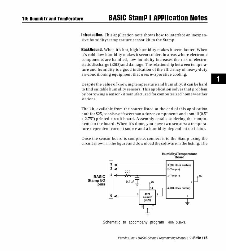
Once the sensor board is complete, connect it to the Stamp using thecircuit shown in the figure and download the software in the listing. The
10: Humidity and Temperature
Schematic to accompany program HUMID.BAS.
220
2 7
4024counter(÷128)
13
14
+50.1µF
4 (RH clock output)
1 (Temp –)
2 (Temp +)
5 (RH clock enable)
6
+5
3
Humidity/Temperature Board
0
1
23
BASIC Stamp I/O
pins
4024counter(÷128)

Page 116 • BASIC Stamp Programming Manual 1.9 • Parallax, Inc.
BASIC Stamp I Application Notes
debug window will appear on your PC screen showing values repre-senting humidity and temperature. To get a feel for the board’s sensi-tivity, try this: Breathe on the sensor board and watch the debug valueschange. The humidity value should increase dramatically, while thetemperature number (which decreases as the temperature goes up) willfall a few counts.
How it works. The largest portion of the program is devoted tomeasuring the temperature, so we’ll start there. The temperature sensoris an LM334Z constant-current source. Current through the devicevaries at the rate of 0.1µA per 1° C change in temperature. The programin the listing passes current from pin 2 of the Stamp through the sensorto a capacitor for a short period of time, starting with 5000 µs. It thenchecks the capacitor’s state of charge through pin 1. If the capacitor isnot charged enough for pin 1 to see a logical 1, the Stamp discharges thecapacitor and tries again, with a slightly wider pulse of 5010 µs.
It stays in a loop, charging, checking, discharging, and increasing thecharging pulse until the capacitor shows as a 1 on pin 1’s input. Since therate of charge is proportional to current, and the current is proportionalto temperature, the width of the pulse that charges the capacitor is arelative indication of temperature.
Sensing humidity is easier, thanks to the design of the kit’s hardware.The humidity sensor is a capacitor whose value changes with relativehumidity (RH). At a relative humidity of 43 percent and a temperatureof 77° F, the sensor has a value of 122 pF ± 15 percent. Its value changesat a rate of 0.4 pF ± 0.05 pF for each 1-percent change in RH.
The sensor controls the period of a 555 timer wired as a clock oscillator.The clock period varies from 225 µs at an arid 10-percent RH to 295 µsat a muggy 90-percent RH. Since we’re measuring this change with theStamp’s pulsin command, which has a resolution of 10 µs, we need toexaggerate those changes in period in order to get a usable change inoutput value. That’s the purpose of the 4024 counter.
We normally think of a counter as a frequency divider, but by definitionit’s also a period multiplier. By dividing the clock output by 128, wecreate a square wave with a period 128 times as long. Now humidity is
10: Humidity and Temperature

Parallax, Inc. • BASIC Stamp Programming Manual 1.9 • Page 117
BASIC Stamp I Application Notes
1
10: Humidity and Temperature
represented by a period ranging from 28.8 to 37.8 milliseconds. Sincepulsin measures only half of the waveform, the time that it’s high, RHvalues range from 14.4 to 18.9 milliseconds. At 10-µs resolution, pulsinexpresses these values as numbers ranging from 1440 to 1890. (Actually,thanks to stray capacitance, the numbers returned by the circuit willtend to be higher than this.)
In order to prevent clock pulses from interfering with temperaturemeasurements, the RH clock is disabled when not in use. If you reallyneed the extra pin, you can tie pin 5 of the sensor board high, leaving theclock on continuously. You may need to average several temperaturemeasurements to eliminate the resulting jitter, however.
Since the accuracy of both of the measurement techniques is highlydependent on the individual components and circuit layout used, we’regoing to sidestep the sticky issue of calibration and conversion to units.A recent article in Popular Electronics (January 1994 issue, page 62,“Build a Relative-Humidity Gauge”) tells how to calibrate RH sensorsusing salt solutions. Our previous application note (Stamp #7, “SensingTemperature with a Thermistor”) covers methods for converting rawdata into units, even if the data are nonlinear.
Program listing and parts source. These programs may be down-loaded from our ftp site at ftp.parallaxinc.com, or through our web siteat http://www.parallaxinc.com. The sensor kit (#WEA-TH-KIT) isavailable for $25 plus shipping and handling from Fascinating Elec-tronics, PO Box 126, Beaverton, OR 97075-0126; phone, 1-800-683-5487.
' Program HUMID.BAS' The Stamp interfaces to an inexpensive temperature/humidity' sensor kit.
Symbol temp = w4 ' TemperatureSymbol RH = w5 ' Humidity
' The main program loop reads the sensors and displays' the data on the PC screen until the user presses a key.
Loop:input 0:input 2: output 3

Page 118 • BASIC Stamp Programming Manual 1.9 • Parallax, Inc.
BASIC Stamp I Application Notes
low 2: low 3let temp = 500 ' Start temp at a reasonable value.
ReadTemp:output 1: low 1pause 1 ' Discharge the capacitor.input 1 ' Get ready for input.pulsout 2,temp ' Charge cap thru temp sensor.if pin1 = 1 then ReadRH ' Charged: we’re done.let temp = temp + 1 ' Else try againgoto ReadTemp ' with wider pulse.
ReadRH:high 3 ' Turn on the 555 timerpause 500 ' and let it stabilize.pulsin 0,1,RH ' Read the pulse width.low 3 ' Kill the timer.debug temp:debug RH ' Display the results.goto Loop ' Do it all again.
10: Humidity and Temperature

Parallax, Inc. • BASIC Stamp Programming Manual 1.9 • Page 119
BASIC Stamp I Application Notes
1
11: Infrared Communication
Introduction. This application note shows how to build a simple andinexpensive infrared communication interface for the BASIC Stamp.
Background. Today’s hottest products all seem to have one thing incommon; wireless communication. Personal organizers beam data intodesktop computers and wireless remotes allow us to channel surf fromour couches. Not wanting the BASIC Stamp to be left behind, wedevised a simple infrared data link. With a few inexpensive parts fromyour neighborhood electronics store you can communicate at 1200baud over distances greater than 10 feet indoors. The circuit can bemodified for greater range by the use of a higher performance LED.
How it works. As the name implies, infrared (IR) remote controlstransmit instructions over a beam of IR light. To avoid interference fromother household sources of infrared, primarily incandescent lights, thebeam is modulated with a 40-kHz carrier. Legend has it that 40 kHz wasselected because the previous generation of ultrasonic remotes worked
Schematic to accompany program IR .BAS.
4.7k
PC RS-232output
pin 4 of 555 timer
GP1U52Xoutput
PC RS-232 input
CMOS inverter(1/6 74HCT04)
PC Interfaces
Transmit Receive
+5
TriggerGND
Output
TLC555
1
Threshold
Discharge
Reset
Control VDD
85
4
RB10k
CT0.001µF
1k
7
6
2
3
100Ω
2N2222
IR LEDSerial inputto 1200 bps
GP1U52X
+5321
4.7k
+5
Serial output
10 feet or more indoors
10k
10k pot
RA
1N914

Page 120 • BASIC Stamp Programming Manual 1.9 • Parallax, Inc.
BASIC Stamp I Application Notes
at this frequency. Adapting their circuits was just a matter of swappingan LED for the ultrasonic speaker.
The popularity of IR remotes has inspired several component manufac-turers to introduce readymade IR receiver modules. They contain thenecessary IR detector, amplifier, filter, demodulator, and output stagesrequired to convert a 40-kHz IR signal into 5-volt logic levels. One suchmodule is the GP1U52X, available from your local Radio Shack store aspart no. 276-137. As the schematic shows, this part is all that’s requiredfor the receiving section of our application.
For the transmitting end, all we need is a switchable source of 40-kHzmodulation to drive an IR LED. That’s the purpose of the timer circuitin the schematic. Putting a 1 on the 555’s reset pin turns the 40-kHzmodulation on; a 0 turns it off. You may have to fiddle with the valuesof RA, RB, and CT. The formula is Frequency = 1.44/((RA+2*RB)*CT).With RB at 10k, the pot in the RA leg of the circuit should be set to about6k for 40-kHz operation. However, capacitor tolerances being whatthey are, you may have to adjust this pot for optimum operation.
To transmit from a Stamp, connect one of the I/O pins directly to pin 4of the ’555 timer. If you use pin 0, your program should contain codesomething like this:
low 0 ' Turn off pin 0's output latch.output 0 ' Change pin 0 to output.... ' other instructionsserout 0,N1200,("X") ' Send the letter "X"
To receive with another Stamp, connect an I/O pin to pin 1 of theGP1U52X. If the I/O pin is pin 0, the code might read:
input 0 ' Change pin 0 to input.... ' other instructionsserin 0,T1200,b2 ' Receive data in variable b2.
To receive with a PC, you’ll need to verify that the PC is capable ofreceiving 5-volt RS-232. If you have successfully sent RS-232 from yourStamp to the PC, then it’s compatible. As shown in the schematic, you’llneed to add a CMOS inverter to the output of the GP1U52X. Don’t use
11: Infrared Communication

Parallax, Inc. • BASIC Stamp Programming Manual 1.9 • Page 121
BASIC Stamp I Application Notes
1
11: Infrared Communication
a TTL inverter; its output does not have the required voltage swing.To transmit from a PC, you’ll need to add a diode and resistor ahead ofthe ’555 timer as shown in the schematic. These protect the timer fromthe negative voltage swings of the PC’s real RS-232 output.
Modifications. I’m sure you’re already planning to run the IR link at2400 baud, the Stamp’s maximum serial speed. Go ahead, but bewarned that there’s a slight detection delay in the GP1U52X that causesthe start bit of the first byte of a string to be shortened a bit. Since theserial receiver bases its timing on the leading edge of the start bit, thefirst byte will frequently be garbled.
If you want more range or easier alignment between transmitter andreceiver, consider using more or better LEDs. Some manufacturers’data sheets offer instructions for using peak current, duty cycle, thermalcharacteristics, and other factors to calculate optimum LED power rightup to the edge of burnout. However, in casual tests around the work-shop, we found that a garden-variety LED driven as shown couldreliably communicate with a receiver more than 10 feet away. A simplereflector or lens arrangement might be as beneficial as an exotic LED forimproving on this performance.
If you find that your IR receiver occasionally produces “garbagecharacters” when the transmitter is off, try grounding the metal case ofthe GP1U52X. It is somewhat sensitive to stray signals. If you build thetransmitter and receiver on the same prototyping board for testing, youare almost certain to have this problem. Bypass all power connectionswith 0.1-µF capacitors and use a single-point ground. And be encour-aged by the fact that the circuit works much better in its intendedapplication, with the transmitter and receiver several feet apart.
Program listing. There’s no program listing this time; however, youmay download programs for other application notes from our Internetftp site at ftp.parallaxinc.com. The ftp site may be reached directly orthrough our web site at http://www.parallaxinc.com.

Page 122 • BASIC Stamp Programming Manual 1.9 • Parallax, Inc.
BASIC Stamp I Application Notes

Parallax, Inc. • BASIC Stamp Programming Manual 1.9 • Page 123
BASIC Stamp I Application Notes
1
12: Sonar Rangefinding
Introduction. This application note presents a circuit that allows theBASIC Stamp to measure distances from 1 to 12 feet using inexpensiveultrasonic transducers and commonly available parts.
Background. When the November 1980 issue of Byte magazine pre-sented Steve Ciarcia’s article Home in on the Range! An UltrasonicRanging System, computer hobbyists were fascinated. The project, basedon Polaroid’s SX-70 sonar sensor, allowed you to make real-worlddistance measurements with your computer. We’ve always wanted tobuild that project, but were put off by the high cost of the Polaroidsensor ($150 in 1980, about $80 today).
If you’re willing to give up some of the more advanced features of the
Figure 1. Schematic to accompany program SONAR.BAS.
CA5160
+5
TriggerGND
Output
TLC555
1
Threshold
Discharge
Reset
Control VDD
85
4
10k
RB10k
CT0.001µF
40-kHz transmitter
7
6
2
3
FromStamp pin 0
10k pot
RA
40-kHz receiver
10k
0.022µF
1M
Ð
+
+5
7
46
2
3
10k10k
+5
18k 18k
10k pot
CT0.001µF
5
6 7
3
1 2
+5
4
0.022µF
0.01µF
LM567
VDD
Output8
+5
10k
To Stamp pin 1
Outputfilter
Loopfilter
Input
Timing R
Timing C GND
+5
Optional: detection LED
1k
Page 124 • BASIC Stamp Programming Manual 1.9 • Parallax, Inc.
BASIC Stamp I Application Notes
Polaroid sensor (35-foot range, multi-frequency chirps to avoid falsereturns, digitally controlled gain) you can build your own experimentalsonar unit for less than $10. Figure 1 shows how.
Basically, our cheap sonar consists of two sections; an ultrasonic trans-mitter based on a TLC555 timer wired as an oscillator, and a receiverusing a CMOS op-amp and an NE567 tone decoder. The Stamp controlsthese two units to send and receive 40-kHz ultrasonic pulses. Bymeasuring the elapsed time between sending a pulse and receiving itsecho, the Stamp can determine the distance to the nearest reflectivesurface. Pairs of ultrasonic transducers like the ones used in this projectare available from the sources listed at the end of this application notefor $2 to $3.50.
Construction. Although the circuits are fairly self-explanatory, a fewhints will make construction go more smoothly. First, the transmitterand receiver should be positioned about 1 inch apart, pointing in thesame direction. For reasons we’ll explain below, the can housing thetransmitter should be wrapped in a thin layer of sound-deadeningmaterial. We used self-adhesive felt from the hardware store. Cloth tapeor thin foam would probably work as well. Don’t try to enclose thetransducers or block the receiver from hearing the transmitter directly;we count on this to start the Stamp’s timing period. More on this later.For best performance, the oscillation frequency of the TLC555 and theNE567 should be identical and as close to 40 kHz as possible. There aretwo ways to achieve this. One way is to adjust the circuits with afrequency counter. For the ’555, temporarily connect pin 4 to +5 voltsand measure the frequency at pin 3. For the ’567, connect the counter topin 5.
If you don’t have a counter, you’ll have to use ±5-percent capacitors forthe units marked CT in the ’555 and ’567 circuits. Next, you’ll need toadjust the pots so that the timing resistance is as close as possible to thefollowing values. For the ’555: Frequency = 1.44/((RA + 2*RB)* CT),which works out to 40x103 = 1.44/((16x103+ 20x103) x 0.001x10-6).
Measure the actual resistance of the 10k resistors labeled RA and RB inthe figure and adjust the 10k pot in the RA leg so that the total of theequation RA + 2*RB is 36k. Once the resistances are right on, the
12: Sonar Rangefinding

Parallax, Inc. • BASIC Stamp Programming Manual 1.9 • Page 125
BASIC Stamp I Application Notes
1
12: Sonar Rangefinding
frequency of oscillation will depend entirely on CT. With 5-percenttolerance, this puts you in the ballpark; 38.1 to 42.1 kHz.
For the ’567 the math comes out like so: Frequency = 1/(1.1*R*CT);40x103 = 1/(1.1 x 22.73x103 x 0.001x10-6)
Adjust the total resistance of the 18k resistor and the pot to 22.73k.Again, the actual frequency of the ’567 will depend on CT. With 5-percent tolerance, we get the same range of possible frequencies as forthe ’555; 38.1 to 42.1 kHz.
Once you get close, you can fine-tune the circuits. Connect the LED andresistor shown in the figure to the ’567. Temporarily connect pin 4 of the’555 to +5 volts. When you apply power to the circuits, the LED shouldlight. If it doesn’t, gradually adjust the pot on the ’555 circuit until itdoes. When you’re done, make sure to reconnect pin 4 of the ’555 toStamp pin 0. Load and run the program in the listing. For a test run,point the transducers at the ceiling; a cluttered room can cause a lot offalse echoes. From a typical tabletop to the ceiling, the Stamp shouldreturn echo_time values in the range of 600 to 900. If it returns mostly0s, try adjusting the RA pot very, very slightly.
Figure 2. Timing diagram of the sonar-ranging process.
Stamp pin 0
Õ555 output
Õ567 output, Stamp pin 1
pulsout
Time for sound to travel from transmitter to receiver plus decode delay
End of pulse reaches receiver
Decoder turns off
Echoes reach receiver and are decoded
pulsin measures this timeÑfrom the end of detection of the outgoing pulse to the beginning of the return echoes
pulsin starts

Page 126 • BASIC Stamp Programming Manual 1.9 • Parallax, Inc.
BASIC Stamp I Application Notes
How it works. In figure 1, the TLC555 timer is connected as a oscillator;officially an astable multivibrator. When its reset pin is high, the circuitsends a 40-kHz signal to the ultrasonic transmitter, which is really justa specialized sort of speaker. When reset is low, the ’555 is silenced.
In the receiving section, the ultrasonic receiver—a high-frequencymicrophone—feeds the CA5160 op amp, which amplifies its signal 100times. This signal goes to an NE567 tone decoder, which looks for a closematch between the frequency of an incoming signal and that of itsinternal oscillator. When it finds one, it pulls its output pin low.
Figure 2 illustrates the sonar ranging process. The Stamp activates the’555 to send a brief 40-kHz pulse out through the ultrasonic transmitter.Since the receiver is an inch away, it hears this initial pulse loud andclear, starting about 74 µs after the pulse begins (the time required forsound to travel 1 inch at 1130 feet per second). After the ’567 has heardenough of this pulse to recognize it as a valid 40-kHz signal, it pulls itsoutput low.
After pulsout finishes, the transmitter continues to ring for a shorttime. The purpose of the felt or cloth wrapping on the transmitter is todamp out this ringing as soon as possible. Meanwhile, the Stamp hasissued the pulsin command and is waiting for the ’567 output to gohigh to begin its timing period. Thanks to the time required for the endof the pulse to reach the receiver, and the pulse-stretching tendency ofthe ’567 output filter, the Stamp has plenty of time to catch the risingedge of the ’567 output.
That’s why we have to damp the ringing of the transmitter. If thetransmitter were allowed to ring undamped, it would extend theinterval between the end of pulsout and the beginning of pulsin ,reducing the minimum range of the sonar. Also, if the ringing wereallowed to gradually fade away, the output of the ’567 might chatterbetween low and high a few times before settling high. This would foolpulsin into a false, low reading.
On the other hand, if we prevented the receiver from hearing thetransmitter at all, pulsin would not get a positive edge to trigger on.It would time out and return a reading of 0.
12: Sonar Rangefinding

Parallax, Inc. • BASIC Stamp Programming Manual 1.9 • Page 127
BASIC Stamp I Application Notes
1
Once pulsin finds the positive edge that marks the end of the NE567’sdetection of the outgoing pulse, it waits. Pulsin records this waitingtime in increments of 10 µs until the output of the ’567 goes low again,marking the arrival of the first return echo. Using debug , the programdisplays this delay on your PC screen.
To convert this value to distance, first remember that the time pulsinmeasures is the round-trip distance from the sonar to the wall or otherobject, and that there’s an offset time peculiar to your homemade sonarunit. To calibrate your sonar, carefully measure the distance in inchesbetween the transmitter/receiver and the nearest wall or the ceiling.Multiply that number by two for the roundtrip, then by 7.375 (at 1130feet/second sound travels 1 inch in 73.746 µs; 7.375 is the number of10-µs pulsin units per inch). Now take a Stamp sonar reading of thedistance. Subtract your sonar reading from the calculated reading.That’s the offset.
Once you have the offset, add that value to pulsin ’s output beforedividing by 7.375 to get the round-trip distance in inches. By the way,to do the division with the Stamp’s integer math, multiply the valueplus offset by 10, then divide by 74. The difference between this anddividing by 7.375 will be about an inch at the sonar’s maximum range.The result will be the round-trip distance. To get the one-way distance,divide by two.
Modifications. The possibilities for modifications are endless. Forthose who align the project without a frequency counter, the mostbeneficial modification would be to borrow a counter and preciselyalign the oscillator and tone decoder.
Or eliminate the need for frequency alignment by designing a transmit-ter oscillator controlled by a crystal, or by the resonance of the ultrasonictransducer itself.
Try increasing the range with reflectors or megaphone-shaped baffleson the transmitter and/or receiver.
Soup up the receiver’s amplifier section. The Polaroid sonar unit usesvariable gain that increases with the time since the pulse was transmit-ted to compensate for faint echoes at long distances.
12: Sonar Rangefinding

Page 128 • BASIC Stamp Programming Manual 1.9 • Parallax, Inc.
BASIC Stamp I Application Notes
Make the transmitter louder. Most ultrasonic transmitters can with-stand inputs of 20 or more volts peak-to-peak; ours uses only 5.
Tinker with the tone decoder, especially the loop and output filtercapacitors. These are critical to reliable detection and ranging. Wearrived at the values used in the circuit by calculating reasonablestarting points, and then substituting like mad. There’s probably stillsome room for improvement.
Many ultrasonic transducers can work as both a speaker and micro-phone. Devise a way to multiplex the transmit and receive functions toa single transducer. This would simplify the use of a reflector or baffle.
Parts sources. Suitable ultrasonic transducers are available from AllElectronics, 1-800-826-5432. Part no. UST-23 includes both transmitterand receiver. Price was $2 at the time of this writing. Marlin P. Jones andAssociates, 1-800-652-6733, stock #4726-UT. Price was $3.95 at the timeof this writing. Hosfelt Electronics, 1-800-524-6464, carries a slightlymore sensitive pair of transducers as part no. 13-334. Price was $3.50 atthe time of this writing.
Program listing. This program may be downloaded from our Internetftp site at ftp.parallaxinc.com. The ftp site may be reached directly orthrough our web site at http://www.parallaxinc.com.
' Program: SONAR.BAS' The Stamp runs a sonar transceiver to measure distances' up to 12 feet.
Symbol echo_time = w2 ' Variable to hold delay time
setup: let pins = 0 ' All pins lowoutput 0 ' Controls sonar xmitterinput 1 ' Listens to sonar receiver
ping: pulsout 0,50 ' Send a 0.5-ms pingpulsin 1,1,echo_time ' Listen for returndebug echo_time ' Display time measurementpause 500 ' Wait 1/2 secondgoto ping ' Do it again.
12: Sonar Rangefinding

Parallax, Inc. • BASIC Stamp Programming Manual 1.9 • Page 129
BASIC Stamp I Application Notes
1
13: Using Serial EEPROMs
Introduction. This application note shows how to use the 93LC66EEPROM to provide 512 bytes of nonvolatile storage. It provides a toolkit of subroutines for reading and writing the EEPROM.
Background. Many designs take advantage of the Stamp’s ability tostore data in its EEPROM program memory. The trouble is that themore data, the smaller the space left for code. If only we could expandthe Stamp’s EEPROM!
This application note will show you how to do the next best thing; adda separate EEPROM that your data can have all to itself.
The Microchip 93C66 and 93LC66 electrically erasable PROMs(EEPROMs) are 512-byte versions of the 93LC56 used as the Stamp’sprogram memory. (Before you ask: No, dropping a ’66 in place of theStamp’s ’56 will not double your program memory!) Serial EEPROMscommunicate with a processor via a three- or four-wire bus using asimple synchronous (clocked) communication protocol at rates of up to2 million bits per second (Mbps).
Data stored in the EEPROM will be retained for 10 years or more,according to the manufacturer. The factor that determines the EEPROM’slongevity in a particular application is the number of erase/writecycles. Depending on factors such as temperature and supply voltage,the EEPROM is good for 10,000 to 1million erase/write cycles. For a thor-ough discussion of EEPROM endur-ance, see the Microchip EmbeddedControl Handbook, publication num-ber DS00092B, November 1993.
How it works. The circuit in the fig-ure specifies a 93LC66 EEPROM, buta 93C66 will work as well. You canalso subsitute the 256-byte ’56, pro-vided you restrict the highest ad-dress to 255. The difference betweenthe C and LC models is that the LChas a wider Vcc range (2.5–5.5 V,
CS
CK
DI
DO
Vcc
NC
ORG
Vss
93C66
+5
2.2k
22k
Stamp Pins
012
6
7
To PC serial in
From PC serial out
Signal ground
512-byte Serial
EEPROM
Schematic to accompanyE E P R O M.B A S .

Page 130 • BASIC Stamp Programming Manual 1.9 • Parallax, Inc.
BASIC Stamp I Application Notes
versus 4–5.5 V), lower current consumption (3 mA versus 4 mA), andcan be somewhat slower in completing internal erase/write operations,presumably at lower supply voltages. In general, the LC type is lessexpensive, and a better match for the operating characteristics of theStamp.
The schematic shows the data in and data out (DI, DO) lines of theEEPROM connected together to a single Stamp I/O pin. The 2.2kresistor prevents the Stamp and DO from fighting over the bus duringa read operation. During a read, the Stamp sends an opcode and anaddress to the EEPROM. As soon as it has received the address, theEEPROM activates DO and puts a 0 on it. If the last bit of the address isa 1, the Stamp could end up sourcing current to ground through theEEPROM. The resistor limits the current to a reasonable level.
The program listing is a collection of subroutines for reading andwriting the EEPROM. All of these rely on Shout , a routine that shiftsbits out to the EEPROM. To perform an EEPROM operation, thesoftware loads the number of clock cycles into clocks and the data tobe output into ShifReg . It then calls Shout , which does the rest.
The demonstration program calls for you to connect the Stamp to yourPC serial port, type in up to 512 characters of text, and hit return whenyou’re done. Please type this sample text rather than downloading a fileto the Stamp. The Stamp will miss characters of a rapidly downloadedfile, though it’s more than fast enough to keep up with typing. As youtype in your message, the Stamp will record each character to EEPROM.
When you’re finished typing, the Stamp will repeat your text back to thePC serial port. In fact, it will read all 512 bytes of the EEPROM contentsback to the PC.
If you don’t have the EEPROM data handy (Microchip Data Book,DS00018D, 1991), you should know about a couple of subtleties. First,when the EEPROM powers up, it is write protected. You must callEenable before trying to write or erase it. It’s a good idea to callEdisbl (disable writes) as soon as possible after you’re done. Other-wise, a power glitch could alter the contents of your EEPROM.
13: Using Serial EEPROMs

Parallax, Inc. • BASIC Stamp Programming Manual 1.9 • Page 131
BASIC Stamp I Application Notes
1
13: Using Serial EEPROMs
The second subtle point is that National Semiconductor makes a seriesof EEPROMs with the same part numbers as the Microchip partsdiscussed here. However, the National parts use a communicationprotocol that’s sufficiently different to prevent them from working withthese routines. Make sure to ask for Microchip parts, or be prepared torewrite portions of the code.
Modifications. If you’re using PBASIC interpreter chips as part of afinished product, you may be contemplating buying a programmer toduplicate EEPROMs for production. If you’d prefer to avoid the ex-pense, why not build a Stamp-based EEPROM copier? Just rememberto include a 2-millisecond delay or read the busy flag between sequen-tial writes to an EEPROM. This is required to allow the internalprogramming process to finish. These topics are covered in more detailin the EEPROM documentation.
Program listing. This program may be downloaded from our Internetftp site at ftp.parallaxinc.com. The ftp site may be reached directly orthrough our web site at http://www.parallaxinc.com.
' Program: EEPROM.BAS' This program demonstrates subroutines for storing data in a' Microchip 93LC66 serial EEPROM. This program will not work' with the National Semiconductor part with the same number.' Its serial protocol is substantially different.
Symbol CS = 0 ' Chip-select line to pin 0.Symbol CLK = 1 ' Clock line to pin 1.Symbol DATA = pin2 ' Destination of Shout; input to ShinSymbol DATA_N = 2 ' Pin # of DATA for "input" & "output"Symbol ReadEE = $C00 ' EEPROM opcode for read.Symbol Enable = $980 ' EEPROM opcode to enable writes.Symbol Disable = $800 ' EEPROM opcode to disable writes.Symbol WriteEE = $A00 ' EEPROM opcode for write.Symbol GetMSB = $800 ' Divisor for getting msb of 12-bit no.Symbol ShifReg = w1 ' Use w1 to shift out 12-bit sequences.Symbol EEaddr = w2 ' 9-bit address for reads & writes.Symbol EEdata = b6 ' Data for writes; data from reads.Symbol i = b7 ' Index counter for EEPROM routines.Symbol clocks = b10 ' Number of bits to shift with Shout.
output DATA_N ' EEPROM combined data connection.output CLK ' EEPROM clock.

Page 132 • BASIC Stamp Programming Manual 1.9 • Parallax, Inc.
BASIC Stamp I Application Notes
output CS ' EEPROM chip select.
' Demonstration program to exercise EEPROM subroutines:' Accepts serial input at 2400 baud through pin 7. Type a' message up to 512 characters long. The Stamp will store' each character in the EEPROM. When you reach 512 characters' or press return, the Stamp will read the message back from' the EEPROM and transmit it serially through pin 6' at 2400 baud.
output 6 ' For serial output.input 7 ' For serial input.gosub Eenabl ' Remove EEPROM write protection.let EEaddr=0 ' Start at 1st (0th) address.
CharIn: serin 7,N2400,EEdata ' Get character.if EEdata<32 then Done ' If it's return, done.gosub Ewrite ' Otherwise, write to EEPROM.let EEaddr=EEaddr+1 ' Increment addr for next write.if EEaddr=512 then Done ' Memory full? Done.goto CharIn
Done: gosub Edisbl ' Protect EEPROM.for w4 = 0 to 511 ' Show all 512 bytes.let EEaddr = w4 ' Point to EEPROM address.gosub Eread ' Retrieve the data.serout 6,N2400,(EEdata) ' Send it out serial port.next ' Next character.End ' Demo over.
' Write the data in EEdata to the address EEaddr.Ewrite: let ShifReg=WriteEE ' Get the write opcode.
let ShifReg=ShifReg|EEaddr ' OR in the address bits.let clocks = 12 ' Send 12 bits to EEPROM.high CS ' Chip select on.gosub Shout ' Send the opcode/address.let ShifReg = EEdata*16 ' Move bit 7 to bit 11.let clocks = 8 ' Eight data bits.gosub Shout ' Send the data.low CS ' Deselect the EEPROM.return
' Read data from EEPROM address EEaddr into EEdata.Eread: let ShifReg=ReadEE ' Get the read opcode.
let ShifReg=ShifReg|EEaddr ' OR in the address bits.let clocks=12 ' Send 12 bits to EEPROM.high CS ' Chip select on.gosub Shout ' Send the opcode/address.gosub Shin ' Receive the byte.low CS ' Deselect the EEPROM.
13: Using Serial EEPROMs

Parallax, Inc. • BASIC Stamp Programming Manual 1.9 • Page 133
BASIC Stamp I Application Notes
1
return
' Enable writes to the EEPROM. Upon power-up the EEPROM is' write-protected, so this routine must be called before' first writing to the EEPROM.Eenabl: let ShifReg=Enable ' Get the write-enable opcode.
high CS ' Chip select on.let clocks = 12 ' Send 12 bits to EEPROM.gosub Shout ' Send the opcode.low CS ' Deselect the EEPROM.return
' Disable writes to the EEPROM.Edisbl: let ShifReg=Disable ' Get the write-disable opcode.
high CS ' Chip select on.let clocks = 12 ' Send 12 bits to EEPROM.gosub Shout ' Send the opcodelow CS ' Deselect the EEPROMreturn
' Shift data into EEdata.Shin: input DATA_N ' Change the data line to input.
let EEdata=0 ' Clear data byte.for i = 1 to 8 ' Prepare to get 8 bits.let EEdata=EEdata*2 ' Shift EEdata to the left.high CLK ' Data valid on rising edge.let EEdata=EEdata+DATA ' Move data to lsb of variable.low CLK ' End of clock pulse.next i ' Get another bit.output DATA_N ' Restore data line to output.return
' Shift data out of ShifReg.Shout: for i = 1 to clocks ' Number of bits to shift out.
let DATA=ShifReg/GetMSB ' Get bit 12 of ShifReg.pulsout CLK,10 ' Output a brief clock pulse.let ShifReg=ShifReg*2 ' Shift register to the left.next i ' Send another bit.return
13: Using Serial EEPROMs

Page 134 • BASIC Stamp Programming Manual 1.9 • Parallax, Inc.
BASIC Stamp I Application Notes

Parallax, Inc. • BASIC Stamp Programming Manual 1.9 • Page 135
BASIC Stamp I Application Notes
1
14: Networking Multiple Stamps
Introduction. This application note shows how to connect multipleStamps together in a simple network. It explains the use of the seroutopen-drain and open-source baudmodes.
Background. Many Parallax customers are interested in connectingmultiple Stamps together to form a network. Their applications includeintelligent home control, security sytems, small-scale robotics, anddistributed sensing arrangements. For these applications, the Stamphas built-in serial networking capabilities requiring a minimum ofexternal components. Better yet, participation in a network requiresonly a couple of lines of Stamp code and one additional I/O line at most.
How it works. The first question that comes to mind is: “Why not justconnect multiple Stamps to one serial port and make them talk one ata time? That would be a good enough network for most jobs.” That’strue, for the most part, but the Stamp’s normal serial outputs woulddestroy each other. Figure 1 shows why.
In output mode, the Stamp’s I/O pins act like switches connected to thepower-supply rails. When the Stamp outputs a 1, it’s turning on theswitch connected to the +5-volt rail while turning off the one going toground. To output a 0, it does the reverse. If you connect multiple Stampoutputs together, you set up the situation in figure 1b: a direct short toground through a pair of Stamp output switches. This would damagethe Stamp’s PBASIC interpreter chip.
Now, before you runoff to design a systemof logic gates or diodesto fix this, listen up: TheStamp can be config-ured to use only one ofthe two switches for se-rial output. This elimi-nates the possibility ofa short circuit andopens up the possibil-ity of network hook-ups. See figure 2.
+5 +5
One-Stamp serial hookup, normal
(N2400) baudmode
to serial port input
Stamp I/O pin
Consequences of connecting Stamps together in normal
baudmode
+5
SHORT TO GROUND!
a b
Figure 1

Page 136 • BASIC Stamp Programming Manual 1.9 • Parallax, Inc.
BASIC Stamp I Application Notes 14: Networking Multiple Stamps
To use this technique,your program shouldbegin by setting the se-rial pin to input in or-der to turn off the out-put switches. Then,when it’s time for theStamp to put some dataonto the network usingserout, the baudmodeargument should beginwith OT, as in OT2400.This is known as an open-drain configuration, in honor of the portionof the PBASIC interpreter’s output MOSFET switch left “open” at thepin connection.
When connected Stamp pins are in different states there’s no problem,because no current flows. No data flows, either, because the pins areincapable of outputting a logical 1 (+5 volts). That’s easily remedied byadding a pullup resistor, however, as shown in figure 3.
The inverter/line driver shown in figure 3 can either be a CMOS typelike one-sixth of a 74HCT04 or an actual RS-232 line driver, such as aMAX-232. If the Stamps will be talking to each other instead of reportingto a host computer, you can eliminate the line driver entirely.
The Stamp also supports an open baudmode that switches to +5 onlyinstead of ground. This is the open-source configuration, selected by anargument beginning with ON, such as ON2400. To make this work, youmust reverse the polarity of everything shown in figure 3. The resistor
would go to ground. Anon-inverting buffer (oradditional inverter)would be used tostraighten out the sig-nal polarity.
Now that we have away to safely connect
One-Stamp serial hookup, open-drain (OT2400) baudmode
Stamp I/O pin
Consequences of connecting Stamps
together in open baudmode
a b
no problem!
Figure 2
+5
1k
True RS-232 or RS-422 output
inverting line driver IC
multiple pins driven by open baudmode (e.g., OT2400)
Figure 3

Parallax, Inc. • BASIC Stamp Programming Manual 1.9 • Page 137
BASIC Stamp I Application Notes
1
14: Networking Multiple Stamps
multiple Stamp serial pins to a single line, how do we ensure that onlyone Stamp talks at once? The possibilities seem endless, and dependprimarily on the nature of the data to be sent through the net. Forexample, each Stamp could alternate between talking and listening onthe net. You could use a system of qualifiers that each Stamp wouldhave to receive via serin before it could transmits onto the net. Thatway, one Stamp would send its data, then turn the net over to the next.That is the approach used in the demonstration programs.
Of course, if you have I/O pins available on each of the Stamps in thenet, you could just have each Stamp wait for a particular logic level totell it to transmit. Another approach would be to have one Stamp triggerits neighbor. As I said, the possibilities go on and on. If you get stuck forideas, just look at a diagram of a local-area network (LAN). LANdesigners have invented all kinds of schemes, called “network topolo-gies,” for determining who talks when. They’ve dreamed up goodnames, too, like token rings, stars, hubs, etc.
The example we present is a variation on the token-ring idea. ThreeStamps named Moe, Larry, and Curly will share a single serial line.When they are first powered up, Moe will transmit a message conclud-ing with “Larry.” Larry, recognizing his name, will transmit a messageconcluding with “Curly.” Curly will transmit a message, concludingwith “Moe.” Moe will start the process all over again. Even though theStamps are communicating among themselves, we’ll still use an in-verter/driver in order to monitor the process with a PC running
Stamp “Moe”
Stamp “Larry”
Stamp “Curly”
+5
1k1/6th of 74HCT04
1 2
7 7 7
PC or terminal: 2400bps
N,8,1+5
14
7
Figure 4. Serial network of Stamps using open-drain output.

Page 138 • BASIC Stamp Programming Manual 1.9 • Parallax, Inc.
BASIC Stamp I Application Notes 14: Networking Multiple Stamps
terminal software. Figure 4 shows the circuit; the program listing showsthe code used in the Stamps.
For your application, you’d simply substitute a real message (based ondata gathered by the Stamps) for the sample messages. Make sure thatyour data messages cannot contain the names of the other Stamps, oryou’ll create chaos. A safe bet is to restrict data to numbers, and namesto text. Make sure that the individual Stamps can gather data quicklyenough to be ready when their names are called. If they’re not ready,they may miss their cues. This can cause the entire net to hang up.Likewise, simple failure of one of the Stamps will hang the net. Forcritical applications, you might want to consider making one of theStamps a supervisor whose job it is to handle these emergencies.
Program listing. These programs may be downloaded from our Internetftp site at ftp.parallaxinc.com. The ftp site may be reached directly orthrough our web site at http://www.parallaxinc.com.
' Program: Moe' Stamp participant in a simple ring-type network. This Stamp has the job of' starting the network up by passing an initial message before receiving a cue.' Thereafter, Moe only transmits when cued by Curly, the last Stamp on the net.
input 7 ' Set pin 7 to input.pause 1000 ' Give others time to wake up.serout 7,OT2400,(10,13,"Three ") ' Say the line.serout 7,OT2400,("Larry",10,13) ' Cue next.
' Now enter the main program loop.Loop:
serin 7,T2400,("Moe",10,13) ' Wait for cue.serout 7,OT2400,(10,13,"Three ") ' Say the line.serout 7,OT2400,("Larry",10,13) ' Cue next.
goto Loop
' Program: Larry' Stamp participant in a simple ring-type network. Only transmits when cued' by Moe, the first Stamp on the net.
input 7 ' Set pin 7 to input.
' Main program loop:

Parallax, Inc. • BASIC Stamp Programming Manual 1.9 • Page 139
BASIC Stamp I Application Notes
1
Loop:serin 7,T2400,("Larry",10,13) ' Wait for cue.serout 7,OT2400,("Blind ") ' Say your line.serout 7,OT2400,("Curly",10,13) ' Cue next
goto Loop
' Program: Curly' Stamp participant in a simple ring-type network. Only transmits when cued' by Larry, the middle Stamp in the net.
input 7 ' Set pin 7 to input.
' Main program loop:Loop:
serin 7,T2400,("Curly",10,13) ' Wait for cue.serout 7,OT2400,("Mice ") ' Say your line.serout 7,OT2400,("Moe",10,13) ' Cue next
goto Loop
14: Networking Multiple Stamps

Page 140 • BASIC Stamp Programming Manual 1.9 • Parallax, Inc.
BASIC Stamp I Application Notes

Parallax, Inc. • BASIC Stamp Programming Manual 1.9 • Page 141
BASIC Stamp I Application Notes
1
15: Using PWM for Analog Output
Introduction. This application note explains how to convert digitalvalues to analog voltages using the BASIC Stamp command pwm.
Background. There’s probably some misunderstanding about thepulse-width modulation (pwm) command. Most Stamp users know thatit generates a waveform whose duty cycle (ratio of on time to off time)can be varied from 0 to 100 percent by varying the duty input from 0to 255. But experience with other devices probably leads them to expectthe output to look like figure 1. This is the sort of variable duty cycle
output you get from most timer and countercircuits.
The Stamp uses a different, more efficientalgorithm to generate pwm. Its output isjust as useful for generating analog volt-ages, but when displayed on an oscillo-scope, it can look like a mess; see figure 2.
The proportion of on time to off time is thesame, but instead of being separated intoneat chunks, Stamp pwm is distributedover a large number of pulses of varyingwidth.
Without getting too far into the details, the reason is this: The Stampgenerates pwm by adding the duty cycle into an internal variable thatwe’ll call the “accumulator.” It doesn’t carewhat the accumulator contains, onlywhether or not it overflows (generates acarry-the-one operation). If it does, the pwmpin goes high; otherwise, low.
The Stamp does this addition quite a fewtimes. The larger the duty cycle is, the moreoften carries occur, and the higher the pro-portion of highs to lows. However, the car-ries occur with an irregular rhythm, so theoutput waveform, while perfect duty-cyclepwm, looks like fruit salad on the ’scope.
“PWM”
20% on
80% off
Figure 1. Whatusers think pwm
looks like.
“PWM”
total off = 80%
total on = 20%
Figure 2. What pwmreally looks like.

Page 142 • BASIC Stamp Programming Manual 1.9 • Parallax, Inc.
BASIC Stamp I Application Notes 15: Using PWM for Analog Output
Using pwm. The primary applicationfor pwm is to generate a voltage from 0to 5 volts proportional to the duty cycle.An even simpler use is to control thebrightness of an LED. See figure 3.
If, as shown in the figure, the LED isconnected to pin 0, the following frag-ment of a Stamp program will gradu-ally raise the brightness of the LEDfrom off to fully on:
low 0 ' LED completely off.for b2 = 0 to 255 ' Loop from off to on.
pwm 0, b2,1 ' Output one burst of pwm.nexthigh 0 ' Leave LED on.
Although the Stamp is sending a stream of 1s and 0s to the LED, itappears to be steadily on at varying levels of brightness. That’s becauseyour eyes integrate (smooth) the rapid flickering, just as they do theframes of a movie or television picture.
If you look at the pwm writeup in the Stamp manual, you’ll see that inmost applications you need a resistor and capacitor to integrate theoutput to a smoothly varying voltage. What the manual doesn’t showis the effect that connected circuits can have on a simple resistor/capacitor (RC) integrator.
The fact is that if you try to draw too much current from the RC circuit,your program will have to output many cycles of pwm, and do so quiteoften in order to maintain the charge on the capacitor. Otherwise, thevoltage level set by pwm will begin to droop.
Figure 4 shows one way to overcome this. The CA5160E operationalamplifier (op amp) has an extremely high input impedance, so it drawsvery little current from the capacitor. Since its gain is set to 1 by theaccompanying components, the voltage at its output is the same as thevoltage at its input, with one big exception: The current drawn from the
470Stamp
pin 0 LED
Figure 3. Controllingthe brightness of an
LED with pwm.

Parallax, Inc. • BASIC Stamp Programming Manual 1.9 • Page 143
BASIC Stamp I Application Notes
1
15: Using PWM for Analog Output
CA5160
0.1µF
2k
+5
7
46
2
310k
Ð
+
100k pot
15
4.7k
0.47µF
Stamp pwm
output
Stiff voltage source
Figure 4. Example op-amp buffer circuit.
output of the op amp does not affect the charge on the capacitor in theRC integrator.
According to the op amp’s specs, you can draw up to 12 mA from itsoutput. Other op amps may offer higher current outputs, but make sureto check all the specifications. The CA5160 was used here because it ishappy operating from a 5-volt, single-ended supply. Supply current istypically 50 µA (ignoring current drawn from the output). Other opamps may require split supplies of ±15 volts or more.
To drive the op-amp circuit properly, the pin used for pwm output mustactually be defined as an input. This ensures that once pwm establishesa voltage level on the capacitor it disconnects itself from the circuit. Thecode we used to set the circuit to approximately 2.5 volts is:
input 0 ' Make pin 0 an input.pwm 0, 127,1 ' Output one burst of pwm.
In our tests, one burst of pwm was sufficient to charge the capacitor tothe desired voltage. Once set, the voltage at the op amp’s output(driving a 1k resistor load) remained steady for more than 15 minutes.It actually drifted slowly upward, probably due to slight current

Page 144 • BASIC Stamp Programming Manual 1.9 • Parallax, Inc.
BASIC Stamp I Application Notes 15: Using PWM for Analog Output
leakage from the Stamp I/O pin. In a real application, you should try toreestablish the voltage level more often than once every 15 minutes.
A few final notes about the circuit. The 100k pot allows you to fine-tunethe op amp’s output offset. Connect the circuit with an accurate voltme-ter at the output. Program the Stamp to kick out a burst of PWM. Thevoltage appearing at the op amp output should be (duty/255) times thesupply voltage (5 volts from the Stamp’s regulated supply). So if theduty is 127, the output voltage should be (127/255) * 5 = 2.49 volts.Adjust the pot until the actual voltage agrees with your calculation.
You may find that your op amp won’t track the input voltage all the wayto +5 volts. One solution is to simply ignore this limitation, and justwork within the range you do get. Another is to connect the + supplypin of the op amp (pin 7) to unregulated +9 volts from the battery. Asthe battery dies, you’ll eventually have the same problem again, butyou will get rail-to-rail performance for most of the battery’s life.
Program listing. There’s no program listing this time; however, youmay download programs for other application notes our Internet ftpsite at ftp.parallaxinc.com. The ftp site may be reached directly orthrough our web site at http://www.parallaxinc.com.

Parallax, Inc. • BASIC Stamp Programming Manual 1.9 • Page 145
BASIC Stamp I Application Notes
1
16: Keeping Stamp Programs Private
Introduction. This application note explains how to use the BASICStamp directive bsave and the program BSLOAD.EXE to enable custom-ers to update Stamp programs without access to the source code. It alsoshows a method by which the Stamp can reload its own programmemory from data received over RS-232.
Background. Try this: Phone Microsoft and tell them you own Excel™or another product of theirs, and you’d like a copy of the source code.Be generous; tell them you are willing to pay for the disks and theshipping charges.
You’ll probably find out how people working at a big corporation reactto pranks. You’ll also learn a lot of new ways to gently say “no.”
If you want to keep your Stamp source code private, but still allowcustomers to download alternative functions, change EEPROM data, orupdate firmware, you need to know about bsave .
Using bsave. When you run a Stamp program using the latest versionsof STAMP.EXE, the software looks for the directive bsave on a line byitself anywhere in the source-code listing. If bsave is present, thesoftware saves a 256-byte file called CODE.OBJ to the current directory.That file contains a copy of the binary data written to the Stamp’sEEPROM. You can rename and distribute that file, along with a pro-gram called BSLOAD.EXE that’s available from the Parallax bulletin-board system.
If you renamed your code file UPDATE.OBJ (it’s smart to retain theextension .OBJ because that is the default recognized by BSLOAD) youcould distribute it, the BSLOAD software, and a Stamp cable to yourcustomer. Instruct the customer to connect the cable from a PC to theStamp-based product, connect power, and type BSLOAD UPDATE. Astatus message appears on the screen to indicate the success of thedownload.
This technique eliminates the need to distribute your source files andSTAMP.EXE in order to update Stamp firmware.

Page 146 • BASIC Stamp Programming Manual 1.9 • Parallax, Inc.
BASIC Stamp I Application Notes 16: Keeping Stamp Programs Private
Self-replacing programs. This is going to sound like do-it-yourselfbrain surgery, but it’s possible to write Stamp programs that replacethemselves in EEPROM program memory. This means you can down-load a new program to the Stamp via a serial link.
Program listings 1 and 2 are examples of self-replacing programs. Thetrick lies in the fact that both contain identical startup code. This code,with the assistance of the serial hookup depicted in the figure, deter-mines whether or not a serial output is connected to the Stamp atstartup. If no serial connection is present, the Stamp goes about itsbusiness—in the cases of list-ings 1 and 2, flashing an LED intwo different ways. If a serialconnection is present at startup,the Stamp receives 256 bytes ofdata and uses them to replacethe entire contents of itsEEPROM.
This means that the programoverwrites itself. It doesn’tcrash, however, because the re-placement program contains the same code in the same place; at thevery beginning of the program.
Listing 3 is a QBASIC program that performs the serial downloading.You may copy and modify this program to fit your own requirements.When you write your own version, be sure to note that QBASIC mustopen the .OBJ file as binary data. Otherwise, chances are good that acontrol-Z character (ASCII 26) somewhere in the .OBJ file would causeQBASIC to end the download.
Here’s how to make this demonstration work: Construct the circuitshown in the figure, but do not connect your PC’s serial port to theStamp yet. Load and run the Stamp program THROB.BAS. Because thefile contains bsave , the Stamp software will write its binary image tothe file CODE.OBJ. Make a mental note of the DOS path to this file; you’llneed it for the downloading step. Next load and run BLINK.BAS. Since itdoes not contain bsave , this will not generate an object file.
330Ω
LED
Stamp pin 0
Stamp pin 7
47k
+5
22kPC serial out(DB9 = pin 3DB25 = pin 2)
PC signal gnd(DB9 = pin 5DB25 = pin 7)

Parallax, Inc. • BASIC Stamp Programming Manual 1.9 • Page 147
BASIC Stamp I Application Notes
1
16: Keeping Stamp Programs Private
Now, quit the Stamp software and disconnect the Stamp from itsbattery or power supply. Remember, the Stamp only looks for the serialconnection at startup, otherwise, it goes into its normal loop.
Boot QBASIC or QuickBASIC and load the program REPROG.BAS. Beforeyou run the program, type your path name into the commandOPEN "D:\CODE.OBJ" FOR BINARY AS #1 . Connect the PC’s serialoutput as indicated in the figure and apply power to the Stamp. Nowrun the program.
As the download proceeds, the program will display the current bytenumber on the screen of your PC, and the Stamp will blink its LED intime to the arriving data. A large FOR/NEXT delay has been added to thedownloading loop to prevent it from outrunning the EEPROM pro-gramming process.
When the download is over, the Stamp will begin running THROB.BAS.If you like, you can create an object file of BLINK.BAS and follow theprocedures above to replace THROB. Or you can write your own pro-gram, include the downloading code, and replace either program withyour program.
Program listing. These programs may be downloaded from our Internetftp site at ftp.parallaxinc.com. The ftp site may be reached directly orthrough our web site at http://www.parallaxinc.com.
' Listing 1: Blink.BAS' This program can replace itself with a new program' downloaded via a serial connection. It is part of a' demonstration described in Stamp application note 16.if pin7 = 1 then Loop ' No serial hookup so skip.for b2 = 255 to 0 step -1 ' Download 256 bytes
serin 7,N2400,b4 ' Get a byte.write b2,b4 ' Write to EEPROM.toggle 0 ' Flash LED.
next
Loop: ' Main program loop:toggle 0 ' blink LED.pause 50
goto Loop

Page 148 • BASIC Stamp Programming Manual 1.9 • Parallax, Inc.
BASIC Stamp I Application Notes
' Listing 2: Throb.BAS' This program can replace itself with a new program' downloaded via a serial connection. It is part of a' demonstration described in Stamp application note 16.if pin7 = 1 then Loop ' No serial hookup so skip.for b2 = 255 to 0 step -1 ' Download 256 bytes
serin 7,N2400,b4 ' Get a byte.write b2,b4 ' Write to EEPROM.toggle 0 ' Flash LED.
next
Loop: ' Main program loop:for b2 = 0 to 255 step 5 ' make LED "throb"pwm 0,b2,1 ' by varying its brightnessnext ' using pwm.for b2 = 255 to 0 step -3pwm 0,b2,1next
goto Loop
' Listing 3: REPROG.BAS (NOT a Stamp program)' This is a QBASIC program that will download a Stamp' object file via an RS-232 serial hookup. Be sure to' enter the correct path to your CODE.OBJ file in the' OPEN command below.DEFINT A-Z:CLSDIM code(255) AS INTEGER' Load the contents of the CODE.OBJ into a variable.' Replace "D:\CODE.OBJ" with your file's path.OPEN "D:\CODE.OBJ" FOR BINARY AS #1FOR i = 0 TO 255
code(i) = ASC(INPUT$(1, 1))NEXT iCLOSE #1' Send the code bytes out the serial port.OPEN "COM1:2400,N,8,1,CD0,CS0,DS0,OP0" FOR RANDOM AS #1FOR i = 0 TO 255
CLS: PRINT "Sending: "; iPRINT #1, CHR$(code(i));FOR j = 1 TO 20000: NEXT j ' Large delay.
NEXT iCLOSE #1END
16: Keeping Stamp Programs Private

Parallax, Inc. • BASIC Stamp Programming Manual 1.9 • Page 149
BASIC Stamp I Application Notes
1
17: Solar-Powered Stamp
Introduction. This application note shows how to operate the Stamp 24hours a day from the power provided by a 1.5" x 2.5" solar battery. Theexample application takes outdoor temperature measurements every12 seconds, then relays them to a computer indoors via an infrared link.
Background. A standard 9-volt battery can power the Stamp for a longtime with the use of the sleep and nap commands. But eventually thebattery will die, if only from old age.
Although it’s usually no problem to just replace the battery, there areapplications that require long periods of unattended operation. Imag-ine a mountaintop weather station, forest wildlife counter, or floatingsensor buoy, drifting in the currents at sea. Now imagine the cost ofmounting an expedition to replace the Stamp’s battery. Whew!
There are also less exotic places in which independence from batterieswould be a good idea. How about pollution-measuring instruments atthe top of a pole, or an electronic bicycle speedometer?
Schematic to accompany program SOLAR.BAS
PC RS-232 input
CMOS inverter(1/6 74HCT04)
TriggerGND
Output
TLC555
1
Threshold
Discharge
Reset
Control VDD
85
4
10k
0.001µF
1k7
6
2
3
220Ω
2N2222
IR LED
Stamp pin 2 +5
321
4.7k
+5
10k
5k pot(adjust for
40kHz)
0.1µF
10k thermistor (Radio Shack 271-110)
Stamp pin 0
Stamp pin 1
High-efficiency solar cell(Edmund G52,169)
RED
BLK
Stamp +9V
1-Farad, 5.5 V Super Cap(Digi-Key P6955)
Stamp +5V
GP1U52X (Radio Shack
276-137)

Page 150 • BASIC Stamp Programming Manual 1.9 • Parallax, Inc.
BASIC Stamp I Application Notes
Solar batteries can solve these problems, but only during the daytime.At night, the Stamp would have to run off an alternative power source,such as a rechargeable battery. However, rechargeables are notoriouslyfussy about proper care and feeding, which might become more of a jobthan the Stamp’s primary mission.
In keeping with the minimalist philosophy of the Stamp itself, wedecided to try the simplest conceivable combination of round-the-clockpower; a solar battery and a really big capacitor.
How it works. For a trial application, we borrowed from two previousapplication notes. We took the thermistor temperature measurementscheme of note #7 and wedded it to the infrared communication setupof note #11. That way, we could show that the Stamp and some fairlycurrent-hungry peripherals could both share our 24-hour power source.See the schematic.
For our test of the project, the Stamp, 40-kHz transmitter, and supercapacitor were mounted outdoors in a small cardboard box taped to awindow on the shady side of a building. The box helped protect thecircuit from the elements, and provided a dark background for the IRLED. The solar battery was mounted outside the box, angled upward.On the indoor side of the window, a breadboard holding the IR receiver,CMOS inverter and power supply was pointed at the IR LED on theother side of the glass.
The project works like this: Every 12 seconds the Stamp takes a tempera-ture reading by executing a pot command on pin 0, the pin to which thethermistor is connected. It converts the resulting byte of data into thecurrent temperature using the power-series technique described in appnote #7. Then the Stamp applies power to the ’555 transmitter circuit.The Stamp sends a byte of data at 1200 baud to the pin 4 of the ’555,causing it to transmit the data as an on/off-keyed 40-kHz infraredsignal.
The infrared remote-control receiver (GP1U52X) converts the modu-lated light beam back into bits. A CMOS inverter reverses the polarityof the bits and provides sufficient voltage swing for reception through
17: Solar-Powered Stamp

Parallax, Inc. • BASIC Stamp Programming Manual 1.9 • Page 151
BASIC Stamp I Application Notes
1
17: Solar-Powered Stamp
a PC serial port. The PC receives the data, adds a time tag, and recordsit to a file on the hard drive.
When the serial transmission is done, the PIC turns off the ’555 and goesto sleep for another 12 seconds.
From the standpoint of the project’s solar power source, there isn’tmuch to explain. The specified solar battery produces up to 10 volts at9 mA in direct sunlight, or 8 volts and 0.075 mA in typical indoorlighting. We split the difference and mounted the battery outdoors onthe shady side of a building. At noon in this location we got 10 volts atabout 1 mA.
Before installing the 1-Farad super capacitor, we charged it to about4 volts by leaving it connected to a 5-volt power supply through a 4.7kresistor for several hours. This limited the amount of charging currentthat the capacitor would demand from the Stamp’s voltage regulatorwhen first connected. Once the capacitor was installed, the solar batterykept it charged.
We ran the project ’round the clock for several days, periodicallyreviewing the time-tagged data files for breaks or erratic data thatwould indicate a power failure. None occurred. The lowest voltageacross the super cap, which occurred after about 10 hours of darkness,was 3.65 volts, just enough to keep the Stamp going. Less than an hourafter sunrise the cap would charge back up to 5 volts.
The solar battery has plenty of excess capacity for this type of applica-tion. An interesting challenge would be to find ways to exploit this. Forexample, in a telemetry application, the Stamp might store data overnight, then transmit it during daylight when power would be abun-dant.
Parts sources. The solar battery is available from Edmund Scientific,609-573-6250. The super cap is available from Digi-Key, 800-344-4539.Many of the other components used in the circuit are available fromRadio Shack electronics stores.
Program listing. These programs may be downloaded from our Internet

Page 152 • BASIC Stamp Programming Manual 1.9 • Parallax, Inc.
BASIC Stamp I Application Notes
ftp site at ftp.parallaxinc.com. The ftp site may be reached directly orthrough our web site at http://www.parallaxinc.com.
' Program: SOLAR.BAS' Program to demonstrate that the Stamp can operate 24 hours a day' from a solar battery and 1-Farad memory-backup capacitor (super' cap). Every 12 seconds the Stamp wakes up, takes a temperature' reading from a thermistor, converts it to degrees F and' transmits it (as a single byte of data) over a 1200-bps' infrared link.
' Coefficients for the thermistor conversion/linearization routine.' For more information, see Stamp app note #7.Symbol co0 = 171 ' Adjusted to match capacitor.Symbol co1top = 255Symbol co1btm = 2125Symbol co2bt1 = 25Symbol co2top = 3Symbol co2btm = 50
' Change pins 1 and 2 to outputs and take them low. Pin 1 controls' power to the '555 timer/40-kHz transmitter. Pin 2 is serial output' to the 40-kHz transmitter.low 1:low 2
' Main program loop.Loop:' Take a thermistor measurement using pot.
pot 0,46,w0' Linearize it and convert to degrees F with the equation from' Stamp application note #6.
let w1 = w0*w0/co2bt1*co2top/co2btmlet w0 = w0*co1top/co1btm+w0let w0 = co0+w1-w0
' Now turn on the '555 timer and give it a little time to get ready.high 1pause 100
' Transmit the data.serout 2,N1200,(b0)
' Turn off the '555.low 1
' Go back to sleep.sleep 10
goto Loop
17: Solar-Powered Stamp

Parallax, Inc. • BASIC Stamp Programming Manual 1.9 • Page 153
BASIC Stamp I Application Notes
1
' Program DATA_LOG.BAS' This is a QBASIC program to display and record the data' from the Stamp program SOLAR.BAS. To quit this program,' either press control-break, or press any key and wait' for the next Stamp transmission.
DEFINT A-ZOPEN "com1:1200,N,8,1,CD0,CS0,DS0,OP0" FOR INPUT AS #1OPEN "c:\data.log" FOR OUTPUT AS #2CLSAgain:
temp$ = INPUT$(1, 1) PRINT ASC(temp$); CHR$(9); TIME$ PRINT #2, ASC(temp$); CHR$(9); TIME$
IF INKEY$ = "" THEN GOTO AgainCLOSEEND
17: Solar-Powered Stamp

Page 154 • BASIC Stamp Programming Manual 1.9 • Parallax, Inc.
BASIC Stamp I Application Notes

Parallax, Inc. • BASIC Stamp Programming Manual 1.9 • Page 155
BASIC Stamp I Application Notes
1
18: One Pin, Many Switches
Introduction. This application note shows how to read multiple switchesthrough a single input/output (I/O) pin by using the pot command.
Background. If your BASIC Stamp application needs to check thestatus of more than a few switches, you have probably considered usingexternal hardware to do the job. The trouble is that most hardwaresolutions still use more than one I/O pin, and often require consider-able program overhead.
Now, consider the pot command. It reads a resistance and returns aproportional number. What if you wired your switches to vary theresistance measured by pot? With an appropriate lookup routine, you’dbe able to determine which switch was pressed.
That’s exactly the method we’re going to demonstrate here.
How it works. As the figure shows, we wired up eight switches andeight 1k resistors in a sort of pushbutton-pot arrangement. When noswitch is pressed, the circuit’s resistance is the sum of all of the resistorsin series; 8k. If you press the switch closest to the pot pin (S0), thenetwork is shorted out, so the resistance is 0. Press S1, and the resistanceis 1k. And so on.
To see this effect in action, follow these steps: Wire up the circuit in thefigure, connect the Stamp to your PC, run STAMP.EXE, and press ALT-P(calibrate pot). Select the appropriate I/O pin; in this case pin 0. The PCscreen will display a dialog box showing a suggested value for the potscale factor—the number that ensures a full-scale response for theconnected combination of the resistor(s) and capacitor.
Schematic to accompany program MANY_SW.BAS
1k 1k 1k 1k 1k 1k 1k 1k
S0 S1 S2 S3 S4 S5 S6 S7
0.1µF
Stamp pin 0

Page 156 • BASIC Stamp Programming Manual 1.9 • Parallax, Inc.
BASIC Stamp I Application Notes 18: One Pin, Many Switches
Press the space bar to lock in the scale factor. Now the screen displaysthe actual value returned by the pot command. Press the switches andwatch the value change. Write down the scale factor and the numbersreturned by pressing S0 through S7. As you do so, you’ll notice that thenumbers vary somewhat. They tend to be steadier in the lower resis-tance ranges, and jumpier at higher resistances. Write down the highestnumber returned for each switch.
Armed with this calibration data, you can write PBASIC code todetermine which switch was pressed just by looking at the pot value.The program listing shows an example. We took the numbers recordedin the step above, added a fixed amount to each, and put them in alookup table. To identify a switch by its resistance value, the programstarts searching at the lowest resistance, represented by switch 0. Theprogram asks, “is this resistance less than or equal to the lookup entryfor switch 0?” If it is, then switch 0 was pressed; if not, the programincrements the switch number and repeats the question until it deter-mines which switch was pressed.
In creating the lookup table, we added 10 to the maximum value foreach of the switches. This serves as a safety margin to prevent errors incase the capacitance and resistance values wander a bit with tempera-ture.
This scheme has some drawbacks, mostly related to the way pot works.Pot makes resistance readings by charging up the capacitor, thengradually discharging it through the series-connected pot or resistor.By measuring the time required to discharge the cap, pot can providea pretty accurate estimate of the relative resistance. This process takesseveral milliseconds to complete.
If one of the switches is pressed during the pot timing cycle, the rate atwhich the capacitor discharges will change. The pot measurement willbe wrong, and the switch number returned by the program will bewrong. To guard against this, the program ignores the first severalreadings after an initial switch closure. This isn’t completely foolproof,but it makes misidentified switches a relatively rare event.
Another potential drawback is that the program cannot detect more

Parallax, Inc. • BASIC Stamp Programming Manual 1.9 • Page 157
BASIC Stamp I Application Notes
1
18: One Pin, Many Switches
than one switch closure at a time. If two switches are closed at the sametime, the program will correctly identify the lower of the two switches.For example, if switches 2 and 5 are both closed, the program willrecognize switch 2. You can understand this by analyzing the circuit.Switch 2 effectively shorts out all of the resistor/switch networkbeyond itself. Additional closed switches have no effect.
Program listing. This program may be downloaded from our Internetftp site at ftp.parallaxinc.com. The ftp site may be reached directly orthrough our web site at http://www.parallaxinc.com.
' Program: MANY_SW.BAS (Read switches with POT command)
' This program illustrates a method for reading eight switches using' one I/O pin by using the POT command. The switches are wired as' shown in the accompanying application note to cut out portions of' a network of series-connected 1k resistors. The POT command reads' the resulting resistance value. The subroutine ID_sw compares the' value to a table of previously determined values to determine' which switch was pushed.
Clear: ' Clear counter that determines how manylet b0 = 0 ' readings are taken before switch is ID'ed.
Again:pot 0,148,b2 ' Take the resistance reading.if b2 >= 231 then Clear ' Higher than 230 means no switch pushed.goto ID_sw ' Value in range: identify the switch.
Display:debug b3 ' Show the switch number on PC screen.
goto Clear ' Repeat.
' ID_sw starts with the lowest switch-value entry in the table (the 0th' entry) and compares the POT value to it. If the POT value is less than' or equal, then that's the switch that was pushed. If it's not' lower, the routine checks the next switch-value entry.
' There's nothing magical about the switch values in the table below. They' were obtained by pressing the switches and recording their POT' values, then adding an arbitrary amount--in this case 10. The idea' was to select numbers that would always be higher than the highest' POT value returned when the corresponding switch was pressed, but' lower than the lowest value returned by the next switch. This keeps

Page 158 • BASIC Stamp Programming Manual 1.9 • Parallax, Inc.
BASIC Stamp I Application Notes
' the comparison/search required to identify the switch as simple as' possible.
ID_sw:if b0 > 8 then skip ' Take 8 readings before trying tob0 = b0+1 ' identify the switch.goto Again
skip:for b3 = 0 to 7 ' Compare table entries to the current reading.
lookup b3,(10,45,80,114,146,175,205,230),b4if b2 <= b4 then done ' Match? Then done.
nextdone: goto Display ' Switch identified; display its number.
18: One Pin, Many Switches

Parallax, Inc. • BASIC Stamp Programming Manual 1.9 • Page 159
BASIC Stamp I Application Notes
1
19: Using Button Effectively
Introduction. This application note explains the button command andpresents an example program that uses button in its immediate anddelay/autorepeat modes.
Background. The idea is simple enough—a single command allowsyour PBASIC programs to read and debounce a switch. However,button’s myriad features and its lack of an equivalent in other BASICdialects have led to considerable misunderstanding among Stampusers. An explanation is in order.
First of all, button is intended to be used inside a loop. The idea is thatthe program goes about its normal business, periodically checking thestate of the button. If conditions set up by the button command are met,then the program goes to the address included in the button command.
Second, we should define a slipperyterm that’s important to understand-ing what button does. That term is“debounce.” When you press aswitch, the contacts smack into eachother with the action of a micro-scopic earthquake. For several milli-seconds they bounce and shudderand grind against one another be-fore finally settling into solid con-tact. This bouncing shows up as sev-eral milliseconds of rapid on/offswitching that can be detected by arelatively fast device like the Stamp.
In order to keep switch bounce fromseeming like several deliberateswitch presses, the button commandignores these very rapid changes inthe switch state. So, when we talkabout switch “debouncing” in thediscussions that follow, we meanbutton’s effort to clean up the switchoutput.
10µF
+5
470
470
470
470
470
Tune 0
Tune 1
Tune 2
Tune 3
Tune 4
10k (both)
Play
Select
40Ω
Stamp pins
7
6
5
4
3
2
1
0
Schematic to accompanyprogram listings 1 and 2.

Page 160 • BASIC Stamp Programming Manual 1.9 • Parallax, Inc.
BASIC Stamp I Application Notes 19: Using Button Effectively
Now, let’s take a look at the parameters of button in detail. The syntax,as described in the instruction manual, is this:
BUTTON pin,downstate,delay,rate,bytevariable,targetstate,address
Pin is a variable or constant in the range of 0 to 7 that specifies which pinthe button is connected to. Remember to use the number of the pin andnot its pin name (e.g., Pin3 or Pins.3). The pin name will return the stateof the specified pin (0 or 1), which is probably not what you want.
Downstate is a variable or constant that specifies what state the buttonwill be in (0 or 1) when it is pressed.
Delay is used with button’s autorepeat capability. If you hold down theA key on your PC keyboard, there’s a small pause before the PC goesinto machine-gun mode and starts rapidly filling the screen withAAAAAAA... With button, delay sets the length of this pause as avariable or constant number of loops (1 to 254) through the buttoncommand. So, if you set delay to 100, your Stamp program must loopthrough the button command 100 times after the initial press beforeautorepeat will begin. How long will this take? It depends on yourprogram. If the delay is too short for your taste, insert a short pause inthe loop that contains the button command.
You can also use the delay setting to change the way button works. Adelay of 0 turns off debounce and autorepeat. A delay of 255 turns ondebounce, but turns off autorepeat.
Rate is a variable or constant that specifies how fast the autorepeat willoccur. Like delay, it is also specified in terms of the number of loopsthrough the button command.
Bytevariable is button’s workspace—a variable in which button storesthe current state of the delay or rate counters. Make sure to give eachbutton command you use a different workspace variable, or yourbuttons will interact in bizarre and undesirable ways. Also make surethat byte variables used by button commands are cleared to 0 beforethey are first used. After that, button will take care of them.

Parallax, Inc. • BASIC Stamp Programming Manual 1.9 • Page 161
BASIC Stamp I Application Notes
1
19: Using Button Effectively
Targetstate is a variable or constant (0 or 1) that specifies whether theprogram should take action when the button is pressed (1), or when it’snot pressed (0). Why the heck would you want to go to some addresswhen the button isn’t pressed? In some cases, it’s simpler to skip overpart of your program unless the button is pushed. This reverse logic canbe a little hard to get used to, but it can help reduce the “spaghetti code”of multiple gotos for which BASIC is so frequently condemned.
Address is the program label that you want to go to when all of theconditions set by the button command are met.
To illustrate how all of these parameters make button work, we’vedesigned a sample application called BTN_JUKE.BAS. It’s a five-selectionjukebox that uses one button to select which tune to play by scrollingthrough five LEDs, and a second button to trigger the currently selectedtune.
How it works. The circuit in the figure should be pretty self-explana-tory, but note that the switches are wired so that the Stamp pins seehighs (+5 volts) when the switches are open and lows (0 volts) whenthey’re pressed.
Now look at listing 1. The program begins by defining the variableSelect, which will hold the number of the currently selected tune. It thensets up the pins’ I/O directions. It clears both of the byte variables thatwill be used in the button commands (b0 and b1) at one time by clearingthe word variable to which they belong (w0). As a final setup step, itturns on the LED corresponding to a selection of 0.
The program then enters its main loop containing the button com-mands. The first is:
button 7,0,0,0,b0,0,no_play
This command translates to: “Read the button on pin 7. When it ispressed, there will be a logical 0 on the pin. Don’t debounce or autorepeat(delay = 0). With autorepeat turned off, rate doesn’t matter, so set it to0. Use b0 as your byte workspace. When the button is not pressed (0), goto no_play.”
Page 162 • BASIC Stamp Programming Manual 1.9 • Parallax, Inc.
BASIC Stamp I Application Notes 19: Using Button Effectively
So as long as the button is not pressed, the button command will skipover the code that plays the selected tune. When the button is pressed,the tune will play.
This button command doesn’t require debounce or autorepeat, becausethe tunes are relatively long. By the time a tune is finished playing, theuser has probably already released the button. If he hasn’t, the tune willsimply play again without delay.
The second button command is:
button 6,0,200,60,b1,1,Pick
This translates to: “Read the button on pin 6. When it is pressed, therewill be a logical 0 on the pin. Debounce the switch and delay 200 cyclesthrough this command before starting autorepeat. Once autorepeatbegins, delay 60 cycles through button between repeats. Use b1 as aworkspace. When the button is pressed (1) go to the label Pick.”
From the user’s standpoint, this means that a single press of the selectbutton lights the next LED in the sequence. Holding down the buttonmakes the LEDs scan rapidly. Releasing the switch causes the currentlylit LED to remain on.
It’s hard to describe what an important difference debounce andautorepeat make in the ease and quality of a user interface. The best wayis to offer a comparison. Listing 2 is the same jukebox program as listing1, but without the button command to debounce the switches. It usesthe same circuit as listing 1, so you can alternately download the twoprograms for an instant comparison.
When you run NO_BTN.BAS, you’ll find no difference in the operation ofthe play button. Remember that button’s debounce and autorepeatfeatures were turned off in the original program anyway. If you need toeconomize on variables, you can substitute a simple if/then for button incases that don’t use these features.
The select button is a different story. It becomes almost impossible toselect the LED you want. To make the comparison fair, we even added

Parallax, Inc. • BASIC Stamp Programming Manual 1.9 • Page 163
BASIC Stamp I Application Notes
1
a brief pause to the Pick routine as a sort of debouncing. It helps, but notenough to make the button action feel solid and predictable. This is thekind of case that requires button.
Program listing. These programs may be downloaded from our Internetftp site at ftp.parallaxinc.com. The ftp site may be reached directly orthrough our web site at http://www.parallaxinc.com.
19: Using Button Effectively
Listing 1: BTN_JUKE.BAS (Demonstration of the Button command)
' The Stamp serves as a tiny jukebox, allowing you to pick from one of' five musical (?) selections created with the sound command. The point' of the program is to demonstrate the proper way to use the button' command. The juke has two buttons--one that lets you pick the tune' by "scrolling" through five LEDs, and the other that plays the tune' you selected. The selection button uses the debounce and autorepeat' features of button, while the play button is set up for immediate' response without delay or autorepeat.
SYMBOL Select = b2 ' Variable to hold tune selection, 0-4.
let dirs = %00111111 ' Pins 6 & 7 are inputs for buttons.let w0 = 0 ' Initialize all variables to zerolet w1 = 0 ' (includes clearing the button variables b0,b1)let pins = %00000010 ' Turn on the first selection LED.
' The main program loop. Main scans the two buttons and branches to' no_play or Pick, depending on which button was pressed. Note the two' different ways the button command is used. In the first case,' button skips over the branch instruction that jumps to the' appropriate tune routine _unless_ the button is pushed.' The tunes are fairly long, so no debounce is needed, and' autorepeat isn't appropriate (the next trip through main will' play the tune again, anyway). The second button command, which' scrolls through the selection LEDs, uses both debounce and auto-' repeat. Switch bounce could cause the display to seem to skip' over selections, and autorepeat is a nice, professional touch' for rapidly scrolling through the display.
Main: button 7,0,0,0,b0,0,no_play ' Don't play tune unless button is pushed. branch Select,(Tune0,Tune1,Tune2,Tune3,Tune4)no_play: button 6,0,200,60,b1,1,Pick ' When button is pushed, change selection.goto Main

Page 164 • BASIC Stamp Programming Manual 1.9 • Parallax, Inc.
BASIC Stamp I Application Notes 19: Using Button Effectively
' Pick increments the variable Selection, while limiting it to a maximum' value of 4. If Selection exceeds 4, the code resets it to 0.
Pick: let Select = Select + 1 ' Increment selection. if Select < 5 then skip ' If Select = 5, then Select = 0. let Select = 0 ' Skip this line if Select is < 3.skip: lookup Select,(2,4,8,16,32),pins ' Light appropriate LED.goto Main ' Return to main program loop.
' The tunes. Not necessarily music.
Tune0: sound 0,(100,10,110,100): goto main
Tune1: sound 0,(98,40,110,10,100,40): goto main
Tune2: sound 0,(100,10,80,100): goto main
Tune3: sound 0,(100,10,110,50,98,10): goto main
Tune4: sound 0,(98,40,100,10,110,40): goto main
' Listing 2: NO_BTN.BAS (Demonstration of poor debouncing)
' This program is identical to BTN_JUKE.BAS, except that it does not' use button commands to read the state of the switches. Contrasting' the operation of this program to BTN_JUKE will give you a good idea' of the benefits of button.
' The Stamp serves as a tiny jukebox, allowing you to pick from one of' five musical (?) selections created with the sound command. The point' of the program is to demonstrate the proper way to use the button' command. The juke has two buttons--one that lets you pick the tune' by "scrolling" through five LEDs, and the other that plays the tune' you selected.
SYMBOL Select = b2 ' Variable to hold tune selection, 0-4.
let dirs = %00111111 ' Pins 6 & 7 are inputs for buttons.let b2 = 0 ' Clear the selection.let pins = %00000010 ' Turn on the first selection LED.
' The main program loop. Main scans the two buttons and takes the' appropriate action. If the play button on pin 7 is not pressed,' the program skips over the code that plays a tune. If the select

Parallax, Inc. • BASIC Stamp Programming Manual 1.9 • Page 165
BASIC Stamp I Application Notes
1
' button is pressed, the program goes to the routine Pick, which' increments the current tune selection and LED indicator.
Main: if pin7 = 1 then no_play ' Don't play tune unless pin 7 button is pushed. branch Select,(Tune0,Tune1,Tune2,Tune3,Tune4)no_play: if pin6 = 0 then Pick ' When pin 6 button is pushed, change tune.goto Main
' Pick increments the variable Selection, while limiting it to a maximum' value of 4. Note that it begins with a pause of 0.15 seconds. This' prevents the code from executing so fast that the LEDs become a blur.' However, it's no substitute for the button command. You'll find that' it is hard to select the particular LED you want.
Pick: pause 150 ' Attempt to debounce by delaying .15 sec. let Select = Select + 1 ' Increment selection. if Select < 5 then skip ' If Select = 5, then Select = 0. let Select = 0 ' Skip this line if Select is < 3.skip: lookup Select,(2,4,8,16,32),pins ' Light appropriate LED.goto Main ' Return to main program loop.
' The tunes. Not necessarily music.
Tune0: sound 0,(100,10,110,100): goto main
Tune1: sound 0,(98,40,110,10,100,40): goto main
Tune2: sound 0,(100,10,80,100): goto main
Tune3: sound 0,(100,10,110,50,98,10): goto main
Tune4: sound 0,(98,40,100,10,110,40): goto main
19: Using Button Effectively

Page 166 • BASIC Stamp Programming Manual 1.9 • Parallax, Inc.
BASIC Stamp I Application Notes

Parallax, Inc. • BASIC Stamp Programming Manual 1.9 • Page 167
BASIC Stamp I Application Notes
1
20: An Accurate Timebase
Introduction. This application note describes an inexpensive andaccurate timebase for Stamp applications.
Background. The Stamp has remarkable timing functions for dealingwith microseconds and milliseconds, but it stumbles a little when itcomes to minutes, hours, and days.
The reason for this is twofold: First, the Stamp’s ceramic resonatortimebase is accurate to about ±1 percent, so the longer the timinginterval, the larger the error. A clock that was off by 1 percent wouldgain or lose almost 15 minutes a day.
Second, Stamp instructions take varying amounts of time. For example,the Pot command reads resistance by measuring the length of timerequired to discharge a capacitor. The higher the resistance, the longerPot takes. The math operators also take varying amounts of timedepending on the values supplied to them.
The result is that even the most carefully constructed long-term timingprograms end up being less accurate than a cheap clock.
An obvious cure for this might be to interface a real-time clock to theStamp. Available units have all kinds of neat features, including calen-dars with leap-year compensation, alarms, etc. The trouble here is thatonce you write a program to handle their synchronous serial interfaces,acquire the time from the user, set the clock, read the time and convert
Figure 1. Schematic to accompany TIC_TOC.BAS
10M
32,768 Hz XTAL
4060counter/oscillator
11
10
220k128
33pF
33pF
16
+5
3Stamp pin 02 Hz
Fast/Slowadjust
4060counter/oscillator

Page 168 • BASIC Stamp Programming Manual 1.9 • Parallax, Inc.
BASIC Stamp I Application Notes 20: An Accurate Timebase
it to a usable form, you have pretty much filled the Stamp’s EEPROM.A compromise approach is to provide the Stamp with a very accuratesource of timing pulses, and let your program decide how to use them.The circuit and example program presented here do just that. For thisdemonstration, the Stamp counts the passing seconds and displaysthem using debug.
How it works. The circuit in figure 1 shows how to construct a crystal-controlled, 2-pulse-per-second timebase from a common digital part,the CD4060B. This part costs less than $1 from mail-order companieslike the one listed at the end of this note. The 32,768-Hz crystal is alsoinexpensive, at just over 50 cents.
The 4060 is a 14-stage binary counter with an onboard oscillator.Although the oscillator can be used with a resistor/capacitor timingcircuit, we’re going for accuracy; hence the crystal. Why 32,768 Hz andnot some other value, like 1 MHz? It just happens that 32,768 = 215, so it’seasy to use a binary counter like the 4060 to divide it down to easyfractions of one second. Since the 4060 is a 14-stage counter, the best itcan do is divide by 214. The program further divides the resulting twice-a-second pulses to produce one count per second.
Take a look at the program listing. It consists of a main loop and aroutine to increment the clock. In an actual application, the main loopwould contain most of the program instructions. For accurate timing,the instructions within the main loop must take less than 250 millisec-onds total. Even with the timing problems we’ve discussed, that’spretty easy to do.
Let’s walk through the program’s logic. In the main loop, the programcompares the state of pin0 to bit0. If they’re equal (both 0 or both 1) itjumps to the tick routine.
In tick, the program toggles bit0 by adding 1 to the byte it belongs to, b0.This makes sure that bit0 is no longer equal to the state of pin0, so theprogram won’t return to tick until pin0 changes again.
B0 also serves as a counter. If it is less than 4, the program returns to themain loop. When b0 reaches 4, tick clears it, adds 1 to the running total

Parallax, Inc. • BASIC Stamp Programming Manual 1.9 • Page 169
BASIC Stamp I Application Notes
1
20: An Accurate Timebase
of seconds, displays the number of seconds on the screen, and jumpsback to the main loop.
This is pretty elementary programming, but there’s one detail that maybe bothering you: If we’re using a 2-Hz timebase, why count to 4 beforeincrementing the seconds? The reason is that we’re counting transi-tions—changes in the state ofpin0—not cycles. Figure 2shows the difference.
This stems from our use of bit0to track changes in the timingpulses. As soon as pin0 = bit0,we drop into tick and toggle the state of bit0. This keeps us from visitingtick more than once during the same pulse. The next time pin0 changes—the next transition—pin0 = bit0, and tick executes again. A side effect ofthis approach is that we increment the counter twice per cycle.
Construction notes. The circuit in figure 1 draws only about 0.5 mA,so you can power it from the Stamp’s +5V supply without any problem.The resistor and capacitor values shown are a starting point, but youmay have to adjust them somewhat for most reliable oscillator startupand best frequency stability. You may substitute a fixed capacitor forthe adjustable one shown, but you’ll have to determine the best valuefor accurate timing. The prototype was right on the money with a 19-pFcapacitor, but your mileage may vary due to stray capacitance and partstolerances.
Parts source. The CD4060B and crystal are available from Digi-Key(800-344-4539) as part numbers CD4060BE-ND and SE3201,respectively.
Program listing. This program may be downloaded from our Internetftp site at ftp.parallaxinc.com. The ftp site may be reached directly orthrough our web site at http://www.parallaxinc.com.
Transitions: T T T T
C CCycles:
Figure 2.

Page 170 • BASIC Stamp Programming Manual 1.9 • Parallax, Inc.
BASIC Stamp I Application Notes
' Program: TIC_TOC.BAS (Increment a counter in response to a' precision 2-Hz external clock.)
' The 2-Hz input is connected to pin0. Bit0 is the lowest bit of b0,' so each time b0 is incremented (in tick), bit0 gets toggled. This' ensures that tick gets executed only once per transition of pin0.
Main:if pin0 = bit0 then tick ' Other program activities-- ' up to 250 ms worth-- ' go here.goto Main
' Tick maintains a 16-bit counter to accumulate the number of seconds.' The maximum time interval w1 can hold is 65535 seconds--a bit over' 18 hours. If you want a minute count instead, change the second' line of tick to read: "if b0 < 240 then Main". There are 1440 minutes' in a day, so w1 can hold up to 65535/1440 = 45.5 days worth of to-the-' minute timing information.
tick:let b0 = b0 + 1 ' Increment b0 counter.if b0 < 4 then Main ' If b0 hasn't reached 4, back to Main.let b0 = 0 ' Else clear b0,let w1 = w1 + 1 ' increment the seconds count,debug cls,#w1," sec." ' and display the seconds.goto Main ' Do it again.
20: An Accurate Timebase

Parallax, Inc. • BASIC Stamp Programming Manual 1.9 • Page 171
BASIC Stamp I Application Notes
1
21: Fun with Trains
Introduction. This application note describes a simple model trainproject that we showed at the Embedded Systems Conference in 1994.The project uses a Stamp to control the speeds of three N-scale trains.The speeds are displayed on an LCD display, and can be changed usingthree buttons: track select, up, and down.
Background. Several months before the Conference, we decided thatwe should have an interesting example of the Stamp’s capabilities. Wedetermined that it should be something physical, something simple,and something that people would relate to. We looked at various toys,including Legos, Erector Sets, electric race cars, and model trains. Theyall had their good and bad points, but we finally decided upon modeltrains. I always liked model trains as a child, and I was the one who hadto build it, anyway.
Trains are somewhat simple to control and detect, and many people likethem (more than we expected). The only drawback was the amazinglyhigh cost of constructing a complete train set. A complete train set, withthree loops of track, three trains, several buildings, and lots of trees, costabout $700! (the trains my parents bought were much less expensive).It didn’t seem like that much, because I purchased the track one day,and the engines a week later, and the buildings a week later, etc. But thebookkeeper was keeping track, and indeed the simple train display wasgetting expensive. But, alas, it was too late to go back.
Having decided upon a train set, I had the harder task of deciding what
The completed Stamp-controlled train set(buildings and treeswere added later).

Page 172 • BASIC Stamp Programming Manual 1.9 • Parallax, Inc.
BASIC Stamp I Application Notes 21: Fun with Trains
to do with it. I had some really neat ideas, like having a Stamp in eachengine, thus making each train intelligent. With a brain in each train, Iwould then have infrared “markers” along the track, so the trainswould know their position and act accordingly. In fact, perhaps theycould even communicate with a master Stamp, which could thenmodify their path and communicate with other trains. The possibilitieswere endless, especially since I hadn’t run into reality, yet.
After some humbling thought, I tapered my ideas to a simple two-partgoal: to control the speed of three trains, and to detect the position of thetrains. I didn’t know exactly how to accomplish these goals, but theyseemed possible. I knew that high-current drivers existed, and could beused to run the trains. As for detecting the trains, my thoughts rangedfrom LED/detector pairs to Hall-effect sensors. The Hall-effect sensorsseemed better, since they could be hidden (LEDs would be too obvious).
Preliminary research. Not knowing much about high-current drivers,I called Scott Edwards. He knows something about everything, and hewas happy to fax a pinout of the Motorola ULN2803. The Motorola chipis an 18-pin device described as an “octal high-voltage, high-currentDarlington transistor array.” Other people refer to it as a “low-sidedriver,” since it’s used to drive the low (GND) side of a load. Eachdriver can sink 500 mA, and as you might guess from the word “octal”in the name, the ULN2803 has eight separate drivers, so you can reallydrive a lot of current with one chip. The chip even has internal clampingdiodes to suppress transients that occur when “noisy” devices turn onand off (“noisy” devices include motors, relays, solenoids, etc.). With-out diodes to suppress transients, the digital control circuitry (in thiscase, the Stamp) may go crazy (I think this is caused by fluctuations onthe I/O pins and/or power pins). In any case, the ULN2803 makes apreviously messy task very clean, simple, and inexpensive (the chipsare under $1).
As for Hall-effect sensors, I ordered a selection from Digi-Key and thenwent to Radio Shack to buy some magnets. If you’re not familiar withthem, Hall-effect sensors are 3-pin, transistor-sized devices that sensemagnetic fields. They sense the presence of a north or south magneticfield, depending on the individual sensor’s design. Some even act as amechanical switch: they trigger when a magnetic field is present, and

Parallax, Inc. • BASIC Stamp Programming Manual 1.9 • Page 173
BASIC Stamp I Application Notes
1
21: Fun with Trains
then remain activated until power is removed. Others remain activeuntil they sense another magnetic field of the same or opposite polarity.And all of the ones I found had TTL-level outputs, which was perfect forthe Stamp. All in all, if you need to sense a magnetic field, there’sprobably one for you.
For me, the only question was: will the train’s engine generate a strongenough field to trigger the sensor? After all, I wanted to place the sensorunder the track, or even under the wooden board on which the train setwas built. This would place the sensor 0.25 to 0.75 inches from theunderside of the train. Unfortunately, the train didn’t produce anadequate field at any distance, no matter how small. So, I purchased aselection of “super strong” magnets at a nearby electronics store. Thesesmall magnets were strong enough to keep themselves secured to myhand by placing one in my palm and the other on the back of my hand(fairly impressive, since my hand is at least an inch thick). And theywere strong enough to activate the most sensitive Hall-effect sensorthrough the track and the wooden board! This was great, because placingthe sensors on the “back” of the train set would be much easier thandrilling holes in the board.
Starting construction. Having done a little preliminary research, itwas time to start making something. It seemed logical to construct thebasic track layout first, and then start integrating the Stamp. So, Iconstructed a simple layout of three oval tracks. The distance separat-ing each track from the next was about half an inch. I thought thiscloseness would look attractive when all three trains were running atthe same time; I even reversed the polarity of the middle track, just tomake the display look especially interesting (all trains going the samedirection might get boring).
With the physical layout complete, I turned to speed control. I remem-bered that the ULN2803 was used on our Stamp Experiment Board, soI used the experiment board for initial testing. Using a handful ofmicrograbber cables, I quickly connected the on-board Stamp circuit tothe ULN2803 and then to the first loop of track. And, of course, nothingworked. I examined the circuit for several hours, and discovered two orthree stupid mistakes. The mistakes were truly stupid (like missingground connections), but one of them reminded me of why the ULN2803
Page 174 • BASIC Stamp Programming Manual 1.9 • Parallax, Inc.
BASIC Stamp I Application Notes 21: Fun with Trains
is called a low-side driver: the driver provides a switchable ground, somy circuit must therefore provide a constant “supply” voltage to oneside of the tracks (in this case, 12 VDC). With the minor bugs corrected,it worked, or at least somewhat. I hadn’t written much code, so thenecessary PWM routines weren’t in place to vary the train’s speed.However, I could toggle a Stamp I/O pin, which drove the ULN2803,which powered the train. A miracle was upon us (at least for me): theBASIC Stamp could make the train start and stop.
A foundation was forming, but there were still basic human-interfacequestions (how many buttons would control the system?, would therebe an LCD display?, etc.). I decided upon the following design:
• Three buttons (track select, up, down)• LCD display for track speeds
I ordered a selection of push-buttons from Digi-Key and called Scottabout his new serial LCD module (it was new at the time). He haddesigned a 1x16 character LCD which was controlled with one line(plus power and ground). The serial LCD was a godsend, because I wasrunning out of I/O lines on the Stamp. Controlling the track voltagestook three lines, and the buttons were going to take three more. This leftonly two unused I/O lines, which would usually fall short of the sixlines required to drive a regular intelligent LCD. But, again, the serialLCD saved the day. With the tracks, buttons, and LCD, I had one I/Oline left unused.
The buttons arrived the next day, and I chose the ones that seemed bestfor the job (large button, small footprint). I soldered the ULN2803 andthree buttons onto a BASIC Stamp, and then connected the Stamp to thetrain set.
Programming custom PWM. It was time to do some real BASICprogramming. Earlier, when Scott sent the ULN2803 data, he alsoincluded some routines to make the Stamp perform “custom” pulse-width-modulation (PWM). The Stamp has a built-in PWM command,but it’s meant for purposes other than driving the ULN2803. To controlthe speed of the trains, I would need to write a program that pulsed thevoltage to the tracks. Instead of varying the voltage to the tracks, which

Parallax, Inc. • BASIC Stamp Programming Manual 1.9 • Page 175
BASIC Stamp I Application Notes
1
21: Fun with Trains
would require more complex hardware, the Stamp could simply pulsethe tracks with a set voltage. Pulse-width-modulation has that namebecause you are varying, or modulating, the width of a pulse. If the pulseis on half the time and off half the time, then you have a duty cycle of0.5, which would theoretically make the train run at half speed (ofcourse, the engine’s performance is probably not linear). Using Scott’sexample as a guide, I wrote a subroutine that pulsed all three tracksaccording to the speed set by the user. I still don’t fully understand realPWM, but the basic theory of the train routine makes sense:
• A counter (or accumulator) is maintained for each track.
• The user sets a speed (0-99) for each track.
• For every pass through the PWM routine, the speed is added tothe accumulator. The high bit (bit 7) of the accumulator is thencopied to the I/O pin for the appropriate track. If the bit is a ‘1’,then the train will receive power; if the bit is a ‘0’, then poweris removed.
• The Stamp executes the PWM routine many times per second,so the train receives a number of ‘on’ and ‘off’ states. A higherspeed value causes the accumulator to overflow more often,which results in more frequent ‘on’ states. If power to the tracksis ‘on’ more often, then the trains move more quickly. If poweris ‘off’ more often, then the trains slow down.
Connecting push-buttons. With the PWM routine working relativelywell, it was time to move on to other concerns. The push-buttons andLCD were waiting to be used. The buttons seemed like the obviousthing to work on next.
The BASIC Stamp has a particularly handy instruction called BUTTON,which is used to read push-buttons and perform otherwise tediousfunctions, such as debounce and auto-repeat. Debounce is necessary toconvert one button press into one electrical pulse (many pulses actuallyoccur when the button’s contacts are closed); auto-repeat allows theuser to hold down the button and have the system act as if he wererepeatedly pressing the button (most computer keyboards do this). I

Page 176 • BASIC Stamp Programming Manual 1.9 • Parallax, Inc.
BASIC Stamp I Application Notes 21: Fun with Trains
had never used the BUTTON instruction before, but it was relativelysimple to experiment with and understand.
But, I noticed that the buttons seemed unstable; sometimes the Stampwould act as if I were still pressing a button long after I had stopped.Then I realized that I had forgotten pull-up resistors on the buttoninputs. In my circuit, when a button was pressed, it connected theassociated I/O pin to ground, which read as ‘0’ to the BASIC program.However, when the button was not pressed, the I/O pin would “float,”since it wasn’t connected to anything. Since the pin was floating, itwould randomly read as ‘0’ or ‘1’. This was solved by adding pull-upresistors to the button inputs; the resistors provide a weak connectionto the 5-volt supply, so the inputs read as ‘1’ when their buttons are notpressed. The last step involving the buttons was to adjust the auto-repeat rate until it seemed right (not too fast, not too slow). The repeatrate is controlled by one of the values given in the BUTTON instruction,so it just took a few quick downloads to arrive at the right value.
Connecting the LCD display. With the buttons working, the next itemwas the LCD. I connected the LCD to the Stamp and then entered thesample program provided with the LCD. After some minor trouble-shooting, the LCD worked, and worked well! Printing text was almostas easy as using the normal PRINT instruction found in other versionsof BASIC. But, since the Stamp has no PRINT instruction, the LCD iscontrolled with simple SEROUT instructions. For instance, SEROUT0,N2400,(“hello”) prints the word “hello” on an LCD module connectedto pin 0.
76543210
+5V
Vin
GND© 1993REV D
BASIC StampTM
ULN2803A
SEL
+
–
Completed Stamp with ULN2803 and buttons

Parallax, Inc. • BASIC Stamp Programming Manual 1.9 • Page 177
BASIC Stamp I Application Notes
1
21: Fun with Trains
I wanted the LCD to display something fancy, but reality came into playfor two reasons: 16 characters isn’t that much, especially if you want todisplay three speeds, and I was quickly running out of program spacein the Stamp. So, I decided upon a simple display of the track speeds,as shown below:
>00 00 00
The pairs of digits represent the speed of the trains, and the arrowindicates which train is currently selected (pressing the up and downbuttons affects the speed of the currently selected train). This arrange-ment was simple to operate, and made good use of available resources.
Streamlining the program. After a day or so, I had a program that wasnearly finished; it read the buttons, updated the LCD, and ran the trains.But, as I finished the LCD routine, I noticed that the performance of thetrains was getting progressively worse. The trains had run smoothlybefore, even at slow speeds, but now they were very jerky, even atmedium and fast speeds. The problem was that the LCD took a fairlylong time to update. Updating the LCD meant sending 22 bytes of data,which took about 0.1 seconds. One-tenth of a second isn’t much to us,but it’s an eternity to the Stamp, and was quite noticeable in the trains.I spent the evening making the program more efficient, which resultedin more acceptable operation. The two changes that really helped were:
• Updating the LCD only when something changed, which looksbetter, anyway (less flicker).
• Calling the train PWM routine several times from within theLCD routine.
I was finally nearing the end of the project. I did a few downloadingtests, and realized that I only had a few more bytes of program space inthe Stamp.
There was one more function I wanted: the trains derailed a few timeswhile running continuously, so I felt that a panic button would be agood idea. The purpose of the button would be to stop the trains in theevent of an accident. Without the panic button, the operator would have

Page 178 • BASIC Stamp Programming Manual 1.9 • Parallax, Inc.
BASIC Stamp I Application Notes 21: Fun with Trains
to set each speed to zero, which would take some time (I imagined trainsstrewn about the board). The panic button was easy: all I needed to addwas a single line in the beginning of the main loop, which would checkthe panic button and jump to an earlier line that set the speeds to zero(something that the program did upon start-up). This seemed straight-forward, but it proved to be more difficult than I thought. The conceptwas fine, but I was short a few bytes of program space.
A few more bytes. Squeezing a few more bytes out of my program waspainfully difficult. Finally, everything did fit, but only after resorting toextreme measures. For instance, if you look at the first few lines of code,you’ll see the following:
symbol track1_speed=b2symbol track1_accum=b1
symbol track2_speed=b3symbol track2_accum=b7
symbol track3_speed=b4symbol track3_accum=b6
symbol current_track = b5...reset: w1 = 0: w2 = 0
You might wonder why I didn’t just use the variables b1-b7 in order,which is how I originally had them. The order shown seems random,but it actually saves program space later. The last line shown resets thetrack speeds and current track variable. The word variable w1 includesb2 and b3, and the word variable w2 includes b4 and b5. So, by clearingtwo word variables, the program clears four byte variables, which savesa byte or two of program space.
If you’re really wondering about variable allocation, you might alsowonder why the program doesn’t store anything in b0. This is becauseb0 has a special role in the train PWM routine:

Parallax, Inc. • BASIC Stamp Programming Manual 1.9 • Page 179
BASIC Stamp I Application Notes
1
21: Fun with Trains
.
.
.b0 = track1_accumpin3 = bit7
In this piece of code, b0 is loaded with the accumulator for track #1. Youmay recall that the high bit (bit 7) of the accumulator is used to drive thetrack. But, how do we isolate the high bit? The easiest way, at least onthe Stamp, is to copy the 8-bit accumulator value into b0, and then usethe unique bit-addressable quality of b0 to drive the track I/O pin. Thestatement pin3 = bit7 means make pin 3 the same state as bit 7 of b0. The onlyvariable that’s bit-addressable is b0, so it should be saved for such cases.
Conclusion. In the end, the train project was fun and educational. Itwasn’t nearly as elaborate as I originally intended, but it was a goodexample of what the BASIC Stamp could do. We now offer a largerStamp, which would have made the programming portion mucheasier. But, it wouldn’t have been nearly as much fun.
The finished trainset schematic.
TRACK SELECT
DOWN
UP
RESET
10K
+5V
DATA
+5V
+12V
I/O 0
I/O 1
I/O 2
I/O 3
I/O 4
I/O 5
I/O 6
I/O 7
8
7
6
11
12
13
109
ULN2803

Page 180 • BASIC Stamp Programming Manual 1.9 • Parallax, Inc.
BASIC Stamp I Application Notes 21: Fun with Trains
' Program: TRAIN.BAS' Uses simple 4-button interface and LCD to control voltages to three N-scale trains.
symbol track1_speed=b2 'set up variable namessymbol track1_accum=b1
symbol track2_speed=b3symbol track2_accum=b7
symbol track3_speed=b4symbol track3_accum=b6
symbol current_track = b5
symbol track_btn = b8symbol up_btn = b9symbol down_btn = b10
pause 2000 'wait for lcd to wake up
serout 6,n2400,(254,1,254," ") 'clear lcd
dirs = %00111000 'make track driver pins'outputs; all others are'inputs
reset: w1 = 0: w2 = 0 'set track speeds and'current track # to 0
goto update_lcd 'update lcd
main_loop:
if pin7 = 0 then reset 'reset everything if'reset button is pressed
gosub run_trains 'update track pwm
track: button 0,0,30,6,track_btn,0,down0 'read track select button
current_track = current_track + 1 'increment current track #if current_track <> 3 then go_lcdcurrent_track = 0 'reset if over 2
go_lcd: goto update_lcd 'update lcd
down0: button 1,0,30,1,down_btn,0,up0 'read down button
Program listing: As with the other appli-cation notes, this program may be down-loaded from our Internet ftp site atftp.parallaxinc.com. The ftp site may bereached directly or through our web siteat http://www.parallaxinc.com.

Parallax, Inc. • BASIC Stamp Programming Manual 1.9 • Page 181
BASIC Stamp I Application Notes
1
21: Fun with Trains
if current_track <> 0 then down1 'check current track #if track1_speed = 0 then up0track1_speed = track1_speed - 1 'reduce track 1 speedgoto update_lcd 'update lcd
down1: if current_track <> 1 then down2 'check current track #if track2_speed = 0 then up0track2_speed = track2_speed - 1 'reduce track 2 speedgoto update_lcd 'update lcd
down2: if track3_speed = 0 then up0track3_speed = track3_speed - 1 'reduce track 3 speedgoto update_lcd 'update lcd
up0: button 2,0,30,1,up_btn,0,main_loop 'read up button
if current_track <> 0 then up1 'check current track #if track1_speed = 99 then main_looptrack1_speed = track1_speed + 1 'increase track 1 speedgoto update_lcd 'update lcd
up1: if current_track <> 1 then up2 'check current track #if track2_speed = 99 then main_looptrack2_speed = track2_speed + 1 'increase track 2 speedgoto update_lcd 'update lcd
up2: if track3_speed = 99 then main_looptrack3_speed = track3_speed + 1 'increase track 3 speed
update_lcd:
serout 6,n2400,(254,130,254," ") 'move cursor and print " "if track1_speed > 9 then abc 'test for 1 or 2 digitsserout 6,n2400,("0") 'print leading zero
abc: serout 6,n2400,(#track1_speed) 'print track 1 speed
gosub run_trains 'update track pwm
serout 6,n2400,(254,134,254," ") 'move cursor and print " "if track2_speed > 9 then abc2 'test for 1 or 2 digitsserout 6,n2400,("0") 'print leading zero
abc2: serout 6,n2400,(#track2_speed) 'print track 2 speed
gosub run_trains 'update track pwm
serout 6,n2400,(254,138,254," ") 'move cursor and print " "if track3_speed > 9 then abc3 'test for 1 or 2 digitsserout 6,n2400,("0") 'print leading zero
abc3: serout 6,n2400,(#track3_speed) 'print track 3 speed

Page 182 • BASIC Stamp Programming Manual 1.9 • Parallax, Inc.
BASIC Stamp I Application Notes
gosub run_trains 'update track pwm
done: b0 = current_track * 4 + 130 'print arrow pointing toserout 6,n2400,(254,b0,254,">") 'currently selected track
goto main_loop
run_trains:
'update track 1 pwmtrack1_accum = track1_accum + track1_speedb0 = track1_accumpin3 = bit7 'drive track 1track1_accum = track1_accum & %01111111
'update track 2 pwmtrack2_accum = track2_accum + track2_speedb0 = track2_accumpin4 = bit7 'drive track 2track2_accum = track2_accum & %01111111
'update track 3 pwmtrack3_accum = track3_accum + track3_speedb0 = track3_accumpin5 = bit7 'drive track 3track3_accum = track3_accum & %01111111
return
21: Fun with Trains

Parallax, Inc. • BASIC Stamp Programming Manual 1.9 • Page 183
BASIC Stamp I Application Notes
1
22: Interfacing a 12-bit ADC
Introduction. This application note shows how to interface the LTC1298analog-to-digital converter (ADC) to the BASIC Stamp.
Background. Many popular applications for the Stamp include analogmeasurement, either using the Pot command or an external ADC. Thesemeasurements are limited to eight-bit resolution, meaning that a 5-voltfull-scale measurement would be broken into units of5/256 = 19.5 millivolts (mV).
That sounds pretty good until you apply it to a real-world sensor. Takethe LM34 and LM35 temperature sensors as an example. They outputa voltage proportional to the ambient temperature in degrees Fahren-heit (LM34) or Centigrade (LM35). A 1-degree change in temperaturecauses a 10-mV change in the sensor’s output voltage. So an eight-bitconversion gives lousy 2-degree resolution. By reducing the ADC’srange, or amplifying the sensor signal, you can improve resolution, butat the expense of additional components and a less-general design.
The easy way out is to switch to an ADC with 10- or 12-bit resolution.Until recently, that hasn’t been a decision to make lightly, since morebits = more bucks. However, the new LTC1298 12-bit ADC is reason-ably priced at less than $10, and gives your Stamp projects two channels
Schematic to accompany LTC1298.BAS
1k
+5
10µFtantalum
+
5kpot
5kpot
+5
pin 0 pin 2 pin 1
Connections to BASIC Stamp I/O pins
Variable Voltage Source for Demo
0Ð5V in
CS
CH0
CH1
GND
Vcc
CLK
Dout
Din
LTC1298
1

Page 184 • BASIC Stamp Programming Manual 1.9 • Parallax, Inc.
BASIC Stamp I Application Notes
of 1.22-mV resolution data. It’s packaged in a Stamp-friendly 8-pin DIP,and draws about 250 microamps (µA) of current.
How it works. The figure shows how to connect the LTC1298 to theStamp, and the listing supplies the necessary driver code. If youhave used other synchronous serial devices with the Stamp, such asEEPROMs or other ADCs described in previous application notes,there are no surprises here. We have tied the LTC1298’s data input andoutput together to take advantage of the Stamp’s ability to switch datadirections on the fly. The resistor limits the current flowing between theStamp I/O pin and the 1298’s data output in case a programming erroror other fault causes a “bus conflict.” This happens when both pins arein output mode and in opposite states (1 vs. 0). Without the resistor,such a conflict would cause large currents to flow between pins,possibly damaging the Stamp and/or ADC.
If you have used other ADCs, you may have noticed that the LTC1298has no voltage-reference (Vref) pin. The voltage reference is what anADC compares its analog input voltage to. When the analog voltage isequal to the reference voltage, the ADC outputs its maximum measure-ment value; 4095 in this case. Smaller input voltages result in propor-tionally smaller output values. For example, an input of 1/10th thereference voltage would produce an output value of 409.
The LTC1298’s voltage reference is internally connected to the powersupply, Vcc, at pin 8. This means that a full-scale reading of 4095 willoccur when the input voltage is equal to the power-supply voltage,nominally 5 volts. Notice the weasel word “nominally,” meaning “inname only.” The actual voltage at the +5-volt rail of the full-size (pre-BS1-IC) Stamp with the LM2936 regulator can be 4.9 to 5.1 volts initially,and can vary by 30 mV.
In some applications you’ll need a calibration step to compensate for thesupply voltage. Suppose the LTC1298 is looking at 2.00 volts. If thesupply is 4.90 volts, the LTC1298 will measure (2.00/4.90) * 4095 = 1671.If the supply is at the other extreme, 5.10 volts, the LTC1298 willmeasure (2.00/5.10) * 4095 = 1606.
How about that 30-mV deviation in regulator performance, which
22: Interfacing a 12-bit ADC

Parallax, Inc. • BASIC Stamp Programming Manual 1.9 • Page 185
BASIC Stamp I Application Notes
1
cannot be calibrated away? If calibration makes it seem as though theLTC1298 is getting a 5.000-volt reference, a 30-mV variation means thatthe reference would vary 15 mV high or low. Using the 2.00-voltexample, the LTC1298 measurements can range from (2.00/4.985) *4095 = 1643 to (2.00/5.015) * 4095 = 1633.
The bottom line is that the measurements you make with the LTC1298will be only as good as the stability of your +5-volt supply.
The reason the manufacturer left off a separate voltage-reference pinwas to make room for the chip’s second analog input. The LTC1298 cantreat its two inputs as either separate ADC channels, or as a single,differential channel. A differential ADC is one that measures thevoltage difference between its inputs, rather than the voltage betweenone input and ground.
A final feature of the LTC1298 is its sample-and-hold capability. At theinstant your program requests data, the ADC grabs and stores the inputvoltage level in an internal capacitor. It measures this stored voltage,not the actual input voltage.
By measuring a snapshot of the input voltage, the LTC1298 avoids theerrors that can occur when an ADC tries to measure a changing voltage.Without going into the gory details, most common ADCs are successiveapproximation types. That means that they zero in on a voltage measure-ment by comparing a guess to the actual voltage, then determiningwhether the actual is higher or lower. They formulate a new guess andtry again. This becomes very difficult if the voltage is constantlychanging! ADCs that aren’t equipped with sample-and-hold circuitryshould not be used to measure noisy or fast-changing voltages. TheLTC1298 has no such restriction.
Parts source. The LTC1298 is available from Digi-Key (800-344-4539)for $8.89 in single quantities (LTC1298CN8-ND). Be sure to request adata sheet or the data book (9210B-ND, $9.95) when you order.
Program listing. This program may be downloaded from our Internetftp site at ftp.parallaxinc.com. The ftp site may be reached directly orthrough our web site at http://www.parallaxinc.com.
22: Interfacing a 12-bit ADC

Page 186 • BASIC Stamp Programming Manual 1.9 • Parallax, Inc.
BASIC Stamp I Application Notes
' Program: LTC1298.BAS (LTC1298 analog-to-digital converter)' The LTC1298 is a 12-bit, two-channel ADC. Its high resolution, low' supply current, low cost, and built-in sample/hold feature make it a' great companion for the Stamp in sensor and data-logging applications.' With its 12-bit resolution, the LTC1298 can measure tiny changes in' input voltage; 1.22 millivolts (5-volt reference/4096).
' ==========================================================' ADC Interface Pins' ==========================================================
' The 1298 uses a four-pin interface, consisting of chip-select, clock,' data input, and data output. In this application, we tie the data lines' together with a 1k resistor and connect the Stamp pin designated DIO' to the data-in side of the resistor. The resistor limits the current' flowing between DIO and the 1298’s data out in case a programming error' or other fault causes a “bus conflict.” This happens when both pins are' in output mode and in opposite states (1 vs 0). Without the resistor,' such a conflict would cause large currents to flow between pins,' possibly damaging the Stamp and/or ADC.
SYMBOL CS = 0 ' Chip select; 0 = active.SYMBOL CLK = 1 ' Clock to ADC; out on rising, in on falling edge.SYMBOL DIO_n = 2 ' Pin _number_ of data input/output.SYMBOL DIO_p = pin2 ' Variable_name_ of data input/output.SYMBOL ADbits = b1 ' Counter variable for serial bit reception.SYMBOL AD = w1 ' 12-bit ADC conversion result.
' ==========================================================' ADC Setup Bits' ==========================================================
' The 1298 has two modes. As a single-ended ADC, it measures the' voltage at one of its inputs with respect to ground. As a differential' ADC, it measures the difference in voltage between the two inputs.' The sglDif bit determines the mode; 1 = single-ended, 0 = differential.' When the 1298 is single-ended, the oddSign bit selects the active input' channel; 0 = channel 0 (pin 2), 1 = channel 1 (pin 3).' When the 1298 is differential, the oddSign bit selects the polarity' between the two inputs; 0 = channel 0 is +, 1 = channel 1 is +.' The msbf bit determines whether clock cycles _after_ the 12 data bits' have been sent will send 0s (msbf = 1) or a least-significant-bit-first' copy of the data (msbf = 0). This program doesn’t continue clocking after' the data has been obtained, so this bit doesn’t matter.
' You probably won’t need to change the basic mode (single/differential)' or the format of the post-data bits while the program is running, so' these are assigned as constants. You probably will want to be able to' change channels, so oddSign (the channel selector) is a bit variable.
22: Interfacing a 12-bit ADC

Parallax, Inc. • BASIC Stamp Programming Manual 1.9 • Page 187
BASIC Stamp I Application Notes
1
SYMBOL sglDif = 1 ' Single-ended, two-channel mode.SYMBOL msbf = 1 ' Output 0s after data transfer is complete.SYMBOL oddSign = bit0 ' Program writes channel # to this bit.
' ==========================================================' Demo Program' ==========================================================
' This program demonstrates the LTC1298 by alternately sampling the two' input channels and presenting the results on the PC screen using Debug.
high CS ' Deactivate the ADC to begin.Again: ' Main loop. For oddSign = 0 to 1 ' Toggle between input channels. gosub Convert ' Get data from ADC. debug "ch ",#oddSign,":",#AD,cr ' Show the data on PC screen. pause 500 ' Wait a half second. next ' Change input channels.goto Again ' Endless loop.
' ==========================================================' ADC Subroutine' ==========================================================
' Here’s where the conversion occurs. The Stamp first sends the setup' bits to the 1298, then clocks in one null bit (a dummy bit that always' reads 0) followed by the conversion data.
Convert: low CLK ' Low clock—output on rising edge. high DIO_n ' Switch DIO to output high (start bit). low CS ' Activate the 1298. pulsout CLK,5 ' Send start bit. let DIO_p = sglDif ' First setup bit. pulsout CLK,5 ' Send bit. let DIO_p = oddSign ' Second setup bit. pulsout CLK,5 ' Send bit. let DIO_p = msbf ' Final setup bit. pulsout CLK,5 ' Send bit. input DIO_n ' Get ready for input from DIO. let AD = 0 ' Clear old ADC result. for ADbits = 1 to 13 ' Get null bit + 12 data bits. let AD = AD*2+DIO_p ' Shift AD left, add new data bit. pulsout CLK,5 ' Clock next data bit in. next ' Get next data bit. high CS ' Turn off the ADCreturn ' Return to program.
22: Interfacing a 12-bit ADC

Page 188 • BASIC Stamp Programming Manual 1.9 • Parallax, Inc.
BASIC Stamp I Application Notes

Parallax, Inc. • BASIC Stamp Programming Manual 1.9 • Page 189
BASIC Stamp I Application Notes
1
23: DS1620 Digital Thermometer
Introduction. This application note shows how to interface the DS1620Digital Thermometer to the BASIC Stamp.
Background. In application note #7, we demonstrated a method forconverting the non-linear resistance of a thermistor to temperaturereadings. Although satisfyingly cheap and crafty, the application re-quires careful calibration and industrial-strength math.
Now we’re going to present the opposite approach: throw money ($7)at the problem and get precise, no-calibration temperature data.
How it works. The Dallas Semiconductor DS1620 digital thermometer/thermostat chip, shown in the figure, measures temperature in units of0.5 degrees Centigrade from –55° to +125° C. It is calibrated at thefactory for exceptional accuracy: +0.5° C from 0 to +70° C.
(In the familiar Fahrenheit scale, those °C temperatures are: range, –67°to +257° F; resolution, 0.9° F; accuracy, +0.9° F from 32° to 158° F.)
The chip outputs temperature data as a 9-bit number conveyed over athree-wire serial interface. The DS1620 can be set to operate continu-ously, taking one temperature measurement per second, or intermit-
+5
0.1µF
1k
pin 2
pin 1
pin 0
Stamp Pins
DQ
CLK
RST
GND
VDD
T(hi)
T(lo)
T(com)
DS1620
1
DQÑData input/output CLKÑClock for shifting data in/out (active-low conversion start in thermostat/ 1-shot mode)RSTÑReset; high activates chip, low disables itGNDÑGround connectionVDDÑSupply voltage; +4.5 to 5.5 VdcT(hi)ÑIn thermostat mode, outputs a 1 when temp is above high setpointT(lo)ÑIn thermostat mode, outputs a 1 when temp is below low setpointT(com) ÑIn thermostat mode, outputs a 1 when temp exceeds high setpoint and remains high until temp drops below low setpoint
Schematic to accompany DS1620.BAS

Page 190 • BASIC Stamp Programming Manual 1.9 • Parallax, Inc.
BASIC Stamp I Application Notes
tently, conserving power by measuring only when told to.
The DS1620 can also operate as a standalone thermostat. A temporaryconnection to a Stamp establishes the mode of operation and high/low-temperature setpoints. Thereafter, the chip independently controlsthree outputs: T(high), which goes active at temperatures above thehigh-temperature setpoint; T(low), active at temperatures below thelow setpoint; and T(com), which goes active at temperatures above thehigh setpoint, and stays active until the temperature drops below thelow setpoint.
We’ll concentrate on applications using the DS1620 as a Stamp periph-eral, as shown in the listing.
Using the DS1620 requires sending a command (what Dallas Semi callsa protocol) to the chip, then listening for a response (if applicable). Thecode under “DS1620 I/O Subroutines” in the listing shows how this isdone. In a typical temperature-measurement application, the programwill set the DS1620 to thermometer mode, configure it for continuousconversions, and tell it to start. Thereafter, all the program must do isrequest a temperature reading, then shift it in, as shown in the listing’sAgain loop.
The DS1620 delivers temperature data in a nine-bit, two’s complementformat, shown in the table. Each unit represents 0.5° C, so a reading of50 translates to +25° C. Negative values are expressed as two’s comple-ment numbers. In two’s complement, values with a 1 in their leftmostbit position are negative. The leftmost bit is often called the sign bit,since a 1 means – and a 0 means +.
To convert a negative two’s complement value to a positive number,you must invert it and add 1. If you want to display this value,remember to put a minus sign in front of it.
Rather than mess with two’s complement negative numbers, the pro-gram converts DS1620 data to an absolute scale called DSabs, with arange of 0 to 360 units of 0.5° C each. The Stamp can perform calcula-tions in this all-positive system, then readily convert the results fordisplay in °C or °F, as shown in the listing.
23: DS1620 Digital Thermometer

Parallax, Inc. • BASIC Stamp Programming Manual 1.9 • Page 191
BASIC Stamp I Application Notes
1
23: DS1620 Digital Thermometer
Once you have configured the DS1620, you don’t have to reconfigure itunless you want to change a setting. The DS1620 stores its configurationin EEPROM (electrically erasable, programmable read-only memory),which retains data even with the power off. In memory-tight Stampapplications, you might want to run the full program once for configu-ration, then strip out the configuration stuff to make more room foryour final application.
If you want to use the DS1620 in its role as a standalone thermostat, theStamp can help here, too. The listing includes protocols for putting theDS1620 into thermostat (NoCPU) mode, and for reading and writing thetemperature setpoints. You could write a Stamp program to accepttemperature data serially, convert it to nine-bit, two’s complementformat, then write it to the DS1620 configuration register.
Be aware of the DS1620’s drive limitations in thermostat mode; itsources just 1 mA and sinks 4 mA. This isn’t nearly enough to drive arelay—it’s just enough to light an LED. You’ll want to buffer this outputwith a Darlington transistor or MOSFET switch in serious applications.
Parts sources. The DS1620 is available from Jameco (800-831-4242) for$6.95 in single quantity as part number 114382 (8-pin DIP). Be sure to
Nine-Bit Format for DS1620 Temperature Data
Temperature DS1620 Data°F °C Binary Hex Decimal
+257 +125 0 11111010 00FA 250+77 +25 0 00110010 0032 50+32.9 +0.5 0 00000001 0001 1+32 0 0 00000000 0000 0+31.1 -0.5 1 11111111 01FF 511-13 -25 1 11001110 01CE 462-67 -55 1 10010010 0192 402
Example conversion of a negative temperature: -25°C = 1 11001110 in binary. The 1 in the leftmost bit indicates that this is anegative number. Invert the lower eight bits and addÊ1: 11001110 -> 00110001 +1 = 00110010 = 50. Units are 0.5°C, soÊdivide by 2. Converted result is -25°C.

Page 192 • BASIC Stamp Programming Manual 1.9 • Parallax, Inc.
BASIC Stamp I Application Notes
request a data sheet when you order. Dallas Semiconductor offers dataand samples of the DS1620 at reasonable cost. Call them at 214-450-0448.
Program listing. The program DS1620.BAS is available from the Paral-lax bulletin board system. You can reach the BBS at (916) 624-7101. Youmay also obtain this and other Stamp programs via Internet:ftp.parallaxinc.com.
23: DS1620 Digital Thermometer
' Program: DS1620.BAS' This program interfaces the DS1620 Digital Thermometer to the' BASIC Stamp. Input and output subroutines can be combined to' set the '1620 for thermometer or thermostat operation, read' or write nonvolatile temperature setpoints and configuration' data.
' ===================== Define Pins and Variables ================SYMBOL DQp = pin2 ' Data I/O pin.SYMBOL DQn = 2 ' Data I/O pin _number_.SYMBOL CLKn = 1 ' Clock pin number.SYMBOL RSTn = 0 ' Reset pin number.SYMBOL DSout = w0 ' Use bit-addressable byte for DS1620 output.SYMBOL DSin = w0 ' " " " word " " input.SYMBOL clocks = b2 ' Counter for clock pulses.
' ===================== Define DS1620 Constants ===================' >>> Constants for configuring the DS1620SYMBOL Rconfig = $AC ' Protocol for 'Read Configuration.’SYMBOL Wconfig = $0C ' Protocol for 'Write Configuration.’SYMBOL CPU = %10 ' Config bit: serial thermometer mode.SYMBOL NoCPU = %00 ' Config bit: standalone thermostat mode.SYMBOL OneShot = %01 ' Config bit: one conversion per start request.SYMBOL Cont = %00 ' Config bit: continuous conversions after start.' >>> Constants for serial thermometer applications.SYMBOL StartC = $EE ' Protocol for 'Start Conversion.’SYMBOL StopC = $22 ' Protocol for 'Stop Conversion.’SYMBOL Rtemp = $AA ' Protocol for 'Read Temperature.’' >>> Constants for programming thermostat functions.SYMBOL RhiT = $A1 ' Protocol for 'Read High-Temperature Setting.’SYMBOL WhiT = $01 ' Protocol for 'Write High-Temperature Setting.’SYMBOL RloT = $A2 ' Protocol for 'Read Low-Temperature Setting.’SYMBOL WloT = $02 ' Protocol for 'Write Low-Temperature Setting.’
' ===================== Begin Program ============================' Start by setting initial conditions of I/O lines.low RSTn ' Deactivate the DS1620 for now.

Parallax, Inc. • BASIC Stamp Programming Manual 1.9 • Page 193
BASIC Stamp I Application Notes
1
high CLKn ' Initially high as shown in DS specs.pause 100 ' Wait a bit for things to settle down.
' Now configure the DS1620 for thermometer operation. The' configuration register is nonvolatile EEPROM. You only need to' configure the DS1620 once. It will retain those configuration' settings until you change them—even with power removed. To' conserve Stamp program memory, you can preconfigure the DS1620,' then remove the configuration code from your final program.' (You’ll still need to issue a start-conversion command, though.)let DSout=Wconfig ' Put write-config command into output byte.gosub Shout ' And send it to the DS1620.let DSout=CPU+Cont ' Configure as thermometer, continuous conversion.gosub Shout ' Send to DS1620.low RSTn ' Deactivate '1620.Pause 50 ' Wait 50ms for EEPROM programming cycle.let DSout=StartC ' Now, start the conversions bygosub Shout ' sending the start protocol to DS1620.low RSTn ' Deactivate '1620.
' The loop below continuously reads the latest temperature data from' the DS1620. The '1620 performs one temperature conversion per second.' If you read it more frequently than that, you’ll get the result' of the most recent conversion. The '1620 data is a 9-bit number' in units of 0.5 deg. C. See the ConverTemp subroutine below.Again: pause 1000 ' Wait 1 second for conversion to finish. let DSout=Rtemp ' Send the read-temperature opcode. gosub Shout gosub Shin ' Get the data. low RSTn ' Deactivate the DS1620. gosub ConverTemp ' Convert the temperature reading to absolute. gosub DisplayF ' Display in degrees F. gosub DisplayC ' Display in degrees C.goto Again
' ===================== DS1620 I/O Subroutines ==================' Subroutine: Shout' Shift bits out to the DS1620. Sends the lower 8 bits stored in' DSout (w0). Note that Shout activates the DS1620, since all trans-' actions begin with the Stamp sending a protocol (command). It does' not deactivate the DS1620, though, since many transactions either' send additional data, or receive data after the initial protocol.' Note that Shout destroys the contents of DSout in the process of' shifting it. If you need to save this value, copy it to another' register.Shout:high RSTn ' Activate DS1620.output DQn ' Set to output to send data to DS1620.
23: DS1620 Digital Thermometer

Page 194 • BASIC Stamp Programming Manual 1.9 • Parallax, Inc.
BASIC Stamp I Application Notes
for clocks = 1 to 8 ' Send 8 data bits. low CLKn ' Data is valid on rising edge of clock. let DQp = bit0 ' Set up the data bit. high CLKn ' Raise clock. let DSout=DSout/2 ' Shift next data bit into position.next ' If less than 8 bits sent, loop.return ' Else return.
' Subroutine: Shin' Shift bits in from the DS1620. Reads 9 bits into the lsbs of DSin' (w0). Shin is written to get 9 bits because the DS1620’s temperature' readings are 9 bits long. If you use Shin to read the configuration' register, just ignore the 9th bit. Note that DSin overlaps with DSout.' If you need to save the value shifted in, copy it to another register' before the next Shout.Shin:input DQn ' Get ready for input from DQ.for clocks = 1 to 9 ' Receive 9 data bits. let DSin = DSin/2 ' Shift input right. low CLKn ' DQ is valid after falling edge of clock. let bit8 = DQp ' Get the data bit. high CLKn ' Raise the clock.next ' If less than 9 bits received, loop.return ' Else return.
' ================= Data Conversion/Display Subroutines ===============' Subroutine: ConverTemp' The DS1620 has a range of -55 to +125 degrees C in increments of 1/2' degree. It’s awkward to work with negative numbers in the Stamp’s' positive-integer math, so I’ve made up a temperature scale called' DSabs (DS1620 absolute scale) that ranges from 0 (-55 C) to 360 (+125 C).' Internally, your program can do its math in DSabs, then convert to' degrees F or C for display.ConverTemp:if bit8 = 0 then skip ' If temp > 0 skip "sign extension" procedure. let w0 = w0 | $FE00 ' Make bits 9 through 15 all 1s to make a
' 16-bit two’s complement number.skip: let w0 = w0 + 110 ' Add 110 to reading and return.return
' Subroutine: DisplayF' Convert the temperature in DSabs to degrees F and display on the' PC screen using debug.DisplayF:let w1 = w0*9/10 ' Convert to degrees F relative to -67.if w1 < 67 then subzF ' Handle negative numbers. let w1 = w1-67 Debug #w1, " F",cr
23: DS1620 Digital Thermometer

Parallax, Inc. • BASIC Stamp Programming Manual 1.9 • Page 195
BASIC Stamp I Application Notes
1
returnsubzF: let w1 = 67-w1 ' Calculate degrees below 0. Debug "-",#w1," F",cr ' Display with minus sign.return
' Subroutine: DisplayC' Convert the temperature in DSabs to degrees C and display on the' PC screen using debug.DisplayC:let w1 = w0/2 ' Convert to degrees C relative to -55.if w1 < 55 then subzC ' Handle negative numbers. let w1 = w1-55 Debug #w1, " C",crreturnsubzC: let w1 = 55-w1 ' Calculate degrees below 0. Debug "-",#w1," C",cr ' Display with minus sign.return
23: DS1620 Digital Thermometer

Page 196 • BASIC Stamp Programming Manual 1.9 • Parallax, Inc.
BASIC Stamp I Application Notes