Joint inversion of AVA data for elastic parameters by bootstrapping
Upload
independentCategory
view
1download
0
Afh
A
E
c
GEOPHYSICS, VOL. 71, NO. 4 �JULY-AUGUST 2006�; P. E41–E48, 11 FIGS.10.1190/1.2212276
VA simultaneous inversion of partially stacked seismic amplitude dataor the spatial delineation of lithology and fluid units of deepwaterydrocarbon reservoirs in the central Gulf of Mexico
rturo Contreras1, Carlos Torres-Verdín2, and Tim Fasnacht3
sfidowa1ecwb
ttnewsR3n
wqvamt
t receivartmen
Engine
nds, Te
ABSTRACT
This paper describes the successful application of ampli-tude-versus-angle �AVA� inversion of prestack-seismic am-plitude data to detect and delineate deepwater hydrocarbonreservoirs in the central Gulf of Mexico. Detailed AVA fluid/lithology sensitivity analysis was conducted to assess the na-ture of AVA effects in the study area based on well-log data.Standard techniques such as crossplot analysis, Biot-Gass-mann fluid substitution, AVA reflectivity modeling, and nu-merical simulation of synthetic gathers were part of the AVAsensitivity analysis.
Crossplot and Biot-Gassmann analyses indicate signifi-cant sensitivity of acoustic properties to fluid substitution.AVA reflectivity and angle-gather modeling indicate that theshale/sand interfaces represented by the top and base of theM-10 reservoir are associated with typical Class III AVA re-sponses caused by relatively low-impedance gas-bearingsands. Consequently, prestack seismic inversion providedaccurate and reliable quantitative information about the spa-tial distribution of lithology and fluid units within the turbid-ite reservoirs based on the interpretation of fluid/lithology-sensitive modulus attributes. From the integration of inver-sion results with analogous depositional models, the M-se-ries reservoirs were interpreted as stacked terminal turbiditelobes within an overall fan complex. This interpretation isconsistent with previous regional stratigraphic/depositionalstudies.
Manuscript received by the Editor September 22, 2005; revised manuscrip1Chevron Energy Technology Company, Earth Sciences Technology Dep
-mail: [email protected] of Texas at Austin, Department of Petroleum and Geosystems
[email protected] Petroleum Corporation, 1201 Lake Robbins Drive, The Woodla© 2006 Society of Exploration Geophysicists.All rights reserved.
E41
INTRODUCTION
The objective of this paper is to analyze and interpret prestackeismic amplitude data acquired in the Marco Polo hydrocarboneld located in the deepwater central Gulf of Mexico. Soon after itsiscovery, Anadarko Petroleum Corporation commenced the devel-pment of the field using the deepest tension leg platform in theorld. The field is located in the Block 608 of the Green Canyon
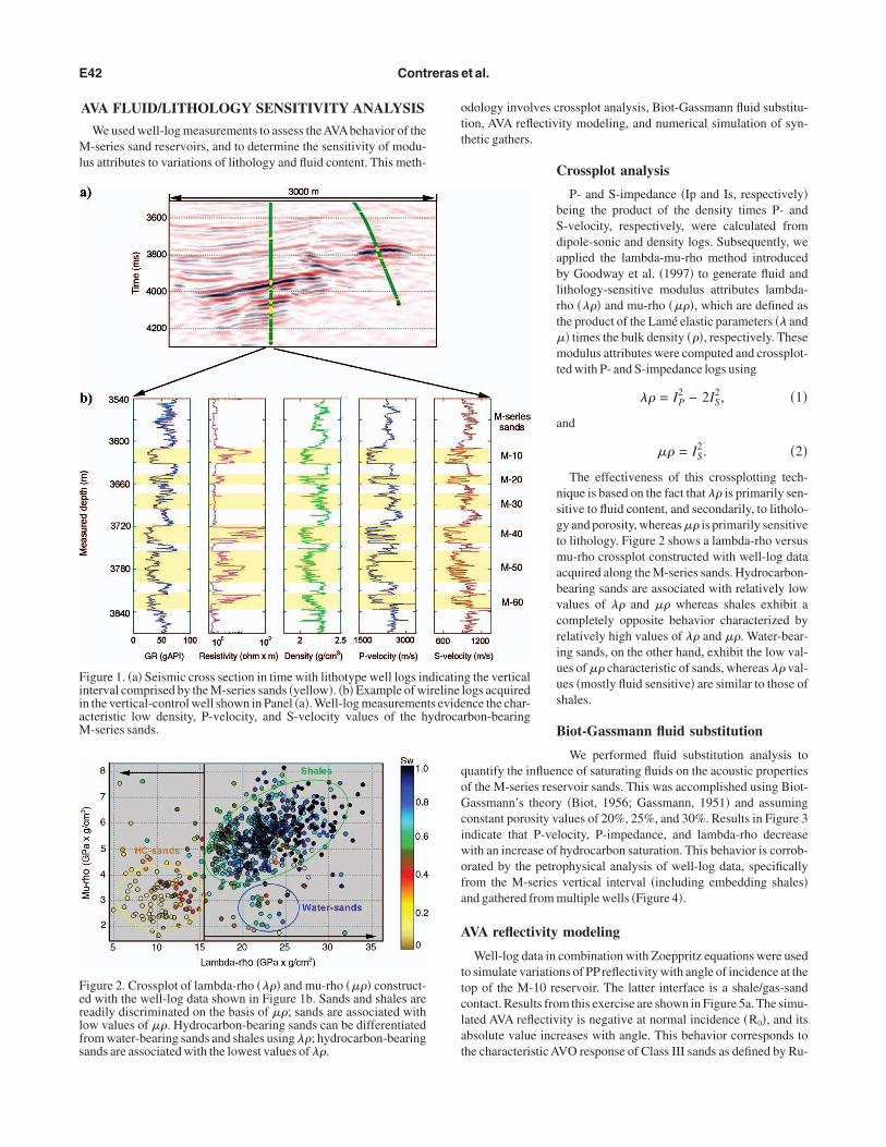
rea, approximately 280 km south of New Orleans, underlying a300-m water column. Hydrocarbon production originates from res-rvoirs consisting of Tertiary deepwater sand deposits. We are spe-ifically concerned with a small portion of the Marco Polo Fieldhere hydrocarbon-bearing sands pertain to the M series and areuried at depths of between 3500 and 3800 m �Figure 1�.
The Miocene-age M reservoir sands consist of unconsolidated, in-erbeded, high- and low-density fine-grained �mixed sandy-muddy�
urbidite deposits. Normally graded beds contain both complete andearly complete Bouma sequences of varying thickness. These res-rvoir intervals are interpreted as stacked, progradational lobesithin an overall fan complex. The massive and planar stratified
ands exhibit moderate sorting and excellent interparticle porosity.ock-core measurements indicate excellent intrinsic properties: 20–0% porosity and several hundred to thousands of millidarcies ofominal permeability.
In an effort to improve reservoir development of the study area,e resorted to amplitude information of prestack seismic data touantify the vertical and lateral extent of the main turbidite reser-oirs. We first conducted amplitude versus angle �AVA� sensitivitynalysis based on well-log data, and subsequently applied AVA si-ultaneous 1D seismic inversion to generate 3D spatial distribu-
ions of lithology/fluid-sensitive modulus attributes.
ed December 22, 2005; published onlineAugust 7, 2006.t Reservoir Characterization Unit, 1500 Louisiana, Houston, Texas 77002.
ering, 1 University Station, Mail Stop C0300, Austin, Texas 78712. E-mail:
xas 77251. E-mail: [email protected].
Ml
ott
qoGciwofa
A
ttclat
FiiaM
Ferlfs
E42 Contreras et al.
AVA FLUID/LITHOLOGY SENSITIVITY ANALYSIS
We used well-log measurements to assess theAVAbehavior of the-series sand reservoirs, and to determine the sensitivity of modu-
us attributes to variations of lithology and fluid content. This meth-
igure 1. �a� Seismic cross section in time with lithotype well logs innterval comprised by the M-series sands �yellow�. �b� Example of wn the vertical-control well shown in Panel �a�. Well-log measuremencteristic low density, P-velocity, and S-velocity values of the h-series sands.
igure 2. Crossplot of lambda-rho ���� and mu-rho ���� construct-d with the well-log data shown in Figure 1b. Sands and shales areeadily discriminated on the basis of ��; sands are associated withow values of ��. Hydrocarbon-bearing sands can be differentiatedrom water-bearing sands and shales using ��; hydrocarbon-bearingands are associated with the lowest values of ��.
dology involves crossplot analysis, Biot-Gassmann fluid substitu-ion, AVA reflectivity modeling, and numerical simulation of syn-hetic gathers.
Crossplot analysis
P- and S-impedance �Ip and Is, respectively�being the product of the density times P- andS-velocity, respectively, were calculated fromdipole-sonic and density logs. Subsequently, weapplied the lambda-mu-rho method introducedby Goodway et al. �1997� to generate fluid andlithology-sensitive modulus attributes lambda-rho ���� and mu-rho ����, which are defined asthe product of the Lamé elastic parameters �� and�� times the bulk density ���, respectively. Thesemodulus attributes were computed and crossplot-ted with P- and S-impedance logs using
�� = IP2 − 2IS
2, �1�
and
�� = IS2. �2�
The effectiveness of this crossplotting tech-nique is based on the fact that �� is primarily sen-sitive to fluid content, and secondarily, to litholo-gy and porosity, whereas �� is primarily sensitiveto lithology. Figure 2 shows a lambda-rho versusmu-rho crossplot constructed with well-log dataacquired along the M-series sands. Hydrocarbon-bearing sands are associated with relatively lowvalues of �� and �� whereas shales exhibit acompletely opposite behavior characterized byrelatively high values of �� and ��. Water-bear-ing sands, on the other hand, exhibit the low val-ues of �� characteristic of sands, whereas �� val-ues �mostly fluid sensitive� are similar to those ofshales.
Biot-Gassmann fluid substitution
We performed fluid substitution analysis touantify the influence of saturating fluids on the acoustic propertiesf the M-series reservoir sands. This was accomplished using Biot-assmann’s theory �Biot, 1956; Gassmann, 1951� and assuming
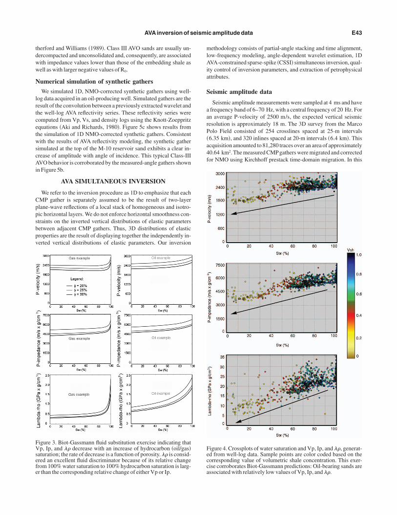
onstant porosity values of 20%, 25%, and 30%. Results in Figure 3ndicate that P-velocity, P-impedance, and lambda-rho decreaseith an increase of hydrocarbon saturation. This behavior is corrob-rated by the petrophysical analysis of well-log data, specificallyrom the M-series vertical interval �including embedding shales�nd gathered from multiple wells �Figure 4�.
VA reflectivity modeling
Well-log data in combination with Zoeppritz equations were usedo simulate variations of PPreflectivity with angle of incidence at theop of the M-10 reservoir. The latter interface is a shale/gas-sandontact. Results from this exercise are shown in Figure 5a. The simu-ated AVA reflectivity is negative at normal incidence �R0�, and itsbsolute value increases with angle. This behavior corresponds tohe characteristic AVO response of Class III sands as defined by Ru-
g the verticallogs acquirednce the char-rbon-bearing
dicatinirelinets evideydroca
tdww
N
lrtcetwscAi
Cppsbpv
mlAia
S
aarP�a4f
FVsefe
Fecca
AVAinversion of seismic amplitude data E43
herford and Williams �1989�. Class III AVO sands are usually un-ercompacted and unconsolidated and, consequently, are associatedith impedance values lower than those of the embedding shale asell as with larger negative values of R0.
umerical simulation of synthetic gathers
We simulated 1D, NMO-corrected synthetic gathers using well-og data acquired in an oil-producing well. Simulated gathers are theesult of the convolution between a previously extracted wavelet andhe well-log AVA reflectivity series. These reflectivity series wereomputed from Vp, Vs, and density logs using the Knott-Zoeppritzquations �Aki and Richards, 1980�. Figure 5c shows results fromhe simulation of 1D NMO-corrected synthetic gathers. Consistentith the results of AVA reflectivity modeling, the synthetic gather
imulated at the top of the M-10 reservoir sand exhibits a clear in-rease of amplitude with angle of incidence. This typical Class-IIIVO behavior is corroborated by the measured-angle gathers shown
n Figure 5b.
AVA SIMULTANEOUS INVERSION
We refer to the inversion procedure as 1D to emphasize that eachMP gather is separately assumed to be the result of two-layerlane-wave reflections of a local stack of homogeneous and isotro-ic horizontal layers. We do not enforce horizontal smoothness con-traints on the inverted vertical distributions of elastic parametersetween adjacent CMP gathers. Thus, 3D distributions of elasticroperties are the result of displaying together the independently in-erted vertical distributions of elastic parameters. Our inversion
igure 3. Biot-Gassmann fluid substitution exercise indicating thatp, Ip, and �� decrease with an increase of hydrocarbon �oil/gas�
aturation; the rate of decrease is a function of porosity. �� is consid-red an excellent fluid discriminator because of its relative changerom 100% water saturation to 100% hydrocarbon saturation is larg-r than the corresponding relative change of either Vp or Ip.
ethodology consists of partial-angle stacking and time alignment,ow-frequency modeling, angle-dependent wavelet estimation, 1DVA-constrained sparse-spike �CSSI� simultaneous inversion, qual-
ty control of inversion parameters, and extraction of petrophysicalttributes.
eismic amplitude data
Seismic amplitude measurements were sampled at 4 ms and havefrequency band of 6–70 Hz, with a central frequency of 20 Hz. Forn average P-velocity of 2500 m/s, the expected vertical seismicesolution is approximately 18 m. The 3D survey from the Marcoolo Field consisted of 254 crosslines spaced at 25-m intervals6.35 km�, and 320 inlines spaced at 20-m intervals �6.4 km�. Thiscquisition amounted to 81,280 traces over an area of approximately0.64 km2. The measured CMPgathers were migrated and correctedor NMO using Kirchhoff prestack time-domain migration. In this
igure 4. Crossplots of water saturation and Vp, Ip, and ��, generat-d from well-log data. Sample points are color coded based on theorresponding value of volumetric shale concentration. This exer-ise corroborates Biot-Gassmann predictions: Oil-bearing sands aressociated with relatively low values of Vp, Ip, and ��.

inawat
L
df�dsgw6pt6
A
wbrtPsst�
Fmplitudes increase with an increase of angle of incidence �typical Class-IIIAV
Fmsl�ISe
E44 Contreras et al.
paper, we assume that the migrated and NMO-corrected CMPgathers are devoid of multiple andtransmission effects and can be accurately de-scribed as the superposition of two-layer respons-es of a stack of horizontal layers. Further, we con-sider only PP reflectivity events in the analysis ofprestack seismic amplitude variations. These as-sumptions are justified by the quality control per-formed on the migrated and NMO-correctedCMP gathers.
Partial-angle stacking andtime alignment
The version of the 1D inversion algorithm im-plemented in this paper assumes input-seismicamplitude data organized into partial-anglestacks �PAS�. Therefore, special processing of theprestack seismic-amplitude data was performedprior to 1D inversion.
We used a ray-tracing algorithm to transformthe prestack seismic amplitude data from the off-set domain to the incidence-angle domain, andgenerated four partial-angle stacks using theNMO-corrected and migrated offset gathers andthe migration-velocity field. The angle rangeavailable from the seismic amplitude data was 6to 46°; each partial-angle stack was generated us-
ng a 10° constant range. Final partial stacks included the followingear, mid, far, and ultrafar angle ranges: �6–16�, �16–26�, �26–36�,nd �36–46� �Figure 6a�. In addition, small time-shift correctionsere applied to the partial-angle stacks in order to reduce event mis-
lignment caused by processing errors such as residual NMO correc-ions.
ow-frequency modeling
Low-frequency volumes of P-Impedance, S-Impedance, andensity are required for 1D trace-based inversion because the low-requency information needed to include the compaction trend0–6 Hz in our case� is not available from the seismic amplitudeata. Additionally, low-frequency volumes are used to guide theoft-trend constraints imposed by the 1D inversion algorithm. Weenerated these volumes with the weighted lateral interpolation ofell logs using the geological model as guiding framework �Figurea�. The geologic model was constructed based on the horizon inter-retation of the tops of the main geologic formations. Finally, the in-erpolated models were low-pass filtered with a cutoff frequency of
Hz to generate the final low-frequency property volumes.
ngle-dependent wavelet estimation
The estimation of AVA wavelets within the target time intervalas performed with deterministic techniques �Figure 6a�. We com-ined well-log data with the partial-angle stacks to estimate the cor-esponding angle-dependent wavelets using Knott-Zoeppritz equa-ions. In so doing, the angle-dependent reflectivity was derived from-sonic, S-sonic, and density well logs, using the angle range as-igned to a particular partial-angle stack. Subsequently, a best least-quares wavelet was estimated from the calculated reflectivity andhe seismic amplitude data following the method described by White1980�.
interface, �b�seismic am-O behavior�.
igure 5. �a� Reflectivity modeling of the Shale/M-10 hydrocarbon-sandeasured angle gather, and �c� synthetic angle gather. Both reflectivity and
igure 6. Schematic description of the AVA simultaneous inversionethodology: �a� Input data: four partial-angle stacks with the corre-
ponding wavelets �extracted from elastic impedance logs�, andow-frequency models of P-impedance, S-impedance, and densitygenerated from the horizon-guided interpolation of well-log data�.nversion results consist of full-band volumes of P-impedance,-impedance, and density. Panel �b� shows RMS maps of these prop-rties within the M-10 reservoir.
1
pgvaojaattos1ii1m1dmZt
r�suqprsse
aCwsPs
vttArss
FpseocA
Fe
AVAinversion of seismic amplitude data E45
D AVA-CSSI simultaneous inversion
The 1D deterministic inversion of partially stacked seismic am-litude data used in this paper is based on the amplitude-versus-an-le-constrained sparse spike inversion �AVA-CSSI� algorithm de-eloped by Fugro-Jason. As described in Appendix A, the inversionlgorithm minimizes an objective function that combines l1-normsf reflectivity with l2-norms of seismic-amplitude data misfit, sub-ect to value-range constraints �Debeye and van Riel, 1990; Pendrelnd van Riel, 1997�. The AVA-CSSI inversion algorithm combinesll the available CMP gathers to estimate the corresponding 1Dime-domain distributions of P-impedance, S-impedance, and densi-y. This trace-based inversion algorithm is an extension to nonzeroffsets of a previously published poststack �zero-offset� constrainedparse-spike inversion �Z0-CSSI� method �Debeye and van Riel,990�. In the Z0-CSSI algorithm, a single-stacked seismic section isnverted into a 1D time distribution of normal-incidence acousticmpedance �AI� �Debeye and van Riel, 1990; Pendrel and van Riel,997; Latimer et al., 2000�, whereas in the AVA-CSSI algorithm,ultiple partial-angle stacks �PAS� are simultaneously inverted into
D time distributions of P-impedance �Ip�, S-impedance �Is�, andensity ��� �Figure 6b�. The inversion algorithm simulates the seis-ic amplitude measurements with 1D convolution based on theoeppritz �Koefoed, 1962, or Aki and Richards, 1980� equations for
wo-layerAVO reflectivity.The main CSSI inversion parameters include a stabilization pa-
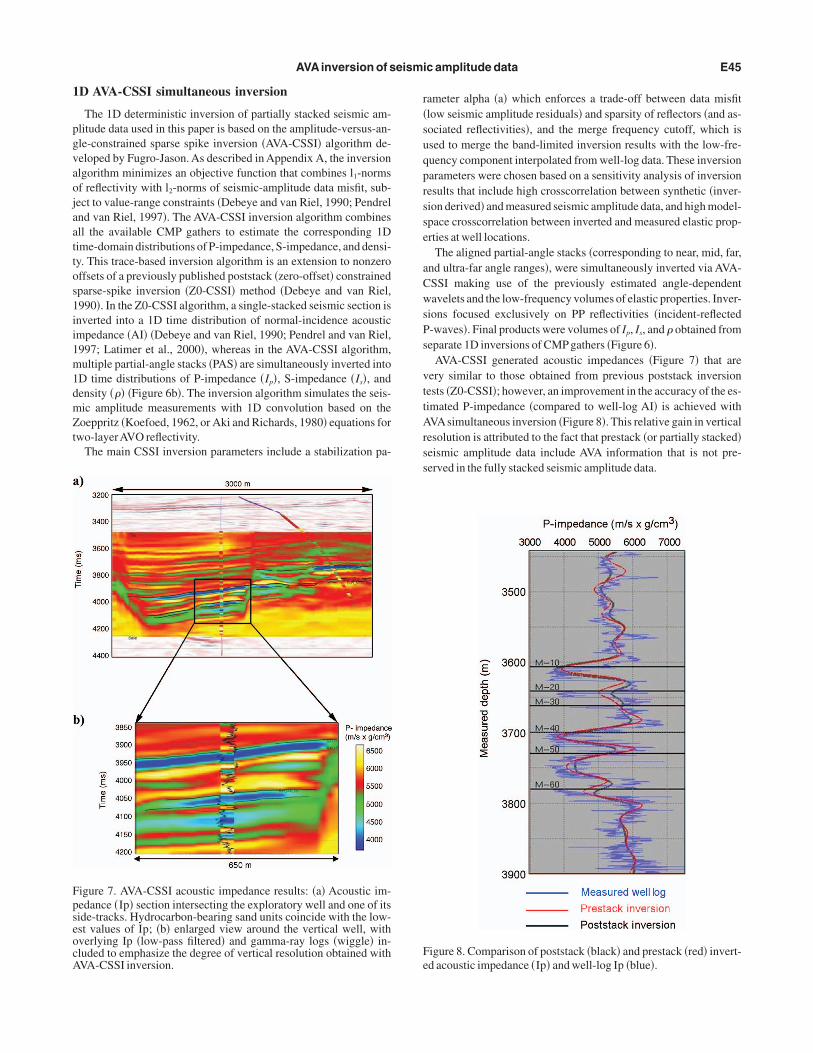
igure 7. AVA-CSSI acoustic impedance results: �a� Acoustic im-edance �Ip� section intersecting the exploratory well and one of itside-tracks. Hydrocarbon-bearing sand units coincide with the low-st values of Ip; �b� enlarged view around the vertical well, withverlying Ip �low-pass filtered� and gamma-ray logs �wiggle� in-luded to emphasize the degree of vertical resolution obtained withVA-CSSI inversion.
ameter alpha �a� which enforces a trade-off between data misfitlow seismic amplitude residuals� and sparsity of reflectors �and as-ociated reflectivities�, and the merge frequency cutoff, which issed to merge the band-limited inversion results with the low-fre-uency component interpolated from well-log data. These inversionarameters were chosen based on a sensitivity analysis of inversionesults that include high crosscorrelation between synthetic �inver-ion derived� and measured seismic amplitude data, and high model-pace crosscorrelation between inverted and measured elastic prop-rties at well locations.
The aligned partial-angle stacks �corresponding to near, mid, far,nd ultra-far angle ranges�, were simultaneously inverted via AVA-SSI making use of the previously estimated angle-dependentavelets and the low-frequency volumes of elastic properties. Inver-
ions focused exclusively on PP reflectivities �incident-reflected-waves�. Final products were volumes of Ip, Is, and � obtained fromeparate 1D inversions of CMP gathers �Figure 6�.
AVA-CSSI generated acoustic impedances �Figure 7� that areery similar to those obtained from previous poststack inversionests �Z0-CSSI�; however, an improvement in the accuracy of the es-imated P-impedance �compared to well-log AI� is achieved withVAsimultaneous inversion �Figure 8�. This relative gain in vertical
esolution is attributed to the fact that prestack �or partially stacked�eismic amplitude data include AVA information that is not pre-erved in the fully stacked seismic amplitude data.
igure 8. Comparison of poststack �black� and prestack �red� invert-d acoustic impedance �Ip� and well-log Ip �blue�.
Foinlt
Frpleci
E46 Contreras et al.
Quality control of inversion results
The accuracy and reliability of the 1D inver-sion results was quantified in four ways: �1� witha sensitivity analysis of inversion residuals, �2�with a perturbation analysis of all of the inversionparameters, �3� with inversion exercises perfor-med on multiple combinations of angle ranges,and �4� with tests on blind wells �wells not includ-ed as part of the input data for the inversions�.
Extraction of petrophysical attributes
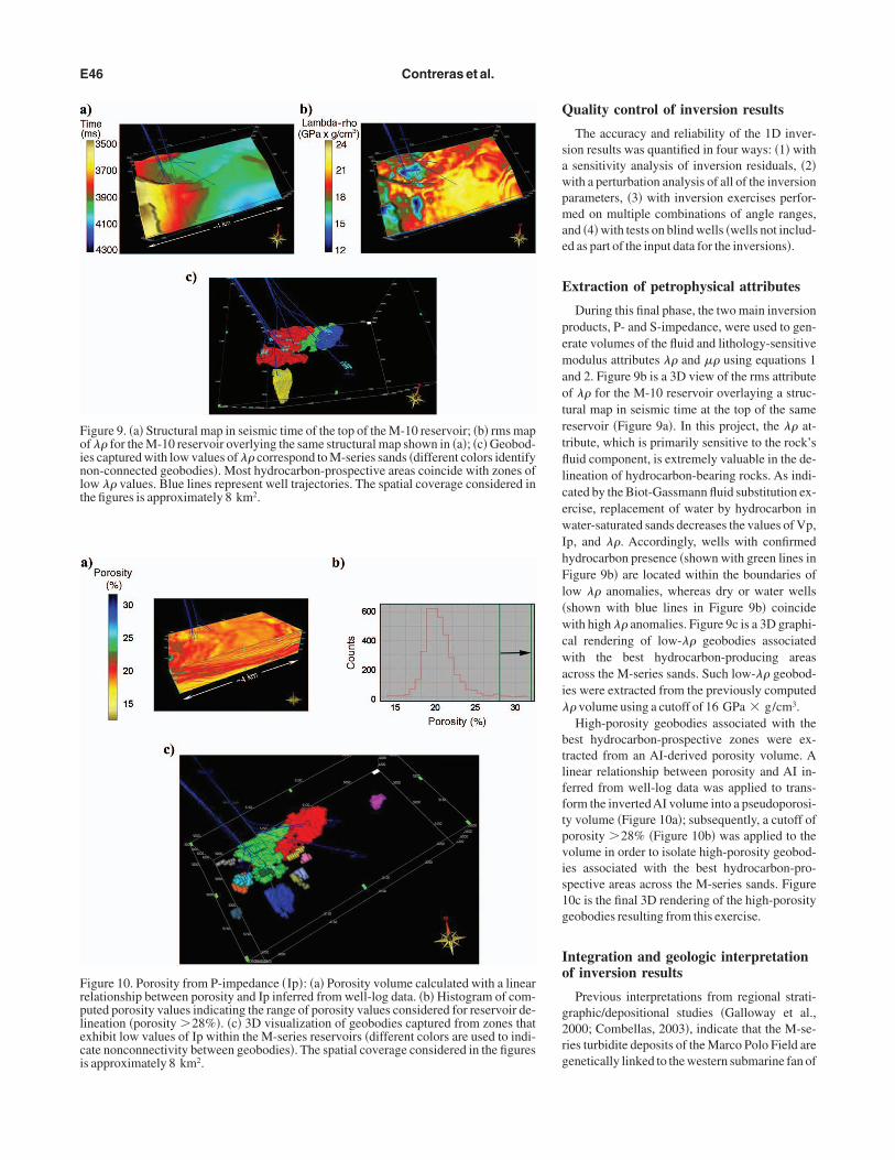
During this final phase, the two main inversionproducts, P- and S-impedance, were used to gen-erate volumes of the fluid and lithology-sensitivemodulus attributes �� and �� using equations 1and 2. Figure 9b is a 3D view of the rms attributeof �� for the M-10 reservoir overlaying a struc-tural map in seismic time at the top of the samereservoir �Figure 9a�. In this project, the �� at-tribute, which is primarily sensitive to the rock’sfluid component, is extremely valuable in the de-lineation of hydrocarbon-bearing rocks. As indi-cated by the Biot-Gassmann fluid substitution ex-ercise, replacement of water by hydrocarbon inwater-saturated sands decreases the values of Vp,Ip, and ��. Accordingly, wells with confirmedhydrocarbon presence �shown with green lines inFigure 9b� are located within the boundaries oflow �� anomalies, whereas dry or water wells�shown with blue lines in Figure 9b� coincidewith high �� anomalies. Figure 9c is a 3D graphi-cal rendering of low-�� geobodies associatedwith the best hydrocarbon-producing areasacross the M-series sands. Such low-�� geobod-ies were extracted from the previously computed�� volume using a cutoff of 16 GPa � g/cm3.
High-porosity geobodies associated with thebest hydrocarbon-prospective zones were ex-tracted from an AI-derived porosity volume. Alinear relationship between porosity and AI in-ferred from well-log data was applied to trans-form the invertedAI volume into a pseudoporosi-ty volume �Figure 10a�; subsequently, a cutoff ofporosity �28% �Figure 10b� was applied to thevolume in order to isolate high-porosity geobod-ies associated with the best hydrocarbon-pro-spective areas across the M-series sands. Figure10c is the final 3D rendering of the high-porositygeobodies resulting from this exercise.
Integration and geologic interpretationof inversion results
Previous interpretations from regional strati-graphic/depositional studies �Galloway et al.,2000; Combellas, 2003�, indicate that the M-se-ries turbidite deposits of the Marco Polo Field aregenetically linked to the western submarine fan of
; �b� rms map; �c� Geobod-olors identifywith zones ofconsidered in
with a linearram of com-reservoir de-m zones thatused to indi-in the figures
igure 9. �a� Structural map in seismic time of the top of the M-10 reservoirf �� for the M-10 reservoir overlying the same structural map shown in �a�es captured with low values of �� correspond to M-series sands �different con-connected geobodies�. Most hydrocarbon-prospective areas coincideow �� values. Blue lines represent well trajectories. The spatial coveragehe figures is approximately 8 km2.
igure 10. Porosity from P-impedance �Ip�: �a� Porosity volume calculatedelationship between porosity and Ip inferred from well-log data. �b� Histoguted porosity values indicating the range of porosity values considered forineation �porosity �28%�. �c� 3D visualization of geobodies captured froxhibit low values of Ip within the M-series reservoirs �different colors areate nonconnectivity between geobodies�. The spatial coverage considereds approximately 8 km2.

tgem
tlv1c
sthsfat
w
citt
mam
csrccwAvbb
FtHf dite lob
AVAinversion of seismic amplitude data E47
he Miocene MCAVLU Submarine Fan System.Accordingly, initialeologic interpretation of core data indicated that the depositionalnvironment consisted of deepwater turbidites associated with ter-inal lobes.By integrating the information rendered by core data, the charac-
eristics of the channel/lobe depositional model introduced by Gal-oway and Hobday �1996� �Figure 11a�, and the geomorphologicisualization achieved with 1D prestack inversion results �Figure1b�, the M-series reservoir can be described conclusively as sta-ked turbidite lobes within an overall fan complex.
CONCLUSIONS
AVA fluid/lithology sensitivity analysis indicates significant sen-itivity of acoustic properties to fluid substitution and corroborateshe existence of Class III AVA responses associated with the shale/ydrocarbon-sand interface at the top of the M-series reservoirands. Accordingly, 1D prestack seismic inversion products in theorm of fluid/lithology sensitive modulus attributes ���� providedccurate quantitative information about the spatial continuity of li-hology and fluid units within the turbidite reservoirs.
From integration of 1D deterministic inversion results with deep-ater analog-depositional models and previous rock-core studies,
igure 11. �a� Depositional model: Geomorphic elements, depositionypical well-log responses of a channel-lobe complex �modified fobday, 1996�; and �b� Deterministic inversion results. From integra
ormation, the M-series reservoirs can be interpreted as stacked turbi
the M-series reservoirs have been interpreted asstacked terminal-turbidite lobes within and over-all fan complex. This interpretation is consistentwith the channel-lobe depositional model, previ-ous interpretations of rock-core measurements,and regional stratigraphic/depositional studies.Finally, by combining fluid/lithology sensitivityanalysis techniques with 1D AVA simultaneousinversion and awareness of inversion pitfalls, it ispossible to substantially reduce the risk in the ex-ploration and development of the M-series reser-voirs.
ACKNOWLEDGMENTS
The authors thankAnadarko Petroleum Corpo-ration for providing the data set used for this re-search study. We are grateful to WesternGeco forgiving us access to the prestack seismic data. Spe-cial gratitude goes to Fugro-Jason for their unre-stricted technical and software support. G. RandyKeller and Steven Arcone provided constructivetechnical and editorial feedback that improvedthe final version of the manuscript. The work re-ported in this paper was supported by Universityof Texas at Austin Research Consortium on For-mation Evaluation, jointly sponsored by Anadar-ko Petroleum Corporation, Baker Atlas, BP,ConocoPhillips, ENI E&P, ExxonMobil, Halli-burton Energy Services, the Mexican Institute forPetroleum, Occidental Petroleum Corporation,Petrobras, Precision Energy Services, Schlum-berger, Shell International E&P, Statoil, andTOTAL.
APPENDIX A
Even though the inversion algorithm developed by Fugro-Jasononsiders several variants for data conditioning, model parameter-zation, model constraints, and stabilization, here we explain onlyhe specific version and features of the algorithm implemented to ob-ain the results described in the paper.
One-dimensional inversion of AVA surface seismic amplitudeeasurements yields distributions of P-impedance �Ip�, S-imped-
nce �Is�, and bulk density ��� as functions of normal-incidence seis-ic traveltime.
The algorithm used in this paper for the 1D inversion of NMO-orrected AVA seismic amplitude measurements is based on aparse-spike regularization strategy. This procedure emphasizes PPeflectivity models that exhibit a prescribed degree of sparsity �orlustering� of reflectors. P- and S-impedances and density are furtheronstrained to remain within upper and lower bounds inferred fromell logs �thus the name AVA constrained sparse-spike inversion, orVA-CSSI, used when referring to this inversion algorithm�. The in-ersion of 1D AVA seismic amplitude measurements is performedy minimizing the constrained objective function F�IP,IS,�� giveny
ach unit, andalloway andthe above in-es.
al isoprom Gtion of
s
IdspmAnbtInIs
emTtsdtnweaaea
cOAojmnlcb
wwFll
A
B
C
D
G
G
G
G
K
L
O
P
R
W
E48 Contreras et al.
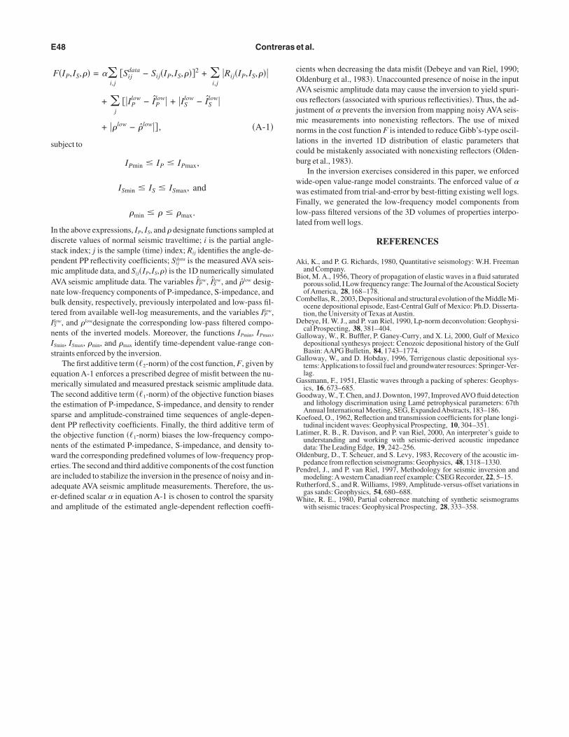
F�IP,IS,�� = ��i,j
�Sijdata − Sij�IP,IS,���2 + �
i,j�Rij�IP,IS,���
+ �j
��IPlow − IP
low� + �ISlow − IS
low�
+ ��low − �low�� , �A-1�
ubject to
IPmin � IP � IPmax,
ISmin � IS � ISmax, and
�min � � � �max.
n the above expressions, IP, IS, and � designate functions sampled atiscrete values of normal seismic traveltime; i is the partial angle-tack index; j is the sample �time� index; Rij identifies the angle-de-endent PP reflectivity coefficients; Sij
data is the measured AVA seis-ic amplitude data, and Sij�IP,IS,�� is the 1D numerically simulatedVA seismic amplitude data. The variables IP
low, ISlow, and �low desig-
ate low-frequency components of P-impedance, S-impedance, andulk density, respectively, previously interpolated and low-pass fil-ered from available well-log measurements, and the variables IP
low,Slow, and �lowdesignate the corresponding low-pass filtered compo-ents of the inverted models. Moreover, the functions IPmin, IPmax,Smin, ISmax, �min, and �max identify time-dependent value-range con-traints enforced by the inversion.
The first additive term ��2-norm� of the cost function, F, given byquation A-1 enforces a prescribed degree of misfit between the nu-erically simulated and measured prestack seismic amplitude data.he second additive term ��1-norm� of the objective function biases
he estimation of P-impedance, S-impedance, and density to renderparse and amplitude-constrained time sequences of angle-depen-ent PP reflectivity coefficients. Finally, the third additive term ofhe objective function ��1-norm� biases the low-frequency compo-ents of the estimated P-impedance, S-impedance, and density to-ard the corresponding predefined volumes of low-frequency prop-
rties. The second and third additive components of the cost functionre included to stabilize the inversion in the presence of noisy and in-dequate AVA seismic amplitude measurements. Therefore, the us-r-defined scalar � in equation A-1 is chosen to control the sparsity
nd amplitude of the estimated angle-dependent reflection coeffi-ients when decreasing the data misfit �Debeye and van Riel, 1990;ldenburg et al., 1983�. Unaccounted presence of noise in the inputVA seismic amplitude data may cause the inversion to yield spuri-us reflectors �associated with spurious reflectivities�. Thus, the ad-ustment of � prevents the inversion from mapping noisy AVA seis-ic measurements into nonexisting reflectors. The use of mixed
orms in the cost function F is intended to reduce Gibb’s-type oscil-ations in the inverted 1D distribution of elastic parameters thatould be mistakenly associated with nonexisting reflectors �Olden-urg et al., 1983�.
In the inversion exercises considered in this paper, we enforcedide-open value-range model constraints. The enforced value of �as estimated from trial-and-error by best-fitting existing well logs.inally, we generated the low-frequency model components from
ow-pass filtered versions of the 3D volumes of properties interpo-ated from well logs.
REFERENCES
ki, K., and P. G. Richards, 1980, Quantitative seismology: W.H. Freemanand Company.
iot, M. A., 1956, Theory of propagation of elastic waves in a fluid saturatedporous solid, I Low frequency range: The Journal of theAcoustical SocietyofAmerica, 28, 168–178.
ombellas, R., 2003, Depositional and structural evolution of the Middle Mi-ocene depositional episode, East-Central Gulf of Mexico: Ph.D. Disserta-tion, the University of Texas atAustin.
ebeye, H. W. J., and P. van Riel, 1990, Lp-norm deconvolution: Geophysi-cal Prospecting, 38, 381–404.
alloway, W., R. Buffler, P. Ganey-Curry, and X. Li, 2000, Gulf of Mexicodepositional synthesys project: Cenozoic depositional history of the GulfBasin: AAPG Bulletin, 84, 1743–1774.
alloway, W., and D. Hobday, 1996, Terrigenous clastic depositional sys-tems:Applications to fossil fuel and groundwater resources: Springer-Ver-lag.
assmann, F., 1951, Elastic waves through a packing of spheres: Geophys-ics, 16, 673–685.
oodway, W., T. Chen, and J. Downton, 1997, ImprovedAVO fluid detectionand lithology discrimination using Lamé petrophysical parameters: 67thAnnual International Meeting, SEG, ExpandedAbstracts, 183–186.
oefoed, O., 1962, Reflection and transmission coefficients for plane longi-tudinal incident waves: Geophysical Prospecting, 10, 304–351.
atimer, R. B., R. Davison, and P. van Riel, 2000, An interpreter’s guide tounderstanding and working with seismic-derived acoustic impedancedata: The Leading Edge, 19, 242–256.
ldenburg, D., T. Scheuer, and S. Levy, 1983, Recovery of the acoustic im-pedance from reflection seismograms: Geophysics, 48, 1318–1330.
endrel, J., and P. van Riel, 1997, Methodology for seismic inversion andmodeling:Awestern Canadian reef example: CSEG Recorder, 22, 5–15.
utherford, S., and R. Williams, 1989, Amplitude-versus-offset variations ingas sands: Geophysics, 54, 680–688.hite, R. E., 1980, Partial coherence matching of synthetic seismograms
with seismic traces: Geophysical Prospecting, 28, 333–358.Copyright © 2022 FDOKUMEN