An Efficient Method for Testing Autonomous Driving Software ...
Upload
khangminh22Category
view
4download
0
1
Autonomous Driving in the Lungusing Deep Learning for Localization
Jake Sganga, Student Member, IEEE, David Eng, Student Member, IEEE, Chauncey Graetzel, Member, IEEE,and David B. Camarillo, Member, IEEE
Abstract—Lung cancer is the leading cause of cancer-relateddeath worldwide, and early diagnosis is critical to improvingpatient outcomes. To diagnose cancer, a highly trained pul-monologist must navigate a flexible bronchoscope deep intothe branched structure of the lung for biopsy. The biopsyfails to sample the target tissue in 26-33% of cases largelybecause of poor registration with the preoperative CT map.To improve intraoperative registration, we develop two deeplearning approaches to localize the bronchoscope in the preop-erative CT map based on the bronchoscopic video in real-time,called AirwayNet and BifurcationNet. The networks are trainedentirely on simulated images derived from the patient-specific CT.When evaluated on recorded bronchoscopy videos in a phantomlung, AirwayNet outperforms other deep learning localizationalgorithms with an area under the precision-recall curve of 0.97.Using AirwayNet, we demonstrate autonomous driving in thephantom lung based on video feedback alone. The robot reachesfour targets in the left and right lungs in 95% of the trials.On recorded videos in eight human cadaver lungs, AirwayNetachieves areas under the precision-recall curve ranging from 0.82to 0.997.
Index Terms—Robotics, Convolutional Neural Networks, Lo-calization, Surgery.
I. INTRODUCTION
D IAGNOSING lung cancer, the leading cause of cancer-related death world-wide, at an early stage significantly
improves patient outcomes [1]. Physicians biopsy potentiallycancerous nodules in the lung by manually driving long,flexible bronchoscopes through the patient’s airways, shownin Fig. 1. This minimally invasive approach is preferred whenthe nodule is accessible, given the lower complication rates(2.2% vs 20.5%) compared to transthoracic needle biopsy [2],[3].
Before the bronchoscopy, the physician selects biopsy tar-gets in the lung’s computed tomography (CT) scan. Duringthe bronchoscopy, the physician maps the feedback from thebronchoscope (2D image) to the CT (3D map). This process iscalled localization [4]. With accurate localization information,a physician can select the correct airways leading to the biopsytargets.
Recently, robotic endoscopy systems have been developedto further aid the physician in reaching the target [5]. If thelocalization were sufficiently precise, a closed-loop control
J. Sganga and D. B. Camarillo are with the Department of Bioengi-neering, Stanford University, Stanford, CA, 94305 USA e-mail: ([email protected])
D. Eng is with the Department of Computer Science, Stanford University.C. Graetzel is with Auris Health, Inc. (A Johnson and Johnson subsidiary)
Lung CT
TumorAirway Centerlines
Path to Tumor
Bronchoscope Camera
A
B
Generations:12345+
Fig. 1. In A, a path through a preoperative lung CT is shown toward the site ofa potential tumor. Images shown were rendered along the path to demonstratewhat the physician would see as they move through the generations of thelung. The branching structure of the lung is represented in a lower dimensionalskeletal tree based on the airway centerlines and the junctions between them,usually bifurcations. In B, a robotic bronchoscope (Auris Health, Inc.) isshown and the distal monocular camera used for visualizing the airways ishighlighted.
system could drive the bronchoscope without human inter-vention. Autonomous driving may improve localization bykeeping clear view of the airways and bifurcations. It couldalso allow for de-skilling standard bronchoscopies, potentiallyreducing the cost of the procedure with a single pulmonologistmonitoring multiple simultaneous procedures.
Many sensing modalities can assist in localization, includinga distal electromagnetic (EM) position sensor. After registra-tion to the preoperative CT of the patient’s chest, the positionsensor can enable GPS-like directions on the road map tothe target site [6]. In these navigated bronchoscopies, thediagnostic yield varies across institutions, ranging from 67-74% [2], [7]. Using electromagnetic navigation, the authors
arX
iv:1
907.
0813
6v1
[cs
.CV
] 1
6 Ju
l 201
9

2
CNN
BronchoscopeImage,
Estimated Locationin Lung CTAirway Visibility, Position, and Orientation
for every Lung Segment in CT
Airway ID:12
16
UnknownLocation
Fig. 2. The inputs and outputs of AirwayNet are shown. A camera image from the bronchoscope’s true position, Icamxt
, passes through a trained CNN(ResNet-18) and outputs the airway characteristics for every airway in the lung skeleton. If the identified airway hasV isChild and the children airwaysisV is are consistent with the lung skeleton, the estimated position xt is backed out from the measurement.
demonstrated closed-loop control of a robotic bronchoscopein a precisely registered phantom lung [8]. Additionally,techniques like fluoroscopy, radial ultrasound probes, andalternative endoscopic sensors (Raman spectroscopy, confocal,etc.) have been developed to further improve diagnostic yield[7]. We chose to focus on advancing image-based approachessince cameras are the cheapest and most prevalent sensorfor bronchoscopies, the local camera frame information isrobust to breathing disturbances, and the information can beintegrated with other modalities.
A localization algorithm must satisfy two requirementsto aid decision-making: 1. it must accurately localize thebronchoscope and 2. it must operate in sufficiently real-timeto enable closed-loop control. Several groups have devel-oped image-based localization algorithms by comparing thebronchoscopic images to simulated images; however, thesemethods usually register images inefficiently at around 1-2 Hzand rely on highly realistic rendering [9], [10]. Methods likeSIFT and ORBSLAM have been used, but the airways haveinsufficient features and tracked features often drop out [11],[12]. Anatomical landmarks have been tracked, like bifurca-tions [13], lumen centers [14], centerline paths [15], or similarimage regions [16], but these approaches may not operatein real-time and tend make assumptions about the airwaygeometries using traditional computer vision techniques.
Because of the difficulties traditional computer vision tech-niques face in this task, we decided to explore a deep learningapproach. Using convolutional neural networks (CNN) toestimate the position and orientation of objects has been shownin many contexts, including for human posture and objects ina robotic hand [17], [18]. The KITTI dataset is a large, highquality dataset to improve visual-based localization methodsfor autonomous cars [19], and the top performing algorithmsuse variations of CNNs to process the visual information. Inthe lung domain, Visentini-Scarzanella et al. and used a CNNto estimate the depth map of 2D images in a phantom lung,which could then be registered to the 3D map, but localization
is not reported [12]. In our previous work, we used a CNN tolocalize a bronchoscope in real-time by predicting the offsetbetween the camera image and a rendering at the expectedposition [20]. This approach, called OffsetNet, showed 1.4 mmaccuracy on a phantom lung sequence, but it fails to track othersequences.
In this work, we contribute two image-based deep-learningapproaches, called AirwayNet and BifurcationNet, that local-ize a bronchoscope in the lung CT frame. We evaluate theapproaches on a dataset recorded from a silicone phantomlung. AirwayNet consistently tracked the bronchoscopic videoin real time after training on simulated images generated fromthe preoperative scan of the phantom lung. Additionally, wedemonstrate autonomous driving in the phantom lung usingAirwayNet. After training on simulated images alone, thesystem reached 4 targets in the lung with a 95% success rate.To the authors’ knowledge, this is the first demonstration ofimage-based closed-loop control of a robotic bronchoscope.Finally, we evaluate AirwayNet on a dataset recorded frombronchoscopies in eight human cadaver lungs.
II. METHOD
Shown in Fig. 2, at every step in the localization task, animage from the bronchoscope, Icam
xt , at time t from the position,xt, is input to the localization algorithm. The algorithm outputsthe set of visible airways and their positions and orientations,yt, with respect to camera frame. If a bifurcation is visible,airway information is used to calculate the 6 degree offreedom (DOF) location of the bronchoscope in CT frame, xt.AirwayNet is described in detail below, while BifurcationNetis described in the Appendix.
A. Network Architecture
AirwayNet consists of a deep residual convolutional net-work (CNN) and a single fully connected layer, which pro-duces the output of size 500 × 7. The residual parts of ournetwork implement the 18-layer architecture described in He

3
TABLE INOTATION
Image StylesIcam Image taken by a bronchoscope within the lungIsim Image rendered by OpenGL using the lung CTIrsim Isim image with varied rendering parameters and varied
noise, smoothing and occlusions added [21]Error between True and Estimated Locations
ep Position error (mm), defined as ep in [10]ed Direction angle error between pointing vectors, pz , of
the two views (◦), defined as ed in [10]er Roll angle error between the px axis after the ed was
corrected for between views (◦), defined as er in [10]CNN Outputs
y(i)p Position vector including x, y, z (mm), defined in cam-
era frame of the furthest visible point on an airway, iy(i)d Direction vector including α, β (rad), defined in cam-
era frame of the airway direction.y(i)isV is True if any point along airway i’s centerline is visible
y(i)hasV isChild True if airway i’s bifurcation is visible
et al. [22]. The CNN is implemented in Tensorflow, version1.9 [23].
Each row of the CNN output corresponds to a uniqueairway, i, in the CT, denoted by Airway ID in Fig. 2, andthe seven associated properties, y(i). There are 2 visibilitybooleans, isV is and hasV isChild. The measure y
(i)isV is is
true if any point along the airway centerline is visible, meaningthe point lies within the field of view of the camera (60◦) andwithin the max visibility distance (set to 3 cm). The measurey(i)hasV isChild is true if the airway’s bifurcation is visible. The
remaining 5 properties describe the position and orientation ofthe airway in camera frame. AirwayNet regresses the position,y(i)p = (x, y, z), of the furthest point on the airway and its
direction, y(i)d = (α, β), in camera frame. The total number
of rows is a hyperparameter set as an upper limit to the numberof possible airways in the lung, which was set to 500 to keepthe dimensions the same for each lung tested.
For all experiments, AirwayNet models are trained on anNVIDIA Titan X GPU for 60k steps using Adam optimization(β1 = 0.9, β2 = 0.999, ε = 10−8) to minimize a weighted L2loss function on the airway positions and angles and a sigmoidcross entropy loss on the classification of the airways.
L =
M∑i=1
f(y(i)p )
(−c1 · y(i)
isV is log(y(i)isV is)
−c2 · y(i)hasV isChild log(y
(i)hasV isChild)
+c3 · y(i)isV is||y(i)
p − y(i)p ||22
+c4 · y(i)isV is||y
(i)d − y
(i)d ||22
)f(y(i)
p ) = max(c5, c6 − c7||y(i)p ||2)
The hyperparameters, c, are manually set to balance theclassification and regression losses as well as to include adepth scaling to weigh the loss on nearby airways more heavilythan distant airways. The regression losses are only incurredwhen airway i is visible. The parameters set for all training inthis paper are c1 = 2, c2 = 2, c3 = 1, c4 = 10, c5 = 0.1, c6 =6, c7 = 0.2. The relationship between position and rotation
errors are set according to a 1 mm:5.7◦(10 mm:1 rad) ratio,which roughly relates to the fact that a 5.7◦ ed angle errorresults in an error of 1 mm for a location 10 mm in front ofthe camera.
As a comparison to AirwayNet, two other deep learningalgorithms, OffsetNet and BifurcationNet, are evaluated onthe phantom lung tracking test, shown in Fig. 7. OffsetNetpredicts the 6DOF offset between the bronchscopic imageand the simulated image at the expected location in the lung[20]. It is comprised of two 34-layer ResNets followed bya fully connected layer. BifurcationNet, described in detailin the Appendix, shares the same architecture of AirwayNet,but it outputs information about the visible airways withoutclassifying them based on the CT. It relies on a novel particlefilter to match the visible airways to airways in the CT.
B. Datasets
The Icam images in the tracking experiment (Fig. 7) arerecorded by teleoperating a robotic bronchoscope (MonarchPlatform, Auris Health Inc.) for 30 minutes in a phantomlung (Koken Co.), covering 3-8 generations of both lungs.The phantom lung is encased in silicone to better representthe material properties of the lung, shown in Fig. 3A. Theimages are manually registered to CT frame using the samemethod as [20]. Example images are shown in Fig. 4.
Robot Arms
Bronchoscope
Phantom Lung
PC
Human Operator
Cadaver
A
B
Fig. 3. In A, the experimental setup for the phantom lung tests is shown. APC laptop with with a 2.70 GHz CPU and 16 GB RAM ran the control loopin the driving experiments, including inference on the trained neural networkswithout GPU support. In B, a representative setup is shown for the cadaverexperiments. Images courtesy Auris Health, Inc.
In the driving experiments (Fig. 8), the images are fed toAirwayNet in real-time.
In the human cadaver localization experiments, the Icam
images are recorded by expert operators teleoperating a roboticbronchoscope (Monarch Platform, Auris Health Inc.) to reachpredefined targets, shown in Fig. 3B. Up to two targets perside of the lung are registered for the localization experiments

4
Isim
Icam
Fig. 4. In the top row, example Icam images taken within the phantom lung bythe bronchoscope are shown. In the bottom row, the Isim images are renderedat the same locations as the example Icam images. Each image is grayscaledand normalized to zero mean and unit standard deviation before training andevaluation.
Irsim
Icam
Fig. 5. In the top row, example Icam images taken within one of the eighthuman cadaver lung by the bronchoscope are shown. In the bottom row, theIrsim images are rendered at the same locations as the example Icam images.The Irsim images are shown with patch and stripe randomization. These imagesare shown in color to highlight the effect, however they would be grayscaledand normalized before being used in training.
shown in Fig. 10. We exclude cadaver sequences in whichthe preoperative CT scan geometry deviated significantly fromthe geometry visible in the Icam images. Example images areshown in Fig. 5.
All Irsim images used for training AirwayNet are renderedusing PyOpenGL and a 3D lung STL from a segmented CTscan of the phantom lung (Monarch Platform, Auris HealthInc.) [20], [24]. The rendering and domain randomizationparameters match Sganga et al. [20]. Images are rendered at 60Hz on a PC with no accelerations. All images were grayscaledand per-image normalized.
For the tracking experiments in the phantom lung shownin Fig. 7, each algorithm is trained on 202835 simulatedimages. The positions of the images are uniformly distributedin translation (8 mm diameter), direction (±23◦), and roll(±23◦) around the labeled positions of the recorded data. Fivesimulated images are generated around each labeled imageposition.
In the driving experiment shown in Fig. 8, the same networktrained for the tracking experiment is used. For the repeateddriving test, shown in Fig. 9, a dataset of simulated images
is generated for each target and a unique model is trainedon each dataset. The positions of the images are distributedaround the trajectory a simulated bronchoscope took as itnavigated to each target. For targets 1-4, models are trainedon 136250, 113500, 120000, and 122750 simulated imagesrespectively. The image positions follow the same uniformdistribution above.
When AirwayNet is trained on human cadaver lungs scans,50 simulated images are generated around each labeled imageposition according to the same uniform distribution. Additionaldomain randomization is incorporated in the training sets toaccount for the lungs’ textured appearance. The additionalrandomization consists of varying the surface color of thevirtual lung in random patches and stripes. Fig. 5 showsexamples of these randomizations before the images weregrayscaled and normalized. For the patches, random RGBcolor variations are assigned to randomly sized and spacedsets of vertices in the underlying STL. For the stripes, a sinewave of randomized spatial frequency (uniform from 1 mmto 20 mm) radiating from a randomly selected lung vertexdetermines the magnitude of a random color to add to thelung vertices. Half of all simulated images are modified withcolor patches, and half are modified with stripes. Images canbe modified with both color randomizations.
C. Closed-loop Motion Control
In the driving task, the planned trajectory to a given targetconsists of a list of airway ID’s the robot is expected tosee sequentially. The robot follows a given airway until itreaches within 1.5 cm of the airway’s distal bifurcation and thenext airway in the trajectory is visible. The motion controllerconsists of a proportional gain controller on the desired viewangle (α, β), which is calculated based on the projection ofthe target airway to a point 1.5 cm in front of the camera. Thisdistance is a manually set hyperparameter. The insertion ratescales linearly based on the error in view angle. Once Target 1is reached, the planned trajectory is adjusted for Target 2. Thistrajectory, however, starts at the trachea, like the first target’strajectory. To handle this situation and situations where thealgorithm loses sight of the airways, the control loop reversesthe insertion and aims the view angle towards the nearestvisible airway until an airway on the new trajectory becomesvisible.
TrainedCNN
MotionController
Trajectory
Robot
Disturbances
uVisible Airways,
Fig. 6. The driving control loop is shown, where a trained AirwayNet feedsthe visible airways in a given image, Icam
xt, into the motion controller. The
motion controller compares the visible airways to the list of trajectory airways,and follows the nearest target airway using a proportional gain controller onthe robot heading.

5
The motion controller is shown below. The proportional gaink is set to 0.5, the max insertion velocity, vins, is set to 10mm/s, and the max direction error, emax, is set to 90◦.
[dαdβ
]=
1
kRθJdutendons[
dαdβ
]=
1
kRθ
[1 0 −1 00 1 0 −1
]dutendons
dutendons = kJ†R>θ
[dαdβ
]duins = framp
(∥∥∥∥[ dαdβ
]∥∥∥∥2
)= max
(0, vins
(1− 1
emax
∥∥∥∥[ dαdβ
]∥∥∥∥2
))III. RESULTS
On a laptop PC with a 2.70 GHz CPU, the localization al-gorithm ran at an average of 53.4 Hz, while the bronchoscopereceives images at a rate of 25-30 Hz.
A. Localization in Phantom Lung
The tracking performance is measured along several dimen-sions to provide a detailed view of the how the localizationwould relate to driving decisions. Since successful navigationcritically depends on identifying airways, the results empha-size the F1 score, which is the harmonic mean of precisionand recall, on visible airways. The F1 score is broken downby each airway to show how performance is affected as thebronchoscope moves deeper into the branched structure. Theprecision-recall curves averaged over all airways provides ahigh-level sense of the algorithm’s performance. The meandistance in position, direction, and roll between the labeledpoint, xt, and the estimated position of the bronchoscope inCT frame, xt, is shown for when a bifurcation is visible andis correctly labeled.
In Fig. 7, three deep learning algorithms are evaluatedon 13 recorded bronchoscopic videos through the phantomlung. Each video starts in the trachea and ends at a targetairway four to eight generations deep. As a comparisonto AirwayNet, we show the performance of OffsetNet andBifurcationNet. Because OffsetNet and BifurcationNet do notassign relative probability to the airways, single precisionand recall values are shown rather than the full precision-recall curve. AirwayNet evaluated with a threshold of 0 onits classification outputs is highlighted for comparison. Onall metrics, including precision and recall on airways and thetracking errors ep and ed, AirwayNet outperforms OffsetNetand BifurcationNet.
B. Closed-Loop Control in Phantom Lung
A trained AirwayNet enables closed-loop control of therobot, shown in Fig. 8. For the driving task, two targets areselected for the robot to reach sequentially. After reaching thefirst target, the robot reverses until it sees the next set of targetairways. The path driven to both targets is shown in Fig. 8,
as well the same analysis performed in Fig. 7. The controlloop for this task is shown in Fig. 6. The model used for thisexperiment is the same as the AirwayNet model evaluated inFig. 7. The loop operates at 48 Hz for this experiment.
To evaluate the consistency of the driving performance, fourtargets are selected to reach in repeated trials. The robot startseach trial in the trachea, and five trials are run sequentially oneach target before moving to the next. The experiments arerun on the same bronchoscope on the same day. The robotsuccessfully reaches the target on 19 out of 20 trials. In threesuccessful trials, the robot recovers after losing sight of thetarget airway. In these situations, the robot recovers by backingup until it recognizes airways on the trajectory again. Thesingle failure case involves a failed recovery attempt. Whenattempting to reach target three, the robot runs too close tothe wall, loses sight of the airway, and after backing up, runsback into the wall.
C. Localization in Human Cadaver Lungs
Similar to the localization task in Fig. 7, AirwayNet’stracking performance is evaluated on 19 recorded sequencesin eight human cadaver lungs, shown in Fig. 10. The areasunder the curve for each of the cadavers range from 0.82 to0.997. The performance varies between cadavers and targets.Despite the difference in domain from the simulated images,Isim, AirwayNet successfully identifies the majority of airwaysin the lungs. In Table II, the area under the curve for eachcadaver is shown for models trained with and without domainrandomization. Averaged across the eight lungs, the domainrandomization increased the areas under the curved by 0.17.
TABLE IIAREAS UNDER THE PRECISION-RECALL CURVES FOR EACH CADAVER ARE
SHOWN COMPARING AIRWAYNET TRAINED ON IMAGES WITH DOMAINRANDOMIZATION, IRSIM , TO AIRWAYNET TRAINED ON IMAGES WITHOUT
RANDOMIZATION, ISIM .
Areas under the Precision-Recall Curves for each Cadaver1 2 3 4 5 6 7 8
Isim 0.985 0.836 0.883 0.548 0.779 0.676 0.574 0.682Irsim 0.997 0.972 0.958 0.941 0.929 0.897 0.840 0.820
IV. DISCUSSION
This work demonstrates that training a deep neural networkon simulated images alone can enable autonomous drivingof a bronchoscope in a phantom lung. AirwayNet tracksbronchoscopic videos in a phantom lung and in human cadaverlungs accurately and in real-time. Given the similarity ofairways, the result that a simple classifier with no contextualinformation can consistently identify airways is unexpected.The performance of this algorithm is sufficiently precise andreal-time to allow for autonomous driving. It also demonstrateshow domain randomization can bridge the domain gap be-tween simulated images and human cadaver lung images.
As shown in Fig. 7, the performance of three deep learningarchitectures varies widely. AirwayNet outperforms both Off-setNet and BifurcationNet. OffsetNet’s fragility was discussedby the authors in [20]. It relies heavily on its expected

6
1 cm
OffsetNet BifurcationNet
AirwayNet
F1 Score for Each Airway
0.0 0.2 0.4 0.6 0.8 1.0
Recall
0.0
0.2
0.4
0.6
0.8
1.0
Pre
cisi
on
AirwayNet,threshold=0
AUC: 0.966
BifurcationNet
OffsetNet
Precision-RecallOver All Airways
0
10
20
30
ep
[mm
]
Tracking Error
0
20
40
60
ed
[◦]
0
20
40
60
er
[◦]
Location Performance withCorrectly Labeled Bifurcation
0.0 0.5 1.0
Airway F1 Score1# Frames Visible
2000
Localization in Phantom Lung
Fig. 7. AirwayNet, BifurcationNet and OffsetNet, trained on Irsim, are shown in 13 independent tracking tasks in a phantom lung. Left, the F1 score inclassifying airways is shown in color for each airway the bronchoscope saw. The number of frames with each airway visible is represented in the line thickness.Middle, the precision-recall curve is shown averaged across all airways. Right, the tracking analysis shows the error in position, direction and roll for theframes when the airways of a bifurcation were correctly labeled by the algorithm.
1 cm
Target 1Target 2
Path DrivenPath Driven
1 cm
0.0 0.5 1.0
Recall
0.0
0.2
0.4
0.6
0.8
1.0
Pre
cisi
onArea Under Curve:0.910
0
10
20
30
ep
[mm
]
0
20
40
60
ed
[◦]
0
20
40
60
er
[◦]
0.00 0.25 0.50 0.75 1.00
Airway F1 Score
1 # Frames Visible 1500
Closed-Loop Driving in Phantom Lung
Fig. 8. Closed-loop control of the robotic bronchoscope is shown using AirwayNet, trained on Irsim. The robot drives to two targets sequentially. Left, theposition of the robot at each time step and the two targets it reached. The entire sequence lasted 79 seconds, and the control loop operated at 48 Hz. Center,the same analysis as Fig. 7 is shown.
position. When that expectation deviates from the true po-sition, its estimates fail to recover on average. BifucationNetcombines airway feature extraction and knowledge of its statein a particle filter to better handle the task. BifurcationNet’sformulation matches the authors’ intuitive understanding ofhow humans navigate the lung, and while it outperformsOffsetNet, it performs worse than AirwayNet. BifurcationNetstruggles due to two main reasons. First, BifurcationNet’sparticle filter is sensitive to estimates from previous frames, soincorrectly classifying airways makes future predictions moredifficult. AirwayNet, on the other hand, does not require aparticle filter and does not factor previous estimates into thecurrent estimate, so mistakes are limited to the specific frame.
Second, to classify an airway, AirwayNet can leverage all theinformation in image space, while BifurcationNet uses only7 airway characteristics plus insertion and state history. Theimage space information evidently makes up for the seeminglyharder task of classifying airways without prior context.
As shown in Fig. 7, AirwayNet begins to struggle in latergenerations. We believe two factors contribute to this: theCT scan’s fidelity decreases deeper in the lung because thetermination of airways creates visual artifacts, and we trainedthe network on fewer images in the periphery. One approachthat can improve the network’s performance in the peripheryis to limit its training set to a sparse set of peripheral airways.In lung cancer biopsies, the target is known preoperatively;

7
1 cm
Target 1
Target 2Target 3Target 4
2 4
Target
100
125
150
175
200
225
Com
ple
tion
Tim
e(s
)
SuccessfulRuns
55
55
45
55
Repeated Driving in Phantom Lung
Fig. 9. Repeated closed-loop control tests of the robotic bronchoscope isshown using AirwayNet, trained on Irsim. A unique AirwayNet was trainedfor each target. The robot drives to each target 5 times sequentially, startingin the trachea each time. Left, the centerline trajectories and terminal pointsfor each target are shown. Right shows the number of successful runs and thecompletion time for each successful run. The mean and standard deviation ofcompletion time are highlighted. The control loop operated at 10 Hz.
therefore, a model can be trained to a specific target, whichdecreases the complexity of the problem. This type of trainingwas implemented in the repeated driving experiment, shownin Fig. 9.
Given the tracking performance in the phantom lung, wechose to pursue autonomous driving with AirwayNet. Usingthe same model shown in Fig. 7, the system is able to identifythe airways along its planned trajectory and command theheading angle toward the airway centerlines. To demonstratethe flexibility of the system, a second target is selected whenthe robot successfully reaches the first target. The secondtarget requires the robot to retract through the lung until itidentifies an airway on its new trajectory. While Fig. 8 showsthe robot successfully reach two distant targets, the analysis ofthe localization performance shows slightly worse localizationperformance than in Fig. 7. This may be related to labelfidelity and the robot driving to poses that were less frequentlysimulated in training.
To evaluate driving consistency, we ran a repeated drivingexperiment, shown in Fig. 9. By reaching the target in 19 of20 trials, the system demonstrates it can reliably reach targetsin the phantom lung. The network architecture’s ability torecover from lost localization is demonstrated in the three trialsthat involve the robot backing out of a particular orientationwith no localization information. Given the stochasticity ofthe network output, each trial involves a slightly differentpaths, which is why the recovered robots can successfullyreach targets on their second attempts. The control loopunexpectedly ran at only 10 Hz on these trials. The firmwareon the robot was different than the firmware used for theexperiment in Fig. 8, and this likely affected the speed, asthe localization and motion control algorithms were shown torun at >50 Hz in other experiments.
Extending the results from the phantom lung to humancadaver lungs requires updating the domain randomization toinclude coloring the lung with random patches and stripes. Theresults in cadavers provides evidence that this technique maybe used for driving in cadavers and potentially live humans. In
fact, live human lungs are often healthier and their appearancemay match the simulated images better, which would improvethe network’s performance.
There are several limitations to this approach. AirwayNet ishighly dependent on the the CT scan’s fidelity to the underly-ing anatomy. While it demonstrates the ability to handle thedeformation caused by controlled respiration in the cadavers,significant deformations would likely impact the algorithm’saccuracy. The algorithm would also struggle when the viewis occluded due to fluid or collapsed peripheral airways.Additionally, the variance between cadavers is a concern whendeploying the algorithm for autonomous driving in cadaversand live pigs. The algorithm demonstrates the ability to recoverfrom situations with limited vision, but the localization canbe made more robust by integrating information from othersensors like the insertion depth and EM position sensors.
This work demonstrates the feasibility of autonomous con-trol of a minimally invasive surgical robot. Autonomy mayoffer advantages in surgery beyond matching human perfor-mance by allowing the physician to focus on higher leveldecision making and enabling physicians to monitor operationson multiple patients in parallel [25].
V. CONCLUSION
This work introduces a novel deep learning localizationalgorithm, evaluates it in a phantom lung and human cadaverlungs, and demonstrates autonomous driving in the phantomlung. Future work will investigate the localization performancein live human data and driving performance in human cadaversand live pigs.
APPENDIXBIFURCATIONNET OVERVIEW
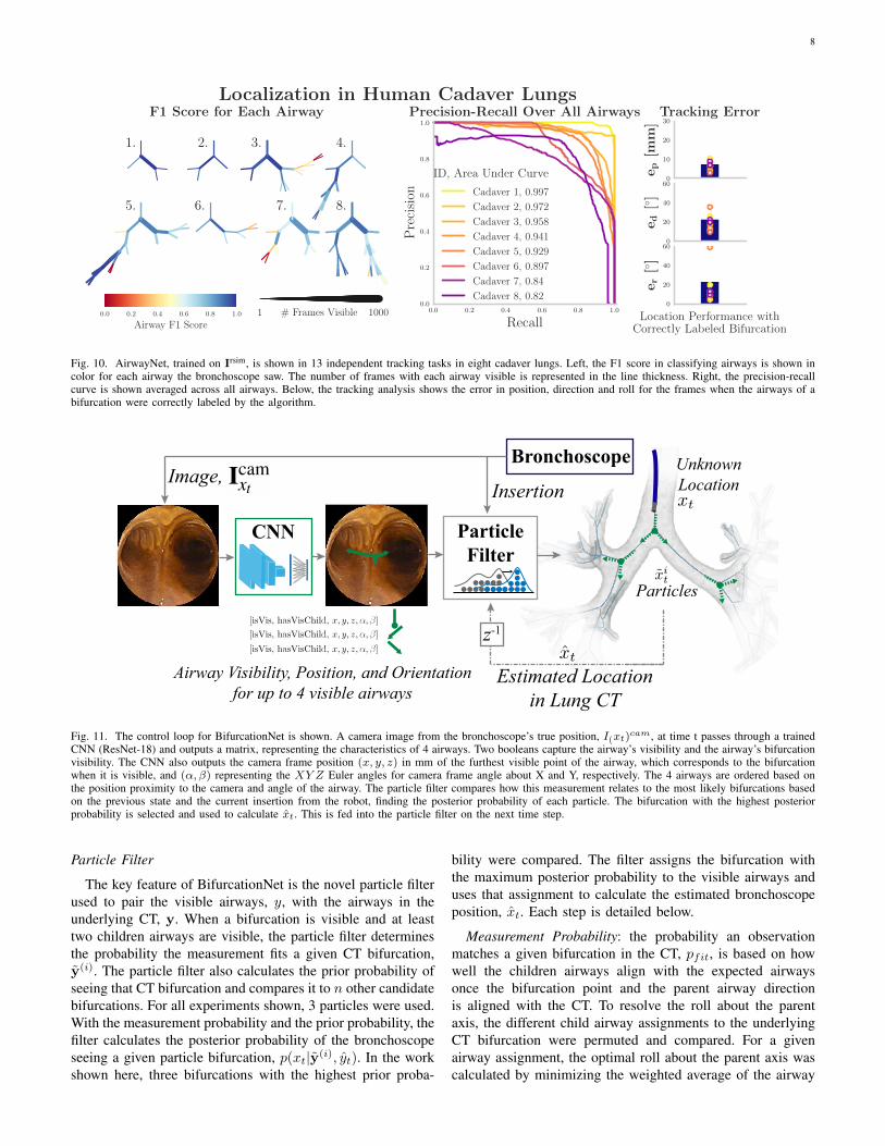
Shown in Fig. 11, at every step in the localization task,an image from the bronchoscope, Icam
xt , at time t from theposition, xt, and the current absolute robot insertion (mm),it, is provided to the localization algorithm and the algorithmoutputs a 6 degree of freedom (DOF) location estimate inCT frame, xt, along with the set of visible airways and theirpositions and orientations, yt, with respect to camera frame.A particle filter assigns the camera frame airways, yt, to theCT airways, yt.
Similar to AirwayNet, BifurcationNet identifies a set ofcommon characteristics for the visible airways in each image.Each airway is characterized through 2 visibility measures,isV is if the airway is visible and hasV isChild if the airway’sbifurcation is visible. For each airway, the networks regressthe camera frame position (x, y, z) of the furthest point onthe airway and its angle (α, β) . BifurcationNet outputs theairway characteristics of up to four visible airways into a novelparticle filter that classifies the airways based on the mostprobable airways in the CT map, shown in Fig. 11.
Bifurcation net shares the 18-layer Resnet architecture, likeAirwayNet, and it is trained using the same Adam optimizationand loss function.
8
1. 2. 3. 4.
5. 6. 7. 8.
F1 Score for Each Airway
0.0 0.2 0.4 0.6 0.8 1.0
Recall
0.0
0.2
0.4
0.6
0.8
1.0
Pre
cisi
on
ID, Area Under Curve
Precision-Recall Over All Airways
Cadaver 1, 0.997
Cadaver 2, 0.972
Cadaver 3, 0.958
Cadaver 4, 0.941
Cadaver 5, 0.929
Cadaver 6, 0.897
Cadaver 7, 0.84
Cadaver 8, 0.82
0
10
20
30
ep
[mm
]
Tracking Error
0
20
40
60
ed
[◦]
0
20
40
60
er
[◦]
Location Performance withCorrectly Labeled Bifurcation
0.0 0.2 0.4 0.6 0.8 1.0
Airway F1 Score1 # Frames Visible 1000
Localization in Human Cadaver Lungs
Fig. 10. AirwayNet, trained on Irsim, is shown in 13 independent tracking tasks in eight cadaver lungs. Left, the F1 score in classifying airways is shown incolor for each airway the bronchoscope saw. The number of frames with each airway visible is represented in the line thickness. Right, the precision-recallcurve is shown averaged across all airways. Below, the tracking analysis shows the error in position, direction and roll for the frames when the airways of abifurcation were correctly labeled by the algorithm.
CNN ParticleFilter
Bronchoscope
InsertionImage,
Estimated Locationin Lung CT
Airway Visibility, Position, and Orientationfor up to 4 visible airways
Particles
UnknownLocation
z-1
Fig. 11. The control loop for BifurcationNet is shown. A camera image from the bronchoscope’s true position, I(xt)cam, at time t passes through a trainedCNN (ResNet-18) and outputs a matrix, representing the characteristics of 4 airways. Two booleans capture the airway’s visibility and the airway’s bifurcationvisibility. The CNN also outputs the camera frame position (x, y, z) in mm of the furthest visible point of the airway, which corresponds to the bifurcationwhen it is visible, and (α, β) representing the XY Z Euler angles for camera frame angle about X and Y, respectively. The 4 airways are ordered based onthe position proximity to the camera and angle of the airway. The particle filter compares how this measurement relates to the most likely bifurcations basedon the previous state and the current insertion from the robot, finding the posterior probability of each particle. The bifurcation with the highest posteriorprobability is selected and used to calculate xt. This is fed into the particle filter on the next time step.
Particle Filter
The key feature of BifurcationNet is the novel particle filterused to pair the visible airways, y, with the airways in theunderlying CT, y. When a bifurcation is visible and at leasttwo children airways are visible, the particle filter determinesthe probability the measurement fits a given CT bifurcation,y(i). The particle filter also calculates the prior probability ofseeing that CT bifurcation and compares it to n other candidatebifurcations. For all experiments shown, 3 particles were used.With the measurement probability and the prior probability, thefilter calculates the posterior probability of the bronchoscopeseeing a given particle bifurcation, p(xt|y(i), yt). In the workshown here, three bifurcations with the highest prior proba-
bility were compared. The filter assigns the bifurcation withthe maximum posterior probability to the visible airways anduses that assignment to calculate the estimated bronchoscopeposition, xt. Each step is detailed below.
Measurement Probability: the probability an observationmatches a given bifurcation in the CT, pfit, is based on howwell the children airways align with the expected airwaysonce the bifurcation point and the parent airway directionis aligned with the CT. To resolve the roll about the parentaxis, the different child airway assignments to the underlyingCT bifurcation were permuted and compared. For a givenairway assignment, the optimal roll about the parent axis wascalculated by minimizing the weighted average of the airway

9
angle offsets. The probability of the fit is calculated basedon a Gaussian distribution over the cosine angle differencebetween the measured child airway directions and CT airwaydirections.
Let p(x;µ, σ) =1√2πσ2
e−(x−µ)2
2σ2 )
pfit =1
n
∑i
p(y(i)>d y
(i)d ; 0, σfit)
Prior: the bifurcation prior is calculated based on the currentrobot insertion length and the filter’s previous state. Theinsertion probability, pins, is based on the distance betweena given CT bifurcation, i, length from the trachea, z(i)bif , andthe robot insertion, uins, plus the observed bifurcation depth incamera frame, y(i)pz . The prior airway probability, pa, increasesthe probability of bifurcations near previously visible airways.If the bifurcation is 1, 2, or 3 generations removed from avisible airway, d(y(i),y(j)), its relative probability incrementsby 1, 0.1 and 0.01. For px, the previously estimated 3DOFlocation, xt−1, is used to calculate a 3D multivariate Gaussianwith the particle estimate. Additionally, a roll probability isincluded to prevent sudden rotations and the previous rollvalue.
pprior = pinspapxpr
pins(z(i)bif |uins, y) = p(uins + y(j)pz − z
(i)bif ; 0, σins)
pa(y(i)|yt−1) =
∑j pgen(y
(j)t−1, y
(i))∑i
∑j pgen(y
(j)t−1, y
(i))
pgen(y(i),y(j)) =
{101−d(y
(i),y(j)) if d(y(i),y(j)) ≤ 3,
0 else
px(x(i)p |xp,t−1) = p(‖x(i)p − xp,t−1‖2; 0, σx)
pr(x(i)r |xr,t−1) = p(|x(i)r − xr,t−1|; 0, σr)
The posterior probability for a given bifurcation, i, wasthen determined and the bifurcation with maximum likelihoodwould be selected as the estimate.
p(y(i)|yt, yt−1, xt−1) = pfitpprior
xt, yt = maxip(y(i)|yt, yt−1, xt−1)
ACKNOWLEDGMENT
The authors would like thank Auris Health Inc. for theequipment and support, the NIH Biotechnology Training Grantand Bio-X for support, and NVIDIA for the Titan X GPU.
REFERENCES
[1] C. S. D. Cruz, L. T. Tanoue, and R. A. Matthay, “Lung cancer:epidemiology, etiology, and prevention,” Clinics in chest medicine,vol. 32, no. 4, pp. 605–644, 2011.
[2] D. E. Ost, et al., “Diagnostic yield and complications of bronchoscopyfor peripheral lung lesions. results of the aquire registry,” Americanjournal of respiratory and critical care medicine, vol. 193, no. 1, pp.68–77, 2016.
[3] D. M. DiBardino, L. B. Yarmus, and R. W. Semaan, “Transthoracicneedle biopsy of the lung,” Journal of thoracic disease, vol. 7, no. Suppl4, p. S304, 2015.
[4] Y. Wu, F. Tang, and H. Li, “Image-based camera localization: anoverview,” Visual Computing for Industry, Biomedicine, and Art, vol. 1,no. 1, p. 8, 2018.
[5] H. Rafii-Tari, C. J. Payne, and G.-Z. Yang, “Current and EmergingRobot-Assisted Endovascular Catheterization Technologies: A Review,”Annals of Biomedical Engineering, vol. 42, no. 4, pp. 697–715.
[6] J. Rosell, A. Perez, P. Cabras, and A. Rosell, “Motion planning forthe virtual bronchoscopy,” in 2012 IEEE International Conference onRobotics and Automation. IEEE, 2012, pp. 2 932–2 937.
[7] P. J. Reynisson, H. O. Leira, T. N. Hernes, E. F. Hofstad, M. Scali,H. Sorger, T. Amundsen, F. Lindseth, and T. Langø, “Navigated bron-choscopy: a technical review,” Journal of bronchology & interventionalpulmonology, vol. 21, no. 3, pp. 242–264, 2014.
[8] J. Sganga and D. B. Camarillo, “Orientation estimation of a continuummanipulator in a phantom lung,” in 2017 IEEE International Conferenceon Robotics and Automation (ICRA). IEEE, 2017, pp. 2 399–2 405.
[9] L. Rai, J. P. Helferty, and W. E. Higgins, “Combined video trackingand image-video registration for continuous bronchoscopic guidance,”International Journal of Computer Assisted Radiology and Surgery,vol. 3, no. 3-4, pp. 315–329, sep 2008.
[10] S. A. Merritt, R. Khare, R. Bascom, and W. E. Higgins, “InteractiveCT-Video Registration for the Continuous Guidance of Bronchoscopy,”IEEE Transactions on Medical Imaging, vol. 32, no. 8, pp. 1 376–1 396,aug 2013.
[11] P. D. Byrnes and W. E. Higgins, “Construction of a multimodal ct-videochest model,” in Medical Imaging 2014: Image-Guided Procedures,Robotic Interventions, and Modeling, vol. 9036. International Societyfor Optics and Photonics, 2014, p. 903607.
[12] M. Visentini-Scarzanella, T. Sugiura, T. Kaneko, and S. Koto, “Deepmonocular 3d reconstruction for assisted navigation in bronchoscopy,”International journal of computer assisted radiology and surgery,vol. 12, no. 7, pp. 1 089–1 099, 2017.
[13] M. Shen, S. Giannarou, P. L. Shah, and G.-Z. Yang, “Branch: Bifurcationrecognition for airway navigation based on structural characteristics,” inInternational Conference on Medical Image Computing and Computer-Assisted Intervention. Springer, 2017, pp. 182–189.
[14] C. Sanchez, A. Esteban-Lansaque, A. Borras, M. Diez-Ferrer, A. Rosell,and D. Gil, “Towards a Videobronchoscopy Localization System fromAirway Centre Tracking.” in VISIGRAPP (4: VISAPP), 2017, pp. 352–359.
[15] E. F. Hofstad, H. Sorger, H. O. Leira, T. Amundsen, and T. Langø,“Automatic registration of CT images to patient during the initial phaseof bronchoscopy: A clinical pilot study,” Medical Physics, vol. 41,no. 4, p. 041903, mar 2014.
[16] X. Luo and K. Mori, “A Discriminative Structural Similarity Measureand its Application to Video-Volume Registration for EndoscopeThree-Dimensional Motion Tracking,” IEEE Transactions on MedicalImaging, vol. 33, no. 6, pp. 1 248–1 261, jun 2014.
[17] X. Zhou, M. Zhu, S. Leonardos, K. G. Derpanis, and K. Daniilidis,“Sparseness Meets Deepness: 3D Human Pose Estimation From Monoc-ular Video,” in The IEEE Conference on Computer Vision and PatternRecognition (CVPR), jun 2016.
[18] OpenAI, et al., “Learning Dexterous In-Hand Manipulation,” 2018.[19] A. Geiger, P. Lenz, and R. Urtasun, “Are we ready for autonomous
driving? the kitti vision benchmark suite,” in 2012 IEEE Conferenceon Computer Vision and Pattern Recognition. IEEE, 2012, pp. 3 354–3 361.
[20] J. Sganga, D. Eng, C. Graetzel, and D. B. Camarillo, “Offsetnet : Deeplearning for localization in the lung using rendered images,” in 2019IEEE International Conference on Robotics and Automation (ICRA).IEEE, 2019.
[21] J. Tobin, R. Fong, A. Ray, J. Schneider, W. Zaremba, and P. Abbeel,“Domain randomization for transferring deep neural networks fromsimulation to the real world,” in 2017 IEEE/RSJ InternationalConference on Intelligent Robots and Systems (IROS). IEEE, sep2017, pp. 23–30.
[22] K. He, X. Zhang, S. Ren, and J. Sun, “Deep residual learning for imagerecognition,” in Proceedings of the IEEE conference on computer visionand pattern recognition, 2016, pp. 770–778.
[23] M. Abadi, et al., “Tensorflow: A system for large-scale machine learn-ing,” in 12th {USENIX} Symposium on Operating Systems Design andImplementation ({OSDI} 16), 2016, pp. 265–283.
[24] A. Mansoor, U. Bagci, B. Foster, Z. Xu, G. Z. Papadakis, L. R. Folio,J. K. Udupa, and D. J. Mollura, “Segmentation and image analysis ofabnormal lungs at ct: current approaches, challenges, and future trends,”RadioGraphics, vol. 35, no. 4, pp. 1 056–1 076, 2015.

10
[25] G. Fagogenis, M. Mencattelli, Z. Machaidze, B. Rosa, K. Price, F. Wu,V. Weixler, M. Saeed, J. Mayer, and P. Dupont, “Autonomous roboticintracardiac catheter navigation using haptic vision,” Science Robotics,vol. 4, no. 29, p. eaaw1977, 2019.
Jake Sganga earned a B.S. in Biomedical Engi-neering from Duke University and an M.S. in Bio-engineering from Stanford University. His researchfocuses on the design of algorithms for the controland localization of soft surgical robotics.
David Eng earned a B.S. and M.S. in ComputerScience from Stanford University.
Chauncey Graetzel earned a B.Sc and M.Sc inMicrotechnology from the Swiss Federal Instituteof Technology in Lausanne (EPFL), and a Ph.D.in Bio-microrobotics from ETH Zurich. He waspreviously Head of Research at Optotune, bringingnovel robotic optical devices to market. At AurisHealth, he is Sr. Manager of Robotics & Controls,where he has spearheaded the development andfirst commercial release of key robotic algorithmscontrolling the medical devices.
David B. Camarillo is Assistant Professor of Bio-engineering, (by courtesy) Mechanical Engineeringand Neurosurgery at Stanford University. Dr. Camar-illo holds a B.S.E in Mechanical and Aerospace En-gineering from Princeton University, a Ph.D. in Me-chanical Engineering from Stanford University andcompleted postdoctoral fellowships in Biophysics atthe UCSF and Biodesign Innovation at Stanford.
Copyright © 2022 FDOKUMEN