Cooperative driving according to Scoop
14
21-4-2011 www.GCDC.net 1 Cooperative driving according to Scoop Assad Alam +,+++ , Fredrik Asplund ++ , Sagar M. Behere ++, Mattias Björk ++ , Liliana Garcia Alonso ++ , Farzad Khaksari + , Altamash Khan + , Joakim Kjellberg + , Kuo-Yun Liang + , Rickard Lyberger +++ , Jonas Mårtensson + , John-Olof Nilsson + , Henrik Pettersson +++ , Simon Pettersson ++ , Elin Stålklinga + , Dennis Sundman +, Dave Zachariah + + KTH Royal Institute of Technology School of Electrical Engineering Stockholm, Sweden ++ KTH Royal Institute of Technology School of Industrial Engineering and Management Stockholm, Sweden +++ Scania CV AB Scania Technical Centre Södertälje, Sweden [email protected] Abstract— KTH Royal Institute of Technology and Scania are entering the GCDC 2011 under the name Scoop – Stockholm Cooperative Driving. This paper is an introduction to their team and to the technical approach they are using in their prototype system for GCDC 2011. I. INTRODUCTION Safety and efficiency are two main issues in the research and development of vehicles and traffic systems. Over the years, much effort has been made to solve these issues by improved design of roads and road networks as well as improved design of the vehicle itself. Traditionally, the focus has been on single actors in the traffic system and how they react to the rest of the traffic and/or the road network. However, if the single actor could act together with the rest of the traffic rather than reacting on it, major improvements in both safety and efficiency could be made. A prerequisite for this to happen is information exchange between vehicles (V2v) and vehicles and infrastructure (V2i) along with applications utilizing the information. One such application is platooning. Platooning is a way to increase the traffic flow by allowing the vehicles to drive closer to each other while not compromising the safety. Another benefit of platooning is that the aero-dynamical forces acting on the vehicles may decrease. This is in particular true for platoons of heavy duty vehicles. The Grand Cooperative Driving Challenge (GCDC) is a competition in cooperative driving and platooning, initiated by TNO and HTAS. Scoop is one of the participating teams.
-
Upload
independent -
Category
Documents
-
view
0 -
download
0
Transcript of Cooperative driving according to Scoop

21-4-2011 www.GCDC.net 1
Cooperative driving according to Scoop Assad Alam+,+++, Fredrik Asplund++, Sagar M. Behere++, Mattias Björk++, Liliana Garcia Alonso++,
Farzad Khaksari+, Altamash Khan+, Joakim Kjellberg+, Kuo-Yun Liang+, Rickard Lyberger+++, Jonas Mårtensson+, John-Olof Nilsson+, Henrik Pettersson+++, Simon Pettersson++,
Elin Stålklinga+, Dennis Sundman+, Dave Zachariah+
+KTH Royal Institute of Technology School of Electrical Engineering
Stockholm, Sweden
++KTH Royal Institute of Technology School of Industrial Engineering and Management
Stockholm, Sweden
+++Scania CV AB Scania Technical Centre
Södertälje, Sweden
Abstract— KTH Royal Institute of Technology and Scania are entering the GCDC 2011 under the name Scoop – Stockholm Cooperative Driving. This paper is an introduction to their team and to the technical approach they are using in their prototype system for GCDC 2011.
I. INTRODUCTION
Safety and efficiency are two main issues in the research and development of vehicles and traffic systems. Over the years, much effort has been made to solve these issues by improved design of roads and road networks as well as improved design of the vehicle itself.
Traditionally, the focus has been on single actors in the traffic system and how they react to the rest of the traffic and/or the road network. However, if the single actor could act together with the rest of the traffic rather than reacting on it, major improvements in both safety and efficiency could be made. A prerequisite for this to happen is information exchange between vehicles (V2v) and vehicles and infrastructure (V2i) along with applications utilizing the information.
One such application is platooning. Platooning is a way to increase the traffic flow by allowing the vehicles to drive closer to each other while not compromising the safety. Another benefit of platooning is that the aero-dynamical forces acting on the vehicles may decrease. This is in particular true for platoons of heavy duty vehicles.
The Grand Cooperative Driving Challenge (GCDC) is a competition in cooperative driving and
platooning, initiated by TNO and HTAS. Scoop is one of the participating teams.

2
Figure 1. A platoon of Scania trucks.
II. THE SCOOP TEAM
Scoop is a Swedish team of Master and PhD students, researchers and engineers from KTH Royal
Institute of Technology in Stockholm and Scania CV AB in Södertälje. The main work is done within a number of master thesis projects, where students, with support of their supervisors, work on different parts of the solution. Eight students are currently engaged in the project, supervised by four departments at KTH (Automatic Control, Mechatronics, Communication Theory and Signal Processing) and by Scania CV AB. Since September 2010, the Scoop team has been working together to build a prototype platooning system for a truck.
CoAct - three Swedish teams The CoAct-project is a platform for the three Swedish GCDC-teams. Chalmers Institute of Technology
and Halmstad University are joining the competition as separate teams, both with cars from Volvo. The CoAct teams have had some collaboration regarding the hardware platform and the wireless communication. In other respects they are competing against eachother. In March they had a joint event at Stora Holms Trafikövingsplats (Traffic training center) outside Gothenburg, where the three teams could test and verify their prototype systems together.
III. OVERVIEW OF PROTOTYPE SYSTEM
The following hardware is used by the Scoop team:
A standard Scania R730 Tractor equipped with an automatic gear change system with an automatic clutch (OPC).
Distance radar. The radar is used by the existing adaptive cruise control (ACC).
Standard sensors of the truck.
GPS
A Linux PC for communication, state estimation and system supervision. On-board sensors of the truck are read via the internal CAN network in the truck.

3
A standard control unit designed for embedded systems, where the control algorithms are implemented. The control unit is communicating with the engine control system and the brake system of the truck.
The students are responsible for different parts of the solution. The topics of the master thesis projects [1] – [8] are:
Architecture – with the aim of creating a feasible architecture for the project. A large part of the architecture will be implemented as a software framework in the Wireless Sensor Unit. A system supervisor is also designed and implemented
Communication - with the aim of implementing the WLAN communication.
State Estimation and Sensor Fusion -with the aim of defining and estimating the states of the ego vehicle and of the other vehicles in the platoon. Kalman filters are used for the estimation.
Control Strategies- with the aim of designing a strategy for controlling a vehicle in a platoon. How do we make best use of the information we get from the other vehicles?
Control Algorithms- implementation, testing and evaluation of the control strategies.
Requirements and Test Cases - with the aim of defining the requirements on the system and also determine which test are needed to verify that the requirements are fulfilled. Both functional requirements and requirements on system performance are specified
Design and execution of tests to verify the performance of the prototype system.
IV. ARCHITECTURE
The system has two main components; WSU (Wireless Sensor unit) and ECU (Electronic Control Unit). WSU: The Wireless Sensor Unit is an embedded computer. Keyboard, mouse, monitor and other typical
PC hardware can easily be plugged in and it also contains the possibility to use wireless communication and serial ports for CAN communication. Most functionality is placed here because of the design and implementation freedom this unit provides. The code is written In C++ with the Orocos-framework.
ECU: The Electronic Control Unit is a control unit typically found in Scania trucks. The ECU is suitable
for controlling the truck since it contains hardware and software familiar to the truck. However, the possibility to implement wireless communication is very limited – which is why this functionality is placed in WSU. The functionality of the ECU is developed in Simulink and its code is auto-generated.
The architecture of the cooperative driving system is shown in Figure 2, and its components are
described more in the following sections.
4
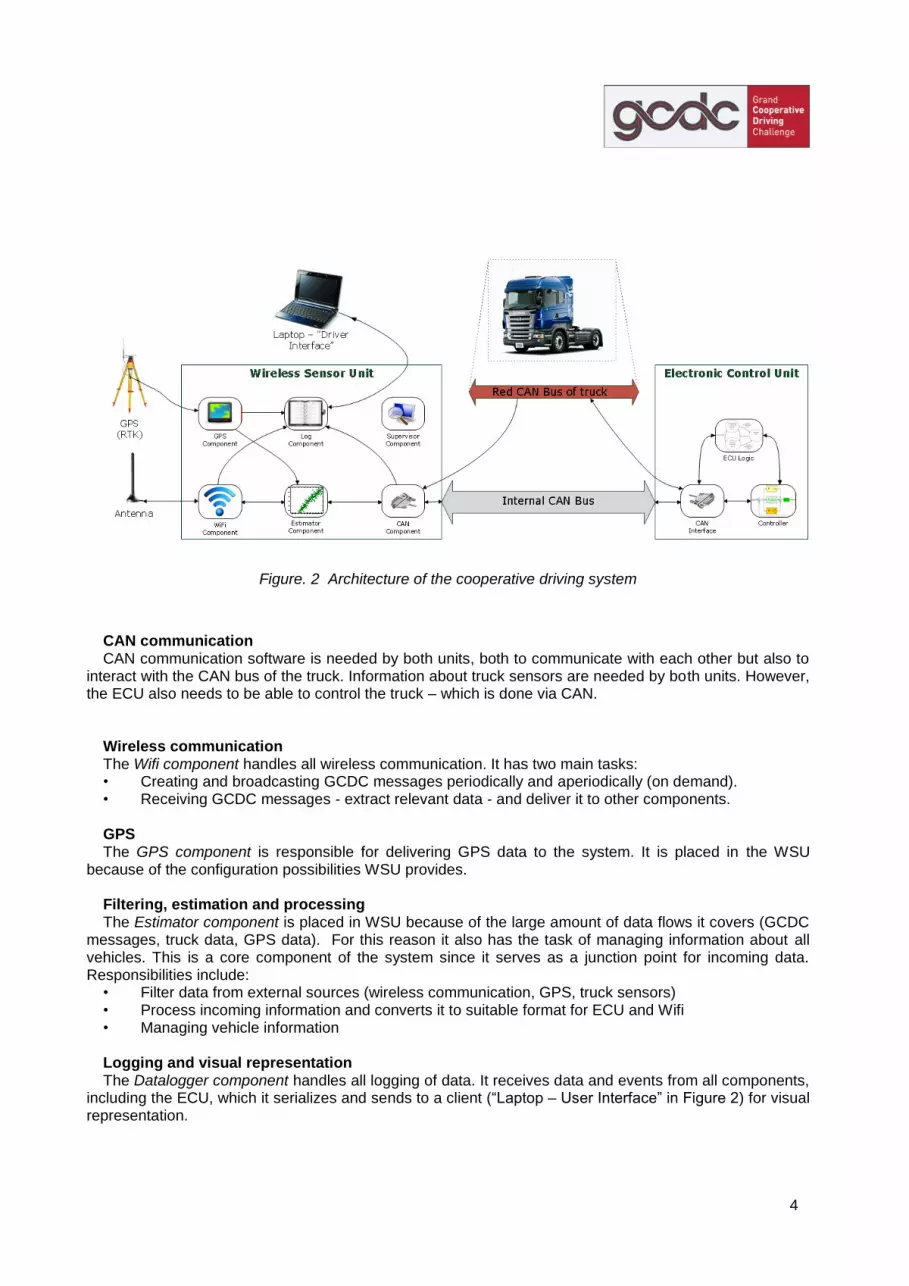
Figure. 2 Architecture of the cooperative driving system
CAN communication CAN communication software is needed by both units, both to communicate with each other but also to
interact with the CAN bus of the truck. Information about truck sensors are needed by both units. However, the ECU also needs to be able to control the truck – which is done via CAN.
Wireless communication The Wifi component handles all wireless communication. It has two main tasks: • Creating and broadcasting GCDC messages periodically and aperiodically (on demand). • Receiving GCDC messages - extract relevant data - and deliver it to other components. GPS The GPS component is responsible for delivering GPS data to the system. It is placed in the WSU
because of the configuration possibilities WSU provides. Filtering, estimation and processing The Estimator component is placed in WSU because of the large amount of data flows it covers (GCDC
messages, truck data, GPS data). For this reason it also has the task of managing information about all vehicles. This is a core component of the system since it serves as a junction point for incoming data. Responsibilities include:
• Filter data from external sources (wireless communication, GPS, truck sensors) • Process incoming information and converts it to suitable format for ECU and Wifi • Managing vehicle information Logging and visual representation The Datalogger component handles all logging of data. It receives data and events from all components,
including the ECU, which it serializes and sends to a client (“Laptop – User Interface” in Figure 2) for visual representation.

5
System “manager” The Supervisor component is hierarchically one level above all other components. It is responsible for
monitoring and diagnostics, state machines, starting and stopping the system, user interface inputs, deciding when to broadcast non-periodic GCDC-messages and decision-making on system-level.
Control system The Control system takes inputs from WSU and truck. It contains several control strategies which it can
choose from depending on the status of input data. If everything is working, it primarily uses information provided by the Estimator. Automatic control of the system is activated by the User Interface of the WSU. It can be turned off at any time by the driver; either by pushing the brake or the throttle pedal.
V. STATE ESTIMATION
The basic purpose of the Estimator is to estimates the dynamic variables of the ego (own) vehicle and of
the other vehicles in the platoon, as well as to maintain a comprehensive picture of the scenario. It includes keeping track of all vehicles, the order of individual vehicles in the platoon, their relative distance to the ego vehicle and also tracking the most relevant traffic light data and speed limit changes. Kalman filters are used to track the data for each vehicle. The Estimator receives the data from the ego vehicle (GPS, wheel speed sensor, built-in gyro and radar), and from the other vehicles and road side units over the WiFi. It then processes the data in order to represent it to the other components inside the system. The processing includes unit conversion, Kalman filtering, sorting and external/internal identity tag translation. To simplify this management, a number of sub-components, or, more specifically, objects, inside the Estimator have been introduced. In the following section we will look at these components and what their purpose is.
A. Geometrical Definitions
The Estimator has to keep track of objects in the real world. Their location in longitude/latitude, their
relative distance to one another, headings, relative headings, yaw rates, etc.. To achieve this some geometrical functions and definitions are used.
Absolute Distance The first function of interest is the absolute distance. The absolute distance between two objects
(commonly between OwnVehicle and OtherVehicle, TrafficLight or SpeedSign) is the unsigned distance in meters between the two specific objects. The absolute distance is found by the longitude and latitude of the two positions, the radius of the Earth and the model that Earth is locally approximated as perfectly round ball.
Line Bearing A second function of interest is what is referred to as the line bearing. The line bearing is the angle
spanned from a line drawn from the heading of the first object (e.g. OwnVehicle, OtherVehicle or SpeedSign) and the line drawn from the first object to the second object.
Signed Base Distance The signed base distance is defined by two properties. The first property is that the distance is positive if
the second objects is ``in front'' of the first and negative if it is ``behind''. An objects is in front of another if the line bearing of the second objects relative the first is somewhere between -90 degrees (i.e. 270 degrees) to +90 degrees.
The second property is that the base distance is the length of a base in a triangle. If the absolute distance is the hypotenuse of a triangle and the heading of the first object is the direction of the base of the

6
triangle, then the base distance is the distance to the place along the base line where the second object is located perpendicularly to the base line. The angle in this triangle, spanned from the first object will be the same angle as the line bearing function.
Fig. 2 Line bearing and base distance b. The arrow symbolizes the heading of the vehicle.
B. Estimator Components
To manage the necessary processing inside the Estimator, a number of sub-components have been
introduced. The components are: OtherVehicle, OwnVehicle, TrafficLight and SpeedSign. We will in this section study each of these components and discuss what their purpose is and how they help us achieve what we want them to do.
OwnVehicle The OwnVehicle object contains all the data necessary for our own vehicle. These values are updated
with information from the GPS and various sensors on the truck via the CAN bus. If multiple sources of the same kind of information, e.g. speed information that can come from both the GPS and the speedometer, the Estimator has to decide which of this information is most reliable.
OtherVehicle If there are multiple vehicles transmitting on the radio, multiple OtherVehicle objects will be created. The
OtherVehicle objects are stored in a by default unsorted vector. If a vehicle is not transmitting any information over the radio for a given time, it will be forgotten by the Estimator - and removed from the vector. The purpose of the OtherVehicles is to keep the data about all the vehicles we know something about. It is also the task of the Estimator to send an “accept to join” message, if a vehicle asks to join the platoon of which we are the leader.
Because of the internal architecture, the unsorted vector of OtherVehicles is sorted according to signed
base distance function to OurVehicle. A new vector is created, where all vehicles behind OurVehicle are thrown away. The Estimator then finds five vehicles of interest that are in front of us. These are: platoon leader, last in platoon (but in front of us), second last, third last and vehicle ahead. A vehicle is considered as part of our platoon if it is in stable state, has the same platoon id as us and has a line bearing to us that is within 10 degrees. Observe that in many cases the vehicle ahead and the last vehicle in platoon is the exact same vehicle. For the vehicle ahead, if the distance reported by the radar is smaller than 100 meters,

7
we choose to trust the radar instead of the GPS data. These five OtherVehicles with their corresponding information is then sent to the electrical control unit (ECU) along with the OwnVehicle information.
Since the Estimator remembers the OtherVehicles for a fixed time if radio is lost, it is necessary to do
some simple filtering. We assume a constant velocity model, so if the radio is lost we extrapolate the position of the OtherVehicle in the last given heading with the speed last reported. If the vehicle is the vehicle ahead, we have the radar information of it and the mentioned filtering is not necessary.
For handling the platoon logic from other vehicles to join our platoon, we are quite generous. If the
platoon id of a vehicle is our platoon id, and our platoon id is the same as our own id (i.e. we are the leader) and their platoon state is transitioning, then we send accept to join directed to this vehicle.
TrafficLight The TrafficLight objects are stored in a vector similar to the OtherVehicle vector. There can be many
traffic lights present so the Estimator needs to find which TrafficLight information is of interest right now. It sends this information to the ECU. Similarly to the OtherVehicles, the TrafficLight are sorted according to signed base distance and the TrafficLight information that has the closest positive base distance is sent to the ECU.
SpeedSign The speed signs are always present three at a time. The speed signs have a notion of heading. The
heading of a speed sign is the direction in which the speed is valid. Since the ECU is only interested in the current speed, we sort the SpeedSign according to signed base distance. We then pick the closest speed sign behind us that has a heading which is -90 degrees to +90 degrees of our own heading. The speed information of this particular SpeedSign is then sent to the ECU.
C. Kalman Filters
Estimation for the Ego vehicle Estimation for the ego vehicle is carried out in order to estimate its dynamic states. This mainly includes
variables that are required to be sent, in the dynamic vehicle information message over the radio interface, to other vehicles. The estimation process is implemented in the form of two Kalman filters in cascade. The first filter is used to estimate the vehicle's true longitudinal speed and the speed scale factor. The observation vector for this filter includes the speed from the wheel speed sensor and ground speed from the GPS. The motivation for employing this filter is the fact that the accuracy of the speed from the wheel speed sensor degrades over time due to changes in the tyre pressure etc.
The true speed estimates from the first filter together with the wheel steering angle is fed into the second
filter. This second filter is implemented as an Extended Kalman Filter (EKF) and it uses the bicycle model to estimate the ECEF-frame (earth centric earth fixed frame) position and velocity alongside with the body frame lateral velocity, yaw-angle, yaw-rate, accelerometer bias and the yaw-rate gyro bias of the ego vehicle. All of these variables form the state vector for the filter. The measurement vector for this filter includes the GPS position, heading, yaw-rate and the lateral acceleration.
Estimation for other Platoon vehicles Estimation for the platoon vehicles (also referred to as platoon mates) is done in order to find their
relative distances, absolute velocities and the absolute accelerations. This information is then subsequently fed to the controller via the CAN bus. Like in the case for the Ego vehicle, the dynamic states for the platoon vehicle, as described above are estimated by using an EKF. The dynamic model for this
8
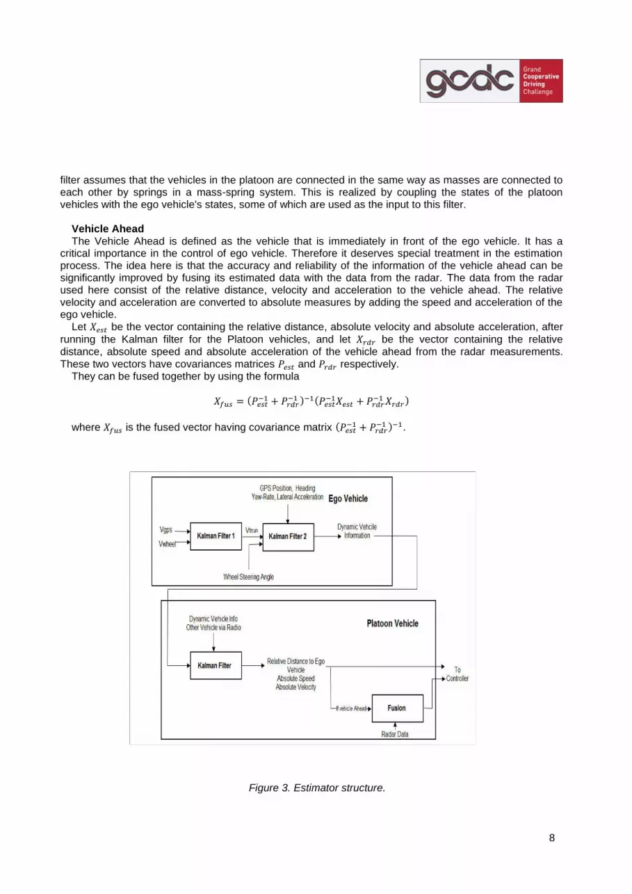
filter assumes that the vehicles in the platoon are connected in the same way as masses are connected to each other by springs in a mass-spring system. This is realized by coupling the states of the platoon vehicles with the ego vehicle's states, some of which are used as the input to this filter.
Vehicle Ahead The Vehicle Ahead is defined as the vehicle that is immediately in front of the ego vehicle. It has a
critical importance in the control of ego vehicle. Therefore it deserves special treatment in the estimation process. The idea here is that the accuracy and reliability of the information of the vehicle ahead can be significantly improved by fusing its estimated data with the data from the radar. The data from the radar used here consist of the relative distance, velocity and acceleration to the vehicle ahead. The relative velocity and acceleration are converted to absolute measures by adding the speed and acceleration of the ego vehicle.
Let be the vector containing the relative distance, absolute velocity and absolute acceleration, after
running the Kalman filter for the Platoon vehicles, and let be the vector containing the relative distance, absolute speed and absolute acceleration of the vehicle ahead from the radar measurements. These two vectors have covariances matrices and respectively.
They can be fused together by using the formula
(
) (
)
where is the fused vector having covariance matrix (
) .
Figure 3. Estimator structure.
9
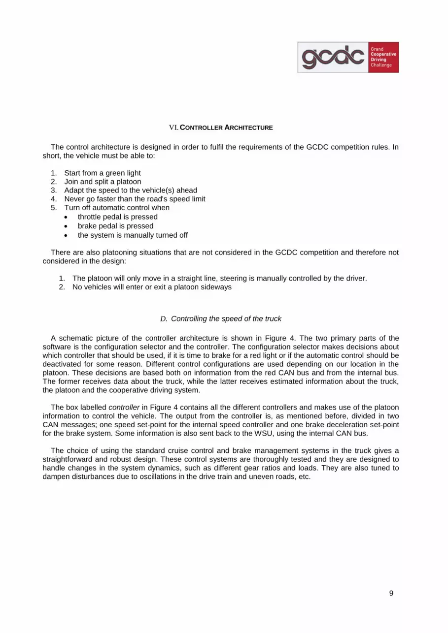
VI. CONTROLLER ARCHITECTURE
The control architecture is designed in order to fulfil the requirements of the GCDC competition rules. In
short, the vehicle must be able to: 1. Start from a green light 2. Join and split a platoon 3. Adapt the speed to the vehicle(s) ahead 4. Never go faster than the road's speed limit 5. Turn off automatic control when
throttle pedal is pressed
brake pedal is pressed
the system is manually turned off There are also platooning situations that are not considered in the GCDC competition and therefore not
considered in the design:
1. The platoon will only move in a straight line, steering is manually controlled by the driver. 2. No vehicles will enter or exit a platoon sideways
D. Controlling the speed of the truck
A schematic picture of the controller architecture is shown in Figure 4. The two primary parts of the
software is the configuration selector and the controller. The configuration selector makes decisions about which controller that should be used, if it is time to brake for a red light or if the automatic control should be deactivated for some reason. Different control configurations are used depending on our location in the platoon. These decisions are based both on information from the red CAN bus and from the internal bus. The former receives data about the truck, while the latter receives estimated information about the truck, the platoon and the cooperative driving system.
The box labelled controller in Figure 4 contains all the different controllers and makes use of the platoon
information to control the vehicle. The output from the controller is, as mentioned before, divided in two CAN messages; one speed set-point for the internal speed controller and one brake deceleration set-point for the brake system. Some information is also sent back to the WSU, using the internal CAN bus.
The choice of using the standard cruise control and brake management systems in the truck gives a
straightforward and robust design. These control systems are thoroughly tested and they are designed to handle changes in the system dynamics, such as different gear ratios and loads. They are also tuned to dampen disturbances due to oscillations in the drive train and uneven roads, etc.

10
Figure 4. Controller architecture
E. Speed Controller
The controller used by the Scoop team is designed based on the following criteria:
Keeping a given distance to the vehicle in front
Mimic the speed profile of the vehicle(s) in front
Reduce oscillations in the platoon If the dynamics of the vehicle to be controlled were significantly higher than the dynamics of the speed
oscillations in the platoon and if there were no time delays in the information, then it would be sufficient to use the speed of the vehicle in front as set-point for the controller. This would give an almost perfect tracking of the vehicle in front. However, this assumption is normally not valid since all the vehicles have similar dynamics.
To improve the tracking capabilities we need to compensate for the dime delays and the dynamics of the
system. This requires a prediction of the future speed profiles of the vehicles ahead of us. Assuming that each vehicle tries to mimic the speed of the vehicle ahead of it, the speed information from vehicles further ahead in the platoon can be seen as predictions of the future speeds of the vehicles further back. The farther ahead we look, the better predictions we can make. If then the dynamic properties of each member in the platoon was known, an optimal control could be designed. However in this GCDC scenario the dynamics and the controllers of the other vehicles are unknown.
Config. selector
Red CANbus
Internal CANbus
Controller
OFF Red CANbus
Internal CANbus
Platooning logic

11
We have chosen a simple approach based on the relative distance to the vehicle ahead and on the speed of the platoon leader and of the three vehicles in front of us (vehicle 1, 2, 3 and n, see Figure 5). The reference speed for the ego vehicle is generated as
))((332211 refnnref dddCvGvGvGvGv
where G1, G2, G3 and Gn are weights that should sum up to one. The optimal weights depend on the relation between the dynamics of the ego vehicle and of the vehicles upstream the platoon. We will use some simulations to show the effects of these weights.
The last term is a distance dependent correction factor used for maintaining a given gap to the vehicle in front, dref. The positive gain C(d) is low in a region around and increases when we deviate from dref. In
that way we will not react on small deviations from the reference in relative distance, but if we get too close or too far away we will compensate for that.
Figure 5. The ego vehicle is number 0 and there are n vehicles ahead of us in the platoon.
F. Simulations
To show the effect of the weight factors, a simple simulation example is shown here. Five identical vehicles are simulated, each with identical PI-controllers for tracking a speed reference. The leading vehicle will increase its speed reference by 5 km/h after 20 seconds. The three following vehicles will use the actual speed of the vehicle ahead as speed reference. The fifth vehicle, (the ego vehicle), uses a reference according to the Scoop controller described above.
Three different parameter sets are used for the ego vehicle, see Table 1.
Set 1 Set 2 Set 3
G1 0 1 0.2
G2 0 0 0.3
G3 0 0 0
Gn 1 0 0.5
Table 1. Weight factors for the ego vehicle used in simulations. Set 1 only uses information from the leader vehicle. As seen in Figure 6, the response will be similar to
that of the second vehicle. This would be the desired behaviour if all the other vehicles in the platoon also used the speed of the leader vehicle as reference. However, if not, (as in the simulation), the ego vehicle will react faster than the vehicle ahead and catch up on that vehicle.
2 1 O 3 n . . . . . .
v1 v2 v3 vn
d

12
Set 2 is the other extreme where only information from the vehicle directly ahead is used, i.e. the same strategy as the other vehicles are using in the simulation example. This will result in a slow response, as can be seen in Figure 7.
Hence, in a platoon with vehicles of unknown dynamics, it will be preferable to use information from multiple platoon members, as in Set 3. The simulation using Set 3 is shown in Figure 8.
Figure 6. Simulation using parameter set 1. Top plot: speed of each vehicle; blue = vehicle 1, green =
vehicle 2, red = vehicle 3, turquoise = vehicle 4, magenta = vehicle 5 (ego vehicle). Bottom plot: relative speed between ego vehicle and the vehicle ahead.
Figure 7. Simulation using parameter set2. Top plot: speed of each vehicle; blue = vehicle 1, green =
vehicle 2, red = vehicle 3, turquoise = vehicle 4, magenta = vehicle 5 (ego vehicle). Bottom plot: relative speed between ego vehicle and the vehicle ahead.
0 5 10 15 20 25 30 35 40 45 5022
22.5
23
23.5
24
Time [s]
Speed [
m/s
]
0 5 10 15 20 25 30 35 40 45 50-0.3
-0.2
-0.1
0
0.1
0.2
0.3
0.4
Time [s]
Speed [
m/s
]
0 5 10 15 20 25 30 35 40 45 5022
22.5
23
23.5
24
Time [s]
Speed [
m/s
]
0 5 10 15 20 25 30 35 40 45 50-0.2
-0.15
-0.1
-0.05
0
0.05
0.1
0.15
Time [s]
Speed [
m/s
]

13
Figure 8. Simulation using parameter set 3. Top plot: speed of each vehicle; blue = vehicle 1, green =
vehicle 2, red = vehicle 3, turquoise = vehicle 4, magenta = vehicle 5 (ego vehicle). Bottom plot: relative speed between ego vehicle and the vehicle ahead.
VII. TEST STATUS AND CONCLUSION
The weeks before the competition tests are being performed at Scania’s test track in Södertälje almost
every day. We have three identical prototype systems which can be hooked up in three trucks. Additional platoon vehicles can be added as dummy vehicles by sending the corresponding WiFi messages from one of the units. In that way platoons with more than three vehicles can be created. Traffic lights and speed signs are created in the same way as the dummy vehicles.
Successful test have been made for:
Wireless communication
Platoon logic (joining and splitting of platoons)
Automatic start and stop
Start at traffic light
Speed limits
Following leading vehicle
Platooning with three vehicles Conclusion: Team Scoop is ready for GCDC 2011. See you there!
0 5 10 15 20 25 30 35 40 45 5022
22.5
23
23.5
24
Time [s]
Speed [
m/s
]
0 5 10 15 20 25 30 35 40 45 50-0.1
-0.05
0
0.05
0.1
0.15
0.2
0.25
Time [s]
Speed [
m/s
]
14
VIII. BIBLIOGRAPHY
[1] Björk, Mattias, “Architecture for autonomous cooperative driving systems," Master's thesis, KTH, 2011, to appear.
[2] Garcia, Liliana, “System requirements and test cases definition for an autonomous cooperative
driving system," Master's thesis, KTH, 2011, to appear.
[3] Khaksari, Mohammadreza, “Specifications and strategies for communication architecture," Master's thesis, KTH, 2011, to appear.
[4] Ahmed Khan, Muhammad Altamash, “Specifications and strategies for state estimation of
vehicle and platoon," Master's thesis, KTH, 2011, to appear.
[5] Stålklinga, Elin, “Specifications and strategies for cooperative control of platooning vehicles," Master's thesis, KTH, 2011, to appear.
[6] Kjellberg, Joakim, “Implementing control algorithms for platooning based on V2V
communication," Master's thesis, KTH, XR-EE-RT 2011:008, 2011.
[7] Liang, Kuo-Yun, “LQR-optimized control and robustness of heavy duty vehicle platooning," Master's thesis, KTH, 2011, to appear.
[8] Pettersson, Simon, “Design and execution of tests - thesis for GCDC,” Master's thesis, KTH,
2011, to appear.