1 Before driving 2 When driving - Dealer E Process
697
TABLE OF CONTENTS Index 2 1-1. Key information Keys ..................................... 30 1-2. Opening, closing and locking the doors Smart key system................. 33 Wireless remote control ....... 47 Side doors ............................ 51 Back door ............................. 56 1-3. Adjustable components (seats, mirrors, steering wheel) Front seats ........................... 61 Rear seats ............................ 65 Head restraints ..................... 76 Seat belts ............................. 79 Steering wheel ..................... 86 Inside rear view mirror .......... 87 Outside rear view mirrors ..... 89 1-4. Opening and closing the windows and moon roof Power windows .................... 91 Power back window ............. 94 Moon roof ............................. 98 1-5. Refueling Opening the fuel tank cap ................................... 102 1-6. Theft deterrent system Engine immobilizer system .............................. 106 Alarm .................................. 109 Theft prevention labels (for U. S. A.) ..................... 112 1-7. Safety information Correct driving posture ....... 113 SRS airbags ....................... 115 Front passenger occupant classification system......... 130 Child restraint systems ....... 136 Installing child restraints ..... 140 2-1. Driving procedures Driving the vehicle .............. 154 Engine (ignition) switch (vehicles without a smart key system) ...................... 164 Engine (ignition) switch (vehicles with a smart key system) ............ 167 Automatic transmission ...... 173 Turn signal lever ................. 179 Parking brake ..................... 180 Horn .................................... 181 2-2. Instrument cluster Gauges and meters ............ 182 Indicators and warning lights ................................. 189 Accessory meter ................. 194 1 Before driving 2 When driving
-
Upload
khangminh22 -
Category
Documents
-
view
0 -
download
0
Transcript of 1 Before driving 2 When driving - Dealer E Process

TABLE OF CONTENTS Index
2
1-1. Key informationKeys ..................................... 30
1-2. Opening, closing and locking the doors
Smart key system................. 33Wireless remote control ....... 47Side doors ............................ 51Back door ............................. 56
1-3. Adjustable components (seats, mirrors, steering wheel)
Front seats ........................... 61Rear seats............................ 65Head restraints..................... 76Seat belts ............................. 79Steering wheel ..................... 86Inside rear view mirror.......... 87Outside rear view mirrors ..... 89
1-4. Opening and closing the windows and moon roof
Power windows .................... 91Power back window ............. 94Moon roof ............................. 98
1-5. RefuelingOpening the fuel tank
cap ................................... 102
1-6. Theft deterrent systemEngine immobilizer
system .............................. 106Alarm .................................. 109Theft prevention labels
(for U. S. A.) ..................... 112
1-7. Safety informationCorrect driving posture ....... 113SRS airbags ....................... 115Front passenger occupant
classification system......... 130Child restraint systems ....... 136Installing child restraints ..... 140
2-1. Driving proceduresDriving the vehicle .............. 154Engine (ignition) switch
(vehicles without a smart key system) ...................... 164
Engine (ignition) switch (vehicles with a smart key system) ............ 167
Automatic transmission ...... 173Turn signal lever ................. 179Parking brake ..................... 180Horn.................................... 181
2-2. Instrument clusterGauges and meters ............ 182Indicators and warning
lights ................................. 189Accessory meter................. 194
1 Before driving
2 When driving
Information Provided by:
1
2
3
4
5
6
7
3
2-3. Operating the lights and wipers
Headlight switch.................. 198Fog light switch ................... 204Windshield wipers and
washer .............................. 205Rear window wiper and
washer .............................. 207
2-4. Using other driving systems
Cruise control...................... 209Intuitive parking assist......... 213Rear view monitor
system .............................. 218Four-wheel drive system
(part-time 4WD models).... 223Four-wheel drive system
(full-time 4WD models) ..... 226Active traction control
system .............................. 230AUTO LSD system.............. 232Rear differential lock
system .............................. 235Downhill assist control
system .............................. 238Crawl Control ...................... 241Multi-terrain Select .............. 245Driving assist systems ........ 253
2-5. Driving informationOff-road precautions........... 262Cargo and luggage............. 267Vehicle load limits............... 273Winter driving tips............... 275Trailer towing...................... 280Dinghy towing..................... 293
3-1. Using the air conditioning system and defogger
Manual air conditioning system.............................. 296
Automatic air conditioning system.............................. 302
Rear window and outside rear view mirror defoggers............... 310
Windshield wiper de-icer .... 312
3-2. Using the audio systemAudio system types ............ 313Using the radio ................... 317Using the CD player ........... 324Playing MP3 and WMA
discs ................................. 333Operating an iPod .............. 341Operating a USB
memory ............................ 348Optimal use of the audio
system.............................. 355Using the AUX port............. 360Using the steering wheel
audio switches.................. 361
3 Interior features
Information Provided by:

TABLE OF CONTENTS Index
4
3-3. Using the Bluetooth® audio system
Bluetooth® audio system.... 364Using the Bluetooth®
audio system.................... 367Operating a Bluetooth®
enabled portable player ... 372Setting up a Bluetooth®
enabled portable player ... 374Bluetooth® audio system
setup ................................ 379
3-4. Using the hands-free phone system (for cellular phone)
Hands-free phone system (for cellular phone) features ............................ 380
Using the hands-free phone system (for cellular phone) ........... 384
Making a phone call ........... 392Setting a cellular phone...... 396Security and system
setup ................................ 401Using the phone book ........ 405
3-5. Using the interior lightsInterior lights list ................. 413• Interior lights .................... 414• Personal lights ................. 414
3-6. Using the storage featuresList of storage features ....... 416• Glove box ......................... 417• Console box ..................... 418• Coin holder ....................... 419• Tissue pocket ................... 420• Pen holder ........................ 421• Auxiliary box ..................... 422• Cup holders ...................... 423• Bottle holders ................... 427
3-7. Other interior featuresSun visors........................... 429Vanity mirrors ..................... 430Clock................................... 431Outside temperature
display .............................. 433Power outlets (12V DC)...... 436Power outlets (120V AC) .... 439Seat heaters ....................... 446Armrest ............................... 448Floor mat ............................ 449Compass ............................ 450Luggage compartment
features ............................ 456Garage door opener ........... 462Safety Connect ................... 469
Information Provided by:

1
2
3
4
5
6
7
5
4-1. Maintenance and careCleaning and protecting
the vehicle exterior............ 478Cleaning and protecting
the vehicle interior............. 481
4-2. MaintenanceMaintenance
requirements..................... 484General maintenance.......... 486Emission inspection and
maintenance (I/M) programs........................... 490
4-3. Do-it-yourself maintenance
Do-it-yourself service precautions ....................... 491
Hood ................................... 494Engine compartment........... 495Tires .................................... 514Tire inflation pressure ......... 520Wheels ................................ 524Air conditioning filter............ 526Wireless remote control/
electronic key battery........ 528Checking and replacing
fuses ................................. 531Light bulbs........................... 541
5-1. Essential informationEmergency flashers............ 554If your vehicle needs to be
towed................................ 555If you think something is
wrong ............................... 561Fuel pump shut off
system.............................. 562Event data recorder............ 563
5-2. Steps to take in an emergency
If a warning light turns on or a warning buzzer sounds.............................. 565
If you have a flat tire ........... 578If the engine will not start.... 591If the shift lever cannot be
shifted from P ................... 593If you lose your keys........... 595If you cannot operate
back door opener ............. 596If the electronic key does
not operate properly ......... 597If the vehicle battery is
discharged........................ 599If your vehicle overheats .... 604If the vehicle becomes
stuck................................. 607If your vehicle has to
be stopped in an emergency ....................... 608
4 Maintenance and care 5 When trouble arises
Information Provided by:

TABLE OF CONTENTS Index
6
6-1. SpecificationsMaintenance data
(fuel, oil level, etc.) ........... 612Fuel information ................. 625Tire information .................. 628
6-2. CustomizationCustomizable features ....... 640
6-3. InitializationItems to initialize................. 646
Reporting safety defects for U.S. owners ................ 648
Seat belt instructions for Canadian owners (in French)........................ 649
SRS airbag instructions for Canadian owners (in French)........................ 651
Abbreviation list........................ 664
Alphabetical index .................... 666
What to do if... .......................... 677
6 Vehicle specifications
7 For owners
Index
Information Provided by:

1
2
3
4
5
6
7
7Information Provided by:

24
For your information
Main Owner’s Manual
Please note that this manual applies to all models and all equipment, includ-ing options. Therefore, you may find some explanations for equipment notinstalled on your vehicle.
All specifications provided in this manual are current at the time of printing.However, because of the Toyota policy of continual product improvement, wereserve the right to make changes at any time without notice.
Depending on specifications, the vehicle shown in the illustrations may differfrom your vehicle in terms of equipment.
Noise from under vehicle after turning off the engine
Approximately five hours after the engine is turned off, you may hear soundcoming from under the vehicle for several minutes. This is the sound of a fuelevaporation leakage check and, it does not indicate a malfunction.
Accessories, spare parts and modification of your Toyota
A wide variety of non-genuine spare parts and accessories for Toyota vehi-cles are currently available on the market. You should know that Toyota doesnot warrant these products and is not responsible for their performance,repair, or replacement, or for any damage they may cause to, or adverseeffect they may have on, your Toyota vehicle.
This vehicle should not be modified with non-genuine Toyota products. Mod-ification with non-genuine Toyota products could affect its performance,safety or durability, and may even violate governmental regulations. In addi-tion, damage or performance problems resulting from the modification maynot be covered under warranty.
Information Provided by:
25
Installation of a mobile two-way radio system
As the installation of a mobile two-way radio system in your vehicle mayaffect electronic systems such as the multi-port fuel injection system/sequen-tial multi-port fuel injection system, cruise control system, anti-lock brakesystem, SRS airbag system and seat belt pretensioner system, be sure tocheck with your Toyota dealer for precautionary measures or special instruc-tions regarding installation.
Scrapping of your Toyota
The SRS airbag and seat belt pretensioner devices in your Toyota containexplosive chemicals. If the vehicle is scrapped with the airbags and seat beltpretensioners left as they are, this may cause an accident such as fire. Besure to have the systems of the SRS airbag and seat belt pretensionerremoved and disposed of by a qualified service shop or by your Toyotadealer before you scrap your vehicle.
Perchlorate Material
Special handling may apply, See www.dtsc.ca.gov/hazardouswaste/perchlorate.
Your vehicle has components that may contain perchlorate. These compo-nents may include airbag, seat belt pretensioners, and wireless remote con-trol batteries.
Information Provided by:

26
CAUTION
■General precautions while drivingDriving under the influence: Never drive your vehicle when under the influ-ence of alcohol or drugs that have impaired your ability to operate your vehi-cle. Alcohol and certain drugs delay reaction time, impair judgment andreduce coordination, which could lead to an accident that could result indeath or serious injury.
Defensive driving: Always drive defensively. Anticipate mistakes that otherdrivers or pedestrians might make and be ready to avoid accidents.
Driver distraction: Always give your full attention to driving. Anything that dis-tracts the driver, such as adjusting controls, talking on a cellular phone orreading can result in a collision with resulting death or serious injury to you,your occupants or others.
■General precaution regarding children’s safetyNever leave children unattended in the vehicle, and never allow children tohave or use the key.
Children may be able to start the vehicle or shift the vehicle into neutral.There is also a danger that children may injure themselves by playing withthe windows, the moon roof, or other features of the vehicle. In addition, heatbuild-up or extremely cold temperatures inside the vehicle can be fatal tochildren.
Information Provided by:
27
Symbols used throughout this manual
Cautions & Notices
Symbols used in illustrations
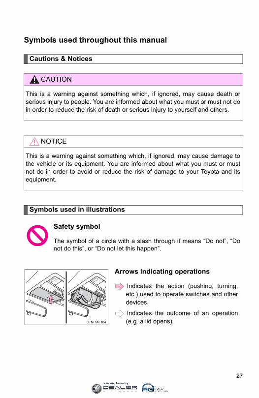
CAUTION
This is a warning against something which, if ignored, may cause death orserious injury to people. You are informed about what you must or must not doin order to reduce the risk of death or serious injury to yourself and others.
NOTICE
This is a warning against something which, if ignored, may cause damage tothe vehicle or its equipment. You are informed about what you must or mustnot do in order to avoid or reduce the risk of damage to your Toyota and itsequipment.
Safety symbol
The symbol of a circle with a slash through it means “Do not”, “Donot do this”, or “Do not let this happen”.
Arrows indicating operations
Indicates the action (pushing, turning,etc.) used to operate switches and otherdevices.
Indicates the outcome of an operation(e.g. a lid opens).
Information Provided by:

28Information Provided by:
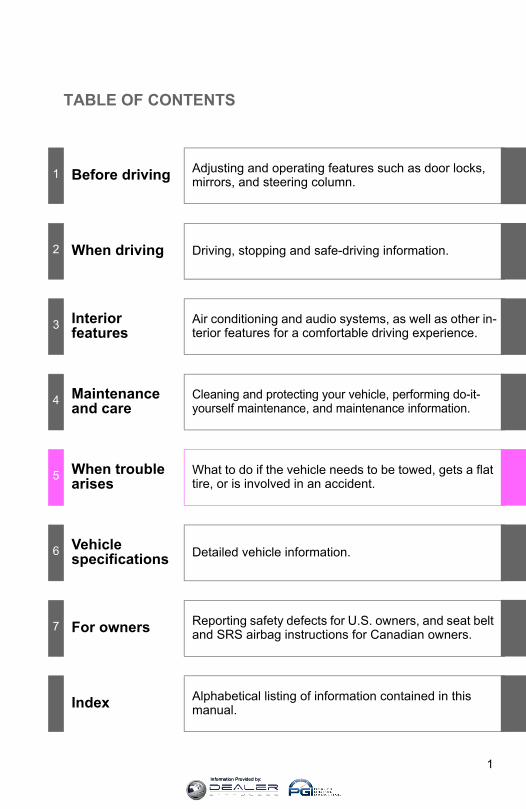
TABLE OF CONTENTS
1
1 Before driving Adjusting and operating features such as door locks, mirrors, and steering column.
2 When driving Driving, stopping and safe-driving information.
3 Interior features
Air conditioning and audio systems, as well as other in-terior features for a comfortable driving experience.
4 Maintenance and care
Cleaning and protecting your vehicle, performing do-it-yourself maintenance, and maintenance information.
5 When trouble arises
What to do if the vehicle needs to be towed, gets a flat tire, or is involved in an accident.
6 Vehicle specifications Detailed vehicle information.
7 For owners Reporting safety defects for U.S. owners, and seat belt and SRS airbag instructions for Canadian owners.
Index Alphabetical listing of information contained in this manual.
Information Provided by:
8
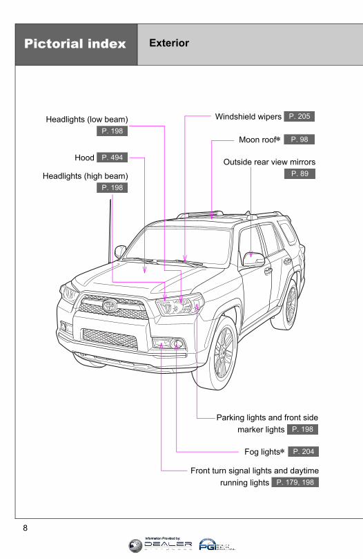
Front turn signal lights and daytimerunning lights P. 179, 198
Pictorial index Exterior
Headlights (low beam) P. 198
Hood P. 494
Windshield wipers P. 205
Moon roof∗ P. 98
Outside rear view mirrorsP. 89
Parking lights and front sidemarker lights P. 198
Fog lights∗ P. 204
Headlights (high beam)P. 198
Information Provided by:
9
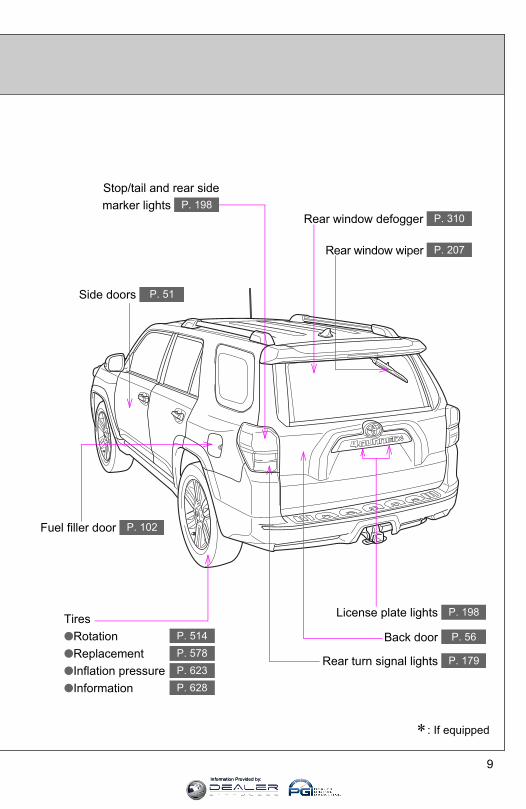
Tires●Rotation●Replacement●Inflation pressure●Information
P. 514P. 578P. 623P. 628
Rear window defogger P. 310
Rear window wiper P. 207
Side doors P. 51
Rear turn signal lights P. 179
License plate lights P. 198
Back door P. 56
∗: If equipped
Stop/tail and rear sidemarker lights P. 198
Fuel filler door P. 102
Information Provided by:
10
CTHPIAS047
Pictorial index Interior
SRS front passenger airbag P. 115
SRS driver airbag P. 115
Head restraints P. 76
Front seats P. 61
Rear seats∗ P. 65
Console box Tissue pocket
Pen holder
P. 418P. 420P. 421
Seat belts P. 79
Cup holders∗ P. 423
Armrest P. 448
Cup holders P. 423
Glove boxP. 417
Floor matsP. 449
Power window switches P. 91
SRS knee airbagsP. 115
SRS side airbags P. 115
Rear seats P. 65
Bottle holders P. 427
Information Provided by:

11
CTHPIAS006
Inside rear view mirror P. 87
SRS curtain shield airbags P. 115
Interior light P. 414
A
Personal lights Interior light
P. 414P. 414
∗: If equipped
Sun visors P. 429
Garage door opener switches “SOS” button∗
Moon roof switches∗ Active traction control switch∗
VSC off switch Rear differential lock switch∗
Downhill assist control switch∗
P. 462P. 469P. 98
P. 230P. 232P. 235P. 238
Auxiliary box∗ Crawl Control switch∗
Multi-terrain Select switch∗
P. 422P. 241P. 245
Vanity mirrors P. 430
Rear view monitor system∗ P. 218
Information Provided by:
12
CTHPIAS007
B
Pictorial index Interior
Door lock switch P. 52
Inside door lock button P. 52
Power window switches P. 91
Window lock switch P. 91
Information Provided by:

13
CTHPIAS087
C
Cup holders P. 423
Power back window switch P. 94
Power outlets∗ P. 439
Seat heater switches∗P. 446
∗: If equipped
Coin holder P. 419
Information Provided by:
14
Pictorial index Instrument panel
Headlight switch Turn signal lever Fog light switch∗
P. 198P. 179P. 204
Windshield wiper and washer switch Rear window wiper and washer switch
P. 205P. 207
Gauges and meters P. 182
Glove boxP. 417
Hood lock release lever P. 494
CTHPIAS059
Accessory meter Compass Clock Outside temperature display
P. 194P. 450
P. 431P. 433
Parking brake pedal P. 180
Emergency flasher switchP. 554
Shift lever P. 173
Audio system∗ Navigation system*1
P. 313
USB port∗ P. 348
Power outlets P. 436
Bottle holders P. 427
Information Provided by:

15
CTHPIAS061
A
CTHPIAS060Security indicator light P. 106, 109
Front passenger “AIR BAG ON” and “AIR BAG OFF” indicator P. 130
∗: If equipped*1: Refer to “Navigation System Owner’s Manual”.
Vehicles with a manual air conditioning system
Vehicles with an automatic air conditioning system
Rear window and outside rear view mirror defoggers P. 310
Security indicator light P. 106, 109
Front passenger “AIR BAG ON” and “AIR BAG OFF” indicator P. 130
Rear window and outside rear view mirror defoggers P. 310
Intuitive parking assist indicator light∗ P. 213
Intuitive parking assist indicator light∗ P. 213
Front passenger’s seat belt reminder light P. 567
Front passenger’s seat belt reminder light P. 567
Information Provided by:
16
CTHPIAS079
Pictorial index Instrument panel
B Vehicles without a smart key system
Vehicles with a smart key system
Party mode switchP. 359
Audio remote control switches∗,*2 P. 361
Cruise control switchP. 209
Horn P. 181
Talk switch∗,*2 P. 385
Telephone switch∗,*2 P. 385
Engine (ignition) switch P. 164
CTHPIAS080
Party mode switchP. 359
Audio remote control switches∗,*2 P. 361
Cruise control switchP. 209
Horn P. 181
Talk switch∗,*2 P. 385
Telephone switch∗,*2 P. 385
Engine (ignition) switch P. 167
Information Provided by:

17
CTHPIAS062
COutside rear view mirror switches P. 89
Instrument panel light control dialP. 187
Intuitive parking assist switch∗P. 213
Tilt and telescopic steering lockrelease lever P. 86
“RSCA OFF” switch P. 128
Power outlet main switch∗ P. 439
Windshield wiper de-icer switch∗P. 312
∗: If equipped*2: For vehicles with a navigation system, refer to the “Navigation System Owner’s Manual”.
Information Provided by:

18
Pictorial index Instrument panel
D
Standard type transmission
CTHPIAS084
AUX portP. 360
Cup holders P. 423
Power outlets P. 436
Shift lock override button P. 593
Multi-mode type transmission (2WD)
CTHPIAS034
AUX portP. 360
Cup holders P. 423
Power outlets P. 436
Shift lock override button P. 593
Information Provided by:

19
D
Multi-mode type transmission (part-time 4WD)
CTHPIAS035
AUX portP. 360
Power outlets P. 436
Front-wheel drive control leverP. 223
Cup holders P. 423
Shift lock override button P. 593
Multi-mode type transmission (full-time 4WD)
CTHPIAS036
AUX portP. 360
Power outlets P. 436
Four-wheel drive control switchP. 226
Cup holders P. 423
Shift lock override button P. 593
Information Provided by:

20
CTHPIAS089
Pictorial index Luggage compartment
Slide deck∗ P. 459
Storage compartment∗ P. 458
Child restraint anchor brackets P. 140
Luggage compartment lights P. 57
Information Provided by:
21
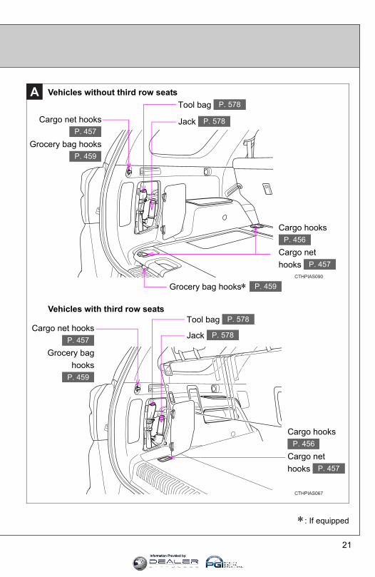
Vehicles without third row seatsA
CTHPIAS090
Grocery bag hooks∗ P. 459
Cargo net hooks
Grocery bag hooksP. 457
P. 459
Tool bag P. 578
Jack P. 578
Cargo hooks
Cargo net hooks
P. 456
P. 457
Vehicles with third row seats
CTHPIAS067
Cargo net hooks
Grocery baghooks
P. 457
P. 459
Tool bag P. 578
Jack P. 578
Cargo hooks
Cargo net hooks
P. 456
P. 457
∗: If equipped
Information Provided by:
22
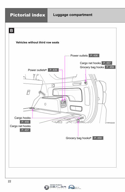
B
Vehicles without third row seats
CTHPIAS028
Grocery bag hooks∗ P. 459
Cargo hooks
Cargo net hooksP. 456
P. 457
Power outlets∗ P. 439
Power outlets P. 436
Cargo net hooks Grocery bag hooks
P. 457P. 459
Pictorial index Luggage compartment
Information Provided by:

23
CTHPIAS029
B
∗: If equipped
Vehicles with third row seats
Storage compartment∗ P. 458
Power outlets P. 436
Power outlets∗ P. 439
Cargo net hooks Grocery bag hooks
P. 457P. 459
Cargo hooks Cargo net hooks
P. 456P. 457
Information Provided by:

CUSTOMER EXPERIENCE CENTER
1-800-331-4331
00505-QRG11-4RUN
Printed in U.S.A. 8/10
10-TCS-03970
414839M1.indd 2414839M1.indd 2 8/5/10 4:36 PM8/5/10 4:36 PM
QUICK REFERENCE
GUIDE
4RUNNER2 0 1 1
414839M1.indd 1414839M1.indd 1 8/5/10 4:36 PM8/5/10 4:36 PM
Information Provided by:
OVE
FEAT
SAFE
EME
IND
1 Visi2 Progmor
3Hom
20114Runner
! A word about safe vehicle operations
This Quick Reference Guide is a summary of basic vehicleoperations. It contains brief descriptions of fundamentaloperations so you can locate and use the vehicle’s mainequipment quickly and easily.
The Quick Reference Guide is not intended as a substitute forthe Owner’s Manual located in the vehicle’s glove box. Westrongly encourage you to review the Owner’s Manual andsupplementary manuals so you will have a better understandingof the vehicle’s capabilities and limitations.
Your dealership and the entire staff of Toyota Motor Sales,U.S.A., Inc. wish you many years of satisfied driving in yournew 4Runner.
This Quick Reference Guide is not a full description of4Runner operations. Every 4Runner owner should review theOwner’s Manual that accompanies this vehicle.
Pay special attention to the boxed information highlighted incolor throughout the Owner’s Manual. Each box contains safeoperating instructions to help you avoid injury or equipmentmalfunction.
All information in this Quick Reference Guide is current atthe time of printing. Toyota reserves the right to makechanges at any time without notice.
11-4Runner.qxd:414839M2 8/3/10 6:22 PM Page 51
25
OVERVIEW
FEATURES/O
PERATIONS
SAFETYAN
DEM
ERGEN
CYFEATU
RES
atorght
Moving the lever to “LOCK” will allow the door to be opened only fromthe outside.
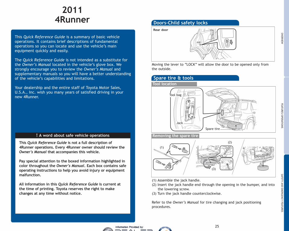
Doors-Child safety locksRear door
ure
Spare tire & toolsTool location
Removing the spare tire
(1) Assemble the jack handle.(2) Insert the jack handle end through the opening in the bumper, and into
the lowering screw.(3) Turn the jack handle counterclockwise.
Refer to the Owner’s Manual for tire changing and jack positioningprocedures.
Tool bag
Jack
(1)
(2)
(3)
Spare tire
11-4Runner.qxd:414839M2 8/3/10 6:26 PM Page 25
Information Provided by:
1
Engine maintenance 8Fuel tank door and cap 6Hood release 8Indicator symbols 4-5Instrument cluster 4Instrument panel 2-3Keyless entry1 6Smart Key system1 7
Air Conditioning/Heating 18-19Audio 20-21Auto lock functions1,2 9Automatic Transmission 9Bluetooth® audio 23Clock 14Cruise control 17Four-wheel drive 10Garage door opener (HomeLink®)3 19iPod®/USB/AUX port 21Light control-Instrument panel 15Lights1 & turn signals 16Moonroof1 14Parking brake 9Power outlets-12V DC 23Power outlets-120V AC 22Seat adjustments-Front 11Seat adjustments-Second row seats 11Seat heaters 18Seats-Folding down second row seats 12Seats-Head restraints 13Seats-Returning third row seats 13Seats-Stowing third row seats 13Telephone controls (Bluetooth®) 22Tilt and telescopic steering wheel 10VSC OFF button 15Windows1 14Window-Back window1 15Windshield wipers & washers 17
Door locks 24Doors-Child safety locks 25Seat belts 24Seat belts-Shoulder belt anchor 24Spare tire & tools 25Tire Pressure Monitoring (warning) System 24
OVERVIEW
FEATURES/OPERATIONS
SAFETY AND
EMERGENCY FEATURES
INDEX
1 Visit your Toyota dealer for information on customizing this feature.2 Programmable by customer. Refer to the Owner’s Manual for instructions andmore information.
3HomeLink® is a registered trademark of Johnson Controls, Inc.
g
OVERVIEW
FEATURES/O
PERATIONS
SAFETYAN
DEM
ERGEN
CYFEATU
RES
11-4Runner.qxd:414839M2 8/3/10 6:25 PM Page 1
Information Provided by:
Power outside rearview mirror controlsInstrument panel light controlIntuitive parking assist switch and indicator1
Tilt and telescopic steering lock release“RSCA OFF” (Roll Sensing of Curtain shield Airbags “OFF”) switch120V AC Power outlet ON/OFF switch1
Windshield wiper de-icer switch1
Headlight, turn signal and front fog light1 controlWiper and washer controlsAccessory meter/Outside temperature displayEmergency flasher switchAudio system1 or navigation system2
Back window and outside rearview mirror defogger switchFront passenger seat belt reminder lightFront passenger occupant classification indicatorEngine immobilizer/Theft deterrent system indicator12V DC Power outlet
2
OVERVIEW
Instrument panelSteering wheel controls
Center console box
UAFoHStVoTeIgPaCSe12Po
1
2
Without Smart Key system
With Smart Key system
Manual Air Condition
11-4Runner.qxd:414839M2 8/3/10 6:25 PM Page 2
Information Provided by:

3
OVERVIEW
FEATURES/O
PERATIONS
SAFETYAN
DEM
ERGEN
CYFEATU
RES
USB port1
AUX portFour-wheel drive selector1
Hood releaseSteering wheel audio controls1,2
Voice command button1,2
Telephone switches1,2
Ignition switch (standard key)1/“ENGINE START STOP” button (Smart Key)1
Party mode switchCruise controlSeat heater switch1
120V AC Power outlet1
Power back window switch
1 If equipped2 For vehicles with a navigation system, refer to the “Navigation System
Owner’s Manual.”
Manual Air Conditioning Automatic Air Conditioning Standard type transmission
Multi-mode type transmission(2WD)
Multi-mode type transmission(part-time 4WD)
Multi-mode type transmission(full-time 4WD)
11-4Runner.qxd:414839M2 8/3/10 6:25 PM Page 3
Information Provided by:
4
OVERVIEW
Low Tire Pressure Warning1
Open door warning1
Airbag SRS warning1
TachometerSpeedometerDisplay change buttonEngine coolant temperatureFuel gaugeEco driving indicator zone displayOdometer, trip meter and average fuel consumption displayShift position and shift range indicatorsVoltmeter
Instrument cluster
Charging system warning1
Low engine oil pressure warning1
Brake system warning1
Malfunction/Check Engine indicator1
Engine oil replacement reminder1
Indicator symbols
Driver/Front passenger seat belt reminder1(alarm will sound if speed is over 12 mph)
Optitron type meters
AIR BAG ON and AIR BAG OFF indicator
Turn signal indicator
Headlight low/high beam indicator
3 If th4 If th
1 For details, refer to “If a warning light turns on or a warning buzzer sounds” Section 5-2,2011 Owner’s Manual.
2 For details, see “SRS airbags” Section 1-7, 2011 Owner’s Manual.
Low fuel level warning1
Non-Optitron type meters
11-4Runner.qxd:414839M2 8/3/10 6:25 PM Page 4
Information Provided by:

5
OVERVIEW
FEATURES/O
PERATIONS
SAFETYAN
DEM
ERGEN
CYFEATU
RES
Automatic Transmission fluid temperature warning1
Crawl Control indicator
Front fog light indicator
Four-wheel drive indicator3
Low speed four-wheel drive indicator3
Center differential lock indicator3
Slip indicator1
Vehicle Stability Control OFF indicator
Downhill Assist Control indicator
AUTO Limited Slip Differential indicator
Cruise control/Cruise control SET indicator4
Roll Sensing of Curtain shield Airbag OFF indicator2
Engine immobilizer/Theft deterrent system indicator
Anti-lock Brake System warning1
3 If this light flashes, refer to “Four-wheel drive system,” Section 2-4, 2011 Owner’s Manual.4 If this light flashes, refer to “Cruise control,” Section 2-4, 2011 Owner’s Manual.
5-2,
Multi-terrain select
Rear differential lock indicator
Active traction control indicator
Power steering system warning1
Kinetic Dynamic Suspension System indicator1
Unengaged Park warning light1
Smart Key system warning1
Intuitive parking assist indicator
Eco driving indicator light
Traction Control OFF indicator
11-4Runner.qxd:414839M2 8/3/10 6:25 PM Page 5
Information Provided by:
6
OVERVIEW
Fuel tank door and cap
PullTurn to open
NOTE: Tighten until one click is heard. If the cap is not properly sealed,Check Engine “ ” indicator may illuminate.
Keyless entryLocking
Unlocking
Panic button
Push and hold
NOTE: If a door is not opened within 60 seconds of unlocking, all doors willrelock for safety.
Push ONCE: Driver doorTWICE: All doors
Push
Without Smart Key system With Smart Key system
Without Smart Key system With Smart Key system
SmStar
AC
ON
OF
NOT
Withswitc
NOT
Pow
Unl
Loc
Carr
Bac
Carr
11-4Runner.qxd:414839M2 8/3/10 6:25 PM Page 6
Information Provided by:
7
OVERVIEW
FEATURES/O
PERATIONS
SAFETYAN
DEM
ERGEN
CYFEATU
RES
pen
ed,
ll
Smart Key system (if equipped)Start function
Accessories such as the radio will operate.
Power ON; the engine not running.
All systems OFF.
ACCESSORY
ON
OFF
NOTE: Gear shift lever must be in Park and brake pedal depressed.
PushDepressbrake pedal
Carrying
Green indicator ON
Without depressing the brake pedal, pressing the “ENGINE START STOP”switch will change the operation mode in succession from:
NOTE: Doors may also be locked/unlocked using remote.
Power (without starting engine)
Push
Unlock
Push
Lock
Locking Unlocking
Carry remote to unlock
Front door lock Front door unlock
Grasp
Carry remote to lock/unlock/open
Back door lock/unlock/open
Carry remote to lock
Touch
Open
Push
11-4Runner.qxd:414839M2 8/3/10 6:25 PM Page 7
Information Provided by:
8
Windshield and back window washer fluid tankPower steering fluid reservoirEngine oil level dipstickEngine coolant reservoirEngine oil filler cap
NOTE: Regularly scheduled maintenance, including oil changes, willhelp extend the life of your vehicle and maintain performance.Please refer to the “Warranty Maintenance Guide.”
Engine maintenance
Hood release
Pull
Pull up latch andraise hood
OVERVIEW FE
Au
* Theped
Shift
Downdowndrive
“S”
AuAutomode-Doo-Doo-Doo-Dooturn
Refe
Pa
4.0 L V6 (1GR-FE) engine
2.7 L 4-cylinder (2TR-FE) engine Stan
11-4Runner.qxd:414839M2 8/3/10 6:25 PM Page 8
Information Provided by:
9
OVERVIEW
FEATURES/O
PERATIONS
SAFETYAN
DEM
ERGEN
CYFEATU
RESlnce.
FEATURES/OPERATIONS
Automatic Transmission
* The ignition/“ENGINE START STOP” switch must be “ON” and the brakepedal depressed to shift from Park.
Shift the shift lever to “S” position from “D” position.
+: Upshift (push and release)-: Downshift (pull and release)
Downshifting increases power going uphill, or provides engine brakingdownhill. For best fuel economy during normal driving conditions, alwaysdrive with the shift lever in the “D” position.
“S” (Sequential) mode
Park*
Reverse
Neutral
Drive
PRND
“S” mode
Auto lock functionsAutomatic door locks can be programmed to operate in four differentmodes, or turned OFF.-Doors lock when shifting from Park.-Doors lock when the vehicle speed is approximately 12 mph or higher.-Doors unlock when shifting into Park.-Doors unlock when the driver’s door is opened within 10 seconds afterturning the “ENGINE START STOP” switch or ignition switch OFF.
Refer to the Owner’s Manual for more details.
Parking brake
Set: DepressRelease: Depress again
BRAKEBRAKE
Multi-mode type
Park*
Reverse
Neutral
Drive
Third gear
Second gear
First gear
PRND
Standard type
11-4Runner.qxd:414839M2 8/3/10 6:25 PM Page 9
Information Provided by:

10
Four-wheel drive (if equipped)
H2
Full-time four-wheel drive models
High speed (2WD)
High speed (4WD)Shift to “H4” with speedbelow 50 mph.
Low speed (4WD)Stop vehicle, shift to “N”position, then move thelever to “L4.”
High speed(center differential locked)
Low speed(center differential locked)Shift to “N” position, thenpush and turn to “L4L.”
H4L
L4L
Part-time four-wheel drive models
Neutral
High speedH4F
FEATURES/OPERATIONS
Tilt and telescopic steering wheel
Hold wheel, push lever down, set angle and length, and return lever.
NOTE: Do not attempt to adjust while the vehicle is in motion.
Lock release leverLength
Angle
SeHSeLuDPaSeLu
SeaMan
Sea
SeSe
Vehi
11-4Runner.qxd:414839M2 8/3/10 6:25 PM Page 10
Information Provided by:

11
OVERVIEW
FEATURES/O
PERATIONS
SAFETYAN
DEM
ERGEN
CYFEATU
RES
ngth
Seat position (forward/backward)Height crank (driver side only)Seatback angleLumbar support (driver side only)Driver seat: seat position, cushion angle and heightPassenger seat: seat position (forward/backward)Seatback angleLumbar support (driver side only)
Seat adjustments-FrontManual seat Power seat
Seat adjustments-Second row seats
Seat position (forward/backward)Seatback angle
Vehicles with third row seats Vehicles without third row seats
11-4Runner.qxd:414839M2 8/3/10 6:25 PM Page 11
Information Provided by:

12
FEATURES/OPERATIONS
Seats-Folding down second row seats
(1) Push
(2) Lower
(3) Stow
(5) Fold down
(4) Pull up
Sea(ifFrom
From
Sea(if
(1) R
Without third row seats
With third row seats
SeaFronrow
Loc
(1) Push
(2) Lower
(5) Pull up
(3) Fold down
(7) Fold down
(6) Push down
(4) Stow
11-4Runner.qxd:414839M2 8/3/10 6:25 PM Page 12
Information Provided by:

13
OVERVIEW
FEATURES/O
PERATIONS
SAFETYAN
DEM
ERGEN
CYFEATU
RES
Seats-Stowing third row seats(if equipped)
(1) Stow (2) Pull up
(3) Pull up
(4) Pull up
(5) Fold down
(1) Stow (2) Pull up (3) Pull up (4) Fold down
From inside
From outside
Seats-Returning third row seats(if equipped)
(1) Raise(2) Pull
(3) Raise
Seats-Head restraintsFront and secondrow
Lock release button
own
Second row (vehicleswithout third row seats)
Third row (if equipped)
11-4Runner.qxd:414839M2 8/3/10 6:25 PM Page 13
Information Provided by:

14
FEATURES/OPERATIONS
Lig
Clock
H- Hour setM- Minute set
Ope
WindowsDriver side
Automatic operation Push the switch completely down or pull itcompletely up and release to fully open or close. To stop window midway,lightly push the switch in the opposite direction.
Window lock switch Deactivates all passenger windows. Driver’s windowremains operable.
Wi
Up
Down
Window lock switch
Win
Clo
Moonroof (if equipped)Sliding operation Tilting operation
Open
CloseClose
Tilt
Push once to open/close completely.To stop partway, press switch lightly.
TheVSC
Refe
VS
11-4Runner.qxd:414839M2 8/3/10 6:25 PM Page 14
Information Provided by:

15
OVERVIEW
FEATURES/O
PERATIONS
SAFETYAN
DEM
ERGEN
CYFEATU
RES
Light control-Instrument panel
tset
Operating from inside
way,
ow
Window-Back windowOperating from outside
Window lock switch
OpenClose
Turn and hold
CloseOpen
With Smart Key system
Without Smart Key system
Close
Open
The VSC OFF button is used to switch between modes related to the TRAC,VSC and Auto LSD (2WD) functions.
Refer to Section 2-4 of the Owner’s Manual for more information.
VSC OFF
VSC OFF button
Brightness control
+
-
Push and hold
11-4Runner.qxd:414839M2 8/3/10 6:25 PM Page 15
Information Provided by:
16
FEATURES/OPERATIONS
Turn signals
Front fog lights (if equipped)
Front fog lights come on only when the headlights are on low beam.
Right turn
Turn
Lane change
Lane change
Left turn
Lights & turn signalsHeadlights
High beam flasher
Low beam
HeadlightsParking lights
High beam
HeadlightsParking lights
DRL ONAuto
DRL OFF
Type BType A
-Automatic light cut off system Will automatically turn lights off after adelay of 30 seconds, or the lock switch on remote may be pushed afterlocking.
Wi
Rea
Fro
NOTclose
* InRo
Cru
Refe
Turn
DRL OFF
11-4Runner.qxd:414839M2 8/3/10 6:25 PM Page 16
Information Provided by:

17
OVERVIEW
FEATURES/O
PERATIONS
SAFETYAN
DEM
ERGEN
CYFEATU
RES
er aer
Windshield wipers & washers
Rear
Front
Interval wipe
Slow
FastPull to wash and wipe
Adjust frequency*
Wash and wipeWipeInterval wipe
Wash and wipe
NOTE: Rear wiper and washer operate only when back window is fullyclosed.
* Intermittent windshield wiper frequency adjustmentRotate to increase/decrease wipe frequency.
Single wipe
Cruise control
Refer to the Owner’s Manual for more details.
Turning system ON/OFF Functions
System ON/OFF
Resume/Increase speed
Set/Decrease speed
Cancel
11-4Runner.qxd:414839M2 8/3/10 6:25 PM Page 17
Information Provided by:

18
Air Conditioning/Heating
FEATURES/OPERATIONS
Temperature selector (driver side)Fan speedAir Conditioning ON/OFFFresh or recirculated cabin airTemperature selector (front passenger side)“DUAL” buttonIndicator ON: Separate temperature settings for driver andpassenger.Indicator OFF: Synchronize temperature settings for driver andpassenger.Rear window and outside rearview mirror defoggersAirflow ventIn “ ” mode, use fresh air (“ ” indicator OFF) to reduce windowfogging. “ ” mode uses fresh air only.Climate control OFFAutomatic climate control ONAdjust the temperature setting, and airflow vents and fan will adjustautomatically.
Automatic Air Conditioning
ManSeat heaters (if equipped)
Driver’s seat
Front passenger’s seat
Ga
Garaprog
Refe
Forvisit
* Hom
11-4Runner.qxd:414839M2 8/3/10 6:25 PM Page 18
Information Provided by:
19
OVERVIEW
FEATURES/O
PERATIONS
SAFETYAN
DEM
ERGEN
CYFEATU
RES
dow
just
Manual Air Conditioning
Fan speedRecirculate cabin air (fresh air when OFF)Airflow ventIn “ ” mode, use fresh air (“ ” indicator OFF) to reducewindow fogging. “ ” mode uses fresh air only.Rear window and outside rearview mirror defoggersSelect for maximum cooling. Air intake will automatically be set torecirculate.Temperature selectorAir Conditioning ON/OFF
Garage door opener (HomeLink®)*
Garage door openers manufactured under license from HomeLink®* can beprogrammed to operate garage doors, estate gates, security lighting, etc.
Refer to the Owner’s Manual for more details.
For programming assistance, contact HomeLink® at 1-800-355-3515, orvisit http://www.homelink.com.
* HomeLink® is a registered trademark of Johnson Controls, Inc.
11-4Runner.qxd:414839M2 8/3/10 6:25 PM Page 19
Information Provided by:
20
CD playerTo scan tracks on a disc Push “SCAN.” Push again to hold selection.CD Changer (Type 3 only)-To load one disc Push “LOAD” and insert one disc.-To load multiple discs Push and hold “LOAD” until you hear a beep.Insert one disc. Shutter will close and then re-open for next disc.To select a file (MP3/WMA only) Turn “TUNE.FILE” or “TUNE.SCROLL.”To select a folder (MP3/WMA only) Push either side of “TYPE/FOLDER.”
Audio
View radio/CDinformation
Eject CD
Push to turnON/OFF
Push to adjusttone & balance
View genre/Push to skipup/down folder
Seek station/CD track select
Station/CDtrack scan Mode
Preset buttons - functions in othermodes indicated above number
Mode
Type 1
Load CD(s)
“U“Pa
Stee
RadioTo preset stations Tune in the desired station and hold down a presetbutton (1-6) until you hear a beep. Push desired preset button (1-6) toselect.To scan stations Push “SCAN.” Push and hold to scan preset stations. Pushagain to hold selection.
FEATURES/OPERATIONS
Type 3 additional functions
Type 2 additional functions
AM/Satelliteradio
iPodBy cothe UUSBAUXBy inportamode
iPod
iPoAU
Partyoptim
Part
11-4Runner.qxd:414839M2 8/3/10 6:25 PM Page 20
Information Provided by:
21
OVERVIEW
FEATURES/O
PERATIONS
SAFETYAN
DEM
ERGEN
CYFEATU
RES
”.”
ustnce
/plder
“ ”Use to search within the selected audio medium (radio, CD, iPod®, etc.).“MODE”Push to turn audio ON and select an audio mode. Push and hold to turnaudio system OFF.
>
>
Steering wheel controls (if equipped)
Push
Volume control
iPod®/USB portBy connecting a USB-compatible portable audio device or USB memory tothe USB port, you can listen to music from the portable audio device orUSB memory through the vehicle’s speaker system.AUX portBy inserting a mini plug into the AUX port, you can listen to music from aportable audio device through the vehicle’s speaker system while in AUXmode.
iPod®/USB AUX
iPod®/USB (if equipped)/AUX port
Party mode increases audio amplification in back door speakers,optimizing audio performance outside vehicle when rear hatch is open.
Party mode switch
11-4Runner.qxd:414839M2 8/3/10 6:25 PM Page 21
Information Provided by:
22
FEATURES/OPERATIONS
Bluetooth® technology allows dialing or receipt of calls without takinghands from the steering wheel or using a cable to connect the compatibletelephone and the system.
Refer to “Using the hands-free phone system (for cellular phone),” Section3-4 in the Owner’s Manual for more details, or go to Toyota.com and enter“Bluetooth” in the keyword search.
Telephone controls (Bluetooth®)(if equipped)
MicrophoneAudio unit
Steering wheel telephone switches
Start call
End call
Voice command button
Volume
Theportacomm
Refemore
Audi
Blu
NOTEswitc
PowCen
Lug(wit
NOTE: The 120V AC power outlet can only be used when engine is running.
Power outlets-120V AC (if equipped)
ON/OFFMain switch
Inside center console
Push
Luggage compartment
11-4Runner.qxd:414839M2 8/3/10 6:25 PM Page 22
Information Provided by:
23
OVERVIEW
FEATURES/O
PERATIONS
SAFETYAN
DEM
ERGEN
CYFEATU
RES
ible
ctionnter
ton
The Bluetooth® audio system enables you to enjoy music played on aportable digital audio player from the vehicle speaker via wirelesscommunication.
Refer to “Bluetooth® audio system,” Section 3-3 in the Owner’s Manual formore details.
MicrophoneAudio unit
Steering wheel audio switches
Selects a track and albumTurns the power on,selects an audio source
Volume
Bluetooth® audio (if equipped)
NOTE: Designed for car accessories. Ignition switch/“ENGINE START STOP”switch must be in the “ACC” or “ON” position to be used.
Power outlets-12V DCCenter panel
Luggage compartment(with the 120V AC outlet)
Glove box
Luggage compartment(without the 120V AC outlet)
ning.
nt
11-4Runner.qxd:414839M2 8/3/10 6:25 PM Page 23
Information Provided by:
24
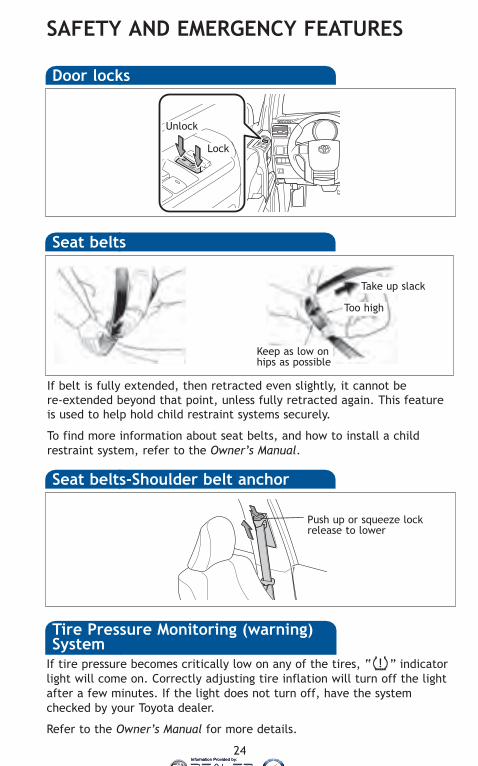
SAFETY AND EMERGENCY FEATURES
If tire pressure becomes critically low on any of the tires, “ ” indicatorlight will come on. Correctly adjusting tire inflation will turn off the lightafter a few minutes. If the light does not turn off, have the systemchecked by your Toyota dealer.
Refer to the Owner’s Manual for more details.
Seat belts-Shoulder belt anchor
Push up or squeeze lockrelease to lower
Movithe o
DoRea
If belt is fully extended, then retracted even slightly, it cannot bere-extended beyond that point, unless fully retracted again. This featureis used to help hold child restraint systems securely.
To find more information about seat belts, and how to install a childrestraint system, refer to the Owner’s Manual.
Keep as low onhips as possible
Take up slack
Too high
Seat belts
Tire Pressure Monitoring (warning)System
SpToo
Rem
(1) A(2) In
t(3) T
Refeproc
Door locks
Unlock
Lock
11-4Runner.qxd:414839M2 8/3/10 6:25 PM Page 24
Information Provided by:
30
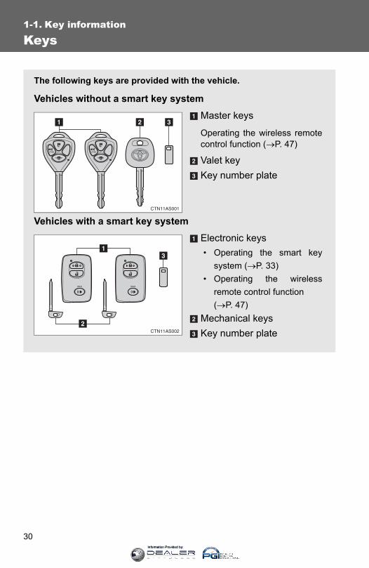
1-1. Key information
Keys
The following keys are provided with the vehicle.
Vehicles without a smart key systemMaster keys
Operating the wireless remotecontrol function (→P. 47)
Valet keyKey number plate
Vehicles with a smart key systemElectronic keys• Operating the smart key
system (→P. 33)• Operating the wireless
remote control function (→P. 47)
Mechanical keysKey number plate
Information Provided by:

31
1-1. Key information
1
Before driving
Using the mechanical key (vehicles with a smart key system)
To take out the mechanical key,push the release button and takethe key out.
After using the mechanical key,store it in the electronic key. Carrythe mechanical key together withthe electronic key. If the electronickey battery is depleted or theentry function does not operateproperly, you will need themechanical key. (→P. 597)
■When required to leave the vehicle’s key with a parking attendantLock the glove box as circumstances demand. (→P. 417)
Vehicles without a smart key system: Carry the master key for your own useand provide the attendant with the valet key.
Vehicles with a smart key system: Remove the mechanical key for your ownuse and provide the attendant with the electronic key only.
■Key number plateKeep the plate in a safe place such as your wallet, not in the vehicle. In theevent that a key (without a smart key system) or mechanical key (with asmart key system) is lost, a new key can be made by your Toyota dealerusing the key number plate. (→P. 595)
■When riding in an aircraftWhen bringing a key with wireless remote control function onto an aircraft,make sure you do not press any buttons on the key while inside the aircraftcabin. If you are carrying the key in your bag etc., ensure that the buttonsare not likely to be pressed accidentally. Pressing a button may cause thekey to emit radio waves that could interfere with the operation of the aircraft.
Information Provided by:
32
1-1. Key information
NOTICE
■To prevent key damageObserve the following:
●Do not drop the keys, subject them to strong shocks or bend them.
●Do not expose the keys to high temperatures for a long period of time.
●Do not get the keys wet or wash them in an ultrasonic washer etc.
●Do not attach metallic or magnetic materials to the keys or place the keysclose to such materials.
●Do not disassemble the keys.
●Do not attach a sticker or anything else to the surface of the electronic key.
●Do not place the keys near objects that produce magnetic fields, such asTVs, audio systems, glass top ranges, or medical electrical equipment,such as low-frequency therapy equipment.
■Carrying the electronic key on your person (vehicles with a smart keysystem)Carry the electronic key 3.9 in. (10 cm) or more away from electric appli-ances that are turned on.
■ In case of a smart key system malfunction or other key-related prob-lems (vehicles with a smart key system)Take your vehicle with all the electronic keys provided with your vehicle toyour Toyota dealer.
■When a vehicle key is lost (vehicles with a smart key system)If the key remains lost, the risk of vehicle theft increases significantly. Visityour Toyota dealer immediately with all remaining electronic keys that wasprovided with your vehicle.
Information Provided by:
33
1
Before driving
1-2. Opening, closing and locking the doors
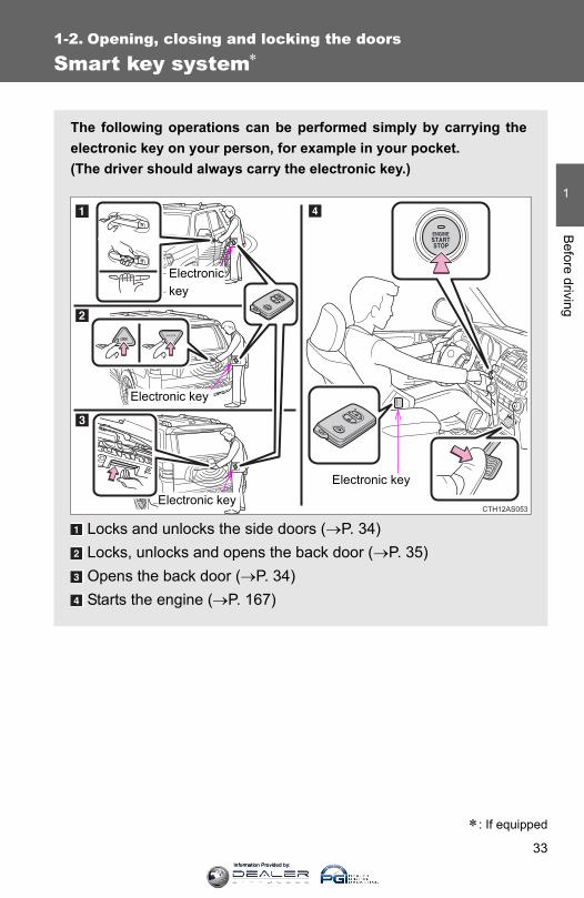
Smart key system∗
∗: If equipped
The following operations can be performed simply by carrying theelectronic key on your person, for example in your pocket.(The driver should always carry the electronic key.)
Locks and unlocks the side doors (→P. 34)Locks, unlocks and opens the back door (→P. 35)Opens the back door (→P. 34)Starts the engine (→P. 167)
CTH12AS053
Electronic key
Electronic key
Electronic key
Electronic key
Information Provided by:

34
1-2. Opening, closing and locking the doors
Unlocking and locking the side doors (front door handles only)
Grip the handle to unlock thedoor.
Make sure to touch the sensor onthe back of the handle.
The doors cannot be unlocked for3 seconds after the doors arelocked.
Touch the lock sensor (theindentation on the upper part ofthe door handle) to lock thedoors.
Opening the back door
Press the back door opener.
The back door can be openedeven if it is locked.
Information Provided by:

35
1-2. Opening, closing and locking the doors
1
Before driving
Unlocking and locking the back door
Press the button to unlock thedoor.
The back window can be openedby pressing and holding this but-ton. (→P. 94)
Press the button to lock the door.
The back window can be closedby pressing and holding this but-ton. (→P. 94)
Information Provided by:
36
1-2. Opening, closing and locking the doors
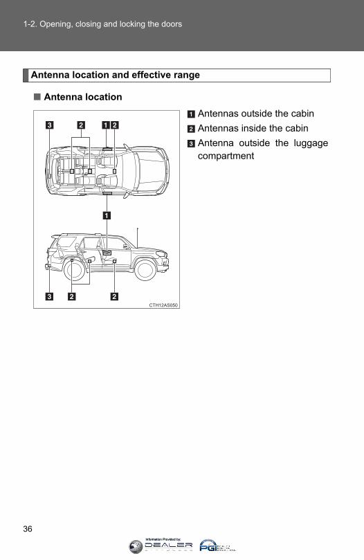
Antenna location and effective range
■ Antenna locationAntennas outside the cabinAntennas inside the cabinAntenna outside the luggagecompartment
CTH12AS050
Information Provided by:
37
1-2. Opening, closing and locking the doors
1
Before driving
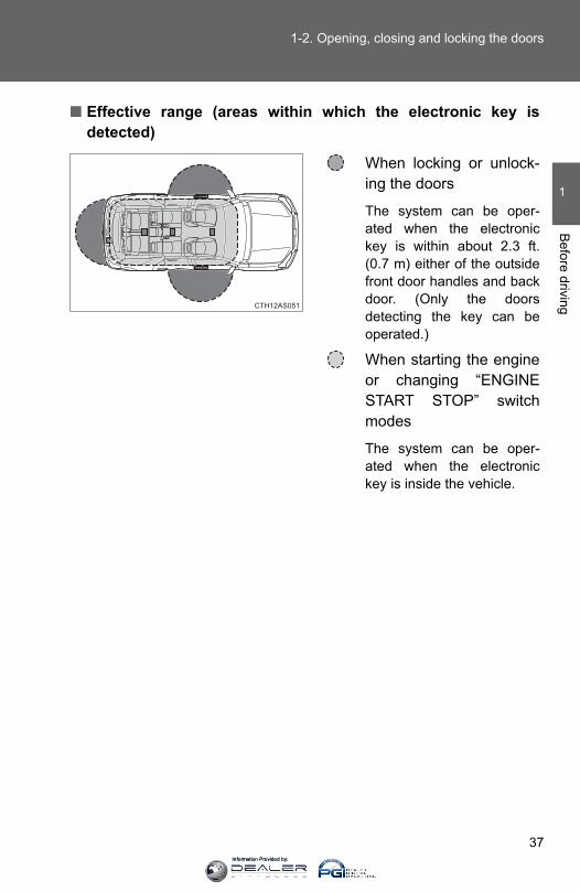
■ Effective range (areas within which the electronic key isdetected)
When locking or unlock-ing the doors
The system can be oper-ated when the electronickey is within about 2.3 ft.(0.7 m) either of the outsidefront door handles and backdoor. (Only the doorsdetecting the key can beoperated.)
When starting the engineor changing “ENGINESTART STOP” switchmodes
The system can be oper-ated when the electronickey is inside the vehicle.
CTH12AS051
Information Provided by:
38
1-2. Opening, closing and locking the doors
■Operation signalsA buzzer sounds and the emergency flashers flash to indicate that the doorshave been locked/unlocked. (Locked: once; Unlocked: twice)
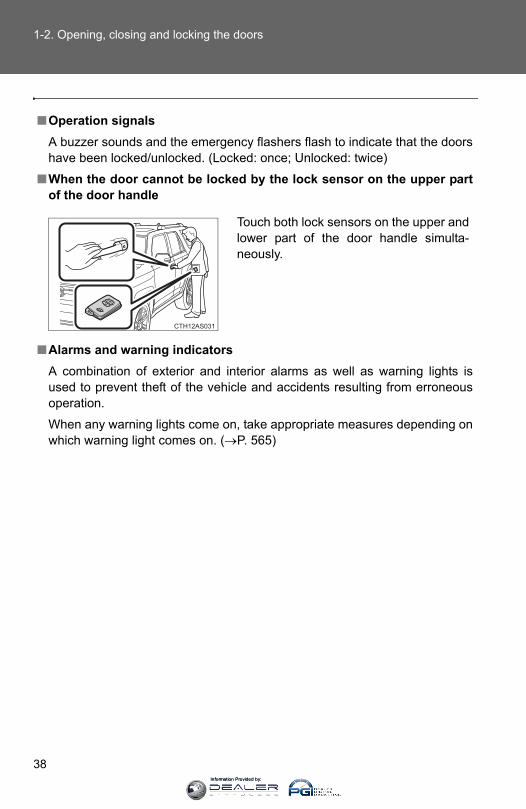
■When the door cannot be locked by the lock sensor on the upper partof the door handle
■Alarms and warning indicatorsA combination of exterior and interior alarms as well as warning lights isused to prevent theft of the vehicle and accidents resulting from erroneousoperation.
When any warning lights come on, take appropriate measures depending onwhich warning light comes on. (→P. 565)
Touch both lock sensors on the upper andlower part of the door handle simulta-neously.
Information Provided by:
39
1-2. Opening, closing and locking the doors
1
Before driving
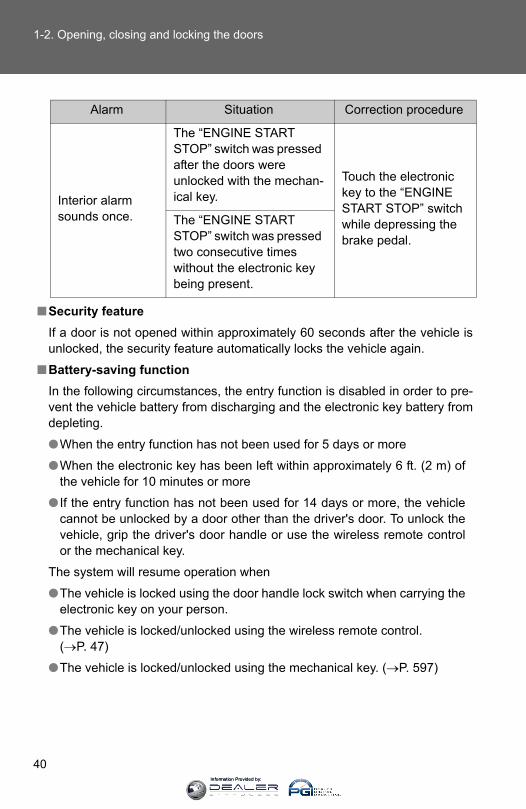
The following table describes circumstances and correction procedureswhen only alarms are sounded.
Alarm Situation Correction procedure
Exterior alarm sounds once for 10 seconds
An attempt was made to lock the doors using the entry function while the electronic key was still inside the vehicle.
Retrieve the elec-tronic key from the vehicle and lock the doors again.
An attempt was made to lock either front door by opening a door and putting the inside lock button into the lock position, then closing the door by pulling on the outside door handle with the electronic key still inside the vehicle.
Exterior alarm sounds once for 10 seconds
An attempt was made to lock the vehicle using the entry function while a door was open.
Close all of the doors and lock the doors again.
Interior alarm sounds continu-ously
An attempt was made to open the door and exit the vehicle when the shift lever was not in P.
Shift the shift lever to P.
Interior alarm pings repeatedly
The “ENGINE START STOP” switch was turned to ACCESSORY mode while the driver's door was open(The driver's door was opened when the “ENGINE START STOP” switch was in ACCES-SORY mode.)
Turn the “ENGINE START STOP” switch off and close the driver's door.
Information Provided by:
40
1-2. Opening, closing and locking the doors
■Security featureIf a door is not opened within approximately 60 seconds after the vehicle isunlocked, the security feature automatically locks the vehicle again.
■Battery-saving functionIn the following circumstances, the entry function is disabled in order to pre-vent the vehicle battery from discharging and the electronic key battery fromdepleting.
●When the entry function has not been used for 5 days or more
●When the electronic key has been left within approximately 6 ft. (2 m) ofthe vehicle for 10 minutes or more
● If the entry function has not been used for 14 days or more, the vehiclecannot be unlocked by a door other than the driver's door. To unlock thevehicle, grip the driver's door handle or use the wireless remote controlor the mechanical key.
The system will resume operation when
●The vehicle is locked using the door handle lock switch when carrying theelectronic key on your person.
●The vehicle is locked/unlocked using the wireless remote control. (→P. 47)
●The vehicle is locked/unlocked using the mechanical key. (→P. 597)
Alarm Situation Correction procedure
Interior alarm sounds once.
The “ENGINE START STOP” switch was pressed after the doors were unlocked with the mechan-ical key.
Touch the electronic key to the “ENGINE START STOP” switch while depressing the brake pedal.
The “ENGINE START STOP” switch was pressed two consecutive times without the electronic key being present.
Information Provided by:

41
1-2. Opening, closing and locking the doors
1
Before driving
■Conditions affecting operationThe smart key system uses weak radio waves. In the following situations,the communication between the electronic key and the vehicle may beaffected, preventing the smart key system, wireless remote control andimmobilizer system from operating properly. (Way of coping →P. 597)
●When the electronic key battery is depleted
●Near a TV tower, electric power plant, gas station, radio station, large dis-play, airport or other facility that generates strong radio waves or electri-cal noise
●When carrying a portable radio, mobile phone, cordless phone or otherwireless communication device
●When the electronic key is in contact with, or is covered by the followingmetallic objects
• Cards to which aluminum foil is attached• Cigarette boxes that have aluminum foil inside• Metallic wallets or bags• Coins• Hand warmers made of metal• Media such as CDs and DVDs
●When multiple electronic keys are in the vicinity
●When other wireless keys (that emit radio waves) are being used nearby
●When carrying the electronic key together with the following devices thatemit radio waves
• Another vehicle's electronic key or a wireless key that emits radiowaves
• Personal computers or personal digital assistants (PDAs)• Digital audio players• Portable game systems
● If window tint with a metallic content or metallic objects are attached tothe back window
Information Provided by:
42
1-2. Opening, closing and locking the doors
■Note for the entry function●Even when the electronic key is within the effective range (detection
areas), the system may not operate properly in the following cases:
• The electronic key is too close to the window or outside door handle,near the ground, or in a high place when the doors are locked orunlocked.
• The electronic key is on the instrument panel or floor, in the glove box,or in the auxiliary box of the instrument panel.
●As long as the electronic key is within the effective range, the doors maybe locked or unlocked by anyone. However, only the doors detecting theelectronic key can be used to unlock the vehicle.
●The doors may lock or unlock if the electronic key is within the effectiverange and a large amount of water splashes on the door handle, such asin the rain or in a car wash. The doors will automatically be locked afterapproximately 60 seconds if a door is not opened and closed.
● If the wireless remote control is used to lock the doors when the elec-tronic key is near the vehicle, there is a possibility that the door may notbe unlocked by the entry function. (Use the wireless remote control tounlock the doors.)
■Notes for locking the doors●Touching the door lock sensor while wearing gloves may delay or prevent
lock operation. Remove the gloves and touch the lock sensor again.
●When the lock operation is performed using the lock sensor, recognitionsignals will be shown up to two consecutive times. After this, no recogni-tion signals will be given.
● If the door handle becomes wet while the electronic key is within theeffective range, the door may lock and unlock repeatedly. Place the keyin a position 6 ft. (2 m) or more separate from the vehicle while the vehi-cle is being washed. (Take care to ensure that the key is not stolen.)
● If the electronic key is inside the vehicle and a door handle becomes wetduring a car wash, a buzzer will sound outside the vehicle. To turn off thealarm, lock all the doors.
Information Provided by:
43
1-2. Opening, closing and locking the doors
1
Before driving
●The lock sensor may not work properly if it comes into contact with ice,snow, mud, etc. Clean the lock sensor and attempt to operate it again, oruse the lock sensor on the lower part of the door handle.
●Fingernails may scrape against the door during operation of the doorhandle. Be careful not to injure fingernails or damage the surface of thedoor.
■Notes for the unlocking function●Gripping the door handle when wearing a glove may not unlock the door.
●A sudden approach to the effective range or door handle may prevent thedoors from being unlocked. In this case, return the door handle to theoriginal position and check that the doors unlock before pulling the doorhandle again.
● If there is another electronic key in the detection area, it may take slightlylonger to unlock the doors after the door handle is gripped.
■When the vehicle is not driven for extended periodsTo prevent theft of the vehicle, do not leave the electronic key within 6 ft. (2m) of the vehicle.
■To operate the system properlyMake sure to carry the electronic key when operating the system. Do not getthe electronic key too close to the vehicle when operating the system fromthe outside of the vehicle.
Depending on the position and holding condition of the electronic key, thekey may not be detected correctly and the system may not operate properly.(The alarm may go off accidentally, or the door lock prevention function maynot operate.)
■ If the smart key system does not operate properly●Locking and unlocking the doors: Use the mechanical key. (→P. 597)
●Starting the engine: →P. 598
Information Provided by:
44
1-2. Opening, closing and locking the doors
■Electronic key battery depletion●The standard battery life is 1 to 2 years.
●As the electronic key always transmits radio waves, the battery willbecome depleted even if the electronic key is not used. The followingsymptoms indicate that the electronic key battery may be depleted.Replace the battery when necessary. (→P. 528)
• The smart key system or the wireless remote control does not operate.• The detection area becomes smaller.• The LED indicator on the key surface does not turn on.
●To avoid serious deterioration, do not leave the electronic key within 3 ft.(1 m) of the following electrical appliances that produce a magnetic field:
• TVs• Personal computers• Cellular phones, cordless phones and battery chargers• Recharging cellular phones or cordless phones• Glass top ranges• Table lamps
■Precautions when disconnecting the battery● In some cases, it may not be possible to unlock the doors using the smart
key system immediately after the battery has been disconnected. Usethe wireless remote control or the mechanical key to lock or unlock thedoors.
●The engine may not start on the first attempt after reconnecting the bat-tery but will start normally after the second attempt. This is not a malfunc-tion.
●The “ENGINE START STOP” switch mode is memorized by the vehicle.When the battery is reconnected, the system will return to the mode itwas in before the battery was disconnected. Before disconnecting thebattery, turn the “ENGINE START STOP” switch off.
If you are unsure what mode the “ENGINE START STOP” switch was inwhen the battery was disconnected, be especially careful when reconnect-ing the battery.
Information Provided by:

45
1-2. Opening, closing and locking the doors
1
Before driving
■When the electronic key battery is fully depleted→P. 528
■Customization that can be configured at Toyota dealerSettings (e.g. smart key system) can be changed. (Customizable features →P. 640)
■Certification for the smart key systemFor vehicles sold in the U.S.A.FCC ID: NI4TMIMB-2
FCC ID: NI4TMLF8-14
FCC ID: HYQ14ACX
FCC ID: HYQ13CZD
FCC ID: HYQ14ADF
FCC ID: HYQ13CZE
NOTE:This device complies with part 15 of the FCC Rules. Operation is subject tothe following two conditions: (1) This device may not cause harmful interfer-ence, and (2) this device must accept any interference received, includinginterference that may cause undesired operation.
FCC WARNING:Changes or modifications not expressly approved by the party responsiblefor compliance could void the user's authority to operate the equipment.
For vehicles sold in CanadaNOTE:Operation is subject to the following two conditions: (1) this device may notcause interference, and (2) this device must accept any interference, includ-ing interference that may cause undesired operation of the device.
Information Provided by:
46
1-2. Opening, closing and locking the doors
CAUTION
■Caution regarding interference with electronic devices●People with implanted pacemakers or cardiac defibrillators should keep
away from the smart key system antennas. (→P. 36)The radio waves may affect the operation of such devices. If necessary,the entry function can be disabled. Ask your Toyota dealer for details, suchas the frequency of radio waves and timing of emitting the radio waves.Then, consult your doctor to see if you should disable the entry function.
●Users of any electrical medical device other than implanted pacemakersand implanted cardiac defibrillators should consult the manufacturer of thedevice for information about its operation under the influence of radiowaves.Radio waves could have unexpected effects on the operation of suchmedical devices.
Ask your Toyota dealer for details on disabling the entry function.
Information Provided by:
47
1
1-2. Opening, closing and locking the doorsB
efore driving
Wireless remote control
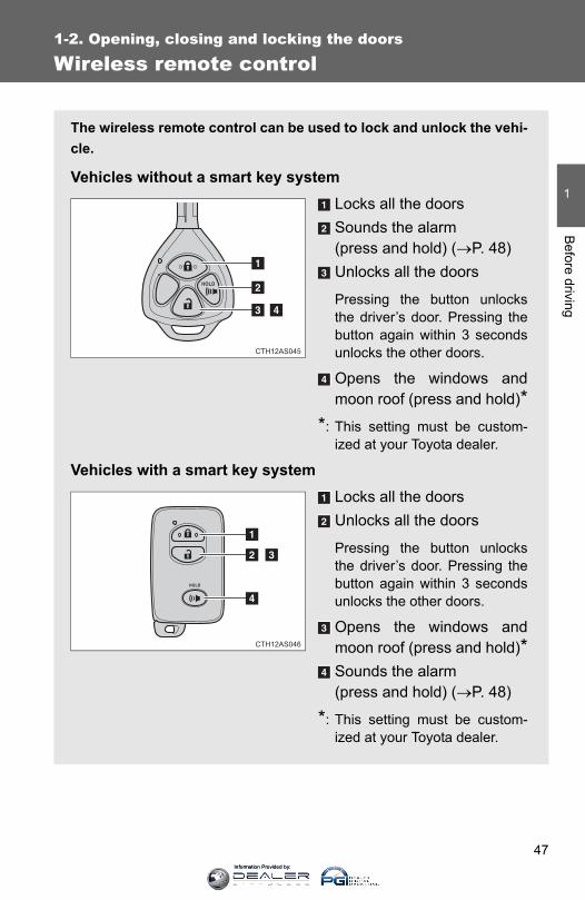
The wireless remote control can be used to lock and unlock the vehi-cle.
Vehicles without a smart key systemLocks all the doorsSounds the alarm (press and hold) (→P. 48)Unlocks all the doors
Pressing the button unlocksthe driver’s door. Pressing thebutton again within 3 secondsunlocks the other doors.
Opens the windows andmoon roof (press and hold)*
*: This setting must be custom-ized at your Toyota dealer.
Vehicles with a smart key systemLocks all the doorsUnlocks all the doors
Pressing the button unlocksthe driver’s door. Pressing thebutton again within 3 secondsunlocks the other doors.
Opens the windows andmoon roof (press and hold)*Sounds the alarm (press and hold) (→P. 48)
*: This setting must be custom-ized at your Toyota dealer.
CTH12AS045
CTH12AS046
Information Provided by:
48
1-2. Opening, closing and locking the doors
■Operation signalsA buzzer sounds and the emergency flashers flash to indicate that the doorshave been locked/unlocked. (Locked: once; Unlocked: twice)
■Door lock buzzerIf an attempt to lock the doors is made when a door is not fully closed, abuzzer sounds continuously. Fully close the door to stop the buzzer, and lockthe vehicle once more.
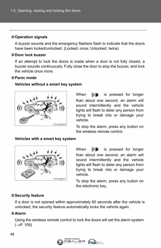
■Panic modeVehicles without a smart key system
Vehicles with a smart key system
■Security featureIf a door is not opened within approximately 60 seconds after the vehicle isunlocked, the security feature automatically locks the vehicle again.
■AlarmUsing the wireless remote control to lock the doors will set the alarm system.(→P. 109)
When is pressed for longerthan about one second, an alarm willsound intermittently and the vehiclelights will flash to deter any person fromtrying to break into or damage yourvehicle.
To stop the alarm, press any button onthe wireless remote control.
When is pressed for longerthan about one second, an alarm willsound intermittently and the vehiclelights will flash to deter any person fromtrying to break into or damage yourvehicle.
To stop the alarm, press any button onthe electronic key.
Information Provided by:

49
1-2. Opening, closing and locking the doors
1
Before driving
■Conditions affecting operationVehicles without a smart key systemThe wireless remote control function may not operate normally in the follow-ing situations:
●Near a TV tower, radio station, electric power plant, airport or other facil-ity that generates strong radio waves
●When carrying a portable radio, cellular phone or other wireless commu-nication devices
●When multiple wireless keys are in the vicinity
●When the wireless key is in contact with, or is covered by, a metallicobject
●When a wireless key (that emits radio waves) is being used nearby
●When the wireless key has been left near an electrical appliance such asa personal computer
Vehicles with a smart key system→P. 41
■ If the wireless remote control does not operate properly (vehicles witha smart key system)Locking and unlocking the doors: Use the mechanical key. (→P. 597)
■Key battery depletionVehicles without a smart key systemIf the wireless remote control function does not operate, the battery may bedepleted. Replace the battery when necessary. (→P. 528)
Vehicles with a smart key system→P. 44
■When the electronic key battery is fully depleted→P. 528
■When riding in an aircraftWhen bringing a key with wireless remote control function onto an aircraft,make sure you do not press any buttons on the key while inside the aircraftcabin. If you are carrying the key in your bag etc, ensure that the buttons arenot likely to be pressed accidentally. Pressing a button may cause the key toemit radio waves that could interfere with the operation of the aircraft.
Information Provided by:

50
1-2. Opening, closing and locking the doors
■Customization that can be configured at Toyota dealerSettings (e.g. wireless remote control system) can be changed. (Customizable features →P. 640)
■Certification for wireless remote controlFor vehicles sold in the U.S.A.FCC ID: HYQ14ACX
FCC ID: HYQ13CZD
FCC ID: HYQ14ADF
FCC ID: HYQ13CZE
FCC ID: HYQ12BBY
FCC ID: HYQ13BDC
NOTE:This device complies with part 15 of the FCC Rules. Operation is subject tothe following two conditions: (1) This device may not cause harmful interfer-ence, and (2) this device must accept any interference received, includinginterference that may cause undesired operation.FCC WARNING:Changes or modifications not expressly approved by the party responsiblefor compliance could void the user’s authority to operate the equipment.
For vehicles sold in CanadaNOTE:Operation is subject to the following two conditions: (1) this device may notcause interference, and (2) this device must accept any interference, includ-ing interference that may cause undesired operation of the device.
Information Provided by:
51
1
1-2. Opening, closing and locking the doorsB
efore driving
Side doors
The vehicle can be locked and unlocked using the entry function,wireless remote control, key or door lock switch.
■ Entry function (vehicles with a smart key system)→P. 33
■ Wireless remote control→P. 47
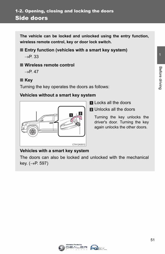
■ KeyTurning the key operates the doors as follows:
Vehicles without a smart key systemLocks all the doorsUnlocks all the doors
Turning the key unlocks thedriver's door. Turning the keyagain unlocks the other doors.
Vehicles with a smart key systemThe doors can also be locked and unlocked with the mechanicalkey. (→P. 597)
Information Provided by:
52
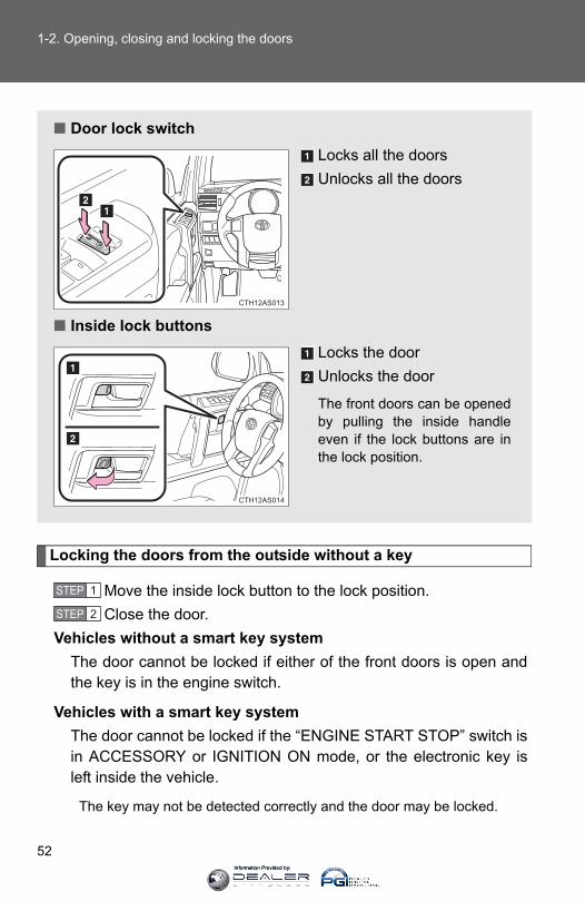
1-2. Opening, closing and locking the doors
Locking the doors from the outside without a key
Move the inside lock button to the lock position.Close the door.
Vehicles without a smart key systemThe door cannot be locked if either of the front doors is open andthe key is in the engine switch.
Vehicles with a smart key systemThe door cannot be locked if the “ENGINE START STOP” switch isin ACCESSORY or IGNITION ON mode, or the electronic key isleft inside the vehicle.
The key may not be detected correctly and the door may be locked.
■ Door lock switchLocks all the doorsUnlocks all the doors
■ Inside lock buttonsLocks the doorUnlocks the door
The front doors can be openedby pulling the inside handleeven if the lock buttons are inthe lock position.
CTH12AS013
CTH12AS014
STEP 1
STEP 2
Information Provided by:
53
1-2. Opening, closing and locking the doors
1
Before driving
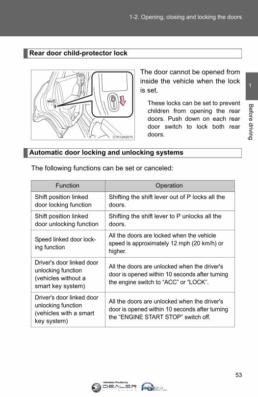
Rear door child-protector lock
The door cannot be opened frominside the vehicle when the lockis set.
These locks can be set to preventchildren from opening the reardoors. Push down on each reardoor switch to lock both reardoors.
Automatic door locking and unlocking systems
The following functions can be set or canceled:
CTH12AS015
Function Operation
Shift position linked door locking function
Shifting the shift lever out of P locks all the doors.
Shift position linked door unlocking function
Shifting the shift lever to P unlocks all the doors.
Speed linked door lock-ing function
All the doors are locked when the vehicle speed is approximately 12 mph (20 km/h) or higher.
Driver's door linked door unlocking function(vehicles without a smart key system)
All the doors are unlocked when the driver's door is opened within 10 seconds after turning the engine switch to “ACC” or “LOCK”.
Driver's door linked door unlocking function(vehicles with a smart key system)
All the doors are unlocked when the driver's door is opened within 10 seconds after turning the “ENGINE START STOP” switch off.
Information Provided by:

54
1-2. Opening, closing and locking the doors
■ Setting and canceling the functionsTo switch between setting and canceling, follow the procedurebelow:
Vehicles without a smart key systemClose all the doors and turn the engine switch to the “ON”position. (Perform step 2 within 20 seconds.)Vehicles with a smart key systemClose all the doors and turn the “ENGINE START STOP”switch to IGNITION ON mode. (Perform step 2 within 20 sec-onds.)
Shift the shift lever to P or N, andpress and hold the driver's doorlock switch ( or ) forapproximately 5 seconds andthen release.
The shift lever and switch posi-tions corresponding to thedesired function to be set areshown in the following table.
Use the same procedure to can-cel the function.
STEP 1
CTH12AS016
STEP 2
Function Shift leverposition
Driver’s door lock switch position
Shift position linked door lock-ing function
PShift position linked door unlocking function
Speed linked door locking func-tion
NDriver's door linked door unlock-ing function
Information Provided by:
55
1-2. Opening, closing and locking the doors
1
Before driving
When the setting or canceling operation is complete, all the doors arelocked and then unlocked.
■Using the mechanical key (vehicles with a smart key system)The doors can also be locked and unlocked with the mechanical key. (→P. 597)
■Customization that can be configured at Toyota dealerSettings (e.g. door unlocking function) can be changed. (Customizable features →P. 640)
CAUTION
■To prevent an accidentObserve the following precautions while driving the vehicle.Failure to do so may result in a door opening and an occupant falling out,resulting in death or serious injury.
●Always use a seat belt.
●Always lock all the doors.
●Ensure that all doors are properly closed.
●Do not pull the inside handle of the doors while driving. The doors may be opened and the passengers are thrown out of the vehi-cle and it may result in serious injury or death.
Be especially careful for the front doors, as the doors may be opened evenif the inside lock buttons are in locked position.
●Set the rear door child-protector locks when children are seated in the rearseats.
Information Provided by:
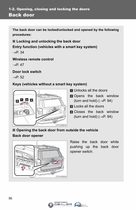
56
1-2. Opening, closing and locking the doors
Back door
The back door can be locked/unlocked and opened by the followingprocedures:
■ Locking and unlocking the back doorEntry function (vehicles with a smart key system)→P. 34
Wireless remote control→P. 47
Door lock switch→P. 52
Keys (vehicles without a smart key system)Unlocks all the doorsOpens the back window(turn and hold) (→P. 94)Locks all the doorsCloses the back window(turn and hold) (→P. 94)
■ Opening the back door from outside the vehicleBack door opener
Raise the back door whilepushing up the back dooropener switch.
CTH12AS018
CTH12AS038
Information Provided by:
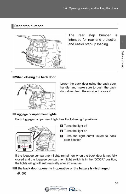
57
1-2. Opening, closing and locking the doors
1
Before driving
Rear step bumper
The rear step bumper isintended for rear end protectionand easier step-up loading.
CTH12AS019
■When closing the back door
■Luggage compartment lightsEach luggage compartment light has the following 3 positions:
If the luggage compartment lights remain on when the back door is not fullyclosed and the luggage compartment light switch is in the “DOOR” position,the lights will go off automatically after 20 minutes.
■ If the back door opener is inoperative or the battery is discharged→P. 596
Lower the back door using the back doorhandle, and make sure to push the backdoor down from the outside to close it.
CTH12AS029
Turns the light off
Turns the light on
Turns the light on/off linked to backdoor position
CTH12AS054
Information Provided by:

58
1-2. Opening, closing and locking the doors
CAUTION
■Caution while driving●Keep the back door closed.
If the back door is left open, it may hit nearby objects while driving or lug-gage may be unexpectedly thrown out, causing an accident.In addition, exhaust gases may enter the vehicle, causing death or a seri-ous health hazard. Make sure to close the back door before driving.
●Before driving the vehicle, make sure that the back door is fully closed. Ifthe back door is not fully closed, it may open unexpectedly while driving,causing an accident.
●Never let anyone sit in the luggage compartment. In the event of suddenbraking or a collision, they are susceptible to death or serious injury.
●Do not get on the rear step bumper.
■When children are in the vehicleObserve the following precautions.Failure to do so may result in death or serious injury.
●Do not leave children alone in the luggage compartment.If a child is accidentally locked in the luggage compartment, they couldhave heat exhaustion.
●Do not allow a child to open or close the back door.Doing so may cause the back door to operate unexpectedly, or cause thechild’s hands, head, or neck to be caught by the closing back door, whichmay result in death or serious injury of the child.
■Operating the back doorObserve the following precautions.Failure to do so may cause parts of the body to be caught, resulting in seri-ous injury.
●Remove any heavy loads, such as snow and ice, from the back doorbefore opening it. Failure to do so may cause the back door to fall closedagain after it is opened.
Information Provided by:

59
1-2. Opening, closing and locking the doors
1
Before driving
CAUTION
●When opening or closing the back door, thoroughly check to make surethe surrounding area is safe.
● If anyone is in the vicinity, make sure they are safe and let them know thatthe back door is about to open or close.
●Use caution when opening or closing the back door in windy weather as itmay move abruptly in strong wind.
●Do not pull on the back door damper stay to close the back door, and donot hang on the back door damper stay. Doing so may cause hands to be caught or the back door damper stay tobreak, causing an accident.
●Do not attach any accessories other than genuine Toyota parts to the backdoor. Such additional weight on the back door may cause the back door tofall closed again after it is opened.
●The back door may fall if it is notopened fully. It is more difficult to openor close the back door on an inclinethan on a level surface, so beware ofthe back door unexpectedly opening orclosing by itself. Make sure that theback door is fully open and securebefore using the luggage compartment.
●When closing the back door, take extracare to prevent your fingers etc. frombeing caught.
●When closing the back door, make sureto press it lightly on its outer surface. Ifthe back door handle is used to fullyclose the back door, it may result inhands or arms being caught.
CTH12AS035
CTH12AS037
Information Provided by:

60
1-2. Opening, closing and locking the doors
NOTICE
■To prevent damage to the back door componentsDo not allow more than one person to get on the rear step bumper at a time.
■Back door damper staysThe back door is equipped with damper stays that hold the back door inplace.
Observe the following precautions.Failure to do so may cause damage to the back door damper stay, resultingin malfunction.
●Do not attach any foreign objects, suchas stickers, plastic sheets, or adhesivesto the damper stay rod.
●Do not touch the damper stay rod withgloves or other fabric items.
●Do not attach any accessories otherthan genuine Toyota parts to the backdoor.
●Do not place your hand on the damperstay or apply lateral forces to it.
CTH12AS036
Information Provided by:

61
1
Before driving
1-3. Adjustable components (seats, mirrors, steering wheel)
Front seats
Manual seat Seat position adjustmentleverVertical height adjustmentlever (driver’s side only)Seatback angle adjustmentleverLumber support adjustmentswitch (driver’s side only)
CTH13AS055
Information Provided by:
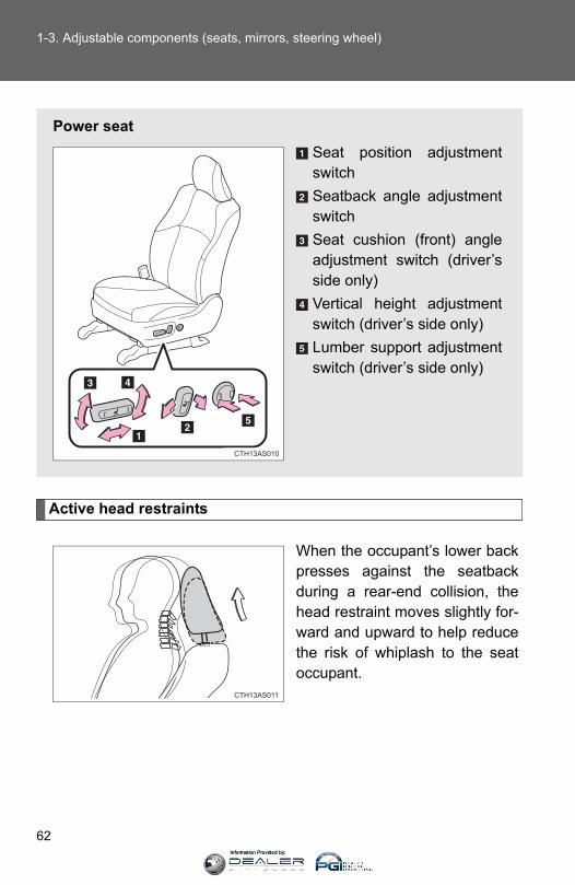
62
1-3. Adjustable components (seats, mirrors, steering wheel)
Active head restraints
When the occupant’s lower backpresses against the seatbackduring a rear-end collision, thehead restraint moves slightly for-ward and upward to help reducethe risk of whiplash to the seatoccupant.
Power seatSeat position adjustmentswitchSeatback angle adjustmentswitchSeat cushion (front) angleadjustment switch (driver’sside only)Vertical height adjustmentswitch (driver’s side only)Lumber support adjustmentswitch (driver’s side only)
CTH13AS010
CTH13AS011
Information Provided by:
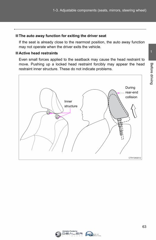
63
1-3. Adjustable components (seats, mirrors, steering wheel)
1
Before driving
■The auto away function for exiting the driver seatIf the seat is already close to the rearmost position, the auto away functionmay not operate when the driver exits the vehicle.
■Active head restraintsEven small forces applied to the seatback may cause the head restraint tomove. Pushing up a locked head restraint forcibly may appear the headrestraint inner structure. These do not indicate problems.
CTH13AS012
Inner structure
Duringrear-endcollision
Information Provided by:

64
1-3. Adjustable components (seats, mirrors, steering wheel)
CAUTION
■Seat adjustment●To reduce the risk of sliding under the lap belt during a collision, do not
recline the seat more than necessary.If the seat is too reclined, the lap belt may slide past the hips and applyrestraint forces directly to the abdomen, or your neck may contact theshoulder belt, increasing the risk of death or serious injury in the event ofan accident.Adjustments should not be made while driving as the seat may unexpect-edly move and cause the driver to lose control of the vehicle.
●After adjusting the seat, make sure that the seat is locked in position.
Information Provided by:

65
1
1-3. Adjustable components (seats, mirrors, steering wheel)B
efore driving
Rear seats
Vehicles without third row seats■ Rear seat
Pull up the seatback angleadjustment lever until the lockis released.
CTH13AS081
Information Provided by:

66
1-3. Adjustable components (seats, mirrors, steering wheel)
Vehicles with third row seats■ Second row seats
Seat position adjustmentleverSeatback angle adjustmentlever
■ Third row seatsThe third row seats do not have a seat adjustment function.
CTH13AS053
Information Provided by:
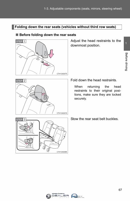
67
1-3. Adjustable components (seats, mirrors, steering wheel)
1
Before driving
Folding down the rear seats (vehicles without third row seats)
■ Before folding down the rear seatsAdjust the head restraints to thedownmost position.
Fold down the head restraints.
When returning the headrestraints to their original posi-tions, make sure they are lockedsecurely.
Stow the rear seat belt buckles.
STEP 1
STEP 2
STEP 3
Information Provided by:
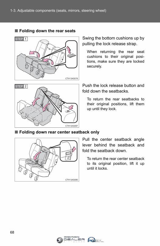
68
1-3. Adjustable components (seats, mirrors, steering wheel)
■ Folding down the rear seatsSwing the bottom cushions up bypulling the lock release strap.
When returning the rear seatcushions to their original posi-tions, make sure they are lockedsecurely.
Push the lock release button andfold down the seatbacks.
To return the rear seatbacks totheir original positions, lift themup until they lock.
■ Folding down rear center seatback onlyPull the center seatback anglelever behind the seatback andfold the seatback down.
To return the rear center seatbackto its original position, lift it upuntil it locks.
STEP 1
STEP 2
Information Provided by:

69
1-3. Adjustable components (seats, mirrors, steering wheel)
1
Before driving
Folding down the second row seats (vehicles with third row seats)
■ Before folding down the second row seatsAdjust the head restraints to thedownmost position.
Stow the second row seat beltbuckles.
CTH13AS045
STEP 1
CTH13AS071
STEP 2
Information Provided by:

70
1-3. Adjustable components (seats, mirrors, steering wheel)
■ Folding down the second row seatsPull the seatback lock releaselever and fold the seatbackdown.
To return the second row seat-backs to their original positions,lift them up until they lock.
■ Folding down the second row center seatback onlyPull the center seatback anglelever behind the seatback andfold the seatback down.
To return the second row centerseatback to its original position,lift it up until it locks.
CTH13AS051
CTH13AS052
Information Provided by:
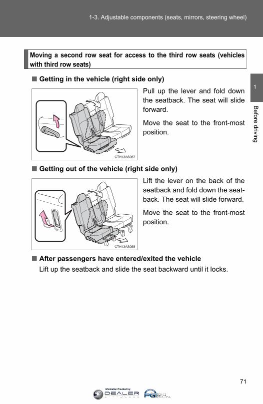
71
1-3. Adjustable components (seats, mirrors, steering wheel)
1
Before driving
Moving a second row seat for access to the third row seats (vehicleswith third row seats)
■ Getting in the vehicle (right side only)Pull up the lever and fold downthe seatback. The seat will slideforward.
Move the seat to the front-mostposition.
■ Getting out of the vehicle (right side only)Lift the lever on the back of theseatback and fold down the seat-back. The seat will slide forward.
Move the seat to the front-mostposition.
■ After passengers have entered/exited the vehicleLift up the seatback and slide the seat backward until it locks.
CTH13AS057
CTH13AS058
Information Provided by:

72
1-3. Adjustable components (seats, mirrors, steering wheel)
Folding down the third row seats (vehicles with third row seats)
■ Before folding down the third row seatsPass the seat belts through theseat belt hangers and secure theseat belt plates.
This prevents the shoulder beltsfrom being damaged.
Make sure that the seat belts areremoved from the hangers beforeusing them.
■ Folding down the third row seatsFrom inside
Pull the strap to fold down thehead restraint.
Pull the lever up.
The seat cushion will slide back-ward.
CTH13AS072
CTH13AS025
STEP 1
CTH13AS026
STEP 2
Information Provided by:
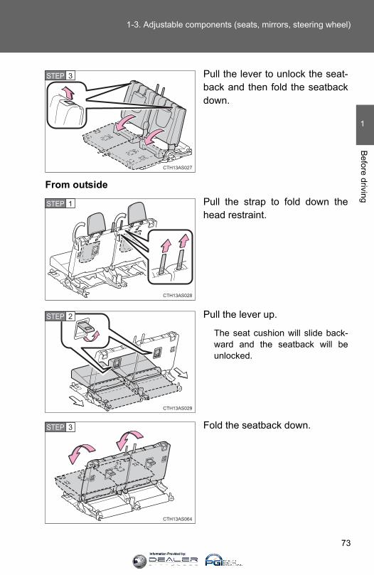
73
1-3. Adjustable components (seats, mirrors, steering wheel)
1
Before driving
Pull the lever to unlock the seat-back and then fold the seatbackdown.
From outsidePull the strap to fold down thehead restraint.
Pull the lever up.
The seat cushion will slide back-ward and the seatback will beunlocked.
Fold the seatback down.
CTH13AS027
STEP 3
CTH13AS028
STEP 1
CTH13AS029
STEP 2
CTH13AS064
STEP 3
Information Provided by:
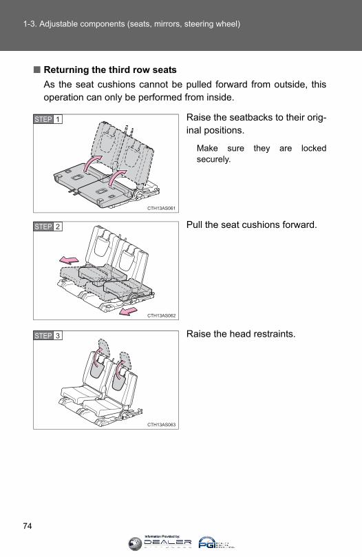
74
1-3. Adjustable components (seats, mirrors, steering wheel)
■ Returning the third row seatsAs the seat cushions cannot be pulled forward from outside, thisoperation can only be performed from inside.
Raise the seatbacks to their orig-inal positions.
Make sure they are lockedsecurely.
Pull the seat cushions forward.
Raise the head restraints.
CTH13AS061
STEP 1
CTH13AS062
STEP 2
CTH13AS063
STEP 3
Information Provided by:

75
1-3. Adjustable components (seats, mirrors, steering wheel)
1
Before driving
CAUTION
■When folding the rear seatbacks downObserve the following precautions. Failure to do so may result in death orserious injury.
●Do not fold the seatbacks down while driving.
●Stop the vehicle on level ground, set the parking brake and shift the shiftlever to P.
●Do not allow anyone to sit on a folded seatback or in the luggage compart-ment while driving.
●Do not allow children to enter the luggage compartment.
■Seat adjustmentTo reduce the risk of sliding under the lap belt during a collision, do notrecline the seat more than necessary.If the seat is too reclined, the lap belt may slide past the hips and applyrestraint forces directly to the abdomen, or your neck may contact the shoul-der belt, increasing the risk of death or serious injury in the event of an acci-dent.Adjustments should not be made while driving as the seat may unexpectedlymove and cause the driver to lose control of the vehicle.
■After returning the rear seatback to the upright positionObserve the following precautions. Failure to do so may result in death orserious injury.
●Make sure the seatback is securely locked by pushing it forward and rear-ward on the top.
●Check that the seat belts are not twisted or caught in the seatback.
NOTICE
■Stowing the seat beltsThe seat belts and the buckles must be stowed before you fold down therear seatbacks.
Information Provided by:

76
1-3. Adjustable components (seats, mirrors, steering wheel)
Head restraints
Head restraints are provided for all seats.
■ Adjusting the head restraintsFront and second seats
Up
Pull the head restraints up.
Down
Push the head restraint downwhile pushing the lock releasebutton.
■ Folding the head restraintsSecond seats (vehicles without third row seats)
To useTo fold
Third seats (vehicles with third row seats)To useTo fold
CTH13AS031
Lock release button
CTH13AS082
CTH13AS034
Information Provided by:

77
1-3. Adjustable components (seats, mirrors, steering wheel)
1
Before driving
■Removing the head restraints (except third row seats)
■ Installing the head restraints (except third row seats)
■Adjusting the height of the head restraints
■Adjusting the second center seat head restraintAlways raise the head restraint one level from the stowed position whenusing.
Pull the head restraint up while pressingthe lock release button.
CTH13AS036
Align the head restraint with the installa-tion holes and push it down to the lockposition.
Press and hold the lock release buttonwhen lowering the head restraint.
CTH13AS037
Make sure that the head restraints areadjusted so that the center of the headrestraint is closest to the top of your ears.
CTH13AS035
Information Provided by:
78
1-3. Adjustable components (seats, mirrors, steering wheel)
CAUTION
■Head restraint precautionsObserve the following precautions regarding the head restraints. Failure todo so may result in death or serious injury.
●Use the head restraints designed for each respective seat.
●Adjust the head restraints to the correct position at all times.
●After adjusting the head restraints, push down on them and make surethey are locked in position.
●Do not drive with the head restraints removed.
Information Provided by:
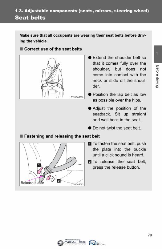
79
1
1-3. Adjustable components (seats, mirrors, steering wheel)B
efore driving
Seat belts
Make sure that all occupants are wearing their seat belts before driv-ing the vehicle.
■ Correct use of the seat belts
● Extend the shoulder belt sothat it comes fully over theshoulder, but does notcome into contact with theneck or slide off the shoul-der.
● Position the lap belt as lowas possible over the hips.
● Adjust the position of theseatback. Sit up straightand well back in the seat.
● Do not twist the seat belt.
■ Fastening and releasing the seat beltTo fasten the seat belt, pushthe plate into the buckleuntil a click sound is heard. To release the seat belt,press the release button.
CTH13AS038
CTH13AS083Release button
Information Provided by:
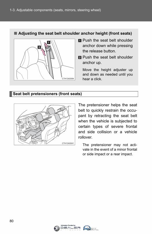
80
1-3. Adjustable components (seats, mirrors, steering wheel)
Seat belt pretensioners (front seats)
The pretensioner helps the seatbelt to quickly restrain the occu-pant by retracting the seat beltwhen the vehicle is subjected tocertain types of severe frontaland side collision or a vehiclerollover.
The pretensioner may not acti-vate in the event of a minor frontalor side impact or a rear impact.
■ Adjusting the seat belt shoulder anchor height (front seats)Push the seat belt shoulderanchor down while pressingthe release button.Push the seat belt shoulderanchor up.
Move the height adjuster upand down as needed until youhear a click.CTH13AS084
CTH13AS041
Information Provided by:

81
1-3. Adjustable components (seats, mirrors, steering wheel)
1
Before driving
■Emergency locking retractor (ELR)The retractor will lock the belt during a sudden stop or on impact. It may alsolock if you lean forward too quickly. A slow, easy motion will allow the belt toextend so that you can move around fully.
■Automatic locking retractor (ALR)When a passenger's shoulder belt is completely extended and thenretracted even slightly, the belt is locked in that position and cannot beextended. This feature is used to hold the child restraint system (CRS) firmly.To free the belt again, fully retract the belt and then pull the belt out oncemore. (→P. 140)
■Pregnant women
■People suffering illnessObtain medical advice and wear the seat belt in the proper way. (→P. 79)
Obtain medical advice and wear the seatbelt in the proper way. (→P. 79)
Women who are pregnant should positionthe lap belt as low as possible over thehips in the same manner as other occu-pants. Extend the shoulder belt com-pletely over the shoulder and position thebelt across the chest. Avoid belt contactover the rounding of the abdominal area.
If the seat belt is not worn properly, notonly the pregnant woman, but also thefetus could suffer death or serious injuryas a result of sudden braking or a colli-sion.
CTH13AS085
Information Provided by:

82
1-3. Adjustable components (seats, mirrors, steering wheel)
■Child seat belt usageThe seat belts of your vehicle were principally designed for persons of adultsize.
●Use a child restraint system appropriate for the child, until the childbecomes large enough to properly wear the vehicle’s seat belt. (→P. 136)
●When the child becomes large enough to properly wear the vehicle’sseat belt, follow the instructions on P. 79 regarding seat belt usage.
■Replacing the belt after the pretensioner has been activatedIf the vehicle is involved in multiple collisions, the pretensioner will activatefor the first collision, but will not activate for the second or subsequent colli-sions.
■Seat belt extender
If your seat belts cannot be fastenedsecurely because they are not longenough, a personalized seat beltextender is available from your Toyotadealer free of charge.
CTH13AS044
Information Provided by:

83
1-3. Adjustable components (seats, mirrors, steering wheel)
1
Before driving
CAUTION
■Wearing a seat beltObserve the following precautions to reduce the risk of injury in the event ofsudden braking, sudden swerving or an accident.Failure to do so may cause death or serious injury.
●Ensure that all passengers wear a seat belt.
●Always wear a seat belt properly.
●Each seat belt should be used by one person only. Do not use a seat beltfor more than one person at once, including children.
●Toyota recommends that children be seated in the rear seat and alwaysuse a seat belt and/or an appropriate child restraint system.
●To achieve a proper seating position, do not recline the seat more thannecessary. The seat belt is most effective when the occupants are sittingup straight and well back in the seats.
●Do not wear the shoulder belt under your arm.
●Always wear your seat belt low and snug across your hips.
■Seat belt pretensioners●Do not place anything, such as a cushion, on the front passenger's seat.
Doing so will disperse the passenger's weight, which prevents the sensorfrom detecting the passenger's weight properly. As a result, the seat beltpretensioner for the front passenger's seat may not activate in the event ofa collision.
● If the pretensioner has activated, the SRS warning light will come on. Inthat case, the seat belt cannot be used again and must be replaced atyour Toyota dealer.
■Adjustable shoulder anchorAlways make sure the shoulder belt is positioned across the center of yourshoulder. The belt should be kept away from your neck, but not falling offyour shoulder. Failure to do so could reduce the amount of protection in anaccident and cause death or serious injuries in the event of a sudden stop,sudden swerve or accident. (→P. 80)
Information Provided by:
84
1-3. Adjustable components (seats, mirrors, steering wheel)
CAUTION
■Child restraint lock function belt precautionDo not allow children to play with the child restraint lock function belt. If thebelt becomes twisted around a child’s neck, it will not be possible to pull thebelt out leading to choking or other serious injuries that could result in death.If this occurs and the buckle cannot be unfastened, scissors should be usedto cut the belt.
■Seat belt damage and wear●Do not damage the seat belts by allowing the belt, plate, or buckle to be
jammed in the door.
● Inspect the seat belt system periodically. Check for cuts, fraying, and looseparts. Do not use a damaged seat belt until it is replaced. Damaged seatbelts cannot protect an occupant from death or serious injury.
●Ensure that the belt and plate are locked and the belt is not twisted.If the seat belt does not function correctly, immediately contact your Toyotadealer.
●Replace the seat assembly, including the belts, if your vehicle has beeninvolved in a serious accident, even if there’s no obvious damage.
●Do not attempt to install, remove, modify, disassemble or dispose of theseat belts. Have any necessary repairs carried out by your Toyota dealer.Inappropriate handling of the pretensioner may prevent it from operatingproperly, resulting in death or serious injury.
■Using a seat belt extender●Do not wear the seat belt extender if you can fasten the seat belt without
the extender.
●Do not use the seat belt extender when installing a child restraint systembecause the belt will not securely hold the child restraint system, increas-ing the risk of death or serious injury in the event of an accident.
●The personalized extender may not be safe on another vehicle, whenused by another person, or at a different seating position other than theone originally intended.
Information Provided by:
85
1-3. Adjustable components (seats, mirrors, steering wheel)
1
Before driving
NOTICE
■When using a seat belt extenderWhen releasing the seat belt, press on the buckle release button on theextender, not on the seat belt.This helps prevent damage to the vehicle interior and the extender itself.
Information Provided by:

86
1-3. Adjustable components (seats, mirrors, steering wheel)
Steering wheel
CAUTION
■Caution while drivingDo not adjust the steering wheel while driving.Doing so may cause the driver to mishandle the vehicle and cause an acci-dent, resulting in death or serious injury.
■After adjusting the steering wheelMake sure that the steering wheel is securely locked. Otherwise, the steering wheel may move suddenly, possibly causing anaccident, and resulting in death or serious injury.
The steering wheel can be adjusted to a comfortable position.
Hold the steering wheel andpush the lever down.
Adjust to the ideal position bymoving the steering wheelhorizontally and vertically.
After adjustment, pull the leverup to secure the steeringwheel.
CTH13AS007
STEP 1
CTH13AS008
STEP 2
Information Provided by:
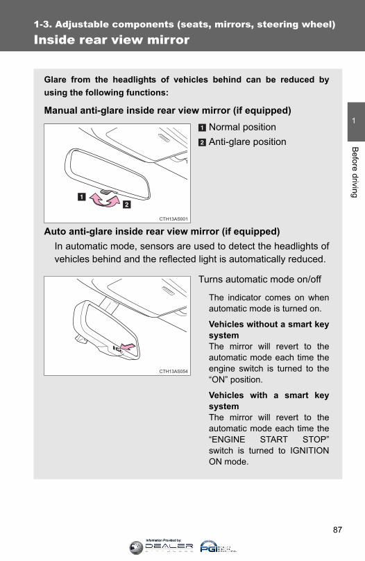
87
1
1-3. Adjustable components (seats, mirrors, steering wheel)B
efore driving
Inside rear view mirror
Glare from the headlights of vehicles behind can be reduced byusing the following functions:
Manual anti-glare inside rear view mirror (if equipped)Normal positionAnti-glare position
Auto anti-glare inside rear view mirror (if equipped)In automatic mode, sensors are used to detect the headlights ofvehicles behind and the reflected light is automatically reduced.
Turns automatic mode on/off
The indicator comes on whenautomatic mode is turned on.
Vehicles without a smart keysystemThe mirror will revert to theautomatic mode each time theengine switch is turned to the“ON” position.
Vehicles with a smart keysystemThe mirror will revert to theautomatic mode each time the“ENGINE START STOP”switch is turned to IGNITIONON mode.
CTH13AS001
CTH13AS054
Information Provided by:
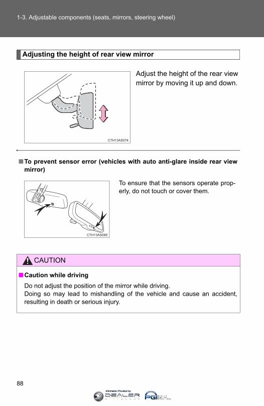
88
1-3. Adjustable components (seats, mirrors, steering wheel)
Adjusting the height of rear view mirror
Adjust the height of the rear viewmirror by moving it up and down.
CTH13AS074
■To prevent sensor error (vehicles with auto anti-glare inside rear viewmirror)
CAUTION
■Caution while drivingDo not adjust the position of the mirror while driving.Doing so may lead to mishandling of the vehicle and cause an accident,resulting in death or serious injury.
To ensure that the sensors operate prop-erly, do not touch or cover them.
CTH13AS088
Information Provided by:
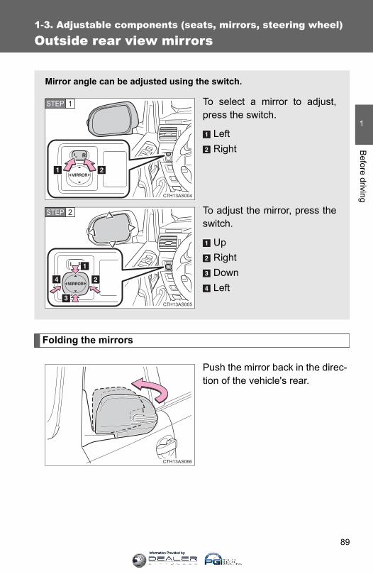
89
1
1-3. Adjustable components (seats, mirrors, steering wheel)B
efore driving
Outside rear view mirrors
Folding the mirrors
Push the mirror back in the direc-tion of the vehicle's rear.
Mirror angle can be adjusted using the switch.
To select a mirror to adjust,press the switch.
LeftRight
To adjust the mirror, press theswitch.
UpRightDownLeft
CTH13AS004
STEP 1
CTH13AS005
STEP 2
CTH13AS006CTH13AS066
Information Provided by:
90
1-3. Adjustable components (seats, mirrors, steering wheel)
■Mirror angle can be adjusted whenVehicles without a smart key systemThe engine switch is in the “ACC” or “ON” position.
Vehicles with a smart key systemThe “ENGINE START STOP” switch is in ACCESSORY or IGNITION ONmode.
■When the mirrors are fogged upTurn on the mirror defoggers to defog the mirrors. (→P. 310)
CAUTION
■When driving the vehicleObserve the following precautions while driving.Failure to do so may result in loss of control of the vehicle and cause anaccident, resulting in death or serious injury.
●Do not adjust the mirrors while driving.
●Do not drive with the mirrors folded.
●Both the driver and passenger side mirrors must be extended and properlyadjusted before driving.
■When a mirror is movingTo avoid personal injury and mirror malfunction, be careful not to get yourhand caught by the moving mirror.
■When the mirror defoggers are operatingDo not touch the rear view mirror surfaces, as they can become very hot andburn you.
Information Provided by:
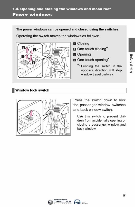
91
1
Before driving
1-4. Opening and closing the windows and moon roof
Power windows
Window lock switch
Press the switch down to lockthe passenger window switchesand back window switch.
Use this switch to prevent chil-dren from accidentally opening orclosing a passenger window andback window.
The power windows can be opened and closed using the switches.
Operating the switch moves the windows as follows:
ClosingOne-touch closing*OpeningOne-touch opening**: Pushing the switch in the
opposite direction will stopwindow travel partway.
CTH14AS010
CTH14AS002
Information Provided by:

92
1-4. Opening and closing the windows and moon roof
■The power windows can be operated whenVehicles without a smart key systemThe engine switch is in the “ON” position.
Vehicles with a smart key systemThe “ENGINE START STOP” switch is in IGNITION ON mode.
■Operating the power windows after turning the engine offVehicles without a smart key systemThe power windows can be operated for approximately 45 seconds evenafter the engine switch is turned to the “ACC” or “LOCK” position. They can-not, however, be operated once either front door is opened.
Vehicles with a smart key systemThe power windows can be operated for approximately 45 seconds evenafter the “ENGINE START STOP” switch is turned to ACCESSORY mode orturned off. They cannot, however, be operated once either front door isopened.
■Jam protection functionIf an object becomes caught between the window and the window frame,window travel is stopped and the window is opened slightly.
■Customization that can be configured at Toyota dealerSettings (e.g. linked door lock operation) can be changed. (Customizable features →P. 640)
Information Provided by:

93
1-4. Opening and closing the windows and moon roof
1
Before driving
CAUTION
■Closing the windowsObserve the following precautions. Failure to do so may result in death or serious injury.
●Check to make sure that all passengers do not have any part of their bodyin a position where it could be caught when a window is being operated.
●Do not allow children to operate the power windows. Closing a power window on someone can cause serious injury, and insome instances, even death.
■Jam protection function●Never use any part of your body to intentionally activate the jam protection
function.
●The jam protection function may not work if something gets caught justbefore the window fully closes.
Information Provided by:
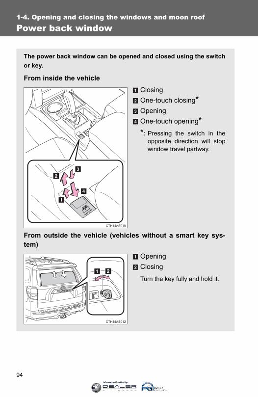
94
1-4. Opening and closing the windows and moon roof
Power back window
The power back window can be opened and closed using the switchor key.
From inside the vehicleClosingOne-touch closing*OpeningOne-touch opening**: Pressing the switch in the
opposite direction will stopwindow travel partway.
From outside the vehicle (vehicles without a smart key sys-tem)
OpeningClosing
Turn the key fully and hold it.
CTH14AS019
CTH14AS012
Information Provided by:

95
1-4. Opening and closing the windows and moon roof
1
Before driving
■The power back window can be operated from inside the vehicle whenVehicles without a smart key systemThe engine switch is in the “ON” position.
Vehicles with a smart key systemThe “ENGINE START STOP” switch is in IGNITION ON mode.
●The power back window can be opened when the rear window wiper isworking, but the wiper stops working until the window is closed again.If the power back window is not fully closed, the rear window wiper,washer, and defogger will not work.
● If the back door is not fully closed, the power back window cannot beopened using the switch located in the cabin. (It is still possible to closethe window.)
● If the back door is opened while the power back window is opening orclosing, window operation will stop.
■The power back window can be operated from outside the vehiclewhen (vehicles with a smart key system)●The “ENGINE START STOP” switch is off.
●The back door is closed.
From outside the vehicle (vehicles with a smart key system)Opening (push and hold)Closing (push and hold)
This operation can only be per-formed when the electronic keyis within the detection range.
CTH14AS018
Information Provided by:

96
1-4. Opening and closing the windows and moon roof
■Operating the power back window from inside the vehicle after turningthe engine offVehicles without a smart key systemThe power back window can be operated for approximately 45 secondseven after the engine switch is turned to the “ACC” or “LOCK” position. Itcannot, however, be operated once either front door is opened.
Vehicles with a smart key systemThe power back window can be operated for approximately 45 secondseven after the “ENGINE START STOP” switch is turned to ACCESSORYmode or turned off. It cannot, however, be operated once either front door isopened.
■Jam protection functionIf an object becomes caught between the window and the window frame,window travel is stopped and the window is opened slightly.
■Customization that can be configured at Toyota dealerSettings (e.g. linked operation) can be changed.(Customizable features →P. 640)
Information Provided by:

97
1-4. Opening and closing the windows and moon roof
1
Before driving
CAUTION
■Caution while drivingKeep the back door and back window closed while driving. If the back dooror the back window is left open, the back door may hit nearby objects whiledriving or luggage may be unexpectedly thrown out, causing an accident.In addition, exhaust gases may enter the vehicle, causing death or a serioushealth hazard. Make sure to close the back door and back window beforedriving.
■Closing the power back windowObserve the following precautions.Failure to do so may result in death or serious injury.
●Check to make sure that all passengers do not have any part of their bodyin a position where it could be caught when a window is being operated.
●Do not allow children to operate the power back window.Closing a power back window on someone can cause serious injury, andin some instances, even death.
■Jam protection function●Never use any part of your body to intentionally activate the jam protection
function.
●The jam protection function may not work if something gets caught justbefore the window fully closes.
Information Provided by:

98
1-4. Opening and closing the windows and moon roof
Moon roof∗
∗: If equipped
Use the overhead switches to open and close the moon roof and tiltit up and down.
■ Opening and closingOpens the moon roof*Closes the moon roof**: Lightly press the switch in
either direction to stop themoon roof partway.
■ Tilting up and downTilts the moon roof up*Tilts the moon roof down**: Lightly press either of the
moon roof switches to stopthe moon roof partway.
CTH14AS007
CTH14AS008
Information Provided by:

99
1-4. Opening and closing the windows and moon roof
1
Before driving
■The moon roof can be operated whenVehicles without a smart key systemThe engine switch is in the “ON” position.
Vehicles with a smart key systemThe “ENGINE START STOP” switch is in IGNITION ON mode.
■Operating the moon roof after turning the engine offVehicles without a smart key systemThe moon roof can be operated for approximately 45 seconds even after theengine switch is turned to the “ACC” or “LOCK” position. It cannot, however,be operated once either front door is opened.
Vehicles with a smart key systemThe moon roof can be operated for approximately 45 seconds even after the“ENGINE START STOP” switch is turned to ACCESSORY mode or turnedoff. It cannot, however, be operated once either front door is opened.
■Jam protection functionIf an object is detected between the moon roof and the frame while the moonroof is closing or tilting down, travel is stopped and the moon roof opensslightly.
■SunshadeThe sunshade can be opened and closed manually. However, the sunshadewill open automatically when the moon roof is opened.
Information Provided by:

100
1-4. Opening and closing the windows and moon roof
■When the moon roof does not close normallyPerform the following procedure:
● If the moon roof closes but then re-opens slightly
Stop the vehicle.
Press and hold the “SLIDE (open/close)” switch in the close posi-tion.*1
The moon roof will close, reopen and pause for approximately 10seconds.*2 Then it will close again, tilt up and pause for approxi-mately 1 second. Finally, it will tilt down, open and close.
Check to make sure that the moon roof is completely closed andthen release the switch.
● If the moon roof tilts down but then tilts back up
Stop the vehicle.
Press and hold the “UP” switch*1 until the moon roof moves into thetilt up position and stops.
Release the “UP” switch once and then press and hold the “UP”switch again.*1
The moon roof will pause for approximately 10 seconds in the tilt upposition.*2 Then it will adjust slightly and pause for approximately 1second. Finally, it will tilt down, open and close.
Check to make sure that the moon roof is completely closed andthen release the switch.
*1:If the switch is released at the incorrect time, the procedure willhave to be performed again from the beginning.
*2:If the switch is released after the above mentioned 10 secondpause, automatic operation will be disabled. In that case, pressand hold the “UP” or “DOWN” switch, and the moon roof will tiltup and pause for approximately 1 second. Then it will tilt down,open and close. Check to make sure that the moon roof is com-pletely closed and then release the switch.
If the moon roof does not fully close even after performing the above proce-dure correctly, have the vehicle inspected by your Toyota dealer.
STEP 1
STEP 2
STEP 3
STEP 1
STEP 2
STEP 3
STEP 4
Information Provided by:
101
1-4. Opening and closing the windows and moon roof
1
Before driving
■Moon roof open reminder functionVehicles without a smart key systemAn alarm will sound when the driver’s door is opened with the moon roof notfully closed and the engine switch off.
Vehicles with a smart key systemAn alarm will sound when the driver’s door is opened with the moon roof notfully closed and the “ENGINE START STOP” switch off.
■Customization that can be configured at Toyota dealerSettings (e.g. linked door lock operation) can be changed. (Customizable features →P. 640)
CAUTION
■Opening the moon roofObserve the following precautions.Failure to do so may cause death or serious injury.
●Do not allow any passengers to put their hands or heads outside the vehi-cle while it is moving.
●Do not sit on top of the moon roof.
■Closing the moon roofObserve the following precautions. Failure to do so may result in death or serious injury.
●Check to make sure that all passengers do not have any part of their bodyin a position where it could be caught when the moon roof is being oper-ated.
●Do not allow children to operate the moon roof. Closing the moon roof on someone can cause death or serious injury.
■Jam protection function●Never use any part of your body to intentionally activate the jam protection
function.
●The jam protection function may not work if something gets caught justbefore the moon roof fully closes.
Information Provided by:
102
1-5. Refueling
Opening the fuel tank cap
Perform the following steps to open the fuel tank cap:
■ Before refueling the vehicleVehicles without a smart key systemTurn the engine switch off and ensure that all the doors and win-dows are closed.
Vehicles with a smart key systemTurn the “ENGINE START STOP” switch off and ensure that allthe doors and windows are closed.
■ Opening the fuel tank capOpen the fuel filler door.
Turn the fuel tank cap slowlyto open.
CTH15AS001
STEP 1
CTH15AS002
STEP 2
Information Provided by:

103
1-5. Refueling
1
Before driving
Closing the fuel tank cap
After refueling, turn the fuel tankcap until you hear a click. Oncethe cap is released, it will turnslightly in the opposite direction.
Hang the fuel tank cap on theback of the fuel filler door.
CTH15AS003
STEP 3
CTH15AS004
Information Provided by:
104
1-5. Refueling
CAUTION
■When refueling the vehicleObserve the following precautions while refueling the vehicle. Failure to doso may result in death or serious injury.
●After exiting the vehicle and before opening the fuel door, touch anunpainted metal surface to discharge any static electricity. It is important todischarge static electricity before refueling because sparks resulting fromstatic electricity can cause fuel vapors to ignite while refueling.
●Always hold the grips on the fuel tank cap and turn it slowly to remove it. A whooshing sound may be heard when the fuel tank cap is loosened.Wait until the sound cannot be heard before fully removing the cap. In hotweather, pressurized fuel may spray out the filler neck and cause injury.
●Do not allow anyone that has not discharged static electricity from theirbody to come close to an open fuel tank.
●Do not inhale vaporized fuel.Fuel contains substances that are harmful if inhaled.
●Do not smoke while refueling the vehicle.Doing so may cause the fuel to ignite and cause a fire.
●Do not return to the vehicle or touch any person or object that is staticallycharged.This may cause static electricity to build up, resulting in a possible ignitionhazard.
■When refuelingSecurely insert the fuel nozzle into the fuel filler neck. If fuel is added withthe nozzle slightly lifted away from the fuel filler neck, the automatic shut offfunction may not operate, resulting in fuel overflowing from the tank.
■When replacing the fuel capDo not use anything but a genuine Toyota fuel tank cap designed for yourvehicle. Doing so may cause a fire or other incident which may result indeath or serious injury.
Information Provided by:

105
1-5. Refueling
1
Before driving
NOTICE
■RefuelingDo not spill fuel during refueling. Doing so may damage the vehicle, such as causing the emission controlsystem to operate abnormally or damaging fuel system components or thevehicle's painted surface.
Information Provided by:
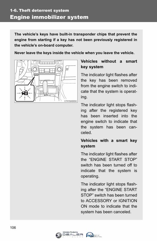
106
1-6. Theft deterrent system
Engine immobilizer system
The vehicle’s keys have built-in transponder chips that prevent theengine from starting if a key has not been previously registered inthe vehicle’s on-board computer.
Never leave the keys inside the vehicle when you leave the vehicle.
Vehicles without a smartkey system
The indicator light flashes afterthe key has been removedfrom the engine switch to indi-cate that the system is operat-ing.
The indicator light stops flash-ing after the registered keyhas been inserted into theengine switch to indicate thatthe system has been can-celed.
Vehicles with a smart keysystem
The indicator light flashes afterthe “ENGINE START STOP”switch has been turned off toindicate that the system isoperating.
The indicator light stops flash-ing after the “ENGINE STARTSTOP” switch has been turnedto ACCESSORY or IGNITIONON mode to indicate that thesystem has been canceled.
CTH16AS004
Information Provided by:

107
1-6. Theft deterrent system
1
Before driving
■System maintenanceThe vehicle has a maintenance-free type engine immobilizer system.
■Conditions that may cause the system to malfunction● If the grip portion of the key is in contact with a metallic object
● If the key is in close proximity to or touching a key to the security system(key with a built-in transponder chip) of another vehicle
■Certifications for the engine immobilizer system (vehicles without asmart key system)●For vehicles sold in the U.S.A.
FCC ID: MOZRI-33BTY
This device complies with Part 15 of the FCC Rules. Operation is subject tothe following two conditions: (1) this device may not cause harmful interfer-ence, and (2) this device must accept any interference received, includinginterference that may cause undesired operation.
FCC WARNING:Changes or modifications not expressly approved by the party responsiblefor compliance could void the user's authority to operate the equipment.
●For vehicles sold in Canada
Operation is subject to the following two conditions: (1) this device may notcause interference, and (2) this device must accept any interference, includ-ing interference that may cause undesired operation of the device.
Information Provided by:
108
1-6. Theft deterrent system
CAUTION
■Certifications for the immobilizer systemChanges or modifications not expressly approved by the party responsiblefor compliance could void the user’s authority to operate the equipment.
NOTICE
■To ensure the system operates correctlyDo not modify or remove the system. If modified or removed, the properoperation of the system cannot be guaranteed.
Information Provided by:

109
1
1-6. Theft deterrent systemB
efore driving
Alarm∗
∗: If equipped
The system sounds the alarm and flashes the lights when forcedentry is detected.
■ Triggering of the alarmThe alarm is triggered in the following situations when the alarmis set:
● A locked door is unlocked or opened in any way other thanusing the entry function, wireless remote control or mechani-cal key. (The doors will lock again automatically.)
● The hood is opened.
■ Setting the alarm systemClose the doors and hood,and lock all the doors. Thesystem will be set automati-cally after 30 seconds.
The indicator light changesfrom being on to flashing whenthe system is set.
■ Deactivating or stopping the alarmDo one of the following to deactivate or stop the alarms:
● Unlock the doors.
● Start the engine. (The alarm will be deactivated or stoppedafter a few seconds.)
CTH16AS004
Information Provided by:

110
1-6. Theft deterrent system
■System maintenanceThe vehicle has a maintenance-free type alarm system.
■ Items to check before locking the vehicleTo prevent unexpected triggering of the alarm and vehicle theft, make sureof the following:
●Nobody is in the vehicle.
●The windows and moon roof are closed before the alarm is set.
●No valuables or other personal items are left in the vehicle.
■Triggering of the alarmThe alarm may be triggered in the following situations:(Stopping the alarm deactivates the alarm system.)
■Alarm-operated door lock●When the alarm is operating, the doors are locked automatically to pre-
vent intruders.
●Do not leave the key inside the vehicle when the alarm is operating, andmake sure the key is not inside the vehicle when recharging or replacingthe battery.
●A person inside the vehicle opens adoor or the hood.
●The battery is recharged or replacedwhen the vehicle is locked.
CTH16AS006
CTH16AS007
Information Provided by:
111
1-6. Theft deterrent system
1
Before driving
NOTICE
■To ensure the system operates correctlyDo not modify or remove the system. If modified or removed, the properoperation of the system cannot be guaranteed.
Information Provided by:
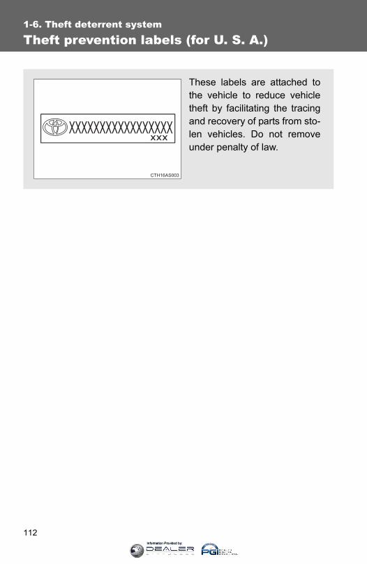
112
1-6. Theft deterrent system
Theft prevention labels (for U. S. A.)
These labels are attached tothe vehicle to reduce vehicletheft by facilitating the tracingand recovery of parts from sto-len vehicles. Do not removeunder penalty of law.
Information Provided by:

113
1
Before driving
1-7. Safety information
Correct driving posture
Drive with a good posture as follows:
Sit upright and well back inthe seat. (→P. 61)Adjust the position of theseat forward or backward toensure the pedals can bereached and easilydepressed to the extentrequired. (→P. 61)Adjust the seatback so thatthe controls are easily oper-able.Adjust the tilt and telescopicpositions of the steeringwheel downward so the air-bag is facing your chest. (→P. 86)Lock the head restraint inplace with the center of thehead restraint closest to thetop of your ears. (→P. 76)Wear the seat belt correctly.(→P. 79)
Information Provided by:

114
1-7. Safety information
CAUTION
■While driving●Do not adjust the position of the driver’s seat.
Doing so could cause the driver to lose control of the vehicle.
●Do not place a cushion between the driver or passenger and the seatback.A cushion may prevent correct posture from being achieved, and reducethe effectiveness of the seat belt and head restraint, increasing the risk ofdeath or serious injury to the driver or passenger.
●Do not place anything under the front seats.Objects placed under the front seats may become jammed in the seattracks and stop the seat from locking in place. This may lead to an acci-dent, resulting in death or serious injury. The adjustment mechanism mayalso be damaged.
■Adjusting the seat position●Take care when adjusting the seat position to ensure that other passen-
gers are not injured by the moving seat.
●Do not put your hands under the seat or near the moving parts to avoidinjury.Fingers or hands may become jammed in the seat mechanism.
Information Provided by:

115
1
1-7. Safety informationB
efore driving
SRS airbags
The SRS airbags inflate when the vehicle is subjected to certaintypes of severe impacts that may cause significant injury to theoccupants. They work together with the seat belts to help reduce therisk of death or serious injury.
SRS front airbagsSRS driver airbag/front passenger airbagCan help protect the head and chest of the driver and front pas-senger from impact with interior componentsSRS knee airbagsCan help provide driver and front passenger protection
SRS side and curtain shield airbagsSRS side airbagsCan help protect the torso of the front seat occupantsSRS curtain shield airbagsCan help protect primarily the head of occupants in the outerseats
CTH17AS103
Information Provided by:
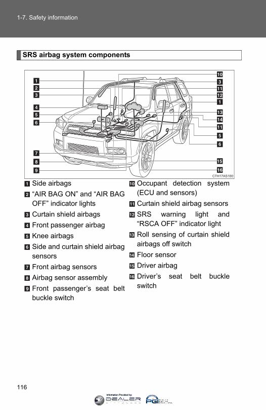
116
1-7. Safety information
SRS airbag system components
Side airbags“AIR BAG ON” and “AIR BAGOFF” indicator lightsCurtain shield airbagsFront passenger airbagKnee airbagsSide and curtain shield airbagsensorsFront airbag sensorsAirbag sensor assemblyFront passenger’s seat beltbuckle switch
Occupant detection system(ECU and sensors)Curtain shield airbag sensorsSRS warning light and“RSCA OFF” indicator lightRoll sensing of curtain shieldairbags off switchFloor sensorDriver airbagDriver’s seat belt buckleswitch
CTH17AS100
Information Provided by:
117
1-7. Safety information
1
Before driving
Your vehicle is equipped with ADVANCED AIRBAGS designed basedon the US motor vehicle safety standards (FMVSS208). The airbagsystem controls airbag deployment power for the driver and front pas-senger. The driver airbag system consists of the driver’s seat beltbuckle switch etc. The front passenger’s airbag system consists ofthe front passenger occupant classification sensor etc.
The main SRS airbag system components are shown above. TheSRS airbag system is controlled by the airbag sensor assembly. Theairbag sensor assembly consists of a safing sensor and an airbagsensor.
In certain types of severe frontal or side impacts, the SRS airbag sys-tem triggers the airbag inflators. A chemical reaction in the inflatorsquickly fills the airbags with non-toxic gas to help restrain the motionof the occupants.
■ If the SRS airbags deploy (inflate)●Bruising and slight abrasions may result from contact with a deploying
(inflating) SRS airbag.
●A loud noise and white powder will be emitted.
●Parts of the airbag module (steering wheel hub, airbag cover and inflator)as well as the front seats, parts of the front and rear pillars, and roof siderails, may be hot for several minutes. The airbag itself may also be hot.
●The windshield may crack.
●For Safety Connect subscribers, if the SRS airbags deploy or in the eventof a severe rear-end collision, the system is designed to send an emer-gency call to the response center, notifying them of the vehicle’s location(without needing to push the “SOS” button) and an agent will attempt tospeak with the occupants to ascertain the level of emergency and assis-tance required. If the occupants are unable to communicate, the agentautomatically treats the call as an emergency and helps to dispatch thenecessary emergency services. (→P. 469)
Information Provided by:

118
1-7. Safety information
■SRS airbag deployment conditions (SRS front airbags)●The SRS front airbags will deploy in the event of an impact that exceeds
the set threshold level (the level of force corresponding to an approxi-mately 12 - 18 mph [20 - 30 km/h] frontal collision with a fixed wall thatdoes not move or deform).
However, this threshold velocity will be considerably higher if the vehiclestrikes an object, such as a parked vehicle and sign pole, which can moveor deform on impact, or if the vehicle is involved in an underride collision(e.g. a collision in which the front of the vehicle “underrides”, or goesunder, the bed of a truck etc.).
● It is possible that in some collisions where the forward deceleration of thevehicle is very close to the designed threshold level, the SRS front air-bags and the seat belt pretensioners may not activate together.
●The SRS front passenger airbag will not activate if there is no passengersitting in the front passenger seat. However, the front passenger airbagmay deploy, if luggage is put in the seat, even if the seat is unoccupied.
■SRS airbag deployment conditions (SRS side airbags)The SRS side airbags will deploy in the event of an impact that exceeds theset threshold level (the level of force corresponding to the impact force pro-duced by an approximately 3300 lb. [1500 kg] vehicle colliding with the vehi-cle cabin from a direction perpendicular to the vehicle orientation at anapproximately speed of 12 - 18 mph [20 - 30 km/h]).
■SRS airbag deployment conditions (SRS curtain shield airbags)The SRS curtain shield airbags will deploy in the event of vehicle rollover oran impact that exceeds the set threshold level (the level of force correspond-ing to the impact force produced by an approximately 3300 lb. [1500 kg]vehicle colliding with the vehicle cabin from a direction perpendicular to thevehicle orientation at an approximately speed of 12 - 18 mph [20 - 30 km/h]).
Information Provided by:

119
1-7. Safety information
1
Before driving
■Conditions under which the SRS airbags may deploy (inflate), otherthan a collisionThe SRS front airbags may also deploy if a serious impact occurs to theunderside of your vehicle. Some examples are shown in the illustration.
The SRS curtain shield airbags may also deploy under the situations shownin the illustration.
■Types of collisions that may not deploy the SRS airbags (SRS front air-bags)The SRS front airbags are generally not designed to inflate if the vehicle isinvolved in a side or rear collision, if it rolls over, or if it is involved in a low-speed frontal collision. But, whenever a collision of any type causes suffi-cient forward deceleration of the vehicle, deployment of the SRS front air-bags may occur.
●Hitting a curb, edge of pavement orhard surface
●Falling into or jumping over a deep hole
●Landing hard or falling
●The angle of vehicle tip-up is marginal.
●The vehicle skids and hits a curb stone.
●Collision from the side
●Collision from the rear
●Vehicle rollover
Information Provided by:

120
1-7. Safety information
■Types of collisions that may not deploy the SRS airbags (SRS side airbags and curtain shield airbags)The SRS side airbag and curtain shield airbag system may not activate if thevehicle is subjected to a collision from the side at certain angles, or a colli-sion to the side of the vehicle body other than the passenger compartment.
The SRS side airbags are not generally designed to inflate if the vehicle isinvolved in a frontal or rear collision, if it rolls over, or if it is involved in a low-speed side collision.
The SRS curtain shield airbags are not generally designed to inflate if thevehicle is involved in a frontal or rear collision, if it pitches end over end, or ifit is involved in a low-speed side collision.
●Collision from the side to the vehiclebody other than the passenger com-partment
●Collision from the side at an angle
●Collision from the front
●Collision from the rear
●Vehicle rollover
●Collision from the front
●Collision from the rear
●Pitching end over end
Information Provided by:
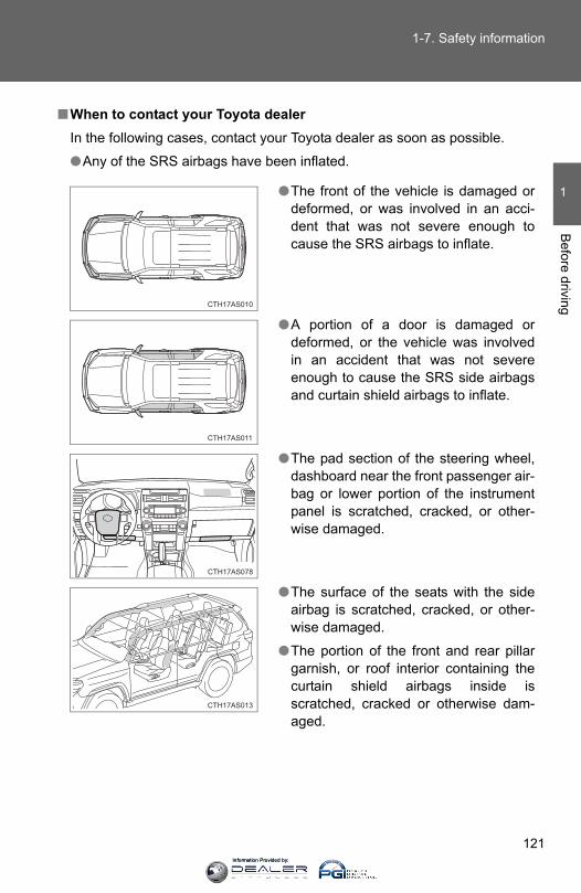
121
1-7. Safety information
1
Before driving
■When to contact your Toyota dealerIn the following cases, contact your Toyota dealer as soon as possible.
●Any of the SRS airbags have been inflated.
●The front of the vehicle is damaged ordeformed, or was involved in an acci-dent that was not severe enough tocause the SRS airbags to inflate.
●A portion of a door is damaged ordeformed, or the vehicle was involvedin an accident that was not severeenough to cause the SRS side airbagsand curtain shield airbags to inflate.
●The pad section of the steering wheel,dashboard near the front passenger air-bag or lower portion of the instrumentpanel is scratched, cracked, or other-wise damaged.
●The surface of the seats with the sideairbag is scratched, cracked, or other-wise damaged.
●The portion of the front and rear pillargarnish, or roof interior containing thecurtain shield airbags inside isscratched, cracked or otherwise dam-aged.
CTH17AS078
Information Provided by:
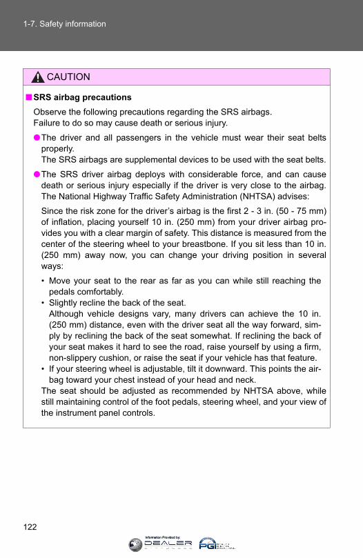
122
1-7. Safety information
CAUTION
■SRS airbag precautionsObserve the following precautions regarding the SRS airbags. Failure to do so may cause death or serious injury.
●The driver and all passengers in the vehicle must wear their seat beltsproperly.The SRS airbags are supplemental devices to be used with the seat belts.
●The SRS driver airbag deploys with considerable force, and can causedeath or serious injury especially if the driver is very close to the airbag.The National Highway Traffic Safety Administration (NHTSA) advises:
Since the risk zone for the driver’s airbag is the first 2 - 3 in. (50 - 75 mm)of inflation, placing yourself 10 in. (250 mm) from your driver airbag pro-vides you with a clear margin of safety. This distance is measured from thecenter of the steering wheel to your breastbone. If you sit less than 10 in.(250 mm) away now, you can change your driving position in severalways:
• Move your seat to the rear as far as you can while still reaching thepedals comfortably.
• Slightly recline the back of the seat. Although vehicle designs vary, many drivers can achieve the 10 in.(250 mm) distance, even with the driver seat all the way forward, sim-ply by reclining the back of the seat somewhat. If reclining the back ofyour seat makes it hard to see the road, raise yourself by using a firm,non-slippery cushion, or raise the seat if your vehicle has that feature.
• If your steering wheel is adjustable, tilt it downward. This points the air-bag toward your chest instead of your head and neck.
The seat should be adjusted as recommended by NHTSA above, whilestill maintaining control of the foot pedals, steering wheel, and your view ofthe instrument panel controls.
Information Provided by:
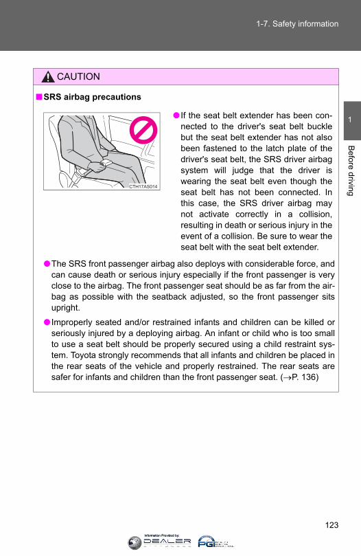
123
1-7. Safety information
1
Before driving
CAUTION
■SRS airbag precautions
●The SRS front passenger airbag also deploys with considerable force, andcan cause death or serious injury especially if the front passenger is veryclose to the airbag. The front passenger seat should be as far from the air-bag as possible with the seatback adjusted, so the front passenger sitsupright.
● Improperly seated and/or restrained infants and children can be killed orseriously injured by a deploying airbag. An infant or child who is too smallto use a seat belt should be properly secured using a child restraint sys-tem. Toyota strongly recommends that all infants and children be placed inthe rear seats of the vehicle and properly restrained. The rear seats aresafer for infants and children than the front passenger seat. (→P. 136)
● If the seat belt extender has been con-nected to the driver's seat belt bucklebut the seat belt extender has not alsobeen fastened to the latch plate of thedriver's seat belt, the SRS driver airbagsystem will judge that the driver iswearing the seat belt even though theseat belt has not been connected. Inthis case, the SRS driver airbag maynot activate correctly in a collision,resulting in death or serious injury in theevent of a collision. Be sure to wear theseat belt with the seat belt extender.
CTH17AS014
Information Provided by:

124
1-7. Safety information
CAUTION
■SRS airbag precautions
●Do not sit on the edge of the seat orlean against the dashboard.
●Do not allow a child to stand in front ofthe SRS front passenger airbag unit orsit on the knees of a front passenger.
●Do not allow the front seat occupants tohold items on their knees.
●Do not lean against the door, the roofside rail or the front and rear pillars.
●Do not allow anyone to kneel on thepassenger seat toward the door or puttheir head or hands outside the vehicle.
CTH17AS015
CTH17AS016
CTH17AS137
CTH17AS018
Information Provided by:

125
1-7. Safety information
1
Before driving
CAUTION
■SRS airbag precautions
●Do not attach anything to or lean any-thing against areas such as the dash-board, steering wheel pad and lowerportion of the instrument panel. Theseitems can become projectiles when theSRS driver, front passenger and kneeairbags deploy.
●Do not attach anything to areas such asa door, windshield glass, side doorglass, front and rear pillars, roof siderail or assist grip.
●Vehicles without a smart key system:Do not attach any heavy, sharp or hardobjects such as keys and accessoriesto the key. The objects may restrict theSRS knee airbag inflation or be thrustinto the driver's seat area by the forceof the deploying airbag, thus causing adanger.
CTH17AS077
CTH17AS020
CTH17AS021
Information Provided by:
126
1-7. Safety information
CAUTION
■SRS airbag precautions●Do not hang coat hangers or other hard objects on the coat hooks. All of
these items could become projectiles and may cause death or seriousinjury, should the SRS curtain shield airbags deploy.
● If a vinyl cover is put on the area where the SRS knee airbag will deploy,be sure to remove it.
●Do not use seat accessories which cover the parts where the SRS sideairbags inflate as they may interfere with inflation of the airbags. Suchaccessories may prevent the side airbags from activating correctly, disablethe system or cause the side airbags to inflate accidentally, resulting indeath or serious injury.
●Do not strike or apply significant levels of force to the area of the SRS air-bag components. Doing so can cause the SRS airbags to malfunction.
●Do not touch any of the component parts immediately after the SRS air-bags have deployed (inflated) as they may be hot.
● If breathing becomes difficult after the SRS airbags have deployed, open adoor or window to allow fresh air in, or leave the vehicle if it is safe to doso. Wash off any residue as soon as possible to prevent skin irritation.
● If the areas where the SRS airbags are stored, such as the steering wheelpad and front and rear pillar garnishes, are damaged or cracked, havethem replaced by your Toyota dealer.
Information Provided by:

127
1-7. Safety information
1
Before driving
CAUTION
■Modification and disposal of SRS airbag system componentsDo not dispose of your vehicle or perform any of the following modificationswithout consulting your Toyota dealer. The SRS airbags may malfunction ordeploy (inflate) accidentally, causing death or serious injury.
● Installation, removal, disassembly and repair of the SRS airbags
●Repairs, modifications, removal or replacement of the steering wheel,instrument panel, dashboard, seats or seat upholstery, front and rear pil-lars, roof side rails or roof head lining
●Repairs or modifications of the front fender, front bumper, or side of theoccupant compartment
● Installation of snow plows, winches, etc. to the front grille (bull bars, orkangaroo bar etc.)
●Modifications to the vehicle’s suspension system
● Installation of electronic devices such as mobile two-way radios and CDplayers
●Modifications to your vehicle for a person with a physical disability
Information Provided by:

128
1-7. Safety information
Deactivating the curtain shield airbags in a vehicle rollover
On/off (hold for a few seconds)
Vehicles without a smart key sys-tem: The “RSCA OFF” indicatorturns on. (only when the engineswitch is in the “ON” position).
The roll sensing function for thecurtain shield airbags and seatbelt pretensioners will turn backon automatically each time theengine switch is turned to the“ON” position.
Vehicles with a smart key system:The “RSCA OFF” indicator comeson. (only when the “ENGINESTART STOP” switch is in IGNI-TION ON mode).
The roll sensing function for thecurtain shield airbags and seatbelt pretensioners will turn backon automatically each time the“ENGINE START STOP” switch isturned to IGNITION ON mode.
CTH17AS084
■This switch only should be usedIn a situation where the inflation is not desired (such as during extreme off-road driving).
■Operating conditions when the “RSCA OFF” indicator is illuminated●The curtain shield airbags and seat belt pretensioner will not activate in a
vehicle rollover.
●The curtain shield airbags will activate in a severe side impact.
Information Provided by:

129
1-7. Safety information
1
Before driving
CAUTION
■During normal drivingMake sure the “RSCA OFF” indicator light is not turned on. If it is left on, thecurtain shield airbags will not activate in the event of an accident, which maycause death or serious injury.
Information Provided by:

130
1-7. Safety information
Front passenger occupant classification system
Your vehicle is equipped with a front passenger occupant classifica-tion system. This system detects the conditions of the front passen-ger seat and activates or deactivates the devices for the frontpassenger.
SRS warning lightFront passenger’s seat belt reminder light“AIR BAG OFF” indicator light“AIR BAG ON” indicator light
CTH17AS108
Type A Type B
Information Provided by:
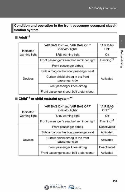
131
1-7. Safety information
1
Before driving
Condition and operation in the front passenger occupant classi-fication system
■ Adult*1
■ Child*3 or child restraint system*4
Indicator/warning light
“AIR BAG ON” and “AIR BAG OFF”indicator lights
“AIR BAG ON”
SRS warning light Off
Front passenger’s seat belt reminder light Flashing*2
Devices
Front passenger airbag
Activated
Side airbag on the front passenger seat
Curtain shield airbag in the front passenger side
Front passenger knee airbag
Front passenger's seat belt pretensioner
Indicator/warning light
“AIR BAG ON” and “AIR BAG OFF”indicator lights
“AIR BAG OFF”*5
SRS warning light Off
Front passenger’s seat belt reminder light Flashing*2
Devices
Front passenger airbag Deactivated
Side airbag on the front passenger seat Activated
Curtain shield airbag in the front passenger side Activated
Front passenger knee airbag Deactivated
Front passenger's seat belt pretensioner Activated
Information Provided by:
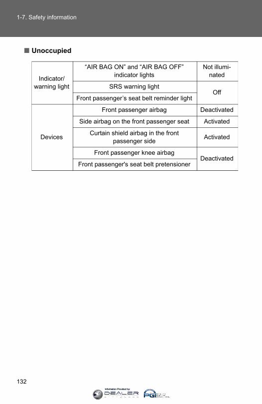
132
1-7. Safety information
■ Unoccupied
Indicator/warning light
“AIR BAG ON” and “AIR BAG OFF” indicator lights
Not illumi-nated
SRS warning lightOff
Front passenger’s seat belt reminder light
Devices
Front passenger airbag Deactivated
Side airbag on the front passenger seat Activated
Curtain shield airbag in the front passenger side Activated
Front passenger knee airbagDeactivated
Front passenger's seat belt pretensioner
Information Provided by:
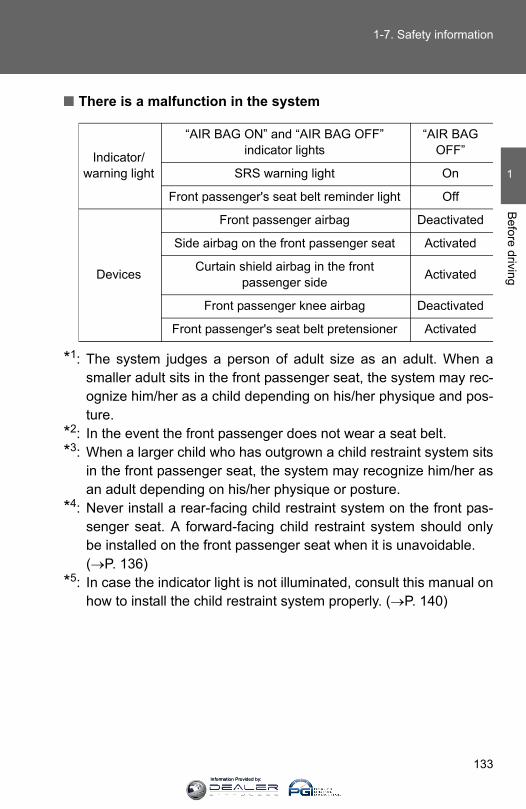
133
1-7. Safety information
1
Before driving
■ There is a malfunction in the system
*1: The system judges a person of adult size as an adult. When asmaller adult sits in the front passenger seat, the system may rec-ognize him/her as a child depending on his/her physique and pos-ture.
*2: In the event the front passenger does not wear a seat belt.*3: When a larger child who has outgrown a child restraint system sits
in the front passenger seat, the system may recognize him/her asan adult depending on his/her physique or posture.
*4: Never install a rear-facing child restraint system on the front pas-senger seat. A forward-facing child restraint system should onlybe installed on the front passenger seat when it is unavoidable. (→P. 136)
*5: In case the indicator light is not illuminated, consult this manual onhow to install the child restraint system properly. (→P. 140)
Indicator/warning light
“AIR BAG ON” and “AIR BAG OFF” indicator lights
“AIR BAG OFF”
SRS warning light On
Front passenger's seat belt reminder light Off
Devices
Front passenger airbag Deactivated
Side airbag on the front passenger seat Activated
Curtain shield airbag in the front passenger side Activated
Front passenger knee airbag Deactivated
Front passenger's seat belt pretensioner Activated
Information Provided by:
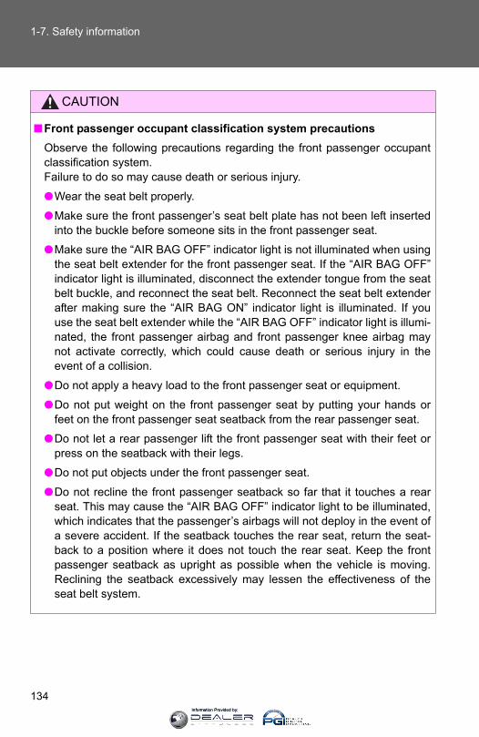
134
1-7. Safety information
CAUTION
■Front passenger occupant classification system precautionsObserve the following precautions regarding the front passenger occupantclassification system. Failure to do so may cause death or serious injury.
●Wear the seat belt properly.
●Make sure the front passenger’s seat belt plate has not been left insertedinto the buckle before someone sits in the front passenger seat.
●Make sure the “AIR BAG OFF” indicator light is not illuminated when usingthe seat belt extender for the front passenger seat. If the “AIR BAG OFF”indicator light is illuminated, disconnect the extender tongue from the seatbelt buckle, and reconnect the seat belt. Reconnect the seat belt extenderafter making sure the “AIR BAG ON” indicator light is illuminated. If youuse the seat belt extender while the “AIR BAG OFF” indicator light is illumi-nated, the front passenger airbag and front passenger knee airbag maynot activate correctly, which could cause death or serious injury in theevent of a collision.
●Do not apply a heavy load to the front passenger seat or equipment.
●Do not put weight on the front passenger seat by putting your hands orfeet on the front passenger seat seatback from the rear passenger seat.
●Do not let a rear passenger lift the front passenger seat with their feet orpress on the seatback with their legs.
●Do not put objects under the front passenger seat.
●Do not recline the front passenger seatback so far that it touches a rearseat. This may cause the “AIR BAG OFF” indicator light to be illuminated,which indicates that the passenger’s airbags will not deploy in the event ofa severe accident. If the seatback touches the rear seat, return the seat-back to a position where it does not touch the rear seat. Keep the frontpassenger seatback as upright as possible when the vehicle is moving.Reclining the seatback excessively may lessen the effectiveness of theseat belt system.
Information Provided by:
135
1-7. Safety information
1
Before driving
CAUTION
■Front passenger occupant classification system precautions● If an adult sits in the front passenger seat, the “AIR BAG ON” indicator
light is illuminated. If the “AIR BAG OFF” indicator is illuminated, ask thepassenger to sit up straight, well back in the seat, feet on the floor, andwith the seat belt worn correctly. If the “AIR BAG OFF” indicator stillremains illuminated, either ask the passenger to move to the rear seat, orif that is not possible, move the front passenger seat fully rearward.
●When it is unavoidable to install a forward-facing child restraint system onthe front passenger seat, install the child restraint system on the front pas-senger seat in the proper order. (→P. 140)
●Do not modify or remove the front seats.
●Do not kick the front passenger seat or subject it to severe impact. Other-wise, the SRS warning light may come on to indicate a malfunction of thedetection system. In this case, contact your Toyota dealer immediately.
●Child restraint systems installed on the second seat should not contact thefront seatbacks.
●Do not use a seat accessory, such as a cushion and seat cover, that cov-ers the seat cushion surface.
●Do not modify or replace the upholstery of the front seat.
Information Provided by:
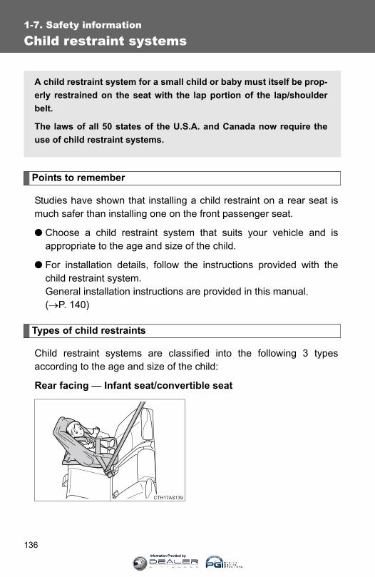
136
1-7. Safety information
Child restraint systems
Points to remember
Studies have shown that installing a child restraint on a rear seat ismuch safer than installing one on the front passenger seat.
● Choose a child restraint system that suits your vehicle and isappropriate to the age and size of the child.
● For installation details, follow the instructions provided with thechild restraint system. General installation instructions are provided in this manual. (→P. 140)
Types of child restraints
Child restraint systems are classified into the following 3 typesaccording to the age and size of the child:
Rear facing — Infant seat/convertible seat
A child restraint system for a small child or baby must itself be prop-erly restrained on the seat with the lap portion of the lap/shoulderbelt.
The laws of all 50 states of the U.S.A. and Canada now require theuse of child restraint systems.
Information Provided by:

137
1-7. Safety information
1
Before driving
Forward facing — Convertible seat
Booster seat
CTH17AS144
CTH17AS112
■Selecting an appropriate child restraint system●Use a child restraint system appropriate for the child until the child
becomes large enough to properly wear the vehicle’s seat belt.
● If the child is too large for a child restraint system, sit the child on a rearseat and use the vehicle’s seat belt. (→P. 79)
Information Provided by:

138
1-7. Safety information
CAUTION
■Child restraint precautions●For effective protection in automobile accidents and sudden stops, a child
must be properly restrained, using a seat belt or child restraint systemdepending on the age and size of the child. Holding a child in your arms isnot a substitute for a child restraint system. In an accident, the child can becrushed against the windshield, or between you and the vehicle’s interior.
●Toyota strongly urges the use of a proper child restraint system that con-forms to the size of the child, installed on the rear seat. According to acci-dent statistics, the child is safer when properly restrained in the rear seatthan in the front seat.
●Never install a rear-facing child restraint system on the front passengerseat even if the “AIR BAG OFF” indicator light is illuminated. In the eventof an accident, the force of the rapid inflation of the front passenger airbagcan cause death or serious injury to the child if the rear-facing childrestraint system is installed on the front passenger seat.
●A forward-facing child restraint system may be installed on the front pas-senger seat only when it is unavoidable. A child restraint system thatrequires a top tether strap should not be used in the front passenger seatsince there is no top tether strap anchor for the front passenger seat.Adjust the seatback as upright as possible and always move the seat asfar back as possible even if the “AIR BAG OFF” indicator light illuminated,because the front passenger airbag could inflate with considerable speedand force. Otherwise, the child may be killed or seriously injured.
Information Provided by:
139
1-7. Safety information
1
Before driving
CAUTION
■Child restraint precautions●Do not use the seat belt extender when installing a child restraint system
on the front or rear passenger seat. If installing a child restraint systemwith the seat belt extender connected to the seat belt, the seat belt will notsecurely hold the child restraint system, which could cause death or seri-ous injury to the child or other passengers in the event of a sudden stop,sudden swerve or an accident.
●Do not allow the child to lean his/her head or any part of his/her bodyagainst the door or the area of the seat, front and rear pillars or roof siderail from which the SRS side airbags or SRS curtain shield airbags deployeven if the child is seated in the child restraint system. It is dangerous ifthe SRS side airbags and SRS curtain shield airbags inflate, and theimpact could cause death or serious injury to the child.
●Make sure you have complied with all installation instructions provided bythe child restraint manufacturer and that the system is properly secured. Ifit is not secured properly, it may cause death or serious injury to the childin the event of a sudden stop, sudden swerve or an accident.
■Child restraint lock function belt precautionDo not allow children to play with the child restraint lock function belt. If thebelt becomes twisted around a child’s neck, it will not be possible to pull thebelt out leading to choking or other serious injuries that could result in death.If this occurs and the buckle cannot be unfastened, scissors should be usedto cut the belt.
■When the child restraint system is not in use●Keep the child restraint system properly secured on the seat even if it is
not in use. Do not store the child restraint system unsecured in the pas-senger compartment.
● If it is necessary to detach the child restraint system, remove it from thevehicle or store it securely in the luggage compartment. This will prevent itfrom injuring passengers in the event of a sudden stop, sudden swerve oraccident.
Information Provided by:

140
1-7. Safety information
Installing child restraints
Follow the child restraint system manufacturer’s instructions. Firmlysecure the child restraints using the LATCH anchors or a seat belt.Attach the top tether strap when installing a child restraint.
The lap/shoulder belt can be used if your child restraint system isnot compatible with the LATCH (Lower Anchors and Tethers for Chil-dren) system.
Vehicles without third row seatsChild restraint LATCH anchors
LATCH anchors are providedfor the outside rear seats. (But-tons displaying the location ofthe anchors are attached to theseats.)
Vehicles with third row seatsChild restraint LATCH anchors
LATCH anchors are providedfor the outside second rowseats. (Buttons displaying thelocation of the anchors areattached to the seats.)
CTH17AS142
CTH17AS143
Information Provided by:

141
1-7. Safety information
1
Before driving
Seat belts equipped with achild restraint locking mecha-nism (ALR/ELR belts exceptdriver’s seat belt) (→P. 79)
Vehicles without third row seatsAnchor brackets (for top tetherstrap)
An anchor bracket is providedfor each rear seat.
Vehicles with third row seatsAnchor brackets (for top tetherstrap)
An anchor bracket is providedfor each second row seat.
CTH17AS114
CTH17AS115
CTH17AS031
Information Provided by:

142
1-7. Safety information
Installation with LATCH system (rear/second row seats only)
■ Installing on the rear seats (vehicles without third row seats)Fold the seatback while pullingthe seatback angle adjustmentlever. Return the seatback andsecure it at the first lock position.(→P. 65)
Type ALatch the hooks of the lowerstraps onto the LATCH anchors.If the child restraint has a toptether strap, the top tether strapshould be latched onto the toptether strap anchor.
For owners in Canada:The symbol on a child restraintsystem indicates the presence ofa lower connector system.
CTH17AS116
STEP 1
CTH17AS117
STEP 2
Canada only
Information Provided by:
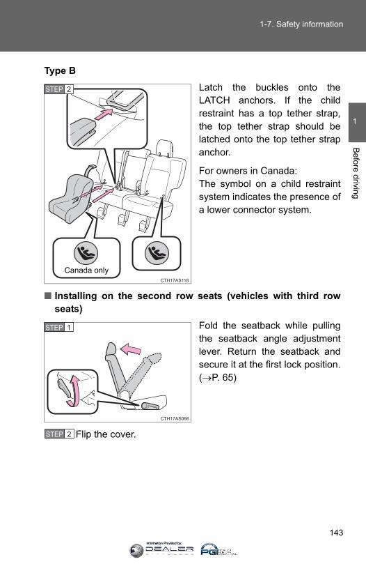
143
1-7. Safety information
1
Before driving
Type BLatch the buckles onto theLATCH anchors. If the childrestraint has a top tether strap,the top tether strap should belatched onto the top tether strapanchor.
For owners in Canada:The symbol on a child restraintsystem indicates the presence ofa lower connector system.
■ Installing on the second row seats (vehicles with third rowseats)
Fold the seatback while pullingthe seatback angle adjustmentlever. Return the seatback andsecure it at the first lock position.(→P. 65)
Flip the cover.
CTH17AS118
STEP 2
Canada only
CTH17AS066
STEP 1
STEP 2
Information Provided by:
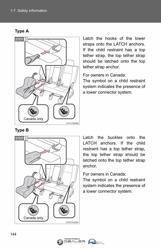
144
1-7. Safety information
Type ALatch the hooks of the lowerstraps onto the LATCH anchors.If the child restraint has a toptether strap, the top tether strapshould be latched onto the toptether strap anchor.
For owners in Canada:The symbol on a child restraintsystem indicates the presence ofa lower connector system.
Type BLatch the buckles onto theLATCH anchors. If the childrestraint has a top tether strap,the top tether strap should belatched onto the top tether strapanchor.
For owners in Canada:The symbol on a child restraintsystem indicates the presence ofa lower connector system.
CTH17AS086
STEP 3
Canada only
CTH17AS087
STEP 3
Canada only
Information Provided by:

145
1-7. Safety information
1
Before driving
Installing child restraints using a seat belt (child restraint lockfunction belt)
■ Rear facing ⎯ Infant seat/convertible seatPlace the child restraint systemon the rear seat facing the rearof the vehicle.
Run the seat belt through thechild restraint system and insertthe plate into the buckle. Makesure that the belt is not twisted.
Fully extend the shoulder beltand allow it to retract to put it inlock mode. In lock mode, the beltcannot be extended.
CTH17AS119
STEP 1
CTH17AS140
STEP 2
CTH17AS121
STEP 3
Information Provided by:

146
1-7. Safety information
While pushing the child restraintsystem down into the rear seat,allow the shoulder belt to retractuntil the child restraint system issecurely in place.
After the shoulder belt hasretracted to a point where there isno slack in the belt, pull the belt tocheck that it cannot be extended.
■ Forward facing ⎯ Convertible seatPlace the child restraint systemon the seat facing the front of thevehicle.
Run the seat belt through thechild restraint system and insertthe plate into the buckle. Makesure that the belt is not twisted.
Fully extend the shoulder beltand allow it to retract to put it inlock mode. In lock mode, the beltcannot be extended.
CTH17AS122
STEP 4
CTH17AS123
STEP 1
CTH17AS124
STEP 2
CTH17AS125
STEP 3
Information Provided by:
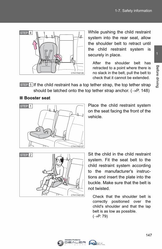
147
1-7. Safety information
1
Before driving
While pushing the child restraintsystem into the rear seat, allowthe shoulder belt to retract untilthe child restraint system issecurely in place.
After the shoulder belt hasretracted to a point where there isno slack in the belt, pull the belt tocheck that it cannot be extended.
If the child restraint has a top tether strap, the top tether strapshould be latched onto the top tether strap anchor. (→P. 148)
■ Booster seatPlace the child restraint systemon the seat facing the front of thevehicle.
Sit the child in the child restraintsystem. Fit the seat belt to thechild restraint system accordingto the manufacturer's instruc-tions and insert the plate into thebuckle. Make sure that the belt isnot twisted.
Check that the shoulder belt iscorrectly positioned over thechild's shoulder and that the lapbelt is as low as possible. (→P. 79)
CTH17AS126
STEP 4
STEP 5
CTH17AS127
STEP 1
CTH17AS128
STEP 2
Information Provided by:
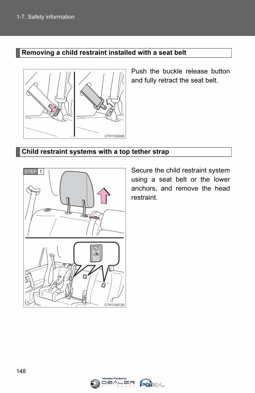
148
1-7. Safety information
Removing a child restraint installed with a seat belt
Push the buckle release buttonand fully retract the seat belt.
Child restraint systems with a top tether strap
Secure the child restraint systemusing a seat belt or the loweranchors, and remove the headrestraint.
CTH17AS048
CTH17AS129
STEP 1
Information Provided by:

149
1-7. Safety information
1
Before driving
Open the anchor bracket cover,latch the hook onto the anchorbracket and tighten the top tetherstrap.
Make sure the top tether strap issecurely latched.
Replace the head restraint.
CTH17AS071
STEP 2
CTH17AS130
STEP 3
■Laws and regulations pertaining to anchoragesThe LATCH system conforms to FMVSS225 or CMVSS210.2.Child restraint systems conforming to FMVSS213 or CMVSS213 specifica-tions can be used.This vehicle is designed to conform to SAE J1819.
Information Provided by:
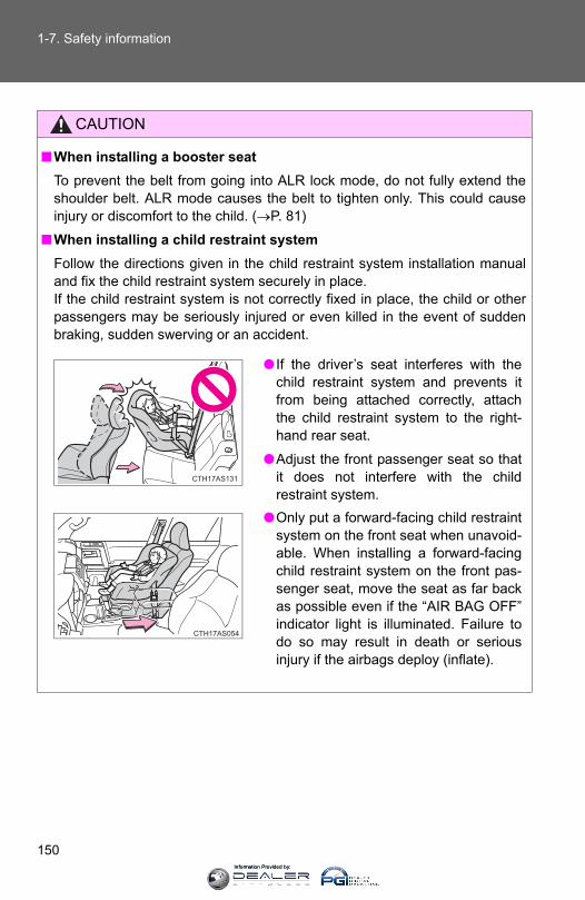
150
1-7. Safety information
CAUTION
■When installing a booster seat To prevent the belt from going into ALR lock mode, do not fully extend theshoulder belt. ALR mode causes the belt to tighten only. This could causeinjury or discomfort to the child. (→P. 81)
■When installing a child restraint systemFollow the directions given in the child restraint system installation manualand fix the child restraint system securely in place.If the child restraint system is not correctly fixed in place, the child or otherpassengers may be seriously injured or even killed in the event of suddenbraking, sudden swerving or an accident.
● If the driver’s seat interferes with thechild restraint system and prevents itfrom being attached correctly, attachthe child restraint system to the right-hand rear seat.
●Adjust the front passenger seat so thatit does not interfere with the childrestraint system.
●Only put a forward-facing child restraintsystem on the front seat when unavoid-able. When installing a forward-facingchild restraint system on the front pas-senger seat, move the seat as far backas possible even if the “AIR BAG OFF”indicator light is illuminated. Failure todo so may result in death or seriousinjury if the airbags deploy (inflate).
CTH17AS131
CTH17AS054
Information Provided by:
151
1-7. Safety information
1
Before driving
CAUTION
■When installing a child restraint system●Vehicles with third row seats: When using the LATCH anchors for a child
restraint system, move the seat as far back as possible, with the seatbackclose to the child restraint system.
●When a booster seat is installed, always ensure that the shoulder belt ispositioned across the center of the child's shoulder. The belt should bekept away from the child's neck, but not so that it could fall off the child'sshoulder. Failure to do so may result in death or serious injury in the eventof sudden braking, sudden swerving or an accident.
●Ensure that the belt and plate are securely locked and the seat belt is nottwisted.
●Push and pull the child restraint system from side to side and forward to besure it is secure.
●After securing a child restraint system, never adjust the seat.
●Follow all installation instructions provided by the child restraint systemmanufacturer.
Information Provided by:
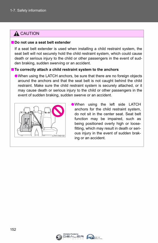
152
1-7. Safety information
CAUTION
■Do not use a seat belt extenderIf a seat belt extender is used when installing a child restraint system, theseat belt will not securely hold the child restraint system, which could causedeath or serious injury to the child or other passengers in the event of sud-den braking, sudden swerving or an accident.
■To correctly attach a child restraint system to the anchors●When using the LATCH anchors, be sure that there are no foreign objects
around the anchors and that the seat belt is not caught behind the childrestraint. Make sure the child restraint system is securely attached, or itmay cause death or serious injury to the child or other passengers in theevent of sudden braking, sudden swerve or an accident.
●When using the left side LATCHanchors for the child restraint system,do not sit in the center seat. Seat beltfunction may be impaired, such asbeing positioned overly high or loose-fitting, which may result in death or seri-ous injury in the event of sudden brak-ing or an accident.
CTH17AS132
Information Provided by:
154
2-1. Driving procedures
Driving the vehicle
The following procedures should be observed to ensure safe driv-ing:
■ Starting the engine→P. 164, 167
■ DrivingWith the brake pedal depressed, shift the shift lever to D.(→P. 173)Release the parking brake. (→P. 180)
Gradually release the brake pedal and gently depress theaccelerator pedal to accelerate the vehicle.
■ StoppingWith the shift lever in D, depress the brake pedal.If necessary, set the parking brake.If the vehicle is to be stopped for an extended period of time, shiftthe shift lever to P or N. (→P. 173)
■ Parking the vehicleWith the shift lever in D, depress the brake pedal.Set the parking brake. (→P. 180)Shift the shift lever to P. (→P. 173)If parking on a hill, block the wheels as needed.
Vehicles without a smart key system:Turn the engine switch to the “LOCK” position to stop theengine.Vehicles with a smart key system:Press the “ENGINE START STOP” switch to stop theengine.Lock the door, making sure that you have the key on yourperson.
STEP 1
STEP 2
STEP 3
STEP 1
STEP 2
STEP 1
STEP 2
STEP 3
STEP 4
STEP 5
Information Provided by:

155
2-1. Driving procedures
2
When driving
Starting off on a steep uphill
Make sure that the parking brake is set and shift the shift leverto D.Gently depress the accelerator pedal.Release the parking brake.
■Driving in the rain●Drive carefully when it is raining, because visibility will be reduced, the
windows may become fogged-up, and the road will be slippery.
●Drive carefully when it starts to rain, because the road surface will beespecially slippery.
●Refrain from high speeds when driving on an expressway in the rain,because there may be a layer of water between the tires and the roadsurface, preventing the steering and brakes from operating properly.
■Breaking in your new ToyotaTo extend the life of the vehicle, observing the following precautions is rec-ommended:
●For the first 200 miles (300 km):Avoid sudden stops.
●For the first 500 miles (800 km):Do not tow a trailer.
●For the first 1000 miles (1600 km):
• Do not drive at extremely high speeds.• Avoid sudden acceleration.• Do not drive continuously in the low gears.• Do not drive at a constant speed for extended periods.
■Drum-in-disc type parking brake systemYour vehicle has a drum-in-disc type parking brake system. This type ofbrake system needs bedding-down of the brake shoes periodically or when-ever the parking brake shoes and/or drum are replaced. Have your Toyotadealer perform the bedding down operation.
STEP 1
STEP 2
STEP 3
Information Provided by:

156
2-1. Driving procedures
■Operating your vehicle in a foreign countryComply with the relevant vehicle registration laws and confirm the availabilityof the correct fuel. (→P. 615)
CAUTION
■When starting the vehicleAlways keep your foot on the brake pedal while stopped with the engine run-ning. This prevents the vehicle from creeping.
■When driving the vehicle●Do not drive if you are unfamiliar with the location of the brake and accel-
erator pedals to avoid depressing the wrong pedal.
• Accidentally depressing the accelerator pedal instead of the brakepedal will result in sudden acceleration that may lead to an accidentthat could result in death or serious injury.
• When backing up, you may twist your body around, leading to a diffi-culty in operating the pedals. Make sure to operate the pedals properly.
• Make sure to keep a correct driving posture even when moving thevehicle only slightly. This allows you to depress the brake and acceler-ator pedals properly.
• Depress the brake pedal using your right foot. Depressing the brakepedal using your left foot may delay response in an emergency, result-ing in an accident.
●Do not drive the vehicle over or stop the vehicle near flammable materials.The exhaust system and exhaust gases can be extremely hot. These hotparts may cause a fire if there is any flammable material nearby.
●Do not let the vehicle roll backward while the shift lever is in a driving posi-tion, or roll forward while the shift lever is in R.Doing so may cause the engine to stall or lead to poor brake and steeringperformance, resulting in an accident or damage to the vehicle.
● If the smell of exhaust is noticed inside the vehicle, open the windows andcheck that the back door is closed. Large amounts of exhaust in the vehi-cle can cause driver drowsiness and an accident, resulting in death or aserious health hazard. Have the vehicle inspected by your Toyota dealerimmediately.
Information Provided by:
157
2-1. Driving procedures
2
When driving
CAUTION
●Do not under any circumstances shift the shift lever to P while the vehicleis moving.Doing so can cause significant damage to the driveline and may result in aloss of vehicle control.
●Do not under any circumstances shift the shift lever to R while the vehicleis moving forward.Doing so can cause significant damage to the driveline and may result in aloss of vehicle control.
●Do not shift the shift lever to N while the vehicle is moving.Doing so may cause insufficient engine braking, resulting in an accident.
●Do not turn the engine off while driving. The power steering and brake actuator will not operate properly if theengine is not running.
●Use engine braking (downshift) to maintain a safe speed when drivingdown a steep hill. Using the brakes continuously may cause the brakes to overheat and loseeffectiveness. (→P. 175)
●Do not adjust the positions of the steering wheel, the seat, or the inside oroutside rear view mirrors while driving.Doing so may result in a loss of vehicle control that can cause accidents,resulting in death or serious injury.
●Always check that all passengers’ arms, heads or other parts of their bodyare not outside the vehicle, as this may result in death or serious injury.
●Do not drive in excess of the speed limit. Even if the legal speed limit per-mits it, do not drive over 85 mph (140 km/h) unless your vehicle has high-speed capability tires. Driving over 85 mph (140 km/h) may result in tirefailure, loss of control and possible injury. Be sure to consult a tire dealerto determine whether the tires on your vehicle are high-speed capabilitytires or not before driving at such speeds.
Information Provided by:
158
2-1. Driving procedures
CAUTION
■When driving on slippery road surfaces●Sudden braking, acceleration and steering may cause tire slippage and
reduce your ability to control the vehicle, resulting in an accident.
●Sudden changes in engine speed, such as engine braking caused by up-shifting or down-shifting, may cause the vehicle to skid, resulting in anaccident.
●After driving through a puddle, lightly depress the brake pedal to makesure that the brakes are functioning properly. Wet brake pads may preventthe brakes from functioning properly. If the brakes on only one side are wetand not functioning properly, steering control may be affected, resulting inan accident.
■When shifting the shift leverBe careful not to shift the shift lever with the accelerator pedal depressed.Shifting the shift lever to a gear other than P or N may lead to unexpectedrapid acceleration of the vehicle that may cause an accident and result indeath or serious injury.
■ If you hear a squealing or scraping noise (brake pad wear limit indica-tors)Have the brake pads checked and replaced by your Toyota dealer as soonas possible. Rotor damage may result if the pads are not replaced when needed.
It is dangerous to drive the vehicle when the wear limits of the brake padsand/or those of the brake discs are exceeded.
Information Provided by:

159
2-1. Driving procedures
2
When driving
CAUTION
■When the vehicle is stopped●Do not race the engine.
If the vehicle is in any gear other than P or N, the vehicle may acceleratesuddenly and unexpectedly, causing an accident.
●Do not leave the vehicle with the engine running for a long time. If such a situation cannot be avoided, park the vehicle in an open spaceand check that exhaust fumes do not enter the vehicle interior.
● In order to prevent accidents due to the vehicle rolling away, always keepdepressing the brake pedal while the engine is running, and apply theparking brake as necessary.
● If the vehicle is stopped on an incline, in order to prevent accidents causedby the vehicle rolling forward or backward, always depress the brake pedaland securely apply the parking brake as needed.
●Avoid revving or racing the engine.Running the engine at high speed while the vehicle is stopped may causethe exhaust system to overheat, which could result in a fire if combustiblematerial is nearby.
■When the vehicle is parked●Do not leave glasses, cigarette lighters, spray cans, or soft drink cans in
the vehicle when it is in the sun.Doing so may result in the following:
• Gas may leak from a cigarette lighter or spray can, and may lead to afire.
• The temperature inside the vehicle may cause the plastic lenses andplastic material of glasses to deform or crack.
• Soft drink cans may fracture, causing the contents to spray over theinterior of the vehicle, and may also cause a short circuit in the vehi-cle's electrical components.
●Do not leave cigarette lighters in the vehicle. If a cigarette lighter is in aplace such as the glove box or on the floor, it may be lit accidentally whenluggage is loaded or the seat is adjusted, causing a fire.
●Do not attach adhesive discs to the windshield or windows. Do not placecontainers such as air fresheners on the instrument panel or dashboard.Adhesive discs or containers may act as lenses, causing a fire in the vehi-cle.
Information Provided by:
160
2-1. Driving procedures
CAUTION
●Do not leave a door or window open if the curved glass is coated with ametallized film such as a silver-colored one. Reflected sunlight may causethe glass to act as a lens, causing a fire.
●Always apply the parking brake, shift the shift lever to P, stop the engineand lock the vehicle.Do not leave the vehicle unattended while the engine is running.
●Do not touch the exhaust pipes while the engine is running or immediatelyafter turning the engine off. Doing so may cause burns.
●Do not leave the engine running in an area with snow build-up, or where itis snowing. If snowbanks build up around the vehicle while the engine isrunning, exhaust gases may collect and enter the vehicle. This may leadto death or a serious health hazard.
■Exhaust gasesExhaust gases include harmful carbon monoxide (CO), which is colorlessand odorless. Inhaling exhaust gases may lead to death or a serious healthhazard.
● If the vehicle is in a poorly ventilated area, stop the engine. In a closedarea, such as a garage, exhaust gases may collect and enter the vehicle.This may lead to death or a serious health hazard.
●The exhaust system should be checked occasionally. If there is a hole orcrack caused by corrosion, damage to a joint or abnormal exhaust noise,be sure to have the vehicle inspected and repaired by your Toyota dealer.Failure to do so may allow exhaust gases to enter the vehicle, resulting indeath or a serious health hazard.
Information Provided by:

161
2-1. Driving procedures
2
When driving
CAUTION
■When taking a nap in the vehicleAlways turn the engine off. Otherwise, if you accidentally move the shift leveror depress the accelerator pedal, this could cause an accident or fire due toengine overheating. Additionally, if the vehicle is parked in a poorly venti-lated area, exhaust gases may collect and enter the vehicle, leading todeath or a serious health hazard.
■When braking●When the brakes are wet, drive more cautiously.
Braking distance increases when the brakes are wet, and this may causeone side of the vehicle to brake differently than the other side. Also, theparking brake may not securely hold the vehicle.
● If the power brake assist function does not operate, do not follow othervehicles closely and avoid hills or sharp turns that require braking. In this case, braking is still possible, but the brake pedal should bedepressed more firmly than usual. Also, the braking distance will increase.
●Do not pump the brake pedal if the engine stalls. Each push on the brake pedal uses up the reserve for the power-assistedbrakes.
●The brake system consists of 2 individual hydraulic systems; if one of thesystems fails, the other will still operate. In this case, the brake pedalshould be depressed more firmly than usual and the braking distance willincrease.If this happens, do not continue to drive the vehicle. Have your brakesfixed immediately.
Information Provided by:

162
2-1. Driving procedures
NOTICE
■When driving the vehicle●Do not depress the accelerator and brake pedals at the same time during
driving. If the brake pedal is depressed while driving with the acceleratorpedal depressed, driving torque may be restrained.
●Do not use the accelerator pedal or depress the accelerator and brakepedals at the same time to hold the vehicle on a hill.
■When parking the vehicleAlways shift the shift lever to P. Failure to do so may cause the vehicle tomove or the vehicle may accelerate suddenly if the accelerator pedal is acci-dentally depressed.
■Avoiding damage to vehicle parts●Do not turn the steering wheel fully in either direction and hold it there for
an extended period of time. Doing so may damage the power steering pump.
●When driving over bumps in the road, drive as slowly as possible to avoiddamaging the wheels, underside of the vehicle, etc.
■ If you get a flat tire while drivingA flat or damaged tire may cause the following situations. Hold the steeringwheel firmly and gradually depress the brake pedal to slow down the vehicle.
● It may be difficult to control your vehicle.
●The vehicle will make abnormal sounds or vibrations.
●The vehicle will lean abnormally.
Information on what to do in case of a flat tire (→P. 578)
Information Provided by:

163
2-1. Driving procedures
2
When driving
NOTICE
■When encountering flooded roadsDo not drive on a road that has flooded after heavy rain etc. Doing so maycause the following serious damage to the vehicle:
●Engine stalling
●Short in electrical components
●Engine damage caused by water immersion
In the event that you drive on a flooded road and the vehicle is flooded, besure to have your Toyota dealer check the following:
●Brake function
●Changes in quantity and quality of oil and fluid used for the engine, trans-mission, transfer (4WD models), differentials, etc.
●Lubricant condition for the propeller shaft, bearings and suspension joints(where possible), and the function of all joints, bearings, etc.
Information Provided by:
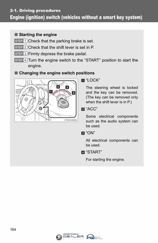
164
2-1. Driving procedures
Engine (ignition) switch (vehicles without a smart key system)
■ Starting the engineCheck that the parking brake is set.Check that the shift lever is set in P.Firmly depress the brake pedal.Turn the engine switch to the “START” position to start theengine.
■ Changing the engine switch positions“LOCK”
The steering wheel is lockedand the key can be removed.(The key can be removed onlywhen the shift lever is in P.)
“ACC”
Some electrical componentssuch as the audio system canbe used.
“ON”
All electrical components canbe used.
“START”
For starting the engine.
STEP 1
STEP 2
STEP 3
STEP 4
CTH21AS002
Information Provided by:

165
2-1. Driving procedures
2
When driving
■Turning the key from “ACC” to “LOCK”Shift the shift lever to P.
■ If the engine does not startThe engine immobilizer system may not have been deactivated. (→P. 106)
■When the steering lock cannot be released
■Key reminder functionA buzzer sounds if the driver’s door is opened, while the engine switch is inthe “LOCK” or “ACC” position to remind you to remove the key.
STEP 1
Push in the key and turn to the “LOCK”position.
CTH21AS017
STEP 2
When starting the engine, the engineswitch may seem stuck in the “LOCK”position. To free it, turn the key while turn-ing the steering wheel slightly left andright.
CTH21AS018
Information Provided by:

166
2-1. Driving procedures
CAUTION
■When starting the engineAlways start the engine while sitting in the driver's seat. Do not depress theaccelerator pedal while starting the engine under any circumstances.Doing so may cause an accident resulting in death or serious injury.
■Caution when drivingDo not turn the engine switch to the “LOCK” position while driving. If, in anemergency, you must turn the engine off while the vehicle is moving, turn theengine switch only to the “ACC” position to stop the engine. An accident mayresult if the engine is stopped while driving.
NOTICE
■To prevent battery dischargeDo not leave the engine switch in the “ACC” or “ON” position for long periodsof time without the engine running.
■When starting the engine●Do not crank the engine for more than 30 seconds at a time. This may
overheat the starter and wiring systems.
●Do not race a cold engine.
● If the engine becomes difficult to start or stalls frequently, have the enginechecked immediately.
Information Provided by:

167
2-1. Driving procedures
2
When driving
Engine (ignition) switch (vehicles with a smart key system)
Performing the following operations when carrying the electronickey on your person starts the engine or changes “ENGINE STARTSTOP” switch modes.
■ Starting the engineCheck that the parking brake is set.Check that the shift lever is set in P.Firmly depress the brake pedal.The “ENGINE START STOP” switch indicator will turn green. Ifthe indicator does not turn green, the engine cannot be started.
Press the “ENGINE STARTSTOP” switch.
The engine will crank until itstarts or for up to 30 seconds,whichever is less.
Continue depressing the brakepedal until the engine is com-pletely started.
The engine can be startedfrom any mode.
■ Stopping the engineStop the vehicle.Shift the shift lever to P.Set the parking brake. (→P. 180)Press the “ENGINE START STOP” switch.Release the brake pedal and check that the indicator on the“ENGINE START STOP” switch is off.
STEP 1
STEP 2
STEP 3
CTH21AS005
STEP 4
STEP 1
STEP 2
STEP 3
STEP 4
STEP 5
Information Provided by:

168
2-1. Driving procedures
■ Changing “ENGINE START STOP” switch modesModes can be changed by pressing the “ENGINE START STOP”switch with brake pedal released. (The mode changes each timethe switch is pressed.)
Off*
The emergency flashers canbe used.
ACCESSORY mode
Some electrical componentssuch as the audio system canbe used.
The “ENGINE START STOP”switch indicator turns amber.
IGNITION ON mode
All electrical components canbe used.
The “ENGINE START STOP”switch indicator turns amber.
*: If the shift lever is in a positionother than P when turning offthe engine, the “ENGINESTART STOP” switch will beturned to ACCESSORY mode,not to off.
CTH21AS006
Information Provided by:
169
2-1. Driving procedures
2
When driving
When stopping the engine with the shift lever in a position other than P
If the engine is stopped with the shift lever in a position other than P,the “ENGINE START STOP” switch will not be turned off but insteadbe turned to ACCESSORY mode. Perform the following procedure toturn the switch off:
Check that the parking brake is set.Shift the shift lever to P.Check that the indicator on the “ENGINE START STOP”switch is illuminated in amber and then press the “ENGINESTART STOP” switch once.Check that the indicator on the “ENGINE START STOP”switch is off.
■Auto power off functionIf the vehicle is left in ACCESSORY or IGNITION ON mode (the engine isnot running) for more than an hour with the shift lever in P, the “ENGINESTART STOP” switch will automatically turn off. However, this function can-not entirely prevent battery discharge. Do not leave the vehicle with the“ENGINE START STOP” switch in ACCESSORY or IGNITION ON mode forlong periods of time when the engine is not running.
■Operation of the “ENGINE START STOP” switchWhen operating the “ENGINE START STOP” switch, one short, firm press isenough. If the switch is pressed improperly, the engine may not start or the“ENGINE START STOP” switch mode may not change. It is not necessary topress and hold the switch.
■Electronic key battery depletion→P. 44
■Conditions affecting operation→P. 41
■Note for the entry function→P. 33
STEP 1
STEP 2
STEP 3
STEP 4
Information Provided by:

170
2-1. Driving procedures
■ If the engine does not startThe engine immobilizer system may not have been deactivated. (→P. 106)
■Steering lockAfter turning the “ENGINE START STOP” switch off and opening and closingthe doors, the steering wheel will be locked due to the steering lock function.Operating the “ENGINE START STOP” switch again automatically cancelsthe steering lock.
■When the steering lock cannot be released
■Steering lock motor overheating preventionTo prevent the steering lock motor from overheating, the motor may be sus-pended if the engine is turned on and off repeatedly in a short period of time.In this case, refrain from operating the engine. After about 10 seconds, thesteering lock motor will resume functioning.
■When the “ENGINE START STOP” switch indicator flashes in amberThe system may be malfunctioning. Have the vehicle inspected by yourToyota dealer immediately.
■ If the electronic key battery is depleted→P. 528
The green indicator light on the “ENGINESTART STOP” switch will flash. Press the“ENGINE START STOP” switch againwhile turning the steering wheel left andright.
CTH21AS019
Information Provided by:
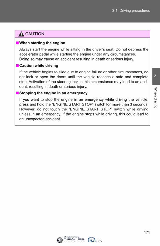
171
2-1. Driving procedures
2
When driving
CAUTION
■When starting the engineAlways start the engine while sitting in the driver’s seat. Do not depress theaccelerator pedal while starting the engine under any circumstances.Doing so may cause an accident resulting in death or serious injury.
■Caution while drivingIf the vehicle begins to slide due to engine failure or other circumstances, donot lock or open the doors until the vehicle reaches a safe and completestop. Activation of the steering lock in this circumstance may lead to an acci-dent, resulting in death or serious injury.
■Stopping the engine in an emergencyIf you want to stop the engine in an emergency while driving the vehicle,press and hold the “ENGINE START STOP” switch for more than 3 seconds.However, do not touch the “ENGINE START STOP” switch while drivingunless in an emergency. If the engine stops while driving, this could lead toan unexpected accident.
Information Provided by:
172
2-1. Driving procedures
NOTICE
■To prevent battery discharge●Do not leave the “ENGINE START STOP” switch in ACCESSORY or IGNI-
TION ON mode for long periods of time without the engine running.
● If the indicator on the “ENGINE START STOP” switch is illuminated, the“ENGINE START STOP” switch is not off. When exiting the vehicle,always check that the “ENGINE START STOP” switch is off.
●Do not stop the engine when the shift lever is in a position other than P. Ifthe engine is stopped in another shift lever position, the “ENGINE STARTSTOP” switch will not be turned off but instead be turned to ACCESSORYmode. If the vehicle is left in ACCESSORY mode, battery discharge mayoccur.
■When starting the engine●Do not race a cold engine.
● If the engine becomes difficult to start or stalls frequently, have the enginechecked immediately.
■Symptoms indicating a malfunction with the “ENGINE START STOP”switchIf the “ENGINE START STOP” seems to be operating somewhat differentlythan usual, such as the switch sticking slightly, there may be a malfunction.Contact your Toyota dealer immediately.
Information Provided by:
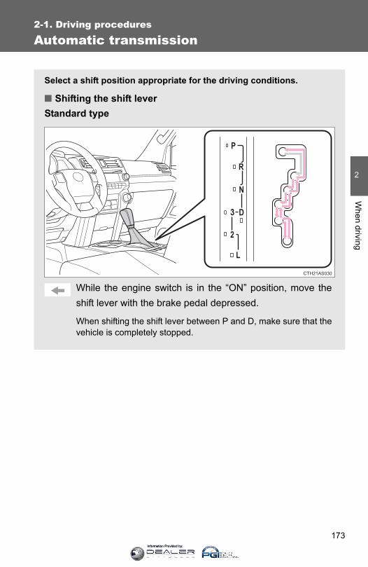
173
2-1. Driving procedures
2
When driving
Automatic transmission
Select a shift position appropriate for the driving conditions.
■ Shifting the shift leverStandard type
While the engine switch is in the “ON” position, move theshift lever with the brake pedal depressed.
When shifting the shift lever between P and D, make sure that thevehicle is completely stopped.
CTH21AS030
Information Provided by:

174
2-1. Driving procedures
Multi-mode type
Vehicles without a smart key system:While the engine switch is in the “ON” position, move theshift lever with the brake pedal depressed.
Vehicles with a smart key system:While the “ENGINE START STOP” switch is in IGNITIONON mode, move the shift lever with the brake pedaldepressed.
When shifting the shift lever between P and D, make sure that thevehicle is completely stopped.
CTH21AS014
Information Provided by:
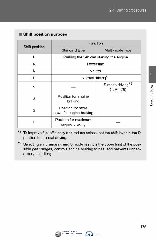
175
2-1. Driving procedures
2
When driving
■ Shift position purpose
*1: To improve fuel efficiency and reduce noises, set the shift lever in the Dposition for normal driving.
*2: Selecting shift ranges using S mode restricts the upper limit of the pos-sible gear ranges, controls engine braking forces, and prevents unnec-essary upshifting.
Shift positionFunction
Standard type Multi-mode type
P Parking the vehicle/ starting the engine
R Reversing
N Neutral
D Normal driving*1
S ⎯S mode driving*2
(→P. 176)
3 Position for engine braking ⎯
2 Position for morepowerful engine braking ⎯
L Position for maximum engine braking ⎯
Information Provided by:

176
2-1. Driving procedures
Changing shift ranges in S mode (multi-mode type)
When the shift lever is in the S position, the shift lever can be oper-ated as follows:
Non-Optitron type meterFor upshiftingFor downshifting
Optitron type meterFor upshiftingFor downshifting
The initial shift range in S mode is set automatically to “4” accordingto vehicle speed. However, the initial shift range may be set to “3” ifAI-SHIFT has operated while the shift lever was in the D position.(→P. 177)
■ Shift ranges and their functions● You can choose from 5 levels of engine braking force.
● A lower shift range will provide greater engine braking force thana higher shift range, and the engine speed will also increase.
CTH21AS025
CTH21AS015
Information Provided by:
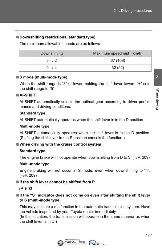
177
2-1. Driving procedures
2
When driving
■Downshifting restrictions (standard type)The maximum allowable speeds are as follows.
■S mode (multi-mode type)When the shift range is “3” or lower, holding the shift lever toward “+” setsthe shift range to “5”.
■AI-SHIFTAI-SHIFT automatically selects the optimal gear according to driver perfor-mance and driving conditions.
Standard typeAI-SHIFT automatically operates when the shift lever is in the D position.
Multi-mode typeAI-SHIFT automatically operates when the shift lever is in the D position.(Shifting the shift lever to the S position cancels the function.)
■When driving with the cruise control systemStandard typeThe engine brake will not operate when downshifting from D to 3. (→P. 209)
Multi-mode typeEngine braking will not occur in S mode, even when downshifting to “4”.(→P. 209)
■ If the shift lever cannot be shifted from P
→P. 593■ If the “S” indicator does not come on even after shifting the shift lever
to S (multi-mode type)This may indicate a malfunction in the automatic transmission system. Havethe vehicle inspected by your Toyota dealer immediately. (In this situation, the transmission will operate in the same manner as whenthe shift lever is in D.)
Downshifting Maximum speed mph (km/h)
3 → 2 67 (108)
2 → L 32 (52)
Information Provided by:
178
2-1. Driving procedures
■Downshift restriction warning buzzer (S mode in multi-mode type)To help ensure safety and driving performance, downshifting operation maysometimes be restricted. In some circumstances, downshifting may not bepossible even when the shift lever is operated. (A buzzer will sound twice.)
CAUTION
■When driving on slippery road surfacesDo not accelerate or shift gears suddenly. Sudden changes in engine braking may cause the vehicle to spin or skid,resulting in an accident.
Information Provided by:
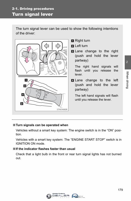
179
2-1. Driving procedures
2
When driving
Turn signal lever
■Turn signals can be operated whenVehicles without a smart key system: The engine switch is in the “ON” posi-tion.
Vehicles with a smart key system: The “ENGINE START STOP” switch is inIGNITION ON mode.
■ If the indicator flashes faster than usualCheck that a light bulb in the front or rear turn signal lights has not burnedout.
The turn signal lever can be used to show the following intentionsof the driver:
Right turnLeft turnLane change to the right(push and hold the leverpartway)
The right hand signals willflash until you release thelever.
Lane change to the left(push and hold the leverpartway)
The left hand signals will flashuntil you release the lever.
CTH21AS028
Information Provided by:
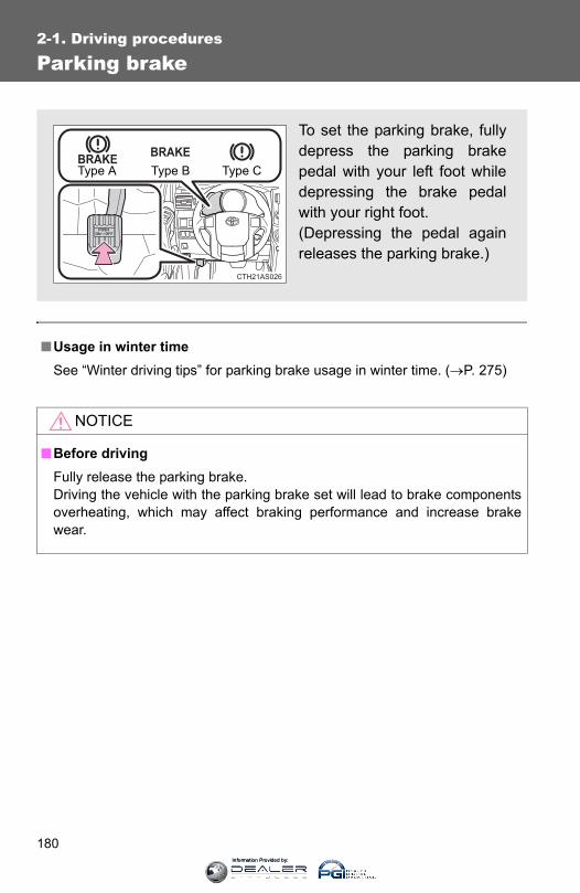
180
2-1. Driving procedures
Parking brake
■Usage in winter timeSee “Winter driving tips” for parking brake usage in winter time. (→P. 275)
NOTICE
■Before drivingFully release the parking brake.Driving the vehicle with the parking brake set will lead to brake componentsoverheating, which may affect braking performance and increase brakewear.
To set the parking brake, fullydepress the parking brakepedal with your left foot whiledepressing the brake pedalwith your right foot. (Depressing the pedal againreleases the parking brake.)
BRAKEBRAKE
CTH21AS026
Type A Type B Type C
Information Provided by:
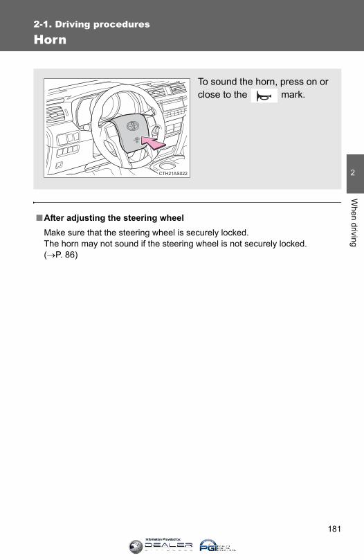
181
2-1. Driving procedures
2
When driving
Horn
■After adjusting the steering wheelMake sure that the steering wheel is securely locked.The horn may not sound if the steering wheel is not securely locked. (→P. 86)
To sound the horn, press on orclose to the mark.
CTH21AS022
Information Provided by:
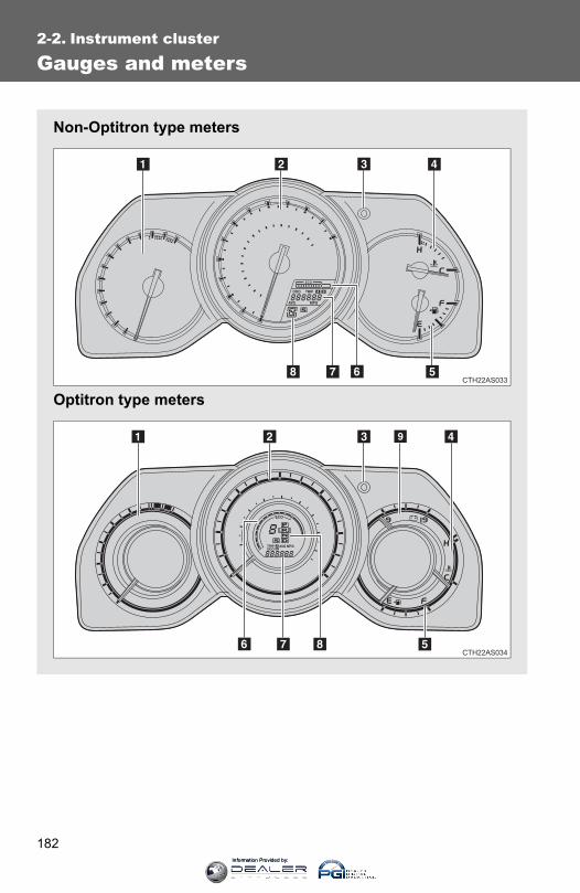
182
2-2. Instrument cluster
Gauges and meters
Non-Optitron type meters
Optitron type meters
Information Provided by:
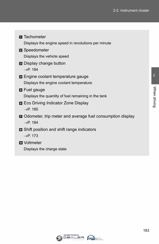
183
2-2. Instrument cluster
2
When driving
TachometerDisplays the engine speed in revolutions per minute
SpeedometerDisplays the vehicle speed
Display change button→P. 184
Engine coolant temperature gaugeDisplays the engine coolant temperature
Fuel gaugeDisplays the quantity of fuel remaining in the tank
Eco Driving Indicator Zone Display→P. 185
Odometer, trip meter and average fuel consumption display→P. 184
Shift position and shift range indicators→P. 173
VoltmeterDisplays the charge state
Information Provided by:

184
2-2. Instrument cluster
Switching the display
Items displayed can be switchedby pressing the display changebutton.
■ OdometerDisplays the total distance the vehicle has been driven.
■ Trip meterDisplays the distance the vehicle has been driven since the meterwas last reset. Trip meters “A” and “B” can be used to record anddisplay different distances independently.
Pressing and holding the display change button will reset the trip meterthat is currently displayed.
Information Provided by:
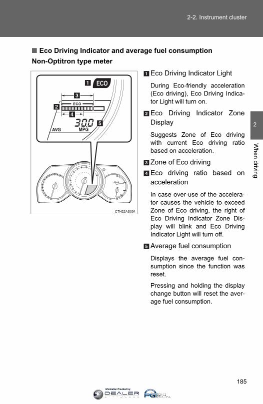
185
2-2. Instrument cluster
2
When driving
■ Eco Driving Indicator and average fuel consumptionNon-Optitron type meter
Eco Driving Indicator Light
During Eco-friendly acceleration(Eco driving), Eco Driving Indica-tor Light will turn on.
Eco Driving Indicator ZoneDisplay
Suggests Zone of Eco drivingwith current Eco driving ratiobased on acceleration.
Zone of Eco drivingEco driving ratio based onacceleration
In case over-use of the accelera-tor causes the vehicle to exceedZone of Eco driving, the right ofEco Driving Indicator Zone Dis-play will blink and Eco DrivingIndicator Light will turn off.
Average fuel consumption
Displays the average fuel con-sumption since the function wasreset.
Pressing and holding the displaychange button will reset the aver-age fuel consumption.
CTH22AS054
Information Provided by:
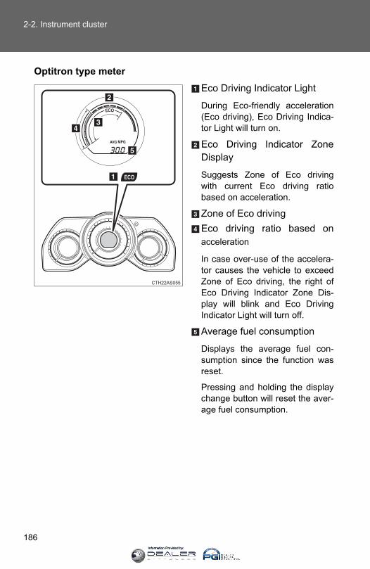
186
2-2. Instrument cluster
Optitron type meterEco Driving Indicator Light
During Eco-friendly acceleration(Eco driving), Eco Driving Indica-tor Light will turn on.
Eco Driving Indicator ZoneDisplay
Suggests Zone of Eco drivingwith current Eco driving ratiobased on acceleration.
Zone of Eco drivingEco driving ratio based onacceleration
In case over-use of the accelera-tor causes the vehicle to exceedZone of Eco driving, the right ofEco Driving Indicator Zone Dis-play will blink and Eco DrivingIndicator Light will turn off.
Average fuel consumption
Displays the average fuel con-sumption since the function wasreset.
Pressing and holding the displaychange button will reset the aver-age fuel consumption.
CTH22AS055
Information Provided by:
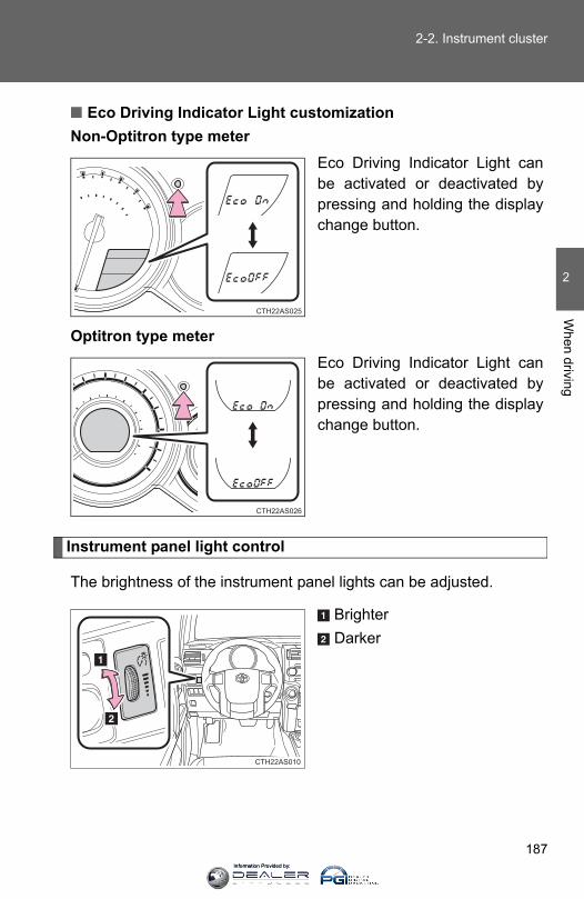
187
2-2. Instrument cluster
2
When driving
■ Eco Driving Indicator Light customizationNon-Optitron type meter
Eco Driving Indicator Light canbe activated or deactivated bypressing and holding the displaychange button.
Optitron type meterEco Driving Indicator Light canbe activated or deactivated bypressing and holding the displaychange button.
Instrument panel light control
The brightness of the instrument panel lights can be adjusted.
BrighterDarker
CTH22AS010
Information Provided by:
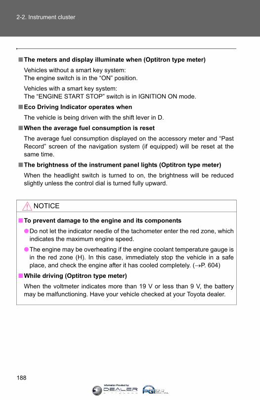
188
2-2. Instrument cluster
■The meters and display illuminate when (Optitron type meter)Vehicles without a smart key system: The engine switch is in the “ON” position.
Vehicles with a smart key system: The “ENGINE START STOP” switch is in IGNITION ON mode.
■Eco Driving Indicator operates whenThe vehicle is being driven with the shift lever in D.
■When the average fuel consumption is resetThe average fuel consumption displayed on the accessory meter and “PastRecord” screen of the navigation system (if equipped) will be reset at thesame time.
■The brightness of the instrument panel lights (Optitron type meter)When the headlight switch is turned to on, the brightness will be reducedslightly unless the control dial is turned fully upward.
NOTICE
■To prevent damage to the engine and its components●Do not let the indicator needle of the tachometer enter the red zone, which
indicates the maximum engine speed.
●The engine may be overheating if the engine coolant temperature gauge isin the red zone (H). In this case, immediately stop the vehicle in a safeplace, and check the engine after it has cooled completely. (→P. 604)
■While driving (Optitron type meter)When the voltmeter indicates more than 19 V or less than 9 V, the batterymay be malfunctioning. Have your vehicle checked at your Toyota dealer.
Information Provided by:
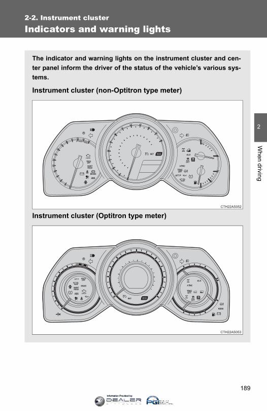
189
2-2. Instrument cluster
2
When driving
Indicators and warning lights
The indicator and warning lights on the instrument cluster and cen-ter panel inform the driver of the status of the vehicle’s various sys-tems.
Instrument cluster (non-Optitron type meter)
Instrument cluster (Optitron type meter)CTH22AS052
CTH22AS053
Information Provided by:
190
2-2. Instrument cluster
Center panel
CTH22AS015
Information Provided by:

191
2-2. Instrument cluster
2
When driving
■ IndicatorsThe indicators inform the driver of the operating state of thevehicle’s various systems.
Turn signal indicator (→P. 179)
(Canada)
“TRC OFF” indicator (→P. 255)
Headlight high beam indicator (→P. 202)
Roll sensing of curtain shield airbags off indica-tor (→P. 128)
(U.S.A.)
Headlight indicator (→P. 198)
(if equipped)
Four-wheel drive indica-tor (→P. 223)
(Canada)
Tail light indicator(→P. 198)
(if equipped)
Downhill assist control system indicator (→P. 238)
(if equipped)
Front fog light indicator(→P. 204)
(if equipped)
Low speed four-wheel drive indicator (→P. 223, 226)
Cruise control indicator (→P. 209)
(if equipped)
Rear differential lock indicator (→P. 235)
Cruise control set indi-cator (→P. 209)
(if equipped)
Center differential lock indicator (→P. 226)
Slip indicator (→P. 254)(if equipped)
“A-TRAC” indicator (→P. 230)
VSC off indicator (→P. 255)
(if equipped)
“AUTO LSD” indicator (→P. 232)
(U.S.A.)
“TRAC OFF” indicator (→P. 255) (if equipped)
Multi-terrain Select indi-cator (→P. 245)
*
*
*
*
* *
*
Information Provided by:
192
2-2. Instrument cluster
*: These lights turn on when the “ENGINE START STOP” switch is turnedto IGNITION ON mode (vehicles with a smart key system) or theengine switch is turned to the “ON” position (vehicles without a smartkey system) to indicate that a system check is being performed. Theywill turn off after the engine is started, or after a few seconds. Theremay be a malfunction in a system if a light does not come on, or if thelights do not turn off. Have the vehicle inspected by your Toyota dealer.
(if equipped)
Crawl Control indicator(→P. 241)
Security indicator (→P. 106, 109)
Eco Driving Indicator Light (→P. 185)
(if equipped)
Intuitive parking assist indicator (→P. 213)
SRS airbag on-off indi-cator (→P. 130)
*
*
*
Information Provided by:
193
2-2. Instrument cluster
2
When driving
CAUTION
■ If a safety system warning light does not come onShould a safety system light such as the ABS or SRS warning light not comeon when you start the engine, this could mean that these systems are notavailable to help protect you in an accident, which could result in death orserious injury. Have the vehicle inspected by your Toyota dealer immediatelyif this occurs.
■ Warning lightsWarning lights inform the driver of malfunctions in any of thevehicle’s systems. (→P. 565)
*: These lights turn on when the “ENGINE START STOP” switch isturned to IGNITION ON mode (vehicles with a smart key system) orthe engine switch is turned to the “ON” position (vehicles without asmart key system) to indicate that a system check is being per-formed. They will turn off after the engine is started, or after a fewseconds. There may be a malfunction in a system if a light does notcome on, or if the lights do not turn off. Have the vehicle inspectedby your Toyota dealer.
(if equipped) (if equipped) (if equipped) (U.S.A.)
(Canada) (U.S.A.) (Canada) (if equipped)
(if equipped) (if equipped)
* * * * * * * *
* * * * *
* * *
Information Provided by:

194
2-2. Instrument cluster
Accessory meter
The accessory meter presents the driver with a variety of driving-related data including the current outside air temperature.
“MODE/ ” button“SET/ ” buttonTrip information (→P. 195)Displays driving range and average fuel consumption
Outside temperature display (→P. 433)Compass (→P. 450)Clock (→P. 431)H (Hour) button (→P. 431)M (Minute) button (→P. 431)Multi-terrain Select display (→P. 245)Automatically displayed when using Multi-terrain Select
Information Provided by:
195
2-2. Instrument cluster
2
When driving
Trip information
Items displayed can be switched by pressing the “MODE/ ” button.
■ Driving range
■ Average fuel consumption
(vehicles without Multi-terrain Select)
(vehicles with Multi-terrain Select)
Displays the estimated maximum distance thatcan be driven with the quantity of fuel remaining
• This distance is computed based on your averagefuel consumption. As a result, the actual distancethat can be driven may differ from that displayed.
• When only a small amount of fuel is added to thetank, the display may not be updated.
(vehicles without Multi-terrain Select)
(vehicles with Multi-terrain Select)
Displays the average fuel consumption since thefunction was reset
Pressing and holding the “SET/ ” button will resetthe average fuel consumption.
Information Provided by:
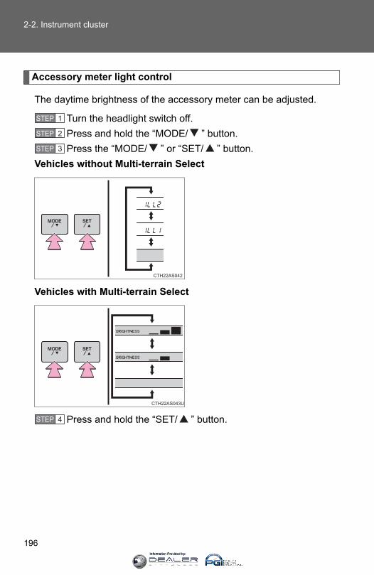
196
2-2. Instrument cluster
Accessory meter light control
The daytime brightness of the accessory meter can be adjusted.
Turn the headlight switch off.Press and hold the “MODE/ ” button.Press the “MODE/ ” or “SET/ ” button.
Vehicles without Multi-terrain Select
Vehicles with Multi-terrain Select
Press and hold the “SET/ ” button.
STEP 1
STEP 2
STEP 3
STEP 4
Information Provided by:
197
2-2. Instrument cluster
2
When driving
■When the average fuel consumption is resetThe average fuel consumption displayed on the instrument cluster and “PastRecord” screen of the navigation system (if equipped) will be reset at thesame time.
■Adjusting the brightness of the accessory meter● If left idle for approximately 6 seconds or more while adjusting, the dis-
play will revert to the trip information display.
●When the parking lights are on, the brightness of the accessory metercan be adjusted only with the instrument panel light control.
● If the “MODE/ ” button is pressed and held when the accessory meterlight control is displayed, the display will switch to compass calibration.(→P. 450)
■Liquid crystal displaySmall spots or light spots may appear on the display. This phenomenon ischaracteristic of liquid crystal displays, and there is no problem with continu-ing to use the display.
NOTICE
■The accessory meter at low temperaturesAllow the interior of the vehicle to warm up before using the liquid crystal dis-play. At extremely low temperatures, the display monitor may respondslowly, and display changes may be delayed.
Information Provided by:

198
2-3. Operating the lights and wipers
Headlight switch
The headlights can be operated manually or automatically.
Turning the end of the lever turns on the lights as follows:
Type AThe daytime runninglights turn on.The side marker, park-ing, tail, license plate,daytime running lightsand instrument panellights turn on.The headlights and allthe lights listed aboveturn on. The daytime runninglights turn off.
CTH23AS033
Information Provided by:
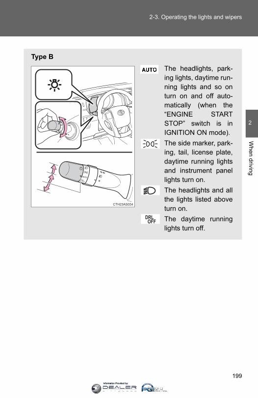
199
2-3. Operating the lights and wipers
2
When driving
Type BThe headlights, park-ing lights, daytime run-ning lights and so onturn on and off auto-matically (when the“ENGINE STARTSTOP” switch is inIGNITION ON mode).The side marker, park-ing, tail, license plate,daytime running lightsand instrument panellights turn on.The headlights and allthe lights listed aboveturn on.The daytime runninglights turn off.
CTH23AS034
Information Provided by:
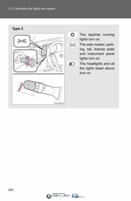
200
2-3. Operating the lights and wipers
Type CThe daytime runninglights turn on.The side marker, park-ing, tail, license plateand instrument panellights turn on. The headlights and allthe lights listed aboveturn on.
CTH23AS030
Information Provided by:
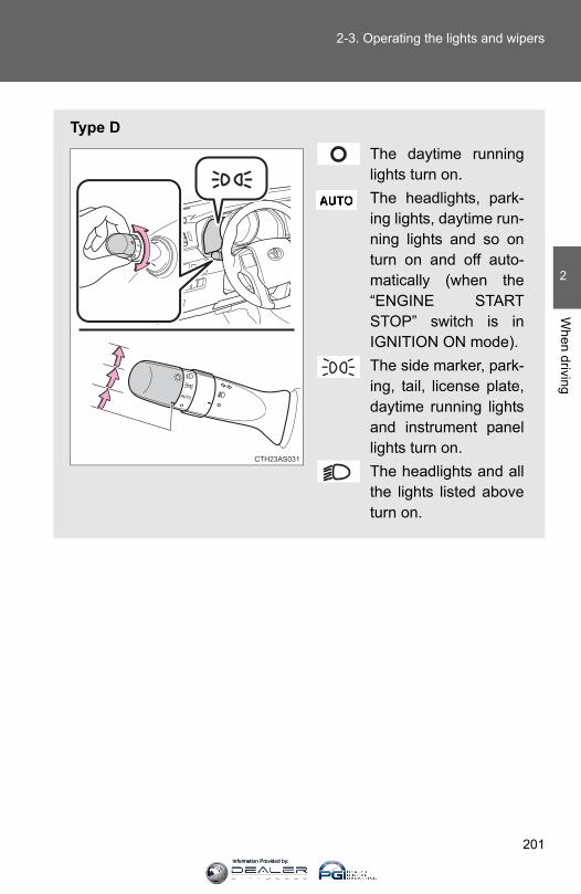
201
2-3. Operating the lights and wipers
2
When driving
Type DThe daytime runninglights turn on.The headlights, park-ing lights, daytime run-ning lights and so onturn on and off auto-matically (when the“ENGINE STARTSTOP” switch is inIGNITION ON mode).The side marker, park-ing, tail, license plate,daytime running lightsand instrument panellights turn on.The headlights and allthe lights listed aboveturn on.
CTH23AS031
Information Provided by:
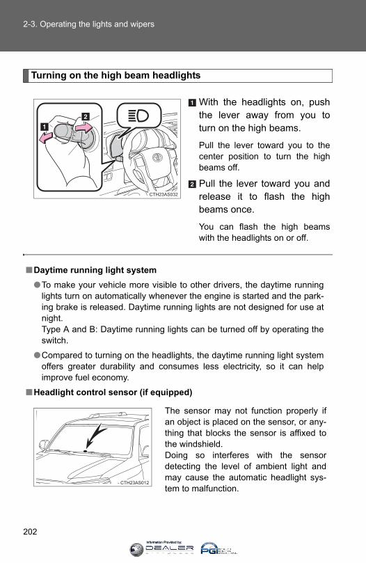
202
2-3. Operating the lights and wipers
Turning on the high beam headlights
With the headlights on, pushthe lever away from you toturn on the high beams.
Pull the lever toward you to thecenter position to turn the highbeams off.
Pull the lever toward you andrelease it to flash the highbeams once.
You can flash the high beamswith the headlights on or off.
CTH23AS032
■Daytime running light system●To make your vehicle more visible to other drivers, the daytime running
lights turn on automatically whenever the engine is started and the park-ing brake is released. Daytime running lights are not designed for use atnight.Type A and B: Daytime running lights can be turned off by operating theswitch.
●Compared to turning on the headlights, the daytime running light systemoffers greater durability and consumes less electricity, so it can helpimprove fuel economy.
■Headlight control sensor (if equipped)
The sensor may not function properly ifan object is placed on the sensor, or any-thing that blocks the sensor is affixed tothe windshield. Doing so interferes with the sensordetecting the level of ambient light andmay cause the automatic headlight sys-tem to malfunction.
CTH23AS012
Information Provided by:
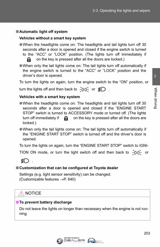
203
2-3. Operating the lights and wipers
2
When driving
■Automatic light off systemVehicles without a smart key system●When the headlights come on: The headlights and tail lights turn off 30
seconds after a door is opened and closed if the engine switch is turnedto the “ACC” or “LOCK” position. (The lights turn off immediately if
on the key is pressed after all the doors are locked.)
●When only the tail lights come on: The tail lights turn off automatically ifthe engine switch is turned to the “ACC” or “LOCK” position and thedriver’s door is opened.
To turn the lights on again, turn the engine switch to the “ON” position, or
turn the lights off and then back to or .
Vehicles with a smart key system●When the headlights come on: The headlights and tail lights turn off 30
seconds after a door is opened and closed if the “ENGINE STARTSTOP” switch is turned to ACCESSORY mode or turned off. (The lightsturn off immediately if on the key is pressed after all the doors arelocked.)
●When only the tail lights come on: The tail lights turn off automatically ifthe “ENGINE START STOP” switch is turned off and the driver’s door isopened.
To turn the lights on again, turn the “ENGINE START STOP” switch to IGNI-
TION ON mode, or turn the light switch off and then back to or
.
■Customization that can be configured at Toyota dealerSettings (e.g. light sensor sensitivity) can be changed. (Customizable features →P. 640)
NOTICE
■To prevent battery dischargeDo not leave the lights on longer than necessary when the engine is not run-ning.
Information Provided by:
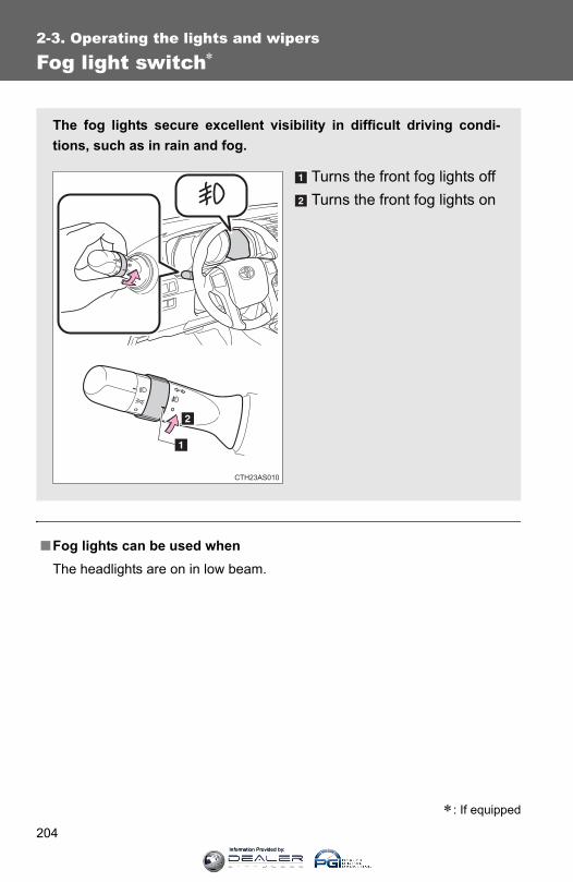
204
2-3. Operating the lights and wipers
Fog light switch∗
■Fog lights can be used whenThe headlights are on in low beam.
The fog lights secure excellent visibility in difficult driving condi-tions, such as in rain and fog.
Turns the front fog lights offTurns the front fog lights on
CTH23AS010
∗: If equipped
Information Provided by:

205
2-3. Operating the lights and wipers
2
When driving
Windshield wipers and washer
When intermittent windshield wiper operation is selected, the wiperinterval can be adjusted.
The wiper operation is selected by moving the lever as follows.
Intermittent windshieldwiper operationLow speed windshield wiperoperationHigh speed windshieldwiper operationTemporary operation
Increases the intermittentwindshield wiper frequencyDecreases the intermittentwindshield wiper frequency
CTH23AS027
CTH23AS028
Information Provided by:

206
2-3. Operating the lights and wipers
■The windshield wipers and washer can be operated whenVehicles without a smart key system: The engine switch is in the “ON” posi-tion.
Vehicles with a smart key system: The “ENGINE START STOP” switch is inIGNITION ON mode.
■ If no windshield washer fluid spraysCheck that the washer nozzles are not blocked if there is washer fluid in thewindshield washer fluid reservoir.
NOTICE
■When the windshield is dryDo not use the wipers, as they may damage the windshield.
■When the washer fluid tank is emptyDo not operate the switch continually as the washer fluid pump may over-heat.
■When a nozzle becomes blockedDo not try to clear it with a pin or other object. The nozzle will be damaged.
Washer/wiper dual opera-tion
The wipers will automaticallyoperate a couple of times afterthe washer squirts.
CTH23AS029
Information Provided by:
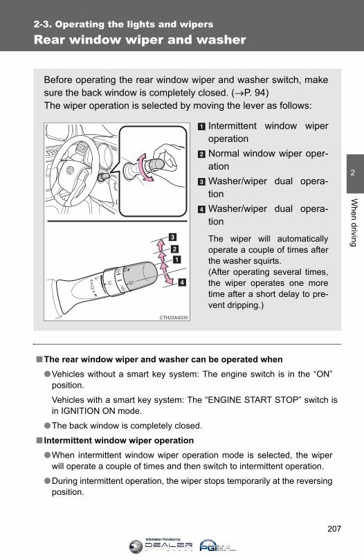
207
2-3. Operating the lights and wipers
2
When driving
Rear window wiper and washer
■The rear window wiper and washer can be operated when●Vehicles without a smart key system: The engine switch is in the “ON”
position.
Vehicles with a smart key system: The “ENGINE START STOP” switch isin IGNITION ON mode.
●The back window is completely closed.
■ Intermittent window wiper operation●When intermittent window wiper operation mode is selected, the wiper
will operate a couple of times and then switch to intermittent operation.
●During intermittent operation, the wiper stops temporarily at the reversingposition.
Before operating the rear window wiper and washer switch, makesure the back window is completely closed. (→P. 94)The wiper operation is selected by moving the lever as follows:
Intermittent window wiperoperationNormal window wiper oper-ationWasher/wiper dual opera-tionWasher/wiper dual opera-tion
The wiper will automaticallyoperate a couple of times afterthe washer squirts.(After operating several times,the wiper operates one moretime after a short delay to pre-vent dripping.)
CTH23AS035
Information Provided by:

208
2-3. Operating the lights and wipers
■When the rear window wiper and washer switch is turned offThe rear wiper will stop operation, and return to the retracted position afterapproximately 3 seconds.However, if the engine switch is turned to the “ACC” or “LOCK” position(vehicles without a smart key system) or the “ENGINE START STOP” switchis turned to ACCESSORY mode or turned off (vehicles with a smart key sys-tem) while the rear wiper is operating, the rear wiper will stop at that positionand will not return to the retracted position.
■ If no washer fluid spraysCheck that the washer nozzle is not blocked if there is washer fluid in thewasher fluid reservoir.
■Customization that can be configured at Toyota dealerSettings (e.g. drip prevention function) can be changed. (Customizable features →P. 640)
NOTICE
■When the rear window is dryDo not use the wiper, as it may damage the rear window.
■When the washer fluid tank is emptyDo not operate the switch continually as the washer fluid pump may over-heat.
■When a nozzle becomes blockedDo not try to clear it with a pin or other object. The nozzle will be damaged.
Information Provided by:

209
2
When driving
2-4. Using other driving systems
Cruise control
Use cruise control to maintain a set speed without depressing theaccelerator pedal.
IndicatorsCruise control switch
■ Setting the vehicle speedPress the “ON-OFF” button toactivate the cruise control.
Press the button again todeactivate the cruise control.
Accelerate or decelerate tothe desired speed, and pushthe lever down to set thespeed.
CTH24AS001
CTH24AS002
STEP 1
CTH24AS057
STEP 2
Information Provided by:

210
2-4. Using other driving systems
■ Adjusting the set speedIncreases the speedDecreases the speed
Hold the lever until the desiredspeed setting is obtained.
Fine adjustment of the setspeed can be made by lightlypushing the lever up or downand releasing it.
■ Canceling and resuming the constant speed controlPulling the lever toward youcancels the constant speedcontrol.
The speed setting is also can-celed when the brakes areapplied.
Pushing the lever upresumes the constantspeed control.
CTH24AS004
CTH24AS005
Information Provided by:

211
2-4. Using other driving systems
2
When driving
■Cruise control can be set when●The shift lever is in D or “3” (standard type), or in D, or “4” or “5” range of
S has been selected (multi-mode type).
●Vehicle speed is above 25 mph (40 km/h).
■AcceleratingThe vehicle can be accelerated normally. After acceleration, the set speedresumes.
■Automatic cruise control cancelationCruise control will stop maintaining the vehicle speed in any of the followingsituations:
●Actual vehicle speed falls more than 10 mph (16 km/h) below the presetvehicle speed.At this time, the memorized set speed is not retained.
●Actual vehicle speed is below 25 mph (40 km/h).
●VSC is activated.
■ If the cruise control indicator light flashesPress the “ON-OFF” button once to deactivate the system, and then pressthe button again to reactivate the system.If the cruise control speed cannot be set or if the cruise control cancelsimmediately after being activated, there may be a malfunction in the cruisecontrol system. Have the vehicle inspected by your Toyota dealer.
Information Provided by:

212
2-4. Using other driving systems
CAUTION
■To avoid operating the cruise control by mistakeSwitch the cruise control off using the “ON-OFF” button when not in use.
■Situations unsuitable for cruise controlDo not use cruise control in any of the following situations.Doing so may result in loss of control and could cause an accident resultingin death or serious injury.
● In heavy traffic
●On roads with sharp bends
●On winding roads
●On slippery roads, such as those covered with rain, ice or snow
●On steep hills Vehicle speed may exceed the set speed when driving down a steep hill.
●When your vehicle is towing anything
Information Provided by:

213
2-4. Using other driving systems
2
When driving
Intuitive parking assist∗
The distance from your vehicle to nearby obstacles when parallelparking or maneuvering into a garage is measured by the sensorsand communicated via an indicator and a buzzer. Always check thesurrounding area when using this system.
■ Types of sensorsRear corner sensors Rear center sensors
■ Intuitive parking assist switchTurns the intuitive parkingassist on/off
When on, the indicator lightcomes on and the buzzersounds to inform the driverthat the system is operational.
CTH24AS008
∗: If equipped
Information Provided by:

214
2-4. Using other driving systems
The indicator and buzzer
When a sensor detects an obstacle, the direction of the obstacle isindicated and the buzzer sounds.
■ Sensor operation and distance to an obstacleThe system operates when the vehicle approaches an obstacle, asshown by the following table.
Rear corner sensors
Rear center sensors
Distance to an obstacle ft. (cm) Indicator and buzzer
Approximately 1.6 - 1.2 (50 - 37.5) Intermittent
Approximately 1.2 - 0.8 (37.5 - 25) Fast intermittent
Approximately 0.8 or less (25 or less) Continuously
Distance to an obstacle ft. (cm) Indicator and buzzer
Approximately 4.9 - 2.0 (150 - 60) Intermittent
Approximately 2.0 - 1.5 (60 - 45) Fast intermittent
Approximately 1.5 - 1.2 (45 - 35) Very fast intermittent
Approximately 1.2 or less (35 or less) Continuously
Information Provided by:
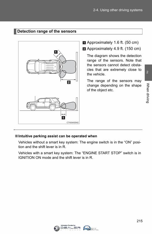
215
2-4. Using other driving systems
2
When driving
Detection range of the sensors
Approximately 1.6 ft. (50 cm)Approximately 4.9 ft. (150 cm)
The diagram shows the detectionrange of the sensors. Note thatthe sensors cannot detect obsta-cles that are extremely close tothe vehicle.
The range of the sensors maychange depending on the shapeof the object etc.
■ Intuitive parking assist can be operated whenVehicles without a smart key system: The engine switch is in the “ON” posi-tion and the shift lever is in R.
Vehicles with a smart key system: The “ENGINE START STOP” switch is inIGNITION ON mode and the shift lever is in R.
Information Provided by:
216
2-4. Using other driving systems
■Sensor detection information●Certain vehicle conditions and the surrounding environment may affect
the ability of a sensor to correctly detect an obstacle. Particular instanceswhere this may occur are listed below.
• There is dirt, snow or ice on a sensor.• A sensor is frozen.• A sensor is covered in any way.• The vehicle is leaning considerably to one side.• On an extremely bumpy road, on an incline, on gravel, or on grass• The vicinity of the vehicle is noisy due to vehicle horns, motorcycle
engines, air brakes of large vehicles, or other loud noises producingultrasonic waves.
• There is another vehicle equipped with parking assist sensors in thevicinity.
• A sensor is coated with a sheet of spray or heavy rain.• A bumper or sensor receives a strong impact.• The vehicle is approaching a tall or right-angled curb.• In harsh sunlight or intense cold weather• A non-genuine Toyota suspension (lowered suspension etc.) is
installed.In addition to the examples above, there are instances in which, because oftheir shape, signs and other objects may be judged by a sensor to be closerthan they are.
●The shape of the obstacle may prevent a sensor from detecting it. Payparticular attention to the following obstacles:
• Wires, fences, ropes, etc.• Cotton, snow and other materials that absorb sound waves• Sharply-angled objects• Low obstacles• Tall obstacles with upper sections projecting outwards in the direction
of your vehicle
Information Provided by:
217
2-4. Using other driving systems
2
When driving
■When the system malfunctionsIf a malfunction occurs and no obstacles have been detected, the indicatorflashes and the buzzer sounds for approximately 7 seconds. If the indicator comes on and stays on after that, have the vehicle inspectedby your Toyota dealer.
■Customization that can be configured at Toyota dealerSettings (e.g. buzzer volume) can be changed. (Customizable features →P. 640)
■CertificationFor vehicles sold in the U.S.A.This device complies with Part 15 of the FCC Rules. Operation is subject tothe following two conditions; (1) This device may not cause harmful interfer-ence, and (2) This device must accept any interference received, includinginterference that may cause undesired operation.
For vehicles sold in CanadaThis ISM device complies with Canadian ICES-001.
Cet appareil ISM est conforme a la norme NMB-001 du Canada.
CAUTION
■Caution when using the intuitive parking assist-sensorDo not attach any accessories within the sensor range.Doing so may result in the vehicle being unable to be driven safely and pos-sibly cause an accident.
NOTICE
■Notes when washing the vehicleDo not apply intensive bursts of water or steam to the sensor area.Doing so may result in the sensor malfunctioning.
Information Provided by:
218
2-4. Using other driving systems
Rear view monitor system (rear view mirror-attached type)∗
The rear view monitor assists the driver by displaying an image ofthe area behind the vehicle while reversing. The image is displayedin reverse on the screen. This reversed image is a similar image tothe one on the inside rear view mirror.
The rear view image is dis-played when the shift lever isin R.
• If the shift lever is shifted out ofR, the screen is turned off.
• The screen remains on forapproximately 5 minutes.
CTH24AS063
Multi-mode type Standard type
∗: If equipped
Information Provided by:
219
2-4. Using other driving systems
2
When driving
■The rear view monitor system can be operated whenVehicles without a smart key system: The engine switch is in the “ON” posi-tion and the shift lever is in R.
Vehicles with a smart key system: The “ENGINE START STOP” switch is inIGNITION ON mode and the shift lever is in R.
■Switching the screen on/off
When the screen is displayed, press the“AUTO” button on the inside rear viewmirror to switch the screen on/off.
Screen on: Green indicator comes on.
Screen off: Orange indicator comes on.
In the following situation, the displaywill be re-enabled if it has been turnedoff:
Vehicles without a smart key systemThe engine switch is turned to the “ON”position.
Vehicles with a smart key systemThe “ENGINE START STOP” switch isturned to IGNITION ON mode.
CTH24AS014
Information Provided by:
220
2-4. Using other driving systems
■Displayed area
■Rear view monitor system camera
The area covered by the camera is lim-ited. Objects that are close to either cor-ner of the bumper or under the bumpercannot be seen on the screen.
The area displayed on the screen mayvary depending on vehicle orientation orroad conditions.
CTH24AS059
Corners of bumper
CTH24AS067
The rear view monitor system camera islocated on the back door as shown in theillustration. The camera uses a speciallens. The distance of the image thatappears on the screen differs from theactual distance.
In the following cases, it may become dif-ficult to see images on the screen evenwhen the system is functioning correctly:
●The vehicle is in a dark area, such as atnight.
●The temperature near the lens isextremely high or low.
CTH24AS012
Information Provided by:

221
2-4. Using other driving systems
2
When driving
■Smear effect
■Flicker effectWhen the camera is used under fluorescent light, sodium lights, or mercurylights etc., the lights and the illuminated areas may appear to flicker.
●Water droplets are on the camera lensor humidity is high, such as when itrains.
●Foreign matter, such as snow or mud,adheres to the camera lens.
●When the camera has scratches or dirton it.
●The sun or headlights are shiningdirectly into the camera lens.
●A bright object such as a white wall isreflected in the mirror surface over themonitor.
If a bright light, such as sunlight reflectedoff the vehicle body, is picked up by thecamera, a smear effect* characteristic tothe camera may occur.
*: Smear effect ⎯ A phenomenon thatoccurs when a bright light is picked upby the camera; when transmitted by thecamera, the light source appears tohave a vertical streak above and belowit.
CTH24AS045
Information Provided by:
222
2-4. Using other driving systems
CAUTION
■When using the rear view monitor systemObserve the following precautions to avoid an accident that could result indeath or serious injuries:
●Never depend solely on the monitor system when reversing.
●Always check visually and with the mirrors to confirm your intended path isclear.
●Use your own eyes to confirm the vehicle’s surroundings, as the displayedimage may become faint or dark, and moving images will be distorted, ornot entirely visible when the outside temperature is low. When backing up,be sure to check behind and all around the vehicle visually and with themirrors before proceeding.
●Depicted distances between objects and flat surfaces differ from actualdistances.
●Do not use the system if the back door is open.
■Conditions which may affect the rear view monitor system● If the back of the vehicle has been hit, the camera’s position and mounting
angle may have changed. Have the vehicle inspected by your Toyotadealer.
●Rapid temperature changes, such as when hot water is poured on thevehicle in cold weather, may cause the system to function abnormally.
● If the camera lens is dirty, it cannot transmit a clear image. Rinse withwater and wipe with a soft cloth. If the camera lens is extremely dirty, washwith a mild cleanser and rinse.
●The displayed image may be darker and moving images may be slightlydistorted when the system is cold.
NOTICE
●Do not allow organic solvent, car wax, window cleaner or glass coat toadhere to the camera. If this happens, wipe it off as soon as possible.
●When replacing tires, please consult your Toyota dealer. If you replace thetires, the area displayed on the screen may change.
Information Provided by:
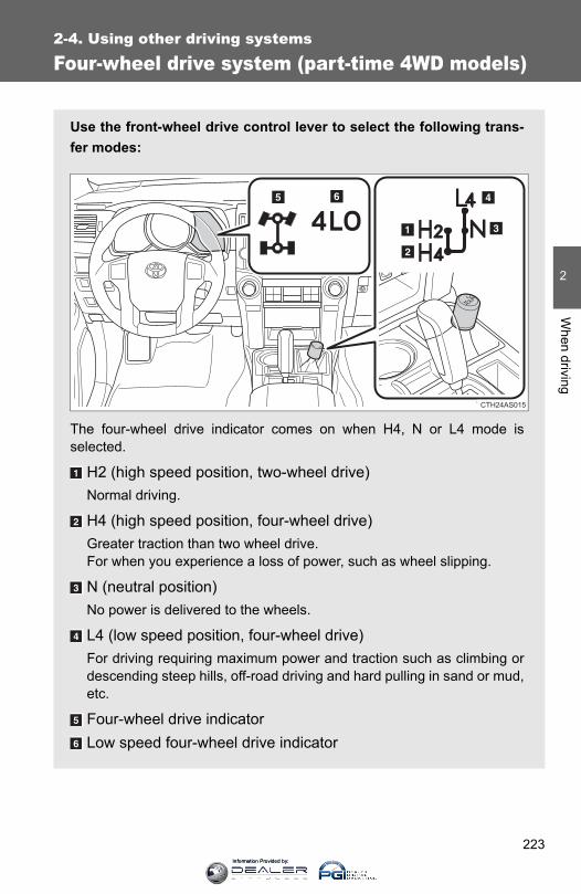
223
2-4. Using other driving systems
2
When driving
Four-wheel drive system (part-time 4WD models)
Use the front-wheel drive control lever to select the following trans-fer modes:
The four-wheel drive indicator comes on when H4, N or L4 mode isselected.
H2 (high speed position, two-wheel drive)Normal driving.
H4 (high speed position, four-wheel drive)Greater traction than two wheel drive.For when you experience a loss of power, such as wheel slipping.
N (neutral position)No power is delivered to the wheels.
L4 (low speed position, four-wheel drive)For driving requiring maximum power and traction such as climbing ordescending steep hills, off-road driving and hard pulling in sand or mud,etc.
Four-wheel drive indicatorLow speed four-wheel drive indicator
CTH24AS015
Information Provided by:
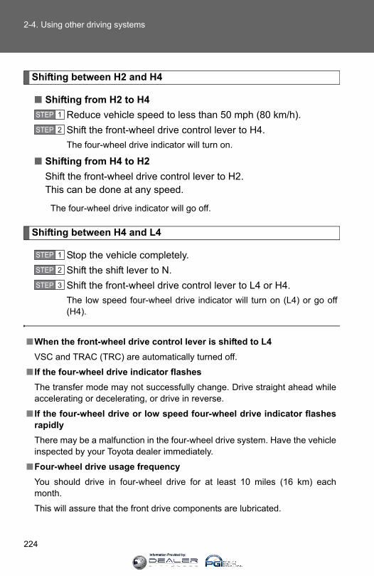
224
2-4. Using other driving systems
Shifting between H2 and H4
■ Shifting from H2 to H4Reduce vehicle speed to less than 50 mph (80 km/h).Shift the front-wheel drive control lever to H4.The four-wheel drive indicator will turn on.
■ Shifting from H4 to H2Shift the front-wheel drive control lever to H2. This can be done at any speed.
The four-wheel drive indicator will go off.
Shifting between H4 and L4
Stop the vehicle completely.Shift the shift lever to N.Shift the front-wheel drive control lever to L4 or H4.The low speed four-wheel drive indicator will turn on (L4) or go off(H4).
■When the front-wheel drive control lever is shifted to L4VSC and TRAC (TRC) are automatically turned off.
■ If the four-wheel drive indicator flashesThe transfer mode may not successfully change. Drive straight ahead whileaccelerating or decelerating, or drive in reverse.
■ If the four-wheel drive or low speed four-wheel drive indicator flashesrapidlyThere may be a malfunction in the four-wheel drive system. Have the vehicleinspected by your Toyota dealer immediately.
■Four-wheel drive usage frequencyYou should drive in four-wheel drive for at least 10 miles (16 km) eachmonth.
This will assure that the front drive components are lubricated.
STEP 1
STEP 2
STEP 1
STEP 2
STEP 3
Information Provided by:
225
2-4. Using other driving systems
2
When driving
CAUTION
■Shifting the front-wheel drive control lever from H2 to H4 while drivingNever operate the front-wheel drive control lever if the wheels are slipping.Stop the slipping or spinning before shifting.
Information Provided by:
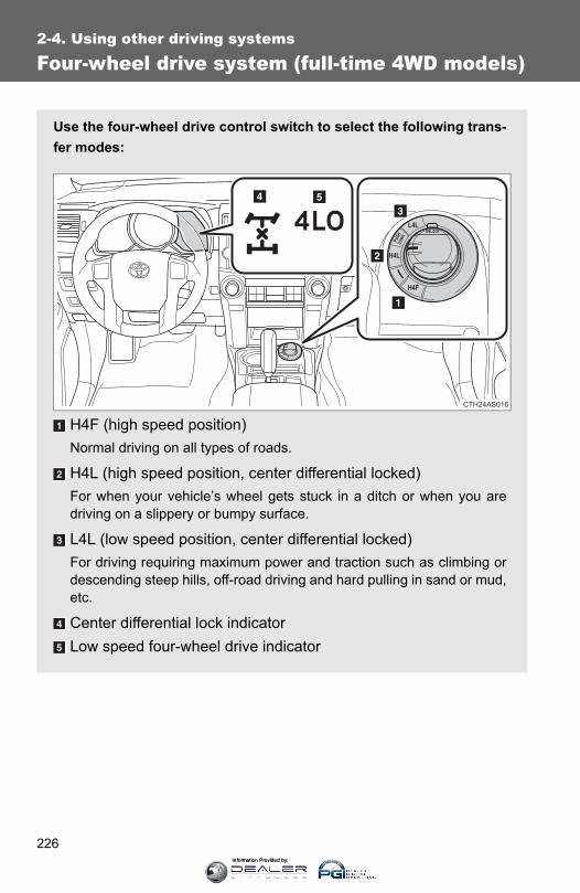
226
2-4. Using other driving systems
Four-wheel drive system (full-time 4WD models)
Use the four-wheel drive control switch to select the following trans-fer modes:
H4F (high speed position)Normal driving on all types of roads.
H4L (high speed position, center differential locked)For when your vehicle’s wheel gets stuck in a ditch or when you aredriving on a slippery or bumpy surface.
L4L (low speed position, center differential locked)For driving requiring maximum power and traction such as climbing ordescending steep hills, off-road driving and hard pulling in sand or mud,etc.
Center differential lock indicatorLow speed four-wheel drive indicator
CTH24AS016
Information Provided by:

227
2-4. Using other driving systems
2
When driving
Shifting between H4F and H4L
Push the “UNLOCK” button andturn the four-wheel drive controlswitch to H4L or H4F.This can be done at any speed.
The center differential lock indica-tor will turn on (H4L) or go off(H4F).
Shifting between H4L and L4L
■ Shifting from H4L to L4LStop the vehicle completely.Shift the shift lever to N.
Push the “UNLOCK” button andthen push and turn the four-wheel drive control switch toL4L.
Maintain this condition until thelow speed four-wheel drive indi-cator turns on.
CTH24AS017
STEP 1
STEP 2
CTH24AS062
STEP 3
Information Provided by:
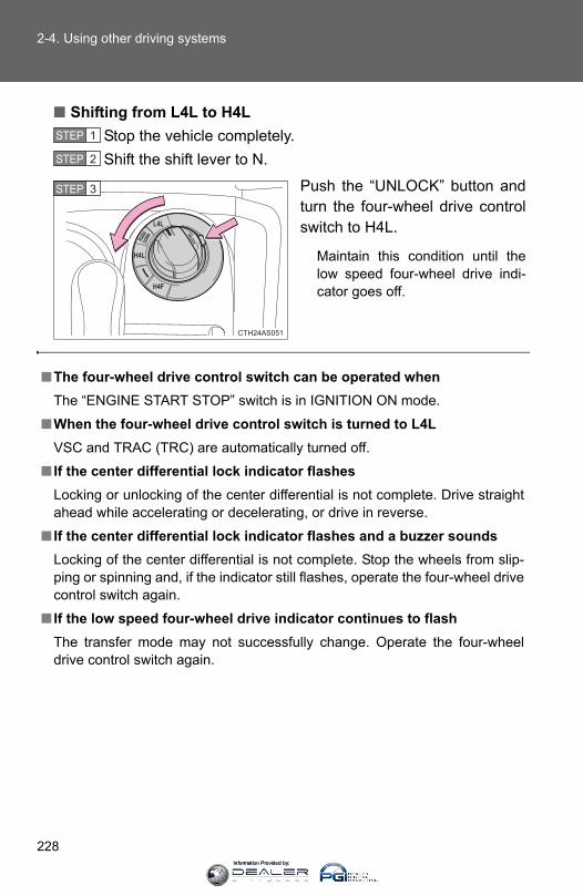
228
2-4. Using other driving systems
■ Shifting from L4L to H4LStop the vehicle completely.Shift the shift lever to N.
Push the “UNLOCK” button andturn the four-wheel drive controlswitch to H4L.
Maintain this condition until thelow speed four-wheel drive indi-cator goes off.
STEP 1
STEP 2
CTH24AS051
STEP 3
■The four-wheel drive control switch can be operated whenThe “ENGINE START STOP” switch is in IGNITION ON mode.
■When the four-wheel drive control switch is turned to L4LVSC and TRAC (TRC) are automatically turned off.
■ If the center differential lock indicator flashesLocking or unlocking of the center differential is not complete. Drive straightahead while accelerating or decelerating, or drive in reverse.
■ If the center differential lock indicator flashes and a buzzer soundsLocking of the center differential is not complete. Stop the wheels from slip-ping or spinning and, if the indicator still flashes, operate the four-wheel drivecontrol switch again.
■ If the low speed four-wheel drive indicator continues to flashThe transfer mode may not successfully change. Operate the four-wheeldrive control switch again.
Information Provided by:

229
2-4. Using other driving systems
2
When driving
■ If the low speed four-wheel drive indicator continues to flash and abuzzer soundsThe shift lever is not in N and/or the vehicle is moving. Stop the vehicle com-pletely, shift the shift lever to N and make sure that the indicator stops flash-ing.
■ If the low speed four-wheel drive indicator or the center differentiallock indicator flashes rapidlyThere may be a malfunction in the four-wheel drive system. Have the vehicleinspected by your Toyota dealer immediately.
CAUTION
■Operating the four-wheel drive control switchNever operate the four-wheel drive control switch if the wheels have losttraction. Doing so may cause an accident resulting in death or serious injury.Stop the wheels from slipping or spinning before operating the switch.
NOTICE
■To prevent damage to the center differential●For normal driving on dry and hard surface roads, unlock the center differ-
ential.
●Unlock the center differential after the wheels are out of the ditch or off theslippery or bumpy surface.
●Do not lock or unlock the center differential when the vehicle is turning orwhen its wheels are spinning freely off the ground.
Information Provided by:

230
2-4. Using other driving systems
Active traction control system∗
The active traction control system automatically helps prevent thespinning of 4 wheels when the vehicle is started or accelerated onslippery road surfaces.
■ System operationPart-time 4WD models:Stop the vehicle, shift the shift lever to N and shift the front-wheel drive control lever into L4.Full-time 4WD models:Stop the vehicle, shift the shift lever to N and then push andturn the four-wheel drive control switch to L4L.
Press the “A-TRAC” switch toactivate the system.
At this time, the “A-TRAC” indi-cator will come on.
To cancel the system, push theswitch again.
STEP 1
STEP 2
∗: If equipped
Information Provided by:

231
2-4. Using other driving systems
2
When driving
When the active traction control system is operating
If all wheels spin, the slip indica-tor flashes to indicate that theactive traction control systemhas been engaged.
CTH24AS047
■When the rear differential is locked (vehicles with a rear differentiallock system)The active traction control system is activated only when vehicle speed isless than 4 mph (6 km/h).
■Sounds and vibrations caused by the active traction control system●A sound may be heard from the engine compartment when the engine is
started or just after the vehicle begins to move. This sound does not indi-cate that a malfunction has occurred in the system.
●Vibrations may be felt through the vehicle body and steering. This mayoccur when the system is operating.
■ If the brake system overheatsThe system will cease operation and a buzzer will sound to alert the driver.At this time, the “A-TRAC” indicator will go off and the “TRAC OFF (TRCOFF)” indicator will come on. Stop the vehicle in a safe place. (There is noproblem with continuing normal driving.)
The system will be automatically restored after a short time.
CAUTION
■The active traction control system may not operate effectively when Directional control and power may not be achievable while driving on slip-pery road surfaces, even if the active traction control system is operating.Do not drive the vehicle in conditions where stability and power may be lost.
Information Provided by:
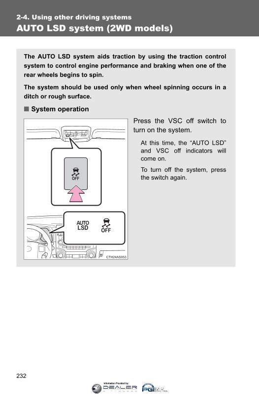
232
2-4. Using other driving systems
AUTO LSD system (2WD models)
The AUTO LSD system aids traction by using the traction controlsystem to control engine performance and braking when one of therear wheels begins to spin.
The system should be used only when wheel spinning occurs in aditch or rough surface.
■ System operationPress the VSC off switch toturn on the system.
At this time, the “AUTO LSD”and VSC off indicators willcome on.
To turn off the system, pressthe switch again.
Information Provided by:

233
2-4. Using other driving systems
2
When driving
When the AUTO LSD system is operating
If the rear wheels spin, the slipindicator flashes to indicate thatthe AUTO LSD system has con-trolled the spinning of the rearwheels.
CTH24AS047
■ If the engine is turned off and restartedThe AUTO LSD system and the indicators are automatically turned off.
■ If the brake system overheatsThe system will cease operation and a buzzer will sound to alert the driver.At this time, the “AUTO LSD” indicator will flash and the “TRAC OFF” indica-tor will come on. Stop the vehicle in a safe place. (There is no problem withcontinuing normal driving.)
The system will be automatically restored after a short time.
CAUTION
■To avoid an accident●Do not use the AUTO LSD system in conditions other when wheel spin-
ning occurs in a ditch or rough surfaces.A much greater steering effort and more careful cornering control will berequired.
●Do not drive with the AUTO LSD system continuously turned on.
Information Provided by:
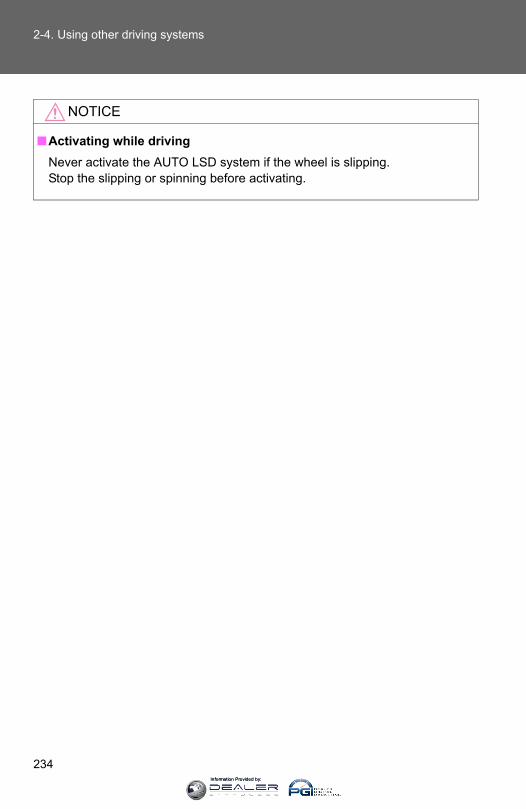
234
2-4. Using other driving systems
NOTICE
■Activating while drivingNever activate the AUTO LSD system if the wheel is slipping.Stop the slipping or spinning before activating.
Information Provided by:

235
2-4. Using other driving systems
2
When driving
Rear differential lock system∗
The rear differential lock system is provided for use only when wheelspinning occurs in a ditch or on a slippery or rugged surface.
The rear differential lock system is effective in case one of the rearwheels is spinning.
Press the switch to lock therear differential.
At this time, the rear differentiallock indicator will flash. Wait afew seconds for the system tocomplete operation. After therear differential is locked, theindicator will stop flashing andremain on.
To unlock the rear differential,press the switch again.
CTH24AS056
∗: If equipped
Information Provided by:
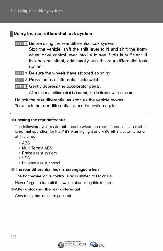
236
2-4. Using other driving systems
Using the rear differential lock system
Before using the rear differential lock system:Stop the vehicle, shift the shift lever to N and shift the front-wheel drive control lever into L4 to see if this is sufficient. Ifthis has no effect, additionally use the rear differential locksystem.Be sure the wheels have stopped spinning.Press the rear differential lock switch.Gently depress the accelerator pedal.After the rear differential is locked, the indicator will come on.
Unlock the rear differential as soon as the vehicle moves.To unlock the rear differential, press the switch again.
■Locking the rear differentialThe following systems do not operate when the rear differential is locked. Itis normal operation for the ABS warning light and VSC off indicator to be onat this time.
• ABS• Multi Terrain ABS• Brake assist system• VSC• Hill-start assist control
■The rear differential lock is disengaged whenThe front-wheel drive control lever is shifted to H2 or H4.
Never forget to turn off the switch after using this feature.
■After unlocking the rear differentialCheck that the indicator goes off.
STEP 1
STEP 2
STEP 3
STEP 4
Information Provided by:
237
2-4. Using other driving systems
2
When driving
CAUTION
■To avoid an accident●Do not use the rear differential lock system except when wheel spinning
occurs in a ditch or on a slippery or rugged surface. Large steering effortand careful cornering control will be required.
●Do not lock the rear differential until the wheels have stopped spinning.Otherwise, the vehicle may move in an unexpected direction when the dif-ferential lock is engaged, resulting in an accident. This may also lead topossible damage to rear differential lock component parts.
●Do not drive over 5 mph (8 km/h) when the rear differential is locked.
●Do not keep driving with the rear differential lock switch on.
Information Provided by:

238
2-4. Using other driving systems
Downhill assist control system∗
With the downhill assist control system, the vehicle is able todescend a steep hill while maintaining a constant low speed of about3 mph (5 km/h) without brake pedal operation.
■ Activating the systemThe system will activate when
● The vehicle is traveling under 15 mph (25 km/h) with theaccelerator and brake pedals released.
● Part-time 4WD models: The front-wheel drive control lever isin L4.Full-time 4WD models: The four-wheel drive control switch isin L4L.
● The rear differential is unlocked (if equipped).
Press the “DAC” switch.
The downhill assist control sys-tem indicator will come on toindicate that the downhill assistcontrol system is activated.
Pressing the switch again turnsthe system off.
∗: If equipped
Information Provided by:

239
2-4. Using other driving systems
2
When driving
While the downhill assist control system is operating
The slip indicator will flash toindicate that the downhill assistcontrol system is operating, andthe stop lights and high mountedstoplight will turn on.
CTH24AS047
■Operating tipsThe system will operate when the shift lever is in any position other than P.However, to make effective use of the system it is recommended that theshift lever be shifted to the “2” or “1” range of S.
■ If the downhill assist control system indicator flashes● In the following situations, the indicator flashes and the system will not
operate:
• The transfer mode is not in L4 (part-time 4WD models) or L4L (full-time4WD models).
• The rear differential is locked.• The brake system overheats.
The system will situations operation and a buzzer will sound to alert thedriver. At this time, the “TRAC OFF (TRC OFF)” indicator will come on.Stop the vehicle in a safe place. Refrain from using the system until theindicator stops flashing and stays on. (There is no problem with con-tinuing normal driving.)
● In the following situations, the indicator flashes to alert the driver, but thesystem will still operate:
• The shift lever is in N. (Engine braking will not occur.)• The “DAC” switch is turned off while the system is operating.
The system will gradually ceases operation. The indicator will flash dur-ing operation, and then go off when the system is fully off.
Information Provided by:
240
2-4. Using other driving systems
■System malfunctionIn case of a system malfunction, the following may occur:
●The downhill assist control system indicator flashes in a situation otherthan those listed above.
●The downhill assist control system indicator does not come on when theengine switch is turned to the “ON” position (vehicles without a smart keysystem) or the “ENGINE START STOP” switch is turned to IGNITION ONmode (vehicles with a smart key system).
Have your vehicle inspected by your Toyota dealer.
CAUTION
■Conditions which may affect the downhill assist control system opera-tion●Do not rely too heavily on the downhill assist control system. On extremely
steep inclines, icy surfaces or muddy roads, the vehicle may slip and thesystem may not be able to maintain the constant low vehicle speed ofabout 3 mph (5 km/h), leading to an accident causing death or seriousinjury.
●Do not shift the shift lever to R while driving forward, or to D while drivingbackward. Doing so may cause the wheels to lock up, leading to an acci-dent causing death or serious injury. In addition, excessive stress will beapplied to the automatic transmission, possibly resulting in damage.
Information Provided by:

241
2-4. Using other driving systems
2
When driving
Crawl Control∗
Allows travel on extremely rough off-road surfaces at a fixed lowspeed without pressing the accelerator or brake pedal. Minimizesloss of traction or vehicle slip when driving on slippery road sur-faces, allowing for stable driving.
■ Crawl Control switch
“ON/OFF” switchThe Crawl Control indicator comes on and the slip indicator flasheswhen operating.
Speed selector dialTurn the dial clockwise to increase the speed and counterclockwise todecrease the speed.
Crawl Control indicatorSlip indicator
∗: If equipped
Information Provided by:
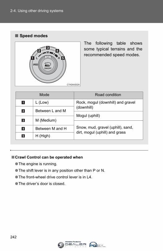
242
2-4. Using other driving systems
■Crawl Control can be operated when●The engine is running.
●The shift lever is in any position other than P or N.
●The front-wheel drive control lever is in L4.
●The driver’s door is closed.
■ Speed modesThe following table showssome typical terrains and therecommended speed modes.
Mode Road condition
L (Low) Rock, mogul (downhill) and gravel (downhill)
Between L and MMogul (uphill)
M (Medium)
Snow, mud, gravel (uphill), sand, dirt, mogul (uphill) and grass
Between M and H
H (High)
Information Provided by:
243
2-4. Using other driving systems
2
When driving
■Crawl Control is temporarily canceled whenVehicle speed exceeds 15 mph (25 km/h). The Crawl Control indicatorflashes until the vehicle speed is reduced.
■Automatic system cancelationIn the following situations, the system will cease operation and a buzzer willsound to alert the driver. The Crawl Control indicator will flash until the sys-tem is turned off completely.
●When the shift lever is shifted to P or N
●When the front-wheel drive control lever is shifted to H4
●When the driver’s door is opened
●When the system is malfunctioning
●When the brake system overheatsStop the vehicle in a safe place. (There is no problem with continuingnormal driving.)
●When the automatic transmission system overheatsStop the vehicle in a safe place until the automatic transmission fluid tem-perature warning light goes off.
■Sounds and vibrations caused by the Crawl Control system●A sound may be heard from the engine compartment when the engine is
started or just after the vehicle begins to move. This sound does not indi-cate that a malfunction has occurred in Crawl Control system.
●Either of the following conditions may occur when the Crawl Control sys-tem is operating. None of these indicates that a malfunction hasoccurred.
• Vibrations may be felt through the vehicle body and steering.• A motor sound may be heard after the vehicle comes to a stop.
Information Provided by:

244
2-4. Using other driving systems
CAUTION
■When using Crawl Control●Do not overly rely on Crawl Control. This function does not extend the
vehicle’s performance limitations. Always check the terrain thoroughly anddrive safely.
●The recommended speed modes for the listed terrains (→P. 242) are onlya reference. The selected mode may not be suitable to actual off-road con-ditions due to factors such as the type or unevenness of the terrain or thedegree of incline. Check the actual terrain thoroughly and drive safely.
●After activating Crawl Control, make sure that the Crawl Control indicatorcomes on. If the indicator flashes, the vehicle is not under system control.
■Conditions under which the system may not operate correctlyWhen driving on the following surfaces, the system may not be able to main-tain a fixed low speed, which may result in an accident:
●Extremely steep inclines
●Extremely uneven surfaces
●Snow-covered roads, or other slippery surfaces
Information Provided by:

245
2-4. Using other driving systems
2
When driving
Multi-terrain Select∗
The Multi-terrain Select system has 4 terrain modes. When a terrainmode is selected in accordance with terrain conditions, enginepower and active traction control system is controlled to enhanceoff-road drivability.
Additionally, guidance messages such as transfer mode selectionadvice are displayed on the accessory meter to assist the driver inoperating the vehicle.
“ON/OFF” switchMode selector dialMode indicatorsMulti-terrain Select indicatorAccessory meter
CTH24AS025U
∗: If equipped
Information Provided by:
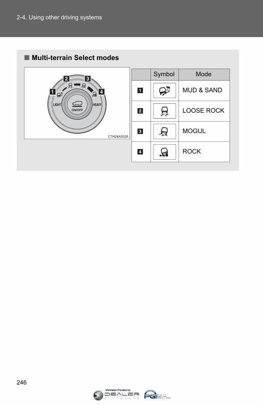
246
2-4. Using other driving systems
■ Multi-terrain Select modes
Symbol Mode
MUD & SAND
LOOSE ROCK
MOGUL
ROCK
Information Provided by:
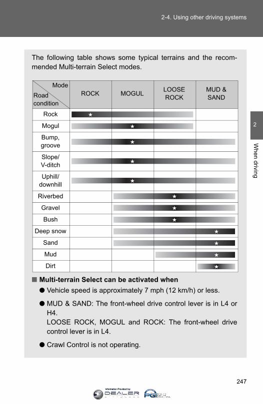
247
2-4. Using other driving systems
2
When driving
The following table shows some typical terrains and the recom-mended Multi-terrain Select modes.
■ Multi-terrain Select can be activated when● Vehicle speed is approximately 7 mph (12 km/h) or less.
● MUD & SAND: The front-wheel drive control lever is in L4 orH4.LOOSE ROCK, MOGUL and ROCK: The front-wheel drivecontrol lever is in L4.
● Crawl Control is not operating.
ROCK MOGUL LOOSE ROCK
MUD & SAND
Rock
Mogul
Bump, groove
Slope/V-ditch
Uphill/downhill
Riverbed
Gravel
Bush
Deep snow
Sand
Mud
Dirt
ModeRoad condition
Information Provided by:
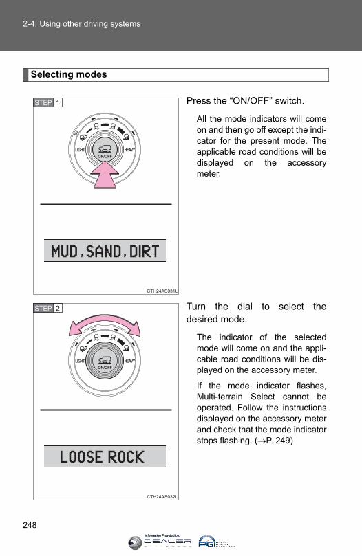
248
2-4. Using other driving systems
Selecting modes
Press the “ON/OFF” switch.
All the mode indicators will comeon and then go off except the indi-cator for the present mode. Theapplicable road conditions will bedisplayed on the accessorymeter.
Turn the dial to select thedesired mode.
The indicator of the selectedmode will come on and the appli-cable road conditions will be dis-played on the accessory meter.
If the mode indicator flashes,Multi-terrain Select cannot beoperated. Follow the instructionsdisplayed on the accessory meterand check that the mode indicatorstops flashing. (→P. 249)
STEP 1
STEP 2
Information Provided by:
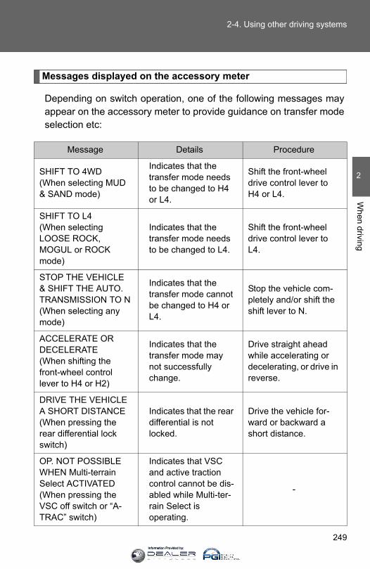
249
2-4. Using other driving systems
2
When driving
Messages displayed on the accessory meter
Depending on switch operation, one of the following messages mayappear on the accessory meter to provide guidance on transfer modeselection etc:
Message Details Procedure
SHIFT TO 4WD(When selecting MUD & SAND mode)
Indicates that the transfer mode needs to be changed to H4 or L4.
Shift the front-wheel drive control lever to H4 or L4.
SHIFT TO L4(When selecting LOOSE ROCK, MOGUL or ROCK mode)
Indicates that the transfer mode needs to be changed to L4.
Shift the front-wheel drive control lever to L4.
STOP THE VEHICLE & SHIFT THE AUTO. TRANSMISSION TO N(When selecting any mode)
Indicates that the transfer mode cannot be changed to H4 or L4.
Stop the vehicle com-pletely and/or shift the shift lever to N.
ACCELERATE OR DECELERATE(When shifting the front-wheel control lever to H4 or H2)
Indicates that the transfer mode may not successfully change.
Drive straight ahead while accelerating or decelerating, or drive in reverse.
DRIVE THE VEHICLE A SHORT DISTANCE (When pressing the rear differential lock switch)
Indicates that the rear differential is not locked.
Drive the vehicle for-ward or backward a short distance.
OP. NOT POSSIBLE WHEN Multi-terrain Select ACTIVATED (When pressing the VSC off switch or “A-TRAC” switch)
Indicates that VSC and active traction control cannot be dis-abled while Multi-ter-rain Select is operating.
-
Information Provided by:

250
2-4. Using other driving systems
CANNOT BE SELECTED (When pressing the “ON/OFF” switch)
Indicates that Multi-terrain Select cannot be operated because vehicle speed exceeds approxi-mately 7 mph (12 km/h).
Reduce vehicle speed.
OP. NOT POSSIBLE WHEN CRAWL CON-TROL ACTIVATED (When pressing the “ON/OFF” switch)
Indicates that Multi-terrain Select cannot be operated because Crawl Control is oper-ating.
Turn Crawl Control off.
Multi-terrain Select HAS BEEN CAN-CELED(When pressing the “ON/OFF” switch)
Indicates that Multi-terrain Select is turned off.
-
Multi-terrain Select NOT AVAILABLE (When pressing the “ON/OFF” switch)
Indicates that Multi-terrain Select cannot be operated because the VSC and/or 4WD system may be mal-functioning.
Contact your Toyota dealer.
Message Details Procedure
Information Provided by:

251
2-4. Using other driving systems
2
When driving
■Multi-terrain Select is temporarily canceled whenThe front-wheel drive control lever is shifted to H4 when Multi-terrain Selectis in ROCK, MOGUL or LOOSE ROCK mode. The mode indicator will flashuntil the lever is shifted back to L4.
■ If the Multi-terrain Select indicator continues to flashThis may indicate a malfunction in the Multi-terrain Select system. In this case, Multi-terrain Select is automatically canceled. Have your vehicleinspected by your Toyota dealer.
■ If the Multi-terrain Select indicator goes off while Multi-terrain Select isoperating●One of the vehicle systems related to Multi-terrain Select may be mal-
functioning.Have your vehicle inspected by your Toyota dealer.
●The brake actuator may be at risk of overheating.A buzzer will sound, the “A-TRAC” indicator will go off and the “TRACOFF (TRC OFF)” indicator will come on. Stop the vehicle in a safe place.Refrain from using Multi-terrain Select until the “A-TRAC” indicatorcomes back on and the “TRAC OFF (TRC OFF)” indicator goes off. (Thevehicle can still be driven, even if Multi-terrain Select is inoperative.)
In the above cases, Multi-terrain Select is automatically canceled.
Information Provided by:
252
2-4. Using other driving systems
CAUTION
■Before drivingTo avoid an accident, observe the precautions relating to off-road driving.(→P. 262)
■When using Multi-terrain Select●Do not use the Multi-terrain Select system for normal (on-road) driving.
The Multi-terrain Select system is designed for off-road use only.
●Do not overly rely on Multi-terrain Select. This function does not extendthe vehicle’s performance limitations. Always check the terrain thoroughlyand drive safely.
●The recommended modes for the listed terrains (→P. 246) are only a refer-ence. The selected mode may not be suitable to actual off-road conditionsdue to factors such as the type or unevenness of the terrain or the degreeof incline. Check the actual terrain thoroughly and drive safely.
●After selecting a mode, make sure that the Multi-terrain Select indicatorand the selected mode indicator come on. If any related indicator flashes,the vehicle is not under Multi-terrain Select control.
Information Provided by:

253
2-4. Using other driving systems
2
When driving
Driving assist systems
To help enhance driving safety and performance, the following sys-tems operate automatically in response to various driving situations.Be aware, however, that these systems are supplementary andshould not be relied upon too heavily when operating the vehicle.
■ ABS (Anti-lock Brake System)Helps to prevent wheel lock when the brakes are applied suddenly, or ifthe brakes are applied while driving on a slippery road surface
■ Multi Terrain ABS (Anti-lock Brake System) (if equipped)Helps to prevent wheel lock when the brakes are applied suddenly, or ifthe brakes are applied while driving on a slippery road surface, or in off-road conditions (such as rough roads, sand and mud)
The Multi Terrain ABS operates in synchronization with the Multi-terrainSelect.
■ Brake assistGenerates an increased level of braking force after the brake pedal isdepressed when the system detects a panic stop situation
■ VSC (Vehicle Stability Control)Helps the driver to control skidding when swerving suddenly or turningon slippery road surfaces
■ TRAC/TRC (Traction Control)Helps to maintain drive power and prevent the drive wheels from spin-ning when starting the vehicle or accelerating on slippery roads
■ Hill-start assist control (if equipped)Helps to prevent the vehicle from rolling backward when starting on anincline or slippery slope
■ LSD (Limited Slip Differential) (if equipped)Transfers drive power to the rear tires when front tires spin, and viceversa, in order to improve traction
Information Provided by:

254
2-4. Using other driving systems
When the VSC/TRAC systems are operating (2WD models)
If the vehicle is in danger of slip-ping or if any of the drive wheelsspins, the slip indicator flashes toindicate that the VSC/TRAC sys-tems are operating.
When the VSC/TRAC (TRC)/hill-start assist control systems areoperating (4WD models)
If the vehicle is in danger of slip-ping or rolling backward whenstarting on an incline, or if any ofthe drive wheels spins, the slipindicator flashes to indicate thatthe VSC/TRAC (TRC)/hill-startassist control systems are oper-ating.
The stop lights and high mountedstoplight turn on and a buzzer(intermittent) sounds when thehill-start assist control system isoperating.
■ KDSS (Kinetic Dynamic Suspension System) (if equipped)Enhances ride comfort and handling response by using a hydrauliccontrol system to control the suspension stabilizer bars in response toroad surface and driving conditions during cornering or off-road driving
CTH24AS047
CTH24AS047
Information Provided by:
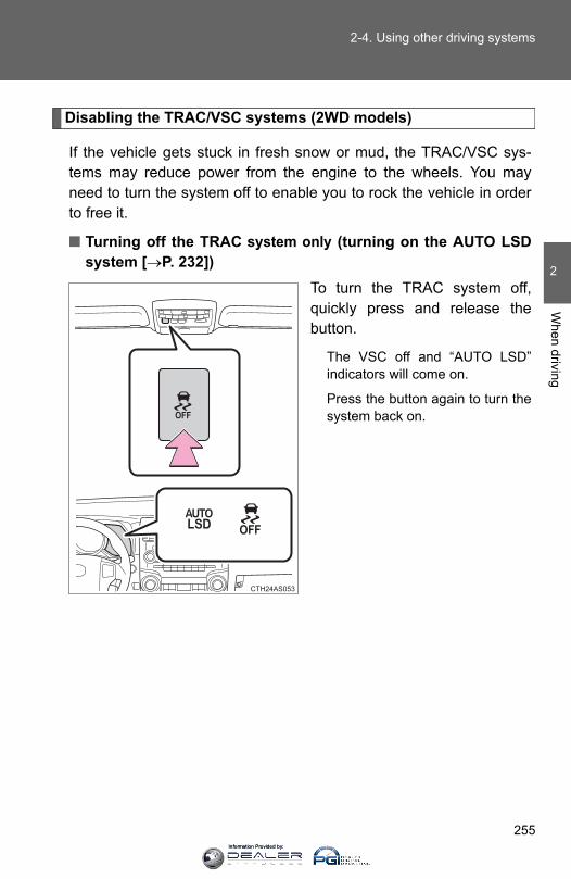
255
2-4. Using other driving systems
2
When driving
Disabling the TRAC/VSC systems (2WD models)
If the vehicle gets stuck in fresh snow or mud, the TRAC/VSC sys-tems may reduce power from the engine to the wheels. You mayneed to turn the system off to enable you to rock the vehicle in orderto free it.
■ Turning off the TRAC system only (turning on the AUTO LSDsystem [→P. 232])
To turn the TRAC system off,quickly press and release thebutton.
The VSC off and “AUTO LSD”indicators will come on.
Press the button again to turn thesystem back on.
Information Provided by:

256
2-4. Using other driving systems
■ Turning off both TRAC and VSC systemsTo turn the TRAC and VSC sys-tems off, press and hold the but-ton for more than 3 secondswhile the vehicle is stopped.
The “TRAC OFF” and VSC offindicators will come on.
Press the button again to turn thesystems back on.
Information Provided by:

257
2-4. Using other driving systems
2
When driving
Disabling the TRAC (TRC)/VSC systems (4WD models)
If the vehicle gets stuck in fresh snow or mud, the TRAC (TRC)/VSCsystems may reduce power from the engine to the wheels. You mayneed to turn the system off to enable you to rock the vehicle in orderto free it.
■ Turning off the TRAC (TRC) system onlyTo turn the TRAC (TRC) systemoff, quickly press and release thebutton.
The “TRAC OFF (TRC OFF)”indicator will come on.
Press the button again to turn thesystem back on.
U.S.A. Canada
Information Provided by:

258
2-4. Using other driving systems
■ Turning off both TRAC (TRC) and VSC systemsTo turn the TRAC (TRC) andVSC systems off, press and holdthe button for more than 3 sec-onds while the vehicle isstopped.
The “TRAC OFF (TRC OFF)” andVSC off indicators will come on.
Press the button again to turn thesystems back on.
CTH24AS055
U.S.A. Canada
Information Provided by:
259
2-4. Using other driving systems
2
When driving
■Hill-start assist control operation conditions●The shift lever is in D or S.
●The brake pedal is not depressed.
●The rear differential is unlocked (if equipped).
■ If the brake system overheatsThe hill-start assist control will cease operation and a buzzer will sound toalert the driver. At this time, the “TRAC OFF (TRC OFF)” indicator will comeon. Stop the vehicle in a safe place. (There is no problem with continuingwith normal driving.)
The system will be automatically restored after a short time.
■Sounds and vibrations caused by the ABS, Multi Terrain ABS (ifequipped), brake assist, VSC, TRAC (TRC) and hill-start assist control(if equipped) systems●A sound may be heard from the engine compartment when the engine is
started or just after the vehicle begins to move. This sound does not indi-cate that a malfunction has occurred in any of these systems.
●Any of the following conditions may occur when the above systems areoperating. None of these indicates that a malfunction has occurred.
• Vibrations may be felt through the vehicle body and steering.• A motor sound may be heard after the vehicle comes to a stop.• The brake pedal may pulsate slightly after the ABS or Multi Terrain
ABS is activated.• The brake pedal may move down slightly after the ABS or Multi Terrain
ABS is activated.
■Reactivation of the TRAC (TRC)/VSC systems after turning off theengineTurning off the engine after turning off the TRAC (TRC)/VSC systems willautomatically reactivate them.
■Reactivation of the VSC system linked to vehicle speed (2WD models)When the TRAC system is turned off and the AUTO LSD system is turnedon, the VSC system will turn on when vehicle speed increases. However,when the TRAC and VSC systems are turned off, the systems will not turnon even when vehicle speed increases.
Information Provided by:
260
2-4. Using other driving systems
■Reactivation of the TRAC (TRC)/VSC systems (4WD models)If the TRAC (TRC)/VSC systems are turned off, the systems will not turn oneven when vehicle speed increases.
CAUTION
■The ABS and Multi Terrain ABS do not operate effectively when●Tires with inadequate gripping ability are used (such as excessively worn
tires on a snow covered road).
●The vehicle hydroplanes while driving at high speed on wet or slick roads.
■Stopping distance when the ABS or Multi Terrain ABS is operating willexceed that of normal conditionsThe ABS and Multi Terrain ABS are not designed to shorten the vehicle’sstopping distance. Always maintain a safe distance from the vehicle in frontof you in the following situations:
●When driving on dirt, gravel or snow-covered roads
●When driving with tire chains
●When driving over bumps in the road
●When driving over roads with potholes or roads with uneven surfaces
■TRAC (TRC) may not operate effectively whenDirectional control and power may not be achievable while driving on slip-pery road surfaces, even if the TRAC (TRC) system is operating. Do not drive the vehicle in conditions where stability and power may be lost.
■ Hill-start assist control does not operate effectively whenDo not overly rely on the hill-start assist control. The hill-start assist controlmay not operate effectively on steep inclines and roads covered with ice.
Information Provided by:
261
2-4. Using other driving systems
2
When driving
CAUTION
■When the VSC is activatedThe slip indicator light flashes. Always drive carefully. Reckless driving may cause an accident. Exercise particular care when theindicator light flashes.
■When TRAC (TRC)/VSC systems are turned offBe especially careful and drive at a speed appropriate to the road condi-tions. As these are systems to ensure vehicle stability and driving force, donot turn the TRAC (TRC)/VSC systems off unless necessary.
■Replacing tiresMake sure that all tires are of the specified size, brand, tread pattern andtotal load capacity. In addition, make sure that the tires are inflated to therecommended tire inflation pressure level.
The ABS, Multi Terrain ABS and VSC will not function correctly if differenttires are fitted on the vehicle.
Contact your Toyota dealer for further information when replacing tires orwheels.
■Handling of tires and the suspensionUsing tires with any kind of problem or modifying the suspension will affectthe driving assist systems, and may cause a system to malfunction.
Information Provided by:
262
2-5. Driving information
Off-road precautions
Off-road vehicle feature
● Specific design characteristics give it a higher center of gravitythan ordinary passenger cars. This vehicle design feature causesthis type of vehicle to be more likely to rollover. And, utility vehicleshave a significantly higher rollover rate than other types of vehi-cles.
● An advantage of the higher ground clearance is a better view of theroad allowing you to anticipate problems.
● It is not designed for cornering at the same speeds as ordinarypassenger cars any more than low-slung sports cars designed toperform satisfactorily under off-road conditions. Therefore, sharpturns at excessive speeds may cause rollover.
This vehicle belongs to the utility vehicle class, which has higherground clearance and narrower tread in relation to the height of itscenter of gravity to make it capable of performing in a wide varietyof off-road applications.
Information Provided by:
263
2-5. Driving information
2
When driving
CAUTION
■Off-road vehicle precautionsAlways observe the following precautions to minimize the risk of death, seri-ous injury or damage to your vehicle:
● In a rollover crash, an unbelted person is significantly more likely to diethan a person wearing a seat belt. Therefore, the driver and all passengersshould fasten their seat belts whenever the vehicle is moving.
●Avoid sharp turns or abrupt maneuvers, if at all possible. Failure to operate this vehicle correctly may result in loss of control orvehicle rollover causing death or serious injury.
●Loading cargo on the roof luggage carrier will make the center of the vehi-cle gravity higher. Avoid high speeds, sudden starts, sharp turns, suddenbraking or abrupt maneuvers, otherwise it may result in loss of control orvehicle rollover due to failure to operate this vehicle correctly.
●Always slow down in gusty crosswinds. Because of its profile and highercenter of gravity, your vehicle is more sensitive to side winds than an ordi-nary passenger car. Slowing down will allow you to have better control.
●When driving off-road or in rugged terrain, do not drive at excessivespeeds, jump, make sharp turns, strike objects, etc. This may cause lossof control or vehicle rollover causing death or serious injury. You are alsorisking expensive damage to your vehicle’s suspension and chassis.
●Do not drive horizontally across steep slopes. Driving straight up orstraight down is preferred. Your vehicle (or any similar off-road vehicle)can tip over sideways much more easily than forward or backward.
Information Provided by:
264
2-5. Driving information
Off-road driving
When driving your vehicle off-road, please observe the following pre-cautions to ensure your driving enjoyment and to help prevent theclosure of areas to off-road vehicles:
● Drive your vehicle only in areas where off-road vehicles are permit-ted to travel.
● Respect private property. Get owner’s permission before enteringprivate property.
● Do not enter areas that are closed. Honor gates, barriers and signsthat restrict travel.
● Stay on established roads. When conditions are wet, driving tech-niques should be changed or travel delayed to prevent damage toroads.
■Additional information for off-road drivingFor owners in U.S. mainland, Hawaii and Puerto Rico:
To obtain additional information pertaining to driving your vehicle off-road,consult the following organizations.
●State and Local Parks and Recreation Departments
●State Motor Vehicle Bureau
●Recreational Vehicle Clubs
●U.S. Forest Service and Bureau of Land Management
Information Provided by:
265
2-5. Driving information
2
When driving
CAUTION
■Off-road driving precautionsAlways observe the following precautions to minimize the risk of death, seri-ous injury or damage to your vehicle:
●Drive carefully when off the road. Do not take unnecessary risks by drivingin dangerous places.
●Do not grip the steering wheel spokes when driving off-road. A bad bumpcould jerk the wheel and injure your hands. Keep both hands and espe-cially your thumbs on the outside of the rim.
●Always check your brakes for effectiveness immediately after driving insand, mud, water or snow.
●After driving through tall grass, mud, rock, sand, rivers, etc., check thatthere is no grass, bush, paper, rags, stone, sand, etc. adhering or trappedon the underbody. Clear off any such matter from the underbody. If thevehicle is used with these materials trapped or adhering to the underbody,a breakdown or fire could occur.
● In a rollover crash, an unbelted person is significantly more likely to diethan a person wearing a seat belt. Therefore, the driver and all passengersshould fasten their seat belts whenever the vehicle is moving.
●When driving off-road or in rugged terrain, do not drive at excessivespeeds, jump, make sharp turns, strike objects, etc. This may cause lossof control or vehicle rollover causing death or serious injury. You are alsorisking expensive damage to your vehicle’s suspension and chassis.
Information Provided by:
266
2-5. Driving information
NOTICE
■To prevent water damageTake all necessary safety measures to ensure that water damage to theengine or other components does not occur.
●Water entering the engine air intake will cause severe engine damage.
●Water entering the automatic transmission will cause deterioration in shiftquality, locking up of your transmission accompanied by vibration, and ulti-mately damage.
●Water can wash the grease from wheel bearings, causing rusting and pre-mature failure, and may also enter the differentials, transmission andtransfer case, reducing the gear oil’s lubricating qualities.
■When you drive through waterIf driving through water, such as when crossing shallow streams, first checkthe depth of the water and the bottom of the riverbed for firmness. Driveslowly and avoid deep water.
■ Inspection after off-road driving●Sand and mud that has accumulated in brake drums and around brake
discs may affect braking efficiency and may damage brake system compo-nents.
●Always perform a maintenance inspection after each day of off-road driv-ing that has taken you through rough terrain, sand, mud, or water. Forscheduled maintenance information, refer to the “Scheduled MaintenanceGuide” or “Owner’s Manual Supplement”.
Information Provided by:
267
2-5. Driving information
2
When driving
Cargo and luggage
Take notice of the following information about storage precau-tions, cargo capacity and load:
● Stow cargo and luggage in the luggage compartment wheneverpossible.
● Be sure all items are secured in place.
● To maintain vehicle balance while driving, position luggageevenly within the luggage compartment.
● For better fuel economy, do not carry unnecessary weight.
Information Provided by:
268
2-5. Driving information
Capacity and distribution
Cargo capacity depends on the total weight of the occupants.
(Cargo capacity) = (Total load capacity) — (Total weight of occupants)
Steps for Determining Correct Load Limit⎯(1)Locate the statement “The combined weight of occupants and
cargo should never exceed XXX kg or XXX lbs.” on your vehicle'splacard.
(2)Determine the combined weight of the driver and passengers thatwill be riding in your vehicle.
(3)Subtract the combined weight of the driver and passengers fromXXX kg or XXX lbs.
(4)The resulting figure equals the available amount of cargo and lug-gage load capacity. For example, if the “XXX” amount equals 1400 lbs. and there willbe five 150 lb passengers in your vehicle, the amount of availablecargo and luggage load capacity is 650 lbs. (1400 - 750 (5 × 150) =650 lbs.)
(5)Determine the combined weight of luggage and cargo beingloaded on the vehicle. That weight may not safely exceed the avail-able cargo and luggage load capacity calculated in Step 4.
(6)If your vehicle will be towing a trailer, load from your trailer will betransferred to your vehicle. Consult this manual to determine howthis reduces the available cargo and luggage load capacity of yourvehicle.(→P. 612)
Information Provided by:

269
2-5. Driving information
2
When driving
Example on your vehicle
Cargo capacityTotal load capacity
When 2 people with the combined weight of 366 lb. (166 kg) areriding in your vehicle, the available amount of cargo and luggage loadcapacity will be as follows:
Without third seatsTotal load capacity: 825 lb. (370 kg)825 lb. - 366 lb. = 459 lb. (370 kg - 166 kg = 204 kg)
With third seatsTotal load capacity: 1155 lb. (520 kg)1155 lb. - 366 lb. = 789 lb. (520 kg - 166 kg = 354 kg)
In this condition, if 3 more passengers with the combined weight of388 lb. (176 kg) get on, the available cargo and luggage load will bereduced as follows:
Without third seats459 lb. - 388 lb. = 71 lb. (204 kg - 176 kg = 28 kg)
With third seats789 lb. - 388 lb. = 401 lb. (354 kg - 176 kg = 178 kg)
As shown in the example above, if the number of occupantsincreases, the cargo and luggage load will be reduced by an amountthat equals the increased weight due to the additional occupants. Inother words, if an increase in the number of occupants causes anexcess of the total load capacity (combined weight of occupants pluscargo and luggage load), you must reduce the cargo and luggage onyour vehicle.
Information Provided by:
270
2-5. Driving information
CAUTION
■Things that must not be carried in the luggage compartmentThe following things may cause a fire if loaded in the luggage compart-ment:●Receptacles containing gasoline●Aerosol cans
■Storage precautionsObserve the following precautions.Failure to do so may result in death or serious injury.●Stow cargo and luggage in the luggage compartment whenever possi-
ble.●Do not stack cargo and luggage in the luggage compartment higher
than the seatbacks. Such items may be thrown about and possibly injure people in thevehicle in the event of sudden braking or in an accident.
●Do not place cargo or luggage in or on the following locations as theitem may get under the brake or accelerator pedal and prevent thepedals from being depressed properly, block the driver’s vision, or hitthe driver or passengers, causing an accident:• At the feet of the driver• On the front passenger or rear seats (when stacking items)• On the instrument panel• On the dashboard
●Secure all items in the occupant compartment, as they may shift andinjure someone in the event of sudden braking, sudden swerving or anaccident.
●When you fold down the rear seats, long items should not be placeddirectly behind the front seats.
●Never allow anyone to ride in the luggage compartment. It is notdesigned for passengers. They should ride in their seats with their seatbelts properly fastened. Otherwise, they are much more likely to sufferdeath or serious bodily injury, in the event of sudden braking, suddenswerving or an accident.
Information Provided by:
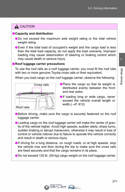
271
2-5. Driving information
2
When driving
CAUTION
■Capacity and distribution●Do not exceed the maximum axle weight rating or the total vehicle
weight rating.●Even if the total load of occupant’s weight and the cargo load is less
than the total load capacity, do not apply the load unevenly. Improperloading may cause deterioration of steering or braking control whichmay cause death or serious injury.
■Roof luggage carrier precautionsTo use the roof rails as a roof luggage carrier, you must fit the roof railswith two or more genuine Toyota cross rails or their equivalent.When you load cargo on the roof luggage carrier, observe the following:
●Before driving, make sure the cargo is securely fastened on the roofluggage carrier.
●Loading cargo on the roof luggage carrier will make the center of grav-ity of the vehicle higher. Avoid high speeds, sudden starts, sharp turns,sudden braking or abrupt maneuvers, otherwise it may result in loss ofcontrol or vehicle rollover due to failure to operate this vehicle correctlyand result in death or serious injury.
● If driving for a long distance, on rough roads, or at high speeds, stopthe vehicle now and then during the trip to make sure the cross railsare fixed securely and that the cargo remains in its place.
●Do not exceed 120 lb. (54 kg) cargo weight on the roof luggage carrier.
●Place the cargo so that its weight isdistributed evenly between the frontand rear axles.
● If loading long or wide cargo, neverexceed the vehicle overall length orwidth.(→P. 612)
CTH25AS005
Cross rails
Roof rails
Information Provided by:

272
2-5. Driving information
NOTICE
■When loading cargoBe careful not to scratch the surface of the moon roof.
Information Provided by:
273
2-5. Driving information
2
When driving
Vehicle load limits
■Total load capacity and seating capacityThese details are also described on the tire and loading informationlabel. (→P. 520)
Vehicle load limits include total load capacity, seating capacity,towing capacity and cargo capacity.
■ Total load capacityVehicles without third seats: 825 lb. (370 kg) Vehicles with third seats: 1155 lb. (520 kg)Total load capacity means the combined weight of occupants,cargo and luggage.
■ Seating capacity Vehicle without third seats: 5 occupants (Front 2, Rear 3)Vehicle with third seats: 7 occupants (Front 2, Rear 5)Seating capacity means the maximum number of occupantswhose estimated average weight is 150 lb. (68 kg) per person.
Even if the number of occupants are within the seating capacity,do not exceed the total load capacity.
■ Towing capacity 2.7 L 4-cylinder (2TR-FE) engine: 2000 lb. (907 kg)4.0 L V6 (1GR-FE) engine: 5000 lb. (2270 kg) Towing capacity means the maximum gross trailer weight (trailerweight plus its cargo weight) that you vehicle is able to tow.
■ Cargo capacityCargo capacity may increase or decrease depending on theweight and the number of occupants.
Information Provided by:

274
2-5. Driving information
CAUTION
■Overloading the vehicleDo not overload the vehicle. It may not only cause damage to the tires, but also degrade steering andbraking ability, resulting in an accident.
Information Provided by:

275
2-5. Driving information
2
When driving
Winter driving tips
Carry out the necessary preparations and inspections before drivingthe vehicle in winter. Always drive the vehicle in a manner appropri-ate to the prevailing weather conditions.
■ Pre-winter preparations● Use fluids that are appropriate to the prevailing outside tem-
peratures.
• Engine oil• Engine coolant• Washer fluid
● Have a service technician inspect the level and specific grav-ity of battery electrolyte.
● Have the vehicle fitted with four snow tires or purchase a setof tire chains for the rear tires.
Ensure that all tires are the same size and brand, and that chainsmatch the size of the tires.
Information Provided by:

276
2-5. Driving information
■ Before driving the vehiclePerform the following according to the driving conditions.
● Do not try to forcibly open a window or move a wiper that isfrozen. Pour warm water over the frozen area to melt the ice.Wipe away the water immediately to prevent it from freezing.
● To ensure proper operation of the climate control system fan,remove any snow that has accumulated on the air inlet ventsin front of the windshield.
● Remove any ice that has accumulated on the vehicle chassis.
● Periodically check for and remove any excess ice or snowthat may have accumulated in the wheel well or on thebrakes.
■ When driving the vehicleAccelerate the vehicle slowly and drive at a reduced speed suit-able to the road conditions.
■ When parking the vehiclePark the vehicle and move the shift lever to P without setting theparking brake. The parking brake may freeze up, preventing itfrom being released. If necessary, block the wheels to preventinadvertent sliding or creeping.
Information Provided by:

277
2-5. Driving information
2
When driving
Selection tire chains
Use the correct tire chain size when mounting the tire chains.Chain size is regulated for each tire size.
Side chain(0.20 in. [5 mm] in diameter)Cross chain(0.20 in. [5 mm] in diameter)
Regulations on the use of tire chains
Regulations regarding the use of tire chains vary depending on loca-tion and type of road. Always check local regulations before installingchains.
CTH25AS009
■Tire chain installationObserve the following precautions when installing and removing chains:
● Install and remove tire chains in a safe location.
● Install tire chains on the rear tires only. Do not install tire chains on thefront tires.
● Install tire chains on rear tires as tightly as possible. Retighten chainsafter driving 1/4 ⎯ 1/2 mile (0.5 ⎯ 1.0 km).
● Install tire chains following the instructions provided with the tire chains.
Information Provided by:

278
2-5. Driving information
CAUTION
■Driving with snow tiresObserve the following precautions to reduce the risk of accidents. Failure to do so may result in a loss of vehicle control and cause death orserious injury.
●Use tires of the size specified.
●Maintain the recommended level of air pressure.
●Do not drive in excess of 75 mph (120 km/h), regardless of the type ofsnow tires being used.
●Use snow tires on all, not just some wheels.
■Driving with tire chainsObserve the following precautions to reduce the risk of accidents. Failing to do so may result in the vehicle being unable to be driven safely,and may cause death or serious injury.
●Do not drive in excess of the speed limit specified for the tire chains beingused, or 30 mph (50 km/h), whichever is lower.
●Avoid driving on bumpy road surfaces or over potholes.
●Avoid sudden turns and braking, as use of chains may adversely affectvehicle handling.
●Slow down sufficiently before entering a curve to ensure that vehicle con-trol is maintained.
Information Provided by:

279
2-5. Driving information
2
When driving
NOTICE
■Repairing or replacing snow tiresRequest repairs or replacement of snow tires from Toyota dealers or legiti-mate tire retailers. This is because the removal and attachment of snow tires affects the opera-tion of the tire pressure warning valves and transmitters.
■Fitting tire chainsThe tire pressure warning valves and transmitters may not function correctlywhen tire chains are fitted.
Information Provided by:

280
2-5. Driving information
Trailer towing
Your vehicle is designed primarily as a passenger-and-load car-rying vehicle. Towing a trailer will have an adverse effect on han-dling, performance, braking, durability, and fuel consumption.For your safety and the safety of others, do not overload the vehi-cle or trailer.
To tow a trailer safely, use extreme care and drive the vehicle inaccordance with the trailer’s characteristics and operating condi-tions.The vehicle stability and braking performance are affected bytrailer stability, brake setting and performance, and the hitch.
Toyota warranties do not apply to damage or malfunction causedby towing a trailer for commercial purposes.
Contact your Toyota dealer for further information about additionalrequirements such as a towing kit, etc.
Information Provided by:
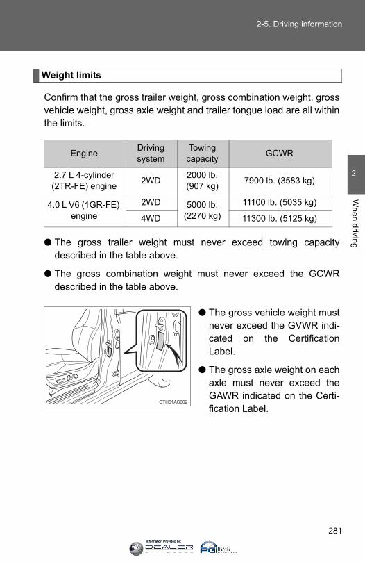
281
2-5. Driving information
2
When driving
Weight limits
Confirm that the gross trailer weight, gross combination weight, grossvehicle weight, gross axle weight and trailer tongue load are all withinthe limits.
● The gross trailer weight must never exceed towing capacitydescribed in the table above.
● The gross combination weight must never exceed the GCWRdescribed in the table above.
● The gross vehicle weight mustnever exceed the GVWR indi-cated on the CertificationLabel.
● The gross axle weight on eachaxle must never exceed theGAWR indicated on the Certi-fication Label.
Engine Driving system
Towing capacity GCWR
2.7 L 4-cylinder (2TR-FE) engine 2WD 2000 lb.
(907 kg) 7900 lb. (3583 kg)
4.0 L V6 (1GR-FE) engine
2WD 5000 lb. (2270 kg)
11100 lb. (5035 kg)
4WD 11300 lb. (5125 kg)
CTH61AS002
Information Provided by:
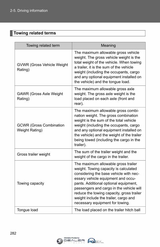
282
2-5. Driving information
Towing related terms
Towing related term Meaning
GVWR (Gross Vehicle Weight Rating)
The maximum allowable gross vehicle weight. The gross vehicle weight is the total weight of the vehicle. When towing a trailer, it is the sum of the vehicle weight (including the occupants, cargo and any optional equipment installed on the vehicle) and the tongue load.
GAWR (Gross Axle Weight Rating)
The maximum allowable gross axle weight. The gross axle weight is the load placed on each axle (front and rear).
GCWR (Gross Combination Weight Rating)
The maximum allowable gross combi-nation weight. The gross combination weight is the sum of the total vehicle weight (including the occupants, cargo and any optional equipment installed on the vehicle) and the weight of the trailer being towed (including the cargo in the trailer).
Gross trailer weight The sum of the trailer weight and the weight of the cargo in the trailer.
Towing capacity
The maximum allowable gross trailer weight. Towing capacity is calculated considering the base vehicle with nec-essary vehicle equipment and occu-pants. Additional optional equipment, passengers and cargo in the vehicle will reduce the towing capacity, gross trailer weight include the trailer, cargo and necessary equipment for towing.
Tongue load The load placed on the trailer hitch ball
Information Provided by:
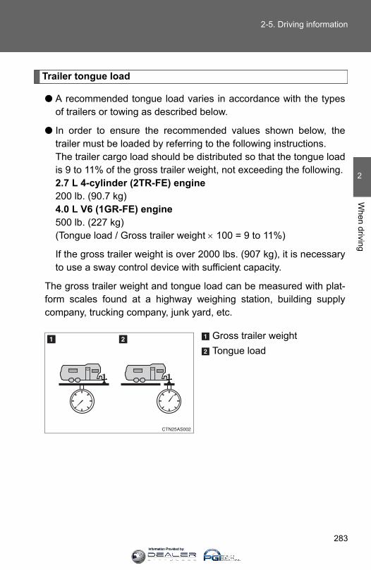
283
2-5. Driving information
2
When driving
Trailer tongue load
● A recommended tongue load varies in accordance with the typesof trailers or towing as described below.
● In order to ensure the recommended values shown below, thetrailer must be loaded by referring to the following instructions.The trailer cargo load should be distributed so that the tongue loadis 9 to 11% of the gross trailer weight, not exceeding the following.2.7 L 4-cylinder (2TR-FE) engine 200 lb. (90.7 kg) 4.0 L V6 (1GR-FE) engine 500 lb. (227 kg) (Tongue load / Gross trailer weight × 100 = 9 to 11%)
If the gross trailer weight is over 2000 lbs. (907 kg), it is necessaryto use a sway control device with sufficient capacity.
The gross trailer weight and tongue load can be measured with plat-form scales found at a highway weighing station, building supplycompany, trucking company, junk yard, etc.
Gross trailer weightTongue load
Information Provided by:
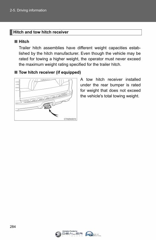
284
2-5. Driving information
Hitch and tow hitch receiver
■ HitchTrailer hitch assemblies have different weight capacities estab-lished by the hitch manufacturer. Even though the vehicle may berated for towing a higher weight, the operator must never exceedthe maximum weight rating specified for the trailer hitch.
■ Tow hitch receiver (if equipped)A tow hitch receiver installedunder the rear bumper is ratedfor weight that does not exceedthe vehicle's total towing weight.
CTH25AS010
Information Provided by:

285
2-5. Driving information
2
When driving
Selecting a trailer ball
Use the correct trailer ball for your application.
Trailer ball load rating
Matches or exceeds the grosstrailer weight rating of the trailer.
Ball diameter
Matches the size of the trailercoupler. Most couplers arestamped with the required trailerball size.
Shank length
Protrudes beyond the bottom ofthe lock washer and nut at least 2threads.
Shank diameter
Matches the ball mount holediameter size.
Connecting trailer lights
Use the wire harness stored inthe rear end under body.
CTH25AS011
Information Provided by:
286
2-5. Driving information
Trailer towing tips
Your vehicle will handle differently when towing a trailer. In order toavoid accident, death or serious injury, keep the following in mindwhen towing.
● Before starting out, check the trailer lights and the vehicle-trailerconnections. Recheck after driving a short distance.
● Practice turning, stopping and reversing with the trailer attached inan area away from traffic until you become accustomed to the feelof the vehicle.
● Reversing with a trailer attached is difficult and requires practice.Grip the bottom of the steering wheel and move your hand to theleft to move the trailer to the left. Move your hand to the right tomove the trailer to right. (This is generally opposite to reversingwithout a trailer attached.) Avoid sharp or prolonged turning. Havesomeone guide you when reversing to reduce the risk of an acci-dent.
● As stopping distance is increased when towing a trailer, vehicle-tovehicle distance should be increased. For each 10 mph (16 km/h)of speed, allow at least one vehicle and trailer length.
● Avoid sudden braking as you may skid, resulting in jackknifing andloss of control. This is especially true on wet or slippery surfaces.
● Avoid jerky starts or sudden acceleration.
● Avoid jerky steering and sharp turns, and slow down before mak-ing turns.
Information Provided by:

287
2-5. Driving information
2
When driving
● Note that when making a turn, the trailer wheels will be closer thanthe vehicle wheels to the inside of the turn. Compensate by makinga larger than normal turning radius.
● Crosswinds and rough roads will adversely affect handling of yourvehicle and trailer, causing sway. Periodically check the rear toprepare for being passed by large trucks or buses, which maycause your vehicle and trailer to sway. If swaying occurs, firmly gripthe steering wheel, reduce speed immediately but gradually, andsteer straight ahead. Never increase speed. If you make noextreme correction with the steering or brakes, your vehicle andtrailer will stabilize.
● Take care when passing other vehicles. Passing requires consider-able distance. After passing a vehicle, do not forget the length ofyour trailer, and be sure you have plenty of room before changinglanes.
● In order to maintain engine braking efficiency when driving on along steep downgrade, do not use overdrive. Transmission shiftrange position must be in 3 (standard type), or “4”, in the S mode(multi-mode type).
● Due to the added load of the trailer, your vehicle’s engine mayoverheat on hot days (at temperatures over 85°F [30°C]) whendriving up a long or steep grade. If the engine coolant temperaturegauge indicates overheating, immediately turn off the air condition-ing (if in use), pull your vehicle off the road and stop in a safe spot.(→P. 604)
Information Provided by:
288
2-5. Driving information
● Always place wheel blocks under both the vehicle and the trailerwheels when parking. Apply the parking brake firmly, and put thetransmission in P. Avoid parking on a slope, but if unavoidable, doso only after performing the following:
Apply the brakes and keep them applied.Have someone place wheel blocks under both the vehicle andtrailer wheels.When the wheel blocks are in place, release the brakes slowlyuntil the blocks absorb the load.Apply the parking brake firmly.Shift into P and turn off the engine.
● When restarting after parking on a slope:
With the transmission in P, start the engine. Be sure to keepthe brake pedal pressed.Shift into D or R (if reversing).Release the parking brake and brake pedal, and slowly pull orback away from the wheel blocks. Stop and apply the brakes.Have someone retrieve the blocks.
STEP 1
STEP 2
STEP 3
STEP 4
STEP 5
STEP 1
STEP 2
STEP 3
STEP 4
Information Provided by:
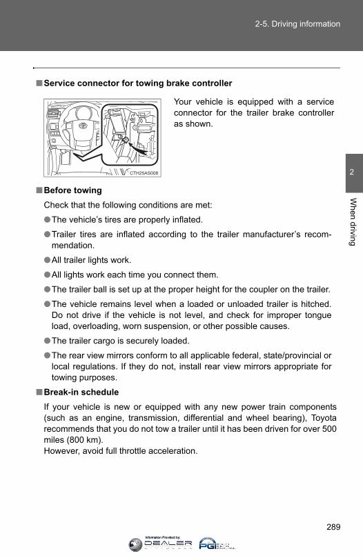
289
2-5. Driving information
2
When driving
■Service connector for towing brake controller
■Before towingCheck that the following conditions are met:
●The vehicle’s tires are properly inflated.
●Trailer tires are inflated according to the trailer manufacturer’s recom-mendation.
●All trailer lights work.
●All lights work each time you connect them.
●The trailer ball is set up at the proper height for the coupler on the trailer.
●The vehicle remains level when a loaded or unloaded trailer is hitched.Do not drive if the vehicle is not level, and check for improper tongueload, overloading, worn suspension, or other possible causes.
●The trailer cargo is securely loaded.
●The rear view mirrors conform to all applicable federal, state/provincial orlocal regulations. If they do not, install rear view mirrors appropriate fortowing purposes.
■Break-in scheduleIf your vehicle is new or equipped with any new power train components(such as an engine, transmission, differential and wheel bearing), Toyotarecommends that you do not tow a trailer until it has been driven for over 500miles (800 km).However, avoid full throttle acceleration.
Your vehicle is equipped with a serviceconnector for the trailer brake controlleras shown.
CTH25AS008
Information Provided by:

290
2-5. Driving information
■Maintenance● If you tow a trailer, your vehicle will require more frequent maintenance
due to the additional load. (See “Scheduled Maintenance Guide” or“Owner’s Manual Supplement”.)
●Retighten the fixing bolts of the towing ball and bracket after approxi-mately 600 miles (1000 km) of trailer towing.
CAUTION
■Trailer towing precautions●Follow all the instructions described in this section. Failure to do so could
cause an accident resulting in death or serious injury.
●Exceeding the towing capacity, GVWR, GCWR and GAWR can cause anaccident resulting in death or serious personal injuries.
■To avoid accident or injury●Do not exceed 45 mph (72 km/h) or the posted towing speed limit, which-
ever is lower. As instability (swaying) of the towing vehicle-trailer combina-tion increases as speed increases, exceeding 45 mph (72 km/h) maycause loss of control.
●Slow down and downshift before descending steep or long downhillgrades. Do not make sudden downshifts.
●Do not exceed the trailer hitch assembly weight, gross vehicle weight,gross axle weight and trailer tongue load capacities.
●Never load more weight in the back than in the front of the trailer. About60% of the load should be in the front half of the trailer, and the remaining40% in the rear.
●Do not use cruise control when you are towing.
●Avoid holding the brake pedal down too long or applying the brakes toofrequently. This could cause the brakes to overheat and result in reducedbraking efficiency.
Information Provided by:

291
2-5. Driving information
2
When driving
CAUTION
■Hitches● If you wish to install a trailer hitch, contact your Toyota dealer.
●Use only a hitch that conforms to the gross trailer weight requirement.
●Follow the directions supplied by the hitch manufacturer.
●Lubricate the hitch ball with a light coat of grease.
●Remove the trailer hitch whenever you are not towing a trailer. Afterremoving the hitch, seal any mounting hole in the vehicle body to prevententry of any substances into the vehicle.
■When towing a trailer● If the gross trailer weight exceeds 1000 lb. (453 kg), trailer brakes are
required. Toyota recommends trailers with brakes that conform to all appli-cable federal and state/provincial regulations.
●Never tap into your vehicle’s hydraulic system, as this will lower the vehi-cle’s braking effectiveness.
●Never tow a trailer without using a safety chain securely attached to boththe trailer and the vehicle. If damage occurs to the coupling unit or hitchball, there is a risk of the trailer wandering into another lane.
Information Provided by:

292
2-5. Driving information
NOTICE
■When installing a trailer hitch●Use only the position recommended by your Toyota dealer. Do not install
the trailer hitch on the bumper; this may cause body damage.
●Do not use axle-mounted hitches, as they can cause damage to the axlehousing, wheel bearings, wheels or tires.
■Safety chainA safety chain must always be used between the towing vehicle and thetrailer. Leave sufficient slack in the chain for turns. The chain should crossunder the trailer tongue to prevent the tongue from dropping to the ground inthe case that it becomes damaged or separated. For the correct safety chaininstallation procedure, ask your Toyota dealer.
■Do not directly splice trailer lightsDirectly splicing trailer lights may damage your vehicle’s electrical systemand cause a malfunction.
Information Provided by:

293
2-5. Driving information
2
When driving
Dinghy towing
NOTICE
■To avoid serious damage to your vehicleDo not tow your vehicle with four wheels on the ground.
Your vehicle is not designed to be dinghy towed (with 4 wheelson the ground) behind a motor home.
Information Provided by:
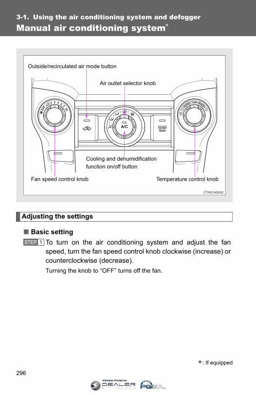
296
3-1. Using the air conditioning system and defogger
Manual air conditioning system∗
Adjusting the settings
■ Basic settingTo turn on the air conditioning system and adjust the fanspeed, turn the fan speed control knob clockwise (increase) orcounterclockwise (decrease).Turning the knob to “OFF” turns off the fan.
∗: If equipped
Fan speed control knob
Air outlet selector knob
Cooling and dehumidification function on/off button
Temperature control knob
Outside/recirculated air mode button
STEP 1
Information Provided by:

297
3-1. Using the air conditioning system and defogger
3
Interior features
To adjust the temperature setting, turn the temperature controlknob clockwise (warm) or counterclockwise (cool).
If is not pressed, the system will blow ambient temperature
air or heated air.
For quick cooling, turn the temperature control knob to “MAX A/C”.The air conditioning will automatically turn on and, if an air outlet
position other than or is selected, the system will beset to recirculated air mode. While “MAX A/C” is selected, it is notpossible to turn off the air conditioning.
To select the air outlets, set the air outlet selector knob to thedesired position.The positions between the air outlet selections shown below canalso be selected for more delicate adjustment.
Air flows to the upper body.
Air flows to the upper body andfeet.
STEP 2
STEP 3
CTH31AS004
CTH31AS005
Information Provided by:
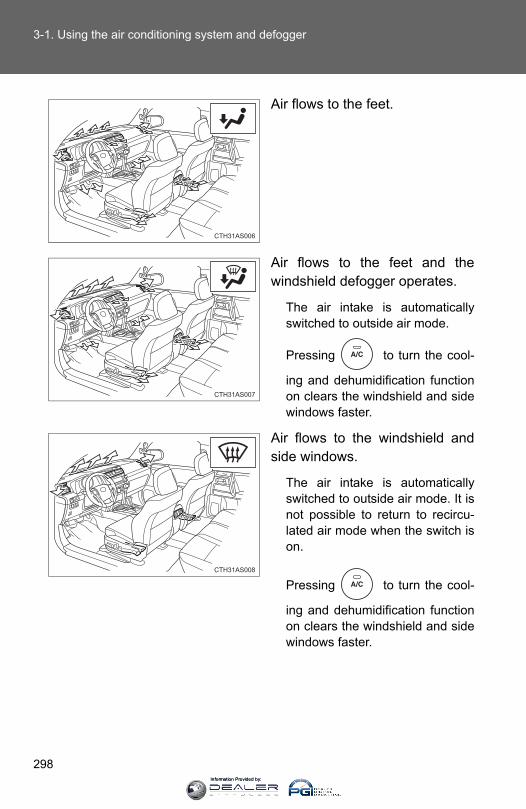
298
3-1. Using the air conditioning system and defogger
Air flows to the feet.
Air flows to the feet and thewindshield defogger operates.
The air intake is automaticallyswitched to outside air mode.
Pressing to turn the cool-
ing and dehumidification functionon clears the windshield and sidewindows faster.
Air flows to the windshield andside windows.
The air intake is automaticallyswitched to outside air mode. It isnot possible to return to recircu-lated air mode when the switch ison.
Pressing to turn the cool-
ing and dehumidification functionon clears the windshield and sidewindows faster.
CTH31AS006
CTH31AS007
CTH31AS008
Information Provided by:
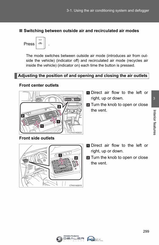
299
3-1. Using the air conditioning system and defogger
3
Interior features
■ Switching between outside air and recirculated air modes
Press .
The mode switches between outside air mode (introduces air from out-side the vehicle) (indicator off) and recirculated air mode (recycles airinside the vehicle) (indicator on) each time the button is pressed.
Adjusting the position of and opening and closing the air outlets
Front center outletsDirect air flow to the left orright, up or down.Turn the knob to open or closethe vent.
Front side outletsDirect air flow to the left orright, up or down.Turn the knob to open or closethe vent.
CTH31AS022
CTH31AS015
Information Provided by:

300
3-1. Using the air conditioning system and defogger
Rear outletsDirect air flow to the left orright, up or down.Turn the knob to open or closethe vent.
CTH31AS016
■Using the system in recirculated air modeThe windows will fog up more easily if recirculated air mode is used for anextended period of time.
■Switching between outside air and recirculated air modesRecirculated air mode or outside air mode may be automatically switched toin accordance with the outside temperature, etc.
■When is selected for the air outlets usedFor your driving comfort, air flowing to the feet may be warmer than air flow-ing to the upper body depending on the temperature setting.
■When the indicator light on flashes
Press to turn off the cooling and dehumidification function and turn it
on again. There may be a problem in the air conditioning system if the indi-cator light continues to flash. Turn the air conditioning system off and have itinspected by your Toyota dealer.
■When outside air temperature is below 32°F (0°C)The cooling and dehumidification function may not operate even when
is pressed.
Information Provided by:

301
3-1. Using the air conditioning system and defogger
3
Interior features
■Air conditioning odors●During use, various odors from inside and outside the vehicle may enter
into and accumulate in the air conditioning system. This may then causeodor to be emitted from the vents.
●To reduce potential odors from occurring: It is recommended that the air conditioning system be set to outside airmode prior to turning the vehicle off.
CAUTION
■To prevent the windshield from fogging upDo not use during cool air operation in extremely humid weather. Thedifference between the temperature of the outside air and that of the wind-shield can cause the outer surface of the windshield to fog up, blocking yourvision.
NOTICE
■To prevent battery dischargeDo not leave the air conditioning system on longer than necessary when theengine is stopped.
Information Provided by:
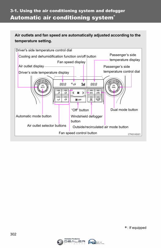
302
3-1. Using the air conditioning system and defogger
Automatic air conditioning system∗
Air outlets and fan speed are automatically adjusted according to thetemperature setting.
Driver's side temperature control dial
Air outlet display
Driver’s side temperature display
Fan speed display
Passenger’s side temperature display
Passenger’s side temperature control dial
Automatic mode button
Air outlet selector buttons
“Off” button
Cooling and dehumidification function on/off button
Fan speed control button
Windshield defogger buttonOutside/recirculated air mode button
Dual mode button
∗: If equipped
Information Provided by:
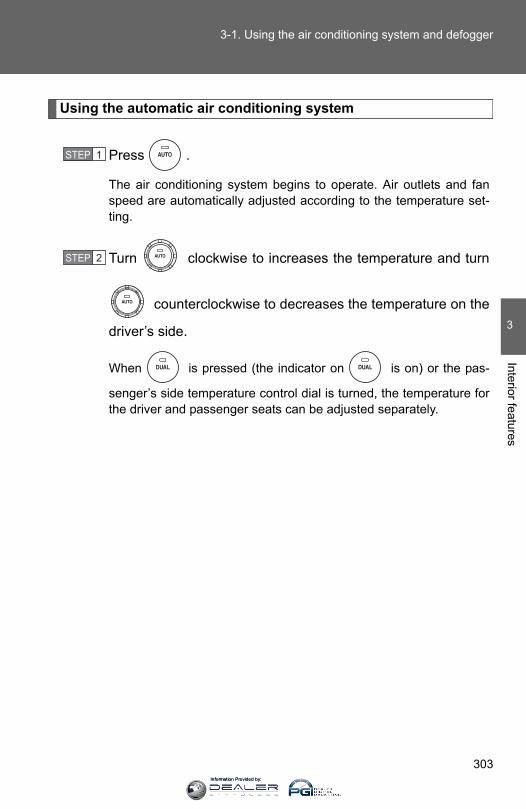
303
3-1. Using the air conditioning system and defogger
3
Interior features
Using the automatic air conditioning system
Press .
The air conditioning system begins to operate. Air outlets and fanspeed are automatically adjusted according to the temperature set-ting.
Turn clockwise to increases the temperature and turn
counterclockwise to decreases the temperature on the
driver’s side.
When is pressed (the indicator on is on) or the pas-
senger’s side temperature control dial is turned, the temperature forthe driver and passenger seats can be adjusted separately.
STEP 1
STEP 2
Information Provided by:

304
3-1. Using the air conditioning system and defogger
Adjusting the settings manually
■ Basic setting
To turn on the air conditioning system and adjust the fan
speed, press “>” on to increase the fan speed and“<” to decrease the fan speed.Press to turn the fan off.
To adjust the temperature setting, turn clockwise to
increases the temperature and counterclockwise to
decreases the temperature.
When is pressed (the indicator on is on) or the pas-
senger’s side temperature control dial is turned, the temperature forthe driver and passenger seats can be adjusted separately.
To change the air outlets, press , , or
.The air flow shown on the display indicates the following:
Air flows to the upper body.
: May occur in automatic mode
STEP 1
STEP 2
STEP 3
CTH31AS009
Information Provided by:

305
3-1. Using the air conditioning system and defogger
3
Interior features
Air flows to the upper body andfeet.
Air flows to the feet.
Air flows to the feet and thewindshield defogger operates.
The air intake is automaticallyswitched to outside air mode.
CTH31AS010
CTH31AS011
CTH31AS012
Information Provided by:
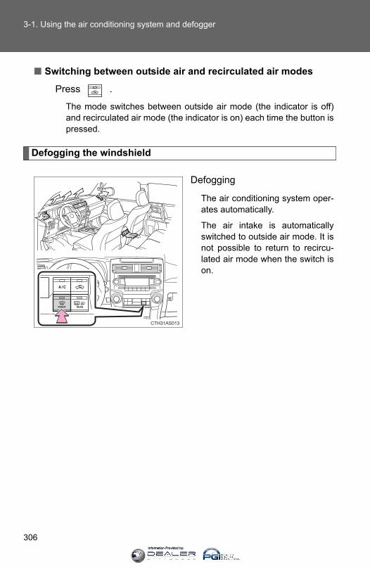
306
3-1. Using the air conditioning system and defogger
■ Switching between outside air and recirculated air modes
Press .
The mode switches between outside air mode (the indicator is off)and recirculated air mode (the indicator is on) each time the button ispressed.
Defogging the windshield
Defogging
The air conditioning system oper-ates automatically.
The air intake is automaticallyswitched to outside air mode. It isnot possible to return to recircu-lated air mode when the switch ison.
CTH31AS013
Information Provided by:

307
3-1. Using the air conditioning system and defogger
3
Interior features
Adjusting the position of and opening and closing the air outlets
Front center outletsDirect air flow to the left orright, up or down.Turn the knob to open or closethe vent.
Front side outletsDirect air flow to the left orright, up or down.Turn the knob to open or closethe vent.
Rear outletsDirect air flow to the left orright, up or down.Turn the knob to open or closethe vent.
CTH31AS014
CTH31AS015
CTH31AS016
Information Provided by:

308
3-1. Using the air conditioning system and defogger
■Using automatic modeFan speed is adjusted automatically according to the temperature settingand ambient conditions. As a result, the following may occur:
●The system may switch automatically to recirculated air mode when thecoolest temperature setting is selected when the ambient temperature ishigh.
● Immediately after the switch is pressed, the fan may stop for a while untilwarm or cool air is ready to flow.
●Cool air may flow to the area around the upper body when the heater ison.
■Switching between outside air and recirculated air modesRecirculated air mode or outside air mode may be automatically switched toin accordance with the temperature setting, the outside temperature, etc.
■Using the system in recirculated air modeThe windows will fog up more easily if recirculated air mode is used.
■Window defogger featureRecirculated air mode may automatically switch to outside air mode in situa-tions where the windows need to be defogged.
■When is selected for the air outlets usedFor your driving comfort, air flowing to the feet may be warmer than air flow-ing to the upper body depending on the temperature setting.
■When driving on dusty roadsClose all windows. If dust thrown up by the vehicle is still drawn into the vehi-cle after closing the windows, it is recommended that the air intake mode beset to outside air mode and the fan speed to any setting except off.
Information Provided by:
309
3-1. Using the air conditioning system and defogger
3
Interior features
■When outside air temperature is below 32°F (0°C)The cooling and dehumidification function may not operate even when
is pressed.
■When the indicator light on flashes
Press to turn off the cooling and dehumidification function and turn iton again. There may be a problem in the air conditioning system if the indi-cator light continues to flash. Turn the air conditioning system off and have itinspected by your Toyota dealer.
■Air conditioning odors●During use, various odors from inside and outside the vehicle may enter
into and accumulate in the air conditioning system. This may then causeodor to be emitted from the vents.
●To reduce potential odors from occurring:
• It is recommended that the air conditioning system be set to outside airmode prior to turning the vehicle off.
• The start timing of the blower may be delayed for a short period of timeimmediately after the air conditioning system is started in automaticmode.
CAUTION
■To prevent the windshield from fogging upDo not use during cool air operation in extremely humid weather. Thedifference between the temperature of the outside air and that of the wind-shield can cause the outer surface of the windshield to fog up, blocking yourvision.
NOTICE
■To prevent battery dischargeDo not leave the air conditioning system on longer than necessary when theengine is stopped.
Information Provided by:
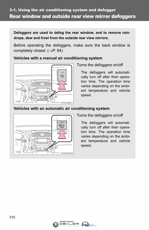
310
3-1. Using the air conditioning system and defogger
Rear window and outside rear view mirror defoggers
Defoggers are used to defog the rear window, and to remove rain-drops, dew and frost from the outside rear view mirrors.
Before operating the defoggers, make sure the back window iscompletely closed. (→P. 94)
Vehicles with a manual air conditioning systemTurns the defoggers on/off
The defoggers will automati-cally turn off after their opera-tion time. The operation timevaries depending on the ambi-ent temperature and vehiclespeed.
Vehicles with an automatic air conditioning systemTurns the defoggers on/off
The defoggers will automati-cally turn off after their opera-tion time. The operation timevaries depending on the ambi-ent temperature and vehiclespeed.
Information Provided by:

311
3-1. Using the air conditioning system and defogger
3
Interior features
■The defoggers can be operated when●Vehicles without a smart key system:
The engine switch is in the “ON” position.
Vehicles with a smart key system: The “ENGINE START STOP” switch is in IGNITION ON mode.
●The back window is completely closed.
■The outside rear view mirror defoggersTurning the rear window defogger on will turn the outside rear view mirrordefoggers on.
CAUTION
■When the outside rear view mirror defoggers are onDo not touch outside surface of the rear view mirrors, as they can becomevery hot and burn you.
Information Provided by:
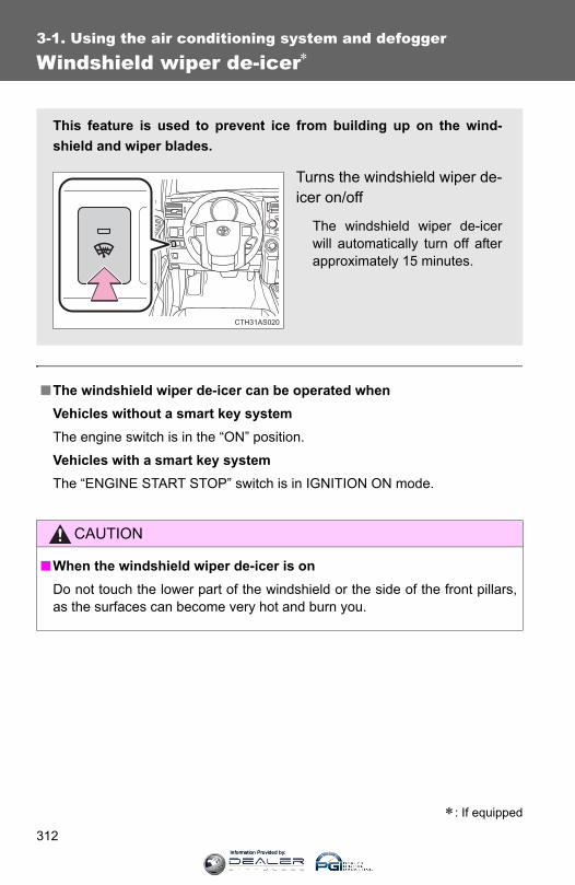
312
3-1. Using the air conditioning system and defogger
Windshield wiper de-icer∗
■The windshield wiper de-icer can be operated whenVehicles without a smart key systemThe engine switch is in the “ON” position.
Vehicles with a smart key systemThe “ENGINE START STOP” switch is in IGNITION ON mode.
CAUTION
■When the windshield wiper de-icer is onDo not touch the lower part of the windshield or the side of the front pillars,as the surfaces can become very hot and burn you.
∗: If equipped
This feature is used to prevent ice from building up on the wind-shield and wiper blades.
Turns the windshield wiper de-icer on/off
The windshield wiper de-icerwill automatically turn off afterapproximately 15 minutes.
CTH31AS020
Information Provided by:

313
3
Interior features
3-2. Using the audio system
Audio system types
With a navigation systemOwners of models equipped with a navigation system should referto the “Navigation System Owner's Manual”.
Without a navigation systemType A: CD player with changer controller and AM/FM radio
Type B: CD player with changer controller and AM/FM radio
Information Provided by:
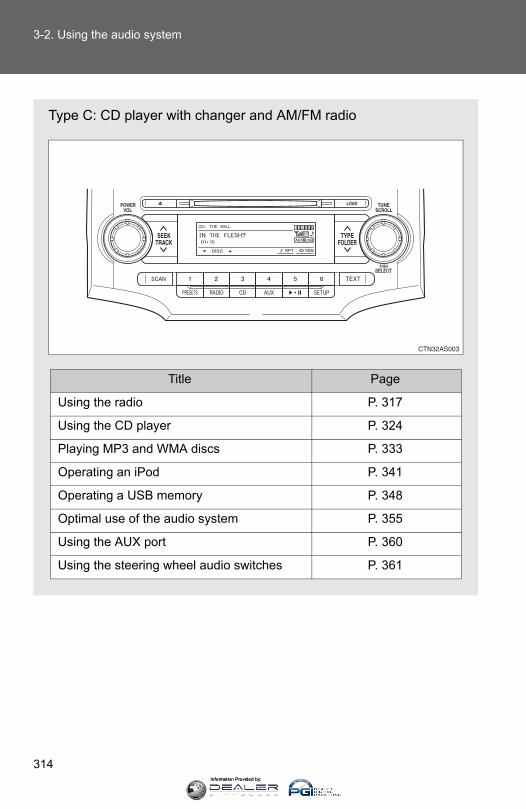
314
3-2. Using the audio system
Type C: CD player with changer and AM/FM radio
Title Page
Using the radio P. 317
Using the CD player P. 324
Playing MP3 and WMA discs P. 333
Operating an iPod P. 341
Operating a USB memory P. 348
Optimal use of the audio system P. 355
Using the AUX port P. 360
Using the steering wheel audio switches P. 361
Information Provided by:
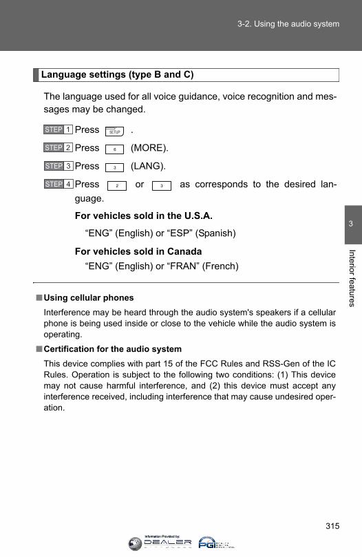
315
3-2. Using the audio system
3
Interior features
Language settings (type B and C)
The language used for all voice guidance, voice recognition and mes-sages may be changed.
Press .
Press (MORE).
Press (LANG).
Press or as corresponds to the desired lan-guage.
For vehicles sold in the U.S.A.
“ENG” (English) or “ESP” (Spanish)
For vehicles sold in Canada“ENG” (English) or “FRAN” (French)
■Using cellular phonesInterference may be heard through the audio system's speakers if a cellularphone is being used inside or close to the vehicle while the audio system isoperating.
■Certification for the audio systemThis device complies with part 15 of the FCC Rules and RSS-Gen of the ICRules. Operation is subject to the following two conditions: (1) This devicemay not cause harmful interference, and (2) this device must accept anyinterference received, including interference that may cause undesired oper-ation.
STEP 1
STEP 2
STEP 3
STEP 4
Information Provided by:
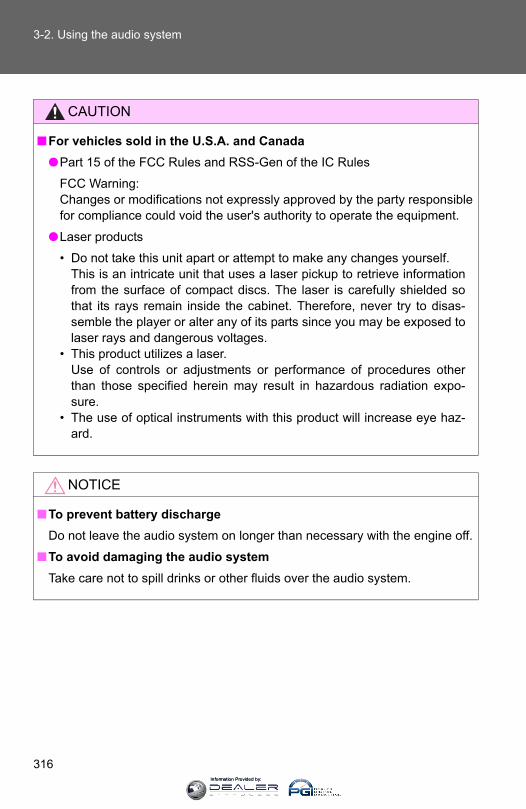
316
3-2. Using the audio system
CAUTION
■For vehicles sold in the U.S.A. and Canada●Part 15 of the FCC Rules and RSS-Gen of the IC Rules
FCC Warning:Changes or modifications not expressly approved by the party responsiblefor compliance could void the user's authority to operate the equipment.
●Laser products
• Do not take this unit apart or attempt to make any changes yourself. This is an intricate unit that uses a laser pickup to retrieve informationfrom the surface of compact discs. The laser is carefully shielded sothat its rays remain inside the cabinet. Therefore, never try to disas-semble the player or alter any of its parts since you may be exposed tolaser rays and dangerous voltages.
• This product utilizes a laser.Use of controls or adjustments or performance of procedures otherthan those specified herein may result in hazardous radiation expo-sure.
• The use of optical instruments with this product will increase eye haz-ard.
NOTICE
■To prevent battery dischargeDo not leave the audio system on longer than necessary with the engine off.
■To avoid damaging the audio systemTake care not to spill drinks or other fluids over the audio system.
Information Provided by:
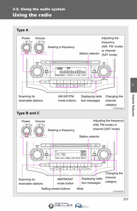
317
3-2. Using the audio system
3
Interior features
Using the radio
Type A
Type B and C
Power Volume Adjusting the frequency(AM, FM mode)or channel (SAT mode)
Seeking a frequency
Displaying radio text messages
AM⋅SAT/FM mode buttons
Scanning for receivable stations
Station selector
Changing the channel category
Power Volume Adjusting the frequency(AM, FM mode) or channel (SAT mode)Seeking a frequency
Displaying radio text messages
AM/FM/SAT mode button
Scanning for receivable stations
Station selector
Setting preset buttons
Changing the channel category
Mute
Information Provided by:

318
3-2. Using the audio system
Setting station presets (excluding XM® Satellite Radio)
Search for desired stations by turning or or
pressing “∧” or “∨” on .
Press and hold a button (from to ) until you heara beep.Type B and C: Each time is pressed, station pages arechanged. There are a total of 6 pages.
Scanning radio stations (excluding XM® Satellite Radio)
■ Scanning the preset radio stations
Press and hold until you hear a beep.Preset stations will be played for 5 seconds each.
When the desired station is reached, press again.
■ Scanning all radio stations within range
Press .All the stations with reception will be played for 5 seconds each.
When the desired station is reached, press again.
■ Displaying radio text messages (for type B and C, FM modeonly)When a new radio text message is received, “MSG” is shown onthe display. To display the message, press .
If the text continues past the end of the display, “ ” is displayed. Press
and hold until you hear a beep.
Text messages are not displayed while driving.
STEP 1
STEP 2
STEP 1
STEP 2
STEP 1
STEP 2
Information Provided by:

319
3-2. Using the audio system
3
Interior features
XM® Satellite Radio (if equipped)
■ Receiving XM® Satellite Radio
Press or .
The display changes as follows each time or ispressed.Type A: AM → SAT1 → SAT2 → SAT3Type B and C: AM → FM → SAT
Turn or to select the desired channel in all the
categories or press “∧” or “∨” on to select the desired
channel in the current category.
■ Setting XM® Satellite Radio channel presetsSelect the desired channel. Press and hold a button (from to
) until you hear a beep.
Type B and C: Each time is pressed, station pages are changed.There are a total of 6 pages.
■ Changing the channel category
Press “∧” or “∨” on .
STEP 1
STEP 2
Information Provided by:
320
3-2. Using the audio system
■ Scanning XM® Satellite Radio channels● Scanning channels in the current category
Press .
When the desired channel is reached, press again.
● Scanning the preset channels
Press and hold until you hear a beep.
When the desired channel is reached, press again.
■ Displaying text informationPress .
Each time is pressed, the display changes in the followingorder: Type A: Channel name → Title (song/program title) → Name (artist name/feature) → Channel number.
Type B and C: Title (song/program title) → Name (artist name/feature)/Title (song/program title).
STEP 1
STEP 2
STEP 1
STEP 2
Information Provided by:
321
3-2. Using the audio system
3
Interior features
■When the battery is disconnectedAll preset stations are erased. (type A only)
■Reception sensitivity●Type B and C ⎯ Cargo loaded on the roof luggage carrier, especially
metal objects, may adversely affect the reception of XM® Satellite Radio.
●Maintaining perfect radio reception at all times is difficult due to the con-tinually changing position of the antenna, differences in signal strengthand surrounding objects, such as trains, transmitters, etc.
●The radio antenna is mounted on the right-side front fender. The antennacan be removed from the base by turning it.
■XM® Satellite RadioAn XM® Satellite Radio is a tuner designed exclusively to receive broadcastsprovided under a separate subscription. Availability is limited to the 48 con-tiguous states and 10 Canadian provinces.
●XM® subscriptionsFor detailed information about XM® Satellite Radio or to subscribe:U.S.A. ⎯Visit on the web at www.xmradio.com or call 1-800-967-2346.Canada ⎯Visit on the web at www.xmradio.ca or call 1-877-438-9677.
●Radio IDYou will need the radio ID when activating XM® service or reporting a
problem. Select “CH000” using or , and the receiver's 8-
character ID number will appear.
●Satellite tunerThe tuner supports only Audio Services (Music and Talk) and the accom-panying Text Information of XM® Satellite Radio.
Information Provided by:

322
3-2. Using the audio system
■ If XM® Satellite Radio does not operate normallyIf a problem occurs with the XM® tuner, a message will appear on the dis-play. Refer to the table below to identify the problem, and take the suggestedcorrective action.
ANTENNA or
CHECK ANTENNA
The XM® antenna is not connected. Check whether the XM® antenna cable is attached securely.
There is a short-circuit in the antenna or the sur-rounding antenna cable. See a Toyota certified dealer.
UPDATINGor
CHANNEL NOT AUTHORIZED
You have not subscribed to XM® Satellite Radio. The radio is being updated with the latest encryp-tion code. Contact XM® Satellite Radio for sub-scription information. When a contract is canceled, you can choose the “CH000” and all free-to-air channels.
The premium channel you selected is not autho-rized. Wait for about 2 seconds until the radio returns to the previous channel or “CH001”. If it does not change automatically, select another channel. If you want to listen to the premium chan-nel, contact XM® Satellite Radio.
NO SIGNALThe XM® signal is too weak at the current location. Wait until your vehicle reaches a location with a stronger signal.
LOADING The unit is acquiring audio or program information. Wait until the unit has received the information.
OFF AIR or
CHANNEL OFF AIR
The channel you selected is not broadcasting any programming. Select another channel.
-----There is no song/program title or artist name/fea-ture associated with the channel at this time. No action needed.
Information Provided by:

323
3-2. Using the audio system
3
Interior features
Contact the XM® Listener Care Center at 1-800-967-2346 (U.S.A.) or 1-877-438-9677 (Canada)
■Certifications for the radio tunerThis equipment has been tested and found to comply with the limits for aclass B digital device, pursuant to Part 15 of the FCC Rules. These limits aredesigned to provide reasonable protection against harmful interference in aresidential installation. This equipment generates, uses and can radiateradio frequency energy and, if not installed and used in accordance with theinstructions, may cause harmful interference to radio communications. How-ever, there is no guarantee that interference will not occur in a particularinstallation.
If this equipment does cause harmful interference to radio or televisionreception, which can be determined by turning the equipment off and on, theuser is encouraged to try to correct the interference by trying one or more ofthe following:
●Reorienting or relocating the receiving antenna.
● Increasing the separation between the equipment and receiver.
●Connecting the equipment into an outlet on a circuit different from that towhich the receiver is connected.
●Consulting the dealer or an experienced radio/TV technician for help.
NOTICE
■To prevent damage, remove the antenna in the following cases.●The antenna will touch the ceiling of a garage.
●A cover will be put on the vehicle.
---or
CHANNEL NOT AVAILABLE
The channel you selected is no longer available. Wait for about 2 seconds until the radio returns to the previous channel or “CH001”. If it does not change automatically, select another channel.
Information Provided by:
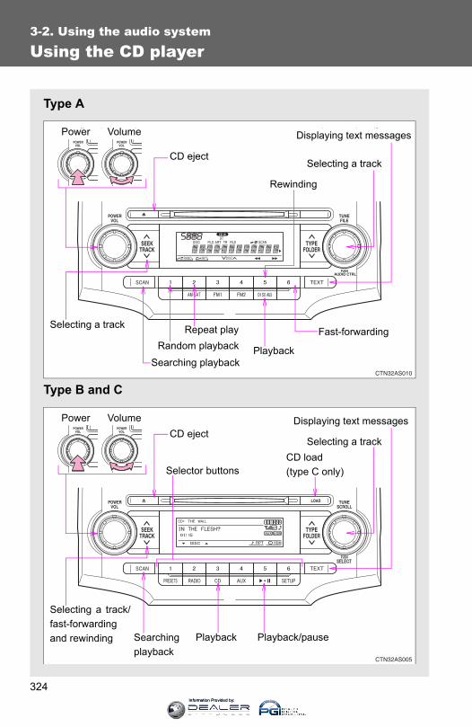
324
3-2. Using the audio system
Using the CD player
Type A
Type B and C
Power Volume Displaying text messages
CD eject
Repeat playSelecting a track
Rewinding
Random playback
Searching playbackPlayback
Fast-forwarding
Selecting a track
Power Volume
CD load (type C only)
Searchingplayback
CD eject
Selecting a track/fast-forwardingand rewinding
Displaying text messages
Selector buttons
Playback Playback/pause
Selecting a track
Information Provided by:
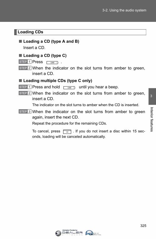
325
3-2. Using the audio system
3
Interior features
Loading CDs
■ Loading a CD (type A and B)Insert a CD.
■ Loading a CD (type C)Press .When the indicator on the slot turns from amber to green,insert a CD.
■ Loading multiple CDs (type C only)Press and hold until you hear a beep.When the indicator on the slot turns from amber to green,insert a CD.The indicator on the slot turns to amber when the CD is inserted.
When the indicator on the slot turns from amber to greenagain, insert the next CD.Repeat the procedure for the remaining CDs.
To cancel, press . If you do not insert a disc within 15 sec-onds, loading will be canceled automatically.
STEP 1
STEP 2
STEP 1
STEP 2
STEP 3
Information Provided by:
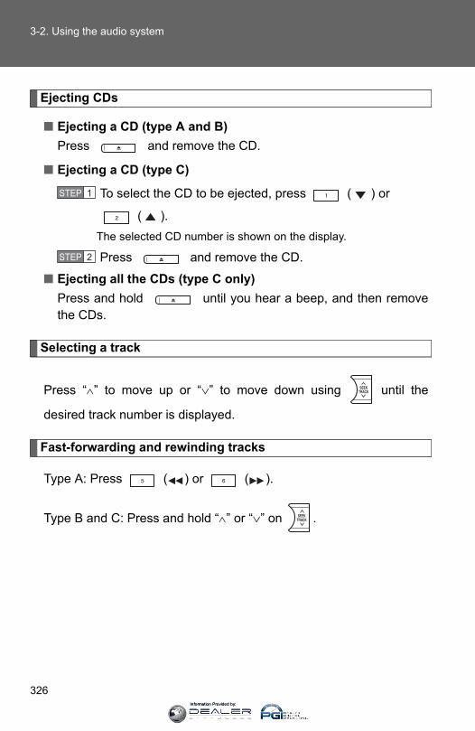
326
3-2. Using the audio system
Ejecting CDs
■ Ejecting a CD (type A and B)Press and remove the CD.
■ Ejecting a CD (type C)
To select the CD to be ejected, press ( ) or
( ).The selected CD number is shown on the display.
Press and remove the CD.
■ Ejecting all the CDs (type C only)Press and hold until you hear a beep, and then removethe CDs.
Selecting a track
Press “∧” to move up or “∨” to move down using until the
desired track number is displayed.
Fast-forwarding and rewinding tracks
Type A: Press ( ) or ( ).
Type B and C: Press and hold “∧” or “∨” on .
STEP 1
STEP 2
Information Provided by:

327
3-2. Using the audio system
3
Interior features
Scanning tracks
Press .The first ten seconds of each track will be played.
To cancel, press again.
Press again when the desired track is reached.
Selecting a CD (type C only)
■ Selecting a CD to playPress ( ) or ( ).
■ Scanning loaded CDs
Press and hold until you hear a beep.The first ten seconds of the first track on each CD will be played.
To cancel, press again.
Press again when the desired CD is reached.
Playing and pausing tracks (type B and C)
Press .
STEP 1
STEP 2
STEP 1
STEP 2
Information Provided by:

328
3-2. Using the audio system
Random playback
■ Current CDPress (RAND) or (RDM).
Songs are played in random order.
To cancel, press the button once more (type A and B), or twice more(type C).
■ All CDs (type C only)Press (RDM) twice.
Tracks on all loaded CDs are played in random order.
To cancel, press the button again.
Repeat play
■ Repeating a trackPress (RPT) or (RPT).
To cancel, press the button once more (type A and B), or twice more(type C).
■ Repeating all of the tracks on a CD (type C only)Press (RPT) twice.
To cancel, press the button again.
Information Provided by:
329
3-2. Using the audio system
3
Interior features
Switching the display
Press .
Each time is pressed, the display changes in the followingorder:
Type A: Track no./Elapsed time → CD title → Track name.
Type B and C: Track title → Track name/Artist name → Track name/Elapsed time.
■Display (type A only)Up to 12 characters can be displayed at a time.If there are 13 characters or more, pressing and holding for 1 sec-ond or more will display the remaining characters.A maximum of 24 characters can be displayed.If is pressed for 1 second or more again or has not been pressedfor 6 seconds or more, the display will return to the first 12 characters.
Depending on the contents recorded, the characters may not be displayedproperly or may not be displayed at all.
Information Provided by:

330
3-2. Using the audio system
■Error messages“CD CHECK”: This indicates a problem either with the CD or inside the
player. The CD may be dirty, damaged or inserted up-sidedown.
“WAIT” or “PLEASE WAIT”: Operation has stopped due to a high tempera-ture inside the player. Wait for a while and thenpress or . Contact your Toyotadealer if the CD still cannot be played back.
■Discs that can be usedDiscs with the marks shown below can be used.Playback may not be possible depending on the recording format or discfeatures, or due to scratches, dirt or deterioration.
CDs with copy-protection features may not be used.
■CD player protection featureTo protect the internal components, playback is automatically stopped whena problem is detected while the CD player is being used.
■ If CDs are left inside the CD player or in the ejected position forextended periodsCDs may be damaged and may not play properly.
■Lens cleanersDo not use lens cleaners. Doing so may damage the CD player.
Information Provided by:

331
3-2. Using the audio system
3
Interior features
NOTICE
■CDs and adapters that cannot be usedDo not use the following types of CDs, 3 in. (8 cm) CD adapters or DualDiscs.Doing so may damage the CD player and/or the CD insert/eject function.
●CD player with changer and AM/FMradio: CDs that have a diameter that isnot 4.7 in. (12 cm)
●Low-quality and deformed CDs
●CDs with a transparent or translucentrecording area
●CDs that have had tape, stickers or CD-R labels attached to them, or that havehad the label peeled off
Information Provided by:

332
3-2. Using the audio system
NOTICE
■CD player precautionsFailure to follow the precautions below may result in serious damage to theCDs or the player itself.
●Do not insert anything other than CDs into the CD slot.
●Do not apply oil to the CD player.
●Store CDs away from direct sunlight.
●Never try to disassemble any part of the CD player.
●Do not insert more than one CD at atime.
Information Provided by:
333
3-2. Using the audio system
3
Interior features
Playing MP3 and WMA discs
Type A
Type B and C
Power Volume
Displaying text messages
CD eject
Repeat play
Selecting a file
Selecting a folder and files
Random playback
Searchingplayback
Playback
Selecting a file
Rewinding
Fast-forwarding
Power Volume
Displaying text messages
CD eject
Playback
Playback/pause
Selecting a file
CD load(type C only)Selector buttons
Selecting a folder and file
Searching playback
Selecting a file/fast-forwardingand rewinding
Information Provided by:

334
3-2. Using the audio system
Loading and ejecting MP3 and WMA discs
→P. 325
Selecting MP3 and WMA discs (type C only)
→P. 326
Selecting and scanning a folder
■ Selecting folders one at a time
Press “∧” or “∨” on to select the desired folder.
■ Scanning the first file of all the folders
Press and hold until you hear a beep.The first ten seconds of the first file in each folder will be played.
When the desired folder is reached, press again.
■ Returning to the first folder
Press and hold “∨” on until you hear a beep.
Selecting and scanning files
■ Selecting one file at a time
Turn or or press “∧” or “∨” on to select the
desired file.
STEP 1
STEP 2
Information Provided by:
335
3-2. Using the audio system
3
Interior features
■ Selecting the desired file by cueing the files in the folderPress .
When the desired file is reached, press once again.
Fast-forwarding and rewinding files
Type A: Press ( ) or ( ).
Type B and C: Press and hold “∧” or “∨” on .
Playing and pausing files (type B and C)
Press .
Random playback
■ Playing files from a particular folder in random orderPress (RAND) or (RDM).
To cancel, press the button once more (type A and B), or twice more(type C).
■ Playing all of the files on a disc in random order (type C only)Press (RDM) twice.
To cancel, press the button again.
Information Provided by:
336
3-2. Using the audio system
Repeat play
■ Repeating a filePress (RPT) or (RPT).
To cancel, press the button once more (type A and B), or twice more(type C).
■ Repeating all of the files in a folderType A: Press and hold (RPT) until you hear a beep.
Type B and C: Press (RPT) twice.
To cancel, press the button once more (type A and B), or twice more(type C).
■ Repeating all of the files in a disc (type C only)Press (RPT) three times.
To cancel, press the same button again.
Switching the display
Press .
Each time is pressed, the display changes in the followingorder:
Type A: Folder no./File no./Elapsed time → Folder name → File name →Album title (MP3 only) → Track title → Artist name.
Type B and C: Track title → Track title/Artist name → Track title/Albumname (MP3 only) → Track title/Elapsed time.
Information Provided by:
337
3-2. Using the audio system
3
Interior features
■Display (type A only)→P. 329
■Error messages“CD CHECK”: This indicates a problem either with the CD or inside the
player. The CD may be dirty, damaged or inserted up-sidedown.
“WAIT” or “PLEASE WAIT”: Operation has stopped due to a high tempera-ture inside the player. Wait for a while and thenpress or . Contact your Toyotadealer if the CD still cannot be played.
■Discs that can be used→P. 330
■CD player protection feature→P. 330
■ If CDs are left inside the CD player or in the ejected position forextended periods→P. 330
■Lens cleaners→P. 330
Information Provided by:
338
3-2. Using the audio system
■MP3 and WMA filesMP3 (MPEG Audio LAYER3) is a standard audio compression format.
Files can be compressed to approximately 1/10 of their original size by usingMP3 compression.
WMA (Windows Media® Audio) is a Microsoft audio compression format.
This format compresses audio data to a size smaller than that of the MP3format.
There is a limit to the MP3 and WMA file standards that can be used and tothe media/formats on which the files are recorded.
●MP3 file compatibility
• Compatible standardsMP3 (MPEG1 LAYER3, MPEG2 LSF LAYER3)
• Compatible sampling frequenciesMPEG1 LAYER3: 32, 44.1, 48 (kHz)MPEG2 LSF LAYER3: 16, 22.05, 24 (kHz)
• Compatible bit rates (Compatible with VBR)MPEG1 LAYER3: 64, 80, 96, 112, 128, 160, 192, 224, 256, 320 (kbps)MPEG2 LSF LAYER3: 64, 80, 96, 112, 128, 144, 160 (kbps)
• Compatible channel modes: stereo, joint stereo, dual channel andmonaural
●WMA file compatibility
• Compatible standardsWMA Ver. 7, 8, 9
• Compatible sampling frequencies32, 44.1, 48 (kHz)
• Compatible bit rates (Only compatible with 2-channel playback)Ver. 7, 8: CBR 48, 64, 80, 96, 128, 160, 192 (kbps)Ver. 9: CBR 48, 64, 80, 96, 128, 160, 192, 256, 320 (kbps)
Information Provided by:

339
3-2. Using the audio system
3
Interior features
●Compatible media
Media that can be used for MP3 and WMA playback are CD-Rs and CD-RWs.
Playback in some instances may not be possible if the CD-R or CD-RW isnot finalized. Playback may not be possible or the audio may jump if thedisc is scratched or marked with fingerprints.
●Compatible disc formats
The following disc formats can be used.
• Disc formats: CD-ROM Mode 1 and Mode 2CD-ROM XA Mode 2, Form 1 and Form 2
• File formats: ISO9660 Level 1, Level 2, (Romeo, Joliet)MP3 and WMA files written in any format other than those listed abovemay not play correctly, and their file names and folder names may notbe displayed correctly.
Items related to standards and limitations are as follows.
• Maximum directory hierarchy: 8 levels• Maximum length of folder names/file names: 32 characters• Maximum number of folders: 192 (including the root)• Maximum number of files per disc: 255
●File names
The only files that can be recognized as MP3/WMA and played are thosewith the extension .mp3 or .wma.
●Multi-sessions
As the audio system is compatible with multi-sessions, it is possible to playdiscs that contain MP3 and WMA files. However, only the first session canbe played.
● ID3 and WMA tags
ID3 tags can be added to MP3 files, making it possible to record the tracktitle, artist name, etc.
The system is compatible with ID3 Ver. 1.0, 1.1, and Ver. 2.2, 2.3 ID3 tags.(The number of characters is based on ID3 Ver. 1.0 and 1.1.)
WMA tags can be added to WMA files, making it possible to record thetrack title and artist name in the same way as with ID3 tags.
Information Provided by:
340
3-2. Using the audio system
●MP3 and WMA playback
When a disc containing MP3 or WMA files is inserted, all files on the discare first checked. Once the file check is finished, the first MP3 or WMA fileis played. To make the file check finish more quickly, we recommend youdo not write in any files other than MP3 or WMA files or create any unnec-essary folders.
If the discs contain a mixture of music data and MP3 or WMA format data,only music data can be played.
●Extensions
If the file extensions .mp3 and .wma are used for files other than MP3 andWMA files, they will be mistakenly recognized and played as MP3 andWMA files. This may result in large amounts of interference and damageto the speakers.
●Playback
• To play MP3 files with steady sound quality, we recommend a fixed bitrate of at least 128 kbps and a sampling frequency of 44.1 kHz.
• CD-R or CD-RW playback may not be possible in some instances,depending on the characteristics of the disc.
• There is a wide variety of freeware and other encoding software forMP3 and WMA files on the market, and depending on the status of theencoding and the file format, poor sound quality or noise at the start ofplayback may result. In some cases, playback may not be possible atall.
• When files other than MP3 or WMA files are recorded on a disc, it maytake more time to recognize the disc. In some cases, playback may notbe possible at all.
• Microsoft, Windows, and Windows Media are the registered trade-marks of Microsoft Corporation in the U.S. and other countries.
NOTICE
■CDs and adapters that cannot be used (→P. 331)■CD player precautions (→P. 332)
Information Provided by:
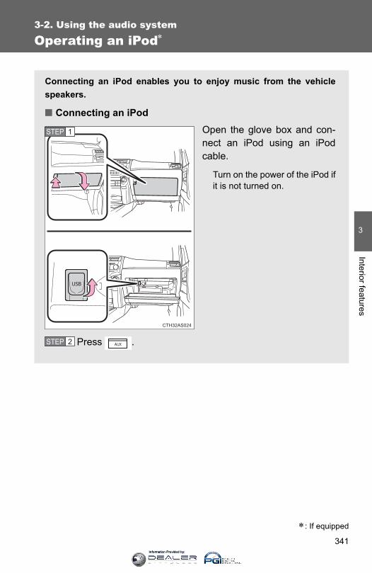
341
3-2. Using the audio system
3
Interior features
Operating an iPod∗
Connecting an iPod enables you to enjoy music from the vehiclespeakers.
■ Connecting an iPodOpen the glove box and con-nect an iPod using an iPodcable.
Turn on the power of the iPod ifit is not turned on.
Press .
CTH32AS024
STEP 1
STEP 2
∗: If equipped
Information Provided by:
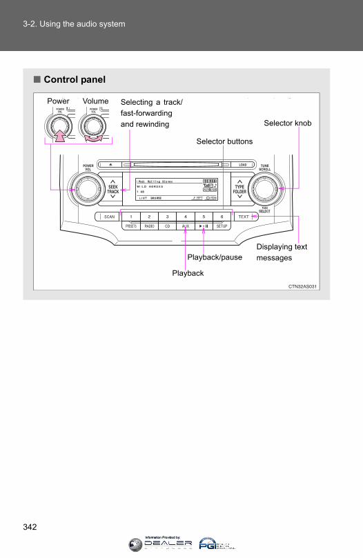
342
3-2. Using the audio system
■ Control panel
Power Volume
Selector knob
Displaying text messages
Selector buttons
Playback
Playback/pause
Selecting a track/fast-forwardingand rewinding
Information Provided by:
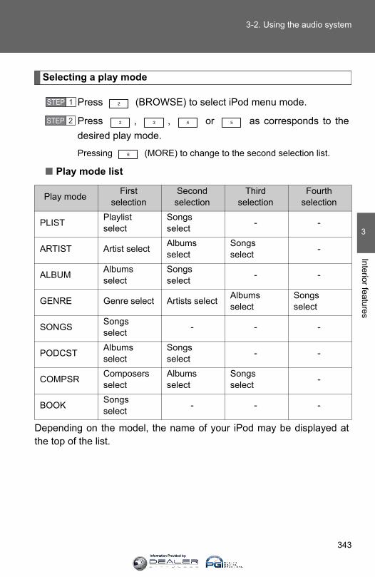
343
3-2. Using the audio system
3
Interior features
Selecting a play mode
Press (BROWSE) to select iPod menu mode.
Press , , or as corresponds to thedesired play mode.
Pressing (MORE) to change to the second selection list.
■ Play mode list
Depending on the model, the name of your iPod may be displayed atthe top of the list.
Play mode First selection
Second selection
Third selection
Fourth selection
PLIST Playlist select
Songs select - -
ARTIST Artist select Albums select
Songs select -
ALBUM Albums select
Songs select - -
GENRE Genre select Artists select Albums select
Songs select
SONGS Songs select - - -
PODCST Albums select
Songs select - -
COMPSR Composers select
Albums select
Songs select -
BOOK Songs select - - -
STEP 1
STEP 2
Information Provided by:

344
3-2. Using the audio system
■ Selecting a list
Turn to display the first selection list.
Press to select the desired item.
Repeat the same procedure to select the desired song name.
To return to the previous selection list, press ( ).
Selecting songs from a song list
Press (LIST).The current playlist is displayed.
Turning to select the desired song.
Press returns the screen from list display to the previous
screen.
STEP 1
STEP 2
STEP 3
STEP 1
STEP 2
Information Provided by:

345
3-2. Using the audio system
3
Interior features
Selecting songs
Turn or press “∧” or “∨” on to select the desired song.
Playing and pausing songs
Press .
Fast-forwarding and rewinding songs
Press and hold “∧” or “∨” on .
Shuffle playback
■ Playing songs from one playlist or album in random orderPress (RDM).
To cancel, press the button twice.
■ Playing songs from all the playlists or albums in random orderPress (RDM) twice.
To cancel, press the button again.
Repeat play
Press (RPT).
To cancel, press the button again.
Even when the repeat play option has not been selected, playback willautomatically continue from the first song in the current play list once thelast song has ended.
Information Provided by:
346
3-2. Using the audio system
Switching the display
Press .
Each time is pressed, the display changes in the followingorder: Track title → Track title/Artist name → Track title/Album name → Tracktitle/Elapsed time
■About iPod●Apple is not responsible for the operation of this device or its compliance
with safety and regulatory standards.
● iPod is a trademark of Apple Inc., registered in the U.S. and other coun-tries.
■ iPod functions●When an iPod is connected and the audio source is changed to iPod
mode, the iPod will resume play from the same point in which it was lastused.
●Depending on the iPod that is connected to the system, certain functionsmay not be available. Disconnecting the device and reconnecting it onceagain may resolve some malfunctions.
■ iPod problemsTo resolve most problems encountered when using your iPod, disconnectyour iPod from the vehicle iPod connection and reset it. For instructions on how to reset your iPod, refer to your iPod Owner's Man-ual.
■Error messages“iPod ERROR”: This indicates a problem in the iPod, inside the
USB box or the connection between them.
“NO SONGS”: This indicates that there is no music data in theiPod.
“UPDATE YOUR iPod”: This indicates that the version of the iPod is notcompatible.
Information Provided by:

347
3-2. Using the audio system
3
Interior features
■Compatible models
Depending on differences between models or software version etc., somemodels listed above might be incompatible with this system. iPod 4th generation and earlier models are not compatible with this system. iPhone, iPod mini, iPod shuffle and iPod photo are not compatible with thissystem.
Items related to standards and limitations are as follows:
●Maximum number of lists in a device: 9999
●Maximum number of songs in a device: 65025
●Maximum number of songs per list: 65025
CAUTION
■Caution while drivingDo not connect iPod or operate the controls.
NOTICE
■To prevent damage to iPod●Do not leave iPod in the vehicle. The temperature inside may become
high, resulting in damage to the player.
●Do not push down on or apply unnecessary pressure to the iPod while it isconnected as this may damage the iPod or its terminal.
●Do not insert foreign objects into the port as this may damage the iPod orits terminal.
Model Generation Software version
iPod 5th generation Ver. 1.2.0 or higher
iPod nano 1st generation Ver. 1.3.0 or higher
2nd generation Ver. 1.1.2 or higher
3rd generation Ver. 1.0.0 or higher
iPod touch 1st generation Ver. 1.1.0 or higher
iPod classic 1st generation Ver. 1.0.0 or higher
Information Provided by:
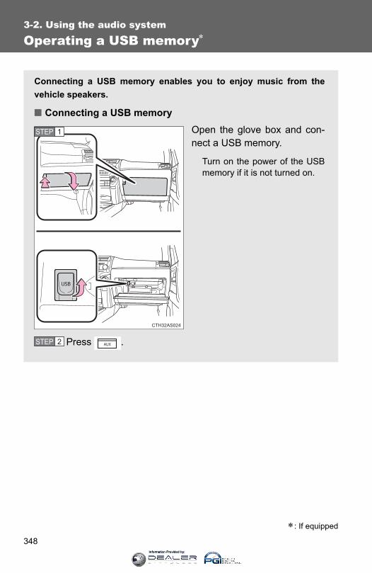
348
3-2. Using the audio system
Operating a USB memory∗
Connecting a USB memory enables you to enjoy music from thevehicle speakers.
■ Connecting a USB memoryOpen the glove box and con-nect a USB memory.
Turn on the power of the USBmemory if it is not turned on.
Press .
CTH32AS024
STEP 1
STEP 2
∗: If equipped
Information Provided by:

349
3-2. Using the audio system
3
Interior features
Selecting and scanning a folder
■ Selecting a folder
Press “∧” or “∨” on to select the desired folder.
■ Returning to the first file of the first folder
Press and hold “∨” on until you hear a beep.
■ Scanning the first file of all the folders
Press and hold until you hear a beep. The first ten seconds of the first file in each folder will be played.
When the desired folder is reached, press again.
■ Control panel
Power Volume Selector knob
Displaying text messages
Playback
Playback/pauseSearchingplayback
Selector buttons
Selecting a folder and file
Selecting a track/fast-forwardingand rewinding
STEP 1
STEP 2
Information Provided by:
350
3-2. Using the audio system
Selecting and scanning files
■ Selecting a file
Turn or press “∧” or “∨” on to select the desired file.
■ Scanning the files in a folderPress .
The first ten seconds of each file will be played.
To cancel, press again.
When the desired file is reached, press again.
Playing and pausing files
Press .
Fast-forwarding and rewinding files
Press and hold “∧” or “∨” on .
Random playback
■ Playing files from a folder in random orderPress (RDM).
To cancel, press the button twice.
■ Playing all the files from a USB memory in random orderPress (RDM) twice.
To cancel, press the button again.
Information Provided by:
351
3-2. Using the audio system
3
Interior features
Repeat play
■ Repeating a filePress (RPT).
To cancel, press the button twice.
■ Repeating all the files in a folderPress (RPT) twice.
To cancel, press the button again.
Switching the display
Press .
Each time is pressed, the display changes in the followingorder: Track title → Track title/Artist name → Track title/Album name → Tracktitle/Elapsed time
■USB memory functionsDepending on the USB memory that is connected to the system, certainfunctions may not be available. Disconnecting the device and reconnecting itonce again may resolve some malfunctions.
■Error messages“USB ERROR”: This indicates a problem either in the USB memory or
inside the USB box or connection between them.
“NO SUPPORT”: This indicates that no MP3/WMA files are included in theUSB memory.
Information Provided by:
352
3-2. Using the audio system
■USB memory●Compatible device
USB memories that can be used for MP3 and WMA playback.
Depending on the type of USB device, playback may not be possible.
●Compatible device formats
The following device formats can be used:
• USB communication formats: USB2.0 FS (12 mbps)• File formats: FAT16/32 (Windows)• Correspondence class: Mass storage class
MP3 and WMA files written in any format other than those listed abovemay not play correctly, and their file names and folder names may notbe displayed correctly.
Items related to standards and limitations are as follows:
• Maximum directory hierarchy: 8 levels• Maximum number of folder in device: 999 (including the root)• Maximum number of files in device: 65025• Maximum number of files per folder: 255
●MP3 and WMA files
MP3 (MPEG Audio LAYER 3) is a standard audio compression format.
Files can be compressed to approximately 1/10 of their original size usingMP3 compression.
WMA (Windows Media® Audio) is a Microsoft audio compression format.
This format compresses audio data to a size smaller than that of the MP3format.
There is a limit to the MP3 and WMA file standards that can be used and tothe media/formats on which the files are recorded.
Information Provided by:

353
3-2. Using the audio system
3
Interior features
●MP3 file compatibility
• Compatible standardsMP3 (MPEG1 AUDIO LAYERII, III, MPEG2 AUDIO LAYERII, III,MPEG2.5)
• Compatible sampling frequenciesMPEG1 AUDIO LAYERII, III: 32, 44.1, 48 (kHz)MPEG2 AUDIO LAYERII, III: 16, 22.05, 24 (kHz)MPEG2.5: 8, 11.025, 12 (kHz)
• Compatible bit rates (compatible with VBR)MPEG1 AUDIO LAYERII, III: 32-320 (kbps)MPEG2 AUDIO LAYERII, III: 32-160 (kbps)MPEG2.5: 32-160 (kbps)
• Compatible channel modes: stereo, joint stereo, dual channel andmonaural
●WMA file compatibility
• Compatible standardsWMA Ver. 9
• Compatible sampling frequenciesHIGH PROFILE 32, 44.1, 48 (kHz)
• Compatible bit ratesHIGH PROFILE 32-320 (kbps, VBR)
●File names
The only files that can be recognized as MP3/WMA and played are thosewith the extension .mp3 or .wma.
● ID3 and WMA tags
ID3 tags can be added to MP3 files, making it possible to record the tracktitle, artist name, etc.
The system is compatible with ID3 Ver. 1.0, 1.1, and Ver. 2.2, 2.3, 2.4 ID3tags. (The number of characters is based on ID3 Ver. 1.0 and 1.1.)
WMA tags can be added to WMA files, making it possible to record thetrack title and artist name in the same way as with ID3 tags.
●MP3 and WMA playback
When a device containing MP3 or WMA files is plugged, all files in theUSB memory device are first checked. Once the file check is finished, thefirst MP3 or WMA file is played. To make the file check finish more quickly,we recommend you do not write in any files other than MP3 or WMA filesor create any unnecessary folders.
Information Provided by:

354
3-2. Using the audio system
●Extensions
If the file extensions .mp3 and .wma are used for files other than MP3 andWMA files, they will be mistakenly recognized and played as MP3 andWMA files. This may result in large amounts of interference and damageto the speakers.
●Playback
• To play MP3 file with steady sound quality, we recommend a fixed bitrate of at least 128 kbps and a sampling frequency of 44.1 kHz.
• There is a wide variety of freeware and other encoding software forMP3 and WMA files on the market, and depending on the status of theencoding and the file format, poor sound quality or noise at the start ofplayback may result. In some cases, playback may not be possible atall.
• Microsoft, Windows, and Windows Media are the registered trade-marks of Microsoft Corporation in the U.S.A. and other countries.
CAUTION
■Caution while drivingDo not use a USB memory, or connect a USB memory.
NOTICE
■To prevent damage to a USB memory●Do not leave a USB memory in the vehicle. The temperature inside may
become high, resulting in damage to the player.
●Do not push down on or apply unnecessary pressure to the USB memorywhile it is connected as this may damage the USB memory or its terminal.
●Do not insert foreign objects into the port as this may damage the USBmemory or its terminal.
Information Provided by:
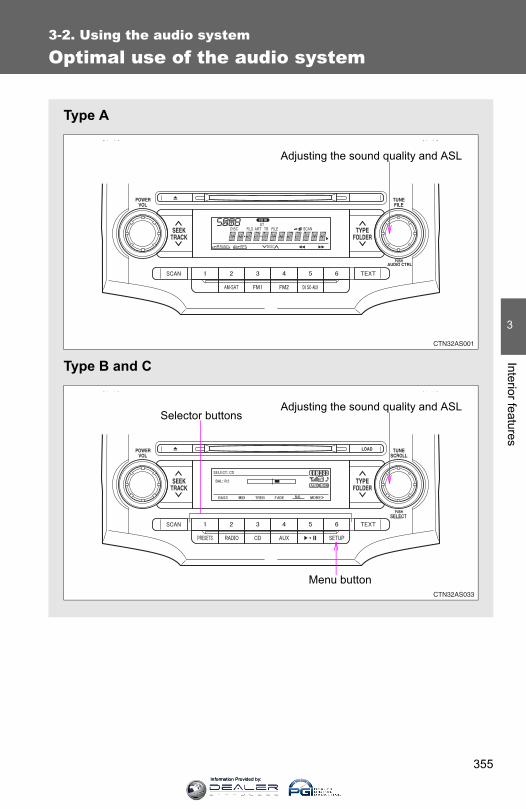
355
3-2. Using the audio system
3
Interior features
Optimal use of the audio system
Type A
Type B and C
Adjusting the sound quality and ASL
Adjusting the sound quality and ASLSelector buttons
Menu button
Information Provided by:

356
3-2. Using the audio system
Using the audio control function
■ Changing sound quality modesType A
Pressing selects the mode to be changed in the following
order:
“BAS”→“TRE”→“FAD”→“BAL”→“ASL”
Type B and C
Press .
Press , , , or (type C only) ascorresponds to the desired mode.“BASS”, “MID” (type C only), “TREB”, “FADE”, or “BAL”
■ Adjusting sound quality
Turning or adjusts the level.
Type A
*: The sound quality level is adjusted individually in each radiomode or CD mode.
STEP 1
STEP 2
Mode displayed
Sound qual-ity mode Level Turn to the
leftTurn to the
right
BAS Bass* -5 to 5Low High
TRE Treble* -5 to 5
FADFront/rear
volume balance
F7 to R7 Shifts to rear Shifts to front
BALLeft/right volume balance
L7 to R7 Shifts to left Shifts to right
Information Provided by:

357
3-2. Using the audio system
3
Interior features
Type B and C
*: The sound quality level is adjusted individually in each audiomode.
■ Adjusting the Automatic Sound Levelizer (ASL)Type A
When “ASL” is selected, turning to the right changes the
“ASL” level in the order of “LOW”, “MID” and “HIGH”.
Turning to the left turns “ASL” off.
ASL automatically adjusts the volume and tone quality according to vehi-cle speed.
Mode displayed
Sound qual-ity mode Level Turn to the
leftTurn to the
right
BASS Bass* -5 to 5
Low HighMID Mid-range*(type C only) -5 to 5
TREB Treble* -5 to 5
FADEFront/rear
volume balance
F7 to R7 Shifts to rear Shifts to front
BALLeft/right volume balance
L7 to R7 Shifts to left Shifts to right
Information Provided by:

358
3-2. Using the audio system
Type B and C
Press .
Press (MORE).
Press (ASL).
Press , , (type B only) or (type Bonly) as corresponds to the desired mode.Type B: “LOW”, “MID”, “HIGH”, or “OFF”
Type C: “ON” or “OFF”
ASL automatically adjusts the volume and tone quality accordingto vehicle speed.
■ Setting the number of preset pages (type B and C)The number of preset pages desired can be set from 1 to 6. The initialsetting is 6 pages.
Press .
Press (MORE).
Press (PRESET).
Press , , , , or as corre-sponds to the desired number of preset pages.
■ Language settings (type B and C)→P. 315
STEP 1
STEP 2
STEP 3
STEP 4
STEP 1
STEP 2
STEP 3
STEP 4
Information Provided by:
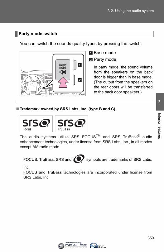
359
3-2. Using the audio system
3
Interior features
Party mode switch
You can switch the sounds quality types by pressing the switch.
Base modeParty mode
In party mode, the sound volumefrom the speakers on the backdoor is bigger than in base mode.(The output from the speakers onthe rear doors will be transferredto the back door speakers.)
CTH32AS048
■Trademark owned by SRS Labs, Inc. (type B and C)
The audio systems utilize SRS FOCUSTM and SRS TruBass® audioenhancement technologies, under license from SRS Labs, Inc., in all modesexcept AM radio mode.
FOCUS, TruBass, SRS and symbols are trademarks of SRS Labs,
Inc.FOCUS and TruBass technologies are incorporated under license fromSRS Labs, Inc.
Information Provided by:
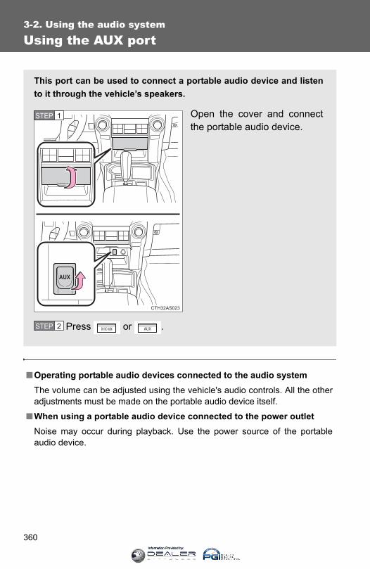
360
3-2. Using the audio system
Using the AUX port
■Operating portable audio devices connected to the audio systemThe volume can be adjusted using the vehicle's audio controls. All the otheradjustments must be made on the portable audio device itself.
■When using a portable audio device connected to the power outletNoise may occur during playback. Use the power source of the portableaudio device.
This port can be used to connect a portable audio device and listento it through the vehicle’s speakers.
Open the cover and connectthe portable audio device.
Press or .
CTH32AS023
STEP 1
STEP 2
Information Provided by:

361
3-2. Using the audio system
3
Interior features
Using the steering wheel audio switches∗
∗: If equipped
Some audio features can be controlled using the switches on thesteering wheel.
Increases/decreases vol-umeRadio mode: Selects radiostationsCD mode: Selects tracks,files (MP3 and WMA) anddiscs (type C only)iPod mode:
Selects a song
USB memory mode: Selects a file andfolder
Bluetooth® audio mode:Selects a track andalbum
Turns the power on, selectsan audio source
CTH32AS046
Information Provided by:
362
3-2. Using the audio system
Turning the power on
Press when the audio system is turned off.
The audio system can be turned off by holding the switch down until youhear a beep.
Changing the audio source
Press when the audio system is turned on. The audio sourcechanges as follows each time the switch is pressed.If no discs are inserted in the player, that mode will be skipped.
FM→SAT→CD (type B only)→CD changer (type C only)→Bluetooth®
Audio→AUX→USB/iPod→AM
Adjusting the volume
Press “+” on to increase the volume and “-” to decrease thevolume.
Press and hold the switch to continue increasing or decreasing the vol-ume.
Selecting a radio station
Press to select radio mode.Press “∨” or “∧” on to select a radio station.
To scan for receivable stations, press and hold “∨” or “∧” on until you hear a beep.
STEP 1
STEP 2
Information Provided by:

363
3-2. Using the audio system
3
Interior features
Selecting a track/file or song
Press to select CD, iPod, USB memory or Bluetooth®
audio mode.
Press “∨” or “∧” on to select the desired track/file orsong.
Selecting a folder or album
Press to select the CD, USB memory or Bluetooth®
audio mode.Press and hold “∨” or “∧” on until you hear a beep.
Selecting a disc in the CD player (type C only)
Press to select CD mode.Press and hold “∨” or “∧” on until you hear a beep.
CAUTION
■To reduce the risk of an accidentExercise care when operating the audio switches on the steering wheel.
STEP 1
STEP 2
STEP 1
STEP 2
STEP 1
STEP 2
Information Provided by:
364
3-3. Using the Bluetooth® audio system
Bluetooth® audio system∗
■Conditions under which the system will not operate● If using a portable player that does not support Bluetooth®
● If the portable player is switched off
● If the portable player is not connected
● If the portable player’s battery is low
● If the portable player is behind the seat or in the glove box or console box
● If metal is covering or touching the portable player
The Bluetooth® audio system enables you to enjoy music played ona portable digital audio player (portable player) from the vehiclespeakers via wireless communication.
This audio system supports Bluetooth®, a wireless data systemcapable of playing portable audio music without cables. If your por-table player does not support Bluetooth®, the Bluetooth® audio sys-tem will not function.
Owners of models equipped with a navigation system should refer tothe “Navigation System Owner's Manual”.
Title Page
Using the Bluetooth® audio system P. 367
Operating a Bluetooth® enabled portable player P. 372
Setting up a Bluetooth® enabled portable player P. 374
Bluetooth® audio system setup P. 379
∗: If equipped
Information Provided by:

365
3-3. Using the Bluetooth® audio system
3
Interior features
■When transferring ownership of the vehicleBe sure to initialize the system to prevent personal data from being improp-erly accessed. (→P. 403)
■About Bluetooth®
■Compatible models●Bluetooth® specifications:
Ver. 1.2
●Following Profiles:
• A2DP (Advanced Audio Distribution Profile) Ver. 1.0• AVRCP (Audio/Video Remote Control Profile) Ver. 1.0 or higher (Ver.
1.3 or higher recommended)Portable players must correspond to the above specifications in order to beconnected to the Bluetooth® audio system. However, please note that somefunctions may be limited depending on the type of portable player.
■Certification for the Bluetooth® audio systemFCC ID: AJDK025IC ID: 775E-K025MADE IN JAPAN
This device complies with Part 15 of the FCC Rules and RSS-Gen of ICRules. Operation is subject to the following two conditions: (1) this devicemay not cause harmful interference, and (2) this device must accept anyinterference received, including interference that may cause undesired oper-ation.
Bluetooth is a registered trademark ofBluetooth SIG. Inc.
Information Provided by:
366
3-3. Using the Bluetooth® audio system
CAUTION
■FCC WARNINGChanges or modifications not expressly approved by the party responsiblefor compliance could void the user's authority to operate the equipment.
Radio Frequency Radiation Exposure. This equipment complies with FCC/IC radiation exposure limits set forth for uncontrolled equipment and meetsthe FCC radio frequency (RF) Exposure Guidelines in Supplement C toOET65 and RSS-102 of the IC radio frequency (RF) Exposure rules. Thisequipment has very low levels of RF energy that it deemed to comply with-out maximum permissive exposure evaluation (MPE). But it is desirable thatit should be installed and operated with at least 7.9 in. (20 cm) and morebetween the radiator and person’s body (excluding extremities: hands,wrists, feet and ankles).
This transmitter must not be co-located or operated in conjunction with anyother antenna or transmitter.
■Caution while drivingDo not connect portable players or operate the controls.
NOTICE
■To prevent damage to portable playersDo not leave portable players in the vehicle. The temperature inside thevehicle may become high, resulting in damage to the player.
Information Provided by:
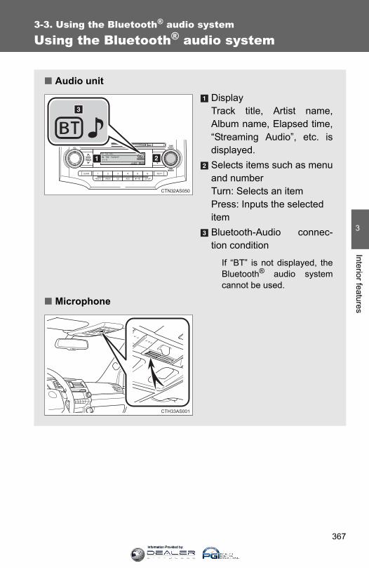
367
3-3. Using the Bluetooth® audio system
3
Interior features
Using the Bluetooth® audio system
■ Audio unitDisplay Track title, Artist name,Album name, Elapsed time,“Streaming Audio”, etc. isdisplayed.Selects items such as menuand numberTurn: Selects an itemPress: Inputs the selecteditemBluetooth-Audio connec-tion condition
If “BT” is not displayed, theBluetooth® audio systemcannot be used.
■ Microphone
CTH33AS001
Information Provided by:
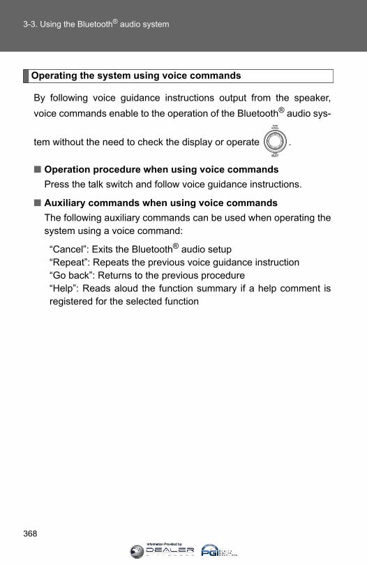
368
3-3. Using the Bluetooth® audio system
Operating the system using voice commands
By following voice guidance instructions output from the speaker,voice commands enable to the operation of the Bluetooth® audio sys-
tem without the need to check the display or operate .
■ Operation procedure when using voice commandsPress the talk switch and follow voice guidance instructions.
■ Auxiliary commands when using voice commandsThe following auxiliary commands can be used when operating thesystem using a voice command:
“Cancel”: Exits the Bluetooth® audio setup“Repeat”: Repeats the previous voice guidance instruction“Go back”: Returns to the previous procedure“Help”: Reads aloud the function summary if a help comment isregistered for the selected function
Information Provided by:

369
3-3. Using the Bluetooth® audio system
3
Interior features
Using the Bluetooth® audio system for the first time
Before using the Bluetooth® audio system, it is necessary to registera Bluetooth® enabled portable player in the system. Follow the proce-dure below to register (pair) a portable player:
Press and hold until “BT AUDIO” is displayed.
Press (SETUP).
The introductory guidance and portable player name registrationinstructions are heard.
Select “Pair Audio Players (Pair audio player)” using a voice
command or .
Register a portable player name by either of the followingmethods:
a. Select “Record Name” using , and say the name to
be registered.b. Press the talk switch and say the name to be registered.
A voice guidance instruction to confirm the input is heard.
Select “Confirm” using a voice command or .
A passkey is displayed and heard, and a voice guidance instructionfor inputting the passkey into the portable player is heard.
STEP 1
STEP 2
STEP 3
STEP 4
STEP 5
Information Provided by:
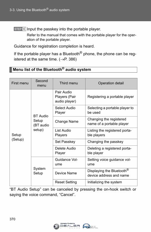
370
3-3. Using the Bluetooth® audio system
Input the passkey into the portable player.Refer to the manual that comes with the portable player for the oper-ation of the portable player.
Guidance for registration completion is heard.
If the portable player has a Bluetooth® phone, the phone can be reg-istered at the same time. (→P. 386)
Menu list of the Bluetooth® audio system
“BT Audio Setup” can be canceled by pressing the on-hook switch orsaying the voice command, “Cancel”.
First menu Second menu Third menu Operation detail
Setup (Setup)
BT Audio Setup (BT audio setup)
Pair Audio Players (Pair audio player)
Registering a portable player
Select Audio Player
Selecting a portable player to be used
Change Name Changing the registered name of a portable player
List Audio Players
Listing the registered porta-ble players
Set Passkey Changing the passkey
Delete Audio Player
Deleting a registered porta-ble player
System Setup
Guidance Vol-ume
Setting voice guidance vol-ume
Device Name Displaying the Bluetooth® device address and name
Reset Setting Initializing the system
STEP 6
Information Provided by:

371
3-3. Using the Bluetooth® audio system
3
Interior features
■When using a voice commandFor numbers, say a combination of single digits from zero to nine.
Say the command correctly and clearly.
■Situations that the system may not recognize your voice●When driving on rough roads
●When driving at high speeds
●When air is blowing out of the vents onto the microphone
●When the air conditioning fan emits a loud noise
■Operations that cannot be performed while driving
●Operating the system with
●Registering a portable player to the system
■Changing the passkey→P. 377
Information Provided by:
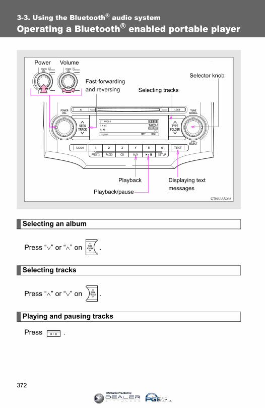
372
3-3. Using the Bluetooth® audio system
Operating a Bluetooth® enabled portable player
Selecting an album
Press “∨” or “∧” on .
Selecting tracks
Press “∧” or “∨” on .
Playing and pausing tracks
Press .
VolumePower
Playback/pause
Displaying text messages
Selector knob
Selecting tracksFast-forwardingand reversing
Playback
Information Provided by:
373
3-3. Using the Bluetooth® audio system
3
Interior features
Fast-forwarding and reversing tracks
Press and hold “∧” or “∨” on .
Switching the display
Press .
Each time is pressed, the display changes in the followingorder: Track title → Track title/Artist name → Track title/Album name → Tracktitle/Elapsed time
Using the steering wheel audio switches
→P. 361
■Bluetooth® audio system functionsDepending on the portable player that is connected to the system, certainfunctions may not be available.
Information Provided by:

374
3-3. Using the Bluetooth® audio system
Setting up a Bluetooth® enabled portable player
Registering a portable player in the Bluetooth® audio system allowsthe system to function. The following functions can be used for reg-istered portable players:
■ Functions and operation procedures
Press and hold until “BT AUDIO” is displayed.
Press (SETUP).
Select one of the following functions using a voice com-
mand or .
● Registering a portable player “Pair Audio Players (Pair audio player)”
● Selecting a portable player to be used “Select Audio Player”
● Changing the registered name of a portable player“Change Name”
● Listing the registered portable players “List Audio Players”
● Changing the passkey “Set Passkey”
● Deleting a registered portable player “Delete Audio Player”
STEP 1
STEP 2
STEP 3
Information Provided by:
375
3-3. Using the Bluetooth® audio system
3
Interior features
Registering a portable player
Select “Pair Audio Players (Pair audio player)” using a voice com-
mand or , and perform the procedure for registering a portable
player. (→P. 369)
Selecting a portable player to be used
Select “Select Audio Player” using a voice command or
.
Select the portable player to be used by either of the followingmethods, and select “Confirm” using a voice command or
:
a. Press the talk switch and say the name of the desired por-table player.
b. Press the talk switch and say “List audio players”. When thename of the desired portable player is read aloud, press thetalk switch.
STEP 1
STEP 2
Information Provided by:
376
3-3. Using the Bluetooth® audio system
Press the talk switch and say “From car” or “From audio”, and
select “Confirm” using a voice command or .
Vehicles with smart key system: If “From car” is selected, the porta-ble player will be automatically connected whenever the “ENGINESTART STOP” switch is in either ACCESSORY or IGNITION ONmode.
Vehicles without smart key system: If “From car” is selected, the por-table player will be automatically connected whenever the engineswitch is in either the “ACC” or “ON” position.
Changing the registered name of a portable player
Select “Change Name” using a voice command or .
Select the name of the portable player to be changed byeither of the following methods, and select “Confirm” using a
voice command or :
a. Press the talk switch and say the name of desired portableplayer.
b. Press the talk switch and say “List audio players”. When thename of the desired portable player is read aloud, press thetalk switch.
Press the talk switch or select “Record Name” using ,
and say the new name.
Select “Confirm” using a voice command or .
STEP 3
STEP 1
STEP 2
STEP 3
STEP 4
Information Provided by:
377
3-3. Using the Bluetooth® audio system
3
Interior features
Listing the registered portable players
Select “List Audio Players” using a voice command or . The list
of registered portable players will be read aloud.When listing is complete, the system returns to “BT Audio Setup”.
Pressing the talk switch while the name of a portable player is beingread aloud selects the portable player, and the following functions willbecome available:
● Selecting a portable player: “Select Audio Player”
● Changing a registered name: “Change Name”
● Deleting a portable player: “Delete Audio Player”
Changing the passkey
Select “Set Passkey” using a voice command or .
Press the talk switch, say a 4 to 8-digit number, and select
“Confirm” using a voice command or .
When the entire number to be registered as a passkey has
been input, press again.
STEP 1
STEP 2
STEP 3
Information Provided by:

378
3-3. Using the Bluetooth® audio system
Deleting a registered portable player
Select “Delete Audio Player” using a voice command or
.
Select the portable player to be deleted by either of the follow-ing methods and select “Confirm” using a voice command or
:
a. Press the talk switch and say the name of the desired por-table player.
b. Press the talk switch and say “List audio players”. When thename of the desired portable player is read aloud, press thetalk switch.
If the portable player to be deleted is paired as a Bluetooth® phone,the registration of the mobile phone can be deleted at the same time.A voice guidance instruction to delete a mobile phone is heard.
Select “Confirm” using a voice command or .
■The number of portable players that can be registeredUp to 2 portable players can be registered in the system.
STEP 1
STEP 2
STEP 3
Information Provided by:
379
3-3. Using the Bluetooth® audio system
3
Interior features
Bluetooth® audio system setup
■ System setup items and operation procedures→P. 401
Information Provided by:

380
3-4. Using the hands-free phone system (for cellular phone)
Hands-free phone system (for cellular phone) features∗
This system supports Bluetooth®, which allows you to make orreceive calls without using cables to connect a cellular phone andthe system, and without operating the cellular phone.Owners of models equipped with a navigation system should refer tothe “Navigation System Owner's Manual”.
■ Hands-free system quick guideSetting a cellular phone. (→P. 384)Adding an entry to the phonebook (Up to 20 names can bestored). (→P. 405)Dialing by inputting a name. (→P. 393)
STEP 1
STEP 2
STEP 3
∗: If equipped
Information Provided by:

381
3-4. Using the hands-free phone system (for cellular phone)
3
Interior features
Title Page
Using the hands-free phone system■Operating the system using a voice
command■Using the hands-free phone system for
the first time■Menu list of the hands-free phone
system
P. 384
Making a phone call■Dialing by inputting a number■Dialing by inputting a name■Speed dialing■When receiving a phone call■Transferring a call■Using the call history memory
P. 392
Setting a cellular phone■Registering a cellular phone■Selecting the cellular phone to be used■Changing a registered name■Listing the registered cellular phone■Deleting a cellular phone■Changing the passkey■Turning the hands-free phone
automatic connection on/off
P. 396
Security and system setup■Setting or changing the PIN■Locking or unlocking the phone book■Setting voice guidance volume■ Initialization
P. 401
Using the phone book■Adding a new phone number■Setting speed dials■Changing a registered name■Deleting registered data■Deleting speed dials■Listing the registered data
P. 405
Information Provided by:

382
3-4. Using the hands-free phone system (for cellular phone)
■Conditions under which the system will not operate● If using a cellular phone that does not support Bluetooth®
● If the cellular phone is switched off
● If you are outside service range
● If the cellular phone is not connected
● If the cellular phone's battery is low
● If the cellular phone is behind the seat or in the glove box or console box
● If metal is covering or touching the cellular phone
■When transferring ownership of the vehicleBe sure to initialize the system to prevent personal data from being improp-erly accessed.
■Required profiles for the cellular phone●HFP (Hands Free Profile) Ver. 1.0
●OPP (Object Push Profile) Ver. 1.1
■About Bluetooth®
■Certification for the hands-free phone systemFCC ID: AJDK025IC ID: 775E-K025MADE IN JAPAN
This device complies with Part 15 of the FCC Rules and RSS-Gen of ICRules. Operation is subject to the following two conditions: (1) this devicemay not cause harmful interference, and (2) this device must accept anyinterference received, including interference that may cause undesired oper-ation.
Bluetooth is a registered trademark ofBluetooth SIG. Inc.
Information Provided by:
383
3-4. Using the hands-free phone system (for cellular phone)
3
Interior features
CAUTION
■FCC WARNINGChanges or modifications not expressly approved by the party responsiblefor compliance could void the user's authority to operate the equipment.
Radio Frequency Radiation Exposure. This equipment complies with FCC/IC radiation exposure limits set forth for uncontrolled equipment and meetsthe FCC radio frequency (RF) Exposure Guidelines in Supplement C toOET65 and RSS-102 of the IC radio frequency (RF) Exposure rules. Thisequipment has very low levels of RF energy that it deemed to comply with-out maximum permissive exposure evaluation (MPE). But it is desirable thatit should be installed and operated with at least 7.9 in. (20 cm) and morebetween the radiator and person’s body (excluding extremities: hands,wrists, feet and ankles).
This transmitter must not be co-located or operated in conjunction with anyother antenna or transmitter.
■Caution while drivingDo not use a cellular phone, or connect the Bluetooth® phone.
NOTICE
■To prevent damage to a cellular phoneDo not leave a cellular phone in the vehicle. The temperature inside maybecome high resulting in damage to the phone.
Information Provided by:
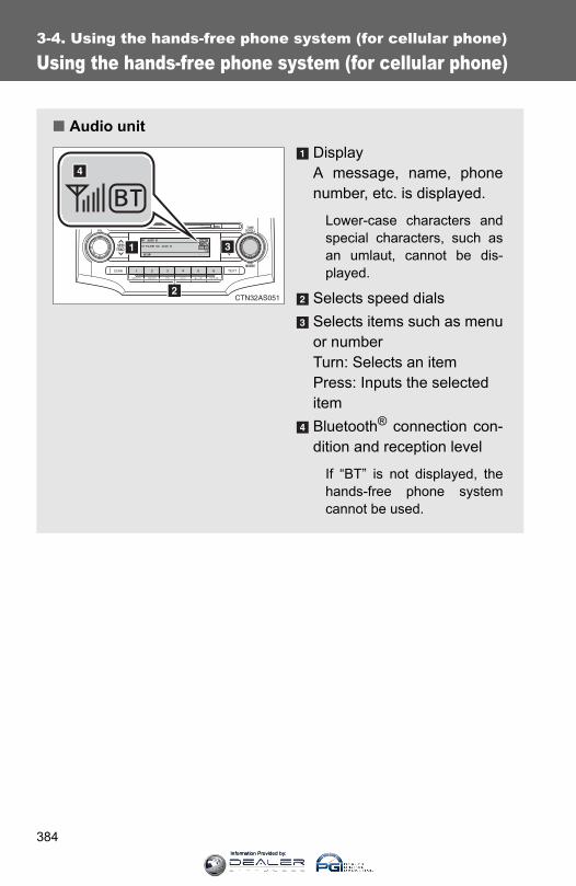
384
3-4. Using the hands-free phone system (for cellular phone)
Using the hands-free phone system (for cellular phone)
■ Audio unitDisplayA message, name, phonenumber, etc. is displayed.
Lower-case characters andspecial characters, such asan umlaut, cannot be dis-played.
Selects speed dialsSelects items such as menuor numberTurn: Selects an itemPress: Inputs the selecteditemBluetooth® connection con-dition and reception level
If “BT” is not displayed, thehands-free phone systemcannot be used.
Information Provided by:
385
3-4. Using the hands-free phone system (for cellular phone)
3
Interior features
■ Steering wheel switchesVolume
The voice guidance volumecannot be adjusted using thisbutton.
On-hook switch Turns the hands-free sys-tem off/ends a call/refuses acallOff-hook switch Turns the hands-free sys-tem on/starts a callTalk switchTurns the voice commandsystem on (press)/turns thevoice command system off(press and hold)
■ Microphone
CTH32AS047
CTH33AS001
Information Provided by:
386
3-4. Using the hands-free phone system (for cellular phone)
Operating the system using a voice command
By following voice guidance instructions output from the speaker,voice commands enable the operation of the hands-free phone sys-
tem without the need to check the display or operate .
■ Operation procedure when using a voice commandPress the talk switch and follow voice guidance instructions.
■ Auxiliary commands when using a voice commandThe following auxiliary commands can be used when operating thesystem using a voice command:
“Cancel”: Exits the hands-free phone system“Repeat”: Repeats the previous voice guidance instruction“Go back”: Returns to the previous procedure“Help”: Reads aloud the function summary if a help comment isregistered for the selected function
Using the hands-free phone system for the first time
Before using the hands-free phone system, it is necessary to registera cellular phone in the system. The phone registration mode will beentered automatically when starting the system with no cellularphone registered. Follow the procedure below to register a cellularphone:
Press the off-hook switch or the talk switch.The introductory guidance and phone name registration instructionsare heard.
STEP 1
Information Provided by:

387
3-4. Using the hands-free phone system (for cellular phone)
3
Interior features
Select “Pair Phone” using a voice command or .
Register a phone name by either of the following methods.
a. Select “Record Name” using , and say a name to be
registered.b. Press the talk switch and say a name to be registered.
A voice guidance instruction to confirm the input is heard.
Select “Confirm” using a voice command or .
Registration to the hands-free phone system only
Select “Phone Only” using a voice command or .
Registration to the hands-free phone system and Bluetooth®
audio system at the same time
Select “Int. Audio (Internal audio)” using a voice command or
.
Select “Confirm” using a voice command or .
A passkey is displayed and heard, and a voice guidance instructionfor inputting the passkey into the cellular phone is heard.
Input the passkey into the cellular phone.Refer to the manual that comes with the cellular phone for the oper-ation of the phone.
Guidance for registration completion is heard.
STEP 2
STEP 3
STEP 4
STEP 5
STEP 5
STEP 6
STEP 7
Information Provided by:
388
3-4. Using the hands-free phone system (for cellular phone)
Menu list of the hands-free phone system
■ Normal operation
First menu Second menu Third menu Operation detail
CallBack(Call back)
- -Dialing a number stored in the incoming call history memory
Redial - -Dialing a number stored in the outgoing call history memory
Dial by Number - - Dialing by inputting a number
Dial by Name (Dial by name)
- - Dialing by inputting a name registered in the phone book
Phonebook
Add Entry - Adding a new number
Change Name - Changing a name in the
phone book
Delete Entry - Deleting the phone book
data
Delete Speed Dial
- Deleting a registered speed dial
List Names - Listing the phone book data
Speed Dial (Set speed dial)
- Registering a speed dial
Information Provided by:

389
3-4. Using the hands-free phone system (for cellular phone)
3
Interior features
Setup (Setup)
Security
Set PIN Setting a PIN code
Phonebook Lock (Phone book lock)
Locking the phone book
Phonebook Unlock (Phone book unlock)
Unlocking the phone book
Phone Setup
Pair Phone Registering the cellular phone to be used
Change Phone Name (Change name)
Changing a registered name of a cellular phone
Delete Phone Deleting a registered cellular phone
List Phones Listing the registered cellular phones
Select Phone Selecting a cellular phone to be used
Set Passkey Changing the passkey
Handsfree Power
Setting a Hands-free power on/off
System Setup
Guidance Vol-ume
Setting voice guidance vol-ume
Device Name Displaying a device informa-tion
Reset Setting Initialization
First menu Second menu Third menu Operation detail
Information Provided by:
390
3-4. Using the hands-free phone system (for cellular phone)
■ Using a short cut key
First menu Second menu Operation detail
Dial “XXX (name)” - Dialing a number registered in the phone book
Dial “XXX (number)” - Dialing the input numbers
Phone book add entry - Adding a new number
Phone book change name -
Changing the name of a phone number in the phone book
Phone book delete entry - Deleting phone book data
Phone book set speed dial - Registering a speed dial
Phone book delete speed dial - Deleting a speed dial
Phone book List names - Listing the phone book data
Information Provided by:

391
3-4. Using the hands-free phone system (for cellular phone)
3
Interior features
■Automatic volume adjustmentWhen vehicle speed reaches 50 mph (80 km/h) or more, the volume auto-matically increases. The volume returns to the previous volume setting whenvehicle speed drops to 43 mph (70 km/h) or less.
■When using a voice commandFor numbers, say a combination of single digits from zero to nine, # (pound), ∗ (star), and + (plus).
Say a command correctly and clearly.
■Situations that the system may not recognize your voice●When driving on a rough road
●When driving at high speeds
●When air is blowing out of the vents onto the microphone
●When the air conditioning fan emits a loud noise
■Operations that cannot be performed while driving
●Operating the system with
●Registering a cellular phone to the system
■Changing the passkey→P. 399
Information Provided by:
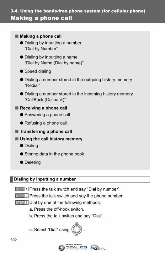
392
3-4. Using the hands-free phone system (for cellular phone)
Making a phone call
Dialing by inputting a number
Press the talk switch and say “Dial by number”.Press the talk switch and say the phone number.Dial by one of the following methods:a. Press the off-hook switch.b. Press the talk switch and say “Dial”.
c. Select “Dial” using .
■ Making a phone call● Dialing by inputting a number
“Dial by Number”
● Dialing by inputting a name“Dial by Name (Dial by name)”
● Speed dialing
● Dialing a number stored in the outgoing history memory“Redial”
● Dialing a number stored in the incoming history memory“CallBack (Callback)”
■ Receiving a phone call● Answering a phone call
● Refusing a phone call
■ Transferring a phone call■ Using the call history memory
● Dialing
● Storing data in the phone book
● Deleting
STEP 1
STEP 2
STEP 3
Information Provided by:

393
3-4. Using the hands-free phone system (for cellular phone)
3
Interior features
Dialing by inputting a name
Press the talk switch and say “Dial by name”.Select a registered name to be input by either of the followingmethods:a. Press the talk switch and say a registered name.b. Press the talk switch and say “List names”. Press the talk
switch while the desired name is being read aloud.Dial by one of the following methods:a. Press the off-hook switch.b. Press the talk switch and say “Dial”.
c. Select “Dial” using .
Speed dialing
Press the off-hook switch.Press the preset button to which the desired number is regis-tered.Press the off-hook switch.
When receiving a phone call
■ Answering a phone callPress the off-hook switch.
■ Refusing a phone callPress the on-hook switch.
STEP 1
STEP 2
STEP 3
STEP 1
STEP 2
STEP 3
Information Provided by:

394
3-4. Using the hands-free phone system (for cellular phone)
Transferring a phone call
A call can be transferred between the cellular phone and systemwhile dialing, receiving a call, or during a call. Use one of the follow-ing methods:
a. Operate the cellular phone.
Refer to the manual that comes with the cellular phone for the oper-ation of the phone.
b. Press the off-hook switch*1.
c. Press the talk switch and say “Call transfer”*2.*1: This operation can be performed only when transferring a call
from the cellular phone to the system during a call.*2: While the vehicle is in motion, a call cannot be transferred from
the system to the cellular phone. Also, this operation is invalidwhile dialing or receiving a call.
Using the call history memory
Follow the procedure below to use a number stored in the call historymemory:
Press the talk switch and say “Redial” (when using a numberstored in the outgoing call history memory) or “Callback”(when using a number stored in the incoming call historymemory).Select the number by either of the following methods:a. Say “Previous” or “Go back” until the desired number is dis-
played.
b. Select the desired number using .
STEP 1
STEP 2
Information Provided by:

395
3-4. Using the hands-free phone system (for cellular phone)
3
Interior features
The following operations can be performed:
Dialing: Press the off-hook switch or select “Dial” using a voice
command or .
Storing the number in the phone book: Select “Store” using a voice
command or .
Deleting: Select “Delete” using a voice command or .
■Call historyUp to 5 numbers can be stored in each of the outgoing and incoming call his-tory memories.
■When talking on the phone●Do not talk at the same time as the other party.
●Keep the volume of the incoming voice down. Otherwise, voice echo willincrease.
Information Provided by:

396
3-4. Using the hands-free phone system (for cellular phone)
Setting a cellular phone
Registering a cellular phone
Select “Pair Phone” using a voice command or , and perform
the procedure for registering a cellular phone. (→P. 386)
Registering a cellular phone in the hands-free phone system allowsthe system to function. The following functions can be used for reg-istered cellular phones:
■ Functions and operation proceduresTo enter the menu for each function, follow the steps below using a
voice command or :
● Registering a cellular phone 1. “Setup (Setup)” → 2. “Phone Setup” → 3. “Pair Phone”
● Selecting the cellular phone to be used 1. “Setup (Setup)” → 2. “Phone Setup” → 3. “Select Phone”
● Changing a registered name 1. “Setup (Setup)” → 2. “Phone Setup” → 3. “Change PhoneName (Change name)”
● Listing the registered cellular phones 1. “Setup (Setup)” → 2. “Phone Setup” → 3. “List Phones”
● Deleting a cellular phone 1. “Setup (Setup)” → 2. “Phone Setup” → 3. “Delete Phone”
● Changing the passkey 1. “Setup (Setup)” → 2. “Phone Setup” → 3. “Set Passkey”
● Turning the hands-free phone automatic connection on/off1. “Setup (Setup)” → 2. “Phone Setup” → 3. “HandsfreePower”
Information Provided by:
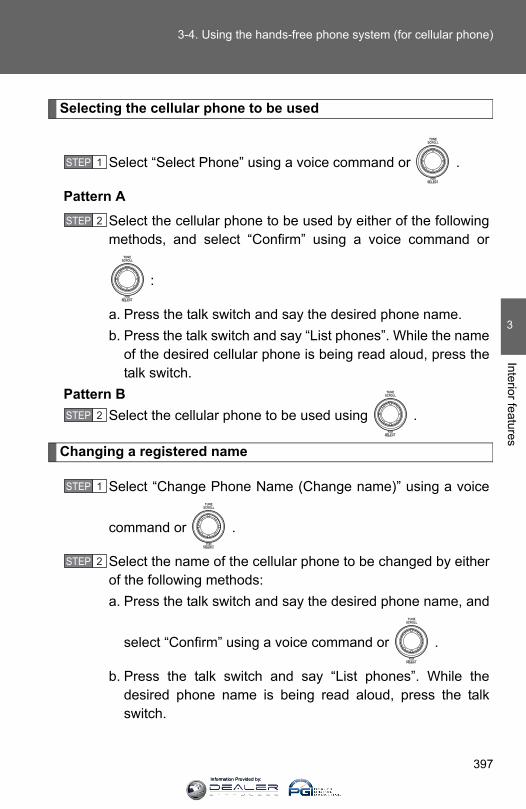
397
3-4. Using the hands-free phone system (for cellular phone)
3
Interior features
Selecting the cellular phone to be used
Select “Select Phone” using a voice command or .
Pattern A
Select the cellular phone to be used by either of the followingmethods, and select “Confirm” using a voice command or
:
a. Press the talk switch and say the desired phone name.b. Press the talk switch and say “List phones”. While the name
of the desired cellular phone is being read aloud, press thetalk switch.
Pattern BSelect the cellular phone to be used using .
Changing a registered name
Select “Change Phone Name (Change name)” using a voice
command or .
Select the name of the cellular phone to be changed by eitherof the following methods:a. Press the talk switch and say the desired phone name, and
select “Confirm” using a voice command or .
b. Press the talk switch and say “List phones”. While thedesired phone name is being read aloud, press the talkswitch.
STEP 1
STEP 2
STEP 2
STEP 1
STEP 2
Information Provided by:
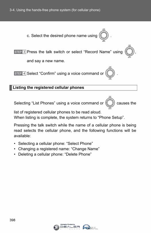
398
3-4. Using the hands-free phone system (for cellular phone)
c. Select the desired phone name using .
Press the talk switch or select “Record Name” using ,
and say a new name.
Select “Confirm” using a voice command or .
Listing the registered cellular phones
Selecting “List Phones” using a voice command or causes the
list of registered cellular phones to be read aloud.When listing is complete, the system returns to “Phone Setup”.
Pressing the talk switch while the name of a cellular phone is beingread selects the cellular phone, and the following functions will beavailable:
• Selecting a cellular phone: “Select Phone”• Changing a registered name: “Change Name”• Deleting a cellular phone: “Delete Phone”
STEP 3
STEP 4
Information Provided by:

399
3-4. Using the hands-free phone system (for cellular phone)
3
Interior features
Deleting a cellular phone
Select “Delete Phone” using a voice command or .
Select the cellular phone to be deleted by either of the follow-ing methods and select “Confirm” using a voice command or
:
a. Press the talk switch and say the name of the desired cellu-lar phone.
b. Press the talk switch and say “List phones”. While the nameof the desired cellular phone is being read aloud, press thetalk switch.
Changing the passkey
Select “Set Passkey” using a voice command or .
Press the talk switch, say a 4 to 8-digit number, and select
“Confirm” using a voice command or .
The number should be input 1 digit at a time.
When the entire number to be registered as a passkey has
been input, press again.
STEP 1
STEP 2
STEP 1
STEP 2
STEP 3
Information Provided by:

400
3-4. Using the hands-free phone system (for cellular phone)
Turning the hands-free phone automatic connection on/off
■ Turning off the automatic connection
Select “Handsfree Power” using a voice command or .
Select “Turn off” using a voice command or .
■ Turning on the automatic connection
Select “Handsfree Power” using a voice command or .
Select “Turn on” using a voice command or .
■The number of cellular phones that can be registeredUp to 6 cellular phones can be registered in the system.
STEP 1
STEP 2
STEP 1
STEP 2
Information Provided by:
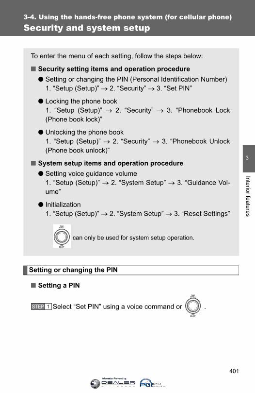
401
3-4. Using the hands-free phone system (for cellular phone)
3
Interior features
Security and system setup
Setting or changing the PIN
■ Setting a PIN
Select “Set PIN” using a voice command or .
To enter the menu of each setting, follow the steps below:
■ Security setting items and operation procedure● Setting or changing the PIN (Personal Identification Number)
1. “Setup (Setup)” → 2. “Security” → 3. “Set PIN”
● Locking the phone book 1. “Setup (Setup)” → 2. “Security” → 3. “Phonebook Lock(Phone book lock)”
● Unlocking the phone book 1. “Setup (Setup)” → 2. “Security” → 3. “Phonebook Unlock(Phone book unlock)”
■ System setup items and operation procedure● Setting voice guidance volume
1. “Setup (Setup)” → 2. “System Setup” → 3. “Guidance Vol-ume”
● Initialization 1. “Setup (Setup)” → 2. “System Setup” → 3. “Reset Settings”
can only be used for system setup operation.
STEP 1
Information Provided by:
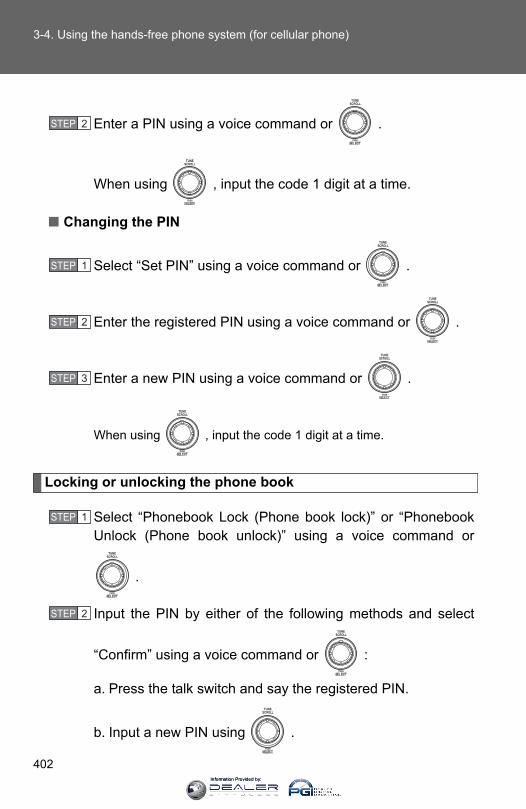
402
3-4. Using the hands-free phone system (for cellular phone)
Enter a PIN using a voice command or .
When using , input the code 1 digit at a time.
■ Changing the PIN
Select “Set PIN” using a voice command or .
Enter the registered PIN using a voice command or .
Enter a new PIN using a voice command or .
When using , input the code 1 digit at a time.
Locking or unlocking the phone book
Select “Phonebook Lock (Phone book lock)” or “PhonebookUnlock (Phone book unlock)” using a voice command or
.
Input the PIN by either of the following methods and select
“Confirm” using a voice command or :
a. Press the talk switch and say the registered PIN.
b. Input a new PIN using .
STEP 2
STEP 1
STEP 2
STEP 3
STEP 1
STEP 2
Information Provided by:
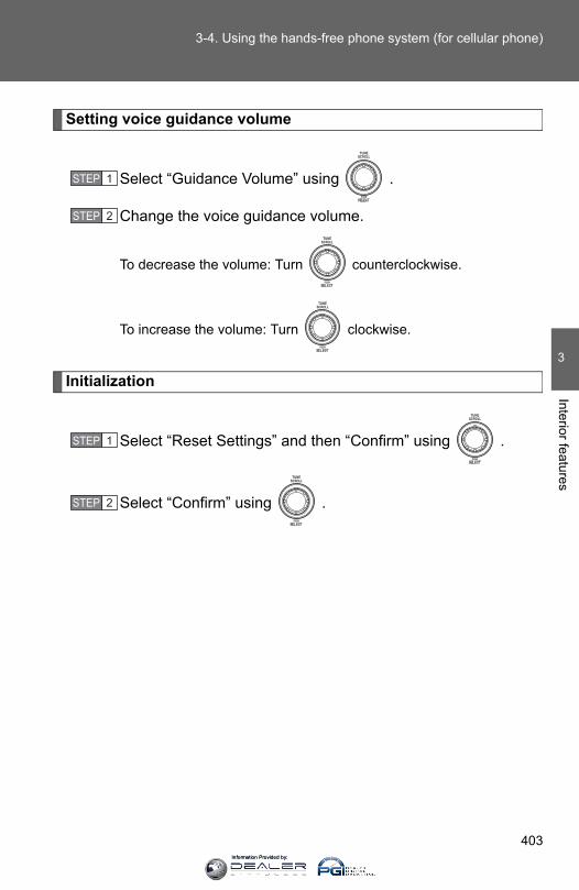
403
3-4. Using the hands-free phone system (for cellular phone)
3
Interior features
Setting voice guidance volume
Select “Guidance Volume” using .
Change the voice guidance volume.
To decrease the volume: Turn counterclockwise.
To increase the volume: Turn clockwise.
Initialization
Select “Reset Settings” and then “Confirm” using .
Select “Confirm” using .
STEP 1
STEP 2
STEP 1
STEP 2
Information Provided by:

404
3-4. Using the hands-free phone system (for cellular phone)
■ Initialization●The following data in the system can be initialized:
• Phone book• Outgoing and incoming call history• Speed dials• Registered cellular phone data• Security code
●Once the initialization has been completed, the data cannot be restoredto its original state.
■When the phone book is lockedThe following functions cannot be used:
●Dialing by inputting a name
●Speed dialing
●Dialing a number stored in the call history memory
●Using the phone book
Information Provided by:
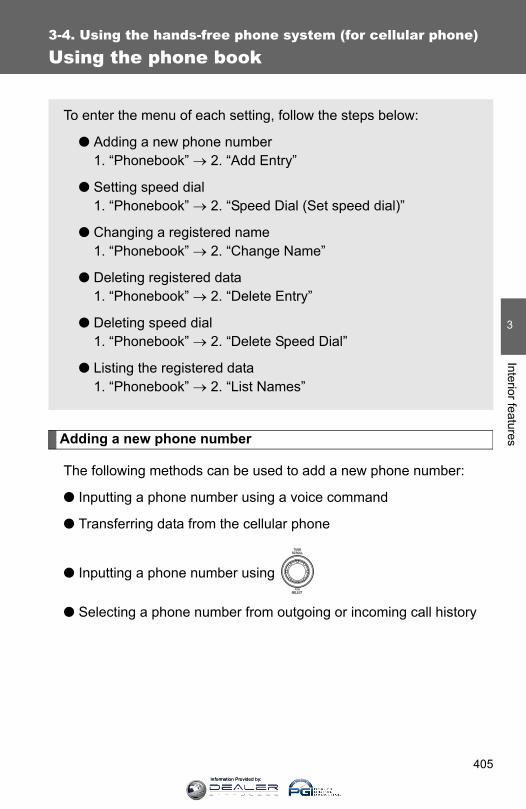
405
3-4. Using the hands-free phone system (for cellular phone)
3
Interior features
Using the phone book
Adding a new phone number
The following methods can be used to add a new phone number:
● Inputting a phone number using a voice command
● Transferring data from the cellular phone
● Inputting a phone number using
● Selecting a phone number from outgoing or incoming call history
To enter the menu of each setting, follow the steps below:
● Adding a new phone number 1. “Phonebook” → 2. “Add Entry”
● Setting speed dial 1. “Phonebook” → 2. “Speed Dial (Set speed dial)”
● Changing a registered name 1. “Phonebook” → 2. “Change Name”
● Deleting registered data 1. “Phonebook” → 2. “Delete Entry”
● Deleting speed dial 1. “Phonebook” → 2. “Delete Speed Dial”
● Listing the registered data 1. “Phonebook” → 2. “List Names”
Information Provided by:
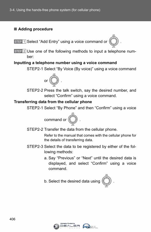
406
3-4. Using the hands-free phone system (for cellular phone)
■ Adding procedure
Select “Add Entry” using a voice command or .
Use one of the following methods to input a telephone num-ber:
Inputting a telephone number using a voice commandSTEP2-1 Select “By Voice (By voice)” using a voice command
or .
STEP2-2 Press the talk switch, say the desired number, andselect “Confirm” using a voice command.
Transferring data from the cellular phoneSTEP2-1 Select “By Phone” and then “Confirm” using a voice
command or .
STEP2-2 Transfer the data from the cellular phone.Refer to the manual that comes with the cellular phone forthe details of transferring data.
STEP2-3 Select the data to be registered by either of the fol-lowing methods:a. Say “Previous” or “Next” until the desired data is
displayed, and select “Confirm” using a voicecommand.
b. Select the desired data using .
STEP 1
STEP 2
Information Provided by:

407
3-4. Using the hands-free phone system (for cellular phone)
3
Interior features
Inputting a phone number using
STEP2-1 Select “Manual Input” using .
STEP2-2 Input a phone number using , and press
once again.
Input the phone number 1 digit at a time.
Selecting a phone number from outgoing or incoming call his-tory
STEP2-1 Select “Call History” using a voice command or
.
STEP2-2 Select “Outgoing Call History (Outgoing)” or “Incom-ing Call History (Incoming)” using a voice command
or .
STEP2-3 Select the data to be registered by either of the fol-lowing methods:a. Say “Previous” or “Go back” until the desired data
is displayed, and select “Confirm” using a voicecommand.
b. Select the desired data using .
Information Provided by:
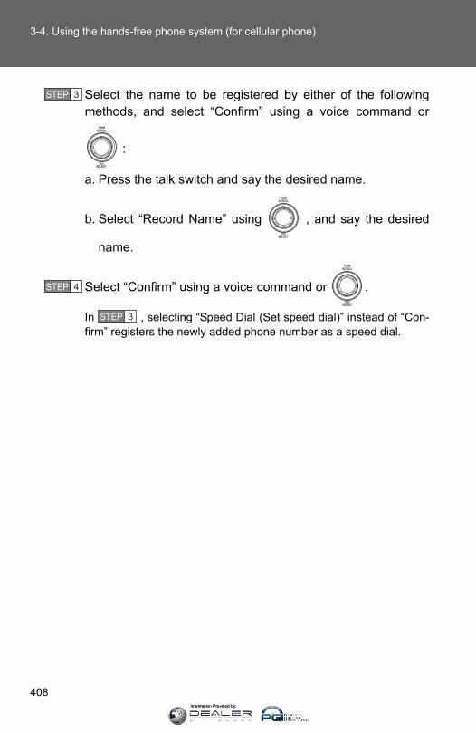
408
3-4. Using the hands-free phone system (for cellular phone)
Select the name to be registered by either of the followingmethods, and select “Confirm” using a voice command or
:
a. Press the talk switch and say the desired name.
b. Select “Record Name” using , and say the desired
name.
Select “Confirm” using a voice command or .
In , selecting “Speed Dial (Set speed dial)” instead of “Con-firm” registers the newly added phone number as a speed dial.
STEP 3
STEP 4
STEP 3
Information Provided by:

409
3-4. Using the hands-free phone system (for cellular phone)
3
Interior features
Setting speed dials
Select “Speed Dial (Set speed dial)” using a voice command
or .
Select the data to be registered as a speed dial by either ofthe following methods:a. Press the talk switch, say desired number, and select “Con-
firm” using a voice command or .
b. Press the talk switch, and say “List names”. While thedesired name is being read aloud, press the talk switch,
and select “Confirm” using a voice command or .
c. Select the desired data using .
Select the desired preset button, and register the data intospeed dial by either of the following methods:a. Press the desired preset button, and select “Confirm” using
a voice command or .
b. Press and hold the desired preset button.
STEP 1
STEP 2
STEP 3
Information Provided by:

410
3-4. Using the hands-free phone system (for cellular phone)
Changing a registered name
Select “Change Name” using a voice command or .
Select the name to be changed by either of the followingmethods.a. Press the talk switch, say desired name, and select “Con-
firm” using a voice command or .
b. Press the talk switch, and say “List names”. While thedesired name is being read aloud, press the talk switch,
and select “Confirm” using a voice command or .
c. Select the desired name using .
Select “Record Name” with or the talk switch.
Say a new name, and select “Confirm” using a voice com-
mand or .
STEP 1
STEP 2
STEP 3
STEP 4
Information Provided by:
411
3-4. Using the hands-free phone system (for cellular phone)
3
Interior features
Deleting registered data
Select “Delete Entry” using a voice command or .
Select the data to be deleted by either of the following meth-
ods, and select “Confirm” using a voice command or :
a. Press the talk switch, and say the name of the desiredphone number to be deleted.
b. Press the talk switch, say “List phones”. While the name ofthe desired phone number is being read aloud, press thetalk switch.
Deleting speed dials
Select “Delete Speed Dial” using a voice command or .
Press the preset button in which the desired speed dial is regis-
tered, and select “Confirm” using a voice command or .
STEP 1
STEP 2
STEP 1
STEP 2
Information Provided by:
412
3-4. Using the hands-free phone system (for cellular phone)
Listing the registered data
Selecting “List names” using a voice command causes a list of theregistered data to be read aloud.
When listing is complete, the system returns to “Phonebook”.Pressing the talk switch while the desired data is being read aloudselects the data, and the following function will be available.
• Dialing: “Dial”• Changing a registered name: “Change Name”• Deleting an entry: “Delete Entry”• Setting a speed dial: “Speed Dial (Set speed dial)”
■Limitation of number of digitsA phone number that exceeds 24 digits cannot be registered.
Information Provided by:

413
3
Interior features
3-5. Using the interior lights
Interior lights list
Rear interior light (→P. 414)Front personal lights/front interior light (→P. 414)Shift lever light (when the engine switch is in the “ACC” or “ON”position [without a smart key system] or “ENGINE STARTSTOP” switch is in ACCESSORY or IGNITION ON mode [with asmart key system])Inside door handle lights (if equipped)Outer foot lights (if equipped)Engine switch light (vehicles without a smart key system)Footwell lights (if equipped)Door courtesy lights (if equipped)Turning the instrument panel light control dial fully downwarddisables the inside door handle lights, footwell lights and shiftlever light. (→P. 187)
CTH35AS003
Information Provided by:
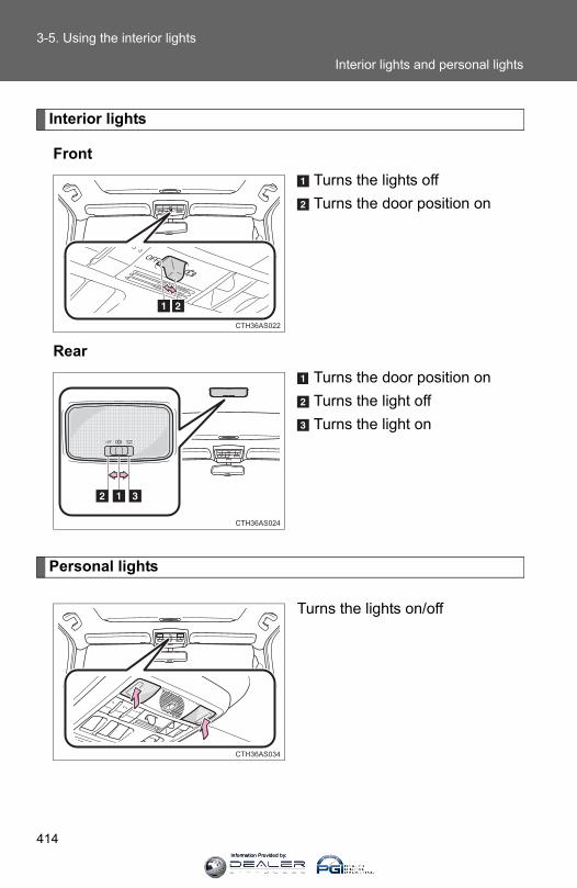
414
3-5. Using the interior lights
Interior lights
FrontTurns the lights offTurns the door position on
RearTurns the door position onTurns the light offTurns the light on
Personal lights
Turns the lights on/off
CTH36AS022
CTH36AS024
CTH36AS034
Interior lights and personal lights
Information Provided by:

415
3-5. Using the interior lights
3
Interior features
■ Illuminated entry systemVehicles without a smart key systemThe lights automatically turn on/off according to the engine switch position,whether the doors are locked/unlocked, and whether the doors are open/closed.
Vehicles with a smart key systemThe lights automatically turn on/off according to “ENGINE START STOP”switch mode, the presence of the electronic key, whether the doors arelocked/unlocked, and whether the doors are open/closed.
■To prevent battery dischargeIf the following lights remain on when the door is not fully closed, the lightswill go off automatically after 20 minutes:
●Engine switch light
●Front interior light (when the switch is in the position)
●Rear interior light (when the switch is in the position)
●Footwell lights
● Inside door handle lights
■Customization that can be configured at Toyota dealerSettings (e.g. the time elapsed before lights turn off) can be changed. (Customizable features →P. 640)
Personal lights
Information Provided by:
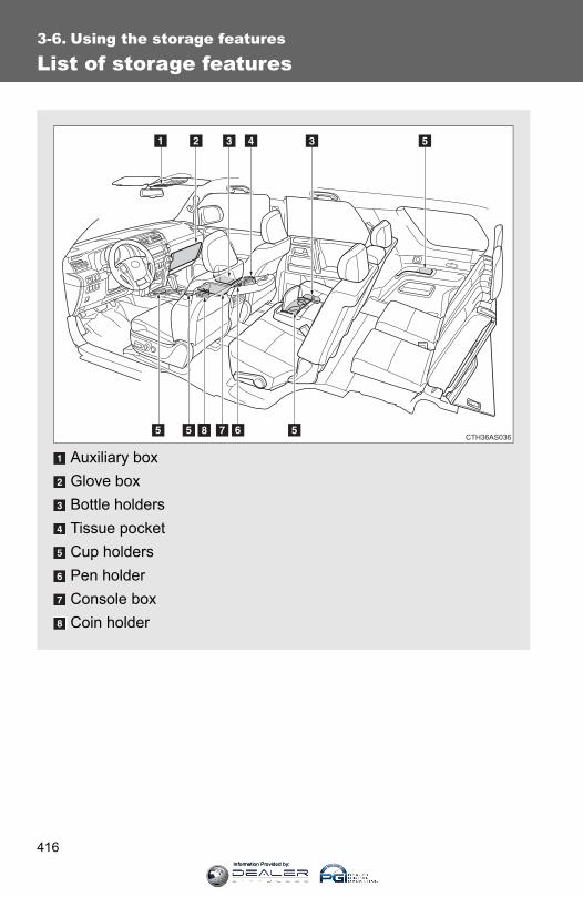
416
3-6. Using the storage features
List of storage features
Auxiliary boxGlove boxBottle holdersTissue pocketCup holdersPen holderConsole boxCoin holder
CTH36AS036
Information Provided by:
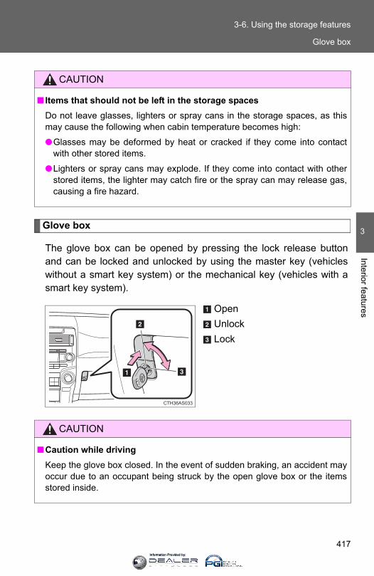
417
3-6. Using the storage features
3
Interior features
Glove box
The glove box can be opened by pressing the lock release buttonand can be locked and unlocked by using the master key (vehicleswithout a smart key system) or the mechanical key (vehicles with asmart key system).
OpenUnlockLock
CAUTION
■ Items that should not be left in the storage spacesDo not leave glasses, lighters or spray cans in the storage spaces, as thismay cause the following when cabin temperature becomes high:
●Glasses may be deformed by heat or cracked if they come into contactwith other stored items.
●Lighters or spray cans may explode. If they come into contact with otherstored items, the lighter may catch fire or the spray can may release gas,causing a fire hazard.
CTH36AS033
CAUTION
■Caution while drivingKeep the glove box closed. In the event of sudden braking, an accident mayoccur due to an occupant being struck by the open glove box or the itemsstored inside.
Glove box
Information Provided by:

418
3-6. Using the storage features
Console box
Lift the lid while pulling up theknob to release the lock.
CTH36AS011
■The separator can be used in either of the positions shown in the illus-tration
CAUTION
■Caution while drivingKeep the console box closed. In the event of sudden braking, an accidentmay occur due to an occupant being struck by the open console box or theitems stored inside.
Change the separator position.
CTH36AS012
Console box
Information Provided by:

419
3-6. Using the storage features
3
Interior features
Coin holder
Lift the lid while pulling up theknob to release the lock.
CTH36AS013
CAUTION
■Caution while drivingKeep the console box closed. In the event of sudden braking, an accidentmay occur due to an occupant being struck by the open console box or theitems stored inside.
Coin holder
Information Provided by:

420
3-6. Using the storage features
Tissue pocket
Lift the lid while pulling up theknob to release the lock.
CTH36AS014
CAUTION
■Caution while drivingKeep the console box closed. In the event of sudden braking, an accidentmay occur due to an occupant being struck by the open console box or theitems stored inside.
Tissue pocket
Information Provided by:
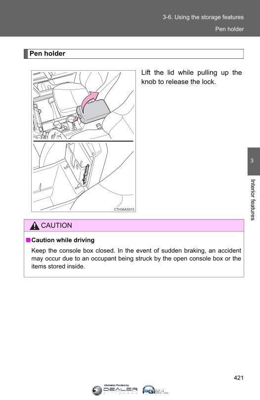
421
3-6. Using the storage features
3
Interior features
Pen holder
Lift the lid while pulling up theknob to release the lock.
CTH36AS015
CAUTION
■Caution while drivingKeep the console box closed. In the event of sudden braking, an accidentmay occur due to an occupant being struck by the open console box or theitems stored inside.
Pen holder
Information Provided by:

422
3-6. Using the storage features
Auxiliary box (if equipped)
Push the lid.
CTH36AS016
CAUTION
■Caution while drivingKeep the auxiliary box closed. In the event of sudden braking, an accidentmay occur due to an occupant being struck by an open auxiliary box or theitems stored inside.
■ Items unsuitable for storingDo not store items heavier than 0.4 lb. (0.2 kg).Doing so may cause the auxiliary box to open and the items inside may fallout, resulting in an accident.
Auxiliary box
Information Provided by:
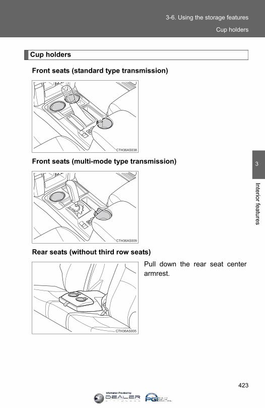
423
3-6. Using the storage features
3
Interior features
Cup holders
Front seats (standard type transmission)
Front seats (multi-mode type transmission)
Rear seats (without third row seats)Pull down the rear seat centerarmrest.
CTH36AS038
CTH36AS009
CTH36AS005
Cup holders
Information Provided by:

424
3-6. Using the storage features
Second row seats (with third row seats)Pull down the second row seatcenter armrest and press downthe button on the armrest.
Third row seats (if equipped)
CTH36AS006
CTH36AS020
Cup holders
Information Provided by:
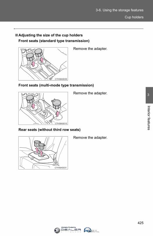
425
3-6. Using the storage features
3
Interior features
■Adjusting the size of the cup holdersFront seats (standard type transmission)
Front seats (multi-mode type transmission)
Rear seats (without third row seats)
Remove the adapter.
CTH36AS039
Remove the adapter.
CTH36AS010
Remove the adapter.
CTH36AS031
Cup holders
Information Provided by:
426
3-6. Using the storage features
CAUTION
■ Items unsuitable for the cup holderDo not place anything other than cups or beverage cans in the cup holders.Other items may be thrown out of the holders in the event of an accident orsudden braking, causing injury. If possible, cover hot drinks to prevent burns.
■When not in use (second row seat cup holders only)Keep the cup holders closed. In the event of sudden braking, an accidentmay occur due to an occupant being struck by the open cup holders or theitems stored inside.
NOTICE
■To prevent damage to the rear cup holders (second row seats only)Stow the cup holders before stowing the armrest.
Cup holders
Information Provided by:
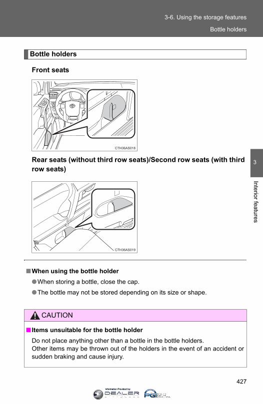
427
3-6. Using the storage features
3
Interior features
Bottle holders
Front seats
Rear seats (without third row seats)/Second row seats (with thirdrow seats)
CTH36AS018
CTH36AS019
■When using the bottle holder●When storing a bottle, close the cap.
●The bottle may not be stored depending on its size or shape.
CAUTION
■ Items unsuitable for the bottle holderDo not place anything other than a bottle in the bottle holders.Other items may be thrown out of the holders in the event of an accident orsudden braking and cause injury.
Bottle holders
Information Provided by:

428
3-6. Using the storage features
NOTICE
■ Items that should not be stowed in the bottle holdersPut the cap on before stowing a bottle. Do not place open bottles in the bot-tle holders, or glasses and paper cups containing liquid. The contents mayspill and glasses may break.
Bottle holders
Information Provided by:
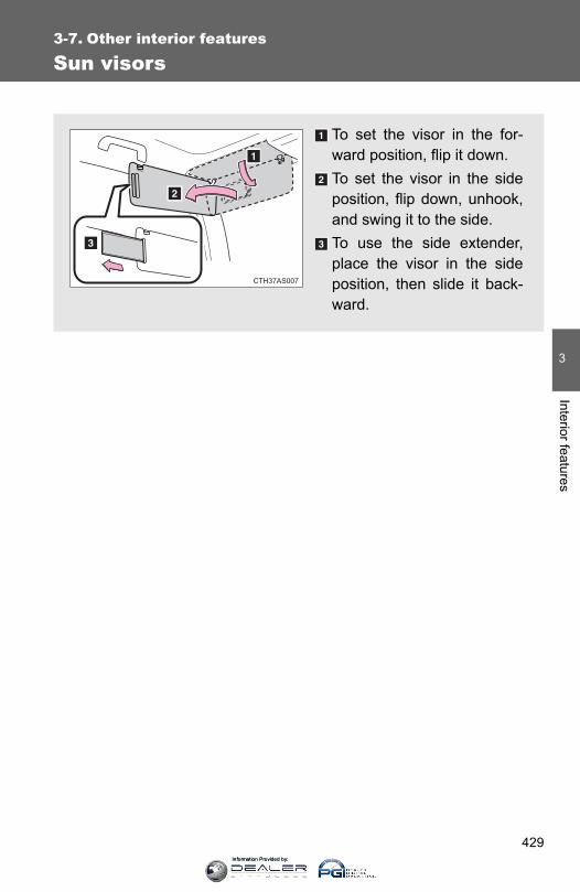
429
3
Interior features
3-7. Other interior features
Sun visors
To set the visor in the for-ward position, flip it down.To set the visor in the sideposition, flip down, unhook,and swing it to the side.To use the side extender,place the visor in the sideposition, then slide it back-ward.
CTH37AS007
Information Provided by:
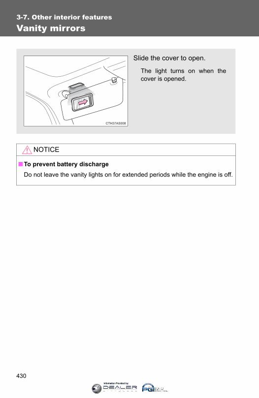
430
3-7. Other interior features
Vanity mirrors
NOTICE
■To prevent battery dischargeDo not leave the vanity lights on for extended periods while the engine is off.
Slide the cover to open.
The light turns on when thecover is opened.
CTH37AS008
Information Provided by:
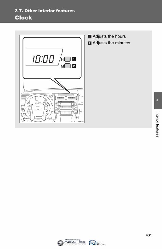
431
3-7. Other interior features
3
Interior features
Clock
Adjusts the hoursAdjusts the minutes
Information Provided by:

432
3-7. Other interior features
■For quicker adjustment of the clockTo advance the minutes and hours quickly, press and hold the “M” or “H” but-ton. The time can be adjusted back or forth by following the procedure below:
■The clock is displayed whenVehicles without a smart key systemThe engine switch is in the “ACC” or “ON” position.
Vehicles with a smart key systemThe “ENGINE START STOP” switch is in ACCESSORY or IGNITION ONmode.
■When disconnecting and reconnecting battery terminalsThe clock data will be reset.
The hour or minute can be moved for-ward or backward by pressing the
“MODE/ ” or “SET/ ” button whilepressing and holding the “H” or “M” but-
ton. If the “MODE/ ” or “SET/ ” but-ton is also pressed and held in the aboveoperation, the hour or minute will movefaster.
Information Provided by:
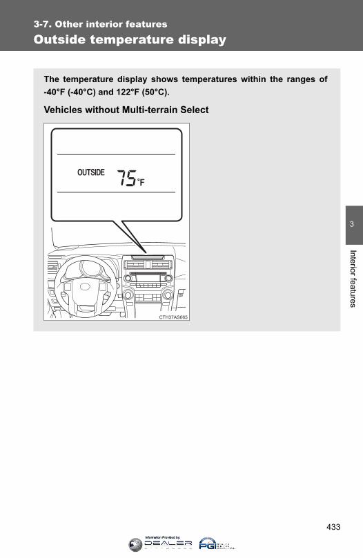
433
3-7. Other interior features
3
Interior features
Outside temperature display
The temperature display shows temperatures within the ranges of-40°F (-40°C) and 122°F (50°C).
Vehicles without Multi-terrain Select
Information Provided by:
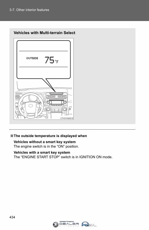
434
3-7. Other interior features
■The outside temperature is displayed whenVehicles without a smart key systemThe engine switch is in the “ON” position.
Vehicles with a smart key systemThe “ENGINE START STOP” switch is in IGNITION ON mode.
Vehicles with Multi-terrain Select
Information Provided by:
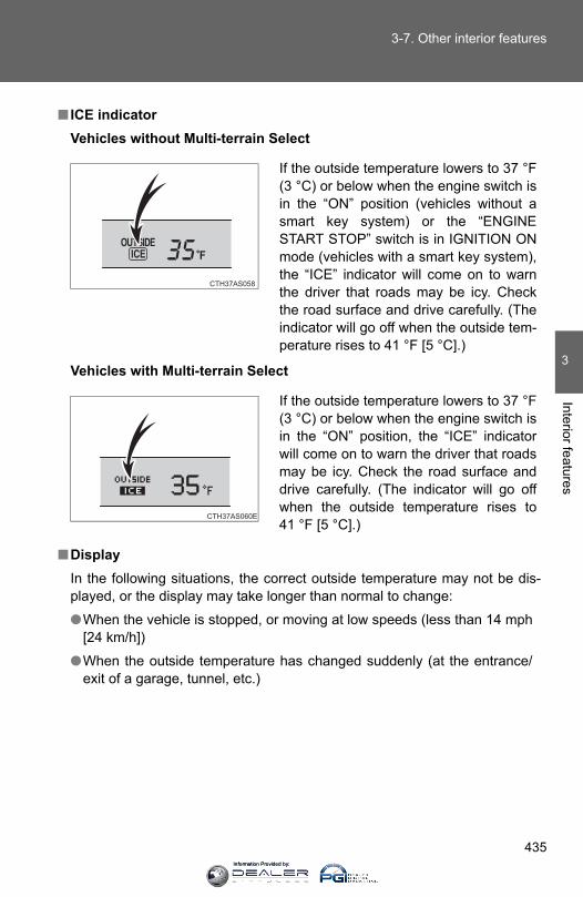
435
3-7. Other interior features
3
Interior features
■ ICE indicatorVehicles without Multi-terrain Select
Vehicles with Multi-terrain Select
■DisplayIn the following situations, the correct outside temperature may not be dis-played, or the display may take longer than normal to change:
●When the vehicle is stopped, or moving at low speeds (less than 14 mph[24 km/h])
●When the outside temperature has changed suddenly (at the entrance/exit of a garage, tunnel, etc.)
If the outside temperature lowers to 37 °F(3 °C) or below when the engine switch isin the “ON” position (vehicles without asmart key system) or the “ENGINESTART STOP” switch is in IGNITION ONmode (vehicles with a smart key system),the “ICE” indicator will come on to warnthe driver that roads may be icy. Checkthe road surface and drive carefully. (Theindicator will go off when the outside tem-perature rises to 41 °F [5 °C].)
If the outside temperature lowers to 37 °F(3 °C) or below when the engine switch isin the “ON” position, the “ICE” indicatorwill come on to warn the driver that roadsmay be icy. Check the road surface anddrive carefully. (The indicator will go offwhen the outside temperature rises to41 °F [5 °C].)
Information Provided by:

436
3-7. Other interior features
Power outlets (12V DC)
The power outlet can be used for 12 V accessories that run on lessthan 10 A.
Center panel
CTH37AS006
Information Provided by:
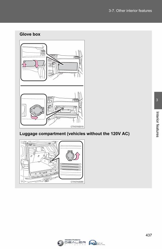
437
3-7. Other interior features
3
Interior features
Glove box
Luggage compartment (vehicles without the 120V AC)
CTH37AS019
CTH37AS085
Information Provided by:

438
3-7. Other interior features
■The power outlet can be used whenVehicles without a smart key system The engine switch is in the “ACC” or “ON” position.
Vehicles with a smart key system The “ENGINE START STOP” switch is in ACCESSORY or IGNITION ONmode.
NOTICE
■To avoid damaging the power outletClose the power outlet lid when the power outlet is not in use. Foreign objects or liquids that enter the power outlet may cause a short cir-cuit.
■To prevent blown fuseDo not use an accessory that uses more than 12 V 10 A.
■To prevent battery dischargeDo not use the power outlet longer than necessary when the engine is notrunning.
Luggage compartment (vehicles with the 120V AC)
CTH37AS086
Information Provided by:
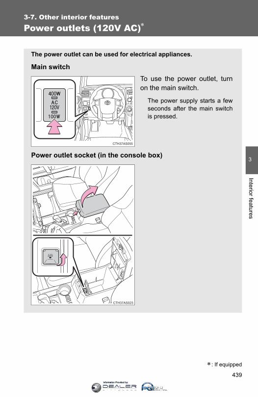
439
3-7. Other interior features
3
Interior features
Power outlets (120V AC)∗
∗: If equipped
The power outlet can be used for electrical appliances.
Main switchTo use the power outlet, turnon the main switch.
The power supply starts a fewseconds after the main switchis pressed.
Power outlet socket (in the console box)
CTH37AS055
CTH37AS023
Information Provided by:
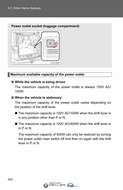
440
3-7. Other interior features
Maximum available capacity of the power outlet
■ While the vehicle is being drivenThe maximum capacity of the power outlet is always 120V AC/100W.
■ When the vehicle is stationaryThe maximum capacity of the power outlet varies depending onthe position of the shift lever.
● The maximum capacity is 120V AC/100W when the shift lever isin any position other than P or N.
● The maximum capacity is 120V AC/400W when the shift lever isin P or N.
The maximum capacity of 400W can only be restored by turningthe power outlet main switch off and then on again with the shiftlever in P or N.
Power outlet socket (luggage compartment)
CTH37AS087
Information Provided by:
441
3-7. Other interior features
3
Interior features
■The power outlet can be used whenThe engine is running.
■The indicator light changes according to the maximum availablecapacity as follows:
■When the power outlet is in operationThe sound of the cooling fan may be heard from the right side of the luggagecompartment. This is normal and does not indicate a malfunction.
■ If the engine is started with the power outlet main switch onThe maximum capacity of the power supply may decrease to below the stan-dard, or may be cut off completely, even when the vehicle is stationary.
■The protection circuit may be activated to cut the power supply if anyof the following conditions apply:●The engine is started with the power outlet main switch on.
●Use of electrical appliances exceeding the maximum capacity isattempted.
A sound may be heard when the protection circuit is activated. This is nor-mal and does not indicate a malfunction.
●Electrical appliances, which consume power exceeding 100W, havebeen used continuously for a long time period.
●The total power usage by all electrical features (headlights, air condition-ing, etc.) has exceeded the total vehicle maximum for an extendedperiod of time.
120V AC/400W120V AC/100W
CTH37AS025
Information Provided by:
442
3-7. Other interior features
■ If the protection circuit is activated and the power supply is cut, con-duct the following procedure:
Park the vehicle in a safe place, and then securely apply the park-ing brake.
Check and ensure that the shift lever is in P or N.
Make sure that the power consumption of the electric appliance iswithin the maximum capacity of the power outlet and the applianceis not broken.
Press the power outlet main switch again.
When the cabin temperature is high, open the windows to cool the tempera-ture down. Once it reaches the normal temperature, turn the power outletmain switch on again.
If the power supply does not resume even after the above procedure hasbeen performed, have the vehicle inspected by your Toyota dealer.
STEP 1
STEP 2
STEP 3
STEP 4
Information Provided by:

443
3-7. Other interior features
3
Interior features
CAUTION
■Using a power outletObserve the following precautions to reduce the risk of injury.
●Use of the power outlet when it is wet with water or snow may result inelectrical shocks and is extremely dangerous. The power outlet must bethoroughly dried before use.
●Do not allow children to use or play with the power outlet.
●Be careful not to get any part of your body caught in the power outlet lid.
●When using electrical appliances, strictly follow any cautions and noticeswritten on their labels and in the manufacturers' instruction manuals.
●Do not modify, disassemble or repair the power outlet or its inverter in anyway. Doing so may result in unexpected malfunctions or accidents, whichcould cause serious damage or injuries. Contact your Toyota dealer forany necessary repairs.
■To prevent injuries and accidents, secure all electric appliances beforeuse and do not use any appliances that may do any of the following:●Distract the driver while driving, or hamper safe driving.
●Result in a fire or burn injuries due to the appliance rolling, falling or over-heating while driving.
●Emit steam while the windows of the cabin are closed.
■To prevent unexpected accidents, such as electric shocks, do not per-form any of the following actions:●Using the power outlet for electric heaters while sleeping.
●Contaminating the power outlet with liquid substances or mud.
●Handling electrical appliance plugs at the power outlet with wet hands orfeet.
● Inserting foreign objects into the power outlet.
●Using malfunctioning electric appliances.
● Inserting inappropriate or badly fitting plugs into the power outlet.
Information Provided by:

444
3-7. Other interior features
NOTICE
■To avoid damaging the power outlet and the plug●Close the power outlet lid when not in use.
●Do not allow foreign objects or liquids to enter the power outlet, as thismay cause a short circuit.
●Do not use plug adaptors to connect too many plugs to the power outlet.
●After removing a plug, gently close the power outlet lid.
■To prevent the fuse from being blownDo not use a 120V AC appliance that requires more than the maximumcapacity of the power outlet. If a 120V AC appliance that consumes morethan the maximum capacity is used, the protection circuit will cut the powersupply.
■Appliances that may not operate properly (120V AC)The following 120V AC appliances may not operate even if their power con-sumption is under maximum capacity.
●Appliances with high initial peak wattage
●Measuring devices that process precise data.
●Other appliances that require an extremely stable power supply
■To prevent battery dischargeTurn off all the vehicle's electronic equipment and accessories, such as theheadlights and air conditioning, when electrical appliances that consume inexcess of 100W are used continuously for long periods of time.
■To prevent any damage caused by heat●Do not use any electrical appliances that give off intense heat, such as
toasters, in any locations including the internal or external trim, seats anddeck.
●Do not use any electrical appliances that are easily affected by vibration orheat inside the vehicle. Vibration while driving, or the heat of the sun whileparking, may result in damage to those electrical appliances.
Information Provided by:

445
3-7. Other interior features
3
Interior features
NOTICE
■ If any electrical appliances are to be used while drivingSecurely fasten both the appliances and their cables to prevent them fromfalling or getting caught in any of the power train components.
■ If the power outlet is loose when an electrical appliance plug is con-nectedReplace the outlet. Contact your Toyota dealer for any necessary replace-ments.
■ If the power outlet gets dirtyTurn the main switch off and use a soft, clean cloth to wipe it gently. Do notuse any cleansing materials, such as organic solvents, wax, or compoundcleaners, as these may damage the power outlet or cause it to malfunction.
Information Provided by:
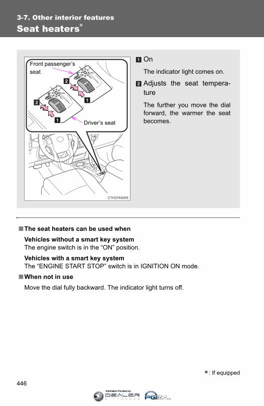
446
3-7. Other interior features
Seat heaters∗
■The seat heaters can be used whenVehicles without a smart key system The engine switch is in the “ON” position.
Vehicles with a smart key system The “ENGINE START STOP” switch is in IGNITION ON mode.
■When not in useMove the dial fully backward. The indicator light turns off.
∗: If equipped
On
The indicator light comes on.
Adjusts the seat tempera-ture
The further you move the dialforward, the warmer the seatbecomes.
CTH37AS005
Front passenger’s seat
Driver’s seat
Information Provided by:
447
3-7. Other interior features
3
Interior features
CAUTION
■Burns●Use caution when seating the following persons in a seat with the seat
heater on to avoid the possibility of burns:
• Babies, small children, the elderly, the sick and the physically chal-lenged
• Persons with sensitive skin• Persons who are fatigued• Persons who have taken alcohol or drugs that induce sleep (sleeping
drugs, cold remedies, etc.)●Do not cover the seat with anything when using the seat heater.
Using the seat heater with a blanket or cushion increases the temperatureof the seat and may lead to overheating.
●Do not use the seat heater more than necessary. Doing so may causeminor burns or overheating.
NOTICE
■To prevent seat heater damageDo not put heavy objects that have an uneven surface on the seat and donot stick sharp objects (needles, nails, etc.) into the seat.
■To prevent battery dischargeTurn the seat heaters off when the engine is not running.
Information Provided by:
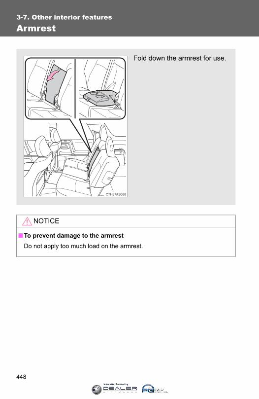
448
3-7. Other interior features
Armrest
NOTICE
■To prevent damage to the armrestDo not apply too much load on the armrest.
Fold down the armrest for use.
CTH37AS088
Information Provided by:

449
3-7. Other interior features
3
Interior features
Floor mat
CAUTION
Observe the following precautions. Failure to do so may cause the driver's floor mat to slip, possibly interferingwith the pedals while driving. An unexpectedly high speed may result or it maybecome difficult to stop the vehicle, leading to a serious accident.■When installing the driver's floor mat
●Do not use floor mats designed for other models or different model yearvehicles, even if they are Toyota Genuine floor mats.
●Only use floor mats designed for the driver's seat.●Always install the floor mat securely using the retaining hooks (clips) pro-
vided.●Do not use two or more floor mats on top of each other.●Do not place the floor mat bottom-side up or upside-down.
■Before driving
Use only floor mats designed specifically for vehicles of the samemodel and model year as your vehicle. Fix them securely in placeonto the carpet.
Fix the floor mat in place usingthe retaining hooks (clips) pro-vided.
For details, refer to the floormat retention clip installationinstructions supplied with theclips.
●Check that the floor mat is securelyfixed in the right place with all the pro-vided retaining hooks (clips). Be espe-cially careful to perform this check aftercleaning the floor.
●With the engine stopped and the shiftlever in P, fully depress each pedal tothe floor to make sure it does not inter-fere with the floor mat.
Information Provided by:

450
3-7. Other interior features
Compass
The compass on the accessory meter display indicates the directionin which the vehicle is heading.
“MODE/ ” button“SET/ ” button
Direction display
■ Displays and directions
Display Direction
“N” North
“NE” Northeast
“E” East
“SE” Southeast
“S” South
“SW” Southwest
“W” West
“NW” Northwest
Information Provided by:

451
3-7. Other interior features
3
Interior features
Calibrating the compass
The direction display deviates from the true direction determined bythe earth’s magnetic field. The amount of deviation varies dependingon the geographic position of the vehicle.
If you cross over one of the map boundaries shown in illustration, thecompass will deviate.To obtain higher precision or perfect calibration, refer to “Deviation calibra-tion”.
CTH37AS072
Samoa: 5 Guam: 8 Saipan: 8
Information Provided by:
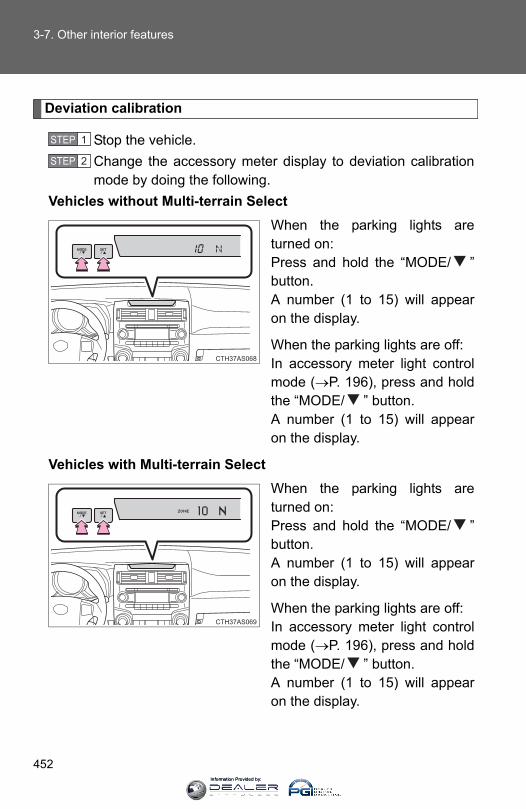
452
3-7. Other interior features
Deviation calibration
Stop the vehicle.Change the accessory meter display to deviation calibrationmode by doing the following.
Vehicles without Multi-terrain SelectWhen the parking lights areturned on:Press and hold the “MODE/ ”button. A number (1 to 15) will appearon the display.
When the parking lights are off:In accessory meter light controlmode (→P. 196), press and holdthe “MODE/ ” button.A number (1 to 15) will appearon the display.
Vehicles with Multi-terrain SelectWhen the parking lights areturned on:Press and hold the “MODE/ ”button. A number (1 to 15) will appearon the display.
When the parking lights are off:In accessory meter light controlmode (→P. 196), press and holdthe “MODE/ ” button.A number (1 to 15) will appearon the display.
STEP 1
STEP 2
Information Provided by:

453
3-7. Other interior features
3
Interior features
Referring to the map above, press the “MODE/ ” or “SET/” button to select the number of the zone you are in.
Press and hold the “SET/ ” button to confirm the numberand to exit deviation calibration mode. (If the button is pressedfor more than 6 seconds, the number will automatically beconfirmed and the display returned to normal.)
Circling calibration
If “•” appears on the left side ofthe direction display, circling cali-bration needs to be performed.
Stop the vehicle in a place where it is safe to drive in a circle.
In deviation calibration mode(→P. 452), press and hold the“MODE/ ” button to change tocircling calibration mode.
“•” on the left side of the directiondisplay will blink.
STEP 3
STEP 4
STEP 1
STEP 2
Information Provided by:
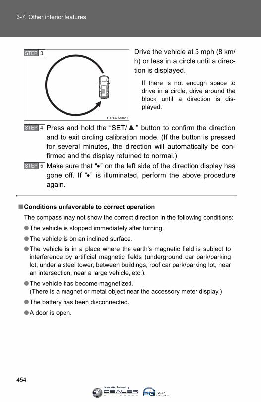
454
3-7. Other interior features
Drive the vehicle at 5 mph (8 km/h) or less in a circle until a direc-tion is displayed.
If there is not enough space todrive in a circle, drive around theblock until a direction is dis-played.
Press and hold the “SET/ ” button to confirm the directionand to exit circling calibration mode. (If the button is pressedfor several minutes, the direction will automatically be con-firmed and the display returned to normal.)Make sure that “•” on the left side of the direction display hasgone off. If “•” is illuminated, perform the above procedureagain.
STEP 3
■Conditions unfavorable to correct operationThe compass may not show the correct direction in the following conditions:
●The vehicle is stopped immediately after turning.
●The vehicle is on an inclined surface.
●The vehicle is in a place where the earth's magnetic field is subject tointerference by artificial magnetic fields (underground car park/parkinglot, under a steel tower, between buildings, roof car park/parking lot, nearan intersection, near a large vehicle, etc.).
●The vehicle has become magnetized.(There is a magnet or metal object near the accessory meter display.)
●The battery has been disconnected.
●A door is open.
STEP 4
STEP 5
Information Provided by:

455
3-7. Other interior features
3
Interior features
■Circling calibration error message (vehicles with Multi-terrain Select)
CAUTION
■While driving the vehicleDo not adjust the display. Adjust the display only when the vehicle isstopped.
■When doing the circling calibrationSecure a wide space, and watch out for people and vehicles in the vicinity.Do not violate any local traffic rules while performing circling calibration.
NOTICE
■To avoid compass malfunctionsDo not place magnets or any metal objects near the accessory meter dis-play. Doing this may cause the compass sensor to malfunction.
■To ensure normal operation of the compass●Do not perform a circling calibration of the compass in a place where the
earth's magnetic field is subject to interference by artificial magnetic fields.
●During calibration, do not operate electric systems (moon roof, power win-dows, etc.) as they may interfere with the calibration.
In the following situations, an error mes-sage regarding the circling calibration willappear on the accessory meter displayfor a few seconds:
●The vehicle was driven too fast duringthe circling calibration.
●The circling calibration was not com-pleted successfully within about twominutes.
Information Provided by:

456
3-7. Other interior features
Luggage compartment features
■ Cargo hooksVehicles with third seats
Fold down the third seats. (→P. 72)
Raise the hook to use.
The cargo hooks are providedfor securing loose items.
Vehicles without third seatsRaise the hook to use.
The cargo hooks are providedfor securing loose items.
STEP 1
CTH37AS041
STEP 2
CTH37AS089
Information Provided by:

457
3-7. Other interior features
3
Interior features
■ Cargo net hooksThe cargo net itself is not included as original equipment.
Vehicles with third seats (pattern 1)Raise the rear cargo hook touse.
Vehicles with third seats (pattern 2)Fold down the third seats. (→P. 72)
Raise the cargo hook to use.
Vehicles without third seats (pattern 1)Raise the rear cargo hook touse.
CTH37AS075
STEP 1
CTH37AS076
STEP 2
CTH37AS090
Information Provided by:

458
3-7. Other interior features
Vehicles without third seats (pattern 2)Raise the cargo hook to use.
■ Storage compartmentType A (if equipped)
Open the storage compart-ment as shown.
Type B (if equipped)Open the storage compart-ment as shown.
CTH37AS091
CTH37AS014
CTH37AS092
Information Provided by:
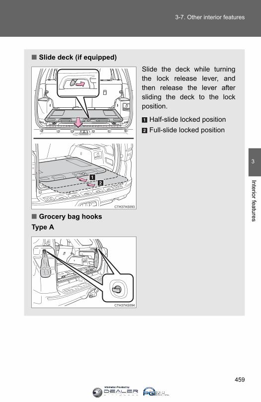
459
3-7. Other interior features
3
Interior features
■ Slide deck (if equipped)Slide the deck while turningthe lock release lever, andthen release the lever aftersliding the deck to the lockposition.
Half-slide locked positionFull-slide locked position
■ Grocery bag hooksType A
CTH37AS093
CTH37AS094
Information Provided by:
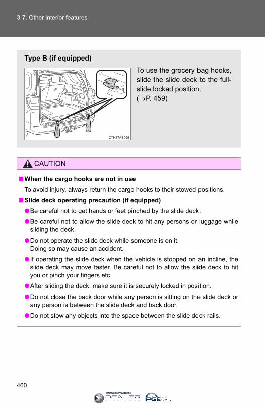
460
3-7. Other interior features
CAUTION
■When the cargo hooks are not in useTo avoid injury, always return the cargo hooks to their stowed positions.
■Slide deck operating precaution (if equipped)●Be careful not to get hands or feet pinched by the slide deck.
●Be careful not to allow the slide deck to hit any persons or luggage whilesliding the deck.
●Do not operate the slide deck while someone is on it. Doing so may cause an accident.
● If operating the slide deck when the vehicle is stopped on an incline, theslide deck may move faster. Be careful not to allow the slide deck to hityou or pinch your fingers etc.
●After sliding the deck, make sure it is securely locked in position.
●Do not close the back door while any person is sitting on the slide deck orany person is between the slide deck and back door.
●Do not stow any objects into the space between the slide deck rails.
Type B (if equipped)To use the grocery bag hooks,slide the slide deck to the full-slide locked position. (→P. 459)
CTH37AS095
Information Provided by:

461
3-7. Other interior features
3
Interior features
NOTICE
■To prevent damage to the cargo net hooks Avoid hanging things other than a cargo net on them.
■Slide deck weight capacity (if equipped)Do not load anything heavier than 440 lb. (200 kg) on the sliding deck.
■Grocery bag hook weight capacityDo not hang any object heavier than 8.8 lb. (4 kg) on the grocery bag hooks.
■When using the slide deck (if equipped)●Do not close the back door while the slide deck is sliding out. Doing so
may cause the back door or slide deck to break.
● If operating the slide deck when the vehicle is stopped on an incline, theslide deck may move faster. Be careful as luggage may become damagedor fly out and damage the cabin.
Information Provided by:

462
3-7. Other interior features
Garage door opener
The garage door opener (HomeLink® Universal Transceiver) is manufac-tured under license from HomeLink®.
Programming HomeLink® (for U.S. owners)
The HomeLink® compatible transceiver in your vehicle has 3 buttonswhich can be programmed to operate 3 different devices. Refer to theprogramming method below appropriate for the device.
Indicator lightButtons
The garage door opener can be programmed to operate garagedoors, gates, entry doors, door locks, home lighting systems, secu-rity systems, and other devices.
CTH37AS044
Information Provided by:

463
3-7. Other interior features
3
Interior features
■ Programming HomeLink®
Point the remote control trans-mitter for the device 1 to 3 in. (25to 75 mm) from the HomeLink®
buttons.
Keep the HomeLink® indicatorlight in view while programming.
Press and hold one of theHomeLink® buttons and thetransmitter button. When theHomeLink® indicator lightchanges from a slow to a rapidflash after 20 seconds, releaseboth buttons.
STEP 1
STEP 2
Information Provided by:
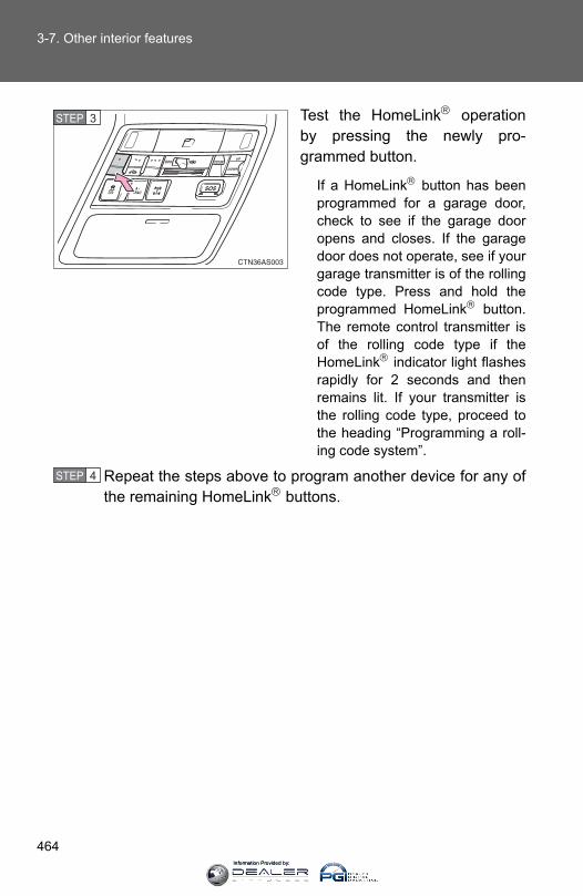
464
3-7. Other interior features
Test the HomeLink® operationby pressing the newly pro-grammed button.
If a HomeLink® button has beenprogrammed for a garage door,check to see if the garage dooropens and closes. If the garagedoor does not operate, see if yourgarage transmitter is of the rollingcode type. Press and hold theprogrammed HomeLink® button.The remote control transmitter isof the rolling code type if theHomeLink® indicator light flashesrapidly for 2 seconds and thenremains lit. If your transmitter isthe rolling code type, proceed tothe heading “Programming a roll-ing code system”.
Repeat the steps above to program another device for any ofthe remaining HomeLink® buttons.
STEP 3
STEP 4
Information Provided by:
465
3-7. Other interior features
3
Interior features
■ Programming a rolling code system (for U.S. owners)If your device is rolling code equipped, follow the steps under theheading “Programming HomeLink®” before proceeding with thesteps listed below.
Locate the learn button on the ceiling mounted garage dooropener motor. The exact location and color of the button mayvary by brand of garage door opener.Refer to the operation manual supplied with the garage door openerfor the location of the learn button.
Press the learn button.Following this step, you have 30 seconds in which to initiate step 3below.
Press and release the vehicle’s programmed HomeLink® but-ton twice. The garage door may open.If the garage door opens, the programming process is complete. Ifthe door does not open, press and release the button a third time.This third press and release will complete the programming processby opening the garage door.
The ceiling mounted garage door opener motor should now recog-nize the HomeLink® signal and operate the garage door.
Repeat the steps above to program another rolling code sys-tem for any of the remaining HomeLink® buttons.
STEP 1
STEP 2
STEP 3
STEP 4
Information Provided by:

466
3-7. Other interior features
■ Programming an entry gate (for U.S. owners)/Programming adevice in the Canadian market
Place the remote control transmitter 1 to 3 in. (25 to 75 mm)away from the HomeLink® buttons.Keep the HomeLink® indicator light in view while programming.
Press and hold the selected HomeLink® button.Repeatedly press and release (cycle) the remote controltransmitter for 2 seconds each until step 4 is completed.When the HomeLink® indicator light starts to flash rapidly,release the buttons.Test the HomeLink® operation by pressing the newly pro-grammed button. Check to see if the gate/device operatescorrectly.Repeat the steps above to program another device for any ofthe remaining HomeLink® buttons.
■ Programming other devicesTo program other devices such as home security systems, homedoor locks and lighting, contact your Toyota dealer for assistance.
■ Reprogramming a buttonThe individual HomeLink® buttons cannot be erased but can bereprogrammed. To reprogram a button, follow the “Reprogramminga HomeLink® button” instructions.
STEP 1
STEP 2
STEP 3
STEP 4
STEP 5
STEP 6
Information Provided by:

467
3-7. Other interior features
3
Interior features
Operating HomeLink®
Press the appropriate HomeLink® button. The HomeLink® indicatorlight should come on.
The HomeLink® compatible transceiver in your vehicle continues to senda signal for up to 20 seconds as long as the button is pressed.
Erasing the entire HomeLink® memory (all three programs)
Press and hold the 2 outside but-tons for 20 seconds until the indi-cator light flashes.
If you sell your vehicle, be sure toerase the programs stored in theHomeLink® memory.
■Before programming● Install a new battery in the remote control transmitter.
●The battery side of the remote control transmitter must be pointed awayfrom the HomeLink® button.
Information Provided by:
468
3-7. Other interior features
■Certification for the garage door openerFor vehicles sold in the U.S.A.FCC ID: CB2300NHL3
NOTE:This device complies with Part 15 of the FCC Rules. Operation is subject tothe following two conditions: (1) this device may not cause harmful interfer-ence, and (2) this device must accept any interference received, includinginterference that may cause undesired operation.
FCC WARNING:Changes or modifications not expressly approved by the party responsiblefor compliance could void the user's authority to operate the equipment.
For vehicles sold in CanadaNOTE:Operation is subject to the following two conditions: (1) this device may notcause interference, and (2) this device must accept any interference, includ-ing interference that may cause undesired operation of the device.
■When support is necessaryVisit on the web at www.homelink.com or call 1-800-355-3515.
CAUTION
■When programming a garage door or other remote control devicesThe garage door or other devices may operate, so ensure people andobjects are out of danger to prevent potential harm.
■Conforming to federal safety standardsDo not use the HomeLink® compatible transceiver with any garage dooropener or device that lacks safety stop and reverse features as required byfederal safety standards.This includes any garage door that cannot detect an interfering object. Adoor or device without these features increases the risk of death or seriousinjury.
Information Provided by:

469
3-7. Other interior features
3
Interior features
Safety Connect∗
Safety Connect is a subscription-based telematics service that usesGlobal Positioning System (GPS) data and embedded cellular tech-nology to provide safety and security features to subscribers. SafetyConnect is supported by Toyota’s designated response center,which operates 24 hours per day, 7 days per week.
Safety Connect service is available by subscription on select,telematics hardware-equipped vehicles.
By using the Safety Connect service, you are agreeing to be boundby the Telematics Subscription Service Agreement and its Terms andConditions, as in effect and amended from time to time, a currentcopy of which is available at Toyota.com. All use of the Safety Con-nect service is subject to such then-applicable Terms and Condi-tions.
■ System componentsMicrophone“SOS” buttonLED light indicators
CTH37AS054
∗: If equipped
Information Provided by:

470
3-7. Other interior features
■ ServicesSubscribers have the following Safety Connect services avail-able:
● Automatic Collision Notification*Helps drivers receive necessary response from emergencyservice providers. (→P. 472)
*: U.S. Patent No. 7,508,298 B2
● Stolen Vehicle LocationHelps drivers in the event of vehicle theft. (→P. 473)
● Emergency Assistance Button (SOS)Connects drivers to response-center support. (→P. 473)
● Enhanced Roadside AssistanceProvides drivers various on-road assistance. (→P. 473)
■ SubscriptionAfter you have signed the Telematics Subscription ServiceAgreement and are enrolled, you can begin receiving services. A variety of subscription terms is available for purchase. Contactyour Toyota dealer, call 1-800-331-4331, or push the “SOS” but-ton in your vehicle for further subscription details.
Information Provided by:

471
3-7. Other interior features
3
Interior features
■Safety Connect Services Information●Phone calls using the vehicles Bluetooth® technology will not be possible
during Safety Connect.
●Safety Connect is available beginning Fall 2009 on select Toyota models.Contact with the Safety Connect response center is dependent upon thetelematics device being in operative condition, cellular connection avail-ability, and GPS satellite signal reception, which can limit the ability toreach the response center or receive emergency service support. Enroll-ment and Telematics Subscription Service Agreement required. A varietyof subscription terms is available; charges vary by subscription termselected.
●Safety Connect services will function in the United States, includingHawaii and Alaska, and in Canada. The services will not function outsideof the United States in countries other than Canada. For details about theservice, contact your Toyota dealer.
●Safety Connect services are not subject to section 255 of the Telecom-munications Act and the device is not TTY compatible.
■LanguagesThe Safety Connect response center will offer support in multiple languages.The Safety Connect system will offer voice prompts in English and Spanish.Please indicate your language of choice when enrolling.
■When contacting the response centerYou may be unable to contact the response center if the network is busy.
Information Provided by:
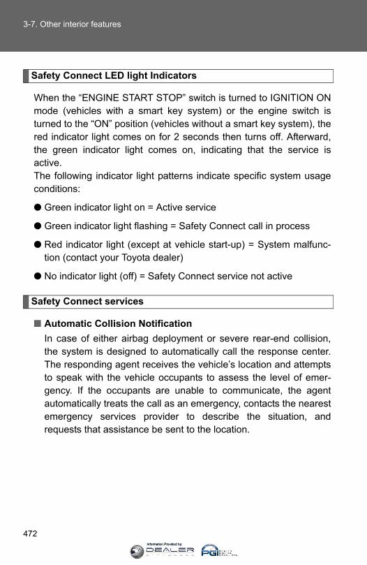
472
3-7. Other interior features
Safety Connect LED light Indicators
When the “ENGINE START STOP” switch is turned to IGNITION ONmode (vehicles with a smart key system) or the engine switch isturned to the “ON” position (vehicles without a smart key system), thered indicator light comes on for 2 seconds then turns off. Afterward,the green indicator light comes on, indicating that the service isactive.The following indicator light patterns indicate specific system usageconditions:
● Green indicator light on = Active service
● Green indicator light flashing = Safety Connect call in process
● Red indicator light (except at vehicle start-up) = System malfunc-tion (contact your Toyota dealer)
● No indicator light (off) = Safety Connect service not active
Safety Connect services
■ Automatic Collision NotificationIn case of either airbag deployment or severe rear-end collision,the system is designed to automatically call the response center.The responding agent receives the vehicle’s location and attemptsto speak with the vehicle occupants to assess the level of emer-gency. If the occupants are unable to communicate, the agentautomatically treats the call as an emergency, contacts the nearestemergency services provider to describe the situation, andrequests that assistance be sent to the location.
Information Provided by:
473
3-7. Other interior features
3
Interior features
■ Stolen Vehicle LocationIf your vehicle is stolen, Safety Connect can work with local author-ities to assist them in locating and recovering the vehicle. After fil-ing a police report, call the Safety Connect response center at 1-800-331-4331 and follow the prompts for Safety Connect to initiatethis service.In addition to assisting law enforcement with recovery of a stolenvehicle, Safety-Connect-equipped vehicle location data may, undercertain circumstances, be shared with third parties to locate yourvehicle. Further information is available at Toyota.com.
■ Emergency Assistance Button (“SOS”)In the event of an emergency on the road, push the “SOS” buttonto reach the Safety Connect response center. The answeringagent will determine your vehicle’s location, assess the emer-gency, and dispatch the necessary assistance required.
If you accidentally press the “SOS” button, tell the response-center agentthat you are not experiencing an emergency.
■ Enhanced Roadside AssistanceEnhanced Roadside Assistance adds GPS data to the alreadyincluded warranty-based Toyota roadside service.
Subscribers can press the “SOS” button to reach a Safety Connectresponse-center agent, who can help with a wide range of needs,such as: towing, flat tire, fuel delivery, etc. For a description of theEnhanced Roadside Assistance services and their limitations,please see the Safety Connect Terms and Conditions, which areavailable at Toyota.com.
Information Provided by:
474
3-7. Other interior features
Safety information for Safety Connect
Important! Read this information before using Safety Connect.
■ Exposure to radio frequency signalsThe Safety Connect system installed in your vehicle is a low-powerradio transmitter and receiver. It receives and also sends out radiofrequency (RF) signals.
In August 1996, the Federal Communications Commission (FCC)adopted RF exposure guidelines with safety levels for mobile wire-less phones. Those guidelines are consistent with the safety stan-dards previously set by the following U.S. and internationalstandards bodies.
● ANSI (American National Standards Institute) C95.1 [1992]
● NCRP (National Council on Radiation Protection and Measure-ment) Report 86 [1986]
● ICNIRP (International Commission on Non-Ionizing RadiationProtection) [1996]
Those standards were based on comprehensive and periodic eval-uations of the relevant scientific literature. Over 120 scientists,engineers, and physicians from universities, and governmenthealth agencies and industries reviewed the available body ofresearch to develop the ANSI Standard (C95.1).
The design of Safety Connect complies with the FCC guidelines inaddition to those standards.
Information Provided by:
475
3-7. Other interior features
3
Interior features
■LicenseLicensed by QUALCOMM Incorporated under one or more of the followingUnited States Patents and/or their counterparts in other nations:
4,901,307 5,490,165 5,056,109 5,504,773 5,101,5015,506,865 5,109,390 5,511,073 5,228,054 5,535,2395,267,261 5,544,196 5,267,262 5,568,483 5,337,3385,600,754 5,414,796 5,657,420 5,416,797 5,659,5695,710,784 5,778,338
■Certification for Safety ConnectFCC ID: O9EGTM1
FCC ID: O6Y-CDMRF101
NOTE:This device complies with Part 15 of the FCC Rules. Operation is subject tothe following two conditions: (1) This device may not cause harmful interfer-ence, and (2) this device must accept any interference received, includinginterference that may cause undesired operation.
FCC WARNING:
Changes or modifications not expressly approved by the party responsiblefor compliance could void the user's authority to operate the equipment.
Information Provided by:

476
3-7. Other interior features
Information Provided by:
478
4-1. Maintenance and care
Cleaning and protecting the vehicle exterior
■Automatic car washes●Fold the mirrors and remove the detachable pole antenna before wash-
ing the vehicle. Start washing from the front of the vehicle. Make sure tore-install the antenna and extend the mirrors before driving.
●Brushes used in automatic car washes may scratch the vehicle surfaceand harm your vehicle’s paint.
● In certain automatic car washes, the roof antenna (if equipped) or rearspoiler may interfere with machine operation. This may prevent the vehi-cle from being cleaned properly or result in damage to the antenna orrear spoiler.
■High pressure car washes●Do not allow the nozzles of the car wash to come within close proximity
of the windows.
●Before using the car wash, check that the fuel filler door on your vehicleis closed properly.
Perform the following to protect the vehicle and maintain it in primecondition:
● Working from top to bottom, liberally apply water to the vehiclebody, wheel wells and underside of the vehicle to remove anydirt and dust.
● Wash the vehicle body using a sponge or soft cloth, such as achamois.
● For hard-to-remove marks, use car wash soap and rinse thor-oughly with water.
● Wipe away any water.
● Wax the vehicle when the waterproof coating deteriorates.
If water does not bead on a clean surface, apply wax when the vehi-cle body is cool.
Information Provided by:

479
4-1. Maintenance and care
4
Maintenance and care
■Aluminum wheels (if equipped)●Remove any dirt immediately by using a neutral detergent. Do not use
hard brushes or abrasive cleaners. Do not use strong or harsh chemicalcleaners. Use the same mild detergent and wax as used on the paint.
●Do not use detergent on the wheels when they are hot, for example afterdriving for long distance in the hot weather.
●Wash detergent from the wheels immediately after use.
■Bumpers and side moldingsDo not scrub with abrasive cleaners.
CAUTION
■When washing the vehicleDo not apply water to the inside of the engine compartment. Doing so maycause the electrical components etc. to catch fire.
■Precautions regarding the exhaust pipeExhaust gasses cause the exhaust pipe to become quite hot.When washing the vehicle, be careful not to touch the pipe until it has cooledsufficiently, as touching a hot exhaust pipe can cause burns.
Information Provided by:
480
4-1. Maintenance and care
NOTICE
■To prevent paint deterioration and corrosion on the body and compo-nents (aluminum wheels etc.)●Wash the vehicle immediately in the following cases:
• After driving near the sea coast• After driving on salted roads• If coal tar or tree sap is present on the paint surface• If dead insects, insect droppings or bird droppings are present on the
paint surface• After driving in an area contaminated with soot, oily smoke, mine dust,
iron powder or chemical substances• If the vehicle becomes heavily soiled with dust or mud• If liquids such as benzene and gasoline are spilled on the paint surface
● If the paint is chipped or scratched, have it repaired immediately.
●To prevent the wheels from corroding, remove any dirt and store in a placewith low humidity when storing the wheels.
■Cleaning the exterior lights●Wash carefully. Do not use organic substances or scrub with a hard brush.
This may damage the surfaces of the lights.
●Do not apply wax on the surfaces of the lights.Wax may cause damage to the lenses.
■Detachable pole antenna installation and removal precautions●Before driving, ensure that the antenna is installed.
●When the antenna is removed, such as before entering an automatic carwash, make sure to store it in a suitable place so as not to lose it. Also,before driving, make sure to reinstall the antenna in its original position.
■High pressure car washes (vehicles with rear view monitor system)When washing the vehicle, do not apply intensive bursts of water to the cam-era or camera area. Doing so may result in the camera malfunctioning.
Information Provided by:

481
4-1. Maintenance and care
4
Maintenance and care
Cleaning and protecting the vehicle interior
The following procedures will help protect your vehicle’s interior andkeep it in top condition:
■ Protecting the vehicle interiorRemove dirt and dust using a vacuum cleaner. Wipe dirty sur-faces with a cloth dampened with lukewarm water.
■ Cleaning the leather areas● Remove dirt and dust using a vacuum cleaner.
● Wipe off any excess dirt and dust with a soft cloth dampenedwith diluted detergent.
Use a diluted water solution of approximately 5% neutral wool deter-gent.
● Wring out any excess water from the cloth and thoroughlywipe off all remaining traces of detergent.
● Wipe the surface with a dry, soft cloth to remove any remain-ing moisture. Allow the leather to dry in a shaded and venti-lated area.
■ Cleaning the synthetic leather areas● Remove loose dirt using a vacuum cleaner.
● Apply a mild soap solution to the synthetic leather using asponge or soft cloth.
● Allow the solution to soak in for a few minutes. Remove thedirt and wipe off the solution with a clean, damp cloth.
Information Provided by:

482
4-1. Maintenance and care
■Caring for leather areasToyota recommends cleaning the interior of the vehicle at least twice a yearto maintain the quality of the vehicle’s interior.
■Shampooing the carpetsThere are several commercial foaming-type cleaners available. Use asponge or brush to apply the foam. Rub in overlapping circles. Do not usewater. Wipe dirty surfaces and let them dry. Excellent results are obtained bykeeping the carpet as dry as possible.
■Seat beltsClean with mild soap and lukewarm water using a cloth or sponge. Alsocheck the belts periodically for excessive wear, fraying or cuts.
CAUTION
■Water in the vehicle●Do not splash or spill liquid in the vehicle.
Doing so may cause electrical components etc. to malfunction or catchfire.
●Do not get any of the SRS components or wiring in the vehicle interior wet. (→P. 115)An electrical malfunction may cause the airbags to deploy or not functionproperly, resulting in death or serious injury.
■Cleaning the interior (especially instrument panel)Do not use polish wax or polish cleaner. The instrument panel may reflectoff the windshield, obstructing the driver’s view and leading to an accident,resulting in death or serious injury.
Information Provided by:
483
4-1. Maintenance and care
4
Maintenance and care
NOTICE
■Cleaning detergents●Do not use the following types of detergent, as they may discolor the vehi-
cle interior or cause streaks or damage to painted surfaces:
• Non-seat portions: Organic substances such as benzene or gasoline,alkaline or acidic solutions, dye, and bleach.
• Seats: Alkaline or acidic solutions, such as thinner, benzene, and alco-hol.
●Do not use polish wax or polish cleaner. The instrument panel’s or otherinterior part’s painted surface may be damaged.
■Preventing damage to leather surfacesObserve the following precautions to avoid damage to and deterioration ofleather surfaces:
●Remove any dust or dirt from leather surfaces immediately.
●Do not expose the vehicle to direct sunlight for extended periods of time.Park the vehicle in the shade, especially during summer.
●Do not place items made of vinyl, plastic, or containing wax on the uphol-stery, as they may stick to the leather surface if the vehicle interior heatsup significantly.
■Water on the floorDo not wash the vehicle floor with water.Vehicle systems such as the audio system may be damaged if water comesinto contact with electrical components such as the audio system above orunder the floor of the vehicle. Water may also cause the body to rust.
■Cleaning the inside of the back window●Do not use glass cleaner to clean the back window, as this may cause
damage to the rear window defogger heater wires. Use a cloth dampenedwith lukewarm water to gently wipe the window clean. Wipe the window instrokes running parallel to the heater wires.
●Be careful not to scratch or damage the heater wires.
Information Provided by:
484
4-2. Maintenance
Maintenance requirements
■Repair and replacementIt is recommended that genuine Toyota parts be used for repairs to ensureperformance of each system. If non-Toyota parts are used in replacement orif a repair shop other than a Toyota dealer performs repairs, confirm the war-ranty coverage.
To ensure safe and economical driving, day-to-day care and regularmaintenance are essential. It is the owner’s responsibility to performregular checks. Toyota recommends performing the following main-tenance:
■ General maintenanceGeneral maintenance should be performed on a daily basis.This can be done by yourself or by a Toyota dealer.
■ Scheduled maintenanceScheduled maintenance should be performed at specified inter-vals according to the maintenance schedule.
For details about maintenance items and schedules, refer to the“Scheduled Maintenance Guide” or “Owner’s Manual Supplement”.
■ Do-it-yourself maintenanceYou can perform some maintenance procedures by yourself. Please be aware that do-it-yourself maintenance may affect war-ranty coverage.
The use of Toyota Repair Manuals is recommended.
For details about warranty coverage, see the separate “Owner’s War-ranty Information Booklet” or “Owner’s Manual Supplement”.
Information Provided by:

485
4-2. Maintenance
4
Maintenance and care
■Allow inspection and repairs to be performed by a Toyota dealer●Toyota technicians are well-trained specialists and are kept up to date
with the latest service information. They are well informed about theoperations of all systems on your vehicle.
●Keep a copy of the repair order. It proves that the maintenance that hasbeen performed is under warranty coverage. If any problem should arisewhile your vehicle is under warranty, your Toyota dealer will promptlytake care of it.
CAUTION
■ If your vehicle is not properly maintainedImproper maintenance could result in serious damage to the vehicle andpossible serious injury or death.
■Handling of the battery●Engine exhaust, some of its constituents, and a wide variety of automobile
components contain or emit chemicals known to the State of California tocause cancer and birth defects and other reproductive harm. Work in awell ventilated area.
●Oils, fuels and fluids contained in vehicles as well as waste produced bycomponent wear contain or emit chemicals known to the State of Califor-nia to cause cancer and birth defects or other reproductive harm. Avoidexposure and wash any affected area immediately.
●Battery posts, terminals and related accessories contain lead and leadcompounds which are known to cause brain damage. Wash your handsafter handling. (→P. 509)
Information Provided by:

486
4-2. Maintenance
General maintenance
Engine compartment
Items Check points
Battery Check the connections.(→P. 509)
Brake fluid Is the brake fluid at the correct level? (→P. 505)
Engine coolant Is the engine coolant at the correct level? (→P. 503)
Engine oil Is the engine oil at the correct level? (→P. 498)
Exhaust system There should not be any fumes or strange sounds.
Power steering fluid Is the power steering fluid at the correct level? (→P. 507)
Radiator/condenserThe radiator and condenser should be free from foreign objects. (→P. 504)
Washer fluid Is there sufficient washer fluid?(→P. 512)
Listed below are the general maintenance items that should be per-formed at the intervals specified in the “Owner's Warranty Informa-tion Booklet” or “Owner’s Manual Supplement/ScheduledMaintenance Guide”. It is recommended that any problem you noticeshould be brought to the attention of your Toyota dealer or qualifiedservice shop for advice.
Information Provided by:
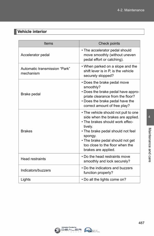
487
4-2. Maintenance
4
Maintenance and care
Vehicle interior
Items Check points
Accelerator pedal• The accelerator pedal should
move smoothly (without uneven pedal effort or catching).
Automatic transmission “Park” mechanism
• When parked on a slope and the shift lever is in P, is the vehicle securely stopped?
Brake pedal
• Does the brake pedal move smoothly?
• Does the brake pedal have appro-priate clearance from the floor?
• Does the brake pedal have the correct amount of free play?
Brakes
• The vehicle should not pull to one side when the brakes are applied.
• The brakes should work effec-tively.
• The brake pedal should not feel spongy.
• The brake pedal should not get too close to the floor when the brakes are applied.
Head restraints • Do the head restraints move smoothly and lock securely?
Indicators/buzzers • Do the indicators and buzzers function properly?
Lights • Do all the lights come on?
Information Provided by:

488
4-2. Maintenance
Items Check points
Parking brake
• Does the parking brake pedal move smoothly?
• When parked on a slope and the parking brake is on, is the vehicle securely stopped?
Seat belts
• Do the seat belts operate smoothly?
• The seat belts should not be dam-aged.
Seats • Do the seat controls operate properly?
Steering wheel
• Does the steering wheel rotate smoothly?
• Does the steering wheel have the correct amount of free play?
• There should not be any strange sounds coming from the steering wheel.
Information Provided by:
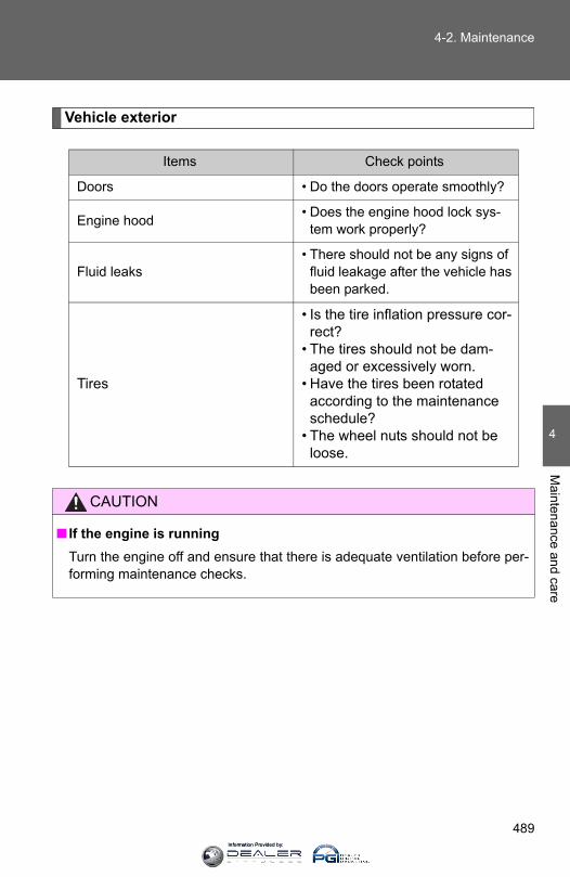
489
4-2. Maintenance
4
Maintenance and care
Vehicle exterior
Items Check points
Doors • Do the doors operate smoothly?
Engine hood • Does the engine hood lock sys-tem work properly?
Fluid leaks• There should not be any signs of
fluid leakage after the vehicle has been parked.
Tires
• Is the tire inflation pressure cor-rect?
• The tires should not be dam-aged or excessively worn.
• Have the tires been rotated according to the maintenance schedule?
• The wheel nuts should not be loose.
CAUTION
■ If the engine is runningTurn the engine off and ensure that there is adequate ventilation before per-forming maintenance checks.
Information Provided by:
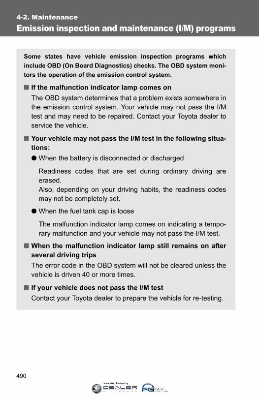
490
4-2. Maintenance
Emission inspection and maintenance (I/M) programs
Some states have vehicle emission inspection programs whichinclude OBD (On Board Diagnostics) checks. The OBD system moni-tors the operation of the emission control system.
■ If the malfunction indicator lamp comes onThe OBD system determines that a problem exists somewhere inthe emission control system. Your vehicle may not pass the I/Mtest and may need to be repaired. Contact your Toyota dealer toservice the vehicle.
■ Your vehicle may not pass the I/M test in the following situa-tions:● When the battery is disconnected or discharged
Readiness codes that are set during ordinary driving areerased.Also, depending on your driving habits, the readiness codesmay not be completely set.
● When the fuel tank cap is loose
The malfunction indicator lamp comes on indicating a tempo-rary malfunction and your vehicle may not pass the I/M test.
■ When the malfunction indicator lamp still remains on afterseveral driving tripsThe error code in the OBD system will not be cleared unless thevehicle is driven 40 or more times.
■ If your vehicle does not pass the I/M testContact your Toyota dealer to prepare the vehicle for re-testing.
Information Provided by:
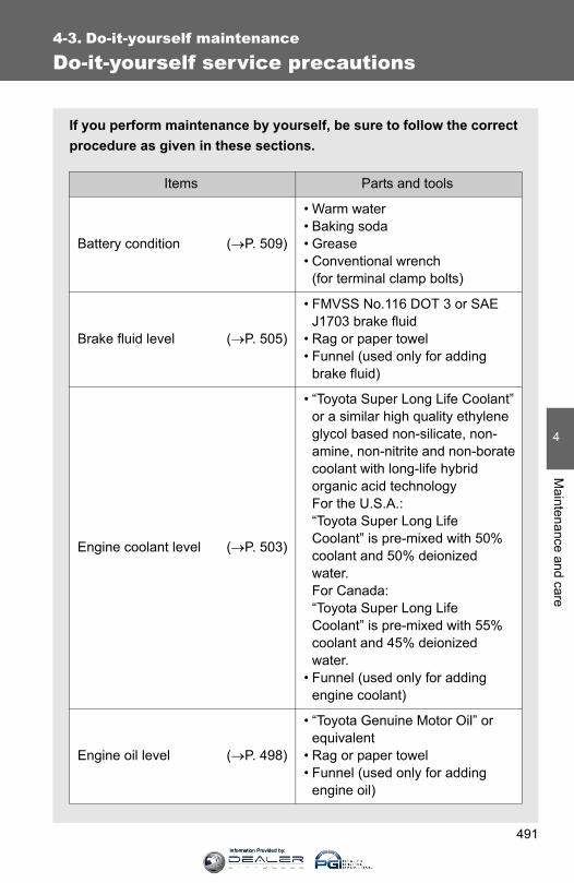
491
4
Maintenance and care
4-3. Do-it-yourself maintenance
Do-it-yourself service precautions
If you perform maintenance by yourself, be sure to follow the correctprocedure as given in these sections.
Items Parts and tools
Battery condition (→P. 509)
• Warm water• Baking soda• Grease• Conventional wrench
(for terminal clamp bolts)
Brake fluid level (→P. 505)
• FMVSS No.116 DOT 3 or SAE J1703 brake fluid
• Rag or paper towel• Funnel (used only for adding
brake fluid)
Engine coolant level (→P. 503)
• “Toyota Super Long Life Coolant” or a similar high quality ethylene glycol based non-silicate, non-amine, non-nitrite and non-borate coolant with long-life hybrid organic acid technologyFor the U.S.A.:“Toyota Super Long Life Coolant” is pre-mixed with 50% coolant and 50% deionized water.For Canada:“Toyota Super Long Life Coolant” is pre-mixed with 55% coolant and 45% deionized water.
• Funnel (used only for adding engine coolant)
Engine oil level (→P. 498)
• “Toyota Genuine Motor Oil” or equivalent
• Rag or paper towel• Funnel (used only for adding
engine oil)
Information Provided by:

492
4-3. Do-it-yourself maintenance
Items Parts and tools
Fuses (→P. 531) • Fuse with same amperage rating as original
Light bulbs (→P. 541)
• Bulb with same number and watt-age rating as original
• Phillips-head screwdriver• Flathead screwdriver• Wrench
Power steering fluid level(→P. 507)
• Automatic transmission fluid DEXRON® II or III
• Rag or paper towel• Clean funnel
Radiator and condenser(→P. 504)
⎯
Tire inflation pressure (→P. 520) • Tire pressure gauge• Compressed air source
Washer fluid (→P. 512)
• Water or washer fluid containing antifreeze (for winter use)
• Funnel (used only for adding water or washer fluid)
Information Provided by:
493
4-3. Do-it-yourself maintenance
4
Maintenance and care
CAUTION
The engine compartment contains many mechanisms and fluids that maymove suddenly, become hot, or become electrically energized. To avoid deathor serious injury, observe the following precautions:
■When working on the engine compartment:●Keep hands, clothing and tools away from the moving fan and engine
drive belt.
●Be careful not to touch the engine, radiator, exhaust manifold, etc. rightafter driving as they may be hot. Oil and other fluids may also be hot.
●Do not leave anything that may burn easily, such as paper and rags, in theengine compartment.
●Do not smoke, cause sparks or expose an open flame to fuel or the bat-tery. Fuel and battery fumes are flammable.
●Be extremely cautious when working on the battery. It contains poisonousand corrosive sulfuric acid.
■Safety glassesWear safety glasses to prevent flying or falling material, fluid spray, etc. fromgetting in your eyes.
NOTICE
■ If you remove the air cleaner filterDriving with the air cleaner filter removed may cause excessive engine weardue to dirt in the air. Also, a backfire could cause a fire in the engine com-partment.
Information Provided by:

494
4-3. Do-it-yourself maintenance
Hood
CAUTION
■Pre-driving checkCheck that the hood is fully closed and locked. If the hood is not locked properly, it may open while the vehicle is in motionand cause an accident, which may result in death or serious injury.
Release the lock from the inside of the vehicle to open the hood.
Pull the hood release lever.
The hood will pop up slightly.
Pull up the auxiliary catchlever and lift the hood.
CTH43AS009
STEP 1
CTH43AS087
STEP 2
Information Provided by:
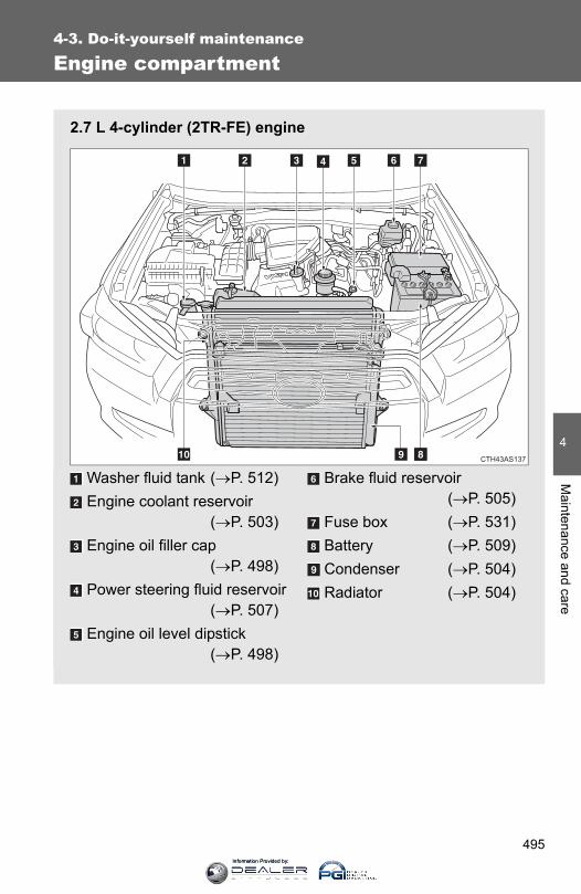
495
4-3. Do-it-yourself maintenance
4
Maintenance and care
Engine compartment
2.7 L 4-cylinder (2TR-FE) engine
Washer fluid tank (→P. 512)Engine coolant reservoir
(→P. 503)Engine oil filler cap
(→P. 498)Power steering fluid reservoir
(→P. 507)Engine oil level dipstick
(→P. 498)
Brake fluid reservoir(→P. 505)
Fuse box (→P. 531)Battery (→P. 509)Condenser (→P. 504)Radiator (→P. 504)
CTH43AS137
Information Provided by:
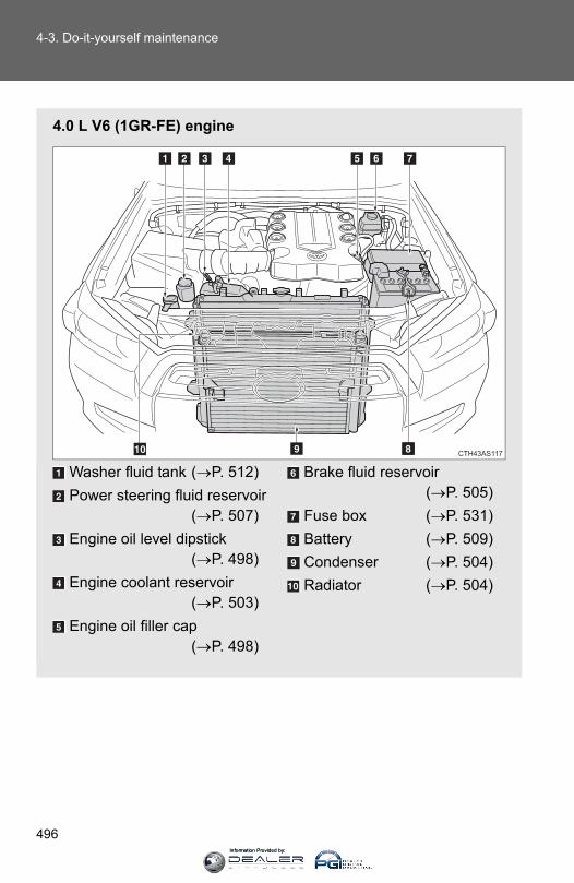
496
4-3. Do-it-yourself maintenance
4.0 L V6 (1GR-FE) engine
Washer fluid tank (→P. 512)Power steering fluid reservoir
(→P. 507)Engine oil level dipstick
(→P. 498)Engine coolant reservoir
(→P. 503)Engine oil filler cap
(→P. 498)
Brake fluid reservoir(→P. 505)
Fuse box (→P. 531)Battery (→P. 509)Condenser (→P. 504)Radiator (→P. 504)
CTH43AS117
Information Provided by:

497
4-3. Do-it-yourself maintenance
4
Maintenance and care
Engine compartment cover
■ Removing the engine compartment cover
■ Installing the clipsCTH43AS121
CTH43AS018
Information Provided by:

498
4-3. Do-it-yourself maintenance
Engine oil
With the engine at operating temperature and turned off, check the oillevel on the dipstick.
■ Checking the engine oilPark the vehicle on level ground. After turning off the engine,wait more than 5 minutes for the oil to drain back into the bot-tom of the engine.Holding a rag under the end, pull the dipstick out.
2.7 L 4-cylinder (2TR-FE) engine
4.0 L V6 (1GR-FE) engine
Wipe the dipstick clean.Reinsert the dipstick fully.Holding a rag under the end, pull the dipstick out and checkthe oil level.Wipe the dipstick and reinsert it fully.
STEP 1
STEP 2
CTH43AS128
CTH43AS012
STEP 3
STEP 4
STEP 5
STEP 6
Information Provided by:

499
4-3. Do-it-yourself maintenance
4
Maintenance and care
2.7 L 4-cylinder (2TR-FE) engineLowFull
4.0 L V6 (1GR-FE) engineLowFull
Information Provided by:
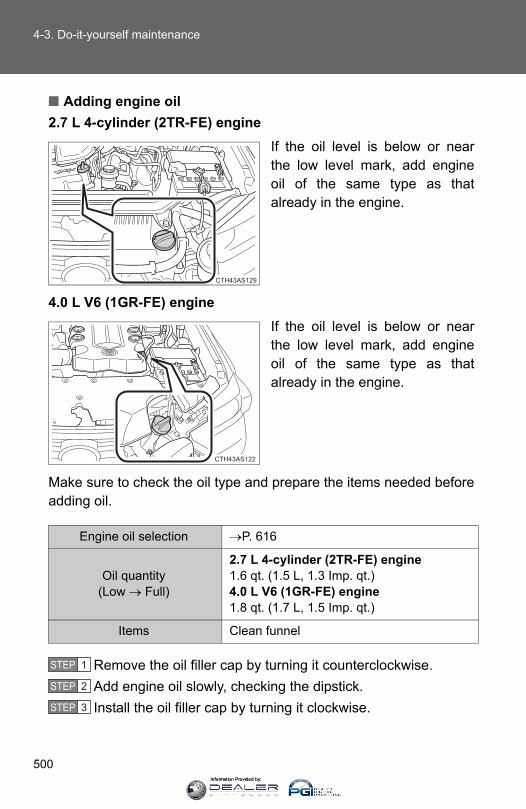
500
4-3. Do-it-yourself maintenance
■ Adding engine oil2.7 L 4-cylinder (2TR-FE) engine
If the oil level is below or nearthe low level mark, add engineoil of the same type as thatalready in the engine.
4.0 L V6 (1GR-FE) engineIf the oil level is below or nearthe low level mark, add engineoil of the same type as thatalready in the engine.
Make sure to check the oil type and prepare the items needed beforeadding oil.
Remove the oil filler cap by turning it counterclockwise.Add engine oil slowly, checking the dipstick.Install the oil filler cap by turning it clockwise.
CTH43AS129
CTH43AS122
Engine oil selection →P. 616
Oil quantity(Low → Full)
2.7 L 4-cylinder (2TR-FE) engine1.6 qt. (1.5 L, 1.3 Imp. qt.)4.0 L V6 (1GR-FE) engine1.8 qt. (1.7 L, 1.5 Imp. qt.)
Items Clean funnel
STEP 1
STEP 2
STEP 3
Information Provided by:

501
4-3. Do-it-yourself maintenance
4
Maintenance and care
■Engine oil consumption●The amount of engine oil consumed depends on the oil viscosity, the
quality of the oil and the way the vehicle is driven.
●More oil is consumed under driving conditions such as high speeds andfrequent acceleration and deceleration.
●A new engine consumes more oil.
●When judging the amount of oil consumption, keep in mind that the oilmay have become diluted, making it difficult to judge the true level accu-rately.
●Oil consumption: Max. 1.1 qt./600 miles (0.9 Imp. qt./600 miles, 1.0 L/1000 km)
● If your vehicle consumes more than 1.1 qt. (1.0 L, 0.9 Imp. qt.) every 600miles (1000 km), contact your Toyota dealer.
■After changing the engine oil (U.S.A. only)The engine oil maintenance data should be reset. Perform the following pro-cedures:
Switch the display to the trip meter A (→P. 184) when the engine isrunning.
Vehicles without a smart key systemTurn the engine switch off.
Vehicles with a smart key systemTurn the “ENGINE START STOP” switch off.
Vehicles without a smart key systemWhile pressing the trip meter reset button (→P. 184), turn theengine switch to the “ON” position (do not start the engine becausereset mode will be canceled). Continue to press and hold the buttonuntil the trip meter displays “000000”.
Vehicles with a smart key systemWhile pressing the trip meter reset button (→P. 184), turn the“ENGINE START STOP” switch to the IGNITION ON mode (do notstart the engine because otherwise the reset mode will be can-celed). Continue to press and hold the button until the trip meterdisplays “000000”.
STEP 1
STEP 2
STEP 3
Information Provided by:
502
4-3. Do-it-yourself maintenance
CAUTION
■Used engine oil●Used engine oil contains potentially harmful contaminants which may
cause skin disorders such as inflammation and skin cancer, so careshould be taken to avoid prolonged and repeated contact. To remove usedengine oil from your skin, wash thoroughly with soap and water.
●Dispose of used oil and filters only in a safe and acceptable manner. Donot dispose of used oil and filters in household trash, in sewers or onto theground. Call your Toyota dealer, service station or auto parts store forinformation concerning recycling or disposal.
●Do not leave used engine oil within the reach of children.
NOTICE
■To prevent serious engine damageCheck the oil level on a regular basis.
■When replacing the engine oil●Be careful not to spill engine oil on the vehicle components.
●Avoid overfilling, or the engine could be damaged.
●Check the oil level on the dipstick every time you refill the vehicle.
●Be sure the engine oil filler cap is properly tightened.
Information Provided by:
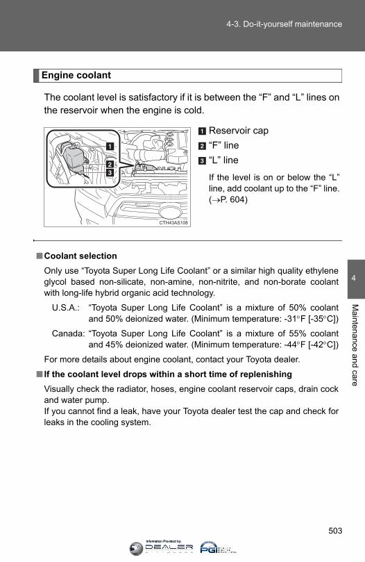
503
4-3. Do-it-yourself maintenance
4
Maintenance and care
Engine coolant
The coolant level is satisfactory if it is between the “F” and “L” lines onthe reservoir when the engine is cold.
Reservoir cap“F” line“L” line
If the level is on or below the “L”line, add coolant up to the “F” line.(→P. 604)
CTH43AS108
■Coolant selectionOnly use “Toyota Super Long Life Coolant” or a similar high quality ethyleneglycol based non-silicate, non-amine, non-nitrite, and non-borate coolantwith long-life hybrid organic acid technology.
U.S.A.: “Toyota Super Long Life Coolant” is a mixture of 50% coolantand 50% deionized water. (Minimum temperature: -31°F [-35°C])
Canada: “Toyota Super Long Life Coolant” is a mixture of 55% coolantand 45% deionized water. (Minimum temperature: -44°F [-42°C])
For more details about engine coolant, contact your Toyota dealer.
■ If the coolant level drops within a short time of replenishingVisually check the radiator, hoses, engine coolant reservoir caps, drain cockand water pump. If you cannot find a leak, have your Toyota dealer test the cap and check forleaks in the cooling system.
Information Provided by:
504
4-3. Do-it-yourself maintenance
Radiator and condenser
Check the radiator and condenser and clear away any foreignobjects. If either of the above parts is extremely dirty or you are not sure oftheir condition, have your vehicle inspected by your Toyota dealer.
CAUTION
■When the engine is hotDo not remove the engine coolant reservoir cap.The cooling system may be under pressure and may spray hot coolant if thecap is removed, causing burns or other injuries.
NOTICE
■When adding coolantCoolant is neither plain water nor straight antifreeze. The correct mixture ofwater and antifreeze must be used to provide proper lubrication, corrosionprotection and cooling. Be sure to read the antifreeze or coolant label.
■ If you spill coolantBe sure to wash it off with water to prevent it from damaging parts or paint.
CAUTION
■When the engine is hotDo not touch the radiator or condenser as they may be hot and cause burns.
Information Provided by:
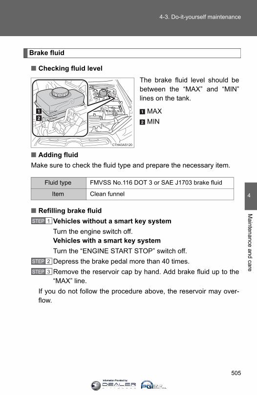
505
4-3. Do-it-yourself maintenance
4
Maintenance and care
Brake fluid
■ Checking fluid levelThe brake fluid level should bebetween the “MAX” and “MIN”lines on the tank.
MAXMIN
■ Adding fluidMake sure to check the fluid type and prepare the necessary item.
■ Refilling brake fluidVehicles without a smart key systemTurn the engine switch off.Vehicles with a smart key systemTurn the “ENGINE START STOP” switch off. Depress the brake pedal more than 40 times.Remove the reservoir cap by hand. Add brake fluid up to the“MAX” line.
If you do not follow the procedure above, the reservoir may over-flow.
CTH43AS120
Fluid type FMVSS No.116 DOT 3 or SAE J1703 brake fluid
Item Clean funnel
STEP 1
STEP 2
STEP 3
Information Provided by:

506
4-3. Do-it-yourself maintenance
■Brake fluid can absorb moisture from the airExcess moisture in the brake fluid can cause a dangerous loss of brakingefficiency. Use only newly opened brake fluid.
CAUTION
■When filling the reservoirTake care as brake fluid can harm your hands and eyes and damage paintedsurfaces.If fluid gets on your hands or in your eyes, flush the affected area with cleanwater immediately.
If you still experience discomfort, see a doctor.
NOTICE
■ If the fluid level is low or highIt is normal for the brake fluid level to go down slightly as the brake padswear out or when the fluid level in the accumulator is high.If the reservoir needs frequent refilling, there may be a serious problem.
Information Provided by:
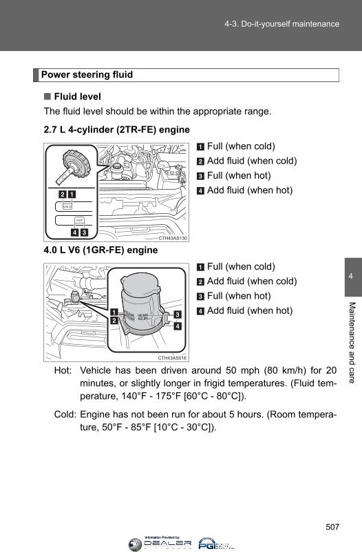
507
4-3. Do-it-yourself maintenance
4
Maintenance and care
Power steering fluid
■ Fluid levelThe fluid level should be within the appropriate range.
2.7 L 4-cylinder (2TR-FE) engineFull (when cold)Add fluid (when cold)Full (when hot)Add fluid (when hot)
4.0 L V6 (1GR-FE) engineFull (when cold)Add fluid (when cold)Full (when hot)Add fluid (when hot)
Hot: Vehicle has been driven around 50 mph (80 km/h) for 20minutes, or slightly longer in frigid temperatures. (Fluid tem-perature, 140°F - 175°F [60°C - 80°C]).
Cold: Engine has not been run for about 5 hours. (Room tempera-ture, 50°F - 85°F [10°C - 30°C]).
CTH43AS130
CTH43AS016
Information Provided by:
508
4-3. Do-it-yourself maintenance
■ Checking the fluid levelMake sure to check the fluid type and prepare the necessary items.
Clean all dirt off the reservoir.Remove the cap by turning it counterclockwise.Wipe the dipstick clean.Reinstall the cap and remove it again.Check the fluid level.
Fluid type Automatic transmission fluid DEXRON® II or III
Items Rag or paper, clean funnel (only for adding fluid)
CAUTION
■When checking the reservoirTake care as the reservoir may be hot.
NOTICE
■When adding fluidAvoid overfilling, or the power steering may be damaged.
■After replacing the reservoir capCheck the steering box case, vane pump and hose connections for leaks ordamage.
STEP 1
STEP 2
STEP 3
STEP 4
STEP 5
Information Provided by:

509
4-3. Do-it-yourself maintenance
4
Maintenance and care
Battery
Check the battery as follows:
Make sure that the battery terminals are not corroded and that thereare no loose connections, cracks, or loose clamps.
TerminalsHold-down clamp
CTH43AS118
■Before rechargingWhen recharging, the battery produces hydrogen gas which is flammableand explosive. Therefore, observe the following before recharging:
● If recharging with the battery installed on the vehicle, be sure to discon-nect the ground cable.
●Make sure the power switch on the charger is off when connecting anddisconnecting the charger cables to the battery.
Information Provided by:
510
4-3. Do-it-yourself maintenance
■After recharging/reconnecting the battery (vehicles with smart key sys-tem)●Unlocking the doors using the smart key system may not be possible
immediately after reconnecting the battery. If this happens, use the wire-less remote control or the mechanical key to lock/unlock the doors.
●Start the engine with the “ENGINE START STOP” switch in ACCES-SORY mode. The engine may not start with the “ENGINE START STOP”switch turned OFF. However, the engine will operate normally from thesecond attempt.
●The “ENGINE START STOP” switch mode is recorded by the vehicle. Ifthe battery is reconnected, the vehicle will return the “ENGINE STARTSTOP” switch mode to the status it was in before the battery was discon-nected. Make sure to turn off the engine before disconnect the battery.Take extra care when connecting the battery if the “ENGINE STARTSTOP” switch mode prior to discharge is unknown.
If the system will not start even after multiple attempts, contact your Toyotadealer.
CAUTION
■Chemicals in the batteryBatteries contain poisonous and corrosive sulfuric acid and may producehydrogen gas which is flammable and explosive. To reduce the risk of deathor serious injury, take the following precautions while working on or near thebattery:
●Do not cause sparks by touching the battery terminals with tools.
●Do not smoke or light a match near the battery.
●Avoid contact with eyes, skin and clothes.
●Never inhale or swallow electrolyte.
●Wear protective safety glasses when working near the battery.
●Keep children away from the battery.
Information Provided by:
511
4-3. Do-it-yourself maintenance
4
Maintenance and care
CAUTION
■Where to safely charge the batteryAlways charge the battery in an open area. Do not charge the battery in agarage or closed room where there is insufficient ventilation.
■How to recharge the batteryOnly perform a slow charge (5 A or less). The battery may explode ifcharged at a quicker rate.
■Emergency measures regarding electrolyte● If electrolyte gets in your eyes
Flush your eyes with clean water for at least 15 minutes and get immedi-ate medical attention. If possible, continue to apply water with a sponge orcloth while traveling to the nearest medical facility.
● If electrolyte gets on your skinWash the affected area thoroughly. If you feel pain or burning, get medicalattention immediately.
● If electrolyte gets on your clothesIt can soak through clothing on to your skin. Immediately take off the cloth-ing and follow the procedure above if necessary.
● If you accidentally swallow electrolyteDrink a large quantity of water or milk. Get emergency medical attentionimmediately.
NOTICE
■When recharging the batteryNever recharge the battery while the engine is running. Also, be sure allaccessories are turned off.
Information Provided by:
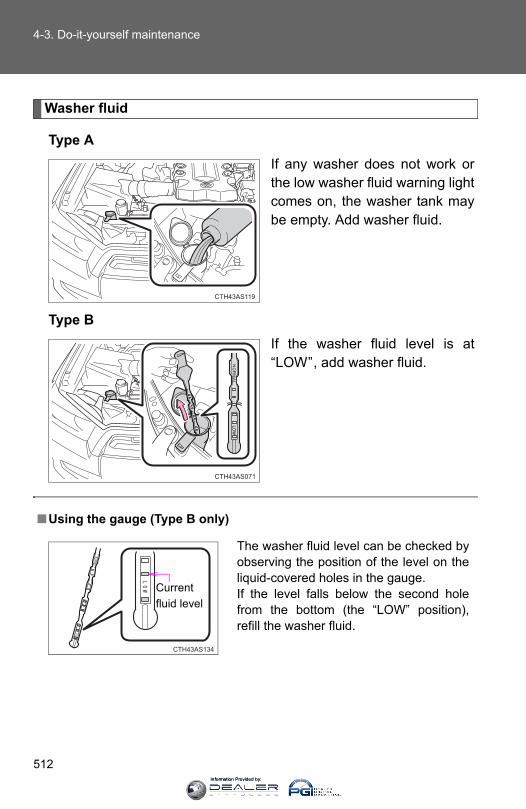
512
4-3. Do-it-yourself maintenance
Washer fluid
Type AIf any washer does not work orthe low washer fluid warning lightcomes on, the washer tank maybe empty. Add washer fluid.
Type BIf the washer fluid level is at“LOW”, add washer fluid.
CTH43AS119
CTH43AS071
■Using the gauge (Type B only)
The washer fluid level can be checked byobserving the position of the level on theliquid-covered holes in the gauge. If the level falls below the second holefrom the bottom (the “LOW” position),refill the washer fluid.
CTH43AS134
Currentfluid level
Information Provided by:
513
4-3. Do-it-yourself maintenance
4
Maintenance and care
CAUTION
■When adding washer fluidDo not add washer fluid when the engine is hot or running as washer fluidcontains alcohol and may catch fire if spilled on the engine etc.
NOTICE
■Do not use any fluid other than washer fluid Do not use soapy water or engine antifreeze instead of washer fluid.Doing so may cause streaking on the vehicle’s painted surfaces.
■Diluting washer fluidDilute washer fluid with water as necessary. Refer to the freezing temperatures listed on the washer fluid tank.
Information Provided by:
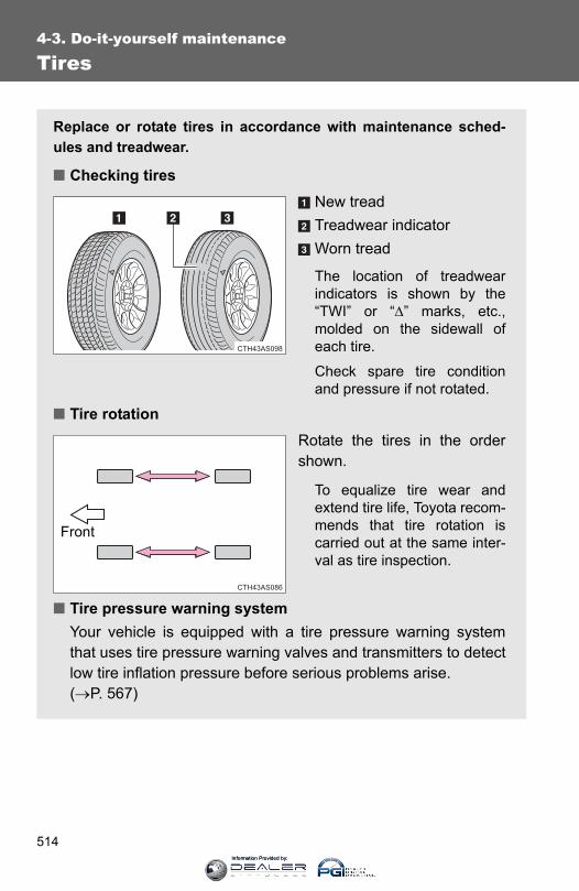
514
4-3. Do-it-yourself maintenance
Tires
Replace or rotate tires in accordance with maintenance sched-ules and treadwear.
■ Checking tiresNew treadTreadwear indicatorWorn tread
The location of treadwearindicators is shown by the“TWI” or “Δ” marks, etc.,molded on the sidewall ofeach tire.
Check spare tire conditionand pressure if not rotated.
■ Tire rotationRotate the tires in the ordershown.
To equalize tire wear andextend tire life, Toyota recom-mends that tire rotation iscarried out at the same inter-val as tire inspection.
■ Tire pressure warning systemYour vehicle is equipped with a tire pressure warning systemthat uses tire pressure warning valves and transmitters to detectlow tire inflation pressure before serious problems arise. (→P. 567)
Front
Information Provided by:
515
4-3. Do-it-yourself maintenance
4
Maintenance and care
Installing tire pressure warning valves and transmitters
When replacing tires or wheels, tire pressure warning valves andtransmitters must also be installed.
When new tire pressure warning valves and transmitters areinstalled, new tire pressure warning valve and transmitter ID codesmust be registered in the tire pressure warning computer and the tirepressure warning system must be initialized. Have tire pressurewarning valve and transmitter ID codes registered by your Toyotadealer. (→P. 515)
Registering ID codes
The tire pressure warning valve and transmitter is equipped with aunique ID code. When replacing a tire pressure warning valve andtransmitter, it is necessary to register the ID code of tire pressurewarning valve and transmitter. Have the ID code registered by yourToyota dealer.
Information Provided by:
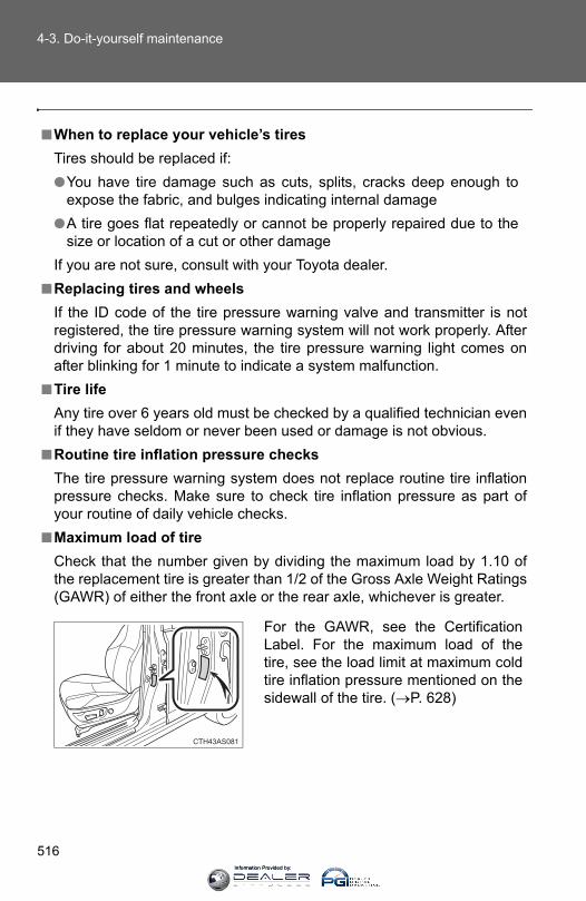
516
4-3. Do-it-yourself maintenance
■When to replace your vehicle’s tiresTires should be replaced if:●You have tire damage such as cuts, splits, cracks deep enough to
expose the fabric, and bulges indicating internal damage●A tire goes flat repeatedly or cannot be properly repaired due to the
size or location of a cut or other damageIf you are not sure, consult with your Toyota dealer.
■Replacing tires and wheelsIf the ID code of the tire pressure warning valve and transmitter is notregistered, the tire pressure warning system will not work properly. Afterdriving for about 20 minutes, the tire pressure warning light comes onafter blinking for 1 minute to indicate a system malfunction.
■Tire lifeAny tire over 6 years old must be checked by a qualified technician evenif they have seldom or never been used or damage is not obvious.
■Routine tire inflation pressure checksThe tire pressure warning system does not replace routine tire inflationpressure checks. Make sure to check tire inflation pressure as part ofyour routine of daily vehicle checks.
■Maximum load of tireCheck that the number given by dividing the maximum load by 1.10 ofthe replacement tire is greater than 1/2 of the Gross Axle Weight Ratings(GAWR) of either the front axle or the rear axle, whichever is greater.
For the GAWR, see the CertificationLabel. For the maximum load of thetire, see the load limit at maximum coldtire inflation pressure mentioned on thesidewall of the tire. (→P. 628)
CTH43AS081
Information Provided by:

517
4-3. Do-it-yourself maintenance
4
Maintenance and care
■Tire types●Summer tires
Summer tires are high-speed performance tires best suited to highwaydriving under dry conditions. Since summer tires do not have the sametraction performance as snow tires, summer tires are inadequate fordriving on snow-covered or icy roads. For driving on snow-coveredroads or icy roads, the use of snow tires is recommended. Wheninstalling snow tires, be sure to replace all four tires.
●All season tiresAll season tires are designed to provide better traction in snow and tobe adequate for driving in most winter conditions as well as for useyear-round. All season tires, however, do not have adequate tractionperformance compared with snow tires in heavy or loose snow. Also,all season tires fall short in acceleration and handling performancecompared with summer tires in highway driving.
●Snow tiresFor driving on snow-covered roads or icy roads, we recommend usingsnow tires. If you need snow tires, select tires of the same size, con-struction and load capacity as the originally installed tires. Since yourvehicle has radial tires as original equipment, make sure your snowtires also have radial construction. Do not install studded tires withoutfirst checking local regulations for possible restrictions. Snow tiresshould be installed on all wheels. (→P. 275)
■ If the tread on snow tires wears down below 0.16 in. (4 mm)The effectiveness of the tires as snow tires is lost.
Information Provided by:
518
4-3. Do-it-yourself maintenance
■Tire pressure warning system certificationFCC ID: PAXPMV107JFCC ID: HYQ13BCXFor vehicles sold in the U.S.A.This device complies with part 15 of the FCC Rules. Operation is subjectto the following two conditions: (1) This device may not cause harmfulinterference, and (2) this device must accept any interference received,including interference that may cause undesired operation.FCC WARNING: Changes or modifications not expressly approved by the party responsi-ble for compliance could void the user's authority to operate the equip-ment. For vehicles sold in CanadaOperation is subject to the following two conditions: (1) this device maynot cause interference, and (2) this device must accept any interference,including interference that may cause undesired operation of the device.
CAUTION
■When inspecting or replacing tiresObserve the following precautions to prevent accidents. Failure to do somay cause damage to parts of the drive train as well as dangerous han-dling characteristics, which may lead to an accident resulting in death orserious injury.●Do not mix tires of different makes, models or tread patterns. Also, do
not mix tires of remarkably different treadwear.●Do not use tire sizes other than those recommended by Toyota.●Do not mix differently constructed tires (radial, bias-belted or bias-ply
tires.)●Do not mix summer, all season and snow tires.
Information Provided by:

519
4-3. Do-it-yourself maintenance
4
Maintenance and care
NOTICE
■Repairing or replacing tires, wheels, tire pressure warning valves,transmitters and tire valve caps●When removing or fitting the wheels, tires or the tire pressure warning
valves and transmitters, contact your Toyota dealer as the tire pres-sure warning valves and transmitter may be damaged if not handledcorrectly.
●When replacing tire valve caps, do not use tire valve caps other thanthose specified. The cap may become stuck.
■To avoid damaging the tire pressure warning valves and transmit-tersDo not use liquid sealants on flat tires.
■Driving on rough roadsTake particular care when driving on roads with loose surfaces or pot-holes. These conditions may cause losses in tire inflation pressure,reducing the cushioning ability of the tires. In addition, driving on roughroads may cause damage to the tires themselves, as well as the vehi-cle’s wheels and body.
■ If tire inflation pressures of each tire becomes low while drivingDo not continue driving, or your tires and/or wheels may be ruined.
Information Provided by:
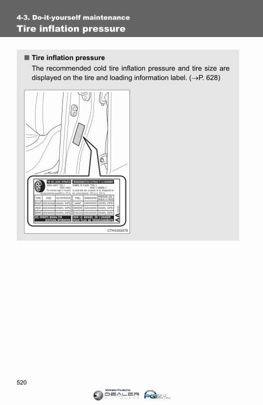
520
4-3. Do-it-yourself maintenance
Tire inflation pressure
■ Tire inflation pressureThe recommended cold tire inflation pressure and tire size aredisplayed on the tire and loading information label. (→P. 628)
CTH43AS078
Information Provided by:

521
4-3. Do-it-yourself maintenance
4
Maintenance and care
■Tire inflation pressure check intervalYou should check tire inflation pressure every two weeks, or at leastonce a month.Do not forget to check the spare.
■ Inspection and adjustment procedureTire valveTire pressure gauge
Remove the tire valve cap.Press the tip of the tire pressure gauge onto the tire valve.Read the pressure using the gauge gradations.If the tire inflation pressure is not at the recommendedlevel, adjust the pressure.If you add too much air, press the center of the valve todeflate.After completing the tire inflation pressure measurementand adjustment, apply soapy water to the valve and checkfor leakage.Put the tire valve cap back on.
STEP 1
STEP 2
STEP 3
STEP 4
STEP 5
STEP 6
Information Provided by:

522
4-3. Do-it-yourself maintenance
■Effects of incorrect tire inflation pressureDriving with incorrect tire inflation pressure may result in the following:●Reduced fuel efficiency●Reduced driving comfort and tire life●Reduced safety●Damage to the drive trainIf a tire needs frequent inflating, have it checked by your Toyota dealer.
■ Instructions for checking tire inflation pressureWhen checking tire inflation pressure, observe the following:●Check only when the tires are cold.
If your vehicle has been parked for at least 3 hours or has not beendriven for more than 1 mile or 1.5 km, you will get an accurate coldtire inflation pressure reading.
●Always use a tire pressure gauge.The appearance of the tire can be misleading. In addition, tire infla-tion pressure that is even just a few pounds off can affect ride qualityand handling.
●Do not reduce tire inflation pressure after driving. It is normal for tireinflation pressure to be higher after driving.
●Never exceed the vehicle capacity weight.Passengers and luggage weight should be placed so that the vehicleis balanced.
Information Provided by:
523
4-3. Do-it-yourself maintenance
4
Maintenance and care
CAUTION
■Proper inflation is critical to save tire performanceKeep your tires properly inflated. Otherwise, the following conditionsmay occur and result in an accident causing death or serious injury:●Excessive wear●Uneven wear●Poor handling●Possibility of blowouts resulting from overheated tires●Poor sealing of the tire bead●Wheel deformation and/or tire separation●A greater possibility of tire damage from road hazards
NOTICE
■When inspecting and adjusting tire inflation pressureBe sure to put the tire valve caps back on.Without the valve caps, dirt or moisture could get into the valve andcause air leakage, which could result in an accident. If the caps are lost,replace them as soon as possible.
Information Provided by:
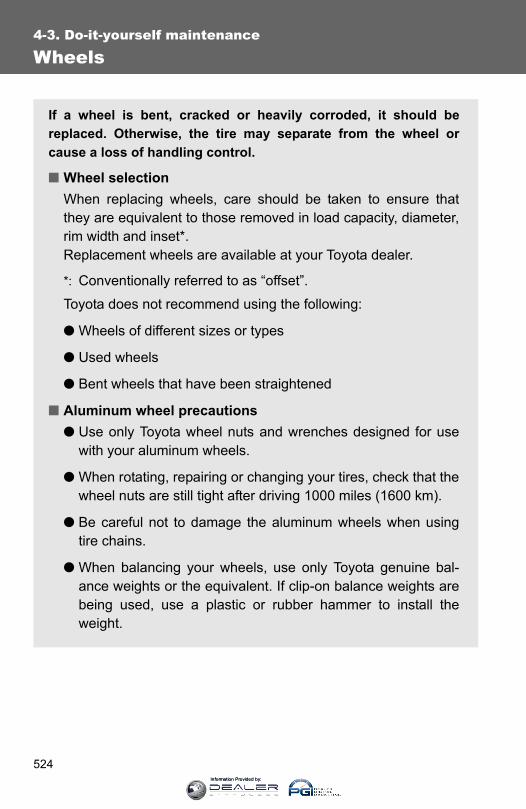
524
4-3. Do-it-yourself maintenance
Wheels
If a wheel is bent, cracked or heavily corroded, it should bereplaced. Otherwise, the tire may separate from the wheel orcause a loss of handling control.
■ Wheel selectionWhen replacing wheels, care should be taken to ensure thatthey are equivalent to those removed in load capacity, diameter,rim width and inset*.Replacement wheels are available at your Toyota dealer.
*: Conventionally referred to as “offset”.
Toyota does not recommend using the following:
● Wheels of different sizes or types
● Used wheels
● Bent wheels that have been straightened
■ Aluminum wheel precautions● Use only Toyota wheel nuts and wrenches designed for use
with your aluminum wheels.
● When rotating, repairing or changing your tires, check that thewheel nuts are still tight after driving 1000 miles (1600 km).
● Be careful not to damage the aluminum wheels when usingtire chains.
● When balancing your wheels, use only Toyota genuine bal-ance weights or the equivalent. If clip-on balance weights arebeing used, use a plastic or rubber hammer to install theweight.
Information Provided by:
525
4-3. Do-it-yourself maintenance
4
Maintenance and care
■When replacing wheelsThe wheels of your vehicle are equipped with tire pressure warning valvesand transmitters that allow the tire pressure warning system to provideadvanced warning in the event of a loss in tire inflation pressure. Wheneverwheels are replaced, the tire pressure warning valves and transmitters mustbe installed. (→P. 515)
CAUTION
■When replacing wheels●Do not use wheels that are a different size from those recommended in the
Owner’s Manual, as this may result in a loss of handling control.
●Never use an inner tube in a leaking wheel which is designed for a tube-less tire. Doing so may result in an accident, causing death or seriousinjury.
NOTICE
■Replacing tire pressure warning valves and transmitters●Because tire repair or replacement may affect the tire pressure warning
valves and transmitters, make sure to have tires serviced by your Toyotadealer or other qualified service shop. In addition, make sure to purchaseyour tire pressure warning valves and transmitters at your Toyota dealer.
●Ensure that only genuine Toyota wheels are used on your vehicle.Tire pressure warning valves and transmitters may not work properly withnon-genuine wheels.
Information Provided by:

526
4-3. Do-it-yourself maintenance
Air conditioning filter
The air conditioning filter must be cleaned or changed regularly tomaintain air conditioning efficiency.
■ Removal methodTurn the engine switch (vehicles without a smart key sys-tem) or “ENGINE START STOP” switch (vehicles with asmart key system) off.
Open the glove box andremove the cover.
Remove the filter cover.
Remove the filter.
The “↑UP” marks shown onthe filter should be pointing up.
STEP 1
CTH43AS089
STEP 2
CTH43AS024
STEP 3
CTH43AS025
STEP 4
Information Provided by:

527
4-3. Do-it-yourself maintenance
4
Maintenance and care
■Checking intervalInspect, clean and replace the air conditioning filter according to the mainte-nance schedule. In dusty areas or areas with heavy traffic flow, more fre-quent cleaning or early replacement may be required. (For scheduledmaintenance information, please refer to the “Scheduled MaintenanceGuide” or “Owner’s Manual Supplement”.)
■ If air flow from the vents decreases dramaticallyThe filter may be clogged. Check the filter and replace if necessary.
NOTICE
■To prevent damage to the system●When using the air conditioning system, make sure that a filter is always
installed.
●When cleaning the filter, do not clean with water.
■ Cleaning methodIf the filter is dirty, clean byblowing compressed airthrough the filter from theunderside.
Hold the air gun 2 in. (5 cm)from the filter and blow forapproximately 2 minutes at 72psi (500 kPa, 5.0 kgf/cm2 orbar).
If an air gun is not available,have the filter cleaned by yourToyota dealer.
CTH43AS026
Information Provided by:

528
4-3. Do-it-yourself maintenance
Wireless remote control/electronic key battery
Replace the battery with a new one if it is depleted.
■ You will need the following items:● Flathead screwdriver
● Lithium battery CR2016 (vehicles without a smart key sys-tem), or CR1632 (vehicles with a smart key system)
■ Replacing the battery (vehicles without a smart key system)Remove the cover.
To prevent damage to the key,cover the tip of the screwdriverwith a rag.
Remove the module.
Open the case cover using acoin protected with tape etc.and remove the depleted bat-tery.
Insert a new battery with the“+” terminal facing up.
STEP 1
STEP 2
STEP 3
Information Provided by:

529
4-3. Do-it-yourself maintenance
4
Maintenance and care
■ Replacing the battery (vehicles with a smart key system)Take out the mechanical key.
Remove the cover.
To prevent damage to the key,cover the tip of the screwdriverwith a rag.
Remove the depleted battery.
Insert a new battery with the“+” terminal facing up.
STEP 1
STEP 2
STEP 3
Information Provided by:
530
4-3. Do-it-yourself maintenance
■Use a CR2016 (vehicles without a smart key system) or CR1632 (vehi-cles with a smart key system) lithium battery●Batteries can be purchased at your Toyota dealer, local electrical appli-
ance shops or camera stores.
●Replace only with the same or equivalent type recommended by themanufacturer.
●Dispose of used batteries according to local laws.
■ If the key battery is depletedThe following symptoms may occur:
●The smart key system and wireless remote control will not function prop-erly.
●The operational range will be reduced.
CAUTION
■Removed battery and other partsKeep away from children. These parts are small and if swallowed by a child,they can cause choking. Failure to do so could result in death or seriousinjury.
NOTICE
■For normal operation after replacing the batteryObserve the following precautions to prevent accidents:
●Always work with dry hands.Moisture may cause the battery to rust.
●Do not touch or move any other component inside the remote control.
●Do not bend either of the battery terminals.
Information Provided by:

531
4-3. Do-it-yourself maintenance
4
Maintenance and care
Checking and replacing fuses
If any of the electrical components do not operate, a fuse may haveblown. If this happens, check and replace the fuses as necessary.
Vehicles without a smart key systemTurn the engine switch off.Vehicles with a smart key systemTurn the “ENGINE START STOP” switch off. Open the fuse box cover.
Engine compartmentPush the tab in and lift the lidoff.
Driver’s side instrument panel Remove the lid.
STEP 1
STEP 2
CTH43AS123
CTH43AS028
Information Provided by:
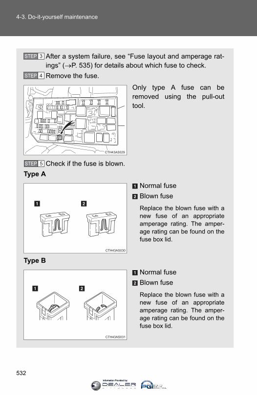
532
4-3. Do-it-yourself maintenance
After a system failure, see “Fuse layout and amperage rat-ings” (→P. 535) for details about which fuse to check.Remove the fuse.
Only type A fuse can beremoved using the pull-outtool.
Check if the fuse is blown.Type A
Normal fuseBlown fuse
Replace the blown fuse with anew fuse of an appropriateamperage rating. The amper-age rating can be found on thefuse box lid.
Type BNormal fuseBlown fuse
Replace the blown fuse with anew fuse of an appropriateamperage rating. The amper-age rating can be found on thefuse box lid.
STEP 3
STEP 4
CTH43AS029
STEP 5
CTH43AS030
CTH43AS031
Information Provided by:

533
4-3. Do-it-yourself maintenance
4
Maintenance and care
Type CNormal fuseBlown fuse
Replace the blown fuse with anew fuse of an appropriateamperage rating. The amper-age rating can be found on thefuse box lid.
Type DNormal fuseBlown fuse
Replace the blown fuse with anew fuse of an appropriateamperage rating. The amper-age rating can be found on thefuse box lid.
Type ENormal fuseBlown fuse
Replace the blown fuse with anew fuse of an appropriateamperage rating. The amper-age rating can be found on thefuse box lid.
CTH43AS073
CTH43AS074
CTH43AS075
Information Provided by:

534
4-3. Do-it-yourself maintenance
Type FNormal fuseBlown fuse
Contact your Toyota dealer.
CTH43AS076
Information Provided by:
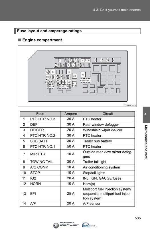
535
4-3. Do-it-yourself maintenance
4
Maintenance and care
Fuse layout and amperage ratings
■ Engine compartment
Fuse Ampere Circuit1 PTC HTR NO.3 30 A PTC heater2 DEF 30 A Rear window defogger3 DEICER 20 A Windshield wiper de-icer4 PTC HTR NO.2 30 A PTC heater5 SUB BATT 30 A Trailer sub battery6 PTC HTR NO.1 50 A PTC heater
7 MIR HTR 10 A Outside rear view mirror defog-gers
8 TOWING TAIL 30 A Trailer tail light9 A/C COMP 10 A Air conditioning system
10 STOP 10 A Stop/tail lights11 IG2 20 A INJ, IGN, GAUGE fuses12 HORN 10 A Horn(s)
13 EFI 25 AMultiport fuel injection system/sequential multiport fuel injec-tion system
14 A/F 20 A A/F sensor
CTH43AS079
Information Provided by:

536
4-3. Do-it-yourself maintenance
15 H-LP RH-HI 10 A Right-hand headlight (high beam)
16 H-LP LH-HI 10 A Left-hand headlight (high beam)
17 HTR 50 A Air conditioning system18 400W INV 80 A Power outlets19 ST 30 A Starter system20 H-LP HI 20 A H-LP RH-HI, H-LP LH-HI fuses21 ALT-S 7.5 A Charging system
22 TURN&HAZ 15 A Turn signal lights, emergency flashers
23 ETCS 10 AMultiport fuel injection system/sequential multiport fuel injec-tion system
24 TOWING 30 A Trailer stop/turn lights25 SHORT PIN ⎯ No circuit26 RAD NO.1 10 A Audio system27 AM2 7.5 A Starter system28 MAYDAY 7.5 A Safety connect 29 AMP 30 A Audio system30 ABS NO.1 50 A ABS, VSC31 ABS NO.2 30 A ABS, VSC
32 AIR PMP 50 AMultiport fuel injection system/sequential multiport fuel injec-tion system
33 DOME 10 A Interior lights, vanity lights
34 ECU-B 10 A Multiplex communication sys-tem, meter and gauge
35 H-LP RH-LO 10 A Right-hand headlight (low beam)
36 H-LP LH-LO 10 A Left-hand headlight (low beam)
37 INJ 10 AMultiport fuel injection system/sequential multiport fuel injec-tion system
Fuse Ampere Circuit
Information Provided by:

537
4-3. Do-it-yourself maintenance
4
Maintenance and care
*: Replace the fuse with one of the same ampere rating as the origi-nal
38 EFI NO.2 7.5 AMultiport fuel injection system/sequential multiport fuel injec-tion system
39 ALT
120 A*
HTR, 400W INV, A/C COMP, TOWING TAIL, SUB BATT, MIR HTR, DEF, DEICER, STOP, PTC HTR NO.1, PTC HTR NO.2, PTC HTR NO.3, S/HTR FR, ACC, P/OUTLET, IG1, ECU-IG NO.1, ECU-IG NO.2, WIP, WASHER, KDSS, 4WD, BKUP LP, TOWING BKUP, DOOR P, DOOR RL, DOOR RR, DOOR D, P/SEAT FL, P/SEAT FR, DOOR, A/C, OBD, DOOR BACK, S/ROOF, PANEL, TAIL, FOG FR, D/L NO.2 fuses
140 A*
40 SPARE 10 A ⎯
41 SPARE 15 A ⎯
42 SPARE 20 A ⎯
43 P/I-B 80 A IG2, EFI, A/F, HORN fuses
44 SECURITY 10 AMultiport fuel injection system/sequential multiport fuel injec-tion system
45 SMART 7.5 A Smart key system46 STRG LOCK 20 A Steering lock system47 TOWING BRK 30 A Trailer brake controller
Fuse Ampere Circuit
Information Provided by:

538
4-3. Do-it-yourself maintenance
■ Driver’s side instrument panel
Fuse Ampere Circuit1 TAIL 10 A Stop/tail lights2 PANEL 7.5 A Instrument panel lights3 GAUGE 7.5 A Meter and gauge
4 IGN 10 A
Multiport fuel injection system/sequential multiport fuel injec-tion system, air bag system, smart key system
5 WASHER 20 A Wiper and washer6 WIP 30 A Wiper and washer7 S/ROOF 25 A Electric moon roof8 DOOR RR 25 A Power windows9 DOOR D 25 A Power windows
10 DOOR BACK 30 A Multiplex communication sys-tem
11 DOOR P 30 A Power windows12 P/SEAT FR 30 A Front passenger's power seat13 S/HTR FR 20 A Seat heater system
14 ECU-IG NO.2 10 A
Air conditioning system, multi-port fuel injection system/sequential multiport fuel injec-tion system
15 IG1 7.5 A Turn signal lights, emergency flashers
16 ECU-IG NO.1 10 AVehicle stability control sys-tem, tire pressure warning sys-tem, steering sensor
17 DOOR 7.5 A Power windows
Information Provided by:
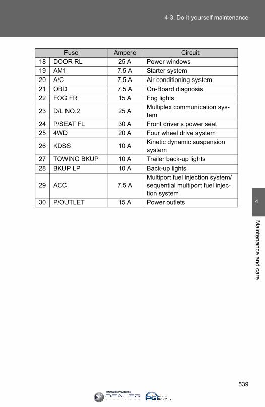
539
4-3. Do-it-yourself maintenance
4
Maintenance and care
18 DOOR RL 25 A Power windows19 AM1 7.5 A Starter system20 A/C 7.5 A Air conditioning system21 OBD 7.5 A On-Board diagnosis22 FOG FR 15 A Fog lights
23 D/L NO.2 25 A Multiplex communication sys-tem
24 P/SEAT FL 30 A Front driver’s power seat25 4WD 20 A Four wheel drive system
26 KDSS 10 A Kinetic dynamic suspension system
27 TOWING BKUP 10 A Trailer back-up lights28 BKUP LP 10 A Back-up lights
29 ACC 7.5 AMultiport fuel injection system/sequential multiport fuel injec-tion system
30 P/OUTLET 15 A Power outlets
Fuse Ampere Circuit
Information Provided by:

540
4-3. Do-it-yourself maintenance
■After a fuse is replaced● If the lights do not turn on even after the fuse has been replaced, a bulb
may need replacement. (→P. 541)
● If the replaced fuse blows again, have the vehicle inspected by yourToyota dealer.
■ If there is an overload in a circuitThe fuses are designed to blow before the entire wiring harness is damaged.
CAUTION
■To prevent system breakdowns and vehicle fireObserve the following precautions.Failure to do so may cause damage, and possibly a fire or injury.
●Never use a fuse of a higher amperage rating than that indicated, or useany other object in place of a fuse.
●Always use a genuine Toyota fuse or equivalent.Never replace a fuse with a wire, even as a temporary fix.This can cause extensive damage or even fire.
●Do not modify the fuses or fuse boxes.
NOTICE
■Before replacing fusesHave the cause of electrical overload determined and repaired by yourToyota dealer as soon as possible.
Information Provided by:
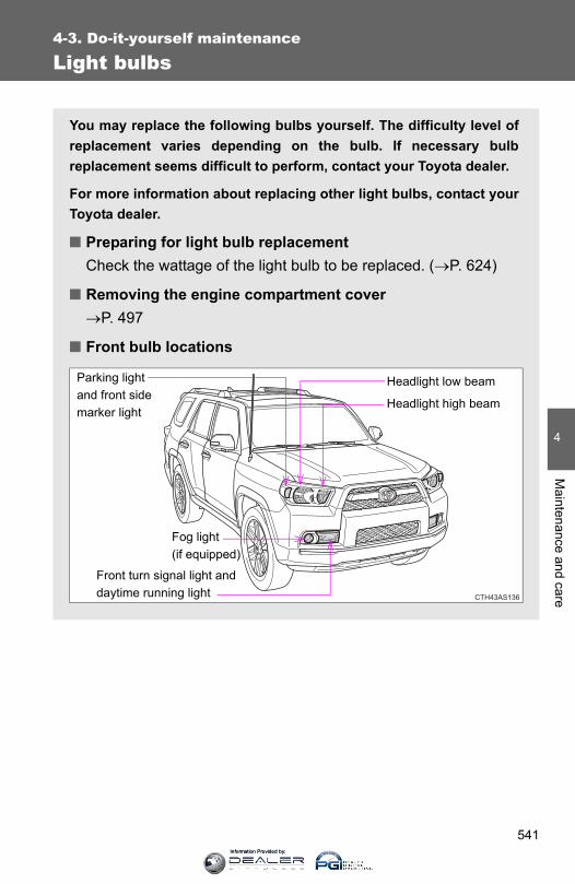
541
4-3. Do-it-yourself maintenance
4
Maintenance and care
Light bulbs
You may replace the following bulbs yourself. The difficulty level ofreplacement varies depending on the bulb. If necessary bulbreplacement seems difficult to perform, contact your Toyota dealer.
For more information about replacing other light bulbs, contact yourToyota dealer.
■ Preparing for light bulb replacementCheck the wattage of the light bulb to be replaced. (→P. 624)
■ Removing the engine compartment cover→P. 497
■ Front bulb locations
CTH43AS136
Parking light and front side marker light
Fog light(if equipped)
Headlight high beam
Headlight low beam
Front turn signal light and daytime running light
Information Provided by:
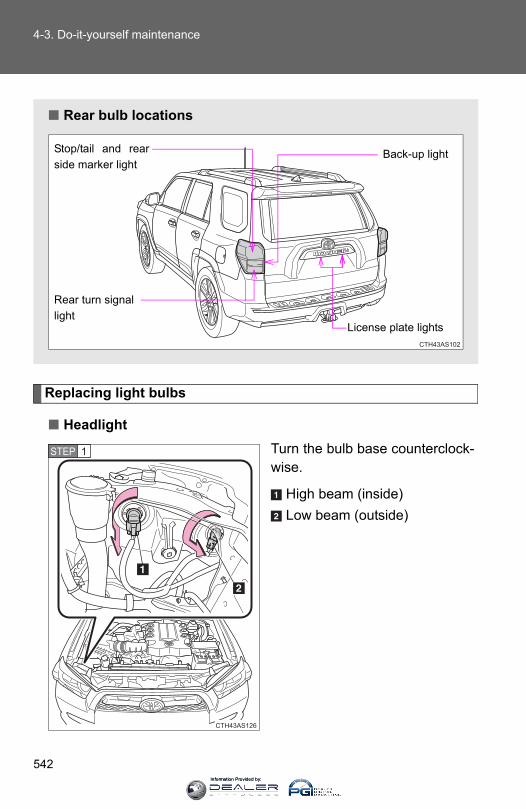
542
4-3. Do-it-yourself maintenance
Replacing light bulbs
■ HeadlightTurn the bulb base counterclock-wise.
High beam (inside)Low beam (outside)
■ Rear bulb locations
CTH43AS102
License plate lights
Rear turn signal light
Back-up light Stop/tail and rearside marker light
CTH43AS126
STEP 1
Information Provided by:
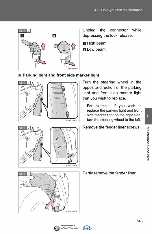
543
4-3. Do-it-yourself maintenance
4
Maintenance and care
Unplug the connector whiledepressing the lock release.
High beamLow beam
■ Parking light and front side marker lightTurn the steering wheel in theopposite direction of the parkinglight and front side marker lightthat you wish to replace.
For example, if you wish toreplace the parking light and frontside marker light on the right side,turn the steering wheel to the left.
Remove the fender liner screws.
Partly remove the fender liner.
CTH43AS091
STEP 2
CTH43AS072
STEP 1
CTH43AS092
STEP 2
CTH43AS093
STEP 3
Information Provided by:
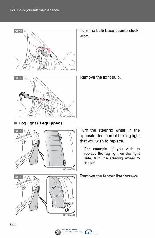
544
4-3. Do-it-yourself maintenance
Turn the bulb base counterclock-wise.
Remove the light bulb.
■ Fog light (if equipped)Turn the steering wheel in theopposite direction of the fog lightthat you wish to replace.
For example, if you wish toreplace the fog light on the rightside, turn the steering wheel tothe left.
Remove the fender liner screws.
CTH43AS114
STEP 4
CTH43AS115
STEP 5
CTH43AS072
STEP 1
CTH43AS092
STEP 2
Information Provided by:

545
4-3. Do-it-yourself maintenance
4
Maintenance and care
Partly remove the fender liner.
Unplug the connector whiledepressing the lock release.
Turn the bulb base counterclock-wise.
CTH43AS093
STEP 3
CTH43AS094
STEP 4
CTH43AS095
STEP 5
Information Provided by:

546
4-3. Do-it-yourself maintenance
■ Front turn signal light and daytime running lightTurn the steering wheel in theopposite direction of the frontturn signal light and daytime run-ning light that you wish toreplace.
For example, if you wish toreplace the front turn signal lightand daytime running light on theright side, turn the steering wheelto the left.
Remove the fender liner screws.
Partly remove the fender liner.
CTH43AS072
STEP 1
CTH43AS092
STEP 2
CTH43AS093
STEP 3
Information Provided by:

547
4-3. Do-it-yourself maintenance
4
Maintenance and care
Turn the bulb base counterclock-wise.
Remove the light bulb.
CTH43AS060
STEP 4
CTH43AS125
STEP 5
Information Provided by:
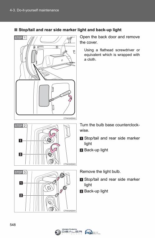
548
4-3. Do-it-yourself maintenance
■ Stop/tail and rear side marker light and back-up lightOpen the back door and removethe cover.
Using a flathead screwdriver orequivalent which is wrapped witha cloth.
Turn the bulb base counterclock-wise.
Stop/tail and rear side markerlightBack-up light
Remove the light bulb.
Stop/tail and rear side markerlightBack-up light
CTH43AS042
STEP 1
CTH43AS043
STEP 2
CTH43AS044
STEP 3
Information Provided by:
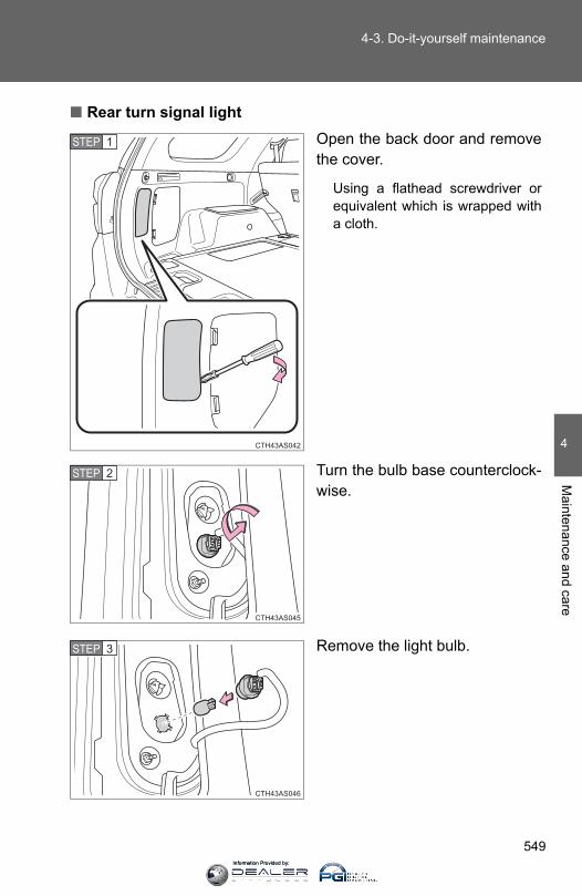
549
4-3. Do-it-yourself maintenance
4
Maintenance and care
■ Rear turn signal lightOpen the back door and removethe cover.
Using a flathead screwdriver orequivalent which is wrapped witha cloth.
Turn the bulb base counterclock-wise.
Remove the light bulb.
CTH43AS042
STEP 1
CTH43AS045
STEP 2
CTH43AS046
STEP 3
Information Provided by:

550
4-3. Do-it-yourself maintenance
■ License plate lightRemove the screws and lens.
Remove the light bulb.
■ Lights other than the aboveIf any of the lights listed below has burnt out, have your Toyotadealer replace it.
● Side turn signal lights (if equipped)
● High mounted stoplight
● Outer foot lights (if equipped)
CTH43AS103
STEP 1
CTH43AS048
STEP 2
Information Provided by:
551
4-3. Do-it-yourself maintenance
4
Maintenance and care
■LED light bulbsThe side turn signal lights and high mounted stoplight consist of a number ofLEDs. If any LEDs burn out, take your vehicle to your Toyota dealer to havethe light replaced.
■Condensation build-up on the inside of the lensContact your Toyota dealer for more information in the following situations.Temporary condensation build-up on the inside of the headlight lens doesnot indicate a malfunction.
●Large drops of water are built up on the inside of the lens.
●Water has built up inside the headlight.
CAUTION
■Replacing light bulbs●Turn off the lights. Do not attempt to replace the bulb immediately after
turning off the lights. The bulbs become very hot and may cause burns.
●Do not touch the glass portion of the light bulb with bare hands. Hold thebulb by the plastic or metal portion.If the bulb is scratched or dropped it may blow out or crack.
●Fully install light bulbs and any parts used to secure them. Failing to do somay result in heat damage, fire, or water entering the headlight unit. Thismay damage the headlights or cause condensation to build up on the lens.
■To prevent damage or fire Make sure bulbs are fully seated and locked.
Information Provided by:

552
4-3. Do-it-yourself maintenance
Information Provided by:
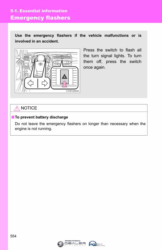
554
5-1. Essential information
Emergency flashers
NOTICE
■To prevent battery dischargeDo not leave the emergency flashers on longer than necessary when theengine is not running.
Use the emergency flashers if the vehicle malfunctions or isinvolved in an accident.
Press the switch to flash allthe turn signal lights. To turnthem off, press the switchonce again.
CTH51AS005
Information Provided by:
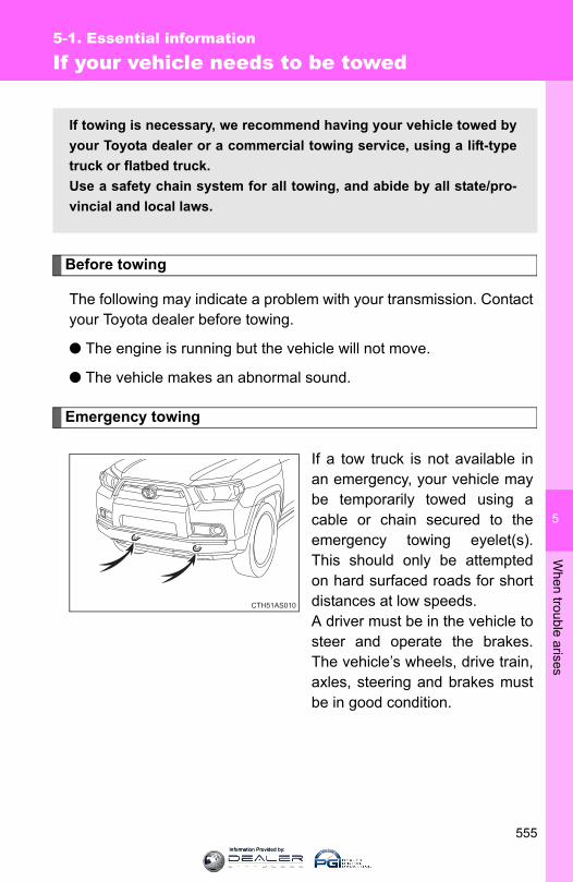
5
When trouble arises
555
5-1. Essential information
If your vehicle needs to be towed
Before towing
The following may indicate a problem with your transmission. Contactyour Toyota dealer before towing.
● The engine is running but the vehicle will not move.
● The vehicle makes an abnormal sound.
Emergency towing
If a tow truck is not available inan emergency, your vehicle maybe temporarily towed using acable or chain secured to theemergency towing eyelet(s).This should only be attemptedon hard surfaced roads for shortdistances at low speeds.A driver must be in the vehicle tosteer and operate the brakes.The vehicle’s wheels, drive train,axles, steering and brakes mustbe in good condition.
If towing is necessary, we recommend having your vehicle towed byyour Toyota dealer or a commercial towing service, using a lift-typetruck or flatbed truck.Use a safety chain system for all towing, and abide by all state/pro-vincial and local laws.
CTH51AS010
Information Provided by:
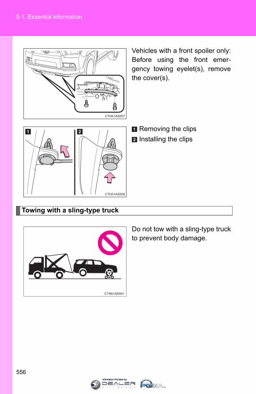
556
5-1. Essential information
Vehicles with a front spoiler only:Before using the front emer-gency towing eyelet(s), removethe cover(s).
Removing the clipsInstalling the clips
Towing with a sling-type truck
Do not tow with a sling-type truckto prevent body damage.
CTH51AS007
CTH51AS008
Information Provided by:
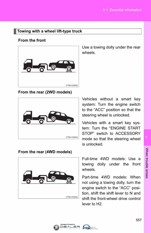
5
When trouble arises
557
5-1. Essential information
Towing with a wheel lift-type truck
From the frontUse a towing dolly under the rearwheels.
From the rear (2WD models)Vehicles without a smart keysystem: Turn the engine switchto the “ACC” position so that thesteering wheel is unlocked.
Vehicles with a smart key sys-tem: Turn the “ENGINE STARTSTOP” switch to ACCESSORYmode so that the steering wheelis unlocked.
From the rear (4WD models)Full-time 4WD models: Use atowing dolly under the frontwheels.
Part-time 4WD models: Whennot using a towing dolly, turn theengine switch to the “ACC” posi-tion, shift the shift lever to N andshift the front-wheel drive controllever to H2.
Information Provided by:
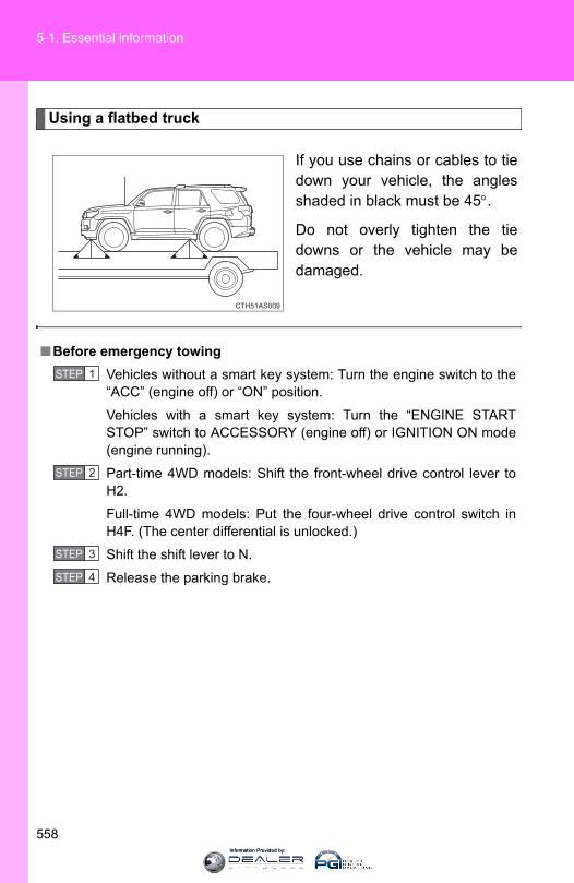
558
5-1. Essential information
Using a flatbed truck
If you use chains or cables to tiedown your vehicle, the anglesshaded in black must be 45°.
Do not overly tighten the tiedowns or the vehicle may bedamaged.
■Before emergency towingVehicles without a smart key system: Turn the engine switch to the“ACC” (engine off) or “ON” position.
Vehicles with a smart key system: Turn the “ENGINE STARTSTOP” switch to ACCESSORY (engine off) or IGNITION ON mode(engine running).
Part-time 4WD models: Shift the front-wheel drive control lever toH2.
Full-time 4WD models: Put the four-wheel drive control switch inH4F. (The center differential is unlocked.)
Shift the shift lever to N.
Release the parking brake.
STEP 1
STEP 2
STEP 3
STEP 4
Information Provided by:

5
When trouble arises
559
5-1. Essential information
CAUTION
■Caution while towing●Use extreme caution when towing the vehicle.
Avoid sudden starts or erratic driving maneuvers which place excessivestress on the emergency towing eyelets and the cables or chains. Alwaysuse caution for the surroundings and other vehicles while towing.
●Vehicles with a smart key system: Do not turn the “ENGINE STARTSTOP” switch off. Doing so will lock the steering wheel and prevent operation, possibly caus-ing an accident and resulting in death or serious injury.
● If the engine is not running, the power assist for the brakes and steeringwill not function, making steering and braking more difficult.
NOTICE
■To prevent causing serious damage to the transmission and transfer(4WD models) when towing using a wheel-lift type truck 2WD models: Never tow this vehicle from the front with the rear wheels onthe ground.4WD models: Never tow this vehicle with any of the wheels in contact withthe ground.
■To prevent damage to the vehicle when towing using a wheel-lift typetruck●2WD models without a smart key system: Do not tow the vehicle from the
rear when the engine switch is in the “LOCK” position or the key isremoved. The steering lock mechanism is not strong enough to hold thefront wheels straight.
●2WD models with a smart key system: Do not tow the vehicle from the rearwhen the “ENGINE START STOP” switch is off. The steering lock mecha-nism is not strong enough to hold the front wheels straight.
●When raising the vehicle, ensure adequate ground clearance for towing atthe opposite end of the raised vehicle. Without adequate clearance, thevehicle could be damaged while being towed.
Information Provided by:
560
5-1. Essential information
NOTICE
■To prevent body damage when towing with a sling-type truckDo not tow with a sling-type truck, either from the front or rear.
■To prevent causing serious damage to the transmission and transfer(4WD models) in emergency towingNever tow a vehicle from the rear with four wheels on the ground. This maycause serious damage to the transmission and transfer.
Information Provided by:
5
When trouble arises
561
5-1. Essential information
If you think something is wrong
If you notice any of the following symptoms, your vehicle probablyneeds adjustment or repair. Contact your Toyota dealer as soon aspossible.
■ Visible symptoms● Fluid leaks under the vehicle
(Water dripping from the air conditioning after use is normal.)
● Flat-looking tires or uneven tire wear
● Engine coolant temperature gauge needle continually pointshigher than normal
● Voltmeter (if equipped) continually points higher or lower thannormal
■ Audible symptoms● Changes in exhaust sound
● Excessive tire squeal when cornering
● Strange noises related to the suspension system
● Pinging or other noises related to the engine
■ Operational symptoms● Engine missing, stumbling or running roughly
● Appreciable loss of power
● Vehicle pulls heavily to one side when braking
● Vehicle pulls heavily to one side when driving on a level road
● Loss of brake effectiveness, spongy feeling, pedal almosttouches the floor
Information Provided by:
562
5-1. Essential information
Fuel pump shut off system
Follow the procedure below to restart the engine after the system isactivated.
Vehicles without a smart key systemTurn the engine switch to the “ACC” or “LOCK” position.Restart the engine.
Vehicles with a smart key systemTurn the “ENGINE START STOP” switch off.Restart the engine.
NOTICE
■Before starting the engineInspect the ground under the vehicle.If you find that fuel has leaked onto the ground, the fuel system has beendamaged and is in need of repair. Do not restart the engine.
To minimize the risk of fuel leakage when the engine stalls or whenan airbag inflates upon collision, the fuel pump shut off systemstops the supply of fuel to the engine.
STEP 1
STEP 2
STEP 1
STEP 2
Information Provided by:
5
When trouble arises
563
5-1. Essential information
Event data recorder
In a crash or near crash event
The SRS airbag sensor assembly contains the EDR. In a crash ornear crash event, this device may record some or all of the followinginformation:
● Gasoline engine speed
● Whether the brake pedal was depressed or not
● Vehicle speed
● To what extent the accelerator pedal was depressed
● Position of the transmission shift lever
● Whether the driver and front passenger wore seat belts or not
● Driver’s seat position
● SRS airbag deployment data
● SRS airbag system diagnostic data
● Front passenger’s occupant classification
The information above is intended to be used for the purpose ofimproving vehicle safety performance. Unlike general data recorders,the EDR does not record sound data such as conversation betweenpassengers.
Your vehicle has computers that monitor and control certain aspectsof your vehicle. These computers assist in driving and maintainingoptimal vehicle performance.
Besides storing data useful for troubleshooting, there is an eventdata recorder (EDR) that records data in a crash or near crashevent.
Information Provided by:

564
5-1. Essential information
Disclosure of the data
Toyota will not disclose the data recorded in an EDR to a third partyexcept when:
● An agreement from the vehicle’s owner (or the leasing company fora leased vehicle) is obtained
● Officially requested to by the police or other authorities
● Necessary, to be used as a defense for Toyota in a law suit
● Ordered by a court of law
However, if necessary Toyota will:
● Use the data for research on Toyota vehicle safety performance
● Disclose the data to a third party for research purposes without dis-closing details of the vehicle owner, and that only when deemednecessary
● Disclose summarized data cleared of vehicle identification informa-tion to a non-Toyota organization for research purposes
Information Provided by:
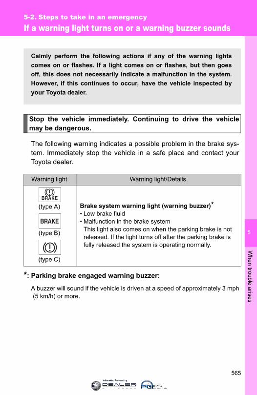
5
When trouble arises
565
5-2. Steps to take in an emergency
If a warning light turns on or a warning buzzer sounds
Stop the vehicle immediately. Continuing to drive the vehiclemay be dangerous.
The following warning indicates a possible problem in the brake sys-tem. Immediately stop the vehicle in a safe place and contact yourToyota dealer.
*: Parking brake engaged warning buzzer:
A buzzer will sound if the vehicle is driven at a speed of approximately 3 mph(5 km/h) or more.
Warning light Warning light/Details
(type A)
(type B)
(type C)
Brake system warning light (warning buzzer)*• Low brake fluid• Malfunction in the brake system
This light also comes on when the parking brake is not released. If the light turns off after the parking brake is fully released the system is operating normally.
Calmly perform the following actions if any of the warning lightscomes on or flashes. If a light comes on or flashes, but then goesoff, this does not necessarily indicate a malfunction in the system.However, if this continues to occur, have the vehicle inspected byyour Toyota dealer.
Information Provided by:

566
5-2. Steps to take in an emergency
Stop the vehicle immediately.
The following warnings indicate the possibility of damage to the vehi-cle that may lead to an accident. Immediately stop the vehicle in asafe place and contact your Toyota dealer.
Have the vehicle inspected by your Toyota dealer immediately.
Failure to investigate the cause of the following warnings may lead tothe system operating abnormally and possibly cause an accident.Have the vehicle inspected by your Toyota dealer immediately.
Warning light Warning light/Details
Charging system warning lightIndicates a malfunction in the vehicle’s charging system
Low engine oil pressure warning lightIndicates that the engine oil pressure is too low
Warning light Warning light/Details
Malfunction indicator lampIndicates a malfunction in:• The emission control system;• The electronic engine control system;• The electronic throttle control system; or• The electronic automatic transmission control system
SRS warning lightIndicates a malfunction in:• The SRS airbag system;• The front passenger occupant classification system; or• The seat belt pretensioner system
Information Provided by:
5
When trouble arises
567
5-2. Steps to take in an emergency
Follow the correction procedures.
After taking the specified steps to correct the suspected problem,check that the warning light goes off.
Warning light Warning light/Details
(U.S.A.)
(Canada)
ABS warning lightIndicates a malfunction in:• The ABS; or• The brake assist system
Slip indicatorIndicates a malfunction in:• The VSC system;• The TRAC (TRC) system;• The active traction control system;• The AUTO LSD system;• The downhill assist control system;• The hill-start assist control system; or • The Crawl Control system
Power steering warning lightIndicates a malfunction in the power steering system
Unengaged “Park” warning light (if equipped)Indicates a malfunction in the transmission “Park” mech-anism.
KDSS warning light (if equipped)Indicates a malfunction in KDSS
Warning light Warning light/Details Correction procedure
Open door warning light (warning buzzer)*1
Indicates that a door is not fully closed
Check that all the doors are closed.
Information Provided by:
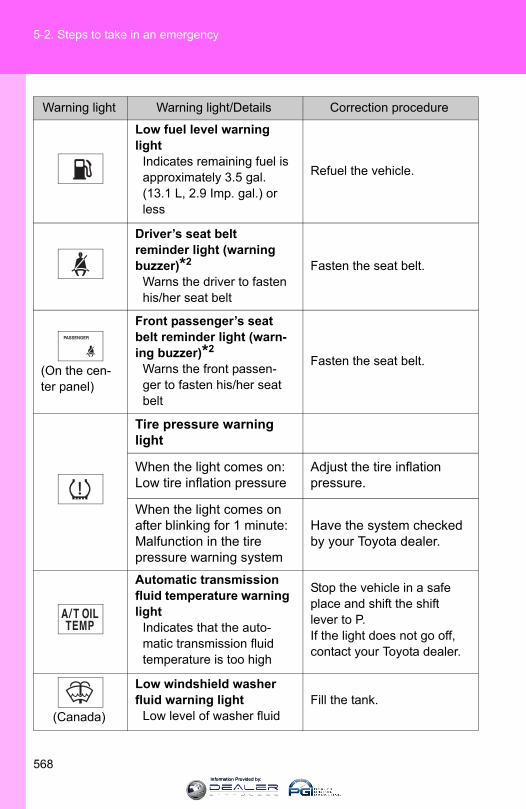
568
5-2. Steps to take in an emergency
Low fuel level warning light
Indicates remaining fuel is approximately 3.5 gal. (13.1 L, 2.9 Imp. gal.) or less
Refuel the vehicle.
Driver’s seat belt reminder light (warning buzzer)*2
Warns the driver to fasten his/her seat belt
Fasten the seat belt.
(On the cen-ter panel)
Front passenger’s seat belt reminder light (warn-ing buzzer)*2
Warns the front passen-ger to fasten his/her seat belt
Fasten the seat belt.
Tire pressure warning light
When the light comes on:Low tire inflation pressure
Adjust the tire inflation pressure.
When the light comes on after blinking for 1 minute:Malfunction in the tire pressure warning system
Have the system checked by your Toyota dealer.
Automatic transmission fluid temperature warning light
Indicates that the auto-matic transmission fluid temperature is too high
Stop the vehicle in a safe place and shift the shift lever to P.If the light does not go off, contact your Toyota dealer.
(Canada)
Low windshield washer fluid warning light
Low level of washer fluidFill the tank.
Warning light Warning light/Details Correction procedure
Information Provided by:
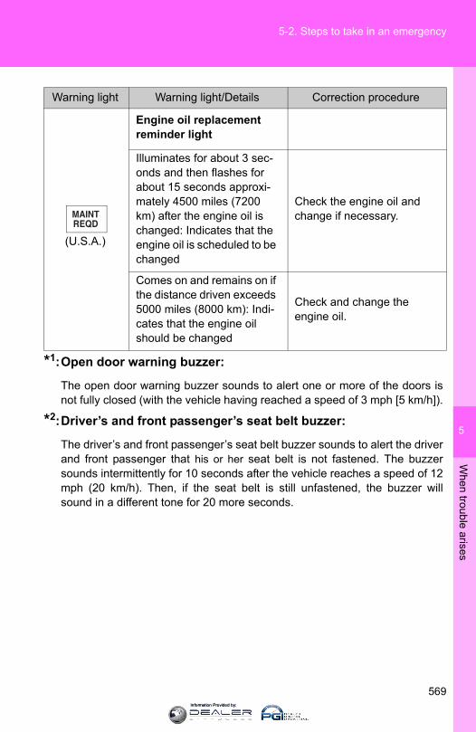
5
When trouble arises
569
5-2. Steps to take in an emergency
*1:Open door warning buzzer:
The open door warning buzzer sounds to alert one or more of the doors isnot fully closed (with the vehicle having reached a speed of 3 mph [5 km/h]).
*2:Driver’s and front passenger’s seat belt buzzer:
The driver’s and front passenger’s seat belt buzzer sounds to alert the driverand front passenger that his or her seat belt is not fastened. The buzzersounds intermittently for 10 seconds after the vehicle reaches a speed of 12mph (20 km/h). Then, if the seat belt is still unfastened, the buzzer willsound in a different tone for 20 more seconds.
(U.S.A.)
Engine oil replacement reminder light
Illuminates for about 3 sec-onds and then flashes for about 15 seconds approxi-mately 4500 miles (7200 km) after the engine oil is changed: Indicates that the engine oil is scheduled to be changed
Check the engine oil and change if necessary.
Comes on and remains on if the distance driven exceeds 5000 miles (8000 km): Indi-cates that the engine oil should be changed
Check and change the engine oil.
Warning light Warning light/Details Correction procedure
Information Provided by:
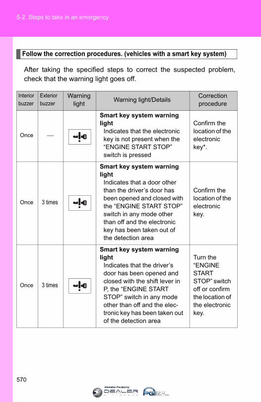
570
5-2. Steps to take in an emergency
Follow the correction procedures. (vehicles with a smart key system)
After taking the specified steps to correct the suspected problem,check that the warning light goes off.
Interiorbuzzer
Exteriorbuzzer
Warning light Warning light/Details Correction
procedure
Once ⎯
Smart key system warning light
Indicates that the electronic key is not present when the “ENGINE START STOP” switch is pressed
Confirm the location of the electronic key*.
Once 3 times
Smart key system warning light
Indicates that a door other than the driver’s door has been opened and closed with the “ENGINE START STOP” switch in any mode other than off and the electronic key has been taken out of the detection area
Confirm the location of the electronic key.
Once 3 times
Smart key system warning light
Indicates that the driver’s door has been opened and closed with the shift lever in P, the “ENGINE START STOP” switch in any mode other than off and the elec-tronic key has been taken out of the detection area
Turn the “ENGINE START STOP” switch off or confirm the location of the electronic key.
Information Provided by:
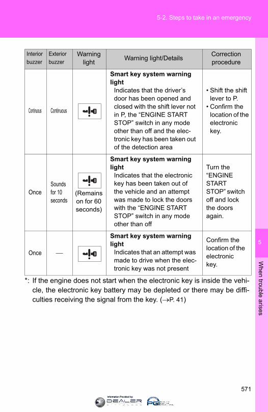
5
When trouble arises
571
5-2. Steps to take in an emergency
*: If the engine does not start when the electronic key is inside the vehi-cle, the electronic key battery may be depleted or there may be diffi-culties receiving the signal from the key. (→P. 41)
Continuous Continuous
Smart key system warning light
Indicates that the driver’s door has been opened and closed with the shift lever not in P, the “ENGINE START STOP” switch in any mode other than off and the elec-tronic key has been taken out of the detection area
• Shift the shift lever to P.
• Confirm the location of the electronic key.
OnceSounds for 10 seconds
(Remains on for 60 seconds)
Smart key system warning light
Indicates that the electronic key has been taken out of the vehicle and an attempt was made to lock the doors with the “ENGINE START STOP” switch in any mode other than off
Turn the “ENGINE START STOP” switch off and lock the doors again.
Once ⎯
Smart key system warning light
Indicates that an attempt was made to drive when the elec-tronic key was not present
Confirm the location of the electronic key.
Interiorbuzzer
Exteriorbuzzer
Warning light Warning light/Details Correction
procedure
Information Provided by:
572
5-2. Steps to take in an emergency
■SRS warning lightThis warning light system monitors the airbag sensor assembly, front airbagsensors, side and curtain shield airbag sensors, curtain shield airbag sen-sors, floor sensor, driver's seat belt buckle switch, front passenger occupantclassification system, SRS airbag on-off indicator, roll sensing of curtainshield airbags off indicator, front passenger's seat belt buckle switch, seatbelt pretensioner assemblies, inflators, interconnecting wiring and powersources. (→P. 115)
■Key reminder buzzer (vehicles without a smart key system)The buzzer indicates that the key has not been removed with the engine offand the driver’s door opened.
■Open moon roof reminder buzzer (if equipped)The buzzer indicates that the moon roof is not fully closed with the engine offand the driver’s door opened.
■Front passenger detection sensor, passenger seat belt reminder andwarning buzzer● If luggage is placed on the front passenger seat, the front passenger
detection sensor may cause the warning light to flash and the warningbuzzer to sound even if a passenger is not sitting in the seat.
● If a cushion is placed on the seat, the sensor may not detect a passen-ger, and the warning light may not operate properly.
■ If the malfunction indicator lamp comes on while drivingFirst check the following:
● Is the fuel tank empty?If it is, fill the fuel tank immediately.
● Is the fuel tank cap loose?If it is, tighten it securely.
The light will go off after several driving trips.If the light does not go off even after several trips, contact your Toyota dealeras soon as possible.
■Changing the engine oil (U.S.A. only)Make sure to reset the oil change system. (→P. 501)
Information Provided by:

5
When trouble arises
573
5-2. Steps to take in an emergency
■The tire pressure warning light may come on due to natural causesThe tire pressure warning light may come on due to natural causes suchas natural air leaks and tire inflation pressure changes caused by tem-perature. In this case, adjusting the tire inflation pressure will turn off thewarning light (after a few minutes).
■When a tire is replaced with a spare tireThe spare tire is not equipped with a tire pressure warning valve andtransmitter. If a tire goes flat, the tire pressure warning light will not turnoff even though the flat tire has been replaced with the spare tire.Replace the spare tire with the repaired tire and adjust the tire inflationpressure. The tire pressure warning light will go off after a few minutes.
Information Provided by:
574
5-2. Steps to take in an emergency
■ If the tire pressure warning system is not functioningThe tire pressure warning system will be disabled in the following condi-tions:(When the condition becomes normal, the system will work properly.)● If tires not equipped with tire pressure warning valves and transmit-
ters are used● If the ID code on the tire pressure warning valves and transmitters is
not registered in the tire pressure warning computer● If the tire inflation pressure is 73 psi (500 kPa, 5.1 kgf/cm2 or bar) or
higherThe tire pressure warning system may be disabled in the following condi-tions:(When the condition becomes normal, the system will work properly.)● If electronic devices or facilities using similar radio wave frequencies
are nearby● If a radio set at a similar frequency is in use in the vehicle● If a window tint that affects the radio wave signals is installed● If there is a lot of snow or ice on the vehicle, particularly around the
wheels or wheel housings● If non-genuine Toyota wheels are used (Even if you use Toyota
wheels, the tire pressure warning system may not work properly withsome types of tires.)
● If tire chains are used■ If the tire pressure warning light comes on after flashing frequently
for 1 minuteIf the tire pressure warning light comes on after flashing frequently for 1minute when the “ENGINE START STOP” switch (vehicles with a smartkey system) or the engine switch (vehicles without a smart key system)is turned on, have it checked by your Toyota dealer.
■Customization that can be configured at Toyota dealerThe vehicle speed linked seat belt reminder buzzer can be disabled. (Customizable features →P. 640) However, Toyota recommends that theseat belt reminder buzzer be operational to alert the driver and front passen-ger when seat belts are not fastened.
Information Provided by:

5
When trouble arises
575
5-2. Steps to take in an emergency
CAUTION
■ If the tire pressure warning light comes onBe sure to observe the following precautions. Failure to do so couldcause a loss of vehicle control and result in death or serious injury.●Stop your vehicle in a safe place as soon as possible. Adjust the tire
inflation pressure immediately. ● If the tire pressure warning light comes on even after tire inflation pres-
sure adjustment, it is probable that you have a flat tire. Check the tires.If a tire is flat, change it with the spare tire and have the flat tirerepaired by the nearest Toyota dealer.
●Avoid abrupt maneuvering and braking. If the vehicle tires deteriorate,you could lose control of the steering wheel or the brakes.
■ If a blowout or sudden air leakage should occurThe tire pressure warning system may not activate immediately.
Information Provided by:

576
5-2. Steps to take in an emergency
CAUTION
■Maintenance of the tiresEach tire, including the spare (if provided), should be checked monthlywhen cold and inflated to the inflation pressure recommended by thevehicle manufacturer on the vehicle placard or tire inflation pressurelabel (tire and load information label). (If your vehicle has tires of a differ-ent size than the size indicated on the vehicle placard or tire inflationpressure label [tire and load information label], you should determine theproper tire inflation pressure for those tires.)As an added safety feature, your vehicle has been equipped with a tirepressure monitoring system (TPMS-tire pressure warning system) thatilluminates a low tire pressure telltale (tire pressure warning light) whenone or more of your tires is significantly under-inflated. Accordingly,when the low tire pressure telltale (tire pressure warning light) illumi-nates, you should stop and check your tires as soon as possible, andinflate them to the proper pressure. Driving on a significantly under-inflated tire causes the tire to overheat and can lead to tire failure.Under-inflation also reduces fuel efficiency and tire tread life, and mayaffect the vehicle's handling and stopping ability.Please note that the TPMS (tire pressure warning system) is not a sub-stitute for proper tire maintenance, and it is the driver's responsibility tomaintain correct tire pressure, even if under-inflation has not reached thelevel to trigger illumination of the TPMS low tire pressure telltale (tirepressure warning light).
Information Provided by:
5
When trouble arises
577
5-2. Steps to take in an emergency
CAUTION
Your vehicle has also been equipped with a TPMS (tire pressure warningsystem) malfunction indicator to indicate when the system is not operat-ing properly. The TPMS (tire pressure warning system) malfunction indi-cator is combined with the low tire pressure telltale (tire pressurewarning light). When the system detects a malfunction, the telltale willflash for approximately one minute and then remain continuously illumi-nated. This sequence will continue upon subsequent vehicle start-ups aslong as the malfunction exists. When the malfunction indicator is illumi-nated, the system may not be able to detect or signal low tire pressureas intended.TPMS (tire pressure warning system) malfunctions may occur for a vari-ety of reasons, including the installation of replacement or alternate tiresor wheels on the vehicle that prevent the TPMS (tire pressure warningsystem) from functioning properly. Always check the TPMS (tire pres-sure warning system) malfunction telltale after replacing one or moretires or wheels on your vehicle to ensure that the replacement or alter-nate tires and wheels allow the TPMS (tire pressure warning system) tocontinue to function properly.
NOTICE
■Precaution when installing a different tireWhen a tire of a different specification or maker is installed, the tire pres-sure warning system may not operate properly.
Information Provided by:
578
5-2. Steps to take in an emergency
If you have a flat tire
Remove the flat tire and replace it with the spare tire provided.
■ Before jacking up the vehicle● Stop the vehicle on a hard, flat surface.
● Set the parking brake.
● Shift the shift lever to P.
● Stop the engine.
● Turn on the emergency flashers.
■ Location of the spare tire, jack and tools
CTH52AS050Spare tire
Jack
Tool bagTool bag
Information Provided by:

5
When trouble arises
579
5-2. Steps to take in an emergency
Taking out the jack and tool bag
Remove the cover.
Unhook and take out the toolbag.
Take out the jack.
For looseningFor tightening
CTH52AS020
STEP 1
CTH52AS004
STEP 2
CTH52AS035
STEP 3
Information Provided by:

580
5-2. Steps to take in an emergency
Taking out the spare tire
Assembling the jack handle.Remove the jack handle and the jack handle extension bar from thetool bag and assembly by following these steps.
Loosen the bolt and the screwusing either the jack handle ora screwdriver.
Assemble the jack handleextension bars and tighten thebolt.
Check that the bolt is firmly tight-ened.
Assemble the jack handle andthe jack handle extension barand tighten the screw.
Check that the screw is firmlytightened.
STEP 1
CTH52AS051
CTH52AS052
CTH52AS053
Information Provided by:
5
When trouble arises
581
5-2. Steps to take in an emergency
Insert the end of the jack handleextension into the loweringscrew and turn it counterclock-wise.
Lower the spare tire completelyto the ground.
Pull out the spare tire andremove the holding bracket.
CTH52AS008
STEP 2
CTH52AS009
STEP 3
Information Provided by:

582
5-2. Steps to take in an emergency
Replacing a flat tire
Chock the tires.
Remove the wheel ornamentusing the wheel ornamentremover.
To protect the wheel ornament,place a rag between the wheelornament remover and thewheel ornament, as shown inthe illustration.
CTH52AS038
STEP 1
Flat tireWheel
chock posi-tions
Front
Left-hand side
Behind the rear right-hand side tire
Right-hand side
Behind the rear left-hand side tire
Rear
Left-hand side
In front of the front right-hand side tire
Right-hand side
In front of the front left-hand side tire
CTH52AS041
STEP 2
Information Provided by:

5
When trouble arises
583
5-2. Steps to take in an emergency
Slightly loosen the wheel nuts(one turn).
Assembling the jack handle.Remove the jack handle, jack handle extension bar and jack handlebar from the tool bag and assembly by following these steps.
Loosen the bolts and thescrew using either the jackhandle or a screwdriver.
Assemble the jack handleextension bars and the jackhandle bar and tighten thebolts.
Check that the bolts are firmlytightened.
CTH52AS012
STEP 3
STEP 4
CTH52AS054
CTH52AS055
Information Provided by:
584
5-2. Steps to take in an emergency
Assemble the jack handleextension bar and the jackhandle and tighten the screw.
Check that the screw is firmlytightened.
Position the jack at the jackpoints as shown.
Front - Under the chassis frameside rail
Rear - Under the rear axle hous-ing
Raise the vehicle until the tire isslightly raised off the ground.
When positioning the jack underthe rear axle housing, makesure the groove on the top ofthe jack fits with the rear axlehousing.
CTH52AS056
CTH52AS039
STEP 5
CTH52AS015
STEP 6
Information Provided by:

5
When trouble arises
585
5-2. Steps to take in an emergency
Remove all the wheel nuts andthe tire.
When resting the tire on theground, place the tire so that thewheel design faces up to avoidscratching the wheel surface.
Installing the spare tire
Remove any dirt or foreign mat-ter from the wheel contact sur-face.
If foreign matter is on the wheelcontact surface, the wheel nutsmay loosen while the vehicle isin motion, causing the tire tocome off.
Install the spare tire and loosely tighten each wheel nut byhand by approximately the same amount.
When replacing an aluminumwheel with a steel wheel, tightenthe wheel nuts until the taperedportion comes into loose contactwith the disc wheel seat.
CTH52AS016
STEP 7
CTH52AS017
STEP 1
STEP 2
CTH52AS034
Taperedportion
Disc wheel seat
Information Provided by:

586
5-2. Steps to take in an emergency
When replacing an aluminumwheel with an aluminum wheel,tighten the wheel nuts until thewashers comes into contact withthe disc wheel.
Lower the vehicle.
Firmly tighten each wheel nuttwo or three times in the ordershown in the illustration.
Tightening torque:83 ft•lbf (110 N•m, 11.5 kgf•m)
CTH52AS037
Washer
Disc wheel
CTH52AS019
STEP 3
CTH52AS029
STEP 4
Information Provided by:
5
When trouble arises
587
5-2. Steps to take in an emergency
Stowing the flat/spare tire, jack and tools
Lay down the tire with the outerside facing up, and install theholding bracket.
Raise the tire. Vehicles with kinetic dynamic suspension: Pull the tire towardthe rear of the vehicle when raising. After raising, visuallycheck that tire is not interfering with components.Stow the tools and jack securely, and replace the cover.
CTH52AS031
STEP 1
■After completing the tire changeThe tire pressure warning system must be reset. (→P. 515)
■When using the spare tireAs the spare tire is not equipped with a tire pressure warning valve andtransmitter, low inflation pressure of the spare tire will not be indicated bythe tire pressure warning system. Also, if you replace the spare tire afterthe tire pressure warning light comes on, the light remains on.
STEP 2
STEP 3
Information Provided by:

588
5-2. Steps to take in an emergency
CAUTION
■Using the tire jackImproper use of the tire jack may cause the vehicle to suddenly fall offthe jack, leading to death or serious injury.●Do not use the tire jack for any purpose other than replacing tires or
installing and removing tire chains.●Only use the tire jack that comes with this vehicle for replacing a flat
tire. Do not use it on other vehicles, and do not use other tire jacks forreplacing tires on this vehicle.
●Always check that the tire jack is securely set to the jack point.●Do not put any part of your body under the vehicle while it is supported
by the jack.●Do not start or run the engine while your vehicle is supported by the
jack.●Do not raise the vehicle while someone is inside.●When raising the vehicle, do not put an object on or under the jack.●Do not raise the vehicle to a height greater than that required to
replace the tire.●Use a jack stand if it is necessary to get under the vehicle.Take particular care when lowering the vehicle to ensure that no oneworking on or near the vehicle may be injured.
Information Provided by:
5
When trouble arises
589
5-2. Steps to take in an emergency
CAUTION
■Using the jack handleTighten all the jack handle bolts securely using a Phillips-head screw-driver, to prevent the extension parts from coming apart unexpectedly.
■Replacing a flat tireObserve the following precautions to reduce the risk of death or seriousinjury.●Lower the spare tire completely to the ground before removing it from
under the vehicle.●Do not try to remove the wheel ornament by hand. Take due care in
handling the ornament to avoid unexpected personal injury.●Never use oil or grease on the wheel bolts or wheel nuts.
Oil and grease may cause the wheel nuts to be excessively tightened,leading to bolt or disc wheel damage. In addition, the oil or grease cancause the wheel nuts to loosen and the wheel may fall off, causing aserious accident. Remove any oil or grease from the wheel bolts orwheel nuts.
●Have the wheel nuts tightened with a torque wrench to 83 ft•lbf (110N•m, 11.5 kgf•m) as soon as possible after changing wheels.
●Do not attach a heavily damaged wheel ornament, as it may fly off thewheel while the vehicle is moving.
●When installing a tire, only use wheel nuts that have been specificallydesigned for that wheel.
● If there are any cracks or deformations in the bolt screws, nut threadsor bolt holes of the wheel, have the vehicle inspected by your Toyotadealer.
Failure to follow these precautions could cause the wheel nuts to loosenand the tire to fall off, resulting in death or serious injury.
Information Provided by:

590
5-2. Steps to take in an emergency
NOTICE
■Do not drive the vehicle with a flat tireDo not continue driving with a flat tire.Driving even a short distance with a flat tire can damage the tire and thewheel beyond repair.
■When stowing the flat tireEnsure that there is no object caught between the tire and the vehicleunderbody.
■When replacing the tires●When removing or fitting the wheels, tires or the tire pressure warning
valve and transmitter, contact your Toyota dealer as the tire pressurewarning valve and transmitter may be damaged if not handled cor-rectly.
●Replace the grommets for the tire pressure warning valves and trans-mitters as well.
■To avoid damage the tire pressure warning valves and transmittersDo not use liquid sealants on flat tires.
Information Provided by:

5
When trouble arises
591
5-2. Steps to take in an emergency
If the engine will not start
If the engine will not start even though correct starting proceduresare being followed (→P. 164, 167), consider each of the followingpoints:
■ The engine will not start even though the starter motoroperates normally.One of the following may be the cause of the problem:
● There may not be sufficient fuel in the vehicle’s tank.Refuel the vehicle.
● The engine may be flooded.Try to restart the engine again following correct starting proce-dures. (→P. 164, 167)
● There may be a malfunction in the engine immobilizer system. (→P. 106)
■ The starter motor turns over slowly, the interior lights andheadlights are dim, or the horn does not sound or sounds ata low volume.One of the following may be the cause of the problem:
● The battery may be discharged. (→P. 599)
● The battery terminal connections may be loose or corroded.
■ The starter motor does not turn over.The engine starting system may be malfunctioning due to anelectrical problem such as an open circuit or a blown fuse. How-ever, an interim measure is available to start the engine. (→P. 592)
Information Provided by:
592
5-2. Steps to take in an emergency
Emergency start function (vehicles with a smart key system)
When the engine does not start, the following steps can be used asan interim measure to start the engine if the “ENGINE START STOP”switch is functioning normally:
Set the parking brake.Shift the shift lever to P.Turn the “ENGINE START STOP” switch to ACCESSORYmode.Press and hold the “ENGINE START STOP” switch for about15 seconds while depressing the brake pedal firmly.
Even if the engine can be started using the above steps, the systemmay be malfunctioning. Have the vehicle inspected by your Toyotadealer.
■ The starter motor does not turn over, the interior lights andheadlights do not turn on, or the horn does not sound.One of the following may be the cause of the problem:
● One or both of the battery terminals may be disconnected.
● The battery may be discharged. (→P. 599)
● There may be a malfunction in the steering lock system. (vehi-cles with a smart key system)
Contact your Toyota dealer if the problem cannot be repaired, or ifrepair procedures are unknown.
STEP 1
STEP 2
STEP 3
STEP 4
Information Provided by:
5
When trouble arises
593
5-2. Steps to take in an emergency
If the shift lever cannot be shifted from P
If the shift lever cannot be shifted with your foot on the brake pedal,there may be a problem with the shift lock system (a system to pre-vent accidental operation of the shift lever). Have the vehicleinspected by your Toyota dealer immediately.The following steps may be used as an emergency measure toensure that the shift lever can be shifted:
Set the parking brake.Vehicles with a smart key system: Turn the “ENGINESTART STOP” switch to ACCESSORY mode.Vehicles without a smart key system: Turn the engineswitch to the “ACC” position.Depress the brake pedal.
Standard typePry the cover up with a flat-head screwdriver or equiva-lent tool.
Press the shift lock overridebutton.
The shift lever can be shiftedwhile the button is pressed.
STEP 1
STEP 2
STEP 3
CTH52AS045
STEP 4
CTH52AS046
STEP 5
Information Provided by:
594
5-2. Steps to take in an emergency
Multi-mode typePry the cover up with a flat-head screwdriver or equiva-lent tool.
Press the shift lock overridebutton.
The shift lever can be shiftedwhile the button is pressed.
CTH52AS021
STEP 4
CTH52AS022
STEP 5
Information Provided by:

5
When trouble arises
595
5-2. Steps to take in an emergency
If you lose your keys
New genuine keys can be made by your Toyota dealer. For vehicleswith the smart key system, bring the other key and the key numberstamped on the key number plate. For vehicles without the smart keysystem, bring a master key and the key number stamped on the keynumber plate.
Information Provided by:
596
5-2. Steps to take in an emergency
If you cannot operate back door opener
If the back door opener does not operate, there may be a problemwith the back door opener system. Have the vehicle inspected byyour Toyota dealer immediately. The following steps may be used as an emergency measure toensure that the back door can be opened from the inside.
Remove the cover on the backdoor trim.
Tear the plastic film. Removethe cover.
Pull the lever.
CTH52AS023
STEP 1
CTH52AS040
STEP 2
CTH52AS036
STEP 3
Information Provided by:
5
When trouble arises
597
5-2. Steps to take in an emergency
If the electronic key does not operate properly (vehicles with a smart key system)
Locking and unlocking the doors
Use the mechanical key (→P.31) in order to perform the fol-lowing operations:
Locks all doors
Unlocks all doorsTurning the key rearwardunlocks the driver’s door.Turning the key once againunlocks the other doors.
If communication between the electronic key and vehicle is inter-rupted (→P. 41) or the electronic key cannot be used because thebattery is depleted, the smart key system and wireless remote con-trol cannot be used. In such cases, the doors can be opened and theengine can be started by following the procedure below.
CTH52AS001
Information Provided by:
598
5-2. Steps to take in an emergency
Changing “ENGINE START STOP” switch modes and starting theengine
Ensure that the shift lever is in P and depress the brake pedal.
Touch the Toyota emblem side ofthe electronic key to the“ENGINE START STOP” switch.
If any of the doors is opened orclosed while the key is beingtouched to the switch, an alarmwill sound to indicate that the startfunction cannot detect the key.
To change “ENGINE START STOP” switch modes: Within 10seconds of the buzzer sounding, release the brake pedal andpress the “ENGINE START STOP” switch. Modes can bechanged each time the switch is pressed. (→P. 168)To start the engine: Press the “ENGINE START STOP” switchwithin 10 seconds of the buzzer sounding, keeping the brakepedal depressed.
In the event that the “ENGINE START STOP” switch cannot be oper-ated, contact your Toyota dealer.
STEP 1
CTH52AS002
STEP 2
■Stopping the engineShift the shift lever to P and press the “ENGINE START STOP” switch asyou normally do when stopping the engine.
■Replacing the key batteryAs the above procedure is a temporary measure, it is recommended that theelectronic key battery be replaced immediately when the battery is depleted. (→P. 529)
STEP 3
Information Provided by:
5
When trouble arises
599
5-2. Steps to take in an emergency
If the vehicle battery is discharged
The following procedures may be used to start the engine if the vehi-cle's battery is discharged.You can also call your Toyota dealer or a qualified repair shop.
If you have a set of jumper (or booster) cables and a second vehi-cle with a 12-volt battery, you can jump start your vehicle by follow-ing the steps below.
2.7 L 4-cylinder (2TR-FE) engine
CTH52AS058
STEP 1
Information Provided by:
600
5-2. Steps to take in an emergency
4.0 L V6 (1GR-FE) engine
Connect the jumper cables according to the following procedure:
Connect a positive jumper cable clamp to the positive (+) batteryterminal on your vehicle.Connect the clamp on the other end of the positive cable to thepositive (+) battery terminal on the second vehicle.Connect a negative cable clamp to the negative (-) battery termi-nal on the second vehicle.Connect the clamp at the other end of the negative cable to asolid, stationary, unpainted metallic point away from the batteryand any moving parts, as shown in the illustration.
CTH52AS044
STEP 1
Information Provided by:

5
When trouble arises
601
5-2. Steps to take in an emergency
Start the engine of the second vehicle. Increase the enginespeed slightly and maintain at that level for approximately 5minutes to recharge the battery of your vehicle.Vehicles with a smart key system only: Open and close anyof the doors of your vehicle with the “ENGINE STARTSTOP” switch off.Maintain the engine speed of the second vehicle and startthe engine of your vehicle by turning the “ENGINE STARTSTOP” switch to IGNITION ON mode (vehicles with a smartkey system) or turning the engine switch to the “ON” posi-tion (vehicles without a smart key system).Once the vehicle’s engine has started, remove the jumpercables in the exact reverse order from which they were con-nected.
Once the engine starts, have the vehicle inspected at your Toyotadealer as soon as possible.
STEP 2
STEP 3
STEP 4
STEP 5
Information Provided by:

602
5-2. Steps to take in an emergency
■Starting the engine when the battery is dischargedThe engine cannot be started by push-starting.
■To prevent battery discharge●Turn off the headlights and the audio system while the engine is off.
●Turn off any unnecessary electrical components when the vehicle is run-ning at a low speed for an extended period, such as in heavy traffic.
■Precautions when the battery is discharged (vehicles with a smart keysystem)● In some cases, it may not be possible to unlock the doors using the smart
key system when the battery is discharged. Use the wireless remote con-trol or the mechanical key to lock or unlock the doors.
●The engine may not start on the first attempt after the battery hasrecharged but will start normally after the second attempt. This is not amalfunction.
●The “ENGINE START STOP” switch mode is memorized by the vehicle.When the battery is reconnected, the system will return to the mode itwas in before the battery was discharged. Before disconnecting the bat-tery, turn the “ENGINE START STOP” switch off. If you are unsure what mode the “ENGINE START STOP” switch was inbefore the battery discharged, be especially careful when reconnectingthe battery.
Information Provided by:

5
When trouble arises
603
5-2. Steps to take in an emergency
CAUTION
■Avoiding battery fires or explosionsObserve the following precautions to prevent accidentally igniting the flam-mable gas that may be emitted from the battery:
●Make sure each jumper cable is connected to the correct terminal and thatit is not unintentionally in contact with any other than the intended terminal.
●Do not allow the + and - clamps of the jumper cables to come into contactwith each other.
●Do not smoke, use matches, cigarette lighters or allow open flame nearthe battery.
■Battery precautionsThe battery contains poisonous and corrosive acidic electrolyte, whilerelated parts contain lead and lead compounds. Observe the following pre-cautions when handling the battery:
●When working with the battery, always wear safety glasses and take carenot to allow any battery fluids (acid) to come into contact with skin, clothingor the vehicle body.
●Do not lean over the battery.
● In the event that battery fluid comes into contact with the skin or eyes,immediately wash the affected area with water and seek medical attention.Place a wet sponge or cloth over the affected area until medical attentioncan be received.
●Always wash your hands after handling the battery support, terminals, andother battery-related parts.
●Do not allow children near the battery.
NOTICE
■When handling jumper cablesWhen connecting the jumper cables, ensure that they do not become entan-gled in the cooling fans or belt.
Information Provided by:

604
5-2. Steps to take in an emergency
If your vehicle overheats
If your engine overheats:
Stop the vehicle in a safe place and turn off the air condi-tioning system.Check to see if steam is coming out from under the hood.If you see steam: Stop the engine. Carefully lift the hood after the steam sub-sides and then restart the engine.If you do not see steam:Leave the engine running and carefully lift the hood.Remove the engine compartment cover. (→P. 497)Check to see if the cooling fan is operating.If the fan is operating: Wait until the temperature of the engine (shown on theinstrument panel) begins to fall and then stop the engine.If the fan is not operating: Stop the engine immediately and call your Toyota dealer.
After the engine has cooleddown sufficiently, check theengine coolant level andinspect the radiator core (radi-ator) for any leaks.
STEP 1
STEP 2
STEP 3
STEP 4
CTH52AS043
STEP 5
Information Provided by:
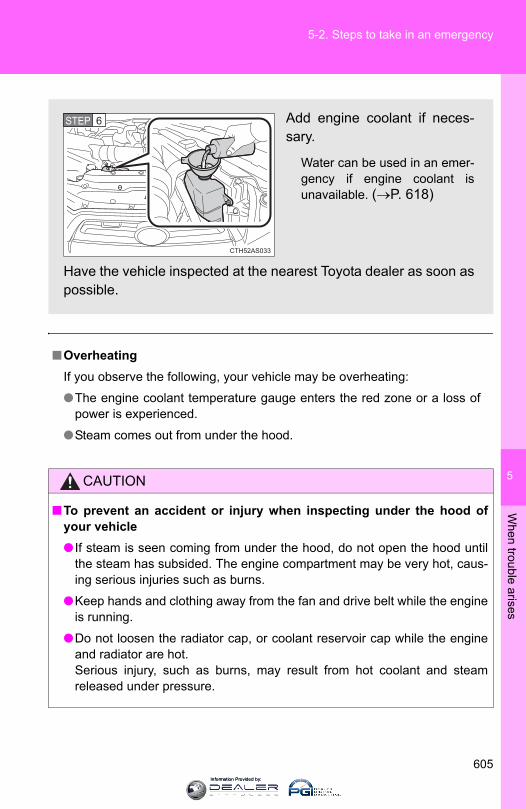
5
When trouble arises
605
5-2. Steps to take in an emergency
■OverheatingIf you observe the following, your vehicle may be overheating:
●The engine coolant temperature gauge enters the red zone or a loss ofpower is experienced.
●Steam comes out from under the hood.
CAUTION
■To prevent an accident or injury when inspecting under the hood ofyour vehicle● If steam is seen coming from under the hood, do not open the hood until
the steam has subsided. The engine compartment may be very hot, caus-ing serious injuries such as burns.
●Keep hands and clothing away from the fan and drive belt while the engineis running.
●Do not loosen the radiator cap, or coolant reservoir cap while the engineand radiator are hot.Serious injury, such as burns, may result from hot coolant and steamreleased under pressure.
Add engine coolant if neces-sary.
Water can be used in an emer-gency if engine coolant isunavailable. (→P. 618)
Have the vehicle inspected at the nearest Toyota dealer as soon aspossible.
CTH52AS033
STEP 6
Information Provided by:
606
5-2. Steps to take in an emergency
NOTICE
■When adding engine coolantWait until the engine has cooled down before adding engine coolant.When adding coolant, do so slowly. Adding cool coolant to a hot engine tooquickly can cause damage to the engine.
Information Provided by:
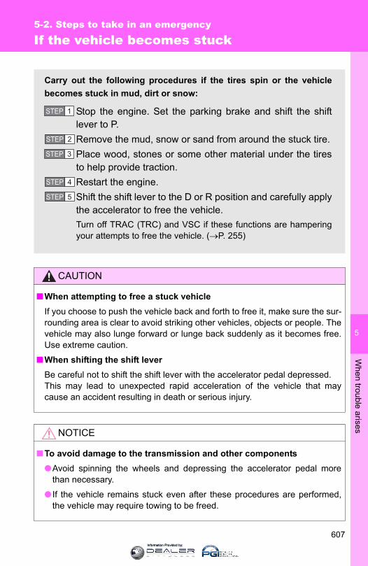
5
When trouble arises
607
5-2. Steps to take in an emergency
If the vehicle becomes stuck
CAUTION
■When attempting to free a stuck vehicleIf you choose to push the vehicle back and forth to free it, make sure the sur-rounding area is clear to avoid striking other vehicles, objects or people. Thevehicle may also lunge forward or lunge back suddenly as it becomes free.Use extreme caution.
■When shifting the shift leverBe careful not to shift the shift lever with the accelerator pedal depressed.This may lead to unexpected rapid acceleration of the vehicle that maycause an accident resulting in death or serious injury.
NOTICE
■To avoid damage to the transmission and other components●Avoid spinning the wheels and depressing the accelerator pedal more
than necessary.
● If the vehicle remains stuck even after these procedures are performed,the vehicle may require towing to be freed.
Carry out the following procedures if the tires spin or the vehiclebecomes stuck in mud, dirt or snow:
Stop the engine. Set the parking brake and shift the shiftlever to P.Remove the mud, snow or sand from around the stuck tire.Place wood, stones or some other material under the tiresto help provide traction.Restart the engine.Shift the shift lever to the D or R position and carefully applythe accelerator to free the vehicle.Turn off TRAC (TRC) and VSC if these functions are hamperingyour attempts to free the vehicle. (→P. 255)
STEP 1
STEP 2
STEP 3
STEP 4
STEP 5
Information Provided by:

608
5-2. Steps to take in an emergency
If your vehicle has to be stopped in an emergency
Only in an emergency, such as if it becomes impossible to stop thevehicle in the normal way, stop the vehicle using the following pro-cedure:
Steadily step on the brake pedal with both feet and firmlydepress it.Do not pump the brake pedal repeatedly as this will increase theeffort required to slow the vehicle.
Shift the shift lever to N.
If the shift lever is shifted to NAfter slowing down, stop the vehicle in a safe place by theroad.Stop the engine.
If the shift lever cannot be shifted to NKeep depressing the brake pedal with both feet to reducevehicle speed as much as possible.
Vehicles without a smart keysystem: Stop the engine byturning the engine switch to“ACC”.
STEP 1
STEP 2
STEP 3
STEP 4
STEP 3
STEP 4
Information Provided by:

5
When trouble arises
609
5-2. Steps to take in an emergency
CAUTION
■ If the engine has to be turned off while driving●Power assist for the brakes and steering wheel will be lost, making the
brake pedal harder to depress and the steering wheel heavier to turn.Decelerate as much as possible before turning off the engine.
●Vehicles without a smart key system: Never attempt to remove the key, asdoing so will lock the steering wheel.
Vehicles with a smart key sys-tem: Stop the engine by press-ing and holding the “ENGINESTART STOP” switch for 3consecutive seconds or more.
Stop the vehicle in a safe place by the road.
Press and hold for 3 seconds or more
STEP 4
STEP 5
Information Provided by:

610
5-2. Steps to take in an emergency
Information Provided by:
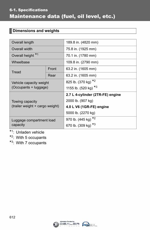
612
6-1. Specifications
Maintenance data (fuel, oil level, etc.)
Dimensions and weights
*1: Unladen vehicle*2: With 5 occupants*3: With 7 occupants
Overall length 189.8 in. (4820 mm)
Overall width 75.8 in. (1925 mm)
Overall height *1 70.1 in. (1780 mm)
Wheelbase 109.8 in. (2790 mm)
TreadFront 63.2 in. (1605 mm)
Rear 63.2 in. (1605 mm)
Vehicle capacity weight(Occupants + luggage)
825 lb. (370 kg) *2
1155 lb. (520 kg) *3
Towing capacity(trailer weight + cargo weight)
2.7 L 4-cylinder (2TR-FE) engine2000 lb. (907 kg)
4.0 L V6 (1GR-FE) engine5000 lb. (2270 kg)
Luggage compartment load capacity
970 lb. (445 kg) *2
670 lb. (309 kg) *3
Information Provided by:

613
6-1. Specifications
6
Vehicle specifications
Vehicle identification
■ Vehicle identification numberThe vehicle identification number (VIN) is the legal identifier for yourvehicle. This is the primary identification number for your Toyota. It isused in registering the ownership of your vehicle.
This number is stamped on thetop left of the instrument panel.
This number is also on the Certi-fication Label.
CTH61AS001
CTH61AS020
Information Provided by:
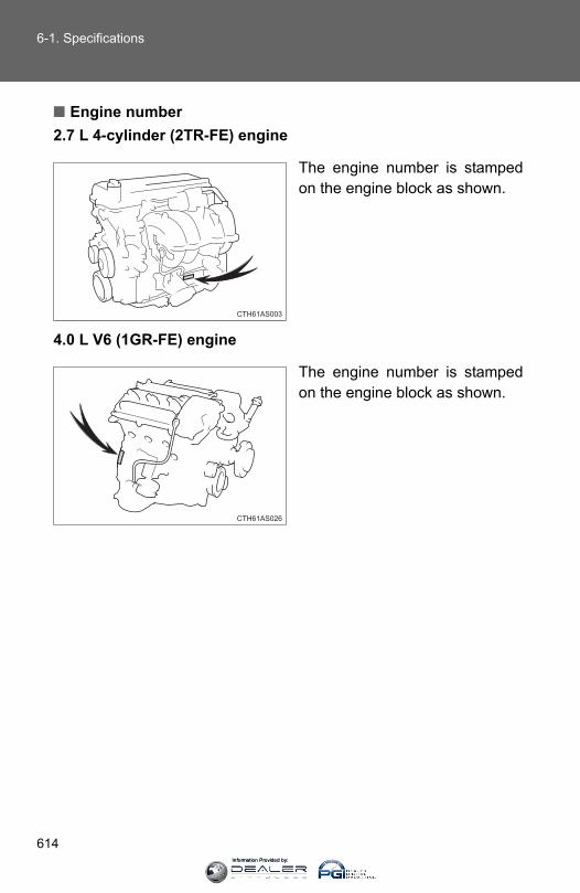
614
6-1. Specifications
■ Engine number2.7 L 4-cylinder (2TR-FE) engine
The engine number is stampedon the engine block as shown.
4.0 L V6 (1GR-FE) engine
The engine number is stampedon the engine block as shown.
CTH61AS003
CTH61AS026
Information Provided by:
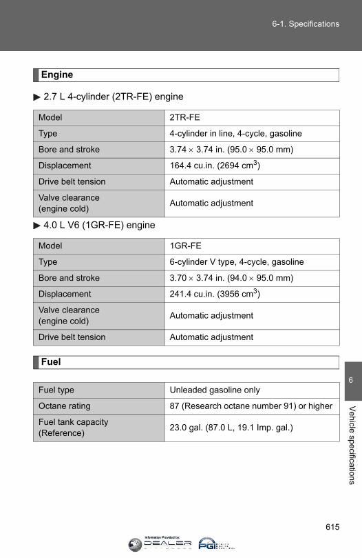
615
6-1. Specifications
6
Vehicle specifications
Engine
2.7 L 4-cylinder (2TR-FE) engine
4.0 L V6 (1GR-FE) engine
Fuel
Model 2TR-FE
Type 4-cylinder in line, 4-cycle, gasoline
Bore and stroke 3.74 × 3.74 in. (95.0 × 95.0 mm)
Displacement 164.4 cu.in. (2694 cm3)
Drive belt tension Automatic adjustment
Valve clearance(engine cold) Automatic adjustment
Model 1GR-FE
Type 6-cylinder V type, 4-cycle, gasoline
Bore and stroke 3.70 × 3.74 in. (94.0 × 95.0 mm)
Displacement 241.4 cu.in. (3956 cm3)
Valve clearance(engine cold) Automatic adjustment
Drive belt tension Automatic adjustment
Fuel type Unleaded gasoline only
Octane rating 87 (Research octane number 91) or higher
Fuel tank capacity (Reference) 23.0 gal. (87.0 L, 19.1 Imp. gal.)
Information Provided by:

616
6-1. Specifications
Lubrication system
■ Engine oil selection“Toyota Genuine Motor Oil” is used in your Toyota vehicle. UseToyota approved “Toyota Genuine Motor Oil” or equivalent to satisfythe following grade and viscosity.
Oil grade: ILSAC multigrade engine oil
Recommended viscosity: SAE 0W-20
SAE 0W-20 is the best choice forgood fuel economy and goodstarting in cold weather.
If SAE 0W-20 is not available,SAE 5W-20 oil may be used.However, it must be replacedwith SAE 0W-20 at the next oilchange.
The 0W portion of the oil viscosity rating indicates the characteristic of theoil which allows cold startability. Oils with a lower value before the W allowfor easier starting of the engine in cold weather.
The 20 in 0W-20 indicates the oil viscosity when the oil is at its operatingtemperature. An oil with a higher viscosity may be better suited if the vehi-cle is operated at high speeds, or under extreme load conditions.
Oil capacity(Drain and refill ⎯ reference)
With filter
Without filter
2.7 L 4-cylinder (2TR-FE) engine 6.1 qt. (5.8 L, 5.1 Imp. qt.)4.0 L V6 (1GR-FE) engine 6.6 qt. (6.2 L, 5.5 Imp. qt.)2.7 L 4-cylinder (2TR-FE) engine 5.4 qt. (5.1 L, 4.5 Imp. qt.)4.0 L V6 (1GR-FE) engine 6.0 qt. (5.7 L, 5.0 Imp. qt.)
CTH61AS015
Outside temperature
Information Provided by:

617
6-1. Specifications
6
Vehicle specifications
How to read oil container label:
The ILSAC (International Lubricant Standardization and ApprovalCommittee) Certification Mark is added to some oil containers to helpyou select the oil you should use.
CTH61AS018
Information Provided by:

618
6-1. Specifications
Cooling system
Ignition system
Capacity
2.7 L 4-cylinder (2TR-FE) engine 8.6 qt. (8.1 L, 7.1 Imp. qt.)4.0 L V6 (1GR-FE) engine 11.1 qt. (10.5 L, 9.2 Imp. qt.)
Coolant type
Use either of the following:• “Toyota Super Long Life Coolant” • A similar high-quality ethylene glycol-
based non-silicate, non-amine, non-nitrite, and non-borate coolant with long-life hybrid organic acid technology
Do not use plain water alone.
Spark plug
MakeGap
DENSO SK20HR110.043 in. (1.1 mm)
NOTICE
■ Iridium-tipped spark plugsUse only iridium-tipped spark plugs. Do not adjust the spark plug gap.
Information Provided by:

619
6-1. Specifications
6
Vehicle specifications
Electrical system
Transfer (4WD models)
*: “Toyota Genuine Transfer Gear oil LF” is put in your Toyota vehicle atthe factory. Use Toyota approved “Toyota Genuine Transfer Gear oilLF” or an equivalent of matching quality to satisfy the above specifi-cation. Please contact your Toyota dealer for further details.
Battery
Open voltage* at 68°F (20°C):
12.6 ⎯ 12.8 V Fully charged12.2 ⎯ 12.4 V Half charged11.8 ⎯ 12.0 V Discharged(*: Voltage checked 20 minutes after the engine and all the lights are turned off.)
Charging rates 5 A max.
Oil capacity
Part-time 4WD models1.1 qt. (1.0 L, 0.9 Imp. qt.)Full-time 4WD models1.5 qt. (1.4 L, 1.2 Imp. qt.)
Oil type* Toyota Genuine Transfer gear oil LF or equivalent
Recommended oil viscosity SAE 75W
Information Provided by:

620
6-1. Specifications
Front differential (4WD models)
*: “Toyota Genuine Differential Gear Oil” is put in your Toyota vehicle atthe factory. Use Toyota approved “Toyota Genuine Differential GearOil” or an equivalent of matching quality to satisfy the above specifi-cation. Please contact your Toyota dealer for further details.
Rear differential
*: “Toyota Genuine Differential Gear Oil” is put in your Toyota vehicle atthe factory. Use Toyota approved “Toyota Genuine Differential GearOil” or an equivalent of matching quality to satisfy the above specifi-cation. Please contact your Toyota dealer for further details.
Oil capacity
Part-time 4WD models1.6 qt. (1.55 L, 1.4 Imp. qt.)Full-time 4WD models1.5 qt. (1.40 L, 1.2 Imp. qt.)
Oil type and viscosity* Toyota Genuine Differential gear oil LT 75W-85 GL-5 or equivalent
Oil capacity
Vehicles without a rear differential lock2.9 qt. (2.70 L, 2.4 Imp. qt.)Vehicles with a rear differential lock2.8 qt. (2.65 L, 2.3 Imp. qt.)
Oil type and viscosity* Toyota Genuine Differential gear oil LT 75W-85 GL-5 or equivalent
Information Provided by:
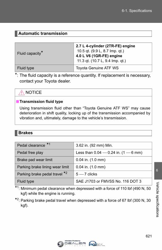
621
6-1. Specifications
6
Vehicle specifications
Automatic transmission
*: The fluid capacity is a reference quantity. If replacement is necessary,contact your Toyota dealer.
Brakes
*1: Minimum pedal clearance when depressed with a force of 110 lbf (490 N, 50kgf) while the engine is running.
*2: Parking brake pedal travel when depressed with a force of 67 lbf (300 N, 30kgf).
Fluid capacity*2.7 L 4-cylinder (2TR-FE) engine 10.5 qt. (9.9 L, 8.7 Imp. qt.)4.0 L V6 (1GR-FE) engine 11.3 qt. (10.7 L, 9.4 Imp. qt.)
Fluid type Toyota Genuine ATF WS
NOTICE
■Transmission fluid typeUsing transmission fluid other than “Toyota Genuine ATF WS” may causedeterioration in shift quality, locking up of the transmission accompanied byvibration and, ultimately, damage to the vehicle’s transmission.
Pedal clearance *1 3.62 in. (92 mm) Min.
Pedal free play Less than 0.04 ⎯ 0.24 in. (1 ⎯ 6 mm)
Brake pad wear limit 0.04 in. (1.0 mm)
Parking brake lining wear limit 0.04 in. (1.0 mm)
Parking brake pedal travel *2 5 ⎯ 7 clicks
Fluid type SAE J1703 or FMVSS No. 116 DOT 3
Information Provided by:

622
6-1. Specifications
Chassis lubrication
Steering
Propeller shafts
SpiderSlide yoke
Lithium base chassis grease, NLGI No.2Molybdenum-disulfide lithium base chas-sis grease, NLGI No.2 or lithium base mul-tipurpose grease, NLGI No.2
Free play Less than 1.2 in. (30 mm)
Power steering fluid type Automatic transmission fluid DEXRON® II or III
Information Provided by:

623
6-1. Specifications
6
Vehicle specifications
Tires and wheels
2.7 L 4-cylinder (2TR-FE) engine
4.0 L V6 (1GR-FE) engine
Tire size P265/70R17 113S
Tire inflation pressure(Recommended cold tire inflation pressure)
Front:33 psi (230 kPa, 2.3 kgf/cm2 or bar)Rear:33 psi (230 kPa, 2.3 kgf/cm2 or bar)Spare:33 psi (230 kPa, 2.3 kgf/cm2 or bar)
Wheel size 17 × 7J
Wheel nut torque 83 ft•lbf (110 N•m, 11.5 kgf•m)
Tire size P265/70R17 113S, P245/60R20 107H
Tire inflation pressure(Recommended cold tire inflation pressure)
Front:32 psi (220 kPa, 2.2 kgf/cm2 or bar)Rear:32 psi (220 kPa, 2.2 kgf/cm2 or bar)Spare:32 psi (220 kPa, 2.2 kgf/cm2 or bar)
Wheel size 17 × 7J, 17 × 7 1/2J, 20 × 7J
Wheel nut torque 83 ft•lbf (110 N•m, 11.5 kgf•m)
Information Provided by:
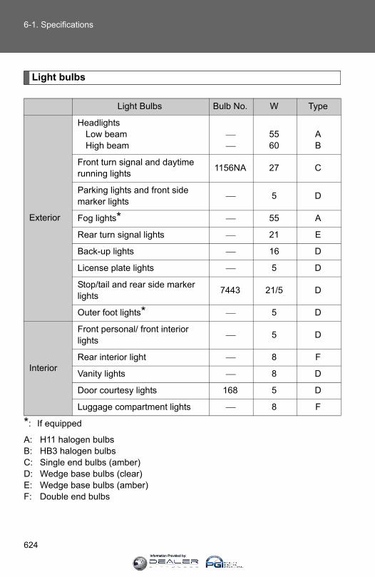
624
6-1. Specifications
Light bulbs
*: If equipped
A: H11 halogen bulbs B: HB3 halogen bulbs C: Single end bulbs (amber)D: Wedge base bulbs (clear) E: Wedge base bulbs (amber) F: Double end bulbs
Light Bulbs Bulb No. W Type
Exterior
HeadlightsLow beamHigh beam
⎯⎯
5560
AB
Front turn signal and daytime running lights 1156NA 27 C
Parking lights and front side marker lights ⎯ 5 D
Fog lights* ⎯ 55 A
Rear turn signal lights ⎯ 21 E
Back-up lights ⎯ 16 D
License plate lights ⎯ 5 D
Stop/tail and rear side marker lights 7443 21/5 D
Outer foot lights* ⎯ 5 D
Interior
Front personal/ front interior lights ⎯ 5 D
Rear interior light ⎯ 8 F
Vanity lights ⎯ 8 D
Door courtesy lights 168 5 D
Luggage compartment lights ⎯ 8 F
Information Provided by:

625
6-1. Specifications
6
Vehicle specifications
Fuel information
■Fuel tank opening for unleaded gasolineTo help prevent incorrect fueling, your Toyota has a fuel tank opening thatonly accommodates the special nozzle on unleaded fuel pumps.
■Gasoline qualityIn very few cases, driveability problems may be caused by the brand of gas-oline you are using. If driveability problems persist, try changing the brand ofgasoline. If this does not correct the problem, consult your Toyota dealer.
You must only use unleaded gasoline in your vehicle.Select octane rating 87 (Research Octane Number 91) or higher. Useof unleaded gasoline with an octane rating lower than 87 may resultin engine knocking. Persistent knocking can lead to engine damage.
At minimum, the gasoline you use should meet the specificationsof ASTM D4814 in the U.S.A. and CGSB3.5-M93 in Canada.
Information Provided by:

626
6-1. Specifications
■Gasoline quality standards●Automotive manufacturers in the U.S.A., Europe and Japan have devel-
oped a specification for fuel quality called the World-Wide Fuel Charter(WWFC), which is expected to be applied worldwide.
●The WWFC consists of four categories that are based on required emis-sion levels. In the U.S., category 4 has been adopted.
●The WWFC improves air quality by lowering emissions in vehicle fleets,and improves customer satisfaction through better performance.
■Recommendation of the use of gasoline containing detergent additives●Toyota recommends the use of gasoline that contains detergent additives
to avoid the build-up of engine deposits.
●All gasoline sold in the U.S.A. contains detergent additives to clean and/or keep clean intake systems.
■Recommendation of the use of cleaner burning gasolineCleaner burning gasoline, including reformulated gasoline that contains oxy-genates such as ethanol or MTBE (Methyl Tertiary Butyl Ether) is available inmany areas.
Toyota recommends the use of cleaner burning gasoline and appropriatelyblended reformulated gasoline. These types of gasoline provide excellentvehicle performance, reduce vehicle emissions and improve air quality.
■Non-recommendation of the use of blended gasoline●Toyota allows the use of oxygenate blended gasoline where the oxygen-
ate content is up to 10% ethanol or 15% MTBE.
● If you use gasohol in your vehicle, be sure that it has an octane rating nolower than 87.
●Toyota does not recommend the use of gasoline containing methanol.
Information Provided by:
627
6-1. Specifications
6
Vehicle specifications
■Non-recommendation of the use of gasoline containing MMTSome gasoline contains an octane enhancing additive called MMT (Methyl-cyclopentadienyl Manganese Tricarbonyl).
Toyota does not recommend the use of gasoline that contains MMT. If fuelcontaining MMT is used, your emission control system may be adverselyaffected.
The malfunction indicator lamp on the instrument cluster may come on. Ifthis happens, contact your Toyota dealer for service.
■ If your engine knocks●Consult your Toyota dealer.
●You may occasionally notice light knocking for a short time while acceler-ating or driving uphill. This is normal and there is no need for concern.
NOTICE
■Notice on fuel quality●Do not use improper fuels. If improper fuels are used, the engine will be
damaged.
●Do not use leaded gasoline.Leaded gasoline can cause damage to your vehicle’s three-way catalyticconverters causing the emission control system to malfunction.
●Do not use gasohol other than the type previously stated.Other gasohol may cause fuel system damage or vehicle performanceproblems.
●Using unleaded gasoline with an octane number or rating lower than thelevel previously stated will cause persistent heavy knocking.At worst, this will lead to engine damage.
■Fuel-related poor driveabilityIf poor driveability is encountered after using a different type of fuel (poor hotstarting, vaporization, engine knocking, etc.), discontinue the use of that typeof fuel.
■When refueling with gasoholTake care not to spill gasohol. It can damage your vehicle’s paint.
Information Provided by:

628
6-1. Specifications
Tire information
Typical tire symbols
Tire size (→P. 630)Summer tire or all season tires (→P. 517)An all season tire has “M+S” on the sidewall. A tire not marked“M+S” is a summer tire.
Uniform tire quality gradingFor details, see “Uniform Tire Quality Grading” that follows.
DOT and Tire Identification Number (TIN) (→P. 629)Tire ply composition and materialsPlies are layers of rubber-coated parallel cords. Cords are thestrands which form the plies in a tire.
Location of treadwear indicators (→P. 514)Load limit at maximum cold tire inflation pressure (→P. 516)
CTH61AS021
Information Provided by:
629
6-1. Specifications
6
Vehicle specifications
Typical DOT and Tire Identification Number (TIN)
DOT symbol*Tire Identification Number(TIN)Tire manufacturer’s identifica-tion markTire size codeManufacturer’s optional tiretype code (3 or 4 letters)Manufacturing weekManufacturing year
*: The DOT symbol certifiesthat the tire conforms toapplicable Federal MotorVehicle Safety Standards.
Maximum cold tire inflation pressure (→P. 623)This means the pressure to which a tire may be inflated.
TUBELESS or TUBE TYPEA tubeless tire does not have a tube and air is directly put into thetire. A tube type tire has a tube inside the tire and the tube main-tains the air pressure.
Radial tires or bias-ply tiresA radial tire has “RADIAL” on the sidewall. A tire not marked “RADIAL”is a bias-ply tire.
CTH61AS008
Information Provided by:

630
6-1. Specifications
Tire size
■ Typical tire size informationThe illustration indicates typical tire size.
Tire use(P = Passenger car, T = Temporary use)Section width (millimeters)Aspect ratio(tire height to section width)Tire construction code(R = Radial, D = Diagonal)Wheel diameter (inches)Load index (2 digits or 3 digits)Speed symbol(alphabet with one letter)
■ Tire dimensionsSection widthTire heightWheel diameter
CTH61AS009
Information Provided by:

631
6-1. Specifications
6
Vehicle specifications
Tire section names
BeadSidewallShoulderTreadBeltInner linerReinforcing rubberCarcassRim linesBead wiresChafer
Uniform Tire Quality Grading
This information has been prepared in accordance with regulationsissued by the National Highway Traffic Safety Administration of theU.S. Department of Transportation.It provides the purchasers and/or prospective purchasers of Toyotavehicles with information on uniform tire quality grading.
Your Toyota dealer will help answer any questions you may have asyou read this information.
■ DOT quality gradesAll passenger vehicle tires must conform to Federal SafetyRequirements in addition to these grades. Quality grades can befound where applicable on the tire sidewall between tread shoulderand maximum section width.
For example: Treadwear 200 Traction AA Temperature A
Information Provided by:
632
6-1. Specifications
■ TreadwearThe treadwear grade is a comparative rating based on the wearrate of the tire when tested under controlled conditions on a speci-fied government test course.
For example, a tire graded 150 would wear one and a half (1 - 1/2)times as well on the government course as a tire graded 100.The relative performance of tires depends upon the actual conditionsof their use. Performance may differ significantly from the norm dueto variations in driving habits, service practices and differences inroad characteristics and climate.
■ Traction AA, A, B, CThe traction grades, from highest to lowest, are AA, A, B and C,and they represent the tire’s ability to stop on wet pavement asmeasured under controlled conditions on specified governmenttest surfaces of asphalt and concrete.
A tire marked C may have poor traction performance.
Warning: The traction grade assigned to this tire is based on braking(straight ahead) traction tests and does not include cornering (turn-ing) traction.
■ Temperature A, B, CThe temperature grades are A (the highest), B, and C, represent-ing the tire’s resistance to the generation of heat and its ability todissipate heat when tested under controlled conditions on a speci-fied indoor laboratory test wheel.
Sustained high temperature can cause the material of the tire todegenerate and reduce tire life, and excessive temperature can leadto sudden tire failure.
Grade C corresponds to a level of performance which all passengercar tires must meet under the Federal Motor Vehicle Safety StandardNo. 109.
Grades B and A represent higher levels of performance on the labo-ratory test wheel than the minimum required by law.
Information Provided by:
633
6-1. Specifications
6
Vehicle specifications
Warning: The temperature grades of a tire assume that it is properlyinflated and not overloaded.Excessive speed, underinflation, or excessive loading, either sepa-rately or in combination, can cause heat buildup and possible tire fail-ure.
Glossary of tire terminology
Tire related term Meaning
Cold tire inflation pressure
Tire pressure when the vehicle has been parked for three hours or more, or has not been driven more than 1 mile or 1.5 km under that condition
Maximum inflation pressure
The maximum cold inflated pressure to which a tire may be inflated, shown on the sidewall of the tire
Recommended inflation pressure
Cold tire inflation pressure recommended by a manufacturer.
Accessory weight
The combined weight (in excess of those stan-dard items which may be replaced) of auto-matic transmission, power steering, power brakes, power windows, power seats, radio and heater, to the extent that these items are available as factory-installed equipment (whether installed or not)
Curb weight
The weight of a motor vehicle with standard equipment, including the maximum capacity of fuel, oil and coolant, and if so equipped, air conditioning and additional weight optional engine
Maximum loaded vehicle weight
The sum of:(a) Curb weight(b) Accessory weight(c) Vehicle capacity weight(d) Production options weight
Information Provided by:

634
6-1. Specifications
Tire related term Meaning
Normal occupant weight
150 lb. (68 kg) times the number of occupants specified in the second column of Table 1* that follows
Occupant distribution Distribution of occupants in a vehicle as speci-fied in the third column of Table 1* below
Production options weight
The combined weight of installed regular pro-duction options weighing over 5 lb. (2.3 kg) in excess of the standard items which they replace, not previously considered in curb weight or accessory weight, including heavy duty brakes, ride levelers, roof rack, heavy duty battery, and special trim
Rim A metal support for a tire or a tire and tube assembly upon which the tire beads are seated
Rim diameter(Wheel diameter) Nominal diameter of the bead seat
Rim size designation Rim diameter and width
Rim type designation The industry manufacturer’s designation for a rim by style or code
Rim width Nominal distance between rim flanges
Vehicle capacity weight (Total load capacity)
The rated cargo and luggage load plus 150 lb. (68 kg) times the vehicle’s designated seating capacity
Vehicle maximum load on the tire
The load on an individual tire that is determined by distributing to each axle its share of the maximum loaded vehicle weight, and dividing by two
Information Provided by:

635
6-1. Specifications
6
Vehicle specifications
Tire related term Meaning
Vehicle normal load on the tire
The load on an individual tire that is determined by distributing to each axle its share of curb weight, accessory weight, and normal occu-pant weight (distributed in accordance with Table 1* below), and dividing by two
Weather side The surface area of the rim not covered by the inflated tire
BeadThe part of the tire that is made of steel wires, wrapped or reinforced by ply cords and that is shaped to fit the rim
Bead separation A breakdown of the bond between components in the bead
Bias ply tire
A pneumatic tire in which the ply cords that extend to the beads are laid at alternate angles substantially less than 90 degrees to the cen-terline of the tread
Carcass The tire structure, except tread and sidewall rubber which, when inflated, bears the load
Chunking The breaking away of pieces of the tread or sidewall
Cord The strands forming the plies in the tire
Cord separation The parting of cords from adjacent rubber com-pounds
Cracking Any parting within the tread, sidewall, or inner-liner of the tire extending to cord material
CT
A pneumatic tire with an inverted flange tire and rim system in which the rim is designed with rim flanges pointed radially inward and the tire is designed to fit on the underside of the rim in a manner that encloses the rim flanges inside the air cavity of the tire
Information Provided by:
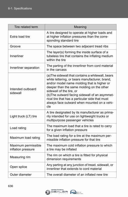
636
6-1. Specifications
Tire related term Meaning
Extra load tireA tire designed to operate at higher loads and at higher inflation pressures than the corre-sponding standard tire
Groove The space between two adjacent tread ribs
InnerlinerThe layer(s) forming the inside surface of a tubeless tire that contains the inflating medium within the tire
Innerliner separation The parting of the innerliner from cord material in the carcass
Intended outboard sidewall
(a)The sidewall that contains a whitewall, bears white lettering, or bears manufacturer, brand, and/or model name molding that is higher or deeper than the same molding on the other sidewall of the tire, or(b)The outward facing sidewall of an asymmet-rical tire that has a particular side that must always face outward when mounted on a vehi-cle
Light truck (LT) tireA tire designated by its manufacturer as prima-rily intended for use on lightweight trucks or multipurpose passenger vehicles
Load rating The maximum load that a tire is rated to carry for a given inflation pressure
Maximum load rating The load rating for a tire at the maximum per-missible inflation pressure for that tire
Maximum permissible inflation pressure
The maximum cold inflation pressure to which a tire may be inflated
Measuring rim The rim on which a tire is fitted for physical dimension requirements
Open splice Any parting at any junction of tread, sidewall, or innerliner that extends to cord material
Outer diameter The overall diameter of an inflated new tire
Information Provided by:
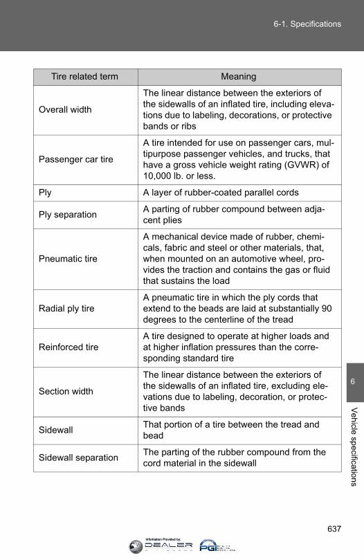
637
6-1. Specifications
6
Vehicle specifications
Tire related term Meaning
Overall width
The linear distance between the exteriors of the sidewalls of an inflated tire, including eleva-tions due to labeling, decorations, or protective bands or ribs
Passenger car tire
A tire intended for use on passenger cars, mul-tipurpose passenger vehicles, and trucks, that have a gross vehicle weight rating (GVWR) of 10,000 lb. or less.
Ply A layer of rubber-coated parallel cords
Ply separation A parting of rubber compound between adja-cent plies
Pneumatic tire
A mechanical device made of rubber, chemi-cals, fabric and steel or other materials, that, when mounted on an automotive wheel, pro-vides the traction and contains the gas or fluid that sustains the load
Radial ply tireA pneumatic tire in which the ply cords that extend to the beads are laid at substantially 90 degrees to the centerline of the tread
Reinforced tireA tire designed to operate at higher loads and at higher inflation pressures than the corre-sponding standard tire
Section width
The linear distance between the exteriors of the sidewalls of an inflated tire, excluding ele-vations due to labeling, decoration, or protec-tive bands
Sidewall That portion of a tire between the tread and bead
Sidewall separation The parting of the rubber compound from the cord material in the sidewall
Information Provided by:
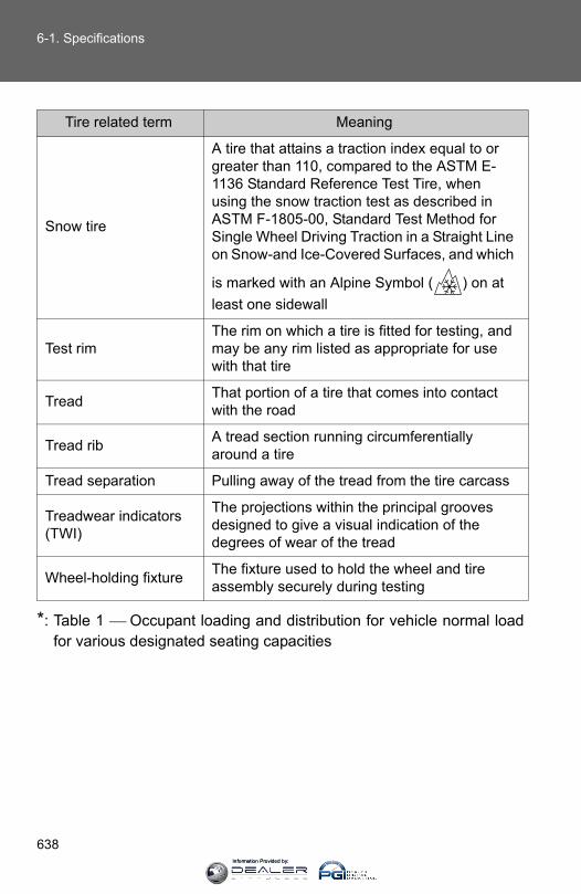
638
6-1. Specifications
*: Table 1 ⎯ Occupant loading and distribution for vehicle normal loadfor various designated seating capacities
Tire related term Meaning
Snow tire
A tire that attains a traction index equal to or greater than 110, compared to the ASTM E-1136 Standard Reference Test Tire, when using the snow traction test as described in ASTM F-1805-00, Standard Test Method for Single Wheel Driving Traction in a Straight Line on Snow-and Ice-Covered Surfaces, and which
is marked with an Alpine Symbol ( ) on at least one sidewall
Test rimThe rim on which a tire is fitted for testing, and may be any rim listed as appropriate for use with that tire
Tread That portion of a tire that comes into contact with the road
Tread rib A tread section running circumferentially around a tire
Tread separation Pulling away of the tread from the tire carcass
Treadwear indicators (TWI)
The projections within the principal grooves designed to give a visual indication of the degrees of wear of the tread
Wheel-holding fixture The fixture used to hold the wheel and tire assembly securely during testing
Information Provided by:
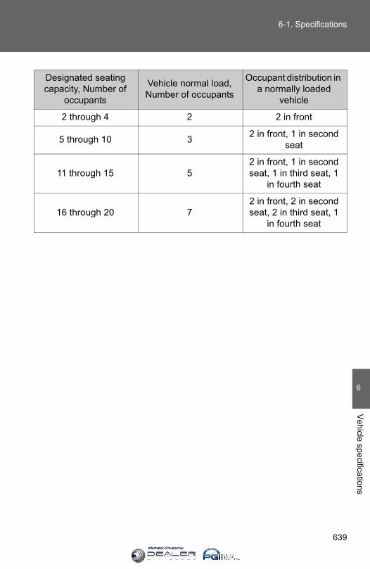
639
6-1. Specifications
6
Vehicle specifications
Designated seating capacity, Number of
occupants
Vehicle normal load, Number of occupants
Occupant distribution in a normally loaded
vehicle
2 through 4 2 2 in front
5 through 10 3 2 in front, 1 in second seat
11 through 15 52 in front, 1 in second seat, 1 in third seat, 1
in fourth seat
16 through 20 72 in front, 2 in second seat, 2 in third seat, 1
in fourth seat
Information Provided by:
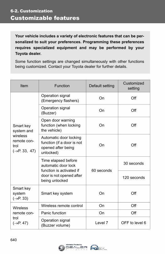
640
6-2. Customization
Customizable features
Item Function Default setting Customizedsetting
Smart key system and wireless remote con-trol (→P. 33, 47)
Operation signal (Emergency flashers) On Off
Operation signal (Buzzer) On Off
Open door warning function (when locking the vehicle)
On Off
Automatic door locking function (if a door is not opened after being unlocked)
On Off
Time elapsed before automatic door lock function is activated if door is not opened after being unlocked
60 seconds
30 seconds
120 seconds
Smart key system (→P. 33)
Smart key system On Off
Wireless remote con-trol (→P. 47)
Wireless remote control On Off
Panic function On Off
Operation signal (Buzzer volume) Level 7 OFF to level 6
Your vehicle includes a variety of electronic features that can be per-sonalized to suit your preferences. Programming these preferencesrequires specialized equipment and may be performed by yourToyota dealer.
Some function settings are changed simultaneously with other functionsbeing customized. Contact your Toyota dealer for further details.
Information Provided by:

641
6-2. Customization
6
Vehicle specifications
Door lock (→P. 51, 597)
Speed-detecting auto-matic door lock function Off On
Shifting the shift lever to position other than P locks all doors
On Off
Shifting the shift lever to P unlocks all doors On Off
Opening driver’s door unlocks all doors Off On
Power win-dows (→P. 91)
Mechanical key linked operation (close) Off On
Mechanical key linked operation (open) Off On
Wireless remote control linked operation (open) Off On
Wireless remote control linked operation signal (Buzzer)
On Off
Automatic light control system (→P. 198)
Light sensor sensitivity Level 3 Levels 1 to 5
Time elapsed before headlights automati-cally turn off after doors are closed
30 seconds
Off
60 seconds
90 seconds
Ambient light level at which instrument illumi-nation begins to dim (meter lights etc.)
Standard -2 (darker) to 2 (brighter)
Ambient light level at which instrument illumi-nation begins to brighten (meter lights etc.)
Standard -2 (darker) to 2 (brighter)
Item Function Default setting Customizedsetting
Information Provided by:
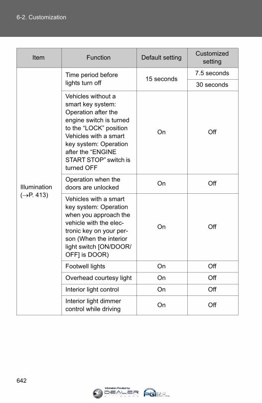
642
6-2. Customization
Illumination (→P. 413)
Time period before lights turn off 15 seconds
7.5 seconds
30 seconds
Vehicles without a smart key system: Operation after the engine switch is turned to the “LOCK” positionVehicles with a smart key system: Operation after the “ENGINE START STOP” switch is turned OFF
On Off
Operation when the doors are unlocked On Off
Vehicles with a smart key system: Operation when you approach the vehicle with the elec-tronic key on your per-son (When the interior light switch [ON/DOOR/OFF] is DOOR)
On Off
Footwell lights On Off
Overhead courtesy light On Off
Interior light control On Off
Interior light dimmer control while driving On Off
Item Function Default setting Customizedsetting
Information Provided by:
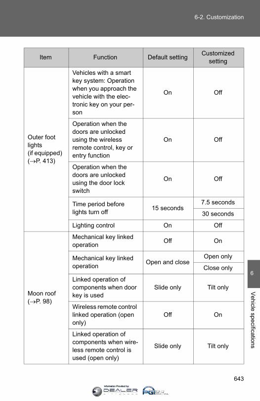
643
6-2. Customization
6
Vehicle specifications
Outer foot lights (if equipped) (→P. 413)
Vehicles with a smart key system: Operation when you approach the vehicle with the elec-tronic key on your per-son
On Off
Operation when the doors are unlocked using the wireless remote control, key or entry function
On Off
Operation when the doors are unlocked using the door lock switch
On Off
Time period before lights turn off 15 seconds
7.5 seconds
30 seconds
Lighting control On Off
Moon roof (→P. 98)
Mechanical key linked operation Off On
Mechanical key linked operation Open and close
Open only
Close only
Linked operation of components when door key is used
Slide only Tilt only
Wireless remote control linked operation (open only)
Off On
Linked operation of components when wire-less remote control is used (open only)
Slide only Tilt only
Item Function Default setting Customizedsetting
Information Provided by:
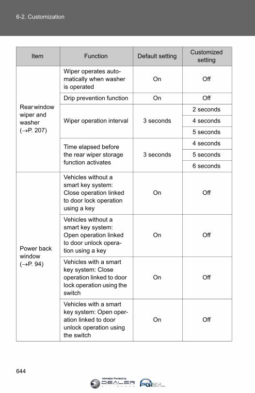
644
6-2. Customization
Rear window wiper and washer (→P. 207)
Wiper operates auto-matically when washer is operated
On Off
Drip prevention function On Off
Wiper operation interval 3 seconds
2 seconds
4 seconds
5 seconds
Time elapsed before the rear wiper storage function activates
3 seconds
4 seconds
5 seconds
6 seconds
Power back window (→P. 94)
Vehicles without a smart key system: Close operation linked to door lock operation using a key
On Off
Vehicles without a smart key system: Open operation linked to door unlock opera-tion using a key
On Off
Vehicles with a smart key system: Close operation linked to door lock operation using the switch
On Off
Vehicles with a smart key system: Open oper-ation linked to door unlock operation using the switch
On Off
Item Function Default setting Customizedsetting
Information Provided by:
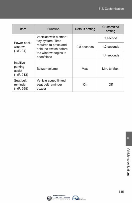
645
6-2. Customization
6
Vehicle specifications
Power back window (→P. 94)
Vehicles with a smart key system: Time required to press and hold the switch before the window begins to open/close
0.8 seconds
1 second
1.2 seconds
1.4 seconds
Intuitive parking assist (→P. 213)
Buzzer volume Max. Min. to Max.
Seat belt reminder (→P. 568)
Vehicle speed linked seat belt reminder buzzer
On Off
Item Function Default setting Customizedsetting
Information Provided by:

646
6-3. Initialization
Items to initialize
Item When to initialize Reference
Engine oil mainte-nance data After changing engine oil P. 501
The following item must be initialized for normal system operation incases such as after the battery is reconnected, or maintenance isperformed on the vehicle.
Information Provided by:

648
Reporting safety defects for U.S. owners
If you believe that your vehicle has a defect which could cause acrash or could cause injury or death, you should immediatelyinform the National Highway Traffic Safety Administration (NHTSA)in addition to notifying Toyota Motor Sales, U.S.A., Inc. (Toll-free:1-800-331-4331).
If NHTSA receives similar complaints, it may open an investigation,and if it finds that a safety defect exists in a group of vehicles, itmay order a recall and remedy campaign. However, NHTSA can-not become involved in individual problems between you, yourdealer, or Toyota Motor Sales, U.S.A., Inc.
To contact NHTSA, you may call the Vehicle Safety Hotlinetoll-free at 1-888-327-4236 (TTY: 1-800-424-9153); go tohttp://www.safercar.gov; or write to: Administrator, NHTSA,1200 New Jersey Ave, S.E., Washington, DC 20590. You canalso obtain other information about motor vehicle safety fromhttp://www.safercar.gov.
Information Provided by:
649
7
For owners
Seat belt instructions for Canadian owners (in French)
The following is a French explanation of seat belt instructionsextracted from the seat belt section in this manual.
See the seat belt section for more detailed seat belt instructions inEnglish.
Utilisation correcte des ceintures de sécurité
● Déroulez la sangle diagonalede telle sorte qu'elle passebien sur l'épaule, sans pourautant être en contact avecvotre cou ou glisser de votreépaule.
● Placez la sangle abdominalele plus bas possible sur leshanches.
● Réglez la position du dossierde siège. Asseyez-vous le dosle plus droit possible et calez-vous bien dans le siège.
● Ne vrillez pas la ceinture desécurité.
CTH13AS038
Information Provided by:
650
Entretien et soin
■Ceintures de sécurité
Nettoyez avec un chiffon ou une éponge humectée d'eau savonneuse tiède.Profitez de l'occasion pour vérifier régulièrement que les ceintures ne sontpas effilochées, entaillées, ou ne paraissent pas exagérément usées.
ATTENTION
■Détérioration et usure des ceintures de sécurité
Inspectez les ceintures de sécurité périodiquement. Contrôlez qu'elles nesont pas entaillées, effilochées, et que leurs ancrages ne sont pasdesserrés. N'utilisez pas une ceinture de sécurité défectueuse avant qu'ellene soit remplacée. Une ceinture de sécurité défectueuse n'apporte aucunegarantie de protection de l'occupant en cas d'accident.
Information Provided by:
651
7
For owners
SRS airbag instructions for Canadian owners (in French)
The following is a French explanation of SRS airbag instructions
extracted from the SRS airbag section in this manual.
See the SRS airbag section for more detailed SRS airbag instruc-
tions in English.
Sacs de sécurité gonflables SRS frontaux
Sac de sécurité gonflable conducteur/sac de sécurité gonflablepassager avant SRSParticipent à la protection de la tête et du thorax du conducteuret du passager avant contre les chocs avec les éléments del'habitacle
Sacs de sécurité gonflables SRS de genouxParticipent à la protection du conducteur et du passager avant
CTH17AS103
Information Provided by:

652
Sacs de sécurité gonflables SRS latéraux et rideau
Sacs de sécurité gonflables SRS latérauxParticipent à la protection du haut du corps des occupants dessièges avant
Sacs de sécurité gonflables SRS rideauParticipent principalement à la protection de la tête desoccupants assis aux places extérieures
Information Provided by:

653
7
For owners
Composition du système de sacs de sécurité gonflables SRS
Sacs de sécurité gonflableslatéraux
Témoins indicateurs “AIRBAG ON” et “AIR BAG OFF”
Sacs de sécurité gonflablesrideau
Sac de sécurité gonflablepassager avant
Sacs de sécurité gonflablesde genoux
Capteurs de sacs de sécuritégonflables latéraux et rideau
Capteurs de sacs de sécuritégonflables frontaux
Boîtier électronique de sacsde sécurité gonflables
Contacteur de boucle deceinture de sécurité passageravant
Système de détection dupassager (calculateurélectronique et capteurs)
Capteurs de sacs de sécuritégonflables rideau
Témoin d'alerte SRS ettémoin indicateur “RSCAOFF”
Bouton de neutralisation decapteur de retournement dessacs de sécurité gonflablesrideau
Capteur au plancher
Sac de sécurité gonflableconducteur
Contacteur de boucle deceinture de sécuritéconducteur
CTH17AS100
Information Provided by:

654
Votre véhicule est équipé de SACS DE SECURITE GONFLABLESINTELLIGENTS (ADVANCED AIRBAGS) conçus selon les normesde sécurité américaines applicables aux véhicules à moteur(FMVSS208). Le système de sacs de sécurité gonflables régule lapuissance de déploiement des sacs de sécurité gonflablesconducteur et passager avant. Le système de sac de sécuritégonflable conducteur comprend le contacteur de boucle de ceinturede sécurité conducteur, etc. Le système de sac de sécurité gonflablepassager avant comprend le capteur de classification des occupantsdu siège passager avant, etc.
Les principaux éléments du système de sacs de sécurité gonflablesSRS sont illustrés ci-dessus. Le système des sacs de sécuritégonflables SRS est commandé par un boîtier électronique. Ce boîtierintègre un capteur de sécurité et un capteur de sac de sécuritégonflable.
Lorsque la violence du choc frontal ou latéral l'exige, le système desacs de sécurité gonflables SRS déclenche les dispositifspyrotechniques de gonflage (générateurs de gaz). Le déploiementrapide des sacs de sécurité gonflables est obtenu au moyen d'uneréaction chimique dans les dispositifs pyrotechniques, qui produit ungaz inoffensif permettant d'amortir le mouvement des occupants.
Information Provided by:

655
7
For owners
ATTENTION
■Précautions avec les sacs de sécurité gonflables SRS
Respectez les précautions suivantes concernant les sacs de sécuritégonflables SRS. À défaut, des blessures graves, voire mortelles, pourraient s'ensuivre.
●Le conducteur et tous les passagers à bord du véhicule doivent porter leurceinture de sécurité correctement.Les sacs de sécurité gonflables SRS sont des dispositifs de protectioncomplémentaires aux ceintures de sécurité.
●Le sac de sécurité gonflable SRS conducteur se déploie avec uneviolence considérable, qui peut être très dangereuse voire mortelle si leconducteur se trouve très près du sac de sécurité gonflable. L'autoritéfédérale chargée de la sécurité routière aux États-Unis, la NHTSA(National Highway Traffic Safety Administration) conseille:
Sachant que la zone de danger pour le sac de sécurité gonflableconducteur se trouve dans les premiers 2 à 3 in. (50 - 75 mm) dedéploiement, vous disposez d'une marge de sécurité confortable en vousplaçant à 10 in. (250 mm) de votre sac de sécurité gonflable conducteur.Cette distance est à mesurer entre le moyeu du volant de direction et lesternum. Si vous êtes actuellement assis à moins de 10 in. (250 mm),vous pouvez changer votre position de conduite de différentes façons:
• Reculez votre siège le plus possible, tout en continuant à pouvoiratteindre confortablement les pédales.
• Inclinez légèrement le dossier du siège. Bien que les véhicules puissent être différents les uns des autres, laplupart des conducteurs peuvent s'asseoir à une distance de 10 in.(250 mm), même avec le siège conducteur complètement avancé,simplement en inclinant un peu le dossier de siège. Si vous avez desdifficultés à voir la route après avoir incliné votre siège, utilisez uncoussin ferme et antidérapant pour vous rehausser ou, si votrevéhicule est équipé du réglage en hauteur du siège, remontez-le.
• Si votre volant de direction est réglable, inclinez-le vers le bas. Cela apour effet d'orienter le sac de sécurité gonflable en direction de votrepoitrine plutôt que de votre tête et de votre cou.
Réglez votre siège selon ces recommandations de la NHTSA, tout enconservant le contrôle des pédales, du volant de direction et la vue descommandes du tableau de bord.
Information Provided by:
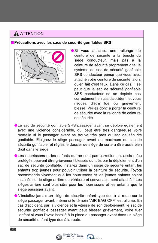
656
ATTENTION
■Précautions avec les sacs de sécurité gonflables SRS
●Le sac de sécurité gonflable SRS passager avant se déploie égalementavec une violence considérable, qui peut être très dangereuse voiremortelle si le passager avant se trouve très près du sac de sécuritégonflable. Éloignez le siège passager avant au maximum du sac desécurité gonflable, et réglez le dossier de siège de sorte à être assis biendroit dans le siège.
●Les nourrissons et les enfants qui ne sont pas correctement assis et/ouprotégés peuvent être grièvement blessés ou tués par le déploiement d'unsac de sécurité gonflable. Installez dans un siège de sécurité enfant lesenfants trop jeunes pour pouvoir utiliser la ceinture de sécurité. Toyotarecommande vivement que les nourrissons et les jeunes enfants soientinstallés sur le siège arrière du véhicule et convenablement attachés. Lessièges arrière sont plus sûrs pour les nourrissons et les enfants que lesiège passager avant.
●N'installez jamais un siège de sécurité enfant type dos à la route sur lesiège passager avant, même si le témoin “AIR BAG OFF” est allumé. Encas d'accident, par la violence et la vitesse de son déploiement, le sac desécurité gonflable passager avant peut blesser grièvement, voire tuerl'enfant si vous l'avez installé à la place du passager avant dans un siègede sécurité enfant type dos à la route.
●Si vous attachez une rallonge deceinture de sécurité à la boucle dusiège conducteur, mais pas à laceinture de sécurité proprement dite, lesystème de sac de sécurité gonflableSRS conducteur pense que vous avezattaché votre ceinture de sécurité, alorsqu'en fait c'est faux. Dans ce cas, il sepeut que le sac de sécurité gonflableSRS conducteur ne se déploie pascorrectement en cas d'accident, et vousrisquez d'être tué ou grièvementblessé. Veillez donc à porter la ceinturede sécurité avec la rallonge de ceinturede sécurité.
CTH17AS014
Information Provided by:
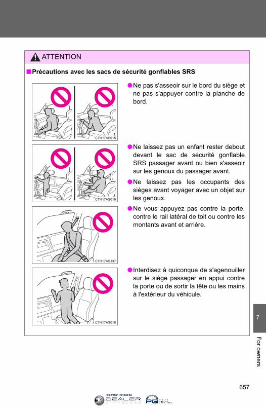
657
7
For owners
ATTENTION
■Précautions avec les sacs de sécurité gonflables SRS
●Ne pas s'asseoir sur le bord du siège etne pas s'appuyer contre la planche debord.
●Ne laissez pas un enfant rester deboutdevant le sac de sécurité gonflableSRS passager avant ou bien s'asseoirsur les genoux du passager avant.
●Ne laissez pas les occupants dessièges avant voyager avec un objet surles genoux.
●Ne vous appuyez pas contre la porte,contre le rail latéral de toit ou contre lesmontants avant et arrière.
● Interdisez à quiconque de s'agenouillersur le siège passager en appui contrela porte ou de sortir la tête ou les mainsà l'extérieur du véhicule.
CTH17AS015
CTH17AS016
CTH17AS137
CTH17AS018
Information Provided by:
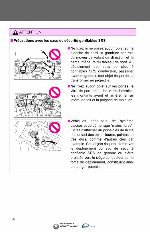
658
ATTENTION
■Précautions avec les sacs de sécurité gonflables SRS
●Ne fixez ni ne posez aucun objet sur laplanche de bord, la garniture centraledu moyeu de volant de direction et lapartie inférieure du tableau de bord. Audéploiement des sacs de sécuritégonflables SRS conducteur, passageravant et genoux, tout objet risque de setransformer en projectile.
●Ne fixez aucun objet sur les portes, lavitre de pare-brise, les vitres latérales,les montants avant et arrière, le raillatéral de toit et la poignée de maintien.
●Véhicules dépourvus de systèmed'accès et de démarrage “mains libres”:Évitez d'attacher au porte-clés de la cléde contact des objets lourds, pointus outrès durs, comme d'autres clés parexemple. Ces objets risquent d'entraverle déploiement du sac de sécuritégonflable SRS de genoux ou d'êtreprojetés vers le siège conducteur par laforce de déploiement, constituant ainsiun danger potentiel.
CTH17AS077
CTH17AS020
CTH17AS021
Information Provided by:
659
7
For owners
ATTENTION
■Précautions avec les sacs de sécurité gonflables SRS
●Ne suspendez aux crochets à vêtements aucun cintre nu ni aucun objetdur. En cas de déploiement des sacs de sécurité gonflables rideau SRS,tous ces objets pourraient se transformer en projectiles et causer desblessures graves, voire mortelles.
●Si une housse en vinyle recouvre la partie où le sac de sécurité gonflableSRS de genoux se déploie, veillez à l'enlever.
●N'utilisez aucun accessoire de siège venant recouvrir les zones dedéploiement des sacs de sécurité gonflables SRS latéraux, car il risqueraitd'en gêner le déploiement. De tels accessoires peuvent empêcher lessacs de sécurité gonflables latéraux de fonctionner correctement,désactiver le dispositif ou entraîner le déploiement accidentel des sacs desécurité latéraux, entraînant la mort ou des blessures graves.
●Évitez de faire subir des chocs ou des pressions excessives aux zonesrenfermant les composants des sacs de sécurité gonflables SRS. En effet, cela pourrait entraîner un fonctionnement anormal des sacs desécurité gonflables SRS.
●Ne touchez aucun composant du système immédiatement après ledéclenchement (déploiement) des sacs de sécurité gonflables SRS, car ilssont alors encore très chauds.
●Si vous avez des difficultés à respirer après le déploiement des sacs desécurité gonflables SRS, ouvrez une porte ou une vitre pour faire entrer del'air frais, ou bien descendez du véhicule si cela ne présente pas dedanger. Essuyez tout résidu dès que possible afin d'éviter d'éventuellesirritations de la peau.
●Si les parties renfermant les sacs de sécurité gonflables SRS, telles que lagarniture du moyeu de volant et les garnitures de montants avant etarrière, apparaissent abîmées ou craquelées, faites-les remplacer parvotre concessionnaire Toyota.
Information Provided by:

660
ATTENTION
■Modification et mise au rebut des éléments du système de sacs de
sécurité gonflables SRS
Consultez impérativement votre concessionnaire Toyota si vous avez besoind'intervenir sur votre véhicule ou de procéder à l'une des modificationssuivantes. Les sacs de sécurité gonflables SRS risquent de ne pasfonctionner correctement ou de se déployer (gonfler) accidentellement,provoquant ainsi des blessures graves, voire mortelles.
● Installation, dépose, démontage et réparations des sacs de sécuritégonflables SRS
●Réparation, modification, dépose ou remplacement du volant de direction,du tableau de bord, de la planche de bord, des sièges ou de leur sellerie,des montants avant et arrière, des rails latéraux de toit ou de la garniturede toit
●Réparation ou modification de l'aile avant, du bouclier avant ou du flanc del'habitacle
● Installation de chasse-neige, de treuils, etc. sur la calandre (pare-buffle,pare-kangourou, etc.).
●Modification des suspensions du véhicule
● Installation d'appareils électroniques, tels qu'un radioémetteur/récepteurou d'un lecteur CD
●Aménagements du véhicule visant à permettre sa conduite par unepersonne atteinte d'un handicap physique
Information Provided by:
661
7
For owners
Désactivation des sacs de sécurité gonflables rideau en cas de
retournement du véhicule
Activation/désactivation(maintenez pendant quelquessecondes)
Véhicules dépourvus de systèmed'accès et de démarrage “mainslibres”: Le témoin “RSCA OFF”s'allume. (Uniquement lorsque lecontacteur de démarrage antivolest sur la position “ON”).
La fonction de détection deretournement des sacs desécurité gonflables rideau et desprétensionneurs de ceintures desécurité est automatiquementréactivée dès lors que vousmettez la clé de contact sur laposition “ON”.
Véhicules équipés d'un systèmed'accès et de démarrage “mainslibres”: Le témoin “RSCA OFF”s'allume. (Uniquement lorsque lebouton de démarrage/d'arrêtmoteur “ENGINE START STOP”est en mode DÉMARRAGE).
La fonction de détection deretournement des sacs desécurité gonflables rideau et desprétensionneurs de ceintures desécurité est automatiquementréactivée dès lors que vousmettez le bouton de démarrage/d'arrêt moteur “ENGINE STARTSTOP” en mode DÉMARRAGE.
CTH17AS084
Information Provided by:
662
ATTENTION
■En marche normale
Assurez-vous que le témoin “RSCA OFF” n'est pas allumé. Si vous lelaissez en position marche, les sacs de sécurité gonflables rideau ne sedéploieront pas en cas d'accident, ce qui peut provoquer des blessuresgraves, voire mortelles.
Information Provided by:

664
Abbreviation list
Abbreviation/Acronym list
ABBREVIATIONS MEANING
2WD 2 Wheel Drive
4WD 4 Wheel Drive
ABS Anti-lock Brake System
ACC Accessory
AI-SHIFT Artificial Intelligence Shift control
ALR Automatic Locking Retractor
A-TRAC Active traction control system
AUTO LSD Automatic Limited Slip Differential
AUX Auxiliary
CRS Child Restraint System
DAC Downhill assist control system
ECU Electronic Control Unit
EDR Event Data Recorder
ELR Emergency Locking Retractor
GAWR Gross Axle Weight Rating
GCWR Gross Combination Weight Rating
GVWR Gross Vehicle Weight Rating
I/M Emission Inspection and Maintenance
KDSS Kinetic Dynamic Suspension System
LATCH Lower Anchors and Tethers for Children
LED Light Emitting Diode
LSD Limited Slip Differential
MAX Maximum
MIN Minimum
MMT Methylcy clopentadienyl Manganese Tricarbonyl
M+S Mud and Snow
MTBE Methyl Tertiary Butyl Ether
Information Provided by:
665
Abbreviation list
OBD On Board Diagnostics
RSCA Roll Sensing of Curtain Shield airbag
SRS Supplemental Restraint System
TIN Tire Identification Number
TPMS Tire Pressure Warning System
TRAC/TRC Traction Control
VIN Vehicle Identification Number
VSC Vehicle Stability Control
ABBREVIATIONS MEANING
Information Provided by:

666
Alphabetical index
Alphabetical index
A/C.....................................296, 302ABS ...........................................253Accessory meter ......................194Active head restraints ...............62Active traction control.............230Air conditioning filter...............526Air conditioning system
Air conditioning filter..............526Automatic air conditioning
system ................................302Manual air conditioning
system ................................296Airbags
Airbag operating conditions...118Airbag precautions for your
child ....................................122Airbag warning light...............566Curtain shield airbag
operating conditions............118Curtain shield airbag
precautions .........................122Front passenger occupant
classification system...........130General airbag precautions...122Locations of airbags..............115Modification and disposal
of airbags............................127Proper driving posture...113, 122Roll sensing of curtain shield
airbags off switch ................128Side airbag operating
conditions............................118Side airbag precautions ........122SRS airbags ..........................115
Alarm.........................................109Antenna ....................................321Anti-lock brake system ...........253Armrest .....................................448Audio input...............................360Audio remote controls ............361Audio system
Antenna.................................321Audio input ............................360AUX port ...............................360CD player/changer ................324iPod.......................................341MP3/WMA disc .....................333Optimal use...........................355Portable music player ...........360Radio.....................................317Steering wheel audio
switch..................................361Type ......................................313USB memory.........................348
AUTO LSD system...................232Automatic air conditioning
system....................................302Automatic light control
system....................................198Automatic transmission
Automatic transmission.........173If the shift lever cannot be
shifted from P .....................593S mode..................................176
AUX port ...................................360Auxiliary box ............................422
A
Information Provided by:

667
Alphabetical index
Back doorBack door ............................... 56Back window .......................... 94Smart key system................... 33Wireless remote control.......... 47
Back-up lightsReplacing light bulbs ............ 542Wattage................................ 624
Back window ............................. 94Battery
Checking .............................. 509If the vehicle has a
discharged battery ............ 599Preparing and checking
before winter ...................... 275Bluetooth® audio..................... 364Bluetooth® phone ................... 380Bottle holder ............................ 427Brake
Fluid...................................... 505Parking brake ....................... 180
Brake assist ............................. 253Break-in tips ............................ 155Brightness control
Instrument light control ......... 187
CareExterior..................................478Interior ...................................481Seat belts ..............................482
Cargo capacity .........................267Cargo hooks.............................456Cargo net hooks.......................457CD player/changer ...................324Center differential lock ............226Chains.......................................277Child-protectors .........................53Child restraint system
Booster seats, definition........136Booster seats, installation .....140Convertible seats,
definition .............................136Convertible seats,
installation...........................140Front passenger occupant
classification system...........130Infant seats, definition ...........136Infant seats, installation.........140Installing CRS with
LATCH system....................142Installing CRS with
seat belts ............................145Installing CRS with top
straps..................................148
B C
Information Provided by:

668
Alphabetical index
Child safetyAirbag precautions ................122Battery precautions .......511, 603Child-protectors.......................53Child restraint system............136How your child should wear
the seat belt ..........................82Installing child restraints........140Moon roof precautions ..........101Power window lock switch.......91Power window precautions .....93Removed key battery
precautions .........................530Seat belt extender
precautions ...........................84Seat belt precautions ..............83Seat heater precautions ........446
CleaningExterior..................................478Interior ...................................481Seat belts ..............................482
Clock .........................................431Coin holder ...............................419Compass...................................450Condenser ................................504Console box .............................418Cooling system
Engine overheating ...............604Crawl Control ...........................241Cruise control...........................209Cup holder ................................423Curtain shield airbags .............115Customizable features.............640
Daytime running light system....................................202
DefoggerRear window .........................310Side mirrors...........................310
Dimension ................................612Dinghy towing..........................293Display
Trip information .....................195Do-it-yourself maintenance ....491Door courtesy lights
Door courtesy lights ..............413Wattage.................................624
Door lockBack door..........................33, 56Side door...........................33, 51Wireless remote control ..........47
DoorsBack door..........................33, 56Door windows .........................91Side door...........................33, 51Side mirrors.............................89
Downhill assist control system....................................238
Driver’s seat belt reminder light.........................................568
D
Information Provided by:

669
Alphabetical index
DrivingBreak-in tips ......................... 155Correct posture..................... 113Driving assist systems.......... 253Off-road precautions............. 262Procedures ........................... 154Winter driving tips................. 275
Electronic key If your electronic key
battery is depleted...... 528, 597Emergency flashers
Switch................................... 554Emergency, in case of
If the electronic key does not operate properly........... 597
If the engine will not start...... 591If the shift lever cannot be
shifted from P..................... 593If the vehicle has a
discharged battery ............ 599If the warning buzzer
sounds ............................... 565If the warning light
turns on.............................. 565If you cannot operate back
door opener........................ 596If you have a flat tire ............ 578If you lose your keys............. 595If you think something is
wrong ................................. 561If your vehicle becomes
stuck................................... 607If your vehicle has to be
stopped in an emergency... 608If your vehicle needs to be
towed ................................. 555If your vehicle overheats ...... 604
EngineCompartment ........................495Engine switch ................164, 167Hood......................................494How to start
the engine ...................164, 167Identification number.............613If the engine will not start ......591Ignition switch................164, 167Overheating...........................604
Engine compartment cover.....497Engine coolant
Capacity ................................618Checking ...............................503Preparing and checking
before winter .......................275Engine coolant temperature
gauge......................................182Engine immobilizer system.....106Engine oil
Capacity ................................616Checking ...............................498Preparing and checking
before winter .......................275Engine oil maintenance
data .........................................501Engine switch...................164, 167Event data recorder .................563
E
Information Provided by:
670
Alphabetical index
Floor mat...................................449Fluid
Brake.....................................505Power steering ......................507Washer..................................512
Fog lightsReplacing light bulbs .............541Switch....................................204Wattage.................................624
Four-wheel drive system ............................223, 226
Front passenger occupant classification system ............130
Front passenger’s seat belt reminder light .................568
Front seatsAdjustment ..............................61
Front side marker lightReplacing light bulbs .............541Switch....................................198Wattage.................................624
Front turn signal lightsReplacing light bulbs .............541Switch....................................179Wattage.................................624
FuelCapacity ................................615Fuel gauge ............................182Fuel pump shut off system....562Gas station information .........680Information ............................625Refueling ...............................102Type ......................................615
Fuel door...................................102Fuel filler door ..........................102Fuel pump shut off
system ....................................562Fuses.........................................531
Garage door opener ................462Gas station information ..........680Gauges......................................182Glove box .................................417Grocery bag hooks ..................459
Hands-free system (for cellular phone)................380
Hazard lightsSwitch ...................................554
Head restraintsAdjusting .................................76
HeadlightsReplacing light bulbs.............541Switch ...................................198Wattage.................................624
HeatersSeat heaters..........................446Side mirrors...........................310
Hill-start assist control............253Hood..........................................494Hooks
Cargo hook ...........................456Cargo net hooks....................457Grocery bag hooks................459
Horn ..........................................181
F G
H
Information Provided by:

671
Alphabetical index
I/M test...................................... 490Identification
Engine .................................. 613Vehicle.................................. 613
Ignition switch ................. 164, 167Illuminated entry system........ 415Indicator lights ........................ 189Initialization
Items to initialize................... 646Inside rear view mirror.............. 87Instrument panel light
control.................................... 187Interior lights
Interior lights......................... 413Switch................................... 414Wattage................................ 624
Intuitive parking assist ........... 213
JackVehicle-equipped jack .......... 578
Jack handle.............................. 578
KDSS.........................................253Keyless entry..............................47Keys
Electronic key..........................30Engine switch ................164, 167If the electronic key does
not operate properly............597If you lose your keys .............595Ignition switch................164, 167Key number.............................30Keyless entry...........................47Keys ........................................30Mechanical key .......................30Wireless remote control key....47
LanguageAudio .....................................315
Licence plate lightsReplacing light bulbs .............541Wattage.................................624
Light bulbsReplacing ..............................541Wattage.................................624
I
J
K
L
Information Provided by:

672
Alphabetical index
LightsDoor courtesy lights ..............413Emergency flasher switch .....554Engine switch light ................413Fog light switch .....................204Footwell lights .......................413Hazard light switch ................554Headlight switch ....................198Inside door handle lights .......413Interior light switch ................414Luggage compartment
lights .....................................57Outer foot lights.....................413Personal light switch .............414Replacing light bulbs .............541Shift lever light.......................413Turn signal lever....................179Vanity lights...........................430Wattage.................................624
Limited slip differential............253Load capacity ...........................273Lock steering column......165, 170Luggage compartment
features...................................456
MaintenanceDo-it-yourself
maintenance .......................491General maintenance............486Maintenance data .................612Maintenance requirements ...484
Manual air conditioning system....................................296
MeterAccessory meter ...................194Instrument panel light
control.................................187Meters ...................................182
MirrorsInside rear view mirror ............87Side mirror heaters ...............310Side mirrors.............................89Vanity mirrors........................430
Moon roof ...................................98MP3 disc ...................................333Multi Terrain ABS.....................253Multi-terrain Select ..................245
Noise from under vehicle..........24
M
N
Information Provided by:
673
Alphabetical index
Odometer ................................. 182Off-road precautions............... 262Oil
Engine oil.............................. 498Opener
Fuel filler door....................... 102Hood..................................... 494
Outside rear view mirrorsAdjusting and folding .............. 89
Outside temperature display ................................... 433
Overhead console ................... 422Overheating, Engine ............... 604
Parking brake .......................... 180Parking lights
Replacing light bulbs ............ 541Switch................................... 198 Wattage................................ 624
Party mode switch .................. 359Pen holder................................ 421Personal lights
Switch................................... 414Wattage................................ 624
Power back window.................. 94Power outlets................... 436, 439Power steering
Fluid...................................... 507Power windows ......................... 91
Radiator ....................................504Radio .........................................317Rear differential lock
system ....................................235Rear seats
Adjustment ..............................65Folding down...............67, 69, 72
Rear step bumper ......................57Rear turn signal lights
Replacing light bulbs .............541Wattage.................................624
Rear view monitor system ......218Rear window...............................94Rear window defogger ............310Rear window wiper ..................207Replacing
Fuses ....................................531Key battery ............................528Light bulbs.............................541Tires ......................................578
Reporting safety defects for U.S. owners ......................648
Roll sensing of curtain shield airbags off switch.......128
Roof luggage carrier................267
O
P
R
Information Provided by:
674
Alphabetical index
Safety Connect.........................469Seat belts
Adjusting the seat belt.............79Automatic Locking
Retractor ...............................81Child restraint system
installation...........................140Cleaning and maintaining
the seat belts ......................482Emergency Locking
Retractor ...............................81How to wear your seat belt......79How your child should wear
the seat belt ..........................82Pregnant women,
proper seat belt use..............81Reminder light .......................568Seat belt extenders .................82Seat belt pretensioners ...........80
Seat heaters..............................446Seating capacity.......................273Seats
Adjustment ........................61, 65Adjustment precautions.....64, 75Child seats/child restraint
system installation ..............140Cleaning................................481Head restraints........................76Properly sitting in the seat.....113Seat heaters..........................446
Service reminder indicators ..............................189
Shift leverAutomatic transmission.........173Front-wheel drive ..................223If the shift lever cannot be
shifted from P .....................593Shift lock system .....................593Side airbags .............................115Side marker lights
Replacing light bulbs.............541Switch ...................................198Wattage.................................624
Side mirrorsAdjusting and folding...............89
Slide deck .................................459Smart key system
Entry function ..........................33Starting the engine................167
“SOS” button ...........................469Spare tire
Inflation pressure ..................623Storage location ....................578
Spark plug ................................618Specifications ..........................612Speech command switch........385Speedometer ............................182Steering
Column lock release .....165, 170Fluid ......................................507
Steering wheelAdjustment ..............................86Audio switches ......................361
Stop lights Replacing light bulbs.............541Wattage.................................624
S
Information Provided by:

675
Alphabetical index
Storage compartment ............. 458Storage feature........................ 416Storage precautions ............... 270Stuck
If your vehicle becomes stuck................................... 607
Sun visors................................ 429Sunshade
Roof........................................ 98Switch
Emergency flasher switch .... 554Engine switch ............... 164, 167Fog light switch..................... 204Hazard light switch ............... 554Ignition switch............... 164, 167Light switches....................... 198Power back window switch..... 94Power door lock switch........... 52Power window switch ............. 91Rear window wiper and
washer switch .................... 207Window lock switch ................ 91Wiper and washer switch ..... 205
TachometerTachometer ...........................182
Tail lightsReplacing light bulbs .............541Switch....................................198Wattage.................................624
Talk switch................................385Telephone switch.....................385Theft deterrent system
Alarm.....................................109Engine immobilizer system ...106
Theft prevention labels............112Tire inflation pressure .............520Tire information
Glossary ................................633Size .......................................630Tire identification number......629Uniform tire quality grading ...631
TiresChains ...................................275Checking ...............................514If you have a flat tire..............578Inflation pressure...................520Inflation pressure sensor.......514Information ............................628Replacing ..............................578Rotating tires .........................514Size .......................................623Snow tires .............................275Spare tire...............................578
Tissue pocket ...........................420Tools .........................................578Total load capacity...................273Towing
Dinghy towing........................293Emergency towing.................555Trailer towing.........................280
TRAC (TRC) ..............................253Traction control........................253Trip information .......................194Trip meter .................................182
T
Information Provided by:

676
Alphabetical index
Turn signal lightsReplacing light bulbs .............541Switch....................................179Wattage.................................624
Valet key .....................................30Vanity lights
Vanity lights...........................430Wattage.................................624
Vanity mirrors...........................430Vehicle identification
number ...................................613Vehicle stability control...........253VSC............................................253
Warning buzzersBrake system ........................565Key reminder.........................572Open door ............................567Open moon roof reminder .....572Seat belt reminder.................568
Warning lightsAnti-lock brake system..........567Automatic transmission
fluid temperature.................568Brake system ........................565Charging system ...................566Engine oil pressure ...............566Engine oil replacement..........569KDSS ....................................567Low fuel level ........................568Low washer fluid ...................568Malfunction indicator lamp ....566Open door .............................567Power steering ......................567Pretensioners ........................566Seat belt reminder.................568Smart key system..................570SRS airbags ..........................566Tire pressure .........................568Unengaged “Park”.................567
WasherChecking ...............................512Preparing and checking
before winter.......................275Switch ...........................205, 207
Washing and waxing ...............478Weight
Cargo capacity ......................267Load limits.............................273Weight...................................612
Wheels ......................................524Window glasses ..................91, 94Window lock switch...................91Windows
Power back window ................94Power windows.......................91Rear window defogger ..........310Washer..........................205, 207
Windshield wiper de-icer ........312Windshield wipers ...................205Wireless remote control key
Replacing the battery ............528Wireless remote control key....47
WMA disc..................................333
V
W
Information Provided by:
677
What to do if...
What to do if...
A tire punctures P. 578 If you have a flat tire
The engine does not startP. 106 Engine immobilizer systemP. 591 If the engine will not startP. 599 If the vehicle battery is discharged
The shift lever cannot be moved out of P P. 593
If the shift lever cannot be shifted from P
The engine coolant temperature gauge enters the red zone
Steam can be seen coming from under the hood
P. 604 If your vehicle overheats
The key is lost P. 595 If you lose your keys
The battery runs out P. 599 If the vehicle battery is discharged
The doors cannot be lockedP. 51 Side doorsP. 56 Back door
The horn begins to sound P. 109 Alarm
The vehicle is stuck in mud or sand P. 607 If the vehicle becomes stuck
A warning light or indicator light comes on P. 565
If a warning light turns on or a warning buzzer sounds
Information Provided by:
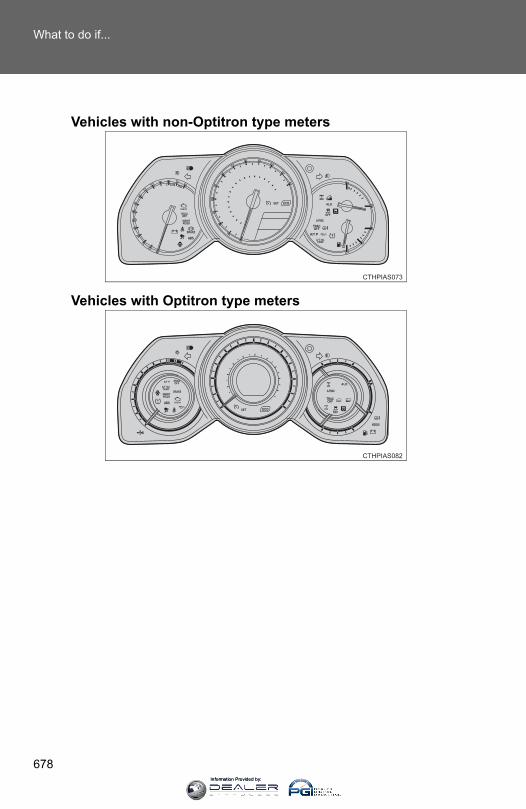
678
What to do if...
Vehicles with non-Optitron type meters
Vehicles with Optitron type meters
CTHPIAS082
Information Provided by:

679
What to do if...
■Warning lights
P. 567or
P. 567or
P. 565 P. 568
P. 566 P. 568
P. 566 P. 568
P. 566 P. 569
P. 566 P. 568
P. 567 P. 568
P. 568or
P. 567 P. 570
P. 567 P. 567
Brake system warning light
Unengaged “Park” warning light
Power steering warning light
Low fuel level warning light
Charging system warn-ing light
Driver’s seat belt reminder light
Low engine oil pressure warning light
Front passenger’s seat belt reminder light
Malfunction indicator lamp
Engine oil replacement reminder light
SRS warning light Low windshield washer fluid warning light
Open door warning light Automatic transmission fluid temper-ature warning light
ABS warning light Tire pressure warning light
Smart key system warn-ing light
Slip indicator KDSS warning light
Information Provided by:
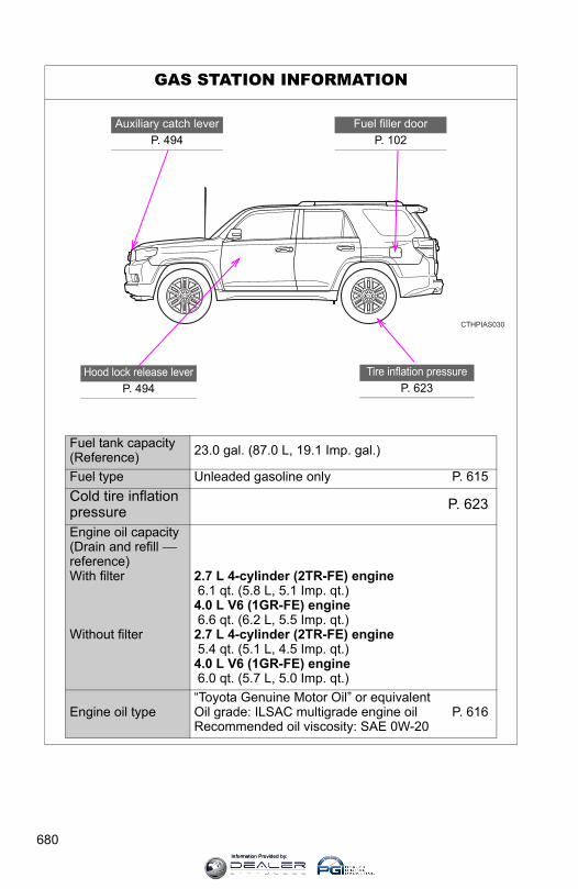
680
GAS STATION INFORMATION
CTHPIAS030
Auxiliary catch leverP. 494
Fuel filler doorP. 102
Tire inflation pressureP. 623
Hood lock release leverP. 494
Fuel tank capacity(Reference) 23.0 gal. (87.0 L, 19.1 Imp. gal.)
Fuel type Unleaded gasoline only P. 615Cold tire inflation pressure P. 623
Engine oil capacity (Drain and refill ⎯ reference)With filter
Without filter
2.7 L 4-cylinder (2TR-FE) engine 6.1 qt. (5.8 L, 5.1 Imp. qt.)4.0 L V6 (1GR-FE) engine 6.6 qt. (6.2 L, 5.5 Imp. qt.)2.7 L 4-cylinder (2TR-FE) engine 5.4 qt. (5.1 L, 4.5 Imp. qt.)4.0 L V6 (1GR-FE) engine 6.0 qt. (5.7 L, 5.0 Imp. qt.)
Engine oil type“Toyota Genuine Motor Oil” or equivalentOil grade: ILSAC multigrade engine oil P. 616Recommended oil viscosity: SAE 0W-20
Information Provided by: