2018-yaris.pdf - Dealer E Process
520
Pictorial index Search by illustration 1 For safety and security Make sure to read through them 2 Instrument cluster How to read the gauges and meters, the variety of warning lights and indicators, etc. 3 Operation of each component Opening and closing the doors and windows, adjustment before driving, etc. 4 Driving Operations and advices which are necessary for driving 5 Multimedia system Operating the multimedia system 6 Interior features Usage of the interior features, etc. 7 Maintenance and care Caring for your vehicle and maintenance procedures 8 When trouble arises What to do in case of malfunction or emergency 9 Vehicle specifications Vehicle specifications, customizable features, etc. 10 For owners Reporting safety defects for U.S. owners, and seat belt and SRS airbag instructions for Canadian owners Index Search by symptom Search alphabetically
-
Upload
khangminh22 -
Category
Documents
-
view
1 -
download
0
Transcript of 2018-yaris.pdf - Dealer E Process

Pictorial index Search by illustration
1For safety and security Make sure to read through them
2Instrument cluster
How to read the gauges and meters, the variety of warning lights and indicators, etc.
3Operation of each component
Opening and closing the doors and windows, adjustment before driving, etc.
4 Driving Operations and advices which are necessary for driving
5Multimedia system Operating the multimedia system
6 Interior features Usage of the interior features, etc.
7Maintenance and care
Caring for your vehicle and maintenance procedures
8When trouble arises What to do in case of malfunction or emergency
9Vehicle specifications Vehicle specifications, customizable features, etc.
10 For ownersReporting safety defects for U.S. owners, and seat belt and SRS airbag instructions for Canadian owners
IndexSearch by symptom
Search alphabetically
TABLE OF CONTENTS2
For your information....................... 8
Reading this manual .................... 12
How to search.............................. 13
Pictorial index .............................. 14
1-1. For safe use
Before driving ...................... 24
For safety drive ................... 26
Seat belts ............................ 28
SRS airbags ........................ 36
Front passenger occupant classification system ......... 49
Exhaust gas precautions..... 55
1-2. Child safety
Riding with children ............. 56
Child restraint systems........ 57
1-3. Theft deterrent system
Engine immobilizer system............................... 74
Theft prevention labels (except Canada) .............. 76
2. Instrument cluster
Warning lights and indicators........................... 78
Gauges and meters............. 83
Multi-information display ..... 85
Fuel consumption information ........................ 89
3-1. Key information
Keys.....................................92
3-2. Opening, closing and locking the doors
Side doors ...........................96
Back door ..........................101
3-3. Adjusting the seats
Front seats.........................106
Rear seats .........................109
Head restraints ..................113
3-4. Adjusting the steering wheel and mirrors
Steering wheel...................116
Inside rear view mirror .......118
Outside rear view mirrors .............................120
3-5. Opening and closing the windows
Power windows..................122
1 For safety and security
2 Instrument cluster
3 Operation of each component
3
1
4
3
2
9
8
7
5
10
6
4-1. Before driving
Driving the vehicle............. 126
Cargo and luggage............ 137
Vehicle load limits ............. 141
Trailer towing..................... 142
Dinghy towing (vehicles with an automatic transmission)................... 143
Dinghy towing (vehicles with a manual transmission)................... 144
4-2. Driving procedures
Engine (ignition) switch ..... 146
Automatic transmission ..... 149
Manual transmission ......... 153
Turn signal lever................ 154
Parking brake .................... 1554-3. Operating the lights
and wipers
Headlight switch ................ 156
Fog light switch ................. 160
Windshield wipers and washer ..................... 162
Rear window wiper and washer ..................... 165
4-4. Refueling
Opening the fuel tank cap...................................168
4-5. Toyota Safety Sense C
Toyota Safety Sense C......171
PCS (Pre-Collision System).....177
LDA (Lane Departure Alert).....191
Automatic High Beam........1964-6. Using the driving support
systems
Cruise control ....................201
Rear view monitor system .............................205
Driving assist systems .......2154-7. Driving tips
Winter driving tips ..............221
4 Driving
TABLE OF CONTENTS4
5-1. Basic Operations
Audio system types ........... 228
Audio system..................... 229
Steering wheel audio switches .......................... 231
USB port/AUX port ............ 232
Basic audio operations...... 233
5-2. Setup
Setup menu....................... 235
General settings ................ 236
Audio settings.................... 238
Display settings ................. 239
Voice settings.................... 240
5-3. Using the multimedia system
Selecting the audio source ............................. 241
List screen operation......... 242
Optimal use of the multimedia system .......... 244
5-4. Using the radio
Radio operation................. 245
5-5. Playing an audio CD and MP3/WMA/AAC discs
CD player operation .......... 247
5-6. Using an external device
Listening to an iPod ...........253
Listening to a USB memory device ................257
Using the AUX port............262
5-7. Connecting Bluetooth®
Preparations to use wireless communication ................263
Registering a Bluetooth® audio player for the first time................267
Registering a Bluetooth® phone for the first time ....268
Registering a Bluetooth® device ..............................269
Connecting a Bluetooth® device ..............................271
Displaying a Bluetooth® device details...................273
Detailed Bluetooth® system settings................274
5-8. Bluetooth® audio
Listening to Bluetooth®
audio................................276
5 Multimedia system

5
1
4
3
2
9
8
7
5
10
6
5-9. Bluetooth® phone
Using a Bluetooth® phone .............................. 277
Making a call ..................... 279
Receiving a call ................. 282
Speaking on the phone ..... 283
Bluetooth® phone message function............ 286
Using the steering wheel switches................ 290
Bluetooth® phone settings............................ 291
Contact/Call History Settings ........................... 293
What to do if... (Troubleshooting)............ 303
5-10.Bluetooth®
Bluetooth®......................... 307
5-11.Using the voice command system
Voice command system.... 311
6-1. Using the air conditioning system and defogger
Air conditioning system......318
Seat heaters ......................326
6-2. Using the interior lights
Interior lights list.................328• Interior light ...................328• Personal lights...............329
6-3. Using the storage features
List of storage features ......330• Glove box ......................331• Cup holders...................331• Bottle holders ................332• Auxiliary box..................333
Luggage compartment features ...........................334
6-4. Using the other interior features
Other interior features........336• Sun visors .....................336• Vanity mirrors ................336• Power outlet ..................337• Assist grips....................338
6 Interior features

TABLE OF CONTENTS6
7-1. Maintenance and care
Cleaning and protecting the vehicle exterior.......... 340
Cleaning and protecting the vehicle interior........... 344
7-2. Maintenance
Maintenance requirements ................... 347
General maintenance........ 349
Emission inspection and maintenance (I/M) programs......................... 352
7-3. Do-it-yourself maintenance
Do-it-yourself service precautions ..................... 353
Hood.................................. 356
Positioning a floor jack ...... 358
Engine compartment ......... 360
Tires .................................. 370
Tire inflation pressure........ 378
Wheels .............................. 382
Air conditioning filter.......... 385
Wireless remote control battery ............................. 388
Checking and replacing fuses ............................... 391
Light bulbs......................... 396
8-1. Essential information
Emergency flashers...........412
If your vehicle has to be stopped in an emergency..................413
8-2. Steps to take in an emergency
If your vehicle needs to be towed..........................415
If you think something is wrong...............................420
Fuel pump shut off system .............................421
If a warning light turns on or a warning buzzer sounds.............................422
If you have a flat tire ..........433
If the engine will not start...448
If the vehicle battery is discharged.......................450
If your vehicle overheats....453
If the vehicle becomes stuck ................................456
7 Maintenance and care 8 When trouble arises

7
1
4
3
2
9
8
7
5
10
6
9-1. Specifications
Maintenance data (fuel, oil level, etc.) .......... 460
Fuel information ................ 471
Tire information ................. 474
9-2. Customization
Customizable features ...... 488
Items to initialize................ 490
Reporting safety defects for U.S. owners........................ 492
Seat belt instructions for Canadian owners (in French) ............................... 493
SRS airbag instructions for Canadian owners (in French) .............................. 495
What to do if... (Troubleshooting).....................506
Alphabetical index ......................509
9 Vehicle specifications
10 For owners
Index
For vehicles with Entune Audio Plus, refer to the “MULTIMEDIA SYS-TEM OWNER’S MANUAL” for information regarding the multimediasystem.
Audio system types: →P. 228

8
For your information
Please note that this manual applies to all models and explains all equipment,including options. Therefore, you may find some explanations for equipmentnot installed on your vehicle.
All specifications provided in this manual are current at the time of printing.However, because of the Toyota policy of continual product improvement, wereserve the right to make changes at any time without notice.
Depending on specifications, the vehicle shown in the illustrations may differfrom your vehicle in terms of equipment.
Approximately five hours after the engine is turned off, you may hear a soundcoming from under the vehicle for several minutes. This is the sound of a fuelevaporation leakage check and, it does not indicate a malfunction.
A wide variety of non-genuine spare parts and accessories for Toyota vehi-cles are currently available on the market. You should know that Toyota doesnot warrant these products and is not responsible for their performance,repair, or replacement, or for any damage they may cause to, or adverseeffect they may have on, your Toyota vehicle.
This vehicle should not be modified with non-genuine Toyota products. Modi-fication with non-genuine Toyota products could affect its performance, safetyor durability, and may even violate governmental regulations. In addition,damage or performance problems resulting from the modification may not becovered under warranty.
Main Owner’s Manual
Noise from under vehicle after turning off the engine
Accessories, spare parts and modification of your Toyota

9
The installation of a mobile two-way radio system in your vehicle could affectelectronic systems such as:
●Multiport fuel injection system/sequential multiport fuel injection system
●Cruise control system (if equipped)
●Anti-lock brake system
●SRS airbag system
●Seat belt pretensioner system
●Toyota Safety Sense C (if equipped)
Be sure to check with your Toyota dealer for precautionary measures or spe-cial instructions regarding installation of a mobile two-way radio system.
Your Toyota is equipped with several sophisticated computers that will recordcertain data, such as:
• Engine speed• Accelerator status• Brake status• Vehicle speed• Shift position (except manual transmission)
The recorded data varies according to the vehicle grade level and optionswith which it is equipped. These computers do not record conversations orsounds, and only record images outside of the vehicle in certain situations.
● Data TransmissionYour vehicle may transmit the data recorded in these computers to Toyotawithout notification to you.
● Data usageToyota may use the data recorded in these computers to diagnose malfunc-tions, conduct research and development, and improve quality.
Toyota will not disclose the recorded data to a third party except:
• With the consent of the vehicle owner or with the consent of the lessee ifthe vehicle is leased
• In response to an official request by the police, a court of law or a govern-ment agency
• For use by Toyota in a lawsuit• For research purposes where the data is not tied to a specific vehicle or
vehicle owner
● To learn more about the vehicle data collected, used and shared byToyota, please visit www.toyota.com/privacyvts/.
Installation of a mobile two-way radio system
Vehicle data recordings

10
This vehicle is equipped with an event data recorder (EDR). The main pur-pose of an EDR is to record, in certain crash or near crash-like situations,such as an air bag deployment or hitting a road obstacle, data that will assistin understanding how a vehicle’s systems performed. The EDR is designed torecord data related to vehicle dynamics and safety systems for a short periodof time, typically 30 seconds or less.
The EDR in this vehicle is designed to record such data as:
• How various systems in your vehicle were operating;• Whether or not the driver and passenger safety belts were buckled/fas-
tened;• How far (if at all) the driver was depressing the accelerator and/or brake
pedal; and,• How fast the vehicle was traveling.
These data can help provide a better understanding of the circumstances inwhich crashes and injuries occur.
NOTE: EDR data are recorded by your vehicle only if a non-trivial crash situ-ation occurs; no data are recorded by the EDR under normal driving condi-tions and no personal data (e.g., name, gender, age, and crash location) arerecorded. However, other parties, such as law enforcement, could combinethe EDR data with the type of personally identifying data routinely acquiredduring a crash investigation. To read data recorded by an EDR, special equipment is required, and accessto the vehicle or the EDR is needed. In addition to the vehicle manufacturer,other parties, such as law enforcement, that have the special equipment, canread the information if they have access to the vehicle or the EDR.
● Disclosure of the EDR dataToyota will not disclose the data recorded in an EDR to a third party exceptwhen:
• An agreement from the vehicle’s owner (or the lessee for a leased vehi-cle) is obtained
• In response to an official request by the police, a court of law or a govern-ment agency
• For use by Toyota in a lawsuitHowever, if necessary, Toyota may:
• Use the data for research on vehicle safety performance• Disclose the data to a third party for research purposes without disclosing
information about the specific vehicle or vehicle owner
Event data recorder

11
The SRS airbag and seat belt pretensioner devices in your Toyota containexplosive chemicals. If the vehicle is scrapped with the airbags and seat beltpretensioners left as they are, this may cause an accident such as fire. Besure to have the systems of the SRS airbag and seat belt pretensionerremoved and disposed of by a qualified service shop or by your Toyota dealerbefore you scrap your vehicle.
Special handling may apply, See www.dtsc.ca.gov/hazardouswaste/perchlorate.
Your vehicle has components that may contain perchlorate. These compo-nents may include airbag, seat belt pretensioners, and wireless remote con-trol batteries.
Scrapping of your Toyota
Perchlorate Material
WARNING
■General precautions while drivingDriving under the influence: Never drive your vehicle when under the influ-ence of alcohol or drugs that have impaired your ability to operate your vehi-cle. Alcohol and certain drugs delay reaction time, impair judgment andreduce coordination, which could lead to an accident that could result indeath or serious injury.
Defensive driving: Always drive defensively. Anticipate mistakes that otherdrivers or pedestrians might make and be ready to avoid accidents.
Driver distraction: Always give your full attention to driving. Anything thatdistracts the driver, such as adjusting controls, talking on a cellular phone orreading can result in a collision with resulting death or serious injury to you,your occupants or others.
■General precaution regarding children’s safetyNever leave children unattended in the vehicle, and never allow children tohave or use the key.
Children may be able to start the vehicle or shift the vehicle into neutral.There is also a danger that children may injure themselves by playing withthe cigarette lighter, the windows, or other features of the vehicle. In addi-tion, heat build-up or extremely cold temperatures inside the vehicle can befatal to children.

12
Reading this manual
WARNING: Explains something that, if not obeyed, could cause death orserious injury to people.
NOTICE: Explains something that, if not obeyed, could cause damage toor a malfunction in the vehicle or its equipment.
Indicates operating or working procedures. Follow the stepsin numerical order.
Indicates the action (push-ing, turning, etc.) used tooperate switches and otherdevices.
Indicates the outcome of anoperation (e.g. a lid opens).
Indicates the component orposition being explained.
Means “Do not”, “Do not dothis”, or “Do not let this hap-pen”.
1 2 3

13
How to search
■ Searching by name• Alphabetical index .......P. 509
■ Searching by installationposition• Pictorial index................P. 14
■ Searching by symptom orsound• What to do if...
(Troubleshooting) ........P. 506
■ Searching by title• Table of contents .............P. 2

14 Pictorial index
Pictorial index
■Exterior
The illustration represents the 5-door models and may differ from the bodyshape of the 3-door models.
Side doors . . . . . . . . . . . . . . . . . . . . . . . . . . . . . . . . . . . . . . . . P. 96Locking/unlocking . . . . . . . . . . . . . . . . . . . . . . . . . . . . . . . . . . . P. 96Opening/closing the door glasses . . . . . . . . . . . . . . . . . . . . . . P. 122Warning lights . . . . . . . . . . . . . . . . . . . . . . . . . . . . . . . . . . . . . P. 425
Back door . . . . . . . . . . . . . . . . . . . . . . . . . . . . . . . . . . . . . . . . P. 101Locking/unlocking . . . . . . . . . . . . . . . . . . . . . . . . . . . . . . . . . . P. 101Warning lights . . . . . . . . . . . . . . . . . . . . . . . . . . . . . . . . . . . . . P. 425
Outside rear view mirrors . . . . . . . . . . . . . . . . . . . . . . . . . . . P. 120Adjusting the mirror angle . . . . . . . . . . . . . . . . . . . . . . . . . . . . P. 120Folding the mirrors. . . . . . . . . . . . . . . . . . . . . . . . . . . . . . . . . . P. 121Defogging the mirrors* . . . . . . . . . . . . . . . . . . . . . . . . . . . . . . P. 322
1
2
3

15Pictorial index
Wipers. . . . . . . . . . . . . . . . . . . . . . . . . . . . . . . . . . . . . . . P. 162, 165Precautions against winter season . . . . . . . . . . . . . . . . . . . . . P. 221
Fuel filler door . . . . . . . . . . . . . . . . . . . . . . . . . . . . . . . . . . . . P. 168Refueling method. . . . . . . . . . . . . . . . . . . . . . . . . . . . . . . . . . . P. 168Fuel type/fuel tank capacity . . . . . . . . . . . . . . . . . . . . . . . . . . . P. 464
Tires . . . . . . . . . . . . . . . . . . . . . . . . . . . . . . . . . . . . . . . . . . . . P. 370Tire size/inflation pressure . . . . . . . . . . . . . . . . . . . . . . . . . . . . P. 469Winter tires/tire chain . . . . . . . . . . . . . . . . . . . . . . . . . . . . . . . . P. 222Checking/rotation/tire pressure warning system* . . . . . . . . . . P. 370Coping with flat tires . . . . . . . . . . . . . . . . . . . . . . . . . . . . . . . . P. 433
Hood . . . . . . . . . . . . . . . . . . . . . . . . . . . . . . . . . . . . . . . . . . . . P. 356Opening . . . . . . . . . . . . . . . . . . . . . . . . . . . . . . . . . . . . . . . . . . P. 356Engine oil . . . . . . . . . . . . . . . . . . . . . . . . . . . . . . . . . . . . . . . . . P. 464Coping with overheat . . . . . . . . . . . . . . . . . . . . . . . . . . . . . . . . P. 453
Camera . . . . . . . . . . . . . . . . . . . . . . . . . . . . . . . . . . . . . . . . . . P. 205
Headlights/parking lights/front side marker lights/daytime running lights* . . . . . . . . . . . . . . . . . . . . . . . . . . . . P. 156Front turn signal lights . . . . . . . . . . . . . . . . . . . . . . . . . . . . . P. 154
Fog lights* . . . . . . . . . . . . . . . . . . . . . . . . . . . . . . . . . . . . . . . P. 160
Tail lights/rear side marker lights. . . . . . . . . . . . . . . . . . . . . P. 156Rear turn signal lights. . . . . . . . . . . . . . . . . . . . . . . . . . . . . . P. 154
Back-up lightsShifting the shift lever to R. . . . . . . . . . . . . . . . . . . . . . . . P. 149, 153
License plate lights . . . . . . . . . . . . . . . . . . . . . . . . . . . . . . . . P. 156
4
5
6
7
8
Light bulbs of the exterior lights for driving(Replacing method: P. 396, Watts: P. 470)
*: If equipped
9
10
11
12
13

16 Pictorial index
■Instrument panel
Engine switch. . . . . . . . . . . . . . . . . . . . . . . . . . . . . . . . . . . . . P. 146Starting the engine. . . . . . . . . . . . . . . . . . . . . . . . . . . . . . . . . . P. 146Changing engine switch positions . . . . . . . . . . . . . . . . . . . . . . P. 146Emergency stop of the engine . . . . . . . . . . . . . . . . . . . . . . . . . P. 413When the engine will not start . . . . . . . . . . . . . . . . . . . . . . . . . P. 448
Shift lever . . . . . . . . . . . . . . . . . . . . . . . . . . . . . . . . . . . . P. 149, 153Changing the shift position . . . . . . . . . . . . . . . . . . . . . . . P. 149, 153Precautions against towing . . . . . . . . . . . . . . . . . . . . . . . . . . . P. 415When the shift lever does not move*1 . . . . . . . . . . . . . . . . . . . P. 151
Meters . . . . . . . . . . . . . . . . . . . . . . . . . . . . . . . . . . . . . . . . . . . . P. 83Reading the meters . . . . . . . . . . . . . . . . . . . . . . . . . . . . . . . . . . P. 83Warning lights/indicators . . . . . . . . . . . . . . . . . . . . . . . . . . . . . . P. 78When the warning lights come on . . . . . . . . . . . . . . . . . . . . . . P. 422
1
2
3

17Pictorial index
Multi-information display . . . . . . . . . . . . . . . . . . . . . . . . . . . . P. 85
Parking brake . . . . . . . . . . . . . . . . . . . . . . . . . . . . . . . . . . . . . P. 155Applying/releasing . . . . . . . . . . . . . . . . . . . . . . . . . . . . . . . . . . P. 155Precautions against winter season . . . . . . . . . . . . . . . . . . . . . P. 222Warning buzzer . . . . . . . . . . . . . . . . . . . . . . . . . . . . . . . . . . . . P. 422
Turn signal lever . . . . . . . . . . . . . . . . . . . . . . . . . . . . . . . . . . P. 154Headlight switch . . . . . . . . . . . . . . . . . . . . . . . . . . . . . . . . . . P. 156Headlights/parking lights/side marker lights/tail lights/daytime running lights*2 . . . . . . . . . . . . . . . . . . . . . . P. 156Fog lights*2 . . . . . . . . . . . . . . . . . . . . . . . . . . . . . . . . . . . . . . . P. 160
Wiper and washer switch . . . . . . . . . . . . . . . . . . . . . . . P. 162, 165Usage (front) . . . . . . . . . . . . . . . . . . . . . . . . . . . . . . . . . . . . . . P. 162Usage (rear). . . . . . . . . . . . . . . . . . . . . . . . . . . . . . . . . . . . . . . P. 165Adding washer fluid . . . . . . . . . . . . . . . . . . . . . . . . . . . . . . . . . P. 369Warning light*2 . . . . . . . . . . . . . . . . . . . . . . . . . . . . . . . . . . . . P. 426
Emergency flasher switch . . . . . . . . . . . . . . . . . . . . . . . . . . P. 412
Hood lock release lever. . . . . . . . . . . . . . . . . . . . . . . . . . . . . P. 356
Tilt steering lock release lever . . . . . . . . . . . . . . . . . . . . . . . P. 116
Air conditioning system . . . . . . . . . . . . . . . . . . . . . . . . . . . . P. 318Usage . . . . . . . . . . . . . . . . . . . . . . . . . . . . . . . . . . . . . . . . . . . P. 318Rear window defogger. . . . . . . . . . . . . . . . . . . . . . . . . . . . . . . P. 322
Entune Audio system*3. . . . . . . . . . . . . . . . . . . . . . . . . . . . . P. 228
*1: Vehicles with automatic transmission
*2: If equipped
*3: For vehicles with Entune Audio Plus,refer to “MULTIMEDIA SYSTEM OWNER’S MANUAL”.
4
5
6
7
8
9
10
11
12

18 Pictorial index
■Switches
Outside rear view mirror switches* . . . . . . . . . . . . . . . . . . . P. 120
Instrument panel light control dial . . . . . . . . . . . . . . . . . . . . . P. 84
LDA (Lane Departure Alert) switch*. . . . . . . . . . . . . . . . . . . P. 191
Automatic High Beam switch* . . . . . . . . . . . . . . . . . . . . . . . P. 196
PCS (Pre-Collision system) switch* . . . . . . . . . . . . . . . . . . P. 180
1
2
3
4
5
19Pictorial index
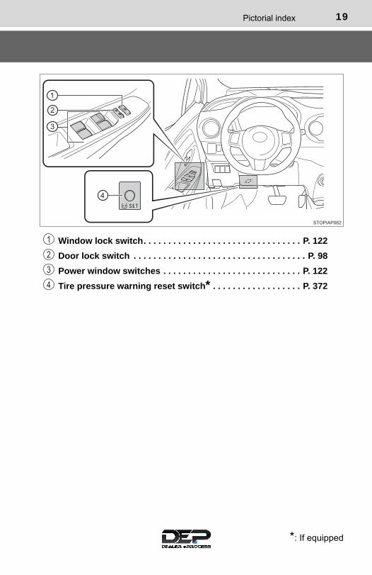
Window lock switch. . . . . . . . . . . . . . . . . . . . . . . . . . . . . . . . P. 122
Door lock switch . . . . . . . . . . . . . . . . . . . . . . . . . . . . . . . . . . . P. 98
Power window switches . . . . . . . . . . . . . . . . . . . . . . . . . . . . P. 122
Tire pressure warning reset switch* . . . . . . . . . . . . . . . . . . P. 372
*: If equipped
1
2
3
4
20 Pictorial index
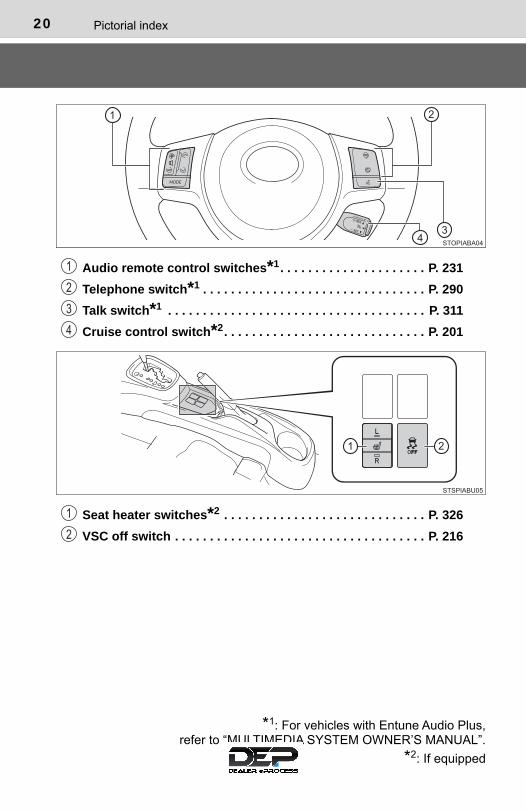
Audio remote control switches*1. . . . . . . . . . . . . . . . . . . . . P. 231
Telephone switch*1 . . . . . . . . . . . . . . . . . . . . . . . . . . . . . . . . P. 290
Talk switch*1 . . . . . . . . . . . . . . . . . . . . . . . . . . . . . . . . . . . . . P. 311
Cruise control switch*2. . . . . . . . . . . . . . . . . . . . . . . . . . . . . P. 201
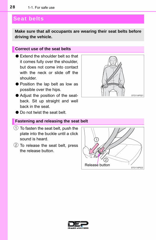
Seat heater switches*2 . . . . . . . . . . . . . . . . . . . . . . . . . . . . . P. 326
VSC off switch . . . . . . . . . . . . . . . . . . . . . . . . . . . . . . . . . . . . P. 216
1
2
3
4
*1: For vehicles with Entune Audio Plus,refer to “MULTIMEDIA SYSTEM OWNER’S MANUAL”.
*2: If equipped
1
2

21Pictorial index
■Interior
SRS airbags . . . . . . . . . . . . . . . . . . . . . . . . . . . . . . . . . . . . . . . P. 36
Floor mats . . . . . . . . . . . . . . . . . . . . . . . . . . . . . . . . . . . . . . . . P. 24
Front seats . . . . . . . . . . . . . . . . . . . . . . . . . . . . . . . . . . . . . . . P. 106
Rear seats. . . . . . . . . . . . . . . . . . . . . . . . . . . . . . . . . . . . . . . . P. 109
Head restraints. . . . . . . . . . . . . . . . . . . . . . . . . . . . . . . . . . . . P. 113
Seat belts . . . . . . . . . . . . . . . . . . . . . . . . . . . . . . . . . . . . . . . . . P. 28
Inside lock buttons . . . . . . . . . . . . . . . . . . . . . . . . . . . . . . . . . P. 98
Cup holders . . . . . . . . . . . . . . . . . . . . . . . . . . . . . . . . . . . . . . P. 331
1
2
3
4
5
6
7
8

22 Pictorial index
Inside rear view mirror . . . . . . . . . . . . . . . . . . . . . . . . . . . . . P. 118
Sun visors . . . . . . . . . . . . . . . . . . . . . . . . . . . . . . . . . . . . . . . P. 336
Vanity mirrors. . . . . . . . . . . . . . . . . . . . . . . . . . . . . . . . . . . . . P. 336
Interior light/personal lights . . . . . . . . . . . . . . . . . . . . . . . . . P. 328
Assist grips . . . . . . . . . . . . . . . . . . . . . . . . . . . . . . . . . . . . . . P. 338
1
2
3
4
5

23
For safety and security 1
1-1. For safe use
Before driving...................... 24
For safety drive ................... 26
Seat belts ............................ 28
SRS airbags........................ 36
Front passenger occupant classification system ......... 49
Exhaust gas precautions..... 55
1-2. Child safety
Riding with children............. 56
Child restraint systems........ 57
1-3. Theft deterrent system
Engine immobilizer system .............................. 74
Theft prevention labels (except Canada) ............... 76

24 1-1. For safe use
Before driving
Use only floor mats designed specifically for vehicles of the samemodel and model year as your vehicle. Fix them securely in placeonto the carpet.
Insert the retaining hooks (clips)into the floor mat eyelets.
Turn the upper knob of eachretaining hook (clip) to securethe floor mats in place.
*: Always align the marks.
The shape of the retaining hooks (clips) may differ from that shown in theillustration.
Floor mat
1
*
2

251-1. For safe use
1
For safety and se
curity
WARNING
Observe the following precautions. Failure to do so may cause the driver’s floor mat to slip, possibly interferingwith the pedals while driving. An unexpectedly high speed may result or it maybecome difficult to stop the vehicle. This could lead to an accident, resulting indeath or serious injury.
■When installing the driver’s floor mat ●Do not use floor mats designed for other models or different model year
vehicles, even if they are Toyota Genuine floor mats.
●Only use floor mats designed for the driver’s seat.
●Always install the floor mat securely using the retaining hooks (clips) pro-vided.
●Do not use two or more floor mats on top of each other.
●Do not place the floor mat bottom-side up or upside-down.
■Before driving
●Check that the floor mat is securelyfixed in the correct place with all theprovided retaining hooks (clips). Beespecially careful to perform this checkafter cleaning the floor.
●With the engine stopped and the shiftlever in P (automatic transmission) or N(manual transmission), fully depresseach pedal to the floor to make sure itdoes not interfere with the floor mat.

26 1-1. For safe use
For safety drive
Adjust the angle of the seat-back so that you are sittingstraight up and so that you donot have to lean forward tosteer. (→P. 106)
Adjust the seat so that you candepress the pedals fully and sothat your arms bend slightly atthe elbow when gripping thesteering wheel. (→P. 106, 116)
Lock the head restraint in place with the center of the head restraintclosest to the top of your ears. (→P. 113)
Wear the seat belt correctly. (→P. 28)
Make sure that all occupants are wearing their seat belts before driv-ing the vehicle. (→P. 28)Use a child restraint system appropriate for the child until the childbecomes large enough to properly wear the vehicle’s seat belt. (→P. 57)
Make sure that you can see the rear of the vehicle clearly, by adjust-ing the inside and outside rear view mirrors properly. (→P. 118, 120)
For safe driving, adjust the seat and mirror to an appropriateposition before driving.
Correct driving posture
1
2
Correct use of the seat belts
Adjusting the mirrors
3
4

271-1. For safe use
1
For safety and se
curity
WARNING
Observe the following precautions.Failure to do so may result in death or serious injury.
●Do not adjust the position of the driver’s seat while driving.Doing so could cause the driver to lose control of the vehicle.
●Do not place a cushion between the driver or passenger and the seatback.A cushion may prevent correct posture from being achieved, and reducethe effectiveness of the seat belt and head restraint.
●Do not place anything under the front seats.Objects placed under the front seats may become jammed in the seattracks and stop the seat from locking in place. This may lead to an acci-dent and the adjustment mechanism may also be damaged.
●Always observe the legal speed limit when driving on public roads.
●When driving over long distances, take regular breaks before you start tofeel tired.Also, if you feel tired or sleepy while driving, do not force yourself to con-tinue driving and take a break immediately.
28 1-1. For safe use
Seat belts
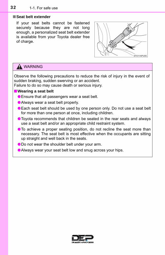
● Extend the shoulder belt so thatit comes fully over the shoulder,but does not come into contactwith the neck or slide off theshoulder.
● Position the lap belt as low aspossible over the hips.
● Adjust the position of the seat-back. Sit up straight and wellback in the seat.
● Do not twist the seat belt.
To fasten the seat belt, push theplate into the buckle until a clicksound is heard.
To release the seat belt, pressthe release button.
Make sure that all occupants are wearing their seat belts beforedriving the vehicle.
Correct use of the seat belts
Fastening and releasing the seat belt
Release button
1
2

291-1. For safe use
1
For safety and se
curity
Take out the plates, and thenpull the seat belt.
Push the plate into the buckle inthe order of plate “A” and plate“B” until a clicking sound isheard.
Plate “A”, buckle “A”
Plate “B”, buckle “B”
Fastening the rear center seat belt
1
Plate “A” Plate “B”
Buckle “B”Buckle “A”
2
1
2

30 1-1. For safe use
To release the hooked buckle“B”, push the buckle releasebutton.
To release the hooked plate “A”,insert the plate “B”, the key intothe hole on the buckle.
When releasing the seat belt,retract it slowly.
Stow the plates as shown in theillustration.
Stow the rear seat belt buckle inthe pocket.
Releasing and stowing the rear center seat belt
B
1
B
A
A
2
3
4

311-1. For safe use
1
For safety and se
curity
The pretensioners help the seatbelts to quickly restrain the occu-pants by retracting the seat beltswhen the vehicle is subjected tocertain types of severe frontal orside collision, or a vehicle rollover.
The pretensioners do not activatein the event of a minor frontalimpact, a minor side impact, or arear impact.
■Emergency locking retractor (ELR)The retractor will lock the belt during a sudden stop or on impact. It may alsolock if you lean forward too quickly. A slow, easy motion will allow the belt toextend so that you can move around fully.
■Automatic locking retractor (ALR)When a passenger’s shoulder belt is completely extended and then retractedeven slightly, the belt is locked in that position and cannot be extended. Thisfeature is used to hold the child restraint system (CRS) firmly. To free the beltagain, fully retract the belt and then pull the belt out once more. (→P. 59)
■Child seat belt usageThe seat belts of your vehicle were principally designed for persons of adultsize.
●Use a child restraint system appropriate for the child, until the childbecomes large enough to properly wear the vehicle’s seat belt. (→P. 57)
●When the child becomes large enough to properly wear the vehicle’s seatbelt, follow the instructions regarding seat belt usage. (→P. 28)
■Replacing the belt after the pretensioner has been activatedIf the vehicle is involved in multiple collisions, the pretensioner will activate forthe first collision, but will not activate for the second or subsequent collisions.
Seat belt pretensioners (front seat)
32 1-1. For safe use
■Seat belt extender
If your seat belts cannot be fastenedsecurely because they are not longenough, a personalized seat belt extenderis available from your Toyota dealer freeof charge.
WARNING
Observe the following precautions to reduce the risk of injury in the event ofsudden braking, sudden swerving or an accident.Failure to do so may cause death or serious injury.
■Wearing a seat belt●Ensure that all passengers wear a seat belt.
●Always wear a seat belt properly.
●Each seat belt should be used by one person only. Do not use a seat beltfor more than one person at once, including children.
●Toyota recommends that children be seated in the rear seats and alwaysuse a seat belt and/or an appropriate child restraint system.
●To achieve a proper seating position, do not recline the seat more thannecessary. The seat belt is most effective when the occupants are sittingup straight and well back in the seats.
●Do not wear the shoulder belt under your arm.
●Always wear your seat belt low and snug across your hips.

331-1. For safe use
1
For safety and se
curity
WARNING
■Pregnant women
■People suffering illnessObtain medical advice and wear the seat belt in the proper way. (→P. 28)
■When children are in the vehicle→P. 68
■Seat belt pretensioners●Do not place anything, such as a cushion, on the front passenger’s seat.
Doing so will disperse the passenger’s weight, which prevents the sensorfrom detecting the passenger’s weight properly. As a result, the seat beltpretensioner for the front passenger’s seat may not activate in the event ofa collision.
● If the pretensioner has activated, the SRS warning light will come on. Inthat case, the seat belt cannot be used again and must be replaced atyour Toyota dealer.
Obtain medical advice and wear the seatbelt in the proper way. (→P. 28)
Women who are pregnant should posi-tion the lap belt as low as possible overthe hips in the same manner as otheroccupants, extending the shoulder beltcompletely over the shoulder and avoid-ing belt contact with the rounding of theabdominal area.
If the seat belt is not worn properly, notonly the pregnant woman, but also thefetus could suffer death or serious injuryas a result of sudden braking or a colli-sion.

34 1-1. For safe use
WARNING
■Seat belt damage and wear●Do not damage the seat belts by allowing the belt, plate, or buckle to be
jammed in the door.
● Inspect the seat belt system periodically. Check for cuts, fraying, and looseparts. Do not use a damaged seat belt until it is replaced. Damaged seatbelts cannot protect an occupant from death or serious injury.
●Ensure that the belt and plate are locked and the belt is not twisted.If the seat belt does not function correctly, immediately contact your Toyotadealer.
●Replace the seat assembly, including the belts, if your vehicle has beeninvolved in a serious accident, even if there is no obvious damage.
●Do not attempt to install, remove, modify, disassemble or dispose of theseat belts. Have any necessary repairs carried out by your Toyota dealer.Inappropriate handling may lead to incorrect operation.
■When using the rear center seat belt
●Do not allow anyone sit on the rear center seat if the rear right seat isfolded down, as the seat belt buckle for the rear center seat belt is thenconcealed under the folded seat and cannot be used.
●Do not use the rear center seat belt witheither buckle released.
Fastening only one of the buckles mayresult in death or serious injury in caseof sudden braking or a collision.

351-1. For safe use
1
For safety and se
curity
WARNING
■Using a seat belt extender●Do not wear the seat belt extender if you can fasten the seat belt without
the extender.
●Do not use the seat belt extender when installing a child restraint systembecause the belt will not securely hold the child restraint system, increas-ing the risk of death or serious injury in the event of an accident.
●The personalized extender may not be safe on another vehicle, whenused by another person, or at a different seating position other than theone originally intended.
NOTICE
■When using a seat belt extenderWhen releasing the seat belt, press on the buckle release button on theextender, not on the seat belt. This helps prevent damage to the vehicle interior and the extender itself.

36 1-1. For safe use
SRS airbags
The SRS airbags inflate when the vehicle is subjected to certaintypes of severe impacts that may cause significant injury to theoccupants. They work together with the seat belts to help reducethe risk of death or serious injury.

371-1. For safe use
1
For safety and se
curity
◆ SRS front airbags
SRS driver airbag/front passenger airbag
Can help protect the head and chest of the driver and front passen-ger from impact with interior components
SRS driver knee airbag
Can help provide driver protection
SRS seat cushion airbags
Can help restrain the driver and front passenger
◆ SRS side and curtain shield airbags
SRS side airbags
Can help protect the torso of the front seat occupants
SRS curtain shield airbags● Can help protect primarily the head of occupants in the outer
seats● Can help prevent the occupants from being thrown from the vehi-
cle in the event of vehicle rollover
1
2
3
4
5

38 1-1. For safe use
SRS airbag system components
Curtain shield airbags
Side impact sensors (front)
Side airbags
Side impact sensors (rear)
SRS warning light
Driver airbag
Passenger seat cushion air-bag
Front passenger’s seat beltbuckle switch
Seat belt pretensioners andforce limiters
Side impact sensors (frontdoor)
Driver seat cushion airbag
Driver’s seat belt buckleswitch
Driver knee airbag
Front impact sensors
Airbag sensor assembly
Front passenger occupantclassification system (ECUand sensors)
Front passenger airbag
“AIR BAG ON” and “AIR BAGOFF” indicator lights
1
2
3
4
5
6
7
8
9
10
11
12
13
14
15
16
17
18

391-1. For safe use
1
For safety and se
curity
Your vehicle is equipped with ADVANCED AIRBAGS designed basedon the US motor vehicle safety standards (FMVSS208). The airbagsensor assembly (ECU) controls airbag deployment based on infor-mation obtained from the sensors, etc. shown in the system compo-nents diagram above. This information includes crash severity andoccupant information. As the airbags deploy, a chemical reaction inthe inflators quickly fills the airbags with nontoxic gas to help restrainthe motion of the occupants.
WARNING
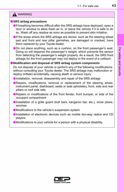
■SRS airbag precautionsObserve the following precautions regarding the SRS airbags. Failure to do so may cause death or serious injury.
●The driver and all passengers in the vehicle must wear their seat beltsproperly.The SRS airbags are supplemental devices to be used with the seat belts.
●The SRS driver airbag deploys with considerable force, and can causedeath or serious injury especially if the driver is very close to the airbag.
The National Highway Traffic Safety Administration (NHTSA) advises: Since the risk zone for the driver’s airbag is the first 2 - 3 in. (50 - 75 mm)of inflation, placing yourself 10 in. (250 mm) from your driver airbag pro-vides you with a clear margin of safety. This distance is measured fromthe center of the steering wheel to your breastbone. If you sit less than10 in. (250 mm) away now, you can change your driving position in sev-eral ways:
• Move your seat to the rear as far as you can while still reaching the ped-als comfortably.
• Slightly recline the back of the seat. Although vehicle designs vary,many drivers can achieve the 10 in. (250 mm) distance, even with thedriver seat all the way forward, simply by reclining the back of the seatsomewhat. If reclining the back of your seat makes it hard to see theroad, raise yourself by using a firm, non-slippery cushion, or raise theseat if your vehicle has that feature.
• If your steering wheel is adjustable, tilt it downward. This points the air-bag toward your chest instead of your head and neck.
The seat should be adjusted as recommended by NHTSA above, whilestill maintaining control of the foot pedals, steering wheel, and your viewof the instrument panel controls.
40 1-1. For safe use
WARNING
■SRS airbag precautions
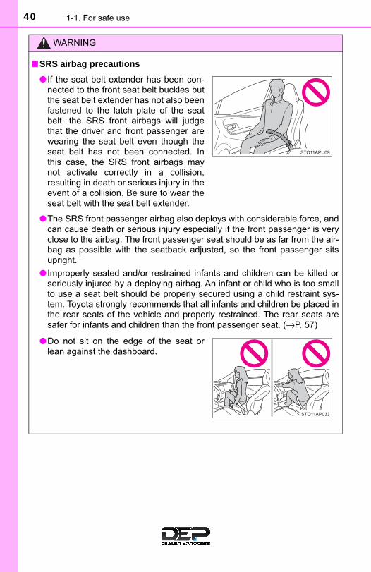
●The SRS front passenger airbag also deploys with considerable force, andcan cause death or serious injury especially if the front passenger is veryclose to the airbag. The front passenger seat should be as far from the air-bag as possible with the seatback adjusted, so the front passenger sitsupright.
● Improperly seated and/or restrained infants and children can be killed orseriously injured by a deploying airbag. An infant or child who is too smallto use a seat belt should be properly secured using a child restraint sys-tem. Toyota strongly recommends that all infants and children be placed inthe rear seats of the vehicle and properly restrained. The rear seats aresafer for infants and children than the front passenger seat. (→P. 57)
● If the seat belt extender has been con-nected to the front seat belt buckles butthe seat belt extender has not also beenfastened to the latch plate of the seatbelt, the SRS front airbags will judgethat the driver and front passenger arewearing the seat belt even though theseat belt has not been connected. Inthis case, the SRS front airbags maynot activate correctly in a collision,resulting in death or serious injury in theevent of a collision. Be sure to wear theseat belt with the seat belt extender.
●Do not sit on the edge of the seat orlean against the dashboard.

411-1. For safe use
1
For safety and se
curity
WARNING
■SRS airbag precautions
●Do not allow a child to stand in front ofthe SRS front passenger airbag unit orsit on the knees of a front passenger.
●Do not allow the front seat occupants tohold items on their knees.
●Do not lean against the door, the roofside rail or the front, side and rear pil-lars.
●Do not allow anyone to kneel on thepassenger seat toward the door or puttheir head or hands outside the vehicle.
●Do not attach anything to or lean any-thing against areas such as the dash-board, steering wheel pad and lowerportion of the instrument panel. These items can become projectileswhen the SRS driver, front passengerand driver knee airbags deploy.

42 1-1. For safe use
WARNING
■SRS airbag precautions
●Do not hang coat hangers or other hard objects on the coat hooks. All ofthese items could become projectiles and may cause death or seriousinjury, should the SRS curtain shield airbags deploy.
● If a vinyl cover is put on the area where the SRS driver knee airbag willdeploy, be sure to remove it.
●Do not use seat accessories which cover the parts where the SRS sideairbags and SRS seat cushion airbags inflate as they may interfere withinflation of the SRS airbags. Such accessories may prevent the side air-bags and seat cushion airbags from activating correctly, disable the sys-tem or cause the side airbags and seat cushion airbags to inflateaccidentally, resulting in death or serious injury.
●Do not strike or apply significant levels of force to the area of the SRS air-bag components. Doing so can cause the SRS airbags to malfunction.
●Do not touch any of the component parts immediately after the SRS air-bags have deployed (inflated) as they may be hot.
●Do not attach anything to areas such asa door, windshield glass, side doorglass, front or rear pillar, roof side railand assist grip.
●Do not attach any heavy, sharp or hardobjects such as keys and accessoriesto the key. The objects may restrict theSRS driver knee airbag inflation or bethrust into the driver’s seat area by theforce of the deploying airbag, thus caus-ing a danger.
431-1. For safe use
1
For safety and se
curity
WARNING
■SRS airbag precautions● If breathing becomes difficult after the SRS airbags have deployed, open a
door or window to allow fresh air in, or leave the vehicle if it is safe to doso. Wash off any residue as soon as possible to prevent skin irritation.
● If the areas where the SRS airbags are stored, such as the steering wheelpad and front and rear pillar garnishes, are damaged or cracked, havethem replaced by your Toyota dealer.
●Do not place anything, such as a cushion, on the front passenger’s seat.Doing so will disperse the passenger’s weight, which prevents the sensorfrom detecting the passenger’s weight properly. As a result, the SRS frontairbags for the front passenger may not deploy in the event of a collision.
■Modification and disposal of SRS airbag system componentsDo not dispose of your vehicle or perform any of the following modificationswithout consulting your Toyota dealer. The SRS airbags may malfunction ordeploy (inflate) accidentally, causing death or serious injury.
● Installation, removal, disassembly and repair of the SRS airbags
●Repairs, modifications, removal or replacement of the steering wheel,instrument panel, dashboard, seats or seat upholstery, front, side and rearpillars or roof side rails
●Repairs or modifications of the front fender, front bumper, or side of theoccupant compartment
● Installation of a grille guard (bull bars, kangaroo bar, etc.), snow plows,winches
●Modifications to the vehicle’s suspension system
● Installation of electronic devices such as mobile two-way radios and CDplayers
●Modifications to your vehicle for a person with a physical disability.

44 1-1. For safe use
■ If the SRS airbags deploy (inflate)●Slight abrasions, burns, bruising, etc., may be sustained from SRS airbags,
due to the extremely high speed deployment (inflation) by hot gases.
●A loud noise and white powder will be emitted.
●Parts of the airbag module (steering wheel hub, airbag cover and inflator) aswell as the front seats, parts of the front and rear pillars, and roof side rails,may be hot for several minutes. The airbag itself may also be hot.
●The windshield may crack.
■SRS airbag deployment conditions (SRS front airbags)●The SRS front airbags will deploy in the event of an impact that exceeds the
set threshold level (the level of force corresponding to an approximately 12 -18 mph [20 - 30 km/h] frontal collision with a fixed wall that does not move ordeform).
However, this threshold velocity will be considerably higher in the followingsituations:
• If the vehicle strikes an object, such as a parked vehicle or sign pole,which can move or deform on impact
• If the vehicle is involved in an underride collision, such as a collision inwhich the front of the vehicle “underrides”, or goes under, the bed of atruck
●Depending on the type of collision, it is possible that only the seat belt pre-tensioners will activate.
●The SRS front airbags for the front passenger will not activate if there is nopassenger sitting in the front passenger seat. However, the SRS front air-bags for the front passenger may deploy if luggage is put in the seat, even ifthe seat is unoccupied.
●The SRS seat cushion airbags on the front seats will not operate if the occu-pant is not wearing a seat belt.
■SRS airbag deployment conditions (SRS side and curtain shield airbags)●The SRS side and curtain shield airbags will deploy in the event of an
impact that exceeds the set threshold level (the level of force correspondingto the impact force produced by an approximately 3300 lb. [1500 kg] vehiclecolliding with the vehicle cabin from a direction perpendicular to the vehicleorientation at an approximate speed of 12 - 18 mph [20 - 30 km/h]).
●The SRS curtain shield airbags will deploy in the event of vehicle rollover.
●The SRS curtain shield airbags may also deploy in the event of a severefrontal collision.

451-1. For safe use
1
For safety and se
curity
■Conditions under which the SRS airbags may deploy (inflate), other thana collision The SRS front airbags and SRS curtain shield airbags may also deploy if aserious impact occurs to the underside of your vehicle. Some examples areshown in the illustration.
The SRS curtain shield airbags may also deploy under the situations shownin the illustration.
■Types of collisions that may not deploy the SRS airbags (SRS front air-bags)The SRS front airbags do not generally inflate if the vehicle is involved in aside or rear collision, if it rolls over, or if it is involved in a low-speed frontalcollision. But, whenever a collision of any type causes sufficient forwarddeceleration of the vehicle, deployment of the SRS front airbags may occur.
●Hitting a curb, edge of pavement or hardsurface
●Falling into or jumping over a deep hole
●Landing hard or falling
●The angle of vehicle tip-up is marginal
●The vehicle skids and hits a curb stone
●Collision from the side
●Collision from the rear
●Vehicle rollover

46 1-1. For safe use
■Types of collisions that may not deploy the SRS airbags (SRS side andcurtain shield airbags)The SRS side and curtain shield airbags may not activate if the vehicle issubjected to a collision from the side at certain angles, or a collision to theside of the vehicle body other than the passenger compartment.
The SRS side airbags do not generally inflate if the vehicle is involved in afrontal or rear collision, if it rolls over, or if it is involved in a low-speed sidecollision.
The SRS curtain shield airbags do not generally inflate if the vehicle isinvolved in a rear collision, if it pitches end over end, or if it is involved in alow-speed side or low-speed frontal collision.
●Collision from the side to the vehiclebody other than the passenger compart-ment
●Collision from the side at an angle
●Collision from the front
●Collision from the rear
●Vehicle rollover
●Collision from the rear
●Pitching end over end

471-1. For safe use
1
For safety and se
curity
■When to contact your Toyota dealerIn the following cases, the vehicle will require inspection and/or repair. Con-tact your Toyota dealer as soon as possible.
●Any of the SRS airbags have been inflated.
●The front of the vehicle is damaged ordeformed, or was involved in an acci-dent that was not severe enough tocause the SRS front airbags to inflate.
●A portion of a door or its surroundingarea is damaged or deformed, or thevehicle was involved in an accident thatwas not severe enough to cause theSRS side and curtain shield airbags toinflate.
●The pad section of the steering wheel,dashboard near the front passenger air-bag or lower portion of the instrumentpanel is scratched, cracked, or other-wise damaged.
●The front seat cushion surface isscratched, cracked, or otherwise dam-aged.

48 1-1. For safe use
●The surface of the seats with the sideairbag is scratched, cracked, or other-wise damaged.
●The portion of the front pillars, rear pil-lars or roof side rail garnishes (padding)containing the curtain shield airbagsinside is scratched, cracked, or other-wise damaged.

491-1. For safe use
1
For safety and se
curity
Front passenger occupant classification system
SRS warning light
Seat belt reminder light
“AIR BAG OFF” indicator light
“AIR BAG ON” indicator light
Your vehicle is equipped with a front passenger occupant classi-fication system. This system detects the conditions of the frontpassenger seat and activates or deactivates the devices for thefront passenger.
Type A
Type B
1
2
3
4
50 1-1. For safe use
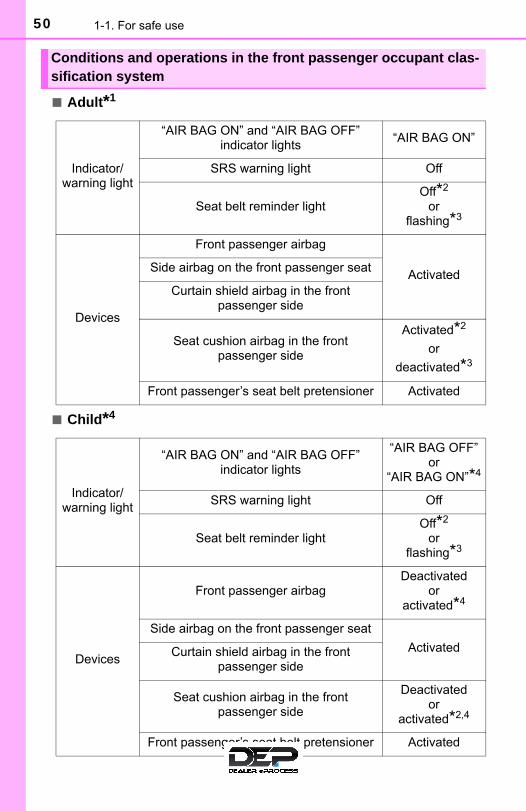
■ Adult*1
■ Child*4
Conditions and operations in the front passenger occupant clas-sification system
Indicator/warning light
“AIR BAG ON” and “AIR BAG OFF” indicator lights
“AIR BAG ON”
SRS warning light Off
Seat belt reminder lightOff*2
or flashing*3
Devices
Front passenger airbag
ActivatedSide airbag on the front passenger seat
Curtain shield airbag in the front passenger side
Seat cushion airbag in the front passenger side
Activated*2
or
deactivated*3
Front passenger’s seat belt pretensioner Activated
Indicator/warning light
“AIR BAG ON” and “AIR BAG OFF” indicator lights
“AIR BAG OFF” or
“AIR BAG ON”*4
SRS warning light Off
Seat belt reminder lightOff*2
or flashing*3
Devices
Front passenger airbagDeactivated
or activated*4
Side airbag on the front passenger seat
ActivatedCurtain shield airbag in the front passenger side
Seat cushion airbag in the front passenger side
Deactivated or
activated*2,4
Front passenger’s seat belt pretensioner Activated

511-1. For safe use
1
For safety and se
curity
■ Child restraint system with infant*5
■ Unoccupied
Indicator/warning light
“AIR BAG ON” and “AIR BAG OFF” indicator lights
“AIR BAG OFF”*6
SRS warning light Off
Seat belt reminder lightOff*2
or flashing*3
Devices
Front passenger airbag Deactivated
Side airbag on the front passenger seat
ActivatedCurtain shield airbag in the front passenger side
Seat cushion airbag in the front passenger side
Deactivated
Front passenger’s seat belt pretensioner Activated
Indicator/warning light
“AIR BAG ON” and “AIR BAG OFF” indicator lights
“AIR BAG OFF”
SRS warning lightOff
Seat belt reminder light
Devices
Front passenger airbag Deactivated
Side airbag on the front passenger seat
ActivatedCurtain shield airbag in the front passenger side
Seat cushion airbag in the front passenger side
Deactivated
Front passenger’s seat belt pretensioner Activated
52 1-1. For safe use
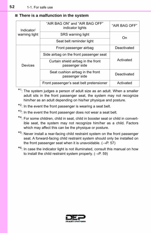
■ There is a malfunction in the system
*1: The system judges a person of adult size as an adult. When a smalleradult sits in the front passenger seat, the system may not recognizehim/her as an adult depending on his/her physique and posture.
*2: In the event the front passenger is wearing a seat belt.
*3: In the event the front passenger does not wear a seat belt.
*4: For some children, child in seat, child in booster seat or child in convert-ible seat, the system may not recognize him/her as a child. Factorswhich may affect this can be the physique or posture.
*5: Never install a rear-facing child restraint system on the front passengerseat. A forward-facing child restraint system should only be installed onthe front passenger seat when it is unavoidable. (→P. 57)
*6: In case the indicator light is not illuminated, consult this manual on howto install the child restraint system properly. (→P. 59)
Indicator/warning light
“AIR BAG ON” and “AIR BAG OFF” indicator lights
“AIR BAG OFF”
SRS warning lightOn
Seat belt reminder light
Devices
Front passenger airbag Deactivated
Side airbag on the front passenger seat
ActivatedCurtain shield airbag in the front passenger side
Seat cushion airbag in the front passenger side
Deactivated
Front passenger’s seat belt pretensioner Activated

531-1. For safe use
1
For safety and se
curity
WARNING
■Front passenger occupant classification system precautionsObserve the following precautions regarding the front passenger occupantclassification system.Failure to do so may cause death or serious injury.
●Wear the seat belt properly.
●Make sure the front passenger’s seat belt plate has not been left insertedinto the buckle before someone sits in the front passenger seat.
●Make sure the “AIR BAG OFF” indicator light is not illuminated when usingthe seat belt extender for the front passenger seat. If the “AIR BAG OFF”indicator light is illuminated, disconnect the extender tongue from the seatbelt buckle, and reconnect the seat belt. Reconnect the seat belt extenderafter making sure the “AIR BAG ON” indicator light is illuminated. If youuse the seat belt extender while the “AIR BAG OFF” indicator light is illumi-nated, the SRS airbags for the front passenger will not activate correctly,which could cause death or serious injury in the event of collision.
●Do not apply a heavy load to the front passenger seat or equipment (e.g.seatback pocket).
●Do not put weight on the front passenger seat by putting your hands orfeet on the front passenger seat seatback from the rear passenger seat.
●Do not let a rear passenger lift the front passenger seat with their feet orpress on the seatback with their legs.
●Do not put objects under the front passenger seat.
●Do not recline the front passenger seatback so far that it touches a rearseat. This may cause the “AIR BAG OFF” indicator light to be illuminated,which indicates that the SRS airbags for the front passenger will not acti-vate in the event of a severe accident. If the seatback touches the rearseat, return the seatback to a position where it does not touch the rearseat. Keep the front passenger seatback as upright as possible when thevehicle is moving. Reclining the seatback excessively may lessen theeffectiveness of the seat belt system.

54 1-1. For safe use
WARNING
■Front passenger occupant classification system precautions● If an adult sits in the front passenger seat, the “AIR BAG ON” indicator
light is illuminated. If the “AIR BAG OFF” indicator is illuminated, ask thepassenger to sit up straight, well back in the seat, feet on the floor, andwith the seat belt worn correctly. If the “AIR BAG OFF” indicator stillremains illuminated, either ask the passenger to move to the rear seat, orif that is not possible, move the front passenger seat fully rearward.
●When it is unavoidable to install a forward-facing child restraint system onthe front passenger seat, install the child restraint system on the front pas-senger seat in the proper order. (→P. 59)
●Do not modify or remove the front seats.
●Do not kick the front passenger seat or subject it to severe impact. Other-wise, the SRS warning light may come on to indicate a malfunction of thefront passenger occupant classification system. In this case, contact yourToyota dealer immediately.
●Child restraint systems installed on the rear seat should not contact thefront seatbacks.
●Do not use a seat accessory, such as a cushion and seat cover, that cov-ers the seat cushion surface.
●Do not modify or replace the upholstery of the front seat.

551-1. For safe use
1
For safety and se
curity
Exhaust gas precautions
Harmful substances to the human body are included in exhaustgases if inhaled.
WARNING
Exhaust gases contain harmful carbon monoxide (CO), which is colorless andodorless. Observe the following precautions.Failure to do so may cause exhaust gases enter the vehicle and may lead toan accident caused by light-headedness, or may lead to death or a serioushealth hazard.
■ Important points while driving●Keep the back door closed.
● If you smell exhaust gases in the vehicle even when the back door isclosed, open the windows and have the vehicle inspected at your Toyotadealer as soon as possible.
■When parking● If the vehicle is in a poorly ventilated area or a closed area, such as a
garage, stop the engine.
●Do not leave the vehicle with the engine running for a long time.If such a situation cannot be avoided, park the vehicle in an open spaceand ensure that exhaust fumes do not enter the vehicle interior.
●Do not leave the engine running in an area with snow build-up, or where itis snowing. If snowbanks build up around the vehicle while the engine isrunning, exhaust gases may collect and enter the vehicle.
■Exhaust pipeThe exhaust system needs to be checked periodically. If there is a hole orcrack caused by corrosion, damage to a joint or abnormal exhaust noise, besure to have the vehicle inspected and repaired by your Toyota dealer.

56 1-2. Child safety
Riding with children
● It is recommended that children sit in the rear seats to avoid acci-dental contact with the shift lever, wiper switch, etc.
● Use the rear door child-protector lock (5-door models only) or thewindow lock switch to avoid children opening the door while drivingor operating the power window accidentally.
● Do not let small children operate equipment which may catch orpinch body parts, such as the power window, hood, back door,seats, etc.
Observe the following precautions when children are in the vehi-cle.Use a child restraint system appropriate for the child, until thechild becomes large enough to properly wear the vehicle’s seatbelt.
WARNING
Never leave children unattended in the vehicle, and never allow children tohave or use the key.
Children may be able to start the vehicle or shift the vehicle into neutral.There is also a danger that children may injure themselves by playing withthe cigarette lighter, the windows or other features of the vehicle. In addi-tion, heat build-up or extremely cold temperatures inside the vehicle can befatal to children.

571-2. Child safety
1
For safety and se
curity
Child restraint systems
Points to remember......................................................................P. 57
Child restraint system ..................................................................P. 59
When using a child restraint system ............................................P. 60
Child restraint system installation method• Fixed with a seat belt ...............................................................P. 63• Fixed with a child restraint LATCH anchor ...............................P. 69• Using an anchor bracket (for top tether strap) .........................P. 72
The laws of all 50 states of the U.S.A. as well as Canada now requirethe use of child restraint systems.● Prioritize and observe the warnings, as well as the laws and regula-
tions for child restraint systems.
● Use a child restraint system until the child becomes large enough toproperly wear the vehicle’s seat belt.
● Choose a child restraint system that suits your vehicle and is appro-priate to the age and size of the child.
Before installing a child restraint system in the vehicle, there areprecautions that need to be observed, different types of childrestraint systems, as well as installation methods, etc., written inthis manual.
● Use a child restraint system when riding with a small child thatcannot properly use a seat belt. For the child’s safety, install thechild restraint system to a rear seat. Be sure to follow the installa-tion method that is in the operation manual enclosed with therestraint system.
Table of contents
Points to remember

58 1-2. Child safety
WARNING
■When a child is ridingObserve the following precautions.Failure to do so may result in death or serious injury.
●For effective protection in automobile accidents and sudden stops, a childmust be properly restrained, using a seat belt or child restraint systemwhich is correctly installed. For installation details, refer to the operationmanual enclosed with the child restraint system. General installationinstruction is provided in this manual.
●Toyota strongly urges the use of a proper child restraint system that con-forms to the weight and size of the child, installed on the rear seat. Accord-ing to accident statistics, the child is safer when properly restrained in therear seat than in the front seat.
●Holding a child in your or someone else’s arms is not a substitute for achild restraint system. In an accident, the child can be crushed against thewindshield or between the holder and the interior of the vehicle.
■Handling the child restraint systemIf the child restraint system is not properly fixed in place, the child or otherpassengers may be seriously injured or even killed in the event of suddenbraking, sudden swerving, or an accident.
● If the vehicle were to receive a strong impact from an accident, etc., it ispossible that the child restraint system has damage that is not readily visi-ble. In such cases, do not reuse the restraint system.
●Make sure you have complied with all installation instructions providedwith the child restraint system manufacturer and that the system is prop-erly secured.
●Keep the child restraint system properly secured on the seat even if it isnot in use. Do not store the child restraint system unsecured in the pas-senger compartment.
● If it is necessary to detach the child restraint system, remove it from thevehicle or store it securely in the luggage compartment.
591-2. Child safety
1
For safety and se
curity
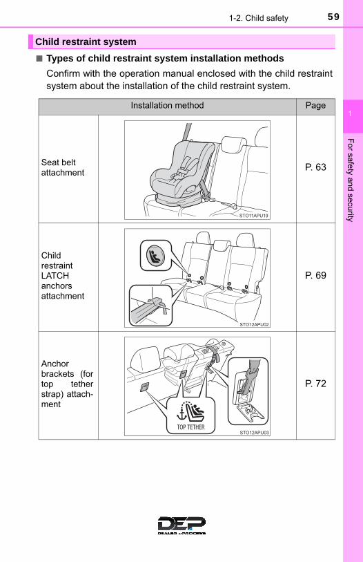
■ Types of child restraint system installation methods
Confirm with the operation manual enclosed with the child restraintsystem about the installation of the child restraint system.
Child restraint system
Installation method Page
Seat belt attachment
P. 63
ChildrestraintLATCHanchorsattachment
P. 69
Anchorbrackets (fortop tetherstrap) attach-ment
P. 72

60 1-2. Child safety
■ When installing a child restraint system to a front passengerseat
For the safety of a child, install a child restraint system to a rearseat. When installing child restraint system to a front passengerseat is unavoidable, adjust the seat as follows and install the childrestraint system.
● Raise the seatback as muchas possible
● Move the seat to the rear-most position
● If the head restraint interfereswith the child restraint sys-tem installation and the headrestraint can be removed,remove the head restraint
When using a child restraint system

611-2. Child safety
1
For safety and se
curity
WARNING
■When using a child restraint systemObserve the following precautions.Failure to do so may result in death or serious injury.
●Never install a rear-facing child restraint system on the front passengerseat even if the “AIR BAG OFF” indicator light is illuminated. In the eventof an accident, the force of the rapid inflation of the front passenger airbagcan cause death or serious injury to the child if the rear-facing childrestraint system is installed on the front passenger seat.
●A forward-facing child restraint system may be installed on the front pas-senger seat only when it is unavoidable. A child restraint system thatrequires a top tether strap should not be used in the front passenger seatsince there is no top tether strap anchor for the front passenger seat.
If the head restraint interferes with the child restraint system installationand the head restraint can be removed, remove the head restraint.
●A forward-facing child restraint systemmay be installed on the front passengerseat only when it is unavoidable. Wheninstalling a forward-facing child restraintsystem on the front passenger seat,move the seat as far back as possible,even if the “AIR BAG OFF” indicatorlight is illuminated.
●Do not allow the child to lean his/herhead or any part of his/her body againstthe door or the area of the seat, front orrear pillars, or roof side rails from whichthe SRS side airbags or SRS curtainshield airbags deploy even if the child isseated in the child restraint system. It isdangerous if the SRS side airbags andcurtain shield airbags inflate, and theimpact could cause death or seriousinjury to the child.

62 1-2. Child safety
WARNING
■When using a child restraint systemObserve the following precautions.Failure to do so may result in death or serious injury.
●When a booster seat is installed, always ensure that the shoulder belt ispositioned across the center of the child’s shoulder. The belt should bekept away from the child’s neck, but not so that it could fall off the child’sshoulder.
●Use child restraint system suitable to the age and size of the child andinstall it to the rear seat.
● If the driver’s seat interferes with thechild restraint system and prevents itfrom being attached correctly, attach thechild restraint system to the right-handrear seat.
●Adjust the front passenger seat so thatit does not interfere with the childrestraint system.

631-2. Child safety
1
For safety and se
curity
A child restraint system for a small child or baby must itself be prop-erly restrained on the seat with the lap portion of the lap/shoulder belt.
◆ Installing child restraint system using a seat belt (childrestraint lock function belt)
Install the child restraint system in accordance to the operationmanual enclosed with the child restraint system.
■ Rear-facing — Infant seat/convertible seat
Place the child restraint sys-tem on the rear seat facingthe rear of the vehicle.
Run the seat belt through thechild restraint system andinsert the plate into thebuckle. Make sure that thebelt is not twisted.
Fully extend the shoulder beltand allow it to retract to put itin lock mode. In lock mode,the belt cannot be extended.
Child restraint system fixed with a seat belt
1
2
3

64 1-2. Child safety
While pushing the childrestraint system down intothe rear seat, allow theshoulder belt to retract untilthe child restraint system issecurely in place.
After the shoulder belt hasretracted to a point where thereis no slack in the belt, pull thebelt to check that it cannot beextended.
After installing the child restraint system, rock it back and forth toensure that it is installed securely. (→P. 68)
■ Forward-facing — Convertible seat
If installing the child restraint system to the front passenger seatis unavoidable, refer to P. 60 for front passenger seat adjustment.
If the head restraint interfereswith the child restraint sys-tem installation and the headrestraint can be removed,remove the head restraint.(→P. 113)
Place the child restraint sys-tem on the seat facing thefront of the vehicle.
4
5
1
2
3

651-2. Child safety
1
For safety and se
curity
Run the seat belt through thechild restraint system andinsert the plate into thebuckle. Make sure that thebelt is not twisted.
Fully extend the shoulder beltand allow it to retract to put itin lock mode. In lock mode,the belt cannot be extended.
While pushing the childrestraint system into the rearseat, allow the shoulder beltto retract until the childrestraint system is securelyin place.
After the shoulder belt hasretracted to a point where thereis no slack in the belt, pull thebelt to check that it cannot beextended.
If the child restraint has a top tether strap, follow the childrestraint manufacturer’s operation manual regarding the installa-tion, using the top tether strap to latch onto the top tether strapanchor. (→P. 72)
After installing the child restraint system, rock it back and forth toensure that it is installed securely. (→P. 68)
4
5
6
7
8
66 1-2. Child safety
■ Booster seat
If installing the child restraint system to the front passenger seatis unavoidable, refer to P. 60 for front passenger seat adjustment.
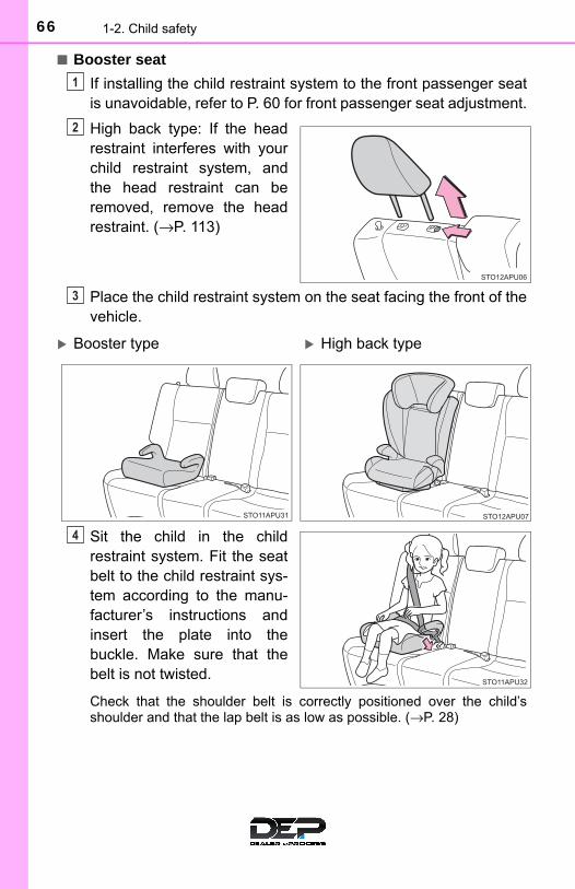
High back type: If the headrestraint interferes with yourchild restraint system, andthe head restraint can beremoved, remove the headrestraint. (→P. 113)
Place the child restraint system on the seat facing the front of thevehicle.
Sit the child in the childrestraint system. Fit the seatbelt to the child restraint sys-tem according to the manu-facturer’s instructions andinsert the plate into thebuckle. Make sure that thebelt is not twisted.
Check that the shoulder belt is correctly positioned over the child’sshoulder and that the lap belt is as low as possible. (→P. 28)
1
2
3
Booster type High back type
4

671-2. Child safety
1
For safety and se
curity
◆ Removing a child restraint system installed with a seat belt
Press the buckle release buttonand fully retract the seat belt.
When releasing the buckle, thechild restraint system mayspring up due to the rebound ofthe seat cushion. Release thebuckle while holding down thechild restraint system.
Since the seat belt automaticallyreels itself, slowly return it to thestowing position.

68 1-2. Child safety
WARNING
■When installing a child restraint systemObserve the following precautions.Failure to do so may result in death or serious injury.
●Do not allow children to play with the seat belt. If the seat belt becomestwisted around a child’s neck, it may lead to choking or other serious inju-ries that could result in death.If this occurs and the buckle cannot be unfastened, scissors should beused to cut the belt.
●Ensure that the belt and plate are securely locked and the seat belt is nottwisted.
●Shake the child restraint system left and right, and forward and backwardto ensure that it has been securely installed.
●After securing a child restraint system, never adjust the seat.
●When a booster seat is installed, always ensure that the shoulder belt ispositioned across the center of the child’s shoulder. The belt should bekept away from the child’s neck, but not so that it could fall off the child’sshoulder.
●Follow all installation instructions provided by the child restraint systemmanufacturer.
●When securing some types of child restraint systems in rear seats, it maynot be possible to properly use the seat belts in positions next to the childrestraint without interfering with it or affecting seat belt effectiveness. Besure your seat belt fits snugly across your shoulder and low on your hips. Ifit does not, or if it interferes with the child restraint, move to a differentposition. Failure to do so may result in death or serious injury.
■When installing a booster seatTo prevent the belt from going into ALR lock mode, do not fully extend theshoulder belt. ALR mode causes the belt to tighten only. This could causeinjury or discomfort to the child. (→P. 31)
■Do not use a seat belt extenderIf a seat belt extender is used when installing a child restraint system, theseat belt will not securely hold the child restraint system, which could causedeath or serious injury to the child or other passengers in the event of sud-den braking, sudden swerving or an accident.

691-2. Child safety
1
For safety and se
curity
■ Child restraint LATCH anchors
LATCH anchors are providedfor the rear outboard seats.(Buttons displaying the locationof the anchors are attached tothe seats.)
■ Installation with LATCH system
Install the child restraint system in accordance to the operationmanual enclosed with the child restraint system.
If the head restraint interfereswith the child restraint sys-tem installation and the headrestraint can be removed,remove the head restraint.(→P. 113)
Child restraint system fixed with a child restraint LATCH anchor
1

70 1-2. Child safety
With flexible lower attachments
Latch the hooks of the lowerstraps onto the LATCHanchors.
For owners in Canada:The symbol on a childrestraint system indicates thepresence of a lower connec-tor system.
With rigid lower attachments
Latch the buckles onto theLATCH anchors.
For owners in Canada:The symbol on a childrestraint system indicates thepresence of a lower connec-tor system.
Canada only
2
Canada only
2

711-2. Child safety
1
For safety and se
curity
If the child restraint has a top tether strap, follow the childrestraint manufacturer’s operation manual regarding the installa-tion, using the top tether strap to latch onto the top tether strapanchor. (→P. 72)
After installing the child restraint system, rock it back and forth toensure that it is installed securely. (→P. 68)
■Laws and regulations pertaining to anchorsThe LATCH system conforms to FMVSS225 or CMVSS210.2.Child restraint systems conforming to FMVSS213 or CMVSS213 specifica-tions can be used.This vehicle is designed to conform to SAE J1819.
WARNING
■When installing a child restraint systemObserve the following precautions.Failure to do so may result in death or serious injury.
●When using the LATCH anchors, be sure that there are no foreign objectsaround the anchors and that the seat belt is not caught behind the childrestraint system.
●Follow all installation instructions provided by the child restraint systemmanufacturer.
●When securing some types of child restraint systems in rear seats, it maynot be possible to properly use the seat belts in positions next to the childrestraint without interfering with it or affecting seat belt effectiveness. Besure your seat belt fits snugly across your shoulder and low on your hips. Ifit does not, or if it interferes with the child restraint, move to a differentposition. Failure to do so may result in death or serious injury.
3
4

72 1-2. Child safety
■ Anchor brackets (for top tether strap)
Anchor brackets are providedfor each rear seat.
Use anchor brackets when fix-ing the top tether strap.
■ Fixing the top tether strap to the anchor bracket
Install the child restraint system in accordance to the operationmanual enclosed with the child restraint system.
Remove the luggage cover. (→P. 334)
Remove the head restraint. (→P. 113)
Secure the child restraint system using the LATCH anchors or aseat belt.
Open the anchor bracketcover, latch the hook onto theanchor bracket and tightenthe top tether strap.
Make sure the top tether strap issecurely latched.
Reinstall the luggage cover.
Using an anchor bracket (for top tether strap)
Anchor brackets
1
2
3
Top tether strap
Hook
4
5

731-2. Child safety
1
For safety and se
curity
■Laws and regulations pertaining to anchorsThe LATCH system conforms to FMVSS225 or CMVSS210.2.Child restraint systems conforming to FMVSS213 or CMVSS213 specifica-tions can be used.This vehicle is designed to conform to SAE J1819.
WARNING
■When installing a child restraint systemObserve the following precautions.Failure to do so may result in death or serious injury.
●Firmly attach the top tether strap and make sure that the belt is not twisted.
●Do not attach the top tether strap to anything other than the anchorbracket.
●After securing a child restraint system, never adjust the seat.
●Follow all installation instructions provided by the child restraint systemmanufacturer.
●When a child restraint system with a top tether strap is installed, do notinstall the head restraint. The head restraint may interfere with the toptether strap preventing secure installation of the child restraint system.
●Make sure to properly store the removed head restraint in a secure placewhen you use the child restraint system on the rear seat.
NOTICE
■Anchor brackets (for top tether strap)When not in use, make certain to close the lid. If it remains open, the lidmay be damaged.
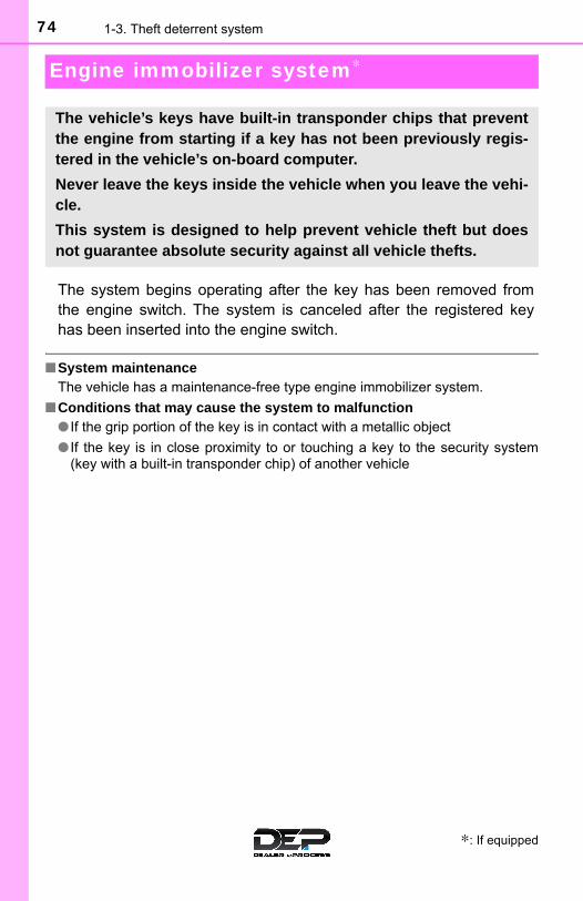
74 1-3. Theft deterrent system
Engine immobilizer system∗
The system begins operating after the key has been removed fromthe engine switch. The system is canceled after the registered keyhas been inserted into the engine switch.
■System maintenanceThe vehicle has a maintenance-free type engine immobilizer system.
■Conditions that may cause the system to malfunction● If the grip portion of the key is in contact with a metallic object
● If the key is in close proximity to or touching a key to the security system(key with a built-in transponder chip) of another vehicle
∗: If equipped
The vehicle’s keys have built-in transponder chips that preventthe engine from starting if a key has not been previously regis-tered in the vehicle’s on-board computer.
Never leave the keys inside the vehicle when you leave the vehi-cle.
This system is designed to help prevent vehicle theft but doesnot guarantee absolute security against all vehicle thefts.

751-3. Theft deterrent system
1
For safety and se
curity
■Certifications for the engine immobilizer systemU.S.A.
FCC ID: PSIRI-43BTY
This device complies with part 15 of the FCC Rules. Operation is subject tothe following two conditions: (1) This device may not cause harmful interfer-ence; and (2) This device must accept any interference received, includinginterference that may cause undesired operation.
Changes or modifications not expressly approved by the party responsible forcompliance could void the user’s authority to operate the equipment.
Canada
This device complies with Industry Canada licence-exempt RSSs.Operation is subject to the following two conditions: (1) This device may notcause interference; and (2) This device must accept any interference, includ-ing interference that may cause undesired operation of the device.
NOTICE
■To ensure the system operates correctlyDo not modify or remove the system. If modified or removed, the properoperation of the system cannot be guaranteed.

76 1-3. Theft deterrent system
Theft prevention labels (except Canada)
These labels are attached to thevehicle to reduce vehicle theft byfacilitating the tracing and recov-ery of parts from stolen vehicles.Do not remove under penalty oflaw.

77
Instrument cluster 2
2. Instrument cluster
Warning lights and indicators .......................... 78
Gauges and meters ............ 83
Multi-information display ..... 85
Fuel consumption information ........................ 89
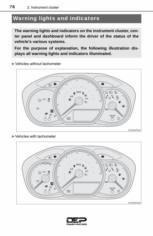
78 2. Instrument cluster
Warning lights and indicators
Vehicles without tachometer
Vehicles with tachometer
The warning lights and indicators on the instrument cluster, cen-ter panel and dashboard inform the driver of the status of thevehicle’s various systems.
For the purpose of explanation, the following illustration dis-plays all warning lights and indicators illuminated.

792. Instrument cluster
2
Instrument cluster
Warning lights inform the driver of malfunctions in the indicated vehi-cle’s systems.
Warning lights
*1
(Except Canada)
Brake system warninglight (→P. 422)
*1Electric power steeringsystem warning light(→P. 423)
*1
(Canada)
Brake system warninglight (→P. 422)
*1, 2, 5
PCS warning light (→P. 424)
*1Charging system warn-ing light (→P. 422)
*1, 3Slip indicator (→P. 424)
*1
Low engine oil pressurewarning light (→P. 422)
*2
(Yellow)
Automatic High Beamindicator (→P. 424)
*1
(Red)
High engine coolanttemperature warninglight (→P. 422)
*2
(Yellow)
Cruise control indicator(→P. 425)
*1
(Except Canada)
Malfunction indicatorlamp (→P. 423)
*2
(Yellow)
LDA indicator (→P. 425)
*1
(Canada)
Malfunction indicatorlamp (→P. 423)
*2, 4
(Yellow)
Lane marker indicators (→P. 425)
*1SRS warning light (→P. 423)
Open door warning light (→P. 425)
*1
(Except Canada)
ABS warning light (→P. 423)
Low fuel level warninglight (→P. 425)
*1
(Canada)
ABS warning light (→P. 423)
Driver’s and front pas-senger’s seat beltreminder light (→P. 425)
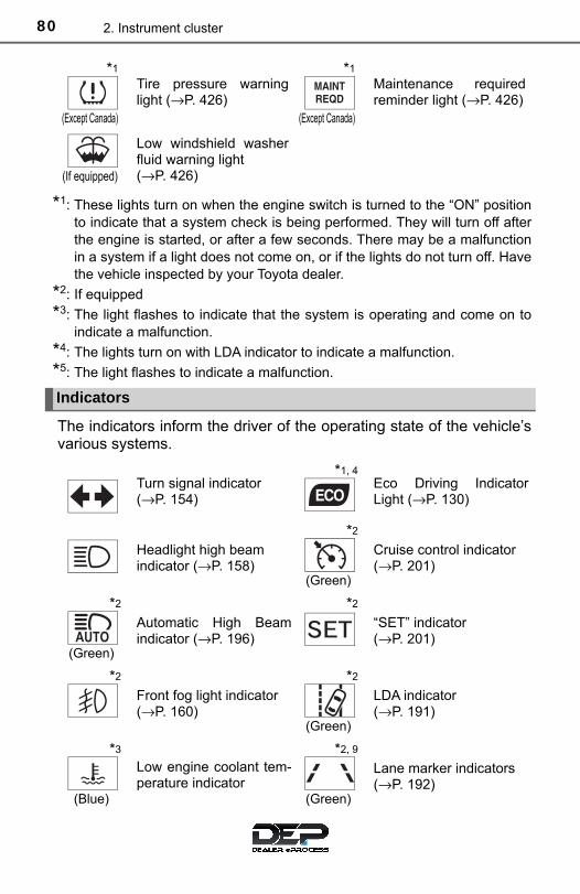
80 2. Instrument cluster
*1: These lights turn on when the engine switch is turned to the “ON” positionto indicate that a system check is being performed. They will turn off afterthe engine is started, or after a few seconds. There may be a malfunctionin a system if a light does not come on, or if the lights do not turn off. Havethe vehicle inspected by your Toyota dealer.
*2: If equipped
*3: The light flashes to indicate that the system is operating and come on toindicate a malfunction.
*4: The lights turn on with LDA indicator to indicate a malfunction.
*5: The light flashes to indicate a malfunction.
The indicators inform the driver of the operating state of the vehicle’svarious systems.
*1
(Except Canada)
Tire pressure warninglight (→P. 426)
*1
(Except Canada)
Maintenance requiredreminder light (→P. 426)
(If equipped)
Low windshield washerfluid warning light(→P. 426)
Indicators
Turn signal indicator (→P. 154)
*1, 4Eco Driving IndicatorLight (→P. 130)
Headlight high beam indicator (→P. 158)
*2
(Green)
Cruise control indicator (→P. 201)
*2
(Green)
Automatic High Beamindicator (→P. 196)
*2
“SET” indicator (→P. 201)
*2
Front fog light indicator (→P. 160)
*2
(Green)
LDA indicator (→P. 191)
*3
(Blue)
Low engine coolant tem-perature indicator
*2, 9
(Green)
Lane marker indicators (→P. 192)

812. Instrument cluster
2
Instrument cluster
*1: These lights turn on when the engine switch is turned to the “ON” positionto indicate that a system check is being performed. They will turn off afterthe engine is started, or after a few seconds. There may be a malfunctionin a system if a light does not come on, or if the lights do not turn off. Havethe vehicle inspected by your Toyota dealer.
*2: If equipped
*3: The light turns on to indicate the engine coolant temperature is low.
*4: Vehicles with an automatic transmission
*5: The light flashes to indicate that the system is operating.
*6: This light illuminates on the center panel.
*7: The light comes on when the system is turned off.
*8: The light comes on when system settings are changed.
*9: The light flashes in yellow to indicate that the vehicle is deviating from thelane.
*1, 5
Slip indicator (→P. 216)
*1, 2, 7PCS warning light (→P. 180)
*1
“TRAC OFF” indicator (→P. 216)
*1, 6
(Except Canada)
“AIR BAG ON/OFF” indicator (→P. 49)
*1
VSC off indicator (→P. 217)
*1, 6
(Canada)
“AIR BAG ON/OFF” indicator (→P. 49)
*2, 5, 8PCS activation indicator (→P. 177)
82 2. Instrument cluster
WARNING
■ If a safety system warning light does not come on Should a safety system light such as the ABS and SRS warning light notcome on when you start the engine, this could mean that these systems arenot available to help protect you in an accident, which could result in deathor serious injury. Have the vehicle inspected by your Toyota dealer immedi-ately if this occurs.
NOTICE
■To prevent damage to the engine and its componentsThe engine may be overheating if the high engine coolant temperaturewarning light flashes or turns on. In this case, immediately stop the vehiclein a safe place, and check the engine after it has cooled completely. (→P. 453)
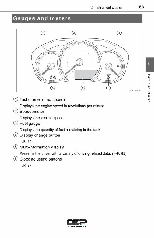
832. Instrument cluster
2
Instrument cluster
Gauges and meters
Tachometer (if equipped)
Displays the engine speed in revolutions per minute.
Speedometer
Displays the vehicle speed.
Fuel gauge
Displays the quantity of fuel remaining in the tank.
Display change button
→P. 85
Multi-information display
Presents the driver with a variety of driving-related data. (→P. 85)
Clock adjusting buttons
→P. 87
1
2
3
4
5
6

84 2. Instrument cluster
The brightness of the instrument panel lights can be adjusted.
Brighter
Darker
■The meters and display illuminate whenThe engine switch is in the “ON” position.
Instrument panel light control
1
2
NOTICE
■To prevent damage to the engine and its componentsOn vehicles with a tachometer, do not let the indicator needle of the tachom-eter enter the red zone, which indicates the maximum engine speed.

852. Instrument cluster
2
Instrument cluster
Multi-information display
Clock (→P. 87)
Outside temperature display(→P. 88)
Shift position and gear stepposition indicator* (→P. 149)
Drive information (→P. 86)
*: Vehicles with an automatic trans-mission only
.
Items displayed can be switchedby pressing the display changebutton.
The multi-information display presents the driver with a varietyof driving-related data including the clock.
Display contents
1
2
3
4
Changing the display

86 2. Instrument cluster
■ Odometer
Displays the total distance the vehicle has been driven.
■ Trip meters
Displays the distance the vehicle has been driven since the meterwas last reset. Trip meters “A” and “B” can be used to record anddisplay different distances independently.
Pressing and holding the display change button while the trip meter isdisplayed will reset the trip meter to “0”.
■ Driving range
Displays the estimated maximum distance that can be driven withthe quantity of fuel remaining.• This distance is computed based on your average fuel consumption. As
a result, the actual distance that can be driven may differ from that dis-played.
• When only a small amount of fuel is added to the tank, the display maynot be updated.
When refueling, turn the engine switch to the “LOCK” position. If the vehi-cle is refueled without turning the engine switch to the “LOCK” position, thedisplay may not be updated.
■ Average fuel consumption
Displays the average fuel consumption since the function wasreset.• The function can be reset by pressing and holding the display change
button when the average fuel consumption is displayed.• Use the displayed average fuel consumption as a reference.
■ Instantaneous fuel consumption
Displays the instantaneous of fuel consumption.
■ Average vehicle speed
Displays the average vehicle speed since the engine was laststarted.
Drive information

872. Instrument cluster
2
Instrument cluster
Eco Driving Indicator Light can be activated or deactivated by press-ing the display change button when the Eco Driving Indicator Lightcustomization display is displayed.
To change the Eco Driving Indicator Light customization display, display theodometer and press and hold the display change button until the displaychanges.
After customization, press the display change button for more than 2 sec-onds to return to the odometer.
The clock can be adjusted by pressing the buttons.
Adjust the hours
Adjust the minutes
Eco Driving Indicator Light customization (Vehicles with an auto-matic transmission)
Clock
1
2

88 2. Instrument cluster
The temperature display shows temperatures within the range of-40°F (-40°C) and 122°F (50°C).
■ Display
In the following situations, the correct outside temperature may notbe displayed, or the display may take longer than normal to change:● When the vehicle is stopped, or moving at low speeds (less than
16 mph [25 km/h])● When the outside temperature has changed suddenly (at the
entrance/exit of a garage, tunnel, etc.)
■ When “− −” or “E” is displayed
The system may be malfunctioning. Take your vehicle to yourToyota dealer.
■When disconnecting and reconnecting battery terminalsThe following information data will be reset.
●Driving range
●Average fuel consumption
●Average vehicle speed
●Clock data
■Liquid crystal displaySmall spots or light spots may appear on the display. This phenomenon ischaracteristic of liquid crystal display, and there is no problem continuing touse the display.
■Changing the pre-collision warning timing→P. 181
Outside temperature display
NOTICE
■The multi-information display at low temperaturesAllow the interior of the vehicle to warm up before using the liquid crystalinformation display. At extremely low temperatures, the display monitor mayrespond slowly, and display changes may be delayed.

892. Instrument cluster
2
Instrument cluster
Fuel consumption information
Vehicles with Entune Audio
Press the “CAR” button.
Vehicles with Entune Audio Plus
Press the “APPS” button, and then select “Eco” on the screen.
■ Trip information
If the “Past Record” screen is displayed, select “Trip Information”.
Resetting the consumptiondata
Average vehicle speed sincethe engine was started
Elapsed time since theengine was started
Fuel consumption in the past15 minutes
Cruising range (→P. 90)
Current fuel consumption
Average fuel consumption for the past 15 minutes is divided bycolor into past averages and averages attained since the engineswitch was last turned to the “ON” position. Use the displayed aver-age fuel consumption as a reference.
These images are examples only.
The fuel consumption information can be displayed on EntuneAudio and Entune Audio Plus screen.
Display the trip information or past record screen
Fuel consumption
1
2
3
4
5
6

90 2. Instrument cluster
■ Past record
If the “Trip Information” screen is displayed, select “Past Record”.
Resetting the past recorddata
Best recorded fuel consump-tion
Average fuel consumption (ifequipped)
Previous fuel consumptionrecord
Current fuel economy
Update the average fuel consumption data
The average fuel consumption history is divided by color into pastaverages and the average fuel consumption since the last updated.Use the displayed average fuel consumption as a reference.
These images are examples only.
■Resetting the dataThe fuel consumption data can be deleted by selecting “Clear”.
■Updating the past record dataUpdate the average fuel consumption by selecting “Update” to measure thecurrent fuel consumption again.
■Cruising rangeDisplays the estimated maximum distance that can be driven with the quan-tity of fuel remaining.
This distance is computed based on your average fuel consumption. As aresult, the actual distance that can be driven may differ from that displayed.
1
2
3
4
5
6
91
3Operation ofeach component
3-1. Key information
Keys .................................... 92
3-2. Opening, closing and locking the doors
Side doors........................... 96
Back door.......................... 101
3-3. Adjusting the seats
Front seats ........................ 106
Rear seats......................... 109
Head restraints.................. 113
3-4. Adjusting the steering wheel and mirrors
Steering wheel .................. 116
Inside rear view mirror ...... 118
Outside rear view mirrors............................. 120
3-5. Opening and closing the windows
Power windows ................. 122

92 3-1. Key information
Keys
The following keys are provided with the vehicle.
Vehicles without an engine immobilizer system
Master keys
Key number plate
Vehicles with an engine immobilizer system (type A)
Master keys
Key number plate
Vehicles with an engine immobilizer system (type B)
Master keys
Operating the wireless remote con-trol function
Key number plate
The keys
1
2
1
2
1
2
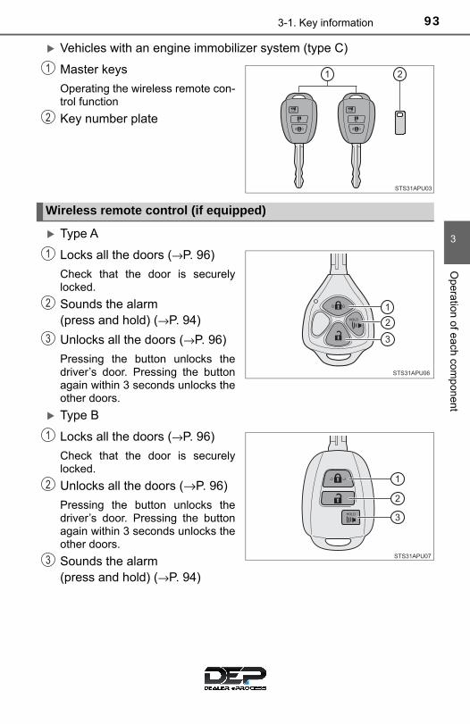
933-1. Key information
3
Opera
tion of each com
ponent
Vehicles with an engine immobilizer system (type C)
Master keys
Operating the wireless remote con-trol function
Key number plate
Type A
Locks all the doors (→P. 96)
Check that the door is securelylocked.
Sounds the alarm (press and hold) (→P. 94)
Unlocks all the doors (→P. 96)
Pressing the button unlocks thedriver’s door. Pressing the buttonagain within 3 seconds unlocks theother doors.
Type B
Locks all the doors (→P. 96)
Check that the door is securelylocked.
Unlocks all the doors (→P. 96)
Pressing the button unlocks thedriver’s door. Pressing the buttonagain within 3 seconds unlocks theother doors.
Sounds the alarm (press and hold) (→P. 94)
1
2
Wireless remote control (if equipped)
1
2
3
1
2
3
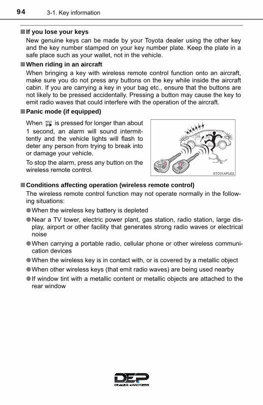
94 3-1. Key information
■ If you lose your keysNew genuine keys can be made by your Toyota dealer using the other keyand the key number stamped on your key number plate. Keep the plate in asafe place such as your wallet, not in the vehicle.
■When riding in an aircraftWhen bringing a key with wireless remote control function onto an aircraft,make sure you do not press any buttons on the key while inside the aircraftcabin. If you are carrying a key in your bag etc., ensure that the buttons arenot likely to be pressed accidentally. Pressing a button may cause the key toemit radio waves that could interfere with the operation of the aircraft.
■Panic mode (if equipped)
■Conditions affecting operation (wireless remote control)The wireless remote control function may not operate normally in the follow-ing situations:
●When the wireless key battery is depleted
●Near a TV tower, electric power plant, gas station, radio station, large dis-play, airport or other facility that generates strong radio waves or electricalnoise
●When carrying a portable radio, cellular phone or other wireless communi-cation devices
●When the wireless key is in contact with, or is covered by a metallic object
●When other wireless keys (that emit radio waves) are being used nearby
● If window tint with a metallic content or metallic objects are attached to therear window
When is pressed for longer than about1 second, an alarm will sound intermit-tently and the vehicle lights will flash todeter any person from trying to break intoor damage your vehicle.
To stop the alarm, press any button on thewireless remote control.

953-1. Key information
3
Opera
tion of each com
ponent
■Key battery depletionIf the wireless remote control function does not operate, the battery may bedepleted. Replace the battery when necessary.
■Customization that can be configured at your Toyota dealerSettings (e.g. wireless remote control system) can be changed. (Customizable features: →P. 488)
■Certification for the wireless remote controlU.S.A.
FCC ID: HYQ23AAAFCC ID: HYQ12BBY
NOTE:This device complies with part 15 of the FCC Rules. Operation is subject tothe following two conditions: (1) This device may not cause harmful interfer-ence, and (2) this device must accept any interference received, includinginterference that may cause undesired operation.
FCC WARNING:Changes or modifications not expressly approved by the party responsible forcompliance could void the user’s authority to operate the equipment.
Canada
NOTE:This device complies with Industry Canada licence-exempt RSSs.Operation is subject to the following two conditions: (1) This device may notcause interference; and (2) This device must accept any interference, includ-ing interference that may cause undesired operation of the device.
NOTICE
■To prevent key damageObserve the following:
●Do not subject the keys to strong shocks, expose them to high tempera-tures by placing them in direct sunlight, or get them wet.
●Do not expose the keys to electromagnetic materials or attach any mate-rial that blocks electromagnetic waves to the key surface.
●Do not disassemble the wireless remote control key.

96 3-2. Opening, closing and locking the doors
Side doors
◆ Wireless remote control (if equipped)
Type A
Locks all the doors
Check that the door is securelylocked.
Unlocks all the doors
Pressing the button unlocks thedriver’s door. Pressing the buttonagain within 3 seconds unlocks theother doors.
Type B
Locks all the doors
Check that the door is securelylocked.
Unlocks all the doors
Pressing the button unlocks thedriver’s door. Pressing the buttonagain within 3 seconds unlocks theother doors.
The vehicle can be locked and unlocked using the keys, wirelessremote control or door lock switch.
Unlocking and locking the doors from the outside
1
2
1
2

973-2. Opening, closing and locking the doors
3
Opera
tion of each com
ponent
◆ Keys
Turning the key operates the doors as follows:
■ Driver’s door
Locks all the doors
Unlocks all the doors
Turning the key unlocks thedriver’s door. Turning the keyagain unlocks the other doors.
■ Front passenger’s door
Locks all the doors
Unlocks all the doors
■Operation signals (vehicles with a wireless remote control)The emergency flashers flash to indicate that the doors have been locked/unlocked. (Locked: once; Unlocked: twice)
■Security feature (vehicles with a wireless remote control)If a door is not opened within approximately 60 seconds after the vehicle isunlocked, the security feature automatically locks the vehicle again.
1
2
1
2

98 3-2. Opening, closing and locking the doors
◆ Door lock switch
Unlocks all the doors
Locks all the doors
◆ Inside door lock buttons
Locks the doors
Unlocks the doors
The front doors can be openedby pulling the inside handleeven if the inside door lock but-ton is in the lock position.
Move the inside door lock button to the lock position.
Close the door.
The door cannot be locked if either of the front doors is open and thekey is in the engine switch.
Unlocking and locking the doors from the inside
1
2
1
2
Locking the front door from the outside without a key
1
2

993-2. Opening, closing and locking the doors
3
Opera
tion of each com
ponent
The door cannot be opened frominside the vehicle when the lock isset.
Unlock
Lock
These locks can be set to preventchildren from opening the reardoors. Push down on each reardoor switch to lock both rear doors.
■Open door warning buzzerIf a door or the back door is not fully closed, a buzzer will sound when thevehicle speed reaches 3 mph (5 km/h).
■Conditions affecting the operation of the wireless remote control→P. 94
■CustomizationSettings (e.g. unlocking function using a key) can be changed. (Customizable features →P. 488)
Rear door child-protector lock (5-door models only)
1
2
100 3-2. Opening, closing and locking the doors
WARNING
■To prevent an accidentObserve the following precautions while driving the vehicle.Failure to do so may result in a door opening and an occupant falling out,resulting in death or serious injury.
●Always use a seat belt.
●Always lock all the doors.
●Ensure that all the doors are properly closed.
●Do not pull the inside handle of the doors while driving. The doors may be opened and the passengers are thrown out of the vehi-cle and it may result in serious injury or death.
Be especially careful for the front doors, as the doors may be openedeven if the inside lock buttons are in locked position.
●5-door models only: Set the rear door child-protector locks when childrenare seated in the rear seats.

1013-2. Opening, closing and locking the doors
3
Opera
tion of each com
ponent
Back door
◆ Wireless remote control (if equipped)
→P. 96
◆ Keys
From the back door (vehicles without wireless remote control):
Unlocks all the doors
Locks all the doors
From the side door: →P. 97
◆ Door lock switch
→P. 98
Raise the back door while pushingup the back door opener switch.
The back door cannot be closedimmediately after the back dooropener switch is pushed.
The back door can be locked/unlocked and opened by the fol-lowing procedures.
Unlocking and locking the back door
1
2
Opening the back door from outside the vehicle

102 3-2. Opening, closing and locking the doors
Lower the back door using theback door handle, and make sureto push the back door down fromthe outside to close it.
■Operation signals (vehicles with a wireless remote control)The emergency flashers flash to indicate that the doors have been locked/unlocked. (Locked: once; Unlocked: twice)
■Open door warning buzzerIf a door or the back door is not fully closed, a buzzer will sound when thevehicle speed reaches 3 mph (5 km/h).
■Luggage compartment lightThe luggage compartment lights turn on when the back door is opened.
When closing the back door
WARNING
■Caution while driving●Keep the back door closed while driving.
If the back door is left open, it may hit near-by objects while driving or lug-gage may be unexpectedly thrown out, causing an accident.In addition, exhaust gases may enter the vehicle, causing death or a seri-ous health hazard. Make sure to close the back door before driving.
●Before driving the vehicle, make sure that the back door is fully closed. Ifthe back door is not fully closed, it may open unexpectedly while driving,causing an accident.
●Never let anyone sit in the luggage compartment. In the event of suddenbraking or a collision, they are susceptible to death or serious injury.

1033-2. Opening, closing and locking the doors
3
Opera
tion of each com
ponent
WARNING
■When children are in the vehicleObserve the following precautions.Failure to do so may result in death or serious injury.
●Do not allow children to play in the luggage compartment.If a child is accidentally locked in the luggage compartment, they couldhave heat exhaustion or other injuries.
●Do not allow a child to open or close the back door.Doing so may cause the back door to move unexpectedly, or cause thechild’s hands, head, or neck to be caught by the closing back door.
■Operating the back doorObserve the following precautions.Failure to do so may cause parts of the body to be caught, resulting in deathor serious injury.
●Remove any heavy loads, such as snow and ice, from the back doorbefore opening it. Failure to do so may cause the back door to suddenlyshut again after it is opened.
●When opening or closing the back door, thoroughly check to make surethe surrounding area is safe.
● If anyone is in the vicinity, make sure they are safe and let them know thatthe back door is about to open or close.
●Use caution when opening or closing the back door in windy weather as itmay move abruptly in strong wind.

104 3-2. Opening, closing and locking the doors
WARNING
●Do not pull on the back door damper stay to close the back door, and donot hang on the back door damper stay.Doing so may cause hands to be caught or the back door damper stay tobreak, causing an accident.
● If a bicycle carrier or similar heavy object is attached to the back door, itmay suddenly shut again after being opened, causing someone’s hands,head or neck to be caught and injured. When installing an accessory partto the back door, using a genuine Toyota part is recommended.
●The back door may suddenly shut if it isnot opened fully. It is more difficult toopen or close the back door on anincline than on a level surface, sobeware of the back door unexpectedlyopening or closing by itself. Make surethat the back door is fully open andsecure before using the luggage com-partment.
●When closing the back door, take extracare to prevent your fingers, etc., frombeing caught.
●When closing the back door, make sureto press it lightly on its outer surface. Ifthe back door handle is used to fullyclose the back door, it may result inhands or arms being caught.

1053-2. Opening, closing and locking the doors
3
Opera
tion of each com
ponent
NOTICE
■Back door damper staysThe back door is equipped with damper stays that hold the back door inplace.
Observe the following precautions.Failure to do so may cause damage to the back door damper stay, resultingin malfunction.
●Do not place your hand on the damper stay or apply lateral forces to it.
●Do not attach any foreign objects, suchas stickers, plastic sheets, or adhesivesto the damper stay rod.
●Do not touch the damper stay rod withgloves or other fabric items.
●Do not attach any accessories otherthan genuine Toyota parts to the backdoor.
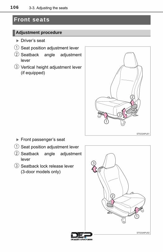
106 3-3. Adjusting the seats
Front seats
Driver’s seat
Seat position adjustment lever
Seatback angle adjustmentlever
Vertical height adjustment lever(if equipped)
Front passenger’s seat
Seat position adjustment lever
Seatback angle adjustmentlever
Seatback lock release lever (3-door models only)
Adjustment procedure
1
2
3
1
2
3

1073-3. Adjusting the seats
3
Opera
tion of each com
ponent
■ Getting in or out the vehicle
For easy access to the rear seat, use the seatback lock releaselever or seatback angle adjustment lever. When the seatback lockrelease lever or seatback angle adjustment lever is used, the seat’soriginal position is memorized, so the seat may be returned to thatoriginal position. The seatback will be returned to the fully uprightposition.
Lift the seatback lock releaselever or seatback angle adjust-ment lever.The seatback will fold forward,and the seat’s slide lock will bereleased.Move the seat all the way for-ward.
■Seat slide position memory function (3-door models only)Slide the seat backward and then lift the seatback. The seat will be set andlocked to its previous slide position automatically, and the seatback will bereturned to the fully upright position.
In the following situations, the seat slide position memory will not be saved orwill be overwritten.
●The seatback is lifted upright at a slide position farther forward than thememorized position.
●The seat slide position is memorized when the seat is slid all the way ornearly all the way forward.
●The seat is slid farther back than the memorized position by using the seatposition adjustment lever.
■ If the seat cannot be returned to the memorized slide positionLift the seatback lock release lever or seatback angle adjustment lever afterremoving the luggage, or after having the passenger get out or sit properly sothat the seat can be slid back to the previous position.
Moving front passenger’s seat for rear seat entry (3-door modelsonly)

108 3-3. Adjusting the seats
WARNING
■When adjusting the seat position●Take care when adjusting the seat position to ensure that other passen-
gers are not injured by the moving seat.
●Do not put your hands under the seat or near the moving parts to avoidinjury.Fingers or hands may become jammed in the seat mechanism.
■Seat adjustment●Be careful that the seat does not hit passenger or luggage.
●To reduce the risk of sliding under the lap belt during a collision, do notrecline the seat more than necessary.If the seat is too reclined, the lap belt may slide past the hips and applyrestraint forces directly to the abdomen, or your neck may contact theshoulder belt, increasing the risk of death or serious injury in the event ofan accident.Adjustments should not be made while driving as the seat may unexpect-edly move and cause the driver to lose control of the vehicle.
●After adjusting the seat, make sure that the seat is locked in position.
●Never allow anyone to touch seatback lock release levers while the vehi-cle is moving.
● If anyone is in the vicinity, make sure they are clear of the seat back pathand let them know that the seat is about to move.
■After returning the seatback to the upright positionMake sure the seatback is securely locked by pushing it forward and rear-ward. Failure to do so may result in death or serious injury.
NOTICE
■To prevent the seat lock mechanism malfunctionDo not use the seatback angle adjustment lever and seatback lock releaselever at the same time. If they are used together, the seat lock mechanismmay be damaged.

1093-3. Adjusting the seats
3
Opera
tion of each com
ponent
Rear seats
Stow the rear seat belt bucklesas shown.
Stow the seat belts.
Center: →P. 30
Outer: Use the seat belt hang-ers to prevent the belts frombeing tangled.
Remove the outer head restraints. (→P. 113)
Lower the center headrestraints to the lowest position.
The seatbacks of the rear seats can be folded down.
Folding down the rear seatbacks
1
2
3
4

110 3-3. Adjusting the seats
Pull the seatback lock releaseknob and fold the seatbackdown.
Each seatback may be folded sep-arately.
Install the outer head restraints. (→P. 113)
Raise the seatback and lock itin place.
When locked, the red label of thelock release knob cannot be seen.
Return the seat belt to the origi-nal position.
Center: →P. 30
Outer: Remove the seat belt ofthe rear outboard seat from thebelt hanger.
5
Returning the rear seatbacks
1
2
3

1113-3. Adjusting the seats
3
Opera
tion of each com
ponent
WARNING
■When folding the rear seatbacks downObserve the following precautions. Failure to do so may result in death orserious injury.
●Do not fold the seatbacks down while driving.
●Stop the vehicle on level ground, set the parking brake and shift the shiftlever to P (automatic transmission) or N (manual transmission).
●Do not allow anyone to sit on a folded seatback or in the luggage compart-ment while driving.
●Do not allow children to enter the luggage compartment.
●Do not allow anyone to sit on the rear center seat if the rear right seat isfolded down, as the seat belt buckle for the rear center seat belt is thenconcealed under the folded seat and cannot be used.
●Be careful not to catch your hand when folding the rear seatbacks.
● If it is necessary to detach the head restraints, remove it from the vehicleor store it securely in the luggage compartment. This will prevent it frominjuring passengers in the event of sudden braking, sudden swerving or anaccident.
●Depending on the position of the front seat, it may interfere when trying tofold down the rear seatbacks. If this happens, adjust the position of thefront seat.
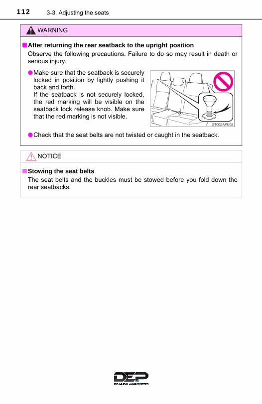
112 3-3. Adjusting the seats
WARNING
■After returning the rear seatback to the upright positionObserve the following precautions. Failure to do so may result in death orserious injury.
●Check that the seat belts are not twisted or caught in the seatback.
NOTICE
■Stowing the seat beltsThe seat belts and the buckles must be stowed before you fold down therear seatbacks.
●Make sure that the seatback is securelylocked in position by lightly pushing itback and forth.If the seatback is not securely locked,the red marking will be visible on theseatback lock release knob. Make surethat the red marking is not visible.

1133-3. Adjusting the seats
3
Opera
tion of each com
ponent
Head restraints
Up
Pull the head restraints up.
Down
Push the head restraint down whilepressing the lock release button.
■Removing the front seats and rear center seat head restraints
■Removing the rear outer seats head restraints
Head restraints are provided for all seats.
Adjusting the front seats and rear center seat head restraints
Lockrelease button
1
2
Pull the head restraint up while pressingthe lock release button.
Pull the lock release knob and folddown the seatback until it reaches theposition where the head restraints canbe removed.
Pull the head restraint up while pushingthe lock release button.
Lockrelease button
1
2
Lock release button
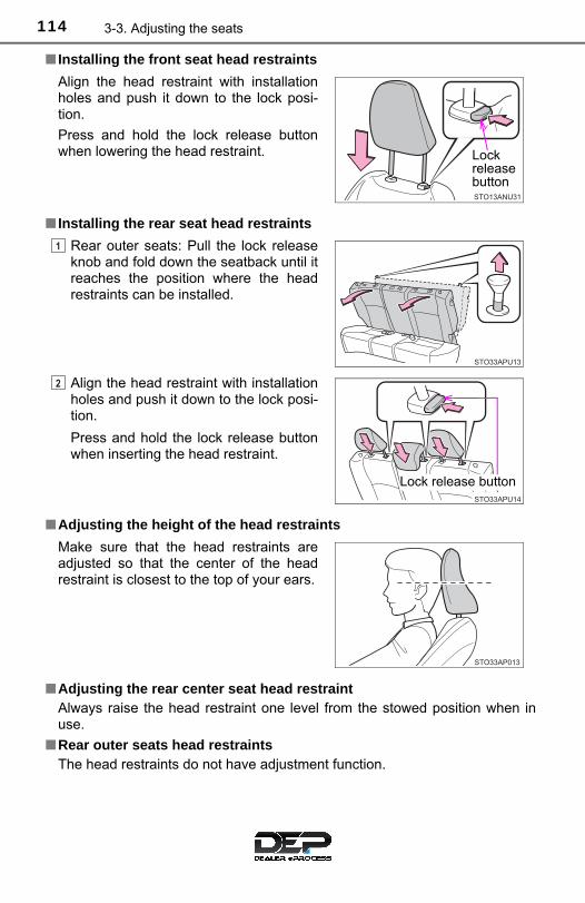
114 3-3. Adjusting the seats
■ Installing the front seat head restraints
■ Installing the rear seat head restraints
■Adjusting the height of the head restraints
■Adjusting the rear center seat head restraintAlways raise the head restraint one level from the stowed position when inuse.
■Rear outer seats head restraintsThe head restraints do not have adjustment function.
Align the head restraint with installationholes and push it down to the lock posi-tion.
Press and hold the lock release buttonwhen lowering the head restraint.
Rear outer seats: Pull the lock releaseknob and fold down the seatback until itreaches the position where the headrestraints can be installed.
Align the head restraint with installationholes and push it down to the lock posi-tion.
Press and hold the lock release buttonwhen inserting the head restraint.
Make sure that the head restraints areadjusted so that the center of the headrestraint is closest to the top of your ears.
Lockrelease button
1
2
Lock release button

1153-3. Adjusting the seats
3
Opera
tion of each com
ponent
WARNING
■Head restraint precautionsObserve the following precautions regarding the head restraints. Failure todo so may result in death or serious injury.
●Use the head restraints designed for each respective seat.
●Adjust the head restraints to the correct position at all times.
●After adjusting the head restraints, push down on them and make surethey are locked in position.
●Do not drive with the head restraints removed.

116 3-4. Adjusting the steering wheel and mirrors
Steering wheel
Hold the steering wheel andpush the lever down.
Adjust to the ideal position bymoving the steering wheel.
After adjustment, pull the lever upto secure the steering wheel.
To sound the horn, press on orclose to the mark.
Adjustment procedure
1
2
Horn

1173-4. Adjusting the steering wheel and mirrors
3
Opera
tion of each com
ponent
■After adjusting the steering wheelMake sure that the steering wheel is securely locked.The horn may not sound if the steering wheel is not securely locked.
WARNING
■Caution while drivingDo not adjust the steering wheel while driving.Doing so may cause the driver to mishandle the vehicle and cause an acci-dent, resulting in death or serious injury.
■After adjusting the steering wheelMake sure that the steering wheel is securely locked. Otherwise, the steering wheel may move suddenly, possibly causing anaccident and resulting in death or serious injury.

118 3-4. Adjusting the steering wheel and mirrors
Inside rear view mirror
The height of the rear view mirror can be adjusted to suit your drivingposture.
Adjust the height of the rear viewmirror by moving it up and down.
Reflected light from the headlights of vehicles behind can be reducedby operating the lever.
Normal position
Anti-glare position
The rear view mirror’s position can be adjusted to enable suffi-cient confirmation of the rear view.
Adjusting the height of rear view mirror
Anti-glare function
1
2

1193-4. Adjusting the steering wheel and mirrors
3
Opera
tion of each com
ponent
WARNING
Do not adjust the position of the mirror while driving.Doing so may lead to mishandling of the vehicle and cause an accident,resulting in death or serious injury.

120 3-4. Adjusting the steering wheel and mirrors
Outside rear view mirrors
Manually-adjustable type
Adjust the mirror up, down, in orout by pushing the mirror surface.
Power-adjustable type
To select a mirror to adjust,press the switch.
Left
Right
To adjust the mirror, press theswitch.
Up
Right
Down
Left
Adjustment procedure
1
1
2
2
1
2
3
4

1213-4. Adjusting the steering wheel and mirrors
3
Opera
tion of each com
ponent
Push the mirror back in the direc-tion of the vehicle’s rear.
■Mirror angle can be adjusted when (power-adjustable type)The engine switch is in the “ACC” or “ON” position.
■When the mirrors are fogged up (vehicles with outside rear view mirrordefoggers)The outside rear view mirrors can be cleared using the mirror defoggers. Turnon the rear window defogger to turn on the outside rear view mirror defog-gers. (→P. 322)
Folding the mirrors
WARNING
■ Important points while drivingObserve the following precautions while driving.Failure to do so may result in loss of control of the vehicle and cause anaccident, resulting in death or serious injury.
●Do not adjust the mirrors while driving.
●Do not drive with the mirrors folded.
●Both the driver and passenger side mirrors must be extended and properlyadjusted before driving.
■When a mirror is moving (power-adjustable type)To avoid personal injury and mirror malfunction, be careful not to get yourhand caught by the moving mirror.
■When the mirror defoggers are operating (vehicles with outside rearview mirror defoggers)Do not touch the rear view mirror surfaces, as they can become very hotand burn you.

122 3-5. Opening and closing the windows
Power windows
The power windows can be opened and closed using the switches.Operating the switch moves the windows as follows:
Closing
Opening
One-touch opening (driver’swindow only)*
*: To stop the window partway, oper-ate the switch in the opposite direc-tion.
Press the switch down to lock thepassenger window switches.
Use this switch to prevent childrenfrom accidentally opening or clos-ing a passenger window.
Opening and closing procedures
1
2
3
Window lock switch

1233-5. Opening and closing the windows
3
Opera
tion of each com
ponent
■The power windows can be operated whenThe engine switch is in the “ON” position.
■Operating the power windows after turning the engineThe power windows can be operated for approximately 45 seconds evenafter the engine switch is turned to the “ACC” or “LOCK” position. They can-not, however, be operated once either front door is opened.
WARNING
Observe the following precautions. Failure to do so may result in death or serious injury.
■Closing the windows●The driver is responsible for all the power window operations, including the
operation for the passengers. In order to prevent accidental operation,especially by a child, do not let a child operate the power windows. It ispossible for children and other passengers to have body parts caught inthe power window. Also, when riding with a child, it is recommended to usethe window lock switch. (→P. 122)
●Check to make sure that all passengers do not have any part of their bodyin a position where it could be caught when a window is being operated.
●When exiting the vehicle, turn the engine switch off, carry the key and exitthe vehicle along with the child. There may be accidental operation, due tomischief, etc., that may possibly lead to an accident.

124 3-5. Opening and closing the windows

125
4Driving
4-1. Before driving
Driving the vehicle............. 126
Cargo and luggage ........... 137
Vehicle load limits ............. 141
Trailer towing..................... 142
Dinghy towing (vehicles with an automatic transmission)................... 143
Dinghy towing (vehicles with a manual transmission)................... 144
4-2. Driving procedures
Engine (ignition) switch ..... 146
Automatic transmission..... 149
Manual transmission ......... 153
Turn signal lever................ 154
Parking brake.................... 155
4-3. Operating the lights and wipers
Headlight switch................ 156
Fog light switch ................. 160
Windshield wipers and washer ..................... 162
Rear window wiper and washer ..................... 165
4-4. Refueling
Opening the fuel tank cap .................................. 168
4-5. Toyota Safety Sense C
Toyota Safety Sense C ..... 171
PCS (Pre-Collision System) .... 177
LDA (Lane Departure Alert) .... 191
Automatic High Beam ....... 196
4-6. Using the driving support systems
Cruise control.................... 201
Rear view monitor system ............................ 205
Driving assist systems ...... 215
4-7. Driving tips
Winter driving tips ............. 221

126 4-1. Before driving
Driving the vehicle
→P. 146
Vehicles with an automatic transmission
With the brake pedal depressed, shift the shift lever to D. (→P. 149)
Release the parking brake. (→P. 155)
Gradually release the brake pedal and gently depress the accelera-tor pedal to accelerate the vehicle.
Vehicles with a manual transmission
While depressing the clutch pedal, shift the shift lever to 1. (→P. 153)
Release the parking brake. (→P. 155)
Gradually release the clutch pedal. At the same time, gentlydepress the accelerator pedal to accelerate the vehicle.
The following procedures should be observed to ensure safedriving:
Starting the engine
Driving
1
2
3
1
2
3

1274-1. Before driving
4
Driving
Vehicles with an automatic transmission
With the shift lever in D, depress the brake pedal.
If necessary, set the parking brake.
If the vehicle is to be stopped for an extended period of time, shift the shiftlever to P or N. (→P. 149)
Vehicles with a manual transmission
While depressing the clutch pedal, depress the brake pedal.
If necessary, set the parking brake.
If the vehicle is to be stopped for an extended period of time, shift the shiftlever to N. (→P. 153)
Vehicles with an automatic transmission
With the shift lever in D, depress the brake pedal.
Set the parking brake (→P. 155), and shift the shift lever to P (→P. 149).
If parking on a hill, block the wheels as needed.
Turn the engine switch to the “LOCK” position to stop the engine.
Lock the door, making sure that you have the key on your person.
Stopping
Parking the vehicle
1
2
1
2
1
2
3
4

128 4-1. Before driving
Vehicles with a manual transmission
While depressing the clutch pedal, depress the brake pedal.
Set the parking brake. (→P. 155)
Shift the shift lever to N. (→P. 153)
If parking on a hill, shift the shift lever to 1 or R and block the wheels asneeded.
Turn the engine switch to the “LOCK” position to stop the engine.
Lock the door, making sure that you have the key on your person.
Vehicles with an automatic transmission
Firmly set the parking brake with the brake pedal depressed, andthen shift the shift lever to D.
Release the brake pedal and gently depress the accelerator pedal.
Release the parking brake.
Vehicles with a manual transmission
With the parking brake firmly set and the clutch pedal fullydepressed, shift the shift lever to 1.
Lightly depress the accelerator pedal at the same time as graduallyreleasing the clutch pedal.
Release the parking brake.
Starting off on a steep uphill
1
2
3
4
5
1
2
3
1
2
3

1294-1. Before driving
4
Driving
■When starting off on an uphillThe hill-start assist control will activate. (→P. 215)
■Driving in the rain●Drive carefully when it is raining, because visibility will be reduced, the win-
dows may become fogged-up, and the road will be slippery.
●Drive carefully when it starts to rain, because the road surface will be espe-cially slippery.
●Refrain from high speeds when driving on an expressway in the rain,because there may be a layer of water between the tires and the road sur-face, preventing the steering and brakes from operating properly.
■Engine speed while drivingIn the following conditions, the engine speed may become high while driving.This is due to automatic up-shifting control or down-shifting implementation tomeet driving conditions. It does not indicate sudden acceleration.
●The vehicle is judged to be driving uphill or downhill
●When the accelerator pedal is released
■Breaking in your new ToyotaTo extend the life of the vehicle, observing the following precautions is recom-mended:
●For the first 200 miles (300 km): Avoid sudden stops.
●For the first 1000 miles (1600 km):
• Do not drive at extremely high speeds.• Avoid sudden acceleration.• Do not drive continuously in low gears.• Do not drive at a constant speed for extended periods.

130 4-1. Before driving
■Eco-friendly driving (vehicles with an automatic transmission)
●The vehicle speed is approximately 80 mph (130 km/h) or higher.
Eco Driving Indicator Light can be activated or deactivated. (→P. 87)
■Operating your vehicle in a foreign countryComply with the relevant vehicle registration laws and confirm the availabilityof the correct fuel. (→P. 471)
During Eco-friendly acceleration opera-tion (Eco driving), Eco Driving IndicatorLight will turn on. When the acceleratorpedal is depressed excessively, and whenthe vehicle is stopped, the light turns off.
Eco Driving Indicator Light will not operatein the following conditions:
●The shift lever is in anything other thanD.
WARNING
Observe the following precautions. Failure to do so may result in death or serious injury.
■When starting the vehicle (automatic transmission)Always keep your foot on the brake pedal while stopped with the enginerunning. This prevents the vehicle from creeping.
■When driving the vehicle●Do not drive if you are unfamiliar with the location of the brake and accel-
erator pedals to avoid depressing the wrong pedal.
• Accidentally depressing the accelerator pedal instead of the brakepedal will result in sudden acceleration that may lead to an accident.
• When backing up, you may twist your body around, leading to difficultyin operating the pedals. Make sure to operate the pedals properly.
• Make sure to keep a correct driving posture even when moving thevehicle only slightly. This allows you to depress the brake and accelera-tor pedals properly.
• Depress the brake pedal using your right foot. Depressing the brakepedal using your left foot may delay response in an emergency, result-ing in an accident.

1314-1. Before driving
4
Driving
WARNING
Observe the following precautions. Failure to do so may result in death or serious injury.
●Do not drive the vehicle over or stop the vehicle near flammable materials.The exhaust system and exhaust gases can be extremely hot. These hotparts may cause a fire if there is any flammable material nearby.
●During normal driving, do not turn off the engine. Turning the engine offwhile driving will not cause loss of steering or braking control, but thepower assist to these systems will be lost. This will make it more difficult tosteer and brake, so you should pull over and stop the vehicle as soon as itis safe to do so. However, in the event of an emergency, such as if it becomes impossibleto stop the vehicle in the normal way: →P. 413
●Use engine braking (downshift) to maintain a safe speed when drivingdown a steep hill. Using the brakes continuously may cause the brakes to overheat and loseeffectiveness. (→P. 149, 153)
●Do not adjust the positions of the steering wheel, the seat, or the inside oroutside rear view mirrors while driving.Doing so may result in a loss of vehicle control.
●Always check that all passengers’ arms, heads or other parts of their bodyare not outside the vehicle.
●Do not drive in excess of the speed limit. Even if the legal speed limit per-mits it, do not drive over 85 mph (140 km/h) unless your vehicle has high-speed capability tires. Driving over 85 mph (140 km/h) may result in tirefailure, loss of control and possible injury. Be sure to consult a tire dealerto determine whether the tires on your vehicle are high-speed capabilitytires or not before driving at such speeds.

132 4-1. Before driving
WARNING
Observe the following precautions. Failure to do so may result in death or serious injury.
■When driving on slippery road surfaces●Sudden braking, acceleration and steering may cause tire slippage and
reduce your ability to control the vehicle.
●Sudden acceleration, engine braking due to shifting, or changes in enginespeed could cause the vehicle to skid, resulting in an accident.
●After driving through a puddle, depress the brake pedal to make sure thatthe brakes are functioning properly. Wet brake pads may prevent thebrakes from functioning properly. If the brakes on only one side are wetand not functioning properly, steering control may be affected.
■When shifting the shift lever●On vehicles with an automatic transmission, do not let the vehicle roll
backward while the shift lever is in a driving position, or roll forward whilethe shift lever is in R. Doing so may cause the engine to stall or lead to poor brake and steeringperformance, resulting in an accident or damage to the vehicle.
●On vehicles with an automatic transmission, do not shift the shift lever to Pwhile the vehicle is moving. Doing so can damage the transmission and may result in a loss of vehiclecontrol.
●Do not shift the shift lever to R while the vehicle is moving forward. Doing so can damage the transmission and may result in a loss of vehiclecontrol.
●Do not shift the shift lever to a driving position while the vehicle is movingbackward. Doing so can damage the transmission and may result in a lossof vehicle control.
●Shifting the shift lever to N while the vehicle is moving will disengage theengine from the transmission. Engine braking is not available when N isselected.
●On vehicles with an automatic transmission, be careful not to shift the shiftlever with the accelerator pedal depressed. Shifting the shift lever to agear other than P or N may lead to unexpected rapid acceleration of thevehicle that may cause an accident and result in death or serious injury.

1334-1. Before driving
4
Driving
WARNING
■ If you hear a squealing or scraping noise (brake pad wear limit indica-tors)Have the brake pads checked and replaced by your Toyota dealer as soonas possible. Rotor damage may result if the pads are not replaced when needed.
It is dangerous to drive the vehicle when the wear limits of the brake padsand/or those of the brake discs are exceeded.
■When the vehicle is stopped●Do not race the engine.
If the vehicle is in any gear other than P (automatic transmission) or N, thevehicle may accelerate suddenly and unexpectedly, causing an accident.
●On vehicles with an automatic transmission, in order to prevent accidentsdue to the vehicle rolling away, always keep depressing the brake pedalwhile the engine is running, and apply the parking brake as necessary.
● If the vehicle is stopped on an incline, in order to prevent accidents causedby the vehicle rolling forward or backward, always depress the brake pedaland securely apply the parking brake as needed.
●Avoid revving or racing the engine. Running the engine at high speed while the vehicle is stopped may causethe exhaust system to overheat, which could result in a fire if combustiblematerial is nearby.
■When the vehicle is parked●Do not leave glasses, cigarette lighters, spray cans, or soft drink cans in
the vehicle when it is in the sun.Doing so may result in the following:
• Gas may leak from a cigarette lighter or spray can, and may lead to afire.
• The temperature inside the vehicle may cause the plastic lenses andplastic material of glasses to deform or crack.
• Soft drink cans may rupture, causing the contents to spray over theinterior of the vehicle, and may also cause a short circuit in the vehicle’selectrical components.
●Do not leave cigarette lighters in the vehicle. If a cigarette lighter is in aplace such as the glove box or on the floor, it may be lit accidentally whenluggage is loaded or the seat is adjusted, causing a fire.

134 4-1. Before driving
WARNING
●Do not attach adhesive discs to the windshield or windows. Do not placecontainers such as air fresheners on the instrument panel or dashboard.Adhesive discs or containers may act as lenses, causing a fire in the vehi-cle.
●Do not leave a door or window open if the curved glass is coated with ametallized film such as a silver-colored one. Reflected sunlight may causethe glass to act as a lens, causing a fire.
●On vehicles with an automatic transmission, always apply the parkingbrake, shift the shift lever to P, stop the engine and lock the vehicle. Do not leave the vehicle unattended while the engine is running.If the vehicle is parked with the shift lever in P but the parking brake is notset, the vehicle may start to move, possibly leading to an accident.
●Do not touch the exhaust pipes while the engine is running or immediatelyafter turning the engine off.Doing so may cause burns.
■When taking a nap in the vehicleAlways turn the engine off. Otherwise, if you accidentally move the shiftlever or depress the accelerator pedal, this could cause an accident or firedue to engine overheating. Additionally, if the vehicle is parked in a poorlyventilated area, exhaust gases may collect and enter the vehicle, leading todeath or a serious health hazard.
■When braking●When the brakes are wet, drive more cautiously.
Braking distance increases when the brakes are wet, and this may causeone side of the vehicle to brake differently than the other side. Also, theparking brake may not securely hold the vehicle.
● If the power brake assist function does not operate, do not follow othervehicles closely and avoid hills or sharp turns that require braking. In this case, braking is still possible, but the brake pedal should bedepressed more firmly than usual. Also, the braking distance will increase.Have your brakes fixed immediately.
●Do not pump the brake pedal if the engine stalls. Each push on the brake pedal uses up the reserve for the power-assistedbrakes.
●The brake system consists of 2 individual hydraulic systems; if one of thesystems fails, the other will still operate. In this case, the brake pedalshould be depressed more firmly than usual and the braking distance willincrease. Have your brakes fixed immediately.

1354-1. Before driving
4
Driving
NOTICE
■When driving the vehicleVehicles with an automatic transmission
●Do not depress the accelerator and brake pedals at the same time duringdriving, as this may restrain the engine output.
●Do not use the accelerator pedal or depress the accelerator and brakepedals at the same time to hold the vehicle on a hill.
Vehicles with a manual transmission
●Do not depress the accelerator and brake pedals at the same time duringdriving, as this may restrain the engine output.
●Do not shift gears unless the clutch pedal is fully depressed. After shifting,do not release the clutch pedal abruptly. Doing so may damage the clutch,transmission and gears.
●Observe the following to prevent the clutch from being damaged.
• Do not rest your foot on the clutch pedal while driving.Doing so may cause clutch trouble.
• Do not use any gear other than the 1st gear when starting off and mov-ing forward.Doing so may damage the clutch.
• Do not use the clutch to hold the vehicle when stopping on an uphillgrade.Doing so may damage the clutch.
●Do not shift the shift lever to R when the vehicle is still moving. Doing somay damage the clutch, transmission and gears.
■When parking the vehicle (automatic transmission)Always set the parking brake, and shift the shift lever to P. Failure to do somay cause the vehicle to move or the vehicle may accelerate suddenly ifthe accelerator pedal is accidentally depressed.
■Avoiding damage to vehicle parts●Do not turn the steering wheel fully in either direction and hold it there for
an extended period of time. Doing so may damage the power steering motor.
●When driving over bumps in the road, drive as slowly as possible to avoiddamaging the wheels, underside of the vehicle, etc.
136 4-1. Before driving
NOTICE
■ If you get a flat tire while driving A flat or damaged tire may cause the following situations. Hold the steeringwheel firmly and gradually depress the brake pedal to slow down the vehi-cle.
● It may be difficult to control your vehicle.
●The vehicle will make abnormal sounds or vibrations.
●The vehicle will lean abnormally.
Information on what to do in case of a flat tire (→P. 433)
■When encountering flooded roadsDo not drive on a road that has flooded after heavy rain, etc. Doing so maycause the following serious damage to the vehicle:
●Engine stalling
●Short in electrical components
●Engine damage caused by water immersion
In the event that you drive on a flooded road and the vehicle is flooded, besure to have your Toyota dealer check the following:
●Brake function
●Changes in quantity and quality of engine oil and transmission fluid, etc.
●Lubricant condition for the bearings and suspension joints (where possi-ble), and the function of all joints, bearings, etc.

1374-1. Before driving
4
Driving
Cargo and luggage
Cargo capacity depends on the total weight of the occupants.
(Cargo capacity) = (Total load capacity) − (Total weight of occupants)
Steps for Determining Correct Load Limit —
(1) Locate the statement “The combined weight of occupants andcargo should never exceed XXX kg or XXX lbs.” on your vehicle’splacard.
(2) Determine the combined weight of the driver and passengers thatwill be riding in your vehicle.
(3) Subtract the combined weight of the driver and passengers fromXXX kg or XXX lbs.
(4) The resulting figure equals the available amount of cargo and lug-gage load capacity.
For example, if the “XXX” amount equals 1400 lbs. and there will befive 150 lb passengers in your vehicle, the amount of availablecargo and luggage load capacity is 650 lbs. (1400 − 750 (5 × 150) =650 lbs.)
(5) Determine the combined weight of luggage and cargo being loadedon the vehicle. That weight may not safely exceed the availablecargo and luggage load capacity calculated in Step 4.
Take notice of the following information about storage precau-tions, cargo capacity and load:
● Stow cargo and luggage in the luggage compartment wheneverpossible.
● Be sure all items are secured in place.
● To maintain vehicle balance while driving, position luggage evenlywithin the luggage compartment.
● For better fuel economy, do not carry unnecessary weight.
Capacity and distribution

138 4-1. Before driving
(6) If your vehicle will be towing a trailer, load from your trailer will betransferred to your vehicle. Consult this manual to determine howthis reduces the available cargo and luggage load capacity of yourvehicle.
Toyota does not recommend towing a trailer with your vehicle. Yourvehicle is not designed for trailer towing.
Cargo capacity
Total load capacity (vehiclecapacity weight) (→P. 460)
When 2 people with the combined weight of A lb. (kg) are riding inyour vehicle, which has a total load capacity (vehicle capacity weight)of B lb. (kg), the available amount of cargo and luggage load capacitywill be C lb. (kg) as follows:
B*2 lb. (kg) − A*1 lb. (kg) = C*3 lb. (kg)
*1: A = Weight of people
*2: B = Total load capacity
*3: C = Available cargo and luggage load
In this condition, if 3 more passengers with the combined weight ofD lb. (kg) get on, the available cargo and luggage load will be reducedE lb. (kg) as follows:
C lb. (kg) − D*4 lb. (kg) = E*5 lb. (kg)
*4: D = Additional weight of people
*5: E = Available cargo and luggage load
Calculation formula for your vehicle
1
2

1394-1. Before driving
4
Driving
As shown in the example above, if the number of occupantsincreases, the cargo and luggage load will be reduced by an amountthat equals the increased weight due to the additional occupants. Inother words, if an increase in the number of occupants causes anexcess of the total load capacity (combined weight of occupants pluscargo and luggage load), you must reduce the cargo and luggage onyour vehicle.
WARNING
■Things that must not be carried in the luggage compartmentThe following things may cause a fire if loaded in the luggage compart-ment:
●Receptacles containing gasoline
●Aerosol cans
■Storage precautionsObserve the following precautions. Failure to do so may prevent the pedals from being depressed properly,may block the driver’s vision, or may result in items hitting the driver orpassengers, possibly causing an accident.
●Stow cargo and luggage in the luggage compartment whenever possi-ble.
●Do not stack anything in the luggage compartment higher than theseatbacks.
●Do not place cargo or luggage in or on the following locations:
• At the feet of the driver• On the front passenger or rear seats (when stacking items)• On the luggage cover• On the instrument panel• On the dashboard
●Secure all items in the occupant compartment.
●When you fold down the rear seats, long items should not be placedirectly behind the front seats.
●Never allow anyone to ride in the luggage compartment. It is notdesigned for passengers. They should ride in their seats with their seatbelts properly fastened. Otherwise, they are much more likely to sufferdeath or serious bodily injury, in the event of sudden braking, suddenswerving or an accident.

140 4-1. Before driving
WARNING
■Capacity and distribution●Do not exceed the maximum axle weight rating or the total vehicle
weight rating.
●Even if the total load of occupant’s weight and the cargo load is lessthan the total load capacity, do not apply the load unevenly. Improperloading may cause deterioration of steering or braking control whichmay cause death or serious injury.

1414-1. Before driving
4
Driving
Vehicle load limits
◆ Total load capacity (vehicle capacity weight): (→P. 460)
Total load capacity means the combined weight of occupants, cargoand luggage.
◆ Seating capacity: 5 occupants (Front 2, Rear 3)
Seating capacity means the maximum number of occupants whoseestimated average weight is 150 lb. (68 kg) per person.
◆ Towing capacity
Toyota does not recommend towing a trailer with your vehicle.
◆ Cargo capacity
Cargo capacity may increase or decrease depending on the weightand the number of occupants.
■Total load capacity and seating capacityThese details are also described on the tire and loading information label.(→P. 378)
Vehicle load limits include total load capacity, seating capacity,towing capacity and cargo capacity.
WARNING
■Overloading the vehicleDo not overload the vehicle.It may not only cause damage to the tires, but also degrade steeringand braking ability, resulting in an accident.

142 4-1. Before driving
Trailer towing
Toyota does not recommend towing a trailer with your vehicle.Toyota also does not recommend the installation of a tow hitchor the use of a tow hitch carrier for a wheelchair, scooter, bicy-cle, etc. Your vehicle is not designed for trailer towing or for theuse of tow hitch mounted carriers.
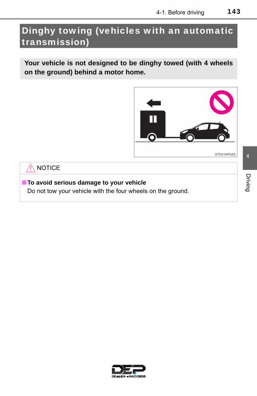
1434-1. Before driving
4
Driving
Dinghy towing (vehicles with an automatic transmission)
Your vehicle is not designed to be dinghy towed (with 4 wheelson the ground) behind a motor home.
NOTICE
■To avoid serious damage to your vehicleDo not tow your vehicle with the four wheels on the ground.

144 4-1. Before driving
Dinghy towing (vehicles with a manual transmission)
To prevent damage to your vehicle, perform the following proceduresbefore towing:
Shift the shift lever to N.
Turn the engine switch to the “ACC” position.
Ensure that the audio system and other powered devices are turned off.
Release the parking brake.
After towing, leave the engine in idle for at least 3 minutes before drivingthe vehicle.
■Necessary equipment and accessoriesSpecialized equipment and accessories are required for dinghy towing. Con-tact the service branch of the motor home manufacturer regarding recom-mended equipment.
Your vehicle can be dinghy towed in a forward direction (with 4wheels on the ground) behind a motor home.
Towing your vehicle with 4 wheels on the ground
1
2
3

1454-1. Before driving
4
Driving
NOTICE
■Dinghy towing direction
■To prevent the steering from lockingEnsure the engine switch is in the “ACC” position.
Do not tow the vehicle backward.
Doing so may cause serious damage.

146 4-2. Driving procedures
Engine (ignition) switch
Check that the parking brake is set.
Check that the shift lever is set in P (automatic transmission) or N(manual transmission).
Firmly depress the brake pedal (automatic transmission) or brakepedal and clutch pedal (manual transmission).
Turn the engine switch to the “START” position to start the engine.
“LOCK”
The steering wheel is locked andthe key can be removed. (Vehicleswith an automatic transmission:The key can be removed onlywhen the shift lever is in P.)
“ACC”
Some electrical components suchas the audio system can be used.
“ON”
All electrical components can beused.
“START”
For starting the engine.
Starting the engine
Changing engine switch positions
1
2
3
4
1
2
3
4

1474-2. Driving procedures
4
Driving
■Turning the key from “ACC” to “LOCK”
Shift the shift lever to P (automatic transmission) or N (manual transmis-sion). (→P. 149, 153)
■ If the engine does not start (vehicles with an engine immobilizer system)The engine immobilizer system may not have been deactivated. (→P. 74) Contact your Toyota dealer.
■When the steering lock cannot be released
■Key reminder functionA buzzer sounds if the driver’s door is opened while the engine switch is inthe “LOCK” or “ACC” position to remind you to remove the key.
Push in the key and turn it to the“LOCK” position.
When starting the engine, the engineswitch may seem stuck in the “LOCK”position. To free it, turn the key while turn-ing the steering wheel slightly left andright.
1
2

148 4-2. Driving procedures
WARNING
■When starting the engineAlways start the engine while sitting in the driver’s seat. Do not depress theaccelerator pedal while starting the engine under any circumstances.Doing so may cause an accident resulting in death or serious injury.
■Caution when drivingDo not turn the engine switch to the “LOCK” position while driving. If, in anemergency, you must turn the engine off while the vehicle is moving, turnthe engine switch only to the “ACC” position to stop the engine. An accidentmay result if the engine is stopped while driving. (→P. 413)
NOTICE
■To prevent battery dischargeDo not leave the engine switch in the “ACC” or “ON” position for long peri-ods of time without the engine running.
■When starting the engine●Do not crank the engine for more than 30 seconds at a time. This may
overheat the starter and wiring system.
●Do not race a cold engine.
● If the engine becomes difficult to start or stalls frequently, have your vehi-cle checked by your Toyota dealer immediately.

1494-2. Driving procedures
4
Driving
Automatic transmission∗
While the engine switch is in the “ON” position, move the shift
lever with the brake pedal depressed.
When shifting the shift lever between P and D, make sure that thevehicle is completely stopped.
*: Shifting to the D position allows the system to select a gear suitable for thedriving conditions. Setting the shift lever to the D position is recommendedfor normal driving.
∗: If equipped
Shifting the shift lever
Shift position purpose
Shift position Function
P Parking the vehicle or starting the engine
R Reversing
N Neutral
D Normal driving*3 Position for engine braking
2 Position for more powerful engine braking
L Position for maximum engine braking

150 4-2. Driving procedures
■Downshift restrictionThe maximum allowable speeds are as follows.
■AI-SHIFTAI-SHIFT automatically selects the suitable gear according to driver perfor-mance and driving conditions. AI-SHIFT automatically operates when the shift lever is in the D position.
■When driving with cruise control activated (if equipped)Even when performing the following actions with the intent of enabling enginebraking, engine braking will not activate while downshifting to 3 becausecruise control will not be canceled. (→P. 203)
■Shift lock systemThe shift lock system is a system to prevent accidental operation of the shiftlever in starting. The shift lever can be shifted from P only when the engine switch is in the“ON” position and the brake pedal is being depressed.
Downshifting Maximum speed mph (km/h)
D→3 84 (135)
3→2 53 (85)
2→L 25 (40)

1514-2. Driving procedures
4
Driving
■ If the shift lever cannot be shifted from PFirst, check whether the brake pedal is being depressed. If the shift lever cannot be shifted with your foot on the brake pedal, there maybe a problem with the shift lock system. Have the vehicle inspected by yourToyota dealer immediately.The following steps may be used as an emergency measure to ensure thatthe shift lever can be shifted.
Releasing the shift lock:
Set the parking brake.
Turn the engine switch to the “LOCK” position.
Depress the brake pedal.
Pry the cover up with a flathead screw-driver or equivalent tool.
To prevent damage to the cover, wrapthe tip of the screwdriver with a rag.
Press the shift lock override button.
The shift lever can be shifted while thebutton is pressed.
1
2
3
4
5

152 4-2. Driving procedures
WARNING
■When driving on slippery road surfacesDo not accelerate or shift gears suddenly. Sudden changes in engine braking may cause the vehicle to spin or skid,resulting in an accident.
■To prevent an accident when releasing the shift lockBefore pressing the shift lock override button, make sure to set the parkingbrake and depress the brake pedal. If the accelerator pedal is accidentally depressed instead of the brake pedalwhen the shift lock override button is pressed and the shift lever is shiftedout of P, the vehicle may suddenly start, possibly leading to an resulting indeath or serious injury.

1534-2. Driving procedures
4
Driving
Manual transmission∗
Fully depress the clutch pedal before operating the shift lever, andthen release it slowly.
If it is difficult to shift in reverse, shift the shift lever to N, release the clutchpedal momentarily, and then try again.
■Maximum downshifting speedObserve the downshifting speeds in the following table to prevent over-revving the engine.
mph (km/h)
∗: If equipped
Shifting the shift lever
Shift position Maximum speed
1 30 (49)
2 57 (92)
3 83 (134)
4 113 (181)

154 4-2. Driving procedures
Turn signal lever
Right turn
Lane change to the right (pushand hold the lever partway)
The right hand signals will flashuntil you release the lever.
Lane change to the left (pushand hold the lever partway)
The left hand signals will flash untilyou release the lever.
Left turn
■Turn signals can be operated whenThe engine switch is in the “ON” position.
■ If the indicator flashes faster than usualCheck that a light bulb in the front or rear turn signal lights has not burnedout.
Operation instructions
1
2
3
4

1554-2. Driving procedures
4
Driving
Parking brake
To set the parking brake, fullypull the parking brake leverwhile depressing the brakepedal.
To release the parking brake,slightly raise the lever andlower it completely while press-ing the button.
■Parking the vehicle→P. 127
■Usage in winter time→P. 222
Operation instructions
Except Canada Canada
1
2
NOTICE
■Before drivingFully release the parking brake.Driving the vehicle with the parking brake set will lead to brake componentsoverheating, which may affect braking performance and increase brakewear.

156 4-3. Operating the lights and wipers
Headlight switch
Turning the end of the lever turns on the lights as follows:
Type A
Off
Vehicles with daytime run-ning light system: The daytime running lightsturn on. (→P. 158)
The side marker, parking,tail, license plate, day-time running lights (ifequipped) (→P. 158) andinstrument panel lightsturn on.
The headlights and alllights listed above(except daytime runninglights) turn on.
The headlights can be operated manually.
Operation instructions
1
2
3

1574-3. Operating the lights and wipers
4
Driving
Type B
Off
Vehicles with daytime run-ning light system: The daytime running lightsturn on. (→P. 158)
The side marker, parking,tail, license plate, day-time running lights (ifequipped) (→P. 158) andinstrument panel lightsturn on.
The headlights and alllights listed above(except daytime runninglights) turn on.
Type C
The daytime runninglights turn on. (→P. 158)
The side marker, parking,tail, license plate, day-t ime running l ights(→P. 158) and instru-ment panel lights turnon.
The headlights and alllights listed above(except daytime runninglights) turn on.
The daytime runninglights turn off.
1
2
3
1
2
3
4

158 4-3. Operating the lights and wipers
With the headlights on, pushthe lever away from you to turnon the high beams.
Pull the lever toward you to thecenter position to turn the highbeams off.
Pull the lever toward you andrelease it to flash the highbeams once.
You can flash the high beams with the headlights on or off.
■Daytime running light system (if equipped)●Vehicles with reflector type headlights: To make your vehicle more visible to
other drivers during daytime driving, the daytime running lights turn on auto-matically whenever the engine is started and the parking brake is released
with the headlight switch off or in the position. (Illuminate dimmer thanthe headlights.) Daytime running lights are not designed for use at night. For type C of this headlight, daytime running lights can be turned off byoperating the switch.
Vehicles with projector type headlights: To make your vehicle more visibleto other drivers during daytime driving, the daytime running lights turn onautomatically whenever the engine is started and the parking brake isreleased with the headlight switch off or in the position. Daytime run-ning lights are not designed for use at night.For type C of this headlight, daytime running lights can be turned off byoperating the switch.
●Compared to turning on the headlights, the daytime running light systemoffers greater durability and consumes less electricity, so it can help improvefuel economy.
■Automatic High Beam (if equipped)→P. 196
■Light reminder buzzerA buzzer sounds when the engine switch is turned to the “LOCK” or “ACC”position and the driver’s door is opened while the lights are turned on.
Turning on the high beam headlights
1
2

1594-3. Operating the lights and wipers
4
Driving
■Automatic light off system (vehicles with daytime running light system)●When the headlights are on: The headlights and tail lights turn off 30 sec-
onds after the engine switch is turned to the “ACC” or “LOCK” position and a
door is opened and closed. (The lights turn off immediately if on the keyis pressed after all the doors are locked.)
●When only the tail lights are on: The tail lights turn off automatically if theengine switch is turned to the “ACC” or “LOCK” position and the driver’sdoor is opened.
To turn the lights on again, turn the engine switch to the “ON” position, or turn
the headlight switch to or once and then back to the or
position.
If any of the doors is kept open, the lights automatically turn off after 20 min-utes.
■Battery-saving function (vehicles with daytime running light system orAutomatic High Beam)In all following conditions, the headlights and the other remaining lights will gooff automatically after 20 minutes in order to prevent the vehicle battery frombeing discharged:
●The engine switch is in the “LOCK” position.
●The headlights and/or tail lights are on.
This function will be canceled in any of the following situations:
●When the engine switch is turned to the “ON” position.
●When the light switch is operated.
●When the door is opened or closed.
■CustomizationSettings (e.g. automatic light off system) can be changed.
(Customizable features: →P. 489)
NOTICE
■To prevent battery dischargeDo not leave the lights on longer than necessary when the engine is notrunning.

160 4-3. Operating the lights and wipers
Fog light switch∗
Type A
Turns the front fog lightsoff
Turns the front fog lightson
∗: If equipped
The fog lights secure excellent visibility in difficult driving con-ditions, such as in rain and fog.
Operation instructions
1
2

1614-3. Operating the lights and wipers
4
Driving
Type B
Turns the front fog lightsoff
Turns the front fog lightson
■Fog lights can be used whenThe headlights are on in low beam.
1
2

162 4-3. Operating the lights and wipers
Windshield wipers and washer
Operate the lever as follows to operate the wipers.
Type A
Intermittent windshieldwiper operation
Low speed windshieldwiper operation
High speed windshieldwiper operation
Temporary operation
Washer/wiper dual operation
The wipers will automatically oper-ate a couple of times after thewasher squirts.
Operating the wiper lever
1
2
3
4
5

1634-3. Operating the lights and wipers
4
Driving
Type B
Intermittent windshieldwiper operation
Low speed windshieldwiper operation
High speed windshieldwiper operation
Temporary operation
Washer/wiper dual operation
The wiper will automaticallyoperate a couple of times afterthe washer squirts.
■The windshield wiper and washer can be operated whenThe engine switch is in the “ON” position.
■ If no windshield washer fluid spraysCheck that the washer nozzles are not blocked, if there is washer fluid in thewindshield washer fluid reservoir.
1
2
3
4
5

164 4-3. Operating the lights and wipers
NOTICE
■When the windshield is dryDo not use the wiper, as they may damage the windshield.
■When the washer fluid tank is emptyDo not operate the switch continually as the washer fluid pump may over-heat.
■When a nozzle becomes blockedIn this case, contact your Toyota dealer.Do not try to clear it with a pin or other object. The nozzle will be damaged.

1654-3. Operating the lights and wipers
4
Driving
Rear window wiper and washer
Turning the end of the lever turns on the rear window wiper andwasher.
Vehicles without intermittent rear wiper (Type A)
Normal window wiperoperation
Washer/wiper dual oper-ation
Washer operation
Operation instructions
1
2
3

166 4-3. Operating the lights and wipers
Vehicles without intermittent rear wiper (Type B)
Normal window wiperoperation
Washer/wiper dual oper-ation
Washer operation
Vehicles with intermittent rear wiper
Intermittent windowwiper operation
Normal window wiperoperation
Washer/wiper dual oper-ation
Washer/wiper dual oper-ation
The wiper will automatically oper-ate a couple of time after the wipersquirts.
1
2
3
1
2
3
4
1674-3. Operating the lights and wipers
4
Driving
■The rear window wiper and washer can be operated whenThe engine switch is in the “ON” position.
■ If no washer fluid spraysCheck that the washer nozzle is not blocked, if there is washer fluid in thewasher fluid reservoir.
NOTICE
■When the rear window is dryDo not use the wiper, as it may damage the rear window.
■When the washer fluid tank is emptyDo not operate the switch continually as the washer fluid pump may over-heat.
■When a nozzle becomes blockedIn this case, contact your Toyota dealer. Do not try to clear it with a pin or other object. The nozzle will be damaged.
168 4-4. Refueling
Opening the fuel tank cap
● Turn the engine switch to the “LOCK” position and ensure that allthe doors and windows are closed.
● Confirm the type of fuel.
■Fuel types→P. 471
■Fuel tank opening for unleaded gasolineTo help prevent incorrect fueling, your vehicle has a fuel tank opening thatonly accommodates the special nozzle on unleaded fuel pumps.
Perform the following steps to open the fuel tank cap:
Before refueling the vehicle
WARNING
■When refueling the vehicleObserve the following precautions while refueling the vehicle. Failure to doso may result in death or serious injury.
●After exiting the vehicle and before opening the fuel door, touch anunpainted metal surface to discharge any static electricity. It is important todischarge static electricity before refueling because sparks resulting fromstatic electricity can cause fuel vapors to ignite while refueling.
●Always hold the grips on the fuel tank cap and turn it slowly to remove it. A whooshing sound may be heard when the fuel tank cap is loosened.Wait until the sound cannot be heard before fully removing the cap. In hotweather, pressurized fuel may spray out the filler neck and cause injury.

1694-4. Refueling
4
Driving
WARNING
●Do not allow anyone that has not discharged static electricity from theirbody to come close to an open fuel tank.
●Do not inhale vaporized fuel.Fuel contains substances that are harmful if inhaled.
●Do not smoke while refueling the vehicle.Doing so may cause the fuel to ignite and cause a fire.
●Do not return to the vehicle or touch any person or object that is staticallycharged.This may cause static electricity to build up, resulting in a possible ignitionhazard.
■When refuelingObserve the following precautions to prevent fuel overflowing from the fueltank:
●Securely insert the fuel nozzle into the fuel filler neck.
●Stop filling the tank after the fuel nozzle automatically clicks off.
●Do not top off the fuel tank.
NOTICE
■RefuelingDo not spill fuel during refueling. Doing so may damage the vehicle, such as causing the emission controlsystem to operate abnormally or damaging fuel system components or thevehicle’s painted surface.

170 4-4. Refueling
Pull up the opener to open thefuel filler door.
Turn the fuel tank cap slowly toopen.
After refueling, turn the fuel tankcap until you hear a click. Oncethe cap is released, it will turnslightly in the opposite direction.
Opening the fuel tank cap
1
2
Closing the fuel tank cap
WARNING
■When replacing the fuel tank capDo not use anything but a genuine Toyota fuel tank cap designed for yourvehicle. Doing so may cause a fire or other incident which may result indeath or serious injury.

1714-5. Toyota Safety Sense C
4
Driving
Toyota Safety Sense C∗
◆ PCS (Pre-Collision System)
→P. 177
◆ LDA (Lane Departure Alert)
→P. 191
◆ Automatic High Beam
→P. 196
∗: If equipped
The Toyota Safety Sense C consists of the following drive assistsystems and contributes to a safe and comfortable driving expe-rience:
WARNING
■Toyota Safety Sense CThe Toyota Safety Sense C is designed to operate under the assumptionthat the driver will drive safely, and is designed to help reduce the impact tothe occupants and the vehicle in the case of a collision or assist the driver innormal driving conditions.
As there is a limit to the degree of recognition accuracy and control perfor-mance that this system can provide, do not overly rely on this system. Thedriver is always responsible for paying attention to the vehicle's surround-ings and driving safely.
172 4-5. Toyota Safety Sense C
The pre-collision system is equipped with a sophisticated computerthat will record certain data, such as:• Accelerator status• Brake status• Vehicle speed• Operation status of the pre-collision system functions• Information (such as the distance and relative speed between your
vehicle and the vehicle ahead or other objects)• Images from the front sensor (available only when the pre-collision
braking function was operating)
The pre-collision system does not record conversations or othersounds and does not record images of the inside of the vehicle.● Data usage
Toyota may use the data recorded in this computer to diagnosemalfunctions, conduct research and development, and improvequality.
Toyota will not disclose the recorded data to a third party except:• With the consent of the vehicle owner or with the consent of the
lessee if the vehicle is leased• In response to an official request by the police, a court of law or a
government agency• For use by Toyota in a lawsuit• For research purposes where the data is not tied to a specific
vehicle or vehicle owner● Recorded images can be erased using a specialized device.
The image recording function can be disabled. However, if the func-tion is disabled, data from when the pre-collision system operateswill not be available.
Vehicle data recording

1734-5. Toyota Safety Sense C
4
Driving
The front sensor is located on theupper side of the windshield. Itconsists of 2 types of sensors,each of which detects informationnecessary to operate the driveassist systems.
Laser sensors
Monocular camera sensor
Front sensor
1
2
WARNING
■Front sensorThe front sensor uses lasers to detect vehicles ahead of your vehicle. Thefront sensor is classified as class 1M laser product according to the IEC60825-1 standard. Under normal usage conditions, these lasers are notharmful to the naked eye. However, it is necessary to observe the followingprecautions. Failure to do so may result in the loss of eyesight or severe visual impair-ment.
●To avoid hazardous laser radiation exposure, never attempt to disassem-ble the front sensor (e.g. remove the lenses). When disassembled, thefront sensor is classified as a class 3B laser product according to the IEC60825-1 standard. Class 3B lasers are hazardous and pose a risk of eyeinjury under direct exposure.

174 4-5. Toyota Safety Sense C
WARNING
●Do not attempt to look into the front sensor with a magnifying glass, micro-scope or other optical instrument within a distance of less than 3.9 in. (100mm).
Laser classification label
Laser explanatory label
Laser emission data
Maximum average power: 45 mW Pulse duration: 33 ns Wave length: 905 nm Divergence (horizontal × vertical): 28° × 12°

1754-5. Toyota Safety Sense C
4
Driving
WARNING
■To avoid malfunction of the front sensorObserve the following precautions.
Otherwise, the front sensor may not operate properly, possibly leading to anaccident resulting in death or serious injury.
●Keep the windshield clean at all times. If the windshield is dirty or coveredwith an oily film, water droplets, snow, etc., clear the windshield. If theinner side of the windshield in front of the front sensor is dirty, contact yourToyota dealer.
● If there is a large difference in temperature between the inside and outsideof the vehicle, such as in winter, the windshield is likely to fog up easily. Ifthe part of the windshield in front of the front sensor is fogged up or cov-ered with condensation or ice, the PCS warning light may illuminates andthe system may be temporarily disabled. In this case, use the windshielddefogger to remove the fog, etc. (→P. 321)
● If the area of the windshield in front of the front sensor is covered withwater droplets, use the windshield wipers to remove them. If the water droplets are not sufficiently removed, the performance of thefront sensor may be reduced.
●Do not attach objects, such as stickers,transparent stickers, etc., and so forth,to the outer side of the windshield infront of the front sensor (shaded area inthe illustration).
A: From the top of the windshield toapproximately 4.0 in. (10 cm) belowthe bottom of the front sensor
B: Approximately 7.9 in. (20 cm)(Approximately 4.0 in. [10 cm] to theright and left from the center of thefront sensor)
●Do not install or attach anything to theinner side of the windshield under thefront sensor (shaded area in the illustra-tion).
A: Approximately 4.0 in. (10 cm) (Start-ing from the bottom of the front sen-sor)
B: Approximately 7.9 in. (20 cm)(Approximately 4.0 in. [10 cm] to theright and left from the center of thefront sensor)
176 4-5. Toyota Safety Sense C
WARNING
● If water droplets cannot be properly removed from the area of the wind-shield in front of the front sensor by the windshield wipers, replace thewiper insert or wiper blade. If the wiper inserts or wiper blades need to be replaced, contact yourToyota dealer.
●Do not attach window tinting to the windshield.
●Replace the windshield if it is damaged or cracked.If the windshield needs to be replaced, contact your Toyota dealer.
●Do not install an antenna in front of the sensor.
●Do not get the front sensor wet.
●Do not allow bright lights to shine into the front sensor.
●Do not dirty or damage the front sensor.When cleaning the inside of the windshield, do not allow glass cleaner tocontact the lens. Also, do not touch the lens.If the lens is dirty or damaged, contact your Toyota dealer.
●Do not subject the front sensor to a strong impact.
●Do not change the installation position or direction of the front sensor orremove it.
●Do not disassemble the front sensor.
●Do not install an electronic device or device that emits strong electricwaves near the front sensor.
●Do not modify any components of the vehicle around the front sensor(inside rear view mirror, sun visors, etc.) or ceiling.
●Do not attach any accessories that may obstruct the front sensor to thehood, front grille or front bumper. Contact your Toyota dealer for details.
● If a surfboard or other long object is to be mounted on the roof, make surethat it will not obstruct the front sensor.
●Do not modify the headlights or other lights.
●Do not attach anything to or place anything on the dashboard.
■ Installation area of front sensor on windshieldWhen the windshield is fogging up easily, the glass around the front sensormay be hot due to the heater running. If the glass is touched, it may result inburns.

1774-5. Toyota Safety Sense C
4
Driving
PCS (Pre-Collision System)∗
◆ Pre-collision warning
When the system determinesthat the possibility of a frontalcollision is high, a buzzer willsound and the PCS activationindicator will flash to urge thedriver to take evasive action.
◆ Pre-collision brake assist
When the system determines that the possibility of a frontal colli-sion with a vehicle is high, the system applies greater braking forcein relation to how strongly the brake pedal is depressed.
◆ Pre-collision braking
When the system determines that the possibility of a frontal colli-sion with a vehicle is high, the system warns the driver. If the sys-tem determines that the possibility of a collision is extremely high,the brakes are automatically applied to help avoid the collision orreduce the collision speed.
∗: If equipped
The pre-collision system uses the front sensor to detect vehi-cles in front of your vehicle. When the system determines thatthe possibility of a frontal collision with a vehicle is high, a warn-ing operates to urge the driver to take evasive action and thepotential brake pressure is increased to help the driver avoid thecollision. If the system determines that the possibility of a fron-tal collision with a vehicle is extremely high, the brakes are auto-matically applied to help avoid the collision or help reduce theimpact of the collision.
The pre-collision system can be disabled/enabled and the warningtiming can be changed. (→P. 180)

178 4-5. Toyota Safety Sense C
WARNING
■Limitations of the pre-collision system●The driver is solely responsible for safe driving. Always drive safely, taking
care to observe your surroundings.
Do not use the pre-collision system instead of normal braking operationsunder any circumstances. This system will not prevent collisions or lessencollision damage or injury in every situation. Do not overly rely on this sys-tem. Failure to do so may lead to an accident, resulting in death or seriousinjury.
●Although this system is designed to help avoid and reduce the impact of acollision, its effectiveness may change according to various conditions,therefore the system may not always be able to achieve the same level ofperformance.
Read the following conditions carefully. Do not overly rely on this systemand always drive carefully.
• Conditions under which the system may operate even if there is no pos-sibility of a collision: →P. 183
• Conditions under which the system may not operate properly: →P. 187●Do not attempt to test the operation of the pre-collision system yourself, as
the system may not operate properly, possibly leading to an accident.
■Pre-collision braking●The pre-collision braking function may not operate if certain operations are
performed by the driver. If the accelerator pedal is being depressedstrongly or the steering wheel is being turned, the system may determinethat the driver is taking evasive action and possibly prevent the pre-colli-sion braking function from operating.
● In some situations, while the pre-collision braking function is operating,operation of the function may be canceled if the accelerator pedal isdepressed strongly or the steering wheel is turned and the system deter-mines that the driver is taking evasive action.
●A large amount of braking force is applied while the pre-collision brakingfunction is operating. Additionally, as the operation of the pre-collisionbraking function will be canceled after the vehicle has been stopped forapproximately 2 seconds if it is stopped by the operation of the pre-colli-sion braking function, the driver should depress the brake pedal as neces-sary.
● If the brake pedal is being depressed, the system may determine that thedriver is taking evasive action and possibly delay the operation timing ofthe pre-collision braking function.

1794-5. Toyota Safety Sense C
4
Driving
WARNING
●While driving, such as when driving through a railway crossing, the systemmay determine that the possibility of a collision with an object, such as rail-way crossing barrier, is high and operate the pre-collision braking function.To move the vehicle in an emergency, such as if the system operates in arailway crossing, perform the following operations and then take the nec-essary measures to ensure your safety.
• If the vehicle has been stopped, depress the accelerator pedal.• If the vehicle is decelerating, fully depress the accelerator pedal.
(→P. 182)• Disable the pre-collision system. (→P. 180)
■When to disable the pre-collision systemIn the following situations, disable the system, as it may not operate prop-erly, possibly leading to an accident resulting in death or serious injury:
●When the vehicle is being towed
●When your vehicle is towing another vehicle
●When transporting the vehicle via truck, boat, train or similar means oftransportation
●When the vehicle is raised on a lift with the engine running on and the tiresare allowed to rotate freely
●When inspecting the vehicle using a drum tester such as a chassis dyna-mometer or speedometer tester, or when using an on vehicle wheel bal-ancer
● If the vehicle cannot be driven in a stable manner, such as when the vehi-cle has been in an accident or is malfunctioning
●When the vehicle is driven in a sporty manner or off-road
●When the condition of the tires is poor and they do not perform well(→P. 370)
●When tires of a size other than specified are installed
●When tire chains are installed
●When a compact spare tire or an emergency tire puncture repair kit is used

180 4-5. Toyota Safety Sense C
■ Enabling/disabling the pre-collision system
Press the PCS switch for 3 sec-onds or more.
The PCS warning light will turnon and a message will be dis-played in the multi-informationdisplay, when the system isturned off.
To enable the system, press thePCS switch again.
The pre-collision system isenabled each time the engine isstarted.
Changing settings of the pre-collision system

1814-5. Toyota Safety Sense C
4
Driving
■ Changing the pre-collision warning timing
Press the PCS switch to turn on the PCS activation indicator anddisplay the current warning timing in the multi-information display.Each time the PCS switch is pressed in the displayed state, the tim-ing for the warning changes as follows:
If the operation timing setting has been changed, the setting will beretained the next time the engine is started.
Far
The warning will begin to oper-ate earlier than with the defaulttiming.
Middle
This is the default setting.
Near
The warning will begin to oper-ate later than with the defaulttiming.
1
2
3

182 4-5. Toyota Safety Sense C
■Operational conditionsThe pre-collision system is enabled and determines that the possibility of afrontal collision with a vehicle is high.
Each function is operational at the following speeds:
●Pre-collision warning:
• Vehicle speed is approximately 10 to 86 mph (15 to 140 km/h).• The relative speed between your vehicle and a preceding vehicle is
approximately 10 mph (15 km/h) or more.●Pre-collision brake assist:
• Vehicle speed is approximately 19 to 49 mph (30 to 80 km/h).• The relative speed between your vehicle and a preceding vehicle is
approximately 19 mph (30 km/h) or more.●Pre-collision braking:
• Vehicle speed is approximately 7 to 49 mph (10 to 80 km/h).• The relative speed between your vehicle and a preceding vehicle is
approximately 7 mph (10 km/h) or more.The system may not operate in the following situations:
● If a battery terminal has been disconnected and reconnected and then thevehicle has not been driven for a certain amount of time
● If the shift lever is in R
● If VSC is disabled (only the pre-collision warning function will be opera-tional)
■Cancelation of the pre-collision braking● If either of the following occur while the pre-collision braking function is
operating, it will be canceled:
• The accelerator pedal is depressed strongly.• The steering wheel is turned sharply or abruptly.
● If the vehicle is stopped by the operation of the pre-collision braking func-tion, the operation of the pre-collision braking function will be canceled afterthe vehicle has been stopped for approximately 2 seconds.

1834-5. Toyota Safety Sense C
4
Driving
■Conditions under which the system may operate even if there is no pos-sibility of a collision● In some situations such as the following, the system may determine that
there is a possibility of a frontal collision and operate.
• If the front of the vehicle is raised or lowered, such as when the road sur-face is uneven or undulating
• When passing a vehicle in an oncom-ing lane that is stopped to make aright/left turn
• When passing an oncoming vehiclewhile making a left or right turn
• When driving on a road where relativelocation to vehicle ahead in an adja-cent lane may change, such as on awinding road
• When rapidly closing on a precedingvehicle

184 4-5. Toyota Safety Sense C
• When driving on a narrow path surrounded by a structure, such as in atunnel or on an iron bridge
• When passing extremely close to avehicle or structural object
• When there is a vehicle or object bythe roadside at the entrance of acurve
• When there is a reflective object(manhole cover, steel plate, etc.),steps, dip, or a protrusion on the roadsurface or roadside
• When passing through a place with alow structure above the road (low ceil-ing, traffic sign, etc.)
• When there is a structural object(overpass, traffic sign, billboard,street light, etc.) at the top of an uphillroad

1854-5. Toyota Safety Sense C
4
Driving
• When using an automatic car wash
• When there are patterns or paint on the road or a wall that may be mis-taken for a vehicle
• When rapidly closing on an electrictoll gate barrier, parking area barrier,or other barrier that opens and closes
• When approaching a low hangingobject that may contact the vehicle,such as a banner, tree branches orthick grass
• When the vehicle is hit by water,snow, dust, etc. from a vehicle ahead
• When driving through steam orsmoke
• When the front part of the vehicle israised or lowered

186 4-5. Toyota Safety Sense C
• When the sensor is misaligned due toa strong impact being applied to thesensor, etc.
• When the vehicle is being parked in aplace where there is a low hangingobject at the height of the front sensor
• When the windshield is covered withraindrops, etc.

1874-5. Toyota Safety Sense C
4
Driving
■Situations in which the system may not operate properly● In some situations such as the following, a vehicle may not be detected by
the front sensor, preventing the system from operating properly:
• If an oncoming vehicle is approaching your vehicle• When approaching the side or front of a vehicle• If a preceding vehicle has a small rear end, such as an unloaded truck
• If a vehicle ahead is carrying a load which protrudes past its rear bumper
• If a vehicle ahead is irregularly shaped, such as a tractor or side car• If the sun or other light is shining directly on a vehicle ahead
• If a vehicle ahead makes an abrupt maneuver (such as sudden swerving,acceleration or deceleration)
• When suddenly cutting behind a preceding vehicle
• If a preceding vehicle has a low rearend, such as a low bed trailer
• If a vehicle ahead has extremely highground clearance
• If a vehicle cuts in front of your vehicleor emerges from beside a vehicle

188 4-5. Toyota Safety Sense C
• When the vehicle is hit by water, snow, dust, etc. from a vehicle ahead• When driving through steam or smoke that may obscure vehicles ahead• When driving in a place where the surrounding brightness changes sud-
denly, such as at the entrance or exit of a tunnel
• While driving on a curve and for a certain amount of time after driving ona curve
• When a vehicle ahead is not directlyin front of your vehicle
• When driving in inclement weathersuch as heavy rain, fog, snow or asand storm
• When a very bright light, such as thesun or the headlights of oncomingtraffic, shines directly into the frontsensor
• When the surrounding area is dim,such as at dawn or dusk, or while atnight or in a tunnel

1894-5. Toyota Safety Sense C
4
Driving
• If the wheels are misaligned• If a wiper blade is blocking the front sensor• The vehicle is wobbling.• The vehicle is being driven at extremely high speeds.• When driving on roads with sharp bends or uneven surfaces• When a preceding vehicle is a poor reflector of laser
● In some situations such as the following, sufficient braking force may not beobtained, preventing the system from performing properly:
• If the braking functions cannot operate to their full extent, such as whenthe brake parts are extremely cold, extremely hot, or wet
• If the vehicle is not properly maintained (brakes or tires are excessivelyworn, improper tire inflation pressure, etc.)
• When the vehicle is being driven on a gravel road or other slippery sur-face
• If your vehicle is skidding
• When the front part of the vehicle israised or lowered
• When the sensor is misaligned due toa strong impact being applied to thesensor, etc.

190 4-5. Toyota Safety Sense C
■ If the PCS warning light flashes or illuminatesThe pre-collision system may be temporarily unavailable or there may be amalfunction in the system.
● In the following situations, the warning light will be cleared and the systemwill become operational when normal operating conditions return:
• When the area around the front sensor is hot, such as after the vehiclehas been parked in the sun
• When the windshield is fogged up or covered with condensation or ice• When the front sensor or the area around either sensor is cold, such as in
an extremely cold environment• If the area in front of the front sensor is obstructed, such as when the
hood is open● If the PCS warning light continues to flash or illuminate, the system may be
malfunctioning. Have the vehicle inspected by your Toyota dealer immedi-ately.
■ If VSC is disabled● If TRAC and VSC are disabled (→P. 217), the pre-collision brake assist and
pre-collision braking functions are also disabled. However, the pre-collisionwarning function will still operate.
●The PCS warning light illuminates.

1914-5. Toyota Safety Sense C
4
Driving
LDA (Lane Departure Alert)∗
While driving on a road that has lane markers, this system recognizesthe lane markers using a camera as a sensor to alert the driver whenthe vehicle deviates from its lane.
If the system judges that the vehicle has deviated from its lane, italerts the driver using a buzzer and indications on the meter.
Front sensor
Press the LDA switch to activatethe system.
The LDA indicator will come on.
Press the switch again to turn theLDA system off.
The LDA system will remain on oroff even if the engine switch isturned to “ON” position.
∗: If equipped
Summary of function
Turning the LDA system on

192 4-5. Toyota Safety Sense C
● When the vehicle speed is approximately 32 mph (50 km/h) ormore
● When the lane width is more than approximately 9.8 ft. (3 m)
● When driving on a straight road or through a curve with a radius ofmore than approximately 492 ft. (150 m)
When both of the lane markerindicators turn green:
Indicates that both right and leftlane markers are recognized.
If the vehicle deviates from thelane, the lane marker indicators ofthe deviated side will flash yellow.
When either of the lane markerindicators turns green:
Indicates that the lane marker onthe green-marked side is recog-nized.
If the vehicle deviates from a laneon the side with the recognizedlane markers, the lane marker indi-cators will flash in yellow.
When both of the lane markerindicators turn off:
Indicates that no lane markers arerecognized or the LDA system istemporarily canceled.
Operating conditions
Indication on the meter
1934-5. Toyota Safety Sense C
4
Driving
■Temporary cancelation of the LDA system functionsIf any of the following occurs, the LDA system functions will be temporarilycanceled. The functions will resume after the necessary operating conditionshave returned.
●The turn signal lever is operated.
●The vehicle speed deviates from the operating range of the LDA systemfunctions.
●When the lane lines cannot be recognized while driving.
●When the lane departure warning sounds. The lane departure warning function will not operate again for a several sec-onds after it has been activated, even if the vehicle leaves the lane again.
■The lane departure warningDepending on the audio system sound level or air conditioning fan noisewhile the audio system or air conditioning system is in use, it may be difficultto hear the warning sound.
■After the vehicle has been parked in the sunThe LDA system may not be immediately available. When the temperature inthe cabin decreases and the temperature around the front sensor (→P. 173)becomes suitable for its operation, the functions will begin to operate.
■ If there are lane markers on only one side of the vehicleThe lane departure warning will not operate for the side on which lane mark-ers could not be recognized.
■Conditions in which the function may not operate correctlyIn the following situations, the front sensor may be unable to recognize lanemarkers causing the lane departure warning function to operate incorrectly.However, this does not indicate a malfunction.
●When driving through an area, such as a tollbooth, a crossing or before aticket checkpoint
●When driving on a sharp curve
●When lane markers are extremely narrow or extremely wide
●When the vehicle leans to one side an unusual amount due to a heavy loador improper tire inflation pressure
●When the following distance between your vehicle and the vehicle ahead isextremely short
●When the lane markers are yellow (These may be more difficult for the sys-tem to recognize compared to white markers.)
●When the lane markers are broken, Botts’ dots (raised pavement markers)or stones

194 4-5. Toyota Safety Sense C
●When the lane markers are on a curb etc.
●When lane markers are obscured or partially obscured by sand, dirt, etc.
●When there are shadows on the road running parallel with lane markers, orif a shadow covers the lane markers
●When driving on a particularly bright road surface, such as concrete
●When driving on a road surface that is bright due to reflected light
●When driving in a location where the light level changes rapidly, such as theentrance to or exit from a tunnel
●When sunlight or the headlights of oncoming vehicles are shining directlyinto the camera lens
●When driving on roads that are branching or merging
●When driving on a road surface that is wet due to rain, previous rainfall,standing water, etc.
●When the vehicle experiences strong up-and-down motion such as whendriving on an extremely rough road or on a seam in the pavement
●When headlight brightness at nighttime is reduced due to dirt on the lenses,or when the headlights are misaligned
●When driving on winding roads or roads that are uneven
●When driving on rough or unpaved roads
●When the windshield is dirty, or if raindrops, condensation or ice are adher-ing to the windshield
●When the heater is blowing to the feet, the upper part of the windshield mayget fogged up and have a negative effect
●When cleaning the inside of the windshield, touching the lens or gettingglass cleaner on the lens may have a negative effect
■When changing the tiresDepending on the tires used, sufficient performance may not be maintainable.
■ If the LDA indicator comes on in yellowIt may indicate a malfunction in the system. Contact your Toyota dealer.
1954-5. Toyota Safety Sense C
4
Driving
WARNING
■Before using the LDA systemDo not rely solely on the LDA system. The LDA system does not drive thevehicle automatically, nor does it reduce the amount of care you need totake. As such, the driver must always assume full responsibility for under-standing his/her surroundings, for operating the steering wheel to correctthe driving line, and for driving safely.
Inappropriate or negligent driving could lead to an accident.
■To avoid operating the LDA by mistakeSwitch the LDA system off using the LDA switch when not in use.
NOTICE
■To prevent damage to or incorrect operation of the LDA system●Do not modify the headlights or attach stickers to the surface of the lights.
●Do not modify the suspension. If your suspension needs repairs, contactyour Toyota dealer.
●Do not install or place anything on the hood or the grille. Also, do not installa grille guard (bull bars, kangaroo bar etc.).

196 4-5. Toyota Safety Sense C
Automatic High Beam∗
Push the lever away from youwith the headlight switch in
position.
Press the Automatic HighBeam switch.
The Automatic High Beam indica-tor will come on green when theheadlights are turned on automati-cally to indicate that the system isactive.
∗: If equipped
The Automatic High Beam uses an in-vehicle front sensor toassess the brightness of streetlights, the lights of oncoming andpreceding vehicles, etc., and automatically turns high beam onor off as necessary.
Activating the Automatic High Beam system
1
2

1974-5. Toyota Safety Sense C
4
Driving
When all of the following conditions are fulfilled, high beam will beautomatically turned on:● Vehicle speed is above approximately 25 mph (40 km/h).
● The area ahead of the vehicle is dark.
● There are no oncoming or preceding vehicles with headlights or taillights turned on.
● There are few streetlights on the road ahead.
If any of the following conditions are fulfilled, high beam will be auto-matically turned off:● Vehicle speed drops below approximately 19 mph (30 km/h).
● The area ahead of the vehicle is not dark.
● Oncoming or preceding vehicles have headlights or tail lightsturned on.
● There are many streetlights on the road ahead.
■ Switching to low beam
Pull the lever to original posi-tion.
The Automatic High Beam indi-cator will turn off.
Push the lever away from you toactivate the Automatic HighBeam system again.
Conditions when high beams automatically turn on or off
Turning the high beam on/off manually

198 4-5. Toyota Safety Sense C
■ Switching to high beam
Press the Automatic HighBeam switch.
The Automatic High Beam indi-cator will turn off and the Head-light high beam indicator willturn on.
Press the switch to activate theAutomatic High Beam systemagain.
■The Automatic High Beam can be operated whenThe engine switch is in the “ON” position.
■Front sensor detection information●High beam may not be automatically turned off in the following situations:
• When oncoming vehicles suddenly appear from a curve• When the vehicle is cut in front of by another• When oncoming or preceding vehicles are hidden from sight due to
repeated curves, road dividers or roadside trees●High beam may be turned off if an oncoming vehicle that is using fog lights
without using the headlights is detected.
●House lights, street lights, red traffic signals, and illuminated billboards orsigns may cause the high beam to turn off.
●The following factors may affect the amount of time taken to turn high beamon or off:
• The brightness of headlights, fog lights, and tail lights of oncoming andpreceding vehicles
• The movement and direction of oncoming and preceding vehicles• When a oncoming or preceding vehicle only has operational lights on one
side• When a oncoming or preceding vehicle is a two-wheeled vehicle• The condition of the road (gradient, curve, condition of the road surface,
etc.)• The number of passengers and amount of luggage

1994-5. Toyota Safety Sense C
4
Driving
●High beam may be turned on or off when unexpected by the driver.
● In the situations below, the system may not be able to correctly detect thesurrounding brightness levels, and may flash or expose nearby pedestriansto the high beam. Therefore, you should consider turning the high beams onor off manually rather than relying on the Automatic High Beam system.
• In bad weather (rain, snow, fog, sandstorms, etc.)• The windshield is obscured by fog, mist, ice, dirt, etc.• The windshield is cracked or damaged.• The front sensor is deformed or dirty.• The front sensor temperature is extremely high.• Surrounding brightness levels are equal to those of headlights, tail lights
or fog lights.• Vehicles ahead have headlights or tail lights that are either switched off,
dirty, are changing color, or are not aimed properly.• When driving through an area of intermittently changing brightness and
darkness.• When frequently and repeatedly driving ascending/descending roads, or
roads with rough, bumpy or uneven surfaces (such as stone-pavedroads, gravel tracks, etc.).
• When frequently and repeatedly taking curves or driving on a windingroad.
• There is a highly reflective object ahead of the vehicle, such as a sign ora mirror.
• The back of a vehicle ahead is highly reflective, such as a container on atruck.
• The vehicle’s headlights are damaged or dirty.• The vehicle is listing or titling, due to a flat tire, a trailer being towed, etc.• The driver believes that the high beam may be causing problems or dis-
tress to other drivers or pedestrians nearby.■ If the Automatic High Beam indicator comes on in yellow
It may indicate a malfunction in the system. Contact your Toyota dealer.
200 4-5. Toyota Safety Sense C
■Temporarily lowering sensor sensitivityThe sensitivity of the sensor can be temporarily lowered.
Turn the engine switch off while the following conditions are met.
• The headlight switch is in .• The headlight switch lever is in low beam position.• Automatic High Beam switch is on.
Turn the engine switch to the “ON” position.
Within 30 seconds after , repeat pulling the headlight switch lever to theoriginal position then pushing it to the high beam position quickly 10 times,then leave the lever in high beam position.
If the sensitivity is changed, the Automatic High Beam indicator is turned onand off 3 times.
Automatic High Beam (headlights) may turn on even if the vehicle is stopped.
WARNING
■Limitations of the Automatic High BeamDo not rely on the Automatic High Beam. Always drive safely, taking care toobserve your surroundings and turning high beam on or off manually if nec-essary.
NOTICE
■Notes when using the Automatic High Beam systemObserve the following to ensure that the Automatic High Beam functionscorrectly.●Do not overload the vehicle.●Do not modify the vehicle.
1
2
3 2
4

2014-6. Using the driving support systems
4
Driving
Cruise control∗
Use the cruise control to maintain a set speed without depressing theaccelerator pedal.
Indicators
Cruise control switch
Press the “ON-OFF” button toactivate the cruise control.
Cruise control indicator will comeon.
Press the button again to deacti-vate the cruise control.
Accelerate or decelerate thevehicle to the desired speed,and push the lever down to setthe speed.
“SET” indicator will come on.
The vehicle speed at the momentthe lever is released becomes theset speed.
∗: If equipped
Summary of functions
1
2
Setting the vehicle speed
1
2

202 4-6. Using the driving support systems
To change the set speed, operate the lever until the desired set speedis obtained.
Increases the speed
Decreases the speed
Fine adjustment: Momentarilymove the lever in the desired direc-tion.
Large adjustment: Hold the lever inthe desired direction.
The set speed will be increased or decreased as follows:
Fine adjustment: By approximately 1 mph (1.6 km/h) each time the lever isoperated.
Large adjustment: The set speed can be increased or decreased continu-ally until the lever is released.
Pulling the lever toward youcancels the constant speedcontrol.
The speed setting is also canceledwhen the brakes are applied or theclutch pedal (manual transmissiononly) is depressed.
Pushing the lever up resumesthe constant speed control.
Resuming is available when the vehicle speed is more than approximately25 mph (40 km/h).
Adjusting the set speed
1
2
Canceling and resuming the constant speed control
1
2

2034-6. Using the driving support systems
4
Driving
■Cruise control can be set when
●The shift lever is in the D or range 3. (vehicles with an automatic transmis-sion)
●Vehicle speed is above approximately 25 mph (40 km/h).
■Accelerating after setting the vehicle speed
●The vehicle can be accelerated normally. After acceleration, the set speedresumes.
●Even without canceling the cruise control, the set speed can be increasedby first accelerating the vehicle to the desired speed and then pushing thelever down to set the new speed.
■Automatic cruise control cancelation
Cruise control will stop maintaining the vehicle speed in any of the followingsituations.
●Actual vehicle speed falls more than approximately 10 mph (16 km/h) belowthe preset vehicle speed.At this time, the memorized set speed is not retained.
●Actual vehicle speed is below approximately 25 mph (40 km/h).
●VSC is activated.
■ If the cruise control indicator comes on in yellow
Press the “ON-OFF” button once to deactivate the system, and then pressthe button again to reactivate the system.If the cruise control speed cannot be set or if the cruise control cancels imme-diately after being activated, there may be a malfunction in the cruise controlsystem. Have the vehicle inspected by your Toyota dealer.
204 4-6. Using the driving support systems
WARNING
■To avoid operating the cruise control by mistake
Switch the cruise control off using the “ON-OFF” button when not in use.
■Situations unsuitable for cruise control
Do not use cruise control in any of the following situations.Doing so may result in loss of control and could cause an accident resultingin death or serious injury.
● In heavy traffic
●On roads with sharp bends
●On winding roads
●On slippery roads, such as those covered with rain, ice or snow
●On steep hillsVehicle speed may exceed the set speed when driving down a steep hill.
●During emergency towing
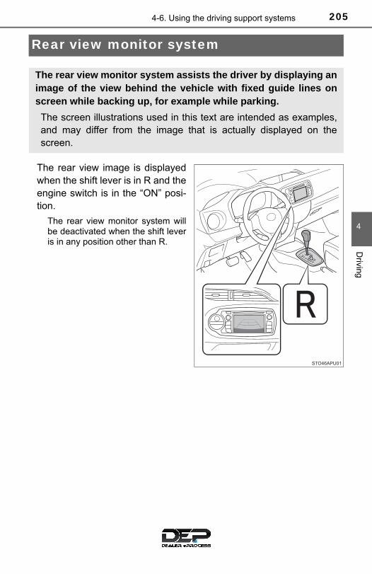
2054-6. Using the driving support systems
4
Driving
Rear view monitor system
The rear view image is displayedwhen the shift lever is in R and theengine switch is in the “ON” posi-tion.
The rear view monitor system willbe deactivated when the shift leveris in any position other than R.
The rear view monitor system assists the driver by displaying animage of the view behind the vehicle with fixed guide lines onscreen while backing up, for example while parking.
The screen illustrations used in this text are intended as examples,and may differ from the image that is actually displayed on thescreen.

206 4-6. Using the driving support systems
■ Screen description
The rear view monitor system screen will be displayed if the shiftlever is shifted to R while the engine switch is in the “ON” position.
Vehicle width guide lines
The line indicates a guide path when the vehicle is being backed straightup.The displayed width is wider than the actual vehicle width.
Vehicle center guide line
This line indicates the estimated vehicle center on the ground.
Distance guide line
The line shows distance behind the vehicle, a point approximately 1.5 ft.(0.5 m) (red) from the edge of the bumper.
Distance guide line
The line shows distance behind the vehicle, a point approximately 3 ft.(1 m) (blue) from the edge of the bumper.
Using the rear view monitor system
1
2
3
4

2074-6. Using the driving support systems
4
Driving
■ Area displayed on screen
The rear view monitor systemdisplays an image of the viewfrom the bumper of the reararea of the vehicle.
The image adjustment proce-dure for the rear view monitorsystem screen is the same asthe procedure for adjusting themultimedia screen. (→P. 239)• The area displayed on the
screen may vary according tovehicle orientation conditions.
• Objects which are close to eithercorner of the bumper or underthe bumper cannot be dis-played.
• The camera uses a special lens.The distance of the image thatappears on the screen differsfrom the actual distance.
• Items which are located higherthan the camera may not be dis-played on the monitor.
Rear view monitor system precautions
Corners of bumper

208 4-6. Using the driving support systems
■ Rear view monitor system camera
The camera for the rear viewmonitor system is located asshown in the illustration.
● Using the camera
If dirt or foreign matter (such as water droplets, snow, mud, etc.)is adhering to the camera, it cannot transmit a clear image. Inthis case, flush it with a large quantity of water and wipe the cam-era lens clean with a soft and wet cloth.
■ Differences between the screen and the actual road
The distance guide lines and the vehicle width guide lines may notactually be parallel with the dividing lines of the parking space, evenwhen they appear to be so. Be sure to check visually.
The distances between the vehicle width guide lines and the leftand right dividing lines of the parking space may not be equal, evenwhen they appear to be so. Be sure to check visually.
The distance guide lines give a distance guide for flat road sur-faces. In any of the following situations, there is a margin of errorbetween the fixed guide lines on the screen and the actual dis-tance/course on the road.

2094-6. Using the driving support systems
4
Driving
● When the ground behind the vehicle slopes up sharply
The distance guide lines willappear to be closer to thevehicle than the actual dis-tance. Because of this,objects will appear to be far-ther away than they actuallyare. In the same way, therewill be a margin of errorbetween the guide lines andthe actual distance/course onthe road.
● When the ground behind the vehicle slopes down sharply
The distance guide lines willappear to be farther from thevehicle than the actual dis-tance. Because of this,objects will appear to becloser than they actually are.In the same way, there will bea margin of error betweenthe guide lines and the actualdistance/course on the road.

210 4-6. Using the driving support systems
● When any part of the vehicle sags
When any part of the vehiclesags due to the number ofpassengers or the distribu-tion of the load, there is amargin of error between thefixed guide lines on thescreen and the actual dis-tance/course on the road.
■ When approaching three-dimensional objects
The distance guide lines are displayed according to flat surfacedobjects (such as the road). It is not possible to determine the posi-tion of three-dimensional objects (such as vehicles) using the vehi-cle width guide lines and distance guide lines. When approaching athree-dimensional object that extends outward (such as the flatbedof a truck), be careful of the following.● Vehicle width guide lines
Visually check the surround-ings and the area behind thevehicle. In the case shown inthe illustration, the truckappears to be outside of thevehicle width guide lines andthe vehicle does not look as ifit hits the truck. However, therear body of the truck mayactually cross over the vehi-cle width guide lines. In real-ity if you back up as guidedby the vehicle width guidelines, the vehicle may hit thetruck.
A margin of error

2114-6. Using the driving support systems
4
Driving
● Distance guide lines
Visually check the surround-ings and the area behind thevehicle. On the screen, itappears that a truck is park-ing at point . However, inreality if you back up to point
, you will hit the truck. Onthe screen, it appears that
is closest and is far-thest away. However, in real-ity, the distance to and
is the same, and isfarther than and .
2
1
1 3
1
3 2
1 3

212 4-6. Using the driving support systems
■ If you notice any symptoms
If you notice any of the following symptoms, refer to the likely causeand the solution, and re-check.
If the symptom is not resolved by the solution, have the vehicleinspected by your Toyota dealer.
Things you should know
Likely cause Solution
The image is difficult to see
• The vehicle is in a dark area• The temperature around the lens
is either high or low• The outside temperature is low• There are water droplets on the
camera• It is raining or humid• Foreign matter (mud, etc.) is
adhering to the camera• Sunlight or headlights are shining
directly into the camera• The vehicle is under fluorescent
lights, sodium lights, mercurylights etc.
If this happens due to these causes,it does not indicate a malfunction.Back up while visually checking thevehicle’s surroundings. (Use themonitor again once conditions havebeen improved.) The procedure for adjusting the pic-ture quality of the rear view monitorsystem is the same as the proce-dure for adjusting the screen. (→P. 239)
The image is blurry
Dirt or foreign matter (such as waterdroplets, snow, mud, etc.) is adher-ing to the camera.
Flush the camera with a large quan-tity of water and wipe the cameralens clean with a soft and wet cloth.
The image is out of alignment
The camera or surrounding area hasreceived a strong impact.
Have the vehicle inspected by yourToyota dealer.

2134-6. Using the driving support systems
4
Driving
The fixed guide lines are very far out of alignment
The camera position is out of align-ment.
Have the vehicle inspected by yourToyota dealer.
• The vehicle is tilted (there is aheavy load on the vehicle, tirepressure is low due to a tire punc-ture, etc.)
• The vehicle is used on an incline.
If this happens due to these causes,it does not indicate a malfunction.Back up while visually checking thevehicle’s surroundings.
WARNING
■When using the rear view monitor system The rear view monitor system is a supplemental device intended to assistthe driver when backing up. When backing up, be sure to check visuallybehind and all around the vehicle before proceeding.
Observe the following precautions to avoid an accident that could result indeath or serious injuries.
●Never depend on the rear view monitor system entirely when backing up.The image and the position of the guide lines displayed on the screen maydiffer from the actual state.Use caution, just as you would when backing up any vehicle.
●Be sure to back up slowly, depressing the brake pedal to control vehiclespeed.
●The instructions given are only guide lines.When and how much to turn the steering wheel will vary according to traf-fic conditions, road surface conditions, vehicle condition, etc., when park-ing. It is necessary to be fully aware of this before using the rear viewmonitor system.
●When parking, be sure to check that the parking space will accommodateyour vehicle before maneuvering into it.
Likely cause Solution

214 4-6. Using the driving support systems
WARNING
●Do not use the rear view monitor system in the following cases:
• On icy or slick road surfaces, or in snow• When using tire chains or the compact spare tire• When the back door is not closed completely• On roads that are not flat or straight, such as curves or slopes.
● In low temperatures, the screen may darken or the image may becomefaint. The image could distort when the vehicle is moving, or you maybecome unable to see the image on the screen. Be sure to check directvisually and with the mirrors all around the vehicle before proceeding.
● If the tire sizes are changed, the position of the fixation guide lines dis-played on the screen may change.
●The camera uses a special lens. The distances between objects andpedestrians that appear in the image displayed on the screen will differfrom the actual distances. (→P. 208)
NOTICE
■How to use the camera●The rear view monitor system may not operate properly in the following
cases.
• If the back of the vehicle is hit, the position and mounting angle of thecamera may change.
• As the camera has a water proof construction, do not detach, disassem-ble or modify it. This may cause incorrect operation.
• When cleaning the camera lens, flush the camera with a large quantityof water and wipe it with a soft and wet cloth. Strongly rubbing the cam-era lens may cause the camera lens to be scratched and unable totransmit a clear image.
• Do not allow organic solvent, car wax, window cleaner or a glass coat-ing to adhere to the camera. If this happens, wipe it off as soon as pos-sible.
• If the temperature changes rapidly, such as when hot water is pouredon the vehicle in cold weather, the system may not operate normally.
• When washing the vehicle, do not apply intensive bursts of water to thecamera or camera area. Doing so may result in the camera malfunc-tioning.
●Do not expose the camera to strong impact as this could cause a malfunc-tion. If this happens, have the vehicle inspected by your Toyota dealer assoon as possible.
2154-6. Using the driving support systems
4
Driving
Driving assist systems
◆ ABS (Anti-lock Brake System)
Helps to prevent wheel lock when the brakes are applied suddenly,or if the brakes are applied while driving on a slippery road surface
◆ Brake assist
Generates an increased level of braking force after the brake pedalis depressed when the system detects a panic stop situation
◆ VSC (Vehicle Stability Control)
Helps the driver to control skidding when swerving suddenly orturning on slippery road surfaces
◆ TRAC (Traction Control)
Helps to maintain drive power and prevent the drive wheels fromspinning when starting the vehicle or accelerating on slippery roads
◆ Hill-start assist control
Helps to reduce the backward movement of the vehicle when start-ing on an uphill
◆ EPS (Electric Power Steering)
Employs an electric motor to reduce the amount of effort needed toturn the steering wheel
◆ PCS (Pre-Collision System) (if equipped)
→P. 177
To help enhance driving safety and performance, the followingsystems operate automatically in response to various drivingsituations. Be aware, however, that these systems are supple-mentary and should not be relied upon too heavily when operat-ing the vehicle.

216 4-6. Using the driving support systems
The slip indicator light will flashwhile the TRAC/VSC systems areoperating.
If the vehicle gets stuck in mud, dirt or snow, the TRAC system may
reduce power from the engine to the wheels. Pressing to turn the
system off may make it easier for you to rock the vehicle in order tofree it.
To turn the TRAC system off,
quickly press and release .
The “TRAC OFF” indicator light willcome on.
Press again to turn the system
back on.
When the TRAC/VSC systems are operating
Disabling the TRAC system

2174-6. Using the driving support systems
4
Driving
■Turning off both TRAC and VSC systemsTo turn the TRAC and VSC systems off, press and hold for more than 3seconds while the vehicle is stopped.
The “TRAC OFF” indicator light and the VSC off indicator light will come on.
Press again to turn the systems back on.
On vehicles with Pre-collision system, Pre-collision brake assist and Pre-colli-sion braking will also be disabled. The PCS warning light will come on. (→P. 190)
■When the “TRAC OFF” indicator light comes on even if has notbeen pressedTRAC cannot be operated. Contact your Toyota dealer.
■Sounds and vibrations caused by the ABS, brake assist, VSC, TRAC andhill-start assist control systems●A sound may be heard from the engine compartment when the brake pedal
is depressed repeatedly, when the engine is started or just after the vehiclebegins to move. This sound does not indicate that a malfunction hasoccurred in any of these systems.
●Any of the following conditions may occur when the above systems areoperating. None of these indicates that a malfunction has occurred.
• Vibrations may be felt through the vehicle body and steering.• A motor sound may be heard also after the vehicle comes to a stop.• The brake pedal may pulsate slightly after the ABS is activated.• The brake pedal may move down slightly after the ABS is activated.
■EPS operation soundWhen the steering wheel is operated, a motor sound (whirring sound) may beheard. This does not indicate a malfunction.
■Automatic reactivation of TRAC and VSC systemsAfter turning the TRAC and VSC systems off, the systems will be automati-cally re-enabled in the following situations:
●When the engine switch is turned to the “LOCK” position
● If only the TRAC system is turned off, the TRAC will turn on when vehiclespeed increasesIf both the TRAC and VSC systems are turned off, automatic re-enabling willnot occur when vehicle speed increases.

218 4-6. Using the driving support systems
■Reduced effectiveness of the EPS systemThe effectiveness of the EPS system is reduced to prevent the system fromoverheating when there is frequent steering input over an extended period oftime. The steering wheel may feel heavy as a result.Should this occur, refrain from excessive steering input or stop the vehicleand turn the engine off. The EPS system should return to normal within 10minutes.
■ Operating conditions of hill-start assist controlWhen the following four conditions are met, the hill-start assist control willoperate:
●Vehicles with an automatic transmission: The shift lever is in a position otherthan P or N (when starting off forward/backward on an upward incline).
●Vehicles with a manual transmission: The shift lever is in a position otherthan R when starting off forward on an upward incline, or the shift lever is inR when starting off backward on an upward incline.
●The vehicle is stopped.
●The accelerator pedal is not depressed.
●The parking brake is not engaged.
■ Automatic system cancelation of hill-start assist controlThe hill-start assist control will turn off in any of the following situations:
●Vehicles with an automatic transmission: The shift lever is shifted to P or N.
●Vehicles with a manual transmission: The shift lever is shifted to R whenstarting off forward on an upward incline, or the shift lever is shifted to otherthan R when starting off backward on an upward incline.
●The accelerator pedal is depressed.
●The parking brake is engaged.
●Approximately 2 seconds elapse after the brake pedal is released.
2194-6. Using the driving support systems
4
Driving
WARNING
■The ABS does not operate effectively when●The limits of tire gripping performance have been exceeded (such as
excessively worn tires on a snow covered road).
●The vehicle hydroplanes while driving at high speed on wet or slick roads.
■Stopping distance when the ABS is operating may exceed that of nor-mal conditionsThe ABS is not designed to shorten the vehicle’s stopping distance. Alwaysmaintain a safe distance from the vehicle in front of you, especially in thefollowing situations:
●When driving on dirt, gravel or snow-covered roads
●When driving with tire chains
●When driving over bumps in the road
●When driving over roads with potholes or uneven surfaces
■TRAC/VSC may not operate effectively whenDirectional control and power may not be achievable while driving on slip-pery road surfaces, even if the TRAC/VSC system is operating. Drive the vehicle carefully in conditions where stability and power may belost.

220 4-6. Using the driving support systems
WARNING
■Hill-start assist control does not operate effectively when●Do not overly rely on hill-start assist control. Hill-start assist control may
not operate effectively on steep inclines and roads covered with ice.
●Unlike the parking brake, hill-start assist control is not intended to hold thevehicle stationary for an extended period of time. Do not attempt to usehill-start assist control to hold the vehicle on an incline, as doing so maylead to an accident.
■When the VSC is activatedThe slip indicator light flashes. Always drive carefully. Reckless driving maycause an accident. Exercise particular care when the indicator light flashes.
■When the TRAC/VSC systems are turned offBe especially careful and drive at a speed appropriate to the road condi-tions. As these are the systems to help ensure vehicle stability and drivingforce, do not turn the TRAC/VSC systems off unless necessary.
■Replacing tiresMake sure that all tires are of the specified size, brand, tread patternand total load capacity. In addition, make sure that the tires are inflatedto the recommended tire inflation pressure level.
The ABS, TRAC and VSC systems will not function correctly if differenttires are installed on the vehicle.
Contact your Toyota dealer for further information when replacing tiresor wheels.
■Handling of tires and the suspensionUsing tires with any kind of problem or modifying the suspension willaffect the driving assist systems, and may cause a system to malfunc-tion.
2214-7. Driving tips
4
Driving
Winter driving tips
● Use fluids that are appropriate to the prevailing outside tempera-tures. • Engine oil• Engine coolant• Washer fluid
● Have a service technician inspect the condition of the battery.
● Have the vehicle fitted with four snow tires or purchase a set of tirechains for the front tires.
Ensure that all tires are the specified size and brand, and that chainsmatch the size of the tires.
Perform the following according to the driving conditions: ● Do not try to forcibly open a window or move a wiper that is frozen.
Pour warm water over the frozen area to melt the ice. Wipe awaythe water immediately to prevent it from freezing.
● To ensure proper operation of the climate control system fan,remove any snow that has accumulated on the air inlet vents infront of the windshield.
● Check for and remove any excess ice or snow that may have accu-mulated on the exterior lights, vehicle’s roof, chassis, around thetires or on the brakes.
● Remove any snow or mud from the bottom of your shoes beforegetting in the vehicle.
Carry out the necessary preparations and inspections beforedriving the vehicle in winter. Always drive the vehicle in a man-ner appropriate to the prevailing weather conditions.
Preparation for winter
Before driving the vehicle
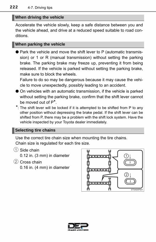
222 4-7. Driving tips
Accelerate the vehicle slowly, keep a safe distance between you andthe vehicle ahead, and drive at a reduced speed suitable to road con-ditions.
● Park the vehicle and move the shift lever to P (automatic transmis-sion) or 1 or R (manual transmission) without setting the parkingbrake. The parking brake may freeze up, preventing it from beingreleased. If the vehicle is parked without setting the parking brake,make sure to block the wheels.Failure to do so may be dangerous because it may cause the vehi-cle to move unexpectedly, possibly leading to an accident.
● On vehicles with an automatic transmission, if the vehicle is parkedwithout setting the parking brake, confirm that the shift lever cannotbe moved out of P*.
*: The shift lever will be locked if it is attempted to be shifted from P to anyother position without depressing the brake pedal. If the shift lever can beshifted from P, there may be a problem with the shift lock system. Have thevehicle inspected by your Toyota dealer immediately.
Use the correct tire chain size when mounting the tire chains. Chain size is regulated for each tire size.
Side chain 0.12 in. (3 mm) in diameter
Cross chain 0.16 in. (4 mm) in diameter
When driving the vehicle
When parking the vehicle
Selecting tire chains
1
2

2234-7. Driving tips
4
Driving
Regulations regarding the use of tire chains vary depending on loca-tion and type of road. Always check local regulations before installingchains.
■Tire chain installationObserve the following precautions when installing and removing chains:
● Install and remove tire chains in a safe location.
● Install tire chains on the front tires only. Do not install tire chains on the reartires.
● Install tire chains on front tires as tightly as possible. Retighten chains afterdriving 1/4 ⎯ 1/2 mile (0.5 ⎯ 1.0 km).
● Install tire chains following the instructions provided with the tire chains.
● If wheel ornaments are used, they will be scratched by the chain band, soremove the ornaments before putting on the chains. (→P. 438)
Regulations on the use of tire chains

224 4-7. Driving tips
WARNING
■Driving with snow tiresObserve the following precautions to reduce the risk of accidents. Failure to do so may result in a loss of vehicle control and cause death orserious injury.
●Use tires of the specified size.
●Maintain the recommended level of air pressure.
●Do not drive in excess of 75 mph (120 km/h), regardless of the type ofsnow tires being used.
●Use snow tires on all, not just some wheels.
●Do not use tires of noticeably different wear level.
■Driving with tire chainsObserve the following precautions to reduce the risk of accidents. Failure to do so may result in the vehicle being unable to be driven safely,and may cause death or serious injury.
●Do not drive in excess of the speed limit specified for the tire chains beingused, or 30 mph (50 km/h), whichever is lower.
●Avoid driving on bumpy road surfaces or over potholes.
●Avoid sudden acceleration, abrupt steering, sudden braking and shiftingoperations that cause sudden engine braking.
●Slow down sufficiently before entering a curve to ensure that vehicle con-trol is maintained.
●Do not use LDA (Lane Departure Alert) (if equipped).

2254-7. Driving tips
4
Driving
NOTICE
■Repairing or replacing snow tires (vehicles with a tire pressure warn-ing system)Request repairs or replacement of snow tires from Toyota dealers or legiti-mate tire retailers.This is because the removal and attachment of snow tires affects the opera-tion of the tire pressure warning valves and transmitters.
■Fitting tire chains (vehicles with a tire pressure warning system)The tire pressure warning valves and transmitters may not function correctlywhen tire chains are fitted.
226
5-1. Basic Operations
Audio system types........... 228
Audio system .................... 229
Steering wheel audio switches .......................... 231
USB port/AUX port............ 232
Basic audio operations...... 233
5-2. Setup
Setup menu....................... 235
General settings................ 236
Audio settings ................... 238
Display settings................. 239
Voice settings.................... 240
5-3. Using the multimedia system
Selecting the audio source ............................. 241
List screen operation......... 242
Optimal use of the multimedia system .... 244
5-4. Using the radio
Radio operation................. 245
5Multimedia system

227
5Multimedia system
5-5. Playing an audio CD and MP3/WMA/AAC discs
CD player operation .......... 247
5-6. Using an external device
Listening to an iPod .......... 253
Listening to a USB memory device................ 257
Using the AUX port ........... 262
5-7. Connecting Bluetooth®
Preparations to use wireless communication................ 263
Registering a Bluetooth® audio player for the first time ............... 267
Registering a Bluetooth® phone for the first time ... 268
Registering a Bluetooth® device.............................. 269
Connecting a Bluetooth® device.............................. 271
Displaying a Bluetooth® device details .................. 273
Detailed Bluetooth® system settings ............... 274
5-8. Bluetooth® audio
Listening to Bluetooth® audio ............................... 276
5-9. Bluetooth® phone
Using a Bluetooth® phone.............................. 277
Making a call ..................... 279
Receiving a call ................. 282
Speaking on the phone ..... 283
Bluetooth® phone message function............ 286
Using the steering wheel switches .......................... 290
Bluetooth® phone settings ........................... 291
Contact/Call History Settings........................... 293
What to do if... (Troubleshooting)............ 303
5-10.Bluetooth®
Bluetooth®......................... 307
5-11.Using the voice command system
Voice command system.... 311
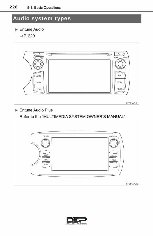
228 5-1. Basic Operations
Audio system types
Entune Audio
→P. 229
Entune Audio Plus
Refer to the “MULTIMEDIA SYSTEM OWNER’S MANUAL”.
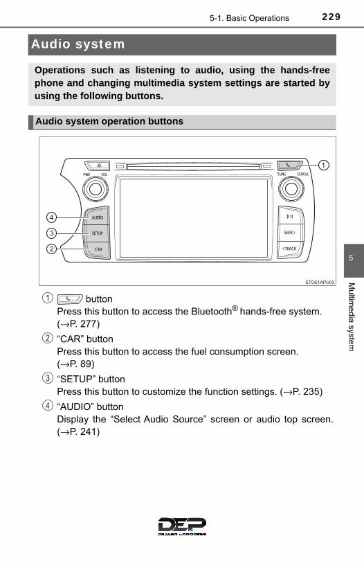
2295-1. Basic Operations
5
Multim
edia system
Audio system
button Press this button to access the Bluetooth® hands-free system. (→P. 277)
“CAR” button Press this button to access the fuel consumption screen.(→P. 89)
“SETUP” button Press this button to customize the function settings. (→P. 235)
“AUDIO” button Display the “Select Audio Source” screen or audio top screen.(→P. 241)
Operations such as listening to audio, using the hands-freephone and changing multimedia system settings are started byusing the following buttons.
Audio system operation buttons
1
2
3
4

230 5-1. Basic Operations
By touching the screen with your finger, you can control the multime-dia system, etc.
■ Drag*Touch the screen with your finger, and move the screen to thedesired position.● Scrolling the lists
■ Flick*Touch the screen with your finger and then quickly move the screenby flicking your finger.● Scrolling the main screen page
*: The above operations may not be performed on all screens.
■When using the touch screen● If the screen is cold, the display may be dark, or the system may seem to be
operating slightly slower than normal.
●The screen may seem dark and hard to see when viewed through sun-glasses. Change your angle of viewing, adjust the display on the “DisplaySettings” screen (→P. 239) or remove your sunglasses.
●Flick operations may not be performed smoothly in high altitudes.
Operating the touch screen
NOTICE
■To avoid damaging the touch screen●To prevent damaging the screen, lightly touch the screen buttons with your
finger.
●Do not use objects other than your finger to touch the screen.
●Wipe off fingerprints using a glass cleaning cloth. Do not use chemicalcleaners to clean the screen, as they may damage the touch screen.

2315-1. Basic Operations
5
Multim
edia system
Steering wheel audio switches
Volume switch• Press: Increases/decreases
volume• Press and hold: Continuously
increases/decreases volume
Radio mode:• Press: Selects a radio station• Press and hold: Seeks up/
down
CD, MP3/WMA disc, Bluetooth®, iPod or USB mode:• Press: Selects a track/file/song• Press and hold: Fast-forward/rewind
“MODE” switch• Changes audio source• Press and hold this switch to mute or pause the current operation
To cancel the mute or pause, press and hold.
Some audio features can be controlled using the switches onthe steering wheel.Operation may differ depending on the type of multimedia sys-tem or navigation system. For details, refer to the manual pro-vided with the multimedia system or navigation system.
Operating the multimedia system using the steering wheelswitches
1
2
WARNING
■To reduce the risk of an accidentExercise care when operating the audio switches on the steering wheel.
3

232 5-1. Basic Operations
USB port/AUX port
● iPod
Open the cover and connect aniPod using an iPod cable.
Turn on the power of the iPod ifit is not turned on.
● USB memory
Open the cover and connectthe USB memory device.
Turn on the power of the USB memory device if it is not turned on.● Portable audio player
Open the cover and connect the portable audio player.
Turn on the power of the portable audio player if it is not turned on.
Connect an iPod, USB memory device or portable audio playerto the USB/AUX port as indicated below. Select “iPod”, “USB” or“AUX” on the “Select Audio Source” screen and the device canbe operated via multimedia system.
Connecting using the USB/AUX port
WARNING
■While drivingDo not connect a device or operate the device controls.

2335-1. Basic Operations
5
Multim
edia system
Basic audio operations
Press this button to eject a disc
Insert a disc into the disc slot
Audio source selection screen appears (→P. 241)
Turn this knob to select radio station bands, tracks and files. Alsothe knob can be used to select items in the list display.
Press to pause or resume playing music.
Press the “SEEK>” or “<TRACK” button to seek up or down for aradio station, or to access a desired track or file.
Setting the Sound (→P. 244)
Pause or resume playing music
Select to enable repeat play
Select to enable random playback
Press: Turns the multimedia system on and off. Turn: Adjusts the volume.
Basic audio operations and functions common to each mode areexplained in this section.
Operating the multimedia system
1
2
3
4
5
6
7
8
9
10
11

234 5-1. Basic Operations
■Using cellular phonesInterference may be heard through the multimedia system’s speakers if a cel-lular phone is being used inside or close to the vehicle while the multimediasystem is operating.
WARNING
■For vehicles sold in U.S.A. and Canada●Part 15 of the FCC Rules
FCC Warning: Any unauthorized changes or modifications to this equipment would voidthe user’s authority to operate this device.
●Laser products
CAUTION: THIS PRODUCT IS A CLASS I LASER PRODUCT. USE OF CONTROLS OR ADJUSTMENTS OR PERFORMANCE OFPROCEDURES OTHER THAN THOSE SPECIFIED HEREIN MAYRESULT IN HAZARDOUS RADIATION EXPOSURE. DO NOT OPENCOVERS AND DO NOT REPAIR BY YOURSELF. REFER SERVICINGTO QUALIFIED PERSONNEL.
• Do not take this unit apart or attempt to make any changes yourself. This is an intricate unit that uses a laser pickup to retrieve informationfrom the surface of compact discs. The laser is carefully shielded sothat its rays remain inside the cabinet. Therefore, never try to disassem-ble the player or alter any of its parts since you may be exposed to laserrays and dangerous voltages.
• This product utilizes a laser. Use of controls or adjustments or performance of procedures other thanthose specified herein may result in hazardous radiation exposure. THE USE OF OPTICAL INSTRUMENTS WITH THIS PRODUCT WILLINCREASE EYE HAZARD.
NOTICE
■To prevent battery dischargeDo not leave the multimedia system on longer than necessary when theengine is off.
■To avoid damaging the multimedia systemTake care not to spill drinks or other fluids on the multimedia system.

2355-2. Setup
5
Multim
edia system
Setup menu
Press the “SETUP” button to display the “Setup” screen.
Select to adjust the settings foroperation sounds, screen ani-mation, etc. (→P. 236)
Select to set the voice settings.(→P. 240)
Select to adjust the settings forcontrast and brightness of thescreen. (→P. 239)
Select to adjust the settings for registering, removing, connectingand disconnecting Bluetooth® devices. (→P. 274)
Select to adjust the settings for phone sound, contact, etc. (→P. 293)
Select to set audio settings. (→P. 238)
Select to turn the screen off.
Select to set the vehicle customization. (→P. 488)
You can adjust the multimedia system to your desired settings.
Display “Setup” screen
1
2
3
4
5
6
7
8
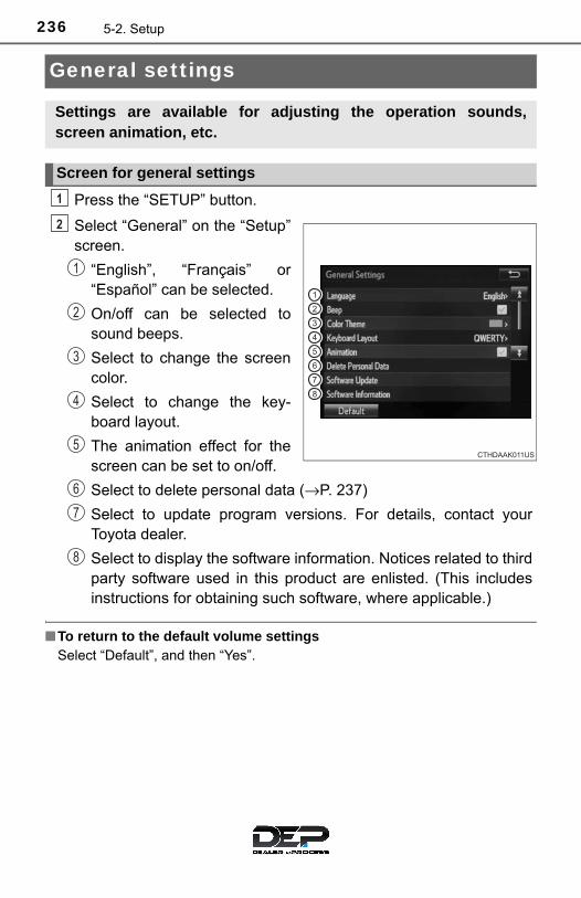
236 5-2. Setup
General settings
Press the “SETUP” button.
Select “General” on the “Setup”screen.
“English”, “Français” or“Español” can be selected.
On/off can be selected tosound beeps.
Select to change the screencolor.
Select to change the key-board layout.
The animation effect for thescreen can be set to on/off.
Select to delete personal data (→P. 237)
Select to update program versions. For details, contact yourToyota dealer.
Select to display the software information. Notices related to thirdparty software used in this product are enlisted. (This includesinstructions for obtaining such software, where applicable.)
■To return to the default volume settingsSelect “Default”, and then “Yes”.
Settings are available for adjusting the operation sounds,screen animation, etc.
Screen for general settings
1
2
1
2
3
4
5
6
7
8

2375-2. Setup
5
Multim
edia system
Select “Delete Personal Data” on the “General Settings” screen.
Select “Delete”.
Check carefully beforehand, as data cannot be retrieved once deleted.
A confirmation screen will be displayed. Select “Yes”.
The following personal data will be deleted or changed to its defaultsettings.• General settings• Audio settings• Phone settings
Delete personal data
1
2
3

238 5-2. Setup
Audio settings
Press the “SETUP” button.
Select “Audio” on the “Setup”screen.
Number of Radio Presets Select the number of radiopreset stations.
Display Cover Art on/off
Automatic Sound Levelizer
Select “Automatic Sound Levelizer”.
Select “High”, “Mid”, “Low” or “Off”.
■About Automatic Sound Leveliser (ASL)ASL automatically adjusts the volume and tone quality according to the vehi-cle speed.
Settings are available for adjusting the radio operation, coverart, etc.
Screen for audio settings
1
2
1
2
3
Automatic sound leveliser (ASL)
1
2
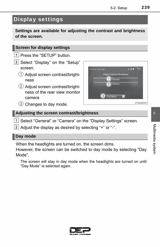
2395-2. Setup
5
Multim
edia system
Display settings
Press the “SETUP” button.
Select “Display” on the “Setup”screen.
Adjust screen contrast/bright-ness
Adjust screen contrast/bright-ness of the rear view monitorcamera
Changes to day mode.
Select “General” or “Camera” on the “Display Settings” screen.
Adjust the display as desired by selecting “+” or “-”.
When the headlights are turned on, the screen dims. However, the screen can be switched to day mode by selecting “DayMode”.
The screen will stay in day mode when the headlights are turned on until“Day Mode” is selected again.
Settings are available for adjusting the contrast and brightnessof the screen.
Screen for display settings
1
2
1
2
3
Adjusting the screen contrast/brightness
Day mode
1
2
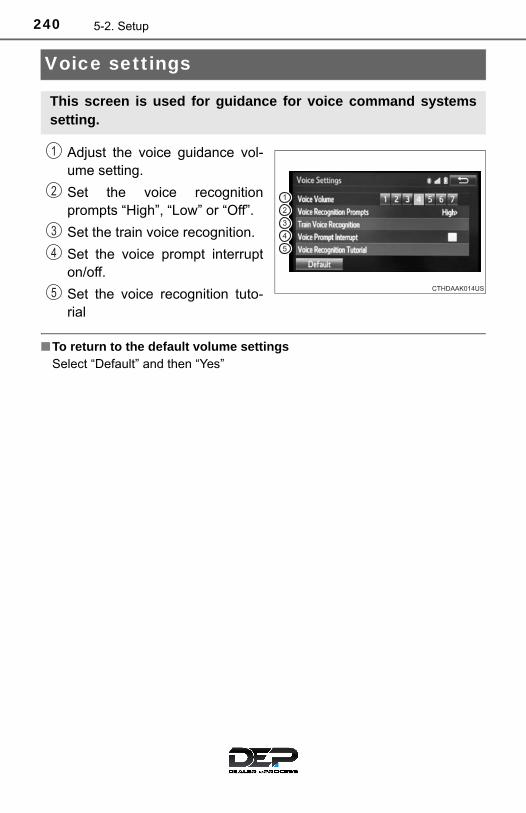
240 5-2. Setup
Voice settings
Adjust the voice guidance vol-ume setting.
Set the voice recognitionprompts “High”, “Low” or “Off”.
Set the train voice recognition.
Set the voice prompt interrupton/off.
Set the voice recognition tuto-rial
■To return to the default volume settingsSelect “Default” and then “Yes”
This screen is used for guidance for voice command systemssetting.
1
2
3
4
5
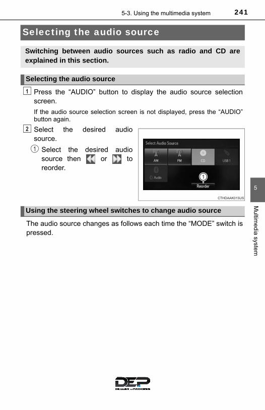
2415-3. Using the multimedia system
5
Multim
edia system
Selecting the audio source
Press the “AUDIO” button to display the audio source selectionscreen.
If the audio source selection screen is not displayed, press the “AUDIO”button again.
Select the desired audiosource.
Select the desired audiosource then or toreorder.
The audio source changes as follows each time the “MODE” switch ispressed.
Switching between audio sources such as radio and CD areexplained in this section.
Selecting the audio source
1
2
1
Using the steering wheel switches to change audio source
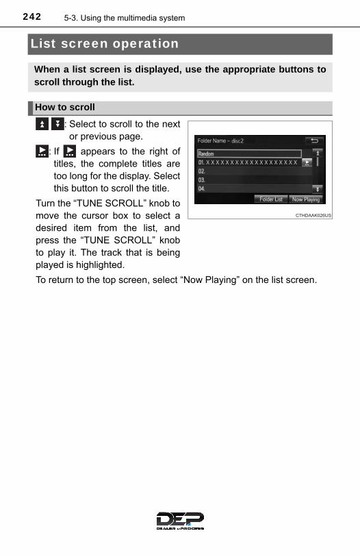
242 5-3. Using the multimedia system
List screen operation
: Select to scroll to the nextor previous page.
: If appears to the right oftitles, the complete titles aretoo long for the display. Selectthis button to scroll the title.
Turn the “TUNE SCROLL” knob tomove the cursor box to select adesired item from the list, andpress the “TUNE SCROLL” knobto play it. The track that is beingplayed is highlighted.
To return to the top screen, select “Now Playing” on the list screen.
When a list screen is displayed, use the appropriate buttons toscroll through the list.
How to scroll

2435-3. Using the multimedia system
5
Multim
edia system
■ Selecting a track/file/song
Press the “SEEK>” or “<TRACK” button or turn the “TUNESCROLL” knob to select the desired track/file/song number.
To fast-forward or reverse, press and hold the “SEEK>” or“<TRACK” button.
■ Selecting a track/file/song from the track/file/song list
Select “Browse” or cover art.
Select the desired track/file/song.
When an MP3/WMA/AAC disc or USB memory device is being used,the folder can be selected. When a Bluetooth® device or iPod is beingused, the album can be selected.
According to the audio device, the following is displayed.
Selecting, fast-forwarding and reversing tracks/files/songs
1
2
Audio source List name
Audio CD Track
MP3/WMA/AAC disc Folder, File
Bluetooth® Album, Track
USBArtists, Albums, Songs, Genres,Composers
iPodArtists, Albums, Songs, Genres,Composers, Audiobooks, Videos

244 5-3. Using the multimedia system
Optimal use of the multimedia system
Select “-” or “+” to adjustthe treble, mid or bass toa level between -5 and 5.
Select “Front” or “Rear” toadjust the front/rear audiobalance.
Select “L” or “R” to adjust theleft/right audio balance.
■The sound quality level is adjusted individuallyThe treble, mid and bass levels can be adjusted for each audio mode sepa-rately.
On the “Sound Settings” screen, sound quality (Treble/Mid/Bass), volume balance can be adjusted.
How to adjust the sound settings and sound quality
1 2 3
4 5
6 7

2455-4. Using the radio
5
Multim
edia system
Radio operation
Pressing the “AUDIO” button displays the audio control screen fromany screens of the selected source.
Audio source selection screenappears
Preset stations
Select to display RBDS textmessage*Scanning for receivable station
Select to display a list of receiv-able stations
Setting the sound (→P. 244)
*: FM only
Tune in to the desired station using one of the following methods.
■ Seek tuning
Press the “SEEK>” or “<TRACK” button.
The radio will begin seeking up or down for a station of the nearestfrequency and will stop when a station is found.
■ Manual tuning
Turn the “TUNE SCROLL” knob.
■ Preset stations
Select the desired preset station.
Select “AM” or “FM” on the audio source selection screen tobegin listening to the radio.
Audio control screen
1
2
3
4
5
Selecting a station
6

246 5-4. Using the radio
Search for desired stations by turning the “TUNE SCROLL” knob orpressing the “SEEK>” or “<TRACK” button.
Select “(add new)”
To change the preset station to a different one, select and hold the presetstation.
Select “Yes”.
Select “OK” after setting the new preset station.
■ Refreshing the station list
Select “Refresh” on the “Station List” screen.
To cancel the refresh, select “Cancel Refresh”.
■Reception sensitivity●Maintaining perfect radio reception at all times is difficult due to the continu-
ally changing position of the antenna, differences in signal strength and sur-rounding objects, such as trains, transmitters, etc.
●The radio antenna is mounted on the roof.
Setting station presets
1
2
3
4
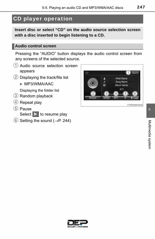
2475-5. Playing an audio CD and MP3/WMA/AAC discs
5
Multim
edia system
CD player operation
Pressing the “AUDIO” button displays the audio control screen fromany screens of the selected source.
Audio source selection screenappears
Displaying the track/file list
MP3/WMA/AAC
Displaying the folder list
Random playback
Repeat play
Pause Select to resume play
Setting the sound (→P. 244)
Insert disc or select “CD” on the audio source selection screenwith a disc inserted to begin listening to a CD.
Audio control screen
1
2
3
4
5
6

248 5-5. Playing an audio CD and MP3/WMA/AAC discs
■Displaying the title and artist nameIf a CD-TEXT disc is inserted, the title of the disc and track will be displayed.
■Error messagesIf an error message is displayed, refer to the following table and take theappropriate measures. If the problem is not rectified, take the vehicle to yourToyota dealer.
■Discs that can be usedDiscs with the marks shown below can be used. Playback may not be possible depending on recording format or disc fea-tures, or due to scratches, dirt or deterioration.
CDs with copy-protection features may not play correctly.
■CD player protection featureTo protect the internal components, playback is automatically stopped when aproblem is detected.
■ If a disc is left inside the CD player or in the ejected position forextended periodsDisc may be damaged and may not play properly.
■Lens cleanersDo not use lens cleaners. Doing so may damage the CD player.
Message Cause Correction procedures
“Check DISC”
• The disc is dirty ordamaged.
• The disc is insertedupside down.
• The disc is not play-able with the player.
• Clean the disc.• Insert the disc cor-
rectly.• Confirm the disc is
playable with theplayer.
“Disc Error”There is a malfunctionwithin the system.
Eject the disc.
“No music files found.”No playable data isincluded on the disc.
Eject the disc.

2495-5. Playing an audio CD and MP3/WMA/AAC discs
5
Multim
edia system
■MP3, WMA and AAC filesMP3 (MPEG Audio LAYER3) is a standard audio compression format.
Files can be compressed to approximately 1/10 of their original size by usingMP3 compression.
WMA (Windows Media Audio) is a Microsoft audio compression format.
This product is protected by certain intellectual property rights of MicrosoftCorporation and third parties. Use or distribution of such technology outsideof this product is prohibited without a license from Microsoft or an authorizedMicrosoft subsidiary and third parties.
This format compresses audio data to a size smaller than that of the MP3 for-mat.
AAC is short for Advanced Audio Coding and refers to an audio compressiontechnology standard used with MPEG2 and MPEG4.
MP3, WMA and AAC file and media/formats compatibility are limited.
●MP3 file compatibility
• Compatible standards MP3 (MPEG1 LAYER3, MPEG2 LSF LAYER3)
• Compatible sampling frequencies MPEG1 LAYER3: 32, 44.1, 48 (kHz) MPEG2 LSF LAYER3: 16, 22.05, 24 (kHz)
• Compatible bit rates (compatible with VBR) MPEG1 LAYER3: 32-320 (kbps) MPEG2 LSF LAYER3: 8-160 (kbps)
• Compatible channel modes: stereo, joint stereo, dual channel and mon-aural
●WMA file compatibility
• Compatible standards WMA Ver. 7, 8, 9 (only compatible with Windows Media Audio Standard)
• Compatible sampling frequencies 32, 44.1, 48 (kHz)
• Compatible bit rates (only compatible with 2-channel playback) Ver. 7, 8: CBR 48-192 (kbps) Ver. 9: CBR 48-320 (kbps)

250 5-5. Playing an audio CD and MP3/WMA/AAC discs
●AAC file compatibility
• Compatible standards MPEG4/AAC-LC
• Compatible sampling frequencies 11.025/12/16/22.05/24/32/44.1/48 (kHz)
• Compatible bit rates 16-320 (kbps)
Compatible channel modes: 1ch and 2ch
●Compatible media
Media that can be used for MP3, WMA and AAC playback are CD-Rs andCD-RWs.
Playback in some instances may not be possible if the CD-R or CD-RW isnot finalized. Playback may not be possible or the audio may jump if thedisc is scratched or marked with fingerprints.
●Compatible disc formats
The following disc formats can be used.
• Disc formats: CD-ROM Mode 1 and Mode 2 CD-ROM XA Mode 2, Form 1 and Form 2
• File formats: ISO9660 Level 1, Level 2, (Romeo, Joliet) UDF (2.01 or lower)
MP3, WMA and AAC files written in any format other than those listedabove may not play correctly, and their file names and folder names maynot be displayed correctly.
Items related to standards and limitations are as follows.
• Maximum directory hierarchy: 8 levels (including the root)• Maximum length of folder names/file names: 32 characters• Maximum number of folders: 192 (including the root)• Maximum number of files per disc: 255
●File names
The only files that can be recognized as MP3/WMA/AAC and played arethose with the extension .mp3, .wma or .m4a.
●Discs containing multi-session recordings
As the multimedia system is compatible with multi session discs, it is possi-ble to play discs that contain MP3, WMA and AAC files. However, only thefirst session can be played.

2515-5. Playing an audio CD and MP3/WMA/AAC discs
5
Multim
edia system
● ID3, WMA and AAC tags
ID3 tags can be added to MP3 files, making it possible to record the tracktitle, artist name, etc.
The system is compatible with ID3 Ver. 1.0, 1.1, and Ver. 2.2, 2.3 ID3 tags.(The number of characters is based on ID3 Ver. 1.0 and 1.1.)
WMA tags can be added to WMA files, making it possible to record thetrack title and artist name in the same way as with ID3 tags.
AAC tags can be added to AAC files, making it possible to record the tracktitle and artist name in the same way as with ID3 tags.
●MP3, WMA and AAC playback
When a disc containing MP3, WMA or AAC files is inserted, all files on thedisc are first checked. Once the file check is finished, the first MP3, WMA orAAC file is played. To make the file check finish more quickly, we recom-mend you do not write any files to the disc other than MP3, WMA or AACfiles or create any unnecessary folders.
Discs that contain a mixture of music data and MP3, WMA or AAC formatdata cannot be played.
●Extensions
If the file extensions .mp3, .wma and .m4a are used for files other thanMP3, WMA and AAC files, they may be mistakenly recognized and playedas MP3, WMA and AAC files. This may result in large amounts of interfer-ence and damage to the speakers.
●Playback
• To play MP3 files with steady sound quality, we recommend a fixed bitrate of at least 128 kbps and a sampling frequency of 44.1 kHz.
• CD-R or CD-RW playback may not be possible in some instances,depending on the characteristics of the disc.
• There is a wide variety of freeware and other encoding software for MP3,WMA and AAC files on the market, and depending on the status of theencoding and the file format, poor sound quality or noise at the start ofplayback may result. In some cases, playback may not be possible at all.
• When files other than MP3, WMA or AAC files are recorded on a disc, itmay take more time to recognize the disc and in some cases, playbackmay not be possible at all.
• Microsoft, Windows, and Windows Media are the registered trademarksof Microsoft Corporation in the U.S.A. and other countries.

252 5-5. Playing an audio CD and MP3/WMA/AAC discs
NOTICE
■Discs and adapters that cannot be usedDo not use the following types of CDs.
Also, do not use 3 in. (8 cm) CD adapters, Dual Discs or printable discs.
Doing so may damage the CD player and/or the CD insert/eject function.
●Discs that have a diameter that is not 4.7 in. (12 cm).
●Low-quality or deformed discs.
●Discs with a transparent or translucent recording area.
●Discs that have tape, stickers or CD-R labels attached to them, or thathave had the label peeled off.
■Player precautionsFailure to follow the precautions below may result in damage to the discs orthe player itself.
●Do not insert anything other than discs into the disc slot.
●Do not apply oil to the player.
●Store discs away from direct sunlight.
●Never try to disassemble any part of the player.

2535-6. Using an external device
5
Multim
edia system
Listening to an iPod
→P. 232
Pressing the “AUDIO” button displays the audio control screen fromany screens of the selected source.
Audio source selection screenappears
Displays cover art
Selecting the play mode
Shuffle play
Repeat play
PauseSelect to resume playback
Setting the sound (→P. 244)
Select “Browse” on the screen.
Select the desired play mode. Then select a song to begin usingthe selected play mode.
Connecting an iPod enables you to enjoy music from the vehiclespeakers.
Select “iPod” on the audio source selection screen.
When the iPod connected to the system includes iPod video, thesystem can only output the sound by selecting the browsescreen.
Connecting an iPod
Audio control screen
1
2
3
4
5
6
Selecting a play mode
7
1
2
254 5-6. Using an external device
■About iPod
● “Made for iPod” and “Made for iPhone” mean that an electronic accessoryhas been designed to connect specifically to iPod or iPhone respectively,and has been certified by the developer to meet Apple performance stan-dards.
●Apple is not responsible for the operation of this device or its compliancewith safety and regulatory standards. Please note that the use of this acces-sory with iPod and iPhone may affect wireless performance.
● iPhone, iPod, iPod classic, iPod nano, and iPod touch are trademarks ofApple Inc., registered in the U.S. and other countries. Lightning is a trade-mark of Apple Inc.
■ iPod cover art●Depending on the iPod and songs in the iPod, iPod cover art may be dis-
played.
●This function can be changed to on/off. (→P. 238)
● It may take time to display iPod cover art, and the iPod may not be operatedwhile the cover art display is in process.
●Only iPod cover art that is saved in JPEG format can be displayed.
■ iPod functions●When an iPod is connected and the audio source is changed to iPod mode,
the iPod will resume play from the same point in which it was last used.
●Depending on the iPod that is connected to the system, certain functionsmay not be available. If a function is unavailable due to a malfunction (asopposed to a system specification), disconnecting the device and recon-necting it may resolve the problem.
●While connected to the system, the iPod cannot be operated with its owncontrols. It is necessary to use the controls of the vehicle’s multimedia sys-tem instead.
●When the battery level of an iPod is very low, the iPod may not operate. Ifso, charge the iPod before use.
●Compatible models (→P. 256)
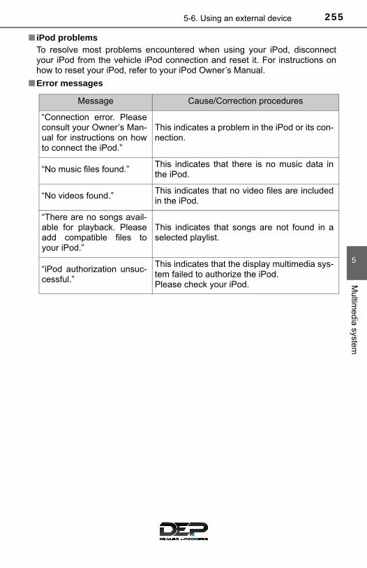
2555-6. Using an external device
5
Multim
edia system
■ iPod problemsTo resolve most problems encountered when using your iPod, disconnectyour iPod from the vehicle iPod connection and reset it. For instructions onhow to reset your iPod, refer to your iPod Owner’s Manual.
■Error messages
Message Cause/Correction procedures
“Connection error. Pleaseconsult your Owner’s Man-ual for instructions on howto connect the iPod.”
This indicates a problem in the iPod or its con-nection.
“No music files found.”This indicates that there is no music data inthe iPod.
“No videos found.”This indicates that no video files are includedin the iPod.
“There are no songs avail-able for playback. Pleaseadd compatible files toyour iPod.”
This indicates that songs are not found in aselected playlist.
“iPod authorization unsuc-cessful.”
This indicates that the display multimedia sys-tem failed to authorize the iPod.Please check your iPod.

256 5-6. Using an external device
■Compatible modelsThe following iPod®, iPod nano®, iPod classic®, iPod touch® and iPhone®
devices can be used with this system.
●Made for
• iPod touch (5th generation)• iPod touch (4th generation)• iPod touch (3rd generation)• iPod touch (2nd generation)• iPod touch (1st generation)• iPod classic• iPod with video• iPod nano (7th generation)• iPod nano (6th generation)• iPod nano (5th generation)• iPod nano (4th generation)• iPod nano (3rd generation)• iPhone 6 Plus• iPhone 6• iPhone 5s• iPhone 5c• iPhone 5• iPhone 4S• iPhone 4• iPhone 3GS• iPhone 3G• iPhone
Depending on differences between models or software versions etc., somemodels might be incompatible with this system.
WARNING
■While drivingDo not connect an iPod or operate the controls.
NOTICE
■To prevent damage to the iPod or its terminals●Do not leave the iPod in the vehicle. The temperature inside the vehicle
may become high, resulting in damage to the iPod.
●Do not push down on or apply unnecessary pressure to the iPod while it isconnected.
●Do not insert foreign objects into the port.

2575-6. Using an external device
5
Multim
edia system
Listening to a USB memory device
→P. 232
Pressing the “AUDIO” button displays the audio control screen fromany screens of the selected source.
Audio source selection screenappears
Displays cover art
Displaying the folder list
Random playback
Repeat play
Pause Select to resume playback
Setting the sound (→P. 244)
Select “Browse” on the screen.
Select the desired play mode. Then select a song to begin usingthe selected play mode.
■ Displaying the now playing list
Select the cover art display.
Connecting a USB memory device enables you to enjoy musicfrom the vehicle speakers.
Select “USB” on the audio source selection screen.
Connecting a USB memory device
Audio control screen
1
2
3
4
5
6
7
Selecting a play mode
1
2

258 5-6. Using an external device
■USB memory functions●Depending on the USB memory device that is connected to the system, the
device itself may not be operable and certain functions may not be avail-able. If the device is inoperable or a function is unavailable due to a mal-function (as opposed to a system specification), disconnecting the deviceand reconnecting it may resolve the problem.
● If the USB memory device still does not begin operation after being discon-nected and reconnected, format the memory.
■Error messages for USB memory
■USB memory●Compatible devices
USB memory device that can be used for MP3, WMA and AAC playback.
●Compatible device formats
The following device format can be used:
• USB communication format: USB2.0 HS (480 Mbps) and FS (12 Mbps)• File system format: FAT16/32 (Windows)• Correspondence class: Mass storage class
MP3, WMA and AAC files written to a device with any format other thanthose listed above may not play correctly, and their file names and foldernames may not be displayed correctly.
Items related to standards and limitations are as follows:
• Maximum directory hierarchy: 8 levels• Maximum number of folders in a device: 3000 (including the root)• Maximum number of files in a device: 9999• Maximum number of files per folder: 255
Message Cause/Correction procedures
“Connection error. Pleaseconsult your Owner’s Man-ual for instruction on how toconnect the USB device.”
This indicates a problem with the USB mem-ory device or its connection.
“There are no files availablefor playback. Please addcompatible files to your USBdevice.”
This indicates that no MP3/WMA/AAC filesare included on the USB memory device.

2595-6. Using an external device
5
Multim
edia system
●MP3, WMA and AAC files
MP3 (MPEG Audio LAYER 3) is a standard audio compression format. Files can be compressed to approximately 1/10 of their original size usingMP3 compression.
WMA (Windows Media Audio) is a Microsoft audio compression format.This format compresses audio data to a size smaller than that of the MP3format.
AAC is short for Advanced Audio Coding and refers to an audio compres-sion technology standard used with MPEG2 and MPEG4.
MP3, WMA and AAC file and media/formats compatibility are limited.
●MP3 file compatibility
• Compatible standards MP3 (MPEG1 AUDIO LAYERII, III, MPEG2 AUDIO LAYERII, III)
• Compatible sampling frequencies MPEG1 AUDIO LAYERII, III: 32, 44.1, 48 (kHz) MPEG2 AUDIO LAYERII, III: 16, 22.05, 24 (kHz)
• Compatible bit rates (compatible with VBR) MPEG1 AUDIO LAYERII, III: 32-320 (kbps) MPEG2 AUDIO LAYERII, III: 8-160 (kbps)
• Compatible channel modes: stereo, joint stereo, dual channel and mon-aural
●WMA file compatibility
• Compatible standards WMA Ver. 7, 8, 9
• Compatible sampling frequencies HIGH PROFILE 32, 44.1, 48 (kHz)
• Compatible bit rates HIGH PROFILE 48-320 (kbps, VBR)
●AAC file compatibility
• Compatible standards MPEG4/AAC-LC
• Compatible sampling frequencies 11.025/12/16/22.05/24/32/44.1/48 (kHz)
• Compatible bit rates 16-320 (kbps)
• Compatible channel modes: 1 ch and 2 ch●File names
The only files that can be recognized as MP3/WMA/AAC and played arethose with the extension .mp3, .wma or .m4a.

260 5-6. Using an external device
● ID3, WMA and AAC tags
ID3 tags can be added to MP3 files, making it possible to record the tracktitle, artist name, etc.
The system is compatible with ID3 Ver. 1.0, 1.1, and Ver. 2.2, 2.3 ID3 tags.(The number of characters is based on ID3 Ver. 1.0 and 1.1.)
WMA tags can be added to WMA files, making it possible to record thetrack title and artist name in the same way as with ID3 tags.
AAC tags can be added to AAC files, making it possible to record the tracktitle and artist name in the same way as with ID3 tags.
●MP3, WMA and AAC playback
• When a device containing MP3, WMA and AAC files is connected, allfiles in the USB memory device are checked. Once the file check is fin-ished, the first MP3, WMA and AAC file is played. To make the file checkfinish more quickly, we recommend that you do not include any files otherthan MP3, WMA and AAC files or create any unnecessary folders.
• When a USB memory device is connected and the audio source ischanged to USB memory mode, the USB memory device will start play-ing the first file in the first folder. If the same device is removed andreconnected (and the contents have not been changed), the USB mem-ory device will resume play from the same point in which it was last used.
●Extensions
If the file extensions .mp3, .wma and .m4a are used for files other thanMP3, WMA and AAC files, they will be skipped (not played).
●Playback
• To play MP3 files with steady sound quality, we recommend a fixed bitrate of at least 128 kbps and a sampling frequency of 44.1 kHz.
• There is a wide variety of freeware and other encoding software for MP3,WMA and AAC files on the market, and depending on the status of theencoding and the file format, poor sound quality or noise at the start ofplayback may result. In some cases, playback may not be possible at all.
• Microsoft, Windows, and Windows Media are the registered trademarksof Microsoft Corporation in the U.S.A. and other countries.

2615-6. Using an external device
5
Multim
edia system
WARNING
■While drivingDo not connect a USB memory device or operate the device controls.
NOTICE
■To prevent damage to the USB memory device or its terminals●Do not leave the USB memory device in the vehicle. The temperature
inside the vehicle may become high, resulting in damage to the USBmemory device.
●Do not push down on or apply unnecessary pressure to the USB memorydevice while it is connected.
●Do not insert foreign objects into the port.

262 5-6. Using an external device
Using the AUX port
→P. 232
■Operating portable audio players connected to the multimedia systemThe volume can be adjusted using the vehicle’s audio controls. All otheradjustments must be made on the portable audio player itself.
■When using a portable audio player connected to the power outletNoise may occur during playback. Use the power source of the portableaudio player.
To use the AUX port, connect a portable player, press the“AUDIO” button, then select “AUX” on display the audio controlscreen.
Connecting a portable audio player
WARNING
■While drivingDo not connect a portable audio player or operate the device controls.

2635-7. Connecting Bluetooth®
5
Multim
edia system
Preparations to use wireless communica-tion
■About Bluetooth®
The Bluetooth® word mark and logos are registered trademarks ownedBluetooth SIG, Inc. and any use of such marks by Panasonic Corporation isunder license. Other trademarks and trade names are those of theirrespective owners.
The following can be performed using Bluetooth® wireless com-munication:
■ A portable audio player can be operated and listened to viamultimedia system
■ Hands-free phone calls can be made via a cellular phone
In order to use wireless communication, register and connect aBluetooth® device by performing the following procedures.

264 5-7. Connecting Bluetooth®
■Certifications for the Bluetooth®
For vehicles sold in U.S.A.
FCC ID: ACJ932YEAP01A727
NOTE:
This device complies with part 15 of the FCC Rules. Operation is subject tothe following two conditions: (1) This device may not cause harmful interfer-ence, and (2) this device must accept any interference received, includinginterference that may cause undesired operation.
FCC WARNING:
Changes or modifications not expressly approved by the party responsible forcompliance could void the user’s authority to operate the equipment.
CAUTION:
Radio frequency radiation exposure information:This equipment complies with FCC radiation exposure limits set forth for anuncontrolled environment.This equipment should be installed and operated with minimum distance of20 cm between the radiator and your body. This transmitter must not be co-located or operated in conjunction with any other antenna or transmitter.
For vehicles sold in Canada
NOTE:
This device complies with Industry Canada licence-exempt RSS standard(s).Operation is subject to the following two conditions: (1) this device may notcause interference, and (2) this device must accept any interference, includ-ing interference that may cause undesired operation of the device.
Le présent appareil est conforme aux CNR d’lndustrie Canada applicablesaux appareils radio exempts de licence. L’exploitation est autorisée aux deuxconditions suivantes: (1) l’appareil ne doit pas produire de brouillage, et (2)l’utilisateur de l’appareil doit accepter tout brouillage radioélectrique subi,même si le brouillage est susceptible d’en compromettre le fonctionnement.
This radio transmitter (identify the device by certification number, or modelnumber if Category II) has been approved by Industry Canada to operate withthe antenna types listed below with the maximum permissible gain andrequired antenna impedance for each antenna type indicated. Antenna typesnot included in this list, having a gain greater than the maximum gain indi-cated for that type, are strictly prohibited for use with this device.
Le présent émetteur radio (identifier le dispositif par son numéro de certifica-tion ou son numéro de modèle s’il fait partie du matériel de catégorie II) a étéapprouvé par Industrie Canada pour fonctionner avec les types d’antenneénumérés ci-dessous et ayant un gain admissible maximal et l’impédancerequise pour chaque type d’antenne. Les types d’antenne non inclus danscette liste, ou dont le gain est supérieur au gain maximal indiqué, sont stricte-ment interdits pour l’exploitation de l’émetteur.
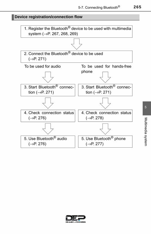
2655-7. Connecting Bluetooth®
5
Multim
edia system
Device registration/connection flow
1. Register the Bluetooth® device to be used with multimediasystem (→P. 267, 268, 269)
2. Connect the Bluetooth® device to be used (→P. 271)
To be used for audio To be used for hands-freephone
3. Start Bluetooth® connec-tion (→P. 271)
3. Start Bluetooth® connec-tion (→P. 271)
4. Check connection status(→P. 276)
4. Check connection status(→P. 278)
5. Use Bluetooth® audio (→P. 276)
5. Use Bluetooth® phone (→P. 277)

266 5-7. Connecting Bluetooth®
To display the screen shown below, press the “SETUP” button andselect “Bluetooth*” on the “Setup” screen.
Select to connect the device tobe used with multimedia sys-tem. (→P. 271)
Select to register a Bluetooth®
device to be used with multime-dia system. (→P. 269)
Select to set detailedBluetooth® system settings.(→P. 274)
Select to delete registered devices. (→P. 270)
*: Bluetooth is a registered trademark of Bluetooth SIG, Inc.
Registering and connecting from the “Bluetooth* Setup” screen
1
2
3
4

2675-7. Connecting Bluetooth®
5
Multim
edia system
Registering a Bluetooth® audio player for the first time
Turn the Bluetooth® connection setting of your audio player on.
Press the “AUDIO” button.
Select “ Audio”.
Select “Select Device”.
Follow the steps in “How to register a Bluetooth® device” from step. (→P. 269)
To use the Bluetooth® Audio, it is necessary to register an audioplayer with the system.
Once the player has been registered, it is possible to use theBluetooth® Audio.
For details about registering a Bluetooth® device (→P. 269)
1
2
3
4
5
2

268 5-7. Connecting Bluetooth®
Registering a Bluetooth® phone for the first time
Turn the Bluetooth® connection setting of your cellular phone on.
Press the button.
Select “OK” to register a phone.
Follow the steps in “How to register a Bluetooth® device” from step (→P. 269)
To use the hands-free system, it is necessary to register aBluetooth® phone with the system.
Once the phone has been registered, it is possible to use thehands-free system.
For details about registering a Bluetooth® device (→P. 269)
1
2
3
4
3

2695-7. Connecting Bluetooth®
5
Multim
edia system
Registering a Bluetooth® device
Display the “Bluetooth* Setup” screen. (→P. 266)
Select “Add Device”.
When this screen is displayed,search for the name displayedon this screen on the screen ofyour Bluetooth® device.
For details about operating theBluetooth® device, see the manualthat comes with it.
To cancel the registration, select“Cancel”.
Register the Bluetooth® device using your Bluetooth® device.
A PIN-code is not required for SSP (Secure Simple Pairing) compatibleBluetooth® devices. Depending on the type of Bluetooth® device beingconnected, a message confirming registration may be displayed on theBluetooth® device’s screen. Respond and operate the Bluetooth® deviceaccording to the confirmation message.
Check that this screen is dis-played when registration iscomplete.
*: Bluetooth is a registered trademark of Bluetooth SIG, Inc.
Bluetooth® compatible phones (HFP) and portable audio players(AVP) can be registered simultaneously. You can register up to 5Bluetooth® devices.
How to register a Bluetooth® device
1
2
3
4
5

270 5-7. Connecting Bluetooth®
Select “OK” when the connection status changes from “Connect-ing...” to “Connected”.
If an error message is displayed, follow the guidance on the screen to tryagain.
Registration can be performed from screens other than the“Bluetooth* Setup” screen.
■ When registering from the “Bluetooth* Audio” screen
Display the “Bluetooth* Audio” screen. (→P. 241)
Select “Select Device”.
Follow the steps in “How to register a Bluetooth® device” fromstep (→P. 269)
*: Bluetooth is a registered trademark of Bluetooth SIG, Inc.
Display the “Bluetooth* Setup” screen. (→P. 266)
Select “Remove”.
Select the desired device.
A confirmation message will be displayed, select “Yes” to delete thedevice.
Check that a confirmation screen is displayed when the operation iscomplete.
*: Bluetooth is a registered trademark of Bluetooth SIG, Inc.
Deleting a Bluetooth® device
6
1
2
3
2
1
2
3
4
5

2715-7. Connecting Bluetooth®
5
Multim
edia system
Connecting a Bluetooth® device
Press the “SETUP” button.
Select “Bluetooth*”.
Select the device to be con-nected.
Supported profile icons will be dis-played.
Phone
Audio player
Supported profile icons for cur-rently connected devices will illumi-nate.
Dimmed icons can be selected to connect to the function directly.
*: Bluetooth is a registered trademark of Bluetooth SIG, Inc.
To turn auto connection mode on, set “Bluetooth* Power” to on. (→P. 274)
When you register a phone, auto connection will be activated. Alwaysset it to this mode and leave the Bluetooth® phone in a place where aconnection can be established.
When the engine switch is turned to the “ACC” or “ON” position, the sys-tem will search for a nearby cellular phone you have registered.
Next, the system automatically connects with the most recent of thephones connected to in the past. Then, the connection result is displayed.
*: Bluetooth is a registered trademark of Bluetooth SIG, Inc.
Up to 5 Bluetooth® devices (Phones [HFP] and audio players[AVP]) can be registered.
If more than 1 Bluetooth® device has been registered, selectwhich device to connect to.
1
2
3
1
2
Auto connection

272 5-7. Connecting Bluetooth®
When auto connection has failed or “Bluetooth* Power” is turned off,you must connect the Bluetooth® device manually.● Follow the steps in “Connecting a Bluetooth* device” from step .
(→P. 271)
*: Bluetooth is a registered trademark of Bluetooth SIG, Inc.
Registering an additional device
Select “Select Device” on the “Bluetooth* Audio” screen.
For more information: →P. 269
Selecting a registered device
Select “Select Device” on the “Bluetooth* Audio” screen.
For more information: →P. 271
*: Bluetooth is a registered trademark of Bluetooth SIG, Inc.
■Reconnecting a Bluetooth® phoneIf the system cannot connect due to poor signal strength with the engineswitch in the “ACC” or “ON” position, the system will automatically attempt toreconnect.
If the system is attempting to connect to a Bluetooth® phone and the Bluetooth®
phone is turned off and then back on, the system will attempt to reconnect.
Manual connection
Connecting a Bluetooth® audio player
1
1
2
1
2

2735-7. Connecting Bluetooth®
5
Multim
edia system
Displaying a Bluetooth® device details
Display the “Bluetooth* Setup” screen. (→P. 266)
Select the device.
Select “Device Info”.
The following screen is dis-played:
Device Name
Change connection method
Bluetooth® Address
Display your telephone num-ber
The number may not be dis-played depending on the modelof phone.
Compatibility profile of thedevice
Restore default settings
*: Bluetooth is a registered trademark of Bluetooth SIG, Inc.
Select “Connect Audio Player from”.
Select “Vehicle” or “Device”.
“Vehicle”: Connect the multimedia system to the portable audio player.
“Device”: Connect the portable audio player to the multimedia system.
You can confirm and change the registered device details.
Bluetooth® device registration status
1
2
3
4
1
2
3
4
5
6
Changing connection method
1
2

274 5-7. Connecting Bluetooth®
Detailed Bluetooth® system settings
Display the “Bluetooth* Setup” screen. (→P. 266)
Select “System Settings”.
The following screen is dis-played:
Bluetooth* Power on/off
You can change Bluetooth*function on/off
Bluetooth* Name
Change PIN-code
Bluetooth* Address
Display Phone Status
You can set the system to showthe status confirmation displaywhen connecting a telephone
Display Audio Player Status
You can set the system to show the status confirmation display whenconnecting an audio player
Compatibility profile of the system
Restore default settings
*: Bluetooth is a registered trademark of Bluetooth SIG, Inc.
You can confirm and change the detailed Bluetooth® settings.
How to check and change detailed Bluetooth® settings
1
2
3
1
2
3
4
5
6
7
8

2755-7. Connecting Bluetooth®
5
Multim
edia system
You can change the PIN-code that is used to register your Bluetooth®
devices in the system.
Select “Bluetooth* PIN”.
Input a PIN-code, and select “OK”.
*: Bluetooth is a registered trademark of Bluetooth SIG, Inc.
Editing the Bluetooth® PIN
1
2

276 5-8. Bluetooth® audio
Listening to Bluetooth® audio
Some titles and controls may not be displayed depending on the typeof portable audio player used.
Connection status
Battery charge
Select or to Play/Pause.
For details on “Bluetooth* Audio” screen operation methods, refer toBasic Audio Operations. (→P. 233)
For details on how to select a track or album, refer to selecting, fast-forwarding and reversing tracks/files/songs. (→P. 243)
*: Bluetooth is a registered trademark of Bluetooth SIG, Inc.
The Bluetooth® audio system enables the user to enjoy musicplayed on a portable player from the vehicle speakers via wire-less communication.
When a Bluetooth® device cannot be connected, check the connec-tion status on the “Bluetooth* Audio” screen. If the device is not con-nected, either register or reconnect the device. (→P. 271)
*: Bluetooth is a registered trademark of Bluetooth SIG, Inc.
Audio control screen
1
2
Indicators Conditions
Connection statusGood Not connected
Battery chargeFull Empty
Playing Bluetooth® audio

2775-9. Bluetooth® phone
5
Multim
edia system
Using a Bluetooth® phone
To display the screen shown below, press the switch on the steer-ing wheel or press the button.
Several functions are available to operate on each screen that is dis-played by selecting the 4 tabs.
Device name
Bluetooth® connection status
The hands-free system is a function that allows you to use yourcellular phone without touching it.
This system supports Bluetooth®. Bluetooth® is a wireless datasystem that allows the cellular phone to wirelessly connect tothe hands-free system and make/receive calls.
Before making a phone call, check the connection status, batterycharge, call area and signal strength. (→P. 278)
If a Bluetooth® device cannot be connected, check the connectionstatus on the phone screen. If the device is not connected, eitherregister or reconnect it. (→P. 271)
Phone screen
1
2

278 5-9. Bluetooth® phone
■ Telephone switch (→P. 290)
■ Microphone
The vehicle’s built in micro-phone is used when talking onthe phone.
The person you are speaking tocan be heard from the frontspeakers.
To use the hands-free system, you must register your Bluetooth®
phone in the system. (→P. 269)
You can check indicators such as signal strength and battery chargeon the phone screen.
Connection status
Signal strength
Battery charge
Status display
1
2
3
Indicators Conditions
Connection statusGood Poor Not connected
Battery chargeFull Empty
Call area “Rm”: Roaming area
Signal strengthExcellent Poor
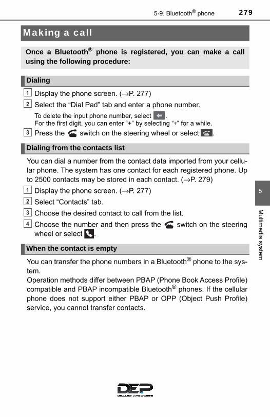
2795-9. Bluetooth® phone
5
Multim
edia system
Making a call
Display the phone screen. (→P. 277)
Select the “Dial Pad” tab and enter a phone number.
To delete the input phone number, select . For the first digit, you can enter “+” by selecting “∗” for a while.
Press the switch on the steering wheel or select .
You can dial a number from the contact data imported from your cellu-lar phone. The system has one contact for each registered phone. Upto 2500 contacts may be stored in each contact. (→P. 279)
Display the phone screen. (→P. 277)
Select “Contacts” tab.
Choose the desired contact to call from the list.
Choose the number and then press the switch on the steeringwheel or select .
You can transfer the phone numbers in a Bluetooth® phone to the sys-tem. Operation methods differ between PBAP (Phone Book Access Profile)compatible and PBAP incompatible Bluetooth® phones. If the cellularphone does not support either PBAP or OPP (Object Push Profile)service, you cannot transfer contacts.
Once a Bluetooth® phone is registered, you can make a callusing the following procedure:
Dialing
Dialing from the contacts list
When the contact is empty
1
2
3
1
2
3
4

280 5-9. Bluetooth® phone
Press the switch on the steering wheel.
If the phonebook is empty, a message will be displayed.
For a PBAP compatible Bluetooth® phone and “Automatic Transfer”is off
Select the desired item.
Select to transfer new con-tacts from a cellular phone,select “Always” and thenenable “Automatic Transfer”.
Select to transfer all the con-tacts from a connected cellu-lar phone only once.
Select to cancel transferring.
For PBAP incompatible but OPP compatible Bluetooth® phones
Select the desired item.
Select to transfer the con-tacts from the connected cel-lular phone.
Select to add a new contactmanually.
Select to cancel transferring.
When “Transfer” is selected
Follow the steps in “Update contacts from phone” from step .(→P. 294)
When “Add” is selected
Follow the steps in “Registering a new contact to the contact list”from step . (→P. 296)
1
2
1
2
3
2
1
2
3
3 2
3
2

2815-9. Bluetooth® phone
5
Multim
edia system
You can make a call using numbers registered in the contact.
Display the phone screen. (→P. 277)
Select “Favorites” tab.
Select the desired number to make a call.
You can make a call using the call history, which has the 3 functionsbelow.
: calls which you missed
: calls which you received
: calls which you made
Display the phone top screen. (→P. 277)
Select “Call History” tab.
Select or the desired entry from the list.
When is selected
Check that the “Call” screen is displayed.
When the desired contact is selected
Select the desired number.
Check that the “Call” screen is displayed.
■Call history list● If you make a call to or receive a call from a number registered in the con-
tacts, the name is displayed in the call history.
● If you make multiple calls to the same number, only the last call made is dis-played in the call history.
■ International callsYou may not be able to make international calls, depending on the mobilephone in use.
Calling using favorites list
Dialing from call history
1
2
3
1
2
3
4
4
5

282 5-9. Bluetooth® phone
Receiving a call
Press the switch on the steer-ing wheel or select .
Press the switch on the steering wheel or select .
Turn the “PWR·VOL” knob. You can also adjust the volume using thesteering switches.
■ International callsReceived international calls may not be displayed correctly depending on thecellular phone in use.
When a call is received, the following screen is displayedtogether with a sound.
To answer the phone
To refuse a call
To adjust the incoming call volume

2835-9. Bluetooth® phone
5
Multim
edia system
Speaking on the phone
Select “-” or “+”. You can also adjust the volume using the steeringswitches or the volume knob.
Select “Mute”.
When using phone services such as an answering service or a bank,you can store phone numbers and code numbers in the contact.
Select “0-9”.
Input the number.
■ Release Tones
“Release Tones” appear when a continuous tone signal(s) contain-ing a (w) is registered in the contact list.● Select “Release Tones”.
The following screen is displayed when speaking on the phone.
To adjust the call volume
To prevent the other party from hearing your voice
Inputting tones
1
2

284 5-9. Bluetooth® phone
■Release Tones●A continuous tone signal is a character string that consists of numbers and
the characters “p” or “w”. (e.g.056133w0123p#1∗)
●When the “p” pause tone is used, the tone data up until the next pause tonewill be automatically sent after 2 seconds have elapsed. When the “w”pause tone is used, the tone data up until the next pause tone will be auto-matically sent after a user operation is performed.
●Release tones can be used when automated operation of a phone basedservice such as an answering machine or bank phone service is desired. Aphone number with continuous tone signals can be registered in the contactlist.
●Tone data after a “w” pause tone can be operated on voice command duringa call.
Select “Handset Mode” to on from a hands-free call to a cellularphone call. Select “Handset Mode” to off from a cellular phone call to a hands-freecall.
Select “Transmit Volume”.
Select the desired level for the transmit volume.
Select “OK”.
Press the switch on the steering wheel or select .
To transfer a call
Transmit volume setting
To hang up
1
2
3

2855-9. Bluetooth® phone
5
Multim
edia system
When a call is interrupted by a third party while talking, an incomingcall message will be displayed.
To talk with the other party: • Press the switch on the
steering wheel.• Select .
To refuse the call: • Press the switch on the
steering wheel.• Select .
Every time you press the switch on the steering wheel or select during call waiting, you will be switched to the other party.
■Transferring calls● If you transfer from the cellular phone to hands-free, the hands-free screen
will be displayed, and you can operate the system using the screen.
●Transfer method and operation may vary according to the cellular phoneused.
●For operation of the cellular phone in use, see the phone’s manual.
■Call waiting operationCall waiting operation may differ depending on your phone company and cel-lular phone.
Call waiting

286 5-9. Bluetooth® phone
Bluetooth® phone message function
Press the button.
Select .
When an e-mail/SMS/MMS is received, the incoming message screenpops up with sound and is ready to be operated on the screen.
Select to check the message.
Select to refuse the message.
Select to call the messagesender.
Received messages can be forwarded from the connectedBluetooth® phone, enabling checking and replying using themultimedia system.
Depending on the type of Bluetooth® phone connected, receivedmessages may not be transferred to the message inbox.
If the phone does not support the message function, this func-tion cannot be used.
Displaying message inbox screen
Receiving a message
1
2
1
2
3

2875-9. Bluetooth® phone
5
Multim
edia system
■Receiving a message●Depending on the cellular phone used for receiving messages, or its regis-
tration status with the navigation system, some information may not be dis-played.
●The pop up screen is separately available for incoming e-mail and SMS/MMS messages under the following conditions:
E-mail:
• “Incoming E-mail Display” is set to “Full Screen”. (→P. 301)• “E-mail Notification Popup” is set to on. (→P. 301)SMS/MMS:
• “Incoming SMS/MMS Display” is set to “Full screen”. (→P. 301)• “SMS/MMS Notification Popup” is set to on. (→P. 301)
Display the message inbox screen. (→P. 286)
Select the desired message from the list.
Check that the message is dis-played.
E-mails: Select “MarkUnread” or “Mark Read” tomark mail unread or read onthe message inbox screen.
This function is available when“Update Read Status on Phone”is set to on (→P. 301)
Select to make a call to the sender.
Select to have messages read out. To cancel this function, select“Stop”.
Select to display the previous or next message.
Select to reply the message.
Checking the messages
1
2
3
1
2
3
4
5

288 5-9. Bluetooth® phone
■Check the messages●Depending on the type of Bluetooth® phone being connected, it may be nec-
essary to perform additional steps on the phone.
●Messages are displayed in the appropriate connected Bluetooth® phone’sregistered mail address folder. Select the tab of the desired folder to be displayed.
●Only received messages on the connected Bluetooth® phone can be dis-played.
●The text of the message is not displayed while driving.
●When “Automatic Message Readout” is set to on, messages will be auto-matically read out. (→P. 301)
●Turn the “PWR⋅VOL” knob, or use the volume switch on the steering wheelto adjust the message read out volume.
●The message read out function is available even while driving.
Display the message inbox screen. (→P. 286)
Select the desired message from the list.
Select “Quick Message”.
Select the desired message.
Select “Send”.
■ Editing quick reply message
Select “Quick Message”.
Select corresponding to the desired message to edit.
Select “OK” when editing is completed.
Replying to a message
1
2
3
4
5
1
2
3
2895-9. Bluetooth® phone
5
Multim
edia system
Calls can be made to an e-mail/SMS/MMS message sender’s phonenumber.
Display the message inbox screen. (→P. 286)
Select the desired message.
Select .
Check that the “Call” screen is displayed.
■ Calling from a number within a message
Calls can be made to a number identified in a message’s text area.
Display the message inbox screen. (→P. 286)
Select the desired message.
Select the text area.
Select corresponding to the desired number.
Check that the “Call” screen is displayed.
■ Calling from the incoming message screen
→P. 285
Calling the message sender
1
2
3
4
1
2
3
4
5

290 5-9. Bluetooth® phone
Using the steering wheel switches
Volume switch• Press: Increase/Decrease
the volume• Press and hold: Continuously
increase/decrease the vol-ume
On hook switch• End a call• Refuse a call
Off hook switch• Make a call• Receive a call• Display “Phone” screen
The steering wheel switches can be used to operate a connectedcellular phone.
Operating a telephone using the steering wheel switches
1
2
3

2915-9. Bluetooth® phone
5
Multim
edia system
Bluetooth® phone settings
To display the screen shown below, press the “SETUP” button, andselect “Phone” on the “Setup” screen.
Set the phone connection (→P. 269)
Sound Settings (→P. 292)
Contact/Call History Settings(→P. 293)
Set the message settings (→P. 301)
Set the phone display (→P. 302)
You can adjust the hands-free system to your desired settings.
“Phone/Message Settings” screen
1
2
13
14
5

292 5-9. Bluetooth® phone
Display the “Phone/Message Settings” screen. (→P. 291)
Select “Sound Settings” on the“Phone/Message Settings”screen.
Set the desired ringtone.
Adjust the ringtone volume.
Adjust the message readoutvolume.
Set the desired incomingSMS/MMS tone.
Adjust the incoming SMS/MMS tone volume.
Set the incoming e-mail tone.
Adjust the incoming e-mail tone volume.
Adjust the default volume of the other party’s voice.
■To return to the default volume settingsSelect “Default”, and then “Yes”.
Sound setting
1
2
1
2
13
4
5
6
7
8

2935-9. Bluetooth® phone
5
Multim
edia system
Contact/Call History Settings
The contacts can be transferred from a Bluetooth® phone to the sys-tem. Contacts can also be added, edited and deleted.
The call history can be deleted and contacts and favorites can bechanged.
Display the “Phone/Message Settings” screen. (→P. 291)
Select “Contact/Call History Settings”.
Select the desired item to beset.
For PBAP compatibleBluetooth® phones, select toset “Automatic Transfer” on/off. When set to on, thephone’s contact data and his-tory are automatically trans-ferred.
Select to update contactsfrom the connected phone. (→P. 294)
Select to sort contacts by the first name or last name field.
Select to add contacts to the favorites list. (→P. 298)
Select to delete contacts from the favorites list. (→P. 300)
Select to display contact images.
Select to clear contacts from the call history.*Select to add new contacts to the contact list.* (→P. 296)
Select to edit contacts in the contact list.* (→P. 297)
Select to delete contacts from the contact list.* (→P. 298)
Select to reset all setup items.
*: For PBAP compatible Bluetooth® phones only, this function is availablewhen “Automatic Transfer” is set to off.
1
2
3
1
2
3
4
5
6
7
8
9
10
11

294 5-9. Bluetooth® phone
Operation methods differ between PBAP compatible and PBAPincompatible but OPP compatible Bluetooth® phones.
If your cellular phone is neither PBAP nor OPP compatible, the con-tacts cannot be transferred.
■ For PBAP compatible Bluetooth® Phones
Select “Update Contacts from Phone”.
Check that a confirmation screen is displayed when the opera-tion is complete.
This operation may be unnecessary depending on the type of cellularphone.
Depending on the type of cellular phone, OBEX authentication may berequired when transferring contact data. Enter “1234” into theBluetooth® phone.
If another Bluetooth® device is connected when transferring contactdata, depending on the phone, the connected Bluetooth® device mayneed to be disconnected.
Depending on the type of Bluetooth® phone being connected, it may benecessary to perform additional steps on the phone.
Update contacts from phone
1
2

2955-9. Bluetooth® phone
5
Multim
edia system
■ For PBAP Incompatible but OPP compatible Bluetooth®
Phones
Select “Update Contacts from Phone”.
Transfer the contact data to the system using a Bluetooth®
phone.
This operation may be unnecessary depending on the type of cellularphone.
Depending on the type of cellular phone, OBEX authentication may berequired when transferring contact data. Enter “1234” into theBluetooth® phone.
To cancel this function, select “Cancel”.
Check that a confirmation screen is displayed when the opera-tion is complete.
■ Updating the contacts in a different way (from the “Call His-tory” screen)
For PBAP compatible Bluetooth® phones, this function is availablewhen “Automatic Transfer” is set to off. (→P. 293)
Display the phone screen. (→P. 277)
Select the “Call History” tab and select a contact not yet regis-tered in the contact list.
Select “Update Contact”.
Select the desired contact.
Select a phone type for the phone number.
1
2
3
1
2
3
4
5
296 5-9. Bluetooth® phone
New contact data can be registered. Up to 4 numbers per person canbe registered. For PBAP compatible Bluetooth® phones, this functionis available when “Automatic Transfer” is set to off. (→P. 293)
Select “New Contact”.
Enter the name and select “OK”.
Enter the phone number and select “OK”.
Select the phone type for the phone number.
To add another number to this contact, select “Yes”.
■ Registering a new contact in a different way (from the “CallHistory” screen)
Display the phone screen. (→P. 277)
Select the “Call History” tab and select a contact not yet regis-tered in the contact list.
Select “Add to Contacts”.
Follow the steps in “Registering a new contact to the contact list”from step .
Registering a new contact to the contact list
1
2
3
4
5
1
2
3
4
2
2975-9. Bluetooth® phone
5
Multim
edia system
For PBAP compatible Bluetooth® phones, this function is availablewhen “Automatic Transfer” is set to off. (→P. 293)
Select “Edit Contact”.
Select the desired contact.
Select corresponding to the desired name or number.
For editing the name
Follow the steps in “Registering a new contact to the contact list”from step . (→P. 296)
For editing the number
Follow the steps in “Registering a new contact to the contact list”from step . (→P. 296)
■ Editing the contacts in a different way (from the “ContactDetails” screen)
Display the phone screen. (→P. 277)
Select the “Contacts”, “Call History” tab or the “Favorites” tab andselect the desired contact.
Select “Edit Contact”.
“E-mail Addresses”: Select to display all registered e-mail addresses forthe contact.
Follow the steps in “Editing the contact data” from step .
Editing the contact data
1
2
3
4
2
4
3
1
2
3
4 3

298 5-9. Bluetooth® phone
For PBAP compatible Bluetooth® phones, this function is availablewhen “Automatic Transfer” is set to off. (→P. 293)
Select “Delete Contacts”.
Select the desired contact and select “Delete”.
Select “Yes” when the confirmation screen appears.
■ Deleting the contact in a different way (from the “ContactDetails” screen)
Display the phone screen. (→P. 277)
Select the “Contacts”, “Call History” tab or the “Favorites” tab andselect the desired contact.
Select “Delete Contact”.
Select “Yes” when the confirmation screen appears.
Up to 15 contacts (maximum of 4 numbers per contact) can be regis-tered in the favorites list.
■ Registering the contacts in the favorites list
Select “Add Favorite”.
Select the desired contact to add to the favorites list.
Dimmed contacts are already stored as a favorite.
Check that a confirmation screen is displayed when the opera-tion is complete.
Deleting the contact data
Favorites list setting
1
2
13
1
2
3
4
1
2
3

2995-9. Bluetooth® phone
5
Multim
edia system
When 15 contacts have already been registered to the favorites list
When 15 contacts have already been registered to the favoriteslist, a registered contact needs to be replaced. Select “Yes” when the confirmation screen appears to replace acontact.
Select the contact to be replaced.
Check that a confirmation screen is displayed when the opera-tion is complete.
Registering contacts in the favorites list in a different way (from the“Contacts” screen)
Display the phone screen. (→P. 277)
Select the “Contacts” tab.
Select at the beginning of the desired contact list name to beregistered in the favorites list.
When selected, is changed to , and the contact is registered inthe favorites list.
Registering contacts in the favorites list in a different way (from the“Contact Details” screen)
Display the phone screen. (→P. 277)
Select the “Contacts” tab or the “Call History” tab and select thedesired contact.
Select “Add Favorite”.
Check that a confirmation screen is displayed when the opera-tion is complete.
1
2
3
1
2
3
1
2
3
4

300 5-9. Bluetooth® phone
■ Deleting the contacts in the favorites list
Select “Remove Favorite”.
Select the desired contacts and select “Remove”.
Select “Yes” when the confirmation screen appears.
Check that a confirmation screen is displayed when the opera-tion is complete.
Deleting contacts in the favorites list in a different way (from the“Contacts” screen)
Display the phone screen. (→P. 277)
Select the “Contacts” tab.
Select at the beginning of the contact list name to be deletedfrom the favorites list.
When selected, is changed to , and the data is deleted from thelist.
Deleting contacts in the favorites list in a different way (from the“Contact Details” screen)
Display the phone screen. (→P. 277)
Select the “Contacts”, “Call History” tab or the “Favorites” tab andselect the desired contact to delete.
Select “Remove Favorite”.
Select “Yes” when the confirmation screen appears.
Check that a confirmation screen is displayed when the opera-tion is complete.
1
2
3
4
1
2
3
1
2
3
4
5

3015-9. Bluetooth® phone
5
Multim
edia system
Display the “Phone/Message Settings” screen. (→P. 291)
Select “Messaging Settings”.
Select the desired item to beset.
Set automatic messagetransfer on/off.
Set automatic messagereadout on/off.
Set the SMS/MMS notifica-tion popup on/off.
Set the e-mail notificationpopup on/off.
Set adding the vehicle signa-ture to outgoing messageson/off.
Set updating message read status on phone on/off.
Change the incoming SMS/MMS display.
“Full Screen”: When an SMS/MMS message is received, the incomingSMS/MMS display screen is displayed and can be operated on thescreen.
“Drop-Down”: When an SMS/MMS message is received, a message isdisplayed on the upper side of the screen.
Change the incoming e-mail display.
“Full Screen”: When an e-mail is received, the incoming e-mail displayscreen is the displayed and can be operated on the screen.
“Drop-Down”: When an e-mail is received, a message is displayed onthe upper side of the screen.
Set display of messaging account names on the inbox tab on/off.
When set to on, messaging account names used on the cellular phonewill be displayed.
Message Settings
1
2
3
1
2
3
4
5
6
7
8
9

302 5-9. Bluetooth® phone
■To return to the default volume settingsSelect “Default”, and then “Yes”.
■ Displaying the “Messaging Settings” screen in a different way
Display the phone screen. (→P. 277)
Select .
Select “Settings”.
Display the “Phone/Message Settings” screen. (→P. 291)
Select “Phone Display Settings”.
Select the desired item to beset.
Change the incoming calldisplay.
“Full Screen”: When a call isreceived, the hands-free screenis displayed and can be oper-ated on the screen.
“Drop-Down”: A message is displayed on the upper side of the screen.
Set display of the contact/history transfer completion messageon/off.
Phone Display Settings
1
2
3
1
2
3
1
2

3035-9. Bluetooth® phone
5
Multim
edia system
What to do if... (Troubleshooting)
If there is a problem with the hands-free system or a Bluetooth®
device, first check the table below.
When using the hands-free system with a Bluetooth® device
The hands-free system or Bluetooth® device does not work.
The connected device may not be a compatible Bluetooth® cellular phone.→ For a list of specific devices which operation has been confirmed
on this system, check with your Toyota dealer or the following web-site: http://www.toyota.com/entune
The Bluetooth version of the connected cellular phone may be older thanthe specified version.→ Use a cellular phone with Bluetooth version 2.0 or higher (recom-
mended: Ver. 3.0 with EDR or higher). (→P. 307)

304 5-9. Bluetooth® phone
When registering/connecting a cellular phone
When making/receiving a call
A cellular phone cannot be registered.
An incorrect passcode was entered on the cellular phone.→ Enter the correct passcode on the cellular phone.
The registration operation has not been completed on the cellular phoneside.→ Complete the registration operation on the cellular phone (approve
registration on the phone).
Old registration information remains on either this system or the cellularphone.→ Delete the existing registration information from both this system
and the cellular phone, then register the cellular phone you wish toconnect to this system. (→P. 270)
A Bluetooth® connection cannot be made.
Another Bluetooth® device is already connected.→ Manually connect the cellular phone you wish to use to this sys-
tem. (→P. 272)
Bluetooth® function is not enabled on the cellular phone.→ Enable the Bluetooth® function on the cellular phone.
“Please check your device settings.” message is displayed.
Bluetooth® function is not enabled on the cellular phone.→ Enable the Bluetooth® function on the cellular phone.
Old registration information remains on either this system or the cellularphone.→ Delete the existing registration information from both this system
and the cellular phone, then register the cellular phone you wish toconnect to this system. (→P. 270)
A call cannot be made/received.
Your vehicle is in a “Out of cellular service area. Please try again later.”area.→ Move to where “Out of cellular service area. Please try again later.”
no longer appears on the display.

3055-9. Bluetooth® phone
5
Multim
edia system
When using the phonebook
Phonebook data cannot be transferred manually/automatically.
The profile version of the connected cellular phone may not be compatiblewith transferring phonebook data.→ For a list of specific devices which operation has been confirmed
on this system, check with your Toyota dealer or the following web-site: http://www.toyota.com/entune
Automatic phonebook transfer function on this system is set to off.→ Set automatic phonebook transfer function on this system to on.
(→P. 293)
Passcode has not been entered on the cellular phone.→ Enter the passcode on the cellular phone if requested (default pass-
code: 1234).
Transfer operation on the cellular phone has not completed.→ Complete transfer operation on the cellular phone (approve trans-
fer operation on the phone).
Phonebook data cannot be edited.
Automatic phonebook transfer function on this system is set to on.→ Set automatic phonebook transfer function on this system to off.
(→P. 293)

306 5-9. Bluetooth® phone
When using the Bluetooth® message function
In other situations
Messages cannot be viewed.
Message transfer is not enabled on the cellular phone.→ Enable message transfer on the cellular phone (approve message
transfer on the phone).
Automatic transfer function on this system is set to off.→ Set automatic transfer function on this system to on. (→P. 301)
New message notifications are not displayed.
Notification of SMS/MMS/E-mail reception on this system is set to off.→ Set notification of SMS/MMS/E-mail reception on this system to on.
(→P. 301)
Automatic message transfer function is not enabled on the cellular phone.→ Enable automatic transfer function on the cellular phone.
Even though all conceivable measures have been taken, the symptom sta-tus does not change.
The cellular phone is not close enough to this system.→ Bring the cellular phone closer to this system.
The cellular phone is the most likely cause of the symptom.→ Turn the cellular phone off, remove and reinstall the battery pack,
and then restart the cellular phone.→ Enable the cellular phone’s Bluetooth® connection.→ Stop the cellular phone’s security software and close all applica-
tions.→ Before using an application installed on the cellular phone, care-
fully check its source and how its operation might affect this sys-tem.
3075-10. Bluetooth®
5
Multim
edia system
Bluetooth®
■When using the Bluetooth® audio system● In the following conditions, the system may not function.
• If the portable audio player is turned off• If the portable audio player is not connected• If the portable audio player’s battery is low
●There may be a delay if a cellular phone connection is made duringBluetooth® audio play.
●Depending on the type of portable audio player that is connected to the sys-tem, operation may differ slightly and certain functions may not be available.
■When using the hands-free system●The multimedia system is muted when making a call.
● If both parties speak at the same time, it may be difficult to hear.
● If the received call volume is overly loud, an echo may be heard. If the Bluetooth® phone is too close to the system, quality of the sound maydeteriorate and connection status may deteriorate.
● In the following circumstances, it may be difficult to hear the other party:
• When driving on unpaved roads• When driving at high speeds• If a roof or window is open• If the air conditioning is blowing directly on the microphone• If there is interference from the network of the cellular phone
■Conditions under which the system will not operate● If using a cellular phone that does not support Bluetooth®
● If the cellular phone is turned off
● If you are outside of cellular phone service coverage
● If the cellular phone is not connected
● If the cellular phone’s battery is low
●When outgoing calls are controlled, due to heavy traffic on telephone lines,etc.
●When the cellular phone itself cannot be used
●When transferring contact data from the cellular phone

308 5-10. Bluetooth®
■Bluetooth® antennaThe antenna is built into the display. If the portable audio player is behind the seat or in the glove box or consolebox, or is touching or covered by metal objects, the connection status maydeteriorate. If the cellular phone is behind the seat or in the console box, or touching orcovered by metal objects, the connection status may deteriorate.
■Battery charge/signal status●This display may not correspond exactly with the portable audio player or
cellular phone itself.
●This system does not have a charging function.
●The portable audio player or cellular phone battery will be depleted quicklywhen the device is connected to Bluetooth®.
■When using the Bluetooth® audio and hands-free system at the sametimeThe following problems may occur.
●The Bluetooth® audio connection may be interrupted.
●Noise may be heard during Bluetooth® audio playback.
■About the contact in this systemThe following data is stored for every registered cellular phone. Whenanother phone is connecting, you cannot read the registered data.
●Contact data
●Call history
●Favorite
●Message
When removing a Bluetooth® phone from the system, the above-mentioneddata is also deleted.
3095-10. Bluetooth®
5
Multim
edia system
■Compatible modelsThe Bluetooth® audio system supports portable audio players with the follow-ing specifications
●Bluetooth® specifications: Ver. 2.0, or higher (Recommended: Ver. 3.0+EDR or higher)
●Profiles:
• A2DP (Advanced Audio Distribution Profile) Ver. 1.0, or higher (Recommended: Ver. 1.2 or higher) This is a profile to transmit stereo audio or high quality sound to the multi-media system.
• AVRCP (Audio/Video Remote Control Profile) Ver. 1.0 or higher (Recommended: Ver. 1.4 or higher) This is a profile to allow remote control the A/V equipment.
However, please note that some functions may be limited depending on thetype of portable audio player connected.
The hands-free system supports cellular phones with the following specifica-tions.
●Bluetooth® specification: Ver. 2.0 or higher (Recommended: Ver. 3.0+EDR or higher)
●Profiles:
• HFP (Hands Free Profile) Ver. 1.0 or higher (Recommended: Ver. 1.6 orhigher) This is a profile to allow hands-free phone calls using a cellular phone orhead set. It has outgoing and incoming call functions.
• OPP (Object Push Profile) Ver. 1.1 or higher (Recommended: Ver. 1.2) This is a profile to transfer contact data. When a Bluetooth® compatiblecellular phone has both PBAP and OPP, OPP cannot be used.
• PBAP (Phone Book Access Profile) Ver. 1.0 or higher (Recommended:Ver. 1.1)
• MAP (Message Access Profile) Ver.1.0 or higher This is a profile to transfer contact data.
If the cellular phone does not support HFP, you cannot register it with thehands-free system. OPP, PBAP or MAP services must be selected individu-ally.
310 5-10. Bluetooth®
■Reconnecting the portable audio playerIf the portable audio player is disconnected due to poor reception when theengine switch is in the “ACC” or “ON” position, the system automaticallyreconnects the portable audio player.
If you have switched off the portable audio player yourself, follow the instruc-tions below to reconnect:
●Select the portable audio player again
●Enter the portable audio player
■When you sell your carBe sure to delete your personal data. (→P. 237)
WARNING
■While drivingDo not use the portable audio player, cellular phone or connect a device tothe Bluetooth® system.
■Caution regarding interference with electronic devices●Your audio unit is fitted with Bluetooth® antennas. People with implantable
cardiac pacemakers, cardiac resynchronization therapy-pacemakers orimplantable cardioverter defibrillators should maintain a reasonable dis-tance between themselves and the Bluetooth® antennas. The radio wavesmay affect the operation of such devices.
●Before using Bluetooth® devices, users of any electrical medical deviceother than implantable cardiac pacemakers, cardiac resynchronizationtherapy-pacemakers or implantable cardioverter defibrillators should con-sult the manufacturer of the device for information about its operationunder the influence of radio waves. Radio waves could have unexpectedeffects on the operation of such medical devices.
NOTICE
■When leaving the vehicleDo not leave your portable audio player or cellular phone in the vehicle. Theinside of the vehicle may become hot, causing damage to the portableaudio player or cellular phone.

3115-11. Using the voice command system
5
Multim
edia system
Voice command system
Press the talk switch.
Select to train voice recogni-tion.
Select to start the voice recog-nition tutorial.
Select “OK” and say the desired command.
On the list screen, you can select the desired command.
To cancel the voice command system, press and hold the talk switch.
The voice command system enables the hands-free system tobe operated using voice commands.
Operations of the voice command system can be performed byselecting the menu corresponding to each function on thescreen. Even if any menu is selected, commands displayed onall menus can be operated.
Using the voice command system
1
1
2
2

312 5-11. Using the voice command system
■Microphone→P. 278
■When using the microphone● It is unnecessary to speak directly into the microphone when giving a com-
mand.
●Voice commands may not be recognized if:
• Spoken too quickly.• Spoken at a low or high volume.• The roof or windows are open.• Passengers are talking while voice commands are spoken.• The air conditioning speed is set high.• The air conditioning vents are turned towards the microphone.
● In the following conditions, the system may not recognize the commandproperly and using voice commands may not be possible:
• The command is incorrect or unclear. Note that certain words, accents orspeech patterns may be difficult for the system to recognize.
• There is excessive background noise, such as wind noise.
Due to natural language speech recognition technology, this systemenables recognition of a command when spoken naturally. However,the system cannot recognize every variation of each command.
In some situations, it is possible to omit the command for the proce-dure and directly state the desired operation.
Not all voice commands are displayed in the short cut menu.
This function is available in English, Spanish and French.
■ Expression examples for each function
Casual speech recognization
Command Expression examples
“Call <name><type>”
Get me <Robert Brown>.Call <Robert Brown> on <Work> phone
“Dial <number>”Dial <3334445555>Get me <3334445555>

3135-11. Using the voice command system
5
Multim
edia system
Some recognizable voice commands and their actions are shownbelow as examples.
Basic
Phone
Command list
Command Action
“Help”Prompts voice guidance to offer examples of com-mands or operation methods
“Go Back” Returns to the previous screen
Command Action
“Redial”Places a call to the phone number of the latest outgo-ing call
“Call Back”Places a call to the phone number of latest incomingcall
“Show RecentCalls”
Displays the call history screen
“Dial <phone num-ber>”
Places a call to the said phone number
“Call <contacts><phonetypes>”
Place a call to the said phone type of the contact fromthe phone book

314 5-11. Using the voice command system
The Mobile Assistant feature will activate Apple’s Siri® Eyes Freemode via the steering wheel switches. To operate the Mobile Assis-tant, a compatible cellular phone must be registered and connected tothis system via Bluetooth®. (→P. 269)
Press and hold the on thesteering wheel until you hearthe beeps.
The Mobile Assistant can beused only when the followingscreen is displayed.
To cancel the Mobile Assistant,select “Cancel”, press the orpress and hold the on the steer-ing wheel.
To restart the Mobile Assistant foradditional commands, press the on the steering wheel.
• Mobile Assistant can only be restarted after the system responds to avoice command.
• After some phone and music commands, the Mobile Assistant feature willautomatically end to complete the requested action.
■ Adjusting the Mobile Assistant volume
The volume of the Mobile Assistant can be adjusted using thePWR·VOL knob or steering wheel volume switches. The MobileAssistant and phone call volumes are synchronized.
Mobile Assistant
1
2

3155-11. Using the voice command system
5
Multim
edia system
■Notes about Mobile Assistant●The available features and functions may vary based on the iOS version
installed on the connected device.
●Some Siri® features are limited in Eyes Free mode. If you attempt to use anunavailable function, Siri® will inform you that the function is not available.
● If Siri® is not enabled on the cellular phone connected via Bluetooth®, anerror message will be displayed on the screen.
●While a phone call is active, the Mobile Assistant cannot be used.
● If using the navigation feature of the cellular phone, ensure the active audiosource is Bluetooth® audio or iPod in order to hear turn by turn directionprompts.

316 5-11. Using the voice command system

317
6Interior features
6-1. Using the air conditioning system and defogger
Air conditioning system ..... 318
Seat heaters...................... 326
6-2. Using the interior lights
Interior lights list ................ 328• Interior light ................... 328• Personal lights .............. 329
6-3. Using the storage features
List of storage features ..... 330• Glove box...................... 331• Cup holders .................. 331• Bottle holders................ 332• Auxiliary box ................. 333
Luggage compartment features........................... 334
6-4. Using the other interior features
Other interior features ....... 336• Sun visors ..................... 336• Vanity mirrors................ 336• Power outlet.................. 337• Assist grips ................... 338
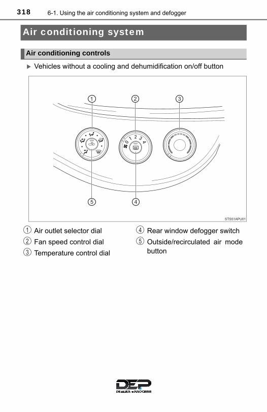
318 6-1. Using the air conditioning system and defogger
Air conditioning system
Vehicles without a cooling and dehumidification on/off button
Air conditioning controls
Air outlet selector dial
Fan speed control dial
Temperature control dial
Rear window defogger switch
Outside/recirculated air modebutton
1
2
3
4
5
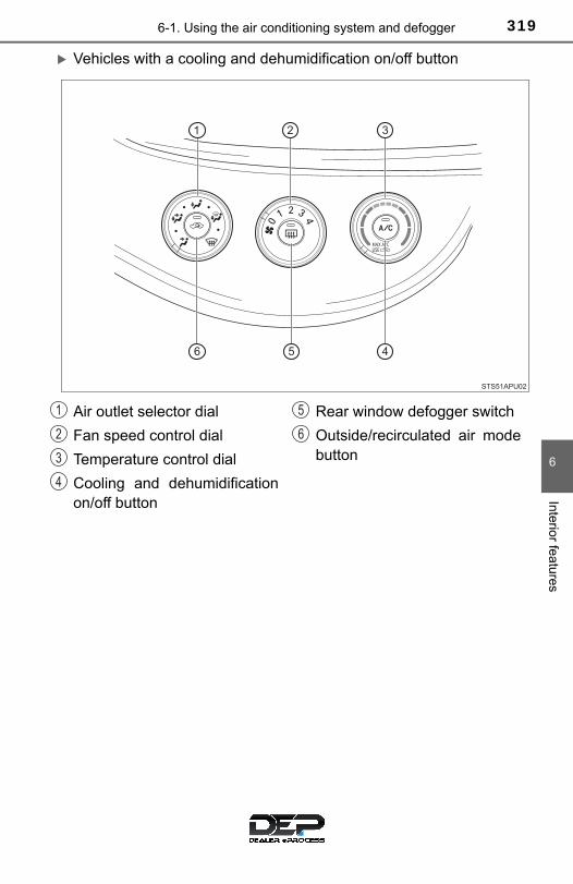
3196-1. Using the air conditioning system and defogger
6
Interior features
Vehicles with a cooling and dehumidification on/off button
Air outlet selector dial
Fan speed control dial
Temperature control dial
Cooling and dehumidificationon/off button
Rear window defogger switch
Outside/recirculated air modebutton
1
2
3
4
5
6
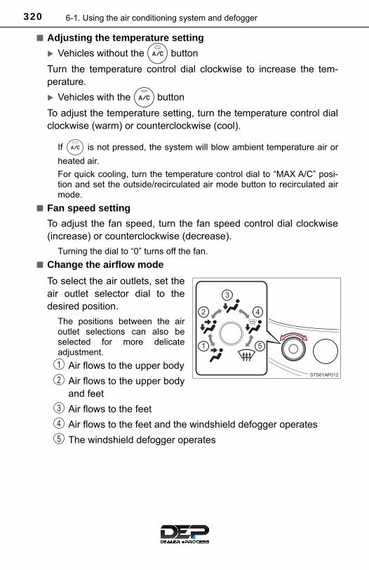
320 6-1. Using the air conditioning system and defogger
■ Adjusting the temperature setting
Vehicles without the button
Turn the temperature control dial clockwise to increase the tem-perature.
Vehicles with the button
To adjust the temperature setting, turn the temperature control dialclockwise (warm) or counterclockwise (cool).
If is not pressed, the system will blow ambient temperature air or
heated air.
For quick cooling, turn the temperature control dial to “MAX A/C” posi-tion and set the outside/recirculated air mode button to recirculated airmode.
■ Fan speed setting
To adjust the fan speed, turn the fan speed control dial clockwise(increase) or counterclockwise (decrease).
Turning the dial to “0” turns off the fan.
■ Change the airflow mode
To select the air outlets, set theair outlet selector dial to thedesired position.
The positions between the airoutlet selections can also beselected for more delicateadjustment.
Air flows to the upper body
Air flows to the upper bodyand feet
Air flows to the feet
Air flows to the feet and the windshield defogger operates
The windshield defogger operates
1
2
3
4
5

3216-1. Using the air conditioning system and defogger
6
Interior features
■ Switching between outside air and recirculated air modes
Press .
The mode switches between outside air mode (introduces air fromoutside the vehicle) (indicator off) and recirculated air mode (recy-cles air inside the vehicle) (indicator on) each time the button ispressed.
■ Defogging the windshield
Defoggers are used to defog the windshield and front side win-dows.
Set the air outlet selector dial to position.
If the recirculated air mode is used, it will automatically switch to the out-side air mode.
In this position, the outside/recirculated air mode cannot be changed tothe recirculated air mode.
Perform the following operations accordingly:● To adjust the fan speed, turn the fan speed control dial.● To adjust the temperature setting, turn the temperature control
dial.
● Vehicles with the button: If the dehumidification function is
not operating, press to operate the dehumidification func-
tion.
To defog the windshield and the side windows early, turn the air flow andtemperature up.
Other functions

322 6-1. Using the air conditioning system and defogger
■ Defogging the rear window and outside rear view mirrors
Vehicles with a rear window defogger
Defogger is used to defog the rear window.
Press .
The defogger will automatically turn off after a period of time.
Vehicles with rear window and outside rear view mirror defoggers
Defoggers are used to defog the rear window, and to remove rain-drops, dew and frost from the outside rear view mirrors.
Press .
The defoggers will automatically turn off after a period of time.
■ Location of air outlets
The air outlets and air volumechanges according to theselected airflow mode.
: Some models
Air outlets

3236-1. Using the air conditioning system and defogger
6
Interior features
■ Adjusting the position, opening and closing the air outlets
Front center outlets
Direct air flow to the left orright, up or down.
Turn the knob to open orclose the vent.
Front side outlets
Direct air flow to the left or right,up or down.
Open the vent.
Close the vent.
1
2
1
2
324 6-1. Using the air conditioning system and defogger
■Fogging up of the windows
●Vehicles with the button: The windows will easily fog up when the
humidity in the vehicle is high. Turning on will dehumidify the air from
the outlets and defog the windshield effectively.
●Vehicles with the button: If you turn off, the windows may fog upmore easily.
●The windows may fog up if the recirculated air mode is used.
■Outside/recirculated air modeWhen driving on dusty roads such as tunnels or in heavy traffic, set the out-side/recirculated air mode button to the recirculated air mode. This is effectivein preventing outside air from entering the vehicle interior. During coolingoperation, setting the recirculated air mode will also cool the vehicle interioreffectively.
■When the indicator light on goes off by itself (vehicles with the
button)
Press to turn off the dehumidification function and turn it on again. Theremay be a problem in the air conditioning system if the indicator light goes offagain. Turn the air conditioning system off and have it inspected by yourToyota dealer.
■When the outside temperature falls to nearly 32°F (0°C) (vehicles with
the button)
The dehumidification function may not operate even when is pressed.
■Ventilation and air conditioning odors●To let fresh air in, set the air conditioning system to the outside air mode.
●During use, various odors from inside and outside the vehicle may enter intoand accumulate in the air conditioning system. This may then cause odor tobe emitted from the vents.
●To reduce potential odors from occurring: It is recommended that the air conditioning system be set to outside airmode prior to turning the vehicle off.

3256-1. Using the air conditioning system and defogger
6
Interior features
■Air conditioning filter→P. 385
WARNING
■To prevent the windshield from fogging up
●Do not set the air outlet selector dial to during cool air operation in
extremely humid weather. The difference between the temperature of theoutside air and that of the windshield can cause the outer surface of thewindshield to fog up, blocking your vision.
■To prevent burns (vehicles with outside rear view mirror defoggers)Do not touch the rear view mirror surfaces when the outside rear view mirrordefoggers are on.
NOTICE
■To prevent battery dischargeDo not leave the air conditioning system on longer than necessary when theengine is stopped.
●Do not place anything on the instrumentpanel which may cover the air outlets.Otherwise, air flow may be obstructed,preventing the windshield defoggersfrom defogging.

326 6-1. Using the air conditioning system and defogger
Seat heaters∗
∗: If equipped
WARNING
■Burns●Use caution when seating the following persons in a seat with the seat
heater on to avoid the possibility of burns:
• Babies, small children, the elderly, the sick and the physically chal-lenged
• Persons with sensitive skin• Persons who are fatigued• Persons who have taken alcohol or drugs that induce sleep (sleeping
drugs, cold remedies, etc.)●Do not cover the seat with anything when using the seat heater.
Using the seat heater with a blanket or cushion increases the temperatureof the seat and may lead to overheating.
●Do not use the seat heater more than necessary. Doing so may causeminor burns or overheating.
NOTICE
■To prevent seat heater damageDo not put heavy objects that have an uneven surface on the seat and donot stick sharp objects (needles, nails, etc.) into the seat.
■To prevent battery dischargeTurn the seat heaters off when the engine is not running.
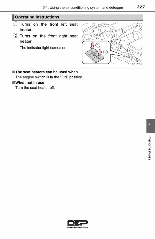
3276-1. Using the air conditioning system and defogger
6
Interior features
Turns on the front left seatheater
Turns on the front right seatheater
The indicator light comes on.
■The seat heaters can be used whenThe engine switch is in the “ON” position.
■When not in useTurn the seat heater off.
Operating instructions
1
2

328 6-2. Using the interior lights
Interior lights list
Off
Door position
On
Interior light (→P. 328)
Personal lights (→P. 329)
Interior light
1
2
1
2
3

3296-2. Using the interior lights
6
Interior features
On
Off
■ Illuminated entry systemThe lights automatically turn on/off according to the engine switch position,whether the doors are locked/unlocked, and whether the doors are opened/closed.
■To prevent the battery from being dischargedThe following lights will go off automatically after 20 minutes:
● Interior light
●Personal lights
●Luggage compartment light
Personal lights
1
2
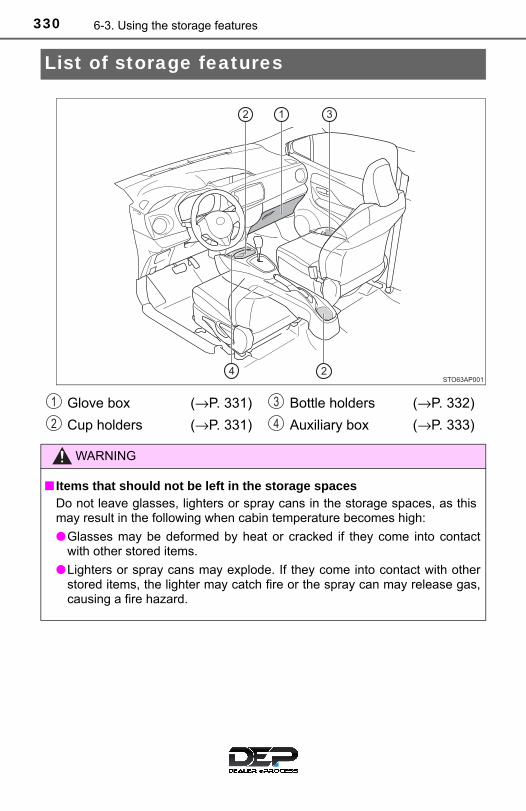
330 6-3. Using the storage features
List of storage features
Glove box (→P. 331)
Cup holders (→P. 331)
Bottle holders (→P. 332)
Auxiliary box (→P. 333)
WARNING
■ Items that should not be left in the storage spacesDo not leave glasses, lighters or spray cans in the storage spaces, as thismay result in the following when cabin temperature becomes high:
●Glasses may be deformed by heat or cracked if they come into contactwith other stored items.
●Lighters or spray cans may explode. If they come into contact with otherstored items, the lighter may catch fire or the spray can may release gas,causing a fire hazard.
1
2
3
4
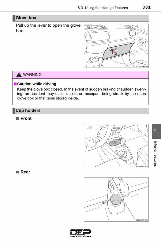
3316-3. Using the storage features
6
Interior features
Pull up the lever to open the glovebox.
■ Front
■ Rear
Glove box
WARNING
■Caution while drivingKeep the glove box closed. In the event of sudden braking or sudden swerv-ing, an accident may occur due to an occupant being struck by the openglove box or the items stored inside.
Cup holders

332 6-3. Using the storage features
■When using the bottle holder●When storing a bottle, close the cap.
●The bottle may not be stored depending on its size or shape.
WARNING
■ Items unsuitable for the cup holders●Do not place anything other than cups or aluminum cans in the cup hold-
ers. Other items may be thrown out of the holders in the event of an acci-dent or sudden braking, causing injury.
●To prevent burns, cover hot drinks when placed in the cup holders.
Bottle holders
WARNING
■ Items unsuitable for the bottle holdersDo not place anything other than a bottle in the bottle holders.Other items may be thrown out of the holders in the event of an accident orsudden braking and cause injury.
NOTICE
■ Items that should not be stowed in the bottle holdersPut the cap on before stowing a bottle. Do not place open bottles in the bot-tle holders, or glasses and paper cups containing liquid. The contents mayspill and glasses may break.

3336-3. Using the storage features
6
Interior features
Auxiliary box
Type A Type B
Open the cover.
Type C
WARNING
■Caution while driving (Type B)Keep the auxiliary boxes closed. In the event of sudden braking, an acci-dent may occur due to an occupant being struck by an open auxiliary box orthe items stored inside.

334 6-3. Using the storage features
Luggage compartment features
The luggage cover can be removed by the following procedure:
Unhook the cords and returnthe luggage cover to horizontalposition.
Lift the luggage cover and pull ittoward you to remove it.
Luggage cover
1
2

3356-3. Using the storage features
6
Interior features
■ Deck board height adjustment
Upper position
Lower position
The lower position can be usedwhen the deck board is placedon the luggage floor cover.
■ Removing the deck board
Lift up the deck board and pull ittoward you to remove it.
Deck board (if equipped)
1
2
WARNING
■When operating the deck boardDo not place anything on the deck board when operating the board. Other-wise, your fingers may be caught or an accident may result causing injuries.

336 6-4. Using the other interior features
Other interior features
To set the visor in the forwardposition, flip it down.
To set the visor in the side posi-tion, flip down, unhook, andswing it to the side.
To use the side extender, placethe visor in the side position,then slide it backward. (ifequipped)
Slide the cover to open.
Sun visors
1
2
3
Vanity mirrors
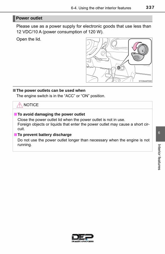
3376-4. Using the other interior features
6
Interior features
Please use as a power supply for electronic goods that use less than12 VDC/10 A (power consumption of 120 W).
Open the lid.
■The power outlets can be used whenThe engine switch is in the “ACC” or “ON” position.
Power outlet
NOTICE
■To avoid damaging the power outletClose the power outlet lid when the power outlet is not in use. Foreign objects or liquids that enter the power outlet may cause a short cir-cuit.
■To prevent battery dischargeDo not use the power outlet longer than necessary when the engine is notrunning.

338 6-4. Using the other interior features
An assist grip installed on the ceil-ing can be used to support yourbody while sitting on the seat.
Assist grips
WARNING
■Assist gripDo not use the assist grip when getting in or out of the vehicle or rising fromyour seat.Doing so could damage the assist grip, or could cause you to injure yourselfby falling over.
NOTICE
■To prevent damage to the assist gripDo not hang any heavy object or put a heavy load on the assist grip.

339
7Maintenance and care
7-1. Maintenance and care
Cleaning and protecting the vehicle exterior.......... 340
Cleaning and protecting the vehicle interior........... 344
7-2. Maintenance
Maintenance requirements................... 347
General maintenance........ 349
Emission inspection and maintenance (I/M) programs......................... 352
7-3. Do-it-yourself maintenance
Do-it-yourself service precautions ..................... 353
Hood ................................. 356
Positioning a floor jack ...... 358
Engine compartment......... 360
Tires .................................. 370
Tire inflation pressure ....... 378
Wheels .............................. 382
Air conditioning filter.......... 385
Wireless remote control battery............................. 388
Checking and replacing fuses ............................... 391
Light bulbs......................... 396

340 7-1. Maintenance and care
Cleaning and protecting the vehicle exterior
● Working from top to bottom, liberally apply water to the vehiclebody, wheel wells and underside of the vehicle to remove any dirtand dust.
● Wash the vehicle body using a sponge or soft cloth, such as achamois.
● For hard-to-remove marks, use car wash soap and rinse thoroughlywith water.
● Wipe away any water.
● Wax the vehicle when the waterproof coating deteriorates.
If water does not bead on a clean surface, apply wax when the vehiclebody is cool.
■Automatic car washes●Fold the mirrors and remove the antenna before washing the vehicle. Start
washing from the front of the vehicle. Make sure to re-install the antennaand extend the mirrors before driving.
●Brushes used in automatic car washes may scratch the vehicle surface andharm your vehicle’s paint.
●Rear spoiler (if equipped) may not be washable in some automatic carwashes. There may also be an increased risk of damage to vehicle.
■High pressure car washes●Do not allow the nozzles of the car wash to come within close proximity of
the windows and door borders, and high mounted stoplight.
●Before using the car wash, check that the fuel filler door on your vehicle isclosed properly.
Perform the following to protect the vehicle and maintain it inprime condition:

3417-1. Maintenance and care
7
Maintenan
ce and care
■Aluminum wheels (if equipped)●Remove any dirt immediately by using a neutral detergent. Do not use hard
brushes or abrasive cleaners. Do not use strong or harsh chemical clean-ers. Use the same mild detergent and wax as used on the paint.
●Do not use detergent on the wheels when they are hot, for example afterdriving for long distance in the hot weather.
●Wash detergent from the wheels immediately after use.
●To preserve the wheels’ luster, do not allow hot water, such as from steamcleaning, to contact them directly.
■BumpersDo not scrub with abrasive cleaners.
WARNING
■When cleaning the windshieldInstallation area of front sensor on windshield:→ P. 176
■When washing the vehicleDo not apply water to the inside of the engine compartment. Doing so maycause the electrical components, etc. to catch fire.
■Precautions regarding the exhaust pipesExhaust gases cause the exhaust pipes to become quite hot.
When washing the vehicle, be careful not to touch the pipes until they havecooled sufficiently, as touching hot exhaust pipes can cause burns.

342 7-1. Maintenance and care
NOTICE
■To prevent paint deterioration and corrosion on the body and compo-nents (aluminum wheels etc.)●Wash the vehicle immediately in the following cases:
• After driving near the sea coast• After driving on salted roads• If coal tar or tree sap is present on the paint surface• If dead insects, insect droppings or bird droppings are present on the
paint surface• After driving in an area contaminated with soot, oily smoke, mine dust,
iron powder or chemical substances• If the vehicle becomes heavily soiled with dust or mud• If liquids such as benzene and gasoline are spilled on the paint surface
● If the paint is chipped or scratched, have it repaired immediately.
●To prevent the wheels from corroding, remove any dirt and store in a placewith low humidity when storing the wheels.
■Cleaning the exterior lights●Wash carefully. Do not use organic substances or scrub with a hard brush.
This may damage the surfaces of the lights.
●Do not apply wax to the surfaces of the lights.Wax may cause damage to the lenses.
■Antenna installation and removal precautions●Before driving, ensure that the antenna is installed.
●When the antenna is removed, such as before entering an automatic carwash, make sure to store it in a suitable place so as not to lose it. Also,before driving, make sure to reinstall the antenna in its original position.
■To prevent damage to the antennaRemove the antenna in the following situations:
●When the antenna will touch the ceiling of a garage or other such places
●When a car cover is to be used to cover the vehicle

3437-1. Maintenance and care
7
Maintenan
ce and care
NOTICE
■When using a high pressure car wash●When washing the vehicle, do not let water of the high pressure washer hit
directly or the vicinity of the camera. Due to the shock from the high pres-sure water, it is possible the device may not operate as normal.
●Do not bring the nozzle tip close to boots (rubber or resin manufacturedcover), connectors or the following parts. The parts may be damaged ifthey come into contact with high-pressure water.
• Traction related parts• Steering parts• Suspension parts• Brake parts

344 7-1. Maintenance and care
Cleaning and protecting the vehicle interior
● Remove dirt and dust using a vacuum cleaner. Wipe dirty surfaceswith a cloth dampened with lukewarm water.
● If dirt cannot be removed, wipe it off with a soft cloth dampened withneutral detergent diluted to approximately 1%.Wring out any excess water from the cloth and thoroughly wipe offremaining traces of detergent and water.
● Remove dirt and dust using a vacuum cleaner.
● Wipe off any excess dirt and dust with a soft cloth dampened withdiluted detergent.
Use a diluted water solution of approximately 5% neutral wool detergent.● Wring out any excess water from the cloth and thoroughly wipe off
all remaining traces of detergent.
● Wipe the surface with a dry, soft cloth to remove any remainingmoisture. Allow the leather to dry in a shaded and ventilated area.
● Remove dirt and dust using a vacuum cleaner.
● Wipe it off with a soft cloth dampened with neutral detergent dilutedto approximately 1%.
● Wring out any excess water from the cloth and thoroughly wipe offremaining traces of detergent and water.
The following procedures will help protect your vehicle’s interiorand keep it in top condition:
Protecting the vehicle interior
Cleaning the leather areas
Cleaning the synthetic leather areas

3457-1. Maintenance and care
7
Maintenan
ce and care
■Caring for leather areasToyota recommends cleaning the interior of the vehicle at least twice a year tomaintain the quality of the vehicle’s interior.
■Shampooing the carpetsThere are several commercial foaming-type cleaners available. Use a spongeor brush to apply the foam. Rub in overlapping circles. Do not use water.Wipe dirty surfaces and let them dry. Excellent results are obtained by keep-ing the carpet as dry as possible.
■Seat beltsClean with mild soap and lukewarm water using a cloth or sponge. Alsocheck the belts periodically for excessive wear, fraying or cuts.
WARNING
■Water in the vehicle●Do not splash or spill liquid in the vehicle.
Doing so may cause electrical components, etc., to malfunction or catchfire.
●Do not get any of the SRS components or wiring in the vehicle interior wet. (→P. 38)An electrical malfunction may cause the airbags to deploy or not functionproperly, resulting in death or serious injury.
■Cleaning the interior (especially instrument panel)Do not use a polish wax or polish cleaner. The instrument panel may reflectoff the windshield, obstructing the driver’s view and leading to an accident,resulting in death or serious injury.
346 7-1. Maintenance and care
NOTICE
■Cleaning detergents●Do not use the following types of detergent, as they may discolor the vehi-
cle interior or cause streaks or damage to painted surfaces:
• Non-seat portions: Organic substances such as benzene or gasoline,alkaline or acidic solutions, dye, and bleach
• Seats: Alkaline or acidic solutions, such as thinner, benzene, and alco-hol
●Do not use a polish wax or polish cleaner. The instrument panel’s or otherinterior part’s painted surface may be damaged.
■Preventing damage to leather surfacesObserve the following precautions to avoid damage to and deterioration ofleather surfaces:
●Remove any dust or dirt from leather surfaces immediately.
●Do not expose the vehicle to direct sunlight for extended periods of time.Park the vehicle in the shade, especially during summer.
●Do not place items made of vinyl, plastic, or containing wax on the uphol-stery, as they may stick to the leather surface if the vehicle interior heatsup significantly.
■Water on the floorDo not wash the vehicle floor with water.Vehicle systems such as the audio system may be damaged if water comesinto contact with electrical components such as the audio system above orunder the floor of the vehicle. Water may also cause the body to rust.
■When cleaning the inside of the windshield (vehicles with ToyotaSafety Sense C)Be careful not to touch the front sensor (→P. 173).If the camera is accidentally scratched or hit, PCS, LDA and Automatic HighBeam may not operate properly or may cause a malfunction.
■Cleaning the inside of the rear window●Do not use glass cleaner to clean the rear window, as this may cause
damage to the rear window defogger heater wires. Use a cloth dampenedwith lukewarm water to gently wipe the window clean. Wipe the window instrokes running parallel to the heater wires.
●Be careful not to scratch or damage the heater wires.

3477-2. Maintenance
7
Maintenan
ce and care
Maintenance requirements
General maintenance should be performed on a daily basis. This canbe done by yourself or by a Toyota dealer.
Scheduled maintenance should be performed at specified intervalsaccording to the maintenance schedule.
For details about maintenance items and schedules, refer to the “Sched-uled Maintenance Guide” or “Owner’s Manual Supplement”.
You can perform some maintenance procedures by yourself.Please be aware that do-it-yourself maintenance may affect warrantycoverage.
The use of Toyota Repair Manuals is recommended.
For details about warranty coverage, see the separate “Owner’s WarrantyInformation Booklet” or “Owner’s Manual Supplement”.
■Repair and replacementIt is recommended that genuine Toyota parts be used for repairs to ensureperformance of each system. If non-Toyota parts are used in replacement or ifa repair shop other than a Toyota dealer performs repairs, confirm the war-ranty coverage.
To ensure safe and economical driving, day-to-day care and reg-ular maintenance are essential. It is the owner’s responsibility toperform regular checks. Toyota recommends the following main-tenance:
General maintenance
Scheduled maintenance
Do-it-yourself maintenance

348 7-2. Maintenance
■Resetting the maintenance required reminder light (except Canada)After the required maintenance is performed according to the maintenanceschedule, please reset the reminder light. To reset the reminder light, follow the procedures described below:
Switch the display to the trip meter “A” when the engine is running. (→P. 85)
Turn the engine switch to the “LOCK” position.
While pressing the display change button (→P. 85), turn the engineswitch to the “ON” position (do not start the engine because reset modewill be canceled). Continue to press and hold the button until the tripmeter displays “000000”.
■Allow inspection and repairs to be performed by a Toyota dealer●Toyota technicians are well-trained specialists and are kept up to date with
the latest service information. They are well informed about the operationsof all systems on your vehicle.
●Keep a copy of the repair order. It proves that the maintenance that hasbeen performed is under warranty coverage. If any problem should arisewhile your vehicle is under warranty, your Toyota dealer will promptly takecare of it.
WARNING
■ If your vehicle is not properly maintainedImproper maintenance could result in serious damage to the vehicle andpossible death or serious injury.
■Handling of the battery●Engine exhaust, some of its constituents, and a wide variety of automobile
components contain or emit chemicals known to the State of California tocause cancer and birth defects and other reproductive harm. Work in awell ventilated area.
●Oils, fuels and fluids contained in vehicles as well as waste produced bycomponent wear contain or emit chemicals known to the State of Califor-nia to cause cancer and birth defects or other reproductive harm. Avoidexposure and wash any affected area immediately.
●Battery posts, terminals and related accessories contain lead and leadcompounds which are known to cause brain damage. Wash your handsafter handling. (→P. 367)
1
2
3

3497-2. Maintenance
7
Maintenan
ce and care
General maintenance
Listed below are the general maintenance items that should beperformed at the intervals specified in the “Owner’s WarrantyInformation Booklet” or “Owner’s Manual Supplement/Sched-uled Maintenance Guide”. It is recommended that any problemyou notice should be brought to the attention of your Toyotadealer or qualified service shop for advice.
Engine compartment
Items Check points
Battery Check the battery fluid and connections. (→P. 367)
Brake fluid Is the brake fluid at the correct level? (→P. 366)
Engine coolant Is the engine coolant at the correct level?(→P. 364)
Engine oil Is the engine oil at the correct level? (→P. 361)
Exhaust system There should not be any fumes or strange sounds.
Radiator/condenserThe radiator and condenser should be free from for-eign objects. (→P. 365)
Washer fluid Is there sufficient washer fluid? (→P. 369)
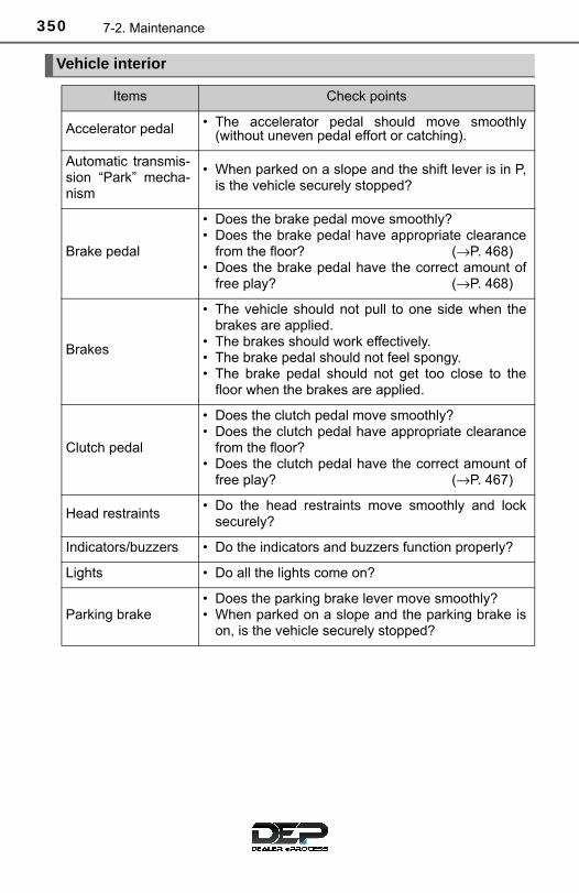
350 7-2. Maintenance
Vehicle interior
Items Check points
Accelerator pedal • The accelerator pedal should move smoothly(without uneven pedal effort or catching).
Automatic transmis-sion “Park” mecha-nism
• When parked on a slope and the shift lever is in P,is the vehicle securely stopped?
Brake pedal
• Does the brake pedal move smoothly?• Does the brake pedal have appropriate clearance
from the floor? (→P. 468)• Does the brake pedal have the correct amount of
free play? (→P. 468)
Brakes
• The vehicle should not pull to one side when thebrakes are applied.
• The brakes should work effectively.• The brake pedal should not feel spongy.• The brake pedal should not get too close to the
floor when the brakes are applied.
Clutch pedal
• Does the clutch pedal move smoothly?• Does the clutch pedal have appropriate clearance
from the floor?• Does the clutch pedal have the correct amount of
free play? (→P. 467)
Head restraints• Do the head restraints move smoothly and lock
securely?
Indicators/buzzers • Do the indicators and buzzers function properly?
Lights • Do all the lights come on?
Parking brake• Does the parking brake lever move smoothly?• When parked on a slope and the parking brake is
on, is the vehicle securely stopped?

3517-2. Maintenance
7
Maintenan
ce and care
Seat belts • Do the seat belts operate smoothly?• The seat belts should not be damaged.
Seats • Do the seat controls operate properly?
Steering wheel
• Does the steering wheel rotate smoothly?• Does the steering wheel have the correct amount
of free play?• There should not be any strange sounds coming
from the steering wheel.
Vehicle exterior
Items Check points
Items Check points
Doors • Do the doors operate smoothly?
Engine hood • Does the engine hood lock system work properly?
Fluid leaks • There should not be any signs of fluid leakageafter the vehicle has been parked.
Tire
• Is the tire inflation pressure correct?• The tires should not be damaged or excessively
worn.• Have the tires been rotated according to the
maintenance schedule?• The wheel nuts should not be loose.
WARNING
■ If the engine is runningTurn the engine off and ensure that there is adequate ventilation before per-forming maintenance checks.
352 7-2. Maintenance
Emission inspection and maintenance (I/M) programs
The OBD system determines that a problem exists somewhere in theemission control system. Your vehicle may not pass the I/M test andmay need to be repaired. Contact your Toyota dealer to service thevehicle.
● When the battery is disconnected or discharged
Readiness codes that are set during ordinary driving are erased.Also, depending on your driving habits, the readiness codes maynot be completely set.
● When the fuel tank cap is loose
The malfunction indicator lamp comes on indicating a temporarymalfunction and your vehicle may not pass the I/M test.
The error code in the OBD system will not be cleared unless the vehi-cle is driven 40 or more times.
Contact your Toyota dealer to prepare the vehicle for re-testing.
Some states have vehicle emission inspection programs whichinclude OBD (On Board Diagnostics) checks. The OBD systemmonitors the operation of the emission control system.
If the malfunction indicator lamp comes on
Your vehicle may not pass the I/M test in the following situations:
When the malfunction indicator lamp still remains on after sev-eral driving trips
If your vehicle does not pass the I/M test

3537-3. Do-it-yourself maintenance
7
Maintenan
ce and care
Do-it-yourself service precautions
If you perform maintenance by yourself, be sure to follow thecorrect procedure as given in these sections.
Items Parts and tools
Battery condition (→P. 367)
• Warm water • Baking soda • Grease• Conventional wrench (for terminal clamp bolts)• Distilled water
Brake fluid level(→P. 366)
• FMVSS No.116 DOT 3 or SAE J1703; FMVSS No.116 DOT 4 or SAE J1704 brake fluid
• Rag or paper towel• Funnel (used only for adding brake fluid)
Engine coolant level (→P. 364)
• “Toyota Super Long Life Coolant” or a similar highquality ethylene glycol-based non-silicate, non-amine, non-nitrite and non-borate coolant with long-life hybrid organic acid technologyExcept Canada
“Toyota Super Long Life Coolant” is pre-mixed with50% coolant and 50% deionized water.Canada
“Toyota Super Long Life Coolant” is pre-mixed with55% coolant and 45% deionized water.
• Funnel (used only for adding engine coolant)
Engine oil level (→P. 361)
• “Toyota Genuine Motor Oil” or equivalent• Rag or paper towel• Funnel (used only for adding engine oil)

354 7-3. Do-it-yourself maintenance
Fuses (→P. 391)
• Fuse with same amperage rating as original
Light bulbs (→P. 396)
• Bulb with same number and wattage rating as origi-nal
• Phillips-head screwdriver
• Flathead screwdriver • Wrench
Radiator and condenser (→P. 365)
⎯
Tire inflation pressure (→P. 378)
• Tire pressure gauge• Compressed air source
Washer fluid (→P. 369)
• Water or washer fluid containing antifreeze (for win-ter use)
• Funnel (used only for adding water or washer fluid)
Windshield wiper/rear window wiper
• The wiper blades should not show any signs ofcracking, splitting, wear, contamination or deforma-tion.
• The wiper blades should clear the windshield/rearwindow without streaking or skipping.
Items Parts and tools

3557-3. Do-it-yourself maintenance
7
Maintenan
ce and care
WARNING
The engine compartment contains many mechanisms and fluids that maymove suddenly, become hot, or become electrically energized. To avoid deathor serious injury, observe the following precautions.
■When working on the engine compartment●Keep hands, clothing and tools away from the moving fan and engine
drive belt.
●Be careful not to touch the engine, radiator, exhaust manifold, etc., rightafter driving as they may be hot. Oil and other fluids may also be hot.
●Do not leave anything that may burn easily, such as paper and rags, in theengine compartment.
●Do not smoke, cause sparks or expose an open flame to fuel on the bat-tery. Fuel and battery fumes are flammable.
●Be extremely cautious when working on the battery. It contains poisonousand corrosive sulfuric acid.
■When working near the electric cooling fan or radiator grilleBe sure the engine switch is in the “LOCK” position. With the engine switch in the “ON” position, the electric cooling fan mayautomatically start to run if the air conditioning is on and/or the coolant tem-perature is high. (→P. 365)
■Safety glassesWear safety glasses to prevent flying or falling material, fluid spray, etc.from getting in your eyes.
NOTICE
■ If you remove the air cleaner filterDriving with the air cleaner filter removed may cause excessive engine weardue to dirt in the air.

356 7-3. Do-it-yourself maintenance
Hood
Pull the hood lock release lever.
The hood will pop up slightly.
Pull up the auxiliary catch leverand lift the hood.
Hold the hood open by insertingthe supporting rod into the slot.
Release the lock from the inside of the vehicle to open the hood.
1
2
3

3577-3. Do-it-yourself maintenance
7
Maintenan
ce and care
WARNING
■Pre-driving checkCheck that the hood is fully closed and locked. If the hood is not locked properly, it may open while the vehicle is in motionand cause an accident, which may result in death or serious injury.
■When opening the hoodMake sure the rod supports the hood securely from falling down on to yourhead or body.
NOTICE
■When closing the hoodBe sure to return the support rod to its clip before closing the hood. Closingthe hood with the support rod not clipped could cause the hood to bend.

358 7-3. Do-it-yourself maintenance
Positioning a floor jack
◆ Front
◆ Rear
When using a floor jack, follow the instructions in the manualprovided with the jack and perform the operation safety.
When raising your vehicle with a floor jack, position the jack cor-rectly. Improper placement may damage your vehicle or causeinjury.

3597-3. Do-it-yourself maintenance
7
Maintenan
ce and care
NOTICE
■When raising your vehicle
Do not jack the vehicle at the suspen-sion. The suspension may be damaged.
Front
Suspension

360 7-3. Do-it-yourself maintenance
Engine compartment
Fuse boxes (→P. 391)
Engine oil filler cap(→P. 362)
Battery (→P. 367)
Brake fluid reservoir (→P. 366)
Radiator (→P. 365)
Condenser (→P. 365)
Electric cooling fan
Engine coolant reservoir (→P. 364)
Engine oil level dipstick (→P. 361)
Washer fluid tank (→P. 369)
1
2
3
4
5
6
7
8
9
10

3617-3. Do-it-yourself maintenance
7
Maintenan
ce and care
With the engine at operating temperature and turned off, check the oillevel on the dipstick.
■ Checking the engine oil
Park the vehicle on level ground. After warming up the engineand turning it off, wait more than 5 minutes for the oil to drainback into the bottom of the engine.
Holding a rag under the end,pull the dipstick out.
Wipe the dipstick clean.
Reinsert the dipstick fully.
Holding a rag under the end, pull the dipstick out and check theoil level.
Low
Normal
Excessive
The shape of the dipstick may differ depending on the type ofvehicle or engine.
Wipe the dipstick and reinsert it fully.
Engine oil
1
2
3
4
5
1
2
3
Non-flat dipstick Flat dipstick
6

362 7-3. Do-it-yourself maintenance
■ Adding engine oil
If the oil level is below or nearthe low level mark, add engineoil of the same type as thatalready in the engine.
Make sure to check the oil type and prepare the items neededbefore adding oil.
Remove the oil filler cap by turning it counterclockwise.
Add engine oil slowly, checking the dipstick.
Install the oil filler cap by turning it clockwise.
■Engine oil consumptionA certain amount of engine oil will be consumed while driving. In the followingsituations, oil consumption may increase, and engine oil may need to berefilled in between oil maintenance intervals.
●When the engine is new, for example directly after purchasing the vehicle orafter replacing the engine
● If low quality oil or oil of an inappropriate viscosity is used
●When driving at high engine speeds or with a heavy load, or when drivingwhile accelerating or decelerating frequently
●When leaving the engine idling for a long time, or when driving frequentlythrough heavy traffic
Engine oil selection →P. 464
Oil quantity (Low → Full)
1.6 qt. (1.5 L, 1.3 Imp.qt.)
Items Clean funnel
1
2
3

3637-3. Do-it-yourself maintenance
7
Maintenan
ce and care
WARNING
■Used engine oil●Used engine oil contains potentially harmful contaminants which may
cause skin disorders such as inflammation and skin cancer, so careshould be taken to avoid prolonged and repeated contact. To remove usedengine oil from your skin, wash thoroughly with soap and water.
●Dispose of used oil and filters only in a safe and acceptable manner. Donot dispose of used oil and filters in household trash, in sewers or onto theground. Call your Toyota dealer, service station or auto parts store for informationconcerning recycling or disposal.
●Do not leave used engine oil within the reach of children.
NOTICE
■To prevent serious engine damageCheck the oil level on a regular basis.
■When replacing the engine oil●Be careful not to spill engine oil on the vehicle components.
●Avoid overfilling, or the engine could be damaged.
●Check the oil level on the dipstick every time you refill the vehicle.
●Be sure the engine oil filler cap is properly tightened.

364 7-3. Do-it-yourself maintenance
The coolant level is satisfactory if it is between the “FULL” and “LOW”lines on the reservoir when the engine is cold.
Reservoir cap
“FULL” line
“LOW” line
If the level is on or below the“LOW” line, add coolant up tothe “FULL” line.
■Coolant selectionOnly use “Toyota Super Long Life Coolant” or a similar high quality ethyleneglycol based non-silicate, non-amine, non-nitrite, and non-borate coolant withlong-life hybrid organic acid technology.
Except Canada
“Toyota Super Long Life Coolant” is a mixture of 50% coolant and 50% deion-ized water. (Minimum temperature: -31°F [-35°C])
Canada
“Toyota Super Long Life Coolant” is a mixture of 55% coolant and 45% deion-ized water. (Minimum temperature: -44°F [-42°C])
For more details about coolant, contact your Toyota dealer.
■ If the coolant level drops within a short time of replenishingVisually check the radiator, hoses, engine coolant reservoir caps, radiatorcap, drain cock and water pump. If you cannot find a leak, have your Toyota dealer test the cap and check forleaks in the cooling system.
Engine coolant
1
2
3
3657-3. Do-it-yourself maintenance
7
Maintenan
ce and care
Check the radiator and condenser and clear away any foreign objects. If any of the above parts is extremely dirty or you are not sure of theircondition, have your vehicle inspected by your Toyota dealer.
WARNING
■When the engine is hotDo not remove the radiator cap. The cooling system may be under pressure and may spray hot coolant if thecap is removed, causing serious injuries, such as burns.
NOTICE
■When adding coolantCoolant is neither plain water nor straight antifreeze. The correct mixture ofwater and antifreeze must be used to provide proper lubrication, corrosionprotection and cooling. Be sure to read the antifreeze or coolant label.
■ If you spill coolantBe sure to wash it off with water to prevent it from damaging parts or paint.
Radiator and condenser
WARNING
■When the engine is hotDo not touch the radiator or condenser as they may be hot and cause seri-ous injuries, such as burns.

366 7-3. Do-it-yourself maintenance
■ Checking fluid level
The brake fluid level should bebetween the “MAX” and “MIN”lines on the tank.
■ Adding fluid
Make sure to check the fluid type and prepare the necessary item.
■Brake fluid can absorb moisture from the airExcess moisture in the brake fluid can cause a dangerous loss of braking effi-ciency. Use only newly opened brake fluid.
Brake fluid
Fluid typeFMVSS No.116 DOT 3 or SAE J1703; FMVSS No.116 DOT 4 or SAE J1704 brake fluid
Item Clean funnel
WARNING
■When filling the reservoirTake care as brake fluid can harm your hands and eyes and damagepainted surfaces.If fluid gets on your hands or in your eyes, flush the affected area with cleanwater immediately.
If you still experience discomfort, consult a doctor.
NOTICE
■ If the fluid level is low or highIt is normal for the brake fluid level to go down slightly as the brake padswear out or when the fluid level in the accumulator is high.If the reservoir needs frequent refilling, there may be a serious problem.

3677-3. Do-it-yourself maintenance
7
Maintenan
ce and care
Check the battery as follows.
■ Battery exterior
Make sure that the battery terminals are not corroded and thatthere are no loose connections, cracks, or loose clamps.
Terminals
Hold-down clamp
■Before rechargingWhen recharging, the battery produces hydrogen gas which is flammable andexplosive. Therefore, observe the following before recharging:
● If recharging with the battery installed on the vehicle, be sure to disconnectthe ground cable.
●Make sure the power switch on the charger is off when connecting and dis-connecting the charger cables to the battery.
Battery
1
2
WARNING
■Chemicals in the batteryBatteries contain poisonous and corrosive sulfuric acid and may producehydrogen gas which is flammable and explosive. To reduce the risk of deathor serious injury, take the following precautions while working on or near thebattery:
●Do not cause sparks by touching the battery terminals with tools.
●Do not smoke or light a match near the battery.
●Avoid contact with eyes, skin and clothes.
●Never inhale or swallow electrolyte.
●Wear protective safety glasses when working near the battery.
●Keep children away from the battery.

368 7-3. Do-it-yourself maintenance
WARNING
■Where to safely charge the batteryAlways charge the battery in an open area. Do not charge the battery in agarage or closed room where there is insufficient ventilation.
■How to recharge the batteryOnly perform a slow charge (5 A or less). The battery may explode ifcharged at a quicker rate.
■Emergency measures regarding electrolyte● If electrolyte gets in your eyes
Flush your eyes with clean water for at least 15 minutes and get immedi-ate medical attention. If possible, continue to apply water with a sponge orcloth while traveling to the nearest medical facility.
● If electrolyte gets on your skinWash the affected area thoroughly. If you feel pain or burning, get medicalattention immediately.
● If electrolyte gets on your clothesIt can soak through clothing on to your skin. Immediately take off the cloth-ing and follow the procedure above if necessary.
● If you accidentally swallow electrolyteDrink a large quantity of water or milk. Get emergency medical attentionimmediately.
NOTICE
■When recharging the batteryNever recharge the battery while the engine is running. Also, be sure allaccessories are turned off.

3697-3. Do-it-yourself maintenance
7
Maintenan
ce and care
Add washer fluid in the followingsituations:● A washer does not work.
● The warning light comes on (ifequipped).
Washer fluid
WARNING
■When adding washer fluidDo not add washer fluid when the engine is hot or running as washer fluidcontains alcohol and may catch fire if spilled on the engine, etc.
NOTICE
■Do not use any fluid other than washer fluid Do not use soapy water or engine antifreeze instead of washer fluid.Doing so may cause streaking on the vehicle’s painted surfaces.
■Diluting washer fluidDilute washer fluid with water as necessary. Refer to the freezing temperatures listed on the label of the washer fluid bot-tle.

370 7-3. Do-it-yourself maintenance
Tires
Check if the treadwear indicators are showing on the tires. Also checkthe tires for uneven wear, such as excessive wear on one side of thetread.
Check the spare tire condition and pressure if not rotated.
New tread
Worn tread
Treadwear indicator
The location of treadwear indicators is shown by a “TWI” or “Δ”mark, etc., molded into the sidewall of each tire.Replace the tires if the treadwear indicators are showing on atire.
Replace or rotate tires in accordance with maintenance sched-ules and treadwear.
Checking tires
1
2
3

3717-3. Do-it-yourself maintenance
7
Maintenan
ce and care
Rotate the tires in the ordershown.
To equalize tire wear and extendtire life, Toyota recommends thattire rotation is carried out at thesame interval as tire inspection.
Vehicles with P195/50R16 tires:
Do not fail to initialize the tirepressure warning system aftertire rotation.
Your vehicle is equipped with a tire pressure warning system that usestire pressure warning valves and transmitters to detect low tire infla-tion pressure before serious problems arise. (→P. 426)
The compact spare tire is not equipped with a tire pressure warningvalve and transmitter.
◆ Installing tire pressure warning valves and transmitters
When replacing tires or wheels, tire pressure warning valves andtransmitters must also be installed. When new tire pressure warning valves and transmitters are installed,new ID codes must be registered in the tire pressure warning com-puter and the tire pressure warning system must be initialized. Havetire pressure warning valve and transmitter ID codes registered byyour Toyota dealer. (→P. 372)
◆ Initializing the tire pressure warning system
■ The tire pressure warning system must be initialized in the fol-lowing circumstances:● For vehicles with P195/50R16 tires, when rotating front and rear
tires which have different tire inflation pressures● When changing the tire size
When the tire pressure warning system is initialized, the current tireinflation pressure is set as the benchmark pressure.
Tire rotation
Front
Tire pressure warning system (if equipped)
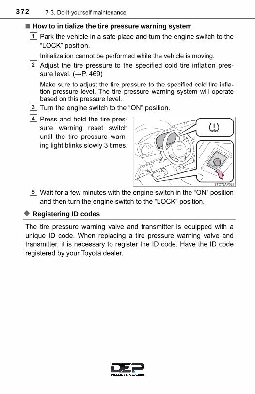
372 7-3. Do-it-yourself maintenance
■ How to initialize the tire pressure warning system
Park the vehicle in a safe place and turn the engine switch to the“LOCK” position.
Initialization cannot be performed while the vehicle is moving.
Adjust the tire pressure to the specified cold tire inflation pres-sure level. (→P. 469)
Make sure to adjust the tire pressure to the specified cold tire infla-tion pressure level. The tire pressure warning system will operatebased on this pressure level.
Turn the engine switch to the “ON” position.
Press and hold the tire pres-sure warning reset switchuntil the tire pressure warn-ing light blinks slowly 3 times.
Wait for a few minutes with the engine switch in the “ON” positionand then turn the engine switch to the “LOCK” position.
◆ Registering ID codes
The tire pressure warning valve and transmitter is equipped with aunique ID code. When replacing a tire pressure warning valve andtransmitter, it is necessary to register the ID code. Have the ID coderegistered by your Toyota dealer.
1
2
3
4
5

3737-3. Do-it-yourself maintenance
7
Maintenan
ce and care
■When to replace your vehicle’s tiresTires should be replaced if:
●The treadwear indicators are showing on a tire.
●You have tire damage such as cuts, splits, cracks deep enough toexpose the fabric, and bulges indicating internal damage
●A tire goes flat repeatedly or cannot be properly repaired due to the sizeor location of a cut or other damage
If you are not sure, consult with your Toyota dealer.
■Replacing tires and wheels (vehicles with a tire pressure warningsystem)If the ID code of the tire pressure warning valve and transmitter is not reg-istered, the tire pressure warning system will not work properly. After driv-ing for about 20 minutes, the tire pressure warning light blinks for 1minute and stays on to indicate a system malfunction.
■Tire lifeAny tire over 6 years old must be checked by a qualified technician evenif it has seldom or never been used or damage is not obvious.
■Routine tire inflation pressure checks (vehicles with a tire pressurewarning system)The tire pressure warning system does not replace routine tire inflationpressure checks. Make sure to check tire inflation pressure as part ofyour routine of daily vehicle checks.
■Low profile tires (vehicles with 195/50R16 tires)Generally, low profile tires will wear more rapidly and tire grip perfor-mance will be reduced on snowy and/or icy roads when compared tostandard tires. Be sure to use snow tires or tire chains on snowy and/oricy roads and drive carefully at a speed appropriate for road and weatherconditions.

374 7-3. Do-it-yourself maintenance
■Maximum load of tireCheck that the maximum load of the replacement tire is greater than 1/2of the Gross Axle Weight Ratings (GAWR) of either the front axle or therear axle, whichever is greater.
■Tire types●Summer tires
Summer tires are high-speed performance tires best suited to highwaydriving under dry conditions. Since summer tires do not have the sametraction performance as snow tires, summer tires are inadequate fordriving on snow-covered or icy roads. For driving on snow-coveredroads or icy roads, the use of snow tires is recommended. When install-ing snow tires, be sure to replace all four tires.
●All season tires
All season tires are designed to provide better traction in snow and tobe adequate for driving in most winter conditions as well as for useyear-round. All season tires, however, do not have adequate tractionperformance compared with snow tires in heavy or loose snow. Also, allseason tires fall short in acceleration and handling performance com-pared with summer tires in highway driving.
●Snow tires
For driving on snow-covered roads or icy roads, we recommend usingsnow tires. If you need snow tires, select tires of the same size, con-struction and load capacity as the originally installed tires. Since yourvehicle has radial tires as original equipment, make sure your snowtires also have radial construction. Do not install studded tires withoutfirst checking local regulations for possible restrictions. Snow tiresshould be installed on all wheels. (→P. 221)
For the GAWR, see the CertificationLabel. For the maximum load of the tire,see the load limit at maximum cold tireinflation pressure mentioned on thesidewall of the tire. (→P. 474)

3757-3. Do-it-yourself maintenance
7
Maintenan
ce and care
■ Initializing the tire pressure warning system (vehicles with a tirepressure warning system)Initialize the system with the tire inflation pressure adjusted to the speci-fied level.
■ If the tread on snow tires wears down below 0.16 in. (4 mm)The effectiveness of the tires as snow tires is lost.
■ If you press the tire pressure warning reset switch accidentally (vehi-cles with a tire pressure warning system)If initialization is performed, adjust the tire inflation pressure to the speci-fied level and initialize the tire pressure warning system again.
■When the initialization of the tire pressure warning system has failed(vehicles with a tire pressure warning system)Initialization can be completed in a few minutes. However, in the followingcases, the settings has not been recorded and the system will not operateproperly. If repeated attempts to record tire inflation pressure settings areunsuccessful, have the vehicle inspected by your Toyota dealer.
●When operating the tire pressure warning reset switch, the tire pressurewarning light does not blink 3 times.
●After driving for a certain period of time since the initialization has beencompleted, the warning light comes on after blinks for 1 minute.
■Certification for the tire pressure warning systemFCC ID: PAXPMVC010
FCC ID: HYQ23AAD
NOTE: This device complies with part 15 of the FCC Rules. Operation is subjectto the following two conditions: (1) This device may not cause harmfulinterference, and (2) this device must accept any interference received,including interference that may cause undesired operation.
FCC WARNING: Changes or modifications not expressly approved by the party responsi-ble for compliance could void the user’s authority to operate the equip-ment.

376 7-3. Do-it-yourself maintenance
WARNING
■When inspecting or replacing tiresObserve the following precautions to prevent accidents.Failure to do so may cause damage to parts of the drive train as well asdangerous handling characteristics, which may lead to an accidentresulting in death or serious injury.
●Do not mix tires of different makes, models or tread patterns.Also, do not mix tires of remarkably different treadwear.
●Do not use tire sizes other than those recommended by Toyota.
●Do not mix differently constructed tires (radial, bias-belted or bias-plytires).
●Do not mix summer, all season and snow tires.
●Do not use tires that have been used on another vehicle.Do not use tires if you do not know how they were used previously.
●Do not tow if your vehicle has a compact spare tire installed.
■When initializing the tire pressure warning system (vehicles with atire pressure warning system)Do not operate the tire pressure warning reset switch without firstadjusting the tire inflation pressure to the specified level. Otherwise, thetire pressure warning light may not come on even if the tire inflationpressure is low, or it may come on when the tire inflation pressure isactually normal.

3777-3. Do-it-yourself maintenance
7
Maintenan
ce and care
NOTICE
■Repairing or replacing tires, wheels, tire pressure warning valves,transmitters and tire valve caps (vehicles with a tire pressure warn-ing system)●When removing or fitting the wheels, tires or the tire pressure warning
valves and transmitters, contact your Toyota dealer as the tire pres-sure warning valves and transmitters may be damaged if not handledcorrectly.
●Make sure to install the tire valve caps. If the tire valve caps are notinstalled, water could enter the tire pressure warning valves and thetire pressure warning valves could be bound.
●When replacing tire valve caps, do not use tire valve caps other thanthose specified. The cap may become stuck.
■To avoid damage to the tire pressure warning valves and transmit-ters (vehicles with a tire pressure warning system)When a tire is repaired with liquid sealants, the tire pressure warningvalve and transmitter may not operate properly. If a liquid sealant isused, contact your Toyota dealer or other qualified service shop as soonas possible. Make sure to replace the tire pressure warning valve andtransmitter when replacing the tire. (→P. 371)
■Driving on rough roadsTake particular care when driving on roads with loose surfaces or pot-holes.These conditions may cause losses in tire inflation pressure, reducingthe cushioning ability of the tires. In addition, driving on rough roadsmay cause damage to the tires themselves, as well as the vehicle’swheels and body.
■Low profile tires (vehicles with 195/50R16 tires)Low profile tires may cause greater damage than usual to the tire wheelwhen sustaining impact from the road surface. Therefore, pay attentionto the following:
●Be sure to use proper tire inflation pressure. If tires are under-inflated,they may be damaged more severely.
●Avoid potholes, uneven pavement, curbs and other road hazards. Fail-ure to do so may lead to severe tire and wheel damage.
■ If tire inflation pressure of each tire becomes low while drivingDo not continue driving, or your tires and/or wheels may be ruined.

378 7-3. Do-it-yourself maintenance
Tire inflation pressure
The recommended cold tire infla-tion pressure and tire size are dis-played on the tire and loadinginformation label. (→P. 469)

3797-3. Do-it-yourself maintenance
7
Maintenan
ce and care
Tire valve
Tire pressure gauge
Remove the tire valve cap.
Press the tip of the tire pressure gauge onto the tire valve.
Read the pressure using the gauge gradations.
If the tire inflation pressure is not at the recommended level, adjustthe pressure.If you add too much air, press the center of the valve to deflate.
After completing the tire inflation pressure measurement andadjustment, apply soapy water to the valve and check for leakage.
Put the tire valve cap back on.
Inspection and adjustment procedure
1
2
1
2
3
4
5
6

380 7-3. Do-it-yourself maintenance
■Tire inflation pressure check intervalYou should check tire inflation pressure every two weeks, or at least oncea month.Do not forget to check the spare.
■Effects of incorrect tire inflation pressureDriving with incorrect tire inflation pressure may result in the following:
●Reduced fuel economy
●Reduced driving comfort and poor handling
●Reduced tire life due to wear
●Reduced safety
●Damage to the drive train
If a tire needs frequent inflating, have it checked by your Toyota dealer.
■ Instructions for checking tire inflation pressureWhen checking tire inflation pressure, observe the following:
●Check only when the tires are cold.If your vehicle has been parked for at least 3 hours or has not beendriven for more than 1 mile or 1.5 km, you will get an accurate cold tireinflation pressure reading.
●Always use a tire pressure gauge.It is difficult to judge if a tire is properly inflated based only on its appear-ance.
● It is normal for the tire inflation pressure to be higher after driving asheat is generated in the tire. Do not reduce tire inflation pressure afterdriving.
●Never exceed the vehicle capacity weight.Passengers and luggage weight should be placed so that the vehicle isbalanced.

3817-3. Do-it-yourself maintenance
7
Maintenan
ce and care
WARNING
■Proper inflation is critical to save tire performanceKeep your tires properly inflated. If the tires are not properly inflated, the following conditions may occurwhich could lead to an accident resulting in death or serious injury:
●Excessive wear
●Uneven wear
●Poor handling
●Possibility of blowouts resulting from overheated tires
●Air leaking from between tire and wheel
●Wheel deformation and/or tire damage
●Greater possibility of tire damage while driving (due to road hazards,expansion joints, sharp edges in the road, etc.)
NOTICE
■When inspecting and adjusting tire inflation pressureBe sure to put the tire valve caps back on.If a valve cap is not installed, dirt or moisture may get into the valve andcause an air leak, resulting in decreased tire inflation pressure.

382 7-3. Do-it-yourself maintenance
Wheels
When replacing wheels, care should be taken to ensure that they areequivalent to those removed in load capacity, diameter, rim width andinset*.Replacement wheels are available at your Toyota dealer.*: Conventionally referred to as “offset”.
Toyota does not recommend using the following:● Wheels of different sizes or types
● Used wheels
● Bent wheels that have been straightened
● Use only Toyota wheel nuts and wrenches designed for use withyour aluminum wheels.
● When rotating, repairing or changing your tires, check that thewheel nuts are still tight after driving 1000 miles (1600 km).
● Be careful not to damage the aluminum wheels when using tirechains.
● Use only Toyota genuine balance weights or equivalent and a plas-tic or rubber hammer when balancing your wheels.
If a wheel is bent, cracked or heavily corroded, it should bereplaced. Otherwise, the tire may separate from the wheel orcause a loss of handling control.
Wheel selection
Aluminum wheel precautions (if equipped)

3837-3. Do-it-yourself maintenance
7
Maintenan
ce and care
■When replacing wheels (vehicles with a tire pressure warning sys-tem)The wheels of your vehicle, except for the compact spare tire, areequipped with tire pressure warning valves and transmitters that allow thetire pressure warning system to provide advance warning in the event ofa loss in tire inflation pressure. Whenever wheels are replaced, tire pres-sure warning valves and transmitters must be installed. (→P. 371)
WARNING
■When replacing wheels●Do not use wheels that are a different size from those recommended in
the Owner’s Manual, as this may result in a loss of handling control.
●Never use an inner tube in a leaking wheel which is designed for atubeless tire. Doing so may result in an accident, causing death or seri-ous injury.
■When installing the wheel nuts
●Never use oil or grease on the wheel bolts or wheel nuts. Oil and grease may cause the wheel nuts to be excessively tightened,leading to bolt or disc wheel damage. In addition, the oil or grease cancause the wheel nuts to loosen and the wheel may fall off, causing anaccident and resulting in death or serious injury. Remove any oil orgrease from the wheel bolts or wheel nuts.
■Use of defective wheels prohibitedDo not use cracked or deformed wheels. Doing so could cause the tire to leak air during driving, possibly causingan accident.
●Be sure to install the wheel nuts withthe tapered ends facing inward.Installing the nuts with the taperedends facing outward can cause thewheel to break and eventually causethe wheel to come off while driving,which could lead to an accidentresulting in death or serious injury.
Tapered portion
384 7-3. Do-it-yourself maintenance
NOTICE
■Replacing tire pressure warning valves and transmitters (vehicleswith a tire pressure warning system)●Because tire repair or replacement may affect the tire pressure warn-
ing valves and transmitters, make sure to have tires serviced by yourToyota dealer or other qualified service shop. In addition, make sure topurchase your tire pressure warning valves and transmitters at yourToyota dealer.
●Ensure that only genuine Toyota wheels are used on your vehicle.Tire pressure warning valves and transmitters may not work properlywith non-genuine wheels.
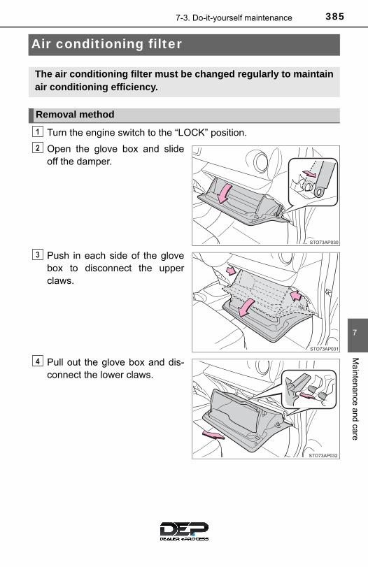
3857-3. Do-it-yourself maintenance
7
Maintenan
ce and care
Air conditioning filter
Turn the engine switch to the “LOCK” position.
Open the glove box and slideoff the damper.
Push in each side of the glovebox to disconnect the upperclaws.
Pull out the glove box and dis-connect the lower claws.
The air conditioning filter must be changed regularly to maintainair conditioning efficiency.
Removal method
1
2
3
4

386 7-3. Do-it-yourself maintenance
Remove the filter cover.
Unlock the filter cover.
Move the filter cover in thedirection of the arrow, andthen pull it out of the claws.
Remove the air conditioning fil-ter and replace it with a newone.
The “↑UP” marks shown on the fil-ter should be pointing up.
■Checking intervalInspect and replace the air conditioning filter according to the maintenanceschedule. In dusty areas or areas with heavy traffic flow, early replacementmay be required. (For scheduled maintenance information, please refer to the“Scheduled Maintenance Guide” or “Owner’s Manual Supplement”.)
■ If air flow from the vents decreases dramaticallyThe filter may be clogged. Check the filter and replace if necessary.
5
1
2
6

3877-3. Do-it-yourself maintenance
7
Maintenan
ce and care
NOTICE
■When using the air conditioning systemMake sure that a filter is always installed.Using the air conditioning system without a filter may cause damage to thesystem.
■When removing the glove boxAlways follow the specified procedure to remove the glove box (→P. 385). Ifthe glove box is removed without following the specified procedure, thehinge of the glove box may become damaged.
■To prevent damage to the filter cover
When moving the filter cover in the direc-tion of arrow to release the fitting, payattention not to apply excessive force tothe claws. Otherwise, the claws may bedamaged.

388 7-3. Do-it-yourself maintenance
Wireless remote control battery∗
● Flathead screwdriver
● Lithium battery CR2016
Type A
Remove the cover.
To prevent damage to the key,cover the tip of the screwdriver witha tape.
Remove the module.
Open the battery cover using acoin protected with tape etc.,and remove the depleted bat-tery.
Insert a new battery with the “+”terminal facing up.
∗: If equipped
Replace the battery with a new one if it is depleted.
You will need the following items:
Replacing the battery
1
2
3

3897-3. Do-it-yourself maintenance
7
Maintenan
ce and care
Type B
Remove the cover.
To prevent damage to the key,cover the tip of the screwdriver witha tape.
To prevent the buttons from beingdisassembled, face the button sur-face downward.
Remove the module.
Open the case cover andremove the depleted battery.
Insert a new battery with the “+”terminal facing up.
1
2
3

390 7-3. Do-it-yourself maintenance
■Use a CR2016 lithium battery●Batteries can be purchased at your Toyota dealer, local electrical appliance
shops or camera stores.
●Replace only with the same or equivalent type recommended by the manu-facturer.
●Dispose of used batteries according to local laws.
■ If the key battery is depleted The following symptoms may occur:
●The wireless remote control will not function properly.
●The operational range will be reduced.
■When replacing the module (type B only)
Replace the module from right above.Replacing it from diagonally above mayprevent the key buttons from operatingproperly.
WARNING
■Removed battery and other partsThese parts are small and if swallowed by a child, they can cause choking.Keep away from children. Failure to do so could result in death or seriousinjury.
NOTICE
■For normal operation after replacing the batteryObserve the following precautions to prevent accidents:
●Always work with dry hands.Moisture may cause the battery to rust.
●Do not touch or move any other component inside the remote control.
●Do not bend either of the battery terminals.

3917-3. Do-it-yourself maintenance
7
Maintenan
ce and care
Checking and replacing fuses
Turn the engine switch to the “LOCK” position.
Open the fuse box cover.
Engine compartment (type A fuse box)
Push the tab in and lift the lidoff.
Engine compartment (type B fuse box)
Push the tab in and lift the lidoff.
If any of the electrical components do not operate, a fuse mayhave blown. If this happens, check and replace the fuses as nec-essary.
1
2

392 7-3. Do-it-yourself maintenance
Engine compartment: type C fuse box
Pull the rubber strip on theedge to unhook it from thecover, and then push thetabs in and lift the cover off.
Remove the battery terminalcover and then the fuse boxcover.
Instrument panel
Remove the lid.
Remove the fuse with the pull-out tool.
Only type A fuse can be removedusing the pullout tool.
1
2
3
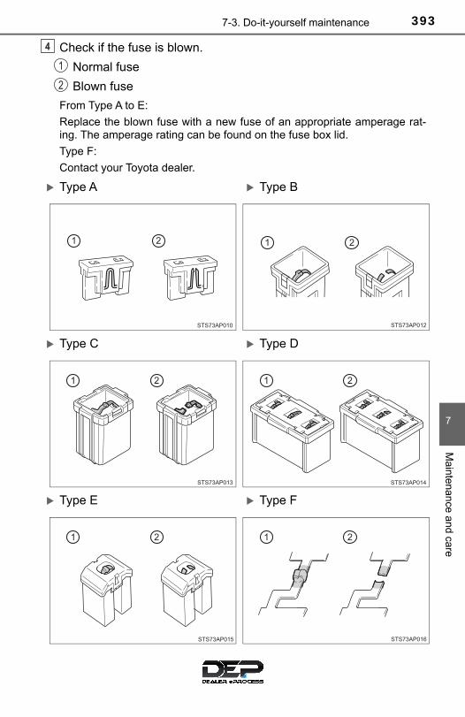
3937-3. Do-it-yourself maintenance
7
Maintenan
ce and care
Check if the fuse is blown.
Normal fuse
Blown fuse
From Type A to E:
Replace the blown fuse with a new fuse of an appropriate amperage rat-ing. The amperage rating can be found on the fuse box lid.
Type F:
Contact your Toyota dealer.
4
1
2
Type A Type B
Type C Type D
Type E Type F
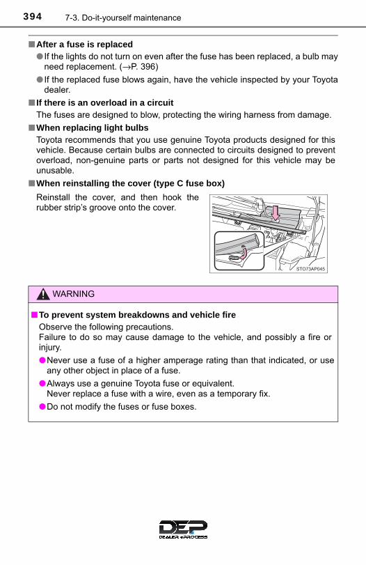
394 7-3. Do-it-yourself maintenance
■After a fuse is replaced● If the lights do not turn on even after the fuse has been replaced, a bulb may
need replacement. (→P. 396)
● If the replaced fuse blows again, have the vehicle inspected by your Toyotadealer.
■ If there is an overload in a circuitThe fuses are designed to blow, protecting the wiring harness from damage.
■When replacing light bulbsToyota recommends that you use genuine Toyota products designed for thisvehicle. Because certain bulbs are connected to circuits designed to preventoverload, non-genuine parts or parts not designed for this vehicle may beunusable.
■When reinstalling the cover (type C fuse box)
Reinstall the cover, and then hook therubber strip’s groove onto the cover.
WARNING
■To prevent system breakdowns and vehicle fireObserve the following precautions.Failure to do so may cause damage to the vehicle, and possibly a fire orinjury.
●Never use a fuse of a higher amperage rating than that indicated, or useany other object in place of a fuse.
●Always use a genuine Toyota fuse or equivalent.Never replace a fuse with a wire, even as a temporary fix.
●Do not modify the fuses or fuse boxes.

3957-3. Do-it-yourself maintenance
7
Maintenan
ce and care
NOTICE
■Before replacing fusesHave the cause of electrical overload determined and repaired by yourToyota dealer as soon as possible.

396 7-3. Do-it-yourself maintenance
Light bulbs
Check the wattage of the light bulb to be replaced. (→P. 470)
■ Front
Headlights and daytime running lights (if equipped)
Front turn signal lights and parking lights
Front side marker lights
Headlights
Front turn signal lights
Front fog lights (if equipped)
You may replace the following bulbs by yourself. The difficultylevel of replacement varies depending on the bulb. If necessarybulb replacement seems difficult to perform, contact yourToyota dealer.
For more information about replacing other light bulbs, contactyour Toyota dealer.
Preparing for light bulb replacement
Bulb locations
Projector type headlights
Reflector type headlights
1
2
3
4
5
6

3977-3. Do-it-yourself maintenance
7
Maintenan
ce and care
■ Rear
■ Headlights and daytime running lights (if equipped)
Vehicles with reflector type headlights
Unplug the connector.
Remove the rubber cover.
Stop/tail and rear sidemarker lights
Rear turn signal lights
Back-up lights
License plate lights
Replacing light bulbs
1
2
3
4
1
2

398 7-3. Do-it-yourself maintenance
Release the bulb retainingspring.
Push the bulb retainingspring and release fromthe hook.
Lift the bulb retainingspring.
Remove the bulb.
Set the new light bulb.
Align the 3 tabs on the light bulbwith the mounting and insert.
Install the bulb retainingspring.
Lower the bulb retainingspring.
Push the bulb retainingspring and then engageand fix the hook.
3
1
2
4
5
6
1
2

3997-3. Do-it-yourself maintenance
7
Maintenan
ce and care
Install the rubber cover.Ensure the rubber cover issecurely attached.
Fit the rubber cover outercircumference in firmly.
Fit the rubber coveraround the light bulb inuntil the light bulb plug canbe seen.
Plug the connector.
Vehicles with projector type headlights
Turn the bulb base counter-clockwise.
Pull the bulb out while press-ing the lock release of theconnector.
7
1
2
8
1
2

400 7-3. Do-it-yourself maintenance
Replace the light bulb, plugthe connector, and theninstall the bulb base.
Align the 3 tabs on the light bulbwith the mounting and insert.
Turn and secure the bulbbase.
Shake the bulb base gently tocheck that it is not loose, turnthe headlights on once and visu-ally confirm that no light is leak-ing through the mounting.
■ Front turn signal lights and parking lights/front turn signallights
Turn the bulb base counter-clockwise.
Remove the light bulb.
When installing, reverse the steps listed.
3
14
1
2
3

4017-3. Do-it-yourself maintenance
7
Maintenan
ce and care
■ Front side marker lights
Turn the bulb base counter-clockwise.
Remove the light bulb
When installing, reverse the steps listed.
■ Front fog lights (if equipped)
Turn the steering wheel andchange the tire direction tothe opposite direction of lightto be exchanged.
Remove the bolt.
1
2
3
1
2

402 7-3. Do-it-yourself maintenance
Remove the fender linerretainer.
Partly remove the fenderliner until the light bulb is visi-ble.
Unplug the connector whilepressing the lock release.
Turn the bulb base counter-clockwise and remove.
3
4
5
6

4037-3. Do-it-yourself maintenance
7
Maintenan
ce and care
Set the new light bulb.
Align the 3 tabs on the light bulbwith the mounting, and insert.
Turn and secure the bulb.
Plug the connector.
Shake the bulb base gently tocheck that it is not loose, turnthe front fog light, on once andvisually confirm that no light isleaking through the mounting.
Install the fender liner.
Attach the end of the fender linerto the inside of the front bumper.
7
78
79
10

404 7-3. Do-it-yourself maintenance
Attach the fender linerretainer.
Install the bolt.
■ Stop/tail and rear side marker lights, and rear turn signal lights
Open the back door andremove the cover.
To prevent damaging the vehi-cle, wrap the screwdriver with atape.
Turn the bulb base counter-clockwise.
Stop/tail and rear sidemarker lights
Rear turn signal light
11
12
1
2
1
2

4057-3. Do-it-yourself maintenance
7
Maintenan
ce and care
Remove the light bulb.
Stop/tail and rear sidemarker lights
Rear turn signal light
Install the new bulb.
Stop/tail and rear sidemarker lights
Rear turn signal light
Turn and secure the bulbbase.
Stop/tail and rear sidemarker lights
Rear turn signal light
Install the cover.
Align the cover claws withthe notches.
Press the cover until it isfixed.
3
1
2
4
1
2
5
1
2
6
1
2
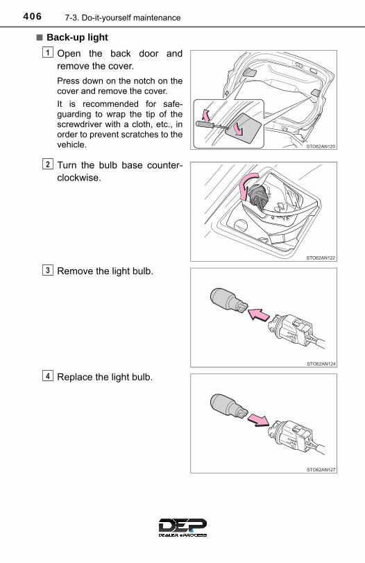
406 7-3. Do-it-yourself maintenance
■ Back-up light
Open the back door andremove the cover.
Press down on the notch on thecover and remove the cover.
It is recommended for safe-guarding to wrap the tip of thescrewdriver with a cloth, etc., inorder to prevent scratches to thevehicle.
Turn the bulb base counter-clockwise.
Remove the light bulb.
Replace the light bulb.
1
2
3
4

4077-3. Do-it-yourself maintenance
7
Maintenan
ce and care
Install the bulb base.
Install the back door cover.
Align the cover 2 tabs on thecover and install.
■ License plate light
Open the back door until the license plate light can be seen.
Remove the lens.
Insert a small flatheadscrewdriver, etc., intoeither the right or left holeof the lens.
Tilt the screwdriver in thedirection of the arrowshown in the illustration soas to release the fittingportion, and then removethe lens.
To prevent damage to thevehicle, wrap the tip of thescrewdriver with tape.
5
6
1
Fitting portion
Lens
2
1
2

408 7-3. Do-it-yourself maintenance
Remove the light bulb.
Install a new light bulb.
Install the lens.
Fit the lens into either theright or left fitting portion.
Push the lens into place.
After installation, confirm thatthe lens is properly installed bygently pulling it.
3
4
Fitting portion
5
1
2
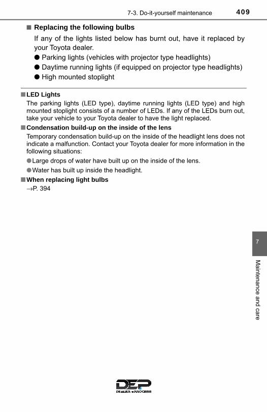
4097-3. Do-it-yourself maintenance
7
Maintenan
ce and care
■ Replacing the following bulbs
If any of the lights listed below has burnt out, have it replaced byyour Toyota dealer.● Parking lights (vehicles with projector type headlights)● Daytime running lights (if equipped on projector type headlights)● High mounted stoplight
■LED LightsThe parking lights (LED type), daytime running lights (LED type) and highmounted stoplight consists of a number of LEDs. If any of the LEDs burn out,take your vehicle to your Toyota dealer to have the light replaced.
■Condensation build-up on the inside of the lensTemporary condensation build-up on the inside of the headlight lens does notindicate a malfunction. Contact your Toyota dealer for more information in thefollowing situations:
●Large drops of water have built up on the inside of the lens.
●Water has built up inside the headlight.
■When replacing light bulbs→P. 394

410 7-3. Do-it-yourself maintenance
WARNING
■Replacing light bulbs●Turn off the lights. Do not attempt to replace the bulb immediately after
turning off the lights. The bulbs become very hot and may cause burns.
●Do not touch the glass portion of the light bulb with bare hands. When it isunavoidable to hold the glass portion, use and hold with a clean dry clothto avoid getting moisture and oils on the bulb. Also, if the bulb is scratched or dropped, it may blow out or crack.
●Fully install light bulbs and any parts used to secure them. Failure to do somay result in heat damage, fire, or water entering the headlight unit. Thismay damage the headlights or cause condensation to build up on the lens.
■To prevent damage or fire ●Make sure bulbs are fully seated and locked.
●Check the wattage of the bulb before installing to prevent heat damage.

411
8When trouble arises
8-1. Essential information
Emergency flashers .......... 412
If your vehicle has to be stopped in an emergency ................. 413
8-2. Steps to take in an emergency
If your vehicle needs to be towed ......................... 415
If you think something is wrong .............................. 420
Fuel pump shut off system ............................ 421
If a warning light turns on or a warning buzzer sounds ............................ 422
If you have a flat tire.......... 433
If the engine will not start ................................. 448
If the vehicle battery is discharged ...................... 450
If your vehicle overheats ... 453
If the vehicle becomes stuck ............................... 456

412 8-1. Essential information
Emergency flashers
Press the switch.
All the turn signal lights will flash.To turn them off, press the switchonce again.
■Emergency flashersIf the emergency flashers are used for a long time while the engine is not run-ning, the battery may discharge.
The emergency flashers are used to warn other drivers when thevehicle has to be stopped in the road to a breakdown, etc.

4138-1. Essential information
8
When
trouble arises
If your vehicle has to be stopped in an emergency
Steadily step on the brake pedal with both feet and firmly depress it.
Do not pump the brake pedal repeatedly as this will increase the effortrequired to slow the vehicle.
Shift the shift lever to N.
If the shift lever is shifted to N
After slowing down, stop the vehicle in a safe place by the road.
Stop the engine.
If the shift lever cannot be shifted to N
Keep depressing the brake pedal with both feet to reduce vehiclespeed as much as possible.
Stop the engine by turning theengine switch to the “ACC”position.
Stop the vehicle in a safe place by the road.
Only in an emergency, such as if it becomes impossible to stopthe vehicle in the normal way, stop the vehicle using the follow-ing procedure:
1
2
3
4
3
4
5

414 8-1. Essential information
WARNING
■ If the engine has to be turned off while driving●Power assist for the brakes and steering wheel will be lost, making the
brake pedal harder to depress and the steering wheel heavier to turn.Decelerate as much as possible before turning off the engine.
●Never attempt to remove the key, as doing so will lock the steering wheel.
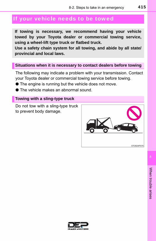
4158-2. Steps to take in an emergency
8
When
trouble arises
If your vehicle needs to be towed
The following may indicate a problem with your transmission. Contactyour Toyota dealer or commercial towing service before towing.● The engine is running but the vehicle does not move.
● The vehicle makes an abnormal sound.
Do not tow with a sling-type truckto prevent body damage.
If towing is necessary, we recommend having your vehicletowed by your Toyota dealer or commercial towing service,using a wheel-lift type truck or flatbed truck.Use a safety chain system for all towing, and abide by all state/provincial and local laws.
Situations when it is necessary to contact dealers before towing
Towing with a sling-type truck

416 8-2. Steps to take in an emergency
If your vehicle is transported by aflatbed truck, it should be tieddown at the locations shown in theillustration.
After transporting, return the cov-ers that were attached to the rearside.
If you use chains or cables to tiedown your vehicle, the anglesshaded in black must be 45°.
Do not overly tighten the tiedowns or the vehicle may be dam-aged.
Towing with a wheel-lift type truck
From the front From the rear
Release the parking brake. Use a towing dolly under thefront wheels.
Using a flatbed truck
Front

4178-2. Steps to take in an emergency
8
When
trouble arises
If a tow truck is not available in an emergency, your vehicle may betemporarily towed using cables or chains secured to the emergencytowing eyelets. This should only be attempted on hard surfaced roadsfor at most 50 miles (80 km) at under 18 mph (30 km/h).A driver must be in the vehicle to steer and operate the brakes. Thevehicle’s wheels, drive train, axles, steering and brakes must be ingood condition.
For vehicles with an automatic transmission, only the front towingeyelets may be used.
Take out the towing eyelet. (→P. 434)
Remove the eyelet cover.
Type A
Push down the upper part ofthe eyelet cover remove theupper claw, and then pull on theeyelet cover to disengage itfrom the front grille.
Type B
Turn the eyelet cover.
Emergency towing
Emergency towing procedure
1
2
Claws

418 8-2. Steps to take in an emergency
Insert the towing eyelet into the hole and tighten partially by hand.
Tighten down the towing eyelet securely using a wheel nut wrenchor hard metal bar.
Securely attach cables or chains to the towing eyelet.
Take care not to damage the vehicle body.
Enter the vehicle being towed and start the engine.
If the engine does not start, turn the engine switch to the “ON” position.
Shift the shift lever to N and release the parking brake.
When the shift lever cannot be shifted (automatic transmission):→P. 151
■While towingIf the engine is not running, the power assist for the brakes and steering willnot function, making steering and braking more difficult.
■Wheel nut wrenchWheel nut wrench is installed in the luggage. (→P. 434)
3
Type A Type B
4
Type A Type B
5
6
7

4198-2. Steps to take in an emergency
8
When
trouble arises
WARNING
Observe the following precautions. Failure to do so may result in death or serious injury.
■When towing the vehicle
■While towing●When towing using cables or chains, avoid sudden starts, etc. which place
excessive stress on the towing eyelets, cables or chains. The towing eye-lets, cables or chains may become damaged, broken debris may hit peo-ple, and cause serious damage.
●Do not turn the engine switch to the “LOCK” position. There is a possibility that the steering wheel is locked and cannot be oper-ated.
■ Installing towing eyelets to the vehicleMake sure that towing eyelets are installed securely.If not securely installed, towing eyelets may come loose during towing.
NOTICE
■To prevent damage to the vehicle when towing using a wheel-lift typetruck●Do not tow the vehicle from the rear when the engine switch is in the
“LOCK” position or the key is removed.The steering lock mechanism is not strong enough to hold the front wheelsstraight.
●When raising the vehicle, ensure adequate ground clearance for towing atthe opposite end of the raised vehicle. Without adequate clearance, thevehicle could be damaged while being towed.
■To prevent damage to the vehicle when towing with a sling-type truckDo not tow with a sling-type truck, either from the front or rear.
■To prevent damage to the vehicle during emergency towingDo not secure cables or chains to the suspension components.
Be sure to transport the vehicle with thefront wheels raised or with all four wheelsraised off the ground. If the vehicle istowed with the front wheels contactingthe ground, the drivetrain and relatedparts may be damaged.

420 8-2. Steps to take in an emergency
If you think something is wrong
● Fluid leaks under the vehicle(Water dripping from the air conditioning after use is normal)
● Flat-looking tires or uneven tire wear
● High engine coolant temperature warning light flashes or comes on
● Low engine coolant temperature indicator comes on or does notcome on continuously
● Changes in exhaust sound
● Excessive tire squeal when cornering
● Strange noises related to the suspension system
● Pinging or other noises related to the engine
● Engine misfire, stumbling or running roughly
● Appreciable loss of power
● Vehicle pulls heavily to one side when braking
● Vehicle pulls heavily to one side when driving on a level road
● Loss of brake effectiveness, spongy feeling, pedal almost touchesthe floor
If you notice any of the following symptoms, your vehicle proba-bly needs adjustment or repair. Contact your Toyota dealer assoon as possible.
Visible symptoms
Audible symptoms
Operational symptoms

4218-2. Steps to take in an emergency
8
When
trouble arises
Fuel pump shut off system
Follow the procedure below to restart the engine after the system isactivated.
Turn the engine switch to the “ACC” or “LOCK” position.
Restart the engine.
To minimize the risk of fuel leakage when the engine stalls orwhen an airbag inflates upon collision, the fuel pump shut offsystem stops the supply of fuel to the engine.
NOTICE
■Before starting the engineInspect the ground under the vehicle. If you find that fuel has leaked onto the ground, the fuel system has beendamaged and is in need of repair. Do not restart the engine.
1
2

422 8-2. Steps to take in an emergency
If a warning light turns on or a warning buzzer sounds
Calmly perform the following actions if any of the warning lightscomes on or flashes. If a light comes on or flashes, but thengoes off, this does not necessarily indicate a malfunction in thesystem. However, if this continues to occur, have the vehicleinspected by your Toyota dealer.
Warning light and warning buzzer list
Warning light Warning light/Details/Actions
(Except Canada)
(Canada)
Brake system warning light (warning buzzer)*1
• Low brake fluid• Malfunction in the brake systemThis light also comes on when the parking brake is notreleased. If the light turns off after the parking brake is fullyreleased, the system is operating normally.
→ Immediately stop the vehicle in a safe place and con-tact your Toyota dealer. Continuing to drive the vehi-cle may be dangerous.
Charging system warning lightIndicates a malfunction in the vehicle’s charging system.
→ Immediately stop the vehicle in a safe place and con-tact your Toyota dealer.
Low engine oil pressure warning lightIndicates that the engine oil pressure is too low.
→ Immediately stop the vehicle in a safe place and con-tact your Toyota dealer.
(Red warning light flashes or comes on)
High engine coolant temperature warning lightIndicates that the engine is overheating.As the coolant temperature rises, it changes from flashingto steady on.
→ P. 453

4238-2. Steps to take in an emergency
8
When
trouble arises
(Except Canada)
(Canada)
Malfunction indicator lampIndicates a malfunction in:• The electronic engine control system;• The electronic throttle control system;• The electronic automatic transmission control system.
→ Have the vehicle inspected by your Toyota dealerimmediately.
SRS warning lightIndicates a malfunction in:• The SRS airbag system; • The front passenger occupant classification system; or• The seat belt pretensioner system.
→ Have the vehicle inspected by your Toyota dealerimmediately.
(Except Canada)
(Canada)
ABS warning lightIndicates a malfunction in:• The ABS; or • The brake assist system.
→ Have the vehicle inspected by your Toyota dealerimmediately.
Electric power steering system warning light (warning buzzer)
Indicates a malfunction in the EPS (Electric Power Steer-ing) system.
→ Have the vehicle inspected by your Toyota dealerimmediately.
Warning light Warning light/Details/Actions

424 8-2. Steps to take in an emergency
PCS warning light*2
When the warning light flashes (and a buzzer sounds):Indicates a malfunction in the PCS (Pre-Collision system)
→ Have the vehicle inspected by your Toyota dealerimmediately.
When the warning light illuminates:Indicates that the PCS (Pre-Collision system) is temporar-ily unavailable, possibly due to either of the following:• The part of the windshield around the front sensor being
dirty, fogged up or covered with condensation, ice, stick-ers, etc.
→ Clear the dirt, fog, condensation, ice, stickers, etc. (→P. 175)
• Front sensor temperature being outside of its opera-tional range
→ Wait for a while until the area around the front sensorhas cooled down sufficiently.
Either the VSC (Vehicle Stability Control) system or PCS(Pre-Collision system) is disabled or both are disabled.
→ To enable the PCS, enable both the VSC system andPCS. (→P. 180, 217)
Slip indicatorIndicates a malfunction in:• The VSC system;• The TRAC system; or• The hill-start assist control system.
→ Have the vehicle inspected by your Toyota dealerimmediately.
(Yellow)
Automatic High Beam indicator*2
Indicates a malfunction in the Automatic High Beam sys-tem.
→ Have the vehicle inspected by your Toyota dealer.
Warning light Warning light/Details/Actions

4258-2. Steps to take in an emergency
8
When
trouble arises
(Yellow)
Cruise control indicator*2
Indicates a malfunction in the cruise control system.→ Have the vehicle inspected by your Toyota dealer
immediately.
(Yellow)
(Yellow)
LDA indicator*2 and lane marker indicators*2
Indicates a malfunction in the LDA system.→ Have the vehicle inspected by your Toyota dealer.
Open door warning light (warning buzzer)*3
Indicates that one or more of the doors is not fully closed.→ Check that all the side doors and back door are
closed.
Low fuel level warning lightIndicates that remaining fuel is about 1.5 gal. (5.8 L,1.3 Imp.gal.) or less.
→ Refuel the vehicle.
Driver’s and front passenger’s seat belt reminder light(warning buzzer)*4
Warns the driver and front passenger to fasten their seatbelts
→ Fasten the seat belt. If the passenger’s seat is occupied, the front passen-ger’s seat belt also needs to be fastened to make thewarning light (warning buzzer) turn off.
Warning light Warning light/Details/Actions

426 8-2. Steps to take in an emergency
Tire pressure warning light (except Canada)When the light comes on: Low tire inflation pressuresuch as • Natural causes (→P. 429)• Flat tire (→P. 433)
→ Adjust the tire inflation pressure to the specifiedlevel.The light will turn off after a few minutes. In casethe light does not turn off even if the tire inflationpressure is adjusted, have the system checked byyour Toyota dealer.
When the light comes on after blinking for 1 minute: Malfunction in the tire pressure warning system. (→P. 430)
→ Have the system checked by your Toyota dealer.
Low windshield washer fluid warning light*2
Indicate that the washer fluid level is low.→ Add washer fluid (→P. 369)
Maintenance required reminder light (except Canada)Indicates that maintenance is required according to thedriven distance on the maintenance schedule.*5
Illuminates for about 3 seconds and then flashes for about15 seconds approximately 4500 miles (7200 km) after thereminder light has been reset.
→ If necessary, perform maintenance.Comes on and remains on if the distance driven exceeds5000 miles (8000 km) after the reminder light has beenreset. (The indicator will not work properly unless thereminder light has been reset.)
→ Perform the necessary maintenance. Please reset thereminder light after the maintenance is performed.(→P. 348)
Warning light Warning light/Details/Actions

4278-2. Steps to take in an emergency
8
When
trouble arises
*1: Parking brake engaged warning buzzer: The buzzer sounds to indicate that the parking brake is still engaged (withthe vehicle having reached a speed of 3 mph [5 km/h]).
*2: If equipped
*3: Open door warning buzzer: A buzzer will sound if the vehicle reaches a speed of 3 mph (5 km/h) ormore with any door open.
*4: Driver’s and front passenger’s seat belt buzzer: The driver’s and passenger’s seat belt buzzer sounds to alert the driverand front passenger that his or her seat belt is not fastened. Once theengine switch is turned to the “ON” or “START” position, the buzzer soundsfor 6 seconds. The buzzer sounds once if the driver’s or front passenger’sseat belt is unfastened when the vehicle reaches a speed of 12 mph(20 km/h). Then, if the seat belt is still unfastened after 30 seconds elapse,the buzzer will sound intermittently for approximately 10 seconds, followedby a different tone for approximately 20 more seconds.
*5: Refer to the separate “Scheduled Maintenance Guide” or “Owner’s ManualSupplement” for the maintenance interval applicable to your vehicle.

428 8-2. Steps to take in an emergency
■SRS warning lightThis warning light system monitors the airbag sensor assembly, front impactsensors, side impact sensors (front), side impact sensors (front door), sideimpact sensors (rear), driver’s seat belt buckle switch, front passenger occu-pant classification system (ECU and sensors), “AIR BAG ON” indicator, “AIRBAG OFF” indicator, front passenger’s seat belt buckle switch, seat belt pre-tensioners, airbags, interconnecting wiring and power sources. (→P. 36)
■Front passenger detection sensor, passenger seat belt reminder andwarning buzzer● If luggage is placed on the front passenger seat, the front passenger detec-
tion sensor may cause the warning light to flash and the warning buzzer tosound even if a passenger is not sitting in the seat.
● If a cushion is placed on the seat, the sensor may not detect a passenger,and the warning light may not operate properly.
■Electric power steering system warning light (warning buzzer)When the battery charge becomes insufficient or the voltage temporarilydrops, the electric power steering system warning light may come on and thewarning buzzer may sounds.
■ If the malfunction indicator lamp comes on while drivingFirst check the following:
● Is the fuel tank empty?If it is, fill the fuel tank immediately.
● Is the fuel tank cap loose?If it is, tighten it securely.
The malfunction indicator lamp will go off after several driving trips.If the malfunction indicator lamp does not go off even after several trips, con-tact your Toyota dealer as soon as possible.
■When the tire pressure warning light comes on (vehicles with a tirepressure warning system)Check the tire inflation pressure and adjust to the appropriate level. Push-ing the tire pressure warning reset switch will not turn off the tire pressurewarning light.

4298-2. Steps to take in an emergency
8
When
trouble arises
■The tire pressure warning light may come on due to natural causes(vehicles with a tire pressure warning system)The tire pressure warning light may come on due to natural causes suchas natural air leaks and tire inflation pressure changes caused by tem-perature. In this case, adjusting the tire inflation pressure will turn off thewarning light (after a few minutes).
■When a tire is replaced with a spare tire (vehicles with a tire pressurewarning system)The compact spare tire is not equipped with a tire pressure warning valveand transmitter. If a tire goes flat, the tire pressure warning light will notturn off even though the flat tire has been replaced with the spare tire.Replace the spare tire with the repaired tire and adjust the tire inflationpressure. The tire pressure warning light will go off after a few minutes.
■ If the tire pressure warning system is not functioning (vehicles with atire pressure warning system)The system will be disabled in the following conditions:(When the condition becomes normal, the system will work properly.)
● If tires not equipped with tire pressure warning valves and transmittersare used
● If the ID code on the tire pressure warning valves and transmitters arenot registered in the tire pressure warning computer
● If the tire inflation pressure is 73 psi (500 kPa, 5.1 kgf/cm2 or bar) orhigher
The tire pressure warning system may be disabled in the following condi-tions:(When the condition becomes normal, the system will work properly.)
● If electronic devices or facilities using similar radio wave frequencies arenearby
● If a radio set at a similar frequency is in use in the vehicle
● If a window tint that affects the radio wave signals is installed
● If there is a lot of snow or ice on the vehicle, particularly around thewheels or wheel housings
● If non-genuine Toyota wheels are used (Even if you use Toyota wheels,the tire pressure warning system may not work properly with some typesof tires.)
● If tire chains are used

430 8-2. Steps to take in an emergency
■ If the tire pressure warning light frequently comes on after blinkingfor 1 minute (vehicles with a tire pressure warning system)If the tire pressure warning light frequently comes on after blinking for1 minute when the engine switch is turned to the “ON” position, have itchecked by your Toyota dealer.
■Customization that can be configured at Toyota dealerThe vehicle speed linked seat belt reminder buzzer can be disabled. (Customizable features →P. 488) However, Toyota recommends that the seatbelt reminder buzzer be operational to alert the driver and front passengerwhen seat belts are not fastened.
WARNING
■ If both the ABS and the brake system warning lights remain onStop your vehicle in a safe place immediately and contact your Toyotadealer. The vehicle will become extremely unstable during braking, and theABS system may fail, which could cause an accident resulting in death orserious injury.
■When the electric power steering system warning light comes onThe steering wheel may become extremely heavy.When steering wheel operations are heavier than usual, grip the steeringwheel firmly and operate it using more force than usual.
■ If the tire pressure warning light comes on (vehicles with a tirepressure warning system)Be sure to observe the following precautions. Failure to do so couldcause a loss of vehicle control and result in death or serious injury.
●Stop your vehicle in a safe place as soon as possible. Adjust the tireinflation pressure immediately.
● If the tire pressure warning light comes on even after tire inflation pres-sure adjustment, it is probable that you have a flat tire. Check the tires.If a tire is flat, change it with the spare tire and have the flat tirerepaired by the nearest Toyota dealer.
●Avoid abrupt maneuvering and braking. If the vehicle tires deteriorate,you could lose control of the steering wheel or the brakes.
■ If a blowout or sudden air leakage should occur (vehicles with a tirepressure warning system)The tire pressure warning system may not activate immediately.

4318-2. Steps to take in an emergency
8
When
trouble arises
WARNING
■Maintenance of the tire (vehicles with a tire pressure warning sys-tem)Each tire, including the spare (if provided), should be checked monthlywhen cold and inflated to the inflation pressure recommended by thevehicle manufacturer on the vehicle placard or tire inflation pressurelabel (tire and load information label). (If your vehicle has tires of a dif-ferent size than the size indicated on the vehicle placard or tire inflationpressure label [tire and load information label], you should determinethe proper tire inflation pressure for those tires.)
As an added safety feature, your vehicle has been equipped with a tirepressure monitoring system (TPMS-tire pressure warning system) thatilluminates a low tire pressure telltale (tire pressure warning light) whenone or more of your tires is significantly under-inflated. Accordingly,when the low tire pressure telltale (tire pressure warning light) illumi-nates, you should stop and check your tires as soon as possible, andinflate them to the proper pressure. Driving on a significantly under-inflated tire causes the tire to overheat and can lead to tire failure.Under-inflation also reduces fuel efficiency and tire tread life, and mayaffect the vehicle’s handling and stopping ability.
Please note that the TPMS (tire pressure warning system) is not a sub-stitute for proper tire maintenance, and it is the driver’s responsibility tomaintain correct tire pressure, even if under-inflation has not reachedthe level to trigger illumination of the TPMS low tire pressure telltale (tirepressure warning light).
Your vehicle has also been equipped with a TPMS (tire pressure warn-ing system) malfunction indicator to indicate when the system is notoperating properly. The TPMS (tire pressure warning system) malfunc-tion indicator is combined with the low tire pressure telltale (tire pressurewarning light). When the system detects a malfunction, the telltale willflash for approximately one minute and then remain continuously illumi-nated. This sequence will continue upon subsequent vehicle start-upsas long as the malfunction exists. When the malfunction indicator is illu-minated, the system may not be able to detect or signal low tire pres-sure as intended.
TPMS (tire pressure warning system) malfunctions may occur for a vari-ety of reasons, including the installation of replacement or alternate tiresor wheels on the vehicle that prevent the TPMS (tire pressure warningsystem) from functioning properly. Always check the TPMS (tire pres-sure warning system) malfunction telltale after replacing one or moretires or wheels on your vehicle to ensure that the replacement or alter-nate tires and wheels allow the TPMS (tire pressure warning system) tocontinue to function properly.

432 8-2. Steps to take in an emergency
NOTICE
■To ensure the tire pressure warning system operates properly(vehicles with a tire pressure warning system)Do not install tires with different specifications or makers, as the tirepressure warning system may not operate properly.

4338-2. Steps to take in an emergency
8
When
trouble arises
If you have a flat tire
● Stop the vehicle in a safe place on a hard, flat surface.
● Set the parking brake.
● Shift the shift lever to P (automatic transmission) or R (manualtransmission).
● Stop the engine.
● Turn on the emergency flashers. (→P. 412)
Your vehicle is equipped with a spare tire. The flat tire can bereplaced with the spare tire.
For details about tires: →P. 370
WARNING
■ If you have a flat tireDo not continue driving with a flat tire.Driving even a short distance with a flat tire can damage the tire and thewheel beyond repair, which could result in an accident.
Before jacking up the vehicle
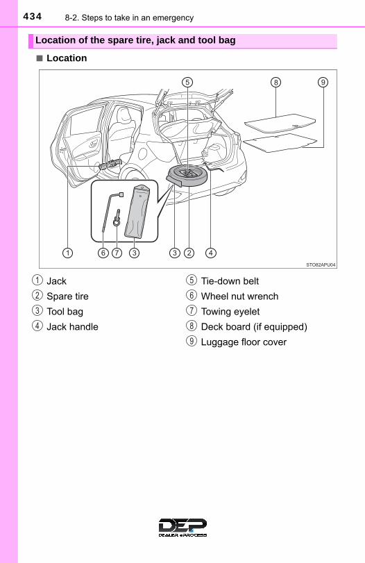
434 8-2. Steps to take in an emergency
■ Location
Location of the spare tire, jack and tool bag
Jack
Spare tire
Tool bag
Jack handle
Tie-down belt
Wheel nut wrench
Towing eyelet
Deck board (if equipped)
Luggage floor cover
1
2
3
4
5
6
7
8
9

4358-2. Steps to take in an emergency
8
When
trouble arises
WARNING
■Using the tire jackObserve the following precautions. Improper use of the tire jack may cause the vehicle to suddenly fall offthe jack, leading to death or serious injury.
●Do not use the tire jack for any purpose other than replacing tires orinstalling and removing tire chains.
●Only use the tire jack that comes with this vehicle for replacing a flattire. Do not use it on other vehicles, and do not use other tire jacks forreplacing tires on this vehicle.
●Put the jack properly in its jack point.
●Do not put any part of your body under the vehicle while it is supportedby the jack.
●Do not start the engine or drive the vehicle while the vehicle is sup-ported by the jack.
●Do not raise the vehicle while someone is inside.
●When raising the vehicle, do not put an object on or under the jack.
●Do not raise the vehicle to a height greater than that required toreplace the tire.
●Use a jack stand if it is necessary to get under the vehicle.
●When lowering the vehicle, make sure that there is no-one near thevehicle. If there are people nearby, warn them vocally before lowering.

436 8-2. Steps to take in an emergency
Move the driver’s seat to thefront most position and removethe cover.
Take out the jack.
For tightening
For loosening
Taking out the jack
1
2
1
2

4378-2. Steps to take in an emergency
8
When
trouble arises
Vehicles with a deck board: Lift the deck board and pull it towardyou to remove it. (→P. 335)
Remove the luggage floorcover.
Remove the spare wheel cush-ion (if equipped), then loosenthe center fastener that securesthe spare tire.
Taking out the spare tire
1
2
3

438 8-2. Steps to take in an emergency
Chock the tires.
For vehicles with full coverwheel ornament, remove thewheel ornament using thewrench.
To protect the wheel ornament,place a rag between the wrenchand the wheel ornament.
If the wheel ornament hasnotches, insert the wrench intothe notch and remove the wheelornament.
Slightly loosen the wheel nuts(one turn).
Replacing a flat tire
1
Flat tire Wheel chock positions
FrontLeft-hand side Behind the rear right-hand side tire
Right-hand side Behind the rear left-hand side tire
RearLeft-hand side In front of the front right-hand side tire
Right-hand side In front of the front left-hand side tire
2
3

4398-2. Steps to take in an emergency
8
When
trouble arises
Turn the tire jack portion byhand until the notch of the jackis in contact with the jack point.
The jack point guides are locatedunder the rocker panel. Theyindicate the jack point positions.
Raise the vehicle until the tire isslightly raised off the ground.
Remove all the wheel nuts andthe tire.
When resting the tire on theground, place the tire so that thewheel design faces up to avoidscratching the wheel surface.
4
5
6
440 8-2. Steps to take in an emergency
WARNING
■Replacing a flat tire●Observe the following precautions.
Failure to do so may result in serious injury:
• Do not try to remove the wheel ornament by hand. Take due care inhandling the ornament to avoid unexpected personal injury.
• Do not touch the disc wheels or the area around the brakes immedi-ately after the vehicle has been driven.After the vehicle has been driven the disc wheels and the areaaround the brakes will be extremely hot. Touching these areas withhands, feet or other body parts while changing a tire, etc., mayresult in burns.
●Failure to follow these precautions could cause the wheel nuts toloosen and the tire to fall off, resulting in death or serious injury.
• Have the wheel nuts tightened with a torque wrench to 76 ft·lbf(103 N·m, 10.5 kgf·m) as soon as possible after changing wheels.
• When installing a tire, only use wheel nuts that have been specifi-cally designed for that wheel.
• If there are any cracks or deformations in the bolt screws, nut threadsor bolt holes of the wheel, have the vehicle inspected by your Toyotadealer.
• When installing the wheel nuts, be sure to install them with thetapered ends facing inward. (→P. 383)

4418-2. Steps to take in an emergency
8
When
trouble arises
Remove any dirt or foreign mat-ter from the wheel contact sur-face.
If foreign matter is on the wheelcontact surface, the wheel nutsmay loosen while the vehicle is inmotion, causing the tire to comeoff.
Install the tire and loosely tighten each wheel nut by hand byapproximately the same amount.
When replacing a steel wheelwith a compact spare tire,tighten the wheel nuts until thetapered portion comes intoloose contact with the discwheel seat.
When replacing an aluminumwheel with a compact sparetire, tighten the wheel nuts untilthe tapered portion comes intoloose contact with the discwheel seat.
Lower the vehicle.
Installing the spare tire
1
2
Tapered portion
Disc wheel seat
Tapered portion
Disc wheel seat
3

442 8-2. Steps to take in an emergency
Firmly tighten each wheel nuttwo or three times in the ordershown in the illustration.
Tightening torque:76 ft·lbf (103 N·m, 10.5 kgf·m)
Do not use other tools or anyadditional leverage other thanyour hands, such as a hammer,pipe or your foot.
Stow the jack and all tools.
Return the deck board.
Vehicles with an aluminumwheels, remove the centerwheel ornament by pushingfrom the reverse side.
Be careful not to lose the wheelornament.
Hook each belt end to the cor-responding anchor brackets.Put the center portion of thebelt onto the rear center headrestraint.
4
Stowing the flat tire, jack and all tools
1
2
3
4

4438-2. Steps to take in an emergency
8
When
trouble arises
Lay the flat tire on the luggagefloor so that the outer side ofthe tire wheel faces toward therear of the vehicle. Detach therear center head restraint fromthe seat and release the belt.
Pass the belt through the centerhole of the flat tire wheel.
Put the center portion of thebelt onto the rear center headrestraint position and thenreturn the rear center headrestraint.
Hold the buckle and pull thebelt to secure the tire.
After stowing the flat tire, checkthat the tire and belt are secured.
5
6
7
8

444 8-2. Steps to take in an emergency
■The compact spare tire●The compact spare tire is identified by the label “TEMPORARY USE
ONLY” on the tire sidewall.Use the compact spare tire temporarily, and only in an emergency.
●Make sure to check the tire inflation pressure of the compact spare tire.(→P. 469)
■After completing the tire change (vehicles with a tire pressure warn-ing system)The tire pressure warning system must be reset. (→P. 372)
■When using the compact spare tire (vehicles with a tire pressurewarning system)As the compact spare tire is not equipped with a tire pressure warningvalve and transmitter, low inflation pressure of the spare tire will not beindicated by the tire pressure warning system. Also, if you replace thecompact spare tire after the tire pressure warning light comes on, the lightremains on.
■When the compact spare tire is equippedThe vehicle height may become lower when driving with the compactspare tire compared to when driving with standard tires.
■ If you have a flat front tire on a road covered with snow or iceInstall the compact spare tire on one of the rear wheels of the vehicle.Perform the following steps and fit tire chains to the front tires:
Replace a rear tire with the compact spare tire.
Replace the flat front tire with the tire removed from the rear of thevehicle.
Fit tire chains to the front tires.
1
2
3
4458-2. Steps to take in an emergency
8
When
trouble arises
WARNING
■When using the compact spare tire●Remember that the compact spare tire provided is specifically
designed for use with your vehicle. Do not use your compact spare tireon another vehicle.
●Do not use more than one compact spare tire simultaneously.
●Replace the compact spare tire with a standard tire as soon as possi-ble.
●Avoid sudden acceleration, abrupt steering, sudden braking and shift-ing operations that cause sudden engine braking.
■When storing the compact spare tireBe careful not to catch fingers or other body parts between the compactspare tire and the body of the vehicle.
■After using the tools and jackBefore driving, make sure all the tools and jack are securely in place intheir storage location to reduce the possibility of personal injury during acollision or sudden braking.
■When the compact spare tire is attachedThe vehicle speed may not be correctly detected, and the following sys-tems may not operate correctly:
• ABS & Brake assist• VSC• TRAC• EPS
*: If equipped
• Cruise control*• PCS (Pre-Collision System)*• LDA (Lane Departure Alert)*• Automatic High Beam*

446 8-2. Steps to take in an emergency
WARNING
■Speed limit when using the compact spare tireDo not drive at speeds in excess of 50 mph (80 km/h) when a compactspare tire is installed on the vehicle.
The compact spare tire is not designed for driving at high speeds. Fail-ure to observe this precaution may lead to an accident causing death orserious injury.
■When stowing the flat tire●Make sure the rear seats are in their original position.
●Secure it using a tire tie-down belt. Otherwise, the flat tire may fly outin case of the sudden braking or an accident, resulting in death or seri-ous injury.

4478-2. Steps to take in an emergency
8
When
trouble arises
NOTICE
■Do not drive the vehicle with a flat tireDo not continue driving with a flat tire.Driving even a short distance with a flat tire can damage the tire and thewheel beyond repair.
■Be careful when driving over bumps with the compact spare tireinstalled on the vehicleThe vehicle becomes lower when driving with the compact spare tirecompared to when driving with standard tires. Be careful when drivingover uneven road surfaces.
■Driving with tire chains and the compact spare tireDo not fit tire chains to the compact spare tire.Tire chains may damage the vehicle body and adversely affect drivingperformance.
■When replacing the tires (vehicles with a tire pressure warning sys-tem)When removing or fitting the wheels, tires or the tire pressure warningvalve and transmitter, contact your Toyota dealer as the tire pressurewarning valve and transmitter may be damaged if not handled correctly.
■To avoid damage to the tire pressure warning valves and transmit-ters (vehicles with a tire pressure warning system)When a tire is repaired with liquid sealants, the tire pressure warningvalve and transmitter may not operate properly. If a liquid sealant isused, contact your Toyota dealer or other qualified service shop as soonas possible. Make sure to replace the tire pressure warning valve andtransmitter when replacing the tire. (→P. 371)

448 8-2. Steps to take in an emergency
If the engine will not start
One of the following may be the cause of the problem:● There may not be sufficient fuel in the vehicle’s tank.
Refuel the vehicle.
● The engine may be flooded.Try to restart the engine again following correct starting procedures.(→P. 146)
● Vehicles with engine immobilizer system: There may be a malfunc-tion in the engine immobilizer system. (→P. 74)
One of the following may be the cause of the problem:● The battery may be discharged. (→P. 450)
● The battery terminal connections may be loose or corroded.
If the engine will not start even though correct starting proce-dures are being followed (→P. 146), consider each of the follow-ing points:
The engine will not start even though the starter motor operatesnormally.
The starter motor turns over slowly, the interior lights and head-lights are dim, or the horn does not sound or sounds at a lowvolume.

4498-2. Steps to take in an emergency
8
When
trouble arises
One of the following may be the cause of the problem:● One or both of the battery terminals may be disconnected.
● The battery may be discharged. (→P. 450)
Contact your Toyota dealer if the problem cannot be repaired, or if repairprocedures are unknown.
The starter motor does not turn over, the interior lights and head-lights do not turn on, or the horn does not sound.
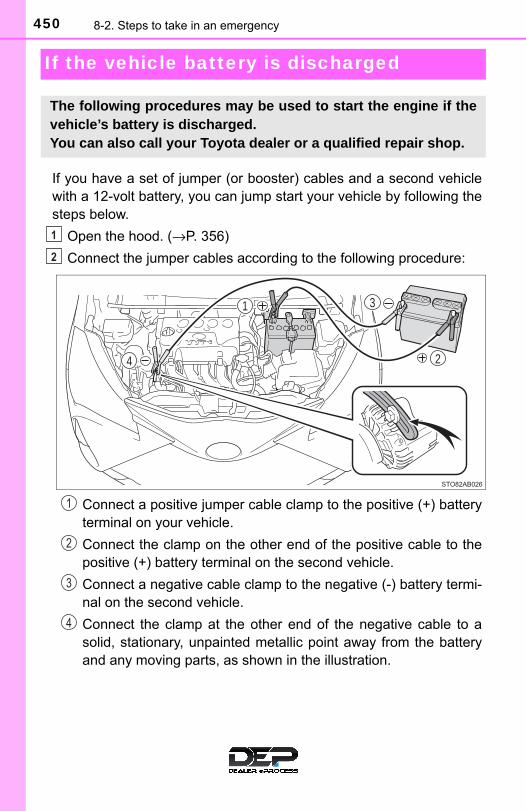
450 8-2. Steps to take in an emergency
If the vehicle battery is discharged
If you have a set of jumper (or booster) cables and a second vehiclewith a 12-volt battery, you can jump start your vehicle by following thesteps below.
Open the hood. (→P. 356)
Connect the jumper cables according to the following procedure:
Connect a positive jumper cable clamp to the positive (+) batteryterminal on your vehicle.
Connect the clamp on the other end of the positive cable to thepositive (+) battery terminal on the second vehicle.
Connect a negative cable clamp to the negative (-) battery termi-nal on the second vehicle.
Connect the clamp at the other end of the negative cable to asolid, stationary, unpainted metallic point away from the batteryand any moving parts, as shown in the illustration.
The following procedures may be used to start the engine if thevehicle’s battery is discharged.You can also call your Toyota dealer or a qualified repair shop.
1
2
31
4 2
1
2
3
4
4518-2. Steps to take in an emergency
8
When
trouble arises
Start the engine of the second vehicle. Increase the engine speedslightly and maintain at that level for approximately 5 minutes torecharge the battery of your vehicle.
Maintain the engine speed of the second vehicle and start theengine of your vehicle.
Once the vehicle’s engine has started, remove the jumper cables inthe exact reverse order from which they were connected.
Once the engine starts, have the vehicle inspected at your Toyotadealer as soon as possible.
■Starting the engine when the battery is discharged (vehicles with anautomatic transmission)The engine cannot be started by push-starting.
■To prevent battery discharge●Turn off the headlights and the audio system while the engine is not running.
●Turn off any unnecessary electrical components when the vehicle is runningat a low speed for an extended period, such as in heavy traffic.
■Charging the batteryThe electricity stored in the battery will discharge gradually even when thevehicle is not in use, due to natural discharge and the draining effects of cer-tain electrical appliances. If the vehicle is left for a long time, the battery maydischarge, and the engine may be unable to start. (The battery rechargesautomatically during driving.)
3
4
5

452 8-2. Steps to take in an emergency
WARNING
■Avoiding battery fires or explosionsObserve the following precautions to prevent accidentally igniting the flam-mable gas that may be emitted from the battery:
●Make sure each jumper cable is connected to the correct terminal and thatit is not unintentionally in contact with anything other than the intended ter-minal.
●Do not allow the other end of the jumper cable connected to the “+” termi-nal to come into contact with any other parts or metal surfaces in the area,such as brackets or unpainted metal.
●Do not allow the + and - clamps of the jumper cables to come into contactwith each other.
●Do not smoke, use matches, cigarette lighters or allow open flame nearthe battery.
■Battery precautionsThe battery contains poisonous and corrosive acidic electrolyte, whilerelated parts contain lead and lead compounds. Observe the following pre-cautions when handling the battery:
●When working with the battery, always wear safety glasses and take carenot to allow any battery fluids (acid) to come into contact with skin, clothingor the vehicle body.
●Do not lean over the battery.
● In the event that battery fluid comes into contact with the skin or eyes,immediately wash the affected area with water and seek medical attention.Place a wet sponge or cloth over the affected area until medical attentioncan be received.
●Always wash your hands after handling the battery support, terminals, andother battery-related parts.
●Do not allow children near the battery.
■To prevent damage to the vehicleDo not pull- or push-start the vehicle as the three-way catalytic convertermay overheat and become a fire hazard.
NOTICE
■When handling jumper cablesWhen connecting the jumper cables, ensure that they do not become entan-gled in the cooling fans or engine drive belt.

4538-2. Steps to take in an emergency
8
When
trouble arises
If your vehicle overheats
● The high engine coolant temperature warning light (→P. 422)comes on or flashes, or a loss of engine power is experienced. (Forexample, the vehicle speed does not increase.)
● Steam comes out from under the hood.
Stop the vehicle in a safe place and turn off the air conditioning sys-tem, and then stop the engine.
If you see steam: Carefully lift the hood after the steam subsides.
If you do not see steam:Carefully lift the hood.
After the engine has cooleddown sufficiently, inspect thehoses and radiator core (radia-tor) for any leaks.
Radiator
Cooling fan
If a large amount of coolant leaks,immediately contact your Toyotadealer.
The coolant level is satisfactoryif it is between the “FULL” and“LOW” lines on the reservoir.
Reservoir
“FULL”
“LOW”
Radiator cap
The following may indicate that your vehicle is overheating.
Correction procedures
1
2
3
1
2
4
1
2
3
4

454 8-2. Steps to take in an emergency
Add coolant if necessary.
Water can be used in an emer-gency if coolant is unavailable.
Start the engine and turn the air conditioning system on to checkthat the radiator cooling fan operates and to check for coolant leaksfrom the radiator or hoses.
The fan operates when the air conditioning system is turned on immedi-ately after a cold start. Confirm that the fan is operating by checking the fansound and air flow. If it is difficult to check these, turn the air conditioningsystem on and off repeatedly. (The fan may not operate in freezing temperatures.)
If the fan is not operating: Stop the engine immediately and contact your Toyota dealer.
If the fan is operating: Have the vehicle inspected at the nearest Toyota dealer.
5
6
7
4558-2. Steps to take in an emergency
8
When
trouble arises
WARNING
■To prevent an accident or injury when inspecting under the hood ofyour vehicleObserve the following precautions. Failure to do so may result in serious injury such as burns.
● If steam is seen coming from under the hood, do not open the hood untilthe steam has subsided. The engine compartment may be very hot.
●Keep hands and clothing (especially a tie, a scarf or a muffler) away fromthe fan and belts while the engine is operating.
●Do not loosen the radiator cap or the reservoir cap while the engine andradiator are hot.
NOTICE
■When adding engine coolantAdd coolant slowly after the engine has cooled down sufficiently. Addingcool coolant to a hot engine too quickly can cause damage to the engine.
■To prevent damage to the cooling systemObserve the following precautions:
●Avoid contaminating the coolant with foreign matter (such as sand or dust,etc.,).
●Do not use any coolant additives.
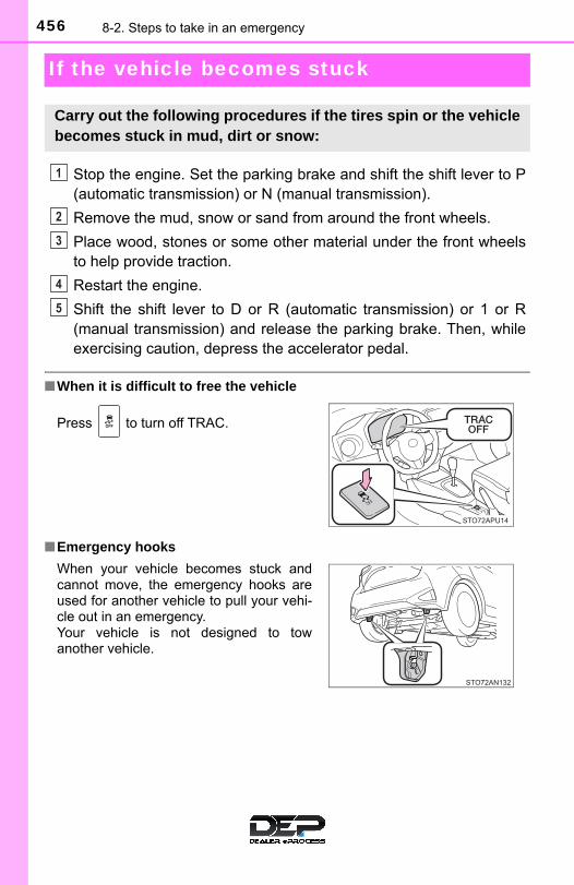
456 8-2. Steps to take in an emergency
If the vehicle becomes stuck
Stop the engine. Set the parking brake and shift the shift lever to P(automatic transmission) or N (manual transmission).
Remove the mud, snow or sand from around the front wheels.
Place wood, stones or some other material under the front wheelsto help provide traction.
Restart the engine.
Shift the shift lever to D or R (automatic transmission) or 1 or R(manual transmission) and release the parking brake. Then, whileexercising caution, depress the accelerator pedal.
■When it is difficult to free the vehicle
■Emergency hooks
Carry out the following procedures if the tires spin or the vehiclebecomes stuck in mud, dirt or snow:
Press to turn off TRAC.
When your vehicle becomes stuck andcannot move, the emergency hooks areused for another vehicle to pull your vehi-cle out in an emergency. Your vehicle is not designed to towanother vehicle.
1
2
3
4
5

4578-2. Steps to take in an emergency
8
When
trouble arises
WARNING
■When attempting to free a stuck vehicleIf you choose to push the vehicle back and forth to free it, make sure thesurrounding area is clear to avoid striking other vehicles, objects or people.The vehicle may also lunge forward or lunge back suddenly as it becomesfree. Use extreme caution.
■When shifting the shift lever (automatic transmission)Be careful not to shift the shift lever with the accelerator pedal depressed.This may lead to unexpected rapid acceleration of the vehicle that maycause an accident resulting in death or serious injury.
NOTICE
■To avoid damage to the transmission and other components●Avoid spinning the front wheels and depressing the accelerator pedal
more than necessary.
● If the vehicle remains stuck even after these procedures are performed,the vehicle may require towing to be freed.

458 8-2. Steps to take in an emergency

459
9Vehicle specifications
9-1. Specifications
Maintenance data (fuel, oil level, etc.) .......... 460
Fuel information ................ 471
Tire information ................. 474
9-2. Customization
Customizable features ...... 488
Items to initialize ............... 490
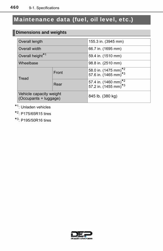
460 9-1. Specifications
Maintenance data (fuel, oil level, etc.)
*1: Unladen vehicles
*2: P175/65R15 tires
*3: P195/50R16 tires
Dimensions and weights
Overall length 155.3 in. (3945 mm)
Overall width 66.7 in. (1695 mm)
Overall height*1 59.4 in. (1510 mm)
Wheelbase 98.8 in. (2510 mm)
Tread
Front58.0 in. (1475 mm)*2
57.6 in. (1465 mm)*3
Rear57.4 in. (1460 mm)*2
57.2 in. (1455 mm)*3
Vehicle capacity weight(Occupants + luggage) 845 lb. (380 kg)

4619-1. Specifications
9
Ve
hicle spe
cifications
■ Vehicle identification number
The vehicle identification number (VIN) is the legal identifier foryour vehicle. This is the primary identification number for yourToyota. It is used in registering the ownership of your vehicle.
This number is stamped underthe front passenger’s seat.
This number is stamped on thetop left side of the instrumentpanel.
This number is also on the Cer-tification Label on the driver’sside of the center pillar.
Vehicle identification

462 9-1. Specifications
■ Engine number
The engine number is stampedon the engine block as shown.

4639-1. Specifications
9
Ve
hicle spe
cifications
Engine
Model 1NZ-FE
Type 4-cylinder in line, 4-cycle, gasoline
Bore and stroke 2.95 × 3.33 in. (75.0 × 84.7 mm)
Displacement 91.3 cu.in. (1497 cm3)
Drive belt tension
68 — 90 lbf (300 — 400 N, 31 — 41kgf)*Vehicles without an air conditioning system
Vehicles with an air conditioning system
*: Drive belt tension measured with Boroughsdrive belt tension gauge No. BT-33-73F whenthe engine is cold (used belt)
Generator
Water pump
Crankshaft
Generator
Crankshaft Water pump
Air conditioning compressor

464 9-1. Specifications
*: The engine oil capacity is a reference quantity to be used when changingthe engine oil. Warm up and turn off the engine, wait more than 5 minutes,and check the oil level on the dipstick.
■ Engine oil selection
“Toyota Genuine Motor Oil” is used in your Toyota vehicle. UseToyota approved “Toyota Genuine Motor Oil” or equivalent to satisfythe following grade and viscosity.
Oil grade: ILSAC GF-5 multigrade engine oil
Recommended viscosity: SAE 5W-30
SAE 5W-30 is the best choicefor good fuel economy andgood starting in cold weather.
If SAE 5W-30 is not available,SAE 10W-30 oil may be used.However, it should be replacedwith SAE 5W-30 at the next oilchange.
Fuel
Fuel type Unleaded gasoline only
Octane rating 87 (Research Octane Number 91) or higher
Fuel tank capacity(Reference)
11.1 gal. (42 L, 9.2 lmp.gal.)
Lubrication system
Oil capacity(Drain and refill-reference*)
With filterWithout filter
3.9 qt. (3.7 L, 3.3 Imp.qt.)3.6 qt. (3.4 L, 3.0 Imp.qt.)
Outside temperature

4659-1. Specifications
9
Ve
hicle spe
cifications
Oil viscosity (5W-30 is explained here as an example): • The 5W in 5W-30 indicates the characteristic of the oil which
allows cold startability. Oils with a lower value before the W allowfor easier starting of the engine in cold weather.
• The 30 in 5W-30 indicates the viscosity characteristic of the oilwhen the oil is at high temperature. An oil with a higher viscosity(one with a higher value) may be better suited if the vehicle isoperated at high speeds, or under extreme load conditions.
How to read oil container label:
The International LubricantSpecification Advisory Commit-tee (ILSAC) Certification Markis added to some oil containersto help you select the oil youshould use.
Cooling system
Capacity (Reference)
Automatic transmission
4.9 qt. (4.6 L, 4.0 Imp.qt.)Manual transmission
5.0 qt. (4.7 L, 4.1 Imp.qt.)
Coolant type
Use either of the following:• “Toyota Super Long Life Coolant”• A similar high-quality ethylene glycol-based
non-silicate, non-amine, non-nitrite, and non-borate coolant with long-life hybrid organicacid technology
Do not use plain water alone.

466 9-1. Specifications
*: The fluid capacity is the reference quantity. If replacement is necessary,contact your Toyota dealer.
Ignition system
Spark plug
Make DENSOSK16R11NGKIFR5A11
Gap 0.043 in. (1.1 mm)
NOTICE
■ Iridium-tipped spark plugsUse only iridium-tipped spark plugs. Do not adjust the spark plug gap.
Electrical system
Battery
Open voltage* at 68°F (20°C):
12.3 V or higherIf the specific voltage is lower than the standardvalue, charge the battery.(*: Voltage checked 20 minutes after the engineand all the lights are turned off.)
Charging rates 5 A max.
Automatic transmission
Fluid capacity* 6.8 qt. (6.4 L, 5.6 Imp.qt.)
Fluid type Toyota Genuine ATF WS
NOTICE
■Transmission fluid typeUsing transmission fluid other than “Toyota Genuine ATF WS” may causedeterioration in shift quality, locking up of the transmission accompanied byvibration and, ultimately, damage to the vehicle’s transmission.

4679-1. Specifications
9
Ve
hicle spe
cifications
Manual transmission
Gear oil capacity (Reference)
2.0 qt. (1.9 L, 1.7 Imp.qt.)
Gear oil type“TOYOTA Genuine Manual Transmission GearOil LV GL-4 75W” or equivalent
NOTICE
■Manual transmission gear oil type●Please be aware that depending on the particular characteristics of the
gear oil used or the operating conditions, idle sound, shift feeling and/orfuel efficiency may be different or affected and, in the worst case, damageto the vehicle's transmission. Toyota recommends to use “TOYOTA Genu-ine Manual Transmission Gear Oil LV GL-4 75W” to achieve optimal per-formance.
●Your Toyota vehicle is filled with “TOYOTA Genuine Manual TransmissionGear Oil LV GL-4 75W” at the factory. Use Toyota approved “TOYOTAGenuine Manual Transmission Gear Oil LV GL-4 75W” or an equivalent oilof matching quality that satisfies the above specifications. Please contactyour Toyota dealer for further details.
Clutch
Pedal free play 0.2 — 0.6 in. (5 — 15 mm)
Fluid typeSAE J1703 or FMVSS No. 116 DOT 3;SAE J1704 or FMVSS No. 116 DOT 4
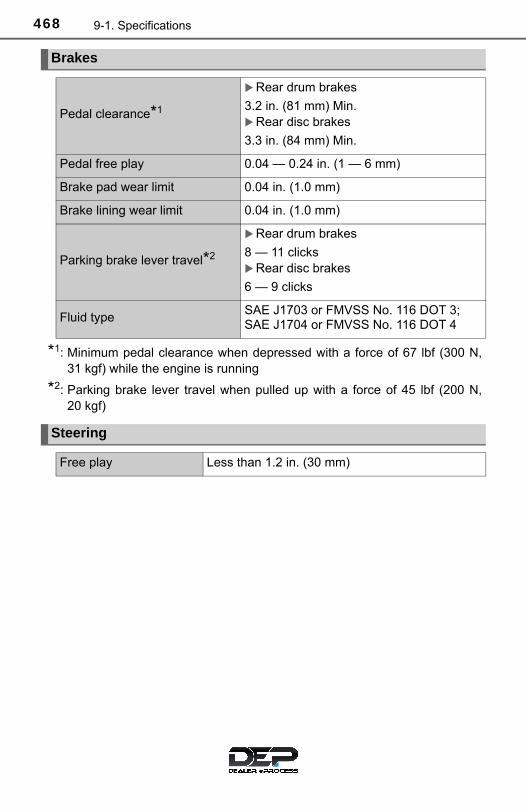
468 9-1. Specifications
*1: Minimum pedal clearance when depressed with a force of 67 lbf (300 N,31 kgf) while the engine is running
*2: Parking brake lever travel when pulled up with a force of 45 lbf (200 N,20 kgf)
Brakes
Pedal clearance*1
Rear drum brakes
3.2 in. (81 mm) Min.Rear disc brakes
3.3 in. (84 mm) Min.
Pedal free play 0.04 — 0.24 in. (1 — 6 mm)
Brake pad wear limit 0.04 in. (1.0 mm)
Brake lining wear limit 0.04 in. (1.0 mm)
Parking brake lever travel*2
Rear drum brakes
8 — 11 clicksRear disc brakes
6 — 9 clicks
Fluid typeSAE J1703 or FMVSS No. 116 DOT 3;SAE J1704 or FMVSS No. 116 DOT 4
Steering
Free play Less than 1.2 in. (30 mm)

4699-1. Specifications
9
Ve
hicle spe
cifications
15-inch tires
16-inch tires
Compact spare tires
Tires and wheels
Tire size P175/65R15 84H
Tire inflation pressure (Recommended coldtire inflation pressure)
Driving under normal conditionsFront: 33 psi (230 kPa, 2.3 kgf/cm2 or bar) Rear: 33 psi (230 kPa, 2.3 kgf/cm2 or bar) Never exceed the maximum cold tire inflationpressure indicated on the tire sidewall.
Wheel size 15 × 5 1/2J
Wheel nut torque 76 ft·lbf (103 N·m, 10.5 kgf·m)
Tire size P195/50R16 83V
Tire inflation pressure (Recommended coldtire inflation pressure)
Driving under normal conditionsFront: 32 psi (220 kPa, 2.2 kgf/cm2 or bar) Rear: 29 psi (200 kPa, 2.0 kgf/cm2 or bar) Never exceed the maximum cold tire inflationpressure indicated on the tire sidewall.
Wheel size 16 × 6J
Wheel nut torque 76 ft·lbf (103 N·m, 10.5 kgf·m)
Tire size T125/70D16 96M
Tire inflation pressure (Recommended coldtire inflation pressure)
60 psi (420 kPa, 4.2 kgf/cm2 or bar) Never exceed the maximum cold tire inflationpressure indicated on the tire sidewall.
Wheel size 16 × 4T
Wheel nut torque 76 ft·lbf (103 N·m, 10.5 kgf·m)

470 9-1. Specifications
A: HB2 halogen bulbs B: HIR2 halogen bulbs C: H16 halogen bulbs D: Wedge base bulbs (clear) E: Wedge base bulbs (amber) F: Single end bulbs (clear) G: Double end bulbs
Light bulbs
Light Bulbs Bulb No W Type
Exterior
Headlights and daytime runninglights (if equipped)Reflector typeProjector type
9003—
60/5555
AB
Front fog lights (if equipped) — 19 C
Front side marker lights — 5 D
Front turn signal lights/parking lights
7444NA 28/8 E
Rear turn signal lights — 21 E
Stop/tail and rear side markerlights
7443 21/5 F
Back-up lights 921 16 D
License plate light — 5 D
InteriorPersonal lights/interior light — 5 D
Luggage compartment light — 5 G
4719-1. Specifications
9
Ve
hicle spe
cifications
Fuel information
■Gasoline qualityIn very few cases, driveability problems may be caused by the brand of gaso-line you are using. If driveability problems persist, try changing the brand ofgasoline. If this does not correct the problem, consult your Toyota dealer.
■Gasoline quality standards●Automotive manufacturers in the U.S.A., Europe and Japan have developed
a specification for fuel quality called World-Wide Fuel Charter (WWFC),which is expected to be applied worldwide.
●The WWFC consists of four categories that are based on required emissionlevels. In the U.S., category 4 has been adopted.
●The WWFC improves air quality by lowering emissions in vehicle fleets, andimproves customer satisfaction through better performance.
You must only use unleaded gasoline.Select octane rating 87 (Research Octane Number 91) or higher.Use of unleaded gasoline with an octane rating lower than 87may result in engine knocking. Persistent knocking can lead toengine damage.
At minimum, the gasoline you use should meet the specifications ofASTM D4814 in the U.S.A.
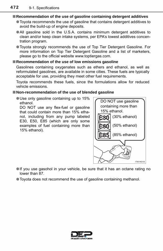
472 9-1. Specifications
■Recommendation of the use of gasoline containing detergent additives●Toyota recommends the use of gasoline that contains detergent additives to
avoid the build-up of engine deposits.
●All gasoline sold in the U.S.A. contains minimum detergent additives toclean and/or keep clean intake systems, per EPA’s lowest additives concen-tration program.
●Toyota strongly recommends the use of Top Tier Detergent Gasoline. Formore information on Top Tier Detergent Gasoline and a list of marketers,please go to the official website www.toptiergas.com.
■Recommendation of the use of low emissions gasolineGasolines containing oxygenates such as ethers and ethanol, as well asreformulated gasolines, are available in some cities. These fuels are typicallyacceptable for use, providing they meet other fuel requirements.
Toyota recommends these fuels, since the formulations allow for reducedvehicle emissions.
■Non-recommendation of the use of blended gasoline
● If you use gasohol in your vehicle, be sure that it has an octane rating nolower than 87.
●Toyota does not recommend the use of gasoline containing methanol.
●Use only gasoline containing up to 15%ethanol. DO NOT use any flex-fuel or gasolinethat could contain more than 15% etha-nol, including from any pump labeledE30, E50, E85 (which are only someexamples of fuel containing more than15% ethanol).
DO NOT use gasoline containing more than 15% ethanol.
(30% ethanol)
(50% ethanol)
(85% ethanol)
4739-1. Specifications
9
Ve
hicle spe
cifications
■Non-recommendation of the use of gasoline containing MMTSome gasoline contains an octane enhancing additive called MMT (Methylcy-clopentadienyl Manganese Tricarbonyl).
Toyota does not recommend the use of gasoline that contains MMT. If fuelcontaining MMT is used, your emission control system may be adverselyaffected.
The malfunction indicator lamp on the instrument cluster may come on. If thishappens, contact your Toyota dealer for service.
■ If your engine knocks●Consult your Toyota dealer.
●You may occasionally notice light knocking for a short time while accelerat-ing or driving uphill. This is normal and there is no need for concern.
NOTICE
■Notice on fuel quality●Do not use improper fuels. If improper fuels are used, the engine will be
damaged.
●Do not use leaded gasoline.Leaded gasoline can cause damage to your vehicle’s three-way catalyticconverters causing the emission control system to malfunction.
●Do not use gasohol other than the type previously stated.Other gasohol may cause fuel system damage or vehicle performanceproblems.
●Using unleaded gasoline with an octane number or rating lower than thelevel previously stated will cause persistent heavy knocking. At worst, this will lead to engine damage.
■Fuel-related poor driveabilityIf poor driveability (poor hot starting, vaporization, engine knocking, etc.) isencountered after using a different type of fuel, discontinue the use of thattype of fuel.
■When refueling with gasoholTake care not to spill gasohol. It can damage your vehicle’s paint.

474 9-1. Specifications
Tire information
Full-size tire
Compact spare tire
Typical tire symbols
4759-1. Specifications
9
Ve
hicle spe
cifications
Tire size (→P. 477)
DOT and Tire Identification Number (TIN) (→P. 476)
Location of treadwear indicators (→P. 370)
Tire ply composition and materials
Plies are layers of rubber-coated parallel cords. Cords are the strandswhich form the plies in a tire.
Uniform tire quality grading
For details, see “Uniform Tire Quality Grading” that follows.
Load limit at maximum cold tire inflation pressure (→P. 481)
Maximum cold tire inflation pressure (→P. 481)
This means the pressure to which a tire may be inflated.
TUBELESS or TUBE TYPE
A tubeless tire does not have a tube and air is directly put into the tire.A tube type tire has a tube inside the tire and the tube maintains the airpressure.
Radial tires or bias-ply tires
A radial tire has “RADIAL” on the sidewall. A tire not marked “RADIAL”is a bias-ply tire.
Summer tires or all season tires (→P. 374)
An all season tire has “M+S” on the sidewall. A tire not marked “M+S”is a summer tire.
“TEMPORARY USE ONLY”
A compact spare tire is identified by the phrase “TEMPORARY USEONLY” molded on its sidewall. This tire is designed for temporaryemergency use only.
1
2
3
4
5
6
7
8
9
10
11

476 9-1. Specifications
DOT symbol*Tire Identification Number (TIN)
Tire manufacturer’s identification mark
Tire size code
Manufacturer’s optional tire type code (3 or 4 letters)
Manufacturing week
Manufacturing year
Manufacturer’s code*: The DOT symbol certifies that the tire conforms to applicable Federal
Motor Vehicle Safety Standards.
Typical DOT and Tire Identification Number (TIN)
Type A Type B
1
2
3
4
5
6
7
8

4779-1. Specifications
9
Ve
hicle spe
cifications
■ Typical tire size information
The illustration indicates typical tire size.
Tire use(P = Passenger car,T = Temporary use)
Section width (millimeters)
Aspect ratio(tire height to section width)
Tire construction code(R = Radial, D = Diagonal)
Wheel diameter (inches)
Load index (2 digits or 3 digits)
Speed symbol (alphabet with one letter)
■ Tire dimensions
Section width
Tire height
Wheel diameter
Tire size
1
2
3
4
5
6
7
1
2
3

478 9-1. Specifications
Bead
Sidewall
Shoulder
Tread
Belt
Inner liner
Reinforcing rubber
Carcass
Rim lines
Bead wires
Chafer
Tire section names
1
2
3
4
5
6
7
8
9
10
11

4799-1. Specifications
9
Ve
hicle spe
cifications
This information has been prepared in accordance with regulationsissued by the National Highway Traffic Safety Administration of theU.S. Department of Transportation.It provides the purchasers and/or prospective purchasers of Toyotavehicles with information on uniform tire quality grading.
Your Toyota dealer will help answer any questions you may have asyou read this information.
■ DOT quality grades
All passenger vehicle tires must conform to Federal Safety Require-ments in addition to these grades. Quality grades can be foundwhere applicable on the tire sidewall between tread shoulder andmaximum section width.
For example: Treadwear 200 Traction AA Temperature A
■ Treadwear
The treadwear grade is a comparative rating based on the wearrate of the tire when tested under controlled conditions on a speci-fied government test course.
For example, a tire graded 150 would wear one and a half (1 - 1/2)times as well on the government course as a tire graded 100.The relative performance of tires depends upon the actual condi-tions of their use. Performance may differ significantly from the normdue to variations in driving habits, service practices and differencesin road characteristics and climate.
Uniform Tire Quality Grading
480 9-1. Specifications
■ Traction AA, A, B, C
The traction grades, from highest to lowest, are AA, A, B and C,and they represent the tire’s ability to stop on wet pavement asmeasured under controlled conditions on specified government testsurfaces of asphalt and concrete.
A tire marked C may have poor traction performance.
Warning: The traction grade assigned to this tire is based on braking(straight ahead) traction tests and does not include cornering (turn-ing) traction.
■ Temperature A, B, C
The temperature grades are A (the highest), B, and C, representingthe tire’s resistance to the generation of heat and its ability to dissi-pate heat when tested under controlled conditions on a specifiedindoor laboratory test wheel.
Sustained high temperature can cause the material of the tire todegenerate and reduce tire life, and excessive temperature can leadto sudden tire failure.
The grade C corresponds to a level of performance which all pas-senger car tires must meet under the Federal Motor Vehicle SafetyStandard No. 109.
Grades B and A represent higher levels of performance on the labo-ratory test wheel than the minimum required by law.
Warning: The temperature grades for this tire are established for atire that is properly inflated and not overloaded.Excessive speed, underinflation, or excessive loading, either sepa-rately or in combination, can cause heat buildup and possible tirefailure.

4819-1. Specifications
9
Ve
hicle spe
cifications
Glossary of tire terminology
Tire related term Meaning
Cold tire inflation pressure
Tire pressure when the vehicle has beenparked for three hours or more, or has notbeen driven more than 1 mile or 1.5 km underthat condition
Maximum inflation pressure
The maximum cold inflated pressure to whicha tire may be inflated, shown on the sidewallof the tire
Recommended inflation pressure
Cold tire inflation pressure recommended by amanufacturer
Accessory weight
The combined weight (in excess of those stan-dard items which may be replaced) of auto-matic transmission, power steering, powerbrakes, power windows, power seats, radioand heater, to the extent that these items areavailable as factory-installed equipment(whether installed or not)
Curb weight
The weight of a motor vehicle with standardequipment, including the maximum capacity offuel, oil and coolant, and if so equipped, airconditioning and additional weight optionalengine
Maximum loaded vehicle weight
The sum of:(a) Curb weight(b) Accessory weight(c) Vehicle capacity weight(d) Production options weight
Normal occupant weight
150 lb. (68 kg) times the number of occupantsspecified in the second column of Table 1*that follows

482 9-1. Specifications
Occupant distribution Distribution of occupants in a vehicle as speci-fied in the third column of Table 1* below
Production options weight
The combined weight of installed regular pro-duction options weighing over 5 lb. (2.3 kg) inexcess of the standard items which theyreplace, not previously considered in curbweight or accessory weight, including heavyduty brakes, ride levelers, roof rack, heavyduty battery, and special trim
RimA metal support for a tire or a tire and tubeassembly upon which the tire beads areseated
Rim diameter (Wheel diameter) Nominal diameter of the bead seat
Rim size designation Rim diameter and width
Rim type designation The industry manufacturer’s designation for arim by style or code
Rim width Nominal distance between rim flanges
Vehicle capacity weight (Total load capacity)
The rated cargo and luggage load plus 150 lb.(68 kg) times the vehicle’s designated seatingcapacity
Vehicle maximum loadon the tire
The load on an individual tire that is deter-mined by distributing to each axle its share ofthe maximum loaded vehicle weight, anddividing by two
Vehicle normal load onthe tire
The load on an individual tire that is deter-mined by distributing to each axle its share ofcurb weight, accessory weight, and normaloccupant weight (distributed in accordancewith Table 1* below), and dividing by two
Tire related term Meaning

4839-1. Specifications
9
Ve
hicle spe
cifications
Weather side The surface area of the rim not covered by theinflated tire
BeadThe part of the tire that is made of steel wires,wrapped or reinforced by ply cords and that isshaped to fit the rim
Bead separation A breakdown of the bond between compo-nents in the bead
Bias ply tire
A pneumatic tire in which the ply cords thatextend to the beads are laid at alternateangles substantially less than 90 degrees tothe centerline of the tread
Carcass The tire structure, except tread and sidewallrubber which, when inflated, bears the load
Chunking The breaking away of pieces of the tread orsidewall
Cord The strands forming the plies in the tire
Cord separation The parting of cords from adjacent rubbercompounds
Cracking Any parting within the tread, sidewall, or inner-liner of the tire extending to cord material
CT
A pneumatic tire with an inverted flange tireand rim system in which the rim is designedwith rim flanges pointed radially inward andthe tire is designed to fit on the underside ofthe rim in a manner that encloses the rimflanges inside the air cavity of the tire
Extra load tireA tire designed to operate at higher loads andat higher inflation pressures than the corre-sponding standard tire
Groove The space between two adjacent tread ribs
Tire related term Meaning

484 9-1. Specifications
InnerlinerThe layer(s) forming the inside surface of atubeless tire that contains the inflating mediumwithin the tire
Innerliner separation The parting of the innerliner from cord materialin the carcass
Intended outboard sidewall
(a)The sidewall that contains a whitewall,bears white lettering, or bears manufac-turer, brand, and/or model name moldingthat is higher or deeper than the samemolding on the other sidewall of the tire, or
(b)The outward facing sidewall of an asym-metrical tire that has a particular side thatmust always face outward when mountedon a vehicle
Light truck (LT) tireA tire designated by its manufacturer as pri-marily intended for use on lightweight trucksor multipurpose passenger vehicles
Load rating The maximum load that a tire is rated to carryfor a given inflation pressure
Maximum load rating The load rating for a tire at the maximum per-missible inflation pressure for that tire
Maximum permissible inflation pressure
The maximum cold inflation pressure to whicha tire may be inflated
Measuring rim The rim on which a tire is fitted for physicaldimension requirements
Open splice Any parting at any junction of tread, sidewall,or innerliner that extends to cord material
Outer diameter The overall diameter of an inflated new tire
Tire related term Meaning

4859-1. Specifications
9
Ve
hicle spe
cifications
Overall width
The linear distance between the exteriors ofthe sidewalls of an inflated tire, including ele-vations due to labeling, decorations, or protec-tive bands or ribs
Passenger car tire
A tire intended for use on passenger cars,multipurpose passenger vehicles, and trucks,that have a gross vehicle weight rating(GVWR) of 10,000 lb. or less
Ply A layer of rubber-coated parallel cords
Ply separation A parting of rubber compound between adja-cent plies
Pneumatic tire
A mechanical device made of rubber, chemi-cals, fabric and steel or other materials, that,when mounted on an automotive wheel, pro-vides the traction and contains the gas or fluidthat sustains the load
Radial ply tireA pneumatic tire in which the ply cords thatextend to the beads are laid at substantially 90degrees to the centerline of the tread
Reinforced tireA tire designed to operate at higher loads andat higher inflation pressures than the corre-sponding standard tire
Section width
The linear distance between the exteriors ofthe sidewalls of an inflated tire, excluding ele-vations due to labeling, decoration, or protec-tive bands
Sidewall That portion of a tire between the tread andbead
Sidewall separation The parting of the rubber compound from thecord material in the sidewall
Tire related term Meaning

486 9-1. Specifications
*: Table 1 — Occupant loading and distribution for vehicle normal load forvarious designated seating capacities
Snow tire
A tire that attains a traction index equal to orgreater than 110, compared to the ASTM E-1136 Standard Reference Test Tire, whenusing the snow traction test as described inASTM F-1805-00, Standard Test Method forSingle Wheel Driving Traction in a StraightLine on Snow-and Ice-Covered Surfaces, andwhich is marked with an Alpine Symbol ( )on at least one sidewall
Test rimThe rim on which a tire is fitted for testing, andmay be any rim listed as appropriate for usewith that tire
Tread That portion of a tire that comes into contactwith the road
Tread rib A tread section running circumferentiallyaround a tire
Tread separation Pulling away of the tread from the tire carcass
Treadwear indicators (TWI)
The projections within the principal groovesdesigned to give a visual indication of thedegrees of wear of the tread
Wheel-holding fixture The fixture used to hold the wheel and tireassembly securely during testing
Tire related term Meaning
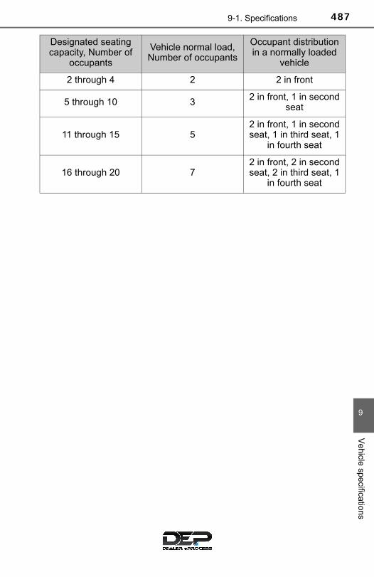
4879-1. Specifications
9
Ve
hicle spe
cifications
Designated seating capacity, Number of
occupants
Vehicle normal load, Number of occupants
Occupant distribution in a normally loaded
vehicle
2 through 4 2 2 in front
5 through 10 3 2 in front, 1 in second seat
11 through 15 52 in front, 1 in second seat, 1 in third seat, 1
in fourth seat
16 through 20 72 in front, 2 in second seat, 2 in third seat, 1
in fourth seat

488 9-2. Customization
Customizable features
Some function settings are changed simultaneously with other func-tions being customized. Contact your Toyota dealer for further details.
Settings that can be changed using the multimedia system.
Settings that can be changed by your Toyota dealer.
Definition of symbols: O = Available, — = Not available
■ Wireless remote control* (→P. 93, 96)
*: If equipped
■ Door lock (→P. 96)
Your vehicle includes a variety of electronic features that can bepersonalized to suit your preferences. Programming these pref-erences requires specialized equipment and may be performedby your Toyota dealer.
Customizable features
1
2
Function Default settingCustomized
setting
Unlocking operation
The driver’s doorunlocked in onestep, all thedoors unlockedin two steps
All the doorsunlocked inone step
— O
Time elapsed before auto-matic door lock function isactivated if door is notopened after being unlocked
60 seconds30 seconds
— O120 seconds
1 2
Function Default settingCustomized
setting
Unlocking using a key
The driver’s doorunlocked in onestep, all thedoors unlockedin two steps
All the doorsunlocked inone step
— O
1 2

4899-2. Customization
9
Ve
hicle spe
cifications
■ Automatic light off system* (→P. 156)
*: Vehicles with daytime running lights
■ Daytime running lights* (→P. 158)
*: If equipped
■ Seat belt reminder buzzer (→P. 425)
Function Default settingCustomized
setting
Time elapsed before head-lights automatically turn offafter doors are closed
30 seconds
0 seconds
O O60 seconds
90 seconds
1 2
Function Default settingCustomized
setting
Daytime running light sys-tem (except for Canada)
On Off O O
1 2
Function Default settingCustomized
setting
Vehicle speed linked seatbelt reminder buzzer
On Off — O
WARNING
■During customizationAs the engine needs to be running during customization, ensure that thevehicle is parked in a place with adequate ventilation. In a closed area suchas a garage, exhaust gases including harmful carbon monoxide (CO) maycollect and enter the vehicle. This may lead to death or a serious healthhazard.
NOTICE
■During customizationTo prevent battery discharge, ensure that the engine is running while cus-tomizing features.
1 2

490 9-2. Customization
Items to initialize
The following items must be initialized for normal system opera-tion after such cases as the battery being reconnected, or main-tenance being performed on the vehicle:
Item When to initialize Reference
Maintenance requiredreminder light (except Canada)
After the maintenanceis performed
P. 348
Tire pressure warningsystem (if equipped)
When rotating thetires on vehicles withdiffering front and reartire inflation pressures
P. 372

491
10For owners
Reporting safety defects for U.S. owners........................ 492
Seat belt instructions for Canadian owners (in French) ............................... 493
SRS airbag instructions for Canadian owners (in French) .............................. 495

492
Reporting safety defects for U.S. owners
If you believe that your vehicle has a defect which could cause acrash or could cause injury or death, you should immediatelyinform the National Highway Traffic Safety Administration(NHTSA) in addition to notifying Toyota Motor Sales, U.S.A., Inc.(Toll-free: 1-800-331-4331).
If NHTSA receives similar complaints, it may open an investiga-tion, and if it finds that a safety defect exists in a group of vehicles,it may order a recall and remedy campaign. However, NHTSA can-not become involved in individual problems between you, yourdealer, or Toyota Motor Sales, U.S.A., Inc.
To contact NHTSA, you may call the Vehicle Safety Hotline toll-free at1-888-327-4236 (TTY: 1-800-424-9153); go to http://www.safercar.gov ;or write to: Administrator, NHTSA, 1200 New Jersey Ave, S.E.,Washington, DC 20590. You can also obtain other information aboutmotor vehicle safety from http://www.safercar.gov.

493
10
For ow
ners
Seat belt instructions for Canadian owners (in French)
● Tirez sur la ceinture épaulièrejusqu’à ce qu’elle recouvreentièrement l’épaule; elle nedoit cependant pas toucher lecou ni glisser de l’épaule.
● Placez la sangle abdominale dela ceinture de sécurité le plusbas possible sur les hanches.
● Réglez la position du dossier du siège. Asseyez-vous le dos le plusdroit possible et calez-vous bien dans le siège.
● Ne pas vriller la ceinture de sécurité.
■ Ceintures de sécurité
Nettoyez avec un chiffon ou une éponge humectée d’eau savon-neuse tiède. Par ailleurs, vérifiez régulièrement que les ceinturesne sont pas effilochées, entaillées, ou ne paraissent pas exagéré-ment usées.
The following is a French explanation of seat belt instructionsextracted from the seat belt section in this manual.
See the seat belt section for more detailed seat belt instructions inEnglish.
Utilisation adéquate des ceintures de sécurité
Entretien et soin
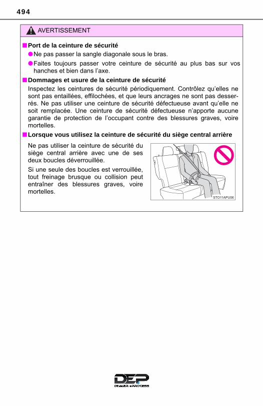
494
AVERTISSEMENT
■Port de la ceinture de sécurité●Ne pas passer la sangle diagonale sous le bras.
●Faites toujours passer votre ceinture de sécurité au plus bas sur voshanches et bien dans l’axe.
■Dommages et usure de la ceinture de sécuritéInspectez les ceintures de sécurité périodiquement. Contrôlez qu’elles nesont pas entaillées, effilochées, et que leurs ancrages ne sont pas desser-rés. Ne pas utiliser une ceinture de sécurité défectueuse avant qu’elle nesoit remplacée. Une ceinture de sécurité défectueuse n’apporte aucunegarantie de protection de l’occupant contre des blessures graves, voiremortelles.
■Lorsque vous utilisez la ceinture de sécurité du siège central arrière
Ne pas utiliser la ceinture de sécurité dusiège central arrière avec une de sesdeux boucles déverrouillée.
Si une seule des boucles est verrouillée,tout freinage brusque ou collision peutentraîner des blessures graves, voiremortelles.

495
10
For ow
ners
SRS airbag instructions for Canadian own-ers (in French)
The following is a French explanation of SRS airbag instructionsextracted from the SRS airbag section in this manual.
See the SRS airbag section for more detailed SRS airbag instruc-tions in English.

496
◆ Coussins gonflables SRS frontaux
Coussin gonflable SRS conducteur/passager avant
Participent à la protection de la tête et du thorax du conducteur etdu passager avant contre les chocs avec les éléments de l’habita-cle
Coussin gonflable SRS de genoux pour le conducteur
Participe à la protection du conducteur
Coussins gonflables SRS d’assise de siège
Participe à retenir le conducteur et le passager avant
◆ Coussins gonflables SRS latéraux et rideau
Coussins gonflables SRS latéraux
Participent à la protection du haut du corps des occupants auxplaces avant
Coussins gonflables SRS rideau● Participent principalement à la protection de la tête des occu-
pants assis dans les sièges des places extérieures● Participent à empêcher les occupants d’être éjectés du véhicule
en cas de retournement de celui-ci
1
2
3
4
5

497
10
For ow
ners
Composition du système de coussins gonflables SRS
Coussins gonflables rideau
Capteurs d’impact latéral(avant)
Coussins gonflables latéraux
Capteurs d’impact latéral(arrière)
Témoin d’alerte SRS
Coussin gonflable conducteur
Coussin gonflable d’assise desiège passager
Contacteur de boucle de cein-ture de sécurité passageravant
Prétensionneurs et limiteursd’effort de ceinture de sécurité
Capteurs d’impact latéral(porte avant)
Coussin gonflable d’assise desiège du conducteur
Contacteur de boucle de cein-ture de sécurité conducteur
Coussin gonflable de genouxconducteur
Capteurs d’impact avant
Boîtier électronique de couss-ins gonflables
Système de classificationd’occupant du siège passageravant (ECU et capteurs)
Coussin gonflable passageravant
Témoins indicateurs “AIRBAG ON” et “AIR BAG OFF”
1
2
3
4
5
6
7
8
9
10
11
12
13
14
15
16
17
18

498
Votre véhicule est équipé de COUSSINS GONFLABLES ÉVOLUÉS,dont la conception est basée sur les normes de sécurité des véhiculesautomobiles américains (FMVSS208). Le boîtier électronique decoussins gonflables (ECU) utilise les informations reçues des cap-teurs, etc. détaillés dans le schéma ci-dessus de composition du sys-tème pour commander le déploiement des coussins gonflables. Cesinformations comprennent des informations sur la gravité de la colli-sion et les occupants. Le déploiement rapide des coussins gonflablesest obtenu au moyen d’une réaction chimique dans les dispositifspyrotechniques, qui produit un gaz inoffensif permettant d’amortir lemouvement des occupants.

499
10
For ow
ners
AVERTISSEMENT
■Précautions avec les coussins gonflables SRSRespectez les précautions suivantes concernant les coussins gonflablesSRS. À défaut, des blessures graves, voire mortelles, pourraient s’ensuivre.
●Le conducteur et tous les passagers à bord du véhicule doivent porter leurceinture de sécurité correctement.Les coussins gonflables SRS sont des dispositifs de protection complé-mentaires aux ceintures de sécurité.
●Le coussin gonflable SRS conducteur se déploie avec une puissance con-sidérable et peut occasionner des blessures graves, voire mortelles, nota-mment lorsque le conducteur se trouve très près du coussin gonflable.
Conseils de la National Highway Traffic Safety Administration (NHTSA): Sachant que la zone de danger pour le coussin gonflable conducteur setrouve dans les premiers 2 à 3 in. (50 à 75 mm) du déploiement, placez-vous à 10 in. (250 mm) du coussin gonflable conducteur pour garantirune marge de sécurité suffisante. Cette distance est à mesurer entre lemoyeu du volant de direction et le sternum. Si vous êtes assis à moins de10 in. (250 mm), vous pouvez changer votre position de conduite de plu-sieurs façons:
• Reculez votre siège le plus possible, tout en continuant à pouvoiratteindre confortablement les pédales.
• Inclinez légèrement le dossier du siège. Bien que les véhicules puissentêtre différents les uns des autres, la plupart des conducteurs peuvents’asseoir à une distance de 10 in. (250 mm), même avec le siège con-ducteur complètement avancé, simplement en inclinant un peu le dos-sier de siège. Si vous avez des difficultés à voir la route après avoirincliné votre siège, utilisez un coussin ferme et antidérapant pour vousrehausser ou, si votre véhicule est équipé du réglage en hauteur dusiège, remontez-le.
• Si votre volant de direction est réglable, inclinez-le vers le bas. Celavous permet d’orienter le coussin gonflable vers votre buste plutôt quevers la tête et le cou.
Le siège doit être réglé selon les recommandations de la NHTSA ci-des-sus, tout en conservant le contrôle des pédales et du volant, et la vue descommandes au tableau de bord.

500
AVERTISSEMENT
■Précautions avec les coussins gonflables SRS
●Le coussin gonflable SRS passager avant se déploie également avec unepuissance considérable et peut occasionner des blessures graves, voiremortelles, notamment lorsque le passager avant se trouve très près ducoussin gonflable. Le siège du passager avant doit se trouver le plus loinpossible du coussin gonflable et le dossier doit être réglé de manière à ceque le passager avant soit assis bien droit.
●Le déploiement d’un coussin gonflable risque d’infliger des blessuresgraves, voire mortelles, aux bébés et aux enfants mal assis et/ou malattachés. Installez dans un siège de sécurité enfant les enfants trop jeunespour pouvoir utiliser la ceinture de sécurité. Toyota recommande vivementque tous les nourrissons et enfants soient installés dans les sièges arrièredu véhicule et convenablement attachés. Les sièges arrière sont plus sûrspour les nourrissons et les enfants que le siège passager avant.
●N’installez jamais un siège de sécurité enfant type dos à la route sur lesiège passager avant, même si le voyant “AIR BAG OFF” est allumé. Encas d’accident, la force exercée par le déploiement rapide du coussin gon-flable passager peut causer des blessures graves, voire mortelles à unenfant, si le siège de sécurité enfant type dos à la route est installé sur lesiège passager avant.
●Si vous attachez une rallonge de cein-ture de sécurité aux boucles des cein-tures de sièges avant, mais pas aupêne de la ceinture de sécurité propre-ment dite, les coussins gonflables SRSfrontaux déterminent que le conducteuret le passager avant portent leur cein-ture de sécurité, alors même qu’ellen’est pas attachée. Dans ce cas, lescoussins gonflables SRS frontaux ris-quent de ne pas se déployer correcte-ment en cas de collision, causant desblessures graves, voire mortelles.Veillez à porter la ceinture de sécuritéavec la rallonge de ceinture de sécurité.

501
10
For ow
ners
AVERTISSEMENT
■Précautions avec les coussins gonflables SRS
●Ne pas s’asseoir sur le bord du siège etne pas s’appuyer contre la planche debord.
●Ne laissez pas un enfant debout faceau coussin gonflable SRS passageravant ni assis sur les genoux d’un pas-sager avant.
●Ne pas laisser les occupants des siègesavant voyager avec un objet sur lesgenoux.
●Ne pas s’appuyer contre la porte, contrele rail latéral de toit ou contre les mon-tants avant, latéraux et arrière.
● Interdisez à quiconque de s’agenouillersur le siège passager en appui contre laporte ou de sortir la tête ou les mains àl’extérieur du véhicule.
●Ne fixez ni ne posez aucun objet sur laplanche de bord, la garniture centraledu volant de direction et la partieinférieure du tableau de bord. Ces objets risquent de se transformeren projectiles lors du déploiement descoussins gonflables SRS conducteur,passager et de genoux conducteur.

502
AVERTISSEMENT
■Précautions avec les coussins gonflables SRS
●Ne suspendez aux crochets à vêtements aucun cintre nu ni aucun objetdur. En cas de déploiement des coussins gonflables SRS rideau, tous cesobjets pourraient se transformer en projectiles et causer des blessuresgraves, voire mortelles.
●Si une housse en vinyle recouvre la partie où le coussin gonflable SRS degenoux conducteur se déploie, veillez à l’enlever.
●N’utilisez aucun accessoire de siège venant recouvrir les zones dedéploiement des coussins gonflables SRS latéraux et des coussins gon-flables SRS d’assise de siège, car il risquerait d’en gêner le déploiement.De tels accessoires peuvent empêcher les coussins gonflables latéraux etd’assise de siège de fonctionner correctement, neutraliser le système ouprovoquer le déploiement accidentel des coussins gonflables latéraux etd’assise de siège, provoquant ainsi des blessures graves, voire mortelles.
●Évitez de faire subir des chocs ou des pressions excessives aux zonesrenfermant les composants des coussins gonflables SRS. En effet, cela pourrait entraîner un mauvais fonctionnement des coussinsgonflables SRS.
●Ne touchez à aucun composant des coussins gonflables SRS immédiate-ment après leur déploiement (gonflage), car ils pourraient être chauds.
●Ne rien fixer aux portes, à la vitre depare-brise, aux vitres latérales, auxmontants avant et arrière, au rail latéralde toit et à la poignée de maintien.
●Ne pas attacher à la clé des objetslourds, pointus ou très durs, commed’autres clés par exemple. Ces objetsrisquent d’entraver le déploiement ducoussin gonflable SRS de genoux con-ducteur ou d’être projetés en directiondu siège conducteur par la force dedéploiement, constituant ainsi un dan-ger potentiel.
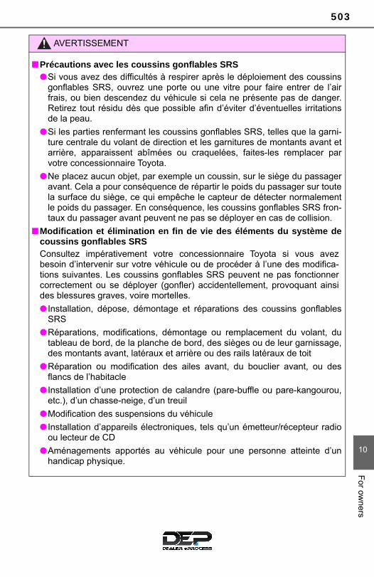
503
10
For ow
ners
AVERTISSEMENT
■Précautions avec les coussins gonflables SRS●Si vous avez des difficultés à respirer après le déploiement des coussins
gonflables SRS, ouvrez une porte ou une vitre pour faire entrer de l’airfrais, ou bien descendez du véhicule si cela ne présente pas de danger.Retirez tout résidu dès que possible afin d’éviter d’éventuelles irritationsde la peau.
●Si les parties renfermant les coussins gonflables SRS, telles que la garni-ture centrale du volant de direction et les garnitures de montants avant etarrière, apparaissent abîmées ou craquelées, faites-les remplacer parvotre concessionnaire Toyota.
●Ne placez aucun objet, par exemple un coussin, sur le siège du passageravant. Cela a pour conséquence de répartir le poids du passager sur toutela surface du siège, ce qui empêche le capteur de détecter normalementle poids du passager. En conséquence, les coussins gonflables SRS fron-taux du passager avant peuvent ne pas se déployer en cas de collision.
■Modification et élimination en fin de vie des éléments du système decoussins gonflables SRSConsultez impérativement votre concessionnaire Toyota si vous avezbesoin d’intervenir sur votre véhicule ou de procéder à l’une des modifica-tions suivantes. Les coussins gonflables SRS peuvent ne pas fonctionnercorrectement ou se déployer (gonfler) accidentellement, provoquant ainsides blessures graves, voire mortelles.
● Installation, dépose, démontage et réparations des coussins gonflablesSRS
●Réparations, modifications, démontage ou remplacement du volant, dutableau de bord, de la planche de bord, des sièges ou de leur garnissage,des montants avant, latéraux et arrière ou des rails latéraux de toit
●Réparation ou modification des ailes avant, du bouclier avant, ou desflancs de l’habitacle
● Installation d’une protection de calandre (pare-buffle ou pare-kangourou,etc.), d’un chasse-neige, d’un treuil
●Modification des suspensions du véhicule
● Installation d’appareils électroniques, tels qu’un émetteur/récepteur radioou lecteur de CD
●Aménagements apportés au véhicule pour une personne atteinte d’unhandicap physique.

504

505
Index
What to do if... (Troubleshooting) .................... 506
Alphabetical index ..................... 509
For vehicles with Entune Audio Plus, refer to the “MULTIMEDIASYSTEM OWNER’S MANUAL” for information regarding the mul-timedia system.
Audio system types: →P. 228

506 What to do if... (Troubleshooting)
What to do if... (Troubleshooting)
● If you lose your keys, new genuine keys can be made by your Toyotadealer. (→P. 94)
● Is the key battery weak or depleted? (→P. 388)
● The function may not operate properly due to the condition of the radiowave. (→P. 94)
● Is the child-protector lock set?The rear door cannot be opened from inside the vehicle when the lock isset. Open the rear door from outside and then unlock the child-protectorlock. (→P. 99)
If you have a problem, check the following before contactingyour Toyota dealer.
The doors cannot be locked, unlocked, opened or closed
You lose your keys
The doors cannot be locked or unlocked
The rear door cannot be opened (5-door models only)

507What to do if... (Troubleshooting)
● Vehicles with a manual transmission: Did you turn the key while firmly depressing the clutch pedal? (→P. 146)
● Vehicles with an automatic transmission: Is the shift lever in P? (→P. 146)
● Is the battery discharged? (→P. 450)
● Is the engine switch in the “ON” position?If you cannot release the shift lever by depressing the brake pedal with theengine switch in the “ON” position. (→P. 151)
● It is locked to prevent theft of the vehicle if the key is pulled from the engineswitch. (→P. 147)
● Is the window lock switch pressed?The power window except for the one at the driver’s seat cannot be oper-ated if the window lock switch is pressed. (→P. 122)
If you think something is wrong
The engine does not start
The shift lever cannot be shifted from P even if you depressthe brake pedal (vehicles with an automatic transmission)
The steering wheel cannot be turned after the engine isstopped
The windows do not open or close by operating the powerwindow switches

508 What to do if... (Troubleshooting)
● The seat belt reminder light is flashing Is the driver wearing the seat belts? (→P. 425)
● The parking brake indicator is on Is the parking brake released? (→P. 422)
Depending on the situation, other types of warning buzzer may also sound.(→P. 422)
● When a warning light turns on, refer to P. 422.
● Stop the vehicle in a safe place and replace the flat tire with the sparetire. (→P. 433)
● Try the procedure for when the vehicle becomes stuck in mud, dirt, orsnow. (→P. 456)
A warning buzzer sounds during driving
A warning light turns on
When a problem has occurred
If you have a flat tire
The vehicle becomes stuck

509Alphabetical index
Alphabetical index
A/C ............................................ 318Air conditioning filter ............. 385Manual air conditioning
system................................ 318ABS (Anti-lock Brake
System) .................................. 215Function ................................ 215Warning light......................... 423
Air conditioning filter .............. 385Air conditioning system.......... 318
Air conditioning filter ............. 385Manual air conditioning
system................................ 318Airbags ....................................... 36
Airbag operating conditions .... 44Airbag precautions for
your child .............................. 39Airbag warning light .............. 423Correct driving posture ........... 26Curtain shield airbag
operating conditions ............. 44Curtain shield airbag
precautions........................... 39Front passenger occupant
classification system............. 49General airbag precautions .... 39Locations of airbags................ 36Modification and
disposal of airbags ............... 43Side airbag operating
conditions ............................. 44Side airbag precautions .......... 39Side and curtain shield
airbags operating conditions ............................. 44
Side and curtain shield airbags precautions .............. 39
SRS airbags............................ 36
Anchor brackets ........................ 59Anti-lock Brake System
(ABS) ...................................... 215Function................................ 215Warning light......................... 423
Assist grips.............................. 338Audio input* ............................ 232Audio remote control
switches*............................... 231Audio system*......................... 229
Antenna ................................ 246Audio input............................ 232Audio settings ....................... 238AUX port/USB port ............... 232Bluetooth® audio .................. 276CD player.............................. 247Display settings .................... 239General settings ................... 236iPod ...................................... 253MP3/WMA disc ..................... 247Portable music player ........... 262Radio .................................... 245Setup menu .......................... 235USB memory ........................ 257Voice settings ....................... 240
Automatic High Beam............. 196Automatic transmission ......... 149
If the shift lever cannot be shifted from P..................... 151
AUX port*................................. 232
A
*: For vehicles with Entune Audio Plus,refer to the “MULTIMEDIA SYSTEM OWNER’S MANUAL”

510 Alphabetical index
Back doorBack door.............................. 101Luggage compartment
light..................................... 102Back-up lights
Replacing light bulb .............. 406Wattage ................................ 470
Battery ...................................... 367If the battery is discharged.... 450Preparing and checking
before winter....................... 221Warning light......................... 422
Bottle holders .......................... 332Brake
Fluid ...................................... 468Parking brake........................ 155Warning light......................... 422
Brake assist ............................. 215Break-in tips ............................ 129Brightness control
Instrument panel light control................................... 84
Care .................................. 340, 344Aluminum wheels ................. 341Exterior ................................. 340Interior .................................. 344Seat belts.............................. 345
CD player* ............................... 247Chains ...................................... 222Child restraint system............... 57
Fixed with a LATCH system.................................. 69
Fixed with a seat belt.............. 63Front passenger occupant
classification system ............ 49Points to remember ................ 57Riding with children ................ 56Types of child restraint
system installation method ................................. 59
Using an anchor bracket......... 72Child safety ................................ 56
Airbag precautions.................. 39Back door precautions.......... 103Battery precautions............... 367Child restraint system............. 57How your child should wear
the seat belt.......................... 31Installing child restraints ......... 57Power window lock switch .... 122Power window precautions... 123Rear door child-protectors ...... 99Removed key battery
precautions......................... 390Seat belt precautions.............. 32
B C

511Alphabetical index
Child-protectors......................... 99Cleaning ........................... 340, 344
Aluminum wheels.................. 341Exterior ................................. 340Interior................................... 344Seat belts.............................. 345
Clock........................................... 87Clutch ....................................... 467Condenser................................ 365Coolant ..................................... 364
Capacity................................ 465Checking............................... 364Preparing and checking
before winter....................... 221Cooling system........................ 364
Engine overheating............... 453CRS (Child Restraint
System) .................................... 57Cruise control .......................... 201
Warning lights ....................... 425Cup holders.............................. 331Curtain shield airbags............... 36Customizable features ............ 488
Deck board............................... 335Defogger
Outside rear view mirrors ..... 322Rear window......................... 322Windshield ............................ 321
Dimensions.............................. 460Display
Drive information .................... 86Fuel consumption
information ........................... 89Multi-information display......... 85
Do-it-yourself maintenance .... 353Door lock
Back door ............................. 101Side doors .............................. 96Wireless remote control.......... 93
DoorsBack door ............................. 101Door glasses......................... 122Door lock ................................ 96Open door warning buzzer ... 425Open door warning light ....... 425Outside rear view mirrors ..... 120Rear door child-protector........ 99Side doors .............................. 96Side windows........................ 122
Driver’s seat belt reminder light ........................................ 425
Driving ...................................... 126Break-in tips.......................... 129Correct driving posture ........... 26Procedures ........................... 126Winter drive tips.................... 221
D
*: For vehicles with Entune Audio Plus,refer to the “MULTIMEDIA SYSTEM OWNER’S MANUAL”
512 Alphabetical index
Eco Driving Indicator Light..... 130Electric Power Steering
(EPS)....................................... 215Function ................................ 215Warning light......................... 423
Emergency flashers ................ 412Emergency, in case of
If the engine will not start ...... 448If the vehicle battery is
discharged.......................... 450If the warning buzzer
sounds................................ 422If the warning light
turns on .............................. 422If you have a flat tire ............. 433If you lose your keys ............... 94If you think something is
wrong.................................. 420If your vehicle becomes
stuck ................................... 456If your vehicle has to be
stopped in an emergency... 413If your vehicle needs to be
towed.................................. 415If your vehicle overheats....... 453
Engine“ACC” position ...................... 146Compartment........................ 360Engine switch ....................... 146Hood..................................... 356How to start the engine......... 146Identification number ............ 462If the engine will not start...... 448If your vehicle has to be
stopped in an emergency... 413Ignition switch
(engine switch) ................... 146Overheating .......................... 453
Engine coolant......................... 364Capacity................................ 465Checking............................... 364Preparing and checking
before winter ...................... 221Engine coolant temperature
warning light.......................... 422Engine immobilizer system...... 74Engine oil ................................. 361
Capacity................................ 464Checking............................... 361Preparing and checking
before winter ...................... 221Engine switch
(ignition switch) .................... 146EPS (Electric Power
Steering) ................................ 215Function................................ 215Warning light......................... 423
Event data recorder................... 10
E

513Alphabetical index
Flat tire...................................... 433Floor mats .................................. 24Fluid
Automatic transmission......... 466Brake .................................... 468Clutch................................... 467Washer ................................. 369
Fog lights ................................. 160Replacing light bulbs............. 401Switch ................................... 160Wattage ................................ 470
Front passenger’s seat belt reminder light......... 425
Front seats ............................... 106Adjustment............................ 106Cleaning................................ 344Correct driving posture ........... 26Head restraints ..................... 113
Front side marker lights.......... 156Light switch ........................... 156Replacing light bulbs............. 401Wattage ................................ 470
Front turn signal lights ........... 154Replacing light bulbs............. 400Turn signal lever ................... 154Wattage ................................ 470
FuelCapacity................................ 464Fuel gauge.............................. 83Fuel pump shut off system.... 421Information............................ 471Refueling............................... 168Type...................................... 464Warning light......................... 425
Fuel consumption information .............................. 89
Fuel consumptionAverage fuel consumption ...... 86Instantaneous fuel
consumption......................... 86Fuel filler door ......................... 168
Refueling .............................. 168Fuel pump shut off system..... 421Fuses........................................ 391
Gas station information .......... 520Gauges ....................................... 83Glove box................................. 331
Hazard lightsSwitch ................................... 412
Head restraints ........................ 113Headlights ................................ 156
Automatic High Beam........... 196Light switch........................... 156Replacing light bulbs ............ 397Wattage ................................ 470
Heaters ..................................... 318Manual air conditioning
system................................ 318Outside rear view mirrors ..... 322Seat heaters ......................... 326
High mounted stoplightReplacing light bulbs ............ 409
Hood ......................................... 356Open..................................... 356
HooksRetaining hooks (floor mat) .... 24
Horn.......................................... 116
F
G
H

514 Alphabetical index
Identification ............................ 461Engine................................... 462Vehicle .................................. 461
Ignition switch(engine switch) ...................... 146
Illuminated entry system ........ 329Immobilizer system ................... 74Indicators ................................... 80Initialization
Maintenance data ................. 348Items to initialize ................... 490Tire pressure warning
system................................ 372Inside rear view mirror ............ 118Instrument panel light
control ...................................... 84Interior light.............................. 328
Switch ................................... 328Wattage ................................ 470
JackPositioning a floor jack.......... 358Vehicle-equipped jack........... 434
Jack handle .............................. 434
Keyless entryWireless remote control .......... 93
Keys............................................ 92Engine switch........................ 146If you lose your keys ............... 94Ignition switch ....................... 146Key number plate.................... 92Keyless entry .......................... 93Replacing the battery............ 388Wireless remote control
key........................................ 93
Lane Departure Alert (LDA) .... 191LATCH anchors ......................... 69LDA (Lane Departure Alert) .... 191Lever
Auxiliary catch lever.............. 356Hood lock release lever ........ 356Shift lever...................... 149, 153Turn signal lever ................... 154Wiper lever ................... 162, 165
License plate lights ................. 156Light switch........................... 156Replacing light bulbs ............ 407Wattage ................................ 470
Light bulbsReplacing.............................. 396Wattage ................................ 470
LightsAutomatic High Beam........... 196Fog light switch..................... 160Headlight switch ................... 156Illuminated entry system....... 329Interior light........................... 328Interior lights list.................... 328Luggage compartment
light..................................... 102Personal lights ...................... 329Replacing light bulbs ............ 396Turn signal lever ................... 154Wattage ................................ 470
Lock steering column ............. 147Luggage cover......................... 334
I
J
K
L

515Alphabetical index
MaintenanceDo-it-yourself maintenance... 353Maintenance data ................. 460Maintenance requirements ... 347
Malfunction indicator lamp..... 423Manual transmission............... 153
Oil ......................................... 467Meter ........................................... 83
Indicators ................................ 80Instrument panel light
control................................... 84Meters..................................... 83Multi-information display ......... 85Warning lights ......................... 79
MirrorsInside rear view mirror .......... 118Outside rear view mirrors...... 120Vanity mirrors........................ 336
MP3 disc*................................. 247Multi-information display.......... 85
Odometer.................................... 86Oil
Engine oil .............................. 464Manual transmission oil ........ 467
OpenerBack door.............................. 101Fuel filler door ....................... 168Hood ..................................... 356
Outside rear view mirrors ....... 120Adjusting and folding ............ 120Outside rear view mirror
defoggers ........................... 322Overheating.............................. 453
Parking brake........................... 155Operation.............................. 155Parking brake engaged
warning buzzer................... 422PCS
(Pre-Collision system) .......... 177Function................................ 177PCS switch ........................... 180Warning light......................... 424
Personal lights......................... 329Switch ................................... 329Wattage ................................ 470
Power outlet............................. 337Power steering......................... 215
Warning light......................... 423Power windows ....................... 122
Operation.............................. 122Window lock switch .............. 122
Pre-Collision system (PCS) ...................................... 177
Function................................ 177PCS switch ........................... 180Warning light......................... 424
M
O
P
*: For vehicles with Entune Audio Plus,refer to the “MULTIMEDIA SYSTEM OWNER’S MANUAL”
516 Alphabetical index
Radiator .................................... 365Radio* ...................................... 245Rear seat .................................. 109
Folding down the rear seatbacks ........................... 109
Rear side marker lights........... 156Light switch ........................... 156Replacing light bulbs............. 404Wattage ................................ 470
Rear turn signal lights............. 154Replacing light bulbs............. 404Turn signal lever ................... 154Wattage ................................ 470
Rear view mirrorInside rear view mirror .......... 118Outside rear view mirrors...... 120
Rear view monitor ................... 205Rear window defogger ............ 322Rear window wiper .................. 165Refueling .................................. 168
Capacity................................ 464Fuel types ............................. 464Opening the fuel tank cap..... 170
ReplacingFuses.................................... 391Light bulbs ............................ 396Tires...................................... 433Wireless remote control
battery ................................ 388Resetting the maintenance
required reminder light......... 348
Seat belt reminder light .......... 425Seat belts ................................... 28
Automatic locking retractor (ALR).................................... 31
Child restraint system installation ............................ 59
Cleaning and maintaining the seat belt........................ 345
Emergency Locking Retractor (ELR).................................... 31
How to wear your seat belt ..... 28How your child should wear
the seat belt.......................... 31Pregnant women, proper
seat belt use......................... 33Reminder light and buzzer.... 425Seat belt pretensioners........... 31SRS warning light ................. 423
Seat heaters ............................. 326Seats................................. 106, 109
Adjustment............................ 106Adjustment precautions ........ 108Child seats/child restraint
system installation................ 57Cleaning ............................... 344Folding down the rear
seatbacks ........................... 109Head restraints ..................... 113Properly sitting in the seat ...... 26
SensorAutomatic High Beam........... 196LDA
(Lane Departure Alert) ....... 191PCS
(Pre-Collision system) ........ 177
R S
517Alphabetical index
Shift lever ......................... 149, 153Automatic transmission......... 149If the shift lever cannot
be shifted from P ................ 151Manual transmission............. 153
Shift lock system..................... 150Side airbags ............................... 36Side doors.................................. 96Side mirrors ............................. 120
Adjusting and folding ............ 120Snow tires ................................ 221Spare tire .................................. 433
Inflation pressure .................. 469Storage location.................... 434
Spark plug................................ 466Specifications .......................... 460Speedometer.............................. 83Steering lock............................ 147Steering wheel ......................... 116
Adjustment............................ 116Audio switches...................... 231
Stop lightsReplacing light bulbs............. 404Wattage ................................ 470
Storage feature ........................ 330Stuck
If the vehicle becomes stuck ................................... 456
Sun visors ................................ 336
SwitchesAudio remote control
switches ............................. 231Automatic High Beam
switch ................................. 196Cruise control switch ............ 201Door lock switch ..................... 98Emergency flashers switch... 412Engine switch ....................... 146Fog light switch..................... 160Hazard switch ....................... 412Ignition switch ....................... 146LDA (Lane Departure
Alert) switch........................ 191Light switch........................... 156Outside rear view mirror
switches ............................. 120PCS (Pre-Collision
System) switch ................... 180Power door lock switch........... 98Power window switches........ 122Rear window defogger
switch ................................. 322Rear window wiper and
washer switch..................... 165Seat heater switches ............ 326Talk switch*.......................... 311Telephone switch* ............... 290Tire pressure warning
reset switch ........................ 372VSC off switch ...................... 216Window lock switch .............. 122Windshield wipers and
washer switch..................... 162
*: For vehicles with Entune Audio Plus,refer to the “MULTIMEDIA SYSTEM OWNER’S MANUAL”

518 Alphabetical index
Tachometer ................................ 83Tail lights.................................. 156
Light switch ........................... 156Replacing light bulbs............. 404Wattage ................................ 470
Talk switch* ............................. 311Telephone switch* .................. 290Theft deterrent system
Engine immobilizer system..... 74Tire inflation pressure............. 378
Maintenance data ................. 469Warning light......................... 426
Tire pressure warningsystem.................................... 371
Function ................................ 371Initializing .............................. 372Installing tire pressure
warning valves and transmitters......................... 371
Registering ID codes ............ 372Tire pressure warning reset
switch ................................. 372Warning light......................... 426
Tires.......................................... 370Chains................................... 222Checking............................... 370If you have a flat tire ............. 433Inflation pressure .................. 469Replacing.............................. 433Rotating tires......................... 371Size....................................... 469Snow tires ............................. 221Spare tire .............................. 433Tire pressure warning
reset switch ........................ 372Warning light......................... 426
Tools......................................... 434Top tether strap ......................... 72Towing
Emergency towing ................ 415Dinghy towing............... 143, 144Towing eyelet ....................... 417Trailer towing ........................ 142
Toyota Safety sense C ............ 171Traction control ....................... 215Transmission ................... 149, 153
Automatic transmission ........ 149If the shift lever cannot
be shifted from P ................ 151Manual transmission............. 153
Trip meters................................. 86Turn signal lights .................... 154
Replacing light bulbs........................... 400, 404
Turn signal lever ................... 154Wattage ................................ 470
USB memory*.......................... 257USB/AUX port* ........................ 232
Vanity mirrors .......................... 336Vehicle data recordings.............. 9Vehicle identification
number................................... 461Vehicle Stability Control
(VSC) ...................................... 215VSC (Vehicle Stability
Control) .................................. 215
T
U
V

519Alphabetical index
Warning buzzersBrake system........................ 422Key reminder ........................ 147Open door............................. 425PCS (Pre-Collision
System) .............................. 177Seat belt reminder ................ 425
Warning lights............................ 79ABS....................................... 423Automatic High Beam
indicator.............................. 424Brake system........................ 422Charging system................... 422Cruise control indicator ......... 425Driver’s and front
passenger’s seat belt reminder light...................... 425
Electric power steering system................................ 423
High engine coolant temperature ........................ 422
LDA (Lane Departure Alert) indicator.............................. 425
Low engine oil pressure........ 422Low fuel level ........................ 425Low windshield washer
fluid..................................... 426Maintenance required
reminder light...................... 426Malfunction indicator lamp.... 423Open door............................. 425PCS (Pre-Collision
System) .............................. 424Slip indicator ......................... 424SRS ...................................... 423Tire pressure......................... 426
Washer ............................. 162, 165Checking............................... 369Preparing and checking
before winter ...................... 221Switch ........................... 162, 165Warning light......................... 426
Washing and waxing............... 340Weight ...................................... 460Wheels...................................... 382
Replacing.............................. 382Size....................................... 469
Window glasses ...................... 122Window lock switch ................ 122Windows................................... 122
Power windows..................... 122Rear window defogger.......... 322Washer ......................... 162, 165
Windshield wipers................... 162Winter driving tips................... 221Wireless remote control
key............................................ 93Locking/Unlocking .................. 93Replacing the battery............ 388
WMA disc* ............................... 247
W
*: For vehicles with Entune Audio Plus,refer to the “MULTIMEDIA SYSTEM OWNER’S MANUAL”

520
GAS STATION INFORMATION
Auxiliary catch lever Fuel filler door
P. 356 P. 170
Hood lock release lever
Fuel filler door opener Tire inflation pressure
P. 356 P. 170 P. 469
Fuel tank capacity(Reference)
11.1 gal. (42 L, 9.2 Imp.gal.)
Fuel typeUnleaded gasoline, Octane Rating 87 (Research Octane Number 91) or higher
Cold tire inflation pressure
P. 469
Engine oil capacity(Drain and refill — reference)
qt. (L, Imp.qt.)With filter 3.9 (3.7, 3.3)Without filter 3.6 (3.4, 3.0)
Engine oil type P. 464