2008 Viper - Dealer E Process
303
Viper OWNER’S MANUAL 2008 2008 Viper
-
Upload
khangminh22 -
Category
Documents
-
view
2 -
download
0
Transcript of 2008 Viper - Dealer E Process

ViperO W N E R ’ S M A N U A L
2 0 0 8
20
08
Vip
er
81-226-0804 Second Edition Printed in U.S.A. Information Provided by:
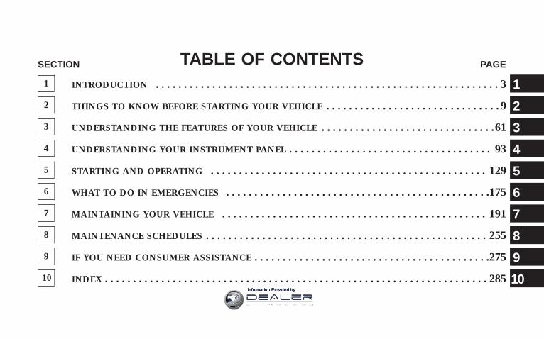
TABLE OF CONTENTSSECTION PAGE
1 INTRODUCTION . . . . . . . . . . . . . . . . . . . . . . . . . . . . . . . . . . . . . . . . . . . . . . . . . . . . . . . . . . . . . 3
2 THINGS TO KNOW BEFORE STARTING YOUR VEHICLE . . . . . . . . . . . . . . . . . . . . . . . . . . . . . . . 9
3 UNDERSTANDING THE FEATURES OF YOUR VEHICLE . . . . . . . . . . . . . . . . . . . . . . . . . . . . . . .61
4 UNDERSTANDING YOUR INSTRUMENT PANEL . . . . . . . . . . . . . . . . . . . . . . . . . . . . . . . . . . . . 93
5 STARTING AND OPERATING . . . . . . . . . . . . . . . . . . . . . . . . . . . . . . . . . . . . . . . . . . . . . . . . . 129
6 WHAT TO DO IN EMERGENCIES . . . . . . . . . . . . . . . . . . . . . . . . . . . . . . . . . . . . . . . . . . . . . . .175
7 MAINTAINING YOUR VEHICLE . . . . . . . . . . . . . . . . . . . . . . . . . . . . . . . . . . . . . . . . . . . . . . . 191
8 MAINTENANCE SCHEDULES . . . . . . . . . . . . . . . . . . . . . . . . . . . . . . . . . . . . . . . . . . . . . . . . . . 255
9 IF YOU NEED CONSUMER ASSISTANCE . . . . . . . . . . . . . . . . . . . . . . . . . . . . . . . . . . . . . . . . . .275
10 INDEX . . . . . . . . . . . . . . . . . . . . . . . . . . . . . . . . . . . . . . . . . . . . . . . . . . . . . . . . . . . . . . . . . . . . 285
1
2
3
4
5
6
7
8
9
10Information Provided by:

Information Provided by:

INTRODUCTION
CONTENTS
m Introduction . . . . . . . . . . . . . . . . . . . . . . . . . . . 4
m How To Use This Manual . . . . . . . . . . . . . . . . . . 4
m Warnings And Cautions . . . . . . . . . . . . . . . . . . . 6
m Vehicle Identification Number . . . . . . . . . . . . . . . 6
m Vehicle Modifications / Alterations . . . . . . . . . . . 7
1
Information Provided by:

INTRODUCTIONThis manual has been prepared with the assistance ofservice and engineering specialists to acquaint you withthe operation and maintenance of your new vehicle. It issupplemented by a Warranty Information Booklet andvarious customer oriented documents. You are urged toread these publications carefully. Following the instruc-tions and recommendations in this manual will helpassure safe and enjoyable operation of your vehicle.
NOTE: After you read the manual, it should be storedin the vehicle for convenient reference and remain withthe vehicle when sold, so that the new owner will beaware of all safety warnings.
When it comes to service, remember that your dealerknows your vehicle best, has the factory-trained techni-cians and genuine Mopart parts, and is interested inyour satisfaction.
HOW TO USE THIS MANUALConsult the table of contents to determine which sectioncontains the information you desire.
The detailed index at the back of this manual contains acomplete listing of all subjects.
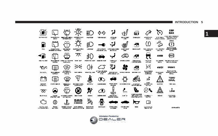
Consult the following table for a description of thesymbols that may be used on your vehicle or throughoutthis Owner’s Manual:
4 INTRODUCTION
Information Provided by:
INTRODUCTION 5
1
Information Provided by:
WARNINGS AND CAUTIONSThis manual contains WARNINGS against operatingprocedures, which could result in an accident or bodilyinjury. It also contains CAUTIONS against procedures,which could result in damage to your vehicle. If you donot read this entire manual, you may miss importantinformation. Observe all Warnings and Cautions.
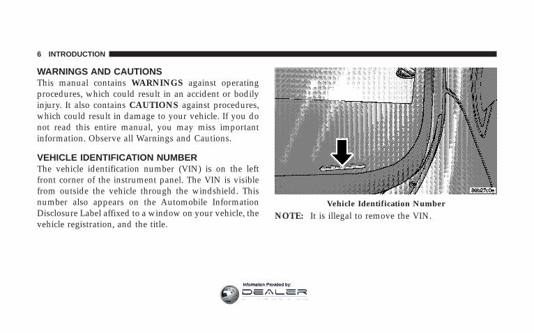
VEHICLE IDENTIFICATION NUMBERThe vehicle identification number (VIN) is on the leftfront corner of the instrument panel. The VIN is visiblefrom outside the vehicle through the windshield. Thisnumber also appears on the Automobile InformationDisclosure Label affixed to a window on your vehicle, thevehicle registration, and the title.
NOTE: It is illegal to remove the VIN.Vehicle Identification Number
6 INTRODUCTION
Information Provided by:
VEHICLE MODIFICATIONS / ALTERATIONS
WARNING!
Any modifications or alterations to this vehicle couldseriously affect its roadworthiness and safety andmay lead to an accident resulting in serious injury ordeath.
INTRODUCTION 7
1
Information Provided by:

Information Provided by:

THINGS TO KNOW BEFORE STARTING YOUR VEHICLE
CONTENTS
m A Word About Your Keys . . . . . . . . . . . . . . . . . .12
▫ Ignition Key Removal . . . . . . . . . . . . . . . . . . .12
▫ Key-In-Ignition Reminder . . . . . . . . . . . . . . . .13
m Security Alarm System . . . . . . . . . . . . . . . . . . . .13
▫ Rearming Of The System . . . . . . . . . . . . . . . . .13
▫ To Arm The System . . . . . . . . . . . . . . . . . . . . .13
▫ To Disarm The System . . . . . . . . . . . . . . . . . . .15
m Illuminated Entry System . . . . . . . . . . . . . . . . . .16
m Remote Keyless Entry . . . . . . . . . . . . . . . . . . . . .17
▫ To Unlock The Doors . . . . . . . . . . . . . . . . . . .17
▫ To Lock The Doors . . . . . . . . . . . . . . . . . . . . .18
▫ To Unlatch The Trunk/Liftgate . . . . . . . . . . . . .19
▫ Using The Panic Alarm . . . . . . . . . . . . . . . . . .19
▫ Programming Additional Transmitters . . . . . . . .20
▫ Battery Replacement . . . . . . . . . . . . . . . . . . . .21
▫ General Information . . . . . . . . . . . . . . . . . . . .22
2
Information Provided by:

m Door Locks . . . . . . . . . . . . . . . . . . . . . . . . . . . .23
▫ Manual Door Lock . . . . . . . . . . . . . . . . . . . . .24
▫ Power Door Locks . . . . . . . . . . . . . . . . . . . . .24
m Windows . . . . . . . . . . . . . . . . . . . . . . . . . . . . .26
▫ Power Windows . . . . . . . . . . . . . . . . . . . . . . .26
▫ Auto Down Feature . . . . . . . . . . . . . . . . . . . .27
▫ Wind Buffeting . . . . . . . . . . . . . . . . . . . . . . . .27
m Liftgate — Coupe Models Only . . . . . . . . . . . . . .28
m Trunk Lock And Release — ConvertibleModels Only . . . . . . . . . . . . . . . . . . . . . . . . . . .29
m Trunk Safety Warning — ConvertibleModels Only . . . . . . . . . . . . . . . . . . . . . . . . . . .30
▫ Trunk Emergency Release . . . . . . . . . . . . . . . .30
m Occupant Restraints . . . . . . . . . . . . . . . . . . . . . .31
▫ Lap/Shoulder Belts . . . . . . . . . . . . . . . . . . . . .31
▫ Lap/Shoulder Belt Untwisting Procedure . . . . .35
▫ Enhanced Seat Belt Reminder System(BeltAlertt) . . . . . . . . . . . . . . . . . . . . . . . . . .36
▫ Automatic Locking Mode . . . . . . . . . . . . . . . .37
▫ Six-Point Belt System - If Equipped . . . . . . . . .38
▫ Seat Belts And Pregnant Women . . . . . . . . . . . .39
▫ Seat Belt Extender . . . . . . . . . . . . . . . . . . . . . .39
▫ Driver And Passenger Supplemental RestraintSystem (SRS) - Airbag . . . . . . . . . . . . . . . . . . .40
▫ Child Restraint . . . . . . . . . . . . . . . . . . . . . . . .50
10 THINGS TO KNOW BEFORE STARTING YOUR VEHICLE
Information Provided by:

m Break-In Recommendations . . . . . . . . . . . . . . . . .56
m Safety Tips . . . . . . . . . . . . . . . . . . . . . . . . . . . .57
▫ Exhaust Gas . . . . . . . . . . . . . . . . . . . . . . . . . .57
▫ Safety Checks You Should Make InsideThe Vehicle . . . . . . . . . . . . . . . . . . . . . . . . . .58
▫ Periodic Safety Checks You Should MakeOutside The Vehicle . . . . . . . . . . . . . . . . . . . .59
THINGS TO KNOW BEFORE STARTING YOUR VEHICLE 11
2
Information Provided by:

A WORD ABOUT YOUR KEYSYou can insert the double-sided keys into the locks witheither side up.
The dealer that sold you your new vehicle has the keycode numbers for your vehicle locks. These numbers canbe used to order duplicate keys from your dealer or alocksmith. Ask your dealer for these numbers and keepthem in a safe place.
Ignition Key Removal
1. Press the clutch pedal to the floor.
2. Bring the vehicle to a stop.
3. Place the gear selector in gear.
4. Apply the parking brake fully.
5. Press the “Key Removal” release button, turn the keyto place the ignition switch in the OFF/LOCK position,and then pull the key out of the switch.
6. Release the clutch pedal.
Ignition Key Positions
12 THINGS TO KNOW BEFORE STARTING YOUR VEHICLE
Information Provided by:

NOTE: The Power Accessory Delay feature allows youto operate the radio and the power windows for 2minutes after turning off the ignition switch. Removingthe key from the ignition switch and opening the driver’sdoor will cancel this feature. Your dealership can enableor disable the Power Accessory Delay feature as desired.
Key-In-Ignition ReminderIf you open the driver’s door when the key is in theignition, a chime will sound to remind you to remove thekey.
NOTE: The Key-In-Ignition reminder only soundswhen the ignition switch is placed in the OFF/LOCK orACC positions.
SECURITY ALARM SYSTEMThis system monitors the doors, trunk/liftgate, and hoodfor unauthorized entry and the ignition switch for unau-thorized operation. If something triggers the alarm, thesystem will prevent the vehicle from starting. It will alsosound the horn and flash the park lights, the taillights,and the fog lights.
Rearming of the System:If something triggers the alarm, and no action is taken todisarm it, the system will turn off the horn after 3minutes, turn off all of the visual signals (flashing lights)after 15 minutes, and then rearm itself.
To Arm the System:Remove the key from the ignition switch and either pressa power door lock switch while the driver or passengerdoor is open or press the LOCK button on the Remote
THINGS TO KNOW BEFORE STARTING YOUR VEHICLE 13
2
Information Provided by:

Keyless Entry (RKE) transmitter. After the last door isclosed, or if all doors are closed, the system will arm itselfin approximately 16 seconds. During the arming process,the Vehicle Security Alarm Indicator light will flash at afast rate. Once the system is armed, the light will flashonce every 6 seconds.
NOTE:• The system will not cancel the arming process if you
open the hood or trunk/liftgate. It will however cancelthe arming process if you open a door or turn on theignition. If this occurs, and you wish to rearm thesystem, simply repeat either of the previously de-scribed arming sequences.
• The Vehicle Security Alarm Indicator light will remainon steady if the hood or trunk/liftgate is open duringthe arming process or if there is a fault in the system.If you verify that the hood and trunk/liftgate are notopen, and the light remains on steady, see yourauthorized dealer for service.
Entering the Trunk with the System Armed —Convertible:
NOTE: Using the key to open the trunk while thesystem armed will trigger the alarm.
Vehicle Security Alarm Indicator Light
14 THINGS TO KNOW BEFORE STARTING YOUR VEHICLE
Information Provided by:

Press the Trunk button on the RKE transmitter to allowaccess without triggering the alarm or having to disarmthe system. The trunk lid will pop open.
Entering the liftgate with the System Armed —Coupe:
NOTE: Using the key to open the liftgate while thesystem armed will trigger the alarm.
Press the Liftgate button on the RKE transmitter to allowaccess without triggering the alarm or having to disarmthe system. Then, within 30 seconds, open the liftgate byusing the key cylinder or the liftgate release switchlocated in the exterior liftgate handle.
NOTE: If you do not open the liftgate within 30 seconds,the system will re-arm and ignore the switch input.
After closing the liftgate, the system will arm immedi-ately without having to re-lock the vehicle.
To Disarm the SystemThere are two ways to disarm the system:
• Use the key to unlock the driver’s door. The door lockis located on the outside door panel beneath themirror.
Mechanical Door Lock
THINGS TO KNOW BEFORE STARTING YOUR VEHICLE 15
2
Information Provided by:

• Press the UNLOCK button on the RKE transmitter.The front and rear park lights and the turn signallights will flash to acknowledge the signal.
NOTE: The vehicle will not start unless the VehicleSecurity Alarm System is disarmed by either method.Inserting the key in the ignition WILL NOT disarm thesystem. Furthermore, turning the ignition key to anyposition while the system is armed will trigger an alarm.
Tamper AlertIf something has triggered the system in your absence,the Vehicle Security Alarm Indicator Light will flashtwice every six seconds. In addition, the horn will soundthree times when you disarm the system.
ILLUMINATED ENTRY SYSTEMThe interior lights will turn on whenever a door isopened or the liftgate is opened (Coupe models) and thedimmer switch is not in the defeat position.
The interior lights will turn on, remain on for about 30seconds, and then fade to off if any of the followingoccur:
• A door is opened using the outside door handle andthen closed.
• A door is unlocked using the remote keyless entrytransmitter.
• A door is unlocked using the outside driver’s door keycylinder.
The interior lights will turn on and remain on for about 4seconds and then fade to off if a door is opened using theinside door handle.
16 THINGS TO KNOW BEFORE STARTING YOUR VEHICLE
Information Provided by:

REMOTE KEYLESS ENTRYThis system allows you to lock or unlock the doors, openthe trunk/liftgate, or activate the panic alarm fromdistances up to about 23 feet (7 meters) using a hand heldradio transmitter. The transmitter need not be pointed atthe vehicle to activate the system.
To Unlock the Doors:Press and release the UNLOCK button on the transmitteronce to unlock the driver’s door, or twice to unlock bothdoors. The park lights and turn signal lights will flash toacknowledge the signal and the illuminated entry systemwill turn on. In addition, the words DOOR UNLOCKED
will flash in the odometer if one door is unlocked or willremain on steadily if both doors are unlocked.
NOTE: On Coupe models, pressing either the UNLOCKbutton or the LIFTGATE button will allow liftgate access.
Remote Key Unlock, Driver Door/Both Doors FirstThis feature lets you program the system to unlock eitherthe driver’s door or both doors on the first press of theUNLOCK button on the transmitter. To change the cur-rent setting, proceed as follows:
1. Press the UNLOCK button on a programmed trans-mitter for at least 4 seconds, but not longer than 10seconds. Then, press the LOCK button.
2. Release both buttons at the same time.
3. Test the feature while outside of the vehicle, bypressing the UNLOCK button on the transmitter with theignition in the OFF/LOCK position, and the key re-moved.
Keyless Entry Transmitter
THINGS TO KNOW BEFORE STARTING YOUR VEHICLE 17
2
Information Provided by:

4. Repeat these steps if you want to return this feature toits previous setting.
NOTE: Pressing the LOCK button on the transmitterwhile you are in the vehicle will activate the SecurityAlarm. Opening a door with the Security Alarm activatedwill cause the alarm to sound. Press the UNLOCK buttonto deactivate the Security Alarm.
Flash Lights with Remote Key LockThis feature will cause the park lights and turn signallights to flash when the doors are locked or unlockedwith the transmitter. This feature can be turned on orturned off. To change the current setting, proceed asfollows:
1. Press the LOCK button on a programmed transmitterfor at least 4 seconds, but no longer then 10 seconds.Then, press the TRUNK/LIFTGATE button.
2. Release both buttons at the same time.
3. Test the feature while outside of the vehicle, bypressing the LOCK/UNLOCK buttons on the transmitterwith the ignition in the OFF/LOCK position, and the keyremoved.
4. Repeat these steps if you want to return this feature toits previous setting.
NOTE: Pressing the LOCK button on the transmitterwhile you are in the vehicle will activate the SecurityAlarm. Opening a door with the Security Alarm activatedwill cause the alarm to sound. Press the UNLOCK buttonto deactivate the Security Alarm.
To Lock the Doors:Press and release the LOCK button on the transmitter tolock the doors. The horn will chirp once and the parklights and turn signal lights will flash to acknowledge thesignal.
18 THINGS TO KNOW BEFORE STARTING YOUR VEHICLE
Information Provided by:

Sound Horn with Remote Key LockThis feature will cause the horn to chirp when the doorsare locked with the transmitter. This feature can beturned on or turned off. To change the current setting,proceed as follows:
1. Press the LOCK button on a programmed transmitterfor at least 4 seconds, but no longer then 10 seconds.Then, press the UNLOCK button.
2. Release both buttons at the same time.
3. Test the feature while outside of the vehicle, bypressing the LOCK button on the transmitter with theignition in the OFF/LOCK position, and the key re-moved.
4. Repeat these steps if you want to return this feature toits previous setting.
NOTE: Pressing the LOCK button on the transmitterwhile you are in the vehicle will activate the Security
Alarm. Opening a door with the Security Alarm activatedwill cause the alarm to sound. Press the UNLOCK buttonto deactivate the Security Alarm.
To Unlatch the Trunk/Liftgate:Press and hold the TRUNK/LIFTGATE button on thetransmitter for at least one second to unlatch the trunk/liftgate. The park lights and turn signal lights will flashthree times to acknowledge the signal.
Using The Panic Alarm:The panic alarm unlocks the driver’s door, turns on theinterior lights, flashes the park lights and fog lights, andsounds the horn. The Panic alarm will not work whendriving the vehicle.
To turn the panic alarm ON or OFF, press and hold thePANIC button on the transmitter for at least one secondand release. The alarm can also be turned off by insertingthe key into the ignition switch and turning it to the
THINGS TO KNOW BEFORE STARTING YOUR VEHICLE 19
2
Information Provided by:

ON/RUN position. If not deactivated through the trans-mitter or the ignition switch, the alarm will turn offautomatically after 3 minutes.
Programming Additional Transmitters
NOTE: You must have at least one programmed trans-mitter to perform this procedure. If you do not have aprogrammed transmitter, contact your dealer for details.
Use this procedure to program up to three additionaltransmitters for your vehicle. To activate the program-ming feature, proceed as follows:
1. Turn the ignition switch to the ON/RUN position.
2. Set the parking brake.
3. Press and hold the UNLOCK button for at least 5seconds, but no longer then 10 seconds on a previouslyprogrammed transmitter. Then, press the PANIC buttonwhile still holing the UNLOCK button.
4. Release both buttons at the same time. A chime willsound to signal that the programming feature is acti-vated.
5. Within 30 seconds, press and release the LOCK buttonand the UNLOCK button at the same time on the newtransmitter.
6. Press and release any button one time on the newtransmitter. A chime will sound to indicate that the newtransmitter is programmed. An additional chime willsound at the end of the 30-second programming period.It will also sound if the ignition is switched OFF.
7. Repeat Steps 3 through 6 to program each additionaltransmitter.
20 THINGS TO KNOW BEFORE STARTING YOUR VEHICLE
Information Provided by:

Battery ReplacementThe recommended replacement battery is 2016. This is ageneric battery, readily available at local retail stores.
NOTE:• Perchlorate Material — special handling may apply.
See www.dtsc.ca.gov/hazardouswaste/perchlorate.
• Do not touch the battery terminals that are on the backhousing or the printed circuit board.
1. Separate the two halves of the transmitter with a coinor similar object.
Separating Transmitter Halves
THINGS TO KNOW BEFORE STARTING YOUR VEHICLE 21
2
Information Provided by:

2. Remove and replace the battery. Avoid touching thenew battery with your fingers. Skin oils may causebattery deterioration. If you touch a battery, clean it withrubbing alcohol.
3. To assemble the transmitter case, snap the two halvestogether.
4. Test the transmitter operation.
General InformationThis transmitter complies with FCC rules part 15. Opera-tion is subject to the following conditions:
1. This device may not cause harmful interference.
2. This device must accept any interference that may bereceived, including interference that may cause undes-ired operation.
If your Remote Keyless Entry transmitter ever fails tooperate from a normal distance, check the following:
1. Closeness to a radio transmitter, such as a radio stationtower, airport transmitter, and some mobile or CB radioscan affect transmitter operation. To verify if this is thecause, move the vehicle to another area and test trans-mitter operation.
2. The transmitter may become “out of sync” and will nolonger function if operated more than 255 times while outof range of the vehicle (23 feet or 7 meters) or if operatedwhile the vehicle battery is dead or disconnected. To“synchronize” the transmitter, remove the key from theignition. Close the hood and all doors. Press both buttonson the transmitter for about 10 seconds. The horn willchirp once to acknowledge the signal. Normal transmit-ter operation should resume.
3. The transmitter battery may be weak or dead. Theexpected life of the battery is a minimum of three years.
22 THINGS TO KNOW BEFORE STARTING YOUR VEHICLE
Information Provided by:

DOOR LOCKS
WARNING!
Do not touch the exhaust pipe sill covers whenentering or exiting your Viper. They can be hotenough to burn you. Observe the warning labels oneach door closure panel.
WARNING!
• For personal security and safety in the event of anaccident, lock the vehicle doors as you drive aswell as when you park and leave the vehicle.
• When leaving the vehicle always remove the keyfrom the ignition lock, and lock your vehicle.Unsupervised use of vehicle equipment may causesevere personal injuries and death.
• Never leave children alone in a vehicle. Leavingchildren in a vehicle unattended is dangerous for anumber of reasons. A child or others could beinjured seriously or fatally. Don’t leave the keys inthe ignition. A child could operate power win-dows, other controls, or move the vehicle.
THINGS TO KNOW BEFORE STARTING YOUR VEHICLE 23
2
Information Provided by:

Manual Door LockThe driver’s door can be locked or unlocked with the key.The door lock is located on the outside door panelbeneath the mirror.
Power Door LocksA power door lock switch is on each door trim panel. Usethis switch to lock or unlock the doors.
NOTE: To prevent you from accidentally locking yourkeys in the vehicle, the power door locks will not operateif the key is in the ignition and the driver’s door is open.
Mechanical Door LockPower Door Lock Switch
24 THINGS TO KNOW BEFORE STARTING YOUR VEHICLE
Information Provided by:

Electronic Door LockThis vehicle is equipped with a virtual lock system. Inputfrom the outside door handle is ignored if the vehicle isvirtually locked.
Door Lock MessagingThe words “DOOR UNLOCKED” will flash in the odom-eter if one door is unlocked or will remain on steadily ifboth doors are unlocked. A door is considered unlockedif the inside door handle is pulled. With the key in theignition switch, this display will turn off approximately40 seconds after switching off the ignition, or if the PowerAccessory Delay feature is active, it will turn off approxi-mately 40 seconds after the delay feature times out.
Automatic Door LocksThis feature locks the doors automatically once vehiclespeed reaches 18 mph (29 km/h).
NOTE: Input from the door handles is ignored once thevehicle is moving faster than 5 mph.
Automatic Door Locks ProgrammingThe Automatic Door Locks feature can be enabled ordisabled as follows:
1. Close all doors and place the key in the ignition.
2. Cycle the ignition switch between ON/RUN andOFF/LOCK 4 times ending up in the OFF/LOCK posi-tion.
3. Depress the power door lock switch to lock the doors.
4. A single chime will indicate the completion of theprogramming.
5. Repeat these steps if you want to return this feature toits previous setting.
This feature can also be disabled at the dealership ifdesired.
NOTE: Use the Automatic Door Locks feature in accor-dance with local laws.
THINGS TO KNOW BEFORE STARTING YOUR VEHICLE 25
2
Information Provided by:

WINDOWS
Power WindowsThe power window switches are located between thedriver and passenger seats on the center tunnel bezel, justto the left of the parking brake. The switch on the left sidecontrols the driver’s window and the switch on the rightcontrols the passenger’s window. The power windowswitches are active when the ignition is in ON/RUN orACC position.
NOTE:• The Power Accessory Delay feature allows you to
operate the power windows for 2 minutes after turn-ing off the ignition switch. Removing the key from theignition switch and opening the driver’s door willcancel this feature. Your dealership can enable ordisable the Power Accessory Delay feature as desired.
• Windows cannot be driven up during Power Acces-sory Delay with a door open. Furthermore, openingthe door will stop the window movement immediatelyif the window is in the process of going up.
• The window will lower slightly if it is closed com-pletely when opening the door. The window willreturn to its fully closed position after closing the door.This action is necessary in order to clear the seal whenopening the door.
WARNING!
Never leave children in a vehicle, with the keys in theignition switch. Occupants, particularly unattendedchildren, can become entrapped by the power win-dows while operating the power window switch. Suchentrapment may result in serious injury or death.
26 THINGS TO KNOW BEFORE STARTING YOUR VEHICLE
Information Provided by:
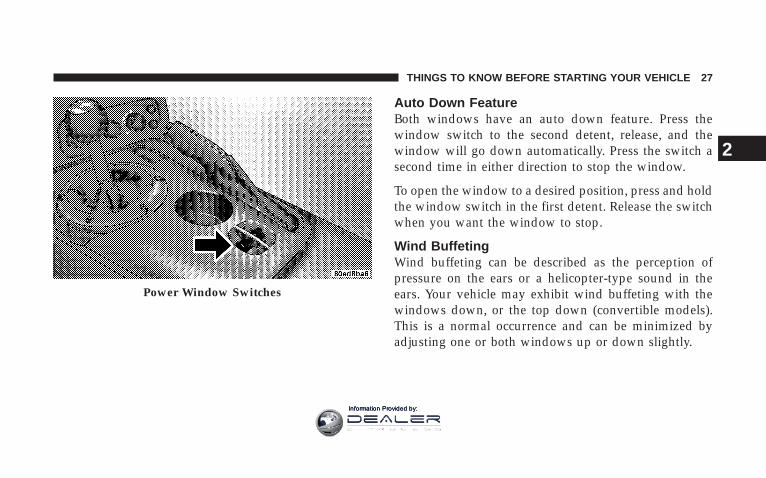
Auto Down FeatureBoth windows have an auto down feature. Press thewindow switch to the second detent, release, and thewindow will go down automatically. Press the switch asecond time in either direction to stop the window.
To open the window to a desired position, press and holdthe window switch in the first detent. Release the switchwhen you want the window to stop.
Wind BuffetingWind buffeting can be described as the perception ofpressure on the ears or a helicopter-type sound in theears. Your vehicle may exhibit wind buffeting with thewindows down, or the top down (convertible models).This is a normal occurrence and can be minimized byadjusting one or both windows up or down slightly.
Power Window Switches
THINGS TO KNOW BEFORE STARTING YOUR VEHICLE 27
2
Information Provided by:

LIFTGATE — COUPE MODELS ONLYThe liftgate can be unlocked or locked by the RemoteKeyless Entry (RKE) transmitter or by activating either ofthe power door lock switches located on the door trimpanels.
To unlock the liftgate with the RKE transmitter, press theLIFTGATE button on the transmitter for at least onesecond. The park lights and turn signal lights will flashthree times to acknowledge the signal.
NOTE: Pressing the UNLOCK button on the transmitterwill also allow liftgate access.
Once unlocked, the liftgate can be opened or closed. Toopen the liftgate, depress the liftgate release switchlocated in the exterior liftgate handle and pull the liftgateopen with one fluid motion.
NOTE: The liftgate release switch will be ignored underthe following conditions:
• When the ignition is in RUN and the parking brake isnot set.
• When vehicle speed is not a 0 mph (0 km/h).
• When all doors are locked (except for RKE liftgateaccess). Refer to “Entering the liftgate with the SystemArmed — Coupe” under “Security Alarm System” inthis section for additional information.
The word “DECK” will flash in the odometer when theliftgate is open. With the key in the ignition switch, thisdisplay will turn off approximately 40 seconds afterswitching off the ignition, or if the Power AccessoryDelay feature is active, it will turn off approximately 40seconds after the delay feature times out.
28 THINGS TO KNOW BEFORE STARTING YOUR VEHICLE
Information Provided by:

WARNING!
• Driving with the liftgate open can allow poison-ous exhaust gases into your vehicle. You and yourpassengers could be injured by these fumes. Keepthe liftgate closed when you are operating thevehicle.
• If you are required to drive with the liftgate open,make sure that all windows are closed, and theclimate control blower switch is set at high speed.DO NOT use the recirculation mode.
Gas props support the liftgate in the open position.However, because the gas pressure drops with tempera-ture, it may be necessary to assist the props whenopening the liftgate in cold weather.
TRUNK LOCK AND RELEASE — CONVERTIBLEMODELS ONLYYou can unlatch the trunk lid by pressing the TRUNKbutton on the Remote Keyless Entry (RKE) transmitterfor at least one second. The park lights and turn signallights will flash three times to acknowledge the signaland the trunk lid will pop open.
You can also unlatch the trunk lid with the key. The keycylinder is located on the trunk lid.
The word “DECK” will flash in the odometer when thetrunk lid is open. With the key in the ignition switch, thisdisplay will turn off approximately 40 seconds afterswitching off the ignition, or if the Power AccessoryDelay feature is active, it will turn off approximately 40seconds after the delay feature times out.
THINGS TO KNOW BEFORE STARTING YOUR VEHICLE 29
2
Information Provided by:

NOTE: Gas props support the trunk lid in the openposition. However, because the gas pressure drops withtemperature, it may be necessary to assist the props whenopening the trunk lid in cold weather.
TRUNK SAFETY WARNING — CONVERTIBLEMODELS ONLY
WARNING!
Do not allow children to have access to the trunk,either by climbing into the trunk from outside, orthrough the inside of the vehicle. Always close thetrunk lid when your vehicle is unattended. Once inthe trunk, young children may not be able to escape.If trapped in the trunk, children can die from suffo-cation or heat stroke.
Trunk Emergency Release
The trunk of your vehicle is equipped with an emergencyrelease handle. It is located on the inside of the trunk lid,near the latch, and is coated so that it glows in a darkenedtrunk. Pull on the handle to open the trunk.
Emergency Release
30 THINGS TO KNOW BEFORE STARTING YOUR VEHICLE
Information Provided by:

OCCUPANT RESTRAINTSSome of the most important safety features in yourvehicle are the restraint systems. These include the seatbelts and the airbags for the driver and passenger.
Please pay close attention to the information in thissection. It explains how to use your restraint systemproperly to keep you and your passenger as safe aspossible. Note that all of the warnings in this sectionapply no matter which system you have.
WARNING!
In a collision, you and your passenger can suffermuch greater injuries if you are not buckled upproperly. You can strike the interior of your vehicle oryour passenger, or you can be thrown out of thevehicle. Always be sure you and your passenger arebuckled up properly.
Buckle up even though you are an excellent driver, evenon short trips. Someone on the road may be a poor driverand cause a collision that includes you. This can happenfar away from home or on your street.
Research has shown that seat belts save lives. They alsocan reduce the seriousness of injuries in a collision. Someof the worst injuries happen when people are thrownfrom the vehicle. Seat belts reduce the possibility ofejection and the risk of injury caused by striking theinside of the vehicle. Everyone in a motor vehicle shouldbe belted at all times.
Lap/Shoulder BeltsEach seat belt is a combined lap/shoulder belt system.The belt webbing retractor will lock only during verysudden stops or impacts. This feature allows the shoulderportion of the belt to move freely with you under normalconditions. However, in a collision, the belt will lock andreduce your risk of striking the inside of the vehicle orbeing thrown out.
THINGS TO KNOW BEFORE STARTING YOUR VEHICLE 31
2
Information Provided by:

WARNING!
• It is extremely dangerous to ride in a cargo area, inside oroutside of a vehicle. In a collision, people riding in theseareas are more likely to be injured seriously or killed.
• Do not allow people to ride in any area of your vehiclethat is not equipped with seats and seat belts.
• Be sure everyone in your vehicle is in a seat and using aseat belt properly.
• Wearing a seat belt incorrectly is dangerous. Seat beltsare designed to go around the large bones of your body.These are the strongest parts of your body and can takethe forces of a collision the best.
• Wearing your belt in the wrong place could make yourinjuries in a collision much worse. You might sufferinternal injuries, or you could even slide out of part ofthe belt. Follow these instructions to wear your seat beltsafely and to keep your passengers safe, too.
• Two people should never be belted into a single seat belt.People belted together can crash into one another in anaccident, hurting one another badly. Never use a lap/shoulder belt or a lap belt for more than one person, nomatter what their size.
Lap/Shoulder Belt Operating Instructions
1. Enter the vehicle and close the door. Sit back andadjust the seat.
2. The seat belt latch plate is located at the side of yourseat back. Grasp the latch plate and pull out the belt.
Latch Plate (Convertible Shown)
32 THINGS TO KNOW BEFORE STARTING YOUR VEHICLE
Information Provided by:
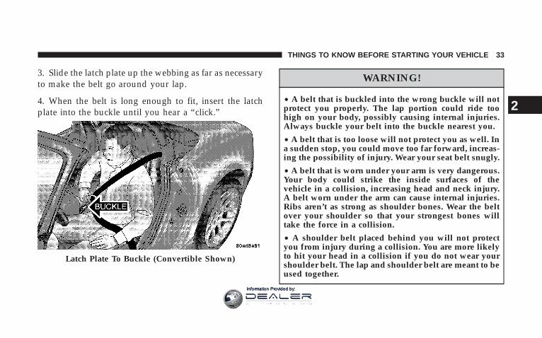
3. Slide the latch plate up the webbing as far as necessaryto make the belt go around your lap.
4. When the belt is long enough to fit, insert the latchplate into the buckle until you hear a “click.”
WARNING!
• A belt that is buckled into the wrong buckle will notprotect you properly. The lap portion could ride toohigh on your body, possibly causing internal injuries.Always buckle your belt into the buckle nearest you.
• A belt that is too loose will not protect you as well. Ina sudden stop, you could move too far forward, increas-ing the possibility of injury. Wear your seat belt snugly.
• A belt that is worn under your arm is very dangerous.Your body could strike the inside surfaces of thevehicle in a collision, increasing head and neck injury.A belt worn under the arm can cause internal injuries.Ribs aren’t as strong as shoulder bones. Wear the beltover your shoulder so that your strongest bones willtake the force in a collision.
• A shoulder belt placed behind you will not protectyou from injury during a collision. You are more likelyto hit your head in a collision if you do not wear yourshoulder belt. The lap and shoulder belt are meant to beused together.
Latch Plate To Buckle (Convertible Shown)
THINGS TO KNOW BEFORE STARTING YOUR VEHICLE 33
2
Information Provided by:

5. Position the lap belt across your thighs, below yourabdomen. To remove slack in the lap belt portion, pull upa little on the shoulder belt, as shown.
6. To loosen the lap belt if it is too tight, lift up on theshoulder belt and pull on the lap belt. A snug belt reducesthe risk of sliding under the belt in a collision.
WARNING!
• A lap belt worn too high can increase the risk ofinternal injury in a collision. The belt forces won’t beat the strong hip and pelvic bones, but across yourabdomen. Always wear the lap belt as low as pos-sible and keep it snug.
• A twisted belt can’t do its job as well. In a collision,it could even cut into you. Be sure the belt is straight.If you can’t straighten a belt in your vehicle, take it toyour dealer and have it fixed.
7. Position the shoulder belt on your chest so that it iscomfortable and not resting on your neck. The retractorwill withdraw any slack in the belt.Removing Slack From Belt (Convertible Shown)
34 THINGS TO KNOW BEFORE STARTING YOUR VEHICLE
Information Provided by:

8. To release the belt, push the red button in the buckle.The belt will retract automatically to its stowed position.If necessary, slide the latch plate down the webbing toallow it to retract fully.
WARNING!
A frayed or torn belt could rip apart in a collision andleave you with no protection. Inspect the belt systemperiodically, checking for cuts, frays, or loose parts.Damaged parts must be replaced immediately. Donot disassemble or modify the system. Seat beltassemblies must be replaced after a collision if theyhave been damaged (bent retractor, torn webbing,etc.).
Lap/Shoulder Belt Untwisting ProcedureUse the following procedure to untwist a twisted lap/shoulder belt.
1. Position the latch plate as close as possible to theanchor point.
2. At about 6 to 12 inches (15 to 30 cm) above the latchplate, grasp and twist the belt webbing 180° to create afold that begins immediately above the latch plate.
3. Slide the latch plate upward over the folded webbing.The folded webbing must enter the slot at the top of thelatch plate.
4. Continue to slide the latch plate up until it clears thefolded webbing.
THINGS TO KNOW BEFORE STARTING YOUR VEHICLE 35
2
Information Provided by:

Enhanced Seat Belt Reminder System (BeltAlert T)If the driver does not buckle their seat belt and vehiclespeed exceeds 5 mph (8 km/h), or if the passenger doesnot buckle their seat belt within 10 seconds of vehiclespeed exceeding 5 mph (8 km/h), the Enhanced WarningSystem (Belt Alert) will alert the occupant(s) to buckletheir seat belt(s). Once triggered, the Enhanced WarningSystem (Belt Alert) will flash the Seat Belt Reminder lightand chime for up to 96 seconds to alert the occupant(s) tobuckle their seat belt(s). If the driver unbuckles their seatbelt while vehicle speed is greater than 5 mph (8 km/h),or if the passenger unbuckles their seat belt for more than10 seconds while vehicle speed is greater than 5 mph (8km/h), the Enhanced Warning System (Belt Alert) willreactivate.
BeltAlertt ProgrammingThe Enhanced Warning System (BeltAlertt) can be en-abled or disabled by your authorized dealer or byperforming the following steps:
NOTE: DaimlerChrysler does not recommend deacti-vating the Enhanced Warning System (BeltAlertt).
1. Close all doors.
2. Turn the ignition switch to the OFF/LOCK position.
3. Buckle the driver’s seat belt.
4. Turn the ignition switch to the ON/RUN position, butdo not start the engine. Wait for the Seat Belt Reminderlight to turn off and then proceed to the next step.
NOTE: You must perform the following steps within 60seconds of turning the ignition switch to the ON/RUNposition.
5. Within 60 seconds of turning the ignition switch to theON/RUN position, unbuckle and then re-buckle thedriver’s seat belt at least three times within 10 seconds,ending with the seat belt buckled.
36 THINGS TO KNOW BEFORE STARTING YOUR VEHICLE
Information Provided by:

NOTE: Watch for the Seat Belt Reminder light to turn onwhile unbuckling the seat belt and turn off while re-buckling the seat belt. It may be necessary to retract theseat belt.
6. Turn the ignition switch to the OFF/LOCK position. Asingle chime will sound to signify that you have com-pleted the programming successfully.
The Enhanced Warning System (BeltAlertt) can be reac-tivated by repeating this procedure.
NOTE: When the Enhanced Warning System(BeltAlertt) is deactivated, the Seat Belt Reminder lightwill continue to illuminate as long as the driver’s seat beltor the passenger’s seat belt is unbuckled.
Automatic Locking ModeThe seat belts for both occupants are equipped withemergency locking retractors for normal use. Emergencylocking retractors activate during very sudden stops orimpacts. The passenger seat belt in your vehicle can alsobe converted to an automatic locking retractor to securechild restraint systems. Seat belts equipped with auto-matic locking retractors have a distinctive label on thewebbing.
How To Engage The Automatic Locking ModeTo convert the passenger seat belt from emergency lock-ing mode to automatic locking mode, grasp the shoulderportion of the belt and pull all of the webbing out of theretractor. Then, allow some of the webbing to retract backinto the retractor. As the belt retracts, you will hear aclicking sound indicating that the belt is now in auto-matic locking mode.
THINGS TO KNOW BEFORE STARTING YOUR VEHICLE 37
2
Information Provided by:
NOTE: Once the belt is in automatic locking mode, youwill not be able to pull any more of the webbing out ofthe retractor. In this mode, you will only be able to retractexcess webbing into the retractor to secure the childrestraint.
How To Disengage The Automatic Locking ModeSimply allow all of the webbing to retract back into theretractor to disengage the automatic locking mode. Thiswill return the retractor to the emergency locking modefor normal use.
Six-Point Belt System - If equippedThis six-point belt system meets SCCA standards and itshould only be used when engaging in performancerelated driving events. In turn, the standard lap/shoulder belt should be used whenever the vehicle isoperated on the street.
Six-Point Belt Operating Instructions
1. Place the anti-submarining belt on the seat so that itpoints upward.
2. Buckle the left and right lap belts and strap both legs.
3. Buckle the left and right shoulder belts.
4. Adjust the belts by pulling on the web ends and/orrepositioning the web clips and straps as required.
5. To release the belts, turn the belt latch mechanism 1⁄4turn in either the clockwise or the counter-clockwisedirection.
NOTE: The anti-submarining belt and the shoulder beltare attached to eye bolts at designated locations and theyshould be removed from the vehicle when not in use. Thelap belts and straps can be stored behind or to the side ofthe seat after removal.
38 THINGS TO KNOW BEFORE STARTING YOUR VEHICLE
Information Provided by:

Seat Belts and Pregnant WomenWe recommend that pregnant women use the seat beltsthroughout their pregnancy. Keeping the mother safe isthe best way to keep the baby safe.
Pregnant women should wear the lap portion of the beltacross the thighs and as snug across the hips as possible.Keep the belt low so that it does not come across theabdomen. That way the strong bones of the hips will takethe force if there is a collision.
Seat Belt ExtenderIf a seat belt is too short, even when extended fully, yourdealer can provide you with a seat belt extender. Thisextender should only be used if the existing belt is notlong enough. When it is not required, remove the ex-tender, and store it.
WARNING!
Using a seat belt extender when not needed canincrease the risk of injury in a collision. Only usewhen the seat belt is not long enough when it is wornlow and snug, and in the recommended seatingpositions. Remove and store the extender when notneeded.
THINGS TO KNOW BEFORE STARTING YOUR VEHICLE 39
2
Information Provided by:
Driver and Passenger Supplemental RestraintSystem (SRS) - AirbagThis vehicle is equipped with airbags for the driver andpassenger as a supplement to the seat belt restraintsystems. The driver airbag is mounted in the steeringwheel. The passenger airbag is mounted underneath acover in the passenger’s side of the instrument panel. Thewords SRS/AIRBAG is embossed on the airbag covers.
NOTE: The airbags are certified to the Federal regula-tions that allow less forceful deployment. The passengerairbag is certified to the Federal regulations that defineOccupant Classification (Refer to “How The Airbag Sys-tem Works” in this section).
The airbags have a multi stage inflator design. This mayallow the airbag to have different rates of inflation thatare based on collision severity and occupant size.
WARNING!
• Do not put anything on or around the airbag covers orattempt to open them manually. You may damage theairbags and you could be injured because the airbags areno longer functional. These protective covers for theairbag cushions are designed to open only when theairbags are inflating.
• Do not drill, cut, or tamper with the knee bolster in anyway.
• Do not mount any accessories to the knee bolster such asalarm lights, stereos, citizens band radios, etc.
• Relying on the airbags alone could lead to more severeinjuries in a collision. The airbags work with your seatbelt to restrain you properly. In some collisions, theairbags won’t deploy at all. Always wear your seat beltseven though you have airbags.
• Being too close to the steering wheel or instrument panelduring airbag deployment could cause serious injury.Airbags need room to inflate. Sit back, extending yourarms comfortably to reach the steering wheel or instru-ment panel.
40 THINGS TO KNOW BEFORE STARTING YOUR VEHICLE
Information Provided by:

The airbags work with the instrument panel knee bolstersand the seat belts to provide improved protection for thedriver and passenger. While the seat belts are designed toprotect the driver and passenger in many types ofcollisions, the airbags will deploy in moderate to severefrontal collisions. However, even in collisions where theairbags deploy, all occupants need the seat belts to keepthem in the right position for the airbags to protectproperly.
NOTE: The passenger airbag may not deploy if theOccupant Classification System (refer to “How The Air-bag System Works” in this section) determines the seat isempty or is occupied by someone that is classified in the“child” category. This could be a child, a teenager, oreven a small adult. Therefore, even if the driver airbagdeploys, the passenger airbag may not deploy.
Here are some simple steps you can take to minimizethe risk of harm from a deploying airbag.
1. An infant up to 1 year or approximately 20 pounds (9kg) should never ride in the vehicle, because in the eventof a crash the rear facing child seat places them too closeto the passenger airbag.
2. An infant in rear facing child safety seat, designed fora child up to one year or approximately 20 pounds (9 kg),should NEVER ride in the front seat of a vehicleequipped with a passenger airbag, unless the airbag isshut OFF. An airbag deployment can cause severe injuryor death to an infant in this position. Refer to “PassengerAirbag Disabled (PAD) Indicator Light” in this section.
3. A child that is not big enough to wear the vehicle seatbelt properly (refer to information on Child Restraint inthis section) should be secured in a child safety seat orbooster seat.
4. An older child who does not use a child safety seat orbooster seat should ride buckled properly in their seat.
THINGS TO KNOW BEFORE STARTING YOUR VEHICLE 41
2
Information Provided by:

5. Never allow a child to place the shoulder belt behindthem or under the arm.
6. Never allow a child to lean forward toward theinstrument panel as a passenger airbag deploymentcould cause severe injury or death to a child in thisposition.
7. For a child from 1 to 12 years old: Move the passengerseat as far back as possible. For a child from 20 to 60pounds (9 kg to 27 kg): Secure them in the appropriatechild safety seat or booster seat. If too large for a boosterseat, the child should wear the lap/shoulder belt prop-erly.
8. Read the instructions provided with your child re-straint to make sure that you are using it properly.
9. Read the instructions provided with your child safetyseat or booster seat to make sure that you are using itproperly.
10. All occupants should wear their lap and shoulderbelts properly.
11. Position the driver seat and passenger seat as faraway from the instrument panel as practical to allow theairbags room to inflate. Note that the power adjustablepedals allow for more driver’s seat adjustment options.Refer to “Adjustable Pedals” in Section 3 of this manualfor details.
Airbag System ComponentsThe airbag system consists of the following:
• Occupant Restraint Controller (ORC)
• Airbag Warning Light
• Driver Airbag
• Passenger Airbag
• Passenger Airbag Off Light
42 THINGS TO KNOW BEFORE STARTING YOUR VEHICLE
Information Provided by:

• Steering Wheel and Column
• Instrument Panel
• Seat Track Position Sensors
• Interconnecting Wiring
• Seat Belt Reminder Light
• Knee Impact Bolsters
• Front Acceleration Sensors
• Passenger Seat Occupant Classification System (OCS)
− Occupant Classification Module (OCM)
− Passenger Airbag Disabled (PAD) Indicator Light
− Flex Mat
− Interconnecting Wiring
− Seat Track Position Sensors
How The Airbag System Works
• The Occupant Restraint Controller (ORC) determinesif a frontal collision is severe enough to require theairbags to inflate. The airbag inflators are designed toprovide different rates of inflation. Based on the levelof collision severity, the ORC determines the properrate of inflation. The ORC may modify the rate ofpassenger airbag inflation or prevent passenger airbagdeployment based on input from the Occupant Clas-sification System (OCS). The ORC will not detect rollover or rear impacts. Furthermore, the airbags are noton and will not inflate if the key is in the OFF/LOCKposition, in the ACC position, or not in the ignition.
The ORC also monitors the readiness of the electronicparts of the system whenever the ignition switch is inthe ON/RUN position. These include all of the itemslisted under “Airbag System Components” except thesteering wheel and column and the knee bolsters.
THINGS TO KNOW BEFORE STARTING YOUR VEHICLE 43
2
Information Provided by:
The ORC turns on the Airbag warning lightand Passenger Airbag Disable (PAD) indica-tor light for 6 to 8 seconds as a self-checkwhen the ignition is first turned on. After the
self-check, the Airbag warning light will turn off andthe PAD indicator light will function normally (Refer to“Passenger Airbag Disable (PAD) Indicator Light” inthis section). If the ORC detects a malfunction in anypart of the system, it turns on the Airbag warning lighteither momentarily or continuously. A single chime willsound if the light comes on again after initial start up.
WARNING!
Ignoring the Airbag Warning Light in your instrumentpanel could mean you won’t have the airbags to protectyou in a collision. If the light does not come on, stayson after you start the vehicle, or if it comes on as youdrive, have the airbag system checked right away.
• The Driver Airbag/Inflator Unit is mounted in thesteering wheel. The Passenger Airbag/Inflator Unit ismounted underneath a cover in the passenger side ofthe instrument panel. When the ORC detects a colli-sion requiring the airbags, it signals the inflator units.A large quantity of non-toxic gas is generated to inflatethe airbags. Different airbag inflation rates may bepossible based on collision severity and occupant size.The steering wheel hub trim cover and the upper rightside of the instrument panel separate and then fold outof the way, as the bags inflate to their full size. Thebags inflate fully in about 50–70 milliseconds. This isabout half of the time it takes to blink your eyes. Thebags then deflate quickly while helping to restrain thedriver and passenger. The airbag gas is vented towardthe instrument panel through vent holes in the airbagmaterial. In this way, the airbags do not interfere withyour control of the vehicle.
44 THINGS TO KNOW BEFORE STARTING YOUR VEHICLE
Information Provided by:

• The Knee Impact Bolsters help protect the knees ofthe driver and the passenger, and position everyonefor the best interaction with the airbags.
• The Occupant Classification Module (OCM) is lo-cated underneath the passenger seat. The OCM usesinput from the Flex Mat to classify the occupant in thepassenger seat into a size category. The OCM commu-nicates this information to the ORC. The ORC maymodify the rate of passenger airbag inflation or pre-vent passenger airbag deployment based on occupantclassification.
If there is a fault present in the OCS, the Airbagwarning light will turn on. This indicates that youshould take the vehicle to an authorized dealer forservice. The Airbag warning light will turn on when-ever there is fault present, which can affect the opera-tion of the airbag system. If there is a fault present inthe OCS, both the PAD indicator light and the Airbag
warning light will illuminate to show that the passen-ger airbag is turned off. Should this occur the passen-ger airbag would remain off until the fault is cleared.If an object is lodged under the seat and interferes withoperation of the Flex Mat, a fault will occur whichturns on both the PAD indicator light and the Airbagwarning light. Once the lodged object is removed, thefault will be cleared automatically after a short period.
• The Passenger Airbag Disabled (PAD) IndicatorLight indicates to the driver and passenger when thepassenger airbag is turned OFF. In the presence of anoccupant seated properly in the passenger seat, whenthe PAD indicator light is illuminated, the passengerairbag is turned OFF.
The passenger airbag will be enabled for most any sizeadult who is seated properly in the passenger seat. Thepassenger airbag may or may not be enabled for(depending on size) a small teenager or a small adult
THINGS TO KNOW BEFORE STARTING YOUR VEHICLE 45
2
Information Provided by:

who is seated properly in the passenger seat. Thedriver and passenger should always use the PADindicator light as an indication that the passenger ispositioned properly in their seat. If the PAD indicatorlight comes on when an adult or teenager is in thepassenger seat, have the passenger reposition their selfin the seat until the light goes out. Remember, if thePAD indicator light is illuminated the passenger air-bag will not inflate in the event of a collision.
The passenger airbag will not be enabled for most anysize child who is seated properly in the passenger seatand for most properly installed child restraint systems.However, under certain conditions, even with a properlyinstalled child restraint system, the PAD indicator lightmay not be on, even though the airbag is disabled. Thiscan occur if the child restraint is lighter than the thresh-old weight necessary to turn the PAD indicator light on.In any case, DO NOT assume the airbag is turned off ifthe PAD indicator light is not illuminated.
WARNING!
An infant in rear facing child safety seat, designedfor a child up to one year or approximately 20 pounds(9 kg), should NEVER ride in the front seat of avehicle equipped with a passenger airbag, unless theairbag is shut OFF. An airbag deployment can causesevere injury or death to an infant in this position.
• The Flex Mat is located beneath the passenger seatcushion foam. The Flex Mat sends signals to the OCMfor classifying the occupant in the passenger seat.
Any weight on the seat will be sensed by the Flex Mat.Therefore, the occupant in the passenger seat needs tosit in a normal position (with their feet on or near thefloor) in order to be classified properly. If an occu-pant’s weight is transferred to another part of thevehicle (like the door or instrument panel), the system
46 THINGS TO KNOW BEFORE STARTING YOUR VEHICLE
Information Provided by:
may not classify the occupant properly. Furthermore,objects lodged under the seat can prevent the occu-pant’s weight from being measured properly and mayresult in the occupant being classified improperly.
The passenger seat assembly contains critical compo-nents that affect passenger airbag deployment. Correctlyfunctioning passenger seat components are critical for theOCS to classify the passenger properly and calculate theproper airbag deployment. Do not make any modifica-tions to the passenger seat components, assembly, or tothe seat cover. If the seat, trim cover, or cushion needsservice for any reason, take the vehicle to your autho-rized dealer. Only manufacturer approved seat accesso-ries may be used.
The following requirements must be strictly adhered to:
• Do not modify the passenger seat assembly or compo-nents in any way.
• Do not use prior or future model year seat covers notdesignated for the specific model being repaired. Al-ways use the correct seat cover specified for thevehicle.
• Do not replace the seat cover with an aftermarket seatcover.
• Do not add a secondary seat cover other than thoseapproved by DaimlerChrysler/Mopar.
• At no time should any supplemental restraint system(SRS) component or SRS related component or fas-tener be modified or replaced with any part exceptthose which are approved by DaimlerChrysler/Mopar.
THINGS TO KNOW BEFORE STARTING YOUR VEHICLE 47
2
Information Provided by:

WARNING!
Unapproved modifications or service procedures tothe passenger seat assembly, its related components,or seat cover may inadvertently change the airbagdeployment in case of a frontal crash. This couldresult in death or serious injury to the passenger ifthe vehicle is involved in an accident. A modifiedvehicle may not comply with required Federal MotorVehicle Safety Standards (FMVSS).
If A Deployment OccursThe airbag system is designed to deploy when the ORCdetects a moderate-to-severe frontal collision, to helprestrain the driver and passenger, and then to deflateimmediately.
NOTE: A frontal collision that is not severe enough toneed airbag protection will not activate the system. Thisdoes not mean something is wrong with the airbagsystem.
If you do have a collision, which deploys the airbags, anyor all of the following may occur:
• The nylon airbag material may sometimes cause abra-sions and/or skin reddening to the driver and passen-ger as the airbags deploy and unfold. The abrasionsare similar to friction rope burns or those you mightget sliding along a carpet or gymnasium floor. Theyare not caused by contact with chemicals. They are notpermanent and normally heal quickly. However, if youhaven’t healed significantly within a few days, or ifyou have any blistering, see your doctor immediately.
• As the airbags deflate, you may see some smoke-likeparticles. The particles are a normal by-product of theprocess that generates the non-toxic nitrogen gas used
48 THINGS TO KNOW BEFORE STARTING YOUR VEHICLE
Information Provided by:

for airbag inflation. These airborne particles may irri-tate the skin, eyes, nose, or throat. If you have skin oreye irritation, rinse the area with cool water. For noseor throat irritation, move to fresh air. If the irritationcontinues, see your doctor. If these particles settle onyour clothing, follow the garment manufacturer’s in-structions for cleaning.
• It is not advisable to drive your vehicle after theairbags have been deployed. If you are involved inanother collision, the airbags will not be in place toprotect you.
WARNING!
Deployed airbags can’t protect you in another colli-sion. Have the airbags replaced by an authorizeddealer as soon as possible.
Maintaining Your Airbag System
WARNING!
• Modifications to any part of the airbag systemcould cause it to fail when you need it. You couldbe injured because the airbag is not there toprotect you. Do not modify the components orwiring, including adding any kind of badges orstickers to the airbag covers. Do not modify thefront bumper or vehicle body structure.
• You need proper knee impact protection in acollision. Do not mount or locate any aftermarketequipment on or behind the knee impact bolsters.
• It is dangerous to try to repair any part of theairbag system yourself. Be sure to tell anyone whoworks on your vehicle that it has airbags.
THINGS TO KNOW BEFORE STARTING YOUR VEHICLE 49
2
Information Provided by:

NOTE: Perchlorate Material — special handling mayapply. See www.dtsc.ca.gov/hazardouswaste/perchlorate.
Airbag Warning LightYou will want to have the airbags ready foryour protection in a collision. While the airbagsystem is designed to be maintenance free, ifany of the following occurs, have an autho-
rized dealer service the system immediately:
• The Airbag Warning light does not come on or flickersduring the 6 to 8 seconds when the ignition switch isfirst turned on.
• The light remains on or flickers after the 6 to 8 secondinterval.
• The light flickers or comes on and remains on whiledriving.
Child RestraintEveryone in your vehicle needs to be buckled up all thetime — babies and children, too. Every state in the UnitedStates and all Canadian provinces require small childrenride in proper restraint systems. This is the law, and youcan be prosecuted for ignoring it.
WARNING!
In a collision, an unrestrained child, even a tiny baby,can become a missile inside the vehicle. The forcerequired to hold even an infant on your lap couldbecome so great that you could not hold the child, nomatter how strong you are. The child and otherscould be injured badly. Any child riding in yourvehicle should be in a proper restraint for the child’ssize.
50 THINGS TO KNOW BEFORE STARTING YOUR VEHICLE
Information Provided by:
There are different sizes and types of restraints forchildren from newborn size to the child almost largeenough for an adult safety belt. Always check the childseat Owner’s Manual to ensure you have the correct seatfor your child. Use the restraint that is correct for yourchild:
Infant and Child Restraints
• Safety experts recommend that children riderearward-facing in the vehicle until they are at leastone year old and weigh at least 20 lbs (9 kg). Two typesof child restraints can be used rearward-facing: infantcarriers and “convertible” child seats.
• The infant carrier is only used rearward-facing in thevehicle. It is recommended for children who weigh upto about 20 lbs (9 kg). “Convertible” child seats can beused either rearward-facing or forward-facing in thevehicle. Convertible child seats often have a higherweight limit in the rearward-facing direction than
infant carriers do, so they can be used rearward-facingby children who weigh more than 20 lbs (9 kg) but areless than one year old. Both types of child restraints areheld in the vehicle by the lap/shoulder belt.
WARNING!
A rearward facing infant restraint must not be usedin your Viper unless the passenger airbag has beenturned off. A rearward facing infant restraint may bestruck by a deploying passenger airbag, which maycause severe or fatal injury to the infant.
Older Children and Child RestraintsChildren who weigh more than 20 lbs (9 kg) and who areolder than one year can ride forward-facing in thevehicle. Forward-facing child seats and convertible childseats used in the forward-facing direction are for children
THINGS TO KNOW BEFORE STARTING YOUR VEHICLE 51
2
Information Provided by:

who weigh 20 to 40 lbs (9 to 18 kg) and who are olderthan one year. These child seats are also held in thevehicle by the lap/shoulder belt.
The belt-positioning booster seat is for children weighingmore than 40 lbs (18 kg), but who are still too small to fitthe vehicle’s seat belts properly. If the child cannot sitwith knees bent over the vehicle’s seat cushion while thechild’s back is against the seat back, they should use abelt-positioning booster seat. The child and belt-positioning booster seat are held in the vehicle by thelap/shoulder belt.
Children Too Large For Booster SeatsChildren who are large enough to wear the shoulder beltcomfortably, and whose legs are long enough to bendover the front of the seat when their back is against theseat back, should use the lap/shoulder belt in a rear seat.
• Make sure that the child is upright in the seat.
• The lap portion should be low on the hips and as snugas possible.
• Check belt fit periodically. A child’s squirming orslouching can move the belt out of position.
• If the shoulder belt contacts the face or neck, move thechild closer to the center of the vehicle. Never allow achild to put the shoulder belt under an arm or behindtheir back.
NOTE: For additional information, refer towww.seatcheck.org or call 1–866–SEATCHECK.
WARNING!
Improper installation can lead to failure of a childrestraint. It could come loose in a collision. The childcould be injured badly or killed. Follow the manufactur-er’s directions exactly when installing a child restraint.
52 THINGS TO KNOW BEFORE STARTING YOUR VEHICLE
Information Provided by:

Here are some tips on getting the most out of your childrestraint:
• Before buying any restraint system, make sure that ithas a label certifying that it meets all applicable SafetyStandards. We also recommend that you make surethat you can install the child restraint in the vehiclewhere you will use it before you buy it.
• The restraint must be appropriate for your child’sweight and height. Check the label on the restraint forweight and height limits.
• Carefully follow the instructions that come with therestraint. If you install the restraint improperly, it maynot work when you need it.
• Buckle the child into the seat according to the childrestraint manufacturer’s directions.
• When your child restraint is not in use, secure it in thevehicle with the seat belt or remove it from the vehicle.
Do not leave it loose in the vehicle. In a sudden stop orcollision, it could strike the occupants or seat backsand cause serious personal injury.
Child Restraint Tether AnchorChild restraints having tether straps and hooksfor connection to tether anchors have beenavailable for some time. In fact, many childrestraint manufacturers will provide add-on
tether-strap kits for some of their older products. There isa tether strap anchor located behind the child tetheraccess cover behind the passenger seat.
To attach a child restraint tether strap:
1. Move the seat forward.
2. Move the seatback to its full forward position.
THINGS TO KNOW BEFORE STARTING YOUR VEHICLE 53
2
Information Provided by:

3. Remove the child tether access cover by prying eitherside with a screwdriver or similar tool, as shown.
NOTE: While the child tether is in use, keep the accesscover in a safe place so that it can be replaced after use ofthe child tether.
4. Pass the child restraint tether hook through eitheropening in the seatback underneath the head restraint.
5. Attach the tether hook to the anchor loop.
6. Move the seat to its farthest rearward position. Applybody pressure to the seat to be sure the seat adjustershave latched.
Child Tether Access Cover
54 THINGS TO KNOW BEFORE STARTING YOUR VEHICLE
Information Provided by:

7. Return the seatback to an upright position.
8. Install the child restraint according to the manufactur-er’s directions.
9. Remove slack from the tether strap according to thechild restraint manufacturer’s directions.
WARNING!
An incorrectly anchored tether strap could lead toincreased head motion and possible injury to thechild. Use only the anchor position directly behindthe child seat to secure a child restraint top tetherstrap.
Installing Child Restraints Using the Vehicle Seat beltThe passenger seat belt is equipped with an automaticlocking retractor for child restraint system installation. Itis designed to keep the lap portion of the restraint heldtightly to the passenger seat. Seat belts equipped withautomatic locking retractors have a distinctive label onthe webbing. (Refer to “Automatic Locking Mode” in thissection for additional information).
To restrain the child seat:
1. Pull enough webbing from the retractor to allow thebelt to pass through the child restraint and insert the latchplate into the buckle until you hear a “click.”
2. Grasp the shoulder portion of the belt and pull all ofthe webbing out of the retractor.
3. Allow some of the webbing to retract back into theretractor. As the belt retracts, you will hear a clickingsound indicating that the belt is now in automatic lockingmode.
THINGS TO KNOW BEFORE STARTING YOUR VEHICLE 55
2
Information Provided by:

4. Tighten the lap portion of the belt and allow the excesswebbing to retract back to the retractor. If it still does notmake the child restraint secure, then secure the childrestraint with the Child Restraint Tether Anchor.
NOTE: Once the belt is in automatic locking mode, youwill not be able to pull any more of the webbing out ofthe retractor. In this mode, you will only be able to retractexcess webbing into the retractor to secure the childrestraint.
Transporting PetsDeploying airbags could harm your pet. An unrestrainedpet will be thrown about and possibly injured, or injure apassenger during panic braking or in a collision.
Pets should be restrained in pet harnesses or pet carriersthat are secured by seat belts.
BREAK-IN RECOMMENDATIONSA long break-in period is not required for the drivetrain(engine, transmission, and rear axle) in your new vehicle.Following these few simple guidelines is all that isnecessary for a good break-in:
For the first 500 miles (800 km):
• Keep your vehicle speed below the legal, posted speedlimit and your engine speed below 4,000 rpm.
• Avoid driving at a constant speed, either fast or slow,for long periods.
• Do not make any full throttle starts and avoid fullthrottle acceleration.
• Use the proper gear for your speed range.
• Wait until the engine has reached normal operatingtemperature before driving at the recommended maxi-mum break-in speed.
56 THINGS TO KNOW BEFORE STARTING YOUR VEHICLE
Information Provided by:

• Avoid excessive idling.
• Check the engine oil level at every fuel fill.
NOTE: A new engine will consume some oil during thefirst few thousand miles of operation. This should beconsidered as a normal part of the break-in and notinterpreted as a sign of difficulty.
SAFETY TIPS
Exhaust GasDo not run the engine in a closed garage or in confinedareas any longer than needed to move your vehicle in orout of the area.
If it is necessary to sit in a parked vehicle with the enginerunning, adjust your heating or cooling controls to forceoutside air into the vehicle. Set the blower at high speed.
The best protection against carbon monoxide entry intothe vehicle body is a properly maintained engine exhaustsystem.
Whenever a change is noticed in the sound of the exhaustsystem, when exhaust fumes can be detected inside thevehicle, or when the underside or rear of the vehicle isdamaged, have a competent technician inspect the com-plete exhaust system and adjacent body areas for broken,damaged, deteriorated, or mispositioned parts. Openseams or loose connections could permit exhaust fumesto seep into the passenger compartment. In addition,inspect the exhaust system each time the vehicle is raisedfor lubrication or oil change. Replace as required.
THINGS TO KNOW BEFORE STARTING YOUR VEHICLE 57
2
Information Provided by:

WARNING!
Exhaust gases can injure or kill. They contain carbonmonoxide (CO) which is colorless and odorless.Breathing it can make you unconscious and caneventually poison you. To avoid breathing (CO)follow the safety tips below.
Safety Checks You Should Make Inside theVehicle
Seat BeltsInspect the belt system periodically, checking for cuts,frays and loose parts. Damaged parts must be replacedimmediately. Do not disassemble or modify the system.
Seat belt assemblies must be replaced after an accident ifthey have been damaged (bent retractor, torn webbing,etc.). If there is any question regarding belt or retractorcondition, replace the belt.
Airbag Warning LightThe light should come on and remain on for 6 to 8seconds as a bulb check when the ignition switch is firstturned ON. If the light does not come on or flickersduring or after the 6 to 8 seconds, or flickers or comes onwhile driving have the system checked by an authorizeddealer.
DefrostersCheck operation by selecting the defrost mode and placethe blower control on high speed. You should be able tofeel the air directed against the windshield.
58 THINGS TO KNOW BEFORE STARTING YOUR VEHICLE
Information Provided by:

Periodic Safety Checks You Should Make OutsideThe Vehicle
TiresExamine tires for excessive tread wear or uneven wearpatterns. Check for stones, nails, glass, or other objectslodged in the tread. Inspect the tread and side wall forcuts and cracks. Check the wheel nuts for tightness.Check the tires for proper pressure.
LightsHave someone observe the operation of exterior lightswhile you work the controls. Check turn signal and highbeam indicator lights on the instrument panel.
Door LatchesCheck for positive closing, latching, and locking.
Fluid LeaksCheck the area under the vehicle after overnight parkingfor fuel, water, oil, or other fluid leaks. Also, if gasolinefumes are present, the cause should be corrected imme-diately.
THINGS TO KNOW BEFORE STARTING YOUR VEHICLE 59
2
Information Provided by:

Information Provided by:

UNDERSTANDING THE FEATURES OF YOUR VEHICLE
CONTENTS
m Convertible Top Operation — ConvertibleModels Only . . . . . . . . . . . . . . . . . . . . . . . . . . .63
▫ To Lower The Top . . . . . . . . . . . . . . . . . . . . . .63
▫ To Raise The Top . . . . . . . . . . . . . . . . . . . . . .64
▫ Convertible Top Boot Cover Installation – IfEquipped . . . . . . . . . . . . . . . . . . . . . . . . . . . .67
▫ Convertible Top Boot Cover Removal AndStorage . . . . . . . . . . . . . . . . . . . . . . . . . . . . .72
m Mirrors . . . . . . . . . . . . . . . . . . . . . . . . . . . . . . .75
▫ Inside Day/Night Mirror . . . . . . . . . . . . . . . . .75
▫ Outside Mirrors . . . . . . . . . . . . . . . . . . . . . . .75
▫ Power Remote Control Mirrors . . . . . . . . . . . . .76
m Seats . . . . . . . . . . . . . . . . . . . . . . . . . . . . . . . . .77
▫ Manual Seat Adjustments . . . . . . . . . . . . . . . .77
m To Open And Close The Hood . . . . . . . . . . . . . .79
m Lights . . . . . . . . . . . . . . . . . . . . . . . . . . . . . . . .81
▫ Exterior & Interior Lighting Control . . . . . . . . .81
▫ Headlights & Parking Lights . . . . . . . . . . . . . .81
▫ Headlight Time Delay . . . . . . . . . . . . . . . . . . .81
3
Information Provided by:

▫ Daytime Running Lights . . . . . . . . . . . . . . . . .82
▫ Lights-On Reminder . . . . . . . . . . . . . . . . . . . .82
▫ Battery Saver Feature — Exterior Lights . . . . . .82
▫ Fog Lights . . . . . . . . . . . . . . . . . . . . . . . . . . .82
▫ Turn Signals . . . . . . . . . . . . . . . . . . . . . . . . . .82
▫ Highbeam/Lowbeam Select Switch . . . . . . . . . .83
▫ Flash To Pass . . . . . . . . . . . . . . . . . . . . . . . . .84
▫ Interior Lights . . . . . . . . . . . . . . . . . . . . . . . .84
m Windshield Wipers And Washers . . . . . . . . . . . . .87
▫ Intermittent Wiper System . . . . . . . . . . . . . . . .87
▫ Mist Feature . . . . . . . . . . . . . . . . . . . . . . . . . .88
▫ Windshield Washers . . . . . . . . . . . . . . . . . . . .88
▫ Adding Washer Fluid . . . . . . . . . . . . . . . . . . .89
m Tilt Steering Column . . . . . . . . . . . . . . . . . . . . .89
m Adjustable Pedals . . . . . . . . . . . . . . . . . . . . . . .90
▫ Adjustable Foot Rest . . . . . . . . . . . . . . . . . . . .92
m Console Features . . . . . . . . . . . . . . . . . . . . . . . .92
62 UNDERSTANDING THE FEATURES OF YOUR VEHICLE
Information Provided by:

CONVERTIBLE TOP OPERATION —CONVERTIBLE MODELS ONLY
WARNING!
The convertible top does not provide the structuralprotection that a reinforced metal roof does, and thefabric top cannot be expected to prevent the ejectionof the occupants of a vehicle in a collision. Therefore,it is important that all occupants wear their seat beltsat all times when riding in a convertible. Studieshave shown that it is generally safer to remain insidea vehicle during a collision, than to be ejected fromthe vehicle.
CAUTION!
• To insure that no damage occurs, be sure that thevehicle is at a complete stop with the gear selectorin the Neutral position before lowering or raisingthe top.
• Do not operate the convertible top with ice orsnow build-up on the top. Damage to the top mayoccur.
To Lower the Top:
1. Lower the window in each door at least one inch.
2. Lower both sun visors.
UNDERSTANDING THE FEATURES OF YOUR VEHICLE 63
3
Information Provided by:

3. Depress the button located at the top of the latch andthen pull the latch handle downward and rearward.
4. Disengage the latch hook from the windshield receiverrod and then pull the latch all the way back to the detentstow position.
5. Pull the convertible top away from the windshieldheader.
6. Raise both sun visors if so desired.
7. Open the trunk.
8. Pull the convertible top all the way back into thestorage well behind the seats.
9. Push the leading edge of the top downward to engagethe downstack latch.
10. Close the trunk.
To Raise the Top:
1. Lower the window in each door at least one inch.
2. Lower both sun visors.
3. Open the trunk.
Unlatching Convertible Top
64 UNDERSTANDING THE FEATURES OF YOUR VEHICLE
Information Provided by:

4. Press downward on the convertible top and then pressthe lever behind the driver seat to release the downstacklatch.
5. Manually raise the convertible top until it meets thewindshield header.
6. Close the trunk.Convertible Top LatchRaising Convertible Top
UNDERSTANDING THE FEATURES OF YOUR VEHICLE 65
3
Information Provided by:

7. From inside the vehicle, grasp the handles and pull theconvertible top toward the windshield header. Then,push the latch handle forward so that the latch hookengages the windshield receiver rod.
8. Ensure that the outboard locating pins are in theirrespective receiving holes in the windshield header andthen push the latch handle forward all the way to closethe latch.
Aligning Convertible Top Engaging Convertible Top
66 UNDERSTANDING THE FEATURES OF YOUR VEHICLE
Information Provided by:

NOTE: Until the convertible top system has had ad-equate time to break-in, it may take a greater effort toengage the latch hook and close the latch. However,several weeks of normal convertible top usage willreduce these efforts.
9. Raise both sun visors if so desired.
10. Adjust the windows as desired.
Convertible Top Boot Cover Installation – IfEquipped
1. Open the trunk.
2. Lower the convertible top. Verify that the latch handleis placed in the detent stow position.
3. Lay the unfolded boot cover across the convertibletop.
Unfolded Boot Cover
UNDERSTANDING THE FEATURES OF YOUR VEHICLE 67
3
Information Provided by:
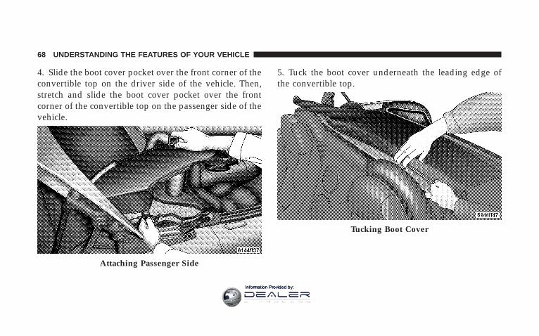
4. Slide the boot cover pocket over the front corner of theconvertible top on the driver side of the vehicle. Then,stretch and slide the boot cover pocket over the frontcorner of the convertible top on the passenger side of thevehicle.
5. Tuck the boot cover underneath the leading edge ofthe convertible top.
Attaching Passenger Side
Tucking Boot Cover
68 UNDERSTANDING THE FEATURES OF YOUR VEHICLE
Information Provided by:

6. On the passenger side of the vehicle, clip the tab underthe trunk lid stop and on the outer edge of the quarterpanel flange.
7. Push downward on the boot cover pocket to engagethe inboard tab.
Attaching Passenger Side TabEngaging Passenger Side Tab
UNDERSTANDING THE FEATURES OF YOUR VEHICLE 69
3
Information Provided by:

8. On the driver side of the vehicle, clip the tab under thetrunk lid stop and on the outer edge of the quarter panelflange.
9. Push downward on the boot cover pocket to engagethe inboard tab.
10. Push downward on the boot cover behind driver seatto lock down the boot cover.
Attaching Driver Side TabEngaging Driver Side Tab
70 UNDERSTANDING THE FEATURES OF YOUR VEHICLE
Information Provided by:

11. Stretch and smooth out the boot cover from the rearof vehicle.
12. Close the trunk.
13. Ensure that the forward edge of the boot cover istucked in fully.
Stretching and Smoothing Cover Forward Edge
UNDERSTANDING THE FEATURES OF YOUR VEHICLE 71
3
Information Provided by:

Convertible Top Boot Cover Removal andStorage
1. Open the trunk.
2. On the driver side of the vehicle, pull upward on theboot cover to disengage the inboard tab.
3. Unclip the tab under the trunk lid stop and on theouter edge of the quarter panel flange.
Disengaging Driver Side Tab
72 UNDERSTANDING THE FEATURES OF YOUR VEHICLE
Information Provided by:

4. On the passenger side of the vehicle, pull upward onthe boot cover to disengage the inboard tab.
5. Unclip the tab under the trunk lid stop and on theouter edge of the quarter panel flange.
6. Slide the boot cover pockets off the front corners of theconvertible top.
Disengaging Passenger Side Tab
UNDERSTANDING THE FEATURES OF YOUR VEHICLE 73
3
Information Provided by:

7. Fold the outer edges of the boot cover inward. 8. Fold the boot cover again.
9. Place the boot cover into the bag and store it in thetrunk or a secure dry area.
10. Close the trunk.
Folding Outer Edges Folding Boot Cover
74 UNDERSTANDING THE FEATURES OF YOUR VEHICLE
Information Provided by:

MIRRORS
Inside Day/Night MirrorAdjust the mirror to center on the view through the rearwindow. A pivot system allows for horizontal and verti-cal mirror adjustment.
Annoying headlight glare can be reduced by moving thesmall control under the mirror to the night position(toward rear of vehicle). The mirror should be adjustedwhile set in the day position (toward windshield).
Outside MirrorsTo receive maximum benefit, adjust the outside mirrorsto center on the adjacent lane of traffic and a slightoverlap of the view obtained from the inside mirror.
NOTE: The passenger side convex outside mirror willgive a much wider view to the rear, and especially of thelane next to your vehicle.
Adjusting Rearview Mirror
UNDERSTANDING THE FEATURES OF YOUR VEHICLE 75
3
Information Provided by:

WARNING!
Vehicles and other objects seen in the passenger sideconvex mirror will look smaller and farther awaythan they really are. Relying too much on yourpassenger side convex mirror could cause you tocollide with another vehicle or other object. Use yourinside mirror when judging the size or distance of avehicle seen in the passenger side convex mirror.
Power Remote Control MirrorsThe power mirror switch is located on the driver’s doortrim panel below the door handle. Press the buttonmarked “L” to select the driver’s outside mirror or thebutton marked “R” to select the passenger’s outsidemirror. After selecting a mirror, either press on the top,bottom, left, or right side of the directional switch and themirror will move in the direction that the arrow is
pointing. To return the power mirror switch to theneutral (off) position, press lightly on the push button notpreviously pressed until the opposite push button popsoutward.
Power Mirror Controls
76 UNDERSTANDING THE FEATURES OF YOUR VEHICLE
Information Provided by:

NOTE: When not in use, return the power mirror switchto the neutral (off) position to prevent accidental mirrormovement.
SEATS
Manual Seat Adjustments
Forward & Rearward AdjustmentThe adjusting bar is at the front of the seat, near the floor.Pull the bar upward to move the seat forward or rear-ward. Release the bar once the seat is in the desiredposition. Then, using body pressure, move forward andrearward on the seat to be sure that the seat adjustershave latched.
Seat Adjusting Bar
UNDERSTANDING THE FEATURES OF YOUR VEHICLE 77
3
Information Provided by:

WARNING!
• Adjusting a seat while the vehicle is moving isdangerous. The sudden movement of the seatcould cause you to lose control. The seat belt mightnot be properly adjusted and you could be injured.Adjust the seat only while the vehicle is parked.
• Do not ride with the seatback reclined so that theshoulder belt is no longer resting against yourchest. In a collision you could slide under the seatbelt and be seriously or even fatally injured. Usethe recliner only when the vehicle is parked.
Recliner AdjustmentThe recliner control is located on the outboard side of theseat. To recline the seat, lean forward slightly, pull therecliner control lever upward, lean backward until theseat is in the desired position, and release the lever. To
return the seat to its full upright position, lean forward,pull the recliner control lever upward and hold it untilthe seat returns to its full upright position.
Recliner Control
78 UNDERSTANDING THE FEATURES OF YOUR VEHICLE
Information Provided by:

TO OPEN AND CLOSE THE HOODTwo latches must be released to open the hood. First,reach into the lower right grille opening and pull theprimary hood latch forward.
Next, raise the front of the hood slightly and push thesafety catch handle to the right. The safety catch handle islocated under the front edge of the hood.
Hood Release LeverHood Safety Catch
UNDERSTANDING THE FEATURES OF YOUR VEHICLE 79
3
Information Provided by:
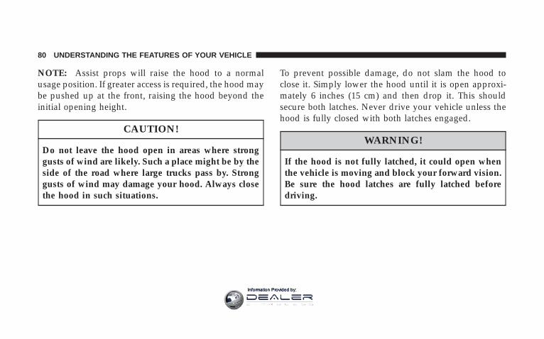
NOTE: Assist props will raise the hood to a normalusage position. If greater access is required, the hood maybe pushed up at the front, raising the hood beyond theinitial opening height.
CAUTION!
Do not leave the hood open in areas where stronggusts of wind are likely. Such a place might be by theside of the road where large trucks pass by. Stronggusts of wind may damage your hood. Always closethe hood in such situations.
To prevent possible damage, do not slam the hood toclose it. Simply lower the hood until it is open approxi-mately 6 inches (15 cm) and then drop it. This shouldsecure both latches. Never drive your vehicle unless thehood is fully closed with both latches engaged.
WARNING!
If the hood is not fully latched, it could open whenthe vehicle is moving and block your forward vision.Be sure the hood latches are fully latched beforedriving.
80 UNDERSTANDING THE FEATURES OF YOUR VEHICLE
Information Provided by:

LIGHTS
Exterior & Interior Lighting ControlThe Multi-Function Lever on the left side of thesteering column controls the operation of theheadlights, parking lights, turn signal lights, front
fog lights, instrument panel lights, and interior lights.
Headlights & Parking LightsTurn the end of the Multi-Function Lever to the firstdetent for parking light operation. Turn the end of thelever to the second detent for headlight operation.
Headlight Time DelayThis feature is particularly useful when exiting yourvehicle in an unlit area. It provides the safety of headlightillumination for about 90 seconds after turning off theignition switch.
To activate the delay, turn the ignition switch off whilethe headlights are still on. Then, turn off the headlightswithin 45 seconds. The delay interval begins when theheadlight switch is turned off.
If you turn the headlights, parking lights, or ignitionswitch on again, the system will cancel the delay.
If you turn the headlights off before the ignition, they willturn off in the normal manner.
Multi-Function Lever
UNDERSTANDING THE FEATURES OF YOUR VEHICLE 81
3
Information Provided by:

This feature can be disabled at the dealership, if sodesired.
Daytime Running LightsThe fog lights will come on as Daytime Running Lights,whenever the ignition switch is on, the headlights are off,and the parking brake is off. The headlight switch mustbe used for normal night time driving.
NOTE: This feature is standard on all Canadian vehiclesand cannot be disabled. For US vehicles, this feature isshipped disabled and can be enabled or disabled at adealership, if so desired.
Lights-On ReminderIf the headlights or parking lights are on and the ignitionswitch is turned off, a chime will sound when the driver’sdoor is opened to alert the driver.
Battery Saver Feature — Exterior LightsTo protect the battery, the exterior lights will turn offautomatically 3 minutes after the ignition switch isturned off. To restore exterior light operation, either turnthe ignition switch on or cycle the headlight switch.
Fog LightsTo activate the front fog lights, turn on the parkinglights or the low beam headlights and pull out onthe end of the Multi-Function Lever.
NOTE: The fog lights will only operate with the head-lights on low beam. Selecting high beam headlights willturn off the fog lights.
Turn SignalsMove the Multi-Function Lever upward or downwardand the corresponding turn signal indicator on the in-strument panel will flash to show proper operation of thefront and rear turn signal lights.
82 UNDERSTANDING THE FEATURES OF YOUR VEHICLE
Information Provided by:

You can also signal a lane change by moving the leverpartially upward or downward without moving beyondthe detent. The turn signals will continue to operate untilyou release the lever.
If either light has a very fast flash rate, check for adefective outside light bulb. If an indicator fails to light
when the lever is moved, it would suggest that the fuseor indicator is defective or there may be a circuit failure.
Highbeam/Lowbeam Select SwitchPull the Multi-Function Lever toward you to switch theheadlights to HIGH beam. Pull the lever a second time toswitch the headlights back to LOW beam.
Turn Signal Control
Headlight Beam Control
UNDERSTANDING THE FEATURES OF YOUR VEHICLE 83
3
Information Provided by:

Flash to PassYou can signal another vehicle with your headlights bylightly pulling the Multi-Function Lever toward you.This will cause the headlights to turn on at high beamand remain on until the lever is released.
Interior LightsThe interior lights will turn on whenever a door isopened or the liftgate is opened (Coupe models) and thedimmer switch is not in the defeat position.
The interior lights will turn on, remain on for about 30seconds, and then fade to off if any of the followingoccur:
• A door is opened using the outside door handle andthen closed.
• A door is unlocked using the remote keyless entrytransmitter.
• A door is unlocked using the outside driver’s door keycylinder.
The interior lights will turn on and remain on for about 4seconds and then fade to off if a door is opened using theinside door handle.
Courtesy/Reading LightsTwo courtesy/reading lights are located in the bottom ofthe rearview mirror. You can turn these lights on and offfrom the switches in the bottom of the mirror or from thedimmer control in the Multi-Function Lever. These lightsare also controlled automatically by the illuminated entrysystem.
84 UNDERSTANDING THE FEATURES OF YOUR VEHICLE
Information Provided by:

Courtesy lights are also found in the driver’s foot well,the passenger’s foot well, and in the liftgate on Coupemodels. You can turn this light on and off from thedimmer control in the Multi-Function Lever. This light isalso controlled automatically by the illuminated entrysystem.
Battery Saver Feature — Interior LightsTo protect the battery, the interior lights will turn offautomatically 15 minutes after the ignition switch ismoved to the OFF/LOCK position. This will occur if theinterior lights were switched on manually or are onbecause a door is open or the liftgate is open (Coupemodels). To restore interior light operation, turn theignition switch to the ON/RUN position or cycle thelight switch.
Dimmer ControlThe dimmer control is part of the Multi-Function Lever. Itcontrols the operation of the interior lights and thebrightness of the instrument panel lights.
Courtesy/Reading Light Switches
UNDERSTANDING THE FEATURES OF YOUR VEHICLE 85
3
Information Provided by:

Instrument Panel DimmingWith the parking lights or headlightson, rotate the dimmer control upwardto increase the brightness of the instru-ment panel lights or rotate it down-ward to decrease the brightness of theinstrument panel lights.
Interior Light (ON)Rotate the dimmer control completelyupward to the second detent to turnon the interior lights. The interiorlights will remain on when the dim-mer control is in this position.
Interior Light Defeat (OFF)Rotate the dimmer control to the ex-treme bottom “OFF” position. The in-terior lights will remain off when thedoors are open.
Parade Mode (Daytime Brightness Feature)Rotate the dimmer control to the firstdetent (white semi-circle). This featurebrightens the odometer and radio dis-play when the parking lights or head-lights are on during daylight condi-tions.
86 UNDERSTANDING THE FEATURES OF YOUR VEHICLE
Information Provided by:

WINDSHIELD WIPERS AND WASHERSThe Windshield Wiper/Washer Control Lever ison the right side of the steering column.
From the “OFF” position, push the Windshield Wiper/Washer Control Lever upward to the first detent past theintermittent “DEL” setting for Low-speed wiper opera-tion, or to the second detent past the intermittent “DEL”setting for High-speed wiper operation.
CAUTION!
Turn the windshield wipers off when drivingthrough an automatic car wash. Damage to the wind-shield wipers may result if the wiper switch is left inany position other than OFF.
Intermittent Wiper SystemUse the intermittent wiper when weather conditionsmake a single wiping cycle with a variable pause be-tween cycles desirable. From the “OFF” position, push
Windshield Wiper/Washer
UNDERSTANDING THE FEATURES OF YOUR VEHICLE 87
3
Information Provided by:

the Windshield Wiper/Washer Control Lever upward tothe first detent “DEL” position, and then rotate the end ofthe lever to select the desired delay interval. There areseven delay settings, which allow you to regulate thewipe interval from a minimum of one cycle every secondto a maximum of approximately 15 seconds betweencycles. Rotating the lever upward decreases the delaytime.
WARNING!
Sudden loss of visibility through the windshieldcould lead to an accident. You might not see othervehicles or other obstacles. To avoid sudden icing ofthe windshield during freezing weather, warm thewindshield with defroster before and during wind-shield washer use.
Mist FeatureFrom the “OFF” position, push the Windshield Wiper/Washer Control Lever downward to activate a singlewipe cycle to clear the windshield of road mist or sprayfrom a passing vehicle. The wipers will continue tooperate until you release the lever.
Windshield WashersTo use the washer, pull the Windshield Wiper/WasherControl Lever toward you and hold it for as long washerspray is desired.
If you activate the washer while the windshield wiper isin the delay range, the wipers will operate in low speedfor two wipe cycles after releasing the lever and thenresume the intermittent interval previously selected.
If you activate the washer while the windshield wiper isturned OFF, the wipers will operate for two wipe cyclesand then turn OFF.
88 UNDERSTANDING THE FEATURES OF YOUR VEHICLE
Information Provided by:

Adding Washer FluidThe windshield washer fluid reservoir is located in thefront of the engine compartment on the passenger side ofthe vehicle. Be sure to check the fluid level in thereservoir at regular intervals. Fill the reservoir withwindshield washer solvent (not radiator antifreeze) andoperate the system for a few seconds to flush out theresidual water.
WARNING!
Commercially available windshield washer solventsare flammable. They could ignite and burn you. Caremust be exercised when filling or working aroundthe washer solution.
TILT STEERING COLUMNThe tilt release lever is located below the multi-functionlever on the left side of the steering column. To tilt thecolumn, simply pull the release lever downward and thenmove the steering wheel upward or downward as desired.When the column is in the desired position, push therelease lever upward to lock the column firmly in place.
Tilt Steering Column Control
UNDERSTANDING THE FEATURES OF YOUR VEHICLE 89
3
Information Provided by:

WARNING!
Tilting the steering column while the vehicle ismoving is dangerous. Without a stable steering col-umn, you could lose control of the vehicle and havean accident. Adjust the column only while the ve-hicle is stopped. Be sure it is locked before driving.
ADJUSTABLE PEDALSThis feature allows the driver to move the brake andaccelerator pedals about 3 inches (72 mm) forward orrearward to allow for greater driving comfort. The Ad-justable Pedals switch is recessed into the knee bolsterbeneath the steering column.
Adjustable Pedal Switch
90 UNDERSTANDING THE FEATURES OF YOUR VEHICLE
Information Provided by:
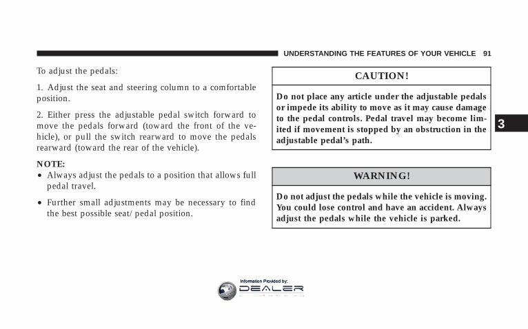
To adjust the pedals:
1. Adjust the seat and steering column to a comfortableposition.
2. Either press the adjustable pedal switch forward tomove the pedals forward (toward the front of the ve-hicle), or pull the switch rearward to move the pedalsrearward (toward the rear of the vehicle).
NOTE:• Always adjust the pedals to a position that allows full
pedal travel.
• Further small adjustments may be necessary to findthe best possible seat/pedal position.
CAUTION!
Do not place any article under the adjustable pedalsor impede its ability to move as it may cause damageto the pedal controls. Pedal travel may become lim-ited if movement is stopped by an obstruction in theadjustable pedal’s path.
WARNING!
Do not adjust the pedals while the vehicle is moving.You could lose control and have an accident. Alwaysadjust the pedals while the vehicle is parked.
UNDERSTANDING THE FEATURES OF YOUR VEHICLE 91
3
Information Provided by:

Adjustable Foot RestThis feature allows the driver to adjust the foot restforward or backward and to rotate it upward or down-ward to allow for greater driving comfort.
To adjust the pedal:
1. Adjust the seat and steering column to a comfortableposition.
2. Using a 13 mm socket wrench, loosen the nut on thepedal.
3. Slide the pedal either forward or backward and rotateit upward or downward as desired.
4. Tighten the nut, being careful not to over tighten it.
CONSOLE FEATURESThe front console has a removable ashtray, power outlet/cigarette lighter, and power window switches.
The center console compartment is equipped with acigarette lighter/power outlet.
Adjustable Foot Rest
92 UNDERSTANDING THE FEATURES OF YOUR VEHICLE
Information Provided by:
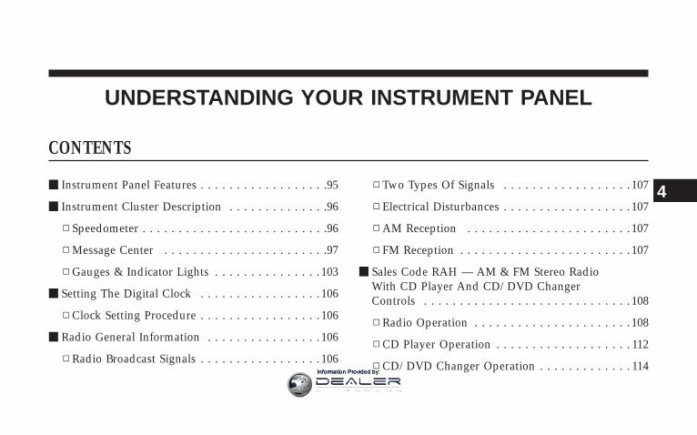
UNDERSTANDING YOUR INSTRUMENT PANEL
CONTENTS
m Instrument Panel Features . . . . . . . . . . . . . . . . . .95
m Instrument Cluster Description . . . . . . . . . . . . . .96
▫ Speedometer . . . . . . . . . . . . . . . . . . . . . . . . . .96
▫ Message Center . . . . . . . . . . . . . . . . . . . . . . .97
▫ Gauges & Indicator Lights . . . . . . . . . . . . . . . 103
m Setting The Digital Clock . . . . . . . . . . . . . . . . . 106
▫ Clock Setting Procedure . . . . . . . . . . . . . . . . . 106
m Radio General Information . . . . . . . . . . . . . . . . 106
▫ Radio Broadcast Signals . . . . . . . . . . . . . . . . . 106
▫ Two Types Of Signals . . . . . . . . . . . . . . . . . . 107
▫ Electrical Disturbances . . . . . . . . . . . . . . . . . . 107
▫ AM Reception . . . . . . . . . . . . . . . . . . . . . . . 107
▫ FM Reception . . . . . . . . . . . . . . . . . . . . . . . . 107
m Sales Code RAH — AM & FM Stereo RadioWith CD Player And CD/DVD ChangerControls . . . . . . . . . . . . . . . . . . . . . . . . . . . . . 108
▫ Radio Operation . . . . . . . . . . . . . . . . . . . . . . 108
▫ CD Player Operation . . . . . . . . . . . . . . . . . . . 112
▫ CD/DVD Changer Operation . . . . . . . . . . . . . 114
4
Information Provided by:

▫ Notes On Playing MP3 Files . . . . . . . . . . . . . 114
▫ Operation Instructions - (CD Mode ForMP3 Audio Play) . . . . . . . . . . . . . . . . . . . . . 116
m Satellite Radio — If Equipped . . . . . . . . . . . . . . 117
▫ System Activation . . . . . . . . . . . . . . . . . . . . . 118
▫ Electronic Serial Number/Sirius IdentificationNumber (ENS/SID) . . . . . . . . . . . . . . . . . . . . 118
▫ Selecting Satellite Mode In RBB, RAH, REVAnd RBK Radios . . . . . . . . . . . . . . . . . . . . . . 119
▫ Selecting Satellite Mode In RBP, RBU, RAZ,RB1 And RBQ Radios . . . . . . . . . . . . . . . . . . 119
▫ Selecting a Channel . . . . . . . . . . . . . . . . . . . . 120
▫ Storing And Selecting Pre-Set Channels . . . . . . 120
▫ Using The PTY (Program Type) Button(If Equipped) . . . . . . . . . . . . . . . . . . . . . . . . 120
▫ PTY Button 9Scan9 . . . . . . . . . . . . . . . . . . . . . 120
▫ PTY Button 9Seek9 . . . . . . . . . . . . . . . . . . . . . 121
▫ Satellite Antenna . . . . . . . . . . . . . . . . . . . . . . 121
▫ Reception Quality . . . . . . . . . . . . . . . . . . . . . 121
m Radio Antenna . . . . . . . . . . . . . . . . . . . . . . . . 122
m CD/DVD Disc Maintenance . . . . . . . . . . . . . . . 122
m Radio Operation And Cellular Phones . . . . . . . . 122
m Climate Controls . . . . . . . . . . . . . . . . . . . . . . . 122
▫ Air Conditioning And Heating System . . . . . . 123
▫ Operating Tips . . . . . . . . . . . . . . . . . . . . . . . 126
m Rear Window Features . . . . . . . . . . . . . . . . . . . 128
▫ Electric Rear Window Defroster . . . . . . . . . . . 128
94 UNDERSTANDING YOUR INSTRUMENT PANEL
Information Provided by:

INSTRUMENT PANEL FEATURES
1 — Air Outlet 7 — Speedometer/Odometer 13 — Climate Control2 — Sound System Speaker 8 — Oil Pressure Gauge 14 — Engine Start Button3 — Main Message Center 9 — Passenger Airbag Off Light 15 — Voltage Gauge4 — Fuel Gauge 10 — Passenger Airbag 16— Engine Coolant Temperature Gauge5 — Auxiliary Message Center 11 — Glove Box 17— Engine Oil Temperature Gauge6 — Tachometer 12 — Sound System Controls 18 — Trip Button
UNDERSTANDING YOUR INSTRUMENT PANEL 95
4
Information Provided by:

INSTRUMENT CLUSTER DESCRIPTION
SpeedometerShows the vehicle’s speed in miles-per-hour (mph) and kilometers-per-hour (km/h).
Odometer/Trip OdometerThe odometer shows the total distance the vehicle hasbeen driven.
NOTE: U.S. federal regulations require upon transfer ofvehicle ownership, the seller certify the mileage thevehicle has been driven. Therefore, if the odometerreading is changed because of repair or replacement, besure to keep a record of the reading before and after theservice so that the correct mileage can be determined.
The trip odometer shows individual trip mileage. Pressand release the Trip button once to switch the displayfrom odometer to trip odometer. Press and release theTrip button a second time to return the display toodometer. While in trip mode, press and hold the Tripbutton for at least 1 second to reset the trip odometer tozero.
Liquid Crystal Display (LCD) PanelThe LCD panel at the bottom of the speedometer displaysspecific messages for given conditions. These messagesare as follows:
• The words “DOOR AJAR” will display if a door is notclosed completely. In addition, a single chime willsound if you move the vehicle when a door is notclosed completely.
• The words “DOOR UNLOCKED” will flash in thedisplay if one door is unlocked and will remain onsteady if both doors are unlocked.
96 UNDERSTANDING YOUR INSTRUMENT PANEL
Information Provided by:

• The word “DECK” will flash in the display if thetrunk/liftgate is open.
• The words “LOW TIRE” will flash slowly in the displayand a chime will sound if the tire pressure is low.
• The words “FLAT TIRE” will flash rapidly in thedisplay and a chime will sound if critically low tirepressure is detected.
Message CenterWhen the appropriate conditions ex-ist, the Message Center displays thefollowing indicators and warnings:
High Beam LightThis light will turn on when the high beamheadlights are on. Pull the Multi-Function Lever
on the left side of the steering column toward you toswitch the headlights from low beam to high beam. Pullthe lever a second time to switch the headlights back tolow beam. (See page 81 for more information.)
Front Fog Light IndicatorThis light will turn on when the front fog lights areon. (See page 82 for more information.)
Anti-Lock Brake Warning LightThe amber Anti-Lock Brake Warning Light willturn on and stay on briefly as a bulb checkwhen the ignition is first turned on. If the lightdoes not turn on during starting, see yourauthorized dealer for service.
This light also illuminates at vehicle start-up to indicatethat the ABS self-check is in process. If the light remainson after start-up, or turns on and remains on at roadspeeds, it may indicate a system malfunction or that thesystem is inoperative. In this case, the system reverts to
UNDERSTANDING YOUR INSTRUMENT PANEL 97
4
Information Provided by:

standard non-anti-lock brakes. If this occurs, safely bringthe vehicle to a complete stop as soon as possible andcycle the ignition key to attempt to reset the ABS. If thelight remains on, see your authorized dealer immediatelyto have the system serviced. Furthermore, if the redBRAKE warning light and the amber ABS warning lightare on, and the parking brake is fully released, see yourauthorized dealer immediately. (See page 147 for moreinformation.)
WARNING!
If the ABS and/or Brake Warning lights illuminate,please seek service immediately! Your vehicle willhave diminished braking capability and control if ABSand/or service brake systems are not working properly.Have your brake system serviced immediately.
Malfunction Indicator LightThis light is part of an onboard diagnosticsystem called OBD. The OBD system monitorsengine control systems. The light will turn onwhen the key is in the ON/RUN position
before engine start. If the light does not come on whenturning the key from OFF/LOCK to ON/RUN, have thecondition checked promptly.
Certain conditions such as a loose or missing gas cap,poor fuel quality, etc. may illuminate the light afterengine start. The vehicle should be serviced if the lightremains on through several of your typical drivingcycles. In most situations, the vehicle will drive normallyand will not require towing.
The Malfunction Indicator Light flashes to alert you toserious conditions that could lead to immediate loss ofpower or severe catalytic converter damage. The vehicleshould be serviced as soon as possible if this occurs. (Seepage 195 for more information.)
98 UNDERSTANDING YOUR INSTRUMENT PANEL
Information Provided by:

CAUTION!
Prolonged driving with the light on could causefurther damage to the emission control system. Itcould also affect fuel economy and driveability. Thevehicle must be serviced before any state emissionstests can be performed.
Turn Signal IndicatorsThe left or right arrow will flash in unison with thecorresponding front and rear turn signals when the
turn signal switch is operated. (See page 82 for moreinformation.)
Hazard IndicatorsBoth turn signal arrows will flash in unison with thefront and rear turn signals when the hazard warning
switch is operated. (See page 176 for more information.)
NOTE: Leaving the hazard flashers on for extendedperiods will wear down the battery.
Airbag Warning LightThis light will turn on for 6 to 8 seconds as abulb check when the ignition switch is firstturned on. If the light does not turn on duringstarting, remains on after starting, or turns on
while driving, have the system checked immediately byan authorized dealer. (See page 40 for more information.)
Brake System Warning LightThe red Brake System Warning Light turns onwhen the ignition is first turned on. It should
stay on briefly as a bulb check. If the light does not turnon during starting, have it repaired promptly. If the lightremains on following the bulb check, it may be anindication that the parking brake is not released. If thelight remains on when the parking brake is released, itindicates a possible hydraulic brake system malfunction.In this case, immediate repair is necessary and continuedoperation of the vehicle in this condition is dangerous.
UNDERSTANDING YOUR INSTRUMENT PANEL 99
4
Information Provided by:
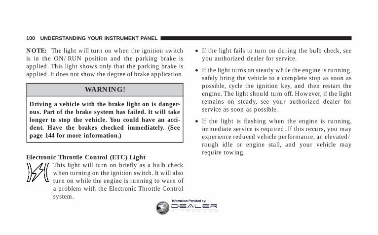
NOTE: The light will turn on when the ignition switchis in the ON/RUN position and the parking brake isapplied. This light shows only that the parking brake isapplied. It does not show the degree of brake application.
WARNING!
Driving a vehicle with the brake light on is danger-ous. Part of the brake system has failed. It will takelonger to stop the vehicle. You could have an acci-dent. Have the brakes checked immediately. (Seepage 144 for more information.)
Electronic Throttle Control (ETC) LightThis light will turn on briefly as a bulb checkwhen turning on the ignition switch. It will alsoturn on while the engine is running to warn ofa problem with the Electronic Throttle Controlsystem.
• If the light fails to turn on during the bulb check, seeyou authorized dealer for service.
• If the light turns on steady while the engine is running,safely bring the vehicle to a complete stop as soon aspossible, cycle the ignition key, and then restart theengine. The light should turn off. However, if the lightremains on steady, see your authorized dealer forservice as soon as possible.
• If the light is flashing when the engine is running,immediate service is required. If this occurs, you mayexperience reduced vehicle performance, an elevated/rough idle or engine stall, and your vehicle mayrequire towing.
100 UNDERSTANDING YOUR INSTRUMENT PANEL
Information Provided by:

Low Tire Pressure Telltale / TPMS MalfunctionIndicator
Each tire, including the spare (if provided),should be checked monthly when cold andinflated to the inflation pressure recommendedby the vehicle manufacturer on the vehicle
placard or tire inflation pressure label. (If your vehiclehas tires of a different size than the size indicated on thevehicle placard or tire inflation pressure label, you shoulddetermine the proper tire inflation pressure for thosetires.)
As an added safety feature, your vehicle has beenequipped with a tire pressure monitoring system (TPMS)that illuminates a low tire pressure telltale when one ormore of your tires is significantly under-inflated. Accord-ingly, when the low tire pressure telltale illuminates, youshould stop and check your tires as soon as possible andinflate them to the proper pressure. Driving on a signifi-cantly under-inflated tire causes the tire to overheat and
can lead to tire failure. Under-inflation also reduces fuelefficiency and tire tread life and may affect the vehicle’shandling and stopping ability.
Please note that the TPMS is not a substitute for propertire maintenance, and it is the driver’s responsibility tomaintain correct tire pressure, even if under-inflation hasnot reached the level to trigger illumination of the TPMSlow tire pressure telltale.
Your vehicle has also been equipped with a TPMSmalfunction indicator to indicate when the system is notoperating properly. The TPMS malfunction indicator iscombined with the low tire pressure telltale.
When the system detects a malfunction, the telltale willflash for approximately one minute and then remaincontinuously illuminated. This sequence will continue
UNDERSTANDING YOUR INSTRUMENT PANEL 101
4
Information Provided by:

upon subsequent vehicle start-ups as long as the mal-function exists. When the malfunction indicator is illumi-nated, the system may not be able to detect or signal lowtire pressure as intended.
TPMS malfunctions may occur for a variety of reasons,including the installation of replacement or alternate tiresor wheels on the vehicle that prevent the TPMS fromfunctioning properly. Always check the TPMS malfunc-tion telltale after replacing one or more tires or wheels onyour vehicle to ensure that the replacement or alternatetires and wheels allow the TPMS to continue to functionproperly. (See page 166 for more information.)
CAUTION!
The Tire Pressure Monitor System (TPMS) has beenoptimized for the original equipment tires andwheels. The TPMS pressures have been establishedfor the tire size equipped on your vehicle. Undesir-able operation or sensor damage may result whenusing replacement equipment that is not of the samesize, type, and/or style. Aftermarket wheels can causesensor damage. Do not use aftermarket tire sealantsor balance beads if your vehicle is equipped with theTPMS, as damage to the sensors may result.
102 UNDERSTANDING YOUR INSTRUMENT PANEL
Information Provided by:

WARNING!
Do not exceed 55 mph (88 km/h) if the LOW Tireindicator is activated. Vehicle handling and brakingmay be reduced. You could have an accident and beseverely or fatally injured.
Seat Belt Reminder LightIf the driver does not buckle their seat belt andvehicle speed exceeds 5 mph (8 km/h), or if thepassenger does not buckle their seat belt within 10
seconds of vehicle speed exceeding 5 mph (8 km/h), theEnhanced Warning System (Belt Alert) will alert theoccupant(s) to buckle their seat belt(s). Once triggered,the Enhanced Warning System (Belt Alert) will flash theSeat Belt Reminder light and chime for up to 96 secondsto alert the occupant(s) to buckle their seat belt(s). If thedriver unbuckles their seat belt while vehicle speed is
greater than 5 mph (8 km/h), or if the passenger unbuck-les their seat belt for more than 10 seconds while vehiclespeed is greater than 5 mph (8 km/h), the EnhancedWarning System (Belt Alert) will reactivate. (See page 36for more information.)
Gauges & Indicator Lights
TachometerThis gauge shows engine speed in revolutions-per-minute (RPM) times 1,000. Avoid excessiveengine speeds in any part of the red warningzone, particularly when driving downhill or inlower gears.
Skip Shift Indicator LightThis indicator is located in the Tachometer. Whenthe indicator light turns amber, it means that you
are being prevented from shifting the transmission fromFirst to Second or to Third gear. When the indictor lightturns red, it means that the tachometer gauge pointer is at
UNDERSTANDING YOUR INSTRUMENT PANEL 103
4
Information Provided by:

6000 RPM. This serves as a visual aid to shift beforereaching the red line. This warning will turn off when thetachometer pointer falls below 5900 RPM. (See page 136for more information.)
Coolant Temperature GaugeThis gauge shows the engine coolant tempera-ture. The gauge pointer will likely show highertemperatures when driving in hot weather, upmountain grades, or in heavy stop and go
traffic. If the red warning Light turns on while driving,safely bring the vehicle to a stop, and turn off the engine.DO NOT operate the vehicle until the cause is corrected.
Engine Temperature Warning LightThe red Engine Temperature Warning Light islocated in the Coolant Temperature Gauge. It willturn on to warn of an overheated engine condi-
tion. If this light turns on while driving, safely bring the
vehicle to a stop and turn off the engine. DO NOToperate the vehicle until the cause is corrected. (See page176 for more information.)
Oil Temperature GaugeThis gauge shows the oil temperature. Thegauge pointer will likely show higher tempera-tures when driving in hot weather, up moun-tain grades, or in heavy stop and go traffic. If
the red warning light remains on after the bulb check orturns on while driving, safely bring the vehicle to acomplete stop and turn off the engine. DO NOT operatethe vehicle until the cause is corrected.
Oil Pressure GaugeThis gauge shows engine oil pressure when theengine is running. The pressure will vary withengine speed, oil viscosity, and engine tem-perature. Oil pressures will be higher as the
engine is warming up. The normal operating pressure is
104 UNDERSTANDING YOUR INSTRUMENT PANEL
Information Provided by:

between 20 and 80 psi (pounds per square inch). If thepointer remains in the red range, safely bring the vehicleto a complete stop and turn off the engine. DO NOToperate the vehicle until the cause is corrected.
This gauge does not indicate the amount of oil in theengine. The engine oil level must be checked under thehood. Check the level often during severe usage.
Oil Pressure Warning LightThe red Oil Pressure Warning Light is located inthe Oil Pressure Gauge. It will turn on to indicate
low engine oil pressure. The light should turn on brieflyas a bulb check when the engine is first started. If thelight remains on or turns on while driving, safely bringthe vehicle to a complete stop and turn off the engine. DONOT operate the vehicle until the cause is corrected.
NOTE: This light does not indicate how much oil is inthe engine. The engine oil level must be checked usingthe procedure shown in section 7. (See page 198 for moreinformation.)
Fuel GaugeThis gauge shows the amount of fuel in the gastank. The reaction time of the gauge has beenslowed to avoid needle fluctuation during pe-riods of high G force cornering.
Voltage GaugeThis gauge shows the electrical system voltage.The normal operating voltage is from 12 to 14volts with the engine running. If the pointerremains at either the high or low ends of the
scale, the electrical system should be serviced.
UNDERSTANDING YOUR INSTRUMENT PANEL 105
4
Information Provided by:

Charge System LightThe red Charge System Light is located in theVoltage Gauge. It will turn on when there is a
charging system malfunction or a possible accessorydrive belt failure.
CAUTION!
The accessory belt also drives the water pump. Op-erating the vehicle with a failed belt can cause engineoverheating and possible severe engine damage.
SETTING THE DIGITAL CLOCKThe digital display panel on the radio displays the time inhours and minutes. The display panel is operative whenthe ignition switch is in the ON/RUN or ACC position.Press and release the Time button on the radio to displaythe time. Press and release the button a second time toturn off the time display.
Clock Setting Procedure
1. Turn the ignition switch to the “ON/RUN” or “ACC”position.
2. Using the point of a ballpoint pen or similar object,press either the “H” (Hour) or “M” (Minute) button onthe radio. The display will show the time.
3. Press the “H” button to set hours or the “M” button toset minutes. The time setting will increase each time youpress a button.
RADIO GENERAL INFORMATION
Radio Broadcast SignalsThe radio will provide excellent reception under mostoperating conditions. Like any system, however, carradios have performance limitations, due to mobile op-eration and natural phenomena, which might lead you tobelieve your sound system is malfunctioning. To help
106 UNDERSTANDING YOUR INSTRUMENT PANEL
Information Provided by:

you understand and save you concern about these “ap-parent” malfunctions, you must understand a point ortwo about the transmission and reception of radio sig-nals.
Two Types of SignalsThere are two basic types of radio signals: AM orAmplitude Modulation, in which the transmitted soundcauses the amplitude, or height, of the radio waves tovary; and FM or Frequency Modulation, in which thefrequency of the wave is varied to carry the sound.
Electrical DisturbancesRadio waves may pick up electrical disturbances duringtransmission. They mainly affect the wave amplitude,and thus remain a part of the AM reception. Theyinterfere very little with the frequency variations thatcarry the FM signal.
AM ReceptionAM sound is based on wave amplitude, so AM receptioncan be disrupted by such things as lightning, power linesand neon signs.
FM ReceptionBecause FM transmission is based on frequency varia-tions, interference that consists of amplitude variationscan be filtered out, leaving the reception relatively clear,which is the major feature of FM radio.
NOTE: The radio, steering wheel radio controls (ifequipped), and 6–Disc CD/DVD changer (if equipped)will remain active for up to 10 minutes after the ignitionswitch has been turned OFF. Opening a vehicle frontdoor will cancel this feature.
UNDERSTANDING YOUR INSTRUMENT PANEL 107
4
Information Provided by:

SALES CODE RAH — AM & FM STEREO RADIOWITH CD PLAYER AND CD/DVD CHANGERCONTROLS
NOTE: The radio sales code is located on the lower leftside of your radio faceplate.
Radio Operation
Power/Volume ControlPress the ON/VOL control to turn the radio on. Turn thevolume control clockwise to increase the volume.
NOTE: Power to operate the radio is supplied throughthe ignition switch. It must be in the ON or ACC positionto operate the radio.
PTY (Program Type)Pressing the INFO button once while in FM mode willturn on the PTY mode for 5 seconds. If no action is takenduring the 5 second time out, the PTY icon will turn off.Pressing the TUNE button within 5 seconds will allowthe program format type to be selected. Many radiostations do not currently broadcast PTY information.
Toggle the TUNE button to select the following formattypes:
RAH radio
108 UNDERSTANDING YOUR INSTRUMENT PANEL
Information Provided by:
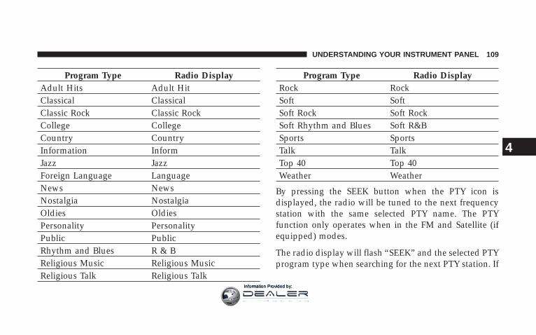
Program Type Radio DisplayAdult Hits Adult HitClassical ClassicalClassic Rock Classic RockCollege CollegeCountry CountryInformation InformJazz JazzForeign Language LanguageNews NewsNostalgia NostalgiaOldies OldiesPersonality PersonalityPublic PublicRhythm and Blues R & BReligious Music Religious MusicReligious Talk Religious Talk
Program Type Radio DisplayRock RockSoft SoftSoft Rock Soft RockSoft Rhythm and Blues Soft R&BSports SportsTalk TalkTop 40 Top 40Weather Weather
By pressing the SEEK button when the PTY icon isdisplayed, the radio will be tuned to the next frequencystation with the same selected PTY name. The PTYfunction only operates when in the FM and Satellite (ifequipped) modes.
The radio display will flash “SEEK” and the selected PTYprogram type when searching for the next PTY station. If
UNDERSTANDING YOUR INSTRUMENT PANEL 109
4
Information Provided by:
no station is found with the selected PTY program type,the radio will return to the last preset station.
If a preset button is activated while in the PTY (ProgramType) mode, the PTY mode will be exited and the radiowill tune to the preset station.
ModePress the MODE button to select between, AM, FM, CD,CD/DVD changer or the Satellite Radio (if equipped).When the Satellite Radio (if equipped) is selected “SA”will appear in your radio display.
A disc may remain in the radio while in the Satellite orradio mode.
SeekPress and release the SEEK button to search for the nextstation in either the AM, FM or Satellite mode. Press thetop of the button to seek up and the bottom to seek down.The radio will remain tuned to the new station until you
make another selection. Holding the button in will by-pass stations without stopping until you release it.
TuningPress the TUNE control up or down to increase ordecrease the frequency. If you press and hold the button,the radio will continue to tune until you release thebutton. The frequency will be displayed and continu-ously updated while the button is pressed.
BalanceThe Balance control adjusts the left-to-right speaker bal-ance. Press the AUDIO button, select BALANCE, thenpress SEEK + or SEEK 2 to adjust the balance.
FadeThe Fade control provides for balance between the frontand rear speakers. Press the AUDIO button, select FADE,then press SEEK + or SEEK 2 to adjust the fade balance.
110 UNDERSTANDING YOUR INSTRUMENT PANEL
Information Provided by:

Tone ControlThe Bass and/or Treble controls sound for the desiredtone. Press the AUDIO button, select Bass or TREBLE,then press SEEK + or SEEK 2 to increase or decreaseamplification of the band.
To Set The Radio Push-Button MemoryWhen you are receiving a station that you wish tocommit to push-button memory, press the SET button.SET 1 will show in the display window. Select thepush-button you wish to lock onto this station and pressand release that button. If a station is not selected within5 seconds after pressing the SET button, the station willcontinue to play but will not be locked into push-buttonmemory.
You may add a second station to each push-button byrepeating the above procedure with this exception: Pressthe SET button twice and SET 2 will show in the displaywindow. Each button can be set for SET 1 and SET 2 in
both AM and FM. This allows a total of 10 AM and 10 FMstations to be locked into memory. You can recall thestations stored in SET 2 memory by pressing the push-button twice.
To Change From Clock To Radio ModePress the TIME button to change the display betweenradio frequency and time.
General InformationThis radio complies with Part 15 of FCC rules and withRSS-210 of Industry Canada. Operation is subject to thefollowing conditions:
1. This device may not cause harmful interference,
2. This device must accept any interference received,including interference that may cause undesired opera-tion.
UNDERSTANDING YOUR INSTRUMENT PANEL 111
4
Information Provided by:
NOTE: Changes or modifications not expressively ap-proved by the party responsible for compliance couldvoid the user’s authority to operate the equipment.
CD Player Operation
NOTE:• The ignition switch must be in the ON or ACC
position and the volume control ON before the CDplayer will operate.
• This Radio is capable of playing compact discs (CD),recordable compact discs (CD-R), rewritable compactdiscs (CD-RW) compact discs with MP3 tracks andmultisession compact discs with CD and MP3 tracks.
Inserting The Compact Disc
CAUTION!
This CD player will accept only 4–3/4 inch (12 cm)discs only. The use of other sized discs may damagethe CD player mechanism.
You may either insert or eject a disc with the radio OFF.
If you insert a disc with the ignition ON and the radioOFF, the display will show the time of day. If you inserta disc with the ignition OFF, the display will show thetime of day for about 5 seconds, then go out.
If the power is ON, the unit will switch from radio to CDmode and begin to play when you insert the disc. Thedisplay will show the track number and index time inminutes and seconds. Play will begin at the start of trackone.
112 UNDERSTANDING YOUR INSTRUMENT PANEL
Information Provided by:
SeekPress the top of the SEEK button for the next selection onthe CD. Press the bottom of the button to return to thebeginning of the current selection, or return to thebeginning of the previous selection if the CD is within thefirst 10 seconds of the current selection.
EJT — EjectPress the EJT button and the disc will unload and moveto the entrance for easy removal. The unit will switch tothe radio mode.
If you do not remove the disc within 15 seconds, it will bereloaded. The radio mode will continue to appear.
The disc can be ejected with the radio OFF.
FF/TUNE/RWPress FF (Fast Forward) and the CD player will begin tofast forward until FF is released. The RW (Reverse)button works in a similar manner.
RND — Random PlayPress the RND button while the CD is playing to activateRandom Play. This feature plays the selections on thecompact disc in random order to provide an interestingchange of pace.
Press the SEEK button to move to the next randomlyselected track.
Press TUNE FF to fast forward through the tracks. Pressthe FF button a second time to stop the fast forwardfeature. If TUNE RW is pressed, the current track willreverse to the beginning of the track and begin playing.
Press the RND button a second time to stop RandomPlay.
UNDERSTANDING YOUR INSTRUMENT PANEL 113
4
Information Provided by:

CD/DVD Changer OperationPress the MODE button to select between the CD playerand the optional remote CD/DVD changer.
TimePress the TIME button to change the display fromelapsed CD or DVD playing time to time of day.
Notes On Playing MP3 FilesThe radio can play MP3 files, however, acceptable MP3file recording media and formats are limited. Whenwriting MP3 files, pay attention to the following restric-tions.
Supported media (disc types)The MP3 file recording media supported by the radio areCD-ROM, CD-R and CD-RW.
Supported medium formats (file systems)The medium formats supported by the radio are ISO 9660Level 1 and Level 2 and includes the Joliet extension.
When reading discs recorded using formats other thanISO 9660 Level 1 and Level 2, the radio may fail to readfiles properly and may be unable to play the file nor-mally. UDF and Apple HFS formats are not supported.
The radio uses the following limits for file systems:
• Maximum number of directory levels: 15
• Maximum number of files: 255
• Maximum number of folders: 100
• Maximum number of characters in file/folder names:
• Level 1: 12 (including a separator 9.9 and a 3character extension)
• Level 2: 31 (including a separator 9.9 and a 3character extension)
Multisession disc formats are supported by the radio.Multisession discs may contain combinations of normal
114 UNDERSTANDING YOUR INSTRUMENT PANEL
Information Provided by:

CD audio tracks and computer files (including MP3 files).Discs created with an option such as 9keep disc open afterwriting9 are most likely multisession discs. The use ofmultisession for CD audio or MP3 playback may result inlonger disc loading times.
Supported MP3 file formatsThe radio will recognize only files with the *.mp3 exten-sion as MP3 files. Non-MP3 files named with the *.mp3extension may cause playback problems. The radio isdesigned to recognize the file as an invalid MP3 and willnot play the file.
When using the MP3 encoder to compress audio data toan MP3 file, the bit rate and sampling frequencies in thefollowing table are supported. In addition, variable bitrates (VBR) are also supported. The majority of MP3 filesuse a 44.1 kHz sampling rate and a 192, 160, 128, 96 orVBR bit rates.
MPEGSpecification
Sampling Fre-quency (kHz) Bit rate (kbps)
MPEG-1 AudioLayer 3 48, 44.1, 32
320, 256, 224,192, 160, 128,
112, 96, 80, 64,56, 48, 40, 32
MPEG-2 AudioLayer 3 24, 22.05, 16
160, 128, 144,112, 96, 80, 64,
56, 48, 40, 32, 24,16, 8
ID3 Tag information for artist, song title and album titleare supported for version 1 ID3 tags. ID3 version 2 is notsupported by the radios.
Playlist files are not supported. MP3 Pro files are notsupported.
UNDERSTANDING YOUR INSTRUMENT PANEL 115
4
Information Provided by:

Playback of MP3 filesWhen a medium containing MP3 data is loaded, theradio checks all files on the medium. If the mediumcontains a lot of folders or files, the radio will take moretime to start playing the MP3 files.
Loading times for playback of MP3 files may be affectedby the following:
• Media - CD-RW media may take longer to load thanCD-R media
• Medium formats - Multisession discs may take longerto load than non-multisession discs
• Number of files and folders - Loading times willincrease with more files and folders
To increase the speed of disc loading, it is recommendedto use CD-R media and single-session discs. To create asingle-session disc, enable the Disc at Once option beforewriting to the disc.
Operation Instructions - (CD Mode For MP3 AudioPlay)
SEEK Button (CD Mode For MP3 Play)Pressing the SEEK + button plays the next MP3 File.Pressing the SEEK 2 button plays the beginning of theMP3 file. Pressing the button within the first ten secondsplays the previous file.
INFO Button (CD Mode For MP3 Play)Press and INFO button while playing MP3 disc. Theradio scrolls through the following TAG information:Song Title, Artist, File Name, and Folder Name (if avail-able).
Press the INFO button once more to return to 9elapsedtime9 priority mode.
116 UNDERSTANDING YOUR INSTRUMENT PANEL
Information Provided by:

RW/FF (CD Mode For MP3 Play)Press the FF side of the button to move forward throughthe MP3 selection. Press the RW side of the button tomove back through the MP3 selection.
AM/FM Button (CD Mode For MP3 Play)Switches back to Radio mode.
RND Button (CD Mode For MP3 Play)Pressing this button plays files randomly.
DIR Button (CD Mode For MP3 Play)Press the DIR Button to display folders, when playing anMP3 discs that have a file/folder structure. Press DISCup (button 1) or DISC down (button 5) to move throughthe folders. Press the SET button to select a folder.
Operating Instructions - Hands Free Phone (IfEquipped)Refer to Hands Free Phone section of the Owner’sManual.
Operating Instructions - Satellite Radio Mode (IfEquipped)Refer to the Satellite Radio section of the Owner’sManual.
Operating Instructions - Video EntertainmentSystem (VESt) (If Equipped)Refer to 6 Disc CD/DVD Changer (RDV) section of theOwner’s Manual.
SATELLITE RADIO — IF EQUIPPEDSatellite radio uses direct satellite to receiver broadcast-ing technology to provide clear digital sound, coast tocoast. The subscription service provider is Sirius™ Satel-lite Radio. This service offers up to 100 channels of music,sports, news, entertainment, and programming for chil-dren, directly from its satellites and broadcasting studios.
UNDERSTANDING YOUR INSTRUMENT PANEL 117
4
Information Provided by:

System ActivationSirius Satellite Radio service is pre-activated, and youmay begin listening immediately to the one year ofSIRIUS audio service that is included with the factory-installed satellite radio system in your vehicle. Sirius willcontact you to supply a welcome kit and to confirmsubscription information, including the set up of youron-line listening account at no additional charge. Forfurther information, call the toll-free number 888-539-7474, or visit the Sirius web site at www.sirius.com, or atwww.siriuscanada.ca for Canadian residents. Please havethe following information available when changing yoursubscription:
1. The Electronic Serial Number/Sirius IdentificationNumber (ESN/SID).
2. Your Vehicle Identification Number.
Electronic Serial Number/Sirius IdentificationNumber (ENS/SID)The Electronic Serial Number/Sirius Identification Num-ber is needed to activate your Sirius Satellite Radiosystem. To access the ESN/SID, refer to the followingsteps:
ESN/SID Access With RBB, RAH, REVand RBKRadiosWith the ignition switch in the ACCESSORY position andthe radio OFF, press the Tape Eject or CD “EJT” button(depending on the radio type) and Time buttons simul-taneously for 3 seconds. The first four digits of thetwelve-digit ESN/SID number will be displayed. Pressthe SEEK UP (+) button to display the next four digits.Continue to press the SEEK UP (+) button until all twelveESN/SID digits have been displayed. The SEEK DOWN(-) will page down until the first four digits are displayed.
118 UNDERSTANDING YOUR INSTRUMENT PANEL
Information Provided by:

The radio will exit the ESN/SID mode when any otherbutton is pushed, the ignition is turned OFF, or 5 minuteshas passed since any button was pushed.
ESN/SID Access With RBP, RBU, RAZ, RB1 andRBQ RadiosWith the ignition switch in the ACCESSORY position andthe radio OFF, press the CD Eject and TIME buttonssimultaneously for 3 seconds. All twelve ESN/SID num-bers will be displayed. The radio will exit the ESN/SIDmode when any other button is pushed, the ignition isturned OFF, or 5 minutes has passed since any buttonwas pushed.
Selecting Satellite Mode in RBB, RAH, REV andRBK RadiosPress the MODE button repeatedly until 9S A9 appears inthe display. A CD or tape may remain in the radio whilein the Satellite radio mode.
Selecting Satellite Mode in RBP, RBU, RAZ, RB1and RBQ RadiosPress the MODE button repeatedly until the word9SIRIUS9 appears in the display. These radios will alsodisplay the following:
• After 3 seconds, the current channel name and channelnumber will be displayed for 5 seconds.
• The current program type and channel number willthen be displayed for 5 seconds.
• The current channel number will then be displayeduntil an action occurs.
A CD or tape may remain in the radio while in theSatellite radio mode.
UNDERSTANDING YOUR INSTRUMENT PANEL 119
4
Information Provided by:

Selecting a ChannelPress and release the SEEK or TUNE buttons to search forthe next channel. Press the top of the button to search upand the bottom of the button to search down. Holding theTUNE button causes the radio to bypass channels untilthe button is released.
Press and release the SCAN button (if equipped) toautomatically change channels every 7 seconds. Theradio will pause on each channel for 7 seconds beforemoving on to the next channel. The word 9SCAN9 willappear in the display between each channel change. Pressthe SCAN button a second time to stop the search.
NOTE: Channels that may contain objectionable contentcan be blocked. Contact Sirius Customer Care at 888-539-7474 to discuss options for channel blocking or unblock-ing. Please have your ESN/SID information available.
Storing and Selecting Pre-Set ChannelsIn addition to the 10 AM and 10 FM pre-set stations, youmay also commit 10 satellite stations to push buttonmemory. These satellite channel pre-set stations will noterase any AM or FM pre-set memory stations. Follow thememory pre-set procedures that apply to your radio.
Using the PTY (Program Type) Button (IfEquipped)Follow the PTY button instructions that apply to yourradio.
PTY Button (SCAN(When the desired program type is obtained, press the9SCAN9 button within five seconds. The radio will play 7seconds of the selected channel before moving to the nextchannel of the selected program type. Press the 9SCAN9button a second time to stop the search.
NOTE: Pressing the 9SEEK9 or 9SCAN9 button whileperforming a music type scan will change the channel by
120 UNDERSTANDING YOUR INSTRUMENT PANEL
Information Provided by:

one and stop the search. Pressing a pre-set memorybutton during a music type scan, will call up the memorychannel and stop the search.
PTY Button (SEEK(When the desired program is obtained, press the 9SEEK9button within five seconds. The channel will change tothe next channel that matches the program type selected.
Satellite AntennaTo ensure optimum reception, do not place items on theroof around the rooftop antenna location or strap items tothe trunk lid around the trunk lid antenna (if equipped).Metal objects placed within the line of sight of theantenna will cause decreased performance. Larger lug-gage items such as bikes should be placed as far rearwardas possible, within the loading design of the rack. Do notplace items directly on or above the antenna.
Reception QualitySatellite reception may be interrupted due to one of thefollowing reasons.
• The vehicle is parked in an underground parkingstructure or under a physical obstacle.
• Dense tree coverage may interrupt reception in theform of short audio mutes.
• Driving under wide bridges or along tall buildings cancause intermittent reception.
• Placing objects over or too close to the antenna cancause signal blockage.
UNDERSTANDING YOUR INSTRUMENT PANEL 121
4
Information Provided by:

RADIO ANTENNAThe radio antenna is located in the windshield.
CD/DVD DISC MAINTENANCETo keep the CD/DVD discs in good condition, take thefollowing precautions:
1. Handle the disc by its edge; avoid touching thesurface.
2. If the disc is stained, clean the surface with a soft cloth,wiping from center to edge.
3. Do not apply paper, paper CD labels, or tape to thedisc; avoid scratching the disc.
4. Do not use solvents such as benzine, thinner, cleaners,or antistatic sprays.
5. Store the disc in its case after playing.
6. Do not expose the disc to direct sunlight.
7. Do not store the disc where temperatures may becometoo high.
RADIO OPERATION AND CELLULAR PHONESUnder certain conditions, the cellular phone being On inyour vehicle can cause erratic or noisy performance fromyour radio. This condition may be lessened or eliminatedby relocating the cellular phone antenna. This conditionis not harmful to the radio. If your radio performancedoes not satisfactorily “clear” by the repositioning of theantenna, it is recommended that the radio volume beturned down or off during cellular phone operation.
CLIMATE CONTROLSThe Air Conditioning and Heating System is designed tomake you comfortable in all types of weather.
122 UNDERSTANDING YOUR INSTRUMENT PANEL
Information Provided by:

Air Conditioning and Heating System Blower ControlUse this control to regulate theamount of air forced through the sys-tem in any mode you select. Turn thecontrol clockwise to increase fanspeed. Turn the control to the O — Offposition to shut off the fan and toprevent any outside air from enteringthe vehicle. This also turns off the A/Ccompressor.
Temperature ControlUse this control to regulate the tem-perature of the air inside the passen-ger compartment. The blue area of thecontrol indicates cooler temperatureswhile the red area indicates warmertemperatures.
Air Conditioning And Heater Controls
UNDERSTANDING YOUR INSTRUMENT PANEL 123
4
Information Provided by:

Mode ControlUse this control to select the directionof air flow.
NOTE: The dot between the mode control icons is a mixposition between the two modes.
The mode settings are as follows:
• Recirculation ControlAir is recirculated inside the vehicle. Youmay choose between Bi-Level and Panel airoutlets while in this mode. Use this mode totemporarily block out any outside odors,
smoke, or dust and to cool the interior rapidly uponinitial start up in very hot or humid weather.
• PanelAir is directed through the outlets in the instru-ment panel. These outlets can be adjusted todirect air flow.
• Bi-LevelAir is directed through the instrument panel andfloor outlets. A small amount of air is alsodirected through the defrost outlets.
NOTE: There is a varying temperature differential be-tween the upper and lower outlets for added comfort.The warmer air goes to the floor outlets. This featureprovides improved comfort during sunny but cool con-ditions.
• FloorAir is directed through the floor outlets with alesser amount through the defrost outlets.
124 UNDERSTANDING YOUR INSTRUMENT PANEL
Information Provided by:
• Defrost/FloorAir is directed through the windshield defrostand the floor outlets. This setting works best incold or snowy conditions that require extra heat
at the windshield. This setting is good for maintainingcomfort while reducing moisture on the windshield.
• DefrostAir is directed through the windshield defrostoutlet. Use this mode with maximum fan and
temperature settings for best windshield defrosting.
NOTE: The air conditioning compressor operates in thismode. This dehumidifies the air to help dry the wind-shield. To improve fuel economy, leave in the Defrostmode only when necessary.
Air Conditioning ControlWith the fan control in the ON position, push theA/C button to turn on the air conditioning com-pressor. An indicator light above the button shows
that the Air Conditioning compressor is on. Conditionedair is now directed through the outlets selected. Pushingthe button a second time turns the compressor OFF.
Slight changes in engine speed or power may be noticedwhen the compressor is on. This is a normal occurrencesince the compressor will cycle on and off to maintaincomfort and increase fuel economy.
NOTE: If your air conditioning performance seemslower than expected, check the front of the A/C con-denser for an accumulation of dirt or insects.
UNDERSTANDING YOUR INSTRUMENT PANEL 125
4
Information Provided by:

Operating Tips
NOTE: Refer to the chart at the end of this section forsuggested control settings for various weather condi-tions.
Summer OperationThe engine cooling system in air-conditioned vehiclesmust be protected with a high-quality antifreeze coolantto provide proper corrosion protection and to protectagainst engine overheating. A 50% solution of ethyleneglycol antifreeze coolant in water is recommended. Referto “Maintenance Procedures” in Section 7 of this manualfor proper coolant selection.
Winter Operation
• Use the Defrost mode to direct cold air away from theoccupants during engine warm-up in cold weather.
• The blower air will heat faster in cold weather if youuse only the low blower speeds for the first tenminutes of vehicle operation.
• Use of the air Recirculation mode during wintermonths is not recommended because it may causewindow fogging.
Vacation StorageAnytime you store your vehicle, or keep it out of service(i.e. vacation) for two weeks or more, run the air condi-tioning system at idle for about five minutes in the freshair and high blower setting. This will insure adequatesystem lubrication to minimize the possibility of com-pressor damage when the system is started again.
126 UNDERSTANDING YOUR INSTRUMENT PANEL
Information Provided by:

Window FoggingInterior fogging on the windshield can be quickly re-moved by turning the mode selector to Defrost. TheDefrost/Floor mode can be used to maintain a clearwindshield and provide sufficient heating. If side win-dow fogging becomes a problem increase blower speed.Vehicle windows tend to fog on the inside in mild butrainy or humid weather.
Outside Air IntakeWhen operating the system, particularly during the win-ter months, make sure the air intake, at the right side ofthe hood, is free of ice, slush, snow, or other obstructionssuch as leaves. Leaves collected in the air-intake plenummay reduce airflow and plug the plenum water drains.
Control Setting Suggestions for Various WeatherConditions
UNDERSTANDING YOUR INSTRUMENT PANEL 127
4
Information Provided by:

REAR WINDOW FEATURES
Electric Rear Window DefrosterThe electric Rear Window Defroster Control islocated on the climate control. Press this button to
turn on the rear window defroster. A light above thebutton will illuminate when the rear window defroster isON. The defroster automatically turns off after approxi-mately 15 minutes of operation for the first push of thebutton, and will turn off after approximately 8 minutesfor the second push of the button.
CAUTION!
To avoid damaging the electrical conductors of therear window defroster, do not use scrapers, sharpinstruments, or abrasive window cleaners on theinterior surface of the window.
Labels can be peeled off after soaking with warmwater.
128 UNDERSTANDING YOUR INSTRUMENT PANEL
Information Provided by:

STARTING AND OPERATING
CONTENTS
m Starting Procedures . . . . . . . . . . . . . . . . . . . . . 132
▫ Normal Starting . . . . . . . . . . . . . . . . . . . . . . 133
▫ If Engine Fails To Start . . . . . . . . . . . . . . . . . 135
▫ After Starting . . . . . . . . . . . . . . . . . . . . . . . . 136
m Transmission Shifting . . . . . . . . . . . . . . . . . . . . 136
▫ Recommended Shift Speeds . . . . . . . . . . . . . . 138
▫ Skip Shift Indicator Light . . . . . . . . . . . . . . . . 138
m Driving On Slippery Surfaces . . . . . . . . . . . . . . 139
▫ Acceleration . . . . . . . . . . . . . . . . . . . . . . . . . 139
▫ Traction . . . . . . . . . . . . . . . . . . . . . . . . . . . . 140
m Driving Through Water . . . . . . . . . . . . . . . . . . 140
▫ Flowing/Rising Water . . . . . . . . . . . . . . . . . . 141
▫ Shallow Standing Water . . . . . . . . . . . . . . . . . 141
m Parking Brake . . . . . . . . . . . . . . . . . . . . . . . . . 142
m Brake System . . . . . . . . . . . . . . . . . . . . . . . . . . 144
▫ Brake Pad Break-In . . . . . . . . . . . . . . . . . . . . 144
▫ Anti-Lock Brake System . . . . . . . . . . . . . . . . 145
m Power Steering . . . . . . . . . . . . . . . . . . . . . . . . 148
5
Information Provided by:

m Tire Safety Information . . . . . . . . . . . . . . . . . . . 149
▫ Tire Markings . . . . . . . . . . . . . . . . . . . . . . . . 149
▫ Tire Identification Number (TIN) . . . . . . . . . . 152
▫ Tire Loading And Tire Pressure . . . . . . . . . . . 153
m Tires — General Information . . . . . . . . . . . . . . . 157
▫ Tire Pressure . . . . . . . . . . . . . . . . . . . . . . . . . 157
▫ Tire Inflation Pressures . . . . . . . . . . . . . . . . . 158
▫ Radial-Ply Tires . . . . . . . . . . . . . . . . . . . . . . 160
▫ Tire Spinning . . . . . . . . . . . . . . . . . . . . . . . . 161
▫ Tread Wear Indicators . . . . . . . . . . . . . . . . . . 161
▫ Life Of Tire . . . . . . . . . . . . . . . . . . . . . . . . . 162
▫ Replacement Tires . . . . . . . . . . . . . . . . . . . . . 162
▫ Alignment And Balance . . . . . . . . . . . . . . . . . 163
m Tire Chains . . . . . . . . . . . . . . . . . . . . . . . . . . . 164
m Snow Tires . . . . . . . . . . . . . . . . . . . . . . . . . . . 164
m Tire Storage . . . . . . . . . . . . . . . . . . . . . . . . . . . 164
m Tire Rotation Recommendations . . . . . . . . . . . . 164
▫ Tire Rotation . . . . . . . . . . . . . . . . . . . . . . . . 165
m Tire Pressure Monitor System (TPMS) . . . . . . . . 166
▫ Low Tire Indicator . . . . . . . . . . . . . . . . . . . . 166
m Fuel Requirements . . . . . . . . . . . . . . . . . . . . . . 168
▫ 8.4L Engine . . . . . . . . . . . . . . . . . . . . . . . . . 168
▫ Reformulated Gasoline . . . . . . . . . . . . . . . . . 168
▫ Gasoline/Oxygenate Blends . . . . . . . . . . . . . . 169
▫ MMT In Gasoline . . . . . . . . . . . . . . . . . . . . . 169
▫ Materials Added To Fuel . . . . . . . . . . . . . . . . 170
130 STARTING AND OPERATING
Information Provided by:

▫ Fuel System Cautions . . . . . . . . . . . . . . . . . . 170
▫ Carbon Monoxide Warnings . . . . . . . . . . . . . . 171
m Adding Fuel . . . . . . . . . . . . . . . . . . . . . . . . . . 171
▫ Fuel Filler Cap (Gas Cap) . . . . . . . . . . . . . . . 171
m Vehicle Loading . . . . . . . . . . . . . . . . . . . . . . . . 173
m Trailer Towing . . . . . . . . . . . . . . . . . . . . . . . . . 174
m Recreational Towing (Behind Motorhome, Etc.) . . 174
▫ Towing This Vehicle Behind Another Vehicle(Flat Towing With All Four Wheels On TheGround) . . . . . . . . . . . . . . . . . . . . . . . . . . . . 174
m Ground Clearance . . . . . . . . . . . . . . . . . . . . . . 174
STARTING AND OPERATING 131
5
Information Provided by:

STARTING PROCEDURESBefore starting your vehicle, adjust your seat, adjust theinside and outside mirrors, fasten your seat belt, and ifpresent, instruct any other occupant to buckle their seatbelt.
WARNING!
• Never leave children alone in a vehicle. Leavingchildren in a vehicle unattended is dangerous for anumber of reasons. A child or others could beinjured seriously or fatally. Don’t leave the keys inthe ignition. A child could operate power win-dows, other controls, or move the vehicle.
• Do not leave animals or children inside parkedvehicles in hot weather; interior heat build up maycause serious injury or death.
• Be sure to turn off the engine if you want to rest orsleep in your car. Accidents can be caused byinadvertently moving the gear selection lever orby pressing the accelerator pedal. This may causeexcessive heat in the exhaust system, resulting inoverheating and vehicle fire, which may causeserious or fatal injuries.
132 STARTING AND OPERATING
Information Provided by:

CAUTION!
Long periods of engine idling, especially at highengine speeds, can cause excessive exhaust tempera-tures, which can damage your vehicle. Do not leaveyour vehicle unattended with the engine running.
Normal Starting
NOTE:• You must disarm the security system in order to start
the engine. For details, refer to “Security Alarm Sys-tem” in Section 2 of this manual
• Normal Starting of either a cold or a warm engine doesnot require pumping or depressing the acceleratorpedal. However, if the engine has not started within 3seconds, slightly depress the accelerator pedal whilecontinuing to crank. If the engine fails to start within15 seconds, turn the key to the “OFF/LOCK” position,wait 5 seconds, then repeat the normal starting proce-dure.
To start the engine:
1. Fully apply the parking brake.
2. Press the clutch pedal to the floor.
NOTE: The engine will not start unless the clutch pedalis pressed to the floor.
3. Place the gear selector in NEUTRAL
4. Insert the ignition key fully into the ignition switch
STARTING AND OPERATING 133
5
Information Provided by:

5. Turn the key to the ON/RUN position. 6. Press the red ENGINE START button located on theinstrument panel. Release the button when the enginestarts.
Ignition Key Positions
Engine Start Button
134 STARTING AND OPERATING
Information Provided by:

If Engine Fails to Start
CAUTION!
To prevent damage to the starter, do not crank theengine for more than 15 seconds at a time. Wait 10 to15 seconds before trying again.
WARNING!
• Never pour fuel or other flammable liquid into thethrottle body air inlet opening in an attempt tostart the vehicle. This could result in flash firecausing serious personal injury.
• Do not attempt to push or tow your vehicle to getit started. Unburned fuel could enter the catalyticconverter and once the engine has started, igniteand damage the converter and vehicle. If thevehicle has a discharged battery, booster cablesmay be used to obtain a start from a boosterbattery or the battery in another vehicle. This typeof start can be dangerous if done improperly, sofollow this procedure carefully. See section 6 ofthis manual for jump starting instructions.
STARTING AND OPERATING 135
5
Information Provided by:

If the engine is flooded, it may start to run, but not haveenough power to continue running when the start buttonis released. If this occurs, continue cranking up to 15seconds with the accelerator pedal pushed all the way tothe floor. Release the accelerator pedal and the startbutton once the engine is running smoothly.
If the engine shows no sign of starting after two 15second periods of cranking with the accelerator pedalheld to the floor, the “NORMAL STARTING” procedureshould be repeated.
After StartingThe idle speed will automatically decrease as the enginewarms up.
TRANSMISSION SHIFTING
NOTE: The parking brake should be engaged and thegear selector placed in REVERSE before leaving thevehicle, especially when parked on an incline.
Your vehicle is equipped with a high torque capacity dualdisc clutch. The clutch pedal must be fully depressed tothe floor during each shift. As you release the clutchpedal, lightly depress the accelerator pedal.
CAUTION!
Failure to depress the clutch pedal fully to the floormay cause increased shift efforts, and may result indamage to the clutch and transmission.
136 STARTING AND OPERATING
Information Provided by:

Be sure the transmission is in FIRST gear when movingforward from a standing position.
CAUTION!
Failure to start out in FIRST gear when movingforward from a starting position may result in dam-age to the clutch.
You will find it easier to use only the lower gears for mostcity driving. For steady highway driving with lightaccelerations, 6th gear is recommended.
Never drive with your foot resting on the clutch pedal, ortry to hold the vehicle on a hill with the clutch pedalpartially engaged. This will cause abnormal wear on theclutch.
Never shift into REVERSE until the vehicle has come to acomplete stop.
NOTE:• Your vehicle is equipped with a transmission reverse
inhibitor system. When vehicle speed is greater than 5mph (8 km/h), the reverse inhibitor activates to helpprevent shifts into reverse. When at a complete stop,you may notice light shift efforts into reverse with theignition key on, and increased shift efforts into reversewith the ignition key off. This is normal operation ofthe transmission reverse inhibitor system.
• Shifting gears during cold weather may require anincreased effort until the transmission lubricant iswarm. This is normal and not harmful to the transmis-sion.
• Due to the high performance nature of your drivetrain,a certain amount of noise from the transmission isnormal. This noise can be most noticeable when thevehicle is idling in neutral with the clutch engaged(clutch pedal released), but it may also be heard when
STARTING AND OPERATING 137
5
Information Provided by:

driving. The noise may also be more noticeable whenthe transmission is warm. This noise is normal and isnot an indication of a problem with your clutch ortransmission.
Recommended Shift SpeedsTo use your manual transmission for fuel economy itshould be upshifted as listed below. Shift at the vehiclespeeds listed for acceleration. Earlier upshifts duringcruise conditions (relatively steady speeds) will result inincreased fuel economy, and may be used as indicated.
MANUAL TRANSMISSIONRECOMMENDED SHIFT SPEEDS
1-2 2-3 3-4 4-5 5-6MPH 15 25 40 45 50
(km/h) (24) (40) (64) (72) (80)
Higher upshift speeds may be used to obtain a desiredacceleration rate.
Skip Shift Indicator LightThere are times when you must shift the transmis-sion directly from First gear to Fourth gear instead
of from First gear to Second gear. This is to help you getthe best possible fuel economy from your vehicle. Thisoccurs when engine coolant is higher than 106°F (41°C),and vehicle speed is greater than 12 MPH but less than 20MPH, and engine speed is less than 1322 RPM, and thetransmission is in 1st gear, and the accelerator is at 1/4throttle or less. The Skip Shift Indicator Light located inthe tachometer will turn Amber during these times.
When the indicator light turns amber, the shift mecha-nism will only allow shifts from First gear to Fourth gear.After you shift the transmission to Fourth gear, you canpress the clutch in and shift to another forward gear.
Downshifting - Proper downshifting will improve fueleconomy and prolong engine life.
138 STARTING AND OPERATING
Information Provided by:
To maintain a safe speed and prolong brake life, down-shift to maintain a safe speed when descending a steepgrade.
WARNING!
Skipping more than one gear while downshifting,could cause you to lose control of your vehicle. Youcould have an accident.
CAUTION!
If you skip more than one gear while downshiftingor downshift at too high an engine speed, you coulddamage the engine, transmission, or clutch.
DRIVING ON SLIPPERY SURFACES
Acceleration
WARNING!
Rapid acceleration on slippery surfaces is dangerous.You could lose control of the vehicle and possiblyhave an accident. Accelerate slowly and carefullywhenever there is likely to be poor traction (ice,snow, wet, mud, loose sand, etc.).
STARTING AND OPERATING 139
5
Information Provided by:

TractionWhen driving on wet or slushy roads, it is possible for awedge of water to build up between the tire and roadsurface. This is hydroplaning and may cause partial orcomplete loss of vehicle control and stopping ability. Toreduce this possibility, the following precautions shouldbe observed:
1. Slow down during rainstorms or when roads areslushy.
2. Slow down if road has standing water or puddles.
CAUTION!
Driving your vehicle through deep puddles at speedsover 5 mph, may cause water to be ingested into theengine. This can cause severe engine damage.
3. Replace tires when tread wear indicators first becomevisible.
4. Keep tires properly inflated.
5. Maintain enough distance between your vehicle andthe vehicle in front to avoid a collision in a sudden stop.
DRIVING THROUGH WATERDriving through water more than a few inches/millimeters deep will require extra caution to ensuresafety and prevent damage to your vehicle.
140 STARTING AND OPERATING
Information Provided by:

Flowing/Rising Water
WARNING!
Do not drive on or cross a road or a path where wateris flowing and/or rising (as in storm run-off). Flow-ing water can wear away the road or path’s surfaceand cause your vehicle to sink into deeper water.Furthermore, flowing and/or rising water can carryyour vehicle away swiftly. Failure to follow thiswarning may result in injuries that are serious orfatal to you, your passengers, and others around you.
Shallow Standing WaterAlthough your vehicle is capable of driving throughshallow standing water, consider the following beforedoing so:
CAUTION!
• Always check the depth of the standing water beforedriving through it. Never drive through standing water thatis deeper than the bottom of the tire rims mounted on thevehicle.
• Determine the condition of the road or the path that isunder water and if there are any obstacles in the way beforedriving through the standing water.
• Do not exceed 5 mph (8 km/h) when driving throughstanding water. This will minimize wave effects.
• Driving through standing water may cause damage to yourvehicle’s drivetrain components. Always inspect your ve-hicle’s fluids (i.e., engine oil, transmission, axle, etc.) forsigns of contamination (i.e., fluid that is milky or foamy inappearance) after driving through standing water. Do notcontinue to operate the vehicle if any fluid appears con-taminated, as this may result in further damage. Suchdamage is not covered by the new vehicle limited warranty.
• Getting water inside your vehicle’s engine can cause it tolockup and stall out and cause serious internal damage tothe engine. Such damage is not covered by the new vehiclelimited warranty.
STARTING AND OPERATING 141
5
Information Provided by:

WARNING!
• Driving through standing water limits your vehi-cle’s traction capabilities. Do not exceed 5 mph (8km/h) when driving through standing water.
• Driving through standing water limits your vehi-cle’s braking capabilities, which increases stop-ping distances. Therefore, after driving throughstanding water, drive slowly and lightly press onthe brake pedal several times to dry the brakes.
• Getting water inside your vehicle’s engine cancause it to lockup and stall out and leave youstranded.
• Failure to follow these warnings may result ininjuries that are serious or fatal to you, yourpassengers, and others around you.
PARKING BRAKEThe parking brake should always be applied when thedriver is not in the vehicle.
WARNING!
Before leaving the vehicle, make sure you fully applythe parking brake and shift the transmission intoREVERSE. Failure to do so may cause the vehicle toroll and cause damage or injury.
As an added precaution when parking the vehicle, turnthe front wheels toward the curb on a downhill gradeand away from the curb on an uphill grade.
To apply the parking brake, grasp the handle and pull itrearward until you feel resistance. To release the parkingbrake, grasp the handle and pull it slightly while pressingthe button on the end of the handle. When the button
142 STARTING AND OPERATING
Information Provided by:
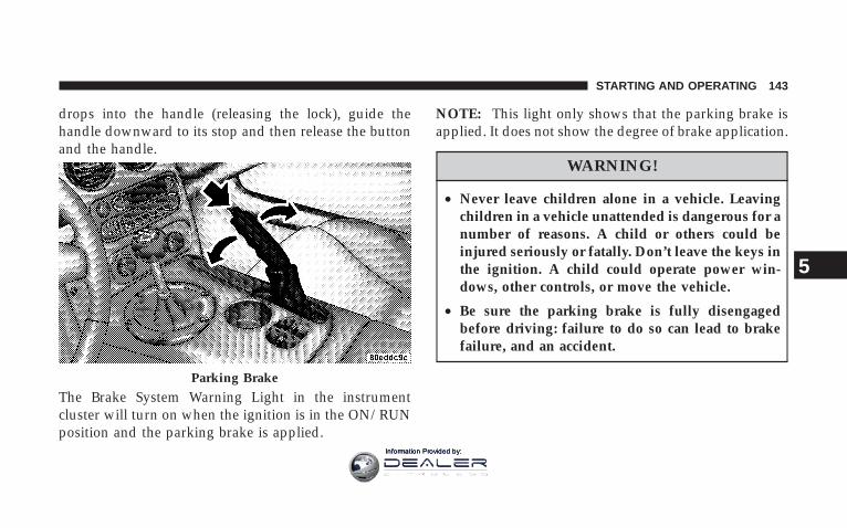
drops into the handle (releasing the lock), guide thehandle downward to its stop and then release the buttonand the handle.
The Brake System Warning Light in the instrumentcluster will turn on when the ignition is in the ON/RUNposition and the parking brake is applied.
NOTE: This light only shows that the parking brake isapplied. It does not show the degree of brake application.
WARNING!
• Never leave children alone in a vehicle. Leavingchildren in a vehicle unattended is dangerous for anumber of reasons. A child or others could beinjured seriously or fatally. Don’t leave the keys inthe ignition. A child could operate power win-dows, other controls, or move the vehicle.
• Be sure the parking brake is fully disengagedbefore driving: failure to do so can lead to brakefailure, and an accident.
Parking Brake
STARTING AND OPERATING 143
5
Information Provided by:

BRAKE SYSTEMYour vehicle is equipped with dual hydraulicbrake systems. If either of the two hydraulicsystems loses normal capability, the remainingsystem will still function. However, there will
be some loss of overall braking effectiveness. You maynotice increased pedal travel during application, greaterpedal force required to slow or stop, and potentialactivation of the Brake System Warning Light.
In the event power assist is lost for any reason (i.e.,repeated brake applications with the engine off) thebrakes will still function. However, the effort required tobrake the vehicle will be much greater than that requiredwith the power system operating.
Brake Pad Break-In
NOTE: Your vehicle is equipped with a high perfor-mance braking system. The brake pads are a semi-metallic compound, which offer superior fade resistancefor consistent operation. A compromise to using this typeof brake pad is that the brakes may squeal slightly undercertain weather and operating conditions (.i.e., duringlight brake applications).
The brakes on your new vehicle do not require a longbreak-in period. However, you should avoid repeatedhard brake applications from high speeds during initialbreak-in. In addition, you should avoid severe brakeloading, such as may be encountered when descendinglong mountain grades.
144 STARTING AND OPERATING
Information Provided by:

Safe Operating Tips
WARNING!
To use your brakes and accelerator more safely, follow thesetips:
• Do not “ride” the brakes by resting your foot on the pedal.This could overheat the brakes and result in unpredictablebraking action, longer stopping distances, or brake damage.
• When descending mountains or hills, repeated braking cancause brake fade with loss of braking control. Avoidrepeated heavy braking by downshifting the transmissionwhenever possible.
• Do not drive too fast for road conditions, especially whenroads are wet or slushy. A wedge of water can build upbetween the tire tread and the road. This hydroplaningaction can cause loss of traction, braking ability, and control.
• After going through deep water or a car wash, brakes maybecome wet, resulting in decreased performance and unpre-dictable braking action. Dry the brakes by gentle, intermit-tent pedal action while driving at very slow speeds.
Anti-Lock Brake SystemThe Anti-Lock Brake System (ABS) is designed to aid thedriver in maintaining vehicle control under adversebraking conditions. The system operates with a separatecomputer to modulate hydraulic pressure to preventwheel lock-up and help avoid skidding on slipperysurfaces.
NOTE: During severe braking conditions, a pulsingsensation may occur and a clicking noise will be heard.This is normal, indicating that the Anti-Lock BrakeSystem is functioning.
The Anti-Lock Brake System conducts a low-speed self-test at about 12 mph (20 km/h). If you have your footlightly on the brake while this test is occurring, you mayfeel slight pedal movement. The movement can be moreapparent on ice and snow. This is normal.
STARTING AND OPERATING 145
5
Information Provided by:

The Anti-Lock Brake System pump motor runs duringthe self-test at 12 mph (20 km/h) and during an ABS stop.The pump motor makes a low humming noise duringoperation, which is normal.
CAUTION!
The Anti-Lock Brake System is subject to possibledetrimental effects of electronic interference causedby improperly installed after-market radios ortelephones.
WARNING!
• The Anti-Lock Brake System contains sophisticated elec-tronic equipment that may be susceptible to interferencecaused by improperly installed or high output radio trans-mitting equipment. This interference can cause possibleloss of anti-lock braking capability. Installation of suchequipment should be performed by qualified professionals.
• Pumping of the Anti-Lock Brakes will diminish their effec-tiveness and may lead to an accident. Pumping makes thestopping distance longer. Just press firmly on your brakepedal when you need to slow down or stop.
• Anti-lock system (ABS) cannot prevent the natural laws ofphysics from acting on the vehicle, nor can it increasebraking or steering efficiency beyond that afforded by thecondition of the vehicle brakes and tires or the tractionafforded.
• The ABS cannot prevent accidents, including those result-ing from excessive speed in turns, following another vehicletoo closely, or hydroplaning. Only a safe, attentive, andskillful driver can prevent accidents.
• The capabilities of an ABS equipped vehicle must never beexploited in a reckless or dangerous manner, which couldjeopardize the user’s safety or the safety of others.
146 STARTING AND OPERATING
Information Provided by:

All vehicle wheels and tires must be the same size andtype as the original equipment and the tires must beproperly inflated to produce accurate signals for thecomputer.
WARNING!
Significant over or under inflation of tires, or mixingsizes of front or rear tires or wheels on the vehicle canlead to loss of braking effectiveness.
Anti-Lock Brake Warning LightThe amber Anti-Lock Brake Warning Light willturn on and stay on briefly as a bulb checkwhen the ignition is first turned on. If the lightdoes not turn on during starting, have it re-paired promptly.
This light also illuminates at vehicle start-up to indicatethat the ABS self-check is in process. If the light remainson after start-up, or turns on and remains on at roadspeeds, it may indicate a system malfunction or that thesystem is inoperative. In this case, the system reverts tostandard non-anti-lock brakes. If this occurs, safely bringthe vehicle to a complete stop as soon as possible andcycle the ignition key to attempt to reset the ABS. If thelight remains on, see your authorized dealer immediatelyto have the system serviced. Furthermore, if the redBRAKE warning light and the amber ABS warning lightare on, and the parking brake is fully released, see yourauthorized dealer immediately.
STARTING AND OPERATING 147
5
Information Provided by:

POWER STEERINGThe standard power steering system will give you goodvehicle response and increased ease of maneuverabilityin tight spaces. The system will provide mechanicalsteering capability if power assist is lost.
If for some reason the power assist is interrupted, it willstill be possible to steer your vehicle. Under these condi-tions, you will observe a substantial increase in steeringeffort, especially at very low vehicle speeds and duringparking maneuvers.
NOTE: Increased noise levels at the end of the steeringwheel travel are considered normal and do not indicatethat there is a problem with the power steering system.
Upon initial start-up in cold weather, the power steeringpump may make noise for a short amount of time. This isdue to the cold, thick fluid in the steering system. Thisnoise should be considered normal, and it does not in anyway damage the steering system.
WARNING!
Continued operation with reduced power steeringassist could pose a safety risk to yourself and others.Service should be obtained as soon as possible.
CAUTION!
Prolonged operation of the steering system at the endof the steering wheel travel will increase the steeringfluid temperature and it should be avoided whenpossible. Damage to the power steering pump mayoccur.
148 STARTING AND OPERATING
Information Provided by:

TIRE SAFETY INFORMATION
Tire Markings
NOTE:• P (Passenger)-Metric tire sizing is based on U.S. design
standards. P-Metric tires have the letter “P” moldedinto the sidewall preceding the size designation. Ex-ample: P215/65R15 95H.
• European Metric tire sizing is based on Europeandesign standards. Tires designed to this standard havethe tire size molded into the sidewall beginning withthe section width. The letter 9P9 is absent from this tiresize designation. Example: 215/65R15 96H
• LT (Light Truck)-Metric tire sizing is based on U.S.design standards. The size designation for LT-Metrictires is the same as for P-Metric tires except for theletters “LT” that are molded into the sidewall preced-ing the size designation. Example: LT235/85R16.
• Temporary Spare tires are high-pressure compactspares designed for temporary emergency use only.Tires designed to this standard have the letter “T”molded into the sidewall preceding the size designa-tion. Example: T145/80D18 103M.
• High Flotation tire sizing is based on U.S. designstandards and it begins with the tire diameter moldedinto the sidewall. Example: 31x10.5 R15 LT.
STARTING AND OPERATING 149
5
Information Provided by:

Tire Sizing Chart
EXAMPLE:Size Designation:
P = Passenger car tire size based on U.S. design standards9....blank....9 = Passenger car tire based on European design standardsLT = Light Truck tire based on U.S. design standardsT = Temporary Spare tire31 = Overall Diameter in Inches (in)215 = Section Width in Millimeters (mm)65 = Aspect Ratio in Percent (%)
—Ratio of section height to section width of tire10.5 = Section Width in Inches (in)R = Construction Code
—9R9 means Radial Construction—9D9 means Diagonal or Bias Construction
15 = Rim Diameter in Inches (in)
150 STARTING AND OPERATING
Information Provided by:

EXAMPLE:Service Description:
95 = Load Index—A numerical code associated with the maximum load a tire can carry
H = Speed Symbol—A symbol indicating the range of speeds at which a tire can carry a load correspondingto its load index under certain operating conditions—The maximum speed corresponding to the Speed Symbol should only be achieved un-der specified operating conditions (i.e., tire pressure, vehicle loading, road conditions,and posted speed limits)
Load Identification:(....blank....( = Absence of any text on sidewall of the tire indicates a Standard Load (SL) TireExtra Load (XL) = Extra Load (or Reinforced) TireLight Load = Light Load TireC,D,E = Load range associated with the maximum load a tire can carry at a specified pressure
Maximum Load — Maximum Load indicates the maximum load this tire is designed to carryMaximum Pressure — Maximum Pressure indicates the maximum permissible cold tire inflation pressure for this tire.
STARTING AND OPERATING 151
5
Information Provided by:

Tire Identification Number (TIN)The TIN may be found on one or both sides of the tire,however, the date code may only be on one side. Tireswith white sidewalls will have the full TIN, includingdate code, located on the white sidewall side of the tire.
Look for the TIN on the outboard side of black sidewalltires as mounted on the vehicle. If the TIN is not found onthe outboard side then you will find it on the inboard sideof the tire.
EXAMPLE:
DOT MA L9 ABCD 0301
DOT = Department of Transportation—This symbol certifies that the tire is in compliance with the U.S. Department of Transportation tire safetystandards, and is approved for highway use
MA = Code representing the tire manufacturing location (two digits)L9 = Code representing the tire size (two digits)ABCD = Code used by tire manufacturer (one to four digits)03 = Number representing the week in which the tire was manufactured (two digits)
—03 means the 3rd week.
01 = Number representing the year in which the tire was manufactured (two digits)—01 means the year 2001—Prior to July 2000, tire manufacturers were only required to have one number to represent the year inwhich the tire was manufactured. Example: 031 could represent the 3rd week of 1981 or 1991
152 STARTING AND OPERATING
Information Provided by:
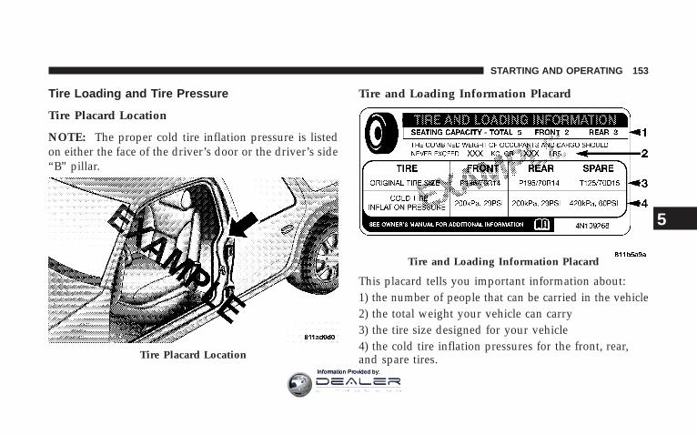
Tire Loading and Tire Pressure
Tire Placard Location
NOTE: The proper cold tire inflation pressure is listedon either the face of the driver’s door or the driver’s side“B” pillar.
Tire and Loading Information Placard
This placard tells you important information about:1) the number of people that can be carried in the vehicle2) the total weight your vehicle can carry3) the tire size designed for your vehicle4) the cold tire inflation pressures for the front, rear,and spare tires.Tire Placard Location
Tire and Loading Information Placard
STARTING AND OPERATING 153
5
Information Provided by:

LoadingThe vehicle maximum load on the tire must not exceedthe load carrying capacity of the tire on your vehicle. Youwill not exceed the tire’s load carrying capacity if youadhere to the loading conditions, tire size, and cold tireinflation pressures specified on the Tire and LoadingInformation placard and in the “Vehicle Loading” sectionof this manual.
NOTE: Under a maximum loaded vehicle condition,gross axle weight ratings (GAWRs) for the front and rearaxles must not be exceeded. For further information onGAWRs, vehicle loading, and trailer towing, refer to the“Vehicle Loading” section of this manual.
To determine the maximum loading conditions of yourvehicle, locate the statement “The combined weight of
occupants and cargo should never exceed XXX kg or XXXlbs.” on the Tire and Loading Information placard. Thecombined weight of occupants, cargo/luggage andtrailer tongue weight (if applicable) should never exceedthe weight referenced here.
Steps for Determining Correct Load Limit
1. Locate the statement “The combined weight of occu-pants and cargo should never exceed XXX pounds” onyour vehicle’s placard.
2. Determine the combined weight of the driver andpassengers that will be riding in your vehicle.
3. Subtract the combined weight of the driver and pas-sengers from XXX kilograms or XXX pounds.
154 STARTING AND OPERATING
Information Provided by:

4. The resulting figure equals the available amount ofcargo and luggage load capacity. For example, if “XXX”amount equals 1400 lbs. and there will be five 150 lb.passengers in your vehicle, the amount of available cargoand luggage load capacity is 650 lbs (295 kg) (since 5 x150 = 750, and 1400 – 750 = 650 lbs (295 kg)
5. Determine the combined weight of luggage and cargobeing loaded on the vehicle. That weight may not safelyexceed the available cargo and luggage load capacitycalculated in Step 4.
6. If your vehicle will be towing a trailer, load from yourtrailer will be transferred to your vehicle. Consult this
manual to determine how this reduces the availablecargo and luggage load capacity of your vehicle.
NOTE: The following table shows examples on how tocalculate total load, cargo/luggage, and towing capaci-ties of your vehicle with varying seating configurationsand number and size of occupants. This table is forillustration purposes only and may not be accurate forthe seating and load carry capacity of your vehicle.
NOTE: For the following example, the combined weightof occupants and cargo should never exceed 865 lbs (392kg).
STARTING AND OPERATING 155
5
Information Provided by:

156 STARTING AND OPERATING
Information Provided by:

WARNING!
Overloading of your tires is dangerous. Overloadingcan cause tire failure, affect vehicle handling, andincrease your stopping distance. Use tires of therecommended load capacity for your vehicle. Neveroverload them.
TIRES — GENERAL INFORMATION
Tire PressureProper tire inflation pressure is essential to the safe andsatisfactory operation of your vehicle. Three primaryareas are affected by improper tire pressure:
1. Safety—
WARNING!
• Improperly inflated tires are dangerous and can causeaccidents.
• Under inflation increases tire flexing and can result in tirefailure.
• Over inflation reduces a tire’s ability to cushion shock.Objects on the road and chuckholes can cause damage thatresult in tire failure.
• Unequal tire pressures can cause steering problems. Youcould lose control of your vehicle.
• Over inflated or under inflated tires can affect vehiclehandling and can fail suddenly, resulting in loss of vehiclecontrol.
• Unequal tire pressures from one side of the vehicle to theother can cause the vehicle to drift to the right or left.
• Always drive with each tire inflated to the recommendedcold tire inflation pressure.
STARTING AND OPERATING 157
5
Information Provided by:

2. Economy—Improper inflation pressures can cause uneven wearpatterns to develop across the tire tread. These abnormalwear patterns will reduce tread life resulting in a need forearlier tire replacement. Under inflation, also increasestire rolling resistance and results in higher fuel consump-tion.
3. Ride Comfort and Vehicle Stability—Proper tire inflation contributes to a comfortable ride.Over inflation produces a jarring and uncomfortable ride.
Tire Inflation PressuresThe proper cold tire inflation pressure is listed either onthe face of the driver’s door or on the driver’s side “B”pillar.
Some vehicles may have Supplemental Tire PressureInformation for vehicle loads that are less than the
maximum loaded vehicle condition. These pressure con-ditions will be found in the “Supplemental Tire PressureInformation” section of this manual.
The pressure should be checked and adjusted as well asinspecting for signs of tire wear or visible damage at leastonce a month. Use a good quality pocket-type gauge to
Tire Placard Location
158 STARTING AND OPERATING
Information Provided by:

check tire pressure. Do not make a visual judgementwhen determining proper inflation. Radial tires may lookproperly inflated even when they are under inflated.
CAUTION!
After inspecting or adjusting the tire pressure, al-ways reinstall the valve stem cap (if equipped). Thiswill prevent moisture and dirt from entering thevalve stem, which could damage the valve stem.
Inflation pressures specified on the placard are always“cold tire inflation pressure.” Cold tire inflation pressureis defined as the tire pressure after the vehicle has notbeen driven for at least 3 hours, or driven less than 1 mile(1 km) after a 3 hour period. The cold tire inflationpressure must not exceed the maximum inflation pres-sure molded into the tire sidewall.
Check tire pressures more often if subject to a wide rangeof outdoor temperatures, as tire pressures vary withtemperature changes.
Tire pressures change by approximately 1 psi (7 kPa) per12° F (7° C) of air temperature change. Keep this in mindwhen checking tire pressure inside a garage, especially inthe winter.
Example: If garage temperature = 68° F (20° C) and theoutside temperature = 32° F (0° C) then the cold tireinflation pressure should be increased by 3 psi (21 kPa),which equals 1 psi (7 kPa) for every 12° F (7° C) for thisoutside temperature condition.
Tire pressure may increase from 2 to 6 psi (13 to 40 kPa)during operation. DO NOT reduce this normal pressurebuild up or your tire pressure will be too low.
STARTING AND OPERATING 159
5
Information Provided by:

Tire Pressures for High Speed OperationThe manufacturer advocates driving at safe speedswithin posted speed limits. Where speed limits or condi-tions are such that the vehicle can be driven at highspeeds, maintaining correct tire inflation pressure is veryimportant. Increased tire pressure and reduced vehicleloading may be required for high-speed vehicle opera-tion. Refer to original equipment or an authorized tiredealer for recommended safe operating speeds, loadingand cold tire inflation pressures.
WARNING!
High speed driving with your vehicle under maxi-mum load is dangerous. The added strain on yourtires could cause them to fail. You could have aserious accident. Don’t drive a vehicle loaded to themaximum capacity at continuous speeds above 75mph (120 km/h).
Radial-Ply Tires
WARNING!
Combining radial ply tires with other types of tireson your vehicle will cause your vehicle to handlepoorly. The instability could cause an accident. Al-ways use radial ply tires in sets of four (or 6, in caseof trucks with dual rear wheels). Never combinethem with other types of tires.
Cuts and punctures in radial tires are repairable only inthe tread area because of sidewall flexing. Consult yourauthorized tire dealer for radial tire repairs.
160 STARTING AND OPERATING
Information Provided by:

Tire SpinningWhen stuck in mud, sand, snow, or ice conditions, do notspin your vehicle’s wheels above 35 mph (55 km/h).
Refer to the paragraph on “Freeing A Stuck Vehicle” inSection 6 of this manual.
WARNING!
Fast spinning tires can be dangerous. Forces gener-ated by excessive wheel speeds may cause tire dam-age or failure. A tire could explode and injure some-one. Do not spin your vehicle’s wheels faster than 30mph (48 km/h) for more than 30 seconds continu-ously when you are stuck, and don’t let anyone neara spinning wheel, no matter what the speed.
Tread Wear IndicatorsTread wear indicators are in the original equipment tiresto help you in determining when your tires should bereplaced.
These indicators are molded into the bottom of the treadgrooves. They will appear as bands when the tread depthbecomes 1/16 inch (2 mm). When the tread is worn to thetread wear indicators, the tire should be replaced.
STARTING AND OPERATING 161
5
Information Provided by:

Many states have laws requiring tire replacement at thispoint.
Life of TireThe service life of a tire is dependent upon varyingfactors including but not limited to:
• Driving style
• Tire pressure
• Distance driven
WARNING!
Tires and spare tire should be replaced after six years,regardless of the remaining tread. Failure to followthis warning can result in sudden tire failure. Youcould lose control and have an accident resulting inserious injury or death.
Keep dismounted tires in a cool, dry place with as littleexposure to light as possible. Protect tires from contactwith oil, grease, and gasoline.
Replacement TiresThe tires on your new vehicle provide a balance of manycharacteristics. They should be inspected regularly forwear and correct cold tire inflation pressure. The manu-facturer strongly recommends that you use tires equiva-lent to the originals in size, quality and performancewhen replacement is needed (refer to the paragraph on“Tread Wear Indicators”). Refer to the “Tire and LoadingInformation” placard for the size designation of your tire.The service description and load identification will befound on the original equipment tire. Failure to useequivalent replacement tires may adversely affect thesafety, handling, and ride of your vehicle. We recommendthat you contact your original equipment or an autho-rized tire dealer with any questions you may have on tirespecifications or capability.
162 STARTING AND OPERATING
Information Provided by:

WARNING!
• Do not use a tire, wheel size or rating other thanthat specified for your vehicle. Some combinationsof unapproved tires and wheels may change sus-pension dimensions and performance characteris-tics, resulting in changes to steering, handling, andbraking of your vehicle. This can cause unpredict-able handling and stress to steering and suspen-sion components. You could lose control and havean accident resulting in serious injury or death.Use only the tire and wheel sizes with load ratingsapproved for your vehicle.
• Never use a tire with a smaller load index orcapacity, other than what was originally equippedon your vehicle. Using a tire with a smaller loadindex could result in tire overloading and failure.You could lose control and have an accident.
• Failure to equip your vehicle with tires havingadequate speed capability can result in sudden tirefailure and loss of vehicle control.
CAUTION!
Replacing original tires with tires of a different sizemay result in false speedometer and odometerreadings.
Alignment And BalancePoor suspension alignment may result in:
• Fast tire wear.
• Uneven tire wear, such as feathering and one-sidedwear.
• Vehicle pull to right or left.
Tires may also cause the vehicle to pull to the left or right.Alignment will not correct this condition. See your dealerfor proper diagnosis.
STARTING AND OPERATING 163
5
Information Provided by:

Improper alignment will not cause vehicle vibration.Vibration may be a result of tire and wheel out-of-balance. Proper balancing will reduce vibration andavoid tire cupping and spotty wear.
TIRE CHAINSDue to limited clearance, tire chains are not recom-mended.
CAUTION!
Damage to the vehicle may result if tire chains areused.
SNOW TIRESThere are no snow tires that are compatible with thewheels on this vehicle.
TIRE STORAGETire storage is addressed in the Michelin Limited TireWarranty Booklet.
Specific recommendations on guidelines for long termtire storage for this vehicle should be requested of theMichelin Tire Corporation 1-800-433-6838.
TIRE ROTATION RECOMMENDATIONSTires on the front and rear axles of vehicles operate atdifferent loads and perform different steering, driving,and braking functions. For these reasons, they wear atunequal rates, and tend to develop irregular wear pat-terns.
These effects can be reduced by timely rotation of tires.The benefits of rotation are especially worthwhile with
164 STARTING AND OPERATING
Information Provided by:

aggressive tread designs such as those on all season typetires. Rotation will increase tread life, help to maintainmud, snow, and wet traction levels, and contribute to asmooth, quiet ride.
Follow the “Maintenance Schedules” in Section 8 of thismanual for the recommended tire rotation frequency foryour type of driving. Remember, more frequent rotation ispermissible if desired. Also, correct for anything causingrapid or unusual wear prior to performing the tire rotation.
Tire RotationRotate the tires “side-to-side” as shown in the diagram.
NOTE: Each wheel on your vehicle contains a tirepressure sensor. The Tire Pressure Monitor System(TPMS) learns the location of each sensor though systemprogramming. Although not required, the manufacturerrecommends reprogramming the TPMS after rotating thetires so that the system can relearn each sensor’s location.See your authorized dealer for system reprogramming.
STARTING AND OPERATING 165
5
Information Provided by:

TIRE PRESSURE MONITOR SYSTEM (TPMS)
Low Tire IndicatorIf tire pressure falls below 20 psi (138 kpa), the Low TirePressure Telltale in the Message Center will illuminate, achime will sound, and the words LOW TIRE will flashslowly in the Liquid Crystal Display (LCD) panel in thebottom of the speedometer. If tire pressure falls below 14psi (97 kpa), the Low Tire Pressure Telltale will illumi-nate, a chime will sound, and the words FLAT TIRE willflash rapidly in the display. You should obtain immediateservice if the low tire indicator is activated.
NOTE: Each wheel on your vehicle contains a tirepressure sensor. The TPMS learns the location of eachsensor though system programming. Although not re-quired, the manufacturer recommends reprogrammingthe TPMS after rotating the tires so that the system canrelearn each sensor’s location. See your authorized dealerfor system reprogramming.
CAUTION!
The Tire Pressure Monitor System (TPMS) has beenoptimized for the original equipment tires andwheels. The TPMS pressures have been establishedfor the tire size equipped on your vehicle. Undesir-able operation or sensor damage may result whenusing replacement equipment that is not of the samesize, type, and/or style. Aftermarket wheels can causesensor damage. Do not use aftermarket tire sealantsor balance beads if your vehicle is equipped with theTPMS, as damage to the sensors may result.
166 STARTING AND OPERATING
Information Provided by:

WARNING!
Do not exceed 55 mph (88 km/h) if the LOW Tireindicator is activated. Vehicle handling and brakingmay be reduced. You could have an accident and beseverely or fatally injured.
TPMS Malfunction WarningYour vehicle has also been equipped with a TPMSmalfunction indicator to indicate when the system is notoperating properly. The TPMS malfunction indicator iscombined with the low tire pressure telltale.
When the system detects a malfunction, the telltale willflash for approximately one minute and then remaincontinuously illuminated. This sequence will continue
upon subsequent vehicle start-ups as long as the mal-function exists. When the malfunction indicator is illumi-nated, the system may not be able to detect or signal lowtire pressure as intended.
TPMS malfunctions may occur for a variety of reasons,including the installation of replacement or alternate tiresor wheels on the vehicle that prevent the TPMS fromfunctioning properly. Always check the TPMS malfunc-tion telltale after replacing one or more tires or wheels onyour vehicle to ensure that the replacement or alternatetires and wheels allow the TPMS to continue to functionproperly. (See page 101 for more information.)
STARTING AND OPERATING 167
5
Information Provided by:

FUEL REQUIREMENTS
8.4L EngineThe 8.4L engine is designed to meet allemissions regulations and provide excel-lent fuel economy and performance whenusing high-quality premium unleadedgasoline with an octane rating of 91 orhigher.
Light spark knock at low engine speeds is not harmful toyour engine. However, continued heavy spark knock athigh speeds can cause damage and immediate service isrequired.
Poor quality gasoline can cause problems such as hardstarting, stalling, and hesitations. If you experience thesesymptoms, try another brand of “premium” gasolinebefore considering service for the vehicle.
Over 40 automobile manufacturers around the worldhave issued and endorsed consistent gasoline specifica-tions (the World Wide Fuel Charter, WWFC) whichdefine fuel properties necessary to deliver enhancedemissions, engine performance, and durability for yourvehicle. The manufacturer recommends the use of gaso-lines that meet the WWFC specifications if they areavailable.
Reformulated GasolineMany areas of the country require the use of cleanerburning gasoline referred to as “Reformulated Gasoline”.
Reformulated gasolines contain oxygenates, and are spe-cifically blended to reduce vehicle emissions and im-prove air quality.
The manufacturer supports the use of reformulated gaso-lines. Properly blended reformulated gasolines will pro-vide excellent performance and durability of engine andfuel system components.
168 STARTING AND OPERATING
Information Provided by:
Gasoline/Oxygenate BlendsSome fuel suppliers blend unleaded gasoline with oxy-genates such as 10% ethanol, MTBE, and ETBE. Oxygen-ates are required in some areas of the country during thewinter months to reduce carbon monoxide emissions.Fuels blended with these oxygenates may be used inyour vehicle.
CAUTION!
DO NOT use gasolines containing Methanol or E85Ethanol. Use of these blends may result in startingand driveability problems and may damage criticalfuel system components.
Problems that result from using methanol/gasoline or E85Ethanol blends are not the responsibility of the manufac-turer. While MTBE is an oxygenate made from Methanol,it does not have the negative effects of Methanol.
MMT In GasolineMMT is a manganese containing metallic additive that isblended into some gasoline to increase the octane num-ber. Gasolines blended with MMT offer no performanceadvantage beyond gasolines of the same octane numberwithout MMT. Gasolines blended with MMT have shownto reduce spark plug life and reduce emission systemperformance in some vehicles. The manufacturer recom-mends using gasolines without MMT. Since the MMTcontent of gasoline may not be indicated on the pump,you should ask your gasoline retailer if his/her gasolinecontains MMT.
It is even more important to look for gasolines withoutMMT in Canada, because MMT can be used at levelshigher than allowed in the United States. MMT is pro-hibited in Federal and California reformulated gasolines.
STARTING AND OPERATING 169
5
Information Provided by:

Materials Added to FuelAll gasoline sold in the United States is required tocontain effective detergent additives. Use of additionaldetergents or other additives are not needed undernormal conditions and they would result in additionalcost. Therefore, you should not have to add anything tothe fuel.
Fuel System Cautions
CAUTION!
Follow these guidelines to maintain your vehicle’sperformance:
• The use of leaded gas is prohibited by Federal law.Using leaded gasoline can impair engine performance,or damage the emission control system.
• An out-of-tune engine, or certain fuel or ignitionmalfunctions, can cause the catalytic converter tooverheat. If you notice a pungent burning odor orsome light smoke, your engine may be out-of-tune ormalfunctioning and may require immediate service.Contact your dealer for service assistance.
• The use of fuel additives, which are now being sold asoctane enhancers, is not recommended. Most of theseproducts contain high concentrations of methanol.Fuel system damage or vehicle performance problemsresulting from the use of such fuels or additives are notthe responsibility of the manufacturer.
NOTE: Intentional tampering with emissions controlsystems can result in civil penalties being assessedagainst you.
170 STARTING AND OPERATING
Information Provided by:

Carbon Monoxide Warnings
WARNING!
Carbon monoxide (CO) in exhaust gases is deadly.Follow the precautions below to prevent carbonmonoxide poisoning:
• Do not inhale exhaust gases. They contain carbonmonoxide, a colorless and odorless gas, which can kill.Never run the engine in a closed area, such as agarage, and never sit in a parked vehicle with theengine running for an extended period. If the vehicle isstopped in an open area with the engine running formore than a short period, adjust the ventilation systemto force fresh, outside air into the vehicle.
• Guard against carbon monoxide with proper mainte-nance. Have the exhaust system inspected every timethe vehicle is raised. Have any abnormal conditionsrepaired promptly. Until repaired, drive with all sidewindows fully open.
• Keep the trunk closed when driving your vehicle toprevent carbon monoxide and other poisonous ex-haust gases from entering the vehicle.
ADDING FUEL
Fuel Filler Cap (Gas Cap)The gas cap is located behind the fuel filler door abovethe rear tire on the passenger side of the vehicle. To accessthe gas cap, grasp the finger pull (on the left side of thefuel filler door) and pull it open. The door will pivottoward the front of the vehicle.
STARTING AND OPERATING 171
5
Information Provided by:
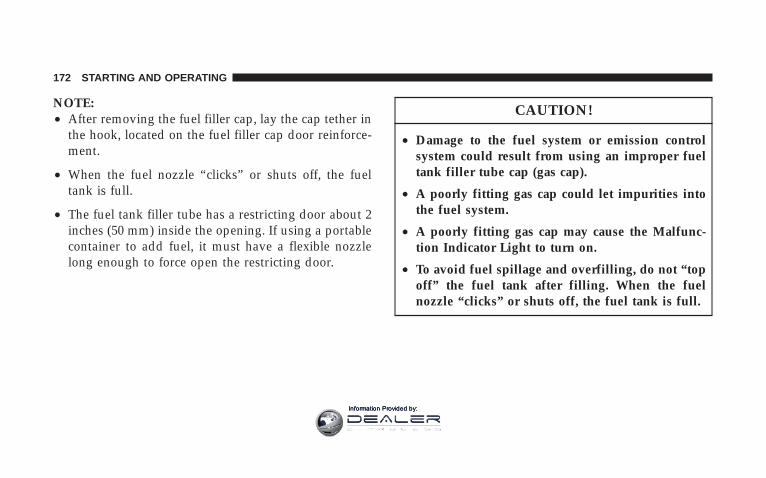
NOTE:• After removing the fuel filler cap, lay the cap tether in
the hook, located on the fuel filler cap door reinforce-ment.
• When the fuel nozzle “clicks” or shuts off, the fueltank is full.
• The fuel tank filler tube has a restricting door about 2inches (50 mm) inside the opening. If using a portablecontainer to add fuel, it must have a flexible nozzlelong enough to force open the restricting door.
CAUTION!
• Damage to the fuel system or emission controlsystem could result from using an improper fueltank filler tube cap (gas cap).
• A poorly fitting gas cap could let impurities intothe fuel system.
• A poorly fitting gas cap may cause the Malfunc-tion Indicator Light to turn on.
• To avoid fuel spillage and overfilling, do not “topoff” the fuel tank after filling. When the fuelnozzle “clicks” or shuts off, the fuel tank is full.
172 STARTING AND OPERATING
Information Provided by:

WARNING!
• Never have any smoking materials lit in or nearthe vehicle when the gas cap is removed or thetank filled.
• Never add fuel to the vehicle when the engine isrunning.
• A fire may result if gasoline is pumped into aportable container that is inside of a vehicle. Youcould be burned. Always place gas containers onthe ground while filling.
NOTE:• Tighten the gas cap until you hear a “clicking” sound.
This is an indication that the gas cap is tightenedproperly. The Malfunction Indicator Light in the in-strument cluster may turn on if the gas cap is notsecured properly. Make sure that the gas cap is tight-ened each time the vehicle is refueled.
• If the gas cap is lost or damaged, be sure the replace-ment cap is for use with this vehicle.
VEHICLE LOADING
Vehicle Loading CapacitiesFront Seat Occupants . . . . . . . . . . . . . . . . . . . . . . . 2Luggage . . . . . . . . . . . . . . . . . . . . . . . 115 lbs. (51 kg)Rated Vehicle Capacity . . . . . . . . . . . . 415 lbs. (187 kg)
STARTING AND OPERATING 173
5
Information Provided by:

TRAILER TOWINGTrailer towing with this vehicle is not recommended.
RECREATIONAL TOWING (BEHINDMOTORHOME, ETC.)
TOWING THIS VEHICLE BEHIND ANOTHERVEHICLE (Flat towing with all four wheels on theground)Recreational towing for this vehicle is not recommended.
NOTE: If the vehicle requires towing, make sure all fourwheels are off the ground.
GROUND CLEARANCEThe front and rear fascias and side sills ride low andground clearance is limited.
CAUTION!
Damage to the front and rear fascias and side sills canoccur if you disregard the low ground clearance inthese areas of your vehicle. Pay close attention whenparking to avoid running into parking curbs. Exercisecaution when entering or exiting steep driveways, orwhen pulling off the road onto soft shoulders.
174 STARTING AND OPERATING
Information Provided by:
WHAT TO DO IN EMERGENCIES
CONTENTS
m Hazard Warning Flasher . . . . . . . . . . . . . . . . . . 176
m If Your Engine Overheats . . . . . . . . . . . . . . . . . 176
m TIREFIT Kit . . . . . . . . . . . . . . . . . . . . . . . . . . . 177
▫ TIREFIT Storage . . . . . . . . . . . . . . . . . . . . . . 178
▫ TIREFIT Usage Precautions . . . . . . . . . . . . . . 178
▫ TIREFIT Kit Components & Operation . . . . . . 180
▫ Sealing a Tire With TIREFIT . . . . . . . . . . . . . . 181
m Jump-Starting Procedures . . . . . . . . . . . . . . . . . 186
m Freeing A Stuck Vehicle . . . . . . . . . . . . . . . . . . 189
m Towing A Disabled Vehicle . . . . . . . . . . . . . . . . 189
6
Information Provided by:

HAZARD WARNING FLASHER
The flasher switch is on the top of the steeringcolumn, just behind the steering wheel. Depress
the flasher button and all front and rear directionalsignals will flash. Depress the flasher button again to turnoff the flashers.
Do not use this emergency warning system when thevehicle is in motion. Use it when your vehicle is disabledand is creating a safety hazard for other motorists.
If it is necessary to leave the vehicle to go for service, theflasher system will continue to operate with the ignitionkey removed.
NOTE: With extended use, the flasher may run downyour battery.
IF YOUR ENGINE OVERHEATSIn any of the following situations, you can reduce thepotential for overheating by taking the appropriate ac-tion.
• On the highways — Slow down and use the highestgear possible.
• In city traffic — While stopped, put the transmissionin neutral, but do not increase engine idle speed.
Hazard Flasher Switch
176 WHAT TO DO IN EMERGENCIES
Information Provided by:

• In city traffic — While moving, shift into the highestgear possible to reduce engine RPM.
NOTE: There are steps that you can take to slow downan impending overheat condition. If your air conditioneris on, turn it off. The air conditioning system adds heat tothe cooling system and turning off the A/C removes thisheat. You can also turn the Temperature control tomaximum heat, the Mode control to floor, and the fancontrol to High. This allows the heater core to act as asupplement to the radiator and aids in removing heatfrom the cooling system.
WARNING!
A hot cooling system is dangerous. You or others couldbe badly burned by steam or boiling coolant. If yourtemperature gauge pointer is in the red area, turn offthe engine immediately. You may want to call a servicecenter for service. If you decide to look under the hoodyourself, see Section 7 of this manual. Follow thewarnings under the Radiator Cap paragraph.
TIREFIT KITSmall punctures in the tire tread can be sealed withTIREFIT. Foreign objects (e.g., screws or nails) should notbe removed from the tire. TIREFIT can be used in outsidetemperatures down to approximately -4°F (-20°C).
WHAT TO DO IN EMERGENCIES 177
6
Information Provided by:

TIREFIT StorageThe TIREFIT kit is located in the trunk.
TIREFIT Usage Precautions
NOTE:• Replace the TIREFIT Sealant Bottle prior to the expi-
ration date (printed on the bottle label) to assureoptimum operation of the system.
• When the TIREFIT Sealant is in a liquid form, cleanwater, and a damp cloth will remove the material fromthe vehicle or tire and wheel components. Once thesealant dries, it can easily be peeled off and properlydiscarded.
• For optimum performance, make sure the valve stemon the wheel is free of debris before connecting theTIREFIT kit.
TIREFIT Location
178 WHAT TO DO IN EMERGENCIES
Information Provided by:

• You can use the TIREFIT air pump to inflate bicycletires. The kit also comes with two needles for inflatingsport balls, rafts, or like inflatable items. However, useonly the Black Air Pump Hose (6) and make sure theMode Select Knob (4) is in the Air Mode wheninflating such items to avoid injecting sealant intothem. The TIREFIT Sealant is only intended to sealsmall punctures in the tire tread of a tire on thisvehicle.
WARNING!• Do not attempt to seal a tire on the side of the vehicle close to
traffic. Pull far enough off the road to avoid the danger of beinghit when using the TIREFIT kit.
• Do not use TIREFIT or drive the vehicle under the followingcircumstances:
− If the cut or puncture in the tire tread is approximately 0.24 in. (6mm) or larger.
− If the tire has any sidewall damage.− If the tire has any damage from driving with extremely low tire
pressure.− If the tire has any damage from driving on a flat tire.− If the wheel has any damage.− If you are unsure of the condition of the tire or the wheel.• Keep TIREFIT away from open flame or heat source.• TIREFIT is not a permanent flat tire repair. Have the tire inspected
and repaired or replaced after using TIREFIT. Do not exceed 55mph (90 km/h) until having the tire repaired or replaced.
• A loose TIREFIT kit thrown forward in a collision or hard stopcould endanger the occupants of the vehicle. Always stow theTIREFIT kit in the place provided.
Failure to follow these warnings can result in injuries that areserious or fatal to you, your passengers, and others around you.
WHAT TO DO IN EMERGENCIES 179
6
Information Provided by:

WARNING!
• Take care not to allow the contents of TIREFIT tocome in contact with hair, eyes, or clothing. TIRE-FIT is harmful if inhaled, swallowed, or absorbedthrough the skin: It causes skin, eye, and respira-tory irritation. Flush immediately with plenty ofwater if there is any contact with eyes or skin.Change clothing as soon as possible, if there is anycontact with clothing.
• TIREFIT Sealant solution contains latex. In case ofallergic reaction or rash, consult a physician imme-diately. Keep TIREFIT out of reach of children. Ifswallowed, rinse mouth immediately with plentyof water and drink plenty of water. Do not inducevomiting! Consult a physician immediately.
TIREFIT Kit Components & Operation
1. Sealant Bottle
2. Pressure Gauge
3. Air Pump Power Button
4. Mode Select Knob
5. Power Plug & Cable
180 WHAT TO DO IN EMERGENCIES
Information Provided by:

6. Air Pump Hose (Black)
7. Sealant Hose (Clear with Yellow Cap)
Using the Mode Select Knob & Hoses
Selecting Air ModeTurn the Mode Select knob (4) to this positionfor air pump operation only. Use the Black AirPump Hose (6) when selecting this mode.
Selecting Sealant/Air ModeTurn the Mode Select knob (4) to this positionto inject the TIREFIT Sealant and to inflate thetire. Use the Sealant Hose (Clear hose with theYellow Cap) (7) when selecting this mode.
Using the Air Pump Power ButtonPush and release the button (3) once to turn Onthe TIREFIT kit. Push and release the button (3)again to turn Off the TIREFIT kit.
Sealing a Tire with TIREFIT
(A) Whenever You Stop to Use TIREFIT:Turn on the vehicle’s hazard warning flashers.
1. Verify that the valve stem (on the wheel with thedeflated tire) is in a position that is near to the ground.This will allow the TIREFIT Hoses (6) and (7) to reach thevalve stem and keep the TIREFIT kit flat on the ground.This will provide the best positioning of the kit wheninjecting the sealant into the deflated tire and running theair pump. Move the vehicle as necessary to place thevalve stem in this position before proceeding.
2. Place the transmission in Park (auto transmission) orin Gear (manual transmission) and turn off the ignition.
3. Set the parking brake.
WHAT TO DO IN EMERGENCIES 181
6
Information Provided by:

(B) Setting Up to Use TIREFIT:Turn the Mode Select knob (4) to the Sealant/Air Mode position.
1. Uncoil the Clear Sealant Hose (7) and then remove theYellow Cap from the fitting at the end of the hose.
2. Place the TIREFIT kit flat on the ground next to thedeflated tire.
3. Remove the cap from the valve stem and then screwthe fitting at the end of the Sealant Hose (7) onto thevalve stem.
4. Uncoil the Power Plug and Cable (5) and then insertthe plug into the vehicle’s power outlet.
NOTE: Do not remove foreign objects (e.g., screws ornails) from the tire.
(C) Injecting TIREFIT Sealant into the deflated tire:
1. Always start the engine before turning on the TIREFITkit.
2. After pressing the Air Pump Power Button(3), the air pump should start to inflate the tireand the sealant (white fluid) will flow from theSealant Bottle (1) through the Sealant Hose (7)
and into the tire. NOTE: Some sealant may leak outthrough the puncture in the tire.
3. If the sealant Does Not Flow Through the ClearSealant Hose (7):
• Press the Air Pump Power Button (3) to turn off theTIREFIT kit. Disconnect the Clear Sealant Hose (7)from the valve stem. Make sure the valve stem isfree of debris. Reconnect the Clear Sealant Hose (7)to the valve stem. Press the Air Pump Power Button(3) to turn on the TIREFIT kit.
182 WHAT TO DO IN EMERGENCIES
Information Provided by:
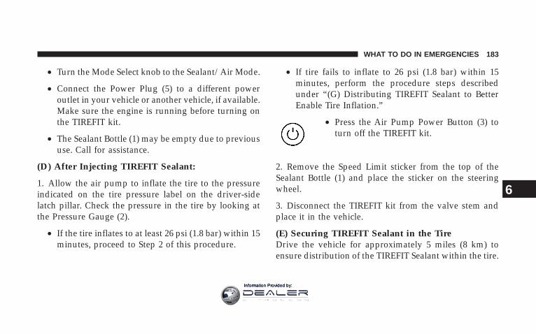
• Turn the Mode Select knob to the Sealant/Air Mode.
• Connect the Power Plug (5) to a different poweroutlet in your vehicle or another vehicle, if available.Make sure the engine is running before turning onthe TIREFIT kit.
• The Sealant Bottle (1) may be empty due to previoususe. Call for assistance.
(D) After Injecting TIREFIT Sealant:
1. Allow the air pump to inflate the tire to the pressureindicated on the tire pressure label on the driver-sidelatch pillar. Check the pressure in the tire by looking atthe Pressure Gauge (2).
• If the tire inflates to at least 26 psi (1.8 bar) within 15minutes, proceed to Step 2 of this procedure.
• If tire fails to inflate to 26 psi (1.8 bar) within 15minutes, perform the procedure steps describedunder “(G) Distributing TIREFIT Sealant to BetterEnable Tire Inflation.”
• Press the Air Pump Power Button (3) toturn off the TIREFIT kit.
2. Remove the Speed Limit sticker from the top of theSealant Bottle (1) and place the sticker on the steeringwheel.
3. Disconnect the TIREFIT kit from the valve stem andplace it in the vehicle.
(E) Securing TIREFIT Sealant in the TireDrive the vehicle for approximately 5 miles (8 km) toensure distribution of the TIREFIT Sealant within the tire.
WHAT TO DO IN EMERGENCIES 183
6
Information Provided by:

WARNING!
TIREFIT is not a permanent flat tire repair. Have thetire inspected and repaired or replaced after usingTIREFIT. Do not exceed 55 mph (90 km/h) untilhaving the tire repaired or replaced. Failure to followthis warning can result in injuries that are serious orfatal to you, your passengers, and others around you.
(F) After Securing TIREFIT Sealant in the Tire:Turn the Mode Select knob (4) to the Air Modeposition.
1. Uncoil the Black Air Pump Hose (6) and connect it tothe valve stem.
2. Check the pressure in the tire by reading the PressureGauge (2).
• If the pressure is less than 19 psi (1.3 bar), the tire istoo badly damaged. Do not attempt to drive thevehicle further. Call for assistance.
• If the pressure is equal to or greater than 19 psi (1.3bar), but less than the level indicated on the tirepressure label, proceed to Step 4 of this procedure.
• If the pressure is at the level indicated on the tirepressure label on the driver-side latch pillar, proceedto Step 5 of this procedure.
3. Inflate the tire to the pressure indicated on the tirepressure label on the driver-side latch pillar.
4. Disconnect the TIREFIT kit from the valve stem andthen reinstall the cap on the valve stem.
184 WHAT TO DO IN EMERGENCIES
Information Provided by:

5. Place the TIREFIT kit in its proper storage area in thevehicle.
6. Have the tire inspected and repaired or replaced at theearliest opportunity at an authorized dealer or tire ser-vice center.
7. Replace the Sealant Bottle (1) at your nearest autho-rized Mopart parts dealership as soon as possible.
(G) Distributing TIREFIT Sealant to Better EnableTire Inflation
NOTE: Use this procedure only if directed here fromStep 1 of “(D) After Injecting TIREFIT Sealant.”
Press the Air Pump Power Button (3) to turn offthe TIREFIT kit. Then, disconnect the kit fromthe valve stem and place it in the vehicle.
1. Drive the vehicle forward approximately 30 to 50 feet(9 to 15 m) to distribute the sealant more evenly withinthe tire.
2. Return to Step 1 of “(D) After Injecting TIREFITSealant” and attempt to inflate the tire. However, thistime, if the tire fails to inflate to 26 psi (1.8 bar) within 15minutes, the tire is too badly damaged. Do not attempt todrive the vehicle further. Call for assistance.
WHAT TO DO IN EMERGENCIES 185
6
Information Provided by:

JUMP-STARTING PROCEDURES
WARNING!• Take care to avoid the radiator cooling fans whenever the hood
is raised. They can start anytime the ignition switch is on. Youcan be hurt by the fans.
• Take care to avoid the accessory drive whenever the hood israised. You can be hurt by the moving components.
• Do not attempt to push or tow your vehicle to get it started.Unburned fuel could enter the catalytic converter and once theengine has started, ignite and damage the converter andvehicle. If the vehicle has a discharged battery, booster cablesmay be used to obtain a start from a booster battery or thebattery in another vehicle. This type of start can be dangerousif done improperly, so follow this procedure carefully.
• Battery fluid is a corrosive acid solution; do not allow batteryfluid to contact eyes, skin, or clothing. Don’t lean over batterywhen attaching clamps or allow the clamps to touch eachother. If acid splashes in eyes or on skin, flush contaminatedarea immediately with large quantities of water.
• A battery generates hydrogen gas, which is flammable andexplosive. Keep flame or spark away from the vent holes.
• Do not use a booster battery or any other booster source withan output that exceeds 12 volts.
NOTE: The battery is located underneath an accesspanel inside the rear compartment on the left side of thevehicle. A remote battery terminal is located in the enginecompartment for jump-starting.
1. Wear eye protection and remove any metal jewelrysuch as watchbands or bracelets that might make aninadvertent electrical contact.
2. When boost is provided by a battery in anothervehicle, park that vehicle within booster cable reach, butwithout allowing the vehicles touch one another.
3. Set the parking brake, place the transmission in neu-tral, and turn the ignition OFF on both vehicles.
4. Turn off the heater, radio, and all unnecessary electri-cal loads.
186 WHAT TO DO IN EMERGENCIES
Information Provided by:
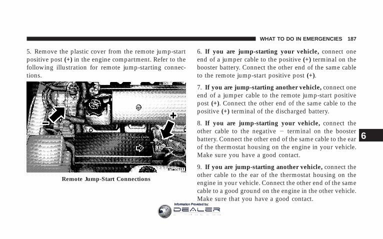
5. Remove the plastic cover from the remote jump-startpositive post (+) in the engine compartment. Refer to thefollowing illustration for remote jump-starting connec-tions.
6. If you are jump-starting your vehicle, connect oneend of a jumper cable to the positive (+) terminal on thebooster battery. Connect the other end of the same cableto the remote jump-start positive post (+).
7. If you are jump-starting another vehicle, connect oneend of a jumper cable to the remote jump-start positivepost (+). Connect the other end of the same cable to thepositive (+) terminal of the discharged battery.
8. If you are jump-starting your vehicle, connect theother cable to the negative 2 terminal on the boosterbattery. Connect the other end of the same cable to the earof the thermostat housing on the engine in your vehicle.Make sure you have a good contact.
9. If you are jump-starting another vehicle, connect theother cable to the ear of the thermostat housing on theengine in your vehicle. Connect the other end of the samecable to a good ground on the engine in the other vehicle.Make sure that you have a good contact.
Remote Jump-Start Connections
WHAT TO DO IN EMERGENCIES 187
6
Information Provided by:

WARNING!
• You should not try to start your vehicle by pushingor towing.
• Do not connect the cable to the negative post of thedischarge battery. The resulting electrical sparkcould cause the battery to explode.
• During cold weather when temperatures are be-low freezing point, electrolyte in a dischargedbattery may freeze. Do not attempt jump-startingbecause the battery could rupture or explode. Thebattery temperature must be brought up abovefreezing point before attempting jump-start.
10. Start the engine in the vehicle that has the boosterbattery. Let the engine idle a few minutes.
11. Turn off the Vehicle Security System.
NOTE: The Vehicle Security System will prevent theengine from starting.
12. Start the engine in the vehicle with the dischargedbattery. If engine does not start in 15 seconds, stopcranking engine and allow starter to cool down beforecranking again.
13. When removing the booster cables, reverse the abovesequence exactly. Be careful of the moving belts and fans.
188 WHAT TO DO IN EMERGENCIES
Information Provided by:

WARNING!
Any procedure other than above could result in:
1. Personal injury caused by electrolyte squirting outthe battery vent;
2. Personal injury or property damage due to batteryexplosion;
3. Damage to charging system of booster vehicle orof immobilized vehicle.
FREEING A STUCK VEHICLEIf your vehicle becomes stuck in mud, sand, or snow, itcan often be moved by a rocking motion. Turn yoursteering wheel right and left to clear the area around thefront wheels. Then shift back and forth between Reverse
and First gear. Usually the least accelerator pedal pres-sure to maintain the rocking motion without spinning thewheels is most effective.
CAUTION!
Racing the engine or spinning the wheels too fastmay lead to transmission/axle overheating and fail-ure. It can also damage the tires. Do not spin thewheels above 30 mph (48 km/h).
TOWING A DISABLED VEHICLEDo not tow with sling type equipment. Only use flat bedequipment. Always comply with applicable state or localtowing ordinances.
WHAT TO DO IN EMERGENCIES 189
6
Information Provided by:
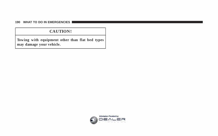
CAUTION!
Towing with equipment other than flat bed typesmay damage your vehicle.
190 WHAT TO DO IN EMERGENCIES
Information Provided by:

MAINTAINING YOUR VEHICLE
CONTENTS
m 8.4L Engine Compartment . . . . . . . . . . . . . . . . 194
m Onboard Diagnostic System (OBD II) . . . . . . . . . 195
m Emissions Inspection And MaintenancePrograms . . . . . . . . . . . . . . . . . . . . . . . . . . . . 196
m Replacement Parts . . . . . . . . . . . . . . . . . . . . . . 197
m Dealer Service . . . . . . . . . . . . . . . . . . . . . . . . . 198
m Maintenance Procedures . . . . . . . . . . . . . . . . . . 198
▫ Engine Oil . . . . . . . . . . . . . . . . . . . . . . . . . . 198
▫ Engine Oil Filter . . . . . . . . . . . . . . . . . . . . . . 201
▫ Drive Belts — Check Condition And Tension . . 202
▫ Spark Plugs . . . . . . . . . . . . . . . . . . . . . . . . . 203
▫ Engine Air Cleaner Filter . . . . . . . . . . . . . . . . 203
▫ Fuel Filter . . . . . . . . . . . . . . . . . . . . . . . . . . 204
▫ Catalytic Converter . . . . . . . . . . . . . . . . . . . . 204
▫ Ignition Wiring System And IgnitionTiming . . . . . . . . . . . . . . . . . . . . . . . . . . . . . 205
▫ Crankcase Emission Control System . . . . . . . . 206
▫ Maintenance-Free Battery . . . . . . . . . . . . . . . . 206
7
Information Provided by:

▫ Battery Save Feature . . . . . . . . . . . . . . . . . . . 210
▫ Air Conditioner Maintenance . . . . . . . . . . . . . 212
▫ Power Steering — Fluid Check . . . . . . . . . . . . 213
▫ Front & Rear Suspension Ball Joints . . . . . . . . 214
▫ Steering Linkage . . . . . . . . . . . . . . . . . . . . . . 214
▫ Body Lubrication . . . . . . . . . . . . . . . . . . . . . 215
▫ Body Mechanism Lubrication . . . . . . . . . . . . . 215
▫ Windshield Wiper Blades . . . . . . . . . . . . . . . . 217
▫ Windshield Washers . . . . . . . . . . . . . . . . . . . 217
▫ Exhaust System . . . . . . . . . . . . . . . . . . . . . . 218
▫ Cooling System . . . . . . . . . . . . . . . . . . . . . . . 219
▫ Hoses And Vacuum/Vapor Harnesses . . . . . . . 224
▫ Fuel System . . . . . . . . . . . . . . . . . . . . . . . . . 224
▫ Brake System . . . . . . . . . . . . . . . . . . . . . . . . 225
▫ Transmission . . . . . . . . . . . . . . . . . . . . . . . . 228
▫ Hydraulic Clutch . . . . . . . . . . . . . . . . . . . . . 228
▫ Rear Axle . . . . . . . . . . . . . . . . . . . . . . . . . . . 230
▫ Wheel Bearings . . . . . . . . . . . . . . . . . . . . . . . 230
▫ Appearance Care And Protection FromCorrosion . . . . . . . . . . . . . . . . . . . . . . . . . . . 230
m Fuses (Power Distribution Centers) . . . . . . . . . . 234
▫ Fuses (Power Distribution Center) . . . . . . . . . 234
▫ Fuses (Mini-Power Distribution Center) . . . . . 237
m Vehicle Storage . . . . . . . . . . . . . . . . . . . . . . . . 238
192 MAINTAINING YOUR VEHICLE
Information Provided by:
m Replacement Bulbs . . . . . . . . . . . . . . . . . . . . . . 240
m Bulb Replacement . . . . . . . . . . . . . . . . . . . . . . 242
▫ Auxiliary High Beam Headlight, FrontPark/Turn Signal Light, Front SideMarker Light . . . . . . . . . . . . . . . . . . . . . . . . 242
▫ High Intensity Discharge Headlights (HID) . . . 243
▫ Front Fog Light . . . . . . . . . . . . . . . . . . . . . . 244
▫ Taillight, Tail/Stop Light, Rear Marker Light . . 245
▫ Backup Light, Rear Turn Signal Light . . . . . . . 246
▫ License Light . . . . . . . . . . . . . . . . . . . . . . . . 250
m Headlight Aiming . . . . . . . . . . . . . . . . . . . . . . 251
m Fluids And Capacities . . . . . . . . . . . . . . . . . . . 251
m Fluids, Lubricants, And Genuine Parts . . . . . . . . 252
▫ Engine . . . . . . . . . . . . . . . . . . . . . . . . . . . . . 252
▫ Chassis . . . . . . . . . . . . . . . . . . . . . . . . . . . . 253
▫ Body . . . . . . . . . . . . . . . . . . . . . . . . . . . . . . 254
MAINTAINING YOUR VEHICLE 193
7
Information Provided by:

8.4L ENGINE COMPARTMENT
194 MAINTAINING YOUR VEHICLE
Information Provided by:

ONBOARD DIAGNOSTIC SYSTEM (OBD II)To meet new government regulations and promotecleaner air, your vehicle is equipped with a sophisticatedonboard diagnostic system called OBD II. This systemmonitors the performance of the emissions and enginecontrol systems. When these systems are operating prop-erly, your vehicle will provide excellent performance andfuel economy, as well as engine emissions well withincurrent government regulations.
If any of these systems require service, the OBD II systemwill turn on the Malfunction Indicator Light. It will alsostore diagnostic codes and other information to assistyour service technician in making repairs. Although yourvehicle will usually be drivable and not need towing, seeyour dealer for service as soon as possible.
CAUTION!
Prolonged driving with the light on could causefurther damage to the emission control system. Itcould also affect fuel economy and driveability. Thevehicle must be serviced before any state emissionstests can be performed.
If the light is flashing, severe catalytic converter damageand power loss will soon occur. Immediate service isrequired.
If the gas cap is not tightened properly, the light maycome on. Be sure the gas cap is tightened every time youadd fuel.
MAINTAINING YOUR VEHICLE 195
7
Information Provided by:

EMISSIONS INSPECTION AND MAINTENANCEPROGRAMSIn some localities, it may be a legal requirement to passan inspection of your vehicle’s emissions control system.Failure to pass could prevent vehicle registration.
For states, which have an I/M (Inspection andMaintenance) requirement, this check verifies thefollowing: the MIL (Malfunction Indicator Light)
is functioning and is not on when the engine is running,and that the OBD (On Board Diagnostic) system is readyfor testing.
Normally, the OBD system will be ready. The OBDsystem may not be ready if your vehicle was recentlyserviced, if you recently had a dead battery, or a batteryreplacement. If the OBD system should be determinednot ready for the I/M test, your vehicle may fail the test.
Your vehicle has a simple ignition key-actuated test,which you can use prior to going to the test station. Tocheck if your vehicle’s OBD system is ready, you must dothe following:
1. Insert your ignition key into the ignition switch.
2. Turn the ignition to the ON position, but do not crankor start the engine.
3. If you crank or start the engine, you will have to startthis test over.
4. As soon as you turn your key to the ON position, youwill see your MIL symbol come on as part of a normalbulb check.
196 MAINTAINING YOUR VEHICLE
Information Provided by:

5. Approximately 15 seconds later, one of two things willhappen:
a. The MIL will flash for about 10 seconds and thenreturn to being fully illuminated until you turn off theignition key or start the engine. This means that yourvehicle’s OBD system is not ready and you should notproceed to the I/M station.
b. The MIL will not flash at all and will remain fullyilluminated until you turn OFF the ignition key or startthe engine. This means that your vehicle’s OBD systemis ready and you can proceed to the I/M station.
If your OBD system is not ready, you should see yourauthorized dealer or repair facility. If your vehicle wasrecently serviced or had a battery failure or replacement,you may need to do nothing more than drive yourvehicle as you normally would in order for your OBDsystem to update. A recheck with the above test routinemay then indicate that the system is now ready.
Regardless of whether your vehicle’s OBD system isready or not ready, if the MIL symbol is illuminatedduring normal vehicle operation, you should have yourvehicle serviced before going to the I/M station. The I/Mstation can fail your vehicle because the MIL symbol is onwith the engine running.
REPLACEMENT PARTSUse of genuine Mopart parts for normal/scheduledmaintenance and repairs is highly recommended to en-sure the designed performance. Damage or failurescaused by the use of non-Mopart parts for maintenanceand repairs will not be covered by the manufacturer’swarranty.
MAINTAINING YOUR VEHICLE 197
7
Information Provided by:

DEALER SERVICEYour authorized dealer has the qualified service person-nel, special tools, and equipment to perform all serviceoperations in an expert manner. Service Manuals areavailable which include detailed service information foryour vehicle. Refer to these manuals before attemptingany procedure yourself.
NOTE: Intentional tampering with emissions controlsystems can result in civil penalties being assessedagainst you.
WARNING!
You can be badly injured working on or around amotor vehicle. Only do service work for which youhave the knowledge and the proper equipment. If youhave any doubt about your ability to perform a servicejob, take your vehicle to a competent mechanic.
MAINTENANCE PROCEDURESThe pages that follow contain the maintenance servicerecommendations by the engineers who designed yourvehicle.
Besides the maintenance items for which there are fixedmaintenance intervals, there are other items, whichshould operate satisfactorily without periodic mainte-nance. However, if a malfunction of these items doesoccur, it could adversely affect the engine or vehicleperformance. These items should be inspected if a mal-function is observed or suspected.
Engine Oil
Checking Oil LevelTo assure proper engine lubrication, the engine oil mustbe maintained at the correct level. Check the oil level atregular intervals, such as every fuel stop.
198 MAINTAINING YOUR VEHICLE
Information Provided by:

The best time to check the oil level is approximately 5minutes after a fully warmed engine is turned off orbefore starting the engine after it has sat overnight.
Checking the oil while the vehicle is on level ground alsowill improve the accuracy of the oil level readings. Addoil only when the level is below the SAFE mark.
CAUTION!
Overfilling or underfilling will cause oil aeration orloss of oil pressure. This could damage your engine.
Change Engine OilRoad conditions and your kind of driving affect theinterval at which your oil should be changed. Check thefollowing list to see if any apply to you.
• Day or night temperatures are below 32°F (0°C)
• Stop and go driving
• Extensive engine idling
• Driving in dusty conditions
• Short trip driving of less than 10 miles (16.2 km)
Engine Oil Dipstick
MAINTAINING YOUR VEHICLE 199
7
Information Provided by:
• More than 50% of your driving is at sustained highspeeds during hot weather, above 90°F (32°C)
• Trailer towing
• Taxi, Police, or delivery service (commercial service)
• Off-road or desert driving
• If equipped for and operating with E-85 (ethanol) fuel
NOTE: If ANY of these apply to you, then change yourengine oil every 3,000 miles (5 000 km) or 3 months,whichever comes first, and follow schedule “B” in the9Maintenance Schedules9 in this manual.
If none of these applies to you, then change your engineoil at every interval shown on schedule 9A9 in the9Maintenance Schedules9 in this manual.
NOTE: Under no circumstances should oil change in-tervals exceed 6,000 miles (10 000 km) or 6 months,whichever comes first.
Engine Oil SelectionFor best performance and maximum protection under alltypes of operating conditions, the manufacturer onlyrecommends full synthetic engine oils that meet theAmerican Petroleum Institute (API) categories of SM orSM/CF, and meet the requirements of DaimlerChryslerMaterial Standard MS-10725.
The manufacturer recommends the use of a full syntheticengine oil, such as Mobil 1t SAE 0W-40 or equivalent.
Engine Oil Viscosity (SAE Grade)The proper SAE viscosity grade of engine oil should beselected based on the following recommendation and bewithin the operating temperature shown in the engine oilviscosity chart.
200 MAINTAINING YOUR VEHICLE
Information Provided by:

The engine oil filler cap also shows the recommendedengine oil viscosity for your engine. For information onengine oil filler cap location, refer to the “Engine Com-partment” illustration in this section.
Materials Added to Engine OilThe manufacture strongly recommends against the addi-tion of any additives (other than leak detection dyes) to
the engine oil. Engine oil is an engineered product and itsperformance may be impaired by supplemental addi-tives.
Disposing of Used Engine Oil and Oil FiltersCare should be taken in disposing of used engine oil andoil filters from your vehicle. Used oil and oil filters,indiscriminately discarded, can present a problem to theenvironment. Contact your dealer, service station, orgovernmental agency for advice on how and where usedoil and oil filters can be safely discarded in your area.
Engine Oil FilterThe engine oil filter should be replaced with a new filterat every engine oil change.
Engine Oil Filter SelectionThis manufacturer’s engines have a full-flow type oilfilter. Use a filter of this type for replacement. The qualityof replacement filters varies considerably. Only high
MAINTAINING YOUR VEHICLE 201
7
Information Provided by:

quality filters should be used to assure most efficientservice. Mopart Engine Oil Filters are a high quality oilfilter and are recommended.
Drive Belts — Check Condition and TensionBelt tension is controlled by means of an automatictensioner. Therefore, no belt tension adjustments arerequired. However, belt and belt tensioner conditionshould be inspected at the specified intervals and re-placed if required. Improper belt tension can cause beltslippage and failure. Low generator belt tension cancause battery failure.
At the intervals indicated on the “Maintenance Sched-ules,” inspect belt and belt tensioner condition. Inspectbelts for evidence of cuts, cracks, glazing, or frayed cordsand replaced if there is indication of damage, which couldresult in belt failure. Also, check belt routing to make surethere is no interference between the belts and other enginecomponents. See your authorized dealer for service.
8.4L ACCESSORY BELT ROUTING1 — Alternator2 — Tensioner3 — Water Pump4 — Power Steering Pump5 — A/C Compressor6— Routing for Non-A/C Applications
202 MAINTAINING YOUR VEHICLE
Information Provided by:

Spark PlugsSpark plugs must fire properly to assure engine perfor-mance and emission control. New plugs should be in-stalled at the specified mileage. The entire set should bereplaced if there is any malfunction due to a faulty sparkplug. Malfunctioning spark plugs can damage the cata-lytic converter. Refer to “Fluids, Lubricants, and GenuineParts” in this section for the proper type of spark plug foruse in your vehicle.
Engine Air Cleaner FilterFor normal driving conditions, inspect and replace theengine air cleaner filter at the intervals shown on Sched-ule “A.” For vehicles driven frequently in dusty or undersevere conditions, inspect and replace the engine aircleaner filter at the intervals shown on Schedule “B.”
WARNING!
The air induction system (air cleaner, hoses, etc) canprovide a measure of protection in the case of enginebackfire. Do not remove the air induction system (aircleaner, hoses, etc) unless such removal is necessaryfor repair or maintenance. Make sure that no one isnear the engine compartment before starting thevehicle with the air induction system (air cleaner,hoses, etc) removed. Failure to do so can result inserious personal injury.
MAINTAINING YOUR VEHICLE 203
7
Information Provided by:

Fuel FilterThe fuel filter is a part of the fuel module and it does notrequire maintenance.
Catalytic ConverterThe catalytic converter requires the use of unleaded fuelonly. Leaded gasoline will destroy the effectiveness of thecatalyst as an emission control device.
Under normal operating conditions, the catalytic con-verter will not require maintenance. However, it is im-portant to keep the engine properly tuned to assureproper catalyst operation and prevent possible catalystdamage.
CAUTION!
Damage to the catalytic converter can result if yourvehicle is not kept in proper operating condition.Have your vehicle serviced promptly in the event ofengine malfunction, particularly when involving en-gine misfire or other apparent loss of performance.Continued operation of your vehicle with a severemalfunction could cause the converter to overheat,resulting in possible damage to the converter and thevehicle.
NOTE: Intentional tampering with emissions controlsystems can result in civil penalties being assessedagainst you.
204 MAINTAINING YOUR VEHICLE
Information Provided by:

WARNING!
A hot exhaust system can start a fire if you park overmaterials that can burn. Such materials might begrass or leaves coming in contact with your exhaustsystem. Do not park or operate your vehicle in areaswhere your exhaust system can contact anything thatcan burn.
In unusual situations involving grossly malfunctioningengine operation, a scorching odor may indicate severeand abnormal catalyst overheating. If this should occur,safely bring the vehicle to a complete stop, shut theengine off, and allow the vehicle to cool. Thereafter,obtain service, including a tune-up to manufacturer’sspecifications immediately.
To minimize the possibility of catalytic converter damage:
• Do not shut off the engine or interrupt the ignitionwhen the transmission is in gear and the vehicle is inmotion.
• Do not try to start the engine by pushing or towing thevehicle.
• Do not idle the engine with any spark plug wiresdisconnected or removed, such as when diagnostictesting, or for prolonged periods during very roughidling or malfunctioning operating conditions.
Ignition Wiring System and Ignition TimingThe ignition cables should be kept clean and the termi-nals fully seated. Do not remove the nipple assembliesfrom the coil towers. Cracked, damaged, or faulty cablesshould be replaced. See your authorized dealer for ser-vice.
MAINTAINING YOUR VEHICLE 205
7
Information Provided by:

NOTE:• Because of the plastic body shell on your vehicle,
ignition cables should be replaced with the speciallydesigned RFI cables available at your dealer.
• The ignition timing cannot be set on this engine.
Crankcase Emission Control SystemProper operation of this system depends on freedomfrom plugging due to deposits. As vehicle mileage buildsup, the Crankcase Ventilation Valve orifice may accumu-late deposits. If a valve is not working properly, it shouldbe replaced with a new orifice. DO NOT ATTEMPT TOCLEAN THE OLD ORIFICE!
Check the ventilation hose for indication of damage orplugging deposits and replace if necessary. See yourauthorized dealer for service.
Maintenance-Free BatteryThe top of the MAINTENANCE-FREE battery is perma-nently sealed. You will never have to add water, nor isperiodic maintenance required.
The battery is located underneath an access panel insidethe rear compartment on the left side of the vehicle. Aremote battery terminal is located in the engine compart-ment for jump-starting.
To gain access to the battery, remove the floor portion ofthe rear compartment carpet.
206 MAINTAINING YOUR VEHICLE
Information Provided by:

Accessing The Battery Battery Location
MAINTAINING YOUR VEHICLE 207
7
Information Provided by:

WARNING!
• Battery fluid is a corrosive acid solution and canburn or even blind you. Don’t allow battery fluidto contact your eyes, skin, or clothing. Don’t leanover a battery when attaching clamps. If acidsplashes in eyes or on skin, flush the area imme-diately with large amounts of water.
• Battery gas is flammable and explosive. Keepflame or sparks away from the battery. Don’t use abooster battery or any other booster source with anoutput greater than 12 volts. Don’t allow cableclamps to touch each other.
• Battery posts, terminals, and related accessoriescontain lead and lead compounds. Wash handsafter handling.
CAUTION!
• It is essential when replacing the cables on thebattery that the positive cable is attached to thepositive post and the negative cable is attached tothe negative post. Battery posts are marked posi-tive (+) and negative (-) and identified on thebattery case. Cable clamps should be tight on theterminal posts and free of corrosion.
• If a “fast charger” is used while battery is invehicle, disconnect both vehicle battery cablesbefore connecting the charger to battery. Do notuse a “fast charger” to provide starting voltage.
208 MAINTAINING YOUR VEHICLE
Information Provided by:

To Service the Battery:
1. Remove the floor portion of the rear compartmentcarpet to access the battery compartment.
2. Remove the battery cover mounting screws and re-move the battery cover.
3. Disconnect the negative battery cable from the battery.
NOTE: The negative battery terminal is marked with a(-) symbol. The positive battery terminal is marked witha (+) symbol.
4. Disconnect the positive battery cable from the battery.
5. Remove or loosen the battery retainer clamp and bolt.
6. Lift out the battery.
7. Clean out the battery tray area, freeing area of dirt,stones, and battery acid.
8. Clean and inspect the battery terminals and replace ifparts are damaged or unusable.
9. Place the battery in the tray.
10. Tighten the battery retainer clamp and bolt down.
11. Connect the positive battery cable to the batterypositive terminal and tighten.
NOTE: The negative battery terminal is marked with a(-) symbol. The positive battery terminal is marked witha (+) symbol.
12. Connect the negative battery cable to the batterynegative terminal and tighten.
13. Install the battery cover and tighten down the screws.
14. Install the carpet in the floor portion of the rearcompartment.
MAINTAINING YOUR VEHICLE 209
7
Information Provided by:

Battery Save FeatureThe Battery Save feature conserves battery power whenstoring the vehicle. It allows for up to 3 months of storagetime without losing radio and engine controller memory.Using this feature is an alternative to disconnecting thebattery.
NOTE: This vehicle is designed to sit in storage with afully charged battery for up to 30 days. If you plan tostore the vehicle longer than 30 days, we recommenddoing one of the following:
• Disconnect the battery.
• Use the battery charger.
• Put the vehicle into Battery Save mode (3-monthcharge).
To Activate the Battery Save Feature:
1. Insert the key into the ignition switch.
2. Cycle the ignition switch from OFF/LOCK to ACCfour times. Leave the switch in the OFF/LOCK positionafter the fourth cycle.
3. Push the driver’s Power Door Lock switch in the UPdirection. A single chime will sound and the horn willchirp to indicate that the process has begun.
Ignition Key Positions
210 MAINTAINING YOUR VEHICLE
Information Provided by:
4. Remove the key from the ignition switch and exit thevehicle. The Battery Save Feature will be enabled 45seconds after all doors are closed.
NOTE:• Turning the ignition switch to the ON/RUN position
at any time will cancel activation of the Battery SaveFeature.
• The remote keyless entry and the exterior passengerdoor handle will not work when the Battery Savefeature is enabled. Enter the vehicle by using the key tounlock the door manually and by using the exteriordriver door handle to open the door.
• The Vehicle Security Alarm is disabled when theBattery Save Feature is enabled. Therefore, the vehicleis not protected when the Battery Save Feature isenabled.
• The exterior and interior lighting functions will notwork when the Battery Save Feature is enabled.
To Deactivate the Battery Save Feature:
1. Press the exterior driver’s door handle once to wakeup the vehicle. Then, press the handle again to open thedoor.
NOTE: If the door does not open (vehicle is armed),press the remote keyless entry unlock button to unlockthe vehicle.
2. Insert the key into the ignition switch.
3. Turn the ignition switch to the ON/RUN position. TheBattery Save Feature will turn off.
NOTE: If the ignition switch is NOT turned to ON/RUN position, the Battery Save Feature will be enabled45 seconds after the driver’s door is closed.
MAINTAINING YOUR VEHICLE 211
7
Information Provided by:

Air Conditioner MaintenanceFor best possible performance, your air conditionershould be checked and serviced by an Authorized Dealerat the start of each warm season. This service shouldinclude cleaning of the condenser fins and a performancetest. Drive belt tension should also be checked at thistime.
NOTE: If A/C performance seems less then normal,check the front of the A/C condenser (located in front ofthe radiator) for dirt and insect accumulation. Clean witha gentle water spray as required. Front end fascia protec-tors may reduce air flow to the condenser and radiator,reducing A/C and engine cooling performance.
WARNING!
• Use only refrigerants and compressor lubricantsapproved by the manufacturer for your air condi-tioning system. Some unapproved refrigerants areflammable and can explode, injuring you. Otherunapproved refrigerants or lubricants can causethe system to fail, requiring costly repairs. Refer toSection 3 of the Warranty Information book forfurther warranty information.
• The air conditioning system contains refrigerantunder high pressure. To avoid risk of personalinjury or damage to the system, adding refrigerantor any repair requiring lines to be disconnectedshould be done by an experienced technician.
212 MAINTAINING YOUR VEHICLE
Information Provided by:

Refrigerant Recovery and RecyclingR-134a Air Conditioning Refrigerant is a hydrofluorocar-bon (HFC) that is endorsed by the Environmental Pro-tection Agency and is an ozone-saving product. How-ever, the manufacturer recommends that air conditioningservice be performed by dealers or other service facilitiesusing recovery and recycling equipment.
NOTE: Use only manufacturer approved A/C SystemSealers, Stop Leak Products, Seal Conditioners, Compres-sor Oil, and Refrigerants.
Power Steering — Fluid CheckCheck the fluid level in the power steering fluid reservoirat the specified intervals. Refer to “Maintenance Sched-ules” in this manual.
Check the fluid HOT with the engine OFF.
WARNING!
Fluid level should be checked with the engine off toprevent injury from moving parts and on a levelsurface to insure accurate fluid level reading.
If adding fluid, use only the manufacturer’s recom-mended fluid as it is specially formulated for minimumeffect on the rubber hoses in the power steering system.Refer to “Fluids, Lubricants and Genuine Parts” in thissection for the correct fluid type.
Before removing the reservoir cap, wipe the outside ofthe cap and reservoir so that no dirt can fall into thereservoir
Add fluid to bring the level up to the requirementsdescribed on the reservoir. Do not overfill. Wipe anyspilled fluid from all surfaces with a clean cloth.
MAINTAINING YOUR VEHICLE 213
7
Information Provided by:

WARNING!
Overfilling the power steering fluid reservoir canresult in spilling power steering fluid on hot engineparts and the power steering fluid catching fire.
Front & Rear Suspension Ball JointsThis vehicle has suspension ball joints that require peri-odic inspection and lubrication.
InspectionThe ball joints should be inspected whenever otherservice or maintenance is performed on the vehicle.Damaged seals should be replaced to prevent leakage orcontamination of the grease. If there is any movementwithin the ball joint, the knuckle or control arm must bereplaced, as the ball joints are not serviceable by them-selves. See your authorized dealer for service.
LubricationThe ball joints are lubricated at the factory with specialgrease. Therefore, when lubricating the ball joints, useonly special long life chassis grease such as Multi-Mileage Lubricant, which is intended for this purpose.Refer to the “Maintenance Schedules” in this manual forthe specified lubrication intervals.
Steering LinkageThere are two tie rod end ball joints that require periodicinspection.
InspectionThe ball joint seals on the tie rod ends should beinspected whenever other service or maintenance isperformed on the vehicle. Damaged seals should bereplaced to prevent leakage or contamination of thegrease. If damaged, the tie rod end must be replaced, asthe seals are not serviceable by themselves. See yourauthorized dealer for service.
214 MAINTAINING YOUR VEHICLE
Information Provided by:

LubricationThe tie rod ends are lubricated for life. No periodiclubrication is required.
Body LubricationLocks and all body pivot points, including seat tracks,doors hinges, trunk/liftgate hinges, and hood hinges,should be lubricated periodically to assure quiet, easyoperation and to protect against rust and wear. Prior tothe application of any lubricant, the parts concernedshould be wiped clean to remove dust and grit; afterlubricating excess oil and grease should be removed.Particular attention should also be given to hood latchingcomponents to insure proper function. When performingother underhood services, the hood latch, release mecha-nism, and safety catch should be cleaned and lubricated.
The external lock cylinders should be lubricated twice ayear, preferably in the fall and spring. Apply a small
amount of a high quality lubricant, such as Mopart LockCylinder Lubricant or equivalent directly into the lockcylinder.
Body Mechanism LubricationBody and other operating mechanisms and linkagesshould be inspected, cleaned, and lubricated, as requiredto maintain ease of operation and to provide protectionagainst rust and wear.
Before the application of any lubricant, the parts con-cerned should be wiped clean to remove dust and grit;after lubricating, excess oil or grease should be removed.
Hood LatchWhen performing other underhood services, the hoodlatch release mechanism and safety catch should beinspected, cleaned, and lubricated.
It is important to maintain proper lubrication to insurethat the hood mechanisms work properly and safely.
MAINTAINING YOUR VEHICLE 215
7
Information Provided by:

Multi-Purpose Lubricant NLGI Grade 2 or equivalentshould be applied sparingly to all pivot and slidingcontact areas.
Other Body MechanismsThe following body mechanisms should be inspectedand, if necessary, all pivot and sliding contact areas ofthese components should be lubricated with a smoothwhite body lubricant such as Mopart Spray White Lubeor equivalent:
• Hood hinge
• D/ lid hinge
• Fuel door hinge
• Lock cylinders
• Parking brake mechanism
• Trunk/liftgate latches
• Ash tray
Points That Should Not Be LubricatedThere are many points that should not be lubricated;some because they are permanently lubricated; somebecause lubricants will be detrimental to the operatingcharacteristics; and some because lubricants will causecomponent failures.
In particular, do not lubricate rubber bushings, since thisnot only will cause them to fail, but will destroy theirnecessary frictional characteristics.
Parts that should not be lubricated are as follows:
• Generator bearings
• Drive belt
• Accessory drive belt idler pulley
• Idler arm assembly
• Front wheel bearing
216 MAINTAINING YOUR VEHICLE
Information Provided by:
• Rubber bushings
• Starter bearing
• Throttle control cable
• Water pump bearings
Windshield Wiper BladesThe rubber edges of the wiper blades and the windshieldshould be cleaned periodically with a sponge or soft clothand a mild nonabrasive cleaner. This will remove accu-mulations of salt or road film.
Operation of the wipers on dry glass for long periodsmay cause deterioration of the wiper blades. Always usewasher fluid when using the wipers to remove salt or dirtfrom a dry windshield.
Avoid using the wiper blades to remove frost or ice fromthe windshield. Keep the blade rubber out of contact withpetroleum products such as engine oil, gasoline, etc.
Windshield WashersThe windshield washer fluid reservoir is located in thefront of the engine compartment on the passenger side ofthe vehicle. Be sure to check the fluid level in thereservoir at regular intervals. Fill the reservoir withwindshield washer solvent (not radiator antifreeze) andoperate the system for a few seconds to flush out theresidual water.
WARNING!
Commercially available windshield washer solventsare flammable. They could ignite and burn you. Caremust be exercised when filling or working aroundthe washer solution.
MAINTAINING YOUR VEHICLE 217
7
Information Provided by:

Exhaust SystemThe best protection against carbon monoxide entry intothe vehicle body is a properly maintained engine exhaustsystem.
If you notice a change in the sound of the exhaust system;or if exhaust fumes can be detected inside the vehicle; orwhen the underside or side of the vehicle is damaged;have a competent technician inspect the complete ex-haust system and adjacent body areas for broken, dam-aged, deteriorated, or mispositioned parts. Open seamsor loose connections could permit exhaust fumes to seepinto the passenger compartment. In addition, inspect theexhaust system each time the vehicle is raised for lubri-cation or oil change. Replace as required.
WARNING!
Exhaust gases can injure or kill. They contain carbonmonoxide (CO) which is colorless and odorless.Breathing it can make you unconscious and caneventually poison you. To avoid breathing CO, referto “Exhaust Gas” in the “Safety Tips” section of thismanual.
218 MAINTAINING YOUR VEHICLE
Information Provided by:

Cooling System
WARNING!
• When working near the radiator cooling fans,disconnect each fan motor lead or turn the ignitionswitch to the OFF position. The fans are tempera-ture controlled and can start any time the ignitionswitch is in the ON position.
• You or others can be badly burned by hot coolantor steam from your radiator. If you see or hearsteam coming from under the hood, don’t open thehood until the radiator has had time to cool. Nevertry to open a cooling system pressure cap when theradiator is hot.
Coolant ChecksCheck engine coolant (antifreeze) protection every 12months (before the onset of freezing weather, whereapplicable). If coolant is dirty or rusty in appearance, thesystem should be drained, flushed, and refilled withfresh coolant. Check the front of the A/C condenser/radiator for any accumulation of bugs, leaves, etc. If dirty,clean by gently spraying water from a garden hosevertically down the face of the condenser/radiator.
Check the coolant recovery bottle tubing for brittle rub-ber, cracking, tears, cuts, and tightness of the connectionat the bottle and radiator. Inspect the entire system forleaks.
With the engine at normal operating temperature (butnot running), check the cooling system pressure cap forproper vacuum sealing by draining a small amount ofcoolant from the radiator drain cock. If the cap is sealingproperly, the engine coolant (antifreeze) will begin to
MAINTAINING YOUR VEHICLE 219
7
Information Provided by:

drain from the coolant recovery bottle. DO NOT RE-MOVE THE COOLANT PRESSURE CAP WHEN THECOOLING SYSTEM IS HOT.
Cooling System — Drain, Flush, and RefillThe system should be drained, flushed, and refilled at theintervals shown on the “Maintenance Schedules” in thismanual.
If the solution is dirty or contains a considerable amountof sediment, clean and flush with a reliable coolingsystem cleaner. Follow with a thorough rinsing to removeall deposits and chemicals. Properly dispose of oldantifreeze solution.
Selection Of CoolantUse only the manufacturer’s recommended coolant. Re-fer to “Fluids, Lubricants, and Genuine Parts” for thecorrect coolant type.
CAUTION!
• Mixing of coolants other than specified HOATengine coolants, may result in engine damage andmay decrease corrosion protection. If a non-HOATcoolant is introduced into the cooling system in anemergency, it should be replaced with the speci-fied coolant as soon as possible.
• Do not use plain water alone or alcohol-baseengine coolant (antifreeze) products. Do not useadditional rust inhibitors or antirust products, asthey may not be compatible with the radiatorengine coolant and may plug the radiator.
• This vehicle has not been designed for use withPropylene Glycol based coolants. Use of Propy-lene Glycol based coolants is not recommended.
220 MAINTAINING YOUR VEHICLE
Information Provided by:

Adding CoolantYour vehicle has been built with an improved enginecoolant that allows extended maintenance intervals. Thiscoolant can be used up to 5 Years or 100,000 miles (160000 km) before replacement. To prevent reducing thisextended maintenance period, it is important that youuse the same coolant throughout the life of your vehicle.Please review these recommendations for using HybridOrganic Additive Technology (HOAT) coolant.
When adding coolant:
• The manufacturer recommends using MopartAntifreeze/Coolant 5 Year/100,000 Mile FormulaHOAT (Hybrid Organic Additive Technology).
• Mix a minimum solution of 50% HOAT engine coolantand distilled water. Use higher concentrations (not toexceed 70%) if temperatures below 234°F (237°C) areanticipated.
• Use only high purity water such as distilled or deion-ized water when mixing the water/engine coolantsolution. The use of lower quality water will reducethe amount of corrosion protection in the enginecooling system.
Please note that it is the owner’s responsibility to main-tain the proper level of protection against freezing ac-cording to the temperatures occurring in the area wherethe vehicle is operated.
NOTE: Mixing coolant types will decrease the life of theengine coolant and will require more frequent coolantchanges.
Cooling System Pressure CapThe cap must be fully tightened to prevent loss ofcoolant, and to insure that coolant will return to theradiator from the coolant recovery bottle.
MAINTAINING YOUR VEHICLE 221
7
Information Provided by:

The cap should be inspected and cleaned if there is anyaccumulation of foreign material on the sealing surfaces.
WARNING!
• The warning words “DO NOT OPEN HOT” onthe cooling system pressure cap are a safety pre-caution. Never add coolant when the engine isoverheated. Do not loosen or remove the cap tocool an overheated engine. Heat causes pressure tobuild up in the cooling system. To prevent scald-ing or injury, do not remove the pressure cap whilethe system is hot or under pressure.
• Do not use a pressure cap other than the onespecified for your vehicle. Personal injury or en-gine damage may result.
Disposal of Used CoolantUsed ethylene glycol based engine coolant is a regulatedsubstance requiring proper disposal. Check with yourlocal authorities to determine the disposal rules for yourcommunity. To prevent ingestion by animals or children,do not store ethylene glycol based engine coolant in opencontainers or allow it to remain in puddles on theground. If ingested by a child, contact a physicianimmediately. Clean up any ground spills immediately.
Coolant LevelThe coolant bottle provides a quick visual method fordetermining that the coolant level is adequate. With theengine idling, and warm to normal operating tempera-ture, the level of the coolant in the bottle should bebetween the ranges indicated on the bottle.
The radiator normally remains completely full, so there isno need to remove the radiator cap unless checking forcoolant freeze point or replacing coolant. Advise your
222 MAINTAINING YOUR VEHICLE
Information Provided by:

service attendant of this. As long as the engine operatingtemperature is satisfactory, the coolant bottle need onlybe checked once a month.
When additional coolant is needed to maintain theproper level, it should be added to the coolant bottle. Donot overfill.
Points to Remember
NOTE: When the vehicle is stopped after a few miles (afew kilometers) of operation, you may observe vaporcoming from the front of the engine compartment. This isnormally a result of moisture from rain, snow, or highhumidity accumulating on the radiator and being vapor-ized when the thermostat opens, allowing hot coolant toenter the radiator.
If an examination of your engine compartment shows noevidence of radiator or hose leaks, the vehicle may besafely driven. The vapor will soon dissipate.
• Do not overfill the coolant recovery bottle.
• Check coolant freeze point in the coolant bottle. Ifantifreeze needs to be added, contents of the coolantbottle also must be protected against freezing.
• If frequent coolant additions are required, or if thelevel in the coolant recovery bottle does not drop whenthe engine cools, the cooling system should be pres-sure tested for leaks.
• Maintain coolant concentration at 50% HOAT enginecoolant (minimum) and distilled water for propercorrosion protection of your engine, which containsaluminum components.
• Make sure that the radiator and coolant recoverybottle overflow hoses are not kinked or obstructed.
• Keep the front of the radiator clean. If your vehicle isequipped with air conditioning, keep the front of thecondenser clean, also.
MAINTAINING YOUR VEHICLE 223
7
Information Provided by:

• Do not change the thermostat for summer or winteroperation. If replacement is ever necessary, installONLY the correct type thermostat. Other designs mayresult in unsatisfactory coolant performance, poor gasmileage, and increased emissions.
Hoses and Vacuum/Vapor HarnessesInspect surfaces of hoses and nylon tubing for evidenceof heat and mechanical damage. Hard or soft spots,brittle rubber, cracking, checking, tears, cuts, abrasions,and excessive swelling suggest deterioration of the rub-ber.
Pay particular attention to those hoses nearest to highheat sources such as the exhaust manifold. Inspect hoserouting to be sure hoses do not come in contact with anyheat source or moving component, which may cause heatdamage or mechanical wear.
Insure nylon tubing in these areas has not melted orcollapsed.
Inspect all hose connections such as clamps and cou-plings to make sure they are secure and no leaks arepresent.
Components should be replaced immediately if there isany evidence of degradation that could result in failure.
Fuel SystemHigh pressure fuel system hoses have unique materialcharacteristics that provide adequate sealing and resistattack by deteriorated gasoline.
Use only manufacturer specified hoses or their equiva-lent in material and specification, in any fuel systemservicing. It is mandatory to replace all clamps that havebeen loosened or removed during service.
224 MAINTAINING YOUR VEHICLE
Information Provided by:

Brake SystemIn order to assure brake system performance, all brakesystem components should be inspected periodically.Recommended service intervals can be found in the“Maintenance Schedules” in this manual.
WARNING!
Riding the brakes can lead to brake failure andpossibly an accident. Driving with your foot restingor riding on the brake pedal can result in abnormallyhigh brake temperatures, excessive lining wear, andpossible brake damage. You wouldn’t have your fullbraking capacity in an emergency.
Brake and Power Steering HosesWhen servicing the vehicle for scheduled maintenance,inspect surface of hoses and nylon tubing for evidence ofheat and mechanical damage. Hard and brittle rubber,
cracking, checking, tears, cuts, abrasion, and excessiveswelling suggest deterioration of the rubber. Particularattention should be made to examining those hose sur-faces nearest to high heat sources, such as the exhaustmanifold.
Insure nylon tubing in these areas has not melted orcollapsed.
Inspect all hose clamps and couplings to make sure theyare secure and no leaks are present.
NOTE:• Often, fluid such as oil, power steering fluid, and
brake fluid are used during assembly plant operationsto facilitate the assembly of hoses to couplings. There-fore, oil wetness at the hose-coupling area is notnecessarily an indication of leakage. Actual drippingof hot fluid when systems are under pressure (duringvehicle operation), should be noted before a hose isreplaced based on leakage.
MAINTAINING YOUR VEHICLE 225
7
Information Provided by:
• Inspect the brake hoses whenever the brake system isserviced and at every engine oil change. Inspect hy-draulic brake hoses for surface cracking, scuffing, orworn spots. If there is any evidence of cracking,scuffing, or worn spots, the hose should be replacedimmediately! Eventual deterioration of the hose cantake place resulting in a possibility of a burst failure.
WARNING!
Worn brake hoses can burst and cause brake failure.You could have an accident. If you see any signs ofcracking, scuffing, or worn spots, have the brakehoses replaced immediately.
Master Cylinder - Brake Fluid Level CheckCheck the fluid level in the master cylinder immediatelyif the brake system warning light indicates system fail-ure.
Check the fluid level in the master cylinder when per-forming underhood services.
Clean the top of the master cylinder area before removingthe cap. If necessary, add fluid to bring the fluid level upto the requirements described on the brake fluid reser-voir.
Overfilling of fluid is not recommended because it maycause leaking in the system.
With disc brakes, fluid level can be expected to fall as thebrake pads wear. However, low fluid level may be causedby a leak and a checkup may be needed.
226 MAINTAINING YOUR VEHICLE
Information Provided by:

Use only the manufacturer’s recommended brake fluid.Refer to “Fluids, Lubricants, and Genuine Parts” for thecorrect fluid type. Use of a brake fluid that may have alower initial boiling point or unidentified as to specifica-tion, may result in sudden brake failure during hardprolonged braking.
WARNING!
Overfilling the brake fluid reservoir can result inspilling brake fluid on hot engine parts and thebrake fluid catching fire.
Use only brake fluid that has been in a tightly closedcontainer to avoid contamination from foreign matter.
CAUTION!
• Do not allow petroleum base fluid to contaminatethe brake fluid, all brake seal components couldbe damaged causing partial or complete brakefailure.
• Brake fluid can damage the finish of your vehicle.Do not allow brake fluid to contact any paintedsurface.
Change Brake FluidBrake fluid will tend to absorb moisture from the atmo-sphere over time. If the fluid becomes contaminated withwater, brake performance will deteriorate. Therefore, thebrake fluid must be changed at the intervals specified inthe “Maintenance Schedules” in this manual. See yourauthorized dealer for service.
MAINTAINING YOUR VEHICLE 227
7
Information Provided by:
Transmission
Transmission Fluid Level CheckCheck the fluid in the transmission when performingother underhood services.
Check the fluid level by removing the fill plug located onthe left side of the transmission. The fluid level should beat the bottom of the fill hole. Add fluid, if necessary, tomaintain the proper level. Refer to the “Fluids, Lubri-cants, and Genuine Parts” for the correct fluid type.
CAUTION!
Using a transmission fluid other than the manufac-turer’s recommended fluid may cause deteriorationin transmission shift quality and/or damage to thetransmission. Refer to the “Fluids, Lubricants, andGenuine Parts” for the correct fluid type.
Change Transmission FluidChange the fluid at the intervals specified in the Main-tenance Schedules in this manual. If contaminated withwater, change the fluid immediately. See your authorizeddealer for service.
Hydraulic Clutch
Master Cylinder — Clutch Fluid Level CheckCheck the fluid in the clutch master cylinder whenperforming underhood services.
Clean the top of the master cylinder area before removingthe cap. If necessary, add fluid to the reservoir.
Do Not Overfill. Overfilling can cause clutch releaseproblems as the clutch wears. A low fluid level mayindicate a leak, in which case, hydraulic clutch linkagereplacement may be required. The fluid level in thereservoir will rise as the clutch wears - Do Not RemoveFluid.
228 MAINTAINING YOUR VEHICLE
Information Provided by:

Use only the manufacturer’s recommended clutch fluid.Refer to “Fluids, Lubricants, and Genuine Parts” for thecorrect fluid type.
WARNING!
Overfilling the clutch fluid reservoir can result inspilling clutch fluid on hot engine parts and theclutch fluid catching fire.
Use only clutch fluid that has been in a tightly closedcontainer to avoid contamination from foreign matter.
CAUTION!
• Do not allow petroleum base fluid to contaminatethe clutch fluid, all clutch seal components couldbe damaged causing partial or complete clutchfailure.
• Clutch fluid can damage the finish of your vehicle.Do not allow clutch fluid to contact any paintedsurface.
Change Clutch FluidClutch fluid will tend to absorb moisture from theatmosphere over time. If the fluid becomes contaminatedwith water, clutch performance will deteriorate. There-fore, the clutch fluid must be changed at the intervalsspecified in the “Maintenance Schedules” in this manu-al.See your authorized dealer for service.
MAINTAINING YOUR VEHICLE 229
7
Information Provided by:

Rear Axle
Axle Lubricant Level CheckCheck the exterior of the axle for evidence of gear oilleakage every 12 months or 6,000 miles (10 000 km). Thischeck should be made with the vehicle level and sup-ported by the suspension, with the vehicle on the groundor raised on an axle and wheel type hoist. The axlelubricant level should be between the bottom of the fillerplug and a point approximately 3/8 inch (9.5 mm) belowthe filler plug. If adding axle lubricant, use only themanufacturer’s recommended axle lubricant. Refer to the“Fluids, Lubricants, and Genuine Parts” for the correctfluid type.
NOTE: The Limited Slip Differential requires that afriction control additive be added when draining andrefilling the axle lubricant.
Change Axle LubricantDrain and fill the axle at the intervals specified in the“Maintenance Schedules” in this manual. Change thelubricant immediately if contaminated with water. Seeyour authorized dealer for service.
Wheel BearingsThe wheel bearings are permanently sealed. No regularmaintenance is required for these components.
Appearance Care and Protection from CorrosionYour manufacturer’s dealer offers a complete line ofproducts for cleaning your vehicle. Follow the instruc-tions on each container.
Commercial Car WashesWe do not recommend taking this vehicle through acommercial car wash.
230 MAINTAINING YOUR VEHICLE
Information Provided by:

In the event that you do take this vehicle to a commercialcar wash, move the Heater/Air Conditioning blowercontrol to the lowest setting. This will prevent the possi-bility of water entering the system.
CAUTION!
The tires on this vehicle are wider than the guidetracks on most washes and the low ground clearanceof this vehicle may not be compatible with some carwash equipment. You could damage your vehicle.
Paint and TrimYour vehicle is exposed to the corrosive effects of chemi-cal fallout, salt spray, and road film. To protect not onlythe paint and trim, but also exposed mountings andfixtures, it is important to wash your vehicle often andthoroughly.
After washing, allow all surfaces to drain and dry beforeparking the vehicle in a closed garage. Prompt washingmay not thoroughly remove these deposits. Additionalcleaners may be required. When using chemical cleanersformulated for this purpose, be certain they are safe foruse on urethane painted surfaces.
Use soap and water on dull black window trim. Polish orcleaners may leave a white residue. If desired, you maypolish your vehicle immediately by using Mopart Auto-mobile Polish or equivalent.
Damage to the Body FinishAny stone chips, fractures or deep scratches in the finishshould be promptly repaired.
Minor damage can be repaired by using touch-up mate-rials available at your dealer. More extensive damageshould be corrected in your dealer’s paint facility.
MAINTAINING YOUR VEHICLE 231
7
Information Provided by:

Convertible Top Care — Convertible Models OnlyUse a mild detergent to clean the top. Avoid heavyscrubbing and rinse with plenty of clean water. Allow todry thoroughly before storage.
Underbody MaintenanceThe corrosive materials used for ice and snow removal ordust control may accumulate on the underbody of yourvehicle. If not removed, these materials may acceleraterusting and deterioration of underbody components suchas fuel lines, frame, floor pan, exhaust system, etc.
At least twice during the winter months, hose down thewheel wells and underside of the vehicle. Make sure youremove mud and salt from panels, crevices and ledges,and that all drain holes and channels are free of debris.
NOTE: You can do more harm by hosing off the vehiclewithout removing caked mud and debris.
The vehicle’s frame of is galvanized for rust-throughprotection. It is also dipped in a black E-Coat to protectthe welded areas. Avoid any scratches through to baremetal.
Glass SurfacesAll glass surfaces should be cleaned regularly with anycommercial household-type glass cleaner. Never use anabrasive type cleaner.
Cleaning Plastic Instrument Cluster LensesWhen cleaning the lenses, use care to avoid scratchingthe plastic.
232 MAINTAINING YOUR VEHICLE
Information Provided by:
NOTE: Never scrape the windows with squeegees,razor blades, or other sharp instruments.
• Clean with a wet soft rag. A mild soap solution may beused, but do not use high alcohol content or abrasivecleaners. If using soap, wipe clean with a clean damprag or chamois cloth.
• Dry with a soft tissue.
Leather or Vinyl Seat/Trim Care and CleaningLeather is best preserved by regular cleaning with adamp soft cloth. Small particles of dirt can act as anabrasive and damage the leather surface and should beremoved immediately with a damp cloth. Stubborn soilscan be removed easily with a soft cloth and Mopart TotalClean or equivalent. Care should be taken to avoidsoaking the leather with any liquid. Please do not usepolishes, oils, cleaning fluids, solvents, detergents, orammonia-based cleaners to clean the leather. Applicationof a leather conditioner is not required to maintain theoriginal condition.
Seat Belt MaintenanceDo not bleach, dye, or clean the belts with chemicalsolvents or abrasive cleaners. This will weaken the fabric.Sun damage will also weaken the fabric.
If the belts need cleaning, use a mild soap solution orlukewarm water. Do not remove the belts from the car towash them.
Replace the belts if they appear frayed or worn or if thebuckles do not work properly.
CarpetingVacuum the carpeting regularly to prevent a soil buildup.Shampoo soiled carpeting with a reliable upholsterycleaner, using a natural sponge or soft bristle brush. Afterthe carpeting dries, vacuum it thoroughly.
MAINTAINING YOUR VEHICLE 233
7
Information Provided by:

FUSES (POWER DISTRIBUTION CENTERS)
Fuses (Power Distribution Center)A power distribution center is located in the enginecompartment on the driver’s side of the vehicle. Thiscenter contains fuses and relays.
Cavity Car-tridgeFuse
MiniFuse
Description
1 40 AmpGreen
— Blower Motor
2 40 AmpGreen
— Anti-Lock Brakes (ABS)Pump Feed/Starter
3 30 AmpPink
— Body Control Module(BCM) - Battery Feed
4 20 AmpBlue
— Amplifier
5 30 AmpPink
— Ignition Switch Run/Accessory Feed -Windows/Adjustable Ped-als
6 40 AmpGreen
— Body Control Module(BCM) - Battery Feed
7 30 AmpPink
— Anti-Lock Brakes (ABS)Module
Power Distribution Center
234 MAINTAINING YOUR VEHICLE
Information Provided by:

Cavity Car-tridgeFuse
MiniFuse
Description
8 30 AmpPink
— Ignition Switch Run/Accessory Feed
9 40 AmpGreen
— Headlights
10 30 AmpPink
— Ignition Switch Run Feed
11 — 20 AmpYellow
Auto Shutdown Relay(ASD)
12 — 20 AmpYellow
Cigar Lighter
13 — 15 AmpBlue
Hazard Flasher
14 — 20 AmpYellow
Auto Shutdown Relay(ASD)
15 — 20 AmpYellow
Rear Window Defogger(EBL)
Cavity Car-tridgeFuse
MiniFuse
Description
16, 17 — 20 AmpYellow
Selectable Power Outlet
18 — 15 AmpBlue
Ignition Off Draw (IOD)
19 — 15 AmpBlue
Horn
20 — 15 AmpBlue
Air Conditioning (A/C)Clutch Relay
21 — 15 AmpBlue
Stop Light Switch
22 — 25 AmpClear
Fuel Pump/PowertrainControl Module (PCM)
23, 24 — 10 AmpRed
Airbag
60, 61 — 15 AmpBlue
Ignition Run/Start RelayFeed
MAINTAINING YOUR VEHICLE 235
7
Information Provided by:

Cavity Car-tridgeFuse
MiniFuse
Description
62, 63 — 15 AmpBlue
Gauges
64, 65 — 10 AmpRed
Airbag
66, 67 — 20 AmpYellow
Wiper Switch
68, 69 — 20 AmpYellow
Left HID Headlight
70, 71 — 20 AmpYellow
Right HID Headlight
CAUTION!
• When installing the Power Distribution Centercover, it is important to ensure the cover is prop-erly positioned and fully latched. Failure to do somay allow water to get into the Power DistributionCenter, and possibly result in an electrical systemfailure.
• When replacing a blown fuse, it is important touse only a fuse having the correct amperage rating.The use of a fuse with a rating other than indicatedmay result in a dangerous electrical system over-load. If a properly rated fuse continues to blow, itindicates a problem in the circuit that must becorrected.
236 MAINTAINING YOUR VEHICLE
Information Provided by:
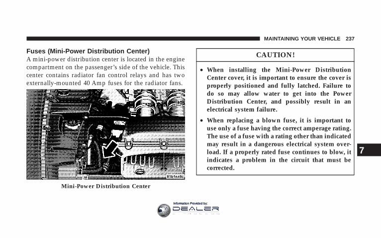
Fuses (Mini-Power Distribution Center)A mini-power distribution center is located in the enginecompartment on the passenger’s side of the vehicle. Thiscenter contains radiator fan control relays and has twoexternally-mounted 40 Amp fuses for the radiator fans.
CAUTION!
• When installing the Mini-Power DistributionCenter cover, it is important to ensure the cover isproperly positioned and fully latched. Failure todo so may allow water to get into the PowerDistribution Center, and possibly result in anelectrical system failure.
• When replacing a blown fuse, it is important touse only a fuse having the correct amperage rating.The use of a fuse with a rating other than indicatedmay result in a dangerous electrical system over-load. If a properly rated fuse continues to blow, itindicates a problem in the circuit that must becorrected.
Mini-Power Distribution Center
MAINTAINING YOUR VEHICLE 237
7
Information Provided by:

VEHICLE STORAGEWe recommend that you follow these guidelines forstoring your vehicle for extended periods.
• Fill the fuel tank. This will prevent water condensationinside the tank. If you plan to store your vehicle morethan 2 months, add an anti-oxidant fuel stabilizer tothe fuel tank.
• Change the oil to remove any corrosive combustionrelated acids in the crankcase.
• Check that the radiator coolant level of protection is toat least -20°F (-29°C).
• Make sure that all tires are inflated to the optimumpressure. (See page 158 for more information.)
• Wash and wax the vehicle to protect the finish.
• Store the vehicle in a dry, well-ventilated location.
• Move the wiper blades away from the windshield.
• Block the wheels. Do not apply the Parking Brake.
• Cut blocks of plywood about the same size of the tires.Cover each block with indoor/outdoor carpeting andplace them between the tires and concrete. This willprevent tire flat spotting.
• For long-term storage, remove the tires and put thevehicle up on blocks. Stack the tires on plywood andcover with a tarp to prevent flat spotting.
• If the vehicle will be subjected to freezing tempera-tures, either remove the battery and store it in a dry,well ventilated area or connect a trickle charger (1.5Amp) with automatic shutdown / overcharge protec-tion to the battery. However, do not leave the tricklecharger hooked up to the battery without beingplugged in to a 110 volt AC outlet, as this will result infurther drain on the vehicle’s battery. If the vehicle isnot going to be driven in the next 3 weeks, perform thebattery recharge procedure in the Service Manual.
238 MAINTAINING YOUR VEHICLE
Information Provided by:

Then, either disconnect the battery at the negativeterminal or use the “Battery Save Feature” to conservebattery power. Refer to “Battery Save Feature” under“Maintenance Procedures” in this section for details.
NOTE: Disconnecting the battery causes the enginecontrol system to lose memory of some “learned” func-tions. After reconnecting the battery, the engine may runrough until the control module “relearns” these func-tions. Using the Battery Save Feature will prevent theengine controller from loosing its memory.
CAUTION!
Use care when disconnecting the remote positivecable. It is connected to the battery and can short outto any metal on the vehicle. Always tape or wrap theexposed cable end to prevent electrical shorts.
• Check the battery every 4 to 6 weeks to ensure that thevoltage is above 12.40 volts. The voltage will dropmore rapidly in hot temperatures. If battery voltagedrops below 12.40 volts, follow the battery rechargeprocedure in the Service Manual.
MAINTAINING YOUR VEHICLE 239
7
Information Provided by:

NOTE: To help prevent the battery from dischargingduring shorter periods of inactivity, perform the follow-ing:
1. Make sure that the trunk/liftgate, hood, doors, win-dows, and convertible top are completely closed.
2. Make sure that remote transmitter is operating andthat the battery is good.
3. Make sure that the hood, trunk/liftgate, and doorswitches are in adjustment. Perform the quick systemcheck, which follows:
Use the remote transmitter to set the alarm. If the alarmSET light comes on and flashes, the system is operatingproperly. If not, there is a problem with a switch or thesystem. See your dealer for service.
• Cover the vehicle whenever possible to prevent acci-dental damage to the finish.
REPLACEMENT BULBS
LIGHT BULBS — Interior Bulb NumberMessage Center Indicators . . . . . . . . . . . . . . . . . . 103Cluster . . . . . . . . . . . . . . . . . . . . . . . . . . . . . . . . 103Gauge Pack . . . . . . . . . . . . . . . . . . . . . . . . . . . . 103Heater Control . . . . . . . . . . . . . . . . . . . . . . . . . . . 37Interior Light . . . . . . . . . . . . . . . . . . . . . . . . . . 212–2Courtesy Foot Well Lights . . . . . . . . . . . . . . . . . . 194Cargo Light (Coupe Liftgate) . . . . . . . . . . . . . . . . 168
240 MAINTAINING YOUR VEHICLE
Information Provided by:
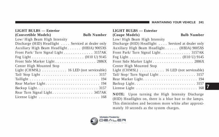
LIGHT BULBS — Exterior(Convertible Models) Bulb NumberLow/High Beam High IntensityDischarge (HID) Headlight . . . . Serviced at dealer onlyAuxiliary High Beam Headlight . . . . . . (HB3A) 9005XSFront Park/Turn Signal Light . . . . . . . . . . . . . 3157AKFog Light . . . . . . . . . . . . . . . . . . . . . . . (H10 U) 9145Front Side Marker Light . . . . . . . . . . . . . . . . . . 2886XCenter High Mounted StopLight (CHMSL) . . . . . . . . . . . 16 LED (not serviceable)Tail/Stop Light . . . . . . . . . . . . . . . . . . . . . . . . . 3157Taillight . . . . . . . . . . . . . . . . . . . . . . . . . . . . . . . 194Rear Marker Light . . . . . . . . . . . . . . . . . . . . . . . . 194Backup Light . . . . . . . . . . . . . . . . . . . . . . . . . . . 3157Rear Turn Signal Light . . . . . . . . . . . . . . . . . . 3457AKLicense Light . . . . . . . . . . . . . . . . . . . . . . . . . . . 168
LIGHT BULBS — Exterior(Coupe Models) Bulb NumberLow/High Beam High IntensityDischarge (HID) Headlight . . . . Serviced at dealer onlyAuxiliary High Beam Headlight . . . . . . (HB3A) 9005XSFront Park/Turn Signal Light . . . . . . . . . . . . . 3157AKFog Light . . . . . . . . . . . . . . . . . . . . . . . (H10 U) 9145Front Side Marker Light . . . . . . . . . . . . . . . . . . 2886XCenter High Mounted StopLight (CHMSL) . . . . . . . . . . . 16 LED (not serviceable)Tail/Stop/Turn Signal Light . . . . . . . . . . . . . . . . 3157Rear Marker Light . . . . . . . . . . . . . . . . . . . . . . . . 194Backup Light . . . . . . . . . . . . . . . . . . . . . . . . . . . 3157License Light . . . . . . . . . . . . . . . . . . . . . . . . . . . 168
NOTE: Upon turning the High Intensity Discharge(HID) Headlights on, there is a blue hue to the lamps.This diminishes and becomes more white after approxi-mately 10 seconds as the system charges.
MAINTAINING YOUR VEHICLE 241
7
Information Provided by:

BULB REPLACEMENT
Auxiliary High Beam Headlight, Front Park/TurnSignal Light, Front Side Marker Light
1. Remove the push pin from the upper outer corner ofthe splash shield and remove the splash shield.
2. Turn the appropriate bulb and socket assemblycounter-clockwise, and then pull it out of the headlightassembly.
1 — Front Side Marker Light2 — Front Park/Turn Signal Light3 — Low/High Beam HID Headlight4 — Auxiliary High Beam Headlight5 — Headlight Adjustment — Aim Up & Down
242 MAINTAINING YOUR VEHICLE
Information Provided by:

3. Pull the bulb out of the socket assembly.
4. Push the replacement bulb into the socket assembly.
5. Reinstall the bulb and socket assembly into the head-light assembly, and then turn it clockwise.
6. Install the splash shield and push pin.
High Intensity Discharge Headlights (HID)The headlights are a type of high voltage discharge tube.High voltage can remain in the circuit even with theheadlight switch off and the key removed. Because ofthis, you should not attempt to service a headlight bulbyourself. If a headlight bulb fails, take your vehicle toan authorized dealer for service.
WARNING!
A transient high tension occurs at the bulb sockets ofHigh Intensity Discharge (HID) headlights when theheadlight switch is turned ON. It may cause seriouselectrical shock or electrocution if not serviced prop-erly. See your authorized dealer for service.
NOTE:• When the High Intensity Discharge Headlights (HID)
are turned on, there is a blue hue to the lights. Thisdiminishes and becomes more white after approxi-mately 10 seconds as the system charges.
• If High Intensity Discharge (HID) lights are not work-ing, cycle the headlight switch 4 times to see if it willrestrike.
MAINTAINING YOUR VEHICLE 243
7
Information Provided by:

Front Fog Light
1. Remove the push pin from the upper outer corner ofthe splash shield and remove the splash shield.
2. Turn the bulb and socket assembly counter-clockwise,and then pull it out of the front fog light assembly.
3. Pull the bulb out of the socket assembly.
4. Push the replacement bulb into the socket assembly.
5. Reinstall the bulb and socket assembly into the frontfog light assembly, and then turn it clockwise.
6. Install the splash shield and push pin.
244 MAINTAINING YOUR VEHICLE
Information Provided by:
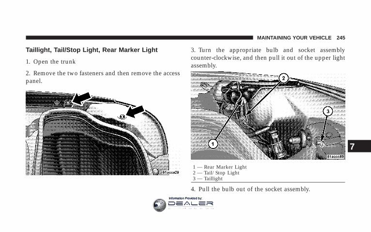
Taillight, Tail/Stop Light, Rear Marker Light
1. Open the trunk
2. Remove the two fasteners and then remove the accesspanel.
3. Turn the appropriate bulb and socket assemblycounter-clockwise, and then pull it out of the upper lightassembly.
4. Pull the bulb out of the socket assembly.
1 — Rear Marker Light2 — Tail/Stop Light3 — Taillight
MAINTAINING YOUR VEHICLE 245
7
Information Provided by:

5. Push the replacement bulb into the socket assembly.
6. Reinstall the bulb and socket assembly into the upperlight assembly, and then turn it clockwise.
7. Install the access panel and the two fasteners.
8. Close the trunk.
Backup Light, Rear Turn Signal Light
1. Open the trunk.
2. Remove the two fasteners and then remove the accesspanel.
246 MAINTAINING YOUR VEHICLE
Information Provided by:

3. Remove the three upper light assembly retaining nuts.
4. Remove the three bulb and socket assemblies from theupper light assembly by turning them counter-clockwiseand then pulling them out of the upper light assembly.
MAINTAINING YOUR VEHICLE 247
7
Information Provided by:

5. Remove the upper light assembly. 6. Turn the appropriate bulb and socket assemblycounter-clockwise, and then pull it out of the lower lightassembly.
1 — Backup Light
248 MAINTAINING YOUR VEHICLE
Information Provided by:

7. Pull the bulb out of the socket assembly.
8. Push the replacement bulb into the socket assembly.
9. Reinstall the bulb and socket assembly into the lowerlight assembly, and then turn it clockwise.
10. Reinstall the three bulb and socket assemblies intothe upper light assembly, and turn them clockwise.
11. Reinstall the upper light assembly and the threeretaining nuts.
12. Install the access panel and the two fasteners.
13. Close the trunk.2 — Rear Turn Signal Light
MAINTAINING YOUR VEHICLE 249
7
Information Provided by:

License Light
1. Open the trunk.
2. Turn the bulb and socket assembly counter-clockwise,and then pull it out of the housing.
3. Pull the bulb out of the socket assembly.
4. Push the replacement bulb into the socket assembly.
5. Reinstall the bulb and socket assembly into the hous-ing, and then turn it clockwise.
6. Close the trunk.
250 MAINTAINING YOUR VEHICLE
Information Provided by:

HEADLIGHT AIMINGThe headlights on your new vehicle were aimed at thefactory under a no load setting. A great increase in weightwill change the aiming of the headlights. Therefore, itmay be necessary to readjust the headlights if youtypically carry an excessive amount of weight in the rearcompartment or generally suspect misalignment. In ei-ther case, see your authorized dealer if the headlightsrequire adjustment.
FLUIDS AND CAPACITIES
U.S. MetricFuel (approximate)
8.4 Liter Engine 16 gal-lons
60.6 li-ters
Engine Oil-With Filter8.4 Liter Engine (SAE 0W-40) 10 qts. 9.5 Li-
tersCooling System *
8.4 Liter Engine* (MopartAntifreeze/Coolant 5 Year/
102,000 Mile Formula) orequivalent.
16 qts. 15 Liters
* Includes heater and coolant recovery bottle filled toMAX level.
MAINTAINING YOUR VEHICLE 251
7
Information Provided by:

FLUIDS, LUBRICANTS, AND GENUINE PARTS
Engine
Component Fluids, Lubricants, and Genuine PartsEngine Coolant Mopart Antifreeze/Coolant 5 Year/102,000 Mile Formula HOAT (Hybrid Or-
ganic Additive Technology) or equivalent.Engine Oil For best performance and maximum protection under all types of operating
conditions, the manufacturer only recommends full synthetic engine oils thatmeet the American Petroleum Institute (API) categories of SM or SM/CF, andmeet the requirements of DaimlerChrysler Material Standard MS-10725. Themanufacturer recommends the use of a full synthetic engine oil, such as Mobil1t SAE 0W-40 or equivalent. For additional information, refer to the “EngineOil Selection” and “Engine Oil Viscosity (SAE Grade)” in the “MaintenanceProcedures” section of this manual.
Engine Oil Filter Mopart Engine Oil Filter or equivalent.Spark Plugs RE10PMC5 (Gap.050)Fuel Selection Premium Unleaded 91 Octane Only or higher
252 MAINTAINING YOUR VEHICLE
Information Provided by:

Chassis
Component Fluid, Lubricant, or Genuine PartTransmission Mopart ATF+4 Automatic Transmission Fluid.Rear Axle Mopart Synthetic Gear and Axle Lubricant SAE 75W-140 or equivalent, with
Limited Slip Additive Friction ModifierBrake Master Cylinder Mopart Brake & Clutch Fluid DOT 4 Motor Vehicle or equivalent.Power Steering Reservoir Mopart Power Steering Fluid + 4, Mopart ATF+4 Automatic Transmission
Fluid.
MAINTAINING YOUR VEHICLE 253
7
Information Provided by:

Body
Component Fluid, Lubricant, or Genuine PartHinges:Door, Trunk & Hood Springs andLinks
Mopart Spray White Lube or equivalent.
Latches:Door, Hood & Trunk Mopart Multi-Purpose Lube NLGI Grade 2 or equivalent.Door Hinge Check Spring Lubriplate Mo-Lith No. 2 Grease or Petrocan Multiflex Moly EP 2 Grease or
equivalent.Seat Regulator & Track Mopart Multi-Purpose Lube NLGI Grade 2 or equivalent.Window System Components Mopart Spray White Lube or equivalent.Lock Cylinders Mopart Spray White Lube or equivalent.Parking Brake Mechanism Mopart Spray White Lube or equivalent.
254 MAINTAINING YOUR VEHICLE
Information Provided by:

MAINTENANCE SCHEDULES
CONTENTS
m Emission Control System Maintenance . . . . . . . . 256
m Maintenance Schedules . . . . . . . . . . . . . . . . . . . 256
▫ Schedule “B” . . . . . . . . . . . . . . . . . . . . . . . . 259
▫ Schedule “A” . . . . . . . . . . . . . . . . . . . . . . . . 269
8
MAINTENANCE
SCHEDULES
Information Provided by:

EMISSION CONTROL SYSTEM MAINTENANCEThe “Scheduled” maintenance services, listed in boldtype must be done at the times or mileages specified toassure the continued proper functioning of the emissioncontrol system. These, and all other maintenance servicesincluded in this manual, should be done to provide bestvehicle performance and reliability. More frequent main-tenance may be needed for vehicles in severe operatingconditions such as dusty areas and very short tripdriving.
Inspection and service also should be done anytime amalfunction is suspected.
NOTE: Maintenance, replacement, or repair of the emis-sion control devices and systems on your vehicle may beperformed by any automotive repair establishment orindividual using any automotive part, which has beencertified pursuant to U.S. EPA or, in the State of Califor-nia, California Air Resources Board regulations.
MAINTENANCE SCHEDULESThere are two maintenance schedules that show therequired service for your vehicle.
First is Schedule “B.” It is for vehicles that are operatedunder the conditions that are listed below and at thebeginning of the schedule.
• Day or night temperatures are below 32° F (0° C).
• Stop and go driving.
• Extensive engine idling.
• Driving in dusty conditions.
• Short trips of less than 10 miles (16 km).
• More than 50% of your driving is at sustained highspeeds during hot weather, above 90° F ( 32° C).
• Trailer towing.
• Taxi, police, or delivery service (commercial service).
256 MAINTENANCE SCHEDULES
8
MAINTENANCE
SCHEDULES
Information Provided by:

• Off-road or desert operation.
• If equipped for and operating with E-85 (ethanol)fuel.
NOTE: If ANY of these apply to you then change yourengine oil every 3,000 miles (5000 km) or 3 months,whichever comes first, and follow the maintenance rec-ommendations in Schedule “B” in this section.
NOTE: If ANY of these apply to you, then flush andreplace the engine coolant every 102,000 miles (170 000km) or 60 months, whichever comes first, and follow themaintenance recommendations in Schedule “B” in thissection.
NOTE: Most vehicles are operated under the conditionslisted for Schedule 9B.9
Second is Schedule “A.” It is for vehicles that are notoperated under any of the conditions listed under Sched-ule 9B.9
Use the schedule that best describes your driving condi-tions. Where time and mileage are listed, follow theinterval that occurs first.
NOTE: Under no circumstances should oil changeintervals exceed 6,000 miles (10 000 km) or 6 months,whichever comes first.
CAUTION!
Failure to perform the required maintenance itemsmay result in damage to the vehicle.
MAINTENANCE SCHEDULES 257
8
MAINTENANCE
SCHEDULES
Information Provided by:
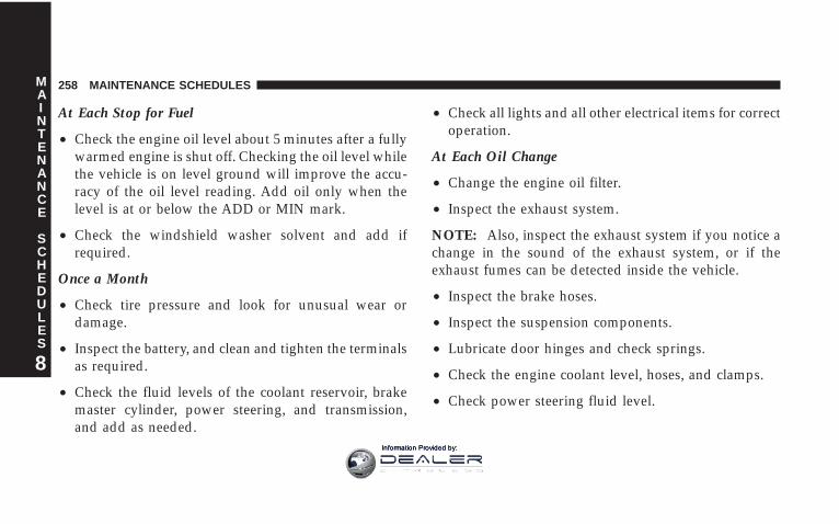
At Each Stop for Fuel
• Check the engine oil level about 5 minutes after a fullywarmed engine is shut off. Checking the oil level whilethe vehicle is on level ground will improve the accu-racy of the oil level reading. Add oil only when thelevel is at or below the ADD or MIN mark.
• Check the windshield washer solvent and add ifrequired.
Once a Month
• Check tire pressure and look for unusual wear ordamage.
• Inspect the battery, and clean and tighten the terminalsas required.
• Check the fluid levels of the coolant reservoir, brakemaster cylinder, power steering, and transmission,and add as needed.
• Check all lights and all other electrical items for correctoperation.
At Each Oil Change
• Change the engine oil filter.
• Inspect the exhaust system.
NOTE: Also, inspect the exhaust system if you notice achange in the sound of the exhaust system, or if theexhaust fumes can be detected inside the vehicle.
• Inspect the brake hoses.
• Inspect the suspension components.
• Lubricate door hinges and check springs.
• Check the engine coolant level, hoses, and clamps.
• Check power steering fluid level.
258 MAINTENANCE SCHEDULES
8
MAINTENANCE
SCHEDULES
Information Provided by:

SCHEDULE “B”Follow schedule “B” if you usually operate your vehicleunder one or more of the following conditions.
• Day or night temperatures are below 32° F (0° C).
• Stop and go driving.
• Extensive engine idling.
• Driving in dusty conditions.
• Short trips of less than 10 miles (16 km).
• More than 50% of your driving is at sustained highspeeds during hot weather, above 90° F (32° C).
• Trailer towing.
• Taxi, police, or delivery service (commercial service).
• Off-road or desert operation.
• If equipped for and operating with E-85 (ethanol)fuel.
NOTE: If ANY of these apply to you, then change yourengine oil every 3,000 miles (5000 km) or 3 months,whichever comes first, and follow the maintenance rec-ommendations in Schedule “B” in this section.
NOTE: If ANY of these apply to you, then flush andreplace the engine coolant every 102,000 miles (170 000km) or 60 months, whichever comes first, and follow themaintenance recommendations in Schedule “B” in thissection.
SCHEDULE “B” 259
8
MAINTENANCE
SCHEDULES
Information Provided by:

Miles 3,000 6,000 9,000 12,000 15,000 18,000(Kilometers) (5 000) (10 000) (15 000) (20 000) (25 000) (30 000)Change engine oil and engine oil filter, if notreplaced at 3 months.
X X X X X X
Rotate the tires. LL X X XInspect and replace the air cleaner filter ifnecessary.
X
Inspect the transmission fluid. XInspect the brake linings. XChange the rear axle fluid. XChange the brake fluid. XLubricate the front and rear suspension balljoints.
X
260 SCHEDULE “B”
8
MAINTENANCE
SCHEDULES
Information Provided by:
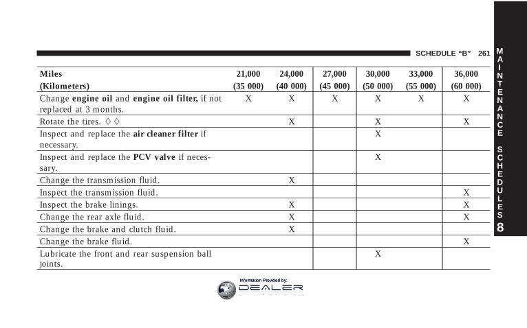
Miles 21,000 24,000 27,000 30,000 33,000 36,000(Kilometers) (35 000) (40 000) (45 000) (50 000) (55 000) (60 000)Change engine oil and engine oil filter, if notreplaced at 3 months.
X X X X X X
Rotate the tires. LL X X XInspect and replace the air cleaner filter ifnecessary.
X
Inspect and replace the PCV valve if neces-sary.
X
Change the transmission fluid. XInspect the transmission fluid. XInspect the brake linings. X XChange the rear axle fluid. X XChange the brake and clutch fluid. XChange the brake fluid. XLubricate the front and rear suspension balljoints.
X
SCHEDULE “B” 261
8
MAINTENANCE
SCHEDULES
Information Provided by:

Miles 39,000 42,000 45,000 48,000 51,000 54,000(Kilometers) (65 000) (70 000) (75 000) (80 000) (85 000) (90 000)Change engine oil and engine oil filter, if notreplaced at 3 months.
X X X X X X
Rotate the tires. LL X X XInspect and replace the engine air cleaner fil-ter if necessary.
X
Inspect and replace the Auto Tension DriveBelt if necessary.
X
Change the transmission fluid. XInspect the brake linings. XChange the rear axle fluid. XChange the brake and clutch fluid. XLubricate the front and rear suspension balljoints.
X
262 SCHEDULE “B”
8
MAINTENANCE
SCHEDULES
Information Provided by:

Miles 57,000 60,000 63,000 66,000 69,000 72,000(Kilometers) (95 000) (100 000) (105 000) (110 000) (115 000) (120 000)Change engine oil and engine oil filter, if not re-placed at 3 months.
X X X X X X
Rotate the tires. LL X X XInspect and replace the air cleaner filter if necessary. XInspect and replace the PCV valve if necessary. XFlush and replace engine coolant at 60 months, ifnot done at 102,000 miles.
X
Inspect and replace the Auto Tension Drive Belt ifnecessary. ‡
X
Inspect the transmission fluid. XChange the transmission fluid. XInspect the brake linings. X XChange the rear axle fluid. X XChange the brake fluid. XChange the brake and clutch fluid. XLubricate the front and rear suspension ball joints. X
SCHEDULE “B” 263
8
MAINTENANCE
SCHEDULES
Information Provided by:

Miles 75,000 78,000 81,000 84,000 87,000 90,000(Kilometers) (125 000) (130 000) (135 000) (140 000) (145 000) (150 000)Change engine oil and engine oil filter, if notreplaced at 3 months.
X X X X X X
Rotate the tires. LL X X XInspect and replace the air cleaner filter ifnecessary.
X X
Inspect and replace the PCV valve if neces-sary.
X
Inspect and replace the Auto Tension DriveBelt if necessary. ‡
X X
Inspect the transmission fluid. XInspect the brake linings. XChange the rear axle fluid. XChange the brake fluid. XLubricate the front and rear suspension balljoints.
X X
264 SCHEDULE “B”
8
MAINTENANCE
SCHEDULES
Information Provided by:

Miles 93,000 96,000 99,000 102,000 105,000 108,000(Kilometers) (155 000) (160 000) (165 000) (170 000) (175 000) (180 000)Change engine oil and engine oil filter, if notreplaced at 3 months.
X X X X X X
Rotate the tires. LL X X XInspect and replace the engine air cleaner fil-ter if necessary.
X
Replace the spark plugs. XReplace the ignition cables. XFlush and replace the engine coolant, if notreplaced at 60 months.
X
Inspect and replace the Auto Tension DriveBelt if necessary. ‡
X
Change the transmission fluid. XInspect the transmission fluid. X
SCHEDULE “B” 265
8
MAINTENANCE
SCHEDULES
Information Provided by:

Miles 93,000 96,000 99,000 102,000 105,000 108,000(Kilometers) (155 000) (160 000) (165 000) (170 000) (175 000) (180 000)Inspect the brake linings. X XChange the rear axle fluid. X XChange the brake and clutch fluid. XChange the brake fluid. XLubricate the front and rear suspension balljoints.
X
266 SCHEDULE “B”
8
MAINTENANCE
SCHEDULES
Information Provided by:

Miles 111,000 114,000 117,000 120,000(Kilometers) (185 000) (190 000) (195 000) (200 000)Change engine oil and engine oil filter, if not replacedat 3 months.
X X X X
Rotate the tires. LL X XInspect and replace the engine air cleaner filter if neces-sary.
X
Inspect and replace the PCV valve if necessary. XFlush and replace the engine coolant, if not replaced at102,000 months.
X
Inspect and replace the Auto Tension Drive Belt if neces-sary. ‡
X
Change the transmission fluid. XInspect the brake linings. XChange the rear axle fluid. X
SCHEDULE “B” 267
8
MAINTENANCE
SCHEDULES
Information Provided by:

Miles 111,000 114,000 117,000 120,000(Kilometers) (185 000) (190 000) (195 000) (200 000)Change the brake and clutch fluid. XLubricate the front and rear suspension ball joints. X
‡ This maintenance is not required if previously replaced.
LL Although not required, the manufacturer recom-mends reprogramming TPMS after rotating tires so sys-tem can relearn tire pressure sensor location. For moreinformation refer to Tire Pressure Monitor System(TPMS) in Section 5 of this manual.
Inspection and service should also be performed anytimea malfunction is observed or suspected. Retain all re-ceipts.
268 SCHEDULE “B”
8
MAINTENANCE
SCHEDULES
Information Provided by:

SCHEDULE “A”
Miles 6,000 12,000 18,000 24,000 30,000(Kilometers) (10 000) (20 000) (30 000) (40 000) (50 000)[Months] [6] [12] [18] [24] [30]Change engine oil and engine oil filter. X X X X XRotate the tires. LL X X X X XInspect and replace the engine air cleaner filter ifnecessary.
X
Inspect the transmission fluid. X XInspect the brake linings. XChange the rear axle fluid. XChange the brake fluid. XLubricate the front and rear suspension ball joints. X
SCHEDULE “A” 269
8
MAINTENANCE
SCHEDULES
Information Provided by:

Miles 36,000 42,000 48,000 54,000 60,000(Kilometers) (60 000) (70 000) (80 000) (90 000) (100 000)[Months] [36] [42] [48] [54] [60]Change engine oil and engine oil filter. X X X X XRotate the tires. LL X X X X XInspect and replace the engine air cleaner filter if necessary. XInspect and replace the PCV valve if necessary. XFlush and replace the engine coolant at 60 months, if notdone at 102,000 miles.
X
Inspect and replace the Auto Tension Drive Belt if necessary. XChange the transmission fluid. XInspect the transmission fluid. X XInspect the brake linings. X XChange the rear axle fluid. X XChange the brake and clutch fluid. XChange the brake fluid. XLubricate the front and rear suspension ball joints. X
270 SCHEDULE “A”
8
MAINTENANCE
SCHEDULES
Information Provided by:

Miles 66,000 72,000 78,000 84,000 90,000(Kilometers) (110 000) (120 000) (130 000) (140 000) (150 000)[Months] [66] [72] [78] [84] [90]Change engine oil and engine oil filter. X X X X XRotate the tires. LL X X X X XInspect and replace the engine air cleaner filter ifnecessary.
X
Inspect and replace the PCV valve if necessary. XInspect and replace the Auto Tension Drive Belt ifnecessary. ‡
X X
Change the transmission fluid. XInspect the transmission fluid. XInspect the brake linings. X XChange the rear axle fluid. X XChange the brake and clutch fluid. XChange the brake fluid. XLubricate the front and rear suspension ball joints. X
SCHEDULE “A” 271
8
MAINTENANCE
SCHEDULES
Information Provided by:

Miles 96,000 102,000 108,000 114,000 120,000(Kilometers) (160 000) (170 000) (180 000) (190 000) (200 000)[Months] [96] [102] [108] [114] [120]Change engine oil and engine oil filter. X X X X XRotate the tires. LL X X X X XInspect and replace the engine air cleaner filter ifnecessary. X
Inspect and replace the PCV valve if necessary. XReplace the spark plugs. XReplace the ignition cables. XFlush and replace the engine coolant, if not re-placed at 60 months.
X
Flush and replace the engine coolant, if not re-placed at 102,000 miles. X
Inspect and replace the Auto Tension Drive Belt ifnecessary. ‡
X X X
Inspect the transmission fluid. X X
272 SCHEDULE “A”
8
MAINTENANCE
SCHEDULES
Information Provided by:

Miles 96,000 102,000 108,000 114,000 120,000(Kilometers) (160 000) (170 000) (180 000) (190 000) (200 000)[Months] [96] [102] [108] [114] [120]Change the transmission fluid. XInspect the brake linings. XChange the rear axle fluid. XChange the brake and clutch fluid. XLubricate the front and rear suspension ball joints. X
‡ This maintenance is not required if previously replaced.
LL Although not required, the manufacturer recom-mends reprogramming TPMS after rotating tires so sys-tem can relearn tire pressure sensor location. For moreinformation refer to Tire Pressure Monitor System(TPMS) in Section 5 of this manual.
Inspection and service should also be performed anytimea malfunction is observed or suspected. Retain all re-ceipts.
WARNING!
You can be badly injured working on or around amotor vehicle. Do only the service work for which youhave the knowledge and the right equipment. If youhave any doubt about your ability to perform a servicejob, take your vehicle to a competent mechanic.
SCHEDULE “A” 273
8
MAINTENANCE
SCHEDULES
Information Provided by:

Information Provided by:

IF YOU NEED CONSUMER ASSISTANCE
CONTENTS
m Suggestions For Obtaining Service ForYour Vehicle . . . . . . . . . . . . . . . . . . . . . . . . . . 277
▫ Prepare For The Appointment . . . . . . . . . . . . 277
▫ Prepare A List . . . . . . . . . . . . . . . . . . . . . . . . 277
▫ Be Reasonable With Requests . . . . . . . . . . . . . 277
m If You Need Assistance . . . . . . . . . . . . . . . . . . . 277
▫ DaimlerChrysler Motors CorporationCustomer Center . . . . . . . . . . . . . . . . . . . . . . 278
▫ DaimlerChrysler Canada Inc. CustomerCenter . . . . . . . . . . . . . . . . . . . . . . . . . . . . . 278
▫ In Mexico Contact . . . . . . . . . . . . . . . . . . . . . 278
▫ Customer Assistance For The HearingOr Speech Impaired (TDD/TTY) . . . . . . . . . . 279
▫ Service Contract . . . . . . . . . . . . . . . . . . . . . . 279
m Warranty Information (U.S. Vehicles Only) . . . . . 280
m Mopart Parts . . . . . . . . . . . . . . . . . . . . . . . . . 280
m Reporting Safety Defects . . . . . . . . . . . . . . . . . . 281
▫ In The 50 United States AndWashington D.C. . . . . . . . . . . . . . . . . . . . . . . 281
▫ In Canada . . . . . . . . . . . . . . . . . . . . . . . . . . 281
9
Information Provided by:

m Publication Order Forms . . . . . . . . . . . . . . . . . . 282
m Department Of Transportation Uniform TireQuality Grades . . . . . . . . . . . . . . . . . . . . . . . . 283
▫ Treadwear . . . . . . . . . . . . . . . . . . . . . . . . . . 283
▫ Traction Grades . . . . . . . . . . . . . . . . . . . . . . 283
▫ Temperature Grades . . . . . . . . . . . . . . . . . . . 284
276 IF YOU NEED CONSUMER ASSISTANCE
Information Provided by:

SUGGESTIONS FOR OBTAINING SERVICE FORYOUR VEHICLE
Prepare For The AppointmentIf you’re having warranty work done, be sure to have theright papers with you. Take your warranty folder. Allwork to be performed may not be covered by thewarranty; discuss additional charges with the servicemanager. Keep a maintenance log of your vehicle’sservice history. This can often provide a clue to thecurrent problem.
Prepare A ListMake a written list of your vehicle’s problems or thespecific work you want done. If you’ve had an accident,or work done that is not on your maintenance log, let theservice advisor know.
Be Reasonable With RequestsIf you list a number of items, and you must have yourvehicle by the end of the day, discuss the situation withthe service advisor and list the items in order of priority.At many authorized dealers, you may obtain a rentalvehicle at a minimal daily charge. If you need a rental, itis advisable to make these arrangements when you callfor an appointment.
IF YOU NEED ASSISTANCEThe manufacturer and its authorized dealers are vitallyinterested in your satisfaction. We want you to be happywith our products and services.
Warranty service must be done by an authorized dealer.We strongly recommend that you take your vehicle toyour authorized selling dealer. They know you and yourvehicle best, and are most concerned that you get promptand high quality service. The manufacturer’s authorizeddealers have the facilities, factory-trained technicians,
IF YOU NEED CONSUMER ASSISTANCE 277
9
Information Provided by:
special tools, and the latest information to assure yourvehicle is fixed correctly and in a timely manner.
This is why you should always talk to your authorizeddealer’s service manager first. Most matters can be re-solved with this process.
• If for some reason you are still not satisfied, talk to thegeneral manager or owner of the authorized dealer-ship. They want to know if you need assistance.
• If your authorized dealership is unable to resolve theconcern, you may contact the Manufacturer’s Cus-tomer Center.
Any communication to the Manufacturer’s CustomerCenter should include the following information:
• Owner’s name and address
• Owner’s telephone number (home and office)
• Authorized dealership name
• Vehicle Identification Number (VIN)
• Vehicle delivery date and mileage
DaimlerChrysler Motors Corporation CustomerCenterP.O. Box 21–8004Auburn Hills, MI 48321–8004Phone: (800) 992-1997
DaimlerChrysler Canada Inc. Customer CenterP.O. Box 1621Windsor, Ontario N9A 4H6Phone: (800) 465–2001
In Mexico contact:Av. Prolongacion Paseo de la Reforma, 1240Sante Fe C.P. 05109Mexico, D. F.In Mexico: (915) 729–1248 or 729–1240Outside Mexico: (525) 729–1248 or 729–1240
278 IF YOU NEED CONSUMER ASSISTANCE
Information Provided by:

Customer Assistance For The Hearing Or SpeechImpaired (TDD/TTY)To assist customers who have hearing difficulties, themanufacturer has installed special TDD (Telecommuni-cation Devices for the Deaf) equipment at its CustomerCenter. Any hearing or speech impaired customer whohas access to a TDD or a conventional teletypewriter(TTY) in the United States can communicate with themanufacturer by dialing 1–800–380–CHRY.
Service ContractYou may have purchased a service contract for yourvehicle to help protect you from the high cost of unex-pected repairs after your manufacturer’s new vehiclelimited warranty expires. The manufacturer stands be-hind only the manufacturer’s Service Contracts. If youpurchased a manufacturer’s Service Contract, you willreceive Plan Provisions and an Owner Identification Cardin the mail within three weeks of your vehicle deliverydate. If you have any questions about your service
contract, call the manufacturer’s Service Contract Na-tional Customer Hotline at 1-800-521-9922.
The manufacturer will not stand behind any servicecontract that is not the manufacturer’s Service Contract. Itis not responsible for any service contract other than themanufacturer’s Service Contract. If you purchased aservice contract that is not a manufacturer’s ServiceContract, and you require service after your manufactur-er’s new vehicle limited warranty expires, please refer toyour contract documents, and contact the person listed inthose documents.
We appreciate that you have made a major investmentwhen you purchased your vehicle. Your authorizeddealer has also made a major investment in facilities,tools, and training to assure that you are absolutelydelighted with your ownership experience. You’ll bepleased with their sincere efforts to resolve any warrantyissues or related concerns.
IF YOU NEED CONSUMER ASSISTANCE 279
9
Information Provided by:

WARNING!
Engine exhaust, some of its constituents, and certainvehicle components contain or emit chemicalsknown to the State of California to cause cancer andbirth defects or other reproductive harm. In addition,certain fluids contained in vehicles and certain prod-ucts of component wear contain or emit chemicalsknown to the State of California to cause cancer andbirth defects or other reproductive harm.
WARRANTY INFORMATION (U.S. Vehicles Only)See the Warranty Information Booklet for the terms andprovisions of DaimlerChrysler’s warranties applicable tothis vehicle.
MOPART PARTSMopart fluids, lubricants, parts, and accessories areavailable from your authorized dealer. They will helpyou keep your vehicle operating at its best.
280 IF YOU NEED CONSUMER ASSISTANCE
Information Provided by:

REPORTING SAFETY DEFECTS
In the 50 United States and Washington D.C.If you believe that your vehicle has a defect which couldcause a crash or cause injury or death, you shouldimmediately inform the National Highway Traffic SafetyAdministration (NHTSA) in addition to notifying themanufacturer.
If NHTSA receives similar complaints, it may open aninvestigation, and if it finds that a safety defect exists ina group of vehicles, it may order a recall and remedycampaign. However, NHTSA cannot become involved inindividual problems between you, your authorizeddealer, and the manufacturer.
To contact NHTSA, you may either call the Auto SafetyHotline toll free at 1–888–327–4236 (TTY: 1–800–424– 9153),or go to http://www.safercar.gov; or write to: Administra-tor, NHTSA, 400 Seventh Street, SW., Washington, DC20590. You can also obtain other information about motorvehicle safety from http://www.safercar.gov.
In CanadaIf you believe that your vehicle has a safety defect, youshould contact the Customer Service Department imme-diately. Canadian customers who wish to report a safetydefect to the Canadian government should write toTransport Canada, Motor Vehicle Defect Investigationsand Recalls, 2780 Sheffield Road, Ottawa, Ontario K1B3V9.
IF YOU NEED CONSUMER ASSISTANCE 281
9
Information Provided by:

PUBLICATION ORDER FORMSTo order the following manuals, you may use either thewebsite or the phone numbers listed below. Visa, Mas-tercard, American Express, and Discover orders are ac-cepted. If you prefer mailing your payment, please callfor an order form.
NOTE: A street address is required when orderingmanuals. (No P.O. Boxes).
• Service Manuals
These comprehensive service manuals provide theinformation that students and professional techniciansneed in diagnosing/troubleshooting, problem solving,maintaining, servicing, and repairing DaimlerChryslerCorporation vehicles. A complete working knowledgeof the vehicle, system, and/or components is writtenin straightforward language with illustrations, dia-grams, and charts.
• Diagnostic Procedure Manuals
Filled with diagrams, charts and detailed illustrations,these practical manuals make it easy for students andtechnicians to find and fix problems on computer-controlled vehicle systems and features. They showexactly how to find and correct problems the first time,using step-by-step troubleshooting and drivabilityprocedures, proven diagnostic tests and a complete listof all tools and equipment.
• Owner’s Manuals
These manuals have been prepared with the assistanceof service and engineering specialists to acquaint youwith specific DaimlerChrysler Corporation vehicles.Included are starting, operating, emergency and main-tenance procedures as well as specifications, capabili-ties and safety tips.
282 IF YOU NEED CONSUMER ASSISTANCE
Information Provided by:

Call Toll Free at:
• 1–800–890–4038 (U.S.)
• 1–800–387–1143 (Canada)
Or
Visit us on the World Wide Web at:
• www.techauthority.daimlerchrysler.com
• www.daimlerchrysler.ca/manuals
DEPARTMENT OF TRANSPORTATION UNIFORMTIRE QUALITY GRADESThe following describes the tire grading categories estab-lished by the National Highway Traffic Safety Adminis-tration. The specific grade rating assigned by the tire’smanufacturer in each category is shown on the sidewallof the tires on your car.
All passenger car tires must conform to Federal safetyrequirements in addition to these grades.
TreadwearThe treadwear grade is a comparative rating based on thewear rate of the tire when tested under controlled con-ditions on a specified government test course. For ex-ample, a tire graded 150 would wear one and a 1 1/2times as well on the government course as a tire graded100. The relative performance of tires depends upon theactual conditions of their use, however, and may departsignificantly from the norm due to variations in drivinghabits, service practices and differences in road charac-teristics and climate.
Traction GradesThe traction grades, from highest to lowest, are AA, A, B,and C. Those grades represent the tire’s ability to stop onwet pavement as measured under controlled conditions
IF YOU NEED CONSUMER ASSISTANCE 283
9
Information Provided by:

on specified government test surfaces of asphalt andconcrete. A tire marked C may have poor traction perfor-mance.
WARNING!
The traction grade assigned to this tire is based onstraight-ahead braking traction tests, and does notinclude acceleration, cornering, hydroplaning, orpeak traction characteristics.
Temperature GradesThe temperature grades are A (the highest), B, and C,representing the tire’s resistance to the generation of heatand its ability to dissipate heat when tested undercontrolled conditions on a specified indoor laboratorytest wheel. Sustained high temperature can cause the
material of the tire to degenerate and reduce tire life, andexcessive temperature can lead to sudden tire failure. Thegrade C corresponds to a level of performance, which allpassenger car tires must meet under the Federal MotorVehicle Safety Standard No. 109. Grades B and A repre-sent higher levels of performance on the laboratory testwheel than the minimum required by law.
WARNING!
The temperature grade for this tire is established fora tire that is properly inflated and not overloaded.Excessive speed, under-inflation, or excessive load-ing, either separately or in combination, can causeheat buildup and possible tire failure.
284 IF YOU NEED CONSUMER ASSISTANCE
Information Provided by:

INDEX
10Information Provided by:
About Your Brakes . . . . . . . . . . . . . . . . . . . . . . . 144ABS (Anti-Lock Brake System) . . . . . . . . . . . . 97,145Accessory Delay, Power . . . . . . . . . . . . . . . . . . 13,26Adding Engine Coolant (Antifreeze) . . . . . . . . . . 221Adding Fuel . . . . . . . . . . . . . . . . . . . . . . . . . . . 171Adding Washer Fluid . . . . . . . . . . . . . . . . . . . 89,217Adjustable Pedals . . . . . . . . . . . . . . . . . . . . . . . . 90Aiming Headlights . . . . . . . . . . . . . . . . . . . . . . . 251Air Cleaner, Engine (Engine Air Cleaner Filter) . . . 203Air Conditioner Maintenance . . . . . . . . . . . . . . . 212Air Conditioning . . . . . . . . . . . . . . . . 122,123,125,212Air Conditioning Controls . . . . . . . . . . . . . . . . . 123Air Conditioning, Operating Tips . . . . . . . . . . . . 127Air Conditioning Refrigerant . . . . . . . . . . . . . 212,213Air Conditioning System . . . . . . . . . . . . . 123,125,212Air Pressure, Tires . . . . . . . . . . . . . . . . . . . . 101,158Airbag . . . . . . . . . . . . . . . . . . . . . . . . . . . . . . . . 40Airbag Deployment . . . . . . . . . . . . . . . . . . . . . 43,48Airbag Light . . . . . . . . . . . . . . . . . . . . . . 44,50,58,99
Airbag Maintenance . . . . . . . . . . . . . . . . . . . . . . . 49Airbag On/Off Switch . . . . . . . . . . . . . . . . . . . . . 51Alarm System (Security Alarm) . . . . . . . . . . . . . . . 13Alignment and Balance . . . . . . . . . . . . . . . . . . . 163Alterations/Modifications, Vehicle . . . . . . . . . . . . . 7Antenna . . . . . . . . . . . . . . . . . . . . . . . . . . . . . . 122Antenna, Satellite Radio . . . . . . . . . . . . . . . . . . . 121Antifreeze (Engine Coolant) . . . . . . . . . . . 220,221,251
Capacities . . . . . . . . . . . . . . . . . . . . . . . . . . . 251Disposal . . . . . . . . . . . . . . . . . . . . . . . . . . . . 222
Anti-Lock Brake System (ABS) . . . . . . . . . . . . . . 145Anti-Lock Warning Light . . . . . . . . . . . . . . . . 97,147Anti-Theft Security Alarm (Theft Alarm) . . . . . . . . 13Appearance Care . . . . . . . . . . . . . . . . . . . . . . . . 230Auto Down Power Windows . . . . . . . . . . . . . . . . 27Automatic Door Locks . . . . . . . . . . . . . . . . . . . . . 25
Ball Joints . . . . . . . . . . . . . . . . . . . . . . . . . . . . . 214Battery . . . . . . . . . . . . . . . . . . . . . . . . . . . . 106,206
286 INDEX
Information Provided by:

Emergency Starting . . . . . . . . . . . . . . . . . . . . . 186Jump Starting . . . . . . . . . . . . . . . . . . . . . . . . . 186Keyless Transmitter Replacement (RKE) . . . . . . . 21Location . . . . . . . . . . . . . . . . . . . . . . . . . . 186,206Saving Feature (Protection) . . . . . . . . . . . . . . . 210Storing Vehicle . . . . . . . . . . . . . . . . . . . . . . . . 210
Bearings . . . . . . . . . . . . . . . . . . . . . . . . . . . . . . 230Belt System, Six Point . . . . . . . . . . . . . . . . . . . . . 38Belts, Drive . . . . . . . . . . . . . . . . . . . . . . . . . . . . 202Belts, Seat . . . . . . . . . . . . . . . . . . . . . . . . . . . . . . 31Body Damage . . . . . . . . . . . . . . . . . . . . . . . . . . 231Body Mechanism Lubrication . . . . . . . . . . . . . . . 215Body Mechanisms . . . . . . . . . . . . . . . . . . . . . . . 216Boot, Convertible Top . . . . . . . . . . . . . . . . . . . 67,72B-Pillar Location . . . . . . . . . . . . . . . . . . . . . . . . 153Brake, Parking . . . . . . . . . . . . . . . . . . . . . . . . . . 142Brake System . . . . . . . . . . . . . . . . . . . . . . . . 144,225
Anti-Lock (ABS) . . . . . . . . . . . . . . . . . . . . 144,145Fluid Check . . . . . . . . . . . . . . . . . . . . . . . 226,253
Hoses . . . . . . . . . . . . . . . . . . . . . . . . . . . . . . 225Master Cylinder . . . . . . . . . . . . . . . . . . . . . . . 226Warning Light . . . . . . . . . . . . . . . . . . . . . . . . . 99
Break-In Recommendations, New Vehicle . . . . . 56,144Bulb Replacement . . . . . . . . . . . . . . . . . . . . . . . 242Bulbs, Light . . . . . . . . . . . . . . . . . . . . . . . . . . . . 240
Capacities, Antifreeze (Engine Coolant) . . . . . . . . 251Capacities, Fluid . . . . . . . . . . . . . . . . . . . . . . . . 251Capacity, Cargo Weight . . . . . . . . . . . . . . . . . . . 173Caps, Filler
Fuel . . . . . . . . . . . . . . . . . . . . . . . . . . . . . . . . 171Oil (Engine) . . . . . . . . . . . . . . . . . . . . . . . . . . 200Power Steering . . . . . . . . . . . . . . . . . . . . . . . . 213Radiator (Coolant Pressure) . . . . . . . . . . . . . . . 221
Car Washes . . . . . . . . . . . . . . . . . . . . . . . . . . . . 230Carbon Monoxide Warning . . . . . . . . . . . . . . . 57,171Cargo Compartment
Capacity . . . . . . . . . . . . . . . . . . . . . . . . . . . . 173
INDEX 287
10Information Provided by:

Carpeting . . . . . . . . . . . . . . . . . . . . . . . . . . . . . 233Catalytic Converter . . . . . . . . . . . . . . . . . . . . . . 204CD (Compact Disc) Changer . . . . . . . . . . . . . . . . 114CD (Compact Disc) Player . . . . . . . . . . . . . . . 108,112Chains, Tire . . . . . . . . . . . . . . . . . . . . . . . . . . . . 164Charging System Light . . . . . . . . . . . . . . . . . . . . 106Chart, Tire Sizing . . . . . . . . . . . . . . . . . . . . . . . . 150Check Engine Light(Malfunction Indicator Light) . . . . . . . . . . . . . . . 196Checks, Safety . . . . . . . . . . . . . . . . . . . . . . . . . . . 57Child Restraint . . . . . . . . . . . . . . . . . . . . 50,51,52,55Child Restraint Tether Anchors . . . . . . . . . . . . . . . 53Circuit Breakers . . . . . . . . . . . . . . . . . . . . . . . . . 234Clean Air Gasoline . . . . . . . . . . . . . . . . . . . . . . . 168Climate Control . . . . . . . . . . . . . . . . . . . . . . . . . 122Clock . . . . . . . . . . . . . . . . . . . . . . . . . . . . . . . . 106Clutch Fluid . . . . . . . . . . . . . . . . . . . . . . . . . . . 228Compact Disc (CD) Maintenance . . . . . . . . . . . . . 122Console . . . . . . . . . . . . . . . . . . . . . . . . . . . . . . . 92
Console, Floor . . . . . . . . . . . . . . . . . . . . . . . . . . . 92Contract, Service . . . . . . . . . . . . . . . . . . . . . . . . 279Converter, Catalytic . . . . . . . . . . . . . . . . . . . . . . 204Convertible . . . . . . . . . . . . . . . . . . . . . . . . . . . . . 63Convertible Boot . . . . . . . . . . . . . . . . . . . . . . . 67,72Convertible Top . . . . . . . . . . . . . . . . . . . . . . . 63,232Convertible Top Maintenance . . . . . . . . . . . . . . . 232Coolant Pressure Cap (Radiator Cap) . . . . . . . . . . 221Cooling System . . . . . . . . . . . . . . . . . . . . . . . . . 219
Adding Coolant (Antifreeze) . . . . . . . . . . . . . . 221Coolant Capacity . . . . . . . . . . . . . . . . . . . . . . 251Coolant Level . . . . . . . . . . . . . . . . . . . . . . 219,222Disposal of Used Coolant . . . . . . . . . . . . . . . . 222Drain, Flush, and Refill . . . . . . . . . . . . . . . . . . 220Inspection . . . . . . . . . . . . . . . . . . . . . . . . . . . 222Points to Remember . . . . . . . . . . . . . . . . . . . . 223Pressure Cap . . . . . . . . . . . . . . . . . . . . . . . . . 221Radiator Cap . . . . . . . . . . . . . . . . . . . . . . . . . 221Rubber and Plastic Components . . . . . . . . . . . . 224
288 INDEX
Information Provided by:

Selection of Coolant (Antifreeze) . . . . . . 220,251,252Crankcase Emission Control System . . . . . . . . . . 206Customer Assistance . . . . . . . . . . . . . . . . . . . . . 277
Daytime Running Lights . . . . . . . . . . . . . . . . . . . 82Dealer Service . . . . . . . . . . . . . . . . . . . . . . . . . . 198Defroster, Rear Window . . . . . . . . . . . . . . . . . . . 128Defroster, Windshield . . . . . . . . . . . . . . . . . . . 58,125Delay (Intermittent) Wipers . . . . . . . . . . . . . . . . . 87Diagnostic System, Onboard . . . . . . . . . . . . . . . . 195Dimmer Control . . . . . . . . . . . . . . . . . . . . . . . . . 85Dimmer Switch, Headlight . . . . . . . . . . . . . . . . . . 83Disposal
Antifreeze (Engine Coolant) . . . . . . . . . . . . . . . 222Door Locks . . . . . . . . . . . . . . . . . . . . . . . . . . . . . 23Door Locks, Automatic . . . . . . . . . . . . . . . . . . . . 25Doors . . . . . . . . . . . . . . . . . . . . . . . . . . . . . . . . . 23Drive Belts . . . . . . . . . . . . . . . . . . . . . . . . . . . . 202
DrivingOn Slippery Surfaces . . . . . . . . . . . . . . . . . . . . 139Through Flowing, Rising, or ShallowStanding Water . . . . . . . . . . . . . . . . . . . . . . . . 140
Electric Remote Mirrors . . . . . . . . . . . . . . . . . . . . 76Electronic Throttle Control Warning Light . . . . . . 100Emergency Brake . . . . . . . . . . . . . . . . . . . . . . . . 142Emergency, In Case of
Freeing Vehicle When Stuck . . . . . . . . . . . . . . . 189Hazard Warning Flasher . . . . . . . . . . . . . . . . . 176Jump Starting . . . . . . . . . . . . . . . . . . . . . . . . . 186Overheating . . . . . . . . . . . . . . . . . . . . . . . . . . 176Towing . . . . . . . . . . . . . . . . . . . . . . . . . . . . . 189
Emission Control System Maintenance . . . . . . 196,256Engine . . . . . . . . . . . . . . . . . . . . . . . . . . . . . . . 194
Air Cleaner . . . . . . . . . . . . . . . . . . . . . . . . . . 203Break-In Recommendations . . . . . . . . . . . . . . . . 56Checking Oil Level . . . . . . . . . . . . . . . . . . . . . 198
INDEX 289
10Information Provided by:

Compartment . . . . . . . . . . . . . . . . . . . . . . . . . 194Coolant (Antifreeze) . . . . . . . . . . . . . . . . . 219,252Cooling . . . . . . . . . . . . . . . . . . . . . . . . . . 104,219Exhaust Gas Caution . . . . . . . . . . . . . . . . 29,57,171Fails to Start . . . . . . . . . . . . . . . . . . . . . . . . . . 135Flooded, Starting . . . . . . . . . . . . . . . . . . . . . . 135Fuel Requirements . . . . . . . . . . . . . . . . . . 168,251Oil . . . . . . . . . . . . . . . . . . . . . . . . . . . 198,251,252Oil Change Interval . . . . . . . . . . . . . . . . . . . . 199Oil Disposal . . . . . . . . . . . . . . . . . . . . . . . . . . 201Oil Filler Cap . . . . . . . . . . . . . . . . . . . . . . . . . 200Oil Filter . . . . . . . . . . . . . . . . . . . . . . . . . . . . 201Oil Selection . . . . . . . . . . . . . . . . . . . . . . . 200,251Overheating . . . . . . . . . . . . . . . . . . . . . . . 104,176
Engine Oil Viscosity . . . . . . . . . . . . . . . . . . . 200,251Engine Oil Viscosity Chart . . . . . . . . . . . . . . . . . 200Ethanol . . . . . . . . . . . . . . . . . . . . . . . . . . . . . . . 169Exhaust Gas Caution . . . . . . . . . . . . . . 29,57,171,218Exhaust System . . . . . . . . . . . . . . . . . . . . . . . 57,218
FiltersAir Cleaner . . . . . . . . . . . . . . . . . . . . . . . . . . 203Engine Fuel . . . . . . . . . . . . . . . . . . . . . . . . . . 204Engine Oil . . . . . . . . . . . . . . . . . . . . . . . . 201,252Engine Oil Disposal . . . . . . . . . . . . . . . . . . . . 201
FlashersHazard Warning . . . . . . . . . . . . . . . . . . . . . 99,176Turn Signal . . . . . . . . . . . . . . . . . . . . . . . . . 82,99
Flash-To-Pass . . . . . . . . . . . . . . . . . . . . . . . . . . . 84Flooded Engine Starting . . . . . . . . . . . . . . . . . . . 135Floor Console . . . . . . . . . . . . . . . . . . . . . . . . . . . 92Fluid Capacities . . . . . . . . . . . . . . . . . . . . . . . . . 251Fluid Leaks . . . . . . . . . . . . . . . . . . . . . . . . . . . . . 59Fluid Level Checks
Brake . . . . . . . . . . . . . . . . . . . . . . . . . . . . 226,253Capacities . . . . . . . . . . . . . . . . . . . . . . . . . . . 251Clutch Fluid . . . . . . . . . . . . . . . . . . . . . . . . . . 228Cooling System . . . . . . . . . . . . . . . . . . . . . . . 219Engine Oil . . . . . . . . . . . . . . . . . . . . . . . . . . . 198
290 INDEX
Information Provided by:

Manual Transmission . . . . . . . . . . . . . . . . . 228,253Power Steering . . . . . . . . . . . . . . . . . . . . . 213,253
Fluids . . . . . . . . . . . . . . . . . . . . . . . . . . . . . . . . 252Fluids, Lubricants and Genuine Parts . . . . . . . . . . 252Fog Lights . . . . . . . . . . . . . . . . . . . . . . . . . 81,82,97Four-Way Hazard Flasher . . . . . . . . . . . . . . . . . . 176Freeing A Stuck Vehicle . . . . . . . . . . . . . . . . . . . 189Fuel . . . . . . . . . . . . . . . . . . . . . . . . . . . . . . . . . 168
Adding . . . . . . . . . . . . . . . . . . . . . . . . . . . . . 171Clean Air . . . . . . . . . . . . . . . . . . . . . . . . . . . . 168Ethanol . . . . . . . . . . . . . . . . . . . . . . . . . . . . . 169Filler Cap (Gas Cap) . . . . . . . . . . . . . . . . . . . . 171Filter . . . . . . . . . . . . . . . . . . . . . . . . . . . . . . . 204Gasoline . . . . . . . . . . . . . . . . . . . . . . . . . . . . 168Gauge . . . . . . . . . . . . . . . . . . . . . . . . . . . . . . 105Hoses . . . . . . . . . . . . . . . . . . . . . . . . . . . . . . 224Methanol . . . . . . . . . . . . . . . . . . . . . . . . . . . . 169Octane Rating . . . . . . . . . . . . . . . . . . . . . . 168,252Requirements . . . . . . . . . . . . . . . . . . . . . . 168,251
Tank Capacity . . . . . . . . . . . . . . . . . . . . . . . . 251Fuel System Caution . . . . . . . . . . . . . . . . . . . . . 172Fueling . . . . . . . . . . . . . . . . . . . . . . . . . . . . . . . 171Fuses . . . . . . . . . . . . . . . . . . . . . . . . . . . . . . . . 234
Gas Cap (Fuel Filler Cap) . . . . . . . . . . . . . . . . . . 171Gasoline, Clean Air . . . . . . . . . . . . . . . . . . . . . . 168Gasoline (Fuel) . . . . . . . . . . . . . . . . . . . . . . . . . 168Gasoline, Reformulated . . . . . . . . . . . . . . . . . . . 168Gauges . . . . . . . . . . . . . . . . . . . . . . . . . . . . . . . 103
Coolant Temperature . . . . . . . . . . . . . . . . . . . . 104Fuel . . . . . . . . . . . . . . . . . . . . . . . . . . . . . . . . 105Oil Pressure . . . . . . . . . . . . . . . . . . . . . . . . . . 104Speedometer . . . . . . . . . . . . . . . . . . . . . . . . . . 96Tachometer . . . . . . . . . . . . . . . . . . . . . . . . . . 103Voltmeter . . . . . . . . . . . . . . . . . . . . . . . . . . . . 105
General Information . . . . . . . . . . . . . . . . . . . . . . 22Glass Cleaning . . . . . . . . . . . . . . . . . . . . . . . . . . 232Ground Clearance . . . . . . . . . . . . . . . . . . . . . . . 174
INDEX 291
10Information Provided by:

HazardDriving Through Flowing, Rising, orShallow Standing Water . . . . . . . . . . . . . . . . . 140
Hazard Warning Flasher . . . . . . . . . . . . . . . . . 99,176Headlights . . . . . . . . . . . . . . . . . . . . . . . . . . 81,243
Aiming . . . . . . . . . . . . . . . . . . . . . . . . . . . . . 251High Beam . . . . . . . . . . . . . . . . . . . . . . . . . . . 83High Beam/Low Beam Select Switch . . . . . . . . . 83Lights On Reminder . . . . . . . . . . . . . . . . . . . . . 82Passing . . . . . . . . . . . . . . . . . . . . . . . . . . . . . . 84Switch . . . . . . . . . . . . . . . . . . . . . . . . . . . . . . . 81Time Delay . . . . . . . . . . . . . . . . . . . . . . . . . . . 81
Heater . . . . . . . . . . . . . . . . . . . . . . . . . . . . . 122,123High Beam Indicator . . . . . . . . . . . . . . . . . . . . . . 97High Beam/Low Beam Select (Dimmer) Switch . . . 83Hood Latch Maintenance . . . . . . . . . . . . . . . . . . 215Hood Release . . . . . . . . . . . . . . . . . . . . . . . . . . . 79Hoses . . . . . . . . . . . . . . . . . . . . . . . . . . . . . 224,225Hydraulic Clutch Fluid . . . . . . . . . . . . . . . . . . . . 228
Ignition . . . . . . . . . . . . . . . . . . . . . . . . . . . . . . . 12Key . . . . . . . . . . . . . . . . . . . . . . . . . . . . . . . . . 12Timing . . . . . . . . . . . . . . . . . . . . . . . . . . . . . . 205Wiring System (Spark Plug Wires) . . . . . . . . . . 205
Ignition Key Removal . . . . . . . . . . . . . . . . . . . . . 12Illuminated Entry . . . . . . . . . . . . . . . . . . . . . . . . 16Infant Restraint . . . . . . . . . . . . . . . . . . . . . . . . 50,51Inflation Pressure Tires . . . . . . . . . . . . . . . . . . . . 101Inside Rearview Mirror . . . . . . . . . . . . . . . . . . . . 75Instrument Cluster . . . . . . . . . . . . . . . . . . . . . . . . 96Instrument Panel and Controls . . . . . . . . . . . . . . . 95Instrument Panel Lens Cleaning . . . . . . . . . . . . . 232Interior Lighting . . . . . . . . . . . . . . . . . . . . . . . 81,84Interior Lights . . . . . . . . . . . . . . . . . . . . . . . . . 84,85Intermittent Wipers (Delay Wipers) . . . . . . . . . . . . 87Introduction . . . . . . . . . . . . . . . . . . . . . . . . . . . . . 4
Jump Starting . . . . . . . . . . . . . . . . . . . . . . . . . . 186
292 INDEX
Information Provided by:

Key-In Reminder . . . . . . . . . . . . . . . . . . . . . . . . . 13Keyless Entry System . . . . . . . . . . . . . . . . . . . . . . 17Keys . . . . . . . . . . . . . . . . . . . . . . . . . . . . . . . . . 12Knee Bolster . . . . . . . . . . . . . . . . . . . . . . . . . . 40,41
Lane Change and Turn Signals . . . . . . . . . . . . . . . 82Lap/Shoulder Belts . . . . . . . . . . . . . . . . . . . . . . . 31Latch Plate . . . . . . . . . . . . . . . . . . . . . . . . . . . . . 32Latches . . . . . . . . . . . . . . . . . . . . . . . . . . . . . . . . 59
Hood . . . . . . . . . . . . . . . . . . . . . . . . . . . . . 79,215Lead Free Gasoline . . . . . . . . . . . . . . . . . . . . . . 168Life of Tires . . . . . . . . . . . . . . . . . . . . . . . . . . . . 162Liftgate . . . . . . . . . . . . . . . . . . . . . . . . . . . . . . . . 28Lights . . . . . . . . . . . . . . . . . . . . . . . . . . . . . . . 59,81
Airbag . . . . . . . . . . . . . . . . . . . . . . . . . 44,50,58,99Anti-Lock . . . . . . . . . . . . . . . . . . . . . . . . . . 97,147Anti-Lock Warning . . . . . . . . . . . . . . . . . . . . . . 97Battery Saver . . . . . . . . . . . . . . . . . . . . . . . . 82,85Brake Warning . . . . . . . . . . . . . . . . . . . . . . . . . 99
Bulb Replacement . . . . . . . . . . . . . . . . . . . . . . 240Courtesy/Reading . . . . . . . . . . . . . . . . . . . . . . 84Daytime Running . . . . . . . . . . . . . . . . . . . . . . . 82Dimmer Switch, Headlight . . . . . . . . . . . . . . . . 83Electronic Throttle Control Warning . . . . . . . . . 100Engine Temperature Warning . . . . . . . . . . . . . . 104Exterior Check . . . . . . . . . . . . . . . . . . . . . . . . . 59Fog . . . . . . . . . . . . . . . . . . . . . . . . . . . . . . . 82,97Hazard Warning Flasher . . . . . . . . . . . . . . . 99,176Headlight Switch . . . . . . . . . . . . . . . . . . . . . . . 81Headlights . . . . . . . . . . . . . . . . . . . . . . . . . 81,243Headlights On Reminder . . . . . . . . . . . . . . . . . 82High Beam . . . . . . . . . . . . . . . . . . . . . . . . . 83,97High Beam Indicator . . . . . . . . . . . . . . . . . . . . 97Illuminated Entry . . . . . . . . . . . . . . . . . . . . . . . 16Instrument Cluster . . . . . . . . . . . . . . . . . . . . . . 81Intensity Control . . . . . . . . . . . . . . . . . . . . . . . 85Interior . . . . . . . . . . . . . . . . . . . . . . . . . . . . 84,85Lights On Reminder . . . . . . . . . . . . . . . . . . . . . 82
INDEX 293
10Information Provided by:

Low Tire . . . . . . . . . . . . . . . . . . . . . . . . . . . . 101Malfunction Indicator (Check Engine) . . . . . . . . 98Map Reading . . . . . . . . . . . . . . . . . . . . . . . . . . 84Oil Pressure . . . . . . . . . . . . . . . . . . . . . . . . . . 105Park . . . . . . . . . . . . . . . . . . . . . . . . . . . . . . . . 81Passing . . . . . . . . . . . . . . . . . . . . . . . . . . . . . . 84Reading . . . . . . . . . . . . . . . . . . . . . . . . . . . . . . 84Seat Belt Reminder . . . . . . . . . . . . . . . . . . . . . 103Service . . . . . . . . . . . . . . . . . . . . . . . . . . . 240,242Service Engine Soon (Malfunction Indicator) . . . . 98Tire Pressure Monitoring (TPMS) . . . . . . . . 101,166Turn Signal . . . . . . . . . . . . . . . . . . . . . . . . . 82,99Voltage . . . . . . . . . . . . . . . . . . . . . . . . . . . . . 106
Loading Vehicle . . . . . . . . . . . . . . . . . . . . . . . . . 173Capacities . . . . . . . . . . . . . . . . . . . . . . . . . . . 173Tires . . . . . . . . . . . . . . . . . . . . . . . . . . . . . . . 153
Locks . . . . . . . . . . . . . . . . . . . . . . . . . . . . . . . . . 23Door . . . . . . . . . . . . . . . . . . . . . . . . . . . . . . . . 23Power Door . . . . . . . . . . . . . . . . . . . . . . . . . . . 24
Low Tire Indicator . . . . . . . . . . . . . . . . . . . . . . . 166Low Tire Pressure System . . . . . . . . . . . . . . . . . . 166Lubricants . . . . . . . . . . . . . . . . . . . . . . . . . . 214,215Lubrication, Body . . . . . . . . . . . . . . . . . . . . . . . 215Luggage/Cargo Capacity . . . . . . . . . . . . . . . . . . 173
Maintenance Free Battery . . . . . . . . . . . . . . . . . . 206Maintenance Procedures . . . . . . . . . . . . . . . . . . . 198Maintenance Schedule . . . . . . . . . . . . . . . . . . . . 256
Light Duty Schedule “B” . . . . . . . . . . . . . . . . . 259Schedule “A” . . . . . . . . . . . . . . . . . . . . . . . . . 269Schedule “B” . . . . . . . . . . . . . . . . . . . . . . . . . 259
Malfunction Indicator Light (Check Engine) . . . 98,196Manual, Service . . . . . . . . . . . . . . . . . . . . . . . . . 282Manual Transmission . . . . . . . . . . . . . . . . . . . . . 136
Fluid Level Check . . . . . . . . . . . . . . . . . . . 228,253Lubricant Selection . . . . . . . . . . . . . . . . . . . . . 253Shift Speeds . . . . . . . . . . . . . . . . . . . . . . . . . . 138
Message Center . . . . . . . . . . . . . . . . . . . . . . . . . . 97
294 INDEX
Information Provided by:

Methanol . . . . . . . . . . . . . . . . . . . . . . . . . . . . . 169Mirrors . . . . . . . . . . . . . . . . . . . . . . . . . . . . . . . . 75
Electric Remote . . . . . . . . . . . . . . . . . . . . . . . . 76Outside . . . . . . . . . . . . . . . . . . . . . . . . . . . . 75,76Rearview . . . . . . . . . . . . . . . . . . . . . . . . . . . . . 75
Modifications/Alterations, Vehicle . . . . . . . . . . . . . 7Monitor, Tire Pressure System . . . . . . . . . . . . . . . 166Mopar Parts . . . . . . . . . . . . . . . . . . . . . . . . . 197,280MTBE/ETBE . . . . . . . . . . . . . . . . . . . . . . . . . . . 169Multi-Function Control Lever . . . . . . . . . . . . . . . . 81
New Vehicle Break-In Period . . . . . . . . . . . . . . . . 56
Occupant Restraints . . . . . . . . . . . . . . . . . . . . . . . 31Octane Rating, Gasoline (Fuel) . . . . . . . . . . . . . . 168Odometer . . . . . . . . . . . . . . . . . . . . . . . . . . . . . . 96
Trip . . . . . . . . . . . . . . . . . . . . . . . . . . . . . . . . 96Oil, Engine . . . . . . . . . . . . . . . . . . . . . . . 198,251,252
Capacity . . . . . . . . . . . . . . . . . . . . . . . . . . . . 251
Change Interval . . . . . . . . . . . . . . . . . . . . . . . 199Checking . . . . . . . . . . . . . . . . . . . . . . . . . . . . 198Dipstick . . . . . . . . . . . . . . . . . . . . . . . . . . . . . 198Disposal . . . . . . . . . . . . . . . . . . . . . . . . . . . . 201Filter . . . . . . . . . . . . . . . . . . . . . . . . . . . . 201,252Filter Disposal . . . . . . . . . . . . . . . . . . . . . . . . 201Materials Added to . . . . . . . . . . . . . . . . . . . . . 201Pressure Gauge . . . . . . . . . . . . . . . . . . . . . . . 104Recommendation . . . . . . . . . . . . . . . . . . . 200,251Viscosity . . . . . . . . . . . . . . . . . . . . . . . . . . 200,251
Oil Filter, Selection . . . . . . . . . . . . . . . . . . . . . . . 201Onboard Diagnostic System . . . . . . . . . . . . . . 195,196Outside Rearview Mirrors . . . . . . . . . . . . . . . . . . 75Overheating, Engine . . . . . . . . . . . . . . . . . . . . . . 176Owner’s Manual (Operator Manual) . . . . . . . . . . 282
Paint Care . . . . . . . . . . . . . . . . . . . . . . . . . . . . . 231Panic Alarm . . . . . . . . . . . . . . . . . . . . . . . . . . . . 19Parking Brake . . . . . . . . . . . . . . . . . . . . . . . . . . 142
INDEX 295
10Information Provided by:

Parking On Hill . . . . . . . . . . . . . . . . . . . . . . . . . 142Passing Light . . . . . . . . . . . . . . . . . . . . . . . . . . . 84PCV Valve . . . . . . . . . . . . . . . . . . . . . . . . . . . . 206Pedals, Adjustable . . . . . . . . . . . . . . . . . . . . . . . . 90Pets . . . . . . . . . . . . . . . . . . . . . . . . . . . . . . . . . . 56Pets, Transporting . . . . . . . . . . . . . . . . . . . . . . . . 56Placard, Tire and Loading Information . . . . . . . . . 153Power
Accessory Delay . . . . . . . . . . . . . . . . . . . . . . 13,26Brakes . . . . . . . . . . . . . . . . . . . . . . . . . . . . . . 144Distribution Center (Fuses) . . . . . . . . . . . . . . . 234Door Locks . . . . . . . . . . . . . . . . . . . . . . . . . . . 24Mirrors . . . . . . . . . . . . . . . . . . . . . . . . . . . . . . 76Steering . . . . . . . . . . . . . . . . . . . . . . . . . . 148,213Steering, Checking . . . . . . . . . . . . . . . . . . . . . 213Windows . . . . . . . . . . . . . . . . . . . . . . . . . . . . . 26
Pregnant Women and Seat Belts . . . . . . . . . . . . . . 39Programming Transmitters(Remote Keyless Entry) . . . . . . . . . . . . . . . . . . . . 20
Radial Ply Tires . . . . . . . . . . . . . . . . . . . . . . . . . 160Radiator Cap (Coolant Pressure Cap) . . . . . . . . . . 221Radio Antenna . . . . . . . . . . . . . . . . . . . . . . . . . 122Radio Broadcast Signals . . . . . . . . . . . . . . . . . . . 106Radio Operation . . . . . . . . . . . . . . . . . . . . . . . . 122Radio, Satellite . . . . . . . . . . . . . . . . . . . . . . . . . . 117Radio (Sound Systems) . . . . . . . . . . . . . . . . . . . . 108Rear Axle (Differential) . . . . . . . . . . . . . . . . . . . . 230Rear Liftgate . . . . . . . . . . . . . . . . . . . . . . . . . . . . 28Rear Wheel Bearings . . . . . . . . . . . . . . . . . . . . . 230Rear Window Defroster . . . . . . . . . . . . . . . . . . . 128Rear Window Features . . . . . . . . . . . . . . . . . . . . 128Rearview Mirrors . . . . . . . . . . . . . . . . . . . . . . . . 75Reclining Front Seats . . . . . . . . . . . . . . . . . . . . . . 78Recreational Towing . . . . . . . . . . . . . . . . . . . . . . 174Reformulated Gasoline . . . . . . . . . . . . . . . . . . . . 168Refrigerant . . . . . . . . . . . . . . . . . . . . . . . . . . . . 213Reminder, Lights On . . . . . . . . . . . . . . . . . . . . . . 82Reminder, Seat Belt . . . . . . . . . . . . . . . . . . . . 36,103
296 INDEX
Information Provided by:

Remote Keyless Entry (RKE) . . . . . . . . . . . . . . . . . 17Remote Trunk Release . . . . . . . . . . . . . . . . . . . . . 29Replacement Parts . . . . . . . . . . . . . . . . . . . . . . . 197Replacement Tires . . . . . . . . . . . . . . . . . . . . . . . 162Reporting Safety Defects . . . . . . . . . . . . . . . . . . . 281Restraints, Child . . . . . . . . . . . . . . . . . . . . . . . . . 50Restraints, Infant . . . . . . . . . . . . . . . . . . . . . . . . . 51Restraints, Occupant . . . . . . . . . . . . . . . . . . . . . . 31Rocking Vehicle When Stuck . . . . . . . . . . . . . . . . 189Rotation, Tires . . . . . . . . . . . . . . . . . . . . . . . . . . 164
Safety Checks Inside Vehicle . . . . . . . . . . . . . . . . . 58Safety Checks Outside Vehicle . . . . . . . . . . . . . . . 59Safety Defects, Reporting . . . . . . . . . . . . . . . . . . 281Safety, Exhaust Gas . . . . . . . . . . . . . . . . . . . . . . . 29Safety Information, Tire . . . . . . . . . . . . . . . . . . . 149Safety Tips . . . . . . . . . . . . . . . . . . . . . . . . . . . . . 57Satellite Radio . . . . . . . . . . . . . . . . . . . . . . . . . . 117Satellite Radio Antenna . . . . . . . . . . . . . . . . . . . 121
Schedule, Maintenance . . . . . . . . . . . . . . . . . . . . 256Scheduled Maintenance . . . . . . . . . . . . . . . . . . . 198Seat Belt Maintenance . . . . . . . . . . . . . . . . . . . . 233Seat Belt Reminder . . . . . . . . . . . . . . . . . . . . . 36,103Seat Belts . . . . . . . . . . . . . . . . . . . . . . . . . . . . . . 31
And Pregnant Women . . . . . . . . . . . . . . . . . . . 39Child Restraint . . . . . . . . . . . . . . . . . . . 50,51,52,55Extender . . . . . . . . . . . . . . . . . . . . . . . . . . . . . 39Inspection . . . . . . . . . . . . . . . . . . . . . . . . . . . . 58Operating Instructions . . . . . . . . . . . . . . . . . . . 32Reminder . . . . . . . . . . . . . . . . . . . . . . . . . . . . 103Untwisting Procedure . . . . . . . . . . . . . . . . . . . . 35
Seats . . . . . . . . . . . . . . . . . . . . . . . . . . . . . . . . . 77Adjustment . . . . . . . . . . . . . . . . . . . . . . . . . . . 77Reclining . . . . . . . . . . . . . . . . . . . . . . . . . . . . . 78
Security Alarm (Theft Alarm) . . . . . . . . . . . . . . . . 13Selection of Coolant (Antifreeze) . . . . . . . . . . 220,252Selection of Oil . . . . . . . . . . . . . . . . . . . . . . . . . 200Service Assistance . . . . . . . . . . . . . . . . . . . . . . . 277
INDEX 297
10Information Provided by:

Service Contract . . . . . . . . . . . . . . . . . . . . . . . . . 279Service Engine Soon Light(Malfunction Indicator) . . . . . . . . . . . . . . . . . . . . 98Service Manuals . . . . . . . . . . . . . . . . . . . . . . . . 282Setting the Clock . . . . . . . . . . . . . . . . . . . . . . . . 106Shift Indicator Light . . . . . . . . . . . . . . . . . . . 103,138Shift Speeds . . . . . . . . . . . . . . . . . . . . . . . . . 136,138Shift Speeds, Manual Transaxle . . . . . . . . . . . . . . 138Shoulder Belts . . . . . . . . . . . . . . . . . . . . . . . . . . . 31Signals, Turn . . . . . . . . . . . . . . . . . . . . . . . . . . 82,99Six Point Belt System . . . . . . . . . . . . . . . . . . . . . . 38Slippery Surfaces, Driving On . . . . . . . . . . . . . . . 139Snow Chains (Tire Chains) . . . . . . . . . . . . . . . . . 164Snow Tires . . . . . . . . . . . . . . . . . . . . . . . . . . . . 164Spark Plugs . . . . . . . . . . . . . . . . . . . . . . . . . . . . 203Speedometer . . . . . . . . . . . . . . . . . . . . . . . . . . . . 96Starting . . . . . . . . . . . . . . . . . . . . . . . . . . . . . . . 132
Emergency (Jump Starting) . . . . . . . . . . . . . . . 186Engine Fails to Start . . . . . . . . . . . . . . . . . . . . 135
Starting and Operating . . . . . . . . . . . . . . . . . . . . 132Starting Procedures . . . . . . . . . . . . . . . . . . . . . . 132Steering
Linkage . . . . . . . . . . . . . . . . . . . . . . . . . . . . . 214Power . . . . . . . . . . . . . . . . . . . . . . . . . . . 148,213Tilt Column . . . . . . . . . . . . . . . . . . . . . . . . . . . 89
Storage . . . . . . . . . . . . . . . . . . . . . . . . . . . . . . . 238Storage, Vehicle . . . . . . . . . . . . . . . . . . . . . . . . . 126Stuck, Freeing . . . . . . . . . . . . . . . . . . . . . . . . . . 189Supplemental Restraint System - Airbag . . . . . . . . 40
Tachometer . . . . . . . . . . . . . . . . . . . . . . . . . . . . 103Temperature Gauge, Engine Coolant . . . . . . . . . . 104Theft Alarm (Security Alarm) . . . . . . . . . . . . . . . . 13Theft System (Security Alarm) . . . . . . . . . . . . . . . 13Tilt Steering Column . . . . . . . . . . . . . . . . . . . . . . 89Tire and Loading Information Placard . . . . . . . . . 153Tire Identification Number (TIN) . . . . . . . . . . . . . 152Tire Markings . . . . . . . . . . . . . . . . . . . . . . . . . . 149
298 INDEX
Information Provided by:

Tire Safety Information . . . . . . . . . . . . . . . . . . . . 149TIREFIT . . . . . . . . . . . . . . . . . . . . . . . . . . . . . . 177Tires . . . . . . . . . . . . . . . . . . . . . . . . . . . . 59,157,283
Aging (Life of Tires) . . . . . . . . . . . . . . . . . . . . 162Air Pressure . . . . . . . . . . . . . . . . . . . . . . . . . . 157Alignment . . . . . . . . . . . . . . . . . . . . . . . . . . . 163Chains . . . . . . . . . . . . . . . . . . . . . . . . . . . . . . 164General Information . . . . . . . . . . . . . . . . . . . . 157High Speed . . . . . . . . . . . . . . . . . . . . . . . . . . 160Inflation Pressures . . . . . . . . . . . . . . . . . . . . . 158Life of Tires . . . . . . . . . . . . . . . . . . . . . . . . . . 162Load Capacity . . . . . . . . . . . . . . . . . . . . . 153,154Pressure Monitor System (TPMS) . . . . . . . . . . . 166Quality Grading . . . . . . . . . . . . . . . . . . . . . . . 283Radial . . . . . . . . . . . . . . . . . . . . . . . . . . . . . . 160Replacement . . . . . . . . . . . . . . . . . . . . . . . . . 162Rotation . . . . . . . . . . . . . . . . . . . . . . . . . . . . . 164Safety . . . . . . . . . . . . . . . . . . . . . . . . . . 59,149,157Sizes . . . . . . . . . . . . . . . . . . . . . . . . . . . . . . . 150
Snow Tires . . . . . . . . . . . . . . . . . . . . . . . . . . . 164Spinning . . . . . . . . . . . . . . . . . . . . . . . . . . . . 161Storage . . . . . . . . . . . . . . . . . . . . . . . . . . . . . 164Tread Wear Indicators . . . . . . . . . . . . . . . . . . . 161
Top Cover . . . . . . . . . . . . . . . . . . . . . . . . . . . . . . 67Towing . . . . . . . . . . . . . . . . . . . . . . . . . . . . 174,189
Behind a Motor Home . . . . . . . . . . . . . . . . . . 174Disabled Vehicle . . . . . . . . . . . . . . . . . . . . . . . 189Recreational . . . . . . . . . . . . . . . . . . . . . . . . . . 174
Towing Vehicle Behind a Motor Home . . . . . . . . . 174Traction . . . . . . . . . . . . . . . . . . . . . . . . . . . . . . 140Trailer Towing . . . . . . . . . . . . . . . . . . . . . . . . . . 174Transmission . . . . . . . . . . . . . . . . . . . . . . . . . . . 228
Fluid . . . . . . . . . . . . . . . . . . . . . . . . . . . . . . . 253Shifting . . . . . . . . . . . . . . . . . . . . . . . . . . 136,138
Transmitter Battery Service(Remote Keyless Entry) . . . . . . . . . . . . . . . . . . . . 21Transmitter Programming(Remote Keyless Entry) . . . . . . . . . . . . . . . . . . . . 20
INDEX 299
10Information Provided by:

Transmitter, Remote Keyless Entry (RKE) . . . . . . 17,21Transporting Pets . . . . . . . . . . . . . . . . . . . . . . . . 56Tread Wear Indicators . . . . . . . . . . . . . . . . . . . . 161Trip Odometer . . . . . . . . . . . . . . . . . . . . . . . . . . 96Trunk Release, Emergency . . . . . . . . . . . . . . . . . . 30Trunk Release Remote Control . . . . . . . . . . . . . . . 29Turn Signals . . . . . . . . . . . . . . . . . . . . . . . . 81,82,99
Underbody Maintenance . . . . . . . . . . . . . . . . . . 232Uniform Tire Quality Grades . . . . . . . . . . . . . . . . 283Unleaded Gasoline . . . . . . . . . . . . . . . . . . . . . . . 168Untwisting Procedure, Seat Belt . . . . . . . . . . . . . . 35Upholstery Care . . . . . . . . . . . . . . . . . . . . . . . . 233
Vehicle Identification Number (VIN) . . . . . . . . . . . . 6Vehicle Loading . . . . . . . . . . . . . . . . . . . . . . 154,173Vehicle Modifications/Alterations . . . . . . . . . . . . . . 7Vehicle Storage . . . . . . . . . . . . . . . . . . . . . . . 126,238Vehicle Theft Alarm (Security Alarm) . . . . . . . . . . 13
Vinyl Trim . . . . . . . . . . . . . . . . . . . . . . . . . . . . . 233Viscosity, Engine Oil . . . . . . . . . . . . . . . . . . . 200,251Voltmeter . . . . . . . . . . . . . . . . . . . . . . . . . . . . . 105
Warning Flasher, Hazard . . . . . . . . . . . . . . . . . . 176Warnings and Cautions . . . . . . . . . . . . . . . . . . . . . 6Warranty Information . . . . . . . . . . . . . . . . . . . . . 280Washer, Adding Fluid . . . . . . . . . . . . . . . . . . . 89,217Washers, Windshield . . . . . . . . . . . . . . . . . 87,88,217Water
Driving Through . . . . . . . . . . . . . . . . . . . . . . 140Wheel Alignment and Balance . . . . . . . . . . . . . . . 163Wheel Bearings . . . . . . . . . . . . . . . . . . . . . . . . . 230Wind Buffeting . . . . . . . . . . . . . . . . . . . . . . . . . . 27Window Fogging . . . . . . . . . . . . . . . . . . . . . . . . 127Windows . . . . . . . . . . . . . . . . . . . . . . . . . . . . . . 26
Power . . . . . . . . . . . . . . . . . . . . . . . . . . . . . . . 26Windshield Defroster . . . . . . . . . . . . . . . . . . . 58,125Windshield Washers . . . . . . . . . . . . . . . . . . 87,88,217
300 INDEX
Information Provided by:

Windshield Wiper Blades . . . . . . . . . . . . . . . . . . 217Windshield Wipers . . . . . . . . . . . . . . . . . . . . . . . 87Wiper Blade Replacement . . . . . . . . . . . . . . . . . . 217
Wipers, Intermittent . . . . . . . . . . . . . . . . . . . . . . . 87Wiring, Ignition (Spark Plug Wires) . . . . . . . . . . . 205
INDEX 301
10Information Provided by:

ViperO W N E R ’ S M A N U A L
2 0 0 8
20
08
Vip
er
81-226-0804 Second Edition Printed in U.S.A.Information Provided by: