2013-outlandersport.pdf - Dealer E Process
602
©2012 Mitsubishi Motors Corporation Printed in U.S.A. This vehicle is manufactured by Mitsubishi Motors North America, Inc. in U.S.A. under license from Mitsubishi Motors Corporation. Introduction N09200100992 Thank you for buying a MITSUBISHI OUTLANDER SPORT/RVR. We are confident you will enjoy your vehicle. It has been engi- neered for optimum performance, durability and comfort. By thoroughly reading this Owner’s Manual, you will gain an understanding of the many features that are included in the OUTLANDER SPORT/RVR. The Owner’s Manual contains descriptions and illustrations that will assist in the operation and maintenance of your vehicle. Your Authorized Mitsubishi Motors Dealer will be happy to assist you with any further questions you may have regarding the operation of your vehicle. Please note that this manual applies to all OUTLANDER SPORT/RVR models and explains all features including options. Some features explained in this manual may not be installed on your vehicle. Please leave this Owner’s Manual in the vehicle at the time of resale. The next owner will appreciate having access to the information contained here. This manual includes instructions for standard and optional equipment available at the time of printing. Mitsubishi Motors Corporation reserves the right to make changes in design and specifications and to make additions or improvements in its product without assuming any obligation to install these on previously manufactured products. Throughout this manual the words WARNING and CAUTION appear. These are reminders to be especially careful. Failure to follow the instructions could result in personal injury or damage to your vehicle. WARNING ! Indicates a strong possibility of severe personal injury or death if instructions are not followed. CAUTION ! Points out hazards or unsafe practices that could cause minor personal injury or damage to your vehicle. You will see another important symbol: NOTE Gives helpful information. As with other vehicles of this type, failure to operate this vehicle correctly may result in loss of control or an accident. Be sure to read “on-pavement” and “off-road” driving guidelines in the “Driving safety” and “Features and controls” sections. WARNING ! ● Engine exhaust, some of its constituents, and certain vehicle components contain or emit chemicals known to the State of California to cause cancer and birth defects and reproduc- tive harm. In addition, certain fluids contained in vehicles and certain products of component wear contain or emit chemicals known to the State of California to cause cancer and birth defects or other reproductive harm.
-
Upload
khangminh22 -
Category
Documents
-
view
0 -
download
0
Transcript of 2013-outlandersport.pdf - Dealer E Process
©2012 Mitsubishi Motors Corporation Printed in U.S.A.
This vehicle is manufactured by Mitsubishi Motors North America,Inc. in U.S.A. under license from Mitsubishi Motors Corporation.
IntroductionN09200100992
Thank you for buying a MITSUBISHI OUTLANDERSPORT/RVR.We are confident you will enjoy your vehicle. It has been engi-neered for optimum performance, durability and comfort. Bythoroughly reading this Owner’s Manual, you will gain anunderstanding of the many features that are included in theOUTLANDER SPORT/RVR. The Owner’s Manual containsdescriptions and illustrations that will assist in the operationand maintenance of your vehicle.
Your Authorized Mitsubishi Motors Dealer will be happy toassist you with any further questions you may have regardingthe operation of your vehicle.Please note that this manual applies to all OUTLANDERSPORT/RVR models and explains all features includingoptions. Some features explained in this manual may not beinstalled on your vehicle.
Please leave this Owner’s Manual in the vehicle at the time ofresale. The next owner will appreciate having access to theinformation contained here.
This manual includes instructions for standard and optionalequipment available at the time of printing. Mitsubishi MotorsCorporation reserves the right to make changes in design andspecifications and to make additions or improvements in itsproduct without assuming any obligation to install these onpreviously manufactured products.
Throughout this manual the words WARNING and CAUTION appear.These are reminders to be especially careful. Failure to follow the instructions could result in personal injury or damage to your vehicle.
WARNING!
Indicates a strong possibility of severe personal injury or death if instructions are not followed.
CAUTION!
Points out hazards or unsafe practices that could cause minor personal injury or damage to your vehicle.You will see another important symbol:NOTE Gives helpful information.
As with other vehicles of this type, failure to operate this vehicle correctly may result in loss of control or an accident. Be sure to read “on-pavement” and “off-road” driving guidelines in the “Driving safety” and “Features and controls” sections.
WARNING!● Engine exhaust, some of its constituents, and certain vehicle
components contain or emit chemicals known to the State ofCalifornia to cause cancer and birth defects and reproduc-tive harm. In addition, certain fluids contained in vehiclesand certain products of component wear contain or emitchemicals known to the State of California to cause cancerand birth defects or other reproductive harm.
13ZC(NAFTA)_Cover2.fm 1 ページ 2012年3月22日 木曜日 午後6時51分
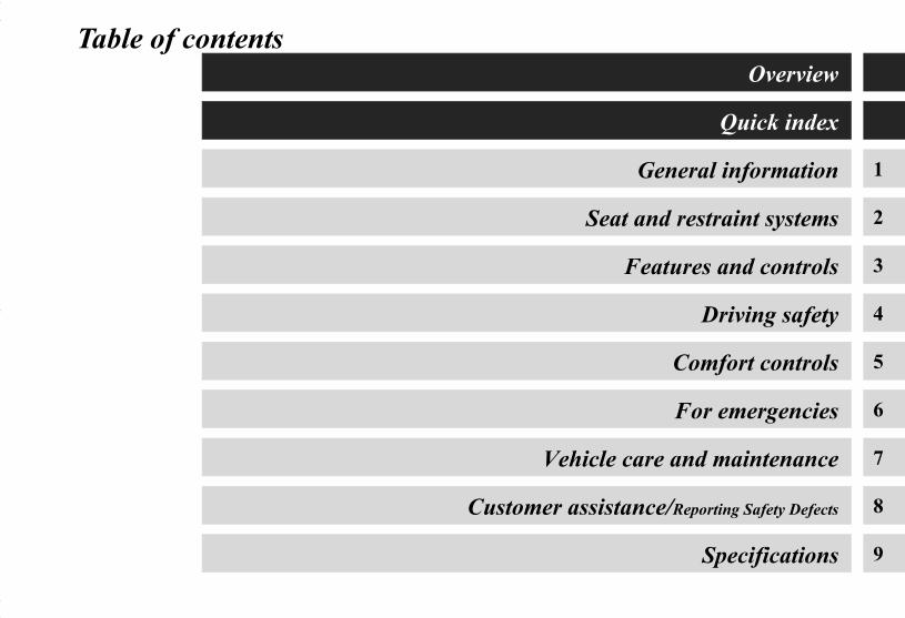
Table of contents
1
2
3
4
5
6
7
8
9
Overview
Quick index
General information
Seat and restraint systems
Features and controls
Driving safety
Comfort controls
For emergencies
Vehicle care and maintenance
Customer assistance/Reporting Safety Defects
Specifications
BK0150700US.book 1 ページ 2012年3月22日 木曜日 午後6時46分

Overview
Instruments and controlsN00100201433
Cruise control switch (if so equipped) P.3-107
Active stability control (ASC) OFF switch P.3-104, 3-137
Ignition switch (if so equipped) P.3-22, 3-66
Tilt & Telescopic steering lever P.3-59
Wiper and washer switch P.3-194Rear window wiper and washer switch P.3-201
Instrument cluster P.3-126
Supplemental restraint system (SRS) - airbag (for driver’s seat) P.2-43, 2-53Horn switch P.3-204
Combination headlights and dimmer switch P.3-183Turn signal lever P.3-192 Front fog light switch (if so equipped) P.3-193
Sportronic steering wheel paddle shifter (if so equipped) P.3-80
Steering wheel audio remote control switches (if so equipped) P.5-92
Bluetooth® 2.0 interface (if so equipped) P.3-205
Headlight leveling switch (if so equipped) P.3-191
Engine switch (if so equipped) P.3-22
Supplemental restraint system - driver’s knee airbag P.2-54
BK0150700US.book 1 ページ 2012年3月22日 木曜日 午後6時46分

Overview
Drive mode-selector (if so equipped) P.3-84
Center vents P.5-2
Gearshift or selector lever P.3-71, 3-75
12V power outlet P.3-238
Glove compartment P.3-247
Fuel tank filler door release lever P.1-4
Rear window defogger switch P.3-203
Side vents P.5-2
Engine hood release leverP.7-4
Hazard warning flasher switch P.3-193
Mitsubishi Multi-Communication System (if so equipped)Audio (if so equipped) P.5-46Clock (if so equipped) P.5-103
Air conditioning P.5-6, 5-16, 5-25, 5-35
Key slot (if so equipped) P.3-28
Cup holder P.3-251
Fuses P.7-39
Multi-information meter switch P.3-131
Parking brake lever P.7-33
BK0150700US.book 2 ページ 2012年3月22日 木曜日 午後6時46分

Overview
InteriorN00100301199
Dome light (front)/Reading lightsP.3-240Sunshade illumination switch (if so equipped) P.3-56
Sun visors P.3-236Vanity mirror P.3-236Card holder P.3-236
Arm rest (if so equipped) P.2-11Cup holder (if so equipped)P.3-252
Arm rest (if so equipped) P.2-9Floor console box P.3-24812V power outlet P.3-238USB input terminal (if so equipped) P.3-231Auxiliary Audio connector (RCA) (if so equipped) P.5-91
Dome light (rear) (if so equipped) P.3-242
Cargo area cover (if so equipped) P.3-253
Supplemental restraint system (SRS) - air bag (for front passenger’s seat) P.2-43, 2-53
Assist grips P.3-254Coat hook P.3-254
Rear seat P.2-11
Bottle holder P.3-252
SC00000100--1.fm 3 ページ 2012年3月26日 月曜日 午後5時34分

Overview
Power window switch P.3-52
Lock switch P.3-55
Electric remote-controlled outside mirror switch P.3-64
Power door lock switch P.3-41
Adjustable seat belt shoulder anchor P.2-27
Supplemental restraint system (SRS) - curtain airbags P.2-61
Seat belts P.2-18
Head restraints P.2-12
Inside rearview mirrorP.3-60, 3-124
Front seat P.2-2Heated seat (if so equipped) P.2-9
Cargo room lightP.3-243
Supplemental restraint system (SRS) - side airbag (for front seats) P.2-60
Tether anchors for child restraint system P.2-35
Sunshade illumination lamp dimming control switch (if so equipped) P.3-243
BK0150700US.book 4 ページ 2012年3月22日 木曜日 午後6時46分

Overview
Luggage compartmentN00100500426
Luggage hooks P.3-255
Jack P. 6-7
Luggage hooks P.3-255
Spare tire P.6-10
Hook
Luggage hooks P.3-255
Tools P.6-7
BK0150700US.book 5 ページ 2012年3月22日 木曜日 午後6時46分

Overview
OutsideN00100601349
Power window P.3-52
Front turn signal lights P.3-192, 7-48, 7-56
Engine hood P.7-4Fuel tank filler P.1-4
Outside rearview mirrors P.3-64
Windshield wipers P.3-194
Front fog lights (if so equipped) P.3-193, 7-48, 7-57
Side turn signal light P.3-192, 7-48, 7-57
Headlights, low beam P.3-188, 7-48, 7-50
Headlights, high beam P.3-188, 7-48, 7-52 Front side-marker and parking lights
P.3-183, 7-48, 7-55
Daytime running lights (if so equipped) P.3-183, 7-48, 7-60
BK0150700US.book 6 ページ 2012年3月22日 木曜日 午後6時46分

Overview
Tire pressure monitoring system P.3-115Changing tires P.6-8Size of tires and wheels P.7-23Tire inflation pressure P.7-27Tire rotation P.7-30Tire chains P.7-32
License plate light P.3-183, 7-48, 7-66
F.A.S.T.-key (Free-hand Advanced Security Transmitter) (if so equipped) P.3-14Keyless entry sysetm (if so equipped) P.3-33Locking and unlocking P.3-38
High-mounted stop light P.7-48, 7-68
Antenna P.5-102
Rear window wiper P.3-201
Back-up light P.7-48, 7-64
Tail and stop light/Rear side-marker lights P.3-183, 7-48, 7-62
Turn signal lights P.3-183, 7-48, 7-62
Rear spoiler
Liftgate P.3-44
Rear-view camera (if so equipped) P.3-121
BK0150700US.book 7 ページ 2012年3月22日 木曜日 午後6時46分

Quick index
1
If this warning light comes on or flashes while you’re driving...N00200701051
NOTE● For information regarding warning displays in the multi-information display, refer to “Multi-information display” on page 3-
129.● These warning lights will come on for a few seconds for a bulb check when the ignition switch is first turned to “ON” or the
operation mode is put in ON.
Warning lights Do this Ref. Page
Charging system warning light
● Park your vehicle in a safe place and stop the engine.Contact your Mitsubishi Motors dealer or a repair facility of your choice for assistance.
P. 3-179
or
Brake warning light
● If this light comes on while driving, check to see that the parking brake is fully released.
● If this light stays on after releasing the parking brake, immediately stop and check the brake fluid level.
● If the brake fluid level is correct, there may be a system malfunction. Avoid hard braking and high speed, and contact an authorized Mitsubishi Motors dealer or a repair facility of your choice for assistance.
P. 3-177
or
Engine malfunction indicator (“SERVICE ENGINE SOON” or
“Check engine light”)
● Although your vehicle will usually be drivable and not need towing, have the engine system checked at an authorized Mitsubishi Motors dealer or a repair facility of your choice as soon as possible. If the vehicle is not drivable, con-tact emergency roadside assistance at 1-888-648-7820 (for vehicles sold in U.S.A.) or 1-888-576-4878 (for vehicles sold in Canada), an authorized Mitsubishi Motors dealer, or local towing company for assistance.
P. 3-178
BK0150700US.book 1 ページ 2012年3月22日 木曜日 午後6時46分

2
Quick index
Anti-lock braking system warning light
● When this light comes on, the anti-lock braking system is not functioning and only the ordinary braking system is functioning.
● Park your vehicle in a safe place and stop the engine.Test the system as described on page 3-98.
● If the light does not go out after the test, or if it comes on again, we recom-mend that you have the system checked at an authorized Mitsubishi Motors dealer or a repair facility of your choice as soon as possible.
P. 3-98
SRS warning light
● It is not necessary to stop the vehicle immediately, but we recommend that you have the airbag and the pre-tensioner seat belt system checked at an authorized Mitsubishi Motors dealer as soon as possible.
P. 2-52
Tire pressure monitoring system warning light
● If the warning light comes on, you should stop and adjust the tires to the proper inflation pressure as soon as possible.(See “Tire inflation pressures” on page 7-27.)Once adjustments have been made, the warning light will go off after a few minutes of driving.
● If the warning light blinks for approximately 1 minute and then remains con-tinuously illuminated, the system is not operating properly. If the system returns to normal, the warning light will go off. If the warning light does not go off, have the vehicle inspected at an authorized Mitsubishi Motors dealer.
P. 3-115
Warning lights Do this Ref. Page
BK0150700US.book 2 ページ 2012年3月22日 木曜日 午後6時46分

Quick index
3
If this problem occurs...N00200900867
Problem Do this Ref. Page
Cannot turn the key.(except for vehicles equipped with the F.A.S.T.-key)
Will not turn from “ACC” to “OFF”.Vehicles with continuously variable transmission (CVT):Check the position of the selector lever.The key cannot be removed unless the selector lever is set to the “P” (PARK) position.
P. 3-68
The engine does not start when the engine switch is pressed.(for vehicles equipped with the F.A.S.T.-key)
Make sure the F.A.S.T.-key is in the vehicle.Vehicles with manual transaxle:Press and hold the clutch pedal all the way down, and then press the engine switch while depressing the brake pedal.
Vehicles with continuously variable transmission (CVT):Make sure the selector lever is in the “P” (PARK) position, and then press the engine switch while depressing the brake pedal.
P. 3-26
The F.A.S.T.-key does not operate.(for vehicles equipped with the F.A.S.T.-key)
Use the emergency key to lock and unlock the door.Insert the F.A.S.T.-key into the key slot inside the glove compartment, and then start the engine or change the operation mode.
P. 3-30
BK0150700US.book 3 ページ 2012年3月22日 木曜日 午後6時46分

4
Quick index
Cannot shift the selector lever from the “P” (PARK) position.(for vehicles with continuously variable transmission (CVT))
Shift the selector lever while pressing the brake pedal.Check that the ignition switch or the operation mode is in ON. P. 3-74
The windows are fogged up.
1. Set the mode selection dial to the “ ” or “ ” position.2. Turn on the blower.
P. 5-14, 5-23, 5-33, 5-43
The engine does not start.The lights do not come on.The lights are dim.The horn does not honk.The horn sound is weak.
Have the battery checked. Recharge or replace as needed. P. 6-2, P. 7-21
Problem Do this Ref. Page
BK0150700US.book 4 ページ 2012年3月22日 木曜日 午後6時46分

Quick index
5
Problem Do this Ref. Page
The engine coolant tempera-ture display “ ” in the multi-information display is flashing.Steam comes out of the engine compartment.
Type 1
Type 2
The engine is overheated.Carefully stop the vehicle in a safe place. P. 6-5
BK0150700US.book 5 ページ 2012年3月22日 木曜日 午後6時46分

6
Quick index
If your vehicle becomes stuck in sand, mud or snow
1. Slowly press down on the accelerator pedal to get your vehicle moving again. For an all-wheel drive vehicle, set the drive mode-selector to the “4WD AUTO” or “4WD LOCK” position and then slowly press down on the accelerator pedal to get your vehicle moving.
2. If there is nothing to stop your tires from slipping, rock your vehicle back and forth to free it.
P. 6-23
WARNING!● When trying to rock your vehicle out of a stuck position, make sure that there are no people nearby. The rocking
motion may cause the vehicle to suddenly lurch forward or backward, possibly injuring bystanders.● Avoid revving the engine or spinning the wheels. Prolonged efforts to free a stuck vehicle may result in overheating
and transaxle failure.If your vehicle is still stuck after several rocking attempts, call for help.
Problem Do this Ref. Page
BK0150700US.book 6 ページ 2012年3月22日 木曜日 午後6時46分
Quick index
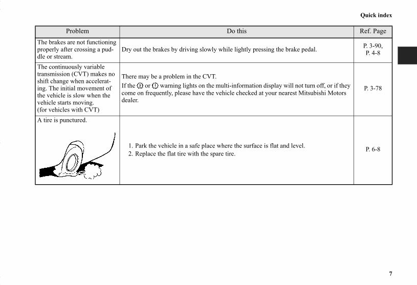
7
Problem Do this Ref. PageThe brakes are not functioning properly after crossing a pud-dle or stream.
Dry out the brakes by driving slowly while lightly pressing the brake pedal. P. 3-90, P. 4-8
The continuously variable transmission (CVT) makes no shift change when accelerat-ing. The initial movement of the vehicle is slow when the vehicle starts moving.(for vehicles with CVT)
There may be a problem in the CVT.If the or warning lights on the multi-information display will not turn off, or if they come on frequently, please have the vehicle checked at your nearest Mitsubishi Motors dealer.
P. 3-78
A tire is punctured.
1. Park the vehicle in a safe place where the surface is flat and level.2. Replace the flat tire with the spare tire.
P. 6-8
BK0150700US.book 7 ページ 2012年3月22日 木曜日 午後6時46分

BK0150700US.book 8 ページ 2012年3月22日 木曜日 午後6時46分
1
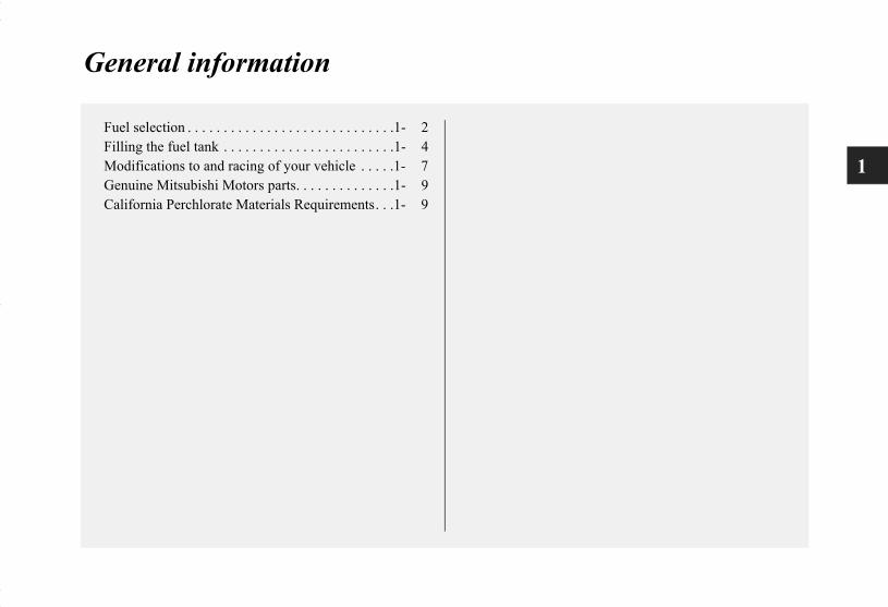
General information
Fuel selection . . . . . . . . . . . . . . . . . . . . . . . . . . . . .1- 2Filling the fuel tank . . . . . . . . . . . . . . . . . . . . . . . .1- 4Modifications to and racing of your vehicle . . . . .1- 7Genuine Mitsubishi Motors parts. . . . . . . . . . . . . .1- 9California Perchlorate Materials Requirements. . .1- 9
BK0150700US.book 1 ページ 2012年3月22日 木曜日 午後6時46分

1-2
General information
1
Fuel selectionN00301000895
Your vehicle is designed to use unleaded gasoline only. It isequipped with a fuel tank filler pipe especially designed toaccept only a small diameter unleaded gasoline dispensing noz-zle.
Gasoline detergent additivesIn the United States, fuel suppliers are required by law to adddetergents to their gasoline to minimize fuel-injector foulingand minimize intake-valve deposits. Detergent gasoline helpskeep your engine in tune and your emission-control systemworking properly.
Octane requirementYour vehicle is designed to operate on unleaded gasoline hav-ing a minimum octane number of 87 [(MON+RON)/2] or 91RON.
Oxygenated gasolineGasoline sold at some service stations contains oxygenatessuch as ethanol, although the oxygenates may not be identifiedby those names. Oxygenates are required in some areas of thecountry. Such fuel can be used in your vehicle.
Ethanol (Gasohol)A mixture of up to 10 % ethanol (grain alcohol) and 90 %unleaded gasoline may be used in your vehicle, provided theoctane number is at least as high as that recommended forunleaded gasoline.
MethanolDo not operate your vehicle on gasoline containing methanol(wood alcohol). Using this type of alcohol could adverselyaffect the vehicle’s performance and damage critical parts ofthe vehicle’s fuel system.
WARNING!● Gasoline is highly flammable and explosive. You
could be burned, seriously injured or killed whenhandling it. Whenever you refuel your vehicle, stopthe engine and keep flames, sparks, and smokingmaterials away from the vehicle. Always handle fuelin well-ventilated outdoor areas.
CAUTION!● Using leaded gasoline in your vehicle will damage
the engine, catalytic converter, and the oxygen sen-sors. Also, using leaded gasoline is illegal, and willvoid your warranty coverage of the engine, catalyticconverter, and oxygen sensors.
BK0150700US.book 2 ページ 2012年3月22日 木曜日 午後6時46分

General information
1-3
1
Reformulated gasolineMany areas of the country require the use of cleaner burningfuel referred to as “Reformulated Gasoline”.Reformulated gasoline contains oxygenates and is speciallyblended to reduce vehicle emissions and improve air quality.Mitsubishi Motors Corporation strongly supports the use ofreformulated gasoline. Properly blended reformulated gasolinehas no adverse effect on vehicle performance or the durabilityof engine and fuel system.
MMT (methylcyclopentadienyl manganese tri-carbonyl)MMT is a manganese-containing metallic additive that isblended into some gasolines to increase the octane number.Mitsubishi Motors Corporation recommends using gasolineswithout MMT.Use of gasolines blended with MMT may adversely affect per-formance, and cause the malfunction indicator on your instru-ment panel to come on. If this happens, contact an authorizedMitsubishi Motors dealer or a repair facility of your choice forassistance.
Sulfur in gasolineYour vehicle may have been designed to satisfy California’slow-emission regulations based on clean-burning low-sulfurgasoline. Gasoline sold in parts of the country other than Cali-fornia is allowed to have a higher sulfur content. Using suchgasoline could adversely affect the vehicle’s catalytic converterand cause the engine malfunction indicator (“SERVICEENGINE SOON” or “Check engine light”) to come on. Illumi-nation of this indicator while you are using high-sulfur gaso-line does not necessarily mean the vehicle’s emission-control
system is malfunctioning. Your authorized Mitsubishi Motorsdealer may suggest you try using a different, lower-sulfurbrand of unleaded gasoline to determine whether the problemis fuel-related.
NOTE● Poor-quality gasoline can cause problems such as poor
starting, stalling during idling, abnormal engine noise, andpoor acceleration. If you experience any of these prob-lems, try using a different brand of gasoline. If the enginemalfunction indicator (“SERVICE ENGINE SOON” or“Check engine light”) flashes, have the vehicle inspectedas soon as possible by the nearest authorized MitsubishiMotors dealer or a repair facility of your choice.
● Repeatedly driving short distances at low speeds cancause deposits to form in the fuel system and engine,resulting in poor starting and poor acceleration. If theseproblems occur, you are advised to add a detergent addi-tive to the gasoline when you refuel the vehicle. The addi-tive will remove the deposits, thereby returning the engineto a normal condition. Be sure to use a genuine Mitsubishicleaning additive. Using an unsuitable additive couldmake the engine malfunction. For details, please contactthe nearest authorized Mitsubishi Motors dealer.
BK0150700US.book 3 ページ 2012年3月22日 木曜日 午後6時46分

1-4
General information
1
Filling the fuel tankN00301100896
Fuel tank capacityAll-wheel drive vehicles: 15.8 gal (60 L)Front-wheel drive vehicles: 16.6 gal (63 L)
Refueling1. Before filling with fuel, stop the engine.2. The fuel tank filler is located on the rear driver side of
your vehicle.The fuel tank filler door can be opened from inside thevehicle with the fuel tank filler door release lever locatedat the left side of the driver’s seat.
WARNING!● Gasoline is highly flammable and explosive. You
could be burned, seriously injured or killed whenhandling it. When refueling your vehicle, alwaysturn the engine off and keep away from flames,sparks, and smoking materials. Always handle fuelin well-ventilated outdoor areas.
● Before removing the fuel tank filler cap, be sure toget rid of your body’s static electricity by touching ametal part of the car or fuel pump. Any static elec-tricity on your body could create a spark that ignitesfuel vapor.
● Perform the whole refueling process (opening thefuel tank filler door, removing the fuel cap, etc.) byyourself; do not let any other person near the fueltank filler. If you allowed a person to help you andthat person was carrying static electricity, fuel vaporcould be ignited.
● Do not move away from the fuel tank filler untilrefueling is finished. If you moved away and didsomething else (for example, sitting on a seat) part-way through the refueling process, you could pickup a fresh charge of static electricity.
● Be careful not to inhale fuel vapor. Fuel containstoxic substances.
● Keep the doors and windows closed while refuelingthe vehicle. If they were open, fuel vapor could getinto the cabin.
BK0150700US.book 4 ページ 2012年3月22日 木曜日 午後6時46分

General information
1-5
1
3. Open the fuel tank filler pipe by slowly turning the fueltank filler cap counterclockwise.
4. While filling with fuel, hang the fuel cap cord on the hooklocated on the inside of the fuel tank filler door.
1- Remove2- Close WARNING!
● Since the fuel system may be under pressure,remove the fuel tank filler cap slowly. This relievesany pressure or vacuum that might have built up inthe fuel tank. If the cap is venting vapor or if youhear a hissing sound, wait until the sound stopsbefore removing the cap. Otherwise, fuel may sprayout, injuring you or others.
BK0150700US.book 5 ページ 2012年3月22日 木曜日 午後6時46分

1-6
General information
1
5. To fill with fuel correctly depends mainly on correct han-dling of the fuel filler nozzle. Do not tilt the nozzle. Insertthe nozzle in the fuel tank filler port as far as it goes.
6. When the nozzle stops automatically, do not try to addmore fuel.
7. To close, turn the fuel tank filler pipe cap slowly clock-wise until you hear clicking sounds, then gently push thefuel tank filler door closed.
NOTE● If the fuel tank filler cap is not tight while driving, the
engine malfunction indicator (“SERVICE ENGINESOON” or “Check engine light”) may come on when theonboard diagnostic (OBD) system performs a self check.Always tighten the fuel tank filler cap until you hear atleast 3 clicks.The indicator will go off after driving several times. If theindicator does not go off, contact your authorizedMitsubishi Motors dealer or a repair facility of yourchoice as soon as possible.
CAUTION!● Your vehicle can only be operated using unleaded
gasoline. Serious engine and catalytic converterdamage will result if leaded gasoline is filled intothese vehicles, and consequently, this must never beattempted.
CAUTION!● To avoid fuel spillage and overfilling, do not “top-
off” the fuel tank. Spilled fuel could discolor, stain,or crack the vehicle’s paintwork. If fuel spills on thepaintwork, wipe it off with a soft cloth.
WARNING!● Make sure the fuel tank filler cap is securely closed.
If the fuel cap were loose, fuel could leak, resultingin a fire.
CAUTION!● If you need to replace the fuel tank filler cap, use
only the cap specified for your model vehicle.
BK0150700US.book 6 ページ 2012年3月22日 木曜日 午後6時46分

General information
1-7
1
Modifications to and racing of your vehicleN00301600149
This vehicle should not be modified with non-MitsubishiMotors genuine parts. Mitsubishi Motors designs and manufac-tures high quality vehicles with an emphasis on safety anddurability. Modifications using non-Mitsubishi Motors genuineparts may affect the performance, safety and/or durability ofyour vehicle, and may violate applicable state and/or federalregulations.
DAMAGE OR PERFORMANCE PROBLEMS RESULT-ING FROM MODIFICATIONS TO OR RACING OFYOUR VEHICLE ARE NOT COVERED UNDER WAR-RANTY.
Examples of modifications to your vehicle that can cause dam-age or performance problems include the following:
● Failure to use Mitsubishi Motors genuine parts● Failure to use required fuel and fluids● Failure to use proper size tires and wheels● Modification of the fuel, intake, exhaust, emission, sus-
pension, engine, drive train or electrical wiring systems● Modification of any onboard computer/control module,
including reprogramming, or replacing/adding chips toany onboard computer/control module
Review the Warranty and Maintenance Manual for furtherdetails regarding warranty coverage.
Installation of accessoriesN00301700166
● The installation of accessories, optional parts, etc., shouldonly be carried out within the limits prescribed by law,and in accordance with the guidelines and warnings con-tained within the documents accompanying this vehicle.Only Mitsubishi Motors approved accessories should befitted to your vehicle.
● Improper installation of electrical parts could cause fire.Refer to the “Modification/alterations to the electrical orfuel systems” section within this owner’s manual.
● Using a cellular phone or radio set inside the vehicle with-out an external antenna may cause electrical system inter-ference, which could lead to unsafe vehicle operation.
● Tires and wheels which do not meet specifications mustnot be used.Refer to the “Specifications” section for informationregarding wheel and tire sizes.
CAUTION!● Before any electrical or electronic accessories are
installed, consult an authorized Mitsubishi Motorsdealer.
BK0150700US.book 7 ページ 2012年3月22日 木曜日 午後6時46分

1-8
General information
1
Important point!Due to the large number of accessory and replacement partsprovided by different manufacturers in the market, it is notalways possible for an authorized Mitsubishi Motors dealer tocheck whether the attachment or installation of non-MitsubishiMotors genuine parts affects the driving safety of yourMitsubishi-vehicle.
Modification/alterations to the electrical or fuel systems
N00301800138
Mitsubishi Motors manufactures high quality vehicles with anemphasis on safety. It is important to consult an authorizedMitsubishi Motors dealer before installation of any accessorywhich may involve modification of the electrical or fuel sys-tems.
WARNING!● While driving, do not use a cellular phone in a way
that hinders safe driving. Anything, including cellu-lar phone usage, that distracts you from the safeoperation of your vehicle increases your risk of anaccident.Refer to and follow all state and local laws in yourarea regarding cellular phone usage while driving.
CAUTION!● Please consult an authorized Mitsubishi Motors
dealer concerning any such accessory fitment ormodification.If the wires interfere with the vehicle body orimproper installation methods are used (protectivefuses not included, etc.), electronic devices may beadversely affected, resulting in a fire, vehicle dam-age, or other accident.
BK0150700US.book 8 ページ 2012年3月22日 木曜日 午後6時46分

General information
1-9
1
Genuine Mitsubishi Motors partsN00301400219
Mitsubishi Motors Genuine Parts are designed and manufac-tured to meet high standards of performance, and are recom-mended for all of your maintenance needs. Also available fromyour Mitsubishi Motors dealer are a wide variety of accessoriesto personalize your new vehicle. Each Mitsubishi Motors vehi-cle has a selection of Mitsubishi Motors authorized accessoriesto choose from to tailor your new vehicle to your own personalpreference. Your Mitsubishi Motors dealer’s Parts Manager hasinformation on various audio systems, protection items, as wellas interior and exterior accessories available for your specificmodel.
California Perchlorate Materials Require-ments
N00300100017
Certain components of this vehicle, such as airbag modules,seat belt pretensioners, and button cell batteries, may containperchlorate materials.Special handling may apply. For additional information, seewww.dtsc.ca.gov/hazardouswaste/perchlorate.
BK0150700US.book 9 ページ 2012年3月22日 木曜日 午後6時46分

BK0150700US.book 10 ページ 2012年3月22日 木曜日 午後6時46分

2
Seat and restraint systems
Seats . . . . . . . . . . . . . . . . . . . . . . . . . . . . . . . . . . . .2- 2Seats and restraint systems. . . . . . . . . . . . . . . . . . .2- 3Front seats . . . . . . . . . . . . . . . . . . . . . . . . . . . . . . .2- 3Rear seats . . . . . . . . . . . . . . . . . . . . . . . . . . . . . . . .2- 11Head restraints . . . . . . . . . . . . . . . . . . . . . . . . . . . .2- 12Extending a luggage compartment. . . . . . . . . . . . .2- 15Seat belts . . . . . . . . . . . . . . . . . . . . . . . . . . . . . . . .2- 18Seat belt use during pregnancy . . . . . . . . . . . . . . .2- 29Seat belt pre-tensioner and
force limiter systems. . . . . . . . . . . . . . . . . . . . . .2- 29Child restraint systems. . . . . . . . . . . . . . . . . . . . . .2- 31Maintenance and inspection of seat belts. . . . . . . .2- 42Supplemental Restraint System (SRS) - airbag . . .2- 43
BK0150700US.book 1 ページ 2012年3月22日 木曜日 午後6時46分

2-2
Seat and restraint systems
2
SeatsN00408400482
1 - Front seat● To adjust the seat forward or backward→Page 2-5● To adjust the seatbacks →Page 2-6● To adjust the seat height (Driver’s seat only) →Page 2-7● Arm rest (if so equipped) →Page 2-9● Heated seat (if so equipped) →Page 2-9
2 - Rear seats● Arm rest (if so equipped)→Page 2-11● Rear Seat Pass Through (if so equipped) →Page 2-11
BK0150700US.book 2 ページ 2012年3月22日 木曜日 午後6時46分

Seat and restraint systems
2-3
2
Seats and restraint systemsN00401600153
Your vehicle has seat belts and other features that help protectyou and your passengers in an accident.Seat belts are the most important safety device. When wornproperly, seat belts can reduce the chance of serious injury ordeath in various types of crashes. For added protection during asevere frontal collision, your vehicle has a SupplementalRestraint System (SRS) with airbags for the driver and passen-gers. The seats, head restraints, and door locks also are safetyequipment, which must be used correctly.
Always check the following before you drive:● That everyone in your vehicle is properly wearing their
seat belt.● That infants and small children are properly secured in
appropriate child restraint systems in the rear seat.● That all doors are fully closed and locked.● That seatbacks are upright, with head restraints properly
adjusted.
Safety equipment cannot prevent injury or death in all motorvehicle accidents. You can help reduce the risk of injury ordeath, however, by following the instructions in this manual.
Front seatsN00401800399
Position the driver’s seat as far back as possible while main-taining a position that still enables you to fully apply the ped-als, easily control the steering wheel and safely operate thevehicle.
Power seat adjustmentManual seat adjustment
BK0150700US.book 3 ページ 2012年3月22日 木曜日 午後6時46分

2-4
Seat and restraint systems
2
WARNING!● Do not attempt to adjust the seat while driving. This
can cause loss of vehicle control and result in anaccident.
● After adjusting the seat, make sure that it is securelylocked into position.
● To reduce the risk to the driver of serious injury ordeath during deployment of the driver’s airbag,always properly wear the seat belt and adjust thedriver’s seat as far back as possible while maintain-ing a position that still enables you to fully apply thepedals, easily control the steering wheel, and safelyoperate the vehicle.
● To reduce the risk to the front passenger of seriousinjury or death during deployment of the passen-ger’s airbag, always properly wear the seat belt andadjust the front passenger’s seat as far back as pos-sible.
● Always place children 12 years old and under in therear seat and use appropriate child restraint sys-tems.
CAUTION!● Make sure that the seat is adjusted by an adult. If it
is adjusted by a child, an unexpected accident mightoccur.
● Do not place a cushion or the like between your backand the seatback while driving. The effectiveness ofthe head restraints will be reduced in the event of anaccident.
● When sliding the seats, be careful not to catch yourhand or leg.
● When sliding or reclining the seat rearward, paycareful attention to the rear seat passengers.
BK0150700US.book 4 ページ 2012年3月22日 木曜日 午後6時46分

Seat and restraint systems
2-5
2
To adjust the seat forward or backwardN00401900228
Manual seat adjustmentPull the seat adjusting lever up and slide the seat forward orbackward to the desired position. Release the adjusting lever tolock the seat in place.
Power seat adjustmentOperate the switch forward or backward to move the seat to thedesired position. Release the switch to lock the seat in place.
NOTE● To prevent the battery from going dead, operate the power
seat with the engine running.WARNING!● To make sure that the seat is securely locked, try to
move it forward or backward without using theadjusting lever.
1- Forward (toward the front of the vehicle)2- Backward (toward the rear of the vehicle)
BK0150700US.book 5 ページ 2012年3月22日 木曜日 午後6時46分

2-6
Seat and restraint systems
2
To adjust the seatbacksN00402000268
Manual seat adjustmentTo adjust the seatback, lean forward slightly, gently pull theseatback lock lever up, then lean backward to a comfortableposition and release the lever. The seatback will lock in place.
Power seat adjustmentOperate the switch in the direction of the arrows to adjust theseatback.
NOTE● To prevent the battery from going dead, operate the power
seat with the engine running.CAUTION!● The reclining mechanism used in the seatback is
spring loaded, and will cause the seatback to returnquickly to the vertical position when the lock lever isoperated. When pulling the lever, sit close to theseatback or hold the seatback with your hand tocontrol its return motion.
1- Move forward2- Move backward
BK0150700US.book 6 ページ 2012年3月22日 木曜日 午後6時46分
Seat and restraint systems
2-7
2
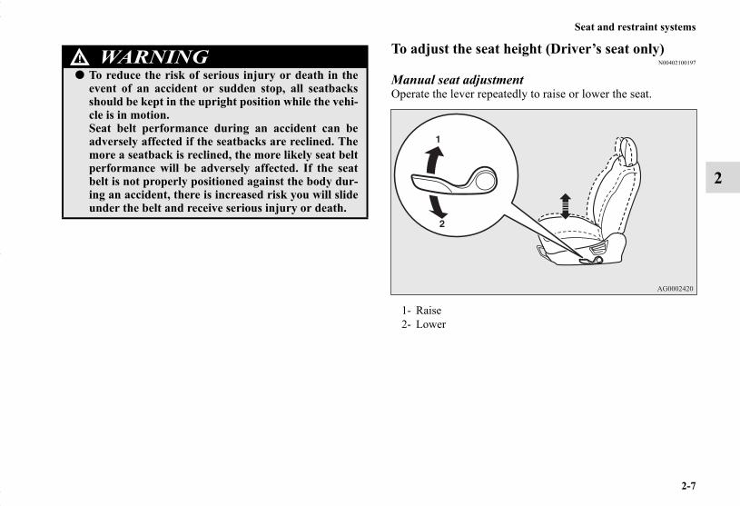
To adjust the seat height (Driver’s seat only)N00402100197
Manual seat adjustmentOperate the lever repeatedly to raise or lower the seat.
WARNING!● To reduce the risk of serious injury or death in the
event of an accident or sudden stop, all seatbacksshould be kept in the upright position while the vehi-cle is in motion.Seat belt performance during an accident can beadversely affected if the seatbacks are reclined. Themore a seatback is reclined, the more likely seat beltperformance will be adversely affected. If the seatbelt is not properly positioned against the body dur-ing an accident, there is increased risk you will slideunder the belt and receive serious injury or death.
1- Raise2- Lower
BK0150700US.book 7 ページ 2012年3月22日 木曜日 午後6時46分
2-8
Seat and restraint systems
2
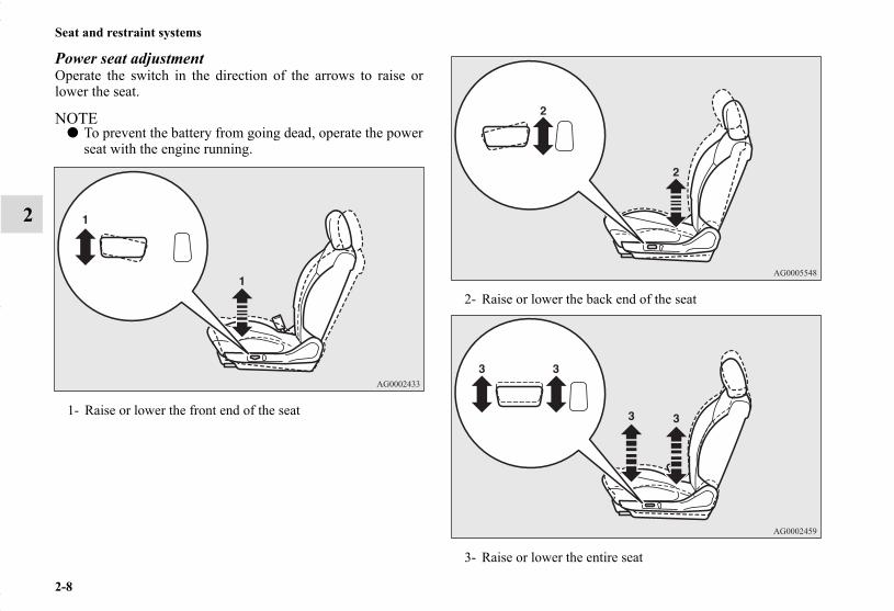
Power seat adjustmentOperate the switch in the direction of the arrows to raise orlower the seat.
NOTE● To prevent the battery from going dead, operate the power
seat with the engine running.
1- Raise or lower the front end of the seat
2- Raise or lower the back end of the seat
3- Raise or lower the entire seat
BK0150700US.book 8 ページ 2012年3月22日 木曜日 午後6時46分

Seat and restraint systems
2-9
2
Arm rest (if so equipped)N00402300069
The lid on the floor console box can be moved forward andbackward and used as an arm rest.
Heated seat (if so equipped)N00435600352
The heated seats can be operated by pushing the switch whenthe ignition switch or the operation mode is in ON. The indica-tor light (A) will illuminate while the heater is on.
1 (HI) - Heater high (for quick heating)2 - Heater off3 (LO) - Heater low (to keep the seat warm)
BK0150700US.book 9 ページ 2012年3月22日 木曜日 午後6時46分
2-10
Seat and restraint systems
2
WARNING!● Persons who are unable to feel temperature change
or skin pain due to age, illness, injury, medication,alcohol use, fatigue or other physical conditions orwho have sensitive skin may suffer burns whenusing the heated seat even at low temperatures. Toreduce the risk of burns, people with such conditionsmust use care when using the heated seat.
CAUTION!● Switch off the heated seats when not in use. Operate
the heaters at the “HI” position for quick heating.After the seat has become warm, set the heaterswitch to the “LO” position to keep it warm. Slightvariations in the seat temperature may be felt whileusing the heated seats. This is caused by the opera-tion of the heater’s internal thermostat and does notindicate a malfunction.
CAUTION!● Do not place heavy objects on the seat or stick pins,
needles, or other pointed objects into the seat.● Do not place a blanket, cushion, or other insulating
material on the seat while using the heater; doing socan cause the heater element to overheat.
● When cleaning the seat, do not use benzine, kero-sene, gasoline, alcohol, or other organic solvents;doing so can cause damage not only to the surface ofthe seat, but also to the heater.
● If water or any other liquid is spilled on the seat,allow it to dry thoroughly before attempting to usethe heater. Turn the heater off immediately if itappears to be malfunctioning during use.
BK0150700US.book 10 ページ 2012年3月22日 木曜日 午後6時46分

Seat and restraint systems
2-11
2
Rear seatsN00402500191
Arm rest (if so equipped)N00403000308
Tilt the arm rest down for use as shown.The arm rest includes a cup holder. (Refer to “Cup holder: Forthe rear seat” on page 3-252.)
NOTE● Never sit on the arm rest.
Doing so could damage the arm rest.
Rear Seat Pass Through (if so equipped)N00409000036
Open the lid in the arm rest to gain access to the luggage com-partment from the cabin. This feature is useful for carryinglong objects while accommodating 2 passengers in the rearseats.Fold down the arm rest. Then slide the knob (A) down whilepulling it forward to open the lid.
BK0150700US.book 11 ページ 2012年3月22日 木曜日 午後6時46分

2-12
Seat and restraint systems
2
Head restraintsN00404300542
Padded head restraints for the seats can reduce the risk of awhiplash injury if your vehicle is hit from the rear.The head restraints are equipped in the illustrated position.To maximize the effectiveness of your head restraint, adjust thefront seatback to the upright position, the rear seatback to thenormal seating position, and the head restraint to the properposition. Sit back against the seatback with your head close tothe head restraint.
WARNING!● Driving without the head restraints in place can
cause you and your passengers serious injury ordeath in an accident. To reduce the risk of injury inan accident, always make sure the head restraintsare installed and properly positioned when the seatis occupied.
● In order to minimize the risk of a neck injury due toa rear impact, the front seatback must be adjustedto the upright position, the rear seatback to the nor-mal seating position, and the head restraint to theproper position before vehicle operation. The drivershould never adjust the seat while the vehicle is inmotion.
● Never place a cushion or similar device on the seat-back. This can adversely affect head restraint per-formance by increasing the distance between yourhead and the restraint.
BK0150700US.book 12 ページ 2012年3月22日 木曜日 午後6時46分

Seat and restraint systems
2-13
2
Adjustment of the head restraint heightTo reduce the risk of injury in an accident, adjust the headrestraint height so that the center of the restraint is at your eyelevel when seated. Any person too tall for the restraint to reachtheir eye level when seated should raise the restraint to thehighest locked position.
● To raise the restraint, pull it straight up.● To lower the restraint, push down on it while pressing the
lock knob (A) in the direction shown by the arrow.● After adjusting the height, push down on the restraint to
make sure it is locked in position.
To removePress the lock knob (A) in the direction shown by the arrows.Then pull the head restraint up and out of the seatback.
To installFirst check that the head restraint is facing in the right directionas shown in the previous illustration, and then insert it into theseatback. Push the head restraint down while pressing the lockknob (A) until the restraint locks into place.
WARNING!● To help minimize the risk of neck injury in the event
of an accident, the head restraints must be properlyinstalled and positioned to proper height beforevehicle operation.
BK0150700US.book 13 ページ 2012年3月22日 木曜日 午後6時46分

2-14
Seat and restraint systems
2
CAUTION!● Check that the lock knob (A) is extended out as
shown in the illustration. Then pull the headrestraint up to make sure that it is locked in placeand will not come out of the seatback.
CAUTION!● The shape and size of the head restraint differs
according to the seat. Always use the correct headrestraint provided for the seat and do not install thehead restraint in the wrong direction.
BK0150700US.book 14 ページ 2012年3月22日 木曜日 午後6時46分
Seat and restraint systems
2-15
2
Extending a luggage compartmentN00405500105
NOTE● When the seatback of a front seat is reclined, return it to
the upright position before driving.
WARNING!● Never adjust the seats to extend a luggage compart-
ment while the vehicle is in motion or on a slope.The seats could move suddenly and cause seriousinjury or an accident.
● After returning a seatback to its normal position,make sure that the seatback is firmly secured. If theseatback is not secured, it could move and cause aserious accident.
● Do not allow anyone to ride in the luggage compart-ment while the vehicle is in motion. People who arenot properly seated and restrained can be seriouslyinjured or killed in an accident.
● The luggage compartment in the rear of the vehicleshould never be used as a play area by children. Allchildren should be properly restrained in a restraintdevice that offers the maximum protection for theirsize and age. Refer to “Child restraint systems” onpage 2-31.
● The front passenger seat is equipped with weightsensors. Depending on the weight detected, the frontpassenger airbag is disabled or enabled. When fold-ing the rear seats forward for increased cargocapacity, the front passenger seat and seatback mustbe adjusted to assure they are not contacting therear seat. In the event the front seat or seatback isallowed to contact the folded rear seat, proper oper-ation of the front passenger airbag system may beaffected.
CAUTION!● In the luggage compartment, do not load the luggage
higher than the top of the seats and make sure thatthe luggage is firmly secured. Restricted rear visionor unsecured objects entering the passenger com-partment from the luggage compartment duringsudden braking can cause serious injury or an acci-dent.
● Seatbacks should always be folded and put back intonormal position by an adult. Seat adjustments by achild could lead to an unexpected accident.
● When adjusting the seats, be careful not to catchyour hand or leg. Personal injury could result.
WARNING!
BK0150700US.book 15 ページ 2012年3月22日 木曜日 午後6時46分

2-16
Seat and restraint systems
2
Folding the rear seatbacks forwardN00417800046
The passenger and luggage compartments can be joined byfolding the seatback forward. This is useful for carrying longobjects.The seatbacks can be folded with the rear seat release button.
NOTE● You can separately fold the right and left side of the seat-
back.
To fold the seatbacks
Push the rear seat release button (A) to fold the seatback for-ward.The rear outboard seat belt can be separated from the seat beltguide (B) to help prevent damage to the seat belt while theseatback is folded.
To return the seatbacks1. If the outboard seat belt has been separated from the seat
belt guide (B), insert it back into the seat belt guide.2. Tilt the seatback up until it is locked properly in position.
Two seatback angles can be selected depending on return-ing speed of the seatback. When the seatback is raised andpushed backward slowly, the seatback angle will be set atthe more upright position.
NOTE● If the seat belt locks up and cannot be pulled out, pull it
once with force and let it retract all the way. Then, pull thebelt out slowly once again.
● To change the seatback angle, move the seatback forwardor backward while pressing the rear seat release button.
CAUTION!● Before folding the driver’s side rear seatback,
detach the center seat belt from the detachableanchor and retract the center seat belt all the way tothe rear trim to prevent damage to the seat beltcaused by an object in the luggage compartment.For details, refer to page 2-23.
BK0150700US.book 16 ページ 2012年3月22日 木曜日 午後6時46分

Seat and restraint systems
2-17
2
3. Make sure the seatback is locked securely in place and theseat belt is passed through the seat belt guide (B).
4. If the center seat belt is stored in the rear trim, pull the seatbelt out and pass it through the seat belt guide (D) near thecenter of the rear seat backs.
CAUTION!● If the red part (C) on the back of the rear seat
release button can be seen, the seatback is not lockedfirmly in place. Push and pull lightly on the seatbackto lock it firmly in place.
BK0150700US.book 17 ページ 2012年3月22日 木曜日 午後6時46分

2-18
Seat and restraint systems
2
5. After making sure that the seat belt is not twisted, insertthe small latch plate (E) into the detachable anchor (F)aligning the marks (G) on the plate and buckle until a“click” is heard. Make sure the detachable anchor issecurely latched and seat belt is not twisted. For details,refer to page 2-23.
Seat beltsN00406000442
Seat belts are installed in your vehicle to help reduce the risk ofinjury to the driver and passenger in the event of an accident.Always use the provided seat belts.Carefully review the following information for proper seat beltusage.
WARNING!● Using the rear center seat belt with the detachable
anchor unlatched increases the risk of serious injuryor death in an accident. Make sure the detachableanchor is properly latched.
WARNING!● To help reduce the risk of injury or death in an acci-
dent, seat belts and child restraint systems mustalways be used. Refer to “Child restraint systems”on page 2-31 for additional information.
● Never use one seat belt for more than one person. ● Never carry more people in your vehicle than there
are seat belts. ● Always adjust the seat belt for a snug fit.● Always place the shoulder belt over your shoulder
and across your chest. Never put it behind you orunder your arm.
● Always wear the lap belt as low as possible acrossyour hips, not around your waist.
● Never modify or alter the seat belts in your vehicle.● To reduce the risk to the driver of serious injury or
death during deployment of the driver’s airbag,always properly wear the seat belt and adjust thedriver’s seat as far back as possible while maintain-ing a position that still enables you to fully apply thepedals, easily control the steering wheel, and safelyoperate the vehicle.
BK0150700US.book 18 ページ 2012年3月22日 木曜日 午後6時46分
Seat and restraint systems
2-19
2
Seat belt instructionsN00406200431
All seats are equipped with a seat belt which uses one com-bined lap-and-shoulder belt with an emergency locking retrac-tor.
This system is designed to provide both comfort and safety. Itpermits full extension and automatic retraction of the belts dur-ing normal vehicle operation. A sensing device inside the beltretractor is designed to lock the retractor in the event of a sud-den change in the vehicle’s motion.
NOTE● For instructions on installing a child restraint system using
a seat belt, refer to “Installing a child restraint systemusing the seat belt” on page 2-38.
● To reduce the risk to a front seat passenger of seri-ous injury or death from a deploying airbag, makesure the passenger always wears the seat belt prop-erly, remains seated all the way back and upright intheir seat, and moves the seat as far back as possible.Refer to “Supplemental Restraint System (SRS) -airbag” on page 2-43 for additional information.
● Never hold an infant or child in your arms or onyour lap when riding in this vehicle even when youare wearing your seat belt. Never place any part ofthe seat belt you are wearing around an infant orchild. Failure to follow these simple instructions cre-ates a risk of serious injury or death to your child inthe event of an accident or sudden stop.
● Children 12 years old and under should always ridein the rear seat and be properly restrained. Thisreduces their risk of serious injury or death in anaccident, especially due to a deploying front passen-ger airbag. Refer to “Child restraint systems” onpage 2-31 for additional information.
● Any child who is too small to properly wear a seatbelt must be properly restrained in an appropriatechild restraint system.
● Infants MUST be placed in a rear-facing child safetyseat and positioned in the rear seat.
● In the event of an accident, all seat belt assemblies,including retractors and attachment hardware,should be inspected by an authorized MitsubishiMotors dealer to determine whether replacement isnecessary.
WARNING!
BK0150700US.book 19 ページ 2012年3月22日 木曜日 午後6時46分

2-20
Seat and restraint systems
2
1. Occupants should always sit back in their seats with theirbacks against the upright seatback. To reduce the risk ofserious injury or death during deployment of the airbag,adjust the driver’s seat as far back as possible while main-taining a position that still enables you to fully apply thepedals, easily control the steering wheel, and safely oper-ate the vehicle. The front passenger seat should also bemoved as far back as possible. Refer to “SupplementalRestraint System (SRS) - airbag” on page 2-43. Also referto “To adjust the seat forward or backward” on page 2-5.
WARNING!● To reduce the risk of serious injury or death in the
event of an accident or sudden stop, all seatbacksshould be kept in the upright position while the vehi-cle is in motion.Seat belt performance during an accident can beadversely affected if the seatbacks are reclined. Themore a seatback is reclined, the more likely seat beltperformance will be adversely affected. If the seatbelt is not properly positioned against the body dur-ing an accident, there is increased risk you will slideunder the belt and receive serious injury or death.
BK0150700US.book 20 ページ 2012年3月22日 木曜日 午後6時46分

Seat and restraint systems
2-21
2
2. Before using the rear center seat belt, make sure that thedetachable anchor is securely latched and the seat belt isnot twisted. For details, refer to page 2-23.
3. Grasp the latch plate and slide it up the webbing so that iteasily pulls across your body.
4. Pull the seat belt out slowly while holding the latch plate.Push the latch plate into the buckle until you hear a“click”. Pull up on the belt to be sure the latch plate islocked securely in the buckle.
NOTE● If the seat belt locks up and cannot be pulled out, pull it
once with force and let it retract all the way. Then, pull the belt out slowly once again.
BK0150700US.book 21 ページ 2012年3月22日 木曜日 午後6時46分

2-22
Seat and restraint systems
2
5. The lap part of the belt must always be worn low and snugacross the hips. Pull up on the shoulder portion of the beltto take up any slack in the lap belt.
NOTE● With the exception of the seat belt for the driver, the seat
belts in all other seating positions are equipped with anAutomatic Locking Retractor (ALR) function. If you pullthe seat belt fully out of the retractor, the retractor willswitch to its ALR child restraint installation function (seepage 2-38).When the ALR function has been activated, the seat beltwill only retract. If this happens, let the belt fully retract,then pull the seat belt back out, repeating steps 1 through5.
6. To release the belt, press the button on the buckle andallow the belt to retract.If the belt does not retract smoothly, pull it out and checkfor kinks or twists in the webbing. Then make sure itremains untwisted as it retracts.
WARNING!● Be sure the lap belt portion fits snugly and is worn
as low as possible across the hips, not around thewaist. Failure to follow this instruction will increasethe risk of serious injury or death in the event of anaccident.
● Be sure the seat belt webbing is not twisted whenworn. Twisted webbing may adversely affect seatbelt performance.
BK0150700US.book 22 ページ 2012年3月22日 木曜日 午後6時46分

Seat and restraint systems
2-23
2
Detachable rear center seat beltN00409700017
The rear center seat belt can be detached to help avoid damagecaused by an object in the luggage compartment while thedriver’s side rear seat back is folded down.
To attach1. Pull the seat belt out slowly and pass it through the seat
belt guide (A).
NOTE● If the seat belt locks up and cannot be pulled out, pull it
once with force and let it retract all the way. Then, pull the belt out slowly once again.
WARNING!● Never detach the rear center seat belt except when
the driver’s side rear seat back is folded down.Using the rear center seat belt with the detachableanchor unlatched increases the risk of serious injuryor death in an accident. Make sure the detachableanchor is properly latched before the center seat beltis used.
BK0150700US.book 23 ページ 2012年3月22日 木曜日 午後6時46分

2-24
Seat and restraint systems
2
2. After making sure that the seat belt is not twisted, insertthe small latch plate (B) into the detachable anchor (C)aligning the marks (D) on the plate and buckle until a“click” is heard.
To detach1. Insert the latch plate (E) of the center seat belt into the slit
(G) on the detachable anchor (C) and release the centerseat belt from the detachable anchor.
BK0150700US.book 24 ページ 2012年3月22日 木曜日 午後6時46分

Seat and restraint systems
2-25
2
2. Pass the seat belt through the seat belt guide (A) andretract it completely toward the rear trim.
3. After the seat belt is retracted completely, insert the latchplate (E) into the upper slit (H) and the small latch plate(B) into the lower slit (I).
BK0150700US.book 25 ページ 2012年3月22日 木曜日 午後6時46分

2-26
Seat and restraint systems
2
Driver’s seat belt reminder/warning light and display
N00418400342
Warning light
Warning display type 1
Warning display type 2
A tone and warning light are used to remind the driver to fastenthe seat belt.If the ignition switch is turned to the “ON” position or theoperation mode is put in ON without the driver’s seat beltbeing fastened, a warning light will come on and a tone willsound for approximately 6 seconds to remind you to fastenyour seat belt.If you then drive with the seat belt unfastened for longer than aminute from when the ignition switch or the engine switch isoperated, the warning light will come on and blink repeatedlyand the tone will sound intermittently.The warning light and the tone will stop after approximately 90seconds.
If you then repeatedly stop and start your vehicle with the seatbelt unfastened, the warning light/display and tone will remindyou to fasten your seat belt every time the vehicle starts mov-ing. You will also be reminded to fasten your seat belt in thisway when you remove your seat belt while driving. The warn-ing light and the tone go off when the seat belt is fastened.
NOTE● At the same time, “FASTEN SEAT BELT” will be dis-
played on the information screen in the multi-informationdisplay.
WARNING!● In order to reduce the risk of serious injury or death
in an accident, always fasten your own seat belt. Donot allow anyone to ride in your vehicle unless he orshe is also seated and fastening a seat belt. Childrenshould additionally be restrained in a secure childrestraint system.
BK0150700US.book 26 ページ 2012年3月22日 木曜日 午後6時46分

Seat and restraint systems
2-27
2
Front passenger seat belt warning lightN00418300194
The front passenger seat belt warning light is located in theinstrument panel.
When the ignition switch is turned to the “ON” position or theoperation mode is put in ON, this indicator normally comes onand goes off a few seconds later.The light comes on when a person sits on the front passengerseat but does not fasten the seat belt. It goes off when the seatbelt is subsequently fastened.
Adjustable seat belt shoulder anchor (front seats)N00406300344
To move the anchor (A), press the lock knob (B) and slide theanchor to the desired position.
WARNING!● Do not install any accessory or sticker that makes
the light difficult to see.
Anchor down Anchor up
BK0150700US.book 27 ページ 2012年3月22日 木曜日 午後6時46分

2-28
Seat and restraint systems
2
Seat belt extenderN00406700191
When your seat belt, even fully extended, is not long enough, aseat belt extender must be obtained. The extender may be usedfor either of the front seats.
WARNING!● Always adjust the shoulder belt anchor so that the
shoulder belt is positioned across the center of yourshoulder without touching your neck. The shoulderbelt should not be able to fall off your shoulder. Fail-ure to follow this instruction can adversely affectseat belt performance and increase the risk of seri-ous injury or death in the event of an accident.
● Adjust the shoulder belt anchor only when the vehi-cle is not in motion.
● Make sure the anchor is securely locked in positionafter adjusting it.
WARNING!● The extender should only be used if the existing belt
is not long enough. Anyone who can use the stan-dard seat belt should not use an extender. Unneces-sary use of an extender can adversely affect seat beltperformance in an accident.
● When not required, the extender must be removedand stowed.
BK0150700US.book 28 ページ 2012年3月22日 木曜日 午後6時46分

Seat and restraint systems
2-29
2
Seat belt use during pregnancyN00406800134
Seat belts work for everyone, including pregnant women. Likeall occupants, pregnant women are more likely to be seriouslyinjured or killed in an accident if they do not wear seat belts.
Seat belt pre-tensioner and force limiter systems
N00417700641
The driver’s and front passenger’s seats each have a seat beltequipped with a pre-tensioner system.
Pre-tensioner systemThe driver and front passenger seat belts are equipped with aseat belt pre-tensioner system. In a moderate-to-severe frontalor side collision or when a rollover or overturning of the vehi-cle is detected, the pre-tensioner system operates simulta-neously with the deployment of the front airbags, side airbagsor curtain airbags.The seat belt pre-tensioners are located within the seat beltretractors (A). When activated, the pre-tensioners quickly drawback seat belt webbing and increase seat belt performance.
WARNING!● To reduce the risk of serious injury or death to preg-
nant women and unborn children in an accident,pregnant women should always wear a seat belt. Thelap portion of the seat belt should be worn snug andlow across the hips and below the rounding. Consultyour doctor if you have any additional questions orconcerns.
BK0150700US.book 29 ページ 2012年3月22日 木曜日 午後6時46分

2-30
Seat and restraint systems
2
The seat belt pre-tensioner system includes the following com-ponents:
The airbag control unit monitors the readiness of the electronicparts of the system whenever the ignition switch or the opera-tion mode is under the following conditions. These include allof the items listed above and all related wiring.[Except for vehicles equipped with the F.A.S.T.-key] The ignition switch is in the “ON” or “START” position.[Vehicles equipped with the F.A.S.T.-key]The operation mode is in ON.
The seat belt pre-tensioners will operate under the same condi-tions as the airbag control unit.
When the seat belt pre-tensioners activate, some smoke isreleased and a loud noise will be heard. The smoke is not harm-ful, but care should be taken not to intentionally inhale it, as itmay cause some temporary irritation to people with respiratoryproblems.Even in the event of a severe impact, the pre-tensioners will notoperate if the seat belts are not fastened. The seat belt pre-ten-sioners may not activate in certain collisions, even though thevehicle may appear to be severely damaged. Such non-activa-tion does not mean that something is wrong with the seat beltpre-tensioner system, but rather that the collision forces werenot severe enough to activate the system.
1- SRS warning light2- Front impact sensors3- Seat belt pre-tensioner4- Airbag control unit5- Side impact sensors6- Seat belt buckle switches
WARNING!● The seat belt pre-tensioner system is designed to
work only once. After the seat belt pre-tensionershave been activated, they will not work again. Theymust promptly be replaced and the entire seat beltpre-tensioner system inspected by an authorizedMitsubishi Motors dealer.
BK0150700US.book 30 ページ 2012年3月22日 木曜日 午後6時46分

Seat and restraint systems
2-31
2
SRS warningN00408700081
This warning light tells you if there is a problem involving theSRS airbags and the seat belt pre-tensioner system. Refer to“SRS warning light/display” on page 2-52.
Force limiter systemN00408900126
In the event of an accident, the seat belt force limiter systemwill help reduce the force applied to the driver and front seatpassenger.
Child restraint systemsN00407100701
When transporting infants or small children in your vehicle, anappropriate child restraint system must always be used. This isrequired by law in the U.S. and Canada.Child restraint systems specifically designed for infants andsmall children are offered by several manufacturers. Chooseonly a child restraint system with a label certifying that it com-plies with Federal Motor Vehicle Safety Standard 213 (FMVSS213) or Motor Vehicle Restraint Systems and Booster CushionsSafety Regulations (RSSR). Look for the manufacturer’s state-ment of compliance on the box and child restraint system itself.
The child restraint system should be appropriate for yourchild’s weight and height, and should properly fit your vehi-cle’s seat.For detail information, refer to the instruction manual accom-panying the child restraint system.
Guidelines for child restraint system selection
All children should be properly restrained in a restraint devicethat offers the maximum protection for their size and age.Be sure to check local, state, or provincial requirements forchild size and age that may vary from the recommendationslisted below.
● Children less than 1 year old and children less than 20pounds (9 kg) MUST ride in a rear-facing child safety seatthat MUST ONLY be used in the rear seat.
● Children older than 1 year of age and who weigh less than40 pounds (18 kg) or who are less than 40 inches (100 cm)tall must be in a forward-facing restraint used only in therear seat.
BK0150700US.book 31 ページ 2012年3月22日 木曜日 午後6時46分

2-32
Seat and restraint systems
2
● Children who weigh more than 40 pounds (18 kg) or whoare more than 40 inches (100 cm) tall, regardless of age,should use a suitable child seat or a booster seat (includinga booster cushion) in the rear seat until the vehicle’s lap-and-shoulder belt fits them properly.
WARNING!● All children must be seated in the rear seat, and
properly restrained.Accident statistics show that children of all sizes andages are safer when properly restrained in the rearseat, rather than in the front seat.
● Any child who is too large to use a child restraintsystem should ride in the rear seat and wear the lap-and-shoulder belt properly. The shoulder belt mustbe positioned over the shoulder and across the chest,not across their neck, and with the lap belt posi-tioned low on the child’s hips, not across their stom-ach. If necessary, a booster seat (including a boostercushion) should be used to help achieve a properseat belt fit. Follow the booster seat (including abooster cushion) manufacturer’s instructions. Onlyuse a booster seat (including a booster cushion) thatis certified as complying with Federal Motor VehicleSafety Standards or Motor Vehicle Restraint Sys-tems and Booster Cushions Safety Regulations.
WARNING!● Never hold an infant or child in your arms or on
your lap when riding in this vehicle, even when youare wearing your seat belt. Never place any part ofthe seat belt you are wearing around an infant orchild. Failure to follow these simple instructions cre-ates a risk of serious injury or death to your child inthe event of an accident or sudden stop.
BK0150700US.book 32 ページ 2012年3月22日 木曜日 午後6時46分
Seat and restraint systems
2-33
2
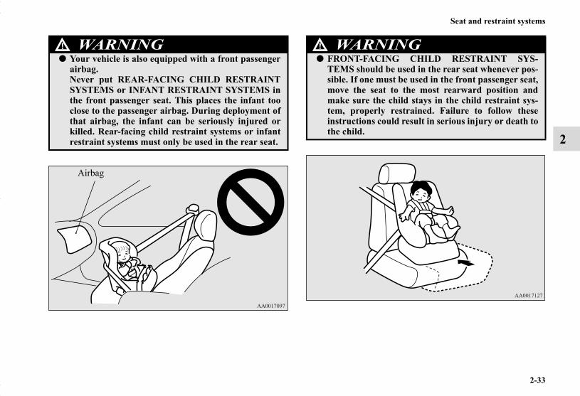
WARNING!● Your vehicle is also equipped with a front passenger
airbag.Never put REAR-FACING CHILD RESTRAINTSYSTEMS or INFANT RESTRAINT SYSTEMS inthe front passenger seat. This places the infant tooclose to the passenger airbag. During deployment ofthat airbag, the infant can be seriously injured orkilled. Rear-facing child restraint systems or infantrestraint systems must only be used in the rear seat.
Airbag
WARNING!● FRONT-FACING CHILD RESTRAINT SYS-
TEMS should be used in the rear seat whenever pos-sible. If one must be used in the front passenger seat,move the seat to the most rearward position andmake sure the child stays in the child restraint sys-tem, properly restrained. Failure to follow theseinstructions could result in serious injury or death tothe child.
BK0150700US.book 33 ページ 2012年3月22日 木曜日 午後6時46分

2-34
Seat and restraint systems
2
NOTE● Before purchasing a child restraint system, try installing it
in the rear seat to make sure there is a good fit. Because ofthe location of the seat belt buckles and the shape of theseat cushion, it may be difficult to securely install somemanufacturer’s child restraint systems.If the child restraint system can be pulled forward or toeither side easily on the seat cushion after the seat belt hasbeen tightened, choose another manufacturer’s childrestraint system.Depending on the seating position in the vehicle and thechild restraint system that you have, the child restraintsystem can be attached using one of the following 2 meth-ods:• Attach to the lower anchorage in the rear seat ONLY if
the child restraint system is compatible with the LATCHsystem (See page 2-35).
• Attach to the seat belt (See page 2-38).
WARNING!● It is important to use an approved rear-facing infant
restraint until the infant is one year old (unless theinfant outgrows the seat sooner). This allows theinfant’s neck and spine to develop enough to supportthe weight of their head in the event of an accident.
● When installing a child restraint system, follow theinstructions provided by the manufacturer and fol-low the directions in this manual. Failure to do socan result in serious injury or death to your child inan accident or sudden stop.
● After installation, push and pull the child restraintsystem back and forth, and side to side, to see that itis firmly secured. If the child restraint system is notinstalled securely, it may cause injury to the child orother occupants in the event of an accident or sud-den stop.
● When not in use, keep your child restraint systemsecured with the seat belt, or remove it from thevehicle, in order to prevent it from being thrownaround inside the vehicle during an accident.
BK0150700US.book 34 ページ 2012年3月22日 木曜日 午後6時46分
Seat and restraint systems
2-35
2
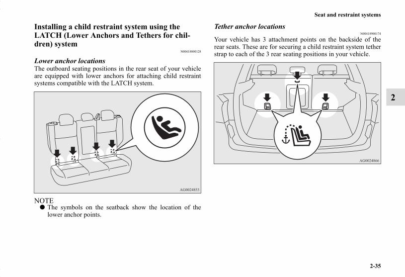
Installing a child restraint system using the LATCH (Lower Anchors and Tethers for chil-dren) system
N00418800128
Lower anchor locationsThe outboard seating positions in the rear seat of your vehicleare equipped with lower anchors for attaching child restraintsystems compatible with the LATCH system.
NOTE● The symbols on the seatback show the location of the
lower anchor points.
Tether anchor locationsN00418900174
Your vehicle has 3 attachment points on the backside of therear seats. These are for securing a child restraint system tetherstrap to each of the 3 rear seating positions in your vehicle.
BK0150700US.book 35 ページ 2012年3月22日 木曜日 午後6時46分

2-36
Seat and restraint systems
2
Examples of child restraint systems compatible with the LATCH system
N00419000114
Using the LATCH systemN00419100216
1. In order to securely fasten the tether strap, remove thehead restraint from the location where you wish to installthe child restraint system.
2. Open the gap a little between the seat cushion (A) and theseatback (B) with your hand to locate the lower anchors(C).
A- Rear-facing child restraint systemB- Front-facing child restraint systemC- Child restraint system lower anchor connectorsD- Tether strap
(These are only examples.)A- Vehicle seat cushion C- Lower anchorB- Vehicle seatback D- Connector
BK0150700US.book 36 ページ 2012年3月22日 木曜日 午後6時46分

Seat and restraint systems
2-37
2
3. Push the anchor connectors (D) on the child restraint sys-tem into the lower anchors (C) in accordance with theinstructions provided by the child restraint system manu-facturer.Remember, the lower anchors provided with your vehicleare designed to secure suitable child restraint systemscompatible with the LATCH system in the outboard posi-tions of the rear seats only. The anchor connectors areNOT designed to secure a suitable child restraint systemin the center position of the rear seat.
NOTE● In order to secure a child restraint system compatible with
the LATCH system, use the lower anchor points in theoutboard positions of the rear seat. It is not necessary touse the vehicle’s seat belt. The vehicle’s seat belt, how-ever, MUST be used to secure a child restraint system inthe center position of the rear seat. 4. Remove the cargo area cover from the vehicle. (Refer to
“Cargo area cover” on page 3-253.)
WARNING!● If there is any foreign material in or around the
lower anchors, remove it before installing the childrestraint system. Also, make sure the seat belt isaway from, not looped through or otherwise inter-fering with, the child restraint system. If foreignmatter is not removed and/or the seat belt interfereswith the child restraint system, the child restraintsystem will not be secured properly, could detachand move forward in the event of sudden braking oran accident, and could result in injury to the child orother vehicle occupants.
● When the vehicle is moving, do not adjust the seatwhere the child restraint system is installed.
BK0150700US.book 37 ページ 2012年3月22日 木曜日 午後6時46分

2-38
Seat and restraint systems
2
5. Latch the tether strap hook (E) of the child restraint sys-tem to the tether anchor bar (F) and tighten the tether strapso it is securely fastened.
6. Push and pull the child restraint system in all directions tobe sure it is firmly secured.
Installing a child restraint system using the seat belt (with emergency/automatic locking mecha-nism)
N00407300426
With the exception of the driver, the seat belt in all other seat-ing positions can be converted from normal Emergency Lock-ing Retractor (ELR) mode, to Automatic Locking Retractor(ALR) mode. This means that when you pull the seat belt fullyout of the retractor, the retractor will switch to its ALR childrestraint installation function. Always use the ALR childrestraint installation function when you install a child restraintsystem using the seat belt.
Children 12 years old and under should always be restrained inthe rear seat, whenever possible, although the front passengerseat belt can also be converted to ALR mode.
WARNING!● Child restraint system tether anchors are designed
only to withstand loads from correctly fitted childrestraint systems. Under no circumstances are theyto be used for adult seat belts, or harnesses, or forattaching other items or equipment to the vehicle.
WARNING!● When you install a child restraint system using the
seat belt, always make sure the retractor has beenswitched to the ALR child restraint installationfunction. The ALR function will keep the childrestraint system tightly secured to the seat.Failure to convert the retractor to the ALR functionmay allow the child restraint system to move for-ward during sudden braking or an accident, result-ing in serious injury or death to the child or otheroccupants.
BK0150700US.book 38 ページ 2012年3月22日 木曜日 午後6時46分
Seat and restraint systems
2-39
2
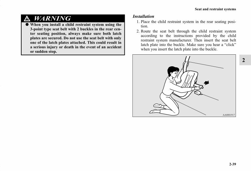
Installation1. Place the child restraint system in the rear seating posi-
tion.2. Route the seat belt through the child restraint system
according to the instructions provided by the childrestraint system manufacturer. Then insert the seat beltlatch plate into the buckle. Make sure you hear a “click”when you insert the latch plate into the buckle.
● When you install a child restraint system using the3-point type seat belt with 2 buckles in the rear cen-ter seating position, always make sure both latchplates are secured. Do not use the seat belt with onlyone of the latch plates attached. This could result ina serious injury or death in the event of an accidentor sudden stop.
WARNING!
BK0150700US.book 39 ページ 2012年3月22日 木曜日 午後6時46分

2-40
Seat and restraint systems
2
3. To activate the ALR child restraint installation function,slowly pull the shoulder part of the belt all the way out ofthe retractor until it stops. Then let the belt feed back intothe retractor.
4. After the belt has retracted, tug on it.If the belt is in the ALR function, you will not be able topull it out. If the webbing can be pulled out from retractor,the ALR function has not been activated and you willneed to repeat steps 3 and 4.
5. After confirming that the belt is locked, grab the shoulderpart of the belt near the buckle and pull up to remove anyslack from the lap part of the belt allowing the slack tofeed into the retractor. Remember, if the lap belt portion isnot tight, the child restraint system will not be secure. Itmay help to put your weight on the child restraint systemand/or push on its seatback while pulling up on the belt(See illustration).
BK0150700US.book 40 ページ 2012年3月22日 木曜日 午後6時46分

Seat and restraint systems
2-41
2
6. Remove the head restraint from the location in which youwish to install a child restraint system.
7. Remove the cargo area cover from the vehicle. (Refer to“Cargo area cover” on page 3-253.)
8. Latch the tether strap hook (A) of the child restraint sys-tem to the tether anchor bar (B) and tighten the tether strapso it is securely fastened.
9. Before putting your child in the restraint, push and pullthe restraint in all directions to be sure it is firmly secure.Do this before each use. If the child restraint system is notfirmly secure, repeat steps 1 through 8.
10. To remove a child restraint system from the vehicle anddeactivate the ALR mode, remove the child from therestraint. Unlatch the buckle. Then remove the belt fromthe restraint and let the belt fully retract.
If your child restraint system requires the use of a tether strap,fasten the tether strap in accordance with the following proce-dures.
WARNING!● Child restraint system tether anchors are designed
only to withstand loads from correctly fitted childrestraint systems. Under no circumstances are theyto be used for adult seat belts, or harnesses, or forattaching other items or equipment to the vehicle.
BK0150700US.book 41 ページ 2012年3月22日 木曜日 午後6時46分

2-42
Seat and restraint systems
2
Children who have outgrown child restraint sys-tems
N00407600520
Children who have outgrown a child restraint system should beseated in the rear seat and wear the seat belt. If the shoulderbelt crosses their face or neck, and/or the lap belt crosses theirstomach, a commercially available booster seat (including abooster cushion) must be used, to raise the child so that theshoulder belt crosses their shoulder and the lap belt remainspositioned low across their hips. The booster seat (including abooster cushion) should fit the vehicle seat and have a labelcertifying compliance with Federal Motor Vehicle Safety Stan-dards or Motor Vehicle Restraint Systems and Booster Cush-ions Safety Regulations.
Maintenance and inspection of seat beltsN00407000221
The seat belt webbing may be cleaned with mild soap or deter-gent solution. Do not use an organic solvent. Allow the belts todry in the shade. Do not allow them to retract until completelydry. Do not attempt to bleach or re-dye the belts. The color mayrub off and the webbing strength may be affected.
Regularly check your seat belt buckles and their release mech-anisms for positive engagement and release of the latch plate.Check the retractors for automatic locking when in the Auto-matic Locking Retractor function.
The entire seat belt assembly should be replaced if the webbingshows any obvious cuts, tears, increase in thickness in any sec-tion of the webbing from broken fibers, or severe fading fromsunlight. All of these conditions indicate a weakening of thebelt, which may adversely affect seat belt performance in anaccident.
WARNING!● Any child who is too small to properly wear a seat
belt must be properly restrained in an appropriatechild restraint system, to reduce their risk of seriousinjury or death in an accident.
● A child should never be left unattended in, or unsu-pervised around, your vehicle. When you leave thevehicle, always take the child out as well.
● Children can die from heat stroke if left or trappedinside the vehicle, especially on hot days.
● Keep your vehicle locked when not in use. Keepyour vehicle keys away from children.
WARNING!● Do not attempt to repair or replace any part of the
seat belt assemblies. This work should be done by anauthorized Mitsubishi Motors dealer. Failure tohave an authorized Mitsubishi Motors dealer per-form the work could reduce the effectiveness of thebelts and could result in a serious injury or death inan accident.
BK0150700US.book 42 ページ 2012年3月22日 木曜日 午後6時46分

Seat and restraint systems
2-43
2
Supplemental Restraint System (SRS) - airbag
N00407700680
This vehicle is equipped with a Supplemental Restraint System(SRS), which includes airbags for the driver and passengers.
The SRS front airbags are designed to supplement the primaryprotection of the driver and front passenger seat belt systemsby providing those occupants with protection against head andchest injuries in certain moderate to severe frontal collisions.The SRS front airbags, together with sensors at the front of thevehicle and sensors attached to the front seats, form anadvanced airbag system.
The SRS driver’s knee airbag is designed to supplement theprimary protection of the driver’s seat belt system. It canreduce the forward movement of the driver’s lower legs andprovide increased overall body protection in certain moderateto severe frontal collisions.
The SRS side airbags and the curtain airbags are also designedto supplement the seat belts. The SRS side airbags provide thedriver and front passenger with protection against chest injuriesby deploying the bag on the side impacted in moderate tosevere side impact collisions. The SRS curtain airbags providethe driver and passengers on the front seat and rear outboardseat with protection against head injuries by deploying a bagon the side impacted in moderate to severe side impact colli-sions and by deploying both bags when a rollover is detected.
The SRS airbags are NOT a substitute for use of the seat belts.For maximum protection in all types of accidents, seat beltsmust ALWAYS be worn by everyone who drives or rides in
this vehicle (with infants and small children in an appropriatechild restraint system in the rear seat, and older children buck-led in the rear seat). Refer to “Child restraint systems” on page2-31.
WARNING!● IT IS VERY IMPORTANT TO ALWAYS WEAR
YOUR SEAT BELT PROPERLY EVEN WITH ANAIRBAG.• Seat belts help keep the driver and passengers
properly positioned. This reduces the risk of injuryin all collisions, and reduces the risk of seriousinjuries or death when the airbags inflate.During sudden braking just before a collision, anunrestrained or improperly restrained driver orpassengers can move forward into direct contactwith, or within close proximity to, the airbag whenit begins to inflate.The beginning stage of airbag inflation is the mostforceful and can cause serious injuries or death ifthe occupant comes in contact with the airbag atthis time.
• Seat belts reduce the risk of injury in rear impactcollisions, and in lower-speed frontal collisionsbecause the airbags are not designed to inflate inthose situations.
• Seat belts reduce the risk of being thrown fromyour vehicle in a collision or rollover.
BK0150700US.book 43 ページ 2012年3月22日 木曜日 午後6時46分

2-44
Seat and restraint systems
2
WARNING!● IT IS VERY IMPORTANT TO BE PROPERLY
SEATED.• A driver or front passenger sitting too close to the
steering wheel or instrument panel during airbagdeployment can be seriously injured or killed.
• Airbags inflate very quickly and with great force.If the driver and front passenger are not properlyseated and restrained, the airbag may not providethe proper protection, and can cause serious inju-ries or death when it inflates.
• To reduce the risk to the driver of serious injury ordeath due to a deploying driver’s airbag, alwaysproperly wear your seat belt and adjust thedriver’s seat as far back as possible, maintaining aposition that still allows the driver to have goodcontrol of the steering wheel, brake, accelerator,and other vehicle controls.
• To reduce the risk to the front passenger of seriousinjury or death from a deploying passenger’sairbag, make sure the passenger always wears theseat belt properly, remains seated upright and allthe way back in the seat, and positions the seat asfar back as possible.
• Seat all infants and children in the rear seat, prop-erly restrained in an appropriate child restraintsystem.
WARNING!● Airbags inflate very quickly and with great force.
Do not sit on the edge of the seat or sit with yourlower legs too close to the instrument panel, or leanyour head or chest close to the steering wheel or theinstrument panel.
● Do not put your feet or legs on or against the instru-ment panel.
BK0150700US.book 44 ページ 2012年3月22日 木曜日 午後6時46分

Seat and restraint systems
2-45
2
WARNING!● Infants and small children should never ride unre-
strained, or lean against the instrument panel. Theyshould never ride held in your arms or on your lap.They can be seriously injured or killed in an acci-dent, especially when the airbags inflate. Seat allinfants and children in the rear seat, properlyrestrained in an appropriate child restraint system.Refer to “Child restraint systems” on page 2-31.
WARNING!● NEVER put REAR-FACING CHILD RESTRAINT
SYSTEMS or INFANT RESTRAINT SYSTEMS inthe front passenger seat. This places the infant tooclose to the passenger airbag. During deployment ofthat airbag, the infant can be seriously injured orkilled.Rear-facing child restraint systems or infantrestraint systems must only be used in the rear seat.
Airbag
BK0150700US.book 45 ページ 2012年3月22日 木曜日 午後6時46分
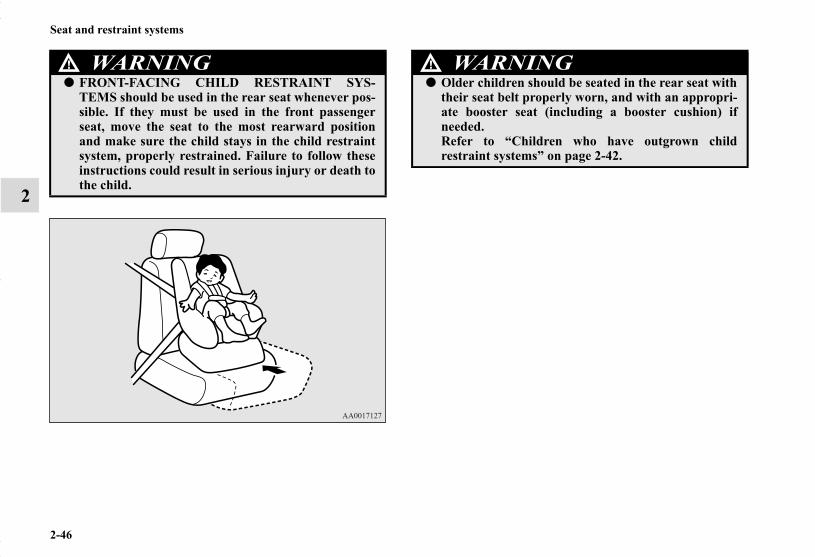
2-46
Seat and restraint systems
2
WARNING!● FRONT-FACING CHILD RESTRAINT SYS-
TEMS should be used in the rear seat whenever pos-sible. If they must be used in the front passengerseat, move the seat to the most rearward positionand make sure the child stays in the child restraintsystem, properly restrained. Failure to follow theseinstructions could result in serious injury or death tothe child.
WARNING!● Older children should be seated in the rear seat with
their seat belt properly worn, and with an appropri-ate booster seat (including a booster cushion) ifneeded.Refer to “Children who have outgrown childrestraint systems” on page 2-42.
BK0150700US.book 46 ページ 2012年3月22日 木曜日 午後6時46分
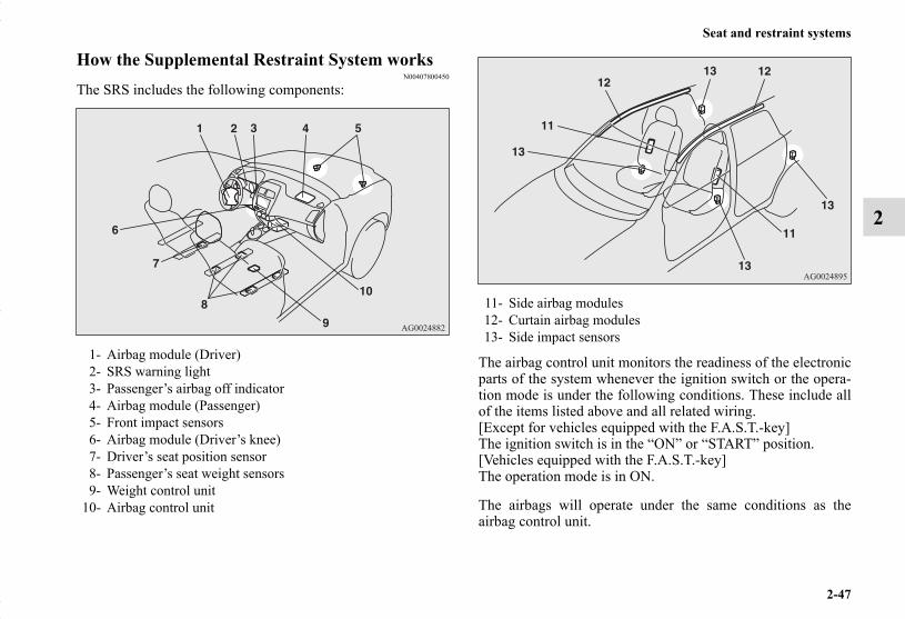
Seat and restraint systems
2-47
2
How the Supplemental Restraint System worksN00407800450
The SRS includes the following components:
The airbag control unit monitors the readiness of the electronicparts of the system whenever the ignition switch or the opera-tion mode is under the following conditions. These include allof the items listed above and all related wiring.[Except for vehicles equipped with the F.A.S.T.-key] The ignition switch is in the “ON” or “START” position.[Vehicles equipped with the F.A.S.T.-key]The operation mode is in ON.
The airbags will operate under the same conditions as theairbag control unit.
1- Airbag module (Driver)2- SRS warning light3- Passenger’s airbag off indicator4- Airbag module (Passenger)5- Front impact sensors6- Airbag module (Driver’s knee)7- Driver’s seat position sensor8- Passenger’s seat weight sensors9- Weight control unit
10- Airbag control unit
11- Side airbag modules12- Curtain airbag modules13- Side impact sensors
BK0150700US.book 47 ページ 2012年3月22日 木曜日 午後6時46分

2-48
Seat and restraint systems
2
When the impact sensors detect a sufficient front or side impactto deploy the airbag(s), the appropriate airbag(s) will bedeployed.
When the airbag control unit detects rollover of the vehicle,curtain airbags will be deployed.
When airbags deploy, some smoke is released accompanied bya loud noise. The smoke is not harmful, but do not intentionallyinhale the smoke as it may cause temporary irritation to peoplewith respiratory problems.
An inflated airbag will deflate quickly, so you may not evennotice that the airbag was inflated.Airbag inflation does not prevent the driver from seeing orbeing able to steer the vehicle, and does not prevent peoplefrom leaving the vehicle.
Event Data RecordingN00418600243
This vehicle is equipped with an event data recorder (EDR).The main purpose of an EDR is to record, in certain crash ornear crash-like situations, such as an airbag deployment or hit-ting a road obstacle, data that will assist in understanding howa vehicle’s systems performed.The EDR is designed to record data related to vehicle dynam-ics and safety systems for a short period of time, typically 30seconds or less.
The EDR in this vehicle is designed to record such data as:● How various systems in your vehicle were operating;● Whether or not the driver and passenger safety belts were
buckled/fastened;● How far (if at all) the driver was depressing the accelera-
tor and/or brake pedal; and,● How fast the vehicle was traveling.
These data can help provide a better understanding of the cir-cumstances in which crashes and injuries occur.
CAUTION!● Airbags inflate very quickly and with great force. In
certain situations, contact with an inflating airbagmay cause small cuts, abrasions, and bruises.
BK0150700US.book 48 ページ 2012年3月22日 木曜日 午後6時46分

Seat and restraint systems
2-49
2
NOTE● EDR data are recorded by your vehicle only if a non-triv-
ial crash situation occurs; no data are recorded by theEDR under normal driving conditions and no personaldata (e.g., name, gender, age, and crash location) arerecorded. However, other parties, such as law enforce-ment, could combine the EDR data with the type of per-sonally identifying data routinely acquired during a crashinvestigation.
To read data recorded by an EDR, special equipment isrequired, and access to the vehicle or the EDR is needed. Inaddition to the vehicle manufacturer, other parties, such as lawenforcement, that have the special equipment, can read theinformation if they have access to the vehicle or the EDR.
Driver’s seat position sensorN00417900177
The driver’s seat position sensor is attached to the seat rail andprovides the airbag control unit with information on the seat’sfore-aft position. The airbag control unit controls deploymentof the driver’s front airbag in accordance with the informationit receives from this sensor.If there is a problem involving the driver’s seat position sensor,the SRS warning light in the instrument panel will come on.Refer to “SRS warning light/display” on page 2-52.
WARNING!● If the SRS warning light or warning display comes
on, have the vehicle inspected by an authorizedMitsubishi Motors dealer as soon as possible.
● Please observe the following instructions to ensurethat the driver’s seat position sensor can operatecorrectly.• Adjust the seat to the correct position, and sit well
back against the seatback.Refer to “Front seats” on page 2-3.
• Do not recline the seatback more than necessarywhen driving.
• Do not place metallic objects or luggage under thefront seat.
● If the vehicle is involved in a severe impact, have theSRS sensors inspected by an authorized MitsubishiMotors dealer as soon as possible.
BK0150700US.book 49 ページ 2012年3月22日 木曜日 午後6時46分
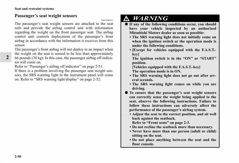
2-50
Seat and restraint systems
2
Passenger’s seat weight sensorsN00418000322
The passenger’s seat weight sensors are attached to the seatrails and provide the airbag control unit with informationregarding the weight on the front passenger seat. The airbagcontrol unit controls deployment of the passenger’s frontairbag in accordance with the information it receives from thissensor.The passenger’s front airbag will not deploy in an impact whenthe weight on the seat is sensed to be less than approximately66 pounds (30 kg). In this case, the passenger airbag off indica-tor will come on.Refer to “Passenger’s airbag off indicator” on page 2-51.If there is a problem involving the passenger seat weight sen-sors, the SRS warning light in the instrument panel will comeon. Refer to “SRS warning light/display” on page 2-52.
WARNING!● If any of the following conditions occur, you should
have your vehicle inspected by an authorizedMitsubishi Motors dealer as soon as possible:• The SRS warning light does not initially come on
when the ignition switch or the operation mode isunder the following conditions.
• [Except for vehicles equipped with the F.A.S.T.-key]The ignition switch is in the “ON” or “START”position.[Vehicles equipped with the F.A.S.T.-key] The operation mode is in ON.
• The SRS warning light does not go out after sev-eral seconds.
• The SRS warning light comes on while you aredriving.
● To ensure that the passenger’s seat weight sensorscan correctly sense the weight being applied to theseat, observe the following instructions. Failure tofollow these instructions can adversely affect theperformance of the passenger’s airbag system.• Adjust the seat to the correct position, and sit well
back against the seatback.Refer to “Front seats” on page 2-3.
• Do not recline the seatback more than necessary.• Never have more than one person (adult or child)
sitting on the seat.• Do not place anything between the seat and the
floor console.
BK0150700US.book 50 ページ 2012年3月22日 木曜日 午後6時46分

Seat and restraint systems
2-51
2
Passenger’s airbag off indicatorN00418100280
The passenger airbag off indicator is located in the instrumentpanel.
The indicator normally comes on when the ignition switch isturned to the “ON” position or the operation mode is put inON, and goes out a few seconds later. In the following situa-tions, the indicator will stay on to show that the passenger frontairbag is not operational.
● The passenger’s seat weight sensors sense a weight of lessthan approximately 66 pounds (30 kg) on the front passen-ger seat.
● The front passenger’s seat is not occupied.When the weight applied to the front passenger seat is sensedto be approximately 66 pounds (30 kg) or greater, the indicatorgoes out to show that the passenger’s front airbag is opera-tional.
• Do not hang anything on the front passenger’sseatback.
• Do not remove the head restraints.• When attaching a child restraint system, secure it
firmly.• Do not place luggage or other objects on the seat.• Do not use a seat cover or a cushion.• Do not remove the seats and seat belts.• Do not modify or replace the seat and seat belt.• Do not place luggage or other objects under the
seat.• Do not place the floor mat on the seat rails.• Do not expose the sensors to liquids or vapors.• Do not subject the sensors to shock.• Do not allow rear-seat occupants to push the front
passenger seat with their feet or force the frontpassenger seat upward.
• Do not allow rear-seat occupants to grasp the frontpassenger’s seatback or put their arms around it.
• When attaching a child restraint system in the rearseat, make sure it does not interfere with the frontseat.
● If the vehicle is involved in a severe impact, have theSRS sensors inspected by an authorized MitsubishiMotors dealer as soon as possible.
WARNING!
BK0150700US.book 51 ページ 2012年3月22日 木曜日 午後6時46分

2-52
Seat and restraint systems
2
SRS warning light/displayN00408300540
Warning light
Warning display type 1
Warning display type 2
Under normal conditions, the warning light comes on when theignition switch is turned to the “ON” position or the operationmode is put in ON, and goes off a few seconds later.If there is an error in the system, the warning light will come onand the warning display will appear on the information screenin the multi-information display.The warning light will also come on and remain on when theSRS airbags and the pre-tensioner system have been activated.The warning light/display is used for both SRS airbag warn-ings and pre-tensioner system warnings.
WARNING!● If any of the following conditions occur, you should
have the airbag system in your vehicle inspected byan authorized Mitsubishi Motors dealer as soon aspossible:• The passenger’s airbag off indicator comes on
when an adult is sitting on the front passengerseat.
• The passenger’s airbag off indicator does not comeon when the front passenger seat is not occupied.
• The passenger’s airbag off indicator does not comeon when the ignition switch is turned to the “ON”position or the operation mode is put in ON.
• The passenger’s airbag off indicator comes on andgoes out repeatedly.
● Do not attach any accessory to your vehicle thatmakes the passenger’s airbag off indicator difficultor impossible to see.You must be able to see the passenger’s airbag offindicator and verify the status of the passenger’sairbag system.
BK0150700US.book 52 ページ 2012年3月22日 木曜日 午後6時46分

Seat and restraint systems
2-53
2
Driver’s and passenger’s front airbag systemN00407900291
The driver’s airbag is located under the padded cover in themiddle of the steering wheel. The front passenger’s airbag iscontained in the instrument panel above the glove compart-ment. The driver’s airbag and the front passenger’s airbag aredesigned to deploy at the same time. However, the front pas-senger’s airbag does not deploy when the front passenger seatis not occupied or when the weight sensor in the front passen-ger seat senses a weight on the seat of less than approximately66 pounds (30 kg).
WARNING!● There may be a system error if the warning
light/display appears as indicated. In such cases, anSRS airbag or a seat belt equipped with pre-ten-sioner system may not function properly in a colli-sion. Have your vehicle checked by an authorizedMitsubishi Motors dealer:• Even when the ignition switch or the operation
mode is in ON, the warning light does not come onor it remains on a few seconds later
• When warning light comes on while driving• When warning display appears while driving
Driver
Front passenger
BK0150700US.book 53 ページ 2012年3月22日 木曜日 午後6時46分

2-54
Seat and restraint systems
2
Driver’s knee airbag systemN00404500010
The driver’s knee airbag is located under the steering wheel.The driver’s knee airbag is designed to deploy at the same timeas the driver’s front airbag.
BK0150700US.book 54 ページ 2012年3月22日 木曜日 午後6時46分
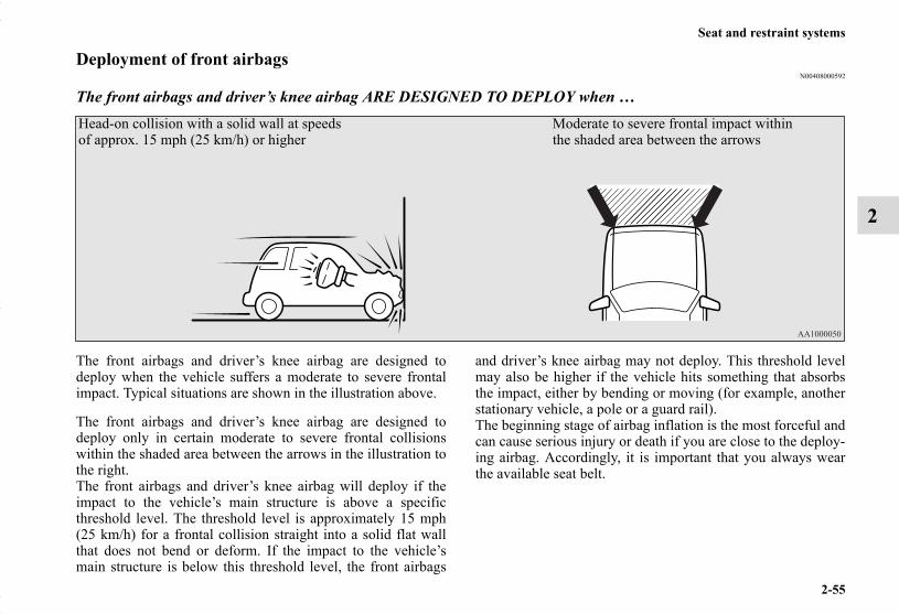
Seat and restraint systems
2-55
2
Deployment of front airbagsN00408000592
The front airbags and driver’s knee airbag ARE DESIGNED TO DEPLOY when …
The front airbags and driver’s knee airbag are designed todeploy when the vehicle suffers a moderate to severe frontalimpact. Typical situations are shown in the illustration above.
The front airbags and driver’s knee airbag are designed todeploy only in certain moderate to severe frontal collisionswithin the shaded area between the arrows in the illustration tothe right.The front airbags and driver’s knee airbag will deploy if theimpact to the vehicle’s main structure is above a specificthreshold level. The threshold level is approximately 15 mph(25 km/h) for a frontal collision straight into a solid flat wallthat does not bend or deform. If the impact to the vehicle’smain structure is below this threshold level, the front airbags
and driver’s knee airbag may not deploy. This threshold levelmay also be higher if the vehicle hits something that absorbsthe impact, either by bending or moving (for example, anotherstationary vehicle, a pole or a guard rail).The beginning stage of airbag inflation is the most forceful andcan cause serious injury or death if you are close to the deploy-ing airbag. Accordingly, it is important that you always wearthe available seat belt.
Head-on collision with a solid wall at speeds of approx. 15 mph (25 km/h) or higher
Moderate to severe frontal impact within the shaded area between the arrows
BK0150700US.book 55 ページ 2012年3月22日 木曜日 午後6時46分

2-56
Seat and restraint systems
2
The front airbags and driver’s knee airbag MAY NOT DEPLOY when …In certain types of front collisions, the front airbags anddriver’s knee airbag may not deploy, even if the deformation ofthe body seems to be large, because the vehicle’s body struc-ture is designed to absorb the impact and deform in order tohelp protect the occupants. Some typical situations where thefront airbags and driver’s knee airbag may not deploy areshown in the illustrations.
Because the front airbags and driver’s knee airbag do not pro-tect the occupant in all types of frontal collisions, be sure toalways wear your seat belts properly.
Collision with a utility pole, tree or other narrow object
Collision where the vehicle slides under the rear body of a truck
Oblique frontal impact
BK0150700US.book 56 ページ 2012年3月22日 木曜日 午後6時46分
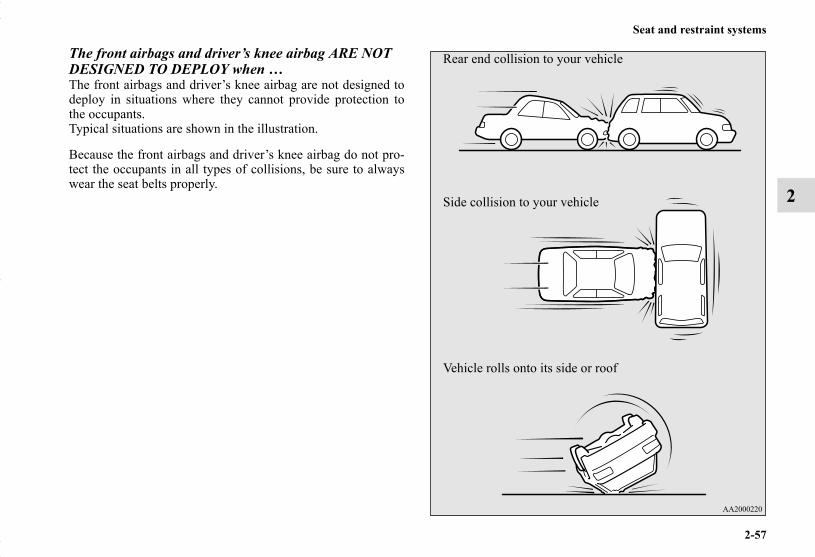
Seat and restraint systems
2-57
2
The front airbags and driver’s knee airbag ARE NOT DESIGNED TO DEPLOY when …The front airbags and driver’s knee airbag are not designed todeploy in situations where they cannot provide protection tothe occupants.Typical situations are shown in the illustration.
Because the front airbags and driver’s knee airbag do not pro-tect the occupants in all types of collisions, be sure to alwayswear the seat belts properly.
Rear end collision to your vehicle
Side collision to your vehicle
Vehicle rolls onto its side or roof
BK0150700US.book 57 ページ 2012年3月22日 木曜日 午後6時46分

2-58
Seat and restraint systems
2
The front airbags and driver’s knee airbag MAY DEPLOY when …The front airbags and driver’s knee airbag may deploy if theunderside of the vehicle suffers a moderate to severe impact(undercarriage impact). Typical situations are shown in theillustration.
Because the front airbags and driver’s knee airbag may deployin certain types of unexpected impacts, as shown in the illustra-tions, and these unexpected impacts can move you out of posi-tion, it is important to always wear the seat belts properly.When worn properly, seat belts can help maintain your distancefrom the airbags when they begin to inflate. The beginningstage of airbag inflation is the most forceful and can cause seri-ous injury or death if you are close to the deploying airbag.
Collision with an elevated median/island or curb
Vehicle travels over a deep hole/pothole
Vehicle drives down a steep slope and hits the ground
BK0150700US.book 58 ページ 2012年3月22日 木曜日 午後6時46分

Seat and restraint systems
2-59
2
WARNING!● Do not attach anything to the steering wheel’s pad-
ded cover, such as trim material, badges, etc. Thesecould strike and injure an occupant if the airbaginflates.
● Do not set anything on, or attach anything to, theinstrument panel above the glove compartment.Such items could strike and injure an occupant if theairbag inflates.
WARNING!● Do not attach accessories to, or put them in front of,
the windshield. They could restrict the airbag infla-tion, or strike and injure an occupant, when theairbag inflates.
● Do not attach additional keys or accessories (hard,pointed or heavy objects) to the ignition key. Suchobjects could prevent the driver’s knee airbag frominflating normally or could be propelled to causeserious injury if the airbag inflates.
● Do not attach accessories to the lower portion of thedriver’s side instrument panel. Such objects couldprevent the driver’s knee airbag from inflating nor-mally or could be propelled to cause serious injury ifthe airbag inflates.
BK0150700US.book 59 ページ 2012年3月22日 木曜日 午後6時46分

2-60
Seat and restraint systems
2
Side airbag systemN00408100391
The side airbags (A) are contained in the driver and front pas-senger seatbacks.The side airbag is designed to inflate only on the side of thevehicle that is impacted, even with no passenger in the frontseat.
WARNING!● Do not attempt to remove, install, disassemble or
repair the SRS airbags.● Do not place objects, such as packages or pets,
between the airbags and the driver or the front pas-senger. Such objects can adversely affect airbag per-formance, or cause serious injury or death when theairbag deploys.
● Immediately after airbag inflation, some parts of theairbag system will be hot. Do not touch them. Youcould otherwise be burned.
● The airbag system is designed to work only once.After the airbags deploy, they will not work again.They must promptly be replaced and the entireairbag system must be inspected by an authorizedMitsubishi Motors dealer.
BK0150700US.book 60 ページ 2012年3月22日 木曜日 午後6時46分

Seat and restraint systems
2-61
2
A label is attached to the seatbacks in vehicles equipped withside airbags.
Curtain airbag systemN00419200187
Your vehicle is equipped with a curtain airbag in the front pil-lar, the rear pillar and the side sections of the roof.The curtain airbag is designed to inflate only on the side of thevehicle that is impacted, even with no passenger in the seat.Also, when the airbag control unit detects rollover of the vehi-cle, the curtain airbags will deploy.
BK0150700US.book 61 ページ 2012年3月22日 木曜日 午後6時46分

2-62
Seat and restraint systems
2
WARNING!● Side airbags and curtain airbags can cause serious
injury or death to anyone too close to the airbagwhen it deploys. To reduce the risk of injury from adeploying side airbag or curtain airbag, driver andfront passenger must be properly restrained andseated well back, upright, and in the middle of theseat. Do not lean against the door.
WARNING!● In order to reduce the risk of injury from a deploy-
ing side airbag, do not allow any rear seat passen-gers to hold onto the back of either front seat.Special care should be taken with children.
● Do not place any objects around the area where theside airbags deploy. Such objects can interfere withproper side airbag deployment, and cause injuryduring deployment of the side airbag.
● Do not place stickers, labels or additional trim onthe back of either front seat. They can interfere withproper side airbag deployment.
BK0150700US.book 62 ページ 2012年3月22日 木曜日 午後6時46分
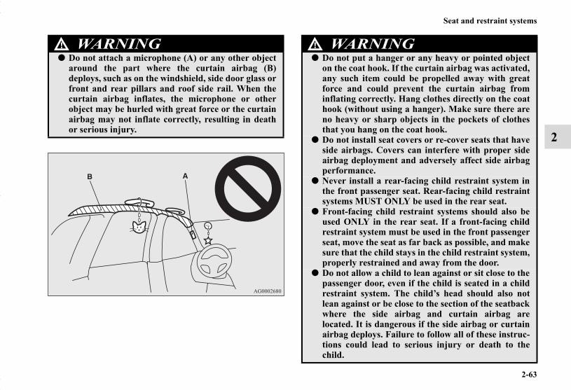
Seat and restraint systems
2-63
2
WARNING!● Do not attach a microphone (A) or any other object
around the part where the curtain airbag (B)deploys, such as on the windshield, side door glass orfront and rear pillars and roof side rail. When thecurtain airbag inflates, the microphone or otherobject may be hurled with great force or the curtainairbag may not inflate correctly, resulting in deathor serious injury.
WARNING!● Do not put a hanger or any heavy or pointed object
on the coat hook. If the curtain airbag was activated,any such item could be propelled away with greatforce and could prevent the curtain airbag frominflating correctly. Hang clothes directly on the coathook (without using a hanger). Make sure there areno heavy or sharp objects in the pockets of clothesthat you hang on the coat hook.
● Do not install seat covers or re-cover seats that haveside airbags. Covers can interfere with proper sideairbag deployment and adversely affect side airbagperformance.
● Never install a rear-facing child restraint system inthe front passenger seat. Rear-facing child restraintsystems MUST ONLY be used in the rear seat.
● Front-facing child restraint systems should also beused ONLY in the rear seat. If a front-facing childrestraint system must be used in the front passengerseat, move the seat as far back as possible, and makesure that the child stays in the child restraint system,properly restrained and away from the door.
● Do not allow a child to lean against or sit close to thepassenger door, even if the child is seated in a childrestraint system. The child’s head should also notlean against or be close to the section of the seatbackwhere the side airbag and curtain airbag arelocated. It is dangerous if the side airbag or curtainairbag deploys. Failure to follow all of these instruc-tions could lead to serious injury or death to thechild.
BK0150700US.book 63 ページ 2012年3月22日 木曜日 午後6時46分

2-64
Seat and restraint systems
2
Deployment of side airbag and curtain airbagN00408200493
The side airbag and curtain airbag ARE DESIGNED TO DEPLOY when...The side airbag and curtain airbag are designed to deploy whenthe vehicle suffers a moderate to severe side impact to the mid-dle of the passenger compartment.The typical situation is shown in the illustration.
● Work done on or in the vicinity of the side airbag orcurtain airbag components should be done only byan authorized Mitsubishi Motors dealer. There is arisk of a serious injury or death. Improper workmethods can cause accidental side airbag or curtainairbag deployment, or render a side airbag or cur-tain airbag inoperable. Either of these situationscould result in serious injury or death.
● Do not place luggage heavier than the specified onthe roof carrier.Such luggage may cause the curtain airbags toinflate accidentally, which could result in seriousinjury or death.
WARNING!
Moderate to severe impact to the middle of the vehicle body’s side structure
When the vehicle detects rollover of the vehicle (Curtain airbag only)
BK0150700US.book 64 ページ 2012年3月22日 木曜日 午後6時46分

Seat and restraint systems
2-65
2
The seat belts in your vehicle are your primary means of pro-tection in an accident. The SRS (Supplemental Restraint Sys-tem) side airbags and curtain airbags are designed to provideadditional protection. Therefore, for your safety and the safetyof all occupants, be sure to always wear your seat belts prop-erly.
The side airbag and curtain airbag MAY NOT DEPLOY when...In certain types of side collisions, the side airbag and curtainairbag may not deploy, even if the deformation of the bodyseems to be large, because the vehicle’s body structure isdesigned to absorb the impact and to deform in order to helpprotect the occupants. There are also cases where the sideairbag and curtain airbag may not deploy at the same time,depending on the location of the impact. Some typical situa-tions where the side airbags and curtain airbags may not deployare shown in the illustrations.
Because the side airbags and curtain airbags do not protect theoccupant in all types of side collisions, be sure to always wearthe seat belts properly.
BK0150700US.book 65 ページ 2012年3月22日 木曜日 午後6時46分
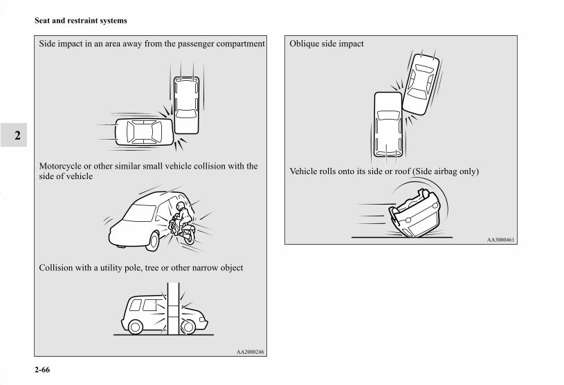
2-66
Seat and restraint systems
2
Side impact in an area away from the passenger compartment
Motorcycle or other similar small vehicle collision with the side of vehicle
Collision with a utility pole, tree or other narrow object
Oblique side impact
Vehicle rolls onto its side or roof (Side airbag only)
BK0150700US.book 66 ページ 2012年3月22日 木曜日 午後6時46分

Seat and restraint systems
2-67
2
The side airbag and curtain airbag ARE NOT DESIGNED TO DEPLOY when...The side airbag and curtain airbag are not designed to deploy insituations where they cannot provide protection to the occu-pants. Typical situations are shown in the illustration.
Because the side airbags and curtain airbags do not protect theoccupant in all types of collisions, be sure to always wear yourseat belts properly.
Head-on collision
Rear end collision to your vehicle
Pitch end over end
BK0150700US.book 67 ページ 2012年3月22日 木曜日 午後6時46分

2-68
Seat and restraint systems
2
SRS servicingN00408500698
NOTE● When you transfer ownership of the vehicle to another
person, we urge you to alert the new owner that it isequipped with the SRS and refer that owner to the applica-ble sections in this owner’s manual.
● If you decide to junk or scrap your vehicle, we urge you tofirst take it to an authorized Mitsubishi Motors dealer sothat the SRS can be made safe for disposal.
● If any of the following parts needs to be modified for useby a handicapped person, the advanced airbag system willbe greatly affected. Please consult an authorizedMitsubishi Motors dealer.• Driver’s seat• Front passenger seat• Front seat belt• Steering wheel• Instrument panel
WARNING!● Any maintenance performed on or near the compo-
nents of the SRS should be performed only by anauthorized Mitsubishi Motors dealer. Do not permitanyone else to do any service, inspection, mainte-nance or repair on any SRS components or wiring.Similarly, no part of the SRS should ever be han-dled, removed or disposed by anyone except anauthorized Mitsubishi Motors dealer.Improper work methods on the SRS components orwiring could result in an accidental airbag deploy-ment or could make the SRS inoperable. Either ofthese situations could result in serious injury ordeath.
● Do not modify your steering wheel or any other SRScomponent or related vehicle part. For example,replacement of the steering wheel, or modificationsto the front bumper or body structure can adverselyaffect SRS performance and may lead to injury.
● If your vehicle has received any damage, you shouldhave the SRS inspected by an authorized MitsubishiMotors dealer to make sure it is in proper workingorder.
● Do not modify your front seats, center pillar or cen-ter console. Such modifications can adversely affectSRS performance and may lead to injury.Also, if you discover any tear or open seam in theseat fabric near the side airbag, have the seatinspected by an authorized Mitsubishi Motorsdealer.
● If you have found any scratch, crack or damage tothe portion of the front and rear pillars and roof siderail, you should have the SRS inspected by an autho-rized Mitsubishi Motors dealer.
WARNING!
BK0150700US.book 68 ページ 2012年3月22日 木曜日 午後6時46分

Seat and restraint systems
2-69
2
[For vehicles sold in U.S.A.]To contact Mitsubishi Motors North America, Inc.call 1-888-648-7820 or write to:Mitsubishi Motors North America, Inc.Customer Relations DepartmentP.O. Box 6400Cypress, CA 90630-0064
[For vehicles sold in Canada]To contact Mitsubishi Motor Sales of Canada, Inc.call 1-888-576-4878 or write to:Mitsubishi Motor Sales of Canada, Inc.Customer Relations DepartmentP.O. Box 410094141 Dixie RoadMississauga, ON L4W 5C9
[For vehicles sold in Puerto Rico]To contact Mitsubishi Motor Sales of Caribbean, Inc.call 1-787-251-8715 or write to:Mitsubishi Motor Sales of Caribbean, Inc.Customer Service DepartmentP.O. Box 192216SAN JUAN PR 00919-2216
[For vehicles sold in Guam]To contact Triple J Enterprises Inc.call (671) 649-3673 or write to:Triple J Enterprises, Inc.P.O. Box 6066TAMUNINGGUAM 96931
[For vehicles sold in Saipan]To contact Triple J Motorscall (670) 234-7133 or write to:Triple J MotorsP.O. Box 500487SAIPAN, MP96950-0487
[For vehicles sold in American Samoa]To contact Pacific Marketing Inc.call 684 (699) 9140 or write to:Pacific Marketing, Inc.P.O. Box 698PAGO PAGO,AMERICAN SAMOA AS, 96799
BK0150700US.book 69 ページ 2012年3月22日 木曜日 午後6時46分

2-70
Seat and restraint systems
2
Warning labelN00408600354
Occupant restraint warning labels for the SRS are located inthe vehicle as shown in the illustration.
* - Located in the passenger’s side as well.
BK0150700US.book 70 ページ 2012年3月22日 木曜日 午後6時46分

3
Features and controls
Break-in recommendations . . . . . . . . . . . . . . . . . . . . . . . . . . . . 3- 2Keys . . . . . . . . . . . . . . . . . . . . . . . . . . . . . . . . . . . . . . . . . . . . . . 3- 2Electronic immobilizer (Anti-theft starting system) . . . . . . . . . 3- 4Keyless entry system (if so equipped) . . . . . . . . . . . . . . . . . . . . 3- 8Free-hand Advanced Security Transmitter (F.A.S.T.-key)
(if so equipped). . . . . . . . . . . . . . . . . . . . . . . . . . . . . . . . . . . 3- 14Door locks . . . . . . . . . . . . . . . . . . . . . . . . . . . . . . . . . . . . . . . . . 3- 38Power door locks . . . . . . . . . . . . . . . . . . . . . . . . . . . . . . . . . . . . 3- 41Child safety locks for rear door . . . . . . . . . . . . . . . . . . . . . . . . . 3- 43Liftgate. . . . . . . . . . . . . . . . . . . . . . . . . . . . . . . . . . . . . . . . . . . . 3- 44Inside liftgate release . . . . . . . . . . . . . . . . . . . . . . . . . . . . . . . . . 3- 47Theft-alarm system . . . . . . . . . . . . . . . . . . . . . . . . . . . . . . . . . . 3- 48Power window control. . . . . . . . . . . . . . . . . . . . . . . . . . . . . . . . 3- 52Sunshade (if so equipped) . . . . . . . . . . . . . . . . . . . . . . . . . . . . . 3- 56Parking brake . . . . . . . . . . . . . . . . . . . . . . . . . . . . . . . . . . . . . . . 3- 58Steering wheel height and reach adjustment . . . . . . . . . . . . . . . 3- 59Inside rearview mirror . . . . . . . . . . . . . . . . . . . . . . . . . . . . . . . . 3- 60Outside rearview mirrors . . . . . . . . . . . . . . . . . . . . . . . . . . . . . . 3- 64Ignition switch . . . . . . . . . . . . . . . . . . . . . . . . . . . . . . . . . . . . . . 3- 66Starting the engine . . . . . . . . . . . . . . . . . . . . . . . . . . . . . . . . . . . 3- 69Manual transaxle (if so equipped) . . . . . . . . . . . . . . . . . . . . . . . 3- 71Continuously variable transmission (CVT) (if so equipped). . . 3- 74Electronically controlled 4WD system (if so equipped) . . . . . . 3- 844-wheel drive operation . . . . . . . . . . . . . . . . . . . . . . . . . . . . . . . 3- 87Inspection and maintenance following rough road operation . . 3- 90Cautions on the handling of 4-wheel drive vehicles . . . . . . . . . 3- 91Service brake . . . . . . . . . . . . . . . . . . . . . . . . . . . . . . . . . . . . . . . 3- 93Hill start assist . . . . . . . . . . . . . . . . . . . . . . . . . . . . . . . . . . . . . . 3- 94Brake assist system . . . . . . . . . . . . . . . . . . . . . . . . . . . . . . . . . . 3- 96Anti-lock braking system. . . . . . . . . . . . . . . . . . . . . . . . . . . . . . 3- 97Electric power steering system (EPS) . . . . . . . . . . . . . . . . . . . . 3- 101Active stability control (ASC) . . . . . . . . . . . . . . . . . . . . . . . . . . 3- 102
Cruise control (if so equipped). . . . . . . . . . . . . . . . . . . . . . . . . . 3- 107Tire pressure monitoring system . . . . . . . . . . . . . . . . . . . . . . . . 3- 115Rear-view camera (if so equipped) . . . . . . . . . . . . . . . . . . . . . . 3- 121Instrument cluster . . . . . . . . . . . . . . . . . . . . . . . . . . . . . . . . . . . . 3- 126Multi-information display . . . . . . . . . . . . . . . . . . . . . . . . . . . . . 3- 129Indicator light, warning light, and
information screen display list . . . . . . . . . . . . . . . . . . . . . . . . 3- 162Indicators . . . . . . . . . . . . . . . . . . . . . . . . . . . . . . . . . . . . . . . . . . 3- 177Warning lights . . . . . . . . . . . . . . . . . . . . . . . . . . . . . . . . . . . . . . 3- 177Information screen display . . . . . . . . . . . . . . . . . . . . . . . . . . . . . 3- 180Combination headlights and dimmer switch . . . . . . . . . . . . . . . 3- 183Headlight leveling switch (if so equipped) . . . . . . . . . . . . . . . . 3- 191Turn signal lever. . . . . . . . . . . . . . . . . . . . . . . . . . . . . . . . . . . . . 3- 192Hazard warning flasher switch . . . . . . . . . . . . . . . . . . . . . . . . . . 3- 193Front fog light switch (if so equipped). . . . . . . . . . . . . . . . . . . . 3- 193Wiper and washer switch . . . . . . . . . . . . . . . . . . . . . . . . . . . . . . 3- 194Electric rear window defogger switch . . . . . . . . . . . . . . . . . . . . 3- 203Horn switch . . . . . . . . . . . . . . . . . . . . . . . . . . . . . . . . . . . . . . . . 3- 204Link System (if so equipped) . . . . . . . . . . . . . . . . . . . . . . . . . . . 3- 205Bluetooth® 2.0 interface (if so equipped) . . . . . . . . . . . . . . . . . 3- 205USB input terminal (if so equipped) . . . . . . . . . . . . . . . . . . . . . 3- 231Sun visors . . . . . . . . . . . . . . . . . . . . . . . . . . . . . . . . . . . . . . . . . . 3- 23612 V power outlets . . . . . . . . . . . . . . . . . . . . . . . . . . . . . . . . . . . 3- 238Interior lights . . . . . . . . . . . . . . . . . . . . . . . . . . . . . . . . . . . . . . . 3- 240Storage spaces . . . . . . . . . . . . . . . . . . . . . . . . . . . . . . . . . . . . . . 3- 246Cup holders . . . . . . . . . . . . . . . . . . . . . . . . . . . . . . . . . . . . . . . . 3- 251Bottle holders . . . . . . . . . . . . . . . . . . . . . . . . . . . . . . . . . . . . . . . 3- 252Cargo area cover (if so equipped) . . . . . . . . . . . . . . . . . . . . . . . 3- 253Assist grips . . . . . . . . . . . . . . . . . . . . . . . . . . . . . . . . . . . . . . . . . 3- 254Coat hook . . . . . . . . . . . . . . . . . . . . . . . . . . . . . . . . . . . . . . . . . . 3- 254Luggage hooks . . . . . . . . . . . . . . . . . . . . . . . . . . . . . . . . . . . . . . 3- 255
SC00000500-3.fm 1 ページ 2012年3月26日 月曜日 午後5時42分
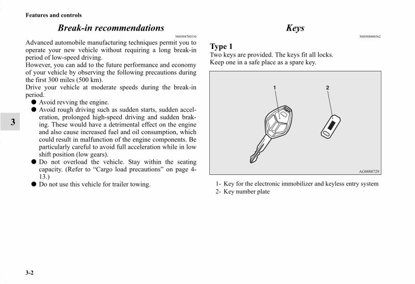
3-2
Features and controls
3
Break-in recommendationsN00508700330
Advanced automobile manufacturing techniques permit you tooperate your new vehicle without requiring a long break-inperiod of low-speed driving.However, you can add to the future performance and economyof your vehicle by observing the following precautions duringthe first 300 miles (500 km).Drive your vehicle at moderate speeds during the break-inperiod.
● Avoid revving the engine.● Avoid rough driving such as sudden starts, sudden accel-
eration, prolonged high-speed driving and sudden brak-ing. These would have a detrimental effect on the engineand also cause increased fuel and oil consumption, whichcould result in malfunction of the engine components. Beparticularly careful to avoid full acceleration while in lowshift position (low gears).
● Do not overload the vehicle. Stay within the seatingcapacity. (Refer to “Cargo load precautions” on page 4-13.)
● Do not use this vehicle for trailer towing.
KeysN00508800562
Type 1Two keys are provided. The keys fit all locks.Keep one in a safe place as a spare key.
1- Key for the electronic immobilizer and keyless entry system2- Key number plate
BK0150700US.book 2 ページ 2012年3月22日 木曜日 午後6時46分

Features and controls
3-3
3
Type 2Two F.A.S.T.-keys and two emergency keys are provided.Keep one F.A.S.T.-key and one emergency key in a safe placetogether as a set of spare keys.
NOTE● The key is a precision electronic device with a built-in sig-
nal transmitter. Please observe the following in order toprevent damage.• Do not leave where it may be exposed to heat caused by
direct sunlight, such as on top of the dashboard.• Do not take the remote control transmitter apart.• Do not excessively bend the key or subject it to strong
impacts.• Keep the remote control transmitter dry.• Keep away from magnetic objects such as key rings.• Keep away from devices that produce magnetism, such
as audio systems, computers and televisions.• Keep away from devices that emit strong electromag-
netic waves, such as cellular phones, wireless devicesand high frequency equipment (including medicaldevices).
• Do not clean with ultrasonic cleaners.• Do not leave the key where it may be exposed to high
temperature or high humidity.● If you lose your key, to prevent the theft of the vehicle
immediately contact an authorized Mitsubishi Motorsdealer.If you notify an authorized Mitsubishi Motors dealer ofthe key number, they can make a new key. The key num-ber is stamped on the key number plate. Keep the keynumber plate in a safe place separate from the key itself.
1- F.A.S.T.-key(with electronic immobilizer and keyless entry system func-tion)
2- Emergency key3- Key number plate
BK0150700US.book 3 ページ 2012年3月22日 木曜日 午後6時46分

3-4
Features and controls
3
● No keys other than those registered in advance can beused to start the engine.Refer to “Electronic immobilizer (Anti-theft starting sys-tem)” on page 3-4.Refer to “Free-hand Advanced Security Transmitter(F.A.S.T.-key): “Electronic immobilizer (Anti-theft start-ing system)” on page 3-31.
● When the theft-alarm is in the system operational status,the alarm operates if a door or liftgate is opened afterusing the key, the door lock knob or the power door lockswitch to unlock the vehicle.
● The system does not enter the preparation status if thekeyless entry system or the F.A.S.T.-key was not used tolock the vehicle.
Electronic immobilizer (Anti-theft starting system)
N00509100780
[For vehicles equipped with the Free-hand Advanced SecurityTransmitter (F.A.S.T.-key)]For information on operations for vehicles equipped with theFree-hand Advanced Security Transmitter (F.A.S.T.-key), referto “Free-hand Advanced Security Transmitter (F.A.S.T.-key):Electronic immobilizer (Anti-theft starting system)” on page 3-31.
[Except for vehicles equipped with the Free-hand AdvancedSecurity Transmitter (F.A.S.T.-key)]The electronic immobilizer is designed to significantly reducethe possibility of vehicle theft. The purpose of the system is toimmobilize the vehicle if an invalid start is attempted. A validstart attempt can only be achieved (subject to certain condi-tions) using a key “registered” to the immobilizer system.All of the keys provided with your new vehicle have been pro-grammed to the vehicle’s electronics.
BK0150700US.book 4 ページ 2012年3月22日 木曜日 午後6時46分

Features and controls
3-5
3
NOTE● In the following cases, the vehicle may not be able to rec-
ognize the registered ID code from the key. This meansthe engine will not start even when the key is turned to the“START” position.• When the key contacts a key ring or other metallic or
magnetic object (Type A)• When the key grip contacts metal of another key (Type
B)• When the key contacts or is close to other immobilizer
keys (including keys of other vehicles) (Type C)● In cases like the above, move the offending object(s) away
from the key and turn the key back to the “ACC” or“OFF” position. Then try to start the engine again. If theengine does not start, contact an authorized MitsubishiMotors dealer.
BK0150700US.book 5 ページ 2012年3月22日 木曜日 午後6時46分
3-6
Features and controls
3
NOTE● The key may not operate properly when it is near an
object or facility that emits strong electromagnetic waves.● Electronic immobilizer is not compatible with commer-
cially available remote starting systems. Use of commer-cially available remote starting systems may result invehicle starting problems and a loss of security protection.
● A system failure is suspected when the ignition switch isturned to the “START” position, and the engine does notstart. In such a case, contact an authorized MitsubishiMotors dealer.
Replacement keysOnly keys that have been programmed to the vehicle’s elec-tronics can be used to start the vehicle.
If you lose the key, you can order a key from your authorizedMitsubishi Motors dealer by referring to the key number.To prevent vehicle theft, the ID code for the vehicle keys mustbe changed.Take your vehicle and all remaining keys to your authorizedMitsubishi Motors dealer to have your ID code changed.
Additional keysTo add a key, you must already have 2 registered keys. Youneed to register the ID code to the vehicle.
Registering the ID code can be done by yourself (except forvehicles sold in Canada), or by your authorized MitsubishiMotors dealer.For you to register the ID code yourself, follow the “Customerkey programming” procedure below.If you choose to have your authorized Mitsubishi Motorsdealer register the ID code, take your vehicle and all remainingkeys to your authorized Mitsubishi Motors dealer.
NOTE● You are provided with 2 keys, but you may register up to 8
keys.
Customer key programming (Except for vehicles sold in Canada)
N00562200126
You can program new keys to the system if you have two valid(already registered) keys and blank immobilizer key (speciallycut for your vehicle at your Mitsubishi Motors dealer) by doingthe following:
1. Insert the first valid key into the ignition switch and turnthe key to the “ON” position for 5 seconds.
2. Turn the key to the “OFF” position and remove the firstkey.
3. Within 30 seconds of removing the first key, insert thesecond valid key into the ignition and turn it to the “ON”position. About 10 seconds later, the immobilizer displaywill start to blink.
CAUTION!
● Do not make any alterations or additions to theimmobilizer system. Alterations or additions couldcause failure of the immobilizer.
BK0150700US.book 6 ページ 2012年3月22日 木曜日 午後6時46分

Features and controls
3-7
3
4. When the immobilizer display starts blinking, turn thesecond valid key to the “OFF” position and remove it.Within 30 seconds after doing so, insert a blank immobi-lizer key into the ignition switch and turn it to the “ON”position. Perform this operation no more than 30 secondsafter the immobilizer display starts blinking. When regis-tration of the ID code is complete, the immobilizer displaywill come on for 3 seconds then go off. If an error occurs,the immobilizer display will go off during the procedure.
NOTE● When the key registration is completed, the immobilizer
display will come on within 30 seconds of turning theignition switch to the “ON” position with the blank immo-bilizer key (specially cut for your vehicle at yourMitsubishi Motors dealer).
5. If you wish to register another key, perform the processagain from step 1.
NOTE● Perform the operation when the interrupt display screen is
not showing. The interrupt display screen may preventyou from seeing the immobilizer display.
● It is not possible to register a key if:• the immobilizer display goes off during the procedure• the immobilizer display does not come on within 30 sec-
onds after step 4.● The procedure will be terminated automatically if:
• a period of 30 seconds or longer elapses from themoment when the first key is turned to the “OFF” posi-tion to the moment when the second key is turned to the“ON” position
• a period of 30 seconds or longer elapses from themoment when the second key is turned to the “OFF”position to the moment when the blank immobilizer keyis turned to the “ON” position
● To use the new remote control transmitters, it is necessaryto register the key with both the electronic immobilizerand keyless entry system.Also refer to “Keyless entry system: Customer remotecontrol transmitter programming” on page 3-11.
General informationN00562300055
Your electronic immobilizer operates on a radio frequency sub-ject to Federal Communications Commission (FCC) Rules(For vehicles sold in U.S.A.) and Industry Canada Rules (Forvehicles sold in Canada). This device complies with part 15 ofthe FCC Rules and RSS-Gen of the Industry Canada Rules.Operation is subject to the following two conditions.
● This device may not cause harmful interference.● This device must accept any interference received, includ-
ing interference that may cause undesired operation.
CAUTION!
● Changes or modifications not expressly approved bythe manufacturer for compliance could void theuser’s authority to operate the equipment.
BK0150700US.book 7 ページ 2012年3月22日 木曜日 午後6時46分

3-8
Features and controls
3
Keyless entry system (if so equipped)N00509000864
Press the remote control transmitter buttons to lock or unlockthe doors and the liftgate.It can also help you signal for attention by setting off the panicalarm.
To lockPress the LOCK button (1) to lock all the doors and the liftgate.The turn signal lights will also blink once.
NOTE● If you press the LOCK button (1) twice the horn will
sound once.
To unlockPress the UNLOCK button (2) to unlock the driver’s door only.Within about 2 seconds, press the UNLOCK button one moretime to unlock all the doors and liftgate.The dome light will turn on for 30 seconds. The turn signallights will also blink twice.The front side-marker and parking lights will also turn on forabout 30 seconds. Refer to “Welcome light” on page 3-189.
NOTE● On a vehicle equipped with a Mitsubishi Multi-Communi-
cation System, the functions can be adjusted on thescreen. For details, refer to the separate operation manual.
● The door and liftgate unlock function can be set so that alldoors and liftgate unlock when the UNLOCK button (2) ispressed once.Refer to “Setting of door and liftgate unlock function” onpage 3-9.
1- LOCK ( ) button2- UNLOCK ( ) button3- PANIC button4- Indicator light
BK0150700US.book 8 ページ 2012年3月22日 木曜日 午後6時46分

Features and controls
3-9
3
Answerback functionThe horn and turn signal lights of the keyless entry systemanswerback function can be changed as required. This is donewith the key removed from the ignition switch.
NOTE● The answerback function will not operate if any of the
doors are open.
Horn deactivation/reactivationThe answerback function can be set in the following threeways.Each time the answerback function is set, a chime will sound totell you the condition of the answerback function.
1. Remove the key from the ignition switch.2. Open the driver’s door and turn the combination head-
lights and dimmer switch to the “OFF” position.3. Press the LOCK button (1) for 4 to 10 seconds and press
the UNLOCK button (2) during this time.4. Release in sequence the UNLOCK and LOCK buttons
within 10 seconds of pressing the UNLOCK button in step3.
NOTE● On a vehicle equipped with a Mitsubishi Multi-Communi-
cation System, the functions can be adjusted on thescreen. For details, refer to the separate operation manual.
Turn signal lights deactivation/reactivationThe answerback function can be turned ON or OFF separately.
1. Remove the key from the ignition switch.2. Open the driver’s door and turn the combination head-
lights and dimmer switch to the “OFF” position.3. Press the UNLOCK button (2) for 4 to 10 seconds and
press the LOCK button (1) during this time.4. Release in sequence the UNLOCK and LOCK buttons
within 10 seconds of pressing the LOCK button in step 3.
NOTE● On a vehicle equipped with a Mitsubishi Multi-Communi-
cation System, the functions can be adjusted on thescreen. For details, refer to the separate operation manual.
Setting of door and liftgate unlock functionN00543600075
The door and liftgate unlock function can be set to the follow-ing two conditions.
One chime: The horn will not sound.Two chimes: The horn will sound.Four chimes: The horn will sound if the LOCK button is
pressed twice within 1 second.
Number of chimes To lock To unlockOne chime One flash Two flashesTwo chimes One flash No flashThree chimes No flash Two flashesFour chimes Two flashes One flashFive chimes No flash One flashSix chimes Two flashes No flashSeven chimes No flash No flash
BK0150700US.book 9 ページ 2012年3月22日 木曜日 午後6時46分

3-10
Features and controls
3
Each time the door and liftgate unlock function is set, a chimewill sound to tell you the condition of the door and liftgateunlock function.
1. Remove the key from the ignition switch.2. Open the driver’s door and turn the combination head-
lights and dimmer switch to the “OFF” position.3. Press the LOCK button (1) for 4 to 10 seconds and press
the UNLOCK button (2) during this time.4. Release in sequence the LOCK and UNLOCK buttons
within 10 seconds of pressing the LOCK button in step 3.
NOTE● On a vehicle equipped with a Mitsubishi Multi-Communi-
cation System, the functions can be adjusted on thescreen. For details, refer to the separate operation manual.
Using the panic alarmN00543700034
If you are near your vehicle and feel threatened, you may acti-vate the alarm to call attention as follows:
1. Press the PANIC button (3) for more than 1 second.2. The headlights will blink on and off and the horn will
sound intermittently for about 3 minutes.3. To turn off the alarm, press any button on the remote con-
trol transmitter.
Replacement remote control transmittersN00543800051
Only remote control transmitters programmed with the vehi-cle’s electronics can lock or unlock all doors and the liftgate.
If you lose the remote control transmitter, you can order aremote control transmitter from your authorized MitsubishiMotors dealer by referring to the key number.To prevent vehicle theft, the ID code for the remote controltransmitter must be changed.Take your vehicle and all remote control transmitters to yourauthorized Mitsubishi Motors dealer to have your ID codechanged.
Additional remote control transmittersN00543900049
To add a remote control transmitter, you must already have 1registered remote control transmitter.Registering the ID code can be done by yourself or by yourauthorized Mitsubishi Motors dealer. For you to register the IDcode yourself, follow the “Customer remote control transmitterprogramming” procedure below.If you choose to have your authorized Mitsubishi Motorsdealer register the ID code, take your vehicle and any remain-ing keys to your authorized Mitsubishi Motors dealer.
NOTE● You are provided with 2 remote control transmitters, but
you may register up to 8 remote control transmitters.
Number of chimes Condition
One chime All doors and the liftgate unlockTwo chimes Driver’s door unlock only
BK0150700US.book 10 ページ 2012年3月22日 木曜日 午後6時46分

Features and controls
3-11
3
Customer remote control transmitter program-ming
N00544000089
You can program new remote control transmitters to the systemif you have one valid (already registered) remote control trans-mitter by doing the following:
1. Have available all (current and new) remote control trans-mitters you wish to register.
2. With a valid (already registered) remote control transmit-ter, press the UNLOCK button (2) for 4 to 10 seconds.Then press and hold the LOCK button (1).
3. Within 10 seconds of pressing the LOCK button, releasethe LOCK and UNLOCK buttons in sequence.At this time, ID codes for all remote control transmittersexcept for the transmitter used in steps 2 and 3 are erasedand the answerback function (door is locked andunlocked) informs you that the registration mode has beenactivated.
4. Within 60 seconds after step 3, complete the following IDcode registration operation using the next remote controltransmitter you wish to register within 4 seconds.i) Press both the LOCK and UNLOCK buttons for 2 sec-onds.ii) Release both the LOCK and UNLOCK buttons for 1second.iii) Press the UNLOCK button. The answerback functioninforms you that the ID code registration of the transmitteris completed.
5. To register the ID codes of additional remote controltransmitters, repeat step 4 within 60 seconds after step 4.
6. If no ID code of a remote control transmitter is registeredwithin 60 seconds after step 4, the registration mode iscanceled and the normal mode returns.
NOTE● For verification purposes, try to lock and unlock the doors
after the registration is completed.● The indicator light (4) comes on each time a button is
pressed.● The keyless entry system does not work if the key is in the
ignition switch.● The remote control transmitter can be used from about 40
feet (12 m) away. However, this distance may change ifyour vehicle is near a TV transmitting tower, a power sta-tion, or a radio station.
● If the UNLOCK button (2) is pressed when all doors andthe liftgate are locked and no doors or the liftgate areopened within about 30 seconds, the doors and the liftgatewill automatically re-lock.On a vehicle equipped with a Mitsubishi Multi-Communi-cation System, the functions can be adjusted on thescreen. For details, refer to the separate operation manual.
● If the following conditions are observed after pressing theLOCK (1) or UNLOCK (2) button on the remote controltransmitter, the battery in the remote control transmittermay need to be replaced.• The doors and the liftgate cannot be locked or unlocked.• The panic alarm cannot be operated.• The indicator light (4) is dim or does not come on.
● If you lose your remote control transmitter, please contactan authorized Mitsubishi Motors dealer for a replacement.
BK0150700US.book 11 ページ 2012年3月22日 木曜日 午後6時46分

3-12
Features and controls
3
● If you wish to obtain an additional remote control trans-mitter, please contact an authorized Mitsubishi Motorsdealer. A maximum of 8 remote control transmitters canbe programmed for your vehicle.
● To use the new remote control transmitters, it is necessaryto register the key with both the electronic immobilizerand keyless entry system.Also refer to “Electronic immobilizer (Anti-theft startingsystem): Customer key programming” on page 3-6.
General informationN00546100071
Your keyless entry system operates on a radio frequency sub-ject to Federal Communications Commission (FCC) Rules(For vehicles sold in U.S.A.) and Industry Canada Rules (Forvehicles sold in Canada). This device complies with Part 15 ofthe FCC Rules and RSS-Gen of the Industry Canada Rules.Operation is subject to the following two conditions.
● This device may not cause harmful interference.● This device must accept any interference received, includ-
ing interference that may cause undesired operation.
Procedure for replacing the remote control trans-mitter battery
N00544100080
1. Before replacing the battery, remove static electricity fromyour body by touching a metal grounded object.
2. With the Mitsubishi mark facing you, insert the cloth-cov-ered tip of a flat blade screwdriver into the notch in theremote control transmitter case and use it to open the case.
NOTE● Be sure to perform the procedure with the Mitsubishi
mark facing you. If the Mitsubishi mark is not facing youwhen you open the remote control transmitter case, thebuttons may come out.
CAUTION!
● Changes or modifications not expressly approved bythe manufacturer for compliance could void theuser’s authority to operate the equipment.
BK0150700US.book 12 ページ 2012年3月22日 木曜日 午後6時46分

Features and controls
3-13
3
3. Remove the remote control transmitter from the remotecontrol transmitter case. Then, open the remote controltransmitter using the method described in step 2.
4. Remove the old battery.
5. Install a new battery with the + side (A) down.
6. Close the remote control transmitter firmly.7. Place the remote control transmitter in the remote control
transmitter case, then securely close the remote controltransmitter case.
8. Check the keyless entry system to see that it works.
NOTE● You may purchase a replacement battery at an electric
appliance store.● An authorized Mitsubishi Motors dealer can replace the
battery for you if you prefer.
+ side
- side
Coin type battery CR1620
BK0150700US.book 13 ページ 2012年3月22日 木曜日 午後6時46分

3-14
Features and controls
3
Free-hand Advanced Security Transmitter (F.A.S.T.-key) (if so equipped)
N00503100111
The Free-hand Advanced Security Transmitter (F.A.S.T.-key)enables the doors and the liftgate to be locked and unlocked,the engine to be started and the operation mode to be changedsimply by carrying it.The F.A.S.T.-key can also be used as the remote control trans-mitter of the keyless entry system.Refer to “Free-hand Advanced Security Transmitter (F.A.S.T.-key): Keyless entry system” on page 3-33.
CAUTION!
● When the remote control transmitter case is opened,be careful to keep water, dust, etc. out. Also, do nottouch the internal components.
The F.A.S.T.-key must be carried by the driver. The F.A.S.T.-key is required for vehicle operations such as locking and unlocking the doors and the liftgate, starting the engine, and changing the operation mode. When leaving the vehicle, make sure you are carrying the F.A.S.T.-key and then lock the vehicle.
WARNING!
● Individuals who use implantable pacemakers orimplantable cardiovascular-defibrillators shouldkeep away from the external and internal transmit-ters. The electromagnetic waves used in the F.A.S.T.-key may affect the operation of implantable pace-makers and implantable cardiovascular-defibrilla-tors.
BK0150700US.book 14 ページ 2012年3月22日 木曜日 午後6時46分

Features and controls
3-15
3The operations possible with the F.A.S.T.-key can bemodified as stated below. (Keyless entry operations arepossible.) For details, contact an authorized MitsubishiMotors dealer.• Enabling only the locking and unlocking of the doors
and the liftgate• Enabling only the starting of the engine• Deactivating the F.A.S.T.-key
A- External transmitterB- Internal transmitter
WARNING!
● Individuals using other electro-medical apparatusbesides implantable pacemakers and implantablecardiovascular-defibrillators should check with themanufacturer of the apparatus to confirm the effectof the electromagnetic waves used by the F.A.S.T.-key. The electromagnetic waves may affect the oper-ations of the electro-medical apparatus.
BK0150700US.book 15 ページ 2012年3月22日 木曜日 午後6時46分
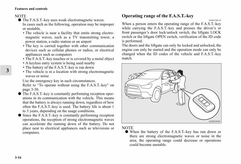
3-16
Features and controls
3
NOTE● The F.A.S.T.-key uses weak electromagnetic waves.
In cases such as the following, operation may be improperor unstable.• The vehicle is near a facility that emits strong electro-
magnetic waves, such as a TV transmitting tower, apower station, a radio station or an airport
• The key is carried together with other communicationdevices such as cellular phones or radios, or electricalappliances such as computers
• The F.A.S.T.-key touches or is covered by a metal object• A keyless entry system is being used nearby• The battery of the F.A.S.T.-key is run down• The vehicle is in a location with strong electromagnetic
waves or noiseUse the emergency key in such circumstances.Refer to “To operate without using the F.A.S.T.-key” onpage 3-30.
● The F.A.S.T.-key is constantly performing reception oper-ations in its communication with the vehicle. This meansthat the battery is always running down, regardless of howoften the F.A.S.T.-key is used. The battery life is about 1to 3 years, depending on the usage conditions.
● Since the F.A.S.T.-key is constantly performing receptionoperations, the reception of strong electromagnetic wavescan accelerate the running down of the battery. Do notplace near to electrical appliances such as televisions orcomputers.
Operating range of the F.A.S.T.-keyN00503200125
When a person enters the operating range of the F.A.S.T.-keywhile carrying the F.A.S.T.-key and presses the driver’s orfront passenger’s door lock/unlock switch, the liftgate LOCKswitch or the liftgate OPEN switch, verification of the ID codeis performed.The doors and the liftgate can only be locked and unlocked, theengine can only be started and the operation mode can only bechanged when the ID codes of the vehicle and F.A.S.T.-keymatch.
NOTE● When the battery of the F.A.S.T.-key has run down or
there are strong electromagnetic waves or noise in thearea, the operating range could decrease or operationscould become unstable.
BK0150700US.book 16 ページ 2012年3月22日 木曜日 午後6時46分

Features and controls
3-17
3
Operating range for locking and unlocking the doors and the liftgateThe operating range is within about 2.3 feet (70 cm) of thedriver’s and front passenger’s door lock/unlock switches, theliftgate LOCK switch and the liftgate OPEN switch.
NOTE● Only the doors and the liftgate that detect the F.A.S.T.-key
can be locked and unlocked.● The system may not operate if the F.A.S.T.-key is too
close to the windshield, door windows or liftgate.● Even if the F.A.S.T.-key is within about 2.3 feet (70 cm)
of the driver’s or front passenger’s door lock/unlockswitch, the liftgate LOCK switch or the liftgate OPENswitch, the system may not operate if the key is close tothe ground or in a high position.
● If the F.A.S.T.-key is within the operating range, even aperson not carrying the F.A.S.T.-key can lock and unlockthe doors or the liftgate by pressing the driver’s or frontpassenger’s door lock/unlock switch, the liftgate LOCKswitch or the liftgate OPEN switch.
*: Front of the vehicle: Operating range
BK0150700US.book 17 ページ 2012年3月22日 木曜日 午後6時46分

3-18
Features and controls
3
Operating range for starting the engine and changing the operation mode
N00503300067
The operating range is the interior of the vehicle.
NOTE● Even if the F.A.S.T.-key is within the operating range, it
may not be possible to start the engine and change theoperation mode if the key is in a storage space such as theglove compartment, on top of the instrument panel, or inthe door pocket or luggage compartment.
● Even if the F.A.S.T.-key is inside the vehicle, it may notbe possible to start the engine and change the operationmode if the key is too close to a door or door window.
To operate using the F.A.S.T.-keyN00503400215
To lockWhile carrying the F.A.S.T.-key, press the driver’s or front pas-senger’s door lock/unlock switch (A), or the liftgate LOCKswitch (B) within the operating range to lock all the doors andthe liftgate.The turn signal lights will blink once and the buzzer will soundonce.
Also refer to “Doors locks”, “Power door locks” and “Liftgate”on pages 3-38, 3-41 and 3-44 respectively.
*: Front of the vehicle: Operating range
Driver’s and front passenger’s door lock/unlock switches
BK0150700US.book 18 ページ 2012年3月22日 木曜日 午後6時46分

Features and controls
3-19
3NOTE
● In cases such as the following, the F.A.S.T.-key does notoperate.• There is a F.A.S.T.-key in the passenger compartment• A door or the liftgate is open or ajar• The operation mode is not in OFF.
● The liftgate OPEN switch (C) can be used to confirm thatthe vehicle is locked properly.Press the liftgate OPEN switch within about 3 seconds oflocking.
● If the liftgate OPEN switch is pressed 3 seconds or moreafter the vehicle is locked, the doors and the liftgate areunlocked.
● The time within which locking confirmation is possiblecan be adjusted. See an authorized Mitsubishi Motorsdealer for details. On a vehicle equipped with a MitsubishiMulti-Communication System, the function can beadjusted on the screen. For details, refer to the separateoperation manual.
Liftgate switches
BK0150700US.book 19 ページ 2012年3月22日 木曜日 午後6時46分

3-20
Features and controls
3
To unlockWhile carrying the F.A.S.T.-key within the operating range,you can unlock the doors and the liftgate by using the F.A.S.T.-key.The dome light will turn on for 30 seconds. The turn signallights will blink twice and the buzzer will sound twice.
Also refer to “Door locks”, “Power door locks” and “Liftgate”on pages 3-38, 3-41 and 3-44 respectively.
Press the driver’s door lock/unlock switch (A) to unlock onlythe driver’s door.Within about 2 seconds, press the driver’s door lock/unlockswitch one more time to unlock all the doors and the liftgate.
NOTE● Settings can be changed so that all doors and the liftgate
are unlocked automatically by pressing the driver’s doorlock/unlock switch once.Refer to “Setting of door and liftgate unlock function” onpage 3-35.
Press the front passenger’s door lock/unlock switch (B) or theliftgate OPEN switch (C) to unlock all the doors and the lift-gate.
Driver’s door lock/unlock switch
Front passenger’s door lock/unlock switch
BK0150700US.book 20 ページ 2012年3月22日 木曜日 午後6時46分

Features and controls
3-21
3NOTE
● If the doors and the liftgate are unlocked using the driver’sor front passenger’s door lock/unlock switch when alldoors and the liftgate are locked and no doors or the lift-gate are opened within about 30 seconds, the doors andthe liftgate will automatically re-lock.
● The amount of time after unlocking until the vehiclerelocks automatically can be adjusted. See an authorizedMitsubishi Motors dealer for details.On a vehicle equipped with a Mitsubishi Multi-Communi-cation System, the functions can be adjusted on thescreen. For details, refer to the separate operation manual.
● The doors and the liftgate cannot be unlocked by using theliftgate OPEN switch for about 3 seconds after locking.
● The time within which locking confirmation is possiblecan be adjusted. See an authorized Mitsubishi Motorsdealer for details.On a vehicle equipped with a Mitsubishi Multi-Communi-cation System, the function can be adjusted on the screen.For details, refer to the separate operation manual.
● In cases such as the following, the F.A.S.T.-key does notoperate.• A door or the liftgate is open or ajar• The operation mode is not in OFF.
● Functions settings can be modified as stated below.See an authorized Mitsubishi Motors dealer for details.On a vehicle equipped with a Mitsubishi Multi-Communi-cation System, the functions can be adjusted on thescreen. For details, refer to the separate operation manual.• Activating the operation confirmation function (blinking
of the turn signal lights) only during locking, or onlyduring unlocking.
• Deactivating the operation confirmation function (blink-ing of the turn signal lights) and buzzer.
• Modifying the number of blinks in the operation confir-mation function (blinking of the turn signal lights).
• Making the buzzer sound when the F.A.S.T.-key isremoved from the passenger compartment when all thedoors and the liftgate are closed.
Liftgate OPEN switch
BK0150700US.book 21 ページ 2012年3月22日 木曜日 午後6時46分

3-22
Features and controls
3
Engine switchN00513500075
To prevent vehicle theft, no F.A.S.T.-keys other than those reg-istered in advance can be used to start the engine. (Electronicimmobilizer function)While carrying the F.A.S.T.-key, the engine switch can be usedto start the engine.
NOTE● When operating the engine switch, press the switch all the
way in. If the switch is not fully pressed, the engine maynot start or the operation mode may not change. If theengine switch is pressed correctly, there is no need to holdthe engine switch down.
Operation mode of the engine switch and its functionOFFThe indicator light on the engine switch turns off.On vehicles equipped with continuously variable transmission(CVT), the operation mode cannot be put in OFF when theselector lever is in any position other than the “P” (PARK)position.
ACCAllows operation of electrical accessories.The indicator light on the engine switch illuminates orange.
ONAll electrical accessories can be used.The indicator light on the engine switch illuminates green.The indicator light turns off when the engine is running.
CAUTION!
● The indicator light (A) will flash orange when thereis a problem or malfunction in Free-hand AdvancedSecurity Transmitter. Never drive if the indicatorlight on the engine switch is flashing orange. Imme-diately contact your authorized Mitsubishi Motorsdealer.
CAUTION!
● If the engine switch operation is not smooth andfeels like it is sticking, do not operate the switch.Immediately contact an authorized MitsubishiMotors dealer.
BK0150700US.book 22 ページ 2012年3月22日 木曜日 午後6時46分

Features and controls
3-23
3
NOTE● Your vehicle is equipped with an electronic immobilizer.
To start the engine, the ID code which the F.A.S.T.-keysends must match the one registered to the immobilizercomputer. (Refer to “Electronic immobilizer (Anti-theftstarting system)” on page 3-31)
Changing the operation modeN00568000025
If you press the engine switch without pressing the brake pedal{continuously variable transmission (CVT)} or the clutchpedal (manual transaxle) while the vehicle is stationary, youcan change the operation mode in the order of OFF, ACC, ON,OFF.
ACC power auto-cutout functionN00568100013
After approximately 30 minutes has elapsed with the operationmode in ACC, the function automatically cuts out the powerfor the audio system and other electric devices that can beoperated with that mode.When the engine switch is pressed while the operation mode isin ACC, the power is supplied again to those devices.
CAUTION!
● When the engine is not running, put the operationmode in OFF. Leaving the operation mode in ON orACC for a long time when the engine is not runningmay cause the battery to be discharged, making itimpossible to start the engine.
● When the battery is disconnected, the current oper-ation mode is memorized. After reconnecting thebattery, the memorized mode is selected automati-cally. Before disconnecting the battery for repair orreplacement, make sure to put the operation modein OFF. Be careful if you are not sure which operation modethe vehicle is in when the battery is run down.
● The operation mode cannot be changed from OFF toACC or ON if the F.A.S.T.-key is not detected to bein the vehicle. Refer to “Operating range for start-ing the engine and changing the operation mode” onpage 3-18.
BK0150700US.book 23 ページ 2012年3月22日 木曜日 午後6時46分

3-24
Features and controls
3
NOTE● It is possible to modify functions as follows:
• The time until the power cuts out can be changed toapproximately 60 minutes.
• The ACC power auto-cutout function can be deacti-vated.
For details, we recommend you to consult an authorizedMitsubishi Motors dealer.On vehicles equipped with Mitsubishi Multi-Communica-tion System, screen operations can be used to make theadjustment.Refer to the separate Mitsubishi Multi-CommunicationsSystem manual for details.
Warning activationN00503500173
With the F.A.S.T.-key, warnings are given through buzzers anddisplays on the information screen in the multi-informationdisplay in order to prevent mistaken operations or vehicle theft.When a warning operates, be sure to check the vehicle and theF.A.S.T.-key. A warning is also displayed if there is a problemin the F.A.S.T.-key.
If the following warning displays, contact an authorizedMitsubishi Motors dealer.
If the following warnings display, the display goes off if thecorrect action is taken.
● The ID codes of the F.A.S.T.-key and the vehicle cannotbe verified
● A door or the liftgate cannot be locked even when thedriver’s or front passenger’s door lock/unlock switch, orthe liftgate LOCK switch is pressed.
There is a problem in the F.A.S.T.-key
Put the operation mode in OFF and then start the engine again.If the warning is not cancelled, there is a fault in the electronic immobilizer (Anti-theft starting sys-tem).Please contact an authorized Mitsubishi Motors dealer.
Someone may be carrying a F.A.S.T.-key with a different ID code, or the F.A.S.T.-key may not be within the operating rangeRefer to “F.A.S.T.-key take-out monitoring sys-tem” on page 3-25.
The battery of the F.A.S.T.-key is run down
Refer to “Key lock-in prevention system” on page 3-25.
Refer to “Door ajar prevention system” on page 3-25.
BK0150700US.book 24 ページ 2012年3月22日 木曜日 午後6時46分

Features and controls
3-25
3
F.A.S.T.-key take-out monitoring systemN00559800128
When the operation mode in any mode other than OFF, and adoor is opened and the F.A.S.T.-key is removed from the pas-senger compartment so that the ID codes of the F.A.S.T.-keyand the vehicle can no longer be verified, the warning displayis displayed and the buzzer sounds 4 times as a warning.
NOTE● The F.A.S.T.-key take-out monitoring system does not
function if the F.A.S.T.-key is removed through a windowwithout opening a door.This setting can be changed.See an authorized Mitsubishi Motors dealer for details.
● The warning may display even if the F.A.S.T.-key is in theoperating range for starting the engine and changing theoperation mode. The surrounding environment or electro-magnetic waves may make it impossible to verify the IDcodes of the F.A.S.T.-key and vehicle.
Key lock-in prevention systemN00559900116
When the operation mode is in OFF, the F.A.S.T.-key is left inthe passenger compartment, all the doors and the liftgate areclosed, and someone tries to lock the vehicle by pressing thedriver’s or front passenger’s door lock/unlock switch, or theliftgate LOCK switch, the warning display is displayed and thebuzzer sounds for about 3 seconds as a warning, and the doorsand the liftgate cannot be locked.
Door ajar prevention systemN00560000117
When the operation mode is in OFF, and someone tries to lockthe vehicle by pressing the driver’s or front passenger’s doorlock/unlock switch, or the liftgate LOCK switch while one ofthe doors or the liftgate is not fully closed, the warning displayis displayed and the buzzer sounds for about 3 seconds as awarning, and the doors and the liftgate cannot be locked.
Refer to “Operation mode OFF reminder system” on page 3-26.
BK0150700US.book 25 ページ 2012年3月22日 木曜日 午後6時46分

3-26
Features and controls
3
Operation mode OFF reminder systemN00560100118
When the operation mode is in any mode other than OFF, allthe doors and the liftgate are closed, and someone tries to lockthe vehicle by pressing the driver’s or front passenger’s doorlock/unlock switch, or the liftgate LOCK switch, the warningdisplay is displayed and the buzzer sounds for about 3 secondsas a warning, and the doors and the liftgate cannot be locked.
Starting and stopping the engineN00514600275
Tips for starting● The operation mode can be in any mode to start the
engine.● The starter motor will be turning for up to approximately
15 seconds if the engine switch is released at once. Press-ing the engine switch again while the starter motor is stillturning will stop the starter motor. The starter motor willbe turning for up to approximately 30 seconds while theengine switch is pressed.If the engine does not start, wait for a while and thenattempt to start the engine again. Trying repeatedly withthe starter motor still turning will damage the startermechanism.
● If the engine will not start because the battery is weak ordischarged, refer to “Jump-starting the engine” on page 6-2 for instructions.
● A longer warm up period will only consume extra fuel.The engine is warmed up enough for driving when the bargraph of engine coolant temperature display starts tomove. Refer to “Interrupt display screen (With ignitionswitch or operation mode in ON)” on page 3-142.
WARNING!
● Never run the engine in a closed or poorly ventilatedarea any longer than is needed to move your vehicleout of the area. Carbon monoxide gas, which isodorless and extremely poisonous, could build upand cause serious injury or death.
CAUTION!
● Do not push-start the vehicle.● Do not run the engine at high rpms or drive at high
speeds until the engine has had a chance to warmup.
BK0150700US.book 26 ページ 2012年3月22日 木曜日 午後6時46分

Features and controls
3-27
3
Starting the engineYour vehicle is equipped with an electronically controlled fuelinjection system. This is a system that automatically controlsfuel injection. There is usually no need to depress the accelera-tor pedal when starting the engine.To prevent battery drain, wait a few seconds between attemptsto restart the engine.
1. Make sure all occupants are properly seated with seatbelts fastened.
2. Make sure the parking brake is applied.3. Press and hold the brake pedal down with your right foot.4. Press and hold the clutch pedal all the way down (manual
transaxle).5. On vehicles equipped with manual transaxle, place the
gearshift lever in the “N” (Neutral) position.On vehicles equipped with continuously variable trans-mission (CVT), make sure the selector lever is in the “P”(PARK) position.
NOTE● On vehicles equipped with continuously variable trans-
mission (CVT), the engine can only be started when theselector lever is in the “P” (PARK) or “N” (NEUTRAL)position.For safety reasons, the engine should be started when theselector lever is in the “P” (PARK) position in which thedriving wheels lock.
6. Press the engine switch.7. Confirm that all warning lights and warning displays are
functioning properly.
NOTE● Minor noises may be heard on engine start-up. These will
disappear as the engine warms up.
When the engine is hard to startAfter several attempts, you may experience that the engine stilldoes not start.
1. Make sure that all electric devices, such as lights, air con-ditioning blower and rear window defogger, are turnedoff.
2. While depressing the brake pedal {continuously variabletransmission (CVT)} or the clutch pedal (manual tran-saxle), press the accelerator pedal halfway and hold itthere, then crank the engine. Release the acceleratorpedal, immediately after the engine starts.
3. If the engine still will not start, the engine could beflooded with too much gasoline. While depressing thebrake pedal (CVT) or the clutch pedal (manual transaxle),push the accelerator pedal all the way down and hold itthere, then press the engine switch to crank the engine. Ifthe engine does not start after 5 to 6 seconds, push theengine switch to stop cranking the engine, and release theaccelerator pedal. Put the operation mode in OFF. Wait afew seconds, and then press the engine switch to crank theengine again while depressing the brake pedal (CVT) orthe clutch pedal (manual transaxle), but do not push theaccelerator pedal. If the engine fails to start, repeat theseprocedures. If the engine still will not start, contact yourlocal Mitsubishi Motors dealer or a repair facility of yourchoice for assistance.
SC00000500-3.fm 27 ページ 2012年3月27日 火曜日 午前9時42分
3-28
Features and controls
3
Startability of continuously variable transmission (CVT)vehicles with an ambient temperature of -22 °F (-30 °C) orlowerWhen the ambient temperature is -22 °F (-30 °C) or lower, itmay not be possible to start from a standstill even with theselector lever in the “D” (DRIVE) position.This phenomenon occurs because the transaxle has not warmedup sufficiently; it does not indicate a problem. If this occurs,place the selector lever in the “P” (PARK) position and let theengine idle for at least 10 minutes.The transaxle will warm up, and you will be able to start nor-mally.Do not leave the vehicle during warm-up operation.
Stopping the engine N00568200014
NOTE● If you have to bring the engine to an emergency stop
while driving, press and hold the engine switch for 3 sec-onds or more, or press it quickly 3 times or more. Theengine will stop and the operation mode will go to ACC.
● On vehicles equipped with continuously variable trans-mission (CVT), do not stop the engine with the selectorlever in any position other than the “P” (PARK) position.If the engine is stopped with the selector lever in any posi-tion other than the “P” (PARK) position, the operationmode will go to ACC rather than OFF.Put the operation mode in OFF after placing the selectorlever in the “P” (PARK) position.
1. Stop the vehicle.2. Fully engage the parking brake while depressing the brake
pedal.3. On vehicles with a manual transaxle, press the engine
switch to stop the engine, and then move the gearshiftlever to the 1st (on a uphill) or “R” (Reverse) (on a down-hill) position.On vehicles equipped with continuously variable trans-mission (CVT), move the selector lever to the “P”(PARK) position, and then press the engine switch to stopthe engine.
If the F.A.S.T.-key is not operating properly N00568300028
Insert the F.A.S.T.-key into the key slot in the glove box. Start-ing the engine and changing the operation mode should be nowpossible. Remove the F.A.S.T.-key from the key slot after starting theengine or changing the operation mode.
WARNING!
● Do not operate the engine switch while drivingexcept in an emergency. If the engine is stoppedwhile driving, the brake servomechanism will ceaseto function and braking efficiency will deteriorate.Also, the power steering system will not functionand it will require greater manual effort to operatethe steering. This could result in a serious accident.
BK0150700US.book 28 ページ 2012年3月22日 木曜日 午後6時46分

Features and controls
3-29
3NOTE
● Do not insert into the key slot anything other than theF.A.S.T.-key. This could cause damage or a malfunction.
● Remove the object or additional key from the F.A.S.T.-key before inserting the key into the key slot. The vehiclemay not be able to receive the registered ID code from theregistered key. Therefore, the engine may not start and theoperation mode may not change.
F.A.S.T.-key reminder
If the operation mode is in OFF and the driver’s door is openedwith the F.A.S.T.-key in the key slot, a warning is issued with
the warning display and the buzzer buzzing for approximately3 seconds to remind you to remove the key.
BK0150700US.book 29 ページ 2012年3月22日 木曜日 午後6時46分

3-30
Features and controls
3
To operate without using the F.A.S.T.-keyN00514800017
Emergency keyN00515200106
The emergency key is built into the F.A.S.T.-key.When the F.A.S.T.-key cannot be used, such as when the bat-tery of the F.A.S.T.-key or the vehicle has run down, the emer-gency key can be used to lock and unlock the driver’s door.
To use the emergency key (A), unlock the lock knob (B) andremove it from the F.A.S.T.-key (C).
NOTE● Only use the emergency key in an emergency. When the
battery of the F.A.S.T.-key has run down, replace the bat-tery as soon as possible and use it as a F.A.S.T.-key again.
● After using the emergency key, be sure to reinsert it intothe F.A.S.T.-key.
Locking and unlocking the driver’s doorTurn the emergency key toward the front of the vehicle to lockthe door. After checking that the door is locked, turn the emer-gency key back to the center and remove it.
1- Insert or remove the emergency key2- Lock3- Unlock
BK0150700US.book 30 ページ 2012年3月22日 木曜日 午後6時46分

Features and controls
3-31
3
Electronic immobilizer (Anti-theft starting sys-tem)
N00529600055
The electronic immobilizer is designed to significantly reducethe possibility of vehicle theft. The purpose of the system is toimmobilize the vehicle if an invalid start is attempted. A validstart attempt can only be achieved (subject to certain condi-tions) using a F.A.S.T.-Key “registered” to the immobilizersystem.All of the keys provided with your new vehicle have been pro-grammed to the vehicle’s electronics.
Replacement F.A.S.T.-keysN00561000042
Only the F.A.S.T.-keys that have been programmed to the vehi-cle’s electronics can be used to start the vehicle.
If you lose the F.A.S.T.-key, you can order a F.A.S.T.-key fromyour authorized Mitsubishi Motors dealer by referring to thekey number.To prevent vehicle theft, take your vehicle and the remainingF.A.S.T.-keys to an authorized Mitsubishi Motors dealer tohave the ID codes reprogrammed.
Additional F.A.S.T.-keysN00561100014
To add a F.A.S.T.-key, you must already have 2 registeredF.A.S.T.-keys. You need to register the ID code to the vehicle.Registering the ID code can be done by your authorizedMitsubishi Motors dealer. Or it can be done by yourself (exceptfor vehicles sold in Canada).For you to register the ID code yourself, follow the “CustomerF.A.S.T.-key programming” procedure below.If you choose to have your authorized Mitsubishi Motorsdealer register the ID code, take your vehicle and all remainingF.A.S.T.-keys to your authorized Mitsubishi Motors dealer.
NOTE● You are provided with 2 F.A.S.T.-keys, but you may regis-
ter up to 4 F.A.S.T.-keys.You can obtain blank F.A.S.T.-keys specially cut for yourvehicle from your Mitsubishi Motors dealer.
BK0150700US.book 31 ページ 2012年3月22日 木曜日 午後6時46分

3-32
Features and controls
3
Customer F.A.S.T.-key programming (Except for vehi-cles sold in Canada)
N00561200161
You can program new F.A.S.T.-keys to the system if you havetwo valid (already registered) F.A.S.T.-keys and blank (not reg-istered) F.A.S.T.-key.
For F.A.S.T.-key programming, follow the procedures below.1. Open the driver’s door.
NOTE● Keep the driver’s door open until F.A.S.T.-key program-
ming is finished. Do not open or close other doors.
2. While carrying the first valid F.A.S.T.-key, put the opera-tion mode in ON. (Perform the following procedurewithin 30 seconds.)
3. Insert the new F.A.S.T.-key into the key slot.
4. With the first valid F.A.S.T.-key, press the UNLOCK but-ton for 4 to 10 seconds and press the LOCK button duringthis time.
5. Release in sequence the LOCK and UNLOCK buttonswithin 10 seconds of pressing the LOCK button in step 4.(Perform the following procedure within 30 seconds.)
6. With the second valid F.A.S.T.-key, press the UNLOCKbutton for 4 to 10 seconds and press the LOCK buttonduring this time.
7. Release in sequence the LOCK and UNLOCK buttonswithin 10 seconds of pressing the LOCK button in step 6.The immobilizer display on the information screen in themulti-information display will blink.
When registration of ID code is complete, the buzzer willsound 3 times and the immobilizer display will come onfor 30 seconds.If an error occurs, F.A.S.T.-key programming will be ter-minated and the buzzer will sound for 3 seconds.
NOTE● F.A.S.T.-key programming will be terminated if the opera-
tion mode is put in OFF before the immobilizer displaystarts blinking.
BK0150700US.book 32 ページ 2012年3月22日 木曜日 午後6時46分

Features and controls
3-33
3
8. If you wish to register another F.A.S.T.-key, repeat theprocess from step 1 after the operation mode is put inOFF.
NOTE● The immobilizer display will go off immediately if the
operation mode is put in OFF.● Perform the operation when the interrupt display screen is
not showing. The interrupt display screen may preventyou from seeing the immobilizer display.
● It is not possible to register a F.A.S.T.-key if the immobi-lizer display goes off during the procedure.
Keyless entry systemN00515500200
Press the remote control transmitter buttons to lock or unlockthe doors and the liftgate.It can also help you signal for attention by setting off the panicalarm.
1- LOCK ( ) button2- UNLOCK ( ) button3- PANIC button4- Operation indicator light
BK0150700US.book 33 ページ 2012年3月22日 木曜日 午後6時46分
3-34
Features and controls
3
To lockPress the LOCK button (1) to lock all the doors and the liftgate.The turn signal lights will also blink once.
NOTE● If you press the LOCK button (1) twice, the horn will
sound once.
To unlockPress the UNLOCK button (2) to unlock the driver’s door only.Within about 2 seconds, press the UNLOCK button one moretime to unlock all the doors and liftgate.The dome light will turn on for 30 seconds. The turn signallights will also blink twice.The front side-marker and parking lights will also turn on forabout 30 seconds. Refer to “Welcome light” on page 3-189.
NOTE● On a vehicle equipped with a Mitsubishi Multi-Communi-
cation System, the functions can be adjusted on thescreen. For details, refer to the separate operation manual.
● The door and liftgate unlock function can be set so that alldoors and liftgate unlock when the UNLOCK button (2) ispressed once.Refer to “Setting of door and liftgate unlock function” onpage 3-35.
Answerback functionThe horn and turn signal lights of the keyless entry systemanswerback function can be changed as required. This is donewith the key removed from the ignition switch.
Horn deactivation/reactivationThe answerback function can be set in the following threeways.
1. Put the operation mode in OFF.2. Open the driver’s door and turn the combination head-
lights and dimmer switch to the “OFF” position.3. Press the LOCK button (1) for 4 to 10 seconds and press
the UNLOCK button (2) during this time.4. Release in sequence the UNLOCK and LOCK buttons
within 10 seconds of pressing the UNLOCK button in step3.
NOTE● On a vehicle equipped with a Mitsubishi Multi-Communi-
cation System, the functions can be adjusted on thescreen. For details, refer to the separate operation manual.
One chime: The horn will not sound.Two chimes: The horn will sound.Four chimes: The horn will sound if the LOCK button is
pressed twice within 1 second.
BK0150700US.book 34 ページ 2012年3月22日 木曜日 午後6時46分

Features and controls
3-35
3
Turn signal light deactivation/reactivationThe answerback function from the turn signal lights can beturned ON or OFF separately.
1. Put the operation mode in OFF.2. Open the driver’s door and turn the combination head-
lights and dimmer switch to the “OFF” position.3. Press the UNLOCK button (2) for 4 to 10 seconds and
press the LOCK button (1) during this time.4. Release in sequence the UNLOCK and LOCK buttons
within 10 seconds of pressing the LOCK button in step 3.
NOTE● On a vehicle equipped with a Mitsubishi Multi-Communi-
cation System, the functions can be adjusted on thescreen. For details, refer to the separate operation manual.
Buzzer deactivation/reactivationThe buzzer answerback function can be turned ON or OFF asrequired.
NOTE● On a vehicle equipped with a Mitsubishi Multi-Communi-
cation System, the functions can be adjusted on thescreen. For details, refer to the separate operation manual.
Setting of door and liftgate unlock functionN00544600072
The door and liftgate unlock function can be set to the follow-ing two conditions.Each time the door and liftgate unlock function is set, a chimewill sound to tell you the condition of the door and liftgateunlock function.
1. Put the operation mode in OFF.2. Open the driver’s door and turn the combination head-
lights and dimmer switch to the “OFF” position.3. Press the LOCK button (1) for 4 to 10 seconds and press
the UNLOCK button (2) during this time.4. Release in sequence the LOCK and UNLOCK buttons
within 10 seconds of pressing the LOCK button in step 3.
NOTE● On a vehicle equipped with a Mitsubishi Multi-Communi-
cation System, the functions can be adjusted on thescreen. For details, refer to the separate operation manual.
Number of chimes To lock To unlockOne chime One flash Two flashesTwo chimes One flash No flashThree chimes No flash Two flashesFour chimes Two flashes One flashFive chimes No flash One flashSix chimes Two flashes No flashSeven chimes No flash No flash
Number of chimes Condition
One chime All doors and the liftgate unlockTwo chimes Driver’s door unlock only
BK0150700US.book 35 ページ 2012年3月22日 木曜日 午後6時46分

3-36
Features and controls
3
Using the panic alarmN00544700057
If you are near your vehicle and feel threatened, you can acti-vate the alarm to call attention as follows:
1. Press the PANIC button (3) for more than 1 second.2. The headlights will blink on and off and the horn will
sound intermittently for about 3 minutes.3. To turn off the alarm, press any button on the remote con-
trol transmitter.
NOTE● The indicator light (4) comes on each time a button is
pressed.● The F.A.S.T.-key can be used from about 40 feet (12 m)
away. However, this distance may change if your vehicleis near a TV transmitting tower, a power station, or a radiostation.
● If the UNLOCK button (2) is pressed when all doors andthe liftgate are locked and no doors or the liftgate areopened within about 30 seconds, the doors and the liftgatewill automatically re-lock.On a vehicle equipped with a Mitsubishi Multi-Communi-cation System, the functions can be adjusted on thescreen. For details, refer to the separate operation manual.
● If the following conditions are observed after pressing theLOCK (1) or UNLOCK (2) button on the remote controltransmitter, the buttery in the F.A.S.T.-key may need to bereplaced.• The doors and the liftgate cannot be locked or unlocked.• The panic alarm cannot be operated.• The indicator light (4) is dim or does not come on.
● If you lose your F.A.S.T.-key, please contact an authorizedMitsubishi Motors dealer for a replacement.
● If you wish to obtain an additional F.A.S.T.-key, pleasecontact an authorized Mitsubishi Motors dealer. A maxi-mum of four F.A.S.T.-key can be programmed for yourvehicle.
● To use the new remote control transmitters, it is necessaryto register the key with the electronic immobilizer andkeyless entry system.Refer to “Electronic immobilizer (Anti-theft starting sys-tem): Customer F.A.S.T.-key programming” on page 3-32.
General informationN00562000036
Your F.A.S.T.-key operates on a radio frequency subject to Fed-eral Communications Commission (FCC) Rules (For vehiclessold in U.S.A.) and Industry Canada Rules (For vehicles sold inCanada). This device complies with Part 15 of the FCC Rules andRSS-Gen of the Industry Canada Rules. Operation is subject tothe following two conditions.
• This device may not cause harmful interference.• This device must accept any interference received, including
interference that may cause undesired operation.
CAUTION!
● Changes or modifications not expressly approved bythe manufacturer for compliance could void theuser’s authority to operate the equipment.
BK0150700US.book 36 ページ 2012年3月22日 木曜日 午後6時46分

Features and controls
3-37
3
Procedure for replacing the remote control trans-mitter battery
N00562100066
1. Before replacing the battery, remove static electricity fromyour body by touching a metal grounded object.
2. With the Mitsubishi mark facing you, insert the cloth-cov-ered tip of a flat blade screwdriver into the notch in thecase and use it to open the case.
NOTE● Be sure to perform the procedure with the Mitsubishi
mark facing you. If the Mitsubishi mark is not facing youwhen you open the case, the transmitter may come out.
3. Remove the old battery.
4. Install a new battery with the + side (A) up.
5. Close the case firmly.6. Check the keyless entry system to see that it works.
NOTE● You may purchase a replacement battery at an electric
appliance store.● An authorized Mitsubishi Motors dealer can replace the
battery for you if you prefer.
CAUTION!
● When the remote control transmitter case is opened,be careful to keep water, dust, etc. out. Also, do nottouch the internal components.
+ side
- side
Coin type battery CR2032
BK0150700US.book 37 ページ 2012年3月22日 木曜日 午後6時46分

3-38
Features and controls
3
Door locksN00509200488
To lock and unlock with the key (driver’s door)Turn the key toward the front of the vehicle to lock the door.After checking that the door is locked, turn the key back to thecenter and remove it.WARNING!
● Make sure all doors are tightly closed and lockedwhile driving.• Locked doors, in combination with the use of seat
belts, can help reduce the risk of ejection in anaccident.
• Locked doors can help keep passengers, especiallysmall children, from opening doors and falling outof moving vehicles.
• Locked doors can help prevent outsiders fromgaining access to your vehicle when you slow orcome to a stop.
● Lock your vehicle whenever you leave it. Childrenwho get into unlocked vehicles may not be able toget out. Children trapped inside vehicles can quicklybe overcome by heat and suffer serious injury ordeath due to heat stroke.
● Never leave a child alone in the vehicle. In additionto the risk of heat stroke, children can activateswitches and controls, resulting in an injury or fatalaccident.
● When closing a door, make sure that the door is fullyclosed and the door-ajar warning display goes outon the information screen on the multi-informationdisplay. If the door is ajar it could open while driv-ing and cause an accident.
1- Insert or remove the key2- Lock3- Unlock
BK0150700US.book 38 ページ 2012年3月22日 木曜日 午後6時46分

Features and controls
3-39
3
NOTE● When locking or unlocking with the key, only the driver’s
door will be locked or unlocked.To lock or unlock all doors and the liftgate, use the powerdoor lock switches, the keyless entry system or theF.A.S.T-key operation.Refer to “Power door locks” on page 3-41, “Keyless entrysystem” on pages 3-8 and 3-33, and “To operate using theF.A.S.T.-key” on page 3-18.
● In vehicles equipped with the F.A.S.T.-key, the driver’sdoor can be locked and unlocked using the emergencykey.Refer to “Emergency key” on page 3-30.
To lock or unlock the door from the insideMove the lock knob to the lock position to lock the door.All doors should be kept locked while driving.
The driver’s door can be unlocked without using the lock knobby pulling on the inside door handle.
1- Lock2- Unlock
BK0150700US.book 39 ページ 2012年3月22日 木曜日 午後6時46分

3-40
Features and controls
3
To lock the door without using the key1. Move the inside lock knob to the locked position.2. Be sure the keys are not inside the vehicle. Close the door.
Key reminder system (except for vehicles equipped with the F.A.S.T.-key)
N00549600224
Type 1
Type 2
If the ignition switch is turned off and the driver’s door isopened with the key in the ignition switch, the key reminderbuzzer will sound intermittently to remind you to remove thekey.The warning display will be displayed on the informationscreen in the multi-information display.
Lock out protectionN00517300042
If the key is in the ignition switch or the operation mode is inany mode other than OFF when you push the lock knob for-ward with the driver’s door or passenger’s door open, the lockknob will automatically return to the unlocked position.
BK0150700US.book 40 ページ 2012年3月22日 木曜日 午後6時46分

Features and controls
3-41
3
Operation mode ON reminder system (vehicles equipped with the F.A.S.T.-key)
N00503800105
If the driver’s door is opened while the engine is stopped andthe operation mode is in any position other than OFF, the oper-ation mode ON buzzer will sound intermittently to remind youto put the operation mode in OFF.The warning display will be displayed on the informationscreen in the multi-information display.
Power door locksN00509300551
NOTE● When locking or unlocking with the key on the driver’s
door, only the driver’s door will lock or unlock.● Repeated continuous operation between lock and unlock
could activate the power door locking system’s built-inprotection circuit, and prevent the system from operating.If this occurs, wait about 1 minute before operating thepower door lock switch.
BK0150700US.book 41 ページ 2012年3月22日 木曜日 午後6時46分
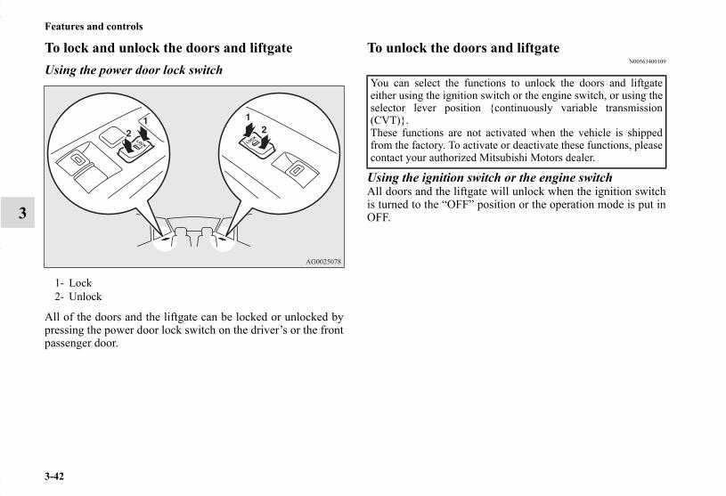
3-42
Features and controls
3
To lock and unlock the doors and liftgateUsing the power door lock switch
All of the doors and the liftgate can be locked or unlocked bypressing the power door lock switch on the driver’s or the frontpassenger door.
To unlock the doors and liftgateN00563400109
Using the ignition switch or the engine switchAll doors and the liftgate will unlock when the ignition switchis turned to the “OFF” position or the operation mode is put inOFF.
1- Lock2- Unlock
You can select the functions to unlock the doors and liftgateeither using the ignition switch or the engine switch, or using theselector lever position {continuously variable transmission(CVT)}.These functions are not activated when the vehicle is shippedfrom the factory. To activate or deactivate these functions, pleasecontact your authorized Mitsubishi Motors dealer.
BK0150700US.book 42 ページ 2012年3月22日 木曜日 午後6時46分

Features and controls
3-43
3
Using the selector lever position {continuously variable transmission (CVT)}All doors and the liftgate will unlock when the selector lever ismoved to the “P” (PARK) position with the ignition switch orthe operation mode in ON.
NOTE● On a vehicle equipped with a Mitsubishi Multi-Communi-
cation System, the functions can be adjusted on thescreen. For details, refer to a separate operation manual.
Child safety locks for rear doorN00509400262
Child safety locks help prevent rear passengers, especially chil-dren, from opening the rear door using the inside door handle.A lock lever for the child safety lock is provided on each reardoor.When the lever is in the lock position (1), the rear door cannotbe opened using the inside door handle.To open the rear door when the child safety lock lever is in thelock position, pull the outside door handle.When the lever is in the release position (2), the child safetylock is released and the rear door can be opened using theinside door handle.
1- To lock2- To release
BK0150700US.book 43 ページ 2012年3月22日 木曜日 午後6時46分

3-44
Features and controls
3
LiftgateN00510100214
NOTE● Locking and unlocking the doors by using power door
locks (driver and front passenger side), keyless entry sys-tem or the F.A.S.T.-key operation (vehicles equipped withthe F.A.S.T.-key) also locks and unlocks the liftgate.
WARNING!
● Always keep the doors tightly closed and lockedwhen driving. An unlocked door may be acciden-tally opened by a passenger, especially by a childwho could fall out. Also, if the doors are not locked,there is a greater risk of someone being thrown fromthe vehicle in an accident.
WARNING!
● It is dangerous to drive with the liftgate open sincecarbon monoxide (CO) gas can enter the passengercompartment.CO is an invisible, odorless gas that can causeunconsciousness and even death.
● When opening and closing the liftgate, make surethat there are no people nearby and be careful not tohit your head or pinch your hands, neck, etc.
CAUTION!
● Do not stand behind the exhaust pipe when loadingand unloading luggage. Heat from the exhaust couldlead to burns.
BK0150700US.book 44 ページ 2012年3月22日 木曜日 午後6時46分

Features and controls
3-45
3
To openAfter unlocking, raise the liftgate.
NOTE● The liftgate cannot be raised if it is not raised immediately
after pressing the liftgate OPEN switch.If this happens, raise the liftgate again after pressing theliftgate OPEN switch.
● It is not possible to open the liftgate while the battery isdisconnected. If necessary, use the inside liftgate release.
● When the battery is reconnected, all doors and the liftgatewill be locked. Unlock them before trying to open the lift-gate.
CAUTION!
● Make sure there is no one standing nearby whenopening the liftgate.
BK0150700US.book 45 ページ 2012年3月22日 木曜日 午後6時46分

3-46
Features and controls
3
To closePull the liftgate grip (A) downward as illustrated and release itbefore the liftgate closes completely. Gently slam the liftgatefrom the outside so that it is completely closed.
NOTE● Gas struts (B) are installed in the locations illustrated in
order to support the liftgate. Please observe the followingin order to prevent damage or faulty operation:• Do not touch, push or pull the gas struts when closing
the liftgate.• Do not attach any plastic material, tape, etc., to the gas
struts.• Do not tie string, etc., around the gas struts.• Do not hang objects on the gas struts.
CAUTION!
● To avoid injuring your hand or arm, do not attemptto close the liftgate without releasing the liftgate grip(A).
● Before starting the vehicle, be sure to confirm thatthe liftgate is locked. If the liftgate opens while driv-ing the vehicle, objects stored in the luggage com-partment could fall out into the road.
BK0150700US.book 46 ページ 2012年3月22日 木曜日 午後6時46分

Features and controls
3-47
3
Inside liftgate releaseN00523100074
The inside liftgate release is designed to provide a way to openthe liftgate if the battery is dead or disconnected.The liftgate release lever (see illustration) is mounted on theliftgate.
You and your family should familiarize yourselves with thelocation and operation of the liftgate release lever.
To open1. Open the lid (A) inside of the liftgate.
BK0150700US.book 47 ページ 2012年3月22日 木曜日 午後6時46分
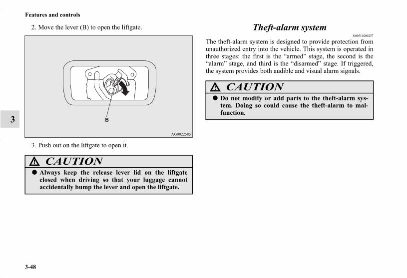
3-48
Features and controls
3
2. Move the lever (B) to open the liftgate.
3. Push out on the liftgate to open it.
Theft-alarm systemN00510200257
The theft-alarm system is designed to provide protection fromunauthorized entry into the vehicle. This system is operated inthree stages: the first is the “armed” stage, the second is the“alarm” stage, and third is the “disarmed” stage. If triggered,the system provides both audible and visual alarm signals.
CAUTION!
● Always keep the release lever lid on the liftgateclosed when driving so that your luggage cannotaccidentally bump the lever and open the liftgate.
CAUTION!
● Do not modify or add parts to the theft-alarm sys-tem. Doing so could cause the theft-alarm to mal-function.
BK0150700US.book 48 ページ 2012年3月22日 木曜日 午後6時46分

Features and controls
3-49
3
Armed stagePark the vehicle and stop the engine. Arm the system asdescribed below.
1. Except for vehicles equipped with the F.A.S.T.-key,remove the key from the ignition switch.For vehicles equipped with the F.A.S.T.-key, put the oper-ation mode in OFF.
2. Make sure that the engine hood is closed.3. Lock all doors and the liftgate by using the keyless entry
system or the F.A.S.T.-key operation.
At this time, the theft-alarm indicator (A) on the audiopanel flashes for confirmation.
4. The system has entered the armed stage after about 20seconds, when the theft-alarm indicator (A) flashingbecomes slower.The theft-alarm indicator (A) continues to flash while thesystem is in the armed stage.
Arm the system and leave
BK0150700US.book 49 ページ 2012年3月22日 木曜日 午後6時46分
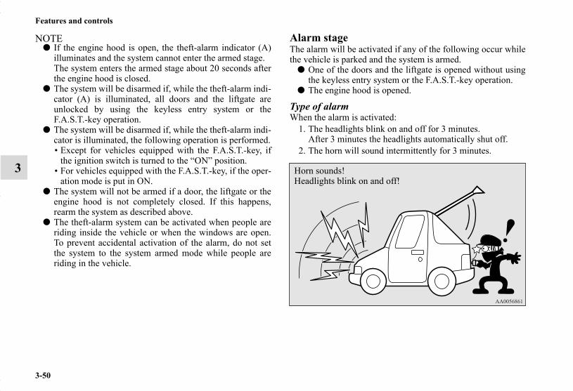
3-50
Features and controls
3
NOTE● If the engine hood is open, the theft-alarm indicator (A)
illuminates and the system cannot enter the armed stage.The system enters the armed stage about 20 seconds afterthe engine hood is closed.
● The system will be disarmed if, while the theft-alarm indi-cator (A) is illuminated, all doors and the liftgate areunlocked by using the keyless entry system or theF.A.S.T.-key operation.
● The system will be disarmed if, while the theft-alarm indi-cator is illuminated, the following operation is performed.• Except for vehicles equipped with the F.A.S.T.-key, if
the ignition switch is turned to the “ON” position.• For vehicles equipped with the F.A.S.T.-key, if the oper-
ation mode is put in ON.● The system will not be armed if a door, the liftgate or the
engine hood is not completely closed. If this happens,rearm the system as described above.
● The theft-alarm system can be activated when people areriding inside the vehicle or when the windows are open.To prevent accidental activation of the alarm, do not setthe system to the system armed mode while people areriding in the vehicle.
Alarm stageThe alarm will be activated if any of the following occur whilethe vehicle is parked and the system is armed.
● One of the doors and the liftgate is opened without usingthe keyless entry system or the F.A.S.T.-key operation.
● The engine hood is opened.
Type of alarmWhen the alarm is activated:
1. The headlights blink on and off for 3 minutes.After 3 minutes the headlights automatically shut off.
2. The horn will sound intermittently for 3 minutes.
Horn sounds!Headlights blink on and off!
BK0150700US.book 50 ページ 2012年3月22日 木曜日 午後6時46分
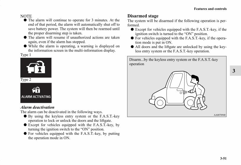
Features and controls
3-51
3
NOTE● The alarm will continue to operate for 3 minutes. At the
end of that period, the alarm will automatically shut off tosave battery power. The system will then be rearmed untilthe proper disarming step is taken.
● The alarm will resume if unauthorized actions are takenagain, even if the alarm has stopped.
● While the alarm is operating, a warning is displayed onthe information screen in the multi-information display.
Type 1
Type 2
Alarm deactivationThe alarm can be deactivated in the following ways.
● By using the keyless entry system or the F.A.S.T.-keyoperation to lock or unlock the doors and the liftgate.
● Except for vehicles equipped with the F.A.S.T.-key, byturning the ignition switch to the “ON” position.
● For vehicles equipped with the F.A.S.T.-key, by puttingthe operation mode in ON.
Disarmed stageThe system will be disarmed if the following operation is per-formed.
● Except for vehicles equipped with the F.A.S.T.-key, if theignition switch is turned to the “ON” position.
● For vehicles equipped with the F.A.S.T.-key, if the opera-tion mode is put in ON.
● All doors and the liftgate are unlocked by using the key-less entry system or the F.A.S.T.-key operation.
Disarm...by the keyless entry system or the F.A.S.T.-key operation
BK0150700US.book 51 ページ 2012年3月22日 木曜日 午後6時46分

3-52
Features and controls
3
NOTE● If the UNLOCK button on the remote control transmitter,
or the driver’s or front passenger’s door lock/unlockswitch is pressed when all doors and the liftgate are closedand no door is opened within approximately 30 seconds,re-arming will automatically occur.
● The amount of time after unlocking until the vehiclerelocks automatically can be adjusted. See an authorizedMitsubishi Motors dealer for details.On a vehicle equipped with a Mitsubishi Multi-Communi-cation System, the functions can be adjusted on thescreen. For details, refer to a separate operational manual.
● Once the system has been disarmed, it cannot be rearmedexcept by repeating the arming procedure.
Testing the theft-alarm systemUse the following procedure to test the system:
1. Lower the driver’s window.2. Arm the system as explained in “Armed stage”.3. Make sure that the theft-alarm indicator comes on and
flashes for approximately 20 seconds.4. Wait a few seconds and then unlock the driver’s side door
by using the inside door lock knob and open the door.5. Make sure that the horn sounds intermittently and the
headlights blink when a door is opened.6. Disarm the system by unlocking all doors and the liftgate
by using the keyless entry system or the F.A.S.T.-keyoperation.
Power window controlN00510800370
NOTE● Never try to operate the main switch and sub-switch in
different directions at the same time. This will freeze thewindow in position.
● Operating the power windows repeatedly with the enginestopped will run down the battery. Use the windowswitches only while the engine is running.
1- Open (down)2- Close (up)
BK0150700US.book 52 ページ 2012年3月22日 木曜日 午後6時46分

Features and controls
3-53
3
Main switchN00548700097
The main switch located on the driver’s door can be used tooperate all the windows.A window can be opened or closed by operating the corre-sponding switch.Press the switch down to open the window, and pull up theswitch to close it.If the driver’s door window switch is fully pressed down/pulledup, the driver’s door window automatically opens/closes com-pletely.If you want to stop the window movement, operate the switchlightly in the reverse direction.
WARNING!
● Before operating the power windows, make surethat nothing can be trapped (head, hands, fingers,etc.) in the window.
● Never leave the vehicle without carrying the key.● Never leave children or unreliable adults unat-
tended inside the vehicle.
1- Driver’s door window switch2- Front passenger door window switch3- Left rear door window switch4- Right rear door window switch5- Lock switch
BK0150700US.book 53 ページ 2012年3月22日 木曜日 午後6時46分

3-54
Features and controls
3
Sub switchN00548800098
Each sub-switch can be used for it’s own passenger door win-dow, unless the driver’s window lock switch is activated.
NOTE● The rear door windows open only half-way.
Power window timer functionN00548900132
The power windows can be run up or down when the ignitionswitch or the operation mode is in ON.The door windows can be opened or closed for a 30-secondperiod after the engine is stopped. However, once the driver’sdoor or the front passenger’s door is opened, the power win-dows cannot be operated.
1- Close2- Open
BK0150700US.book 54 ページ 2012年3月22日 木曜日 午後6時46分
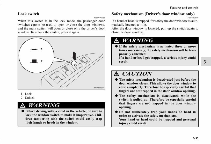
Features and controls
3-55
3
Lock switchN00549000130
When this switch is in the lock mode, the passenger doorswitches cannot be used to open or close the door windows,and the main switch will open or close only the driver’s doorwindow. To unlock the switch, press it again.
Safety mechanism (Driver’s door window only)N00528800106
If a hand or head is trapped, for safety the door window is auto-matically lowered a little.After the door window is lowered, pull up the switch again toclose the door window.
1- Lock2- Unlock
WARNING!
● Before driving with a child in the vehicle, be sure tolock the window switch to make it inoperative. Chil-dren tampering with the switch could easily traptheir hands or heads in the window.
WARNING!
● If the safety mechanism is activated three or moretimes successively, the safety mechanism will be tem-porarily cancelled.If a hand or head got trapped, a serious injury couldresult.
CAUTION!
● The safety mechanism is deactivated just before thedoor window closes. This allows the door window toclose completely. Therefore be especially careful thatfingers are not trapped in the door window opening.
● The safety mechanism is deactivated while theswitch is pulled up. Therefore be especially carefulthat fingers are not trapped in the door windowopening.
● Do not deliberately trap your hands or head inorder to activate the safety mechanism.Your hand or head could be trapped and personalinjury could result.
BK0150700US.book 55 ページ 2012年3月22日 木曜日 午後6時46分

3-56
Features and controls
3
NOTE● The safety mechanism can be activated if the driving con-
ditions or other circumstances cause the door window tobe subjected to a physical shock similar to that caused bytrapped hand or head.
● If the safety mechanism is activated 3 or more times con-secutively, the safety mechanism is deactivated and nor-mal closing of the door window will be aborted.Use the following method to return to normal operation.1. If the door window is open, repeatedly pull up the
power window switch to fully close the door window.2. With fully closing the window, release the switch and
then pull up the switch again for about 1 second.
What to do if you hear wind buffeting when driv-ing
N00551400043
Wind buffeting can be described as the perception of pressureon the ears or a booming or rumbling sound. Your vehicle mayexhibit wind buffeting when driving with one or both rear doorwindows down or partially opened. This is a normal occur-rence that can be minimized. If the buffeting occurs with therear door windows open, open the front door windows as wellas the rear door windows to minimize the condition.
Sunshade (if so equipped)N00511000614
WARNING!
● Before operating the sunshade, make sure that noth-ing can be trapped (head, hands, fingers, etc.).
● Never leave a child (or other person who is incapa-ble of safely operating the sunshade switch) alone inthe vehicle.
● Do not bring your head, hand, finger, etc. near theopening edge of the sunshade receptacle while thevehicle is in motion.It may cause injury to your head, hand, finger, etc.in the event of a sudden braking.
CAUTION!
● Do not place heavy luggage on the panoramic glassroof. Doing so could damage the glass roof.
● Do not hang heavy luggage from, allow a person tohang onto, or apply any other strong force to theopening of the sunshade receptacle or the partsbetween the ceiling and the sunshade opening oneither side. Doing so could damage the sunshade.
BK0150700US.book 56 ページ 2012年3月22日 木曜日 午後6時46分

Features and controls
3-57
3
NOTE● Release the switch when the sunshade has reached a com-
pletely open or completely closed position.● If the sunshade does not operate when the sunshade
switch is operated, release the switch and check whethersomething is trapped by the sunshade. If nothing istrapped, have the sunshade checked at an authorizedMitsubishi Motors dealer.
● Operating the sunshade repeatedly with the engine turnedoff will run down the battery. Operate the sunshade onlywhile the engine is running.
● Close the sunshade when parking the vehicle for a longtime. Parking in the hot sun with the sunshade open willmake the vehicle inside extremely hot.
The sunshade can be opened and closed with the ignitionswitch or the operation mode in ON.
To openPress the switch (1), the sunshade opens.Press and hold the switch (1), the sunshade automaticallyopens. Release the switch once the sunshade starts movingautomatically.To stop the moving sunshade, press the switch (1), (2) or (3).
To closePress the switch (2), the sunshade closes.Press and hold the switch (2), the sunshade automaticallycloses. Release the switch once the sunshade starts movingautomatically.To stop the moving sunshade, press the switch (1), (2) or (3).
Safety mechanismIf a hand or head is trapped in the closing sunshade opening,the safety mechanism will cause the sunshade to re-open auto-matically. The opened sunshade will become operational againafter a few seconds.
NOTE● The safety mechanism can be activated if the driving con-
ditions or other circumstances cause the sunshade to besubjected to a physical shock similar to that caused by atrapped hand or head.
CAUTION!
● Do not deliberately trap your hands or head inorder to activate the safety mechanism.Personal injury and malfunction of the sunshadecould result.
BK0150700US.book 57 ページ 2012年3月22日 木曜日 午後6時46分

3-58
Features and controls
3
Parking brakeN00511400373
To park the vehicle, first bring it to a complete stop, fullyengage the parking brake, and then move the gearshift lever to1st (on a uphill) or “R” (Reverse) (on a downhill) position forvehicles equipped with a manual transaxle, set the selectorlever to “P” (PARK) position for vehicles equipped with a con-tinuously variable transmission (CVT).
To apply
To deactivate
When parking on a hill, set the parking brake, and turn thefront wheels toward the curb on a downhill, or away from thecurb on an uphill.
1- Pull the lever up without pushing the button at the end ofhand grip.When the parking brake is set and the ignition switch are inthe “ON” position, the brake warning light in the instrumentcluster will come on.
Before driving, be sure to release the parking brake.
1- Pull the lever up slightly.2- Press and hold the button at the end of the hand grip.3- Push the lever downward.
BK0150700US.book 58 ページ 2012年3月22日 木曜日 午後6時46分
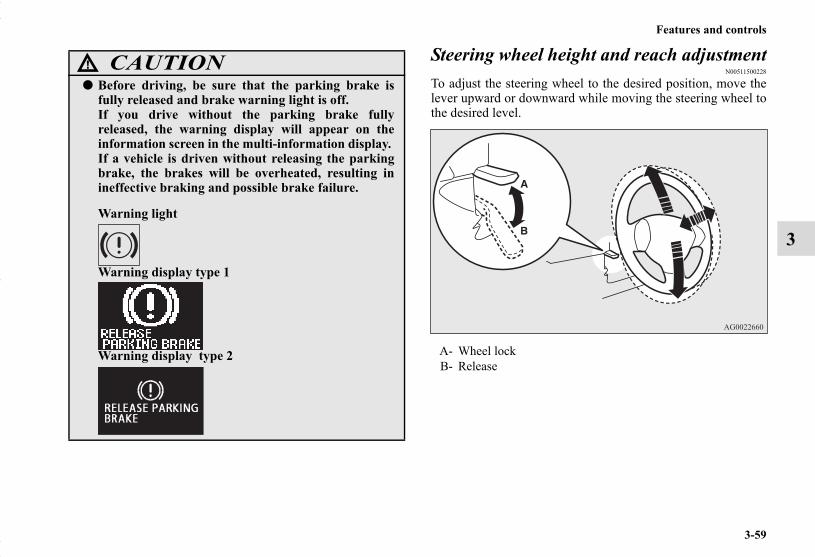
Features and controls
3-59
3
Steering wheel height and reach adjustmentN00511500228
To adjust the steering wheel to the desired position, move thelever upward or downward while moving the steering wheel tothe desired level.
CAUTION!
● Before driving, be sure that the parking brake isfully released and brake warning light is off.If you drive without the parking brake fullyreleased, the warning display will appear on theinformation screen in the multi-information display. If a vehicle is driven without releasing the parkingbrake, the brakes will be overheated, resulting inineffective braking and possible brake failure.
Warning light
Warning display type 1
Warning display type 2 A- Wheel lockB- Release
BK0150700US.book 59 ページ 2012年3月22日 木曜日 午後6時46分

3-60
Features and controls
3
Inside rearview mirrorN00511600304
Adjust the inside rearview mirror only after making any seatadjustments so as to have a clear view to the rear of the vehicle.
WARNING!
● After adjusting, make sure the lever is secured in thelocked (A) position.
● Do not attempt to adjust the steering wheel whiledriving. This can be dangerous.
● When releasing the lever (moving it to the position(B)), be sure to hold the steering wheel firmly. Oth-erwise, the steering wheel may slip down too sud-denly.
WARNING!
● Do not attempt to adjust the inside rearview mirrorwhile driving. This can be dangerous.Be sure to adjust the mirror before driving.
BK0150700US.book 60 ページ 2012年3月22日 木曜日 午後6時46分

Features and controls
3-61
3
NOTE● When the gearshift lever or the selector lever is in “R”
position with the ignition switch in the “ON” position orthe operation mode in ON, the rear-view camera imagewill be displayed on the left portion of a type 3 mirror. For details, refer to “Rear-view camera” on page 3-121.
Adjust the inside mirror to maximize the view through the rearwindow.
To adjust the vertical mirror positionIt is possible to move the mirror up and down to adjust its posi-tion.
Type 1
Type 2
Type 3
BK0150700US.book 61 ページ 2012年3月22日 木曜日 午後6時46分
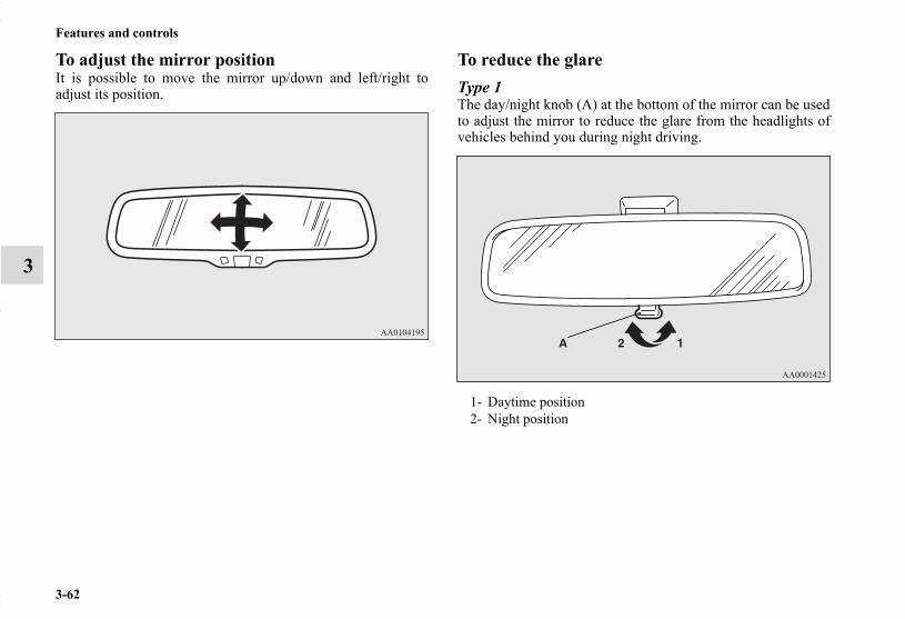
3-62
Features and controls
3
To adjust the mirror positionIt is possible to move the mirror up/down and left/right toadjust its position.
To reduce the glareType 1The day/night knob (A) at the bottom of the mirror can be usedto adjust the mirror to reduce the glare from the headlights ofvehicles behind you during night driving.
1- Daytime position2- Night position
BK0150700US.book 62 ページ 2012年3月22日 木曜日 午後6時46分

Features and controls
3-63
3
Type 2When the headlights of the vehicles behind you are very bright,the reflection factor of the rearview mirror is automaticallychanged to reduce the glare.
Normally, use the automatic mode. When the ignition switch isturned to the “ON” position or the operation mode is put inON, the reflection factor of the mirror is automaticallychanged.
NOTE● Do not hang items on, or spray glass cleaner on the sensor
(1), as reduced sensitivity could result.
Type 3When the headlights of the vehicles behind you are very bright,the reflection factor of the rearview mirror is automaticallychanged to reduce the glare.
Normally, use the automatic mode. When the ignition switch isturned to the “ON” position or the operation mode is put inON, the green indicator (1) illuminates and the reflection factorof the mirror is automatically changed.
NOTE● Do not hang items on, or spray glass cleaner on the sen-
sors (2), as reduced sensitivity could result.
(Back side)
BK0150700US.book 63 ページ 2012年3月22日 木曜日 午後6時46分

3-64
Features and controls
3
● If you want to stop automatic mode, press the switch (3)and the indicator will go off.To return to automatic mode, press the switch again orperform the following operation.[Except for vehicles equipped with the Free-handAdvanced Security Transmitter (F.A.S.T.-key)]Turn the ignition switch to the “ON” position after turningto “OFF” or “ACC” position.[For vehicles equipped with the Free-hand AdvancedSecurity Transmitter (F.A.S.T.-key)]Put the operation mode in ON after putting the operationmode in OFF.
Outside rearview mirrorsN00512200206
Adjust the outside rearview mirrors only after making any seatadjustments so as to have a clear view to the rear of the vehicle.
To adjust the mirror positionN00549100131
The outside rearview mirrors can be adjusted when the ignitionswitch or the operation mode is in ON or ACC.
WARNING!
● Do not attempt to adjust the outside rearview mir-rors while driving. This can be dangerous.Be sure to adjust the mirrors before driving.
● Your passenger’s side mirror is convex. The objectsyou see in the mirror will look smaller and fartheraway than they appear in a regular flat mirror.Do not use this mirror to estimate the distance ofvehicles following you when changing lanes.
BK0150700US.book 64 ページ 2012年3月22日 木曜日 午後6時46分

Features and controls
3-65
3
Move the lever (A) to the same side as the mirror you wish toadjust.
Press the switch (B) to adjust the mirror position.
NOTE● After adjusting, return the lever to the “•” (OFF) position
(C).
To fold the mirrorN00549200086
The outside mirror can be folded in towards the side window toprevent damage when parking in tight locations.
L- Left outside mirror adjustmentR- Right outside mirror adjustment
1- Up2- Down3- Right4- Left
BK0150700US.book 65 ページ 2012年3月22日 木曜日 午後6時46分

3-66
Features and controls
3
Door mirror heaterN00549300191
When the rear window defogger switch is pressed with theengine running, the outside rearview mirrors are defogged ordefrosted. Current will flow through the heater element insidethe mirrors, thus clearing away frost or condensation.The indicator light (A) will illuminate while the defogger is on.The heater will be turned off automatically in about 20 min-utes.
Ignition switchN00512400673
[For vehicles equipped with the Free-hand Advanced Secu-rity Transmitter (F.A.S.T.-key)]For information on operations for vehicles equipped with theFree-hand Advanced Security Transmitter (F.A.S.T.-key), referto “Free-hand Advanced Security Transmitter (F.A.S.T.-key):Engine switch”on page 3-22.
[Except for vehicles equipped with the Free-handAdvanced Security Transmitter (F.A.S.T.-key)]
BK0150700US.book 66 ページ 2012年3月22日 木曜日 午後6時46分

Features and controls
3-67
3
OFFThe engine is off. The key can be inserted and removed onlywhen the switch is in this position.
ACCAllows operation of electrical accessories with the engine off.
ONThe engine runs and all accessories can be used.
STARTEngages the starter. Release the key when the engine starts.Itwill automatically back to the “ON” position.
NOTE● Your vehicle is equipped with an electronic immobilizer.
To start the engine, the ID code which the transponderinside the key sends must match the one registered to theimmobilizer computer. (Refer to “Electronic immobilizer”on page 3-31.)
ACC power auto-cutout functionN00539600058
After about 30 minutes has elapsed with the ignition switch inthe “ACC” position, the function automatically cuts out thepower for the audio system and other electric devices that canbe operated with that position.When the ignition switch is turned from the “ACC” position,the power is supplied again to those devices.
NOTE● It is possible to modify functions as follows:
• The time until the power cuts out can be changed toabout 60 minutes.
• The ACC power auto-cutout function can be deacti-vated.
For details, we recommend you to consult an authorizedMITSUBISHI MOTORS dealer.On vehicles equipped with Mitsubishi Multi-Communica-tion System, screen operations can be used to make theadjustment.Refer to the separate Mitsubishi Multi-CommunicationsSystem manual for details.
BK0150700US.book 67 ページ 2012年3月22日 木曜日 午後6時46分

3-68
Features and controls
3
To remove the keyN00550900197
1. Set the selector lever to the “P” (PARK) position {contin-uously variable transmission (CVT)}.
2. Turn the key to the “OFF” position and remove it.
CAUTION!
● If the engine is stopped while driving, the brake ser-vomechanism will cease to function and brakingefficiency will deteriorate. Also, the power steeringsystem will not function and it will require greatermanual effort to operate the steering.
● Do not leave the key in the “ON” position for a longtime when the engine is not running, doing so willcause the battery to be discharged.
● Do not turn the key to the “START” position whenthe engine is running, doing so could damage thestarter motor.
BK0150700US.book 68 ページ 2012年3月22日 木曜日 午後6時46分
Features and controls
3-69
3
Starting the engineN00512600776
[For vehicles equipped with the Free-hand Advanced Secu-rity Transmitter (F.A.S.T.-key)]For information on operation for vehicles equipped with theFree-hand Advanced Security Transmitter (F.A.S.T.-key), referto “Free-hand Advanced Security Transmitter (F.A.S.T.-key):Starting and stopping the engine” on page 3-26.
[Except for vehicles equipped with the Free-handAdvanced Security Transmitter (F.A.S.T.-key)]
Tips for starting● Do not operate the starter motor continuously for longer
than 15 seconds as this could run the battery down ordamage the starter motor. If the engine does not start, turnthe ignition switch back to the “OFF” position, wait a fewseconds, and then try again. Trying repeatedly with theengine or starter motor still turning will damage the startermechanism.
● If the engine will not start because the battery is weak ordischarged, refer to “Jump-starting the engine” (on page6-2) for instructions.
● A longer warm up period will only consume extra fuel.The engine is warmed up enough for driving when the bargraph of engine coolant temperature display starts tomove. Refer to “Interrupt display screen (With ignitionswitch or operation mode in ON)” on page 3-142.
Starting the engineThis model is equipped with an electronically controlled fuelinjection system. This is a system that automatically controlsfuel injection. There is usually no need to depress the accelera-tor pedal when starting the engine.The starter should not be run for more than 15 seconds at atime.To prevent battery drain, wait a few seconds between attemptsto restart the engine.
1. Make sure all occupants are properly seated with seatbelts fastened.
WARNING!
● Never run the engine in a closed or poorly ventilatedarea any longer than is needed to move your vehicleout of the area. Carbon monoxide gas, which isodorless and extremely poisonous, could build upand cause serious injury or death.
CAUTION!
● Do not push-start the vehicle.● Do not run the engine at high rpms or drive at high
speeds until the engine has had a chance to warmup.
● Release the ignition switch as soon as the enginestarts. Otherwise, the starter motor will be dam-aged.
BK0150700US.book 69 ページ 2012年3月22日 木曜日 午後6時46分

3-70
Features and controls
3
2. Insert the ignition key.3. Make sure the parking brake is applied.4. Press and hold the brake pedal down with your right foot.5. Press and hold the clutch pedal all the way down (manual
transaxle).6. On vehicles equipped with manual transaxle, place the
gearshift lever in the “N” (Neutral) position.On vehicles equipped with continuously variable trans-mission (CVT), make sure the selector lever is in the “P”(PARK) position.
NOTE● On vehicles equipped with CVT, the starter will not oper-
ate unless the selector lever is in the “P” (PARK) or “N”(NEUTRAL) position.For safety reasons, start the engine in the “P” (PARK)position so that the wheels are locked.
7. Turn the ignition switch to the “ON” position and makecertain that all warning lights are functioning properlybefore starting the engine.
8. Turn the ignition switch to the “START” position withoutpressing the accelerator pedal. Release the key when theengine starts.
NOTE● Minor noises may be heard on engine start-up. These will
disappear as the engine warms up.
When the engine is hard to startAfter several attempts, you may experience that the engine stilldoes not start.
1. Make sure that all electric devices, such as lights, air con-ditioning blower and rear window defogger, are turnedoff.
2. While depressing the brake pedal {continuously variabletransmission (CVT)} or the clutch pedal (manual tran-saxle), press the accelerator pedal halfway and hold itthere, then crank the engine. Release the acceleratorpedal, immediately after the engine starts.
3. If the engine still will not start, the engine could beflooded with too much gasoline. While depressing thebrake pedal (CVT) or the clutch pedal (manual transaxle),push the accelerator pedal all the way down and hold itthere, then crank the engine for 5 to 6 seconds. Return theignition switch to the “OFF” position and release theaccelerator pedal. Wait a few seconds, and then crank theengine again for 5 to 6 seconds while depressing the brakepedal (CVT) or the clutch pedal (manual transaxle), butdo not push the accelerator pedal. Release the ignition keyif the engine starts. If the engine fails to start, repeat theseprocedures. If the engine still will not start, contact yourlocal Mitsubishi Motors dealer or a repair facility of yourchoice for assistance.
BK0150700US.book 70 ページ 2012年3月22日 木曜日 午後6時46分

Features and controls
3-71
3
Startability of automatic transaxle vehicle and CVT vehicle with ambient temperature of -22 °F (-30 °C) or lowerWhen the ambient temperature is -22 °F (-30 °C) or lower, itmay not be possible to start from a standstill even with theselector lever in the “D” (DRIVE) position.This occurs because the transaxle has not warmed up suffi-ciently; it does not indicate a problem. If this occurs, place theselector lever in the “P” (PARK) position and let the engineidle for at least 10 minutes.The transaxle will warm up, and you will be able to start nor-mally.Do not leave the vehicle during warm-up operation.
Manual transaxle (if so equipped)N00512700126
The shift pattern below is shown on the gearshift lever. Pressthe clutch pedal all the way down while shifting gears.
NOTE● During cold weather, shifting may be difficult until the
transaxle lubricant has warmed up. This is normal and notharmful to the transaxle.
To startPress the clutch pedal all the way down and shift into 1st or“R” (Reverse) position. Then gradually release the clutch pedalwhile depressing the accelerator pedal.
BK0150700US.book 71 ページ 2012年3月22日 木曜日 午後6時46分
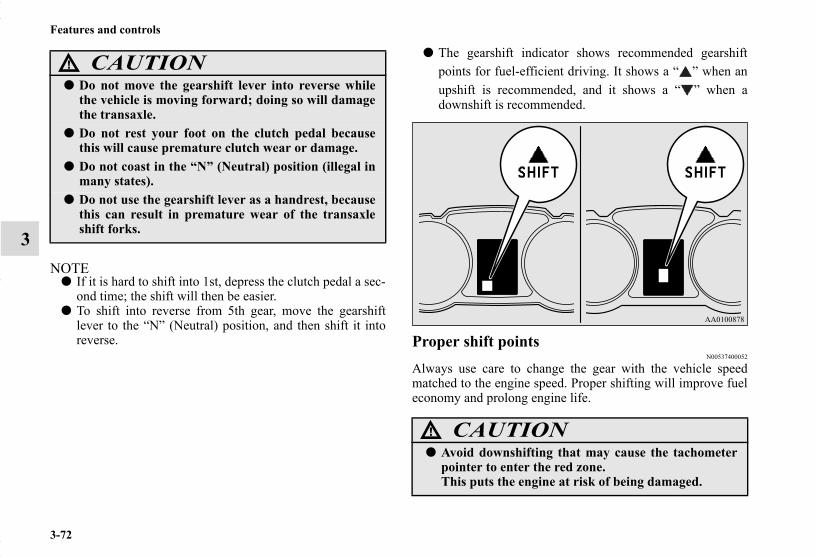
3-72
Features and controls
3NOTE
● If it is hard to shift into 1st, depress the clutch pedal a sec-ond time; the shift will then be easier.
● To shift into reverse from 5th gear, move the gearshiftlever to the “N” (Neutral) position, and then shift it intoreverse.
● The gearshift indicator shows recommended gearshiftpoints for fuel-efficient driving. It shows a “ ” when anupshift is recommended, and it shows a “ ” when adownshift is recommended.
Proper shift pointsN00537400052
Always use care to change the gear with the vehicle speedmatched to the engine speed. Proper shifting will improve fueleconomy and prolong engine life.
CAUTION!
● Do not move the gearshift lever into reverse whilethe vehicle is moving forward; doing so will damagethe transaxle.
● Do not rest your foot on the clutch pedal becausethis will cause premature clutch wear or damage.
● Do not coast in the “N” (Neutral) position (illegal inmany states).
● Do not use the gearshift lever as a handrest, becausethis can result in premature wear of the transaxleshift forks.
CAUTION!
● Avoid downshifting that may cause the tachometerpointer to enter the red zone.This puts the engine at risk of being damaged.
BK0150700US.book 72 ページ 2012年3月22日 木曜日 午後6時46分
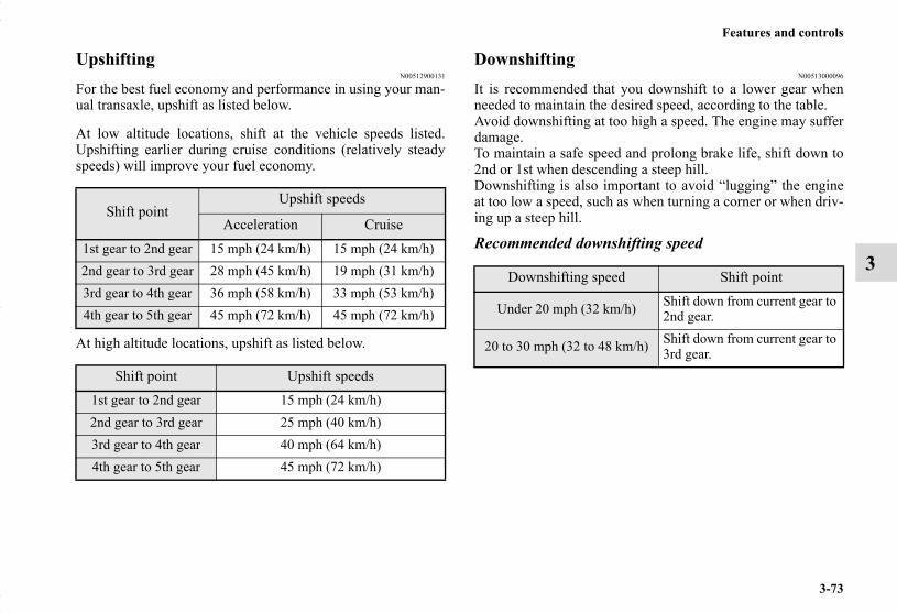
Features and controls
3-73
3
UpshiftingN00512900131
For the best fuel economy and performance in using your man-ual transaxle, upshift as listed below.
At low altitude locations, shift at the vehicle speeds listed.Upshifting earlier during cruise conditions (relatively steadyspeeds) will improve your fuel economy.
At high altitude locations, upshift as listed below.
DownshiftingN00513000096
It is recommended that you downshift to a lower gear whenneeded to maintain the desired speed, according to the table.Avoid downshifting at too high a speed. The engine may sufferdamage.To maintain a safe speed and prolong brake life, shift down to2nd or 1st when descending a steep hill.Downshifting is also important to avoid “lugging” the engineat too low a speed, such as when turning a corner or when driv-ing up a steep hill.
Recommended downshifting speed
Shift pointUpshift speeds
Acceleration Cruise1st gear to 2nd gear 15 mph (24 km/h) 15 mph (24 km/h)2nd gear to 3rd gear 28 mph (45 km/h) 19 mph (31 km/h)3rd gear to 4th gear 36 mph (58 km/h) 33 mph (53 km/h)4th gear to 5th gear 45 mph (72 km/h) 45 mph (72 km/h)
Shift point Upshift speeds1st gear to 2nd gear 15 mph (24 km/h)2nd gear to 3rd gear 25 mph (40 km/h)3rd gear to 4th gear 40 mph (64 km/h)4th gear to 5th gear 45 mph (72 km/h)
Downshifting speed Shift point
Under 20 mph (32 km/h) Shift down from current gear to 2nd gear.
20 to 30 mph (32 to 48 km/h) Shift down from current gear to 3rd gear.
BK0150700US.book 73 ページ 2012年3月22日 木曜日 午後6時46分

3-74
Features and controls
3
Driving precautionsN00513100228
● Do not use the gearshift lever as a handrest. This canresult in premature wear of the transaxle shift forks.
Maximum possible driving speed
● The table above shows the maximum recommended driv-ing speed for in each gear. Do not drive near or at thesespeeds for prolonged periods of time.
Continuously variable transmission (CVT) (if so equipped)
N00560200047
The CVT will automatically and continuously change its gearratio depending on road and driving conditions. This helpsachieve smooth driving and excellent fuel efficiency. Also youcan manually shift up and shift down the transmission. Refer to
“Sports mode” on page 3-80.
DRIVING UPHILLThe transmission prevents unnecessary upshifts even when theaccelerator pedal is released and ensures smooth driving.
DRIVING DOWNHILLAccording to the conditions, the transmission will automati-cally shift to a lower gear ratio to achieve stronger engine brak-ing. This may help reduce your need to use the service brake.
Shift points Maximum possible driving speed
1st gear 28 mph (45 km/h)2nd gear 59 mph (95 km/h)3rd gear 86 mph (140 km/h)4th gear 111 mph (180 km/h)
BK0150700US.book 74 ページ 2012年3月22日 木曜日 午後6時46分

Features and controls
3-75
3
Selector lever operationN00560300048
As an additional safety precaution, models equipped with acontinuously variable transmission have a shift-lock devicethat holds the selector lever in the “P” (PARK) position. Tomove the selector lever from the “P” (PARK) position toanother position, follow the steps below.
1. Press and hold the brake pedal down.2. Move the selector lever to the desired position.
NOTE● The selector lever cannot be moved from “P” (PARK) to
another position if the ignition switch is set to the “OFF”or “ACC” position, or if the key has been removed, or ifthe brake pedal is not pressed and held down.
The CVT selects an optimum ratio automatically when theselector lever is in the “D” (DRIVE) position, depending on thespeed of the vehicle and the position of the accelerator pedal.The selector lever (A) has 2 gates; the main gate (B) and themanual gate (C).
NOTE● There are 4 selector lever positions in the main gate.● For information on manual gate operation, please refer to
“Sports mode” on page 3-80.
BK0150700US.book 75 ページ 2012年3月22日 木曜日 午後6時46分

3-76
Features and controls
3
NOTE● To prevent mistakes in operating the lever, make sure you
stop briefly at each position. After operating, check theposition in the multi-information display.
● If the brake pedal is not depressed and held, the shift-lockdevice activates to prevent the selector lever from beingmoved from the “P” (PARK) position.
● For a shift indicated by in the illustration, depress thebrake pedal before moving the selector lever. If youattempt to move the selector lever before depressing thebrake pedal, the selector lever may be immovable.
Set the selector lever in the gate to operate while thebrake pedal is depressed.
Set the selector lever in the gate to operate.
WARNING!
● Always press the brake pedal when shifting theselector lever into a selector position from the “N”(NEUTRAL) position.When beginning to drive, do not shift the selectorlever from the “N” (NEUTRAL) position whilepressing the accelerator pedal. This will cause thevehicle to “jump” forward or backward.
BK0150700US.book 76 ページ 2012年3月22日 木曜日 午後6時46分
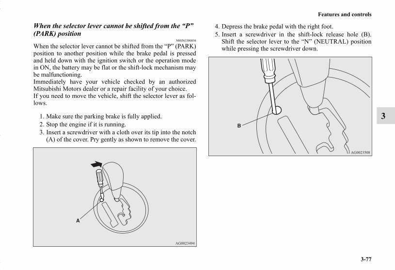
Features and controls
3-77
3
When the selector lever cannot be shifted from the “P” (PARK) position
N00563300036
When the selector lever cannot be shifted from the “P” (PARK)position to another position while the brake pedal is pressedand held down with the ignition switch or the operation modein ON, the battery may be flat or the shift-lock mechanism maybe malfunctioning.Immediately have your vehicle checked by an authorizedMitsubishi Motors dealer or a repair facility of your choice.If you need to move the vehicle, shift the selector lever as fol-lows.
1. Make sure the parking brake is fully applied.2. Stop the engine if it is running.3. Insert a screwdriver with a cloth over its tip into the notch
(A) of the cover. Pry gently as shown to remove the cover.
4. Depress the brake pedal with the right foot.5. Insert a screwdriver in the shift-lock release hole (B).
Shift the selector lever to the “N” (NEUTRAL) positionwhile pressing the screwdriver down.
BK0150700US.book 77 ページ 2012年3月22日 木曜日 午後6時46分

3-78
Features and controls
3
Selector lever position displayN00560400065
When the ignition switch is turned to the “ON” position or theoperation mode is put in ON, the position of the selector leveris indicated in the multi-information display, the selector leverposition is shown on the multi-information display.
Warning displayN00560500037
Type 1
or
Type 2
or
When the warning display or the warning displayappears on the information screen in the multi-information dis-play while you are driving, there could be a malfunction in theCVT.
Type 1 Type 2
BK0150700US.book 78 ページ 2012年3月22日 木曜日 午後6時46分

Features and controls
3-79
3
Selector lever positions (Main gate)N00560600054
“P” PARKThis position locks the transmission to prevent the vehiclefrom moving. The engine can be started from the “P” (PARK)position.
“R” REVERSEMove the lever to this position only after the vehicle has cometo a complete stop.
“N” NEUTRALAt this position, the transmission is disengaged. It is the sameas the neutral position on a manual transaxle and should beused when the vehicle is not moving for an extended length oftime during driving, such as in a traffic jam.
CAUTION!
● If a malfunction occurs in the CVT while driving,the warning display or the warning displaywill appear on the information screen in the multi-information display. In this case, follow these procedures:[When warning display is showing]The continuously variable transmission (CVT) fluidis overheating. The engine control may activate tolower the CVT fluid temperature, causing theengine revolutions and vehicle speed to decrease, Inthis case, take one of the following procedures.• Slow down your vehicle.• Stop your vehicle in a safe place, put the selector-
lever in the “P” (PARK) position, and open theengine hood with the engine running to allow theengine to cool down.
After a while, confirm that the warning display isno longer showing. It is safe to continue driving ifthe display is no longer showing. If the warning dis-play remains or flashes frequently, have your vehicleinspected by an authorized Mitsubishi Motorsdealer or a repair facility of your choice. [When warning display is showing]It may be that there is something unusual happeningin the CVT, causing a safety device to activate. Haveyour vehicle inspected by an authorized MitsubishiMotors dealer or a repair facility of your choice assoon as possible.
CAUTION!
● Never shift into the “P” (PARK) or “R”(REVERSE) position while the vehicle is in motion.If the lever is shifted into the “P” (PARK) or “R”(REVERSE) position while the vehicle is in motion,the transmission may be damaged.
WARNING!
● Never move the selector lever to the “N” (NEU-TRAL) position while driving since you could acci-dentally slip it into the “P” (PARK) or “R”(REVERSE) position, damaging the transmission.
BK0150700US.book 79 ページ 2012年3月22日 木曜日 午後6時46分

3-80
Features and controls
3“D” DRIVEThis position is used for most city and highway driving. Thetransmission will automatically and continuously change itsgear ratio depending on road and driving conditions.
Sports modeN00560700055
Whether the vehicle is stationary or in motion, sports mode isselected by pushing the selector lever from the “D” (DRIVE)position into the manual gate (A). To return to “D” (DRIVE)operation, push the selector lever back into the main gate (B).In sports mode, rapid shifting is possible simply by operatingthe selector lever or sportronic steering wheel paddle shifter.Unlike the manual transaxle, sports mode allows shifting withthe accelerator pedal depressed.
NOTE● For vehicles equipped with the sportronic steering wheel
paddle shifter, sports mode can be operated even when theselector lever is in the main gate (B). Also, you can returnto the “D” operation in any of following ways. Whenreturning to “D” operation, the selector lever position dis-play will change to “D” (DRIVE) position.• Pull the + (SHIFT UP) side sportronic steering wheel
paddle shifter forward (toward the driver) for over 2 sec-onds.
• Stop the vehicle• Push the selector lever from the “D” (DRIVE) position
into the manual gate (A) and push the selector leverback into the main gate (B).
● To prevent the vehicle from rolling when stopped ona slope, the engine should be started in the “P”(PARK) position, not in “N” (NEUTRAL) position.
● To prevent rolling, always keep your foot on thebrake pedal when the vehicle is in “N” (NEUTRAL)position, or when shifting into or out of “N” (NEU-TRAL) position.
CAUTION!
● To prevent transmission damage, never shift into the“D” (DRIVE) position from the “R” (REVERSE)position while the vehicle is in motion.
WARNING!
BK0150700US.book 80 ページ 2012年3月22日 木曜日 午後6時46分

Features and controls
3-81
3+ (SHIFT UP)Transmission shifts up once by each operation.
- (SHIFT DOWN)Transmission shifts down once by each operation.
NOTE● The upward shift may be made automatically in sports
mode when the engine revolutions rises and approachesthe tachometer’s red zone (the red-colored part of thetachometer dial).
● Shift ranges can only be selected in a forward directionfrom 1st to 6th. To reverse or park the vehicle, move theselector lever to the “R” or “P” position.
● To maintain good running performance, the transmissionmay refuse to perform an upshift when the selector leveror sportronic steering wheel paddle shifter is moved to the“+ (SHIFT UP)” position at certain vehicle speeds. Also,to prevent over-revving of the engine, the transmissionmay refuse to perform a downshift when the shift lever orsportronic steering wheel paddle shifter is moved to the “-(SHIFT DOWN)” position at certain vehicle speeds.When this happens, a buzzer sounds to indicate that adownshift is not going to take place.
● In sports mode, downward shifts are made automaticallywhen the vehicle slows down. When the vehicle stops, 1stposition is automatically selected.
CAUTION!
● In sports mode, the driver must execute upwardshifts in accordance with prevailing road conditions,taking care to keep the engine speed below the redzone.
● Repeated continuous operation of the selector leveror the sportronic steering wheel paddle shifter willcontinuously switch shift position.
SHIFT DOWN
SHIFT UP
SHIFT DOWN
SHIFT UP
● On vehicles with a sportronic steering wheel paddleshifter, shift ranges may not change when the lateralpaddle shifters are operated at the same time.
CAUTION!
BK0150700US.book 81 ページ 2012年3月22日 木曜日 午後6時46分

3-82
Features and controls
3
Sports mode displayN00560900057
In sports mode, the currently selected shift range is displayedon the information screen in the multi-information display.
Operation of the CVTN00560800027
Type 1 Type 2
CAUTION!
● Before selecting a position with the engine runningand the vehicle stationary, firmly depress the brakepedal to prevent the vehicle from creeping.The vehicle will begin to move as soon as the CVT isengaged, especially when the engine speed or idlespeed is high, or with the air conditioning operating.Do not release the brake pedal until you are ready todrive away.
● Depress the brake pedal with the right foot at alltimes.Using the left foot could cause driver movementdelay in case of an emergency.
● To prevent sudden acceleration, never run theengine at high rpms when shifting from the “P”(PARK) or “N” (NEUTRAL).
● Operating the accelerator pedal while the other footis resting on the brake pedal will affect braking effi-ciency and may cause premature wear of brakepads.
● Use the selector lever in the correct shift position inaccordance with driving conditions.Never coast downhill backward in the driving shiftposition {“D” (DRIVE) or sport mode} or coast for-ward in the “R” (REVERSE) position.Engine stopping and increased brake pedal andsteering effort could lead to an accident.
BK0150700US.book 82 ページ 2012年3月22日 木曜日 午後6時46分

Features and controls
3-83
3Passing accelerationTo gain extra acceleration in “D” (DRIVE) position (whenpassing another vehicle) push the accelerator to the floor. TheCVT will automatically downshift.
NOTE● In sports mode, downshifts do not take place when the
accelerator is depressed all the way to the floor.
WaitingFor short waiting periods, such as at traffic lights, the vehiclecan be left in selector lever position and held stationary withthe service brake.For longer waiting periods with the engine running, place theselector lever in the “N” (NEUTRAL) position and apply theparking brake, while holding the vehicle stationary with theservice brake.Prior to moving off after having stopped the vehicle, make surethat the selector lever is in “D” (DRIVE) position or Sportsmode position.
ParkingTo park the vehicle, first bring it to a complete stop, fullyengage the parking brake, and then move the selector lever tothe “P” (PARK) position.
When the CVT makes no speed changeIf the CVT does not shift while driving, or your vehicle doesnot pick up enough speed when starting on an uphill slope, itmay be that there is something unusual happening in the trans-mission, causing a safety device to activate. Have your vehiclechecked at an authorized Mitsubishi Motors dealer or a repairfacility of your choice as soon as possible.
NOTE● When the warning display and “SLOW DOWN” or the
warning display and “SERVICE REQUIRED” appearon the information screen in the multi-information dis-play, there could be a malfunction in the CVT. Refer to“Continuously variable transmission (CVT): Warning dis-play” on page 3-78.
● Do not rev the engine with the brake pedal pressedwhen the vehicle is stationary.This can damage the CVT.Also, when you depress the accelerator pedal whileholding down the brake pedal with the selector leverin the “D” (DRIVE) position, the engine revolutionsmay not rise as high as when performing the sameoperation with the selector lever in the “N” (NEU-TRAL) position.
CAUTION! CAUTION!
● To avoid transmission overheating, never try to keepyour vehicle stationary on a hill by using the acceler-ator pedal. Always apply the parking brake and/orservice brake.
● Do not rev the engine unnecessarily while the vehicleis stationary. Unexpected acceleration may occur ifthe selector lever is in a position other than “P”(PARK) or “N” (NEUTRAL).
BK0150700US.book 83 ページ 2012年3月22日 木曜日 午後6時46分
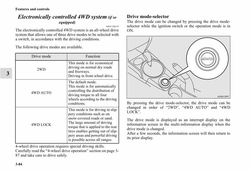
3-84
Features and controls
3
Electronically controlled 4WD system (if so equipped)
N00517200155
The electronically controlled 4WD system is an all-wheel drivesystem that allows one of three drive modes to be selected witha switch, in accordance with the driving conditions.
The following drive modes are available.
4-wheel drive operation requires special driving skills.Carefully read the “4-wheel drive operation” section on page 3-87 and take care to drive safely.
Drive mode-selectorThe drive mode can be changed by pressing the drive mode-selector while the ignition switch or the operation mode is inON.
By pressing the drive mode-selector, the drive mode can bechanged in order of “2WD”, “4WD AUTO” and “4WDLOCK”.
The drive mode is displayed as an interrupt display on theinformation screen in the multi-information display when thedrive mode is changed.After a few seconds, the information screen will then return toits prior display.
Drive mode Function
2WD
This mode is for economical driving on normal dry roads and freeways.Driving in front-wheel drive.
4WD AUTO
The default mode.This mode is for automatically controlling the distribution of driving torque to all four wheels according to the driving conditions.
4WD LOCK
This mode is for driving in slip-pery conditions such as on snow-covered roads or sand.The large amount of driving torque that is applied to the rear tires enables getting out of slip-pery areas and powerful driving is possible across all ranges.
BK0150700US.book 84 ページ 2012年3月22日 木曜日 午後6時46分

Features and controls
3-85
3
NOTE● The drive mode can be switched while driving or stopped.
Drive mode indicator
Normally the indicator illuminates when the ignition switch isturned to the “ON” position or the operation mode is put inON, and then the drive mode is displayed a few seconds afterthe engine is started.
Drive modeDisplay
Type 1 Type 2
2WD
4WD AUTO
4WD LOCK
CAUTION!
● Do not operate the drive mode-selector with thefront wheels spinning on a snowy road or in similarconditions. The vehicle could lunge in an unexpecteddirection.
● Driving on dry, paved roads in “4WD LOCK” modecauses increased fuel consumption, noise, and pre-mature tire wear.
● Do not drive with the tires spinning in “2WD” mode.Doing so could generate heat in the drive-systemcomponents.
Type 1 Type 2
DriveMode
Drive modeindicator
“4WD” indicator “LOCK” indicator2WD OFF OFF
4WD AUTO ON OFF4WD LOCK ON ON
CAUTION!
BK0150700US.book 85 ページ 2012年3月22日 木曜日 午後6時46分

3-86
Features and controls
3
CAUTION!
● If the selected drive mode indicator is blinking, thevehicle switches automatically to front-wheel drivein order to protect the drive-system components,and drive mode selection is no longer possible withthe drive mode-selector.The warning display is also displayed in the infor-mation screen in the multi-information display.Reduce speed, and if the indicator goes out afterdriving a while, resume driving as before. If the indi-cator continues blinking for more than about 5 min-utes, have the vehicle inspected at an authorizedMitsubishi Motors dealer or a repair facility of yourchoice as soon as possible.
Type 1 Type 2
CAUTION!
● The warning display on the information screen inthe multi-information display, a problem hasoccurred with the electronically controlled 4WD sys-tem and the safety device has activated. Have aninspection made by an authorized MitsubishiMotors dealer or a repair facility of your choice assoon as possible.
Type 1 Type 2
CAUTION!
● Always use tires of the same size, type, and brandthat have no wear differences. Using tires that differin size, type, brand, or wear amount may activatethe protection of the drive-system components, caus-ing the drive mode in “4WD AUTO” mode to lock orthe “4WD” and “LOCK” indicators to blink alter-nately.
BK0150700US.book 86 ページ 2012年3月22日 木曜日 午後6時46分

Features and controls
3-87
3
4-wheel drive operationN00530600156
Your vehicle has been designed primarily for use on pavement.But its unique 4 -wheel drive system allows you to occasion-ally travel on unpaved roads, to campgrounds, picnic sites, andsimilar locations.Not only does this ensure better handling on dry, paved roadsbut also permits better traction when driving on slippery, wet orsnow-covered roads and when moving out of mud.But it is not suitable for heavy off road use or towing in roughconditions.It is particularly important to note that 4-wheel drive may notgive sufficient hill climbing ability and engine braking on steepslopes. You should try to avoid driving on steep slopes.Also, you must exercise caution when driving on sand and mudand when driving through water because sufficient tractionmay not be available in certain circumstances.Please avoid driving the vehicle through areas where the tiresmay get stuck in deep sand or mud. NOTE
● Driving on rough roads can be hard on a vehicle. Beforeyou leave the pavement, be sure all scheduled mainte-nance and service has been done, and that you haveinspected your vehicle. Pay special attention to the condi-tion of the tires, and check the tire pressures.
● Mitsubishi Motors is not responsible to the operator forany damage or injury caused or liability incurred byimproper and negligent operation of a vehicle. All tech-niques of vehicle operation depend on the skill and experi-ence of the operator and other participating parties. Anydeviation from the recommended operating instructionsabove is at their own risk.
WARNING!
● Do not over-rely on the 4-wheel drive vehicles. Even4-wheel drive vehicles have limits to the system andability to maintain control and traction. Recklessdriving may lead to accidents. Always drive care-fully, taking account of the road conditions.
● Improperly operating this vehicle on or off-pave-ment can cause an accident or rollover in which youand your passengers could be seriously injured orkilled.• Follow all instructions and guidelines in the
owner’s manual.• Keep your speed low and do not drive faster than
conditions.
BK0150700US.book 87 ページ 2012年3月22日 木曜日 午後6時46分

3-88
Features and controls
3
● Note that the stopping distance required of the 4-wheeldrive vehicle differs very little from that of the front-wheel drive vehicle. When driving on a snow-coveredroad or a slippery, muddy surface, make sure that youkeep a sufficient distance between your vehicle and theone ahead of you.
● The driving posture should be more upright; adjust theseat to a good position for easy steering and pedal opera-tion. Be sure to wear the seat belt.
● After driving on rough roads, check each part of the vehi-cle and wash it thoroughly with water. Refer to the“Inspection and maintenance following rough road opera-tion” section and “Vehicle care and Maintenance” sec-tions.
Turning sharp cornersWhen turning a sharp corner in “4WD LOCK” or “LOCK”position at low speed, a slight difference in steering may beexperienced similar to feeling as if the brakes were applied.This is called tight corner braking and results from each of thefour tires being at a different distance from the corner. The phe-nomenon is typical of 4-wheel drive vehicles. If this occurs,either straighten out the steering wheel or change to anothermode.
On snowy or icy roadsSet the drive mode-selector to “4WD AUTO”, “4WD LOCK”or “SNOW” in accordance with the road conditions, and thengradually depress the accelerator pedal for a smooth start.
NOTE● The use of snow tires is recommended.● Maintain a safe distance between vehicles, avoid sudden
braking, and use engine braking (downshifting).
Driving on sandy or muddy roadsSet the drive mode-selector to “4WD LOCK” or “LOCK” andthen gradually depress the accelerator pedal for a smooth start.Keep the pressure on the accelerator pedal as constant as possi-ble, and drive at low speed.
CAUTION!
● Setting the drive mode-selector to “4WD LOCK” or“LOCK” position to drive on dry paved road willincrease fuel consumption, with possible noise gen-eration.
CAUTION!
● Avoid sudden braking, sudden acceleration andsharp turning. Skidding occurs and control of thevehicle could be lost.
CAUTION!
● Do not force the vehicle or drive recklessly on sandysurfaces. In comparison with normal road surfaces,the engine and other drive-system components areput under excessive strain when driving on such asurface. This could lead to accidents.
BK0150700US.book 88 ページ 2012年3月22日 木曜日 午後6時46分

Features and controls
3-89
3
NOTE● Avoid sudden braking, sudden acceleration and sharp
turning; such operations could result in the vehiclebecoming stuck.
● If the vehicle becomes stuck in sandy or muddy roads, itcan often be moved with a rocking motion. Move thegearshift lever alternately between the 1st and “R”(Reverse) positions (M/T), the “D” (DRIVE) and “R”(REVERSE) positions (CVT), while pressing lightly onthe accelerator pedal.
● Driving on rough road can cause rust on the vehicle; washthe vehicle thoroughly as soon as possible after such use.
Climbing/descending sharp gradesYour vehicle may not provide sufficient hill climbing abilityand engine braking on steep slope. Avoid driving on steepslopes even though the vehicle is an 4-wheel drive vehicle.
● If any of the following conditions occur while thevehicle is being driven, immediately park your vehi-cle in a safe place and follow these procedures:
• If the engine coolant temperature display flashes on the information screen in the multi-information display or the engine power dropssuddenly.Refer to “Engine overheating” on page 6-5.
• If the “ ” warning display and “SLOW DOWN”or the “ ” warning display and “SERVICEREQUIRED” appear on the information screen inthe multi-information display.Refer to “Warning display” on page 3-78.
WARNING!
● When attempting to rock your vehicle out of a stuckposition, be sure that the area around the vehicle isclear of people and physical objects. The rockingmotion may cause the vehicle to suddenly launchforward/backward, causing injury or damage tonearby people or objects.
CAUTION!
BK0150700US.book 89 ページ 2012年3月22日 木曜日 午後6時46分
3-90
Features and controls
3
Driving through waterN00537800098
If the electrical circuits become wet, further operation of thevehicle will be impossible; therefore, avoid driving throughwater unless absolutely necessary. If driving through water isunavoidable, use the following procedure:
Check the depth of the water and the terrain before attemptingto drive through it. Drive slowly to avoid creating excessivewater splashing.
Inspection and maintenance following rough road operation
N00530700098
After operating the vehicle in rough road conditions, be sure toperform the following inspection and maintenance procedures:
● Check that the vehicle has not been damaged by rocks,gravel, etc.
● Carefully wash the vehicle with water.Drive the vehicle slowly while lightly depressing thebrake pedal in order to dry out the brakes. If the brakesstill do not function properly, contact an authorizedMitsubishi Motors dealer or a repair facility of yourchoice as soon as possible to have the brakes checked.
● Remove the insects, dried grass, etc. clogging the radiatorcore.
● After driving through water, check the engine, transaxleand differential oil. If the oil or grease is milky or cloudybecause of water contamination, it must be replaced withnew oil.
● Check the inside of the vehicle. If water entry is found,dry the carpet etc.
● Inspect the headlights. If water is in the headlight housing,have it drained at an authorized Mitsubishi Motors dealeror a repair facility of your choice.
● Have an authorized Mitsubishi Motors dealer replacegrease in the wheel bearings.
CAUTION!
● Never drive through water that is deep enough tocover wheel hubs, axles or exhaust pipe. Do notchange the gearshift lever position (M/T) or theselector lever position (CVT) while driving throughwater.Frequent driving through water can adversely affectthe life span of the vehicle; consult an authorizedMitsubishi Motors dealer or a repair facility of yourchoice and take the necessary measures to prepare,inspect, and repair the vehicle.
● After driving through water, apply the brakes to besure they are functioning properly. If the brakes arewet and not functioning properly, dry them out bydriving slowly while lightly depressing the brakepedal. Inspect each part of the vehicle carefully.
BK0150700US.book 90 ページ 2012年3月22日 木曜日 午後6時46分

Features and controls
3-91
3
Cautions on the handling of 4-wheel drive vehicles
N00530800187
Tires and wheelsSince the driving torque can be applied to the four wheels, thedriving performance of the vehicle when operating in 4-wheeldrive is greatly affected by the condition of the tires.
Pay close attention to the tires.● Install only the specified tires on all wheels. Refer to
“Tires and wheels” on page 9-8.● Be sure all four tires and wheels are the same size and
type.When it is necessary to replace any of the tires or wheels,replace all four.
● All tires should be rotated before the wear differencebetween the front and rear tires is recognizable.
Good vehicle performance cannot be expected if there is a dif-ference in wear between tires. Refer to “Tire rotation” on page7-30.
● Check the tire inflation pressure regularly.
CAUTION!
● Always use tires of the same size, type, and brandthat have no wear differences. Using tires of differ-ent size, type, brands or degree of wear, will increasethe differential oil temperature and result in possi-ble damage to the driving system. Further, the drivetrain will be subject to excessive loading, possiblyleading to oil leakage, component seizure, or otherserious failures.
BK0150700US.book 91 ページ 2012年3月22日 木曜日 午後6時46分

3-92
Features and controls
3
Towing
Jacking up a 4-wheel drive vehicle
CAUTION!
● Do not tow 4-wheel drive vehicles with the front orrear wheels on the ground (Type A or Type B) asillustrated. This could result in damage to the driv-etrain, or unstable towing.If you tow 4-wheel drive vehicles, use Type C orType D equipment.
● Even in “2WD” mode, the vehicle cannot be towedwith the front or the rear wheels on the ground.
WARNING!
● Do not crank the engine while jacking up the vehi-cle.The tire on the ground may turn and the vehiclemay roll off the jack.
CAUTION!
BK0150700US.book 92 ページ 2012年3月22日 木曜日 午後6時46分

Features and controls
3-93
3
Service brakeN00517500275
Brake pedalOveruse of the brake can cause weakening, resulting in poorbrake response and premature wear of the brake pads.When driving down a long or steep hill, use engine braking bydownshifting.
Power brakesN00517600436
Your vehicle is equipped with power brakes for more brakingforce with less brake pedal effort.Your brakes are designed to operate at full capacity, even if thepower assist is not being used.If the power assist is not being used, the effort needed to pressthe brake pedal is greater.If you should lose the power assist for some reason, the brakeswill still work.If the power brake unit or either of the two brake hydraulic sys-tems stops working properly, the rest of the brake system willstill work, but the vehicle will not slow down as quickly.You will know this has happened if you find you need to pressthe brake down farther, or harder when slowing down or stop-ping, or if the brake warning light and the warning display inthe multi-information display come on. Have the brake systemrepaired at an authorized Mitsubishi Motors dealer or a repairfacility of your choice immediately.
WARNING!
● Do not leave any objects near the brake pedal or leta floor mat slide under it; doing so could prevent thefull pedal stroke that would be necessary in an emer-gency. Make sure that the pedal can be operatedfreely at all times. Make sure the floor mat issecurely held in place.
CAUTION!
● It is important not to drive the vehicle with your footresting on the brake pedal when braking is notrequired. This practice can result in very high braketemperatures, premature lining wear, and possibledamage to the brakes.
WARNING!
● Never coast downhill with the engine OFF. Keep theengine running whenever your vehicle is in motion.If you turn off the engine while driving, the powerbrake booster will stop working and your brakeswill not work as well.
● If the power assist is lost or if either brake hydraulicsystem stops working properly, take your vehicle toan authorized Mitsubishi Motors dealer or a repairfacility of your choice immediately.
BK0150700US.book 93 ページ 2012年3月22日 木曜日 午後6時46分

3-94
Features and controls
3
Brake pad wear alarmN00550700124
The disc brakes have an alarm that makes a metallic squealwhen the brake pads have worn down enough to need service.If you hear this sound, have the brake pads replaced at anauthorized Mitsubishi Motors dealer or a repair facility of yourchoice.
Hill start assistN00562600074
The hill start assist makes it easy to start off on a steep uphillslope by preventing the vehicle from moving backwards. Itkeeps the braking force for about 2 second when you moveyour foot from the brake pedal to the accelerator pedal.
WARNING!
● Driving with worn brake pads will make it harder tostop, and can cause an accident.
CAUTION!● Do not overly rely on the hill start assist to prevent
backwards movement of the vehicle. Under certaincircumstances, even when hill start assist is acti-vated, the vehicle may move backwards if the brakepedal is not sufficiently depressed, if the vehicle isheavily loaded, or if the road is very steep or slip-pery.
● The hill start assist is not designed to keep the vehi-cle stopped in place on uphill slopes for more than 2seconds.
● When facing uphill, do not rely on using the hillstart assist to maintain a stopped position as analternative to depressing the brake pedal.Doing so could cause an accident.
● Do not perform the following operation while thehill start assist is operating.[Except for vehicles equipped with the F.A.S.T.-key]Turn the ignition switch to the “OFF” or “ACC”position.[Vehicles equipped with the F.A.S.T.-key]Put the operation mode in OFF or ACC. The hillstart assist could stop operating, which could resultin an accident.
BK0150700US.book 94 ページ 2012年3月22日 木曜日 午後6時46分

Features and controls
3-95
3
To operateN00562700059
1. Stop the vehicle completely using the brake pedal.2. On vehicles equipped with manual transaxle, place the
gearshift lever into the 1st positon.On vehicles equipped with a continuously variable trans-mission (CVT), place the selector lever into the “D” posi-tion.
NOTE● When reversing on an uphill slope, place the gearshift
lever or the selector lever into the “R” position.
3. Release the brake pedal and the hill start assist will main-tain the braking force applied while stopping for approxi-mately 2 seconds.
4. Depress the accelerator pedal and the hill start assist grad-ually will decrease the braking force as the vehicle startsmoving.
NOTE● The hill start assist is activated when all of the following
conditions are met.• The engine is running.
(The hill start assist will not be activated while theengine is starting or immediately after the engine isstarted.)
• On vehicles equipped with manual transaxle, the gear-shift lever is in the following position.[When starting an uphill slope forwards.]The gearshift lever is in any position other than “R”.(The hill start assist will operate, even if the gearshiftlever is in the “N” position.)
[When starting an uphill slope backwards.]The gearshift lever is in the “R” position.(The hill start assist will not operate when the gearshiftlever is in the “N” position.)
• On vehicles equipped with CVT, the selector lever is inany position other than “P” or “N”.
• The vehicle is completely stationary, with the brakepedal depressed.
• The parking brake is released.● The hill start assist will not operate if the accelerator pedal
is depressed before the brake pedal is released.● The hill start assist also operates when reversing on an
uphill slope.
Warning displayN00562800050
If an abnormal condition occurs in the system, the followingdisplay/indicator will turn on.
Warning display type 1
Warning display type 2
- ASC indicator
BK0150700US.book 95 ページ 2012年3月22日 木曜日 午後6時46分

3-96
Features and controls
3
NOTE● The combination of items shown on the display varies
depending on the vehicle model.
Brake assist systemN00567300089
The brake assist system is a device assisting drivers who can-not depress the brake pedal firmly such as in emergency stopsituations and provides greater braking force.
If the brake pedal is depressed suddenly, the brakes will beapplied with more force than usual.
CAUTION!
● If the warning is displayed, the hill start assist willnot operate. Start off carefully.
● Park your vehicle in a safe place and stop the engine.Restart the engine and check whether the indica-tor/display goes out, in which case the hill start assistis again working normally. If they remain displayed or reappear frequently, it isnot necessary to stop the vehicle immediately, butthe vehicle should be inspected by an authorizedMitsubishi Motors dealer or a repair facility of yourchoice as soon as possible.
CAUTION!
● The brake assist system is not a device designed toexercise braking force greater than its capacity.Make sure to always keep a sufficient distancebetween vehicles in front of you without relying toomuch on the brake assist system.
BK0150700US.book 96 ページ 2012年3月22日 木曜日 午後6時46分
Features and controls
3-97
3
NOTE● Once the brake assist system is operational, it maintains
great braking force even if the brake pedal is lightlyreleased.To stop its operation, completely remove your foot fromthe brake pedal.
● The brake assist system may become operational when thebrake pedal is fully depressed even if it has not beendepressed suddenly.
● When the brake assist system is in use while driving, youmay feel as if the depressed brake pedal is soft, the pedalmoves in small motions in conjunction with the operationnoise, or the vehicle body and the steering wheel vibrate.This occurs when the brake assist system is operating nor-mally and does not indicate faulty operation. Continue todepress the brake pedal.
● You may hear an operation noise when the brake pedal issuddenly or fully depressed while stationary. This doesnot indicate a malfunction and the brake assist system isoperating normally.
Anti-lock braking systemN00517900240
The anti-lock braking system helps prevent the wheels fromlocking up when braking. This helps maintain vehicle drivabil-ity and steering wheel handling.
Driving hints● When using the anti-lock brakes (sudden braking), steer-
ing is slightly different from normal driving conditions.Use the steering wheel carefully.
● Always keep a safe distance from the vehicle in front ofyou. Even if your vehicle is equipped with the anti-lockbraking system, leave a greater braking distance when:• Driving on gravel or snow-covered roads.• Driving on uneven road surfaces.
● Operation of anti-lock braking system is not restricted sit-uations where brakes are applied suddenly. This systemmay also prevent the wheels from locking when you driveover manholes, steel roadwork plates, road markings, orany uneven road surface.
● When the anti-lock braking system is in use, you may feelthe brake pedal vibrating and hear a unique sound. It mayalso feel as if the pedal resists being pressed.In this situation, simply hold the brake pedal downfirmly. Do not pump the brake, which will result inreduced braking performance.
BK0150700US.book 97 ページ 2012年3月22日 木曜日 午後6時46分
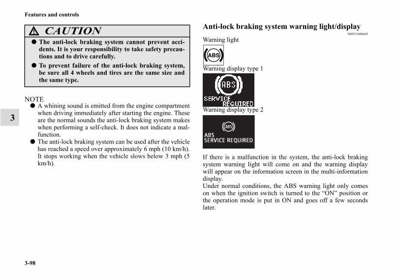
3-98
Features and controls
3
NOTE● A whining sound is emitted from the engine compartment
when driving immediately after starting the engine. Theseare the normal sounds the anti-lock braking system makeswhen performing a self-check. It does not indicate a mal-function.
● The anti-lock braking system can be used after the vehiclehas reached a speed over approximately 6 mph (10 km/h).It stops working when the vehicle slows below 3 mph (5km/h).
Anti-lock braking system warning light/displayN00531600645
Warning light
Warning display type 1
Warning display type 2
If there is a malfunction in the system, the anti-lock brakingsystem warning light will come on and the warning displaywill appear on the information screen in the multi-informationdisplay.Under normal conditions, the ABS warning light only comeson when the ignition switch is turned to the “ON” position orthe operation mode is put in ON and goes off a few secondslater.
CAUTION!
● The anti-lock braking system cannot prevent acci-dents. It is your responsibility to take safety precau-tions and to drive carefully.
● To prevent failure of the anti-lock braking system,be sure all 4 wheels and tires are the same size andthe same type.
BK0150700US.book 98 ページ 2012年3月22日 木曜日 午後6時46分

Features and controls
3-99
3
If the warning light/display illuminate while driv-ing
N00531700574
If only the anti-lock braking system warning light/dis-play illuminate
● Avoid hard braking and high-speed driving. Stop the vehi-cle in a safe place.Test the system by restarting the engine and driving at aspeed of about 12 mph (20 km/h) or higher.If the warning light/display then remains off during driv-ing, there is no abnormal condition.However, if the warning light/display do not disappear, orif they come on again when the vehicle is driven, have thevehicle checked by an authorized MITSUBISHIMOTORS dealer or repair facility of your choice as soonas possible.
CAUTION!
● Any of the following indicates that the anti-lockbraking system is not functioning and only the stan-dard brake system is working. (The standard brakesystem is functioning normally.) If this happens,take your vehicle to an authorized MitsubishiMotors dealer or a repair facility of your choice. • When the ignition switch is turned to the “ON”
position or the operation mode is put in ON, thewarning light does not come on or it remains onand does not go off.
• The warning light comes on while driving• The warning display appears while driving
BK0150700US.book 99 ページ 2012年3月22日 木曜日 午後6時46分
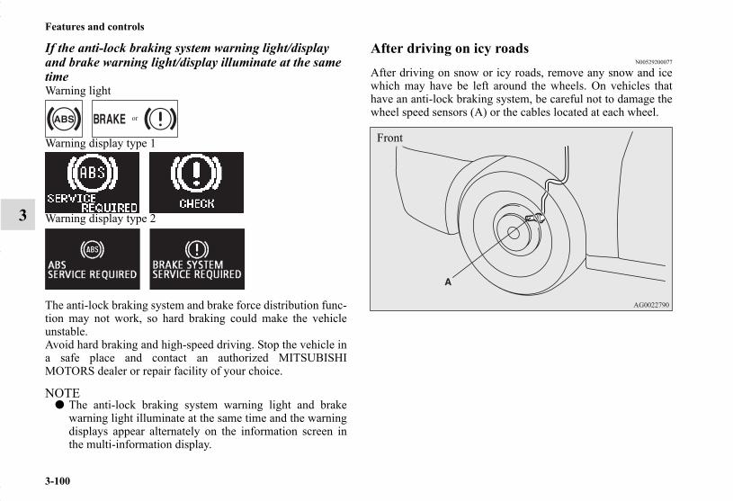
3-100
Features and controls
3
If the anti-lock braking system warning light/display and brake warning light/display illuminate at the same timeWarning light
Warning display type 1
Warning display type 2
The anti-lock braking system and brake force distribution func-tion may not work, so hard braking could make the vehicleunstable.Avoid hard braking and high-speed driving. Stop the vehicle ina safe place and contact an authorized MITSUBISHIMOTORS dealer or repair facility of your choice.
NOTE● The anti-lock braking system warning light and brake
warning light illuminate at the same time and the warningdisplays appear alternately on the information screen inthe multi-information display.
After driving on icy roadsN00529200077
After driving on snow or icy roads, remove any snow and icewhich may have be left around the wheels. On vehicles thathave an anti-lock braking system, be careful not to damage thewheel speed sensors (A) or the cables located at each wheel.
Front
BK0150700US.book 100 ページ 2012年3月22日 木曜日 午後6時46分

Features and controls
3-101
3
Electric power steering system (EPS)N00568400061
The power steering system operates while the engine is run-ning. It helps reduce the effort needed to turn the steeringwheel.The power steering system has mechanical steering capabilityin case the power assist is lost. If the power assist is lost forsome reason, you will still be able to steer your vehicle, butyou will notice it takes much more effort to steer. If this hap-pens, have your vehicle inspected at an authorized MitsubishiMotors dealer or a repair facility of your choice.
NOTE● During repeated full-lock turning of the steering wheel
(for example, while you are manoeuvring the vehicle intoa parking space), a protection function may be activated toprevent overheating of the power steering system. Thisfunction will make the steering wheel gradually harder toturn. In this event, limit your turning of the steering wheelfor a while. When the system has cooled down, the steer-ing effort will return to normal.
● If you turn the steering wheel while the vehicle is station-ary with the headlights on, the headlights may becomedim. This behavior is not abnormal. The headlights willreturn to their original brightness after a short while.
Rear
WARNING!
● Do not stop the engine while the vehicle is moving.Stopping the engine would make the steering wheelextremely hard to turn, possibly resulting in an acci-dent.
BK0150700US.book 101 ページ 2012年3月22日 木曜日 午後6時46分
3-102
Features and controls
3
Electric power steering system warning displayType 1
Type 2
If there is a malfunction in the system, the warning display willappear on the information screen in the multi-information dis-play.
Active stability control (ASC)N00559100134
The Active stability control (ASC) takes overall control of theanti-lock braking system, traction control function and skidcontrol function to help maintain the vehicle’s control and trac-tion. Please read this section in conjunction with the page onthe anti-lock braking system, traction control function and skidcontrol function.
Anti-lock braking system → P.3-97Traction control function → P.3-103Skid control function → P.3-103
CAUTION!
● If the warning display appears while the engine isrunning, have the vehicle inspected by an authorizedMitsubishi Motors dealer or a repair facility of yourchoice as soon as possible. It may become harder toturn the steering wheel.
CAUTION!
● Do not over-rely on the ASC. Even the ASC cannotprevent the natural laws of physics from acting onthe vehicle. This system, like any other system, haslimits and cannot help you to maintain traction andcontrol of the vehicle in all circumstances. Recklessdriving can lead to accidents. It is the driver’sresponsibillty to drive carefully, This means takinginto account the traffic, road and environmentalconditions.
● Be sure to use the same specified type and size of tireon all four wheels. Otherwise, the ASC may notwork properly.
● Do not install any aftermarket limited slip differen-tial (LSD) on your vehicle. The ASC may stop func-tioning properly.
BK0150700US.book 102 ページ 2012年3月22日 木曜日 午後6時46分

Features and controls
3-103
3
NOTE● An operation noise may be emitted from the engine com-
partment in the following situations. The sound is associ-ated with checking the operations of the ASC. At thistime, you may feel a shock from the brake pedal if youdepress it. These do not indicate a malfunction.• When the ignition switch is turned to the “ON” position
or the operation mode is put in ON.• When the vehicle is driven for a while after the engine is
turned on.● When the ASC is activated, you may feel a vibration in
the vehicle body or hear a whining sound from the enginecompartment.This indicates that the system is operating normally. Itdoes not indicate a malfunction.
● When the anti-lock braking system warning light is illu-minated, the ASC is not active.
Traction control functionN00559200076
On slippery surfaces, the traction control function prevents thedrive wheels from spinning excessive, thus helping the vehicleto start moving from a stopped condition. It also provides suffi-cient driving force and steering performance as the vehicleturns while pressing the acceleration pedal.
Skid control functionN00559300051
The skid control function is designed to help the driver main-tain control of the vehicle on slippery roads or during rapidsteering maneuvers. It works by controlling the engine outputand the brake on each wheel.
NOTE● The skid control function operates at speeds of about 9
mph (15 km/h) or higher.
CAUTION!
● When driving a vehicle on a snowy or icy road, besure to install snow tires and drive the vehicle atmoderate speeds.
BK0150700US.book 103 ページ 2012年3月22日 木曜日 午後6時46分

3-104
Features and controls
3
ASC OFF switchN00559400241
The ASC is automatically activated when the ignition switch isturned to the “ON” position or the operation mode is put inON. You can deactivate the system by pressing down the “ASCOFF” switch for 3 seconds or longer. When the ASC is deactivated, the display/indicator will turnon. To reactivate the ASC, momentarily press the “ASC OFF”switch ; the display/indicator is turned off.
NOTE● Using the “ASC OFF” switch turns off both the stability
control function and the traction control function.● When moving out of mud, sand or fresh snow, pressing
the accelerator pedal may not allow the engine speed toincrease. In such situations, temporarily turning off ASCwith the “ASC OFF” switch will make it easier to moveout your vehicle.
● If you continue to press the “ASC OFF” switch after theASC is turned off, the “mistaken operation protectionfunction” will activate and the ASC will turn back on.
CAUTION!
● For safety reasons, the “ASC OFF” switch should beoperated when your vehicle is stopped.
● Be sure to keep the ASC on while driving in normalcircumstances.
BK0150700US.book 104 ページ 2012年3月22日 木曜日 午後6時46分

Features and controls
3-105
3
ASC operation display or ASC OFF displayN00546500075
NOTE● The combination of items shown on the display varies
depending on the vehicle model.
NOTE● The display/indicator may turn on when you start the
engine. This means that the battery voltage momentarilydropped when the engine was started. It does not indicatea malfunction, provided that the display goes out immedi-ately.
● When a compact spare tire has been put on your vehicle,the gripping ability of the tire will be lower, making itmore likely that the display/indicator will blink.
- ASC operation display/ASC indicatorThe display/indicator will blink when the ASC is operat-ing.
- ASC OFF display/ASC OFF indicatorThis display/incicator will turn on when the ASC isturned off with the “ASC OFF” switch.
CAUTION!
● When display/indicator blinks, ASC is operating,which means that the road is slippery or that yourvehicle’s wheels are beginning to slip. If this hap-pens, drive slower with less accelerator input.
● If the temperature in the braking system continuesto increase due to continuous brake control on aslippery road surface, the display/indicator willblink. To prevent the brake system from overheat-ing, the brake control of the traction control func-tion will be temporarily suspended.The engine control of the traction control functionand normal brake operation will not be affected.Park your vehicle in a safe place. When the temper-ature in the braking system has come down, the display/indicator will be turned off and the tractioncontrol function will start operating again.
BK0150700US.book 105 ページ 2012年3月22日 木曜日 午後6時46分
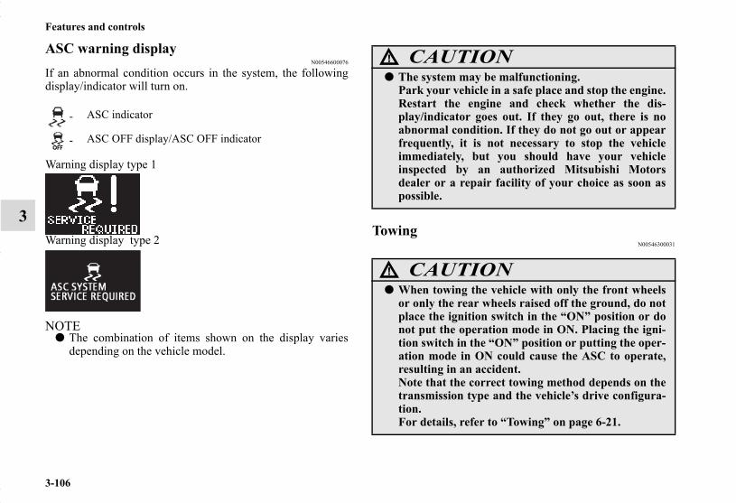
3-106
Features and controls
3
ASC warning displayN00546600076
If an abnormal condition occurs in the system, the followingdisplay/indicator will turn on.
Warning display type 1
Warning display type 2
NOTE● The combination of items shown on the display varies
depending on the vehicle model.
TowingN00546300031
- ASC indicator
- ASC OFF display/ASC OFF indicator
CAUTION!
● The system may be malfunctioning.Park your vehicle in a safe place and stop the engine.Restart the engine and check whether the dis-play/indicator goes out. If they go out, there is noabnormal condition. If they do not go out or appearfrequently, it is not necessary to stop the vehicleimmediately, but you should have your vehicleinspected by an authorized Mitsubishi Motorsdealer or a repair facility of your choice as soon aspossible.
CAUTION!
● When towing the vehicle with only the front wheelsor only the rear wheels raised off the ground, do notplace the ignition switch in the “ON” position or donot put the operation mode in ON. Placing the igni-tion switch in the “ON” position or putting the oper-ation mode in ON could cause the ASC to operate,resulting in an accident.Note that the correct towing method depends on thetransmission type and the vehicle’s drive configura-tion.For details, refer to “Towing” on page 6-21.
BK0150700US.book 106 ページ 2012年3月22日 木曜日 午後6時46分

Features and controls
3-107
3
Cruise control (if so equipped)N00518300544
Cruise control is an automatic speed control system that keepsa set speed. It can be activated at speeds from about 25 mph(40 km/h). Cruise control does not work at speeds below about25 mph (40 km/h).
NOTE● Cruise control may not be able to keep your speed on
uphills or downhills.● Your speed may decrease on a steep uphill. You may use
the accelerator pedal if you want to stay at your set speed.● Your speed may increase to more than the set speed on a
steep downhill. You have to use the brake to control yourspeed. As a result, the set speed driving is deactivated.
Cruise control switches
CAUTION!
● When you do not wish to drive at a set speed, turnoff the cruise control for safety.
● Do not use cruise control when driving conditionswill not allow you to stay at the same speed, such asin heavy traffic or on roads that are winding, icy,snow-covered, wet, slippery, on a steep downhillslope.
● On vehicles equipped with manual transaxle, do notmove the gearshift lever to the “N” (Neutral) posi-tion while driving at a set speed without depressingthe clutch pedal. The engine will run too fast andmight be damaged.
BK0150700US.book 107 ページ 2012年3月22日 木曜日 午後6時46分
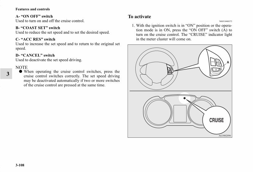
3-108
Features and controls
3
A- “ON OFF” switchUsed to turn on and off the cruise control.
B- “COAST SET” switchUsed to reduce the set speed and to set the desired speed.
C- “ACC RES” switch Used to increase the set speed and to return to the original setspeed.
D- “CANCEL” switchUsed to deactivate the set speed driving.
NOTE● When operating the cruise control switches, press the
cruise control switches correctly. The set speed drivingmay be deactivated automatically if two or more switchesof the cruise control are pressed at the same time.
To activateN00518400372
1. With the ignition switch is in “ON” position or the opera-tion mode is in ON, press the “ON OFF” switch (A) toturn on the cruise control. The “CRUISE” indicator lightin the meter cluster will come on.
BK0150700US.book 108 ページ 2012年3月22日 木曜日 午後6時46分

Features and controls
3-109
3
NOTE● If the cruise control is on when the following operation is
performed, cruise control will be on automatically thenext time you start the engine. The “CRUISE” indicatorlight will also be on.[Except for vehicles equipped with the F.A.S.T.-key] Turn the ignition switch to the “OFF” or “ACC” position.[Vehicles equipped with the F.A.S.T.-key] Put the operation mode in OFF or ACC.
● If the battery voltage is insufficient, the memory data forthe cruise control may be erased.As a result, the “CRUISE” indicator light may not comeon when you restart the engine.If this happens, press the “ON OFF” switch once again toturn on the cruise control.
2. Accelerate or decelerate to your desired speed, then pressand release the “COAST SET” switch (B) when the“CRUISE” indicator light is illuminated. The vehicle willthen maintain the desired speed.
NOTE● When you release the “COAST SET” switch, the vehicle
speed will be set.
BK0150700US.book 109 ページ 2012年3月22日 木曜日 午後6時46分
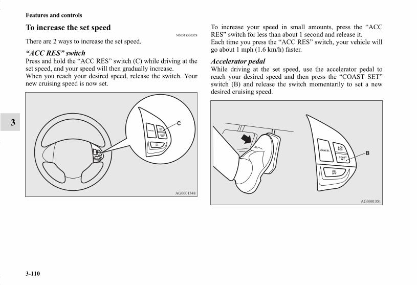
3-110
Features and controls
3
To increase the set speedN00518500328
There are 2 ways to increase the set speed.
“ACC RES” switchPress and hold the “ACC RES” switch (C) while driving at theset speed, and your speed will then gradually increase.When you reach your desired speed, release the switch. Yournew cruising speed is now set.
To increase your speed in small amounts, press the “ACCRES” switch for less than about 1 second and release it.Each time you press the “ACC RES” switch, your vehicle willgo about 1 mph (1.6 km/h) faster.
Accelerator pedalWhile driving at the set speed, use the accelerator pedal toreach your desired speed and then press the “COAST SET”switch (B) and release the switch momentarily to set a newdesired cruising speed.
BK0150700US.book 110 ページ 2012年3月22日 木曜日 午後6時46分

Features and controls
3-111
3
To decrease the set speedN00518600257
There are 2 ways to decrease the set speed.
“COAST SET” switchPress and hold the “COAST SET” switch (B) while driving atthe set speed, and your speed will slow down gradually.When you reach your desired speed, release the switch. Yournew cruising speed is now set.
To slow down your speed in small amounts, press the “COASTSET” switch for less than about 1 second and release it.Each time you press the “COAST SET” switch, your vehiclewill slow down by about 1 mph (1.6 km/h).
Brake pedalWhile driving at the set speed, use the brake pedal, which dis-engages the cruise control, then press the “COAST SET”switch (B) and release the switch momentarily to set a newdesired cruising speed.
BK0150700US.book 111 ページ 2012年3月22日 木曜日 午後6時46分

3-112
Features and controls
3
To temporarily increase or decrease the speedN00541700043
To temporarily increase the speedDepress the accelerator pedal as you would normally. Whenyou release the pedal, you will return to your set speed.
To temporarily decrease the speedDepress the brake pedal to decrease the speed. To return to thepreviously set speed, press the “ACC RES” switch (C).Refer to “To resume the set speed” on page 3-114.
BK0150700US.book 112 ページ 2012年3月22日 木曜日 午後6時46分

Features and controls
3-113
3
To deactivateN00518800549
The set speed driving can be deactivated as follows:● Press the “ON OFF” switch (A). (Cruise control will be
turned off.)● Press the “CANCEL” switch (D).● Depress the brake pedal.
The set speed driving is deactivated automatically in any of thefollowing ways.
● When you depress the clutch pedal (on vehicles equippedwith manual transaxle).
● When your speed slows to about 10 mph (15 km/h) ormore below the set speed because of a hill, etc.
● When your speed slows to about 25 mph (40 km/h) orless.
● When the active stability control (ASC) starts operating.Refer to “Active stability control (ASC)” on page 3-102.
Also, the set speed driving may be deactivated as follow:● When the engine speed rises and approaches the tachome-
ter’s red zone (the red-colored part of the tachometer dial).
WARNING!
● On vehicles equipped with continuously variabletransmission (CVT), although the set speed drivingwill be deactivated when shifting to the “N” (NEU-TRAL) position, never move the selector lever to the“N” (NEUTRAL) position while driving.You would have no engine braking and could causea serious accident.
CAUTION!
● When the set speed driving is deactivated automati-cally in any situation other than those listed above,there may be a system malfunction.Press the “ON OFF” switch to turn off the cruisecontrol and have your vehicle inspected by an autho-rized Mitsubishi Motors dealer or a repair facility ofyour choice.
BK0150700US.book 113 ページ 2012年3月22日 木曜日 午後6時46分

3-114
Features and controls
3
To resume the set speedN00518900292
If the set speed driving is deactivated by the conditiondescribed in “To deactivate” on page 3-113, you can resumethe previously set speed by pressing the “ACC RES” switch(C) while driving at a speed of about 25 mph (40 km/h) orhigher.
Under either of the following conditions, however, using theswitch does not allow you to resume the previously set speed.In these situations, repeat the speed setting procedure:
● The “ON OFF” switch is pressed.● [Except for vehicles equipped with the F.A.S.T.-key]
Turn the ignition switch to the “OFF” or “ACC” position.[Vehicles equipped with the F.A.S.T.-key] Put the operation mode in OFF or ACC.
● “CRUISE” indicator light is turned OFF.
BK0150700US.book 114 ページ 2012年3月22日 木曜日 午後6時46分

Features and controls
3-115
3
Tire pressure monitoring systemN00530200468
The tire pressure monitoring system uses tire inflation pressuresensors (A) on the wheels to monitor the tire inflation pres-sures. The system only indicates when a tire is significantlyunder-inflated.
NOTE● The tire pressure monitoring system is not a substitute for
regularly checking tire inflation pressures.Be sure to check the tire inflation pressures as described in“Tires” on page 7-23.
● The rubber air valve where the tire inflation pressure sen-sor is mounted should be replaced with a new one whenthe tire is replaced.For details, contact your authorized Mitsubishi Motorsdealer.
WARNING!
● The compact spare wheel does not have a tire infla-tion pressure sensor.When the spare tire is used, the tire pressure moni-toring system will not work properly.See an authorized Mitsubishi Motors dealer as soonas possible to replace or repair the original tire.
Tire inflation pressure sensor
Rubber air valve
BK0150700US.book 115 ページ 2012年3月22日 木曜日 午後6時46分
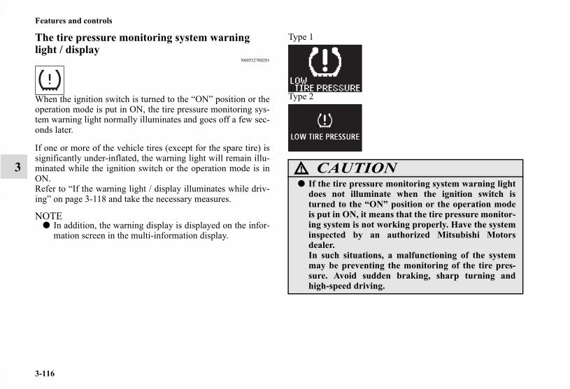
3-116
Features and controls
3
The tire pressure monitoring system warning light / display
N00532700281
When the ignition switch is turned to the “ON” position or theoperation mode is put in ON, the tire pressure monitoring sys-tem warning light normally illuminates and goes off a few sec-onds later.
If one or more of the vehicle tires (except for the spare tire) issignificantly under-inflated, the warning light will remain illu-minated while the ignition switch or the operation mode is inON.Refer to “If the warning light / display illuminates while driv-ing” on page 3-118 and take the necessary measures.
NOTE● In addition, the warning display is displayed on the infor-
mation screen in the multi-information display.
Type 1
Type 2
CAUTION!
● If the tire pressure monitoring system warning lightdoes not illuminate when the ignition switch isturned to the “ON” position or the operation modeis put in ON, it means that the tire pressure monitor-ing system is not working properly. Have the systeminspected by an authorized Mitsubishi Motorsdealer.In such situations, a malfunctioning of the systemmay be preventing the monitoring of the tire pres-sure. Avoid sudden braking, sharp turning andhigh-speed driving.
BK0150700US.book 116 ページ 2012年3月22日 木曜日 午後6時46分

Features and controls
3-117
3
NOTE● In addition, the warning display is displayed on the infor-
mation screen in the multi-information display.
Type 1
Type 2
Each tire, including the spare (if provided), should be checkedmonthly when cold and inflated to the inflation pressure rec-ommended by the vehicle manufacturer on the vehicle placardor tire inflation pressure label. (If your vehicle has tires of adifferent size than the size indicated on the vehicle placard ortire inflation pressure label, you should determine the propertire inflation pressure for those tires.)As an added safety feature, your vehicle has been equippedwith a tire pressure monitoring system (TPMS) that illuminatesa low tire pressure telltale when one or more of your tires issignificantly under-inflated.Accordingly, when the low tire pressure telltale illuminates,you should stop and check your tires as soon as possible, andinflate them to the proper pressure. Driving on a significantlyunder-inflated tire causes the tire to overheat and can lead totire failure.Under-inflation also reduces fuel efficiency and tire tread life,and may affect the vehicle’s handling and stopping ability.Please note that the TPMS is not a substitute for proper tiremaintenance, and it is the driver’s responsibility to maintain
● If a malfunction is detected in the tire pressure mon-itoring system, the tire pressure monitoring systemwarning light will blink for approximately 1 minuteand then remain continuously illuminated. Thewarning light will issue further warnings each timethe engine is restarted as long as the malfunctionexists.Check to see whether the warning light goes off afterfew minutes driving.If it then goes off during driving, there is no prob-lem.However, if the warning light does not go off, or if itblinks again when the engine is restarted, have thevehicle inspected by an authorized MitsubishiMotors dealer.In such situations, a malfunctioning of the systemmay be preventing the monitoring of the tire pres-sure. For safety reasons, when the warning lightappears while driving, avoid sudden braking, sharpturning and high-speed driving.
CAUTION!
BK0150700US.book 117 ページ 2012年3月22日 木曜日 午後6時46分

3-118
Features and controls
3
correct tire pressure, even if under-inflation has not reached thelevel to trigger illumination of the TPMS low tire pressure tell-tale.
Your vehicle has also been equipped with a TPMS malfunctionindicator to indicate when the system is not operating properly.The TPMS malfunction indicator is combined with the low tirepressure telltale.When the system detects a malfunction, the telltale will flashfor approximately one minute and then remain continuouslyilluminated. This sequence will continue upon subsequentvehicle start-ups as long as the malfunction exists.When the malfunction indicator is illuminated, the system maynot be able to detect or signal low tire pressure as intended.TPMS malfunctions may occur for a variety of reasons, includ-ing the installation of replacement or alternate tires or wheelson the vehicle that prevent the TPMS from functioning prop-erly. Always check the TPMS malfunction telltale after replac-ing one or more tires or wheels on your vehicle to ensure thatthe replacement or alternate tires and wheels allow the TPMSto continue to function properly.
If the warning light/display illuminates while driving
N00532800471
1. If the tire pressure monitoring system warning light illu-minates, avoiding hard braking, sharp steering maneuversand high speeds. You should stop and adjust the tires tothe proper inflation pressure as soon as possible. Adjustthe spare tire at the same time. Refer to “Tires” on page 7-23.
NOTE● In addition, the warning display is displayed on the infor-
mation screen in the multi-information display.● When inspecting or adjusting the tire pressure, do not
apply excessive force to the valve stem to avoid breakage.● After inspecting or adjusting the tire pressure, always
reinstall the valve cap on the valve stem.Without the valve cap, dirt or moisture could get into thevalve, resulting in damage to the tire inflation pressuresensor.
● Do not use metal valve caps, which may cause a metalreaction, resulting in corrosion and damage of the tireinflation pressure sensors.
● Once adjustments have been made, the warning light willgo off after a few minutes of driving.
BK0150700US.book 118 ページ 2012年3月22日 木曜日 午後6時46分

Features and controls
3-119
3
2. If the tire pressure monitoring system warning lightremains illuminated after you have been driving for about20 minutes after you adjust the tire inflation pressure, oneor more of the tires may have a puncture. Inspect the tireand if it has a puncture, have it repaired by an authorizedMitsubishi Motors dealer as soon as possible.
NOTE● To avoid the risk of damage to the tire inflation pressure
sensors, have any punctured tire repaired by an authorizedMitsubishi Motors dealer. If the tire repair is not done byan authorized Mitsubishi Motors dealer, it is not coveredby your warranty.
● Do not use an aerosol puncture-repair spray on any tire.Such a spray could damage the tire inflation pressure sen-sors.Have any puncture repaired by an authorized MitsubishiMotors dealer.
The tire pressure monitoring system may not work normally inthe following circumstances:
● A wireless facility or device using the same frequency isnear the vehicle.
● Snow or ice is stuck inside the fenders and/or on thewheels.
● The tire inflation pressure sensor’s battery is dead.● Wheels other than Mitsubishi genuine wheels are being
used.● Wheels that are not fitted with tire inflation pressure sen-
sors are being used.● Wheels whose ID codes are not memorized by the vehicle
are used.● Compact spare tire is fitted on a road wheel.● A window tint that affects the radio wave signals is
installed.
WARNING!
● If the warning light/display illuminates while youare driving, avoid hard braking, sharp steeringmaneuvers and high speeds.Driving with an under-inflated tire adversely affectsvehicle performance and can result in an accident.
CAUTION!
● If a tire has a puncture, replace that tire with thespare tire. Driving on a punctured tire could lead toan accident.
● The warning light/display may not illuminate imme-diately in the event of a tire blowout or rapid leak.
BK0150700US.book 119 ページ 2012年3月22日 木曜日 午後6時46分

3-120
Features and controls
3
NOTE● Tire inflation pressures vary with the ambient tempera-
ture. If the vehicle is subjected to large variations in ambi-ent temperature, the tire inflation pressures may be under-inflated (causing the warning light/display come on) whenthe ambient temperature is relatively low. If the warninglight/display comes on, adjust the tire inflation pressure.
Whenever the tires and wheels are replaced with new ones
N00532900153
If new wheels with new tire inflation pressure sensors areinstalled, their ID codes must be programmed into the tire pres-sure monitoring system. Have tire and wheel replacement per-formed by an authorized Mitsubishi Motors dealer to avoid therisk of damaging the tire inflation pressure sensors. If thewheel replacement is not done by an authorized MitsubishiMotors dealer, it is not covered by your warranty.
General informationN00533000223
Your tire pressure monitoring system operates on a radio fre-quency subject to Federal Communications Commission(FCC) Rules (For vehicles sold in U.S.A.) and Industry CanadaRules (For vehicles sold in Canada). This device complies withPart 15 of the FCC Rules and RSS-Gen of the Industry CanadaRules.Operation is subject to the following two conditions.
● This device may not cause harmful interference.● This device must accept any interference received, includ-
ing interference that may cause undesired operation.
CAUTION!
● The use of non-genuine wheels will prevent theproper fit of the tire inflation pressure sensors,resulting air leakage or damage of the sensors.
CAUTION!
● Changes or modifications not expressly approved bythe manufacturer for compliance could void theuser’s authority to operate the equipment.
BK0150700US.book 120 ページ 2012年3月22日 木曜日 午後6時46分
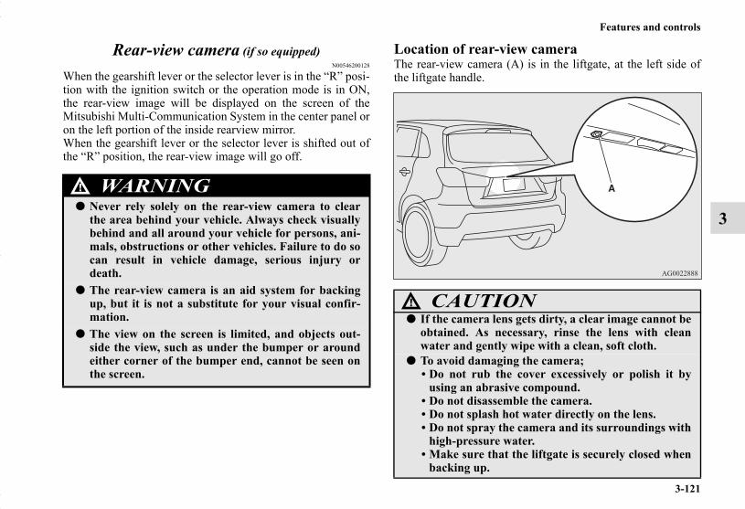
Features and controls
3-121
3
Rear-view camera (if so equipped)N00546200128
When the gearshift lever or the selector lever is in the “R” posi-tion with the ignition switch or the operation mode is in ON,the rear-view image will be displayed on the screen of theMitsubishi Multi-Communication System in the center panel oron the left portion of the inside rearview mirror.When the gearshift lever or the selector lever is shifted out ofthe “R” position, the rear-view image will go off.
Location of rear-view cameraThe rear-view camera (A) is in the liftgate, at the left side ofthe liftgate handle.
WARNING!
● Never rely solely on the rear-view camera to clearthe area behind your vehicle. Always check visuallybehind and all around your vehicle for persons, ani-mals, obstructions or other vehicles. Failure to do socan result in vehicle damage, serious injury ordeath.
● The rear-view camera is an aid system for backingup, but it is not a substitute for your visual confir-mation.
● The view on the screen is limited, and objects out-side the view, such as under the bumper or aroundeither corner of the bumper end, cannot be seen onthe screen.
CAUTION!● If the camera lens gets dirty, a clear image cannot be
obtained. As necessary, rinse the lens with cleanwater and gently wipe with a clean, soft cloth.
● To avoid damaging the camera;• Do not rub the cover excessively or polish it by
using an abrasive compound. • Do not disassemble the camera.• Do not splash hot water directly on the lens. • Do not spray the camera and its surroundings with
high-pressure water.• Make sure that the liftgate is securely closed when
backing up.
BK0150700US.book 121 ページ 2012年3月22日 木曜日 午後6時46分
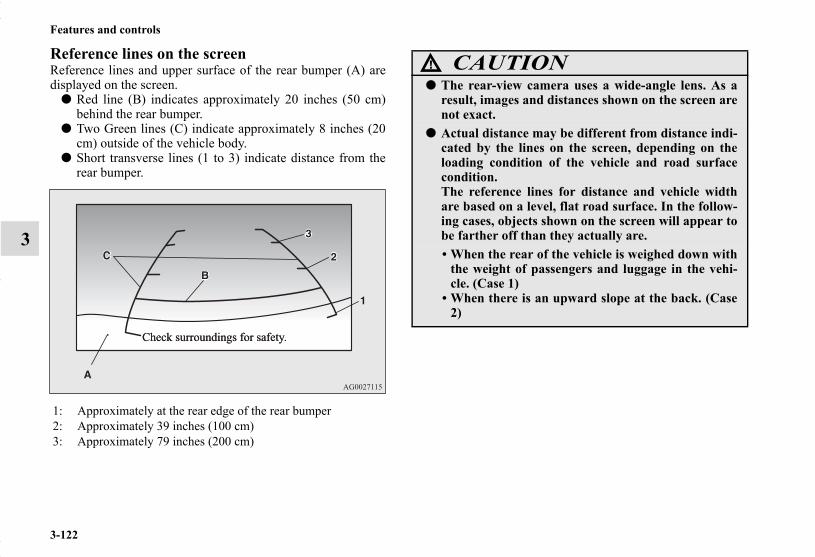
3-122
Features and controls
3
Reference lines on the screenReference lines and upper surface of the rear bumper (A) aredisplayed on the screen.
● Red line (B) indicates approximately 20 inches (50 cm)behind the rear bumper.
● Two Green lines (C) indicate approximately 8 inches (20cm) outside of the vehicle body.
● Short transverse lines (1 to 3) indicate distance from therear bumper.
1: Approximately at the rear edge of the rear bumper 2: Approximately 39 inches (100 cm) 3: Approximately 79 inches (200 cm)
CAUTION!
● The rear-view camera uses a wide-angle lens. As aresult, images and distances shown on the screen arenot exact.
● Actual distance may be different from distance indi-cated by the lines on the screen, depending on theloading condition of the vehicle and road surfacecondition.The reference lines for distance and vehicle widthare based on a level, flat road surface. In the follow-ing cases, objects shown on the screen will appear tobe farther off than they actually are.• When the rear of the vehicle is weighed down with
the weight of passengers and luggage in the vehi-cle. (Case 1)
• When there is an upward slope at the back. (Case2)
BK0150700US.book 122 ページ 2012年3月22日 木曜日 午後6時46分

Features and controls
3-123
3A- Actual objectsB- Objects shown on the screen
Case 1
Case 2
A- Actual objectsB- Objects shown on the screen
CAUTION!
● The reference lines for distance and vehicle widthare intended to indicate the distance to a flat objectsuch as a level, flat road surface. They may not indi-cate correct distance depending on the shape of anobstacle.For example, when there is an object behind thevehicle that has upper sections projecting in thedirection of the vehicle, the reference lines on thescreen will indicate that point A is the farthest pointand point B is the closest point to the vehicle. In real-ity, point A and B are actually the same distancefrom the vehicle, and point C is farther off thanpoint A and B.
BK0150700US.book 123 ページ 2012年3月22日 木曜日 午後6時46分

3-124
Features and controls
3
NOTE● Mirror image is displayed on the screen.● Monitor brightness is adjusted automatically by sensors.● It is possible to change the display language of the screen.
For details, please refer to the separated owner’s manualfor “Mitsubishi Multi-Communication System” or“Change language or turn off the inside rearview mirrorscreen: To change the language of warning text (3)” onpage 3-124.
● Under certain circumstances, it may become difficult tosee an image on the screen, even when the system is func-tioning correctly. • In a dark area, such as at night. • When water drops or condensation are on the lens. • When sun light or headlights shine directly into the lens.
Change language or turn off the inside rearview mirror screen
N00568900053
It is possible to turn off the screen of the inside rearview mirrorand change the language of the warning messages on thescreen.
To temporarily set the non-display modeIf you press the switch (1) while the image appears on thescreen, it goes off temporarily.To return to display mode, press the switch again or performthe following operation.[Except for vehicles equipped with the Free-hand AdvancedSecurity Transmitter (F.A.S.T.-key)]Turn the ignition switch to the “ON” position after turning to“OFF” or “ACC” position.[For vehicles equipped with the Free-hand Advanced SecurityTransmitter (F.A.S.T.-key)]Put the operation mode in ON after putting the operation modein OFF.
BK0150700US.book 124 ページ 2012年3月22日 木曜日 午後6時46分

Features and controls
3-125
3
To permanently set the non-display mode1. Turn the ignition switch to the “ON” position or put the
operation mode in ON.
2. Put the gearshift lever or the selector lever in the “R” posi-tion.
3. Press and hold down the switch (1) (for about 15 sec-onds).While you keep the switch pressed, the orange indicator(2) comes on. When the image goes off, the non-displaymode setting is completed.
To change the language of warning text (3)1. Turn the ignition switch to the “ON” position or put the
operation mode in ON.
2. Put the gearshift lever or the selector lever in the “R” posi-tion.
3. Press and hold down the switch (1) to enter languageselection mode (for 6 to 11 seconds).In this mode, the image appears and the green indicator(2) comes on.
4. Press the switch until the desired language appears on thedisplay.Each time you press the switch, the language will changeto the next one. When the warning text flashes, setting iscompleted.
CAUTION!
● For safety reasons, do not perform the followingoperations with the engine running.
CAUTION!
● For safety reasons, do not perform the followingoperations with the engine running.
BK0150700US.book 125 ページ 2012年3月22日 木曜日 午後6時46分

3-126
Features and controls
3
Instrument clusterN00519000388
SpeedometerN00519100259
The speedometer shows the vehicle speed in miles per hour(mph) or kilometers per hour (km/h).
1- Tachometer → P.3-1272- Multi-information display → P.3-129
Information screen display list → P.3-1633- Speedometer → P.3-1264- Rheostat meter illumination button → P.3-128
Type A
BK0150700US.book 126 ページ 2012年3月22日 木曜日 午後6時46分

Features and controls
3-127
3
TachometerN00519200289
The tachometer shows engine revolutions per minute. Thisallows the driver to determine the most efficient selector posi-tion and engine speed combinations.This gauge also assists in evaluating engine performance.
Type B
CAUTION!
● The red zone indicates an engine speed beyond therange of safe operation.Select the correct shift position (manual transaxle)or selector position (CVT) to control the enginespeed so that the tachometer indicator does notenter the red zone.
BK0150700US.book 127 ページ 2012年3月22日 木曜日 午後6時46分
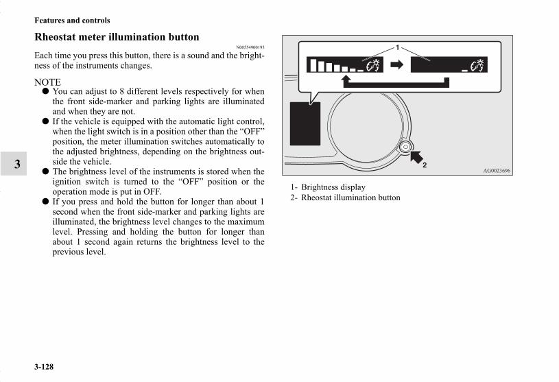
3-128
Features and controls
3
Rheostat meter illumination buttonN00554900195
Each time you press this button, there is a sound and the bright-ness of the instruments changes.
NOTE● You can adjust to 8 different levels respectively for when
the front side-marker and parking lights are illuminatedand when they are not.
● If the vehicle is equipped with the automatic light control,when the light switch is in a position other than the “OFF”position, the meter illumination switches automatically tothe adjusted brightness, depending on the brightness out-side the vehicle.
● The brightness level of the instruments is stored when theignition switch is turned to the “OFF” position or theoperation mode is put in OFF.
● If you press and hold the button for longer than about 1second when the front side-marker and parking lights areilluminated, the brightness level changes to the maximumlevel. Pressing and holding the button for longer thanabout 1 second again returns the brightness level to theprevious level.
1- Brightness display2- Rheostat illumination button
BK0150700US.book 128 ページ 2012年3月22日 木曜日 午後6時46分

Features and controls
3-129
3
Multi-information displayN00555000265
The multi-information display displays warnings, the odometer, trip odometer, service reminder, engine coolant temperature, fuelremaining, outside temperature, selector lever position, all-wheel drive operation status, average and momentary fuel consumption,driving range, average speed, instrument brightness, etc.It is also possible to change elements such as the language and units used on the multi-information display.
With ignition switch or operation mode is in OFF
With ignition switch or operation mode is in ON (CVT)
Type 1 Type 2
With ignition switch or operation mode is in ON (Manual transaxle)
Type 1 Type 2 Type 1 Type 2
1- Warning display screen (With ignition switch or opera-tion mode in OFF) → P.3-131
2- Information screen (With ignition switch or operation modein OFF) → P.3-131Interrupt display screen (With ignition switch or operationmode in OFF) → P.3-134
3- Door ajar warning display screen (With ignition switch oroperation mode in OFF) → P.3-135
4- Drive mode indicator display screen (if so equipped)→ P.3-137
5- Warning display screen (With ignition switch or opera-tion mode in ON) → P.3-137
6- Active stability control (ASC) OFF display screen (if soequipped) → P.3-137
7- Information screen (With ignition switch or operation modein ON) → P.3-138Interrupt display screen (With ignition switch or operationmode in ON) → P.3-142
8- Selector lever position display screen (if so equipped) →P.3-143
9- Outside temperature display screen → P.3-143
BK0150700US.book 129 ページ 2012年3月22日 木曜日 午後6時46分

3-130
Features and controls
3
NOTE● The fuel units, temperature units, display language, and
other settings can be changed.Refer to “Changing the function settings (With ignitionswitch or operation mode in ON)” on page 3-148.
● The display screen is different depending on whether theignition switch or the operation mode in OFF or ON.Refer to “Information screen (With ignition switch oroperation mode in OFF)” on page 3-131.Refer to “Warning display list (With ignition switch oroperation mode in OFF)” on page 3-164.Refer to “Information screen (With ignition switch turnedfrom the “OFF” position to the “ON” position or opera-tion mode changed from OFF to ON)” on page 3-136.Refer to “Information screen (With ignition switch oroperation mode in ON)” on page 3-138.Refer to “Warning display list (With ignition switch oroperation mode in ON)” on page 3-167.
10- Fuel remaining display screen → P.3-14411- Engine coolant temperature display (if so equipped)
→ P.3-13812- ECO mode indicator (if so equipped) → P.3-14413- Gearshift indicator display screen (if so equipped)
→ P.3-71
BK0150700US.book 130 ページ 2012年3月22日 木曜日 午後6時46分

Features and controls
3-131
3
Multi-information meter switchN00555100149
The multi-information meter switch is a button marked“INFO” on the left side of the dash.Each time the multi-information meter switch is operated, asound is emitted and the multi-information display changesbetween information such as warnings, Odometer (Type1), tripodometer, service reminder, engine coolant temperature (Type1), average and momentary fuel consumption, driving range,and average speed.It is also possible to change elements such as the language andunits used on the multi-information display by operating themulti-information meter switch.
Warning display screen (With ignition switch or operation mode in OFF)
N00555200179
If you press the multi-information meter switch and returnfrom the warning display screen to the previous screen, the warning is displayed.Refer to “Returning to the display screen from before the warn-ing display” on page 3-134.This mark is also displayed if there is another warning otherthan the one displayed. When the cause of the warning displayis eliminated, the warning goes out automatically.
NOTE● When the warning is displayed, the warning display
screen can be redisplayed on the information screen.Refer to “Information screen (With ignition switch oroperation mode in OFF)” on page 3-131.Refer to “Information screen (With ignition switch oroperation mode in ON)” on page 3-138.
Information screen (With ignition switch or oper-ation mode in OFF)
N00555300167
Each time you lightly press the multi-information meterswitch, the display screen switches in the following order.
BK0150700US.book 131 ページ 2012年3月22日 木曜日 午後6時46分

3-132
Features and controls
3
Odometer/Trip odometerN00555400113
Each time you lightly press the multi-information meterswitch, the display screen switches.
Odometer/trip odometer → Odometer/trip odometer →Service reminder → Redisplay of a warning display screen →Odometer/trip odometer .
OdometerShows the total distance traveled.
Trip odometerShows the distance traveled between two points.
To reset the trip odometerTo return the display to 0, hold down the multi-informationmeter switch for about 2 seconds or more. Only the currentlydisplayed value will be reset.
ExampleIf trip odometer is displayed, only trip odometer willbe reset.
When there is no warning display
When there is a warning display
Type 1
Type 2
When there is no warning display
When there is a warning display
1- Odometer (Type1)/Trip odometer 2- Odometer (Type1)/Trip odometer 3- Service reminder4- Redisplay of a warning display screen
Usage examples for trip odometer , trip odometer It is possible to measure two currently traveled distances,from home using trip odometer and from a particularpoint on the way using trip odometer .
BK0150700US.book 132 ページ 2012年3月22日 木曜日 午後6時46分

Features and controls
3-133
3
NOTE● If there is no warning display, the switching sequence is:
odometer/trip odometer → odometer/trip odometer → service reminder → odometer/trip odometer .
● Both trip odometers and can count up to 9999.9miles/kilometers.When a trip odometer goes past 9999.9 miles/kilometers,it returns to 0.0 miles/kilometers.
● When disconnecting the battery terminal, the memories oftrip odometer displays and are cleared, and theirdisplays return to “0.0 miles/kilometers”.
Service reminderN00555500042
Shows the distance and number of months until the next peri-odic inspection.Refer to “Service reminder” on page 3-145.
Type 1
Type 2
BK0150700US.book 133 ページ 2012年3月22日 木曜日 午後6時46分
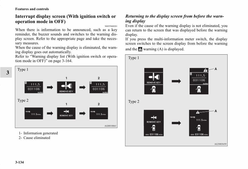
3-134
Features and controls
3
Interrupt display screen (With ignition switch or operation mode in OFF)
N00559600201
When there is information to be announced, such as a keyreminder, the buzzer sounds and switches to the warning dis-play screen. Refer to the appropriate page and take the neces-sary measures.When the cause of the warning display is eliminated, the warn-ing display goes out automatically.Refer to “Warning display list (With ignition switch or opera-tion mode in OFF)” on page 3-164.
Returning to the display screen from before the warn-ing displayEven if the cause of the warning display is not eliminated, youcan return to the screen that was displayed before the warningdisplay.If you press the multi-information meter switch, the displayscreen switches to the screen display from before the warningand the warning (A) is displayed.
1- Information generated2- Cause eliminated
Type 1
Type 2
Type 1
Type 2
BK0150700US.book 134 ページ 2012年3月22日 木曜日 午後6時46分

Features and controls
3-135
3
NOTE● Warning display screens with a “ ” or “ ” mark dis-
played in the upper right of the screen can be switched. Ifyou want to switch the display, press the multi-informa-tion meter switch as follows.“ ”: Press lightly.“ ”: Press for about 2 seconds or more.
Redisplay of a warning display screenWhen the warning is displayed, if you lightly press themulti-information meter switch a few times, the warning dis-play screen you switched from is redisplayed.Refer to “Information screen (With ignition switch or operationmode in OFF)” on page 3-131.
Door ajar warning display screen (With ignition switch or operation mode in OFF)
N00559700156
If any of the doors or the liftgate is not completely closed, thisdisplays the open door or liftgate.
1- Doors and liftgate are closed2- Doors or liftgate is open
Type 1
Type 2
BK0150700US.book 135 ページ 2012年3月22日 木曜日 午後6時46分

3-136
Features and controls
3
Information screen (With the ignition switch is turned from the “OFF” position to the “ON” position or the operation mode is changed from OFF to ON)
N00555800191
When the ignition switch is turned to the “ON” position or theoperation mode changed to ON, the display screen switches inthe following order.
System check screenWhen the ignition switch is turned to the “ON” position or theoperation mode is changed to ON, the system check screen isdisplayed for about 4 seconds. If there in no fault, the informa-tion screen is displayed.If there is a fault, the screen changes to warning display.Refer to “Warning display list (With ignition switch or opera-tion mode in ON)” on page 3-167.
NOTE● The system check screen display varies depending on
your equipment.1- Screen when the ignition switch or operation mode is OFF)2- System check screen3- Screen when the ignition switch or operation mode is ON)
Type 1
Type 2
Type 1 Type 2
BK0150700US.book 136 ページ 2012年3月22日 木曜日 午後6時46分

Features and controls
3-137
3
Service reminderWhen the time for periodic inspection arrives, the warning dis-play is displayed for a few seconds after the screen that is ini-tially displayed when the ignition switch is turned “ON” or theoperation mode is changed to ON.Refer to “Service reminder” on page 3-145.Type 1
Type 2
Drive mode indicator display screen (if so equipped)N00555900020
Shows the 4WD drive status.Refer to “Drive mode-selector” on page 3-84.
Warning display screen (With ignition switch or operation mode in ON)
N00555200182
This is displayed when you press the multi-information meterswitch and switch the warning display screen.This mark is also displayed if there is another warning otherthan the one displayed.When the cause of the warning display is eliminated, the warning goes out automatically.
NOTE● When the warning is displayed, the warning display
screen can be redisplayed on the information screen.Refer to “Information screen (With ignition switch oroperation mode in OFF)” on page 3-131.Refer to “Information screen (With ignition switch oroperation mode in ON)” on page 3-138.
“Active stability control (ASC) OFF” display screen (if so equipped)
N00556100117
This is displayed when the Active stability control (ASC) isturned “OFF” with the “ASC OFF” switch.Also, if an abnormal condition is occurred in the ASC whiledriving, the “ASC OFF” display illuminates.Refer to “ASC OFF switch” on page 3-104.
BK0150700US.book 137 ページ 2012年3月22日 木曜日 午後6時46分

3-138
Features and controls
3
Information screen (With ignition switch or oper-ation mode in ON)
N00556200222
Each time you lightly press the multi-information meterswitch, the display screen switches in the following order.
When there is no warning display
When there is a warning display
When there is no warning display
When there is a warning display
Type 1
Type 2
BK0150700US.book 138 ページ 2012年3月22日 木曜日 午後6時46分

Features and controls
3-139
3
NOTE● While driving, the function setting screen is not displayed
even if you operate the multi-information meter switch.Always park the vehicle in a safe place before operating.Refer to “Changing the function settings (With ignitionswitch or operation mode in ON)” on page 3-148.
● When there is information to be announced, such as a sys-tem fault, the tone sounds and the screen display isswitched.Refer to “Interrupt display screen (With ignition switch oroperation mode in ON)” on page 3-142.
Odometer/Trip odometerThe operation method is the same as when the ignition switchor the operation mode is in OFF.For further details, refer to “Odometer/Trip odometer” on page3-132.
Service reminderShows the distance and number of months until the next peri-odic inspection.Refer to “Service reminder” on page 3-145.
Engine coolant temperature displayShows the engine coolant temperature.If the coolant becomes hot, “ ” will blink.Pay careful attention to the engine coolant temperature displaywhile you are driving.
1- Odometer (Type1)/Trip odometer 2- Odometer (Type1)/Trip odometer 3- Service reminder4- Engine coolant temperature display (Type 1)5- Driving range display (Type 1)6- Average speed display, average fuel consumption display,
momentary fuel consumption display (Type 1)7- Driving range display, momentary fuel consumption display
(Type 2)8- Average fuel consumption display, momentary fuel con-
sumption display (Type 2)9- Average speed display, momentary fuel consumption display
(Type 2)10- Function setting screen11- Redisplay of a warning display screen
CAUTION!
● If the engine is overheating, “ ” will blink. In thiscase, the bar graph is on the red zone. Immediatelypark the vehicle in a safe place and take the requiredmeasures. Refer to “Engine overheating” on page 6-5.
BK0150700US.book 139 ページ 2012年3月22日 木曜日 午後6時46分

3-140
Features and controls
3
Driving range displayShows the approximate driving range (how many more milesor kilometers you can drive). When this driving range fallsbelow 30 miles (50 km), “---” is displayed.Refuel as soon as possible.
NOTE● The driving range is determined based on the fuel con-
sumption data. This may vary depending on the drivingconditions and habits. Treat the distance displayed as justa rough guideline.
● When you refuel, the driving range display is updated.However, if you only add a small amount of fuel, the cor-rect value will not be displayed. Fill to a full tank when-ever possible.
● When your vehicle is stopped on an extremely steep hill,the driving range value may, change. This is due to themovement of fuel in the tank and does not indicate anybreakdown.
● The display setting can be changed to the preferred units(miles or km).Refer to “Changing the function settings (With ignitionswitch or operation mode in ON)” on page 3-148.
Average speed displayThis displays the average speed from the last reset to thepresent.There are 2 types of mode settings as follows.For details on how to change the average speed display setting,refer to “Changing the function settings (With ignition switchor operation mode in ON)” on page 3-148.
Manual reset mode● When the average speed is being displayed, if you hold
down the multi-information meter switch, these calcula-tions will be reset to zero.
● When the following operation is performed, the mode set-ting changes automatically from manual to auto.
[Except for vehicles equipped with the F.A.S.T.-key]Turn the ignition switch to the “ON” position from the“ACC” or “OFF” position.
[For vehicles equipped with the F.A.S.T.-key]Change the operation mode to ON from ACC or OFF.
Auto reset mode● When the average speed is being displayed, if you hold
down the multi-information meter switch, these calcula-tions will be reset to zero.
● When the engine switch or the operation mode is in thefollowing conditions, the average speed display will auto-matically reset.
[Except for vehicles equipped with the F.A.S.T.-key]The ignition switch has been set to the “ACC” or “OFF”position for about 4 hours or more.
[For vehicles equipped with the F.A.S.T.-key]The operation mode has been set to ACC or OFF for about4 hours or more.
NOTE● The average speed display and the average fuel consump-
tion display can be reset separately in both auto resetmode and manual reset mode.
BK0150700US.book 140 ページ 2012年3月22日 木曜日 午後6時46分

Features and controls
3-141
3
● “---” is displayed when the average speed cannot be mea-sured.
● The initial (default) setting is “Auto reset mode”.● The display setting can be changed to the preferred units
(mph or km/h).Refer to “Changing the function settings (With ignitionswitch or operation mode in ON)” on page 3-148.
● Disconnecting the battery cable will erase from memorythe manual reset mode or auto reset mode setting for theaverage speed display.
Average fuel consumption displayThis displays the average fuel consumption from the last resetto the present.There are 2 types of mode settings as follows.For details on how to change the average fuel consumption dis-play setting, refer to “Changing the function settings (Withignition switch or operation mode in ON)” on page 3-148.The “ ” mark in the momentary fuel gauge shows the averagefuel consumption. (Type 2)
Manual reset mode● When the average fuel consumption is being displayed, if
you hold down the multi-information meter switch, thesecalculations will be reset to zero.
● When the following operation is performed, the mode set-ting changes automatically from manual to auto.
[Except for vehicles equipped with the F.A.S.T.-key] Turn the ignition switch to the “ON” position from the“ACC” or “OFF” position.
[For vehicles equipped with the F.A.S.T.-key]Change the operation mode to ON from ACC or OFF.
Auto reset mode● When the average fuel consumption is being displayed, if
you hold down the multi-information meter switch, thesecalculations will be reset to zero.
● When the engine switch or the operation mode is in thefollowing conditions, the average fuel consumption dis-play will automatically reset.
[Except for vehicles equipped with the F.A.S.T.-key] The ignition switch has been set to the “ACC” or “OFF”position for about 4 hours or more.
[For vehicles equipped with the F.A.S.T.-key]The operation mode has been set to ACC or OFF for about4 hours or more.
NOTE● The average speed display and the average fuel consump-
tion display can be reset separately in both auto resetmode and manual reset mode.
● “---” is displayed when the average fuel consumption can-not be measured.
● The initial (default) setting is “Auto reset mode”.
BK0150700US.book 141 ページ 2012年3月22日 木曜日 午後6時46分

3-142
Features and controls
3
● Average fuel consumption may vary depend on the driv-ing conditions (road conditions, how you drive, etc.) Theactual fuel consumption may differ from the fuel con-sumption displayed, so treat the fuel consumption dis-played as just a rough guideline.
● Disconnecting the battery cable will erase from memorythe manual reset mode or auto reset mode setting for theaverage fuel consumption display.
● The display setting can be changed to the preferred units{mpg(US), mpg(UK), L/100km or km/L}.Refer to “Changing the function settings (With ignitionswitch or operation mode in ON)” on page 3-148.
Momentary fuel consumption displayWhile driving, the momentary fuel consumption is shown witha bar graph.When the momentary fuel consumption surpasses the averagefuel consumption, the momentary fuel consumption is dis-played with a green bar graph. (Type 2)Be conscious of maintaining the momentary fuel consumptionabove the average fuel consumption, it can help you drive withthe better fuel consumption.
NOTE● When the momentary fuel consumption cannot be mea-
sured, a bar graph is not shown.● The display setting can be changed to the preferred units
{mpg(US), mpg(UK), L/100km or km/L}.Refer to “Changing the function settings (With ignitionswitch or operation mode in ON)” on page 3-148.
● It is possible to cancel the green bar graph.Refer to “Changing the function settings (With ignitionswitch or operation mode in ON)” on page 3-148.
Function setting screenThe “Display language”, “Temperature unit”, “Fuel consump-tion unit”, and “Average fuel consumption and speed resetmethod” settings can be modified as desired.For further details, refer to “Changing the function settings(With ignition switch or operation mode in ON)” on page 3-148.
Interrupt display screen (With ignition switch or operation mode in ON)
N00556300180
Warning displayWhen there is information to be announced, such as a systemfault, a tone sounds and the information screen is switched tothe warning display screen.Refer to the warning list and take the necessary measures.Refer to “Warning display list (With ignition switch or opera-tion mode in ON)” on page 3-167.When the cause of the warning display is eliminated, the warn-ing display goes out automatically.
Returning to the display screen from before the warning displayEven if the cause of the warning display is not eliminated, youcan return to the screen that was displayed before the warningdisplay.
If you press the multi-information meter switch, the displayscreen switches to the screen display from before the warningand the warning (A) is displayed.
BK0150700US.book 142 ページ 2012年3月22日 木曜日 午後6時46分

Features and controls
3-143
3
NOTE● Warning display screens with a “ ” or “ ” mark dis-
played in the upper right of the screen can be switched. Ifyou want to switch the display, press the multi-informa-tion meter switch as follows.“ ”: Press lightly.“ ”: Press for about 2 seconds or more.
Redisplay of a warning display screenWhen the warning is displayed, if you lightly press themulti-information meter switch a few times, the warning dis-play screen you switched from is redisplayed.
Other interrupt displaysThe operation status of each system is displayed on the infor-mation screen.For further details, refer to the appropriate page in the warningdisplay list.Refer to “Other interrupt displays” on page 3-174.
Selector lever position display screen (if so equipped)
N00556400064
Shows the position of the selector lever.Refer to “Selector lever operation” on page 3-75.
Outside temperature display screenN00556500065
Shows the temperature outside the vehicle.
NOTE● The display setting can be changed to the preferred units
(°F or °C).Refer to “Changing the function settings (With ignitionswitch or operation mode in ON)” on page 3-148.
● Depending on factors such as the driving conditions, thedisplayed temperature may vary from the actual outsidetemperature.
Type 1
Type 2
BK0150700US.book 143 ページ 2012年3月22日 木曜日 午後6時46分
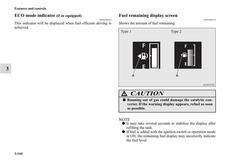
3-144
Features and controls
3
ECO mode indicator (if so equipped)N00568700019
This indicator will be displayed when fuel-efficient driving isachieved.
Fuel remaining display screenN00556600170
Shows the amount of fuel remaining.
NOTE● It may take several seconds to stabilize the display after
refilling the tank.● If fuel is added with the ignition switch or operation mode
in ON, the remaining fuel display may incorrectly indicatethe fuel level.
CAUTION!
● Running out of gas could damage the catalytic con-verter. If the warning display appears, refuel as soonas possible.
Type 1 Type 2
BK0150700US.book 144 ページ 2012年3月22日 木曜日 午後6時46分
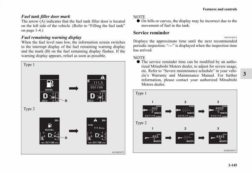
Features and controls
3-145
3
Fuel tank filler door markThe arrow (A) indicates that the fuel tank filler door is locatedon the left side of the vehicle. (Refer to “Filling the fuel tank”on page 1-4.)
Fuel remaining warning displayWhen the fuel level runs low, the information screen switchesto the interrupt display of the fuel remaining warning displayand the mark (B) on the fuel remaining display flashes. If thewarning display appears, refuel as soon as possible.
NOTE● On hills or curves, the display may be incorrect due to the
movement of fuel in the tank.
Service reminderN00556700214
Displays the approximate time until the next recommendedperiodic inspection. “---” is displayed when the inspection timehas arrived.
NOTE● The service reminder time can be modified by an autho-
rized Mitsubishi Motors dealer, to adjust for severe usage,etc. Refer to “Severe maintenance schedule” in your vehi-cle’s Warranty and Maintenance Manual. For furtherinformation, please contact your authorized MitsubishiMotors dealer.
Type 1
Type 2
Type 1
Type 2
BK0150700US.book 145 ページ 2012年3月22日 木曜日 午後6時46分

3-146
Features and controls
3
1. Shows the time until the next periodic inspection.
NOTE● Shows the distance in units of 100 miles (100 km) and the
time in units of 1 month.2. This informs you that a periodic inspection is due. Contact
an authorized Mitsubishi Motors dealer or a repair facilityof your choice to have the system checked.
At that time, when the ignition switch is switched fromthe “OFF” position to the “ON” position or the operationmode is changed from OFF to ON, the warning display isdisplayed for a few seconds on the information screen.
Type 1
Type 2
3. After your vehicle is inspected at an authorized MitsubishiMotors dealer, it displays the time until the next periodicinspection.
To reset The “---” display can be reset while the ignition switch or theoperation mode is in OFF. When the display is reset, the timeuntil the next periodic inspection is displayed and the warningdisplay is no longer displayed when the ignition switch isswitched from the “OFF” position to the “ON” position or theoperation mode is changed from OFF to ON.
1. When you lightly press the multi-information meterswitch, the information screen switches to the servicereminder display screen.
Type 1
Type 2
BK0150700US.book 146 ページ 2012年3月22日 木曜日 午後6時46分
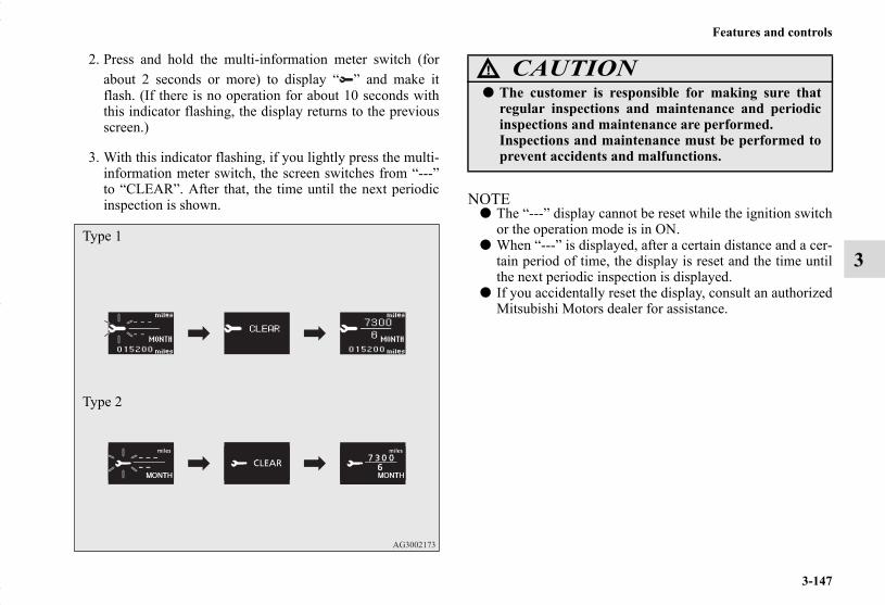
Features and controls
3-147
3
2. Press and hold the multi-information meter switch (forabout 2 seconds or more) to display “ ” and make itflash. (If there is no operation for about 10 seconds withthis indicator flashing, the display returns to the previousscreen.)
3. With this indicator flashing, if you lightly press the multi-information meter switch, the screen switches from “---”to “CLEAR”. After that, the time until the next periodicinspection is shown. NOTE
● The “---” display cannot be reset while the ignition switchor the operation mode is in ON.
● When “---” is displayed, after a certain distance and a cer-tain period of time, the display is reset and the time untilthe next periodic inspection is displayed.
● If you accidentally reset the display, consult an authorizedMitsubishi Motors dealer for assistance.
Type 1
Type 2
CAUTION!
● The customer is responsible for making sure thatregular inspections and maintenance and periodicinspections and maintenance are performed.Inspections and maintenance must be performed toprevent accidents and malfunctions.
BK0150700US.book 147 ページ 2012年3月22日 木曜日 午後6時46分

3-148
Features and controls
3
Door ajar warning display screen (With ignition switch or operation mode is in ON)
N00555700132
Type 1
Type 2
If any of the doors or the liftgate is not completely closed, thisdisplays the open door or liftgate.If the speed increases to about 5 mph (8 km/h) or higher with adoor ajar, a tone will sound 4 times to inform you that a door isajar.
Changing the function settings (With ignition switch or operation mode is in ON)
N00556800130
1. Park your vehicle in a safe place.Fully apply the parking brake and move the gearshift leverinto the “N” (Neutral) position (Manual transaxle) or theselector lever into the “P” (PARK) position (CVT).
2. When you lightly press the multi-information meterswitch, the information screen switches to the functionsetting screen.Refer to “Information screen (With ignition switch oroperation mode in ON)” on page 3-138.
CAUTION!
● Always make sure that the warning display goes outbefore beginning to drive.
Type 1 Type 2
BK0150700US.book 148 ページ 2012年3月22日 木曜日 午後6時46分

Features and controls
3-149
3
3. Press and hold the multi-information meter switch (forabout 2 seconds or more) to switch from the setting modescreen to the menu screen.
NOTE● To return the menu screen to the function setting screen,
press and hold the multi-information meter switch (forabout 2 seconds or more).
● If no operations are made within about 15 seconds of themenu screen being displayed, the display returns to thefunction setting screen.
4. Select the item to change on the menu screen and changeto the desired setting. For further details on the operationmethods, refer to the following sections.
Refer to “Changing the reset mode for average fuel con-sumption and average speed” on page 3-150.Refer to “Changing the fuel consumption display unit” onpage 3-151.Refer to “Changing the temperature unit” on page 3-153.Refer to “Changing the display language” on page 3-154.Refer to “Changing the language on Mitsubishi Multi-Communication System or Bluetooth® 2.0 interface tomatch the multi-information display (if so equipped)” onpage 3-155.Refer to “Operation sound setting” on page 3-156.Refer to “Changing the time until “REST REMINDER” isdisplayed” on page 3-157.Refer to “Changing the turn signal sound” on page 3-158.Refer to “Changing the momentary fuel consumption dis-play (Type 2)” on page 3-159.Refer to “Returning to the factory settings” on page 3-160.
CAUTION!
● For safety, stop the vehicle before operating.While driving, even if you operate the multi-infor-mation meter switch, the function setting screen isnot displayed.
Type 1
Type 2
BK0150700US.book 149 ページ 2012年3月22日 木曜日 午後6時46分

3-150
Features and controls
3
Changing the reset mode for average fuel consumption and average speed
N00557000227
You can change the mode condition for the average fuel con-sumption and average speed display to “Auto reset” or “Man-ual reset.”
1. Press and hold the multi-information meter switch (forabout 2 seconds or more) to switch from the setting modescreen to the menu screen.Refer to “Changing the function settings (With ignitionswitch or operation mode is in ON)” on page 3-148.
2. Lightly press the multi-information meter switch to select“AVG” (average fuel consumption and average speed set-ting).
3. Press and hold the multi-information meter switch (forabout 2 seconds or more) to switch in sequence from A or1 (Auto reset) → M, 2 or P (Manual reset) → A or 1 (Autoreset).The setting is changed to the selected reset condition.
Type 1
Type 2
BK0150700US.book 150 ページ 2012年3月22日 木曜日 午後6時46分

Features and controls
3-151
3
Manual reset mode● If you press and hold the multi-information meter switch
when the average fuel consumption and average speed aredisplayed, these calculations will be reset to zero.
● When the following operation is performed, the mode set-ting changes automatically from manual to auto.
[Except for vehicles equipped with the F.A.S.T.-key]Turn the ignition switch to the “ON” position from the“ACC” or “OFF” position.
[For vehicles equipped with the F.A.S.T.-key]Change the operation mode to ON from ACC or OFF.
Auto reset mode● When the average fuel consumption and average speed
are being displayed, if you hold down the multi-informa-tion meter switch, these calculations will be reset to zero.
● When the engine switch or the operation mode is in thefollowing conditions, the average fuel consumption dis-play and the average speed display will automaticallyreset.
[Except for vehicles equipped with the F.A.S.T.-key]The ignition switch has been set to the “ACC” or “OFF”position for about 4 hours or more.
[For vehicles equipped with the F.A.S.T.-key]The operation mode has been in ACC or OFF for about 4hours or more.
NOTE● Disconnecting the battery cable will erase from memory
the manual reset mode or auto reset mode setting for theaverage speed display and average fuel consumption dis-play.
● The initial (default) setting is “Auto reset mode”.
Changing the fuel consumption display unitN00557100143
The fuel consumption display unit can be changed. The dis-tance, speed, and amount units are also changed to match theselected fuel consumption unit.
1. Press and hold the multi-information meter switch (forabout 2 seconds or more) to change from the setting modescreen to the menu screen.Refer to “Changing the function settings (With ignitionswitch or operation mode is in ON)” on page 3-148.
BK0150700US.book 151 ページ 2012年3月22日 木曜日 午後6時46分

3-152
Features and controls
3
2. Lightly press the multi-information meter switch to select“AVG UNIT” (fuel consumption display unit setting).
3. Press and hold the multi-information meter switch (forabout 2 seconds or more) to display “AVG UNIT” (fuelconsumption display unit setting).
4. Lightly press the multi-information meter switch to switchin sequence from km/L → L/100 km → mpg (US) → mpg(UK) → RETURN → km/L.
5. Press and hold the multi-information meter switch (forabout 2 seconds or more) to change the setting to theselected unit.
Type 1
Type 2
Type 1 Type 2
BK0150700US.book 152 ページ 2012年3月22日 木曜日 午後6時46分

Features and controls
3-153
3
NOTE● The display units for the driving range, the average fuel
consumption, the average speed and the momentary fuelconsumption are changed, but the units for the indicatingneedle (speedometer), the odometer and the trip odometerwill remain unchanged.
● If the battery is disconnected, the memory of the unit set-ting is erased and is automatically set to {mpg (US) orL/100 km}.
The distance and speed units are also changed in the followingcombinations to match the selected fuel consumption unit.
Changing the temperature unitN00557200115
The temperature display unit can be switched.1. Press and hold the multi-information meter switch (for
about 2 seconds or more) to switch from the setting modescreen to the menu screen.Refer to “Changing the function settings (With ignitionswitch or operation mode is in ON)” on page 3-148.
2. Lightly press the multi-information meter switch to select“ ” (temperature unit setting).
Fuel economy
Distance (driving range)
Speed (average speed)
mpg (US) mile (s) mphmpg (UK) mile (s) mph
km / L km km / hL / 100 km km km / h
Type 1
Type 2
BK0150700US.book 153 ページ 2012年3月22日 木曜日 午後6時46分

3-154
Features and controls
3
3. Press and hold the multi-information meter switch (forabout 2 seconds or more) to change in sequence from °F→ °C → °F.The setting is changed to the selected temperature unit.
NOTE● If the battery is disconnected, the memory of the unit set-
ting is erased and is automatically set to °F (°C).
Changing the display languageN00557300161
The language of the multi-information display can be changed.1. Press and hold the multi-information meter switch (for
about 2 seconds or more) to change from the setting modescreen to the menu screen.Refer to “Changing the function settings (With ignitionswitch or operation mode is in ON)” on page 3-148.
2. Lightly press the multi-information meter switch to select“LANGUAGE” (language setting).
Type 1
Type 2
BK0150700US.book 154 ページ 2012年3月22日 木曜日 午後6時46分
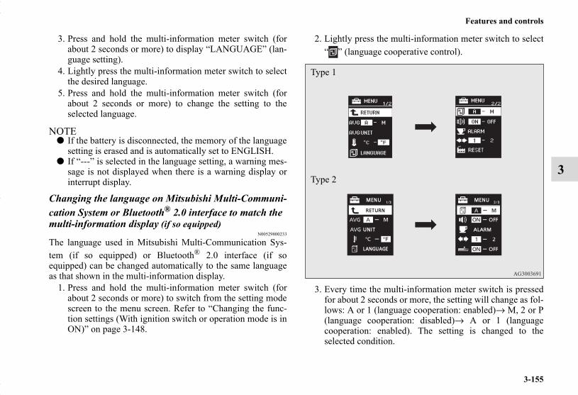
Features and controls
3-155
3
3. Press and hold the multi-information meter switch (forabout 2 seconds or more) to display “LANGUAGE” (lan-guage setting).
4. Lightly press the multi-information meter switch to selectthe desired language.
5. Press and hold the multi-information meter switch (forabout 2 seconds or more) to change the setting to theselected language.
NOTE● If the battery is disconnected, the memory of the language
setting is erased and is automatically set to ENGLISH.● If “---” is selected in the language setting, a warning mes-
sage is not displayed when there is a warning display orinterrupt display.
Changing the language on Mitsubishi Multi-Communi-cation System or Bluetooth® 2.0 interface to match the multi-information display (if so equipped)
N00529800233
The language used in Mitsubishi Multi-Communication Sys-tem (if so equipped) or Bluetooth® 2.0 interface (if soequipped) can be changed automatically to the same languageas that shown in the multi-information display.
1. Press and hold the multi-information meter switch (forabout 2 seconds or more) to switch from the setting modescreen to the menu screen. Refer to “Changing the func-tion settings (With ignition switch or operation mode is inON)” on page 3-148.
2. Lightly press the multi-information meter switch to select“ ” (language cooperative control).
3. Every time the multi-information meter switch is pressedfor about 2 seconds or more, the setting will change as fol-lows: A or 1 (language cooperation: enabled)→ M, 2 or P(language cooperation: disabled)→ A or 1 (languagecooperation: enabled). The setting is changed to theselected condition.
Type 1
Type 2
BK0150700US.book 155 ページ 2012年3月22日 木曜日 午後6時46分
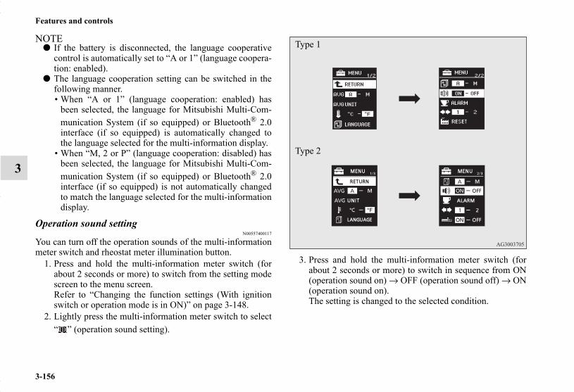
3-156
Features and controls
3
NOTE● If the battery is disconnected, the language cooperative
control is automatically set to “A or 1” (language coopera-tion: enabled).
● The language cooperation setting can be switched in thefollowing manner.• When “A or 1” (language cooperation: enabled) has
been selected, the language for Mitsubishi Multi-Com-munication System (if so equipped) or Bluetooth® 2.0interface (if so equipped) is automatically changed tothe language selected for the multi-information display.
• When “M, 2 or P” (language cooperation: disabled) hasbeen selected, the language for Mitsubishi Multi-Com-munication System (if so equipped) or Bluetooth® 2.0interface (if so equipped) is not automatically changedto match the language selected for the multi-informationdisplay.
Operation sound settingN00557400117
You can turn off the operation sounds of the multi-informationmeter switch and rheostat meter illumination button.
1. Press and hold the multi-information meter switch (forabout 2 seconds or more) to switch from the setting modescreen to the menu screen.Refer to “Changing the function settings (With ignitionswitch or operation mode is in ON)” on page 3-148.
2. Lightly press the multi-information meter switch to select“ ” (operation sound setting).
3. Press and hold the multi-information meter switch (forabout 2 seconds or more) to switch in sequence from ON(operation sound on) → OFF (operation sound off) → ON(operation sound on).The setting is changed to the selected condition.
Type 1
Type 2
BK0150700US.book 156 ページ 2012年3月22日 木曜日 午後6時46分

Features and controls
3-157
3
NOTE● If the battery is disconnected, the memory of the operation
sound setting is erased and is automatically set to “ON”(operation sound on).
● The operation sound setting only deactivates the operationsound of the multi-information meter switch and rheostatmeter illumination button. The warning display and othersounds cannot be deactivated.
Changing the time until “REST REMINDER” is dis-played
N00557500134
The time until the display appears can be changed.1. Press and hold the multi-information meter switch (for
about 2 seconds or more) to switch from the setting modescreen to the menu screen.Refer to “Changing the function settings (With ignitionswitch or operation mode is in ON)” on page 3-148.
2. Lightly press the multi-information meter switch to select“ALARM” (rest time setting).
Type 1
Type 2
BK0150700US.book 157 ページ 2012年3月22日 木曜日 午後6時46分

3-158
Features and controls
3
3. Press and hold the multi-information meter switch (forabout 2 seconds or more) to display “ALARM” (rest timesetting).
4. Lightly press the multi-information meter switch to selectthe time until the display appears.
5. Press and hold the multi-information meter switch (forabout 2 seconds or more) to change the setting to theselected time.
NOTE● If the battery is disconnected, the memory of the unit set-
ting is erased and is automatically set to the “OFF”.● The drive time is reset when the ignition switch is in the
“OFF” position or the operation mode is in OFF.
Changing the turn signal soundN00563500041
It is possible to change the turn signal sound.
1. Press and hold the multi-information meter switch forabout 2 seconds or more to switch from the setting modescreen to the menu screen.Refer to “Changing the function settings (With ignitionswitch or operation mode is in ON)” on page 3-148.
2. Lightly press the multi-information meter switch to select. (changing the turn signal sound)
Type 1 Type 2
Type 1
Type 2
BK0150700US.book 158 ページ 2012年3月22日 木曜日 午後6時46分
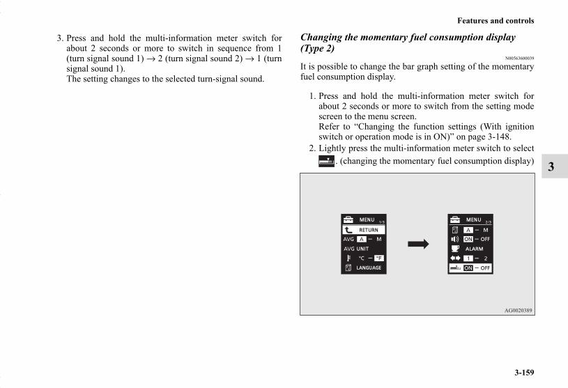
Features and controls
3-159
3
3. Press and hold the multi-information meter switch forabout 2 seconds or more to switch in sequence from 1(turn signal sound 1) → 2 (turn signal sound 2) → 1 (turnsignal sound 1).The setting changes to the selected turn-signal sound.
Changing the momentary fuel consumption display (Type 2)
N00563600039
It is possible to change the bar graph setting of the momentaryfuel consumption display.
1. Press and hold the multi-information meter switch forabout 2 seconds or more to switch from the setting modescreen to the menu screen.Refer to “Changing the function settings (With ignitionswitch or operation mode is in ON)” on page 3-148.
2. Lightly press the multi-information meter switch to select. (changing the momentary fuel consumption display)
BK0150700US.book 159 ページ 2012年3月22日 木曜日 午後6時46分
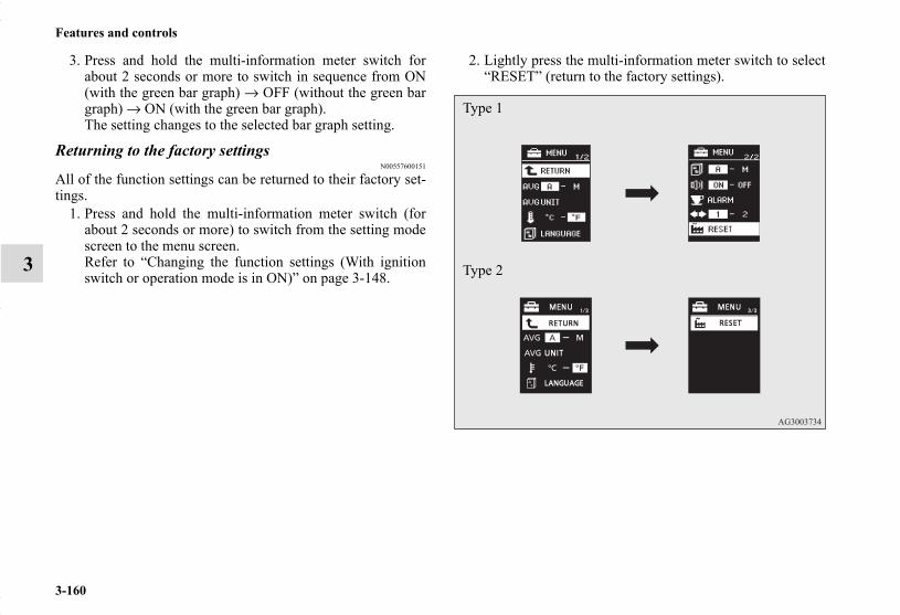
3-160
Features and controls
3
3. Press and hold the multi-information meter switch forabout 2 seconds or more to switch in sequence from ON(with the green bar graph) → OFF (without the green bargraph) → ON (with the green bar graph).The setting changes to the selected bar graph setting.
Returning to the factory settingsN00557600151
All of the function settings can be returned to their factory set-tings.
1. Press and hold the multi-information meter switch (forabout 2 seconds or more) to switch from the setting modescreen to the menu screen.Refer to “Changing the function settings (With ignitionswitch or operation mode is in ON)” on page 3-148.
2. Lightly press the multi-information meter switch to select“RESET” (return to the factory settings).
Type 1
Type 2
BK0150700US.book 160 ページ 2012年3月22日 木曜日 午後6時46分

Features and controls
3-161
3
3. Press and hold the multi-information meter switch (forabout 5 seconds or more), the buzzer sounds and all of thefunction settings are returned to the factory settings.
NOTE● The factory settings are as follows.
• Average fuel consumption and average speed resetmode: A (Auto reset)
• Fuel consumption display unit: mpg (US) or (L/100 km)• Temperature unit: °F (Fahrenheit) or °C (Celsius)• Display language: ENGLISH• Cooperative language setting: A• Operation sounds: ON (Operation sound on)• “REST REMINDER” display: OFF• Turn signal sound: Turn signal sound 1• Momentary fuel consumption with the green bar graph
(Type 2): ON
BK0150700US.book 161 ページ 2012年3月22日 木曜日 午後6時46分

3-162
Features and controls
3
Indicator light, warning light, and information screen display listN00557700048
Indicator and warning light listN00557800267
Type A Type BType B
1- Position indicator → P.3-1772- High beam indicator → P.3-1773- Charging system warning light → P.3-1794- Turn signal indicator/hazard warning light → P.3-1775- Front fog light indicator (if so equipped) → P.3-1776- Anti-lock braking system warning light → P.3-987- Tire pressure monitoring system warning light → P.3-1168- Brake warning light → P.3-1779- Cruise control indicator (if so equipped) → P.3-108
10- Seat belt reminder/warning light → P.2-2611- Supplemental Restraint System (SRS) warning light
→ P.2-5212- ECO mode indicator (if so equipped) → P.3-17713- Engine malfunction indicator (“SERVICE ENGINE SOON”
or “Check engine light”) → P.3-17814- Active stability control (ASC) OFF indicator (if so
equipped) → P.3-10515- Active stability control (ASC) indicator → P.3-10516- Information screen display list → P.3-163
BK0150700US.book 162 ページ 2012年3月22日 木曜日 午後6時46分

Features and controls
3-163
3
Information screen display listN00557900082
When there is information to be announced, such as light reminder, the tone sounds and the screen switches to the displays shownbelow. Refer to the appropriate page and take the necessary measures.When the cause of the warning display is eliminated, the warning display goes out automatically.Refer to “Warning display list (With ignition switch or operation mode is in OFF)” on page 3-164.Refer to “Warning display list (With ignition switch or operation mode is in ON)” on page 3-167.Refer to “Other interrupt displays” on page 3-174.
NOTE● In the following cases, a warning may be displayed on the information screen and the buzzer may sound for a few seconds, at
times.This is caused by the system picking up interference such as strong electromagnetic waves or noise, and is not a functionalproblem.• An extremely strong electromagnetic wave is received from a source such as an illegal radio set, a spark from a wire, or a
radar station.• Abnormal voltage or a static electricity discharge is generated by the operation of your vehicle’s electronics (including after-
market parts).If the warning display has occurred a number of times, take your vehicle to an authorized Mitsubishi Motors dealer or a repairfacility of your choice and have the system checked.
BK0150700US.book 163 ページ 2012年3月22日 木曜日 午後6時46分

3-164
Features and controls
3
Warning display list (With ignition switch or operation mode is in OFF)N00558000224
Screen type 1 Screen type 2 Cause Do this (Reference)
● You have forgotten to remove the key from the ignition switch.
● Remove the key.Refer to “Key reminder system” on page 3-40.
● You have forgotten to turn off the lights.
Refer to “Light auto-cutout function (head-lights and other lights)” on page 3-186.
● The theft-alarm system is operating. Refer to “Theft-alarm system” on page 3-48.
● Immobilizer is registered. Refer to “Customer key programming (Except for vehicles sold in Canada)” on page 3-6.Refer to “Customer F.A.S.T.-key program-ming (Except for vehicles sold in Canada)” on page 3-32.
BK0150700US.book 164 ページ 2012年3月22日 木曜日 午後6時46分

Features and controls
3-165
3—
● There is a fault in the F. A. S. T. -key. Refer to “Free-hand Advanced Security Transmitter (F.A.S.T.-key)” on page 3-14.
—
● There is a fault in the electronic immo-bilizer. (Anti-theft starting system).
● Contact an authorized Mitsubishi Motors dealer or a repair facility of your choice to have the system checked.
Screen type 1 Screen type 2 Cause Do this (Reference)
BK0150700US.book 165 ページ 2012年3月22日 木曜日 午後6時46分

3-166
Features and controls
3
—
● The F. A. S. T. -key is not detected. ● Insert the F. A. S. T. -key into the key slot in the glove compartment. Refer to “If the F. A. S. T. -key is not operating properly” on page 3-28.
—
● You have forgotten to remove the F. A. S. T. -key from the key slot in the glove compartment.
● Remove the F. A. S. T. -key from the key slot in the glove compartment.
—
● The engine switch is pressed to stop the engine and the selector lever is in a position other than the “P” (PARK) position.
● On vehicles with CVT, place the selec-tor lever in the “P” (PARK) position to put the operation mode in OFF.
—
● There is a fault in the electrical system. ● Park your vehicle in a safe place as soon as possible and contact an autho-rized Mitsubishi Motors dealer or a repair facility of your choice to have the system checked.
Screen type 1 Screen type 2 Cause Do this (Reference)
BK0150700US.book 166 ページ 2012年3月22日 木曜日 午後6時46分

Features and controls
3-167
3
Warning display list (With ignition switch or operation mode is in ON)N00558100296
Screen type 1 Screen type 2 Cause Do this (Reference)
● There is a fault in the EPS. ● Have the vehicle inspected by an authorized Mitsubishi Motors dealer or a repair facility of your choice as soon as possible.Refer to “Electric power steering sys-tem (EPS)” on page 3-101.
BK0150700US.book 167 ページ 2012年3月22日 木曜日 午後6時46分
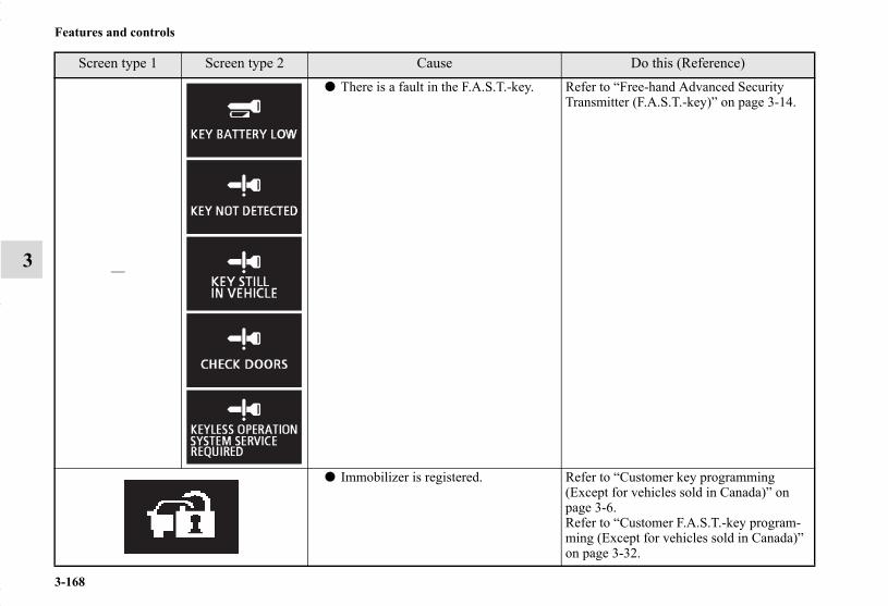
3-168
Features and controls
3 —
● There is a fault in the F.A.S.T.-key. Refer to “Free-hand Advanced Security Transmitter (F.A.S.T.-key)” on page 3-14.
● Immobilizer is registered. Refer to “Customer key programming (Except for vehicles sold in Canada)” on page 3-6.Refer to “Customer F.A.S.T.-key program-ming (Except for vehicles sold in Canada)” on page 3-32.
Screen type 1 Screen type 2 Cause Do this (Reference)
BK0150700US.book 168 ページ 2012年3月22日 木曜日 午後6時46分

Features and controls
3-169
3
● The brake fluid level is low.● There is a fault in the brake system.
● Park the vehicle in a safe place and inspect it.
● If the light still illuminates after the inspection, contact an authorized Mitsubishi Motors dealer or a repair facility of your choice for assistance.Refer to “Brake warning display” on page 3-180.
● There is a fault in the Anti-lock brak-ing system.
● Avoid sudden braking and high-speed driving, park the vehicle in a safe place, and take corrective measures. Refer to “Anti-lock braking system warning” on page 3-98.
● The tire pressure in one of the tires (except spare tire) is low.
Refer to “Tire Pressure Monitoring System” on page 3-116.
● There is a fault in the Tire Pressure Monitoring System.
Refer to “Tire Pressure Monitoring System” on page 3-116.
● One of the doors or the liftgate is not completely closed.The open door is displayed.
● Close the door or liftgate.Refer to “Door ajar warning display screen (With ignition switch or opera-tion mode is in ON)” on page 3-148.
Screen type 1 Screen type 2 Cause Do this (Reference)
BK0150700US.book 169 ページ 2012年3月22日 木曜日 午後6時46分

3-170
Features and controls
3
● The engine hood is open. ● Close the engine hood.Refer to “Engine hood” on page 7-4.
—
● There is a fault in the electronic immo-bilizer (Anti-theft starting system).
● Put the operation mode in OFF, and then start the engine again.If the warning is not cancelled, please contact an authorized Mitsubishi Motors dealer or a repair facility of your choice.
—
● The driver’s door is open when the operation mode is in any mode other than OFF.
● Put the operation mode in OFF.Refer to “Changing the operation mode” on page 3-23.
—
● There is a fault in the electrical system. ● Park your vehicle in a safe place as soon as possible and contact an autho-rized Mitsubishi Motors dealer or a repair facility of your choice to have the system checked.
● The engine is overheated. ● Park the vehicle in a safe place and take corrective measures.Refer to “Engine overheating” on page 6-5.
Screen type 1 Screen type 2 Cause Do this (Reference)
BK0150700US.book 170 ページ 2012年3月22日 木曜日 午後6時46分
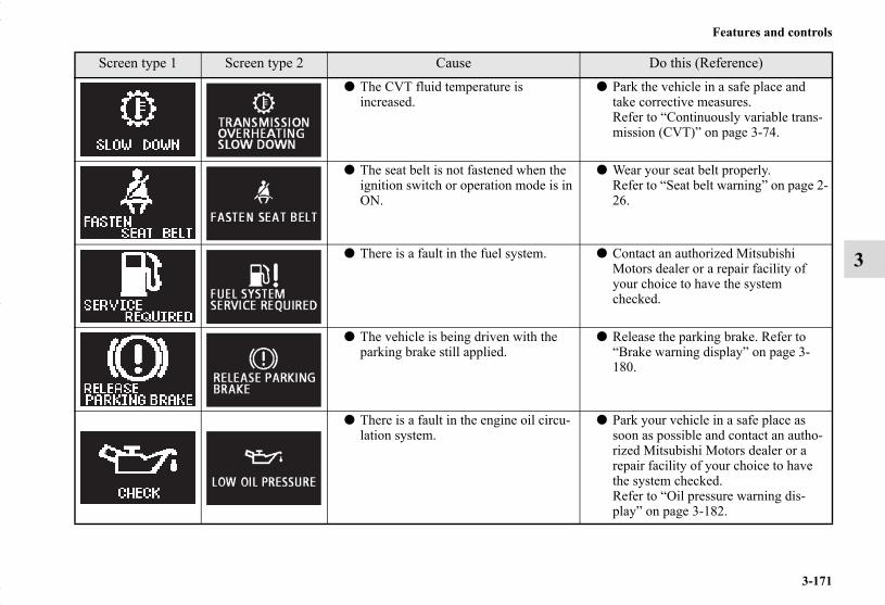
Features and controls
3-171
3
● The CVT fluid temperature is increased.
● Park the vehicle in a safe place and take corrective measures.Refer to “Continuously variable trans-mission (CVT)” on page 3-74.
● The seat belt is not fastened when the ignition switch or operation mode is in ON.
● Wear your seat belt properly. Refer to “Seat belt warning” on page 2-26.
● There is a fault in the fuel system. ● Contact an authorized Mitsubishi Motors dealer or a repair facility of your choice to have the system checked.
● The vehicle is being driven with the parking brake still applied.
● Release the parking brake. Refer to “Brake warning display” on page 3-180.
● There is a fault in the engine oil circu-lation system.
● Park your vehicle in a safe place as soon as possible and contact an autho-rized Mitsubishi Motors dealer or a repair facility of your choice to have the system checked.Refer to “Oil pressure warning dis-play” on page 3-182.
Screen type 1 Screen type 2 Cause Do this (Reference)
BK0150700US.book 171 ページ 2012年3月22日 木曜日 午後6時46分

3-172
Features and controls
3
● There is a fault in the charging system. ● Park your vehicle in a safe place as soon as possible and contact an autho-rized Mitsubishi Motors dealer or a repair facility of your choice for assis-tance.Refer to “Charging system warning light” on page 3-179.
● There is a fault in the SRS airbag or the pre-tensioner system.
● Contact an authorized Mitsubishi Motors dealer or a repair facility of your choice to have the system checked.Refer to “SRS airbag/Pre-tensioner system warning” on page 2-52.
● There is a fault in the Active stability control (ASC).
● Contact an authorized Mitsubishi Motors dealer or a repair facility of your choice to have the system checked.Refer to “Active stability control (ASC)” on page 3-102.
● There is a fault in the Hill start assist. ● Have the vehicle checked at an autho-rized Mitsubishi Motors dealer or a repair facility of your choice.Refer to “Hill start assist” on page 3-94.
● There is a fault in the electronically controlled 4WD system.
● Contact an authorized Mitsubishi Motors dealer or a repair facility of your choice to have the system checked.Refer to “Electronically controlled 4WD system” on page 3-84.
Screen type 1 Screen type 2 Cause Do this (Reference)
BK0150700US.book 172 ページ 2012年3月22日 木曜日 午後6時46分

Features and controls
3-173
3
● There is a fault in the CVT. ● Contact an authorized Mitsubishi Motors dealer or a repair facility of your choice to have the system checked.Refer to “Continuously variable trans-mission (CVT)” on page 3-74.
● The electronically controlled 4WD sys-tem is hot.
Refer to “Electronically controlled 4WD system” on page 3-84.
● The fuel is running low. ● Refuel as soon as possible. Refer to “Fuel remaining display screen” on page 3-144.
● The outside temperature is 37 °F (3 °C) or less.
● Be careful driving on frozen ground.● The ground may be frozen even when
this warning is not displayed, so drive carefully.
Screen type 1 Screen type 2 Cause Do this (Reference)
BK0150700US.book 173 ページ 2012年3月22日 木曜日 午後6時46分

3-174
Features and controls
3
Other interrupt displaysN00558200242
Screen type 1 Screen type 2 System operation status Reference
—
● When starting the engine, you pressed the engine switch without depressing the clutch pedal (manual transaxle).
● On vehicles with manual transaxle, place the gearshift lever in the “N” (Neutral) position, fully depress the clutch pedal, depress and hold the brake pedal with the right foot, and then press the engine switch to start the engine.Refer to “Starting and stopping the engine” on page 3-26.
—
● When starting the engine, the selector lever is in a position other than the “P” (PARK) or the “N” (NEUTRAL) posi-tion, or you pressed the engine switch without depressing the brake pedal (CVT).
● On vehicles with CVT, place the selec-tor lever in the “P” (PARK) position, depress and hold the brake pedal with the right foot, and then press the engine switch to start the engine.Refer to “Starting and stopping the engine” on page 3-26.
BK0150700US.book 174 ページ 2012年3月22日 木曜日 午後6時46分

Features and controls
3-175
3
The operation status of each system is displayed on the information screen. For further details, refer to the appropriate page for eachsystem.
Screen type 1 Screen type 2 System operation status Reference
● When “2WD” drive mode is selected with the drive mode selector.
Refer to “Electronically controlled 4WD system” on page 3-84.
● When “4WD AUTO” mode is selected with the drive mode selector.
● When “4WD LOCK” mode is selected with the drive mode selector.
● When the Active stability control (ASC) is operating.
Refer to “Active stability control (ASC) ” on page 3-102.
BK0150700US.book 175 ページ 2012年3月22日 木曜日 午後6時46分

3-176
Features and controls
3
This informs you that a periodic inspection is due.
The rest time can be set.
Screen type 1 Screen type 2 Do thisHave an inspection made by an authorized Mitsubishi Motors dealer. For further details, refer to “Service reminder” on page 3-145.
Screen type 1 Screen type 2 Do this
Park the vehicle in a safe place, turn off the engine, and take a rest.Use this display as rough guide for taking rests during a long drive.The interval from the start of your trip until this message is displayed can be set.Refer to “Changing the function settings (With the ignition switch or operation mode is in ON)” on page 3-148.The display and buzzer alert the driver when the set time is reached. If you continue to drive without having a rest, the buzzer sounds about every 5 minutes to encourage you to take a rest.
● In the following cases, the time driven is reset and the display returns to the previ-ous display screen. After this, when the set time is reached again, the display and buzzer encourage you to take a rest.• The buzzer sounds 3 times.• The ignition switch is turned to the “OFF” position or the operation mode is put
in OFF.• The multi-information meter switch is held (for about 2 seconds or more).
BK0150700US.book 176 ページ 2012年3月22日 木曜日 午後6時46分

Features and controls
3-177
3
IndicatorsN00519900127
Turn signal indicators/Hazard warning lightsN00520000216
The arrows will flash in time with the corresponding exteriorturn signals when the turn signal lever is used.
Both arrows will flash when the hazard warning flasher switchis pressed.
NOTE● If the indicator flashes faster than usual or if the indicator
stays on without flashing, check for a malfunctioning turnsignal light bulb or turn signal connection.
High beam indicatorN00520100086
A blue light comes on when the headlights are on high beam.
Front fog light indicator (if so equipped)N00520200175
This indicator comes on while the front fog lights are on.
Position indicatorN00551300026
This indicator light illuminates while the position lights are on.
ECO mode indicator (if so equipped)N00568800023
This indicator will be displayed when fuel-efficient driving isachieved.
Warning lightsN00520300147
Brake warning lightN00520400470
This light comes on when the ignition switch is turned to the“ON” position (engine off) or the operation mode is put in ON.When the engine is started, the light should go off a few sec-onds later. A warning is also displayed in the multi-informationdisplay.The warning light also illuminates after starting the engineunder the following conditions.
● When the parking brake is still applied.● When the brake fluid level is low.● When the brake system circuit is not working properly.
Before driving, be sure that the parking brake is fully releasedand brake warning light is off.
BK0150700US.book 177 ページ 2012年3月22日 木曜日 午後6時46分

3-178
Features and controls
3
Engine malfunction indicator (“SERVICE ENGINE SOON” or “Check engine light”)
N00520500804
This indicator is a part of the onboard diagnostic (OBD) sys-tem which monitors the emissions, engine control system orcontinuously variable transmission (CVT) control system. If aproblem is detected in one of these systems, this indicator illu-minates or flashes. When the ignition switch is turned to the“ON” position or the operation mode is put in ON, this indica-tor normally comes on and goes off after the engine has started.
This indicator will come on if the fuel tank filler cap is notproperly tightened. If this indicator comes on and stays on afterrefueling, stop the engine and check that the cap is properlytightened. (Turn the cap clockwise until you hear clickingsounds.)If this indicator does not go off after several seconds or lightsup while driving, have the system checked as soon as possibleat an authorized Mitsubishi Motors dealer or a repair facility ofyour choice.
CAUTION!
● If the brake warning light and the Anti-lock brakingsystem warning light are illuminated at the sametime, the braking force distribution function will notoperate, so the vehicle may be destabilized duringsudden braking under the following conditions.• When the brake warning light does not go out even
when the parking brake is released.• When the brake warning light stays on while driv-
ing.• If the above occurs, avoid sudden braking and
high-speed driving. Park the vehicle in a safeplace, and contact an authorized MitsubishiMotors dealer or a repair facility of your choice assoon as possible.
● The vehicle should be brought to a halt in the follow-ing manner when brake performance is deterio-rated.• Confirm that the vehicle slows down when you
press down on the brake pedal harder than usual.In some cases, the brake pedal may go all the wayto the floor.
• Should the brakes fail, use engine braking toreduce your speed and slowly apply the parkingbrake.Depress the brake pedal to illuminate the stoplights to alert the vehicles behind you.
CAUTION!
● Driving for a long time with the engine malfunctionindicator on may cause more damage to the emissioncontrol system. This could also affect fuel economyand drivability.
● If this indicator does not come on when the ignitionswitch is turned to the “ON” position or the opera-tion mode is put in ON, have the system checked atan authorized Mitsubishi Motors dealer or a repairfacility of your choice.
BK0150700US.book 178 ページ 2012年3月22日 木曜日 午後6時46分

Features and controls
3-179
3NOTE
● Do not disconnect the battery cable when the engine mal-function indicator (“SERVICE ENGINE SOON” or“Check engine light”) is on.The engine electronic control module stores critical OBDinformation (especially exhaust emission data), whichmay be lost if the battery cable is disconnected while theengine malfunction indicator is on. This will make it diffi-cult to diagnose the cause of future problems.
Charging system warning lightN00520600300
This light comes on in the event of a malfunction in the charg-ing system or when the ignition switch is turned to the “ON”position (engine off) or the operation mode is put in ON. Awarning is also displayed in the multi-information display.When the engine is started, the light should go out. Check tomake sure that the light has gone out before driving.
● If the engine malfunction indicator comes on whilethe engine is running, avoid driving at high speeds.During vehicle operation with the indicator on, thevehicle may not accelerate when you depress theaccelerator pedal.When the vehicle is stationary with the indicator on,you must depress the brake pedal more firmly thanusual since the engine idling speed is higher thanusual and a vehicle with a CVT has a stronger ten-dency to creep forward.
CAUTION!
CAUTION!
● If the warning light stays on while the engine is run-ning, park your vehicle in a safe place as soon aspossible and contact an authorized MitsubishiMotors dealer or a repair facility of your choice tohave the system checked.
BK0150700US.book 179 ページ 2012年3月22日 木曜日 午後6時46分

3-180
Features and controls
3
Information screen displayN00558300038
Brake warning displayN00558400143
Type 1
Type 2
This warning is displayed if the vehicle is being driven with theparking brake still applied. The warning light in the instrumentcluster only comes on when the parking brake is applied.
Type 1
Type 2
When the ignition switch is turned to the “ON” position or theoperation mode is put in ON, if the brake fluid is low, thiswarning is displayed.The warning light in the instrument cluster also illuminates.
CAUTION!
● If a vehicle is driven without releasing the parkingbrake, the brakes will overheat, resulting in ineffec-tive braking and possible brake failure.If this warning is displayed, release the parkingbrake.
CAUTION!
● If this warning stays on and does not go out whiledriving, there is a danger of ineffective braking. Ifthis happens, park the vehicle in a safe place, andcontact an authorized Mitsubishi Motors dealer or arepair facility of your choice.
BK0150700US.book 180 ページ 2012年3月22日 木曜日 午後6時46分
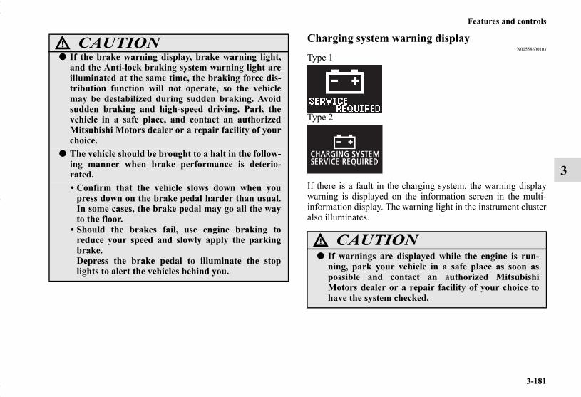
Features and controls
3-181
3
Charging system warning displayN00558600103
Type 1
Type 2
If there is a fault in the charging system, the warning displaywarning is displayed on the information screen in the multi-information display. The warning light in the instrument clusteralso illuminates.
● If the brake warning display, brake warning light,and the Anti-lock braking system warning light areilluminated at the same time, the braking force dis-tribution function will not operate, so the vehiclemay be destabilized during sudden braking. Avoidsudden braking and high-speed driving. Park thevehicle in a safe place, and contact an authorizedMitsubishi Motors dealer or a repair facility of yourchoice.
● The vehicle should be brought to a halt in the follow-ing manner when brake performance is deterio-rated.• Confirm that the vehicle slows down when you
press down on the brake pedal harder than usual.In some cases, the brake pedal may go all the wayto the floor.
• Should the brakes fail, use engine braking toreduce your speed and slowly apply the parkingbrake.Depress the brake pedal to illuminate the stoplights to alert the vehicles behind you.
CAUTION!
CAUTION!
● If warnings are displayed while the engine is run-ning, park your vehicle in a safe place as soon aspossible and contact an authorized MitsubishiMotors dealer or a repair facility of your choice tohave the system checked.
BK0150700US.book 181 ページ 2012年3月22日 木曜日 午後6時46分

3-182
Features and controls
3
Oil pressure warning displayN00558700090
Type 1
Type 2
If the engine oil pressure drops while the engine is running, thewarning display is displayed on the information screen in themulti-information display.
NOTE● The oil pressure warning display does not show the
amount of oil. The oil level must be checked using thedipstick.
CAUTION!
● If the vehicle is driven while the engine oil is low, orthe oil level is normal but the warning is displayed,the engine may overheat and damage may result.
● If the warning is displayed while the engine is run-ning, park your vehicle in a safe place as soon aspossible and check the engine oil level.
● If this warning display comes on when the engine oillevel is proper, have your vehicle checked at anauthorized Mitsubishi Motors dealer or a repairfacility of your choice.
BK0150700US.book 182 ページ 2012年3月22日 木曜日 午後6時46分

Features and controls
3-183
3
Combination headlights and dimmer switchN00522500723
HeadlightsNOTE
● Do not leave the headlights and other lights on for a longperiod of time when the engine is not running. The batterywill run down.
● When it rains, or when the vehicle has been washed, theinside of the lens sometimes becomes foggy. This is thesame as when window glass mists up on a humid day, anddoes not indicate a problem. When the light is switchedon, the heat will dry out the fog. However, if water col-lects inside the light, have it checked by an authorizedMitsubishi Motors dealer or a repair facility of yourchoice.
Type 1Rotate the switch to operate the lights.
The combinations of switch operations and illuminated lightsdiffer in accordance with the following conditions.
Except for vehicles equipped with daytime running lights OFF All lights off
Parking, tail, front and rear side-marker lights, license plate and instrument panel lights on
Headlights and other lights on
BK0150700US.book 183 ページ 2012年3月22日 木曜日 午後6時46分
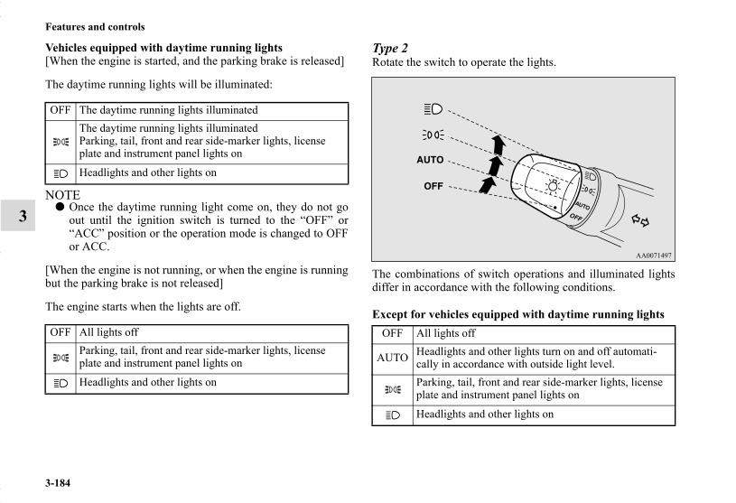
3-184
Features and controls
3
Vehicles equipped with daytime running lights[When the engine is started, and the parking brake is released]
The daytime running lights will be illuminated:
NOTE● Once the daytime running light come on, they do not go
out until the ignition switch is turned to the “OFF” or“ACC” position or the operation mode is changed to OFFor ACC.
[When the engine is not running, or when the engine is runningbut the parking brake is not released]
The engine starts when the lights are off.
Type 2Rotate the switch to operate the lights.
The combinations of switch operations and illuminated lightsdiffer in accordance with the following conditions.
Except for vehicles equipped with daytime running lights
OFF The daytime running lights illuminatedThe daytime running lights illuminatedParking, tail, front and rear side-marker lights, license plate and instrument panel lights on
Headlights and other lights on
OFF All lights offParking, tail, front and rear side-marker lights, license plate and instrument panel lights on
Headlights and other lights on
OFF All lights off
AUTO Headlights and other lights turn on and off automati-cally in accordance with outside light level.Parking, tail, front and rear side-marker lights, license plate and instrument panel lights on
Headlights and other lights on
BK0150700US.book 184 ページ 2012年3月22日 木曜日 午後6時46分

Features and controls
3-185
3
Vehicles equipped with daytime running lights[When the engine is started, and the parking brake is released]
The daytime running lights will be illuminated:
NOTE● Once the daytime running light come on, they do not go
out until the ignition switch is turned to the “OFF” or“ACC” position or the operation mode is changed to OFFor ACC.
[When the engine is not running, or when the engine is runningbut the parking brake is not released]
The engine starts when the lights are off.
NOTE● The sensitivity of the automatic on/off control can be
adjusted.For further information, please contact your authorizedMitsubishi Motors dealer or a repair facility of yourchoice.On vehicles equipped with Mitsubishi Multi-Communica-tion System, screen operations can be used to make theadjustment.Refer to the separate owner’s manual for details.
● Do not cover the sensor (A) for the automatic on/off con-trol by affixing a sticker or label to the windshield.
● If the lights do not turn on or off with the switch in the“AUTO” position, manually operate the switch. Have thesystem checked by an authorized Mitsubishi Motorsdealer or a repair facility of your choice.
OFF The daytime running lights illuminated
AUTOThe daytime running lights illuminatedHeadlights and other lights turn on and off automati-cally in accordance with outside light level.The daytime running lights illuminatedParking, tail, front and rear side-marker lights, license plate and instrument panel lights on
Headlights and other lights on
OFF All lights off
AUTO Headlights and other lights turn on and off automati-cally in accordance with outside light level.Parking, tail, front and rear side-marker lights, license plate and instrument panel lights on
Headlights and other lights on
BK0150700US.book 185 ページ 2012年3月22日 木曜日 午後6時46分
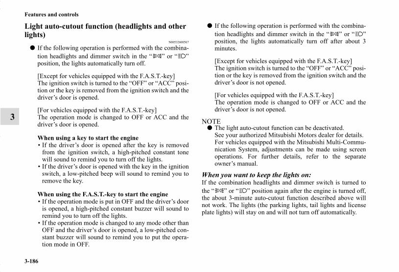
3-186
Features and controls
3
Light auto-cutout function (headlights and other lights)
N00532600567
● If the following operation is performed with the combina-tion headlights and dimmer switch in the “ ” or “ ”position, the lights automatically turn off.
[Except for vehicles equipped with the F.A.S.T.-key]The ignition switch is turned to the “OFF” or “ACC” posi-tion or the key is removed from the ignition switch and thedriver’s door is opened.
[For vehicles equipped with the F.A.S.T.-key]The operation mode is changed to OFF or ACC and thedriver’s door is opened.
When using a key to start the engine• If the driver’s door is opened after the key is removed
from the ignition switch, a high-pitched constant tonewill sound to remind you to turn off the lights.
• If the driver’s door is opened with the key in the ignitionswitch, a low-pitched beep will sound to remind you toremove the key.
When using the F.A.S.T.-key to start the engine• If the operation mode is put in OFF and the driver’s door
is opened, a high-pitched constant buzzer will sound toremind you to turn off the lights.
• If the operation mode is changed to any mode other thanOFF and the driver’s door is opened, a low-pitched con-stant buzzer will sound to remind you to put the opera-tion mode in OFF.
● If the following operation is performed with the combina-tion headlights and dimmer switch in the “ ” or “ ”position, the lights automatically turn off after about 3minutes.
[Except for vehicles equipped with the F.A.S.T.-key]The ignition switch is turned to the “OFF” or “ACC” posi-tion or the key is removed from the ignition switch and thedriver’s door is not opened.
[For vehicles equipped with the F.A.S.T.-key]The operation mode is changed to OFF or ACC and thedriver’s door is not opened.
NOTE● The light auto-cutout function can be deactivated.
See your authorized Mitsubishi Motors dealer for details.For vehicles equipped with the Mitsubishi Multi-Commu-nication System, adjustments can be made using screenoperations. For further details, refer to the separateowner’s manual.
When you want to keep the lights on:If the combination headlights and dimmer switch is turned tothe “ ” or “ ” position again after the engine is turned off,the about 3-minute auto-cutout function described above willnot work. The lights (the parking lights, tail lights and licenseplate lights) will stay on and will not turn off automatically.
BK0150700US.book 186 ページ 2012年3月22日 木曜日 午後6時46分

Features and controls
3-187
3
NOTE● When the engine is started using the key, if the driver’s
door is opened and the key is removed, the headlightreminder buzzer intermittently emits a high-pitchedsound. If the key is still in the ignition switch the keyreminder buzzer intermittently emits a low-pitched sound.The buzzer stops when the driver’s door is closed. (Awarning is also displayed in the multi-information dis-play.)
● When the engine is started using the F.A.S.T.-key, if thedriver’s door is opened and the operation mode is put inOFF, the headlight reminder buzzer intermittently emits ahigh-pitched sound. If the operation mode is in any modeother than OFF, the operation mode on reminder buzzerintermittently emits a low-pitched sound.The buzzer stops when the driver’s door is closed. (Awarning is also displayed in the multi-information dis-play.)
Headlight reminder buzzerN00549800226
[When using a key to start the engine]If the driver’s door is opened with the key in the “OFF” or“ACC” position or removed from the ignition switch while thelights are on, the tone will sound to remind you to turn off thelights.
[When using the F.A.S.T.-key to start the engine]If the driver’s door is opened with the operation mode is put inOFF or ACC, or if the operation mode is changed to OFF whilethe lights are on, the tone will sound to remind you to turn offthe lights.
In either case, the lights will turn off automatically and so willthe tone. Or you can turn the light switch to the “OFF” positionto stop the tone.
BK0150700US.book 187 ページ 2012年3月22日 木曜日 午後6時46分

3-188
Features and controls
3
Dimmer (high/low beam change)N00549900142
To change the headlights from high beam to low beam and viceversa, pull the turn signal lever to (1). Switch the headlights tolow beam as a courtesy whenever there are oncoming vehicles,or when there is traffic moving ahead of you. An illuminatedblue light in the instrument cluster indicates when the head-lights are on high beam.
Headlight flasherN00550000185
You can flash the high beams by pulling the lever gentlytoward you (2). The lights will go back to normal when you letgo. While the high beam is on, you will see a blue light on theinstrument panel.
NOTE● You can flash the high beams by pulling the lever toward
you, even if the light switch is off.● If you turn the lights off with the head lights set to high-
beam illumination, the headlights are automaticallyreturned to their low-beam setting when the light switch isnext turned to the “ ” position.
BK0150700US.book 188 ページ 2012年3月22日 木曜日 午後6時46分

Features and controls
3-189
3
Welcome lightN00563200064
This function turns on the front side-marker and parking lightsfor about 30 seconds after the UNLOCK button (A) on theremote control transmitter is pressed when the combinationheadlights and dimmer switch is in the “OFF” or “AUTO”position (for vehicles equipped with the automatic light con-trol). On vehicles equipped with the automatic light control,the welcome light function will operate only when it is darkoutside the vehicle.
NOTE● While the welcome light function is operating, perform
one of the following operations to cancel the function.
• Push the LOCK button (B) on the remote control trans-mitter.
• Turn the combination headlights and dimmer switch tothe “ ” or “ ” position.
• Turn the ignition switch to the “ON” position or put theoperation mode in ON.
● It is possible to modify functions as follows:• The headlights can be set to come on in the low beam
setting.• The welcome light function can be deactivated.For details, consult a Mitsubishi Motors dealer.On vehicles equipped with Mitsubishi Multi-Communica-tion System, screen operations can be used to make theadjustment.Refer to the separate owner’s manual for details.
BK0150700US.book 189 ページ 2012年3月22日 木曜日 午後6時46分

3-190
Features and controls
3
Coming home lightN00547300100
This function turns on the headlights in the low beam settingfor about 30 seconds after the ignition switch is turned to the“OFF” position or the operation mode is put in OFF.
1. Turn the combination headlights and dimmer switch to the“OFF” or “AUTO” position (for vehicles equipped withthe automatic light control).
2. Turn the ignition switch to the “OFF” position or put theoperation mode in OFF. Also, if a key was used to start theengine, remove the key from the ignition switch.
3. Within 60 seconds of turning the ignition switch to the“OFF” position or putting the operation mode in OFF, pullthe turn signal lever toward you.
4. The headlights will come on in the low beam setting forabout 30 seconds. After the headlights go off, the head-lights can be turned on again in the low beam setting forabout 30 seconds by pulling the turn signal lever towardyou within 60 seconds of turning the ignition switch to the“OFF” position or putting the operation mode in OFF. Toturn on the headlights again after 60 seconds of turningthe ignition switch to the “OFF” position or putting theoperation mode in OFF, repeat the process from step 1.
NOTE● While the coming home light function is operating, per-
form one of the following operations to cancel the func-tion.• Pull the turn signal lever toward you.• Turn the combination headlights and dimmer switch to
the “ ” or “ ” position or put the operation mode inON.
• Turn the ignition switch to the “ON” position or put theoperation mode in ON.
● It is possible to modify functions as follows:• The time that the headlights remain on can be changed.• The coming home light function can be deactivated.For details, consult a Mitsubishi Motors dealer.On vehicles equipped with Mitsubishi Multi-Communica-tion System, screen operations can be used to make theadjustment.Refer to the separate owner’s manual for details.
BK0150700US.book 190 ページ 2012年3月22日 木曜日 午後6時46分

Features and controls
3-191
3
Headlight leveling switch (if so equipped)N00537100105
The direction of the headlight beam (the direction in which thelight shines) alters according to the number of people and theload in the vehicle. Lower the headlight angle if it is too highdue to the number of people and/or the load in the vehicle sothat the headlights’ glare does not distract the drivers ofapproaching vehicles. First set the light switch to the “ ”position, then turn the headlight leveling switch knob to lowerthe beam. The greater the number on the headlight levelingswitch knob, the lower the beam will point.Set the switch to the appropriate position so that the headlightbeam is level with the road.
NOTE● Start adjusting when the knob is at the “0” position (when
the beam is at its highest).● Keep the knob in the “0” position except when using the
knob to lower the headlight beam angle.● Always return the knob to the “0” position when the load
is removed and the people have left the vehicle.
WARNING!
● To avoid distraction while driving, always performheadlight adjustments before vehicle operation.
BK0150700US.book 191 ページ 2012年3月22日 木曜日 午後6時46分

3-192
Features and controls
3
Turn signal leverN00522600450
When changing lanes, or to making a gradual turn, hold thelever in the “lane change” position (1). It will return to the neu-tral position when you let go. Use the full position (2) whenmaking a normal turn. The lever will return to the neutral posi-tion when the turn is complete. There may be times when thelever does not return to the neutral position. This usually hap-pens when the steering wheel is turned only slightly. You caneasily return the lever by hand.Also, when you move the lever to (1) slightly then release it,the turn signal lights and the indicator light in the instrumentcluster will flash three times.
NOTE● A light in the instrument panel flashes to show when the
front and rear turn signal lights are working properly.If this light flashes faster than usual, check for a burnedout turn signal light bulb or malfunctioning connection inthe signal.If the panel light does not come on when the lever ismoved, check for a blown fuse or a burned out bulb in thepanel.Have the system inspected by your authorized MitsubishiMotors dealer or a repair facility of your choice.
● It is possible to modify functions as follows:• Deactivate the turn signal light 3-flash function for lane
changes.• Adjust the time required to operate the lever for the 3-
flash function.See your authorized Mitsubishi Motors dealer for details.For vehicles equipped with the Mitsubishi Multi-Commu-nication System, adjustments can be made using screenoperations. For further details, refer to the separateowner’s manual.
BK0150700US.book 192 ページ 2012年3月22日 木曜日 午後6時46分

Features and controls
3-193
3
Hazard warning flasher switchN00522700275
If you press the flasher switch, the front and rear turn signalswill flash intermittently, and so will the hazard warning lights.This is an emergency warning system and should not be usedwhen the vehicle is in motion, except for emergencies.If you need to leave your vehicle, the flashers will keep work-ing after the ignition switch is removed or the operation modeis put in OFF.
NOTE● If the flashers are used for several hours, the battery will
run down. This could make it difficult or impossible torestart your vehicle.
Front fog light switch (if so equipped)N00522800393
The front fog lights illuminate only when the headlights are onlow beam.Turning the knob in the direction of the “ON” position turns onthe front fog lights as well as the indicator in the instrumentcluster. To turn them off, turn the knob in the direction of the“OFF” position.The knob will return to the neutral position when it is released.
NOTE● If the headlights are switched to high beam, the front fog
lights will go out; they will illuminate again when theheadlights are switched back to low beam.
BK0150700US.book 193 ページ 2012年3月22日 木曜日 午後6時46分

3-194
Features and controls
3
● If the light switch is rotated to the “OFF” or “ ” posi-tion while the front fog lights are illuminated, they willautomatically turn off. They can be turned back on againby rotating the combination headlights and dimmer switchback to “ ” position, and turning the knob in the direc-tion of the “ON” position.
● Do not use fog lights except in conditions of fog, other-wise excessive light glare may temporarily blind oncom-ing vehicle drivers.
Wiper and washer switchN00523000653
Windshield wipersNOTE
● To ensure a clear rearward view, the rear window wiperwill automatically perform several continuous operationsif the gearshift lever or the selector lever is put in the “R”position while the windshield wipers are operating.Refer to “Rear window wiper and washer” on page 3-201.
Except for vehicle with rain sensorThe windshield wiper and washer can be operated with theignition switch or the operation mode is in ON or ACC.If the blades are frozen to the windshield, do not operate thewipers until the ice has melted and the blades are freed, other-wise the wiper motor may be damaged.
CAUTION!
● If the washer is used in cold weather, the washerfluid sprayed against the glass may freeze, whichmay hinder visibility. Warm the glass with thedefroster before using the washer.
BK0150700US.book 194 ページ 2012年3月22日 木曜日 午後6時46分

Features and controls
3-195
3
To adjust intermittent intervalsWith the lever in the “INT” (speed sensitive intermittent opera-tion) position, the intermittent intervals can be adjusted byturning the knob (A).
NOTE● The speed-sensitive-operation function of the windshield
wipers can be deactivated.For further information, please contact your authorizedMITSUBISHI MOTORS dealer or a repair facility of yourchoice. On vehicles equipped with Mitsubishi Multi-Communication System, screen operations can be used tomake the adjustment.Refer to separate owner’s manual for details.
MIST- Misting functionThe wipers will operate once.
OFF- OffINT- Intermittent (Speed sensitive)LO- SlowHI- Fast
1- Fast2- Slow
BK0150700US.book 195 ページ 2012年3月22日 木曜日 午後6時46分
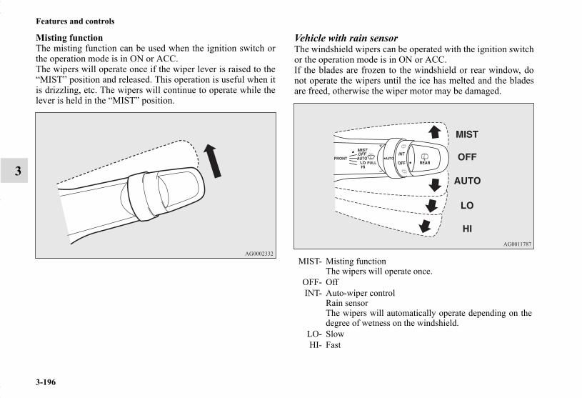
3-196
Features and controls
3
Misting functionThe misting function can be used when the ignition switch orthe operation mode is in ON or ACC.The wipers will operate once if the wiper lever is raised to the“MIST” position and released. This operation is useful when itis drizzling, etc. The wipers will continue to operate while thelever is held in the “MIST” position.
Vehicle with rain sensorThe windshield wipers can be operated with the ignition switchor the operation mode is in ON or ACC.If the blades are frozen to the windshield or rear window, donot operate the wipers until the ice has melted and the bladesare freed, otherwise the wiper motor may be damaged.
MIST- Misting functionThe wipers will operate once.
OFF- OffINT- Auto-wiper control
Rain sensorThe wipers will automatically operate depending on thedegree of wetness on the windshield.
LO- SlowHI- Fast
BK0150700US.book 196 ページ 2012年3月22日 木曜日 午後6時46分

Features and controls
3-197
3
Rain sensor (if so equipped)Can only be used when the ignition switch or the operationmode is in ON.If the lever is put in the “AUTO” position, the rain sensor (A)will detect the extent of rain (or snow, other moisture, dust,etc.) and the wipers will operate automatically.Keep the lever in the “OFF” position if the windshield is dirtyand the weather is dry.Wiper operation under these conditions can scratch the wind-shield and damage the wipers.
CAUTION!
● With the ignition switch or the operation mode inON and the lever in the “AUTO” position, the wip-ers may automatically operate in the situationsdescribed below.• When cleaning the outside surface of the wind-
shield, if you touch the rain sensor.• When cleaning the outside surface of the wind-
shield, if you wipe with a cloth the rain sensor.• When using an automatic car wash.• A physical shock is applied to the windshield.• A physical shock is applied to the rain sensor.If your hands get trapped, you could suffer injuriesor the wipers could malfunction. Be sure to turn theignition switch to the “OFF” position or put theoperation mode in OFF, or move the lever to the“OFF” position to deactivate the rain sensor.
BK0150700US.book 197 ページ 2012年3月22日 木曜日 午後6時46分
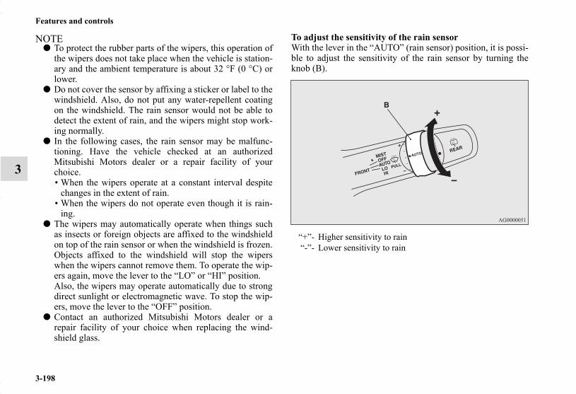
3-198
Features and controls
3
NOTE● To protect the rubber parts of the wipers, this operation of
the wipers does not take place when the vehicle is station-ary and the ambient temperature is about 32 °F (0 °C) orlower.
● Do not cover the sensor by affixing a sticker or label to thewindshield. Also, do not put any water-repellent coatingon the windshield. The rain sensor would not be able todetect the extent of rain, and the wipers might stop work-ing normally.
● In the following cases, the rain sensor may be malfunc-tioning. Have the vehicle checked at an authorizedMitsubishi Motors dealer or a repair facility of yourchoice.• When the wipers operate at a constant interval despite
changes in the extent of rain.• When the wipers do not operate even though it is rain-
ing.● The wipers may automatically operate when things such
as insects or foreign objects are affixed to the windshieldon top of the rain sensor or when the windshield is frozen.Objects affixed to the windshield will stop the wiperswhen the wipers cannot remove them. To operate the wip-ers again, move the lever to the “LO” or “HI” position.Also, the wipers may operate automatically due to strongdirect sunlight or electromagnetic wave. To stop the wip-ers, move the lever to the “OFF” position.
● Contact an authorized Mitsubishi Motors dealer or arepair facility of your choice when replacing the wind-shield glass.
To adjust the sensitivity of the rain sensorWith the lever in the “AUTO” (rain sensor) position, it is possi-ble to adjust the sensitivity of the rain sensor by turning theknob (B).
“+”- Higher sensitivity to rain“-”- Lower sensitivity to rain
BK0150700US.book 198 ページ 2012年3月22日 木曜日 午後6時46分

Features and controls
3-199
3
NOTE● Automatic wiper operation (rain sensitive) can be changed
to intermittent operation, either vehicle speed sensitive ornot vehicle speed sensitive.For further information, please contact your authorizedMITSUBISHI MOTORS dealer or a repair facility of yourchoice.On vehicles equipped with Mitsubishi Multi-Communica-tion System, screen operations can be used to make theadjustment.Refer to the separate owner’s manual for details.
Misting functionMove the lever in the direction of the arrow and release, tooperate the wipers once.Use this function when you are driving in mist or drizzle.The wipers will operate once if the lever is raised to the“MIST” position and released when the ignition switch or theoperation mode is in ON or ACC. The wipers will continue tooperate while the lever is held in the “MIST” position.
BK0150700US.book 199 ページ 2012年3月22日 木曜日 午後6時46分

3-200
Features and controls
3
The wipers will operate once if the lever is moved to the“AUTO” position and the knob (C) is turned in the “+” direc-tion when the ignition switch or the operation mode is in ON.
Windshield washerN00504600227
The windshield washer can be operated with the ignitionswitch or the operation mode is in ON or ACC.The washer fluid will be sprayed onto the windshield by pull-ing the lever toward you.When the wipers are not in operation or in intermittent opera-tion, by pulling the lever toward you, the wipers will operateseveral times while the washer fluid is being sprayed.Also, by releasing the lever soon after pulling it toward you,the washer fluid will be sprayed several times while the wipersare operating several times. (Intelligent washer)Intelligent washer will stop operating with any operation of thelever.
BK0150700US.book 200 ページ 2012年3月22日 木曜日 午後6時46分
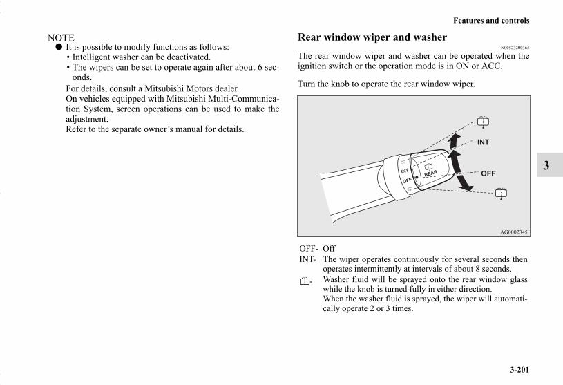
Features and controls
3-201
3
NOTE● It is possible to modify functions as follows:
• Intelligent washer can be deactivated.• The wipers can be set to operate again after about 6 sec-
onds.For details, consult a Mitsubishi Motors dealer.On vehicles equipped with Mitsubishi Multi-Communica-tion System, screen operations can be used to make theadjustment.Refer to the separate owner’s manual for details.
Rear window wiper and washerN00523200365
The rear window wiper and washer can be operated when theignition switch or the operation mode is in ON or ACC.
Turn the knob to operate the rear window wiper.
OFF- OffINT- The wiper operates continuously for several seconds then
operates intermittently at intervals of about 8 seconds.- Washer fluid will be sprayed onto the rear window glass
while the knob is turned fully in either direction.When the washer fluid is sprayed, the wiper will automati-cally operate 2 or 3 times.
BK0150700US.book 201 ページ 2012年3月22日 木曜日 午後6時46分

3-202
Features and controls
3
NOTE● The rear window wiper will automatically perform several
continuous operations if the gearshift lever or the selectorlever is put in the “R” position while the windshield wip-ers or the rear window wiper is operating.(automatic oper-ation mode)After the automatic operation, the rear window wiper willstop operating if the knob is in the “OFF” position. If theknob is in the “INT” position, the rear window wiper willreturn to the intermittent operation.It is possible to set the rear window wiper to perform theautomatic operation only if the gearshift lever or the selec-tor lever is put in the “R” position while the rear windowwiper is operating with the knob in the “INT” position.See your authorized Mitsubishi Motors dealer for details.
● If the knob is in the “OFF” position, turn the knob to the“INT” position twice quickly to operate the rear windowwiper continuously. (continuous operation mode)Turn the knob to the “OFF” position to stop the rear win-dow wiper continuous operation.
● The wiper intermittent operation time can be adjusted.See your authorized Mitsubishi Motors dealer for details.For vehicles equipped with the Mitsubishi Multi-Commu-nication System, adjustments can be made using screenoperations. For further details, refer to the separateowner’s manual.
● The washer fluid reservoir is located in the engine com-partment.Check the fluid level regularly and refill if necessary.(Refer to “Washer fluid” on page 7-19.)
Precautions to observe when using wipers and washers
N00523500195
NOTE● Do not use the wipers when the windshield is dry. This
could scratch the glass and wear the wiper blades prema-turely.
● Before using the wipers in cold weather, check to be surethat the wiper blades are not frozen to the windshield orrear window. Using the wipers while the blades are frozencould cause the wiper motor to burn out.
● If the wipers become blocked by ice or other deposits onthe glass, the motor may still burn out even if the wiperswitch is OFF. If deposits form on the windshield, parkyour vehicle in a safe place, turn off the engine, and cleanthe glass so that the wipers can operate smoothly.
● Avoid using the washer for more than 20 seconds at atime. Do not operate the washer when the washer fluidreservoir is empty or the pump may fail.
● During cold weather, add a recommended washer solutionthat will not freeze in the washer fluid reservoir. Other-wise the washer may not work or may be damaged.
CAUTION!
● If the washer is used in cold weather, the washerfluid sprayed onto the glass might freeze, blockingyour view. Heat the glass with the defroster beforeusing the washer.
BK0150700US.book 202 ページ 2012年3月22日 木曜日 午後6時46分

Features and controls
3-203
3
● Replace the wiper blades when they are worn. Use theproper size replacement blades. For further information,please contact your authorized Mitsubishi Motors dealer.
Electric rear window defogger switchN00523700373
The rear window defogger can be used when the engine is run-ning.The indicator light (A) will come on when you press the elec-tric rear window defogger switch. Electric current will flowthrough the heating wires on the rear window to help clearaway moisture or frost.
After about 20 minutes of operation, the system will shut offautomatically.To switch the defogger OFF before 20 minutes have passed,press the switch again. The indicator light will go out and thedefogger will turn off.If you need the defogger for more than 20 minutes, press theswitch again. This will add 20 more minutes.
BK0150700US.book 203 ページ 2012年3月22日 木曜日 午後6時46分

3-204
Features and controls
3
NOTE● As your vehicle is equipped with heated mirrors, mist can
also be removed from the outside rearview mirrors whenthe rear window defogger switch is pressed. (Refer to“Door mirror heater” on page 3-66.)
Horn switchN00523800172
To honk the horn, press around the “ ” mark on the steeringwheel.
CAUTION!
● The rear window defogger is not designed to meltsnow. Remove any snow manually before using therear window defogger.
● Use the rear window defogger only after the enginehas started and is running. Be sure to turn thedefogger switch off immediately after the window isclear to save on battery power.
● Do not place stickers, tape, or other items that areattached with adhesive over the grid wires on therear window.
● When cleaning the inside rear window, use a softcloth and wipe lightly over the grid wires.
BK0150700US.book 204 ページ 2012年3月22日 木曜日 午後6時46分

Features and controls
3-205
3
Link System (if so equipped)N00563700027
The Link System takes overall control of the devices connectedvia the USB input terminal or the Bluetooth® 2.0 interfaceallowing the connected devices to be operated by using theswitches in the vehicle or voice commands.See the following section for details on how to operate.
Refer to “Bluetooth® 2.0 interface” on page 3-205.Refer to “USB input terminal” on page 3-231.Refer to “To play tracks from USB device” on page 5-73.Refer to “To play tracks from a Bluetooth® device” on page 5-88.Refer to “To use the external audio input function” on page 5-91.
Bluetooth® is a registered trademark of BLUETOOTH SIG,INC.
Link System End User License AgreementN00563800015
You have acquired a device that includes software licensed byMitsubishi Motors Corporation from JOHNSON CONTROLSInc (the automotive experience business unit), and their subse-quent 3rd party suppliers. For a complete list of these 3rd partyproducts and their end user license agreements, please go to thefollowing website.http://www.jciblueconnect.com/faq/fulldisclosure.pdf
Bluetooth® 2.0 interface (if so equipped)N00563900146
The Bluetooth® 2.0 interface allows for making/receivinghands-free calls in the vehicle using a Bluetooth® compatiblecellular phone based on the wireless communication technol-ogy commonly known as Bluetooth®. It also allows the user toplay music, saved in a Bluetooth® music player, from the vehi-cle’s speakers.The system is equipped with a voice recognition function,which allows you to make hands-free calls by simple switchoperations and voice command operations using a definedvoice tree.
The Bluetooth® 2.0 interface can be used when the ignitionswitch or the operation mode is in ON or ACC.
Before you can use the Bluetooth® 2.0 interface, you must pairthe Bluetooth® device and Bluetooth® 2.0 interface. Refer to“Connecting the Bluetooth® 2.0 interface and Bluetooth®
device” on page 3-213.
Bluetooth® is a registered trademark of BLUETOOTH SIG,INC.
BK0150700US.book 205 ページ 2012年3月22日 木曜日 午後6時46分
3-206
Features and controls
3NOTE
● If the ignition switch or the operation mode is left in ACC,the accessory power will automatically turn off after a cer-tain period of time and you will no longer be able to usethe Bluetooth® 2.0 interface. The accessory power comeson again if the ignition switch or the engine switch isoperated. Refer to “ACC power auto-cutout function” onpage 3-67.
● The Bluetooth® 2.0 interface cannot be used if the Blue-tooth® device has a dead battery or the device power isturned off.
● Hands-free calls will not be possible if your phone doesnot have service available.
● If you place the Bluetooth® device in the luggage com-partment, you may not be able to use the Bluetooth® 2.0interface.
● Some Bluetooth® devices are not compatible with theBluetooth® 2.0 interface.
● You can confirm the Link System software version bypressing the HANG-UP button 3 times (press and hold 2times and then press briefly) within 10 seconds.
● For detail of the Bluetooth® 2.0 interface, refer to the fol-lowing web site:[For vehicles sold in U.S.A.]You can see to access the MITSUBISHI MOTORSNORTH AMERICA web site.[For vehicles sold in Canada]You can see to access via the MITSUBISHI MOTORSweb site.Please read and agree the “Warning about Links to theWeb Sites of Other Companies” because it connects otherthan MITSUBISHI MOTORS web site.http://www.mitsubishi-motors.com/en/products/index.html
● Software updates by cellular phone/digital audio devicemanufacturers may change/alter device connectivity.
Steering control switch → P.3-207Voice recognition function → P.3-208Useful voice commands → P.3-209Speaker enrollment function → P.3-211Connecting the Bluetooth® 2.0 interface and the Bluetooth®
device → P.3-213Operating a music player connected via Bluetooth® → P.3-218How to make or receive hands-free calls → P.3-218Phonebook function → P.3-222
WARNING!
● Although the Bluetooth® 2.0 interface allows you tomake hands-free calls, if you choose to use the cellu-lar phone while driving, you must not allow yourselfto be distracted from the safe operation of your vehi-cle. Anything, including cellular phone usage, thatdistracts you from the safe operation of your vehicleincreases your risk of an accident.
● Refer to and comply with all state and local laws inyour area regarding cellular phone usage while driv-ing.
BK0150700US.book 206 ページ 2012年4月2日 月曜日 午前10時19分

Features and controls
3-207
3
Steering control switchN00564000014
Volume up buttonPress this button to increase the volume.
Volume down buttonPress this button to decrease the volume.
SPEECH button● Press this button to change to voice recognition mode.
While the system is in voice recognition mode, “Listen-ing” will appear on the audio display.
● If you press the button briefly while in voice recognitionmode, it will interrupt prompting and allow voice com-mand input.Pressing the button longer will deactivate the voice recog-nition mode.
● Pressing this button briefly during a call will enable voicerecognition and allow voice command input.
PICK-UP button● Press this button when an incoming call is received to
answer the telephone.● When another call is received during a call, press this but-
ton to put the first caller on hold and talk to the new caller. • In such circumstances, you can press the button briefly
to switch between callers. You will switch to the firstcaller and the other caller will be put on hold.
• To establish a three-way call in such situations, press theSPEECH button to enter voice recognition mode andthen say “Join calls.”
1- Volume up button2- Volume down button3- SPEECH button4- PICK-UP button5- HANG-UP button
BK0150700US.book 207 ページ 2012年3月22日 木曜日 午後6時46分

3-208
Features and controls
3
HANG-UP button● Press this button when an incoming call is received to
refuse the call.● Press this button during a call to end the current call.
When another call is on hold, you will switch to that call.● If this button is pressed in the voice recognition mode, the
voice recognition mode will be deactivated.
NOTE● When you press the SPEECH button to enter voice recog-
nition mode with a cellular phone paired to the system,current information on the cellular phone, such as“remaining battery life,” “signal strength” or “roaming,”will be displayed on the audio display.**: Some cellular phones will not send this information tothe Bluetooth® 2.0 interface.
● Call waiting and three-way calls can be used by the Blue-tooth® 2.0 interface, only if it is possible to use those ser-vices with your cellular phone.
Voice recognition functionN00564100028
The Bluetooth® 2.0 interface is equipped with a voice recogni-tion function.Simply say voice commands and you can perform variousoperations and make or receive hands-free calls.
With the Bluetooth® 2.0 interface, voice recognition is possiblefor US English, North American Spanish, Canadian French andJapanese. The factory setting is “English.”
NOTE● If the voice command that you say differs from the pre-
defined command or cannot be recognised due to ambientnoise or some other reason, the Bluetooth® 2.0 interfacewill ask you for the voice command again up to 3 times.
● For best performance and further reduction of ambientnoise, the vehicle windows should be closed while engag-ing the voice recognition function.
● Some voice commands have alternative commands.● Depending on the selected language, some functions may
not be available.
BK0150700US.book 208 ページ 2012年3月22日 木曜日 午後6時46分

Features and controls
3-209
3
Selecting the language1. Press the SPEECH button.2. Say “Setup.”3. Say “Language.”4. The voice guide will say “Select a language: English,
Spanish, French or Japanese.” Say the desired language.(Example: “English”)
5. The voice guide will say “English (Spanish, French orJapanese) selected. Is this correct?” Say “Yes.”If you say “No,” the system will return to Step 4.
NOTE● The voice guide will repeat the same message twice. The
first message is in the current language, and the secondmessage is in the selected language.
● If many entries are registered in the vehicle phonebook,changing the language will take a longer time.
● Changing the language deletes the mobile phonebookimported to the Bluetooth® 2.0 interface. If you wish touse it, you will have to import it again.
6. When the voice guide says “English (Spanish, French orJapanese) selected,” the language change process will becompleted and the system will return to the main menu.
Useful voice commandsN00564200016
Help functionN00564300017
The Bluetooth® 2.0 interface is equipped with a help function. If you say “Help” when the system is waiting for a voice com-mand input, the system will tell you a list of the commands thatcan be used under the circumstances.
CancelingN00564400018
There are 2 cancel functions.If you are at the main menu, say “Cancel” to exit from theBluetooth® 2.0 interface. If you are anywhere else within the system, say “Cancel” toreturn to the main menu.
BK0150700US.book 209 ページ 2012年3月22日 木曜日 午後6時46分

3-210
Features and controls
3
Confirmation function settingN00564500019
The Bluetooth® 2.0 interface is equipped with a confirmationfunction.With the confirmation function activated, you are given moreopportunities than normal to confirm a command when makingvarious settings to the Bluetooth® 2.0 interface. This allowsyou to decrease the possibility that a setting is accidentallychanged. The confirmation function can be turned on or off by followingthe steps below.
1. Press the SPEECH button.2. Say “Setup.”3. Say “Confirmation prompts.”4. The voice guide will say “Confirmation prompts are
<on/off>. Would you like to turn confirmation prompts<off/on>.”Answer “Yes” to change the setting or answer “No” tokeep the current setting.
5. The voice guide will say “Confirmation prompts are<off/on>” and then the system will return to the mainmenu.
Security functionN00564600023
It is possible to use a passcode as a security function by settinga passcode of your choice for the Bluetooth® 2.0 interface.When the security function is turned on, it is necessary to makea voice input of a 4-digit passcode in order to use all functionsof the Bluetooth® 2.0 interface, except for reception.
Setting the passcodeUse the following procedure to turn on the security function bysetting a passcode.
1. Press the SPEECH button.2. Say “Setup.”3. Say “Passcode.”4. The voice guide will say “Passcode is disabled. Would
you like to enable it?” Answer “Yes.”Answer “No” to cancel the setting of the passcode andreturn to the main menu.
5. The voice guide will say “Please say a 4-digit passcode.Remember this passcode. It will be required to use thissystem.” Say a 4-digit number which you want to set as a passcode.
6. For confirmation purposes, the voice guide will say “Pass-code <4-digit passcode>. Is this correct?” Answer “Yes.”Answer “No” to return to the passcode input in Step 5.
7. When the registration of the passcode is completed, thevoice guide will say “Passcode is enabled” and the systemwill return to the main menu.
NOTE● Passcode will be required to access the system after the
next ignition cycle.● It is required for a little time after engine stop that the
entered passcode is actually recorded in the system.If the ignition switch or the operation mode is made toACC or ON or the engine is started immediately afterengine stop, there is a case when the entered passcode isnot recorded in the system. At this time, please try to enterthe passcode again.
BK0150700US.book 210 ページ 2012年3月22日 木曜日 午後6時46分
Features and controls
3-211
3
Entering the passcodeIf a passcode has been set and the security function is enabled,the voice guide will say “Hands-free system is locked. State thepasscode to continue” when the SPEECH button is pressed toenter voice recognition mode. Say the 4-digit passcode numberto enter the passcode. If the entered passcode is wrong, the voice guide will say “<4-digit passcode>, Incorrect passcode. Please try again.” Enterthe correct passcode.
NOTE● You can reenter the passcode as many times as you want. ● If you have forgotten your passcode, say “Cancel” to quit
the voice input mode and then check with an authorizedMitsubishi Motors dealer.
Disabling the passcodeUse the following procedure to turn off the security function bydisabling the passcode.
NOTE● System must be unlocked to disable the passcode.
1. Press the SPEECH button.2. Say “Setup.”3. Say “Passcode.”4. The voice guide will say “Passcode is enabled. Would you
like to disable it?” Answer “Yes.”Answer “No” to cancel the disabling of the passcode andreturn to the main menu.
5. When the disabling of the passcode is completed, thevoice guide will say “Passcode is disabled” and the sys-tem will return to the main menu.
Speaker enrollment functionN00564700011
The Bluetooth® 2.0 interface can use the speaker enrollmentfunction to create a voice model for one person per language. This makes it easier for the Bluetooth® 2.0 interface to recogn-ise voice commands said by you. You can turn a voice model registered with the speaker enroll-ment function on and off whenever you want.
Speaker enrollmentN00564800038
It takes about 2 to 3 minutes to complete the speaker enroll-ment process.To ensure the best results, run through the process while in thedriver’s seat, in an environment that is as quiet as possible(when there is no rain or strong winds and the vehicle windowsare closed). Please turn off your phone while in speaker enroll-ment to prevent interruption of the process.Use the following procedure for speaker enrollment.
1. Stop your vehicle in a safe area, put the gearshift lever inthe “N” (Neutral) position (manual transaxle), or theselector lever in the “P” (PARK) position (continuouslyvariable transmission (CVT)), and pull the parking brakelever.
NOTE● Speaker enrollment is not possible unless the vehicle is
parked. Make sure you park the vehicle in a safe areabefore attempting speaker enrollment.
2. Press the SPEECH button.3. Say “Voice training.”
BK0150700US.book 211 ページ 2012年3月22日 木曜日 午後6時46分

3-212
Features and controls
3
4. The voice guide will say “This operation must be per-formed in a quiet environment while the vehicle isstopped. See the owner’s manual for the list of requiredtraining phrases. Press and release the SPEECH buttonwhen you are ready to begin. Press the HANG-UP buttonto cancel at any time.”Press the SPEECH button to start the speaker enrollmentprocess.
NOTE● If you do not start the speaker enrollment process within 3
minutes after pressing the SPEECH button, the speakerenrollment function will time out. The voice guide will say “Speaker enrollment has timedout.” The system will then beep and the voice recognitionmode will be deactivated.
5. The voice guide will prompt for phrase 1. Repeat the cor-responding phrase listed in table “Enrollment commands”on page 3-230.The system will register your voice and then move on tothe registration of the next command. Continue the pro-cess until all phrases have been registered.
NOTE● To repeat the most recent voice training command, press
and release the SPEECH button.● If you press the HANG-UP button anytime during the pro-
cess, the system will beep and stop the speaker enrollmentprocess.
6. When all enrollment commands have been read out, thevoice guide will say “Speaker enrollment is complete.”The system will then end the speaker enrollment processand return to the main menu.
NOTE● Completing the speaker enrollment process will turn on
the voice model automatically.● The commands “Help” and “Cancel” will not work in this
mode.
Enabling and disabling the voice model and retrainingN00564900055
You can turn a voice model registered with the speaker enroll-ment function on and off whenever you want.You can also retrain the system.Use the following procedure to perform these actions.
1. Press the SPEECH button.2. Say “Voice training.”3. If you have completed a speaker enrollment process once
already, the voice guide will say either “Enrollment isenabled. Would you like to disable or retrain?” or “Enroll-ment is disabled. Would you like to enable or retrain?”
4. When enrollment is “enabled,” the voice model is on;when enrollment is “disabled,” the voice model is off. Saythe command that fits your needs. Say “Retrain” to start the speaker enrollment process andrecreate a new voice model. (Refer to “Speaker enroll-ment” on page 3-211.)
BK0150700US.book 212 ページ 2012年3月22日 木曜日 午後6時46分

Features and controls
3-213
3
Connecting the Bluetooth® 2.0 interface and Bluetooth® device
N00565000170
Before you can make or receive hands-free calls or play musicusing the Bluetooth® 2.0 interface function, you must pair theBluetooth® device and Bluetooth® 2.0 interface.
NOTE● Pairing is required only when the device is used for the
first time. Once the device has been paired with the Blue-tooth® 2.0 interface, all you need is to bring the deviceinto the vehicle next time and the device will connect tothe Bluetooth® 2.0 interface automatically (if supportedby the device). The device must have Bluetooth® turnedON to connect.
Up to 7 Bluetooth® devices can be paired with the Bluetooth®
2.0 interface.If multiple paired Bluetooth® devices are available in the vehi-cle, the cellular phone or music player most recently connectedis automatically connected to the Bluetooth® 2.0 interface.
You can also change a Bluetooth® device to be connected.
To pairTo pair a Bluetooth® device with the Bluetooth® 2.0 interface,follow the steps below.
1. Stop your vehicle in a safe area, put the gearshift lever inthe “N” (Neutral) position (manual transaxle), or theselector lever in the “P” (PARK) position (continuouslyvariable transmission (CVT)), and pull the parking brakelever.
NOTE● You cannot pair any Bluetooth® device with the Blue-
tooth® 2.0 interface unless the vehicle is parked. Beforepairing a Bluetooth® device with the Bluetooth® 2.0 inter-face, confirm that the vehicle is parked in a safe location.
2. Press the SPEECH button.3. Say “Setup.”4. Say “Pairing Options.”
BK0150700US.book 213 ページ 2012年3月22日 木曜日 午後6時46分

3-214
Features and controls
3
5. The voice guide will say “Select one of the following:pair, edit, delete, or list.” Say “Pair.”
NOTE● If 7 devices have already been paired, the voice guide will
say “Maximum devices paired” and then the system willend the pairing process. To register a new device, deleteone device and then repeat the pairing process.(Refer to “Selecting a device: Deleting a device” on page3-215.)
6. The voice guide will say “Please say a 4-digit pairingcode.” Say a 4-digit number.When the confirmation function is on, the system willconfirm whether the number said is acceptable. Answer“Yes.”Answer “No” to return to pairing code selection.
NOTE● Some Bluetooth® devices require a specific pairing code.
Please refer to the device manual for pairing code require-ments.
● The pairing code entered here is only used for the Blue-tooth® connection certification. It is any 4-digit numberthe user would like to select.Remember the pairing code as it needs to be keyed intothe Bluetooth® device later in the pairing process. Depending on the connection settings of the Bluetooth®
device, this code may have to be entered each time youconnect the Bluetooth® device to the Bluetooth® 2.0interface. For the default connection settings, refer to theinstructions for the device.
7. The voice guide will say “Start pairing procedure on thedevice. See the device manual for instructions.” Enter inthe Bluetooth® device the 4-digit number you have regis-tered in Step 6.
NOTE● Depending on the Bluetooth® device, it may take a few
minutes to pair it with the Bluetooth® 2.0 interface.● If the Bluetooth® 2.0 interface cannot recognize the Blue-
tooth® device, the voice guide will say “Pairing has timedout” and the pairing process will be cancelled.Confirm that the device you are pairing supports Blue-tooth®, and try pairing it again.
● If you enter the wrong number, the voice guide will say“Pairing failed” and the pairing process will be cancelled.Confirm the number is right, and try pairing it again.
8. The voice guide will say “Please say the name of thedevice after the beep.” You can assign a desired name forthe Bluetooth® device and register it as a device tag. Saythe name you want to register after the beep.
NOTE● When the confirmation function is on, after repeating the
device tag you have said, the voice guide will ask “Is thiscorrect?” Answer “Yes.”To change the device tag, answer “No” and then say thedevice tag again.
9. The voice guide will say “Pairing complete,” after whicha beep will be played and the pairing process will end.
BK0150700US.book 214 ページ 2012年3月22日 木曜日 午後6時46分
Features and controls
3-215
3
Selecting a deviceN00565100025
If multiple paired Bluetooth® devices are available in the vehi-cle, the cellular phone or music player most recently connectedis automatically connected to the Bluetooth® 2.0 interface.You can connect to the other paired cellular phone or musicplayer by following setting change procedures.
To select a cellular phone1. Press the SPEECH button.2. Say “Setup.”3. Say “Select phone.”4. After the voice guide says “Please say,” the numbers of
the cellular phones and device tags of corresponding cel-lular phones will be read out in order, starting with the cel-lular phone that has been most recently connected.Say the number of the cellular phone that you want to con-nect to.When the confirmation function is on, the system will askyou again whether the phone that you want to connect tois correct. Answer “Yes” to continue and connect to thecellular phone.Answer “No,” and the voice guide will say “Please say.”Say the number of the phone that you want to connect to.
NOTE● You can connect to a phone at any time by pressing the
SPEECH button and saying the number, even before all ofthe paired numbers and device tags of corresponding cel-lular phones are read out by the system.
5. The selected phone will be connected to the Bluetooth®
2.0 interface. The voice guide will say “<device tag>selected” and then the system will return to the mainmenu.
To select a music player1. Press the SPEECH button.2. Say “Setup.”3. Say “Select music player.”4. After the voice guide says “Please say,” the numbers of
the music players and device tags of corresponding musicplayers will be read out in order, starting with the musicplayer that has been most recently connected.Say the number of the music player that you want to con-nect to.When the confirmation function is on, the system will askyou again whether the music player that you want to con-nect to is correct. Answer “Yes” to continue and connectto the music player.Answer “No,” and the voice guide will say “Please say.”Say the number of the music player that you want to con-nect to.
NOTE● You can connect to a music player at any time by pressing
the SPEECH button and saying the number, even beforeall of the paired numbers and device tags of correspondingmusic players are read out by the system.
BK0150700US.book 215 ページ 2012年3月22日 木曜日 午後6時46分

3-216
Features and controls
3
5. The selected music player will be connected to the Blue-tooth® 2.0 interface.The voice guide will say “<device tag> selected” and thenthe system will return to the main menu.
Deleting a deviceUse the following procedure to delete a paired Bluetooth®
device from the Bluetooth® 2.0 interface.1. Press the SPEECH button.2. Say “Setup.”3. Say “Pairing Options.”4. The voice guide will say “Select one of the following:
pair, edit, delete, or list.” Say “Delete.”5. After the voice guide says “Please say,” the numbers of
the devices and device tags of corresponding devices willbe read out in order, starting with the device that has beenmost recently connected. After it completes reading allpairs, the voice guide will say “or all.”Say the number of the device that you want to delete fromthe system.If you want to delete all paired phones from the system,say “All.”
6. For confirmation purposes, the voice guide will say“Deleting <device tag> <number>. Is this correct?” or“Deleting all devices. Is this correct?”Answer “Yes” to delete the phone(s).Answer “No,” the system will return to Step 4.
7. The voice guide will say “Deleted,” and then the systemwill end the device deletion process.
NOTE● If the device deletion process fails for some reason, the
voice guide will say “Delete failed” and then the systemwill cancel deleting the device.
To check a paired Bluetooth® deviceN00565200013
You can check a paired Bluetooth® device by following thesteps below.
1. Press the SPEECH button.2. Say “Setup.”3. Say “Pairing Options.”4. The voice guide will say “Select one of the following:
pair, edit, delete, or list.” Say “List.”5. The voice guide will read out device tags of correspond-
ing devices in order, starting with the Bluetooth® devicethat has been most recently connected.
6. After the device tags of all paired Bluetooth® deviceshave been read, the system will say “End of list, wouldyou like to start from the beginning?”To hear the list again from the beginning, answer “Yes.” When you are done, answer “No” to return to the mainmenu.
BK0150700US.book 216 ページ 2012年3月22日 木曜日 午後6時46分

Features and controls
3-217
3
NOTE● If you press and release the SPEECH button and say
“Continue” or “Previous” while the list is being read, thesystem will advance or rewind the list.Say “Continue” to proceed to the device with the nexthighest number or “Previous” to return to the phone withthe previous number.
● You can change the device tag by pressing and releasingthe SPEECH button and then saying “Edit” while the listis being read.
● You can change the phone to be connected by pressingand releasing the SPEECH button and then saying “Selectphone” while the list is being read.
● You can change the music player to be connected bypressing and releasing the SPEECH button and then say-ing “Select music player” while the list is being read.
Changing a device tagN00565300014
You can change the device tag of a paired cellular phone ormusic player.Follow the steps below to change a device tag.
1. Press the SPEECH button.2. Say “Setup.”3. Say “Pairing Options.”4. The voice guide will say “Select one of the following:
pair, edit, delete, or list.” Say “Edit.”
5. The voice guide will say “Please say,” and read out thenumbers of the Bluetooth® devices and device tags of cor-responding devices in order, starting with the Bluetooth®
that has been most recently connected.After all paired device tags have been read, the voiceguide will say “Which device, please?” Say the number ofthe device tag you want to change.
NOTE● You can press and release the SPEECH button while the
list is being read, and immediately say the number of thedevice tag you want to change.
6. The voice guide will say “New name, please.” Say thename you want to register as a new device tag.When the confirmation function is on, the voice guide willsay “<New device tag>. Is this correct?” Answer “Yes.”Answer “No,” you can say the new device tag you want toregister again.
7. The device tag is changed.When the change is complete, the voice guide will say“New name saved” and then the system will return to themain menu.
BK0150700US.book 217 ページ 2012年3月22日 木曜日 午後6時46分

3-218
Features and controls
3
Operating a music player connected via Blue-tooth®
N00565400015
For the operation of a music player connected via Bluetooth®,refer to “To play tracks from a Bluetooth® device” on page 5-88.
How to make or receive hands-free callsN00565500087
You can make or receive hands-free calls using a Bluetooth®
compatible cellular phone connected to the Bluetooth® 2.0interface.You can also use the phonebooks in the Bluetooth® 2.0 inter-face to make calls without dialing telephone numbers.
To make a call P.3-218Send function P.3-220Receiving calls P.3-221Mute function P.3-221Switching between hands-free mode and private mode P.3-221
NOTE● Hands-free calls may not operate correctly when you
place or receive the call directly from your cellular phone,instead of using the Bluetooth® 2.0 interface.
To make a callN00565600020
You can make a call in the following 3 ways using the Blue-tooth® 2.0 interface:- By saying a telephone number- By using the Bluetooth® 2.0 interface’s phonebook- By redialing a telephone number
Making a call by using the telephone numberYou can make a call by saying the telephone number.
1. Press the SPEECH button.2. Say “Dial.”3. After the voice guide says “Number please,” say the tele-
phone number.4. The voice guide will say “Dialing <number recognized>.”
The Bluetooth® 2.0 interface will then make the call. When the confirmation function is on, the system willconfirm the telephone number again. To continue withthat number, answer “Yes.” To change the telephone number, answer “No.” The sys-tem will say “Number please” then say the telephonenumber again.
NOTE● In the case of English, the system will recognise both
“zero” and “oh” (Letter “o”) for the number “0.”● The Bluetooth® 2.0 interface supports numbers (0 to 9)
and characters (+, # and *).
BK0150700US.book 218 ページ 2012年3月22日 木曜日 午後6時46分
Features and controls
3-219
3
● The maximum supported telephone number length is asfollows:• International telephone number: + and telephone num-
bers (to 18 digits).• Except for international telephone number: telephone
numbers (to 19 digits).
Making a call using a phonebookYou can make calls using the vehicle phonebook or mobilephonebook of the Bluetooth® 2.0 interface.For details on the phonebooks, refer to “Phonebook function”on page 3-222.
1. Press the SPEECH button.2. Say “Call.”
NOTE● If you say “Call” when the vehicle phonebook and the
mobile phonebook are empty, the voice guide will say“The vehicle phonebook is empty. Would you like to add anew entry now?”Answer “Yes,” and the voice guide will say “Entering thephonebook - new entry menu.” You can now create data inthe vehicle phonebook.Answer “No,” the system will return to the main menu.
3. After the voice guide says “Name please,” say the nameyou want to call, from those registered in the phonebook.
4. If there is only 1 match, the system will proceed to Step 5.If there are 2 or more matches, the voice guide will say“More than one match was found, would you like to call<returned name>.” If that person is the one you want tocall, answer “Yes.”Answer “No,” the name of the next matching person willbe uttered by the voice guide.
NOTE● If you say “No” to all names read by the system, the voice
guide will say “Name not found, returning to main menu”and the system will return to the main menu.
BK0150700US.book 219 ページ 2012年3月22日 木曜日 午後6時46分

3-220
Features and controls
3
5. If only 1 telephone number is registered under the nameyou just said, the voice guide will proceed to Step 6.If 2 or more telephone numbers are registered that matchthe name you just said, the voice guide will say “Wouldyou like to call <name> at [home], [work], [mobile], or[other]?” Select the location to call.
NOTE● If the name you selected has matching data in the vehicle
phonebook but no telephone number is registered underthe selected location, the voice guide will say“{home/work/mobile/other} not found for <name>.Would you like to add location or try again?”Say “Try again,” and the system will return to Step 3.Say “Add location” and you can register an additionaltelephone number under the selected location.
● If the name you selected has matching data in the mobilephonebook but no telephone number is registered underthe selected location, the voice guide will say“{home/work/mobile/other} not found for <name>.Would you like to try again?” Answer “Yes,” and the system will return to Step 3.Answer “No,” and the call will be cancelled. Start overagain from Step 1.
6. The voice guide will say “Calling <name> <location>”and then the system will dial the telephone number.
NOTE● When the confirmation function is on, the system will
check if the name and location of the receiver are correct.If the name is correct, answer “Yes.”To change the name or location to call, answer “No.” Thesystem will return to Step 3.
RedialingYou can redial the last number called, based on the history ofdialed calls in the paired cellular phone.Use the following procedure to redial.
1. Press the SPEECH button.2. Say “Redial.”
Send functionN00565700018
During a call, press the SPEECH button to enter voice recogni-tion mode, then say “<numbers> SEND” to generate DTMFtones.For example, if during a call you need to simulate the pressingof a phone button as a response to an automated system, pressthe SPEECH button and speak “1 2 3 4 pound send” and the1234# will be sent via your cellular phone.
BK0150700US.book 220 ページ 2012年3月22日 木曜日 午後6時46分
Features and controls
3-221
3
Receiving callsN00565800019
If an incoming phone call is received while the ignition switchis in the “ACC” or “ON” position, the audio system will beautomatically turned on and switched to the incoming call,even when the audio system was originally off.The voice guide announcement for the incoming call will beoutput from the front passenger’s seat speaker.If the CD player or radio was playing when the incoming callwas received, the audio system will mute the sound from theCD player or radio and output only the incoming call. To receive the call, press the PICK-UP button on the steeringwheel control switch.When the call is over, the audio system will return to its previ-ous state.
Mute functionN00565900010
At any time during a call, you can mute the vehicle micro-phone. Pressing the SPEECH button and then saying “Mute” during acall will turn ON the mute function and mute the microphone.Saying “Mute off” in the same way will turn off the mute func-tion and cancel the mute on the microphone.
Switching between hands-free mode and private modeN00566600014
The Bluetooth® 2.0 interface can switch between hands-freemode (hands-free calls) and private mode (calls using cellularphone). If you press the SPEECH button and say “Transfer call” duringa hands-free call, you can stop the hands-free mode and talk inprivate mode. To return to hands-free mode, press the SPEECH button againand say “Transfer call.”
BK0150700US.book 221 ページ 2012年3月22日 木曜日 午後6時46分

3-222
Features and controls
3
Phonebook functionN00566000018
The Bluetooth® 2.0 interface has 2 types of unique phonebooksthat are different from the phonebook stored in the cellularphone. They are the vehicle phonebook and the mobile phone-book.These phonebooks are used to register telephone numbers andmake calls to desired numbers via voice recognition function.
NOTE● Disconnecting the battery cable will not delete informa-
tion registered in the phonebook.
Vehicle phonebookN00566100035
This phonebook is used when making calls with the voice rec-ognition function.Up to 32 names can be registered in the vehicle phonebook perlanguage.Also, each entry has 4 locations associated with: home, work,mobile and other. You can register one telephone number foreach location.
You can register a desired name as a name for any phonebookentry registered in the vehicle phonebook.Names and telephone numbers can be changed later on.
The vehicle phonebook can be used with all paired cellularphones.
To register a telephone number in the vehicle phonebookYou can register a telephone number in the vehicle phonebookin the following 2 ways: Reading out a telephone number, andselecting and transferring 1 phonebook entry from the phone-book of the cellular phone.
To register by reading out a telephone number1. Press the SPEECH button.2. Say “Phonebook.”3. The voice guide will say “Select one of the following:
new entry, edit number, edit name, list names, delete,erase all, or import contact.” Say “New entry.”
4. The voice guide will say “Name please.” Say your pre-ferred name to register it.
NOTE● If the maximum number of entries are already registered,
the voice guide will say “The phonebook is full. Wouldyou like to delete a name?” Say “Yes” if you want todelete a registered name.If you say “No,” the system will return to the main menu.
5. When the name has been registered, the voice guide willsay “home, work, mobile, or other?” Say the location forwhich you want to register a telephone number.
NOTE● When the confirmation function is on, the voice guide will
say “<Location>. Is this correct?” Answer “Yes.”If a telephone number has been registered for the selectedlocation, the voice guide will say “The current number is<telephone number>, number please.”If you do not want to change the telephone number, say“cancel” or the original number to keep it registered.
BK0150700US.book 222 ページ 2012年3月22日 木曜日 午後6時46分

Features and controls
3-223
3
6. The voice guide will say “Number please.” Say the tele-phone number to register it.
NOTE● In the case of English, the system will recognise both
“zero” and “oh” (Letter “o”) for the number “0.”
7. The voice guide will repeat the telephone number youhave just read, and then register the number.When the telephone number has been registered, the voiceguide will say “Number saved. Would you like to addanother number for this entry?”To add another telephone number for a new location forthe current entry, answer “Yes.” The system will return tolocation selection in Step 5.Answer “No” to end the registration process and return tothe main menu.
NOTE● When the confirmation function is on, after repeating the
telephone number you have read, the voice guide will ask“Is this correct?” Answer “Yes.”Answer “No” to return to telephone number registration instep 6.
To select and transfer one phonebook entry from the phonebook of the cellular phoneYou can select 1 phonebook entry from the phonebook of thecellular phone and register it in the vehicle phonebook.
NOTE● Transfer is not permitted unless the vehicle is parked.
Before transferring, make sure that the vehicle is parkedin a safe location.
● All or part of data may not be transferred, even when thecellular phone supports Bluetooth®, depending on thecompatibility of the device.
● The maximum supported telephone number length is 19digits. Any telephone number of 20 digits or more will betruncated to the first 19 digits.
● If telephone numbers contain characters other than 0 to 9,*, # or +, these characters are deleted before the transfer.
● For the connection settings on the cellular phone side,refer to the instructions for the cellular phone.
1. Press the SPEECH button.2. Say “Phonebook.”3. The voice guide will say “Select one of the following:
new entry, edit number, edit name, list names, delete,erase all, or import contact.” Say “Import contact.”
BK0150700US.book 223 ページ 2012年3月22日 木曜日 午後6時46分

3-224
Features and controls
3
4. The voice guide will say “Would you like to import a sin-gle entry or all contacts?” Say “Single entry.”The Bluetooth® 2.0 interface will become ready to receivetransferred phonebook data.
NOTE● If the maximum number of entries are already registered,
the voice guide will say “The phonebook is full. Wouldyou like to delete a name?” Say “Yes” if you want todelete a registered name.If you say “No,” the system will return to the main menu.
5. After the voice guide says “Ready to receive a contactfrom the phone. Only a home, a work, and a mobile num-ber can be imported,” the Bluetooth® 2.0 interface willreceive the phonebook data from the Bluetooth® compati-ble cellular phone.
6. Operate the Bluetooth® compatible cellular phone to set itup so that the phonebook entry you want to register in thevehicle phonebook can be transferred to the Bluetooth®
2.0 interface.
NOTE● If the Bluetooth® 2.0 interface cannot recognise the Blue-
tooth® compatible cellular phone or the connection takestoo much time, the voice guide will say “Import contacthas timed out” and then the system will cancel the regis-tration. In such case, start over again from Step 1.
● Pressing the HANG-UP button or pressing and holdingthe SPEECH button will cancel the registration.
7. When the reception is complete, the voice guide will say“<Number of telephone numbers that had been registeredin the import source> numbers have been imported. Whatname would you like to use for these numbers?”Say the name you want to register for this phonebookentry.
NOTE● If the entered name is already used for other phonebook
entry or similar to a name used for other phonebook entry,that name cannot be registered.
8. The voice guide will say “Adding <name>.”When the confirmation function is on, the system will askif the name is correct. Answer “Yes.”Answer “No,” the voice guide will say “Name please.”Register a different name.
9. The voice guide will say “Numbers saved.”10. The voice guide will say “Would you like to import
another contact?”Answer “Yes” if you want to continue with the registra-tion. You can continue to register a new phonebook entryfrom Step 5.Answer “No,” the system will return to the main menu.
BK0150700US.book 224 ページ 2012年3月22日 木曜日 午後6時46分
Features and controls
3-225
3
To change the content registered in the vehicle phonebookYou can change or delete a name or telephone number regis-tered in the vehicle phonebook.You can also listen to the list of names registered in the vehiclephonebook.
NOTE● The system must have at least one entry.
[Editing a telephone number]1. Press the SPEECH button.2. Say “Phonebook.”3. The voice guide will say “Select one of the following:
new entry, edit number, edit name, list names, delete,erase all, or import contact”. Say “Edit number.”
4. The voice guide will say “Please say the name of the entryyou would like to edit, or say list names.” Say the name ofthe phonebook entry you want to edit.
NOTE● Say “List names,” and the names registered in the phone-
book will be read out in order. Refer to “Vehicle phone-book: Listening to the list of registered names” on page 3-222.
5. The voice guide will say “Home, work, mobile or other?”Select and say the location where the telephone numberyou want to change or add is registered.When the confirmation function is on, the system willcheck the target name and location again. Answer “Yes” ifyou want to continue with the editing.Answer “No,” the system will return to Step 3.
6. The voice guide will say “Number, please.” Say the tele-phone number you want to register.
NOTE● If the telephone number is already registered in the
selected location, the voice guide will say “The currentnumber is <current number>. New number, please.” Say anew telephone number to change the current number.
7. The voice guide will repeat the telephone number.When the confirmation function is on, the system will askif the number is correct. Answer “Yes.”Answer “No,” the system will return to the Step 3.
8. Once the telephone number is registered, the voice guidewill say “Number saved” and then the system will returnto the main menu.
NOTE● If the location where a telephone number was already reg-
istered has been overwritten with a new number, the voiceguide will say “Number changed” and then the systemwill return to the main menu.
BK0150700US.book 225 ページ 2012年3月22日 木曜日 午後6時46分

3-226
Features and controls
3
[Editing a name]1. Press the SPEECH button.2. Say “Phonebook.”3. The voice guide will say “Select one of the following:
new entry, edit number, edit name, list names, delete,erase all, or import contact.” Say “Edit name.”
4. The voice guide will say “Please say the name of the entryyou would like to edit, or say list names.” Say the nameyou want to edit.
NOTE● Say “List names,” and the names registered in the phone-
book are read out in order. Refer to “Vehicle phonebook:Listening to the list of registered names” on page 3-222.
5. The voice guide will say “Changing <name>.”When the confirmation function is on, the system willcheck if the name is correct. Answer “Yes” if you want tocontinue with the editing based on this information.Answer “No,” the system will return to Step 4.
6. The voice guide will say “Name please.” Say the newname you want to register.
7. The registered name will be changed.When the change is complete, the system will return to themain menu.
[Listening to the list of registered names]1. Press the SPEECH button.2. Say “Phonebook.”3. The voice guide will say “Select one of the following:
new entry, edit number, edit name, list names, delete,erase all, or import contact.” Say “List names.”
4. Bluetooth® 2.0 interface will read out the entries in thephonebook in order.
5. When the voice guide is done reading the list, it will say“End of list, would you like to start from the beginning?”When you want to check the list again from the beginning,answer “Yes.”When you are done, answer “No” to return to the previousor main menu.
NOTE● You can call, edit or delete a name that is being read out.
Press the SPEECH button and say “Call” to call the name,“Edit name” to edit it, or “Delete” to delete it.The system will beep and then execute your command.
● If you press the SPEECH button and say “Continue” or“Previous” while the list is being read, the system willadvance or rewind the list. Say “Continue” to proceed tothe next entry or “Previous” to return to the previousentry.
BK0150700US.book 226 ページ 2012年3月22日 木曜日 午後6時46分
Features and controls
3-227
3
[Deleting a telephone number]1. Press the SPEECH button.2. Say “Phonebook.”3. The voice guide will say “Select one of the following:
new entry, edit number, edit name, list names, delete,erase all, or import contact.” Say “Delete.”
4. The voice guide will say “Please say the name of the entryyou would like to delete, or say list names.” Say the nameof the phonebook entry in which the telephone numberyou want to delete is registered.
NOTE● Say “List names,” and the names registered in the phone-
book are read out in order. Refer to “Vehicle phonebook:Listening to the list of registered names” on page 3-222.
5. If only one telephone number is registered in the selectedphonebook entry, the voice guide will say “Deleting<name> <location>.”If multiple telephone numbers are registered in theselected phonebook entry, the voice guide will say“Would you like to delete [home], [work], [mobile],[other], or all?”Select the location to delete, and the voice guide will say“Deleting <name> <location>.”
NOTE● To delete the telephone numbers from all locations, say
“All.”
6. The system will ask if you really want to delete theselected telephone number(s) to go ahead with the dele-tion, answer “Yes.”Answer “No,” the system will cancel deleting the tele-phone number(s) and then return to Step 4.
7. When the telephone number deletion is complete, thevoice guide will say “<name> <location> deleted” andthen the system will return to the main menu.If all locations are deleted, the system will say “<name>and all locations deleted” and the name will be removedfrom the phonebook. If numbers still remain under theentry, the name will retain the other associated numbers.
BK0150700US.book 227 ページ 2012年3月22日 木曜日 午後6時46分

3-228
Features and controls
3
Erasing the phonebookYou can delete all registered information from the vehiclephonebook.
1. Press the SPEECH button.2. Say “Phonebook.”3. The voice guide will say “Select one of the following:
new entry, edit number, edit name, list names, delete,erase all, or import contact.” Say “Erase all.”
4. For confirmation purposes, the voice guide will ask “Areyou sure you want to erase everything from your hands-free system phonebook?” Answer “Yes.”Answer “No” to cancel the deletion of all registered infor-mation in the phonebook and return to the main menu.
5. The voice guide will say “You are about to delete every-thing from your hands-free system phonebook. Do youwant to continue?” Answer “Yes” to continue.Answer “No” to cancel the deletion of all registered infor-mation in the phonebook and return to the main menu.
6. The voice guide will say “Please wait, erasing the hands-free system phonebook” and then the system will deleteall data in the phonebook.When the deletion is complete, the voice guide will say“Hands-free system phonebook erased” and then the sys-tem will return to the main menu.
Mobile phonebookN00566200049
All entries in the phonebook stored in the cellular phone can betransferred in a batch and registered in the mobile phonebook.Up to 7 mobile phonebooks, each containing up to 1,000names, can be registered.
The Bluetooth® 2.0 interface automatically converts from textto voice the names registered in the transferred phonebookentries, and creates names.
NOTE● Only the mobile phonebook transferred from the con-
nected cellular phone can be used with that cellular phone.● You cannot change the names and telephone numbers in
the phonebook entries registered in the mobile phone-book. You cannot select and delete specific phonebookentries, either.To change or delete any of the above, change the applica-ble information in the source phonebook of the cellularphone and then transfer the phonebook again.
BK0150700US.book 228 ページ 2012年3月22日 木曜日 午後6時46分

Features and controls
3-229
3
To import a devices phonebookFollow the steps below to transfer to the mobile phonebook thephonebook stored in the cellular phone.
NOTE● Transfer should be completed while the vehicle is parked.
Before transferring, make sure that the vehicle is parkedin a safe location.
● The already stored phonebook in the mobile phonebook isoverwritten by the stored phonebook in the cellular phone.
● All or part of data may not be transferred, even when thecellular phone supports Bluetooth®, depending on thecompatibility of the device.
● Only a home, a work, and a mobile number can beimported.
● The maximum supported telephone number length is 19digits. Any telephone number of 20 digits or more will betruncated to the first 19 digits.
● If telephone numbers contain characters other than 0 to 9,*, # or +, these characters are deleted before the transfer.
● For the connection settings on the cellular phone side,refer to the instructions for the cellular phone.
1. Press the SPEECH button.2. Say “Phonebook.”3. The voice guide will say “Select one of the following:
new entry, edit number, edit name, list names, delete,erase all, or import contact.” Say “Import contact.”
4. The voice guide will say “Would you like to import a sin-gle entry or all contacts?” Say “All contacts.”
5. The voice guide will say “Importing the contact list fromthe mobile phonebook. This may take several minutes tocomplete. Would you like to continue?” Answer “Yes,”transferring to the mobile phonebook the phonebookstored in the cellular phone will start.Answer “No,” the system will return to the main menu.
NOTE● The transfer may take some time to complete depending
on the number of contacts.● If the Bluetooth® 2.0 interface could not be connected to
the Bluetooth® compatible cellular phone, the voice guidewill say “Unable to transfer contact list from phone” andthen the system will return to the main menu.
● If you press the HANG-UP button or press and hold theSPEECH button during the data transfer, the transfer willbe cancelled and the system will return to the main menu.
● If an error occurs during the data transfer, all transfer willbe cancelled and the voice guide will say “Unable to com-plete the phonebook import” and then the system willreturn to the main menu.
● If there are no contacts in the phonebook, the voice guidewill say “There are no contacts on the connected phone.”
6. When the transfer is complete, the voice guide will say“Import complete” and then the system will return to themain menu.
BK0150700US.book 229 ページ 2012年3月22日 木曜日 午後6時46分

3-230
Features and controls
3
General informationN00566300024
MODEL: MMC FCC ID: CB2MDGMY10 IC: 279B-MDGMY10Your Bluetooth® 2.0 interface operates on a radio frequencysubject to Federal Communications Commission (FCC) Rules(For vehicles sold in U.S.A.) and Industry Canada Rules (Forvehicles sold in Canada). This device complies with Part 15 ofthe FCC Rules and RSS-210 of the Industry Canada Rules.Operation is subject to the following two conditions:
● This device may not cause interference.● This device must accept any interference received, includ-
ing interference that may cause undesired operation.
The term “IC:” before the radio certification number only sig-nifies that Industry Canada technical specifications were met.The antenna used for this transmitter must not be co-located oroperating in conjunction with any other antenna or transmitter.End-users and installers must be provided with installationinstructions and transmitter operating conditions for satisfyingRF exposure compliance.
Enrollment CommandsN00566400041
CAUTION!
● Changes or modifications not expressly approved bythe manufacturer for compliance could void theuser’s authority to operate the equipment.
BK0150700US.book 230 ページ 2012年3月22日 木曜日 午後6時46分

Features and controls
3-231
3
USB input terminal (if so equipped)N00566700015
You can connect your USB memory device or iPod* to playmusic files stored in the USB memory device or iPod.The following explains how to connect and remove a USBmemory device or iPod.Refer to the following sections for details on how to play musicfiles:Refer to “To play tracks from USB device” on page 5-73.
*: “iPod” is a registered trademark of Apple Inc. in the UnitedStates and other countries.
How to connect a USB memory deviceN00566800090
1. Park your vehicle in a safe place and turn the ignitionswitch to the “OFF” position or put the operation mode inOFF.
2. Open the USB input terminal cover (A) in the floor con-sole box.
BK0150700US.book 231 ページ 2012年3月22日 木曜日 午後6時46分

3-232
Features and controls
3
3. Connect a commercially available USB connector cable(C) to the USB memory device (B).
4. Connect the USB connector cable (C) to the USB inputterminal (D).
CAUTION!
● Keep the lid of the floor console box closed whiledriving the vehicle. A lid or the contents of the floorconsole box could otherwise cause injuries.
BK0150700US.book 232 ページ 2012年3月22日 木曜日 午後6時46分

Features and controls
3-233
3
NOTE● Do not connect the USB memory device to the USB input
terminal directly.The USB memory device may be damaged.
● When closing the floor console box, be careful not to trapthe USB connector cable.
5. To remove the USB connector cable, turn the ignitionswitch to the “OFF” position or put the operation mode inOFF first and perform the installation steps in reverse.
How to connect an iPodN00566900088
1. Park your vehicle in a safe place and turn the ignitionswitch to the “OFF” position or put the operation mode inOFF.
2. Open the USB input terminal cover (A) in the floor con-sole box.
BK0150700US.book 233 ページ 2012年3月22日 木曜日 午後6時46分

3-234
Features and controls
3
3. Connect the Dock connector (C) to the iPod (B).
NOTE● Use a genuine Dock connector from Apple Inc.
4. Connect the Dock connector (C) to the USB input termi-nal (D).
NOTE● When closing the floor console box, be careful not to trap
the connector cable.
5. To remove the Dock connector, turn the ignition switch tothe “OFF” position or put the operation mode in OFF firstand perform the installation steps in reverse.
CAUTION!
● Keep the lid of the floor console box closed whiledriving the vehicle. A lid or the contents of the floorconsole box could otherwise cause injuries.
BK0150700US.book 234 ページ 2012年3月22日 木曜日 午後6時46分

Features and controls
3-235
3
Types of connectable devices and supported file specifications
N00567000015
Device typesN00567100090
Devices of the following types can be connected.
*: “iPod touch,” “iPod classic,” “iPod” and “iPod nano” areregistered trademarks of Apple Inc. in the United States andother countries.
NOTE● Depending on the type of the USB memory device or
other device connected, the connected device may notfunction properly or the available functions may be lim-ited.
● It is recommended to use an iPod with firmware updatedto the lastest version.
● You can charge your iPod by connecting it to the USBinput terminal when the ignition switch or the operationmode is in ON or ACC.
● Do not keep your USB memory device or iPod in yourvehicle.
● It is recommended that you back up the files in case ofdata damage.
● Do not connect to the USB input terminal any device(hard disk, card reader, memory reader, etc.) other thanthe connectable devices specified in the previous section.The device and/or data may be damaged. If any of thesedevices was connected by mistake, remove it after turningthe ignition switch to the “OFF” position or putting theoperation mode in OFF.
Model name Condition
USB memory device Storage capacity of 256 Mbytes or more
iPod touch* F/W Ver.1.1.1 or lateriPod classic* F/W Ver.1.0 or lateriPod (fifth generation)* F/W Ver.1.2.2 or lateriPod nano (fifth generation)* F/W Ver.1.2 or lateriPod nano (second generation)* F/W Ver.1.1.2 or laterModels other than USB mem-ory devices and iPods
Digital audio player supporting mass storage class
BK0150700US.book 235 ページ 2012年3月22日 木曜日 午後6時46分

3-236
Features and controls
3
File specificationsN00567200017
You can play music files of the following specifications thatare saved in a USB memory device or other device supportingmass storage class.
Sun visorsN00524600337
Pull the sun visor downward (1) to reduce front glare whiledriving. To reduce side glare, turn the visor to the side (2).
Item ConditionFile format MP3, WMA, AAC, WAVMaximum number of levels(including the root) Level 8
Number of folders 700Number of files 65,535
BK0150700US.book 236 ページ 2012年3月22日 木曜日 午後6時46分

Features and controls
3-237
3
Vanity mirrorType 1A vanity mirror is fitted to the back of the sun visor.Operating the lid of the vanity mirror will automatically turnon the mirror light (A).
Type 2A vanity mirror is fitted to the back of the sun visor.
CAUTION!
● If the lid of vanity mirror with light is kept open forprolonged periods of time, the vehicle’s battery willbe discharged.
BK0150700US.book 237 ページ 2012年3月22日 木曜日 午後6時46分
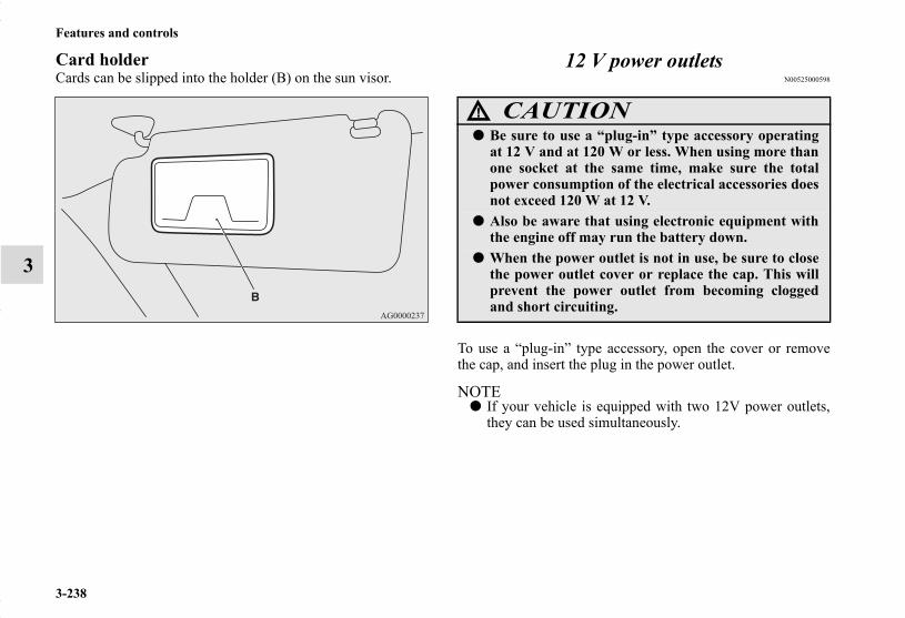
3-238
Features and controls
3
Card holderCards can be slipped into the holder (B) on the sun visor.
12 V power outletsN00525000598
To use a “plug-in” type accessory, open the cover or removethe cap, and insert the plug in the power outlet.
NOTE● If your vehicle is equipped with two 12V power outlets,
they can be used simultaneously.
CAUTION!
● Be sure to use a “plug-in” type accessory operatingat 12 V and at 120 W or less. When using more thanone socket at the same time, make sure the totalpower consumption of the electrical accessories doesnot exceed 120 W at 12 V.
● Also be aware that using electronic equipment withthe engine off may run the battery down.
● When the power outlet is not in use, be sure to closethe power outlet cover or replace the cap. This willprevent the power outlet from becoming cloggedand short circuiting.
BK0150700US.book 238 ページ 2012年3月22日 木曜日 午後6時46分

Features and controls
3-239
3
Type 1Accessories can be operated while the ignition switch or theoperation mode is in ON or ACC.
Type 2Accessories can be operated in all ignition switch positions orall operation modes.
WARNING!
● The hole next to the power outlet in the floor consoleis not a cup holder. This hole can be used as a per-sonal compartment, but should never be used as acup holder. Spilling beverages onto the power outletcould cause a short-circuit or an electric shock.
Floor console Floor console box
BK0150700US.book 239 ページ 2012年3月22日 木曜日 午後6時46分

3-240
Features and controls
3
Interior lightsN00525300562
NOTE● Be aware that leaving the light illuminated with the engine
off may run the battery down.Never leave the vehicle without checking that the light isoff.
Dome light (front)/Reading lightsN00525400420
Dome light (front)
1- (DOOR)The light illuminates when a door or the liftgate is opened.It goes off approximately 30 seconds after the door or lift-gate is closed.However, the light goes off immediately in the followingcases:• When the ignition switch is turned to the “ON” position
or the operation mode is put in ON.• When the power door lock function is used to lock the
vehicle.• When the remote control transmitter of the keyless entry
system or the F.A.S.T.-key is used to lock the vehicle.
1- Cargo room light → P.3-2432- Dome light (Rear) (if so equipped) → P.3-2423- Dome light (Front)/Reading lights → P.3-240
Sunshade illumination dimming control switch (if so equipped) → P.3-244
BK0150700US.book 240 ページ 2012年3月22日 木曜日 午後6時46分
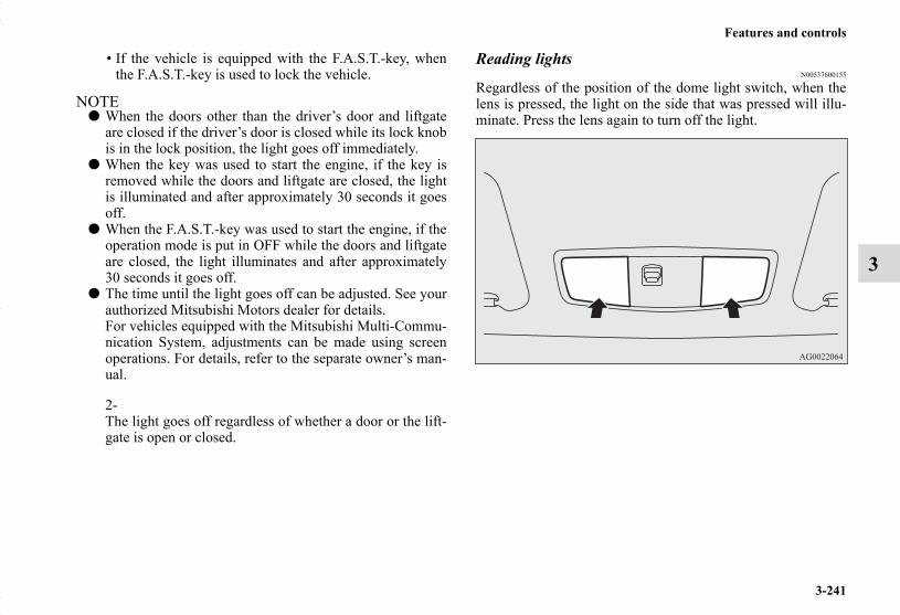
Features and controls
3-241
3
• If the vehicle is equipped with the F.A.S.T.-key, whenthe F.A.S.T.-key is used to lock the vehicle.
NOTE● When the doors other than the driver’s door and liftgate
are closed if the driver’s door is closed while its lock knobis in the lock position, the light goes off immediately.
● When the key was used to start the engine, if the key isremoved while the doors and liftgate are closed, the lightis illuminated and after approximately 30 seconds it goesoff.
● When the F.A.S.T.-key was used to start the engine, if theoperation mode is put in OFF while the doors and liftgateare closed, the light illuminates and after approximately30 seconds it goes off.
● The time until the light goes off can be adjusted. See yourauthorized Mitsubishi Motors dealer for details.For vehicles equipped with the Mitsubishi Multi-Commu-nication System, adjustments can be made using screenoperations. For details, refer to the separate owner’s man-ual.
2-The light goes off regardless of whether a door or the lift-gate is open or closed.
Reading lightsN00537600155
Regardless of the position of the dome light switch, when thelens is pressed, the light on the side that was pressed will illu-minate. Press the lens again to turn off the light.
BK0150700US.book 241 ページ 2012年3月22日 木曜日 午後6時46分

3-242
Features and controls
3
Dome light (rear) (if so equipped)N00525800189
1- ( )The light illuminates regardless of whether a door or theliftgate is open or closed.2- (●)The light illuminates when a door or the liftgate is opened.It goes off approximately 30 seconds after the door or lift-gate is closed.However, the light goes off immediately in the followingcases:• When the ignition switch is turned to the “ON” position
or the operation mode is put in ON.• When the power door lock function is used to lock the
vehicle.• When the remote control transmitter of the keyless entry
system or the F.A.S.T.-key is used to lock the vehicle.
• If the vehicle is equipped with the F.A.S.T.-key, whenthe F.A.S.T.-key is used to lock the vehicle.
NOTE● When the doors other than the driver’s door and liftgate
are closed if the driver’s door is closed while its lock knobis in the lock position, the light goes off immediately.
● When the key was used to start the engine, if the key isremoved while the doors and liftgate are closed, the lightis illuminated and after approximately 30 seconds it goesoff.
● When the F.A.S.T.-key was used to start the engine, if theoperation mode is put in OFF while the doors and liftgateare closed, the light illuminates and after approximately30 seconds it goes off.
● The time until the light goes off can be adjusted. See yourauthorized Mitsubishi Motors dealer for details.For vehicles equipped with the Mitsubishi Multi-Commu-nication System, adjustments can be made using screenoperations. For details, refer to the separate owner’s man-ual.
3- ( )The light goes off regardless of whether a door or the lift-gate is open or closed.
BK0150700US.book 242 ページ 2012年3月22日 木曜日 午後6時46分

Features and controls
3-243
3
Cargo room lightN00526100163
The light illuminates when the liftgate is opened, and goes outwhen the liftgate is closed.
Sunshade illumination dimming control switch (if so equipped)
N00568500020
The brightness of the sunshade illumination can be adjusted to3 different levels when the ignition switch or the operationmode is in ON or ACC.Each time you press the switch, the brightness switches insequence from high → middle → low → off → high.
NOTE● The brightness can be adjusted even when the ignition
switch is in the “OFF” position or the operation mode is inOFF, provided that the sunshade illumination is turned on.
BK0150700US.book 243 ページ 2012年3月22日 木曜日 午後6時46分
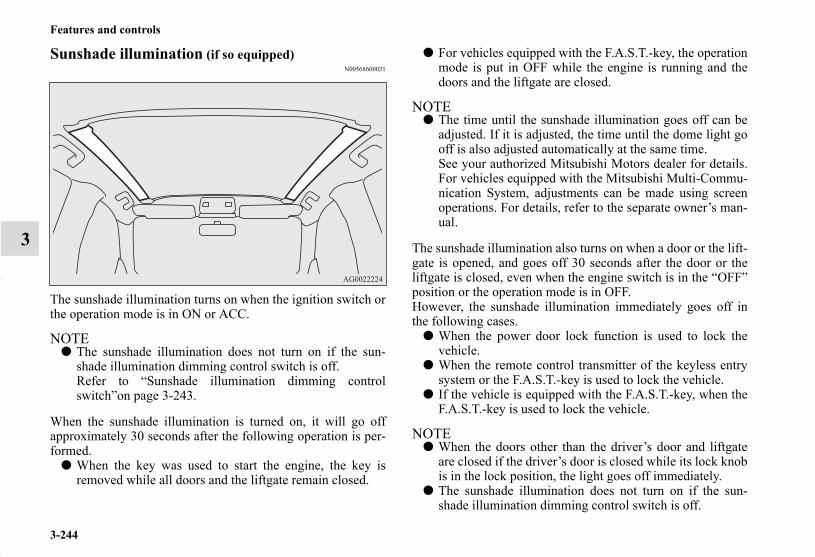
3-244
Features and controls
3
Sunshade illumination (if so equipped)N00568600021
The sunshade illumination turns on when the ignition switch orthe operation mode is in ON or ACC.
NOTE● The sunshade illumination does not turn on if the sun-
shade illumination dimming control switch is off.Refer to “Sunshade illumination dimming controlswitch”on page 3-243.
When the sunshade illumination is turned on, it will go offapproximately 30 seconds after the following operation is per-formed.
● When the key was used to start the engine, the key isremoved while all doors and the liftgate remain closed.
● For vehicles equipped with the F.A.S.T.-key, the operationmode is put in OFF while the engine is running and thedoors and the liftgate are closed.
NOTE● The time until the sunshade illumination goes off can be
adjusted. If it is adjusted, the time until the dome light gooff is also adjusted automatically at the same time.See your authorized Mitsubishi Motors dealer for details.For vehicles equipped with the Mitsubishi Multi-Commu-nication System, adjustments can be made using screenoperations. For details, refer to the separate owner’s man-ual.
The sunshade illumination also turns on when a door or the lift-gate is opened, and goes off 30 seconds after the door or theliftgate is closed, even when the engine switch is in the “OFF”position or the operation mode is in OFF.However, the sunshade illumination immediately goes off inthe following cases.
● When the power door lock function is used to lock thevehicle.
● When the remote control transmitter of the keyless entrysystem or the F.A.S.T.-key is used to lock the vehicle.
● If the vehicle is equipped with the F.A.S.T.-key, when theF.A.S.T.-key is used to lock the vehicle.
NOTE● When the doors other than the driver’s door and liftgate
are closed if the driver’s door is closed while its lock knobis in the lock position, the light goes off immediately.
● The sunshade illumination does not turn on if the sun-shade illumination dimming control switch is off.
BK0150700US.book 244 ページ 2012年3月22日 木曜日 午後6時46分

Features and controls
3-245
3
● The time until the sunshade illumination goes off can beadjusted. If it is adjusted, the time until the dome light gooff is also adjusted automatically at the same time. Seeyour authorized Mitsubishi Motors dealer for details.For vehicles equipped with the Mitsubishi Multi-Commu-nication System, adjustments can be made using screenoperations. For details, refer to the separate owner’s man-ual.
Interior light auto-cutout function (dome light and other lights)
N00526300439
● If any of the interior lights are left switched on with theignition switch is in the “OFF” position or the operationmode is in OFF, it goes off automatically after approxi-mately 30 minutes.
● The lights will illuminate again after they automaticallygo off if the ignition switch or the engine switch is oper-ated, or if the keyless entry system or the F.A.S.T.-key isoperated.
NOTE● The interior light auto-cutout function can be deactivated.
The time until the lights automatically go off can beadjusted. See your authorized Mitsubishi Motors dealerfor details.For vehicles equipped with the Mitsubishi Multi-Commu-nication System, adjustments can be made using screenoperations. For details, refer to the separate owner’s man-ual.
BK0150700US.book 245 ページ 2012年3月22日 木曜日 午後6時46分

3-246
Features and controls
3
Storage spacesN00526400469
NOTE● Do not leave valuables in any storage space when leaving
the vehicle.
CAUTION!
● Never leave lighters, carbonated drink cans, or spec-tacles in the cabin when parking the vehicle in hotsunshine. The cabin will become extremely hot, solighters and other flammable items may catch fireand unopened drink cans (including beer cans) mayrupture. The heat may also deform or crack plasticspectacle lenses and other spectacle parts that aremade of plastic.
● Keep the lids of storage spaces closed while drivingthe vehicle. A lid or the contents of a storage spacecould otherwise cause injuries during a sudden stop. 1- Floor console box
2- Glove compartment
BK0150700US.book 246 ページ 2012年3月22日 木曜日 午後6時46分

Features and controls
3-247
3
Glove compartmentN00551500204
To open, pull the lever (A).
NOTE● When the lights are illuminated with the light switch in
the “ ”, “ ”, or “AUTO” position (vehicles with auto-matic light control), the glove conpartment light illumi-nates.
Pen holderThere is a pen holder inside the glove compartment.
NOTE● There is a limit to the size of pens that can be stored in the
holder. Forcing large pens into the holder could causedamage.
WARNING!
● An open glove compartment door can cause a seri-ous injury or death to the front passenger in an acci-dent, even if the passenger is wearing his/her seatbelt. Always keep the glove compartment doorclosed when driving.
BK0150700US.book 247 ページ 2012年3月22日 木曜日 午後6時46分
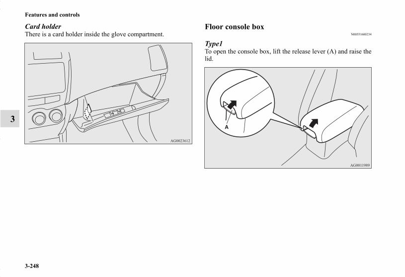
3-248
Features and controls
3
Card holderThere is a card holder inside the glove compartment.
Floor console boxN00551600234
Type1To open the console box, lift the release lever (A) and raise thelid.
BK0150700US.book 248 ページ 2012年3月22日 木曜日 午後6時46分

Features and controls
3-249
3
Type2Upper and lower boxes are located inside the floor consolebox.
NOTE● The floor console box can also be used as an arm rest.
Refer to the “Arm rest” section on page 2-9.
NOTE● The Auxiliary Audio connector (RCA) is located in the
floor console box (if so equipped). For details, refer to “Touse the external audio input function” on page 5-91.
● The USB input terminal is located in the floor consol box(if so equipped). For details, refer to “USB input terminal”on page 3-231.
Upper boxTo open the upper box, lift the right release lever (B) and raisethe lid.
1- Upper box2- Lower box
1 2
BK0150700US.book 249 ページ 2012年3月22日 木曜日 午後6時46分

3-250
Features and controls
3
Lower boxTo open the lower box, lift the left release lever (C) and raisethe lid.
Tissue holderThe tissue holder (D) is located on the underside of the floorconsole box lid.
Type 1 Type 2
BK0150700US.book 250 ページ 2012年3月22日 木曜日 午後6時46分

Features and controls
3-251
3
Cup holdersN00527300322
The cup holder is designed for holding cups or drink-canssecurely in its holes.
For the front seatThe cup holder is located in front of the floor console.
WARNING!
● The hole next to the power outlet in the floor consoleis not and should not be used as a cup holder. Spill-ing beverages onto the adjacent power outlet couldcause a short-circuit or electrical failure.
BK0150700US.book 251 ページ 2012年3月22日 木曜日 午後6時46分

3-252
Features and controls
3
For the rear seat (if so equipped)N00537000133
In order to use the cup holder, allow the arm rest (A) to dropdown.
Bottle holdersN00527300377
There are bottle holders located on the front doors.
NOTE● Make sure all lids are tightly closed when storing bever-
ages that are in plastic bottles, etc.● Some beverages may not be stored, depending on the size
and shape of the plastic bottles, etc.
CAUTION!
● Drink beverages while driving your vehicle is dis-tracting and can cause an accident.
● Vibration and shaking while driving may cause bev-erages to spill. Be very careful, as spilling hot bever-ages could cause burns.
SC00000500-3.fm 252 ページ 2012年3月26日 月曜日 午後5時42分
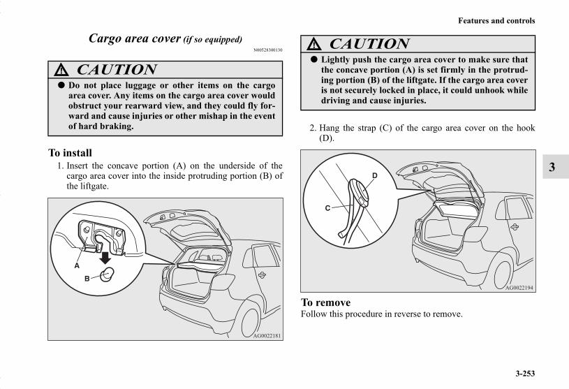
Features and controls
3-253
3
Cargo area cover (if so equipped)N00528300130
To install1. Insert the concave portion (A) on the underside of the
cargo area cover into the inside protruding portion (B) ofthe liftgate.
2. Hang the strap (C) of the cargo area cover on the hook(D).
To removeFollow this procedure in reverse to remove.
CAUTION!
● Do not place luggage or other items on the cargoarea cover. Any items on the cargo area cover wouldobstruct your rearward view, and they could fly for-ward and cause injuries or other mishap in the eventof hard braking.
CAUTION!
● Lightly push the cargo area cover to make sure thatthe concave portion (A) is set firmly in the protrud-ing portion (B) of the liftgate. If the cargo area coveris not securely locked in place, it could unhook whiledriving and cause injuries.
SC00000500-3.fm 253 ページ 2012年3月26日 月曜日 午後5時29分

3-254
Features and controls
3
Assist gripsN00559000061
The assist grips (located above the doors on the headliner) arenot designed to support body weight. They are intended for useonly while seated in the vehicle.
Coat hookN00553600153
There is a coat hook on the rear seat assist grip of the driver’sside.
CAUTION!
● Do not use the assist grips when getting into or outof the vehicle. The assist grips could detach causingyou to fall.
WARNING!
● Do not put a hanger or any heavy or pointed objecton the coat hook. If the curtain airbag was activated,any such item could be propelled away with greatforce and could prevent the curtain airbag frominflating correctly. Hang clothes directly on the coathook (without using a hanger). Make sure there areno heavy or sharp objects in the pockets of clothesthat you hang on the coat hook.
SC00000500-3.fm 254 ページ 2012年3月26日 月曜日 午後5時29分

Features and controls
3-255
3
Luggage hooksN00528500259
There are hooks on the sides of the luggage compartment foruse in securing luggage.
CAUTION!
● Do not load the luggage higher than the top of theseatback.Be sure that luggage is firmly secured.Restricted rear vision or flying objects entering thepassenger compartment during sudden brakingcould result in a serious accident.
SC00000500-3.fm 255 ページ 2012年3月26日 月曜日 午後5時29分

SC00000500-3.fm 256 ページ 2012年3月26日 月曜日 午後5時29分

4
Driving safety
Driving precaution . . . . . . . . . . . . . . . . . . . . . . . . .4- 2Fuel economy. . . . . . . . . . . . . . . . . . . . . . . . . . . . .4- 2Driving, alcohol and drugs. . . . . . . . . . . . . . . . . . .4- 3Floor mat . . . . . . . . . . . . . . . . . . . . . . . . . . . . . . . .4- 3Vehicle preparation before driving. . . . . . . . . . . . .4- 5Safe driving techniques . . . . . . . . . . . . . . . . . . . . .4- 6Driving during cold weather . . . . . . . . . . . . . . . . .4- 7Braking. . . . . . . . . . . . . . . . . . . . . . . . . . . . . . . . . .4- 8Parking . . . . . . . . . . . . . . . . . . . . . . . . . . . . . . . . . .4- 8Loading information . . . . . . . . . . . . . . . . . . . . . . .4- 9Cargo loads . . . . . . . . . . . . . . . . . . . . . . . . . . . . . .4- 13Trailer towing. . . . . . . . . . . . . . . . . . . . . . . . . . . . .4- 16
BK0150700US.book 1 ページ 2012年3月22日 木曜日 午後6時46分

4-2
Driving safety
4
Driving precautionN00629300053
Utility vehicles have higher ground clearance and a narrowertrack, which enables them to perform in a wide variety of off-road situations. Because of the higher ground clearance, thesevehicles have a higher center of gravity, which makes themhandle differently than ordinary vehicles when driving onpavement. They are not designed to maneuver or corner at thesame speed on pavement as conventional 2-wheel drive pas-senger cars any more than low-slung sports cars are designedto perform satisfactorily in off-road conditions.Always drive safely and steer the vehicle carefully. Avoid oper-ating the vehicle in a manner that might require sharp turns orabrupt maneuvers. As with other vehicles of this type, failureto operate this vehicle correctly can result in loss of control orvehicle rollover.In a rollover crash, an unbelted person is significantly morelikely to die than a person wearing a seat belt. Before startingthe vehicle, always make certain that you and all your passen-gers are properly wearing their seat belts (with children in therear seat, in appropriate restraints).
Fuel economyN00628800152
Fuel economy is dependent on many factors. Your personaldriving habits can have a significant effect on your fuel use.Several recommendations for achieving the greatest fuel econ-omy are listed below.
● Whenever accelerating from a stop, always accelerateslowly and smoothly.
● When parked for even a short period, do not idle theengine. Shut it off.
● Plan your trips to avoid unnecessary stops.● Keep your tires inflated to the recommended pressures.● When you drive on highways or dry improved roads, set
the drive mode-selector “2WD” or “4WD AUTO” posi-tion (if so equipped).
● For freeway driving, maintain a speed of approximately50 mph (80 km/h) when traffic, roadway and weather con-ditions safely permit.
● Keep your air filter clean and your vehicle lubricatedaccording to the recommendations in this manual.
● Always keep your vehicle well maintained. A poorlymaintained engine wastes fuel and costs money.
● Never overload your vehicle.
WARNING!● Utility vehicles have a significantly higher rollover
rate than other types of vehicles. Avoid abruptmaneuvers and excessive speed. Always buckle up.
BK0150700US.book 2 ページ 2012年3月22日 木曜日 午後6時46分

Driving safety
4-3
4
Driving, alcohol and drugsN00628900049
Drunk driving is one of the most frequent causes of accidents.Your driving ability can be seriously impaired even with bloodalcohol levels far below the legal minimum. If you have beendrinking, don’t drive. Ride with a designated non-drinkingdriver, call a cab or a friend, or use public transportation.Drinking coffee or taking a cold shower will not make yousober.Similarly, prescription and nonprescription drugs affect youralertness, perception and reaction time. Consult with your doc-tor or pharmacist before driving while under the influence ofany of these medications.
Floor matN00628600046
The original equipment floor mat provided with your vehiclewas specifically designed for your vehicle. Always properlyposition the floor mat and assure it does not interfere withoperation of the pedals. Always use the retaining clip on thedriver’s floorboard to secure the floor mat. When used, this clipwill help prevent the floor mat from moving forward and possi-bly interfering with the operation of the pedals. To prevent thefloor mat from moving forward and possibly interfering withthe operation of the pedals, Mitsubishi genuine floor mats arerecommended.
WARNING!● NEVER DRINK AND DRIVE.
Your perceptions are less accurate, your reflexes areslower and your judgment is impaired.
BK0150700US.book 3 ページ 2012年3月22日 木曜日 午後6時46分

4-4
Driving safety
4
To install the floor matN00628700047
1. Place the floor mat to fit the shape of the floorboard.2. Align the floor mat with the installation holes over the
retaining clips.3. Secure the floor mat with retaining clips.
NOTE● The shape of the mat and the number of retaining clips
may vary depending on the vehicle model.
WARNING!● If a floor mat is the wrong size or is not properly
installed, it can interfere with the operation of thepedals. Interference with the pedals can cause unin-tended acceleration and/or increased stopping dis-tances resulting in a crash and injury. Always makesure the floor mat does not interfere with the accel-erator or brake pedal.
● Always use the retaining clip on the driver’s floor-board to secure the floor mat.
● Always install the mat with the correct side facingdown.
● Never install a second mat over or under an existingfloor mat.
● Do not use a floor mat designed for another modelvehicle even if it is a Mitsubishi genuine floor mat.
BK0150700US.book 4 ページ 2012年3月22日 木曜日 午後6時46分
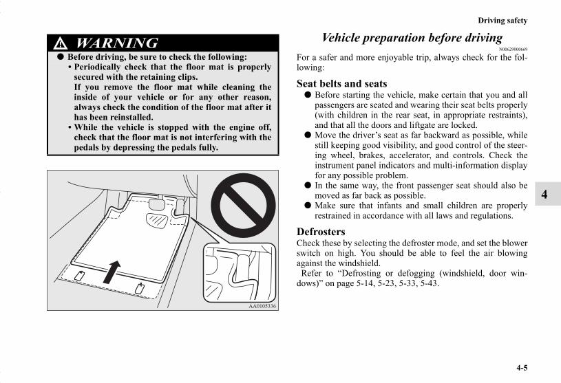
Driving safety
4-5
4
Vehicle preparation before drivingN00629000669
For a safer and more enjoyable trip, always check for the fol-lowing:
Seat belts and seats● Before starting the vehicle, make certain that you and all
passengers are seated and wearing their seat belts properly(with children in the rear seat, in appropriate restraints),and that all the doors and liftgate are locked.
● Move the driver’s seat as far backward as possible, whilestill keeping good visibility, and good control of the steer-ing wheel, brakes, accelerator, and controls. Check theinstrument panel indicators and multi-information displayfor any possible problem.
● In the same way, the front passenger seat should also bemoved as far back as possible.
● Make sure that infants and small children are properlyrestrained in accordance with all laws and regulations.
DefrostersCheck these by selecting the defroster mode, and set the blowerswitch on high. You should be able to feel the air blowingagainst the windshield. Refer to “Defrosting or defogging (windshield, door win-dows)” on page 5-14, 5-23, 5-33, 5-43.
WARNING!● Before driving, be sure to check the following:
• Periodically check that the floor mat is properlysecured with the retaining clips.If you remove the floor mat while cleaning theinside of your vehicle or for any other reason,always check the condition of the floor mat after ithas been reinstalled.
• While the vehicle is stopped with the engine off,check that the floor mat is not interfering with thepedals by depressing the pedals fully.
BK0150700US.book 5 ページ 2012年3月22日 木曜日 午後6時46分

4-6
Driving safety
4
TiresCheck all the tires for heavy tread wear or uneven wear pat-terns. Look for stones, nails, glass, or other objects stuck in thetread. Look for any tread cuts or sidewall cracks. Check thewheel nuts for tightness, and the tires (including spare tire) forproper pressure. Replace your tires before they are heavilyworn out.As your vehicle is equipped with a tire pressure monitoringsystem, there is a risk of damage to the tire inflation pressuresensors when the tire is replaced on the rim. Tire replacementshould, therefore, be performed only by an authorizedMitsubishi Motors dealer.
LightsHave someone watch while you turn all the exterior lights onand off. Also check the turn signal indicators and high-beamindicators on the instrument panel.
Fluid leaksCheck the ground under the vehicle after parking overnight, forfuel, water, oil, or other leaks. Make sure all the fluid levels arecorrect. Also, if you can smell fuel, you need to find out whyimmediately and have it fixed.
Safe driving techniquesN00629200094
Even this vehicle’s safety equipment, and your safest driving,cannot guarantee that you can avoid an accident or injury.However, if you give extra attention to the following areas, youcan better protect yourself and your passengers:
● Drive defensively. Be aware of traffic, road and weatherconditions. Leave plenty of stopping distance betweenyour vehicle and the vehicle ahead.
● Before changing lanes, check your mirrors and use yourturn-signal light.
● While driving, watch the behavior of other drivers, bicy-clists, and pedestrians.
● Always obey applicable laws and regulations. Be a politeand alert driver. Always leave room for unexpectedevents, such as sudden braking.
● If you plan to drive in another country, obey their vehicleregistration laws and make sure you will be able to get theright fuel.
BK0150700US.book 6 ページ 2012年3月22日 木曜日 午後6時46分

Driving safety
4-7
4
Driving during cold weatherN00629400461
● Check the battery. At the same time, check the terminalsand wiring. During extremely cold weather, the batterywill not be as strong. Also, the battery power level maydrop because more power is used for cold starting anddriving.Before driving the vehicle, check to see if the engine runsat the proper speed and if the headlights are as bright asnormally. Charge or replace the battery if necessary. Dur-ing extreme cold weather, it is possible that a very lowbattery could freeze.
● Warm the engine sufficiently. After starting the engine,allow a short warm-up time to distribute oil to all cylin-ders. Then drive your vehicle slowly.
● Stay at low speeds at first so that the transaxle, transfercase and rear axle oil have time to spread to all the lubri-cation points.
● Manual transaxle can be harder to shift in cold weatherconditions. This is normal and shifting will get easier asthe transaxle warms up.
● Check the engine antifreeze.If there is not enough coolant because of a leak or fromengine overheating, add Mitsubishi Motors GenuineSuper Long Life Coolant Premium or equivalent.Please read this section in conjunction with the “Enginecoolant” on page 7-10.
WARNING!● The battery gives off explosive hydrogen gas. Any
spark or flame can cause the battery to explode,which could cause serious injury or death.Always wear protective clothes and a face maskwhen working with your battery, or let a skilledmechanic do it.
WARNING!● Never open the radiator cap when the radiator is
hot. You could be seriously burned.
BK0150700US.book 7 ページ 2012年3月22日 木曜日 午後6時46分
4-8
Driving safety
4
BrakingN00629500491
All the parts of the brake system are critical to safety. Have thevehicle serviced by an authorized Mitsubishi Motors dealer ora repair facility of your choice at regular intervals according tothe “WARRANTY AND MAINTENANCE MANUAL”.
When brakes are wetCheck the brake system while driving at a low speed immedi-ately after starting, especially when the brakes are wet, to con-firm they work normally.A film of water can be formed on the brake discs and preventnormal braking after driving in heavy rain or through largepuddles, or after the vehicle is washed. If this occurs, dry thebrakes out by driving slowly while lightly depressing the brakepedal.
When driving in cold weatherOn snowy roads, ice can form on the braking system, makingthe brakes less effective. While driving in such conditions, payclose attention to preceding and following vehicles and to thecondition of the road surface. From time to time, lightlydepress the brake pedal and check how effective the brakes are.
When driving downhillIt is important to take advantage of the engine braking bydownshifting while driving on steep downhill roads in order toprevent the brakes from overheating.
ParkingN00629600304
Parking on a hillWhen parking on a hill, set the parking brake, and turn thefront wheels toward the curb on a downhill, or away from thecurb on an uphill.If necessary, apply chocks to wheels.
For vehicles equipped with manual transaxlePlace the gearshift lever into the “R” (Reverse) position whenparking on a downhill slope, into the 1st position when parkingon an uphill slope.
For vehicles equipped with continuously variable trans-mission (CVT)Be sure that the parking brake is firmly set when parked andthat the selector lever is in the “P” (PARK) position.When parking on a hill, it is important to set the parking brakebefore moving the selector lever to the “P” (PARK) position.This prevents loading the parking brake against the transaxle.When this happens, it is difficult to move the selector lever outof the “P” (PARK) position.
Parking with the engine runningNever leave the engine running while you take a short sleep orrest. Also, never leave the engine running in a closed or poorlyventilated place.
BK0150700US.book 8 ページ 2012年3月22日 木曜日 午後6時46分

Driving safety
4-9
4
Where you parkYour front bumper can be damaged if you scrape it over curbsor parking stop blocks. Be careful when traveling up or downsteep slopes where your bumper can scrape the road.
Do not keep the steering wheel fully turned for a long timeMore effort could be required to turn the steering wheel.Refer to “Electric power steering system (EPS)” on page 3-101.
When leaving the vehicleAlways remove the key from the ignition switch and lock alldoors and the liftgate when leaving the vehicle unattended.Always try to park your vehicle in a well lit area.
Loading informationN00629900408
It is very important to know how much weight your vehicle cancarry. This weight is called the vehicle capacity weight andincludes the weight of all occupants, cargo (including the roofload), non-factory-installed options, if any, being towed. Thetire and loading information placard located on the driver’sdoor sill of your vehicle will show how much weight it mayproperly carry.
It is important to familiarize yourself with the following termsbefore loading your vehicle:
● Vehicle maximum load on the tire: load on an individualtire that is determined by distributing to each axle its shareof the maximum loaded vehicle weight and dividing bytwo.
● Vehicle normal load on the tire: load on an individual tirethat is determined by distributing to each axle its share ofthe curb weight, accessory weight, and normal occupantweight and dividing by two.
● Maximum loaded vehicle weight: the sum of -(a) Curb weight;(b) Accessory weight;(c) Vehicle capacity weight; and(d) Production options weight.
WARNING!● Leaving the engine running risks injury or death
from accidentally moving the gearshift lever (man-ual transaxle) or the selector lever (CVT) or fromthe accumulation of toxic exhaust fumes in the pas-senger compartment.
WARNING!● Do not park your vehicle in areas where combustible
materials such as dry grass or leaves can come incontact with a hot exhaust, since a fire could occur.
WARNING!● Never overload your vehicle. Overloading can dam-
age your vehicle, adversely affect vehicle perfor-mance, including handling and braking, cause tirefailure, and result in an accident.
BK0150700US.book 9 ページ 2012年3月22日 木曜日 午後6時46分

4-10
Driving safety
4
● Curb weight: the weight of a motor vehicle with standardequipment including the maximum capacity of fuel, oil,and coolant.
● Accessory weight: the combined weight (in excess ofthose standard items which may be replaced) of automatictransmission, power steering, power brakes, power win-dows, power seats, radio, and heater, to the extent thatthese items are available as factory- installed equipment(whether installed or not).
● Vehicle capacity weight: the rated cargo and luggage loadplus 150 lbs (68 kg) * times the vehicle’s designated seat-ing capacity.
● Production options weight: the combined weight of thoseinstalled regular production options weighing over 5 lbs(2.3 kg) in excess of those standard items which theyreplace, not previously considered in curb weight oraccessory weight, including heavy duty brakes, ride level-ers, roof rack, heavy duty battery, and special trim.
● Normal occupant weight: 150 lbs (68 kg) * times the num-ber of specified occupants. (In your vehicle the number is3)
● Occupant distribution: Occupant distribution within thepassenger compartment (In your vehicle the distribution is2 in front, 1 in second row seat)
Tire and loading information placardN00630100383
The tire and loading information placard is located on theinside sill of the driver’s door.
This placard shows the maximum number of occupants permit-ted to ride in your vehicle as well as “the combined weight ofoccupants and cargo” (A), which is called the vehicle capacityweight. The weight of roof load is included in the definition of“cargo” when determining the vehicle capacity weight. Thisplacard also tells you the size and recommended inflation pres-sure for the original equipment tires on your vehicle. For moreinformation, refer to “Tires” on page 7-23.
*: 150 lbs (68 kg) is the weight of one person as defined byU.S.A. and Canadian regulations.
BK0150700US.book 10 ページ 2012年3月22日 木曜日 午後6時46分

Driving safety
4-11
4
Steps for Determining Correct Load LimitN00630200182
1. Locate the statement “The combined weight of occu-pants and cargo should never exceed XXX kg or XXXlbs.” on your vehicle’s placard.
2. Determine the combined weight of the driver and pas-sengers that will be riding in your vehicle.
3. Subtract the combined weight of the driver and passen-gers from XXX kg or XXX lbs.
4. The resulting figure equals the available amount ofcargo and luggage load capacity. For example, if the“XXX” amount equals 1400 lbs. and there will be five150 lbs. passengers in your vehicle, the amount ofavailable cargo and luggage load capacity is 650 lbs.(1400 - 750 (5 x 150) = 650 lbs.)
5. Determine the combined weight of luggage and cargobeing loaded on the vehicle. That weight may notsafely exceed the available cargo and luggage loadcapacity calculated in Step 4.
6. If your vehicle will be towing a trailer, load from yourtrailer will be transferred to your vehicle. Consult thismanual to determine how this reduces the availablecargo and luggage load capacity of your vehicle.
NOTE● The above steps for determining correct load limit were
written in accordance with U.S.A. regulations.Your vehicle cannot tow a trailer, so step 6 is irrelevant.
BK0150700US.book 11 ページ 2012年3月22日 木曜日 午後6時46分
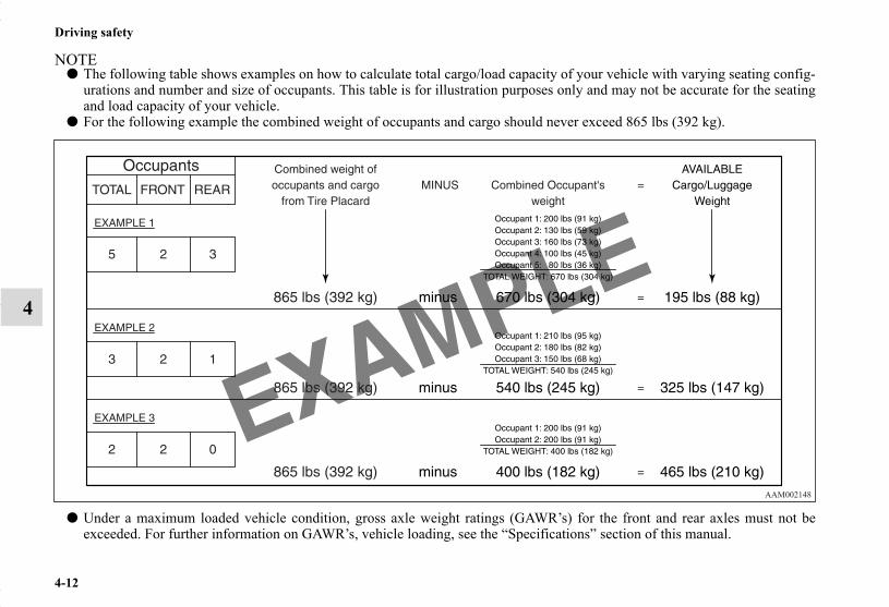
4-12
Driving safety
4
NOTE● The following table shows examples on how to calculate total cargo/load capacity of your vehicle with varying seating config-
urations and number and size of occupants. This table is for illustration purposes only and may not be accurate for the seatingand load capacity of your vehicle.
● For the following example the combined weight of occupants and cargo should never exceed 865 lbs (392 kg).
● Under a maximum loaded vehicle condition, gross axle weight ratings (GAWR’s) for the front and rear axles must not beexceeded. For further information on GAWR’s, vehicle loading, see the “Specifications” section of this manual.
BK0150700US.book 12 ページ 2012年3月22日 木曜日 午後6時46分

Driving safety
4-13
4
Cargo loadsN00629700435
Cargo load precautionsN00630300040
To determine the cargo load capacity for your vehicle, subtractthe weight of all vehicle occupants from the vehicle capacityweight. For additional information, if needed, refer to “Stepsfor Determining Correct Load Limit” on page 4-11.DO NOT USE the Gross Vehicle Weight Rating and GrossAxle Weight Rating numbers listed on the safety certificationlabel (A) located on the inside sill of the driver’s door as theguide for passengers and/or cargo weight.
WARNING!● To reduce the risk of serious injury or death, the
combined weights of the driver, passengers andcargo and must never exceed the vehicle capacityweight.
● Exceeding the vehicle capacity weight will adverselyaffect vehicle performance, including handling andbraking, and may cause an accident.
● Do not load cargo or luggage higher than the top ofthe seatback. Be sure that your cargo or luggagecannot move when your vehicle is in motion.Having either the rear view blocked, or your cargobeing thrown inside the cabin if you suddenly haveto brake can cause a serious accident or injury ordeath.
● Put cargo or luggage in the cargo area of your vehi-cle. Try to spread the weight evenly.
BK0150700US.book 13 ページ 2012年3月22日 木曜日 午後6時46分

4-14
Driving safety
4
Loading cargo on the roofN00630400100
NOTE● To prevent wind noise or reduction in gas mileage,
remove the roof carrier when not in use.● Before using an automatic car wash, check with the atten-
dant to determine if the roof carrier should be removed.● Be sure that adequate clearance is maintained for raising
the liftgate when installing a roof carrier.
WARNING!● Weight placed on the roof of the vehicle will raise the
vehicle’s center of gravity and adversely affect itshandling characteristics. As a result, driving errorsor emergency maneuvers could lead to a loss of con-trol and result in an accident. Drive slowly andavoid excessive maneuvers such as sudden brakingor quick turning.
● Make sure that the weight of luggage and the roofcarrier do not exceed the maximum roof load, 176 lb(80 kg). If the maximum roof load is exceeded, thiscould cause damage to the vehicle or result in anaccident.
● The total weight of all occupants and luggage,including your roof load, must not exceed the vehiclecapacity weight. For more information, refer to“Tire and loading information placard” on page 9-4
● Roof load is determined by adding the weight of theroof carrier and the weight of the luggage placed onthe roof carrier.
● For additional information, refer to “Maximum roofload” on page 9-6.
CAUTION!● Do not load luggage directly onto the roof. Use a roof
carrier that properly fits your vehicle.For installation, refer to the instruction manual pro-vided with the roof carrier.
● Place the luggage on the carrier so that its weight isdistributed evenly with the heaviest items on thebottom. Do not load items that are wider than theroof carrier.
● When attaching/removing the roof carrier and load-ing/removing luggage, do not apply excessive pres-sure on a single point.Depending on how and where the force is applied,this may cause dents on the vehicle roof.
● Before driving and after traveling a short distance,always check the load to make sure it is securely fas-tened to the roof carrier.Stop the vehicle periodically and check that the loadremains secure. If the load is not secure, it could fallfrom the vehicle and damage your vehicle, anothervehicle or create a road hazard.
BK0150700US.book 14 ページ 2012年3月22日 木曜日 午後6時46分

Driving safety
4-15
4
Roof carrier mounting brackets (if so equipped)N00630600085
When installing the roof carrier, use the brackets (A).The brackets (A) are located under each cover (B).
Attaching the roof carrierSlide each cover (B) toward the front of the vehicle to removeit.
BK0150700US.book 15 ページ 2012年3月22日 木曜日 午後6時46分

4-16
Driving safety
4
Refitting the covers1. With each cover, put the tabs (C) on the cover in the holes
(D) in the roof.2. Slide the cover (B) toward the rear of the vehicle to install
it.
Trailer towingN00629800306
WARNING!● Do not use this vehicle for trailer towing. It may not
be possible to maintain control or adequate braking.
BK0150700US.book 16 ページ 2012年3月22日 木曜日 午後6時46分

5
Comfort controls
Vents. . . . . . . . . . . . . . . . . . . . . . . . . . . . . . . . . . . .5- 2Manual air conditioning-Type 1
(if so equipped). . . . . . . . . . . . . . . . . . . . . . . . . .5- 6Manual air conditioning-Type 2
(if so equipped). . . . . . . . . . . . . . . . . . . . . . . . . .5- 16Automatic air conditioning-Type1
(if so equipped). . . . . . . . . . . . . . . . . . . . . . . . . .5- 25Automatic air conditioning-Type2
(if so equipped). . . . . . . . . . . . . . . . . . . . . . . . . .5- 35Important air conditioning operating tips . . . . . . .5- 45Air purifier . . . . . . . . . . . . . . . . . . . . . . . . . . . . . . .5- 46Audio system (if so equipped) . . . . . . . . . . . . . . . .5- 46To play tracks from USB device
(if so equipped). . . . . . . . . . . . . . . . . . . . . . . . . .5- 73To play tracks from a Bluetooth® device
(vehicles with Bluetooth® 2.0 interface) . . . . . .5- 88To use the external audio input function
(if so equipped). . . . . . . . . . . . . . . . . . . . . . . . . .5- 91Steering wheel audio remote control switch
(if so equipped). . . . . . . . . . . . . . . . . . . . . . . . . .5- 92Error codes . . . . . . . . . . . . . . . . . . . . . . . . . . . . . . .5- 95
Error codes (SIRIUS Satellite Radio) (if so equipped) . . . . . . . . . . . . . . . . . . . . . . . . . 5- 96
Error codes (iPod) . . . . . . . . . . . . . . . . . . . . . . . . . 5- 98Error codes (USB memory device) . . . . . . . . . . . . 5- 99Handling of compact discs . . . . . . . . . . . . . . . . . . 5-100Antenna . . . . . . . . . . . . . . . . . . . . . . . . . . . . . . . . . 5-102Clock (if so equipped) . . . . . . . . . . . . . . . . . . . . . . 5-103General information about your radio. . . . . . . . . . 5-104
BK0150700US.book 1 ページ 2012年3月22日 木曜日 午後6時46分

5-2
Comfort controls
5
VentsN00729900249
Air flow and direction adjustmentsN00730200327
Center ventsMove the knob (A) to make adjustments.To close the vent, move the knob (A) to the inside as far as pos-sible.
A- Center ventsB- Side vents
1- Close2- Open
BK0150700US.book 2 ページ 2012年3月22日 木曜日 午後6時46分

Comfort controls
5-3
5
Side ventsMove the knob (A) to make adjustments.To close the vent, move the knob (A) to the outside as far aspossible.
NOTE● On rare occasions, air from the vents of an air-conditioned
vehicle may be foggy. This is only moist air cooling sud-denly and does not indicate a problem.
● Do not let drinks or other liquids get into the vents as theycould prevent the air conditioning from operating nor-mally.
Changing the mode selectionN00736400552
To change the position and amount of air flowing from thevents, turn the mode selection dial. Refer to “Mode selectiondial” on page5-7, 5-17, 5-27, 5-37.These symbols are used in the next several illustrations to dem-onstrate the quantity of air coming from the vents.
: Small amount of air from the vents : Medium amount of air from the vents : Large amount of air from the vents
Face positionAir flows only to the upper part of the passenger compartment.
1- Close2- Open
Left Right
BK0150700US.book 3 ページ 2012年3月22日 木曜日 午後6時46分

5-4
Comfort controls
5
Foot/Face positionAir flows to the upper part of the passenger compartment, andflows to the leg area.
NOTE● With the mode selection dial between the “ ” and “ ”
positions, air flows mainly to the upper part of the passen-ger compartment. With the mode selection dial betweenthe “ ” and “ ” positions, air flows mainly to the legarea.
Foot positionAir flows mainly to the leg area.
BK0150700US.book 4 ページ 2012年3月22日 木曜日 午後6時46分
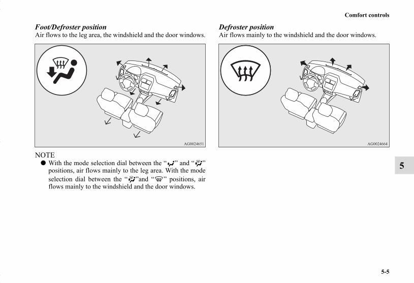
Comfort controls
5-5
5
Foot/Defroster positionAir flows to the leg area, the windshield and the door windows.
NOTE● With the mode selection dial between the “ ” and “ ”
positions, air flows mainly to the leg area. With the modeselection dial between the “ ”and “ ” positions, airflows mainly to the windshield and the door windows.
Defroster positionAir flows mainly to the windshield and the door windows.
BK0150700US.book 5 ページ 2012年3月22日 木曜日 午後6時46分

5-6
Comfort controls
5
Manual air conditioning-Type 1 (if so equipped)N00730300331
Control panelN00730500258
Blower speed selection dialN00736500175
When the ignition switch or the operation mode is in ON,select the blower speed by turning the blower speed selectiondial.Turning the dial clockwise will increase the blower speed;turning the dial counterclockwise will decrease it. When thedial is set to the “OFF” position, all fan-driven airflow willstop.
A- Temperature control dialB- Air selection switchC- Blower speed selection dialD- Air conditioning switchE- Mode selection dialF- Electric rear window defogger switch→ P.3-203
BK0150700US.book 6 ページ 2012年3月22日 木曜日 午後6時46分

Comfort controls
5-7
5
Temperature control dialN00736600222
Turn the temperature control dial clockwise to make the airwarmer. Turn it counterclockwise to make the air cooler.
NOTE● While the engine coolant temperature is low, the tempera-
ture of the air from the heater will be cool/cold until theengine warms up, even if you have selected warm air withthe dial.
● For instructions on how to use the “MAX A/C” position(A), refer to “For quick cooling” on page5-12.
Mode selection dialN00736700151
To change the amount of air flowing from the vents, turn themode selection dial. Refer to “Changing the mode selection”on page 5-3.
BK0150700US.book 7 ページ 2012年3月22日 木曜日 午後6時46分

5-8
Comfort controls
5
Air selection switchN00736800383
Normally, use the outside air position to keep the windshieldand side windows clear and to quickly remove fog or frostfrom the windshield.
To change the air selection, simply press the air selectionswitch. A sound will be made every time you push the switch.
● Outside air {Indicator light (A) OFF}● Recirculated air {Indicator light (A) ON}
When the air conditioning turns on, the air selection is con-trolled automatically.When the air conditioning turns off, the air selection automati-cally goes back to the outside air position.The air selection indicator light (A) shows the selected posi-tion.
NOTE● When the air conditioning operates with the air selection
switch in the outside air position, the system automati-cally determines whether to continue using outside air orto perform recirculation.If the outside temperature is high, the system selects recir-culation to achieve rapid cooling and causes the air selec-tion indicator in the switch to illuminate. When the airconditioning turns off or the blower speed selection dial isset to the “OFF” position, the air selection automaticallygoes back to the outside air position.
If the outside air is dusty or contaminated in some way, use therecirculation position. Switch to the outside air position everynow and then to keep the windows from fogging up.
CAUTION!● Using recirculated air for a long time may cause the
windows to fog up.
BK0150700US.book 8 ページ 2012年3月22日 木曜日 午後6時46分

Comfort controls
5-9
5
NOTE● While the mode selection dial is set between “ ” and
“ ” position, the air conditioning compressor will runautomatically. The outside air position will also beselected automatically. (In this case, the air conditioningindicator will not change.)
● When the temperature control dial is set to the “MAXA/C” position, the air selection will be automatically setto the recirculation position.
● When the temperature control dial is in the “MAX A/C”position, if it is set to a position other than “MAX A/C”,the setting for the air selection switch is selected asdescribed below. The selection of recirculated air or out-side air depends on the setting before “MAX A/C” wasused.• If automatic control was set:
Automatic control is continued• If recirculated air was selected:
Recirculated air is selected• If outside air was selected:
Outside air is continued
Personalizing the air selection (Changing the function setting)
N00702100015
You can change the following functions to match your prefer-ence.
● Enable automatic air control:When the air conditioning operates, the air selectionswitch will be automatically controlled.
● Disable automatic air control:Even when the air conditioning operates, the air selectionswitch will not be automatically controlled.
● Changing the settingsPress the air selection switch for about 10 seconds orlonger.When the setting has changed, the system will beep andthe indicator light will flash.• When the setting has changed from enabled to disabled,
the system will beep three times and the indicator willflash three times.
• When the setting has changed from disabled to enabled,the system will beep two times and the indicator lightwill flash three times.
NOTE● The factory setting is “Enable automatic air control”.● While the mode selection dial is set between “ ” and
“ ” position, the air selection will automatically changeto the outside air position, even if the system is set to“Disable automatic air control”, in order to prevent win-dows from fogging up.
BK0150700US.book 9 ページ 2012年3月22日 木曜日 午後6時46分

5-10
Comfort controls
5
Air conditioning switchN00731000377
Push the switch, and the air conditioning compressor will turnon. The air conditioning indicator light (A) will come on.A sound will be made every time you push the switch.
Push the switch again and the air conditioning compressor willstop and the indicator light (A) goes off.
NOTE● If a problem is detected in the air conditioning compres-
sor, the air conditioning indicator light (A) blinks. Pressthe air conditioning switch once to turn it off, then oncemore to turn it back on. If the air conditioning indicatorlight (A) does not blink, there is no problem. If it doesblink, have it checked at an authorized Mitsubishi Motorsdealer or a repair facility of your choice.
● Sometimes, for example after using a high-pressure carwash, the condenser can get wet, and the air conditioningindicator light (A) blinks temporarily. Wait for a while,press the air conditioning switch once to turn the systemoff, then once more to turn it back on. Once the waterevaporates, the blinking will stop.
CAUTION!● Using the air conditioning slightly increases the
engine idle speed. Therefore, make sure your foot isfirmly on the brake pedal when shifting the tran-saxle into drive.
BK0150700US.book 10 ページ 2012年3月22日 木曜日 午後6時46分

Comfort controls
5-11
5
Operating the air conditioning systemN00731100222
HeatingSet the mode selection dial to the “ ” position and set the airselection switch (A) to the outside air position.Turn the temperature control dial clockwise or counterclock-wise to the desired temperature. Select the best speed to fityour needs.
NOTE● For quick heating, set the blower speed selection dial to
the position shown in the illustration.
BK0150700US.book 11 ページ 2012年3月22日 木曜日 午後6時46分

5-12
Comfort controls
5
CoolingN00731200308
For ordinary cooling
1. Set the mode selection dial to the “ ” position.2. Push the air selection switch (A) to set it to the outside air
position.3. Push the air conditioning switch (B).4. Change the temperature by turning the control dial clock-
wise or counterclockwise.5. Set the desired blower speed.
NOTE● If the outside air is dusty or contaminated in some way,
push the air selection switch (A) to set it to the recircula-tion position. Let in some outside air from time to time forgood ventilation.
● To cool the leg areas, set the mode selection dial to the“ ” position.
For quick cooling
1. Set the mode selection dial to the “ ” position.2. Set the temperature control dial to the “MAX A/C” posi-
tion.3. Set the blower speed to the highest position.
BK0150700US.book 12 ページ 2012年3月22日 木曜日 午後6時46分

Comfort controls
5-13
5
NOTE● When the temperature control dial is set to the “MAX
A/C” position, the air conditioning compressor will runautomatically and the light will come on. The recircula-tion position will be selected automatically. In this case,you cannot turn the air conditioning off or select the out-side air position.
● When the temperature control dial is set to a position otherthan “MAX A/C”, the air selection will automaticallychange to outside air. The air conditioning will revert tothe previous condition in which the “MAX A/C” positionwas not selected.
Combination of unheated air and heated airN00731300253
Set the mode selection dial to the positions shown in the illus-tration and set the air selection switch (A) to the outside airposition.
The air flow will be directed to the leg area and the upper partof the passenger compartment. Set the desired blower speed.Warm air flows to the leg area and unheated or slightly warmair (depending upon the position of the temperature controldial) flows to the upper part of the passenger compartment.
BK0150700US.book 13 ページ 2012年3月22日 木曜日 午後6時46分

5-14
Comfort controls
5
Defrosting or defogging (windshield, door windows)N00731400427
Set the mode selection dial (between “ ” and “ ”) toremove frost or mist from the windshield and door window.
For ordinary defrostingUse this setting to keep the windshield and door windows clearof mist, and to keep the leg area heated (when driving in rain orsnow).
1. Set the mode selection dial to the “ ” position.2. Select your desired blower speed by turning the blower
speed selection dial.3. Select your desired temperature by turning the tempera-
ture control dial.
CAUTION!● For safety, make sure you have a clear view through
all the windows.
BK0150700US.book 14 ページ 2012年3月22日 木曜日 午後6時46分
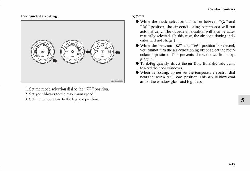
Comfort controls
5-15
5
For quick defrosting
1. Set the mode selection dial to the “ ” position.2. Set your blower to the maximum speed.3. Set the temperature to the highest position.
NOTE● While the mode selection dial is set between “ ” and
“ ” position, the air conditioning compressor will runautomatically. The outside air position will also be auto-matically selected. (In this case, the air conditioning indi-cator will not chage.)
● While the between “ ” and “ ” position is selected,you cannot turn the air conditioning off or select the recir-culation position. This prevents the windows from fog-ging up.
● To defog quickly, direct the air flow from the side ventstoward the door windows.
● When defrosting, do not set the temperature control dialnear the “MAX A/C” cool position. This would blow coolair on the window glass and fog it up.
BK0150700US.book 15 ページ 2012年3月22日 木曜日 午後6時46分

5-16
Comfort controls
5
Manual air conditioning-Type 2 (if so equipped)N00730300298
Control panelN00730500261
Blower speed selection dialN00736500188
When the ignition switch or the operation mode is in ON,select the blower speed by turning the blower speed selectiondial.Turning the dial clockwise will increase the blower speed;turning the dial counterclockwise will decrease it. When thedial is set to the “OFF” position, all fan-driven airflow willstop.
A- Temperature control dialB- Air selection switchC- Blower speed selection dialD- Air conditioning switchE- Mode selection dialF- Electric rear window defogger switch→ P.3-203
BK0150700US.book 16 ページ 2012年3月22日 木曜日 午後6時46分

Comfort controls
5-17
5
Temperature control dialN00736600176
Turn the temperature control dial clockwise to make the airwarmer. Turn it counterclockwise to make the air cooler.
NOTE● While the engine coolant temperature is low, the tempera-
ture of the air from the heater will be cool/cold until theengine warms up, even if you have selected warm air withthe dial.
Mode selection dialN00736700207
To change the amount of air flowing from the vents, turn themode selection dial. Refer to “Changing the mode selection”on page 5-3.
BK0150700US.book 17 ページ 2012年3月22日 木曜日 午後6時46分
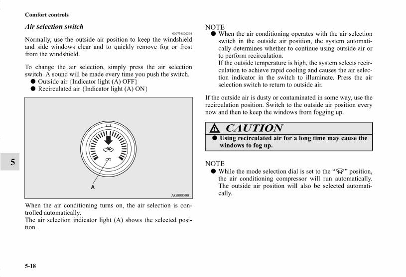
5-18
Comfort controls
5
Air selection switchN00736800396
Normally, use the outside air position to keep the windshieldand side windows clear and to quickly remove fog or frostfrom the windshield.
To change the air selection, simply press the air selectionswitch. A sound will be made every time you push the switch.
● Outside air {Indicator light (A) OFF}● Recirculated air {Indicator light (A) ON}
When the air conditioning turns on, the air selection is con-trolled automatically.The air selection indicator light (A) shows the selected posi-tion.
NOTE● When the air conditioning operates with the air selection
switch in the outside air position, the system automati-cally determines whether to continue using outside air orto perform recirculation.If the outside temperature is high, the system selects recir-culation to achieve rapid cooling and causes the air selec-tion indicator in the switch to illuminate. Press the airselection switch to return to outside air.
If the outside air is dusty or contaminated in some way, use therecirculation position. Switch to the outside air position everynow and then to keep the windows from fogging up.
NOTE● While the mode selection dial is set to the “ ” position,
the air conditioning compressor will run automatically.The outside air position will also be selected automati-cally.
CAUTION!● Using recirculated air for a long time may cause the
windows to fog up.
BK0150700US.book 18 ページ 2012年3月22日 木曜日 午後6時46分
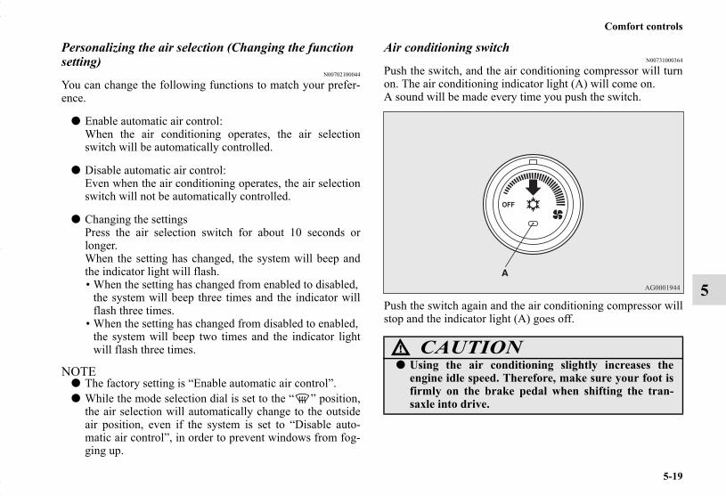
Comfort controls
5-19
5
Personalizing the air selection (Changing the function setting)
N00702100044
You can change the following functions to match your prefer-ence.
● Enable automatic air control:When the air conditioning operates, the air selectionswitch will be automatically controlled.
● Disable automatic air control:Even when the air conditioning operates, the air selectionswitch will not be automatically controlled.
● Changing the settingsPress the air selection switch for about 10 seconds orlonger.When the setting has changed, the system will beep andthe indicator light will flash.• When the setting has changed from enabled to disabled,
the system will beep three times and the indicator willflash three times.
• When the setting has changed from disabled to enabled,the system will beep two times and the indicator lightwill flash three times.
NOTE● The factory setting is “Enable automatic air control”.● While the mode selection dial is set to the “ ” position,
the air selection will automatically change to the outsideair position, even if the system is set to “Disable auto-matic air control”, in order to prevent windows from fog-ging up.
Air conditioning switchN00731000364
Push the switch, and the air conditioning compressor will turnon. The air conditioning indicator light (A) will come on.A sound will be made every time you push the switch.
Push the switch again and the air conditioning compressor willstop and the indicator light (A) goes off.
CAUTION!● Using the air conditioning slightly increases the
engine idle speed. Therefore, make sure your foot isfirmly on the brake pedal when shifting the tran-saxle into drive.
BK0150700US.book 19 ページ 2012年3月22日 木曜日 午後6時46分
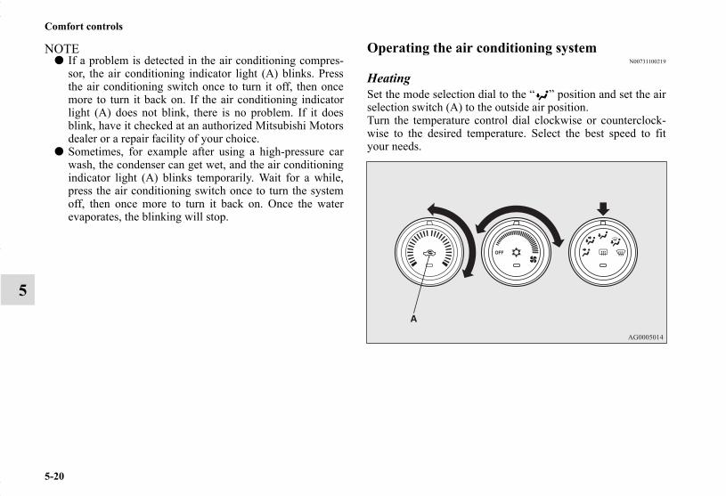
5-20
Comfort controls
5
NOTE● If a problem is detected in the air conditioning compres-
sor, the air conditioning indicator light (A) blinks. Pressthe air conditioning switch once to turn it off, then oncemore to turn it back on. If the air conditioning indicatorlight (A) does not blink, there is no problem. If it doesblink, have it checked at an authorized Mitsubishi Motorsdealer or a repair facility of your choice.
● Sometimes, for example after using a high-pressure carwash, the condenser can get wet, and the air conditioningindicator light (A) blinks temporarily. Wait for a while,press the air conditioning switch once to turn the systemoff, then once more to turn it back on. Once the waterevaporates, the blinking will stop.
Operating the air conditioning systemN00731100219
HeatingSet the mode selection dial to the “ ” position and set the airselection switch (A) to the outside air position.Turn the temperature control dial clockwise or counterclock-wise to the desired temperature. Select the best speed to fityour needs.
BK0150700US.book 20 ページ 2012年3月22日 木曜日 午後6時46分

Comfort controls
5-21
5
NOTE● For quick heating, set the blower speed selection dial to
the position shown in the illustration.
CoolingN00731200311
1. Set the mode selection dial to the “ ” position.2. Push the air selection switch (A) to set it to the outside air
position.3. Push the air conditioning switch (B).4. Change the temperature by turning the control dial clock-
wise or counterclockwise.5. Set the desired blower speed.
BK0150700US.book 21 ページ 2012年3月22日 木曜日 午後6時46分

5-22
Comfort controls
5
NOTE● If the outside air is dusty or contaminated in some way,
push the air selection switch (A) to set it to the recircula-tion position. Let in some outside air from time to time forgood ventilation.
● To cool the leg areas, set the mode selection dial to the“ ” position.
Combination of unheated air and heated airN00731300266
Set the mode selection dial to the positions shown in the illus-tration and set the air selection switch (A) to the outside airposition.
The air flow will be directed to the leg area and the upper partof the passenger compartment. Set the desired blower speed.Warm air flows to the leg area and unheated or slightly warmair (depending upon the position of the temperature controldial) flows to the upper part of the passenger compartment.
BK0150700US.book 22 ページ 2012年3月22日 木曜日 午後6時46分

Comfort controls
5-23
5
Defrosting or defogging (windshield, door windows)N00731400515
Set the mode selection dial (between “ ” and “ ”) toremove frost or mist from the windshield and door window.
For ordinary defrostingUse this setting to keep the windshield and door windows clearof mist, and to keep the leg area heated (when driving in rain orsnow).
1. Set the mode selection dial to the “ ” position.2. Select your desired blower speed by turning the blower
speed selection dial.3. Select your desired temperature by turning the tempera-
ture control dial.
CAUTION!● For safety, make sure you have a clear view through
all the windows.
BK0150700US.book 23 ページ 2012年3月22日 木曜日 午後6時46分
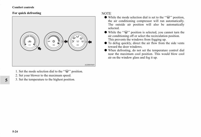
5-24
Comfort controls
5
For quick defrosting
1. Set the mode selection dial to the “ ” position.2. Set your blower to the maximum speed.3. Set the temperature to the highest position.
NOTE● While the mode selection dial is set to the “ ” position,
the air conditioning compressor will run automatically.The outside air position will also be automaticallyselected.
● While the “ ” position is selected, you cannot turn theair conditioning off or select the recirculation position.This prevents the windows from fogging up.
● To defog quickly, direct the air flow from the side ventstoward the door windows.
● When defrosting, do not set the temperature control dialnear the maximum cool position. This would blow coolair on the window glass and fog it up.
BK0150700US.book 24 ページ 2012年3月22日 木曜日 午後6時46分

Comfort controls
5-25
5
Automatic air conditioning-Type1 (if so equipped)
N00731500268
Control panelN00711800526
NOTE● There is an interior air temperature sensor (G) in the illus-
trated position.Never place anything over the sensor, since doing so willprevent it from functioning properly.
A- Temperature control dialB- Air selection switchC- Blower speed selection dialD- Air conditioning switchE- Mode selection dialF- Electric rear window defogger switch→ P.3-203
BK0150700US.book 25 ページ 2012年3月22日 木曜日 午後6時46分
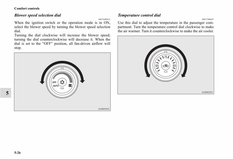
5-26
Comfort controls
5
Blower speed selection dialN00736900153
When the ignition switch or the operation mode is in ON,select the blower speed by turning the blower speed selectiondial.Turning the dial clockwise will increase the blower speed;turning the dial counterclockwise will decrease it. When thedial is set to the “OFF” position, all fan-driven airflow willstop.
Temperature control dialN00737000207
Use this dial to adjust the temperature in the passenger com-partment. Turn the temperature control dial clockwise to makethe air warmer. Turn it counterclockwise to make the air cooler.
BK0150700US.book 26 ページ 2012年3月22日 木曜日 午後6時46分

Comfort controls
5-27
5
NOTE● While the engine coolant temperature is low, the tempera-
ture of the air from the heater will be cool/cold until theengine warms up, even if you have selected warm air withthe dial.
● When the temperature is set to the highest or the lowestsetting under the AUTO operation, the air selection andthe air conditioning will be automatically changed as fol-lows.Also, if the air selection is operated manually after anautomatic changeover, manual operation will be selected.• Quick Heating (When the temperature is set to the high-
est setting)Outside air will be introduced and the air conditioningwill stop.
• Quick Cooling (When the temperature is set to the low-est setting)Inside air will be recirculated and the air conditioningwill operate.
The above indicates the factory settings. You can personalizethe air selection switch and air conditioning switch to matchyour personal preferences.Contact your Mitsubishi Motors dealer or a repair facility ofyour choice for assistance.Refer to “Personalizing the air conditioning switch (Changingthe function setting)” on page5-31.Refer to “Personalizing the air selection (Changing the func-tion setting)” on page5-29.
Mode selection dialN00737100093
To change the amount of air flowing from the vents, turn themode selection dial. Refer to “Changing the mode selection”on page 5-3.
BK0150700US.book 27 ページ 2012年3月22日 木曜日 午後6時46分

5-28
Comfort controls
5
Air selection switchN00737200339
Normally, use the outside air position to keep the windshieldand side windows clear and to quickly remove fog or frostfrom the windshield.
To change the air selection, simply press the air selectionswitch. A sound will be made every time you press the switch.
● Outside air {Indicator light (A) OFF}Outside air is introduced into the passenger compartment.
● Recirculated air {Indicator light (A) ON}Air is recirculated inside the passenger compartment.
When the air conditioning turns on, the air selection is con-trolled automatically. When the air conditioning turns off, theair selection automatically goes back to the outside air position.If high cooling performance is desired, or if the outside air isdusty or contaminated in some way, use the recirculation posi-tion. Switch to the outside air position every now and then tokeep the windows from fogging up.
NOTE● If the mode selection dial is set between “ ” and “ ”,
you cannot turn the air conditioning off or select the recir-culation position.This prevents the windows from fogging up.
● When the mode selection dial or the blower speed selec-tion dial is set to the “AUTO” position again after manualoperation, the air selection switch will also be automati-cally controlled.
CAUTION!● Using recirculated air for a long time may cause the
windows to fog up.
BK0150700US.book 28 ページ 2012年3月22日 木曜日 午後6時46分

Comfort controls
5-29
5
Personalizing the air selection (Changing the function setting)
N00760000018
You can change the following functions to match your prefer-ence.
● Enable automatic air control:When the mode selection dial or the blower speed selec-tion dial is set to the “AUTO” position, the air selectionswitch will also be automatically controlled.
● Disable automatic air control:Even when the mode selection dial or the blower speedselection dial is set to the “AUTO” position, the air selec-tion switch will not be automatically controlled.
● Changing the settingsPress the air selection switch for about 10 seconds orlonger.When the setting has changed, the system will beep andthe indicator light will flash.• When the setting has changed from enabled to disabled,
the system will beep three times and the indicator willflash three times.
• When the setting has changed from disabled to enabled,the system will beep two times and the indicator lightwill flash three times.
NOTE● The factory setting is “Enable automatic air control”.● While the mode selection dial is set between “ ” and
“ ” position, the air selection will automatically changeto the outside air position, even if the system is set to“Disable automatic air control”, in order to prevent win-dows from fogging up.
BK0150700US.book 29 ページ 2012年3月22日 木曜日 午後6時46分

5-30
Comfort controls
5
Air conditioning switchN00737300200
Push the switch, and the air conditioning compressor will turnon. The air conditioning indicator light (A) will come on.A sound will be made every time you push the switch.
Push the switch again and the air conditioning compressor willstop and the indicator light (A) goes off.
NOTE● If a problem is detected in the air conditioning compres-
sor, the air conditioning indicator light (A) blinks. Pressthe air conditioning switch once to turn it off, then oncemore to turn it back on. If the air conditioning indicatorlight does not blink there is no problem. If it does blink,have it checked at an authorized Mitsubishi Motors dealeror a repair facility of your choice.
● Sometimes, for example after using a high-pressure carwash, the condenser can get wet, and the air conditioningindicator light (A) blinks temporarily. Wait for a while,press the air conditioning switch once to turn the systemoff, then once more to turn it back on. Once the waterevaporates, the blinking will stop.
CAUTION!● Using the air conditioning slightly increases the
engine idle speed. Therefore, make sure your foot isfirmly on the brake pedal when shifting the tran-saxle into drive.
BK0150700US.book 30 ページ 2012年3月22日 木曜日 午後6時46分

Comfort controls
5-31
5
Personalizing the air conditioning switch (Changing the function setting)
N00759800045
You can change the following functions to match your prefer-ence.
● Enable automatic air conditioning control:When the mode selection dial or blower speed selectiondial has been set to the “AUTO” position or when the tem-perature control dial has been set to the minimum temper-ature, the air conditioning switch is automaticallycontrolled.
● Disable automatic air conditioning control:The air conditioning switch is not automatically con-trolled, unless the air conditioning switch is used.
● Changing the settingsPress the air conditioning switch for about 10 seconds orlonger.When the setting has changed, the system will beep andthe indicator light will flash.• When the setting has changed from enabled to disabled,
the system will beep three times and the indicator willflash three times.
• When the setting has changed from disabled to enabled,the system will beep two times and the indicator lightwill flash three times.
NOTE● The factory setting is “Enable automatic air conditioning
control”.● While the mode selection dial is set between “ ” and
“ ” position, the air conditioning will run automatically,even if the system is set to “Disable automatic air condi-tioning control”, in order to prevent windows from fog-ging up.
BK0150700US.book 31 ページ 2012年3月22日 木曜日 午後6時46分
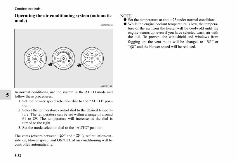
5-32
Comfort controls
5
Operating the air conditioning system (automatic mode)
N00731700260
In normal conditions, use the system in the AUTO mode andfollow these procedures:
1. Set the blower speed selection dial to the “AUTO” posi-tion.
2. Select the temperature control dial to the desired tempera-ture. The temperature can be set within a range of around61 to 89. The temperature will increase as the dial isturned to the right.
3. Set the mode selection dial to the “AUTO” position.
The vents (except between “ ” and “ ”), recirculation/out-side air, blower speed, and ON/OFF of air conditioning will becontrolled automatically.
NOTE● Set the temperature at about 75 under normal conditions.● While the engine coolant temperature is low, the tempera-
ture of the air from the heater will be cool/cold until theengine warms up, even if you have selected warm air withthe dial. To prevent the windshield and windows fromfogging up, the vent mode will be changed to “ ” or“ ” and the blower speed will be reduced.
BK0150700US.book 32 ページ 2012年3月22日 木曜日 午後6時46分

Comfort controls
5-33
5
Operating the air conditioning system (manual mode)
N00731800072
Blower speed and vent mode may be controlled manually bysetting the blower speed selection dial and the mode selectiondial to the desired positions. To return to automatic operation,set the dials to the “AUTO” position.
Defrosting or defogging (windshield, door windows)N00732400280
To remove frost or mist from the windshield and door win-dows, use the mode selection dial (“ ” or “ ”).
For ordinary defrostingUse this setting to keep the windshield and door windows clearof mist, and to keep the leg area heated (when driving in rain orsnow).
1. Set the mode selection dial to the “ ” position.2. Select your desired blower speed by turning the blower
speed selection dial.3. Select your desired temperature by turning the tempera-
ture control dial.
CAUTION!● For safety, make sure you have a clear view through
all the windows.
BK0150700US.book 33 ページ 2012年3月22日 木曜日 午後6時46分

5-34
Comfort controls
5
For quick defrosting
1. Set the mode selection dial to the “ ” position.2. Set your blower to the maximum speed.3. Set the temperature to the highest position.
NOTE● While the mode selection dial is set between “ ” and
“ ” position, the air conditioning compressor will runautomatically. The outside air position will also beselected automatically.
● If the mode selection dial is set between “ ” and “ ”you cannot turn the air conditioning off or select the recir-culation position. This prevents the windows from fog-ging up.
● To defog quickly, direct the air flow from the side ventstoward the door windows.
● When defrosting, do not set the temperature control dial tothe maximum cool position. This will blow cool air on thewindow glass and fog it up.
BK0150700US.book 34 ページ 2012年3月22日 木曜日 午後6時46分

Comfort controls
5-35
5
Automatic air conditioning-Type2 (if so equipped)
N00731500271
Control panelN00711800539
NOTE● There is an interior air temperature sensor (G) in the illus-
trated position.Never place anything over the sensor, since doing so willprevent it from functioning properly.
A- Temperature control dialB- Air selection switchC- Blower speed selection dialD- Air conditioning switchE- Mode selection dialF- Electric rear window defogger switch→ P.3-203
BK0150700US.book 35 ページ 2012年3月22日 木曜日 午後6時46分

5-36
Comfort controls
5
Blower speed selection dialN00736900166
When the ignition switch or the operation mode is in ON,select the blower speed by turning the blower speed selectiondial.Turning the dial clockwise will increase the blower speed;turning the dial counterclockwise will decrease it. When thedial is set to the “OFF” position, all fan-driven airflow willstop.
Temperature control dialN00737000308
Use this dial to adjust the temperature in the passenger com-partment. Turn the temperature control dial clockwise to makethe air warmer. Turn it counterclockwise to make the air cooler.
BK0150700US.book 36 ページ 2012年3月22日 木曜日 午後6時46分

Comfort controls
5-37
5
NOTE● While the engine coolant temperature is low, the tempera-
ture of the air from the heater will be cool/cold until theengine warms up, even if you have selected warm air withthe dial.
● When the temperature is set to the highest or the lowestsetting under the AUTO operation, the air selection andthe air conditioning will be automatically changed as fol-lows.Also, if the air selection is operated manually after anautomatic changeover, manual operation will be selected.• Quick Heating (When the temperature is set to the high-
est setting)Outside air will be introduced and the air conditioningwill stop.
• Quick Cooling (When the temperature is set to the low-est setting)Inside air will be recirculated and the air conditioningwill operate.
The above indicates the factory settings. You can personalizethe air selection switch and air conditioning switch to matchyour personal preferences.Contact your Mitsubishi Motors dealer or a repair facility ofyour choice for assistance.Refer to “Personalizing the air conditioning switch (Changingthe function setting)” on page5-41.Refer to “Personalizing the air selection (Changing the func-tion setting)” on page5-39.
Mode selection dialN00737100136
To change the amount of air flowing from the vents, turn themode selection dial. Refer to “Changing the mode selection”on page 5-3.
BK0150700US.book 37 ページ 2012年3月22日 木曜日 午後6時46分

5-38
Comfort controls
5
Air selection switchN00737200342
Normally, use the outside air position to keep the windshieldand side windows clear and to quickly remove fog or frostfrom the windshield.
To change the air selection, simply press the air selectionswitch. A sound will be made every time you press the switch.
● Outside air {Indicator light (A) OFF}Outside air is introduced into the passenger compartment.
● Recirculated air {Indicator light (A) ON}Air is recirculated inside the passenger compartment.
When the air conditioning turns on, the air selection is con-trolled automatically. When the air conditioning turns off, theair selection automatically goes back to the outside air position.If high cooling performance is desired, or if the outside air airis dusty or contaminated in some way, use the recirculationposition. Switch to the outside air position every now and thento keep the windows from fogging up.
CAUTION!● Using recirculated air for a long time may cause the
windows to fog up.
BK0150700US.book 38 ページ 2012年3月22日 木曜日 午後6時46分
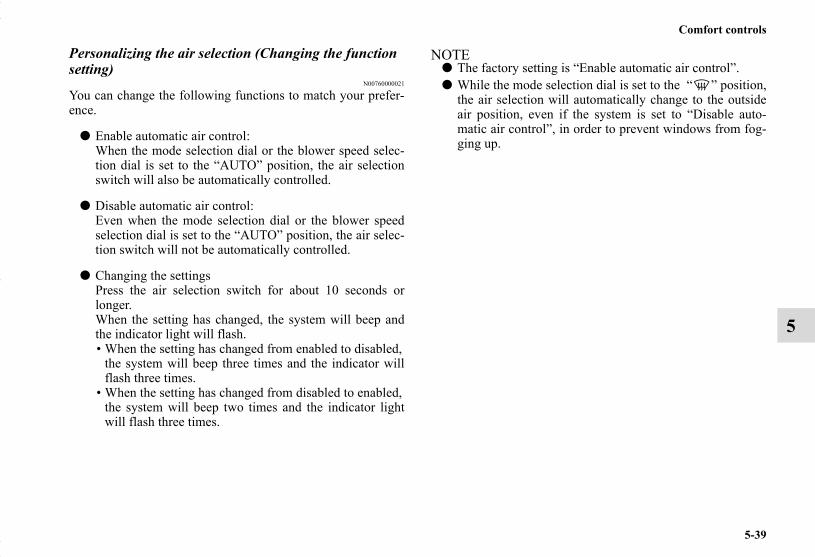
Comfort controls
5-39
5
Personalizing the air selection (Changing the function setting)
N00760000021
You can change the following functions to match your prefer-ence.
● Enable automatic air control:When the mode selection dial or the blower speed selec-tion dial is set to the “AUTO” position, the air selectionswitch will also be automatically controlled.
● Disable automatic air control:Even when the mode selection dial or the blower speedselection dial is set to the “AUTO” position, the air selec-tion switch will not be automatically controlled.
● Changing the settingsPress the air selection switch for about 10 seconds orlonger.When the setting has changed, the system will beep andthe indicator light will flash.• When the setting has changed from enabled to disabled,
the system will beep three times and the indicator willflash three times.
• When the setting has changed from disabled to enabled,the system will beep two times and the indicator lightwill flash three times.
NOTE● The factory setting is “Enable automatic air control”.● While the mode selection dial is set to the “ ” position,
the air selection will automatically change to the outsideair position, even if the system is set to “Disable auto-matic air control”, in order to prevent windows from fog-ging up.
BK0150700US.book 39 ページ 2012年3月22日 木曜日 午後6時46分

5-40
Comfort controls
5
Air conditioning switchN00737300239
Push the switch, and the air conditioning compressor will turnon. The air conditioning indicator light (A) will come on.A sound will be made every time you push the switch.
Push the switch again and the air conditioning compressor willstop and the indicator light (A) goes off.
NOTE● If a problem is detected in the air conditioning compres-
sor, the air conditioning indicator light (A) blinks. Pressthe air conditioning switch once to turn it off, then oncemore to turn it back on. If the air conditioning indicatorlight does not blink there is no problem. If it does blink,have it checked at an authorized Mitsubishi Motors dealeror a repair facility of your choice.
● Sometimes, for example after using a high-pressure carwash, the condenser can get wet, and the air conditioningindicator light (A) blinks temporarily. Wait for a while,press the air conditioning switch once to turn the systemoff, then once more to turn it back on. Once the waterevaporates, the blinking will stop.
CAUTION!● Using the air conditioning slightly increases the
engine idle speed. Therefore, make sure your foot isfirmly on the brake pedal when shifting the tran-saxle into drive.
BK0150700US.book 40 ページ 2012年3月22日 木曜日 午後6時46分
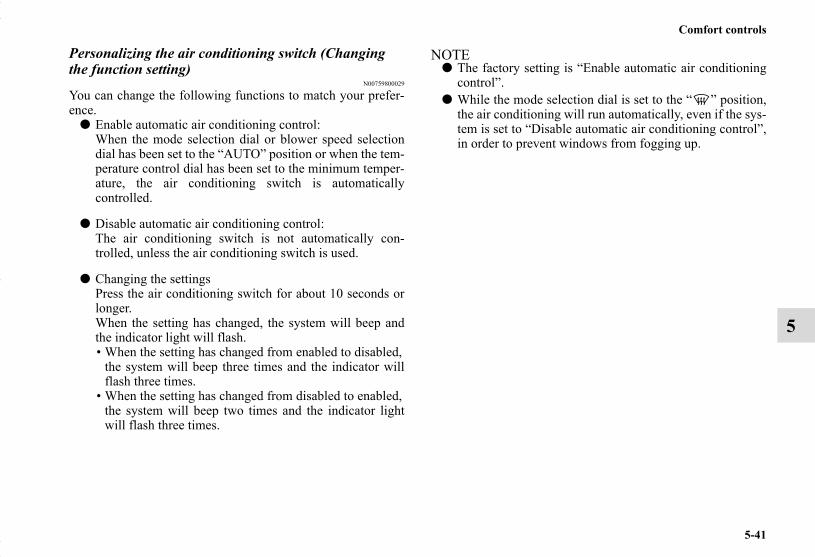
Comfort controls
5-41
5
Personalizing the air conditioning switch (Changing the function setting)
N00759800029
You can change the following functions to match your prefer-ence.
● Enable automatic air conditioning control:When the mode selection dial or blower speed selectiondial has been set to the “AUTO” position or when the tem-perature control dial has been set to the minimum temper-ature, the air conditioning switch is automaticallycontrolled.
● Disable automatic air conditioning control:The air conditioning switch is not automatically con-trolled, unless the air conditioning switch is used.
● Changing the settingsPress the air conditioning switch for about 10 seconds orlonger.When the setting has changed, the system will beep andthe indicator light will flash.• When the setting has changed from enabled to disabled,
the system will beep three times and the indicator willflash three times.
• When the setting has changed from disabled to enabled,the system will beep two times and the indicator lightwill flash three times.
NOTE● The factory setting is “Enable automatic air conditioning
control”.● While the mode selection dial is set to the “ ” position,
the air conditioning will run automatically, even if the sys-tem is set to “Disable automatic air conditioning control”,in order to prevent windows from fogging up.
BK0150700US.book 41 ページ 2012年3月22日 木曜日 午後6時46分

5-42
Comfort controls
5
Operating the air conditioning system (automatic mode)
N00731700286
In normal conditions, use the system in the AUTO mode andfollow these procedures:
1. Set the blower speed selection dial to the “AUTO” posi-tion.
2. Select the temperature control dial to the desired tempera-ture. The temperature can be set within a range of around18 to 32. The temperature will increase as the dial isturned to the right.
3. Set the mode selection dial to the “AUTO” position.
The vents (except “ ”), recirculation/outside air, blowerspeed, and ON/OFF of air conditioning will be controlled auto-matically.
NOTE● Set the temperature at about 25 under normal conditions.● While the engine coolant temperature is low, the tempera-
ture of the air from the heater will be cool/cold until theengine warms up, even if you have selected warm air withthe dial. To prevent the windshield and windows fromfogging up, the vent mode will be changed to “ ” or“ ” and the blower speed will be reduced.
BK0150700US.book 42 ページ 2012年3月22日 木曜日 午後6時46分

Comfort controls
5-43
5
Operating the air conditioning system (manual mode)
N00731800098
Blower speed and vent mode may be controlled manually bysetting the blower speed selection dial and the mode selectiondial to the desired positions. To return to automatic operation,set the dials to the “AUTO” position.
Defrosting or defogging (windshield, door windows)N00732400323
To remove frost or mist from the windshield and door win-dows, use the mode selection dial (“ ” or “ ”).
For ordinary defrostingUse this setting to keep the windshield and door windows clearof mist, and to keep the leg area heated (when driving in rain orsnow).
1. Set the mode selection dial to the “ ” position.2. Select your desired blower speed by turning the blower
speed selection dial.3. Select your desired temperature by turning the tempera-
ture control dial.
CAUTION!● For safety, make sure you have a clear view through
all the windows.
BK0150700US.book 43 ページ 2012年3月22日 木曜日 午後6時46分
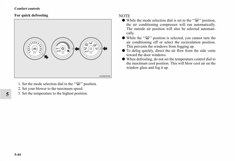
5-44
Comfort controls
5
For quick defrosting
1. Set the mode selection dial to the “ ” position.2. Set your blower to the maximum speed.3. Set the temperature to the highest position.
NOTE● While the mode selection dial is set to the “ ” position,
the air conditioning compressor will run automatically.The outside air position will also be selected automati-cally.
● While the “ ” position is selected, you cannot turn theair conditioning off or select the recirculation position.This prevents the windows from fogging up.
● To defog quickly, direct the air flow from the side ventstoward the door windows.
● When defrosting, do not set the temperature control dial tothe maximum cool position. This will blow cool air on thewindow glass and fog it up.
BK0150700US.book 44 ページ 2012年3月22日 木曜日 午後6時46分
Comfort controls
5-45
5
Important air conditioning operating tipsN00733700280
1. Park the vehicle in the shade whenever possible. Parkingin the hot sun makes the vehicle interior extremely hotwhich then requires more time to cool. If it is necessary topark in the sun, open the windows for the first few min-utes of air conditioning to expel the hot air.
2. Afterwards, keep the windows closed when the air condi-tioning is in use. The entry of outside air through openwindows will reduce cooling efficiency.
3. When running the air conditioning, make sure the airintake, which is located in front of the windshield, is freeof obstructions such as leaves. Leaves collected in the air-intake chamber may reduce air flow and plug the waterdrains.
Air conditioning system refrigerant and lubri-cant recommendationsIf the air conditioning seems less effective than usual, the causemight be a refrigerant leak.Have the system inspected by your authorized MitsubishiMotors dealer or a repair facility of your choice.
During a long period of disuseThe air conditioning should be operated for at least five min-utes each week, even in cold weather. This includes the quickdefrosting mode. Operating the air condition system weeklymaintains lubrication of the compressor internal parts to keepthe air conditioning in the best operating condition.
CAUTION!● The air conditioning system in your vehicle must be
charged with the refrigerant HFC-134a and thelubricant SUN-PAG56.Use of any other refrigerant or lubricant will causesevere damage and may require replacing your vehi-cle’s entire air conditioning system.The release of refrigerant into the atmosphere is notrecommended.The new refrigerant HFC-134a in your vehicle isdesigned not to harm the earth’s ozone layer. How-ever, it may contribute slightly to global warming.It is recommended that the old refrigerant be savedand recycled for future use.
BK0150700US.book 45 ページ 2012年3月22日 木曜日 午後6時46分

5-46
Comfort controls
5
Air purifierN00733800151
The air conditioning system is equipped with an air filter toremove pollen and dust.The air filter’s ability to collect pollen and dirt is reduced as itbecomes dirty, so replace it periodically. For the maintenanceinterval, refer to the “WARRANTY AND MAINTENANCEMANUAL”.
NOTE● Operation in certain conditions such as driving on a dusty
road and frequent use of the air conditioning can lead toreduction of service life of the filter. When you feel thatthe air flow is lower than normal or when the windshieldor windows start to fog up easily, replace the air filter.Contact your Mitsubishi Motors dealer or a repair facilityof your choice for assistance.
Audio system (if so equipped)N00734301033
For information on operations of the audio system for vehiclesequipped with Mitsubishi Multi-Communications sys-tem(MMCS), refer to the separate owner’s manual.
Type 1- AM/FM electronically tuned radio with CD player(RBDS and MP3 compatible)
Type 2- AM/FM electronically tuned radio with CD changer(RBDS and MP3 compatible)
Type 1
Type 2
BK0150700US.book 46 ページ 2012年3月22日 木曜日 午後6時46分

Comfort controls
5-47
5
The audio system can only be used when the ignition switch orthe operation mode is in ON or ACC.
NOTE● To listen to the audio system while the engine is not run-
ning, turn the ignition switch to the “ACC” position or putthe operation mode in ACC.If the ignition switch or the operation mode is left in ACC,the accessory power will automatically turn off after a cer-tain period of time and you will no longer be able to usethe audio system. The accessory power comes on again ifthe ignition switch or the engine switch is operated with itin the “ACC” position. Refer to “ACC power auto-cutoutfunction” on page 3-23 and 3-67.
● If a cellular phone is used inside the vehicle, it may createnoise in the audio equipment. This does not mean thatanything is wrong with your audio equipment. In such acase, use the cellular phone at a place as far away as possi-ble from the audio equipment.
● If foreign objects or water get into the audio equipment, orif smoke or a strange odor comes from it, immediatelyturn off the audio system and have it checked at an autho-rized Mitsubishi Motors dealer or a repair facility of yourchoice. Never try to repair it yourself. Avoid using theaudio system until it is inspected by a qualified person.
● If the audio system is damaged by foreign objects, water,or fire, have the system checked by a qualified MitsubishiMotors technician.
● The audio amplifier (if so equipped) is located under thefront right seat.Do not subject the amplifier to a strong impact.It could damage the amplifier or malfunctioning couldresult.
BK0150700US.book 47 ページ 2012年3月22日 木曜日 午後6時46分

5-48
Comfort controls
5
Volume and tone control panelN00711900703
To adjust the volumeN00712000394
Turn the VOL knob clockwise to increase the volume; counter-clockwise to decrease the volume.The status will be displayed in the display.
NOTE● The volume control mode will shut off automatically if
either the radio or CD is selected, or if no adjustment ismade within about 2 seconds.
1- PWR (On-Off) switch2- VOL (Volume control) knob3- Display4- SOUND (Sound control) switch
BK0150700US.book 48 ページ 2012年3月22日 木曜日 午後6時46分

Comfort controls
5-49
5
To adjust the toneN00712100656
1. Press the SOUND switch repeatedly to select the tone orbalance control to change. The order is: SUB PUNCH →TYPE → FIELD → BASS → MID → TREBLE →FADER → BALANCE → Audio adjust mode OFF
NOTE● SUB PUNCH can be adjusted only on vehicles with a pre-
mium sound system.On vehicles without a premium sound system, TYPE willdisplay first (no SUB PUNCH display).
QUICK ACCESS MODETo access the sound customization features quickly, pushand hold the SOUND switch, then turn the switch clock-wise or counterclockwise to access your desired soundcustomization setting. Release the switch to adjust the set-ting.
2. Turn the SOUND switch either clockwise or counter-clockwise to change the tone/balance setting.The status will be displayed in the display.
A- Adjust modeB- Adjust level
BK0150700US.book 49 ページ 2012年3月22日 木曜日 午後6時46分

5-50
Comfort controls
5
SUB PUNCH (subwoofer volume control) (if so equipped)To select the desired deep bass level.
TYPE (acoustic characteristic selection)To select the desired acoustic characteristic.
AdjustMode
AdjustLevel
Sound control switch operation
Counterclock-wise turn Clockwise turn
SUB PUNCH 1 to 6 Weaker Stronger
TYPE NORMAL ↔ POP ↔ ROCK ↔ HIP-HOP ↔ COUNTRY
FIELD NORMAL ↔ STAGE ↔ LIVE ↔ HALLBASS
-6 to 6 Weaker StrongerMIDTREBLE
FADER F11 to R11 R (Rear) increases
F (Front) increases
BALANCE L11 to R11 L (Left) increases
R (Right) increases
Acoustic characteristic DescriptionNORMAL Sounds good for all types of music.
POP Tight bass and high frequency sound.
ROCKTuned for hard rock and heavy metal with powerful drums, guitars, and vocals.
HIP-HOP Deep bass punch and wll-defined vocals.
COUNTRY Enhanced main vocals.
BK0150700US.book 50 ページ 2012年3月22日 木曜日 午後6時46分

Comfort controls
5-51
5
FIELD (Sound field selection)To select the desired sound field.
BASS (Bass tone control)To select the desired bass level.
MID (Midrange tone control)To select the desired midrange level.
TREBLE (Treble tone control)To select the desired treble level.
FADER (Front/Rear balance control)To balance the volume from the F (front) and the R (rear)speakers.
BALANCE (Left/Right balance control)To balance the volume from the L (left) and the R (right)speakers.
NOTE● When set to “0”, it will beep.● When SUB PUNCH, TYPE or FIELD is changed, the
sound will cut out briefly, but this does not indicate a mal-function.
● The audio adjust mode will automatically shut off wheneither the radio or CD is selected, or if no adjustment ismade within about 10 seconds.
● If the SOUND switch is pushed and held for more than 2seconds during the audio adjust mode, it will change to“Hold” mode. The selected audio mode will be held untilthe SOUND switch is pushed for more than 2 secondsagain.
Sound field type Description
NORMAL Optimized for the Rockford Fosgate high bass output.
STAGEPlaces the image of a sound stage in front of the driver with the vocalist in the center (for driver only).
LIVE Front seat occupants are surrounded by sound from front and rear speakers.
HALL
Places the image of a sound stage in front of the driver with the vocalist in the center (for driver only). Sound reflections are added to the rear speak-ers to simulate the experience of being at a concert hall. Best with classical or vocalist music.
BK0150700US.book 51 ページ 2012年3月22日 木曜日 午後6時46分

5-52
Comfort controls
5
Speed Compensated Volume functionN00752200268
Speed Compensated Volume function is a feature that automat-ically adjusts the VOLUME, BASS, MID, and TREBLE set-tings in accordance with the vehicle speed. It is possible to turnthis function ON-OFF using the following methods:
1. If you are presently pushing the SOUND switch and mak-ing a tone adjustment, finish making the tone adjustment.
2. Push the SOUND switch for at least about 2 seconds. Thesystem will switch to MENU mode and the characters“SCV ON” will be shown on the display.
NOTE● When you enter the MENU mode while listening to satel-
lite radio (if so equipped), “SKIP SETTING” will beshown on the display and you will enter the satellite radiosetting mode. Every time you press the SOUND switch,the display will change in the following order: “SKIPSETTING” → “LOCK SETTING” → “SCV ON.” Pressthe SOUND switch until “SCV ON” is shown on the dis-play, to switch to the setting mode for the Speed Compen-sated Volume function.
3. Turn the SOUND switch clockwise to turn the functionON. Turn it counterclockwise to turn the function OFF.
NOTE● The factory setting for the Speed Compensated Volume
function is ON.● The MENU mode will automatically shut off when either
the radio or CD is selected or the user does not move anyof the switches for 10 seconds.
Radio control panel and displayN00734900898
1- RADIO (AM/FM selection) button2- PWR (On-Off) switch3- DISP (Display) button4- PAGE button5- FM (FM1/FM2) indicator6- ST (Stereo) indicator7- RBDS (Radio Broadcast Data System) indicator8- PTY (Program Type) indicator9- Memory select buttons
10- SCAN button11- PTY (Program Type) button12- TUNE switch13- SEEK (Up-seek) button14- SEEK (Down-seek) button
BK0150700US.book 52 ページ 2012年3月22日 木曜日 午後6時46分

Comfort controls
5-53
5
To listen to the radioN00735000896
1. Press the PWR switch to turn the audio system ON andOFF. The system turns on in the last mode used.Press the RADIO button to turn ON the radio.
2. Press the RADIO button to select the desired band(AM/FM1/FM2).
3. Press the SEEK button to tune to a station, or press one ofthe Memory select buttons to tune in to a station memo-rized for that button.Refer to “Automatic tuning”, “Manual tuning” or “Toenter frequencies into the memory”.
Automatic tuningAfter pressing the SEEK button, a receivable station will beautomatically selected and reception of the station will begin.
SCAN functionPress the SCAN button. The radio will tune consecutively toeach available station for about 5 seconds per station. If youwant to stop scanning, press the SCAN button again.The frequency display of the current station flashes once persecond during SCAN.
Manual tuningThe frequency changes every time the TUNE switch is turned.Turn the switch to select the desired station.
To enter frequencies into the memoryAs many as 6 AM and 12 FM stations can be entered into thememory.
To store a frequency in the memory, follow these steps:
1. Press the SEEK button , or turn the TUNE switch to tuneto the frequency you wish to keep in the memory.
2. Press one of the Memory select buttons until it beeps.The sound will be momentarily interrupted while the fre-quency is being entered into the memory. The number ofthe button matching the entry in the memory as well as thefrequency are displayed.
3. To recall a frequency that has been saved in memory,press the corresponding button briefly for no longer thanabout 1 second.
NOTE● Disconnecting the battery cables erases all the radio sta-
tion settings stored in the memory.
BK0150700US.book 53 ページ 2012年3月22日 木曜日 午後6時46分

5-54
Comfort controls
5
Radio Broadcast Data System (RBDS)N00751800137
RBDS features are available for use only on FM stations thatbroadcast RBDS information.This RBDS radio can search for stations broadcasting theselected type of programming and display messages from radiostations.
PTY (Program Type)RBDS broadcasts are classified according to program type(PTY) as follows.
To search for a broadcast of desired PTY1. To enter PTY (Program Type) mode, press the PTY button
during FM reception.2. Press the PTY button repeatedly until your desired PTY is
reached.You can press one of the Memory select buttons for about2 seconds to save the currently displayed PTY to thatMemory select button. Thereafter, you can easily call upyour desired PTY by pressing the corresponding Memoryselect button.
3. Press the SEEK button, and the radio will begin to searchfor a broadcast of the selected PTY. During search, theselected PTY on the display blinks and the sound will bemomentarily interrupted.
4. When the radio picks up a station with your desired PTY,the PTY and the frequency will each appear on the displayfor 2 seconds. Then the PTY and the station name willalternately appear on the display for 6 seconds.
5. The frequency will appear on the display. Then the radiowill start receiving the program and exit the PTY mode.
1. ROCK2. COUNTRY3. EASY LIS4. CLASSICL5. JAZZ6. Top 407. R&B8. INFORM9. RELIGION
10. MISC
BK0150700US.book 54 ページ 2012年3月22日 木曜日 午後6時46分

Comfort controls
5-55
5
NOTE● If you wish to listen to another station of the same PTY as
currently selected, repeat the previous procedure fromstep 2.
● To display the station name and the PTY, press the DISPbutton and the PTY button respectively.
● If no station is found with your desired PTY, “EMPTY”will appear on the display for 5 seconds. Then the radiowill return to the previous station and exit the PTY mode.
● If the radio cannot read the station name, the PTY and thefrequency will alternately appear on the display for 6 sec-onds. Then the radio will start receiving the program andexit the PTY mode.
Scan function
1. After selecting your desired PTY, press the SCAN button.The radio will tune consecutively to each available stationof the selected PTY for about 5 seconds per station.
2. To stop the scan mode, press the SCAN button again.
BK0150700US.book 55 ページ 2012年3月22日 木曜日 午後6時46分

5-56
Comfort controls
5
Text messageThe radio can receive text messages broadcast by some RBDSstations.
1. While tuning in to an RBDS station, press the DISP but-ton.
2. A text message will appear on the display. If a stationname appears, press the DISP button again, then the textmessage will be displayed.
3. To cancel the text message display, press the DISP buttonagain.
NOTE● When there is no text message to be displayed, the display
shows “NO MESSAGE” and then shows the frequency.● The display can show up to 12 characters. If a text mes-
sage has more than 12 characters, press the PAGE buttonto view the next 12 characters.
SIRIUSTM Satellite Radio (if so equipped)N00760100149
Satellite radio uses direct satellite to receiver broadcastingtechnology to provide clear digital sound, coast to coast. Thesubscription service provider is SIRIUS Satellite Radio. Thisservice offers over 100 channels of music, sports, news, enter-tainment, and programming for listeners, directly from its sat-ellites and broadcasting studios.
System activationTo activate your SIRIUS Satellite Radio service, call the toll-free number 888-539-SIRIUS (7474), or visit the Sirius website at www.sirius.com. Please have the following informationavailable when activating your system:
1. The Sirius Identification Number (SIRIUS ID). Refer tothe section “SIRIUS ID indication” on page5-57.
2. Credit card information.3. Your Vehicle Identification Number. Refer to “Vehicle
identification number plate” on page9-2.
“SIRIUS”, the SIRIUS dog logo and channel names and logosare trademarks of SIRIUS Satellite Radio, Inc.
BK0150700US.book 56 ページ 2012年3月22日 木曜日 午後6時46分
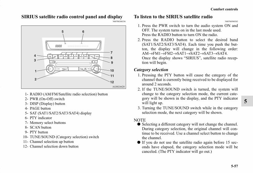
Comfort controls
5-57
5
SIRIUS satellite radio control panel and displayN00700200256
To listen to the SIRIUS satellite radioN00760500202
1. Press the PWR switch to turn the audio system ON andOFF. The system turns on in the last mode used.Press the RADIO button to turn ON the radio.
2. Press the RADIO button to select the desired band(SAT1/SAT2/SAT3/SAT4). Each time you push the but-ton, the display will change in the following order:AM→FM1→FM2→SAT1→SAT2→SAT3→SAT4.Once the display shows “SIRIUS”, satellite radio recep-tion will begin.
Category selection1. Pressing the PTY button will cause the category of the
channel that is currently being received to be displayed foraround 2 seconds.
2. If the TUNE/SOUND switch is turned, the system willchange to the category selection mode, the current cate-gory will be shown in the display, and the PTY indicatorwill light up.
3. Turning the TUNE/SOUND switch while in the categoryselection mode, the next category will be shown.
NOTE● Selecting a different category will not change the channel.
During category selection, the original channel will con-tinue to be received. Use a channel select button to changethe channel.
● If you do not use the satellite radio again before 15 sec-onds have elapsed, the category selection mode will becanceled. (The PTY indicator will go out.)
1- RADIO (AM/FM/Satellite radio selection) button2- PWR (On-Off) switch3- DISP (Display) button4- PAGE button5- SAT (SAT1/SAT2/SAT3/SAT4) display6- PTY indicator7- Memory select buttons8- SCAN button9- PTY button
10- TUNE/SOUND (Category selection) switch11- Channel selection up button12- Channel selection down button
BK0150700US.book 57 ページ 2012年3月22日 木曜日 午後6時46分

5-58
Comfort controls
5
● Pressing the PTY button while in the category selectionmode will cause the current channel to be displayed foraround 2 seconds.
Channel selectionYou can select a channel by pressing a channel select button.
NOTE● While in the category selection mode, only channels in the
category can be selected.
Scan function1. Pressing the SCAN button will cause the satellite radio to
tune consecutively to each available channel for about 7seconds per channel.
2. To stop the scan mode, press the SCAN button again.
NOTE● While in the category selection mode, only channels in the
category can be scanned.
To enter channels into the memoryYou can save one channel to each Memory select button, for amaximum of 24 channels in memory.To store a channel in the memory, follow these steps:
1. Press a channel select button and select the channel thatyou wish to keep in the memory.
2. Press one of the Memory select buttons until it beeps,indicating that the channel has been stored in memory.
NOTE● If you store a channel in the memory, you can call up your
desired channel immediately by simply pushing the corre-sponding Memory select button.
SIRIUS ID indication If you press a channel selection button to select “CH 0”, theSIRIUS ID will be displayed.
1. If you select “CH 0”, the SIRIUS ID (12 digits) will bedisplayed.
2. To stop the SIRIUS ID indication, press a channel selec-tion button and select a channel other than “CH 0”.
BK0150700US.book 58 ページ 2012年3月22日 木曜日 午後6時46分
Comfort controls
5-59
5
To skip or lock a desired channel - MENU modeYou can set the satellite radio so that it locks a desired channelor skips the channel during channel selection.
1. While the satellite radio is tuned in to the channel, pressthe TUNE/SOUND switch for about 2 seconds or longerto enter the MENU mode.
2. In the MENU mode, the satellite radio channel SKIP set-ting and LOCK setting are possible.Each time you press the TUNE/SOUND switch, the statuswill change in the following sequence.“SKIP SETTING” (SKIP setting mode) → “LOCK SET-TING” (LOCK setting mode) → “SCV ON” → “PHONEOFF” → MENU mode off.
NOTE● The MENU mode will automatically shut off when either
the radio or CD is selected, when the TUNE/SOUNDswitch is pressed for about 2 seconds or longer, or whenthe radio is left alone for 10 seconds.
● The SKIP settings, LOCK settings and lock cancellationcode are stored in memory.Disconnecting the battery cable will erase these settings.(The lock cancellation code will reset to the factory set-ting: “1111”.)
● For more information on the SCV function, refer to“Speed Compensated Volume function” on page 5-52.
● “PHONE OFF” is displayed but the function is notenabled.
● If the vehicle is equipped with a Mitsubishi Motors autho-rized hands-free phone system, “PHONE OFF” will notbe displayed.
“SKIP SETTING” (SKIP Setting Mode)You can set any channel to be skipped during channel selec-tion. You can also cancel a skip setting.You can turn the TUNE/SOUND switch and select “SKIP CH”or “UNSKIP ALL”. These functions are described below.
“LOCK SETTING” (LOCK Setting Mode)You can lock any channel of your choice or unlock a lockedchannel.You can turn the TUNE/SOUND switch and select “LOCKCH” (or “UNLOCK CH”), “UNLOCK ALL” or “CODEEDIT”.These functions are described below.
NOTE● If the channel that is currently being received is not
locked, you can select “LOCK CH”; if it is locked, youcan select “UNLOCK CH”.
SKIP CH: Sets the satellite radio so that it skipsthe channel that is currently beingreceived.
UNSKIP ALL: Cancels skip setting on all channels.
LOCK CH: Locks the channel that is currentlybeing received.
UNLOCK CH: Unlocks the channel that is currentlybeing received.
UNLOCK ALL: Cancels lock setting on all channels.CODE EDIT: Changes the lock cancellation code.
BK0150700US.book 59 ページ 2012年3月22日 木曜日 午後6時46分

5-60
Comfort controls
5
To skip a desired channelYou can set any channel to be skipped during channel selec-tion.
1. Select the channel that you want to skip. 2. Press the TUNE/SOUND switch for about 2 seconds or
longer to enter the MENU mode. Then select the SKIPsetting mode.
3. In the SKIP setting mode, turn the TUNE/SOUND switchand select “SKIP CH”.
4. Press the TUNE/SOUND switch. “STORED” will beshown for 2 seconds and then the channel that is currentlybeing received will be set to be skipped.
5. After the skip setting is made, the radio will tune into thenext channel after the channel that was set to be skipped.If you want to this channel to be skipped as well, press theTUNE/SOUND switch again.
NOTE● The channel that was set to be skipped will be skipped
automatically during channel selection.● Channels that are stored in the preset memory can also be
set to be skipped. When the corresponding memory selectbutton is pushed to call up the channel, “SKIP CHAN-NEL” will appear on the display and the audio will bemuted.
To cancel skip settingsYou can cancel skip settings on channels.
1. Press the TUNE/SOUND switch for about 2 seconds orlonger to enter the MENU mode. Then select the SKIPsetting mode.
2. In the SKIP setting mode, turn the TUNE/SOUND switchand select “UNSKIP ALL”.
3. Press the TUNE/SOUND switch. “STORED” will beshown for 2 seconds and then skip settings on all channelswill be cancelled. After you cancel the setting, the satelliteradio will return to the SKIP setting mode. (The displaywill show “SKIP SETTING”.)
To lock a desired channelYou can lock any channel of your choice.
1. Select the channel that you want to lock. 2. Press the TUNE/SOUND switch for about 2 seconds or
longer to enter the MENU mode. Then select the LOCKsetting mode.
3. In the LOCK setting mode, turn the TUNE/SOUNDswitch and select “LOCK CH”.
4. Press the TUNE/SOUND switch. “LOCKED” will be dis-played for 2 seconds and then the channel that is currentlybeing received will be locked. The satellite radio thenreturns to the LOCK setting mode.
NOTE● If you attempt to select a locked channel, the display will
show “LOCKED” or “PARENTAL LOCK”.● Channels that are stored in the preset memory can also be
locked.
BK0150700US.book 60 ページ 2012年3月22日 木曜日 午後6時46分

Comfort controls
5-61
5
To unlock locked channelsThere are two ways to unlock a locked channel. One way is tounlock a single locked channel of your choice. The other wayis to unlock all locked channels. To unlock a locked channel, you must enter the lock cancella-tion code.
1. To unlock a single locked channel of your choice, selectthe locked channel that you want to unlock. (If you wantto unlock all locked channels, it doesn't matter whichlocked channel you have selected.)
2. Press the TUNE/SOUND switch for about 2 seconds orlonger to enter the MENU mode. Then select the LOCKsetting mode.
3. In the LOCK setting mode, turn the TUNE/SOUNDswitch and select “UNLOCK CH” when you want tounlock one locked channel of your choice or “UNLOCKALL” when you want to unlock all locked channels.
4. When you press the TUNE/SOUND switch, the codeentry window will be shown in the display.
5. Use the Memory select buttons to enter the code (1111 to6666) and then press the TUNE/SOUND switch.
6. If the entered code is correct, “UNLOCKED” will beshown and the locked channel(s) will be unlocked. Thesatellite radio will then return to the LOCK setting mode.If the entered code is incorrect, a warning sound will beemitted and “CODE ERROR” will be displayed. The codeentry window will then be shown again.You can try to enter the code again, no matter how manytimes an incorrect code has been entered.
NOTE● The default factory setting for the code is “1111”.● You can change the code to any number you want with the
“CODE EDIT” function.
BK0150700US.book 61 ページ 2012年3月22日 木曜日 午後6時46分

5-62
Comfort controls
5
● To cancel a code entry, turn the TUNE/SOUND switchwhile the code entry window is displayed.The code entry will be cancelled and then the settingmenu will be switched.
To change the lock cancellation codeYou can change the code for unlocking channel(s) to any num-ber you want.
1. Press the TUNE/SOUND switch for about 2 seconds orlonger to enter the MENU mode. Then select the LOCKsetting mode.
2. In the LOCK setting mode, turn the TUNE/SOUNDswitch and select “CODE EDIT”.
3. When you press the TUNE/SOUND switch, the codeentry window will be shown in the display.
4. Use the memory select buttons to enter the current codeand then press the TUNE/SOUND switch.
5. If the correct code is entered, the code entry window willbe shown again. Enter your desired code.If the entered code is incorrect, a warning sound will beemitted and “CODE ERROR” will be displayed. The codeentry window will then be shown again.You can try to enter the code again, no matter how manytimes an incorrect code has been entered.
6. After you enter the new code, press the TUNE/SOUNDswitch. The code entry window will be shown again forconfirmation. Enter the new code again and press theTUNE/SOUND switch.
7. “STORED” will be displayed for 2 seconds, the code willbe changed and the satellite radio will return to the LOCKsetting mode.
NOTE● The SKIP settings, LOCK settings and lock cancellation
code are stored in memory. Disconnecting the batterycable will erase these settings. (The lock cancellation code will reset to the default fac-tory setting: “1111”).
To reset the lock cancellation codeIn case you forget the code, it is possible to reset the code to thefactory setting (1111).
1. With the audio power OFF, press the PWR switch and theTUNE/SOUND switch at the same time. The display will show “CODE INITIAL”.
2. Press the TUNE/SOUND switch. “YES” will be dis-played. To reset the code, press the TUNE/SOUNDswitch again. “STORED” will be shown for 2 seconds andthe code will be reset. If you do not want to reset the code, turn theTUNE/SOUND switch to display “CANCEL” and thenpress the TUNE/SOUND switch again.
Text messageYou can change what is shown on the display when the satelliteradio tunes into a channel.Press the DISP button repeatedly to change to your desired dis-play mode. The order is:Channel Number + Channel Name →Category Name → Artist Name → Song Title → ComposerName
NOTE● Category name can also displayed by pressing the PTY
button.
BK0150700US.book 62 ページ 2012年3月22日 木曜日 午後6時46分

Comfort controls
5-63
5
● The display can show up to 12 characters. If there aremore than 12 characters, press the PAGE button to viewthe next 12 characters.
CD control panel and displayN00735300730
1- RADIO (AM/FM selection) button2- CD (CD mode changeover) button3- PWR (On-Off) switch4- LOAD button (if so equipped)5- LOAD indicator (if so equipped)6- DISP (Display) button7- PAGE button8- RPT (Repeat) button9- RDM (Random) button
10- Fast-reverse button11- Fast-forward button
12- Display13- DISC (Disc down) button (if so equipped)14- DISC (Disc up) button (if so equipped)15- SCAN button16- Eject button17- Disc loading slot18- FOLDER switch19- TRACK (Track up/down) button
BK0150700US.book 63 ページ 2012年3月22日 木曜日 午後6時46分

5-64
Comfort controls
5
To listen to a CDN00735501032
With CD player1. Press the PWR switch to turn the audio system ON and
OFF. The system turns on in the last mode used.2. Insert the disc with the label facing up.
When a disc is inserted, the CD player will begin playingeven if the radio is being used. The CD player will alsobegin playing when the CD button is pressed with a discset in the CD player or in the disc loading slot, even if theradio is being used.
NOTE● For information concerning the adjustment of volume and
tone, refer to “To adjust the volume” on page 5-48 and“To adjust the tone” on page 5-49.
● For information concerning the handing of the compactdiscs, refer to “Handling of compact discs” on page 5-100.
With CD changerThe compact disc (CD) can be loaded or ejected by pressingthe LOAD button or the eject button even if the audio systempower is OFF.
1. Press the PWR switch to turn the audio system ON andOFF. The system turns on in the last mode used.
2. Press the CD button to enter CD mode. The CD changerwill start playback if the CD is already in the CD changer.
3. To stop the CD, turn off the power by pressing the PWRswitch or change over to radio mode by pressing theRADIO button, or eject the disc by pressing the eject but-ton.
NOTE● For information concerning the adjustment of volume and
tone, refer to “To adjust the volume” on page 5-48 and“To adjust the tone” on page 5-49.
● As many as 6 CDs can be inserted into the CD changer.● For information concerning the handing of the compact
discs, refer to “Handling of compact discs” on page 5-100.
To set a single disc1. Press the LOAD button briefly.2. The CD changer will show “WAIT” on the display and
start making itself ready for disc loading.3. When the CD changer is ready for disc loading, the
LOAD indicator will illuminate and the display will show“LOAD DISC No. (1-6)”.
4. When a disc is inserted into the CD slot, the disc willbegin to play.
NOTE● If there are multiple empty slots, you can select your
desired slot by pressing the DISC buttons.● If you do not insert a disc for about 15 seconds after the
CD changer starts standing by for loading, the loadingstandby mode will be canceled.
To set all the discs1. Press the LOAD button for 2 seconds or longer (until you
hear a beep).2. The CD changer will select the lowest-numbered empty
slot and switch to loading standby mode.3. When the display shows “LOAD DISC No.(1-6)”, insert a
disc. The CD changer will then automatically select thenext empty slot and enter loading standby mode.
BK0150700US.book 64 ページ 2012年3月22日 木曜日 午後6時46分

Comfort controls
5-65
5
4. Repeat the above-described steps until every slot containsa disc. Playback will then begin with the disc that youinserted last.
NOTE● If you press the LOAD button again while the CD changer
is in loading standby mode, the loading standby mode willbe canceled.
To select a desired discYou can select your desired disc by using the DISC button. Theactive disc will be indicated by “ ” on the display.
<Disc up>Press the DISC (Disc up) button repeatedly until the desireddisc number appears on the display.
<Disc down>Press the DISC (Disc down) button repeatedly until the desireddisc number appears on the display.
To listen to a music CD
Push the CD button if a disc is already in the audio system. Theaudio system will enter CD mode and start playback. The discnumber (if the audio system is equipped with the CD changer),the track number, and the playing time will appear on the dis-play. The discs in the CD changer unit will be played consecu-tivelsy and continuously.
BK0150700US.book 65 ページ 2012年3月22日 木曜日 午後6時46分

5-66
Comfort controls
5
To listen to an MP3 CDThis audio system allows you to play MP3 (MPEG AudioLayer-3) files recorded on CD-ROMs, CD-Rs (recordableCDs), and CD-RWs (rewritable CDs) in ISO9660 Level1/Level 2, Joliet, and Romeo formats. Each disc may have amaximum of 16 trees, 100 folders and 255 files. During MP3playback, the unit can display ID3 tag information. For infor-mation concerning ID3 tag, refer to “CD text and MP3 title dis-play” on page 5-72.
Push the CD button if a disc is already in the audio system.The display shows “READING”, then playback begins. Thefolder number, the track number, the playing-time, and “MP3”indicator will appear on the display.
NOTE● While listening to a disc on which CD-DA (CD-Digital
Audio) and MP3 files have both been recorded, you canswitch between reading of the CD-DA, reading of theMP3 files, and the external audio input mode by pressingthe CD button for 2 seconds or longer (until you hear abeep).For information on the external audio input, refer to “Touse the external audio input function” on page 5-91.
● With a disc that contains both CD-DA and MP3 files, theCD-DA files are automatically played first.
● The playback sound quality differs depending on theencoding software and the bit rate. For details, refer to theuser manual of your encoding software.
● Depending on file/folder configurations on a disc, it maytake some time before playback starts.
● MP3 encode software and writing software are not sup-plied with this unit.
● You may encounter trouble in playing an MP3 or display-ing the information of MP3 files recorded with certainwriting software or CD recorders (CD-R/RW drivers).
● If you record too many folders or files other than MP3onto a disc, it may take some time before playback starts.
● This unit does not record MP3 files.● For information concerning CD-Rs/RWs, refer to “Notes
on CD-Rs/RWs” on page 5-102.
BK0150700US.book 66 ページ 2012年3月22日 木曜日 午後6時46分

Comfort controls
5-67
5
Folder selection order/MP3 file playback order (Example)CAUTION!● Attempting to play a file not in the MP3 format
which has the “.mp3” file name may produce noisefrom the speakers and speaker damage, and candamage your hearing.
Folder selection In the order
File selection In the order
Root folder (Root directory)
Tree 1 Tree 2 Tree 3 Tree 4
BK0150700US.book 67 ページ 2012年3月22日 木曜日 午後6時46分

5-68
Comfort controls
5
To fast forward/reverse the discTo fast forward or fast reverse the disc, press the fast-forwardbutton or the fast-reverse button.
Fast forwardYou can fast-forward the disc by pressing the fast-forward but-ton. While the button is kept pressed, the disc will be fast-for-warded.
Fast reverseYou can fast reverse the disc by pressing the fast-reverse but-ton. While the button is kept pressed, the disc will be fast-reversed.
To select a desired folder (MP3 CDs only)You can select your desired folder by turning the FOLDERswitch.
Folder upTurn the FOLDER switch clockwise until the desired foldernumber appears on the display.
Folder downTurn the FOLDER switch counterclockwise until the desiredfolder number appears on the display.
BK0150700US.book 68 ページ 2012年3月22日 木曜日 午後6時46分
Comfort controls
5-69
5
To select a desired trackYou can select your desired track by using the TRACK button.
Track upPress the side of the TRACK button repeatedly until thedesired track number appears on the display.When listening to a MP3 CD, keep pressing the button to con-tinue to move up tracks.
Track downPress the side of the TRACK button repeatedly until thedesired track number appears on the display.When listening to a MP3 CD, keep pressing the button to con-tinue to move down tracks.
NOTE● Pressing the side of the TRACK button once during
the song will cause the autochanger to restart playbackfrom the beginning of the song.
To repeat a trackTo repeat a trackPress the RPT button briefly while the track is playing. “RPT”will appear on the display. To exit the repeat mode, press the RPT button again.
To repeat a disc (music CDs only) <CD changer>While a song is playing, press the RPT button for 2 second orlonger (until you hear a beep). “D-RPT” will appear on the dis-play. You can listen to the music CD repeatedly. To exit the repeat mode, briefly press the RPT button again.
To repeat songs in the same folder (MP3 CDs only)While a song is playing, press the RPT button for 2 seconds orlonger (until you hear a beep). “D-RPT” will appear on the dis-play. The autochanger will repeat all the songs in the samefolder.To exit the repeat mode, briefly press the RPT button again.
NOTE● The single track repeat mode will be canceled by pressing
the TRACK button or the eject button.● The disc or folder repeat mode will be canceled by press-
ing the DISC button or the eject button.● With a disc that contains both CD-DA and MP3 files, the
repeat mode causes only files of the same format (CD-DAonly or MP3 files only) to be repeated.
BK0150700US.book 69 ページ 2012年3月22日 木曜日 午後6時46分

5-70
Comfort controls
5
To change the order of tracks for playbackRandom playback for a disc (music CDs only)Press the RDM button briefly. “RDM” will appear on the dis-play. Tracks on the currently selected disc will be played in arandom sequence.To exit the random mode, press the RDM button again.
Random playback for a folder (MP3 CDs only)Press the RDM button briefly. “RDM” will appear on the dis-play. Tracks in the currently selected folder will be played in arandom sequence.To exit the random mode, press the RDM button again.
Random playback for all discs in the CD changer (music CDs only)Press the RDM button for 2 seconds or longer (until you hear abeep). “D-RDM” will appear on the display. Tracks from allthe discs loaded in the CD changer will be played in a randomsequence.To exit the random mode, briefly press the RDM button again.
Random playback for all folders on a disc (MP3 CDs only)Press the RDM button for 2 seconds or longer (until you hear abeep). “D-RDM” will appear on the display. Tracks from allthe folders on the currently selected disc will be played in arandom sequence.To exit the random mode, briefly press the RDM button again.
NOTE● In the all discs random mode, if an MP3 CD has been
loaded in the CD changer, the CD changer will skip over itto the next music CD. <CD changer>
● With a disc that contains both CD-DA and MP3 files, therandom mode causes only files of the same format (CD-DA only or MP3 files only) to be played in a randomsequence.
BK0150700US.book 70 ページ 2012年3月22日 木曜日 午後6時46分

Comfort controls
5-71
5
To find the start of each track on a disc for playbackPress the SCAN button. “SCAN” will appear on the displayand the audio system will play back the first 10 seconds of eachtrack on the selected disc.The track number will blink while the scan mode is selected.To stop the scan mode, press the SCAN button again.
NOTE● Once all tracks on the disc have been scanned, playback
of the disc will restart from the beginning of the track thatwas playing when scanning started.
● The scan mode will be canceled when radio or CD opera-tion is selected.
● With a disc that contains both CD-DA and MP3 files, thescan mode causes only files of the same format (CD-DAonly or MP3 files only) to be played.
To eject discs <CD player>When the eject button is pressed, the disc automatically stopsand is ejected. The system automatically switches to radiomode.
NOTE● If you do not remove an ejected disc before 15 seconds
have elapsed, the disc will be reloaded.
To eject discs <CD changer>To eject a single discPress the eject button briefly to eject the currently selecteddisc.
NOTE● If you press the eject button while the display is showing
“LOAD DISC No.(1-6)”, the loading standby mode willbe canceled and the next disc will be ejected.
● If you do not remove an ejected disc before 15 secondshave elapsed, the disc will be reloaded and the eject modewill be canceled. The reloaded disc will not be played.
To eject all the discs1. Press the eject button for 2 seconds or longer (until you
hear a beep).2. The currently selected disc will be ejected. When you
remove the ejected disc, the next disc will automaticallybe ejected.
3. Repeat the above-described steps until all of the discshave been ejected. The CD changer will then enter load-ing standby mode.
NOTE● If you do not remove an ejected disc before 15 seconds
have elapsed, the disc will be reloaded and the eject modewill be canceled. The reloaded disc will not be played.
BK0150700US.book 71 ページ 2012年3月22日 木曜日 午後6時46分

5-72
Comfort controls
5
CD text and MP3 title displayN00752100153
This audio system can display CD text and MP3 titles includ-ing ID3 tag information.
CD textThe audio system can display disc and track titles for discswith converted disc and track title information. Press the DISPbutton repeatedly to make selections in the following sequence:disc name → track name → normal display mode.
NOTE● The display can show up to 12 characters. If a disc name
or track name has more than 12 characters, press thePAGE button to view the next 12 characters.
● When there is no title information to be displayed, the dis-play shows “NO TITLE”.
● Characters that the audio system cannot display are shownas “•”.
MP3 titleThe audio system can display folder and track titles for discswith converted folder and track information. Press the DISPbutton repeatedly to make selections in the following sequence:folder name → track name → normal display mode.
BK0150700US.book 72 ページ 2012年3月22日 木曜日 午後6時46分

Comfort controls
5-73
5
ID3 tag informationThe audio system can display ID3 tag information for files thathave been recorded with ID3 tag information.
1. Press the DISP button for 2 seconds or longer to switch tothe ID3 tag information. “TAG” indicator will appear onthe display.
2. Press the DISP button repeatedly to make selections in thefollowing sequence: album name → track name → artistname → normal display mode.
NOTE● To return from ID3 tag information to the folder name,
press the DISP button again for 2 seconds or longer.● When there is no title information to be displayed, the dis-
play shows “NO TITLE”.● The display can show up to 12 characters. If a folder
name, track name, or item of ID3 tag information hasmore than 12 characters, press the PAGE button to viewthe next 12 characters.
● Folder names and track names can each be displayed up toa length of 32 characters. Items of ID3 tag informationcan each be displayed up to a length of 30 characters.
● Characters that the audio system cannot display are shownas “•”.
To play tracks from USB device (if so equipped)
N00762200043
You can connect your iPod or USB memory device to the USBinput terminal and play music files stored in the iPod or USBmemory device.See the following section for the types of connectable devicesand supported files.Refer to “Types of connectable devices and supported filespecifications” on page 3-235.See the following sections for the connecting methods, “Howto connect an iPod” on page 3-233 and “How to connect a USBmemory device” on page 3-231.If your vehicle is equipped with a Bluetooth® 2.0 interface,you can play music files in your iPod or USB memory devicevia voice operation.Refer to “To play iPod tracks via voice operation” on page 5-77and “To play USB memory device tracks via voice operation”on page 5-87.
NOTE● A file protected by copyright might not be able to start
playback.● It is recommended to leave the equalizer of the connected
device flat.
BK0150700US.book 73 ページ 2012年3月22日 木曜日 午後6時46分

5-74
Comfort controls
5
iPod control panel and displayN00762300031
To play from an iPodN00762400045
1. Press the PWR button to turn on the audio system. Thesystem turns on in the last mode used.
2. Connect your iPod to the USB input terminal.Refer to “How to connect an iPod” on page 3-233.
3. Press the CD button several times to switch to the iPodmode. The input mode changes every time the CD buttonis pressed.
CD mode → iPod mode → Bluetooth® mode (if soequipped)
NOTE● If your vehicle is equipped with audio input RCA termi-
nals, pressing and holding the CD button for 2 seconds ormore switches the system to the AUX mode.
4. Once the device is selected, playback starts and “i”appears on the display.
NOTE● Depending on the condition of your iPod, it may take a
longer time before the playback starts.
1- RADIO button2- CD (Mode change) button3- PWR (On-Off) button4- DISP (Title display)button5- PAGE (Title scroll)button6- RPT (Repeat) button7- RDM (Random) button8- (Fast-reverse) button9- (Fast-forward) button
10- i (iPod) indicator11- TRACK indicator12- RPT/RDM/D-RDM indicator13- DISC UP button14- FOLDER switch
15- TRACK (Track up/down) button
BK0150700US.book 74 ページ 2012年3月22日 木曜日 午後6時46分
Comfort controls
5-75
5
5. To stop the playback, press the RADIO button or CD but-ton to switch to a different mode.
NOTE● Buttons on the iPod are disabled while the iPod is con-
nected to the audio system.● To adjust the volume and tone, refer to “To adjust the vol-
ume” on page 5-48 and “To adjust the tone” on page 5-49.
To fast-forward/reverse the trackN00762500020
To fast-forward/reverse the current track, press the buttonor button.
Fast-forwardTo fast-forward the current track, press the button. Whilethe button is pressed, the track will be fast-forwarded.
Fast-reverseTo fast-reverse the current track, press the button. While thebutton is pressed, the track will be fast-reversed.
To select a desired trackN00762600021
Press the TRACK button to select the desired track number.
If the side of the button is pressed once while a track isplaying, playback returns to the start of that track.
NOTE● Every time the track selection button is pressed, the track
number in the display changes.
Press : The track number increases by one.Press : The track number decreases by one.Press for a long period (approx. 2 seconds or more)
: The track number increases continu-ously while the button is pressed.
Press for a long period (approx. 2 seconds or more)
: The track number decreases continu-ously while the button is pressed.
BK0150700US.book 75 ページ 2012年3月22日 木曜日 午後6時46分

5-76
Comfort controls
5
To find a track from the iPod menuN00762700035
You can select desired tracks from the “Playlists”, “Artists”,“Albums”, “Songs” or “Genre” (vehicles with Bluetooth® 2.0interface) menus on your iPod.
Operate the following switch to select desired tracks.The selected menu or category or track is shown in the display.
NOTE● To cancel the selection, press the DISC UP button to
return to the previous step.● If no operation is performed for 10 seconds or more or
another button is operated after the FOLDER button hasbeen pressed, searching of the desired tracks is canceled.
● If no operation is performed for 5 seconds or more afterthe track is displayed, playback starts.
To play the same track repeatedlyN00762800023
Press the RPT button during playback to show “RPT” in thedisplay.To exit this mode, press the button again.
To play tracks in random orderN00762900024
Press the RDM button to show “RDM” in the display.The iPod randomly selects tracks from the current category andplays the selected tracks.To exit this mode, press the button again.
To play tracks in each album in random orderN00763000022
Press and hold the RDM button until you hear a beep to show“D-RDM” in the display.The iPod randomly selects tracks in the album from the currentcategory and play the selected tracks.To exit this mode, press the button again.
Turn the FOLDER switch : To show the menu or category ortrack.
Press the FOLDER switch : To select the menu or category ortrack.
BK0150700US.book 76 ページ 2012年3月22日 木曜日 午後6時46分

Comfort controls
5-77
5
To switch the displayN00763100023
You can display the track titles, artist names and album titlesrecorded in the iPod.The display changes as follows every time the DISP button ispressed during playback.Album title → Track name → Artist name → Normal display
NOTE● Up to 10 characters are shown in the display at once. If the
title is cut off in the middle, press the PAGE button. Thenext characters are displayed every time this button ispressed.
● If no title is stored, “NO TITLE” is shown in the display.● Characters that cannot be displayed are substituted
by “ • ”.
To play iPod tracks via voice operation (vehicles with Bluetooth® 2.0 interface)
N00763200024
Desired tracks can be selected and played from your iPod by“Artist”, “Album”, “Playlist” and “Genre” using voice com-mands.For information concerning the voice recognition function orspeaker registration function, refer to “Bluetooth® 2.0 inter-face” on page 3-205.The following explains how to prepare for voice operation andplay the tracks.
Preparation for voice operationN00763300038
To use the voice operation, press the SPEECH button (1) first.
Album title
Track name
Artist name
Example
BK0150700US.book 77 ページ 2012年3月22日 木曜日 午後6時46分

5-78
Comfort controls
5
To search by artist nameN00763400039
1. Say “Play” on the main menu.
NOTE● The Bluetooth® 2.0 interface starts recognizing the con-
nected device.If the connected device cannot be recognized or a connec-tion error occurs, the Bluetooth® 2.0 interface starts anappropriate voice guide. Follow the voice guide.
2. After the voice guide says “Would you like to play by Art-ist, Album, Playlist or Genre?,” say “Artist”.
NOTE● If you say “Artist <name>,” you can skip step 3.
3. After the voice guide says “What Artist would you like toplay?,” say the artist name.
4. If there is only one match, the system proceeds to step 6.
5. If there are two or more matches, the voice guide will say“More than one match was found, would you like to play<artist name>?” If you say “Yes,” the system proceeds tostep 6.If you say “No,” the next matching artist is uttered by thesystem.
NOTE● If you say “No” to three or all artist names uttered by the
system, the voice guide will say “Artist not found, pleasetry again” and the system returns to step 2.
● Search time depends on the number of songs on your con-nected device. Devices containing a large number ofsongs may take longer to return search results.
6. After the voice guide says “Playing <artist name>,” thesystem creates a playlist index for the artist.
NOTE● If the confirmation function is active, the voice guide con-
firms if the artist name is correct. If the artist name is cor-rect, say “Yes”. If not, say “No”. After the voice guidesays “Artist not found, please try again,” the systemreturns to step 2.
7. The system exits the voice recognition mode and startsplayback.
BK0150700US.book 78 ページ 2012年3月22日 木曜日 午後6時46分

Comfort controls
5-79
5
To search by album titleN00763500030
1. Say “Play” on the main menu.
NOTE● The Bluetooth® 2.0 interface starts recognizing the con-
nected device.If the connected device cannot be recognized or a connec-tion error occurs, the Bluetooth® 2.0 interface starts anappropriate voice guide. Follow the voice guide.
2. After the voice guide says “Would you like to play by Art-ist, Album, Playlist or Genre?,” say “Album”.
NOTE● If you say “Album <title>,” you can skip step 3.
3. After the voice guide says “What Album would you liketo play?” say the album title.
4. If there is only one match, the system proceeds to step 6.5. If there are two or more matches, the voice guide will say
“More than one match was found, would you like to play<album title>?” If you say “Yes,” the system proceeds tostep 6.If you say “No,” the name of the next matching album isuttered by the system.
NOTE● If you say “No” to three or all album titles uttered by the
system, the voice guide will say “Album not found, pleasetry again” and the system returns to step 2.
6. After the voice guide says “Playing <album title>,” thesystem creates a playlist index for the album title.
NOTE● If the confirmation function is active, the voice guide con-
firms if the album title is correct. If the album title is cor-rect, say “Yes”. If not, say “No”. After the voice guidesays “Album not found, please try again,” the systemreturns to step 2.
7. The system exits the voice recognition mode and startsplayback.
To search by playlistN00763600031
1. Say “Play” on the main menu.
NOTE● The Bluetooth® 2.0 interface starts recognizing the con-
nected device.If the connected device cannot be recognized or a connec-tion error occurs, the Bluetooth® 2.0 interface starts anappropriate voice guide. Follow the voice guide.
2. After the voice guide says “Would you like to play by Art-ist, Album, Playlist or Genre?,” say “Playlist”.
NOTE● If you say “Playlist <playlist>,” you can skip step 3.
If the device has no playlist, the voice guide will say“There are no playlists stored on device” and the systemreturns to step 2.
BK0150700US.book 79 ページ 2012年3月22日 木曜日 午後6時46分

5-80
Comfort controls
5
3. After the voice guide says “What Playlist would you liketo play?,” say the playlist name.
4. If there is only one match, the system proceeds to step 6.5. If there are two or more matches, the voice guide will say
“More than one match was found, would you like to play<playlist>?” If you say “Yes,” the system proceeds tostep 6.If you say “No,” the next matching playlist name isuttered by the system.
NOTE● If you say “No” to three or all playlist names uttered by
the system, the voice guide will say “Playlist not found,please try again” and the system returns to step 2.
6. After the voice guide says “Playing <playlist>,” the sys-tem creates an index for the playlist.
NOTE● If the confirmation function is active, the voice guide con-
firms if the playlist name is correct. If the playlist name iscorrect, say “Yes”. If not, say “No”. After the voice guidesays “Playlist not found, please try again,” the systemreturns to step 2. Refer to “Confirmation function setting”on page 3-210.
7. The system exits the voice recognition mode and startsplayback.
To search by genreN00763700032
1. Say “Play” on the main menu.
NOTE● The Bluetooth® 2.0 interface starts recognizing the con-
nected device.If the connected device cannot be recognized or a connec-tion error occurs, the Bluetooth® 2.0 interface starts anappropriate voice guide. Follow the voice guide.
2. After the voice guide says “Would you like to play by Art-ist, Album, Playlist or Genre?,” say “Genre”.
NOTE● If you say “Genre <type>,” you can skip step 3.
3. After the voice guide says “What Genre would you like toplay?,” say the music type.
4. If there is only one match, the system proceeds to step 6.5. If there are two or more matches, the voice guide will say
“More than one match was found, would you like to play<genre>?” If you say “Yes,” the system proceeds tostep 6.If you say “No,” the next matching genre is uttered by thesystem.
NOTE● If you say “No” to three or all genres uttered by the sys-
tem, the voice guide will say “Genre not found, please tryagain” and the system returns to step 2.
BK0150700US.book 80 ページ 2012年3月22日 木曜日 午後6時46分

Comfort controls
5-81
5
6. After the voice guide says “Playing <genre>,” the systemcreates an index for the genre.
NOTE● If the confirmation function is active, the voice guide con-
firms if the genre is correct. If the genre is correct, say“Yes”. If not, say “No”. After the voice guide says “Genrenot found, please try again,” the system returns to step 2.Refer to “Confirmation function setting” on page 3-210.
7. The system exits the voice recognition mode and startsplayback.
USB control panel and displayN00763900034
To play from a USB memory deviceN00764000045
1. Press the PWR button to turn on the audio system. Thesystem turns on in the last mode used.
2. Connect your USB memory device to the USB input ter-minal.Refer to “How to connect a USB memory device” on page3-231.
1- RADIO button2- CD (Mode change) button3- PWR (On-Off) button
4- DISP (Title display)button5- PAGE (Title scroll)button6- RPT (Repeat) button7- RDM (Random) button8- (Fast-reverse) button9- (Fast-forward) button
10- U (USB) indicator11- FOLDER indicator12- TRACK indicator13- RPT/D-RPT/RDM/D-RDM/SCAN/F-SCAN indicator14- DISC UP button15- SCAN button16- FOLDER switch17- TRACK (Track up/down) button
BK0150700US.book 81 ページ 2012年3月22日 木曜日 午後6時46分

5-82
Comfort controls
5
3. Press the CD button several times to switch to the USBmode. The input mode changes as follows every time theCD button is pressed.CD mode → USB mode → Bluetooth® mode (if soequipped)
NOTE● If your vehicle is equipped with audio input RCA termi-
nals, pressing and holding the CD button for 2 seconds ormore switches the system to the AUX mode.
4. Once the device is selected, playback starts and “U”appears on the display.
NOTE● Depending on the condition of your USB device, it may
take a longer time before the playback starts.5. To stop the playback, press the RADIO button or CD but-
ton to switch to a different mode.
NOTE● To adjust the volume and tone, refer to “To adjust the vol-
ume” on page 5-48 and “To adjust the tone” on page 5-49.
Supported compressed music filesN00764100091
This audio can play MP3, WMA, AAC and WAV filesrecorded in a USB memory device. This audio supports up to65,535 files in 700 folders on 8 levels.
Folder selection order/file playback order (example)The folder and file hierarchy in the USB memory device isshown below.
Folder selection In the order
File selectionIn the order
Root folder (Root directory)
Level 1 Level 2 Level 3 Level 4
BK0150700US.book 82 ページ 2012年3月22日 木曜日 午後6時46分

Comfort controls
5-83
5
NOTE● If a file protected by copyrights is played, the file will be
skipped.
To fast-forward/reverse the trackN00764200021
To fast-forward/reverse the current track, press the buttonor button.
Fast-forwardTo fast-forward the current track, press the button. Whilethe button is pressed, the track will be fast-forwarded.
Fast-reverseTo fast-reverse the current track, press the button. While thebutton is pressed, the track will be fast-reversed.
To select a fileN00764300022
Press the TRACK button to select the desired file number.
If the side of the button is pressed once after a few seconds,playback returns to the start of that track.
NOTE● Every time the TRACK button is pressed, the file number
in the display changes.
Press : The file number increases by one.Press : The file number decreases by one.Press for a long period (approx. 2 seconds or more)
: The file number increases continuouslywhile the button is pressed.
Press for a long period (approx. 2 seconds or more)
: The file number decreases continuouslywhile the button is pressed.
BK0150700US.book 83 ページ 2012年3月22日 木曜日 午後6時46分
5-84
Comfort controls
5
To find a trackN00764400036
You can select a folder to find a desired track.1. Turn the FOLDER switch to show the desired folder in
the display.
NOTE● If no operation is performed for 10 seconds or more or
another button is operated after the FOLDER switch hasbeen turned, the selected track becomes unselected andthe display returns to the playback display.
2. Press the FOLDER switch to select the folder.
NOTE● When the DISC UP button is pressed, the selected folder
is played from the beginning.
3. Turn the FOLDER switch to show the desired track in thedisplay.
NOTE● If no operation is performed for 5 seconds or more after
the FOLDER switch is turned, the displayed track isplayed.
4. Press the FOLDER switch to select the file.
To play the same file repeatedlyN00764500024
Press the RPT button to show “RPT” in the display. To cancelthis mode, press the button again.
To play the files in the same folder repeatedlyN00764600025
Press and hold the RPT button until you hear a beep to show“D-RPT” in the display.All tracks in the current folder are played repeatedly.To exit this mode, press the button again.
To play a folder in random orderN00764700026
Press the RDM button to show “RDM” in the display.The audio randomly selects tracks from the current folder andplays the selected tracks.To exit this mode, press the button again.
To play all folders in random orderN00764800027
Press and hold the RDM button until you hear a beep to show“D-RDM” in the display.The audio randomly selects tracks from all folders and playsthe selected tracks.To exit this mode, press the button again.
BK0150700US.book 84 ページ 2012年3月22日 木曜日 午後6時46分

Comfort controls
5-85
5
To find the start of each track in a folder for playback (vehicles without Bluetooth® 2.0 interface)
N00764900086
Press the SCAN button. “SCAN” is shown in the display andthe tracks in the current folder are played for several secondsfrom the beginning.The file number will blink while the scan mode is selected.To exit this mode, press the button again.
NOTE● Once all tracks in the folder have been cued, playback will
restart from the beginning of the track that was playingwhen cueing started.
To find the start of each track in all folders for playback (vehicles with Bluetooth® 2.0 interface)
N00702500022
Press the SCAN button. “SCAN” is shown in the display andall tracks in the all folders are played for several seconds fromthe beginning.The file number will blink while the scan mode is selected.To exit this mode, press the button again.
BK0150700US.book 85 ページ 2012年3月22日 木曜日 午後6時46分
5-86
Comfort controls
5
To find the start of first tracks in all folders for playbackN00765000042
Press and hold the SCAN button until you hear a beep to show“F-SCAN” in the display.The first tracks in all folders are played for several secondsfrom the beginning.Playback starts from the folder next to the one currently play-ing.The folder number will blink while the scan mode is selected.To exit this mode, press the button again.
NOTE● Once the cueing playback ends, playback will start from
the track at the beginning of the folder next to the one thatwas playing when the cueing started.
To switch the displayN00765100030
You can display titles with tag information.
Folder titleThe display changes as follows every time the DISP button ispressed during playback.Folder title → File title → Normal display
Tag information1. Press and hold the DISP button until you hear a beep to
show “TAG” in the display.2. The display changes as follows every time the DISP but-
ton is pressed briefly.Album title → Track title → Artist name → Genre (vehi-cles with Bluetooth® 2.0 interface) → Normal display
Folder title
File title
Example
BK0150700US.book 86 ページ 2012年3月22日 木曜日 午後6時46分

Comfort controls
5-87
5
NOTE● Press and hold the DISP button again until you hear a
beep, and the tag information display returns to the foldertitle display.
● Up to 10 characters are shown in the display at once. If thetitle is cut off in the middle, press the PAGE button. Thenext characters are displayed every time this button ispressed.
● If no title is stored, “NO TITLE” is shown in the display.● Characters that cannot be displayed are substituted
by “ • ”.
To play USB memory device tracks via voice operation (vehicles with Bluetooth® 2.0 interface)
N00765200044
Desired tracks can be selected and played from your USBmemory device by “Artist”, “Album”, “Playlist” and “Genre”using voice commands.For information concerning the voice recognition function orspeaker registration function, refer to “Bluetooth® 2.0 inter-face” on page 3-205.
The playback sequence of tracks is the same as when an iPod isconnected. Refer to the “To play iPod tracks via voice opera-tion” on page 5-77.
Preparation for voice operationTo use the voice operation, press the SPEECH button (1) first.
BK0150700US.book 87 ページ 2012年3月22日 木曜日 午後6時46分

5-88
Comfort controls
5
To play tracks from a Bluetooth® device (vehicles with Bluetooth® 2.0 interface)
N00765300090
You can wirelessly connect a digital audio player or cellularphone supporting Bluetooth® to listen to the tracks on the con-nected device.
Refer to “Bluetooth® 2.0 interface” for the connecting method,etc. on page 3-205.
The following explains the basic playback method.
NOTE● Depending on the connected device, operation of the con-
nected device is limited to its available functions.● Depending on the connected device, the device may not
operate correctly.● A file protected by copyright might not be able to start
playback.● It is recommended to leave the equalizer of the connected
device flat.● The voice operation is not available to access music files
on the connected Bluetooth® device.
Bluetooth® device control panel and displayN00765400033
1- CD (Mode change) button2- PWR (On-Off) button3- DISP (Title display)button4- PAGE (Title scroll)button5- RPT (Repeat) button6- RDM (Random) button7- B (Bluetooth®) indicator8- TRACK indicator9- RPT/RDM/SCAN indicator
10- DISC DOWN (Pause/Stop) button11- DISC UP (Play) button12- SCAN button13- TRACK (Track up/down) button
BK0150700US.book 88 ページ 2012年3月22日 木曜日 午後6時46分

Comfort controls
5-89
5
To listen to tracks from a device connected via Bluetooth®
N00765500047
1. Press the PWR button to turn on the audio system. Thesystem turns on in the last mode used.
2. Press the CD button several times to switch to theB (Bluetooth®) mode. The input mode changes as followsevery time the CD button is pressed.CD mode → USB (iPod) mode → Bluetooth® mode
NOTE● For vehicles equipped with audio input RCA terminals,
pressing and holding the CD button for 2 seconds or moreswitches the system to the AUX mode.
3. Connect your Bluetooth® device.Refer to “Connecting the Bluetooth® 2.0 interface andBluetooth® device” on page 3-213.
4. Playback starts automatically.
NOTE● Depending on the connected device, the playback may not
start automatically.In this case, operate the connected device to start the play-back.
To stop the playback (if supported by the device)N00765600022
To stop the playback, press the DISC DOWN button.To restart the playback, press the DISC UP button.
To pause the playback (if supported by the device)N00765700023
To pause the playback, press the DISC DOWN button.To restart the playback, press the DISC UP button.
To select a track (if supported by the device)N00765800024
Press the TRACK button to select the desired track number.
If the side of the button is pressed once while a track isplaying, playback returns to the start of that track.
NOTE● Every time the track selection button is pressed, the track
number in the display changes.
To play the same track repeatedly (if supported by the device)
N00765900025
Press the RPT button during playback to show “RPT” in thedisplay.To exit this mode, press the button again.
Press : The track number increases by one.Press : The track number decreases by one.Press for a long period (approx. 2 seconds or more)
: The track number increases continu-ously while the button is pressed.
Press for a long period (approx. 2 seconds or more)
: The track number decreases continu-ously while the button is pressed.
BK0150700US.book 89 ページ 2012年3月22日 木曜日 午後6時46分
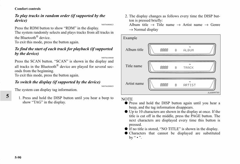
5-90
Comfort controls
5
To play tracks in random order (if supported by the device)
N00766000023
Press the RDM button to show “RDM” in the display.The system randomly selects and plays tracks from all tracks inthe Bluetooth® device.To exit this mode, press the button again.
To find the start of each track for playback (if supported by the device)
N00766100040
Press the SCAN button. “SCAN” is shown in the display andall tracks in the Bluetooth® device are played for several sec-onds from the beginning.To exit this mode, press the button again.
To switch the display (if supported by the device)N00766200025
The system can display tag information.
1. Press and hold the DISP button until you hear a beep toshow “TAG” in the display.
2. The display changes as follows every time the DISP but-ton is pressed briefly:Album title → Title name → Artist name → Genre→ Normal display
NOTE● Press and hold the DISP button again until you hear a
beep, and the tag information disappears.● Up to 10 characters are shown in the display at once. If the
title is cut off in the middle, press the PAGE button. Thenext characters are displayed every time this button ispressed.
● If no title is stored, “NO TITLE” is shown in the display.● Characters that cannot be displayed are substituted
by “ • ”.
Album title
Title name
Example
Artist name
BK0150700US.book 90 ページ 2012年3月22日 木曜日 午後6時46分

Comfort controls
5-91
5
To use the external audio input function (if so equipped)
N00702200175
You can listen to commercially available audio equipment,such as a portable audio system, from your vehicle’s speakers,by connecting the audio equipment to the audio input connec-tors, which are external input connectors (pin jacks).
To activate the external audio input mode
1. Use a commercially available audio cable to connect theaudio equipment to the internal audio input connector.
2. Press the CD button for more than 2 seconds.The display will show “AUX” and then the external audioinput mode will be activated.
Auxiliary Audio connector (RCA)A- Left audio input connector (white)B- Right audio input connector (red)
Auxiliary Audio connector (RCA)
A- CD buttonB- RADIO button
BK0150700US.book 91 ページ 2012年3月22日 木曜日 午後6時46分

5-92
Comfort controls
5
3. To deactivate the external audio input mode, press theRADIO button or the CD button to switch to anothermode.
NOTE● The connected audio equipment cannot be operated with
the vehicle’s audio system.● Depending on the connected audio equipment, it may pro-
duce noise from the speakers.● For information on how to connect and operate the audio
equipment, refer to the owner’s manual for the equipment.
Steering wheel audio remote control switch (if so equipped)
N00714800439
The remote control switch is located on the left side of thesteering wheel.It can be used when the ignition switch or the operation modeis in ON or ACC.
NOTE● Do not press multiple buttons at the same time when using
the steering wheel audio remote control switch.
CAUTION!● Do not operate the connected audio equipment while
driving.This could distract you and an accident might occur.
1- Volume up button2- Volume down button3- Power switch/Mode selector button4- Seek up/Track up/File up/Fast-forward button5- Seek down/Track down/File down/Fast-reverse button
BK0150700US.book 92 ページ 2012年3月22日 木曜日 午後6時46分

Comfort controls
5-93
5
To turn on the powerPress the power switch to turn on the power. When the power isturned on, the last mode used before turning off is displayed.To turn off the power, press and hold down the power switchfor about 2 seconds until you hear a beep.
Volume controlVolume up buttonWhile the button is pressed, the volume will continue toincrease.
Volume down buttonWhile the button is pressed, the volume will continue todecrease.
Mode selectionPress the mode selector button to select the desired mode.The mode changes in the following order.AM → FM1 → FM2 → (SAT1 → SAT2 → SAT3 → SAT4) →CD → USB or iPod* → Bluetooth®* → AM*: If you connect these devices.
To listen to the radioPress the mode selector button and select AM or FM mode.
Automatic tuningSeek up button / Seek down buttonAfter pressing one of these buttons, a receivable station will beautomatically selected and reception of the station will begin.
Channel selection / Category selection (Vehicles with satellite radio)Seek up button / Seek down buttonPress the button to select the desired channel.Pressing down the button for 2 seconds or longer will changethe system to category selection mode. While the button ispressed, the category will change in order. When you reach thedesired category, release the button.
To listen to a CDPress the mode selector button and select CD mode.
To fast forward/reverse the disc (music CDs only)To fast forward or fast reverse the disc, press the fast-forwardbutton or the fast-reverse button.
Fast forwardYou can fast forward the disc by holding down the fast-forwardbutton. While the button is kept pressed, the disc will be fast-forwarded.
Fast reverseYou can fast reverse the disc by holding down the fast-reversebutton. While the button is kept pressed, the disc will be fast-reversed.
NOTE● With an MP3 CD, you can fast forward and fast reverse
tracks in the same folder.
BK0150700US.book 93 ページ 2012年3月22日 木曜日 午後6時46分

5-94
Comfort controls
5
To select a desired trackYou can select your desired track by using the track up buttonor the track down button.
NOTE● Pressing the track down button once during the song will
cause the system to restart playing from the beginning ofthe song.
To listen to an iPodPress the mode selector button and select iPod mode.
To select a desired trackTrack up buttonPress the button repeatedly until the desired track numberappears on the display.
NOTE● The track number continues to increase while the button is
pressed.
Track down buttonPress the button repeatedly until the desired track numberappears on the display.
NOTE● The track number continues to decrease while the button
is pressed.
To listen to a USB memory devicePress the mode selector button and select USB mode.
To select a desired fileFile up buttonPress the button repeatedly until the desired track numberappears on the display.
NOTE● The track number continues to increase while the button is
pressed.
File down buttonPress the button repeatedly until the desired track numberappears on the display.
NOTE● The track number continues to decrease while the button
is pressed.
BK0150700US.book 94 ページ 2012年3月22日 木曜日 午後6時46分

Comfort controls
5-95
5
Error codesN00736100751
If an error code appears in the display, take action in accordance with the table below.
Error display Problem Item Repair
NO DISC No disc inserted Disc is not in CD player. Insert disc.
ERROR 01 Focus error Disc is not loaded correctly, or condensation on disc.
Insert disc with label facing up.Remove moisture from disc.
ERROR 02 Disc error Disc is dirty, scratched, or deformed; or exces-sive vehicle vibration.
Clean or replace disc. Retry when vibrations stop.
ERROR 03 Mechanism error Loading or eject error. Pick-up is out of posi-tion.
Eject disc and reload. If disc will not eject, bring your vehicle to your authorized Mitsubishi Motors dealer or a repair facility of your choice for repair.
ERROR HOT Inside of audio system is hot. Internal protection against high temperatures. Allow radio to cool by waiting about 30 min-
utes.
ERROR Communication or power supply error
Communication error between external device and equipment. Power supply error of external device.
Check connection of display and radio. If there is poor connection, repair the connection.
BK0150700US.book 95 ページ 2012年3月22日 木曜日 午後6時46分

5-96
Comfort controls
5
Error codes (SIRIUS Satellite Radio) (if so equipped)N00760300095
If an error code appears in the display, take action in accordance with the table below.
Error display Problem Description Repair
ANTENNA ↔ ERROR Antenna error The antenna may be faulty, not securely connected, or open-circuited.
Take the vehicle to your authorized Mitsubishi Motors dealer or a repair facility of your choice.
ACQUIRING Cannot pick up signal. The signal is too weak to be received. Move to a place where the signal is easy to receive.
CALL ↔ 888-539-SIRIUS Unauthorized channel Contract does not include reception of this channel.
Contact SIRIUS Satellite Radio and obtain a contract.
NO CHANNEL There is no selectable channel. There is no selectable channel. Cancel SKIP settings.
INVALID ↔ CHANNEL Channel is invalidNo program is currently being broadcast on this channel; or reception is not possi-ble with this channel.
Consult SIRIUS Satellite Radio at 888-539-SIRUS.
SAT ERROR Mechanical fault or bad connection
There is a mechanical fault or a bad con-nection.
Take the vehicle to your authorized Mitsubishi Motors dealer or a repair facility of your choice.
OFF AIR OFF AIRThis channel is not broadcasting at the present time; or satellite radio broadcast-ing is suspended.
Check the broadcast times with SIRIUS Satellite Radio.
NOT ACTIVATED ID not registered The ID code in the receiver has not been registered with SIRIUS Satellite Radio.
Contact your authorized Mitsubishi Motors dealer or a repair facility of your choice.
READING Data reading in progress Reading of received data is in progress. Received data are being read. Please wait.
BK0150700US.book 96 ページ 2012年3月22日 木曜日 午後6時46分
Comfort controls
5-97
5
NOTE● Reception may not be possible in a place where the signal is interrupted by a tunnel, by the roof of a garage or other structure,
by woods, or by a tall building. At such times, the audio is muted. This behavior does not indicate a fault.● Reception conditions may vary according to the angle of the satellite used for the satellite radio service.● Reception may deteriorate if a luggage carrier is attached to the roof or snow collects on the antenna.● Satellite radio reception may not be possible in certain regions.
UPDATING Channel data updating in progress
SIRIUS Satellite Radio is presently updat-ing the channel data. Wait until updating is complete.
SUB UPDATED Contract status updating complete The contract status has been updated. Press any audio key.
Error display Problem Description Repair
BK0150700US.book 97 ページ 2012年3月22日 木曜日 午後6時46分
5-98
Comfort controls
5
Error codes (iPod)N00766300026
If an error code appears in the display, take action in accordance with the table below.
Error display Item Repair
NO SONG There are no playable music files. Record music files in the iPod.VER ERROR (Blink) The iPod or its software cannot be recognized. Connect a supported iPod.
USB BUS PWR (Blink) An overcurrent or other power-supply error has occurred.
Remove the iPod. Have the vehicle inspected at an authorized Mitsubishi Motors dealer or a repair facility of your choice.
CONNECT RETRY (Blink)
If the iPod indicator illuminates, the iPod cannot be authenticated. Reconnect the iPod.
If the iPod indicator goes out, it shows the USB communication error.
Reconnect the iPod correctly. If this error is displayed again, have the vehicleinspected at an authorized Mitsubishi Motors dealer or arepair facility of your choice.
BK0150700US.book 98 ページ 2012年3月22日 木曜日 午後6時46分

Comfort controls
5-99
5
Error codes (USB memory device)N00766400027
If an error code appears in the display, take action in accordance with the table below.
Error display Item Repair
U NO SONG There are no playable music files. Record music files in the format supported by the USB memory device.
U FILE ERROR (Blink) The file cannot be played. The file is protected by copyrights, etc. An error isdisplayed for several seconds, and then the nextplayable file is played automatically.
UNSUPPORTED DEVICE (Blink) The USB memory device cannot be recog-nized. Remove the USB memory device.
UNSUPPORTED FORMAT (Blink) The USB memory device format cannot be recognized. Remove the USB memory device.
USB BUS PWR (Blink) An overcurrent or other power-supply error has occurred.
Remove the USB memory device.Have the vehicle inspected at an authorized Mitsubishi Motors dealer or a repair facility of your choice.
U LSI ERROR (Blink) Internal device errors Have the vehicle inspected at an authorized Mitsubishi Motors dealer or a repair facility of your choice.
U CONNECT RETRY (Blink) USB communication error
Reconnect the USB memory device correctly. If this error is displayed again, have the vehicleinspected at an authorized Mitsubishi Motors dealeror a repair facility of your choice.
BK0150700US.book 99 ページ 2012年3月22日 木曜日 午後6時46分

5-100
Comfort controls
5
Handling of compact discsN00734100340
● Use only the type of compact discs that have the markshown in the illustration below. (Playback of CD-R orCD-RW discs may cause problems.)
● The use of special shaped, damaged compact discs (likecracked discs) or low-quality compact discs (like warpeddiscs or burrs on the discs) such as those shown will dam-age the CD player.
BK0150700US.book 100 ページ 2012年3月22日 木曜日 午後6時46分

Comfort controls
5-101
5
● In the following circumstances, moisture can form oncompact discs and inside the audio system, preventingnormal operation.• When there is high humidity (for example, when it is
raining).• When the temperature suddenly rises, such as right after
the heater is turned on in cold weather.
In this case, wait until the moisture has had time to dryout.
● When the CD player is subjected to violent vibrations,such as during off-road driving, the tracking may notwork.
● When storing compact discs, always store them in theirseparate cases. Never place compact discs in direct sun-light, or in any place where the temperature or humidity ishigh.
● Never touch the flat surface of the disc where there isn’t alabel. This will damage the disc surface and could affectthe sound quality. When handling a compact disc, alwayshold it by the outer edge and the center hole.
● To clean a disc, use a soft, clean, dry cloth. Wipe directlyfrom the center hole toward the outer edge. Do not wipe ina circle. Never use any chemicals such as benzine, paintthinner, a disc spray cleaner, or an anti-static agent on thedisc.
● Do not use a ball point pen, felt pen, pencil, etc. to writeon the label surface of the disc.
● Do not put additional labels or stickers on compact discs.Also, do not use any compact disc on which a label orsticker has started to peel off or any compact disc that hasstickiness or other contamination left by a peeled-off labelor sticker. If you use such a compact disc, the CD playermay stop working properly and you may not be able toeject the compact disc.
BK0150700US.book 101 ページ 2012年3月22日 木曜日 午後6時46分

5-102
Comfort controls
5
Notes on CD-Rs/RWsN00751900066
● You may have trouble playing back some CD-R/RW discsrecorded on CD recorders (CD-R/RW drives), either dueto their recording characteristics or dirt, fingerprints,scratches, etc. on the disc surface.
● CD-R/RW discs are less resistant to high temperatures andhigh humidity than ordinary music CDs and can thereforebe damaged and rendered unplayable if left inside yourvehicle for a long time.
● Depending on the combination of the writing software,the CD recorder (CD-R/RW drive), and the disc used tocreate a CD-R/RW, the disc might not play successfully.
● This player cannot play the CD-R/RW discs if the sessionis not closed.
● This player cannot play CD-R/RW discs which containdata other than CD-DA or MP3 data (Video CD, etc.).
● Be sure to observe the handling instructions for the CD-R/RW disc.
AntennaN00734200439
To removeTurn the pole (A) counterclockwise.
To installScrew the pole (A) clockwise into the base (B) until it issecurely retained.
NOTE● Be sure to remove the roof antenna in the following cases:
• When using an automatic car wash• When covering your vehicle with a car cover• When driving into a structure that has a low ceiling.
WARNING!● Operating the CD player in a manner other than
specifically instructed herein may result in hazard-ous radiation exposure. Do not remove the coverand attempt to repair the CD player by yourself.There are no user serviceable parts inside. In case ofmalfunction, contact an authorized MitsubishiMotors dealer or a repair facility of your choice.
BK0150700US.book 102 ページ 2012年3月22日 木曜日 午後6時46分

Comfort controls
5-103
5
Clock (if so equipped)N00755000111
The time is displayed when the ignition switch or the operationmode is in ON or ACC.
To set the time
1. Press and hold the CLOCK button and the clock displayflashes.
2. Press the various buttons to adjust.
3. When the time is set, press the DISP button to stop theclock display from flashing. After time signal setting,however, the clock display automatically stops flashing.
NOTE● Reset the time after the battery terminals are disconnected
and reconnected.● Seconds do not appear in the clock display, but after
adjusting the “Minutes” setting and time signal setting,the clock begins to operate from 0 seconds.
H — “Hour” settingPress this button to fast-forward the “hours”.
M — “Minutes” settingPress this button to fast-forward the “minutes”.
CLOCK DISP H M :00
:00 — Time signal settingAt the same time the button is pressed, the fol-lowing modifications are made.10:00 - 10:29 ......Change to 10:0010:30 - 11:00 ......Change to 11:00
BK0150700US.book 103 ページ 2012年3月22日 木曜日 午後6時46分

5-104
Comfort controls
5
General information about your radioN00733900442
Your vehicle’s radio receives both AM and FM stations.The quality of your reception is affected by distance, obstacles,and signal interference.
This radio complies with Part 15 of Federal CommunicationsCommission (FCC) Rules (for vehicles sold in U.S.A.). Opera-tion is subject to the following conditions:
● The device may not cause harmful interference.● This device must accept any interference recieved, includ-
ing interference that may cause undesirable operation.
Signal transmissionFM signals do not follow the earth surface nor are theyreflected by the upper atmosphere. For this reason, FM broad-casts cannot be received over long distances. AM signals fol-low the earth’s surface and are reflected by the upperatmosphere. For this reason, AM broadcasts can be receivedover longer distances.
Weak reception (fading)Because of the limited range of FM signals and the way FMwaves transmit, you may experience weak or fading FM recep-tion. When the broadcast is blocked by mountains or similarobstructions, reception can be disturbed.
CAUTION!● Changes or modifications not expressly approved by
the party meeting the above conditions could voidthe user’s authority to operate the equipment.
FM AM
25 to 40 mile radius(40 to 64 km)
100 mile radius(160 km)
BK0150700US.book 104 ページ 2012年3月22日 木曜日 午後6時46分

Comfort controls
5-105
5
ReflectionThe reason why one can hear FM but not AM in parkinggarages, under bridges etc., is that FM signals, unlike AM sig-nals, are reflected by solid objects such as buildings, etc.Because FM signals are easily reflected by buildings, this canalso cause reception disturbances.The direct signal from the broadcast station reaches the antennaslightly before the reflected signal. This time difference maycause some reception disturbance or flutter.This problem occurs primarily in urban areas.
Cross modulationIf one listens to a weak station and is in the vicinity of anotherstrong station, both stations might be received simultaneously.
FM stereo receptionStereo reception requires a high quality broadcast signal. Thismeans that types of disturbances mentioned previously becomemore marked and the reception range is somewhat diminishedduring stereo reception.
BK0150700US.book 105 ページ 2012年3月22日 木曜日 午後6時46分
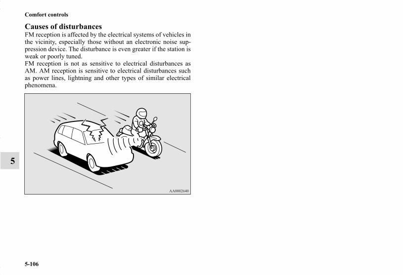
5-106
Comfort controls
5
Causes of disturbancesFM reception is affected by the electrical systems of vehicles inthe vicinity, especially those without an electronic noise sup-pression device. The disturbance is even greater if the station isweak or poorly tuned.FM reception is not as sensitive to electrical disturbances asAM. AM reception is sensitive to electrical disturbances suchas power lines, lightning and other types of similar electricalphenomena.
BK0150700US.book 106 ページ 2012年3月22日 木曜日 午後6時46分

6
For emergencies
If the vehicle breaks down . . . . . . . . . . . . . . . . . . .6- 2Jump-starting the engine . . . . . . . . . . . . . . . . . . . .6- 2Engine overheating . . . . . . . . . . . . . . . . . . . . . . . .6- 5Jack and tools . . . . . . . . . . . . . . . . . . . . . . . . . . . . .6- 7How to change a tire . . . . . . . . . . . . . . . . . . . . . . .6- 8Towing . . . . . . . . . . . . . . . . . . . . . . . . . . . . . . . . . .6- 21Operation under adverse driving conditions . . . . .6- 23
BK0150700US.book 1 ページ 2012年3月22日 木曜日 午後6時46分

6-2
For emergencies
6
If the vehicle breaks downN00836300187
If your vehicle breaks down on the road, move to the shoulderand turn on the hazard warning flashers. If there is no shoulder,or the shoulder is not safe, drive in the right lane slowly, withthe hazard lights flashing, until you come to a safe stoppingplace. Keep the flashers flashing.
If the engine stops/failsIf the engine stops, there will be no power assist to the steeringand brakes, making these difficult to use.
● The brake booster will not work, so the brakes will notgrip well. The brake pedal will be harder to press thanusual.
● Since there is no power steering assist, the steering wheelwill be hard to turn.
When the engine fails at the intersectionGet help from your passengers, bystanders, etc. to push thevehicle and move it to a safe zone.
Jump-starting the engineN00836400755
If the engine cannot be started because the battery is weak ordead, you can start it with the battery from another vehicleusing jumper cables.
1. Take off any metal jewelry such as watch bands or brace-lets that might make an accidental electrical contact.
2. Position the vehicles close enough together so that thejumper cables can reach, but be sure the vehicles aren’ttouching each other.
WARNING!● When using jumper cables to start a vehicle, follow
the procedures and be very cautious.
CAUTION!● Do not try to start your vehicle by pushing or tow-
ing. Vehicles with automatic transaxles cannot bestarted this way. Also, there is more risk of an acci-dent when a vehicle is being pushed or towed.
CAUTION!● Check the other vehicle. It must have a 12-volt bat-
tery. If the other system isn’t 12-volt, both systemscan be damaged.
BK0150700US.book 2 ページ 2012年3月22日 木曜日 午後6時46分
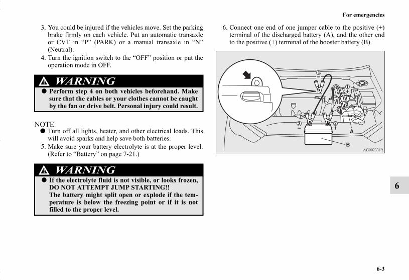
For emergencies
6-3
6
3. You could be injured if the vehicles move. Set the parkingbrake firmly on each vehicle. Put an automatic transaxleor CVT in “P” (PARK) or a manual transaxle in “N”(Neutral).
4. Turn the ignition switch to the “OFF” position or put theoperation mode in OFF.
NOTE● Turn off all lights, heater, and other electrical loads. This
will avoid sparks and help save both batteries.5. Make sure your battery electrolyte is at the proper level.
(Refer to “Battery” on page 7-21.)
6. Connect one end of one jumper cable to the positive (+)terminal of the discharged battery (A), and the other endto the positive (+) terminal of the booster battery (B).
WARNING!● Perform step 4 on both vehicles beforehand. Make
sure that the cables or your clothes cannot be caughtby the fan or drive belt. Personal injury could result.
WARNING!● If the electrolyte fluid is not visible, or looks frozen,
DO NOT ATTEMPT JUMP STARTING!!The battery might split open or explode if the tem-perature is below the freezing point or if it is notfilled to the proper level.
BK0150700US.book 3 ページ 2012年3月22日 木曜日 午後6時46分

6-4
For emergencies
6
NOTE● Open the terminal cover before connecting the jumper
cable to the positive terminal of the battery.(Refer to “Battery” on page 7-21.)
● Use the proper cables suitable for the battery size.Otherwise heat damage to the cables could result.
● Check the jumper cables for damage and corrosion beforeuse.
7. Connect one end of the other jumper cable to the negative(-) terminal of the booster battery (B), and the other end tothe engine block of the vehicle with the low battery (A) atthe point farthest from the battery.
8. Start the engine in the vehicle providing the boost. Let theengine idle a few minutes, then start the engine in thevehicle with the low battery.
9. After the engine is started, disconnect the cables in thereverse order from the way you connected them.
WARNING!● Be sure to follow the proper order when connecting
the batteries, of: → → →● Make sure that the connection is made to the
engine properly. If the connection is directly made tothe negative terminal of the battery, the flammablegases from inside the battery might catch fire andexplode, causing personal injury.
● When connecting the jumper cable, do not connectthe positive (+) cable to the negative (-) terminal.Otherwise sparks can make the battery explode.
CAUTION!● Make sure that the jumper cable will not be caught
in the cooling fan or other moving parts in theengine compartment.
WARNING!● Charging your battery while it is still in your vehicle
might cause the battery to catch fire and explode. Ifyou have to charge it while in the vehicle, disconnectthe negative (-) terminal.
● Keep sparks, cigarettes, and flames away from thebattery because the battery could explode.
● Keep your work area well vented when charging orusing the battery in an enclosed space.
● Remove all the caps before charging the battery.● Electrolyte (battery acid) is made of corrosive
diluted sulfuric acid. If electrolyte comes in contactwith your hands, eyes, clothes, or the painted sur-face of your vehicle, thoroughly flush with water. Ifelectrolyte gets in your eyes, flush them immediatelyand thoroughly with water, and get prompt medicalattention.
● Always wear protective clothing and goggles whenworking near the battery.
● Keep the battery out of the reach of children.
BK0150700US.book 4 ページ 2012年3月22日 木曜日 午後6時46分

For emergencies
6-5
6
As your vehicle has anti-lock brakesIf you drive your vehicle with a low battery charge after theengine has been started by using jumper cables, the engine maymisfire. This can cause the anti-lock braking system warninglight to blink on and off. This is only due to the low batteryvoltage. It is not a problem with the brake system. If this hap-pens, fully charge the battery and ensure the charging system isoperating properly.
Engine overheatingN00836500352
When the engine is overheating, the information screen in themulti-information display will be interrupted and the enginecoolant temperature warning display will appear. Also “ ”blink. If this happens:
1. Stop the vehicle in a safe place. Turn on the hazard warn-ing flashers.
2. With the engine still running, carefully raise the enginehood to vent the engine compartment.
3. Check that the cooling fan is running. If the fan is notturning, stop the engine immediately and contact anauthorized Mitsubishi Motors dealer or a repair facility ofyour choice for assistance.
4. If you see steam or spray coming from under the hood,turn off the engine.
WARNING!● To avoid personal injury, keep hands, hair, jewelry
and clothes away from the cooling fan. The coolingfan can start at any time.
BK0150700US.book 5 ページ 2012年3月22日 木曜日 午後6時46分

6-6
For emergencies
6
5. If you do not see steam or spray coming from under thehood, leave the engine on until the bar graph for theengine coolant temperature warning display on the multi-information display goes down. When it is in the middleof the normal zone, you can start driving again. If the bargraph stays in the red zone, turn off the engine.
6. When you do not see any more steam or spray, open thehood. Look for obvious leaks, such as a split radiatorhose. Be careful as components will be hot. Any leaksource must be repaired.
7. If there is no obvious leak source, check the coolant levelin the engine coolant reserve tank. If there is none, or if itis too low, slowly add coolant.
8. If the engine coolant reserve tank needs coolant, you willprobably also need to add coolant to the radiator. Do notloosen or remove the radiator cap until the engine hascooled down.
9. Start the engine, and slowly add coolant, up to the bottomof the filler neck. Use plain water if you have to (andreplace it with the right coolant as soon as possible).
10. Replace the radiator cap and tighten it fully. Check theengine coolant temperature display on the multi-informa-tion display. You can start driving again when the bargraph for the engine coolant temperature display returnsto the normal zone.
11. Have the system inspected by your authorized MitsubishiMotors dealer or a repair facility of your choice.
WARNING!● Before raising the engine hood, check to see if there
is steam or spray coming from under the hood.Steam or spray coming from an overheated enginecould seriously scald you.Do not open the hood until there is no steam orspray.
WARNING!● Removing the radiator cap could scald you with
escaping hot water or steam. When checking theradiator level, cover the cap with a cloth before try-ing to remove it. Turn it slowly counterclockwise,without pressing down, to the first notch. The pres-sure in the system will then be let out. When thepressure is COMPLETELY LET OUT, press downand keep turning the cap counterclockwise until itcomes off.
BK0150700US.book 6 ページ 2012年3月22日 木曜日 午後6時46分

For emergencies
6-7
6
Jack and toolsN00836600337
StorageThe tools and jack are stowed in the luggage compartment.
Tools
1- Tools2- Jack
1- Bar2- Wheel nut wrench
BK0150700US.book 7 ページ 2012年3月22日 木曜日 午後6時46分

6-8
For emergencies
6
JackBefore removing the jack, lift up the luggage floor board.
How to change a tireN00836900792
Before changing a tire, first stop your vehicle in a safe, flatlocation.
1. Park the vehicle on level and stable ground.2. Set the parking brake firmly.3. On vehicles equipped with manual transaxle, stop the
engine and move the gearshift lever to the “R” (Reverse)position.On vehicles equipped with continuously variable trans-mission (CVT), move the selector lever to the “P”(PARK) position, and stop the engine.
4. Turn on the hazard flashers and set up a warning triangle,flashing signal light, etc., at an adequate distance from thevehicle, and have all your passengers leave the vehicle.
WARNING!● The jack should not be used for any purpose other
than to change a tire.● Never get under the vehicle or put any portion of
your body under the vehicle while it is supported bythe jack.
BK0150700US.book 8 ページ 2012年3月22日 木曜日 午後6時46分

For emergencies
6-9
6
5. To prevent the vehicle from rolling when it is raised on thejack, place chocks or blocks (A) in front of and behind thetire that is diagonally opposite from the tire (B) you arechanging.
NOTE● The chocks shown in the illustration do not come with
your vehicle. It is recommended that you purchase chocksor blocks and keep them in the vehicle for use if needed.
● If chocks or blocks are not available, use stones or anyother objects that are large enough to hold the wheel inposition.
6. Get the jack, bar and wheel nut wrench ready.(Refer to “Jack and tools” on page 6-7.)
WARNING!● Be sure to apply chocks or blocks to the correct tire
when jacking up the vehicle. If the vehicle moveswhile jacked up, the jack could slip out of position,leading to an accident.
BK0150700US.book 9 ページ 2012年3月22日 木曜日 午後6時46分

6-10
For emergencies
6
Spare tire informationN00849600331
Compact spare tireThe compact spare tire is stowed beneath the luggage floorboard of the luggage compartment. It is designed to save spacein the luggage compartment. Its lighter weight makes it easierto use if a flat tire occurs.
WARNING!● Tires, including spare tire, degrade over time with
age even when they are not being used. It is recom-mended that tires over 6 years generally be replacedeven if damage is not obvious.
CAUTION!● While the compact spare tire is stowed, the inflation
pressure should be checked at least once a month toassure that it remains at the recommended inflationpressure. See the tire and loading information plac-ard attached to the driver’s door sill. Refer to “Tireand loading information placard” on page 9-4.
● Driving with an improperly inflated tire can causean accident. If you have no choice but to drive withan under-inflated tire, keep your speed down andavoid sudden steering or braking, if possible. Inflatethe tire to the correct pressure as soon as possible.Refer to “Tire inflation pressures” on page 7-27.
● The compact spare tire should be used only tempo-rarily. While the compact spare tire is being used,the tire pressure monitoring system will not functionproperly. Have the tire replaced or repaired at anauthorized Mitsubishi Motors dealer or a repairfacility of your choice as soon as possible.
● Do not go over 50 mph (80 km/h) when driving withthe compact spare tire.
● Avoid sudden starting and braking when drivingwith the compact spare tire.
● Do not drive through automatic car washes and overobstacles that could possibly damage the undersideof your vehicle. Because the compact spare tire issmaller than the original tire, there is less clearancebetween the ground and your vehicle.
● Because the compact spare tire is designed only foryour vehicle, do not use it on any other vehicle.
● Do not put the compact spare tire on a differentwheel, and do not put standard tires, snow tires,wheel covers or trim rings on the compact sparewheel. Otherwise, you could damage these parts orother parts on your vehicle.
● Do not use tire chains with your compact spare tire.Using a chain could cause damage to your vehicleand loss of the chains.
CAUTION!
BK0150700US.book 10 ページ 2012年3月22日 木曜日 午後6時46分

For emergencies
6-11
6
To remove the spare tireN00849700273
1. Lift up the luggage floor board.2. To remove the spare tire, remove the installation clamp
(A) by turning it counterclockwise.
NOTE● The clamp cannot be used for a normal size tire. Store a
normal size tire under the luggage floor board.
To change a tireN00849800421
1. On vehicles with wheel covers, first remove the covers(refer to “Wheel covers” on page 6-19). Then, loosen thewheel nuts with the wheel nut wrench. Do not remove thewheel nuts yet.
BK0150700US.book 11 ページ 2012年3月22日 木曜日 午後6時46分

6-12
For emergencies
6
2. Place the jack under one of the jacking points (A) shownin the illustration. Use the jacking point closest to the tireyou wish to change.
NOTE● Put the spare wheel under the vehicle body near the jack.
This makes it safer if the jack slips out of position.
WARNING!● Set the jack only at the positions shown here. If the
jack is set at a wrong position, it could dent yourvehicle or the jack might fall over and cause per-sonal injury.
● Do not use the jack on a tilted or soft surface.Otherwise, the jack might slip and cause personalinjury. Always use the jack on a flat, hard surface.Before setting the jack, make sure there are no sandor pebbles under the jack base.
BK0150700US.book 12 ページ 2012年3月22日 木曜日 午後6時46分

For emergencies
6-13
6
3. Rotate the jack by hand until the flange portion (B) fits inthe groove (C) at the top of the jack.
4. Insert the bar (D) into the wheel nut wrench (E). Then putthe end of the bar into the shaft’s jack end, as shown in theillustration.Slowly rotate the wheel nut wrench until the tire is raisedslightly off the ground surface.
WARNING!● Stop jacking up the vehicle as soon as the tire is
raised off the ground. It is dangerous to raise thevehicle any higher.
● Do not get under your vehicle while using the jack.● Do not bump the raised vehicle or leave it sitting on
the jack for a long time. Both are very dangerous.● Do not use a jack except the one that came with your
vehicle.● The jack should not be used for any purpose other
than to change a tire.
BK0150700US.book 13 ページ 2012年3月22日 木曜日 午後6時46分

6-14
For emergencies
6
5. Remove the wheel nuts with the wheel nut wrench, thentake the wheel off.
6. Clean out any mud, etc. on the hub surface (F), hub bolts(G) or in the installation holes (H) in the wheel, and thenmount the spare tire.● No one should be in your vehicle when using the
jack.● Do not start or run the engine while your vehicle is
on the jack.● Do not turn the raised wheel. The tires that are still
on the ground could turn and make your vehicle falloff the jack.
CAUTION!● Handle the wheel carefully when changing the tire,
to avoid scratching the wheel surface.
WARNING!
BK0150700US.book 14 ページ 2012年3月22日 木曜日 午後6時46分
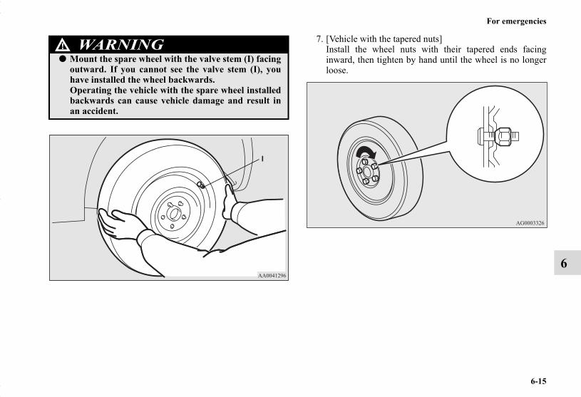
For emergencies
6-15
6
7. [Vehicle with the tapered nuts]Install the wheel nuts with their tapered ends facinginward, then tighten by hand until the wheel is no longerloose.
WARNING!● Mount the spare wheel with the valve stem (I) facing
outward. If you cannot see the valve stem (I), youhave installed the wheel backwards.Operating the vehicle with the spare wheel installedbackwards can cause vehicle damage and result inan accident.
BK0150700US.book 15 ページ 2012年3月22日 木曜日 午後6時46分

6-16
For emergencies
6
[Vehicle with the flange nuts]• Aluminium wheel
Temporarily tighten the wheel nuts until their flangesection comes in contact with the wheel and it is nolonger loose.
• Steel wheelInstall the wheel nuts with their tapered ends facinginward, then tighten by hand until the wheel is no longerloose.
NOTE● Flange nuts can be temporarily used on the compact spare
or steel wheel, but return them to the original wheel andtire as soon as possible.
● If all 4 wheels are changed to steel wheels, use taperednuts.
CAUTION!● Never apply oil to either the wheel bolts or the nuts
or they will tighten too much.
BK0150700US.book 16 ページ 2012年3月22日 木曜日 午後6時46分

For emergencies
6-17
6
8. Lower the vehicle slowly until the tire touches the ground,by rotating the wheel nut wrench counterclockwise.
9. Tighten the nuts in the order shown in the illustration untileach nut has been tightened to the torque listed here.65 to 80 ft-lb (88 to 108 N•m)
10. Lower the jack all the way and remove it.
CAUTION!● Never use your foot or a pipe extension to apply
added force to the wheel nut wrench when tighten-ing the wheel nuts. If you do so, you can over-tightenthe wheel nuts and damage the wheel, wheel nutsand hub bolts.
BK0150700US.book 17 ページ 2012年3月22日 木曜日 午後6時46分

6-18
For emergencies
6
11. Check the tire inflation pressure. The recommended tirepressure for your vehicle is listed on the tire and loadinginformation placard attached to the driver’s door sill asshown in the illustration. Refer to “Tire inflation pres-sures” on page 7-27.
To store the flat tire or spare tire, jack, bar and wheel nut wrench
N00850000162
Reverse the removing procedure when storing the flat tire orspare tire, jack, bar and wheel nut wrench.Refer to “To remove the spare tire” on page 6-11 and “Jack andtools” on page 6-7.
CAUTION!
● Driving with an improperly inflated tire can causean accident. If you have no choice but to drive withan under-inflated tire, keep your speed down andavoid sudden steering or braking, if possible. Inflatethe tire to the correct pressure as soon as possible.Refer to “Tire inflation pressures” on page 7-27.
● After changing the tire and driving the vehicle about620 miles (1,000 km), retighten the wheel nuts tomake sure that they have not come loose.
● If the steering wheel vibrates when driving afterchanging the tire, have the tire checked for balanceat an authorized Mitsubishi Motors dealer or arepair facility of your choice.
● Do not mix one type of tire with another or use a dif-ferent size from the one listed. This would causeearly wear and poor handling.
BK0150700US.book 18 ページ 2012年3月22日 木曜日 午後6時46分

For emergencies
6-19
6
Wheel cover (if so equipped)N00849400195
To removeWrap the tip of the bar with a cloth, insert it deeply into thenotch provided in the wheel cover, and pry the cover awayfrom the wheel.Using the same procedure at the other wheel cover notches,work the wheel cover away from the wheel to remove it com-pletely.
NOTE● The wheel cover is made of plastic. Be careful when pry-
ing it off.
To install
CAUTION!● Trying to remove the wheel cover with only your
bare hands can seriously injure your fingers.
CAUTION!● Before installing the wheel cover to the wheel, make
sure that the tabs (A) on the back of the wheel covercorrectly engage the ring (B) to prevent the wheelcover from coming off. Do not install a wheel coverthat has broken tabs.
BK0150700US.book 19 ページ 2012年3月22日 木曜日 午後6時46分
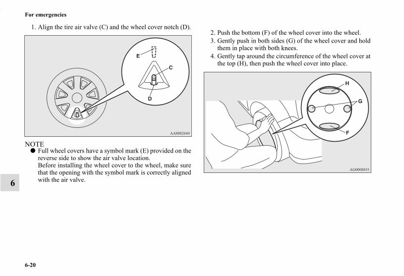
6-20
For emergencies
6
1. Align the tire air valve (C) and the wheel cover notch (D).
NOTE● Full wheel covers have a symbol mark (E) provided on the
reverse side to show the air valve location.Before installing the wheel cover to the wheel, make surethat the opening with the symbol mark is correctly alignedwith the air valve.
2. Push the bottom (F) of the wheel cover into the wheel.3. Gently push in both sides (G) of the wheel cover and hold
them in place with both knees.4. Gently tap around the circumference of the wheel cover at
the top (H), then push the wheel cover into place.
BK0150700US.book 20 ページ 2012年3月22日 木曜日 午後6時46分

For emergencies
6-21
6
TowingN00837000875
If your vehicle needs to be towedIf towing is necessary, we recommend you to have it done by acommercial tow truck service.When towing is required, transport the vehicle using a towtruck.Incorect towing equipment could damage your vehicle.
NOTE● Do not use the tie-down hooks for towing. These hooks
are provided only for the purpose of transporting the vehi-cle itself.
● Your vehicle cannot tow any other vehicle.
There may be local regulations concerning towing in your area.Obey the regulations of the area where you are driving yourvehicle.
CAUTION!● Do not attempt to be towed by another vehicle with
a rope.
Do not tow all-wheel drive vehicles with this style.
Do not tow all-wheel drive vehicles or CVT vehicles with this style.
BK0150700US.book 21 ページ 2012年3月22日 木曜日 午後6時46分

6-22
For emergencies
6
Towing the vehicle by a tow truck
Towing with rear wheels off the ground (Type B)Set the gearshift lever to the “N” (Neutral) position.Secure the steering wheel in a straight-ahead position with arope or tie-down strap.
CAUTION!● This vehicle must not be towed by a tow truck using
sling lift type equipment (Type A) as illustrated.Using a sling lift will damage the bumper and frontend.
● Do not tow all-wheel drive vehicles with the front orrear wheels on the ground (Type B or Type C) asillustrated. This could result in the driving systemdamage or vehicle may jump at the carriage.If you tow all-wheel drive vehicles, use only Type Dor E equipment.All-wheel-drive vehicles cannot be towed with onlythe front or rear tires on the ground even if it is in“2WD” drive mode.
● Do not tow continuously variable transmission(CVT) vehicles with the driving wheels on theground (Type B) as illustrated. If the vehicle istowed like this, the continuously variable transmis-sion (CVT) fluid may not reach all parts of thetransmission, thus damaging it.If you tow CVT vehicles, use Type C, D or E equip-ment.
● If the manual transaxle is malfunctioning or dam-aged, transport the vehicle with the driving wheelson a carriage (Type C, D or E) as illustrated.
● [For front-wheel drive vehicle equipped with theactive stability control (ASC)]If the vehicle is towed with the ignition switch in the“ON” position or the operation mode in ON andonly the front wheels or only the rear wheels raisedoff the ground (Type B or C), the ASC may operate,resulting in an accident. When towing the vehiclewith the rear wheels raised, turn the ignition switchto “OFF” or “ACC” position or put the operationmode in OFF or ACC. When towing the vehicle withthe front wheels raised, keep the ignition switch orthe operation mode as follows.[Except for vehicles equipped with the F.A.S.T.-key] The ignition switch is in “OFF” or “ACC” position.[Vehicles equipped with the F.A.S.T.-key] The operation mode is in OFF or ACC.
CAUTION!
BK0150700US.book 22 ページ 2012年3月22日 木曜日 午後6時46分
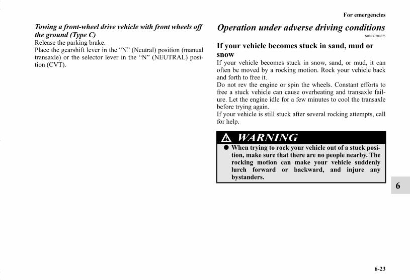
For emergencies
6-23
6
Towing a front-wheel drive vehicle with front wheels off the ground (Type C)Release the parking brake.Place the gearshift lever in the “N” (Neutral) position (manualtransaxle) or the selector lever in the “N” (NEUTRAL) posi-tion (CVT).
Operation under adverse driving conditionsN00837200675
If your vehicle becomes stuck in sand, mud or snowIf your vehicle becomes stuck in snow, sand, or mud, it canoften be moved by a rocking motion. Rock your vehicle backand forth to free it.Do not rev the engine or spin the wheels. Constant efforts tofree a stuck vehicle can cause overheating and transaxle fail-ure. Let the engine idle for a few minutes to cool the transaxlebefore trying again.If your vehicle is still stuck after several rocking attempts, callfor help.
WARNING!● When trying to rock your vehicle out of a stuck posi-
tion, make sure that there are no people nearby. Therocking motion can make your vehicle suddenlylurch forward or backward, and injure anybystanders.
BK0150700US.book 23 ページ 2012年3月22日 木曜日 午後6時46分

6-24
For emergencies
6
On wet roads On snowy or icy roads● When driving on a road covered with snow or ice, use
snow tires. Tire chains cannot be used on your vehicle.There may be state or local regulations about using snowtires. Always check the regulations in your local areabefore using them. Refer to “Snow tires” on page 7-32and “Tire chains” on page 7-32.
● Drive slowly. Do not make sudden starts or stops, sharpturns, or slam on the brakes.
● Allow extra distance between your vehicle and the vehiclein front of you, and avoid sudden braking.
● If a skid occurs when the accelerator pedal is depressed,take your foot off the pedal. Steer gently in the directionof the skid.
● Your vehicle is equipped with an anti-lock braking system(ABS). Hold the brake pedal down firmly and keep itdepressed. Do not pump the brake pedal which will resultin reduced braking performance.
● After parking on snowy or icy road, it may be difficult tomove your vehicle due to freeze-up of the brake. Depressthe accelerator pedal little by little to move the vehicleafter confirming safety of the vehicle.
CAUTION!● Avoid flooded roads. Water is often deeper than it
looks, and you could be seriously hurt by drivinginto flood water.
● When driving in rain, on water-covered roads, orthrough a car wash, water could get into the brakediscs and make them fail temporarily. In such cases,lightly press the brake pedal to see if they are work-ing properly. If they are not, press the pedal lightlyseveral times while driving to dry the brake pads orlinings, then check them again.
● When driving in rain, a layer of water may formbetween the tires and the road surface (hydroplan-ing). This loosens your tires’ grip on the road, mak-ing it difficult to steer or brake properly. Whendriving on a wet road:• Drive your vehicle at a safe speed.• Do not drive on worn tires.• Always keep the tires at the correct inflation pres-
sures.
CAUTION!● Do not depress the accelerator pedal rapidly. The
vehicle could start moving when it breaks free fromthe ice, possibly resulting in an accident.
BK0150700US.book 24 ページ 2012年3月22日 木曜日 午後6時46分

For emergencies
6-25
6
On a bumpy or rutted road● Drive as slow as possible when driving on bumpy, rutted
roads or over potholes.
CAUTION!● Driving on bumpy, rutted roads or over potholes can
damage the tires and wheels.Wheels with low-profiles tires or under-inflated tiresare especially at risk for damage.
BK0150700US.book 25 ページ 2012年3月22日 木曜日 午後6時46分

BK0150700US.book 26 ページ 2012年3月22日 木曜日 午後6時46分

7
Vehicle care and maintenance
Service precautions . . . . . . . . . . . . . . . . . . . . . . . .7- 2Catalytic converter . . . . . . . . . . . . . . . . . . . . . . . . .7- 3Engine hood . . . . . . . . . . . . . . . . . . . . . . . . . . . . . .7- 4View of the engine compartment . . . . . . . . . . . . . .7- 6Engine oil and oil filter . . . . . . . . . . . . . . . . . . . . .7- 7Engine coolant . . . . . . . . . . . . . . . . . . . . . . . . . . . .7- 10Air cleaner filter . . . . . . . . . . . . . . . . . . . . . . . . . . .7- 12Manual transaxle oil (if so equipped) . . . . . . . . . .7- 17Continuously variable transmission (CVT) fluid
(if so equipped). . . . . . . . . . . . . . . . . . . . . . . . . .7- 18Transfer oil (All-wheel drive models) . . . . . . . . . .7- 18Rear axle oil (All-wheel drive models) . . . . . . . . .7- 19Washer fluid . . . . . . . . . . . . . . . . . . . . . . . . . . . . . .7- 19Brake fluid/Clutch fluid (if so equipped). . . . . . . .7- 20Battery . . . . . . . . . . . . . . . . . . . . . . . . . . . . . . . . . .7- 21Tires . . . . . . . . . . . . . . . . . . . . . . . . . . . . . . . . . . . .7- 23Clutch pedal free play (if so equipped) . . . . . . . . .7- 32Brake pedal free play . . . . . . . . . . . . . . . . . . . . . . .7- 33Parking brake . . . . . . . . . . . . . . . . . . . . . . . . . . . . .7- 33Wiper blades . . . . . . . . . . . . . . . . . . . . . . . . . . . . .7- 34Emission-control system maintenance. . . . . . . . . .7- 34
General maintenance . . . . . . . . . . . . . . . . . . . . . . . 7- 36For cold and snowy weather . . . . . . . . . . . . . . . . . 7- 38Fusible links . . . . . . . . . . . . . . . . . . . . . . . . . . . . . 7- 39Fuses . . . . . . . . . . . . . . . . . . . . . . . . . . . . . . . . . . . 7- 39Replacement of light bulbs . . . . . . . . . . . . . . . . . . 7- 47Vehicle care precautions . . . . . . . . . . . . . . . . . . . . 7- 69Cleaning the inside of your vehicle. . . . . . . . . . . . 7- 70Cleaning the outside of your vehicle. . . . . . . . . . . 7- 71
BK0150700US.book 1 ページ 2012年3月22日 木曜日 午後6時46分

7-2
Vehicle care and maintenance
7
Service precautionsN00937300374
Taking regular care of your vehicle will preserve its value andappearance as long as possible.
You can do some of the maintenance work yourself, and therest should only be performed by an authorized MitsubishiMotors dealer or a repair facility of your choice.If you discover a malfunction or other problem, have it cor-rected by an authorized Mitsubishi Motors dealer or a repairfacility of your choice.This section describes the maintenance inspections that youcan do yourself, if you so desire. Follow the instructions andprecautions for each procedure.
Have you purchased the Mitsubishi Motors Diamond Care Pro-tection Plan? The Plan supplements your new vehicle warran-ties. See your authorized Mitsubishi Motors dealer for details.
WARNING!
● When checking or servicing the inside of the enginecompartment, be sure the engine is stopped and hashad a chance to cool down.
● If you need to work in the engine compartment withthe engine running, be especially careful that yourclothing, hair, etc. does not get caught in the fan,drive belts, or other moving parts.
● The fan can turn on automatically even if the engineis not running. Turn the ignition switch to the“OFF” position or put the operation mode in OFF tobe safe while you work in the engine compartment.
● Do not smoke or allow open flames around fuel orthe battery. The fumes are flammable.
● Be extremely careful when working around the bat-tery. It contains poisonous and corrosive sulfuricacid.
● Do not get under your vehicle while it is on a jack.Always use properly rated automotive jack stands.
● Handling your vehicle’s parts and materials in thewrong way can injure you. Ask an authorizedMitsubishi Motors dealer or a repair facility of yourchoice if you have questions.
WARNING!
BK0150700US.book 2 ページ 2012年3月22日 木曜日 午後6時46分

Vehicle care and maintenance
7-3
7
Catalytic converterN00937400447
The catalytic converter requires you to use unleaded fuel only.Leaded gasoline will destroy the emission-control effective-ness of the converter.
Normally, the catalytic converter does not require maintenance.However, it is important to keep the engine properly tuned forthe converter to continue to work properly.
To reduce the possibility of catalytic converter damage:● Use UNLEADED GASOLINE ONLY of the type of rec-
ommended in “Fuel selection”.● Do not drive with an extremely low fuel level. Running
out of gas could damage the catalytic converter.● Do not try to start the engine by pushing or towing the
vehicle. If the battery is weak or run down, use jumpercables to properly start the engine.
● Do not idle the engine with any spark plug wires discon-nected or removed, such as when performing diagnostictests.
● Do not idle the engine for a long time if it is idlingroughly or otherwise obviously malfunctioning.
● To prevent the catalytic converter from being damagedfrom unburned gas, do not race the engine when stoppingthe engine.
● Stop driving the vehicle if you think the performance isnoticeably low, or the engine has a malfunction such aswith the ignition, etc. If you are not able to stop drivingimmediately, slow down and drive for only a short time.Have your vehicle checked at an authorized MitsubishiMotors dealer or a repair facility of your choice as soon aspossible.
● In unusual situations involving major engine problems, aburning odor may indicate severe and abnormal catalyticconverter overheating. If this occurs, stop in a safe place,shut the engine off and let the vehicle cool. Once theengine is cool, immediately take your vehicle to a dealeror a repair facility of your choice for service.
CAUTION!
● Damage to the catalytic converter can result if yourvehicle is not kept in proper operating condition. Ifthe engine malfunctions or misfires, or if your vehi-cle performance suffers, have it serviced promptly.Running your vehicle when it is overheated mayresult in damage to the converter and vehicle.
WARNING!
● Do not park or run your vehicle in areas where com-bustible materials such as dry grass or leaves cancome in contact with a hot exhaust, since a fire couldoccur.
● Do not put undercoat paint on the catalytic con-verter.
BK0150700US.book 3 ページ 2012年3月22日 木曜日 午後6時46分
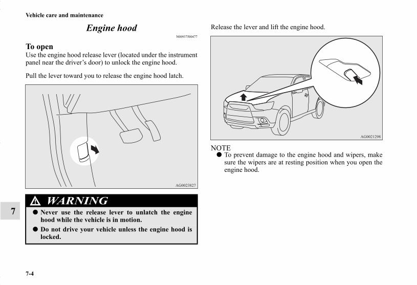
7-4
Vehicle care and maintenance
7
Engine hoodN00937500477
To openUse the engine hood release lever (located under the instrumentpanel near the driver’s door) to unlock the engine hood.
Pull the lever toward you to release the engine hood latch.
Release the lever and lift the engine hood.
NOTE● To prevent damage to the engine hood and wipers, make
sure the wipers are at resting position when you open theengine hood.
WARNING!
● Never use the release lever to unlatch the enginehood while the vehicle is in motion.
● Do not drive your vehicle unless the engine hood islocked.
BK0150700US.book 4 ページ 2012年3月22日 木曜日 午後6時46分
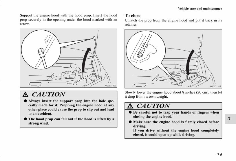
Vehicle care and maintenance
7-5
7
Support the engine hood with the hood prop. Insert the hoodprop securely in the opening under the hood marked with anarrow.
To closeUnlatch the prop from the engine hood and put it back in itsretainer.
Slowly lower the engine hood about 8 inches (20 cm), then letit drop from its own weight.CAUTION!
● Always insert the support prop into the hole spe-cially made for it. Propping the engine hood at anyother place could cause the prop to slip out and leadto an accident.
● The hood prop can fall out if the hood is lifted by astrong wind.
CAUTION!
● Be careful not to trap your hands or fingers whenclosing the engine hood.
● Make sure the engine hood is firmly closed beforedriving.If you drive without the engine hood completelyclosed, it could open up while driving.
BK0150700US.book 5 ページ 2012年3月22日 木曜日 午後6時46分

7-6
Vehicle care and maintenance
7
NOTE● If this does not close the engine hood properly, drop it
again from a slightly higher position.● Do not push down strongly on the engine hood. Depend-
ing on how strongly or where you push down, you couldcreate a dent in the vehicle body.
● If you drive with the engine hood left open, warning dis-play is displayed on the information screen in the multi-information display.
View of the engine compartmentN00937600625
Type 1 Type 2
1- Engine oil level dipstick2- Engine oil filler cap3- Air cleaner filter4- Brake fluid/Clutch fluid reservoir (if so equipped)5- Windshield and rear window washer fluid reservoir6- Engine coolant reserve tank7- Radiator cap8- Battery
BK0150700US.book 6 ページ 2012年3月22日 木曜日 午後6時46分
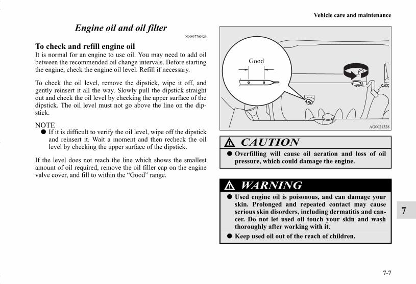
Vehicle care and maintenance
7-7
7
Engine oil and oil filterN00937700929
To check and refill engine oilIt is normal for an engine to use oil. You may need to add oilbetween the recommended oil change intervals. Before startingthe engine, check the engine oil level. Refill if necessary.
To check the oil level, remove the dipstick, wipe it off, andgently reinsert it all the way. Slowly pull the dipstick straightout and check the oil level by checking the upper surface of thedipstick. The oil level must not go above the line on the dip-stick.
NOTE● If it is difficult to verify the oil level, wipe off the dipstick
and reinsert it. Wait a moment and then recheck the oillevel by checking the upper surface of the dipstick.
If the level does not reach the line which shows the smallestamount of oil required, remove the oil filler cap on the enginevalve cover, and fill to within the “Good” range.
CAUTION!
● Overfilling will cause oil aeration and loss of oilpressure, which could damage the engine.
WARNING!
● Used engine oil is poisonous, and can damage yourskin. Prolonged and repeated contact may causeserious skin disorders, including dermatitis and can-cer. Do not let used oil touch your skin and washthoroughly after working with it.
● Keep used oil out of the reach of children.
Good
BK0150700US.book 7 ページ 2012年3月22日 木曜日 午後6時46分

7-8
Vehicle care and maintenance
7
NOTE● Engine oil consumption is greatly influenced by payload,
engine speed, etc.● The engine oil will deteriorate rapidly if the vehicle is
subjected to severe conditions (for example, repeatedoperation on rough roads, in mountainous regions, onroads with many uphill and downhill gradients, or overshort distances). Consequently, the oil will require earlierreplacement in accordance with the schedule in the“WARRANTY AND MAINTENANCE MANUAL”.
Engine oil identification markMitsubishi Motors recommends using only engine oils with theILSAC certification symbol on the front of the container.
ILSAC certification symbol
BK0150700US.book 8 ページ 2012年3月22日 木曜日 午後6時46分

Vehicle care and maintenance
7-9
7
If you cannot find oils with the ILSAC certification symbol,use an API classification SN or higher oil with the followinglabel.This mark appears on the top of the oil container and tells youtwo important things about the oil.
Recommended engine oil viscosityUse engine oil with the proper thickness for the outdoor tem-peratures where you will be driving.
SAE 0W-20 engine oil is strongly recommended for optimumfuel economy and cold starting.If SAE 0W-20 is not available, the ILSAC certification oil ofother viscosity grades can be temporarily used.
1- The upper part indicates the quality of the oil.2- The center part indicates the SAE grade of the oil viscosity.
API service symbol
BK0150700US.book 9 ページ 2012年3月22日 木曜日 午後6時46分
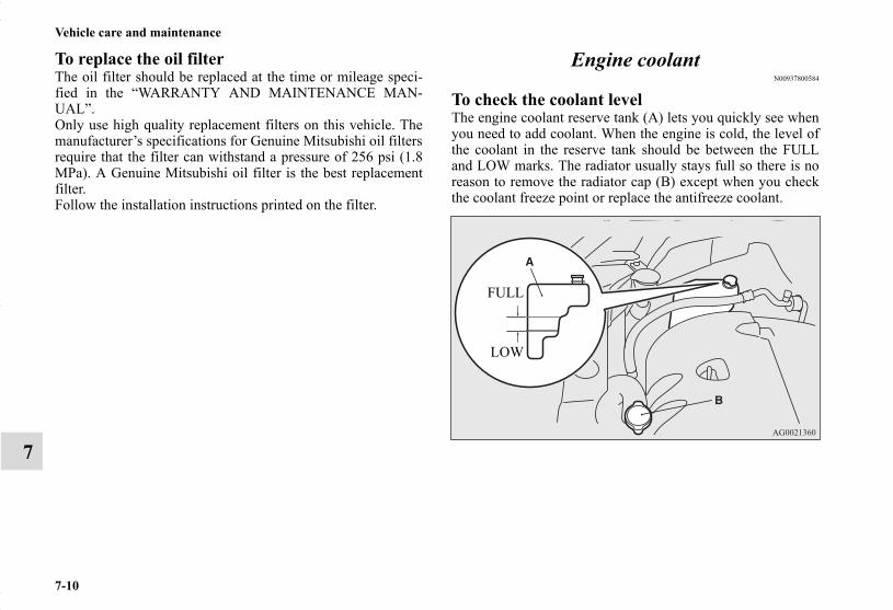
7-10
Vehicle care and maintenance
7
To replace the oil filterThe oil filter should be replaced at the time or mileage speci-fied in the “WARRANTY AND MAINTENANCE MAN-UAL”.Only use high quality replacement filters on this vehicle. Themanufacturer’s specifications for Genuine Mitsubishi oil filtersrequire that the filter can withstand a pressure of 256 psi (1.8MPa). A Genuine Mitsubishi oil filter is the best replacementfilter.Follow the installation instructions printed on the filter.
Engine coolantN00937800584
To check the coolant levelThe engine coolant reserve tank (A) lets you quickly see whenyou need to add coolant. When the engine is cold, the level ofthe coolant in the reserve tank should be between the FULLand LOW marks. The radiator usually stays full so there is noreason to remove the radiator cap (B) except when you checkthe coolant freeze point or replace the antifreeze coolant.
FULL
LOW
BK0150700US.book 10 ページ 2012年3月22日 木曜日 午後6時46分
Vehicle care and maintenance
7-11
7
To add coolant
Mitsubishi Motors Genuine Coolant provides excellent protec-tion against corrosion and rust formation on all metals, includ-ing aluminum, and prevents clogs in some parts of the engine.If you need to add coolant often, or if the level in the reservetank does not drop when the engine cools, the cooling systemshould be pressure-tested for leaks. Take your vehicle to anauthorized Mitsubishi Motors dealer or a repair facility of yourchoice for testing.
Radiator capThe radiator cap must be tight sealed to prevent losing coolant,which may result in engine damage. Only use a GenuineMitsubishi Parts radiator cap, or an approved equivalent.
Points to remember● Do not overfill the reserve tank.● Your vehicle uses a special radiator cap that stays sealed
and lets the coolant flow from the reserve tank back to theradiator when the engine cools down. If you need tochange the cap, use the exact same kind.
● Check the coolant freeze point in the radiator with theproper gauge, and only when it is safe. If you add anti-freeze, the contents of the reserve tank must be protectedagainst freezing.
Use “Mitsubishi Motors Genuine Super Long Life Coolant Pre-mium” or equivalent*.*: similar high quality ethylene glycol based non-silicate, non-
amine, non-nitrate and non-borate coolant with long lifehybrid organic acid technology
CAUTION!
● Do not use alcohol or methanol antifreeze or anyengine coolants that contain them. Using the wrongantifreeze can corrode aluminum parts.
● The required concentration of anti-freeze differsdepending on the expected ambient temperature.Above -31 °F (-35 °C) : 50 % concentration of anti-freezeBelow -31 °F (-35 °C) : 60 % concentration of anti-freezeYou can check the concentration level with a gaugefrom an automotive supply store, or your authorizedMitsubishi Motors dealer or service station cancheck it for you.
● Do not use water to adjust the concentration of cool-ant.
● Do not top off the tank with plain water only. Waterby itself boils at a lower temperature and does notstop rust or freezing. If the water freezes, it willdamage your cooling system. Do not use tapwater. Itcan cause corrosion and rust.
WARNING!
● Wait for the engine to cool down before opening theradiator cap. Otherwise hot steam or boiling coolantcould spray up from the radiator and scald you.
CAUTION!
BK0150700US.book 11 ページ 2012年3月22日 木曜日 午後6時46分

7-12
Vehicle care and maintenance
7
● Keep the front of the radiator and condenser clean.● If the engine coolant temperature does not rise after the
engine is warmed-up, take your vehicle to an authorizedMitsubishi Motors dealer or a repair facility of yourchoice to have the thermostat checked, and replaced ifnecessary.
Air cleaner filterN00937900400
The air cleaner filter will get dirty and dusty from use and notfilter properly. Replace it with a new filter using the schedulein the “WARRANTY AND MAINTENANCE MANUAL”.
1. Remove the upper cover and duct. For details, refer to“Removing and installing the upper cover and duct” onpage 7-14.
2. While holding down the tab (A), pull out the connector(B).
BK0150700US.book 12 ページ 2012年3月22日 木曜日 午後6時46分

Vehicle care and maintenance
7-13
7
3. Unclamp the cover. Open up the top of the cover and takeout the air cleaner filter.
4. Replacing the air cleaner filter and put the cover back onin its original position.
NOTE● Genuine Mitsubishi Motors Parts are recommended when
replacing the air cleaner filter.● Make sure that the connector is properly reconnected.● After replacing the air cleaner filter, make sure that the
hinges at the bottom of cover are firmly set.
Type 1
Type 2
CAUTION!
● Take care not to scratch the engine air flow sensorwhen removing the air cleaner cover.
BK0150700US.book 13 ページ 2012年3月22日 木曜日 午後6時46分

7-14
Vehicle care and maintenance
7
5. Put the duct and upper cover back on in its original posi-tion. For details, refer to “Removing and installing theupper cover and duct” on page 7-14.
Removing and installing the upper cover and ductTo replace the air cleaner filter, remove the upper cover andduct.
To remove1. Remove the clips (A), and then remove the upper cover
(B).
WARNING!
● Turn the ignition switch to the “OFF” position orput the operation mode in OFF.Make sure that your clothes cannot be caught by thefan or drive belt. Personal injury could result.
BK0150700US.book 14 ページ 2012年3月22日 木曜日 午後6時46分
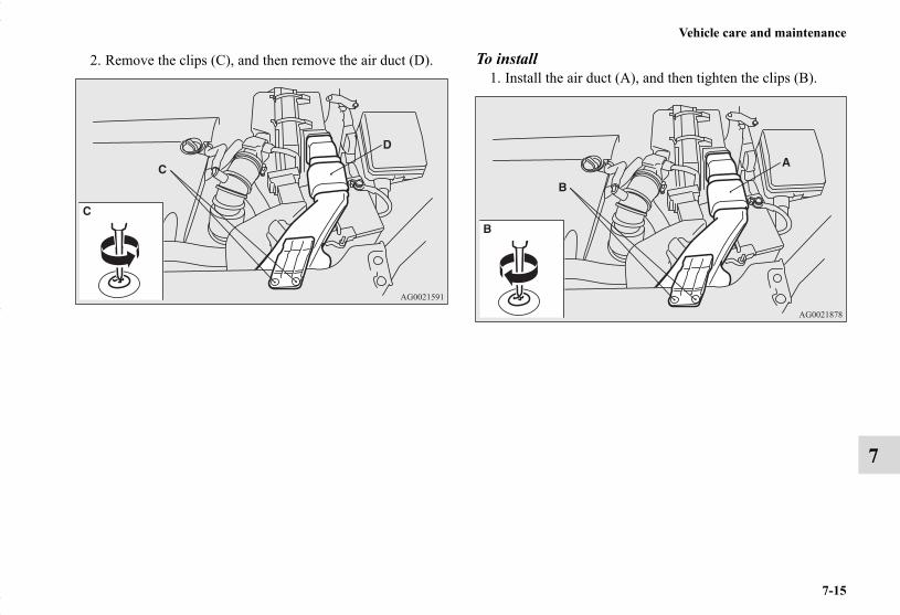
Vehicle care and maintenance
7-15
7
2. Remove the clips (C), and then remove the air duct (D). To install1. Install the air duct (A), and then tighten the clips (B).
BK0150700US.book 15 ページ 2012年3月22日 木曜日 午後6時46分

7-16
Vehicle care and maintenance
7
2. Turn the upper cover over. Squeeze the head of the mould-ing clip (C) with pliers and remove the moulding.
3. Install the upper cover, and then attach the moulding (D).
NOTE● Attach the moulding with the wide part toward the front of
the vehicle.
BK0150700US.book 16 ページ 2012年3月22日 木曜日 午後6時46分

Vehicle care and maintenance
7-17
7
4. Install the clips (E). Manual transaxle oil (if so equipped)N00938200178
Whenever the manual transaxle oil level is checked, add oil tomaintain the proper level, if necessary.Refill or change the oil according to the table.
Oil type
LubricantMitsubishi Motors Genuine NEW
MULTI GEAR OIL API Classifica-tion GL-3
Viscosity range SAE 75W-80
BK0150700US.book 17 ページ 2012年3月22日 木曜日 午後6時46分

7-18
Vehicle care and maintenance
7
Continuously variable transmission (CVT) fluid (if so equipped)
N00938100089
The continuously variable transmission (CVT) should be main-tained and serviced by an authorized Mitsubishi Motors dealeror a repair facility of your choice to obtain the best perfor-mance and longest life. It is important that the transmissionfluid is kept at the correct level.
Fluid typeUse only “Mitsubishi Motors Genuine CVTF-J4” transmissionfluid to ensure optimum transmission performance.
Special additivesDo not use any fluid additives to the transmission.
Transfer oil (All-wheel drive models)N00938400271
Whenever the transfer oil level is checked, add oil as necessaryto maintain the proper level. Fill or change the oil according tothe table.
Fluid type
Lubricant Mitsubishi Motors Genuine Super Hypoid Gear Oil API classification GL-5
Viscosity range SAE 80
BK0150700US.book 18 ページ 2012年3月22日 木曜日 午後6時46分

Vehicle care and maintenance
7-19
7
Rear axle oil (All-wheel drive models)N00915200269
Whenever the oil level is checked, add oil as necessary tomaintain the proper level.Fill or change oil according to the table.
Fluid type
Washer fluidN00938600299
The windshield and rear window washer fluid reservoir is inthe engine compartment.Check the washer fluid level at regular intervals and addwasher fluid to reservoir if necessary.Open the reservoir cap and check the fluid level with the dip-stick.
When freezing weather is anticipated, flush out the water in thereservoir by operating the pump. Fill the reservoir with wind-shield antifreeze (not radiator antifreeze), and operate the sys-tem for a few seconds to flush out the residual water.
Lubricant Mitsubishi Motors Genuine Super Hypoid Gear Oil API classification GL-5
Viscosity range SAE 80
FULL EMPTY
BK0150700US.book 19 ページ 2012年3月22日 木曜日 午後6時46分
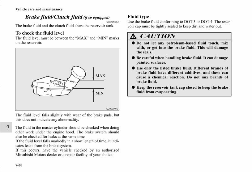
7-20
Vehicle care and maintenance
7
Brake fluid/Clutch fluid (if so equipped)N00938700245
The brake fluid and the clutch fluid share the reservoir tank.
To check the fluid levelThe fluid level must be between the “MAX” and “MIN” markson the reservoir.
The fluid level falls slightly with wear of the brake pads, butthis does not indicate any abnormality.
The fluid in the master cylinder should be checked when doingother work under the engine hood. The brake system shouldalso be checked for leaks at the same time.If the fluid level falls markedly in a short length of time, it indi-cates leaks from the brake system.If this occurs, have the vehicle checked by an authorizedMitsubishi Motors dealer or a repair facility of your choice.
Fluid typeUse the brake fluid conforming to DOT 3 or DOT 4. The reser-voir cap must be tightly sealed to keep dirt and water out.
MAX
MIN
CAUTION!
● Do not let any petroleum-based fluid touch, mixwith, or get into the brake fluid. This will damagethe seals.
● Be careful when handling brake fluid. It can damagepainted surfaces.
● Use only the listed brake fluid. Different brands ofbrake fluid have different additives, and these cancause a chemical reaction. Do not mix brands ofbrake fluid.
● Keep the reservoir tank cap closed to keep the brakefluid from evaporating.
BK0150700US.book 20 ページ 2012年3月22日 木曜日 午後6時46分

Vehicle care and maintenance
7-21
7
BatteryN00939100930
The condition of the battery is very important for quick startingand to keep the vehicle’s electrical system working properly.Check the battery regularly.
If battery performance is suspect, have the battery and chargingsystem tested by an authorized Mitsubishi Motors dealer or arepair facility of your choice.
NOTE● After replacing the battery, the electronic control system
data for the automatic transaxle, etc., will be erased.As a result, shifting may be rough.Shifting will become smoother after several changes inspeed.
During cold weatherN00901600031
The battery is weaker in cold temperatures. This has to do withits chemical and physical properties and is why a very cold bat-tery, especially one with a low charge, will have a hard timestarting your vehicle.It is recommended that you have your battery and charging sys-tem checked by an authorized Mitsubishi Motors dealer or arepair facility of your choice before the start of cold weather. Ifnecessary, have it charged. This will guarantee more reliablestarting, and longer battery life.
Disconnection and connectionN00901700074
To disconnect the battery cable, stop the engine. Disconnect thenegative (-) terminal first, then the positive (+) terminal. Toreconnect the battery, first connect the positive (+) terminal andthen the negative (-) terminal, before starting the vehicle.
NOTE● Open the terminal cover (A) before disconnecting or con-
necting the positive (+) terminal of the battery.● Loosen the nut (B) and then disconnect the battery cable
from the positive (+) terminal.
BK0150700US.book 21 ページ 2012年3月22日 木曜日 午後6時46分

7-22
Vehicle care and maintenance
7
NOTE● Check each battery terminal for corrosion. You can stop
more corrosion by washing with a solution of baking sodaand water. Grease the posts and clamps after cleaning ortightening them.
● Check to see that the battery is securely installed and can-not be moved. Also check each terminal for tightness.
● If you will not be driving your vehicle for a long period oftime, remove the battery and store it in a place where thebattery fluid will not freeze. The battery only should bestored with a full charge.
● Before cleaning the battery, tighten all the filler port capsto keep dirt and moisture out.
WARNING!
● Never disconnect the battery while the engine is run-ning, or you could damage the vehicle’s electricalparts.
● Never short-circuit the battery. This could cause itto overheat and be damaged.
● Keep sparks, cigarettes, and flames away from thebattery because the battery could explode.
● Electrolyte (battery acid) is made of corrosivediluted sulfuric acid. If it spills on nearby parts, itcan crack, stain, or discolor them. And if it gets onyour skin or in your eyes, it can cause burns orblindness. Please observe the following handlinginstructions:• If electrolyte gets on plastic parts or other nearby
parts, wipe it off with a soft cloth or chamoissoaked in a solution of water and neutral detergentthen immediately rinse the affected parts withplenty of water.
• If electrolyte gets on your hands or clothes, rinsethoroughly with water. If electrolyte gets in youreyes, flush them with water immediately and getimmediate medical attention.
● Open doors and windows in any closed space whereyou may be charging or working with the battery.
● Always wear protective clothing and goggles whenworking with the battery, or have a skilled automo-bile technician do it.
● If you are quick-charging your battery, first discon-nect the battery cables.
● In order to prevent a short-circuit, be sure to discon-nect the negative (-) terminal first, and reconnect itlast.
● Battery posts, terminals and related accessories con-tain lead and lead compounds. Wash hands afterhandling.
WARNING!
BK0150700US.book 22 ページ 2012年3月22日 木曜日 午後6時46分

Vehicle care and maintenance
7-23
7
TiresN00939200494
It is important to familiarize yourself with the following terms:● Cold tire pressure:
• The measured pressure after the vehicle has been parkedfor at least three hours,or
• The measured pressure when the vehicle is driven lessthan 1 mile (1.6 km) after having been parked for threehours.
● Maximum pressure: the maximum permissible cold tireinflation pressure for this tire.
● Recommended inflation pressure: the inflation pressurefor optimum tire performance.
● Intended outboard sidewall:• The sidewall that contains a whitewall, bears white let-
tering or bears manufacturer, brand, and/or model namemolding that is higher or deeper than the same moldingon the other sidewall of the tire, or
• The outward facing sidewall of an asymmetrical tire thathas a particular side that must always face outwardwhen mounted on a vehicle.
● Passenger car tire: a tire intended for use on passengercars, multipurpose passenger vehicles, and trucks, thathave a gross vehicle weight rating (GVWR) of 10,000pounds or less.
● Light truck (LT) tire: a tire designated by its manufactureras primarily intended for use on lightweight trucks or mul-tipurpose passenger vehicles.
● Tread: portion of a tire that comes into contact with theroad.
● Tread rib: a tread section running circumferentiallyaround a tire.
● Tread separation: pulling away of the tread from the tirecarcass.
● Carcass: the tire structure, except tread and sidewall rub-ber which, when inflated, bears the load.
● Sidewall: portion of a tire between the tread and bead.● Section width: the linear distance between the exteriors of
the sidewalls of an inflated tire, excluding elevations dueto labeling, decoration, or protective bands.
● Bead: the part of the tire that is made of steel wires,wrapped or reinforced by ply cords and that is shaped tofit the rim.
● Ply: a layer of rubber-coated parallel cords.● Cord: the strands forming the plies in the tire.
WARNING!
● Driving with tires that are worn, damaged orimproperly inflated is dangerous.These type tire conditions will adversely affect vehi-cle performance.These type tire conditions can also cause a tread sep-aration or blowout which may result in an accidentcausing serious injury or death.
● Tires, including spare tire, degrade over time withage even when they are not being used.It is recommended that tires over 6 years generallybe replaced even if damage is not obvious.
BK0150700US.book 23 ページ 2012年3月22日 木曜日 午後6時46分

7-24
Vehicle care and maintenance
7
● Rim: a metal support for a tire or a tire and tube assemblyupon which the tire beads are seated.
● Rim diameter: nominal diameter of the bead seat.● Groove: the space between two adjacent tread ribs.
Tire Markings
Size Designation
EXAMPLE: P215/65R15
NOTE● European/Japanese metric tire sizing is based on Euro-
pean/Japanese design standards. Tires designed to thesestandards have the tire size molded into the sidewallbeginning with the section width. The letter “P” isabsent from this tire size designation. Example:215/65R15 96H.
● LT (Light Truck) -metric tire sizing is based on U.S.A.design standards. The size designation for LT-metrictires is the same as for P-metric tires except for the let-ters “LT” that are molded into the sidewall precedingthe size designation. Example: LT235/85R16.
P Passenger car tire size based on U.S.A. design standards
215 Section width in millimeters (mm)
65 Aspect ratio in percent (%)Ratio of section height to section width of tire.
RConstruction code • “R” means radial construction. • “D” means diagonal or bias construction.
15 Rim diameter in inches (in)
BK0150700US.book 24 ページ 2012年3月22日 木曜日 午後6時46分

Vehicle care and maintenance
7-25
7
● Temporary spare tires are high pressure compact sparesdesigned for temporary emergency use only. Tiresdesigned to this standard have the letter “T” moldedinto the sidewall preceding the size designation. Exam-ple: T145/80D18 103M.
Service Description
EXAMPLE: 95H
Maximum LoadMaximum load indicates the maximum load this tire isdesigned to carry.
Maximum PressureMaximum Pressure indicates the maximum permissiblecold tire inflation pressure for this tire.
95Load indexA numerical code associated with the maximum load a tire can carry.
H
Speed symbolA symbol indicating the range of speeds at which a tire can carry a load corresponding to its load index under certain operating conditions.The maximum speed corresponding to the speed symbol should only be achieved under specified operating conditions. (i.e. tire pressure, vehicle loading, road conditions and posted speed lim-its)
WARNING!
● Overloading of your tire is dangerous. Overload-ing can cause tire failure, affect vehicle handling,and increase your stopping distance. Use tires ofthe recommended load capacity for your vehicle.Never overload them.
BK0150700US.book 25 ページ 2012年3月22日 木曜日 午後6時46分
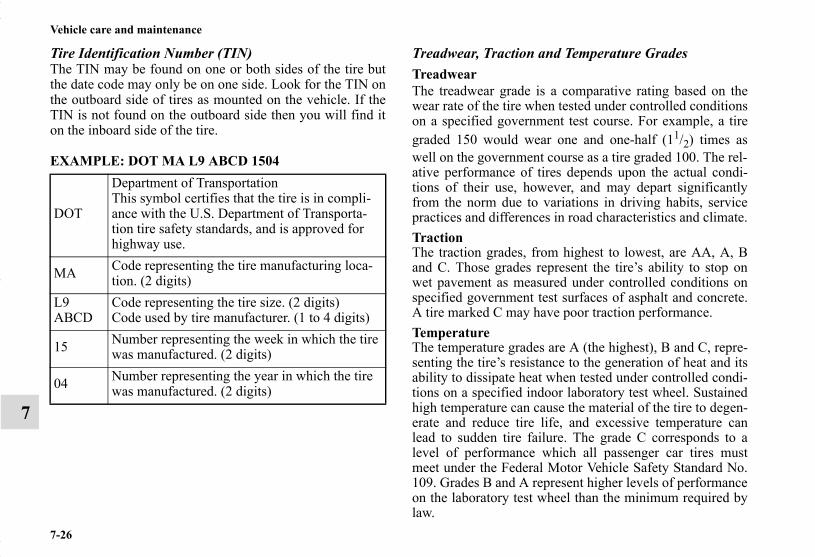
7-26
Vehicle care and maintenance
7
Tire Identification Number (TIN)The TIN may be found on one or both sides of the tire butthe date code may only be on one side. Look for the TIN onthe outboard side of tires as mounted on the vehicle. If theTIN is not found on the outboard side then you will find iton the inboard side of the tire.
EXAMPLE: DOT MA L9 ABCD 1504
Treadwear, Traction and Temperature GradesTreadwearThe treadwear grade is a comparative rating based on thewear rate of the tire when tested under controlled conditionson a specified government test course. For example, a tiregraded 150 would wear one and one-half (11/2) times aswell on the government course as a tire graded 100. The rel-ative performance of tires depends upon the actual condi-tions of their use, however, and may depart significantlyfrom the norm due to variations in driving habits, servicepractices and differences in road characteristics and climate.TractionThe traction grades, from highest to lowest, are AA, A, Band C. Those grades represent the tire’s ability to stop onwet pavement as measured under controlled conditions onspecified government test surfaces of asphalt and concrete.A tire marked C may have poor traction performance.TemperatureThe temperature grades are A (the highest), B and C, repre-senting the tire’s resistance to the generation of heat and itsability to dissipate heat when tested under controlled condi-tions on a specified indoor laboratory test wheel. Sustainedhigh temperature can cause the material of the tire to degen-erate and reduce tire life, and excessive temperature canlead to sudden tire failure. The grade C corresponds to alevel of performance which all passenger car tires mustmeet under the Federal Motor Vehicle Safety Standard No.109. Grades B and A represent higher levels of performanceon the laboratory test wheel than the minimum required bylaw.
DOT
Department of TransportationThis symbol certifies that the tire is in compli-ance with the U.S. Department of Transporta-tion tire safety standards, and is approved for highway use.
MA Code representing the tire manufacturing loca-tion. (2 digits)
L9ABCD
Code representing the tire size. (2 digits)Code used by tire manufacturer. (1 to 4 digits)
15 Number representing the week in which the tire was manufactured. (2 digits)
04 Number representing the year in which the tire was manufactured. (2 digits)
BK0150700US.book 26 ページ 2012年3月22日 木曜日 午後6時46分

Vehicle care and maintenance
7-27
7
Tire inflation pressuresN00939300899
Proper tire inflation pressure is essential for the safe and satis-factory operation of your vehicle. The wrong tire pressure willcause problems in three major areas:
● SafetyToo little pressure increases flexing in the tire and cancause tire failure. Too much pressure can cause a tire tolose its ability to cushion shock. Objects on the road andpotholes could then cause tire damage that may result intire failure.
● EconomyThe wrong tire pressure can cause uneven wear patterns inthe tire tread. These abnormal wear patterns will reducethe tread life, and the tire will have to be replaced sooner.Too little pressure also makes it harder for the tire to roll,and this uses up more fuel.
● Ride comfort and vehicle stabilityThe superior riding experience built into your vehiclepartly depends on the correct tire pressure. Too muchpressure gives an uncomfortable and jarring ride. Too lit-tle pressure feels as if your vehicle is slow to respond.Unequal tire pressures can make steering your vehicleuneven and unpredictable.
The tire pressure for your vehicle under normal driving condi-tions is listed on the placard attached to the driver’s door sill.(Refer to “Tire and loading information placard” on page 9-4.)
The recommended inflation pressures under normal drivingconditions should be used for the tires listed below.
Tire pressures should be checked, and adjusted if necessary, atleast once a month.Pressures should be checked more often whenever weathertemperatures change severely, because tire pressures changewith outdoor temperatures. The pressures listed are always“cold inflation pressure”.Cold inflation pressure is measured after the vehicle has beenparked for at least three hours or is driven less than 1 mile (1.6km) after having been parked for three hours.Cold inflation pressure must not go above the maximum valuesmolded into the tire sidewall. After driving several miles, yourtire inflation pressure may increase 2 to 6 psi (14 to 41 kPa)from the cold inflation pressure. Do not let air out of the tires toget back to the specified cold pressure, or your tires will be toolow.
Item Tire size Front Rear
Normal tireP215/70R16 240 kPa,
35 psi240 kPa,
35 psi
P225/55R18 230 kPa, 33 psi
230 kPa, 33 psi
Compact spare wheel T155/90D16 420 kPa, 60 psi
BK0150700US.book 27 ページ 2012年3月22日 木曜日 午後6時46分

7-28
Vehicle care and maintenance
7
Check your tires each time you refuel. If one tire looks lowerthan the others, check the pressure for all of them.You should also take the following safety precautions:
● Keep your tires inflated to the recommended pressures.(See the tire and loading information placard attached tothe driver’s door sill.)
● Stay within the recommended load limits.● Make sure that the weight of any load in your vehicle is
evenly distributed.● Drive at safe speeds.● After filling your tires to the correct pressure, check them
for damage and air leaks. Be sure to reinstall the caps onthe valve stems.
Replacing tires and wheelsN00939600241
CAUTION!
● Avoid using different size tires from the one listedand the combined use of different types of tires, asthis can affect driving safety.Refer to “Tires and wheels” on page 9-8.
● On all-wheel drive vehicles, always use tires of thesame size, same type, and same brand, and whichhave no wear differences. Using tires that differ insize, type, brand or the degree of wear, will increasethe differential oil temperature, resulting in possibledamage to the driving system. Further, the drivetrain will be subjected to excessive loading, possiblyleading to oil leakage, component seizure, or otherserious problems.
● Only Mitsubishi Motors Authorized wheels shouldbe used, because your vehicle is equipped with a tirepressure monitoring system.Use of another type of wheel risks air leaks and sen-sor damage, as it will not be possible to install thetire pressure sensor properly.
BK0150700US.book 28 ページ 2012年3月22日 木曜日 午後6時46分
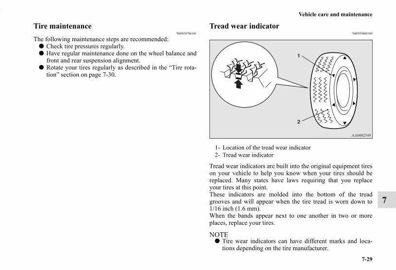
Vehicle care and maintenance
7-29
7
Tire maintenanceN00939700141
The following maintenance steps are recommended:● Check tire pressures regularly.● Have regular maintenance done on the wheel balance and
front and rear suspension alignment.● Rotate your tires regularly as described in the “Tire rota-
tion” section on page 7-30.
Tread wear indicatorN00939800184
Tread wear indicators are built into the original equipment tireson your vehicle to help you know when your tires should bereplaced. Many states have laws requiring that you replaceyour tires at this point.These indicators are molded into the bottom of the treadgrooves and will appear when the tire tread is worn down to1/16 inch (1.6 mm).When the bands appear next to one another in two or moreplaces, replace your tires.
NOTE● Tire wear indicators can have different marks and loca-
tions depending on the tire manufacturer.
1- Location of the tread wear indicator2- Tread wear indicator
BK0150700US.book 29 ページ 2012年3月22日 木曜日 午後6時46分

7-30
Vehicle care and maintenance
7
Tire rotationN00939900488
To even out the wear on your tires and make them last longer,Mitsubishi Motors Corporation recommends that you rotateyour tires at the mileage listed in the “WARRANTY ANDMAINTENANCE MANUAL”.However, the timing for tire rotation may vary according toyour vehicle condition, road surface conditions, and your ownpersonal driving habits. Any time you notice unusual wear,rotate your tires as soon as possible.
When rotating tires, check for uneven wear, damage, and wheelalignment. Abnormal wear is usually caused by a wrong tirepressure, wheels that are not aligned properly, wheels that areout-of-balance, or severe braking.Check with an authorized Mitsubishi Motors dealer or a repairfacility of your choice to find out the reason for uneven treadwear.
The first tire rotation is the most important one. It will allow allyour tires to wear evenly.
CAUTION!
● A compact spare tire can be installed temporarily inplace of a tire that has been removed during the tirerotation. However, it must not be included in theregular tire rotation sequence.
Tires that do not have arrows showing rotation direction
Tires that have arrows showing rotation direction
Front
Front
BK0150700US.book 30 ページ 2012年3月22日 木曜日 午後6時46分

Vehicle care and maintenance
7-31
7
CAUTION!
● If the tires have arrows (A) indicating the correctdirection of rotation, swap the front and rear tireson the left-hand side of the vehicle and the front andrear tires on the right-hand side of the vehicle sepa-rately. Keep each tire on its original side of the vehi-cle. When installing the tires, make sure the arrowspoint in the direction in which the wheels will turnwhen the vehicle moves forward. Any tire whosearrow points in the wrong direction will not performto its full potential.
Front
CAUTION!
● Avoid the combined use of different types of tires.Using different types of tires can affect vehicle per-formance and safety.
BK0150700US.book 31 ページ 2012年3月22日 木曜日 午後6時46分

7-32
Vehicle care and maintenance
7
Snow tiresN00940000320
In some areas of the country, snow tires are required for winterdriving. If snow tires are required in your area, you mustchoose snow tires of the same size and type as the original tiresprovided with your vehicle. Snow tires should also be installedon all four wheels. Otherwise your safety and vehicle handlingcan be reduced.Even where laws may permit it, snow tires should not be oper-ated at sustained speeds over 75 mph (120 km/h).
Tire chainsN00940100116
Clutch pedal free play (if so equipped)N00940200074
To check the clutch pedal free play (A), turn off the engine andpress the pedal until you feel resistance.
Clutch pedal free play:.2 to .4 inch (4 to 9 mm)
CAUTION!
● Only Mitsubishi Motors Authorized wheels shouldbe used, because your vehicle is equipped with a tirepressure monitoring system.Use of another type of wheel risks air leaks and sen-sor damage, as it will not be possible to install thetire pressure sensor properly.
CAUTION!
● Tire chains cannot be used on your vehicle. Theclearance between the chains and the body is notsufficient to allow proper clearance, and the vehiclebody might be damaged.
BK0150700US.book 32 ページ 2012年3月22日 木曜日 午後6時46分

Vehicle care and maintenance
7-33
7
Brake pedal free playN00940300323
To check the brake pedal free play (A), turn off the engine andpress the brake pedal several times with your foot. Then pressthe pedal down with your fingers until you first feel resistance.
Brake pedal free play:.1 to .3 inch (3 to 8 mm)
If the free play is not within these limits, take your vehicle toan authorized Mitsubishi Motors dealer or a repair facility ofyour choice for adjustment.
Parking brakeN00940400249
Parking brake lever strokeCheck the parking brake lever travel occasionally. To checkthis, pull the lever up slowly and count the number of clicks ofthe ratchet. You should feel the parking brake grab between 6to 7 notches (clicks).Also check to see if the lever stays gripped by the ratchet afterpulling.
WARNING!
● Continued operation of the vehicle with the parkingbrake lever out of adjustment may result in the vehi-cle moving when unattended.
BK0150700US.book 33 ページ 2012年3月22日 木曜日 午後6時46分

7-34
Vehicle care and maintenance
7
Wiper bladesN00940700138
Check the wiper blades occasionally. Clean them regularly toremove deposits of salt and road film. Use a sponge or clothand a mild detergent or non-abrasive cleaner to clean the bladesand glass areas.Replace the blades if they continue to streak or smear.
NOTE● Do not run the wipers on dry glass for a long time. This
wears out the rubber and can scratch the glass.
During cold weatherIf the blades are frozen to the windshield or rear window, donot operate the wipers until the ice has melted and the bladesare freed, otherwise the wiper motor may be damaged.
Emission-control system maintenanceN00940800328
Your vehicle is equipped with an emission-control system thatmeets all the requirements of the U.S. Environmental Protec-tion Agency and Environment Canada. The emission-controlsystem is made of:
● a positive crankcase ventilation system● an evaporative emission-control system● an exhaust emission-control system
To be sure the emission-control system works properly, haveyour vehicle inspected and maintained by an authorizedMitsubishi Motors dealer or a repair facility of your choice.This should be done at the time or mileage specified in the“WARRANTY AND MAINTENANCE MANUAL”.These, and all the other “general” maintenance services listedin this manual, need to be performed to keep your vehicle run-ning properly and reliably.You should also have an inspection and service any time yoususpect a malfunction.
NOTE● To meet government regulations and promote cleaner air,
your vehicle is equipped with an onboard diagnostic sys-tem (OBD). The engine electronic control module thatcontrols OBD functions stores various data (especiallyabout the exhaust emissions). This data will be erased ifthe battery cable is disconnected, which could make arapid diagnosis difficult. Do not disconnect the batterycable when the engine malfunction indicator (“SERVICEENGINE SOON” or “Check engine light”) is ON.
BK0150700US.book 34 ページ 2012年3月22日 木曜日 午後6時46分

Vehicle care and maintenance
7-35
7
Spark plugsN00940900228
Spark plugs must fire properly for good engine performanceand emission-control.Do not reuse them by cleaning or regapping. Change them atthe mileage listed in the “WARRANTY AND MAINTE-NANCE MANUAL”.
NOTE● Use the spark plugs listed under “Engine specifications”
on page 9-7 or plugs that are exactly the same. Otherplugs could cause engine damage, performance problemsor radio noise.
Fuel hosesN00941000040
Check the hose surfaces for any heat and mechanical damage,hard and brittle rubber, cracking, tears, cuts and abrasions. Payspecial attention to the hoses closest to high heat sources suchas the exhaust manifold. Check all the hose connections, suchas clamps and couplings, to make sure they are secure and thatthere are no leaks. If you see any wear or damage, replace thehoses immediately.
Intake valve clearanceN00950100050
Have the valve clearance checked at an authorized MitsubishiMotors dealer at the mileage specified in the “WARRANTYAND MAINTENANCE MANUAL”.If the engine sounds abnormally loud, have adjustments madeby an authorized Mitsubishi Motors dealer.
Fuel system (tank, pipe line and connection, and fuel tank filler cap)
N00941300173
Check these regularly for damage or leaks in the fuel lines andconnections. Check the fuel tank filler cap for damage or loose-ness. Pay special attention to the fuel lines closest to high heatsources such as the exhaust manifold.
WARNING!
● If you see a fuel leak or if you smell fuel, do not runthe engine. Any spark (including from the ignition),flame or smoking material could cause an explosionor fire. Call an authorized Mitsubishi Motors dealeror a repair facility of your choice for assistance.
BK0150700US.book 35 ページ 2012年3月22日 木曜日 午後6時46分

7-36
Vehicle care and maintenance
7
Evaporative emission control system (except evaporative emission canister)
N00941400187
If the fuel-vapor vent line is clogged or damaged, the fuel-vapor mixture will escape, polluting the air.Have the system checked at an authorized Mitsubishi Motorsdealer at the mileage specified in the “WARRANTY ANDMAINTENANCE MANUAL”.
General maintenanceN00941500247
The next pages list the maintenance service recommended byMitsubishi Motors Corporation. In addition to the generalmaintenance that needs to be performed at the times listed,there are other parts which do not usually need regular mainte-nance.But, if any of these parts stops working properly, your vehicleperformance could suffer. Have these items checked if younotice a problem with them.
See your authorized Mitsubishi Motors dealer for assistance, ifyou have any questions.
Disc brake padsN00941600059
Good brakes are essential for safe driving. Check the brakepads for wear. For good braking performance, replace the brakepads with the same type pads as the originals.
Brake hosesN00941700076
Brake hoses and tubing should be checked for:● Severe surface cracking, scuffing or worn spots. If the
fabric casing of the hose is showing through any cracks orworn spots in the rubber hose cover, the hose should bereplaced. The brakes can fail if the hose wears through.
● Improper installation may cause twisting, or wheel, tire orchassis interference.
BK0150700US.book 36 ページ 2012年3月22日 木曜日 午後6時46分

Vehicle care and maintenance
7-37
7
Ball joint, steering linkage seals and drive shaft boots
N00941800077
Check the following parts for damage and grease leaks:● Ball joint boots of the front suspension and steering link-
age● Bellows on both ends of the drive shaft
Exhaust systemN00942200094
The best way to keep carbon monoxide gas from enteringinside your vehicle is to have the engine exhaust system prop-erly serviced.Have a competent mechanic inspect the complete exhaust sys-tem and nearby body areas for broken, damaged, deteriorated,or mispositioned parts if you notice any of the following:
● A change in the sound of the exhaust system● The smell of exhaust fumes inside the vehicle● The underside or rear of the vehicle is damaged
Also check the exhaust system each time the vehicle is raisedfor lubrication, oil changes, or required service. Any openseams or loose connections could let dangerous exhaust fumesseep into the luggage compartment and passenger compart-ments.
Check for any of the following conditions:● Check for holes or exhaust gas leaks caused by corrosion
or damage.● Check the joints and connections for looseness or exhaust
gas leaks.● Check the rubber hangers and brackets for damage.
WARNING!
● Carbon monoxide gas from your vehicle’s exhaust ispoisonous. Breathing these fumes can cause uncon-sciousness or death.
BK0150700US.book 37 ページ 2012年3月22日 木曜日 午後6時46分
7-38
Vehicle care and maintenance
7
Hood lock release mechanism and safety catchN00942500101
The hood lock release mechanism and hood safety catch shouldbe checked, cleaned, and oiled when needed for easy move-ment and to stop rust and wear. Use Multipurpose GreaseNLGI Grade 2 sparingly for all sliding parts of the hood latchand release lever. Work the grease into the hood lock mecha-nism until all the movable surfaces are covered.Also, put a light coat of the same grease on the safety catchwherever moving parts touch.
For cold and snowy weatherN00942600102
Ventilation slotsThe ventilation slots in front of the windshield should bebrushed clear after a heavy snowfall so that the operation of theheating and ventilation systems will not be impaired.
WeatherstrippingTo prevent freezing of the weatherstripping on the doors,engine hood, etc., they should be treated with silicone grease.
Additional equipment (For regions where snow is encountered)It is a good idea to carry a shovel or a short-handled spade inthe vehicle during the winter so that you can clear away snowif you get stranded. A small hand-brush for sweeping snow offthe vehicle and a plastic scraper for the windshield, side andrear window are also useful.
BK0150700US.book 38 ページ 2012年3月22日 木曜日 午後6時46分

Vehicle care and maintenance
7-39
7
Fusible linksN00942700305
The fusible links will melt to prevent a fire if a large currentattempts to flow through certain electrical systems.In case of a melted fusible link, see your authorized MitsubishiMotors dealer or a repair facility of your choice for inspectionand replacement.For the fusible links, please refer to “Fuse load capacities” onpage 7-41.
FusesN00942800856
Fuse block locationTo prevent damage to the electrical system from short-circuit-ing or overloading, each individual circuit is equipped with afuse. The fuse blocks are located in the passenger compartmentand in the engine compartment.
Passenger compartment
The fuse blocks in the passenger compartment are locatedbehind the fuse lid.
WARNING!
● Fusible links must not be replaced by any otherdevice. Failing to fit the correct fusible link mayresult in fire in the vehicle, property destruction andserious or fatal injuries at any time.
A- Main fuse blockB- Sub fuse block
BK0150700US.book 39 ページ 2012年3月22日 木曜日 午後6時46分

7-40
Vehicle care and maintenance
7
Main fuse block1. Insert a screwdriver into the notch of the fuse lid and pry
gently to remove it.
2. To put back the fuse lid, line up the fuse lid hook (A) withthe clamp (B) on the instrument panel and push the lidback in.
BK0150700US.book 40 ページ 2012年3月22日 木曜日 午後6時46分

Vehicle care and maintenance
7-41
7
Engine compartment
In the engine compartment, the fuse block is located as shownin the illustration.
Fuse load capacitiesN00954800172
This fuse list shows the names of the electrical systems andtheir fuse capacities.There are spare fuses in the fuse block cover in the enginecompartment. Always replace a blown fuse with one of thesame capacity as the original.
Passenger compartment fuse location table
1- Push the lock lever.2- Remove the fuse block cover.
Passenger compartment fuse location
Sub fuse blockMain fuse block
BK0150700US.book 41 ページ 2012年3月22日 木曜日 午後6時46分

7-42
Vehicle care and maintenance
7
*: Fusible link● Some fuses may not be installed on your vehicle, depend-
ing on the vehicle model or specifications.● The table above shows the main equipment corresponding
to each fuse.
No. Symbol Electrical system Capacity
1 Heater 30 A*
2 Stop lights(Brake lights) 15 A
3 Rear fog light 10 A
4 Windshield wiper 30 A
5 Optional 10 A
6 Door locks 20 A
7 Radio 15 A
8 Control unit relay 7.5 A
9 Interior lights(Dome lights) 15 A
10 Hazard warning flasher 15 A
11 Rear window wiper 15 A
12 Gauges 7.5 A
13 Cigarette lighter/Accessory socket 15 A
14 IgnitionSwitch 10 A
15 Sunroof 20 A
16 Outside rearview mirrors 10 A
17 All-wheel drive system 10 A
18 Back-up lights 7.5 A
19 Accessory socket 15 A
20 Power window control 30 A*
21 Defogger 30 A*
22 Heated door mirror 7.5 A
23 Passenger’s power seat 25 (20) A
24 Driver’s power seat 25 (20) A
25 Heated seats 30 A
No. Symbol Electrical system Capacity
BK0150700US.book 42 ページ 2012年3月22日 木曜日 午後6時46分

Vehicle care and maintenance
7-43
7
Engine compartment fuse location table
Engine compartment fuse location
Behind the fuse block cover
No. Symbol Electrical system Capacity
1 Front fog lights 15 A
2 Engine 7.5 A
3 Automatic transaxle 20 A
4 Horn 10 A
5 Alternator 7.5 A
6 Headlight washer 20 A
7 Air conditioning 10 A
8 ETV/Oil cooler fan (Twin Clutch SST) 15 A
9 Security horn 20 A
10 Wiper deicer 15 A
11 — — —12 Power gate 30 A
13 Daytime running lights 10 A
14 Headlight(high beam) (left) 10 A
15 Headlight(high beam) (right) 10 A
16Headlight
(low beam) (left)
Discharge 20 A
BK0150700US.book 43 ページ 2012年3月22日 木曜日 午後6時46分

7-44
Vehicle care and maintenance
7
*: Fusible link● Some fuses may not be installed on your vehicle, depend-
ing on the vehicle model or specifications.● The table above shows the main equipment corresponding
to each fuse.There are no 7.5 A, 25 A or 30 A spare fuses. If a fuse of one ofthese capacities blows, replace it temporarily by borrowing oneof the fuses indicated below.7.5 A: 10 A spare fuse25 A: 20 A spare fuse30 A: 30 A audio amplifier fuseReplace the borrowed fuse with a fuse that has the correctcapacity as soon as possible.
17Headlight
(low beam) (right)
Discharge 20 A
18Headlight
(low beam) (left)
Halogen 10 A
19Headlight
(low beam) (right)
Halogen 10 A
20 ENG/POWER 10 A
21 Ignition coil 10 A
22ENG/POWER 20 A
Fuel line heater 25 A
23 Fuel pump 15 A
24 Starter 30 A*
25 — — —
26 Anti-lock braking system 40 A*
27 Anti-lock braking system 30 A*
28 Air conditioning condenser fan motor 30 A*
29 Radiator fan 40 A*
30 IOD IOD 30 A
31 Audio amplifier 30 A
No. Symbol Electrical system Capacity
32 Diesel 30 A33 — Spare fuse 10 A34 — Spare fuse 15 A35 — Spare fuse 20 A
No. Symbol Electrical system Capacity
BK0150700US.book 44 ページ 2012年3月22日 木曜日 午後6時46分

Vehicle care and maintenance
7-45
7
Identification of fuse Fuse replacementN00954900128
1. Before replacing a fuse, always turn off the electrical itemconcerned to the fuse and turn the ignition switch to the“OFF” position or put the operation mode in OFF.
2. There is a fuse remover (A) in the engine compartmentfuse block.
Capacity Color7.5 A Brown10 A Red15 A Blue20 A Yellow25 A Natural (white)30 A Green (fuse type) /Pink (fusible link type)40 A Green (fusible link type)
BK0150700US.book 45 ページ 2012年3月22日 木曜日 午後6時46分
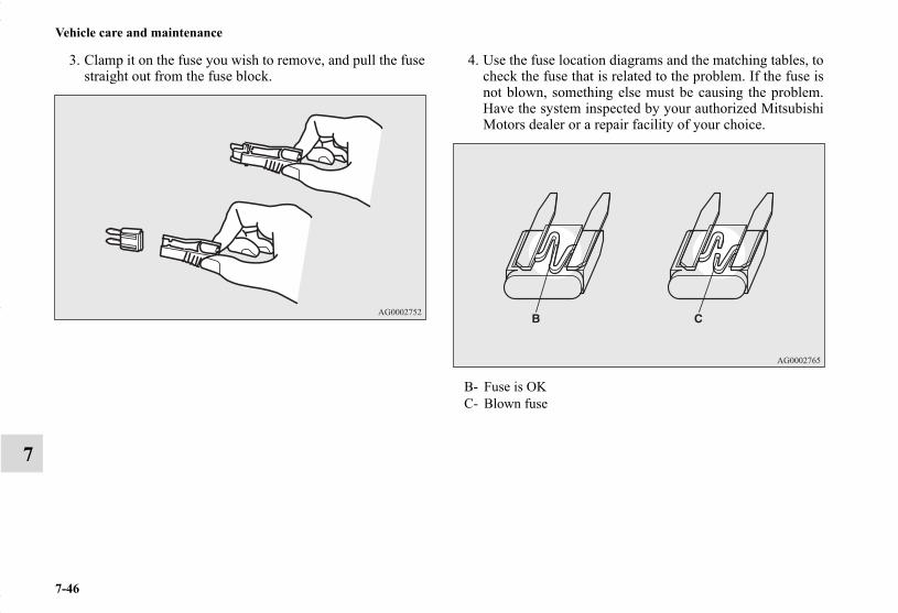
7-46
Vehicle care and maintenance
7
3. Clamp it on the fuse you wish to remove, and pull the fusestraight out from the fuse block.
4. Use the fuse location diagrams and the matching tables, tocheck the fuse that is related to the problem. If the fuse isnot blown, something else must be causing the problem.Have the system inspected by your authorized MitsubishiMotors dealer or a repair facility of your choice.
B- Fuse is OKC- Blown fuse
BK0150700US.book 46 ページ 2012年3月22日 木曜日 午後6時46分

Vehicle care and maintenance
7-47
7
5. Insert a new fuse of the same capacity securely into theappropriate slot.
Replacement of light bulbsN00942900310
Before replacing the bulb, be sure the light is off. Do not touchthe glass part of the new bulb with your bare fingers; the oilfrom your skin will stay on the glass and dim or destroy thebulb when it gets hot.
NOTE● If you are unsure of how to carry out the work as required,
it is recommended that these procedures be carried out byan authorized Mitsubishi Motors dealer or a repair facilityof your choice.
● Be careful not to scratch the vehicle body when removinga light and lens.
● When it rains, or when the vehicle has been washed, theinside of the lens sometimes becomes temporarily foggy.This is the same phenomenon as when window glass mistsup on a humid day, and does not indicate a functionalproblem.When the light is switched on, the heat will remove thefog. However, if water gathers inside the light, pleasehave it checked by an authorized Mitsubishi Motorsdealer or a repair facility of your choice.
CAUTION!
● Never use a fuse with a capacity greater than the onelisted or any substitute, such as wire, foil etc. Thiswould cause the circuit wiring to heat up and couldcause a fire.
● If the replacement fuse blows again after a shorttime, have the electrical system checked by anauthorized Mitsubishi Motors dealer or a repairfacility of your choice to find and correct the cause.
CAUTION!
● Bulbs are extremely hot immediately after beingturned off.When replacing the bulb, wait for it to cool suffi-ciently before touching it. You could otherwise beburned.
BK0150700US.book 47 ページ 2012年3月22日 木曜日 午後6時46分

7-48
Vehicle care and maintenance
7
Bulb capacityN00943000132
The bulb should only be replaced with a new bulb with thesame rating and type. The type and rating are listed on the baseof the bulb.
OutsideN00950300850
Front
Description WattageANSI Trade No. or Bulb
type1 Front turn signal light 21 W WY21W2 Headlight, high beam 60 W HB3
3
Daytime running light / Front fog light (Type 1)
Front fog light 35 W H8
Daytime running light
13 W P13W
Front fog light (Type 2) 55 W H11
4 Headlight, low beam
Halogen bulb 55 W H11
Discharge bulb 35 W —
5 Front side-marker and parking light 5 W WY5W
6 Side turn signal light 5 W —
BK0150700US.book 48 ページ 2012年3月22日 木曜日 午後6時46分

Vehicle care and maintenance
7-49
7
NOTE● It is not possible to repair or replace only the bulb for the
side turn signal light.Check with an authorized Mitsubishi Motors dealer or arepair facility of your choice when the light needs to berepaired or replaced.
NOTE● The rear side-marker light, the tail and stop light and the
high-mounted stop light use an LED instead of the bulb.Check with an authorized Mitsubishi Motors dealer orrepair facility of your choice when either light needs to berepaired or replaced.
WARNING!
● Check with an authorized Mitsubishi Motors dealeror a repair facility of your choice when it is neces-sary to repair a high intensity discharge headlight orto replace the bulb.The power circuit, bulb and electrodes generate highvoltages that may cause a severe shock.
Item Wattage ANSI trade No. or bulb type
7 High-mounted stop light — —8 License plate light 5 W W5W9 Back-up light 16 W W16W10 Rear turn signal light 21 W W21W
11 Rear side-marker light, and tail and stop light — —
Rear
BK0150700US.book 49 ページ 2012年3月22日 木曜日 午後6時46分

7-50
Vehicle care and maintenance
7
CompartmentN00950400633
Headlights (low beam, except for vehicles equipped with high intensity discharge head-lights)
N00901800062
1. Turn the cap (A) counterclockwise to remove it.
Item Wattage1 Dome light (rear) (if so equipped) 8 W2 Vanity mirror lights (if so equipped) 2 W3 Dome light (front)/Reading light 8 W4 Cargo room light 5 W5 Glove compartment light 1.4 W
*- Front of the vehicle
BK0150700US.book 50 ページ 2012年3月22日 木曜日 午後6時46分
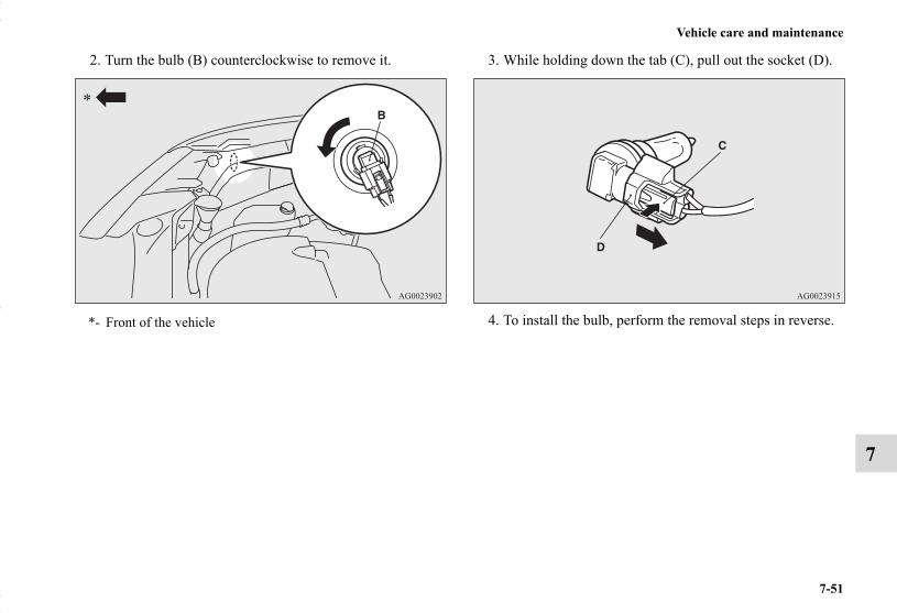
Vehicle care and maintenance
7-51
7
2. Turn the bulb (B) counterclockwise to remove it. 3. While holding down the tab (C), pull out the socket (D).
4. To install the bulb, perform the removal steps in reverse.*- Front of the vehicle
BK0150700US.book 51 ページ 2012年3月22日 木曜日 午後6時46分

7-52
Vehicle care and maintenance
7
Headlights (high beam)N00901900050
1. Turn the cap (A) counterclockwise to remove it.CAUTION!
● Handle halogen light bulb with care. The gas insidea halogen light bulb is highly pressurized, so drop-ping, knocking, or scratching a halogen light bulbcan cause it to shatter.
● Never hold the halogen light bulb with a bare hand,dirty glove, etc.The oil from your hand could cause the bulb tobreak the next time the headlights are used.If the glass surface is dirty, clean it with alcohol andlet it dry completely before installing the bulb.
*- Front of the vehicle
BK0150700US.book 52 ページ 2012年3月22日 木曜日 午後6時46分

Vehicle care and maintenance
7-53
7
2. Turn the bulb (B) counterclockwise to remove it. 3. While holding down the tab (C), pull out the socket (D).
*- Front of the vehicle
BK0150700US.book 53 ページ 2012年3月22日 木曜日 午後6時46分

7-54
Vehicle care and maintenance
7
4. To install the bulb, perform the removal steps in reverse. Headlights (low beam, for vehicles equipped with high intensity discharge headlights)
N00900300099
Do not attempt to disassemble or repair headlights, and do notattempt to replace their bulbs.
Adjustment of headlight aimN00943200121
The alignment of the headlights should be checked by anauthorized Mitsubishi Motors dealer or a repair facility of yourchoice.
CAUTION!
● Handle halogen light bulb with care. The gas insidea halogen light bulb is highly pressurized, so drop-ping, knocking, or scratching a halogen light bulbcan cause it to shatter.
● Never hold the halogen light bulb with a bare hand,dirty glove, etc.The oil from your hand could cause the bulb tobreak the next time the headlights are used.If the glass surface is dirty, clean it with alcohol andlet it dry completely before installing the bulb.
WARNING!
● A high voltage is present in the power circuit and inthe bulbs and bulb terminals. To avoid the risk of anelectric shock, contact an authorized Mitsubishidealer whenever repair or replacement is necessary.
BK0150700US.book 54 ページ 2012年3月22日 木曜日 午後6時46分

Vehicle care and maintenance
7-55
7
Front side-marker and parking lightsN00917300479
1. Turn the socket (A) counterclockwise to remove it.
2. Pull the bulb out of the socket.
3. To install the bulb, perform the removal steps in reverse.
*- Front of the vehicle
BK0150700US.book 55 ページ 2012年3月22日 木曜日 午後6時46分
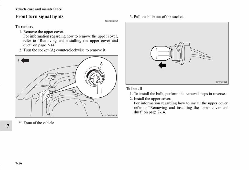
7-56
Vehicle care and maintenance
7
Front turn signal lightsN00943400367
To remove1. Remove the upper cover.
For information regarding how to remove the upper cover,refer to “Removing and installing the upper cover andduct” on page 7-14.
2. Turn the socket (A) counterclockwise to remove it.
3. Pull the bulb out of the socket.
To install1. To install the bulb, perform the removal steps in reverse.2. Install the upper cover.
For information regarding how to install the upper cover,refer to “Removing and installing the upper cover andduct” on page 7-14.
*- Front of the vehicle
BK0150700US.book 56 ページ 2012年3月22日 木曜日 午後6時46分

Vehicle care and maintenance
7-57
7
Side turn signal lightsN00943500137
NOTE● It is not possible to repair or replace only the bulb for the
side turn signal light.Check with an authorized Mitsubishi Motors dealer or arepair facility of your choice when the light needs to berepaired or replaced.
Front fog lights (if so equipped)N00943600750
1. Insert a straight blade (or minus) screwdriver with a clothover its tip info the light cover (A) and pry gently toremove it.
BK0150700US.book 57 ページ 2012年3月22日 木曜日 午後6時46分

7-58
Vehicle care and maintenance
7
2. Remove the screws (B) and remove the light unit. NOTE● Except for vehicles equipped with daytime running lights,
when unfastening the screws, be careful not to move thebeam position adjustment screw (C).
BK0150700US.book 58 ページ 2012年3月22日 木曜日 午後6時46分

Vehicle care and maintenance
7-59
7
3. While holding down the tab (D), pull out the socket (E). 4. Turn the bulb (F) counterclockwise to remove it.
BK0150700US.book 59 ページ 2012年3月22日 木曜日 午後6時46分
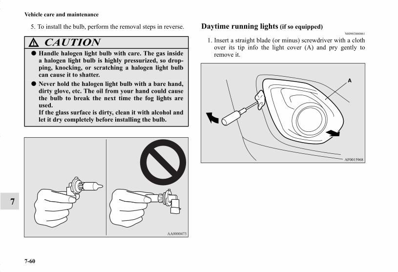
7-60
Vehicle care and maintenance
7
5. To install the bulb, perform the removal steps in reverse. Daytime running lights (if so equipped)N00902000061
1. Insert a straight blade (or minus) screwdriver with a clothover its tip info the light cover (A) and pry gently toremove it.
CAUTION!
● Handle halogen light bulb with care. The gas insidea halogen light bulb is highly pressurized, so drop-ping, knocking, or scratching a halogen light bulbcan cause it to shatter.
● Never hold the halogen light bulb with a bare hand,dirty glove, etc. The oil from your hand could causethe bulb to break the next time the fog lights areused.If the glass surface is dirty, clean it with alcohol andlet it dry completely before installing the bulb.
BK0150700US.book 60 ページ 2012年3月22日 木曜日 午後6時46分

Vehicle care and maintenance
7-61
7
2. Remove the screws (B) and remove the light unit. 3. Turn the bulb (C) counterclockwise to remove it.
BK0150700US.book 61 ページ 2012年3月22日 木曜日 午後6時46分

7-62
Vehicle care and maintenance
7
4. While holding down the tab (D), pull out the socket (E).
5. To install the bulb, perform the removal steps in reverse.
Rear combination lightsN00943700458
1. Remove the screws (A) that hold the light unit and removethe light unit.
BK0150700US.book 62 ページ 2012年3月22日 木曜日 午後6時46分

Vehicle care and maintenance
7-63
7
2. Turn the socket and bulb assembly counterclockwise toremove it.
NOTE● The rear side-marker light, and the tail and stop light uses
an LED instead of the bulb.Check with an authorized Mitsubishi Motors dealer or arepair facility of your choice when the light needs to berepaired or replaced.
3. Pull the bulb out of the socket.
B- Rear side-marker light, and tail and stop light (LED) - cannot be replaced
C- Rear turn signal light
BK0150700US.book 63 ページ 2012年3月22日 木曜日 午後6時46分

7-64
Vehicle care and maintenance
7
4. To install the bulb, perform the removal steps in reverse.
NOTE● When mounting the light unit, align the groove (D) on the
light unit with the clip on the body and the pin (E) on theunit with the hole in the body.
Back-up lightsN00929100054
1. Open the liftgate.2. Insert a screwdriver into the notch of the cover and pry
gently to remove the cover.
NOTE● Wrap a cloth around the tip of the screwdriver to keep
from scratching the cover.
BK0150700US.book 64 ページ 2012年3月22日 木曜日 午後6時46分

Vehicle care and maintenance
7-65
7
3. Turn the socket counterclockwise to remove it. 4. Pull the bulb out of the socket.
BK0150700US.book 65 ページ 2012年3月22日 木曜日 午後6時46分

7-66
Vehicle care and maintenance
7
5. To install the bulb, perform the removal steps in reverse.
NOTE● When installing the lid, align the tab on the lid with the
hole on the vehicle side.
License plate lightsN00944000386
1. When removing the light unit (A), push it toward the leftside of the vehicle body.
BK0150700US.book 66 ページ 2012年3月22日 木曜日 午後6時46分

Vehicle care and maintenance
7-67
7
2. Remove the socket (B) and bulb assembly by turning itcounterclockwise.
3. Pull the bulb out of the socket.
BK0150700US.book 67 ページ 2012年3月22日 木曜日 午後6時46分

7-68
Vehicle care and maintenance
7
4. To install the bulb, perform the removal steps in reverse.
NOTE● When mounting the light unit, insert tab (C) first then
align tab (D) with its hole.
High-mounted stop lightN00943900102
NOTE● The high-mounted stop light uses an LED instead of the
bulb. Check with an authorized Mitsubishi Motors dealeror a repair facility of your choice when the light needs tobe repaired or replaced.
BK0150700US.book 68 ページ 2012年3月22日 木曜日 午後6時46分

Vehicle care and maintenance
7-69
7
Vehicle care precautionsN00945100166
In order to maintain the value of your vehicle, perform regularmaintenance using the proper materials and procedures. Besure to use only those materials and procedures that meet yourlocal environmental pollution control regulations. Choose thematerials you will use carefully, to be sure that they do not con-tain corrosives. If you are not sure, contact an authorizedMitsubishi Motors dealer for help in choosing these materials.
These can all be dangerous, and they all can damage your vehi-cle.
CAUTION!
● Cleaning products can be dangerous. Some are poi-sonous and others are highly flammable. Some aredangerous if you breathe their fumes in a closedspace. When you use anything in a container toclean your vehicle, be sure to follow the instructions.Always open your vehicle doors or windows whenyou’re cleaning the inside. Never use the followingchemicals to clean your vehicle:• Gasoline• Carbon Tetrachloride• Benzine• Kerosene• Naphtha• Acetone• Turpentine• Paint Thinner• Lacquer Thinner• Nail Polish Remover
BK0150700US.book 69 ページ 2012年3月22日 木曜日 午後6時46分
7-70
Vehicle care and maintenance
7
Cleaning the inside of your vehicleN00945200095
After washing the inside of your vehicle with any cleaner, wipeit dry in a shady, well ventilated area.
NOTE● Always read the instructions on the cleaner label.
Plastic, vinyl leather, fabric and flocked partsN00945300142
1. Lightly wipe these off with a soft cloth soaked in a 3%solution of gentle soap and water.
2. To rinse, dip the cloth in fresh water, wring it out well, andwipe off all the soap.
NOTE● Do not use cleaners, conditioners, and protectants contain-
ing silicones or wax.Such products, when applied to the instrument panels orother parts, may cause reflections on the windshield andobscure vision.Also, if such products get on the switches of the electricalaccessories, it may lead to failure of these accessories.
UpholsteryN00945500128
1. To maintain the value of your new vehicle, maintain theupholstery carefully and keep the interior clean.Use a vacuum cleaner and brush to clean the seats. Ifstained, vinyl and synthetic leather should be cleaned withan appropriate cleaner. Cloth fabrics can be cleaned witheither upholstery cleaner or a 3% solution of gentle soapin lukewarm water.
2. Clean the carpeting with a vacuum cleaner and removeany stains with carpet cleaner. Oil and grease can beremoved by lightly dabbing with a clean white cloth andspot remover.
NOTE● If fuzzing is difficult to remove from the seat upholstery,
draw a suitable defuzzing brush over the surface in onedirection.
CAUTION!
● Do not use organic substances (solvents, benzine,kerosene, alcohol, gasoline, etc.) or alkaline or acidicsolutions.These chemicals can cause discoloring, staining orcracking of the surface.If you use cleaners or polishing agents, make suretheir ingredients do not include the substances men-tioned above.
BK0150700US.book 70 ページ 2012年3月22日 木曜日 午後6時46分
Vehicle care and maintenance
7-71
7
Genuine leather (if so equipped)N00945600187
1. To clean, lightly wipe the leather with a soft cloth soakedin a 5% solution of gentle soap and water.
2. To rinse, dip the cloth in fresh water, wring it out well, andwipe off all the soap.
3. To preserve and protect, use a leather protecting agent onthe genuine leather surface.
NOTE● If genuine leather is wet with water, wipe it with a dry,
soft cloth. If left damp, mildew may grow.● The genuine leather surface can be damaged if brushed
with a nylon or synthetic fiber brush.● Organic solvents such as benzine, kerosene, alcohol, gaso-
line, or acid or alkaline solvents can discolor the genuineleather surface and should not be used.
● Genuine leather can mildew if not kept clean. Clean upany oil stains immediately.
● The genuine leather surface may harden and shrink if it isexposed to the direct sunlight for long hours. When yourvehicle is parked, place it in the shade as much as possi-ble.
● When the temperature of the vehicle interior rises in sum-mer, vinyl products left on the genuine leather seat maydeteriorate and stick to the seat.
Cleaning the outside of your vehicleN00945700058
To protect your vehicle’s finish, wash it often and thoroughly.If desired, you may wax your vehicle using a nonabrasive auto-mobile wax.
Foreign materialN00945800033
Industrial pollution, road tar, bird droppings, tree sap, insectremains, sea water and other foreign matters can damage thefinish on your vehicle.Generally, the longer any foreign material stays on the finish,the worse the damage. Wash your vehicle as soon as possiblewhenever the finish gets soiled.
WashingN00945900597
Chemicals contained in the dirt and dust picked up from air,rain, snow, or road surfaces can damage the paint and body ofyour vehicle if left on.Frequent washing and waxing is the best way to protect yourvehicle from this damage.Do not wash the vehicle in direct sunlight. Park the vehicle inthe shade and spray it with water to remove dust. Next, usingplenty of clean water and a car washing mitt or sponge, washthe vehicle from top to bottom.Use a mild car washing soap if necessary. Rinse thoroughlyand wipe dry with a chamois or soft cloth. After washing thevehicle, carefully clean the joints and flanges of the doors,hood, etc., where dirt is likely to remain.
BK0150700US.book 71 ページ 2012年3月22日 木曜日 午後6時46分

7-72
Vehicle care and maintenance
7
During cold weatherSalt and other chemicals spread on winter roads in some geo-graphical areas can have a detrimental effect on the vehicleunderbody. You should flush the underbody with a high pres-sure hose every time you wash the outside of your vehicle.Take special care to remove mud or other debris which couldtrap and hold salt and moisture.After washing your vehicle, wipe off all waterdrops from therubber parts around the doors to prevent the doors from freez-ing.
CAUTION!
● When washing the underside of your vehicle or thewheels, wear a pair of gloves to protect your hands.
● If your vehicle has rain sensor wipers, place thewiper switch lever in the “OFF” position to deacti-vate the rain sensor before washing the vehicle. Oth-erwise, the wipers will operate in the presence ofwater spray on the windshield and may get damagedas a result.
● Never spray or splash water on the electrical partsin the engine compartment. This may damage them.Be careful also when washing the underbody toensure that water does not enter the engine com-partment.
● Avoid automatic car washers that use rotatingbrushes. These brushes may scratch the paint sur-face and make it dull.Scratches are more noticeable on darker coloredvehicles.
● Some hot water washing equipment uses high pres-sure and heat to clean your vehicle. Because hotwater can damage plastics parts and seep insideyour vehicle, make sure you do the following whenusing such equipment:• Keep the washing nozzle at least 28 inches (70 cm)
away from the vehicle body.• When washing around the door glass, hold the
nozzle at a distance of more than 28 inches (70 cm)and at a right angle to the glass surface.
● Make sure to do the following when using an auto-matic car wash, with help from either this manual orthe car wash operator, to avoid damaging your vehi-cle:• Fold the outside rearview mirrors.• Remove the antenna.• Tape the wiper arm assembly.• If your vehicle is equipped with a rear spoiler or
roof rails, check with the car wash operator beforeusing the car wash.
• If your vehicle is equipped with the rain sensorwipers, place the wiper switch lever in the “OFF”position to deactivate the rain sensor.
CAUTION!
BK0150700US.book 72 ページ 2012年3月22日 木曜日 午後6時46分

Vehicle care and maintenance
7-73
7
NOTE● When the door is frozen, opening it by force may tear off
or crack the rubber gasket installed around the door. Pourwarm water to melt the ice. Be sure to thoroughly wipe offthe water after opening the door. To prevent freezing ofthe weatherstripping on the doors, hood, etc., treat withsilicone lubricant.
WaxingN00946000234
Wax your vehicle once or twice a year, or when water does notbead up on the paint.Use a soft cloth to put a small amount of wax on the paintedsurfaces. After the wax has dried, polish with a dry soft cloth.Do not wax your vehicle in direct sunlight.You should wax when the painted surfaces are cool.
CAUTION!
● Waxes containing high abrasive compounds shouldnot be used. These waxes remove rust and staineffectively from the paintwork, but are harmful tothe finish of the paint, because they also removepaint/clearcoat.They are also harmful to other glossy surfaces suchas the grille, trim, moldings, etc.
● Do not use gasoline, benzine, kerosene or paint thin-ners to remove road tar or other dirt from the vehi-cle surface.
● Do not put wax on the areas having black mattecoating because it can cause uneven discoloration,patches, blurs, etc. If these get wax on them, wipethe wax off right away with a soft cloth and warmwater.
CAUTION!
BK0150700US.book 73 ページ 2012年3月22日 木曜日 午後6時46分

7-74
Vehicle care and maintenance
7
PolishingN00946100046
If painted surfaces have been severely damaged and lost theiroriginal luster and color tone, polish the surface lightly with afine polishing compound. Avoid limiting your polishing to thedamaged surface only; polish a somewhat wider area, movingthe polishing cloth in one direction. After polishing, flush thecompound from the surface and apply a coat of wax to regain abeautiful luster.
Damaged paintN00946200047
Small cracks and scratches in the paint coat should be touchedup as soon as possible with touch-up paint to prevent corrosion.Check body areas facing the road or the tires carefully for dam-age to the paint caused by flying stones, etc. The paint codenumber for your vehicle can be found on the vehicle informa-tion code plate in the engine compartment.
Cleaning plastic partsN00946300194
Use a sponge or chamois to clean these parts.If a vehicle wax sticks to a gray or black rough surface of thebumper, molding or lights, the surface may appear white incolor. In this case, wipe it off using lukewarm water and a softcloth or chamois.
Chrome partsN00946400052
To prevent spots and corrosion of chrome parts, wash withwater, dry thoroughly, and apply a nonabrasive automotivewax. If the chrome is severely damaged or pitted, use a com-mercially available chrome polish.
CAUTION!
● Do not use a scrubbing brush or other rough scrub-ber as these may damage the plastic surface.
● Do not use wax containing compounds (polishingpowder) which may damage the plastic surface.
● Do not let plastic parts get soiled with gasoline, oil,brake fluids, engine oils, greases, paint thinner, andsulfuric acid (battery electrolyte), as such substanceswill cause stains, cracks, or discoloration.If any of these get on a plastic part, wipe them upwith a soft cloth or chamois and a mild solution ofsoap and water. Then rinse them immediately withwater.
BK0150700US.book 74 ページ 2012年3月22日 木曜日 午後6時46分

Vehicle care and maintenance
7-75
7
Aluminum wheels (if so equipped)N00946500183
1. Remove dirt using a wet sponge.2. Use a mild detergent on any dirt that cannot be removed
easily with water.Rinse off the detergent after washing the wheel.
3. Dry the wheel thoroughly using a chamois leather or a softcloth.
Window glassN00946600054
The window glass can usually be cleaned using only a spongeand water. Glass cleaner can be used to remove wax, oil,grease, dead insects, etc. After washing the glass, wipe it drywith a clean, dry, soft cloth.
Wiper bladesN00946700068
Use a soft cloth and glass cleaner to remove grease, deadinsects, etc., from the wiper blades.Replace the wiper blades when they no longer clean the wind-shield and rear window properly.
Engine compartmentN00947000071
Never spray or splash water on the electrical accessories in theengine compartment. This puts the engine at risk of being dam-aged.Do not bring the circumferential parts, the plastic parts and soon into contact with sulfuric acid (battery electrolyte) whichmay crack, stain or discolor them.If they are in contact, wipe off with soft cloth, chamois or thelike and an aqueous solution of neutral detergent then immedi-ately rinse the affected parts with plenty of water.
CAUTION!
● Do not use a brush or other hard implement on thewheels.
● Do not use any cleaner that contains an abrasivesubstance or is acidic or alkaline. Doing so couldcause the coating on the wheels to peel or becomediscolored or stained.
● Do not directly apply hot water using a steamcleaner or by any other means.
● Contact with seawater or road salt used for de-icingcan cause corrosion. Rinse off such substances assoon as possible.
BK0150700US.book 75 ページ 2012年3月22日 木曜日 午後6時46分

BK0150700US.book 76 ページ 2012年3月22日 木曜日 午後6時46分

8
Customer assistance/Reporting Safety Defects
Consumer information (For vehicles sold in U.S.A.) . . . . . . . . . . . . . . .8- 2
Reporting Safety Defects . . . . . . . . . . . . . . . . . . . .8- 3Important facts to know in case of an accident . . .8- 5
BK0150700US.book 1 ページ 2012年3月22日 木曜日 午後6時46分

8-2
Customer assistance/Reporting Safety Defects
8
Consumer information (For vehicles sold in U.S.A.)
N01047100171
This information is provided in compliance with the require-ments of the National Highway Traffic Safety Administration,Department of Transportation. It provides the purchasersand/or prospective purchasers with information on reportingsafety defects.
Uniform tire quality gradingDOT quality grades - All passenger vehicle tires must conformto Federal Safety Requirements in addition to these grades. Thespecific grade rating in each grade category is shown on theside wall of the tires on your vehicle.
Treadwear The treadwear grade is a comparative rating based on the wearrate of the tire when tested under controlled conditions on aspecified government test course. For example, a tire graded150 would wear one and one-half (11/2) times as well on thegovernment course as a tire graded 100. The relative perfor-mance of tires depends upon the actual conditions of their use,however, and may depart significantly from the norm due tovariations in driving habits, service practices and differences inroad characteristics and climate.
Traction AA, A, B, C The traction grades, from highest to lowest, are AA, A, B andC. Those grades represent the tire’s ability to stop on wet pave-ment as measured under controlled conditions on specifiedgovernment test surfaces of asphalt and concrete. A tiremarked C may have poor traction performance.
Temperature A, B, CThe temperature grades are A (the highest), B and C, represent-ing the tire’s resistance to the generation of heat and its abilityto dissipate heat when tested under controlled conditions on aspecified indoor laboratory test wheel. Sustained high tempera-ture can cause the material of the tire to degenerate and reducetire life, and excessive temperature can lead to sudden tire fail-ure. The grade C corresponds to a level of performance whichall passenger car tires must meet under the Federal Motor Vehi-cle Safety Standard No. 109. Grades B and A represent higherlevels of performance on the laboratory test wheel than theminimum required by law.
WARNING!● The traction grade assigned to this tire is based on
straight-ahead braking traction tests, and does notinclude acceleration, cornering, hydroplaning, orpeak traction characteristics.
WARNING!● The temperature grade for this tire is established for
a tire that is properly inflated and not overloaded.Excessive speed, underinflation, or excessive load-ing, either separately or in combination, can causeheat buildup and possible tire failure.
BK0150700US.book 2 ページ 2012年3月22日 木曜日 午後6時46分

Customer assistance/Reporting Safety Defects
8-3
8
Reporting Safety DefectsN01047200475
If you believe that your vehicle has a defect which couldcause a crash or could cause injury or death, you shouldimmediately inform the National Highway Traffic SafetyAdministration (NHTSA) in addition to notifyingMitsubishi Motors North America, Inc.
If NHTSA receives similar complaints, it may open aninvestigation, and if it finds that a safety defect exists in agroup of vehicles, it may order a recall and remedy cam-paign. However, NHTSA cannot become involved in indi-vidual problems between you, your dealer, or MitsubishiMotors North America, Inc.
To contact NHTSA, you may call the Vehicle Safety Hotlinetoll-free at 1-888-327-4236 (TTY: 1-800-424-9153); go tohttp://www.safercar.gov; or write to:
You can also obtain other information about motor vehiclesafety from http://www.safercar.gov.
For vehicles sold in U.S.A.To contact Mitsubishi Motors North America, Inc. call 1-888-648-7820 or write to:
For vehicles sold in CanadaIf you live in Canada, and you believe that your vehicle hasa safety defect, you should immediately notify TransportCanada, in addition to notifying Mitsubishi Motor Sales ofCanada, Inc. You may write to:
To contact Mitsubishi Motor Sales of Canada, Inc. call 1-888-576-4878 or write to:
NHTSA Headquarters 1200 New Jersey Avenue, SEWest BuildingWashington, DC 20590
Mitsubishi Motors North America, Inc.Customer Relations DepartmentP.O. Box 6400Cypress, CA 90630-0064
Transport Canada330 Sparks StreetTower COttawa, Ontario K1A 0N5
Mitsubishi Motor Sales of Canada, Inc.Customer Relations DepartmentP.O. Box 410094141 Dixie RoadMississauga, ON L4W 5C9
BK0150700US.book 3 ページ 2012年3月22日 木曜日 午後6時46分

8-4
Customer assistance/Reporting Safety Defects
8
For vehicles sold in Puerto RicoTo contact Mitsubishi Motor Sales of Caribbean, Inc.call 1-787-251-8715 or write to:
For vehicles sold in GuamTo contact Triple J Enterprises Inc.call (671)649-3673 or write to:
For vehicles sold in SaipanTo contact Triple J Motorscall (670)234-7133 or write to:
For vehicles sold in American SamoaTo contact Pacific Marketing Inc.call 684(699)9140 or write to:
Mitsubishi Motor Sales of Caribbean, Inc.Customer Service DepartmentP.O. Box 192216SAN JUAN PR 00919-2216
Triple J Enterprises, Inc.P.O. Box 6066TAMUNINGGUAM 96931
Triple J MotorsP.O. Box 500487SAIPAN, MP96950-0487
Pacific Marketing, Inc.P.O. Box 698PAGO PAGO,AMERICAN SAMOA AS, 96799
BK0150700US.book 4 ページ 2012年3月22日 木曜日 午後6時46分

Customer assistance/Reporting Safety Defects
8-5
8
Important facts to know in case of an acci-dent
N01047300098
We hope you will never be involved in an accident, but there isalways that potential danger. So, please be sure to buckle upand drive safely.
In the event of an accident ● Remain calm.● Check for injuries. Report all injuries to the police, and, if
necessary, call for an ambulance.● Record all the details of the accident. This will provide
you with accurate records of the accident for discussionswith your insurance company and other persons who maybe acting on your behalf.
Key information to discuss with your insurance company
● Understand your repair estimate before approving repairs.● Choosing the repair shop and the brands of parts that they
use on your vehicle is your decision.● Ask for genuine Mitsubishi Motors parts. Many times, to
save money, your insurance company will recommendimitation parts that do not meet the original specificationsof fit, finish, corrosion resistance or workmanship.
Mitsubishi Motors built-in protection The strength and integrity built into your Mitsubishi vehicle isthe result of a specific design referred to as “Energy Manage-ment”. Individual body parts are designed to act as one unit inthe event of an accident. Shock waves are absorbed by protec-tive panels or are channeled around the passenger compart-
ment. This important feature is possible because high tensilesteel is used in Mitsubishi panels and structural parts, some-thing that cannot be guaranteed by the manufacturers of imita-tion parts. All Genuine Mitsubishi body panels and supportbrackets are designed and constructed as important protectionfeatures in the event of an accident. By replacing body partswith imitations, your vehicle may no longer meet originalequipment specifications.
Consumer rights (For vehicles sold in U.S.A.)As a consumer requesting repair on your vehicle, you haveconsumer rights. Across the country, State Insurance Commis-sioners have begun considering rules on the use of non-OEMparts. This could mean that repair shops will have to disclose tothe consumer, when they intend to use non-OEM parts. Sinceregulations are not consistent on this point, remember you havea choice. So, if you want genuine Mitsubishi Motors parts, youmay have to specifically request them. Make certain yourinsurance company understands imitations are not to be used inthe repair of your vehicle. You deserve the best genuineMitsubishi Motors parts.
Genuine Mitsubishi Motors partsGenuine Mitsubishi Motors parts are built with the high qualityand durability standards you expect. Genuine MitsubishiMotors replacements parts are your guarantee that your vehiclewill have all the technological advantages and maintain thestyle and protection of a brand new Mitsubishi Motors.Remember to ask for genuine Mitsubishi Motors parts.
BK0150700US.book 5 ページ 2012年3月22日 木曜日 午後6時46分

BK0150700US.book 6 ページ 2012年3月22日 木曜日 午後6時46分

9
Specifications
Vehicle labeling . . . . . . . . . . . . . . . . . . . . . . . . . . .9- 2Vehicle dimensions . . . . . . . . . . . . . . . . . . . . . . . .9- 5Vehicle weights . . . . . . . . . . . . . . . . . . . . . . . . . . .9- 6Engine specifications . . . . . . . . . . . . . . . . . . . . . . .9- 7Battery . . . . . . . . . . . . . . . . . . . . . . . . . . . . . . . . . .9- 8Tires and wheels. . . . . . . . . . . . . . . . . . . . . . . . . . .9- 8Capacity . . . . . . . . . . . . . . . . . . . . . . . . . . . . . . . . .9- 9
BK0150700US.book 1 ページ 2012年3月22日 木曜日 午後6時46分

9-2
Specifications
9
Vehicle labelingN01147400654
Keep a record of the chassis number and vehicle identificationnumber. Such information will assist police if your vehicle isstolen.
1 - Vehicle emission control information labelThe vehicle emission control information label is affixed on theunderside of the engine hood.
2 - Vehicle identification number plateThe vehicle identification number is stamped on the plate riv-eted to the left front corner of the vehicle body. It is visiblefrom outside of the vehicle through the windshield.
3 - Air conditioning labelThe air conditioning label is affixed on the inside panel of theengine hood.
4 - Vehicle information code plateThe vehicle information code plate is located on the front pas-senger door sill.
BK0150700US.book 2 ページ 2012年3月22日 木曜日 午後6時46分

Specifications
9-3
9
Chassis numberThe chassis number is stamped on the bulkhead as shown inthe illustration.
Engine serial numberThe engine serial number is stamped on the cylinder block asshown in the illustration.
*- Front of the vehicle
BK0150700US.book 3 ページ 2012年3月22日 木曜日 午後6時46分

9-4
Specifications
9
Tire and loading information placardN01148100603
The tire and loading information placard is located on thedriver’s door sill.
BK0150700US.book 4 ページ 2012年3月22日 木曜日 午後6時46分

Specifications
9-5
9
Certification labelN01148200167
The certification label is located on the driver’s door sill.
Vehicle dimensionsN01147500479
Overall length 169.1 in (4,295 mm)Overall width 69.7 in (1,770 mm)
Overall heightWithout roof rails 64.2 in (1,630 mm)With roof rails 64.6 in (1,640 mm)
Wheel base 105.1 in (2,670 mm)
BK0150700US.book 5 ページ 2012年3月22日 木曜日 午後6時46分

9-6
Specifications
9
Vehicle weightsN01147600858
NOTE● Roof load is important because it affects the vehicle capacity weight. Refer to “Loading cargo on the roof” on page 4-14.
GVWR: maximum total weight (load) limit specified for the vehicleGAWR: maximum weight (load) limit specified for the front or rear axleSeating capacity: the maximum number of occupants
Gross vehicle weight rating 4,343 lb (1,970 kg)
Gross axle weight ratingFront 2,271 lb (1,030 kg)Rear 2,205 lb (1,000 kg)
Vehicle capacity weight 827 lb (375 kg)Maximum roof load 176 lb (80 kg)Seating capacity 5 persons
BK0150700US.book 6 ページ 2012年3月22日 木曜日 午後6時46分

Specifications
9-7
9
Engine specificationsN01147700442
Engine model 4B11
Engine displacement 121.9 CID (1,998 cm3)No. of cylinders and cylinder arrangement 4 in lineBore 3.39 in (86.0 mm)Stroke 3.39 in (86.0 mm)Compression ratio 10.0Thermostat valve opening temperature 189 °F (87 °C)Spark plugs NGK DIFR6C11Spark plug gap .040 to .043 in (1.0 to 1.1 mm)Firing order 1-3-4-2
BK0150700US.book 7 ページ 2012年3月22日 木曜日 午後6時46分
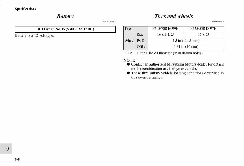
9-8
Specifications
9
BatteryN01147800283
Battery is a 12 volt type.
Tires and wheelsN01147900721
PCD: Pitch Circle Diameter (installation holes)
NOTE● Contact an authorized Mitsubishi Motors dealer for details
on the combination used on your vehicle.● These tires satisfy vehicle loading conditions described in
this owner’s manual.
BCI Group No.35 (530CCA/118RC) Tire P215/70R16 99H P225/55R18 97H
WheelSize 16 x 6 1/2J 18 x 7JPCD 4.5 in (114.3 mm)Offset 1.81 in (46 mm)
BK0150700US.book 8 ページ 2012年3月22日 木曜日 午後6時46分

Specifications
9-9
9
CapacityN01148001058
*: similar high quality ethylene glycol based non-silicate, non-amine, non-nitrate and non-borate coolant with long life hybridorganic acid technology
Item Capacity Lubricants
Fuel (approximate)
Front-wheel drive vehicles 16.6 gal (63 L)Refer to “Fuel selection” on page 1-2
All-wheel drive vehicles 15.8 gal (60 L)
Engine oil
Oil pan 4.2 qt (4.0 L) Engine oils displaying the ILSAC certification mark (“star-burst” symbol) on the container.If these oils are not available, and API classification SN or higher can be used.
Oil filter .32 qt (0.3 L)
Manual transaxle 2.6 qt (2.5 L) Mitsubishi Motors Genuine NEW MULTI GEAR OIL API classification GL-3 SAE 75W-80
Continuously variable transmission (CVT) 7.5 qt (7.1 L) Mitsubishi Motors Genuine CVTF - J4
Transfer oil .50 qt (0.47 L) Mitsubishi Motors Genuine Super Hypoid Gear Oil API classification GL-5 SAE 80
Differential Rear axle .42 qt (0.4 L) Mitsubishi Motors Genuine Super Hypoid Gear Oil API classification GL-5 SAE 80
Brake/Clutch (if so equipped) As required Conforming to Brake fluid DOT3 or DOT4Hood lock release mechanism and safety catch As required Multipurpose type grease NLGI Grade 2Engine coolant{Includes .69 qt (0.65 L) in reserve tank} 7.9 qt (7.5 L) Mitsubishi Motors Genuine Super Long Life Coolant Pre-
mium or equivalent*Washer fluid 4.8 qt (4.5 L) —
Refrigerant (air conditioning)Refer to the “Air
conditioning label” on page 9-2.
HFC-134a
BK0150700US.book 9 ページ 2012年3月22日 木曜日 午後6時46分

BK0150700US.book 10 ページ 2012年3月22日 木曜日 午後6時46分

Alphabetical index
1
AAccessory (installation) 1-8Active stability control (ASC) 3-102Air bag 2-43Air cleaner filter 7-12Air conditioning
Automatic air conditioning 5-25, 5-35Important air conditioning operating tips 5-45Manual air conditioning 5-6, 5-16
Air purifier 5-46Aluminum wheels 7-75Antenna
Roof antenna 5-102Anti-lock braking system 3-97Arm rest 2-11Assist grip 3-254Audio 5-46
Error codes 5-95, 5-96External audio input function 5-91Handling of compact discs 5-100Steering wheel audio remote control switch 5-92
Automatic air conditioning 5-25, 5-35Automatic transaxle
Fluid 9-9
BBack-up light
Bulb capacity 7-48Replacement 7-64
Ball joint, steering linkage seals and drive shaft boots 7-37Battery 7-21
Charging system warning light 3-179Disconnection and connection 7-21During cold weather 7-21Specification 9-8
Bluetooth 2.0 interface 3-205Bottle holders 3-252Brake
Fluid 9-9Brake assist system 3-96Braking 4-8
Anti-lock braking system 3-97Hose 7-36Pad wear alarm 3-94Parking brake 3-58Pedal 3-93Pedal free play 7-33Power brakes 3-93Service brake 3-93Warning lights 3-177
Break-in recommendations 3-2Bulb capacity 7-48
BK0150700US.book 1 ページ 2012年3月22日 木曜日 午後6時46分

Alphabetical index
2
CCalifornia Perchlorate Materials Requirements 1-9Capacities 9-9Card holder 3-238Cargo area cover 3-253Cargo loads 4-13Cargo room light
Bulb capacity 7-50Catalytic converter 7-3Cautions on the handling of all-wheel drive vehicles 3-91Certification label 9-5Charging system warning light 3-179Child restraint systems 2-31Child safety locks for rear door 3-43Cleaning
Inside of your vehicle 7-70Outside of your vehicle 7-71
Clock 5-103Clutch
Pedal free play 7-32Coat hook 3-254Consumer information 8-2Continuously variable transmission (CVT) 3-74
Fluid 7-18, 9-9Selector lever operation 3-75Selector lever positions 3-79Sports mode 3-80
Coolant (engine) 7-10, 9-9
Cruise control 3-107Cup holder 3-251
DDaytime running lights
Bulb capacity 7-48Replacement 7-60
Defogger (rear window) 3-203Defrosting or defogging (windshield, door windows) 5-14,
5-23, 5-33, 5-43Dimensions 9-5Dimmer (high/low beam change) 3-188Disc brake pads 7-36Dome light
Bulb capacity 7-50Doors
Lock 3-38Power door locks 3-41
Driving during cold weather 4-7Driving precaution 4-2Driving, alcohol and drugs 4-3
EElectric rear window defogger switch 3-203Electronic immobilizer (Anti-theft starting system) 3-4, 3-31Electronically controlled 4WD system 3-84Emission-control system maintenance 7-34
BK0150700USIX.fm 2 ページ 2012年3月26日 月曜日 午後5時35分

Alphabetical index
3
EngineCompartment 7-6Coolant 7-10, 9-9Hood 7-4Oil and oil filter 7-7, 9-9Overheating 6-5Serial number 9-2Specification 9-7
Engine coolant temperature display 3-139Engine hood 7-4Engine switch 3-22Exhaust system 7-37
FFloor console box 3-248Floor mat 4-3Fluid
Automatic transaxle fluid 9-9Brake fluid 9-9Continuously variable transmission (CVT) fluid 7-18, 9-9Engine coolant 7-10, 9-9Power steering fluid 9-9Washer fluid 7-19, 9-9
Fluid capacities and lubricants 9-9Free-hand advanced security transmitter (F.A.S.T.-key) 3-14
Front fog lightsBulb capacity 7-48Indicators 3-177Replacement 7-57Switch 3-193
Front seat adjustment 2-3Front side-marker lights
Bulb capacity 7-48Replacement 7-55
Front turn signal lightBulb capacity 7-48Replacement 7-56
FuelFilling the fuel tank 1-4Fuel economy 4-2Fuel hoses 7-35Fuel selection 1-2Tank capacity 9-9
Fuses 7-39Fusible links 7-39
GGeneral maintenance
Maintenance 7-36General vehicle data 9-5Genuine parts 1-9Glove compartment 3-247
BK0150700US.book 3 ページ 2012年3月22日 木曜日 午後6時46分
Alphabetical index
4
HHazard warning flasher switch 3-193Hazard warning lights 3-177Head restraints 2-12Headlight leveling switch 3-191Headlights
Bulb capacity 7-48Dimmer 3-188Headlight flasher 3-188Replacement 7-50, 7-52Switch 3-183
High beam indicator 3-177High-mount stop light
Bulb capacity 7-48Hill start assist 3-94Hood lock release mechanism and safety catch 7-38Horn switch 3-204
IIf the vehicle breaks down 6-2Ignition switch 3-66Important facts to know in case of an accident 8-5Indicators 3-177Information screen display 3-126Inside rearview mirror 3-60Inspection and maintenance following rough road
operation 3-90Instrument cluster 3-129
Interior lights 3-240
JJack
Storage 6-7Jump-starting the engine 6-2
KKey slot 3-28Keyless entry system 3-8, 3-33Keys 3-2
LLabeling 9-2License plate light
Bulb capacity 7-48Replacement 7-66
Liftgate 3-44Inside liftgate release 3-47
Link System 3-205Loading information 4-9Lubricants 9-9Luggage hooks 3-255
BK0150700US.book 4 ページ 2012年3月22日 木曜日 午後6時46分

Alphabetical index
5
MMalfunction indicator light 3-178Manual air conditioning 5-6, 5-16Manual transaxle 3-71
Oil 7-17Shift points (recommended speed) 3-72
Modification of your vehicle 1-7Multi-information display 3-126
OOctane rating 1-2Oil
Engine oil 7-7, 9-9Manual transaxle oil 7-17Rear axle oil 7-19, 9-9Transfer oil 7-18, 9-9
Operation mode 3-22Operation under adverse driving conditions 6-23Outside rearview mirrors 3-64Overheating 6-5
PParking 4-8
Parking brake break-in 7-33Parking brake lever stroke 7-33
Parking brake 3-58
Parking lightsBulb capacity 7-48Replacement 7-55
Polishing 7-74Power brakes 3-93Power outlet 3-238Power steering
Fluid 9-9Power windows 3-52Puncture (Tire changing) 6-8
RRadio
General information about your radio 5-104Reading lights
Bulb capacity 7-50Rear axle oil 7-19, 9-9Rear combination lights
Bulb capacity 7-48Replacement 7-62
Rear Seat Pass Through 2-11Rear side-marker lights
Bulb capacity 7-48Replacement 7-62
Rear turn signal lightBulb capacity 7-48Replacement 7-62
Rear-view camera 3-121
BK0150700US.book 5 ページ 2012年3月22日 木曜日 午後6時46分

Alphabetical index
6
Rearview mirrorInside rearview mirror 3-60Outside rearview mirrors 3-64
Replacement of light bulbs 7-47Replacing tires and wheels 7-28Reporting Safety Defects 8-3
SSafe driving techniques 4-6Seat belt 2-18
Adjustable seat belt shoulder anchor 2-27Child restraint systems 2-31Front passenger seat belt warning light 2-27Maintenance and inspection 2-42Seat belt extender 2-28Seat belt force limitter 2-31Seat belt pre-tensioners 2-29Seat belt use during pregnancy 2-29
Seats 2-2Arm rest 2-11Front seats 2-3Head restraints 2-12Heated seat 2-9Seats and restraint systems 2-3
Service brake 3-93Service precautions 7-2Side turn signal light
Bulb capacity 7-48Snow tires 7-32
Spark plugs 7-35Starting the engine 3-69Steering
Power steering fluid 9-9Steering wheel height and reach adjustment 3-59
Stop lightsBulb capacity 7-48Replacement 7-62
Storage spaces 3-246Sun visors 3-236Sunshade 3-56Supplemental Restraint System 2-43
How the Supplemental Restraint System works 2-47Maintenance service 2-68
TTail light
Bulb capacity 7-48Replacement 7-62
Tank capacity 9-9Theft-alarm system 3-48Tire 7-23
Inflation pressure 7-27Maintenance 7-29Quality grading 8-2Replacing tires and wheels 7-28Rotation 7-30Size (tire and wheel) 9-8Snow tires 7-32
BK0150700USIX.fm 6 ページ 2012年3月29日 木曜日 午後2時50分
Alphabetical index
7
To change a tire 6-8Tread wear indicator 7-29
Tire pressure monitoring system 3-115Tires
Tire and loading information placard 9-4Tire chains 7-32
Tools 6-7Storage 6-7
Towing 6-21Trailer towing 4-16Transfer oil 7-18, 9-9Turn signal light
Indicators 3-177Lever 3-192
UUSB input terminal 3-231
How to connect an iPod 3-233USB input terminal device
How to connect a USB memory 3-231
VVanity mirror 3-237Vanity mirror lights
Bulb capacity 7-50Vehicle care precautions 7-69Vehicle dimensions 9-5Vehicle labeling 9-2
Vehicle preparation before driving 4-5Vehicle weights 9-6Vents 5-2
WWarning lights 3-177Washer
Fluid 7-19, 9-9Rear window washer 3-201Switch 3-200
Washing 7-71Waxing 7-73Weights 9-6Wheel
Covers 6-19Specification 9-8
WiperRear window wiper 3-201Switch 3-194Wiper blades 7-34
Numerics4-wheel drive operation 3-87
BK0150700USIX.fm 7 ページ 2012年3月29日 木曜日 午後2時51分

How to calculate your gasoline mileage
You can calculate your miles-per-gallon or kilometers-per-litreby using the following process:
1. Fill your vehicle’s fuel tank and record the odometer mile-age.
2. Drive your vehicle as you normally do.
3. Refill the fuel tank. Record the odometer mileage again,as well as the gallons/litres of fuel used.
4. Subtract the first mileage number from the second numberto know how many miles/kilometers were driven. Dividethe number of miles/kilometers driven by the number ofgallons/litres of fuel used. This is your approximate miles-per-gallon or kilometers-per-litre.
Gas mileage record Gas mileage record
Date OdometerGallons/Litres
This Fill
Cost Per Gallon/Litre
Cost This Fill
Miles Per Gallon/Kilo-meters Per Litre
(Miles/Gals.)/(Kilome-ters/Litres)
Date OdometerGallons/Litres
This Fill
Cost Per Gallon/Litre
Cost This Fill
Miles Per Gallon/Kilo-meters Per Litre
(Miles/Gals.)/(Kilome-ters/Litres)
MMNA_last page.fm 1 ページ 2012年3月29日 木曜日 午後2時46分

NOTE
Maintenance record
Name of Owner Date of Purchase
Address of Owner Model of Vehicle
Name and Address of Dealer Vehicle Identification Number
Service Performed Date KilometersMiles Inspection and Maintenance Item
13ZC(NAFTA)_Cover3.fm 1 ページ 2012年3月22日 木曜日 午後6時51分