
AT&T - PbxMechanic.com
276
AT&T AT&T SYSTEM 25 CALL MANAGEMENT SYSTEM SYSTEM MANUAL
-
Upload
khangminh22 -
Category
Documents
-
view
1 -
download
0
Transcript of AT&T - PbxMechanic.com

AT&T
AT&T SYSTEM 25CALL MANAGEMENT SYSTEMSYSTEM MANUAL

©1988 AT&TAll Rights ReservedPrinted in USA
Call Management SystemSystem ManualPrepared by System 25Document Development Group and theTechnical Publications Group

Contents
Section 1: Introduction
How to Use the CMS Documents 1-1
Section 2: Understanding CMS
Overview 2-1Key Terms and Concepts 2-2Optional CMS Features 2-5A Typical CMS Application 2-10Managing CMS 2-13CMS Components 2-15
Section 3: Your PC and CMS
Overview 3-1Duplicating the CMS Diskettes 3-2Installing the CMS Software 3-5Using Your PC with CMS 3-10
Section 4: Administering CMS
OverviewGetting StartedAdministering StationsAdministering CMS Lines and Line GroupsCreating an Agent DirectoryBuilding or Editing Shift ConfigurationsSetting OptionsSelecting ExceptionsPrinting System 25 Administration InstructionsBacking Up Shift Configurations
4-14-44-64-104-264-294-474-514-634-67
Section 5: Supervising CMS
OverviewStartup ProceduresMaking Agents Available for CMS CallsMonitoring Call ManagementSupervising Your AgentsDynamic ReconfigurationSelecting Day or Night ServiceDay-to-Day Operation of CMS
5-15-35-85-105-335-345-495-53

Section 6: Handling CMS Calls
Overview 6-1The Agent’s Voice Terminal 6-2The CMS Supervisor’s Voice Terminal 6-10
Section 7: Generating CMS Reports
Overview 7-1Types of CMS Reports 7-3
Section 8: Archiving Data
Overview 8-1
Section 9: Troubleshooting
OverviewStartup ProblemsCall Management ProblemsVoice Announcement Unit ProblemsPrinter ProblemsAgent ProblemsSystem ErrorsRunning CMS from a Floppy Diskette BackupManaging Calls When CMS is Not Running
9-19-29-189-229-269-299-339-349-35
Section 10: Ongoing System 25 Administration
Overview 10-1The Partial Print 10-2Adding Lines, Stations, or Voice Announcement Units 10-5Changing Station, Line, PC Jack, or VAU Information 10-7Removing Lines, Stations or Voice Announcement Units 10-8
Glossary
Overview G-1CMS and System 25 Terms G-2
Index
Index I-l

Section 1: Introduction

How to Use the CMS Documents
The Call Management System (CMS) is the Automatic Call Distributor (ACD)for System 25. The CMS component of System 25 answers calls and connectsthem to available agents. When there’s more than one agent available for acall, CMS connects the call to the agent who has been idle the longest. If noagent is available, CMS connects the call to a delay message. When themessage is finished playing, CMS places the call on hold until an agentbecomes available.
It’s important that your System 25 is administered to support CMS and thatthe CMS options and parameters are set to meet your call managementneeds. The explanations and instructions in each of the following CMSdocuments can contribute to a fully integrated System 25/CMS system.
CMS PLANNING GUIDE The AT&T System 25 Call Management System Planning Guide (CMS Planning(555-532-650) Guide) is designed to help you, the CMS Supervisor, together with the System
25 Administrator plan a fully integrated System 25/CMS oriented to the wayyour business operates. The “Original Forms” section of the AT&T System 25Call Management System binder (CMS binder) includes planning forms forrecording the decisions you make during planning. A complete set ofplanning forms will help ensure a trouble-free system installation andadministration.
NOTE: If you don’t have a completed set of planning forms at thispoint, the CMS Planning Guide is the place to start.
CMS INSTALLATION AND The AT&T System 25 Call Management System Installation and Startup GuideSTARTUP GUIDE (CMS Installation and Startup Guide) comes packaged with the CMS binder.(555-532-504) When you have completed the planning forms described in the CMS Planning
Guide, the System 25/CMS installer can use the CMS Installation and StartupGuide to get your CMS up and running. This document leads the System25/CMS installer through the steps needed to prepare the PC for CMS. Theseinclude:
•
•
•
•
•
•
Installing the AT&T CMS PC Interface Card
Installing the MS-DOS operating system
Installing the CMS software
Administering CMS
Administering System 25 to support CMS
Testing CMS
When finished, you will have a fully operational CMS with a primaryconfiguration.
Once you have an operational shift configuration, you should keep the CMSInstallation and Startup Guide in the CMS binder for future reference.
How to Use the CMS Documents 1-1

CMS SYSTEM MANUAL This is the manual you are reading now. It contains information on every(555-532-110) aspect of CMS operation and administration, from understanding CMS to
troubleshooting. The AT&T System 25 Call Management System, System Manual(CMS System Manual) can be used after the initial installation andadministration described in the CMS Installation and Startup Guide.
AGENT CARD(555-532-506)
Copies of the card are packaged with this binder. CMS agents can use thecard as a handy reference for using the agent voice terminal with CMS. EachCMS Supervisor and agent should have one of these cards.
What’s in This Manual
The CMS System Manual is intended for the CMS Supervisor, the personwho oversees the setup and operation of CMS, and the System 25Administrator, who is responsible for the administration and operation ofSystem 25. Here you will find an overall description of CMS – all theconcepts, procedures, and other information you need to make the most ofCMS in your business. This information is organized as follows:
Introduction
This section previews the contents of the manual and explains what thespecial symbols and typefaces mean.
Understanding CMS
This section includes the following background information about CMS:— Definitions and descriptions of key terms and features
– Description of how Bon Voyage Travel, a fictitious business, uses CMS
– Description of the responsibilities and interactions of the CMS Supervisorand the System 25 Administrator for CMS operation
– Description of CMS components
– Contingency planning
Your PC and CMS
This section gives you instructions on how to make duplicates of the CMSdiskettes and install the CMS software. You’ll also learn how to enter andedit data in response to prompts that appear on your AT&T PersonalComputer (PC) screen.
1-2 How to Use the CMS Documents

Administering CMS
This section tells you how to use your PC to administer CMS. This includesidentifying stations, identifying agents, identifying CMS lines, assigning voiceannouncement units, and building a shift configuration (an arrangement ofline groups and agent splits for call management).
This section also describes other administration tasks used to fine tune CMSfor your business. These include setting options and exception thresholds toalert you of unusual and undesirable situations. Procedures for making abackup copy of your shift configuration(s) are also described. A menu mapillustrates the interrelationships of the screens used for CMS administration.
Supervising CMS
From the information in this section, you will learn how to activate a shiftconfiguration, monitor system status, and dynamically reconfigure thesystem. Dynamic reconfiguration involves changing the configuration that iscurrently being used to manage calls, for example, moving an agent from onesplit to another. Menu maps show you the screens you will be using. Thissection also describes two modes of CMS operation: Day Service and NightService.
Handling CMS Calls
This section includes criteria for selecting the right voice terminal for youragents and for the supervisor station. It also includes procedures for usingvoice terminal features for CMS.
Generating Reports
This sections describes the types of reports available from CMS, and how toselect, print, and interpret these reports.
Archiving Data
The information in this section tells you how to archive historical data ontofloppy diskettes for storage and analysis.
Troubleshooting
This section helps you identify system problems and correct them.
Glossary
The Glossary defines CMS and System 25 terms.
Index
The index provides page references for screens, terms, and procedures.
How to Use the CMS Documents 1-3

Documentation Conventions
Several special symbols and typefaces appear in this manual.
For instance, keys that appear on your keyboard are shown like this:
[F1] (fuction key F1) and[Shift] + [Print Scrn] (press the [Print Scrn] key while holding down the [Shift]key to print a screen).
The following typefaces are used to distinguish information you type (usingthe keyboard) from information that appears on your PC screen:
This italic bold typeface represents information that you type on the PC screen.
This bold typeface represents information that CMS or MS-DOS displays, such as aprompt or message.
1-4 How to Use the CMS Documents

Section 2: Understanding CMS

Overview
The Call Management System for System 25 is a powerful tool for managingyour incoming calls. With CMS, you can handle calls efficiently, distributethe workload equally among your agents, and collect many types of data oncall traffic and call handling performance.
“Understanding CMS” includes information that is basic to understandingCMS. It is organized as follows:
Key Terms and Concepts
Explains important CMS terms.
Optional CMS Features
Describes four optional CMS features.
A Typical CMS Application
Describes how Bon Voyage Travel, a fictitious business, uses CMS to manageits incoming call traffic. This example appears throughout this manual andother CMS documents to illustrate CMS concepts.
Managing CMS
Lists the responsibilities and interactions of the CMS Supervisor and theSystem 25 Administrator for CMS operation.
CMS Components
Describes hardware, software, and trunks that are required or can be usedwith CMS. Also included are procedures for recording messages on the voiceannouncement units.
Overview 2-1

Key Terms and Concepts
The terms listed below appear frequently in this manual and other CMSdocuments. The paragraphs that follow the list offer explanations of thesekey concepts:
•
•
•
•
•
•
•
•
•
Automatic Call Distributor(ACD)
Trunks (Lines)
Line groups
Line sub-groups
Priority lines
Agents
Agent splits
Shift configurations
Main and secondary
•
•
•
•
•
•
•
•
•
•splits
Intraflow
Intraflow Threshold
Answer Delay
Force Delay
Logged Out state
Available state
After-Call-Work (ACW) state
Call management
Day Service
Night Service
CMS is the Automatic Call Distributor (ACD) designed to work with yourSystem 25 communications system. It distributes calls that come in on theSystem 25 trunks that have been assigned to CMS. (Although CMSpersonnel may know these as lines, the System 25 Administrator will refer tothem as trunks.)
NOTE: A System 25 may have more than one CMS, but each CMSrequires its own PC, hardware, and software.
The System 25 telephone lines assigned to CMS are organized into linegroups. You usually assign lines to line groups so that all calls coming in onlines assigned to a particular line group are the same type. For instance, thelines for a service department might be assigned to one line group; the linesfor a billing inquiries department might be assigned to a second line group,and the lines for a sales department might be assigned to a third line group.You can assign up to 28 telephone lines to CMS, and you can divide the linesamong a maximum of four line groups. In order to have CMS generatereports on separate lines or smaller groups of lines within a line group, youcan also divide the lines in your line groups into sub-groups. Each line groupcan have its lines divided into a maximum of seven line sub-groups. If youhave lines that should be answered before other lines in a line group, you candesignate these lines as priority lines.
Incoming calls are answered by agents who are organized into agent splits.A split is a team of agents who handle the same type of call. Each split isassigned to answer calls for one or more line groups. You can have up to sixsplits handling CMS calls at the same time, and you can assign up to 28agents to a split. A maximum of 28 agents can be active in CMS at any onetime.
A shift configuration is an arrangement of agent splits for answering calls.You can store up to six shift configurations in the system’s memory, but onlyone shift configuration can be active at a time.
2-2 Key Terms and Concepts

In a shift configuration, some agent splits are main splits and others aresecondary splits. A main split has primary responsibility for answering callsfor a line group. A secondary split acts as a backup to the main split for aline group. Agents in the secondary split answer calls that come in for theline group when all agents in the main split are busy or unavailable. Routingcalls to the secondary split is called intraflow. The number of seconds a callwaits for an agent in the main split before it is eligible to be sent to thesecondary split is called the Intraflow Threshold.
The Answer Delay is the number of seconds CMS lets a call ring beforeanswering it and connecting it to the voice announcement unit if no agent isavailable to service the call. When you turn on the Force Delay option, nocalls arriving for a group are transferred to an agent until callers have heardthe entire delay message, even if an agent is available. If Force Delay is off,calls are transferred to an agent as soon as one becomes available.
When call management begins for a shift, the agents in the shift are in theLogged Out state. CMS neither sends calls to nor keeps statistics on agentswho are logged out. The agents must signal CMS when they are ready toreceive calls, that is, they must put themselves in the Available state. Agentsenter the Available state by turning on the light next to the Available buttonon their voice terminals. CMS will send calls to agents who have indicated toCMS that they are available. When agents need time to complete work ontheir most recent CMS call (such as processing an order or updating a record),they can leave the Available state and enter the After-Call-Work (ACW) stateby pressing the ACW button to turn on the light next to it. (The light next tothe Available button is automatically extinguished.) CMS does not send callsto agents who are in the ACW state. When agents are neither handling callsnor doing after-call-work, they log themselves out by pressing their LoggedOut button, which turns on the light next to it.
CMS automatically changes the agent’s state under the following conditions:•
•
•
•
When an agent is moved or added to an active shift configuration, theagent is put in the Logged Out state.
If an agent does not answer a CMS call within the number of ringsspecified as the Transfer Return Threshold, the agent is put in the ACWstate.
If you have the Agent Logout ACW exception turned on, an agent whohas been in the ACW state longer than the specified time is placed in theLogged Out state.
When you put CMS in Night Service mode, agents’ voice terminals areplaced in the Logged Out state.
From the CMS PC, you can move an agent from the Logged Out state to theAvailable state, or you can log out an agent who is in the Available or ACWstate.
Key Terms and Concepts 2-3

Call management is the automatic distribution of calls that come in on CMSlines. CMS provides two modes of call management, Day Service and NightService. When Day Service mode is active, a call that comes into CMS goesthrough this basic sequence of steps:
1 .
2 .
3 .
4 .
5 .
CMS looks for an available agent in the main split assigned to the linegroup on which the call came in. (If the Force Delay option is turned on,calls are not transferred to an agent until callers have heard the entiredelay message, even if an agent is available.)
If agents in the main split are available, CMS routes the call to the agentwho has been idle the longest.
If no agent is available, CMS connects the call to a voice announcementunit for a delay message after waiting the number of seconds specified asthe Answer Delay. If an agent becomes available while the delay messageis playing, CMS immediately transfers the call to the agent and the callerdoes not hear the complete delay message.
If no agent has become available by the end of the delay message, CMSputs the call on hold in the main split’s queue of waiting calls.
As soon as an agent in the main split becomes available, CMS transfersthe call at the front of the queue to the agent.
If no agent in the main split becomes available and the call at the front ofthe queue has waited a predetermined amount of time (the IntraflowThreshold), the call is sent to an available agent in the secondary split (ifintraflow has been turned on for the split and a secondary split has beenadministered for the call’s line group).
When CMS Night Service is active, CMS routes calls to a voice announcementunit, and disconnects the calls after the message is finished.
2-4 Key Terms and Concepts

Optional CMS Features
As you plan your CMS, you may want to consider the following optionalfeatures for CMS operation:•
••
The Assist and Transfer-into-Queue features help CMS agents in theirdaily routine.
The Service Monitoring feature allows you to monitor your agents’ calls.
When CMS is not managing calls, you can use the CMS contingency planto distribute calls automatically to agents.
THE ASSIST FEATURE Feature DescriptionThe Assist feature provides agents with a visual means of signaling you whenthey need assistance. The System 25 Station-to-Station Message Waitingfeature is used to implement this feature.
When help is needed, an agent presses the Assist (MSG WAIT) button on theagent voice terminal. This turns on the light next to the agent’s Assist buttonand also turns on the light next to the paired Assist (MSG WAIT) button onthe supervisor voice terminal. A subsequent press of the Assist button fromeither voice terminal turns off both lights. If the agent has a call in progress,using the Assist button will not disrupt the call.
Button RequirementsThis feature requires an administered System 25 MSG WAIT button on theagent’s voice terminal and a paired MSG WAIT button on your supervisorvoice terminal. The supervisor voice terminal must have a paired MSG WAITbutton for each agent who has this feature.
Hardware RequirementsNone.
CMS Administration RequirementsNone.
System 25 Administration RequirementsA MSG WAIT button must be administeredvoice terminal.
on both the agent and supervisor
THE Feature DescriptionTRANSFER-INTO-QUEUE The Transfer-into-Queue feature is designed to facilitate the handling of callsFEATURE that come in on a trunk associated with one line group when the caller
actually needs to speak to an agent handling calls for another line group.
For example, a retail business has set up its CMS with three line groups:Sales, Service, and Billing. Each line group is serviced by a split of the samename. A caller with a question about an invoice mistakenly calls in on a linein the Sales line group. The agent in the Sales split who answers the calluses this feature to transfer the call to a transfer-queue line in the Billing linegroup. Transfer-queue lines are priority lines. CMS, therefore, places thiscall at the front of the Billing line group’s queue of waiting calls so that it willbe answered by the first available agent in the Billing split.
Optional CMS Features 2-5

The CMS Transfer-into-Queue feature can be used by CMS agents and otherSystem 25 users; for example, the System 25 Attendant can use this feature totransfer calls that come in on non-CMS lines to a particular CMS line groupfor servicing. The agent, or other System 25 user, transfers the call to a“ghost” single-line voice terminal whose associated System 25 port on a TipRing Line or Analog Line Circuit Pack is physically connected to a port on aLoop Start Trunk Circuit Pack. Though neither a “real” single-line voiceterminal nor a loop start trunk is used with this feature, one real single-line(Tip Ring Line or Analog Line) port and one real Loop Start Trunk port arerequired for each transfer-queue line. See “Hardware Requirements” for thisfeature below. A line group can have up to three transfer-queue linesassigned to it.
If a CMS agent answers the original call, both the agent who transfers the calland the agent who services the transferred call get credit for handling a CMScall on CMS reports. CMS statistics count the call as two distinct CMS calls.
Button RequirementsThough no voice terminal buttons are required for this feature, you may wantto have a DSS, Flex DSS, or Repertory Dial button on your agents’ voiceterminals programmed with the PDC of the “ghost” single-line voice terminalassociated with the transfer-queue line. This will provide one-touch dialing ofthat voice terminal’s PDC.
Even if there is more than one transfer-queue line assigned to the line group,only one button is required. It can be programmed with the PDC of any oneof the single-line voice terminals associated with that group of transfer-queuelines. If the “ghost” single-line voice terminal dialed is busy, the callautomatically hunts to the next “ghost” single-line voice terminal in thegroup.
Hardware RequirementsFor each transfer-queue line, a port on a Tip Ring Line (ZTN78) or AnalogLine (TN742) Circuit Pack, and a port on a Loop Start Trunk (ZTN77) CircuitPack are required. Figure 2-1 illustrates the hardware connection for thisCMS feature.
2-6 Optional CMS Features
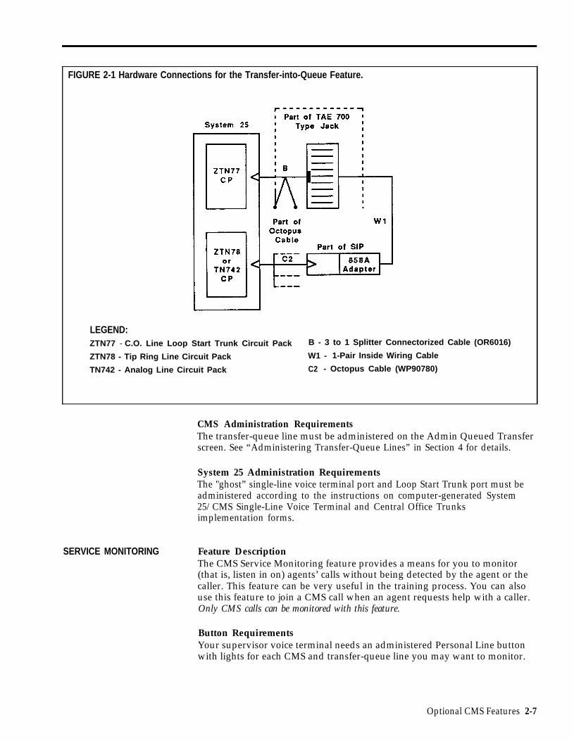
FIGURE 2-1 Hardware Connections for the Transfer-into-Queue Feature.
LEGEND:ZTN77 - C.O. Line Loop Start Trunk Circuit Pack B - 3 to 1 Splitter Connectorized Cable (OR6016)
ZTN78 - Tip Ring Line Circuit Pack W1 - 1-Pair Inside Wiring Cable
TN742 - Analog Line Circuit Pack C2 - Octopus Cable (WP90780)
CMS Administration RequirementsThe transfer-queue line must be administered on the Admin Queued Transferscreen. See “Administering Transfer-Queue Lines” in Section 4 for details.
System 25 Administration RequirementsThe "ghost” single-line voice terminal port and Loop Start Trunk port must beadministered according to the instructions on computer-generated System25/CMS Single-Line Voice Terminal and Central Office Trunksimplementation forms.
SERVICE MONITORING Feature DescriptionThe CMS Service Monitoring feature provides a means for you to monitor(that is, listen in on) agents’ calls without being detected by the agent or thecaller. This feature can be very useful in the training process. You can alsouse this feature to join a CMS call when an agent requests help with a caller.Only CMS calls can be monitored with this feature.
Button RequirementsYour supervisor voice terminal needs an administered Personal Line buttonwith lights for each CMS and transfer-queue line you may want to monitor.
Optional CMS Features 2-7

CONTINGENCY
Hardware RequirementNone.
CMS Administration Requirements None.
System 25 Administration RequirementsAdminister Personal Line buttons on your supervisor voice terminal.
PLAN Feature DescriptionWhen CMS is not managing calls, either because you are generating reportsor administering the system, or in the event of PC problems which preventCMS from managing calls, you can still distribute calls automatically to agentsif you have implemented the CMS contingency plan. This backup plan usesthe System 25 Direct Group Calling (DGC) Group Coverage feature todistribute CMS calls to predefined groups of agents. Each of these agentgroups is known as a System 25 DGC group. Calls to a DGC group hunt foran idle voice terminal in a circular manner starting with the voice terminalfollowing the last one to ring (whether or not the call was answered at thatvoice terminal). CMS statistics are not kept for calls handled through theDGC feature. For information on using this feature to manage calls, see"Managing Calls When CMS is Not Running" in Section 9.
Button RequirementsNone.
Hardware RequirementsNone.
CMS Administration RequirementsNone.
System 25 Administration RequirementsFor each CMS line group, a "ghost" 34-button voice terminal on a fictitiousSystem 25 ATL Line Circuit Pack must be administered. Each "ghost" voiceterminal must have a Personal Line button administered for each CMS andtransfer-queue line in that line group. The "ghost" voice terminal must alsohave DGC Group Coverage. The DGC group covering the "ghost" voiceterminal must be administered to include the agent voice terminals whichnormally handle calls to the line group.
In the section, "Completing System 25/CMS Implementation Forms", in theCMS Planning Guide, you will find information for setting up this contingencyplan. It is strongly recommended that you complete the necessary System25/CMS implementation forms for the contingency plan and that you haveyour System 25 Administrator or System 25/CMS installer complete allnecessary administration before you start using CMS so this alternate means ofcall distribution is available if you should need to use it.
2-8 Optional CMS Features

IMPORTANT: The administration of fictitious System 25 voice terminalports causes the following message to be entered as a PermanentSystem Alarm and also causes the Alarm light on the Attendantconsole to flash following a Warm Start of System 25:
XXXXX Port Board Missing But Administered
(XXXXX represents the port number of the fictitious port.)
The Attendant Alarm light can be turned off by removing thePermanent System Alarm message through System 25 administration.The System 25 translations for the fictitious port(s) must not beremoved or the CMS contingency plan, described above, will notwork.
Optional CMS Features 2-9

A Typical CMS Application
In this part of the manual you’ll learn about a fictitious travel agency, BonVoyage Travel, which uses CMS to manage the revenue producing incomingcall traffic for its System 25 communications system. Examples based on BonVoyage Travel are used in the remaining sections of this manual.
CMS AND BON VOYAGE At Bon Voyage Travel, agents plan and book trips for several types ofTRAVEL customers. Most of the travel agency orders are placed by phone, so CMS
plays an important role in the agency’s daily business transactions.
In order to handle three different types of customers and to manage thefrequent overflow of calls, Bon Voyage Travel’s CMS Supervisor has dividedthe telephone lines customers use into three line groups and organized thetravel agents into four splits. Figure 2-2 shows a diagram of Bon VoyageTravel’s CMS.
FIGURE 2-2 Bon Voyage Travel’s CMS.
Public Line Group
4 lines with the published number 555-3070;
2 lines with the publishednumber 800-555-4185;
2 priority Lines with the unpublishednumber 800-555-4950;
1 transfer-queue line withthe PDC 500.
Business Line Group
4 lines with the publishednumber 800-555-1242;
2 lines with the publishednumber 555-8300.
Charter Line Group
2 lines with the publishednumber 555-1234;
3 lines with the publishednumber 800-555-3000.
= Calls routed to the main split
= Calls intraflowed to the secondary split
2-10 A Typical CMS Application

• The Public line group has nine lines, eight Central Office (CO) trunks andone transfer-queue line. There are four local lines with the publishednumber 555-3070, and two WATS lines with the published number 800-555-4185. The number for the local lines is published in the Yellow Pagesand advertised in the local newspapers; the number for the WATS lines isadvertised in several national travel magazines. There are also twopriority lines with the number 800-555-4950. These lines are reserved forvalued repeat customers who may book several trips with Bon VoyageTravel each year. Their unpublished telephone number is given only tothese preferred clients. For reporting purposes, the Central Office lineshave been divided into three line sub-groups, Public local lines (PL),Public WATS lines (PW), and Public special lines (PS).
In addition, there is one transfer-queue line assigned to this line group.When calls come in on lines other than the Public line group’s lines andneed to be placed in the Public line group’s queue of waiting calls, agentscan transfer the calls to PDC 500, the PDC of the single-line portassociated with the transfer-queue line. The transfer-queue line is in linesub-group Q1.
Calls coming into the Public -line group are from customers who want tobook personal vacations. The Public Travel split handles calls that comeinto the Public line group.
To provide optimal service to customers when there is a high volume ofcall traffic coming into the Public line group, the Support split has beenassigned as the Public line group’s secondary (or backup) split. Thenumber of agents available for CMS calls in this split varies according tothe incoming call traffic. The employees who staff the Support split haveprimary responsibilities such as bookkeeping, advertising, and trippackaging. But, since these people have some experience as travel agents,they are often used to back up the Personal Travel split when call traffic isheavy on the lines in the Public line group.
• The Business line group consists of six lines. These lines have beendivided into two line sub-groups. One line sub-group, BW, contains fourWATS lines with the published number 800-555-1242. The other line sub-group, BL, has two lines for local service with the advertised number 555-8300.
Calls coming into this line group are from large corporations wishing tobook business trips for their employees. The Business Travel split servesas this line group’s main split.
• The Charter line group consists of five lines, divided into two line sub-groups. Two lines, which have the published number 555-1234 listed inthe local Yellow Pages, are in the line sub-group CL. Three WATS lines,which have the published number 800-555-3000 listed in national travelmagazines, are in the line sub-group CW.
The Charter Travel split, which handles CMS calls coming into theCharter line group, arranges trips for groups and frequently books tripsfor local and national holiday clubs.
A Typical CMS Application 2-11

Occasionally, customers who have previously made travel arrangementsthrough a holiday club will call one of the Charter line group’s numbers tomake personal travel arrangements. In these cases the agent in theCharter split who receives the call uses the Transfer-into-Queue feature totransfer the call to the Public line group’s queue of waiting calls. CMSthen distributes the call to an agent in the Public Travel split.
Since both the Charter Travel split and the Business Travel split handlegroup trips, the Business Travel split serves as a secondary split to handlecall overflow from the Charter Travel split. Likewise, the Charter Travelsplit backs up the Business Travel split during peak calling hours.
BON VOYAGE TRAVEL’S All of Bon Voyage Travel’s voice terminals and outside telephone lines areOTHER CALL TRAFFIC part of the agency’s System 25 communications system, but some of Bon
Voyage Travel’s voice terminals and outside lines are not assigned to the CallManagement System. Agents and nonagents alike use lines not assigned toCMS for all outgoing calls and nonrevenue producing incoming calls.
CMS AND OTHERBUSINESSES
Bon Voyage Travel’s line groups and agent splits are typical for a travelagency. Other types of businesses would have other names for their linegroups and splits. For example, a wholesale distributor might have linegroups and splits for inside sales and customer service (such as ordertracking) while a bank may have line groups and splits dedicated to specifictypes of loans and customer services. The characteristics of your businessshould dictate your decisions as you plan your CMS.
2-12 A Typical CMS Application

Managing CMS
Since System 25 must be administered to support CMS, the CMS Supervisorand the System 25 Administrator work together to ensure successful CMSoperation. This section describes the typical CMS interactions andresponsibilities of these two people.
RESPONSIBILITIES OF The CMS Supervisor has many responsibilities, all of which are described inTHE CMS SUPERVISOR this manual. Typically, the role of the CMS Supervisor involves:
• Working with the System 25 Administrator to:
– Identify and record port numbers, PDCs, and trunk numbers for CMSequipment
– Ensure removal of stations or trunks no longer needed by CMS
– See that System 25 administration needed to support CMS isperformed
Administering CMS, including the following:
Administering stations, CMS lines, transfer-queue lines, line groups,and voice announcement units
– Building an Agent Directory
– Creating shift configurations of line groups and agent splits
– Setting options
– Selecting Exception Thresholds to be monitored
– Printing System 25 administration instructions
See Section 4, “Administering CMS. ”
Monitoring line status, split status, call traffic, and system problemsduring call management, and making changes to shift configurations asneeded, to ensure efficient call handling and maximum agent productivity.See “Monitoring Call Management” and “Dynamic Reconfiguration” inSection 5.
Helping agents understand how to use their voice terminals for handlingCMS calls. See Section 6, “Handling CMS Calls. ”
Generating reports and using the data in the CMS reports to maintainefficient call management and agent productivity. See Section 7,"Generating Reports," for ongoing data collection; see Section 8, "Archiving Data," for storing historical CMS data.
Having a contingency plan in place and using it to manage calls whenCMS is not running. See “Managing Calls When CMS is Not Running” inSection 9.
Troubleshooting. See Section 9, “Troubleshooting.”
•
•
•
•
•
Managing CMS 2-13

RESPONSIBILITIES OF System 25 and CMS must be administered identically with respect to trunkTHE SYSTEM 25 numbers, port numbers, PDCs, and feature button assignments required byADMINISTRATOR CMS. The following are typical responsibilities involved in maintaining
harmony between the two systems:
●
●
●
Assigning trunk numbers, ports, and PDCs to CMS equipment andfacilities, both when CMS is installed and when more resources areneeded.
Using the System 25 administration instructions printed out by the CMSsoftware, along with hand-completed System 25/CMS implementationforms, to administer System 25 for CMS.
Backing up System 25 translations to a tape or diskette when CMS is firstconfigured and after changes are made. (Translations are specificinformation assigned to a voice terminal or System 25 such as portnumbers and PDCs. )
2-14 Managing CMS

CMS Components
This section lists the hardware required for and trunks compatible with CMS.
HARDWARE COMPATABLEWITH CMS
•••
•••••
•
•
•
The following hardware and software are required for CMS:
AT&T System 25: Release 2
An—
—
—
—
—
AT&T Personal Computer (PC), with the following characteristics:
Hard disk (10 MB and 512K RAM minimum)
One floppy diskette drive
MS-DOS 3.2, Version 2.02 (or higher)
Keyboard
Monochrome or color monitor
AT&T Printer Model 473 (or compatible parallel printer)
AT&T CMS PC Interface Card
Two System 25-CMS floppy diskettes
At least two blank floppy diskettes
Agent voice terminals (any of the following):—
—
—
—
—
—
—
—
—
—
—
5-Button Voice Terminal
10-Button Voice Terminal
10-Button Hands-Free Answer on Intercom (HFAI) Voice Terminal
10-Button Built-in Speakerphone (BIS) Voice Terminal
22-Button BIS Voice Terminal
34-Button Voice Terminal
34-Button Deluxe Voice Terminal
34-Button BIS Voice Terminal
34-Button Deluxe BIS Voice Terminal
34-Button BIS Voice Terminal with Display
34-Button Deluxe BIS Voice Terminal with Display
Direct Trunk Attendant Console (DTAC), a 34-Button Deluxe or34-Button Deluxe BIS Voice Terminal
Switched Loop Attendant Console (SLAC), a 34-Button Deluxe BISwith Display -
Supervisor voice terminal:
– One 34-button Deluxe voice terminal is required. A second multilinevoice terminal may be needed.
For more information about selecting a voice terminal for yourself and forthe CMS agents, see Section 6, “Handling CMS Calls. ”
Cables:
– Two 14-foot 4-pair modular-plug stations cords (D8W-87) forconnections to the AT&T CMS PC Interface Card
CMS Components 2-15

The following optional hardware can be used with CMS:
● Up to four Model DACON-DA-5SL voice announcement units (stronglyrecommended). One 14-foot 2-pair modular-plug station cord (D4BU-87) isrequired for each voice announcement unit.
● Headsets and headset adapters
NOTE: A headset and headset adapter cannot be used with a 5-buttonvoice terminal or a 10-button HFAI voice terminal.
● A music source compatible with the System 25 Music-on-Hold port(strongly recommended).
● A telephone answering machine capable of answering calls on the firstring for special Night Service applications. See "Caller Message RecordingDuring Night Service" in Section 5.
TRUNKS COMPATIBLE Either Ground Start or Loop Start trunks maybe used with CMS, butWITH CMS Ground Start trunks are strongly recommended because they lessen the
likelihood of abandoned calls being transferred to agents. Ground Starttrunks are also recommended if headsets will be used with voice terminalsused for CMS.
Central Office (CO), WATS (800 Service), and Foreign Exchange (FX) trunksmay be used with CMS. Trunks may be arranged in CO hunt groups. Ahunt group is a group of trunks that share a listed telephone number. Whena call comes in on the listed number, the CO switch scans the hunt group foran idle trunk and connects the call to the first one it finds.
THE VOICE Before recording delay messages on the DACON unit, read theANNOUNCEMENT UNIT documentation that came with it, and keep the following guidelines in mind:
● You can assign a separate voice announcement unit to each linegroup, or two or more line groups can share one voiceannouncement unit.
● The voice announcement unit has two channels to provide twomessages, one for Day Service and the other for Night Service. Theannouncement unit has 64 seconds of message time available that canbe divided between your two messages.
● Leave 3 or 4 seconds of silence before the beginning of your messageto allow time for CMS to connect the caller to the voiceannouncement unit. This will ensure that the caller will hear themessage from the beginning.
● You must note the length of the Day Service message on the AssignAnnouncement screen. See “Assigning Announcements” in Section4 for more information.
● If call traffic is light when CMS is in Night Service mode, you canuse a telephone answering machine(s) to answer calls and recordcallers’ voice messages. Refer to “Caller Message Recording DuringNight Service” in Section 5 of this manual for additional information.
2-16 CMS Components

RECORDING MESSAGES The following steps describe how to record a message on your DACON voiceannouncement unit. Figure 2-3 shows you the front of the unit.
FIGURE 2-3 The DACON-DA-5SL Voice Announcement Unit.
NOTE: If you are recording only one message, the message can be upto 64 seconds in length. If you are recording two messages, onemessage on Channel 1 and one on Channel 2, you must divide the 64seconds of message time between the two messages.
Prepare a clear, informative message before you begin to record. Once youhave plugged in the voice announcement unit and turned it on, use thefollowing instructions to record a message on Channel 1.
1 Turn your DACON unit so that the front of the unit is facing you.
2 Insert the handset modular plug into the front panel jack.
3 To record on Channel 1, the red light on the Channel button must be off.If the light is on, press the Channel button once so that the light goes off.
4 Press the Record button and hold it down while you press the Playbutton.
(The Channel button light flashes during the first 16 seconds of yourrecording. The Record button light flashes during the second 16 seconds.The Play button light flashes during the third 16 seconds. The On-Linebutton light flashes during the fourth 16 seconds.)
5 Speak into the handset to record your message.
6 When you are finished recording your message, press the On-Line button.
To record a message on Channel 2, follow this procedure:
1 The red light on the Channel button must be on. If the light is off, pressthe Channel button once.
(The red light on the button goes on.)
2 Repeat steps 4 through 6 above to record the message.
CMS Components 2-17

To listen to the recorded announcement on either of the channels:1
2
3
4
5
Make sure the handset is plugged into the front panel jack.
If you want to listen to a message on Channel 1, make sure that the redlight on the Channel button is off.
If you want to listen to a message on Channel 2, the red light on theChannel button should be on.
Press the Play button.
Listen to the message through the handset.
If you want to rerecord the message, follow the steps in this section forrecording announcements.
2-18 CMS Components

Section 3: Your PC and CMS

Overview
CMS runs on the AT&T Personal Computer (PC). By working with the CMSmenus and screens, you can tailor CMS to suit your business needs. Thissection of the manual describes how to load the CMS software onto your PC’shard disk and how to enter data into your PC.
The information in this section is organized as follows:
Duplicating the CMS Diskettes
Describes how to make working copies of the CMS diskettes. (A set of blankdiskettes has been packaged with the CMS binder.)
Installing the CMS Software
Describes how to copy the CMS software onto the PC’s hard disk, and set thetime and date on your PC.
Using Your PC with CMS
Describes how to use CMS screens, enter and edit data, and access helpscreens.
Overview 3-1

Duplicating the CMS Diskettes
Since it is important to protect your original CMS floppy diskettes fromdamage or wear, a duplicate (working copy) of each diskette was made whenCMS was installed. Keep the originals in a safe place and use them only tomake additional working copies.
If you have to make additional working copies, you need the following:
● Your PC
● The original CMS diskettes, labeled “SYSTEM 25 CMS SYSTEM” and“ SYSTEM 25 CMS REPORT AND ADMIN”
● Two blank diskettes
NOTE: If you are reusing diskettes, make sure the diskettes do nothave old files on them that you need because they will be overwrittenwhen you copy the CMS diskettes.
In order to make duplicates of the CMS diskettes, MS-DOS (including the“diskcopy” and “diskc omp” commands) must already be on the hard disk.MS-DOS (including these commands) was installed on your PC’s hard diskwhen CMS was first installed.
DUPLICATING THE CMS To make duplicate copies of the original CMS diskettes:DISKETTES Turn on the PC.1
If the CMS Menu appears, press [F8] (labled "Exit to DOS") to get to the MS-DOS prompt.
2 When the C> prompt appears, type:
diskcopy a: a:
and press [Enter]
You see the following messages:
Insert SOURCE diskette in drive A:Strike any key when ready . . .
NOTE: PC responses may be slightly different from the ones printed here,depending on the version of MS-DOS you are using.
3 Insert the original CMS diskette labeled “SYSTEM 25 CMS SYSTEM, ” intodrive A with the label of the diskette facing upwards, and the notch in theside of the diskette on the left. When you hear a click, indicating that thediskette has been fully inserted, press down the latch on drive A until youfeel the latch lock.
This diskette is the “source” diskette, the diskette that contains theinformation being copied.
3-2 Duplicating the CMS Diskettes

4 When you are ready, press any key.
The in-use light on disk drive A comes on while the system is reading thesource diskette.
5
6
7
8
9
WARNING
Do not remove a diskette from the drive while thein-use light is on; data on the diskette may bedamaged or lost.
When the system has read the diskette, the following messages aredisplayed:
Insert TARGET diskette in drive A:Strike any key when ready. . .
When the in-use light on drive A is off, remove the source diskette, inserta blank diskette, and press any key. This diskette is the “target” diskette,the diskette on which the information is being copied.
The in-use light comes on while the system is copying the informationonto the target diskette. If the blank diskette is not formatted, themessage
Formatting While Copying
appears on the screen.
NOTE: Depending on the amount of memory on your PC, the system mayprompt you to swap diskettes during diskcopy.
When the copying process is finished, you see:
Copying completeCopy another diskette (Y/N)?
Remove the duplicate diskette, write “SYSTEM 25 CMS SYSTEMWORKING COPY” on a label using a felt tip pen, apply the label to thediskette, and put the diskette in its paper sleeve. Return the originaldiskette to its paper sleeve.
Type y. The following message appears:
Insert SOURCE diskette in drive A:Strike any key when ready...
Insert the original CMS diskette labeled “SYSTEM 25 CMS REPORT ANDADMIN” into drive A. This is the source diskette.
Repeat Steps 4 and 5, using the second blank diskette as the “target”diskette.
Duplicating the CMS Diskettes 3-3

10 Type n when prompted to copy another diskette.
11 When the C> prompt appears, remove the duplicate diskette, write“SYSTEM 25 CMS REPORT AND ADMIN WORKING COPY” on a labelusing a felt tip pen, apply the label to the diskette, and store the diskettein its paper sleeve. Return the original diskette to its paper sleeve.
12 Store both the original and working copy CMS diskettes in a safe place.
It is recommended that you store the working copy diskettes separatelyfrom the original diskettes.
3-4 Duplicating the CMS Diskettes

Installing the CMS Software
COPYING THE CMS SOFTWARE ONTO THE PC’S HARD DISK
Installing the CMS software involves copying the contents of the workingcopies of the two CMS diskettes onto the PC’s hard disk. This was donewhen CMS was first set up for you. As part of the installation procedure, aCONFIG.SYS and an AUTOEXEC.BAT file were placed on your PC’s harddisk. If these files existed prior to CMS installation, the installation procedureedited these files. See “The CONFIG.SYS File” and “The AUTOEXEC.BATFile” later in this section.
You can perform the following software procedures tore-install the CMSsoftware if errors occur that you cannot fix and you need to begin again.When you are finished, the system will have copied the programs requiredfor CMS operations onto the ‘PC’s hard disk. -
— —
1
2
3
To copy the CMS software onto the PC’s hard disk:
Insert the diskette labeled “SYSTEM 25 CMS SYSTEM WORKING COPY”into drive A.
At the C> prompt, type a:\cmsinstall and then press [Enter]..
The following messages appear in the upper portion of the screen andremain on the screen throughout the installation procedure:
**** SYSTEM 25 Call Management System**** Installation Procedure
Additional messages appear in the lower area of the screen.
While the installation procedure is in progress, the following messageusually appears on your screen:
**** Installation Now In Progress. Please Wait...
However, there are a couple ways in which the installation procedurecould be interrupted:
— If there are errors on your CMS working copy diskette that preventthe installation program from continuing, the following messagesappear on the screen:
**** ERROR on Installation Floppy DiskTry installation from Another Floppy
Discard the diskette, make another working copy using the originalCMS diskette, and then begin the CMS software installation procedureagain.
— If there is insufficient storage space on the hard disk for newinformation, the following messages appear on your screen:
**** “Insufficient Disk Space for CMS.An Additional xxxK is Required.Delete Old Files and Try Installation Again.
If you need directions on using the MS-DOS “delete” (del) and“directory” (dir) commands to delete files, see the user’s guide thatcame with the MS-DOS diskette.
Installing the CMS Software 3-5

4
5
6
7
8
9
After the contents of the “SYSTEM 25 CMS SYSTEM WORKING COPY”diskette have been copied onto the hard disk, the following messages aredisplayed:
**** Please remove the diskette currently in floppy disk drive A.**** “Insert the diskette labeled SYSTEM 25 CMS REPORT AND ADMIN
into drive A.Press ‘c’ to continue or ‘q’ to quit.
Remove the “SYSTEM 25 CMS SYSTEM WORKING COPY” diskette andplace it in its protective cover.
Insert the diskette labeled “SYSTEM 25 CMS REPORT AND ADMINWORKING COPY” into drive A and press c .
Once the installation program has copied all the CMS programs and filesonto the hard disk, the final installation messages appear on your screen:
**** Call Management System Successfully Installed.**** Please remove the diskette currently in floppy disk drive A.**** Reboot the system by holding down ‘CTRL’ and ‘ALT’ while
pressing ‘DEL.’
Remove the “SYSTEM 25 CMS REPORT AND ADMIN WORKINGCOPY” from the disk drive, place it in its paper sleeve, and store it in asafe place.
Reboot the system by holding down [Ctrl] and [Alt] while pressing [Delete].
After Resident Diagnostics are run, the CMS Menu appears on the screen.—
3-6 Installing the CMS Software

The CONFIG.SYS File
In order for the CMS software to run properly, you must have aCONFIG.SYS file in the root (\) directory of the PC’s hard disk. This filemust contain the following lines:
BUFFERS =20FILES =20
If the CONFIG.SYS file existed prior to CMS software installation, the abovetwo lines were appended to the file when CMS was installed. If no fileexisted, a CONFIG.SYS file containing these lines was automatically createdwhen CMS was installed.
To view the contents of the CONFIG.SYS file:
1 At the C> prompt, typecd \
then press [Enter]
2 At the C> prompt, type
type config.sys
then press [Enter].
The contents of the CONFIG.SYS file appear on the screen.
Installing the CMS Software 3-7

The AUTOEXEC.BAT File
During the CMS installation process, an AUTOEXEC.BAT file containing thethree lines below was placed on your PC’s hard disk. If the AUTOEXEC.BATfile existed on your PC’s hard disk prior to CMS installation, these three lineswere added to the end of the file when CMS was installed.
The three lines are:
prompt $p$gcd c: \cmscms
The first line causes the full pathname of the current directory to be displayedas part of the MS-DOS prompt. The second and third lines cause the CMSMenu to displa}’ automatically after MS-DOS Resident Diagnostics are run.This happens whenever your PC is turned on or MS-DOS is rebooted.
If you ever edit the AUTOEXEC.BAT file, make sure these lines remain as thelast three lines of the file.
To view the contents of the AUTOEXEC.BAT file:
1 At the C> prompt, type
cd \
then press [Enter].
2 At the C> prompt, type
type autoexec.bat
then press [Enter].
The contents of the AUTOEXEC.BAT file appear on the screen.
3-8 Installing the CMS Software

Setting the Time and Date
Since the date and time are significant parts of your daily CMS statistics, it isimportant that your PC screen show the correct date and the correct time.
You can check the time and date by looking at the upper right-hand corner ofany CMS screen. If the time or date is incorrect, you can easily change it onyour PC.
To
1
2
3
To
1
2
check or change the date on your PC:
Exit to MS-DOS by pressing [F8] (labeled “Exit to DOS”) on the CMSMenu.
When the C> prompt appears, type
date
and press [Enter].
The following message appears on your screen:
Current date is Wed 4-07-1988Enter new date (mm-dd-yy):
If the date is correct, press [Enter].
If the date is incorrect, type in the correct date in the form mm-dd-yy (forexample, 04-08-88 ) and press [Enter].
check or change the time on your PC:
When the C> prompt appears, type
time
and press [Enter].
The following message appears on your screen:
Current time is 12:01:30.00Enter new time:
If the time is correct, press [Enter].
If the time is incorrect, type in the correct hour and minute in the formhh:mm (for example, 9:03) and press [Enter]. (MS-DOS works on thebasis of a 24-hour clock, so if you want to enter the time as 2:30 P.M. youmust type 14:30.)
MS-DOS keeps track of the seconds and hundredths of seconds.You do not enter these details into your PC.
Installing the CMS Software 3-9

Using Your PC with CMS
SCREEN FORMATS
1
3
4
5
This section describes the format of CMS screens, the method of entering andediting data, and how to access help screens. If you have questions aboutMS-DOS, the layout of your keyboard, or other information about your PC,refer to the manuals that accompanied them.
The general format of a CMS screen is demonstrated below in the AgentDirectory screen. e
a c d
AGENT DIRECTORY ANNC CU1 CU2 Don’tPrtScr LoStorage DAY CMS1.0 2:38p 04/18
Last NameAbellBeckmanBrownChuDumbraFangFentonGarciaGerkensmeierJohnsonKesselringLeonardLindquistLindquistMack
FirstMary-AnnJimAllanDavidMarieJohnScottJoseOttoAndrewAnaMichaelHalHalJoel
AGENT DIRECTORY
IDMARYAJIMALLANDAVEMARIEJohnSCOTTJOSEOTTOANDYANAMIKEHALlHAL2JOEL
Last NameMariettaMassonOngOpalachReichegRowlinsonSeilerSiegelSmithSonSticklerVatierWalshWellYang
2:38 04/18 l *** Split 1 - Agent LINDA - Refused Calls
ADD AGENT: Last Name: Zuckerman First: Amy ID: AMYF Cancel FPrevious F Next1 Prompt 5 Field 6 Field
FirstJaneWilliamIenJosephLouisDonLindaLawrenceBernardSarahCraigBarbaraJenniferHarveyCJ
IDJANEBILLIENJoeLOUDonLINDALARRYBERNESARAHCRAIGBARBJENNYHARVCJ
F Enter8 Data
Each numbered or lettered term listed below corresponds to a number orletter in the screen above. The following types of information may appear inthe indicated area of the screen.
1 The ID line contains:
a Screen name
b Status indicators: ANNC blinks if there is a voice announcement unitproblem. (If you decide not to use any voice announcement units,ANNC appears in the ID line, even though there is no problem.) Ifthere is a problem with the connections to the PC, CU1 and/or CU2blinks. Don’tPrtSc appears if the printer is disconnected or is notready. NoStorage or LoStorage appears if there is a storage problemon the hard disk. For information on resolving problems, see Section9, “Troubleshooting.”
c Current CMS mode: CMS appears when the CMS Menu is displayed.DAY or NIGHT indicates that calls are being managed using Day
Service or Night Service mode, respectively. (See “Selecting Day orNight Service” in Section 5.) ADMIN indicates CMS is being used foradministration. REPT appears when you generate reports.
3-10 Using Your PC with CMS
2
3
4
5
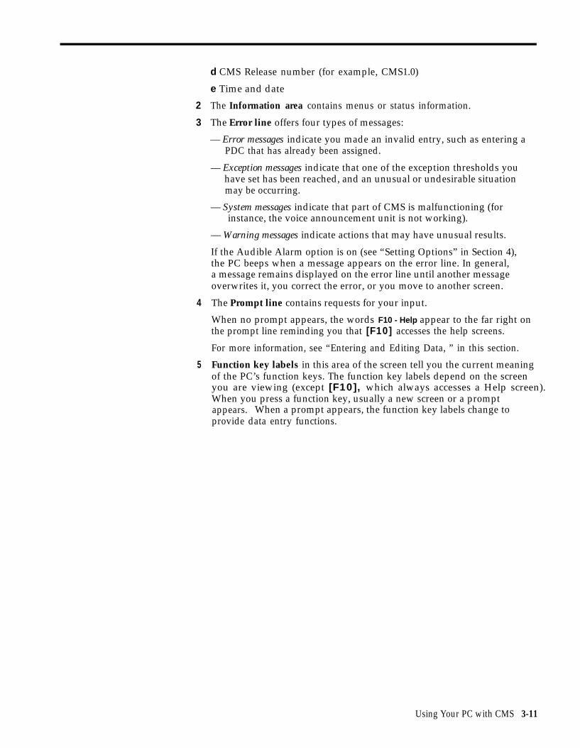
d CMS Release number (for example, CMS1.0)
e Time and date
The Information area contains menus or status information.
The Error line offers four types of messages:
— Error messages indicate you made an invalid entry, such as entering aPDC that has already been assigned.
— Exception messages indicate that one of the exception thresholds youhave set has been reached, and an unusual or undesirable situationmay be occurring.
— System messages indicate that part of CMS is malfunctioning (forinstance, the voice announcement unit is not working).
— Warning messages indicate actions that may have unusual results.
If the Audible Alarm option is on (see “Setting Options” in Section 4),the PC beeps when a message appears on the error line. In general,a message remains displayed on the error line until another messageoverwrites it, you correct the error, or you move to another screen.
The Prompt line contains requests for your input.
When no prompt appears, the words F10 - Help appear to the far right onthe prompt line reminding you that [F10] accesses the help screens.
For more information, see “Entering and Editing Data, ” in this section.
Function key labels in this area of the screen tell you the current meaningof the PC’s function keys. The function key labels depend on the screenyou are viewing (except [F10], which always accesses a Help screen). When you press a function key, usually a new screen or a promptappears. When a prompt appears, the function key labels change toprovide data entry functions.
Using Your PC with CMS 3-11

Entering and Editing Data
Entering and editing data is easy. You enter data by pressing function keysand responding to the prompt that appears on the prompt line on yourscreen. Prompts contain one or more fields (blank spaces) into which youtype your responses. Whenever a prompt appears, the function keys arelabeled as shown in the screen below.
AGENT DIRECTORY ADMIN CMS1.O 2:31p 04/18
AGENT DIRECTORY
Last Name First ID Last Name First ID
AbellBeckmanBrownChuDumbraFangFentonGarciaGerkensmeirJohnsonKesselringLeonardLindquistLindquistMack
Mary-AnnJimAllanDavidMarieJohnScottJoseOttoAndrewAnaMichaelHalHalJoel
MARYAJIMALLANDAVEMARIEJOHNSCOTTJOSEOTTOANDYANAMIKEHAL1HAL2JOEL
ManettaMassonOngOpalachReichegRowlinsonSeilerSeigelSmithSonSticklerVatierWalshWollYang
JaneWilliamIenJosephLouisDonLindaLawrenceBernardSarahCraigBarbaraJenniferHarveyCJ
JANEBILLIENJOELOUDONLINDALARRYBERNESARAHCRAIGBARBJENNYHARVCJ
ADD AGENT:F Cancell Prompt
Last Name: First:F Previous5 Field
ID:F Next8 Field
F Enter8 Data
NOTE: When a prompt contains only one field, the only function keysdisplayed are [F1] (labeled “Cancel Prompt”) and [F8] (labeled“Enter Data” ).
In this manual, instructions for entering data in prompts are usuallypresented as follows:
[F1] Add Agent
Pressing this function key on the Agent Directory screen allows you to addagents to CMS.
Prompt:
ADD AGENT: Last Name: First: ID:
Action: 1 Enter a last name up to 12 letters, numbers, or specialcharacters (such as * or #), with no spaces between them.
2 Enter a first name up to eight letters, numbers, or specialcharacters, with no spaces between them.
3 Enter a unique ID up to five letters and/or numbers.
4 Press [F8] (labeled “Enter Data”).
3-12 Using Your PC with CMS
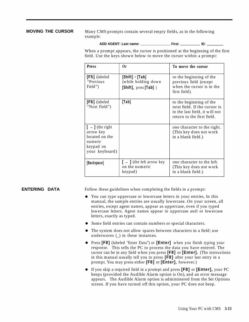
MOVING THE CURSOR Many CMS prompts contain several empty fields, as in the followingexample:
ADD AGENT: Last name: First: ID:
When a prompt appears, the cursor is positioned at the beginning of the firstfield. Use the keys shown below to move the cursor within a prompt:
Press Or To move the cursor
[F5] (labeled [Shift] + [Tab] to the beginning of the“Previous (while holding down previous field (exceptField”) [Shift], press [Tab] ) when the cursor is in the
first field).
[F6] (labeled [Tab] to the beginning of the“Next Field”) next field. If the cursor is
in the last field, it will notreturn to the first field.
[ → ] (the right one character to the right.arrow key (This key does not worklocated on the in a blank field.)numerickeypad onyour keyboard)
[Backspace] [ ← ] (the left arrow key one character to the left.on the numeric (This key does not workkeypad) in a blank field.)
ENTERING DATA Follow these guidelines when completing the fields in a prompt:
●
●
●
●
●
You can type uppercase or lowercase letters in your entries. In thismanual, the sample entries are usually lowercase. On your screen, allentries, except agent names, appear as uppercase, even if you typedlowercase letters. Agent names appear in uppercase and/or lowercaseletters, exactly as typed.
Some field entries can contain numbers or special characters.
The system does not allow spaces between characters in a field; useunderscores (_) in these instances.
Press [F8] (labeled "Enter Data") or [Enter] when you finish typing yourresponse. This tells the PC to process the data you have entered. Thecursor can be in any field when you press [F8] or [Enter]. (The instructionsin this manual usually tell you to press [F8] after your last entry in aprompt. You may press either [F8] or [Enter], however.)
If you skip a required field in a prompt and press [F8] or [Enter], your PCbeeps (provided the Audible Alarm option is On), and an error messageappears. The Audible Alarm option is administered from the Set Optionsscreen. If you have turned off this option, your PC does not beep.
Using Your PC with CMS 3-13

EDITING DATA
VALIDATING DATA
USING THE HELP SCREENS
To
●
To
●
To
●
To
●
IMPORTANT: To cancel any prompt, press [F1] (labeled “CancelPrompt”) or [Delete]. Any data you entered in the prompt fields areignored, the prompt disappears, and the function key labels changefrom data entry labels to the labels for the particular CMS screen.
change a character in a field:
Move the cursor to the incorrect character and simply type anothercharacter over it.
add characters at the end of an entry:
Press [ → ] after the last character and type additional characters.
insert characters in an entry:
Move the cursor to the first character you want to change and retype theentry from that character onward. You cannot use [Insert] to insert acharacter between other characters.
replace a long entry with a shorter one:
Type over any characters you want to change, then press the space barafter the last character of the new entry. The remaining characters in theprevious entry disappear. For example, to change “Joseph” to “Joe”,move the cursor to “s”, type “e”, and press [Space]. The letters “eph”disappear.
CMS validates the information entered in two ways:
1 The first type of validation occurs as you type each piece of information ina field. If you make an invalid entry (for instance, entering a letter in anumeric field), the PC beeps, the character does not display, and thecursor remains in the same position so you can make another entry.
2 The second type of validation occurs after you press [F8] (labeled “EnterDatan). At this point, CMS begins to validate each field of informationfrom left to right. If there is an invalid entry or you left a required fieldblank, the PC beeps, and an error message appears above the prompt.The cursor returns to the first error so you can correct the entry.
You can press [F10] (labeled “Help”) on any screen to receive moreinformation about the function keys on that screen. To exit a Help screen andreturn to your previous place, press the spacebar. If you press a labeledfunction key to exit a Help screen, you will exit Help and then perform thefunction of that particular function key.
3-14 Using Your PC with CMS

Section 4: Administering CMS
Overview
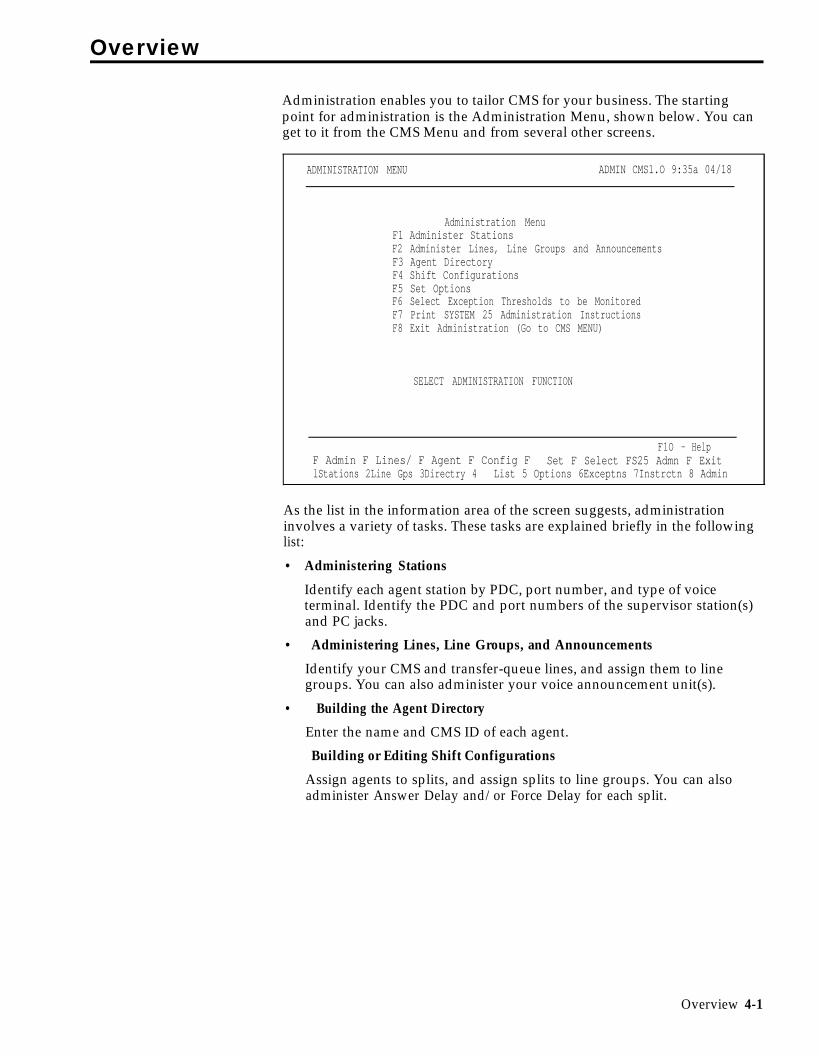
Administration enables you to tailor CMS for your business. The startingpoint for administration is the Administration Menu, shown below. You canget to it from the CMS Menu and from several other screens.
ADMINISTRATION MENU ADMIN CMS1.O 9:35a 04/18
Administration MenuF1 Administer StationsF2 Administer Lines, Line Groups and AnnouncementsF3 Agent DirectoryF4 Shift ConfigurationsF5 Set OptionsF6 Select Exception Thresholds to be MonitoredF7 Print SYSTEM 25 Administration InstructionsF8 Exit Administration (Go to CMS MENU)
F1O - HelpF Admin F Lines/ F Agent F Config F Set F Select FS25 Admn F ExitlStations 2Line Gps 3Directry 4 List 5 Options 6Exceptns 7Instrctn 8 Admin
SELECT ADMINISTRATION FUNCTION
As the list in the information area of the screen suggests, administrationinvolves a variety of tasks. These tasks are explained briefly in the followinglist:
• Administering Stations
Identify each agent station by PDC, port number, and type of voiceterminal. Identify the PDC and port numbers of the supervisor station(s)and PC jacks.
• Administering Lines, Line Groups, and Announcements
Identify your CMS and transfer-queue lines, and assign them to linegroups. You can also administer your voice announcement unit(s).
• Building the Agent Directory
Enter the name and CMS ID of each agent.
Building or Editing Shift Configurations
Assign agents to splits, and assign splits to line groups. You can alsoadminister Answer Delay and/or Force Delay for each split.
Overview 4-1

● Setting Options
Tailor CMS to your business needs by defining your Service Level Limit,Abandoned vs. Incoming Call Threshold, and Transfer Return Threshold.You can also set your PC to beep whenever an unusual or undesirablesituation occurs. In addition, you can turn on and off a validation optionthat causes CMS to perform a check of PC-Port Personal Line buttonadministration when call management is started.
● Selecting Exception Thresholds to be Monitored
Select the agent, split, and line group exceptions that are appropriate foryour business.
● Printing System 25 Administration Instructions
Print the instructions that the System 25 Administrator will need in orderto administer System 25 to support CMS.
● Backing Up Shift Configurations
Make a backup copy of your shift configurations in case you need torestore your system after a problem.
4-2 Overview

The map of the CMS Administration screens in Figure 4-1 illustrates theinterrelationships of the screens used for CMS administration.
FIGURE 4-1 Menu Map for CMS Administration.
Overview 4-3

Getting Started
STARTING CMSADMINISTRATION
These procedures describe turning on the PC and selecting an administrationactivity from the Administration Menu.
To start administering CMS:
1 Make sure the PC’s floppy drive is empty; then turn on your PC.
The AUTOEXEC.BAT file, installed on your PC’s hard disk during theCMS installation process, causes the CMS Menu to be displayedautomatically after MS-DOS Resident Diagnostics are run. (For moreinformation, see “The AUTOEXEC.BAT File” in Section 3.)
NOTE: If the PC is already on and the C> prompt appears, do thefollowing to display the CMS menu:
a Type cd \cms and press [Enter].
b Type cms and press [Enter].
The CMS Menu, shown below, appears.
CMS MENU CMS CMS1.09:19a 04/18
CALL MANAGEMENT SYSTEM (CMS)
FOR THE AT&T SYSTEM 25 PBX
(c) 1988 by AT&T
F1 Start Call Management
F4 Administer CMS
F5 Print Reports
F8 Exit to DOS
F10 - HelpF Start F Admin F Print F Exit1 Call Mgt 4 CMS 5 Reports 8 to DOS
4-4 Getting Started

2 Press [F4] (labeled “Admin CMS”) to begin administering CMS.
The Administration Menu screen, shown below, appears.
ADMINISTRATION MENU ADMIN CMS1.O 9:35a 04/18
F1F2F3F4F5F6F7F8
Administration MenuAdminister StationsAdminister Lines, Line Groups and AnnouncementsAgent DirectoryShift ConfigurationsSet optionsSelect Exception Thresholds to be MonitoredPrint SYSTEM 25 Administration InstructionsExit Administration (Go to CMS MENU)
SELECT ADMINISTRATION FUNCTION
F1O - HelpF Admin F Lines/ F Agent F Config F Set F Select F S25 Admin F Exit1 Stations 2 line Gps 3 Directry 4 List 5 Options 6 Exceptns 7 Instrctn 8 Admin
3 Press the function key for the administration activity you want toperform. Turn to the corresponding instructions in this section of themanual.
Getting Started 4-5

Administering Stations
Administering stations with the CMS PC involves:
• Entering the System 25 PDC, port number, and voice terminal type foreach agent station (voice terminal)
• Entering the PDCs and port numbers for up to two supervisor stations
• Entering the PDCs and port numbers for the two PC jacks
• Removing agent stations no longer needed for CMS
• Changing the information associated with an agent station, supervisorstation, or PC jack, as needed
IMPORTANT: Port number and PDC assignments are made by theSystem 25 Administrator. Changes in port number and PDCassignments should not be made without consulting the System 25Administrator. System 25 and CMS must reflect the sameassignments of port numbers, PDCs, and voice terminal type forcorrect operation of CMS. If you make any additions, deletions, orchanges when administering stations that require System 25administration, CMS prompts you to print System 25 administrationinstructions when you attempt to exit CMS administration. You mustprint the System 25 administration instructions and have your System25 Administrator administer System 25 to reflect these changes.Otherwise, CMS may not function properly. For more information,see “Printing Administration Instructions,” later in this section.
Pressing [F1] (labeled “Admin Stations”) on the Administration Menu selectsthe Administer Stations screen shown below.
ADMINISTER STATIONS ADMIN CMS1.0 9:44a 04/19
AGENT STATIONS
PDC Port# Type PDC Port# TYPE401 11101 304 411 11203 304402 11102 304 412 11204 304403 11103 304 413 11205 304404 11104 304 414 11206 304405 11105 304 415 11207 304406 11106 304 416 11208 308407 11107 304 417 11004 304408 11108 304 418 11006 304409 11201 304 424 10902 307 Other Connections410 11202 304 U S E PDC Port #
SUPVR STA: 430 11001431 11002
PC Jack CU1: 600 11003PC Jack CU2: 601 11005
F10 - HelpF Add F Remove F Change F Admin F Admin F Admin1 Agnt Stn 2 Agnt Stn 3 Agnt Stn 5 Supervsr 6 PC Jacks 8 Menu
4-6 Administering Stations

This section describes the following activities which you can perform from theAdminister Stations screen:
●
●
●
●
●
Adding an Agent Station
Add an agent station to CMS.
Removing an Agent Station
Take an agent station out of CMS use.
Changing Agent Station Information
Change an agent station’s port number or voice terminal type.
Administering the Supervisor Station(s)
Identify the System 25 PDC and port number of each supervisor station,
Administering PC Jacks
Identify the PDCs and port numbers for the two PC jacks.
ADMINISTER STATIONS When administering stations, keep the CMS Station Assignments PlanningSCREEN form handy. This form includes information about your agent stations,
supervisor stations, and PC jacks.
To administer stations, press the function key for the activity you want toperform:
[F1] Add Agnt Stn (Add Agent Station)
Press this function key to display the prompt that allows you to add an agentstation to CMS by identifying its System 25 PDC and port number, and itsvoice terminal type. You must obtain the PDC and port number from theSystem 25 Administrator.
Prompt: ADD AGENT STATION: PDC: Port #: T y p e :
Action: 1 Enter the System 25 PDC (maximum of 4 digits).
2 Enter the System 25 port number (5 digits).
3 Enter the number that corresponds to the type of voiceterminal:
302 = 5-Button303 = 10-Button Hands-Free Answer on Intercom (HFAI)304 = 10-Button Built-in Speakerphone (MS)304 = 10-Button305 = 22-Button BIS (without headset)305 = 34-Button BIS (without headset)305 = 34-Button BIS, Deluxe (without headset)305 = 34-Button BIS with Display (without headset)305 = 34-Button Deluxe BIS with Display (without headset)307 = 34-Button307 = 34-Button Deluxe
Administering Stations 4-7

308 = 22-Button BIS (with headset)308 = 34-Button BIS (with headset)308 = 34-Button BIS, Deluxe (with headset)308 = 34-Button BIS with Display (with headset)308 = 34-Button Deluxe BIS with Display (with headset)309 = 34-Button Direct Trunk Attendant Console (DTAC)311 = Switched Loop Attendant Console, Deluxe
4 Press [F8] (labeled “Enter Data”).
[F2] Remove Agnt Stn (Remove Agent Station)
Press this function key to display the prompts that allow you to remove anagent station from CMS.
Prompt: REMOVE AGENT STATION: PDC:
Action: 1 Enter the PDC of the agent station to be removed.
2 Press [F8] (labeled “Enter Data”).
3 When the confirmation prompt appears, type y to confirmyour request or n to cancel it.
4 Press [F8] (labeled "Enter Data").
NOTE: Removing an agent station may cause inaccuracies in thehistorical data. Therefore, if you have been managing calls withCMS and decide to remove an agent station, print anyoutstanding historical reports before you remove the agent station.(See Section 7, “Generating CMS Reports.”) If you archive thedata, be sure to copy the old system tables, too. (For moreinformation, see Section 8, “Archiving Data.”)
[F3] Change Agnt Stn (Change Agent Station Information)
Press this function key to display the prompt that allows you to change anagent station’s port number and/or voice terminal type. You cannot changean agent station’s PDC with this function key. To change an agent station’sPDC, you must first remove the station by pressing [F2] (labeled “RemoveAgnt Stn”), and then add the station with the correct PDC by pressing [F1](labeled “Add Agnt Stn”).
Prompt: CHANGE AGENT STATION INFO: PDC: Port #: T y p e :
Action: 1 Enter the PDC of an agent station displayed on the screen.
2 Enter the new port number. Leave the field blank if you don’twant to change it.
3 Enter the new voice terminal type. Leave the field blank ifyou don’t want to change it.
4 Press [F8] (labeled “Enter Data”).
4-8 Administering Stations

[F5] Admin Supervsr (Administer Supervisor Station)
Press this function key to display the prompt that allows you to add asupervisor station to CMS or to change supervisor station informationdisplayed on the screen. You can enter data for either one or two supervisorstations. To change a field, enter information only in the field you want tochange.
Prompt:
SUPERVISOR STATION(S): PDC: Port #: 2nd PDC: 2nd Port #:
Action: 1 Enter the PDC for the first supervisor station.
2 Enter the System 25 port number for the first supervisorstation.
3 Enter the PDC for the second supervisor station.
4 Enter the System 25 port number for the second supervisorstation.
5 Press [F8] (labeled “Enter Data”).
[F6] Admin PC Jacks (Administer PC Jacks)
The AT&T CMS PC Interface Card in the PC has two connections (labeledCU1 and CU2) for wiring to System 25. Use this function key to administerthe two CMS PC jacks by identifying their System 25 PDCs and portnumbers. You must obtain the PDCs and port numbers from the System 25Administrator.
Prompt:
PC JACKS: CU1-PDC: CU1-Port#: CU2-PDC: CU2-Port#:
Action: 1 Enter the PDC for PC jack CU1.
2 Enter the System 25 port number for PC jack CU1.
3 Enter the PDC for PC jack CU2.
4 Enter the System 25 port number for PC jack CU2.
5 Press [F8] (labeled “Enter Data”).
[F8] Admin Menu (Administration Menu)
Press this function key to return to the Administration Menu screen.
[F10] Help
Press this function key to view a Help screen for the Administer Stationsscreen.
Administering Stations 4-9

Administering CMS Lines and Line Groups
Your CMS supports up to 28 lines, including both CMS and transfer-queuelines. (Refer to the next section, “Administering Transfer-Queue Lines,” formore information.) You can arrange your lines in up to four line groups. Ifyou want, you can assign all your lines to a single line group.
You can also divide lines into sub-groups (for reporting purposes), and/orassign priority to lines. The priority of a line determines its position in thequeue of calls waiting to be transferred to an agent. Calls on priority lines areanswered before older calls on non-priority lines. Priority lines are identifiedby a “+” in the Priority (P) column of the Administer Line Groups screen.
Pressing [F2] (labeled “Lines/Line Gps”) on the Administration Menu screenselects the Administer Line Groups screen, shown below. Use this screen to:
● Identify the CMS lines (Central office trunks) that are part of CMS.
● Assign CMS lines to line groups.
● Change CMS line information (including line priority).
● Assign or change line group IDs.
● Access the screen for administering transfer-queue lines.
● Access the screen for administering voice announcement units.
ADMINISTER LINE GROUPS ADMIN CMS1.0 2:52p 04/18
LINE GROUPSI -------------Line--- ”---------l I -------------Line --, ----------l
Group SbGrp Port# ID Tk# Typ P Group SbGrp Port# ID Tk # Typ PA PUBLC PL 10401 L3070 3070 G C CHART CL 10603 L1234 1234 G
PL 10402 L3071 3071 G CL 10604 L1235 1235 GPL 10403 L3072 3072 G CW 106O5 W3000 3000 GPL 10404 L3073 3073 G CW 10606 W3001 3001 GPW 10405 W4185 4185 G CW 10607 W3002 3002 GPW 10406 W4186 4186 GPS 10407 S4950 4950 G + DPS 10408 S4951 4951 G +Q1 10701 Q500 8000 L +
B BUSNS BW 10501 W1242 1242 GBW 10502 W1243 1243 GBW 10503 W1244 1244 GBW 10504 W1245 1245 GBL 10601 L8300 8300 GBL 10602 L8301 8301 G
F10 - HelpF Add CMS F Remove F Move CMS FChg CMS FAsgn/Chg F Admin F Admin F Admin1 Line 2CMS Line 3 Line 4LineInfo 5Group ID 6Xfr Que 7 Anncs 8 Menu
4-10 Administering CMS Lines and Line Groups

ADMINISTER LINE To administer lines and groups:GROUPS SCREEN
●
●
●
- .Keep your CMS Line Groups Planning Form handy. It includesinformation about each of your CMS lines and line groups.
Press the function key for the activity you want to perform.
Perform the activity according to the instructions on the following pages.
NOTE: When you add, remove, or move a line, or add, remove or changethe sub-group of a line, inaccuracies may occur in the historical data,Therefore, if you have been managing calls with CMS and decide to makeany of the above changes, print out any outstanding historical reportsbefore you make the changes. (See Section 7, “Generating CMS Reports.”)If you archive the data, be sure to copy the old system tables, too. (Formore information, see Section 8, “Archiving Data.”)
If you add or remove a CMS line, or if you change the port number, trunknumber, or line type of a CMS line, CMS prompts you to print theSystem 25 Administration instructions when you attempt to exit CMSAdministration. You must print the administration instructions and haveyour System 25 Administrator administer System 25 to reflect thesechanges. Otherwise, CMS may not function properly. For moreinformation, see “Printing System 25 Administration Instructions,” later inthis section.
IMPORTANT: The instructions below cannot be used to administertransfer-queue lines. To administer transfer-queue lines, press [F6](labeled “Admin Xfr Que”), and follow the instructions in the nextpart of this section, “Administering Transfer-Queue Lines.”
[F1] Add CMS Line
Press this function key to display the prompt that allows you to add a CMSline and assign it to a line group. Obtain the port number, trunk number andtrunk type from the System 25 Administrator.
Prompt:
ADD LINE: Grp (A-D):__ SubGrp:___ Port # :_______ ID:______ Trunk #:_______ Type:
Action: 1
2
3
Enter the letter (A through D) for the line group to which youare assigning the line.
If you want to keep track of sub-groups within a line group,such as the WATS lines, enter up to two numbers, letters, orspecial characters for the sub-group in which the line is to beincluded. (You can have a maximum of seven sub-groups foreach line group.)
Otherwise, press [F6] (labeled “Next Field”) to skip theSubGrp field.
Enter the 5-digit System 25 port number.
Administering CMS Lines and Line Groups 4-11

4 Enter a unique line ID of up to five letters or numbers to helpyou identify the line. You may want to use the last four digitsof the telephone number, an ID which associates the line witha particular line group (such as SERV1 or SALE1), or an IDwhich indicates the type of line (such as WATS1).
NOTE: A CMS line ID cannot begin with the letter “Q.” Onlytransfer-queue lines can have ID’s beginning with a “Q.”
5 Enter the 4- digit System 25 trunk number (0001 through 9999).
6 In the Type field, enter G for a Ground Start trunk or L for aLoop Start trunk.
7 Press [F8] (labeled "Enter Data").
NOTE: To assign priority to the line, use [F4] (labeled "Chg CMSLine Info").
[F2] Remove CMS Line
Press this function key to display the prompts that allow you to remove aCMS line.
Prompt: REMOVE CMS LINE: Port #:
Action: 1 Enter the System 25 port number of a line displayed on thescreen.
2 Press [F8] (labeled “Enter Data”).
3 When the confirmation prompt appears, type y to confirmyour request or n to cancel it.
4 Press [F8] (labeled “Enter Data”).
[F3] Move CMS Line
Press this key to display the prompt that allows you to shift a line from oneline group to another.
Prompt: MOVE CMS LINE: Line ID: to Group (A-D): _
Action: 1 Enter the ID of the line to be moved.
2 Enter the letter (A through D) of the group to which the line isto be moved.
3 Press [F8] (labeled “Enter Data”).
4-12 Administering CMS Lines and Line Groups
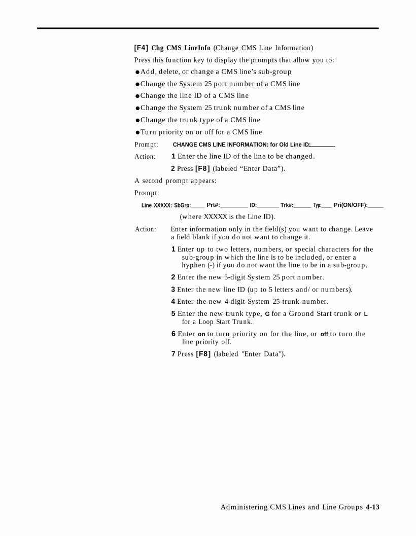
[F4] Chg CMS LineInfo (Change CMS Line Information)
Press this function key to display the prompts that allow you to:
● Add, delete, or change a CMS line’s sub-group
● Change the System 25 port number of a CMS line
● Change the line ID of a CMS line
● Change the System 25 trunk number of a CMS line
● Change the trunk type of a CMS line
● Turn priority on or off for a CMS line
Prompt: CHANGE CMS LINE INFORMATION: for Old Line ID:
Action: 1 Enter the line ID of the line to be changed.
2 Press [F8] (labeled “Enter Data”).
A second prompt appears:
Prompt:
Line XXXXX: SbGrp:_____ Prt#: ID: Trk#:______ Typ:_____ Pri(ON/OFF):_____
(where XXXXX is the Line ID).
Action: Enter information only in the field(s) you want to change. Leavea field blank if you do not want to change it.
1 Enter up to two letters, numbers, or special characters for thesub-group in which the line is to be included, or enter ahyphen (-) if you do not want the line to be in a sub-group.
2 Enter the new 5-digit System 25 port number.
3 Enter the new line ID (up to 5 letters and/or numbers).
4 Enter the new 4-digit System 25 trunk number.
5 Enter the new trunk type, G for a Ground Start trunk or Lfor a Loop Start Trunk.
6 Enter on to turn priority on for the line, or off to turn theline priority off.
7 Press [F8] (labeled "Enter Data").
Administering CMS Lines and Line Groups 4-13

[F5] Assgn/Chg Group ID (Assign/Change Group ID)
Press this function key to display the prompt that allows you to assign orchange a line group’s ID. IDs help you identify the line groups on the statusscreens and reports. A line group and a split can have the same ID.
Prompt: ASSIGN/CHANGE GROUP ID: Group (A-D): _ New ID:
Action: 1 Enter a line group letter (A through D).
2 Enter the new line group ID (up to 5 letters or numbers).
3 Press [F8] (labeled “Enter Data”).
[F6] Admin Xfr Que (Administer Transfer-Queue Lines)
Press this function key to display the screen you use to administer lines forthe Transfer-into-Queue feature. See the next heading in this section.
[F7] Admin Anncs (Administer Announcements)
Press this function key to display the screen you use to administer voiceannouncement units. This function is described later in this section.
[F8] Admin Menu
Press this function
[F10] Help
Press this functionGroups screen.
(Administration Menu)
key to return to the Administration Menu.
key to display a Help screen for the Administer Line
4-14 Administering CMS Lines and Line Groups

Administering Transfer-Queue Lines
Each line group can have up to three transfer-queue lines assigned to it. Eachtransfer-queue line is automatically assigned as a priority line. The prioritystatus of a transfer-queue line can only be changed from the Line Statusscreen. (See “Using the Line Status Screen” in Section 5.) Transfer-queuelines allow an agent to transfer a call to another line group’s queue. Whenthe call is received by that line group, it is then treated as a new incomingCMS call. It is important to note that transfer-queue lines cannot be used tomake outside calls.
A Loop Start trunk port and a single-line station port are associated with eachtransfer-queue line.
CMS automatically assigns each transfer-queue line a line ID that cannot bechanged. This is designated by a “Q” followed by the PDC of the single-linestation.
Pressing [F6] (labeled “Admin Xfr Que”) on the Administer Line Groupsscreen selects the Administer Queued Transfer screen, shown below.
ADMIN QUEUED TRANSFER ADMIN CMS1.0 2:54p 04/18
LINE GROUPS|------------ Trunk Port ---------------| |-Single-Line Port-|
Group SubGrp Port# ID Trk# Type Prior Port#A PUBLIC Q1 10701 Q500 8000 L + 10801
F10 - HelpF Add Xfr F Remove F Move Xfr F Chg Xfr F Adminl Que Line 2 Que Line 3 Que Line 4 Que Info 8 LineGrps
On this screen you can:
• Add transfer-queue lines
• Remove transfer-queue lines
• Move transfer-queue lines
• Change transfer-queue line information
Administering CMS Lines and Line Groups 4-15
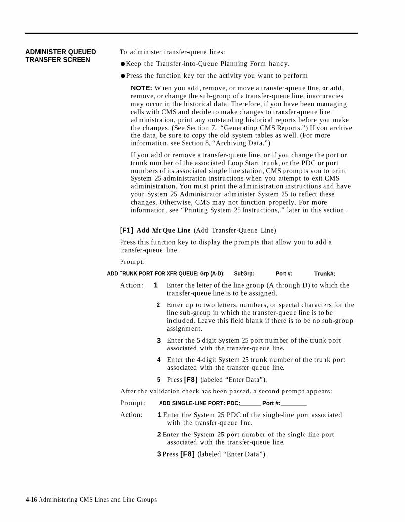
ADMINISTER QUEUED To administer transfer-queue lines:TRANSFER SCREEN
● Keep the Transfer-into-Queue Planning Form handy.
● Press the function key for the activity you want to perform
NOTE: When you add, remove, or move a transfer-queue line, or add,remove, or change the sub-group of a transfer-queue line, inaccuraciesmay occur in the historical data. Therefore, if you have been managingcalls with CMS and decide to make changes to transfer-queue lineadministration, print any outstanding historical reports before you makethe changes. (See Section 7, “Generating CMS Reports.”) If you archivethe data, be sure to copy the old system tables as well. (For moreinformation, see Section 8, “Archiving Data.”)
If you add or remove a transfer-queue line, or if you change the port ortrunk number of the associated Loop Start trunk, or the PDC or portnumbers of its associated single line station, CMS prompts you to printSystem 25 administration instructions when you attempt to exit CMSadministration. You must print the administration instructions and haveyour System 25 Administrator administer System 25 to reflect thesechanges. Otherwise, CMS may not function properly. For moreinformation, see “Printing System 25 Instructions, ” later in this section.
[F1] Add Xfr Que Line (Add Transfer-Queue Line)
Press this function key to display the prompts that allow you to add atransfer-queue line.
Prompt:
ADD TRUNK PORT FOR XFR QUEUE: Grp (A-D): SubGrp: Port #: Trunk#:
Action: 1
2
3
4
5
Enter the letter of the line group (A through D) to which thetransfer-queue line is to be assigned.
Enter up to two letters, numbers, or special characters for theline sub-group in which the transfer-queue line is to beincluded. Leave this field blank if there is to be no sub-groupassignment.
Enter the 5-digit System 25 port number of the trunk portassociated with the transfer-queue line.
Enter the 4-digit System 25 trunk number of the trunk portassociated with the transfer-queue line.
Press [F8] (labeled “Enter Data”).
After the validation check has been passed, a second prompt appears:
Prompt: ADD SINGLE-LINE PORT: PDC: Port #:
Action: 1 Enter the System 25 PDC of the single-line port associatedwith the transfer-queue line.
2 Enter the System 25 port number of the single-line portassociated with the transfer-queue line.
3 Press [F8] (labeled “Enter Data”).
4-16 Administering CMS Lines and Line Groups

[F2] Remove Que Line (Remove Transfer-Queue Line)
Press this function key to display the prompts that allow you to removea transfer-queue line. The information for both the trunk port and thesingle-line station port associated with the transfer-queue line is removedwhen you use this function.
Prompt: REMOVE TRANSFER QUEUE LINE: Port #:
Action: 1 Enter the port number of the trunk associated with thetransfer-queue line.
2 Press [F8] (labeled "Enter Data").
3 When the confirmation prompt appears, type y to confirmyour request, or n to cancel it.
4 Press [F8] (labeled “Enter Data”).
[F3] Move Xfr Que Line (Move Transfer-Queue Line)
Press this function key to display the prompt that allows you to move thetransfer-queue line to a different line group.
Prompt: MOVE TRANSFER QUEUE LINE: ID: to Group (A-D):___
Action: 1 Enter the ID of the transfer-queue line to be moved.
2 Enter the letter of the line group (A through D) to which theline is to be moved.
3 Press [F8] (labeled “Enter Data”).
[F4] Chg Xfr Que Info (Change Transfer-Queue Line Information)
Press this function key to display the prompt that allows you to:
●
●
●
●
●
Change the sub-group of the transfer-queue line
Change the System 25 port number of the trunk port associated with thetransfer-queue line
Change the System 25 trunk number of the trunk port associated with thetransfer-queue line
Change the PDC of the single-line port associated with the transfer-queueline
Change the System 25 port number of the single-line port associated withthe transfer-queue line
NOTE: If you need to change the priority status of a transfer-queue line,you must do so from the Line Status screen. See “Using the Line StatusScreen” in Section 5.
Administering CMS Lines and Line Groups 4-17

Prompt:
CHG INFO: ID: SbGrp: Tk Prt#: T r k # : P D C : SL Prt#:
Action: You must enter the ID; the other fields are optional. Enterinformation only in the field(s) you want to change. Leave a fieldblank if you do not want to change it.
1 Enter the line ID of the transfer-queue line.
2 Enter up to two letters, numbers, or special characters for thesub-group in which the line is to be included, or enter ahyphen (-) if you do not want the line to be in a sub-group.
3 Enter the new System 25 port number for the associated trunkport.
4 Enter the new System 25 trunk number for the associatedtrunk port.
5 Enter the new PDC for the single-line port.
6 Enter the new System 25 port number for the single-line port.
7 Press [F8] (labeled “Enter Data”).
[F8] Admin LineGrps (Administer Line Groups)
Press this function key to return to the Administer Line Groups screen.
[F10] Help
Press this function key to view a Help screen for the Administer QueuedTransfer screen.
4-18 Administering CMS Lines and Line Groups

Administering Announcements
Your CMS supports up to four voice announcement units for providing delaymessages to callers. The voice announcement units are connected to System25 ports and have PDCs associated with them.
To administer voice announcement units, press [F7] (labeled “Admin Anncs”)on the Administer Line Groups screen. The Administer Announcementscreen, shown below, appears.
ADMINISTER ANNOUNCEMENT ADMIN CMS1.0 2:57p 04/18
PDC
F10 - HelpF Add F Remove F Change F Assign F Admin F Adminl Annc 2 Annc 3 Annc 6 Anncs 7 lineGrps 8 Menu
ADMINISTER ANNOUNCEMENTS
ANNC ID PORT#
1 PUBLIC 10802
2 BUSINES 10803
3 CHARTER 10804
4
610
611
612
With this screen you can:
●
●
●
●
Add an announcement unit by entering its announcement ID, System 25port number, and PDC
Remove an announcement unit
Change the information (announcement ID, port number, or PDC)pertaining to an announcement unit
Access the screen used to assign announcements to line groups, specifythe message length of each announcement unit, and put anannouncement unit in or out of service
You can return to the Administer Line Groups screen or AdministrationMenu from the Administer Announcement screen by pressing [F7] or [F8] ,respectively.
NOTE: The following require System 25 administration:
– Adding a voice announcement unit
– Removing a voice announcement unit
– Changing the PDC or port number of a voice announcement unit
Administering CMS Lines and Line Groups 4-19

If you make any changes listed in the above Note and attempt to exit CMSadministration, you are prompted to print the System 25 administrationinstructions. Print the instructions and have the System 25 Administratormake the appropriate changes. For more information, see “Printing System25 Administration Instructions, ” later in this section.
ADMINISTER To administer announcements, press the function key for the activity youANNOUNCEMENT SCREEN want to perform:
[F1] Add Annc (Add Announcement)
Press this function key to display the prompt that allows you to add a voiceannouncement unit to CMS. Obtain the port number and PDC for the newunit from the System 25 Administrator.
When you add an announcement unit, a warning appears indicating thatSystem 25 administration is necessary.
Prompt: ADD ANNOUNCEMENT: Anne ID: Port #: PDC:_______
Action: 1 Enter a unique announcement ID (up to seven letters ornumbers) for the voice announcement unit.
Depending on your type of business and number ofannouncement units, you may want to use an ID describingthe type of message on that unit. For instance, theannouncement unit with the ID SALES might have a messageadvertising a seasonal special. The announcement unit withthe ID ACCTNO might have a message requesting customersto have their account numbers ready.
2 Enter the System 25 port number.
3 Enter the PDC.
4 Press [F8] (labeled “Enter Data”).
[F2] Remove Annc (Remove Announcement)
Press this function key to display the prompts that allow you to remove avoice announcement unit from CMS. If you remove a voice announcementunit and no other unit is assigned to handle calls on that line group, thecallers to that line group hear ringing until an agent answers.
Prompt: REMOVE ANNOUNCEMENT: Announcement Number___
Action: 1 Enter the number of the announcement unit (1 through 4).
2 Press [F8] (labeled “Enter Data”).
3 When the confirmation prompt appears, type y to confirm orn to cancel your request.
4 Press [F8] (labeled “Enter Data”).
4-20 Administering CMS Lines and Line Groups

[F3] Change Annc (Change Announcement Information)
Press this function key to display the prompt that allows you to update orcorrect the ID, System 25 port number, or PDC for a voice announcementunit. Unless you are correcting a typing error, changing a port number orPDC also requires System 25 administration.
Prompt:
CHANGE ANNC INFO: Annc #:__ Annc ID: Port #: PDC:
Action: 1
2
3
4
5
NOTE:
Enter the number of the announcement unit you want tochange (1 through 4).
Enter the new announcement ID or leave the field blank if youdon’t want to change it.
Enter the new System 25 port number or leave the field blankif you don’t want to change it.
Enter the new System 25 PDC or leave the field blank if youdon’t want to change it.
Press [F8] (labeled “Enter Data”).
If you enter an announcement number and press [F8] withoutchanging the information in any field, the data for that voiceannouncement unit stay the same.
[F6] Assign Anncs (Assign Announcements)
See the following heading “Assigning Announcements.”
[F7] Admin LineGrps (Administer Line Groups)
Press this function key to return to the Administer Line Groups screen.
[F8] Admin Menu (Administration Menu)
Press this function key to return to the Administration Menu.
[F10] Help
Press this function key to view a Help screen for the AdministerAnnouncement screen.
Administering CMS Lines and Line Groups 4-21

Assigning Announcements
Certain information about the daily use of voice announcement units isadministered from the Assign Announcement screen. To reach the AssignAnnouncement screen, you must first select an announcement from the SelectAnnouncement screen. Press [F6] (labeled “Assign Anncs”) on theAdminister Announcement screen to reach the Select Announcement screen,shown below.
SELECT ANNOUNCEMENT ADMIN CMS1.O 3:07p 04/18
ANNOUNCEMENT ASSIGNMENTS
MAX MSG ANNC LINE GP A LINE GP B LINE GP C LINE GP DANNC# ANNC ID LENGTH CONDTN PUBLIC BUSNS CHART -
1 PUBIC 18 sec REMVD x
2 BUSINES 15 sec AVAIL - x
3 CHARTER 13 sec AVAIL - x
4
F1O - HelpF Select F Adminl Annc 8 Anncs
SELECT ANNOUNCEMENT To select an announcement from the Select Announcement screen:SCREEN 1 Press [F1] (labeled “Select Annc”) to select a particular voice
announcement unit.
The following prompt appears:
SELECT ANNOUNCEMENT: Announcement Number____
2 Enter the number of the voice announcement unit and press [F8] (labeled“Enter Data”).
4-22 Administering CMS Lines and Line Groups

A box appears around the data for the voice announcement unit youselected, and the screen title changes to Assign Announcement, and thefunction keys are relabeled as shown below.
ASSIGN ANNOUNCEMENT ADMIN CMS1.0 3:07p 04/18
ANNOUNCEMENT ASSIGNMENTS
MAX MSG ANNC LINE GP A LINE GP B LINE GP C LINE GP DANNC# ANNC ID LENGTH CONDTN PUBLC BUSNS CHART -
1 PUBLIC 18 sec REMVD x
2 BUSINES 15 sec AVAIL - x
3 CHARTER 13 sec AVAIL - x
4
F1O - HelpF Select F Chg Max FChange FLn Gp A FLn Gp B FLn Gp C FLn Gp D F Adminl Annc 2 Msg Len 3Condtn 4 Asgn/Rmv 5 Asgn/Rmv 6 Asgn/Rmv 7 Asgn/Rmv 8 Anncs
ASSIGN ANNOUNCEMENTSCREEN
The activities you can perform from the Assign Announcement screen are:
● Indicating the maximum length of the Day Service message on a voiceannouncement unit
● Changing the condition (available, broken, or removed) of a voiceannouncement unit in order to put it in or out of service.
● Assigning a voice announcement unit to one or more line groups
Press the function key for the activity you want to perform. Descriptions ofthe functions keys begin below.
[F1] Select Annc (Select Announcement)
Press this function key to display the prompt that allows you to select adifferent voice announcement unit.
Prompt: SELECT ANNOUNCEMENT: Announcement Number: ____
Action: 1 Enter the number of a voice announcement unit (1 through 4).
2 Press [F8] (labeled “Enter Data”) .
Administering CMS Lines and Line Groups 4-23

[F2] Chg Max Msg Len (Change Maximum Message Length)
The CMS software uses the maximum message length field to determine ifeach voice announcement unit is hanging up after playing the Day Servicedelay message. When you first administer an announcement, CMS gives thisfield an initial setting of 10 seconds.
To determine the maximum message length of your Day Service message,time the period beginning when the voice announcement unit answers thecall and ending when the voice announcement unit disconnects from the call.
NOTE: If the maximum message length you enter is less than theactual Day Service delay message, CMS will indicate that the voiceannouncement unit is broken when it is actually working properly.
Prompt: Maximum Message Length in Seconds (1-999):____
Action: 1 Enter the maximum message length in seconds.
2 Press [F8] (labeled “Enter Data”).
IMPORTANT: When recording an announcement, leave three to fourseconds of silence at the beginning of the message to allow time forCMS to connect the caller to the voice announcement unit.Remember to include this time in the maximum message length.
[F3] Change Condtn (Change Announcement Condition)
The ANNC CONDTN column on the Assign Announcement screen containsan entry for each voice announcement unit that has been administered. Theentries are BROKN (broken), REMVD (removed), or AVAIL (available). OnlyCMS can change the entry to BROKN. CMS automatically changes theAnnouncement Condition field to BROKN if it detects a problem with theassociated voice announcement unit.
To remove an announcement unit from service (for instance, to change themessage or repair the unit), press the Change Announcement Conditionfunction key to change the Announcement Condition field to REMVD. Callsare not transferred to announcement units that are broken or removed. Youalso use the Change Announcement Condition function key to indicate anannouncement unit is available (AVAIL), that is, back in service and ready toreceive calls.
Press [F3] (labeled “Change Condtn”) until the condition you want appears.
[F4] Ln Gp A Asgn/Rmv (Line Group A Assign/Remove)[F5] Ln Gp B Asgn/Rmv (Line Group B Assign/Remove)[F6] Ln Gp C Asgn/Rmv (Line Group C Assign/Remove)[F7] Ln Gp D Asgn/Rmv (Line Group D Assign/Remove)
Use these function keys to assign a voice announcement unit to one or moreline groups. You also use these keys to remove voice announcement unitsthat have been previously assigned to a line group.
4-24 Administering CMS Lines and Line Groups

An X in the line group column for anunit is assigned to that line group. Aassigned to that line group.
announcement unit indicates that thehyphen (-) indicates the unit is not
To assign a voice announcement unit to a line group (or remove it from thatgroup) press the appropriate function key. As you press the function key, themark in the column toggles between “X” and “-”.
[F8] Admin Anncs (Administer Announcements)
Press this function key to return to the Administer Announcement screen.
[F10] Help
Press this function key to view a Help screen for the Assign Announcementscreen.
Administering CMS Lines and Line Groups 4-25

Creating an Agent Directory
The Agent Directory screen contains a "master list" of CMS agents. It lists allCMS agents alphabetically by last name.
Each CMS agent needs a unique ID of up to 5 characters. You use this IDwhen you add, remove, or move an agent. Agents are also identified by IDin exception messages. You can assign up to 60 agent IDs. However, only 28agents can be assigned to a single shift configuration.
Pressing [F3] (labeled “Agent Directry”) from the Administration Menu screenselects the Agent Directory screen, shown below. Use this screen to addagents, remove agents, or edit agent information.
AGENT DIRECTORY ADMIN CMS1.0 2:31p 04/18
AGENT DIRECTORY
Last Name First ID Last Name First IDAbellBeckmanBrownChuDumbraFangFentonGarciaGerkensmierJohnsonKessleringLeonardLindquistLindquistMack
Mary-AnnJimAllanDavidMarieJohnScottJoseOttoAndrewAnaMichaelHalHalJoel
MARYAJIMALLANDAVEMARIEJOHNSCOTTJOSEOTTOANDYANAMIKEHAL1HAL2JOEL
ManettaMassonOngOplachReichegRowlinsonSeilerSieglSmithSonSticklerVaiterWalshWollYang
JaneWilliamIenJosephLouisDonLindaLawrenceBernardSarahCraigBarbaraJenniferHarveyCJ
JANEBILLIENJOELOUDONLINDALARRYBERNESARAHCRAIGBARBJENNYHARVCJ
F1O - HelpF Add F Remove F Change F Next F Config F Admin1 Agent 2 Agent 3 Agt Name 5 Page 7 Splits 8 Menu
USING THE AGENT To use the Agent Directory screen, press the function key for the activity youDIRECTORY SCREEN want to perform:
[F1] Add Agent
Use this function key to add new agents to the Agent Directory. This activitydoes not add agents to an active configuration; it merely identifies them inthe Agent Directory.
HINT: If any agent is regularly assigned to more than one split, create morethan one entry for the agent in the Agent Directory. Enter the agent with adifferent ID for each split. Then use the appropriate ID when you add theagent to a split. The different IDs permit separate tracking of theagent’s statistics in each split. For example, Hal works in split 1 sometimesand in split 2 other times. Hal’s supervisor added him to the directory oncewith the ID HAL1 and again as HAL2.
4-26 Creating an Agent Directory

Prompt: ADD AGENT: Last Name: First: I D :
Action: 1 Enter the agent’s last name, up to 12 letters, numbers, orspecial characters (such as * or #), with no spaces betweenthem. The last name appears in uppercase and/or lowercaseletters, exactly as you type it.
2 Enter the agent’s first name, up to 8 letters, numbers, orspecial characters, with no spaces between them. The firstname appears in uppercase and/or lowercase letters, exactly asyou type it.
3 Enter a unique agent ID, up to 5 letters or numbers. The IDappears on the screen in uppercase letters, even if you enterlowercase ones.
4 Press [F8] (labeled “Enter Data”).
[F2] Remove Agent
Press this function key to display the prompts that allow you to delete anagent from CMS. To help you avoid removing an agent by accident, CMSprompts you to confirm your request.
NOTE: Removing an agent from the Agent Directory will delete thehistorical data for that agent. If you have any historical reports thathave not yet been printed, print them before you remove the agent.Refer to Section 7 for information on generating CMS reports. (If youare archiving the historical data, be sure to copy the system tables aswell as the data files. For more information, see Section 8, “ArchivingData.”)
Prompt: REMOVE AGENT: ID:
Action: 1 Enter the ID of the agent to be removed.
2 Press [F8] (labeled "Enter Data").
3 When the confirmation prompt appears, type y to confirmyour request or n to cancel it.
4 Press [F8] (labeled “Enter Data”).
[F3] Change Agt Name (Change Agent Name)
Press this function key to display the prompt that allows you to change anagent’s last name or first name in the Agent Directory. (You cannot changean agent’s ID using this function key. To change an agent’s ID, you mustfirst remove the agent and then add the agent with a different ID.)
Prompt:
CHANGE AGENT NAME: ID: Last Name: First:
Creating an Agent Directoy 4-27

Action: 1 Enter the agent ID as it appears on the screen.
2 Enter the new last name, or leave the field blank if you don’twant to change it.
3 Enter the new first name, or leave the field blank if you don’twant to change it.
4 Press [F8] (labeled “Enter Data”).
[F5] Next Page/Prev Page (Next Page/Previous Page)
If the Agent Directory contains more than 30 entries and the first page isdisplayed, [F5] is labeled “Next Page.” Pressing this key allows you to lookat the second page of the Agent Directory. When the second page of theAgent Directory is displayed, [F5] is labeled "Prev Page", and pressing itreturns you to the first page of the Agent Directory.
[F7] Config Splits (Configure Splits)
Press this function key to display the Configure Splits screen. This functionkey works only if you have already selected a particular configuration to buildor edit. If you haven’t already selected a configuration, use the ConfigurationList screen to select a configuration. You can access the Configuration Listscreen by pressing [F4] (labeled “Config List” ) from the Administration Menuscreen.
[F8] Admin Menu (Administration Menu)
Press this function key to return to the Administration Menu screen.
[F10] Help
Press this function key to view a Help screen for the Agent Directory screen.
4-28 Administering CMS

Building or Editing Shift Configurations
A shift configuration is an arrangement of line groups and agent splits formanaging calls. Before CMS can begin managing calls, you must build atleast one shift configuration. You can build as many as six configurations tohandle different calling patterns in your business. For instance, a businessmay require Day, Evening, and Weekend configurations.
CMS Night Service mode (which is different from System 25 Night Service)can be used when no agents are on duty. During Night Service, CMSconnects all incoming calls to a voice announcement unit message andautomatically disconnects the calls when the message is over. For moreinformation, see “Selecting Day or Night Service” in Section 5.
In a shift configuration, splits are assigned to line groups as main splits andsecondary splits. A main split has primary responsibility for answering callsfor a line group (or line groups). A secondary split answers calls to a linegroup only if all agents in the main split are busy or unavailable, intraflow isturned on, and the Intraflow Threshold has been reached. (For moreinformation on intraflow, see “Administering Call Flow,“ later in this section.)
In the Day configuration for Bon Voyage Travel, main splits and secondarysplits are assigned like this:
Line Group Main Split Secondary Split
Public line Public Travel Support splitgroup split
Business line Business Travel Charter Travelgroup split split
Charter line Charter Travel Business Travelgroup split split
Building or Editing Shift Configurations 4-29

Administering shift configurations begins with the Configuration List screenshown below. Pressing [F4] (labeled “Config List” ) from the AdministrationMenu screen selects this screen.
CONIFIGURATION LIST ADMIN CMS1.0 3:18p 04/18
STORED SHIFT CONFIGURATIONS
123456
——————
DAYEVENINGWEEKENDUNUSEDUNUSEDUNUSED
F10 - HelpF Select F Save F Rename F Choose F Config F Admin1 Config 2 Config 3 Config 4 Startup 7 Screen 8 Menu
This section describes the following activities you can perform from theConfiguration List screen:
●
●
●
●
●
Selecting a Shift Configuration
Select a new shift configuration to build, or change (edit) an existing one.
Saving an Edited Configuration
Store the shift configuration that was last edited.
Renaming a Shift Configuration
Name, rename, or delete a shift configuration.
Selecting a Startup Configuration
Select one of your shift configurations to be invoked automatically duringthe call management startup procedure.
Returning to Other Screens
If you press [F7] (labeled “Config Screen”), you return to theConfiguration screen for the cofiguration you last selected. (The name ofthat configuration is shown in reverse video on the Configuration Listscreen.) If you press [F8] (labeled “Admin Menu”), you return to theAdministration Menu screen.
4-30 Building or Editing Shift Configurations
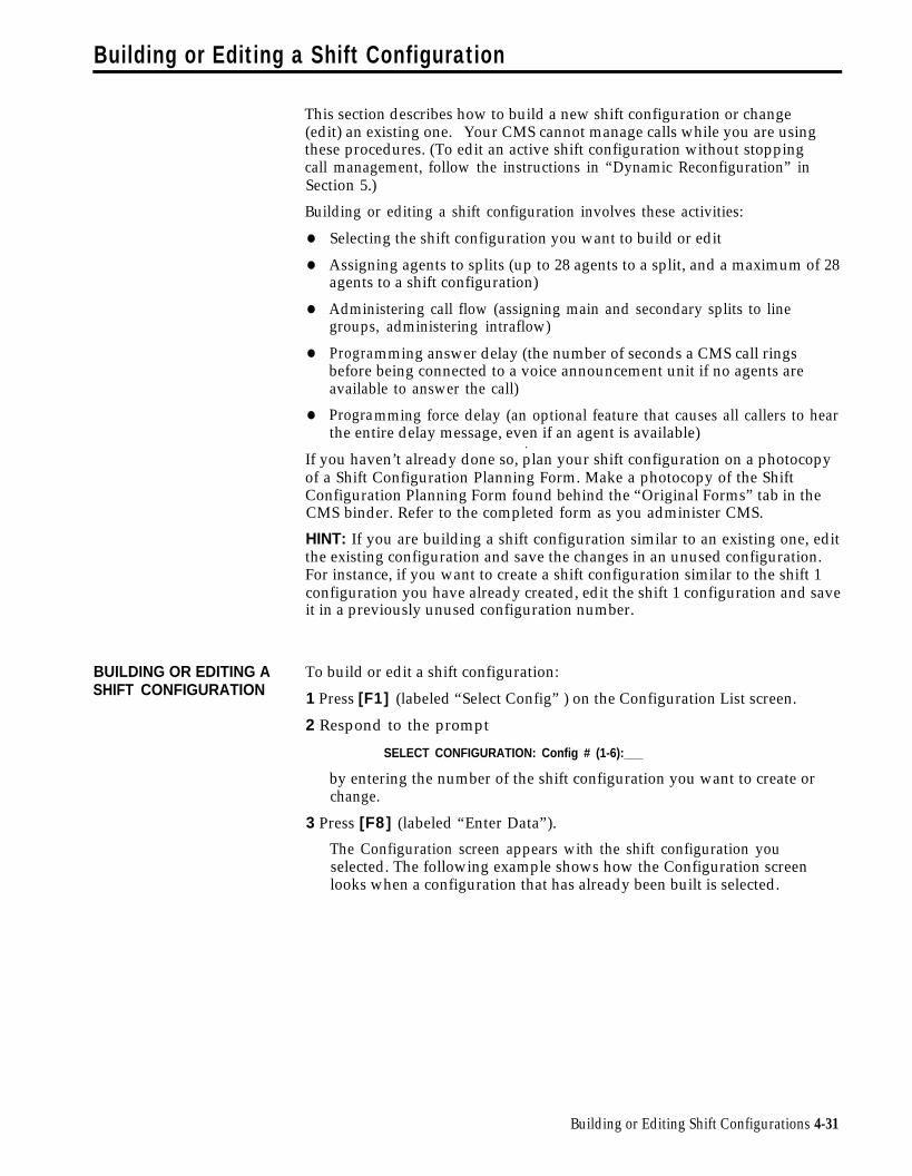
Building or Editing a Shift Configuration
This section describes how to build a new shift configuration or change(edit) an existing one. Your CMS cannot manage calls while you are usingthese procedures. (To edit an active shift configuration without stoppingcall management, follow the instructions in “Dynamic Reconfiguration” inSection 5.)
Building or editing a shift configuration involves these activities:
●
●
●
●
●
Selecting the shift configuration you want to build or edit
Assigning agents to splits (up to 28 agents to a split, and a maximum of 28agents to a shift configuration)
Administering call flow (assigning main and secondary splits to linegroups, administering intraflow)
Programming answer delay (the number of seconds a CMS call ringsbefore being connected to a voice announcement unit if no agents areavailable to answer the call)
Programming force delay (an optional feature that causes all callers to hearthe entire delay message, even if an agent is available)
.If you haven’t already done so, plan your shift configuration on a photocopyof a Shift Configuration Planning Form. Make a photocopy of the ShiftConfiguration Planning Form found behind the “Original Forms” tab in theCMS binder. Refer to the completed form as you administer CMS.
HINT: If you are building a shift configuration similar to an existing one, editthe existing configuration and save the changes in an unused configuration.For instance, if you want to create a shift configuration similar to the shift 1configuration you have already created, edit the shift 1 configuration and saveit in a previously unused configuration number.
BUILDING OR EDITING A To build or edit a shift configuration:SHIFT CONFIGURATION 1 Press [F1] (labeled “Select Config” ) on the Configuration List screen.
2 Respond to the prompt
SELECT CONFIGURATION: Config # (1-6):___
by entering the number of the shift configuration you want to create orchange.
3 Press [F8] (labeled “Enter Data”).
The Configuration screen appears with the shift configuration youselected. The following example shows how the Configuration screenlooks when a configuration that has already been built is selected.
Building or Editing Shift Configurations 4-31

CONFIGURATION ADMIN CMS1.0 3:20p 04/18
AGENT SPLITS ANSWER/FORCE DELAY|--Agent--| |--Agent--| Num Answer Force
Split PDC ID Split PDC ID Group Lines Delay Delay1 PUBLIC
2 BUSNS
3 CHART
4 SUPPT
401402403404405406407408409410411412415416
LINDAJOELIENJENNYSCOTTBILLSARAHJOHNJIMBERNEDONALLANANDYLOU
4 SPPT
5 -6 -
417418424
CRAIGBARBCJ
A PUBLCB BUSNSC CHARTD -
9650
10s0s5s5s
OffOnOffOff
CALL FLOWFlow
|-Splits-| Intra Spl ThreshGp Main Sec FlowABCD
123-
432-
OnOffOffOff
123456
50s30s30s30s30s30s
Configuration #1 - DAY
F10 - HelpF Splits FAns/Fore F Call F Clear F Config F Admin1 2 Delay 3 Flow 5 Config 7 List 8 Menu
4-32 Building or Editing Shift Configurations

The following Configuration screen illustrates a new configuration that hasyet to be built.
The items in the following list correspond to the circled letters in theprevious screen. They show the initial settings supplied for a newconfiguration.
a
b
c
d
e
f
g
Split numbers 1 through 6 are displayed in the Agent Splits area.
Split IDs will be displayed if the splits have been previously named.Otherwise, a hyphen (-) will appear in the “Split” column.
Answer delay is set to 5 seconds.
Force delay is turned off.
Main and secondary splits are unassigned (indicated by hyphens).
Intraflow is turned off.
Intraflow thresholds are set to 30 seconds.
4 Select the activity you want to perform from the following list and thenturn to the appropriate instructions.
— Administering Splits
Add, move, or remove agents in the splits in the displayedconfiguration, as well as change the split ID.
— Administering Answer Delay and Force Delay
Administer how you want CMS to answer calls with respect to thevoice announcement unit(s).
Building or Editing Shift Configurations 4-33

– Administering Call Flow
Assign splits to cover line groups, turn intraflow on or off, or setIntraflow Thresholds for splits.
– Clearing a Configuration
Delete the contents of a configuration.
– Returning to Other Screens
Return to the Configuration List screen by pressing [F7] (labeled“Config List” ), where you can save the configuration you have justbuilt or edited. Return to the Administration Menu by pressing [F8](labeled "Admin Menu") to select another administration activity.
CONFIGURING SPLITS The list of agents you created on the Agent Directory screen is your master listof agents. Any agent in the Agent Directory can be assigned to a split. TheAdminister Stations screen contains the master list of PDCs for agent stations.You can assign only PDCs that appear in the Agent Stations section of theAdminister Stations screen.
Pressing [F1] (labeled “Splits”) from the Configuration screen selects theConfigure Splits screen shown below.
CONFIGURE SPLITS ADMIN CMS1.O 3:27p 04/18
AGENT SPLITS ANSWER/FORCE DELAY❘ ..Agent.. ❘ ❘ --Agent-- ❘ Num Answer Force
Split DelayPDC ID Split PDC ID Group Lines Delay1 PUBLIC401
402403404405406407408409410411412415516
LINDAJOELIENJENNYSCOTTBILLSARAHJOHNJIMBERNEDONALLANANDYLOU
4 SUPPT 417 CRAIG418 BARB424 CJ
A PUBLICB BUSNSC CHARTD -
9650
10S0S5S5S
OffOnOffOff5 -
6 -
2 BUSNS CALL FLOWFlow
Spl Thresh3 CHART ❘ -Splits- ❘ IntraGp Main Sec Flow
4 SUPPT
ABCD
123-
432
O nO f fO f fO f f
12345 6
50s30s30s30s30s 30s
Configuration #1 - DAY
F1O - HelpF Add F Remove F Move F Replace F New1 Agent
F Change F Config F Agent2 Agent 3 Agent 4 Agent 5 Agent 6 Split ID 7 Screen 8 Directry
4-34 Building or Editing Shift Configurations

To configure splits, press the function key for the activity you want toperform:
[F1] Add Agent
Press this function key to display the prompt that allows you to assign anagent to a split. The agent must already be listed on the Agent Directoryscreen and the station must already appear on the Administer Stations screen.A split may have up to 28 agents. A total of 28 agents can be assigned to ashift configuration.
HINT: If you want to add an agent who is not already in the AgentDirectory, use [F5] (labeled “New Agent”) instead of [F1].
Prompt: ADD AGENT: ID: PDC: to Split #: _
Action: 1 Enter the ID of an agent listed in the Agent Directory.
2 Enter the System 25 PDC of an agent station displayed on theAdminister Stations screen.
3 Enter the split number (1 through 6).
4 Press [F8] (labeled “Enter Data”).
[F2] Remove Agent
Press this function key to display the prompts that allow you to remove anagent from a split. (The agent will still be Listed on the Agent Directoryscreen.)
Prompt: REMOVE AGENT: ID:
Action: 1 Enter the ID for the agent you want to remove.
2 Press [F8] (labeled “Enter Data”).
3 When the confirmation prompt appears, type y to confirmyour request, or n to cancel it.
4 Press [F8] (labeled “Enter Data”).
[F3] Move Agent
Press this function key to display the prompt that allows you to move anagent from one split to another and/or from one station to another.
Prompt: MOVE AGENT: ID: New PDC: New Split #: _
Building or Editing Shift Configurations 4-35

Action: 1 Enter the ID for the agent you want to move.
2 Enter the agent’s new PDC or leave this field blank if youwant the agent to stay at the same station.
3 Enter the agent’s new split number (1 through 6) or leave thisfield blank if you want the agent to stay in the same split.
4 Press [F8] (labeled “Enter Data”).
[F4] Replace Agent
Press this function key to display the prompt that allows you to substituteone agent for another at a particular agent station.
Prompt:
REPLACE AGENT: Remove Agent ID: and Add Agent ID:
Action: 1 Enter the ID of the agent to be replaced.
2 Enter the ID of the agent you want to substitute at thatstation.
3 Press [F8] (labeled “Enter Data”).
[F5] New Agent
Press this function key to display the prompt that allows you to add an agentwho is not already listed on the Agent Directory screen to a split. The agentis simultaneously added to the split and to the Agent Directory.
Prompt:
NEW AGNT: ID: ____ Last name: First: PDC: Split#:___
Action: 1
2
3
4
5
6
Enter the agent ID, up to 5 letters or numbers. (IDs must beunique.)
Enter the agent’s last name, up to 12 letters, numbers, orspecial characters with no spaces between them.
Enter the agent’s first name, up to 8 letters, numbers, orspecial characters with no spaces between them.
Enter the System 25 PDC of an agent station displayed on theAdminister Stations screen.
Enter the split number (1 through 6).
Press [F8] (labeled “Enter Data”).
[F6] Change Split ID
Press this function key to display the prompt that allows you to assign,change, or delete the ID for a split. Split IDs carry through all shiftconfigurations. They make it easier to identify splits on screens and inreports. Each split ID must be unique. However, a split and a line group canhave the same ID.
4-36 Building or Editing Shift Configurations

Prompt: CHANGE SPLIT ID: Split # (l-6):_ New Split ID:
Action: 1 Enter the split number (1 through 6).
2 Enter the new split ID (up to 5 letters or numbers), or enter ahyphen (-) to delete the split ID.
3 Press [F8] (labeled “Enter Data”).
[F7] Config Screen (Configuration Screen)
Press this function key to return to the Configuration screen.
[F8] Agent Directory (Agent Directory)
Press this function key to return to the Agent Directory screen if you need torefer to or change agent information. Press [F7] on the Agent Directoryscreen to return to the Configure Splits screen.
[F10] Help
Press this function key to display a Help screen for the Configure Splitsscreen.
Building or Editing Shift Configurations 4-37

Administering Answer Delay and Force Delay
Pressing [F2] (labeled “Ans/Forc Delay”) from the Configuration screendisplays the Configure Delay screen, shown below.
CONFIGURE DELAY ADMIN CMS1.0 3:31p 04/18
AGENT SPLITS ANSWER/FORCE DELAY|-Agent-| |-Agent-|
Split PDC ID Split PDC IDN u mLines
AnswerDelay
ForceDelayGroup
1 PUBLIC
2 BUSNS
3 CHART
4 SUPPT
401402403404405406407408409410411412415416
LINDAJOELIENJENNYSCOTTBILLSARAHJOHNJIMBERNEDONALLANANDYLOU
4 SUPPT
5 -6 -
417418424
CRAIGBARBCJ
A PUBLCB BUSNSC CHARTD -
9650
10s0s5s5s
OffOnOffOff
CALL FLOWFlow
|-Splits-| Spl ThreshGp Main Sec FlowABCD
123-
432-
OnOffOffOff
123456
50s30s30s30s30s30s
Configuration #1 - DAY
ANS/FORCE DELAY: Grp (A-D):___ Ans Delay (0-99 sec):___ Force Delay (ON/OFF):____F Cancel1 Prompt
F Previous5 Field
F Next6 Field
F Enter8 Data
From this screen, you can administer two delay options that affect thehandling of incoming calls: Answer Delay and Force Delay.
Answer DelayThe Answer Delay is the number of seconds CMS has a call wait beforeconnecting it to a voice announcement unit when no agents are available toservice the call. You may want to get some experience with CMS callmanagement before you change the answer delay from its initial setting of 5seconds.
Think of Answer Delay as a trade-off between the time a customer spendslistening to ringing and the time the customer spends on hold. You can set adifferent Answer Delay value for each line group, depending on the type oflines in the group and the amount of time the caller is likely to wait before anagent is available.
4-38 Building or Editing Shift Configurations
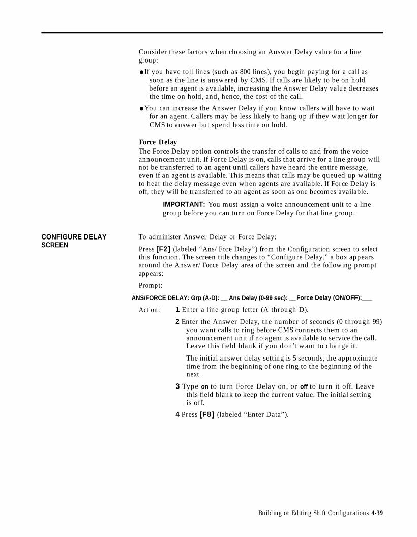
CONFIGURE DELAYSCREEN
Consider these factors when choosing an Answer Delay value for a linegroup:
● If you have toll lines (such as 800 lines), you begin paying for a call assoon as the line is answered by CMS. If calls are likely to be on holdbefore an agent is available, increasing the Answer Delay value decreasesthe time on hold, and, hence, the cost of the call.
● You can increase the Answer Delay if you know callers will have to waitfor an agent. Callers may be less likely to hang up if they wait longer forCMS to answer but spend less time on hold.
Force DelayThe Force Delay option controls the transfer of calls to and from the voiceannouncement unit. If Force Delay is on, calls that arrive for a line group willnot be transferred to an agent until callers have heard the entire message,even if an agent is available. This means that calls may be queued up waitingto hear the delay message even when agents are available. If Force Delay isoff, they will be transferred to an agent as soon as one becomes available.
IMPORTANT: You must assign a voice announcement unit to a linegroup before you can turn on Force Delay for that line group.
To administer Answer Delay or Force Delay:
Press [F2] (labeled “Ans/Fore Delay”) from the Configuration screen to selectthis function. The screen title changes to “Configure Delay,” a box appearsaround the Answer/Force Delay area of the screen and the following promptappears:
Prompt:
ANS/FORCE DELAY: Grp (A-D): __ Ans Delay (0-99 sec): __Force Delay (ON/OFF):___
Action: 1 Enter a line group letter (A through D).
2 Enter the Answer Delay, the number of seconds (0 through 99)you want calls to ring before CMS connects them to anannouncement unit if no agent is available to service the call.Leave this field blank if you don’t want to change it.
The initial answer delay setting is 5 seconds, the approximatetime from the beginning of one ring to the beginning of thenext.
3 Type on to turn Force Delay on, or off to turn it off. Leavethis field blank to keep the current value. The initial settingis off.
4 Press [F8] (labeled “Enter Data”).
Building or Editing Shift Configurations 4-39

Administering Call Flow
Administering call flow includes the following tasks:
● Assigning a main split and a secondary split (optional) for each line group
● Turning intraflow on or off for a line group
● Setting an Intraflow Threshold for each split
Intraflow is the process of transferring calls from a main split’s queue to anavailable agent in the secondary split. A main split has primary responsibilityfor answering calls for a line group (or groups). A secondary split coverscalls to a line group only if all the agents in the main split for that line groupare busy or unavailable, the Intraflow Threshold has been reached, andintraflow is on.
The Intraflow Threshold is the number of seconds the oldest call in a mainsplit’s queue must wait before it can be sent to an available agent (if there isone) in the secondary split. This waiting time begins when the call first rings.However, if calls already in the secondary split’s queue have exceeded itsIntraflow Threshold, the secondary split will not accept intraflowed calls untilthese queued calls have been answered. For a detailed description of howand when calls are intraflowed, see “How Intraflow Works” later in thissection of the manual.
Consider these points when establishing your Intraflow Threshold(s):
● How long do you want your callers to wait for an agent in the main splitif there are agents available in your secondary split? (The waiting timestarts as soon as the call begins ringing.) Answering this question helpsdetermine a reasonable Intraflow Threshold for the main split.
● If your secondary split serves as a main split for another line group, youmay not want that split to accept intraflowed calls if it is busy with itsown calls. The secondary split’s Intraflow Threshold determines how longits own calls may wait before the split refuses to accept intraflowed calls.(If a secondary split is not a main split as well, you don’t need to set athreshold for that split.)
Pressing [F3] (labeled “Call Flow”) on the Configuration screen selects thefollowing Configure Call Flow screen.
4-40 Building or Editing Shift Configurations

CONFIGURE CALL FLOW ADMIN CMS1.0 3:32p 04/18
AGENT SPLITS ANSWER/FORCE DELAY|--Agent--| |--Agent--| Num
LinesAnswerDelay
ForceDelaySplit PDC ID Split PDC ID Group
1 PUBLC
2 BUSNS
3 CHART
4 SUPPT
401402403404405406407408409410411412415416
LINDAJOELIENJENNYSCOTTBILLSARAHJOHNJIMBERNEDONALLANANDYLOU
4 SUPPT
5 -6 -
417418424
CRAIGBARBCJ
A PUBLCB BUSNSC CHARTD -
9650
10s0 s5 s5 s
OffO nOffOff
CALL FLOWFlow
|-Splits-|Gp
IntraFlow
Spl ThreshMain Sec
ABCD
123-
432-
O nOffOffOff
123456
50s30s30s30s30s30s
Configuration #1 - DAY
F10 - HelpF Assign1 Splits
F Flow2 On/Off
F Set3 Thresh
F Config7 Screen
How Intraflow WorksThis example assumes there are main and secondary splits assigned to theline group and no agent is available in the main split. If an agent becameavailable at any step, CMS would immediately transfer the call to that agent.This example also assumes that Force Delay is off.
If a call comes in and no agent is available in the main split, the call is treatedas follows:
1
2
3
4
The call continues to ring for the Answer Delay interval you haveestablished.
CMS answers the call and connects it to the voice announcement unit fora delay message.
NOTE: If the Answer Delay for a line group is longer than the IntraflowThreshold for the line group’s main split, the call may be intraflowed tothe secondary split before the delay message is played.
The call is put on hold (or connected to Music-on-Hold) and is put intothe main split’s queue of waiting calls.
The call is intraflowed (sent) to an agent in the secondary split if all theseconditions are met:
- Intraflow is turned on for the call’s line group.
– The call is the oldest call eligible for intraflow to the secondary split.
- The amount of time the call has waited (that is, from the time the callstarted ringing until now) has exceeded the Intraflow Threshold forthe main split.
- There is no available agent in the main split.
Building or Editing Shift Configurations 4-41

– There is an available agent in the secondary split.
CALL FLOW SCREEN
– The oldest call in the secondary split’s queue has not waited longerthan the Intraflow Threshold for the secondary split.
5 If there is no agent available in the secondary split, the call stays in themain split’s queue. The call will be answered by the first available agentin either the main split or the secondary split (if the secondary split’sIntraflow Threshold is not exceeded by another call).
To administer call flow, press the function key for the activity you want toperform:
HINT: If you are administering call flow for a new shift configuration,perform the activities in this order: assign splits, set thresholds, then changeintraflow.
[F1] Assign Splits
Press this function key to display the prompt that allows you to assign a mainsplit and, optionally, a secondary split, to a line group. Initially, all splits areunassigned; you choose which split answers calls for each line group.
Prompt:
ASSIGN SPLITS for Call Flow: Line Group (A-D): _ Main Spiit: _ Secondary Split: _
Action: 1 Enter a line group letter (A through D).
2 Enter the number of the main split number (1 through 6) thatwill answer calls for the line group.
3 Enter a split number to assign to a secondary, or enter ahyphen (-) if you do not want to assign a secondary split or ifyou want to delete a previously assigned secondary split.
4 Press [F8] (labeled “Enter Data“).
[F2] Flow On/Off (Turn Intraflow On/Off)
Press this function key to display the prompt that allows you to turn intraflowon or off for a particular line group. Each line group’s intraflow statusappears in the Intraflow column of the Call Flow area of the screen. Theinitial intraflow setting for each line group is Off.
Prompt: CHANGE INTRAFLOW: Line Group (A-D):__
Action: 1 Enter a line group letter (A through D).
2 Press [F8] (labeled “Enter Data”). The intraflow designationfor that line group automatically changes from On to Off orvice versa.
4-42 Building or Editing Shift Configurations

[F3] Set Thresh (Set Intraflow Threshold)
Press this function key to display the prompt that allows you to set theIntraflow Threshold for a split. This threshold sets the number of seconds theoldest call waits in a main split’s queue before becoming eligible for intraflow.You need reasonable thresholds for your main splits. For more informationon choosing your thresholds, see “Administering Call Flow” earlier in thissection. The initial setting is 30 seconds.
Prompt:
SET CALL FLOW THRESHOLD: Split # (1-6):__ Threshold (0-999 sec):__
Action: 1 Enter a split number (1 through 6).
2 Enter a number of seconds (0 through 999).
3 Press [F8] (labeled “Enter Data”).
[F7] Config Screen (Configuration Screen)
Press this function key to return to the Configuration screen after you havefinished administering call flow.
[F10] Help
Press this function key to display a Help screen for the Configure Call Flowscreen.
Building or Editing Shift Configurations 4-43

Clearing a Configuration
Pressing [F5] (labeled "Clear Config") on the Configuration screen displaysthe prompt that allows you to clear the contents of a shift configuration. Youmight want to do this if you have made several data entry errors and want tobegin again instead of making changes. If you clear the contents of theconfiguration, the values on the Configuration screen return to their initialsettings.
Prompt:
CLEAR CONFIG: This deletes contents of config. Clear Config? (Y/N): __
Action: 1 Type y or n.
2 Press [F8] (labeled "Enter Data"). If you clear the contents ofthe configuration, the values on the Configuration screenreturn to their initial settings.
NOTE: If you accidentally clear a configuration, you canrestore the configuration by doing the following immediatelyafter you’ve cleared it: Press [F7] (labeled "Config List") toselect the Configuration List screen. On this screen, press [F1](labeled “Select Config”) to select a configuration. A promptasks if you want to save your previous editing changes (whichinclude clearing the configuration). Type n, and press [Enter]to restore the cleared configuration to the state it was in thelast time it was saved.
Returning to Other Screens
You can select two other screens from the Configuration screen: theConfiguration List screen and the Administration Menu. You may want to goto the Configuration List screen to save your new configuration or an old oneyou have edited. Pressing [F7] (labeled "Config List") selects theConfiguration List screen, from which you can:
● Select a configuration to view, build, or edit
● Save your editing changes (or save a new configuration you’ve just built)
● Rename a configuration
● Select a startup configuration
You can return to the Administration Menu from the Configuration screen bypressing [F8] (labeled "Admin Menu").
4-44 Building or Editing Shift Configurations

Saving an Edited (Changed) Configuration
When you build a new shift configuration or make changes in an existingone, the word (edited) appears on the Configuration List screen to the left ofthe configuration number. You can store the last edited configuration in apreviously unused configuration or store it in place of another configuration.
For example, you could edit configuration 1 (DAY in our example) andreplace the original with the updated copy. If, on the other hand, you wantto keep the original configuration 1 as well as the edited copy, store the copyin an unused configuration number.
Pressing [F2] (labeled "Save Config" ) on the Configuration List screendisplays the prompts that allow you to save the last selected configuration.The name of the configuration is highlighted. If you edit the selectedconfiguration, the word (edited) appears to the left of the configuration name.
Prompt: SAVE CONFIGURATION: in Config #:__
Action: 1 Press [F8] (labeled “Enter Data”) to save the editedconfiguration under the same configuration name and numberas the original (in other words, to replaceupdated copy).
or
Enter a configuration number, then press
the original with the
[F8] (labeled “EnterData”) to save the edited configuration under a differentconfiguration number.
A second prompt appears:
SAVE CONFIGURATION: Replace Contents of Config #X - NAME? (Y/N):__
The number of the configuration (X) you want to replace andits name (NAME) appear in this prompt.
2 Type y to confirm your request or n to cancel it; then press[F8] (labeled "Enter Data").
IMPORTANT: If you accidentally cleared a configuration with [F5](labeled “Clear Config”) on the Configuration List screen, do not press[F2] (labeled “Save Config”) on the Configuration List screen. Forinformation on restoring a configuration that has been accidentallycleared, see "Clearing a Configuration" earlier in this section.
Building or Editing Shift Configurations 4-45

Renaming a Shift Configuration
To name or rename a configuration, press [F3] (labeled “Rename Config” ) onthe Configuration List screen. Configuration names can contain up to 10letters, numbers, or special characters. Spaces are not allowed, so you maywant to use hyphens or underlines instead. Renaming a configuration"UNUSED", will clear the configuration.
Prompt:
RENAME CONFIGURATION: Config # (1-6): _ New Name:
Action: 1
2
3
Enter the configuration number (1 through 6).
Enter the new name (up to 10 letters, numbers, or specialcharacters).
NOTE: A startup configuration cannot be renamed“UNUSED,” and results in an error message if you attempt todo so.
Press [F8] (labeled “Enter Data”).
Selecting a Startup Configuration
You can select one of the six shift configurations to be invoked automaticallyduring the CMS call management startup procedure. Don’t select a startupconfiguration, however, if you want to choose a configuration each time youbegin call management.
Press [F4] (labeled “Choose Startup”) on the Configuration List screen tochoose this activity.
Prompt:
CHOOSE STARTUP CONFIGURATION: Config # (1-6 or ‘-’ for none):___
Action: 1 Enter the number of the configuration you want to use as thestartup configuration, or enter a hyphen (-) if you don’t want astartup configuration.
2 Press [F8] (labeled “Enter Data”). The word (Startup) appearsto the right of the configuration you selected.
4-46 Administering CMS

Setting Options
SERVICE LEVEL LIMIT
After you have used CMS for a few days, you should have enoughinformation to set several system options. Initial settings are in effect for thefollowing options until you define new values:
● Service Level Limit
● Abandoned vs. Incoming Call Threshold
● Audible Alarm On/Off
● Transfer Return Threshold
● CMS-Port Personal Line Button Verification
Pressing [F5] (labeled “Set Options”) on the Administration Menu screenselects the Set Options screen, shown below.
SET OPTIONS ADMIN CMS1.0 3:36p 04/18
OPTION SETTINGS
Option Value
F1 Service Level Limit 20 sec
F2 Abandoned vs. Incoming Call Threshold 10 sec
F3 Audible Alarm (ON/OFF) ON
F4 Transfer Return Threshold 5 rings
F5 CMS-Port Personal Line Button Verify ON
F10 - HelpF Service F Abandon F Alarm F Return F Verify F Admin1 Level 2 Thresh 3 On/Off 4 Thresh 5 On/Off 8 Menu
The service level is a measure of how quickly your customers’ calls areanswered by agents. The service level is the percentage of calls that wereconnected to agents within a specified number of seconds (called the ServiceLevel Limit). For instance, during a particular hour your agents may answer90% of the CMS calls within 20 seconds.
The initial value for the Service Level Limit is 20 seconds. Since the length oftime between the beginning of one ring and the beginning of the next isabout 5 seconds, a Service Level Limit of 20 seconds equals about 4 rings.
The service level is displayed on the System Status screen and is continuallyupdated while CMS is managing calls. (The service level also appears in theDaily Split Report and in the Cumulative Split Report.) If the service leveldrops below an acceptable level, it may indicate the need to turn on intraflowor to add more agents to a split.
Setting Options 4-47

ABANDONED CALLTHRESHOLD
The Service Level Limit you choose depends on your particular type ofbusiness. The Service Level Limit is measured from the time a call first ringsat System 25 until the call is answered by an agent. This includes AnswerDelay time, time connected to the voice announcement unit (if any), time onhold waiting to be transferred to an agent, and ringing time at an agentstation. You need to decide how quickly you want the majority of your callsanswered. Note that having Force Delay on impacts your service level.
An important function of CMS is tracking the number of abandoned calls,that is, the number of callers who hang up before they’ve been connected toan agent. Occasionally an abandoned call gets transferred to an agent. Whenthis happens, the agent answers the call and finds no one on the line.
The Abandoned vs. Incoming Call Threshold allows you to set the minimumnumber of seconds an agent must be connected to a call for it to beconsidered a serviced call. By setting this threshold, you can distinguishbetween the abandoned calls that are connected to agents and “real“ calls thatare handled by the agents. Distinguishing serviced calls from abandonedones gives a more accurate picture of the service level of your system.
To establish a realistic Abandoned vs. Incoming Call Threshold, you need toknow how long agents usually spend talking to callers. If your agents usuallyspend at least 30 seconds talking to customers, then you can assume thatmost calls that take less than 15 seconds are probably abandoned calls.However, if your agents often receive calls that take only a few seconds tohandle, you will want to set a lower abandoned call threshold, and thechance of errors (that is, mistaking an abandoned call for a “real” call, or viceversa) will increase. The initial value for the Abandoned vs. Incoming CallThreshold is 10 seconds.
NOTE: If your CMS lines are Ground Start trunks, the number ofabandoned calls transferred to agents is considerably less than if yourCMS lines are Loop Start trunks.
AUDIBLE ALARM ON/OFF You can have your PC beep every time an exception message, a systemmessage, or an error message appears on the PC screen. (An exceptionoccurs when a service or performance threshold you set has been exceeded.For more information, see “Selecting Exceptions” later in this section.)Turning the alarm on is helpful since it will alert you to potential problemsthat might occur when you are not looking at the PC screen. Initially, theAudible Alarm option is on.
TRANSFER RETURNTHRESHOLD
The Transfer Return Threshold allows you to set the maximum number oftimes a CMS call will ring at an agent’s voice terminal before being returnedto CMS for transfer to another agent. You can choose a value of 1 to 9 rings;the initial setting is 5 rings.
There are two instances in which a call is not transferred immediately toanother agent when the Transfer Return Threshold is reached:
● If no other agents are available when the Transfer Return Threshold isreached, and the caller has not heard an announcement, the call isconnected to an announcement and then placed in the queue of callsawaiting transfer to an agent.
4-48 Setting Options

CMS-PORT PERSONALLINE BUTTON VERIFY
SETTING OPTIONS
● If no other agents are available when the Transfer Return Threshold isreached and the caller has already heard an announcement, the callcontinues to ring at the original agent’s voice terminal until an agentbecomes available. At that time, CMS transfers the call to the availableagent.
NOTE: If the agent does not answer the call before the TransferReturn Threshold is reached, the agent is considered to have“refused” the call, and the agent’s station is placed in the ACW state.If the Refused Call agent exception is turned on, then CMS generatesan exception message when the Transfer Return Threshold is reached.See “Selecting Agent Exceptions” later in this section.
Accurate System 25 administration is critical to the proper functioning of callmanagement; inaccuracies may result in unanswered calls, dropped calls, ormistransferred calls. If CMS-Port Personal Line verification is on, CMS canverify that the Personal Line appearances of the CMS trunks are correctlyadministered on PC jack CU1. When the verification procedure begins, thefollowing message appears on the Initialization screen:
PC-Port Verification In Progress-May Last Up To 4 Minutes
Problems detected during the verification procedure appear on theInitialization screen and are listed in the Events Log. Initially, verification ofCMS-Port Personal Line button administration is on. You should turn thisoption on whenever you run CMS for the first time after System 25 changesfor CMS have been made.
To set options, press the function key for the option you want to change:
[F1] Service Level (Service Level Limit)
The service level is the percentage of calls connected to agents within aspecified number of seconds (the Service Level Limit). The initial value is20 seconds.
Prompt:
SERVICE LEVEL: % Calls Answered within XXX sec. XXX (1-999):___
Action: 1 Enter the number of seconds (1 through 999).
2 Press [F8] (labeled "Enter Data").
[F2] Abandon Thresh (Abandoned vs. Incoming Call Threshold)
The Abandoned vs. Incoming Call Threshold is the minimum number ofseconds an agent must be connected to a call for the call not to be consideredan abandoned call. The initial value is 10 seconds.
Prompt: ABANDON THRESHOLD: (1-99 seconds):___
Action: 1 Enter the number of seconds (1 through 99).
2 Press [F8] (labeled “Enter Data”).
Setting Options 4-49

[F3] Alarm On/Off (Audible Alarm On/Off)
You can choose to have your PC beep every time an exception message,system message, or error message appears. The word ON in this field meansthe PC beeps.alarm is ON.
A c t i o n : ●
The word OFF means the PC does not beep. Initially, the
Press [F3] to change the value that appears in the AudibleAlarm field on your screen.
[F4] Return Thresh (Transfer Return Threshold)
The Transfer Return Threshold is the maximum number of times a CMS callwill ring at an agent’s voice terminal before being returned to CMS fortransfer to another agent. The initial value for the Transfer Return Thresholdis 5 rings.
Prompt: TRANSFER RETURN: (1-9 rings):__
Action: 1 Enter the number of times (1 through 9) a CMS call shouldring at an agent’s voice terminal before being returned toCMS.
2 Press [F8] (labeled “Enter Data”).
[F5] Verify On/Off (CMS-Port Personal Line Button Verification)
If CMS-Port Personal Line Button Verification is on, CMS will check to see ifthe Personal Line appearances of CMS trunks are correctly administered onPC jack CU1. This verification occurs when call management is started, andcan last up to four minutes. The word ON means that verification is enabled.The word OFF means the verification procedure is disabled. Initially,verification is ON.
Action: ● Press [F5] to change the value that appears in the CMS-PortPersonal Line Verify field on your screen.
[F8] Admin Menu (Administration Menu)
Press this function key to return to the Administration Menu screen.
[F10] Help
Press this function key to display a Help screen for the Set Options screen.
4-50 Setting Options

Selecting Exceptions
An exception message indicates that a particular performance threshold hasbeen reached or exceeded and an unusual or undesirable situation may beoccurring. Exceptions allow you to customize performance goals for each splitor line group. For instance, you may establish a threshold of 3 minutes as anacceptable Talk Time for one split and 4 minutes as an acceptable Talk Timefor another split.
You may want to use CMS for a few days before you select your exceptionsand set your exception thresholds. In the meantime, all exceptions are set tooff.
After you turn on an exception, you receive an exception message on your PCscreen whenever the threshold for that exception has been reached orexceeded. The exception message also appears on the CMS Events Log. (Formore information see, “Using the Events Log Screen” in Section 5, and“Events Log Report” in Section 7.) The exception message includes the dateand time the exception occurred. For instance, you may choose to receive anexception message when an agent has refused a call or when all the lines in aline group have been busy for a certain number of seconds. In addition, ifyou want your PC to beep when an exception occurs, turn on the AudibleAlarm option from the Set Options screen (described earlier in “Settingoptions “).
Exceptions are an important management tool because they free you to domore productive work. Instead of constantly monitoring system status onyour PC, you can administer exceptions to notify you when problems arise.
Most businesses need only two or three exceptions. Using all the exceptionsavailable or setting unrealistic exception thresholds merely gives you unusableor inappropriate data. Consider these points when choosing the exceptionsfor your business:
● In sales line groups, the exceptions that indicate the length of time alllines are busy and the number of abandoned calls are important. Whenall lines are busy, potential customers may not be able to get through andmay call a competitor. This means lost revenue for your business.Abandoned calls (instances where a caller hangs up before beingconnected to an agent) signal callers who are tired of waiting for an agentand who might not call back— again, lost revenue.
The thresholds for these exceptions depend on the dollar value of each callversus the expense of an additional agent:
– In businesses where each call generates high revenue (or wherecustomer service directly affects sales), the thresholds should be setlow. Thus the exception messages can alert the supervisor before toomany calls are lost.
– In businesses where the revenue per call is low, it may not beeconomical to have enough lines and agents to handle all calls.Exception thresholds could be set high.
● In a service business, agent productivity and cost per call may beimportant concerns. In this situation, the length of time an agent spendson a call (Talk Time) and in the ACW state may be the most importantexceptions to monitor.
Let the characteristics of your business guide your decisions about selectingexceptions and setting thresholds.
Selecting Exceptions 4-51
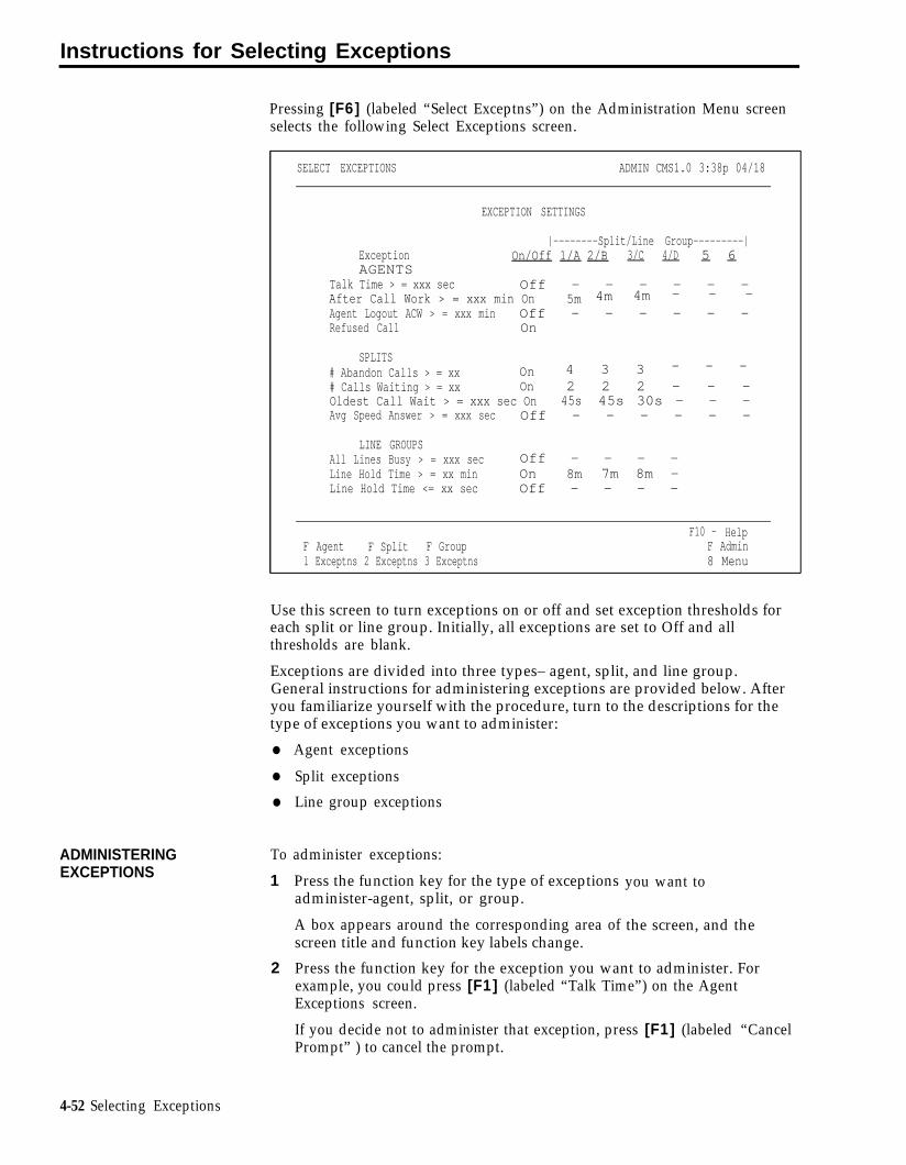
Instructions for Selecting Exceptions
ADMINISTERINGEXCEPTIONS
Pressing [F6] (labeled “Select Exceptns”) on the Administration Menu screenselects the following Select Exceptions screen.
SELECT EXCEPTIONS ADMIN CMS1.0 3:38p 04/18
EXCEPTION SETTINGS
|--------Split/Line Group---------|Exception On/Off 1/A 2/B 3/C 4/D 5 6AGENTS
Talk Time > = xxx sec Off - – - - - –After Call Work > = xxx min On 5m 4m 4m – – –
Agent Logout ACW > = xxx min Off – – - - – -Refused Call On
SPLITS# Abandon Calls > = xx On 4 3 3 – – –
# Calls Waiting > = xx On 2 2 2 - – -Oldest Call Wait > = xxx sec On 45s 45s 30s – – -Avg Speed Answer > = xxx sec Off – – - – – -
LINE GROUPSAll Lines Busy > = xxx sec Off – – - -Line Hold Time > = xx min On 8m 7m 8m –Line Hold Time <= xx sec Off - – - -
F10 - HelpF Agent F Split F Group F Adminl Exceptns 2 Exceptns 3 Exceptns 8 Menu
Use this screen to turn exceptions on or off and set exception thresholds foreach split or line group. Initially, all exceptions are set to Off and allthresholds are blank.
Exceptions are divided into three types– agent, split, and line group.General instructions for administering exceptions are provided below. Afteryou familiarize yourself with the procedure, turn to the descriptions for thetype of exceptions you want to administer:
●
●
●
To
1
2
Agent exceptions
Split exceptions
Line group exceptions
administer exceptions:
Press the function key for the type of exceptionsadminister-agent, split, or group.
A box appears around the corresponding area ofscreen title and function key labels change.
you want to
the screen, and the
Press the function key for the exception you want to administer. Forexample, you could press [F1] (labeled “Talk Time”) on the AgentExceptions screen.
If you decide not to administer that exception, press [F1] (labeled “CancelPrompt” ) to cancel the prompt.
4-52 Selecting Exceptions

3
4
5
6
7
8
Type on in the ON/OFF field of the prompt to turn the exception on, ortype off to turn the exception off.
Enter thresholds for splits or line groups.
Keep these points in mind:
– You do not need to enter a threshold for each split or line group. Ifyou don’t want to enter a threshold for a particular split or line group,simply leave it blank. This feature allows you to turn on an exceptionfor selected splits or groups.
– To delete a threshold value, type a hyphen (-) in the field you want todelete.
– You may enter thresholds even if you turn off an exception. Forexample, you may want to turn on the Talk Time exception when calltraffic is heavy. During slow periods, however, you might not carehow long an agent talks to customers. You may want to turn off theTalk Time exception then, but still keep the thresholds set.
Press [F8] (labeled "Enter Data") after you make an entry in the last field.
Press a different function key to administer another exception on thatscreen.
Press [F8] (labeled “Select Exceptns” ) on the Agent Exceptions, SplitExceptions, or Line Group Exceptions screen to return to the SelectExceptions screen when you finish administering exceptions for Agents,Splits, or Line Groups, respectively.
Press [F8] (labeled “Admin Menu”) to return to the Administration Menuscreen.
Selecting Exceptions 4-53

Selecting Agent Exceptions
Agent exceptions allow you to monitor the activity of individual agents. Youcan use these exceptions to indicate reasonable expectations for call handling,and to help determine where extra training might be necessary. You can setdifferent exception thresholds for each split to tailor the exception for the typeof calls each split handles. For instance, some splits may need more ACWtime than others.
Pressing [F1] (labeled “Agent Exceptns” ) from the Select Exceptions screenselects the Agent Exceptions screen shown below. The box in the screenindicates the four agent exceptions: Talk Time, After Call Work, AgentLogout ACW, and Refused Call.
AGENT EXCEPTIONS ADMIN CMS1.0 3:39p 04/18
EXCEPTION SETTINGS|--------Split/Line Group--------|
Exception On/Off 1/A 2/B 3/C 4/D 5 6AGENTS
Talk Time > = xxx sec Off - - - - - - After Call Work > = xxx min On 5m 4m 4m - - -Agent Logout ACW >= xxx min Off - - - - - - Refused Call On
SPLITS# Abandon Calls > = xx On 4 3 3 - - -# Calls Waiting > = xx On 2 2 2 - - -Oldest Call Wait > = xxx sec On 45s 45s 45s - - -Avg Speed Answer > = xxx sec Off - - - - - -
LINE GROUPSAll Lines Busy > = xxx sec Off - - - -Line Hold Time > = xx min On 8m 7m 8m -Line Hold Time < = XX sec Off - - - -
F10 - HelpF Talk F ACW F Agent FRefused F Select1 Time 2 3 Logout 4 Call 8Exceptns
ADMINISTERING AGENT To administer an agent exception:EXCEPTIONS 1 Press the function key for that exception and refer to the description and
instructions that follow this list. The exception message that appearswhen an exception threshold is reached or exceeded is also listed.
2 Press a function key to administer another agent exception, or press [F8](labeled “Select Exceptns”) to return to the Select Exceptions screen whenyou are finished.
4-54 Selecting Exceptions

[F1] Talk Time
Talk Time is the number of seconds an agent is connected to a call. If youturn on this exception, CMS notifies you when an agent’s Talk Time meets orexceeds the threshold set for that split.
Prompt:
TALK TIME (seconds): ON/OFF?__ Split 1:__ 2:___ 3:____ 4:___ 5:____ 6 : _ _ _
Action: 1 Type on or off, or leave the field blank if you want tokeep the current value.
2 Enter the number of seconds (1 through 999) for themaximum Talk Time for each split. To keep the currentvalue, leave the field blank. To turn off this exception fora particular split, enter a hyphen (-).
3 Press [F8] (labeled “Enter Data”) after the last field.
Message: • • • Split X - Agent XXXXX - Talk Time > = XXX seconds
[F2] ACW (After Call Work)
The ACW state refers to the period of time agents make themselvestemporarily unavailable for calls. If you turn on this exception, CMS notifiesyou when an agent has been in the ACW state longer than the threshold setfor that split.
Prompt:
ACW (minutes): ON/OFF?__ Split 1:___ 2:___ 3:___ 4:___ 5:___ 6:___
Action: 1 Type on or off, or leave the field blank if you want tokeep the current value.
2 Enter a number of minutes (1 through 999) for each split.To keep the current value of a field, leave the field blank.To turn off this exception for a particular split, enter ahyphen (-).
3 Press [F8] (labeled “Enter Data”) after the last field.
Message: • • • Split X - Agent XXXXX - After Call Work > = XXX minutes
Selecting Exceptions 4-55

[F3] Agent Logout (Agent Logout ACW)gent
If you turn on this exception, CMS automatically logs out an agent who hasbeen in the ACW state as long or longer than the threshold you set. You arenotified when the exception threshold is reached and the agent is logged out.
Prompt:
AGENT OUT (minutes): ON/OFF?__ S p l i t 1 : _ _ _ 2 : _ _ _ 3 : _ _ _ 4 : _ _ _ 5 : _ _ _ 6 : _ _ _
Action: 1 Type on or off, or leave the field blank if you want tokeep the current value.
2 Enter the number of minutes (1 through 999) for each split.To keep the current value, leave the field blank. To turnoff this exception for a particular split, enter a hyphen (-).
3 Press [F8] (labeled “Enter Data”) after the last field.
Message: • • • Split X - Agent XXXXX - Logged Out - ACW > = XXX minutes
[F4] Refused Call
If you turn on this exception, CMS notifies you whenever an agent refuses acall (i.e., whenever an agent does not answer a CMS call within the numberof rings specified in the Transfer Return Threshold on the Set Optionsscreen).
Prompt: REFUSED CALLS: ON/OFF? ___
Action: 1 Type on or off.
2 Press [F8] (labeled “Enter Data”).
Message: • • • Split X - Agent XXXXX - Refused Call
o r
• • • Split X - Agent XXXXX - Refused XFR Call on Line QXXXX
[F8] Select Exceptns (Select Exceptions)
Press this function key to return to the Select Exceptions screen.
[F10] Help
Press this function key to display a Help screen for the Agent Exceptionsscreen.
4-56 Selecting Exceptions

Selecting Split Exceptions
Split exceptions alert you to unusual or undesirable situations affecting awhole split. For example, you can be notified when the number of callswaiting in a split’s queue meets or exceeds a threshold you set. Splitexceptions can alert you to a need for more agents or faster call handling.
Pressing [F2] (labeled "Split Exceptns") from the Select Exceptions screenselects the Split Exceptions screen shown below. The box indicates the splitexceptions.
SPLIT EXCEPTIONS ADMIN CMS1.0 3:40P 04/18
EXCEPTION SETTINGS❘ .........Split/Line Group......... ❘
EXCEPTION On/Off 1/A 2/B 3/C 4/D 5 6A G E N T S
Talk Time > = xxx secAfter Call Work >= xxx minAgent Logout ACW>= xxx minRefused Call
OffOnOffOn
-5m-
-4m-
-4m-
---
---
---
SPLITS# Abandon Calls >= xx# Calls Waiting >= xxOldest Call Wait >= xxx secAvg Speed Answer >= xx sec
4245s-
3245s-
3230s-
- - - - - - - - - - - -
LINE GROUPSAll Lines Busy>= xxx secLine Hold Time >= xx minLine Hold Time= xx sec
OffOnOff
-8m-
-7m-
-8 m
-
---
FAbandon1 Calls
F Calls2Waiting
F Oldest3 Call
F Avg4 Speed
F10 - Help F Select 8Exceptns
ADMINISTERING SPLIT To administer a split exception:EXCEPTIONS 1 Press the function key for that exception and refer to the description and
instructions that follow this list. The exception message that appearswhen an exception threshold is met or exceeded is also listed.
2 Press a function key to administer another split exception or press [F8](labeled “Select Exceptns”) to return to the Select Exceptions screen whenyou are finished.
Selecting Exceptions 4-57

[F1] Abandon Calls (Number of Abandoned Calls)
When a caller hangs up before speaking to an agent, or an agent is connectedto a caller for less than the Abandoned vs. Incoming Call Threshold, the callis considered an abandoned call. If you turn on this exception, CMS notifiesyou whenever the number of abandoned calls in an hour reaches or exceedsthe threshold you set for the split.
Prompt:
# ABANDON CALLS: ON/OFF? _ Split 1:___ 2:___ 3:___ 4:___ 5:___ 6:___
Action: 1 Type on or off, or leave the field blank if you want tokeep the current value.
2 If you want to enter threshold values, enter the number ofseconds (1 through 99) for each split. To keep the currentvalue, leave the field blank. To turn off this exception fora particular split, type a hyphen (-).
3 Press [F8] (labeled “Enter Data”) after the last field.
Message: • • • Split X - # Abandoned Calls > = XX
[F2] Calls Waiting (Number of Calls Waiting)
The Calls Waiting exception refers to the number of calls not yet connected toagents. If you turn on this exception, CMS notifies you when the number ofcalls waiting in a split’s queue meets or exceeds the threshold you set for thatsplit. The maximum number of calls that can be waiting for a split is equal tothe number of CMS lines and transfer-queue lines assigned to that split.
Prompt:
# CALLS WAITING: ON/OFF? _ Split 1:___ 2:___ 3:___ 4:___ 5:___ 6:___
Action: 1 Type on or off, or leave the field blank if you want tokeep the current value.
2 If you want to enter threshold values, enter a number lessthan or equal to the number of CMS and transfer-queuelines assigned to each split. To keep the current value,leave the field blank. To turn off this exception for aparticular split, type a hyphen (-).
3 Press [F8] (labeled "Enter Data") after the last field.
Message: • • • Split X - # Calls Waiting > = XX
4-58 Selecting Exceptions

[F3] Oldest Call (Oldest Call Waiting)
The oldest call is the call that has been waiting the longest in a split’s queue.If you turn on this exception, CMS notifies you when the number of secondsthe oldest call has been waiting meets or exceeds the threshold you set.
Prompt:
OLDEST CALL (sec): ON/OFF?__ Split 1:___ 2:___ 3:___ 4:___ 5:___ 6:___
Action: 1 Type on or off, or leave the field blank if you want tokeep the current value.
2 If you want to enter threshold values, enter a number ofseconds (1 through 999) for each split. To keep the currentvalue, leave the field blank. To turn off this exception fora particular split, type a hyphen (-).
3 Press [F8] (labeled “Enter Data”) after the last field.
Message: • • • Split X - Oldest Call Waiting > = XXX seconds
[F4] Avg Speed (Average Answering Speed)
The average answering speed is the average time it takes from the time a callrings until it is connected to an agent in a particular split. This includes theAnswer Delay (the amount of time a call rings before CMS answers it andconnects it to a voice announcement unit), the time connected to the voiceannouncement unit, the time on hold waiting to be transferred to an agent,and the time it takes to transfer the call to an agent.
If you turn on this exception, CMS notifies you when the average speed ofanswer in a split meets or exceeds the threshold you set.
Prompt:
AVG SPEED ANS (sec): ON/OFF?___ Split 1:___ 2:___ 3:___ 4:___ 5:___ 6:___
Action: 1 Type on or off, or leave the field blank if you want tokeep the current value.
2 If you want to enter threshold values, enter a number ofseconds (1 through 999) for each split. To keep the currentvalue, leave the field blank. To turn off this exception fora particular split, type a hyphen (-).
3 Press [F8] (labeled "Enter Data") after the last field.
Message: • • • Split X - Avg Speed of Answer > = XXX seconds
[F8] Select Exceptns (Select Exceptions)
Press this function key to return to the Select Exceptions screen.
[F10] Help
Press this function key to view a Help screen for the Split Exceptions screen.
Selecting Exceptions 4-59

Selecting Line Group Exceptions
Line group exceptions alert you to unusual or undesirable situations affectinglines or line groups. For instance, the All Lines Busy exception notifies youwhen all lines in a line group or all lines in a sub-group of that line grouphave been busy more than a specified number of seconds.
Pressing [F3] (labeled “Group Exceptns”) from the Select Exceptions screenselects the Group Exceptions screen, shown below. The box indicates the linegroup exceptions.
GROUP EXCEPTIONS ADMIN CMS1.0 3:42P 04/18
EXCEPTION SETTINGS❘ .........Split/Line Group........ ❘
Exception On/Off 1/A 2/B 3/C 4/D 5 6A G E N T S
Talk Time >= xxx secAfter Call Work >= xxx minAgent Logout ACW >= xxx minRefused Call
Off
On
Off
On
-
5 m
-
-
4m
-
-
4m
-
- - -
- - -
- - -
SPLITS# Abandon Calls >= xx# Calls Waiting >= xxOldest Call Wait >= xxx secAvg Speed Answer > = xxx sec
O nOnO nOff
4245s-
3245s-
3230s-
- - - - - - - - - - - -
LINE GROUPSAll Lines Busy >= xxx secLine Hold Time > = xx minLine Hold Time <= xx sec
OffOnOff
-8 m-
-7m-
-8m-
---
F Lines FHoldTime FHoldTime1 Busy 2Maximum 3Minimum
F10 - HelpF Select8Exceptns
ADMINISTERING LINE To administer a line group exception:GROUP EXCEPTIONS 1 Press the function key for that exception and refer to the description and
instructions that follow this list. The exception message that appearswhen each exception threshold is exceeded is also listed.
2 Press a function key to administer another line group exception, or press[F8] (labeled “Select Exceptns”) to return to the Select Exceptions screenwhen you are finished.
4-60 Selecting Exceptions
[F1] Lines Busy (All Lines Busy)
The All Lines Busy exception refers to the number of seconds all lines in aline group (or all lines in a sub-group of that line group) are busy. If youturn on this exception, CMS notifies you when the threshold you set is metor exceeded.
NOTE: If there are transfer-queue lines in the line group, all the CMSand transfer-queue lines in the group must be busy for the exceptionmessage to be displayed. If you want to be notified when all non-transfer-queue lines in a line group are busy, assign all non-transfer-queue lines to a sub-group.
Prompt:
ALL LINES BUSY (seconds): ON/OFF?___ Line Group A:___ B : _ _ _ C:___ D:____
Action: 1 Type on or off, or leave the field blank if you want tokeep the current value.
2 If you want to enter threshold values, enter a number ofseconds (1 through 999) for each line group. To keep thecurrent value, leave the field blank. To turn this exceptionoff for a particular line group, type a hyphen (-).
3 Press [F8] (labeled “Enter Data”) after the last field.
Message: • • • Group X - All Lines Busy > = XXX seconds
or
• • • Sub-Group XX of Group X - All Lines Busy > = XX seconds
[F2] Hold Time Maximum (Maximum Line Holding Time)
The line holding time refers to the length of time a line has been in use for asingle call. If you turn on the Maximum Line Holding Time exception, CMSnotifies you when the length of time a line has been seized meets or exceedsthe threshold you set for its line group.
Prompt:
MAXIMUM HOLD-TIME (minutes): ON/OFF?___ Line Group A:___ B:___ C:___ D:___
Action: 1 Type on or off, or leave the field blank if you want tokeep the current value.
2 If you want to enter threshold values, enter a number ofminutes (1 through 99) for each line group. To keep thecurrent value, leave the field blank. To turn off thisexception for a particular line group, type a hyphen (-).
3 Press [F8] (labeled “Enter Data”) after the last field.
Message: • • • Group X - Line XXXXX Hold Time > = XX minutes
Selecting Exceptions 4-61

[F3] HoldTime Minimum (Minimum Line Holding Time)
The line holding time refers to the length of time a line has been in use for asingle call. If you turn on this exception, CMS notifies you when the lengthof time a line has been in use is less than the threshold you set. If theholding time of a line is consistently short, it may signal a line problem.
Prompt:
MINIMUM HOLD-TIME (seconds): ON/OFF?___ Line Group A:___ B:___ C:___ D:___
Action: 1 Type on or off, or leave this field blank if you want tokeep the current value.
2 If you want to enter threshold values, enter a number ofseconds (1 through 99) for each line group. To keep thecurrent value, leave the field blank. To turn off thisexception for a particular line group, type a hyphen (-).
3 Press [F8] (labeled “Enter Data”) after the last field.
Message: • • • Group X - Line XXXXX - Hold Time < = XX seconds
[F8] Select Exceptns (Select Exceptions)
Press this function key to return to the Select Exceptions screen.
[F10] Help
Press this function key to display a Help screen or the Group Exceptionsscreen.
4-62 Selecting Exceptions

Printing System 25 Administration Instructions
System 25 must be administered to support CMS operation. In order forCMS to function properly, System 25 must reflect the same port numbers,PDCs, voice terminal types, trunk numbers, and trunk types as CMS.Therefore, if you make changes to any of the above for agent stations, PCjacks, voice announcement units or lines (CMS or transfer-queue), you mustprint out System 25 Administration Instructions and have the System 25Administrator make the necessary changes before resuming CMS callmanagement; otherwise, CMS will not operate correctly.
NOTE: Changes to the CMS supervisor station(s) do not appear onthe System 25 Administration Instructions. Any changes to asupervisor’s station should be discussed with, and administered by,the System 25 Administrator.
To remind you that System 25 administration is needed, CMS prompts you toprint administration instructions when you attempt to exit CMSadministration. The following message is displayed:
You made changes affecting SYSTEM 25 Admin: Print Instructions? (Y/N):___
Type y and press [Enter] to print the instructions. The following screen isdisplayed.
PRINT SYSTEM25 INSTRUCT ADMIN CMS1.0 3:44p 04/18
Form Print
System 25 CMS Administration
Turn on Printer and Align Paper. (When Ready, Select a Labeled Function Key)F Full F Partial F Update F Admin1 Print 2 Print 3 S25 File 8 Menu
Printing System 25 Administration Instructions 4-63

You can also access the screen at any time by pressing [F7] (labeled “ S25Admn Instrctn” ) from the Administration Menu screen. With this screen youcan:
• Obtain a Full Print of the System 25 Administration Instructions ( [F1] )
You only need this report initially to administer System 25 for CMS.
• Obtain a Partial Print of the System 25 Administration Instructions ( [F2] )
• Update the System 25 file ( [F3] )
• Return to the Administration Menu ( [F8] )
• Obtain Help ( [F10] )
When you access the Print System25 Instruct screen, the following messageappears on the prompt line:
Turn on Printer and Align Paper. (When Ready, Select a Labeled Function Key.)
To print the System 25 Administration instructions:
1 Turn on the printer connected to your PC. Make sure the “Ready” light ison, indicating that the printer is ready to print.
2 Press [F1] to obtain a Full Print or [F2] to obtain a Partial Print of System25 Administration Instructions.
Below are descriptions of the Full Print, Partial Print, and Update S25 Fileoptions.
[F1] Full Print
When you request a Fullinformation necessary to
Print report, CMS prints out forms consisting ofadminister the agent stations, PC jacks,
announcement units, CMS lines, and transfer-queue lines. (Remember thatthere is no printout for the supervisor stations.) The Full Print option alsoautomatically updates the System 25 file after the print is completed.Therefore, no further updating using [F3] (labeled “Update S25 File”) isnecessary.
Select this print option when you initially administer CMS and any timeafterwards when you want to get a full set of System 25 AdministrationInstructions.
To print out a Full Print report:
1 Press [F1] (labeled “Full Print”).
The following prompt appears:
FULL PRINT: Print all SYSTEM 25 Instructions? (Y/N):___
2 Type y or n and press [F8] (labeled “Enter Data”).
If you type y, the system checks that the printer is ready, and then printsout the forms.
If you type n, the original Print System25 Instruct screen appears.
3 Remove the instructions from the printer, and give them to the System 25Administrator.
4-64 Printing System 25 Administration Instructions

WARNING
If you selected this option because you madechanges, CMS will not work correctly until System 25is administered to reflect these changes. In themeantime, follow the instructions for “ManagingCalls When CMS is Not Running”, in Section 9 ofthis manual.
[F2] Partial Print
Request the Partial Print of System 25 Administration Instructions wheneveryou make changes after the initial System 25 administration for CMS. APartial Print report prints out only the forms that have been affected since thelast time [F3] (labeled “Update S25 File”) was pressed or a Full Print ( [F1] )was done.
In most cases, after you do a Partial Print, you should update the System 25file by pressing [F3] (labeled “Update S25 File”), and give the print to theSystem 25 Administrator to make the necessary changes. The only exceptionto this print update sequence is if you are planning to make more changesaffecting System 25 administration before resuming call management. In thiscase, you can do as many interim prints as you like, but wait until after thefinal print is done (Partial or Full) before updating the System 25 file. Giveonly the final print to the System 25 Administrator.
To print out the Partial Print instructions:
1 Press [F2] (labeled “Partial Print“).
The following prompt appears:
PARTIAL PRINT: Print only SYSTEM 25 changes from last S25 File Update? (Y/N):___
2 Type y or n and press [F8] (labeled “Enter Date”).
If you type y, the system checks that the printer is ready and then printsout the necessary forms.
If you type n, the system returns to the original Print System25 Instructscreen.
NOTE: If no changes were made that require System 25 administration,the following message appears on the error line:
Can’t find any changes since last S25 File Update affecting SYSTEM 25
and the system returns to the original Print System25 Instruct screen.
3 Remove the instructions from the printer and give them to the System 25Administrator.
4 Press [F3] (labeled “Update S25 File”) to update the System 25 file. (Formore information about updating the System 25 File, see [F3] Update S25File, later in this section.)
Printing System 25 Administration Instructions 4-65

WARNING
CMS will not work correctly until the System 25administration is complete. In the meantime, followthe instructions for “Managing Calls When CMS isNot Running”, in Section 9 of this manual.
[F3] Update S25 FileAfter you have obtained the System 25 Administration Instructions PartialPrint, press this function key to update the System 25 file with all the changesmade prior to your last Partial Print of System 25 instructions. In mostinstances, you should update the file immediately following a Partial Print.
NOTE: The Full Print option updates the System 25 file automatically,so you don’t need to press [F3] after a Full Print is done.
4-66 Printing System 25 Administration Instructions

Backing Up Shift Configurations
By routinely making a backup copy (on a diskette) of your shift configurationsand system tables files, you will have a current version to use if you need torestore your system after a problem. If your hard disk drive ever becomesinoperable, you can also use your backup copy to run CMS from the floppydisk drive. However, you cannot save historical data or administer CMSwhen you run CMS using the floppy diskette. (For more information see“Running CMS From a Floppy Diskette Backup,” in Section 9.)
NOTE: If you plan to archive your historical data, see Section 8,“Archiving Data”. The Archiving Data procedure is different from theone described here and must be done on a different diskette.
COPYING SHIFTCONFIGURATIONSSYSTEM TABLES
To make a backup copy of your shift configurations and system tables files:AND 1
2
3
4
5
6
7
8
Exit to MS-DOS by pressing [F8] (labeled “Exit to DOS”) on the CMSMenu.
Insert the diskette labeled “SYSTEM 25 CMS SYSTEM WORKING COPY”into disk drive A. For instructions on how to make a working copydiskette, see “Duplicating the CMS Diskettes” in Section 3.
To change to the cmsmgmt directory on the hard disk, type the followingcommand at the c> prompt:
cd \ cms \ cmsmgmt
then press [Enter].
Change to the cmsmgmt directory on the floppy diskette as follows. Atthe c> prompt type
a:
then press [Enter]. At the A> prompt type
cd \ cms \ cmsmgmt
then press [Enter].
To copy all your shift configurations from the hard disk onto the floppydiskette, type
copy c:shift*.cms a:
then press [Enter].
To copy the system tables onto the floppy diskette, type
copy c:systbls.cms a:
then press [Enter].
Remove the working copy diskette when the in-use light on disk drive Agoes out.
With a felt tip pen, write the current date on a label and attach it to thediskette.
Backing Up Shift Configurations 4-67

9 To return to the cms directory on disk drive C, do the following. At theA> prompt type
c:
then press [Enter]. At the C> prompt type
cd . .
then press [Enter].
10 To display the CMS Menu, type
cms
and then press [Enter].
RESTORING SHIFT If you ever lose a shift configuration (for instance, if you clear a configurationCONFIGURATIONS AND by accident), copy the desired configuration (or all configurations) from theSYSTEM TABLES working copy diskette as follows:
1
2
3
4
5
6
Repeat steps 1 through 4 in the previous procedure.
To copy all your shift configurations from the duplicate onto the harddisk, type
COPY a:shift*.cms c:
then press [Enter] .
or
To copy a single shift configuration from the working copythe following, replacing the X with the number of the shift
copy a:shiftX.cms c:
then press [Enter].
diskette, typeconfiguration.
To copy the system tables from the working copy diskette onto the harddisk, type
copy a:systbls.cms c:
then press [Enter].
Remove the working copy diskette when the in-use light on the disk drivegoes out.
To return to the CMS directory on disk drive C, do the following. At theA> prompt type
c:
then press [Enter]. At the C> prompt type
cd. .
then press [Enter].
To display the CMS Menu, type
cms
and then press [Enter].
4-68 Backing Up Shift Configurations

Section 5: Supervising CMS

Overview
“Supervising CMS” means starting and monitoring call management, makingchanges in the configuration being used to manage calls, and operating CMSday to day. This section is organized as follows:
Startup Procedures
Describes turning on your PC and starting data collection and callmanagement.
Making Agents Available for CMS Calls
Describes how agents make themselves available for CMS calls and how theycan enter the After-Call-Work state or Logged Out state.
Monitoring Call Management
Explains how to read the status screens to obtain current information onagent and split activity, call traffic, and system problems.
Supervising Your Agents
Describes the Service Monitoring feature that allows you to monitor agents’calls, and the Assist feature that enables agents to signal you when they needassistance.
Dynamic Reconfiguration
Describes changing the active shift configuration while CMS is managingcalls. Typical changes during dynamic reconfiguration are reassigning agentsand turning intraflow on or off. This part also tells you how to save thechanges you have made, and how to select a new configuration for callmanagement.
Selecting Day or Night Service
Describes changing CMS from Day Service mode (where CMS routes calls toagents) to Night Service mode (where CMS answers calls, connects them to adelay message, and then disconnects them).
Day-to-Day Operation of CMS
Describes how the CMS Supervisor at Bon Voyage Travel, a fictitiousbusiness, uses CMS on a typical day. You may want to read this brief partfirst to become more familiar with the types of activities involved in usingCMS.
Figure 5-1, “Menu Map for Call Management,” on the following page showsthe screens you use to monitor call management and perform dynamicreconfiguration.
Overview 5-1

FIGURE 5-1 Menu Map for Call Management.
5-2 Overview

Startup Procedures
To start CMS call management, follow these steps:
1 Turn on your PC.
If your PC automatically starts the CMS program, the CMS Menu, shownbelow, appears soon after you turn on the PC. For information onautomatic startup, refer to “The AUTOEXEC.BAT File” in Section 3 of thismanual.
If you do not use automatic startup, do the following:
● When the MS-DOS prompt C> appears, type
cd \ cms
and press [Enter].
● When c> appears again, type
cms
and press [Enter].
This starts the CMS program. The CMS Menu screen, shown below,appears.
CALL MANAGEMENT SYSTEM (CMS)
FOR THE AT&T SYSTEM 25 PBX
(C) 1988 by AT&T
CMS MENU CMS CMS1.0 9:19a 04/18
F1 Start Call Management
F4 Administer CMS
F5 Print Reports
F8 Exit to DOS
F10 - HelpF Start F Admin F Print F Exit1 Call Mgt 4 CMS 5 Reports 8 to DOS
Startup Procedures 5-3

2 Press [F1] (labeled “Start Call Mgt”) to begin call management.
3 If you have previously selected a particular shift configuration to beginautomatically during call management startup, go to step 5. For moreinformation about activating a configuration automatically, see “Selecting aStartup Configuration” in Section 4 of this manual.
If you have not preselected a startup shift configuration, a list ofconfigurations and a prompt appear, as shown below.
INITIALIZATION DAY CMS1.0 6:02p 04/20
STORED SHIFT CONFIGURATIONS
123456
——————
DAYEVENINGWEEKENDUNUSEDUNUSEDUNUSED
SELECT CONFIGURATION: Config # (l-6): ___F Cancel F Enter1 Prompt 8 Data
4 Enter the number of the configuration you want to activate and press [F8](labeled “Enter Data”).
5-4 Startup Procedures

5 The following Initialization screen appears.
INITIALIZATION DAY CMS1.0 6:10p 04/20
INITIALIZATION IN PROGRESS
6 CMS performs a series of checks. If the CMS-Port Personal Line ButtonVerification option is on, the following message appears below the“INITIALIZATION IN PROGRESS” message:
PC-Port Verification In Progress--May Last Up to 4 Minutes
CMS will verify that the Personal Line appearances of the CMS trunks arecorrectly administered on PC jack CU1. Any problems appear on thisscreen below the “INITIALIZATION IN PROGRESS” message, as well asin the Events Log.
If you receive an error message, find the error message in Section 9,“Troubleshooting,” and take the recommended corrective action.
NOTE: Eleven error messages will fit on the Initialization screen. If morethan eleven errors are found, the earlier messages displayed will scroll offthe screen. In that case, exit call management and print the Events LogReport. By checking the “Time” and “Date” columns on the Events LogReport, you can locate all the error messages generated during callmanagement startup. For more information about generating the EventsLog Report, see “Events Log Report” and “How to Generate Reports “ inSection 7 of this manual.
You can disable the CMS-Port Personal Line Button Verification optionfrom the administration Set Options screen. Refer to “Setting Options” inSection 4, “Administering CMS ”.
Startup Procedures 5-5

7 After successful system checks, the following screen appears and callmanagement begins.
INITIALIZATION DAY CMS1.0 6:10p 04/20
INITIALIZATION COMPLETED
CMS IS NOW MANAGING CALLS
F10 - HelpF Con fig F System F Exit1 Screen 3 Status 8 Call Mgt
NOTE: When call management begins, all agents are automatically in theLogged Out state. To make themselves available, agents have to press theAvailable button on their voice terminals. This turns on the light next tothe Available button and signals CMS that they are ready to receive calls.
8 Press the function key for the activity you want to perform next. Forinformation on moving the cursor in prompts, entering data, and editingdata, see “Using Your PC with CMS” in Section 3.
The function keys active on this screen are:
[F1] Config Screen (Configuration Screen)
Press this function key to select the Configuration screen, which displaysthe active shift configuration. From the Configuration screen you canmake changes to the configuration while it is managing calls. For instance,you may want to replace an agent who is absent. For more information,see “Dynamic Reconfiguration, ” later in this section.
[F3] System Status
Press this function key to select the System Status screen, the “home”screen while CMS call management is running. The System Status screensummarizes the activity in each agent split and line group and lists thestatus of each voice announcement unit. For information on interpretingthis screen, see “Key to System Status Screen Data,“ later in this section.
5-6 Startup Procedures

[F8] Exit Call Mgt (Exit Call Management)
Press this function key to stop call management. You are prompted toconfirm your request. Your CMS stops answering new incoming calls butcontinues to function until all calls already answered by CMS, whetherconnected to the voice announcement unit, on hold waiting for an agent,or connected to an agent are completed. The status screens continue to beupdated as long as calls are being handled.
When all calls are completed, the historical data are written to the PC’shard disk and the CMS Menu screen appears. From the CMS Menu youcan choose to administer CMS, print reports, exit to MS-DOS, or start callmanagement again.
[F10] HelpPress this function key to display a Help screen containing a description ofthe functions available from the Initialization screen.
Startup Procedures 5-7

Making Agents Available for CMS Calls
Since it is important that CMS knows when an agent is available for CMScalls, agents must understand how to indicate the work state they are in. Inthis way your CMS can run efficiently and maintain accurate records.
Agents assigned to splits in an active configuration can be in one of threeagent states:
● Available state. An agent is available for CMS calls when the light next tothe agent’s Available button is on.
● After-Call-Work (ACW) state. Agents may need to complete work relatedto the current CMS call. In order to do so, before hanging up from thecall, they should place themselves in the ACW state by pressing the ACWbutton. This turns on the light next to the ACW button. An agent willnot receive CMS calls while in the ACW state.
● Logged Out state. When agents are neither available for CMS calls nordoing after-call-work, they must be in the Logged Out state. The lightnext to the agent’s Logged Out button must be on. Time spent in thisstate is not included in report statistics. When CMS is in Night Servicemode, all agents are in the Logged Out state.
Agents in the Available or ACW states are considered logged in.
MOVING FROM STATE TO Logged Out StateSTATE When an agent is neither available to accept CMS calls nor doing after-call-
work, the agent can enter the Logged Out state by pressing the Logged Outbutton. (The light next to the Logged Out button goes on.) As the CMSSupervisor, you can also place an agent in the Logged Out state from theSplit Status screen.
All agents are automatically in the Logged Out state when CMS callmanagement begins and when CMS stops managing calls with one shiftconfiguration and begins managing calls with another. While CMS is in theNight Service mode, all agents in the active configuration are in the LoggedOut Nite state.
Individual agents are automatically placed in the Logged Out state:
• When you add an agent to an active configuration.
• When an agent in an active configuration is moved to another station orsplit .
• When the Agent Logout ACW exception is on and an agent has been inthe ACW state for longer than the time specified as the exceptionthreshold. For more information, see “Selecting Agent Exceptions” inSection 4.
5-8 Making Agents Available for CMS Calls

Available StateWhen call management begins, all agents are automatically placed in theLogged Out state. Tell your agents when CMS call management has begunso they can make themselves available for CMS calls. Those agents who areready for CMS calls can turn on the light next to the Available button at theirvoice terminals by pressing the Available button.
When agents want to reenter the Available state from the ACW or LoggedOut state, they can signal their availability by pressing the Available buttonand thus turning on the light next to it.
NOTE: Remind agents whom you add to a configuration, move to anew split, or move to a different agent station that they must pressthe Available button to signal their availability.
After-Call-Work StateWhen agents need to finish paperwork associated with a CMS call, they canannounce their unavailability by pressing the ACW button. (The light next toit goes on.) Agents who refuse a CMS call (that is, the agents do not answerthe call within the number of rings specified in the Transfer Return Thresholdon the Set Options screen) are automatically placed in the ACW state.
Making Agents Available for CMS Calls 5-9

Monitoring Call Management
Once you begin call management (as described earlier in “StartupProcedures“), you can monitor line group and split activity through the statusscreens. The following status screens are described in this section:
●
●
●
●
By
System Status screen
This screen is considered the “home” screen during call management. Itsummarizes the activity in each line group and split.
Split Status screens
There is a Split Status screen for each split. This screen describes theactivity of each agent in the split and summarizes the activity for theentire split. From this screen you can log in or log out an agent in thedisplayed split (that is, make an agent available or unavailable for CMScalls).
Line Status screen
This screen summarizes the activity for each line and line group. Fromthis screen you can change the priority of a CMS or transfer-queue line.
Events Log screen .
This screen lists the 19 most recent exception, warning, and system errormessages along with the time they occurred.
monitoring the status screens, you can discover problems as they occurand correct them through dynamic reconfiguration. See “DynamicReconfiguration“, later in this section.
To obtain a printed copy of a displayed screen, hold down [Shift] and press[Print Scrn].
CAUTION
If you see the message Don’tPrtSc on the top line of the screen orWARNING-- Printer Not Ready. Using Prt SC Key Will Halt CMS on the error line,do NOT attempt to print a screen. If you attempt to print a screen whileeither of these messages is displayed, CMS will stop managing calls.
If the printer is not ready, you can perform the following checks:
● Make sure the printer is plugged in, turned on, and that the Ready light ison.
● Make sure there is paper in the printer and that the paper is alignedproperly and not jammed.
● Press the Form Feed button on the printer to make sure the paper feedsproperly. (After you do that, make sure you turn the Ready light backon.)
See “Printer Problems” in Section 9 for more information abouttroubleshooting your printer.
5-10 Monitoring Call Management

STATUS SCREEN TERMS The System Status, Split Status, and Line Status screens provide continuouslyupdated data to help you monitor your CMS. The following terms are usedin the remainder of this section to distinguish between different types of calls:
• Serviced vs. Abandoned
“Serviced” calls have come into CMS and were connected to an agent forlonger than the Abandoned vs. Incoming Call Threshold. “Abandoned”calls have come into CMS but were not handled by an agent. Either thecall was disconnected before being transferred to an agent, or the talk timewas less than the Abandoned vs. Incoming Call Threshold set on the SetOptions screen. For information about the Abandoned vs. Incoming CallThreshold, see “Setting Options” in Section 4.
• Completed vs. Not Completed
“Completed” calls are those that have been serviced by agents and thendisconnected. “Not completed” calls are those that either were abandonedor are currently in progress (ringing, on hold, or connected to agents).When these terms are used to describe “other” (that is, non-CMS) calls, a“completed” call is any call that has been disconnected, and a “notcompleted” call is one that has not yet been disconnected.
Many CMS statistics are based on completed activities for a certain hour.If a call is in progress when an hour ends, the data on that call are notincluded in the statistics for that hour. The data on the call are includedinstead in the statistics for the hour in which the call is completed.Therefore, some statistics, such as total holding time of a line, may showmore than 60 minutes of activity within a given hour.
• ACD vs. Other
Incoming calls to CMS lines which are answered by CMS and transferredto an available agent are considered “ACD” (Automatic Call Distributor)calls. ACD calls include calls that are transferred to an agent using theTransfer-into-Queue feature.
“Other” calls are non-ACD incoming calls, outbound calls (even if theyuse CMS lines), inside calls, and calls transferred to a specific agent byanother agent or person on System 25 (whether or not the call wasoriginally an ACD Call).
Monitoring Call Management 5-11

Using the System Status Screen
The System Status screen, an example of which is shown below, summarizesthe activity in each line group and agent split. It is considered the “home”screen during call management. For an explanation of the data on thisscreen, see “Key to System Status Screen Data,” later in this section. -
SYTEM STATUS DAY CMS1.0 10:26a 05/19
LINE GROUP INFORMATION ANNOUNCEMENT UNIT STATUSLine ❘ ...Lines... ❘ ❘ ...Splits... ❘ ❘ ...1... ❘ ❘ ...2... ❘ ❘ ...3... ❘ ❘ ...4... ❘ Group Busy Total Main Sec Flow PUBLIC BUSINES CHARTER A PUBLCB BUSNSC CHARTD -
2500
9650
123-
432-
OffOnOffOff
IDLE- - - -- - - -- - - -
- - - -CNCT- - - -- - - -
- - - -- - - -IDLE- - - -
----------------
SPLIT INFORMATION❘ -------Agents------- ❘ ❘ -Waiting- ❘ ❘ -Abandon- ❘ Intrflw ❘ -Calls Handled- ❘ Serv
Split ACD Aval ACW Out Othr Num Old Num Delay In Out Num AvgTalk ASA Levl1 PUBLC2 BUSNS3 CHART4 SUPPT5- 6 -
230000
202000
100000
100500
001000
020000
0s7s0s0s0s0s
100000
7s0s0s0 s0s0s
0011000
0110000
664251000
2:022:552:250:000:000:00
10s37s51s0s0s0s
90%57%33%0%0%0%
F10 - HelpFSet Opt/1Chg Mode
F Select2 Anncs
F Select3Exceptns
F Events4 Log
F Line5 Status
F Split6 Status
F Config7 Screen
F Exit8Call Mgt
So you can tell at a glance if CMS is operating efficiently, the System Statusscreen lists:
●
●
●
●
●
●
The status of line groups (the number of busy lines and the total numberof lines in the line group)
How splits are assigned to line groups and whether or not intraflow isturned on
The status of each voice announcement unit and an indication of the linegroup(s) to which it is assigned
Status information on each split (such as the number of agents on CMScalls and the number of available agents)
The number of calls waiting for each split
Important data collected since the beginning of the report hour (such asthe number of calls handled and the service level)
If the System Status screen indicates a call management problem that needsimmediate correction, you can make that correction through dynamicreconfiguration. For more information, see “Dynamic Reconfiguration,” laterin this section.
5-12 Monitoring Call Management

You can access the screen used to change the system from Day Service modeto Night Service mode by pressing [F1] (labeled “Set Opt/Chg Mode”) on theSystem Status screen. In Day Service mode, CMS routes calls to agents. InNight Service mode, CMS connects incoming calls to a voice announcementunit and disconnects them when the announcement is over. For moreinformation, see “Selecting Day or Night Service,” later in this section.
To select another screen from the System Status screen, or to exit callmanagement, press the corresponding function key:
[F1] Set Opt/Chg Mode (Set Options/Change Mode)
Press this function key to select the Set Options/Modes screen to change thesystem from Day Service mode to Night Service mode or vice versa. Formore information, see “Selecting Day or Night Service,” later in this section.You can also change the Service Level Limit, Abandoned vs. Incoming CallThreshold, Audible Alarm, and Transfer Return Threshold options from thisscreen. For more information on these options, see “Setting Options“ inSection 4.
[F2] Select Anncs (Select Announcements)
Press this function key to reassign voice announcement units to line groups orto change the condition of a unit to removed or available. You can alsochange the maximum message length of each announcement from this screen.You cannot change the port or PDC associated with a voice announcementunit while CMS is managing calls. This must be done through CMSadministration. For more information about administering voiceannouncement units, see “Administering Announcements” and “AssigningAnnouncements” in Section 4.
[F3] Select Exceptns (Select Exceptions)
Press this function key to display the Select Exceptions screen, which enablesyou to select different exceptions or change exception thresholds. For moreinformation, see "Selecting Exceptions" in Section 4.
[F4] Events Log
Press this function key to select the Events Log screen, which displays the 19most recent exception, warning, and system error messages. For moreinformation, see “Using the Events Log Screen,“ later in this section.
[F5] Line Status
Press this function key to select the Line Status screen, which displaysinformation about every line in every line group. You can also change linepriority from this screen. For more information, see “Using the Line StatusScreen” and “Key to Line Status Screen Data,” later in this section.
Monitoring Call Management 5-13
[F6] Split Status
Press this function key to view a Split Status screen for a particular split. Youare prompted for the split number. The Split Status screens give you adetailed picture of the activity in each split. You can change the status of anagent to Available or Logged Out from these screens. For more information,see “Using the Split Status Screen” and “Key to Split Status Screen Data,”later in this section.
[F7] Config Screen (Configuration Screen)
Press this function key to select the Configuration screen. From that screenyou can begin dynamic reconfiguration of your system. This involvesmodifying the configuration that is currently managing calls. For moreinformation, see “Dynamic Reconfiguration,” later in this section.
[F8] Exit Call Mgt (Exit Call Management)
Press this function key to stop call management. You are prompted toconfirm your request. Your CMS stops answering new incoming calls butcontinues to function until all calls already answered by CMS, whetherconnected to the voice announcement unit, on hold waiting for an agent, orconnected to an agent are completed. The status screens continue to beupdated as long as calls are being handled.
Once all calls are completed, the historical data are written to the disk and theCMS Menu screen appears. From the CMS Menu you can choose toadminister CMS, print reports, exit to MS-DOS, or start call managementagain.
[F10] Help
Press this function key to view a Help screen for the System Status screen.
5-14 Monitoring Call Management

Key to System Status Screen Data
LINE GROUPINFORMATION
The numbers in the following list correspond to the circled numbers providedin the above screen.
1 Line Group The line group letter and line group ID.
2 Lines Busy The number of lines in the line group that are notidle. They may be connected, ringing, or on hold.
3 Lines Total The total number of lines assigned to the linegroup.
4 Splits Main The number of the main split assigned to the linegroup. If no main split is assigned, a hyphen (-)appears instead of a number.
The number of the secondary split assigned to theline group for intraflow. The secondary split canreceive calls for the line group only if intraflow ison. If no secondary split is assigned, a hyphen (-)appears instead of a number.
6 Flow Intraflow status is indicated by On or Off .
5 Splits Sec
Monitoring Call Management 5-15

ANNOUNCEMENT UNIT 7 Announce-STATUS ment Unit
Status
SPLIT INFORMATION 8 Split
9 Agents ACD
10 AgentsAvail
11 AgentsACW
12 Agents Out
Number, ID, and status of each voiceannouncement unit. Statuses are as follows:
— : the unit is not assigned to that particularline group or is not administered in CMS.
BUSY: the unit is in use on a CMS call, but thecall is not connected to a line in that line group.
CNCT: the unit is connected to one of the linegroup’s calls.
IDLE: the unit is in service and assigned to thatline group, but is not connected to a call at themoment.
RMVD: the unit has been taken out of service bythe CMS Supervisor, but is still assigned to thatline group.
BRKN: CMS has determined that the unit is notworking and has taken it out of service.
TEST: CMS is performing a test on the unit tosee if it will answer a call. This test is performedautomatically when a unit is put back into serviceand also when CMS call management is started.
OTHR: A non-CMS call is connected to the unitor the message is being played during the test call.
The number and ID of each split.
The number of agents currently active on ACD(CMS) calls. Active calls include both callscurrently connected to an agent and calls theagent has placed on hold.
During Day Service, the number of agentscurrently available to receive ACD (CMS) calls(that is, agents whose Available light is on andwhose voice terminals are on-hook).
During Day Service, the number of agentson-hook in the After-Call-Work state.
During Day Service, the number of agents in theLogged Out state. During Night Service, thenumber of agents on-hook.
5-16 Monitoring Call Management

13 Agents During Day Service, the number of agents in theOthr Available or ACW state that are currently active
on non-ACD calls such as outgoing calls, non-ACD incoming calls, and inside calls. Active callsinclude calls currently connected to agents andcalls agents have placed on hold. Also includedare agents handling calls transferred directly tothem by other agents using the System 25Transfer feature, even if the calls originally camein on CMS lines. (Note, however, that agentshanding calls transferred to them through theCMS Transfer-into-Queue feature are counted asbeing active on an ACD call.) During NightService, the number of agents off-hook.
The number of CMS calls that are waiting to betransferred to an agent in the split.
The number of seconds the current oldest call hasbeen waiting to be transferred to an agent in aparticular split. Call waiting time begins when acall reaches System 25. The waiting time endswhen the call begins ringing at the station of theagent who answers it.
The following information reflects activity during the current hour only.
14 Waiting
15 WaitingOld
16 AbandonNum
17 AbandonDelay
18 Intrflow In
19 IntrflowOut
The number of abandoned calls for a particularsplit. Abandoned calls include those that weredisconnected prior to being answered by an agentand those that were answered by an agent buthad a talk time less than the Abandoned vs.Incoming Call Threshold.
Abandoned calls are credited to the main split,even if the call was abandoned after beingintraflowed to the secondary split.
The average length of time (in seconds)abandoned calls spent waiting in the system.
The number of serviced calls intraflowed into thissplit from another split. Calls are credited to thesplit after they are completed (that is,disconnected).
The number of serviced calls originally queued forthis split but intraflowed to the secondary split.Calls are credited to the split after they arecompleted (that is, disconnected).
Monitoring Call Management 5-17

20 CallsHandledNum
21 CallsHandledAvg Talk
22 CallsHandledASA
23 ServiceLevl
The total number of ACD calls serviced by a split.This includes completed calls only; abandonedcalls are not counted.
The average time (in minutes and seconds) thatagents in a particular split spent on each CMS callthey completed. Talk time includes time that callswere put on hold by an agent. Completedintraflowed calls are also included.
The average speed of answer (ASA) for completedcalls. It is the average number of seconds thatthese calls waited for an agent. Waiting timeincludes the initial ringing time, CMS hold time,and the time the call rings at an agent’s voiceterminal. Abandoned calls are not counted. Anaverage speed of answer of zero means no callswere answered by that split.
The waiting time for intraflowed calls is reflectedin the average speed of answer for both the mainand secondary splits; that is, the waiting time isdivided proportionally based on the amount oftime the call waited in each split.
The service level is the percentage of callsconnected to agents within the Service Level Limitset by the CMS Supervisor on the Set Optionsscreen. This includes completed calls only;abandoned calls are not counted.
5-18 Monitoring Call Management

Using the Split Status Screens
With the Split Status screens, you can get a detailed picture of the activities ofeach agent-in each split. You can also make an agent available or unavailablefor CMS calls by logging the agent in or out from the Split Status screen.
The same type of data is collected for each split. Each Split Status screencontains one split’s data. Pressing [F6] (labeled “Split Status”) from anyother status screen, the Configuration screen, or the Events Log screen,prompts you to enter the split number for the Split Status screen you want tosee. A sample Split Status screen appears below.
SPLIT STATUS DAY CMS1.0 4:27P 06/14
SPLIT 2: BUSNS SPLIT STATUS❘ ---ACD Calls--- ❘ Calls ❘ --Other-- ❘ ❘ Waiting ❘
PDC ID Stat Line Num AvgTlk AvgACW Rfusd Num AvgTlk Split Num Old407408409Spl
SARAHJOHNJIM2:2
RingACDAval
Avail/3
W1242
Tot
55414
2:191:392:042:00
0:230:270:000:25
0011
0033
0 : 0 00 : 0 01 : 5 41 : 5 4
1 PUBLC2 BUSNS3 CHART4 SUPPT
122000
6s122s55s0s0s0s
5 - 6 -
CALL FLOW❘ Splits- ❘ Intra
Gp Main Sec FlowABCD
123-
432-
OnOffOnOff
F10 - HelpLog In1 Agent
Flog Out2 Agents
F Events4 log
F Line5 Status
F Split6 Status
F Config7 Screen
F System8 Status
NOTE: If the split has more than 14 agents, the Split Status screencontains two pages.
The left section of the screen describes the activities of each agent in the splitand summarizes the activity in the entire split. The right side of the screenkeeps you in touch with the system as a whole by displaying the number ofcalls waiting to be transferred to agents for each split and call flow status foreach line group. For an explanation of each type of data, see “Key to SplitStatus Screen Data” later in this section.
If the data on a Split Status screen indicate a problem that needs immediatecorrection, you can do so through dynamic reconfiguration. For moreinformation, see “Dynamic Reconfiguration,” later in this section.
Monitoring Call Management 5-19

To log in or log out an agent or view the next or previous page of a list ofagents, press the corresponding function key:
[F1] Log In Agent
Press this function key to place an agent currently in the Logged Out stateinto the Available state. The agent must be in the displayed split of the activeconfiguration. The light next to the agent’s Available button willautomatically turn on, and the light next to the Logged Out button will turnoff. The agent’s status will be updated on the Split Status screen to Aval ifthe agent station is on-hook, or Othr if the station is off-hook.
NOTE: This function is available only when CMS is in Day Servicemode.
After you press [F1] (labeled “ Log In Agent”) , the following prompt appears:
Prompt: LOG IN AGENT: ID:
Action: 1 Enter the ID of an agent in the displayed split of the activeconfiguration.
2 Press [F8] (labeled “Enter Data”).
[F2] Log Out Agent
Press this function key to log out an agent who is presently in the Availableor in the ACW state. The agent must be in the displayed split. An agentwho is currently handling a CMS call cannot be logged out until he or she hasfinished the call. The light next to the agent’s Logged Out buttonautomatically turns on, and the light next to the Available or ACW buttonturns off. The agent’s status is updated on the Split Status screen to LOut .
NOTE: This function is available only when CMS is in Day Servicemode.
After you press [F2] (labeled “Log Out Agent“) , the following promptappears:
Prompt: LOG OUT AGENT: ID:
Action: 1 Enter the ID of an agent in the displayed split who is currentlyin the Available or ACW state.
2 Press [F8] (labeled “Enter Data”).
[F3] Next/Previous Page
If there are more than 14 agents in the displayed split, you can press thisfunction key (labeled “Next Page”) to view the second page of the list ofagents. When you are viewing the second page of the agent list, you canpress this function key (labeled “Previous Page” ) to view the first page again.If you have fewer than 14 agents in the split, [F3] is blank.
5-20 Monitoring Call Management

To select another screen from the Split Status screen, press the correspondingfunction key:
[F4] Events Log
Press this function key to select the Events Log screen, which lists the 19most recent exception, warning, and system error messages. For moreinformation, see “Using the Events Log Screen,” later in this section.
[F5] Line Status
Press this function key to select the Line Status screen, which displaysinformation about every line and every line group. For more information, see“Using the Line Status Screen” and “Key to Line Status Screen Data,” later inthis section.
[F6] Split Status
Press this function key to view the Split Status screen for a different split.You are prompted to enter a split number.
[F7] Config Screen (Configuration Screen)
Press this function key to select the Configuration screen. From that screenyou can begin dynamic reconfiguration of your system. For moreinformation, see “Dynamic Reconfiguration, ” later in this section.
[F8] System Status
Press this function key to select the System Status screen, which summarizesthe activity in each split and line group. For more information, see “Usingthe System Status Screen” and “Key to System Status Screen Data,” earlier inthis section.
[F10] Help
Press this function key to view a Help screen for the Split Status screen.
Monitoring Call Management 5-21

Key to Split Status Screen Data
AGENT STATUS
The numbers in the following list correspond to the numbers circled in thesample screen above. The statistics presented on this screen reflect the currenthour only.
1 PDC
2 ID
The PDC of the agent’s voice terminal.
The ID assigned to the agent.
5-22 Monitoring Call Management
3 Status
4 Line
5 ACD CallsNum
6 ACD CallsAvgTlk
7 ACD CallsAvgACW
The agent’s current status. During CMS DayService an agent’s status can be as follows:
Aval: The agent is currently available to accept anACD (CMS) call. The light next to the agent’sAvailable button is on, and the agent’s voiceterminal is on-hook.
ACD: The light next to the agent’s Available orACW button is on, but the agent is busy on anACD (CMS) call or has placed an ACD call onhold. The associated line ID is displayed in the“Line” column.
ACW: The light next to the agent’s ACW buttonis on, and the agent’s voice terminal is on-hook.
Othr: The light next to the agent’s Available orACW button is on, but the agent is busy on anon-ACD call.
LOut: The light next to the agent’s Logged Outbutton is on.
Ring: The agent’s voice terminal is ringing withan ACD (CMS) call.
During CMS Night Service, an agent’s status canbe:
Nite: The agent’s voice terminal is on-hook.
Othr: The agent’s voice terminal is off-hook.
The line ID of the line to which the agent isconnected while servicing an ACD (CMS) call.
The number of completed ACD (CMS) calls theagent has serviced. This figure includesintraflowed calls.
The average amount of time (in minutes andseconds) the agent has spent on each completedACD (CMS) call. This figure includes intraflowedcalls .
The average amount of time (in minutes andseconds) the agent has spent on-hook in theAfter-Call-Work state. Time spent off-hook onnon-ACD (“other”) calls while in the After-Call-Work state is not included. If no ACD calls wereserviced by the agent during the data collectionperiod, the total ACW time is reported instead ofthe average ACW time.
Monitoring Call Management 5-23

8 Calls Rfusd The number of ACD (CMS) calls that rang at anagent’s station and were not answered by theagent before the Transfer Return Threshold wasreached.
NOTE: A CMS call continues to ring at an agentstation beyond the Transfer Return Threshold ifno other agent is available and the caller hasalready heard the announcement (or noannouncement is available). Even though the callcontinues to ring at the station, CMS moves thestation from the Available to the ACW state whenthe Transfer Return Threshold is exceeded. Toreceive credit for the call after it has exceeded thethreshold, the agent must press the Availablebutton before answering the call. Otherwise, theagent is credited for handling an “other” call.
9 Other Num The number of completed non-ACD calls theagent has placed or received.
10 Other The average amount of time (in minutes andAvgTlk seconds) the agent has spent on completed
“other” calls. This includes any time duringwhich the agent had the calls on hold.
SPLIT SUMMARY LINE Summary data for the agent split appear in reverse video (dark letters on alight background) below the agent data. The figures are totals and averagesfor the entire split during the current hour.
11 Spl X The number of the split, such as Spl 1 for split 1.
12 XX Avail
13 X X T o t
The number of agents currently available toanswer ACD (CMS) calls.
The total number of agents currently assigned tothe split.
The total number of ACD calls answered byagents in the split.
14 ACD Calls Num
15 ACD Calls AvgTalk
16 ACD Calls AvgACW
The average talk time per ACD (CMS) call (not peragent).
The average ACW time per call.
The total number of calls refused.
The total number of non-ACD calls placed oranswered.
17 Calls Rfusd
18 Other Num
5-24 Monitoring Call Management
SPLIT STATUS
CALL FLOWINFORMATION
19 Other The average talk time per non-ACD call.AvgTlk
The top right section of the screen summarizes calls waiting for all splits.
20 Split The number and ID of the split.
21 Waiting The number of CMS calls that are waiting to beNum transferred to an agent in the split.
22 Waiting The number of seconds the current oldest call hasOld been waiting to be transferred to an agent in a
particular split. Call waiting time ends when thecall begins ringing at the station of the agent whoanswers it.
The bottom right section of the screen shows how splits are assigned to linegroups and whether intraflow is turned on or off for each line group.
23 GP The line group letter.
24 Splits Main The number of the main split assigned to the linegroup. A hyphen (-) indicates that there is nomain split assigned to the line group.
25 Splits Sec The number of the secondary split assigned to theline group. A hyphen (-) indicates that there is nosecondary split assigned to the line group.
26 IntraFlow The intraflow status for the line group (On orOff).
Monitoring Call Management 5-25
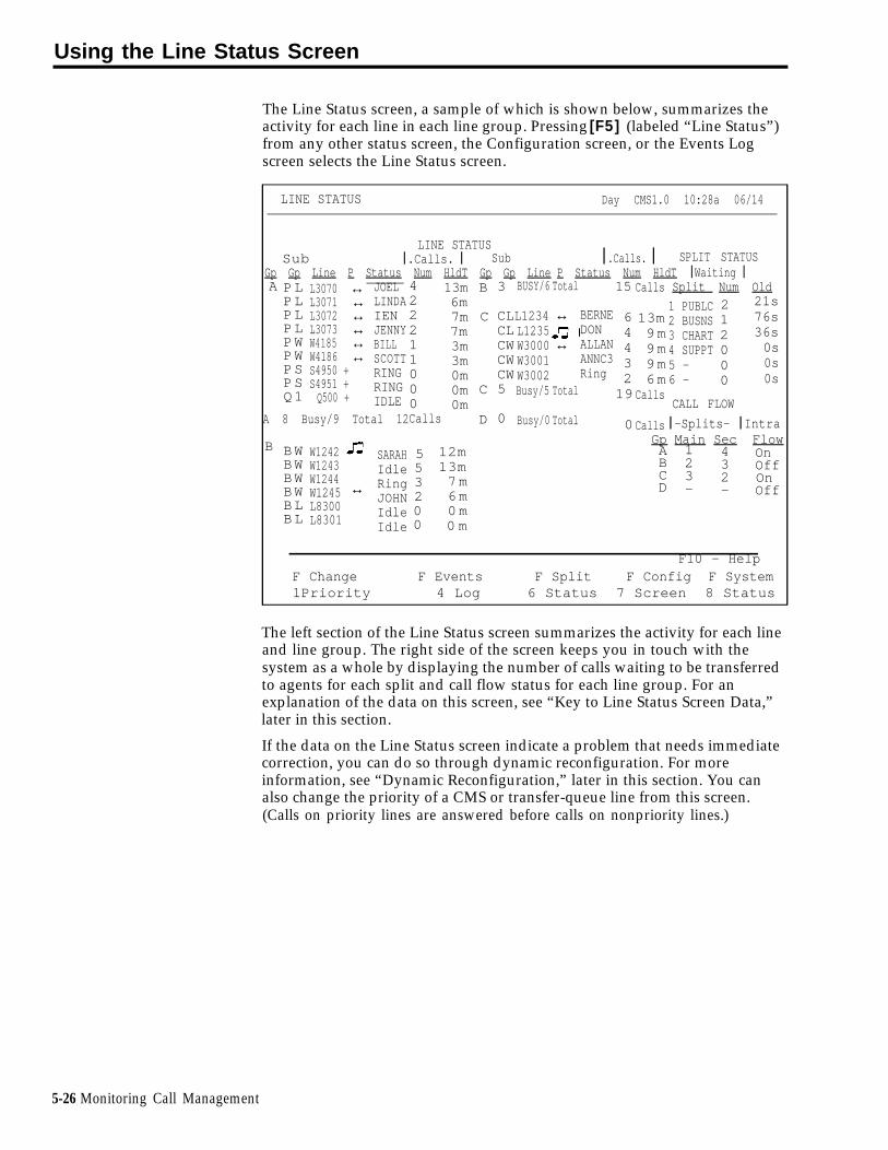
Using the Line Status Screen
The Line Status screen, a sample of which is shown below, summarizes theactivity for each line in each line group. Pressing [F5] (labeled “Line Status”)from any other status screen, the Configuration screen, or the Events Logscreen selects the Line Status screen.
LINE STATUS Day CMS1.0 10:28a 06/14
LINE STATUSSub ❘ .Calls. ❘ Sub ❘ .Calls. ❘ SPLIT STATUS
Gp Gp Line P Status Num HldT Gp Gp Line P Status Num HldT ❘ Waiting ❘A ↔
↔↔↔↔↔
JOELLINDAIENJENNYBILLSCOTTRINGRINGIDLE
422211000Calls
PLPLPLPLPWPWPSPSQ1
BWBWBWBWBLBL
L3070L3071L3072L3073W4185W4186S4950 +S4951 +Q500 +
W1242W1243W1244W1245L8300L8301
13m6m7m7m3m3m0m0m0m
B
C
C
3
CLCLCWCWCW5
0
BUSY/6
L1234L1235W3000W3001W3002Busy/5
Busy/0
Total
↔
↔
Total
Total
BERNEDONALLANANNC3Ring
15
6443219
0
Calls
13m9 m9 m9 m6 m
Calls
Calls
Split Num Old
1 PUBLC2 BUSNS3 CHART4 SUPPT5 - 6 -
212000
21s76s36s0s0s0s
CALL FLOWA 8 Busy/9 Total 12 D ❘ -Splits- ❘ Intra
B Gp Main Sec Flow553200
12m13m7 m6 m0 m0 m
ABCD
123-
432-
OnOffOnOff↔
SARAHIdleRingJOHNIdleIdle
F10 - HelpF Change F Events F Split F Config F System1Priority 4 Log 6 Status 7 Screen 8 Status
The left section of the Line Status screen summarizes the activity for each lineand line group. The right side of the screen keeps you in touch with thesystem as a whole by displaying the number of calls waiting to be transferredto agents for each split and call flow status for each line group. For anexplanation of the data on this screen, see “Key to Line Status Screen Data,”later in this section.
If the data on the Line Status screen indicate a problem that needs immediatecorrection, you can do so through dynamic reconfiguration. For moreinformation, see “Dynamic Reconfiguration,” later in this section. You canalso change the priority of a CMS or transfer-queue line from this screen.(Calls on priority lines are answered before calls on nonpriority lines.)
5-26 Monitoring Call Management

To change a line’s priority or select another screen, press the correspondingfunction key:
[F1] Change Priority
Press this function key to display the prompt that allows you to change aCMS or transfer-queue line from a priority line to a nonpriority line, or viceversa. The priority of a line determines its position in the queue of callswaiting to be answered by an agent. Priority lines are answered first and areindicated by a “+” in the P (priority) column of the Line Status screen.
After you press [F1] (labeled “Change Priority”) , the following promptappears.
Prompt: CHANGE PRIORITY: Line ID:
Action: 1 Enter a line ID to change the priority of that line.
2 Press [F8] (labeled “Enter Data”).
[F4] Events Log
Press this function key to select the Events Log screen, which displays the 19most recent exception, warning, and system error messages. For moreinformation, see “Using the Events Log Screen ” later in this section.
[F6] Split Status
Press this function key to view the Split Status screen for a particular split.You are prompted to enter a split number. The Split Status screenssummarize the activity in each split. You can also make an agent available orunavailable for CMS calls by logging the agent in or out from these screens.For more information, see “Using the Split Status Screens” and “Key to SplitStatus Screen Data, ” earlier in this section.
[F7] Config Screen (Configuration Screen)
Press this function key to select the Configuration screen. From that screenyou can begin dynamic reconfiguration of your system. For more informationand instructions, see “Dynamic Reconfiguration,” later in this section.
[F8] System Status
Press this function key to select the System Status screen, which summarizesthe activity in each split and line group. For more information, see “Usingthe System Status Screen” and “Key to System Status Screen Data,” earlier inthis section.
[F10] Help
Press this function key to display a Help screen for the Line Status screen.
Monitoring Call Management 5-27

Key to Line Status Screen Data
LINE STATUS
The numbers in the following list correspond to the numbers circled in theabove screen. The statistics described on this screen reflect information for thecurrent hour only.
1 Gp The letter assigned to the line group.
2 SubGp The sub-group ID of the line.
3 Line The ID of the line.
4 P Line priority status. A "+" in this columnindicates that the line is a priority line. Prioritylines are answered before nonpriority lines in theline group.
5-28 Monitoring Call Management

5 Status The line status, which can be one of the following:
Ring: A call ringing on the line, but CMS has notanswered it.
Idle: The line is not in use.
Q u e u e d : The call is in the CMS hold state. Thecall has already been played the announcementand is on hold, waiting for an agent to becomeavailable.
AGTID: The call has been transferred to anagent with the ID, AGTID, but the call has not yetbeen answered by an agent.
↔ AGTID: The agent with the ID, AGTID, hasanswered and is handling the call.
ANNCX: The call is being played announcementnumber “X“.
Othr: The line is being used by an incoming oroutgoing non-CMS call.
NOTE: When a CMS call that comes in on a CMSline (Central Office trunk) is transferred by anagent to a transfer-queue line, the status of theCMS line changes from " ↔ AGTID" to “Othr”when the agent who transfers the call goes on-hook.
6 Calls Num The number of CMS calls that came in on aparticular line in the current hour. This includesserviced and abandoned calls. Calls answered bystations other than agent stations are not included.Outgoing calls are also not included.
7 Calls HldT The amount of time between the moment a callbegins ringing at System 25 and the time it isdisconnected. Calls HldT includes completed callsonly. It includes both serviced and abandonedcalls. It does not include calls connected to non-agents nor does it include data on outgoing calls.
LINE GROUP SUMMARY A line group summary line appears below the data for the lines in the lineLINE group. The summary line is displayed in reverse video (dark letters on a light
background).
8 XX Busy The number of lines (XX) in the line group thatare currently in use for incoming or outgoing calls.
9 XX Total The total number of lines (XX) in the line group.
10 XX Calls The total number of completed CMS calls (XX) tothe line group during the current hour. Bothserviced and abandoned calls are included.
Monitoring Call Management 5-29

SPLIT STATUS The top right section of the screen summarizes calls waiting for all splits.
11 Split The number and ID of the split.
12 Waiting The number of CMS calls that are waiting to beNum transferred to an agent in the split.
13 Waiting The number of seconds the current oldest call hasOld been waiting to be transferred to an agent in a
particular split. Call waiting time ends when thecall begins ringing at the station of the agent whoanswers it.
CALL FLOWINFORMATION
The bottom right section of the screen shows how splits are assigned to linegroups and whether intraflow is turned on or off for each line group.
14 Gp
15 Splits Main
16 Splits Sec
17 IntraFlow
The line group letter.
The number of the main split assigned to the linegroup. A hyphen (-) indicates that there is nomain split assigned to the line group.
The number of the secondary split assigned to theline group. A hyphen (-) indicates that there is nosecondary split assigned to the line group.
The intraflow status for the line group (On orOff).
5-30 Monitoring Call Management

Using the Events Log Screen
The Events Log screen displays the last 19 exception, warning, and systemerror messages with the time and date they occurred. For more informationabout exception messages, see “Setting Exceptions” in Section 4 of thismanual.
Pressing [F4] (labeled “Events Log”) on any status screen or the Configurationscreen selects the Events Log screen. A sample Events Log screen is shownbelow.
EVENTS LOG DAY CMS1.0 3:46p 04/20
Time Date Event3:02p 05/18 *** Split 2 - Agent JOHN - Talk Time > = 480 seconds4:25p 05/18 *** Split 1 - Agent LINDA - Refused Calls4:30p 05/18 *** Split 1 - Oldest Call Waiting > = 45 seconds5:35p 05/18 Night Service Now In Effect5:43p 05/18 Normal Call Management Shutdown5:47p 05/18 REPORT ABORTED - Check Printer8:0la 05/19 CMS for System 25 PBX Version 1.0 Call Management Started8:02a 05/19 Firmware Version 2.1. Clock Type 18.2058:lla 05/19 Day Service Now In Effect9:15a 05/19 *** Group C - All Lines Busy >= 240 seconds9:27a 05/19 *** Split 1 - Agent JOEL - Refused Calls10:03a 05/19 *** Group A - Line L3071 - Hold Time >= 8 minutes10:21a 05/19 *** Split 3 - Agent DON - Talk Time >= 480 seconds11:20a 05/19 *** Split 2 - #Abandoned Calls >= 3ll:32a 05/19 *** Split 1 - Oldest Call Waiting >= 45 secondsll:54a 05/19 *** Split 1 - Agent JENNY - Refused Calls12:44p 05/19 *** Group A - Line L3072 - Hold Time >= 8 minutesl:33p 05/19 *** Split 3 - Oldest Call Waiting >= 30 secondsl:45p 05/19 *** Split 2 - Agent BERNE - Refused Callsl:56p 05/19 *** Split 1 - #Abandoned calls >= 4
F10 - HelpF Line F Split F Con fig F System5 Status 6 Status 7 Screen 8 Status
You must select the specific exceptions your CMS monitors. If you have notselected any exceptions, the Events Log screen lists only system and warningmessages.
If an exception indicates a problem that needs immediate correction, you cando so through dynamic reconfiguration. For more information, see "DynamicReconfiguration", later in this section.
To access another screen from the Events Log screen, press the correspondingfunction key:
[F5] Line Status
Press this function key to select the Line Status screen, which displaysinformation about every line in every line group. For more information, see“Using the Line Status Screen” and “Key to Line Status Screen Data,“ earlierin this section.
Monitoring Call Management 5-31

[F6] Split Status
Press this function key to view the Split Status screen for a particular split.(You are prompted for the split number.) The Split Status screens give you adetailed picture of the activity in each split. You can also make an agentavailable or unavailable for CMS calls by logging the agent in or out from thisscreen. For more information, see “Using the Split Status Screens” and “Keyto Split Status Screen Data,” earlier in this section.
[F7] Config Screen (Configuration Screen)
Press this function key to select the Configuration screen. From that screenyou can begin dynamic reconfiguration of your system. For moreinformation, see “Dynamic Reconfiguration,” later in this section.
[F8] System Status
Press this function key to select the System Status screen, which summarizesthe activity in each split and line group. For more information, see “Usingthe System Status Screen” and “Key to System Status Screen Data,” earlier inthis section.
[F10] HelpPress this function key to display a Help screen for the Events Log screen.
5-32 Monitoring Call Management

Supervising Your Agents
As the CMS Supervisor, you may find the CMS Service Monitoring andAssist features useful in supervising your CMS agents. These features requireSystem 25 button administration on your voice terminal.
SERVICE MONITORING The CMS Service Monitoring feature provides a means of monitoring agents’calls without being detected by the agent or the caller. This feature can bevery useful in the agent training process. You can also use the ServiceMonitoring feature to join a call when an agent requests help with acustomer. For this feature, your multiline voice terminal must have onePersonal Line button administered for each CMS and transfer-queue line youwant to monitor.
ASSIST BUTTONS Providing your agents with an Assist button gives them a means of visuallysignaling you when they need help. To do so, an agent presses a System 25Station-to-Station Message Waiting button, labeled “Assist,” administered onhis or her voice terminal. When the agent presses the Assist button, thegreen light next to that button on the agent’s voice terminal goes on, as doesa corresponding Station-to-Station Message Waiting (Assist) button on yourvoice terminal. You can also use the Assist button on your voice terminal toturn on the light next to the corresponding Assist button on the agent’s voiceterminal. If either person presses the Assist button when the green light ison, the Assist button lights at both voice terminals go off. You need oneAssist button for each agent whom you want to signal or who may need tosignal you.
For more information about these features, see Sectioncalls.“
6, “Handling CMS
Supervising Your Agents 5-33

Dynamic Reconfiguration
Once you activate a shift configuration (as described earlier in “StartupProcedures”), you can modify it through dynamic reconfiguration. Forexample, you can reassign agents or turn on intraflow to handle unexpectedincreases in incoming call traffic.
Such changes are immediately activated in the current configuration. If youwant, you can save the changes before you shut down CMS or before youselect another shift configuration. Otherwise, the changes are not savedwhen the current configuration is no longer active.
You use the following screens during dynamic reconfiguration:
• Configuration screen
• Configure Splits screen
• Configure Call Flow screen
• Configuration List screen
These screens are almost identical to the configuration screens you use forCMS administration. During administration, however, CMS is not managingcalls. CMS is managing calls during dynamic reconfiguration.
Pressing [F1] (labeled “Config Screen”) from the Initialization screen or [F7](labeled “Config Screen”) from any status screen selects the Configurationscreen. It displays the current configuration, as shown in the example below.
CONFIGURATION DAY CMS1.0 3:20p 04/18
AGENT SPLITS ANSWER/FORCE DELAY❘ --Agent-- ❘ ❘ --Agent-- ❘ Num Answer Force
Split PDC ID Split PDC ID Group Lines Delay Delay1 PUBLC 4 SUPPT 417 CRAIG
418 BARB424 CJ
A PUBLCB BUSNSC CHARTD -
9650
10s0s5s5s
O f fO nOffOff5 -
6 -
2 BUSNS
401402403404405406407408409410411412415416
LINDAJOELIENJENNYSCOTTBILLSARAHJOHNJIMBERNEDONALLANANDYLOU
CALL FLOWFlow
❘ -Splits- ❘ Intra Spl Thresh3 CHART Gp Main Sec Flow
4 SUPPT
ABCD
123-
432-
OnOffOff Off
123456
50s30s30s30s30s30s
Configuration #1 - Day
F Splits
1FAns/Forc2 Delay
F Call3 Flow
F Events4 Log
F Line5 Status
F Split
6 Status
F10 - HelpF Config7 List
F System8 Status
5-34 Dynamic Reconfiguration

From the Configuration screen you can perform the types of reconfigurationdescribed below or select other screens.detail later in this section.
•
•
•
•
Reconfiguring Splits
Press [F1] (labeled “Splits”) to reach
Each of these
the Configure
topics is described in
Splits screen. Throughthis screen you can add, move, or remove the agents in splits. You canalso change the ID of a split.
Changing Answer Delay or Force Delay
Press [F2] (labeled “Ans/Fore Delay”) to display the Configure Delayscreen. Through this screen, you can change the number of seconds callsto a line group ring before CMS answers them and connects them to adelay message if no agents are available to answer the calls (the AnswerDelay). You can use the Force Delay option to indicate if you want allcallers to a line group to hear a delay message before being transferred toagents.
Reconfiguring Call Flow
Press [F3] (labeled “Call Flow”) to reach the Configure Call Flow screen.Through this screen you can reassign splits to line groups, changeIntraflow Thresholds, and turn intraflow on or off.
Using the Configuration List
Press [F7] (labeled "Config List") to reach the list of stored shiftconfigurations. With this screen, you can select a different configurationfor call management, save your changes either in the current configurationor in another configuration, rename a configuration, or select a startupconfiguration.
You can also reach the status screens from the Configuration screen.
Once you are familiar with dynamic reconfiguration, you can use the “QuickReference Guide to Dynamic Reconfiguration,” later in this section. TO seehow the CMS Supervisor at Bon Voyage Travel uses dynamic reconfigurationduring a typical day, see “Day-to-Day Operation of CMS", later in thissection.
Dynamic Reconfiguration 5-35

Reconfiguring Splits
Pressing [F1] (labeled “Splits”) from the Configuration screen selects theConfigure Splits screen, shown below. It looks the same as the Configurationscreen except that a box appears around the Agent Splits portion of thescreen and the function keys are relabeled. Use this screen to reassign, add,or remove agents in the active configuration.
CONFIGURE SPLITS DAY CMS1.0 3:27p 04/18
AGENT SPLITS ANSWER/FORCE DELAY|--Agent--| |--Agent--| Num
LinesAnswerDelay
ForceDelaySplit PDC ID Split PDC ID Group
1 PUBLC
2 BUSNS
3 CHART
4 SUPPT
401402403404405406407408409410411412415416
LINDAJOELIENJENNYSCOTTBILLSARAHJOHNJIMBERNEDONALLANANDYLOU
4 SUPPT
5 -6 -
417418424
CRAIGBARBCJ
ABCD
PUBLCBUSNSCHART-
9650
10s0s5s5s
OffOnOffOff
CALL FLOWFlow
|-Splits-| IntraFlow
Spl ThreshGp Main SecABCD
123-
432-
OnOffOffOff
123456
50s30s30s30s30s30s
Configuration #1 - DAY
F Add1 Agent
F Remove2 Agent
F Move3 Agent
F Replace4 Agent
F New5 Agent
F Change6 Split ID
F Config7 Screen
F10 HelpF Agent8 Directry
To reconfigure splits, press the function key for the activity you want toperform and follow the instructions:
[F1] Add Agent
Press this function key to assign an agent already listed on the AgentDirectory screen to the active configuration. When you add agents, they areautomatically placed in the Logged Out state. They must make themselvesavailable for calls by pressing the Available button. No report statistics arecollected for an agent until this is done.
Prompt: ADD AGENT: ID: PDC: to Split #:___
Action: 1 Enter an ID of an agent already entered in the AgentDirectory.
2 Enter the System 25 PDC of an agent station that is alreadyentered on the Administer Stations screen.
3 Enter a split number (1 through 6).
4 Press [F8] (labeled “Enter Data”).
5-36 Dynamic Reconfiguration

[F2] Remove Agent
Press this function key to remove an agent from the active configuration.(The agent entry remains on the Agent Directory screen.)
Prompt: REMOVE AGENT: ID:
Action: 1 Enter the agent’s ID.
2 Press [F8] (labeled “Enter Data”).
3 When the confirmation prompt appears, type y to confirmyour request or n to cancel it.
4 Press [F8] (labeled “Enter Data”).
[F3] Move Agent
Press this function key to move an agent from one agent station to anotherand/or from one split to another. (This is equivalent to removing the agentfrom one agent station or split and adding the agent to another agent stationor split.)
NOTE: The agent is automatically placed in the Logged Out state, andno statistics are collected for the agent until the agent makes himselfor herself available or until you make the agent available by logging inthe agent from the Split Status screen. See “Using the Split StatusScreen”, earlier in this section.
Prompt: MOVE AGENT: ID: New PDC: New Split #: _
Action: 1 Enter the ID of the agent you want to move.
2 You may enter a new PDC, a new split number, or both. Toskip a field, press [F6] (labeled “Next Field”).
3 Press [F8] (labeled “Enter Data”) after your last entry.
Check the Splits section of the screen to make sure you moved the agent asyou intended.
Moving an agent to a different station in the same split does not affect thedata being collected for that agent. Moving an agent from one split toanother, however, results in partial collected data for the hour in which themove was made. To keep the agent’s data as accurate as possible, do not usethe Move Agent function key to move an agent to a different split. Instead,remove the agent from the first split and add the agent to the second split witha different ID. (If the Agent Directory screen does not already have more thanone ID for that agent, use the New Agent function key to add the agent witha different ID.)
For example, an agent named Hal might have the ID HAL1 when he works insplit 1 and HAL2 when he works in split 2. If you use a separate ID for himfor each split in which he works, the data will show Hal’s work in each splitseparately.
Dynamic Reconfiguration 5-37

[F4] Replace Agent
Press this function key to substitute agents at a particular agent station. Thisis equivalent to removing one agent and adding another agent to the sameagent station in the same split.
NOTE: The agent you added remains in the same state as the agentbeing replaced.
Prompt: REPLACE AGENT: Remove Agent ID: and Add Agent ID:
Action: 1 Enter the ID of the agent to be removed.
2 Enter the ID of the new agent. (This agent must already beentered into the Agent Directory.)
3 Press [F8] (labeled “Enter Data”).
[F5] New Agent
Press this function key to add a new agent (one who is not listed in the AgentDirectory) to the active configuration. Agents added using the New Agentfunction on the Configure Splits screen are simultaneously added to theAgent Directory.
Prompt:
NEW AGNT: ID: Last Name: First: PDC: ___ Split #:____
Action: 1
2
3
4
5
6
Enter the agent ID, up to 5 uppercase letters or numbers.ID must be unique.)
Enter the agent’s last name, up to 12 uppercase and/orlowercase letters, numbers, or special characters, with nospaces between them.
Enter the agent’s first name, up to 8 uppercase and/orlowercase letters, numbers, or special characters, with nospaces between them.
(The
Enter the System 25 PDC. (The PDC must already be assignedto a station, that is, already listed on the Administer Stationsscreen.)
Enter the split number (1 through 6).
Press [F8] (labeled “Enter Data”).
5-38 Dynamic Reconfiguration
[F6] Change Split ID
Press this function key to assign, change, or delete a split ID. Each split IDmust be unique. However, a split and a line group can have the same ID.
Prompt: CHANGE SPLIT ID: Split # (l-6): _ New Split ID:
Action: 1 Enter a split number (1 through 6).
2 Enter a split ID (up to 5 uppercase letters or numbers).
3 Press [F8] (labeled "Enter Data" ).
NOTE: Once you have entered a split ID for a split in one shiftconfiguration, it remains the same for that split in other shiftconfigurations.
[F7] Config Screen (Configuration Screen)
Press this function key to return to the Configuration screen. The box aroundthe agents section of the screen disappears and the functions keys arerelabeled.
[F8] Agent Directry (Agent Directory)
Press this function key to view the Agent Directory screen if you need to lookup an agent’s ID in order to add the agent to a split. You can also edit theAgent Directory. From the Agent Directory screen, press [F7] (labeled“Config Splits”) to return to the Configure Splits screen.
[F10] Help
Press this function key to display a Help screen for the Configure Splitsscreen.
Dynamic Reconfiguration 5-39

Reconfiguring Answer Delay or Force Delay
ANSWER DELAY
FORCE DELAY
You can change the current setting for the Answer Delay or Force Delayoption at any time.
The Answer Delay is the number of seconds CMS lets a call ring beforeconnecting it to a voice announcement unit if no agent is available to servicethe call.
Think of Answer Delay as a trade-off between the time a customer spendslistening to ringing and the time the customer spends on hold. You can use adifferent Answer Delay value for each line group, depending on the type oflines in the group and the amount of time the caller is likely to wait before anagent is available.
The initial setting for Answer Delay is 5 seconds, the approximate length oftime from the beginning of one ring to the beginning of the next. Considerthese factors when choosing an Answer Delay value for a line group:
• Someone begins paying for a call as soon as the line is answered. If callsare likely to be on hold before an agent is available, you can increase theAnswer Delay value in order to decrease the amount of time on hold andthe cost of the call.
• You may want to increase the Answer Delay value if you know callershave to wait for an agent. Callers may be less inclined to hang up if theywait a little longer for CMS to answer the call but spend less time on hold.
The Force Delay option controls the transfer of calls to and from the voiceannouncement unit. If Force Delay is on for a particular line group, calls thatarrive for that line group will not be transferred to an agent until callers haveheard the entire message, even if an agent is available. This means that callsmay be queued up waiting to hear the delay message even when agents areavailable.
When Force Delay is on, the Answer Delay setting for that line group isignored by CMS; that is, calls to that line group are transferred to the linegroup’s voice announcement unit as soon as it is available. If Force Delay isoff, the caller will be transferred to an agent as soon as one becomesavailable.
Pressing [F2] (labeled “Ans/Forc Delay”) from the Configuration screen selectsthe Configure Delay screen. A box appears around the Answer/Force Delayarea of the screen and a prompt appears, as shown in the following exampleof a Configure Delay screen.
5-40 Dynamic Reconfiguration

CONFIGURE DELAY DAY CMS1.0 3:31p 04/18
AGENT SPLITS ANSWER/FORCE DELAY|--Agent--| |--Agent--| Num
LinesAnswerDelay
ForceDelaySplit PDC ID Split PDC ID Group
1 PUBLC
2 BUSNS
3 CHART
4 SUPPT
401402403404405406407408409410411412415416
LINDAJOELIENJENNYSCOTTBILLSARAHJOHNJIMBERNEDONALLANANDYLOU
4 SUPPT
5 -6 -
417418424
CRAIGBARBCJ
A PUBLCB BUSNSC CHARTD -
9650
10s0s5s5s
OffOnOffOff
CALL FLOWFlowThresh|-Splits-| Intra
FlowSpl
Gp Main SecABCD
123-
432-
OnOffOffOff
123456
50s30s30s30s30s30s
Configuration #1 - DAY
ANS/FORCE DELAY:F Cancel1 Prompt
Grp (A-D):____ Ans Delay (0-99 sec):___ Force Delay (ON/OFF):____F Previous5 Field
F Next6 Field
F Enter8 Data
To change Answer Delay or Force Delay for a line group, respond to theprompt:
Prompt:
ANS/FORCE DELAY: Grp (A-D):___ Ans Delay (0-99 sec): ___ Force Delay (ON/OFF): ___
Action: 1 Enter the line group letter (A through D).
2 Enter the Answer Delay, the number of seconds (0 through 99)you want calls to ring before CMS connects them to anannouncement unit if an agent is not available. Leave the fieldblank to keep the current value.
3 Type on or off to turn Force Delay on or off for the linegroup. Leave the field blank to keep the current value.
4 Press [F8] (labeled “Enter Data”).
Dynamic Reconfiguration 5-41

Reconfiguring Call Flow
If you experience unexpected changes in call traffic, you may need toreconfigure call flow assignments in the active configuration. For instance,you may decide to reassign secondary splits or turn on intraflow for some linegroups. Pressing [F3] (labeled “Call Flow” ) from the Configuration screenselects the Configure Call Flow screen, a sample of which is shown below.
CONFIGURE LIST DAY CMS1.0 3:32p 04/18
AGENT SPLITS ANSWER/FORCE DELAY|--Agent--| |--Agent--| Num
LinesAnswerDelay
ForceDelaySplit PDC ID Split PDC ID Group
1 PUBLC
2 BUSNS
3 CHART
4 SUPPT
401402403404405406407408409410411412415416
LINDAJOELIENJENNYSCOTTBILLSARAHJOHNJIMBERNEDONALLANANDYLOU
4 SUPPT
5 -6 -
417418424
CRAIGBARBCJ
A PUBLCB BUSNSC CHARTD -
9650
10s0s5s5s
OffOnOffOff
CALL FLOWFlowThresh|-Splits-| Intra
FlowSpl
Gp Main SecABCD
123-
432-
OnOffOffOff
123456
50s30s30s30s30s30s
Configuration #1 - DAY
F10 HelpF Assign1 Splits
F Flow2 ON/OFF
F Set3 Thresh
F Config7 Screen
Use the Configure Call Flow screen to set thresholds for intraflow, assignsplits to line groups, and turn intraflow on or off.
To reconfigure call flow, press the function key for the activity you want toperform:
[F1] Assign Splits
Press this function key to assign main splits and secondary splits to linegroups. If you do not want to assign a secondary split for a line group, entera hyphen (-) instead of a split number. For more information on intraflow,see “Administering Call Flow” in Section 4.
Prompt:
ASSIGN SPLITS for Call Flow: Line Group (A-D): ___ Main Split:___ Secondary Split:___
Action: 1 Enter a line group letter (A through D).
2 Enter a main split number (1 through 6), or leave the fieldblank if you do not want to change it.
5-42 Dynamic Reconfiguration

3 Enter a secondary split number (1 through 6), or enter ahyphen (-) if you do not want to assign a secondary split.Leave the field blank if you do not want to change it.
4 Press [F8] (labeled “Enter Data”).
[F2] Flow On/Off (Turn Intraflow On/Off)
Press this function key to turn intraflow on or off for a particular line group.Each line group’s intraflow status appears in the Intraflow column of the CallFlow area of the screen.
Prompt: CHANGE INTRAFLOW: Line Group (A-D): ___
Action: 1 Enter a line group letter (A through D).
2 Press [F8] (labeled “Enter Data”). The intraflow designationfor that line group automatically changes from On to Off orvice versa.
[F3] Set Thresh (Set Intraflow Threshold)
Press this function key to change the Intraflow Threshold for a split. Thisthreshold is based on the number of seconds the oldest call has been waitingin a split’s queue. The initial setting is 30 seconds. For more information onintraflow and Intraflow Thresholds, see “Administering Call Flow” in Section4.
Prompt:
SET CALL FLOW THRESHOLD: Split # (1-6):___ Threshold (0-999 sec):___
Action: 1 Enter a split number (1 through 6).
2 Enter a number of seconds (0 through 999).
3 Press [F8] (labeled “Enter Data”).
[F7] Config Screen (Configuration
Press this function key to return to
[F10] HelpPress this function key to display ascreen.
Screen)
the Configuration screen.
Help screen for the Configure Call Flow
Dynamic Reconfiguration 5-43

Using the Configuration List
The Configuration List screen, shown below, is very similar during callmanagement and administration.
CONFIGURATION LIST DAY CMS1.0 3:18p 04/18
STORED SHIFT CONFIGURATIONS
(edited) 1 - DAY (Startup)
23456
—————
EVENINGWEEKENDUNUSEDUNUSEDUNUSED
F10 HelpF Select1 Config
F Save2 Config
F Rename3 Config
F Choose4 Startup
F Config7 Screen
F System8 Status
The shift configuration currently in use for call management is shown inreverse video. If you made any changes to the configuration but have not yetsaved them, the word (edited) appears to the left of that configurationnumber. If you have chosen a configuration to be invoked automaticallywhen you start call management, the word (Startup) appears to the right ofthat configuration name.
During call management, you can perform these activities with theConfiguration List:
• Select a different shift configuration for call management.
• Save the changes you made during dynamic reconfiguration.
• Rename a configuration.
• Select a startup configuration.
• Display the Configuration screen for the active
• Display the System Status screen.
configuration.
5-44 Dynamic Reconfiguration

To use the Configuration List, press the function key for the activity you wantto perform:
[F1] Select Config (Select Configuration)
Press this function key to select a different shift configuration for callmanagement.
Prompt: SELECT CONFIGURATION: Config # (1-6): ___
Action: 1 Enter a configuration number (1 though 6).
2 Press [F8] (labeled “Enter Data”).
3 When the confirmation prompt appears, type y to confirmyour request or n to cancel it.
4 Press [F8] (labeled “Enter Data”).
When CMS is changing from one shift configuration to another in response toyour request, calls are handled as follows:
• All ACD (CMS) calls connected to agents (that is, in-progress calls) areconsidered “completed” for the purpose of report statistics at the time ofthe request to select a new configuration.
• Calls already in the queue for agent splits are placed in a temporaryqueue. The time of arrival for each call is saved.
• All new incoming calls are connected to the delay message and thenplaced in a temporary queue.
When the new configuration is activated:
• Calls currently connected to agents are credited as “other” calls, in the splitin the new configuration.
• Calls in the temporary queue are assigned to the appropriate queuesaccording to their order of arrival.
• New calls (that is, those received after the new shift configuration isactive) are handled normally.
NOTE: All agents in the new configuration are automatically placed in theLogged Out state and must make themselves available for CMS calls bypressing their Available button.
[F2] Save Config (Save Configuration)
Press this function key to save any changes you made to the activeconfiguration. If you don’t save the changes, they will be lost when you stopmanaging calls with that configuration. You can save the edited configurationin the active configuration, in a previously unused configuration, or you canstore it in place of another configuration.
Dynamic Reconfiguration 5-45
Prompt: SAVE CONFIGURATION: in Config #: ___
Action: 1 Press [F8] (labeled “Enter Data”) to save the editedconfiguration under the same configuration name and numberas the original (in other words, to replace the original with theedited copy).
or
Enter another configuration number and press [F8] (labeled“Enter Data”) to save the edited configuration under adifferent configuration number.
A second prompt appears:
SAVE CONFIGURATION: Replace Contents of Config #X - NAME? (Y/N):___
The number of the configuration you want to replace and itsname appear in this prompt.
2 Type y to confirm your request or n to cancel it.
3 Press [F8] (labeled “Enter Data”).
[F3] Rename Config (Rename Configuration)
Press this function key to name or rename a configuration. Configurationnames can contain up to 10 uppercase letters, numbers, or special characters.Spaces are not allowed, so you may want to use hyphens or underlinesinstead.
Prompt:
RENAME CONFIGURATION: Config # (1-6):___ New Name:
Action: 1 Enter the configuration number (1 through 6).
2 Enter the new name (up to 10 uppercase letters, numbers, orspecial characters).
3 Press [F8] (labeled “Enter Data”).
NOTE: If you rename an inactive configuration as “UNUSED", you will delete its contents. The current configuration cannot be renamed“UNUSED” since an unused configuration cannot be activated.
Also, if you attempt to rename the startup configuration "UNUSED",an error message appears on the screen.
[F4] Choose Startup (Choose Startup Configuration)
Press this function key to select a shift configuration to be invokedautomatically during call management startup. Don’t select a startupconfiguration, however, if you want to choose a startup configuration eachtime you begin call management.
5-46 Dynamic Reconfiguration

Prompt: CHOOSE STARTUP CONFIGURATION: Config # (1-6 or ‘-’ for none): ___
Action: 1 Enter the configuration number of the startup configuration, orenter a hyphen (-) if you do not want a startup configuration.
2 Press [F8] (labeled “Enter Data”). The word (startup) appearsnext to the configuration you selected.
[F7] Config Screen (Configuration Screen)
Press this function key to display the Configuration screen for the activeconfiguration.
[F8] System Status
Press this function key to display the System Status screen.
[F10] Help
Press this function key to display a Help screen for the Configuration Listscreen.
Dynamic Reconfiguration 5-47

Quick Reference Guide to Dynamic Reconfiguration
This guide shows what screens to select if you want to activate a differentconfiguration or make changes to the active configuration. While callmanagement is running, you can do the following:
• Reconfigure agent splits
• Change Answer Delay or Force Delay
• Reconfigure call flow
• Use the Configuration List screen to save your changes or to activate adifferent configuration
For detailed descriptions of these procedures, see “Dynamic Reconfiguration",earlier in this section.
You can make changes in an active CMS configuration from the Configurationscreen. You can access this screen from:
• The Initialization screen, from which you start call management
• Any of the status screens
The screens and function keys used for dynamic reconfiguration areillustrated in the following diagram.
After you make a change, press [F7] (labeled “ Config Screen”) to return tothe Configuration screen. Continue with dynamic reconfiguration or pressthe appropriate function key to access one of the status screens.
5-48 Dynamic Reconfiguration

Selecting Day or Night Service
CMS provides two modes of call management: Day Service and NightService. During Day Service, one of your shift configurations is active andCMS routes each call to an agent. During Night Service, CMS answers eachincoming call, connects it to the appropriate voice announcement unit, anddisconnects the call after the message is over. Depending upon the needs ofyour business, you may choose to use a tape answering machine instead ofthe Dacon voice announcement unit during Night Service so that callers canleave a recorded message after hearing the announcement. For moreinformation, see "Caller Message Recording During Night Service", later inthis section.
You may want callers to hear a different message when Night Service is ineffect than when Day Service is in effect. If that is the case, record twoannouncements, a Day Service and a Night Service announcement, on eachannouncement unit.
When you start call management, CMS is automatically in Day Service mode.Change the mode of service from the System Status screen by pressing [F1](labeled “Set Opt/Chg Mode”). The Set Options/Modes screen, shownbelow, appears. Press [F5] (labeled “Chg Serv Mode”) , and continue withthe instructions below for the mode to which you are changing.
SET OPTIONS/MODES DAY CMS1.0 3:36p 04/18
OPTION AND MODE SETTINGS
Option/Mode Value
F1 Service Level Limit 20 sec
F2 Abandoned vs. Incoming Call Threshold 10 sec
F3 Audible Alarm (ON/OFF) ON
F4 Transfer Return Threshold 5 rings
F5 Change Mode of Service (Day/Night) DAY
F10 - HelpF Service F Abandon F Alarm F Return F Chg Serv F System1 Level 2 Thresh 3 On/Off 4 Thresh 5 Mode 8 Status
Selecting Day or Night Service 5-49

CHANGING TO NIGHT To change from Day Service to Night Service:SERVICE Prompt: SERVICE MODE: Change to NIGHT Service? (Y/N):___
Action: 1 Type y to change to Night Service mode or type n to keepcall management in Day Service mode.
2 Press [F8] (labeled “Enter Data”).
3 If you typed y to change mode, the prompt reads:
Change Anncs for NIGHT, then press F8 when ready; or to Cancel press F1.
Until you press a key in response to this prompt, CMS willnot answer any ringing calls. Calls that are connected to anannouncement unit or that have heard an announcement willbe distributed to agents and recorded in the data.
4 Switch to the night message, if you have one, by pressing the“Chan.” button on the front of the Dacon voice announcementunit and then responding to the prompt.
– If some CMS calls are connected to agents or are on holdwaiting for an agent when you press [F8], the followingmessage will appear on the screen:
Night Service Now in Effect. Some Day Calls Still Active
Then, when agents finish handling all those calls, thefollowing message is displayed:
Night Service Now in Effect. All Day Calls Finished
– If no CMS calls are in progress when you press [F8], thefollowing message is displayed:
Night Service Now in Effect. All Day Calls Finished
Ringing CMS calls and new incoming CMS calls are connectedto the night message, then disconnected. The word NIGHTappears to the left of the CMS release number on the ID lineof the screen. All agent stations are put in the Logged Outstate.
5 Press a function key to select another activity or screen.
5-50 Selecting Day or Night Service

CHANGING TO DAYSERVICE
To change from Night Service to Day Service:
Prompt: SERVICE MODE: Change to DAY Service? (Y/N): ___
Action: 1 Type y to change to Day Service mode or type n to keep callmanagement in Night Service mode.
2 Press [F8] (labeled “Enter Data”).
3 If you typed y to change mode, the prompt reads:
Change Anncs for DAY then press F8 when ready; or to Cancel press F1.
When the prompt appears, CMS stops answering ringing calls(that is, the calls keep ringing). Any calls already connected tothe voice announcement unit stay connected until the messageis finished, and are then disconnected. Any calls not yetconnected to the voice announcement unit remain ringing untilDay Service mode is in effect. At that time, the calls areanswered by CMS and connected to an agent or a voiceannouncement unit, as appropriate.
4 Switch to the day message, if necessary, by pressing the“Chan.” button on the front of the Dacon voice announcementunit, and then respond to the prompt.
When you press [F8], the last configuration that was active onthe system is activated again. Call management and datacollection proceed as normal for Day Service, and thefollowing message appears:
Day Service Now in Effect.
The word DAY appears to the left of the CMS release numberon the ID line of the screen. When Day Service callmanagement begins, all agents in the configuration areautomatically in the Logged Out state. To become available toanswer calls, they must press their Available button to turn onthe Available light on their voice terminals.
5 Press a function key to select another activity or screen.
Selecting Day or Night Service 5-51
CMS OPERATION DURING You can access all your status screens while CMS is in the Night ServiceNIGHT SERVICE mode. If you start Night Service during a data collection hour, then for the
rest of that hour the status screens show whatever Day Service data had beencollected prior to the switchover, plus any Night Service data collected. Afterthat hour is over, the screens show only Night Service data.
The System Status screen shows Night Service data for the number of busylines and for calls waiting. It shows agent status as Othr if the agent stationis off-hook, and as Out if the agent station is on-hook. Time spent in Nightstate is not counted as time logged in for reporting purposes.
On the Split Status screen, the “Stat” column will show Nite when the agentstation is on-hook and Othr when the agent station is off-hook. The numberof calls shown in the “Other” (Calls) column will reflect the number of callsplaced plus the number of calls received and answered during that hour.
You can also access reconfiguration screens during Night Service. Anychanges you make on these screens do not influence Night Service operation,but do affect the last active configuration (that is, the displayed shiftconfiguration). If you return to Day Service, any changes you made in thelast active configuration will be in effect.
CALLER MESSAGERECORDING DURINGNIGHT SERVICE
For standard CMS operation during Day Service, it is strongly recommendedthat you use a digital voice announcement unit. However, there may besituations during Night Service when call volume is low. At those times youmay choose to use a tape answering machine instead, so callers can leave amessage for you. The tape answering machine must be one which you canprogram to answer calls on the first ring and which has a voice-activatedmessage length.
You can set up the tape answering unit in either of two ways:
• You can disconnect the voice announcement unit used during Day Serviceand connect the tape answering unit in its place for Night Service.
• You can administer the tape answering unit as a valid announcement unitand keep it connected at all times. However, you can change the status ofthe tape answering unit reflected in the “Annc Condtn” column on theAssign Announcement screen to REMVD (Removed) during Day Service,.and change the status of the digital voice announcement unit to AVAIL(Available). When you switch to Night Service, you can change the tapeanswering unit’s status to AVAIL on the Assign Announcement screenand change the status of the digital voice announcement unit to REMVD.
5-52 Selecting Day or Night Service
Day-to-Day Operation of CMS
Your day-to-day interaction with CMS primarily involves monitoring systemstatus during call management and using dynamic reconfiguration to makeany needed changes in the configuration being used to manage calls.
The following example illustrates how the CMS Supervisor at Bon VoyageTravel interacts with the system during a typical day.
THE CMS SUPERVISOR’S At 9 A.M. each business day, Pat Roberts turns on Bon Voyage’s PC and startsACTIVITIES AT BON managing calls with the Day configuration. All agents are automatically inVOYAGE TRAVEL the Logged Out state when call management begins. Pat asks the agents to
press the Available button on their voice terminals to make themselvesavailable for CMS calls.
Pat performs several dynamic reconfiguration activities during the day. First,Pat removes Linda Seiler from her position in the Public Travel split becauseshe is on vacation, and moves a new agent, Allan Brown, into Linda’sposition in that split. Pat tells Allan to place himself in the Available state.
As the peak calling hour approaches, Pat turns on intraflow for the Public linegroup. Pat tells the agents in the Support split that they may now receivecalls for the Public line group. (The Support split is a secondary split for thePublic line group.)
Throughout his shift, Pat monitors the System Status screen, theLine Status screen, and the Split Status screens. Pat can use the[Shift] + [Print Scrn] keys to print any of these screens if desired. The screensprovide a detailed picture of activity throughout the system. Using them, Patcan tell when to turn intraflow on or off, when a new agent may be havingtrouble handling calls, or when all lines in a line group are busy. Pat can usedynamic reconfiguration to correct these situations as they occur.
For instance, Pat notices that three calls are waiting in the Charter Travelsplit’s queue, and there have been several abandoned calls. Pat turns onintraflow to allow waiting calls to be sent to the Business Travel split (thesecondary split for the Charter line group). Pat also increases the AnswerDelay (the length of time a call rings before CMS connects it to a voiceannouncement unit when no agents are available) so callers will spend a littleless time on hold.
Pat has a new agent in the Business Travel split. Yesterday, Pat spent timewith the new agent, explaining the voice terminal features the agent will beusing. As the new agent answers CMS calls for the first time, Pat watchesthe Split Status screen to see when the agent is on a call, and then monitorsthe call. In this way, Pat is able to give the agent advice on handling calls.
Pat also looks at the Management Information System (MIS) reports todetermine if Bon Voyage Travel has an efficient number of lines and agents.The Events Log Report lists many occurrences of the All Lines Busyexception, which means that people heard a busy signal if they called duringthose times. Pat can use exception information like this to determine if morelines are needed for some line groups or line sub-groups.
Day-to-Day Operation of CMS 5-53

Section 6: Handling CMS Calls

Overview
When a call comes into CMS during Day Service, the system looks for anavailable agent in the main split assigned to the line group for the call. Ifagents are available, CMS routes the call to the agent who has been idle thelongest. After answering the call, the agent may need to do the following:
• Transfer the call to another agent or person on System 25
• Transfer the call to another line group’s queue
• Signal the CMS Supervisor for help
When the conversation with the customer is completed, the agent may needto enter the After-Call-Work state to complete the necessary paperworkassociated with the call.
So that agents can complete all of these CMS duties with a minimum ofdifficulty, it is important that they understand how to use their voice terminalfeatures. In most cases, you, as the CMS Supervisor, will be the personresponsible for teaching the agents how to use their voice terminals and theone whom agents will call should problems arise.
This section will help you understand how you and your CMS agents can useyour voice terminals and features to handle CMS calls efficiently. Theinformation in this section is organized as follows:
The Agent’s Voice Terminal
Describes the types of voice terminals agents can use, the features to beassigned to agent voice terminal buttons, and procedures for using thesefeatures.
The CMS Supervisor’s Voice Terminal
Describes the type of voice terminal the CMS Supervisor needs, the featuresthe CMS Supervisor uses, and the procedures for using these features.
Overview 6-1
The Agent’s Voice Terminal
This section describes the voice terminals and the features that enable CMSagents to handle ACD (CMS) calls efficiently. The CMS Agent Card alsodescribes procedures for using the agent voice terminal for CMS.
The information in this section supplements the information in the AT&TSystem 25 Multiline Terminal User Guide. That guide describes many otherSystem 25 features you may find useful.
Selecting Voice Terminals for Your Agents
A critical factor in selecting a voice terminal for your agents is choosing avoice terminal with enough buttons to accommodate the necessary CMS andSystem 25 features. The following information will help you decide thenumber of buttons with lights your agents’ voice terminals will need, and, inturn, help you decide the size of the voice terminal that you should assigneach agent. .
You may use any of these as a CMS agent voice terminal:
• 5-Button Voice Terminal
• 10-Button Voice Terminal
• 10-Button Hands-Free Answer on Intercom (HFAI) Voice Terminal
• 10-Button Built-in Speakerphone (BIS) Voice Terminal
• 22-Button BIS Voice Terminal
• 34-Button Voice Terminal
• 34-Button Deluxe Voice Terminal
• 34-Button Built-in Speakerphone (BIS) Voice Terminal
• 34-Button Deluxe BIS Voice Terminal
• 34-Button BIS Voice Terminal with Display
• 34-Button Deluxe BIS Voice Terminal with Display
• Direct Trunk Attendant Console (DTAC), a 34-Button Deluxe VoiceTerminal or 34-Button Deluxe BIS Voice Terminal
• Switched Loop Attendant Console (SLAC), a 34-Button Deluxe BIS VoiceTerminal with Display
NOTE: A headset cannot be used with a 5-button voice terminal or a10-button HFAI voice terminal.
Each of these types of voice terminals provides basic telephone functions,such as Transfer, Conference, and Hold. However, other features required oruseful for CMS may be administered on agent voice terminals.
6-2 The Agent’s Voice Terminal

All agent voice terminals will require buttons with lights for the followingfeatures:
• System Access buttons. Each agent voice terminal must have at least oneSystem Access button. Two System Access buttons are recommended.
• Agent State buttons. Three agent-state buttons, Available, ACW (After-Call-Work), and Logged Out, are required on each agent voice terminal.
In addition, the optional Assist feature requires a button with lights.
• Assist button. Agents may need to signal you visually that they requireassistance. These agents must have a Station-to-Station Message Waiting(MSG WAIT) button on their voice terminal. (Your supervisor voiceterminal will have a corresponding button so that you will know when theagent needs help.)
You may want to reserve buttons (with or without lights) for other System 25features, such as Direct Station Selection (DSS) or Repertory Dialing. Theseand other available features are described in the AT&T System 25 R2VIReference Manual and in the AT&T System 25 Multiline Terminal User Guide.
IMPORTANT: An agent voice terminal must not have either a Send AllCalls or an Exclusion button administered on it. These System 25features interfere with CMS operation.
A TYPICAL AGENT VOICE Figure 6-l shows typical agent voice terminal button assignments. (ThisTERMINAL example shows a 10-button voice terminal; your agents may be using a
different voice terminal.)
The Agent’s Voice Terminal 6-3

FIGURE 6-1 Typical Button Assignments on a CMS Agent Voice Terminal.
1 The volume control adjusts speaker and ringer 6 An Assist (MSG WAIT) button is used by theloudness.
2 Conference, Drop, Transfer, and Hold help theagent handle calls more efficiently.
3 The T/P switch is used to program and testvoice terminal features. For CMS operation,the switch must be set to the middle position.
4 The lights next to the three agent-state buttons(Available, ACW, and Logged Out) let CMSknow whether an agent is currently availablefor CMS calls, doing after-call-work, or islogged out.
agent to turn on a light at the supervisor voiceterminal to signal that the agent needs help.The agent can use this signal at any time, evenduring a call.
7 DSS or Flexible DSS buttons allow an agent toplace inside calls with one touch.
8 Repertory Dialing buttons allow an agent toplace inside or outside calls with one touch.
9 An optional headset and adaptor maybeplugged into the jack labeled "Other" or “HFU”underneath some types of voice terminals.
5 The flashing green lights next to the SystemAccess buttons show the button on which a callis coming in. The number on the button labelis the PDC (extension) of this voice terminal.
6-4 The Agent’s Voice Terminal

Using the Agent Voice Terminal for CMS
Your CMS agents can announce their availability or unavailability for CMScalls, place and answer both inside and outside calls, signal you forassistance, transfer calls, and, when CMS is not managing calls, answer callsthat come into a DGC group.
In the following procedures, some button names have brackets surroundingthem, such as [AVAILABLE] or [DSS]. This indicates the feature assigned tothe button. For features such as DSS, Flexible DSS, or Repertory Dialing,you may choose to label the agent’s voice terminal buttons with a telephonenumber that has been programmed onto that button for automatic dialing.
NOTE: Agents can use the CMS Agent Card as a quick reference forusing their voice terminals for CMS.
USING THE AVAILABLE, During call management, an agent may enter and leave the following workACW, AND LOGGED OUT states: Available, After-Call-Work, and Logged Out. Every agent voiceBUTTONS terminal needs a button for each of these three work states. When agents are
in either the Available or ACW state, they are considered logged in.
Available StateIn order to receive CMS calls, an agent’s voice terminal must be in theAvailable state.
To enter the Available state, the agent must:
• Press [AVAILABLE].(The green light next to the Available button turns on.)
After-Call-Work StateEntering the ACW state makes the agent unavailable for CMS calls whilefinishing paperwork associated with the previous CMS call.
To enter the ACW state, the agent should do the following:
• Before hanging up from a CMS call, the agent should press [ACW].(The light next to the ACW button turns on, and the light next to theAvailable button turns off.)
NOTE: If the agent does not press [ACW] while still off-hook, CMScan send the agent another ACD (CMS) call when the agent hangs upthe handset.
Logged Out StateAn agent is automatically placed in the Logged Out state by CMS when callmanagement starts, when a new configuration is selected, and when theagent is moved or added to a configuration. You can log out the agent fromthe Split Status screen. If the Agent Logout ACW exception on the AgentExceptions screen is turned on, agents who have been in the ACW state morethan the time specified as the exception threshold are placed in the LoggedOut state.
The Agent’s Voice Terminal 6-5

To enter the Logged Out state, the agent should do the following:
• Press [LOGGED OUT].(The light next to the Logged Out button turns on, and the light next tothe Available or ACW button turns off.)
When ready for CMS calls again, the agent should press the Available button.(The light next to the Available button turns on.)
ANSWERING CMS CALLS During Day Service, when a CMS call comes in, the CMS automaticallydistributes the call to the agent in the appropriate split who has been idle thelongest. If all agents are busy, CMS connects the caller to a recorded delaymessage and then puts the call on hold. The caller is connected to an agentwhen one becomes free.
NOTES: All CMS calls, including those transferred through theTransfer-into-Queue feature, ring on the System Access button(s).
Agents will receive CMS calls only if the light next to the buttonlabeled “Available” is on and the agent’s voice terminal is on-hook.
To answer a ringing call, the agent must do the following:
• Lift the handset or switch on the headset.(The agent is automatically connected to the CMS call.)
If the agent does not answer a CMS call within the time specified in theTransfer Return Threshold (see “Setting Options” in Section 4), the call istransferred to another agent, if available, or is connected to the voiceannouncement unit, if the caller has not yet heard the delay message. Ifneither an agent nor a voice announcement unit is available, the call willcontinue to ring at the agent’s station until an agent or voiceannouncement unit becomes available. The agent who didn’t answer thecall is then placed in the ACW state (the light next to the Available buttonturns off, and the light next to the ACW button turns on), and the CMSstatistics show that the agent refused a call. The agent will not receiveany more CMS calls until he or she announces availability again bypressing the Available button. If the call is still ringing at the refusingagent’s station because no other agent or voice announcement unit isavailable, and the agent answers the call without first pressing theAvailable button, the agent will get credited for answering an "Other" callrather than an ACD (CMS) call.
When the CMS call is finished, the agent should:
• Hang Up the handset, or press the switchhook, or switch off the headset
but
if the agent needs to complete paperwork associated with a previous CMScall, the agent should press the ACW button before hanging up from thecall. If the agent waits to press the ACW button until after he or shehangs up, CMS may send the agent another CMS call before the agenthas a chance to press the ACW button.
6-6 The Agent’s Voice Terminal

USING THE ASSIST At times an agent may want to signal you that assistance is needed. To doBUTTON so, the agent can press the Assist button. (This will not interrupt the current
CMS call.) This action turns on the green light next to the correspondingAssist button at your voice terminal. To find out what line the agent is usingso that you can join the agent’s call in progress, look at the CMS Line Statusscreen or appropriate Split Status screen. Either you or the agent can turn offthe Assist button lights at both voice terminals by pressing the Assist buttonnext to the light that is on. (If you need to assign Assist buttons, refer to theCMS Planning Guide for information.)
If agents need help with a CMS call in progress, they should do thefollowing:
• Without hanging up, press [ASSIST].(The green light next to the Assist button on the agent’s voice terminaland the green light next to the corresponding button on the supervisorvoice terminal turn on.)
To turn off the Assist button on both the agent voice terminal and thesupervisor voice terminal, do the following:
• Press [ASSIST].(The green light next to the Assist button on the agent voice terminal andthe corresponding button on the supervisor voice terminal turn off.)
PLACING A CALL ONHOLD
If an agent puts a call on hold and then places the voice terminal on-hook,CMS considers the call finished and makes the agent available for anotherCMS call. When the agent then lifts the handset to pickup the call again,CMS credits the agent with an “other” call. Therefore, if an agent is toreceive ACD credit for the entire call, the agent must leave the handset off-hook while the call is on hold.
To place a call on hold, the agent should do the following:
• Press [HOLD]. Do not hang up the handset.(The green light next to the held call’s line button winks.)
NOTE: If the agent hangs up while a call is on hold, the agent isautomatically available for another CMS call.
To return to the call on hold, the agent should:
• Press the button next to the winking light of the held call.
TRANSFERRING CALLS After answering a CMS call, an agent may need to transfer the call:
• TO a specific person (agent or non-agent) on your System 25
• Into another line group’s queue of calls
The Agent’s Voice Terminal 6-7
Transferring Calls to a Specific Person on System 25To transfer a call to a specific person on System 25, the agent must do thefollowing:
1 Press [TRANSFER].(The green light next to the button of the call winks, indicating the call isput on hold.)
2 Listen for dial tone.
3 Dial the person’s PDC or press the [DSS], [FLEX DSS], or [REP DIAL]button for that person.
NOTE: If the agent misdials the number, the agent can return to the heldcall by pressing the button next to the winking light. Then return tostep 1.
4 Announce the call when the other person answers.
NOTE: If a busy signal is heard or the other person doesn’t answer,return to the held call by pressing the button next to the winking light ofthe held call.
5 Hang up.
Transferring Calls to Another Line Group’s QueueIf the Transfer-into-Queue feature has been administered for your CMS,agents can transfer a call to another line group’s queue as follows:
1 Press [TRANSFER].(The call is put on hold, and the green light next to the button of the heldcall winks.)
2 Listen for dial tone.
3 Dial the PDC or press the [DSSJ, [FLEX DSS], or [REP DIAL] button forthe line group’s queue (that is, the PDC of the single-line stationassociated with the transfer-queue line).
NOTE: If the agent misdials the number, the agent can return to the heldcall by pressing the button next to the winking light. Then return tostep 1.
4 When the call starts ringing, hang up. Do not wait for the call to beanswered.(If a busy signal is heard, press the button next to the winking light toreturn to the held call.)
NOTE: This feature can also be used by non-CMS agents to transfer a callinto a line group’s queue. People who may need to use this feature, suchas the System 25 Attendant, should be trained in its use.
6-8 The Agent’s Voice Terminal

DGC GROUPS Direct Group Calling (DGC) groups may be set up to provide an alternatemeans of call distribution when CMS is not able to distribute calls. WhenCMS is managing calls, all agents must remove themselves from theirassigned DGC groups so that CMS can distribute calls to them.
If CMS is not able to distribute calls, the agents must return to their DGCgroup assignments so that System 25 can distribute calls to the CMS agents.When System 25 is distributing calls, and agents need to make themselvesunavailable for CMS calls, they must remove themselves from their DGCgroups.
For more information, refer to “Managing Calls When CMS is Not Running”in Section 9 of this manual.
In order to remove themselves from assigned DGC groups, agents must dothe following:
1 Lift the handset.
2 Listen for dial tone.
3 Dial ✱ 4.
4 Listen for confirmation tone (three short tones).
5 Hang Up.
When CMS is not managing calls, you must inform your agents to return totheir DGC groups by following this procedure:
1 Lift the handset.
2 Listen for dial tone.
3 Dial ✱ 6
4 Listen for confirmation tone (three short tones).
5 Hang up.
The Agent’s Voice Terminal 6-9

The CMS Supervisor’s Voice Terminal
As the CMS Supervisor, you are required to have one 34-button deluxe voiceterminal. On your voice terminal you may want the following features:
• A Personal Line appearance for each CMS and transfer-queue line isrecommended in order to provide you with the ability to do ServiceMonitoring. These Personal Line button assignments will also allow youto answer and/or join CMS calls, if the need arises. One button withlights is required for each Personal Line appearance.
• You will also need one Station-to-Station Message Waiting button for eachagent with an Assist (MSG WAIT) button. These buttons must havelights.
You may need additional buttons for other System 25 features. Refer to theAT&T System 25 R2V1 Reference Manual for descriptions of these features.
NOTE: It is recommended that you do not have an Exclusion buttonon your voice terminal. If you press this button while you aremonitoring a call, you will drop the agent from the call.
Using Your Voice Terminal for CMS
SERVICE MONITORING If your voice terminal has a Personal Line button for every CMS and transfer-queue line, you can listen to any CMS call without being detected by thecaller or the agent. This Service Monitoring feature is useful for trainingagents.
To use Service Monitoring:
1
2
3
Look at the Line Status screen or appropriate Split Status screen to seewhich line the agent you want to monitor is using.
– On the Line Status screen, look at the “Status” column to locate theagent. A ↔ AGTID (where AGTID represents the agent’s CMS ID)in the “Status” column indicates the agent is handling a CMS call.Look in the “Line” column to see which line the agent is handling.
– On the Split Status screen, ACD will be displayed next to the agent’sID, in the "Stat" column and the ID of the CMS line will be displayedin the “Line” column.
Check the light next to the Personal Line button to make sure that the callis not on hold. (The green light should be steady rather than winking.)
NOTE: If Service Monitoring is done incorrectly, it will interfere with thehandling of CMS calls. If you try to monitor a CMS call that has not yetbeen answered by an agent or that is on hold, CMS will relinquish controlof the call.
Press the Personal Line button on your voice terminal.
6-10 The CMS Supervisor’s Voice Terminal

USING THE ASSISTFEATURE
4 Press [SPEAKER] to join the call.
You will not be able to speak to either person unless you lift yourhandset. If you listen to the call through the handset instead of throughthe voice terminal speaker, the caller and agent may be able to hearsurrounding room noise.
5 Press [SPEAKER] again to leave the call.
For each agent who may need a visual means of signaling you for help, theremust be a System 25 Station-to-Station Message Waiting button on theagent’s voice terminal and a paired Station-to-Station Message Waiting buttonon your supervisor voice terminal. On both voice terminals, label the buttoneither ASSIST or MSG WAIT and the PDC of the corresponding voiceterminal. When an agent needs assistance, the agent can press the Assist(MSG WAIT) button on the agent voice terminal. The green light next to thecorresponding button on your supervisor voice terminal will turn on.
You can see which agent is signaling you by following this procedure:
1 Your Assist buttons should be marked with the PDC of the correspondingvoice terminal so that you will be able to tell which station is signaling youfor assistance.
2 If necessary, look at the Split Status screen to see which agent is handlingcalls at that station.
To turn off the light next to the Assist button on both the agent’s and yoursupervisor voice terminal, press the Assist button next to the light you wantto turn off.
The CMS Supervisor’s Voice Terminal 6-11

Section 7: Generating CMS Reports

Overview
In addition to real-time status screens, CMS provides a wealth ofManagement Information System (MIS) data through historical reports.They can help you manage your resources efficiently and cost effectively.For instance, you can use reports to forecast staffing needs and to see ifline groups need more or fewer lines.
The reports are generated from historical data stored on the hard disk.You can print reports whenever CMS is not managing calls.
This section, “Generating CMS Reports” is organized as follows:
How to Generate Reports describes how to select and print reports.
Types of CMS Reports describes the MIS reports:
• Agent Split Summary
• Split Report
• Line Group Report
• Sub-Group Report
• Events Log Report
Also included in this section is a description of the Print All Reports option.
You can also copy historical data onto floppy disks so that you will alwayshave the data available should you want to generate or regenerate reports atany time in the future. For more information, see Section 8, “ArchivingData.“
Overview 7-1

WARNING
Several types of changes that you can make could affect the historicaldata for a line group, agent, or split. These changes include:
• Adding or removing a station
• Removing an agent from the Agent Directory
• Adding a line to a line group, removing a line from a line group,or moving a line from one line group to another
• Adding a line to a sub-group, removing a line from a sub-group,or moving a line from one sub-group to another
• Assigning an agent an ID that used to belong to another agent
• Changing line group IDs or the number of line groups on theAdminister Line Groups screen
• Changing line sub-group IDs or the number of sub-groups on theAdminister Line Groups or the Admin Queued Transfer screen
• Changing a split ID or changing the number of splits on theConfigure Splits screen
To keep your historical data accurate, print any outstandinghistorical reports and delete the old historical data files beforemaking any of the changes listed. The historical files are located inthe directory \cms\cmsrept. For instructions on deleting files, seethe MS-DOS user’s guide that came with your PC.
7-2 Overview
Types of CMS Reports
The CMS reports are described individually in this order:
• Agent Split Summary
• Split Report
• Line Group Report
• Sub-Group Report
• Events Log Report
The first four reports give you the option of selecting either a Daily Report ora Cumulative Report. You can choose to print all daily or all cumulativereports at the same time by using the Print All Reports option described inthis section.
Daily reports cover one day‘s activities from 12:00 A.M. through 11:59 P.M.Many of the report statistics are based on activities completed during oneparticular hour. If an activity is still in progress at the end of an hour, itsdata are not included in that hour’s statistics. Instead, those data areincluded in the statistics for the hour in which the activity is completed.
For instance, one line of a daily report might show data collected from 3:00P.M. through 3:59 P.M. The next line would show data collected from 4:00through 4:59. If a call was answered at 3:50 and ended at 4:05, that callwould be included in the statistics on the 4:00 line. This makes it possible forsome statistics, such as the holding time of a line, to show more than 60minutes of activity within a single hour.
In the reports, the term ACD (Automatic Call Distributor) calls refers toincoming calls on CMS or transfer-queue lines that were handled by CMSagents.
Cumulative reports cover activities that span anywhere from 2 to 93 days,inclusive, thus allowing you to generate quarterly reports. The Split, LineGroup, and Sub-Group Reports break this down even further by allowingyou to select cumulative reports that cover activities by the hour or by theday.
The Events Log Report lists the 200 most recent exceptions and systemmessages. Depending on how often exceptions and system messages occur inyour system, this report may span several days or part of one day.
Types of CMS Reports 7-3

How to Generate Reports
You can select and print MIS reports whenever you are not administeringCMS and are not using CMS to manage calls. (If you need to automaticallydistribute calls when you are generating reports, follow the directions in“Managing Calls When CMS is Not Running” in Section 9 of this manual.)
To generate a report, go to the CMS Menu and follow these steps:
1 Press [F5] (labeled "Print Reports").
The Print Reports Menu screen, shown below, appears.
PRINT REPORTS MENU REPT CMS1.0 10:04a 04/20
Print Reports Menu
F1 Print Agent Split SumaryF2 Print Split ReportF3 Print Line Group ReportF4 Print Sub-Group ReportF5 Print All Reports (Fl, F2, F3, & F4)
F7 Print Events Log ReportF8 Exit Reports (Go to CMS Menu)
Turn on Printer and Align Paper. (When Ready, Select a Labeled Function Key)F Agent F Split FLine Grp FSub-Grp F All F Events F Exit1Summary 2 Report 3 Report 4 Report 5 7Log Rept 8Reports
2 To get the printer ready:
a Turn on the printer.
b Press the Ready button.(The Ready light goes off.)
c Press the Form Feed button.
d Align the paper and press the Ready button.(The Ready light goes on.)
If you have trouble with your printer, refer to “Printer Problems” inSection 9.
7-4 Types of CMS Reports

3 Press the function key for the type of report(s) you want to print.
– [F1] Print Agent Split Summary for all splits active.
– [F2] Print Split Report for all splits active.
– [F3] Print Line Group Report for all line groups active.
– [F4] Print Sub-Group Report for all line groups.
– [F5] Print All Reports (Fl, F2, F3, and F4) for all active line groupsand splits.
– [F7] Print Events Log Report.
If you select the Events Log Report, the error line reads:
Generating Events Log Report
and printing begins automatically. Go to step 5.
4 If you press function key F1 through F5, you are prompted to select adaily or cumulative report (or all daily or cumulative reports).
If you select a daily report (or all daily reports), the following promptappears:
PRINT [report name]: Select Report Date: mm/dd/yy
where mm/dd/yy is the current date or the date of the last reportrequested.
If the date that you see in the prompt is correct, press [F8] (labeled“Enter Data” ).
If you want to select a different date than the one shown in theprompt, enter a new date (for instance, 05/19/88 for May 19, 1988) andpress [F8] (labeled “Enter Data”).
If you select a cumulative report (or all cumulative reports), one ofthese prompts appears, according to the type of cumulative report youhave chosen:
PRINT CUMULATIVE REPORT BY DAY: Starting:___/___/___ Ending:___/___/___
or
PRINT CUMULATIVE REPORT BY HOUR: Starting:___/___/___ Ending:___/___/___
If the starting and ending dates shown in the prompt are correct,press [F8] (labeled “Enter Data”).
If you want to select a different starting and/or ending date, enter thenew date(s) (for instance, 06/10/88 for June 10, 1988) and press [F8](labeled “Enter Data”).
After you supply the date, the error line reads:
Generating [report name]…
5 Press another function key to select another report or press [F8] (labeled“Exit Reports”) to return to the CMS Menu.
Types of CMS Reports 7-5

Agent Split Summary
DAILY AGENT SPLITSUMMARY REPORT
Press [F1] (labeled “Agent Summary”) on the Print Reports Menu screen toreach the Print Agent Summary screen, shown below.
PRINT AGENT SUMMARY REPT CMS1.0 10:04a 04/20
F1 Print Daily Agent Split SummaryF2 Print Cumulative Agent Split Summary
F8 Return to Print Reports Menu
PRINT AGENT SPLIT SUMMARY REPORT: F10 - HelpF Daily F Cumltive F Reports1 Report 2 Report 8 Menu
You can request either a daily or a cumulative Agent Split Summary Reportfrom this screen.
The Daily Agent Split Report provides daily summary data for each agent in agiven split. There is a different Daily Agent Split Summary page for eachsplit.
This report can help you:
• Understand the skills of your top performers and transfer those skills toother agents.
• Implement incentive programs by providing objective data about agentactivity.
During Night Service, only data on “other” calls are recorded in the DailyAgent Split Summary Report. Time spent in the Logged Out or Night statesis not counted as time staffed in this report.
NOTE: If an agent serves in two different splits during the same hour,it is a good idea to assign the agent a different agent ID for each split.This keeps the report data separate. Otherwise, all data for that hourwill be shown as if the agent had been in the second split for thewhole hour.
7-6 Types of CMS Reports

To print the Daily Agent Split Summary Report:
1 Press [F1] (labeled “Daily Report”) on the Print Agent Summary screen.
The following prompt appears:
PRINT DAILY AGENT SUMMARY: Select Report Date: ___/___/___
2 If the date next to “Select Report Date” is correct, press [F8] (labeled“Enter Data”).
If you want to select a different date than the one shown in the prompt,enter the new date and press [F8] (labeled “Enter Data”).
A sample Daily Agent Split Summary is shown below.
DAILY AGENT SPLIT SUMMARYSPLIT 1: PUBLCDate: 04/20/88
❘ ---------ACD CALLS--------- ❘ ❘ OTHER CALLS ❘ NumACD
Calls
AvgTalkTime
AvgAfterCall
AvgWorkTime
NumOtherCalls
AvgTalkOther
TotalTime
StaffedAgent---------------------------------------------------------------------------------FentonKesselringMackMassonOngSeilerSticklerWalshWollYang
ScottAnaJoelBillIenLindaCraigJennyHarveyC J
201362625739214135
2:402:383:156:002:413:252:562:122:131:57
13:447:2166:494:303:2319:272:108:292:202:41
16:259:5970:0410:306:0422:525:0610:414:334:41
221318641017221032
0:461:510:540:441:023:221:001:171:170:50
8.5hr4.1hr8.5hr8.4hr8.5hr4.3hr8.5hr8.5hr8.5hr8.5hr
--------------------------------------------------------------------------------------------------------------Split 1 Totals 233 2:54 6:42 9:36 217 1:05 76.3hr
Note1. Call statistics are counted in the hour and day in which they complete.
2. Split totals may not be the sum of the agent total if agents have beenmoved between splits within an hour.
CALL MANAGEMENT SYSTEM FOR THE SYSTEM 25 PBXDate Printed: 2/21/88 Time Printed: 9:30am
CUMULATIVE AGENTSPLIT SUMMARY REPORT
The Cumulative Agent Split Summary Report is identical in format to theDaily Agent Split Summary Report except for the following:
•
•
•
The start and end dates are shown on the report instead of the singlereport date.
The word “Cumulative” replaces the word "Daily" in the report title.
Days for which there are no CMS data do not appear in the report; thesedates are listed in the "Note" section at the bottom of the report.
Types of CMS Reports 7-7

To print the Cumulative Agent Split Summary Report:
1
2
3
Press [F2] (labeled “Cumltive Report”) on the Print Agent Summaryscreen.
The following prompt appears:
PRINT CUMULATIVE REPORT BY DAY:
If the dates next to “Starting” and
Starting:___/___/___ Ending: ___/___/___
"Ending" are correct, press [F8] (labeled“Enter Data”).
If you want to use a different starting and/or ending date than the onesshown in the prompt, enter the desired date(s) and press [F8] (labeled“Enter Data”).
A sample Cumulative Agent Split Summary Report is shown below.
CUMULATIVE AGENT SPLIT SUMMARY
S P L I T 1 : P U B L CPeriod of: 04/20/88 - 04/24/88
❘ ---------ACD CALLS--------- ❘ ❘ OTHER CALLS ❘ NumACD
Calls
AvgTalkTime
AvgAfterCall
AvgWorkTime
NumOtherCalls
AvgTalkOther
%ACDTime
TotalTime
StaffedAgent---------------------------------------------------------------------------------------------FentonKesselringLeonardMackMassonOngSeilerSticklerWalshWollYang
ScottA n aMikeJoelBillI e nLindaCraigJennyHarveyC J
4811853176564315170
10392
2:252:092:222:172:202:512:314:402:262:052:30
16:162:085:223:3413:0912:3114:024:103:173:574:36
18:414:177:445:5115:2915:2216:338:495:436:027:06
4233228679643191657848
1:351:000:481:561:061:281:270:461:120:520:51
59%33%40%45%58%56%52%45%26%37%43%
25.4hr25.4hr17.0hr3.7hr29.0hr29.2hr16.3hr16.8hr25.3hr28.2hr25.4hr
--------------------------------------------------------------------------------------------------------------Split 1 Totals 712 2:32 6:39 9:11 621 1:1145% 241.6hr
Note1. Call statistics are counted in the hour and day in which they complete.
2. Split totals may not be the sum of the agent totals if agents have beenmoved between splits within an hour.
CALL MANAGEMENT SYSTEM FOR THE SYSTEM 25 PBXDate Printed: 4/25/88 Time Printed: 9:31am
7-8 Types of CMS Reports

Key to Agent Split Summary Data
The numbers in the following list correspond to the circled numbers in thesample Agent Split Summary screen above.
NOTE: Activities in progress at the end of an hour are included in thestatistics for the hour in which the activities were completed.
AGENT
ACD CALLS
1 Agent The agent’s last name (up to 12 characters) andfirst name (up to 8 characters), as it appears in theAgent Directory.
2 Num ACD The number of completed ACD calls each agentCalls serviced while logged into this split. The total
includes intraflowed calls serviced by the agent.Abandoned calls are not included.
3 Avg Talk The average amount of time (in minutes andTime seconds) the agent spent on each ACD call. The
total includes intraflowed calls serviced by theagent. Abandoned calls are not included.
Types of CMS Reports 7-9

OTHER CALLS
ADDITIONAL DATA
4 Avg AfterCall
5 Avg WorkTime
6 Num OtherCalls
7 Avg TalkOther
8 % ACDTime
9 Total TimeStaffed
10 Split XTotals
The average amount of time (in minutes andseconds) the agent spent in each ACW stateperiod. It is calculated by adding up the amountof time the agent spent in the ACW state (that is,the time the light next to the agent’s ACW buttonwas lit and the agent station was on-hook),divided by the number of ACD calls the agentcompleted. If the agent did not complete anyACD calls, the cumulative, instead of the average,ACW time is shown.
The average amount of time (in minutes andseconds) spent on CMS-related work (the sum ofthe ACD Avg Talk Time and the ACD Avg AfterCall time).
The number of non-ACD calls completed by theagent during the data collection period. Thefigure includes data from both Day and NightService. Both incoming and outgoing calls areincluded.
The average amount of time the agent spent oneach non-ACD call. The figure includes data fromboth Day and Night Service.
The percentage of time the agent spent on CMS-related work (on ACD calls and in the After-Call-Work state). It is calculated as follows: 100%multiplied by the Avg Work Time multiplied bythe Num ACD Calls divided by the Total TimeStaffed.
The total amount of time (rounded to the nearesttenth of an hour) the agent was logged into agiven split on a particular day (and under a givenID).
Totals and averages for split number X in each ofthe above categories.
7-10 Types of CMS Reports

Split Report
Press [F2] (labeled “Split Report”) on the Print Reports Menu screen to reachthe following Print Split Report screen.
PRINT SPLIT REPORT REPT CMS1.0 10:04a 04/20
F1 Print Daily Split ReportF2 Print Cumulative Split Report by DayF3 Print Cumulative Split Report by Hour
F8 Return to Print Reports Menu
PRINT SPLIT REPORT: F1O - HelpF Daily F Cumltive F Cumltive F Reports1 Report 2 Day Rep 3 Hour Rep 8 Menu
You can request either a daily or cumulative Split Report from this screen.
DAILY SPLIT REPORT The Daily Split Report shows the statistics for a particular split by hour andsummarized for each hour (up to 24 hours) that CMS was managing calls.During Night Service, only data on “other” calls are recorded in the DailySplit Report an example of which is shown on the following page. You canuse this report to:
•
•
•
To
1
2
3
Compare the performance of splits that answer similar calls.
Pinpoint peak calling hours for each split and staff the splits accordingly.
See if the splits are reaching your target service level.
print the Daily Split Report:
Press [F1] (labeled “Daily Report”) on the Print Split Report screen.
The following prompt appears:
PRINT DAILY SPLIT REPORT: Select Report Date: ___/___/___
If the date next to "Select Report Date" is correct, press [F8] (labeled“Enter Data”).
If you want to select a different date than the one shown in the prompt,enter the new date and press [F8] (labeled “Enter Data“).
Types of CMS Reports 7-11

The following is a sample Daily Split Report.
Time
DAILY SPLIT REPORT
SPLIT 1: PUBLCDate: 04/20/88
❘ ----------ACD CALLS--------- ❘ ❘ -OTHER CALLS- ❘ Avg
SpeedAns
NumCallsAband
NumACDCalls
FlowIn
FlowOut
AvgTalkTime
AvgAfterCall
NumOtherCalls
AvgTalkOther
AvgNumPos
%ACDTime
ServLevl
-------------------------------------------------------------------------------------------------------------------------------------------------------7:00a8:00a9:00a
10:00a11:00a12:00p1:00p2:00p3:00p4:00p
12s8s8s8s7s8s15s9s8s7s
1120011020
520362920253130316
1025143420
0000000000
2:563:462:403:262:253:362:042:173:202:21
4:444:445:213:509:159:3010:495:375:158:44
2030212214251230403
0:460:460:560:501:520:561:531:360:551:06
2.68.08.08.08.10.0
10.010.010.0
1.7
25%35%60%44%48%55%67%39%44%67%
80%100%92%97%95%92%84%90%90%100%
----------------------------------------------------------------------------------------------------------9s 8 233 22 0 2:54 6:42 217 1:05 7.6 48% 92%
Note1. Call statistics are counted in the hour and day in which they complete.
CALL MANAGEMENT SYSTEM FOR THE WSYSTEM 25 PBXDate Printed: 4/21/88/ Time Printed: 9:32am
CUMULATIVE SPLITREPORT
The Cumulative Split Report is identical in format to the Daily Split Reportwith the following exceptions:
• The start and end dates are shown instead of the single report date.
• The word “Cumulative” replaces the word “Daily” in the title.
• Days for which there are no CMS data are excluded from the report; thesedates appear in the “Note” section at the bottom of the report.
• On the Cumulative Split Report by Hour, hours that CMS was in NightService mode for the entire duration of the hour are not included in thereport; these excluded Night Service hours are listed in the “Note” sectionat the bottom of the report.
• On the Cumulative Split Report by Day, each line of data is a dailysummary instead of an hourly summary. The first column of this reportlists the date summarized instead of the hour.
7-12 Types of CMS Reports

To print the Cumulative Split Report:
1 Press the function key that corresponds to the desired cumulative report,either [F2] (labeled “Cumltive Day Rep”) or [F3] (labeled “Cumltive HourRep”).
One of the following prompts appears:
PRINT CUMULATIVE REPORT BY DAY: Starting: ___/___/___ Ending: ___/___/___
or
PRINT CUMULATIVE REPORT BY HOUR: Starting: ___/___/___ Ending: ___/___/___
2 If the dates next to “Starting” and “Ending” are correct, press [F8] (labeled“Enter Data”).
If you want to select a different starting and/or ending date for thereports, enter the new date(s) and press [F8] (labeled “Enter Data”).
A sample Cumulative Split Report by Hour is shown below.
CUMULATIVE SPLIT REPORT
S P L I T 1 : P U B L CPeriod: 04/20/88 - 04/24/88
❘ ---------ACD CALLS--------- ❘ ❘ -OTHER CALLS- ❘ AvgSpeedAns
NumCallsAband
NumACDCalls
Flow FlowIn Out
AvgTalkTime
AvgAfterCall
NumOtherCAlls
AvgTalkOther
AvgNumPos
%ACDTimeTime
ServLevl
-----------------------------------------------------------------7:00a8:00a9:00a10:00a11:00a12:00p1:00p2:00p3:00p4:00p
13s10s9s9s8s8s
11s9s8s8s
1336213130
1810010990697576798412
510711797791
0000000000
2 : 4 02 : 3 82 : 3 12 : 3 31 : 5 92 : 4 42 : 2 82 : 2 12 : 5 12 : 3 1
1:462:185:236:2810:577:4711:066:016:259:21
33787688565450849111
0:541:191:170:571:461:111:051:110:571:15
1.76.27.07.57.87.47.27.37.21.1
20%33%52%45%48%45%59%38%45%56%
83%91%92%94%91%93%87%94%90%92%
------------------------------------------------------------------------9s 23 712 73 0 2:32 6:39 621 1:11 6.0 45% 91%
Note
1. Call statistics are counted in the hour and day in which they complete.
2. Hours in which CMS was in Night Sevice for the entire duration of thehour will not be included in the averages.
3. NO CMS DATA EXISTS FOR THE FOLLOWING DAY(S)
04/24/88
CALL MANAGEMENT SYSTEM FOR THE SYSTEM 25 PBXDate Printed: 4/25/88 Time Printed: 10:50pm
Types of CMS Reports 7-13

Key to Daily Split Report Data
T I M E
ACD CALLS
The numbers in the following list correspond to the numbers circled in thesample Daily Split Report above.
1 Time The start time of each data collection hour. Hoursin which no agents were logged into the splitduring Day Service mode, or no calls were placedor received at an agent station during NightService mode, are not shown on the report.
2 Avg Speed The average speed of answering for ACD callsAns answered by agents in the split during a given
hour. This is determined by dividing the wait timefor all completed calls in the split (the time fromwhen the call first reaches System 25 until it isanswered by an agent) by the number ofcompleted calls. Abandoned calls are not counted.
The waiting time for intraflowed calls is reflectedin the average speed of answer for both the mainand secondary splits; that is, the waiting time isdivided proportionally based on the amount oftime the call waited in each split.
7-14 Types of CMS Reports

OTHER CALLS
3 Num CallsAband
4 Num ACDCalls
5 Flow In
6 Flow Out
7 Avg TalkTime
8 Avg AfterCall
9 Num OtherCalls
10 Avg TalkOther
The number of ACD calls which weredisconnected before reaching the Abandoned vs.Incoming Call Threshold set by the CMSSupervisor on the Set Options screen.
The total number of completed ACD calls toagents during a given hour. Abandoned calls arenot counted. Calls still in progress at the end ofthe hour are included in the next hour’s data.
The total number of completed calls intraflowedfrom another split into this split during a givenhour. Abandoned calls are not included.Intraflowed calls still in progress at the end of thehour are included in the next hour’s data.
The total number of completed calls intraflowedout of this split and answered by agents inanother split during a given hour. Abandonedcalls are not included.
The average amount of time (in minutes andseconds) agents in the split spent on an ACD call.The average includes time a call may have beenplaced on hold by an agent. Calls still in progressat the end of the hour are included in the nexthour’s data. Abandoned calls are not included.
The average amount of time (in minutes andseconds) the agent spent in each After-Call-Workstate period. It is calculated by adding up theamount of time the agent spent in the ACW state(that is, the time the light next to the agent’sACW button was lit and the agent station wason-hook), divided by the number of ACD calls theagent completed. If the agent did not completeany ACD calls, the cumulative, instead of theaverage ACW time is shown.
The number of non-ACD calls (incoming oroutgoing) completed by agents in the split duringa given hour. This includes calls transferred to aspecific agent by another agent, even if the callswere originally ACD calls. The total includes datafrom both Day and Night service.
The average amount of time (in minutes andseconds) spent on non-ACD calls by agents in thesplit during a given hour. The total includes datafrom both Day and Night Service.
Types of CMS Reports 7-15

ADDITIONAL DATA 11 Avg Num The average number of agent stations (to thePos nearest “tenth of an agent”) staffed during a given
hour. The average is determined by dividing thetotal number of minutes all agents in the split arelogged in during the hour by 60.
12 % ACD The percentage of time agents spent on CMS-Time related work (on ACD calls and in the ACW
state). It is calculated by taking the sum of thetime spent on ACD calls plus the time spent in theACW state and multiplying by 100% and thendividing by the cumulative time the agents werelogged into the split during the hour.
13 Serv Levl The percentage of completed calls that wereconnected to an agent in the split within theService Level Limit. The value of the ServiceLevel Limit is set on the Set Options screen.
7-16 Types of CMS Reports

Line Group Report
DAILY LINE GROUPREPORT
Press [F3] (labeled “Line Grp Report”) on the Print Reports Menu screen toselect the Print Line Group Report screen, shown below.
PRINT LINE GROUP REPORT REPT CMS1.0 10:04a 04/20
F1 Print Daily Line Group ReportF2 Print Cumulative Line Group Report by DayF3 Print Cumulative Line Group Report by Hour
F8 Return to Print Reports Menu
PRINT LINE GROUP REPORT: F1O - HelpF Daily F Cumltive F Cumltive F Reports1 Report 2 Day Rep 3 Hour Rep 8 Menu
You can request either a daily or cumulative Line Group Report from thisscreen.
The Daily Line Group Report gives hour-by-hour data for a given line group.It includes data for every hour that CMS is in Day Service or Night Servicemode during the 24-hour period the report covers. You can use thisinformation to control your expenses for telephone lines. For instance:
• A high number of abandoned calls may indicate too few agents.
• You can add more lines if you see that all lines in a group are often busy,even if agents seem to be handling calls quickly.
• You can eliminate lines in line groups with light call traffic.
During Night Service, the Daily Line Group Report shows the number of callsoffered (calls that rang) per line group per hour, the average and total holdingtimes, and data on “other” calls.
To print the Daily Line Group Report:
1 Press [F1] (labeled “Daily Report”) on the Print Line Group Report screen.
The following prompt appears:
PRINT DAILY LINE GROUP REPORT: Select Report Date: ___/___/___
2 If the date next to “Select Report Date” is correct, press [F8] (labeled“Enter Data” ).
Types of CMS Reports 7-17
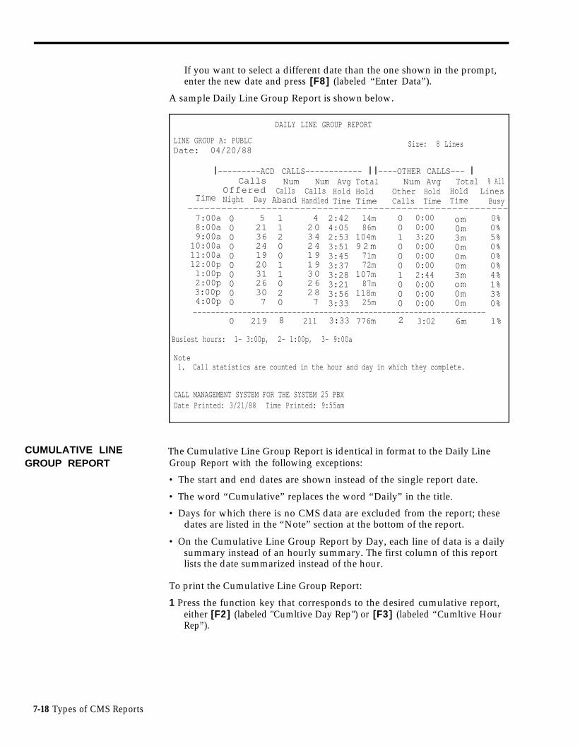
If you want to select a different date than the one shown in the prompt,enter the new date and press [F8] (labeled “Enter Data”).
A sample Daily Line Group Report is shown below.
DAILY LINE GROUP REPORT
LINE GROUP A: PUBLCDate: 04/20/88
Size: 8 Lines
❘ ---------ACD CALLS------------ ❘ ❘ ----OTHER CALLS--- ❘ CallsOfferedNight Day
Num CallsAband
Num CallsHandled
AvgHoldTime
TotalHoldTime
NumOtherCalls
AvgHoldTime
TotalHoldTime
% AllLines BusyTime
---------------------------------------------------------7:00a8:00a9:00a
10:00a11:00a12:00p1:00p2:00p3:00p4:00p
0000000000
521362419203126307
1120011020
420342419193026287
2:424:052:533:513:453:373:283:213:563:33
14m86m
104m9 2 m71m72m
107m87m
118m25m
0010001000
0:000:003:200:000:000:002:440:000:000:00
om0m3m0m0m0m3mom0m0m
0%0%5%0%0%0%4%1%3%0%
-----------------------------------------------------------------0 219 8 211 3:33 776m 2 3:02 6m 1%
Busiest hours: 1- 3:00p, 2- 1:00p, 3- 9:00a
Note1. Call statistics are counted in the hour and day in which they complete.
CALL MANAGEMENT SYSTEM FOR THE SYSTEM 25 PBXDate Printed: 3/21/88 Time Printed: 9:55am
CUMULATIVE LINEGROUP REPORT
The Cumulative Line Group Report is identical in format to the Daily LineGroup Report with the following exceptions:
• The start and end dates are shown instead of the single report date.
• The word “Cumulative” replaces the word “Daily” in the title.
• Days for which there is no CMS data are excluded from the report; thesedates are listed in the “Note” section at the bottom of the report.
• On the Cumulative Line Group Report by Day, each line of data is a dailysummary instead of an hourly summary. The first column of this reportlists the date summarized instead of the hour.
To print the Cumulative Line Group Report:
1 Press the function key that corresponds to the desired cumulative report,either [F2] (labeled "Cumltive Day Rep") or [F3] (labeled “Cumltive HourRep”).
7-18 Types of CMS Reports

One of the following prompts appears:
PRINT CUMULATIVE REPORT BY DAY: Starting: ___/___/___ Ending: ___/___/___
or
PRINT CUMULATIVE REPORT BY HOUR: Starting: ___/___/___ Ending: ___/___/___
2 If the dates next to “Starting” and "Ending" are correct, press [F8] (labeled“Enter Data”).
If you want to select a different starting and/or ending date than the onesshown in the prompt, enter the new date(s) and press [F8] (labeled “EnterData").
A sample Cumulative Line Group Report by Hour is shown below.
CUMULATIVE LINE GROUP REPORT
LINE GROUP A: PUBLCPeriod: 04/20/88 - 04/24/88
Size: 8 Lines
❘ --------ACD CALLS------------ ❘ ❘ ----OTHER CALLS-- ❘ CallsOfferedNight Day
NumCallsAband
NumCalls
Handled
AvgHoldTime
TotalHoldTime
NumOtherCalls
AvgHoldTime
TotalHoldTime
% AllLines BusyTime
--------------------------------------------------7:00a8:00a9:00a
10:00a11:00a12:00p1:00p2:00p3:00p4:00p
0000000000
139310683646574737514
1336213130
1290
10377626471727214
3:013:172:593:033:212:593:253:063:183:34
39m305m317m254m214m194m253m226m247m50m
0010001020
0:000:003:200:000:000:002:400:004:010:00
0m0m3m0m0m0m3m0m8m0m
0 %2 %7 %5 %2 %0 %1 %0 %3 %0 %
---------------------------------------------0 660 23 637 3:11 2099m 4 3:31 14m 2%
Busiest hours: 1- 9:00, 2- 8:00a, 3- 10:00a
Note1. Call statistics are counted in the hour and day in which they complete.
2. NO CMS DATA EXISTS FOR THE FOLLOWING DAY(S)
04/20/88
CALL MANAGEMENT SYSTEM FOR THE SYSTME 25 PBX
Date printed: 3/25/88 Time Printed: 9:58pm
Types of CMS Reports 7-19
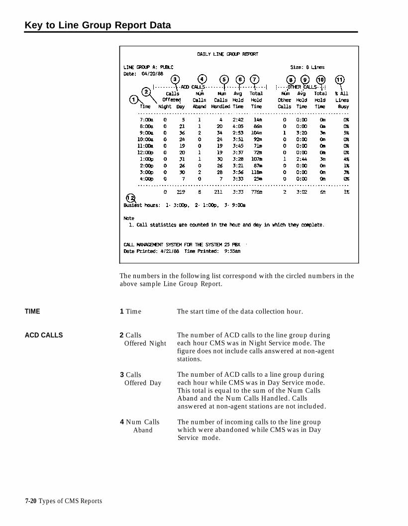
Key to Line Group Report Data
TIME
ACD CALLS
The numbers in the following list correspond with the circled numbers in theabove sample Line Group Report.
1 Time
2 CallsOffered Night
3 CallsOffered Day
4 Num CallsAband
The start time of the data collection hour.
The number of ACD calls to the line group duringeach hour CMS was in Night Service mode. Thefigure does not include calls answered at non-agentstations.
The number of ACD calls to a line group duringeach hour while CMS was in Day Service mode.This total is equal to the sum of the Num CallsAband and the Num Calls Handled. Callsanswered at non-agent stations are not included.
The number of incoming calls to the line groupwhich were abandoned while CMS was in DayService mode.
7-20 Types of CMS Reports

OTHER CALLS
5 Num CallsHandled
6 Avg HoldTime
7 Total HoldTime
8 Num OtherCalls
9 Avg HoldTime
10 Total HoldTime
The number of completed ACD calls (includingintraflowed calls) to the line group while CMS wasin Day Service mode. Calls still in progress at theend of the data collection hour are included in thenext hour’s data. Abandoned calls are notincluded.
The average amount of time (in minutes andseconds) each incoming call held a line. Avg HoldTime is determined by dividing the cumulativehold time (measured from the time the call reachesSystem 25 to line disconnect, for both abandonedand completed calls) by the Calls Offered Day.The average does not include calls answered atnon-agent stations. Calls still in progress at theend of the data collection hour are included in thenext hour’s data.
The total amount of time (to the nearest minute)all lines were held (in use) by incoming calls. Thetotal includes times for serviced and abandonedcalls, and for calls placed during both Day andNight Service, but does not include times for callsanswered at non-agent stations. Calls still inprogress at the end of the data collection hour arereported with the statistics for the next hour.
The number of “other” calls on the line group’slines during the indicated hour. Outgoing callsplaced on CMS lines, incoming calls on CMS linesthat are answered at non-agent voice terminalsand incoming calls on CMS lines that have beenanswered by an agent and then transferred toanother voice terminal are included. Calls still inprogress at the end of the hour are included in thenext hour’s data.
The average amount of time (in minutes andseconds) each “other” call completed during thereporting hour held a CMS line.
The total amount of time (to the nearest minute)all lines were held (in use) by completed “other”calls .
Types of CMS Reports 7-21

ADDITIONAL DATA 11 % All Lines The percentage of time in a given hour that allBusy lines (both CMS and transfer-queue lines) in the
line group were simultaneously busy.
12 Busiest The three data collection hours with the largestHours ACD Calls Total Hold Time values appear, in
descending order, under the totals line. Fewerthan three hours will appear if there were fewerthan three hours in which calls were handled.
7-22 Types of CMS Reports

Sub-Group Report
Press [F4] (labeled “Sub-Grp Report”) on the Print Reports Menu screen toselect the Print Sub-Group Report screen, shown below.
PRINT SUB-GROUP REPORT REPT CMS1.0 10:04a 04/20
F1 Print Daily Sub. Group ReportF2 Print Cumulative Sub-Group Report by DayF3 Print Cumulative Sub-Group Report by Hour
F8 Return to Print Reports Menu
PRINT SUB-GROUP REPORT: F1O - HelpF Daily F Cumltive F Cumltive F Reportsl Report 2 Day Rep 3 Hour Rep 8 Menu
You can request either a daily or cumulative Sub-Group Report from thisscreen.
DAILY SUB-GROUP The Daily Sub-Group Report allows you to generate a report by sub-group onREPORT all line sub-groups. Similar to the Daily Line Group Report, this report gives
you hour-by-hour data for all lines within a line sub-group. For example, BonVoyage Travel has a line group called BUSNS (the Business Line Group)whose lines are divided into two sub-groups, one sub-group containing fourWATS lines and another sub-group containing two local lines. The firm usesthe Daily Sub-Group Report to find out how each of the two sub-groups isdoing. As with the Daily Line Group Report, you can detect the followingsituations which may occur:
• A high number of abandoned calls, indicating that there are too fewagents to handle calls to the line group.
• Frequent periods when all the lines in this sub-group are busy, indicatingthat you should consider adding more lines.
• Frequent periods when there is light call traffic, indicating you may wantto consider eliminating lines.
For hours that CMS was in Night Service mode, the Daily Sub-Group Reportshows the number of calls offered (calls that rang) per line (in the sub-group)per hour, the average and total holding times, and data on “other” calls. (Allcalls during Night Service are reported as “Othr”.)
Types of CMS Reports 7-23

To print the Daily Sub-Group Report:
1 Press [F1] (labeled “Daily Report”) on the Print Sub-Group Report screen.
The following prompt appears:
PRINT DAILY SUB-GROUP REPORT: Select Report Date: ___/___/___
2 If the date next to “Date” is correct, press [F8] (labeled “Enter Data”).
If you want to select a different date than the one shown in the prompt,enter the new date and press [F8] (labeled “Enter Data”).
A typical Daily Sub-Group Report is shown below.
DAILY LINE SUB - GROUP REPORT
SUB - GROUP: PLLINE GROUP A: PUBLCDate: 04/20/88
Size: 4 Lines
❘ ---------ACD CALLS-------------- ❘ ❘ --OTHER CALLS--- ❘ CallsOfferedNight Day
NumCallsAband
NumCalls
Handled
AvgHoldTime
TotalHoldTime
NumOtherCalls
AvgHoldTime
TotalHoldTime
% AllLines BusyTime
------------------------------------------------------------------------------------7:00a8:00a9:00a10:00a11:00a12:00p1:00p2:00p3:00p4:00p
0000000000
312211211111917164
1010001010
212201211111817154
2:394:023:053:593:513:013:163:033:513:32
7 m4 9 m6 8 m5 1 m4 3 m3 0 m6 1 m5 0 m6 1 m1 4 m
0010000000
0:000:003:200:000:000:000:000:000:000:00
0m0m3m0m0m0m0m0m0m0m
0%1%3%0%0%0%2%0%1%0%
------------------------------------------------------------------0 126 4 122 3:26 434m 1 3:20 3m 1%
Busiest hours: 1 - 9:00a. 2- 1:00p. 3- 3:00p
Note1. Call statistics are counted in the hour and day in which they complete.
CALL MANGEMENTS SYSTEM FOR THE SYSTEM 25 PBXDate Printed: 4/21/88 Time Printed: 2:16pm
CUMULATIVE SUB-GROUP REPORT
The Cumulative Sub-Group Report is identical to the Daily Sub-Group Reportwith the following exceptions:
• The start and end dates are shown instead of the single report date.
• The word “Cumulative” replaces the word “Daily” in the title.
• Days for which there is no CMS data are excluded from the report; thesedates are listed in the “Note” section at the bottom of the report.
• On the Cumulative Sub-Group Report by Day, each line of data is a dailysummary instead of an hourly summary. The first column of this reportlists the date summarized instead of the hour.
7-24 Types of CMS Reports

To print the Cumulative Sub-Group Report:
1 Press the function key that corresponds to the desired cumulative report,either [F2] (labeled “Cumltive Day Rep”) or [F3] (labeled “Cumltive HourRep”).
One of the following prompts appears:
PRINT CUMULATIVE REPORT BY DAY: Starting: ___/___/___ Ending:___/___/___
or
PRINT CUMULATIVE REPORT BY HOUR: Starting: ___/___/___Ending:___/___/___
2 If the dates next to “Starting” and Ending” are correct, press [F8] (labeled“Enter Data”).
If you want to select a different starting and/or ending date, enter the newdate(s) and press [F8] (labeled “Enter Data”).
A sample Cumulative Sub-Group Report by Hour is shown below.
CUMULATIVE LINE SUB - GROUP REPORT
SUB - GROUP: PLof LINE GROUP A: PUBLCPeriod: 04/20/88 - 04/24/88
Size: 4 Lines
x ---------ACD CALLS------------ x x --OTHER CALLS--- x CallsOfferedNight Day
NumCallsAband
NumCallsHandled
Avg HoldTime
TotalHoldTime
NumOtherCalls
AvgHoldTime
TotalHoldTime
% AllLinesBusyTime
-------------------------------------------------------------------------------------------7:00a8:00a9:00a
10:00a11:00a12:00p1:00p2:00p3:00p4:00p
0000000000
75 36 54 84 14 14 84 54 19
1114102010
65 2645 44 04 14 645409
3:343:503:082:533:172:273:072:483:213:10
26m205m221m142m112m95m
130m103m117m26m
0010000000
0:000:003:200:000:000:000:000:000:000:00
0 m0 m3 m0 m0m0m0m0m0m0m
0 %2 %3 %4 %0 %1 %2 %0 %1 %0 %
----------------------------------------------------------------0 408 11 397 3:23 1177m 1 3:20 3m 1%
Busiest hours: 1- 9:00a. 2- 8:00a. 3- 10:00a
Note1. Call statistics are counted in the hour and day in which they complete.
CALL MANAGEMENT SYSTEM FOR THE SYSTEM 25 PBXDate Printed: 4/25/88/Time Printed: 2:16pm
Types of CMS Reports 7-25

Key to Daily Sub-Group Report Data
TIME
ACD CALLS
The numbers in the following list correspond with the circled numbers in thesample Daily Sub-Group Report above.
1 Time
2 CallsOfferedNight
3 CallsOfferedDay
4 Num CallsAband
The start time of the data collection hour.
The number of ACD calls to the line sub-groupduring each hour the CMS was in Night Servicemode. The figure does not include calls answeredat non-agent stations.
The number of ACD calls to the line sub-groupduring each hour the CMS was in Day Servicemode. This total is equal to sum of the Num CallsAband and the Num Calls Handled. The figuredoes not include calls answered at non-agentstations.
The number of incoming calls to the line sub-group which were abandoned while the CMS wasin Day Service mode.
7-26 Types of CMS Reports

OTHER CALLS
5 Num Calls The number of completed ACD calls (includingHandled intraflowed calls) to the line sub-group while the
CMS was in Day Service mode. Calls still inprogress at the end of the data collection hour areincluded in the next hour’s data. Abandoned callsare not included.
6 Avg Hold The average amount of time (in minutes andTime seconds) each incoming call held a line in the
sub-group. Avg Hold Time is determined bydividing the cumulative hold time (measured fromtime the call reaches System 25 to line disconnect,for both abandoned and completed calls) by theNum Calls Offered. The average does not includecalls answered at non-agent stations. Calls still inprogress at the end of the data collection hour areincluded in the next hour’s data.
7 Total Hold The total amount of time (to the nearest minute)Time all lines in the sub-group were held (in use) by
incoming calls. The total includes times forserviced and abandoned calls, and for calls placedduring both Day and Night Service, but does notinclude times for calls answered at non-agentstations. Calls still in progress at the end of thedata collection hour are reported with the statisticsfor the next hour.
8 Num Other The number of “other” calls on lines in the sub-Calls group during the indicated hour. Outgoing calls
made on CMS lines, incoming calls on CMS linesthat are answered at non-agent voice terminals,and incoming calls on CMS lines that have beenanswered by an agent and then transferred toanother voice terminal are included. Calls still inprogress at the end of the hour are included in thenext hour’s data.
9 Avg Hold The average amount of time (in minutes andTime seconds) each “other” call completed during the
reporting hour held a CMS line.
10 Total Hold The total amount of time (to the nearest minute)Time all lines in the sub-group were held (in use) by
completed “other” calls.
Types of CMS Reports 7-27

ADDITIONAL DATA 11 % All Lines The percentage of time in a given hour that allBusy CMS and transfer-queue lines in the line sub-
group were simultaneously busy.
12 Busiest The three data collection hours with the largestHours ACD Calls Total Hold Time values appear, in
descending order, under the totals line. Fewerthan three hours will appear if there were fewerthan three hours in which calls were handled.
7-28 Types of CMS Reports

Print All Reports
Press [F5] (labeled “All”) on the Print Reports Menu screen to print all fourtypes of reports. A sample Print All Report screen appears below.
PRINT ALL REPORT REPT CMS1.O 10:04a 04/20
F1 Print All Daily ReportsF2 Print All Cumulative Reports by DayF3 Print All Cumulative Reports by Hour
F8 Return to Print Reports Menu
PRINT ALL REPORTS: (Agent Split Summary Not Computed by Hour) F1O - HelpF Daily F Cunltive F Cumltive F Reports1 Reports 2 Day Reps 3 Hour Rep 8 Menu
You can request either all daily or all cumulative reports from this screen.
ALL DAILY REPORTS You can print all four types of daily reports by following this procedure:
1 Press [F1] (labeled “Daily Reports”) on the Print All Reports screen.
The following prompt appears:
PRINT ALL DAILY REPORTS: Select Report Date: ___/___/___
2 If the date next to “Select Report Date” is correct, press [F8] (labeled“Enter Data”).
If you want to select a different date than the one shown in the prompt,enter the new date and press [F8] (labeled “Enter Data“ ).
For the meaning of the data on individual reports, refer to the key to thespecific report in this section.
Types of CMS Reports 7-29

ALL CUMULATIVE If you want to print all four types of cumulative reports, follow thisREPORTS procedure:
1 Press the function key that corresponds to the desired cumulative report,either [F2] (labeled “Cumltive Day Reps”) or [F3] (labeled “Cumltive HourRep”).
One of the following prompts appears:
PRINT CUMULATIVE REPORT BY DAY: Starting: ___/___/___ Ending:___/___/___
or
PRINT CUMULATIVE REPORT BY HOUR: Starting: ___/___/___ Ending:___/___/___
2 If the dates next to “Starting” and “Ending” are correct, press [F8] (labeled"Enter Data").
If you want to select a different starting and/or ending date, enter the newdate(s) and press [F8] (labeled “Enter Data”).
For the meaning of the data on individual reports, refer to the key to thespecific report in this section.
7-30 Types of CMS Reports

Events Log Report
The Events Log Report lists the 200 most recent exceptions and systemmessages, along with the date and time they occurred. Depending on howoften exceptions and system messages occur in your system, this report mayspan several days or part of one day. Below is a portion of a sample EventsLog Report.
EVENTS LOG REPORT Page 1
Time Date Event
8:11a9:15a9:27a10:03a10:21a11:20a11:32a11:54a12:04p12:33p1:15p1:17p1:24p1:56p2:12p2:16p2:19p2:25p2:56p
05/1905/1905/1905/1905/1905/1905/1905/1905/1905/1905/1905/1905/1905/1905/1905/1905/1905/1905/19
Day******************************************************
ServiceGroup CSplit 1Group ASplit 3Split 2Split 1Split 1Group ASplit 3Split 2Split 1Split 3Split 1Split 1Split 1Split 2Split 1Split 1
Now------------------
In EffectAll Lines Busy > = 240 secondsAgent JOEL - Refused CallsLine L3071 - Hold Time > = 8 minutesAgent DON - Talk Time > = 480 seconds# Abandoned Calls > = 3Oldest Call Waiting > = 45 secondsAgent JENNY - Refused CallsLine L3072 - Hold Time > = 8 minutesOldest Call Waiting > = 30 secondsAgent BERNE - Refused Calls# Abandoned Calls > = 4Agent ALLAN - Talk Time > =480 secondsAgent SCOTT - Refused CallsOldest Call Waiting > =45 secondsAgent BILL - Refused Calls# Calls Waiting > = 2# Abandoned Calls > = 4Agent Scott = Refused Calls
You can use information on the Events Log Report to spot problems such asthese:
•
•
•
Split staffing or configuration problems
By monitoring the Abandoned Call, Average Speed of Answer and OldestCall Waiting exceptions, you can determine if you need to add moreagents or activate intraflow during peak hours.
Exception thresholds that are set too low
For instance, if you receive many exception messages for Talk Time, AgentLogout ACW, or time spent in the ACW state, exception thresholds youare using may not be realistic.
Line problems
For instance, frequent minimum holding time exceptions for a particularline may indicate the line is faulty. Frequent All Lines Busy exceptionsmay indicate that you need more lines or that agents need to handle callsfaster.
You can also use this report to see how effectively dynamic reconfigurationwas used during each shift. If many exceptions are listed for a single shift,the exception thresholds may be set too low or the information from thestatus screens may not have been used effectively.
Types of CMS Reports 7-31

Section 8: Archiving Data

Overview
Archiving is the process of copying historical data from the hard disk ontofloppy diskettes. You need to archive data when the hard disk begins to runout of space and you want to save your old files. You should archive dataonce a month to keep the system running efficiently.
This section discusses how to archive data and contains information about thedirectories and files CMS uses. It includes procedures for copying the systemtables and historical data files to a floppy diskette using the MS-DOS copycommand, and for erasing these files from the hard disk using the MS-DOSerase command. This section also tells you how to restore archived data tothe hard disk so that you can print historical reports.
TRANSFERRING To print historical reports from archived data, you need the system tables andHISTORICAL DATA ONTO historical data files for the days in which you’re interested. The system tablesDISKETTES file includes the information that identifies the lines, splits, and agents
contained in historical data that have been saved. Up to four historical datafiles and one system tables file fit on a single 360K floppy diskette.
To clear space on the hard disk, you can simply erase your oldest files.However, if you want to save the data for possible future use, you shouldarchive those files onto a floppy diskette first, and then erase them from thehard disk. Copy the four oldest data files and the oldest system table to thefloppy diskette. After you verify that the files were copied, erase those filesfrom the hard disk.
If you archive files on a regular schedule, such as once a week, you can avoidrunning out of space on the hard disk. Figure 8-1 shows the locations of thedirectories and files CMS uses.
Overview 8-1

Copying the System Tables FileTo copy the system tables file, do as follows:
1 If you are in CMS, exit to MS-DOS by pressing [F8] (labeled Exit to DOS)on the CMS Menu.
2 Access the cmsmgmt directory on the hard disk by typing
cd \ cms \ cmsmgmt
and pressing [Enter].
3 To copy the system tables file for the current date, type
copy c:systbls.cms a:syymmdd.cms
where yymmdd is the date, and press [Enter]. For example, to copy thesystem tables file on 04/19/88, copy it to a file called s880419.cms.
If you copy the system tables file only when a change affecting line, agent,or split assignments has been made, use the date the change becameeffective. For instance, if the change was made Monday morning beforecall management was started, use Monday’s date. If the change wasmade after call management stopped on Monday, use Tuesday’s date.
Copying Historical Data FilesTo copy the historical data files, do the following:
1 If you are in CMS, exit to MS-DOS by pressing [F8] (labeled Exit to DOS)on the CMS Menu.
2 Access the cmsrept directory by typing
cd \ cms \ cmsrept
and pressing [Enter].
3 Type a series of commands in the form
copy c:dyymmdd.cms a:
where yymmdd is the date on which data were collected. Press [Enter]after each command. For example, if you want the historical data file for04/19/88, you would copy the file d880419.cms.
To copy 10 days’ data at a time, for instance, files from 07/20/88 through07/29/88, type a command in this format:
copy c:d88072* .cms a:
then press [Enter].
Erasing Files from the Hard DiskTo erase the archived files from the hard disk, do as follows:
Type a series of commands in the form
erase c:dyymmdd.cms
where dyymmdd.cms is the name of the file to be erased. Press [Enter] aftereach command.
8-2 Overview

GENERATING HISTOR-ICAL REPORTS
If you have transferred old CMS data from the hard disk onto floppydiskettes, you may later want a report or a complete set of reports for aparticular date. The procedures that follow explain how to copy the systemtables and data files for the date from the floppy diskette onto the hard disk,so that you can then generate reports for that date.
Saving the Current System TablesYou have to save the current system tables file in a temporary file so that youdon’t lose it when you copy the historical system table file to the hard disk.To save the current system tables file, do as follows:
1 If you are in CMS, exit to MS-DOS by pressing [F8] (labeled Exit to DOS)on the CMS Menu.
2 Access the cmsmgmt directory on the hard disk by typing
cd \ cms \ cmsmgmt
and pressing [Enter].
3 To copy the current system tables file to a temporary file, type.
copy systbls.cms temp
then press [Enter].
This copies (and saves) the current system tables file to a file called “temp.”(You can choose another name for the file if you want.) Remember to copythe current system tables file back into systbls.cms in the cmsmgmt directorybefore you have CMS begin managing calls again.
Copying the Historical System Tables to the Hard DiskYou should still be in the cmsmgmt directory. To copy the system tables filesfor the date you want, type the following:
copy a:syymmdd.cms c:systbls.cms
where yymmdd is the date of the system tables file. Press [Enter].
Copying the Historical Data Files to the Hard DiskYou should still be in the cmsmgmt directory. To copy the historical data filesfrom the floppy disk to the hard disk, do as follows:
1
2
3
Access the cmsrept directory by typing
cd \ cms \ cmsmpt
then press [Enter].
Type a series of commands in the form
copy a:dyymmdd.cms c:
where yymmdd is the date of the data you want. Press [Enter] after eachcommand.
When you’re finished copying data to the hard disk, type
cd \ cms
then press [Enter].
Overview 8-3

Generating ReportsThe system tables file and data for the date(s) you’re interested in should nowbe in the correct locations on the hard disk. To generate the reports youwant, follow the instructions in “Generating CMS Reports” in Section 7.
RESTORING DATACOLLECTIONCONDITIONS
Now that you have the historical reports, you must restore the hard disk toits previous condition. Otherwise, CMS cannot effectively store new datawhen it resumes managing calls. To do this, erase the historical data fromthe hard disk-data remains saved on the floppy diskette-and restore thecurrent system tables file to the proper file.
Erasing the Historical Data from the Hard DiskTo erase the historical data from the hard disk, do the following:
1 If you are in CMS, exit to MS-DOS by pressing [F8] (labeled Exit to DOS)on the CMS Menu.
2 To access the cmsrept directory, type
cd \ cms \ cmsrept
then press [Enter].
3 To erase a data file, type
erase c:dyymmdd.cms
where yymmdd is the date of the data file to be erased. Then press[Enter].
Restoring the Current System Tables FileTo restore the current system tables file to its appropriate place in the cmsdirectory, do the following:
1 To access the cmsmgmt directory, type
cd \ cms \ cmsmgmt
and then press [Enter].
2 To restore the system tables file, type
copy temp systbls.cms
and press [Enter].
You should now have the historical reports you wanted, and CMS should beready to store new data.
8-4 Overview

Section 9: Troubleshooting

Overview
This section of the manual suggests corrective action for problems that mayoccur with your CMS. It is organized as follows:
Startup Problems
Suggests corrective action for problems the CMS program detects during callmanagement startup.
Call Management Problems
Identifies problems that can cause CMS to stop managing calls and suggestscorrective action.
Voice Announcement Unit Problems
Suggests corrective action for problems that effect voice announcement units.
Printer Problems
Identifies and suggests corrective action for problems that can prevent youfrom printing CMS screens and reports.
Agent problems
Anticipates and suggests solutions to problems you and your agents are mostlikely to encounter as you begin to use CMS.
System Errors
Explains messages beginning SYSERR that may appear on your status screensand/or Events Log screen during CMS operation.
Running CMS from a Floppy Diskette Backup
Tells you how to run CMS using the floppy diskette backups in the event thatthe PC’s hard disk is damaged.
Managing Calls When CMS is Not Running
Tells you how to use your System 25 Direct Group Calling (DGC) Coveragefeature to manage calls until CMS is running again.
Overview 9-1

Startup Problems
The following pages identify and suggest corrective action for problems thatmay occur when you start up CMS call management. The problems aregrouped as follows, according to the kind of message they cause to appear inthe information portion of the Initialization screen:
• Error messages
• Warning messages
Use these pages to find the message that identifies your problem, and takethe corrective action(s) described.
Error Messages
Problems that generate error messages on the CMS Initialization screen alwaysbring the call management startup procedure to a halt. Until you havecorrected the problem, you have to manage incoming calls on CMS linesaccording to the instructions in “Managing Calls When CMS is Not Running”at the end of this section.
• ERROR--NO Lines in CMS. Must ADMINISTER Lines/Groups.
Effect on Call Management: Until this problem is corrected, CMS cannotmanage calls. See “Managing Calls When CMS is Not Running“ at the endof this section of the manual.
Possible Cause Corrective Action
You omitted one or 1 From the Initialization screen, inmore steps when you sequence, press [F8] (labeledadministered your “Exit Call Mgt”), [F4] (labeledCMS line groups. "min CMS", and [F2] (labeled
"Lines/LineGps") to get theAdminister Line Groups screen.
2 Follow the instructions under theheading “Administering CMS Linesand Line Groups” in Section 4 toadminister line groups.
3 Make sure you have completed atleast one shift configuration asdescribed in “Building or EditingShift Configurations” in Section 4.
4 Restart call management from theCMS Menu by pressing [F1](labeled “Start Call Mgt”).
9-2 Startup Problems

• ERROR--NO Configurations Found. Must ADMINISTER System.
Effect on Call Management: Until this problem is corrected, CMS cannot managecalls. See “Managing Calls When CMS is Not Running” at the end of thissection.
Possible Cause
You omitted one ormore steps when youbuilt your shiftconfigurations.
Corrective Action
1 From the Initialization screen, insequence, press [F8] (labeled "ExitCall Mgt"), [F4] (labeled “AdminCMS”), and [F4] (labeled “ConfigList”) to get to the ConfigurationList screen.
2 Build at least one shiftconfiguration according to theinstructions in “Building or EditingShift Configurations” in Section 4of this manual.
3 Restart call management from theCMS Menu by pressing [F1](labeled “Start Call Mgt”).
• ERROR--CMS File Missing. Must ADMINISTER System.
Effect on Call Management: Until this problem is corrected, CMS cannotmanage calls. See “Managing Calls When CMS is Not Running” at the endof this section of the manual.
Possible Cause Corrective Action
CMS was notadministered or wasadministeredincorrectly.
1 From the Initialization screen, press[F8] (labeled "Exit Call Mgt"); thenpress [F4] (labeled "Admin CMS")to access the Administration Menuscreen.
2 Administer CMS according to theinstructions in Section 4 of thismanual.
Startup Problems 9-3

• ERROR--CUX Faulty or Disconnected. CMS Can’t Manage Calls(X refers to PC jack CU1 or PC jack CU2).
Status Indicator: CU1 or CU2 (flashing)
Audible Signal: A beep from the CMS PC Interface Card.
Effect on Call Management: Until this problem is corrected, CMS cannotmanage calls. See “Managing Calls When CMS is Not Running” at the endof this section.
Possible Cause Corrective Action
There’s a loose cable Make sure one end of the cable isconnection between securely plugged into the CU1 (orthe CU1 and/or CU2 CU2) jack at the back of the PC andjack and the System 25 the other end is securely plugged intowall jack. the wall jack assigned to CU1 (or
CU2).
If this does not work, have the System25 Administrator check the stationinterconnect panel (SIP) connections tothe System 25 cabinet for CU1 and/orCU2.
The cable is faulty. Try switching the two cables around(unplug the cable from the CU1 jackand plug it into CU2, and vice versa).If the CU1 indicator on the screenstops flashing and the CU2 indicatorgoes on (or vice versa), you know theproblem is either a faulty cable or afaulty System 25 component.
The System 25 ATL Have the System 25 Administratorport(s) assigned to CU1 check the ports on the ATL Lineand/or CU2 is faulty. Circuit Pack.
The wrong cable type The cable must be a 4-pair modularis being used. cable, D8W-87, the type of cable that
came with your CMS PC InterfaceCard.
The CU1 and/or CU2 If none of the previous actions correctsjack on the CMS PC the problem, contact your equipmentInterface Card is faulty. supplier for assistance.
9-4 Startup Problems
• ERROR--CMS Card Not Found or Faulty. CMS Can’t Manage Calls.
Effect on Call Management: Until this problem is corrected, CMS cannotmanage calls. See “Managing Calls When CMS is Not Running” at the endof this section.
Possible Cause Corrective Action
The CMS PC Interface 1 From the Initialization screen, pressCard is installed [F8] (labeled “Exit Call Mgt”), thenincorrectly. press [F8] (labeled "Exit to DOS")
to exit to MS-DOS.2 Turn off the PC and unplug it from
the power source.3 Make sure the CMS PC Interface
Card is installed as described in theAT&T System 25 Call ManagementSystem Installation and Startup Guide.
4 Reconnect and turn on the PC.5 Restart call management from the
CMS Menu.
The CMS PC Interface If the same message appears whenCard is faulty. you restart CMS call management, you
may have a faulty CMS PC InterfaceCard. Contact your equipmentsupplier for assistance.
Startup Problems 9-5
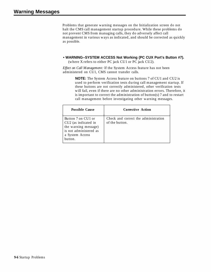
Warning Messages
Problems that generate warning messages on the Initialization screen do nothalt the CMS call management startup procedure. While these problems donot prevent CMS from managing calls, they do adversely affect callmanagement in various ways as indicated, and should be corrected as quicklyas possible.
• WARNING--SYSTEM ACCESS Not Working (PC CUX Port’s Button #7).(where X refers to either PC jack CU1 or PC jack CU2).
Effect on Call Management: If the System Access feature has not beenadministered on CU1, CMS cannot transfer calls.
NOTE: The System Access feature on buttons 7 of CU1 and CU2 isused to perform verification tests during call management startup. Ifthese buttons are not correctly administered, other verification testswill fail, even if there are no other administration errors. Therefore, itis important to correct the administration of button(s) 7 and to restartcall management before investigating other warning messages.
Possible Cause Corrective Action
Button 7 on CU1 orCU2 (as indicated inthe warning message)is not administered asa System Accessbutton.
Check and correct the administrationof the button.
9-6 Startup Problems

• WARNING--EXCLUSION Not Working (PC CU1 Port’s Button #8).
Effect on Call Management: Some CMS calls are disconnected before beingconnected to an agent station.
Possible Cause Corrective Action
The modular cables Reverse the cables connected to PCconnected to PC jacks jacks CU1 and CU2. Then restartCU1 and CU2 are CMS call management from the CMSreversed. Menu.
PC jack CU1 is Check that PC jack CUl is connectedconnected to the to the wall jack assigned to CU1.wrong System 25 ATL If this is not the problem, have theport. System 25 Administrator check the
Station Interconnect Panel (SIP)connections to the System 25 cabinetfor CU1.
System 25 feature Have the System 25 Administratoradministration of check System 25 administration of thebutton number 8 on CMS CU1 jack to see that buttonPC jack CU1 is number 8 was administered with theincorrect. Exclusion feature.
Startup Problems 9-7

• WARNING--PERS LINE Not Working (CU1’s Button # NN for TrunkXXXXX) (where NN is the button number on CU1 and XXXXX is the LineID associated with the CMS or transfer-queue line).
Effect on Call Management: CMS does not recognize an incoming call, andtherefore, does not answer the call.
Possible Cause
The modular cablesconnected to PC jacksCU1 and CU2 arereversed.
PC jack CU1 isconnected to thewrong System 25 ATLport.
System 25 featureadministration ofbutton number NN forPC jack CU1 isincorrect.
The trunk with Line IDXXXX is administeredfor Dial-in Only access.This causes the CMStest for this line to failwhen there is not aproblem
Corrective Action
Reverse the cables connected to PCjacks CU1 and CU2. Then restartCMS call management from the CMSMenu.
Check that PC jack CU1 is connectedto the wall jack assigned to CU1.
If this is not the problem, have theSystem 25 Administrator check the SIPconnections to the System 25 cabinetfor CU1.
Have the System 25 Administratorcheck System 25 administration of PCjack CU1 to see that button numberNN was administered as a PersonalLine for trunk XXXX.
Have the System 25 Administratorchange the Dial-in Only option to no.Then restart call management from theCMS Menu.
9 - 8 S t a r t u p P r o b l e m s

• WARNING--DSS Not Working (CU1’s Button # NN for VAU XXXXXX,PDC ZZZZ) (where NN is the button number on PC jack CU1, XXXXXX isthe voice announcement unit ID, and ZZZZ is the voice announcementunit’s PDC).
Effect on Call Management: Calls cannot be transferred to the voiceannouncement unit.
Possible Cause Corrective Action
The modular cables Reverse the cables connected to PCconnected to PC jacks jacks CU1 and CU2. Then restart callCU1 and CU2 are management from the CMS Menu.reversed.
PC jack CU1 is Check that PC jack CU1 is connectedconnected to the to the wall jack assigned to CU1.wrong System 25 ATL If this is not the problem, have theport. System 25 Administrator check the SIP
connections to the System 25 cabinetfor CU1.
System 25 feature Have the System 25 Administratoradministration of check System 25 administration of PCbutton number NN on jack CU1 to see that button numberPC jack CU1 is NN was administered as a DSS buttonincorrect. for PDC ZZZZ.
Startup Problems 9-9

• WARNING--AGENT STATUS Not Working (CU2’S Button # NN for PDCZZZZ) (where NN is the button number on PC jack CU2 and ZZZZ is thePDC of the agent’s voice terminal).
Effect on Call Management: CMS agents do not receive CMS calls.
Possible Cause Corrective Action
The modular cables Reverse the cables connected to PCconnected to PC jacks jacks CU1 and CU2. Then restartCU1 and CU2 are CMS call management from the CMSreversed. Menu.
PC jack CU2 is Check that PC jack CU2 is connectedconnected to the to the wall jack assigned to CU2.wrong System 25 ATL If this is not the problem, have theport. System 25 Administrator check the SIP
connections to the System 25 cabinetfor CU2.
System 25 feature Have the System 25 Administratoradministration for check System 25 administration of PCbutton number NN on jack CU2 to see that button numberPC jack CU2 is NN was administered with the CMSincorrect. Monitor feature.
System 25 feature Have the System 25 Administratoradministration of one check System 25 administration of theor more of the agent three agent status buttons on the agentstatus buttons on the voice terminal.agent voice terminal isincorrect.
9-10 Startup Problems

• WARNING--One or More Line Groups Has No Lines.
Effect on Call Management: Calls cannot come into a line group with no lines.
Possible Cause Corrective Action
You have at least one 1 From the Initialization screen, pressagent split assigned to [F1] (labeled "Config Screen") toa line group containing get to the Configuration screen.no lines. 2 By looking at the "Num" column in
the Answer/Force Delay area andthe “Main” and “Sec” columns inthe Call Flow area, find the linegroup(s) (A-D) with no lines and amain and/or secondary splitassigned to it (them).– If you want to assign lines to a
line group with no lines, exitcall management and follow
the instructions in“Administering CMS Lines andLine Groups” in Section 4 ofthis manual.
– If you want to remove an agentsplit assignment from an emptyline group, then do so whencall management begins byfollowing the instructions in“Reconfiguring Call Flow” inSection 5.
Startup Problems 9-11

• WARNING--NO Agents Covering Line Group(s). Press CONFIGSCREEN.
Effect on Call Management: If both the main and secondary splits assigned to aline group have no agents, calls coming in on that group of lines will not beanswered. If the main split has agents but the secondary split does not, callscoming in on that group of lines cannot be intraflowed. If the main split hasno agents but the secondary split does, and if intraflow is on, calls coming inon that group of lines will be connected to a delay message, then put on holduntil they can be intraflowed to the secondary split.
Possible Cause
You have at least oneempty split assigned toat least one line group.
Corrective Action
1 From the Initialization screen, press[F1] (labeled “Config Screen”) to getthe Configuration screen.
2 Looking at the Agent Split and theCall Flow areas, find the split(s) withno agents.
3 Assign agents to the empty split(s)using the Configure Splits screen orremove the empty splits using theCall Flow screen according to theinstructions in “DynamicReconfiguration” in Section 5 of thismanual.
• WARNING--NO Secondary Split Assigned to One or More Line Groups.
Effect on Call Management: Calls coming in to a line group with no secondarysplit assigned to it cannot be intraflowed.
Possible Cause
You have at least oneline group with a mainsplit assigned to it andintraflow turned on,but the line group hasno secondary splitassigned to it.
Corrective Action
1 From the Initialization screen, press[F1] (labeled “Config Screen”) to getthe Configuration screen.
2 In the Call Flow area, find the linegroup(s) with intraflow turned onbut no secondary split assigned.
3 Following the instructions in“Reconfiguring Call Flow” in Section5, either turn intraflow off or assigna secondary split to the line group.
9-12 Startup Problems

• WARNING--NO Main Split Assigned to One or More Line Groups.
Effect on Call Management: Calls coming into a line group with no main splitassigned to it will be answered only if intraflowed.
Possible Cause Corrective Action
You have at least one 1 From the Initialization screen, pressline group with no [F1] (labeled “Config Screen”) tomain split assigned to get to the Configuration screen.it, but with a 2 Looking at the Call Flow area, findsecondary split the line group(s) with no main splitassigned to it. assigned.
3 Following the instructions in“Reconfiguring Call Flow” inSection 5, assign a main split to theline group(s).
Startup Problems 9-13

• WARNING--Only x Day’s Space Left for Storing History Data.
Status Indicator: LoStorage
Possible Cause Corrective Action
This message appears 1 Exit to MS-DOS by pressing [F8]when there is room for (labeled “Exit to DOS”) on theless than ten days of CMS Menu.historical data. 2 Access the cmsrept directory by
typing
cd \ cms \ cmsrept
then press [Enter].3 Type dir, then press [Enter] to
display the names of all the files inthe directory.
Data files are in the formdyymmdd.cms (where yymmddrepresents a year, a month, and aday.
4 If you plan to delete files, but wantto transfer (save) data from thesefiles onto a floppy diskette beforedeleting them, see Section 8,“Archiving Data” in this manual.
5 Delete files by typing
erase c:dyymmdd.cms
(where yymmdd represents theyear, month and day of the file);then press [Enter].
6 Repeat Step 5 for each file youwant to delete.
9-14 Startup Problems

• WARNING--Out of Disk Space on Drive C:--No Storage of History Data.
Status Indicator: NoStorage
Effect on Data Collection: CMS continues to manage calls, but all datacollection stops until the problem is corrected.
Possible Cause Corrective Action
There’s no room on 1 Exit to MS-DOS by pressing [F8]the hard disk for new (labeled “Exit to DOS”) on thedata. CMS Menu.
2 Access the cmsrept directory bytyping
cd \ cms \ cmsrept
then press [Enter]3 Type dir then press [Enter] to
display the names of all the files inthe directory.
Data files are in the formdyymmdd.cms (where yymmddrepresents a year, a month, and aday.
4 If you plan to delete files, but wantto transfer (save) data from thesefiles onto a floppy diskette beforedeleting them, see Section 8,“Archiving Data” in this manual.
5 Delete files by typing
erase c:dyymmdd.cms
(where yymmdd represents theyear, month and day of the file);then press [Enter].
6 Repeat Step 5 for each file youwant to delete.
Startup Problems 9-15

• WARNING--Printer Not Ready. Using Prt Sc Key Will Halt CMS.
Status Indicator: Don’t PrtSc
Effect on Call Management: If you press [Shift] + [Print Scrn] when this message isdisplayed, CMS stops managing calls.
Effect on Data Collection: If you press [Shift] + [Print Scrn] when this message isdisplayed, all data collection stops, but resumes normally when the problemis corrected. Statistics for time logged in are not affected.
Possible Cause Corrective Action
The printer is not Make sure the printer is plugged inreceiving power. and turned on, and that the Ready
light is on.
There’s no paper in the 1 Make sure there’s paper in theprinter, or the paper is printer and the paper isn’tjammed. jammed.
2 Make sure the paper is alignedproperly.
3 Press the Form Feed button on theprinter to make sure the paperfeeds properly.
There’s a loose cable Make sure the connections are secureconnection between at both ends of the cable runningthe printer and the PC. between the printer and the PC.
If the problem is corrected, you willsee the message Printer Now Ready onthe error line. If you do not see thismessage, try correcting the problemagain. If you still do not see themessage, turn the PC off, then on, andrestart CMS call management from theCMS Menu.
The printer is not Make sure the printer’s Ready light isready. on. If not, press the button next to
the Ready light.
9-16 Startup Problems

• WARNING-Annc #N, XXXXXXX, is Not Hanging Up. Check Unit. (Nrepresents the announcement unit number and XXXXXXX is theAnnouncement ID.)
Status Indicator: ANNC
Effect on Call Management: Until the problem is corrected, CMS cannot connectcalls to the designated announcement unit. The Announcement Unit Statusfield on the System Status screen displays BRKN and the Annc Condtn fieldon the Select Announcement and Assign Announcement screens also showsBROKN.
Possible Cause Corrective Action
The announcement Turn off the Continuous Play switch.unit is in the Bring the unit back into serviceContinuous Play mode. following the directions in “Voice
Announcement Unit Problems,” laterin this section.
Startup Problems 9-17

Call Management Problems
The following pages identify and suggest corrective action for problems thatmay occur while CMS is managing calls. Scan the pages to locate the errormessage or problem description that identifies your problem. Then take therecommended corrective action.
IMPORTANT: All the problems identified here bring call managementto a halt. In most cases, CMS resumes managing calls as soon as theproblem is corrected. Meanwhile, you have to manage incoming callson CMS lines according to the instructions in “Managing Calls WhenCMS is Not Running” at the end of this section of the manual.
• ERROR--CMS Card Not Found or Faulty. CMS Can’t Manage Calls.
Status Indicator: CU1 (flashing) and CU2 (flashing)
Audible Signal: A 30-second beep from the PC
Effect on Call Management: Until this problem is corrected, CMS cannotmanage calls. See “Managing Calls When CMS is Not Running” at the endof this section of the manual. .
Effect on Data Collection: When this problem occurs, data collection stops.Data on calls completed within the hour are saved if the problem is correctedwithin the same hour in which CMS became disabled. Data on calls inprogress when CMS became disabled are lost. When the problem iscorrected, data collection resumes.
Possible Cause Corrective Action
The CMS PC Interface 1 Exit to MS-DOS bv pressing [F8]Card has become (labeled “Exit to DOS”) on theloose. CMS Menu.
2 Turn off the PC and unplug it fromthe power source.
3 Make sure the CMS PC InterfaceCard is installed as described in theAT&T System 25 Call ManagementSystem Installation and Startup Guide.
4 Reconnect and turn on the PC.5 Restart CMS call management.
The CMS PC Interface If the same message appears on theCard is faulty. screen when you try to restart CMS,
contact your equipment supplier forassistance.
9-18 Call Management Problems

• PROBLEM: The PC stops functioning, and call management stops, butno message appears on the screen.
Audible Signal: The alarm on the CMS PC Interface Card comes on and stayson.
Effect on Call Management: Until this problem is corrected, CMS cannotmanage calls. See “Managing Calls When CMS is Not Running” at the endof this section of the manual.
Effect on Data Collection: When this problem occurs, data collection stops, andall data from the current hour are lost.
Possible Cause Corrective Action
The PC has failed. Press the reset button below the diskdrives on the front of the PC, andrestart CMS call management from theCMS Menu.
If you cannot restart the PC , see theuser’s guide that came with your PC.
• PROBLEM: The PC stops, restarts, and displays the MS-DOSC> prompt, or the CMS Menu.
Effect on Call Management: Call management stops, but should resume shortlyafter you restart call management.
Effect on Data Collection: Data for the current hour are lost.
Possible Cause Corrective Action
Electrical power to the Restart call management from thePC was interrupted, or CMS Menu. (Refer to “Startupsomeone pressed the Procedures” in Section 5 for details.)reset button on the PC.
Call Management Problems 9-19

• ERROR--CU X Faulty or Disconnected. CMS Can’t Manage Calls(X refers to either PC jack CU1 or PC jack CU2).
Status Indicator: CU1 or CU2 (flashing)
Audible Signal: A single short beep from the PC and a longer beep from theCMS PC Interface Card
Effect on Call Management: Until this problem is corrected, CMS cannotmanage calls. See “Managing Calls When CMS is Not Running” at the endof this section of the manual.
Effect on Data Collection: When this message appears, data collection stops.Data on completed calls are saved, but data on calls in progress when theproblem occurred are lost. When the problem is corrected, data collectionresumes.
Possible Cause Corrective Action
There’s a loose cable Make sure one end of the cable isconnection between plugged securely into the CU1 (orthe CU1 and/or CU2 CU2) jack at the back of the PC andjack and the System 25 the other end is plugged securely intowall jack. the wall jack assigned to CU1 (or
CU2).
If this does not work, have the System25 Administrator check that the stationinterconnect panel (SIP) connections tothe System 25 cabinet for the CU1and/or CU2 are in place.
The cable is faulty. Try switching the cables around(unplug the cable from CU1 and plugit into CU2, and vice versa). If theCU1 indicator on the screen stopsflashing and the CU2 indicator appearson the screen (or vice versa), youknow the problem is either a faultycable or a faulty System 25component.
The ATL port(s) Have the System 25 Administratorassigned to CU1 and/or check the ATL Line Circuit Pack toCU2 is faulty. which CU1 and CU2 are connected.
The wrong cable is The cable must be a 4-pair modularbeing used. cable, D8W-87, the type of cable that
came with your CMS PC InterfaceCard.
The CU1 and/or CU2 If none of the above actions correctsjacks on the CMS PC the problem, contact your equipmentInterface Card are supplier for assistance.faulty.
9-20 Call Management Problems

• PROBLEM: CMS stops managing calls. No error message appears onthe screen, and the function keys don’t work.
Effect on Call Management: No calls are processed.
Effect on Data Collection: Only statistics for time logged in are collected.
Possible Cause Corrective Action
You pressed • See “Printer Not Ready” message[Shift] + {Print Scrn] under the heading, “Printerwhen the printer was Problems” later in this section for anot ready. list of corrective actions.
When the printer is fixed, CMSresumes call management. If it doesnot, reboot the PC (by pressing thereset button on the front of the PC orby turning the PC off and then onagain), and then restart CMS callmanagement from the CMS Menu.
Call Management Problems 9-21

Voice Announcement Unit Problems
After correcting a voice announcement unit problem, bring the unit back intoservice as follows:
1 From the System Status screen, press [F2] (labeled “Select Anncs” ).2 Press [F1] (labeled “Select Annc”).3 Enter the number of the announcement unit; then press [F8] (labeled
“Enter Data”).4 Press [F3] (labeled “Change Condtn” ) once to change the announcement
unit condition from BROKN to REMVD.5 Press [F3] again to change the condition to AVAIL .
CMS immediately attempts to test the unit.
9-22 Voice Announcement Unit Problems

• WARNING--Annc #N, XXXXXXX, (PDC = YYYY) Not Responding. CheckUnit (where N represents the announcement unit number, XXXXXXX isthe Announcement ID, and YYYY is the announcement unit’s PDC).
Status Indicator: ANNC
Effect on Call Management: The voice announcement unit has failed thestartup/back-in-service test. Until the problem is corrected, CMS cannotconnect calls to the designated announcement unit. The Announcement UnitStatus field on the System Status screen is updated to BRKN and the AnncCondtn field on the Select Announcement and Assign Announcement screensis updated to BROKN.
Possible Cause Corrective Action
The voiceannouncement unit isnot receiving power.
Make sure the voice announcementunit is plugged in and turned on.Using the Assign Announcementscreen, bring the unit back intoservice.
There is a loose cableconnection betweenthe voiceannouncement unitand the System 25 walljack.
Make sure the modular cable isplugged into the voice announcementunit and the System 25 wall jack.Using the Assign Announcementscreen, bring the unit back intoservice.
There is no messagerecorded on the voiceannouncement unit.
Record a message. Using the AssignAnnouncement screen, bring the unitback into service.
System 25 and CMSadministration do notmatch for theannouncement unit.
Have the System 25 Administratorcheck System 25 administration for thePDC and port numbers associated withthe announcement unit. The System25 Administrator should also check theSystem 25 administration of the DSSbutton representing the announcementunit on PC jack CU1.. Using theAssign Announcement screen, bringthe unit back into service.
Voice Announcement Unit Problems 9-23
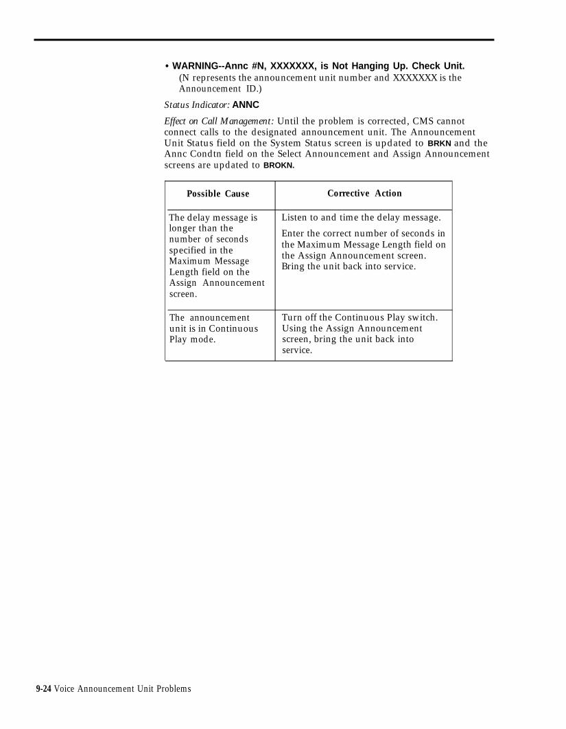
• WARNING--Annc #N, XXXXXXX, is Not Hanging Up. Check Unit.(N represents the announcement unit number and XXXXXXX is theAnnouncement ID.)
Status Indicator: ANNC
Effect on Call Management: Until the problem is corrected, CMS cannotconnect calls to the designated announcement unit. The AnnouncementUnit Status field on the System Status screen is updated to BRKN and theAnnc Condtn field on the Select Announcement and Assign Announcementscreens are updated to BROKN.
Possible Cause
The delay message islonger than thenumber of secondsspecified in theMaximum MessageLength field on theAssign Announcementscreen.
The announcementunit is in ContinuousPlay mode.
Corrective Action
Listen to and time the delay message.
Enter the correct number of seconds inthe Maximum Message Length field onthe Assign Announcement screen.Bring the unit back into service.
Turn off the Continuous Play switch.Using the Assign Announcementscreen, bring the unit back intoservice.
9-24 Voice Announcement Unit Problems

• WARNING--Annc # N, XXXXXXX, Not Answering. Check Unit.(N represents the Announcement Number and XXXXXXX is theannouncement ID.)
Status Indicator: ANNC
Effect on Call Management: Until the problem is corrected, CMS cannotconnect calls to the designated voice announcement unit. TheAnnouncement Unit Status field on the System Status screen is updated toBRKN and the Annc Condtn field on the Select Announcement and Assign
Announcement screens is updated to BROKN.
Possible Cause Corrective Action
The voice Make sure the voice announcementannouncement unit is unit is plugged in and turned on.not receiving power. Using the Assign Announcement
screen, bring the unit back intoservice.
There is a loose cable Make sure the modular cable isconnection between plugged into the voice announcementthe voice unit and the System 25 wall jack.announcement unit Using the Assign Announcementand the System 25 wall screen, bring the unit back intojack. service.
• WARNING--Annc # N, XXXXXXX, Hung Up Too Soon. Check Unit.
Status Indicator: ANNC
Effect on Call Management: Until the problem is corrected, CMS cannotconnect calls to the designated voice announcement unit. TheAnnouncement Unit Status field on the System Status screen is updated toBRKN and the Annc Condtn field on the Select Announcement and Assign
Announcement screens is updated to BROKN.
Possible Cause Corrective Action
Delay message is less Record new delay message that is atthan 5 seconds long. least 5 seconds long. Using the Assign
Announcement screen, bring the unitback into service.
Voice Announcement Unit Problems 9-25

Printer Problems
• WARNING--Printer Not Ready. Using Prt Sc Key Will Halt CMS.
Status Indicator: Don’t PrtSc
Effect on Call Management: If you press [Shift] + [Print Scrn] when this message isdisplayed, CMS stops managing calls.
Effect on Data Collection: If you press [Shift] + [Print Scrn] when this message isdisplayed, all data collection stops, but resumes normally when the problemis corrected. Statistics for time logged in are not affected.
Possible Cause Corrective Action
The printer is not Make sure that the printer is pluggedreceiving power. in and turned on, and that the Ready
light is on.
There’s no paper in the 1 Make sure there’s paper in theprinter, or the paper is printer and the paper isn’tjammed. jammed.
2 Make sure the paper is alignedproperly.
3 Press the Form Feed button on theprinter to make sure the paperfeeds properly.
There’s a loose cable Make sure the connections are secureconnection between at both ends of the cable runningthe printer and the PC. between the printer and the PC.
• If the problem is corrected, youwill see the message Printer NowReady on the error line. (If you donot see this message, try correctingthe problem again.)
• If, after a second attempt, you stilldo not see the message, turn thePC off, then turn it on, or rebootthe PC by pressing the Resetbutton below the disk drive on thefront of the PC. Then restart callmanagement from the CMS Menu.
The printer is not Make sure the printer’s Ready light isready. on. If not, press the button next to
the Ready light.
9-26 Printer Problems

• Printer Not Ready. (When Ready, Select a Labeled Function Key.)
Possible Cause Corrective Action
The printer is not Make sure that the printer is pluggedreceiving power. in and turned on, and that the Ready
light is on.
There’s no paper in the 1 Make sure there’s paper in theprinter, or the paper is printer and the paper isn’tjammed. jammed.
2 Make sure the paper is alignedproperly.
3 Press the Form Feed button on theprinter to make sure the paperfeeds properly.
There’s a loose cable Make sure the connections are secureconnection between at both ends of the cable runningthe printer and the PC. between the printer and the PC.
If the problem is corrected, you willsee the message Printer Now Ready onthe error line. If you do not see thismessage, try correcting the problemagain. If you still do not see themessage, turn the PC off, then turn itback on, and restart call managementfrom the CMS Menu.
The printer is not Make sure the Ready light on theready. printer is on. If not, press the button
next to the Ready light.
Printer Problems 9-27

• REPORT ABORTED-Printer Not Ready.
Possible Cause Corrective Action
There’s no paper in the 1 Make sure there’s paper in theprinter, or the paper is printer and the paper isn’tjammed. jammed.
2 Press the Form Feed button on theprinter to make sure the paperfeeds properly.
3 When the printer is ready, repeatyour print request.
9-28 Printer Problems

Agent Problems
• PROBLEM: An agent is not receiving any CMS calls.
Possible Cause
The agent isn’t using theAvailable, ACW, or LoggedOut buttons correctly.
The agent has not been addedto the shift configurationcurrently being used for callmanagement.
The agent used the System 25Following or Forwardingfeature.
One or more agents are notremoved from their DGCgroup.
Connective Action
Refer the agent to “Using theAvailable, ACW, and Logged OutButtons” in Section 6, “Handling CMSCalls” in this manual.
Add the agent to the current shiftconfiguration following theinstructions in "Reconfiguring Splits"in Section 5 of this manual.
Have the agent sign in at the CMSagent station using the PDC for thatstation.
Have all the agents remove themselvesfrom their DGC groups as follows:1 Lift the handset.2 Press [*] [4] and listen for the
confirmation tone.3 Hang Up.
• PROBLEM: An agent is receiving the wrong CMS calls. For example, anagent in the Public-Travel split is receiving calls for the Business Travelsplit.
Possible Cause
The agent is assigned to thewrong split.
The agent used the System 25Following or Forwardingfeature.
One or more agents are notremoved from their DGCgroup.
Corrective Action
Reassign the agent to the correct splitfollowing the instructions in“Reconfiguring Splits” in Section 5 ofthis manual.
Have the agent sign in at the CMSagent station using the PDC for thatstation.
Have all the agents remove themselvesfrom their DGC groups as follows:1 Pick up the handset and listen for
dial tone.2 Press [*] [4] and listen for the
confirmation tone.3 Hang Up.
Agent Problems 9-29

• PROBLEM: Agents continue to receive CMS calls when their Availablelights are not lit.
Possible Cause Corrective Action
The agents are pressing the Remind the agents to press the ACWACW button after they hang button before they hang up.up.
The agent is not removed fromthe DGC group. Therefore,System 25 (not CMS) isdistributing calls to the agent.(A clue to this would be thatthe CMS calls distributed toagents by System 25 produce adouble ring, while callsdistributed by CMS produce asingle ring.)
The agent must remove himself orherself from the DGC group, asfollows:1 Pick up the handset and listen for
dial tone.2 Press [*] [4].3 Listen for confirmation tone.4 Hang up.
• PROBLEM: While on one CMS call, an agent receives another CMS call.
Possible Cause Corrective Action
The agent put the first call onhold and hung up the handset.
Remind the agent to lay the handseton the desk after putting a call onhold. Hanging up while the light nextto the Available button is on signalsCMS that the agent is available forCMS calls.
The agent is not removed fromthe DGC group. Therefore,System 25 and CMS aredistributing calls to the agent.(A clue to this would be thatthe CMS calls distributed toagents by System 25 produce adouble ring, while callsdistributed by CMS produce asingle ring.)
The agent must remove himself orherself from the DGC group, asfollows:1 Pick up the handset and listen for
dial tone.2 Press [*] [4].3 Listen for confirmation tone.4 Hang Up.
9-30 Agent Problems
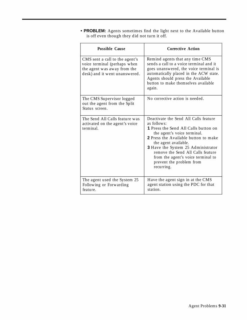
• PROBLEM: Agents sometimes find the light next to the Available buttonis off even though they did not turn it off.
Possible Cause Corrective Action
CMS sent a call to the agent’s Remind agents that any time CMSvoice terminal (perhaps when sends a call to a voice terminal and itthe agent was away from the goes unanswered, the voice terminal isdesk) and it went unanswered. automatically placed in the ACW state.
Agents should press the Availablebutton to make themselves availableagain.
The CMS Supervisor logged No corrective action is needed.out the agent from the SplitStatus screen.
The Send All Calls feature was Deactivate the Send All Calls featureactivated on the agent’s voice as follows:terminal. 1 Press the Send All Calls button on
the agent’s voice terminal.2 Press the Available button to make
the agent available.3 Have the System 25 Administrator
remove the Send All Calls featurefrom the agent’s voice terminal toprevent the problem fromrecurring.
The agent used the System 25 Have the agent sign in at the CMSFollowing or Forwarding agent station using the PDC for thatfeature. station.
Agent Problems 9-31

• PROBLEM: The agent presses the Available, ACW, or Logged Outbutton, but can’t change the status of the associated light.
Possible Cause Corrective Action
The agent terminal switch is in Take the voice terminal out of ProgramProgram Mode. Mode by moving the top left hand
switch on the agent’s voice terminal tothe midpoint (neutral) position.
NOTE: Instruct agents that if they heara single burst of ringing, repeatingevery 60 seconds, their voice terminalsare in Program Mode, and need to bereturned to operating mode.
9-32 Agent Problems

System Errors
WHAT THEY MEAN
WHAT TO DO
While CMS is managing calls, messages beginning with SYSERR may appearon the error line of a status screen and also on the Events Log screen.
A SYSERR usually indicates that a CMS file has been damaged. (Forexample, a user may have accidentally deleted a CMS file, or a power surgemay have damaged one.) A SYSERR does not necessarily mean that CMShas stopped managing calls. For example, if the only SYSERR you receive is
SYSERR-Possible Help File Damage. Reinstall CMS.
you will not be able to use the Help screens, but CMS is probably stillmanaging calls correctly.
If you receive a SYSERR message on a status screen or on the Events Logscreen, try the following:
1 Study the CMS screens to determine if CMS is still managing callscorrectly. If you are not sure, call one of your CMS lines.
— Does the System Status screen add your call to the Call Waitingcolumn soon after you hear ringing?
— Is your call answered by an agent in the appropriate split?
— Does the System Status screen show an agent’s status change fromAvailable to ACD?
If CMS is stall managing calls correctly, you do not have to shut thesystem down. You should check CMS periodically, however, just in caseother problems develop. If the Events Log screen shows additionalsystem errors, make sure your printer is on (and the Ready light is lit),then print a copy of the Events-Log screen by pressing [Shift] + [Print Scrn].
2 If CMS has stopped managing calls, print the Events Log Report to seewhat sequence of error messages was generated.
3 Reboot the PC by pressing the reset button located below the disk driveson the front of the PC or by turning the PC off and then on again.
4 Try to restart CMS Call Management.
— If CMS restarts, check to see if it is managing calls correctly.
— If CMS is managing calls correctly, check CMS periodically for arecurrence of the problem.
5 If CMS does not restart, or if you get the same SYSERR again, you haveto reinstall the CMS software. See “Installing the CMS Software” inSection 3 of this manual.
6 If CMS continues to have problems after you reinstall the software, callthe CMS Hotline: 1-800-628-2888
NOTE: Be sure to have a list of the system errors generated by theproblem handy.
7 See “Managing Calls When CMS is Not Running” at the end of thissection.
System Errors 9-33
Running CMS from a Floppy Diskette Backup
If the PC’s hard disk becomes damaged, you may still be able to manage callswith CMS by running the CMS program from the "SYSTEM 25 CMSSYSTEM WORKING COPY" diskette. In order to be able to do this, thediskette must contain the latest version of the CMS shift configurations andsystem tables. (The procedure for copying the needed files onto diskettes isdescribed in Section 4, “Backing Up Shift Configurations.”)
When CMS is run from a floppy diskette, you cannot store historical data,run reports, or administer CMS. You should only run from a floppy diskettetemporarily while the hard disk problem is being corrected.
To run CMS from the floppy diskette:
1
2
3
4
5
6
7
Insert the “MS-DOS/GW BASIC System Diskette” into the PC’s floppydisk drive.
Turn on the PC.
When the A> prompt appears, remove the “MS-DOS/GW BASIC SystemDiskette.”
Insert the “SYSTEM 25 CMS SYSTEM WORKING COPY” diskette intothe floppy disk drive.
At the A> prompt, type
cd cms
and press [Enter].
At the A> prompt, type cms, and press [Enter].
When the CMS Menu is displayed, press [F1] (labeled “Start Call Mgt”).
9-34 Running CMS from a Floppy Diskette Backup

Managing Calls When CMS is Not Running
If you need an alternate method of distributing calls to agents when CMS isnot ruining, use the System 25 Direct Group Calling (DGC) ContingencyPlan. This feature should have already been administered by the System 25Administrator or CMS installer.
If this feature has not been administered, you can use the AlternativeContingent Plan described later in this section.
ABOUT THE DGCFEATURE
Agent stations are divided into DGC groups, with each agent stationbelonging to only one DGC group. Each line group is assigned a DGC groupto cover its calls. A DGC group can be assigned to cover the calls for one ormore line groups.
The CMS Planning Guide describes how to plan your DGC groups. Theappropriate forms can be found behind the “Original Planning Forms” tab inthe CMS binder.
NOTE: You should plan your DGC groups when you first start usingCMS so this feature will be available whenever you need it.
MANAGING CALLS WITH When CMS is managing calls, all agents must be logged out of their DGCDGC groups (as described below). Failure to do so may disrupt CMS call
management. When it becomes necessary to use the DGC feature, agents cansimply return to their DGC groups.
To
1
2
3
4
5
NOTE: If it becomes necessary for agents to leave their stationsunattended or to otherwise make themselves unavailable for CMScalls while the DGC contingency plan is being used to manage calls,they should remove themselves from their DGC group.
log out of a DGC group, agents should:
Lift the handset.
Listen for dial tone.
Dial [*] [4].
Listen for confirmation tone (three short tones).
Hang up.
When CMS is again managing calls, or when agents need to leave their DGCgroups temporarily, they should use the procedure above to removethemselves from their DGC group.
To return to their DGC groups so System 25 can distribute calls to them,agents should:
1 Lift the handset.
2 Listen for dial tone.
3 Dial [*] [4].
4 Listen for confirmation tone (three short tones).
5 Hang up.
Managing Calls When CMS is Not Running 9-35

ALTERNATIVE TO If you have not set up a DGC contingency plan, you can still distribute yourCONTINGENCY PLAN calls manually, as follows:
1 Unplug the cord connected to PC jack CU1.
2 Plug the cord into a 34-Button Deluxe voice terminal.
3 Answer the calls and transfer them to the appropriate agents.
NOTE: If you have Personal Line buttons administered on yoursupervisor voice terminal for all the CMS and transfer-queue lines,then you can use that voice terminal to answer CMS calls (insteadof unplugging the cord from PC jack CU1 and connecting it to a34-Button Deluxe voice terminal).
9-36 Managing Calls When CMS is Not Running

Section 10: Ongoing System Administration

Overview
Once the System 25/CMS installer has installed and administered CMS andSystem 25, you can begin CMS operation. However, as the needs of yourbusiness change, you may find that you need to add or remove lines, stationsor voice announcement units. If this happens, you can make the necessaryCMS administration changes and then request a Partial Print of System 25administration instructions. The Partial Print will show only those System 25administration changes needed as a result of changes to CMS administrationsince the last System 25 File Update or last Full Print of System 25administration instructions.
Overview 10-1
The Partial Print
The page(s) of the Partial Print have the same format as those in the initialadministration instructions. However, the words “CMS PARTIALPRINTOUT” appear on each page as a reminder that these administrationinstructions reflect only changes in System 25 administration made since thelast System 25 File Update or Full Print of System 25 administrationinstructions. (The changes shown in the System 25 administrationinstructions printout represent System 25 administration needed to supportchanges in CMS administration.)
Below, a page from a Partial Print showing PC jack CU1 button featureassignment changes is illustrated.
10-2 The Partial Print

The Partial Print 10-3

The voice terminal buttons that are labeled on a Partial Print Button Layoutpage reflect the button features that need to be added, changed, or deleted.As in the illustration, the numbers and labels across the top of the buttonsindicate the following:
a The button number
b The System 25 button feature
c The button feature code.
In this example, Buttons 35 and 37 show button features that need to beadded because of the addition of a line and a voice announcement unit,respectively. The label on button 38 means that the feature previouslyadministered on that button needs to be removed. It’s your responsibility, asCMS Supervisor, to inform the System 25 Administrator what equipment andfacilities are no longer needed for CMS.
On Partial Print Implementation forms, the following conventions have beenfollowed:
• If a value appears in ( ), it is strongly recommended that this value not bechanged to ensure optimal CMS functioning.
• A System 25 default value, shown in { }, may be left as is, or changed, ifnecessary. It will not affect CMS operation.
• When a value has been filled in for you, and does not have either a ( ) or{ } around it, the value must not be changed since it is required for properCMS functioning.
For more information about administering System 25 from the the computer-generated administration printouts, see “Performing Software Translations forCMS” in the CMS Installation and Startup Guide.
NOTE: It is recommended that after you have administered CMS withthe changes and have generated a Partial Print of System 25administration instructions that you update the System 25 File bypressing [F3] (labeled “Update S25 File”) on the Print System25Instruct screen.
10-4 The Partial Print
Adding Lines, Stations, or Voice Announcement Units
CMS LINES
CMS AGENT ANDSUPERVISOR STATIONS
In general, when adding lines, agent stations, supervisor stations or voiceannouncement units to CMS, update the CMS Planning Forms with the newinformation, and complete the necessary System 25/CMS implementationforms. (Refer to the CMS Planning Guide for instructions.) Then administerCMS to reflect these additions, and generate a Partial Print.
Give the hand-completed System 25/CMS implementation forms and thecomputer-generated forms to the System 25 Administrator so that System 25can be administered to reflect these additions. (Instructions for coordinatingthe information on these forms and using these forms to administer System25 can be found in the CMS Installation and Startup Guide.)
When adding a line (that is, a Central Office trunk) to CMS, you need toobtain the trunk number, trunk type, and System 25 port assignment fromthe System 25 Administrator. Update the Line Groups Planning Form, andcomplete a System 25/CMS Central Office Trunks implementation form.
Referring to the Line Groups Planning Form, administer the trunk on theCMS Administer Line Groups screen. Then generate a Partial Print ofSystem 25 administration instructions.
NOTE: Add a Personal Line button for the trunk on the appropriate“Ghost” Voice Terminal for the CMS Contingency Plan form. IfService Monitoring is desired, add a Personal Line button for thetrunk on on the CMS Supervisor Voice Terminal implementationform.
Give the hand-completed System 25/CMS implementation forms and thecomputer-generated forms to the System 25 Administrator so that System 25can be administered to reflect these additions.
When adding an agent or supervisor station, obtain the PDC and portnumber from the System 25 Administrator. Update the Station AssignmentsPlanning Form and complete a System 25/CMS voice terminal implementationform for the voice terminal. Enter the new information from the StationAssignments Planning Form onto the CMS Administer Stations screen. Thengenerate a Partial Print of System 25 administration instructions.
If you’re adding an agent station, remember to assign that agent to a DGCGroup so the agent station will be included in the Contingency Plan. Enterthe agent station on the appropriate System 25/CMS Direct Group Calling Listfor the CMS Contingency Plan implementation form. Also, if you want touse the Assist feature, remember to add a Station-to-Station Message Waiting(Assist) button on both the agent and supervisor voice terminals.
NOTE: The addition of a supervisor station does not appear on thePartial (or Full) printout. Be sure to complete a System 25/CMSimplementation form if you are adding a supervisor station.
Give the hand-completed System 25/CMS implementation forms and thecomputer-generated forms to the System 25 Administrator so that System 25can be administered to reflect these additions.
Adding Lines, Stations, or Voice Announcement Units 10-5

TRANSFER-QUEUE LINES To add a transfer-queue line, obtain a trunk number and System 25 portassignment for the transfer-queue line’s Loop Start Trunk port and a PDCand System 25 port assignment for single-line port from the System 25Administrator. Update the Transfer-into-Queue Planning Form with the newinformation.
Referring to the Transfer-into-Queue Planning Form, administer the transfer-queue line on the CMS Admin Queued Transfer screen. Then generate aPartial Print of System 25 administration instructions.
NOTE: On the appropriate “Ghost” Voice Terminal for the CMSContingency Plan implementation form, add a Personal Line buttonfor the Loop Start Trunk associated with the transfer-queue line. IfService Monitoring is desired, add a Personal Line button for theassociated Loop Start Trunk on the CMS Supervisor Voice Terminalimplementation form.
Give the hand-completed System 25/CMS implementation forms and thecomputer-generated forms to the System 25 Administrator so that System 25can be administered to reflect these additions.
VOICE ANNOUNCEMENT When adding a Voice Announcement Unit (VAU), obtain a PDC and portUNITS number from the System 25 Administrator. Update the Voice Announcement
Unit Planning Form, and enter the new information on the AdministerAnnouncement and Assign Announcement screens. Then generate a PartialPrint of System 25 administration instructions. Give the computer-generatedform to the System 25 Administrator so that System 25 can be administered toreflect this addition.
10-6 Adding Lines, Stations, or Voice Announcement Units
Changing Station, Line, PC Jack, or VAU Information
When making changes in PDCs or port numbers of CMS equipment orfacilities, obtain the completed System 25/CMS implementation forms fromthe Administration Records binder and make the desired changes on theseforms. Update the appropriate CMS Planning Forms with this information,and administer the changes on the appropriate CMS screens. Then generatea Partial Print of System 25 administration instructions. Any changes you’vemade that require System 25 administration will appear on the computer-generated printouts. Give the hand-completed implementation forms andany computer-generated printouts to the System 25 Administrator foradministration.
Record changes to System 25 voice terminal or trunk features and options onthe hand-completed implementation forms (stored in the AdministrationRecords binder) and have these changes administered by the System 25Administrator. (Consult the CMS Planning Guide for voice terminal andtrunk feature restrictions.)
Changes made to the supervisor station(s) do not appear on the System 25administration instructions printouts. Therefore, these changes should berecorded on the hand-completed forms (stored in the Administration Recordsbinder) and given to the System 25 Administrator for administration.
Changing Station, Line, PC Jack, or VAU Information 10-7

Removing Lines, Stations, or Voice Announcement Units
If there are lines, stations or voice announcement units that are no longerneeded for CMS, update the CMS Planning Forms with this information andadminister those changes on the appropriate CMS screens. Then generate aPartial Print of System 25 administration instructions and give it to theSystem 25 Administrator for administration.
AGENT STATIONS If there is an agent station that is no longer needed for CMS, update theStation Assignments Planning Form and delete the station from the CMSAdminister Stations screen. There will be no System 25 administrationinstructions printout for this change, so you must be sure to remove the threeCMS Agent Status buttons (Available, ACW and Logged Out) from the voiceterminal implementation form (stored in the Administration Records binder)and have the System 25 Administrator administer the change.
If the agent station was part of a DGC Group used for the CMS ContingencyPlan, delete the voice terminal from the System 25/CMS Direct Group CallingList implementation form and have the System 25 Administrator administerthe change. If the agent station has an Assist (Station-to-Station MessageWaiting) button, you may want to remove it and the corresponding Assistbutton on the supervisor voice terminal.
REMOVING CMS LINES If there is a Central Office trunk that is no longer needed for CMS, updatethe Line Groups Planning Form and remove the line from the CMSAdminister Line Groups screen.
Remove the Personal Line button for the trunk from the appropriate “Ghost”Voice Terminal for the CMS Contingency Plan implementation form. If youhave Service Monitoring administered for this line, update the System25/CMS Supervisor Voice Terminal implementation form by removing thePersonal Line button administered for that line.
Generate a Partial Print of System 25 administration instructions and give thecomputer-generated form and any updated hand-completed System 25/CMSimplementation forms to the System 25 Administrator for administration.
REMOVING TRANSFER- If there is a transfer-queue line that is no longer needed for CMS, update theQUEUE LINES Transfer-into-Queue Planning Form and remove the line from the CMS
Admin Queued Transfer screen.
Remove the Personal Line button for the associated Loop Start Trunk fromthe appropriate “Ghost” Voice Terminal for the CMS Contingency Planimplementation form. If you have Service Monitoring administered for thisline, update the System 25/CMS Supervisor Voice Terminal implementationform by removing the Personal Line button administered for that line.
Generate a Partial Print of System 25 administration instructions and give thecomputer-generated form and any updated hand-completed System 25/CMSimplementation forms to the System 25 Administrator for administration.
10-8 Removing Lines, Stations, or Voice Announcement Units

Glossary

Overview
This glossary defines key terms used to describe the setup and operation ofCMS. The list also includes System 25 terminology related to CMS.
For an explanation of the various statistics presented in the System Status,Split Status, and Line Status screens, see Section 5, “Supervising CMS.” Theterms used to identify the information contained in the CMS reports areexplained in Section 7, “Generating Reports.”
Overview G-1

CMS and System 25 Terms
Abandonedcall
Abandoned vs.Incoming CallThreshold
Automatic CallDistributor(ACD)
ACD Call
ACW Button
ACW (After-Call-Work)State
Administer
Agent Split
Agent Station
Answer Delay
A call that came into CMS and was eitherdisconnected by the caller before being serviced byan agent, or was connected, but the talk time wasless than the Abandoned vs. Incoming CallThreshold.
The minimum number of seconds an agent mustbe connected to a call for it to be considered aserviced call. Calls that are disconnected beforereaching this threshold are considered abandonedcalls.
The abbreviation for Automatic Call Distributor.ACD is the general term for systems like CMS thatautomatically answer incoming calls and distributethem to available agents.
An incoming call that is distributed to an agent byCMS.
A button administered on agents’ voice terminalsthat they use to turn on their After-Call-Work(ACW) light. When the ACW light is on, theagent will not receive CMS calls.
An agent-activated or CMS-activated state inwhich the agent receives no ACD calls. Agentsusually put their voice terminals into this statewhen they need to finish work associated with aprevious call. CMS puts an agent voice terminalin this state when the agent fails to answer anACD call. When an agent is in the ACW state,the ACW light on the agent’s voice terminal is on.
To access and change the parameters associatedwith the services or features of System 25 or CMS.
A team of agents who handle the same types ofincoming calls.
The voice terminal assigned to an agent.
The amount of time an incoming ACD call isadministered to ring before being connected to avoice announcement unit if no agents are availableto answer the call.
G-2 CMS and System 25 Terms

Assist Button
ATL
AvailableButton
Available State
Central Office
CMS HoldTime
Completed Call
Configuration,Shift
Direct StationSelection (DSS)
A button administered on an agent’s voiceterminal that, when pressed, turns on the lightbeside a corresponding button on the CMSSupervisor’s voice terminal. This optional featureenables an agent on an ACD call to signal thesupervisor for help without interrupting the call.The System 25 Station-to-Station Message Waitingfeature is used to implement this feature.
Analog Terminal Line.
A button administered on agents’ voice terminalsthat they use to turn on their Available light. Ifthe Available light is on, and the agent’s voiceterminal is on-hook, the agent is available toreceive ACD calls.
An agent-activated state in which the Availablelight on the agent voice terminal is on, and theagent is idle and available to handle ACD calls.The CMS Supervisor can place an agent who is inthe Logged Out state into the Available state.
The location housing telephone switchingequipment that provides local service and accessto toll facilities for long distance calling.
The time period beginning when an ACD callreaches System 25 and ending when the call isdisconnected from System 25. CMS Hold Timeoften includes delay messages.
A call on a CMS or transfer-queue line that wasanswered by an agent, serviced, anddisconnected.
An arrangement of CMS line groups and agentsplits that, when activated, determines how CMScalls are routed to agents. CMS allows you todefine as many as six different shiftconfigurations.
A System 25 feature that allows one-button accessto another voice terminal, a paging zone, or aDGC group. For instance, the System 25Administrator could program the CMSSupervisor’s PDC onto a DSS button on eachagent’s voice terminal. The agents could thenpress the DSS button to call the supervisor.
CMS and System 25 Terms G-3

Direct Group A System 25 feature that allows incoming calls toCalling (DGC) be directed to a specific group of voice terminals.
The DGC Group Coverage feature, ifadministered, can be used to manage CMS callswhen CMS call management is not running.
Dynamic The process of making changes to the CMSReconfiguration configuration currently being used to manage
calls.
Exception An indication that a particular performancethreshold for an agent, split, or line group hasbeen reached or exceeded and an unusual orundesirable situation may be occurring. Exceptionmessages appear on the screen of the CMS PC.
ExceptionThreshold
Exclusion
The point at which the CMS exception messagewill be displayed indicating that an exception hasoccurred.
A System 25 feature that allows multiline voiceterminal users to keep other users who have aPersonal Line appearance of the line being usedfrom listening in on their call. This feature shouldnot be administered on agent voice terminalsbecause agents invoking Exclusion prevent theCMS Supervisor from monitoring their CMS callsusing the Service Monitoring feature.
External Call A connection between a System 25 user and aperson on the public telephone network or on atie trunk.
Flexible DSS A Flexible Direct Station Selection button enablesa user to dial a PDC, by pressing just one button,a Flex DSS button. The System 25 Administratormust administer a particular button as a Flex DSSbutton (unless the button is assigned this featureby default). The user then programs the PDC onthe button.
Force Delay An answering option that forces incoming ACDcalls to be connected to a delay message andforces callers to hear the entire delay messagebefore being transferred to an available agent. IfForce Delay is off, calls are transferred to an agentas soon as one becomes available, even if themessage has not finished playing.
ForeignExchange
A trunk that directly connects System 25 to acentral office other than the local central office.
(FX) Trunk
G-4 CMS and System 25 Terms
Initial Setting
Internal Call
Intraflow
IntraflowThreshold
Line Group
Logged OutButton
Logged OutState
Main Split
The factory-set (default) value for a system optionwhich allows CMS to operate immediately afterinstallation. The CMS Supervisor may later finetune system performance by replacing some initialsettings with values more appropriate to the needsof the business.
A connection between two System 25 users.
The automatic transfer of a call waiting in themain split’s queue to an agent in the secondarysplit. This occurs when no agents are available inthe main split and the call has waited apredetermined number of seconds.
The number of seconds the oldest call waits in themain split’s queue before it is eligible to beintraflowed (transferred) to an available agent inthe secondary split.
A group of telephone lines assigned to CMS thatcan be answered by the same team of agents(agent split).
A button administered on agents’ voice terminalsthat they use to turn on the Logged Out light toindicate they are not doing CMS work. When theLogged Out light is on, an agent will not receiveACD Calls.
A state in which the agent receives no ACD callsand is not counted as logged in for reportingpurposes. Agents are placed in this state when callmanagement is started, when a new shiftconfiguration is selected, when an agent is movedor added to a configuration, or when an agent hasremained in the After-Call-Work state longer thanthe specified Agent Logout ACW exceptionthreshold (if the threshold is enabled). Agentsplace themselves in the Logged Out state whenthey are not doing CMS work. The CMSSupervisor can also place an agent in the Availableor ACW state into the Logged Out state. Whenthe agent is in the Logged Out state, the LoggedOut light on the agent’s voice terminal is on.
The agent split with primary responsibility foranswering calls that come in on a particular linegroup.
CMS and System 25 Terms G-5

Night ServiceMode
Other Calls
Personal DialCode (PDC)
Personal Line
Port
Priority Line
Queue
Refused Call
A mode of CMS operation in which the systemanswers calls, connects them to a voiceannouncement unit, and then disconnects the callswhen the message is over.
Non-ACD calls, such as outgoing calls, non-ACDincoming calls, internal calls, and calls transferredto an agent by another person (except Transfer-into-Queue calls).
A number with up to four digits assigned to eachSystem 25 ATL port or single-line port. Voiceterminals, PC jacks CU1 and CU2, voiceannouncement units, and the single-line stationassociated with each transfer-queue line have aunique PDC. People within System 25 can calleach other by dialing a PDC.
A dedicated outside line which can be accessedthrough a dedicated feature button on a multilinevoice terminal. Each CMS and transfer-queue linehas a Personal Line button appearance on CMSPC jack CU1. For Service Monitoring, the CMSSupervisor’s voice terminal must have a PersonalLine button for each CMS and transfer-queue lineto be monitored.
A physical address on a System 25 circuit pack.Each CMS line, transfer-queue line, voiceterminal, voice announcement unit, and PC jack isconnected to a port with a specific number, suchas 20608. The two connections (PC jacks) from theCMS PC Interface Card in the PC (labeled CU1and CU2) are also called ports.
A line that has a special status in CMS. Incomingcalls on a priority line are answered before oldercalls on nonpriority lines.
An ordered sequence of calls waiting to beanswered.
A call that rings at an available agent’s station andis not answered before the Transfer ReturnThreshold is reached. When a call is refused, theagent’s station is automatically put into the ACWstate.
G-6 CMS and System 25 Terms

RepertoryDialing
Ringing
Secondary Split
Service Level
Service LevelLimit
Serviced Call
ServiceMonitoring
ShiftConfiguration
Speaker Button
Split, Agent
Station-to-StationMessageWaiting
A feature that allows multiline voice terminalusers to store a frequently dialed number inSystem 25’s memory and associate that numberwith a particular Rep Dial button. The user can then dial the stored number by pressing the RepDial button.
Two types of ringing are of importance to CMS:initial ringing occurs during the answer delay,from the time the line is seized by an incomingcall until CMS answers the call; transfer ringingoccurs at an agent voice terminal, from the timeCMS transfers the call to an available agent untilthe agent lifts the handset.
The agent split assigned to answer calls on aparticular line group if all of the agents in themain split are busy or unavailable. After a presetnumber of seconds, calls that haven’t beenanswered are intraflowed (routed automatically) toavailable agents in the secondary split.
The percentage of calls that go from initial ringingto answered within a specified length of time,called the Service Level Limit.
A performance goal for answering incoming calls.It represents the maximum number of seconds itshould take for an incoming call to be answeredby an agent.
An ACD call that has been connected to an agentfor longer than the Abandoned vs. Incoming CallThreshold.
A CMS feature that enables the CMS Supervisorto join or listen to calls on CMS or transfer-queuelines. This feature can be used in agent training.
See Configuration, Shift.
A button on the lower right corner of multilinevoice terminals which the CMS Supervisor can useto monitor CMS calls without lifting the handset.
See Agent Split.
A System 25 feature that allows a multiline voiceterminal user to turn on or off a pre-designatedlight located on another multiline voice terminal.Both voice terminals must have a Station-to-Station Message Waiting button. CMS uses thisSystem 25 feature to implement the CMS Assistfeature.
CMS and System 25 Terms G-7
Status LED
System AccessButtons
SystemAdministrator
System 25
Tape Save
Transfer-into-Queue
Transfer ReturnThreshold
Translations
Trunk
VoiceAnnouncementUnit (VAU)
The green light on a voice terminal that shows thestatus of a call appearance or a feature button bythe state of the light (on, off, flashing, winking, orbroken flutter).
System 25 users can place and receive internal andexternal calls using System Access buttons. AllACD calls appear on agent System Accessbuttons.
A person responsible for specifying andadministering features and services for System 25.
An advanced digital switching system whichintegrates voice and data communications.
A System 25 administration procedure used tocreate a backup tape of System 25 translations.This tape can later be used to restore System 25after a problem that resulted in a loss oftranslations.
A CMS feature that allows an agent to transfer acall into another line group’s queue of waitingcalls. The call will be treated as a new incomingACD call to that line group.
A limit on the number of times an ACD call ringsat an agent station before returning to CMS. Acall not answered within the Transfer ReturnThreshold is recorded as being refused by theagent. The CMS Supervisor can select from one tonine rings as the Transfer Return Threshold.
System 25 specific information assigned to a voiceterminal or to the system and customized for theuser. Examples are port numbers, Personal DialCodes (PDCs), and features assigned to voiceterminal buttons.
A phone line between the central office andSystem 25.
The machine used to provide a delayannouncement to callers. CMS can support up tofour VAUs.
G-8 CMS and System 25 Terms

Index
AAbandoned Call Threshold, definition of, 4-48ACD. See Automatic Call DistributorACW Button, using, 6-5. See also After-Call-Work StateAdministering Announcements, 4-19 — 4-21
Administer Announcement screen, 4-19using the Administer Announcement
screen, 4-20 — 4-21Administering Answer Delay and Force Delay,
4-38 — 4-39. See also Answer Delay Optionanswer delay, 4-38 — 4-39Configure Delay screen, 4-38force delay, 4-39using the Configure Delay screen, 4-39
Administering Call Flow, 4-40 — 4-43. See alsoIntraflow
Configure Call Flow screen, 4-41using the Call Flow screen, 4-42 — 4-43
Administering CMS, 1-2, 4-1 — 4-3Administration Menu screen, 4-5Administer Stations screen, 4-6CMS Menu, 4-4Menu Map for CMS Administration, 4-3starting CMS administration, 4-4using the Administer Stations screens, 4-7 — 4-9
Administering Exceptions, 4-50Administering CMS Lines and Line Groups, 4-10 — 4-25
Administer Line Groups screen, 4-10using the Administer Line Groups screen, 4-11 — 4-14
Administering Stations, 4-6 — 4-9Administer Stations screen, 4-6using the Administration Menu screen, 4-7 — 4-9
Administering System 25 to Support CMS, 1-1Administering Transfer-Queue Lines, 4-15 — 4-18
Administer Queued Transfer screen, 4-15using the Administer Queued Transfer
screen, 4-16 — 4-18After-Call-Work (ACW) State, 2-3, 4-51, 5-8 — 5-9Agent(s), 2-2
adding, 10-5assist buttons, 5-33making agents available for CMS calls, 5-8 — 5-9problems, 9-29 — 9-32Service Monitoring feature, 5-33supervising your, 5-33warning, 7-2
Agent Card, 1-2. See also CMS DocumentsAgent Directory
Agent Directory screen, 4-26creating, 4-26 — 4-28using the agent Directory screen, 4-26 — 4-28
Agent Directory Screen, using, 3-10, 3-12, 4-24 — 4-26Agent Exceptions
administering agent exceptions, 4-54 — 4-56Agent Exceptions screen, 4-54selecting, 4-52 – 4-54
Agent Splits, 2-2Agent Split Summary, 7-6 — 7-8
Cumulative Agent Split Summary Report,7-7 — 7-8
Daily Agent Split Summary Report, 7-6 — 7-8Print Agent Summary screen, 7-6
Agent Station(s)adding, 4-7administering, 4-7changing information, 4-7removing, 4-7
Agent Work StateACW State, 2-2 — 2-3Available State, 2-2 — 2-3Logged Out State, 2-2 — 2-3, 5-8reasons CMS may change the state, 2-3
Agent’s Voice Terminal, 2-15, 6-2 — 6-9button assignments, illustration of, 6-4selecting voice terminals for your
agents, 6-2 — 6-3typical agent voice terminal, 6-3using the terminal for CMS, 6-5 See also
Using the Agent Voice Terminal for CMSAnalog Line (TN742) Circuit Pack, 2-6ANNC, 3-10Announcement Screen, administering, 4-19Announcements, selecting, 4-21
assigning an Announcement screen, 4-21Answer Delay Option, 2-2 — 2-3, 4-36 — 4-37
reconfiguring, 5-40 — 5-41Archiving Data, 1-3, 8-1
generating historical reports, 8-3 — 8-4restoring data collection conditions, 8-4transferring historical data onto diskettes,
procedures for, 8-1 — 8-2ASA. See Average Speed of AnswerAssigning Announcements, 4-22 — 4-25
Assign Announcement screen, 4-23Select Announcement screen, 4-22using the Assign Announcement screen, 4-23 — 4-25using the Select Announcement screen, 4-22 — 4-23
Assist Feature, optional CMS features, 2-5, 6-10Assist (MSG Wait) Button, using, 2-5, 6-6Attendant Alarm Light, 2-9AT&T CMS PC Interface Card, installing, 1-1, 2-15AT&T Personal Computer (PC) 6300, 2-15, 3-1Audible Alarm On/Off, 3-11, 3-13, 4-48AUTOEXEC.BAT File, 3-5, 3-8. See also CMS SoftwareAutomatic Call Distributor (ACD), 1-1, 2-2Available Button, using, 6-5Available State, 2-2 – 2-3, 5-8Average Speed of Answer (ASA), 5-18
BBacking Up Shift Configurations, 4-67 — 4-68.
See also Shift ConfiguringBackup Split. See Secondary Split
copying shift configurations and system tables,4-64 — 4-65
BIS. See Built-in SpeakerphoneBL, 2-11Bon Voyage Travel, 2-10
other call traffic, 2-12Built-in Speakerphone (BIS), 2-15Building or Editing Shift Configurations, 4-29 — 4-37.
See also Shift ConfigurationConfiguration screen, 4-32 — 4-33Configuration List screen, 4-30. See also
Configuration List screenconfiguring splits, 4-34 — 4-37Configure Splits screen, 4-32
Business Line Group, 2-11, 4-29Business Travel Split, 2-11, 4-29Button Feature Code, 10-4. See also Partial
Print Button LayoutButton Layout, partial print, 10-4BW, 2-11
Index I-l

CCall Flow, 5-30
administering, 4-38 — 4-41Configure Call Flow screen, 5-42reconfiguring, 5-42 — 5-43
Call Management, 2-2, 2-4Menu Map for, 5-2monitoring, 5-10problems, 9-18 — 9-21typical application of CMS, 2-10 — 2-12
Call Management System (CMS), 1-1, 2-1, 2-4, 5-1Day Service mode, 2-2 — 2-4day-to-day operation of, 5-53handling calls, 6-1 — 6-10managing, 2-13 — 2-14. See also Managing CMSMenu screen, CMS, 5-3Night Service mode, 2-3 — 2-4startup procedures, 5-3 — 5-7testing. See CMS Installation and Startup Guideunderstanding, 2-1using your PC with, 3-1, 3-10
Central Office (CO), 2-7, 2-16Charter Line Group, 2-11, 4-29Charter Travel Split, 2-11, 4-29Circuit Pack (CP)
Analog Line (TN742), 2-6Loop Start Trunk (ZTN77), 2-6
CL, 2-11Clearing a Configuration, 4-44CMS Administration Menu Map, 4-3CMS Administration screens, map of, 4-3CMS Application, 2-10 — 2-12
Bon Voyage Travel’s other call traffic, 2-12CMS and Bon Voyage Travel,
illustration, 2-10 — 2-12CMS and other businesses, 2-12
CMS Calls, answering, 6-6making agents available for, 5-8 — 5-9
CMS Compatibility With AT&T PC, 3-1CMS Components, 2-15 — 2-18
hardware compatible with CMS, 2-15 — 2-16trunks compatible with CMS, 2-16voice announcement unit, 2-16recording messages, 2-17 — 2-18
CMS Contingency Plan, 2-5, 2-8 — 2-9implementation form, 10-8
CMS Directories and Files, location of, 8-1CMS Diskettes
duplicating, 3-2 — 3-4running CMS from a floppy diskette
back-up, 9-34CMS Documents, how to use them, 1-1 — 1-2
CMS Planning Guide, 1-1CMS Installation and Startup Guide, 1-1System Manual, 1-2Agent Card, 1-2
CMS Features, optional, 2-5 — 2-6CMS for Bon Voyage, 2-8. See also Bon Voyage TravelCMS Hardware, 2-15 — 2-18
optional hardware to use with, 2-14CMS Installation and Startup Guide, 1-1
administering CMS, 4-1 — 4-3administering System 25 to support CMS, 1-1installing the AT&T CMS PC interface card, 1-1installing the CMS software, 1-1installing the MS-DOS operating system, 1-1testing CMS, 1-1
CMS Lines, 2-2. See also Trunksadding, 10-5Central Office, 2-11changing, 10-7local, published number, 2-11priority, 2-2Public Local, 2-11Public Special, 2-11Public WATS, 2-11removing, 10-8subgroups, 2-2transfer-queue lines, 10-8
CMS Menu, 4-1CMS Night Service Mode, 4-27CMS Planning Guide, 1-1CMS-Port
administration option, 5-5personal line button verification, 4-49 — 4-50
CMS Reports, 7-3Agent Split Summary, 7-1, 7-3. See also
Agent Split SummarySplit Report, 7-1, 7-3Line Group Report, 7-1, 7-3Sub-Group Report, 7-1, 7-3Events Log Report, 7-1, 7-3
CMS Software, 2-15AUTOEXEC.BAT file, 3-5, 3-8CONFIG.SYS file, 3-5, 3-7installing, 1-1, 3-5 — 3-6
CMS Supervisorresponsibilities of, 2-13voice terminal, 6-10
CMS System Manual, 1-2CMS Terms, glossary, G-1 — G-8CO. See Central OfficeConfiguration(s)
clearing, 4-42listing of, 5-4returning to other configuration screens, 4-42saving an edited (changed) configuration, 4-43selecting a startup configuration, 4-44using the configuration list, 5-44
Configuration List, using, 5-44 –5-47Configuration List screen, 5-44
Configuration List Screen Options, 4-28renaming a shift configuration, 4-28, 4-44returning to other screens, 4-28, 4-42saving an edited (changed) configuration, 4-28, 4-43selecting a shift configuration, 4-28selecting a startup configuration, 4-28, 4-44
Configure Delay Screen, 4-37Configuring Splits, 4-34 — 4-37CONFIG.SYS File, 3-5, 3-7. See also CMS SoftwareContingency Plan, 2-8Copying Shift Configurations and System Tables, 4-64 — 4-65CP. See Circuit PackCreating an Agent Directory, 4-26 — 4-28.
See also Agent DirectoryCursor, moving, 3-13Cumulative Agent Split Summary Report, 7-7 — 7-8Cumulative Line Group Report by Hour, 7-18 — 7-19Cumulative Split Report, 7-12 — 7-13Cumulative Sub-Group Report, 7-24 — 7-25CW, 2-9
I-2 Index

DDACON-DA-5SL Voice Announcement Unit, 2-16 — 2-17Daily Agent Split Summary Report, 7-6 — 7-7Daily Split Report, 7-11Data
editing, 3-13 — 3-14entering, 3-13 — 3-14using the Help screens, 3-14validating, 3-14
Day Service Mode, 2-3 — 2-4changing to, 5-51selecting, 5-49
Day-to-Day Operation of CMS, 5-53CMS supervisor’s activities at Bon Voyage, 5-53
D8W-87. See Modular-Plug Station CordDeleting Information, 10-7
agent stations, 10-7CMS lines, 10-7supervisor stations, 10-7
Direct Group Calling (DGC) Group CoverageFeature, 2-17, 9-35. See also System 25
Diskettes, 2-15, 3-2 — 3-4DGC. See Direct Group CallingDGC Groups, 6-9Documentation Conventions, 1-4
Partial Print implementation forms, 10-4Don’tPrtSc, 3-10DSS Button, 2-6Duplicating the CMS Diskettes, 3-2 — 3-4Dynamic Reconfiguration, 5-34 — 5-48
Configuration screen, 5-34Configure Splits screen, 5-36quick reference guide to, 5-48reconfiguring splits, 5-36 — 5-39screens and function keys, 5-48using the configuration list, 5-44 — 5-47
EEntering and Editing (Changing) Data, 3-12 — 3-14
Agent Directory screen, 3-12editing data, 3-14entering data, 3-13 — 3-14moving the cursor, 3-13using the Help screens, 3-13validating data, 3-14
Editing CMS Data, 3-12 — 3-14Entering Data Into the PC, 3-12 — 3-14Error Line, 3-11
error messages, 3-11exception messages, 3-11system messages, 3-11warning messages, 3-11
Error Messages, 5-5, 9-2 — 9-5. See also Startup ProceduresEvents Log Report, 7-31Events Log Screen, using, 4-51, 5-31 — 5-32
agent, selecting, 4-54 — 4-56Exceptions
administering, 4-52 — 4-53instructions for selecting, 4-52Select Exceptions screen, 4-52selecting, 4-51 — 4-62
FFlex DSS Button, 2-6Force Delay Option, 2-3, 4-39, 5-40 — 5-41. See also
Administering Answer Delay and Force Delay
FormsCMS Contingency Plan Implementation Form, 10-8Implementation Forms, partial print, 10-4Station Assignments Planning Form, 10-5Transfer-into-Queue Planning, 10-6, 10-8
Function Key Labels, 3-11FX, 2-16
GGenerating Reports, 1-3, 7-1, 7-4 — 7-5Getting Started, CMS administration, 4-4 – 4-5
CMS Menu screen, 4-4Administration Menu screen, 4-5
Ghost, 2-6. See also Single-Line Station,Single-Line Voice Terminal
Glossary, CMS and System 25 terms, G-1 – G-8
HHandling CMS Calls, 1-3, 6-1 – 6-10
answering, 6-6placing a call on hold, 6-7
Hands-Free Answer on Intercom Voice Terminal, 2-13Hard Disk, 2-15
copying onto, 3-5 – 3-6damaged, 9-34erasing files from, 8-2
Hardware Compatible With CMS, 2-15 – 2-16.See also CMS Components
Help Screens, using, 3-14HFAI. See Hands-Free Answer on IntercomHistorical Data
copying files, 8-2copying the System Tables file, 8-1erasing files from the hard disk, 8-2transferring onto diskettes, 8-10warning, 7-2
Historical Data Files, copying to hard disk, 8-3Historical Reports, generating, 8-3 –8-4.
See also Archiving DataHold Feature, placing a call on hold, 6-7How to Generate Reports, 7-24How to Use the CMS Documents, 1-1 – 1-2
IImplementation Forms, 10-4Index, 1-3, I-1 – I-6Information that Appears on Your Screen. See
Documentation ConventionsInitialization Screen, error messages, 5-5Installing the CMS Software, 3-5 – 3-9
AUTOEXEC.BAT File, 3-5, 3-8CONFIG.SYS File, 3-5, 3-7copying the CMS software onto the
PC’s hard disk, 3-5 — 3-6setting the time and date, 3-9
Instructions for Selecting Exceptions, 4-52 — 4-53Intraflow, 2-3, 4-40 — 4-41Intraflow Threshold, 2-3, 4-40 — 4-41Introduction to CMS, 1-1 — 1-4
KKey Terms and Concepts of CMS, 2-2 — 2-4Key to Agent Split Summary Data, 7-9 — 7-10Key to Daily Split Report Data, 7-14 — 7-16Key to Daily Sub-Group Report Data, 7-26 — 7-28
Index I-3

Key to Line Group Report Data, 7-20 — 7-22Key to Line Status Screen Data, 5-28 — 5-30
call flow information, 5-30line group summary line, 5-29line status, 5-28 — 5-29split status, 5-30
Key to Split Status Screen Data, 5-22agent status, 5-22 — 5-24call flow information, 5-25split status, 5-25split summary line, 5-24
Key to System Status Screen Data, 5-15 — 5-18announcement unit status, 5-16line group information, 5-15split information, 5-16 — 5-18
LLine Group(s), 2-2
assigning, 4-29planning form, 10-5, 10-8public, 2-9warning, 7-2
Line Group Exceptionsadministering, 4-60 — 4-62Group Exceptions screen, 4-60selecting, 4-60 — 4-62
Line Group Report, 7-17 — 7-19Cumulative Line Group Report by Hour, 7-19Daily Line Group Report, 7-18using the Cumulative Line Group Report by Hour, 7-19using the Daily Line Group Report, 7-17 — 7-18
Line Status Screen, using, 5-10, 5-26 — 5-27call flow information, 5-30key to screen data, 5-28 — 5-30line group summary line, 5-29line status, 5-28 — 5-29split status, 5-30using the Line Status Screen, 5-26 — 5-27
Line Subgroups, 2-2Logged Out Button, using, 6-5Logged Out State, 2-3, 5-8 — 5-9Loop Start Trunk (ZTN77) Circuit Pack, 2-6LoStorage, 3-10. See also NoStorage
MMain Split(s), 2-2 — 2-3
assigning, 4-29Making Agents Available for CMS Calls, 5-8 — 5-9
moving from state to state, 5-8 — 5-9Management Information System (MIS), 7-1Managing Calls When CMS Is Not Running, 9-35 — 9-36
about the DGC feature, 9-35alternative to contingency plan, 9-36managing calls with DGC, 9-35
Managing CMS, 2-13 — 2-14responsibilities of the CMS Supervisor, 2-13responsibilities of the System 25 Administrator, 2-14
Menu Map for Call Management, 5-2Menu Map for CMS Administration, 4-3MIS. See Management Information SystemModular-Plug Station Cord, 2-15Monitoring Call Management, 5-10 — 5-32
Status screen terms, 5-11MS-DOS Operating System, 1-1, 3-2, 3-5, 3-7 — 3-9.
See also CMS Installation and Startup Guide
I-4 Index
MSG Wait Button. See Assist ButtonMusic-on-Hold Port, 2-16
NNight Service Mode, 2-2, 2-4
caller message recording during, 5-52 — 5-53changing from Day Service to, 5-50CMS operation during, 5-52other calls, 7-6selecting, 5-49
NoStorage, 3-10. See also LoStorage
OOngoing System 25 Administration, overview, 10-1
abandoned vs. incoming call threshold, 4-47 — 4-48alarm on/off, 4-47 — 4-48CMS-port personal line button verify, 4-49partial print, 10-2 — 10-3service level, 4-47 — 448transfer return threshold, 4-48 — 4-49
Option(s)answer delay, 2-3, 4-38 — 4-39CMS-port personal line button verify, 4-49force delay, 2-3, 4-39setting, 4-49 — 4-50
Optional CMS Features, 2-5 – 2-6Assist feature, 2-5Service Monitoring feature, 2-5Transfer-into-Queue feature, 2-5
PPartial Print, 10-2 — 10-3
implementation forms, 10-4Partial Print, button layout, 10-4
button feature code, 10-4button number, 10-4System 25 button feature, 10-4
PC, using with CMS, 3-1, 3-10 — 3-14. See alsoPersonal Computer
PC Jacksadministering, 4-7changing, 10-7
PDC. See Personal Dial CodePermanent System Alarm Message, 2-9Personal Computer (PC), 1-2Personal Dial Code (PDC), 2-6Personal Line Button, 10-8
verification, 4-49. See also CMS-PortPL. See Public LocalPlacing a Call on Hold, 6-7Print All Reports, 7-29 — 7-30
Cumulative Reports, 7-30Daily Reports, 7-29
Printer Problems, 9-26 — 9-28Printing Screen Formats, 5-10Printing System 25 Administration Instructions,
4-63 — 4-66Priority Lines, 2-2PS. See Public SpecialPublic Line Group, 2-11, 4-29Public Local (PL), 2-11Public Travel Split, 2-11, 4-29Public Special (PS), 2-11Public WATS (PW), 2-11PW. See Public WATS

Q Setting Options, 4-47 — 4-50Quick Reference Guide to Dynamic Reconfiguration, abandoned call threshold, 4-48
5-48. See also Dynamic Reconfiguration audible alarm on/off, 4-48CMS-port personal line button verify, 4-49
Rservice level limit, 4-47 — 4-48Set Options screen, 4-47
Reconfiguring Answer Delav or Force Delav, 5-40 — 5-41 setting options, 4-49 — 4-50Configure Delay screen, 5-41
Reconfiguring Call Flow, 5-42 — 5-43Reconfiguring Splits, 5-36 — 5-39Recording Messages, 2-17 — 2-18Renaming a Shift Configuration, 4-46Repertory Dial Button, 2-6Reports, types of, 7-1
CMS Agent Split Summary, 7-1, 7-3.See also Agent Split Summary
Cumulative Agent Split Summary, 7-7 — 7-8Cumulative Line Group Report by Hour, 7-19Cumulative Line SubGroup Report, 7-18Cumulative Split Report, 7-12 — 7-13Daily Agent Split Summary Report, 7-6Daily Split Report, 7-9Events Log Report, 7-1, 7-3, 7-31generating CMS reports, 7-4 — 7-5historical. See ArchivingLine Group Report, 7-1, 7-3, 7-17 — 7-19.
See also Line Group ReportSplit Report, 7-1, 7-3, 7-11 — 7-13Sub-Group Report, 7-1, 7-3, 7-23 — 7-25
Resolving Problems. See TroubleshootingRestoring Data Collection Conditions, 8-4
erasing the historical data from hard disk, 8-4restoring the current System Tables file, 8-4
Returning to Other Screens, 4-44Root Directory, 3-7Running CMS from a Floppy Diskette Back-up, 9-34
SSaving an Edited (Changed) Configuration, 4-45Screen Formats, 3-10 — 3-11
ID line, 3-10information area, 3-11error line, 3-11function key labels, 3-11how to print, 5-10printing, 5-10prompt line, 3-11
Secondary Split(s), 2-3 — 2-4, 2-11, 4-29, 4-40Selecting a Startup Configuration, 4-46Selecting Agent Exceptions. See Agent ExceptionsSelecting Day or Night Service, 5-49 — 5-52
caller message recording during NightService, 5-52
changing to Day Service, 5-51changing to Night Service, 5-50CMS operation during Night Service, 5-52Set Options/Modes Screen, 5-49
Selecting Exceptions, 4-51 — 4-62. See alsoExceptions
Selecting Line Group Exceptions, 4-60 — 4-62.See also Line Group Exceptions
Selecting Split Exceptions. See Split ExceptionsService Level Limit, 4-47 — 4-48. See also
Daily Split ReportService Monitoring Feature, 2-5, 2-7 — 2-8, 6-10Set Options Screen, 4-47
transfer return threshold, 4-48 — 4-49Setting the Time and Date, 3-9Shift Configuration, definition of, 2-2
backing up, 4-67 — 4-68building, 4-29, 4-31 — 4-37copying, 4-67 — 4-68. See also System Tablesediting, 4-31 — 4-34renaming, 4-28, 4-46saving an edited (changed), 4-30, 4-46selecting, 4-30selecting a startup. See Startup Configuration
Single-Line Station, 2-6Single-Line Voice Terminal, 2-6Split Exceptions, selecting, 4-57
administering, 4-57 — 4-59selecting, 4-57Split Exceptions screen, 4-57
Split Report, 7-11 — 7-13Cumulative Split Report, 7-12Daily Split Report, 7-11
Split Status Screen, using, 5-10, 5-19 – 5-21key to split status screen data, 5-22 — 5-25
Splits, 2-2agent, 2-2configuring, 4-34 — 4-37main, 2-2 — 2-3reconfiguring, 5-36 — 5-39secondary, 2-3warning, 7-2
Starting CMS Administration, automatically, 4-4Startup Configuration, 4-30, 4-46Startup Procedures, 5-3 — 5-7
CMS Menu screen, 5-3 — 5-6error messages, 9-2 — 9-5Initialization screen, 5-4, 5-5listing of configurations, 5-4problems, 9-2warning messages, 9-6 — 9-17
State to State, moving from, 5-8 — 5-9Station Assignments Planning Form, 10-5Station(s)
adding, 10-5administering, 4-6 — 4-7changing information, 10-7removing, 10-8screen, administering, 4-7 — 4-9
Station-to-Station Message Waiting Feature, 2-5Status Screen Terms, 5-11Sub-Group Report, 7-19, 7-23 — 7-25
Cumulative Sub-Group Report, 7-24Daily Sub-Group Report, 7-23 — 7-24
Sub-Groups, 2-2Supervising CMS, 1-3, 5-1Supervising Your Agents, 5-33
Assist buttons, 5-33Service Monitoring feature, 5-33
Supervisor Station(s), 4-6 — 4-7, 10-5Supervisor’s Voice Terminal, 2-15, 6-9 — 6-10
Service Monitoring feature, 6-9using the Assist feature, 6-10
Index I-5

Support Split, 2-11, 4-29System Errors, 9-33
System Manual, 1-2System Status Screen, using, 5-12 — 5-14
key to screen data, 5-15 — 5-18System Tables File, 4-67 — 4-68, 8-2. See also
Backing Up Shift Configurationscopying historical System Tables to hard disk, 8-3restoring current System Tables files, 8-4
System 25administering System 25 to support CMS, 1-1administrator, responsibilities, 2-14Direct Group Calling (DGC) Group Coverage feature, 2-8Night Service mode, 4-29ongoing administration, 10-1 — 10-8. See alsoStation-to-Station Message Waiting feature, 2-5terms, G-1 — G-8Warm start, 2-9
System 25 Administration Instructions, printing, 4-63 — 4-66
TTip Ring Line (ZTN78), 2-6TN742, 2-6. See also Analog Line (TN742) Circuit PackTransfer-into-Queue Feature, 2-5 — 2-7
hardware connections, 2-7planning form, 10-6, 10-8
Transfer-Queue Line(s)adding, 10-6administering Queued Transfer Screen, 4-16 — 4-18removing, 10-8
Transfer-Queued Transfer Screen Options, 4-14Transfer Return Threshold, definition of, 4-48Transferring Calls, 6-7Troubleshooting, 9-1
agent problems, 9-29 — 9-32call management problems, 9-18 — 9-21error messages, 9-2 — 9-5printer problems, 9-26 — 9-28startup problems, 9-2system errors, 9-33voice announcement unit problems, 9-22 — 9-25warning messages, 9-6 — 9-17
Trunks (Lines) Compatible With CMS, 2-2, 2-16
UUnderstanding CMS, overview, 2-1Using the Agent Voice Terminal for CMS, 6-5 — 6-9
answering CMS calls, 6-6DGC groups, 6-9. See also Direct Group Callingplacing a call on hold, 6-7transferring calls, 6-7using the Assist button, 6-7using the Available, ACW, and Logged Out buttons, 6-5
Using the Help Screens, 3-14Agent Directory Screen, 3-10screen formats, 3-10 — 3-11
Using Your PC With CMS, 3-10. See also PCentering and editing data, 3-12 — 3-14screen formats, 3-10 — 3-11
VValidating Data, 3-14Voice Announcement Unit (VAU), 2-4, 2-16, 10-8
adding, 10-6changing information, 10-7DACON-DA5, 2-16problems, 9-22 — 9-25recording messages, 2-17 — 2-18removing, 10-8
Voice TerminalCMS Agent Card, quick reference, 6-5Service Monitoring feature, 6-11using the Assist feature, 6-11using your voice terminal for CMS, 6-10
WWarm Start of System 25, 2-9Warning Messages 9-6 — 9-17. See also
Startup ProceduresWATS Lines, 2-11What’s in This Manual, 1-2 — 1-3When You Have Finished Ongoing Administration, 10-8
YYour PC and CMS, overview, 3-1
ZZTN78, 2-6. See also Tip Ring LineZTN77, 2-6. See also Loop Start Trunk Circuit Pack
I-6 Index