Value-oriented concept selection in aero-engine sub-systems design: the EVOKE approach
Upload
khangminh22Category
view
0download
0
Filser Electronic GmbH • Gewerbestraße 2 • 86875 Waal phone: +49 8246 96 99-0 • fax: 08246 / 10 49 • web: www.filser.de
ATR500 P/N 500-(0XX)-(0XX)
P/N 500-(1XX)-(1XX)
VHF Communication Transceiver
Installation and Operation
Dokument-Nr.: 01.1251.010.71e Revision: 1.06 Date: 27.07.2007

ATR500 INSTALLATION AND OPERATION
Dokument-Nr.: 01.1251.010.71e / Revision: 1.06 2
List of Changes Revision Date Description of Change 1.00 09.01.2006 initial version 1.01 07.02.2007 new chapter “Customer Support” 1.02 26.02.2007 Troubleshooting, if CON was misadjusted 1.03 21.03.2007 Description of equipment prior to
P/N 500-(1XX)-(1XX) 1.04 02.04.2007 microphones/headphones: parallel connection 1.05 30.05.2007 MIC setting completed 1.06 27.07.2007 External Fuse 4 A. List of Service Bulletins (SB)
Service Bulletins have to be inserted into this manual and to be enlisted in the following table.
SB No Rev. No Issue Date Entry Date Name

ATR500 INSTALLATION AND OPERATION
Dokument-Nr.: 01.1251.010.71e / Revision: 1.06 3
Contents
1 GENERAL.........................................................................................5 1.1 Symbols ......................................................................................5 1.2 Customer Support.......................................................................5 1.3 Survey of Part Numbers..............................................................6 1.4 System Description .....................................................................6 1.5 Technical Data............................................................................7 1.6 Telecommunication Data ............................................................8 1.7 Environmental Conditions ...........................................................9 1.8 Scope of Delivery......................................................................10 1.9 Accessories ..............................................................................10
2 INSTALLATION ..............................................................................11 2.1 Unpacking.................................................................................11 2.2 Requirements ...........................................................................11 2.3 Antenna ....................................................................................12 2.4 On-Board Wiring .......................................................................12
2.4.1 Annotations.........................................................................12 2.4.2 Microphone Connection ......................................................13 2.4.3 Headphone Connection ......................................................13 2.4.4 Display Illumination .............................................................14 2.4.5 Wiring Single-Seater ...........................................................14 2.4.6 Wiring Double-Seater with Intercom....................................15
2.5 Microphone Settings .................................................................16 2.6 Installation Check......................................................................17
3 DRAWINGS ....................................................................................18 3.1 Equipment.................................................................................18 3.2 Equipment Connectors..............................................................18 3.3 Panel Cut-out............................................................................18
4 OPERATION...................................................................................19 4.1 ON/OFF ....................................................................................19 4.2 INIT Menu.................................................................................20
4.2.1 MIC-setting .........................................................................20 4.2.2 Reset ..................................................................................21
4.3 Return-Mode (from P/N 500-(1XX)-(1XX)) ................................21 4.4 VOL, SQ, VOX, DIM, CON – Basic Settings .............................22
4.4.1 General...............................................................................22 4.4.2 VOL – Volume ....................................................................22 4.4.3 Squelch...............................................................................23 4.4.4 VOX – Threshold of Intercom Function ...............................23 4.4.5 DIM – Background Illumination ...........................................23
ATR500 INSTALLATION AND OPERATION
Dokument-Nr.: 01.1251.010.71e / Revision: 1.06 4
4.4.6 CON – Contrast ..................................................................24 4.5 Frequency Setting.....................................................................25
4.5.1 Direct Input .........................................................................25 4.5.2 Select Frequency from Memory Position.............................25 4.5.3 Save new Frequency ..........................................................25
4.6 Automatic Frequency Checkup .................................................26 4.7 BAT – Low-Battery....................................................................26 4.8 Transmit Operation ...................................................................26 4.9 Receive Operation ....................................................................26 4.10 Controls ....................................................................................27

ATR500 INSTALLATION AND OPERATION
Dokument-Nr.: 01.1251.010.71e / Revision: 1.06 5
1 GENERAL 1.1 Symbols
Instructions whose non-observance can cause damage to the device or other parts of the equipment.
Supplementary information.
1.2 Customer Support For fastest handling of reshipments please use the reshipment form available from our homepage www.filser.de.
Any suggestions for improvement of our manuals are welcome. Feel free to contact [email protected].

ATR500 INSTALLATION AND OPERATION
Dokument-Nr.: 01.1251.010.71e / Revision: 1.06 6
1.3 Survey of Part Numbers No Part Number Description
1 P/N 500-(0XX)-(0XX) prior to S/N 00301 04
no background illumination
2 P/N 500-(1XX)-(1XX) from S/N 00301 04
background illumination adjustable in the INIT Menu
3 P/N 500-(1XX)-(1XX) background illumination adjustable in the normal Menu
1.4 System Description
• VHF Communication Transceiver for installation in aircraft • operating frequency range from 118.000 to 136.975 MHz • 25 kHz channel spacing (760 channels) • panel mounting in a 57 mm cut-out • memory capacity for 9 user defined frequency entries
To avoid unintentional permanent transmit operation, the transmitter automatically stops transmission after two minutes of uninterrupted operation.

ATR500 INSTALLATION AND OPERATION
Dokument-Nr.: 01.1251.010.71e / Revision: 1.06 7
1.5 Technical Data
GENERAL
COMPLIANCE JTSO-2C37e, ED-23B Class 4 JTSO-2C38e, ED-23B Class C TSO-C37d, RTCA DO-186A Class 4 TSO-C38d, RTCA DO-186A Class C LBA.O.10.911/113 JTSO
DIMENSIONS Height: 61 mm (2,4 in) Width: 61 mm (2,4 in) Depth: 190 mm (7,4 in) behind Panel
WEIGHT 0,49 kg (1,1 lbs)
MOUNTING Panel mounting
OPERATING TEMPERATURE RANGE
-20 0C .. +55 0C, 30 minutes at +70 0C
STORAGE TEMPERATURE RANGE -55 0C .. +85 0C
POWER REQUIREMENTS 14 VDC (9 to 18 VDC)
CURRENT CONSUMPTION
Transmitter: 2,5 A Receiver: 0,1 A (stand-by), max. 0,5 A
FUSE external fuse required: 4 A, slow blow
FREQUENCY RANGE 118,000 MHz .. 136,975 MHz
FREQUENCY STABILITY ±30 ppm
TRANSMITTER
POWER OUTPUT 6 W (nominal) 4 W (minimal)
MODULATION 70 % modulation capability limited to 98% distortion < 10 % at 70 % modulation
SIDETONE OUTPUT 100 mW into 500 Ω (headphone)
MICROPHONE Standard microphone with 100 mVRMS (MIC 1 or MIC 2) or dynamic microphone (MIC 1 switchable)
DUTY CYCLE 2 minutes on, 4 minutes off; auto turn-off after 2 minutes of continuous transmit operation

ATR500 INSTALLATION AND OPERATION
Dokument-Nr.: 01.1251.010.71e / Revision: 1.06 8
RECEIVER
RECEIVER SENSITIVITY 2,5 µV EMF (6 dB S+N/N, m = 30 % /1 kHz)
BANDWDTH -6 dB bandwidth > ±8.0 kHz
SELECTIVITY -40 dB bandwidth < ±17.0 kHz
-60 dB bandwidth < ±22.0 kHz
RECEIVER OUTPUT 4 W into 4 Ω (speaker output)
AGC CHARACTERISTICS AF output deviation < 3 dB from 10 µV to 10 mV
SQUELCH automatic squelch (adjustable)
SPURIOUS RESPONSES > 80 dB
INTERCOM INPUT The microphone is connected to the intercom input. 100 mVRMS at the microphone input produce 100 mW output power at the headphone output.
1.6 Telecommunication Data Depending on your national telecommunications legislation, the following data may be required when applying for the aircraft radio station license:
Manufacturer Filser Electronic GmbH Type Designation ATR500 EASA Number LBA.O.10.911/113 JTSO Transmitter Power Output 6 W Frequency 118.000 – 136.975 MHz Emission Designator 6k00A3E

ATR500 INSTALLATION AND OPERATION
Dokument-Nr.: 01.1251.010.71e / Revision: 1.06 9
1.7 Environmental Conditions
Characteristic DO–160D Section Cat. Condition Temperature / Altitude 4.0 Low ground survival temperature 4.5.1 – 55°C Low operating temperature 4.5.1 – 20°C High ground survival Temperature 4.5.2 + 85°C High Short-time Operating Temperature 4.5.2 + 70°C
High Operating Temperature 4.5.3
C1
+ 55°C In –Flight Loss of Cooling 4.5.4 Z No auxiliary cooling required Altitude 4.6.1 C1 50,000 ft
Temperature Variation 5.0 C 2°C change rate minimum per minute
Humidity 6.0 A
Shock 7.0 A 6 G operational shocks 20 G crash safety Test Type R in all 6 directions
Vibration 8.0 S Vibration Curve M Explosion Proofness 9.0 X No test required Water Proofness 10.0 X No test required Fluids Susceptibilities 11.0 X No test required Sand and Dust 12.0 X No test required Fungus Resistance 13.0 X No test required Salt Spray 14.0 X No test required Magnetic Effect 15.0 Z < 0.3 m Compass Safe Distance
Power Input (DC) 16.0 B Voltage Spike Conducted 17.0 A Audio Frequency Conducted Susceptibility 18.0 A
Induced Signal Susceptibility 19.0 A Radio Frequency Susceptibility 20.0 TT Emission of RF Energy 21.0 M Lightning Induced Transient Susceptibility 22.0 B3F
3
Lightning Direct Effects 23.0 X No test required Icing 24.0 X No test required Electrostatic Discharge (ESD) 25.0 A

ATR500 INSTALLATION AND OPERATION
Dokument-Nr.: 01.1251.010.71e / Revision: 1.06 10
1.8 Scope of Delivery order no. description ATR500 ATR500, 760 channel communication transceiver 01.1251.010.71e manual ATR500 „Installation and Operation“ EASA Form 1
1.9 Accessories Maintenance Manual
Bestellnummer description 01.125.010.13e Maintenance Manual
Cable Looms
order no. description BSKS500A cable loom with free ends for gliders
BSKS500E cable loom with free ends for airplanes incl. connector set
BSKS500F cable loom with free ends for airplanes (with light). without connector set
BSKS500U cable loom for ATR500 with 2 headset connectors and 1 PTT BSKS500V cable loom for ATR500 with 2 headset connectors and 2 PTT BSKSZUB connector set ZSHM10 swan neck microphone
Antennas for Planes
order. no. description SP100 folded-top antenna, alu, with 10 m antenna cable SP2000 folded-top antenna, cable, BNC-jack SP200010 antenna cable for SP2000, 10 m
Mobile Station
order. no. description ZGS6 carrying bag (leather) incl. battery, antenna and mike AL2000 charger 32023100 antenna ZDHMGS6 dynamic hand-microphone PNEGAK01 replacement battery 12V/6,5Ah for GS6/GS7

ATR500 INSTALLATION AND OPERATION
Dokument-Nr.: 01.1251.010.71e / Revision: 1.06 11
2 INSTALLATION 2.1 Unpacking
• Carefully unpack the equipment. • Damages due to transport must be reported to the shipping
company. • Save the shipping container and all packing materials to
substantiate your claim.
For storage or reshipment the original packaging should be used.
2.2 Requirements
• In arrangement with an avionics shop, location and kind of the installation are specified. An avionics shop can install all cables. Refer to 1.9 Accessories for cable looms.
• The equipment is front-laterally fixed in the instrument panel in a 57 mm cut-out using four M4 screws (included in delivery).
• Leave sufficient space for the installation of cables and connectors. • Avoid sharp bends and the routing of cables close to control
cables. • Avoid installation close to heat sources. • Care for adequate convection cooling.
Note 2.4.2 Microphone Connection BEFORE mounting!

ATR500 INSTALLATION AND OPERATION
Dokument-Nr.: 01.1251.010.71e / Revision: 1.06 12
2.3 Antenna Use an omni-directional vertical polarized VHF COM antenna with a 50 Ohm impedance. Wideband comm antennas provide efficient operation over the VHF communications band. Installation recommendations:
• consider the manufacturer’s recommendations • Mount the antenna in vertical position so on or under the belly that
it is as far distant as possible from all protruding parts (propeller, chassis, vertical stabilizer).
• To avoid any mutual interference of the radios, the antenna isolation between a voice transmission and a navigation antenna as well as between double COM antennas should be as high as possible. A separation of 2 meters usually is sufficient.
• The metallic contact between airplane surface and antenna must be very good. On non-metallic airplanes a metal foil (min. 80 cm x 80 cm) shall be used as electrical counterweight on the inside of the belly.
• For glider installation the internal antenna installed by the manufacturer should be used.
2.4 On-Board Wiring 2.4.1 Annotations
• Keep wiring as short as possible. • Avoid cable running near strong high frequency sources such as
ignition coil, generator or battery charger. • Refer to 1.9 Accessories for cable looms. • All cables can be installed by an aeronautical-engineering
enterprise. • The cables must be approved for airplane installation. • conductor cross-section:
o power, GND: AWG18 (0.96 mm²) o signals: AWG22 (0.38 mm²)
• external slow-blow fuse (4 A) required.

ATR500 INSTALLATION AND OPERATION
Dokument-Nr.: 01.1251.010.71e / Revision: 1.06 13
2.4.2 Microphone Connection Microphone inputs: MIC 1: switchable („Mic Switch“on the right side of the equipment) for
• dynamic microphones (factory setting) • standard microphones
MIC 2: only for standard microphones The input for standard microphones is appropriate for input voltages of 50 mVpp to 2 Vpp. This input has a bias voltage of 8 V at 330 ohms. Sensitivity is adjustable in the init menu with MIC. The input for dynamic microphones is appropriate for input voltages of 5 mVpp to 10 mVpp. This input has no bias. Use microphones of the same type, since the settings described in the following are always concerning both microphone inputs.
Check setting of the MIC switch on the right side of the radio BEFORE mounting! (Factory setting: dynamic microphone) Two microphones may be connected parallel per microphone input.
2.4.3 Headphone Connection Headphones may be connected parallel as long as the total impedance doesn’t fall below 8 Ω.

ATR500 INSTALLATION AND OPERATION
Dokument-Nr.: 01.1251.010.71e / Revision: 1.06 14
2.4.4 Display Illumination From No 2 of 1.3 Survey of Part Numbers!
„DISPLAY_LIGHTING“ (Pin 4) must be connected according to the desired function:
• GND illumination off • +UB illumination on • dimmer illumination external adjustable • switch illumination external switchable
If pin 4 is connected to an external voltage supply, illumination can be adjusted by the DIM function (refer to 4.4.5, page 23). 2.4.5 Wiring Single-Seater Cable loom BSKS500A
DISPLAY_LIGHTING: Refer to 2.4.4 for connection.

ATR500 INSTALLATION AND OPERATION
Dokument-Nr.: 01.1251.010.71e / Revision: 1.06 15
2.4.6 Wiring Double-Seater with Intercom Cable Looms: BSKS500U: 1 PTT button; BSKS500V 2 PTT buttons.
DISPLAY_LIGHTING: Refer to 2.4.4 for connection.

ATR500 INSTALLATION AND OPERATION
Dokument-Nr.: 01.1251.010.71e / Revision: 1.06 16
2.5 Microphone Settings Settings of MIC- und VOX-values are essential for intercom operation. Using VOX the threshold level is adjusted so that usual flight noise is not transmitted to the headphones, but only an additional signal caused by speaking will start intercom operation. With very strong background noise or uncompensated microphones VOX can be deactivated by setting VOX01. In this case intercom is activated using a press-to-talk key (PTT), which connects pin 12 (intercom) of the equipment connector to GND. If required, e. g. in a tandem cockpit, use two parallel connected PTT keys. For operating in VOX mode pin 12 has to be connected permanently to GND. Transmission merely operates when PTT is pressed. The suppression of background noise is only possible using differential microphones, as they are usual with modern headsets. Normal electret microphones are not suitable.
For setting refer to 4.2.1 MIC-setting.

ATR500 INSTALLATION AND OPERATION
Dokument-Nr.: 01.1251.010.71e / Revision: 1.06 17
2.6 Installation Check When installation is completed all steering and control functions of the aircraft are to be examined, in order to exclude disturbances by the wiring. Subsequently, check antenna matching. Insert a standing wave meter, respectively a direction-sensitive RF power meter into the antenna line. Determine standing wave ratio (SWR) over the entire operating frequency range. The SWR shall not exceed 3:1 (the reflected power shall not exceed 25% of the forward power). If this value is exceeded, a mismatching is present, which can be caused e. g. by incorrect or insufficient electrical counterweight, bad contacting or incorrect radiator length.
With COM antennas attached on the fuselage lower side this measurement must be accomplished during flight, in order to avoid faulty measurements.
After the antenna measurement a communication test with an aeronautical station shall be accomplished. Furthermore a test flight is recommended, in order to guarantee the proper in-flight operation of the radio:
• In a flight altitude of at least 1500 ft contact a ground station in a distance of at least 100 km (60 nautical miles).
• Pay attention to unusual electrical interference. • If possible, perform the radio test on frequencies within the upper
and lower VHF communication frequency range.

ATR500 INSTALLATION AND OPERATION
Dokument-Nr.: 01.1251.010.71e / Revision: 1.06 18
3 DRAWINGS
3.1 Equipment
23 m
m
18 m
m
61 m
m
61 mm
163
mm
3.2 Equipment Connectors
Ca.
70
mm
3.3 Panel Cut-out
Not full scale!

ATR500 INSTALLATION AND OPERATION
Dokument-Nr.: 01.1251.010.71e / Revision: 1.06 19
4 OPERATION For figure of controls refer to page 27. 4.1 ON/OFF
• power on: press about 0,5 s • power off: press about 3 s
Display after power on
ATR500 V2.5
device type
software release
Afterwards one of the following viewings appears, depending on the position of the MEM switch:
118.00 >118.00
active frequency
stand-by frequency
or
118.00 M3
active frequency
memory position
At power on the last settings are used.
ATR500 INSTALLATION AND OPERATION
Dokument-Nr.: 01.1251.010.71e / Revision: 1.06 20
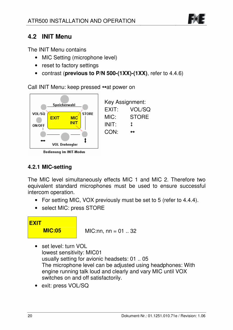
4.2 INIT Menu The INIT Menu contains
• MIC Setting (microphone level) • reset to factory settings • contrast (previous to P/N 500-(1XX)-(1XX), refer to 4.4.6)
Call INIT Menu: keep pressed at power on
Key Assignment: EXIT: VOL/SQ MIC: STORE INIT: CON:
4.2.1 MIC-setting The MIC level simultaneously effects MIC 1 and MIC 2. Therefore two equivalent standard microphones must be used to ensure successful intercom operation.
• For setting MIC, VOX previously must be set to 5 (refer to 4.4.4). • select MIC: press STORE
EXIT MIC:05
MIC:nn, nn = 01 .. 32
• set level: turn VOL lowest sensitivity: MIC01 usually setting for avionic headsets: 01 .. 05 The microphone level can be adjusted using headphones: With engine running talk loud and clearly and vary MIC until VOX switches on and off satisfactorily.
• exit: press VOL/SQ

ATR500 INSTALLATION AND OPERATION
Dokument-Nr.: 01.1251.010.71e / Revision: 1.06 21
4.2.2 Reset
EXIT MIC INIT
• Select INIT: press UP/DOWN
All values will be set to factory defaults:
MEM1 118.00 VOL 03 MEM2 127.00 SQ 08 MEM3 136.97 VOX 05 MEM4 127.50 MIC 05 MEM5 130.47 DIM 10 MEM6-9 118.00 CON 05
4.3 Return-Mode (from P/N 500-(1XX)-(1XX)) The return mode determines, if the display automatically returns to frequency view after changes by the user (VOL, VOX, etc.). • Call menu: keep pressed during power on
EXIT RETURN (Y)
RETURN: Y/N
• select (Yes/No): VOL yes: switch to frequency view after 5 s (default) no: remain in actual setting item
• exit: VOL/SQ

ATR500 INSTALLATION AND OPERATION
Dokument-Nr.: 01.1251.010.71e / Revision: 1.06 22
4.4 VOL, SQ, VOX, DIM, CON – Basic Settings 4.4.1 General Select one of the following setting modes: press VOL/SQ (repeatedly).
• VOL volume • SQ squelch • VOX threshold of intercom function • DIM display background illumination • CON display contrast • frequency view
Use the rotary knob to change values. Return to frequency view: press or or wait for auto-return (after 5 s without manipulation). (Auto-return can be switched off as described in chapter 4.3.
If contrast was misadjusted and the display is not readable: • Switch power off and on again. • Wait for 5 s, then press VOL/SQ 5 times. • Turn VOL to set contrast.
4.4.2 VOL – Volume
127.50 VOL:13
VOL:nn, nn = 01 ... 16
(prior to P/N 500-(1XX)-(1XX): nn = 01 .. 32)
VOL only affects the received signal, not the intercom level, which is set ex-factory.

ATR500 INSTALLATION AND OPERATION
Dokument-Nr.: 01.1251.010.71e / Revision: 1.06 23
4.4.3 Squelch
127.50 SQ :03
SQ :nn, nn = 01 .. 10
Usual setting is 03 .. 05. Superior values can cause unwanted suppression of low signals. Squelch does not affect the intercom function.
4.4.4 VOX – Threshold of Intercom Function With VOX the volume threshold is set to avoid transmission of normal noise in the cockpit to the headphones. Only an additional voice signal activates intercom operation.
127.50 VOX:05
VOX:nn, nn = 01 .. 10
4.4.5 DIM – Background Illumination precondition: corresponding wiring (refer to 2.4.4). ab P/N 500-(1XX)-(1XX)
127.50 DIM:10
DIM:nn, nn = 01 .. 10

ATR500 INSTALLATION AND OPERATION
Dokument-Nr.: 01.1251.010.71e / Revision: 1.06 24
P/N 500-(0XX)-(0XX) from S/N 00301 04
• call LIGHT menu: keep pressed during power on.
EXIT LIGHT
• press
EXIT LIGHT:05
LIGHT:nn, nn = 01 .. 32
• exit: VOL/SQ
4.4.6 CON – Contrast from P/N 500-(1XX)-(1XX)
127.50 CON:10
CON:nn, nn = 01 .. 10
P/N 500-(0XX)-(0XX)
• call INIT-Menu: keep pressed during power on. • select „CON“: press
EXIT CON:16
CON:nn, nn = 01 .. 32
• exit: VOL/SQ

ATR500 INSTALLATION AND OPERATION
Dokument-Nr.: 01.1251.010.71e / Revision: 1.06 25
4.5 Frequency Setting 4.5.1 Direct Input
• turn MEM to position „SET“
127.00 >136.95
active frequency
stand-by frequency
• select setting of MHz or kHz using ““
“>”/“<” marks the selected part of the frequency value (MHz/kHz) • turn VOL to change values
• press (UP/DOWN) to activate stand-by frequency (swap previously active and stand-by frequency)
4.5.2 Select Frequency from Memory Position
• Turn „MEM“ to select position (M1...M9) The stored frequency is displayed and set as active frequency.
136.95 M2
stored frequency
selected memory position
4.5.3 Save new Frequency
• Set frequency (manually) (refer to 4.5.1). • Select memory position (M1 .. M9).
Position and according frequency are displayed and active, the previously active frequency is stored in the background.
• Press STORE, to save the memorized value. (The present value will be overwritten.)

ATR500 INSTALLATION AND OPERATION
Dokument-Nr.: 01.1251.010.71e / Revision: 1.06 26
4.6 Automatic Frequency Checkup If „–“ is displayed behind the frequency value, the equipment is not able to set the frequency. Transmit/receive operation stops. In this case the ATR500 and has to be sent to the manufacturer.
If „–“ appears for less than 1 second, an extreme radio interference could be the reason. This is no malfunction of the device.
4.7 BAT – Low-Battery If battery voltage drops below 10,5 V, a blinking „B“ is displayed. 4.8 Transmit Operation Pushing PTT starts transmission on the selected frequency shown in the upper line. This operation is indicated by “T”.
136T95 M2
„T“ indicates correct operating of the transmitter.
To avoid unintended transmission the transmitter stops after two minutes and the display changes from “T” to “E”. To start transmission again, release PTT and push again. 4.9 Receive Operation
136R95 M2
While receiving (squelch is open) “R” is shown.

ATR500 INSTALLATION AND OPERATION
Dokument-Nr.: 01.1251.010.71e / Revision: 1.06 27
4.10 Controls
1: MEM/SET select frequency from memory position (M1 .. M9) direct frequency input (SET)
2: rotary knob change values
3: VOL/SQ select VOL, SQ, VOX, DIM, CON
4: STORE save frequency
5: ON/OFF on/off (press for 0,5 bzw. 3 s)
6: select MHz/kHz setting start INIT mode
7: (UP/DOWN)
swap active/stand-by frequency

Copyright © 2022 FDOKUMEN