1 05 5 E RE PART CA TL A LO G 2 IO - 5 5 0 - -E -F -L - LG Aero
71
I, 1 05 5 ERE PART C A TL A LO G 2 I O - 5 5 0 - -E -F -L AUGUST 1991 Form X30606A © 1991 Teledyne Industries, Inc.
-
Upload
khangminh22 -
Category
Documents
-
view
1 -
download
0
Transcript of 1 05 5 E RE PART CA TL A LO G 2 IO - 5 5 0 - -E -F -L - LG Aero

I,
1 05 5 E REPART
C A TL A LO G 2I O - 5 5 0 -
-E-F-L
AUGUST 1991Form X30606A© 1991 Teledyne Industries, Inc.

CURRENT STATUS OF PAGES AS OF:
AUGUST 1991
THE ORIGINAL DATE OF THIS PUBLICATION IS FEBRUARY 1991INSERT LATEST PAGES DESTROY SUPERSEDED PAGES
MODELS: 10-550-D,E,F & L FORM X30606A
PAGE STATUS
HI Thru72-30-05 Feb. 1991
72-30-06,07,08 Aug. 1991
72-30-09 Thru82-10-01 Feb. 1991
PAGE STATUS PAGE STATUS PAGE STATUS
II August 1991

WVARNING(Please note th~e following statements from FMA Ad~visory Circular 20-62C entitled "EUGIBILITY. QUALITY. AND IDENTIFICATIONOF APPROVED REPLACE ME NT PARTS'):
3. BACKG ROU ND. An increasing amount of replacement parts (including standard parts), materials,appliances, and instruments are offered for sale as being of aircraft quality when actually the quality andorigin of these units are unknown. Users of such units are usually not aware of the potential hazardsinvolved with replacement parts that are not eligible for use on certificated aircraft. Frequently such unitsare deceptively advertised or presented as "unused," "like new," or "remanufactured." This impliesthat the quality of such units is equal to an original or appropriately repaired or overhauled unit.
The performance rules for replacement of parts and materials used in the maintenance and alteration ofU.S. certif icated aircraft are specified in Federal Aviation Regulations (FAR) 43.13 and FAR 145.57. Theresponsibility for the continued airworthiness of the aircraft, which includes the replacement of parts, isthe responsIbIlIty of the owner/operator as outlined in FAR 91.163, FAR 121.363, FAR 123.45, FAR127.131 and FAR 135.143 (a).
4-IDENTIFICATION OF THE APPROVED PARTS. Approved serviceable replacementparts are identif ied as follows:
a. By an FAA Form 81 30-3 (Formerly FAA Form 186), Airworthiness Approval Tag. An AirworthinessApproval Tag identif ies a part or group of parts that have been approved by authorized FAArepresentatives.
b. By an FAA Technical Standard Order (TSO) number and identif ication mark that indicates the partor appliance has been manufactured under the requirements of FAR 37.
c. By an FAA'PMA symbol, together with the manufacturer's name, trademark or symbol, part number,and the make and model of the type certificated product on which the part is eligible for installation,stamped on the part. An FAA Parts Manufacturer Approval (FAA'PMA) is issued under FAR 21.305.The make and model information may be on a tag attached to the part.
d. By shipping ticket, invoice, or other document which provides evidence that the part was producedby a manufacturer holding an FAA Approved Production Inspection System issued under FAA 21,Subpart F, or by a manufacturer holding an FAA Production Certificate issued under FAA 21, SubpartG.
e. By a certif icate of airworthiness for export issued by a foreign government under the provisions ofFAR 21, Subpart N.
11. KNOW YOUR SUPPLIER. It has come to our attention that many reproduced parts andcomponents, particularly instruments which have been manufactured by persons other than the originalmanufacturer, are available for purchase and installation on U.S. certif icated aircraft. Often, an originalpart is used as a sample to produce duplicates. The reproduced parts appear to be as good as the originalpart; however, there are many unknown factors to be considered that may not be readily apparent to thepurchaser, i.e., heat treating, plating, inspections, tests and calibrations. All too often the f aulty part is notdiscovered until a malf unction or an accident occurs.
12. SUMMARY. in accordance with FAR's, certification of materials, pants, and appliances forreturn to service, for use on aircraft, Is the responsibility of the person or agency who signs theapproval. The owner/operator, as denoted in paragraph 3 of this advisory circular, is responsible for thecontinued airworthiness of the aircraft. To assure continued safety in aircraft operation, it is essential thatgreat care be used when inspecting, testing, and determining the acceptability of all parts and materials.Particular caution should be exercised when the identity of materials, parts, and appliances cannot beestablished or when their origin is in doubt.
III

INDEX
PAGE
INTRODUCTION ............. ...... 72-00-01
ABBREVIATIONS AND SYMBOLS...............72-00-03
RELATED PUBLICATIONS.................72-00-03
REPAIR PARTS SETS AND MATERIALS.............72-00-04
OVERSIZE AND UNDERSIZE PARTS LIST .. .......... 72-00-05
NUMERICAL PARTS LISTING................72-01-01
CUSTOMER SPECIFICATIONS ... ............ 72-02-0 1
BASIC GROUP ASSEMBLY PARTS LIST
72-10
72-10-0172-10-0272-1 0-03
72-20
72-20-0172-20-0272-20-03
72-30
72-30-0172-30-01 A72-30-0272-30-0372-30-0472-30-0572-30-0672-30-07
72-50
72-50-0172-50-0272-50-0372-50-04
PAGE
CRANKCASE
Crankcase Studding AssemblyCrankcase Attaching PartsCrankcase Associated Parts
DRIVE TRAIN
Crankshaft Group ......Camshaft Group .......Connecting Rod Assembly .
72-1 0-0272-1 0-0472-10-06
72-20-0072-20-0272-20-03
CYLINDERS
Cylinder Assembly .. ...7th Stud Nut Identification ......Piston and Pin Assembly ......Induction System (10-550-D) . ...
Induction System (1O-550-E) . ...
Induction System (10-550-F & L)Air Throttle Assembly (10-550-D & E)Air Throttle Assembly (10-550.:F & L)
LUBRICATION
Oil Sump Assembly (10-550-D, E, & F)Oil Sump Assembly (10-550-L) ...
Oil Pump Assembly (10-550-D & F)Oil Pump Assembly (10-550-E & L)
72-30-0072-30-0072-30-0372-30-0472-30-0672-30-0872-30-1072-30-1 1
72-50-0072-50-0172-50-0272-50-04
iv

73-10 FUELSYSTEM
Fuel Injection System (10-550-D) .....FuelFuelFuelFuel
Injection System (10-550-E) ........Injection System (10-550-F & L) ......Pump and Vapor Separator Assembly ..Pump and Vapor Separator Fitting Locations
Fuel Manifold Valve Assembly ......Fuel Manifold Valve Fitting Locations .Fuel Control Fitting Locations . ....
IGNITION SYSTEM
Magneto and Accessory Drive AssemblyIgnition System (10-550-F) ........Ignition System (10-550-D, E & L) . ...
LUBRICATION
Oil Cooler Assembly . . . . . . . 79-20-0 1
STARTER SYSTEM
Starter and Starter Adapter Assembly............ 80-10-00
ALTERNATOR AND HUBAlternator and Hub Assembly ..................... 82-1 0-00Electrical Components ......................... 82-10-01
V
73-1 0-0173-10-0273-1 0-0373-1 0-0473-10-0573-1 0-0673-1 0-0773-10-06
74
74-1 0-0174-20-0174-20-02
73-1 0-0073-1 0-0273-1 0-0473-1 0-0673-1 0-0773-10-0873-1 0-0973-10-10
74-1 0-0174-20-0074-20-02
79-20
79-20-01
80-10
80-1 0-01
82-10
82-1 0-0182-10-02
. . . . .
. . . . . . . .
. . . . . . . .
. . . . . . . .

INTENTIONALLY
LEFT
B LAN K
0
vi

INTRODUCTION
TCM has formalized the following Parts Catalog underthe GAMA system. The system allows for certainstandardization within the industry that may provide uniformity in arrangement of systems andcomponents of systems within each manufacturer's service manuals.
The format breaks down the engine systems in component groups that allow the user to cross-referencebetween any manual by TCM using this format. The individual component groups are given numericalidentification and allow the groups to be broken down into their individual parts. Each group will havethree sets of numbers.
The first two numbers designate the chapter listing giving overall category. The second two numbersindicate the section giving the particular function within the category. The third set of numbers apply toa list of detail part numbers of a particular subassembly or system.
Example:
-72-Is the number for the chapter for 'engine reciprocating".
-1 0-Is the number for the section listing given for the 'crankcase' description of the chapter listing.
-01 -is the number given for particular item ref erred to under the section and chapter numbers; inthis case "studding assembly".
Therefore the number 72-10-01 refers to a discussion on the crankcase studding assembly of theengine, reciprocating.
This parts catalog is presented in looseleaf form. Changes will be issued as they occur to those pageswhich are affected only. In this manner, the parts catalogs can be kept current with manufacturing andservice requirements. Changes to this parts catalog will be sent to the purchaser on receipt of theregistration card from the front of the manual.
In this edition, currently available parts are listed for 10-550 Model Engines. If accessories or partsattached to any engine installed in an aircraft manufactured in the United States under a productionmodel number do not appear in this catalog, determine whether they are available from the aircraftmanufacturer before placing an order with a Teledyne Continental Authorized Distributor.
The Basic Group Assembly Parts List contains Figures where each of the major assemblies and groupsof the basic engines are illustrated in'exploded" form. Each figure has its own set of index numbers toindicate the subparts. The list of parts in the assembly or group appears on the same page with theillustration or on an adjacent page. The first column of each assembly group list contains the figurenumber (not repeated on all lines) and, following a dash, the index numbers of the sub-parts in numericalorder. Do not order parts by index number, use the part number which appears in the second columnand use the name of the part which appears in the column under the title "DESCRIPTION". Do notorder any parts listed when "NOT SOLD", herein abbreviated as "NS", appears in the "QUANTITY PERASSEMBLY" column, because these parts are niot suitable for installation without factory equipment,or they are major parts of assemblies and are more economically supplied in the assembled condition,or they are assemblies which would have to be disassembled for installation. To replace any detail part"NOT SOLD", order the smallest assembly containing the part (listed above it with names beginningone column to left). To replace any assembly "NOT SOLD', order whatever subassemblies and detailparts (listed below it, with names indented) that are in need of replacement. Quantities of parts in theBasic Group Assembly Parts List are for specific application in one assembly. Similar assemblies arecombined, and quantities of sub-parts are for one assembly.
72-00-01

Oversize and undersize parts must be ordered by the numbers listed herein, with correct descriptions,to avoid errors. Corresponding standard size part numbers in the Basic Group Assembly Parts List arepreceded by a symbol (+) to indicate the availability of the non-standard size. (Refer to list ofabbreviations and symbols).
Repair Parts Sets are usually wanted in such groups for overhaul work and should be ordered by setpart numbers.
A Numerical Parts List is provided and part numbers are arranged in numerical order along with a figureand index number. If the number of any desired part is known, the name may be located by referringto the Basic Group Parts List. When using this listing and referring to an illustration with the figure andindex references, you will note in some cases, there is more than one illustration of an assembly dueto differences between certain engine models. If this is the case, you must look under the illustrationlisting your particular model engine to locate the part number and name.
NOTE.. . The aircraft manufacturer occasionally changes certain accessories per customer request.
72-00-02

LIST OF ABBREVIATIONS AND SYMBOLS
DEFINITONAs RequiredDiameterHeadHexagon(aI)Inside DiameterInchesLongMillimetersOutside diameterOptionalOversize
SYMBOLNS
PDRF (rf)NPTusNo.
DEFINITONNot SoldParts included in a setPitch diameter (threa)ReferenceNational Pipe Tap (or thread)UndersizeNumberOversize parts availableUndersize parts availableEnd of group of attaching parts
RELATED PUBLICATIONS
Engine Manuals:
1 . Overhaul Manual for 10-550 Series Aircraft Engine, Form X30607A
2. Illustrated Parts Catalog for 10-550 Series Aircraft Engine, Form X30606A.
3. Maintenance and Operators Manual X30605.
4. Teledyne Continental Motors Aircraft Engine Service Bulletins.
5. Fuel Injection Manual, Form X30593A.
The above publications may be ordered through your Teledyne Continental Motors Distribution orordered directly, if prepaid from:
Teledyne Continental MotorsAircraft ProductsP.O0. Box 90Mobile, AL 36601Attn: Accounts Recivable
72-00-03
SYMBOLAR (ar)dia.hdhexIDin.
1g.mmGDOPOs

REPAIR PARTS SETS AND MATERIALS
PART NO.646548A1646563A1649227649227P005649227P01 0649227P01 5649227CP646592A1646592A1 MOl1 0
626531-1626531-2535011S641543
642188646940646941646942646943646944
DESCRIPTIONGasket Set - Complete Overhaul
© Gasket Set - Single CylinderRing Set - Single CylinderRing Set - Single CylinderRing Set - Single CylinderRing Set - Single Cylinder
® Ring Set - Single CylinderBearing Set - CrankshaftBearing Set - Crankshaft
Enamel-Gold, EngineEnamel-Gold, EngineLockwire-0.040 In. Dia. SteelSilk Thread
Gasket SealantF/I SealantAdhesive/SealantGasket MakerAnti-Seize LubricantPrimer
SIZEStandardStandardStandard.005'OS on OD.010'OS on OD.015" 05 on ODStandardStandard.010' US on ID
1 Quart1 GallonOrder by 1 Lb. Roll1 Spool (260 Yd.)
1.5 Oz. Tube1.69 Oz.1.69 Oz.1.69 Oz.1/4 Lg.6 Oz. (Aerosol Can)
NOTES:
o This set does not contain intake hoses.(Z For use with chrome cylinder.
4072-00-04
MflflFID, E, F, LALLALLALLALLALLALLD, E, F, LALL
ALLALLALLALL
ALLALLALLALLALLALL
S17F mnni=i

OVERSIZE AND UNDERSIZE PARTS LIST
PART NO. DESCRIPTION DIMENSION PART NO. DESCRIPTION DIMENSION
25008P00325008P00625008P009
35967P00535967P01 035967P01 535967P02035967P030
Stud,Mag&Acc.D riveStud,Mag&Acc.D riveStud,Mag&Acc.Drive
Insert,Exh.ValveInsert,Exh.ValveInsert,Exh.ValveInsert,Exh.ValveInsert,Exh.Valve
350998P0015 Bushing,C/Shaft350998P003 Bushing,C/Shaft350998P005 Bushing,C/Shaft
401800P003 Stud,Oil Pump401800P007 Stud, Oil Pump
401 804P003401 804P007401 804P01 2
Stud,CrankcaseStud,CrankcaseStud,Crankcase
401 808P003 Stud,Crankcase401 808P007 Stud,Crankcase
401 832P003 Stud,Crankcase
401 852P003 Stud,Crankcase401 852P007 Stud,Crankcase
401 870P003401 870P007401 870P01 2
Stud,CrankcaseStud, CrankcaseStud, Cran kcase
401871 P003 Stud,Crankcase401871 P007 Stud,Crankcase
401881 P003 Stud,Crankcase401881 P007 Stud,Crankcase
401885P003 Stud Crankcase401885P007 Stud, Crankcase
401 893P003401 893P007401 893P01 2
.003" 05 on PD
.006" 05 on PD
.009" OS on PD
.005" 0S on OD
.010 05O on OD
.015" OS on OD
.020" 05 on OD
.030" OS on OD
.0015" 05 on OD
.003" 05 on OD
.005" 05 on OD
.003" 05 on PD
.007" 05 on PD
.003" 05 on PD
.007" 05 on PD
.012" OS on PD)
.003" 05 on PD
.007" 05 on PD
.003" 05 on PD)
.003" 05 on PD)
.007" 05 on PD
.003" OS On PD
.007" OS on PD
.012" 05 on PD
.003" 05 on PD
.007' 05 on PD
.003" 05 on PD)
.007" 05 on PD
.003"O05 on PD)
.007" 05 on PI)
Stud,Oil-Transf.Collar .003" OS on PDStud,Oi1-Transf.Collar .007"O05 on PDStud,Oil-Transf.Collar .01 2" 05 on PD)
401895P007 Stud, Crankcase
401895P003 Stud, Crankcase
.007" 05 on PD)
.003" 0S on PD
401 950P003 Stud, Crankcase
401963 P003401963 P007401 963P012
401965 P003401 965P007401 965P012
Stud, Oil PumpStud, Oil PumpStud, Oil Pump
Stud, CrankcaseStud, CrankcaseStud, Crankcase
402038P003 Stud, Crankcase402038P007 Stud, Crankcase
402066P003 Stud, Crankcase
4021 27P0034021 27P007402127P012
402151 P003402151 P007402151 P012
Stud,Starter AdapterStud,Starter AdapterStud,Starter Adapter
Stud, CrankcaseStud, CrankcaseStud, Crankcase
402158P003 Stud, Crankcase402158P007 Stud, Crankcase
402159P003 Stud, Crankcase402159P007 Stud, Crankcase
404584P003 Stud, Crankcase
404584P007 Stud, Crankcase
536563P005 Dowel, Crankshaft
538304P030 Pushrod
539800M015 Spring, Str. Clutch
62673 9MOO 1626739M01 0626739M01 1
639573P01 0639573 P020639573 P030
Oil Transf. CollarOil Transf. CollarOil Transf. Collar
ThrstWash/RkrArmThrstWash/RkrArmThrstWash/RkrArm
642398M010 Bearing,Con Rod
642720M01 0 Bearing, C/Shaft
643766P005 Valve Guide Intake643766P010 Valve Guide Intake
.003" 05 on PD
.003" OS on PD.007" 05 on PD.012" 05 on PD)
.003" 05 on PD
.007" 0S on PD.012" 05 on PD
.003" 05 on PD)
.007" 05 on PD)
.003" 0S on PD
.003" 05 on PD
.007" 05 on PD
.012" OS on PD
.003" 05 on PD
.007" 05 on PD
.01 2"OS on PD
.003" 05 on PD
.007" 05 on PD
.003" 0S on PD
.007" 05 on PD
.003" 05 on PD
.007" 05 on PD
.005" 05 on OD
.030" 05
.01 5" US on ID
.001" US on ID
.010"' US on ID
.01 1" US on ID
.010 OOS on OD
.020" Os on OD
.030" OS on OD
.010"' US on ID
.010"' US on ID
.005" 05 on OD
.010" 05 on OD
72-00-05

PART O. DSCRITION DIMENSION PART NO. DESCRIPTION DIMENSION
Valve Guide IntakeValve Guide IntakeValve Guide Intake
Ring, PistonRing, PistonRing, Piston
Ring, PistonRing, PistonRing, Piston
Ring, PistonRing, PistonRing, Piston
.ois" OS on OD
.020' OS on OD.030' 0S on OD
.005" OS on OD
.010 OOS on OD
.015" OS on OD
.005" OS on OD
.010 OOS on OD
.015" OS on OD
.005" OS on OD
.010" OS on OD.015" OS on OD
648008P005648008P01 0648008P01 5
64801 4P00564801 4P01 064801 4P01 5648014 P02064801 4P030
Ring-PistonRing-PistonRing, Piston
Vlv.Guide ExhaustVlv.Guide ExhaustVlv.Guide ExhaustVlv.Guide ExhaustVlv.Guide Exhaust
648046P010 Piston648046P015 Piston
649478P020 Camshaft
.005" OS on OD
.01 0" OS on OD
.015" 0S on OD
.005" 0S on OD.010"' OS on OD.015" 05 on OD.020" OS on OD.030" 0S on OD
.010" OS on OD
.015" 05 on OD
.020" Os on OD
643766P01 5643766P020643766P030
648005P005648005P01 0648005P01 5
648006P005648006P01 0648006P01 5
648007P005648007PO10a648007P01 5
S
72-00-06
PARTNO. DESCRIP71ON

NUMERICAL PARTS LIST
PART FIG &NUMBER INDEX
AN121501
AN1 23862
AN1 23866AN31 6-9R3AN4-26AAN4-7AAN5-1 3A
AN5-15SAAN50OA1 0-4AN500A8-1 2AN501l-lO-lOAN565E81-16AN737TFW46AN81 6-8AN932-5AN932-2AN960-8AN960-51 6L
AN960C916M330S208MS122121MS122122MS 122162MS1 24657
MS20073-04-1 0MS20074-04-04MS20074-04-04MS20074-04-03MS20074-04-03MS20364-428MS20822-8MS21 042-5MS21 044N3
MS29513-010MS35266-61MS35337-43MS35337-44
--73-10-01-1373-10-02-1372-10-02-1780-10-01-2172-10-03-1480-10-01-3472-30-04-3072-30-04-2272-10-01 -3272-10-02-2272-10-02-1072-10-02-2672-10-02-3073-10-06-874-20 -01 -2472-30-06-1572-30-05-1579-20-01-1572-50-04-772-50-03-573-10-06-973-10-02-3373-10-01-3273-10-03-3280-10-01 -3272-30-04-2572-30-01-872-10-01-572-10-01-472-50-04-1672-50-03-1472-50-03-2872-50-01-472-50-02-472-50-01-572-50-02-572-30-04-2079-20-01-1672-30-06-973-10-03-1673-10-02-1673-10-01-1672-10-02-572-10-03-3472-50-04-3472-50-04-3973-10-03-22
PART FIG &NUMBER INDEX
MS35337-44
MS35337-45
MS35338-43
MS35338-44
MS35338-44
MS35338-45
MS35338-46
MS35756-8
MS35769-1 1
MS35769-15MS35769-1 8MS35769-26
MS35769-48MS9021-011
MS9021 -038MS9134-01
72-50-04-4272-30-0 1-3172-30-04-2972-30-04-2173-10-01-2272-30-04-574-10-01-1972-30-05-572-30-03-572-1 0-03-1079-20-01-1079-20-01-472-50-01-1172-10-03-1972-50-02-974-20-02-474-10-01-873-10-02-3474-20-01-480-1 0-01-2880-10-01-382-10-01-1280-10-01-3774-20-02-674-20-01-2372-1 0-03 -3672-50-03-3873-10-02-2272-10-03-4073-10-01-3373-10-03-3374-1 0-01-972-20-02-580-10-01-3080-10-01-1172-50-02-1172-50-01-872-10-01-2672-50-01-872-50-03-3572-50-03-1272-50-04-1472-50-03-2572-10-02-1372-20-01-1872-10-03-2780-10-01-4074-10-01-16
PART FIG &NUMBER INDEX
M,591 34-01Q9S552-0609T1 16-0709T1 16-218X1 3041X1 473'
13XX1813013XX1 896
13XX202B
1 3XX2992024202520522
2065521007
2120821 208A22253522661
227862389024239
24372439
72-50-04-3672-50-03-2972-50-03-3172-50-03-2780-10-0 -1372-50-04-1772-50-03-1572-30-06-1472-10-03-3774-20-02-772-30-04-1672-30-03-1572-30-05-3172-30-05-1780-10-01-3372-30-03-1872-10-01 -2272-30-04-472-50-01-373-10-02-2172-30-0 1-3073-10-03-2 172-30-05-2672-50-02-372-30-05-472-30-03-472-50-03-3772-50-04-4173-10-01 -2179-20-01-579-20-01-1172-50-04-3572-30-0 1-2072-30-0 1-2372-50-04-2372-50-03-2372-10-03-1772-30-04-3172-30-04-2372-30-05-2482-10-01-672-30-04-3572-10-02-1882-10-01-772-30-04-2873-10-03-3473-10-01 -3474-20-02-5
72-01 -01

NUMERICAL PARTS LIST
PART FIG &NUMBER INDEX
2439 72-10-02-1274-10-01-1072-10-03-2073-10-02-3572-10-02-2372-30-05-2774-20-01-572-30-05-3072-10-02-2880-10-01-4380-10-01-572-10-03-472-10-02-2074-10-01-1182-10-01-572-50-04-3372-1 0-03 -3572-1 0-03-3572-50-04-3874-10-01-1872-10-03-672-10-01 -3172-10-03-1872-50-02-872-10-02-2772-10-02-2572-10-02-1572-10-02-1172-50-01-1074-10-01-672-30-01-2672-10-02-2180-10-01-3680-10-01-280-1 0-01 -2772-10-02-3272-30-01-1772-30-04-672-30-03-672-30-05-673-10-02-1973-10-03-1973-10-01-1974-10-01-574-10-01-472-10-02-672-20-01-172-30-01-10
2441
24712472
2473
247642480224835
2500
25008251022517135099835967
PART FIG &NUMBER INDEX
3597136151 L
36151 R401507401800
401804401808401832
401852401870401871401881401885401893
401899401950401963
4019654020384020664021 27402151402158402159404584501 867
501868502287520112-3530346
530658
531001
531178
72-30-01 -1672-30-05-872-30-04-872-10-03-3174-10-01-772-50-04-372-50-03-372-10-01 -3472-10-01-672-10-01-1372-10-01-1172-10-01 -2872-10-01-1172-10-01-972-10-01-3372-10-01 -1772-10-01-1072-50-04-2972-20-01-1672-10-01-772-10-01 -2072-50-03-472-50-04-472-10-01-1272-10-01-672-10-01-880-10-01-772-10-01-1472-10-01-1572-10-01 -1672-10-01 -2073-10-02-1073-10-03-1173-10-01-1080-10-01-1882-10-01 -1580-10-01-1472-30-01-372-50-02-1072-50-01-1272-30-04-1772-30-03-1682-10-01-1172-20-03-272-10-02-772-30-0 1-4074-10-01-1472-50-04-28
PART FIG &NUMBER INDEX
531548532432
72-10-01-372-50-02-1272-50-01-972-10-01-2572-30-0 1-3672-30-0 1-3772-20-02-680-10-01-2480-10-01-2572-10-03-972-1 0-03-872-20-0 1-2672-50-02-672-50-01-674-20-02-174-20-01-172-20-0 1-2580-10-01 -3172-30-0 1-2874-10-01-180-10-01 -2672-50-02-172-50-01-180-10-01 -2272-50-04-2172-50-03-1972-10-03-2372-50-04-2072-50-03-1872-20-02-379-20-01-372-30-03-1079-20-01-972-10-02-1972-10-03-2574-20-02-374-20-01-372-50-04-3172-50-04-3272-50-04-3072-50-03-3072-20-0 1-2272-30-05-172-30-03-172-30-04-172-20-0 1-2180-10-01-1072-20-01 -20
534609534610534655534685534715534728534740534741534743
534750
534757534775534857534863534938534940
534980535008535008535091535634
535662535668535681535756535810535823535847
535885535887535908535933536379536413
536421536552536563
72-01-02

NUMERICAL PARTS LIST
PART FIG &NUMBER INDEX
537019537296537299537505537539537629537650537690
537721537738A1537742537745537749537750
537961
538076538100538185538304538468538650538727538773538789A1538801538804538944-8.88538989538999
539058
539114539374539518539523539523539547-32.00539568539634
72-30-01 -2772-30-01-3572-10-03-3072-10-01-2982-10-01-1373-10-02-2472-50-01-773-10-03-1873-10-01-1873-10-02-1872-10-01-280-10-01-2380-10-01-480-10-01-180-10-01-2072-50-02-1072-50-01-1272-30-05-1880-1 0-01 -3882-10-01-1480-10-01-2972-50-02-1072-30-05-3272-20-02-772-30-04-2472-50-03-172-30-0 1-3972-30-04-3672-10-02-2472-50-03-2672-10-03-2272-50-04-2772-10-03-2272-1 0-03-2 172-1 0-02-272-10-02-880-10-01-3580-10-01-3972-10-03-380-10-01 -4272-30-04-3472-10-02-1472-10-03-172-50-03-772-50-04-982-10-01-1680-10-01-1573-10-01-2
PART FIG &NUMBER INDEX
539634539634539785539800539805539942
625207625238625327-2
625327-1
625327-2625393625457
625601
625615625886
625966626147626334626486
626487626557626577-2
626634
626739626744626812
626813
6268 13-1626879-1626889627335D1 2
73-10-03-273-10-02-280-10-01-1680-10-01-1780-10-01-972-30-07-1372-30-06-1872-50-01-272-30-06-273-10-02-1773-10-03-1772-30-06-572-30-07-373-10-01-1772-30-01-1572-30-06-672-30-07-472-30-07-1272-30-06-1772-30-0 1-2972-50-04-2272-50-03-2072-10-03-1372-30-0 1-3872-10-03-1273-10-03-3073-10-02-3172-10-03-4173-10-06-473-10-01-3173-10-03-3173-10-02-3272-30-07-772-30-06-1273-10-01-1473-10-03-1473-10-02-1472-20-01-1472-30-04-1172-30-07-1472-30-06-1972-30-06-473-10-03-1072-30-07-272-30-06-373-10-04-272-20-01-1573-10-01-29
PART FIG &NUMBER INDEX
627335D 12627335D 12627368627433
627496627670627681
627773627820627836628129628321-.38628739628740628833629076629077629104629138
629163-5
629202629218
629325
629338629338AI629353629354629397A1
629399A
629448
629495
629518-1 H
629518-1
73-10-02-3073-10-03-2972-30-04-3772-10-03-772-10-02-1679-20-01-1472-30-04-1972-30-05-2872-30-04-2772-1 0-03-572-30-03-1172-30-05-2572-50-03-3272-1 0-03-4374-20-0 1-3574-20-0 1-3472-30-04-2674-10-01-1274-10-01-1372-20-01-1172-30-05-272-30-04-272-30-03-272-30-05-972-30-04-972-30-03-872-10-03-3872-50-03-672-50-04-872-30-03-372-30-05-372-30-04-373-10-03-2073-10-0372-30-05-2072-30-05-2173-10-0372-30-05-1972-30-0773-10-03-672-50-04-1972-50-03-1774-20-02-2274-20-0 1-2072-10-01 -2372-10-01 -2172-50-04-672-30-05-13
72-01-03
------- -

NUMERICAL PARTS LIST
PARTFINUMBER IDEX
629518-3629597629703-2A3629837
629847629904-2A6630046630124630184630350630387
630455
630691630943-10.50631246631252631266-1631275-2631287631 287A1
631330631478631521631550A10631638631650
631653
631683
631664
631714631 714A7631737-2
631739
631819631845
72-10-01-2472-30-04-1273-10-03-774-20-02-2774-20-01-2772-10-01-3073-10-02-772-30-02-672-30-06-1673-10-06-672-30-05-3373-10-01-1173-10-02-1173-10-03-1272-30-06-172-30-07-182-10-01 -272-10-02-173-10-01-3080-10-01-1272-10-03-3272-10-03-3372-30-04-1873-10-0272-30-0673-10-06-372-50-03-3472-30-01-1373-10-02-672-50-03-3372-50-04-2572-50-03-2172-50-03-1072-50-04-1273-10-02-473-10-03-473-10-01-473-10-01-173-10-03-173-10-02-172-50-03-272-50-0374-20-01-2574-20-02-2574-20-02-2874-20-0 1-2872-30-07-1172-20-02-2
PART FIG &NUMBER INDEX
631927631927631928631972
631995632085
632105
632149632151632328632329632330632373632425632437632443-4632554-2632554-1
632554-2
632555-49632555-5632555-22632555-23632555-31632555-35
632555-44632556632557
632557-1632558
632558A1632558A1632653A1632762
632859632859A1
72-10-03-2972-10-01-2772-10-03-2872-30-04-772-30-03-772-30-05-772-50-03-3672-50-04-2672-50-03-2274-20-01-2974-20-02-2972-10-03-3372-10-03-2972-30-05-1172-30-05-1274-10-01-372-50-04-573-10-06-582-10-01-472-20-01-1773-1 0-03-973-10-01-972-30-06-873-10-02-972-30-07-672-30-06-1172-30-07-1073-10-01-873-10-03-872-30-06-772-30-07-972-30-07-572-30-06-773-10-02-872-30-06-1072-30-06-1073-10-01-1573-10-02-1573-10-03-1573-10-01-1273-10-02-1273-10-0173-10-0274-10-01-272-50-04-1872-50-03-1673-10-01-2073-10-01
PART FIG &NUMBER INDEX
632871633129
633189633379633412633845634150
634209634325634503634511634617634657634673634675
634805634807635050635050A4635158S4S1 2.00
6351 58S4S40.00635169635360
635363
635616635640636951636953637255-4
637409-48
72-30-03-1272-30-04-1572-30-05-1472-30-04-1372-20-01-272-30-06-1672-50-01-780-10-01-1972-50-03-972-50-04-1172-30-03-1373-10-06-772-20-01-1272-10-02-982-10-01-1082-10-01-872-10-03-274-20-01-674-20-02-872-30 04 3272-30-04-3380-10-01-680-10-0 173-10-02-2673-10-02-2773-1 0-02-2880-1 0-0 1-3 174-20-0 1-3074-20-02-3074-20-0 1-3174-20-02-3172-50-02-772-50-02-274-20-0274-20-0172-30-05-1572-30-04-1474-20-02-1174-20-01-1174-20-02-1274-20-02-1374-20-01-1274-20-02-1474-20-02-974-20-01-1674-20-01-1774-20-01-1874-20-01-15
72-01-04

NUMERICAL PARTS LIST
PART FIG &NUMBER INDEX
6374094.8637409-48
637837638125638139638172639193
639195639196639305639479
639573639596
63971 5A763971 7-2A2639997640261640380
640620-5640620-9641030641054
641066641 250641306641361641368641 656641657641862641930-9.81
74-20-01-1474-20-02-1674-20-01-1374-20-02-1074-20-02-1574-20-02-2074-20-01-874-20-02-1774-20-01-774-20-01-974-20-02-1874-20-02-1974-20-01-1072-30-01-1472-30-01-774-20-02-2374-10-01 -1572-20-01-672-20-01-472-20-01-572-20-01-379-20-01-1372-30-06-1372-30-07-872-30-01-2472-30-03-1773-10-0172-30-0673-10-01-673-10-01-772-1 0-03-1682-10-01-972-50-04-3774-10-01-1772-10-03-2472-10-03-2473-10-06-274-20-0 1-3374-20-02-3372-30-01-172-20-0 1-2372-20-0 1-2472-10-03-4280-10-01-882-10-01-182-10-0172-20-02-972-1 0-02-3
PART FIG &NUMBER INDEX
641931-10.75642224
642249642250642283A1642318642335
642336
642398642523642589642714
642720642796642914643059
643060
643062
643063-1
643085643112643215643626-103643626-104643626-105643629643743-1643749643766643778-164393564.3967646050646109646113646140-1646140-264621 2-l A564621 2-lA5646238
72-10-02-472-50-03-1372-50-04-1572-20-01-1972-10-02-2973-10-03-1372-30-01-972-50-03-1172-50-04-1372-50-04-1072-50-03-872-20-03-572-30-03-1482-10-01-372-50-04-2472-50-03-2472-20-01-1273-10-04-172-10-03-3974-20-02-2174-20-01-1974-20-0 1-3274-20-02-3274-20-02-2474-20-0 1-2274-20-02-2674-20-0 1-2672-30-05-2272-20-03-372-20-03-472-20-01-772-20-01-872-20-01-972-20-01 -1072-50-04-272-50-04-172-30-01-472-50-0472-10-03-272-30-0 1-3479-20-01-873-10-06-173-10-0672-10-01-1872-10-01-1973-10-01 -573-10-0480-10-01-41
PART FIG &NUMBER INDEX
646275646277646283646286646288646297646298646312646482646483
646486646508-9Al
646605
646623646644S4S1l0.00
646644S4S1 2.00646644S4S 14.00646644S4S32.00646644S4S40.00646673646688646689646708646727
646745646748646824-1lAl
646835
646837
80-10-01-4172-20-02-872-30-01-1172-30-01-1272-20-01-1372-30-0 1-4372-30-01-4472-30-0 1-4272-20-03-172-30-05-2972-20-02-474-20-01-2173-10-0673-10-03-2473-10-01 -2473-10-02-2573-10-02-2372-50-03-3974-10-01-2072-10-03-1172-50-04-4372-50-04-4073-10-01 -2373-10-03-2379-20-01-1272-20-0 173-10-03-2673-10-01-2673-10-01-2573-10-03-2573-10-03-2773-10-01-2773-10-02-2072-10-03-172-10-03-173-10-0173-10-03-2873-10-02-2973-10-0173-10-04-172-10-03-273-10-0473-10-03-573-10-02-573-10-02-2973-10-01-2873-10-03-2873-10-02-29
72-01 -05

NUMERICAL PARTS LIST
PART FIG &NUMBER INDEX
646837646957646958646975646985648000648005648005CP648006648006CP648007648007CP648008648008CP648046A2648051649052All1649052A3-1
73-1 0-03-2874-20-02-274-20-02-274-20-01-272-30-01-672-30-0 1-2572-30-02-272-30-02-272-30-02-372-30-02-372-30-02-472-30-02-472-30-02-572-30-02-572-30-02-172-30-01-573-10-0173-10-02
PART FIG &NUMBER INDEX
649053A3649352649353-75649369649478649684-1649923649981649990
649994-13
652079652112652129
73-10-0372-30-05-2372-30-0 1-3272-10-03-1272-20-02-182-10-02-172-50-04-4472-10-03-1573-10-01-373-10-03-373-10-02-372-30-03-972-30-04-1072-30-05-1079-20-01-772-30-01-1672-30-0 1-2272-30-01-19
PART FIG &NUMBER INDEX
652130652131652358652428652458652485652486652541652555-2652555-3652618652650652661652954652954A1652974.652977
72-30-01-2172-30-01-1872-30-05-1672-50-0472-30-0 1-3382-10-01-182-1 0--0l1-172-30-0 1-4172-10-01-172-10-01-179-20-01-679-20-01-279-20-01-172-30-01-272-30-0174-20-0174-20-02
72-01-06

CUSTOMER SPECIFICATIONS
The customer specification section is important in noting the difference between the basic engine modelgiven in the Basic Group Assembly Parts List and the individual engine model specification. Yourspecific engine model specification must be known when ordering parts to ensure you are in factordering the right parts for your engine. The specification number is located right after the engine modelnumber on your engine identif ication plate. Example: 10-550-D2. In this case "2" is the model spec.number. The figure and index column refer to an illustrated view of the parts or assembly difference.These illustrations are located throughout the basic engine parts list.
72-02-01

©D MODEL PART 1 2 3 45 DESCRIPfl0NISPEC. NUMBER
10-550-D2 649052A1 1 -1630693-10.44
10-550-D3 646275630693-1 044633435AN737TW46649052A1 1 -1
10-550-D4 538944-10.00641931-1 0.95641930-10.95646689646688539518649369646050649958AN81 6-820522MS35337-44646605646275649283AN7-46AAN960-71 6MS21 045-7MS90725-6322786MS35337-46649213539547-30.00640704640705640706640677640707652458643967652692652517MS21919WDF1 1AN780-2652693642990646981646983649052A1 1-2
10-550-F2 646238
Fuel Injection System .........Bolt 3/8-24 x 10.44 ...........Starter 24 Volt .............Bolt 3/8-24 x 10.44 ...........Bracket Balance Tube .........Clamp 1.00 L.D.............Fuel Injection System .........Bolt, Thru CC Tie Upper Nose . ...Bolft, Thru .50 x20 ...........Bolt, Thru .50 x 20 #6 Cyl. To C/C LowerBracket Eng. Mount at #6 Cyl ......Bracket Eng. Mount at #5 Cyl ......Bracket Eng. Mount at #1 & 2 Cyls. .Oil Temperature Control Valve ....Adapter Oil Cooler Pad ........Gasket, Adapter to C/C-O/C ......Nipple, Flared, Adapter 0/C ......W asher ......... .... ....Washer, Lock .............Nut, Plain . . . .. . . . . . . . . . . .Starter ..................Alternator ............ ....Bolt, Lower Mounting ..........Washer .....N ut . . . . . . . . . . . . . . . . . .
Bolt . . . . . . . . . . . . . . . . . .W asher .......... ... ....Washer, Lock ..............Bracket, Alternator ............Belt, Alt. Drive ..............Tube, Intake Cyl. #1 & #3 ........Tube, Intake Cyl. #5 ...........Tube, Intake Cyl. #2 ...........Tube, Intake Cyl. #4 ...........Tube, Intake Cyl. #6 ...........Gasket, Exhaust Flange .........Nut, Special ...............Tube, Check Valve Inlet .........Check Valve ...............Clamp, Loop ...............Nipple, Union ..............Tube Assy. Check Valve to Primer ...
Elbow Assy. Primer ...........Magneto, TCM ..............Magneto, TCM ..............Fuel Injection Assembly .........Starter 12-Volt ..............
® Same as basic engine except for those items listed.
72-02-02
CITY.
111111121111211113331111111111211116
241112111111
FIGUREINDEXNot Illus.Not lilus.Not Illus.Not Illus.Not Illus.Not Illus.Not Illus.Not Illus.Not Illus.Not Illus.Not Illus.Not Illus.Not Illus.Not Illus.Not Illus.Not Illus.Not Illus.Not Illus.Not Illus.Not Illus.Not Illus.Not Illus.Not Illus.Not Illus.Not l~lus.Not Illus.Not lilus.Not Illus.Not Illus.Not Illus.Not Illus.Not Illus.Not Illus.Not Illus.Not Illus.Not Illus.Not Illus.Not Illus.Not Illus.Not Illus.Not Illus.Not Illus.Not Illus.Not Illus.Not Illus.Not IllusNot Illus.
S

GROUP ASSEMBLY
PARTS LIST
The Basic Group Assembly Parts List contains engine part numbers for the basic engine models only.For differences between the basic engine model and a particular engine model specification, see theCustomer Specifi!cations Section in this manual.
72-10-01

0
FIGURE 72-1 0-01. CRANKCASE STUDDING ASSEMBLY (10-550-D,EF,L)
72-10-02

[FIG. & PARTDECITOIIDE NUMBER 1 2 3 4 5 DECITO
Studding Assembly, CrankcaseStudding Assembly, Crankcase
*Bearing, Needle .......*Dowel, 5/16 x 11116 Inch Long*Helical Coil ..........*Helical Coil ..........*Stud, 1/2 x 2-5/16 Inch Long
+ .Stud, 1/2 x 2-5/16 Inch Long+ .Stud, 5/16 x 2.00 Inch Long+ .Stud, 3/8 x 1-7/8 Inch Long+ .Stud, 1/4xl-1/8 Inch Long+ .Stud, 5/16 x 1-5/16 Inch Long+ .Stud, 1/4 x 1-1 3/32 Inch Long+ .Studl1/4 x1-1 3/16 ......+ .Stud, 3/8 x 1 -1 7/32 Inch Long+ .Stud, 1/4 x 2-3/4 Inch Long+ .Stud, 5/16 x 1-1/4 Inch Long+ .Stud, 1/4 x 4-13/32 Inch Long+ .Stud, 1/4 x 4-3/32 Inch Long+ .Stud, 5/16 x 1-1/4 Inch Long
*Stud, 7116 x 2-1/16 Inch Long+ .Stud, 7/16 x 1-19/32 Inch Long+ Stud 5/16 x 6-3/8 Inch Long
+ Stud, 5/16 x 4-7/8 Inch Long*Plug, 1/8 -27 NPTF*Plug, 1/8 -27 NPT ......*Plug, 1/8 -18 NPTF .....*Plug, 3/8 -18 NPTF .....
Plug, Machine Thread . ...
$ *Gasket, Copper ........Extension, Oil Gauge Housing
+ *Stud, 1/4 x 2-13/16 Inch LongBreather Assembly, Crankcase
+ .Nozzle, Squirt
*Washer, Plain . .....Bolt ..............
+ .Stud 3/8 x 2.25 ........+ .Stud 1/2 x1-5/8 ........
QUANTITY
72-10-01 - 1- 1- 2- 3- 4- 5- 6- 6- 7- 8- 9- 10- 11- 11- 12- 13- 14- 15- 16-17- 18-19- 20- 20- 21- 22- 23- 24- 25- 26- 27- 28- 29
30- 31- 32-33- 34
652555-3652555-2537721531548MS122162MS 12212-2402038401808401899402066401870401885401852401832401965401832402151402158402159401881646140-1646140-2404584401950629518-1 H202562951 8-1 H62951 8-3532422MS35769-1 16319274018325375056298472473AN5-1 3A401871401804
D1
24
5
4162121
222521
241 8
4
1
12161
1
E
12415
4162121
222521
2412
1141211121611
F
124
5
4162121
222521
241 2
1141211121611
L
11241
5416212
1232421
241 81
14121112161112
72-10-03
1 1
7
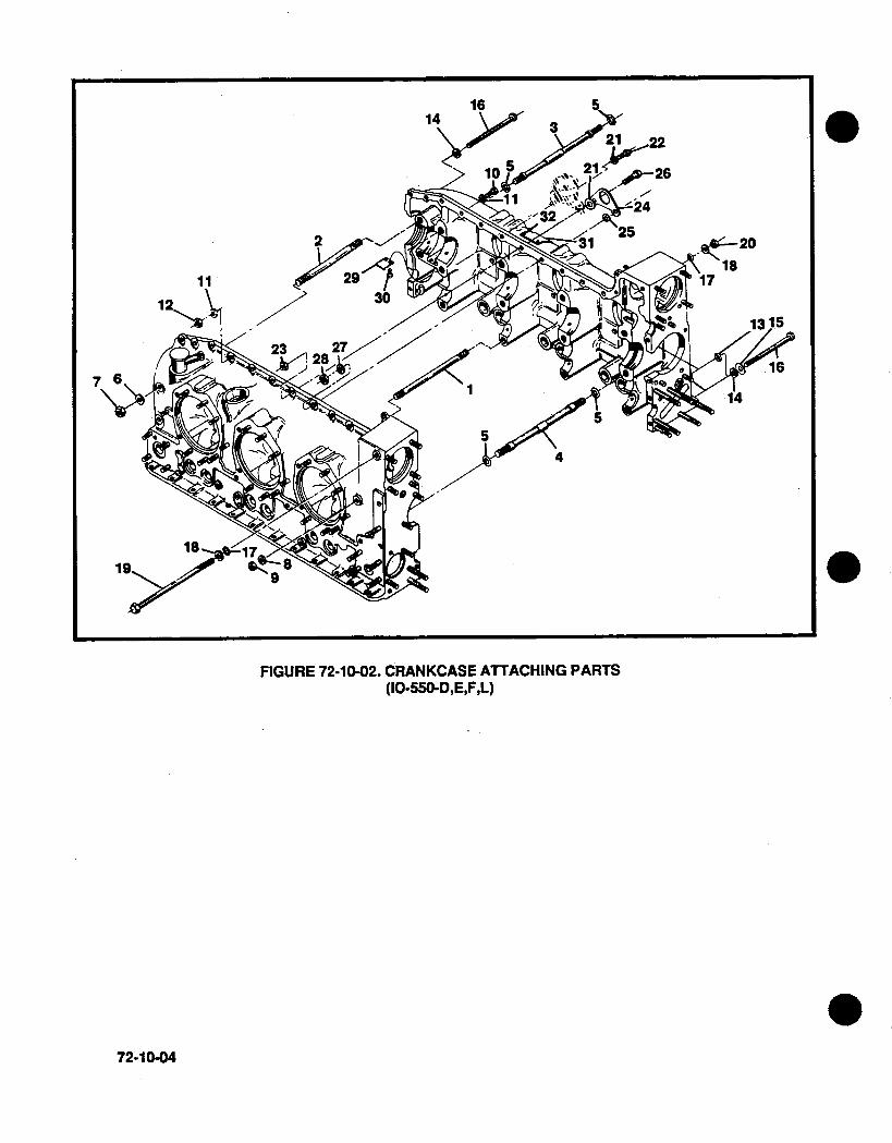
FIGURE 72-10-02. CRANKCASE ATTACHING PARTS(10-550-D,E,F,L)
72-10-04
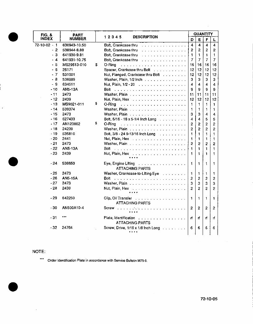
FIG. & PART 234 DECITOINDEX NUMBER12345 DECITO
72-10-02 - 1- 2-3-4-5- 6- 7- 8- 9- 10-11- 12- 13- 14-15-16-17-18- 19-20-21-22-23
630943-10.50538944-8.88641930-9.81641 931-10.75MS2951 3-01 025171531001538989634511AN5-1 3A24732439MS9021-01 15393742473627433AN1 238622423953581024412473AN5-1 3A2439
-24 538650
-25- 26
-27- 28
2473AN5-1 5A24732439
-29 642250
-30 AN50OA10-4
-31 ..
-32 24764
Bolt, Crankcase thru ...............Bolt, Crankcase thru ...............Bolt, Crankcase thru ...............Bolt, Crankcase thru ...............
$ 0-Ring . . . . . . . . . . . . . . . . . . . . . .Spacer, Crankcase thru Bolt ...........Nut, Flanged, Crankcase thru Bolt.Washer, Plain, 1/2 Inch ..............Nut, Plain, 1/2 - 20 ................Bolt ........................Washer, Plain ...................Nut, Plain, Hex ..................
$ 0-Ring . . . . . . . . . . . . . . . . . . . . . .Washer, Plain ...................Washer, Plain ...................Bolt, 5/16 - 18 x 5-1/4 Inch Long.
$ 0-Ring . . . . . . . . . . . . . . . . . . . . . .Washer, Plain ...................Bolt, 3/8 - 24 9-13/16 Inch LongNut, Plain, Hex ..................Washer, Plain ...................Bolt ........................Nut, Plain, Hex ..................
Eye, Engine Lifting ................ATTACHING PARTS
Washer, Crankcase-to-Lifting Eye.Bolt ........................Washer, Plain ...................Nut, Plain, Hex ..................
Clip, Oil Transfer .................ATTACHING PARTS
Screw ....... I................
Plate, Identification ................ATTACHING PARTS
Screw, Drive, 1/16 x 1/8 Inch Long.
NOTE:
.. Order Identification Plate in accordance with Service Bulletin M75-5.
72-10-05
I UANTITYID E F L4217161212349
1 112
3422
2
1
1232
2
rf
6
4217161212349
1 112
3422
2
1
1232
1
2
rf
6
42171 61 21 23491 11211452211211
232
2
rf
6
42171 61212349
1 112114522.11211
1
1232
1
2
rf
6

FIGURE 72-10-03. CRANKCASE ASSOCIATED PARTS (10-550-D,E,F,L)
FIG. & PART IINDEX NUMBER 1 2 3 4 5 DESCRIPTION
72-10-03 - 111222
345
- 6- 7- 8- 9
539518646688646689643935634673646748
5390582441627773
2473627433534740534728
-10 MS35337-44- 11 646605
Bracket, Engine Mount ........Bracket, Engine ............Bracket, Engine ............Bracket, Engine Mount, Cyl. No. 2Bracket, Engine Mount & AlternatorBracket, Engine Mount & Alternator
ATTACHING PARTSWasher, Plain .............Nut, Plain, Hex ............Nut, Barrel ... .......... .
Washer, Plain .............Bolt, 5/16-18 x 5-1/4 Inch Long ....
$ Gasket, Idler Support Pin .......Pin, Idler Support ...........
ATTACHING PARTSWasher, Lock .............Nut, Plain, Hex ............
72-10-06
QUANTITYD3
1
16164
1111
22
E3
1
161 64
111
2
2
F3
1
161 64
1111
22
L1
1
161 64
1111
22
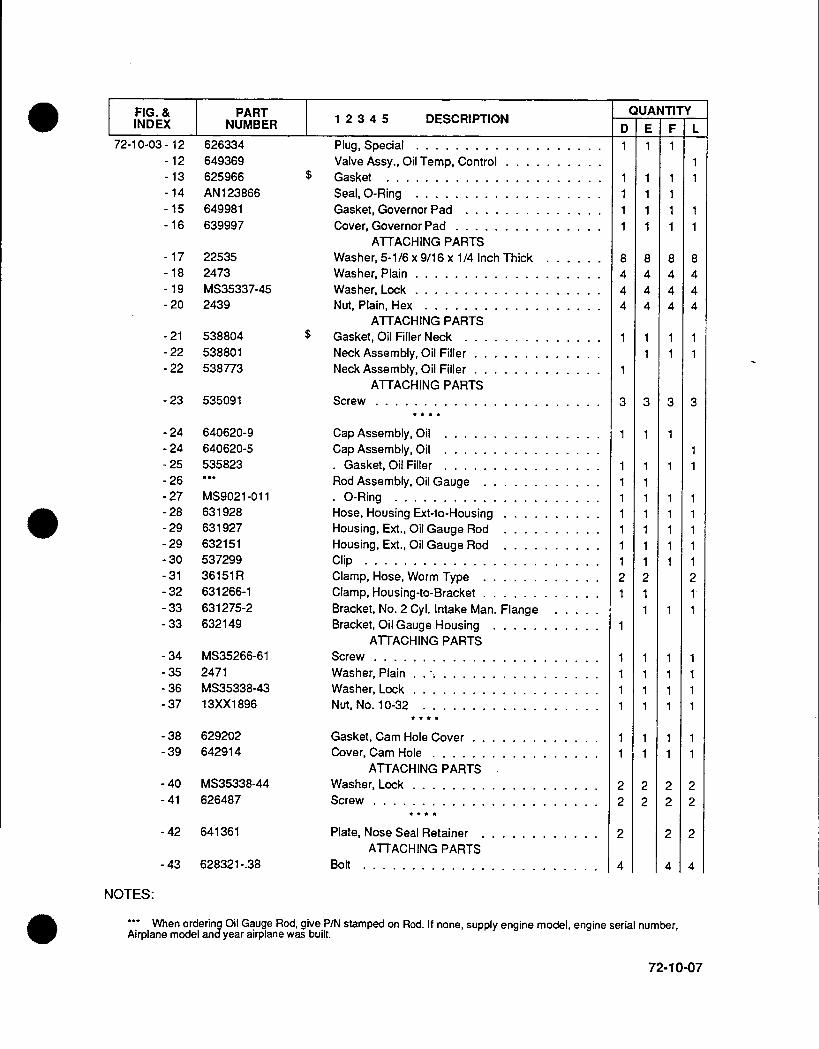
F FIG. & PART 234 DECITOINDEX NUMBER 12345 DECITO
72-10-03 -12- 12-13-14- 15- 16
626334649369625966AN1 23866649981639997
-17 22535- 18 2473-19 MS35337-45-20 2439
-21 538804-22 538801-22 538773
-23 535091
-24- 24-25-26- 27-28-29-29-30-31-32-33-33
- 34- 35- 36- 37
640620-9640620-5535823
MS9021 -01163192863192763215153729936151 R631266-1631275-2632149
MS35266-612471MS35338-4313XX1 896
-38 629202-39 642914
-40 MS35338-44-41 626487
-42 641361
-43 628321-.38
Plug, Special ...................Valve Assy., Oil Temp, Control ..........
$ Gasket . . . . . . . . . . . . . . . . . . . . . .Seal, 0-Ring ...................Gasket, Governor Pad ..............Cover, Governor Pad ...............
ATTACHING PARTSWasher, 5-1/6 x 9/16 x 1/4 Inch Thick.Washer, Plain ...................Washer, Lock ...................Nut, Plain, Hex ..................
ATTACHING PARTS$ Gasket, Oil Filler Neck ..............
Neck Assembly, Oil Filler .............Neck Assembly, Oil Filler .............
ATTACHING PARTSScrew .......................
Cap Assembly, Oil ................Cap Assembly, Oil ................
Gasket, Oil Filler ................Rod Assembly, Oil Gauge ............
0 -Ring .....................Hose, Housing Ext-to-Housing ..........Housing, Ext., Oil Gauge Rod ..........Housing, Ext., Oil Gauge Rod ..........Clip ........................Clamp, Hose, Worm Type ............Clamp, Housing-to-Bracket ............Bracket, No. 2 Cyl. Intake Man. FlangeBracket, Oil Gauge Housing ...........
ATTACHING PARTSScrew .......................Washer, Plain . ..Washer, Lock ...................Nut, No. 10-32 ..................
Gasket, Cam Hole Cover .............Cover, Cam Hole .................
ATTACHING PARTSWasher, Lock ...................Screw .......................
Plate, Nose Seal Retainer ............ATTACHING PARTS
Bolt ........................
I QUANTITY
1
8444
3
E
1111
8444
1
3
F1
1111
8444
11
3
I -1118444
3
NOTES:
.. When ordering Oil Gauge Rod, give P/N stamped on Rod. If none, supply engine model, engine serial number,Airplane model and year airplane was built.
72-10-07
[ D
1

17 "
FIG.URE 72-20-01. CRANKSHAFT GROUP(10-550-D,E,F,L)
72-20-00
23
1 ~12&",15
19
22
i
e. 0

FIG.& PARTINDEX FNUMBER 1 2 3 4 5 DESCRIPTION
72-20-01-1-2-3-4-5-6-7-8-9
646623350998633189639196639193639195639193643626-103643626-104643626-105
-10 643629- 11 629104
-12 642720-12 634503
-13 646288-14 626739-15 626889- 16 401893- 17 632443-4- 18 MS9021 -01 1-19 642249-20 536563-21 536421
-22 536379
Crankshaft and Damper Assembly ........+ .Bushing, Damper ................
*Plug, Oil Control ................*Counterweight Assy., 4th & 5th Order.*. Bushing, Counterweight ...........*Counterweight Assy., 6th Order ........*. Bushing, Counterweight ...........*Pin, Damper, 4th Order............*Pin, Damper, 5th Order............Pin, Damper, 6th Order............
ATTACHING PARTS* Plate, Pin Retaining ..............Ring, Retaining .................
±$ Bearing, Crankshaft ...............
+$ Bearing, Crankshaft ...............$ Washer, Thrust ..................+ Collar Assy., Governor Oil Transfer .......
Roll Pin .....................+ .Stud,1/4xl-1/41nchLong ..........
Nut, Marsden, Lock, 1/4 -28 ..........$ 0-Ring . . . . . . . . . . . . . . . . . . . . . .
Sleeve, Governor Oil Transfer ..........+ Dowel, Crankshaft-to-Gear ............
Gear, Crankshaft .................ATTACHING PARTS
Screw, 5/16-24 x 7/8 Inch Long .........
641250641306534757534741
Seal Assembly, Oil ......Spring ...........
Gear Assembly, Idler . ...Bushing ...........
NOTES:
See Page 72-00-04 for complete bearing set.
QUANTITYD
8
242
2
4
161 6
464
2222
1
6
7F
8
242
2
4
1 61 6
464
2222
1
6
L
812424224
1 616
46412222111
6
8
242
2
4
1 61 6
464
2222
1
6
- 23-24-25-26
1 11
1111
72-20-01
[ E
1111
. . . . . . . . .
. . . . . . . . .
. . . . . . . . .
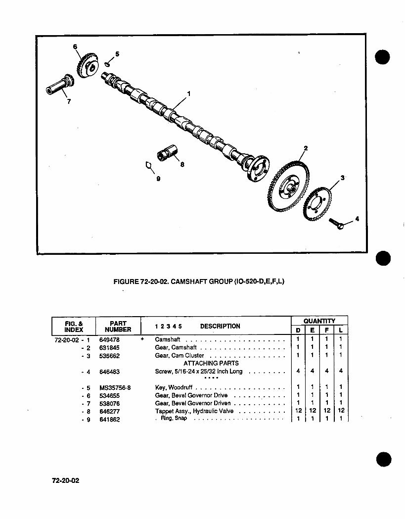
FIGURE 72-20-02. CAMSHAFT GROUP (10-520-D,E,F,L)
FIG. & PART 234 DECITOINDEX INUMBER 1I ECIlO
72-20-02 - 1- 2- 3
649478631845535662
- 4 646483
. 5- 6- 7- 8- 9
MS35756-8534855538076646277641862
+Camshaft............
Gear, Camshaft..........Gear, Cam Cluster ................
ATTACHING PARTSScrew, 5/16-24 x 25/32 Inch Long.
Key, Woodruff ..........Gear, Bevel Governor Drive ...........Gear, Bevel Governor Driven ...........Tappet Assy., Hydraulic Valve ..........
R ing, Snap ...........
72-20-02
QUANTITYD111
4
11I
121
E111
4
111121
F111
4
111
121
L111
4
111121

1
FIGURE 72-20-03. CONNECTING ROD ASSEMBLY
FIG. & PART 234 DECITOIINDEX NUMBER 1 ECITO
72-20-03 - 1- 2- 3- 4- 5
646482530658643112643215642398
Connecting Rod Assembly.......* Bushing, Piston Pin........* Bolt, Connecting Rod .............
. Nut, 7/16-28 ..................+Bearing, Connecting Rod ............
2
5
QUANTITYD
6
2212
E
612212
F6
2212
L
612212
72-20-03

FIGURE 72-30-01. CYLINDER ASSEMBLY
FIGURE 72-30-01A. 7TH STUD NUT IDENTIFICATION
FIG. & I PART 234 DECITOINDEX NUMBER 1 2 ECITO
72-30-01 - 1
- 2- 3
641066652954A1652954520112-3
72-30-00
$ 0-Ring ............Cylinder and Valve Assembly ..........* Cylinder Assembly ..............* . Insert, Spark Plug Thread ..........
3/4,. ~~~~~~~~~11/16"
SPHERICAL ~ ~ ~ ~ ~ ~ . -~ FLATSEAT ~~~~~~~~SEAT
7TH STUD FLANGE NUT 42 C L O DD W L N E N >CYL. HOLD DOW FLANGE NU\T40, 41
QUANTITYD6612
EE66
2
F6612
L6612
3/4"
SPHERICALSEAT

FIG. & PART 234 DECITOINDEX NUMBER 12345 DECITO
72-30-01 - 4- 5- 6- 7- 8- 9
- 10- 11- 12- 13- 14- 15- 16- 16- 17- 18- 19- 20- 21- 22- 23- 24- 25
643766648051646985638125MS 1221216423183596764628364628663152163783762539365211235971248026521316521292100765213065212921007639573648000
- 26 2473- 27 537019
- 28 534857- 29 625615
- 30 20522-31 MS35337-44- 32 649353-75
- 33 652458
-34 643967
-35-36-37-38-39
-40-41-42-43-44
537296534609534610626147538304
531001652541646312646297646298
4+* . Guide, Valve, Intake ..........
Guide, Valve, Exhaust .........* . Seal Assy., Intake Valve Guide --
*.Stud, Ring Locked ..............*.Insert, Intake Pipe Flange ..........*.Insert, Intake Valve Seat ..........*.Insert, Exhaust Valve Seat .........Valve, Intake ..................Valve, Exhaust ................Spring, Valve, Inner ..............Spring, Valve, Outer ..............Retainer. Valve Spring, Inner .........Roto-Coil,Assy.,Vlv.Spring,Outer(Exhaust)Retainer, Valve Spring Outer (intake) .....
*Key, Valve Spring Retainer ..........Rocker Assembly, Intake Valve .........
Bushing, Valve Rocker ............Screw, Drive ..................
Rocker Assembly, Exhaust Valve ........Bushing, Valve Rocker ............Screw, Drive ..................
+ W asher, Thrust .................
Shaft, Valve Rocker ...............ATTACHING PARTS
Washer, Plain ..................Screw, Hex Head ................
$ Gasket, Valve Rocker Cover..........Cover, Valve Rocker ...............
ATTACHING PARTSWasher, Plain ..................W asher, Lock ..................Screw, Fillister Head, 1/4 x 3/4 Inch Long ....
$ Gasket, Assembly, Exhaust Flange .......ATTACHING PARTS
Nut, Hex Head 1/4-28 ..............
Housing, Push Rod ...............Washer, Push Rod Housing ...........
$ Packing, Push Rod Housing ...........Spring, Push Rod Housing ...........
+ Push Rod Assembly ...............ATTACHING PARTS
Nut, Flanged, 7/16-20 ..............Nut, Flanged, 1/2-30 ...............Nut, Flanged, 7TH Stud .............Bracket, 7TH Stud (Flat) .............Bracket, 7TH Stud ('L').............
QUANTITYD11144111
222
462
621
241 2
1212
66
484848
6
24
1 248241212
3612642
E
44
11
222
2
21
24
12
1212
66
484848
6
24
1248241212
3612642
F
1
441
22211462
62
2412
1212
66
484848
6
24
1248241212
3612642
L111441111222114621621
2412
1 9
1 2
66
484848
6
24
1248241212
361 2642
72-30-01

INTENTIONALLY
LEFT
BLANK
0
72-30-02

FIGURE 72-30-02. PISTON AND PIN ASSEMBLY (ALL MODELS)
FIG. & I1 PARTINDEX NUMBER I 1 2 3 4 5 DESCRIPTION
648046A2 +648005 +648005CP TO2 $ +648006 +648006CP (DC2 $ +648007 a )$+648007CPOWX1$+648008 $648008CP $ +630048 (+
Piston, B.5:1 Compression Ratio ....
Ring, Compression, Top Groove.Ring, Compression, Top Groove ....
Ring, Compression, Second GrooveRing, Compression, Second GrooveRing, Oil Control, Third Groove.Ring, Oil Control, Third Groove .....Ring, Scraper, Fourth Groove ......Ring, Scraper, Fourth Groove ......Pin & Plug Assembly, Piston ......
QUANTITYD66
opt6
opt6
opt6
opt6
E66
opt6
opt6
opt6
opt6
F66
opt6
opt6
opt6
opt6
L66
opt6
opt6
opt6
opt6
NOTES:
(i These nings are optional and must be used in single cylinder sets. only.0) These rings are for use with chrome cylinders.(i These ring assemblies onntain a 646638, 643972 and 636145 ring respectively, which cannot be serviced
separately. Complete ring sets are listed on Page 72-00-04.
72-30-03
72-30-02 - 1223344556

13
15 .14
FIGURE 72-30-03. INDUCTION SYSTEM (10-550-D)
72-30-04
16-
1
8
113
4-
67
9 ~~~~~~7 1
27
9
.14
9 17

FIG. & PART 234 DECITOIINDEX NUMBER 1I ECITO
72.30-03 - 1- 2
536413629138
- 3 629325
-4-5-6
-7-8.9
- 10- 11- 12- 13- 14
20522MS35337-4424835
631972629163.5649994.13535681627820632871634209642523
.15 13XX202B- 16 530346
- 17 639596- 18 2024
$ Gasket, Intake Manifold Flange .........Tube Assy.. Intake Manifold.
1-2-3-4-5 Cylinder ..............Tube Assy., Intake Manifold. No. 6 Cyl .....
ATTACHING PARTSWasher, Plain ..................Washer, Lock ..................Screw, 1/4-20 x 7/8 Inch Long .........
Clamp, Hose .. ....Clamp Assembly, Hose ......Hose, Intake Manifold .......Tube, Elbow 2-4-6 Side ......Tube Assembly, Elbow 1-3-5 SideBracket, Balance Tube ......Clamp, Balance Tube Bracket .Tube Assembly, Balance . ...
ATTACHING PARTSWasher, Lock ..................Screw, 5/16-18 x 7/8 Inch Long .........
Throttle Assembly, Air ...............Plug, Pipe, 1/8-27 NPTF ............
QUANTITYE F LD
6
5
24
2424
1 6210
rf
72-30-05
. . . . . . .. . . . . . .. . . . . . .. . . . . . .. . . . . . .. . . . . . .. . . . . . .. . . . . . .

16
23
1
10 9'
22
2
8
11
FIGURE 72-30-04. INDUCTION SYSTEM (10-550-E)
FIG. & PART 234 DECITOIINDEX NUMBER 1 ECITO
72-30-04 - 1- 2
649959629138
- 3 629325
- 4 24835- 5 MS35337-44- 6 20522
- 7 631972- 8 36151 L- 9 629163-5
72-30-06 August 1991
$ Gasket, Intake Manifold Flange .........Tube Assy., Intake Manifold,
No. 1 -2-3-4-5 Cylinders ............Tube Assy., Intake Manifold, No. 6 Cyl.
ATTACHING PARTSBolt 1/4 .20 x 7/8 Inch Long ...........Washer, Lock ...................Washer, Plain ..................
Clamp, Hose ...................Clamp, Hose ...................Clamp Assembly, Hose .............
QUANTITYD ~E F L
6
51
242424
882

FIG. & PART 234 DECITOINDEX INUMBER 1I ECITO
72-30.04 - 10- 11-12- 13- 14-15-16
649994-1364691064690962951 8-1 H646812AN737TW46632280
-.17 537961- 1 8 MS3533 7-45
- 9 641643- 20 AN4-26A-21 MS20364-428-22 634805-23 6348 07--.24 538468.25 627681
-26 646483-27 MS35337-44- 28 2439-29 537750-30 13XX202B.31 2473
-32 627836
-33 646605-34 MS35337-44.35 20522
-36 627368 $.37 652937A2 $
Hose, Intake Manifold ......Tube, Elbow, Left Side ......Tube, Elbow, Right Side .....Plug, Elbow ............Tube Assembly, Balance .....Clamp, Balance Tube ......Bracket, Balance Tube .....
ATTACHING PARTSScrew, 5/16 - 18 x 1 Inch LongWasher, Lock ..........
Bracket Assembly Air ThrottleBolft................Nut, Self Locking .........Bracket, L/H, Air Throttle SupportBracket, R/H, Air Throttle SupportBushing, Air Throttle Support .Bracket, Crankcase-to-Air Throttle
ATTACHING PARTSScrew 5/16 - 24 x 5/8 Inch LongWasher, Lock ...........Nut, Plain .............Screw 5/16.- 18 x 1 1 /8 Inch LongWasher, Lock ...........Washer, Plain ..........
Bracket, Air Throttle Support ...ATTACHING PARTS
Nut, Plain 1/4 ...........Washer, Lock ...........Washer, Plain ..........
Gasket, Air Throttle Body ....
Throttle Assembly Air ......
QUANTITYE F
101
211
Ref
August 1991 72-30-07
D L

9-
FIGURE 72-30-05. INDUCTION SYSTEM (10-550-F,L)
FIG. & PART 234 DECITOIINDEX NUMBER 1I ECITO
72-30-05 - 1 536413- 2 629138
- 3 629325
- 4 20522- 5 MS35337-44-6 24835
- 7 631972- 8 36151 L- 9 629163-5- 10 649994-13- 11 632328- 12 632329-13 629518-1H- 14 653121-15 AN737TW46- 15 637255-4-16 652358
-17 13XX202B-18 537750
-19 629397A172-30-08 August 1991
Gasket, Intake Manifold Flange.Tube Assy., intake Manifold
1 -2-3-4-5 Cylinder ...........Tube Assy., intake Manifold, No. 6 Cyl.
ATTACHING PARTSWasher, Plain ...............Washer, Lock ...............Screw, 1/4-20 x 7/8 Inch Long ......
Clamp, Hose.......Clamp, Hose.......Clamp, Assembly, Hose....Hose, Intake Manifold .......Tube Assy., Elbow 2-4-6 Side .Tube Assy., Elbow 1-3-5 Side...Plug, Pipe, 1/8-27 NPTF ......Bracket, Balance Tube .......Clamp, Balance Tube Bracket .-Clamp, Band, Balance Tube . ...
Tube Assembly, Balance ......ATTACHING PARTS
Washer, Lock ............Screw, 5/16-18xl1-1/81Inch Long-
Throttle Assy., Air .........
3 ~~~~~~~~~~~~~~28
2a
2 *~~~~~~~~~~~~-- 277
10
QUANTITYD E
I
F6
5
24
2424
84
8
21 0
21
rf
L6
5
24
2424
84
8
210
2
rfrf
rf
3
2
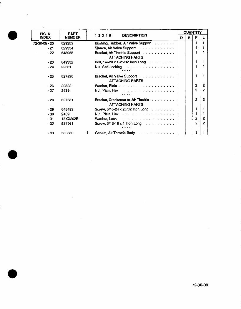
FIG. & PART 234 DECITOIINDEX NUMBER 1I ECITO
Bushing, Rubber, Air Valve Support.Sleeve, Air Valve Support............Bracket, Air Throttle Support ...........
ATTACHING PARTSBolt, 1/4-28 x 1-25/32 Inch Long .........Nut, Self-Locking .................
Bracket, Air Valve Support ............ATTACHING PARTS
Washer, Plain ...................Nut, Plain, Hex ..................
Bracket, Crankcase-to-Air Throttle.ATTACHING PARTS
Screw, 5/16-24 x 25/32 Inch Long.Nut, Plain, Hex ..................W asher, Lock ..................Screw, 5/1 6-18 x 1 Inch Long ..........
$ Gasket, Air Throttle Body .............
QUANTITYD
72-30-05- 20-21- 22
- 23- 24
- 25
- 26- 27
- 28
- 29- 30- 31- 32
- 33
629353629354643085
64935222661
627836
205222439
627681
646483243913XX202B537961
630350
F111
11
1
22
2
1122
1
L111
11
1
22
2
1122
1
72-30-09
E
18 18
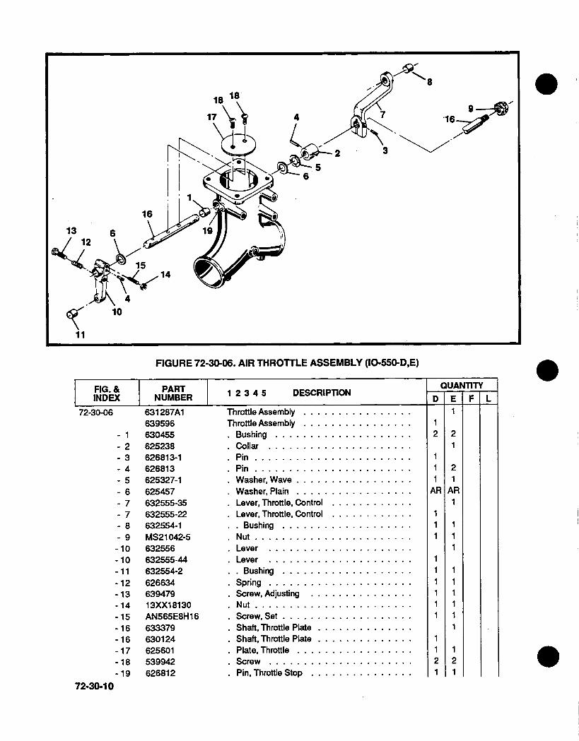
FIGURE 72-30-06. AIR THROTULE ASSEMBLY (10-550-D,E)
FIG. & I PART 234 DECITOINDEX NUMBER 12345 DECITO
72-30-06
- 1- 2- 3- 4. 5- 6-.7- 7- 8- 9- 10.10-11- 12-13- 14- 15- 16- 16- 17- 18-19
72-30-10
631 287A1639596630455625238626813-1626813625327-1625457632555-35632555-22632554-1MS21 042-5632556632555-44632554-262663463947913XX1 81 30AN565E8H 16633379630124625601539942626812
Throttle Assembly ....
Throttle Assembly.*Bushing ........*Collar .........*Pin ...........*Pin ...........*Washer, Wave .....*Washer, Plain .....*Lever, Throttle, ControlLever, Throttle, Control
Bushing ........Nut ...........
Lever .........Lever .........
Bushing .......Spring .........Screw, Adjusting ...Nut ...........Screw, Set .......Shaft, Throttle PlateShaft, Throttle PlatePlate. Throttle .....Screw .........Pin, Throttle Stop ...
4 ~~~~~~~~~~16~
56
16
13 6
10
QUANTITY
Di E F L1
21
21
AR1
111
1111I1
121
2
AR
111R
111
1121
4
1-11�

FIGURE 72-30-07. AIR THROTTLE ASSEMBLY (10-550-F,L)
FIG. & PART 234 DECITOINDEX INUMBER 1 ECITO
72-30-07 629397A1 Throttle Assembly ................- 1 630455 .Bushing ....................- 2 626813 .Pin .......................- 3 625327-1 .Washer, Wave .................- 4 625457 .Washer, Plain .........- 5 632555-31 .Lever, Throttle Control . . . . . .
- 6 632554-1 .. Bushing ..........
-7 626634 .Spring ...........- 8 639479 .Screw, Adjusting ...............
- 9 632555-23 .Lever .....................
- 10 632554-2 .. Bushing ...................- 11 631819 .Shaft, Throttle Plate ..............- 12 625601 .Plate, Throttle .................-13 539942 .Screw .....................- 14 626812 .Pin, Throttle Stop ...............
QUANTITYD E F
1221
AR111
11
21
L122
AR111
1111
21
72-30-11

0
S72-50-01. OIL SUMP (10-550-D,E,F)
FIG. & PART 234 DECITOINDEX NUMBER12345 ERIiO
534940625207
20522MS20074-04-04MS20074-04-03
534743633412537650MS35769-1 1MS35769-1 55324322473MS35337-45530346537750
4i Gasket, Suction Tube Assembly........Tube Assembly, Suction, Oil Pump.......
ATTACHING PARTSWasher, Plain ....
Bolt..........Bolt..........
$ Gasket, Oil Sump .............Sump Assembly, Oil ............Sump Assembly, Oil ............
$ .Gasket, Annular .............$ .Gasket, Annular .............
*D Plug, Oil Drain.........Washer, Plain ...............Washer, Lock ...............Screw, 5/16-18 x 7/8 Inch Long.Screw, 5/16-18 x 1 -1 /8 Inch Long.
IQUANTITYED:
222
2
32
3232
E11
222
2
3232
F
222
11
1
13032302
L
NOTE:
(D The magnetic drain plug. P/N 636376 may be used as an option to drain plug P/N 532432.
72-50-00
72-50-0 1 - 1- 2
- 3- 4- 5
- 6- 7- 7- 8- 8. 9- 10-11- 12-12
11
11
...........
...........
...........

FIGURE 72-50-02. OIL SUMP (10-550-L)
FIG. & PART 234 DECITOINDEX NUMBER12345 DSCIiN
53494063564020522MS20074-04-04MS20074-04-035347436356162473MS35337-45530346537750537961MS35769-1 1
-12 532432
$ Gasket, Suction Tube Assembly .Tube Assembly, Oil Pump Suction.Washer, Plain ..................Bolt . . . . . . . . . ..hBolt . . . . . . . . . . . . . . . . . . . . . . .
$ Gasket ......................Sump Assembly, Oil ..............Washer, Plain ..................Washer, Lock ..................Screw, 5/16 x 7/8 Inch Long ..........Screw, 5/16 x 1 -1 /8 Inch Long .........Screw, 5/16 x 1 Inch Long ...........
$ Gasket, Annular .................® Plug . . . . . . . . . . . . . . . . . . . . . . . . . .
1122211
2832282211
NOTE:
0 The magnetic drain plug. P/N 636376 may be used as an option to drain plug P/N 532432.
72-50-01
QUANTITY
72-50-02 - 1- 2- 3- 4- 5- 6- 7- 8- 9
-10-10-10-11
D FE F L

FIGURE 72-50-03. OIL PUMP ASSEMBLY (IO-550-D,F)
72-50-02
23
35436
' 1 5

FIG. & PART 234 DECITOINDEX NUMBER 1 ECIO
72-50-03 3- 1 538185631 71 4A7
- 2 631714- 3 401800- 4 401963- 5 AN932-2- 6 629218- 7 539523- 8 642336- 9 634150- 10 631653- 11 642335-12 MS35769-26- 13 642224- 14 MS124657-15 X1473-16 632762-17 629448-18 535634- 19 535008-20 625886-21 631650-22 632085-23 21208A2-24 642714-25 MS35769-48-26 538727-27 Q9T1 16-218-28 MS20073-04-1-29 Q9S552-06-30 535933-31 Q9T1 16-07-32 628129-33 631638-34 631478-35 MS35769-18-36 631995
-37 20522- 38 MS35338-44-39 646605
$ Gasket, Oil Pump Housing-to-CrankcaseOil Pump Assembly, Complete .....
+ Housing & Shaft Assy., Oil Pump .+ Stud, 1/4 x 1-1/1 6 Inch Long ....
+ .Stud, 1/4 x1 Inch Long ......* Plug. Pipe ..............Gear Assy., Oil Pump Driven ....
Bushing, Oil Pump Gear ......Plunger, Oil Press, Relief Valve...Spring, Oil Press, Relief Valve ....
Washer, Spring Guide ........Screw. Adjusting ...........
$ .Gasket ................Housing Oil Press, Relief Valve...
Helical Coil .............Washer, Copper ...........Nut, Adjusting ............Shaftgear Assy., Tach Drive, O/P.
Pin, Dowel .............Gear, Bevel, Tach Drive .......Cover, Right Angle Tach Drive, 0/PShaft Assembly, Tach Drive .....
$ .Gasket, Cover Tach Housing ....
Housing Assembly, Tach Drive ...$ .. Seal, Oil, Tach Housing ......$ .Gasket, Annular ...........
Filter Assembly, Oil.........Tube Assembly, Perforated . ...
Bolt, Drilled Hex Head .......Washer, Annular 1/4 Inch .....Gasket, Felt, 5/8 Inch ID ......Element Filter ...........Body Casting, Filter........
Valve, Filter By-Pass .........Spring, Filter By-Pass ........
$ .Gasket, Copper...........Pin and Plug Assy., Oil Pump By-Pass
ATTACHING PARTSWasher, Pin ...............Washer, Lock ...............Nut, Plain, Hex ..............
IQUANTITY
L111111
21
1111111111111
11
12
1
1
1313
13
1111111211111111111111111111112111111
131313
72-50-03
7D 7E F F

FIGURE 72-50-04. OIL PUMP ASSEMBLY (10-550-E,L)
FIG. & PART 234 DECITOINDEX NUMBER 1I ECITO
$ Gasket, Oil Pump-to-CrankcaseOil Pump Assembly ........Oil Pump Assembly ........
*Housing Assembly .......+ .. Stud, 1/4 x1-1 /l6 Inch Long+ .. Stud, 1/4 x1 Inch Long . ...
*.Stud, adapter ..........Piug ...............Plug ..............
*Gear Assy., Oil Pump Driven .*. Bushing, Oil Pump Gear ...
*Plunger, Oil Press, Relief Valve*Spring, Oil Press, Relief Valve*Seat, Spring Guide .......
QUANTITYD
72-50-04 - 1
- 2- 3- 4- 5- 6- 7- 8- 9-10-11- 12
F643749652428643778-1643743-1401800401963632373629518-1 HAN932-5629218539523642336634150631653
E11
12111
2
1
L1
112111112111
72-50-04

FIG. & PART I 234 DECPTOI INDEX NUMBER12345 DERITN
72-50-04 - 13- 14-15-16-17-18-19- 20-21- 22- 23- 24- 25- 26- 27- 28- 29- 30-31- 32
642335MS35769-26642224MS1 24657X1 47363276262944853563453500862588621208642714631650632085538789A1531378401893535908535885535887
- 33 2471- 34 MS35337-43-35 20655
- 36 MS9134-01-37 640380
-38 2472-39 MS35337-44-40 646605
-41 20522.42 MS35337-44-43 646605
-44 649923
*Screw, Adjusting ........$ .Gasket .............
*Housing, Oil Press, Relief Valve*. Helical Coil ..........*Washer, Copper ........*Nut, Adjusting Screw, 5/16-24*Shaftgear Assembly. Tach Drive* Pin, Dowel ..........*Gear, Bevel, Tach Drive ....
*Cover, Right Angle Tach ....
*Housing, Tach Drive ......$ . . Seal . . . . . . . . . . . . .
*Shaft Assembly, Tach Drive*Gasket, Tach Drive Housing
Cover Assembly, Oil Pump ....
$ .Seal Oil ......+ .Stud, 1/4 x 1 -l4 InchLong
Gear, Bevel, Tach Drive .....$ Gasket ..............
Cover, Tach Gear Box ......ATTACHING PARTS
Washer, Plain ...........Washer, Lock ...........Screw ...............
$ Gasket ..............Cover, Tach Drive Pad ......
ATTACHING PARTSWasher, Plain ...........Washer, Lock ...........Nut, Plain, Hex ..........
ATTACHING PARTSWasher, Plain ...........Washer, Lock ...........Nut, Plain .............
Filter Assembly ..........
IQUANTITY
7D FE111111111
111111
444
11
444
131313
1
L1111
1 31313
1
72-50-05

FIGURE 73-10-01. FUEL INJECTION SYSTEM (10-550-D)
FIG. & PART 234 DECITOINDEX NUMBER12345 DERIiN
73-10-01 - 1 631684 Gear Assy., Fuel Pump Drive ..........- 2 539634 . Plug ......................
- 3 649990 $ Gasket, Fuel Pump-to-Crankcase ........- 4 631683 Coupling .....................
649052A1 1 Fuel Injection Assembly, Complete .......
73-10-00
QUANTITYD E F L11111
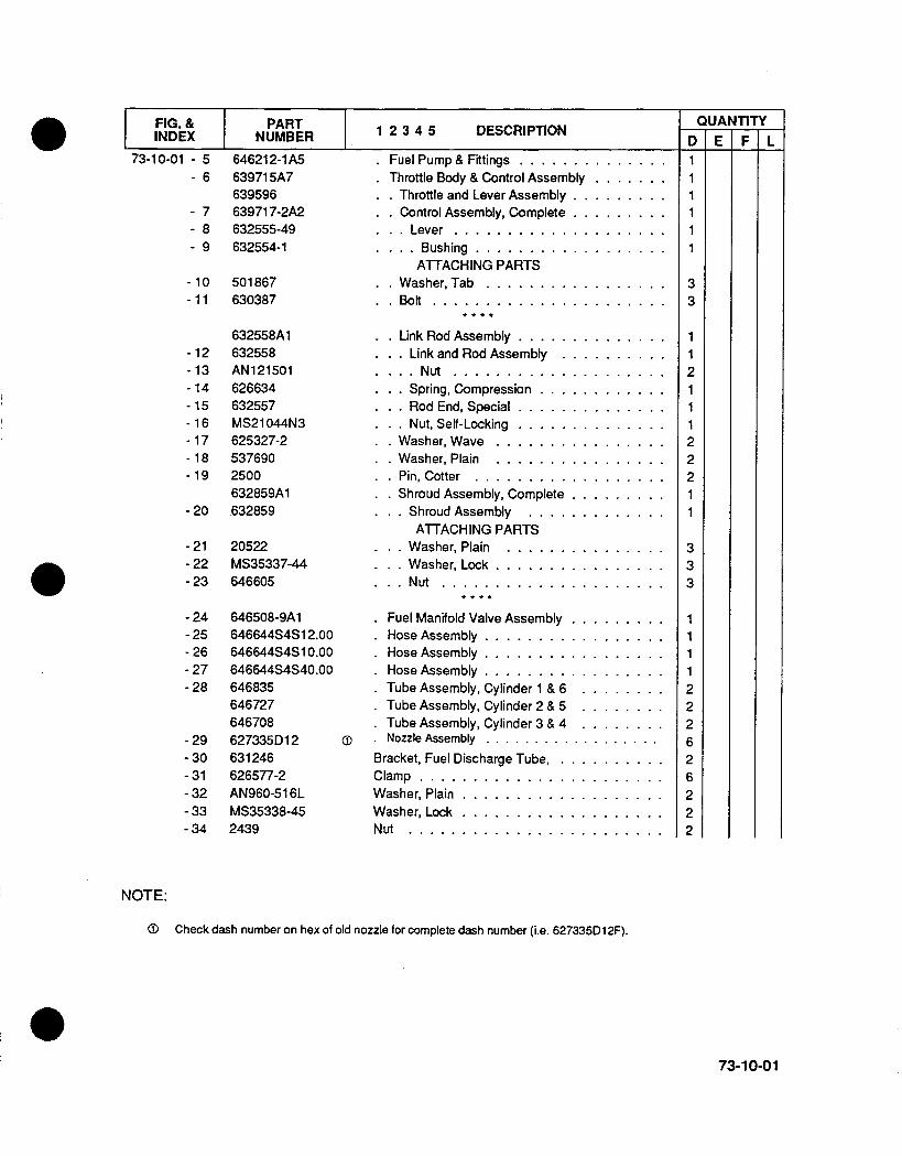
FIG. & PART 234 DECITOI INDEX I NUMBER12345 DERITO
73-10-01 - 5- 6
789
64621 2-1 A563971 5A763959663971 7-2A2632555-49632554-1
-10 501867-11 630387
632558A1-12 632558-13 AN121501-14 626634-15 632557-16 MS21044N3-17 625327-2-18 537690-19 2500
632859A1.20 632859
-21 20522-22 MS35337-44-23 646605
-24 646508-9A1-25 646644S4SI2.00- 26 646644S4S1 0.00- 27 646644S4S40.00-28 646835
646727646708
-29 627335D12-30 631246-31 626577-2-32 AN960-51 6L-33 MS35338-45-34 2439
*Fuel Pump & Fittings ..............*Throttle Body & Control Assembly.
*.Throttle and Lever Assembly .........*.Control Assembly, Complete .........
Lever ....................Bushing ..................
ATTACHING PARTSWasher, Tab .................Bolt ......................
-. Link Rod Assembly ..............Link and Rod Assembly ..........
. .Nut ....................Spring, Compression ............
*..Rod End, Special ..............Nut, Self-Locking ..............
Washer, Wave ................W asher, Plain ................
*.Pin, Cotter ..................Shroud Assembly, Complete .........
Shroud Assembly .............ATTACHING PARTS
- ..W asher, Plain ...............
Washer, Lock ..................Nut .....................
Fuel Manifold Valve Assembly .........Hose Assembly .................Hose Assembly .................Hose Assembly .................Tube Assembly, Cylinder 1 & 6 ........Tube Assembly, Cylinder 2 & 5 ........
*Tube Assembly, Cylinder 3 & 4 ........Nozzle Assembly ..................
Bracket, Fuel Discharge Tube ...........Clamp .......................Washer, Plain ...................Washer, Lock ...................N ut . . . . . . . . . . . . . . . . . . . . . . . .
QUANTITYD1
FE F L
NOTE:
0 Check dash number on hex of old nozzle for complete dash number (i.e. 627335D1 2F).
73-10-01

28K-42~
.37
FIGURE 73-10-02. FUEL INJECTION SYSTEM (10-550-E)
FIG. & I PART I 234 DECPTOI-INDEX NUMBER12345 DE RIT N
- 1 631684- 2 539634- 3 649990- 4 631683
649052A3-1* 5 646824-lAl- 6 631550A10
631287A1
Gear Assembly, Fuel Pump .....* Plug .................
$ Gasket, Fuel Pump-to-Crankcase .Coupling ...............Fuel Injection Assy., Complete ....
* Fuel Pump and Fittings .......* Throttle Body and Control Assembly* . Throttle and Lever Assembly...
I
J~z
73-10-02
QUANTITYD 7E F L
73-10-02
1
1
II

FIG. & PART 234 DECITO~ INDEX NUMBER12345 DERIIN
73-10-02 - 789
629904-2A6632555-35632554-1
- 10 501867- 11 630387
632,558AI-12 632558-13 AN121501-14 626634-15 632557-16 MS21044N3- 17 625327-2-18 537690-19 2500-20 646673
-21 20522-22 MS35338-44-23 646605-24 537629
-25 646508-9A1-26 635158S4S1 2.00-27 635158S4S12.00-28 635158S4S40.00-29 646835-29 646727-29 646837-30 6273351)12-31 626486-32 626577-2-33 AN960-516L-34 MS35337-45-35 2439
*.Control Assembly, Complete*..Lever ...........
*...Bushing .........ATTACHING PARTS
*.Washer, Tab ........*.Bolt .............
*.Link Rod Assembly .....*..Link and Rod Assembly.. NNut ...........
Spring, Compression...**Rod End, Special .....
Nut, Self-Locking .....Washer, Wave .......Washer, Plain ........Pin, Cotter .........Shroud Assembly ......
ATTACHING PARTSWasher, Plain ........Washer, lock ........Nut .............Screw ............
Fuel Manifold Valve AssemblyHose Assembly ........Hose Assembly ........Hose Assembly ........Tube Assy., Cylinder 1 & 6Tube Assy., Cylinder 2 & 5Tube Assy., Cylinder 3 & 4
*Nozzle Assembly .. ...
Bracket, Fuel Discharge Tube,Clamp ..............Washer, Plain ..........Washer, Lock ..........Nut . . . . . . . . . . . . . . .
111
NOTE:
CiD Check dash number on hex of old nozzle for complete part number (i.e. 627335Dl3A).
73-10-03
QUANTITYD E F L

24. - - k '
1
FIGURE 73-10-03. FUEL INJECTION SYSTEM (10-550-F,L)
FIG. & PARTII DECPTOINDEX NUMBER12345 DECITO
73-10-03 - 1 631684- 2 539634- 3 649990- 4 631683
649053A3- 5 646824-lAl- 6 629399A8
629397A1- 7 629703-2A3- 8 632555-5- 9 632554-2
-10 626813
- 11 501867
73-10-04
Gear Assembly, Fuel Pump ...........Plug . . . . . . . . . . . . . . . . . . . . . .
$ Gasket, Fuel Pump-to-Crankcase .Coupling, Fuel Pump Drive...........Fuel Injection Assy., Complete ..........*Fuel Pump & Fittings .............*Throttle and Control Assembly
Throttle and Lever Assembly.Control Assembly, Complete
Lever ....................* ... Bushing . . . . . . . . . . . . . . . . .
Pin, Tubular ................ATTACHING PARTS
Was~her, Tab .................
QUANTITYD FE L
1
11rf1
3
1
111rf11
3
[ F
I
i
I
I
I
. JI
II
I
I

FIG. & PART 234 DECITOINDEX NUMBER 1I ECI~O
73-10-03 - 12 630387
- 13 642283A1-14 626634-15 632557-1-16 MS21044N3- 17 625327-2-18 537690-19 2500
629338A1-20 629338
-21 20522- 22 MS35337-4.4- 23 646605
- 24- 25- 26- 27- 28- 28- 28- 29- 30-31- 32- 33- 34
646508-gA1646644S4S 14.00646644S4S 10.00646644S4S32.00646835646727646837627335D1 2626486626577-2AN960-516LMS35338-452439
.Bolt............
*.Link Rod Assembly, Complete*..Spring, Compression ......*..Rod, End ..................*..Nut, Self-Locking ..............Washer, Wave ................Washer, Plain ................Pin, Cotter ..................Shroud Assembly, Complete ...
Shroud Assembly .............ATTACHING PARTS
Washer, Plain ...............Washer, Lock ........
..Nut ...........
Manifold Valve Assembly, Fuel.....Hose Assy., Fuel Pump-to-Control.Hose Assy., Control-to-Fuel Pump.Hose Assy., Control-to-Man, Valve.Tube Assembly, Cylinders 1 & 6Tube Assembly, Cylinders 2 & 5Tube Assembly, Cylinders 3 & 4Nozzle Assembly..........
Bracket, Fuel Discharge Tube ..........Clam p . . . . . .. . ... .. .. . .. .. . .W asher, Plain ..................Washer, Lock ...................Nut ........................
3 3
I11122211
333
1111222626222
NOTES:CD Check dash number on hex of old nozzle for complete part number (i.e. 6273351)12F).
73-10-05
QUANTITYD E F L

1
FIGURE 73-10-04. FUEL PUMP AND VAPOR SEPARATOR ASSEMBLY
FIG. & PARIINDEX NUMRBER 1 2 3 4 5 DESCRIPTION D
QUANTITY
73-10-04
- 1- 1
646212-1lA5646824-1 Al642796646745
2 626879-1
Fuel Pump and Fittings .....Fuel Pump and Fittings .....* Shroud Assembly .......* Shroud Assembly .......
ATTACHING PARTS
* Grommet...........
I
3
1
1
4
1
1
4
1
1
4
NOTE: For detail parts, see Fuel Injection Systems Overhaul Manual and Parts Catalog. Form X30593A.
73-10-06
2210-550-D10-550- E,F&L
E ~F L. . . . . . .
. . . . . . .
. . . . . . .

FIGURE 73-10-05. FUEL PUMP AND VAPOR SEPARATOR FITTING LOCATIONS
NOTE:
G0 This part number not available. See Page 73-10-06 fcor omplete Fuel Pump Assembly.
73-10-07
Fuel Pump Mixture Vapor Seal& Vapor Inlet outlet Return Return Drain
Separator Fitting Fitting Ritting Fitting Fitting__________ Number 0 "A" Number "B" Number "C'. Number "D" Number "E" Number
10-550-D 632017 62711964621 2-1 MS20823-613 628438 628437 628476 628438
10-550-EF,L 632017 633343 627119646824-1 687286 628438 628476 628476 628438
____________ ___________ 62 8436 _ _ _ _ _ _ _ _ _ _ _

3
FIGURE 73-10-06. FUEL MANIFOLD VALVE ASSEMBLY (10-550-D,E,F,L)
FIG. & PART 234 DECITOIINDEX INUMBER 1I ECITO
646508-9AI- 1 646109
646113- 2 641030- 3 631330- 4 626557- 5 632425- 6 630184- 7 634325
- 8 AN500A8-12- 9 AN960-8
Valve Assembly, Manifold . ...
*Bracket Assembly .......*. Bracket Assembly ......*Body, Fuel Manifold ......*Seal, Plunger .........*Screen .............*Diaphragm & Plunger Assembly*Spring .............*Cover .............
ATTACHING PARTSScrew .............Washer ............
2
9I1-
5
7
73-10-06
QUANTITYD111111111
44
E1
11
11
44
7F11
44
L111111111
44
73-10-08
A ~~~~~~~~~~A
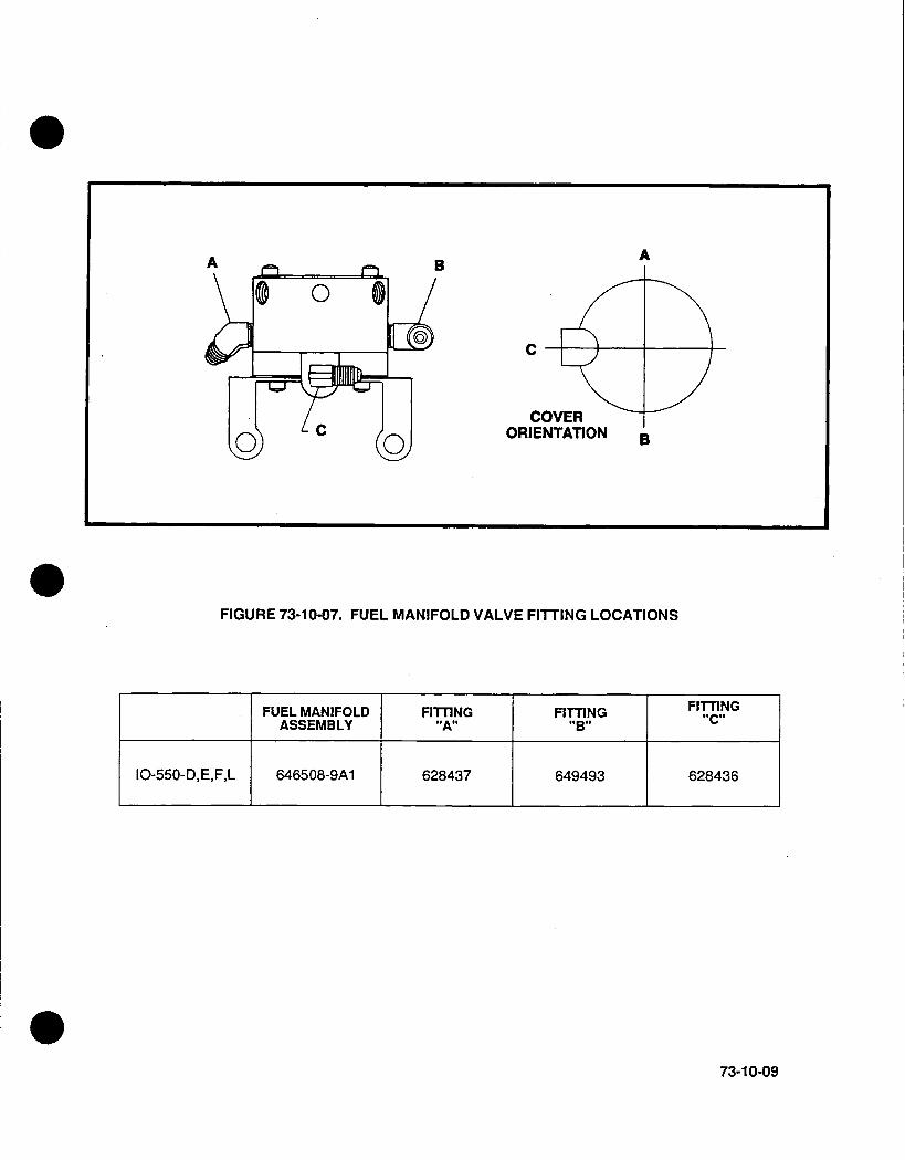
FIGURE 73-10-07. FUEL MANIFOLD VALVE FITTING LOCATIONS
FUEL MANIFOLD FITTING FITTING F I T..TIN G
ASSEMBLY A "B"C
10-550-D, E,F,L 646508-9Al 628437 649493 628436
73-10-09
- I I
COVE
ORIENTATION 5
Ats
I

0
FIGURE 73-10-08. FUEL CONTROL FITTING LOCATIONS
MODELControl AssemblyFuel Injection P/N
Port No. 1Filling No.
Port No. 2Fitting No.Port No. 3Fitting No.
Port No. 4Fitting No.
Port No. 5Finling No.
Mixture ControlLever "A"No.
Bushing - MixtureLever "B" No.Pin -Mixture
Lever "C" No.
Screw - MixtureLever "D" No.Lockwasher -
Mixture Lever "E"
Castle Nut -Mixture Lever "F"
MeteringloLever "G"No
Bushing - MeteningLever "H" No.
Pin - MeteringLever "J No.__
10-550-D
639717-2 ®
630119628476
628437
2024
628437
2024
632555-49
632554-1
626813
AN501 -1 0-1 0
13XX260
MS21 042-5
632555-24
632554-2
626813
10-550-E
629904-2 (D
628478
2024
2024
628437
628478
632555-35
632554-1
626813
AN501 -10-14
13XX260
MS21 042-5
632555-24
632554-2
626813
10-50-F,L
629703-2 cT
628478
2024
2024
628478
628438
632555-28
632554-1
626813-1
632555-5
6325.54-2
626813
NOTES:
CD This part number not available. See complete Fuel Injection for Control Assembly order number.
73-10-10
BA
' PORT NO. 3PORT NO. 4646665 GASKET539959 SCREEN ASSEMBLY

14
FIGURE 74-1 0-01. MAGNETO AND ACCESSORY DRIVE ASSEMBLY (ALL MODELS)
FIG. & I PART 234 DECITOINDEX NUMBER 1 ECITO
74-10-01 - 1- 2
-3-4-5-6-7-8-9
- 10- 11-12- 13- 14- 15- 16- 17
534863632653A1
63233025102250082473401507MS35337-45MS35338-4624392441629076629077531178638172MS91 34-0 1640380
-18 2472- 19 MS35337-44-20 646605
$ Gasket, Adapter-to-Crankcase ..........Adapter Assy., Magneto & Accy. Drive
Bushing, Adapter ................$ .Seal, Oil ....................+ .Stud, 1/4xl1-13/321Inch Long .........
W asher, Plain ..................W asher, Plain ..................Washer, Lock ...................Washer, Lock ...................Nut, Plain, Hex, 5/16-24 .............Nut, Plain, Hex, 3/8-24 ..............Gear Assy., Magneto & Accy. Drive .......
Sleeve, Drive Gear ...............Retainer, Magneto Drive Coupling ........Bushing, Drive Coupling, Rubber........
$ Gasket, Adapter-to-Cover ............
Cover, Accessory Drive .............ATTACHING PARTS
W asher, Plain ..................Washer, Lock ...................Nut, Plain, Hex, 1/4-28 ..............
121
5
118
/ 199C ~20
*. S w I,
10
QUANTITYF22
L22
D22
1
46262622
2422
888
E22
11462626221242
8
88
74-10-01
7 �
,,A kr u(j
15
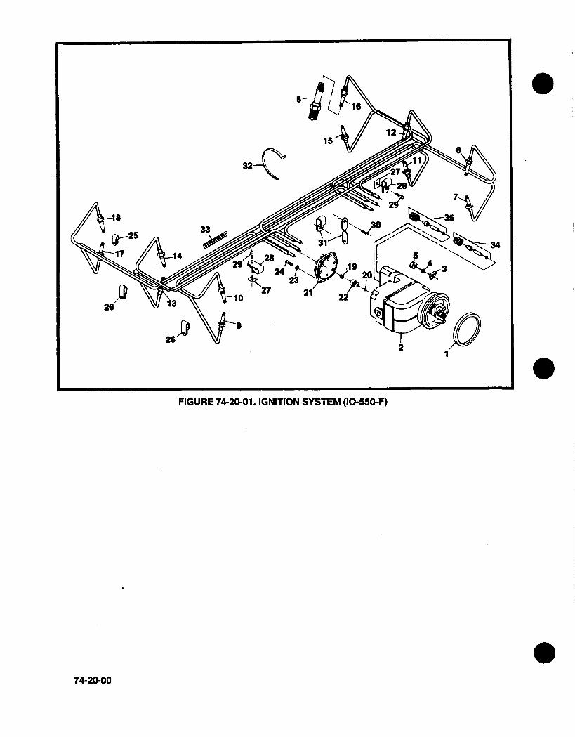
FIGURE 74-20-01. IGNITION SYSTEM (10-55G-F)
74-20-00
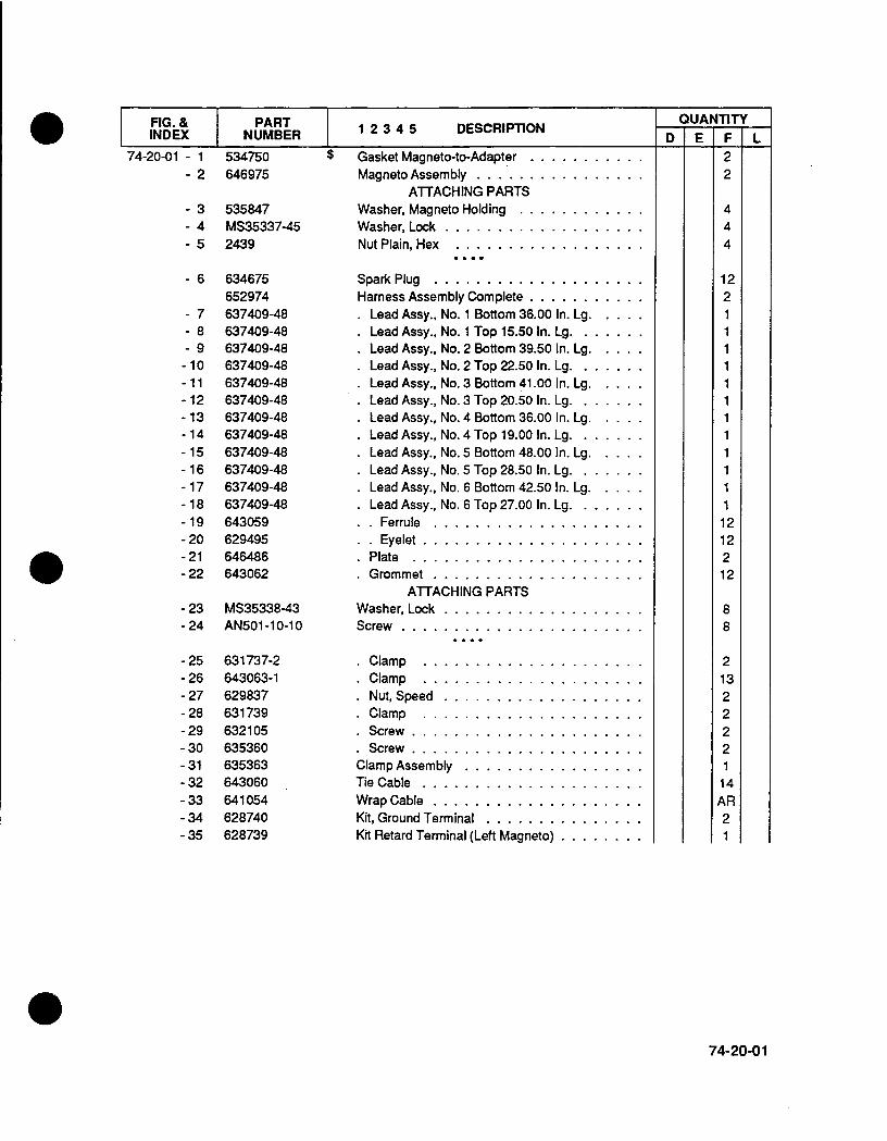
FIG. & I PART 234 DECITOI INDEX NUMBER 1I ECIiO
74-20-0 1 - 1- 2
- 3- 4- 5
534750646975
535847MS35337-452439
- 6 634675652974
- 7 637409-48- 8 637409-48- 9 637409-48-10 637409.48-11 637409-48-12 637409-48-13 637409-48
-14 637409-48-15 637409-48-16 637409-48-17 637409-48-18 637409-48-19 643059-20 629495-21 646486-22 643062
- 23 MS35338-43-24 AN501l-lO-1 O
-25 631737-2-26 643063-1-27 629837-28 631739-29 632105-30 635360-31 635363-32 643060-33 641054-34 628740-35 628739
$ Gasket Magneto-to-Adapter .......Magneto Assembly ............
ATTACHING PARTSWasher, Magneto Holding ........Washer, Lock ...............Nut Plain, Hex ..............
Spark Plug ................Harness Assembly Complete .......
*Lead Assy., No. 1 Bottom 36.00 In. Lg.*Lead Assy., No. 1 Top 15.50 In. Lg. .*Lead Assy., No. 2 Bottom 39.50 In. Lg.Lead Assy., No. 2 Top 22.50 In. Lg. .Lead Assy., No. 3 Bottom 41.00 In. Lg.Lead Assy., No. 3 Top 20.50 In. Lg. .Lead Assy., No. 4 Bottom 36.00 In. Lg.Lead Assy., No. 4 Top 19.00 In. Lg. .Lead Assy., No. 5 Bottom 48.00 In. Lg.Lead Assy., No. 5 Top 28.50 In. Lg. .Lead Assy., No. 6 Bottom 42.50 In. Lg.Lead Assy., No. 6 Top 27.00 In. Lg. .
Ferrule ................Eyelet .................
Plate ..................Grommet ................
ATTACHING PARTSWasher, Lock ...............Screw ...................
Clamp .. .. .. . .. .. .. . . . .Clamp .. . .. . . .. .. .. . . . .Nut, Speed ...............Clamp .. .... . .. .. .. . . . .Screw ..................Screw ..................
Clamp Assembly .............Tie Cable .................Wrap Cable ................Kit, Ground Terminal ...........Kit Retard Terminal (Left Magneto) ....
QUANTITYD E LF
22
444
122
11I1111111112121212
82
8
2132222114AR21
74-20-01

32-1
2426 715
26~~2
-I
FIGURE 74-20-02. IGNITION SYSTEM (10-550-D,E,L)
74-20-02

FIG. & PART 1 2 3 4 5 DESCRIPTIONINDEX INUMBER
74-20-02 - 122
- 3- 4- 5
- 6- 7
534750646958646957
535847MS35337-452439
MS35338-4313XX1896
- 8 634675652997
- 9 637409-48-10 637409-48-11 637409-48-12 637409-48-13 637409-48-14 637409-48-15 637409-48- 16 637409-48- 17 637409-48- 18 637409-48- 19 637409-48- 20 637409-48-21 643059-22 629495-23 638139-24 643062-25 631737-2-26 643063-1-27 629837-28 631739-29 632105-30 635360-31 635363-32 643060-33 641054
$ Gasket Magneto-to-Adapter .......Magneto Assembly, Left .........Magneto Assembly, Right........
ATTACHING PARTSWasher, Magneto Holding ........Washer, Lock ...............Nut Plain Hex ...............
ATTACHING PARTSWasher, Lock .............Nut ...................
Spark Plug ................Harness Assembly Complete ......
Lead Assy., No. 1 Bottom 36.00 In. Lg.Lead Assy., No. 1 Top 15.00 In. Lg. .Lead Assy., No. 2 Bottom 38.00 In. Lg.Lead Assy., No. 2 Top 21.00 In. Lg. .Lead Assy., No. 3 Bottom 40.50 In. Lg.Lead Assy., No. 3 Top 19.50 In. Lg. .Lead Assy., No. 4 Bottom 35.50 In. Lg.Lead Assy., No. 4 Top 16.50 In. Lg. .Lead Assy., No. 5 Bottom 47.00 In. Lg.Lead Assy., No. 5 Top 28.00 In. Lg. .Lead Assy., No. 6 Bottom 41.50 In. Lg.Lead Assy., No. 6 Top 24.00 In. Lg. .
Ferrule ................Eyelet .................
Plate ..................Grommet ................Clamp . .. .. . . . . . . . . . . . .Clamp . . . . . . . . . . . . . . . . .
*Nut, Speed ...............Clamp .. . . . . . . . . . . . . . . .Screw ..................
*Screw ..................Clamp Assembly ............Tie, Cable ...............Wrap, Cable ..............
QUANTITYFD
211
444
88
12
1212212213222
11AR
E211
444
88
121111111111111
121 221221322211
1 1AR
L211
444
88
121111111111111
121221221322211
1 1AR
74-20-03

INTENTIONALLY
LEFT
BLANK
74-20-04
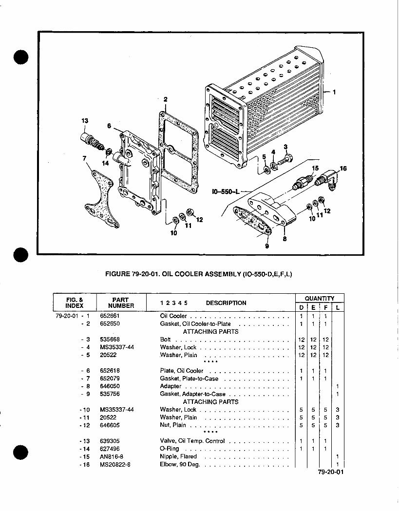
2
FIGURE 79-20-01. OIL COOLER ASSEMBLY (10-550-D,E,F,L)
FIG. & PART 234 DECITOINDEX NUMBER12345 DECPTO
79-20-01 - 1 652661- 2 652650
535668MS35337-4420522
652618652079646050535756
- 10 MS35337-44-11 20522-12 646605
- 13 639305-14 627496-15 AN816-8- 16 MS20822-8
Oil Cooler .. ....Gasket, Oil Cooler-to-Plate
ATTACHING PARTSBolt ..............Washer, Lock .........Washer, Plain ........
Plate, Oil Cooler .......Gasket, Plate-to-Case ....
Adapter ............Gasket, Adlapter-to-Case...
ATTACHING PARTSWasher, Lock .........Washer, Plain ........Nut, Plain ...........
Valve, Oil Temp. Control ...
0-Ring ............Nipple, Flared ........Elbow, 90 Deg .........
D11
121212
555
QUANTITY
,16
9
345
6789
E
1
1 21 21 2
555
FF1
12
1 21 2
12
1
555
11
7-
333
79-20-01
III

FIGURE 80-10-01. STARTER AND STARTER ADAPTER ASSEMBLY (10-550-D,E,F,L)
FIG. & PART 234 DECITOI INDEX INUMBER 1I ECITO
537745635050A4
2473MS35337-455377422439
635050402127641368
Gasket, Adapter-to-Crankcase .........©Adapter Assy., Starter
Complete (Less Sheave) ..............ATTACHING PARTS
Washer, Plain ..................Washer, Lock ..................Screw, 5/16-18 x 2-13/16 Inch LongNut, Plain ....................
*Adapter Assembly, Starter ..........+ *.Stud, 3/8-16x 1-17/321Inch Long .
*.Bearing, Needle ...............
D1
3
3
2
12
1
80-10-01 - 1
2345
678
QUANTITY
80-10-00
E1
1
3312
121
F1
3
3
2
12
1
7 L1
1
3312
121

&PARTX& INUMBER
- 9 539805-10 536552- 11 MS35756-8-12 631252-13 X13041-14 502287-15 539568-16 539785-17 539800
-18 501867-19 633845
-20- 21- 22- 23- 24- 25- 26
537749AN1 23862534980537738A1534685534715534938
- 27 2473- 28 MS35337-45-29 537750-30 MS35756-8
-31 534775-31 635169
-32 AN960C916-33 13XX299-34 AN316-9R
-.35- 36- 37- 38- 39- 40-41-41
5389992473MS35337-45537750538999MS9021 -038646238646275
-42 539058-43 2439
1 2 3 4 5 DESCRIPTION
*Gear, Starter Worm........* Spring, Starter ................*Key, Woodruff .................*Shaft, Worm Drive ..............Bearing, Ball ..... ............Ring, Retaining ................
*Shaftgear, Starter ...............Gear, Starter Worm Wheel ..........
+.Spring, Clutch .................ATTACHING PARTS
W asher, Tab .................Screw, 1/4-20 x 13/32 Inch Long.
$ .Gasket, Cover-to-Adapter ..........$ . -Ring . . . . . . . . . . . . . . . . . . . .
Sleeve, Bearing Retainer ...........Cover, Starter Adapter ............
Bearing, Ball ................Ring, Retaining ...............
$ .. Seal, Oil ...................ATTACHING PARTS
Washer, Plain .................
Washer, Lock .................Screw, 5/16-18 x 1-1 /8 Inch LongKey, Woodruff .................
Sheave, Generator Drive ............Sheave, Generator Drive ............
ATTACHING PARTSWasher, Plain ..................Washer, Lock ..................Nut ........................
Bolt, 5/16-18 x 3-5/8 Inch Long .........Washer, Plain . .........Washer, Lock ..................Screw, 5/16-18 x 1-1 /8 Inch Long ........Bolt, 5/16-18 x 3-5/8 Inch Long .........
$ 0-Ring ......................Starter, 12 Volt .................Starter, 24 Volt .................
ATTACHING PARTSWasher, Plain ..................Nut, Plain, Hex .................
0D This assembly is also available as rebuilt See your local TCM Distributor.
80-10-01
FIG.INDE
80-1 0-01
QUANTITYF L
111111111
E1
111
1
1
111
1
3
3
222
11
2
2
NOTE:
I

109
FIGURE 82-10-01. ALTERNATOR ASSEMBLY (IO-550-E,F)
FIG. & PART 234 DECITOINDEX NUMBER 1I ECI~O
- 1 652486652485
- 2 630691- 3 642589- 4 632437
- 5 2441- 6 22786- 7 634657
- 8-9
-10-11- 12- 13- 14
640261634617
530346MS35337-45537539537750501868
- 15 539547-32.00
Alternator ...........Alternator ...........Washer, Plain .........Nut . . . . . . . . . . . . . .Key ..............
ATTACHING PARTSN ut . . . . . . . . . . . . . .Washer ............Bolt ..............
Sheave ............Bracket ............
ATTACHING PARTSScrew .......Lockwasher ..........Washer ............Screw .............Washer, Tab .........
Belt, 32 Inch Long .......
I QUANTITYrD E
1
131
11
1
12
11
1
F
11
13121
8
15
7
82-1 0-017L
82-10-00
9

1
FIGURE 82-10-02. ELECTRICAL COMPONENTS
dftage (1 2 Volt) ...........
NOTE:
G0 Use as applicable, not used on all engine models.
82-10-01
. 0


![$Tl]DH - E-Journal UIN Jakarta](https://static.fdokumen.com/doc/165x107/63260c1d051fac18490d904c/tldh-e-journal-uin-jakarta.jpg)


![TP-Link TL-MR3020 [OpenWrt Wiki] - emoc](https://static.fdokumen.com/doc/165x107/63377625e8797a6c4909364b/tp-link-tl-mr3020-openwrt-wiki-emoc.jpg)