
Atomistic simulations of Bauschinger effects of metals with high angle and low angle grain...
14
Atomistic simulations of Bauschinger effects of metals with high angle and low angle grain boundaries H. Fang a, * , M.F. Horstemeyer a,b, * , M.I. Baskes c , K. Solanki a a Center for Advanced Vehicular Systems, P.O. BOX 9627, Mississippi State University, Mississippi State, MS 39762, USA b Department of Mechanical Engineering, Mississippi State University, 206 Carpenter Building, Mississippi State, MS 39762, USA c MST-8, Los Alamos National Laboratory, Los Alamos, NM 87545, USA Received 5 May 2003; received in revised form 20 August 2003; accepted 2 December 2003 Abstract In this paper, we examined Bauschinger effects in nickel single crystals and nickel containing arrays of high angle or low angle grain boundaries under shear deformation using molecular dynamics with embedded atom method (EAM) potentials. In order to take into account dislocation nucleation under different boundary conditions and their effects on the stress–strain relationship, two limiting constraints were used to both high angle and low angle grain boundaries: fixed end on all sides and free ends on all sides. Stress–strain curves were then compared under these two boundary conditions for three cases: single crystal, high angle grain boundary arrays, and low angle grain boundary arrays. In each of the three cases, loading was reversed at different strain levels after yield and Bauschinger effects were examined on all the scenarios. The simulation results were also compared with macroscopic mechanics ideas for both high angle and low angle grain boundaries. The Bauschinger effect was found to be the largest for the case of high angle boundaries and the lowest for the single crystal. Ó 2004 Elsevier B.V. All rights reserved. Keywords: Atomistic simulations; Nanoscale; Bauschinger; Embedded atom method 1. Introduction Atomistic simulation studies have recently focused on multiscale issues related to helping characterize continuum quantities such as stress [1], strain [2], resolved shear stress [3], and damage nucleation [4]. Other studies have focused on multiscale aspects in an effort to bridge the atomic scale with continuum concepts [5–8]. Most of these previous studies have focused on single crystal effects. This particular study focuses on samples with grain boundary (GB) arrays and the relationship between the aforementioned single crystal studies and effects of GBs. For example, in the aforementioned studies, dislocation nucleation was a * Corresponding authors. Fax: +1-6623257223 (M.F. Horstemeyer). E-mail address: [email protected] (M.F. Horstemeyer). 0045-7825/$ - see front matter Ó 2004 Elsevier B.V. All rights reserved. doi:10.1016/j.cma.2003.12.052 Comput. Methods Appl. Mech. Engrg. 193 (2004) 1789–1802 www.elsevier.com/locate/cma
-
Upload
independent -
Category
Documents
-
view
4 -
download
0
Transcript of Atomistic simulations of Bauschinger effects of metals with high angle and low angle grain...

Comput. Methods Appl. Mech. Engrg. 193 (2004) 1789–1802
www.elsevier.com/locate/cma
Atomistic simulations of Bauschinger effects of metalswith high angle and low angle grain boundaries
H. Fang a,*, M.F. Horstemeyer a,b,*, M.I. Baskes c, K. Solanki a
a Center for Advanced Vehicular Systems, P.O. BOX 9627, Mississippi State University, Mississippi State, MS 39762, USAb Department of Mechanical Engineering, Mississippi State University, 206 Carpenter Building, Mississippi State, MS 39762, USA
c MST-8, Los Alamos National Laboratory, Los Alamos, NM 87545, USA
Received 5 May 2003; received in revised form 20 August 2003; accepted 2 December 2003
Abstract
In this paper, we examined Bauschinger effects in nickel single crystals and nickel containing arrays of high angle or
low angle grain boundaries under shear deformation using molecular dynamics with embedded atom method (EAM)
potentials. In order to take into account dislocation nucleation under different boundary conditions and their effects on
the stress–strain relationship, two limiting constraints were used to both high angle and low angle grain boundaries:
fixed end on all sides and free ends on all sides. Stress–strain curves were then compared under these two boundary
conditions for three cases: single crystal, high angle grain boundary arrays, and low angle grain boundary arrays. In
each of the three cases, loading was reversed at different strain levels after yield and Bauschinger effects were examined
on all the scenarios. The simulation results were also compared with macroscopic mechanics ideas for both high angle
and low angle grain boundaries. The Bauschinger effect was found to be the largest for the case of high angle boundaries
and the lowest for the single crystal.
� 2004 Elsevier B.V. All rights reserved.
Keywords: Atomistic simulations; Nanoscale; Bauschinger; Embedded atom method
1. Introduction
Atomistic simulation studies have recently focused on multiscale issues related to helping characterize
continuum quantities such as stress [1], strain [2], resolved shear stress [3], and damage nucleation [4]. Other
studies have focused on multiscale aspects in an effort to bridge the atomic scale with continuum concepts[5–8]. Most of these previous studies have focused on single crystal effects. This particular study focuses on
samples with grain boundary (GB) arrays and the relationship between the aforementioned single crystal
studies and effects of GBs. For example, in the aforementioned studies, dislocation nucleation was a
* Corresponding authors. Fax: +1-6623257223 (M.F. Horstemeyer).
E-mail address: [email protected] (M.F. Horstemeyer).
0045-7825/$ - see front matter � 2004 Elsevier B.V. All rights reserved.
doi:10.1016/j.cma.2003.12.052

1790 H. Fang et al. / Comput. Methods Appl. Mech. Engrg. 193 (2004) 1789–1802
dominant mechanism upon the volume averaged stress–strain response. This study seeks to compare thedislocation nucleation from free surfaces and GBs. Furthermore, we analyze the effect of rigid constraints
versus more flexible constraints on the samples with GBs. Finally, we also perform some reverse straining
conditions in order to evaluate the Bauschinger effect at the atomic scale. Stout and Rollett [18], have
performed numerous experiments to examine the Bauschinger. Chuna et al. [19,20] developed a new
material model and used it in finite element method to simulate the Bauschinger effect. However, to the
authors’ knowledge, a study to understand the Bauschinger effect at the atomic scale has not been per-
formed before.
2. Embedded atom method (EAM)
The premise for the atomistic simulations starts from embedded atom method (EAM) potential cast in a
molecular dynamics framework since metals are the focus. Daw and Baskes [9] developed EAM, which
employs a pair potential augmented by a function of another pair-wise sum, for metals. We use EAM in the
atomistic calculations for study of finite deformations of nickel.
The notion of embedding energy was first suggested by Freidel [10] and further developed by Stott andZaremba [11]. Daw and Baskes [9] proposed a numerical method for calculating atomic energetics. Daw
et al. [12] summarize many applications of EAM. Essentially, EAM comprises a cohesive energy of an atom
determined by the local electron density into which that atom is placed. A function, qðrÞ, is viewed as the
contribution to the electron density at a site due to the neighboring atoms. The embedding energy F is
associated with placing an atom in that electron environment. The functional form of the total energy is
given by
E ¼Xi
F iXi6¼j
qiðrijÞ !
þ 1
2
Xij
/ijðrijÞ; ð1Þ
where i refers to the atom in question and j refers to the neighboring atom, rij is the separation distance
between atoms i and j, and /ij is the pair potential. Because each atom is counted, contra-variant and
covariant index notation is not used here. Subscripts denote the rank of the tensor, for example, one
subscript denotes a vector, two subscripts denote a second rank tensor, and so on. Superscripts identify the
atom of interest. In molecular dynamics, the energy is used to determine the forces on each atom. At each
atom the dipole force tensor, b, is given by
bikm ¼ 1
Xi
XNjð6¼iÞ
f ikðrijÞrijm; ð2Þ
where i refers to the atom in question and j refers to the neighboring atom, fk is the force vector betweenatoms, rm is a displacement vector between atoms i and j, N is the number of nearest neighbor atoms, and
Xi is the undeformed atomic volume. If stress could be defined at an atom, then b would be the stress tensor
at that point. Since stress is defined at a continuum point, we determine the stress tensor as a volume
average over the block of material,
rmk ¼1
N �
XN�
i
bimk; ð3Þ
in which the stress tensor is defined in terms of the total number of atoms, N �, in the block of material.
H. Fang et al. / Comput. Methods Appl. Mech. Engrg. 193 (2004) 1789–1802 1791
3. Description of model set-up
3.1. Geometry and constraints
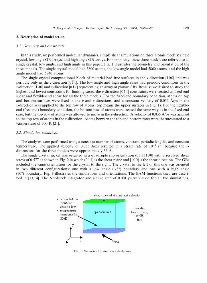
In this study, we performed molecular dynamics, simple shear simulations on three atomic models: single
crystal, low angle GB arrays, and high angle GB arrays. For simplicity, these three models are referred to as
single crystal, low angle, and high angle in this paper. Fig. 1 illustrates the geometry and orientation of the
three models. The single crystal model had 5800 atoms, the low angle model had 5860 atoms, and the highangle model had 5840 atoms.
The single crystal computational block of material had free surfaces in the x-direction [100] and was
periodic only in the z-direction [011]. The low angle and high angle cases had periodic conditions in the
x-direction [100] and z-direction [011] representing an array of planar GBs. Because we desired to study thehighest and lowest constraints for limiting cases, the y-direction [011] constraints were treated as fixed-end
shear and flexible-end shear for all the three models. For the fixed-end boundary condition, atoms on top
and bottom surfaces were fixed in the y and z-directions, and a constant velocity of 0.035 �A/ps in the
x-direction was applied to the top row of atoms (top means the upper surfaces in Fig. 1). For the flexible-end (free-end) boundary condition, the bottom row of atoms were treated the same way as in the fixed-end
case, but the top row of atoms was allowed to move in the y-direction. A velocity of 0.035 �A/ps was appliedto the top row of atoms in the x-direction. Atoms between the top and bottom rows were thermostatted to a
temperature of 300 K [21].
3.2. Simulation conditions
The analyses were performed using a constant number of atoms, constant periodic lengths, and constanttemperature. The applied velocity of 0.035 �A/ps resulted in a strain rate of 10�9 s�1 because the y-dimensions for the three models were approximately 35 �A.
The single crystal nickel was oriented in a quadruple slip orientation (011)[100] with a resolved shear
stress of 0.577 as shown in Fig. 2 in which (011) is the shear plane and [100] is the shear direction. The GBs
included the same orientation for the crystal to the right. The crystal to the left of this one was oriented
in two different configurations: one with a low angle (�8�) boundary and one with a high angle
(90�) boundary. Fig. 3 illustrates the simulations and orientations. The EAM functions used are descri-
bed in [13,14]. The Nordsieck integrator and a time step of 0.001 ps were used for all the simulations.
Fig. 1. Geometry for atomistic calculations.

Fig. 2. Crystal orientation for multiple slips.
Fig. 3. Various Microstructures are examined: single crystal, high angle grain boundaries, and low angle grain boundaries.
1792 H. Fang et al. / Comput. Methods Appl. Mech. Engrg. 193 (2004) 1789–1802
Computation times on a single processor (Sun 750 MHz UltraSPARC III) for these three models rangedfrom 20 to 40 h, depending on what level of strain were to be achieved.
The Bauschinger effects were examined for single crystals, low angle GBs, and high angle GBs under
the aforementioned two boundary conditions. Comparisons are made for all the three models under the
same boundary conditions. The reverse load points were chosen such that the three models passed their
yield points and have the same total strain. The plastic strains for the two boundary conditions may not
necessarily be the same, because the yield stresses may not be the same for these two boundary condi-
tions.

H. Fang et al. / Comput. Methods Appl. Mech. Engrg. 193 (2004) 1789–1802 1793
4. Results and discussions
4.1. Grain boundary and dislocation effects on yield stresses
Fig. 4 shows the volume averaged stress strain response for the single crystal nickel and the correlating
dislocation nucleation, motion, and interaction throughout the history. The dislocation motion is dem-
onstrated by use of the centrosymmetry parameter [15]. For FCC metals, the centrosymmetry parameter is
defined as follows:
CSP ¼X6i¼1
ðri þ riþ6Þ2; ð4Þ
where ri and riþ6 are vectors corresponding to the six pairs of opposite nearest neighbors in the FCC lattice.
The six-pair vectors for each atom are first determined in the undistorted bulk FCC lattice. The analogous
six-pair vectors for each atom in the distorted lattice are then calculated by finding neighbors in the dis-torted lattice with vectors closest in distance to the undistorted nearest-neighbor vectors. The centrosym-
metry parameter is zero for atoms in a perfect FCC lattice.
Clearly, in this initially pristine material, the dislocations nucleate from the corners of the material block.
As first described in [16], in an effort to reach dynamic equilibrium the internal structure responds with a
dislocation.
Fig. 5 shows simulation results from the fixed-end shearing case in which the relative displacements of
the atoms are plotted in order to illustrate the kinematic response of the single crystal versus the low and
high angle GBs. This snapshot occurs at 10% strain after plasticity has started. The volume averaged stress–strain response in Fig. 5 shows that global yielding occurred at approximately 8% strain. The low angle
GBs and single crystal gave very similar relative displacement results, but the high angle GBs gave a much
different result. Furthermore, the stress–strain response of the single crystal showed yielding at the same
strain as the low angle GBs in this fixed-end highly constrained case.
Fig. 4. Evolution of dislocations relative to volume averaged stress–strain response.
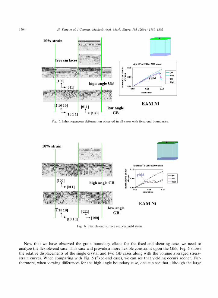
Fig. 5. Inhomogeneous deformation observed in all cases with fixed-end boundaries.
Fig. 6. Flexible-end surface reduces yield stress.
1794 H. Fang et al. / Comput. Methods Appl. Mech. Engrg. 193 (2004) 1789–1802
Now that we have observed the grain boundary effects for the fixed-end shearing case, we need to
analyze the flexible-end case. This case will provide a more flexible constraint upon the GBs. Fig. 6 shows
the relative displacements of the single crystal and two GB cases along with the volume averaged stress–
strain curves. When comparing with Fig. 5 (fixed-end case), we can see that yielding occurs sooner. Fur-
thermore, when viewing differences for the high angle boundary case, one can see that although the large

H. Fang et al. / Comput. Methods Appl. Mech. Engrg. 193 (2004) 1789–1802 1795
displacements occur at the grain boundary for both flexible-end and fixed-end cases, the directions ofdisplacements in both cases are different. Not much difference is observed at the low angle grain boundaries.
4.2. Bauschinger effects analyses
The Bauschinger effects can be observed qualitatively from the stress–strain response curves. In order to
quantitatively describe the Bauschinger effects for nanoscale simulations, we use two types of definitions,
the Bauschinger stress parameter (BSP) and the Bauschinger effect parameters (BEP). The definitions are
given as follows [17]:
BSP ¼ jrf j � jrrjjrf j ; ð5Þ
BEP ¼ jrf j � jrrjjrf j � jryj ; ð6Þ
where rf is the stress in the forward load path at reverse point, rr is the yield stress in the reverse load path,
and ry is the initial forward yield stress.
We first examine the Bauschinger effects for the fixed-end boundary condition. Fig. 7 shows the volumeaveraged stress–strain responses including both forward and reverse loading path for single crystal, low
angle GB, and high-angle GB. The reverse load points were chosen at about 9% strain. Fig. 7 shows that a
strong Bauschinger effects existed in all the three simulations. Table 1 gives the stresses and strains at the
reverse load points. The BSPs and BEPs are calculated and given in Table 2 to quantify the result.
The definitions of BSP and BEP indicate that the larger the BSP and BEP, the stronger the Bauschinger
effect. The results in Table 2 shows that grain boundaries do have an effect on the stress–strain responses
Fig. 7. Volume averaged stress–strain response for fixed-end, reverse loading at 9% strain.
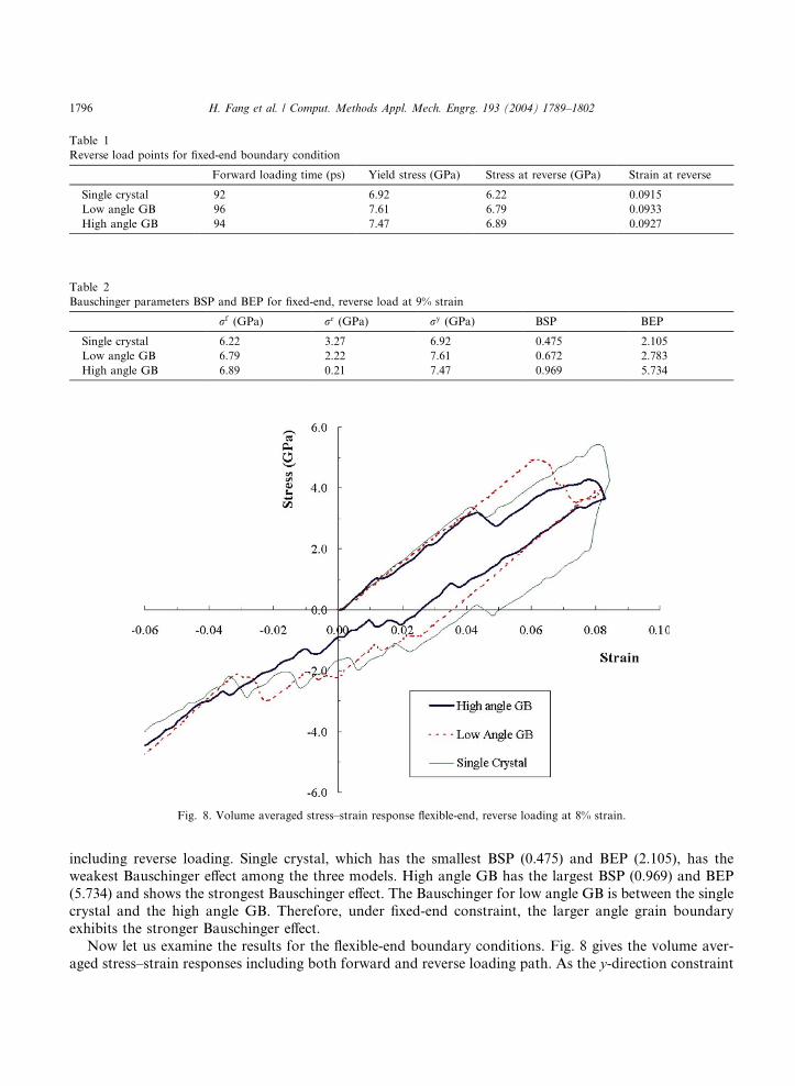
Table 1
Reverse load points for fixed-end boundary condition
Forward loading time (ps) Yield stress (GPa) Stress at reverse (GPa) Strain at reverse
Single crystal 92 6.92 6.22 0.0915
Low angle GB 96 7.61 6.79 0.0933
High angle GB 94 7.47 6.89 0.0927
Table 2
Bauschinger parameters BSP and BEP for fixed-end, reverse load at 9% strain
rf (GPa) rr (GPa) ry (GPa) BSP BEP
Single crystal 6.22 3.27 6.92 0.475 2.105
Low angle GB 6.79 2.22 7.61 0.672 2.783
High angle GB 6.89 0.21 7.47 0.969 5.734
Fig. 8. Volume averaged stress–strain response flexible-end, reverse loading at 8% strain.
1796 H. Fang et al. / Comput. Methods Appl. Mech. Engrg. 193 (2004) 1789–1802
including reverse loading. Single crystal, which has the smallest BSP (0.475) and BEP (2.105), has theweakest Bauschinger effect among the three models. High angle GB has the largest BSP (0.969) and BEP
(5.734) and shows the strongest Bauschinger effect. The Bauschinger for low angle GB is between the single
crystal and the high angle GB. Therefore, under fixed-end constraint, the larger angle grain boundary
exhibits the stronger Bauschinger effect.
Now let us examine the results for the flexible-end boundary conditions. Fig. 8 gives the volume aver-
aged stress–strain responses including both forward and reverse loading path. As the y-direction constraint
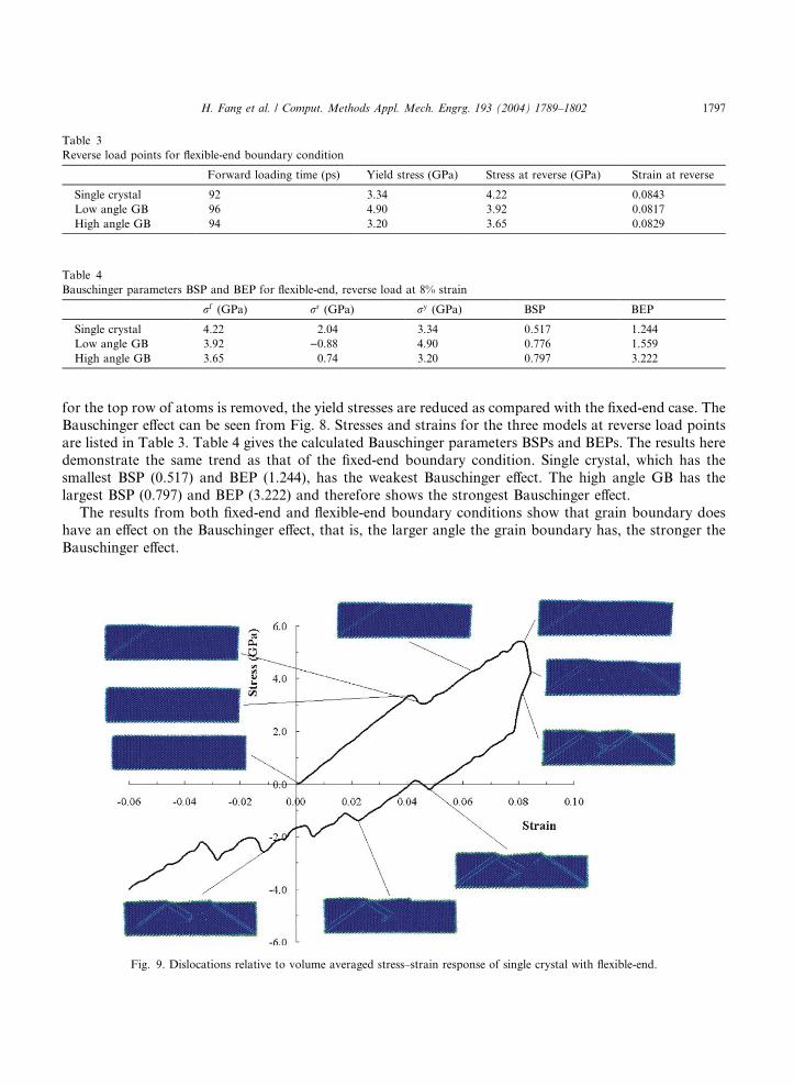
Table 3
Reverse load points for flexible-end boundary condition
Forward loading time (ps) Yield stress (GPa) Stress at reverse (GPa) Strain at reverse
Single crystal 92 3.34 4.22 0.0843
Low angle GB 96 4.90 3.92 0.0817
High angle GB 94 3.20 3.65 0.0829
Table 4
Bauschinger parameters BSP and BEP for flexible-end, reverse load at 8% strain
rf (GPa) rr (GPa) ry (GPa) BSP BEP
Single crystal 4.22 2.04 3.34 0.517 1.244
Low angle GB 3.92 )0.88 4.90 0.776 1.559
High angle GB 3.65 0.74 3.20 0.797 3.222
H. Fang et al. / Comput. Methods Appl. Mech. Engrg. 193 (2004) 1789–1802 1797
for the top row of atoms is removed, the yield stresses are reduced as compared with the fixed-end case. TheBauschinger effect can be seen from Fig. 8. Stresses and strains for the three models at reverse load points
are listed in Table 3. Table 4 gives the calculated Bauschinger parameters BSPs and BEPs. The results here
demonstrate the same trend as that of the fixed-end boundary condition. Single crystal, which has the
smallest BSP (0.517) and BEP (1.244), has the weakest Bauschinger effect. The high angle GB has the
largest BSP (0.797) and BEP (3.222) and therefore shows the strongest Bauschinger effect.
The results from both fixed-end and flexible-end boundary conditions show that grain boundary does
have an effect on the Bauschinger effect, that is, the larger angle the grain boundary has, the stronger the
Bauschinger effect.
Fig. 9. Dislocations relative to volume averaged stress–strain response of single crystal with flexible-end.

Fig. 10. Dislocations relative to volume averaged stress–strain response of low angle GB arrays with flexible-end.
Fig. 11. Dislocations relative to volume averaged stress–strain response of high angle GB arrays with flexible-end.
1798 H. Fang et al. / Comput. Methods Appl. Mech. Engrg. 193 (2004) 1789–1802
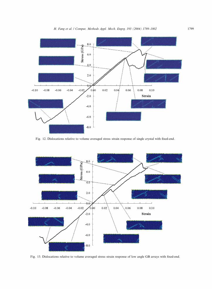
Fig. 12. Dislocations relative to volume averaged stress–strain response of single crystal with fixed-end.
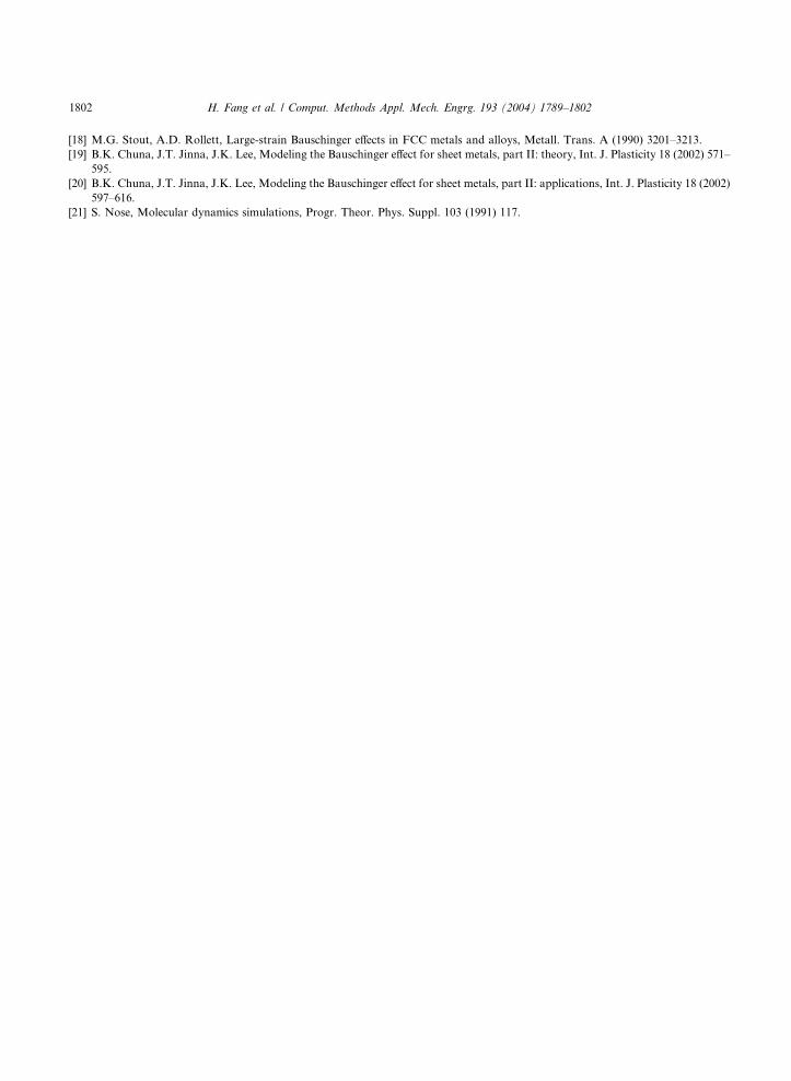
Fig. 13. Dislocations relative to volume averaged stress–strain response of low angle GB arrays with fixed-end.
H. Fang et al. / Comput. Methods Appl. Mech. Engrg. 193 (2004) 1789–1802 1799

Fig. 14. Dislocations relative to volume averaged stress–strain response of high angle GB arrays with fixed-end.
1800 H. Fang et al. / Comput. Methods Appl. Mech. Engrg. 193 (2004) 1789–1802
Another interesting finding is that in the flexible-end simulations, the low angle GB has a much higher
apparent yield stress than the single crystal and high-angle GB. This seems to contradict to what was
expected; that is, the yield stress of the low angle GB bi-crystal would be closer to the other two models.
By closely examining the dislocations in these models, this apparent inconsistency becomes clear. Figs. 9–
11 illustrate the dislocations along the forward and reverse loading path for single crystal, low angle GB,
and high angle GB, respectively. Fig. 10 shows that for the low angle GB, a dislocation nucleated at an
earlier stage than the other two models and material hardening actually occurred before the apparent
yield point due to dislocation nucleation. This means, a dislocation nucleated the easiest at the low angleGB without the constraint in the y-direction on the top row atoms. Even so, the Bauschinger effect for
the low angle GB is still smaller than that of the high angle GB, according to the BSP and BEP defi-
nitions.
Figs. 12–14 illustrate the dislocations under fixed-end boundary conditions for single crystal, low angle
GBs, and high angle GBs, respectively. We can see that dislocation nucleation occurs earlier (before
apparent yield) at the low angle GB. In the single crystal and high angle GB cases, dislocations do not occur
until the apparent yield occurs.
5. Conclusions
In this study, we examined the volume averaged stress–strain responses of three nickel models, single
crystal, low angle GB arrays, and high angle GB arrays, using molecular dynamics with the embedded atom
method. Forward and reverse simple shear load was applied to the three models under two types of

H. Fang et al. / Comput. Methods Appl. Mech. Engrg. 193 (2004) 1789–1802 1801
boundary condition, fixed-end and flexible-end. The stress–strain responses and Bauschinger effect werethen compared to show the effects of grain boundaries as well as constraints. The analyses showed that less
constrained materials (e.g., flexible-end) exhibited reduced yield stresses compared to highly constrained
materials (e.g., fixed-end). The single crystal had the smallest Bauschinger effect and high angle GB had the
strongest Bauschinger effect, for both fixed-end and flexible-end boundary conditions. An interesting
finding was that dislocation nucleation occurred earlier in low angle GB than the single crystal and high
angle GB cases. This finding was true for both fixed-end and flexible-end boundary conditions.
Acknowledgements
The work by Fang, Horstemeyer, and Solanki was sponsored by the Mississippi State University Center
for Advanced Vehicular Systems, and the work by Baskes has been sponsored by the US Department of
Energy, Office of Science, Office of Basic Energy Sciences, Division of Materials Sciences. We would like to
thank Dr. B. Zhang, Department of Mechanical Engineering, Mississippi State University, for his valuable
comments and discussions on the work presented in this paper.
References
[1] P.M. Gullett, M.F. Horstemeyer, D.J. Bammann, and M.I. Baskes, A comparison of atomistic and elastic continuum based shear
stress distributions near an edge dislocation, in: Proceedings of the International Conference on Computational Engineering and
Science, August 19–25, 2001, Puerta Vallarta, Mexico.
[2] M.F. Horstemeyer, and M.I. Baskes, Strain tensors at the atomic scale, MRS in: Proceedings of Multiscale Phenomena in
Materials: Experiments and Modeling, vol. 578, Pittsburgh, PA, 2000.
[3] M.F. Horstemeyer, M.I. Baskes, D.A. Hughes, A. Godfrey, Orientation effects on the stress state of molecular dynamics large
deformation simulations, Int. J. Plasticity 18 (2002) 203–209.
[4] K.A. Gall, M.F. Horstemeyer, M. Van Schilfgaarde, M.I. Baskes, Atomistic simulations on the tensile debonding of an
aluminum–silicon interface, J. Mech. Phys. Solids 48 (2000) 2183–2212.
[5] W.W. Gerberich, N.I. Tymak, J.C. Grunlan, M.F. Horstemeyer, M.I. Baskes, Interpretations of indentation size effects, J. Appl.
Mech. 69 (2002) 442–443.
[6] M.F. Horstemeyer, S.J. Plimpton, M.I. Baskes, Size scale and strain rate effects on yield and plasticity of metals, Acta Mater. 49
(2001) 4363–4374.
[7] M.F. Horstemeyer, M.I. Baskes, S.J. Plimpton, Computational nanoscale plasticity simulations using embedded atom potentials,
Theor. Appl. Fract. Mech. 37 (2001) 49–98.
[8] M.F. Horstemeyer, T.J. Lim, W.Y. Lu, D.A. Mosher, M.I. Baskes, V.C. Prantil, S.J. Plimpton, Torsion/simple shear of single
crystal copper, J. Engrg. Mater. Technol. 124 (2002) 322–328.
[9] M.S. Daw, M.I. Baskes, Embedded-tom method: derivation and application to impurities, surfaces, and other defects in metals,
Phys. Rev. B (1984) 6443–6453.
[10] J. Freidel, Phil. Mag. 43 (1952) 153.
[11] M.J. Stott, E. Zaremba, Quasi atoms: An approach to atoms in nonuniform electronic systems, Phys. Rev. B 22 (1980) 1564–1583.
[12] M.S. Daw, S.M. Foiles, M.I. Baskes, The embedded-atom method: a review of theory and applications, Materials Science
Reports, A Review Journal 9 (1993) 251–310.
[13] J.E. Angelo, N.R. Moody, M.I. Baskes, Trapping of hydrogen to lattice defects in nickel, J. Model. Simul. Mater. Sci. Engrg. 3
(1995) 289–307.
[14] M.I. Baskes, X. Sha, J.E. Angelo, N.R. Moody, Comment: trapping of hydrogen to lattice defects in nickel, Model. Simul. Mater.
Sci. Engrg. 5 (1997) 651–652.
[15] C. Kelchner, S. Plimpton, Hamilton, Dislocation nucleation and defect structure during surface indentation, J. Phys. Rev. B 58
(1998) 11085–11088.
[16] M.F. Horstemeyer, M.I. Baskes, Atomistic finite deformation simulations: a discussion on length scale effects in relation to
mechanical stresses, J. Engrg. Matls. Techn. Trans. ASME 121 (1998) 114–119.
[17] M.F. Horstemeyer, Damage influence on Bauschinger effect of a CAST A356 alluminum alloy, Scripta Mater. 39 (1998) 1491–
1495.
1802 H. Fang et al. / Comput. Methods Appl. Mech. Engrg. 193 (2004) 1789–1802
[18] M.G. Stout, A.D. Rollett, Large-strain Bauschinger effects in FCC metals and alloys, Metall. Trans. A (1990) 3201–3213.
[19] B.K. Chuna, J.T. Jinna, J.K. Lee, Modeling the Bauschinger effect for sheet metals, part II: theory, Int. J. Plasticity 18 (2002) 571–
595.
[20] B.K. Chuna, J.T. Jinna, J.K. Lee, Modeling the Bauschinger effect for sheet metals, part II: applications, Int. J. Plasticity 18 (2002)
597–616.
[21] S. Nose, Molecular dynamics simulations, Progr. Theor. Phys. Suppl. 103 (1991) 117.


![[IN FIRST-ANGLE PROJECTION METHOD]](https://static.fdokumen.com/doc/165x107/6312eb38b1e0e0053b0e36b0/in-first-angle-projection-method.jpg)


