Assortment Box Retainers for shafts, type KL Material: Steel ...
37
576 ® Assortment Box Retainers for shafts, type KL Product No. 618 000 01 Material: Steel, phosphatized and oiled. The assortment box is made from impact- resitant plastic of premium quality and is filled with KL-Retainers matching BEKbolts with groove/clevises/clevis joints. Contains 880 pieces. Weight 1.8 kg. Assortment Box SL-Retainers Retainers for shafts, type SL Product No. 618 000 02 Material: Steel, phosphatized and oiled. The assortment box is made from impact- resitant plastic of premium quality and is filled with SL-Retainers matching BEKbolts with groove/clevises/clevis joints. Contains 560 pieces. Weight 1.23 kg. Assortment Box Bolts with Cotter Pin Hole Product No. 618 000 04 Material: Steel, zinc-plated. The assortment box is made from impact- resitant plastic of premium quality and is filled with cotter pins DIN 1434. Contains 100 pieces. Weight 3.24 kg. Sizes Amount 6 x 18 x 15.3 10 6 x 25 x 22 10 8 x 23 x 19.5 10 8 x 28 x 25 10 10 x 35 x 30 10 10 x 45 x 40 10 12 x 35 x 30 10 12 x 50 x 45 10 14 x 40 x 35 10 14 x 50 x 45 10 Size Amount 3 100 4 100 5 100 6 100 8 100 10 80 12 100 14 80 16 100 24 20 Size Amount 4 100 5 100 6 100 8 100 10 40 12 40 14 40 16 40 Product No. 618 000 04 Product No. 618 000 01 Product No. 618 000 02
-
Upload
khangminh22 -
Category
Documents
-
view
2 -
download
0
Transcript of Assortment Box Retainers for shafts, type KL Material: Steel ...

576 ®
Assortment Box Retainers for shafts, type KL
Product No. 618 000 01
Material: Steel, phosphatized and oiled.
The assortment box is made from impact-resitant plastic of premium quality and is filled with KL-Retainers matching BEKbolts with groove/clevises/clevis joints. Contains 880 pieces. Weight 1.8 kg.
Assortment Box SL-Retainers Retainers for shafts, type SL
Product No. 618 000 02
Material: Steel, phosphatized and oiled.
The assortment box is made from impact-resitant plastic of premium quality and is filled with SL-Retainers matching BEKbolts with groove/clevises/clevis joints. Contains 560 pieces. Weight 1.23 kg.
Assortment Box Bolts with Cotter Pin Hole
Product No. 618 000 04
Material: Steel, zinc-plated.
The assortment box is made from impact-resitant plastic of premium quality and is filled with cotter pins DIN 1434. Contains 100 pieces. Weight 3.24 kg.
Sizes Amount6 x 18 x 15.3 106 x 25 x 22 108 x 23 x 19.5 108 x 28 x 25 10 10 x 35 x 30 1010 x 45 x 40 1012 x 35 x 30 1012 x 50 x 45 1014 x 40 x 35 1014 x 50 x 45 10
Size Amount 3 100 4 100 5 100 6 100 8 100 10 80 12 100 14 80 16 100 24 20
Size Amount 4 100 5 100 6 100 8 100 10 40 12 40 14 40 16 40
Product No. 618 000 04
Product No. 618 000 01
Product No. 618 000 02
577®
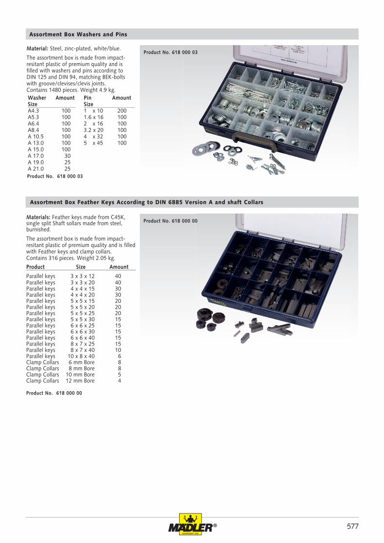
Assortment Box Washers and Pins
Product No. 618 000 03
Material: Steel, zinc-plated, white/blue.
The assortment box is made from impact-resitant plastic of premium quality and is filled with washers and pins according to DIN 125 and DIN 94, matching BEK-bolts with groove/clevises/clevis joints. Contains 1480 pieces. Weight 4.9 kg.
Pin AmountSize 1 x 10 2001.6 x 16 1002 x 16 1003.2 x 20 1004 x 32 1005 x 45 100
Washer AmountSize A 4.3 100A 5.3 100A 6.4 100A 8.4 100 A 10.5 100 A 13.0 100 A 15.0 100 A 17.0 30 A 19.0 25 A 21.0 25
Assortment Box Feather Keys According to DIN 6885 Version A and shaft Collars
Materials: Feather keys made from C45K,single split Shaft sollars made from steel, burnished.
The assortment box is made from impact-resitant plastic of premium quality and is filled with Feather keys and clamp collars. Contains 316 pieces. Weight 2.05 kg.
Product Size Amount
Parallel keys 3 x 3 x 12 40Parallel keys 3 x 3 x 20 40Parallel keys 4 x 4 x 15 30Parallel keys 4 x 4 x 20 30Parallel keys 5 x 5 x 15 20Parallel keys 5 x 5 x 20 20Parallel keys 5 x 5 x 25 20Parallel keys 5 x 5 x 30 15Parallel keys 6 x 6 x 25 15Parallel keys 6 x 6 x 30 15Parallel keys 6 x 6 x 40 15Parallel keys 8 x 7 x 25 15Parallel keys 8 x 7 x 40 10Parallel keys 10 x 8 x 40 6Clamp Collars 6 mm Bore 8Clamp Collars 8 mm Bore 8Clamp Collars 10 mm Bore 5 Clamp Collars 12 mm Bore 4
Product No. 618 000 03
Product No. 618 000 00
Product No. 618 000 00

578 ®
hh11 l1
bh9
618 902 02 2 2 31618 903 03 3 3 71618 904 04 4 4 126618 905 05 5 5 196618 906 06 6 6 283618 908 07 8 7 440618 908 08 8 8 502618 910 08 10 8 628
618 910 10 10 10 785618 912 08 12 8 754618 912 12 12 12 1130618 914 09 14 9 989618 916 10 16 10 1256618 918 11 18 11 1554618 920 12 20 12 1884
618 002 00 2 2 6 0,2618 003 00 2 2 8 0,3618 004 00 2 2 10 0,3618 005 00 2 2 12 0,4618 006 00 2 2 14 0,4618 007 00 2 2 15 0,5618 008 00 2 2 16 0,5618 009 00 2 2 18 0,6618 010 00 2 2 20 0,6618 011 00 2 2 22 0,7618 012 00 2 2 25 0,8618 030 00 3 3 8 0,6618 031 00 3 3 10 0,7618 032 00 3 3 12 0,8618 034 00 3 3 14 1,0618 035 00 3 3 15 1,1618 036 00 3 3 16 1,1618 037 00 3 3 18 1,3618 038 00 3 3 20 1,4618 039 00 3 3 22 1,6618 040 00 3 3 25 1,8618 041 00 3 3 28 2,0618 042 00 3 3 30 2,1618 063 00 4 4 10 1,3618 064 00 4 4 12 1,5618 065 00 4 4 14 1,8618 066 00 4 4 15 1,9618 067 00 4 4 16 2,0618 068 00 4 4 18 2,3
618 069 00 4 4 20 2,5618 070 00 4 4 22 2,8618 071 00 4 4 25 3,1618 072 00 4 4 28 3,5618 073 00 4 4 30 3,8618 094 00 5 5 12 2,4618 095 00 5 5 14 2,7618 096 00 5 5 15 2,9618 097 00 5 5 16 3,1618 098 00 5 5 18 3,5618 099 00 5 5 20 3,9618 100 00 5 5 22 4,3618 101 00 5 5 25 4,9618 102 00 5 5 28 5,5618 103 00 5 5 30 5,9618 104 00 5 5 35 6,9618 105 00 5 5 40 7,9618 106 00 5 5 45 8,8618 107 00 5 5 50 9,8618 119 00 6 6 15 4,2618 120 00 6 6 16 4,5618 121 00 6 6 18 5,1618 122 00 6 6 20 5,7618 123 00 6 6 22 6,2618 124 00 6 6 25 7,1618 125 00 6 6 28 7,9618 126 00 6 6 30 8,5618 127 00 6 6 35 9,9618 128 00 6 6 40 11,3
618 129 00 6 6 45 12,7618 130 00 6 6 50 14,1618 131 00 6 6 55 15,5618 132 00 6 6 60 17,0618 146 00 8 7 20 8,8618 147 00 8 7 22 9,7618 148 00 8 7 25 11,0618 149 00 8 7 28 12,3618 150 00 8 7 30 13,2618 151 00 8 7 35 15,4618 152 00 8 7 40 17,6618 153 00 8 7 45 19,8618 154 00 8 7 50 22,0618 155 00 8 7 55 24,2618 156 00 8 7 60 26,4618 171 00 10 8 25 15,7618 172 00 10 8 28 17,6618 173 00 10 8 30 18,8618 174 00 10 8 35 22,0618 175 00 10 8 40 25,1618 176 00 10 8 45 28,3618 177 00 10 8 50 31,4618 178 00 10 8 55 34,5618 179 00 10 8 60 37,7618 197 00 12 8 35 26,4618 198 00 12 8 40 30,1618 199 00 12 8 45 33,9618 200 00 12 8 50 37,7618 201 00 12 8 55 41,4
618 202 00 12 8 60 45618 203 00 12 8 65 49618 204 00 12 8 70 53618 211 00 14 9 40 40618 212 00 14 9 45 45618 213 00 14 9 50 49618 214 00 14 9 55 54618 215 00 14 9 60 59618 216 00 14 9 65 64618 217 00 14 9 70 69618 218 00 14 9 75 74618 219 00 14 9 80 79618 228 00 16 10 45 57618 229 00 16 10 50 63618 230 00 16 10 55 69618 231 00 16 10 60 75618 232 00 16 10 65 82618 233 00 16 10 70 88618 234 00 16 10 75 94618 235 00 16 10 80 100618 246 00 18 11 50 78618 247 00 18 11 55 85618 248 00 18 11 60 93618 249 00 18 11 65 101618 250 00 18 11 70 109618 251 00 18 11 75 117618 252 00 18 11 80 124
hh11
bh9
≈1000
Feather Keys According to DIN 6885
Material: C45K
Version A.
Ordering Details: e.g.: Product No. 618 002 00, Feather Keys, 2 x 2 x 6 mm
Bright Key Steel DIN 6880
Material: C45K.
Standard length about 1000 mm.
Ordering details: e.g.: Product No. 618 902 02, Bright Key Steel DIN 6880, 2x2x1000 mm
Product No. bh9 hh11 Weight mm mm g
Product No. bh9 hh11 Weight mm mm g
Product No. bh9 h l1 Weight mm mm mm g
Product No. bh9 h l1 Weight mm mm mm g
Product No. bh9 h l1 Weight mm mm mm g
Product No. bh9 h l1 Weight mm mm mm g

579®
hh11 l1
bh9
619 902 02 2 2 31619 903 03 3 3 70619 904 04 4 4 125619 905 05 5 5 195619 906 06 6 6 280619 908 07 8 7 438
619 910 08 10 8 626619 912 08 12 8 750619 914 09 14 9 984619 916 10 16 10 1250619 918 11 18 11 1560619 920 12 20 12 1880
618 990 30 3 3 8 0,6618 990 31 3 3 10 0,7618 990 32 3 3 12 0,8618 990 36 3 3 16 1,1618 990 38 3 3 20 1,4618 990 40 3 3 25 1,8618 990 63 4 4 10 1,3618 990 64 4 4 12 1,5618 990 67 4 4 16 2,0618 990 69 4 4 20 2,5618 990 71 4 4 25 3,1618 990 72 4 4 28 3,5618 990 73 4 4 30 3,8618 990 94 5 5 12 2,4618 990 97 5 5 16 3,1618 990 99 5 5 20 3,9618 991 01 5 5 25 4,9618 991 02 5 5 28 5,5618 991 03 5 5 30 5,9618 991 05 5 5 40 7,9618 991 06 5 5 45 8,8618 991 07 5 5 50 9,8618 991 20 6 6 16 4,5
618 991 22 6 6 20 5,7618 991 24 6 6 25 7,1618 991 25 6 6 28 7,9618 991 26 6 6 30 8,5618 991 28 6 6 40 11,3618 991 29 6 6 45 12,7618 991 30 6 6 50 14,1618 991 46 8 7 20 8,8618 991 48 8 7 25 11,0618 991 49 8 7 28 12,3618 991 50 8 7 30 13,2618 991 52 8 7 40 17,6618 991 53 8 7 45 19,8618 991 54 8 7 50 22,0618 991 71 10 8 25 15,7618 991 72 10 8 28 17,6618 991 73 10 8 30 18,8618 991 75 10 8 40 25,1618 991 76 10 8 45 28,3618 991 77 10 8 50 31,4618 991 98 12 8 40 30,1618 991 99 12 8 45 33,9618 992 00 12 8 50 37,7
hh11
bh9
≈1000
Material: Stainless steel 1.4571.
Standard length about 1000 mm.
Ordering Details: e.g.: Product No. 619 902 02, Key Steel DIN 6880, Stainless, 2 x 2 x 1000 mm
Product No. bh9 hh11 Weight mm mm g
Product No. bh9 hh11 Weight mm mm g
Material: Stainless steel 1.4571
Version A.
Ordering Details: e.g.: Product No 618 990 30, Feather Keys, 3 x 3 x 8 mm, Stainless
Product No. bh9 h l1 Weight mm mm mm g
Feather Keys According to DIN 6885, Stainless
Bright Key Steel DIN 6880, Stainless
STAINLESS
STAINLESS
Product No. bh9 h l1 Weight mm mm mm g

580 ®
687 020 00 1,0 - 4,0 50 140
687 030 00 4,0 - 6,0 100 160
687 010 00 15 15 10 10 687 020 00 30 20 20 20 687 030 00 50 40 30 30
687 010 00 1,0 - 2,0 100 65
Material: PVC/Steel.
Edge trims simplify the protection of edges, save time in preparatory and sub-sequent work, and cover sharp edges. They also have a decorative effect.
The substructure of the edge trim con-tains steel metal clips or a wire construc-tion. This means they have a strong hold even if there are radii or bent parts. Edge trims are mounted on the edges to be covered by hand or with a plastic mallet. Glues or special mounting parts are not required.
Edge Trims
Ordering Details: e.g.: Product No. 687 010 00, Edge Trim
Please note that the stated minimum ben-ding radii are only reference values that can vary depending on the material, the clamp range and the application in which the profile is used.
Minimum Bending Radii
Product No. Clamp Range Colour Maximum Length Weight mm m g/m
Product No. Clamp Range Colour Maximum Length Weight mm m g/m
Product No. Clamp Range Colour Maximum Length Weight mm m g/m
Product No. a b c d mm mm mm mm
black
black
black

581®
687 140 00 1,0 - 4,0 100 175
687 150 00 1,0 - 4,0 100 180
687 160 00 1,0 - 4,0 100 170
687 140 00 70 80 15 15 687 150 00 50 30 100 120 687 160 00 40 40 150 150
Material: PVC/EPDM/Steel.
Trim seals are a combination of edge trims made from PVC with a substructure of metal clips and sealed on EPDM-foam rubber.
These profiles serve a double function: 1.Easy covering of construction-condi-tioned sharp edges. 2. The sealing effect.The foam rubber strips or hollow section are highly flexible and can seal doors and lids. The mounting is done as with edge trims.
Trim Seals
Ordering Details: e.g.: Product No. 687 140 00, Trim Seal
Product No. Clamp Range Colour Maximum Length Weight mm m g/m
Product No. Clamp Range Colour Maximum Length Weight mm m g/m
Product No. Clamp Range Colour Maximum Length Weight mm m g/m
Please note that the stated minimum ben-ding radii are only reference values that can vary depending on the material, the clamp range and the application in which the profile is used.
Minimum Bending Radii
Product No. a b c d mm mm mm mm
black
black
black

582 ®
Ring Eyelet
Predetermined Break Point
Gas-Generating Pellet
Electrolyte Fluid
Piston
Lubricant
Lid with External Thread/ Lubricant-Level Indicator
External ThreadR1/4“
Sealing Plug
Dimensions in mm
Tightening the activating screw makes the gas generator drop into the electrolyte fluid, where it starts a chemical reaction that builds up pressure and causes the piston to move forward. The lubricant is continuously injected into the lubrication point. When the lubrication cartridge is empty, the coloured piston becomes clearly visible. The initial delay between activation and the first discharge of lubricant depends on the perma® type. Lubricant volume 120 cm3.
Automatic Lubricators ”perma®” (Housing Made from Steel Sheet)
Ordering Details: e.g.: Product No. 680 501 00, perma Lubricator, SF 01, Type 1
Function
The lubrication period is determined by the different colour acti-vating screws, and can be checked at any time.
Lubrication period Colour Type 1 month yellow 1 3 months green 3 6 months red 612 months gray 12
The code for the lubricant contained is stamped into the bottom of the housing (e.g. SF 01 = all-purpose grease).
On request, the perma automatic lubricator can also be supplied with transparent plastic housing.
perma® Types
Product No. Name Field of Application Thickener Base Substance Temperature DIN NLGI Weight Range in ºC g Greases680 501 00 SF 01 Type 1 Universal Li/Ca MIN -25...+130 KP2K-20 2 265680 503 00 SF 01 Type 3680 505 00 SF 01 Type 6680 507 00 SF 01 Type 12680 511 00 SF 02 Type 1 High Pressure Li + MoS2 MIN -30...+120 KPF2K-30 2 265680 513 00 SF 02 Type 3680 515 00 SF 02 Type 6680 517 00 SF 02 Type 12 680 521 00 SF 04 Type 1 High Temperature PHS MIN -20...+160 K1S-20 0/1 265680 523 00 SF 04 Type 3680 525 00 SF 04 Type 6680 527 00 SF 04 Type 12Oils680 531 00 SO 14 Type 1 Chains/ - SYN -20...+250 CLPE 320 - 265680 533 00 SO 14 Type 3 Rails680 535 00 SO 14 Type 6680 537 00 SO 14 Type 12
Product No. Description Accessory Weight g
680 540 00 Bracket 16680 547 00 Oil throttle G 1/4 27680 543 00 Extension G 1/4, 30 mm long 25680 545 00 Oil brush Ø 20 mm, R 1/4 internal thread 34680 546 00 Oil brush of horsehair, Width 30 x 40 mm long, R 1/4 internal thread 38
Accessories
Lubricator
Oil Throttle G 1/4
Bracket
Oil Brush
Material: Housing made from steel sheet.

583®
680 202 00 10 R 1/8“ 80 39 25 9 100 680 212 00 3680 203 00 20 R 1/8“ 85 42 30 9 100 680 213 00 5680 204 00 36 R 1/4“ 120 54 40 11 160 680 113 00 9680 205 00 84 R 1/4“ 120 55 50 11 200 680 115 00 17680 206 00 140 R 1/4“ 130 65 60 11 240 680 117 00 40680 207 00 200 R 1/4“ 150 85 60 11 260 680 118 00 40680 208 00 500 R 1/2“ 185 110 80 13 500 680 219 00 80680 209 00 1000 R 1/2“ 210 135 100 13 620 680 220 00 120
680 401 00 20 R 1/4“ 11 32 20 120 42 100 680 421 00 6680 402 00 20 R 1/8“ 11 32 20 120 42 100 680 422 00 6680 403 00 35 R 1/4“ 11 40 20 125 48 120 680 423 00 10680 404 00 35 R 3/8“ 11 40 20 130 48 120 680 424 00 10680 405 00 65 R 3/8“ 12 50 20 135 55 125 680 425 00 15680 406 00 115 R 1/2“ 14 60 28 165 72 200 680 426 00 35680 407 00 200 R 1/2“ 14 70 28 190 85 260 680 427 00 50680 408 00 280 R 1/2“ 14 80 28 190 95 420 680 428 00 70680 409 00 450 R 3/4“ 16 90 28 210 110 630 680 429 00 270680 410 00 600 R 3/4“ 16 100 28 225 120 730 680 430 00 400680 411 00 880 R 3/4“ 16 110 28 250 140 850 680 431 00 500
Material: Brass, nickel-plated. Glass cylinder made from acryl.
Advantages of these drip-feed oilers: drip rate can be precise-ly adjusted, instantaneous shutting off, stainless valve needle (brass), large filler spout with dust cover.
Drip-Feed Oilers UNI with Adjustment at Top
Ordering Details: e.g.: Product No. 680 202 00, Drip-Feed Oiler UNI, R 1/8”
Product No. Capacity Thread A B C D Weight Product No. WeightComplete Unit cm3 Inch mm mm mm mm g Spare Glass g
Material: pickled brass. Vase glasses up to Ø 80 mm made from acrylic glass, above made from natural glass.
With instantaneous shutting off, with turnable replenishing bowl, easy visual inspection of drop fall.
Drip-Feed Oilers System Unikum with Adjustment from Top
Ordering Details: e.g.: Product No. 680 401 00, Drip-Feed Oiler Unikum, R 1/4“
Product No. Capacity Thread A D d H h Weight Product No. WeightComplete Unit cm3 Inch mm mm mm mm mm g Spare glass g
Thread
Thread

584 ®
680 301 00 680 331 00 140 R 1/2“ 163 60 60 12 67 640 680 117 00 40 680 302 00 680 332 00 200 R 1/2“ 180 80 60 12 67 640 680 118 00 40 680 304 00 680 334 00 500 R 1/2“ 209 100 80 12 67 800 680 219 00 80 680 305 00 680 335 00 1000 R 1/2“ 235 120 100 12 67 940 680 220 00 120 680 306 00 680 336 00 2000 R 1/2“ 270 150 133 12 67 1280 680 321 00 220 680 307 00 680 337 00 3000 R 1/2“ 310 180 150 12 67 1520 680 322 00 400
Material: Brass nickel-plated. Glass cylinder made from acryl.
Voltage and frequency of the electromagnetic valve:230V, 50Hz or 24V DC.
Drip rate normal: about 45 drops per 1 ml.
Electric Drip-Feed Oilers ELO
Ordering Details: e.g.: Product No. 680 301 00, Oiler ELO, 230 V, 50Hz, R 1/2“
Product No. Product No. Capacity E A B C D F Weight Product No. Weight230V, 50Hz 24V DC cm³ Inch mm mm mm mm mm g Spare Glass g
Other than the manual drip-feed oiler, which also drips when the machine has stopped, the electric drip-feed oiler only drips as long as the machine is running. When the machine stops, the electric drip-feed oiler is also automatically shut off, as the oiler is controlled via the machine programme. Finest dosing of drops is possible - by turning a knurled nut at the top part of the oiler.
Almost all liquids can be dosed drop by drop, provided they are not mixed with solid matters. It is also suited for other media, provided they do not thicken with heat. Attention must be paid to the compatibility with acrylic glass and buna N used as sealing material. (possibly natural glass and vitone sealings on request)
Rolling bearings are to find:
• in this catalog page 416
• on the internet at www.maedler.de

585®
681 801 00 681 821 00 11 G 3/8“ 22 8 7,5 20 9681 802 00 681 822 00 11 M16 x 1,5 22 8 7,5 20 8681 803 00 681 823 00 14 G 1/2“ 26 8,5 7,5 23 11681 804 00 681 824 00 14 M20 x 1,5 26 8,5 7,5 23 10681 805 00 681 825 00 18 G 3/4“ 32 9 8 30 18681 806 00 681 826 00 18 M26 x 1,5 32 9 8 30 18681 807 00 681 827 00 24 G 1“ 40 11 8,5 36 26681 808 00 681 828 00 24 M33 x 1,5 40 11 8,5 36 26681 809 00 681 829 00 32 G 1 1/4“ 50 12 9 46 42681 810 00 681 830 00 32 M40 x 1,5 50 12 9 46 39
681 835 01 9 G 1 ⁄4“ 18 10 6 15 2 - 3 1,8681 835 02 11 G 3 ⁄8“ 22 8 7 19 3 - 5 4681 835 03 11 M16 x 1,5 22 8 7 19 2 - 3 3681 835 04 14 G 1 ⁄2“ 26 10 8 22 4 - 6 5681 835 05 14 M20 x 1,5 26 10 8 22 8 - 10 4681 835 06 18 M25 x 1,5 31 8 10 27 8 - 10 9681 835 07 19 M26 x 1,5 31 13 9 27 8 - 10 8681 835 08 20 G 3 ⁄4“ 31 10 10 27 6 - 8 6681 835 09 20 M27 x 1,5 31 10 10 27 8 - 10 10681 835 10 22 M30 x 1,5 35 9 10 30 8 - 10 6681 835 11 25 G 1“ 40 11 10 34 8 - 10 12681 835 12 25 M35 x 1,5 40 11 10 34 8 - 10 13681 835 13 30 G 1 1 ⁄4“ 47 12 13 41 8 - 10 20681 835 14 30 M40 x 1,5 47 12 13 41 8 - 10 20
l1 l2
ød1
d 2 ød3
s
l1 l2
ød1
d 2 ød3
s
Reflector
Seal
Material oil-level sight glass 743: Housing: Aluminium, polished. Reflector: Thermoplast. Temperature resistant up to 100ºC. Sight glass: Float-Glass. Seals: Rubber NBR (Perbunan®).
Material oil-level sight glass 743.1: as oil-level sight glass 743, but temperature resistant up to 180ºC. Sight glass: tempered glass. Seals: Synthetic rubber FPM (Viton®), identification by non-black finish.
Oil-Level Sight Glasses 743 and 743.1, Aluminium
Ordering Details: e.g.: Product No. 681 801 00, Oil-Level Sight Glass 743, G 3/8“
Product No. Product No. d1 d2 d3 ≈ l1 l2 s Weight743 743.1 mm Thread mm mm mm mm g
Product No. d1 d2 d3 ≈ l1 l2 s TA* Weightmm Thread mm mm mm mm Nm g
Ordering Details: e.g.: Product No. 681 835 01, Oil-Level Sight Glass 541, G 1/4“
Material: Housing: Polyamid (PA-T) non-ageing, highly transpa-rent. Reflector: Aluminium, anodized in natural colour. Seal: Rubber NBR (Perbunan®).
Temperature resistant up to 100ºC.
High strength. Resistant against oil, diesel and solvents. Not resistant against alcohol. At mounting wall thickness below 4mm, a nut is required.
Oil-Level Sight Glasses 541, Plastic
* Fastening torque.
Reflector
Seal

586 ®
680 001 00 1 R 1/8“ 12 17,5 15680 002 00 2 R 1/4“ 17 24 30680 003 00 3 R 1/4“ 17 32,5 45680 004 00 4 R 1/4“ 17 38 55680 005 00 5 R 1/4“ 17 49,5 85680 006 00 6 R 1/4“ 17 58 115
681 130 00 SR 60 39 x 18 60 x 45 4 x Ø 5,5 28 55681 131 00 SR 80 59 x 18 80 x 45 4 x Ø 5,5 45 84681 132 00 SR 100 79 x 18 100 x 45 6 x Ø 5,5 35 108681 133 00 SR 125 104 x 18 125 x 45 6 x Ø 5,5 45 135681 134 00 SR 160 139 x 18 160 x 45 8 x Ø 5,5 40 170681 135 00 SR 200 179 x 18 200 x 45 10 x Ø 5,5 40 210 681 136 00 SR 250 229 x 18 250 x 45 12 x Ø 5,5 40 270
Material: Steel, blued. Top and bottom part drawn, with rolled spigot screw thread.
Stauffer Grease Boxes DIN 3411
Ordering Details: e.g.: Product No. 680 001 00, Stauffer Grease Box DIN 3411, Gr. 1
Product No. Size Thread Width Across Flats Outer Ø D Weight Inch mm mm g
Width
across Flats
Thread
Material: Aluminium with inserted disk of natural glass and Perbunan® seal.
Rectangular shape, clear readability.Also diesel-oil resistant.
Temperature resistant up to +120ºC.
Oil-Level Windows SR
Ordering Details: e.g.: Product No. 681 130 00, Oil-Level Window SR 60, 39 x 18 mm
Product No. Type Sight L x Width Mounting Holes X Weight mm mm Quantity x mm mm g

Come and visit our stall at a fair and get detailed information on our entire product range.Exact dates at:www.maedler.de

588 ®
Pos. B
Pos. A
DS
590
591
592
593
594
594
Precision Levelling Adjusters
The precision levelling adjusters consist of a threaded mounting bolt (1) and a nut base (2). The fine thread design permits a precise adjustment as well as easy readjust-ment using the wrench spanner HS (page 536).Under static load, the adjusted level is firmly fixed by tightening the mounting bolt. The Levellers with Locking Nut are recommended for dynamic loads or when no bolts are used for the mounting.The safety screw features (3) serves as an end stop for maximum adjustment.The use of Precision Adjusters KAE/KAEK, KVS/KVSK and KAS facilitates precise adjustment of non-parallel surfaces.
Precision Adjuster NAE and NAEK Page
• For parallel surfaces.• Low overall height with short adjustment travel.• Type NAE (without lock nut): From 15mm (plus 4mm adjustment travel) to 48mm (plus 14mm adjustment travel).• Type NAEK (with lock nut): From 20mm (plus 4mm adjustment travel) to 63mm (plus 14mm adjustment travel).
Ball Head Precision Adjuster KAE and KAEK Page
• For non-parallel surfaces up to 4º slope.• Low overall height with short adjustment travel.• Type KAE (without lock nut): From 22mm (plus 4mm adjustment travel) to 72mm (plus 14mm adjustment travel).• Type KAEK (with lock nut): From 27mm (plus 4mm adjustment travel) to 87mm (plus 14mm adjustment travel).
Precision Leveller HVS and HVSK Page
• For parallel surfaces.• Larger overall height with more adjustment travel.• Type HVS (without lock nut): From 28mm (plus 15mm adjustment travel) to 95 mm (plus 55mm adjustment travel).• Type HVSK (with lock nut): From 33mm (plus 10mm adjustment travel) to 110mm (plus 40mm adjustment travel).
• For non-parallel surfaces up to 4º slope.• Larger overall height with more adjustment travel.• Type KVS (without lock nut): From 35mm (plus 15mm adjustment travel) to 119mm (plus 55mm adjustment travel).• Type KVSK (with lock nut): From 40mm (plus 10mm adjustment travel) to 134mm (plus 40mm adjustment travel).
The Spacer DS is used to bridge gaps bet-ween the levelling adjuster and the bea-ring surface when the adjustment travel Dh is insufficient.
Like the ball head precision adjusters KAE the ball shim KAS (Pos. A) facilitates adjustment of non-parallel surfaces with an angle of inclination of up to 4º. If the angle of inclination a > 1º, the use of an additional ball shim (Pos. B) is recommen-ded to assure a stable support of the bolt head.
Ball Head Precision Adjuster KVS and KVSK Page
Spacer DS Page
Ball Shim KAS Page
Notes on Mounting
All models can be assembled with a normal mounting screw, to prevent a change of posi-tion. Suitable screw sizes are provided in the dimensions tables. The screw length depends on the customers components. That’s why the
screw is not included. The adjustment thread is greased on all models (with high quality longli-fe grease), to prevent seizing. This means that loosening / adjustment is possible even after prolonged use.
All precision levelling adjusters have a safety screw to keep them from falling apart.

589®
15-6,620-6,620-9,020-1130-1130-13,530-17,540-17,540-2240-2650-2250-2650-3360-2660-3360-3980-39
9,3 9,3 17,0 27,1 27,1 39,6 74,5 74120173120173277173277394394
M6M6M8M10M10M12M16M16M20M24M20M24M30M24M30M36M36
27,1 43,4 43,4 43,4 84 84 84148148148225225225323323323546
30,7 55,7 48,0 37,9 92,9 80,4 45,5136 90 37210157 53322218101466 (526)5)
40 65 65 65120120120210210210330330330495495495860 (920)5)
6,84 6,84 12,5 20 20 29 55 55 89128 89128204128204285285
20,30 36,56 30,90 23,41 64,01 54,82 28,90 92,90 59,10 20,30136 97 20,60195118 38261
10,1 10,1 24,6 48 48 84 206 206 415 714 415 7141420 714142024822482
7,5 7,5 18,2 36,5 36,5 62 153 153 300 515 300 5151031 515103117931793
1) Fastening torque (for screw strength 8.8 for standard versions or 6.8 for stainless version).2) The preload of any mounting screw used (tensile strength 8.8 for standard versions or 6.8 for stainless version).3) Fadd. = max. permissible static load, in addition to the preload of a mounting screw.4) Ftot. = max. permissible total static load.5) Bracketed values apply to HVS / HVSK and KVS / KVSK.
Load Table (static)
Type(Size)
Mounting Screw
Preload2)
kNF add.3)
kNF tot4)
kN
s t a n d a r dPreload2)
kNF add.3)
kNF tot4)
kN
s t a i n l e s s
Precision levelling adjusters
Examples
Precise fixation of components at an exact level using the Precision Levelling Adjusters NAE or HVS
With an incline of up to about 4º the level can be adjusted by using ball head pre-cision adjusters KAE or KVS.
Level adjustment if there are various substructures.
Torque1)
kNTorque1)
kN

590 ®
686 305 00 686 993 05 NAE 15- 6,6 M6 15 19 4 25 M15x1,0 6,6 40 30,7 43686 310 00 686 993 10 NAE 20- 6,6 M6 18 23 5 32 M20x1,0 6,6 65 55,7 92686 315 00 686 993 15 NAE 20- 9,0 M8 18 23 5 32 M20x1,0 9,0 65 48,0 90686 320 00 686 993 20 NAE 20-11,0 M10 18 23 5 32 M20x1,0 11,0 65 37,9 84686 325 00 686 993 25 NAE 30-11,0 M10 22 29 7 45 M30x1,5 11,0 120 92,9 219686 330 00 686 993 30 NAE 30-13,5 M12 22 29 7 45 M30x1,5 13,5 120 80,4 210686 335 00 686 993 35 NAE 30-17,5 M16 22 29 7 45 M30x1,5 17,5 120 45,5 196686 340 00 686 993 40 NAE 40-17,5 M16 28 37 9 58 M40x1,5 17,5 210 136,0 457686 345 00 686 993 45 NAE 40-22,0 M20 28 37 9 58 M40x1,5 22,0 210 90,0 425686 350 00 686 993 50 NAE 40-26,0 M24 28 37 9 58 M40x1,5 26,0 210 37,0 387686 355 00 686 993 55 NAE 50-22,0 M20 33 43 10 70 M50x1,5 22,0 330 210,0 780686 360 00 686 993 60 NAE 50-26,0 M24 33 43 10 70 M50x1,5 26,0 330 157,0 741686 365 00 686 993 65 NAE 50-33,0 M30 33 43 10 70 M50x1,5 33,0 330 53,0 656686 370 00 686 993 70 NAE 60-26,0 M24 38 50 12 80 M60x2,0 26,0 495 322,0 1135686 375 00 686 993 75 NAE 60-33,0 M30 38 50 12 80 M60x2,0 33,0 495 218,0 1060686 380 00 686 993 80 NAE 60-39,0 M36 38 50 12 80 M60x2,0 39,0 495 101,0 965686 385 00 686 993 85 NAE 80-39,0 M36 48 62 14 105 M80x2,0 39,0 860 466,0 2500
686 605 00 686 996 05 NAEK 15- 6,6 M6 20 24 4 25 M15x1,0 6,6 40 30,7 59686 610 00 686 996 10 NAEK 20- 6,6 M6 24 29 5 32 M20x1,0 6,6 65 55,7 129686 615 00 686 996 15 NAEK 20- 9,0 M8 24 29 5 32 M20x1,0 9,0 65 48,0 121686 620 00 686 996 20 NAEK 20-11,0 M10 24 29 5 32 M20x1,0 11,0 65 37,9 116686 625 00 686 996 25 NAEK 30-11,0 M10 29 36 7 45 M30x1,5 11,0 120 92,9 299686 630 00 686 996 30 NAEK 30-13,5 M12 29 36 7 45 M30x1,5 13,5 120 80,4 287686 635 00 686 996 35 NAEK 30-17,5 M16 29 36 7 45 M30x1,5 17,5 120 45,5 262686 640 00 686 996 40 NAEK 40-17,5 M16 37 46 9 58 M40x1,5 17,5 210 136,0 628686 645 00 686 996 45 NAEK 40-22,0 M20 32 46 9 58 M40x1,5 22,0 210 90,0 586686 650 00 686 996 50 NAEK 40-26,0 M24 37 46 9 58 M40x1,5 26,0 210 37,0 543686 655 00 686 996 55 NAEK 50-22,0 M20 44 54 10 70 M50x1,5 22,0 330 210,0 1096686 660 00 686 996 60 NAEK 50-26,0 M24 44 54 10 70 M50x1,5 26,0 330 157,0 1038686 665 00 686 996 65 NAEK 50-33,0 M30 44 54 10 70 M50x1,5 33,0 330 53,0 932686 670 00 686 996 70 NAEK 60-26,0 M24 49 61 12 80 M60x2,0 26,0 495 322,0 1533686 675 00 686 996 75 NAEK 60-33,0 M30 49 61 12 80 M60x2,0 33,0 495 218,0 1428686 680 00 686 996 80 NAEK 60-39,0 M36 49 61 12 80 M60x2,0 39,0 495 101,0 1301686 685 00 686 996 85 NAEK 80-39,0 M36 63 77 14 105 M80x2,0 39,0 860 466,0 3469
Precision Levelling Adjusters
Precision Adjusters NAE
Material:Standard version: 42CrMo4V, No. 1.7225,Surface zinc plated and chromated.
Stainless version: X10CrNiS18.9, No. 1.4305.
• For parallel surfaces.• Low overall height with short adjustment travel.• Without lock nut.
Ordering Details: e.g.: Product No. 686 305 00, NAE 15-6.6 standard
Other sizes on request.
Precision Adjusters NAEK
Material:Standard version: 42CrMo4V, No. 1.7225, Surface zinc plated and chromated.
Stainless version: X10CrNiS18.9, No. 1.4305.
• For parallel surfaces.• Low overall height with short adjustment travel.• With lock nut.
Ordering Details: e.g.: Product No. 686 605 00, NAEK 15-6.6 standard
Product No. Product No. Type matching h h1 D h Dm dg dD Ftot.* Fadd.* Weight standard stainless screw mm mm mm mm mm mm kN kN g
Other sizes on request. * Values apply to standard version. Values for stainless version, see page 589. Ftot. = max. load. (incl. preload from any mounting screw).Fadd = Load after subtracting the preload of any mounting screw.
Product No. Product No. Type matching h h1 Dh Dm dg dD Ftot.* Fadd.* Weight standard stainless screw mm mm mm mm mm mm kN kN g
STAINLESS
STAINLESS

591®
686 405 00 686 994 05 KAE 15- 6,6 M6 22 26 4 25 M15x1,0 6,6 4º 40 30,7 64686 410 00 686 994 10 KAE 20- 6,6 M6 26 31 5 32 M20x1,0 6,6 4º 65 55,7 132686 415 00 686 994 15 KAE 20- 9,0 M8 26 31 5 32 M20x1,0 9,0 4º 65 48,0 126686 420 00 686 994 20 KAE 20-11,0 M10 26 31 5 32 M20x1,0 11,0 4º 65 37,9 120686 425 00 686 994 25 KAE 30-11,0 M10 34 41 7 45 M30x1,5 11,0 4º 120 92,9 340686 430 00 686 994 30 KAE 30-13,5 M12 34 41 7 45 M30x1,5 13,5 4º 120 80,4 324686 435 00 686 994 35 KAE 30-17,5 M16 34 41 7 45 M30x1,5 17,5 4º 120 45,5 299686 440 00 686 994 40 KAE 40-17,5 M16 44 53 9 58 M40x1,5 17,5 4º 210 136,0 720686 445 00 686 994 45 KAE 40-22,0 M20 44 53 9 58 M40x1,5 22,0 4º 210 90,0 667686 450 00 686 994 50 KAE 40-26,0 M24 44 53 9 58 M40x1,5 26,0 4º 210 37,0 622686 455 00 686 994 55 KAE 50-22,0 M20 50 60 10 70 M50x1,5 22,0 4º 330 210,0 1225686 460 00 686 994 60 KAE 50-26,0 M24 50 60 10 70 M50x1,5 26,0 4º 330 157,0 1170686 465 00 686 994 65 KAE 50-33,0 M30 50 60 10 70 M50x1,5 33,0 4º 330 53,0 1043686 470 00 686 994 70 KAE 60-26,0 M24 56 68 12 80 M60x2,0 26,0 4º 495 322,0 1666686 475 00 686 994 75 KAE 60-33,0 M30 56 68 12 80 M60x2,0 33,0 4º 495 218,0 1000686 480 00 686 994 80 KAE 60-39,0 M36 56 68 12 80 M60x2,0 39,0 4º 495 101,0 1181686 485 00 686 994 85 KAE 80-39,0 M36 72 86 14 105 M80x2,0 39,0 4º 860 466,0 3400
686 705 00 686 997 05 KAEK 15- 6,6 M6 27 31 4 25 M15x1,0 6,6 4º 40 30,7 84686 710 00 686 997 10 KAEK 20- 6,6 M6 32 37 5 32 M20x1,0 6,6 4º 65 55,7 168686 715 00 686 997 15 KAEK 20- 9,0 M8 32 37 5 32 M20x1,0 9,0 4º 65 48,0 166686 720 00 686 997 20 KAEK 20-11,0 M10 32 37 5 32 M20x1,0 11,0 4º 65 37,9 153686 725 00 686 997 25 KAEK 30-11,0 M10 41 48 7 45 M30x1,5 11,0 4º 120 92,9 421686 730 00 686 997 30 KAEK 30-13,5 M12 41 48 7 45 M30x1,5 13,5 4º 120 80,4 389686 735 00 686 997 35 KAEK 30-17,5 M16 41 48 7 45 M30x1,5 17,5 4º 120 45,5 356686 740 00 686 997 40 KAEK 40-17,5 M16 53 62 9 58 M40x1,5 17,5 4º 210 136,0 847686 745 00 686 997 45 KAEK 40-22,0 M20 53 62 9 58 M40x1,5 22,0 4º 210 90,0 782686 750 00 686 997 50 KAEK 40-26,0 M24 53 62 9 58 M40x1,5 26,0 4º 210 37,0 720686 755 00 686 997 55 KAEK 50-22,0 M20 61 71 10 70 M50x1,5 22,0 4º 330 210,0 1312686 760 00 686 997 60 KAEK 50-26,0 M24 61 71 10 70 M50x1,5 26,0 4º 330 157,0 1238686 765 00 686 997 65 KAEK 50-33,0 M30 61 71 10 70 M50x1,5 33,0 4º 330 53,0 1082686 770 00 686 997 70 KAEK 60-26,0 M24 67 79 12 80 M60x2,0 26,0 4º 495 322,0 1538686 775 00 686 997 75 KAEK 60-33,0 M30 67 79 12 80 M60x2,0 33,0 4º 495 218,0 1367686 780 00 686 997 80 KAEK 60-39,0 M36 67 79 12 80 M60x2,0 39,0 4º 495 101,0 1194686 785 00 686 997 85 KAEK 80-39,0 M36 87 101 14 105 M80x2,0 39,0 4º 860 466,0 4387
Precision Levelling Adjusters
Ball Head Precision Adjusters KAE
Material:Standard version: 42CrMo4V, No. 1.7225, Surface zinc plated and chromated.
Stainless version: X10CrNiS18.9, No. 1.4305.
• For non-parallel surfaces up to 4º slope.• Low overall height with short adjustment travel.• Without lock nut.
Ordering Details: e.g.: Product No. 686 405 00, KAE 15-6.6 standard
Product No. Product No. Type matching h h1 Dh Dm dg dD a Ftot.* Fadd.* Weight standard stainless screw mm mm mm mm mm mm approx. kN kN g
Other sizes on request.
Ball Head Precision Adjusters KAEK
Material:Standard version: 42CrMo4V, No. 1.7225, Surface zinc plated and chromated.
Stainless version: X10CrNiS18.9, No. 1.4305.
• For non-parallel surfaces up to 4º slope.• Low overall height with short adjustment travel.
• With lock nut.
Ordering Details: e.g.: Product No. 686 705 00, KAEK 15-6.6 standard
Product No. Product No. Type matching h h1 Dh Dm dg dD a Ftot.* Fadd.* Weight standard stainless screw mm mm mm mm mm mm approx. kN kN g
Other sizes on request. * Values apply to standard version. Values for stainless version, see page 589.Ftot. = max. load. (incl. preload from any mounting screw).Fadd = Load after subtracting the preload of any mounting screw.
STAINLESS
STAINLESS

592 ®
686 105 00 686 991 05 HVS 15- 6,6 M6 28 43 15 25 M15x1,0 6,6 40 30,7 68,1686 110 00 686 991 10 HVS 20- 6,6 M6 35 55 20 32 M20x1,0 6,6 65 55,7 160,9686 115 00 686 991 15 HVS 20- 9,0 M8 35 55 20 32 M20x1,0 9,0 65 48,0 151,6686 120 00 686 991 20 HVS 20-11,0 M10 35 55 20 32 M20x1,0 11,0 65 37,9 143,5686 125 00 686 991 25 HVS 30-11,0 M10 42 67 25 45 M30x1,5 11,0 120 92,9 372,0686 130 00 686 991 30 HVS 30-13,5 M12 42 67 25 45 M30x1,5 13,5 120 80,4 349,3686 135 00 686 991 35 HVS 30-17,5 M16 42 67 25 45 M30x1,5 17,5 120 45,5 318,4686 140 00 686 991 40 HVS 40-17,5 M16 54 86 32 58 M40x1,5 17,5 210 136,0 782,0686 145 00 686 991 45 HVS 40-22,0 M20 54 86 32 58 M40x1,5 22,0 210 90,0 730,0686 150 00 686 991 50 HVS 40-26,0 M24 54 86 32 58 M40x1,5 26,0 210 37,0 666,4686 155 00 686 991 55 HVS 50-22,0 M20 66 106 40 70 M50x1,5 22,0 330 210,0 1440,0686 160 00 686 991 60 HVS 50-26,0 M24 66 106 40 70 M50x1,5 26,0 330 157,0 1360,0686 165 00 686 991 65 HVS 50-33,0 M30 66 106 40 70 M50x1,5 33,0 330 53,0 1200,0686 170 00 686 991 70 HVS 60-26,0 M24 76 126 50 80 M60x2,0 26,0 495 322,0 2167,0686 175 00 686 991 75 HVS 60-33,0 M30 76 126 50 80 M60x2,0 33,0 495 218,0 1862,0686 180 00 686 991 80 HVS 60-39,0 M36 76 126 50 80 M60x2,0 39,0 495 101,0 1671,0686 185 00 686 991 85 HVS 80-39,0 M36 95 150 55 105 M80x2,0 39,0 920 526,0 4540,0
686 205 00 686 992 05 HVSK 15- 6,6 M6 33 43 10 25 M15x1,0 6,6 40 30,7 78,0686 210 00 686 992 10 HVSK 20- 6,6 M6 41 55 14 32 M20x1,0 6,6 65 55,7 179,2686 215 00 686 992 15 HVSK 20- 9,0 M8 41 55 14 32 M20x1,0 9,0 65 48,0 172,3686 220 00 686 992 20 HVSK 20-11,0 M10 41 55 14 32 M20x1,0 11,0 65 37,9 165,5686 225 00 686 992 25 HVSK 30-11,0 M10 49 67 18 45 M30x1,5 11,0 120 92,9 409,1686 230 00 686 992 30 HVSK 30-13,5 M12 49 67 18 45 M30x1,5 13,5 120 80,4 393,2686 235 00 686 992 35 HVSK 30-17,5 M16 49 67 18 45 M30x1,5 17,5 120 45,5 365,0686 240 00 686 992 40 HVSK 40-17,5 M16 63 86 23 58 M40x1,5 17,5 210 136,0 881,9686 245 00 686 992 45 HVSK 40-22,0 M20 63 86 23 58 M40x1,5 22,0 210 90,0 822,9686 250 00 686 992 50 HVSK 40-26,0 M24 63 86 23 58 M40x1,5 26,0 210 37,0 761,7686 255 00 686 992 55 HVSK 50-22,0 M20 77 106 29 70 M50x1,5 22,0 330 210,0 1595,0686 260 00 686 992 60 HVSK 50-26,0 M24 77 106 29 70 M50x1,5 26,0 330 157,0 1516,0686 265 00 686 992 65 HVSK 50-33,0 M30 77 106 29 70 M50x1,5 33,0 330 53,0 1344,0686 270 00 686 992 70 HVSK 60-26,0 M24 87 126 39 80 M60x2,0 26,0 495 322,0 2340,0686 275 00 686 992 75 HVSK 60-33,0 M30 87 126 39 80 M60x2,0 33,0 495 218,0 2140,0686 280 00 686 992 80 HVSK 60-39,0 M36 87 126 39 80 M60x2,0 39,0 495 101,0 1840,0686 285 00 686 992 85 HVSK 80-39,0 M36 110 150 40 105 M80x2,0 39,0 920 526,0 4950,0
Precision Levelling Adjusters
Precision Levellers HVS
Material: Standard Version: 42CrMo4V, Nr. 1.7225, Surface zinc plated and chromated
Stainless Steel: X10CrNiS18.9, Nr. 1.4305.
• For parallel surfaces.
• Larger overall height with more adjustment travel.
• Without lock nut.
Ordering Details: e.g.: Product No. 686 105 00, HVS 15-6.6 Standard
Product No. Product No. Type Matching h h1 Dh Dm dg dD Ftot.* Fadd.* Weight standard stainless Screw mm mm mm mm mm mm kN kN g
Precision Levellers with Lock Nut HVSK
Material: Standard Version: 42CrMo4V, Nr. 1.7225, Surface zinc plated and chromated
Stainless Steel: X10CrNiS18.9, Nr. 1.4305.
• For parallel surfaces.
• Larger overall height with more adjustment travel.
• With lock nut.
Ordering Details: e.g.: Product No. 686 205 00, HVSK 15-6.6 standard
Product No. Product No. Type Matching h h1 Dh Dm dg dD Ftot.* Fadd.* Weight standard stainless Screw mm mm mm mm mm mm kN kN g
Other sizes available on request.
Other sizes on request. * Values apply to standard version. Values for stainless version, see page 589.Ftot. = max. load. (incl. preload from any mounting screw).Fadd = Load after subtracting the preload of any mounting screw.
STAINLESS
STAINLESS

593®
686 805 00 686 998 05 KVS 15- 6,6 M6 35 50 15 25 M15x1,0 6,6 4º 40 30,7 100686 810 00 686 998 10 KVS 20- 6,6 M6 43 63 20 32 M20x1,0 6,6 4º 65 55,7 205686 815 00 686 998 15 KVS 20- 9,0 M8 43 63 20 32 M20x1,0 9,0 4º 65 48,0 195686 820 00 686 998 20 KVS 20-11,0 M10 43 63 20 32 M20x1,0 11,0 4º 65 37,9 187686 825 00 686 998 25 KVS 30-11,0 M10 54 79 25 45 M30x1,5 11,0 4º 120 92,9 492686 830 00 686 998 30 KVS 30-13,5 M12 54 79 25 45 M30x1,5 13,5 4º 120 80,4 468686 835 00 686 998 35 KVS 30-17,5 M16 54 79 25 45 M30x1,5 17,5 4º 120 45,5 437686 840 00 686 998 40 KVS 40-17,5 M16 70 102 32 58 M40x1,5 17,5 4º 210 136,0 1042686 845 00 686 998 45 KVS 40-22,0 M20 70 102 32 58 M40x1,5 22,0 4º 210 90,0 989686 850 00 686 998 50 KVS 40-26,0 M24 70 102 32 58 M40x1,5 26,0 4º 210 37,0 925686 855 00 686 998 55 KVS 50-22,0 M20 83 123 40 70 M50x1,5 22,0 4º 330 210,0 1897686 860 00 686 998 60 KVS 50-26,0 M24 83 123 40 70 M50x1,5 26,0 4º 330 157,0 1816686 865 00 686 998 65 KVS 50-33,0 M30 83 123 40 70 M50x1,5 33,0 4º 330 53,0 1652686 870 00 686 998 70 KVS 60-26,0 M24 94 144 50 80 M60x2,0 26,0 4º 495 322,0 2771686 875 00 686 998 75 KVS 60-33,0 M30 94 144 50 80 M60x2,0 33,0 4º 495 218,0 2460686 880 00 686 998 80 KVS 60-39,0 M36 94 144 50 80 M60x2,0 39,0 4º 495 101,0 2265686 885 00 686 998 85 KVS 80-39,0 M36 119 174 55 105 M80x2,0 39,0 4º 920 526,0 5549
686 905 00 686 999 05 KVSK 15- 6,6 M6 40 50 10 25 M15x1,0 6,6 4º 40 30,7 110686 910 00 686 999 10 KVSK 20- 6,6 M6 49 63 14 32 M20x1,0 6,6 4º 65 55,7 225686 915 00 686 999 15 KVSK 20- 9,0 M8 49 63 14 32 M20x1,0 9,0 4º 65 48,0 216686 920 00 686 999 20 KVSK 20-11,0 M10 49 63 14 32 M20x1,0 11,0 4º 65 37,9 208686 925 00 686 999 25 KVSK 30-11,0 M10 61 79 18 45 M30x1,5 11,0 4º 120 92,9 537686 930 00 686 999 30 KVSK 30-13,5 M12 61 79 18 45 M30x1,5 13,5 4º 120 80,4 513686 935 00 686 999 35 KVSK 30-17,5 M16 61 79 18 45 M30x1,5 17,5 4º 120 45,5 482686 940 00 686 999 40 KVSK 40-17,5 M16 79 102 23 58 M40x1,5 17,5 4º 210 136,0 1139686 945 00 686 999 45 KVSK 40-22,0 M20 79 102 23 58 M40x1,5 22,0 4º 210 90,0 1086686 950 00 686 999 50 KVSK 40-26,0 M24 79 102 23 58 M40x1,5 26,0 4º 210 37,0 1021686 955 00 686 999 55 KVSK 50-22,0 M20 94 123 29 70 M50x1,5 22,0 4º 330 210,0 2050686 960 00 686 999 60 KVSK 50-26,0 M24 94 123 29 70 M50x1,5 26,0 4º 330 157,0 1969686 965 00 686 999 65 KVSK 50-33,0 M30 94 123 29 70 M50x1,5 33,0 4º 330 53,0 1805686 970 00 686 999 70 KVSK 60-26,0 M24 105 144 39 80 M60x2,0 26,0 4º 495 322,0 2945686 975 00 686 999 75 KVSK 60-33,0 M30 105 144 39 80 M60x2,0 33,0 4º 495 218,0 2634686 980 00 686 999 80 KVSK 60-39,0 M36 105 144 39 80 M60x2,0 39,0 4º 495 101,0 2439686 985 00 686 999 85 KVSK 80-39,0 M36 134 174 40 105 M80x2,0 39,0 4º 920 526,0 6008
Precision Levelling Adjusters
Ball Head Precision Adjusters KVS
Material:Standard version: 42CrMo4V, No. 1.7225, Surface zinc plated and chromated.
Stainless version: X10CrNiS18.9, No. 1.4305.
• For non-parallel surfaces up to 4º slope.• Larger overall height with more adjustment travel.• Without lock nut.
Ordering Details: e.g.: Product No. 686 805 00, KVS 15-6.6 standard
Product No. Product No. Type matching h h1 Dh Dm dg dD a Ftot.* Fadd.* Weight standard stainless screw mm mm mm mm mm mm approx. kN kN g
Other sizes on request.
Ball Head Precision Adjuster KVSK
Material:Standard version: 42CrMo4V, No. 1.7225, Surface zinc plated and chromated.
Stainless version: X10CrNiS18.9, No. 1.4305.
• For non-parallel surfaces up to 4º slope.• Larger overall height with more adjustment travel.• With lock nut.
Ordering Details: e.g.: Product No. 686 905 00, KVSK 15-6.6 standard
Product No. Product No. Type matching h h1 Dh Dm dg dD a Ftot.* Fadd.* Weight standard stainless screw mm mm mm mm mm mm approx. kN kN g
Other sizes on request. * Values apply to standard version. Values for stainless version, see page 589 Ftot. = max. load. (incl. preload from any mounting screw).Fadd = Load after subtracting the preload of any mounting screw.
STAINLESS
STAINLESS

594 ®
686 505 00 686 995 05 KAS 15 M6 8,0 25 15 8,5 22686 510 00 686 995 10 KAS 20 M10 10,0 32 20 13,0 44686 515 00 686 995 15 KAS 30 M16 12,5 45 30 20,0 104686 520 00 686 995 20 KAS 40 M24 16,0 58 38 29,0 215686 525 00 686 995 25 KAS 50 M30 20,0 70 48 36,0 366686 530 00 686 995 30 KAS 60 M36 20,0 80 61 44,0 439686 535 00 686 995 35 KAS 80 M48 25,0 105 78 58,0 944
686 555 00 686 995 55 DS 15 ...15-... 25 6,6 4 14686 560 00 686 995 60 DS 20 ...20-... 32 11,0 5 27686 565 00 686 995 65 DS 30 ...30-... 45 17,5 6 62686 570 00 686 995 70 DS 40 ...40-... 58 26,0 8 128686 575 00 686 995 75 DS 50 ...50-... 70 33,0 10 222686 580 00 686 995 80 DS 60 ...60-... 80 39,0 12 342686 585 00 686 995 85 DS 80 ...80-... 105 52,0 16 775
653 400 25 25 - 28 ...15-... 136 45653 400 30 30 - 32 ...20-... 136 50653 400 45 45 - 50 ...30-... 206 155653 400 58 58 - 62 ...40-... 240 260653 400 68 68 - 75 ...50-... 240 255653 400 80 80 - 90 ...60-... 280 410653 401 10 110 - 115 (105) ...80-... 335 745 517
Precision Levelling Adjusters
Ball Shims KAS
Material: Standard Version: 42CrMo4V, Nr. 1.7225, Surface zinc plated and chromated.
Stainless Steel: X10CrNiS18.9, Nr. 1.4305.
For an angle of inclination (alpha) of up to 4º. If the angle of inclination (alpha) exceeds > 1º out of parallel, the use of an additional KAS is recommended to assure a stable support of the bolt head. See also page 588.
Ordering Details: e.g.: Product No. 686 505 00, KAS 15 standard
Product No. Product No. Type suitable h Dm d D Weight standard stainless for mm mm mm mm g
Product No. Product No. Type for Type NAE, KAE, Dm dD s Weight standard stainless HVS, HVSK mm mm mm g
Spacers DS
Material: Standard Version: 42CrMo4V, Nr. 1.7225, Surface zinc plated and chromated.
Stainless Steel Version: X10CrNiS18.9, Nr. 1.4305.
Ordering Details: e.g.: Product No. 686 555 00, DS 15 Standard
Hook Wrenches DIN 1810 A
Material: Special steel, hardened and burnished.
Important: two spanner wrenches are required for mounting the precision levelling adjusters.
Ordering Details: e.g.: 2 Pieces, Product No. 653 400 25, Hock Wrenches 25-28mm
STAINLESS
STAINLESS
Product No. Dm Range for Type Length Weight mm (Size) mm g
More sizes page
595®
48 Tr. 24 17,5 16,5 16,5 6,5 11 60 Tr. 28/30/32 21,8 20 20 8 13 80 Tr. 40 30 28,5 25 10 22
654 106 00 12 4,6 10 7 2,5 4 DIN 6332/M6 4,4654 108 00 16 6,1 12 9 4 5 DIN 6332/M8 9654 110 00 20 8,1 15 11 5 6 DIN 6332/M10 17654 112 00 25 8,1 18 13 6 7 DIN 6332/M12 33654 116 00 32 12,1 22 15 7 7,5 DIN 6332/M16 57654 120 00 40 15,6 28 16 9 8 DIN 6332/M20 103654 124 00 48 17,7 32 24 12 12 Tr./M24 215654 130 00 60 22 40 32 17 14 Tr./M28/30/32 465654 140 00 80 30,3 60 45 25 17 Tr./M40 1287
654 006 00 654 006 01 M6 30 4,5 4 6 2,5 4,9654 007 00 654 007 01 M6 50 4,5 4 6 2,5 8,4654 009 00 654 009 01 M8 40 6 5,4 7,5 3 11,8654 011 00 654 011 01 M8 60 6 5,4 7,5 3 18,1654 013 00 654 013 01 M10 60 8 7,2 9 4,5 27,5654 015 00 654 015 01 M10 80 8 7,2 9 4,5 37,5654 017 00 654 017 01 M12 60 8 7,2 10 4,5 40654 019 00 654 019 01 M12 80 8 7,2 10 4,5 55654 020 00 654 020 01 M12 100 8 7,2 10 4,5 69654 024 00 654 024 01 M16 80 12 11 12 5 100654 025 00 654 025 01 M16 100 12 11 12 5 126654 026 00 654 026 01 M16 125 12 11 12 5 160654 030 00 654 030 01 M20 100 15,5 14,4 14 5,5 190654 031 00 654 031 01 M20 125 15,5 14,4 14 5,5 240654 032 00 654 032 01 M20 150 15,5 14,4 14 5,5 290
S
SK
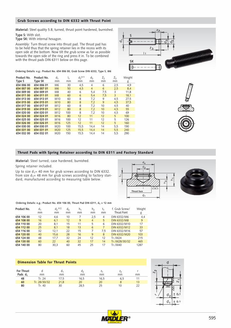
Material: Steel quality 5.8, turned, thrust point hardened, burnished.
Type S: With slot. Type SK: With internal hexagon.
Assembly: Turn thrust screw into thrust pad. The thrust pad has to be held thus that the spring retainer lies in the recess with its open side at the bottom. Now tilt the grub screw as far as possible towards the open side of the ring and press it in. To be combined with the thrust pads DIN 6311 below on this page.
Grub Screws according to DIN 6332 with Thrust Point
Ordering Details: e.g.: Product No. 654 006 00, Grub Screw DIN 6332, Type S, M6
For Thrust d d1 d2 z1 z2 r Pads d1 mm mm mm mm mm mm
Dimension Table for Thrust Points
Material: Steel turned, case hardened, burnished.
Spring retainer included.
Up to size d1= 40 mm for grub screws according to DIN 6332.from size d1= 48 mm for grub screws according to factory stan-dard, manufactured according to measuring table below.
Thrust Pads with Spring Retainer according to DIN 6311 and Factory Standard
Ordering Details: e.g.: Product No. 654 106 00, Thrust Pad DIN 6311, d1 = 12 mm
Product No. d1 d2 h12 d4 h1 h2 t1 f. Grub Screw/ Weight
mm mm mm mm mm mm Thrust Point g
Thrust face
Product No. Product No. d1 l1 d2h11 d3 Z2 Z3 Weight
Type S Type SK mm mm mm mm mm mm g

596 ®
655 206 00 655 226 00 655 992 06 M6 20 14 2,5 5 10 10 4 8 17,2 8,2 17,2655 208 00 655 228 00 655 992 08 M8 25 18 4 7 13 18 7 14 36,7 17,2 36,7655 210 00 655 230 00 655 992 10 M10 32 22 5 9 17 20 10 16 77,3 35,8 77,3655 212 00 655 232 00 655 992 12 M12 40 26 6 11 19 35 18 28 125 54 125655 216 00 655 236 00 655 992 16 M16 50 32 7 13,5 24 45 20 36 249 103 249655 220 00 655 240 00 655 992 20 M20 60 42 8 17 30 55 22 44 478 205 478655 224 00 655 244 00 655 992 24 M24 60 45 9,5 19 36 65 25 52 665 285 665
655 206 01 655 206 91 M6 60 20 57 14 2,5 10 10 8 29655 208 01 655 208 91 M8 80 25 76 18 4 13 18 14 66655 210 01 655 210 91 M10 100 32 95,5 22 5 17 20 16 133655 210 02 655 210 92 M10 150 32 145,5 22 5 17 20 16 159655 212 01 655 212 91 M12 100 40 94,5 26 6 19 35 28 211655 212 02 655 212 92 M12 150 40 144,5 26 6 19 35 28 247655 216 01 655 216 91 M16 100 50 94 32 7 24 45 36 407655 216 02 655 216 92 M16 200 50 194 32 7 24 45 36 540655 220 01 655 220 91 M20 100 60 92,5 42 8 30 55 44 722655 220 02 655 220 92 M20 200 60 192,5 42 8 30 55 44 924655 224 01 655 224 91 M24 100 60 91 45 9,5 36 65 52 935655 224 02 655 224 92 M24 200 60 191 45 9,5 36 65 52 1231
Material Type A: Ball bearing: free cutting steel, induction hardened, burnished, Pad: steel, heat-treated, burnished.
Material Type D: Ball bearing: stainless steel 1.4305. Pad: Plastic POM, white, Temperature range: -30ºC to +80ºC.
Material Type N: Completely from stainless steel 1.4305.
Levelling Pads 2259
Ordering Details: e.g.: Product No. 655 206 00, Levelling Pad 2259, Type A, M6
* Only suitable for compressive load.** Figures apply to room temperature only, at higher temperatures the load bearing capacity is reduced.
STAINLESS
Static Load Capacity* Weight Weight WeightProduct No. Product No. Product No. d1 d2 h1 h2 t SW Typ A Typ D** Typ N Typ A Typ D Typ NTyp A Typ D Typ N mm mm mm mm mm mm kN kN kN g g g
Static Load Capacity* WeightProduct No. Product No. d1 l1 d2 l2 h1 h2 SW Typ AG Typ NG AG, NGTyp AG Typ NG mm mm mm mm mm mm mm kN kN g
* Only suitable for compressive load.
Material Type AG: Ball with threated bolt: free cutting steel, induction hardened, burnished. Pad: steel, heat-treated, burnished.
Material Type NG: Stainless steel 1.4305.
Levelling Pads 2259, with external Thread
Ordering Details: e.g.: Product No. 655 206 01, Levelling Pad 2259, Type AG, M6 x 60
STAINLESS

597®
655 301 00 655 331 00 655 993 01 655 993 31 60 M10 43 32 23 14 14 14000 0,05655 302 00 655 332 00 655 993 02 655 993 32 60 M10 68 32 23 14 14 14000 0,08655 303 00 655 333 00 655 993 03 655 993 33 60 M10 98 32 23 14 14 14000 0,16655 304 00 655 334 00 655 993 04 655 993 34 60 M12 43 32 23 14 14 14000 0,07655 305 00 655 335 00 655 993 05 655 993 35 60 M12 68 32 23 14 14 14000 0,10655 306 00 655 336 00 655 993 06 655 993 36 60 M12 98 32 23 14 14 14000 0,19 655 311 00 655 341 00 655 993 11 655 993 41 60 M16 68 32 23 16 14 14000 0,14655 312 00 655 342 00 655 993 12 655 993 42 60 M16 108 32 23 16 14 14000 0,12 655 313 00 655 343 00 655 993 13 655 993 43 60 M16 148 32 23 16 14 14000 0,27655 314 00 655 344 00 655 993 14 655 993 44 80 M16 68 32 23 16 14 16000 0,16655 315 00 655 345 00 655 993 15 655 993 45 80 M16 108 32 23 16 14 16000 0,21655 316 00 655 346 00 655 993 16 655 993 46 80 M16 148 32 23 16 14 16000 0,26655 321 00 655 351 00 655 993 21 655 993 51 80 M20 98 42 23 24 24 18000 0,36655 322 00 655 352 00 655 993 22 655 993 52 80 M20 138 42 23 24 24 18000 0,43655 323 00 655 353 00 655 993 23 655 993 53 80 M20 158 42 23 24 24 18000 0,47 655 324 00 655 354 00 655 993 24 655 993 54 100 M20 98 42 23 24 24 25000 0,44655 325 00 655 355 00 655 993 25 655 993 55 100 M20 138 42 23 24 24 25000 0,48 655 326 00 655 356 00 655 993 26 655 993 56 100 M20 158 42 23 24 24 25000 0,50655 327 00 655 357 00 655 993 27 655 993 57 100 M24 98 42 23 24 24 25000 0,61655 328 00 655 358 00 655 993 28 655 993 58 100 M24 158 42 23 24 24 25000 0,77655 329 00 655 359 00 655 993 29 655 993 59 100 M24 198 42 23 24 24 25000 0,88
Articulated Levelling Feets 344 and 344.5 Plastic with Steel or Stainless Steel Bolt
Material Version 344: base: plastic (polyamide), glass-fibre reinforced, matt finish black.Bolt: steel, strength class 5.8., zinc plated, chromated.Rubber pad: NBR (perbunan) 70º Shore hardness, black.Type A: without nut, without rubber pad, bolt steel.Type AG: without nut, with rubber pad, bolt steel.
Material Version 344.5: Base: Plastic (polyamide), glass-fibre rein-forced, matt finish black. Bolt M10, M12, M16 (SW16): 1.4305.Bolt M20, M24: 1.4301.Rubber pad: NBR (perbunan) 70º Shore hardness, black.Type N: without nut, without rubber pad, bolt stainless steel.Type NG: without nut, with rubber pad, bolt stainless steel.
Ordering Details: e.g.: Product No. 655 301 00 Foot 344, A, Ø 60 x 43 mm
* Static Load
Articulated Feet 344 and 344.5 are slightly stepped, this makes them look good and easy to clean.
Due to the use of a high grade plastic material and their shape (ribbed base), that serves to spread the weight over a larger area, the feet have a high load bearing capacity.The rubber pad is fixed to the base with four pins/bores. The rubber pad levels out slightly uneven ground and makes the foot non-slip.
The load figures specified in the table above are guide line values. If these are exceeded, serious permanent deformation or breakage of the plastic base can occur.
These values were established through a series of tests, where with a certain number of levelling feet, a vertical force was applied on the disk for a certain time.
Dependend on the application and the load, a safety factor has to be taken into account, so that the permissable load may be below the guide line values stated in the table.
We cannot accept any liability for possible damages which could be caused by the incorrect use of the articulated feet.
General
Version 344, steel Version 344.5, stainless
Product No. Product No. Product No. Product No. d1 d2 l1 l2 l3 sw Ball Ø Static WeightType A Type AG Type N Type NG mm mm mm mm mm mm mm Load N* kg
AG / NG with Rubber Pad
STAINLESS

598 ®
655 741 00 655 997 41 50 M16 75 29 25,5 14,5 11 3,5 8 12 16 28 193655 742 00 655 997 42 50 M16 100 29 25,5 14,5 11 3,5 8 12 16 28 270655 743 00 655 997 43 50 M16 125 29 25,5 14,5 11 3,5 8 12 16 28 290655 744 00 655 997 44 50 M16 150 29 25,5 14,5 11 3,5 8 12 16 28 310655 751 00 655 997 51 60 M16 75 30 26 16 12 4 8 12 16 28 280655 752 00 655 997 52 60 M16 100 30 26 16 12 4 8 12 16 28 300655 753 00 655 997 53 60 M16 125 30 26 16 12 4 8 12 16 28 320655 754 00 655 997 54 60 M16 150 30 26 16 12 4 8 12 16 28 340655 761 00 655 997 61 80 M16 75 32 27 18 13 5 8 12 12 19 400655 762 00 655 997 62 80 M16 100 32 27 18 13 5 8 12 12 19 450655 763 00 655 997 63 80 M16 125 32 27 18 13 5 8 12 12 19 470655 764 00 655 997 64 80 M16 150 32 27 18 13 5 8 12 12 19 500655 765 00 655 997 65 80 M20 75 33 28 18 13 5 10 15 12 19 490655 766 00 655 997 66 80 M20 100 33 28 18 13 5 10 15 12 19 525655 767 00 655 997 67 80 M20 125 33 28 18 13 5 10 15 12 19 570655 768 00 655 997 68 80 M20 150 33 28 18 13 5 10 15 12 19 630655 771 00 655 997 71 100 M20 75 35 29 20 14 6 10 15 11 17 610655 772 00 655 997 72 100 M20 100 35 29 20 14 6 10 15 11 17 660655 773 00 655 997 73 100 M20 125 35 29 20 14 6 10 15 11 17 680655 774 00 655 997 74 100 M20 150 35 29 20 14 6 10 15 11 17 780655 775 00 655 997 75 100 M24 100 38 32 20 14 6 12 19 11 17 840655 776 00 655 997 76 100 M24 125 38 32 20 14 6 12 19 11 17 890655 777 00 655 997 77 100 M24 150 38 32 20 14 6 12 19 11 17 940
Levelling Feets 340 of Steel and 340.5 of Stainless Steel
Material Version 340: Steel, zinc plated, chromated.Rubber pad: NBR (perbunan) 80 - 85º Shore hardness, black.
Type AG: Steel, with rubber pad.
Material Version 340.5: Stainless steel 1.4301. Rubber pad: NBR (perbunan) 70º Shore hardness, black.
Type NG: Stainless Steel, with rubber pad.
Ordering Details: e.g.: Product No. 655 741 00 Levelling Foot 340, Type AG, 50 x M16 x 75
* Static Load
A feature of the leveling feet is the firmly bonded rubber pad in the steel foot also fixed by a screw. The bolt can be adjusted either at the hexagon at the upper end or at the spanner flats at the bottom end.
The static load is limited by any deformation of the steel base (3 mm thick).
The load figures specified in the table above are based on a series of tests in which a vertical load was applied on the base. At the values stated in the table, a slight deformation of the base might occur.
General
STAINLESS
Product No. Product No. approx. Static Load*Version 340 Version 340.5 d1 d2 l1 l2 l3 l4 l5 l6 sw1 sw2 Vers. 340 Vers. 340.5 WeightSteel Stainless Steel mm mm mm mm mm mm mm mm mm mm kN kN g
599®
685 950 00 77 30 M10 9 110 59 128 2 0,30685 955 00 92 45 M12 10,5 110 73,5 138 3 0,69685 960 00 106 38 M12 14 x 18 138/146 81 172 3 0,75685 965 00 108 50 M16 16,5 160 83 190 5 1,12685 970 00 121 42 M16 13,5 158 92 188 3 0,97
685 912 00 KA 010 73 53 30 10 M10 60 0,27685 913 00 KA 090 90 73 35 10 M12 100 0,60685 915 00 KA 015 120 95 35 12 M12 100 0,94685 918 00 KA 020 150 120 40 12 M16 100 2,24685 921 00 KA 030 200 170 45 15 M20 x 1,5 120 4,90
KA 010 KA 090 KA 015 KA 020 KA 030
1500 4200 6500 14000 34000 2100 3500 12000 28000 100 4200 8000 25000 150 2400 4000 13500 170 1750 2500 9000 200 1400 2000 4500 6300 11000 18000 40000
685 950 00 2700 2,8 964685 955 00 6000 3,3 1818685 960 00 5500 2,8 1964685 965 00 8100 2,9 2793685 970 00 6800 3,5 1942
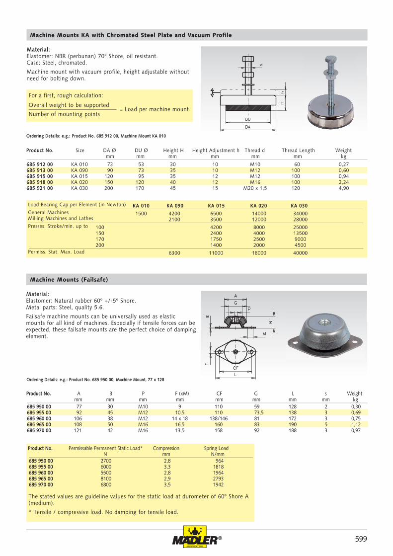
Material:Elastomer: Natural rubber 60º +/-5º Shore.Metal parts: Steel, quality 5.6.
Failsafe machine mounts can be universally used as elastic mounts for all kind of machines. Especially if tensile forces can be expected, these failsafe mounts are the perfect choice of damping element.
Machine Mounts (Failsafe)
Ordering Details: e.g.: Product No. 685 950 00, Machine Mount, 77 x 128
Product No. A B P F (xM) CF G L s Weight mm mm mm mm mm mm mm mm kg
Machine Mounts KA with Chromated Steel Plate and Vacuum Profile
Material: Elastomer: NBR (perbunan) 70º Shore, oil resistant.Case: Steel, chromated.
Machine mount with vacuum profile, height adjustable without need for bolting down.
Ordering Details: e.g.: Product No. 685 912 00, Machine Mount KA 010
Product No. Size DA Ø DU Ø Height H Height Adjustment h Thread d Thread Length Weight mm mm mm mm mm mm kg
Load Bearing Cap.per Element (in Newton) General Machines Milling Machines and Lathes Presses, Stroke/min. up to Permiss. Stat. Max. Load
Product No. Permissable Permanent Static Load* Compression Spring Load N mm N/mm
The stated values are guideline values for the static load at durometer of 60º Shore A (medium).
* Tensile / compressive load. No damping for tensile load.
Overall weight to be supported
Number of mounting points= Load per machine mount
For a first, rough calculation:

600 ®
685 781 00 10 10 M4 10 38 43 2,6685 783 00 10 15 M4 10 13 43 2,9685 786 00 15 7 M4 10 136 95 3,5685 787 00 15 8 M4 10 122 95 3,6685 788 00 15 10 M4 10 106 95 3,8685 790 00 15 15 M4 10 74 95 7,3685 791 00 20 5 M6 18 340 170 8685 801 00 20 8 M6 18 330 170 7,9685 801 11 20 11 M6 18 150 170 9685 802 00 20 15 M6 18 138 170 10,3685 802 20 20 20 M6 18 100 170 11685 802 25 20 25 M6 18 80 170 14685 803 08 25 8 M6 18 300 280 14685 803 10 25 10 M6 18 270 280 14685 803 00 25 15 M6 18 254 280 17,2685 803 20 25 20 M6 18 128 280 20685 803 25 25 25 M6 18 100 280 24685 803 30 25 30 M6 18 80 280 30685 804 15 30 15 M8 23 290 400 29685 804 00 30 20 M8 20 200 400 27685 804 25 30 25 M8 20 180 400 35685 804 30 30 30 M8 20 120 400 35685 804 40 30 40 M8 20 90 400 48685 805 20 40 20 M8 23 340 650 52685 805 00 40 30 M8 23 234 650 75685 805 30 40 30 M10 28 240 650 74685 805 40 40 40 M8 23 200 650 80685 806 00 50 20 M10 28 680 1000 85685 806 30 50 30 M10 28 425 1000 100685 806 40 50 40 M10 28 390 1000 132685 806 45 50 45 M10 28 350 1000 140685 806 50 50 50 M10 28 310 1000 152685 806 60 60 40 M10 28 470 1500 179685 806 65 60 40 M12 33 460 1500 190685 806 70 70 25 M10 28 650 1800 198685 806 75 70 45 M10 28 800 1800 292685 807 00 75 25 M12 37 2000 2300 241685 807 40 75 40 M12 37 810 2300 320685 807 50 75 50 M12 37 620 2300 357685 807 55 75 55 M12 37 760 2300 384685 808 00 100 40 M16 41 1578 4200 641685 808 50 100 50 M16 41 900 4200 669685 808 55 100 55 M16 41 860 4200 760685 808 60 100 60 M16 41 800 4200 730685 808 75 100 75 M16 41 540 4200 874
Rubber-Metal Bump Stops MGS with Threaded Stud
Material: Metal parts: Steel, zinc plated. Elastomer: Natural rubber, hardness 55º Shore.
Metal on one side only.
For elastically mounting of power units, and as bump stop to limit the spring travel in vehicles. Bump stops can also be used for machines that cannot be fixed to the floor or are standing on floors with an easily damaged surface, e.g. office machines.
Temperature resistant up to 80ºC.
Ordering Details: z.B.: Product No.. 685 781 00, Bump Stop MGS, 10 mm
Pressure Load Spring Rate Perm. Pressure Product No. D Ø H G I CD medium Load Fperm.* Weight mm mm mm mm N/mm N g
* Fperm.: Note page 602 bottom.
Loctite thread locking and bonding products page 811.
601®
685 031 00 20 24 M6 18 15 60 11685 035 00 30 36 M8 20 23 140 37685 041 00 35 40 M8 20 27 150 45685 045 00 50 58 M 10 28 33 320 127685 051 00 50 67 M8 36 40 400 136685 055 00 75 89 M12 37 55 900 341685 061 00 115 136 M16 43 75 1800 1042
685 131 00 50 35 M10 10 100 400 88685 135 00 80 60 M12 12 170 1200 308685 141 00 125 90 M16 16 260 3000 830
685 831 00 25 17 M6 x 18 external thread 119 500 15685 835 00 50 18 M10 x 28 external thread 670 2000 75685 841 00 25 17 M6 x 6 internal thread 130 500 15685 845 00 50 18 M10 x 10 internal thread 735 2000 75
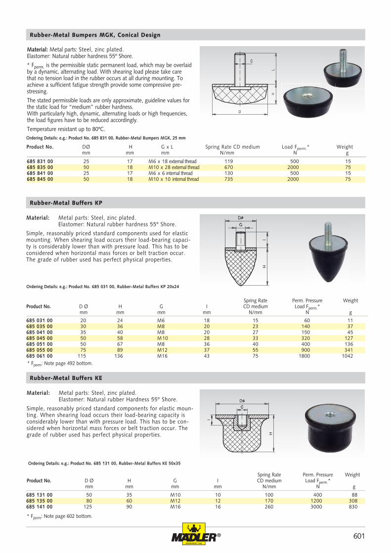
Rubber-Metal Bumpers MGK, Conical Design
Ordering Details: e.g.: Product No. 685 831 00, Rubber-Metal Bumpers MGK, 25 mm
Material: Metal parts: Steel, zinc plated. Elastomer: Natural rubber hardness 55º Shore.
* Fperm. is the permissible static permanent load, which may be overlaid by a dynamic, alternating load. With shearing load please take care that no tension load in the rubber occurs at all during mounting. To achieve a sufficient fatigue strength provide some compressive pre-stressing.
The stated permissible loads are only approximate, guideline values for the static load for “medium” rubber hardness. With particularly high, dynamic, alternating loads or high frequencies, the load figures have to be reduced accordingly.
Temperature resistant up to 80ºC.
Rubber-Metal Buffers KP
Material: Metal parts: Steel, zinc plated. Elastomer: Natural rubber hardness 55º Shore.
Simple, reasonably priced standard components used for elastic mounting. When shearing load occurs their load-bearing capaci-ty is considerably lower than with pressure load. This has to be considered when horizontal mass forces or belt traction occur. The grade of rubber used has perfect physical properties.
Ordering Details: e.g.: Product No. 685 031 00, Rubber-Metal Buffers KP 20x24
Spring Rate Perm. Pressure WeightProduct No. D Ø H G I CD medium Load Fperm.* mm mm mm mm N/mm N g
Rubber-Metal Buffers KE
Material: Metal parts: Steel, zinc plated. Elastomer: Natural rubber Hardness 55º Shore.
Simple, reasonably priced standard components for elastic moun-ting. When shearing load occurs their load-bearing capacity is considerably lower than with pressure load. This has to be con-sidered when horizontal mass forces or belt traction occur. The grade of rubber used has perfect physical properties.
Ordering Details: e.g.: Product No. 685 131 00, Rubber-Metal Buffers KE 50x35
Spring Rate Perm. Pressure WeightProduct No. D Ø H G I CD medium Load Fperm.* mm mm mm mm N/mm N g
* Fperm: Note page 602 bottom.
Product No. DØ H G x L Spring Rate CD medium Load Fperm.* Weight mm mm mm N/mm N g
* Fperm: Note page 492 bottom.

602 ®
685 280 00 8 8 M3 6 30 35 9 10 1685 281 00 10 10 M4 10 44 43 9 15 3,2685 283 00 10 15 M4 10 29 43 5 15 3,9685 286 00 15 7 M4 10 174 95 29 35 5,8685 287 00 15 8 M4 10 160 95 27 35 6685 288 00 15 10 M4 10 124 95 24 35 6,4685 289 00 15 20 M4 13 54 95 10 35 7685 290 00 15 15 M4 10 61 95 13 35 7,8685 301 00 20 8 M6 18 307 170 36 60 15685 302 00 20 10 M6 18 150 170 40 60 15685 304 00 20 15 M6 18 130 170 24 60 20685 304 20 20 20 M6 18 100 170 20 60 19685 304 25 20 25 M6 18 70 170 13 60 20685 305 00 25 20 M6 18 85 170 17 60 30685 307 00 25 10 M6 18 750 280 74 95 20685 307 15 25 15 M6 18 140 280 25 95 27,5685 307 25 25 25 M6 18 600 280 37 95 32685 307 30 25 30 M6 18 71 280 17 95 40685 308 00 30 15 M8 20 525 400 58 140 37685 309 00 30 20 M8 20 204 400 40 140 56685 309 25 30 25 M8 20 180 400 33 140 58685 311 00 30 30 M8 20 108 400 25 140 65685 311 10 30 40 M8 20 85 400 18 140 64685 311 20 40 15 M8 20 380 650 90 250 79685 311 23 40 25 M8 23 270 650 60 250 84685 311 28 40 25 M10 28 270 650 60 250 90685 312 00 40 30 M8 23 213 650 43 250 102685 312 30 40 30 M10 28 213 650 40 250 105685 313 00 40 40 M8 23 140 650 22 250 115685 315 00 50 20 M10 28 857 1000 110 400 141685 314 00 50 25 M10 28 583 1000 84 400 155685 316 00 50 30 M10 28 375 1000 66 400 163685 317 00 50 40 M10 28 260 1000 53 400 178685 324 00 50 45 M10 33 215 1000 43 400 208685 317 50 50 50 M10 28 200 1000 39 400 199685 317 60 60 40 M10 28 390 1500 60 550 231685 317 70 70 45 M10 28 450 1800 70 750 401685 318 00 75 25 M12 37 2710 2300 211 850 369685 318 40 75 40 M12 37 734 2300 117 850 420685 319 00 75 50 M12 37 506 2300 91 850 483685 320 00 75 55 M12 37 417 2300 78 850 514685 322 00 100 30 M16 41 3800 4200 310 1600 831685 321 00 100 40 M16 41 1970 4200 257 1600 956685 321 50 100 50 M16 41 900 4200 160 1600 1033685 321 55 100 55 M16 41 892 4200 145 1600 980685 323 00 100 60 M16 41 809 4200 136 1600 1177685 325 00 100 75 M16 41 750 4200 110 1600 1124
Rubber-Metal Buffers MGP with Threaded Studs
Material: Metal parts: Steel, zinc plated. Elastomer: Natural rubber, 55º Shore hardness.
Simple, reasonably priced standard components for elastic moun-ting. When shearing load occurs their load-bearing capacity is considerably lower than with pressure load. This has to be con-sidered when horizontal mass forces or belt traction occur. The grade of rubber used has perfect physical properties.
Temperature resistant up to 80ºC.
Ordering Details: e.g.: Product No. 685 280 00, Rubber-Metal Buffers MGP, 8 mm
For a linear resilience characteristic the Spring Load C means, for any operating point, the constant relation of load F [N] to jounce travel f [mm].
C = [N/mm] In the technical data, these constants are stated as CD for pure pressure load and as CS for pure shear load.
F
f
* Fperm. is the permissible static permanent load, which may be overlaid by a dynamic, alternating load. With shearing load please take care that no tension load in the rubber occurs at all during mounting. To achieve a sufficient fatigue strength provide some compressive prestressing.
The stated permissible loads are only approximate, guideline values for the static load for “medium” rubber hardness. With particularly high, dynamic, alternating loads or high frequencies, the load figures have to be accordingly reduced.
P r e s s u r e L o a d S h e a r i n g L o a d Spring Load CD Permiss. Load Spring Load CS Permiss. Load WeightProduct No. D Ø H G I medium F perm.* medium Fperm.* mm mm mm mm N/mm N N/mm N g

603®
685 721 00 10 10 M4 4 30 35 4 20 2685 723 00 30 20 M8 8 130 650 25 85 25685 725 00 40 48 M8 8 145 870 80 130 80685 727 00 50 30 M10 10 200 1000 63 240 63
685 631 00 20 15 M6 18 100 300 15685 635 00 30 20 M8 20 150 700 46685 641 00 40 48 M8 23 160 900 88685 645 00 50 30 M 10 33 210 1100 140685 651 00 75 40 M12 37 600 3000 369685 655 00 100 55 M16 45 850 4100 975
Rubber-Metal Buffers CT
Material: Metal parts: Steel, zinc plated. Elastomer: Natural rubber hardness 55º Shore.
Rubber-Metal buffers are simple, reasonably priced standard components used for elastic mounting. When shearing load occurs their load-bearing capacity is considerably lower than with pressure load. This has to be considered when horizontal mass forces or belt traction occur. The grade of rubber used has perfect physical properties.
Ordering Details: e.g.: Product No. 685 721 00, Rubber-Metal Buffers CT 10x10
Pressure Load Shearing Load Spring Rate Perm. Pressure Spring Rate Perm. Shearing WeightProduct No. D Ø H G I CD medium Load Fperm* CS medium Load Fperm.* mm mm mm mm N/mm N N/mm N g
* Fperm.: Note page 602 bottom.
Rubber-Metal Buffers AT
Material: Metal parts: Steel, zinc plated. Elastomer: Natural rubber hardness 55º Shore.
Simple, reasonably priced standard components for elastic moun-ting. When shearing load occurs their load-bearing capacity is considerably lower than with pressure load. This has to be con-sidered when horizontal mass forces or belt traction occur. The grade of rubber used has perfect physical properties.
Ordering Details: e.g.: Product No. 685 631 00, Rubber-Metal Buffers AT 20x15
Spring Rate Perm. Pressure WeightProduct No. D Ø H G I CD medium Load Fperm.* mm mm mm mm N/mm N g
* Fperm.: Note page 602 bottom.

604 ®
685 580 00 8 8 M3 6 3 28 35 10 10 1685 581 00 10 10 M4 10 4 48 43 10 15 2,7685 583 00 10 15 M4 10 4 29 43 5 15 3,6685 590 00 15 15 M4 10 6 67 95 15 35 8,3685 591 15 15 15 M5 8 6 65 95 5 35 5685 591 20 15 20 M4 10 5 43 95 12 35 6685 591 30 15 30 M4 15 6 32 95 9 35 9685 592 15 20 15 M6 18 6 110 170 37 60 14685 592 20 20 20 M6 18 6 85 170 17 60 16685 601 00 20 25 M6 18 6 61 170 11 60 17685 602 15 25 15 M6 18 6 165 280 45 95 25685 602 00 25 20 M6 18 6 130 280 30 95 28685 602 25 25 25 M6 18 6 89 280 27 95 30685 602 30 25 30 M6 18 6 71 280 19 95 30685 607 15 30 15 M8 20 8 270 400 68 140 38685 607 00 30 20 M8 20 8 235 400 42 140 51685 607 25 30 25 M8 20 8 180 400 37 140 48685 603 00 30 30 M8 20 8 113 400 28 140 47685 605 00 30 40 M8 20 8 106 400 13 140 60685 598 00 40 25 M8 23 8 265 650 35 250 77685 608 00 40 30 M8 23 8 234 650 49 250 91685 600 00 40 30 M10 28 10 234 650 48 250 92685 609 00 40 40 M8 23 8 147 650 23 250 103685 610 20 50 20 M10 28 10 450 1000 95 400 112685 610 25 50 25 M10 28 10 425 1000 82 400 125685 610 30 50 30 M10 28 10 395 1000 73 400 135685 610 00 50 40 M10 28 10 273 1000 58 400 168685 611 00 50 45 M10 33 10 250 1000 50 400 174685 613 00 50 50 M10 28 10 210 1000 37 400 183685 613 60 60 40 M10 28 10 390 1500 63 550 224685 613 65 60 40 M12 33 12 390 1500 60 550 243685 613 70 70 45 M10 28 10 450 1800 72 700 348685 613 75 75 25 M12 37 12 980 2300 270 850 299685 614 40 75 40 M12 37 12 735 2300 118 850 420685 614 45 75 45 M12 37 12 690 2300 105 850 417685 614 00 75 50 M12 37 12 530 2300 101 850 467685 614 55 75 55 M12 37 12 500 2300 90 850 469685 615 00 100 40 M16 41 16 2160 4200 283 1600 871685 615 50 100 50 M16 41 16 950 4200 220 1600 830 685 615 55 100 55 M16 41 16 870 4200 170 1600 870685 616 00 100 60 M16 41 16 843 4200 142 1600 1097685 616 75 100 75 M16 41 16 750 4200 110 1600 1064
Rubber-Metal Buffers MGA with Internal Thread and Threaded Stud
Material: Metal parts: Steel, zinc plated. Elastomer: Natural rubber, Rubber hardness Shore A medium: about 55º.
For this version the same remarks apply as for the Rubber-Metal buffers MGP page 544.
Temperature resistant up to 80ºC.
Ordering Details: e.g.: Product No. 685 580 00, Rubber-Metal Buffers MGA, 8 mm
P r e s s u r e L o a d S h e a r i n g L o a d Spring Load CD Permiss. Load Spring Load CS Permiss. Load Product No. D Ø H G I t medium F perm.* medium Fperm.* Weight mm mm mm mm mm N/mm N N/mm N g
* Fperm.: Note page 602 bottom.

605®
685 410 00 10 10 M4 4 39 43 9 15 2685 410 15 10 15 M4 4 28 43 4 15 2685 415 00 15 15 M4 5 62 95 12 35 5685 420 00 20 25 M6 6 103 170 15 60 17685 425 00 25 20 M6 6 83 170 16 60 24685 425 30 25 30 M6 6 67 280 16 95 30685 430 00 30 20 M8 8 207 400 37 140 35685 430 30 30 30 M8 8 117 400 24 140 44685 430 40 30 40 M8 8 67 400 13 140 50685 440 00 40 30 M8 8 209 650 41 250 78685 440 40 40 40 M8 8 114 650 20 250 93685 450 00 50 30 M10 10 352 1000 68 400 126685 450 40 50 40 M10 10 247 1000 51 400 145685 450 50 50 50 M10 10 118 1000 37 400 169685 475 00 75 40 M12 12 720 2300 110 850 366685 475 50 75 50 M12 12 498 2300 89 850 425685 500 00 100 40 M16 16 1830 4200 249 1600 733685 500 60 100 60 M16 16 770 4200 129 1600 863
Rubber-Metal Buffers MGI
Material: Metal parts: Steel, zinc plated. Elastomer: Natural rubber hardness 55º Shore.
Simple, reasonably priced standard components for elastic moun-ting. When shearing load occurs their load-bearing capacity is considerably lower than with pressure load. This has to be con-sidered when horizontal mass forces or belt traction occur. The grade of rubber used has perfect physical properties.
Ordering Details: e.g.: Product No. 685 410 00, Rubber-Metal Buffer 10 mm
Pressure Load Shearing Load Spring Rate Perm. Pressure Spring Rate Perm. Shearing WeightProduct No. D Ø H G I CD medium Load Fperm* CS medium Load Fperm.* mm mm mm mm N/mm N N/mm N g
* Fperm.: Note page 602 bottom.

606 ®
685 001 00 26+0,1 12+0,15 24,0±0,1 18,0±0,3 690 1962 680 226 13 4,4 0,338 26 9,0 37685 002 00 30+0,1 13+0,15 40,0±0,1 40,0±0,3 1670 3335 - 392 15 9,0 0,6 30 18,0 79685 003 00 34+0,15 18+0,3 36,0±0,1 32,0±0,3 1570 3237 830 417 14 12,0 0,9 28 25,0 94685 004 00 45+0,15 20+0,3 62,5±0,1 55,0±0,3 3430 3924 1860 540 15 22,0 1,5 30 44,0 255685 005 00 45+0,15 20+0,3 62,5±0,1 59,5±0,3 3920 4905 910 608 15 30,0 2,0 30 60,0 258685 006 00 50+0,15 25+0,3 67,5±0,1 65,5±0,3 6380 6082 760 755 15 60,0 3,9 30 120,0 370685 007 00 55+0,15 25+0,3 93,5±0,1 89,5±0,3 9810 8829 1650 824 15 70,0 4,6 30 140,0 677685 008 00 55+0,15 30+0,4 94,0±0,1 89,5±0,3 13730 16677 2600 1177 13 100,0 7,6 26 200,0 622685 009 00 70+0,15 50+0,4 60,0±0,1 60,0±0,3 11770 10620 - 1511 6,5 140,0 21,1 13 370,0 494685 010 00 75+0,2 40+0,4 70,0±0,1 57,0±0,3 5890 4611 4510 697 14 130,0 9,1 28 260,0 759
Heavy-Duty steel rubber Bushes PHO
Material: Metal Parts: Steel. Elastomer: Natural rubber, Strength 55º Shore.
Fit: Up to external diameter 30mm: mounting hole H11 / H12. From external diameter 34mm: mounting hole H13.
Temperature resistant up to 80ºC.
Ordering Details: e.g.: Product No. 685 001 00, Heavy Duty Bush PHO, 26 mm
These Rubber-Metal, heavy-duty bushes feature an especially high permissible load and large permissible deformation. This great performance is achieved because the rubber parts are firmly attached to the metal parts. The bushes withstand radial, axial and torsional load, without the rubber moving in relation to the metal parts. Minimal gimbal offset (tilting) of the axis of the inner tube in relation to the outer tube, or vice versa, is possible. Depending on the strength, hardness, and length of the rubber, the rubber parts are relatively stiff.
Can be used in machine building or car manufacture as elastic joints, which at permanent operation have to withstand a deflec-tion of approx. ±15º and have to absorb higher radial forces. During deflection a recoiling moment occurs, which is proporti-onal to the torsional angle, as the rubber cannot move in rela-tion to the metal. The bushes are completely maintenance free,
General
silent and vibration isolating along with a high fatigue strength. Spring element and joint are combined in one single element.
The grade of rubber used is not oil proof. An operating tempe-rature of max. 80º must not be exceeded, otherwise the service life is shortened. Hardness about 60 Shore-A-units. The bushes are usually fixed to the outer tube by pressfit.The inner tube can, e.g., be fixed by applying pressure on the front face. In this case the bolt running through the bore of the bush presses the counter bearing against the front face of the inner tube.
Radial-Load Axial-Load Torsion Length Length Perm.Stat. Radial Perm.Stat. Axial Perm.St. Perm.St. Torsion Perm. Perm. of of Radial Spring Axial Spring Torsion Torque Spring Max. Max. External Internal Internal External Load Rate Load Rate Angle Rate Torsion Torque Ø Ø Bush Bush Angle Product No. D d l L Fr Cr Fa Ca ϕ Md Cf ϕmax. Mdmax Weight mm mm mm mm N N/mm N N/mm degrees Nm Nm/degree degrees Nm g
607®
691 229 00 29-17 2 17 28 5 M5 25 13,5 38 10691 237 00 37-22 3 22 36 5 M5 32 19,5 50 15691 243 00 43-25 4 25 43 5 M5 37 19,5 58 20691 250 00 50-35 6 35 49 5 M5 44 34 68 25691 263 00 63-43 15 43 64 5 M5 55 43,5 87 55691 267 00 67-40 25 40 66,5 5 M5 59 46 88 80 691 276 00 76-46 40 46 76 6 M6 67 46 102 105 691 283 00 83-50 45 50 83 6 M6 73 51 109 150
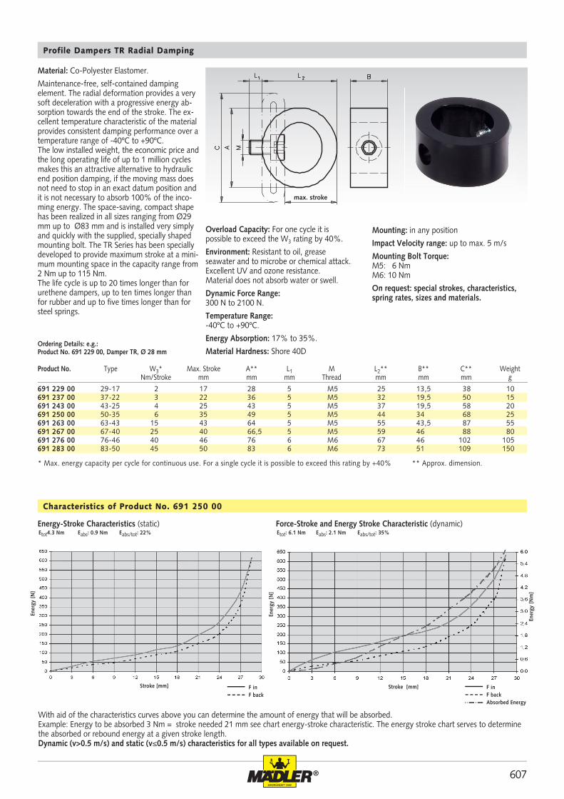
Profile Dampers TR Radial Damping
Ordering Details: e.g.: Product No. 691 229 00, Damper TR, Ø 28 mm
Material: Co-Polyester Elastomer.
Maintenance-free, self-contained damping element. The radial deformation provides a very soft deceleration with a progressive energy ab-sorption towards the end of the stroke. The ex-cellent temperature characteristic of the material provides consistent damping performance over a temperature range of -40ºC to +90ºC.The low installed weight, the economic price and the long operating life of up to 1 million cycles makes this an attractive alternative to hydraulic end position damping, if the moving mass does not need to stop in an exact datum position and it is not necessary to absorb 100% of the inco-ming energy. The space-saving, compact shape has been realized in all sizes ranging from Ø29 mm up to Ø83 mm and is installed very simply and quickly with the supplied, specially shaped mounting bolt. The TR Series has been specially developed to provide maximum stroke at a mini-mum mounting space in the capacity range from 2 Nm up to 115 Nm.The life cycle is up to 20 times longer than for urethene dampers, up to ten times longer than for rubber and up to five times longer than for steel springs.
* Max. energy capacity per cycle for continuous use. For a single cycle it is possible to exceed this rating by +40% ** Approx. dimension.
Overload Capacity: For one cycle it is possible to exceed the W3 rating by 40%.
Environment: Resistant to oil, grease seawater and to microbe or chemical attack. Excellent UV and ozone resistance. Material does not absorb water or swell.
Dynamic Force Range: 300 N to 2100 N.
Temperature Range: -40ºC to +90ºC.
Energy Absorption: 17% to 35%.
Material Hardness: Shore 40D
Mounting: in any position
Impact Velocity range: up to max. 5 m/s
Mounting Bolt Torque:M5: 6 NmM6: 10 Nm
On request: special strokes, characteristics, spring rates, sizes and materials.
Characteristics of Product No. 691 250 00
With aid of the characteristics curves above you can determine the amount of energy that will be absorbed. Example: Energy to be absorbed 3 Nm = stroke needed 21 mm see chart energy-stroke characteristic. The energy stroke chart serves to determine the absorbed or rebound energy at a given stroke length. Dynamic (v>0.5 m/s) and static (v≤0.5 m/s) characteristics for all types available on request.
Ener
gy [
N]
Stroke [mm]
Etot4.3 Nm Eabs: 0.9 Nm Eabs/tot: 22%
F in F back
Ener
gy [
N]
Stroke [mm]
Etot: 6.1 Nm Eabs: 2.1 Nm Eabs/tot: 35%
F in F backAbsorbed Energy
Ener
gy [
Nm
]Energy-Stroke Characteristics (static) Force-Stroke and Energy Stroke Characteristic (dynamic)
Product No. Type W3* Max. Stroke A** L1 M L2** B** C** Weight Nm/Stroke mm mm mm Thread mm mm mm g
max. stroke

608 ®
691 012 00 12-5 2 5 12 3 M3 10,5 15 11 3691 017 00 17-7 6 7 17 4 M4 16 22 15 4691 021 00 21-9 10 9 20 5 M5 18,5 26 18 5691 022 00 22-10 15 10 20 6 M6 19,5 27 19 5691 028 00 28-12 30 12 28 6 M6 26 36 25 10691 034 00 34-14 50 14 34 6 M6 30 43 30 20691 037 00 37-16 65 16 34 6 M6 33 48 33 25691 043 00 43-18 100 18 43 8 M8 38 55 38 40691 047 00 47-20 130 20 45 12 M12 41 60 41 50691 050 00 50-22 160 22 50 12 M12 45 64 44 60691 054 00 54-22 190 22 52 12 M12 47 68 47 65691 057 00 57-24 230 24 57 12 M12 52 73 50 90691 062 00 62-25 280 25 59 12 M12 54 78 53 105691 065 00 65-27 350 27 65 12 M12 58 82 57 130 691 080 00 80-32 600 32 80 16 M16 69 100 69 225
max. stroke
Profile Dampers TA Axial Damping
Product No. Type W3* Max. Stroke D** L1 M L2** d1** d2** Weight Nm/Stroke mm mm mm Thread mm mm mm g
Material: Co-Polyester Elastomer.
Maintenance-free, self-contained damping ele-ments. Due to the degressive damping characte-ristics it provides a very high energy absorption at the beginning of the stroke. The excellent temperature characteristic of the material provides consistent damping performance over a tempera-ture range of -40ºC to +90ºC.
The low installed weight, the economic price and the long operating life of up to 1 million cycles makes this an attractive alternative to hydraulic end position damping, if the moving mass does not need to stop in an exact datum position and it is not necessary to absorb 100% of the incoming energy. The space-saving, compact shape has been realized in all sizes ranging from Ø12 mm up to Ø80 mm and is installed very simply and quickly with the supplied, specially shaped mounting bolt. The TA Series has been specially developed to provide maximum stroke at a minimum mounting space in the capacity range from 2 Nm up to 280 Nm.
The life cycle is up to 20 times longer than for urethene dampers, up to ten times longer than for rubber and up to five times longer than for steel springs.
* Max. energy capacity per cycle for continuous use. For a single cycle it is possible to exceed this rating by +40% ** Approx. dimensions.
Overload Capacity: For one cycle it is possible to exceed the W3 rating by 40%.
Environment: Resistant to oil, grease seawater and to microbe or chemical attack. Excellent UV and ozone resistance. Material does not absorb water or swell.
Dynamic Force Range: 980 N to 23500 N.
Temperature Range: -40ºC to +90ºC.
Energy Absorption: 40% to 59%.
Material Hardness: Shore 55D
Mounting: in any position
Impact Velocity range: up to max. 5 m/s
Mounting Bolt Torque:M3: 2 NmM4: 4 NmM5: 6 NmM6: 10 NmM8: 25 NmM12: 85 NmM16: 210 Nm
On request: special strokes, characteristics, spring rates, sizes and materials.
Characteristics of Product No. 691 037 00
With aid of the characteristics curves above you can determine the amount of the energy that will be absorbed. Example: Energy to be absorbed 50 Nm = stroke needed 8.8 mm see chart energy-stroke characteristic. The energy stroke chart serves to deter-mine the absorbed or rebound energy at a given stroke length. Dynamic (v>0.5 m/s) and static (v≤0.5 m/s) characteristics for all types available on request.
Force-Stroke Characteristics (static)Etot: 25.9 Nm Eabs: 12.0 Nm Eabs/tot: 46%
Force-Stroke and Energy-Stroke Characteristics (dynamic)Etot: 62.6 Nm Eabs: 40.3 Nm Eabs/tot: 64%
Stroke [mm]
Forc
e [N
]
Stroke [mm]
Forc
e [N
]
Ener
gy [
Nm
]

609®
691 114 00 14-7 2 7 14 4 M4 15 19 13 3691 118 00 18-9 4 9 17 5 M5 18,5 24 16 4691 120 00 20-10 6 10 19,5 6 M6 21 27 19 5691 126 00 26-15 15 15 26 6 M6 28 37 25 10691 132 00 32-16 25 16 31 6 M6 33 44 30 15691 135 00 35-19 30 19 33,5 6 M6 36,5 48 33 25691 140 00 40-19 35 19 36,5 6 M6 37,5 51 34 30691 141 00 41-21 45 21 39,5 12 M12 41,5 55 38 40691 144 00 44-23 65 23 42 12 M12 44,5 60 40 45 691 148 00 48-25 80 25 48 12 M12 49 64 44 60 691 151 00 51-27 90 27 51 12 M12 52 69 47 70 691 154 00 54-29 115 29 54 12 M12 55 73 50 80 691 158 00 58-30 135 30 58 12 M12 59 78 53 100 691 161 00 61-32 160 32 61 16 M16 62 83 56 120 691 164 00 64-34 195 34 64 16 M16 66 87 60 145
max. stroke
Product No. Type W3* Max. stroke D** L1 M L2** d1** d2** Weight Nm/Stroke mm mm mm Thread mm mm mm g
Profile Dampers TS, Axial, Soft Damping
Ordering Details: e.g.: Product No. 691 114 00, Damper TS, Ø 14 mm.
Material: Co-Polyester Elastomer.
Maintenance free, self-contained damping elements. Due to the almost linear damping characteristics it provides very smooth energy absorption along with minimum reaction loads on the machine. The excellent temperature characteristic of the material provides consistent damping performance over a temperature range of -40ºC to +90ºC.
The low installed weight, the economic price and the long operating life of up to 1 million cycles makes this an attractive alternative to hydraulic end position damping, if the moving mass does not need to stop in an exact datum position and it is not necessary to absorb 100% of the incoming energy. The space-saving compact shape has been realised in all size ranges from Ø14 mm up to Ø64 mm and is very simply and quickly installed with the supplied, specially shaped mounting bolt. The TS Series has been specially developed to provide maximum energy absorption for the minimum overall height in the capacity range from 2 Nm to 65 Nm.
The life cycle is up to 20 times longer than the urethane dampers, up to 10 times longer than for rubber and up to 5 times longer than for steel springs.
* Max. energy absorption per stroke for continuous use. For a single cycle it is possible to exceed this rating by +40%. ** Approx. dimensions.
Overload Capacity: For one cycle it is possible to exceed the W3 rating by 40%.
Environment: Resistant to microbes, seawater, chemicals and exhibits excellent UV and ozone resistance. Material does not absorb water and swell.
Dynamic Force Range:670 N to 5800 N.
Permissible temperature range:-40ºC to +90ºC.Energy absorption: 26% to 45%.
Material hardness: Shore 40D
Mounting position: optional
Impact velocity range: up to max. 5 m/s
Tightening torque:M4: 4 NmM5: 6 NmM6: 10 NmM12: 85 NmM16: 210 Nm
Special strokes, characteristics, spring rates, sizes and materials on request.
Characteristics for Product No. 691 144 00
With aid of the characteristic curves, you can determine the amount of energy that will be absorbed. For example: Energy to be absorbed 50 Nm = stroke needed 14 mm see chart of energy-stroke characteristic. The energy-stroke chart serves to determine the absorbed or rebound energy at a given stroke length.Dynamic (v>0.5 m/s) and static (v≤0.5 m/s) characteristics for all types available on request.
Force-Stroke Characteristics (static)
Forc
e [N
]
Stroke [mm]
Etot: 32,7 Nm Eabs: 10,1 Nm Eabs/tot: 31%Force-Stroke and Energy-Stroke Characteristics (dynamic)
Forc
e [N
]
Stroke [mm]
Etot: 64,1 Nm Eabs: 29,2 Nm Eabs/tot: 45%
F in F backEnergy abs.
Ener
gy [
Nm
]

610 ®
690 030 00 3,5 5650 0,23 15 1 - 5 0,3 2690 050 00 5,5 5100 4,5 20 3 - 6 0,3 2690 035 00 4 6000 5,9 57 5 - 11 0,2 2690 150 00 22 35000 1,0 109 3 - 5 0,4 5*690 225 00 25 45000 2,3 226 5 - 10 0,1 2*690 600 00 68 68000 9,0 1360 10 - 30 0,2 2*690 900 00 100 90000 14 2040 10 - 35 0,4 1
690 030 00 48 13,1 3 8 4,1 3,2 6,4 M8x1 10 A 25 690 030 04 0,8690 050 00 50 14,9 4 7 5,1 3,2 7,7 M10x1 12 A 30 690 050 04 1,4690 035 00 66 18 5 10 5 3,2 7,7 M12x1 14 A 43 690 035 04 2,4690 150 00 70 22,5 6 12,5 7,5 4,8 12 M14x1,5 17 B 60 690 150 04 4,8690 225 00 88 30 8 19 13,5 4,8 17 M20x1,5 23 C 130 690 225 04 8690 600 00 106,6 36,4 10 25,4 16,5 6,3 23 M25x1,5 30 C 310 690 600 04 18690 900 00 138 51 10 40 16,5 6,3 23 M25x1,5 30 C 400 690 600 04 18
Miniature Shock Absorbers
Product No. Max. Energy Capacity Effective Weight me per Cycle per hour adjustable W3 W4 min. max. Return Force Rod Reset Time Max. Side Load Angle Nm Nm kg kg N s Degrees
Material: Shock absorber and accessories: Stahl burnished. Button: hardened. Piston rod: hardened, stainless steel.
Miniature shock absorbers are maintenance-free, self-contained hydraulic elements. The adjustable miniature shock absorbers can be perfectly set up for the respective application. They include an integrated mechanical stop. Due to the long stroke length, the unit offers smooth deceleration and low reaction forces.
These shock absorbers are ideal for absorbing fast movements in small linear units, handling modules, robotics systems and other applications.
Adjustment: by turning the adjustment screw. After installation, cycle the machine a few times, turning the adjustment screw until optimum deceleration is achieved.
Impact velocity range: 0.3 to 3.6 m/s.
Exceeding W4 (max. energy absorption per hour) is possible, if the unit is turned off from time to time or the shock absorber is cooled with the cylinder exhaust air.
Mounting position: optional.
Permissible temperature range: 0ºC to 66ºC.
* For higher side load angles consider using the Side Load Adaptor (on request).
Piston Rod
Positive Stop
Seal
Main Bearing
Accumulator
Piston Check Valve
Piston
Metering Orifices
Return Spring
Outer Body
Pressure/Adjust Chamber
Adjustment Knob
Capacity Chart
Ordering Details: e.g.: Product No. 690 030 00, Miniature Shock Absorbers, Stroke 8 mm
Dimensions
Type of Button A Type of Button B Type of Button C
Product No. Width Across Flats Type of Weight Product No. WeightMiniature A B C stroke I D Ø E Ø G SW Buttom additional Lock nutShock Absorber mm mm mm mm mm mm mm Thread mm g lock nut g
Stroke
Impact Buttom
Lock Nut
Type of Button A
Type of Button B
Type of Button C
additionallock nut
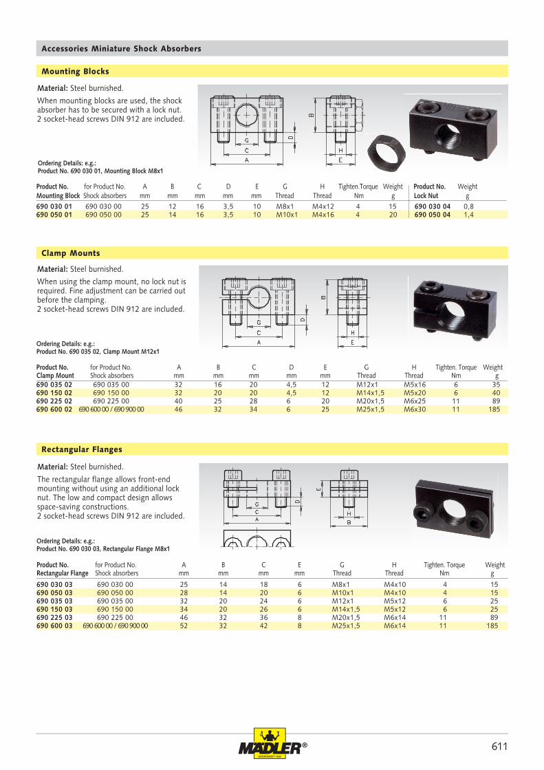
611®
690 030 01 690 030 00 25 12 16 3,5 10 M8x1 M4x12 4 15 690 030 04 0,8690 050 01 690 050 00 25 14 16 3,5 10 M10x1 M4x16 4 20 690 050 04 1,4
690 030 03 690 030 00 25 14 18 6 M8x1 M4x10 4 15690 050 03 690 050 00 28 14 20 6 M10x1 M4x10 4 15690 035 03 690 035 00 32 20 24 6 M12x1 M5x12 6 25690 150 03 690 150 00 34 20 26 6 M14x1,5 M5x12 6 25690 225 03 690 225 00 46 32 36 8 M20x1,5 M6x14 11 89690 600 03 690 600 00 / 690 900 00 52 32 42 8 M25x1,5 M6x14 11 185
690 035 02 690 035 00 32 16 20 4,5 12 M12x1 M5x16 6 35690 150 02 690 150 00 32 20 20 4,5 12 M14x1,5 M5x20 6 40690 225 02 690 225 00 40 25 28 6 20 M20x1,5 M6x25 11 89690 600 02 690 600 00 / 690 900 00 46 32 34 6 25 M25x1,5 M6x30 11 185
Rectangular Flanges
Material: Steel burnished.
The rectangular flange allows front-end mounting without using an additional lock nut. The low and compact design allows space-saving constructions.2 socket-head screws DIN 912 are included.
Ordering Details: e.g.:Product No. 690 030 03, Rectangular Flange M8x1
Material: Steel burnished.
When mounting blocks are used, the shock absorber has to be secured with a lock nut. 2 socket-head screws DIN 912 are included.
Accessories Miniature Shock Absorbers
Ordering Details: e.g.:Product No. 690 030 01, Mounting Block M8x1
Product No. for Product No. A B C D E G H Tighten.Torque Weight Product No. WeightMounting Block Shock absorbers mm mm mm mm mm Thread Thread Nm g Lock Nut g
Mounting Blocks
Material: Steel burnished.
When using the clamp mount, no lock nut is required. Fine adjustment can be carried out before the clamping.2 socket-head screws DIN 912 are included.
Ordering Details: e.g.:Product No. 690 035 02, Clamp Mount M12x1
Clamp Mounts
Product No. for Product No. A B C E G H Tighten. Torque WeightRectangular Flange Shock absorbers mm mm mm mm Thread Thread Nm g
Product No. for Product No. A B C D E G H Tighten. Torque WeightClamp Mount Shock absorbers mm mm mm mm mm Thread Thread Nm g

612 ®
MÄDLER
® meets even the highest quality requirements: Top quality, precision and reliability.
Certificateson the internet atwww. maedler.dein the sector Downloads