EFI VUTEk Q3r and Q5r superwide roll-to-roll printers brochure
Upload
independentCategory
view
0download
0
Assignment No. 2 - Design of Structure for Rotary Crane
Assignment
By
SHIVRAJ SANGAPPA VADGERIRoll No-13DE015
ME- Mechanical Engineering DesignAs a Part of Continuous Evaluation Scheme
AY 2013-14
Subject: Design of Material Handling
EquipmentUnder guidance of
Prof: Yogesh Karandikar
All India Shri Shivaji MemorialSociety’s
College of Engineering, Pune -1
Department of Mechanical Engineering
Roll No.-13DE015 Page 1
Assignment No. 2 - Design of Structure for Rotary Crane
All India Shri Shivaji Memorial Society's
CRANES Crane is a materials handling equipment for liftingor lowering a load by a hook and moving (transferring) ithorizontally, in which the hoisting mechanism is an integralpart of the equipment. A crane may be driven manually or bypower and may be fixed or mobile. Equipment like stackers,lift trucks, power shovels, backhoes, excavators and otherhoisting equipment not discussed in this chapter are notincluded in the category of crane.
A crane essentially consists of (i) a steel structure,(ii) a hoisting mechanism or a winch mechanism with its pulleyand pulley system, (iii) suitable load handling attachment /sand (iv) drive and controls. The major classification of cranesis based on whether they are stationary or mobile. However, itis to be noted that, even for the stationary cranes, somestructural component of the crane is capable of movement fortransferring the load within reach of its movement. Movementsof components of these stationary cranes may be linear,revolving or combination of both.
Revolving cranes: The characteristic feature of these cranes is presence of a structural arm called boom, which can be rotatedthrough 360° about a vertical axis. These cranes are also called rotary crane or slewing crane. Boom may be strut or struss type. The lower end of the boom is affixed to a mast,
Roll No.-13DE015 Page 2

Assignment No. 2 - Design of Structure for Rotary Crane
base, carriage or support against which it can be pivoted and moved up and down which is called luffing or booming. The upper end of the boom supports a hook or other end attachmentsfor lifting of load.
Types of cranes There are different types of cranes under eachclassification, based on their constructional features andspecific uses. Some of the common types are:Stationary Cranes(i) Jib crane(ii) Overhead Travelling crane (also called Bridge crane)(iii) Gantry craneStationary Revolving Cranes(i) Wharf crane(ii) Pillar crane(iii) Tower craneMobile Cranes(i) Truck/wagon mounted crane(ii) Crawler crane(iii) Railway/Locomotive crane(iv) Floating crane
There are many different styles and variation ofcranes that abound in the world.Each of them is used for specific tasks but most of them areused for industrialpurposes and are considered as heavy equipment machinery.However, in generalthere are three types of cranes in industries which can beclassified in terms of theirmechanical structures and dynamics. They are classified asgantry, rotary, and boomcranes.
Roll No.-13DE015 Page 3
Assignment No. 2 - Design of Structure for Rotary Crane
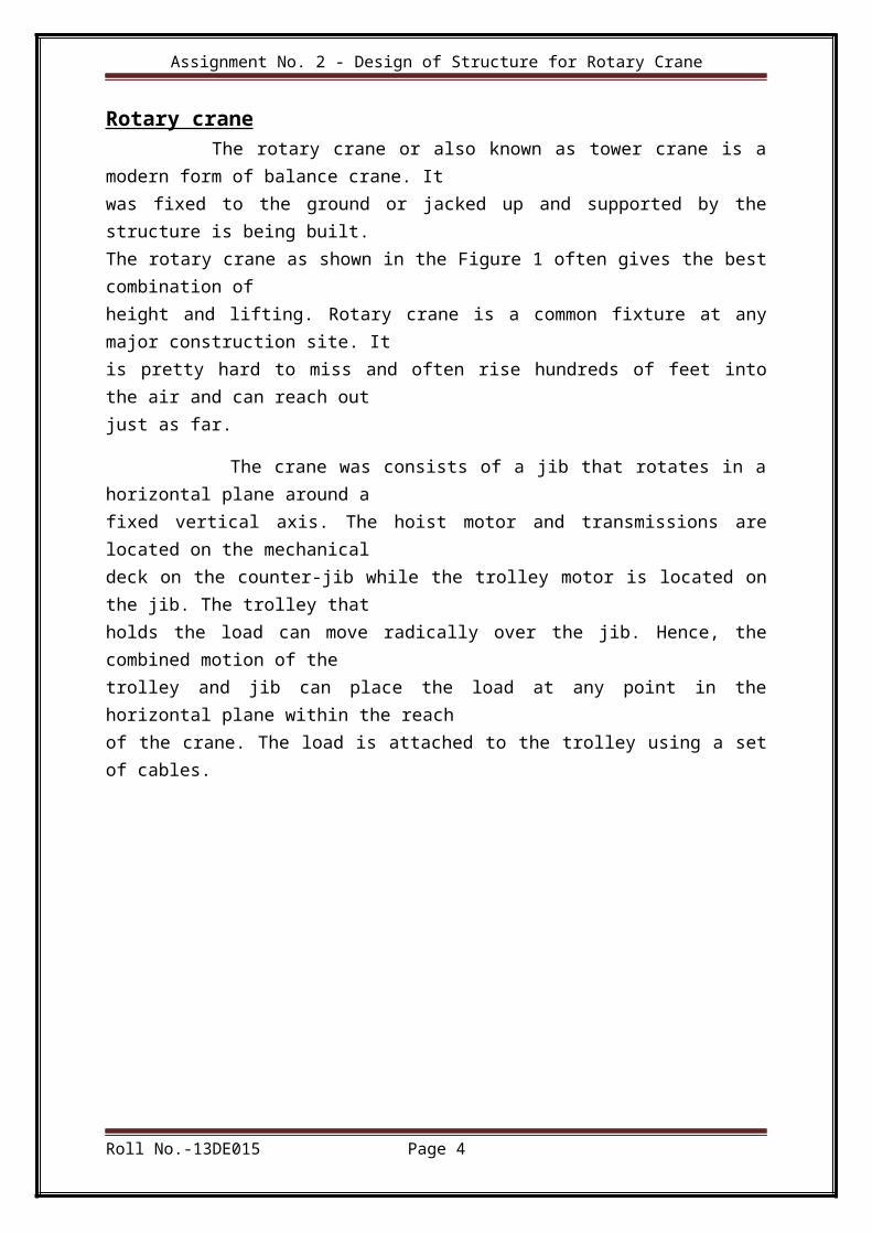
Rotary crane The rotary crane or also known as tower crane is amodern form of balance crane. Itwas fixed to the ground or jacked up and supported by thestructure is being built.The rotary crane as shown in the Figure 1 often gives the bestcombination ofheight and lifting. Rotary crane is a common fixture at anymajor construction site. Itis pretty hard to miss and often rise hundreds of feet intothe air and can reach outjust as far.
The crane was consists of a jib that rotates in ahorizontal plane around afixed vertical axis. The hoist motor and transmissions arelocated on the mechanicaldeck on the counter-jib while the trolley motor is located onthe jib. The trolley thatholds the load can move radically over the jib. Hence, thecombined motion of thetrolley and jib can place the load at any point in thehorizontal plane within the reachof the crane. The load is attached to the trolley using a setof cables.
Roll No.-13DE015 Page 4
Assignment No. 2 - Design of Structure for Rotary Crane
Figure 1: Rotary Crane
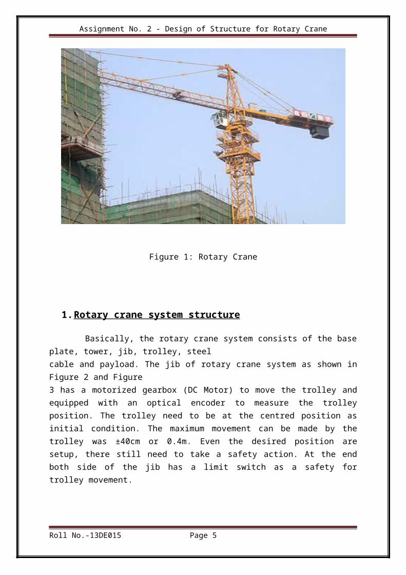
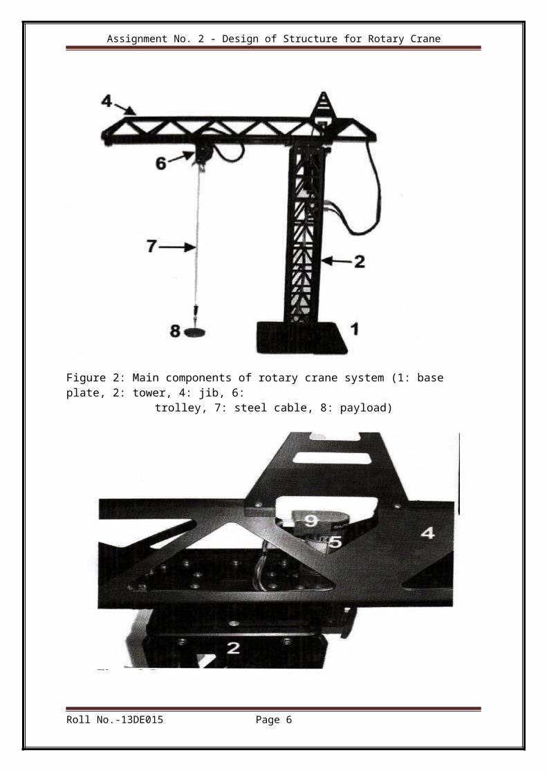
1.Rotary crane system structure Basically, the rotary crane system consists of the baseplate, tower, jib, trolley, steelcable and payload. The jib of rotary crane system as shown inFigure 2 and Figure3 has a motorized gearbox (DC Motor) to move the trolley andequipped with an optical encoder to measure the trolleyposition. The trolley need to be at the centred position asinitial condition. The maximum movement can be made by thetrolley was ±40cm or 0.4m. Even the desired position aresetup, there still need to take a safety action. At the endboth side of the jib has a limit switch as a safety fortrolley movement.
Roll No.-13DE015 Page 5
Assignment No. 2 - Design of Structure for Rotary Crane
Figure 2: Main components of rotary crane system (1: base plate, 2: tower, 4: jib, 6:
trolley, 7: steel cable, 8: payload)
Roll No.-13DE015 Page 6
Assignment No. 2 - Design of Structure for Rotary Crane
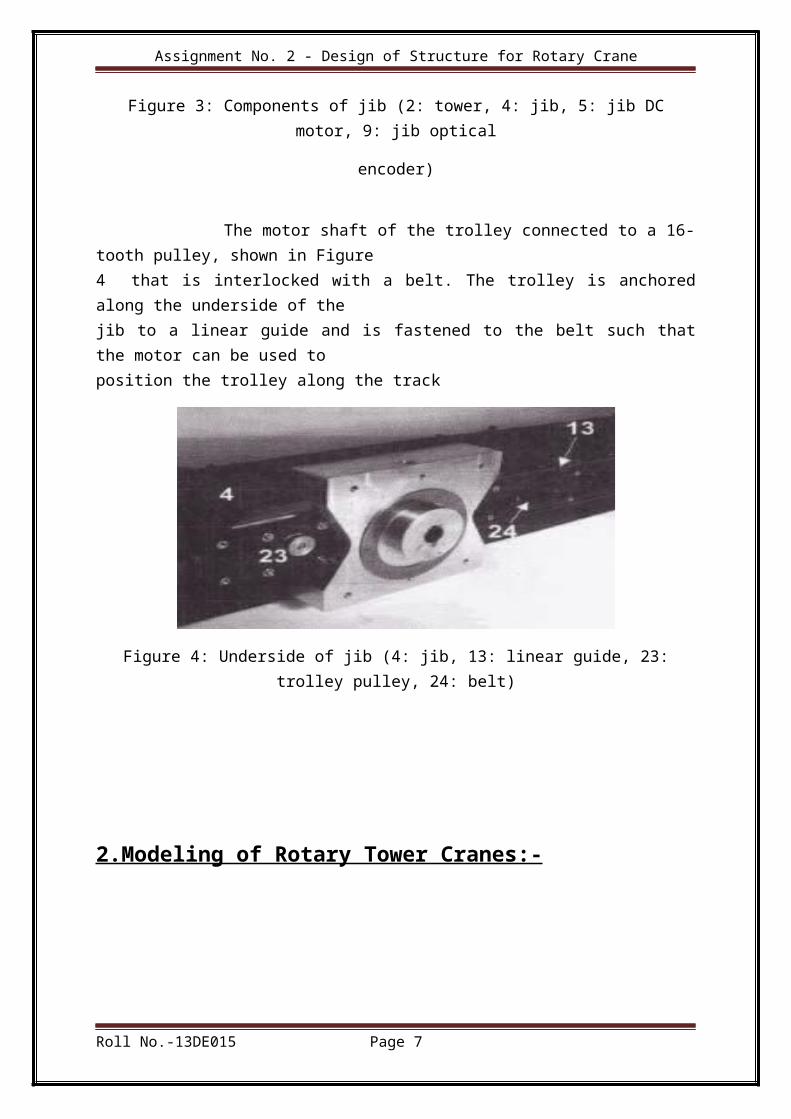
Figure 3: Components of jib (2: tower, 4: jib, 5: jib DCmotor, 9: jib optical
encoder)
The motor shaft of the trolley connected to a 16-tooth pulley, shown in Figure4 that is interlocked with a belt. The trolley is anchoredalong the underside of thejib to a linear guide and is fastened to the belt such thatthe motor can be used toposition the trolley along the track
Figure 4: Underside of jib (4: jib, 13: linear guide, 23:trolley pulley, 24: belt)
2.Modeling of Rotary Tower Cranes:-
Roll No.-13DE015 Page 7
Assignment No. 2 - Design of Structure for Rotary Crane
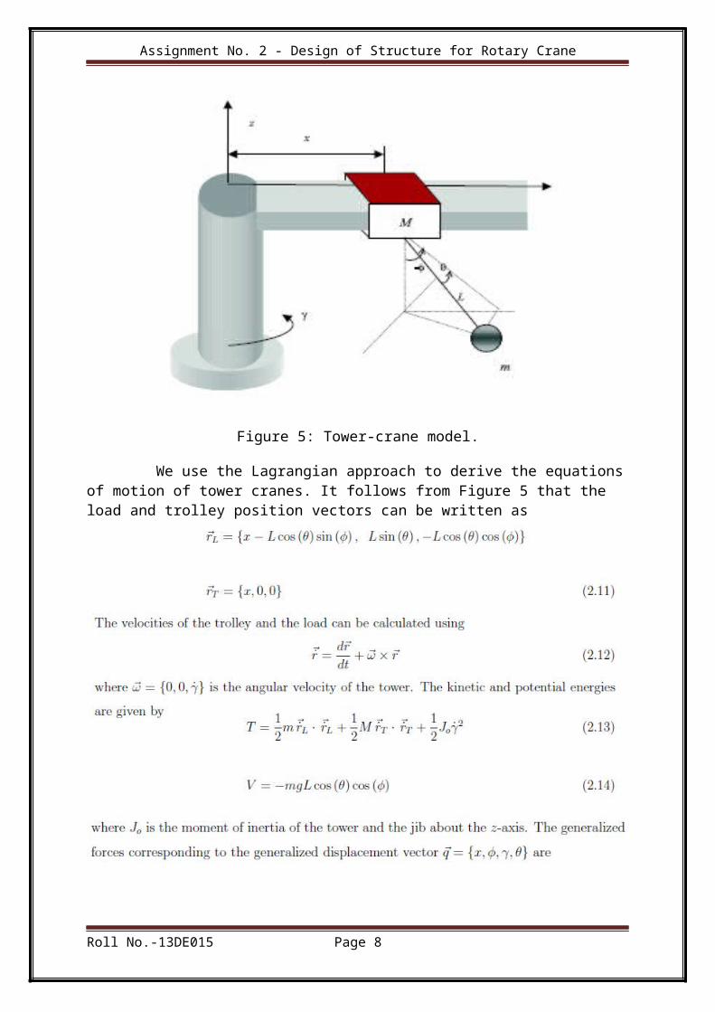
Figure 5: Tower-crane model.
We use the Lagrangian approach to derive the equationsof motion of tower cranes. It follows from Figure 5 that the load and trolley position vectors can be written as
Roll No.-13DE015 Page 8
Assignment No. 2 - Design of Structure for Rotary Crane
Roll No.-13DE015 Page 9
Assignment No. 2 - Design of Structure for Rotary Crane
Roll No.-13DE015 Page 10
Assignment No. 2 - Design of Structure for Rotary Crane
3.DC motor position modelling:-
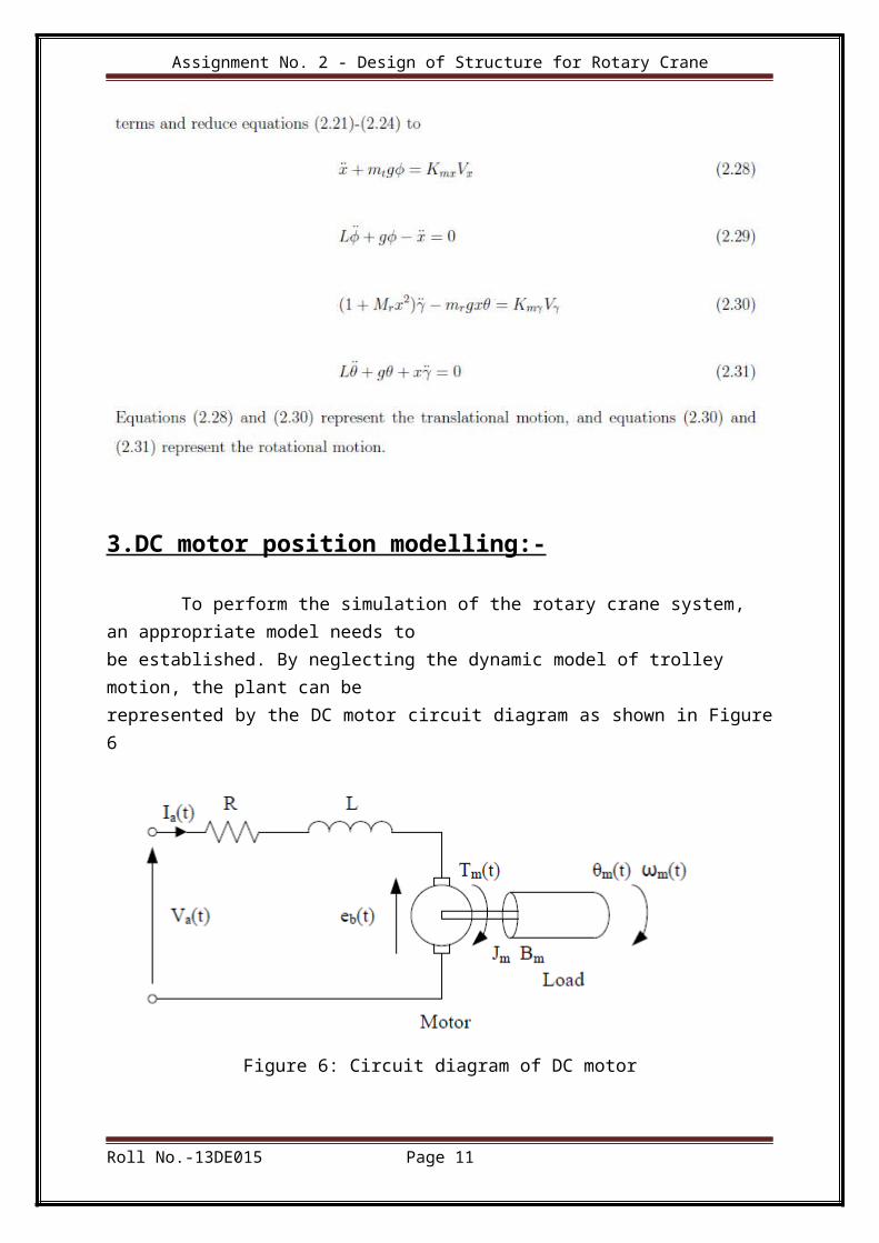
To perform the simulation of the rotary crane system, an appropriate model needs tobe established. By neglecting the dynamic model of trolley motion, the plant can berepresented by the DC motor circuit diagram as shown in Figure6
Figure 6: Circuit diagram of DC motor
Roll No.-13DE015 Page 11
Assignment No. 2 - Design of Structure for Rotary Crane
Roll No.-13DE015 Page 12
Assignment No. 2 - Design of Structure for Rotary Crane
Roll No.-13DE015 Page 13
Assignment No. 2 - Design of Structure for Rotary Crane
REFERENCES
1.Lee, H. H. and Cho, S. K. (2001). A New Fuzzy-Logic Anti-Swing Control forIndustrial Three-Dimensional Overhead Cranes. Proc. Int. Conferenceon Robotics & Automation 2001. Seoul, Korea, pp.2956-2961.
2.Omar, H.M (2003). Control of Gantry and Tower Cranes. M.S. VirginiaTech. Ph.D.Thesis.
3.Wahyudi & Jalani, J. (2005). Design and Implementation ofLogic Controller forIntelligent Gantry Crane System. Proc. of the 2nd Int. Conference onMechatronics, ICOM’05. Kuala Lumpur, Malaysia.
4.Jalani, J. (2005). Control Strategies for Automatic Gantry Crane System.IslamicInternational University of Malaysia: Master Thesis.
5.Othman, M. Z. (2006). A New Approach for ControllingOverhead Traveling CraneUsing Rough Controller. Int. Journal of Intelligent Technology 1:3 2006
Roll No.-13DE015 Page 14
Assignment No. 2 - Design of Structure for Rotary Crane
6.Ruslee, R. , Jalani, J. & Abdullah, J. (2008). Anti-SwingControl Strategy forAutomatic 3 D.O.F. Crane System Using FLC. Proc. of the 3rd Int.Conference on Mechatronics, ICOM’08. Kuala Lumpur, Malaysia
Roll No.-13DE015 Page 15
Copyright © 2022 FDOKUMEN