Lisa Alejandro Eric Forden Allison Gosney Erland Herfindahl ...
Upload
khangminh22Category
view
5download
0
Appendix A
ASIP Development UsingLISA 2.0
In this appendix, the language LISA 2.0, which is the basis of a uni-fied approach for all phases of Application Specific Instruction Set Pro-cessor (ASIP) design, is presented. These phases include architectureexploration, architecture implementation, software tools design and ar-chitecture integration. The work presented is the result of research atthe Institute for Integrated Signal Processing Systems (ISS), AachenUniversity of Technology, headed by Prof. Heinrich Meyr, Prof. GerdAscheid and Prof. Rainer Leupers. This appendix reflects the currentresearch status (October 2003), while major research work is ongoingin the field of compiler generation, Register Transfer Level (RTL) pro-cessor synthesis and system integration. The technology developed iscommercialized by CoWare Inc. [61].
A.1 The LISA 2.0 Language
The open language LISA 2.0 [110][109] is aimed at the formalizeddescription of programmable architectures, their peripherals and in-terfaces. It was developed to close the gap between purely structure-oriented languages (VHDL, Verilog) and instruction set languages forarchitecture exploration purposes. LISA provides a high flexibilityto describe the instruction set of various processor types, such asSIMD, MIMD and VLIW-type architectures. Processors with complexpipelines or multi-threading can easily be modelled, too.Furthermore, LISA models may cover a wide range of abstraction lev-els. This comprises all levels starting at a pure functional abstractionmodelling the data path of the architecture, to a model including thepipeline and functional units. In the domain of timing, the abstrac-tion can go from an instruction-accurate level to cycle-accurate or even

172 Appendix A. ASIP Development Using LISA 2.0
phase-accurate level. A working set of software tools can be generatedfrom all levels of abstraction. Moreover, cycle-accurate models can beused to generate a RTL representation of the architecture.LISA architecture descriptions are composed of two main components:the resource definition in the so called RESOURCE section and the LISAoperation tree consisting of several LISA operations. The RESOURCEsection is a unique place to declare the resources of the architecturesuch as memories, buses, registers, pipelines and pins. The amount ofinformation given in the RESOURCE section depends on the level ofabstraction the model is dedicated for. For example, a pipeline is notspecified in an instruction-accurate model.
all instructions
16bit instructions 32bit instructions
load/storeinstructions
arithmeticinstructions
opcode condition operandoperand
add sub mul
...
...
instr
... ... ...
instr
Figure A.1: Extract of the LISA operation tree
A LISA operation consists of various information and is the atomicelement of the LISA operation tree. There are two main aspectswhich must be described explicitly by the LISA operation: the behav-ior and the instruction set. The behavior is described in the so calledBEHAVIOR and EXPRESSION sections. While the EXPRESSIONsection simply returns a particular value, e.g. a register content, theBEHAVIOR section contains the state transition functions of the pro-cessor architecture. This state transition is described by writing C code.An instruction set is defined by its assembly syntax and its binary rep-resentation. These two pieces of information are described in the LISASYNTAX and CODING section, respectively.

A.2. Design Space Exploration 173
Additionally, a LISA operation may contain an ACTIVATION section,which describes the timing of the architecture by defining a chain ofLISA operations to be executed.The LISA operations are organized in a tree-like structure. An exam-ple can be seen in Figure A.1. The behavior, coding and syntax of aninstruction is distributed over several LISA operations. It starts at theroot operation, which contains the basic information for all valid pro-cessor instructions. In this example, the separation into 16 bit and 32bit instructions is a first specialization. Each of those operations con-tains the relevant information for their instruction type. Accordingly,the operations representing the load/store instructions or arithmetic in-structions are further specializations of the instructions. The specializa-tion is the basic principle in developing a LISA model. Moreover, ascan also be seen in Figure A.1, a LISA operation is not only used torepresent a whole instruction but also a part of an instruction, such asopcode, operand or special condition field. Thus, developing a LISAmodel results in creating a LISA operation tree, that unifies the com-plete description of the behavior, syntax, coding and timing of the targetarchitecture.The LISA language allows to describe hierarchical models which guar-antees modularity and reusability. Architecture models can easily bemodified or adopted to new processors, which is the basis of a success-ful and fast design space exploration.
A.2 Design Space Exploration
The key factor of designing ASIPs is an efficient design space explo-ration phase. The LISA language allows to apply changes to the archi-tecture model quickly as the level of abstraction is higher than RTL. Asshown in Figure A.2 a LISA model of the target architecture is usedto automatically generate software tools such as C-compiler, assembler,linker and simulator. These software tools are used to profile and mod-ify both architecture and application. This exploration loop is repeateduntil a sufficient cost/performance ratio is reached.
Although the higher level of abstraction is the basic reason for the suc-cess of Architecture Description Languages (ADLs), the link to the

174 Appendix A. ASIP Development Using LISA 2.0
physical parameters such as chip area, power consumption or clockspeed gets lost. Ignoring physical parameters in the design space ex-ploration phase leads to suboptimal solutions or long redesign cycles.The necessity of combining the high level abstraction and physical pa-rameter evaluation during design space exploration is compelling.
To overcome those limitations, as shown in Figure A.2, a complete hard-ware model is automatically generated from LISA in order to get a pre-liminary estimate about the clock speed, area and power consumption.The LISA processor design platform takes the gate-level synthesis re-sults into account during the exploration phase. The LISA model is usedto derive a fully synthesizable model on RTL. Compared to other ASIPdevelopment approaches the designer is able to perform this synthesisflow without being restricted to fixed RTL components.
If the synthesis results of the generated architecture fulfill the givenphysical constraints, then the hardware model can even be used for thefinal architecture implementation. As the datapath is often highly op-timized and based on in-house IP, it may be replaced by the designermanually. This is shown in Figure A.2 on the right hand side.
ImplementationExploration
LISA Description
Evaluation Results
Model Verification& Evaluation
LISA Compiler
Compiler
Assembler
Linker
Simulator
Evaluation Results
Chip Area, Clock Speed,
Power Consumption
Complete HDL
Model
Gate Level Synthesis
Handwritten
Functional Units
Gate Level Model
Complete Structure,Decoders, Pipeline
Controller
Gate Level Synthesis
Figure A.2: Exploration and Implementation based on LISA

A.3. Design Implementation 175
A.3 Design Implementation
The LISA model is used to derive the complete target architecture inform of a Hardware Description Language (HDL) [217][112]. Lan-guages supported are VHDL, Verilog and SystemC. As described inSection A.2, the generated model is used for design exploration andimplementation.
The synthesized architecture consists of several entities. The base entityinstantiates one entity which groups all registers, one entity for all mem-ories and another for the complete pipeline. The pipeline entity againconsists of entities representing every pipeline stage and intermediatepipeline registers. This entity also contains the automatically generatedpipeline controller. The entities representing each pipeline stage instan-tiates the final level of hierarchy - the entities for the functional units,such as ALUs, Address Generation units, etc. Moreover, the generateddecoder is placed inside the pipeline stage entities.
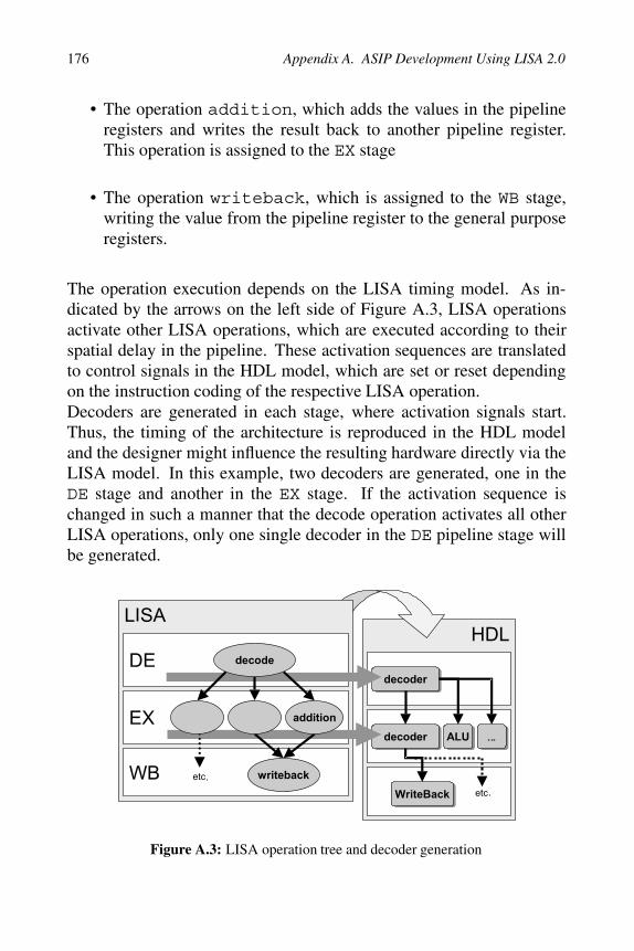
The elements, which constitute the control path, are the instruction de-coder and the pipeline controller. The decoder may be distributed overseveral pipeline stages and sets the control signals to the functionalunits, to initiate the execution of those. They also steers the pipelinecontroller. The pipeline controller gathers several information, such assignals from the decoder or the status of the processor, and sends appro-priate flush and stall signals to the pipeline registers.The decoder generation requires various information about the target ar-chitecture. Both, the RESOURCE section as well as the LISA operationsare used to derive the decoder and control-path. In fact, detailed infor-mation about the instruction coding (CODING section) and the timing(ACTIVATION section) is extracted from the LISA operation tree.A single LISA operation is assigned to a dedicated pipeline stage. Thebehavior of a software instruction, for example the instruction add,is distributed over several different LISA operations as shown in Fig-ure A.3 :
• The operation decode is assigned to the DE stage. This operationloads the operands from a general purpose register into a pipelineregister.
176 Appendix A. ASIP Development Using LISA 2.0
• The operation addition, which adds the values in the pipelineregisters and writes the result back to another pipeline register.This operation is assigned to the EX stage
• The operation writeback, which is assigned to the WB stage,writing the value from the pipeline register to the general purposeregisters.
The operation execution depends on the LISA timing model. As in-dicated by the arrows on the left side of Figure A.3, LISA operationsactivate other LISA operations, which are executed according to theirspatial delay in the pipeline. These activation sequences are translatedto control signals in the HDL model, which are set or reset dependingon the instruction coding of the respective LISA operation.Decoders are generated in each stage, where activation signals start.Thus, the timing of the architecture is reproduced in the HDL modeland the designer might influence the resulting hardware directly via theLISA model. In this example, two decoders are generated, one in theDE stage and another in the EX stage. If the activation sequence ischanged in such a manner that the decode operation activates all otherLISA operations, only one single decoder in the DE pipeline stage willbe generated.
Figure A.3: LISA operation tree and decoder generation

A.4. Software Tools Generation 177
A.4 Software Tools Generation
The software tools generated from the LISA description are able tocope with the requirements of complex application development. FromLISA, C-compiler, assembler, linker and simulator are generated. Theautomatic C-compiler generation is currently one of the major researchtopics.
A.4.1 Compiler Generation
The shift from assembly to the C programming language for applicationdevelopment is ongoing. This move is driven by the fact that most DSPalgorithms are realized using the C language. Considering the variousconfigurations of an ASIP, even during design space exploration, theautomatic re-targeting of a compiler is highly desired [267]. For thisreason, the automatic generation of a C-compiler came strongly into fo-cus recently.For retargeting a compiler, the architecture specific back-end of a com-piler must be adjusted or rewritten, whereas the architecture indepen-dent frontend and most of the optimizations are kept unchanged. There-fore, a retargetable compiler platform is employed which reads in a setof description files generated from the LISA description to build thecompiler.All relevant information for compiler generation are derived from theLISA model. While some information is explicit in the LISA model(e.g. via resource declarations), other relevant information (e.g. con-cerning instruction scheduling) is only implicit and needs to be ex-tracted by special algorithms. Some further, heavily compiler-specific,information is not at all present in the LISA model, e.g. C type bitwidths. Thus, compiler information is automatically extracted fromLISA whenever possible, while GUI-based user interaction is employedfor other compiler components. The GUI reads the LISA model andpresents all relevant machine features (e.g. resources and machine op-erations) for which interaction is required to the user for further refine-ment.
The compiler backend basically consists of a register allocator, instruc-tion selector, scheduler and code emitter. Apart from that, the calling

178 Appendix A. ASIP Development Using LISA 2.0
conventions and the stacklayout have to be configured. The GUI guidesthe designer through the specification of the different components:
• Purely numerical parameters (such as C type bit widths, type align-ments, minimum addressable memory unit size) are directly cap-tured by means of GUI tables.
• Calling conventions (i.e. how arguments are passed/returnedto/from functions) are also captured with GUI tables.
• For the supported stack layout, the designer has to specify the stackpointer and the frame pointer whereas other configuration itemscan be simply selected/deselected.
• Retargeting the register allocator is reduced to the selection of al-locatable registers out of the set of all available registers in theLISA model.
• The scheduler and the code emitter is generated fully automati-cally [270][268][269].
• The code selector rules are specified by means of a convenientdrag-and-drop mechanism: The user can compose these rules fromthe compiler operators (e.g. addition). Like in most compilers,these mapping rules are the basis for the tree pattern matchingbased code selector. The link between mapping rules and their ar-guments on the one hand and LISA operations and their operandson the other hand is made via drag-and-drop in the GUI.
Once everything is specified the designer can finally build the compilerwithin minutes.
A.4.2 Assembler and Linker Generation
The generated assembler [111] processes the assembly application andproduces object code for the target architecture. An automatically gen-erated assembler is required, as the modelled architecture consists ofa specialized instruction set. Certainly, the common assembler featuresare also supported in the generated assembler. For example, many GNU

A.4. Software Tools Generation 179
assembler directives are supported. A comfortable macro assembler ex-ists to provide more flexibility to the designer.
The different pieces of object code are linked by the automatically gen-erated linker. With respect to the modelled memory configuration theobject code is used to create the final executable. Various configurationpossibilities are provided to steer the linking process.
A.4.3 Simulator Generation
The generated simulator is separated into backend and frontend. Thedebugger frontend and profiler is shown in Figure A.4. It supports ap-plication debugging, architecture profiling and application profiling ca-pabilities. The screenshot shows some features such as disassemblyview (1) including loop and execution profiling (2), LISA operation ex-ecution profiling (3), memory profiling (4) and LISA operation codecoverage (5). Also, the content of memories (6), resources (7) and reg-isters (8) can be viewed and modified. Thus, the designer is able toeasily debug both the processor model and application. Additionally,the necessary profiling information for design space exploration is pro-vided.
The performance of the simulator is strongly dependent on the abstrac-tion level of the underlying LISA model and the memory model. Fig-ure A.5 shows the ranges of simulation speed achieved by the simulatorsgenerated from LISA. The results were achieved by using a 2000 MHzAthlon PC, 768 MB RAM running the Red Hat Linux operating sys-tem. The simulation speed of a LISA model, written on a high levelof abstraction, both in the domain of timing and architectural features,reaches up to 15 Million Instructions Per Second (MIPS). After increas-ing the model accuracy, by changing the memory to a complex memorysubsystem, the simulation speed drops to 8 MIPS. Changing the coremodel to a pipelined and thus cycle-accurate version without touchingthe memory model, decreases the simulation speed by 10 MIPS. Finally,simulating a very detailed model close or equal to the real hardware be-havior, the simulator still achieves a speed of about 0,5 MIPS.
The simulator backend, includes a well defined Application Program-ming Interface (API), which can be easily used to connect to any other

180 Appendix A. ASIP Development Using LISA 2.0
1
2
3
4
5
6
7
8
Figure A.4: The simulator and debugger frontend
instructionaccurate
cycle accurate
plainmemory
memorysubsystem
memory
15MIPS
0,5 MIPS
5 MIPS
8 MIPS
architecture
Figure A.5: Achieved simulation speed
simulator frontend. Various simulation techniques [35] are supported,such as compiled simulation, interpretive simulation and Just-In-Time
A.4. Software Tools Generation 181
Cache Compiled Simulation (JIT-CCS) [193]. These mechanisms arebriefly described below.
A.4.3.1 Interpretive Simulation
The interpretive simulation technique is a software implementation ofthe underlying decoder of the architecture. For this reason the inter-pretive simulation is considered to be a virtual machine performing thesame operations as the hardware does: fetch, decode and execute the in-struction. All simulation steps are performed at runtime, which providesthe highest possible flexibility. However, the straight-forward mappingof the hardware behavior into a software simulator is the major dis-advantage of the interpretive simulation technique. Compared to thedecoding of the real instructions in hardware, the control flow requiresan significant amount of time in software.
A.4.3.2 Compiled Simulation
The compiled simulation uses the locality of code in order to speed upthe execution time of the simulation compared to the interpretive sim-ulation technique. The task of fetching and decoding an instruction isperformed once before simulation run. The decoding results are storedand used later on during simulation. Execution time is saved as, duringthe following executions of the same instruction, the fetch and decodesteps do not need to be repeated. Thus, the compiled simulation re-quires the program memory content to be fixed before simulation run-time. Various scenarios are unsupported by the compiled simulationtechnique, such as system simulations with external and thus unknownmemory content and operating systems with changing program memorycontent. Additionally, large applications, which require a huge amountof memory on the target host, are hard to support.
A.4.3.3 Just-In-Time Cache Compiled Simulation (JIT-CCS)
The objective of the JIT-CCS is to combine the advantages of both in-terpretive and compiled simulation. This new technique provides the

182 Appendix A. ASIP Development Using LISA 2.0
ARM7 - instruction accurate JIT-CCS
jpeg 2000 codec
0,0 0,0
99,9 98,395,3
84,4
74,7
58,5
33,1
19,1
8,8
2,9 2,0 1,0 0,4 0,1 0,0
0
1
2
3
4
5
6
7
8
Com
piled
Inte
rpre
tive 2 4 8 16 32 64 12
825
651
2
1024
2048
4096
8192
1638
4
3276
8
Cache Size [Records]
Pe
rfo
rma
nc
e[M
IPS
]
0
10
20
30
40
50
60
70
80
90
100
Cach
eM
iss
Rate
Figure A.6: Performance of the just-in-time cache compiled simulation
full flexibility of the interpretive simulation while reaching the perfor-mance of the compiled simulation. The underlying principle is to per-form the compilation, in fact the decoding process, just-in-time at sim-ulation runtime. Because of that, full flexibility is provided. Moreover,the decoding results are stored in a cache. In every subsequent simu-lation step the cache is searched for already existing decoding results.Due to the locality of code in typical applications, the simulation speedcan be improved using the JIT-CCS. The cache size used in the JIT-CCSis variable and can be changed in a range from 1 - 32768 lines, wherea line corresponds to one decoded instruction. The maximum amountof cache lines corresponds to a memory consumption of less than 16MB on the simulator host. Compared to the traditional compiled sim-ulation technique, where the complete application is translated beforesimulation time, this memory consumption is negligible.
Figure A.6 illustrates the performance of the cache compiled simulationdepending on the cache size. The results were achieved by using an1200 MHz Athlon PC, 768 MB RAM running the Microsoft Windows2000 operating system. A cache size of one line means, that the Just-In-Time cache compiled simulation essentially performs the same way asthe interpretive simulation. Every instruction is decoded and simulatedagain, without using the advantage of code locality. With a rising num-
A.5. System Integration 183
ber of cache lines the simulation performance (wide bars) comes closerto the performance of a compiled simulation and even reaches that per-formance. The simulation speed increases with decreasing cache missrate (narrow bars). As can be seen in the figure, the performance ofthe compiled simulation can be reached with a relatively small numberof cache size and thus less memory consumption on the host machine.Moreover, this memory consumption on the target host is constant rela-tive to the application size.
A.5 System Integration
Today, typical single chip electronic system implementations combinea mixture of DSPs, micro-controllers, ASICs and memories. In future,the number of programmable units in a System-on-Chip (SoC) designwill even increase. To handle the enormous complexity, system levelsimulation is absolutely necessary for both performance evaluation aswell as verification in system context. The earlier in the flow designerrors or lack of performance are detected, the less the costs for re-design cycles get. The automatically generated LISA processor simu-lators can be integrated into various System Simulation Environments,such as CoWare ConvergenSC[61] or SYNOPSYS CoCentric SystemStudio[234]. Thus, modules provided by different design teams or eventhird parties can be combined easily.
The communication of the LISA processors with their system environ-ment can be modelled on different levels of abstraction. First, LISApin resources can directly be mapped to the SoC environment for pinaccurate co-simulation. Alternatively, the LISA bus interface allowsmodelling the SoC communication on a higher abstraction level, i.e.,Transaction Level Modeling (TLM) [239]. By that, accesses to busesand memories external to the respective processor core are efficientlymapped to the communication primitives applied in the SoC simulationworld.
For user friendly debugging and online profiling of the embedded SWand its platform, the user always has the possibility of getting the fullSW centric view of an arbitrary SW block[274] at simulation runtime.This is done just by dynamically connecting a HUB debugger GUI to

184 Appendix A. ASIP Development Using LISA 2.0
the processor of interest. Thus, only one or two debugger GUIs are suf-ficient even to debug complex multiprocessor systems. All other SWblocks, that are currently not considered, still simulate at maximumspeed. The remote debugger frontend instance offers all observabil-ity and controllability features for multiprocessor simulation as knownfrom standalone processor simulation. Even resources external to a pro-cessor module but mapped into its address space like peripheral regis-ters and external memories can be visualized and modified by the multi-processor debugger GUI. The SW developer can dynamically connectto relevant processors, set break/watch points in respective code seg-ments, disconnect from simulation and automatically re-connect whena breakpoint is hit.
A.6 Summary
This appendix presents the development of Application Specific In-struction Set Processors (ASIPs) based on the architecture descriptionlanguage LISA. This includes the design exploration, implementation,software tools design and system integration. The LISA model of thetarget architecture is used to automatically generate the software tools:C-compiler, assembler, linker and simulator from the same LISA model.Given a cycle-accurate LISA model, even the complete hardware modelcan be derived both for exploration and implementation purpose. Thegenerated software tools are powerful enough to be used in complex ap-plication design as powerful assembler, macro assembler and differentsimulation techniques are provided. The highly flexible system integra-tion allows to connect to any co-simulation environment or customerspecific environments. The current research topics are focusing on thefield of compiler generation, RTL processor synthesis and system inte-gration.

Appendix B
Computational Kernels
In this chapter, the computational kernels that have been used for il-lustration purposes in Chapter 5 and as benchmarks in Chapter 7 aredescribed.
B.1 The CORDIC Algorithm
The CORDIC algorithm1 for the vectoring and rotate mode was firstdescribed by Volder [266]. In the vectoring mode the magnitude andthe angle of a given vector are computed, whereas in the rotate mode agiven vector is rotated by a given angle.
The CORDIC algorithm uses iterative computations according to thefollowing equations:
Xi+1 = Xi ∓ 2−iYi (B.1)
Yi+1 = Yi ± 2−iXi (B.2)
αi+1 = αi ∓ tan−1(2−i) (B.3)
These iterations are valid for Xi > 0, otherwise, the vector with a nega-tive Xi has to be rotated by 180°. The pathological case of a zero vectorhas to be treated as an exception.
After N iterations the magnitude of the resulting vector (XN , YN) hasbeen incremented compared to the start vector (X0, Y0) by a factor KN
which can be (pre-)computed using the following equation:
KN =i=N−1∏
i=0
√1 + 2−2i (B.4)
1CORDIC stands for COordinate Rotation DIgital Computer.

186 Appendix B. Computational Kernels
If the length of the resulting vector in the rotate mode has to be pre-served, the scaling factor K−1
N needs to be applied.
The strategy for the choice of the signs in equations B.1 to B.3 has tobe selected according to the operating mode.
• rotate mode: in order to obtain αN → 0 the |αi+1| has to be smallerthan the previous |αi|, therefore, the upper sign is chosen, if αi >0, else the lower sign.
• vectoring mode: in order to obtain YN → 0 the |Yi+1| has to besmaller than the previous |Yi|, therefore, the lower sign is chosen,if Yi > 0, else the upper sign.
Listings B.1 and B.2 are C code implementations of the CORDIC bothfor the vectoring and the rotate mode.
void cordic_vect(long *x,long y,long *z, const long N) {long x_next, y_next, z_next, delta, i, flag;double K;*z=0; K=1.0;if (*x >= 0 )
flag = 1;else {
*x=-(*x); y=-y; flag = -1;}for(i=0; i<=N; i++) { /* "Vectoring" mode y->0 */
if (y>=0) delta = -1; else if (y<0) delta = 1;x_next = (*x)-delta*(y>>i);y_next = y+delta*((*x)>>i);z_next = (long) (*z-delta*(long) ((1<<N)
*atan(1.0 / ((float)(1<<i)))+0.5));*x = x_next; y = y_next; *z = z_next;K=K*1.0/sqrt(1+pow(2.0, -2.0*i));
}if(flag == -1)
if (*z < 0) (*z)+=(long) ((1<<N)*M_PI);else (*z)-=(long) ((1<<N)*M_PI);
*x=(long) (K*(*x)); /* scaling */}
Listing B.1: CORDIC Implementation for Vectoring Mode

B.2. FIR Filter 187
void cordic_rot(long *x,long *y,long z, const long N) {
long x_next, y_next, z_next, delta, i, flag;double K;
K=1.0;if (z<(long)(-(1<<N)*0.5*M_PI)) {flag = 1;z+=(long) ((1<<N)*M_PI);
}else if(z>(long)((+(1<<N)*0.5*M_PI))) {flag = 1;z-=(long) ((1<<N)*M_PI);
}elseflag = 0;
if ((z<-(1<<N)*0.5*M_PI) || (z>(1<<N)*0.5*M_PI)) {printf("\n\nError in CORDIC subroutine: z out of range!\n");printf("z = %ld\n", z);printf("Bounds: %ld %ld\n", (long) (-(1<<N)*0.5*M_PI),
(long ) ((1<<N)*0.5*M_PI));exit(1);
}
for(i=0; i<=N; i++) { /* "rotate" mode z->0 */
if (z>=0)delta = 1;
else if (z<0)delta = -1;
x_next = *x-delta*(*y>>i);y_next = *y+delta*(*x>>i);z_next = (long) (z-delta*(long) ((1<<N)
*atan(1.0 / ((float)(1<<i)))+0.5));*x = x_next;*y = y_next;z = z_next;K=K*1.0/sqrt(1+pow(2.0, -2.0*i));
}
if (flag == 1) {*x=-(*x);*y=-(*y);
}
*x=(long) (K*(*x)); /* scaling */*y=(long) (K*(*y));
}
Listing B.2: CORDIC Implementation for Rotate Mode
B.2 FIR Filter
FIR filters are important DSP kernels for a variety of applications. Manycommercial DSPs using multiply-accumulate units are optimized for

188 Appendix B. Computational Kernels
these FIR kernels. The following equation defines the behavior of anM-tap-FIR filter:
y(n) =
k=M−1∑k=0
hkx(n − k) (B.5)
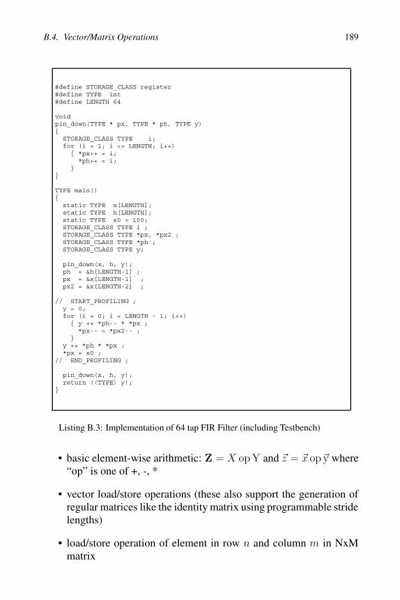
where x(m) is the input, hk are the coefficients and y(n) is the outputof the filter. In Listing B.3 a C code implementation for the FIR filter isgiven, which has been taken out of the DSPstone benchmark programsuite [285]. This implementation uses explicit memory copy operationsin order to obtain the correct delay for the inputs x(n − k). Providedthat a processor supports modulo addressing [275], this delay line canalso be implemented using a circular buffer in the memory, which ap-proximately halves the number of memory accesses.
B.3 The Fast Fourier Transformation
The fast fourier transformation [57] is an algorithm to compute the dis-crete fourier transformation (DFT) at reduced computational costs. The8192 point radix 2 FFT implementation in Listing B.4 uses the decima-tion in time algorithm [154]. The complex coefficients are partially pre-computed, which saves memory bandwidth at the expense of additionalarithmetic computations. The function ReverseBits() in Listing B.4 isneeded to reverse the bit order of an integer for addressing purposes.
B.4 Vector/Matrix Operations
The following vector and vector-matrix operations have been consid-ered:
• dot product: z =i=N−1∑
i=0
xiyi
• matrix-vector multiply: Z = �V T X and Z = X�V
• matrix-matrix multiply: Z = XY, Z = XYT and Z = XTY
B.4. Vector/Matrix Operations 189
#define STORAGE_CLASS register#define TYPE int#define LENGTH 64
voidpin_down(TYPE * px, TYPE * ph, TYPE y){
STORAGE_CLASS TYPE i;for (i = 1; i <= LENGTH; i++){ *px++ = i;
*ph++ = i;}
}
TYPE main(){
static TYPE x[LENGTH];static TYPE h[LENGTH];static TYPE x0 = 100;STORAGE_CLASS TYPE i ;STORAGE_CLASS TYPE *px, *px2 ;STORAGE_CLASS TYPE *ph ;STORAGE_CLASS TYPE y;
pin_down(x, h, y);ph = &h[LENGTH-1] ;px = &x[LENGTH-1] ;px2 = &x[LENGTH-2] ;
// START_PROFILING ;y = 0;for (i = 0; i < LENGTH - 1; i++){ y += *ph-- * *px ;
*px-- = *px2-- ;}
y += *ph * *px ;*px = x0 ;
// END_PROFILING ;
pin_down(x, h, y);return ((TYPE) y);
}
Listing B.3: Implementation of 64 tap FIR Filter (including Testbench)
• basic element-wise arithmetic: Z = X op Y and �z = �x op�y where“op” is one of +, -, *
• vector load/store operations (these also support the generation ofregular matrices like the identity matrix using programmable stridelengths)
• load/store operation of element in row n and column m in NxMmatrix

190 Appendix B. Computational Kernels
B.5 Complex EVD using a Jacobi-like Algorithm
According to [134] for the singular value decomposition (SVD) as wellas for the eigenvector/eigenvalue decomposition2 (EVD) there are twoalgorithms that are widely used: Jacobi-like [128] algorithms and QR-factorization-based algorithms [94]. For this case study, a Jacobi-likealgorithm using modified Givens-rotations is used, because of the betternumeric stability and precision compared to the QR methods [63].
In order to decompose a hermitian NxN matrix A = A0 into the (real)eigenvalues and complex eigenvectors the Givens-rotations are used asfollows: After each multiplication according to the following equation,a Pivot element ai,j of the hermitian matrix An is canceled:
An+1 = G−1n AnGn (B.6)
The matrix Gn is the modified Givens-matrix that is computed using aNxN identity matrix into which a 2x2 pivot submatrix Qi,j is embeddedat the positions (i,i), (i,j), (j,i) and (j,j) as follows (i < j):
Gn =
⎛⎜⎜⎜⎜⎜⎝
11
qi,i qi,j
1qj,i qj,j
1
⎞⎟⎟⎟⎟⎟⎠
(B.7)
This 2x2 submatrix Qi,j is given by
Qi,j =
(cos ϕ eiαsin ϕ
−e−iαsin ϕ cos ϕ
)(B.8)
whereeiα =
ai,j
|ai,j| (B.9)
and
tan 2ϕ =2|ai,j|
aj,j − ai,i,
−π
4≤ ϕ ≤ π
4(B.10)
2The EVD is a special case of the SVD.

B.5. Complex EVD using a Jacobi-like Algorithm 191
Successive Givens-rotations have to be performed for all off-diagonalelements of A, which is commonly referred to as one sweep. It is typ-ically necessary to perform several sweeps in order to reach a givenprecision, because the Givens-rotations set Pivot elements that have al-ready been canceled by a previous rotation back to a value differentfrom zero3. After a certain precision is reached after M rotations, whichcan be monitored by computing the energy of the off-diagonal elements
Eoff diag =
row=N∑row=1
col=N∑col=row+1
|arow,col|2 (B.11)
the computed real eigenvalues λi are an approximation of the diagonalelements of the matrix AM .
The associated right and left eigenvectors are given by the orthogonalmatrices EVr and EVl which have normalized rows and columns ac-cording to
EVr =M∏i=1
Gi (B.12)
and
EVl =
M∏i=1
G−1n (B.13)
The computations in Equation B.9 and Equation B.10 can obviously beimplemented with a CORDIC processor, which enables to compute thephase and magnitude of a vector as well as the sin() and cos() functionsof a given angle.
3However, the magnitude of this value is smaller than the magnitude of the value that has just beencanceled. Therefore, the algorithm converges to a diagonal matrix.

192 Appendix B. Computational Kernels
#define DP 10 // decimal point of fixed point numbersvoid fft_ll (
int InverseTransform, long *RealIn, long *ImagIn,long *RealOut, long *ImagOut )
{unsigned i, j, k, n;unsigned BlockSize, BlockEnd;constant unsigned NumSamples = 8192; /* FFT-length */constant unsigned NumBits=13; /* No. of bits to store indices */NumBits = 13;long tr, ti; /* temp real, temp imaginary */// delta_angle;long sm2_arr[13] = {0, 0, -1023, -724, -391, -199, -100, -50,
-25, -12, -6, -3, -1};long sm2, sm1_arr[13] = {0, -1023, -724, -391, -199, -100, -50, -25,
-12, -6, -3, -1, 0};long sm1, cm2_arr[13] = {1023, -1023, 0, 724, 946, 1004, 1019, 1022,
1023, 1023, 1023, 1023, 1023};long cm2, cm1_arr[13] = {-1023, 0, 724, 946, 1004, 1019, 1022, 1023,
1023, 1023, 1023, 1023, 1023};long cm1, w, ar[3], ai[3], tmp;int loopcnt;for ( i=0; i < NumSamples; i++ ) {
j = ReverseBits ( i, NumBits );RealOut[j] = RealIn[i]<<DP;ImagOut[j] = (ImagIn == NULL) ? 0 : ImagIn[i]<<DP;
}// START_PROFILING ;loopcnt=0; BlockEnd = 1;for ( BlockSize = 2; BlockSize <= NumSamples; BlockSize <<= 1 ){
sm1 = sm1_arr[loopcnt]; sm2 = sm2_arr[loopcnt];cm1 = cm1_arr[loopcnt]; cm2 = cm2_arr[loopcnt];w = (2 * cm1); loopcnt++;for ( i=0; i < NumSamples; i += BlockSize ) {
ar[2] = cm2; ar[1] = cm1;ai[2] = sm2; ai[1] = sm1;for ( j=i, n=0; n < BlockEnd; j++, n++ ){
ar[0]=(w*ar[1])>>DP-ar[2];ar[2]=ar[1];ar[1]=ar[0];ai[0]=(w*ai[1])>>DP-ai[2];ai[2]=ai[1];ai[1]=ai[0];k = j + BlockEnd;tr = (ar[0]*RealOut[k])>>DP - (ai[0]*ImagOut[k])>>DP;ti = (ar[0]*ImagOut[k])>>DP + (ai[0]*RealOut[k])>>DP;RealOut[k]=(RealOut[j]-tr); ImagOut[k]=(ImagOut[j]-ti);RealOut[j]=(RealOut[j]+tr); ImagOut[j]=(ImagOut[j]+ti);
}}BlockEnd = BlockSize;
}unsigned ReverseBits ( unsigned index, unsigned NumBits ){
unsigned i, rev;for ( i=rev=0; i < NumBits; i++ ) {
rev = (rev << 1) | (index & 1);index >>= 1;
}return rev;
} // END_PROFILING ;}
Listing B.4: Implementation of an 8192 point FFT

Appendix C
ICORE Instruction SetArchitecture
This chapter is organized as follows: First of all, the ICORE proces-sor pipeline organization is described and an overview of the importantprocessor resources is given. Furthermore, the processor instructionsas well as exceptions to the orthogonal instruction execution model arediscussed A description of the memory and I/O organization as well asthe ICORE approach to instruction coding concludes this chapter.
C.1 Processor Resources
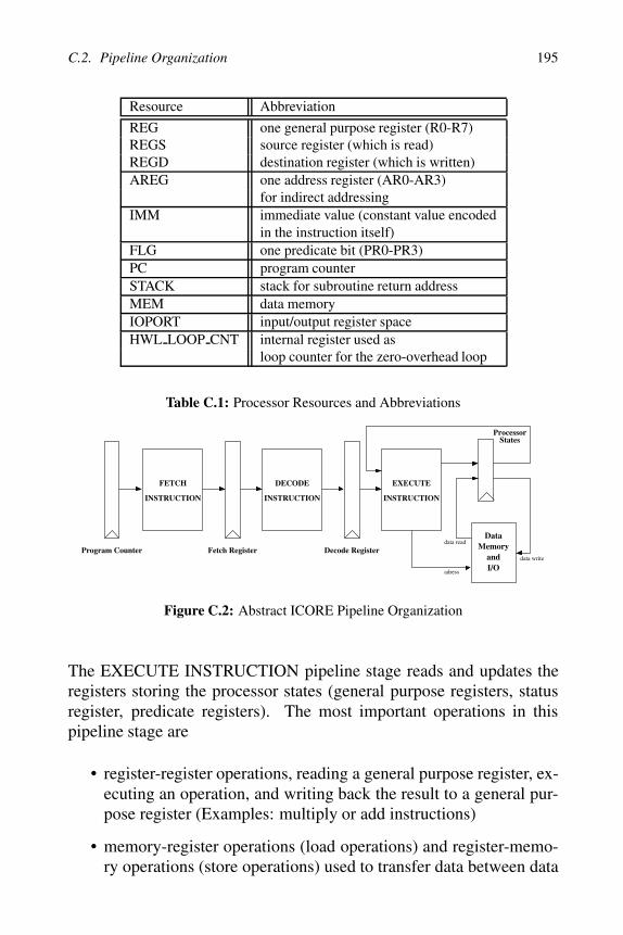
The visible processor storage entities for the programmer (cf. Fig-ure C.1) are the general purpose register file (8x32bit registers), the ad-dress registers (4x9bit), the status register (with less-than and zero flag)and the predicate registers (4x1bit, used as storage bits for conditions).These resources are abbreviated in the following sections according totable C.1 in order to simplify the notation.
The following instruction descriptions use a C-like notation to specifythe instruction behavior. Example: AREG=IMM means, that the imme-diate value ”IMM” (which is taken from the instruction word) is loadedinto address register ”AREG”, where ”AREG” denotes one of the ad-dress registers AR0 to AR3.
C.2 Pipeline Organization
ICORE uses a 3 stage pipeline which is depicted in figure C.2. Thefirst pipeline stage is the stage, where the instruction word is fetchedfrom program memory (“FETCH INSTRUCTION”). The address for

194 Appendix C. ICORE Instruction Set Architecture
InstructionROM
Flow Control Unit, Test Interface and I2C-Ctrl.
Decoder
Branch Ctrl.
DataAddress
Generator
ZO-LoopCtrl.
GeneralPurposeRegisters
Shifter
Multiplier
Minmax
ALU
Bitmanip
Addsub
Data Mem.
IF ID RD/EX/WB
AddressRegisters
I/O Reg.
Predicateand
StatusRegisters
Figure C.1: ICORE Architecture
the program memory is taken from the program counter PC. The pro-gram ROM in this stage is clocked by the falling clock edge, whereasall the other registers are clocked by the rising clock edge. Thus, givena certain value for the PC (e.g. PC=0x100), the instruction (in this casethe instruction of ROM address 0x100) is stored into the fetch registerduring the next rising clock edge. This is convenient, because no addi-tional pipeline delay is introduced by the ROM itself. In the next stage(“DECODE INSTRUCTION”) the instruction is decoded and internalcontrol signals are generated and stored in the decode register. Thesesignals are propagated to all the functional units of the core and controlthe behavior of the decoded instruction.
C.2. Pipeline Organization 195
Resource Abbreviation
REG one general purpose register (R0-R7)REGS source register (which is read)REGD destination register (which is written)AREG one address register (AR0-AR3)
for indirect addressingIMM immediate value (constant value encoded
in the instruction itself)FLG one predicate bit (PR0-PR3)PC program counterSTACK stack for subroutine return addressMEM data memoryIOPORT input/output register spaceHWL LOOP CNT internal register used as
loop counter for the zero-overhead loop
Table C.1: Processor Resources and Abbreviations
DECODE
INSTRUCTIONINSTRUCTION
FETCH
Fetch Register
DataMemory
andI/O
Program Counter Decode Register
EXECUTE
INSTRUCTION
ProcessorStates
data read
data write
adress
Figure C.2: Abstract ICORE Pipeline Organization
The EXECUTE INSTRUCTION pipeline stage reads and updates theregisters storing the processor states (general purpose registers, statusregister, predicate registers). The most important operations in thispipeline stage are
• register-register operations, reading a general purpose register, ex-ecuting an operation, and writing back the result to a general pur-pose register (Examples: multiply or add instructions)
• memory-register operations (load operations) and register-memo-ry operations (store operations) used to transfer data between data

196 Appendix C. ICORE Instruction Set Architecture
memory and general purpose registers. The same principle is validfor I/O-register (input operations) and register-I/O operations (out-put operations).
The important point for the DSP programmer is the fact, that the updateof the processor state is performed in the same cycle. This means, thatno pipeline delay has to be considered for this kind of instructions.
Example 1:
MOVI 0x2f, R0 /* R0=0x2f */MOVI 0x0a, R1 /* R1=0x0a */MOVI 0x0b, R2 /* R1=0x0b */ADD R1, R2 /* R2=R2+R1 */MUL R0, R2 /* R2=R2*R0= */
/* (0x0a+0x0b)*0x2f *//* =0x1432=5170d */
The results of the “MOVI 0x0b, R2” instruction in R2 is available forthe “ADD R1, R2” without delay, furthermore the result of the “ADDR1, R2” instruction is also available without delay for the multiply in-struction.
ICORE uses a predict-untaken scheme for conditional branches like the“BGE L1” instruction in the following example.
Example 2:
CMP R1, R2 /* set status reg. */BGE L1 /* if R2>=R1 then L1 */MOVI 0x01, R3 /* R3 = 1 */MOVI 0x05, R6 /* R3 = 1 */...
L1:MOVI 0x0, R3 /* R3 = 0 */
In this example the program continues without delay with the instruc-tions after the branch (“MOVI 0x01, R3” and “MOVI 0x05, R6”), if thebranch is not taken. However, there is a delay after the execution of thebranch and the branch target instruction “MOVI 0x0, R3”, if the branchis taken. In the case of a taken branch, the pipeline, which has already
C.2. Pipeline Organization 197
loaded and decoded both “MOVI” instructions, is flushed (reset to no-operation instructions (NOP)). Thus, the delay between the execution ofthe taken BGE-instruction and the “MOVI 0x0, R3” is exactly 2 cycles.
In summary, the programmer of ICORE can write functional correctassembly code without having to worry about pipeline delays, becauseICORE either has no delays (like in the case of example 1) or the delaysslots are hidden from the programmer (like in example 2). This sim-plifies code development, because the processor behaves according to astraightforward model. An implementation alternative to avoid pipelineflushes after branches would have been to execute the branch delay slotsand fill them with useful instructions. The assembly code for this imple-mentation is much less understandable and, frequently, it is impossibleto fill the delay slot with a useful instruction other than a NOP. For thisreason a very short pipeline for ICORE has been chosen, which implic-itly minimizes the branch penalty.
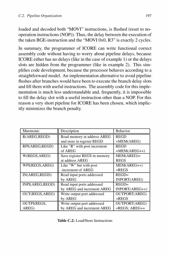
Mnemonic Description Behavior
R(AREG,REGD) Read memory at address AREG REGDand store in register REGD =MEM(AREG)
RPI(AREG,REGD) Like ”R” with post increment REGDof AREG =MEM(AREG++)
W(REGS,AREG) Save register REGS in memory MEM(AREG)=at address AREG REGS
WPI(REGS,AREG) Like ”W” but with post MEM(AREG++)-increment of AREG =REGS
IN(AREG,REGD) Read input ports addressed REGD=by AREG INPORT(AREG)
INPI(AREG,REGD) Read input ports addressed REGD=by AREG and increment AREG INPORT(AREG++)
OUT(REGS,AREG) Write output port addressed OUTPORT(AREG)by AREG =REGS
OUTPI(REGS, Write output port addressed OUTPORT(AREG)AREG) by AREG and increment AREG =REGS; AREG++
Table C.2: Load/Store Instructions

198 Appendix C. ICORE Instruction Set Architecture
Mnemonic Description Behavior
LAI(CON, AREG) Load address register immediate AREG=CONLAIR0(CON,AREG) Load address register immediate AREG=CON+R0
with displacement in R0
Table C.3: Address Register Instructions
C.3 Instruction Summary
The ICORE instruction set can be divided into
• 8 load/store instructions (to load (store) data from (to) the datamemory or the I/O registers) explained in detail in table C.2
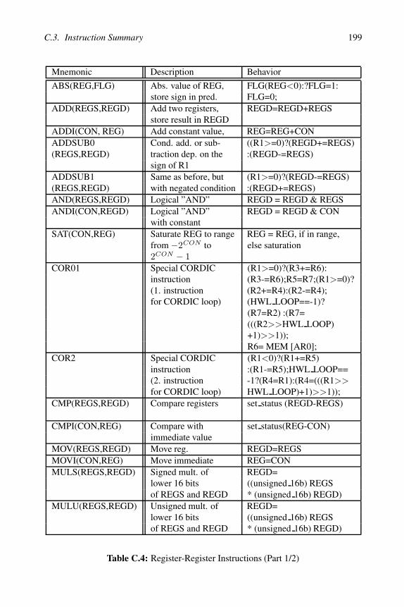
• 28 register-register instructions (performing operations on the gen-eral purpose register, using data values from the general purposeregisters or the immediate field of the instructions) described intable C.4
• 16 program flow control instructions (like branches, loop instruc-tions and instructions to wait for external events) given in tableC.6
• 2 address register load instructions explained in table C.3
The column “Behavior” in the tables C.2, C.4, C.6 and C.3 containsa C-like description of the instruction behavior. The meaning of theoperators in this column (e.g. “<<” or “&&”) can be looked up in anyC language manual. Refer to the appropriate footnote on this page foran explanation of the coding for the “CON”-field of RBIT, WBIT andWBITI.
C.3. Instruction Summary 199
Mnemonic Description Behavior
ABS(REG,FLG) Abs. value of REG, FLG(REG<0):?FLG=1:store sign in pred. FLG=0;
ADD(REGS,REGD) Add two registers, REGD=REGD+REGSstore result in REGD
ADDI(CON, REG) Add constant value, REG=REG+CONADDSUB0 Cond. add. or sub- ((R1>=0)?(REGD+=REGS)(REGS,REGD) traction dep. on the :(REGD-=REGS)
sign of R1ADDSUB1 Same as before, but (R1>=0)?(REGD-=REGS)(REGS,REGD) with negated condition :(REGD+=REGS)AND(REGS,REGD) Logical ”AND” REGD = REGD & REGSANDI(CON,REGD) Logical ”AND” REGD = REGD & CON
with constantSAT(CON,REG) Saturate REG to range REG = REG, if in range,
from −2CON to else saturation2CON − 1
COR01 Special CORDIC (R1>=0)?(R3+=R6):instruction (R3-=R6);R5=R7;(R1>=0)?(1. instruction (R2+=R4):(R2-=R4);for CORDIC loop) (HWL LOOP==-1)?
(R7=R2) :(R7=(((R2>>HWL LOOP)+1)>>1));R6= MEM [AR0];
COR2 Special CORDIC (R1<0)?(R1+=R5)instruction :(R1-=R5);HWL LOOP==(2. instruction -1?(R4=R1):(R4=(((R1>>for CORDIC loop) HWL LOOP)+1)>>1));
CMP(REGS,REGD) Compare registers set status (REGD-REGS)
CMPI(CON,REG) Compare with set status(REG-CON)immediate value
MOV(REGS,REGD) Move reg. REGD=REGSMOVI(CON,REG) Move immediate REG=CONMULS(REGS,REGD) Signed mult. of REGD=
lower 16 bits ((unsigned 16b) REGSof REGS and REGD * (unsigned 16b) REGD)
MULU(REGS,REGD) Unsigned mult. of REGD=lower 16 bits ((unsigned 16b) REGSof REGS and REGD * (unsigned 16b) REGD)
Table C.4: Register-Register Instructions (Part 1/2)

200 Appendix C. ICORE Instruction Set Architecture
Mnemonic Description Behavior
NEG(REG) Negate register REG = -REGSLA(REGS,REGD) Arith. shift left REGD=REGD<<REGS low5
(shift count in5 LSBs of REGS)
SLAI(CON,REG) Arith. shift left REG=REG<<CON low5SRA(REGS,REGD) Arith. shift right REGD=REGD>>REGS low5SRAI(CON,REG) Arith. shift right REGD=REG>>CONSRA1(REGS, CORDIC instr.: (HWL COUNT<= -1)?REGD) (shift by nr+1 bits, (REGD=REGS): (REGD=
where nr=”current (((REGS>>HWL COUNT)+1)hardware loop cnt.”, >>1)with rounding)
SRAI1(CON,REG) CORDIC instr. (CON<= -1)?(REG=REG)for shift and round :(REG=(((REG>>CON)+1)
>>1)SUB(REGS,REGD) Subtraction REGD=REGD-REGSSUBI(CON,REG) Subtraction of const. REG=REG-CONRBIT(CON4,REG) Extract bit field R0=((REG>>CON right)
in REG & ((1<<CON length)-1))WBIT(CON5,REG) Write bit field in R0 R0=(((R0>>(CON left+1))
<<(CON left+1))+((REG&((1<<(CON left-CON right+1))-1))<<CON right)++(R0&((1<<CON right)-1)))
WBITI(CON6,REG) Write constant in REG=(((REG>>(CON left+1))bit field of REG <<(CON left+1))+((31&
CON value&((1<<(CON left-CON right+1))-1))<<CON right)+(REG&((1<<CON right)-1)))
Table C.5: Register-Register Instructions (Part 2/2)
4CON is defined by the relation CON=CON length*8 +CON right, where CON length and CON rightare 3 bit unsigned values
5CON is defined by CON=CON length*8 +CON right, where CON length and CON right are 3 bitunsigned values; CON left = CON right + CON length -1
6CON is defined by CON=64*CON value+8*CON length+CON right, where CON value is a 5 bit fieldand CON length and CON right are 3 bit unsigned values; CON left = CON right + CON length -1

C.3. Instruction Summary 201
Mnemonic Description Behavior
B(CON) Uncond. rel. branch PC=PC+CON+1BSR(CON) Uncond. rel. branch STACK=PC;
to subroutine PC=PC+CON+1;BE(CON) Rel. branch if ”=” If(STATUS.Z==1)
cond. in status reg. PC=PC+CON+1;BNE(CON) Rel. branch if ”!=” if(STATUS.Z==0)
cond. in status reg. PC=PC+CON+1;BLT(CON) Rel. branch if ”<” if(STATUS.L==1
cond. in status reg. && STATUS.L==0)PC=PC+CON+1
BLE(CON) Rel. branch if ”<=” if(STATUS.L==1cond. in status —— STATUS.Z==1)register PC=PC+CON+1
BGT(CON) Rel. branch if ”>” if(STATUS.L==0cond. in status && STATUS.Z==0)register PC=PC+CON+1
BGE(CON) Rel. branch if ”>=” if(STATUS.L==0cond. in status —— STATUS.Z==0)register PC=PC+CON+1
BPC(FLG,CON) Rel. branch if pred. if(FLG==0)bit FLG is clear PC=PC+CON+1
BPS(FLG,CON) Rel. branch if pred. if(FLG==1)bit FLG is set PC=PC+CON+1
END Enter idle mode -RTS Return from subrout. PC=STACKSUSPG Wait until -
guard trig=”1”SUSPP Wait until -
ppubus en=”1”LPCNT(CON,REG) Init. loop cnt. reg. lp start count=CON;
lp end count=REG;LPINI(CON) Init. loop start and -
end addr. (CON)and activ. loopprocessing withnext instr.
Table C.6: Program Flow Control Instructions
202 Appendix C. ICORE Instruction Set Architecture
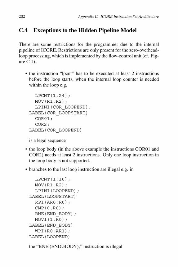
C.4 Exceptions to the Hidden Pipeline Model
There are some restrictions for the programmer due to the internalpipeline of ICORE. Restrictions are only present for the zero-overhead-loop processing, which is implemented by the flow-control unit (cf. Fig-ure C.1).
• the instruction “lpcnt” has to be executed at least 2 instructionsbefore the loop starts, when the internal loop counter is neededwithin the loop e.g.
LPCNT(1,24);MOV(R1,R2);LPINI(COR_LOOPEND);
LABEL(COR_LOOPSTART)COR01;COR2;
LABEL(COR_LOOPEND)
is a legal sequence
• the loop body (in the above example the instructions COR01 andCOR2) needs at least 2 instructions. Only one loop instruction inthe loop body is not supported.
• branches to the last loop instruction are illegal e.g. in
LPCNT(1,10);MOV(R1,R2);LPINI(LOOPEND);
LABEL(LOOPSTART)RPI(AR0,R0);CMP(0,R0);BNE(END_BODY);MOVI(1,R0);
LABEL(END_BODY)WPI(R0,AR1);
LABEL(LOOPEND)
the “BNE (END BODY);” instruction is illegal

C.5. ICORE Memory Organization and I/O Space 203
C.5 ICORE Memory Organization and I/O Space
ICORE uses a Harvard architecture, which means that instruction anddata memory are separated. An instruction ROM of 2048 words with20 bits is used to store the program.
The data memory is subdivided into a small (synthesized) 24 wordROM and a 256x32 bit RAM. Table C.7 shows the address mappingof the data memory. The data memory itself contains about 200 tempo-rary states and variables which correspond to the states defined in theDVB-T A&T specification.
Memory Start Address End Address
Synth. ROM 0 23unused 24 255RAM 256 511
Table C.7: Data Memory Mapping
The I/O-address space of ICORE is separated from the data and theinstruction memory and uses about 40 different registers for I/O values.
C.6 Instruction Coding
The instruction code word is the representation of operations andoperands in the instruction memory. For instance, the word“000100DDDIIIIIIIIIII” is the instruction code word for “MOVI #I, D”where “I” represents an 11-bit immediate value and D is the destina-tion (general purpose register R0-R7). Thus, the operation “MOVI011100b, R5” moves the signed binary value 011100b to the registerR5 and has the machine coding “00010010100000011100”.
In order to simplify the design space exploration, which involves fre-quent changes of the instruction coding, a tool called ICON has beendeveloped for programming. This tool has been described in Subsec-tion 6.3.1 in this thesis. ICON is an instruction coding generator, ahardware generator for the decoder hardware description, and an as-sembler. ICON uses the assembler program in a line-oriented input file

204 Appendix C. ICORE Instruction Set Architecture
and automatically generates the instruction coding, the instruction de-coder and the machine code (as COFF file for the ROM). The user hasthe freedom to select the preferred coding scheme for the opcodes andthe alignment of operand fields. The remaining degrees of freedom areoptimized to minimize the coding width and the power consumption.Figure C.3 shows an example input file (“.cri”-file) for ICON, whichcontains the assembler program in the following format:
• the first line contains a description of the individual fields of thefile, starting with the opcode and the individual operands. Thesecond field, for instance, specifies the field “reg0” (first generalpurpose register) which is encoded as 3bit unsigned value (“3u”),the fifth field specifies the 11-bit signed immediate value
• the second line is a blank line
• the following lines specify the actual program to be implementedstarting with the operation e.g. “movi op” and the appropriatefields e.g. “u3reg0=5” and “s11immediate=28” for the above ex-ample (“MOVI 011100b, R5”). “x” values indicate don’t careoperand values.
opcode |u3r0 |u3r1 |u2ar |s11imm |u2pr
b_op x x x 6 xmovi_op 0 x x 0 xlai_op x x 0 32 xlpc_op 1 x x 1 xrpi_op 2 x 1 x xcmp_op 4 2 x x xend_op x x x x x
Figure C.3: Assembler Input File for ICON

Appendix D
Different ICORE PipelineOrganizations
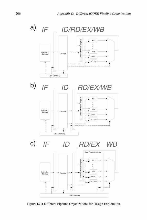
Figure D.1 depicts the different pipeline organizations that have beenexplored during the design of ICORE. Figure D.1 neglects many detailsof the implementation including the status and predicate register file,the address generator etc. It rather depicts the part of the data path thatis needed for register-register and memory-register instructions. Im-plementation a) shows a two stage pipeline: the critical path of thisimplementation is typically the ID/RD/EX/WB stage. Implementationb) reduces this critical path by inserting an additional pipeline stage af-ter the decoder. This also increases the branch penalty by one cycle.Implementation c), finally, uses a 4-stage pipeline with a data forward-ing path. This implementation, which is pretty similar to many con-ventional RISC-processor implementations, needs additional MUXesin the RD/EX stage to implement the forwarding logic. For the ICOREbenchmark, implementation b) exposed the best energy-efficiency andwas able to meet the given timing constraints.
206 Appendix D. Different ICORE Pipeline Organizations
IF ID/RD/EX/WB
InstructionMemory Decoder
FU1
FUn
.
.
.
Mem.
I/O, I2C
a)
Flow Control a)
IF ID
InstructionMemory Decoder
FU1
FUn
.
.
.
Mem.
I/O, I2C
b)
Flow Control b)
RD/EX/WB
IF ID
InstructionMemory Decoder
FU1
FUn
.
.
.
Mem.
I/O, I2C
c)
Flow Control c)
RD/EX WB
Gen
eral
Pur
pose
Reg
iste
rG
ener
al P
urpo
se R
egis
ter
Gen
eral
Pur
pose
Reg
iste
r
Data Forwarding Path
Figure D.1: Different Pipeline Organizations for Design Exploration

Appendix E
ICORE HDL DescriptionTemplates
In this chapter generic examples for HDL templates that implement reg-ister file instances and functional units are described. These descriptionscan also be used and parameterized by an automatic HDL generator.
E.1 Generic Register File Entity
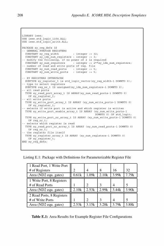
The implementation of a processor register like a status or a general pur-pose register file can be achieved using the template register descriptionin Listing E.2 together with a parameterization package according toListing E.1. This synthesizable register file can be parameterized tomatch any register structure that can be described with LISA.
Parameters of this register file template are the bit width of register el-ements, the number of registers, and the number of individual read andwrite ports of the register. If two write ports try to write to the same ad-dress, this write access conflict is resolved in hardware using a prioriza-tion scheme (here, write ports with lower number have higher priority).Optionally, hardware or simulation code to detect this condition can beadded (which has been omitted in Listing E.2 due to a lack of space).
Write and read accesses to such a register file can be implemented byconnecting the inputs of the write ports to the associated data sourcesusing multiplexers in case of multiple sources. Due to the fact that theread and write ports have access to all of the available internal reg-isters, the hardware generator has to find an optimum assignment ofdata sources/sinks to register write/read ports. This assignment can beachieved using a balancing scheme, which minimizes the total multi-plexer area and delay of the implementation.
208 Appendix E. ICORE HDL Description Templates
LIBRARY ieee;USE ieee.std_logic_1164.ALL;USE ieee.std_logic_arith.ALL;
PACKAGE xy_reg_defs IS-- GENERAL PURPOSE REGISTERS
CONSTANT xy_reg_width : integer := 32;CONSTANT xy_ldn_num_registers : integer := 3;
-- modify the following, if no power of 2 is requiredCONSTANT xy_num_registers : integer := 2**xy_ldn_num_registers;
-- number of read and write ports of reg. fileCONSTANT xy_num_read_ports : integer := 5;CONSTANT xy_num_write_ports : integer := 5;
-- XY REGISTERS INTERFACESSUBTYPE xy_register_t is std_logic_vector(xy_reg_width-1 DOWNTO 0);
-- type to select registersSUBTYPE reg_nr_t IS unsigned(xy_ldn_num_registers-1 DOWNTO 0);
-- all read portsTYPE xy_read_port_array_t IS ARRAY(xy_num_read_ports-1 DOWNTO 0)
OF xy_register_t;-- all write ports
TYPE xy_write_port_array_t IS ARRAY (xy_num_write_ports-1 DOWNTO 0)OF xy_register_t;
-- selects if write port is active and which register is writtenTYPE xy_write_port_enable_array_t IS ARRAY (xy_num_write_ports-1
DOWNTO 0) OF std_logic;TYPE xy_write_port_nr_array_t IS ARRAY (xy_num_write_ports-1 DOWNTO 0)
OF reg_nr_t;-- selects which register is read
TYPE xy_read_port_nr_array_t IS ARRAY (xy_num_read_ports-1 DOWNTO 0)OF reg_nr_t;
-- the register file itselfTYPE xy_register_array_t IS ARRAY (xy_num_registers-1 DOWNTO 0)
OF xy_register_t;END xy_reg_defs;
Listing E.1: Package with Definitions for Parameterizable Register File
1 Read Port, 1 Write Port# of Registers 2 4 8 16 32Area (ND2 equ. gates) 0.61k 1.09k 2.10k 3.99k 7.79k
1 Write Port, 8 Registers# of Read Ports 1 2 3 4 5Area (ND2 equ. gates) 2.10k 2.53k 2.99k 3.44k 3.90k
2 Read Ports, 8 Registers# of Write Ports 1 2 3 4 5Area (ND2 equ. gates) 2.53k 3.15k 3.28k 3.79k 3.88k
Table E.1: Area Results for Example Register File Configurations

E.2. Generic Bit-Manipulation Unit 209
Table E.1 contains synthesis results for a register file with 32 bit regis-ters and several example configurations for the register number and thenumber of read and write ports. Compared to the area of a functionalunit like a 16x16 bit multiplier, which consumes about 1.9k equivalentgates (target frequency: 200MHz), the register file area can be signifi-cant, if many registers are needed. From the power perspective, registersalso consume a significant part of the total power, because they are fre-quently accessed in a typical load/store architecture (cf. Appendix F).
E.2 Generic Bit-Manipulation Unit
This section describes an application-specific functional unit with thepurpose to read and write short bit fields within a longer (e.g. 32-bit)word. This so-called bit-manipulation unit is an example for a hand-optimized VHDL description of a functional unit, because this kind ofoperation is not available in the DesignWare-library of Synopsys [233].
As an example for a bit field write operation refer to Section C.3, wherethe instructions RBIT, RBITI, WBIT and WBITI are described. Forinstance in case of a WBIT instruction, the bit-manipulation unit (cf.VHDL-Listings E.5, E.3 and E.4) simply replaces the bits CON rightto CON right + CON length − 1 with the CON length LSBs ofop1 in nb.

210 Appendix E. ICORE HDL Description Templates
ENTITY xy_reg_file ISPORT (
clk_sysd2,rstq : IN std_logic;xy_write_port_enable : IN xy_write_port_enable_array_t;xy_write_port_regnr : IN xy_write_port_nr_array_t;xy_data_in : IN xy_write_port_array_t;xy_regnr_read : IN xy_read_port_nr_array_t;xy_data_out : OUT xy_read_port_array_t;xy_register : OUT xy_register_array_t);
END xy_reg_file;
ARCHITECTURE rtl OF xy_reg_file ISSIGNAL gpreg : xy_register_array_t;
BEGINxy_register <= gpreg;gp_register_write : PROCESS(rstq, clk_sysd2)VARIABLE enable_bus : std_logic_vector(xy_num_registers-1
DOWNTO 0);VARIABLE tmp_gpreg : xy_register_t;
BEGINIF (rstq = ’0’) THENgpreg <= (OTHERS => (OTHERS => ’0’));
ELSIF (clk_sysd2’event AND clk_sysd2 = ’1’) THENenable_bus := (OTHERS => ’0’);FOR i IN xy_num_write_ports-1 DOWNTO 0 LOOP
IF (xy_write_port_enable(i) = ’1’) THENenable_bus(conv_integer(xy_write_port_regnr(i))) := ’1’;
END IF;END LOOP;FOR i IN xy_num_registers-1 DOWNTO 0 LOOP
tmp_gpreg := (OTHERS => ’0’);FOR j IN xy_num_write_ports-1 DOWNTO 0 LOOP
IF (xy_write_port_regnr(j) = iAND xy_write_port_enable(j) = ’1’) THEN
tmp_gpreg := xy_data_in(j);END IF;
END LOOP;IF (enable_bus(i) = ’1’) THEN
gpreg(i) <= tmp_gpreg;ELSE
gpreg(i) <= gpreg(i);END IF;
END LOOP;END IF;
END PROCESS;
gp_register_read : PROCESS(gpreg, xy_regnr_read)VARIABLE nr_var : integer range 0 to xy_num_registers-1;BEGIN
xy_data_out <= (OTHERS => (OTHERS => ’0’));FOR i IN xy_num_read_ports-1 DOWNTO 0 LOOPnr_var := conv_integer(xy_regnr_read(i));xy_data_out(i) <= gpreg(nr_var);
END LOOP;END PROCESS;-- insert write collision detection here
END rtl;
Listing E.2: Synthesizable VHDL Description of Parameterizable RF

E.2. Generic Bit-Manipulation Unit 211
ARCHITECTURE rtl OF ppu_bitmanip ISSIGNAL rbit_notwbit : std_logic;SIGNAL enable_imm : std_logic;SIGNAL immediate : immediate_value_t;SIGNAL op0_in : data_path_t;SIGNAL op1_in : data_path_t;SUBTYPE mask_t IS unsigned(bitmanip_max_mod_field-1 DOWNTO 0);TYPE mask_table_t IS ARRAY (bitmanip_max_mod_field-1 DOWNTO 0) OF mask_t;SIGNAL mask_table : mask_table_t;SIGNAL dummy : std_logic;
BEGINbitmanip_block_proc : PROCESS(enable, rbit_notwbit_nb, enable_imm_nb,
immediate_nb, op0_in_nb, op1_in_nb)BEGINIF (enable = ’0’ AND use_blocked_input = 1) THEN
rbit_notwbit <= ’0’;enable_imm <= ’0’;immediate <= (OTHERS => ’0’);op0_in <= (OTHERS => ’0’);op1_in <= (OTHERS => ’0’);
ELSErbit_notwbit <= rbit_notwbit_nb;enable_imm <= enable_imm_nb;immediate <= immediate_nb;op0_in <= op0_in_nb;op1_in <= op1_in_nb;
END IF;END PROCESS;bitmanip_proc : PROCESS(rbit_notwbit, enable_imm, immediate,
op0_in, op1_in, mask_table)VARIABLE value_to_insert_v: std_logic_vector(bitmanip_max_mod_field-1
DOWNTO 0);VARIABLE masked_value_v : data_path_t;VARIABLE shifted_mask_v : std_logic_vector(bitmanip_max_affected
DOWNTO 0);VARIABLE shifted_op_v : data_path_t;VARIABLE length_v : unsigned(bitmanip_len_field_len-1
DOWNTO 0);VARIABLE right_pos_v : unsigned(bitmanip_rpos_field_len-1
DOWNTO 0);BEGINlength_v := conv_unsigned(immediate(imm_value_width-
bitmanip_value_field_le-1 DOWNTOimm_value_width-bitmanip_value_field_len
-bitmanip_len_field_len),bitmanip_len_field_len);
right_pos_v := conv_unsigned(immediate(bitmanip_rpos_field_len-1DOWNTO 0),bitmanip_rpos_field_len);
shifted_mask_v := conv_std_logic_vector(shl(mask_table(conv_integer(length_v)),right_pos_v), bitmanip_max_affected+1);
IF (rbit_notwbit = ’0’) THENIF (enable_imm = ’1’) THEN -- wbiti
value_to_insert_v := conv_std_logic_vector(conv_unsigned(immediate(imm_value_width-1 DOWNTO imm_value_width-bitmanip_value_field_len),bitmanip_value_field_len),bitmanip_max_mod_field);
ELSE -- wbitvalue_to_insert_v := op1_in(bitmanip_max_mod_field-1 DOWNTO 0);
END IF;
Listing E.3: Synthesizable VHDL Architecture of Bit-Manipulation Unit 1/2

212 Appendix E. ICORE HDL Description Templates
-- mask significant bitsmasked_value_v := (OTHERS => ’0’);masked_value_v(bitmanip_max_mod_field-1 DOWNTO 0) :=
value_to_insert_v ANDconv_std_logic_vector(mask_table(conv_integer(length_v)),
bitmanip_max_mod_field);-- shift masked_value_v to the left by right_pos_v bitsmasked_value_v := conv_std_logic_vector(shl(UNSIGNED(masked_value_v),
right_pos_v), data_path_width);-- combine resultsresult <= (op0_in AND (NOT conv_std_logic_vector(
UNSIGNED(shifted_mask_v),data_path_width)))OR masked_value_v;
ELSE -- rbit-- shift rightshifted_op_v := conv_std_logic_vector(shr(UNSIGNED(op0_in),
right_pos_v), data_path_width);-- maskresult <= shifted_op_v AND
conv_std_logic_vector(mask_table(conv_integer(length_v)),data_path_width);
END IF;END PROCESS;
gen_mask_proc : PROCESS(dummy)BEGIN
mask_table <= (OTHERS => (OTHERS => ’0’));FOR j IN bitmanip_max_mod_field-2 DOWNTO 0 LOOPFOR i IN j DOWNTO 0 LOOP
mask_table(j+1)(i) <= ’1’;END LOOP; -- i
END LOOP; -- jmask_table(0) <= (OTHERS => ’1’);
END PROCESS;END rtl;
Listing E.4: Synthesizable VHDL Architecture of Bit-Manipulation Unit 2/2
ENTITY ppu_bitmanip ISPORT (
enable : IN std_logic;rbit_notwbit_nb : IN std_logic; -- ’0’ = wbit instructionenable_imm_nb : IN std_logic; -- for wbitiimmediate_nb : IN immediate_value_t; -- immediate from instruct.op0_in_nb : IN data_path_t; -- operand from registerop1_in_nb : IN data_path_t; -- "value field" for wbitresult : OUT data_path_t -- update for r0);
END ppu_bitmanip;
Listing E.5: Synthesizable VHDL Entity of Bit-Manipulation Unit
Appendix F
Area, Power and Design Timefor ICORE
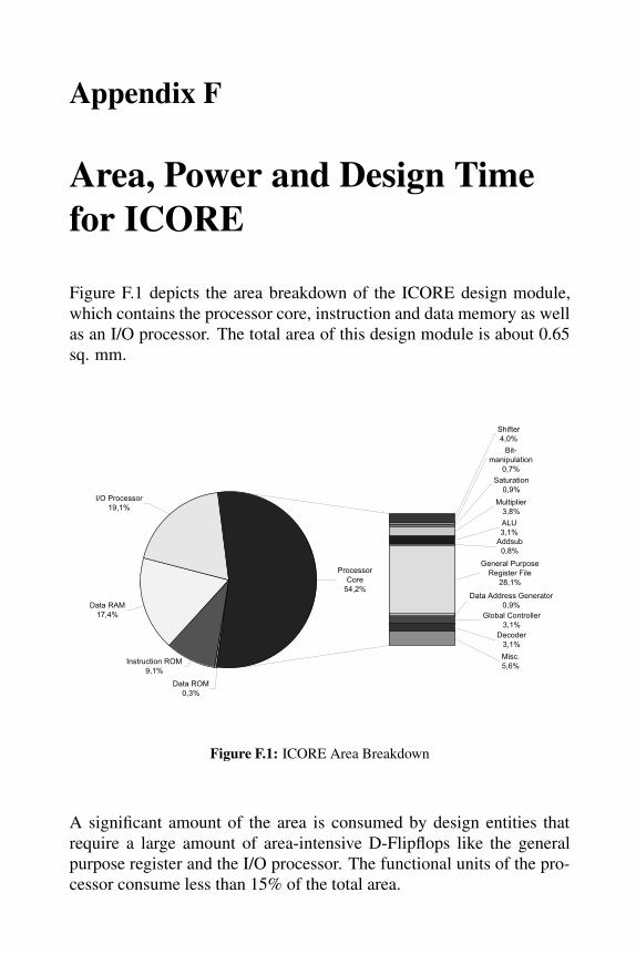
Figure F.1 depicts the area breakdown of the ICORE design module,which contains the processor core, instruction and data memory as wellas an I/O processor. The total area of this design module is about 0.65sq. mm.
Data ROM
0,3%
Instruction ROM
9,1%
Multiplier
3,8%
Saturation
0,9%
Bit-
manipulation
0,7%
Shifter
4,0%
ALU
3,1%
Addsub
0,8%
Misc.
5,6%
Decoder
3,1%
Global Controller
3,1%
Processor
Core
54,2%Data Address Generator
0,9%
General Purpose
Register File
28,1%
Data RAM
17,4%
I/O Processor
19,1%
Figure F.1: ICORE Area Breakdown
A significant amount of the area is consumed by design entities thatrequire a large amount of area-intensive D-Flipflops like the generalpurpose register and the I/O processor. The functional units of the pro-cessor consume less than 15% of the total area.

214 Appendix F. Area, Power and Design Time for ICORE
In Figure F.2 the power consumption of the ICORE module for all thedesign entities as well as the clock tree is shown. The total power of thecomplete design module is 18.8mW.
Compared to other processor-based systems, the power consumption inthe clock tree is significantly lower, due to the extensive use of clockgating. This is especially efficient, because the switching activity ofmany register intensive design entities is low: For instance, a large partof the I/O controller is used in order to store mainly static informationthat configures the operating mode of the design. Moreover, it has tobe mentioned that the power consumption of the instruction memoryin Figure F.2 is measured after the optimization process that has beendescribed in Section 6.3.1. The power in the instruction ROM is stillsignificant despite of this optimization, because the memory is accessedin each clock cycle.
Routing MUXes
9,3%
Multiplier
3,1%
Status Register
0,0%
Data Address Generator
0,4%
Bitmanipulation
1,1%
Saturation
0,8%
Global Controller
1,7%
Clock Tree
16,2%
Data ROM
0,1%
Misc.
2,1%
Decoder
3,6%
Addsub
0,1%
ALU
1,7%
Shifter
2,9%
General Purpose Register File
17,9%
Processor
Core
54%
Data RAM
4,9%
IO-Controller
1,7%
Instruction ROM
32,4%
Figure F.2: ICORE Power Breakdown for a Typical Operation Scenario
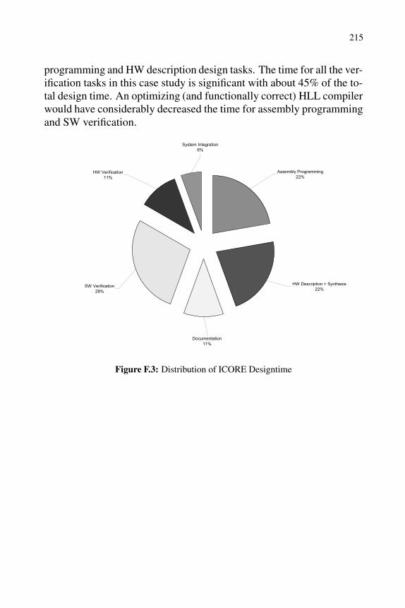
The total design time of ICORE was 10.5 man months. Figure F.3shows the percentage of the design time for the different design tasks.The time for the design space exploration is included in the assembly
215
programming and HW description design tasks. The time for all the ver-ification tasks in this case study is significant with about 45% of the to-tal design time. An optimizing (and functionally correct) HLL compilerwould have considerably decreased the time for assembly programmingand SW verification.
Assembly Programming
22%
System Integration
6%
HW Verification
11%
SW Verification
28%
Documentation
11%
HW Description + Synthesis
22%
Figure F.3: Distribution of ICORE Designtime
Appendix G
Acronyms
A silicon areaAD/DA analog digital / digital analog converterALICE here: name of a parameterizable processor ar-
chitecture with compiler supportALU arithmetic logic unitAPI application programming interfaceASI application specific instructionASIC application-specific integrated circuitASIP application-specific instruction set processorASPP application-specific programmable processorATM asynchronous transfer modeBL bit line in a memory arrayCDFG control data flow graphCLIW configurable long instruction wordCMOS complementary metall oxide semiconductorCOFDM coded orthogonal frequency division multiplexCOFF common object file formatCORDIC coordinate rotation digital computerCOSY compiler design system (ACE)CPU central processing unitDES data encryption standardDFG data flow graphDFT discrete fourier transformationDMA direct memory accessDOA direction-of-arrival (multi-antenna systems)DSP digital signal processing or digital signal pro-
cessorDSSP domain specific signal processorsDVB-T terrestrial digital video broadcastingE energy

218 Appendix G. Acronyms
EDA electronic design automationEPIC explicitly parallel instruction computingEV eigenvector or eigenvalueEVD eigenvalue/eigenvector decompositionFFT fast fourier transformationFIR finite impulse response (filter)FPGA field-programmable gate arrayFSM finite state machineFU functional unit of a processorGCC GNU C compilerGP general purposeGPR general purpose registerGSM global system for mobile communicationsGUI graphical user interfaceHDL hardware description languageHLL high level languageHW hardwareICORE ISS-core (the first ASIP designed at the Institute
for Integrated Signal Processing Systems)IDFT inverse discrete fourier transformationIIR infinite impulse response (filter)ILP instruction level parallelismIP intellectual propertyIPO in-place optimizationIRQ interrupt requestISA instruction set architectureISI inter-symbol interferenceISS instruction set simulatorJPEG joint photographic experts groupLISA language for instruction set architecture de-
scription (ISS)LMS least mean squareLSB least significant bit/byteMIMD multiple instruction, multiple data (architec-
ture)MIPS million instructions per second, commercial
processor architectureMISD multiple instruction, single data (architecture)

219
MOS metall oxide semiconductorMPEG motion pictures experts groupMSB most significant bit/byteND2 NAND standard cell with two inputsNMOS metall oxide semiconductor with N-field effect
transistorsNOP no-operation instructionNP network processorOFDM orthogonal frequency division multiplexingPAST projection approximation subspace trackingPC program counterPEQ phase equalizationPSA programmable system architecturePTL processor template libraryQAM quadrature amplitude modulationRAM random access memoryRF register fileRISC reduced instruction set computerROM read only memoryRTL register transfer languageSIMD single instruction, multiple data (architecture)SISD single instruction, single data (architecture)SM signed magnitude (number representation)SPARC scalable processor architectureSPICE simulation program with integrated circuit em-
phasisSRAM static random access memorySVD singular value decompositionT critical path of a synchronous designTCG test case generatorVHDL VHSIC hardware description languageVHSIC very-high-speed integrated circuitsVLIW very long instruction wordVLSI very large scale integrationXOR exclusive logical OR operation
Bibliography[1] Arthur Abnous and Jan Rabaey. Ultra-Low-Power Domain-Specific Multimedia Processors. Pro-
ceedings of the VLSI Signal Processing Workshop, pages 461–470, Oct. 1996.
[2] Santosh Abraham, Bob Rau, Robert Schreiber, Greg Snider, and Michael Schlansker. Efficient De-sign Space Exploration in PICO. Proc. of the Conference on Compilers, Architectures and Synthesisfor Embedded Systems (CASES), pages 71–79, Nov. 2000.
[3] ACE – Associated Compiler Experts bv., http://www.ace.nl. The COSY Compiler DevelopmentSystem, 2002.
[4] Douglas Adams. The Ultimate Hitchhikers’s Guide – Complete & unabridged. Wings Books, 1996.
[5] Advanced Risc Machines Ltd. ARM7100 Data Sheet, Dec. 1994.
[6] S. Affes, S. Gazor, and Y. Grenier. An Algorithm for Multi-Source Beamforming and Multi-TargetTracking. IEEE Trans. on Signal Processing, 44(6):1512–1522, 1996.
[7] A. Aiken and A. Nicolau. A Realistic Resource-Constrained Software Pipelining Algorithm. Ad-vances in Languages and Compilers for Parallel Processing, A. Nicola et al., Pitman/The MIT Press,London, pages 274–290, 1991.
[8] A. Alomary, T. Nakata, Y. Honma, M. Imai, and N. Hikichi. An ASIP Instruction Set Optimiza-tion Algorithm with Functional Module Sharing Constraint. Proc. IEEE/ACM, Int. Conference onComputer Aided Design, Santa Clara, CA, USA, pages 526–532, Nov. 1993.
[9] G. M. Amdahl. Validity of Single-Processor Approach to Achieving Large-Scale Computing Capa-bility. Proc. AFIPS Conf. Reston, VA, pages 483–485, 1967.
[10] Analog Devices Inc. TigerSHARC Reference Manual, Dec. 2001.
[11] David P. Appenzeller and Andreas Kuehlmann. Formal Verification of a PowerPCTM Microproces-sor, Report RC (19971). Technical report, IBM T. J. Watson Research Center, Yorktown Heights,NY 10598, March 1995.
[12] ARC Cores Ltd. ARC Programmers Reference Manual, Dec. 1999.
[13] ARC Cores Ltd. ARCtangent Processor, http://www.arccores.com, 2001.
[14] Simon Segars ARM Inc. Low-Power Design Techniques for Microprocessors. In International SolidState Circuits Conference, February 4–8, 2001.
[15] ARM Limited, http://www.arm.com. ARM9E-S Technical Reference Manual, 1999.
[16] ARM Ltd., Cambridge, UK. ARM Instruction Set Quick Reference Card, ARM QRC 001D, 1999.
[17] M. Arnold and Henk Corporaal. Designing Domain-Specific Processors. Proc. of the 2001 Int.Workshop on Hardware/Software Codesign, Copenhagen, Denmark, 2001.
[18] Krste Asanovic, Mark Hampton, Ronny Krashinsky, and Emmet Witchel. Energy-Exposed Instruc-tion Sets. 1st Chapter of Power Aware Computing, Editors: Robert Graybill and Rami Melhem,Plenum Publishing, to appear, 2002.
[19] Semiconductor Industry Association. International Technology Roadmap for Semiconductors. Tech-nical report, http://public.itrs.net/files/1999 SIA Roadmap/Home.htm, 1999.
[20] Y. Bajot and H. Mehrez. A Macro-Block Based Methodology for ASIP Core Design. In Proc. of theInt. Conf. on Signal Processing Applications and Technology (ICSPAT), Nov. 1999.
[21] S. Balakrishnan and S. K. Nandy. Multithreaded Architectures for Media Processing. 1st Workshopon Media Processors and DSPs (MP-DSP), Haifa, Israel, Nov. 15, 1999.
[22] M. Barbacci. Instruction Set Processor Specifications (ISPS): The Notation and its Application.IEEE Transactions on Computers, C-30(1):24–40, Jan. 1981.
[23] Michael J. Bass and Clayton M. Christinsen. The Future of the Microprocessor Business. IEEESpectrum, pages 34–39, April 2002.

222 Bibliography
[24] Maurice Bellanger. Digital Processing of Signals - Theory and Practice. John Wiley & Sons Ltd.,2000.
[25] L. Benini, G. De Micheli, E. Macii, D. Sciuto, and C. Silvano. Asymptotic Zero-Transition ActivityEncoding for Address Busses in Low-Power Microprocessor-Based Systems. Proc. of the 7th GreatLakes Symposium on VLSI, Urbana, IL, March 13-15, 1997.
[26] S. B. Bensley and B. Aazhang. Subspace-Based Channel Estimation for Code Division MulipleAccess Communication Systems. IEEE Trans. on Communications, 1994.
[27] J. Bier. DSP 16xxx Targets Communications Apps. Technical report, Microprocessor Report, Vol.11, No. 12, Sept. 15, 1997.
[28] A. Bindra. Two ‘Lode’ up on TCSI’s new DSP core. EE Times, Jan. 1995.
[29] Nguyen Ngoc Binh, Masaharu Imai, Akichika Shiomi, and Nobuyuki Hikichi. A Hardware/SoftwarePartitioning Algorithm for Designing Pipelined ASIPs with Least Gate Counts. Proceedings of theDesign Automation Conference (DAC 96), Las Vegas, Nevada, USA, pages 527–532, June 1996.
[30] Matthias A. Blumrich, Kai Li, Richard Alpert, Cezary Dubnicki, and Edward W. Felten. VirtualMemory Mapped Network Interface for the SHRIMP Multicomputer. Proc. of the 21st AnnualInternational Symposium on Computer Architecture, pages 142–153, April 1994.
[31] BOPS, Inc., www.bops.com. Man Array Architecture, 2000.
[32] G. Boriello. Software Scheduling in the Co-Synthesis of Reactive Real-Time Systems. Proc. of the31st Design Automation Conference, 1994.
[33] Jorg Bormann, Jorg Lohse, Michael Payer, and Gerd Venzl. Model Checking in Industrial HardwareDesign. Proceedings of the Design Automation Conference (DAC95), San Francisco, CA, June 12–16, 1995.
[34] D.G. Bradlee, R.E. Henry, and S.J. Eggers. The Marion System for Retargetable Instruction Schedul-ing. In Proc. of the Int. Conf. on Programming Language Design and Implementation (PLDI), pages229–240, 1991.
[35] G. Braun, A. Hoffmann, A. Nohl, and H. Meyr. Using Static Scheduling Techniques for the Re-targeting of High Speed, Compiled Simulators for Embedded Processors from an Abstract MachineDescription. In Proc. of the Int. Symposium on System Synthesis (ISSS), Oct. 2001.
[36] Thomas D. Burd and Robert W. Brodersen. Processor Design for Portable Systems. Journal of VLSISignal Processing, 13(2/3):203–222, Aug. 1996.
[37] Thomas D. Burd and Robert. W. Brodersen. Processor Design for Portable Systems. Journal of VLSISignal Processing, 13 (2/3), pages 203–222, August 1996.
[38] Klaus-Peter Buss and Volker Wittke. Mikro-Chips fur Massenmarkte – Innovationsstrategien dereuropaischen und amerikanischen Halbleiterhersteller in den 90er Jahren. Mitteilungen des Soziol-ogischen Forschungsinstituts (SOFI), Universitat Gottingen, July 2000.
[39] Cadence Design Systems, Inc., 2655 Seely Avenue, San Jose, CA 95134, USA. Cadence VirtualComponent Co-Design (VCC), 2002.
[40] T. Callaway and E. Swartzlander. Optimizing Arithmetic Elements for Signal Processing. In IEEEVLSI Signal Processing Workshop, Oct. 1992.
[41] R. Camposano and J. Wilberg. Embedded System Design. ACM Transactions on Design Automationfor Electronic Systems, 10(1):5–50, 1996.
[42] Francky Catthoor, Frank Franssen, Sven Wuytack, Lode Nachtergaele, and Hugo De Man. GlobalCommunication and Memory Optimizing Transformations for Low Power Signal Processing Sys-tems. VLSI Signal Processing Workshop, pages 178–187, Oct. 1994.
[43] A. Chandra, V. Iyengar, D. Jameson, R. Jawalekar, I. Nair, B. Rosen, M. Mullen, J. Yoon, R. Rmoni,D. Geist, and Y. Wolfsthal. AVPGEN – A Test Generator for Architecture Verification. IEEETransactions on Very Large Scale Integration (VLSI) Systems, 3(2):188–199, 1995.
[44] A. Chandrakasan and R. Brodersen. Minimizing Power Consumption in Digital CMOS Circuits. InProc. of the IEEE, volume 83,4, April 1995.

Bibliography 223
[45] A. Chandrakasan, M. Potkonjak, R. Mehra, J. Rabaey, and R. Brodersen. Optimizing Power UsingTransformations. In IEEE Transactions on Computer Aided Design, volume 14,1, pages 12–31, Jan.1995.
[46] A. P. Chandrakasan and R. W. Brodersen. Low Power Digital CMOS Design. Kluwer AcademicPublishers, 1995.
[47] Chang. Power-Area Tradeoff in Divided Word Line Memory Arrays. Journal of Circuits, Systems,Computers, 1(7):49–57, 1997.
[48] D. G. Chinnery, B. Nikolic, and K. Keutzer. Achieving 550 MHz in an ASIC Methodology.DAC2001, June 18-22, Las Vegas, Nevada, USA 2001.
[49] H. Choi, I.C. Park, S.H. Hwang, and C.M. Kyung. Synthesis of Application Specific Instructionsfor Embedded DSP Software. In Proc. of the Int. Conf. on Computer Aided Design (ICCAD), Nov.1998.
[50] H. Choi, J.H. Yi, J.Y. Kee, I.C. Park, and C.M. Kyung. Exploiting Intellectual Properties in ASIPDesigns for Embedded DSP Software. In Proc. of the Design Automation Conference (DAC), Jun.1999.
[51] D. Chuang, G. Kamosa, D. Arya, and R. Priebe. JPEG2000: A Scalable and Configurable Multipro-cessor VLIW Implementation. Mobile Multimedia Conference 2000, Tokyo, Japan, Oct. 2000.
[52] A. Cilio. Efficient Code Generation for ASIPs with Different Word Sizes. Proc. of the 3rd Confer-ence of the Advanced School for Computing and Imaging, The Netherlands, June 1997.
[53] Andrea G. M. Cilio and Henk Corporaal. Global Program Optimization: Register Allocation ofStatic Scalar Objects. Proc. of the 5th Annual Conference of the advanced School for Computingand Imaging, Delft, pages 52–57, June 1999. ISBN: 90-803086-4-1.
[54] Theo A. C. M. Claasen. High Speed: Not the Only Way to Exploit the Intrinsic Computational Powerof Silicon. Proc. of the 1999 IEEE International Solid-State Circuits Conference, pages 22–25, 1999.
[55] I. Bernhard Cohen. Howard Aiken: Portrait of a Computer Pioneer. MIT Press, March 1999.
[56] Robert Cohn and Mark Vandevoorde. Instrumentation, and Profile Based Optimization. In Tuto-rial 4 at the International Conference on Architectural Support for Programming Languages andOperating Systems, San Jose, CA, http://www.tru64unix.compaq.com/dcpi/publications.htm, 1998.
[57] J. W. Cooley and J. W. Tukey. An Algorithm for the Machine Computation of Complex FourierSeries. Math. Comp., 19:297–301, 1965.
[58] Joel Mc Cormack, Robert Mc Namara, Christopher Gianos, Larry Seiler, Norman P. Jouppi, KenCorrell, Todd Dutton, and John Zurawski. WRL Research Report 98/1: Neon - A (Big) (Fast)Single-Chip 3D Workstation Graphics Accelerator. Technical report, COMPAQ, Western ResearchLaboratory, Palo Alto, CA, USA, 1998.
[59] Thomas H. Cormen, Charles E. Leiserson, and Ronald L. Rivest. Introduction to Algorithms. MITPress, ISBN 0-262-03141-8, 1989.
[60] Olivier Coudet. The Quest for Timing Closure. In Tutorial 3, Part 4, ASP-DAC 2001, Yokohama,Japan, http://cadlab.cd.ucla.edu/ cong/slides/asp-dac01 tutorial/t3 p4 cou.pdf, 2001.
[61] CoWare. http://www.coware.com.
[62] H. Dawid and H. Meyr. The Differential CORDIC Algorithm: Constant Scale Factor RedundantImplementation without correcting Iterations. IEEE Transactions on Computers, 45(3):307–318,March 1996.
[63] J. Demmel and K. Veselic. Jacobi’s Method is more accurate than QR. Technical report, CourantInstitute of Mathematical Sciences, Department of Computer Science, New York University, 1989.
[64] S. Devadas, A. Ghosh, and K. Keutzer. Logic Synthesis. Mc Graw Hill, NY, 1994.
[65] S. Devadas, A. Ghosh, and K. Keutzer. An Observability-Based Code Coverage Metric for Func-tional Simulation. Proc. of the International Conference on Computer-Aided Design, pages 418–425,1996.

224 Bibliography
[66] Srinivas Devadas and Sharad Malik. A Survey of Optimization Techniques Targeting Low PowerVLSI Circuits. 32nd Design Automation Conference, 1995.
[67] S. Dey, Y. Gefen, A.C. Parker, and M. Potkonjak. Wiley Encyclopedia of Electrical and ElectronicsEngineering: Critical Path Analysis and Minimization in Digital Circuits, volume 4, pages 404–415.John Wiley & Sons, 2000.
[68] Nathan Dohm, Carl Ramey, Darren Brown, Scot Hildebrandt, James Huggins, Mike Quinn, andScott Taylor. Zen and the Art of Alpha Verification. Int. Conference on Computer Design (ICCD98),Austin, Texas, Oct. 5–7, 1998.
[69] F. Engel, J. Nuhrenberg, and G.P. Fettweis. A Generic Tool Set for Application Specific ProcessorArchitectures. In Proc. of the Int. Workshop on Hardware/Software Codesign, Apr. 1999.
[70] J.-H. Yang et al. Metacore: An Application Specific DSP Development System. In Proc. of theDesign Automation Conference (DAC), Jun. 1998.
[71] K. Usami et al. Design Methodology of Ultra Low-Power MPEG4 Codec Core Exploiting VoltageScaling Techniques. In Proceedings of the 35th Design Automation Conference, San Francisco, CA,USA, pages 483–488, 1998.
[72] S. C. Huang et al. RLC Signal Integrity Analysis of High-Speed Global Interconnects. In Interna-tional Electron Devices Meeting (IEDM), Tech. Digest, 2000.
[73] S. Gary et al. The PowerPC 603 Microprocessor: A Low-Power Design for Portable Applications.In Proceedings of the 39th IEEE Computer Society International Conference, pages 307–315, March1994.
[74] S. Kobayashi et al. Compiler Generation in PEAS-III: an ASIP Development System. In Proc. ofthe Workshop on Software and Compilers for Embedded Systems (SCOPES), Mar. 2001.
[75] European Telecommunication Standards Institute, Sophia Antipolis, France. ETSI ETS 300744, Dig-ital Video Broadcasting: Framing Structure, Channel Coding and Modulation for Digital TerrestrialTelevision, V1.1.2, 1997.
[76] P. Faraboschi, G. Desoli, and J.A. Fisher. Very Long Instruction Word Architectures for DSP andMultimedia Applications: The Latest Word in Digital and Media Processing. IEEE Signal Process-ing Magazine, pages 59–85, Mar. 1998.
[77] Paolo Faraboschi, Geoffrey Brown, Joseph A. Fisher, Giuseppe Desoli, and Fred Homewood. Lx:A Technology Platform for Customizable VLIW Embedded Processing. Proc. 27th Annual Interna-tional Symposium on Computer Architecture (ISCA-2000), pages 203–213, June 12–14, 2000.
[78] A. Fauth, M. Freericks, and A. Knoll. Generation of Hardware Machine Models from InstructionSet Descriptions. In Proc. of the IEEE Workshop on VLSI Signal Processing, 1993.
[79] A. Fauth and A. Knoll. Automatic Generation of DSP Program Development Tools Using a Ma-chine Description Formalism. In Proc. of the Int. Conf. on Acoustics, Speech and Signal Processing(ICASSP), 1993.
[80] Jay Fenlason and Richard Stallman. GNU gprof - The GNU Profiler. Free Software Foundation,Inc., 1997.
[81] Gerhard Fettweis, M. Weiss, W. Drescher, U. Walther, F. Engel, S. Kobayaschi, and T. Richter.Breaking New Grounds Over 3000M MAC/s: A Broadband Mobile Multimedia Modem DSP. Proc.of the Int. Conf. on Signal Processing Applications and Technology (ICSPAT’98), Toronto Canada,pages 1547–1551, 1998.
[82] M. J. Flynn. Some Computer Organizations and their Effectiveness. IEEE Trans. Computers,21(9):948–960, September 1972.
[83] W. Fornaciari, D. Sciuto, and C. Silvano. Power Estimation for Architectural Exploration of HW/SWCommunication on System-Level Buses. In Proc. of the Int. Workshop on Hardware/Software Code-sign (CODES99), Rome, Italy, May 3–5, 1999.
[84] M. Freericks. The nML Machine Description Formalism. Technical Report, Technical University ofBerlin, Department of Computer Science, 1993.

Bibliography 225
[85] C. Ghez, M. Miranda, A. Vandecappelle, F. Catthoor, and D. Verkest. Systematic High-Level Ad-dress Code Transformations for Piece-Wise Linear Indexing Illustrations: Illustration on a MedicalAlgorithm. In Proceedings IEEE Workshop on Signal Processing Systems, Lafayette, LA, USA, Oct.2000.
[86] T. Glokler, Stefan Bitterlich, and Heinrich Meyr. Power Reduction for ASIPs: A Case Study. IEEEWorkshop on Signal Processing Systems (SIPS), Antwerpen, Belgium, 2001.
[87] Tilman Glokler, Stefan Bitterlich, and Heinrich Meyr. DSP Core Verification Using Automatic TestCase Generation. IEEE Trans. Acoust., Speech and Signal Processing, June 2000.
[88] Tilman Glokler, Stefan Bitterlich, and Heinrich Meyr. ICORE: A Low-Power Application SpecificInstruction Set Processor for DVB-T Acquisition and Tracking. 13th IEEE workshop on SignalProcessing Systems (ASIC/SOC’2000), September 2000.
[89] Tilman Glokler, Stefan Bitterlich, and Heinrich Meyr. Increasing the Power Efficiency of Applica-tion Specific Instruction Set Processors using Datapath Optimization. Workshop on Sig. Proc. Syst.SIPS2000, October 2000.
[90] Tilman Glokler, Stefan Bitterlich, and Heinrich Meyr. Power-Efficient Semi-Automatic InstructionEncoding for Application Specific Instruction Set Processors. IEEE Trans. Acoust., Speech andSignal Processing, May 2001.
[91] Tilman Glokler, Andreas Hoffmann, and Heinrich Meyr. Methodical Low-Power ASIP Design SpaceExploration. Kluwer Journal of VLSI Signal Processing (JVSP), Volume 33, Issue 3:229–246, March2003.
[92] Tilman Glokler and Heinrich Meyr. ASIP Design and the Energy-Flexibility Tradeoff. In Pro-ceedings of the 10th Aachen Symposium on Signal Theory, ISBN 3-8007-2610-6, Aachen, Germany,pages 343–348, September 2001.
[93] Steve Golson. Resistance is Futile! Building Better Wireload Models. In Synopsys Users GroupConference (SNUG99), San Jose, 1999.
[94] G. H. Golub and C. F. Van Loan. Matrix Computations. North Oxford Academic, 1989.
[95] J. Gong, D.D. Gajski, and S. Narayan. Software Estimation Using a Generic-Processor Model. InProc. of the European Design and Test Conference (ED&TC), Mar. 1995.
[96] Jie Gong, Daniel D. Gajski, and Alex Nicolau. A Performance Evaluator for Parameterized ASICArchitectures. Proc. of the European Conference on Design Automation (EDAC), pages 66–71, 1994.
[97] R. Gonzales. Xtensa: A Configurable and Extensible Processor. IEEE Micro, 20(2):60–70, Mar.2000.
[98] G. Goosens, J. van Praet, D. Lanneer, W. Geurts, A. Kifli, C. Liem, and P. G. Paulin. EmbeddedSoftware in Real-Time Signal Processing Systems: Design Technologies. IEEE Proc. Spec. Issue onHardware/Software Codesign, 1996.
[99] R. Govindarajan, Erik R. Altman, and Guang R. Gao. A Theory for Software-Hardware Co-Scheduling for ASIPs and Embedded Processors. Proc. of the Int. Conf. on Application SpecificSystems, Architectures, and Processors (ASAP), Boston, MA, USA, July 10–12, 2000.
[100] B. Grattan, G. Stitt, and F. Vahid. Codesign-Extended Applications. IEEE/ACM International Sym-posium on Hardware/Software Codesign, Estes Park, May 2002.
[101] M. Gschwind. Instruction Set Selection for ASIP Design. In Proc. of the Int. Workshop on Hard-ware/Software Codesign, May 1999.
[102] A. Halambi, P. Grun, V. Ganesh, A. Khare, N. Dutt, and A. Nicolau. EXPRESSION: A Languagefor Architecture Exploration through Compiler/Simulator Retargetability. In Proc. of the Conferenceon Design, Automation & Test in Europe (DATE), Mar. 1999.
[103] S. Hanono, G. Hadjiyiannis, and S. Devadas. Aviv: A Retargetable Code Generator Using ISDL.Tech Report, SPAM Project, Princeton University, April 1996.
[104] Paul J. Havinga and Gerard J. M. Smit. Design Techniques for Low Power Systems. Journal ofSystem Architectures, 46(1):1–21, 2000. ISSN: 1383-7621.

226 Bibliography
[105] S. Haykin. Adaptive Filter Theory. Prentice Hall, 1991.
[106] Gerben J. Hekstra and Ed F. Deprettere. A Chip Set For A Ray-Casting Engine. Proc. of theWorkshop on VLSI Signal Processing IX, San Francisco, CA, USA, 1996.
[107] J. Hennessy and D. Patterson. Computer Architecture: A Quantitative Approach. Morgan KaufmannPublishers Inc., 1996. Second Edition.
[108] Richard C. Ho, C. Han Yang, Mark A. Horowitz, and David L. Dill. Architecture Validation forProcessors. Proc. of the International Symposium on Computer Architecture (ISCA), pages 404–413, 1995.
[109] A. Hoffmann, T. Kogel, A. Nohl, G. Braun, O. Schliebusch, A. Wieferink, and H. Meyr. A NovelMethodology for the Design of Application Specific Instruction Set Processors (ASIP) Using a Ma-chine Description Language. IEEE Transactions on Computer-Aided Design, 20(11):1338–1354,Nov. 2001.
[110] A. Hoffmann, H. Meyr, and R. Leupers. Architecture Exploration for Embedded Processors withLISA. Kluwer Academic Publishers, 2002.
[111] A. Hoffmann, A. Nohl, G. Braun, and H. Meyr. Generating Production Quality Software Devel-opment Tools Using A Machine Description Language. In Proc. of the Conference on Design,Automation & Test in Europe (DATE), Mar. 2001.
[112] A. Hoffmann, O. Schliebusch, A. Nohl, G. Braun, O. Wahlen, and H. Meyr. A Methodology for theDesign of Application Specific Instruction-Set Processors Using the Machine Description LanguageLISA. In Proc. of the Int. Conf. on Computer Aided Design (ICCAD), Nov. 2001.
[113] B. Holmer and B. Prangle. Hardware/Software Codesign Using Automated Instruction Set Design& Processor Synthesis, 1993.
[114] Mark Horowitz. Lecture 24: Power, Low Power Design.http://www.cs.utexas.edu/users/skeckler/cs384v/ handouts/lecture24 2.pdf, Stanford University,1999.
[115] I.J. Huang and A.M. Despain. Generating Instruction Sets and Microarchitectures from Applications.In Proc. of the Int. Conf. on Computer Aided Design (ICCAD), Nov. 1994.
[116] I.J. Huang and A.M. Despain. Synthesis of Instruction Sets for Pipelined Microprocessors. In Proc.of the Design Automation Conference (DAC), Jun. 1994.
[117] I.J. Huang, B. Holmer, and A.M. Despain. ASIA: Automatic Synthesis of Instruction-Set Architec-tures. In Proc. of the SASIMI Workshop, Oct. 1993.
[118] G. A. Van Huben. The Role of Two-Cycle Simulation in the S/390 Verification Process. IBM Journalof Research & Development, 41(4/5), 1997.
[119] David A. Huffman. A Method for the Construction of Minimum-Redundancy Codes. Proc. of theIRE, 40(9):1098–1101, 1952.
[120] Kai Hwang and Zhiwei Xu. Scalable Parallel Computing. McGraw-Hill International Editions,1997.
[121] IBS. Analysis of SOC Design Costs, A Custom Study for Synopsys Professional Services. Technicalreport, International Business Strategies, Inc., 632 Industrial Way, Los Gatos, CA 95030, USA,February 2002.
[122] Berkeley Design Technology Inc. VLIW Architectures for DSP: A Two Part Lecture. Proceed-ings of ICSPAT99, the International Conference on Signal Processing Applications and Technology,November 1–4, 1999.
[123] INFINEON Technologies AG, Munich, Germany. Product Brief SQC 6100 - Terrestrial Receiverfor DVB-T, 2000. www.infineon.com/products/ics/pdf/sqc 10b.pdf.
[124] M. J. Irwin. Low Power Design for Systems on a Chip (SOCs). Tutorial at the 12th Annual IEEEASIC/SOC Conference, September 1999.
Bibliography 227
[125] Sergio Akira Ito, Luigi Carro, and Ricardo Pezzuol Jacobi. System Design Based on Single Lan-guage and Single-Chip Java ASIP Microcontroller. Proc. of the Conference on Design, Automation& Test in Europe (DATE), Paris, France, pages 703–707, March 2000.
[126] M. Itoh, S. Higaki, J. Sato, A. Shiomi, Y. Takeuchi A. Kitajima, and M. Imai. PEAS-III: An ASIPDesign Environment. In Proc. of the Int. Conf. on Computer Design (ICCD), Sep. 2000.
[127] M. Itoh, Y. Takeuchi, M. Imai, and A. Shiomi. Synthesizable HDL Generation for Pipelined Pro-cessors from a Micro-Operation Description. IEICE Transactions on Fundamentals of Electronics,Communications and Computer Sciences, E83-A(3), Mar. 2000.
[128] C. G. J. Jacobi. Uber ein leichtes Verfahren die in der Theorie der Sacularstorungen vorkommendenGleichungen numerisch aufzulosen. Crelle’s Journal, 30, 1846.
[129] Carsten Jacobi. Evaluation and Implementation of DSP Core Architectures for COFDM. Mas-ter’s thesis, Supervisor: T. Glokler, D 418, Institute for Integrated Signal Processing Systems (ISS),RWTH Aachen, Jul. 2000.
[130] Margarida F. Jacome and Gustavo de Veciana. Lower Bound On Latency For VLIW ASIP Datapath.Proc. of the Int. Conf. on Computer Aided Design (ICCAD99), pages 261–269, November 1999.
[131] Manoj Kumar Jain, Lars Wehmeyer, Peter Marwedel, and M. Balakrishnan. Register File Synthesisin ASIP Design. Tech. Report No. 747, University of Dortmund, Dept. of CSXII, 2001.
[132] M.K. Jain, M. Balakrishnan, and A. Kumar. ASIP Design Methodologies: Survey and Issues. In Int.Conf. on VLSI Design, Jan. 2001.
[133] Curtis L. Janssen. VPROF - Programmer’s Manual, 2002.
[134] Poul M. Rands Jensen. On Jacobi-Like Algorithms for Computing the Ordinary Singular ValueDecomposition. Technical Report R 91 - 33, Department of Communication Technology, Institutefor Electronic Systems, Aalborg University, Denmark, Oct. 1991.
[135] Robert B. Jones. Efficient Validity Checking for Processor Verification. IEEE International Confer-ence on Computer Aided Design (ICCAD), 1995.
[136] Andrew B. Kahng. Design Technology Productivity in the DSM Era. Invited Talk to the Asia South-Pacific Design Automation Conference, Yokohama, February 2001.
[137] Vinod Kathail, Michael S. Schlansker, and B. Ramakrishna Rau. HPL-PD Architecture Specifica-tion: Version 1.1. Technical report, Compiler and Architecture Research, HP Laboratories Palo Alto,Feb. 2000.
[138] Stephan Keil. Untersuchung von Prozessorarchitekturen und generische VHDL-Implementierungeines skalierbaren digitalen Signalprozessors. Master’s thesis, Supervisor: T. Glokler, D 411Institutefor Integrated Signal Processing Systems (ISS), RWTH Aachen, Dec. 1999.
[139] T. M. Kemp, R. K. Montoye, J.D. Harper, J.D. Palmer, and D. J. Auerbach. A Decompression Corefor PowerPC. IBM Journal of Research and Development, 42(6):807–812, Nov. 1998.
[140] Bart Kienhuis, Ed Deprettere, Kees Vissers, and Pieter van der Wolf. The Construction of a Re-targetable Simulator for an Architecture Template. International Workshop on Hardware/SoftwareCo-design, IEEE Computer Society, CODES/CASHE’98, Seattle Washington, USA, March 15–18,1998.
[141] P. Kievits, E. Lambers, C. Moerman, and R. Woudsma. R.E.A.L. DSP Technology for TelecomBaseband Processing. Proc. of the Int. Conf. on Signal Processing Applications and Technology(ICSPAT), Toronto, CA, 1998.
[142] K.-W. Kim, T. T. Hwang, C. L. Liu, and S.-M. Kang. Logic Transformation for Low Power Synthe-sis. In Design, Automation and Test in Europe Conference and Exhibition, Munich, Germany, March9–12, 1999.
[143] Kyosun Kim, Ramesh Karri, and Miodrag Potkonjak. Synthesis of Application Specific Pro-grammable Processors. Proc. of the Design Automation Conference (DAC 97), Anaheim, California,1997.

228 Bibliography
[144] Y.-W. Kim, Y.-M. Yang, J.-T. Yoo, and S.-W. Kim. Low-Power Digital Filtering Using ApproximateProcessing with Variable Canonic Signed Digit Coefficients. In IEEE Int. Symposium on Circuitsand Systems, May 28–31, 2000.
[145] Y.G. Kim and T.G. Kim. A Design and Tool Reuse Methodology for Rapid Prototyping of Applica-tion Specific Instruction Set Processors. In In Proc. of the Workshop on Rapid System Prototyping(RSP), Apr. 1999.
[146] A. Kitajima, M. Itoh, J. Sato, A. Shiomi, Y. Takeuchi, and M. Imai. Effectiveness of the ASIPDesign System PEAS-III in Design of Pipelined Processors. In Proc. of the Asia South PacificDesign Automation Conference (ASPDAC), Jan. 2001.
[147] S. Klauke and J. Gotze. Low Power Algorithms for Signal Processing. ITG Workshop Mikroelek-tronik fur die Informationstechnik, Darmstadt, Germany, 2000.
[148] Peter Voigt Knudsen and Jan Madsen. Aspects of Modelling in Hardware/Software Partitioning. Int.Workshop on Rapid System Prototyping, Thessaloniki, Greece, June 19–21, 1996.
[149] Gerd Kruger. A Tool for Hierarchical Test Generation. IEEE Transactions on Computer-AidedDesign, 10(4):519–524, April 1991.
[150] Kayan Kucukcakar. An ASIP Design Methodology for Embedded Systems. 7th International Work-shop on HW/SW Co-Design, Roma, Italy, 1999.
[151] R. Kumaresan and D. W. Tufts. Estimating the Angles of Arrival of Multiple Plane Waves. IEEETrans. on Aerospace Electron. Syst., AES-19:134–139, 1983.
[152] M. Kuulusa, J. Nurmi, J. Takala, P. Ojala, and H. Herranen. A Flexible DSP Core for EmbeddedSystems. IEEE Design & Test of Computers, 14(4):60–68, 1997.
[153] Young-Jun Kwon, Danny Parker, and Hyuk Jae Lee. TOE: Instruction Set Architecture for Code SizeReduction and Two Operations Execution. Int. Workshop on Compiler and Architecture Support forEmbedded Systems, Washington D. C., USA, Oct. 1–3, 1999.
[154] L. R. Rabiner and B. G. Gold. Theory and Application of Digital Signal Processing. EnglewoodCliffs, NJ: Prentice-Hall, 1975.
[155] M. Lam. Software Pipelining: An Effective Scheduling Technique For VLIW Machines. Proc. of theSIGPLAN’88 Conf. On Programming Language and Implementation, Atlanta, GA, pages 318–328,June 1988.
[156] D. Lanner, J. Van Praet, A. Kifli, K. Schoofs, W. Geurts, F. Thoen, and G. Goossens. Chess: Retar-getable Code Generation for Embedded DSP Processors. In P. Marwedel and G. Goosens, editors,Code Generation for Embedded Processors. Kluwer Academic Publishers, 1995.
[157] Hsien-Hsin Lee, Youfeng Wu, and Gary Tyson. Accurate Invalidation Profiling for Effective DataSpeculation on EPIC Processors. International Symposium on Performance Analysis of Systems andSoftware, Apr. 8–10, 2000.
[158] Lea Hwang Lee, Bill Moyer, and John Arends. Instruction Fetch Energy Reduction Using LoopCaches for Embedded Applications with Small Tight Loops. IEEE Symp. on Low Power Electronicsand Design, San Diego, CA, Aug. 16–17, 1999.
[159] Lea Hwang Lee, Bill Moyer, and John Arends. Instruction Fetch Energy Reduction Using LoopCaches For Embedded Applications with Small Tight Loops. IEEE Int. Symposium on Low PowerElectronics and Design, San Diego, CA, August 16–17, 1999.
[160] S.H. Leibson. Jazz Joins VLIW Juggernaut – CMP and Java as an HDL Take System-on-ChipDesign to Parallel Universe. Microprocessor Report, 2000.
[161] C. E. Leierson, F. M. Rose, and J. B. Saxe. Optimizing Synchronous Circuitry by Retiming. Proc.3rd Caltech Conference on VLSI, pages 23–36, March 1883.
[162] Jeroen A. J. Leijten, Jef L. van Meerbergen, Adwin H. Timmer, and Jochen A. G. Jess. PROPHID:A Data-Driven Multi-Processor Architecture for High-Performance DSP. Proceedings of the 1997European Design and Test Conference (ED&TC’97), 1997.

Bibliography 229
[163] H. Lekatsas, J. Henkel, and W. Wolf. Code Compression for Low Power Embedded System Design.Int. Workshop on Hardware/Software Co-Design, 2000.
[164] H. Lekatsas and W. Wolf. Random Access Decompression using Binary Arithmetic Coding. Proc.of the 1999 IEEE Data Compression Conference, March 1999.
[165] Rainer Leupers and Peter Marwedel. Retargetable Generation of Code Selectors from HDL Proces-sor Models. European Design and Test Conference, pages 140–144, 1997.
[166] Rainer Leupers and Peter Marwedel. Retargetable Code Generation Based on Structural ProcessorDescriptions. Design Automation for Embedded Systems, 3, Jan. 1998.
[167] Jeremy Levitt and Kunle Olukotun. A Scalable Formal Verification Methodology for PipelinedMicroprocessors. Proceedings of the Design Automation Conference (DAC 96), Las Vegas, Nevada,1996.
[168] Daniel Lewin, Dean Lorenz, and Shmuel Ur. A Methodology for Processor Implementation Verifica-tion. First Int. Conf. on Formal Methods in Computer Aided Design, Springer Verlag, 1166:126–142,1996.
[169] Y.-T. S. Li, S. Malik, and A. Wolfe. Performance Estimation for Embedded Software with InstructionCache Modeling. Int. Conf. on Computer-Aided Design (ICCAD), pages 380–387, 1995.
[170] Clifford Liem, Trevor May, and Pierre Paulin. Register Assignment through Resource Classificationfor ASIP Microcode Generation. Proc. of the Int. Conference on Computer Aided Design (ICCAD),Nov. 1994.
[171] Markus Lorenz, Rainer Leupers, and Peter Marwedel. Low-Energy DSP Code Generation Using aGenetic Algorithm. Int. Conf. on Computer Design (ICCD), Austin, Texas, Sept. 2001.
[172] J. Ludwig, S. Nawab, and A. Chandrakasan. Low-Power Digital Filtering Using Approximate Pro-cessing. IEEE Journal of Solid-State Circuits, Vol. 31, No. 3, 31(3), March 1996.
[173] F. Maessen, A. Giulietti, B. Bougard, V. Derudder, L. Van der Perre, F. Catthoor, and M.Engels.Memory Power Reduction for the High-Speed Implementation of Turbo Codes. In IEEE Workshopon Signal Processing Systems (SIPS), 2001.
[174] Steven T. Mangelsdorf, Raymond P. Gratias, Richard M. Blumberg, and Rohit Bhatia. FunctionalVerification of the HP PA 8000 Processor. Hewlett-Packard Journal, Article 3, Aug. 1997.
[175] Peter Marwedel, Stefan Steinke, and Lars Wehmeyer. Compilation Techniques for Energy-, Code-Size-, and Run-Time-Efficient Embedded Software. Workshop on Advanced Compiler Techniquesfor High Performance and Embedded Processors, Bucharest, 2001.
[176] Jean-Marc Masgonty, Stefan Cserveny, and Christian Piguet. Low-power sram and rom memo-ries. International Workshop-Power And Timing Modeling, Optimization and Simulation (PATMOS2001), Yverdon-Les-Bains, Switzerland, September 26–28, 2001.
[177] Mahesh Mehendale, Sunil D. Sherlekar, and G. Venkatesh. Low-Power Realization of FIR Filterson Programmable DSPs. IEEE Transactions on Very Large Scale Integration (VLSI) Systems, 6(4),Dec. 1998.
[178] H. Meyr and G. Ascheid. Synchronization in Digital Communications, volume 1. John Wiley &Sons, 1990.
[179] H. Meyr, M. Moeneclaey, and S. A. Fechtel. Digital Communication Receivers. John Wiley & Sons,Inc., Wiley Series in Telecommunication and Signal Processing edition, 1998.
[180] MIPS Technologies Inc., Mountain View, CA. MIPS32 4Kc Processor Core Datasheet, 1999.
[181] M. Miranda, C. Ghez, C. Kulkarni, F. Catthoor, and D. Verkest. Systematic Speed-Power MemoryData-Layout Explorations for Cache Controlled Embedded Multimedia Applications. Proceedingsof the International Symposium of System Synthesis (ISSS), Montreal, Quebec, Oct. 1–3, 2001.
[182] F. Monssen. MicroSim PSpice with Circuit Analysis, 2nd Edition. Prentice Hall, Upper Saddle River,NJ, 1998.
[183] J. Monteiro, S. Devadas, and A. Ghosh. Retiming Sequential Circuits for Low Power. Proc. IEEEInternational Conference on Computer Aided Design (ICCAD), pages 398–402, Nov. 1993.

230 Bibliography
[184] G. Moore. Cramming more Components onto Integrated Circuits. Electronics magazine, Apr. 1965.
[185] V. Moshnyaga. Adaptive Bit-Width Compression for Low Energy Frame Memory Design. In IEEEWorkshop on Signal Processing Systems (SIPS), 2001.
[186] Motorola. SC110 DSP Core Reference Manual, Apr. 2001.
[187] Motorola Inc. M•Core Reference Manual.
[188] G. J. Myers. The Art of Software Testing. John Wiley & Sons, New York, 1976.
[189] Chetana Nagendra, Robert Michael Owen, and Mary Jane Irwin. Low Power Tradeoffs in SignalProcessing Hardware Primitives. In J. Rabaey and P. M. Chau, editors, VLSI Signal Processing,volume VII, pages 276–285. IEEE Signal Processing Society Press, 1994.
[190] Chetana Nagendra and Robert Michael Owens. Power-Delay Characteristics of CMOS Adders.IEEE Transactions on VLSI Systems, 2(3):377–381, Sept. 1994.
[191] F. Najm, I. Haji, and P. Yang. Electromigration Median Time-to-Failure based on Stochastic CurrentWaveform. In Proc. of the IEEE International Conference on Computer Design, Nov. 1989.
[192] J. Von Neumann. First draft of a report on the EDVAC. In N. Stern, editor, From ENIAC to Univac:An Appraisal of the Eckert-Mauchly Computer. Digital Press, Bedford, Massachusetts, 1945.
[193] A. Nohl, G. Braun, O. Schliebusch, A. Hoffmann, R. Leupers, and H. Meyr. A Universal Techniquefor Fast and Flexible Instruction-Set Architecture Simulation. In Proc. of the Design AutomationConference (DAC), 2002.
[194] Tobias G. Noll. The Deep-Submicron Nightmare, Invited Speaker. In Workshop on EmbeddedSystems and Applications, Livigno, Italy, March 1996.
[195] F. Onion, A. Nicolau, and N. Dutt. Incorporating Compiler Feedback into the Design of ASIPs.Proceedings of the 1995 European Design and Test Conference (ED&TC’95), 1995.
[196] Keshab K. Parhi. Fast Low-Energy VLSI Binary Addition. International Conference on ComputerDesign, pages 676–684, 1997.
[197] Keshab K. Parhi. VLSI Digital Signal Processing Systems. John Wiley & Sons, 1999.
[198] David Y. W. Park, Jens U. Skakkebaek, Mats P. E. Heimdahl, Barbara J. Czerny, and David L. Dill.Checking Properties of Safety Critical Specifications Using Efficient Decision Procedures. Proc. ofthe 2nd Workshop on Formal Methods in Software Practice (FMSP’98), St. Petersburg, FL, March1998.
[199] P. Paulin. Design Automation Challenges for Application-Specific Architecture Platforms. Keynotespeech at SCOPES 2001 - Workshop on Software and Compilers for Embedded Systems (SCOPES),Apr. 2001.
[200] P. Paulin, F. Karim, and P. Bromley. Network Processors: A Perspective on Market Requirements,Processor Architectures and Embedded SW Tools. In Proc. of the Conference on Design, Automation& Test in Europe (DATE), Mar. 2001.
[201] P. Paulin, C. Liem, C. May, and S. Sutarwala. CodeSyn: A Retargetable Code Synthesis System. InProc. of the Int. Symposium on System Synthesis (ISSS), May 1994.
[202] P. Paulin, C. Liem, T.C. May, and S. Sutarwala. FlexWare: A Flexible Firmware DevelopmentEnvironment for Embedded Systems. In Code Generation for Embedded Processors, Editors: P.Marwedel and G. Goossens. Kluwer Academic Publishers, 1995.
[203] A. Paulraj, R. Roy, and T. Kailath. A Subspace Approach to Signal Parameter Estimation. Proceed-ings of the IEEE, 74:1044-1045, 1986.
[204] Craig Peterson, Tim Elliott, and Naveed Sherwani. Seven Critical Scaling Challenges of ASICDesign. http://www.intel.com/design/asics/pdf/Micro-ASIC wp.pdf, 2001.
[205] Philips, http://www.semiconductor.philips.com/acrobat/literature/9397/75007159.pdf. TrimediaData Book, 2001.
[206] Padmanabhan Pillai and Kang G. Shin. Real-Time Dynamic Voltage Scaling for Low-Power Em-bedded Operating Systems. In 18th ACM Symposium on Operating Systems Principles, 2001.
Bibliography 231
[207] P. Ploger and J. Wildberg. A Design Example Using CASTLE. Workshop on Design Methodologyfor Microelectronics, Inst. for Computer Systems, Slovak Academy of Science, Bratislava, Slovakia,pages 160–167, Sept. 1995.
[208] J. Van Praet, D. Lanneer, G. Goossens, W. Geurts, and H. De Man. A Graph Based Processor Modelfor Retargetable Code Generation. Proc. of the European Design & Test Conference, March 1996.
[209] S. Ramanathan, V. Visvanathan, and S. K. Nandy. Synthesis of ASIPs for DSP Algorithms. Integra-tion, The VLSI Journal, June 1999.
[210] B. Ramakrishna Rau. Iterative Modulo Scheduling. International Journal of Parallel Processing,24(1), Feb. 1996.
[211] B.R. Rau and M.S. Schlansker. Embedded Computer Architecture and Automation. IEEE Computer,34(4):75–83, Apr. 2001.
[212] John D. Ruley. The Future of Moore’s Law, Part 2. BYTE Magazine, June 2001.
[213] Y. Saad and M. Schultz. Data Communication in Parallel Architectures. Journal of Parallel andDistributed Computing, Feb. 1989.
[214] H. Savoj, R. Brayton, and H. Touati. Extracting Local Don’t Care for Network Optimization. Proc.of the Int. Conf. on Computer Aided Design (ICCAD), pages 514–517, 1991.
[215] Lou Scheffer. Timing Closure Today. In Tutorial 3, Part 2, ASP-DAC 2001, Yokohama, Japan,http://cadlab.cd.ucla.edu/ cong/slides/asp-dac01 tutorial/t3 p2 lou.pdf, 2001.
[216] U. Schlichtmann. Design Reuse: Experiences at Siemens Semiconductor and Future Directions.http://www.ecsi.org/ecsi/Doc/OtherDoc/IPreuse/PDF/siemens.pdf, Oct. 10, 1997.
[217] O. Schliebusch, A. Hoffmann, A. Nohl, G. Braun, and H. Meyr. Architecture Implementation Usingthe Machine Description Language LISA. In Proc. of the ASPDAC/VLSI Design - Bangalore, India,Jan. 2002.
[218] Oliver Schliebusch, Andreas Hoffmann, Achim Nohl, Gunnar Braun, and Heinrich Meyr. Archi-tecture implementation using the machine description language lisa. ASP-DAC/VLSI Design 2002,Bangalore, India, pages 239–244, Jan. 2002.
[219] R. O. Schmidt. A Signal Subspace Approach to Multiple Emitter Location and Spectral Estimation.PhD thesis, Standord University, Nov. 1981.
[220] B. Schneier. Applied Cryptography (2nd Edition). Protocols, Algorithms, and Source Code in C.John Wiley & Sons, 1996.
[221] Pieter J. Schoenmakers and J. Frans M. Theeuwen. Clock Gating on RT-Level VHDL. Proc. of theInt. Workshop on Logic Synthesis, Tahoe City, CA, pages 387–391, June 7–10, 1998.
[222] Robert Schreiber, Shail Aditya, Scott Mahlke, and Vinod Kathail. PICO-NPA: High-Level Syn-thesis of Nonprogrammable Hardware Accelerators. Technical report, Hewlett-Packard Company,Laboratories, Palo Alto, CA 94304, 2001.
[223] Jeff Scott, Lea Hwang Lee, John Arends, and Bill Moyer. Designing the Low Power M•CoreArchitecture. Power Driven Microarchitecture Workshop at the IEEE Int. Symposium on Circuitsand Systems (ISCAS), Barcelona, Spain, June 1998.
[224] Jeff Scott, Lea Hwang Lee, Bill Moyer, and John Arends. Assembly-Level Optimizations for theM•CoreTM M3 Processor Core. Int. Workshop on Compiler and Architecture Support for Embed-ded Systems, Oct. 1999.
[225] B. Shackleford, M. Yasuda, E. Okushi, H. Koizumi, H. Tomiyama, and H. Yasuura. Satsuki: An Inte-grated Processor Synthesis and Compiler Generation System. In IEICE Transactions on Informationand Systems, pages 1373–1381, 1996.
[226] C. E. Shannon. A Mathematical Theory of Communications. The Bell System Technical Journal,Vol. 27, pp. 379-423, pp. 623-656, Jul./Oct. 1948.
[227] Deszso Sima, Terence Fountain, and Peter Kacsuk. Advanced Computer Architectures - A DesignSpace Approach. Addison-Wesley, 1997.

232 Bibliography
[228] The SPARC Architecture Manual Version V8, 1992.
[229] R.M. Stallman. Using and Porting the GNU Compiler Collection. Free Software Foundation, gcc-2.95 edition, 1999.
[230] Stefan Steinke, Rudiger Schwarz, Lars Wehmeyer, and Peter Marwedel. Low Power Code Genera-tion for a RISC Processor by Register Pipelining. Technical Report #754, Department of ComputerScience, University of Dortmund, 2001.
[231] Greg Stitt, Frank Vahid, Tony Givargis, and Roman Lysecky. A First Step Towards an ArchitectureTuning Methodology for Low Power. Int. Conf. on Compilers, Architectures, and Synthesis forEmbedded Systems (CASES), San Jose, CA, Nov. 2000.
[232] R. Sucher, R. Niggebaum, G. Fettweiss, and A. Rom. CARMEL - A New High Performance DSPCore using CLIW. http;//www.carmledsp.com, 1999.
[233] Synopsys. DesignWare Foundation Library Databook, Volume 1-3, Release 2001.08, August 2001.
[234] Synopsys. CoCentric System Studiohttp://www.synopsys.com/products/cocentric studio/cocentric studio.html, 2001.
[235] Synopsys, Inc. Design Compiler User Guide, Version 2001.08, August 2001.
[236] Synopsys, Inc., http://www.synopsys.com. Module Compiler User Guide, Version 2001.08, August2001.
[237] Synopsys, Inc., 700 East Middlefield Road, Mountain View, CA 94043, USA. Formality User’sGuide, Version 2001.06-FM1, 2001.
[238] Synopsys, Inc., 700 East Middlefield Road, Mountain View, CA 94043, USA. CoCentric SystemStudio Data Sheet, 2002.
[239] G. Martin S. Swan T. Grotker, S. Liao. System Design with SystemC. Kluwer Academic Publishers,2002.
[240] Target Compiler Technologies. CHESS/CHECKERS/BRIDGE/DARTS/GOhttp://www.retarget.com, 2001.
[241] Serdar Tasiran and Kurt Keutzer. Coverage Metrics for Functional Verification of Hardware Designs.IEEE Design & Test of Computers, pages 2–11, July/August 2001.
[242] J. Teich, R. Weper, D. Fischer, and S. Trinkert. BUILDABONG: A Rapid Prototyping Environmentfor ASIPs. In Proc. of the DSP Germany (DSPD), Oct. 2000.
[243] Tensilica. Xtensahttp://www.tensilica.com, 2001.
[244] Texas Instruments. TMS320C2x User’s Guide, Jan. 1993.
[245] Texas Instruments. TMS320C54x CPU and Instruction Set Reference Guide, Oct. 1996.
[246] Texas Instruments. TMS320C62x/C67x CPU and Instruction Set Reference Guide, Mar. 1998.
[247] Adwin H. Timmer, Marino T. J. Srik, Jef L. Van Meerbergen, and Jochen A. G. Jess. ConflictModelling and Instruction Scheduling in Code Generation for In-House DSP Cores. Proc. of the32nd Design Automation Conference, San Francisco, CA, pages 593–598, 1995.
[248] V. Tiwari, P. Ashar, and S.Malik. Technology Mapping for Low Power. In Proceedings of the DesignAutomation Conference, pages 74–79, 1993.
[249] V. Tiwari, D. Singh, S. Rajgopal, G. Mehta, R. Patel, and F. Baez. Reducing Power in High-Performance Microprocessors. Design Automation Conference (DAC98), pages 732–737, 1998.
[250] Vivek Tiwari and Mike Tien-Chien Lee. Power Analysis of a 32-bit Embedded Microcontroller.VLSI Design Journal, 7(3), 1998.
[251] Vivek Tiwari, Sharad Malik, and Pranav Ashar. Guarded Evaluation: Pushing Power Managment toLogic Synthesis/Design. In International Symposium on Low Power Design, Dana Point, CA, April1995.

Bibliography 233
[252] Vivek Tiwari, Sharad Malik, and Andrew Wolfe. Compilation Techniques for Low Energy: AnOverview. Symposium on Low-Power Electronics, San Diego, CA, Oct. 1994.
[253] Vivek Tiwari, Sharad Malik, and Andrew Wolfe. Instruction Level Analysis and Optimization ofSoftware. Journal of VLSI Signal Processing, 13(2), 1996.
[254] Hiroyuki Tomiyama, Tohrue Ishihara, Akihiko Inoue, and Hiroto Yasuura. Instruction Scheduling forPower Reduction in Processor-Based System Design. Proc. of the Conference on Design, Automation& Test in Europe (DATE), Feb. 1998.
[255] Trimaran. http://www.trimaran.org, 2001. An Infrastructure for Research in Instruction-Level Par-allelism.
[256] Barbara Tuck. Linking Logical and Physical Design. Electronic Systems, 38(1):58–64, 1999.
[257] A. Turier, L. Ben Ammar, and A. Amara. An Accurate Power and Timing Modeling Technique Ap-plied To A Low-Power ROM Compiler. Proc. of the Int. Workshop on Power, and Timing Modeling,Optimization and Simulation (PATMOS), Lyngby, Technical University of Denmark, Oct. 7–9, 1998.
[258] A. Tyagi. Energy-Time Trade-offs in VLSI Computation. In Proc. of the 9th Conference on the Foun-dations of Software Technology and Theoretical Computer Science, LNCS series. Springer Verlag,1989.
[259] Jul. 1994 United States Environmental Protection Agency, EPA 430-K-94-006. Purchasing An En-ergy Star Computer.
[260] Shmuel Ur and Yoav Yadin. Micro Architecture Coverage Directed Generation of Test Programs.Proceedings of the Design Automation Conference (DAC99), New Orleans, LA, pages 175–180, June1999.
[261] Cary Ussery. Configurable Processing Platforms: Redefining SoC. http://www.improvsys.com, 2001.
[262] J. van Praet, G. Goossens, D. Lanner, and H. De Man. Instruction Set Definition and InstructionSelection for ASIPs. In Proc. of the Int. Symposium on System Synthesis (ISSS), Oct. 1994.
[263] Martin Vaupel. Effizienter Entwurf eines DVB-Satelliten-Empfangers. PhD thesis, Institute for Inte-grated Signal Processing Systems, RWTH Aachen, Shaker Verlag, ISBN 3-8265-6676-9, 1999.
[264] Luis Villa, Michael Zhang, and Krste Asanovic. Dyamic Zero Compression for Cache Energy Re-duction. 33rd Int. Symp. on Microarchitecture, Monterey, CA, Dec. 2000.
[265] S. Virtanen, J. Lilius, and T. Westerlund. A Processor Architecture for the TACO Protocol ProcessorPlatform. Proceedings of the 18th IEEE NorChip Conference, Turku, Finland, Nov. 6–7, 2000.
[266] J.E. Volder. The CORDIC Trigonometric Computing Technique. IRE Transactions on ElectronicComputers, Volume EC-8(no.3):330–334, Sept. 1959.
[267] O. Wahlen, T. Glokler, A. Nohl, A. Hoffmann, R. Leupers, and H. Meyr. Application SpecificCompiler/Architecture Codesign: A Case Study. In Proc. of the Joint Conference on Languages,Compilers, and Tools for Embedded Systems (LCTES) and Software and Compilers for EmbeddedSystems (SCOPES), Jun. 2002.
[268] O. Wahlen, M. Hohenauer, R. Leupers, and H. Meyr. Using Virtual Resources for Generating Instruc-tion Schedulers. In Proc. of IEEE/ACM International Workshop on Application Specific Processors(WASP’02), Nov. 2002.
[269] O. Wahlen, M. Hohenauer, R. Leupers, and H. Meyr. Instruction scheduler generation for retar-getable compilation. In IEEE Design & Test of Computers, Jan. 2003.
[270] O. Wahlen, M.Hohenauer, G. Braun, R. Leupers, G. Ascheid, H. Meyr, and Xiaoningg Nie. Extrac-tion of Efficient Instruction Schedulers from Cycle-True Processor Models. In Proc. of the Confer-ence on Sofware and Compilers for Embedded Systems (SCOPES), Sep. 2003.
[271] Oliver Wahlen and Tilman Glokler et al. Application Specific Architecture/Compiler Codesign: ACase Study. SCOPES Workshop 2002, Berlin, Germany, June 19–21, 2002.
[272] Marlene Wan, Yuji Ichikawa, David Lidsky, and Jan Rabaey. An Energy Conscious Methodologyfor Early Design Exploration of Heterogeneous DSPs. Proc. of the Custom Integrated CircuitsConference, Santa Clara, CA, May 1998.

234 Bibliography
[273] C.-Y. Wang and K. Roy. An Activity-Driven Encoding Scheme for Power Optimization in Micro-programmed Control Unit. IEEE Transactions on Very Large Scale Integration (VLSI) Systems,7(1):130–134, March 1999.
[274] A. Wieferink, T. Kogel, A. Nohl, A. Hoffmann R. Leupers, and H. Meyr. A Generic Toolset for SoCMultiprocessor Debugging and Synchronisation. In ”IEEE International Conference on Application-Specific Systems, Architectures and Processors (ASAP)”, June 2003.
[275] M. Willems, H. Keding, and V. Zivojnovic. Modulo-Addressing Utilization in Automatic SoftwareSynthesis for Digital Signal Processors. In Proceedings of the IEEE International Conference onAcoustics, Speech and Signal Processing (ICASSP), pages 287–290, Munchen, Apr. 1997.
[276] M. Willems and V. Zivojnovic. DSP-Compiler: Product Quality for Control-Dominated Applica-tions? In Proc. of the Int. Conf. on Signal Processing Applications and Technology (ICSPAT), Oct.1996.
[277] Phillip J. Windley. Formal Modeling and Verification of Microprocessors. IEEE Transactions onComputers, 44(1):54–72, 1995.
[278] A. Wolfe and A. Chanin. Executing Compressed Programs on an Embedded RISC Architecture.Proc. 25th Annual International Symposium on Micro-Architectures, Portland, OR, USA, pages 81–91, Dec. 1992.
[279] B. Yang. Projection Approximation Subspace Tracking. IEEE Trans. on Signal Processing,43(1):95–107, Jan. 1995.
[280] J.-H. Yang, B.-W. Kim, S.-J. Nam, Y.-S. Kwon, D.-H. Lee, J.-Y. Lee, C.-S. Hwang, Y.-H. Lee,S.-H. Hwang, I.-C. Park, and C.-M. Kyung. MetaCore: An Application-Specific ProgrammableDSP Development System. IEEE Transactions on Very Large Scale Integration (VLSI) Systems,8(2):173–183, Apr. 2000.
[281] Gary Yeap. Practical Low Power Digital VLSI Design. Kluwer Academic Publishers, 1998.
[282] Qin Zhao, Bart Mesmann, and Twan Basten. Practical Instruction Set Design and Compiler Retar-getability Using Static Resource Models. Proceedings of the IEEE Design Automation and Test inEurope, DATE 2002, Paris, France, March 2002.
[283] V. A. Zivkovic, R. J. W. T. Tangelder, and H. G. Kerkhoff. Design and Test Space Exploration ofTransport-Triggered Architectures. Proc. of the Conference on Design, Automation & Test in Europe(DATE), Paris, France, pages 146–151, March 27, 2000.
[284] V. Zivojnovic, S. Pees, Ch. Schlager, M. Willems, R. Schoenen, and H. Meyr. DSP Proces-sor/Compiler Co-Design: A Quantitative Approach. In Proc. of the IEEE Symposium on SystemSynthesis - La Jolla, Nov. 1996.
[285] V. Zivojnovic, H. Schraut, M. Willems, and R. Schoenen. DSPs, GPPs, and Multimedia Applica-tions: An Evaluation using DSPstone. In Proc. Int. Conf. on Signal Processing Application andTechnology (ICSPAT), Boston, Oct. 1995.
[286] V. Zivojnovic, S. Tjiang, and H. Meyr. Compiled Simulation of Programmable DSP Architectures.In Proc. of the IEEE Workshop on VLSI Signal Processing, Oct. 1995.
Copyright © 2022 FDOKUMEN