Lisa Alejandro Eric Forden Allison Gosney Erland Herfindahl ...
This content has been downloaded from IOPscience. Please scroll down to see the full text.
Download details:
IP Address: 54.161.147.196
This content was downloaded on 29/08/2016 at 21:26
Please note that terms and conditions apply.
You may also be interested in:
Optical testbed for the LISA phasemeter
T S Schwarze, G Fernández Barranco, D Penkert et al.
Phase noise contribution of EOMs and HF cables
Simon Barke, Michael Tröbs, Benjamin Sheard et al.
LISA long-arm interferometry
Benjamin Sheard, Gerhard Heinzel and Karsten Danzmann
Ranging and phase measurement for LISA
Juan José Esteban, Antonio F García, Johannes Eichholz et al.
Auxiliary functions of the LISA laser link
Gerhard Heinzel, Juan José Esteban, Simon Barke et al.
Improved optical ranging for space based gravitational wave detection
Andrew J Sutton, Kirk McKenzie, Brent Ware et al.
Characterization of photoreceivers for LISA
F Guzmán Cervantes, J Livas, R Silverberg et al.
Optical ranging and data transfer development for LISA
View the table of contents for this issue, or go to the journal homepage for more
2009 J. Phys.: Conf. Ser. 154 012025
(http://iopscience.iop.org/1742-6596/154/1/012025)
Home Search Collections Journals About Contact us My IOPscience
Optical ranging and data transfer development for
LISA
Juan Jose Esteban, Iouri Bykov, Antonio Francisco Garcıa Marın,Gerhard Heinzel, Karsten Danzmann.Max-Planck-Institut fur Gravitationsphysik (Albert-Einstein-Institut) and UniversitatHannover, Germany
E-mail: [email protected]
Abstract.In order to implement optical inter-spacecraft ranging and data transfer for LISA, the carrier
of the laser link must be phase modulated with pseudo-randon noise sidebands. The dataacquisition and delay estimation are then implemented in the phasemeter as back end processing.This work presents a proposed demodulation scheme with submeter ranging accuracy and severalkilobytes data rate. Its functionality is demonstrated both in a software simulation and in aFPGA-based hardware implementation.
1. IntroductionThe Laser Interferometer Space Antenna is an international space project to detect and observegravitational waves on the frequency range from 0.1 mHz to 100 mHz. LISA is a clusterof three satellites forming an equilateral triangle and separated by five million kilometerscommunicated via three bidirectional laser links. The primary quantity to be measured isthe pathlength variation between the free-floating test masses onboard two different spacecraftby means of heterodyne interferometry with a required sensitivity of 1 pm/
√Hz. It must be
taken into account that, due to relative movements between the spacecraft, the distance of theinterferometer arm is expected to change approximately ±1% over one year orbit (' 50.000 km).As consequence, the resulting unequal arm configuration of LISA turns laser frequency intoexcess noise added to the measured phase, which could spoil the scientific performance of themission. One of the three methods planned to reduce the influence of laser frequency noiseis time-delay interferometry (TDI). This consists in post-processing the data on ground tomake LISA work virtually like an equal arm interferometer, suppressing the frequency noisecontribution up to seven orders of magnitude. However, TDI is based on the knowledge ofthe absolute distances between the satellites with meters resolution and hence any error in thisranging measurement will turn into an error in the TDI post-processing scheme. To achieve thementioned accuracy, a pseudo-random noise (PRN) sequence can be modulated on the phaseof the laser link. The PRN sequence in the remote laser phase can be measured by the localphasemeter system (PMS) [1, 2] and its correlation with the local PRN can be performed asphasemeter back-end processing, delivering the light travel time τ between the satellites.
7th International LISA Symposium IOP PublishingJournal of Physics: Conference Series 154 (2009) 012025 doi:10.1088/1742-6596/154/1/012025
c© 2009 IOP Publishing Ltd 1
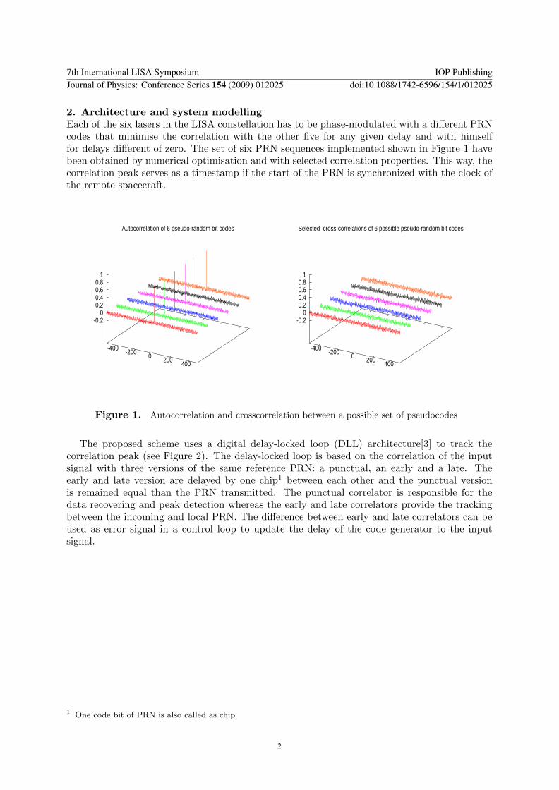
2. Architecture and system modellingEach of the six lasers in the LISA constellation has to be phase-modulated with a different PRNcodes that minimise the correlation with the other five for any given delay and with himselffor delays different of zero. The set of six PRN sequences implemented shown in Figure 1 havebeen obtained by numerical optimisation and with selected correlation properties. This way, thecorrelation peak serves as a timestamp if the start of the PRN is synchronized with the clock ofthe remote spacecraft.
-400 -200 0 200 400
-0.2 0
0.2 0.4 0.6 0.8
1
Autocorrelation of 6 pseudo-random bit codes
-400 -200 0 200 400
-0.2 0
0.2 0.4 0.6 0.8
1
Selected cross-correlations of 6 possible pseudo-random bit codes
Figure 1. Autocorrelation and crosscorrelation between a possible set of pseudocodes
The proposed scheme uses a digital delay-locked loop (DLL) architecture[3] to track thecorrelation peak (see Figure 2). The delay-locked loop is based on the correlation of the inputsignal with three versions of the same reference PRN: a punctual, an early and a late. Theearly and late version are delayed by one chip1 between each other and the punctual versionis remained equal than the PRN transmitted. The punctual correlator is responsible for thedata recovering and peak detection whereas the early and late correlators provide the trackingbetween the incoming and local PRN. The difference between early and late correlators can beused as error signal in a control loop to update the delay of the code generator to the inputsignal.
1 One code bit of PRN is also called as chip
7th International LISA Symposium IOP PublishingJournal of Physics: Conference Series 154 (2009) 012025 doi:10.1088/1742-6596/154/1/012025
2
Loop �lter
Code generator
C1-C2 punctual
C3 early
C4 late
C2 punctual
C1 puctual
Internal signal from PMS
C3 early
C4 late
Lock
Data
Delay- Locked Loop
Zoom
Zoom
Code rate = 1.5 Mhz
Data rate = 97 Khz
Length 1024 code bits1 code bit --> 32 samples
1 data bit --> 512 samples
Equivalent resolution 6 m
1 data bit --> 16 code bits
Sampling Frequency = 50 Mhz
Data Sequence
Pseudo-random noise Sequence
Complete pseudosequence (1024 code bits at 1.5 MHz) ---> 200 Km
Tdata = 10 µs
Tpscode = 640 ns
Ts = 20 ns
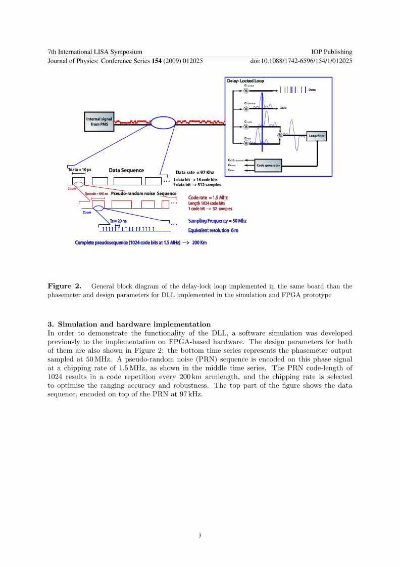
Figure 2. General block diagram of the delay-lock loop implemented in the same board than thephasemeter and design parameters for DLL implemented in the simulation and FPGA prototype
3. Simulation and hardware implementationIn order to demonstrate the functionality of the DLL, a software simulation was developedpreviously to the implementation on FPGA-based hardware. The design parameters for bothof them are also shown in Figure 2: the bottom time series represents the phasemeter outputsampled at 50 MHz. A pseudo-random noise (PRN) sequence is encoded on this phase signalat a chipping rate of 1.5 MHz, as shown in the middle time series. The PRN code-length of1024 results in a code repetition every 200 km armlength, and the chipping rate is selectedto optimise the ranging accuracy and robustness. The top part of the figure shows the datasequence, encoded on top of the PRN at 97 kHz.
7th International LISA Symposium IOP PublishingJournal of Physics: Conference Series 154 (2009) 012025 doi:10.1088/1742-6596/154/1/012025
3
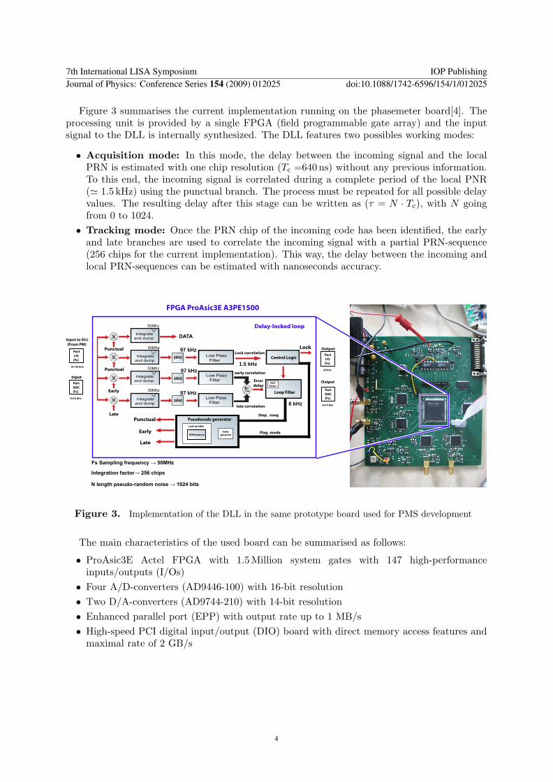
Figure 3 summarises the current implementation running on the phasemeter board[4]. Theprocessing unit is provided by a single FPGA (field programmable gate array) and the inputsignal to the DLL is internally synthesized. The DLL features two possibles working modes:
• Acquisition mode: In this mode, the delay between the incoming signal and the localPRN is estimated with one chip resolution (Tc =640 ns) without any previous information.To this end, the incoming signal is correlated during a complete period of the local PNR(' 1.5 kHz) using the punctual branch. The process must be repeated for all possible delayvalues. The resulting delay after this stage can be written as (τ = N · Tc), with N goingfrom 0 to 1024.• Tracking mode: Once the PRN chip of the incoming code has been identified, the early
and late branches are used to correlate the incoming signal with a partial PRN-sequence(256 chips for the current implementation). This way, the delay between the incoming andlocal PRN-sequences can be estimated with nanoseconds accuracy.
Port
I/O
(Fs)
FPGA ProAsic3E A3PE1500
|abs|
Low Pass
Filter
50Mhz
50Mhz
50Mhz 97Khz
Control Logic
Loop Filter
Pseudocode generator
DATA
Index
generator
Look-up table
ROM memory
Flag_mode
Step_ nseg
Error
delay
Punctual
Early
Late
Late
Early
Punctual
Punctual
Lock
Gain
Factor
Delay-locked loop
)V�6DPSOLQJ�IUHTXHQF\�:���0+]
,QWHJUDWLRQ�IDFWRU:�����FKLSV
1�OHQJWK�SVHXGR�UDQGRP�QRLVH�:������ELWV
input to DLL
(From PM)
Lock correlation
early correlation
late correlation
50Mhz
[4-16] bits
97Khz
|abs| 97Khz
|abs| 97Khz
6 Khz
1.5 Khz
Low Pass
Filter
Low Pass
Filter
Integrate
and dump
Port
I/O
(Fs)
Output
24 bits
Port
DAC
(Fs)
Output
2x14 bits
Integrate
and dump
Integrate
and dump
Integrate
and dump
Port
ADC
(Fs)
Input
4x16 bits
������������
������������
������������
������������
��������������������
��������������������
����������������
����������������
��������������������
��������������������
6 kHz
1.5 kHz
97 kHz
97 kHz
97 kHz
Figure 3. Implementation of the DLL in the same prototype board used for PMS development
The main characteristics of the used board can be summarised as follows:
• ProAsic3E Actel FPGA with 1.5 Million system gates with 147 high-performanceinputs/outputs (I/Os)• Four A/D-converters (AD9446-100) with 16-bit resolution• Two D/A-converters (AD9744-210) with 14-bit resolution• Enhanced parallel port (EPP) with output rate up to 1 MB/s• High-speed PCI digital input/output (DIO) board with direct memory access features and
maximal rate of 2 GB/s
7th International LISA Symposium IOP PublishingJournal of Physics: Conference Series 154 (2009) 012025 doi:10.1088/1742-6596/154/1/012025
4
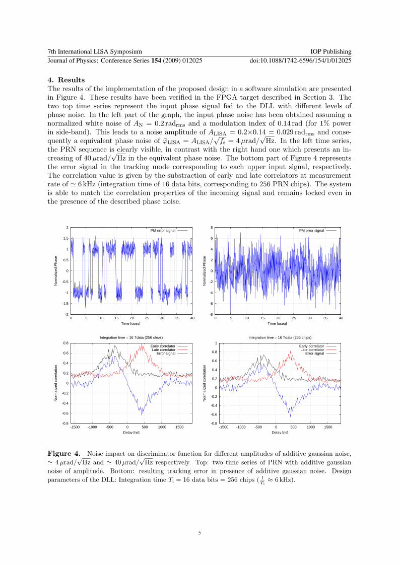
4. ResultsThe results of the implementation of the proposed design in a software simulation are presentedin Figure 4. These results have been verified in the FPGA target described in Section 3. Thetwo top time series represent the input phase signal fed to the DLL with different levels ofphase noise. In the left part of the graph, the input phase noise has been obtained assuming anormalized white noise of AN = 0.2 radrms and a modulation index of 0.14 rad (for 1% powerin side-band). This leads to a noise amplitude of ALISA = 0.2×0.14 = 0.029 radrms and conse-quently a equivalent phase noise of ϕLISA = ALISA/
√fs = 4µrad/
√Hz. In the left time series,
the PRN sequence is clearly visible, in contrast with the right hand one which presents an in-creasing of 40µrad/
√Hz in the equivalent phase noise. The bottom part of Figure 4 represents
the error signal in the tracking mode corresponding to each upper input signal, respectively.The correlation value is given by the substraction of early and late correlators at measurementrate of ' 6 kHz (integration time of 16 data bits, corresponding to 256 PRN chips). The systemis able to match the correlation properties of the incoming signal and remains locked even inthe presence of the described phase noise.
-2
-1.5
-1
-0.5
0
0.5
1
1.5
2
0 5 10 15 20 25 30 35 40
Nor
mal
ized
Pha
se
Time [useg]
PM error signal
-8
-6
-4
-2
0
2
4
6
8
0 5 10 15 20 25 30 35 40
Nor
mal
ized
Pha
se
Time [useg]
PM error signal
-0.8
-0.6
-0.4
-0.2
0
0.2
0.4
0.6
0.8
-1500 -1000 -500 0 500 1000 1500
Nor
mal
ized
cor
rela
tion
Delay [ns]
Integration time = 16 Tdata (256 chips)
Early correlatorLate correlator
Error signal
-0.8
-0.6
-0.4
-0.2
0
0.2
0.4
0.6
0.8
1
-1500 -1000 -500 0 500 1000 1500
Nor
mal
ized
cor
rela
tion
Delay [ns]
Integration time = 16 Tdata (256 chips)
Early correlatorLate correlator
Error signal
Figure 4. Noise impact on discriminator function for different amplitudes of additive gaussian noise,' 4µrad/
√Hz and ' 40µrad/
√Hz respectively. Top: two time series of PRN with additive gaussian
noise of amplitude. Bottom: resulting tracking error in presence of additive gaussian noise. Designparameters of the DLL: Integration time Ti = 16 data bits = 256 chips ( 1
Ti≈ 6 kHz).
7th International LISA Symposium IOP PublishingJournal of Physics: Conference Series 154 (2009) 012025 doi:10.1088/1742-6596/154/1/012025
5

5. ConclusionsThis paper presents an architecture based an a DLL for the implementation of optical rangingand inter-spacecraft data transmission for LISA. The proposed design can be implemented asback-end processing of the phasemeter. Its functionality has been tested in a software simulationand in a hardware implementation on the same board as our present phasemeter design.
The next steps include the evaluation of the performance with external phase signals and theintegration, together with the phasemeter, in a full optical ranging experiment.
6. References[1] Shaddock D, Ware B, Halverson P, Spero R, Klipstein B 2006 Overview of the LISA Phasemeter AIP Conf
Proc. 873 654-60[2] Wand V, Guzman F, Heinzel G, Danzmann K 2006 LISA Phasemeter Development AIP Conf Proc. 873
689-96[3] Misra P and Enge P 2nd Ed Global positioning system, signals, measurements, and performance Ganga-
Jamura Press[4] Bykov I, Esteban J.J, Garcıa Marın A.F, Heinzel G, Danzmann K 2008 LISA phasemeter development:
Advanced prototyping J. Phys.: Conf. Series. this issue
7th International LISA Symposium IOP PublishingJournal of Physics: Conference Series 154 (2009) 012025 doi:10.1088/1742-6596/154/1/012025
6
Copyright © 2022 FDOKUMEN