ASE Program Certification Standards for Automobile ... - ERIC
100
DOCUMENT RESUME ED 391 005 CE 070 532 TITLE ASE Program Certification Standards for Automobile Technician Training Programs. INSTITUTION National Automotive Technicians Education Foundation, Herndon, VA. PUB DATE 93 NOTE 97p.; For related training programs, see CE 070 533-535. PUB TYPE Guides - Classroom Use - Teaching Guid3s (For Teacher) (052) EDRS PRICE MFOI/PC04 Plus Postage. DESCRIPTORS Academic Education; *Auto Mechanics; *Certification; Engines; Entry Workers; Integrated Curriculum; *Job Skills; Occupational Information; Postsecondary Education; *Program Development; Program Implementation; Secondary Education; *Standards; Technical Education IDENTIFIERS National Institute Automotive Service Excellence ABSTRACT This publication provides the evaluation policies, procedures, and standards to which an automobile technician training program must adhere to be granted certification by the National Institute for Automotive Service Excellence. The policies section has three parts: the automobile areas that may be certified and minimum requirements for certification; information about evaluation teas leaders, on-site evaluation team members, task lists, tools and equipment, and automobile program evaluation; and discussion of policies on articulation agreements, recognition for certification, appeals and action for revocation. The procedures section provides an overview of the process for certification. The next section contains the 10 program standards in these areas: purpose, administration, learning resources, finances, student services, instruction, equipment, facilities, instructional staff, and cooperative agreements. The task list follows. Lists of assumptions and definitions are provided. The tasks are divided into the following: engine repair, automatic transmission and transaxle, manual drive train and axles, suspension and steering, brakes, electrical/electronic systems, heating and air conditioning, and engine performance. Lists are also provided of applied academics (language arts and communications, mathematics, science) and workplace skills. The final section lists tools and equipment, including hand tools, general lab/shop equipment, and specialty tools and equipment. (YLB)
-
Upload
khangminh22 -
Category
Documents
-
view
0 -
download
0
Transcript of ASE Program Certification Standards for Automobile ... - ERIC

DOCUMENT RESUME
ED 391 005 CE 070 532
TITLE ASE Program Certification Standards for Automobile Technician Training Programs.
INSTITUTION National Automotive Technicians Education Foundation, Herndon, VA.
PUB DATE 93 NOTE 97p.; For related training programs, see CE 070
533-535. PUB TYPE Guides - Classroom Use - Teaching Guid3s (For
Teacher) (052)
EDRS PRICE MFOI/PC04 Plus Postage. DESCRIPTORS Academic Education; *Auto Mechanics; *Certification;
Engines; Entry Workers; Integrated Curriculum; *Job Skills; Occupational Information; Postsecondary Education; *Program Development; Program Implementation; Secondary Education; *Standards; Technical Education
IDENTIFIERS National Institute Automotive Service Excellence
ABSTRACT This publication provides the evaluation policies,
procedures, and standards to which an automobile technician training program must adhere to be granted certification by the National Institute for Automotive Service Excellence. The policies section has three parts: the automobile areas that may be certified and minimum requirements for certification; information about evaluation teas leaders, on-site evaluation team members, task lists, tools and equipment, and automobile program evaluation; and discussion of policies on articulation agreements, recognition for certification, appeals and action for revocation. The procedures section provides an overview of the process for certification. The next section contains the 10 program standards in these areas: purpose, administration, learning resources, finances, student services, instruction, equipment, facilities, instructional staff, and cooperative agreements. The task list follows. Lists of assumptions and definitions are provided. The tasks are divided into the following: engine repair, automatic transmission and transaxle, manual drive train and axles, suspension and steering, brakes, electrical/electronic systems, heating and air conditioning, and engine performance. Lists are also provided of applied academics (language arts and communications, mathematics, science) and workplace skills. The final section lists tools and equipment, including hand tools, general lab/shop equipment, and specialty tools and equipment. (YLB)

ASE PROGRAM CERTIFICATION STANDARDS
Automobile
Administered By:
National Automotive Technicians Education Foundation (NATEF) 13505 Dulles Technology Drive, Suite 2
Herndon, VA 22071-3421(703) 713-0100
1993

ASE PROGRAM CERTIFICATION STANDARDS
FOR
AUTOMOBILE TECHNICIAN TRAINING PRC 3RAMS
Administered By:
National Automotive Technicians Education Foundation (NATEF) 13505 Dulles Technology Drive, Suite 2
Herndon, VA 22071-3421 (703) 713-0100
©1993

TABLE OF CONTENTS
Policies Automobile Technician Training Certification Program 1 Automobile Minimum Requirements 3 Information About Evaluation Team Leaders (ETLs) 5 Information About On-Site Evaluation Team Members 6 Task List Information 7 Tools And Equipment Information 8 Automobile Program Evaluation 9 NATEF Policies On Articulation Agreements 10 Recognition For Certification 13 Appeals And Action For Revocation 14
Procedures Process Overview 16 On-Site Evaluation Cost Sheet 19
Program Standards Standard 1 - Purpose 20 Standard 2 - Administration 20 Standard 3 - Learning Resources 21 Standard 4 - Finances 22 Standard 5 - Student Services 22 Standard 6 - Instruction 23 Standard 7 - Equipment 25 Standard 8 - Facilities 26 Standard 9 - Instructional Staff 27 Standard 10 - Cooperative Agreements 28
Task List Task List And Assumptions 29 Definitions 31 NATEF Task List 34
Engine Repair 34 Automatic Transmission And Transaxle 38 Manual Drive Train And Axles 42 Suspension And Steering 48 Brakes 53 Electrical/Electronic Systems 57 Heating And Air Conditioning 61 Engine Performance 65
Applied Academics and Workplace Skills 72 Language Arts & Communications 73 Mathematics 74 Science 77 Workplace Skills 82
Tools And Equipment Tools And Equipment 85 Hand Tools 86 General Lab/Shop Equipment 88 Specialty Tools And Equipment 89
Suspension And Steering 89 Brakes 90 Heating And Air Conditioning 90 Engine Performance 90 Automatic Transmission/Transaxle 91 Electrical/Electronic Systems 91 Manual Drive Train And Axles 91 Engine Repair 91

POLICIES
AUTOMOBILE TECHNICIAN TRAINING CERTIFICATION PROGRAM
The Board of the National Institute for Automotive Service Excellence (ASE) is the responsible body for the Automobile Technician Training Certification Program. ASE will grant certification to programs that comply with the evaluation procedure, meet established standards, and adhere to the policies in this document.
The Certification Program is under the direct supervision of the Board of Trustees of the National Automotive Technicians Education Foundation (NATEF) and such personnel who are designated or employed by the Foundation.
The purpose of the Automobile Technician Training Certification Program is to improve the quality of training offered at the secondary and post-secondary levels. NATEF does not endorse specific curricular materials nor provide instruction to individuals, groups or institutions. It does, however, set standards for the content of instruction which includes: tasks, tools and equipment, hours, and instructor qualifications.
The Program is a certification program only and it is n21 associated with the accreditation role of other agencies.
The cost to each program for certification will be as reasonable as possible to encourage program participation. This cost will include: self-evaluation materials, on-site team evaluation materials, and the honorarium and expenses of the Evaluation Team Leader (ETL).
The eight Automobile areas that may be certified are:
1.Brakes 2.Electrical/Electronic Systems 3.Engine Performance 4.Suspension and Steering 5.Automatic Transmission and Transaxle 6.Engine Repair 7.Heating and Air Conditioning 8.Manual Drive Train and Axles
Effective January 1, 1993, four areas are required for minimum certification. Three specified areas are required at this time: Brakes, Electrical/Electronic Systems, and Engine Performance. The fourth area may be any one of the remaining areas. However, effective January 1, 1996 Suspension and Steering will be required as the fourth area for any program applying for certification.

All programs due to recertify after January 1, 1993 are required to meet minimum requirements in the four designated areas of Brakes, Electrical/Electronic Systems, Engine Performance, and Suspension and Steering. However, any programs due to recertify between January 1993 and December 31, 1995 may have their certification extended until January 1, 1996, if needed, to provide sufficient time to meet the new requirements. Programs wishing an extension must submit a written request to NATEF.
Programs having difficulty in meeting certification requirements should consider the following options:
A) Initiating an Articulation Agreement with another secondary or post-secondary training institution (see NATEF Policies on Articulation Agreements).
B) Borrowing equipment needed for instruction from a manufacturer, dealership or independent repair shop.
C) Arranging for instruction on tasks requiring equipment not available in the school program at a dealership or independent repair shop.
Programs choosing option B or C are required to show documentation on where the tasks are taught, by whom, and how students are evaluated.

AUTOMOBILE MINIMUM REQUIREMENTS
1. The minimum program requirements are identical for initial certification and for recertification.
2. A program providing instruction in allof the automobile areas must have a minimum total of 1,080 hours of combined laboratory/shop (coop) and classroom instruction. Tasks related to the eight automobile areas may be taught at different times during the course of study. Therefore, the hours for an individual area would be the sum total of all the hours of instruction related to the tasks. Individual areas must have the following hours:
a.Brakes 100
b.Electrical/Electronic Systems 200
c.Engine Performance 260
d.Suspension & Steering 100
e.Automatic Transmission & Transaxle 120
f.Engine Repair 120
g.Heating & Air Conditioning 80
h.Manual Drive Train & Axles 1211
TOTAL HOURS 1,080
3. All eight areas are required for master certification designation.
4. The average rating on Standards 6, 7, 8, and 9 must be a four (4) on the five-point scale. The program will not be approved for an on-site evaluation if the average is less than 4 on those Standards. The program should make improvements before submitting the application to NATEF for review. A program will be denied certification if the on-mite evaluation team average on Standards 6, 7, 8, and 9 is less than four.
5. A program may not be approved for an on-site evaluation if the average rating on Standards 1 - 5 and 10 is less than a four (4) on the five-point scale. A program may be denied certification if the on-site evaluation team average on Standards 1 - 5 and 10 is less than four. Approval for on-site

evaluation or certification will be made by NATEF, based on the number of Standards rated at 4 or 5 as well as the individual rating on any Standard rated below 4.
6. Effective 1/1/95 for initial program certification, instructor(s) must hold current ASE certification in the automobile area(s) they are teaching. For recertification, instructors must be ASE certified in the area(s) they are teaching (current NATEF policy).
7. The program Advisory Committee must conduct at least two working meetings a year and have a minimum of 5 people on the committee. Minutes of the meetings must be provided for review by the on-site evaluation team.
8. The Task List is divided into three priority areas. The following guidelines must be followed:
95% of all Priority 1 (P-1) items must be taught in the curriculum.
80% of all Priority 2 (P-2) items must be taught in the curriculum.
50% of all Priority 3 (P-3) items must be taught in the curriculum.
9. A program that does not meet the minimum hour requirements may be eligible for certification if both of the following conditions are met in the program areas requesting certification:
a.show evidence that all graduates from the previous academic year have taken the ASE certification examination, and
b.show documentation that 75% of those graduates passed the ASE certification tests.
10. The concern for safety is paramount to the learning environment. Each program area has the following safety task preceding all related tasks:
Comply with personal and environmental safety practices associated with clothing, eye protection, hand tools, power equipment, and handling, storage, and disposal of chemicals in accordance with local, state, and federal safety and environmental regulations.

INFORMATION ABOUT EVALUATION TEAM LEADERS (ETLs)
Evaluation Team Leaders (ETLs) are educators who have been trained by NATEF to lead the on-site evaluation. The ETL will be assigned by the NATEF office once a program has been approved for an on-site evaluation. Every effort will be made to assign an ETL located closest to the school to reduce the cost for the evaluation. Three additional team members, selected by the program and approved by the ETL, are required for an automobile program on-eite evaluation. (See the following page for additional information about team members.)
Persons selected as ETLs must have:
1.a minimum of six years of combined experience as an automobile technician and automobile instructor (at least three years experience as an automobile technician is required),
2.a B.A. or B.S. in Education from a college or university recognized for teacher training by the state, and
3.ASE certification in All automobile areas (effective 1/1/95). *
If a state does not employ automobile instructors with the preceding requirements, the following qualifications will apply:
1.six years experience as an automobile technician, 2.four years automobile teaching experience at the secondary,
post-secondary or community college level, and 3.ASE certification in All automobile areas (effective
1/1/95). *
ETL training is valid for two years. However, automatic two-year renewal is granted every time an ETL conducts an on-site evaluation. ETLs are required to attend additional training sessions if they have not conducted an on-site evaluation in two years. This additional training is required even if the individual holds current ASE certification.
* Prior to 1/1/95, individuals who would like to become an ETL must hold ASE certification in a minimum of four automobile areas.
** Anyone interested in becoming an Evaluation Team Leader should contact the NATEF office at (703) 713-0100 or their State Supervisor for more details.

INFORMATION ABOUT ON-SITE EVALUATION TEAM MEMBERS
The program requesting certification is responsible for recruiting and recommending on-site evaluation team members. The ETL must approve individuals recommended by the program. The on-site evaluation team members must be practicing automobile technicians, service managers or shop owners from businesses in the area served by the training program. For initial certification only, one team member may be an automobile instructor from another school district/system.
Team members must have:
1.high school diploma or the equivalent (industry or military training may be considered as the equivalent), and
2.at least seven years full-time experience as a general automobile technician.
ASE automobile certification is recommended but not required.
An automobile instructor from another school district/system must have a minimum total of seven years experience. The seven years must include three or more years full-time experience as an automobile technician and three or more years of post high school training.
The initial certification evaluation team is composed of four individuals: the ETL and three team members. Two team members must be from industry (one from a dealership and one from an independent repair facility). The third member may be from one of the following: a dealership, an independent repair facility or from an automobile training program.
The recertification evaluation team is composed of three individuals: the ETL and two team members. One team member must be from a dealership and one team member must be from an independent repair facility.
Each program requesting initial certification or recertification must identify their choices for evaluation team members on the On-Site Evaluation Team Member List. An alternate team member choice must be identified on the On-Site Evaluation Team Member List in the event that one of the team members is unable to conduct the on-site evaluation. The alternate team member must be from either a dealership or from an independent repair facility.
Team members must not be advisory committee members, former instructors, or graduates of the program within the past ten years.

TASK LIST INFORMATION
An essential element of any curriculum or training program is a valid task list. Automobile technician instructors need a well-developed task list that serves as a solid base for course of study outlines and facilitates communication and articulation of their training programs with other institutions in the region.
It is NATEF policy that the task list developed by the National Institute for Automotive Service Excellence (ASE) serves as the basis for the NATEF task list. Panels of technical service experts from the automotive service industry and vocational education are called upon to develop and validate the ASE and NATEF task lists. The ASE task list is also used to develop the ASE certification examination, a nationally recognized symbol of competence in diagnosing and repairing vehicle problems. Additional information on the development of the NATEF task list can be found in the Task List section.
All tasks have a Priority designation.
Ninety-five percent (95%) of Priority 1 (P-1) items Must be taught in the curriculum. Eighty percent (80%) of Priority 2 (P-2) items must be taught in the curriculum. Fifty percent (50%) of the Priority 3 (P-3) items must be taught in the curriculum.

TOOLS AND EQUIPMENT INFORMATION
The basic tools and equipment that must be available for use in the automobile program are listed in the Tools and Equipmentsection. Many tools and much of the equipment are thu same for some or all of the program areas. However, some equipment is specialized and must be available for use in the selected program areas. These individual program area lists are included in the Tools and Equipment section.
The student hand tool list covers all program areas. This list indicates the tools a student will need to own to be successful in each of the specialty areas.
Although no brand names are listed, the equipment and tools must address the following programmatic issues:
1.Safety - Equipment and tools must have all shields, guards, and other safety devices in place and operable.
2.Type and Ouality - The tools and equipment used in a certified program must be of the type and quality found in industry. They must also be adequate and in sufficient quantity to meet the program goals and student performance objectives.
3.Consumable Supplies - Supplies should be in sufficient quantity to assure continuous instruction. Consumable supplies, such as solvents, sand paper, etc. are not listed.
4.Maintenance - Al preventative maintenance schedule should be used to minimize equipment down-time.
5.Replacement - A systematic schedule for replacement should be used to maintain up-to-date tools and equipment at industry and safety standards. Information gained from student program evaluations as well as advisory committee input should be used in the replacement process.
6.Inventory - An inventory system should be used to account for tools, equipment, parts, and supplies.
7.parts Purchasing - A systematic parts purchasing system should be used - from work order to supplier.
8.Rand Tools - Each student should be encouraged to purchase a hand tool set during the period of instruction.
9.Storage - Adequate storage of tools should be provided. Space for storage of the students' hand tools should be provided.

AUTOMOBILE PROGRAM EVALUATION
NATEF Standards for Initial Certification and Recertification are identical. Three items are critical for certification and are in bold print in the Automobile Program Self-Evaluation materials. These three items are:
2.5 A 6.5 A 7.1 A
Programs must be able to support a yes response for 2.5 A and 6.5 A. Programs must hold at least two working meetings of the Advisory Committee each year (2.5 A). In section 6.5 A, the programs must include the required percentage of the P-1, P-2, and P-3 tasks in the areas where certification is desired. Programs must also achieve a i on the 5-point scale on item 7.1 A. If these responses are not achieved, do not apply for certification at this time.
In addition, an on-site evaluation will not be scheduled unless the average score on Standards 6, 7, 8, and 9 is at least a 4 on the Automobile Program Self-Evaluation. Please refer to the Automobile Program Requirements for more information.

NATEF POLICIES ON ARTICULATION AGREEMENTS FOR ASE PROGRAM CERTIFICATION
In a number of states and localities technician training programs are able to meet ASE standards for certification only by establishing an articulation effort between secondary and post-secondary programs. Recent NATEF Trustee action, as well as language in the Carl D. Perkins Vocational Education Act, encourages articulation between programs at the secondary and post-secondary levels.
Articulation agreements encourage, but cannot require, graduates of secondary programs to go on to post-secondary education. Financial and social considerations suggest that many, perhaps most, graduates must seek employment upon graduation from high school.
Articulation agreements for Automobile, Autobody, and Medium/Heavy Truck technician training programs may involve two or more training centers at secondary and post-secondary levels or two programs at the secondary level. However, when programs articulate the following conditions must be met:
1.The minimum ASE specialty areas required in Automobile, Autobody, and Medium/Heavy Truck technician training programs must be included.
Automobile: Brakes, Electrical/Electronic Systems, Engine Performance, and Suspension & Steering.
Medium/Heavy Truck: Diesel Engines, Suspension & Steering, Brakes, Electrical/Electronic, and Preventive Maintenance Inspection.
Autobody: Structural Analysis & Damage Repair plus at least two of the following areas:
Non-Structural Analysis & Damage Repair, Mechanical & Electrical Components, Plastics & Adhesives, Painting & Refinishing
(Note: A program may be certified in Painting & Refinishing only and would not be required to have an articulation agreement.)
2.Automobile and Medium/Heavy Truck programs must have a minimum of IN2 required specialty areas to articulate with another program for ASE certification purposes.

3. Autobody programs must have Structural Analysis & Damage Repair and one of the four optional program areas to articulate with another program for ASE certification purposes.
** TEE SIGNED. COPY OF TEE ARTICULATION AGREEMENT MUST BE SUBMITTED IN EVERY CASE ALONG WITH THE
SELF-EVALUATION MATERIALS. **
4. The articulation agreement must be in writing and approved by the administration of both institutions. The agreement shall:
a. List the areas of instruction to be offered by each training center.
b. Stipulate how credit will be granted for successful completion of the instructional areas at each institution. This should also include the criteria for evaluating successful completion.
c. Describe procedures for applying for credit at the post-secondary level for instruction received at the secondary level.
5. WHEN TWO OR MORE CENTERS ARE TO BE EVALUATED AT THE SAME TIME
The procedures for submitting the self-evaluation materials and on-site team evaluation application are as follows:
a. Each training center in an articulation agreement shall conduct a self-evaluation for the specialty areas at their training center. The center requesting the largest number of specialty areas to be certified shall be designated the lead center. Ii the participating centers are requesting the same number of areas certified, they will select one center as the lead center. The lead center will be responsible for submitting All self-evaluation materials including a cover letter and a signed, copy of the articulation agreement.
b. When two or more centers under an articulation agreement are being evaluated at the same time they shall agree upon the selection of the on-site evaluation team members.
c. The NATEF office must be informed of the number of training centers and specialty areas being evaluated. The number of centers and areas being evaluated may require additional members or additional days to complete the evaluation.

d. The division of the local costs involved for the on-site evaluation is to be explained on the Application for On-Site Evaluation.
e. The curriculum for the articulated centers requesting certification shall be sent by the lead center to the Evaluation Team Leader assigned by NATEF.
6. WHEN ONE CENTER IS ALREADY CERTIFIED
The procedures for submitting the self-evaluation materials and on-site team evaluation application are as follows:
a. When a training center is entering into an articulation agreement with a center that is currently certified, the center that is not certified will submit the self-evaluation materials along with a signed, copy of the articulation agreement. The uncertified center will follow through with the total certification process.
b. The on-site evaluation team members will only evaluate the materials at the training center requesting certification.
c. The training center that is already certified will NOT be required to be evaluated until they are due to recertify their training program.
7. Articulated training centers may certify in one or more of the same specialty areas as long as they meet the minimum required areas jointly. For example, one automotive training center (Center A) may be certified in four or more areas, including the minimum required areas. The articulated automotive training center (Center B) may offer only two of the required areas. Center B would be eligible for certification only after articulating with Center A.
8. Each training center in an articulation agreement shall provide their graduates with a certificate identifying successful completion of instructional areas meeting ASE standards.
9. Certification shall be awarded for each articulated program. Each secondary and post-secondary program shall receive a plaque which will include specialty area plates only for instructional areas offered in their training center.
10. The certified plaque shall indicate the name of the training center and will include "articulated with training center". This will clearly indicate that a training center may be certified in fewer than the required areas only when it articulates with another training center.

RECOGNITION FOR CERTIFICATION
A program approved for certification will receive a plaque that bears the ASE seal and the school's name. Individual plates will be attached to the plaque to identify the areas in which the program is certified. These will also include the expiration date of certification. Any program certified in all eight areas will receive a Master Certification plaque. A statement below the seal will read:
"THE INSTRUCTION, COURSE OF STUDY, FACILITIES AND EQUIPMENT OF THIS INSTITUTION HAVE BEEN EVALUATED BY THE NATIONAL AUTOMOTIVE TECHNICIANS EDUCATION FOUNDATION AND MEET THE NATIONAL INSTITUTE FOR AUTOMOTIVE SERVICE EXCELLENCE STANDARDS OF QUALITY FOR THE TRAINING OF AUTOMOBILE TECHNICIANS IN THE FOLLOWING AREAS:
Institutions receiving ASE certification are encouraged to put on the graduate's diploma or certificate the following statement:
"The person holding this diploma has participated in an automobile technician training program that was certified by the National Institute for Automotive Service Excellence and has completed instruction in the following areas:
A screened ASE/NATEF logo may be overprinted with the above statement and placed on the graduate's diploma. A camera ready logo is provided in the promotional material a program receives upon certification.
A program approved for recertification will receive a brass plate which reads "RECERTIFIED Exp. 19 _ ".
Certified programs will also receive a 24"x30" sign indicating that the training program is ASE certified.

APPEAL!' AND ACTION FOR REVOCATION
APPEALS: PROGRAMS APPLYING FOR CERTIFICATION
A complaint received from any school concerning the procedures, evaluation or certification of the automobile technicians training program must be made in writing to the ASE office in Herndon, VA. It will be immediately referred to the Grievance Examiner who will acknowledge receipt of the complaint, in writing, to the complainants. Thereafter, the Grievance Examiner will investigate the complaint and prepare a report. A copy of the report will be given to the complainants and to an Appeals Committee within thirty (30) days of the receipt of the complaint.
The Appeals Committee will review the findings and recommendations of the Grievance Examiner, together with the complaint and any data supplied in connection therewith. The Appeals Committee will be empowered to dismiss the matter o to initiate such action as they may deem appropriate.
If the complainants desire to review the Appeals Committee's evaluation, they may do so at the office of the Grievance Examiner in Herndon, VA. However, they will not be permitted to make copies of the results.
ACTION FOR REVOCATION: ABE CERTIFIED PROGRAMS
The Appeals Committee will also advise the ASE President of its judgements and recommendations for action in any cases of malpractice or misrepresentation involving the misuse of ASE certification for an automobile technician training program. Upon receipt of a complaint alleging misuse or misrepresentation by a certified program, the Grievance Examiner will be notified. The Grievance Examiner will notify, in writing, the parties against whom the complaint has been filed, indicating the alleged wrongdoing. The parties will be further advised that they may submit a written explanation concerning the circumstances of the complaint within thirty (30) days. After the Grievance Examiner has considered the complaint and received the explanation, if any, the Grievance Examiner will determine whether there is a reasonable basis for a possible wrongdoing. If the Grievance Examiner finds such a basis, the Grievance Examiner will inform the parties of the findings. At that time, the Grievance Examiner will inform the parties of their right to a hearing before the Appeals Committee. The parties will have fifteen (15) days to notify the Grievance Examiner, in writing, of their decision.

In the event the involved parties elect to be bound by the findings of the Grievance Examiner without a hearing, the Grievance Examiner will submit a written report with recommendations to the Chairman of the Appeals Committee. This report will be submitted within sixty (60) days of the receipt of the waiver of a hearing. The Chairman of the Appeals Committee will mail a copy of the Grievance Examiner's findings and recommendations to the parties.
In the event that the involved parties elect to appear at a hearing, the Chairman of the Appeals Committee will call a Board of Inquiry. This Board will consist of four ASH Board members, one from each of the following categories: Education, Public Interest, Service Employers, and Vehicle and Service Products Manufacturers. The Board of Inquiry will be convened in Herndon, VA at a date and time determined by the Chairman. The Board will notify the involved parties, in writing, regarding the time and place of the hearing.
The Grievance Examiner will be responsible for investigating and presenting all matters pertinent to the alleged wrongdoing to the Board of Inquiry. The involved parties will be entitled to be at the hearings with or without counsel. The parties will be given an opportunity to present such evidence or testimony as they deem appropriate.
The Board of Inquiry will notify the Chairman of the Appeals Committee of its findings and recommendations, in writing, ten (10) days after the hearing is completed.
The Appeals Committee will review the findings and recommendations of either the Grievance Examiner if a hearing was waived or the Board of Inquiry if a hearing was held. The Appeals Committee will determine if the record on the complaint supports a finding of conduct contrary to or in violation of reasonable practices. If two-thirds of the Appeals Committee so find, the Committee will recommend to the President of ASE appropriate sanctions or courses of action against the parties charged.

PROCEDURES FOR CERTIFICATION/RECERTIFICATION
Process Overview
NOTE: NATEF recommends that programs maintain a file containing copies of all reference and documentation materials developed during all phases of the certification process.
1. Purchase application materials
The program requesting certification must purchase self-evaluation materials from NATEF in Herndon, VA. To begin the certification process, the program must return four items from the evaluation materials packet. These four items are:
a.Application for Certification or Recertification b.Self-Evaluation Summary Sheet c.On-site Evaluation Team Member List d.Instructor Qualifications Forms
2. NATE? review of application
The national office will review the materials within 30 days. Following the review, the program administrator and the state Trade & Industrial Supervisor will be notified about the status of the program. The program will be identified as one of the following:
a.qualified for on-site evaluation for all the specialty areas listed on the application.
b.qualified for on-site evaluation for some but not all specialty areas listed on the application. The program administrator may proceed with the on-site evaluation for the specialty areas that qualify at that time OR make improvements and resubmit the application at a later date.
c.not qualified for an on-site evaluation at that time. NATEF will indicate specific improvements that must be made before the on-site evaluation can be scheduled.
3. Evaluation Team Leader (ETL) assigned, program coordinator makes contacts
In cooperation with state officials, NATEF will assign an Evaluation Team Leader (ETL) to a program. NATEF will also send the program the Application for On-site Evaluation. With a legitimate reason, the program coordinator can contact the NATEF office to request a different ETL. (The ETL assigned must NOT be a present or former teacher or administrator of the program to be evaluated.) The program coordinator must contact the ETL to arrange a date for the on-site evaluation.

The Application for the On-site Evaluation will be sent with instructions that outline the plans for the local administration and the costs for the ETL's services and expenses. These costs will be paid by the institution requesting certification.
4. Sand on-site application, check, course of study, and list of on-site evaluation team members to ETL
The Application for On-site Evaluation must be sent to the ETL, signed by the program administrator, and accompanied by a check to cover the costs of materials for the on-site evaluation team members. A copy of the course of study and this application must be received by the ETL at least two weeks prism to the on-site evaluation or the on-site must be rescheduled. The course of study should include the following items:
a.syllabus for each class b.tasks to be taught under each area, specified according to
High Priority designations (P-1, P-2, P-3) c.number of contact hours for each area (Tasks may be taught
at different times in the program or in more than one area. However, the hours for the tasks may be counted only once.)
d. areas and sequence of instruction to be included in the program
e.list of training materials and audio-visual materials used in training
f.sample evaluation form used to track student progress
Include the On-site Evaluation Team Member List for the ETL to review and approve. Once a date has been set and the on-site evaluation team members have been approved by the ETL, the program coordinator must contact the on-site evaluation team members to make arrangements for the evaluation day(s).
5. On-site evaluation
Initial certification requires 2 consecutive days, while students are in class, for the on-site evaluation review of all the Standards. However, if more than one program is applying for certification (general automotive and Ford ASSET, for example), additional team members and additional days may be required to complete the on-site evaluation. The need for additional team members and/or days will be determined by the NATEF office.
Recertification requires ;-day on-site evaluation, while students are in class, and Standards 6-9 are reviewed by the on-site evaluation team. However, if the Advisory Committee average on Standards 1-5 or Standard 10 was less than 4, these Standards must be reviewed by the on-site evaluation team. The NATEF office will determine whether an additional day or additional team members will be required to complete the evaluation.

6.ETL reports results to NATEF
The ETL will submit all on-site evaluation materials and a final report to NATEF with a recommendation for or against program certification.
7.Program certification
The national office will review the final report and all additional evaluation materials to determine whether the program meets the requirements for certification and will make their recommendation to the ASE Board. The ASE President, however, will approve certification as sanctioned by the Board of Trustees.
Programs that do not earn certification will be given a written report specifying improvements that must be made to qualify for certification. The decision at the national level will be final unless appealed to the ASE Board of Trustees. Appeals will be heard only at regular meetings of the Board.
The program administrator and the state Trade & Industrial Supervisor will be notified of all decisions regarding the certification status of all programs applying for ASE certification.
8.Display and reporting of certification materials
A wall plaque identifying the certified areas will be forwarded from the national office to the program administrator. Schools must accurately report areas of ASE certification.
9.Certified Automobile Technician Training List
The NATEF office maintains a current listing of all ASE certified programs. The list is made available upon request.
10.Compliance report
A program will be certified for five years. A compliance report is required after 2M years. The compliance report will be used to verify that a program is maintaining its standards. NATEF will notify the program administrator of the compliance date and will send the appropriate compliance review forms at that time. The program administrator must complete the forms and return them to the NATEF office.
11.Recertification
The NATEF office will contact the program coordinator six (6) months prior to the certification expiration date. The program must formally request recertification materials and follow the process outlined above.

On-site Evaluation Cost Sheet Effective April 1, 1995
AUTOMOBILE
CERTIFICATION RECERTIFICATION
Certification Manuals $60.00 $50.00 (Applied Academics general statements and workplace skills list are included)
On-site Evaluation Team Manuals (minimum of 4 sets for initial cert. 160.00 120.00 and 3 sets for recert. @ $40 each.)
Honorarium for Evaluation Team Leader (ETL) $175/day 350.00 175.00
Estimated mileage, hotel and meal expenses for the ETL 150.00 100.00
ESTIMATED TOTAL COSTS $720.00 $445.00
NOTE: It is anticipated that team members recruited from local independent repair facilities and dealerships will serve without charge to the institution.

AUTOMOBILE PROGRAM STANDARDS
STANDARD 1 - PURPOSE
THE AUTOMOBILE TEMICIAN TRAINING PROGRAM SHOULD HAVE CLEARLY STATED PROGRAM GOALS, RELATED TO THE NEEDS OF THE STUDENTS AND EMPLOYERS SERVED.
Standard 1.1 - Employment Potential The employment potential for automobile technicians, trained
to the level for the specialty or general areas outlined in the program goals, should exist in the geographic area served by the program.
Standard 1.2 - Program Description/Goals The written description/goals of the program should be shared
with potential students and must include admission requirements, employment potential, area(s) of specialty training offered, and the cost of all tuition and fees. Technical qualifications of the faculty and the overall goal(s) of the program should also be included.
STANDARD 2 - ADMINISTRATION
PROGRAM ADMINISTRATION SHOULD ENSURE THAT INSTRUCTIONAL ACTIVITIES SUPPORT AND PROMOTE THE GOALS OF THE PROGRAM.
Standard 2.1 - Student Competency Certification The certificate or diploma a student receives upon program
completion should clearly specify the area(s) of demonstrated competency.
Standard 2.2 - Chain of Command An organizational chart should be used to indicate the
responsibilities for instruction, administration, and support services.
Standard 2.3 - Administrative Support Positive administrative support from institutional and local
governing bodies should be demonstrated. Indicators of administrative support would include: support for staff in-service training; provision of appropriate facilities; up-to-date tools, equipment, and training support materials.
Standard 2.4 - Written Policies Written policies should be adopted by the administration and
policy board for use in decision-making situations and to provide guidance in achieving the program goals Policies regarding

safety, liability, and lab/shop operation should be written and prominently displayed as well as provided to all students and instructors.
Standard 2.5 - Advisory Committee An Advisory Committee must convene at least two times a year
and be utilized to provide counsel, assistance, and information from the community served by the training program. This Committee should be broadly based and include former students, employed technicians, employers, and representatives for consumer's interests.
Standard 2.6 - Public/Community Relations An organized plan should be used to provide the community at
large information regarding the training program, its graduates, its plans, and any services provided to the community.
Standard 2.7 - Live Work A systematic method of collecting, documenting, and disbursing
live work repair receipts should be used. Instructional staff should not be required to collect payment for live work repairs.
STANDARD 3 - LEARNING RESOURCES
SUPPORT MATERIAL, CONSISTENT WITH BOTH PROGRAM GOALS AND PERFORMANCE OBJECTIVES, SHOULD BE AVAILABLE TO STAFF AND STUDENTS.
Standard 3.1 - Service Information Service information with current manufacturers' service
procedures and specification data for vehicles manufactured within the last ten (10) years should be available. This information should be accessible to students while working in the lab/shop area.
Standard 3.2 - Multimedia Appropriate up-to-date multimedia materials such as video
equipment, transparencies, etc. should be readily available and utilized in the training process.
Standard 3.3 - Instructional Development Services The service of professional instructional development
personnel should be used when available. At a minimum, equipment and supplies should be available for duplication or copying printed materials and transparencies. Instructional development personnel should conduct in-service and/or training in curriculum and media development.
Standard 3.4 - Periodicals Current general and technical automobile magazines and
newspapers should be available for student and instructor use.

Standard 3.5 - Student Materials Necessary instructional texts or pertinent material should be
available for each student to satisfy the objectives of the mode of instruction used. Basic textbooks should have copyright dates that are not over six (6) years old; specialized textbooks should have copyright dates that are not over six (6) years old.
STANDARD 4 - FINANCES
FUNDING SHOULD BE PROVIDED TO MEET THE PROGRAM GOALS AND PERFORMANCE OBJECTIVES.
Standard 4.1 - Program Training Cost The enrollment in the program or program area should be
sufficient to keep the per-student training costs to a realistic figure.
Standard 4.2 - Budget An adequate annual budget should be developed, allocated, and
used for the operation of the program.
Standard 4.3 - Budget Preparation The budget should be prepared by the institutional
administration in conjunction with the program faculty.
Standard 4.4 - Status Reports Budget status reports should be made available to program
staff, at least quarterly.
STANDARD 5 - STUDENT SERVICES
SYSTEMATIC PRE-ADMISSION TESTING, INTERVIEWS, COUNSELING SERVICES, PLACEMENT, AND FOLLOW-UP PROCEDURES SHOULD BE USED.
Standard 5.1 - Pretesting A formal pretesting program should be used to assess a
student's abilities in reading, mathematics, and mechanical aptitude to evaluate and assure the student a reasonable probability of success as an automobile technician. Testing procedures should be stated in program explanatory material and justification for all requirements should be available.
Standard 5.2 - Pre-admission Interviews Prior to program admission, a student should be interviewed
and approved for admission.
Standard 5.3 - Student Records Permanent records of former students should be available,
preferably in one central location, and kept confidential.

Standard 5.4 - Placement A systematic student placement system should be used to assist
program graduates to obtain employment in the automobile industry.
Standard 5.5 - Follow-up A follow-up system should be used to determine students'
employment location and for feedback regarding the efficiency, effectiveness, and appropriateness of training. The follow-up procedure should be designed to assure feedback regarding needed additions or deletions to the training curriculum, program, and tools and equipment. Follow-up of graduates employed outside of the automobile industry should indicate reasons for non-automobile employment. When applicable, this information should be used to modify the training quality and/or content.
Standard 5.6 - Legal Requirements The training program should meet all applicable local, state,
and federal requirements.
STANDARD 6 - INSTRUCTION
INSTRUCTION MUST BE SYSTEMATIC AND REFLECT PROGRAM GOALS. A TASK LIST AND SPECIFIC PERFORMANCE OBJECTIVES WITH CRITERION REFERENCED MEASURES MUST BE USED.
Standard 6.1 - Program Plan The training plan should progress in logical steps, provide
for alternate sequences, where applicable, and be made available to each student.
Standard 6.2 - Student Training Plan A training plan for each student should be used, indicating
the student's training goal(s) and specific steps needed to meet that goal. Students should be given a copy of their training plan.
Standard 6.3 - Preparation Time Adequate time should be provided for teacher preparation and
program development.
Standard 6.4 - Teaching Load The instructor/student ratio and class contact hours should
allow time for interaction on a one-to-one basis.
Standard 6.5 - Curriculum All tasks have been given a priority rating. Ninety-five
percent (95%) of the tasks designated as Priority 1 (P-1) must be taught in the curriculum. Eighty percent (80%) of the tasks designated as Priority 2 (P-2) must be taught in the curriculum. Fifty percent (50%) of the tasks designated as Priority 3 (P-3)

must be taught in the curriculum. Additional tasks may be included to meet the needs of local employers. All additional tasks should be approved by the Advisory Committee.
Instruction on the legal aspects and responsibilities of the automobile technician in areas such as Environmental Protection Agency regulations, safety regulations, OSHA regulations, and other appropriate requirements should be included in the curriculum. Instruction and practice in filling out work order forms, ordering parts, and basic record keeping should be a part of the training program.
Tools and equipment must be available to perform the tasks in each of the areas for which certification is requested.
Standard 6.6 - Student Progress A record of each student's progress should be maintained
through the use of a progress chart or other recording device. The record should indicate tasks required for mastery in the area and those tasks the student has mastered.
Standard 6.7 - Performance Standards All instruction should be performance based, with an
acceptable performance standard stated for each task. These standards should be shared with students and potential employers. Students should demonstrate "hands-on competency" or "mastery" of a task before the instructor verifies a student's performance.
Standard 6.8 - Safety Standards Safety instruction should be given prior to lab/shop work and
be an integral part of the training program. A safety test should be included in the training program. Students and instructors should comply with personal and environmental safety practices associated with clothing, eye protection, hand tools, power equipment, and handling, s:orage, and disposal of chemicals while in the lab/shop area.
Standard 6.9 - Personal Characteristics All training activities and instructional material should
emphasize the importance of maintaining high personal standards.
Standard 6.10 - Work Habits/Ethics The training program should be organized in such a manner that
work habits and ethical practices required on the job are an integral part of the instruction.
Standard 6.11 - Provision for Individual Differences The training program should be structured in such a manner
that students with different levels of cognitive and psychomotor skills can be accommodated.

Standard 6.12 - Related Instruction Instruction in related mathematics, communication, and
interpersonal relations should be provided and coordinated with ongoing instruction in the training program. This instruction should be provided by a qualified instructor.
Standard 6.13 - Testing Both written and performance based tests should be used to
validate student competency. Students should be encouraged to take certification tests that are publicly recognized indicators of capabilities.
Standard 6.14 - Evaluation of Instruction Instructional procedures should be evaluated in a systematic
manner. This evaluation should be through regular reviews by students and the administration. Self-evaluation of instruction should also be utilized on a systematic and regular basis. This system should include input from former students and the Advisory Committee members. Instructional procedures should show a responsiveness to the feedback from these evaluations.
Standard 6.15 - Live Work Live work should be scheduled to benefit the student and
supplement ongoing instruction on items specified in the NATEF task list. A student should have had instruction and practice on a specific repair task before live work requiring that task is assigned. Donated vehicles by the manufacturers or other sources, customer-owned vehicles, and other training vehicles may be used as the primary source of live work. Automobile training program student-owned vehicles, school buses, and other vehicles owned and operated by the governing body of the school should not be the primary source of live work vehicles. All vehicles in the lab/shop should have a completed industry-type work order attached to or on the vehicle.
Standard 6.16 - Articulation Agreements between programs with equivalent competencies
should be used to eliminate unnecessary duplication of instruction.
STANDARD 7 - EQUIPMENT
EQUIPMENT AND TOOLS USED IN THE AUTOMOBILE TECHNICIAN TRAINING PROGRAM MUST BE OF TEE TYPE AND QUALITY FOUND IN TEE REPAIR INDUSTRY AND MUST ALSO BE TEE TYPE NEEDED TO PROVIDE TRAINING TO MEET THE PROGRAM GOALS AND PERFORMANCE OBJECTIVES.
Standard 7.1 - Safety Equipment and tools used in the training program must have all
shields, guards, and other safety devices in place, operable, and used.

Standard 7.2 - Quantity and Quality The tools and equipment used in the training program should
reflect the program goals and performance objectives. Sufficient tools and equipment should be available for the training offered. The tools and equipment should meet industry quality standards.
Standard 7.3 - Consumable Supplies Sufficient consumable supplies should be readily available to
assure continuous instruction.
Standard 7.4 - Maintenance A preventive maintenance schedule should be used to minimize
equipment down-time.
Standard 7.5 - Replacement A systematic schedule for replacement should be used to
maintain up-to-date tools and equipment at industry and safety standards. Student follow-up and Advisory Committee input should be used in this system.
Standard 7.6 - Inventory An inventory system should be used to account for tools,
equipment, parts, and supplies.
Standard 7.7 - Parts Purchasing A systematic parts purchasing system, from work order to parts
specialist to jobber, should be used. Task performance should not be unreasonably delayed due to lack of replacement parts.
Standard 7.8 - Hand Tools Each student should have a basic hand tool set comparable to
tools required for employment. The students should be encouraged to purchase a hand tool set during the period of instruction, appropriate to the automobile specialty area(s) in which they are receiving training.
STANDARD 8 - FACILITIES
TEE PHYSICAL FACILITIES MUST BE ADEQUATE TO PERMIT ACHIEVEMENT OF THE PROGRAM GOALS AND PERFORMANCE OBJECTIVES.
Standard 8.1 - Training Stations Training stations (bench and live work) should be available in
the type and number required for the performance of tasks outlined in the program goals and performance objectives.
Standard 8.2 - Safety The facilities should meet all applicable safety standards.

Standard 8.3 - Maintenance A regular facilities maintenance program should be used to
ensure facilities are suitable when required for instruction.
Standard 8.4 - Housekeeping The classroom(s), lab/shop, and support area(s) should be kept
clean and orderly.
Standard 8.5 - Office Space An area separate from the lab/shop should be available and
convenient for the instructor(s) use as an office.
Standard 8.6 - Instructional Area A classroom convenient to, but separate from, the lab/shop
area should be available for instruction and other non-lab/shop activities.
Standard 8.7 - Storage Storage areas for tools, parts, supplies, and automobiles
should be sufficient to support the activities outlined in the program goals and performance objectives. Security should be provided to prevent pilferage, and vandalism.
Standard 8.8 - Support Facilities Restrooms, clean-up areas, and lockers should be provided for
both male and female students and be convenient to the instructional area.
Standard 8.9 - Ventilation An adequate exhaust fume removal system should be in place and
operational. When appropriate, heating and cooling systems should be used to provide sufficient comfort for learning.
Standard 8.10 - First Aid A first aid kit should be in place and comply with local
regulations.
Standard 8.11 - Facility Evaluation The Advisory Committee should conduct an annual evaluation of
the facilities to assure adequacy to meet program goals.
STANDARD 9 - INSTRUCTIONAL STAff
THE INSTITUTIONAL STAFF MUST HAVE TECHNICAL COMPETENCY AND MEET ALL STATE AND LOCAL REQUIREMENTS FOR CERTIFICATION.
Standard 9.1 - Technical Competency The instructor must hold current ASE certification in the
specialty area considered for certification (effective 1/1/95).

Standard 9.2 - Instructional Competency/Certification Instructors should meet all state certifying requirements.
Standard 9.3 - Technical Updating Faculty members should be provided technical materials
required to maintain their competency. An opportunity should be provided for instructors to return to industry on a regular basis for in-service and skill upgrading.
Standard 9.4 - First Aid The program should have a written policy, approved by the
administrator of the school, on First Aid procedures.
Standard 9.5 - Substitutes A systematic method of obtaining "substitute" instructors
should be used to assure instructional continuity. An orientation session for substitutes should be held on a regular basis. The substitute should be a competent automobile instructor.
STANDARD 10 - COOPERATIVE AGREEMENTS
WRITTEN POLICIES AND PROCEDURES SHOULD BE USED FOR COOPERATIVE AND APPRENTICESHIP TRAINING PROGRAMS.
Standard 10.1 - Standards Student performance standards should be developed and
coordinated by the supervising instructor.
Standard 10.2 - Agreements All agreements should be written and legally binding.
Standard 10.3 - Supervision A supervising automobile instructor should be assigned
responsibility, authority, and time to coordinate and monitor cooperative/apprenticeship automobile programs.

TASK UST AND ASSUMPTIONS
The NATEF task list was reviewed and updated in 1993 with funding from a grant awarded by the U.S. Department of Education. In June 1993, a national committee was assembled in Herndon, Virginia to review the standards used in the Automobile certification program. The committee consisted of individuals representing the major automobile manufacturers, automobile repair shop owners and technicians, automobile instructors, automobile equipment and parts suppliers, and state and local Technical and Industrial education supervisors.
The committee reviewed the standards, task list, tools and equipment list, program hours, and instructor qualifications. The committee also had the most current National Institute for Automotive Service Excellence (ASE) automobile task lists for reference purposes.
All the tasks are assigned a priority number: P-1, P-2 or P-3. Please refer to the Task List Information in the Policies section for additional information on the requirements for instruction on tasks.
Theory instruction and hands-on performance of all the basic tasks will provide initial training for employment in the automotive service field or further training in any or all of the specialty areas. Competency in the tasks will indicate to employers that the graduate is skilled in that area.
1. It is assumed:
that in all areas, appropriate theory, safety, and supportinstruction will be required for performing each task; that this instruction has included identification and use of appropriate tools and testing and measurement equipment required to accomplish certain tasks; that the student has received the necessary training to locate and use current reference and training materials from accepted industry publications.
2. It is assumed:
that all diagnostic and repair tasks described in this document are to be accomplished in accordance with manufacturer's recommended procedures as published.

3. It is assumed:
that individual training programs being evaluated for certification should have written and detailed performance standards for each task covered and taught in the curriculum; that learning progress of students will be monitored and evaluated against these performance standards; that a system is in place which informs all students of their individual progress through all phases of the training program.
4. It is assumed:
that individual courses of study will differ across automobile technician training programs; that development of appropriate learning delivery systems and tests which monitor student progress will be the responsibility of the individual training program.
5. It is assumed:
that all students will receive instruction in the storage, handling, and use of Hazardous Materials as required in Hazard Communication Title 29 Code of Federal Regulation Part 1910.1200, "Right to Know Law".

DEFINITIONS
ADD - To increase fluid or pressure to the correct level or amount.
ADJUST - To bring components to specified operational settings.
AIR TEST - To use air pressure to determine proper action of components.
ALIGN - To bring to precise alignment or relative position of components.
ANALYZE - To examine the relationship of components of an operation.
ASSEMBLE (REASSEMBLE) - To fit together the components of a device.
BALANCE - To establish correct linear, rotational or weight relationship.
BLEED - To allow air fluids to enter or exit a closed system.
CHARGE - To bring to "full" state; e.g., battery or air conditioning system.
CHECK - To verify condition by performing an operational or comparative examination.
CLEAN - To rid component of extraneous matter for the purpose of reconditioning, repairing, measuring or reassembling.
DETERMINE - To establish the procedure to be used to effect the necessary repair.
DIAGNOSE - To locate the cause or nature of a problem by using the specified procedure.
DISASSEMBLE - To separate a component's parts as a preparation for cleaning, inspection or service.
DISCHARGE - To empty a storage device or system.
DRAIN - To use gravity to empty a container.
EVACUATE - To remove air, fluid or vapor from a closed system by use of a vacuum pump.
FILL (REFILL) - To bring fluid level to specified point or volume.

FIND - To locate a particular problem, e.g., shorts, grounds or opens in an electrical circuit.
FLUSH - To use a fluid to clean an internal system.
HONE - To restore or resize or bore by using rotating cutting stones.
IDENTIFY - To establish the identity of a vehicle or component prior to service; to determine the nature or degree of a problem.
INSPECT - (SEE CHECK)
INSTALL (REINSTALL) - To place a component in its proper position in a system.
JUMP START - To use an auxiliary power supply, i.e., battery, battery charger, etc. to assist a car's battery to crank an engine.
LEAK TEST - To locate the source of leaks in a component or system.
LISTEN - To use audible clues in the diagnostic process; to hear the customer's description of a particular problem.
LUBRICATE - To employ the correct procedures and materials in performing the prescribed lubrication service.
MEASURE - To compare existing dimensions to specified dimensions by the use of calibrated instruments and gauges.
MOUNT - To attach or place tool or component in proper position.
PRESSURE TEST - To use air or fluid pressure to determine the condition or operation of a component or system.
PERFORM - To accomplish a procedure in accordance with established methods.
PURGE - To eliminate a undesired air or fluid from a closed system.
READY - To prepare a system or component for service, installation or operation.
REASSEMBLE - (SEE ASSEMBLE)
REFILL - (SEE FILL)
REINSTALL - (SEE INSTALL)
REMOVE - To disconnect and separate a component from a system.

REPAIR - To restore a malfunctioning component or system to operating condition.
REPLACE - To exchange an unserviceable component with a new or rebuilt component; to reinstall a component.
RESET (SET) - To adjust a variable component to a given, usually initial, specification.
SELECT - To choose the correct part or setting during assembly or adjustment.
SERVICE - To perform a specified procedure when called for in the owner's or service manual.
TEST - To verify condition through the use of meters, gauges or instruments.
TRIM - (SEE ADJUST)
TORQUE- To tighten a fastener to specified degree or tightness (in a given order or pattern if multiple fastener are involved on a single component).
VACUUM TEST - To determine the integrity and operation of a vacuum operated component and/or system.
VERIFY - To establish that a problem exists after hearing the customer's complaint and performing a preliminary diagnosis.

Task List Priority item Totals (by area)
I. Engine Repair
P-1 = 5 P-2 = 32 P-3 = 23
II. Automatic Transmission and Transaxle
P-1 = 2 P-2 = 28 P-3 = 13
III. Manual Drive Train and Axles
P-1 = 1 P-2 = 52 P-3 = 18
IV. Suspension and Steering
P-1 = 8 P-2 111 36 P-3 = 17
V. Brakes
P-1 = 8 P-2 = 37 P-3 = 4
VI. Electrical/Electronic Systems
P-1 = 7 P-2 = 24 P-3 = 11
VII. Heating and Air Conditioning
P-i = 5 P-2 = 25 P-3 = 10
VIII. Engine Performance
P-1 = 4 P-2 = 64 P-3 = 1

NATEF TASK UST
ENGINE REPAIR
for every task in Engine Repair the following safety task must be strictly enforced as a nuiber 1 priority:
Copply with personal and environmental safety practices associated with clothing, eye protection, hand tools, power equipment and handling, storage and disposal of chemicals in accordance with local, state, and federal safety and environmental regulations.
I. ENGINE REPAIR
A. General Engine Diagnosis; Removal and Reinstallation (R R)
1.Interpret and verify complaint; determine P-2 needed repairs.
2.Inspect engine assembly for fuel, oil, P-2 coolant, and other leaks; determine needed repairs.
3.Listen to engine noises; determine needed P-2 repairs.
4.Diagnose the cause of excessive oil P-2 consumption, unusual engine exhaust color, odor, and sound; determine needed repairs.
5.Perform engine vacuum tests; determine P-3 needed repairs.
6.Perform cylinder power balance tests; P-2 determine needed repairs.
7.Perform cylinder compression tests; P-2 determine needed repairs.
8.Perform cylinder leakage tests; determine P-1 needed repairs.
9.Remove engine (front-wheel drive); prepare P-3 for tear down.
10.Reinstall engine (front-wheel drive). P-3

11. Remove engine (rear-wheel drive); prepare P-3 for tear down.
12. Reinstall engine (rear-wheel drive). P-3
I. ENGINE REPAIR
B. Cylinder Read and Valve Train Diagnosis and Repair
1. Remove cylinder head(s); inspect cylinder P-2 head(s) for cracks; gasket surface areas for warpage and leakage; check passage condition.
2. Install cylinder head(s) and gasket(s). P-2
3. Inspect and test valve springs for P-2 squareness, pressure, and free height comparison; replace as needed.
4. Inspect valve spring retainers, locks, P-3 and valve grooves.
5. Replace valve stem seals. P-2
6. Inspect valve guides for wear; check P-2 valve guide height and stem-to-guide clearance; recondition or replace as needed.
7. Inspect valves; resurface or replace. P-3
8. Inspect valve seats; resurface or replace. P-3
9. Check valve face-to-seat contact and valve P-3 seat concentricity (runout); service seats and valves as needed.
10. Check valve spring assembled height and P-3 valve stem height; service valve and spring assemblies as needed.
11. Inspect pushrods, rocker arms, rocker arm P-2 pivots and shafts for wear, bending, cracks, looseness, and blocked oil passages; repair or replace.
12. Inspect hydraulic or mechanical lifters; P-2 replace as needed.
13. Adjust valves (mechanical or hydraulic P-2 lifters).

14. Inspect and replace camshaft drives P-2 (including gear wear and backlash, sprocket and chain wear, overhead cam drive sprockets, drive belts, belt tension, and tensioners).
15. Inspect and measure camshaft journals P-3 and lobes. 16. Inspect and measure camshaft bearings P-3
for damage, out-of-round, and alignment; determine needed repairs.
I. ENGINE REPAIR
C. Engine Block Diagnosis and Repair
1. Inspect and replace pans, covers, gaskets, P-3 and seals.
2. Inspect engine block for cracks, passage P-3 condition, core and gallery plug condition, and surface warpage; surface block or determine needed repairs.
3. Inspect internal and external threads; P-1 repair as needed.
4. Remove cylinder wall ridges. P-3
5. Inspect and measure cylinder walls for P-2 damage and wear; determine needed repairs.
6. Deglaze and clean cylinder walls. P-2
7. Inspect and measure camshaft bearings for P-3 wear damage, out-of-round, and alignment; determine needed repairs.
8. Inspect crankshaft for surface cracks and P-3 journal damage; check oil passage condition; measure journals; service crankshaft or determine needed repairs.
9. Inspect and measure main and connecting rod P-2 bearings for damage, clearance, and end play; determine needed repairs (includes the proper selections of bearings).

10. Identify piston and bearing wear patterns P-3 that indicate connecting rod alignment and main bearing bore problems; inspect rod alignment and bearing bore condition. 11. Inspect, measure, service or replace P-2
pistons. 12. Inspect, measure, and install piston P-2
rings.
13. Inspect, repair or replace crankshaft P-3 vibration damper (harmonic balancer).
14. Inspect flywheel or flexplate and ring P-3 gear for cracks and wear; measure runout; determine needed repairs.
15. Inspect, remove, and replace crankshaft P-2 pilot bearing or bushing (as applicable).
16. Reassemble engine components using correct P-2 gaskets and sealants.
17. Inspect auxiliary (balance, intermediate, P-3 idler, counterbalance or silencer) shaft(s); inspect shaft(s) and support bearings for damage and wear; determine needed repairs; reinstall and time.
18. Prime engine lubrication system. P-2
I. =GINN IMPAIR
D. Lubrication and Cooling Systems Diagnosis and Repair
1. Perform oil pressure tests; determine P-2 needed repairs.
2. Inspect oil pump gears or rotors, housing, P-3 pressure relief devices, and pump drive; replace as needed.
3. Perform cooling system tests (pressure, P-1 combustion leakage, and temperature); determine needed repairs.
4. Inspect, replace, and adjust drive belts P-1 and pulleys.
5. Inspect and replace engine cooling and P-2 heater system hoses.

6. Inspect, test, and replace thermostat P-2
and housing.
7. Inspect coolant; drain, flush, refill, P-2 and bleed cooling system with recommended coolant.
8. Inspect, test, and replace water pump; P-2 replace as needed.
9. Inspect, test, and replace radiator, P-2 pressure cap, and coolant recovery system.
10. Clean, inspect, test, and replace fan(s) P-2 (electrical or mechanical), fan clutch, and fan shroud.
11. Inspect and test electrical fan control P-2 system and circuits.
12. Inspect auxiliary oil coolers; replace P-3 as needed.
13. Inspect, test, and replace oil temperature P-2 and pressure switches and sensors.
14. Perform oil change. P-1
AUTOMATIC TRANSMISSION AND muumuus
For every task in Automatic Transmission and Transazle the following safety task must be strictly enforced as a number 1 priority:
Comply with personal and environmental safety practices associated with clothing, eye protection, hand tools, power equipment and handling, storage and disposal of chemicals in accordance with local, state, and federal safety and environmental regulations.
II. AUTOMATIC TRANSMISSION AND TRAMMELS
A. General Transmission and Transaxle Diagnosis
1. Interpret and verify driver's complaint; P-2
verify proper engine operation; determine needed repairs.

2. Diagnose unusual fluid usage, level, and P-2 condition problems; determine needed repairs.
3. Perform pressure tests; determine needed P-1 repairs.
4. Perform stall tests; determine needed P-2 repairs.
5. Perform lock-up converter system tests; P-2 determine needed repairs.
6. Diagnose mechanical and vacuum control P-2 systems; determine needed repairs.
II. AUTOMATIC TRANSMISSION AND TRAM=
B. Transmission and Transamle Maintenance and Adjustment
1. Inspect, adjust or replace manual shift P-2 valve and throttle (TV) linkages or cables (as applicable).
2. Service transmission; perform visual P-1 inspection; replace fluids and filters.
II. AUTOMATIC TRANSMISSION AND TRANSAXLE
C. In-Vehicle Transmission and Transude Repair
1. Inspect, adjust or replace (as applicable) P-3 vacuum modulator; inspect and repair or replace lines and hoses.
2. Inspect, repair, and replace governor P-3 cover, seals, sleeve, valve, weights, springs, retainers, and gear.
3. Inspect and replace external seals and P-3 gaskets.
4. Inspect extension housing; replace P-3 bushing and seal.
5. Inspect, leak test, flush, and replace P-3 cooler, lines, and fittings.
6. Inspect and replace speedometer drive P-3 gear, driven gear, and retainers.
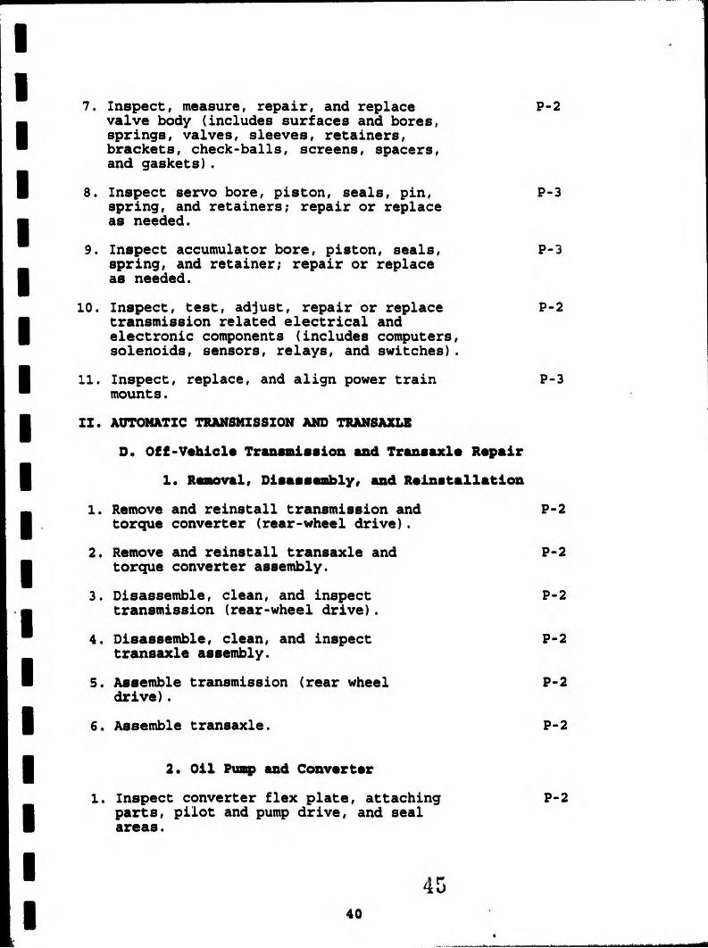
7. Inspect, measure, repair, and replace P-2 valve body (includes surfaces and bores, springs, valves, sleeves, retainers, brackets, check-balls, screens, spacers, and gaskets).
8. Inspect servo bore, piston, seals, pin, P-3 spring, and retainers; repair or replace as needed.
9. Inspect accumulator bore, piston, seals, P-3 spring, and retainer; repair or replace as needed.
10. Inspect, test, adjust, repair or replace P-2 transmission related electrical and electronic components (includes computers, solenoids, sensors, relays, and switches).
11. Inspect, replace, and align power train P-3 mounts.
II. AUTOMATIC TRANSMISSION AND TRANSAXLE
D. Off-Vehicle Transmission and Transaxle Repair
1. Removal, Disassembly, and Reinstallation
1. Remove and reinstall transmission and P-2 torque converter (rear-wheel drive).
2. Remove and reinstall transaxle and P-2 torque converter assembly.
3. Disassemble, clean, and inspect P-2 transmission (rear-wheel drive).
4. Disassemble, clean, and inspect P-2 transaxle assembly.
5. Assemble transmission (rear wheel P-2 drive).
6. Assemble transaxle. P-2
2. Oil Pump and Converter
1. Inspect converter flex plate, attaching P-2 parts, pilot and pump drive, and seal areas.

2. Measure torque converter end play, and P-2
check for interference; check stator clutch.
3. Inspect, measure, and replace oil pump P-3 housings, shafts, vanes, rotors, gears, valves, seals, and bushings.
4. Flush torque converter and transmission P-3 cooling system.
3. Gear Train, Shafts, Bushings and Case 1. Check end play or preload; determine P-2
needed service.
2. Inspect, measure, and replace thrust P-2
washers and bearings.
3. Inspect oil delivery seal rings, ring P-2 grooves, and sealing surface areas.
4. Inspect bushings; replace as needed. P-2
5. Inspect and measure planetary gear P-2 assembly (includes sun, ring gear, thrust washers, planetary gears, and carrier assembly); replace as needed.
6. Inspect cases, bores, passages, bushings, P-2 vents, and mating surfaces; replace as needed.
7. Inspect transaxle drive, link chains, P-2 sprockets, gears, bearings, and bushings; replace as needed.
8. Inspect, measure, repair, adjust or P-2 replace transaxle final drive components.
9. Inspect and reinstall parking pawl, shaft, P-3 spring, and retainer; replace as needed.
4. Friction and Feaction Units
1. Inspect clutch drum, piston, check-balls, P-2 springs, retainers, seals, and friction and pressure plates); replace as needed.
2. Measure clutch pack clearance; adjust as P-2 needed.

3. Air test operation of clutch and servo P-2 assemblies.
4. Inspect roller and sprag clutch, races, P-2 rollers, sprags, springs, cages, and retainers; replace as needed.
5. Inspect bands and drums; replace as needed. P-3
MANUAL DRIVE TRAIN AND AZLX8
For every task in Menual Drive Train and Axles the following safety task must be strictly enforced as a number 1 priority:
Comply with personal and environmental safety practices associated with clothing, eye protection, hand tools, power equipment and handling, storage and disposal of ahmmicals in accordance with local, state, and federal safety and environmental regulations.
In. MANUAL DRIVE TRAIN AND AXLES
A. Clutch Diagnosis and Repair
1. Diagnose clutch noise, binding, slippage, P-2 pulsation, and chatter problems; determine needed repairs.
2. Inspect, adjust or replace clutch pedal P-2 linkage, cables, automatic adjuster mechanisms, brackets, bushings, pivots, and springs.
3. Inspect, adjust, repair or replace P-2 hydraulic clutch slave and master cylinders, lines, and hoses.
4. Inspect, adjust or replace release P-2 (throw-out) bearing, lever, and pivot.
5. Inspect and replace clutch pressure P-2 plate assembly and clutch disc.
6. Inspect, remove or replace crankshaft P-2 pilot bearing or bushing (as applicable).
7. Inspect, repair, and service or replace P-2 flywheel and ring gear.

8. Inspect engine block, clutch (bell) P-3
housing, and transmission case mating surfaces; determine needed repairs.
9. Measure flywheel-to-block runout and P-3 crankshaft end play; determine needed repairs.
10. Measure clutch (bell) housing bore-to- P-3 crankshaft runout and face squareness; determine needed service.
III, MANUAL DRIVE TRAIN AND AXLES
Be Transmission Diagnosis and Repair
1. Diagnose transmission noise, hard shifting, P-2 jumping out of gear, and fluid leakage problems; determine needed repairs.
2. Inspect, adjust, and replace transmission P-2 shift linkages, brackets, bushings, cables, pivots, and levers.
3. Inspect, replace, and align power train P-3 mounts.
4. Inspect and replace transmission gaskets, P-2 seals, and sealants; inspect sealing surfaces.
5. Remove and reinstall traxIsmission. P-2
6. Disassemble, clean, and reassemble P-2 transmission components.
7. Inspect, adjust, and reinstall transmission P-2 shift cover, forks, grommets, levers, shafts, sleeves, detent mechanisms, interlocks, and springs.
8. Inspect and reinstall input (clutch) shaft P-2 and bearings.
9. Inspect and reinstall main shaft, gears, P-2 thrust washers, bearings, and retainers.
10. Inspect and reinstall synchronizer hub, P-2 sleeve, keys (inserts), springs, and blocking rings.

11. Inspect and reinstall counter (cluster) P-2
gear, shaft, bearings, thrust washers, and retainers; check end play; adjust as needed.
12. Inspect and reinstall reverse idler gear, P-2 shaft, bearings, thrust washers, and retainers; check end play; adjust as needed.
13. Inspect and replace speedometer drive gear, P-2 driven gear, vehicle speed sensor (VSS), and retainers.
III. MANUAL DRIVE TRAIN AND AXLES
C. Transaxle Diagnosis and Repair
1. Diagnose transaxle noise, hard shifting, P-2 jumping out of gear, and fluid leakage problems; determine needed repairs.
2. Inspect, adjust, and reinstall transaxle P-3 shift linkages, brackets, bushings, cables, pivots, and levers.
3. Inspect and reinstall power train mounts. P-3
4. Remove and reinstall transaxle. P-2
S. Inspect and replace transaxle gaskets, P-2 seals, and sealants; inspect sealing surfaces.
6. Remove and replace transaxle final drive P-3 as applicable).
7. Disassemble and clean transaxle final P-3 drive (as applicable).
8. Inspect, adjust, and reinstall transaxle P-2 shift cover, forks, levers, grommets, shafts, sleeves, detent mechanism, interlocks, and springs.
9. Inspect and reinstall input (clutch) P-2 shaft and bearings.
10. Inspect and reinstall output shaft, P-2 gears, thrust washers, bearings, and retainers.

11. Measure end play or preload (shim or P-2 spacer selection procedure) on transaxie shafts; adjust as needed.
12. Inspect and reinstall synchronizer hub, P-2 sleeve, keys (inserts), springs, and blocking rings.
13. Inspect and reinstall reverse idler gear, P-2 shaft, bearings. thrust washers, and retainers.
14. Inspect transaxie case, mating surfaces, P-2 bores, bushings, and vents.
15. Inspect and reinstall speedometer drive P-2 gear, driven gear, vehicle speed sensors, and retainers.
16. Diagnose differential assembly noise P-3 and vibration problems; determine needed repairs.
17. Remove, inspect, measure, adjust, and P-2 reinstall differential pinion gears (spiders), shaft, side gears, side bearings, thrust washers, and case assembly.
III. MANUAL DRIVE TRAIN AND AXLES
D. Drive and Half Shaft Universal and Constant-Velocity (CV) Joint Diagnosis and Repair
1. Diagnose constant-velocity (CV) joint P-1 noise and vibration problems; determine needed repairs.
2. Diagnose universal joint noise and P-2 vibration problems; determine needed repairs.
3. Diagnose front wheel drive (FWD) front P-2 wheel bearing noise and vibration problems; determine needed repairs.
4. Inspect, service, and replace front wheel P-2 drive (FWD) and rear wheel drive (RWD) shafts, yokes, and boots.
5. Inspect, service, and replace shaft center P-3 support bearings.

III. MANUAL DRIVE TRAIN AND AXLES
N. Rear Axle Diagnosis and Repair
1. Ring and Pinion Gears and Differential Case Assembly 1. Diagnose noise and vibration problems; P-2
determine needed repairs. .2. Diagnose fluid leakage problems; P-2
determine needed repairs.
3. Inspect and replace companion flange P-2 and pinion seal. 4. Inspect ring gear and measure runout; P-2
determine needed repairs.
5. Remove and inspect drive pinion gear, P-2 spacers, sleeves, and bearings.
6. Measure and adjust drive pinion depth. P-2
7. Measure and adjust drive pinion bearing P-2 preload.
8. Measure and adjust side bearing preload P-2 and ring and pinion gear backlash on a differential carrier assembly (threaded cup and shim types).
9. Check ring and pinion tooth contact P-2 patterns; adjustments as needed.
10. Disassemble, inspect, measure, and adjust P-2 or replace differential pinion gears (spiders), shaft, side gears, side bearings, thrust washers, and case.
11. Reassemble and reinstall differential P-2 case assembly; measure runout; determine needed repairs.
2. Limited Slip Differential
1. Diagnose noise, slippage, and chatter P-3 problems; determine needed repairs.
2. Inspect and flush differential housing; P-3 refill with correct lubricant.

3. Inspect and reinstall clutch (cone or P-3 plate) components.
4. Measure rotating torque; determine P-3 needed repairs.
3. Axle Shaft
1. Diagnose rear axle shafts, bearings and P-2 seals for noise, vibration, and fluid leakage problems; determine needed repairs.
2. Inspect and replace rear axle shaft P-3 wheel studs.
3. Remove and replace rear axle shafts. P-2
4. Inspect and replace rear axle shaft P-2 seals, bearings, and retainers.
5. Measure rear axle flange runout and shaft P-2 end play; determine needed repairs.
III. MANUAL DRIVE TRAIN AND AXLES
F. Four-wheel Drive Component Diagnosis and Repair
1. Diagnose four-wheel drive assembly noise, P-3 vibration, and unusual steering problems; determine needed repairs.
2. Inspect, adjust, and repair transfer case P-2 shifting controls (mechanical, electrical, and vacuum), bushings, mounts, levers, and brackets.
3. Remove and reinstall four-wheel drive P-3 transfer case.
4. Disassemble, service, and reassemble P-3 transfer case and components.
5. Inspect, service, and replace front-wheel P-2 bearings and locking hubs.
6. Check four-wheel drive assembly seals and P-2 vents; check lube level.

SUSPENSION AND nun=
For every task in Suspension and Steering the following safetytask must be strictly enforced as a number 1 priority:
Comply with personal and environmental safety practicesassociated with clothing, eye protection, hand tools, power equipment and handling, storage and disposal of chemicals inaccordance with local, state, and federal safety and environmental regulations.
IV. SUSPENSION AND STEERING
A. Steering Systems Diagnosis and Repair
1.Disable supplemental restraint systems (SRS) P-1 in accordance with manufacturers' procedures.
2.Diagnose steering column noises, looseness, P-3 and binding problems (including tilt mechanisms); determine needed repairs.
3.Diagnose power non-rack and pinion P-3 steering gear binding, uneven turningeffort, looseness, hard steering, andfluid leakage problems; determine needed repairs.
4.Diagnose power rack and pinion steering P-2 gear vibration, looseness, and hard steering problems; determine needed repairs.
5.Inspect and replace steering shaft P-2 universal-joints(s), flexible coupling(s), collapsible column,lock cylinder mechanism, and steering wheel.
6.Adjust manual or power non-rack and P-3 pinion worm bearing preload and sector lash.
7.Remove and replace manual or power rack P-2and pinion steering gear; inspect mounting builhings and brackets.
8.Disassemble, inspect, repair, and P-3 reassemble rack and pinion steering gear.

9. Adjust manual or power rack and pinion P-3 steering gear.
10. Inspect and replace manual or power rack P-2 and pinion steering gear inner tie rod ends (sockets) and bellows boots.
11. Inspect manual and power steering fluid P-3 levels and condition.
12. Flush power steering system. P-3
13. Diagnose power steering fluid leakage; P-3 determine needed repairs.
14. Inspect, adjust or replace and adjust P-1 power steering pump belt. 15. Remove, inspect, and replace power P-3
steering pump, pump mounts, pump seals, and gaskets.
16. Remove, inspect, and replace power P-3 steering pump pulley; check alignment.
17. Perform power steering system pressure P-3 test; determine needed repairs.
18. Inspect and replace power steering hoses P-2 and fittings.
19. Inspect and replace pitman arm, relay P-2 (centerlink/intermediate) rod, idler arm and mountings, and steering linkage damper.
20. Inspect, replace, and adjust tie rod ends P-2 (sockets), tie rod sleeves, and clamps.
21. Diagnose, inspect, adjust, repair or P-3 replace components of electronically- controlled steering systems.

IV. SUSPENSION AND STEERING
B. Suspension Systems Diagnosis and Repair
1. Front Suspensions
1. Diagnose short and long arm suspension P-2 system noises, body sway, and uneven riding height problems; determine needed repairs.
2. Diagnose MacPherson strut suspension P-2 system noises, body sway, and uneven riding height problems; determine needed repairs.
3. Remove, inspect, and replace upper and P-2 lower control arms, bushings, shafts, and rebound bumpers.
4. Remove, inspect, replace, and adjust P-2 strut (compression/tension) rods and bushings.
S. Remove, inspect, and replace upper and P-2 lower ball joints on short and long arm suspension systems.
6. Remove, inspect, and replace steering P-2 knuckle assemblies,
7. Remove, inspect, and replace short and P-2 long arm suspension system coil springs and spring insulators.
8. Remove, inspect, replace, and adjust P-3 suspension system torsion bars; inspect mounts.
9. Remove, inspect, and replace stabilizer P-3 bar bushings, brackets, and links.
10. Remove, inspect, and replace ball joints P-2 on MacPherson strut suspension systems.
11. Remove, inspect, and replace MacPherson P-1 strut cartridge or assembly, strut coil spring, and insulators.
12. Lubricate suspension and steering systems. P-2

2. Rear Suspensions
1. Remove, inspect, and replace coil springs P-2 and spring insulators.
2. Remove, inspect, and replace transverse P-2 links, control arms, bushings, and mounts.
3. Remove, inspect, and replace leaf springs, P-3 leaf spring insulators (silencers), shackles, brackets, bushings, and mounts.
4. Remove, inspect, and replace MacPherson P-2 strut cartridge or assembly, strut coil spring, and insulators (silencers).
3. Miscellaneous Service
1. Inspect and replace shock absorbers. P-2
2. Remove, inspect, and service or replace P-1 front or rear wheel bearings.
3. Diagnose, inspect, adjust, repair or P-3 replace components of electronically- controlled suspension systems.
IV. SIISPINSION AND STERRING
C. Wheel Alignment Diagnosis, Adjustment and Repair
1. Diagnose vehicle wandering, pulling, P-2 hard steering, and poor steering return problems; determine needed repairs.
2. Measure vehicle riding height; P-2 determine needed repairs.
3. Check and adjust front and rear wheel P-2 camber (where applicable); determine needed repairs.
4. Check and adjust caster (where applicable); P-2 determine needed repairs.
5. Check and adjust front wheel toe; adjust P-2 as needed.
6. Center steering wheel. P-2

7. Check toe-out-on-turns (turning radius); P-2 determine needed repairs.
8. Check SAI (steering axis inclination)/KPI P-2 (king pin inclination) and included angle; determine needed repairs.
9. Check and idjust (where applicable) rear P-2 wheel toe.
10. Check rear wheel thrust angle; determine P-2 needed repairs.
11. Check for front wheel setback; determine P-2 needed repairs.
12. Check front cradle (subframe) alignment; P-3 determine needed repairs.
IV. SUSPENSION AND STEERING
D. Wheel and Tire Diagnosis and Repair
1. Diagnose unusual tire wear patterns; P-2 determine needed repairs.
2. Inspect tires; check and adjust air P-1 pressure.
3. Diagnose wheel and tire vibration (shimmy P-2 and tramp) problems; determine needed repairs.
4. Rotate tires according to manufacturer's P-1 recommendations.
5. Measure wheel, tire, axle, and hub runout; P-2 determine needed repairs.
6. Diagnose tire pull (lead) problem; P-2 determine corrective actions.
7. Balance wheel and tire assembly (static P-1 and dynamic).
8. Dismount, inspect, repair, and remount P-2 tire on wheel.
9. Reinstall wheel; torque lug nuts. P-1

UAW
For every task in Brakes the following safety task must be strictly enforced as a number 1 priority:
Comply with personal and environmental safety practicesassociated with clothing, eye protection, hand tools, power equipment and handling, storage and disposal of chemicals inaccordance with local, state, and federal safety and environmentalregulations.
V. BRARIS
A. Hydraulic System Diagnosis and Repair
1.Measure and adjust pedal pushrod length. P-3
2.Check master cylinder for internal and P-2 external leaks and proper operation;determine needed repairs. 3.Remove, bench bleed, and replace master P-2
cylinder.
4.Diagnose poor stopping, pulling or P-1 dragging caused by problems in the hydraulic system; determine neededrepairs.
5.Inspect brake lines and fittings for P-2 leaks, dents, kinks, rust, cracks or wear; tighten loose fittings and supports.
6.Inspect flexible brake hoses for P-2 leaks, kinks, cracks, bulging or wear; tighten loose fittings and supports.
7.Fabricate and install brake lines P-2 (double flare or ISO types); replacehoses, fittings, and supports as needed.
8; Select, handle, store, and install brake P-3. fluids to proper level.
9. Inspect, test, and replace metering (hold- P-2 off), proportioning (balance), pressuredifferential, and combination valves.

10. Inspect, test, replace, and adjust height P-3 sensing (load) proportioning valve.
11. Inspect, test, and replace components of P-2 brake warning light system.
12. Bleed (manual, pressure, vacuum or surge) P-1 brake system flush as needed.
V. BRAKES
B. Drum Brake Diagnosis and Repair
1.Diagnose poor stopping, noise, pulling, P-2 grabbing, dragging or pedal pulsation problems; determine needed repairs.
2.Remove, clean (using proper safety P-1 procedures), inspect, and measure brake drums; service or replace as needed.
3.Mount brake drum on lathe; machine P-2 braking surface.
4.Remove, clean, and inspect brake shoes, P-2 springs, pins, clips, levers, adjusters/ self-adjusters, other related brake hardware, and backing support plates; lubricate and reassemble.
5.Remove and reinstall wheel cylinders. P-2
6.Adjust brake, shoes, and reinstall brake P-2 drums or drum/hub assemblies and wheel bearings.
7.Reinstall wheel; torque lug nuts. P-1
V. BRAXIS
C. Disc Brake Diagnosis and Repair
1.Diagnose poor stopping, noise, pulling, P-2 grabbing, dragging or pedal pulsation caused problems; determine needed repairs.
2.Remove caliper assembly from mountings; P-2 clean and inspect for leaks and damage to caliper housing.

3. Clean and inspect caliper mounting and P-2 slides for wear and damage.
4. Remove, clean, and inspect pads and P-2 retaining hardware; determine needed service.
5. Disassemble and clean caliper assembly; P-2 inspect parts for wear, rust, scoring, and damage; replace seal, boot, and damaged or worn parts.
6. Reassemble, lubricate, and reinstall P-2 caliper, pads, and related hardware.
7. Clean and inspect rotor; measure rotor P-1 with a dial indicator and a micrometer.
8. Refinish rotor according to manufacturer's P-2 recommendations.
9. Adjust calipers with integrated parking P-2 brake system.
10. Fill master cylinder with recommended P-2 fluid and seat pads; inspect caliper for leaks.
11. Reinstall wheel; torque lug nuts. P-1
V. BRAXIS
D. Power Assist Vats Diagnosis and Repair
1. Test pedal free travel with and without P-2 engine running; check power assist operation.
2. Check vacuum supply (manifold or auxiliary P-2 pump) to vacuum-type power booster.
3. Inspect the vacuum-type power booster unit P-2 for vacuum leaks; inspect the check valve for proper operation; repair or replace parts as needed.

V. BRAKES
E. Miscellaneous (Wheel Bearings, Parking Brakes, Electrical, Etc.) Diagnosis and Repair
1. Diagnose wheel bearing noises, wheel shimmy, P-2 and vibration problems; determine needed repairs.
2. Remove, clean, inspect, repack, and reinstall P-i wheel bearings and replace seals; reinstall hub and adjust wheel bearings.
3. Check parking brake cables and components P-2 for wear, rusting, binding, and corrosion; clean, lubricate, and replace as needed.
4. Check parking brake operation; adjust as P-2 needed.
5. Check operation of parking brake indicator P-2 light system.
6. Check operation of brake stop light system; P-2 adjust and service as needed.
V. BRAKES
F. Anti-lock Brake Systems
1. Inspect, test, and service anti-lock brake P-2 system (ABS) hydraulic, electrical, and mechanical components.
2. Diagnose poor stopping, wheel lock-up, P-3 pedal feel, pulsation, and noise problems caused by the anti-lock brake system (ABS); determine needed repairs.
3. Observe anti-lock brake system (ABS) P-2 warning light(s) at startup; determine if further diagnosis is needed.
4. Diagnose anti-lock brake system (ABS) P-2 electronic control(s) and components using self-diagnosis and/or recommended test equipment; determine needed repairs.
5. Depressurize integral (high pressure) P-2 components of the anti-lock brake system (ABS) following manufacturer's recommended safety procedures.

6.Fill the anti-lock brake system (ABS) P-2
master cylinder with recommended fluidfollowing manufacturer's procedures;inspect system for leaks.
7.Bleed the anti-lock brake system's (ABS) P-2 front and rear hydraulic circuits followingmanufacturer's procedures.
8.Perform a fluid pressure (hydraulic boost) P-2 diagnosis on the integral (high pressure) anti-lock system (ABS); determine neededrepairs.
9.Remove and install anti-lock brake system P-3 (ABS) electrical/electronic/hydraulic components following manufacturer's procedures and specifications.
10.Service, test, and adjust anti-lock brake P-2 system (ABS) speed sensors followingmanufacturer's recommended procedures.
ELECTRICAL/ELECTRONIC SYSTEMS
For every task in Electrical Systems the following safety task must be strictly enforced as a number 1 priority:
Comply with personal and environmental safety practicesassociated with clothing, eye protection, hand tools, power equipment and handling, storage and disposal of chemicals inaccordance with local, state, and federal safety and environmental regulations.
VI. ELECTRICAL/ELECTRONIC SYSTEMS
A. General Electrical System Diagnosis
1.Use wiring diagrams during diagnosis of P-1 electrical circuit problems.
2.Check electrical circuits with a test P-2 light; determine needed repairs.
3.Check voltages and voltage drops in P-1 electrical/electronic circuits usinga digital multimeter (DMM); determineneeded repairs.

4. Check current flow in electrical/electronic P-2 circuits and components using an ammeter; determine needed repairs.
5. Check electrical circuits using jumper P-2 wires; determine needed repairs.
6. Find shorts, grounds, opens, and high P-1 resistance problems in electrical/ electronic circuits; determine needed repairs.
7. Measure and diagnose the cause(s) of P-1 abnormal key-off battery drain; determine needed repairs.
8. Inspect and test fusible links, circuit breakers, and fuses; replace as needed.
9. Inspect and test switches, connectors, and wires of electrical/electronic circuits; repair or replace as needed.
VI. ELECTRICAL/ELECTRONIC SYSTEMS
B. Battery Diagnosis and Service
1. Perform battery state-of-charge test; P-2 determine needed service.
2. Perform battery capacity (load, high-rate P-2 discharge) test; determine needed service.
3. Maintain or restore electronic memory P-2 functions.
4. Inspect, clean, fill or replace battery. P-2
5. Perform slow/fast battery charge. P-2
6. Inspect and clean battery cables, P-2 connectors, clamps, and hold-downs; repair or replace as needed.
7. Start a vehicle using jumper cables P-2 and a battery or auxiliary power supply.

VI. ELECTRICAL/ELECTRONIC SYSTEMS
C. Starting System Diagnosis and Repair
1. Perform starter current draw and P-1 circuit voltage drop test; determine needed repairs.
2. Inspect and test starter relays and P-2 solenoids; replace as needed.
3. Remove and replace/reinstall starter. P-2
4. Perform starter free-running (bench) P-2 tests; determine needed repairs.
VI. ELECTRICAL/ELECTRONIC SYSTEMS
D. Charging System Diagnosis and Repair
1. Diagnose charging system problems that P-2 cause an undercharge, a no-charge or an overcharge condition.
2. Inspect and adjust alternator drive P-2 belts; replace as needed. 3. Inspect and test voltage regulator; P-2
replace as needed.
4. Remove, inspect, and replace/reinstall P-2 alternator.
5. Disassemble, clean, inspect, and test P-2 alternator components; replace as needed.
VI. ELECTRICAL/ UCTRONIC SYSTEMS
I. Lighting Systems Diagnosis and Repair
1. Diagnose the cause of brighter than normal, P-2 intermittent, dim or no light operation.
2. Inspect, replace, and aim headlights and P-2 bulbs.
3. Inspect, diagnose, and test the cause of P-2 no turn signal or hazard light operation or lights with no flash on one or both sides; repair or replace as needed.

VI. ELECTRICAL/ELECTRONIC SYSTEMS
Y. Gauges, Warning Devices, and Driver Information Systems Diagnosis and Repair
1. Diagnose the cause of intermittent, high, P-2 low or no gauge readings.
2. Test gauge circuit voltage regulators P-3 (limiters); replace as needed.
3. Inspect and teat gauges and gauge sending P-2 units; replace as needed.
4. Inspect and test connectors, wires, and P-3 printed circuit boards of gauge circuits; repair or replace as needed.
5. Diagnose the cause of constant, intermittent P-2 or no warning light and driver information system operation.
6. Diagnose the cause(s) of intermittent, high, P-3 low or no readings on electronic digital instrument clusters.
7. Inspect and test sensors, sending units, P-3 connectors, and wires of electronic digital instrument circuits; repair or replace as needed.
VI. ELECTRICAL/ELECTRONIC SYSTEMS
G. Horn and Wiper/Washer Diagnosis and Repair
1. Diagnose the cause of constant, intermittent P-3 or no horn(s) operation; repair as needed.
2. Diagnose the cause of constant, intermittent P-3 or no wiper operation; diagnose the cause of wiper speed control and park problems; repair as needed.
3. Diagnose the cause of constant, intermittent P-3 or no windshield washer operation; repair as needed.

VI. ELECTRICAL/ELECTRONIC SYSTEMS
R. Accessories Diagnosis and Repair
1.Diagnose the cause of slow, intermittent P-2or no operation of motor-driven accessory circuits; repair as needed.
2.Diagnose the cause of poor, intermittent P-3or no heated glass operation; repair asneeded.
3.Diagnose the cause of poor, intermittent P-3 or no electric door and hatch/trunk lock operation; repair as needed.
4.Diagnose the cause of unregulated, P-3 intermittent or no operation ofcruise control systems; repair as needed.
5.Diagnose the cause(s) of the supplemental P-3 restraint system (SRS) warning lightstaying on or flashing; repair as needed. (Note: Follow manufacturer'ssafety procedures to prevent accidentaldeployment.)
EMIATING AND AIR COMDITIORZINI
For every task in abating and Air Conditioning the following safety task must be strictly enforced as a number 1 priority:
Comply with personal and environmental safety practicesassociated with clothing, eye protection, hand tools, power equipment and handling, storage and disposal of chemicals inaccordance with local, state, and federal safety and environmental regulations.
VII. HEATING AND AIR CONDITIONING
A. A/C System Diagnosis and Repair
1. Diagnose the cause of unusual operating P-2 noises in the A/C system; determineneeded repairs.

2. Conduct a performance test of the A/C P-2 system (includes pressure gauge readings, visual inspection, and touch procedures); determine needed repairs.
3. Leak test A/C system; determine needed P-2 repairs.
4. Inspect the condition of discharged oil. P-2
5. Select oil type; measure and add oil to P-2 A/C system as needed.
VII. HEATING AND AIR CONDITIONING
B. Refrigeration System Component Diagnosis and Repair
1. Compressor and Clutch
1. Diagnose A/C system problems that cause P-2 the pressure protection devices to interrupt system operation; repair as needed.
2. Inspect A/C compressor drive belts; P-2 replace and adjust as needed.
3. Inspect and test A/C compressor clutch P-2 components or assembly; replace as needed.
4. Inspect A/C drive pulley; replace as P-2 needed.
5. Remove and replace A/C compressor and P-2 mountings.
6. Inspect and replace A/C compressor shaft P-2 seal assembly(s).
2. Evaporator, Receiver/Drier, Condenser, Etc.
1. Diagnose A/C system problems caused by P-3 too much moisture in the refrigerant; determine needed repairs.
2. Install A/C system filter. P-3
3. Remove and inspect A/C system mufflers, P-2 hoses, lines, fittings, o-rings, seals, and service valves; replace as needed.

4. Inspect A/C condenser for air flow P-3 restrictions; service as required.
5. Inspect receiver/drier or accumulator/ P-2 drier; replace as needed. 6. Inspect and test expansion valve or P-2
orifice (expansion) tube; replace as needed.
7. Inspect evaporator housing water drain; P-3 repair as needed.
VII. HEATING AND AIR CONDITIONING
C. Heating and Engine Cooling Systems Diagnosis and Repair
1. Diagnose the cause of temperature control P-2 problems in the heater/ventilation system; determine needed repairs.
2. Perform cooling system, cap, and recovery P-2 system tests (pressure, combustion leakage, and temperature); determine needed repairs.
3. Inspect engine cooling and heater system P-2 hoses and belts; replace as needed.
4. Inspect thermostat and housing; replace P-2 as needed.
5. Inspect coolant condition; drain and P-2 recover.
6. Flush system and refill with recommended P-2 coolant; bleed system.
7. Clean, inspect, and test fan, fan clutch P-2 (electrical and mechanical), and fan shroud; replace as needed.
8. Inspect and test heater control valve(s) P-2 (manual, vacuum, and electrical types); replace as needed.

VII. HEATING AND AIR CONDITIONING
D. Operating Systems and Related Controls Diagnosis and Repair
1. Electrical 1. Diagnose the cause of failures in the P-2
electrical controls of heating and A/C systems; determine needed repairs.
2. Inspect and test A/C-heater blower, motors, P-2 resistors, switches, relays, wiring, and protection devices; repair or replace as needed.
3. Test A/C compressor load cut-off systems; P-3 determine needed repairs.
2. Vacuum/Mechanical
1. Diagnose the cause of failures in the P-2 vacuum and mechanical controls of the heating and A/C system; determine needed repairs.
2. Inspect and teat A/C-heater control panel P-3 assembly; replace as needed.
3. Inspect and test A/C-heater control cables P-3 and linkages; adjust or replace as needed.
4. Inspect and test A/C-heater vacuum control P-3 switches, hoses, diaphragms (motors), vacuum reservoir, check valve, and restrictors; replace as needed.
5. Inspect and test A/C-heater ducts, doors, P-3 hoses, and outlets; replace as needed.
3. Automatic. and Semi-Automatic Temperature Controls 1. Check operation of automatic and semi- P-3
automatic heating, ventilation, and air- conditioning (HVAC) control systems; determine needed repairs.

VII. HEATING AND AIR CONDITIONING
E. Refrigerant Recovery, Recycling, and Handling
1.Verify correct operation of refrigerant handling equipment.
2.Identify and recover A/C system refrigerant.
3.Recycle refrigerant.
4.Label and store refrigerant.
5.Test recycled refrigerant for non-condensable gases.
ENGINE PERFORMANCE
For every task in Engine Performance the following safety task must be strictly enforced as a number 1 priority:
Comply with personal and environmental safety, practices associated with clothing, eye protection, hand tools, power equipment and handling, storage and disposal of chemicals inaccordance with local, state, and federal safety and environmental regulations.
VIII. ENGINE PERFORMANCE
A. General Engine Diagnosis 1.Interpret and verify complaint; P-2
determine needed repairs.
2.Inspect engine assembly for fuel, P-2 oil, coolant, and other leaks; determine needed repairs. 3.Diagnose the cause of unusual engine P-2
noise or vibration problems; determine needed repairs.
4.Diagnose the cause of unusual exhaust P-2 color, odor, and sound; determine needed action.
5.Perform engine absolute (vacuum/boost) P-2 manifold pressure tests; determine needed repairs.

6.Perform cylinder power balance test; P-2 determine needed action. 7.Perform cylinder compression test; P-2
determine needed action. 8.Perform cylinder leakage test; P-2
determine needed action.
9.Diagnose engine mechanical, electrical, P-2 electronic, fuel, and ignition problems with an ignition oscilloscope and engine analyzer; determine needed action.
10.Prepare and inspect vehicle and 4-gas P-1 analyzer; obtain exhaust readings.
VIII. ENGINE PERFORMANCE
B. Computerized Engine Controls Diagnosis and Repair
1.Diagnose the causes of emissions problems P-2 resulting from failure of computerized engine controls.
2.Perform analytic/diagnostic procedures on P-2 vehicles with on-board diagnostic computer systems; determine needed action.
3.Inspect and test sensors, controls, and P-2 actuator components and circuits of computerized engine control systems; adjust or replace as needed.
4.Obtain and interpret digital multimeter (DMM) readings.
5.Read and interpret technical information.
6.Locate and interpret vehicle and major component identification numbers (VIN, vehicle certification labels and calibration decals).
7.Inspect and teat power and ground circuits P-2 and connections; service or replace as needed.
8. Practice recommended precautions when P-2 handling static sensitive devices.

VIII. ENGINE PERFORMANCE
C. Ignition System Diagnosis and Repair
1. Diagnose no-starting, hard starting, engine P-2 misfire, poor driveability, spark knock, power loss, poor mileage, and emissions problems on vehicles with electronic ignition (distributorless) systems; determine needed repairs.
2. Diagnose no-starting, hard starting, engine P-2 misfire, poor driveability, spark knock, power loss, poor mileage, and emissions problems on vehicles with electronic distributor ignition systems; determine needed repairs.
3. Inspect and test ignition primary circuit P-2 wiring and components; repair or replace as needed.
4. Inspect and test distributor; service as P-2 needed.
5. Inspect and test ignition system secondary P-2 circuit wiring and components; replace as needed.
6. Inspect and test ignition coil(s); replace P-2 as needed.
7. Check and adjust (where applicable) ignition P-2 system timing and timing advance/retard.
8. Inspect and test ignition wiring harness P-2 and connectors; replace as needed.
9. Inspect and test ignition system pick-up P-2 sensor or triggering devices; replace as needed.
10. Inspect and test ignition control module; P-2 replace as needed.

VIII. MINI PIRFORKANtE
D. Fuel, Air Induction, and Exhaust Systems Diagnosis and Repair
1. Diagnose h‘pt or cold no-starting, hard P-2 starting, poor driveability, incorrect idle speed, poor idle, flooding, hesitation, surging, engine misfire, power loss, stalling, poor mileage, dieseling, and emissions problems on vehicles with carburetor-type fuel systems; determine needed action.
2. Diagnose hot or cold no-starting, hard P-2 starting, poor driveability, incorrect idle speed, poor idle, flooding, hesitation, surging, engine misfire, power loss, stalling, poor mileage, dieseling, and emissions problems on vehicles with injection-type fuel systems; determine needed action.
3. Inspect fuel tank and fuel cap; inspect P-2 and replace fuel lines. fittings, and hoses.
4. check fuel for contaminants and quality. P-3
5. ILspect and test mechanical and electrical P-2 fuel pumps and pump control systems; replace as needed.
6. Replace fuel filters. P-2
7. Inspect and test fuel pressure regulation P-2 system and components of injection type fuel systems; adjust or replace as needed.
8. Inspect and test cold enrichment system P-2 components; adjust or replace as needed.
9. Remove, clean, and reinstall throttle body; P-2 adjust related linkages.
10. Inspect and test fuel injectors; clean or P-2 replace as needed.
11. Inspect throttle body mounting plates, air P-2 induction and filtration system, intake manifold, and gaskets; clean or replace as needed.

12. Check/adjust idle speed and fuel mixture P-2 where applicable.
13. Remove, inspect, and test vacuum and P-2 electrical components and connections of fuel system; repair or replace as needed.
14. Inspect exhaust manifold, exhaust pipes, P-2 muf.lers, resonators, tail pipes, and heat shields; repair or replace as needed.
VIII. ENGINE PERFORMANCE
E. Emissions Control Systems Diagnosis and Repair
1. Positive Crankcase Ventilation
1. Diagnose the cause(s) of emissions P-2 problems resulting from failure of the positive crankcase ventilation system.
2. Inspect and test positive crankcase P-2 ventilation (PCV) filter/breather cap,
'valve, tubes, orifices, and hoses; service or replace as needed.
2. Spark Timing Controls
1. Diagnose the cause(s) of emissions problems P-2 resulting from failure of the spark timing control system.
2. Inspect and test circuits of spark timing P-2 control systems; replace as needed.
3. Idle and Deceleration Speed Controls
1. Diagnose the cause(s) of emissions problems P-2 resulting from failure of the idle and deceleration speed control system.
2. Inspect and test wiring, hoses, and P-2 components of idle speed control systems; adjust or replace as needed.
3. Inspect and test electrical components, P-2 circuits, vacuum components, and hoses of deceleration controls; adjust or replace as needed.

4. Exhaust Gas Recirculation
1. Diagnose the cause(s) of emissions P-2 problems caused by failure of the exhaust gas recirculation (EGR) system.
2. Inspect and test valve, valve manifold, P-2 and exhaust passages of exhaust gas recirculation (EGR) systems; service or replace as needed.
3. Inspect and test vacuum/pressure P-2 controls, filters, and hoses of exhaust gas recirculation (EGR) systems; service or replace as needed.
4. Inspect and test electrical/electronic P-2 sensors, controls, and wiring of exhaust gas recirculation (EGR) systems; repair or replace as needed.
5. Exhaust Gas Treatment
1. Diagnose the cause(s) of emissions problems P-2 resulting from failure of the air injection or catalytic converter systems.
2. Inspect and test mechanical components of P-2 air injection systems; service or replace as needed.
3. Inspect and test electrical/electronically- P-2 operated components and circuits of air injection systems; replace as needed.
4. Inspect and test components of catalytic P-2 converter systems; replace as needed.
6. Intake Air Temperature Controls
1. Diagnose the cause(s) of emissions problems P-2 resulting from failure of the intake air temperature control systems.
2. Inspect and test components of inlet air P-2 temperature control systems; replace as needed.

7. Early Fuel Evaporation (Intake Manifold Temperature) Controls
1.Diagnose the cause(s) of emissions problems P-2 resulting from failure of early fuel evaporation control systems.
2.Inspect and test components of early fuel P-2 evaporation control systems; service or replace as needed.
8. Evaporative Emissions Controls
1.Diagnose the cause(s) of emissions problems P-2 resulting from failure of evaporative emissions control system.
2.Inspect and test components and hoses of P-2 evaporative emissions control systems; replace as needed.
VIII. ENGINE PERFORMANCE
F. Engine Related Service
1.Adjust valves on engines with mechanical P-2 or hydraulic lifters.
2.Verify correct camshaft timing; determine P-2 needed action. 3.Verify engine operating temperature; P-2
determine needed action.
4.Perform cooling system pressure tests; check P-2 coolant condition; inspect and test radiator, pressure cap, coolant recovery tank, and hoses; service or replace as needed.
5.Inspect and test thermostat, by-pass, and P-2 housing; replace as needed.
6.Inspect and test mechanical/electrical fans, P-2 fan clutch, fan shroud/ducting, and fan control devices; service or replace as needed.

APPLIED ACADEMICS AND WORKPLACE SKILLS
The following Applied Academic Skills general statements were developed in cooperation with the Vocational-Technical Education Consortium of States (V-TECS). The process involved using the NATEF task list and the Basic/Essential Skills Taxonomy developed at Arizona State University by Dr. Lester Snyder.
Committee meetings were held in the following four cities: Atlanta, Georgia; Boston, Massachusetts; Cincinnati, Ohio; and Phoenix, Arizona. At each of the meetings, ASE Certified Master Automobile technicians were used as experts in the automotive service industry. V-TECS used experts in three academic areas (language arts, mathematics, and science) to help the committees understand the specific definitions of the concepts used in the taxonomy.
The committees were asked to identify the academic skills required to perform each task listed in the eight automobile areas. Their responses were recorded using the Basic/Essential Skills Taxonomy codes and were put into a data base. After all the meetings were completed, a composite or unduplicated list of the codes was generated for language arts, mathematics, and science. Specific statements related to the use of the academic skill in the automotive industry were then written. A matrix was built to show the relationship between the composite list and each of the eight automobile areas. The general statements included in this manual were developed from the specific statements. Several crosschecks and reviews were conducted to ensure the accuracy of the statement and the relationship to the NATEF task list.
The Workplace Skills List was generated by having the committees identify the workplace skills from the V-TECS/ILLINOIS WORKPLACE SKILLS LIST that are important for employment as an automobile technician.
'• Please contact the NATEF office to order the Applied Academics and Workplace Skills for Automobile Technicians book. This book includes the unduplicated list of applied academic skills in all eight automobile areas, complete with statements of their use by automobile technicians; the matrix; the definitions of the Basic/Essential Skills codes; the total number of times each code was identified; the general statements; the Workplace Skills List; and the NATEF Task List.
The information in the book will provide a common vocabulary for instructors and administrators to use in achieving academic and vocational skill standards. This information can be used by programs to document the academic skills taught in automotive technical classes. The examples for teaching an academic concept in an applied context will also be useful for schools when planning, designing, or writing curricula. `•

Narrative for Language Arts and Communications Related Academic Skills for all
NATEF Automobile Technician Task Lists
The automobile technician must be proficient in the following Language Arts and Communications related academic skills that are embedded in the occupation. Using these skills the technician must be able to:
Request, collect, comprehend, evaluate, and apply oral and written information gathered from customers, associates, and supervisors regarding problem symptoms and potential solutions to problems.
Identify the purpose for all written and oral communication and then choose the most effective strategies for listening, reading, speaking, and writing to facilitate the communication process.
Adapt a reading strategy for all written materials, e.g., customer's notes, service manuals, shop manuals, technical bulletins, etc., relevant to problem identification, diagnosis, solution, and repair.
Attend to verbal and nonverbal cues in discussions with customers, supervisors, and associates to verify, identify, and solve problems.
Use study habits and techniques, i.e. previewing, scanning, skimming, taking notes, etc., when reviewing publications (shop manuals, references, databases, operator's manuals, and text resources) for problem solving, diagnosis, and repair.
Use prior knowledge learned from solving similar problems to diagnose and repair specific problems.
VVrIte clear, concise, complete, and grammatically accurate sentences and paragraphs.
VVrite warranty reports and work orders to include information regarding problem resolution and the results of the work performed for the customer or manufacturer.
Comprehend and apply industry definitions and specifications to diagnose and solve problems in all automotive systems and components.
Follow all oral/written directions that relate to the task or system under study.
Comprehend and use problem-solving techniques and decision trees that are contained in service manuals to determine cause-and ffect relationships.
Scan service manuals and databases to locate specific information for problem-solving purposes.
Use the service manual to identify the manufacturer's specifications for system parameters, operation, and potential malfunctions.
Interpret charts, tables, or graphs to determine the manufacturer's specifications for system operation to identify out-of-tolerance systems and subsystems.
Supply clarifying information to customers, associates, parts supplier, and supervisors.

Narrative for Mathematics Related Academic Skills for all
NATEF Automobile Technician Task Lists
The automobile technician must be proficient in the following mathematics-related academic skills that are embedded in the occupation. Given these skills the technician must be able to:
Determine the proper sequence of arithmetic operations to arrive at a solution that can be compared to other specifications when comparing system measurements to the manufacturer's specifications.
Add two or more whole numbers, fractions, or decimals to determine component conformance of multiple measurements with the manufacturer's specifications.
Subtract whole numbers, fractions, or decimals to arrive at a difference for comparison with the manufacturer's specifications.
Divide decimals to determine measurement conformance with the manufacturer's specifications.
Convert variables presented orally to a mathematical form that provides for an algebraic solution.
Estimate the results of basic arithmetic operations, and accurately round up or down depending on the appropriate rule for the situation.
Analyze and solve problems requiring the use of fractions, decimals, ratios, or percentages by a direct or indirect variation of the numerical elements of the problem.
Determine the irrelevant and/or missing data needed to solve a problem.
Determine and interpret place value (tenths, hundredths, thousandths) when conducting precision measurements.
Use Centigrade or Fahrenheit measurement scales to determine the existing temperature of substances such as a coolant or lubricant.
Use English and Metric volume measurement techniques to determine the volume of a system, component. or cylinder.
Use conventional symbols (E for voltage, etc.) to solve circuit parameter calculations using formulas such as Ohm's Law, EIBIR.
Understand that if the described problem has certain conditions (symptoms), then a limited number of solutions to the problem apply.
Understand the relationship between the frequency of the occurrence of a problem (symptom) and the probability of accurately predicting the problem.
Calculate the average (mean) of several measurements to determine the variance from the manufacturer's specifications.

Use English and Metric angle and distance measurements and techniques to determine angle variances from the manufacturer's specifications.
Solve problems that involve determining the relative proportion of desired versus undesired ingredients or elements of a mixture, and determine if that proportion is within the manufacturer's specifications.
Comprehend and use standards defined by each manufacturer for the system being analyzed.
Convert test readings that are in decimal or fraction form to a ratio or percent for comparison with the manufacturers specifications for the sub-system.
Know when to use an estimated performance value versus an exact value, basing the decision on the system being analyzed or repaired.
Visually perceive the geometric relationship of systems and sub-systems that require alignment.
Construct or interpret a chart, table, graph, or symbol that depicts a range of performance characteristics that can be used for comparing various system operational conditions.
Use measurement devices to determine the parallelism or perpendicularity of chassis, suspension, and other vehicle systems requiring geometric alignment.
Use formulas to indirectly confirm systems that are outside of the manufacturers specifications.
Verify that the relationship between parallel lines and angles concurs with the manufacturers specifications when diagnosing a system's malfunction.
Visually formulate a belt (e.g., suspension/drive) angle and verify conformance to the manufacturer's specified angle.
Measure timed or sequenced operating parameters to determine conformance with the manufacturer's specifications.
Use English and Metric scales to determine the conformance of components to the manufacturer's specified weight.
Determine the degree of conformance to the manufacturer's specifications for length, volume, and other appropriate measurements in the English and/or Metric system.
Distinguish the congruence of the measured tolerances with those specified by the manufacturer.
Measure and/or test with tools designed for English or Metric measurements, then convert the result to the manufacturer's system used for specifying the correct measurement or tolerance.
Compute mentally whether the observed measurement is out-of-tolerance when comparing the observed measurement to the manufacturer's specifications.

Solve problems that involve determining whether the proportion of the existing volume compares to the manufacturers specifications and is within the recommended tolerance.
Distinguish whether a measurement or tolerance is equal or not equal to the manufacturers specifications.

Narrative for Science Related Academic Skills for all
NATEF Automobile Technician Task Lists
The automobile technician must be proficient in the following science-related academic skills that are imbedded in the occupation. Using these skills the technician must be able to:
Analyze and evaluate waste products from the repair task and dispose of the parts, residue, or trash according to applicable federal, state, and local rules and regulations.
Follow all safety regulations and procedures while performing any task.
Use the information provided in service manuals, charts, tables, or graphs to determine the manufacturer's specifications for system(s) operation(s) and the appropriate repair/replacement procedure.
Develop a hypothesis regarding the cause of the problem and test the hypothesis to determine the solution to the problem. 1. identify the problem 2. gather information 3. develop hypothesis 4. take action 5. check results
Convert measurements taken using the English or Metric system to specifications stated in terms of either system.
Explain and demonstrate an understanding of the chemical reaction that occurs in an automobile regarding the combustion of fuels, catalytic converters, and contamination when introduced into systems.
Explain the purpose of additives in lubricants.
Demonstrate an understanding of the kinetic and potential energy relationships that occur in valve systems, ignition systems, and other stored energy systems, such as springs and fuels, and determine efficiency.
Demonstrate an understanding of the role of balanced and unbalanced forces on linear and rotating vehicle assemblies.
Explain the relationship of centrifugal/centripetal force to the failure of rotating systems.
Explain the ignition characteristics of fuels resulting from varying levels of fractional distillation.
Demonstrate an understanding of how fuel characteristics affect combustion in an automotive engine.
Demonstrate an understanding of the effect of heat on automotive systems.

Explain the concept of heat transfer in terms of conduction, convection, and radiation in automotive systems.
Demonstrate an understanding of the expansion and contraction of system parts as a result of heat generated during use and the cooling of the system when not in operation.
Demonstrate an understanding of the effect that adding heat will cause in a state of matter, such as solid to liquid to gas.
Explain the role of insulation in maintaining stable temperatures.
Demonstrate an understanding of refraction in fiber optic systems.
Explain that dyes added to lubricants fluoresce in ultraviolet light and provide a process for determining the source of leakage.
Demonstrate an understanding of the process of acceleration and deceleration as a function of weight and available power.
Demonstrate an understanding of the reaction of fluid to the motion of a valve or piston.
Demonstrate an understanding of the circular motion of a vehicle as it relates to such events as toe-out on turns and tracking.
Demonstrate an understanding of the types of vibrations caused by out-of-balance or excessively worn systems.
Explain to a customer how sound can be amplified due to resonant cavities and other physical characteristics of the vehicle.
Explain and demonstrate an understanding of how sound generated in one place in the body and engine can be carried to other parts of the engine through metal and other materials.
Explain the need for sound deadening and vibration damping materials to control the level of sound in the passenger compartment.
Demonstrate an understanding of the relationship of the perceived intensity to the decibel level of a noise.
Explain the relationship of the frequency of the sound to a normal or abnormally operating system.
Explain and demonstrate an understanding of the role of listening to sounds as part of the trouble-shooting process.
Explain that the presence of overtones may indicate changes in the vibrations of various systems.
Demonstrate an understanding of the relationship of barometric pressure to engine performance (horsepower).
Explain the relationship of engine torque to vehicle performer ce.

Explain how levers and pulleys can be used to increase an applied force or distance.
Identify the effect of solution pH on chemical changes in a system.
Identify the characteristics that define a system that is operating within the manufacturer's specifications.
Use precision measuring devices to determine if wear and adjustments are within the manufacturer's specifications, and to assure that repair or replacement parts meet the manufacturer's specifications.
Use tension gauges, such as a torque wrench, to measure the force or tension required to tighten connections to the manufacturer's specifications.
Use a scale to measure component weight to balance rotating systems.
Use pressure measuring tools to determine pressures in hydraulic or pneumatic systems and compare to the manufacturer's specifications.
Use direct and indirect methods to measure system temperatures and then convert to Fahrenheit/Centigrade as required.
Use direct and indirect methods to measure time and compare the results to the manufacturer's specifications.
Use direct and indirect methods to measure the volume of liquids in a system and compare to the manufacturer's specifications.
Use computer databases for information retrieval and input devices to process information for customers, billing purposes, warranty work, and other record-keeping purposes.
Explain how an applied force at one location can be transmitted via fluid pressure to provide a force at a remote location.
Explain catalytic converter principles which modify emission gases at the atomic level to provide a low level of HC, CO and NOx in the final exhaust.
Explain the role that friction plays in acceleration and deceleration of objects as illustrated by transmitting motion to a part not physically connected to the powered part.
Explain to the customer the need for lubrication of adjacent parts to minimize friction as a result of movement at the junction of the parts.
Explain the necessity of knowing that the hardness of a metal determines, in part, its function and location in the automobile.
Explain the dynamic control properties of a hydraulic system.
Explain the surface processes that occur on system seals due to the absorption of the contained materials.

Demonstrate an understanding of how the deterioration in an engine's performance can be caused by a chemical reaction that occurs in a liquid that has been contaminated.
Demonstrate an understanding of how torque relates to force and angular acceleration.
Demonstrate an understanding of how cams, pulleys, and levers are used to multiply force or transfer directions of force.
Explain how rotational motion is changed to linear motion and the need for balance in rotating systems.
Demonstrate an understanding of how variances in flow rate in air flow sensors or cooling systems can affect engine performance.
Electrical/Tolerances
Explain and demonstrate an understanding of the properties of electricity that impact the lighting, engine management, and other electrical systems in the vehicle.
Demonstrate an understanding of the characteristics of a quality electrical ground and explain the problems associated with an inadequate electrical circuit ground.
Explain voltage and current flow in series and parallel circuits.
Demonstrate an understanding of the processes used to locate a short circuit in the electrical/electronic system.
Demonstrate an understanding of the role of the alternator in maintaining battery and system voltage.
Demonstrate an understanding of the role of solar panels in maintaining battery voltage and operating selected accessories.
Explain and demonstrate an understanding of the ignition coil's role in generating the high voltages required to fire the sparkplug.
Demonstrate an understanding of the correct procedure used to measure the electrical parameters of voltage, current, resistance, or power.
Explain and demonstrate an understanding of the role of a fuse or fusible link as a protective device in an electrical or electronic circuit.
Explain and demonstrate an understanding of the use of Ohm's Law in verifying circuit parameters (resistance, voltage, amperage).
Explain and demonstrate an understanding of the relationship of resistance to heat, voltage drop, and circuit parameters.
Explain and demonstrate an understanding of system voltage generation, uses, and characteristico.

Demonstrate an understanding of the ion transfer process that occurs in an automotive battery.
Explain the conductivity problems in a circuit when connectors corrode due to electrochemical reactions.
Explain the relationship between electrical current in a conductor and the magnetic field produced in a coil such as the starter solenoid.
Explain the ability of a coil to increase battery voltage to the level required to fire a sparkplug.
Explain the effect of magnetic fields on unshielded circuits in selected control modules.
Explain the need for a specific gravity test of battery electrolyte to determine charge.
Use precision electrical test equipment to measure current, voltage, resistance, continuity, and/or power.
Demonstrate an understanding of the role of capacitance in timer circuits, such as RC timers or MAP sensors, where the changing manifold pressure causes two metal discs to act like a capacitor by sending varying voltage to the electronic engine control system.
Demonstrate an understanding of the capacity of semiconductor devices to modify rapidly engine operation parameters depending on multiple inputs from engine operational sensors.
Explain how the movement of a conductor in a magnetic field can generate electricity.
Demonstrate an understanding of the role of mechanical transducers in sending electrical control signals to modify system operating characteristics.
Demonstrate an understanding of the purpose of photocells and measurement processes relative to determining output.

WORKPLACE SKILLS
IDENTIFIED AS BEING IMPORTANT BY THE NATEF AUTOMOTIVE TECHNICIANS RELATED ACADEMIC SKILLS COMMITTEE
FROM THE V-TECS/ILLINOIS WORKPLACE SKILLS LIST
A. DEVELOPING AN EMPLOYMENT PLAN
1. Match interests to employment area. 2. Match aptitudes to employment area. 3. Identify short term work goals. 4. Match attitudes to a job area. 5. Match physical capabilities to a job area. 6. Demonstrate a drug-free status.
B. SEEKING AND APPLYING FOR EMPLOYMENT OPPORTUNITIES
1. Identify steps in applying for a job. 2. Locate employment opportunities. 3. Identify job requirements. 4. Identify conditions for employment. 5. Evaluate job opportunities. 6. Prepare a resume. 7. Write job application letter. 8. Complete job application form. 9. Prepare for job interview. 10. Dress for job interview.
C. ACCEPTING EMPLOYMENT
1. Apply for social security number. 2. Complete state and federal tax forms. 3. Complete employees withholding allowance certificate Form W-4.
D. COMMUNICATING ON THE JOB
1. Communicate orally with others 2. Ask questions about task. 3. Follow written and oral directions. 4. Prepare written communication. 5. Interpret the use of body language. 6. Use telephone etiquette.
E. INTERPRETING THE ECONOMICS OF WORK
1. Describe responsibilities of employee. 2. Describe responsibilities of employer or management. 3. Investigate opportunities and options for business ownership.

F. MAINTAINING PROFESSIONALISM
1. Participate in employment orientation. 2. Treat people with respect. 3. Exhibit positive behavior. 4. Comply with organizational expectations. 5. Comply with company dress and appearance standards. 6. Use job-related terminology. 7. Participate in meetings in a positive an constructive manner. 8. Assess business image and products/services.
G. ADAPTING/COPING CHANGE
1. Identify the elements of the job transition. 2. Exhibit ability to handle stress. 3. Recognize need to change or quit a job 4. Write a letter of resignation.
H. SOLVING PROBLEMS AND CRITICAL THINKING
1. Clarify purposes and goals. 2. Identify the problem. 3. Employ reasoning skills. 4. Access employer and employee responsibility in solving a problem. 5. Evaluate options. 6. Estimate results of implemented options. 7. Set priorities. 8. Identify solutions to the problem and their impact. 9. Select and implement a solution to a problem. 10 Prioritize and organize workloads.
I. MAINTAINING SAFE AND HEALTHY ENVIRONMENT
1. Follow conservation/environmental practices and policies. 2. Comply with safety and health rules/procedures. 3. Identify hazardous substances in the work place. 4. Use and maintain proper tools and equipment. 5. Maintain work area. 6. Act during emergencies.

J. DEMONSTRATING WORK ETHICS AND BEHAVIOR
1. Follow rules, regulations and policies as established. 2. Implement responsibilities of job position. 3. Maintain regular attendance. 4. Assume responsibility for decisions and actions. 5. Demonstrate willingness to learn. 6. Practice time management. 7. Practice cost effectiveness. 8. Apply ethical reasoning. 9. Display initiative. 10. Display assertiveness. 11. Exhibit pride.
K. DEMONSTRATING TECHNOLOGY LITERACY
1. Demonstrate basic keyboarding skills. 2. Demonstrate basic knowledge of computing. 3. Recognize impact of technological changes on tasks and people.
L MAINTAINING INTERPERSONAL RELATIONSHIPS
1. Value individual diversity. 2. Respond to praise or criticism. 3. Provide constructive praise or criticism. 4. Chanel and control emotional reactions. 5. Resolve conflicts. 6. Display a positive attitude. 7. Identify and react to sexual intimidation/harassment.
M. DEMONSTRATING TEAM WORK
1. Identify style of leadership used in team work. 2. Match team member's skills and group activity. 3. Work with team members. 4. Complete a team task. 5. Evaluate outcomes.

TOOLS AND EQUIPMENT
Local employment opportunities and the availability of funds are key factors for determining the program's structure and operation. This section was developed recognizing that in the majority of programs, all of the tasks and specialty areas cannot be covered. Therefore, the basic philosophy is this: For the tasks which are covered, the training should be as thorough as possible.
The basic tools and equipment the lab/shop and student should have for training in any given apecialty area are included in this section. Obviously, many tools and much equipment are the same for some or all of the specialty areas. Some equipment is specialized, however, and must be available in the lab/shop to provide quality training. No specific brand names are identified because they will vary in each local situation.
The student hand tool list covers all areas, and indicate the tools a student will need to be successful in each of the specialty areas. Industry surveys indicate that most (90%) employers require that a candidate for employment provide his/her own basic hand tool set in order to be hired as an entry level automobile tePThnician.

HAND TOOLS CONTAINED IN INDIVIDUAL SETS OR TOOL CRIB
(IN SUFFICIENT QUANTITIES TO PERMIT EFFICIENT INSTRUCTION)
Adjustable Wrench - 6" and 12" Air Blow Gun (OSHA approved) Allen Wrench Set - Standard (.050" - 3/8") Allen Wrench Set - Metric (2mm - 7mm) Battery Post Cleaner Battery Terminal Pliers Battery Terminal Puller Brake Spoon Chisels - Cape 5/16"
Cold 3/8", 3/4" Claw Type Pickup Tool Combination Wrenches - Standard (1/4" - 1")
Metric (7mm - 19mm) Continuity Test Light (12V) Crowfoot Wrench Set Metric Crowfoot Wrench Set U.S. Feeler Gauge (Blade Type) .002" - .040"
.006mm - .070mm Files - Coarse 6" and 12"
Fine 6" and 12" Half Round 12" Round 6" and 12"
Flare Nut (tubing) Wrenches 3/8" - 3/4" (Standard) 10mm - 17mm (Metric)
Flashlight Hack Saw Hammers - 16 oz. Ball Peen
Brass Dead Blow Plastic Mallet Plastic Tip
Ignition Wrench Set - U.S. and Metric Inspection Mirror Jumper Wire Set (with various adapters) Magnetic Pickup Tool Pliers - Combination 6"
Hose Clamp Locking Jaw Needle Nose 6" Side Cutting Slip Joint (Water Pump)
Pry Bars - Rolling Head Straight
Punches Center Brass Drift Pin 1/8", 3/16", 1/4", 5/16" Taper 3/8", 1/2", 5/8"

Safety Glasses Scraper - Carbon 1"
Gasket 1" Screwdriver - Blade Type: Stubby
6" 9" 12" Offset
Screwdriver - Phillips: Stubby #1, #2 6" #1, #2 12" #3 Offset #2
Screwdriver - PoAdrive Set #1, #2, #3, #4 Screwdriver - Torxe Set T-8, T-10, T-15, T-20, T-25,
T-27, T-30, T-40, T-50, T-55 Screw Starter - Phillips
Standard Socket Set - 1/4" Drive: 1/4" - 1/2" U.S. Standard Depth
1/4" - 1/2" U.S. Deep 6mm - 12mm Metric Standard Depth 6mm - 12mm Metric Deep Flex/Universal Type 3", 6" Extensions Ratchet
Socket Set - 3/8" Drive: 5/16" - 3/4" U.S. Standard Depth (6 point)
3/8" - 3/4" U.S. Deep (6 point) 9mm - 19mm Metric Standard Depth 9mm - 19mm Metric Deep Drive Air Ratchet 3", 6", 12", 18" Extensions Flexhead Ratchet Impact Socket Sets (U.S. and Metric) Impact Wrench Ratchet Spark Plug Sockets 5/8", 13/16" Speed Handle Universal Joint Flexible Socket Set 3/8" - 3/4" Flexible Socket Set 9mm - 19mm
Socket Set - 1/2" Drive: 7/16" - 1 1/8" U.S. Standard Depth 7/16" - 1 1/8" U.S. Deep 10mm - 25mm Metric Standard Depth 10mm - 25mm Metric Deep 3", 6", 12" Extensions Flex Handle (Breaker Bar) Impact Sockets 7/16" - 1 1/8" Impact Sockets 12mm - 32mm Impact Wrench Ratchet

Spark Plug Feeler Gauge (Gap Tool) Tape Measure Tire Pressure Gauge Torque Wrench - 3/8" Drive (30 - 250 lb. in.)
3/8" Drive (5 - 75 lb. ft.) 1/2" Drive (50 - 250 lb. ft.)
Wire Brush
GENERAL LAB/SHOP EQUIPMENT
The tools and equipment on this list are used in general lab/shop work but are not generally considered to be individual hand tools. A well equipped, certified program should have all of these general tools and equipment readily available and in sufficient quantity to provide quality instruction.
Air Chisel Set (various bits) Air Compressor and Hoses Axle Stands (Safety Stands) Battery Charger Belt Tension Gauge Bench or Pedestal Grinder Compression Tester Computer Scan Tool (hand held) - On-Board Diagnostics Level II
(OBD II) trouble code compliant - (recommended) Cooling System Pressure Tester Creeper Cylinder Leakage Tester Dial Indicator with Flex Arm and Clamp Base Diyital Multi-meter with various leadsets Drain Pans Drill - 3/8" variable speed, reversible Drill - 1/2" variable speed, reversible Engine Coolant Recovery/Recycler or Contract Service Extension Corde Fender Covers Floor Jack (14 Ton Minimum) Gear Lube Dispenser Hand Held Vacuum Pump Hoist (s) Hot Plate or equivalent Hydraulic Press with adapters (25 Ton) Jumper Cables Master Puller Set Micrometers - 0-1", 1-2", 2-3", 3-4", 4-5" (Outside Type) Oil Can - Pump Type Oil Filter Wrench

Parts Cleaning Tank Remote Starter Switch Screw Extractor Set Seat Covers Snap Ring Pliers Set external Snap Ring Pliers Set - internal Soldering Gun Soldering Iron (25 Watt Pencil Tip) Spark Plug Boot Puller Steel Top Workbenches with vises Tach/Dwell Meter Tap and Die Set - Standard Tap and Die Set - Metric Thread Repair Insert Kit Tire Inflator Chuck Trouble/Work Lights (Flourescent Preferred) Tube Quick Disconnect Tool Set Tubing Cutter/Flaring Set Twist Drill Set - 1/64" - 1/2" Valve Core Removing Tool Waste Oil Receptacle with extension neck and funnel
SPECIALTY TOOLS AND EQUIPMENT
This section covers the tools and equipment a lab/shop should have for training in any given specialty area. This equipment is specialized and it must be available in the lab/shop. No specific type or brand names are identified because they will vary in each local situation.
SUSPENSION & STEERING
Ball Joint Press and other Special Tools Bearing Packer - hand operated Brake Pedal Holder Dial Indicator Set Drag Link Tool Hand Grease Gun Inner Tie Rod End Tool Pitman Arm Puller Shock Absorber Tools Spring/Strut Compressor Tool Tie Rod Puller Tire Mounting Machine Wheel Alignment Equipment 4 wheel with rack (including
alicmment tools) Wheel Balancer - Electronic Type Wheel Weight Pliers

BRAKES
Bearing Packer, hand operated Brake Bleeder, Pressure Brake Cylinder Clamps Brake Disc Micrometer Brake Drum Micrometer Brake Lathe, mobile or stationary with disc service
attachments Brake Shoe Adjusting Gauge Brake Spring Installers Brake Spring Pliers Method for Removing Asbestos Contamination
HEATING AND AIR CONDITIONING
Refrigerant Recovery/Recycling Machine (R-12 and HFC-134a) Air Conditioner Repair Unit - pullers
removers adapters special feeler gauges necessary hoses leak detector circuit tester thermometer ratchet dispenser valves portable vacuum pump
A/C Service Port Adapter Set Manifold Gauge Set or equivalent (R-12 and HFC-134a)
ENGINE PERFORMANCE
Antifreeze Tester Battery/Starter/Charging System Tester Carburetor Plug and Angle Gauge Set Computer Carburetor Tools Cylinder Leakage Tester Dual Trace Lab Scope - (strongly recommended) Engine Analyzer - with scope (lab scope capability recommended
also) Four Gas Exhaust Analyzer Fuel Injection Cleaner Fuel Injection Pressure Gauge Sets with adapters Injector Pulse Tester Logic Probe Oxygen Sensor Socket Sending Unit Socket

Spark Plug Thread Tap Static Strap Timing Advance Light Vacuum/Pressure Gauge
AUTOMATIC TRANSMISSION/TRANSAXLE
Hydraulic Pressure Gauge Set Front Wheel Drive Engine Support Fixture Powertrain (Cradle) Removal and Installation Tool Transmission Jack(s) Transmission Holding Fixtures Transmission Special Tool Sets
ELECTRICAL/ELECTRONIC SYSTEMS
Alternator Service Tools Battery/Starter/Charging System Tester Connector Pick Tool Set Wire and Terminal Repair Kit
MANUAL DRIVE TRAIN AND AXLES
Clutch Alignment Set Clutch Pilot Puller Tool C V Joint Tools Front Wheel Drive Engine Support Fixture Powertrain (Cradle) Removal and Installation Tool Special Tools for Transaxles Transmission Holding Fixtures Transmission Jack(s) Universal Joint Tools
ENGINE REPAIR
Ball Gauges Cam Bearing Driver Set Cylinder Deglazer Dial Bore Indicator Engine Stands/Benches Inside Micrometer Set: 0 - 6"
0 - 125mm
Outside Micrometer Set: 0 - 6" 0 - 125mm
Portable Crane - 1/2 Ton Powertrain Removal and Installation Tool

Ridge Reamer Ring Compressor Ring Expander Ring Groove Cleaner Straight Edge Telescopic Gauge Set Torque Angle Gauge Valve and Valve Seat Resurfacing Equipment Valve Guide Repair Unit Valve Spring Compressor Valve Spring Tester Vernier Calipers: 0 - 6"
0 - 125mm

END U.S. Dept. of Education
Office of Educational Research and Improvement (OERI)
ERIC Date Filmed
June 23, 1996

U.S. DEPARTMENT OF EDUCATION Office of Educational Research end Intprovement (OERI)
Educational Resources Information Con* (ERIC) ERIC REPRODUCTION RELEASE
(Specific Document)
I. DOCUMENT IDENTIFICATION: Title:
Author(s):
Publication Date: Corporatesource
II. REPRODUCTION RELEASE:
In order to disseminate as widely as possible timely and significant materials of interest to the educational community, documents announced in the monthly abstract journal of the ERIC system, Resources In Education (RAE), am usually made available to users in microfiche, reproduced paper copy, and electronic/optical media, and sold through the ERIC Document Reproduction Service (EDRS) or other ERIC vendors. Credit is given to the source of each document, and, If reproduction release Is granted, one of the following notices Is affixed to the document
U permission Is granted to reproduce the identified document, please CHECK ONE of the following options and sign the release below.
Sample sticker to be affixed to document Sample sticker to be affixed to document
Check here "PERMISSION TO REPRODUCE THIS MATERIAL HAS BEEN GRANTED BY
PERMISSION TO REPRODUCE THIS MATERIAL IN OTHER THAN PAPER or here
Permitting COPY HAS BEEN GRANTED BY microfiche (4' x 8' film),
Permitting reproduction
Paper coPY, electronic, and
in other than Mir coPet
optical media reproduction. TO THE EDUCATIONAL RESOURCES
INFORMATION CENTER (ERIC)" TO THE EDUCATIONAL RESOURCES
INFORMATION CENTER (ERIC)'
Level 1 Level 2
Sign Here, Please Documents will be processed as indicated provided reproduction quality permits. If permission to reproduce is granted, but
neither box is checked, documents will be processed at Level 1.
I hereby grant to the Educational Resources Information Center (ERIC) nonexclusive permission to reproduce this document as indicated above. Reproduction from the ERIC microfiche or electronic/optical media by persons other than ERIC employees and its system contractors requires permission from the copyright holder. Exception is made for nonprofit reproduction by libraries and other service agencies to satisfy information needs of educators in response to discrete inquiries'
Signature: Position:
Printed Name: Organization:
Address: Telephone Number:
Date:

III. DOCUMENT AVAILABILITY INFORMATION (FROM NON-ERIC SOURCE):
If permission to reproduce is not granted to ERIC, or, if you wish ERIC to cite the availability of the document from another source, please provide the following information reguarding the availability of the document. (ERIC will not announce a document unless gig publicly available, and a dependable source can be specified. Contributors should also be aware that ERIC selection criteria are significantly more stringent for documents that cannot be made available through EDRS.)
PublisMr/Distributor:
Price Per Copy: Quantity Price:
IV. REFERRAL OF ERIC TO COPYRIGHT/REPRODUCTION RIGHTS HOLDER:
If the right to grant reproduction release is held by someone other thAn the addressee. please provide the appropriate name and address:
Name and address of current copyright/reproduction rights holder:
Name:
Address:
V. WHERE TO SEND THIS FORM:
Send this form to the following ERIC Clearinghouse:
If you are making an unaolicited contribution to ERIC, you may return this form (and the document being contributed) to:
ERIC Facility 1301 Piccard Drive, Suite 300 Rockville, Maryland 20850-4305
Telephone: (301) 258-5500
(Rev. 9/91)