Artificial neural network based modified incremental conductance algorithm for maximum power point...
12
This article appeared in a journal published by Elsevier. The attached copy is furnished to the author for internal non-commercial research and education use, including for instruction at the authors institution and sharing with colleagues. Other uses, including reproduction and distribution, or selling or licensing copies, or posting to personal, institutional or third party websites are prohibited. In most cases authors are permitted to post their version of the article (e.g. in Word or Tex form) to their personal website or institutional repository. Authors requiring further information regarding Elsevier’s archiving and manuscript policies are encouraged to visit: http://www.elsevier.com/authorsrights
-
Upload
kalasalingam -
Category
Documents
-
view
1 -
download
0
Transcript of Artificial neural network based modified incremental conductance algorithm for maximum power point...

This article appeared in a journal published by Elsevier. The attachedcopy is furnished to the author for internal non-commercial researchand education use, including for instruction at the authors institution
and sharing with colleagues.
Other uses, including reproduction and distribution, or selling orlicensing copies, or posting to personal, institutional or third party
websites are prohibited.
In most cases authors are permitted to post their version of thearticle (e.g. in Word or Tex form) to their personal website orinstitutional repository. Authors requiring further information
regarding Elsevier’s archiving and manuscript policies areencouraged to visit:
http://www.elsevier.com/authorsrights
Author's personal copy
Artificial neural network based modified incremental conductancealgorithm for maximum power point tracking in photovoltaic systemunder partial shading conditions
K. Punitha a, *, D. Devaraj a, S. Sakthivel b
a Kalasalingam University, Srivilliputhur, Tamilnadu, Indiab PSNA College of Engineering, Dindigul, Tamilnadu, India
a r t i c l e i n f o
Article history:Received 3 May 2013Received in revised form30 July 2013Accepted 14 August 2013Available online 10 October 2013
Keywords:Photovoltaic power generationMaximum power point trackingNeural networkPartial shadingFPGA
a b s t r a c t
In solar PV (photovoltaic) system, tracking the module’s MPP (maximum power point) is challenging dueto varying climatic conditions. Moreover, the tracking algorithm becomes more complicated under thecondition of partial shading due to the presence of multiple peaks in the power voltage characteristics.This paper presents a NN (neural network) based modified IC (incremental conductance) algorithm forMPPT (maximum power point tracking) in PV system. The PV system along with the proposed MPPTalgorithm was simulated using Matlab/Simulink simscape tool box. The simulated system was evaluatedunder uniform and non-uniform irradiation conditions and the results are presented. For comparison,P&O (perturb and observe) and Fuzzy based Modified Hill Climbing algorithms were used for MPPtracking, and the results show that the proposed approach is effective in tracking the MPP under partialshading conditions. To validate the simulated system hardware implementation of the proposed algo-rithm was carried out using FPGA (Field Programmable Gate Array).
� 2013 Elsevier Ltd. All rights reserved.
1. Introduction
Power generation from renewable energy sources like solar andwind turbines will have a significant role in the future electricitysupply. Solar PV (photovoltaic) technology has been well developedand is one of themost promising sources of renewable energies. ThePV system can be grid-connected [1] or can work in standalonemode [2]. The main weakness of the PV system is high installationcost and low efficiency. Hence, it is essential to operate the PV sys-tem at its maximum power point. There are a number of MPPT(maximum power point tracking) algorithms that have been pro-posed in literature. They have been classified into two broad cate-gories: model-based methods and model-free methods [3]. Theformer generates control signal using physical values of PV panelssuch as open circuit voltage or short circuit current or both. Themethods under this category are open circuit voltage method [4],short circuit current method [5] and soft computing methods whichinclude neural network [6,7], fuzzy logic [8,9], genetic algorithm[10,11] etc. The latter uses instantaneous voltage or current or bothto generate control signals. P&O (perturb and observe) [12,13], ESC
(extremum seeking control) [14], RCC (ripple correction control)method [15], IC (incremental conductance) [16] comes under thiscategory. The notable disadvantage of themodel-basedmethods is itneeds periodic shedding to track MPP (maximum power point).Under the categories of model-free method, P&O can be imple-mented by applying perturbation to the reference voltage or thereference current of the PV panel to track MPP. But it is not suitablefor rapidly varying weather conditions. The method which makesuse of the ripple in the power to perform the tracking of MPP, isknown as the ripple correction control (RCC). In both ESC and RCCmethods attainment of MPP is guaranteed but they have difficultiesin hardware implementation. The idea behind the IC method is toincrease or decrease Vref (reference voltage) value based on thecomparison of instantaneous conductance to incremental conduc-tance. It offers an effective solution under rapidly changing atmo-spheric conditions [17e21]. Under the variation in atmosphericcondition this algorithm tracks the MPP by applying increments ordecrements to Vref. The size of increment or decrement value iscrucial for the success of this approach. If the size is large, the al-gorithm finds MPP quickly but results in oscillation around the MPP.On the other hand if the size is small, the oscillation around the MPPis reduced but the rate of convergence will decrease. To overcomethis disadvantage use of a variable step size is followed [22]. Thisrequires complex control circuitry. Fast tracking of MPP without
* Corresponding author.E-mail addresses: [email protected] (K. Punitha), [email protected]
(D. Devaraj), [email protected] (S. Sakthivel).
Contents lists available at ScienceDirect
Energy
journal homepage: www.elsevier .com/locate/energy
0360-5442/$ e see front matter � 2013 Elsevier Ltd. All rights reserved.http://dx.doi.org/10.1016/j.energy.2013.08.022
Energy 62 (2013) 330e340
Author's personal copy
oscillations can be achieved with the prior knowledge of Vref valueunder partial shading conditions. Generally, the value of Vref is ob-tained from linear equation [16] which relates the physical values ofPV panels such as open circuit voltage or short circuit current orboth. This approach needs manual tuning. Also this increases thecomputation burden, thus making real time implementation moredifficult.
In this work, ANN (artificial neural network) approach is pro-posed to provide the reference voltage Vref on-line for the ICmethod under partial shading condition. The data required togenerate the ANNmodel are obtained from the PV curve of the solarPV cell under different irradiation and temperature conditions.Using this Vref value IC algorithm can find the global MPP. Theperformance of the proposed MPPT method is analyzed underdifferent operating conditions. The PV system and the control al-gorithm are simulated using Matlab/Simscape and Simulink soft-ware. The prototype of the proposed MPPT algorithm is developedusing Altera Cyclone� FPGA (Field Programmable Gate Array) tovalidate its effectiveness.
This paper is organized as follows: Section 2 introducesmodeling of PV cell and its characteristics; Section 3 describesoverall systemdescription in detail. Section 4 presents the details ofproposed MPPT methods. Section 5 briefs the results and discus-sions. Conclusions are presented in the last section.
2. PV modeling and characteristics
The solar photovoltaic (PV) technology is concerned with theconversion of the solar energy into electrical energy. The basicelement of a PV system is a PV cell. The PV cells under the sunlight,can convert solar energy directly to DC (direct current) electricity. Atypical PV cell consists of a pen junction formed in a semiconductormaterial similar to a diode. Silicon PV cells typically produce onlyabout 0.5 V per cell; a number of cells need to be connected inseries. The serially connected PV cells are called PV module. A PVpanel is a collection of PV modules physically and electricallygrouped together. A group of series-connected PV module is PVstring. A PV array is a collection of PV panels. A PV cell can berepresented by an equivalent circuit, as shown in Fig. 1.
The characteristics of the PV cell can be represented by thefollowing equation.
I ¼ IPH � IS�eVþIRsNVt
�1�
(1)
here Is represents the saturation current of diodes; Vt representsthermal voltage; N represents the quality factor and IPH representslight generated current. The value of IPH is in proportion to lightintensity (Ir), and is given by,
IPH ¼ IrIPH0Ir0
(2)
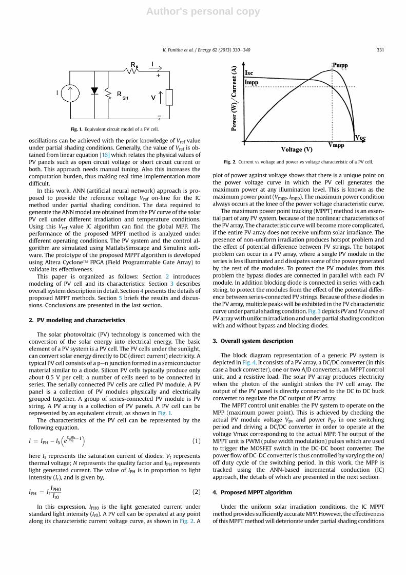
In this expression, IPH0 is the light generated current understandard light intensity (Ir0). A PV cell can be operated at any pointalong its characteristic current voltage curve, as shown in Fig. 2. A
plot of power against voltage shows that there is a unique point onthe power voltage curve in which the PV cell generates themaximum power at any illumination level. This is known as themaximum power point (Vmpp, Impp). The maximumpower conditionalways occurs at the knee of the power voltage characteristic curve.
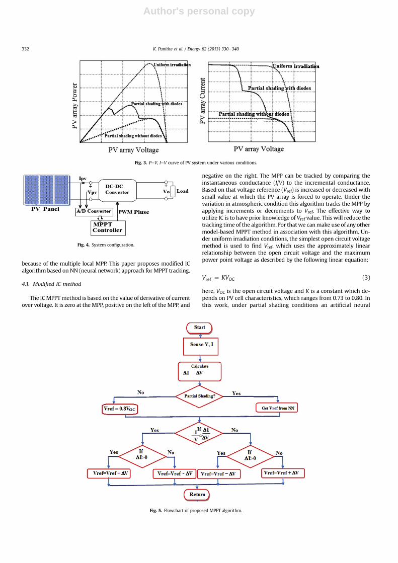
The maximum power point tracking (MPPT) method is an essen-tial part of any PV system, because of the nonlinear characteristics ofthe PV array. The characteristic curvewill becomemore complicated,if the entire PV array does not receive uniform solar irradiance. Thepresence of non-uniform irradiation produces hotspot problem andthe effect of potential difference between PV strings. The hotspotproblem can occur in a PV array, where a single PV module in theseries is less illuminated and dissipates some of the power generatedby the rest of the modules. To protect the PV modules from thisproblem the bypass diodes are connected in parallel with each PVmodule. In addition blocking diode is connected in series with eachstring, to protect the modules from the effect of the potential differ-ence between series-connected PV strings. Because of these diodes inthe PV array, multiple peakswill be exhibited in the PV characteristiccurveunderpartial shading condition. Fig. 3 depictsPVand IV curveofPVarraywithuniformirradiationandunderpartial shadingconditionwith and without bypass and blocking diodes.
3. Overall system description
The block diagram representation of a generic PV system isdepicted in Fig. 4. It consists of a PV array, a DC/DC converter (in thiscase a buck converter), one or two A/D converters, an MPPT controlunit, and a resistive load. The solar PV array produces electricitywhen the photon of the sunlight strikes the PV cell array. Theoutput of the PV panel is directly connected to the DC to DC buckconverter to regulate the DC output of PV array.
The MPPT control unit enables the PV system to operate on theMPP (maximum power point). This is achieved by checking theactual PV module voltage Vpv and power Ppv in one switchingperiod and driving a DC/DC converter in order to operate at thevoltage Vmax corresponding to the actual MPP. The output of theMPPT unit is PWM (pulse widthmodulation) pulses which are usedto trigger the MOSFET switch in the DC-DC boost converter. Thepower flowof DC-DC converter is thus controlled by varying the on/off duty cycle of the switching period. In this work, the MPP istracked using the ANN-based incremental conduction (IC)approach, the details of which are presented in the next section.
4. Proposed MPPT algorithm
Under the uniform solar irradiation conditions, the IC MPPTmethodprovides sufficientlyaccurateMPP.However, the effectivenessof thisMPPTmethodwill deteriorate under partial shading conditions
Fig. 1. Equivalent circuit model of a PV cell.
Fig. 2. Current vs voltage and power vs voltage characteristic of a PV cell.
K. Punitha et al. / Energy 62 (2013) 330e340 331
Author's personal copy
because of the multiple local MPP. This paper proposes modified ICalgorithm based on NN (neural network) approach forMPPT tracking.
4.1. Modified IC method
The ICMPPTmethod is based on the value of derivative of currentover voltage. It is zero at theMPP, positive on the left of theMPP, and
negative on the right. The MPP can be tracked by comparing theinstantaneous conductance (I/V) to the incremental conductance.Based on that voltage reference (Vref) is increased or decreased withsmall value at which the PV array is forced to operate. Under thevariation in atmospheric condition this algorithm tracks the MPP byapplying increments or decrements to Vref. The effective way toutilize IC is to have prior knowledge of Vref value. This will reduce thetracking time of the algorithm. For thatwe canmake use of any othermodel-based MPPT method in association with this algorithm. Un-der uniform irradiation conditions, the simplest open circuit voltagemethod is used to find Vref, which uses the approximately linearrelationship between the open circuit voltage and the maximumpower point voltage as described by the following linear equation:
Vref ¼ KVOC (3)
here, VOC is the open circuit voltage and K is a constant which de-pends on PV cell characteristics, which ranges from 0.73 to 0.80. Inthis work, under partial shading conditions an artificial neural
Fig. 3. PeV, IeV curve of PV system under various conditions.
Fig. 4. System configuration.
Fig. 5. Flowchart of proposed MPPT algorithm.
K. Punitha et al. / Energy 62 (2013) 330e340332
Author's personal copy
network (NN) is used to supply the value of Vref. The proposed ICMPPT algorithm estimates the partial shading conditions, using thefollowing linear equations [16].
DVPV � VPVðtÞ � VPVðt � 1Þ � DVSET (4)
IPVðtÞ � IPVðt � 1ÞNP
� DIPVðt � 1ÞNP
zDISET (5)
here DVSET and DISET are predetermined voltage and current valueset by the user and NP is the number of parallel connected modulesin a PV system. The value of DVSET, in eqs. (4) and (5) are selectedbased on the system performance related with input voltage ripple.The value of DVSET should be greater than input voltage rippleunder steady state operation of the system. The value DISET can becalculated as the sensed current DISET(t � 1) divided by NP. If theseequations are satisfied, the algorithm infers that the PV system isunder partially shaded condition.
The ability of ANN to estimate unknown parameters inspired itsapplication for MPP tracking. These networks can be trained off-line for non-linear mapping and can then be used in an efficientway in the on-line environment. By combining with ANN, theeffectiveness of the IC MPPT method can be improved [24]. Theproposed algorithm has the advantage of trackingMPP quickly than
using the IC algorithm alone. The flowchart of the proposedmethodis shown in Fig. 5.
4.2. Artificial neural network for estimation of Vref
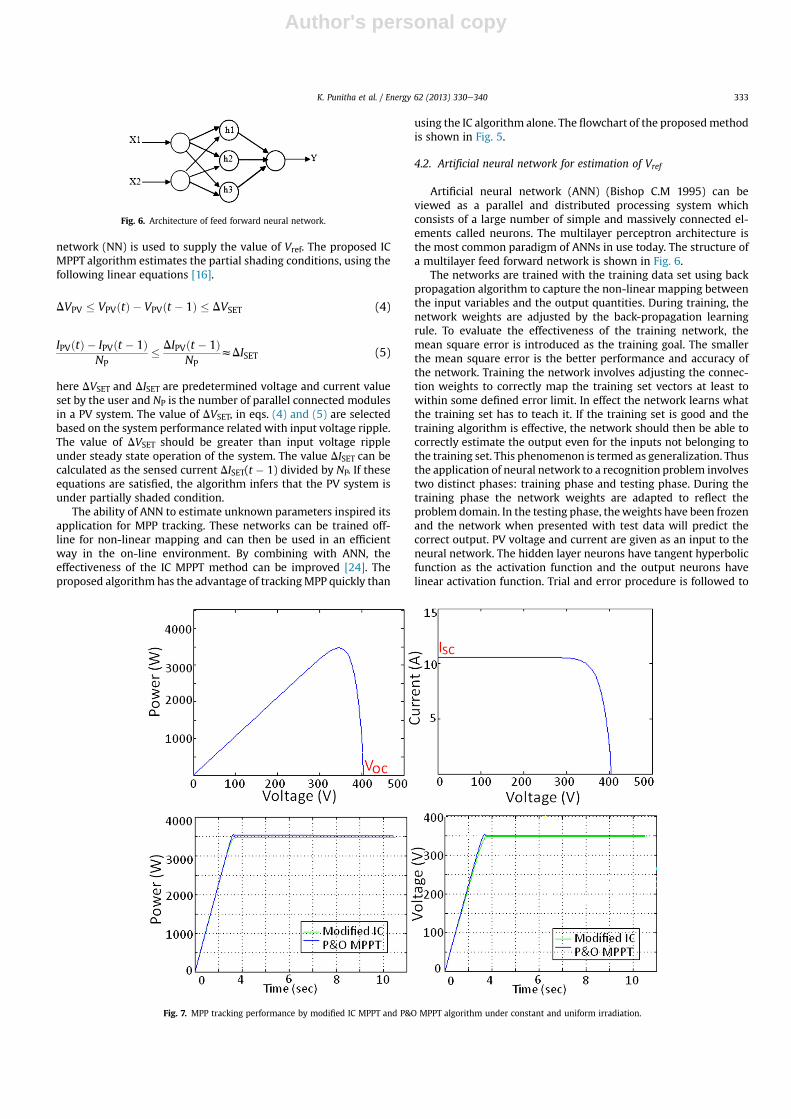
Artificial neural network (ANN) (Bishop C.M 1995) can beviewed as a parallel and distributed processing system whichconsists of a large number of simple and massively connected el-ements called neurons. The multilayer perceptron architecture isthe most common paradigm of ANNs in use today. The structure ofa multilayer feed forward network is shown in Fig. 6.
The networks are trained with the training data set using backpropagation algorithm to capture the non-linear mapping betweenthe input variables and the output quantities. During training, thenetwork weights are adjusted by the back-propagation learningrule. To evaluate the effectiveness of the training network, themean square error is introduced as the training goal. The smallerthe mean square error is the better performance and accuracy ofthe network. Training the network involves adjusting the connec-tion weights to correctly map the training set vectors at least towithin some defined error limit. In effect the network learns whatthe training set has to teach it. If the training set is good and thetraining algorithm is effective, the network should then be able tocorrectly estimate the output even for the inputs not belonging tothe training set. This phenomenon is termed as generalization. Thusthe application of neural network to a recognition problem involvestwo distinct phases: training phase and testing phase. During thetraining phase the network weights are adapted to reflect theproblem domain. In the testing phase, theweights have been frozenand the network when presented with test data will predict thecorrect output. PV voltage and current are given as an input to theneural network. The hidden layer neurons have tangent hyperbolicfunction as the activation function and the output neurons havelinear activation function. Trial and error procedure is followed to
Fig. 6. Architecture of feed forward neural network.
Fig. 7. MPP tracking performance by modified IC MPPT and P&O MPPT algorithm under constant and uniform irradiation.
K. Punitha et al. / Energy 62 (2013) 330e340 333
Author's personal copy
select the suitable number of neurons in the hidden layer. Theneural network is used to obtain the voltage of the maximum po-wer of the solar panel. For model development, a large number oftraining data is required. Experimental data is used for this pur-pose. The measured voltage and current of PV array are used as aninput to the model and the identified maximum power pointvoltage Vref is the output of the model. The input and output arenormalized between 0 and 1 and presented to the feed forwardneural networks.
5. Results and discussion
5.1. Simulation results
The PV system is simulated using the built-in PV modules ofMatlab/Simscape software. Each module consists of 36 photocellsconnected in series. The parameters of the photovoltaic modules areset as Isc ¼ 5.29 A, Voc ¼ 45.2 V, Imp ¼ 4.97 A, Vmp ¼ 36.2 V,Ir0 ¼ 1000 W/m2, N ¼ 1.2 � 36 and Rs ¼ 0.65 U (referred from themanufacturer’s data sheet). The arrays of photovoltaic modules areestablished by connecting two sets of 9 panels in series, and thenconnecting the two sets of 9 panels inparallel to get the poweroutputof 3.3 kW (single phase). SIMSCAPE software has the provision toconnect the bypass and reverse blocking diodes and to represent thevarying atmospheric conditions, irradiations and temperature.
The performance of the proposed approach was evaluated un-der three different conditions: (i) Constant and uniform irradiation,
(ii) Rapidly varying irradiation, (iii) Partially shading or non-uniform irradiation condition and the results are presented below:
Case (i) First, PV systemwas simulated with uniform irradiationon all the solar cells. A constant irradiation level of G ¼ 1000 W/m2
was maintained on the PV panel. Only one MPP occurs in this case.The modified IC algorithm was applied to track the MPP. The PVcharacteristics of the PV system and the tracking of MPP by themodified IC method are shown in Fig. 7. For comparison P&Omethodwas applied to track theMPP and the tracking performanceby the P&O approach is also shown in Fig. 7. It is noticed that themaximumpower reached by the PV systemwhile usingmodified ICalgorithm is 6% higher than P&Omethod. Also P&OMPPT algorithmoscillates around MPP as noticed in Fig. 7.
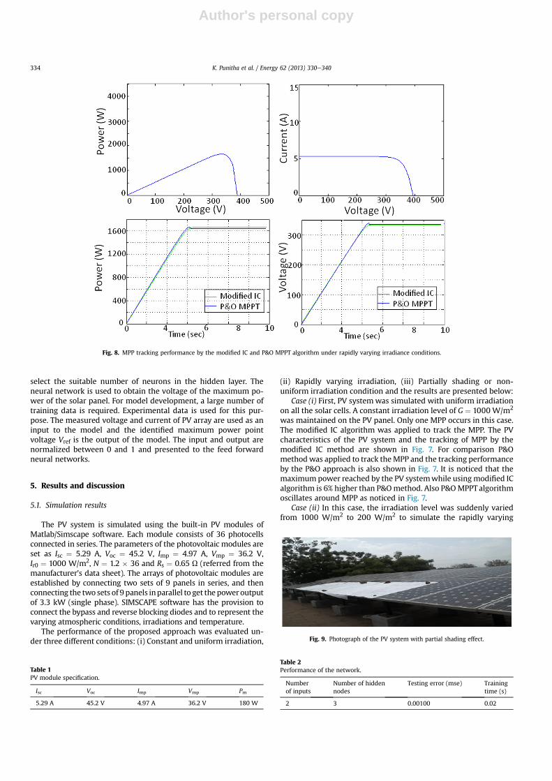
Case (ii) In this case, the irradiation level was suddenly variedfrom 1000 W/m2 to 200 W/m2 to simulate the rapidly varying
Fig. 8. MPP tracking performance by the modified IC and P&O MPPT algorithm under rapidly varying irradiance conditions.
Table 1PV module specification.
Isc Voc Imp Vmp Pm
5.29 A 45.2 V 4.97 A 36.2 V 180 W
Fig. 9. Photograph of the PV system with partial shading effect.
Table 2Performance of the network.
Numberof inputs
Number of hiddennodes
Testing error (mse) Trainingtime (s)
2 3 0.00100 0.02
K. Punitha et al. / Energy 62 (2013) 330e340334
Author's personal copy
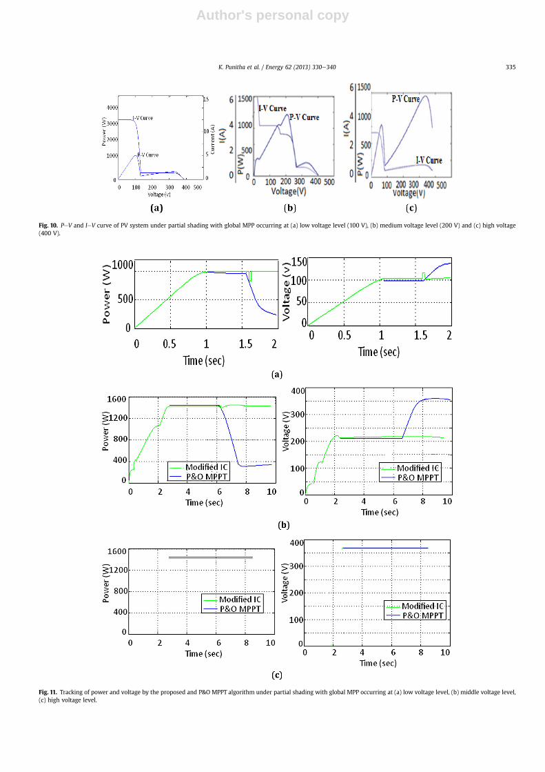
Fig. 10. PeV and IeV curve of PV system under partial shading with global MPP occurring at (a) low voltage level (100 V), (b) medium voltage level (200 V) and (c) high voltage(400 V).
Fig. 11. Tracking of power and voltage by the proposed and P&O MPPT algorithm under partial shading with global MPP occurring at (a) low voltage level, (b) middle voltage level,(c) high voltage level.
K. Punitha et al. / Energy 62 (2013) 330e340 335
Author's personal copy
irradiation condition. As shown in Fig. 8, here also only onemaximum power point occurs on the PV curve but the maximumpower has reduced from 3500 W to 1750 W when the irradiationlevel is reduced. The maximum power reached by the PV systemwhile using modified IC algorithm is 1% higher than P&O method isnoticed in Fig. 8.
Case (iii)Next, the PV systemwas simulatedwith partial shadingeffect, and the tracking of global MPP by the modified IC MPPT al-gorithm and P&O algorithm are investigated. The proposed modi-fied IC MPPT algorithm predicts the occurrence of partial shadingconditions, using the eqs. (4) and (5). Under non-uniform irradia-tion condition an artificial neural network (NN) is used to supplythe value of Vref. The inputs to the ANN are PV voltage and currentand the output is the reference voltage used for modified IC MPPTalgorithm. The training and testing data required to develop theANN are collected from the PV system installed at Sri BalaGana-pathy Mills Pvt. Ltd., Sivakasi. The PV system consists of 54 PVmodules which are separated into 3-phases. Each phase comprises18modules. The peak-value power of eachmodule is 180W. The PVsystem includes 9 series connectedmodules in parallel with other 9series connected module to form single phase. The specifications ofthe PV system are given in Table 1.
The measurements were taken with and without shading. Tocreate partial shading condition artificially the PV modules arecovered by a partially transparent sheet as shown in Fig. 9. In everycase, power voltage characteristic is recorded and the corre-sponding Vref value is also obtained. Back-propagation training al-gorithm was used for the training the network. Totally 10,000 datawere collected from 15 PV curves with three different voltage
position of GP (global point). 80% of the data was devoted fortraining and 20% for testing. The network is trained with Leven-bergeMarquardt algorithm. After training, the ANN model re-produces reasonably the optimal reference voltage. Because theANN is trained for a specific type of PVmodule, the MPPT algorithmcan work correctly for this particular PV module. Then the ANNoutput voltage is used by the modified IC method with a smallincrement to track the exact MPP of system.
Next the models of the PV array configuration are established inMatlab/Simscape similar to the experimental PV system of 10 kW.The models of single-phase PV array (3.3 kW) with 18 modules areconsidered in this paper. After training, the network is tested withthe test data to access the generalization ability of the network. Theperformance of the network during training and testing is pre-sented in Table 2.
The tracking of global MPP by the MPPT algorithms is analyzedunder three voltage levels. The PV curve is shown in Fig. 10(a)e(c)low, medium and high and the tracking performance is shown inFig. 10(a)e(c).
Fig. 11(a) shows that both algorithms are able to track the globalMPP, when the MPP is on high voltage level. Fig. 11(b &c) shows thedifference in performance between P&O and proposed MPPT al-gorithm when global MPP occurs at low and middle voltage levels.In Fig.11(b) global MPP is at middle voltage level and the P&OMPPTalgorithm is unable to differentiate global MPP among local MPPs.The proposed algorithm also tracks local MPPs, but it finds theoccurrence of partial shading by using the linear equations (4) and(5). When these equations are satisfied, the proposed algorithmreceives new reference voltage from NN. Then the operating
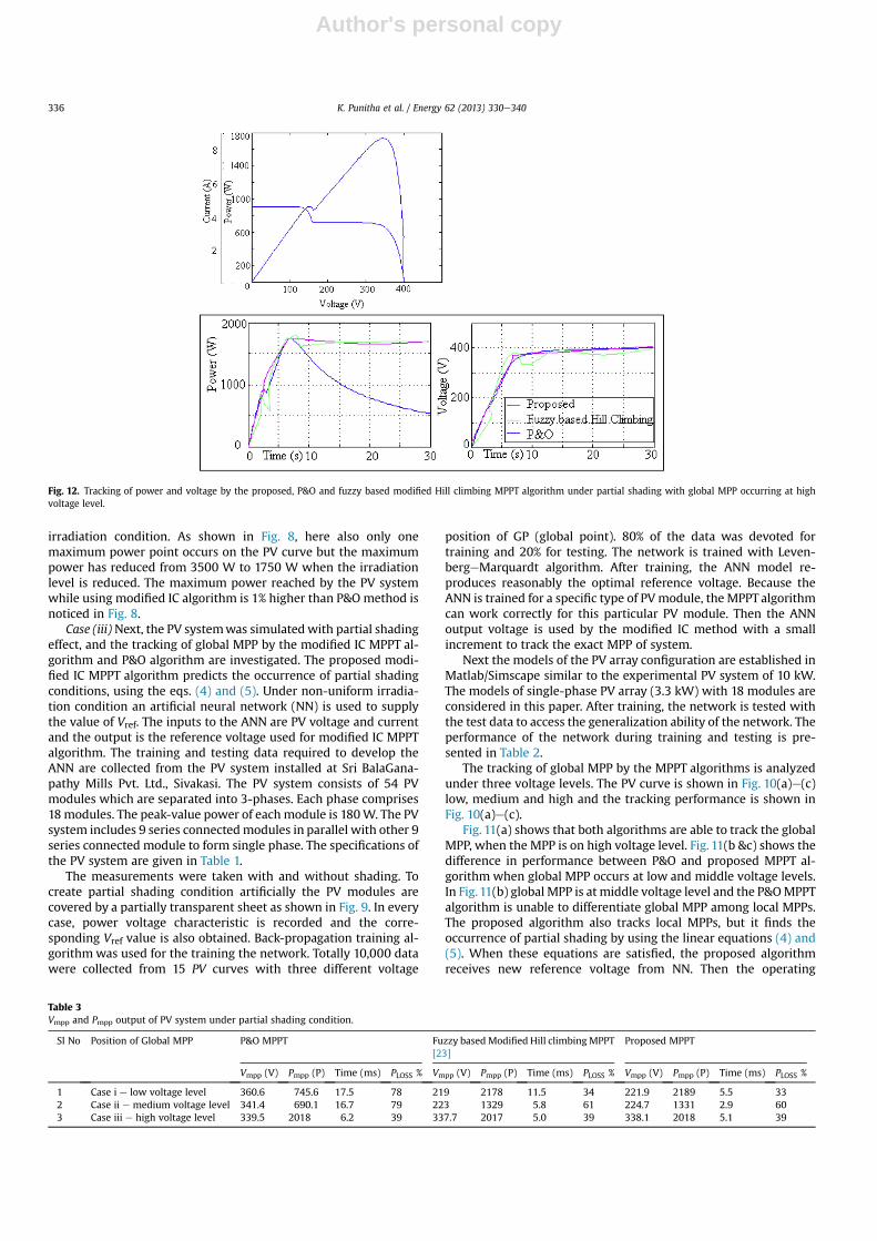
Fig. 12. Tracking of power and voltage by the proposed, P&O and fuzzy based modified Hill climbing MPPT algorithm under partial shading with global MPP occurring at highvoltage level.
Table 3Vmpp and Pmpp output of PV system under partial shading condition.
Sl No Position of Global MPP P&O MPPT Fuzzy basedModified Hill climbingMPPT[23]
Proposed MPPT
Vmpp (V) Pmpp (P) Time (ms) PLOSS % Vmpp (V) Pmpp (P) Time (ms) PLOSS % Vmpp (V) Pmpp (P) Time (ms) PLOSS %
1 Case i e low voltage level 360.6 745.6 17.5 78 219 2178 11.5 34 221.9 2189 5.5 332 Case ii e medium voltage level 341.4 690.1 16.7 79 223 1329 5.8 61 224.7 1331 2.9 603 Case iii e high voltage level 339.5 2018 6.2 39 337.7 2017 5.0 39 338.1 2018 5.1 39
K. Punitha et al. / Energy 62 (2013) 330e340336
Author's personal copy
voltage is changed to a reference voltage and new MPP is trackedagain by the proposed IC MPPT algorithm. Fig. 11(b & c) shows thetracking of MPP by both algorithms. Further, the tracking perfor-mance of proposed algorithm is compared with fuzzy based Hillclimbing MPPT algorithm [23] and is shown in Fig. 12. The trackedvalues of voltage, power and time taken to track GP using the threeapproaches are tabulated in Table 3. From Table 3 it is inferred thatthe proposed method tracks maximum value of power within a
short duration of time compared to the conventional P&O as well asfuzzy based Hill climbing MPPT algorithm. Also, the loss inmaximum power is less in the case of proposed MPPT algorithm.
5.2. Experimental results
To validate the performance of the proposed MPPT algorithm,the experimental studies were conducted on the prototype of the
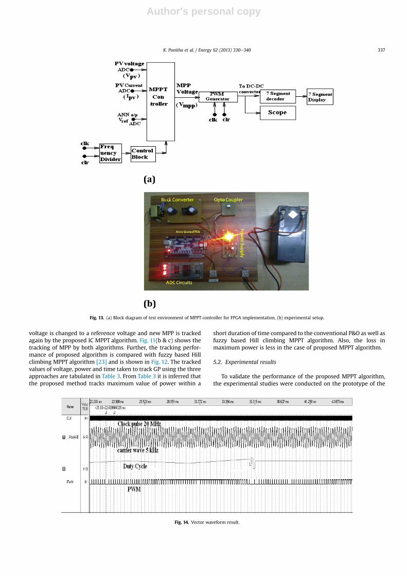
Fig. 13. (a) Block diagram of test environment of MPPT controller for FPGA implementation, (b) experimental setup.
Fig. 14. Vector waveform result.
K. Punitha et al. / Energy 62 (2013) 330e340 337
Author's personal copy
PV solar system. The developed prototype is composed of a variablepower supply, a buck converter, Altera Cyclone� FPGA, ADC(analog to digital converter) circuits and optocoupler. The proposedMPPT algorithm and PWM generator are implemented in FPGA.
The block diagram representation of test environment of FPGAimplementation of the proposed algorithm and PWM generator isshown in Fig. 13(a). The measured current and voltage through ADCmodule are given to Altera Cyclone� FPGA controller. The FPGAgenerates PWM pulses which is used to control DCeDC buck con-verter. Battery used in this circuit is for storage purpose and toprovide a constant voltage to external load irrespective of PVvoltage variations. The frequency divider block generates clocksignal at 1 Hz from the internal clock signal of 100 MHz. Actually,the FPGA works with the frequency of 100 Hz, but for testing pur-poses and in order to visualize the results, it is made to work at 1 sclock period. 7-segments displayer displays the value of the dutycycle D in hexadecimal. The scope displays the generated PWMsignal. The VHDL schematic diagram of proposed MPPT and PWMgenerator and its vector waveform results are shown in Appendixin Fig. A1 and Fig. 14.
After verifying the results of vector waveform, the VHDL (veryhigh speed integrated circuits' hardware description language)program is downloaded into the FPGA and the experimental inputs(voltage and current) are connected to validates its output.Fig. 13(b) shows the experimental setup. The PV source is emulatedby a variable DC voltage supply and a series resistor. The DC supplyvoltage level changes represent the irradiation variation and thetemperature variation is simulated by changing the resistor value.The parameters of experimental setup are tabulated in Table 4.
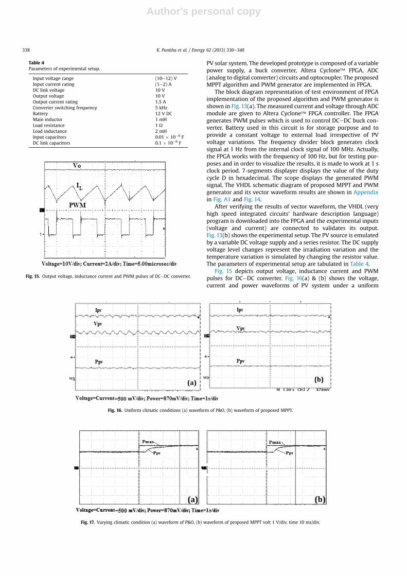
Fig. 15 depicts output voltage, inductance current and PWMpulses for DCeDC converter. Fig. 16(a) & (b) shows the voltage,current and power waveforms of PV system under a uniform
Fig. 16. Uniform climatic conditions (a) waveform of P&O, (b) waveform of proposed MPPT.
Table 4Parameters of experimental setup.
Input voltage range (10e12) VInput current rating (1e2) ADC link voltage 10 VOutput voltage 10 VOutput current rating 1.5 AConverter switching frequency 5 kHzBattery 12 V DCMain inductor 1 mHLoad resistance 1 ULoad inductance 2 mHInput capacitors 0.01 � 10�6 FDC link capacitors 0.1 � 10�6 F
Fig. 15. Output voltage, inductance current and PWM pulses of DCeDC converter.
Fig. 17. Varying climatic condition (a) waveform of P&O, (b) waveform of proposed MPPT volt 1 V/div, time 10 ms/div.
K. Punitha et al. / Energy 62 (2013) 330e340338

Author's personal copy
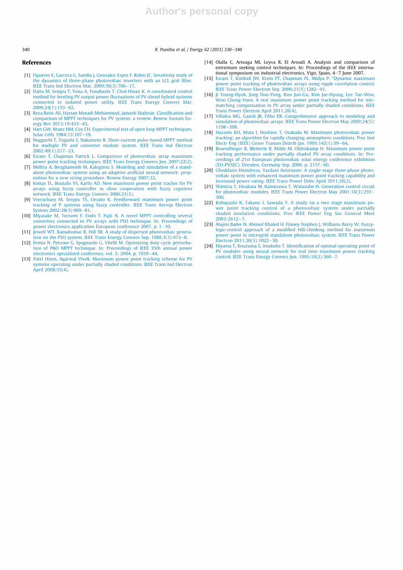
climatic condition with P&O and IC algorithms, respectively. Fig. 16shows that more oscillation is occurring around MPP in P&O algo-rithm but themodified IC algorithm hasmuch less oscillation. Undervarying climatic condition the response of P&O and the modified ICalgorithm are shown in Fig. 17. When the occurrence of partialshading is detected by the proposed MPPT algorithm from eqs. (4)and (5), the operating point is changed to new reference voltageprovided by NN. The tracking of MPP in this case is shown in Fig. 17.It is observed from Fig. 17 that the performance of the modified ICalgorithm is more consistent and stable than the P&O algorithm. Italso attains its MPP in a relatively short time. The generated PWMpulse under varying climatic condition is shown in Fig. 18.
6. Conclusions
In this paper, a modified IC method is proposed to track theMPP under partial shading condition. An ANN is used to supply
the voltage Vref to the modified IC method. An off-line ANN,trained using a back-propagation algorithm is utilized for onlineestimation of reference voltage for the feed-forward loop.Experimental data under various atmospheric conditions is usedfor the offline training of the ANN, and software Matlab is used inthe training of the net. The PV system using the proposedapproach for MPPT is simulated using MATLAB/Simscape tool. Forcomparison conventional P&O approach and fuzzy based modi-fied Hill climbing MPPT algorithms were used. From the simula-tion results it is observed that the proposed approach provideshigher percentage of maximum power with less response timethan other two methods. The proposed approach for MPPT wasimplemented using FPGA to validate the results from the hard-ware setup.
Appendix
Fig. 18. Generating PWM pulse under varying climatic condition.
Fig. A1VHDL schematic diagram.
K. Punitha et al. / Energy 62 (2013) 330e340 339
Author's personal copy
References
[1] Figueres E, Garcera G, Sandia J, Gonzalez-Espin F, Rubio JC. Sensitivity study ofthe dynamics of three-phase photovoltaic inverters with an LCL grid filter.IEEE Trans Ind Electron Mar. 2009;56(3):706e17.
[2] Datta M, Senjyu T, Yona A, Funabashi T, Chul-Hwan K. A coordinated controlmethod for leveling PV output power fluctuations of PV-diesel hybrid systemsconnected to isolated power utility. IEEE Trans Energy Convers Mar.2009;24(1):153e62.
[3] Reza Reisc Ali, Hassan Moradi Mohammad, Jamasb Shahriar. Classification andcomparison of MPPT techniques for PV system: a review. Renew Sustain En-ergy Rev 2013;19:433e43.
[4] Hart GW, Branz HM, Cox CH. Experimental test of open loop MPPT techniques.Solar Cells 1984;13:107e19.
[5] Nogguchi T, Togashi S, Nakamoto R. Short-current pulse-based MPPT methodfor multiple PV and converter module system. IEEE Trans Ind Electron2002;49(1):217e23.
[6] Esram T, Chapman Patrick L. Comparison of photovoltaic array maximumpower point tracking techniques. IEEE Trans Energy Convers Jun. 2007;22(2).
[7] Mellita A, Benghanemb M, Kalogirou S. Modeling and simulation of a stand-alone photovoltaic system using an adaptive artificial neural network: prop-osition for a new sizing procedure. Renew Energy 2007;32.
[8] Kottas TL, Boutalis YS, Karlis AD. New maximum power point tracker for PVarrays using fuzzy controller in close cooperation with fuzzy cognitivenetwork. IEEE Trans Energy Convers 2006;21(3).
[9] Veerachary M, Senjyu TS, Uezato K. Feedforward maximum power pointtracking of P systems using fuzzy controller. IEEE Trans Aerosp ElectronSystem 2002;38(3):969e81.
[10] Miyatake M, Toriumi F, Endo T, Fujii N. A novel MPPT controlling severalconverters connected to PV arrays with PSO technique. In: Proceedings ofpower electronics application European conference 2007. p. 1e10.
[11] Jewell WT, Ramakumar R, Hill SR. A study of dispersed photovoltaic genera-tion on the PSO system. IEEE Trans Energy Convers Sep. 1988;3(3):473e8.
[12] Femia N, Petrone G, Spagnuolo G, Vitelli M. Optimizing duty cycle perturba-tion of P&O MPPT technique. In: Proceedings of IEEE 35th annual powerelectronics specialized conference, vol. 3; 2004. p. 1939e44.
[13] Patel Hiren, Agarwal Vivek. Maximum power point tracking scheme for PVsystems operating under partially shaded conditions. IEEE Trans Ind ElectronApril 2008;55(4).
[14] Olalla C, Arteaga MI, Leyva R, El Aroudi A. Analysis and comparison ofextremum seeking control techniques. In: Proceedings of the IEEE interna-tional symposium on industrial electronics, Vigo, Spain, 4e7 June 2007.
[15] Esram T, Kimball JW, Krein PT, Chapman PL, Midya P. “Dynamic maximumpower point tracking of photovoltaic arrays using ripple correlation control.IEEE Trans Power Electron Sep. 2006;21(5):1282e91.
[16] Ji Young-Hyok, Jung Doo-Yong, Kim Jun-Gu, Kim Jae-Hyung, Lee Tae-Won,Won Chung-Yuen. A real maximum power point tracking method for mis-matching compensation in PV array under partially shaded conditions. IEEETrans Power Electron April 2011;26(4).
[17] Villalva MG, Gazoli JR, Filho ER. Comprehensive approach to modeling andsimulation of photovoltaic arrays. IEEE Trans Power Electron May 2009;24(5):1198e208.
[18] Hussein KH, Muta I, Hoshino T, Osakada M. Maximum photovoltaic powertracking: an algorithm for rapidly changing atmospheric conditions. Proc InstElectr Eng (IEEE) Gener Transm Distrib Jan. 1995;142(1):59e64.
[19] Bruendlinger R, Bletterie B, Milde M, Oldenkamp H. Maximum power pointtracking performance under partially shaded PV array conditions. In: Pro-ceedings of 21st European photovoltaic solar energy conference exhibition(EU-PVSEC), Dresden, Germany Sep. 2006. p. 2157e60.
[20] Ghoddami Himidreza, Yazdani Amirnaser. A single-stage three-phase photo-voltaic system with enhanced maximum power point tracking capability andincreased power rating. IEEE Trans Power Deliv April 2011;26(2).
[21] Shimizu T, Hirakata M, Kamezawa T, Watanabe H. Generation control circuitfor photovoltaic modules. IEEE Trans Power Electron May 2001;16(3):293e300.
[22] Kobayashi K, Takano I, Sawada Y. A study on a two stage maximum po-wer point tracking control of a photovoltaic system under partiallyshaded insolation conditions. Proc IEEE Power Eng Soc General Meet2003:2612e7.
[23] Alajmi Bader N, Ahmed Khaled H, Finney Stephen J, Williams Barry W. Fuzzy-logic-control approach of a modified Hill-climbing method for maximumpower point in microgrid standalone photovoltaic system. IEEE Trans PowerElectron 2011;26(3):1022e30.
[24] Hiyama T, Kouzuma S, Imakubo T. Identification of optimal operating point ofPV modules using neural network for real time maximum power trackingcontrol. IEEE Trans Energy Convers Jun. 1995;10(2):360e7.
K. Punitha et al. / Energy 62 (2013) 330e340340