laparoscopic testicular artery ligation as an alternative to ...
Upload
khangminh22Category
view
1download
0
Artery-CAn OMNeT++ Based Discrete Event Simulation
Framework for Cellular V2XExtended Version∗
Anupama Hegde
Technische Hochschule Ingolstadt / [email protected]
Andreas Festag†
Technische Hochschule Ingolstadt / [email protected]
Abstract
Cellular Vehicle-to-X (Cellular V2X) is a communication technology that aims to facilitate the communication amongvehicles and with the roadside infrastructure. Introduced with LTE Release 14, Cellular V2X enables device-to-devicecommunication to support road safety and traffic efficiency applications. We present Artery-C, a simulation frameworkfor the performance evaluation of Cellular V2X protocols and V2X applications. Our simulator relies on the simulationframework SimuLTE and substantially extends it by implementing control and user planes. Besides the vehicle-to-network communication via the up-/downlink interface, it provides vehicle-to-vehicle and vehicle-infrastructurecommunication via the sidelink interface using the managed and the unmanaged mode of Cellular V2X (mode 3 and 4,respectively). The simulator also implements advanced features of 5G mobile networks, such as variable numerologies.For the transmission of of V2X messages, it adds a non-IP interface. Artery-C integrates seamlessly into the simulationframework Artery, which enables the simulation of standardized V2X messages at the facilities layer as well as thecoupling to the mobility simulator SUMO. A specific feature of Artery-C is the support of dynamic switching betweenall modes of Cellular V2X. In order to demonstrate the capabilities of Artery-C, we evaluate V2X-based platooning as arepresentative use case and present results for mode 3, mode 4 and mode switching in a highway scenario.
I. Introduction
V2X communication enables the exchange ofinformation among vehicles, roadside infras-tructure and other traffic participants. The
continuous information exchange supports vehiclesto obtain an accurate knowledge of its surround-ing environment in order to improve traffic safetyand efficiency. Cellular V2X is a mobile network-based communication technology that facilitates theconventional communication between vehicle andnetwork (V2N) to provide backend services and ad-
∗A short version of the paper appeared in: A. Hegde andA. Festag “Artery-C – An OMNeT++ Based Discrete Event Sim-ulation Framework for Cellular V2X”, 23rd International ACMConference on Modeling, Analysis and Simulation of Wirelessand Mobile Systems (MSWiM ’20), November 16–20, 2020, Ali-cante, Spain, DOI: 10.1145/3416010.3423240†Also with Fraunhofer Application Center “Connected Mo-
bility and Infrastructure”
ditionally realizes a direct communication amongend devices, i.e., vehicle-to-vehicle (V2V), vehicle-to-pedestrian (V2P) and vehicle-to-infrastructure (V2I)communication. The direct communication, also re-ferred to as device-to-device (D2D) communication,allows two physically close end devices to commu-nicate using the sidelink interface (LTE PC-5). Bysidelink, devices do not have to depend on the cel-lular access and core network for allocation of radioresources for data transmission [1].
In comparison to the cellular communication viaup- and downlink, the sidelink communication in-curs a shorter latency for message transfer, which isa critical aspect for vehicle safety and automation.The sidelink communication enables the transmis-sion of periodic and non-periodic V2X messagesas they are defined, amongst other standards, inthe European standards for V2X communications,most importantly the Cooperative Awareness Mes-
1
arX
iv:2
009.
0572
4v1
[cs
.NI]
12
Sep
2020

A. Hegde and A. Festag
Table 1: Comparison of existing simulation frameworks for Cellular V2X with ARTERY-C
SimuLTE [2] Cellular-VCS [3]
OpenCV2X [4] Artery-C
Base framework OMNeT++ ns-3 OMNeT++ OMNeT++Protocol stack LTE LTE LTE LTE, 5G sel. featuresPlane User User User Control & UserModes UL, DL, D2Da UL, DL, SL
mode 3UL, DL, SLmode 4
UL, DL, SLmode 3 & 4
Mode switching Cellular – D2D No No Cellular – D2D,SL mode 3 – 4
Variablenumerology
No No No Yes
V2X applications IP-based V2I,V2N
IP-based V2I,V2N,V2V mode 3
Non-IP-basedV2V mode 4
IP-based V2I, V2N;Non-IP-based V2V(mode 3 & 4)
Facilities No No Yes, withArtery [5]
Yes, with Artery
Open source Yes No Yes Plannedb
aAbbreviations: UL = Uplink, DL = Downlink, D2D = Device-to-Device, SL = SidelinkbWe plan to publish the simulation framework under an open source license.
sages (CAM) and Decentralized Environmental No-tification Message (DENM). With CAMs, vehiclesperiodically broadcast their status information suchas position, speed, heading to neighboring vehi-cles with a periodicity of 1 to 10 Hz. DENMs aretriggered in critical safety situations. With the avail-ability of up-/down- and sidelink in Cellular V2X,these periodic and event-driven messages can behandled across the LTE Uu and PC-5 interfaces.
One of the key challenges in modelling vehic-ular communications for simulation-based perfor-mance evaluation is the required integration of adiverse set of components, including vehicle mo-bility, environmental perception, radio propagationand related effects as well as V2X services and com-munication protocols. The existing OMNeT++-basedsimulation framework Artery [5] – originally de-veloped for standard-compliant, WLAN-based V2Xcommunication – provides a clear separation of fa-cilities, application layer and vehicular scenarios,which makes it an ideal base framework for Cel-lular V2X simulations. To model the data planefunctionalities of the LTE Radio Access Network(RAN) and Evolved Packet Core (EPC), we have uti-lized and extended the user plane of the simulation
framework SimuLTE [2], implemented the controlplane functions, and integrated both user and con-trol plane into Artery, resulting in Artery-C.1
In Artery-C, the modules for radio resource allo-cation take into account that a vehicle can be locatedin the region of cellular coverage and that the allo-cation process is managed by an LTE base stationin a centralized manner (referred to as network-assisted or mode 3 in 3GPP standards [6]). In casethe vehicle cannot remain in the region of cellu-lar coverage, it autonomously configures the ra-dio resources from a pre-defined pool of resources(defined as mode 4 in 3GPP standards). Hence,Artery-C supports three modes in a common simu-lation framework, i.e., up-/downlink with the RANand the EPC, network-assisted sidelink (mode 3)and out-of-coverage sidelink with distributed re-source allocation and management (mode 4). As anadditional feature to the simultaneous support of allthree modes, Artery-C supports dynamic switch-ing among the modes as a part of the simulationscenario. For example, a scenario may involve achange from mode 3 to 4, when a vehicle moves
1The -C in Artery-C stands for Cellular V2X.
2

Artery-C – An OMNeT++ Based Discrete Event Simulation Framework for Cellular V2X
out-of-coverage and switch back to mode 3 whennetwork coverage resumes. The same vehicle maycommunicate simultaneously via the up-/downlink.Hence, the support of mode switching allows mod-eling more complex scenarios and studying V2Xapplications under more realistic conditions.
For performance evaluation of Cellular V2X,several simulation frameworks exist (see Tab. 1).A baseline for sidelink in LTE networks hasbeen developed in the OMNeT++-based simulatorSimuLTE [2] and extended for network assisteddevice-to-device (D2D) [7]. In [3], the authors stud-ied Cellular V2X mode 3 using the ns-3 framework.The OpenCV2X simulator in [4] aims to model andevaluate the performance of sidelink mode 4 in Cel-lular V2X. However, the existing simulators so farassume only a single resource allocation mode at agiven time for a given scenario. This leads to a lim-itation that heterogeneous V2X scenarios with V2V,V2I and V2N cannot be simultaneously studied.
The remainder of the paper is organized as fol-lows: Sec. II describes the requirements on a Cellu-lar V2X simulation environment. Sec. III explainsthe implementation design of ARTERY-C. Sec. IVpresents simulation results for an example V2X usecase using different capabilities of ARTERY-C forthe purpose of validation. For the use case, wehave chosen V2X-based platooning and study it ina highway scenario for mode 3, mode 4 and modeswitching. Sec. V concludes the paper.
II. Requirements for a Cellular V2Xsimulation environment
The VANET simulator Artery [5] provides a com-prehensive framework with a clear separation ofthe protocol stack and the environment model. Itallows for a smooth interaction between OMNeT++and SUMO, and adapting the facilities layer to dif-ferent access technologies. The Artery middlewareenables vehicles to use multiple V2X services simul-taneously.
Originally developed for ITS-G5 type of accesstechnologies, the recent version of Artery supportsmobile networks, specifically up-/downlink andnetwork-assisted D2D communication [8]. A firstapproach to extend Artery for sidelink mode 4 hasbeen addressed in [4]. For the development of a
comprehensive Cellular-V2X protocol suite withdedicated control and user planes, with a sidelinkinterface for both mode 3 and mode 4, and withsupport of different V2X application scenarios, wehave identified several requirements.
i. Software-related Requirements
Modularity: The layers of the protocol suite aredefined as modules, which communicate with eachother through messages sent across gates. The lay-ers of the user plane – Packet Data and Conver-gence Protocol (PDCP), Radio Link Control (RLC),Medium Access Control (MAC) and Physical (PHY)– are implemented as simple modules and encap-sulated into a compound module called NetworkInterface Card (NIC) as shown in Fig. 1. The controlplane (RRC) is modeled as an independent mod-ule, which communicates with the user plane by amessage-passing paradigm.
Separation between protocol stack and roadtraffic model: Traffic models to study differenttypes of V2X scenarios such as V2V, V2I, V2N andV2P are developed using the microscopic road traf-fic simulator SUMO2. The Cellular V2X protocolstack is implemented separately in the OMNeT++ sim-ulation framework and specifically used to studyrelevant aspects in V2X communication environ-ments, such as resource allocation and scheduling.
Message formats for V2X communication ser-vices: Currently, the framework Artery-C includesthe V2X message types CAM and DENM. Theframework aims to support various other messageformats for V2X use cases such as infrastructuremessages, sensor data sharing and maneuver coor-dination [9].
ii. Cellular V2X-specific Requirements
Dedicated sidelink interface: In order to facilitatean uninterrupted exchange of messages among ve-hicles, infrastructure and road traffic participants, adedicated sidelink (PC-5) communication interfaceis implemented. This interface co-exists with theup- and downlink (Uu) interfaces. The vehicle com-municates with the infrastructure (V2N/V2I) using
2https://sumo.dlr.de (retrieved Sep 10, 2020)
3

A. Hegde and A. Festag
the up-/downlink and the sidelink is used for V2V,V2I and V2P applications.
Sidelink resource allocation modes and dy-namic switching: Both sidelink resource allocationmodes, i.e., mode 3 and mode 4, should be sup-ported so that vehicles can exchange messages de-pending on whether they are located inside or out-side the coverage of base station. Dynamic switch-ing between sidelink resource allocation modescauses overhead in terms of mode switching la-tency [10].
Support of heterogeneous traffic: Depending onthe type of application, the framework enables ve-hicles to simultaneously send both IP-based andnon-IP-based data.
Resource allocation and scheduling: Conven-tional scheduling schemes such as Round Robin(RR), Deficit Round Robin (DRR), MAXimum Car-rier over Interference (MAXCI) and ProportionalFair queuing (PF) are already implemented in theuser plane of SimuLTE for uplink and downlink. Fol-lowing 3GPP standards, the sidelink uses sensing-based semi-persistent scheduling (SB-SPS) for bothmode 3 and mode 4 (see Sec. III).
iii. Timing-related Requirements
Transmit time interval (TTI): The smallest unitstep time for the protocol simulations is 1 ms, whichcorresponds to the smallest time unit size for re-source allocation in LTE. Furthermore, 5G-New Ra-dio (NR)(3GPP TS 38.300 V16.1.0) supports a flex-ible size of resource units in frequency and time,which requires variable numerologies in the simu-lator.
Control and user plane latency: Control planelatency is characterized by delays incurred due tocommunication between the control plane compo-nents responsible for registering the end devicewith the infrastructure and acquiring system in-formation (SI). Correspondingly, the user plane la-tency is caused by the communication delays be-tween the layers of the user plane. In order to studypacket end-to-end latency for various applications,resource allocation during mode switching etc, it isimportant to understand the impact of both controland user plane latency.
Simulation run time: It refers to the amount of
consumed processing time for simulation execu-tion. The simulator allows achieving statisticallymeaningful results within a reasonable time andcommodity computing resources.In order to meet the Cellular V2X-specific require-ments and realize the software- and timing-relatedaspects, we have implemented the simulation frame-work Artery-C.
III. Implementation design of
ARTERY-C
In the OMNeT++ framework, the basic implementa-tion unit is called a module. Modules communi-cate with each other through event-driven messages.Each module is characterized by a structure definedvia .ned files and a behavior implemented via C++classes. The modules in a network can be of twotypes – stationary and dynamic. In this section, wepresent the salient features of our simulation frame-work Artery-C that has been built as an extensionto the user plane implementation in the simulationframework SimuLTE [2, 7].
The implementation design of the Artery-Cframework consists of two layers. The lower layercovers the protocols of the Cellular V2X access tech-nology. The implementation is aligned with theCellular V2X protocol stack. It comprises the con-trol plane with RRC and the user plane with PHY,MAC, RLC and PDCP. The layer on top is for gener-ation and reception of V2X messages and representsthe facilities of the C-ITS protocol stack.
The user plane has two parallel pipelines for IP-based and non-IP-based traffic (Fig. 1) with clearlyseparated functionalities. The facilities layer real-izes the V2X messaging, such as the CAM servicemodules of Artery to generate non-IP-based peri-odic messages. For IP-based V2I traffic, Artery-Cre-utilizes the modules from INET and Artery. Theuser plane is directly linked with the SUMO traf-fic model via the TRaCI API in order to continu-ously track the position of the vehicle and identifieswhether it is located in the region of cellular cov-erage or not. The LTE base stations (eNodeB) androad side units (RSUs) are modelled as stationarymodules and vehicles are modelled as dynamicmodules.
4

Artery-C – An OMNeT++ Based Discrete Event Simulation Framework for Cellular V2X
Figure 1: Implementation design of the Cellular V2X stack
i. Control Plane – Radio Resource Control
Cell search and mode selection: The controlplane/Radio Resource Control (RRC) component ismodelled in accordance with the 3GPP Release 15standards for 5G-NR (TS 38.331, V15.7.0). TheRRC is responsible to carry out three primary func-tionalities, i.e., system information acquisition, cellsearch and mode selection & mode switching con-trol. Based on the position updates of the vehiclefrom the SUMO traffic scenario, the cell search mod-ule of the RRC determines the distance between anUE and an LTE base station (eNodeB). If the UEis located inside the communication range of theeNodeB and the received signal strength meets thethreshold limits, then mode 3 is the preferred modeof operation. If an UE lies outside the region of abase station’s communication range, then mode 4 isselected.
System information acquisition: The processof system information acquisition involves the ex-change of network-related messages between UEand eNodeB that enables the UE to establish a suc-cessful connection with the eNodeB and the com-ponents of the Evolved Packet Core (EPC). Whenan UE recognizes itself to be in the region of cel-lular coverage, it sends a RRCConnSetup request to
the eNodeB. The eNodeB responds with the appro-priate Master Information Block (MIB) and SystemInformation Block (SIB) for different communica-tion interfaces, i.e., UL, DL and SL. Additionally,the eNodeB pre-configures a set of time and fre-quency resources in the form of SIB that can beused by the UE when it operates in mode 4. Thesynchronization-related information [10] betweenUE and eNodeB are exchanged immediately afterthe establishment of successful connection.
Mode switching control: The mode switchingcontrol module is responsible to regulate the dy-namic switching between mode 3 and mode 4. Thisis based on the availability of network coverage, re-ceived signal strength and traffic load. The resourceallocation modes directly correlate with the oper-ating states of the RRC - RRCIDLE, RRCINACTIVEand RRCCONN and correspond to the three-statefinite state machine (FSM) as shown in Fig. 2.
Figure 2: RRC state transition
In the RRCCONN state, the UE is connected tothe eNodeB and has established its identity withthe EPC. The eNodeB is responsible for allocatingsubchannels and subframes for sidelink communi-cation. When an UE is inside the network coveragebut not exchanging any information with the eN-odeB, it transits to RRCINACTIVE state. In this state,it is still registered with eNodeB and hence con-tinues to function in mode 3. When an UE movesoutside the base station coverage, the RRC tran-sits to RRCIDLE state and it informs the PHY andMAC component to allocate resources from a pre-configured pool of resources mentioned in appro-priate SIBs. The UE is now completely disconnectedfrom the base station.
ii. User/Data Plane
Packet data and convergence protocol (PDCP):The PDCP is the connecting component between theCellular V2X access technology and the networking
5
A. Hegde and A. Festag
& transport layer. It processes both IP and non-IPpackets. In case of IP traffic, it performs RobustHeader Compression (ROHC) and assigns/createsthe Connection Identifier (CID) that uniquely iden-tifies, together with the UE ID, a connection in thewhole network. When an IP packet arrives at PDCP,a logical connection identifier (LCID) is attached toit and forwarded to the radio link control (RLC). Incase of a non-IP-based packet3 the PDCP performsROHC, creates an entry in the non-IP connectionstable and forwards the packet as a PDU to the RLC.The two pipelines are illustrated in Fig. 1.
The PDCP consists of two separate gates for datainput from IP and non-IP traffic. Additionally, ithas a separate gate to receive control-related mes-sages from the control plane. For interaction withthe RLC, similar to [2], three different gates are con-nected with the PDCP-RRC module, one for eachRLC mode.
Radio link control (RLC): The RLC oper-ates in three modes - acknowledged (AM), un-acknowledged (UM) and transparent mode (TM).The key functionality of this component is to mul-tiplex and de-multiplex MAC SDUs to/from theMAC. The implementation of the RLC has not beenmodified much in reference to [2]. For sidelinkbroadcast operation, an acknowledgement is notapplied and we use the un-acknowledged mode.
iii. Medium Access Control (MAC)
The design of the MAC for the UE module hasbeen modified in a way that the sidelink schedulingco-exists with the previous uplink and downlinkimplementations as done in SimuLTE [2, 7]. Addi-tionally, the MAC module has a separate gate toreceive control-related information from the controlplane and incorporates an additional sub-modulecalled sidelink configuration (SC). The sidelink con-figuration sub-module interacts with the sidelinkresource allocation (SRA) submodule in the PHYcomponent and together they support the process ofresource configuration and allocation [10]. A func-
3In the European C-ITS standards, non-IP packet transportis realized by GeoNetworking (ETSI EN 302 636-4), an ad hocnetwork protocol based on geographic positions, and BTP , anUDP-like transport protocol (ETSI EN 302 636-5). Both areimplemented in the simulation framework Artery but beyondthe scope of this paper.
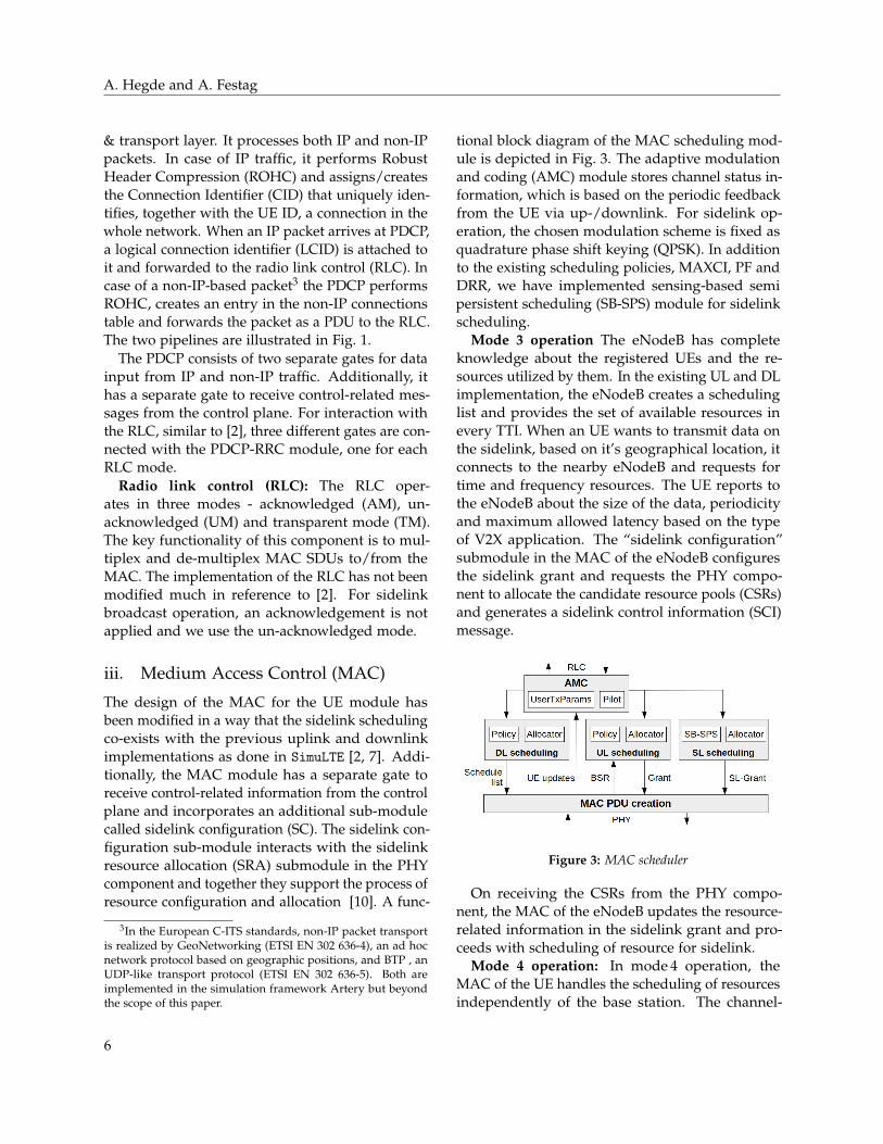
tional block diagram of the MAC scheduling mod-ule is depicted in Fig. 3. The adaptive modulationand coding (AMC) module stores channel status in-formation, which is based on the periodic feedbackfrom the UE via up-/downlink. For sidelink op-eration, the chosen modulation scheme is fixed asquadrature phase shift keying (QPSK). In additionto the existing scheduling policies, MAXCI, PF andDRR, we have implemented sensing-based semipersistent scheduling (SB-SPS) module for sidelinkscheduling.
Mode 3 operation The eNodeB has completeknowledge about the registered UEs and the re-sources utilized by them. In the existing UL and DLimplementation, the eNodeB creates a schedulinglist and provides the set of available resources inevery TTI. When an UE wants to transmit data onthe sidelink, based on it’s geographical location, itconnects to the nearby eNodeB and requests fortime and frequency resources. The UE reports tothe eNodeB about the size of the data, periodicityand maximum allowed latency based on the typeof V2X application. The “sidelink configuration”submodule in the MAC of the eNodeB configuresthe sidelink grant and requests the PHY compo-nent to allocate the candidate resource pools (CSRs)and generates a sidelink control information (SCI)message.
Figure 3: MAC scheduler
On receiving the CSRs from the PHY compo-nent, the MAC of the eNodeB updates the resource-related information in the sidelink grant and pro-ceeds with scheduling of resource for sidelink.
Mode 4 operation: In mode 4 operation, theMAC of the UE handles the scheduling of resourcesindependently of the base station. The channel-
6

Artery-C – An OMNeT++ Based Discrete Event Simulation Framework for Cellular V2X
related cost metrics such as signal-to-noise-ratio(SINR), the reference signal received power (RSRP)and the received signal strength indicator (RSSI)are computed in the PHY component, which play akey role in determining the list of CSRs. On receiv-ing the pool of CSRs from the PHY component, itfurther handles the SPS information and schedulestime-frequency resources for both data and SCI.
The flow of packets in MAC buffers is shown inFig. 4. On obtaining the service data unit (SDU)from the RLC, they are stored inside MAC buffers.Based on the scheduling list generated by the sched-uler, MAC protocol data units (PDU) are createdand stored in HARQ buffers. There are separatetransmission and reception HARQ buffers to storeMAC PDUs that are sent and received. The HARQbuffers in eNodeB contain MAC PDU informationfor each of its connected UEs in both uplink anddownlink.
Figure 4: Flow of packets in the MAC component
iv. Physical (PHY) component
The PHY module contains information about an-tenna power characteristics, standard channel mod-els and cell related information (macro, micro andpico cells). The functional components of the PHYmodule are depicted in Fig. 5. In the context ofour work, the key functionality of the PHY com-ponent is to allocate a set of candidate resourcepools (CSRs) for sidelink broadcast communicationthrough SB-SPS. The “sidelink resource allocation”sub-module is responsible for computing the CSRsby utilizing the cell-related information and ob-
taining the channel-related parameters from thechannel modules.
Figure 5: Physical (PHY) component
Sidelink resource allocation (SRA): The sidelinkcontrol information (SCI) is a 32 bit sequence thatis transmitted prior to the transmission of transmitblock (TB). In both mode 3 and mode 4, the SCI istransmitted over two resource blocks in the samesubframe as TB. The TB carries the payload data,which are generated in the facilities layer. The timeresources are allocated in the form of subframesand the frequency resources are characterized bysubchannels, which comprise a group of physicalresource blocks (PRBs). The number of subchannels(NsubCH) and size of subchannels (i.e., number ofPRBs per subchannel) (NPRB) can vary in a certainrange as specified in [6].
The set of subframes belonging to PSSCH pool(mode 3 & mode 4) is denoted by [tSL
0 , tSL1 , · · · tSL
max].This pool includes all subframes except the sub-frames where sidelink synchronization signals(SLSS) is transmitted. Synchronization subframesoccur periodically at every 160 ms.
The frequency resource pool consists of a set ofsubchannels (NsubCH) comprising of contiguouslyallocated resource blocks (NPRB). The SCI and TBcan be transmitted in adjacent or non-adjacent re-source blocks of the same subframe. If SCI and TBare transmitted on adjacent resource blocks, the sub-channel m comprises a set of contiguous resourceblocks calculated as
nPRB = nsubCHRBStart + m ∗ nsubCHsize + j + β (1)
where m = 0, 1, · · ·NsubCH−1 and j =0, 1, · · · nsubCHsize − 1. The starting index of sub-channel, nsubCHRBStart is indicated by the higherlayer components. Here the value of β is 2.
7

A. Hegde and A. Festag
Selection of candidate single-subframe re-source (CSR) pool: The PHY module determinesthe CSRs based on sensing-based semi persistentscheduling (SB-SPS). In mode 3, the procedure iscarried out by the eNodeB in a centralized man-ner and in mode 4, it is carried out by the UE in adistributed way. The time interval between the gen-eration of a packet Tp and the maximum allowedlatency TL is known as the selection window. TheTTIs and the resource blocks (RBs) consist of sub-carrier groups in a time-frequency grid as depictedin Fig. 6. The minimum number of RBs needed totransmit an SCI is two [6, 11]. The number of RBsfor data transmission varies depending on the sizeof the transmit data block (TB).
Figure 6: Sensing-based semi-persistent scheduling (SPS)
In Fig. 6, Veh-1 is our desired transmitter UE forwhich resources have to be allocated. In each TTIof the selection window, Veh-1 identifies a list L1of Mtotal candidate resources that are needed forthe transmission of both SCI and TB (adjacent RBsare allocated for SCI and TB in Fig. 6). A candidatesingle-subframe resource Rx,y is a set of contiguoussubchannels LsubCH . The selection window timeinterval is [n + TP, n + TL], where TP ≤ 4 ms and20 ≤ TL ≤ 100 ms [6].
From the above list L1, Veh-1 discards those re-sources that are affected by the events below andcreates a new list L2. Next, Veh-1 discards the re-source elements in the list L1, which are alreadyreserved (persistently scheduled) by another UE inthe previous 1,000 TTIs (highlighted in red color inFig. 6). The UE decides to discard a certain sub-frame y in the selection window in accordance to
Eq. 2 where there is an integer j that meets
y + j ∗ P′rsvp−TX = z + Pstep ∗ k (2)
z is a subframe in the sensing window, theresource reservation interval given by higherlayers is P
′rsvp−TX = Prsvp−TX ∗ Pstep/100, j =
0, 1, · · ·Cresel − 1. If the RSRP value measured overany resource element in the list L1 exceeds a giventhreshold, it indicates that another UE is currentlyusing it for its transmission.
Note that the number of resources in L2 mustcontain at least 20 % of resources in the selectionwindow. Otherwise, we increase the RSRP thresh-old by 3 dB and iterate again. From the list L2, Veh-1ranks the resource elements in increasing order oftheir RSSI values and identifies the ones with lowRSSI values thereby creating a new list L3. These re-source elements are preferred because a low valueof RSSI indicates that it has not been used by anyother UE during the TTI of our interest. Fromthis list L3, Veh-1 autonomously chooses any of theavailable resources and uses it for transmission.
Mode 3 operation: In mode 3, the subframes andsubchannels for transmission of SCI and TB areallocated by the eNodeB. From the standards per-spective, Eq. (2) is adapted as
y + j ∗ P′SPS = z + Pstep ∗ k (3)
where P′SPS is the sidelink SPS interval of the
corresponding SL SPS configuration given by higherlayers, P
′SPS = PSPS ∗ Pstep/100.
Mode 4 operation: Utilizing the sidelink grant,the UE monitors the resources utilized by otherUEs in the previous 1,000 ms interval, which isknown as sensing. The UE uses a resource re-selection counter Cresel whose value is decrementedby one every time a packet is successfully transmit-ted. Once the Cresel value reaches zero, the UE hasto perform sensing and allocate resources.
IV. Validation of the ARTERY-Csimulator
In order to validate the implementation of the Cellu-lar V2X protocol stack in the simulation frameworkand to demonstrate its capabilities, we assess the
8

Artery-C – An OMNeT++ Based Discrete Event Simulation Framework for Cellular V2X
(a) Non-IP, V2V broadcast among platoon members (PM) and platoonhead (PH) and IP, V2I unicast data traffic between PH and roadsideunit (RSU)
(b) Scenario with adjacent regions with and without eNodeB coverage
Figure 7: Use case V2X-based platooning with mode switching between adjacent regions of cellular coverage and non-coverage
performance of V2X-based platooning [9]. The im-plementation of the use case applies sidelink anda simultaneous flow of IP and non-IP based datatraffic for V2I and V2V (Fig. 7a). We test the usecase in a highway-tunnel scenario with a truck pla-toon and surrounding vehicles with three variants:(i) full eNodeB coverage, (ii) no eNodeB coverageand (iii) adjacent regions with and without eNodeBcoverage. The latter option implies mode switch-ing, see Fig. 7b. The scenario-related simulationparameters are listed in Table 2.
For the platooning use case, we assume that thevehicles, which consists of N trucks, drive in asingle-lane formation with a fixed inter-vehicle dis-tance and coordinate their maneuvers. The firsttruck acts as “platoon head”, the others as “platoonmember” (PH and PM, respectively). The vehiclesoperate in sidelink mode 4 when they are outsideof coverage of an RSU. When cellular coverage isavailable, they can switch to mode 3 or continueto remain in mode 4 (Fig. 7a). In the chosen setup,an RSU operates as eNodeB.4 It stays connected tothe infrastructure and is responsible for network-assisted V2I communication.
The platoon exchanges two types of messages (Ta-ble 3): (i) all vehicles inside a platoon, including PHand PMs, transmit non-IP, V2V broadcast messages.Following ETSI standards, these messages have thetype CAM, a variable size of 280-330 bytes and aregenerated periodically [12]. (ii) The PH exchangesIP-based, V2I unicast messages with an RSU andforwards the information from the RSU to the other
4An RSU can operate as UE- or eNodeB-type (3GPP TR 23.285V14.2.0).
trucks in the platoon by non-IP, V2V broadcast.These messages contain information about distantroad conditions and traffic information; their sizevaries between 50 and 1,500 bytes. We note thatthe scenario also contains other surrounding vehi-cles, which are not PM and periodically generateCAMs whose frequency is expected to vary be-tween λ = [1, 10]Hz. In the simulations, the nodesgenerate CAMs with a fixed period, which doesnot depend on the vehicle dynamics as in [12]. In-stead, we vary the CAM period in order to controlthe data traffic load. The generated traffic load interms of payload size depends on the values ofλ and hence we consider normalized traffic loadin our simulations. The mobility model for theplatoon is adapted according to the “ACC” car fol-lowing model in SUMO where the vehicles drive inaccordance to the speed limits in Table 2 whilemaintaining a minimum gap of 2.5 m.
For the performance assessment of the “in-platoon” V2X communication for both modes, weconsider two metrics for evaluation. The proba-bility of message reception Pr refers to the ratioof the number of messages successfully received(Nr) to the number of messages transmitted to theintended recipient (Nt). The factors contributingto successful message exchange between UEs are:(i) the periodicity of CAMs and the reception timeof alert messages from the RSU, (ii) the availabilityof resources in the selection window of SB-SPS and(iii) half-duplex constraints.5 The second metric,end-to-end (E2E) latency, measures the time taken
5Due to the half-duplex constraints, a vehicle cannot receive apacket because it transmits its own packet in the same subframe.
9

A. Hegde and A. Festag
Table 2: Scenario-related simulation parameters
Parameter Road type
Highway Tunnel
Vehicle speed [km/h] 100 – 130 60 – 80Range of sidelink broadcast [m] 100 80Cellular coverage regions (Fig. 7b) R2, R4 R1, R3Types of vehicles Cars, trucksPedestrians/slow moving vehicles NoTraffic capacity (number of vehicles) 2,000 – 6,000 2,000
Table 3: Overview of the simulated use case
Use case V2X-based platooningRoad type Highway with tunnelNodes Platoon with 6 vehicles, RSU,
other vehicles with32 vehicles/(km lane)
Message types Non-IP based CAM,IP-based Alert
Data exchange V2I: RSU platoon head (PH)V2V: platoon members (PM)
Message Unicast: RSU, infrastructuredistribution Unicast: RSU and PH
Broadcast: among PMsInterfaces Uu and PC-5Mode switching Uu to PC-5 (mode 3)
PC-5 sidelink mode 3 to 4Carrier frequency V2I: 5.9 GHz, V2V: 5.9 GHz
for the transport of a CAM between the transmit-ting UE and the intended recipient UE. The E2Elatency for alert messages is calculated as the timetaken for the transport of message from the RSU toa PM via the PH. The E2E latency in both cases isaffected by the resource allocation latency [10] ofthe SB-SPS scheme.
For each of the above defined metrics, we make acomparison of the mode 3 and mode 4 performanceas depicted in Fig. 8 and 9. In Fig. 8a, we can ob-serve that at lower traffic loads, Pr is comparablefor both modes. For small CAM generation fre-quencies, there is sufficient time for the CAMs toobtain resources and get transmitted. At medium-to-high traffic load, mode 3 performs better thanmode 4 because the eNodeB is constantly aware of
all the connected UEs, their traffic load and theresources utilized by them. Also, when an alertmessage interrupts a CAM transmission, the eN-odeB employs a load balancing scheme to efficientlyallocate resources for different message types. Inmode 4 when the CAM transmission of a vehicle isinterrupted by another message of higher priority,i.e., alert, the UE has to immediately configure thesidelink grant and allocate resources for the higherpriority message. If resources are still available inthe selection window, CAMs can still get transmit-ted; otherwise they are lost. We stress that mode 4suffers from half duplex constraints where mes-sages are lost at the receiving UE when a senderuses the same subframe to transmit its own CAM oralert message. This constraint does not depend onthe distance between the transmitter and receiverbut rather on the size of the subframe and the mes-sage rate of a vehicle. In case of mode 4, the effectis more pronounced at higher traffic load.
In case of mode 3, the eNodeB decides on theresource reservation and allocation based on thefeedback it receives from the vehicle about the dy-namically changing traffic load and the latency re-quirements. On the other hand, in mode 4, thevehicles reserve their resources for several consec-utive periodic message transmissions indicated bythe Cresel . When the traffic load changes dynam-ically, several vehicles will compete for the sameradio resources, which leads to multiple iterationsof resource re-selections causing additional latency.However, with the vehicle density considered inour simulation scenario, we can see that the E2Elatency for both CAM and alert messages meet thedefined limits set by the standards [9, 12] for both
10

Artery-C – An OMNeT++ Based Discrete Event Simulation Framework for Cellular V2X
(a) Probability of successful message reception Pr (aggregated CAMs andalerts)
(b) End-to-end latency for CAMs and alerts
Figure 8: Dissemination of periodic messages among vehicles in a motorway platoon: Comparison of mode 3 & 4
mode 3 and mode 4.Fig. 9 illustrates the impact of mode switching on
the reliability of packet transmission. We note thatthe PMs do not remain in the same mode through-out the simulation as in Fig. 8. When the vehiclesswitch from mode 4 to mode 3, connection establish-ment and time synchronization with the eNodeB isfaster than the vice versa process. As a result, thevehicles obtain resources within the expiry periodof the message. This effect ensures that almost upto 90 % of the generated messages are successfullyreceived. Depending on the location of the vehicleand the time at which it switches to mode 4, it hasto wait for the subsequent cycle to exchange syn-chronization subframes, which occurs at a periodof 160 ms, with other UEs. In situations where thetraffic load is high and the synchronization getsslower, we can observe that (Pr) reduces to almost60 %. This further supports the fact that it is al-ways preferable for a vehicle to switch to mode 3 ifavailable.
Figure 9: Impact of mode switching on reliability
V. Conclusions
We have presented Artery-C, an OMNeT++-based dis-crete event simulation framework for the assess-ment of Cellular V2X protocols and the evaluationof V2X application performance. Artery-C com-prises control and user plane of Cellular V2X, im-plements components for every layer of the CellularV2X protocol stack and realizes up-/downlink andsidelink communication. By seamless integrationinto the existing Artery framework, it facilitates theuse of microscopic mobility models from SUMO,the simulation of the full C-ITS protocol stack in-cluding ad hoc networking, facilities, security andvarious other advanced features. Artery-C meetsthe requirements for a comprehensive simulationframework related to software, Cellular V2X andtiming. Using Artery-C, we also have presentedperformance results for V2X-based platooning ina highway scenario as a representative use case.These results demonstrate several capabilities of thesimulator and validate technical key features.
VI. Acknowledgements
This work was supported by the German ScienceFoundation (DFG) within the priority program Co-operatively Interacting Automobiles (CoInCar) (SPP1835). We would like to thank Mr. Raphael Riebl forinsights about OMNeT++ and Artery, Mr. QuentinDelooz and Ms. Julia Rainer for feedback and thedevelopers of SimuLTE for providing their simula-tion environment to the open source community.
11

A. Hegde and A. Festag
References
[1] Rafael Molina-Masegosa and Javier Gozalvez.LTE-V for sidelink 5G V2X vehicular commu-nications: A new 5G technology for short-range vehicle-to-everything communications.IEEE Vehicular Technology Magazine, 12(4):30–39, 2017.
[2] Antonio Virdis, Giovanni Stea, and GiovanniNardinis. Simulating LTE/LTE-advanced net-works with SimuLTE. In M. S. Obaidat, T. Ören,J. Kacprzyk, and J. Filipe, editors, Simulationand Modeling Methodologies, Technologies and Ap-plications, pages 83–105. Springer, Cham, 2015.(SimuLTE website https://simulte.com, re-trieved Sep 11, 2020).
[3] Sebastian Kühlmorgen, Patrick Schmager,Andreas Festag, and Gerhard Fettweis.Simulation-based evaluation of ETSI ITS-G5and Cellular-VCS in a real-world road trafficscenario. In VTC-Fall, Chicago, IL, USA, Au-gust 2018. IEEE.
[4] Brian McCarthy and Aisling O’Driscoll.Opencv2x mode 4: A simulation extensionfor cellular vehicular communication networks.In CAMAD, Limassol, Cyprus, October 2019.IEEE. (OpenCV2X website: http://www.cs.ucc.ie/cv2x, retrieved Sep 11, 2020).
[5] Raphael Riebl, Hendrik GÃijnther, ChristianFacchi, and LarsS Wolf. Artery: ExtendingVeins for VANET applications. In MT-ITS’15, pages 450–456, Budapest, Hungary, June2015. IEEE. (Artery website http://artery.v2x-research.eu, retrieved Sep 11, 2020).
[6] European Telecommunications Standards In-stitute (ETSI). Intelligent Transport Sys-tems (ITS); LTE-V2X Access Layer Specifica-tion for Intelligent Transport Systems Oper-ating in the 5 GHz Frequency Band, 2020.EN 303 613 V1.1.1.
[7] Antonio Virdis, Giovanni Stea, and GiovanniNardini. Modeling unicast device-to-devicecommunications with SimuLTE. In IWSLS,Vienna, Austria, July 2016. IEEE.
[8] Raphael Riebl, Giovanni Nardini, and Anto-nio Virdis. Simulating LTE-enabled vehicu-lar communications. In Recent Advances inNetwork Simulation, pages 407–423. Springer,Cham, 2019.
[9] 3rd Generation Partnership Project (3GPP).Study on enhancement of 3GPP support for5G V2X services, 2018. TR 22.886 V16.2.0.
[10] Anupama Hegde and Andreas Festag. Modeswitching strategies in Cellular-V2X. IFACSymposium, 52(8):81–86, September 2019.
[11] Sasssan Ahmadi. 5G NR: Architecture, Technol-ogy, Implementation, and Operation of 3GPP NewRadio Standards. Elsevier Academic Press, 2019.DOI: 0.1016/C2016-0-04944-6.
[12] European Telecommunications Standards Insti-tute (ETSI). Intelligent Transport Systems (ITS);Vehicular Communications; Basic Set of Ap-plications; Part 2: Specification of CooperativeAwareness Basic Service, 2019. EN 302 637-2V1.4.1.
12
Copyright © 2022 FDOKUMEN