ARI-FABA®-Plus - Amazon AWS
48
Edition 06/13 - Data subject to alteration - Regularly updated data on www.ari-armaturen.com! Data sheet 040005 englisch (english) ARI-FABA ® -Plus - Straight through with flanges DIN DVGW-Type approval EN ISO 15848-1 / TA - Luft TÜV-Test-No. 973-10675245-10 B TRB 801 Annex II No. 45 (except EN-JL1040) • • • Grey cast iron SG iron Cast steel Forged steel Stainless steel Fig. 046 Page 2-4 ARI-FABA ® -Plus - Straight through with butt weld ends DIN DVGW-Type approval EN ISO 15848-1 / TA - Luft TÜV-Test-No. 973-10675245-10 B TRB 801 Annex II No. 45 • • • Forged steel Fig. 040 Page 5 ARI-FABA ® -Plus - Straight through with butt weld ends DIN DVGW-Type approval EN ISO 15848-1 / TA - Luft TÜV-Test-No. 973-10675245-10 B TRB 801 Annex II No. 45 • • • Cast steel Fig. 040 Page 6 ARI-FABA ® -Plus - Y-pattern with flanges EN ISO 15848-1 / TA - Luft TÜV-Test-No. 973-10675245-10 B TRB 801 Annex II No. 45 • • Stainless steel Fig. 069 Page 7 ARI-FABA ® -Plus - Y-pattern with butt weld ends DIN DVGW-Type approval EN ISO 15848-1 / TA - Luft TÜV-Test-No. 973-10675245-10 B TRB 801 Annex II No. 45 • • • Cast steel Stainless steel Fig. 066 Page 8+9 ARI-FABA ® -Plus - Angle pattern with flanges DIN DVGW-Type approval EN ISO 15848-1 / TA - Luft TÜV-Test-No. 973-10675245-10 B TRB 801 Annex II No. 45 (except EN-JL1040) • • • Grey cast iron SG iron Cast steel Fig. 047 Page 10 ARI-FABA ® -Plus Stop valve with bellows seal Free of maintenance stop valve with bellow seal - metallic sealing Features: Double wall bellows seal as standard Plug with marginal seat Stem with fine thread Flat lubricating nipple Locking device, countersunk Cast iron variations with nodular iron bonnet as standard Heat dissipating bonnet Bonnet optimised for accessories Secondary sealing: gland packing Position indicator as standard Non-rising handwheel Non-rotation lock for each nominal diameter External stem thread Stem with roll hardened thread • • • • • • • • • • • • • • Fig. 046 For ANSI versions refer to data sheet „ARI-FABA ® -Plus/-Supra ANSI“
-
Upload
khangminh22 -
Category
Documents
-
view
2 -
download
0
Transcript of ARI-FABA®-Plus - Amazon AWS

Edition 06/13 - Data subject to alteration - Regularly updated data on www.ari-armaturen.com! Data sheet 040005 englisch (english)
ARI-FABA®-Plus - Straight through with flanges
DIN DVGW-Type approvalEN ISO 15848-1 / TA - Luft TÜV-Test-No. 973-10675245-10 B TRB 801 Annex II No. 45 (except EN-JL1040)
••
•
Grey cast iron SG ironCast steelForged steelStainless steel Fig. 046 Page 2-4
ARI-FABA®-Plus - Straight through with butt weld ends
DIN DVGW-Type approvalEN ISO 15848-1 / TA - Luft TÜV-Test-No. 973-10675245-10 BTRB 801 Annex II No. 45
••
• Forged steel Fig. 040 Page 5
ARI-FABA®-Plus - Straight through with butt weld ends
DIN DVGW-Type approvalEN ISO 15848-1 / TA - Luft TÜV-Test-No. 973-10675245-10 BTRB 801 Annex II No. 45
••
• Cast steelFig. 040 Page 6
ARI-FABA®-Plus - Y-pattern with flanges
EN ISO 15848-1 / TA - Luft TÜV-Test-No. 973-10675245-10 BTRB 801 Annex II No. 45
•
•Stainless steelFig. 069 Page 7
ARI-FABA®-Plus - Y-pattern with butt weld ends
DIN DVGW-Type approvalEN ISO 15848-1 / TA - Luft TÜV-Test-No. 973-10675245-10 BTRB 801 Annex II No. 45
••
•Cast steel Stainless steel Fig. 066 Page 8+9
ARI-FABA®-Plus -Angle pattern with flanges
DIN DVGW-Type approvalEN ISO 15848-1 / TA - Luft TÜV-Test-No. 973-10675245-10 BTRB 801 Annex II No. 45 (except EN-JL1040)
••
•
Grey cast ironSG ironCast steelFig. 047 Page 10
ARI-FABA®-Plus Stop valve with bellows seal
Free of maintenance stop valve with bellow seal - metallic sealing
Features:Double wall bellows seal as standardPlug with marginal seatStem with fine threadFlat lubricating nippleLocking device, countersunkCast iron variations with nodular iron bonnet as standardHeat dissipating bonnetBonnet optimised for accessoriesSecondary sealing: gland packingPosition indicator as standardNon-rising handwheelNon-rotation lock for each nominal diameterExternal stem threadStem with roll hardened thread
••••••••••••••
Fig. 046
For ANSI versions refer to data sheet
„ARI-FABA®-Plus/-Supra ANSI“

2 Edition 06/13 - Data subject to alteration - Regularly updated data on www.ari-armaturen.com!
ARI-FABA®-Plus 046Technical data
Stop valve - straight through with flanges and bellows seal (Grey cast iron, SG iron, Cast steel)
PartsPos. Sp.p. Description Fig. 12.046 Fig. 22. / 23.046 Fig. 34. / 35. 0461 Body EN-JL1040, EN-GJL-250 EN-JS1049, EN-GJS-400-18U-LT GP240GH+N, 1.0619+N
1.2 Seat ring X20Cr13+QT, 1.4021+QT ≤DN50: X20Cr13+QT, 1.4021+QT / ≥DN65: G19 9 NbSi, 1.4551
2 Bonnet EN-JS1049, EN-GJS-400-18U-LT GP240GH+N, 1.0619+N3 x Plug ≤ DN200: X20Cr13+QT, 1.4021+QT (hardened) / ≥ DN250: P265GH, 1.0425 / Stellit 214
xSpindle unit
4.1 Bellows seal X6CrNiMoTi17 12 2, 1.45714.2 Stem X20Cr13+QT, 1.4021+QT5 Handwheel ≤DN125: St (cataphoretic coating) / ≥DN150: EN-JL1040, EN-GJL-250 (epoxy-coating)6 x Packing ring Pure graphite7 Hexagon bolt 5.6 --7 Stud -- 25CrMo4, 1.72188 Hexagon nut -- C35E, 1.11819 x Gasket Pure graphite (CrNi laminated with graphite)15 x Insert nuts 11SMn30+C, 1.0715+C
└ Spare parts
DN 15 20 25 32 40 50 65 80 100 125 150 200 250 300 350 400
Face-to-face dimension FTF series 1 acc. to DIN EN 558L (mm) 130 150 160 180 200 230 290 310 350 400 480 600 730 850 980 1100
Dimensions Standard-flange dimensions refer to page 14H1 (mm) 205 205 210 210 225 230 245 265 365 395 430 550 720 775 975 1015
ØCPN16 (mm) 125 125 125 125 150 150 175 175 225 300 400 520 520 520 640 640PN25 (mm) 125 125 125 125 150 150 175 175 300 300 400 520 520 520 640 640PN40 (mm) 125 125 125 125 150 150 175 225 300 300 400 520 520 -- -- --
Travel (mm) 6 6 8 8 13 13 16 20 25 32 40 50 70 80 90 100Kvs-value (m3/h) 5,3 7,2 12 16 28,5 43 75 105 170 270 405 675 1090 1460 2010 2640Zeta-value -- 2,9 4,9 4,3 6,5 5 5,4 5,1 5,9 5,5 5,3 4,9 5,6 5,2 6,1 5,9 5,9Zeta-value ... range of tolerance for Kvs-values acc. to VDI/VDE 2173
Weights12. / 22. / 23.046 (kg) 3,7 4,5 5,6 6,9 8,9 11 15,3 21,1 32,4 51,6 74 147 247 404 524 --34.046 (kg) -- -- -- -- -- -- -- -- -- -- -- 168 268 395 629 86535.046 (kg) 4,1 5,1 6,2 7,3 10,6 12,6 19,1 26,1 35 60,3 88 225 310 -- -- --
Figure-No. Nominal pressure Material Nominal diameter12.046 PN16 EN-JL1040 DN15-300
22.046PN16 EN-JS1049 DN15-350Test: • DIN DVGW-Reg. DG-4313AO 0772
23.046 PN25 EN-JS1049 DN15-150
34.046PN25 1.0619+N DN200-400Test: • DIN DVGW-Reg. DG-4314AO 0777
35.046PN40 1.0619+N DN15-250Test: • DIN DVGW-Reg. DG-4314AO 0778
Test: • EN ISO 15848-1 / TA - Luft TÜV-Test-No. 973-10675245-10 B
Plug design: • Plug with marginal seat standard
At high differential pressures a balancing plug is necessary! (refer to page 12)
2
Information / restriction of technical rules need to be observed!Operating and installation instructions can be downloaded at www.ari-armaturen.com. ARI-Valves of EN-JL1040 are not allowed to be operated in systems acc. to TRD 110.A production allowance acc. to TRB 801 No. 45 exists (acc. to TRB 801 No. 45 EN-JL1040 is not allowed.)The engineer, designing a system or a plant, is responsible for the selection of the correct valve. Resistance and fitness must be verified (contact manufacturer for information, refer to Product overview and Resistance list).

3Edition 06/13 - Data subject to alteration - Regularly updated data on www.ari-armaturen.com!
ARI-FABA®-Plus 046Technical data
3
Stop valve - straight through with flanges and bellows seal (Stainless steel)
PartsPos. Sp.p. Description Fig. 52. / 54. / 55.046 Fig. 62. / 64. / 65.0461 Body GX5CrNiMo19-11-2, 1.44082 Bonnet GX5CrNiMo19-11-2, 1.4408 GP240GH+N, 1.0619+N3 x Plug X6CrNiMoTi17 12 2, 1.45714
xSpindle unit
4.1 Bellows seal X6CrNiMoTi17 12 2, 1.45714.2 Stem X6CrNiMoTi17 12 2, 1.45715 x Handwheel ≤DN125: St (cataphoretic coating) / ≥DN150: EN-JL1040, EN-GJL-250 (epoxy-coating)6 Packing ring Pure graphite7 Hexagon bolt --7 Stud A4-70 25CrMo4, 1.72188 Hexagon nut A4 C35E, 1.11819 x Gasket Pure graphite (CrNi laminated with graphite)
└ Spare parts
DN 15 20 25 32 40 50 65 80 100 125 150 200 250
Face-to-face dimension FTF series 1 acc. to DIN EN 558L (mm) 130 150 160 180 200 230 290 310 350 400 480 600 730
Dimensions Standard-flange dimensions refer to page 14H1 (mm) 200 200 210 210 225 230 245 265 365 395 430 550 720
ØCPN16 (mm) 125 125 125 125 150 150 175 175 225 300 400 520 520PN25 (mm) 125 125 125 125 150 150 175 175 300 300 400 520 520PN40 (mm) 125 125 125 125 150 150 175 225 300 300 400 520 520
Travel (mm) 6 6 8 8 13 13 16 20 25 32 40 50 70Kvs-value (m3/h) 5,3 7,2 12 16 28,5 43 75 105 170 270 405 675 1090Zeta-value -- 2,9 4,9 4,3 6,5 5 5,4 5,1 5,9 5,5 5,3 4,9 5,6 5,2Zeta-value ... range of tolerance for Kvs-values acc. to VDI/VDE 2173
Weights52. / 54. / 62. / 55. / 64. / 65.046 (kg) 4,3 4,8 6,3 7,3 10,3 12,6 19 25 33 53 71 187 272
Figure-No. Nominal pressure Material Nominal diameter52.046 PN16 1.4408 DN15-250
62.046 PN16 1.4408 Body / 1.0619+N Cover
DN15-250
54.046 PN25 1.4408 DN200-250
64.046 PN25 1.4408 Body / 1.0619+N Cover
DN200-250
55.046 PN40 1.4408 DN15-150
65.046 PN40 1.4408 Body / 1.0619+N Cover
DN15-150
Test: • EN ISO 15848-1 / TA - Luft TÜV-Test-No. 973-10675245-10 B
Plug design: • Plug with marginal seat standard
At high differential pressures a balancing plug is necessary! (refer to page 12)
Information / restriction of technical rules need to be observed!Operating and installation instructions can be downloaded at www.ari-armaturen.com. A production allowance acc. to TRB 801 No. 45 exists The engineer, designing a system or a plant, is responsible for the selection of the correct valve. Resistance and fitness must be verified (contact manufacturer for information, refer to Product overview and Resistance list).

4 Edition 06/13 - Data subject to alteration - Regularly updated data on www.ari-armaturen.com!
Figure-No. Nominal pressure Material Nominal diameter
45.046PN40 1.0460 DN15-50DN >50 refer to Fig. 35.046 (1.0619+N)
Test: • EN ISO 15848-1 / TA - Luft TÜV-Test-No. 973-10675245-10 B • DIN DVGW-Reg. DG-4314AO 0778
Plug design: • Plug with marginal seat standard
DN15-32
Stop valve - straight through with flanges and bellows seal (Forged steel)
DN40-50
PartsPos. Sp.p. Description Fig. 45.0461 Body P250 GH, 1.04601.2 Seat G19 9 NbSi, 1.45512 Bonnet GP240GH+N, 1.0619+N3 x Plug X20Cr13+QT, 1.4021+QT (hardened)4
xSpindle unit
4.1 Bellows seal X6CrNiMoTi17 12 2, 1.45714.2 Stem X20Cr13+QT, 1.4021+QT5 x Handwheel Fe P01, 1.0330 (cataphoretic coating)6 Packing ring Pure graphite7 Stud 25CrMo4, 1.72188 Hexagon nut C35E, 1.11819 x Gasket Pure graphite (CrNi laminated with graphite)
└ Spare parts
DN 15 20 25 32 40 50
Face-to-face dimension FTF series 1 acc. to DIN EN 558L (mm) 130 150 160 180 200 230
Dimensions Standard-flange dimensions refer to page 14H1 (mm) 215 215 225 230 230 230ØC (PN40) (mm) 125 125 125 125 150 150Travel (mm) 6 6 8 8 13 13Kvs-value (m3/h) 3,6 6,3 10 13 24 36Zeta-value -- 6,2 6,4 6,2 9,9 7,1 7,7Zeta-value ... range of tolerance for Kvs-values acc. to VDI/VDE 2173
Weights45.046 (kg) 3,8 4,8 5,5 7 10 12
ARI-FABA®-Plus 046Technical data
Information / restriction of technical rules need to be observed!Operating and installation instructions can be downloaded at www.ari-armaturen.com. A production allowance acc. to TRB 801 No. 45 exists.The engineer, designing a system or a plant, is responsible for the selection of the correct valve. Resistance and fitness must be verified (contact manufacturer for information, refer to Product overview and Resistance list).

5Edition 06/13 - Data subject to alteration - Regularly updated data on www.ari-armaturen.com!
Stop valve - straight through with butt weld ends and bellows seal (Forged steel)
Figure-No. Nominal pressure Material Nominal diameter
45.040PN40 1.0460 DN15-50DN >50 refer to Fig. 35.040 (1.0619+N)
Butt weld ends according to DIN EN 12627 - 4 (refer to page 11)
Test: • EN ISO 15848-1 / TA - Luft TÜV-Test-No. 973-10675245-10 B• DIN DVGW-Reg. DG-4314AO 0778
Plug design: • Plug with marginal seat standard
PartsPos. Sp.p. Description Fig. 45.0401 Body P250 GH, 1.04601.2 Seat G19 9 NbSi, 1.45512 Bonnet GP240GH+N, 1.0619+N3 x Plug X20Cr13+QT, 1.4021+QT (hardened)4
xSpindle unit
4.1 Bellows seal X6CrNiMoTi17 12 2, 1.45714.2 Stem X20Cr13+QT, 1.4021+QT5 x Handwheel Fe P01, 1.0330 (cataphoretic coating)6 Packing ring Pure graphite7 Stud 25CrMo4, 1.72188 Hexagon nut C35E, 1.11819 x Gasket Pure graphite (CrNi laminated with graphite)
└ Spare parts
DN 15 20 25 32 40 50
Face-to-face dimension ETE series 1 according to DIN EN 12982L (mm) 130 150 160 180 200 230
Dimensions Butt weld ends according to DIN EN 12627 - 4 (refer to page 11)H1 (mm) 215 215 225 230 250 255ØC (PN40) (mm) 125 125 125 125 150 150Travel (mm) 6 6 8 8 13 13Kvs-value (m3/h) 3,6 3,6 10 13 21 32Zeta-value -- 6,2 6,4 6,2 9,9 9,3 9,7Zeta-value ... range of tolerance for Kvs-values acc. to VDI/VDE 2173
Weights45.040 (kg) 2,6 2,8 3,8 4,2 5,8 8,2
ARI-FABA®-Plus 040Technical data
Information / restriction of technical rules need to be observed!Operating and installation instructions can be downloaded at www.ari-armaturen.com. A production allowance acc. to TRB 801 No. 45 existsThe engineer, designing a system or a plant, is responsible for the selection of the correct valve. Resistance and fitness must be verified (contact manufacturer for information, refer to Product overview and Resistance list).

6 Edition 06/13 - Data subject to alteration - Regularly updated data on www.ari-armaturen.com!
Stop valve - straight through with butt weld ends and bellows seal (Cast steel)
Figure-No. Nominal pressure Material Nominal diameter34.040 PN25 1.0619+N DN200-300
Test: • DIN DVGW-Reg. DG-4314AO 077735.040 PN40 1.0619+N DN65-250
Test: • DIN DVGW-Reg. DG-4314AO 0778
Butt weld ends according to DIN EN 12627 - 4 (refer to page 11) alternative: DN 65-200 with shoed ends of P235GH
Test: • EN ISO 15848-1 / TA - Luft TÜV-Test-No. 973-10675245-10 B
Plug design: • Plug with marginal seat standard
At high differential pressures a balancing plug is necessary! (refer to page 12)
PartsPos. Sp.p. Description Fig. 34.040 / 35.0401 Body GP240GH+N, 1.0619+N1.2 Seat G19 9 NbSi, 1.45512 Bonnet GP240GH+N, 1.0619+N3 x Plug ≤DN200: X20Cr13+QT, 1.4021+QT (hardened) / ≥DN250: P265GH, 1.0425 / Stellit 214
xSpindle unit
4.1 Bellows seal X6CrNiMoTi17 12 2, 1.45714.2 Stem X20Cr13+QT, 1.4021+QT5 x Handwheel ≤DN125: St (cataphoretic coating) / >DN125: EN-JL1040, EN-GJL-250 (epoxy-coating)6 Packing ring Pure graphite7 Stud 25CrMo4, 1.72188 Hexagon nut C35E, 1.11819 x Gasket Pure graphite (CrNi laminated with graphite)
└ Spare parts
DN 65 80 100 125 150 200 250 300
Face-to-face dimension ETE series 1 according to DIN EN 12982L (mm) 290 310 350 400 480 600 730 850
Dimensions Butt weld ends according to DIN EN 12627 - 4 (refer to page 11)H1 (mm) 245 265 365 395 430 550 720 775
ØCPN25 (mm) -- -- -- -- -- 520 520 520PN40 (mm) 175 225 300 300 400 520 520 --
Travel (mm) 16 20 25 32 40 50 70 80Kvs-value (m3/h) 75 105 170 270 405 675 1090 1460Zeta-value -- 5,1 5,9 5,5 5,3 4,9 5,6 5,2 6,1Zeta-value ... range of tolerance for Kvs-values acc. to VDI/VDE 2173
Weights 34.040 (kg) -- -- -- -- -- 160 242 37035.040 (kg) 12 16,8 23,6 40 56 166 251 --
ARI-FABA®-Plus 040Technical data
alternative
Information / restriction of technical rules need to be observed!Operating and installation instructions can be downloaded at www.ari-armaturen.com. A production allowance acc. to TRB 801 No. 45 existsThe engineer, designing a system or a plant, is responsible for the selection of the correct valve. Resistance and fitness must be verified (contact manufacturer for information, refer to Product overview and Resistance list).
7Edition 06/13 - Data subject to alteration - Regularly updated data on www.ari-armaturen.com!
ARI-FABA®-Plus 069Technical data
Stop valve - Y-pattern with flanges and bellows seal (Stainless steel)
PartsPos. Sp.p. Description Fig. 52.069 / Fig. 54.069 / Fig. 55.069 Fig. 62.069 / Fig. 64.069 / Fig. 65.0691 Body GX5CrNiMo19-11-2, 1.44082 Bonnet GX5CrNiMo19-11-2, 1.4408 GP240GH+N, 1.0619+N3 x Plug X6CrNiMoTi17 12 2, 1.45714
xSpindle unit
4.1 Bellows seal X6CrNiMoTi17 12 2, 1.45714.2 Stem X6CrNiMoTi17 12 2, 1.45715 x Handwheel ≤DN125: St (cataphoretic coating) / ≥DN150: EN-JL1040, EN-GJL-250 (epoxy-coating)6 Packing ring Pure graphite7 Stud A4-70 25CrMo4, 1.72188 Hexagon nut A4 C35E, 1.11819 x Gasket Pure graphite (CrNi laminated with graphite)
└ Spare parts
DN 15 20 25 32 40 50 65 80 100 125 150 200
Face-to-face dimension FTF series 1 acc. to DIN EN 558L (mm) 130 150 160 180 200 230 290 310 350 400 480 600
Dimensions Standard-flange dimensions refer to page 14H2 (mm) 195 195 205 205 235 235 265 295 380 415 480 615
ØCPN16 (mm) 125 125 125 125 150 150 175 175 225 300 400 520PN25 (mm) 125 125 125 125 150 150 175 175 300 300 400 520PN40 (mm) 125 125 125 125 150 150 175 225 300 300 400 520
B (mm) 95 70 70 55 65 35 15 50 120 100 90 140Travel (mm) 6 6 8 8 13 13 16 20 25 32 40 50Kvs-value (m3/h) 6,4 9,5 14,5 19,5 36 54 92 127 205 324 485 810Zeta-value -- 2 2,8 3 4,4 3,2 3,4 3,4 4,1 3,8 3,7 3,4 3,9Zeta-value ... range of tolerance for Kvs-values acc. to VDI/VDE 2173
Weights52. / 54. / 62.069 (kg) 4 4,5 5,4 6,5 8,5 11,7 16 21,7 31,1 43,5 62 18055. / 64. / 65.069 (kg) 4 4,5 5,4 6,5 8,5 11,7 16 21,7 31,1 43,5 62 186
Figure-No. Nominal pressure Material Nominal diameter
52.069 PN16 1.4408 DN15-200
62.069 PN16 1.4408 Body / 1.0619+N Cover
DN15-200
54.069 PN25 1.4408 DN200
64.069 PN25 1.4408 Body / 1.0619+N Cover
DN200
55.069 PN40 1.4408 DN15-150
65.069 PN40 1.4408 Body / 1.0619+N Cover
DN15-150
Test: • EN ISO 15848-1 / TA - Luft TÜV-Test-No. 973-10675245-10 B
Plug design: • Plug with marginal seat standard
At high differential pressures a balancing plug is necessary! (refer to page 12)
Information / restriction of technical rules need to be observed!Operating and installation instructions can be downloaded at www.ari-armaturen.com. A production allowance acc. to TRB 801 No. 45 exists The engineer, designing a system or a plant, is responsible for the selection of the correct valve. Resistance and fitness must be verified (contact manufacturer for information, refer to Product overview and Resistance list).
8 Edition 06/13 - Data subject to alteration - Regularly updated data on www.ari-armaturen.com!
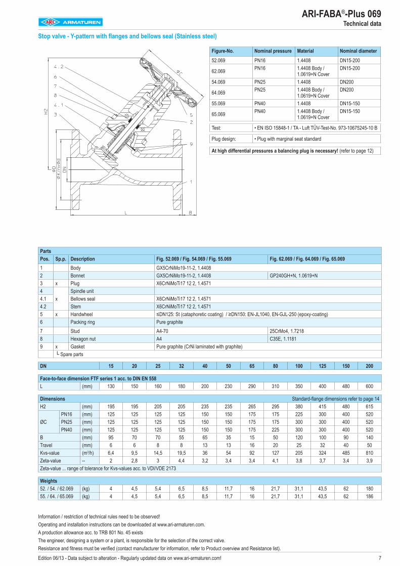
Stop valve - Y-pattern with butt weld ends and bellows seal (Cast steel)
PartsPos. Sp.p. Description Fig. 34./35.0661 Body GP240GH+N, 1.0619+N1.2 Seat ring ≤DN80: X20Cr13+QT, 1.4021+QT / ≥DN80: G19 9 NbSi, 1.45512 Bonnet GP240GH+N, 1.0619+N3 x Plug ≤DN200: X20Cr13+QT, 1.4021+QT (hardened) / ≥DN250: P265GH, 1.0425 / Stellit 214
xSpindle unit
4.1 Bellows seal X6CrNiMoTi17 12 2, 1.45714.2 Stem X20Cr13+QT, 1.4021+QT5 x Handwheel ≤DN125: St (cataphoretic coating) / >DN125: EN-JL1040, EN-GJL-250 (epoxy-coating)6 Packing ring Pure graphite7 Stud 25CrMo4, 1.72188 Hexagon nut C35E, 1.11819 x Gasket Pure graphite (CrNi laminated with graphite)
└ Spare parts
DN 15 20 25 32 40 50 65 80 100 125 150 200 250 300
Face-to-face dimension ETE series 1 according to DIN EN 12982L (mm) 130 150 160 180 200 230 290 310 350 400 480 600 730 850
Dimensions Butt weld ends according to DIN EN 12627 - 4 (refer to page 11)H2 (mm) 195 195 205 205 235 235 265 295 380 415 480 615 740 795B (mm) 85 65 65 50 60 35 10 45 90 60 50 110 100 45
ØCPN25 (mm) -- -- -- -- -- -- -- -- -- -- -- 520 520 520PN40 (mm) 125 125 125 125 150 150 175 225 300 300 400 520 520 --
Travel (mm) 6 6 8 8 13 13 16 20 25 32 40 50 70 80Kvs-value (m3/h) 6,4 9,5 14,5 19,5 36 54 92 127 205 324 485 810 1310 1752Zeta-value -- 2 2,8 3 4,4 3,2 3,4 3,4 4,1 3,8 3,7 3,4 3,9 3,6 4,2Zeta-value ... range of tolerance for Kvs-values acc. to VDI/VDE 2173
Weights34.066 (kg) -- -- -- -- -- -- -- -- -- -- -- 138 230 31735.066 (kg) 2,8 3 3,4 3,6 4,5 7,3 9 11,4 30 42 62 144 239 --
Figure-No. Nominal pressure Material Nominal diameter
34.066PN25 1.0619+N DN200-300Test: • DIN DVGW-Reg. DG-4314AO 0775
35.066PN40 1.0619+N DN15-250Test: • DIN DVGW-Reg. DG-4314AO 0776
Butt weld ends according to DIN EN 12627 - 4 (refer to page 11)
Test: • EN ISO 15848-1 / TA - Luft TÜV-Test-No. 973-10675245-10 B
Plug design: • Plug with marginal seat standard
At high differential pressures a balancing plug is necessary! (refer to page 12)
ARI-FABA®-Plus 066Technical data
Information / restriction of technical rules need to be observed!Operating and installation instructions can be downloaded at www.ari-armaturen.com. A production allowance acc. to TRB 801 No. 45 existsThe engineer, designing a system or a plant, is responsible for the selection of the correct valve. Resistance and fitness must be verified (contact manufacturer for information, refer to Product overview and Resistance list).

9Edition 06/13 - Data subject to alteration - Regularly updated data on www.ari-armaturen.com!
PartsPos. Sp.p. Description Fig. 54./55.0661 Body GX5CrNiMoN19-11-2, 1.45812 Bonnet GX5CrNiMo19-11-2, 1.44083 x Plug X6CrNiMoTi17 12 2, 1.45714
xSpindle unit
4.1 Bellows seal X6CrNiMoTi17 12 2, 1.45714.2 Stem X6CrNiMoTi17 12 2, 1.45715 x Handwheel ≤DN125: St (cataphoretic coating) / >DN125: EN-JL1040, EN-GJL-250 (epoxy-coating)6 Packing ring Pure graphite7 Stud A2-708 Hexagon nut A29 x Gasket Pure graphite (CrNi laminated with graphite)
└ Spare parts
DN 15 20 25 32 40 50 65 80 100 125 150 200
Face-to-face dimension ETE series 1 according to DIN EN 12982L (mm) 130 150 160 180 200 230 290 310 350 400 480 600
Dimensions Butt weld ends according to DIN EN 12627 - 4 (refer to page 11)H2 (mm) 195 195 205 205 235 235 265 295 380 415 480 615B (mm) 85 65 65 50 60 35 10 45 90 60 50 110
ØCPN25 (mm) -- -- -- -- -- -- -- -- -- -- -- 520PN40 (mm) 125 125 125 125 150 150 175 225 300 300 400 520
Travel (mm) 6 6 8 8 13 13 16 20 25 32 40 50Kvs-value (m3/h) 6,4 9,5 14,5 19,5 36 54 92 127 205 324 485 810Zeta-value -- 2 2,8 3 4,4 3,2 3,4 3,4 4,1 3,8 3,7 3,4 3,9Zeta-value ... range of tolerance for Kvs-values acc. to VDI/VDE 2173
Weights54.066 (kg) -- -- -- -- -- -- -- -- -- -- -- 15755.066 (kg) 3,2 3,6 4 4,8 6,8 8,5 10 13,8 32 45 66 157
Figure-No. Nominal pressure Material Nominal diameter
54.066 PN25 1.4581 DN20055.066 PN40 1.4581 DN15-150
Butt weld ends according to DIN EN 12627 - 4 (refer to page 11)
Test: • EN ISO 15848-1 / TA - Luft TÜV-Test-No. 973-10675245-10 B
Plug design: • Plug with marginal seat standard
At high differential pressures a balancing plug is necessary! (refer to page 12)
ARI-FABA®-Plus 066Technical data
Stop valve - Y-pattern with butt weld ends and bellows seal (Stainless steel)
Information / restriction of technical rules need to be observed!Operating and installation instructions can be downloaded at www.ari-armaturen.com. A production allowance acc. to TRB 801 No. 45 existsThe engineer, designing a system or a plant, is responsible for the selection of the correct valve. Resistance and fitness must be verified (contact manufacturer for information, refer to Product overview and Resistance list).

10 Edition 06/13 - Data subject to alteration - Regularly updated data on www.ari-armaturen.com!
Stop valve - angle pattern with flanges and bellows seal (Grey cast iron, SG iron, Cast steel)
Figure-No. Nominal pressure Material Nominal diameter
12.047 PN16 EN-JL1040 DN15-300
22.047PN16 EN-JS1049 DN15-300Test: • DIN DVGW-Reg. DG-4313AO 0771
34.047PN25 1.0619+N DN200-300Test: • DIN DVGW-Reg. DG-4314AO 0773
35.047PN40 1.0619+N DN15-150Test: • DIN DVGW-Reg. DG-4314AO 0774
Test: • EN ISO 15848-1 / TA - Luft TÜV-Test-No. 973-10675245-10 B
Plug design: • Plug with marginal seat standard
At high differential pressures a balancing plug is necessary! (refer to page 12)
PartsPos. Sp.p. Description Fig. 12.047 Fig. 22.047 Fig. 34.047 / Fig. 35.0471 Body EN-JL1040, EN-GJL-250 EN-JS1049, EN-GJS-400-18U-LT GP240GH+N, 1.0619+N
1.2 Seat ring X20Cr13+QT, 1.4021+QT X20Cr13+QT, 1.4021+QT ≤DN65: X20Cr13+QT, 1.4021+QT ≥DN80: G19 9 NbSi, 1.4551
2 Bonnet EN-JS1049, EN-GJS-400-18U-LT EN-JS1049, EN-GJS-400-18U-LT GP240GH+N, 1.0619+N3 x Plug ≤DN200: X20Cr13+QT, 1.4021+QT (hardened) / >DN200: P265GH, 1.0425 / Stellit 214
xSpindle unit
4.1 Bellows seal X6CrNiMoTi17 12 2, 1.45714.2 Stem X20Cr13+QT, 1.4021+QT5 x Handwheel ≤DN125: St (cataphoretic coating) / ≥DN150: EN-JL1040, EN-GJL-250 (epoxy-coating)6 Packing ring Pure graphite7 Hexagon bolt 5.6 --7 Stud -- 25CrMo4, 1.72188 Hexagon nut -- C35E, 1.11819 x Gasket Pure graphite (CrNi laminated with graphite)
└ Spare parts
DN 15 20 25 32 40 50 65 80 100 125 150 200 250 300
Face-to-face dimension CTF series 8 acc. to DIN EN 558l (mm) 90 95 100 105 115 125 145 155 175 200 225 275 325 375
Dimensions Standard-flange dimensions refer to page 14H3 (mm) 190 190 195 195 210 210 220 235 325 345 370 485 615 665
ØCPN16 (mm) 125 125 125 125 150 150 175 175 225 300 400 520 520 520PN25 (mm) 125 125 125 125 150 150 175 175 300 300 400 520 520 520PN40 (mm) 125 125 125 125 150 150 175 225 300 300 400 520 -- --
Travel (mm) 6 6 8 8 13 13 16 20 25 32 40 50 70 80Kvs-value (m3/h) 6 9 14 19 35 53 94 143 245 390 590 845 1360 1825Zeta-value -- 2,2 3,2 3,2 4,6 3,3 3,6 3,2 3,2 2,7 2,6 2,3 3,6 3,4 3,9Zeta-value ... range of tolerance for Kvs-values acc. to VDI/VDE 2173
Weights12. / 22.047 (kg) 3,7 4,4 5,1 6,5 8,3 11,2 14,6 19,4 29,4 44 58 145 221 29834.047 (kg) -- -- -- -- -- -- -- -- -- -- -- 155 273 30935.047 (kg) 4,6 6,4 6,7 7,5 10,1 12,7 17,5 22 34 49 60 -- -- --
ARI-FABA®-Plus 047Technical data
Information / restriction of technical rules need to be observed! Operating and installation instructions can be downloaded at www.ari-armaturen.com. ARI-Valves of EN-JL1040 are not allowed to be operated in systems acc. to TRD 110. A production allowance acc. to TRB 801 No. 45 exists (acc. to TRB 801 No. 45 EN-JL1040 is not allowed.) The engineer, designing a system or a plant, is responsible for the selection of the correct valve. Resistance and fitness must be verified (contact manufacturer for information, refer to Product overview and Resistance list).

11
DN 15 20 25 32 40 50 65 80 100 125 150 200 250 300 350 400
Butt weld ends according to DIN EN 12627L (mm) 130 150 160 180 200 230 290 310 350 400 480 600 730 850 980 1100ØA (mm) 22 28 35 44 50 62 77 91 117 144 172 223 278 329 362 413ØB (mm) 17,3 22,3 28,5 37,2 43,1 53,9 68,9 80,9 104,3 130,7 157,1 204,9 257, 307,9 338, 384,4Ødi (mm) 15 20 25 32 40 50 65 80 100 125 150 200 250 300 330 375R (mm) 3 3 3 3 3 3 3 3 3 3 3 5 5 5 5 5L1 (similar) (mm) 10 10 10 10 10 10 10 12 14 18 20 20 25 33 45 45Ød3 (mm) 21,3 26,9 33,7 42,4 48,3 60,3 76,1 88,9 114,3 139,7 168,3 219,1 273 323,9 355,6 406,4s1 (mm) 2 2,3 2,6 2,6 2,6 3,2 3,6 4 5 4,5 5,6 7,1 8 8 8,8 11Face-to-face dimension ETE series 1 according to DIN EN 12982 Butt weld ends according to DIN EN 12627 Fig. 4 Weld joint according to DIN EN 29692 code number 1.3.3 The material used for ARI valves with butt weld ends are: GP240GH+N, 1.0619+N acc. to DIN EN 10213-2,
P250GH, 1.0460 acc. to DIN EN 10222-2, GX5CrNiMoN19-11-2, 1.4581 acc. to DIN EN 10213-4.
DN 15 20 25 32 40 50 65 80 100 125 150 200 250 300 350 400
Shoed ends of P235GH (Pipe connection =̂ welding neck flanges)Ød (mm) -- -- -- -- -- -- 76,1 88,9 114,3 139,7 168,3 219,1 -- -- -- --Øs (mm) -- -- -- -- -- -- 2,9 3,2 3,6 4 4,5 6,3 -- -- -- --The material used for ARI valves with shoed ends (DN 65-200) P235GH according to DIN EN 10216-2.
Based on our experience we recommend electric welding process for connecting valves or strainers with tubes or with each other Lime based electrodes with an appropriate composite material should be used as filler material for welding.Gas welding should be avoided. Due to the different material composition and material thickness of valves and tubes, gas welding is more susceptible to produce faults than electric welding (hardness cracks, coarse-grained structure).
L = Face-to-face dimensionEdge shaping acc. to DIN EN ISO 5817
ARI-FABA®-Plus 040 / 066 Valves with butt weld ends
Edition 06/13 - Data subject to alteration - Regularly updated data on www.ari-armaturen.com!

12Edition 06/13 - Data subject to alteration - Regularly updated data on www.ari-armaturen.com!
ARI-FABA®-PlusPlug - design
Isolation plug with marginal seat; stellited seat and plug 1)
Plug with Soft seal Max. operating temperature 200°C at PTFE + 25% carbon
Screw down non-return plug with re-setting spring (Set pressure refer to annex: Flow diagram)
Regulating plug with marginal seat 1)
Regulating plug with soft seal 1) Max. operating temperature 200°C at PTFE + 25% carbon
Screw down non-return regulating plugwith marginal seat 1) (Set pressure refer to annex: Flow diagram)
1) for max. permissible ΔP in throttling function, refer to annex: Flow diagram
Flow direction
Balancing plug
Valves with balancing plugs have to be installed with medium flowing over the plug (3) as indicated by flow direction arrow on valve body. Working principles: When the valve is closed, anticlockwise rotation of the hand wheel lifts the pilot plug (3.1) off the larger balancing plug (3). This allows the medium to pass through the plug and equalizes the pressure of the medium under the plug (3). After the pressures have been equalized within the values stated in the table, the valve can be opened by turning the valve further with normal manual force. Balancing plugs are fully effective only in closed systems. The pressures of the medium on either side of the plug can not be equalized if the medium is discharged into open air. A bypass line or some other arrangement is necessary if too much time is required for pressure equalization owing to the volume in the piping system.
ARI-stop valves with differential pressures exceeding the following pressures, have to be fitted with pressure balancing plugs DN 125 150 200 250 300 350 400 500Gauge press. (ΔP) (bar) 25 21 14 9 6 4,5 3,5 1,5

13Edition 06/13 - Data subject to alteration - Regularly updated data on www.ari-armaturen.com!
Limit switch Hood valve acc. to DIN EN 12828 (tamper resistant handwheel cover)
Size DN ØC ØC1(mm) (mm) (mm)
I 15-50 125 170II 65-80 150 190III 100-150 225 330
Handwheel-Ø from DN 65 reduced!
Chain wheel
DN ØC2 Weight(mm) (mm) (kg)15-32 180 2,540-80 220 7100-150 260 8,9200-400 300 11 Stem extension (please specify height in your order)
Lubricating nipple / Locking device / Travel limiter
Travel limiter (Accessories are not included !)DN Hexagon bolt(mm) (mm x mm)15-80 M8 x 55100 M12 x 70125-150 M12 x 80200 M12 x 100250-300 M12 x 120350-400 M16 x 160
ARI-FABA®-PlusFunctions / special design / accessories
Accessories: Travel limiter
Lubricating nipple
Locking device

14 Edition 06/13 - Data subject to alteration - Regularly updated data on www.ari-armaturen.com!
Please indicate when ordering- Figure-No. - Nominal pressure- Nominal diameter- Special design / accessoriesExample:Figure 35.046; nominal pressure PN40; nominal diameter DN100.
ARI-FABA®-Plus Standard-flange dimensions / Pressure-temperature-ratings
DN 15 20 25 32 40 50 65 80 100 125 150 200 250 300 350 400 500
Standard-flange dimensions acc. to DIN EN 1092-1/-2 Flange holes / -thickness tol. acc. to DIN 2533/2544/2545
PN6ØD (mm) 80 90 100 120 130 140 160 190 210 240 265 320 -- -- -- -- --ØK (mm) 55 65 75 90 100 110 130 150 170 200 225 280 -- -- -- -- --n x Ød (mm) 4x11 4x11 4x11 4x14 4x14 4x14 4x14 4x18 4x18 8x18 8x18 8x18 -- -- -- -- --
PN16ØD (mm) 95 105 115 140 150 165 185 200 220 250 285 340 405 460 520 580 715ØK (mm) 65 75 85 100 110 125 145 160 180 210 240 295 355 410 470 525 650n x Ød (mm) 4x14 4x14 4x14 4x18 4x18 4x18 4x18 1) 8x18 8x18 8x18 8x22 12x22 12x26 12x26 16x26 16x30 20x33
PN25ØD (mm) 95 105 115 140 150 165 185 200 235 270 300 360 425 485 555 620 730ØK (mm) 65 75 85 100 110 125 145 160 190 220 250 310 370 430 490 550 660n x Ød (mm) 4x14 4x14 4x14 4x18 4x18 4x18 8x18 8x18 8x22 8x26 8x26 12x26 12x30 16x30 16x33 16x36 20x36
PN40ØD (mm) 95 105 115 140 150 165 185 200 235 270 300 375 450 515 580 660 755ØK (mm) 65 75 85 100 110 125 145 160 190 220 250 320 385 450 510 585 670n x Ød (mm) 4x14 4x14 4x14 4x18 4x18 4x18 8x18 8x18 8x22 8x26 8x26 12x30 12x33 16x33 16x36 16x39 20x42
1) also with 8 bore holes acc. to DIN EN 1092-1/-2 possible.
Pressure-temperature-ratings Intermediate values for max. permissible operational pressures can be determined by linear interpolation of the given temperature / pressure chart.
acc. to DIN EN 1092-2 -60°C to <-10°C 1) -10°C to 120°C 150°C 200°C 250°C 300°C 350°C 400°C 450°C
EN-JL1040 16 (bar) -- 16 14,4 12,8 11,2 9,6 -- -- --
EN-JS1049 16 (bar) on request 16 15,5 14,7 13,9 12,8 11,2 -- --
EN-JS1049 25 (bar) on request 25 24,3 23 21,8 20 17,5 -- --
EN-JS1049 40 (bar) on request 40 38,8 36,8 34,8 32 28 -- --
acc. to manufacturers standard -60°C to <-10°C 1) -10°C to 120°C 150°C 200°C 250°C 300°C 350°C 400°C 450°C
1.0619+N 25 (bar) 18,7 25 23,9 22 20 17,2 16 14,8 8,2
1.0619+N 40 (bar) 30 40 38,1 35 32 28 25,7 23,8 13,1
1.0460 25 (bar) 18,7 25 23,9 22 20 17,2 16 14,8 10
1.0460 40 (bar) 30 40 38,1 35 32 28 25,7 23,8 16
acc. to DIN EN 1092-1 -60°C to <-10°C 1) -10°C to 100°C 150°C 200°C 250°C 300°C 350°C 400°C 450°C
1.4408 16 (bar) 16 16 14,5 13,4 12,7 11,8 11,4 10,9 --
1.4408 25 (bar) 25 25 22,7 21 19,8 18,5 17,8 17,1 --
1.4408 40 (bar) 40 40 36,3 33,7 31,8 29,7 28,5 27,4 --
1.4581 16 (bar) 8 16 15,6 14,9 14,1 13,3 12,8 12,4 --
1.4581 25 (bar) 12,5 25 24,5 23,3 22,1 20,8 20,1 19,5 --
1.4581 40 (bar) 20 40 39,2 37,3 35,4 33,3 32,1 31,2 --
1) Studs and nuts made of A4-70 (at temperatures below -10°C)
Technology for the Future. G E R M A N Q U A L I T Y V A L V E S
ARI-Armaturen Albert Richter GmbH & Co. KG, D-33756 Schloß Holte-Stukenbrock, Tel. +49 52 07 / 994-0, Telefax +49 52 07 / 994-158 or 159 Internet: http://www.ari-armaturen.com E-mail: [email protected]

ARI-FABA®-Plus 046Straight through form
Edition 07/11 - Data subject to alteration - Regularly updated data on www.ari-armaturen.com! Datenblatt 040009 (deutsch)
→ V
olume
flow
rate
in m3 /h
(wate
r)
The curves shows the stabel operation range.
Pressure drop in Pascal (10 Pascal 1mm WS (1mm WS = 9,8066 Pa) 1bar = 0,1MPa = 105Pa
Differential pressure (bar)
Loose plug with marginal seat and re-setting spring DN15-100 Operation stable
DN Travel Kv-value ∆P min Q min(mm) (m3/h) (mbar) (m3/h)
15 6 3,5 600 2,720 6 3,8 600 2,925 8 9 500 6,432 8 14 400 8,940 13 25 350 14,850 13 42 350 24,965 16 75 350 44,480 20 105 350 62,1100 25 160 350 94,7125 32 260 400 165150 40 400 400 250
Loose plug with marginal seat without re-setting spring
DN15-100 Operation stable
DN Travel Kv-value ∆P min Q min(mm) (m3/h) (mbar) (m3/h)
15 6 3,5 100 1,120 6 3,8 100 1,225 8 9 100 2,832 8 14 100 4,440 13 25 100 7,950 13 42 100 13,365 16 75 100 23,780 20 105 100 33,2100 25 160 100 50,6125 32 260 100 81150 40 400 100 120
Installation only with vertical stem position.
→ V
olume
flow
rate
in m3 /h
(wate
r)
Differential pressure (bar)

2 Edition 07/11 - Data subject to alteration - Regularly updated data on www.ari-armaturen.com!
ARI-FABA®-Plus 046Straight through form
Loose regulating plug with marginal seal without re-setting spring DN15-100 Operation stable
DN Travel Kv-value ∆P min Q min(mm) (m3/h) (mbar) (m3/h)
15 6 3,2 150 1,220 6 3,5 150 1,425 8 7 150 2,732 8 11 150 4,340 13 20 150 7,850 13 27 150 10,565 16 56 150 21,780 20 80 150 31100 25 110 150 42,6125 32 220 200 83150 40 260 200 120
Installation only with vertical stem position.
→ V
olume
flow
rate
in m3 /h
(wate
r)
Differential pressure (bar)
The curves shows the stabel operation range.
Pressure drop in Pascal (10 Pascal 1mm WS (1mm WS = 9,8066 Pa) 1bar = 0,1MPa = 105Pa
Technology for the Future. G E R M A N Q U A L I T Y V A L V E S
ARI-Armaturen Albert Richter GmbH & Co. KG, D-33756 Schloß Holte-Stukenbrock, Tel. +49 52 07 / 994-0, Telefax +49 52 07 / 994-158 or 159 Internet: http://www.ari-armaturen.com E-mail: [email protected]

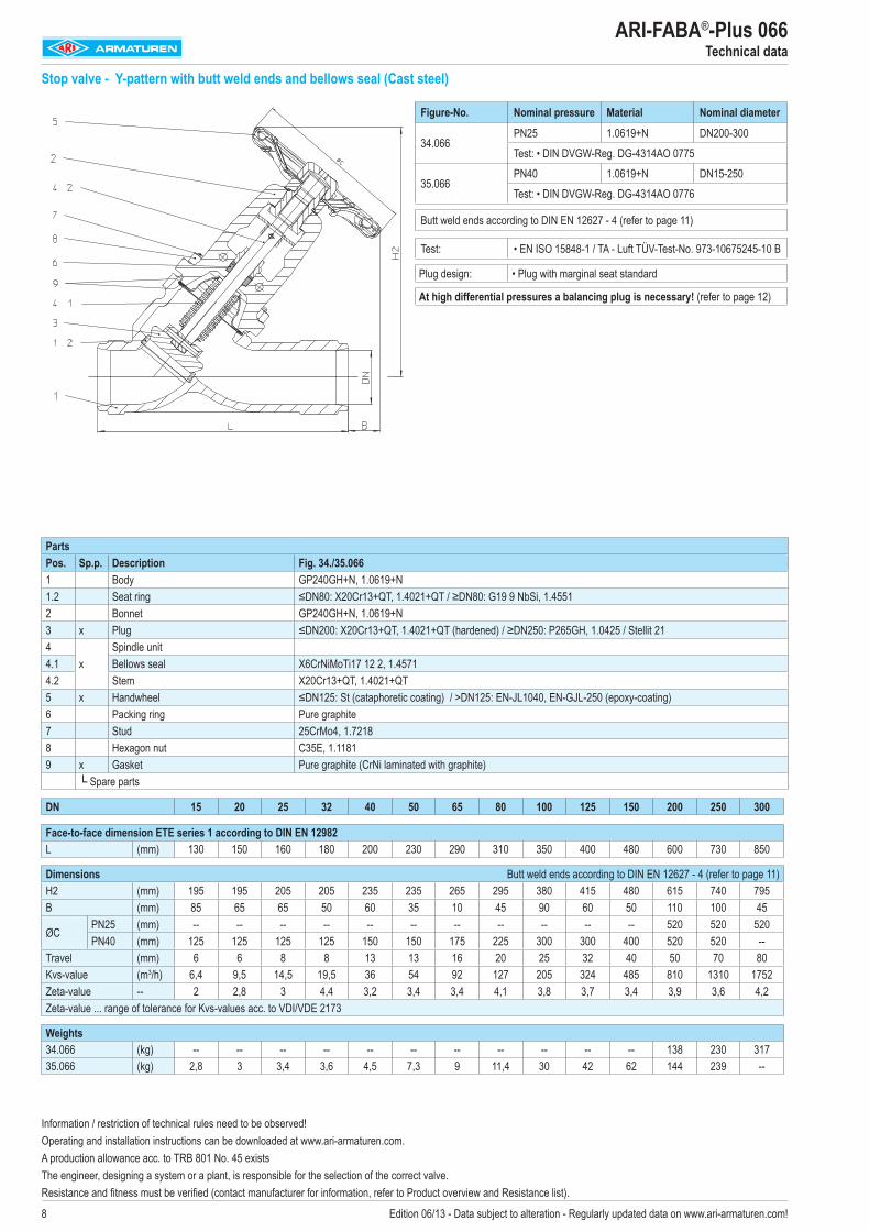
ARI-FABA®-Plus 046Straight through
Edition 11/12 - Data subject to alteration - Regularly updated data on www.ari-armaturen.com!
max. permissible differential pressure in throttling function 2,0 bar.max. permissible flow speed: Liquids ≤ 4 m/s, Gases and vapours ≤ 60 m/sCondition: The flow must be free from cavitation.
DN15 / PN16-40 Isolation plug with marginal seat
DN20 / PN16-40 Isolation plug with marginal seat
max. permissible differential pressure in throttling function 2,0 bar.max. permissible flow speed: Liquids ≤ 4 m/s, Gases and vapours ≤ 60 m/sCondition: The flow must be free from cavitation.
Kv - flow diagram
Handwheel rotation
Kv-v
alue
Handwheel rotation
Kv-value (m3/h)
Data sheet 040005_kvs-kennlinien (english)
Kv - flow diagram
Handwheel rotation
Kv-v
alue
Handwheel rotation
Kv-value (m3/h)

2 Edition 11/12 - Data subject to alteration - Regularly updated data on www.ari-armaturen.com!
ARI-FABA®-Plus 046Straight through
max. permissible differential pressure in throttling function 2,0 bar.max. permissible flow speed: Liquids ≤ 4 m/s, Gases and vapours ≤ 60 m/sCondition: The flow must be free from cavitation.
DN25 / PN16-40 Isolation plug with marginal seat
DN32 / PN16-40 Isolation plug with marginal seat
max. permissible differential pressure in throttling function 2,0 bar.max. permissible flow speed: Liquids ≤ 4 m/s, Gases and vapours ≤ 60 m/sCondition: The flow must be free from cavitation.
Kv - flow diagram
Handwheel rotation
Kv-v
alue
Handwheel rotation
Kv-value (m3/h)
Handwheel rotation
Kv-v
alue
Handwheel rotation
Kv-value (m3/h)
Kv - flow diagram

3Edition 11/12 - Data subject to alteration - Regularly updated data on www.ari-armaturen.com!
ARI-FABA®-Plus 046Straight through
max. permissible differential pressure in throttling function 2,0 bar.max. permissible flow speed: Liquids ≤ 4 m/s, Gases and vapours ≤ 60 m/sCondition: The flow must be free from cavitation.
DN40 / PN16-40 Isolation plug with marginal seat
DN50 / PN16-40 Isolation plug with marginal seat
max. permissible differential pressure in throttling function 2,0 bar.max. permissible flow speed: Liquids ≤ 4 m/s, Gases and vapours ≤ 60 m/sCondition: The flow must be free from cavitation.
Kv - flow diagram
Handwheel rotation
Kv-v
alue
Handwheel rotation
Kv-value (m3/h)
Handwheel rotation
Kv-v
alue
Handwheel rotation
Kv-value (m3/h)
Kv - flow diagram

4
ARI-FABA®-Plus 046Straight through
max. permissible differential pressure in throttling function 2,0 bar.max. permissible flow speed: Liquids ≤ 4 m/s, Gases and vapours ≤ 60 m/sCondition: The flow must be free from cavitation.
DN65 / PN16-40 Isolation plug with marginal seat
DN80 / PN16-40 Isolation plug with marginal seat
max. permissible differential pressure in throttling function 2,0 bar.max. permissible flow speed: Liquids ≤ 4 m/s, Gases and vapours ≤ 60 m/sCondition: The flow must be free from cavitation.
Edition 11/12 - Data subject to alteration - Regularly updated data on www.ari-armaturen.com!
Kv - flow diagram
Handwheel rotation
Kv-v
alue
Handwheel rotation
Kv-value (m3/h)
Handwheel rotation
Kv-v
alue
Handwheel rotation
Kv-value (m3/h)
Kv - flow diagram

5
ARI-FABA®-Plus 046Straight through
max. permissible differential pressure in throttling function 1,5 bar.max. permissible flow speed: Liquids ≤ 4 m/s, Gases and vapours ≤ 60 m/sCondition: The flow must be free from cavitation.
DN100 / PN16-25 Isolation plug with marginal seat
DN100 / PN40 Isolation plug with marginal seat
max. permissible differential pressure in throttling function 1,5 bar.max. permissible flow speed: Liquids ≤ 4 m/s, Gases and vapours ≤ 60 m/sCondition: The flow must be free from cavitation.
Edition 11/12 - Data subject to alteration - Regularly updated data on www.ari-armaturen.com!
Kv - flow diagram
Handwheel rotation
Kv-v
alue
Handwheel rotation
Kv-value (m3/h)
Handwheel rotation
Kv-v
alue
Handwheel rotation
Kv-value (m3/h)
Kv - flow diagram

6
ARI-FABA®-Plus 046Straight through
max. permissible differential pressure in throttling function 1,5 bar.max. permissible flow speed: Liquids ≤ 4 m/s, Gases and vapours ≤ 60 m/sCondition: The flow must be free from cavitation.
DN125 / PN16-25 Isolation plug with marginal seat
DN125 / PN40 Isolation plug with marginal seat
max. permissible differential pressure in throttling function 1,5 bar.max. permissible flow speed: Liquids ≤ 4 m/s, Gases and vapours ≤ 60 m/sCondition: The flow must be free from cavitation.
Edition 11/12 - Data subject to alteration - Regularly updated data on www.ari-armaturen.com!
Kv - flow diagram
Handwheel rotation
Kv-v
alue
Handwheel rotation
Kv-value (m3/h)
Handwheel rotation
Kv-v
alue
Handwheel rotation
Kv-value (m3/h)
Kv - flow diagram

-
�
max. permissible differential pressure in throttling function 1,0 bar.max. permissible flow speed: Liquids ≤ 4 m/s, Gases and vapours ≤ 60 m/sCondition: The flow must be free from cavitation.
DN150 / PN16-25 Isolation plug with marginal seat
DN150 / PN40 Isolation plug with marginal seat
max. permissible differential pressure in throttling function 1,0 bar.max. permissible flow speed: Liquids ≤ 4 m/s, Gases and vapours ≤ 60 m/sCondition: The flow must be free from cavitation.
ARI-FABA®-Plus 046Straight through
Edition 11/12 - Data subject to alteration - Regularly updated data on www.ari-armaturen.com!
Kv - flow diagram
Handwheel rotation
Kv-v
alue
Handwheel rotation
Kv-value (m3/h)
Handwheel rotation
Kv-v
alue
Handwheel rotation
Kv-value (m3/h)
Kv - flow diagram

�
ARI-FABA®-Plus 046Straight through
DN200 / PN16-40 Isolation plug with marginal seat
Handwheel rotation
Kv-value [m3/h]
1.0 25.02.0 65.03.5 150.05.0 250.0�.0 3�0.08.5 460.010.0 510.012.0 570.013.5 610.015.0 640.016.7 675.0
max. permissible differential pressure in throttling function 0,� bar.max. permissible flow speed: Liquids ≤ 4 m/s, Gases and vapours ≤ 60 m/sCondition: The flow must be free from cavitation.
DN250 / PN16-40 Isolation plug with marginal seat
Handwheel rotation
Kv-value [m3/h]
1.0 31.02.5 110.04.5 255.0�.0 445.09.5 605.012.0 �30.014.0 815.016.5 905.019.0 975.021.0 1030.023.3 1090.0
max. permissible differential pressure in throttling function 0,� bar.max. permissible flow speed: Liquids ≤ 4 m/s, Gases and vapours ≤ 60 m/sCondition: The flow must be free from cavitation.
Kv - flow diagram
Handwheel rotation
Kv-v
alue
Handwheel rotation
Kv-v
alue
Kv - flow diagram

9
ARI-FABA®-Plus 046Straight through
DN300 / PN16-40 Isolation plug with marginal seat
Handwheel rotation
Kv-value [m3/h]
1.5 59.03.0 190.05.5 445.0�.0 655.011.0 885.013.5 1030.016.0 1150.019.0 1260.021.5 1340.024.0 1400.026.7 1460.0
max. permissible differential pressure in throttling function 0,5 bar.max. permissible flow speed: Liquids ≤ 4 m/s, Gases and vapours ≤ 60 m/sCondition: The flow must be free from cavitation.
DN350 / PN16-40 Isolation plug with marginal seat
Handwheel rotation
Kv-value [m3/h]
1.5 50.03.0 145.06.0 470.09.0 �10.012.0 1120.015.0 1360.01�.0 1540.021.0 1680.024.0 1�20.02�.0 1930.030.0 2010.0
max. permissible differential pressure in throttling function 0,5 bar.max. permissible flow speed: Liquids ≤ 4 m/s, Gases and vapours ≤ 60 m/sCondition: The flow must be free from cavitation.
Kv - flow diagram
Handwheel rotation
Kv-v
alue
Handwheel rotation
Kv-v
alue
Kv - flow diagram

10
ARI-FABA®-Plus 046Straight through
Ausgabe 11/12 - Techn. Änderungen vorbehalten - Ständig aktualisierte Daten unter www.ari-armaturen.com!
DN400 / PN16-40 Isolation plug with marginal seat
Handwheel rotation
Kv-value [m3/h]
2.0 95.03.5 215.0�.0 650.010.0 1040.013.5 1450.01�.0 1775.020.0 19�0.023.5 2190.02�.0 23�0.030.0 2510.033.3 2635.0
max. permissible differential pressure in throttling function 0,5 bar.max. permissible flow speed: Liquids ≤ 4 m/s, Gases and vapours ≤ 60 m/sCondition: The flow must be free from cavitation.
Kv - flow diagram
Handwheel rotation
Kv-v
alue

11
ARI-FABA®-Plus 046Straight through
Ausgabe 11/12 - Techn. Änderungen vorbehalten - Ständig aktualisierte Daten unter www.ari-armaturen.com!

12
ARI-FABA®-Plus 046Straight through
max. permissible differential pressure in throttling function 2,0 bar.max. permissible flow speed: Liquids ≤ 4 m/s, Gases and vapours ≤ 60 m/sCondition: The flow must be free from cavitation.
DN15 / PN16-40 Regulating plug with marginal seat
DN20 / PN16-40 Regulating plug with marginal seat
max. permissible differential pressure in throttling function 2,0 bar.max. permissible flow speed: Liquids ≤ 4 m/s, Gases and vapours ≤ 60 m/sCondition: The flow must be free from cavitation.
Edition 11/12 - Data subject to alteration - Regularly updated data on www.ari-armaturen.com!
Kv - flow diagram
Handwheel rotation
Kv-v
alue
Handwheel rotation
Kv-value (m3/h)
Handwheel rotation
Kv-v
alue
Handwheel rotation
Kv-value (m3/h)
Kv - flow diagram

13
ARI-FABA®-Plus 046Straight through
max. permissible differential pressure in throttling function 2,0 bar.max. permissible flow speed: Liquids ≤ 4 m/s, Gases and vapours ≤ 60 m/sCondition: The flow must be free from cavitation.
DN25 / PN16-40 Regulating plug with marginal seat
DN32 / PN16-40 Regulating plug with marginal seat
max. permissible differential pressure in throttling function 2,0 bar.max. permissible flow speed: Liquids ≤ 4 m/s, Gases and vapours ≤ 60 m/sCondition: The flow must be free from cavitation.
Edition 11/12 - Data subject to alteration - Regularly updated data on www.ari-armaturen.com!
Kv - flow diagram
Handwheel rotation
Kv-v
alue
Handwheel rotation
Kv-value (m3/h)
Handwheel rotation
Kv-v
alue
Handwheel rotation
Kv-value (m3/h)
Kv - flow diagram

14
ARI-FABA®-Plus 046Straight through
max. permissible differential pressure in throttling function 2,0 bar.max. permissible flow speed: Liquids ≤ 4 m/s, Gases and vapours ≤ 60 m/sCondition: The flow must be free from cavitation.
DN40 / PN16-40 Regulating plug with marginal seat
DN50 / PN16-40 Regulating plug with marginal seat
max. permissible differential pressure in throttling function 2,0 bar.max. permissible flow speed: Liquids ≤ 4 m/s, Gases and vapours ≤ 60 m/sCondition: The flow must be free from cavitation.
Edition 11/12 - Data subject to alteration - Regularly updated data on www.ari-armaturen.com!
Kv - flow diagram
Handwheel rotation
Kv-v
alue
Handwheel rotation
Kv-value (m3/h)
Handwheel rotation
Kv-v
alue
Handwheel rotation
Kv-value (m3/h)
Kv - flow diagram

15
ARI-FABA®-Plus 046Straight through
max. permissible differential pressure in throttling function 2,0 bar.max. permissible flow speed: Liquids ≤ 4 m/s, Gases and vapours ≤ 60 m/sCondition: The flow must be free from cavitation.
DN65 / PN16-40 Regulating plug with marginal seat
DN80 / PN16-40 Regulating plug with marginal seat
max. permissible differential pressure in throttling function 2,0 bar.max. permissible flow speed: Liquids ≤ 4 m/s, Gases and vapours ≤ 60 m/sCondition: The flow must be free from cavitation.
Edition 11/12 - Data subject to alteration - Regularly updated data on www.ari-armaturen.com!
Kv - flow diagram
Handwheel rotation
Kv-v
alue
Handwheel rotation
Kv-value (m3/h)
Handwheel rotation
Kv-v
alue
Handwheel rotation
Kv-value (m3/h)
Kv - flow diagram

16
ARI-FABA®-Plus 046Straight through
max. permissible differential pressure in throttling function 1,5 bar.max. permissible flow speed: Liquids ≤ 4 m/s, Gases and vapours ≤ 60 m/sCondition: The flow must be free from cavitation.
DN100 / PN16-25 Regulating plug with marginal seat
DN100 / PN40 Regulating plug with marginal seat
max. permissible differential pressure in throttling function 1,5 bar.max. permissible flow speed: Liquids ≤ 4 m/s, Gases and vapours ≤ 60 m/sCondition: The flow must be free from cavitation.
Edition 11/12 - Data subject to alteration - Regularly updated data on www.ari-armaturen.com!
Kv - flow diagram
Handwheel rotation
Kv-v
alue
Handwheel rotation
Kv-value (m3/h)
Handwheel rotation
Kv-v
alue
Handwheel rotation
Kv-value (m3/h)
Kv - flow diagram

1�
ARI-FABA®-Plus 046Straight through
max. permissible differential pressure in throttling function 1,5 bar.max. permissible flow speed: Liquids ≤ 4 m/s, Gases and vapours ≤ 60 m/sCondition: The flow must be free from cavitation.
DN125 / PN16-25 Regulating plug with marginal seat
DN125 / PN40 Regulating plug with marginal seat
max. permissible differential pressure in throttling function 1,5 bar.max. permissible flow speed: Liquids ≤ 4 m/s, Gases and vapours ≤ 60 m/sCondition: The flow must be free from cavitation.
Edition 11/12 - Data subject to alteration - Regularly updated data on www.ari-armaturen.com!
Kv - flow diagram
Handwheel rotation
Kv-v
alue
Handwheel rotation
Kv-value (m3/h)
Handwheel rotation
Kv-v
alue
Handwheel rotation
Kv-value (m3/h)
Kv - flow diagram

1�
ARI-FABA®-Plus 046Straight through
max. permissible differential pressure in throttling function 1,0 bar.max. permissible flow speed: Liquids ≤ 4 m/s, Gases and vapours ≤ 60 m/sCondition: The flow must be free from cavitation.
DN150 / PN16-25 Regulating plug with marginal seat
DN150 / PN40 Regulating plug with marginal seat
max. permissible differential pressure in throttling function 1,0 bar.max. permissible flow speed: Liquids ≤ 4 m/s, Gases and vapours ≤ 60 m/sCondition: The flow must be free from cavitation.
Edition 11/12 - Data subject to alteration - Regularly updated data on www.ari-armaturen.com!
Kv - flow diagram
Handwheel rotation
Kv-v
alue
Handwheel rotation
Kv-value (m3/h)
Handwheel rotation
Kv-v
alue
Handwheel rotation
Kv-value (m3/h)
Kv - flow diagram

19
ARI-FABA®-Plus 046Straight through
Edition 11/12 - Data subject to alteration - Regularly updated data on www.ari-armaturen.com!
DN200 / PN16-40 Regulating plug with marginal seat
Handwheel rotation
Kv-value [m3/h]
1.0 12.02.0 21.03.5 35.05.0 65.0�.0 140.08.5 210.010.0 285.012.0 3�0.013.5 445.015.0 510.016.7 580.0
max. permissible differential pressure in throttling function 0,� bar.max. permissible flow speed: Liquids ≤ 4 m/s, Gases and vapours ≤ 60 m/sCondition: The flow must be free from cavitation.
DN250 / PN16-40 Regulating plug with marginal seat
Handwheel rotation
Kv-value [m3/h]
1.0 40.02.5 �0.04.5 90.0�.0 130.09.5 200.012.0 315.014.0 430.016.5 560.019.0 655.021.0 715.023.3 765.0
max. permissible differential pressure in throttling function 0,� bar.max. permissible flow speed: Liquids ≤ 4 m/s, Gases and vapours ≤ 60 m/sCondition: The flow must be free from cavitation.
Kv - flow diagram
Handwheel rotation
Kv-v
alue
Handwheel rotation
Kv-v
alue
Kv - flow diagram

20
ARI-FABA®-Plus 046Straight through
DN300 / PN16-40 Regulating plug with marginal seat
Handwheel rotation
Kv-value [m3/h]
1.5 25.03.0 50.05.5 111.0�.0 220.011.0 400.013.5 550.016.0 �00.019.0 580.021.5 950.024.0 1040.026.7 1120.0
max. permissible differential pressure in throttling function 0,5 bar.max. permissible flow speed: Liquids ≤ 4 m/s, Gases and vapours ≤ 60 m/sCondition: The flow must be free from cavitation.
DN350 / PN16-40 Regulating plug with marginal seat
Handwheel rotation
Kv-value [m3/h]
1.5 35.03.0 60.06.0 125.09.0 230.012.0 385.015.0 635.01�.0 910.021.0 1150.024.0 1330.02�.0 1500.030.0 1640.0
max. permissible differential pressure in throttling function 0,5 bar.max. permissible flow speed: Liquids ≤ 4 m/s, Gases and vapours ≤ 60 m/sCondition: The flow must be free from cavitation.
Edition 11/12 - Data subject to alteration - Regularly updated data on www.ari-armaturen.com!
Kv - flow diagram
Handwheel rotation
Kv-v
alue
Handwheel rotation
Kv-v
alue
Kv - flow diagram

21
ARI-FABA®-Plus 046Straight through
DN400 / PN16-40 Regulating plug with marginal seat
Handwheel rotation
Kv-value [m3/h]
2.0 55.03.5 95.0�.0 185.010.0 285.013.5 490.01�.0 785.020.0 1100.023.5 1430.02�.0 1�00.030.0 1�90.033.3 2090.0
max. permissible differential pressure in throttling function 0,5 bar.max. permissible flow speed: Liquids ≤ 4 m/s, Gases and vapours ≤ 60 m/sCondition: The flow must be free from cavitation.
Edition 11/12 - Data subject to alteration - Regularly updated data on www.ari-armaturen.com!
Kv - flow diagram
Handwheel rotation
Kv-v
alue

74
55
65
35
22 Edition 11/12 - Data subject to alteration - Regularly updated data on www.ari-armaturen.com!
ARI-FABA®-Plus 046Straight through
Kv - flow diagram
Handwheel rotation
Kv-v
alue
Handwheel rotation
Kv-v
alue
Kv - flow diagram
max. permissible differential pressure in throttling function 2,0 bar.max. permissible flow speed: Liquids ≤ 4 m/s, Gases and vapours ≤ 60 m/sCondition: The flow must be free from cavitation.
DN15 / PN16-40 Loose plug with marginal seat
DN20 / PN16-40 Loose plug with marginal seat
max. permissible differential pressure in throttling function 2,0 bar.max. permissible flow speed: Liquids ≤ 4 m/s, Gases and vapours ≤ 60 m/sCondition: The flow must be free from cavitation.
Handwheel rotation
Kv-value (m3/h)
Handwheel rotation
Kv-value (m3/h)

2.0
5555
855
0
23Edition 11/12 - Data subject to alteration - Regularly updated data on www.ari-armaturen.com!
ARI-FABA®-Plus 046Straight through
Kv - flow diagram
Handwheel rotation
Kv-v
alue
Handwheel rotation
Kv-v
alue
Kv - flow diagram
max. permissible differential pressure in throttling function 2,0 bar.max. permissible flow speed: Liquids ≤ 4 m/s, Gases and vapours ≤ 60 m/sCondition: The flow must be free from cavitation.
DN25 / PN16-40 Loose plug with marginal seat
DN32 / PN16-40 Loose plug with marginal seat
max. permissible differential pressure in throttling function 2,0 bar.max. permissible flow speed: Liquids ≤ 4 m/s, Gases and vapours ≤ 60 m/sCondition: The flow must be free from cavitation.
Handwheel rotation
Kv-value (m3/h)
Handwheel rotation
Kv-value (m3/h)

4
0
55
0
24 Edition 11/12 - Data subject to alteration - Regularly updated data on www.ari-armaturen.com!
ARI-FABA®-Plus 046Straight through
Kv - flow diagram
Handwheel rotation
Kv-v
alue
Handwheel rotation
Kv-v
alue
Kv - flow diagram
max. permissible differential pressure in throttling function 2,0 bar.max. permissible flow speed: Liquids ≤ 4 m/s, Gases and vapours ≤ 60 m/sCondition: The flow must be free from cavitation.
DN40 / PN16-40 Loose plug with marginal seat
DN50 / PN16-40 Loose plug with marginal seat
max. permissible differential pressure in throttling function 2,0 bar.max. permissible flow speed: Liquids ≤ 4 m/s, Gases and vapours ≤ 60 m/sCondition: The flow must be free from cavitation.
Handwheel rotation
Kv-value (m3/h)
Handwheel rotation
Kv-value (m3/h)
25Edition 11/12 - Data subject to alteration - Regularly updated data on www.ari-armaturen.com!
ARI-FABA®-Plus 046Straight through
Kv - flow diagram
Handwheel rotation
Kv-v
alue
Handwheel rotation
Kv-v
alue
Kv - flow diagram
DN65 / PN16-40 Loose plug with marginal seat
DN80 / PN16-40 Loose plug with marginal seat
max. permissible differential pressure in throttling function 2,0 bar.max. permissible flow speed: Liquids ≤ 4 m/s, Gases and vapours ≤ 60 m/sCondition: The flow must be free from cavitation.
max. permissible differential pressure in throttling function 2,0 bar.max. permissible flow speed: Liquids ≤ 4 m/s, Gases and vapours ≤ 60 m/sCondition: The flow must be free from cavitation.
Handwheel rotation
Kv-value (m3/h)
Handwheel rotation
Kv-value (m3/h)

60.0
22 /
2009/12/03
6
60.0
26 Edition 11/12 - Data subject to alteration - Regularly updated data on www.ari-armaturen.com!
ARI-FABA®-Plus 046Straight through
Kv - flow diagram
Handwheel rotation
Kv-v
alue
Handwheel rotation
Kv-v
alue
Kv - flow diagram
max. permissible differential pressure in throttling function 1,5 bar.max. permissible flow speed: Liquids ≤ 4 m/s, Gases and vapours ≤ 60 m/sCondition: The flow must be free from cavitation.
DN100 / PN16-25 Loose plug with marginal seat
DN100 / PN40 Loose plug with marginal seat
max. permissible differential pressure in throttling function 1,5 bar.max. permissible flow speed: Liquids ≤ 4 m/s, Gases and vapours ≤ 60 m/sCondition: The flow must be free from cavitation.
Handwheel rotation
Kv-value (m3/h)
Handwheel rotation
Kv-value (m3/h)

2�
ARI-FABA®-Plus 046Straight through
Edition 11/12 - Data subject to alteration - Regularly updated data on www.ari-armaturen.com!

KVS-Kennlinien-Diagramm
0
0,25
0,5
0,75
1
1,25
1,5
1,75
2
2,25
2,5
2,75
3
3,25
3,5
0 0,25 0,5 0,75 1 1,25 1,5 1,75 2 2,25 2,5 2,75 3 3,25 3,5
Handrad-Umdrehungen
Kv-Wert
KVS-Kennlinien-Diagramm
0
0,25
0,5
0,75
1
1,25
1,5
1,75
2
2,25
2,5
2,75
3
3,25
3,5
3,75
0 0,25 0,5 0,75 1 1,25 1,5 1,75 2 2,25 2,5 2,75 3 3,25 3,5
Handrad-Umdrehungen
Kv-Wert
2�
ARI-FABA®-Plus 046Straight through
Kv - flow diagram
Handwheel rotation
Kv-v
alue
Handwheel rotation
Kv-v
alue
Kv - flow diagram
max. permissible differential pressure in throttling function 2,0 bar.max. permissible flow speed: Liquids ≤ 4 m/s, Gases and vapours ≤ 60 m/sCondition: The flow must be free from cavitation.
DN15 / PN16-40 Loose regulating plug with marginal seat
DN20 / PN16-40 Loose regulating plug with marginal seat
max. permissible differential pressure in throttling function 2,0 bar.max. permissible flow speed: Liquids ≤ 4 m/s, Gases and vapours ≤ 60 m/sCondition: The flow must be free from cavitation.
Handrad- Umdrehung
Kv-Wert [m3/h]
0,5 0,751 1,351,5 1,752 2,22,5 2,63 2,953,4 3,2
Handrad- Umdrehung
Kv-Wert [m3/h]
0,5 0,91 1,51,5 1,952 2,352,5 2,�3 3,23,4 3,5
Handwheel rotation
Kv-value (m3/h)
Handwheel rotation
Kv-value (m3/h)
Edition 11/12 - Data subject to alteration - Regularly updated data on www.ari-armaturen.com!

KVS-Kennlinien-Diagramm
0
0,5
1
1,5
2
2,5
3
3,5
4
4,5
5
5,5
6
6,5
7
0 0,25 0,5 0,75 1 1,25 1,5 1,75 2 2,25 2,5 2,75 3 3,25 3,5 3,75 4 4,25 4,5 4,75 5
Handrad-Umdrehungen
Kv-Wert
KVS-Kennlinien-Diagramm
00,51
1,52
2,53
3,54
4,55
5,56
6,57
7,58
8,59
9,510
10,511
0 0,25 0,5 0,75 1 1,25 1,5 1,75 2 2,25 2,5 2,75 3 3,25 3,5 3,75 4 4,25 4,5 4,75 5
Handrad-Umdrehungen
Kv-Wert
29
ARI-FABA®-Plus 046Straight through
Kv - flow diagram
Handwheel rotation
Kv-v
alue
Handwheel rotation
Kv-v
alue
Kv - flow diagram
max. permissible differential pressure in throttling function 2,0 bar.max. permissible flow speed: Liquids ≤ 4 m/s, Gases and vapours ≤ 60 m/sCondition: The flow must be free from cavitation.
DN25 / PN16-40 Loose regulating plug with marginal seat
DN32 / PN16-40 Loose regulating plug with marginal seat
max. permissible differential pressure in throttling function 2,0 bar.max. permissible flow speed: Liquids ≤ 4 m/s, Gases and vapours ≤ 60 m/sCondition: The flow must be free from cavitation.
Handrad- Umdrehung
Kv-Wert [m3/h]
0,5 1,151 2,051,5 2,�2 3,42,5 4,153 4,754,6 �
Handrad- Umdrehung
Kv-Wert [m3/h]
0,5 1,551 3,251,5 4,552 5,652,5 6,63 7,553,5 8,54 9,54,5 10,�4,6 11
Handwheel rotation
Kv-value (m3/h)
Handwheel rotation
Kv-value (m3/h)
Edition 11/12 - Data subject to alteration - Regularly updated data on www.ari-armaturen.com!

KVS-Kennlinien-Diagramm
0123456789101112131415161718192021
0 0,5 1 1,5 2 2,5 3 3,5 4 4,5 5 5,5 6 6,5
Handrad-Umdrehungen
Kv-Wert
KVS-Kennlinien-Diagramm
012345678910111213141516171819202122232425262728
0 0,5 1 1,5 2 2,5 3 3,5 4 4,5 5 5,5 6 6,5
Handrad-Umdrehungen
Kv-Wert
30
ARI-FABA®-Plus 046Straight through
Kv - flow diagram
Handwheel rotation
Kv-v
alue
Handwheel rotation
Kv-v
alue
Kv - flow diagram
max. permissible differential pressure in throttling function 2,0 bar.max. permissible flow speed: Liquids ≤ 4 m/s, Gases and vapours ≤ 60 m/sCondition: The flow must be free from cavitation.
DN40 / PN16-40 Loose regulating plug with marginal seat
DN50 / PN16-40 Loose regulating plug with marginal seat
max. permissible differential pressure in throttling function 2,0 bar.max. permissible flow speed: Liquids ≤ 4 m/s, Gases and vapours ≤ 60 m/sCondition: The flow must be free from cavitation.
Handrad- Umdrehung
Kv-Wert [m3/h]
0,5 2,151 3,451,5 4,652 5,853 8,354 11,25 14,66,5 20
Handrad- Umdrehung
Kv-Wert [m3/h]
0,5 2,51 4,62 8,653 12,44 16,45 20,�6 24,96,5 2�
Handwheel rotation
Kv-value (m3/h)
Handwheel rotation
Kv-value (m3/h)
Edition 11/12 - Data subject to alteration - Regularly updated data on www.ari-armaturen.com!

KVS-Kennlinien-Diagramm
0246810121416182022242628303234363840424446485052545658
0 0,5 1 1,5 2 2,5 3 3,5 4 4,5 5 5,5 6 6,5 7 7,5 8 8,5
Handrad-Umdrehungen
Kv-Wert
KVS-Kennlinien-Diagramm
0
510
15
20
2530
35
4045
50
55
6065
70
75
8085
90
0 0,5 1 1,5 2 2,5 3 3,5 4 4,5 5 5,5 6 6,5 7 7,5 8 8,5 9 9,5 10 10,5
Handrad-Umdrehungen
Kv-Wert
31
ARI-FABA®-Plus 046Straight through
Kv - flow diagram
Handwheel rotation
Kv-v
alue
Handwheel rotation
Kv-v
alue
Kv - flow diagram
max. permissible differential pressure in throttling function 2,0 bar.max. permissible flow speed: Liquids ≤ 4 m/s, Gases and vapours ≤ 60 m/sCondition: The flow must be free from cavitation.
DN65 / PN16-40 Loose regulating plug with marginal seat
DN80 / PN16-40 Loose regulating plug with marginal seat
max. permissible differential pressure in throttling function 2,0 bar.max. permissible flow speed: Liquids ≤ 4 m/s, Gases and vapours ≤ 60 m/sCondition: The flow must be free from cavitation.
Handrad- Umdrehung
Kv-Wert [m3/h]
0,5 2,251 4,52 10,23 16,14 22,15 29,66 3�,2� 46,3� 56
Handrad- Umdrehung
Kv-Wert [m3/h]
0,5 2,51 5,952 12,33 19,24 27,65 35,96 45,2� 54,5� 63,510 �0
Edition 11/12 - Data subject to alteration - Regularly updated data on www.ari-armaturen.com!

KVS-Kennlinien-Diagramm
05101520253035404550556065707580859095100105110115
0 0,5 1 1,5 2 2,5 3 3,5 4 4,5 5 5,5 6 6,5 7 7,5 8 8,5 9 9,5 10 10,5
Handrad-Umdrehungen
Kv-Wert
KVS-Kennlinien-Diagramm
05101520253035404550556065707580859095100105110115
0 0,5 1 1,5 2 2,5 3 3,5 4 4,5 5 5,5 6 6,5 7 7,5 8 8,5
Handrad-Umdrehungen
Kv-Wert
32
ARI-FABA®-Plus 046Straight through
Kv - flow diagram
Handwheel rotation
Kv-v
alue
Handwheel rotation
Kv-v
alue
Kv - flow diagram
max. permissible differential pressure in throttling function 1,0 bar.max. permissible flow speed: Liquids ≤ 4 m/s, Gases and vapours ≤ 60 m/sCondition: The flow must be free from cavitation.
DN100 / PN16-25 Loose regulating plug with marginal seat
DN100 / PN40 Loose regulating plug with marginal seat
max. permissible differential pressure in throttling function 1,0 bar.max. permissible flow speed: Liquids ≤ 4 m/s, Gases and vapours ≤ 60 m/sCondition: The flow must be free from cavitation.
Handrad- Umdrehung
Kv-Wert [m3/h]
1 �,92 15,853 23,654 33,455 43,16 55� 68� �29 9610 110
Handrad- Umdrehung
Kv-Wert [m3/h]
1 9,52 193 29,54 41,25 556 �0,�� 87,75� 104,35�,3 110
Handwheel rotation
Kv-value (m3/h)
Handwheel rotation
Kv-value (m3/h)
Technology for the Future. G E R M A N Q U A L I T Y V A L V E S
ARI-Armaturen Albert Richter GmbH & Co. KG, D-33756 Schloß Holte-Stukenbrock, Tel. +49 52 07 / 994-0, Telefax +49 52 07 / 994-158 or 159 Internet: http://www.ari-armaturen.com E-mail: [email protected]
Edition 11/12 - Data subject to alteration - Regularly updated data on www.ari-armaturen.com!