ETHM-1 Plus - SATEL
41
ETHM-1 Plus Ethernet communication module Firmware version 2.07 ethm1_plus_en 12/20 SATEL sp. z o.o. • ul. Budowlanych 66 • 80-298 Gdańsk • POLAND tel. +48 58 320 94 00 www.satel.eu
-
Upload
khangminh22 -
Category
Documents
-
view
5 -
download
0
Transcript of ETHM-1 Plus - SATEL

ETHM-1 Plus
Ethernet communication module
Firmware version 2.07 ethm1_plus_en 12/20
SATEL sp. z o.o. • ul. Budowlanych 66 • 80-298 Gdańsk • POLAND tel. +48 58 320 94 00
www.satel.eu
IMPORTANT
The module should be installed by qualified personnel. Read carefully this manual before proceeding to installation. Changes, modifications or repairs not authorized by the manufacturer shall void your rights under the warranty. FreeRTOS is used in this device (www.freertos.org). SATEL aims to continually improve the quality of its products, which may result in changes in
their technical specifications and software. Current information about the changes being introduced is available on our website.
Please visit us at: http://support.satel.eu
The declaration of conformity may be consulted at www.satel.eu/ce
The following symbols may be used in this manual:
- note;
- caution.

CONTENTS 1 General ............................................................................................................................. 2 2 Field of application ............................................................................................................ 2 3 Electronics board .............................................................................................................. 3 4 Setting address ................................................................................................................. 4
4.1 Module connected to INTEGRA / INTEGRA Plus control panel ................................. 4 4.2 Module connected to VERSA control panel ................................................................ 4
5 Installation ........................................................................................................................ 4 6 Configuring the settings .................................................................................................... 6
6.1 Module connected to INTEGRA / INTEGRA Plus control panel ................................. 6 6.1.1 ETHM-1 ................................................................................................................ 6 6.1.2 INT-GSM functions ............................................................................................. 11 6.1.3 IP filter ................................................................................................................ 11 6.1.4 User functions .................................................................................................... 13 6.1.5 Virtual keypad .................................................................................................... 14 6.1.6 Macro commands ............................................................................................... 15
6.2 Module connected to VERSA control panel .............................................................. 25 6.2.1 LAN .................................................................................................................... 27 6.2.2 Messaging .......................................................................................................... 27
7 Remote programming / operating of control panel via module ....................................... 29 7.1 GUARDX program .................................................................................................... 29
7.1.1 Configuring the GUARDX program settings ....................................................... 30 7.1.2 Initiating connection from GUARDX program ..................................................... 31 7.1.3 Initiating connection from keypad (through control panel) .................................. 32 7.1.4 Initiating connection by SMS message .............................................................. 32 7.1.5 Establishing connection via the SATEL server ................................................... 32
7.2 Web browser............................................................................................................. 33 7.3 INTEGRA CONTROL application ............................................................................. 34
7.3.1 Configuring the settings in INTEGRA CONTROL application (Android) ............. 34 7.3.2 Configuring the settings in INTEGRA CONTROL application (iOS) ................... 36 7.3.3 Establishing the communication ......................................................................... 38
8 Specifications ................................................................................................................. 38

2 ETHM-1 Plus SATEL
1 General
The ETHM-1 Plus module enables the INTEGRA Plus, INTEGRA and VERSA alarm control panels to communicate via the Ethernet network. The data transmission is encrypted by means of an advanced algorithm based on 192-bit key.
You can connect the INT-GSM / INT-GSM LTE module to the ETHM-1 Plus module. This will allow the cellular data network to be used as a backup communication path and enable dual path reporting.
The module firmware can be updated using the application available on www.satel.eu
2 Field of application
• Control panel configuration using the DLOADX program from a computer with Internet access. The feature is available for the INTEGRA Plus, INTEGRA (firmware version 1.03 or newer) and VERSA (firmware version 1.01 or newer) control panels.
• Management of the alarm system using the GUARDX program from a computer with Internet access. The feature is available for the INTEGRA Plus and INTEGRA (firmware version 1.03 or newer) control panels.
• Operation and configuration of the control panel using a web browser which supports JAVA applications. The feature is available for the INTEGRA Plus and INTEGRA (firmware version 1.03 or newer) control panels.
• Operation and configuration of the control panel using the INTEGRA CONTROL application from a mobile device with Internet access. The mobile device acts as an additional keypad for the alarm system. The feature is available for the INTEGRA Plus and INTEGRA (firmware version 1.03 or newer) control panels.
• Operation of the control panel using the VERSA CONTROL application from a mobile device with Internet access. The feature is available for the VERSA (firmware version 1.04 or newer) control panels.
• Reporting events from the control panel to the monitoring station via the Ethernet network. This contributes considerably to reducing the costs of reporting. The feature is available for the INTEGRA Plus, INTEGRA (firmware version 1.04 or newer) and for the VERSA (firmware version 1.01 or newer) control panels.
• Notification of events in the alarm system using e-mail messages. The message body is generated automatically (it corresponds to the description in the event log in case of INTEGRA Plus system). The feature is available for INTEGRA Plus (firmware version 1.13 or newer) and VERSA (firmware version 1.04 or newer) control panels.
• Integration of the control panel with other systems, due to the open protocol for communication over Ethernet. It is a dedicated solution for companies engaged in integration of the object-oriented systems, which requires development of own software. The feature is available for the INTEGRA Plus and INTEGRA (firmware version 1.06 or newer) control panels.
For additional information on the open communication protocol, please visit www.satel.eu

SATEL ETHM-1 Plus 3
3 Electronics board
Fig. 1. Module electronics board.
terminals: +12V - +12 VDC power input. COM - common ground. TMP - tamper input (NC) – if not used, it should be shorted to common ground. A RS485 B - RS-485 port for connecting INT-GSM / INT-GSM LTE module. The
INT-GSM / INT-GSM LTE module is supported if the ETHM-1 Plus module is connected to the INTEGRA Plus / INTEGRA (required control panel firmware version: 1.19 or newer).
DTM - data (communication bus). CKM - clock (communication bus).
RS-232 port. PWR/LOG LED: OK – power OK, flashing – communication via the module in progress.
BUS LED – blinking LED indicates that data exchange with the control panel is in progress.
pins for setting the module address (see “Setting address”). RJ-45 connector for Ethernet network. It is provided with two LEDs: green – ON when the module is connected to the network, yellow – flashes during data transmission.

4 ETHM-1 Plus SATEL
4 Setting address
To set an address, you must place jumpers across the ADDRESS pins. Table 1 shows how to use jumpers in order to set a specific address ( - jumper on; - jumper off). Address 0 1 2 3 4 5 6 7 Pins status
Table 1.
4.1 Module connected to INTEGRA / INTEGRA Plus control panel Set an address in the module within the range: • from 0 to 3, if it is connected to INTEGRA 24 or INTEGRA 32 control panel, • from 0 to 7, if it is connected to another INTEGRA or INTEGRA Plus control panel. The address set must be different from that in the other devices connected to the keypad bus of the control panel (the control panel does not support devices with the same address).
4.2 Module connected to VERSA control panel Set address 4 in the module. No keypad with the address 4 may be connected to the control panel.
5 Installation
Disconnect power before making any electrical connections.
The device is designed to be used only in the local area networks (LAN). It must not be connected directly to the public computer network (MAN, WAN). For establishing connection with public networks, use a router or xDSL modem.
The device is designed for installation indoors, in spaces with normal air humidity. 1. Secure the module electronics board in the enclosure. The module should be installed in
the same enclosure as the control panel. This will facilitate connecting the RS-232 ports of control panel and module, which is required, if the control panel is to be configured via Ethernet using the DLOADX program.
2. Set the module address (see “Setting address”). 3. Connect the +12V, COM, DTM and CKM module terminals to the control panel terminals
(Fig. 2). It is recommended that an unshielded non-twisted cable be used for making the connection. If you use the twisted-pair type of cable, remember that CKM (clock) and DTM (data) signals must not be sent through one twisted-pair cable. The wires must be run in one cable.
4. If the module is to supervise the enclosure tamper switch, connect the tamper switch wires to the TMP and COM terminals. Otherwise, connect the TMP terminal to the module COM terminal.
5. Connect the module to the Ethernet network. Use a cable compliant with the 100Base-TX standard (identical as for connecting the computer to the network).
6. Power on the alarm system.
SATEL ETHM-1 Plus 5
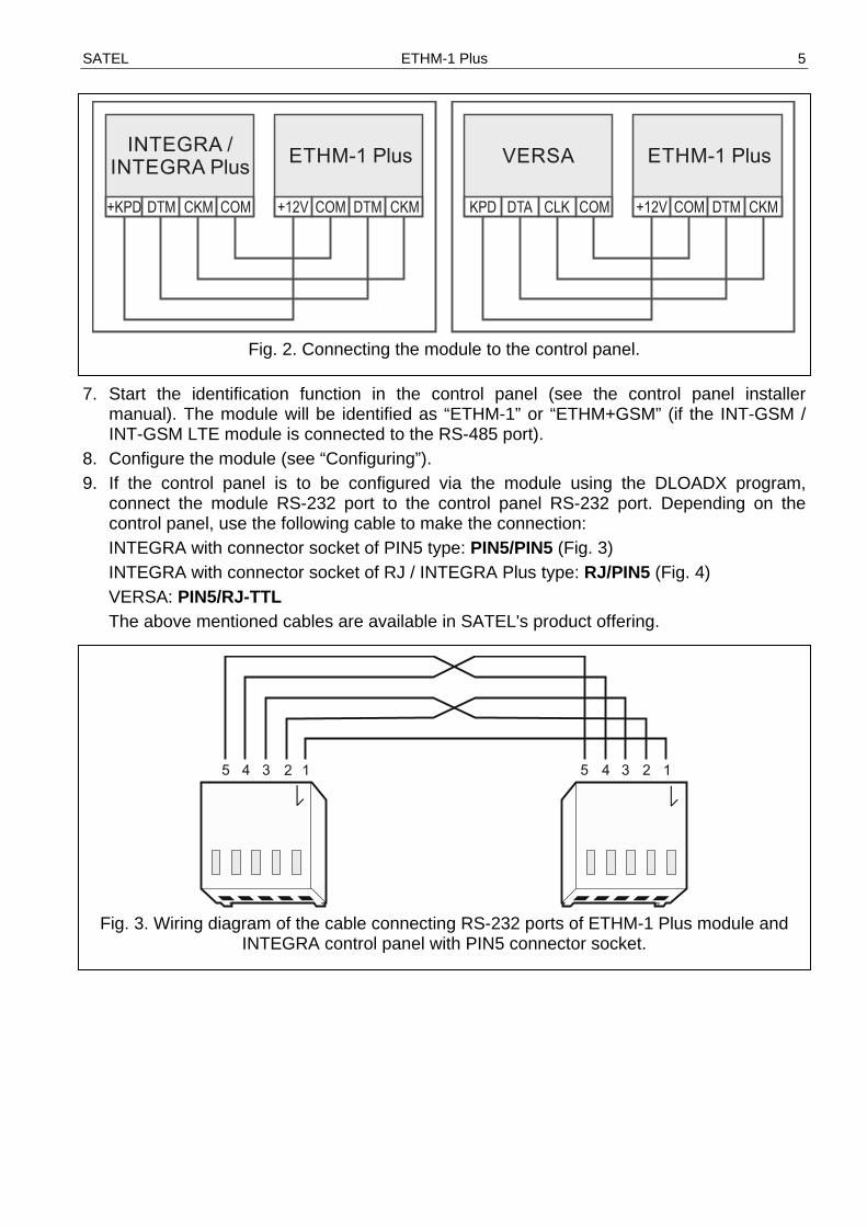
Fig. 2. Connecting the module to the control panel.
7. Start the identification function in the control panel (see the control panel installer
manual). The module will be identified as “ETHM-1” or “ETHM+GSM” (if the INT-GSM / INT-GSM LTE module is connected to the RS-485 port).
8. Configure the module (see “Configuring”). 9. If the control panel is to be configured via the module using the DLOADX program,
connect the module RS-232 port to the control panel RS-232 port. Depending on the control panel, use the following cable to make the connection: INTEGRA with connector socket of PIN5 type: PIN5/PIN5 (Fig. 3) INTEGRA with connector socket of RJ / INTEGRA Plus type: RJ/PIN5 (Fig. 4) VERSA: PIN5/RJ-TTL The above mentioned cables are available in SATEL's product offering.
Fig. 3. Wiring diagram of the cable connecting RS-232 ports of ETHM-1 Plus module and
INTEGRA control panel with PIN5 connector socket.

6 ETHM-1 Plus SATEL
Fig. 4. Wiring diagram of the cable connecting RS-232 ports of ETHM-1 Plus module and
INTEGRA / INTEGRA Plus control panel with RJ type connector socket.
6 Configuring the settings
The module settings differ, depending on the control panel to which the module is connected. Names of parameters and options from the DLOADX program are used in this manual. When a parameter or an option is described, you will find in the square brackets their name displayed on the keypad.
6.1 Module connected to INTEGRA / INTEGRA Plus control panel You can configure parameters and options of the module using: • DLOADX program: “Structure” window “Hardware” tab “Keypads” branch [module name],
• LCD keypad: SERVICE MODE STRUCTURE HARDWARE LCD KEYPADS SETTINGS [module name].
All settings you can configure only by means of the DLOADX program.
If the module has been identified as “ETHM+GSM” (the INT-GSM / INT-GSM LTE module is connected to the ETHM-1 Plus module), the INT-GSM / INT-GSM LTE module will take over tasks from the ETHM-1 Plus module if the Ethernet connection is lost. These tasks are performed via cellular data network. Therefore many options and parameters apply to both modules. This should be borne in mind when configuring the settings.
6.1.1 ETHM-1 Name – individual name of the device (up to 16 characters). Tamper signaled in part. [Tamper in part.] – partition where alarm will be triggered in the
event of module tamper.
Network settings Obtain IP address automatically (DHCP) [DHCP] – if this option is enabled, the module will
automatically download data on IP address, subnet mask and gateway from the DHCP server (in such a case, you do not have to program these parameters).
SATEL ETHM-1 Plus 7
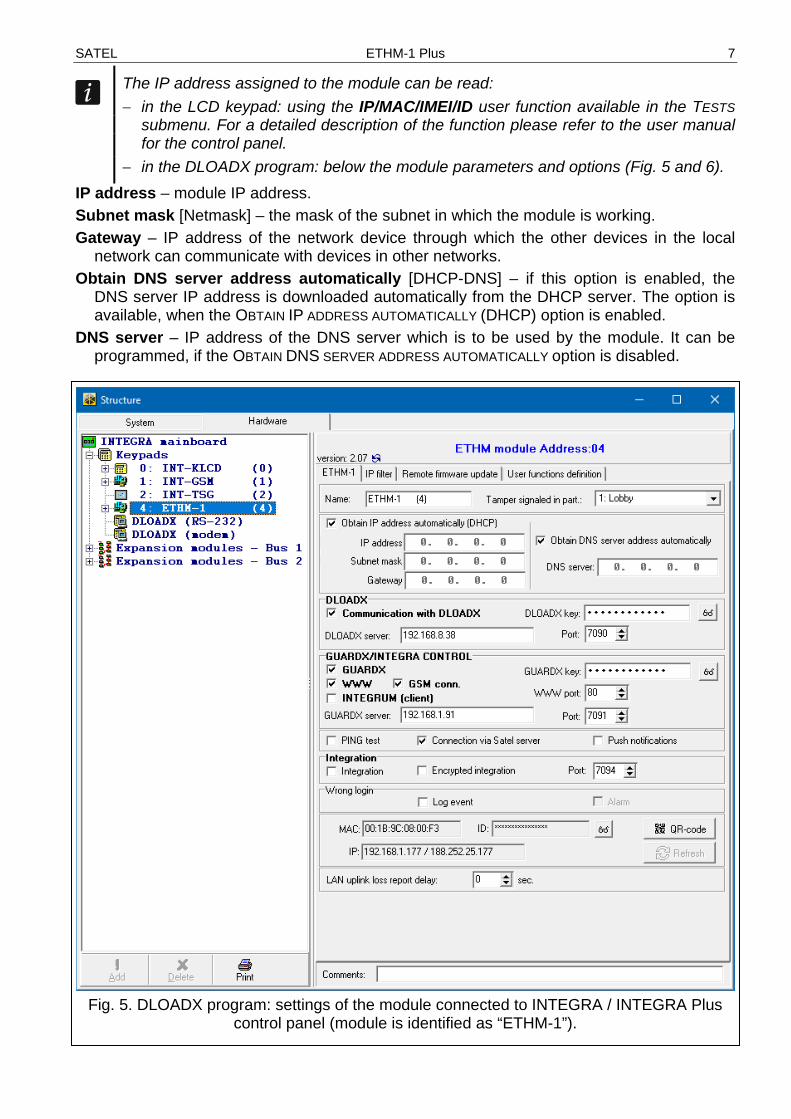
The IP address assigned to the module can be read: − in the LCD keypad: using the IP/MAC/IMEI/ID user function available in the TESTS
submenu. For a detailed description of the function please refer to the user manual for the control panel.
− in the DLOADX program: below the module parameters and options (Fig. 5 and 6). IP address – module IP address. Subnet mask [Netmask] – the mask of the subnet in which the module is working. Gateway – IP address of the network device through which the other devices in the local
network can communicate with devices in other networks. Obtain DNS server address automatically [DHCP-DNS] – if this option is enabled, the
DNS server IP address is downloaded automatically from the DHCP server. The option is available, when the OBTAIN IP ADDRESS AUTOMATICALLY (DHCP) option is enabled.
DNS server – IP address of the DNS server which is to be used by the module. It can be programmed, if the OBTAIN DNS SERVER ADDRESS AUTOMATICALLY option is disabled.
Fig. 5. DLOADX program: settings of the module connected to INTEGRA / INTEGRA Plus
control panel (module is identified as “ETHM-1”).
8 ETHM-1 Plus SATEL
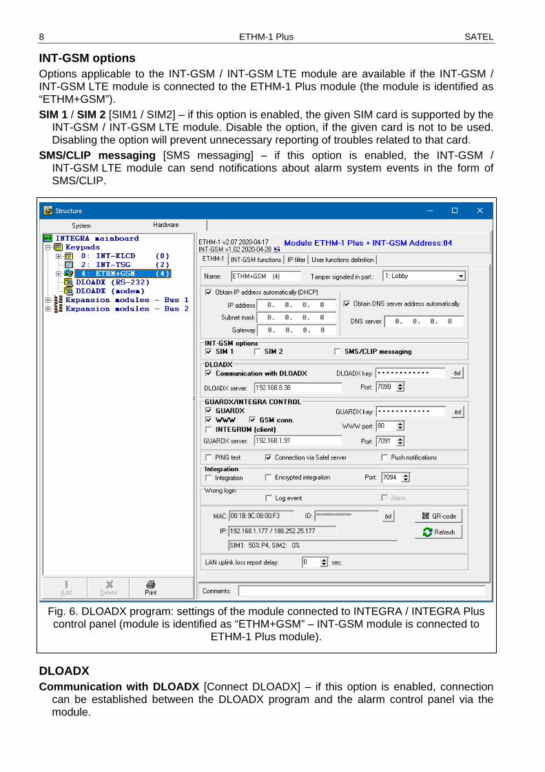
INT-GSM options Options applicable to the INT-GSM / INT-GSM LTE module are available if the INT-GSM / INT-GSM LTE module is connected to the ETHM-1 Plus module (the module is identified as “ETHM+GSM”). SIM 1 / SIM 2 [SIM1 / SIM2] – if this option is enabled, the given SIM card is supported by the
INT-GSM / INT-GSM LTE module. Disable the option, if the given card is not to be used. Disabling the option will prevent unnecessary reporting of troubles related to that card.
SMS/CLIP messaging [SMS messaging] – if this option is enabled, the INT-GSM / INT-GSM LTE module can send notifications about alarm system events in the form of SMS/CLIP.
Fig. 6. DLOADX program: settings of the module connected to INTEGRA / INTEGRA Plus control panel (module is identified as “ETHM+GSM” – INT-GSM module is connected to
ETHM-1 Plus module).
DLOADX Communication with DLOADX [Connect DLOADX] – if this option is enabled, connection
can be established between the DLOADX program and the alarm control panel via the module.

SATEL ETHM-1 Plus 9
DLOADX key [Key (DLOADX)] – a string of up to 12 alphanumeric characters (digits, letters and special characters) used for data encryption during communication with the DLOADX program via module.
DLOADX server [DLOADX IP] – address of the computer running the DLOADX program. If the communication takes place in a wide area network, it must be a public address. You can enter either the IP address or the domain name.
In the LCD keypad, the function for programming address of the computer with DLOADX program is available in the user menu, CHANGE OPTIONS submenu (available to service and administrators).
Port [Port (DLOADX)] – number of the TCP port used for communication with the DLOADX program. You can enter values from 1 to 65535. The value must be different from that entered for the other ports. Default value: 7090.
GUARDX/INTEGRA CONTROL GUARDX [Connect GUARDX] – if this option is enabled, connection can be established
between the GUARDX program and the alarm control panel via the module. The option is not available when the INTEGRUM (CLIENT) option is enabled.
WWW [Connect Intern.] – if this option is enabled, connection can be established between the web browser and the alarm control panel via the module. The option is not available when the INTEGRUM (CLIENT) option is enabled.
GSM conn. [Connect GSM] – if this option is enabled, connection can be established between the INTEGRA CONTROL application / INTEGRUM server and the alarm control panel via the module. The option is not available when the INTEGRUM (CLIENT) option is enabled.
INTEGRUM (client) [INTEGRUM] – if this option is enabled, the module initiates connection to the INTEGRUM server to establish communication between the control panel and the INTEGRUM server. This method of establishing communication is supported by the INTEGRUM server with version 2.0 (or newer). In the GUARDX SERVER field enter the INTEGRUM server address, and in the PORT field enter the communication port number. When the option is enabled, the GUARDX, WWW and GSM CONN. options are not available (the module does not support the GUARDX program / web browser / INTEGRA CONTROL app).
GUARDX server [GUARDX IP] – address of the computer running the GUARDX program or INTEGRUM server. If the communication takes place in a wide area network, it must be a public address. You can enter either the IP address or the domain name.
In the keypad, the function for programming address of the computer with GUARDX program installed / INTEGRUM system server is available in the user menu, CHANGE OPTION submenu (available to service and administrators).
GUARDX key [Key (others)] – a string of up to 12 alphanumeric characters (digits, letters and special characters) used for data encryption during communication with: − GUARDX program, − JAVA application in the web browser, − INTEGRA CONTROL in the mobile device, − INTEGRUM system.
WWW port – number of the TCP port used for communication with the web browser. You can enter values from 1 to 65535 The value must be different from that entered for the other ports. Default value: 80.

10 ETHM-1 Plus SATEL
Port [Port (others)] – number of the TCP port used for communication with: − GUARDX program, − JAVA application in the web browser, − INTEGRA CONTROL in the mobile device, − INTEGRUM system. You can enter values from 1 to 65535. The value must be different from that entered for the other ports. Default value: 7091.
The port cannot be used by several services at a time. The port can only be used by one service (e.g. when communication with the INTEGRUM server is ongoing, you will not be able to connect to the control panel using the GUARDX program, the web browser or the INTEGRA CONTROL application).
PING test PING test – if this option is enabled, the module can perform a communication test using the
ping command sent to the indicated network device. Parameters related to the communication test should be programmed in the control panel: LCD keypad: SERVICE MODE OPTIONS PING TEST, DLOADX program: “Structure” window “Hardware” tab “Keypads” branch.
SATEL server Connection via Satel server [SATEL server] – if the option is enabled, the module connects
to the SATEL server and the communication via the SATEL server with the control panel can be established (Connection Setup Service). This way of communication requires no additional configuring of the network device through which the module connects to the public network.
For establishing communication with the SATEL server, the DNS server must be used.
For communication via the SATEL server, the ports of 1024-65535 range are used as outgoing ports. These ports must not be blocked.
Push notifications – if this option is enabled, the INTEGRA CONTROL application can provide information about alarm system events by means of push notifications.
Integration Integration [Integrate] – if this option is enabled, the module can be used for integration of
the alarm control panel with other systems. Encrypted integration [Coded integr.] – if this option is enabled, communication with other
systems is encrypted. The integration encryption key should be programmed in the control panel: LCD keypad: SERVICE MODE OPTIONS INTEGRATE KEY, DLOADX program: “Options” window “Service” tab.
Port [Port (integr.)] – number of the TCP port used for integration. You can enter values from 1 to 65535. The value must be different from that entered for the other ports. Default value: 7094.
Wrong login Log event [Fail. – event] – if this option is enabled, all unauthorized attempts to connect to
the module are written to the event log.
SATEL ETHM-1 Plus 11
Alarm [Fail. – alarm] – if this option is enabled, any unauthorized attempt to connect to the module will trigger the tamper alarm. The option is available, if the LOG EVENT option is enabled.
Information MAC – module hardware address. ID – individual ID number assigned to the module by the SATEL server.
If the module is to be used in another alarm system, the hitherto used ID number must be deleted. You should do it after connecting the module to the new control panel and establishing connection with the SATEL server, using the CHANGE ID function available from the keypad (SERVICE MODE STRUCTURE HARDWARE LCD KEYPADS SETTINGS [module name] CHANGE ID), if the control panel is connected to the SATEL server. Having deleted the old ID number, the control panel will receive a new one. The INTEGRA CONTROL applications using the old ID number will be unable to connect to the control panel.
IP – local address / public address of the module. [Cellular network signal] – information about cellular signal strength and cellular network
operator. The information is displayed when the INT-GSM / INT-GSM LTE module is connected to the ETHM-1 Plus module (module is identified as “ETHM+GSM”).
QR-code – click the button to open the window in which the QR code is displayed. The QR code contains information required when configuring settings of communication through the SATEL server. You can read the QR code by using a mobile device or export to the file and transmit to the users. The QR code facilitates configuring the INTEGRA CONTROL application settings.
Refresh – click to refresh all information. LAN uplink loss report delay – if the Ethernet network is not available for a preset period of
time, the module will report a trouble. A delay in reporting the trouble prevents sending information about short-time loss of Ethernet connectivity.
6.1.2 INT-GSM functions These settings apply to the INT-GSM / INT-GSM LTE module. They are available if the INT-GSM / INT-GSM LTE module is connected to the ETHM-1 Plus module (the module is identified as “ETHM+GSM”). For description of the settings, refer to the INT-GSM / INT-GSM LTE module manual.
6.1.3 IP filter The module connected to the INTEGRA / INTEGRA Plus control panel with firmware version 1.15 (or newer) offers IP filter. Using IP filtering allows you to enhance security level of the alarm system. Establishing connection with the Ethernet module (alarm control panel) will only be possible from defined IP addresses or subnets. IP filtering does not apply to communication via the SATEL server. You can configure IP filtering for the incoming connections: • from DLOADX program, • from GUARDX program (applies also to web browser, mobile application and INTEGRUM
system), • as part of integration. In each case you can define the filtering rules in one of the following configurations: • up to 4 allowed IP addresses,
12 ETHM-1 Plus SATEL
• 1 allowed subnet and up to 2 allowed IP addresses, • up to 2 allowed subnets.
To activate the filtering feature, enter a value in one of the four fields available for the given type of incoming connections.
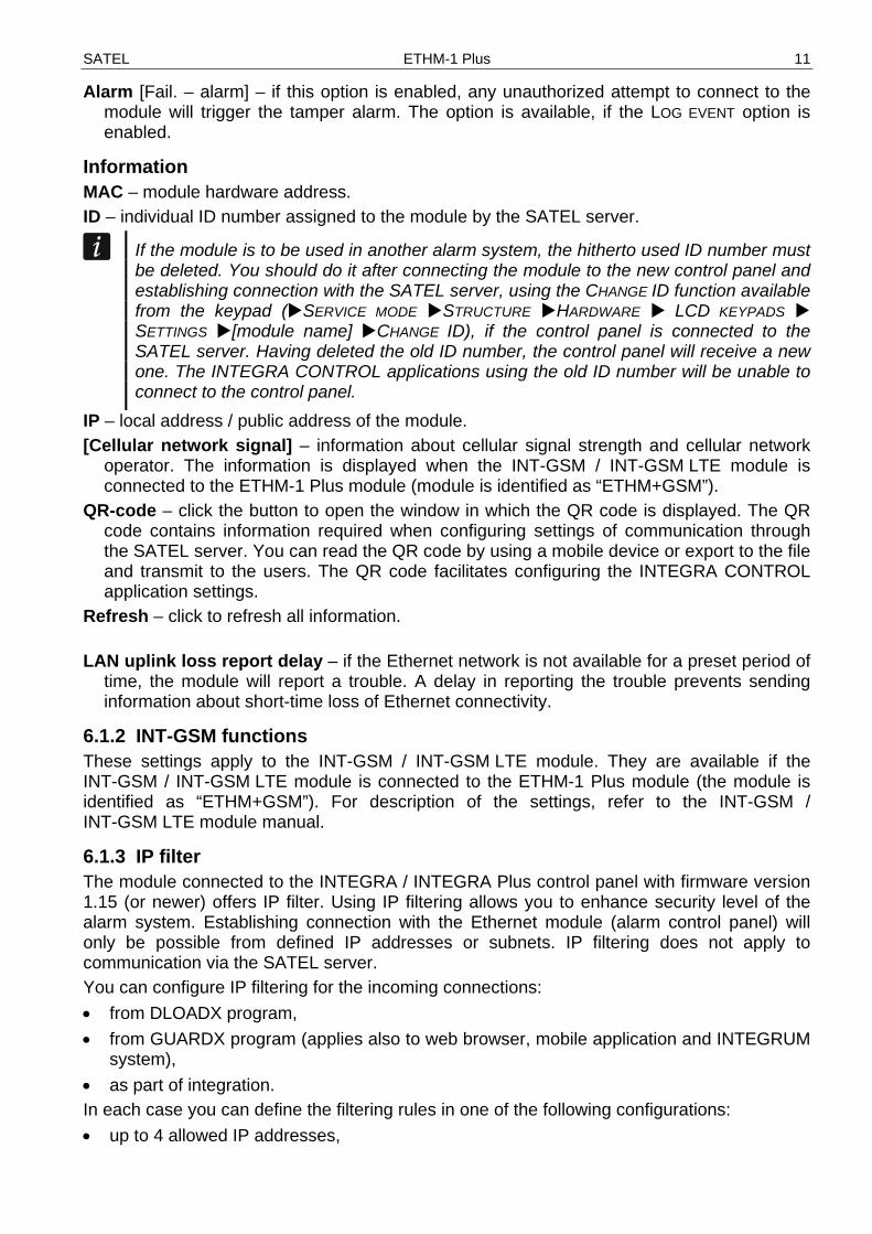
Fig. 7. DLOADX program: “IP filter” tab.
IP Address – if the SUBNET option is disabled: the network address from which connection
with the Ethernet module can be established. If the SUBNET option is enabled: the IP address used for defining the subnet from which connection with the Ethernet module can be established.
subnet – if the option is enabled, you can define the subnet from which incoming connections will be received by the module.
Subnet mask – mask used for separating the portion defining subnet from the IP address.
Filtering by IP address In the IP ADDRESS field, enter the network address from which establishing connection with the module (control panel) is to bed possible. The SUBNET option on the right-hand side of the field must not be selected.

SATEL ETHM-1 Plus 13
Filtering by subnet 1. Select the SUBNET option. Description of one of the IP ADDRESS fields will change to
SUBNET MASK. From now on, the IP ADDRESS and SUBNET MASK fields constitute a pair.
2. Enter the address to be used to define the subnet.
3. Enter the mask to be used to separate the portion defining subnet in the IP address.
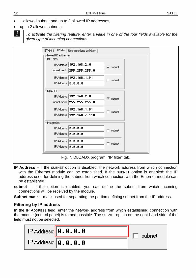
6.1.4 User functions If the INTEGRA CONTROL application is used in the mobile device, the virtual keypad allows you to quickly start user functions after entering the code and pressing an arrow key.
14 ETHM-1 Plus SATEL
Fig. 8. Program DLOADX: “User functions definition” tab.
6.1.5 Virtual keypad The virtual keypad allows you to operate and program the alarm system in much the same way as using a physical keypad. You can use the virtual keypad in the DLOADX and GUARDX programs, web browser and in the mobile device (after installation of the INTEGRA CONTROL application). Parameters and options of the virtual keypad available in the DLOADX program can be programmed using: • LCD keypad: SERVICE MODE STRUCTURE HARDWARE LCD KEYPADS SETTINGS
DLOADX RS, • DLOADX program: “Structure” window “Hardware” tab “Keypads” branch “DLOADX (RS-232)” item.
Settings of the virtual keypad available in the GUARDX program, web browser or mobile device can be programmed using: • LCD keypad: SERVICE MODE STRUCTURE HARDWARE LCD KEYPADS SETTINGS
GUARDX ADDR. n [n = module address], • DLOADX program: “Structure” window “Hardware” tab “Keypads” branch [module name] branch “GUARDX/INTEGRA CONTROL” item (Fig. 9).
For description of the keypad parameters and options, please refer to the programming manual for INTEGRA / INTEGRA Plus control panel (only some of these parameters and options are available for the virtual keypad).

SATEL ETHM-1 Plus 15
Fig. 9. DLOADX program: parameters and options of the virtual keypad available in GUARDX
program, web browser or mobile device.
6.1.6 Macro commands The INTEGRA CONTROL application allows to control the alarm system by means of macro commands, thus making it possible to quickly and easily run a number of different functions by touching just a few keys. The macro commands can be defined in the DLOADX program (“Structure” window “Hardware” tab “Keypads” branch [module name] branch “GUARDX/INTEGRA CONTROL” item “Macro Commands” tab). Defined macro commands can be automatically downloaded by the INTEGRA CONTROL application after establishing connection with the module.

16 ETHM-1 Plus SATEL
Macro commands can be loaded into the application without establishing connection with the module. The file containing macro commands can be exported, and then saved to the mobile device memory (to transfer the file, you can use a memory card or other solutions available for the given device). This method allows you to use macro commands defined e.g. for the INT-TSG keypad in the INTEGRA CONTROL application. Instead of a file with macro commands defined for the ETHM-1 Plus module, you can load a file with macro commands defined for the LCD keypad.
The data related to macro commands are stored in the module memory. Before you start defining the macro commands, click on the “Read” button in the “Macro commands” tab to read the data from the module. Having defined the macro commands, click on the “Write” button in the “Macro commands” tab to write the data to the module. The macro command related data are not read / written when you click
on the button in the main menu of DLOADX program.
Groups
Fig. 10. DLOADX program: “Groups” tab.
SATEL ETHM-1 Plus 17
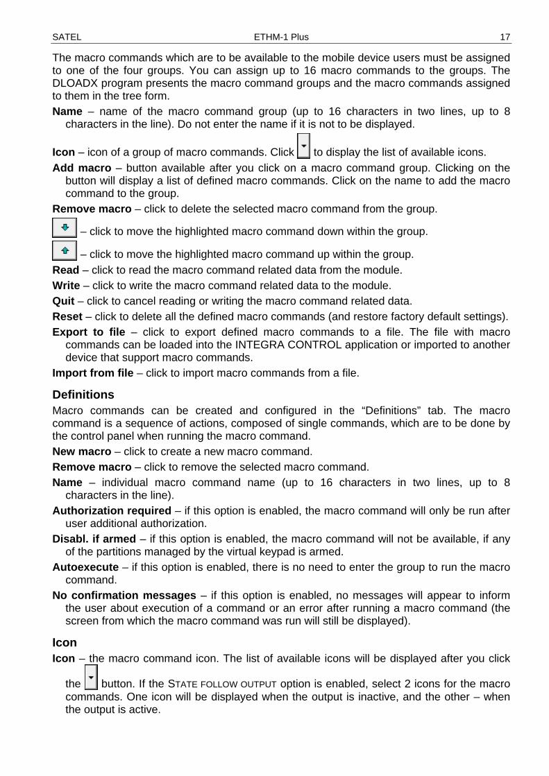
The macro commands which are to be available to the mobile device users must be assigned to one of the four groups. You can assign up to 16 macro commands to the groups. The DLOADX program presents the macro command groups and the macro commands assigned to them in the tree form. Name – name of the macro command group (up to 16 characters in two lines, up to 8
characters in the line). Do not enter the name if it is not to be displayed.
Icon – icon of a group of macro commands. Click to display the list of available icons. Add macro – button available after you click on a macro command group. Clicking on the
button will display a list of defined macro commands. Click on the name to add the macro command to the group.
Remove macro – click to delete the selected macro command from the group.
– click to move the highlighted macro command down within the group.
– click to move the highlighted macro command up within the group. Read – click to read the macro command related data from the module. Write – click to write the macro command related data to the module. Quit – click to cancel reading or writing the macro command related data. Reset – click to delete all the defined macro commands (and restore factory default settings). Export to file – click to export defined macro commands to a file. The file with macro
commands can be loaded into the INTEGRA CONTROL application or imported to another device that support macro commands.
Import from file – click to import macro commands from a file.
Definitions Macro commands can be created and configured in the “Definitions” tab. The macro command is a sequence of actions, composed of single commands, which are to be done by the control panel when running the macro command. New macro – click to create a new macro command. Remove macro – click to remove the selected macro command. Name – individual macro command name (up to 16 characters in two lines, up to 8
characters in the line). Authorization required – if this option is enabled, the macro command will only be run after
user additional authorization. Disabl. if armed – if this option is enabled, the macro command will not be available, if any
of the partitions managed by the virtual keypad is armed. Autoexecute – if this option is enabled, there is no need to enter the group to run the macro
command. No confirmation messages – if this option is enabled, no messages will appear to inform
the user about execution of a command or an error after running a macro command (the screen from which the macro command was run will still be displayed).
Icon Icon – the macro command icon. The list of available icons will be displayed after you click
the button. If the STATE FOLLOW OUTPUT option is enabled, select 2 icons for the macro commands. One icon will be displayed when the output is inactive, and the other – when the output is active.
18 ETHM-1 Plus SATEL
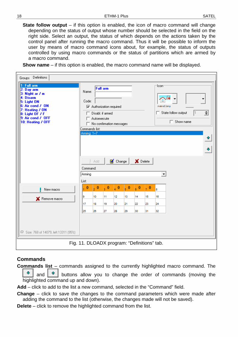
State follow output – if this option is enabled, the icon of macro command will change depending on the status of output whose number should be selected in the field on the right side. Select an output, the status of which depends on the actions taken by the control panel after running the macro command. Thus it will be possible to inform the user by means of macro command icons about, for example, the status of outputs controlled by using macro commands or the status of partitions which are armed by a macro command.
Show name – if this option is enabled, the macro command name will be displayed.
Fig. 11. DLOADX program: “Definitions” tab.
Commands Commands list – commands assigned to the currently highlighted macro command. The
and buttons allow you to change the order of commands (moving the highlighted command up and down).
Add – click to add to the list a new command, selected in the “Command” field. Change – click to save the changes to the command parameters which were made after
adding the command to the list (otherwise, the changes made will not be saved). Delete – click to remove the highlighted command from the list.
SATEL ETHM-1 Plus 19
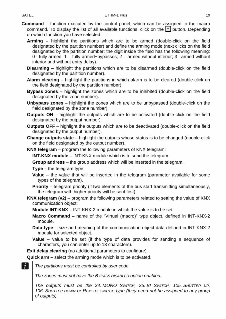
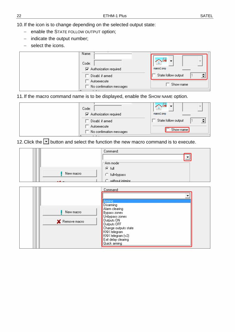
Command – function executed by the control panel, which can be assigned to the macro command. To display the list of all available functions, click on the button. Depending on which function you have selected: Arming – highlight the partitions which are to be armed (double-click on the field
designated by the partition number) and define the arming mode (next clicks on the field designated by the partition number; the digit inside the field has the following meaning: 0 - fully armed; 1 – fully armed+bypasses; 2 – armed without interior; 3 - armed without interior and without entry delay).
Disarming – highlight the partitions which are to be disarmed (double-click on the field designated by the partition number).
Alarm clearing – highlight the partitions in which alarm is to be cleared (double-click on the field designated by the partition number).
Bypass zones – highlight the zones which are to be inhibited (double-click on the field designated by the zone number).
Unbypass zones – highlight the zones which are to be unbypassed (double-click on the field designated by the zone number).
Outputs ON – highlight the outputs which are to be activated (double-click on the field designated by the output number).
Outputs OFF – highlight the outputs which are to be deactivated (double-click on the field designated by the output number).
Change outputs state – highlight the outputs whose status is to be changed (double-click on the field designated by the output number).
KNX telegram – program the following parameters of KNX telegram: INT-KNX module – INT-KNX module which is to send the telegram. Group address – the group address which will be inserted in the telegram. Type – the telegram type. Value – the value that will be inserted in the telegram (parameter available for some
types of the telegram). Priority – telegram priority (if two elements of the bus start transmitting simultaneously,
the telegram with higher priority will be sent first). KNX telegram (v2) – program the following parameters related to setting the value of KNX
communication object: Module INT-KNX – INT-KNX-2 module in which the value is to be set. Macro Command – name of the “Virtual (macro)” type object, defined in INT-KNX-2
module. Data type – size and meaning of the communication object data defined in INT-KNX-2
module for selected object. Value – value to be set (if the type of data provides for sending a sequence of
characters, you can enter up to 13 characters). Exit delay clearing (no additional parameters to configure). Quick arm – select the arming mode which is to be activated.
The partitions must be controlled by user code.
The zones must not have the BYPASS DISABLED option enabled.
The outputs must be the 24. MONO SWITCH, 25. BI SWITCH, 105. SHUTTER UP, 106. SHUTTER DOWN or REMOTE SWITCH type (they need not be assigned to any group of outputs).

20 ETHM-1 Plus SATEL
Using the INTEGRA CONTROL application, you can control the KNX system, if the INT-KNX module is connected to the control panel.
Defining macro commands 1. Click the “Read” button to read the macro command related data from the module.
2. Click on the “Definitions” tab.
3. Click the “New macro” button. A new macro command will appear on the list.
4. Enter a name for the new macro command.
SATEL ETHM-1 Plus 21
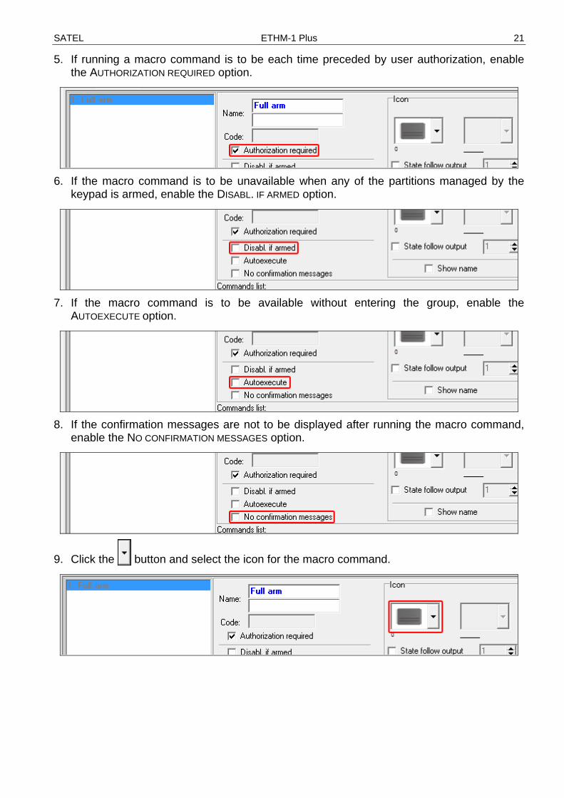
5. If running a macro command is to be each time preceded by user authorization, enable the AUTHORIZATION REQUIRED option.
6. If the macro command is to be unavailable when any of the partitions managed by the
keypad is armed, enable the DISABL. IF ARMED option.
7. If the macro command is to be available without entering the group, enable the
AUTOEXECUTE option.
8. If the confirmation messages are not to be displayed after running the macro command,
enable the NO CONFIRMATION MESSAGES option.
9. Click the button and select the icon for the macro command.
22 ETHM-1 Plus SATEL
10. If the icon is to change depending on the selected output state: − enable the STATE FOLLOW OUTPUT option; − indicate the output number; − select the icons.
11. If the macro command name is to be displayed, enable the SHOW NAME option.
12. Click the button and select the function the new macro command is to execute.
SATEL ETHM-1 Plus 23
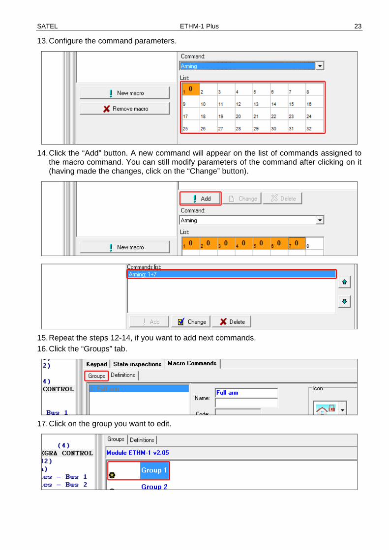
13. Configure the command parameters.
14. Click the “Add” button. A new command will appear on the list of commands assigned to
the macro command. You can still modify parameters of the command after clicking on it (having made the changes, click on the “Change” button).
15. Repeat the steps 12-14, if you want to add next commands. 16. Click the “Groups” tab.
17. Click on the group you want to edit.

24 ETHM-1 Plus SATEL
18. Enter the group name, if it is to be displayed.
19. Click the button and select the icon for the macro command group.
20. Click the “Add macro” button. A list of all defined macro commands will be displayed.
21. Click on a macro command to add it to the group. The macro command will be put in the
tree under the group.
22. Click the “Write” button to write the macro command related data to the module.

SATEL ETHM-1 Plus 25
6.2 Module connected to VERSA control panel You can configure parameters and options of the module using: • LCD keypad: SERVICE MODE 2. HARDWARE 1. KPDS. & EXPS. 2. SETTINGS [module
name], • DLOADX program: “Versa – Structure” window “Hardware” tab “Expansion
modules” branch [module name] (Fig. 12). Name – individual name of the device (up to 16 characters). Tamper signaled in part. [Tamper in p.] – partition where alarm will be triggered in the event
of module tamper. DLOADX->ETHM-1 connection [DLOADXETHM-1] – if this option is enabled, connection
can be established between the DLOADX program and the alarm control panel via the module.
DLOADX DLOADX server [DLOADX] – address of the computer running the DLOADX program. If the
communication takes place in a wide area network, it must be a public address. You can enter either the IP address or the domain name.
Port [DLOADX port] – number of the TCP port used during communication between control panel and a computer with DLOADX program via Ethernet. You can enter values from 1 to 65535. The value must be different from that entered for the other ports. Default value: 7090.
DLOADX key – a string of up to 12 alphanumeric characters (digits, letters and special characters) which is used for data encryption during communication with the DLOADX program via module.
SATEL service LAN [SATEL server LAN] – if the option is enabled, the module connects to the SATEL
server and the communication via the SATEL server with the control panel can be established (Connection Setup Service). This way of communication requires no additional configuring of the network device through which the module connects to the public network.
For establishing communication with the SATEL server, the DNS server must be used.
For communication via the SATEL server, the ports of 1024-65535 range are used as outgoing ports. These ports must not be blocked.
Do not report SATEL server connection trouble [No SATEL trbl.] – if this option is enabled, loss of communication with the SATEL server will not be reported.
Communication with mobile application [Mobile app.] – if this option is enabled, connection can be established between the VERSA CONTROL application and the alarm control panel via the module. The option is available if the LAN option is enabled.
Alarm 3 incorrect codes (mobile application) [Al.3 wrong codes] – if this option is enabled, entering an invalid code three times from the VERSA CONTROL application will trigger an alarm.
Push notifications – if this option is enabled, the VERSA CONTROL application can provide information about alarm system events by means of push notifications.
Information MAC – module hardware address. ID – individual ID number assigned to the module by the SATEL server.

26 ETHM-1 Plus SATEL
If the module is to be used in another alarm system, the hitherto used ID number must be deleted. You should do it after connecting the module to the new control panel and establishing connection with the SATEL server, from the keypad, when programming the Ethernet module, in the last step. Having deleted the old ID number, the module will receive a new one. The VERSA CONTROL applications using the old ID number will be unable to connect to the control panel.
IP – local address / public address of the module. QR-code – click the button to open the window in which the QR code is displayed. The QR
code contains information required when configuring settings of communication through the SATEL server. You can read the QR code by using a mobile device or export to the file and transmit to the users. The QR code facilitates configuring the VERSA CONTROL application settings.
Refresh – click to refresh all information.
Time from a time server LAN [Time from srvLAN] – if the option is enabled, the control panel clock will be
synchronized with the time server once a day.
For communication with the time server, the DNS server must be used. Time zone – difference between the universal time (GMT) and the zone time. The parameter
is required, if the control panel clock is to be synchronized with the time server.
Fig. 12. DLOADX program: settings of the module connected to VERSA control panel.
SATEL ETHM-1 Plus 27
6.2.1 LAN Obtain IP address automatically (DHCP) [DHCP] – if this option is enabled, the module will
automatically download data on IP address, subnet mask and gateway from the DHCP server (in such a case, you do not have to program these parameters).
The IP address assigned to the module can be read in the LCD keypad using the MODULE VER. user function available in the TESTS submenu. For a detailed description of the function please refer to the user manual for the control panel.
IP address – module IP address. Subnet mask [Netmask] – the mask of the subnet in which the module is working. Gateway – IP address of the network device through which the other devices in the local
network can communicate with devices in other networks. Obtain DNS server address automatically [DHCP-DNS] – if this option is enabled, the
DNS server IP address is downloaded automatically from the DHCP server. The option is available, when the OBTAIN IP ADDRESS AUTOMATICALLY (DHCP) option is enabled.
DNS server – IP address of the DNS server which is to be used by the module. It can be programmed, if the OBTAIN DNS SERVER ADDRESS AUTOMATICALLY option is disabled.
PING test Address to test [PING] – address of the device to which a ping command to test
communication is to be sent by the module. You can enter IP address or domain name. Period [PING period] – the time interval between successive communication tests using the
ping command. If value 0 is programmed, the communication test is disabled. Tries no. before trouble [PING tries] – the number of failed communication tests (the
module received no answer to the ping command sent), after which the trouble will be reported. If value 0 is programmed, the communication test is disabled.
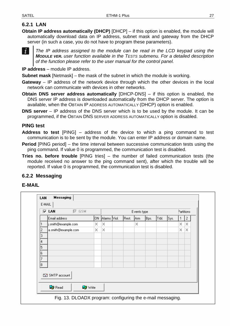
6.2.2 Messaging
Fig. 13. DLOADX program: configuring the e-mail messaging.

28 ETHM-1 Plus SATEL
Before making any changes, click the “Read” button, and after making the changes –the “Write” button (the data relating to the e-mail messaging are not read after clicking
on the button or saved after clicking on the button in the DLOADX program main menu).
LAN – if the option is enabled, the control panel can notify of occurrence of specified events by means of e-mail messages.
Email address – e-mail address to which messages are to be sent for notification of events.
Because the message is sent to many recipients, the addressees are hidden. If you want the addressee to be shown, place @ before the email address (e.g. @[email protected]).
ON – with this option enabled, it will be possible to send messages to the given e-mail address for notification of events.
Events type – define of which events the given e-mail address is to be notified. Part. – define the partitions, about the events from which the given e-mail address is to be
notified. SMTP account – click to open “SMTP account” window. Read – click to read the data related to e-mail messaging. Write – click to write the data related to e-mail messaging.
SMTP account
Fig. 14. DLOADX program: “SMTP account” window. The presented settings are just an
example.
It is required to have an e-mail account so as to enter its parameters in the DLOADX program for the purpose of e-mail messaging.
Mail server (SMTP) – address of outgoing mail server. Server port – number of outgoing mail port. User name – name of the e-mail account used for authorization by the SMTP server (login to
e-mail account). Password – the password used for authorization by the SMTP server. Encryption – you can define if and how the outgoing mail is encrypted:
none – outgoing mail is not encrypted. STARTTLS – outgoing mail will be encrypted using the STARTTLS protocol. SSL/TLS – outgoing mail will be encrypted using the SSL/TLS protocol.
SATEL ETHM-1 Plus 29
Subject – subject of the e-mail message. It will be inserted in each e-mail message to be sent.
Sender address – e-mail address which will be inserted in the outgoing e-mail message as the sender address. If this field is blank, the name of e-mail account will be treated as the sender address.
7 Remote programming / operating of control panel via module
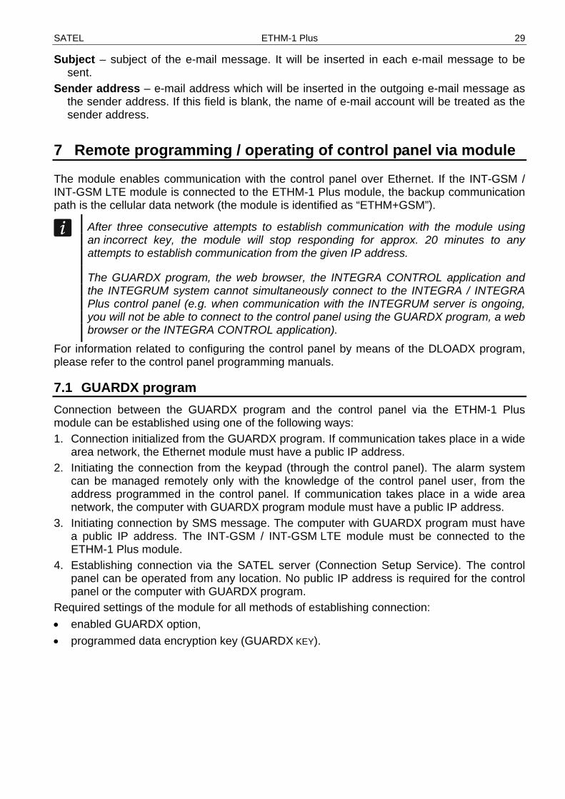
The module enables communication with the control panel over Ethernet. If the INT-GSM / INT-GSM LTE module is connected to the ETHM-1 Plus module, the backup communication path is the cellular data network (the module is identified as “ETHM+GSM”).
After three consecutive attempts to establish communication with the module using an incorrect key, the module will stop responding for approx. 20 minutes to any attempts to establish communication from the given IP address.
The GUARDX program, the web browser, the INTEGRA CONTROL application and the INTEGRUM system cannot simultaneously connect to the INTEGRA / INTEGRA Plus control panel (e.g. when communication with the INTEGRUM server is ongoing, you will not be able to connect to the control panel using the GUARDX program, a web browser or the INTEGRA CONTROL application).
For information related to configuring the control panel by means of the DLOADX program, please refer to the control panel programming manuals.
7.1 GUARDX program Connection between the GUARDX program and the control panel via the ETHM-1 Plus module can be established using one of the following ways: 1. Connection initialized from the GUARDX program. If communication takes place in a wide
area network, the Ethernet module must have a public IP address. 2. Initiating the connection from the keypad (through the control panel). The alarm system
can be managed remotely only with the knowledge of the control panel user, from the address programmed in the control panel. If communication takes place in a wide area network, the computer with GUARDX program module must have a public IP address.
3. Initiating connection by SMS message. The computer with GUARDX program must have a public IP address. The INT-GSM / INT-GSM LTE module must be connected to the ETHM-1 Plus module.
4. Establishing connection via the SATEL server (Connection Setup Service). The control panel can be operated from any location. No public IP address is required for the control panel or the computer with GUARDX program.
Required settings of the module for all methods of establishing connection: • enabled GUARDX option, • programmed data encryption key (GUARDX KEY).

30 ETHM-1 Plus SATEL
7.1.1 Configuring the GUARDX program settings
Fig. 15. GUARDX program: startup window.
1. Select the communication method in the GUARDX program startup window, “Connection”
field: “TCP/IP: GUARDX->ETHM”, “TCP/IP: GUARDX<-ETHM/INT-GSM” or “TCP/IP: SATEL server” (Fig. 15).
2. Click on the “Configuration” button. The “System name” window will be displayed. 3. Enter the system name and click on the “OK” button. The “Connection” window will be
displayed.
“Communication Identifiers” tab
Fig. 16. GUARDX program: “Communication Identifiers” tab in “Connection” window.
Panel’s identifier – identifier of the alarm control panel. It must consist of 10 characters
(digits or letters from A to F). PC identifier – identifier of the computer with GUARDX program. It must consist of 10
characters (digits or letters from A to F).
You must enter the same identifiers in the GUARDX program and in the control panel.
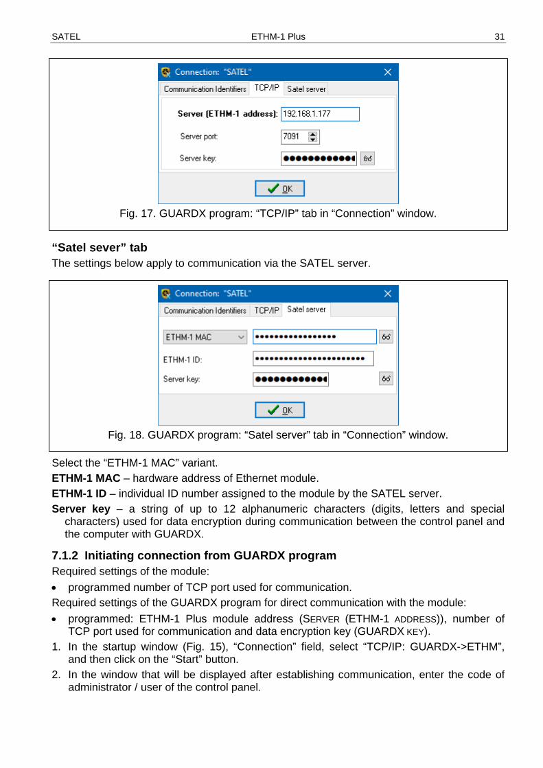
“TCP/IP” tab The settings below apply to direct communication with the module. Server (ETHM-1 address) – address of the Ethernet module. If the Ethernet module is not in
the same local network as the computer with GUARDX program, it must be a public address. You can enter either the IP address or the domain name.
Server port – the number of TCP port used during communication between the control panel and computer with GUARDX program.
Server key – a string of up to 12 alphanumeric characters (digits, letters and special characters) used for data encryption during communication between the control panel and the computer with GUARDX.
SATEL ETHM-1 Plus 31
Fig. 17. GUARDX program: “TCP/IP” tab in “Connection” window.
“Satel sever” tab The settings below apply to communication via the SATEL server.
Fig. 18. GUARDX program: “Satel server” tab in “Connection” window.
Select the “ETHM-1 MAC” variant. ETHM-1 MAC – hardware address of Ethernet module. ETHM-1 ID – individual ID number assigned to the module by the SATEL server. Server key – a string of up to 12 alphanumeric characters (digits, letters and special
characters) used for data encryption during communication between the control panel and the computer with GUARDX.
7.1.2 Initiating connection from GUARDX program Required settings of the module: • programmed number of TCP port used for communication. Required settings of the GUARDX program for direct communication with the module: • programmed: ETHM-1 Plus module address (SERVER (ETHM-1 ADDRESS)), number of
TCP port used for communication and data encryption key (GUARDX KEY). 1. In the startup window (Fig. 15), “Connection” field, select “TCP/IP: GUARDX->ETHM”,
and then click on the “Start” button. 2. In the window that will be displayed after establishing communication, enter the code of
administrator / user of the control panel.

32 ETHM-1 Plus SATEL
7.1.3 Initiating connection from keypad (through control panel) Required settings of the module: • programmed: address of computer with GUARDX program (GUARDX SERVER) and umber
of TCP port used for communication. Required settings of the GUARDX program for direct communication with the module: • programmed: number of TCP port used for communication and data encryption key
(GUARDX KEY). 1. In the startup window (Fig. 15), “Connection” field, select “TCP/IP: GUARDX<-ETHM/INT-
GSM”, and then click on the “Start” button. 2. Ask the user to start the ETHM-1 GUARDX function ([code] DOWNLOADING
ETHM-1 GUARDX). The function is available to the service, administrator and user having the DOWNLOADING STARTING right.
3. In the window that will be displayed after establishing communication, enter the code of administrator / user of the control panel.
7.1.4 Initiating connection by SMS message Required settings of the module: • programmed: address of computer with GUARDX program (GUARDX SERVER) and
number of TCP port used for communication, • programmed control command which, if sent in the SMS message, will initiate connection
with the GUARDX program (SMS INITIATING GUARDX CONNECTION). Required settings of the GUARDX program for direct communication with the module: • programmed: number of TCP port used for communication and data encryption key
(GUARDX KEY). 1. In the startup window (Fig. 15), “Connection” field, select “TCP/IP: GUARDX<-ETHM/INT-
GSM”, and then click on the “Start” button. 2. Send to the INT-GSM / INT-GSM LTE module the following SMS message:
xxxx= (“xxxx” – the control command to initiate establishment of communication with GUARDX program) – the module is to connect to the computer address programmed in the module,
xxxx=aaaa:p= (“xxxx” – the control command to initiate establishment of communication with GUARDX program; “aaaa” – address of the computer with GUARDX program (IP address or domain name); “p” – TCP port) – the module is to connect to the computer whose address has been given in the SMS message and use for communication the TCP port given in the SMS message.
3. In the window that will be displayed after establishing communication, enter the code of administrator / user of the control panel.
7.1.5 Establishing connection via the SATEL server Required settings of the module: • enabled CONNECTION VIA SATEL SERVER option. Required settings of the GUARDX program for communication via the SATEL server: • programmed: ID number assigned to the module by the SATEL server (ETHM-1 ID), MAC
address of the module (ETHM-1 MAC) and data encryption key (SERVER KEY). 1. In the startup window (Fig. 15), “Connection” field, select “TCP/IP: SATEL server”, and
then click on the “Start” button. 2. In the window that will be displayed after establishing communication, enter the code of
administrator / user of the control panel.
SATEL ETHM-1 Plus 33
7.2 Web browser Required settings of the module: • enabled WWW option, • programmed data encryption key (GUARDX KEY). • programmed the number of TCP port which will be used for communication with the web
browser (WWW PORT), • programmed the number of TCP port which will be used for communication with the JAVA
application in the web browser (PORT). The Java Virtual Machine must be installed on your computer. You can download it from www.java.com
It is recommended that the 32-bit version of Java Virtual Machine be installed. 1. Start the web browser. 2. In the address field, enter the IP address of ETHM-1 Plus module, and then press
ENTER.
If a port other than 80 is to be used for communication between the module and the web browser, the address entered must be followed by a colon and the port number.
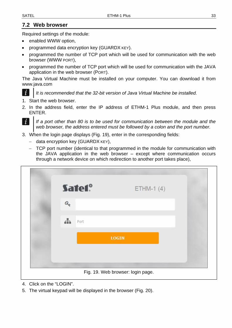
3. When the login page displays (Fig. 19), enter in the corresponding fields: − data encryption key (GUARDX KEY), − TCP port number (identical to that programmed in the module for communication with
the JAVA application in the web browser – except where communication occurs through a network device on which redirection to another port takes place),
Fig. 19. Web browser: login page.
4. Click on the “LOGIN”. 5. The virtual keypad will be displayed in the browser (Fig. 20).

34 ETHM-1 Plus SATEL
Fig. 20. Web browser: virtual keypad.
7.3 INTEGRA CONTROL application The INTEGRA / INTEGRA Plus alarm system can be operated and configured from a mobile device, if the INTEGRA CONTROL application is installed. If the IP cameras are installed in the protected premises, using the application you can watch video from these cameras. The application can be downloaded from the internet store “Google play” (Android system devices) or “App Store” (iOS system devices). On the www.satel.eu website, you will find links to the locations from which the applications can be downloaded. The INTEGRA CONTROL app can connect directly to the ETHM-1 Plus module (the module must have a public IP address) or establish connection via the SATEL server (Connection Setup Service – the module requires no public IP address). Required module settings for both ways of establishing connection: • enabled INTEGRA CONTROL option, • programmed data encryption key (GUARDX KEY). • enabled CONNECTION VIA SATEL SERVER option, if connection is to be established via the
SATEL server, • programmed the number of TCP port which will be used for communication, if connection
is to be established directly with the module. To configure settings for communication via SATEL server in the INTEGRA CONTROL app, you can use the QR code (see p. 11). If the communication settings are configured in one mobile device, you can easily copy them to another mobile device. You just need to display the QR code on the device in which the settings for communication with the given module are already configured and read it on another device.
7.3.1 Configuring the settings in INTEGRA CONTROL application (Android) When you launch the application for the first time, the screen for adding a control panel will be displayed. It allows you to configure the settings required for establishing connection to the control panel.
SATEL ETHM-1 Plus 35
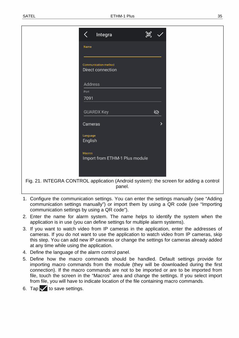
Fig. 21. INTEGRA CONTROL application (Android system): the screen for adding a control
panel. 1. Configure the communication settings. You can enter the settings manually (see “Adding
communication settings manually”) or import them by using a QR code (see “Importing communication settings by using a QR code”).
2. Enter the name for alarm system. The name helps to identify the system when the application is in use (you can define settings for multiple alarm systems).
3. If you want to watch video from IP cameras in the application, enter the addresses of cameras. If you do not want to use the application to watch video from IP cameras, skip this step. You can add new IP cameras or change the settings for cameras already added at any time while using the application.
4. Define the language of the alarm control panel. 5. Define how the macro commands should be handled. Default settings provide for
importing macro commands from the module (they will be downloaded during the first connection). If the macro commands are not to be imported or are to be imported from file, touch the screen in the “Macros” area and change the settings. If you select import from file, you will have to indicate location of the file containing macro commands.
6. Tap to save settings.
36 ETHM-1 Plus SATEL
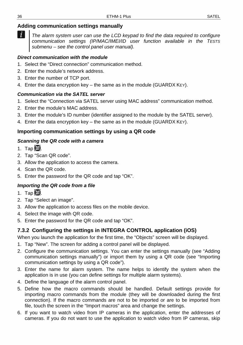
Adding communication settings manually The alarm system user can use the LCD keypad to find the data required to configure communication settings (IP/MAC/IMEI/ID user function available in the TESTS submenu – see the control panel user manual).
Direct communication with the module 1. Select the “Direct connection” communication method. 2. Enter the module’s network address. 3. Enter the number of TCP port. 4. Enter the data encryption key – the same as in the module (GUARDX KEY).
Communication via the SATEL server 1. Select the “Connection via SATEL server using MAC address” communication method. 2. Enter the module’s MAC address. 3. Enter the module’s ID number (identifier assigned to the module by the SATEL server). 4. Enter the data encryption key – the same as in the module (GUARDX KEY).
Importing communication settings by using a QR code Scanning the QR code with a camera 1. Tap . 2. Tap “Scan QR code”. 3. Allow the application to access the camera. 4. Scan the QR code. 5. Enter the password for the QR code and tap “OK”.
Importing the QR code from a file 1. Tap . 2. Tap “Select an image”. 3. Allow the application to access files on the mobile device. 4. Select the image with QR code. 5. Enter the password for the QR code and tap “OK”.
7.3.2 Configuring the settings in INTEGRA CONTROL application (iOS) When you launch the application for the first time, the “Objects” screen will be displayed. 1. Tap “New”. The screen for adding a control panel will be displayed. 2. Configure the communication settings. You can enter the settings manually (see “Adding
communication settings manually”) or import them by using a QR code (see “Importing communication settings by using a QR code”).
3. Enter the name for alarm system. The name helps to identify the system when the application is in use (you can define settings for multiple alarm systems).
4. Define the language of the alarm control panel. 5. Define how the macro commands should be handled. Default settings provide for
importing macro commands from the module (they will be downloaded during the first connection). If the macro commands are not to be imported or are to be imported from file, touch the screen in the “Import macros” area and change the settings.
6. If you want to watch video from IP cameras in the application, enter the addresses of cameras. If you do not want to use the application to watch video from IP cameras, skip

SATEL ETHM-1 Plus 37
this step. You can add new IP cameras or change the settings for cameras already added at any time while using the application.
7. Tap “Save” to save the settings.
Fig. 22. INTEGRA CONTROL application (iOS system): the screen for adding a control
panel.
Adding communication settings manually The alarm system user can use the LCD keypad to find the data required to configure communication settings (IP/MAC/IMEI/ID user function available in the TESTS submenu – see the control panel user manual).
Direct communication with the module 1. Enter the module’s network address. 2. Enter the number of TCP port. 3. Enter the data encryption key – the same as in the module (GUARDX KEY).
Communication via the SATEL server 1. Enable the “Server Satel” option. 2. Enter the module’s MAC address.

38 ETHM-1 Plus SATEL
3. Enter the module’s ID number (identifier assigned to the module by the SATEL server). 4. Enter the data encryption key – the same as in the module (GUARDX KEY).
Importing communication settings by using a QR code 1. Tap . 2. Allow the application to access the camera. 3. Scan the QR code. 4. Enter the password for the QR code and tap “OK”.
7.3.3 Establishing the communication Tap the name of the alarm system. After communication with the control panel is established, the application will ask you to enter the user code. After you enter the code, the “Macros” screen will be displayed (in the iOS system you can define, which screen will be displayed as the first one after the next communication is established).
Fig. 23. INTEGRA CONTROL application (Android system): virtual keypad.
8 Specifications
Supply voltage .................................................................................................... 12 VDC ±15% Standby current consumption ..........................................................................................70 mA Maximum current consumption ........................................................................................80 mA Environmental class according to EN50130-5 ......................................................................... II

SATEL ETHM-1 Plus 39
Operating temperature range ................................................................................... -10...+55°C Maximum humidity .......................................................................................................... 93±3% Dimensions ........................................................................................................... 68 x 140 mm Weight ................................................................................................................................. 64 g