ARCHLine.XP 2013
90
ARCHLine.XP 2013 News 1 ARCHLine.XP ® ARCHLine.XP 2013 News Release 1
-
Upload
khangminh22 -
Category
Documents
-
view
3 -
download
0
Transcript of ARCHLine.XP 2013

ARCHLine.XP 2013 News 1
ARCHLine.XP®
ARCHLine.XP 2013
News
Release 1

2
Information in this document is subject to change without notice and does not represent a commitment on the part of CadLine. The software, which includes the information contained in any databases, described in this document is furnished under a license agreement or nondisclosure agreement. The software may be used or copied only in accordance with the terms of the agreement. It is against the law to copy the software on any medium except as specifically allowed in the license or nondisclosure agreement. The licensee (purchaser) may make one copy of the software for the purpose of creating a backup copy. No part of this manual may be reproduced, transmitted, transcribed, or translated into any language in any form or by any means, without the express written permission of CadLine. 2013. CadLine. All rights reserved. In no event shall CadLine be liable for special, indirect or consequential damages in connection with or arising from the use of this document or any programs contained herein. Microsoft, MS, and MS-DOS are registered trademarks and Windows is a trademark of Microsoft Corporation. ARCHLine.XP
® is a trademark of CadLine.
This manual was produced using Microsoft Word and ARCHLine.XP
®.

ARCHLine.XP 2013 News 3
ARCHLine.XP®
Contents
1. Install / Activation ............................................................................................................................................................. 5
2. ARCHLine.XP 2013 project format ................................................................................................................................... 7
3. User interface .................................................................................................................................................................... 8
3.1. Drawing window............................................................................................................................................ 8 3.2. Screen menu board ...................................................................................................................................... 9 3.3. Drawing window arrangement .................................................................................................................... 10 3.4. Workspace skins......................................................................................................................................... 10 3.5. Navibar ....................................................................................................................................................... 11 3.6. Information bar............................................................................................................................................ 11 3.7. Coordinate bar ............................................................................................................................................ 12 3.8. Drawing Pane ............................................................................................................................................. 12
3.8.1. Control bar .................................................................................................................................................. 13 3.8.2. Pager .......................................................................................................................................................... 13
3.9. Status bar ................................................................................................................................................... 13 3.9.1. General Options.......................................................................................................................................... 13 3.9.2. Floors / 3D Perspectives control buttons group .......................................................................................... 15
3.10. Further options............................................................................................................................................ 15 3.11. Animation editor .......................................................................................................................................... 16
3.11.1. Create Partial animation ............................................................................................................................. 17 3.11.2. Relocate the observation point and the target point.................................................................................... 17
4. 64-bit and multi-core processor support ...................................................................................................................... 18
4.1. Why 64-bits? ............................................................................................................................................... 18 4.2. Frequently Asked Questions about 64-bit Software .................................................................................... 18 4.3. 64 bit Rendering support ............................................................................................................................ 19
5. Hidden Line Removal – Improved performance ........................................................................................................... 20
6. Material management...................................................................................................................................................... 22
6.1. Design Centre – The Search Box ............................................................................................................... 22 6.2. Material selector ......................................................................................................................................... 22
7. Category manager ........................................................................................................................................................... 24
7.1.1. Content selector buttons ............................................................................................................................. 24 7.1.2. Search ........................................................................................................................................................ 25 7.1.3. Result window ............................................................................................................................................ 25 7.1.4. Commands ................................................................................................................................................. 25
8. Doors / windows .............................................................................................................................................................. 26
8.1. Properties ................................................................................................................................................... 26 8.2. Handles ...................................................................................................................................................... 26 8.3. Accessories ................................................................................................................................................ 26
9. Banister improvement .................................................................................................................................................... 31
10. Gutter and downspout .................................................................................................................................................... 32
11. Modelling tools ................................................................................................................................................................ 34
11.1. Loft .............................................................................................................................................................. 34 11.2. Smart Object Parts ..................................................................................................................................... 44 11.3. Furniture Assembly ..................................................................................................................................... 54 11.4. Parasol and Awning .................................................................................................................................... 58
11.4.1. Awning ........................................................................................................................................................ 59 11.4.2. Parasol ....................................................................................................................................................... 60
11.5. Cabinet wizard – Different frame thickness on top...................................................................................... 61 11.6. Custom worktop profile ............................................................................................................................... 62
12. Roof .................................................................................................................................................................................. 63
12.1. Roof Survey ................................................................................................................................................ 63 12.1.1. First surveyed roof plane ............................................................................................................................ 64 12.1.2. Second surveyed roof plane ....................................................................................................................... 65 12.1.3. Next surveyed roof planes .......................................................................................................................... 66 12.1.4. Display roof plane length and area ............................................................................................................. 70 12.1.5. Add custom text to annotations .................................................................................................................. 70
12.2. Roof – Ridge elevation: .............................................................................................................................. 70 12.3. Same height ............................................................................................................................................... 70

4
12.4. Asymmetric Roof: Different elevation .......................................................................................................... 71
13. Terrain .............................................................................................................................................................................. 73
13.1. Terrain change elevation for all terrain points ............................................................................................. 73
14. Miscellaneous .................................................................................................................................................................. 74
14.1. Offset simplification ..................................................................................................................................... 74 14.2. Smooth nodes ............................................................................................................................................ 74 14.3. Fillet All ....................................................................................................................................................... 75 14.4. Split the slab ............................................................................................................................................... 75 14.5. Selection - cycling through overlapping objects .......................................................................................... 75
15. Align ................................................................................................................................................................................. 76
16. DWG export – multiply floors together.......................................................................................................................... 79
17. Improved Importing for DWG file format ....................................................................................................................... 79
18. PDF import ....................................................................................................................................................................... 79
19. Export file formats .......................................................................................................................................................... 81
19.1. Indigo render export .................................................................................................................................... 82 19.2. Autodesk FBX export .................................................................................................................................. 82
20. Change model in one material – Paper model .............................................................................................................. 83
21. ARCHLine.XP Layer Tools - Summary .......................................................................................................................... 85
22. Hide and Isolate Objects ................................................................................................................................................. 85
23. Quantity take-off .............................................................................................................................................................. 86
23.1. Room book – Excel output .......................................................................................................................... 86 23.2. Tiling – Excel output ................................................................................................................................... 88
24. Delete unused materials from a project ........................................................................................................................ 90

ARCHLine.XP 2013 News 5
ARCHLine.XP®
1. Install / Activation
Installing ARCHLine.XP 2013 is really simple and straight forward. It only takes a couple of minutes and you are ready to go.
Install
There is no need for any code during the installation of ARCHLine.XP 2013. The software is installed as trial version automatically. You can install a 32-bit version of ARCHLine.XP 2013 on a computer running a 32-bit or 64-bit version of Windows operating system. You can install a 64-bit version of ARCHLine.XP 2013 on a computer running a 64-bit version of Windows operating system. See the notes on Chapter 64-bit support. If you run the ARCHLine.XP 2013 first time after install, you will be asked to use the software as Architecture or Interior Design version. Choose it according to your purchased version or as a focus of your interest if you use the software in trial mode.
Buy
Buying is the registration of purchase information as your unique serial code. You can find your serial code inside the ARCHLine.XP 2013 package—or in a confirmation e-mail if you purchased and downloaded ARCHLine.XP 2013 online. You have 30 days after installing ARCHLine.XP 2013 to register your serial code. If this 30-day period expires before you complete registration, some ARCHLine.XP 2013 features will stop working until you enter your serial code (demo mode). To registrate the software, open the dialog by clicking the Help menu, and then clicking „Buy now...” Type your ARCHLine.XP 2013 serial code. Click Ok, and then follow the instructions. ARCHLine.XP 2013 must be restarted in order to complete the process.
Activation
You have to activate ARCHLine.XP 2013 once or periodically according to your Perpetual or Subscription financial model. To activate the software, open the dialog by clicking the Help menu, and then clicking „Activate Product”. Activation requires an Internet connection to connect to the ARCHLine.XP web server on the Internet. If you have Internet connection you can select the Activation via Internet option and then follow the instructions. Attention! The Serial code is NOT the same as Activation code!
If you have no Internet connection select the Activation via e-mail option, or call the phone number below the button.
Type your ARCHLine.XP 2013 activation code obtained from your provider. Click Ok, and then follow the instructions. If you have no connection then you can choose the option to activate by telephone.
Frequently Asked Questions
Is product activation the same as registration?
No. They are different procedures, but linked to each other. Registration is a separate process where you registrate your unique serial code which prevents unauthorized use of your license by another person.The activation verifies that your serial code is valid and the software has been activated only on eligible computers. I have entered my serial code but I cannot press the OK button to do registration. Why is the application not being registrated?
Verify your serial code once again. The ARCHLine.XP 2013 cannot accept serial codes for 2012, 2011 or earlier releases. The OK button will be active only if you type the appropriate 16 digit serial code accurately. How often will the software connect to the activation server via the Internet?
ARCHLine.XP 2013 connects to its activation server when it is first installed, when it is registered and activated. You can enable or disable Internet connection to activation server by clicking the Help menu and then clicking „Check for Updates”. If you have no Internet connection you have to registrate and activate manually by phone or by e-mail. However if you disable Internet connection you will not receive notification of important updates. Does the internet connection speed affect activation? Will dial-up access work?
6
The amount of data transferred during activation is very small. Any stable internet connection will work. Slower connections such as dial-up access may take slightly longer to complete the activation steps. During activation what information is passed to the server?
No personal information or information about your computer configuration is transferred. There is a one-way hash* of some machine configuration data, your serial code, and the optional email address sent to the server. If you do not provide the optional information (email address and registration information) then no personal information will be transferred. *One-way Hash: Codes that identify parts of the computer are put through a special function that turns the codes into a code number that is unique to your computer but cannot be deciphered to determine what those components are. Only this hash value is sent to the activation server and not the details on the computer parts. Can I move my license to another computer?
Yes, this can be done easily. ARCHLine.XP's license specifically authorizes you to use the software on more than one computer if you are using hard lock protection. For example, you can install ARCHLine.XP's on your office computer and your laptop. Simply install the software on the other machine and click on the "Buy now” and later the "Activate product" button. You have to enter the same serial code and activation code. The software will run properly on that computer where you plug in the Hard lock protection If you are using software protection without hard lock device you can use the software on one computer only. If you wish to move the software to another computer you should use the Activation via e-mail option to receive a new activation code valid for the computer where you move your license. Activating it on the second computer will automatically deactivate the license for the first computer. What is the serial code for?
The serial code uniquely identifies your license. You will need the serial code if you ever need to reactivate your software (such as after a disk reformat and reinstall or moving the software to a new machine). The serial code will not change when you reactivate your software. We suggest that you write the serial code down in some permanent location. What is the email address for and is it mandatory?
The email address on the activation dialog is mandatory if you choose the Activation via email button. You will be able to activate without email address if you choose activation via phone. Your email address will not be sold or provided to any third party. What if I have forgotten my serial code?
During a registration the previously provided serial code is required. If the serial code has been lost and cannot be recovered (because an email address was not provided, or the email address is no longer valid) please contact us via our support form. We will be happy to reset your password. Will changes to my computer cause my application to stop working?
There are no changes that will cause a permanent disabling of the software. Major changes (disk reformat being one such major change) will mean that you need to reactivate the software. If you have your serial code, this will be a fast and easy process. I wish to do an online activation but my firewall is set up to block such requests. What are the firewall settings?
The following is the information that you need to setup your firewall: Server IP address: archlinexp.com Port: 80 (Standard HTTP) Domain: archlinexp.com Why does ARCHLine.XP revert to demo mode?
There might be several reasons: You forgot to register your serial code. You forgot to activate your license within the allowed time. You forgot to plug in your hard lock.

ARCHLine.XP 2013 News 7
ARCHLine.XP®
2. ARCHLine.XP 2013 project format
In order to deliver customer-requested feature improvements as 64 bit development it was necessary to update the ARCHLine.XP project file format. CadLine has introduced a new project format that includes platform compatible file compression method and 32 and 64 bit support as well. Regardless of the new project format you can share your projects with others that are using older ARCHLine.XP versions by saving the files in 2012 format that is compatible with the previous versions of ARCHLine.XP. You find the project saving options in File menu Save as command.
ARCHLine.XP 2013 supports reading of the following older ARCHLine.XP file formats as you see below. 2013: 2013 (2012/2011/2010/2009/2008/2007/2006/2005/XP).

8
3. User interface
ARCHLine.XP comes with improved modern user interface that highly increased the speed at which you can move around your drawing. The new interface enables to switch quickly between individual drawings regardless of the drawing complexity. OpenGL and DirectX graphic engines are equally suppported, and panning and zooming improvements are applied in both platforms.
User interface components:
1. Application Title: Displays the name of the current project. 2. Menu bar: Collection of ARCHLine.XP commands. Commands in the menu bar can be accessed through
shortcuts. 3. Quick access toolbars: The Quick Access Toolbar is a system toolbar that contains a set of commands. You can move the
Quick Access Toolbar freely on other location 4. Tool Palettes: It contains the Toolbox, Design Centre, Project Navigator and Properties Panel. 5. Screen menu board: touch-screen like menu display 6. Project container: List of all drawings within the current project. Click one of the items in the list to open a drawing. 7. Input board: View the coordinate values of your cursor, 8. Help: First line information related to the current command 9. Navigation centre: Quick screen controls for zoom, pan, and rotation commands. 10. Command prompt: Execute a command by entering at the command prompt panel and pressing ENTER. When
Dynamic Input is on you can enter command or value in a pop up window that is displayed over the cursor. 11. Status bar: Collection of the most frequently used commands in ARCHLine.XP.
3.1. Drawing window
ARCHLine.XP drawing window is divided into workspaces and comes with new layout and properties. Speed
The new interface enables to switch quickly between individual drawings regardless of the drawing complexity. Always on Top
Always On Top is an innovative utility which forces selected window to stay on top relative to other workspaces.

ARCHLine.XP 2013 News 9
ARCHLine.XP®
Always On Top allows controlling windows' 'behaviour' by means of extra button placed near the standard
Minimize/Restore/Close group that results in greater workspace e.g. for your floor plan and its accuracy.
Example: Place your 3D view in Always on Top state meanwhile you can work on the floor plan using the full size of your screen.
3.2. Screen menu board
Screen menu board is an easy to use touch-screen like menu display. Using the Screen menu board you can memorize the most frequently used commands, without mastering the complete software. The screen menu board shows categories such as Drafting, Building etc. Categories have items within them. When a category is selected, the items within that category will display. Screen menu board is an equivalent tool with the Toolbox menu used in the earlier ARCHLine.XP releases.
Further commands related to Screen menu board: 1. Mouse right click -> Open Properties dialog of the selected element 2. CTRL + Mouse left click > The command will select all of the objects with the same type in the drawing regardless of
their properties.

10
Components Control tool
You find the control tool on the left side. Control tool enables to move, hide and show the Screen menu board.
Menu board
Screen menu board consists of three levels. The top level contains the main categories such as Project, Drafting, Building, etc. You can open and browse on the sub menus with simply moving the mouse over it or with a mouse left click. How to use it: Hiding
Clicking on an item the related command is executed and the menu board automatically disappears. Closing the command the menu board comes up again. Close the menu board
You can manage the menu board as a pop-up menu or you can switch it off if you wish to work without it.
3.3. Drawing window arrangement
The Drawing Window in ARCHLine.XP is the area where you draw. It is divided into work spaces known as 2D Floor plan, 3D model, Section, Animation and Printing Layout. You work always in the active one and you can switch between them. You can choose among three drawing window arrangement styles or switch the active work spaces into full size view.
3.4. Workspace skins
You can customize the graphical appearance of ARCHLine.XP workspace layout choosing among different colour models.
.

ARCHLine.XP 2013 News 11
ARCHLine.XP®
3.5. Navibar
ARCHLine.XP 2013 comes with a new navigation bar on the bottom right side of the screen. You find here the tools to navigate on the work spaces with the zoom and pan commands, as well as rotation in 3D model. The NaviBar’s appearance in the 2D (2D floor plan, Printing Layout) and 3D (3D model, Section) is different. You can navigate with simple left mouse clicks or by dragging in some cases like zooming, panning or rotating. If you wish to zoom, pan or rotate continuously than you have to click on the appropriate command, hold down the mouse button and move the mouse.
2D Navibar
When your active view has 2D content (2D floor plan, Printing Layout), the Navibar displays one group of commands.
3D Navibar
When your active work space has 3D content (3D model, Section), the Navibar displays a second group of commands. This second group contains useful commands which facilitate setting up the view of the 3D model as 3D view, Walk, 3D visual styles, Shadow, Rendering and Perspective view.
Move the Navibar
You can move the navibar on any other place on the workspace that is best for you. To move the navibar, move the mouse over the grip point on the right side and left click and drag it to where you want to place it and release the mouse button.
Restore
You can restore the navibar to its factory default state with a mouse right button click on the grip point.
Close the Navibar
To close the Navigation Wheel click on the little triangle on the bottom left corner.
3.6. Information bar
ARCHLine.XP Information bar displays the actual prompt help concerning the command to be executed actually.
By default you find it in the middle bottom part of the drawing window. It consists of 3 parts: Information button; Message field; Grip point.
Information button
You find the information button on the left side of the information bar. The information button can display two icons. Interactive Help – You can click on the button when displays the ‘i’ letter, and the program will open the interactive online
help. Control tool info – When you move the mouse over the Drawing Pane, Coordinate bar, Navibar and Bubble menu the
icon in the information bar changes to hand style and displays the name of the tool under the mouse actually.
Message field
ARCHLine.XP Information bar displays the actual prompt help concerning the command to be executed actually or the Control Tool Info.

12
Move the Information bar
You can move the information bar on any other place on the workspace that is best for you. To move the information bar, move the mouse over the grip point on the right side and left click and drag it to where you want to place it and release the mouse button.
The program saves the new place even when you restart it.
Restore
You can restore the information bar to its factory default state with a mouse right button click on the grip point.
3.7. Coordinate bar
The coordinate bar displays the North direction; the reference point command icon, the absolute or relative coordinate’s mode icon and the current cursor coordinate values. You can click on each of them to edit the relevant information.
North
Displays and specifies the north direction. If you click on the North icon you can change the Geographic location, the date and the North direction.
Reference point
The selected point becomes the reference point for next input. It replaces the last input point.
Relative / Absolute coordinate input
There are two modes to enter coordinates in ARCHLine.XP: Absolute or Relative coordinates. Absolute coordinates uses the Cartesian System to specify a position in the X, Y to locate a point from the 0, 0 origin. Relative coordinates are interpreted from the last input point. As relative coordinates much more frequently used than absolute, the default setting is relative. You find the Relative Input icon to change between absolute / relative mode on the left side.
Display coordinate info
The coordinate bar displays the coordinate values of the cursor in absolute or relative coordinate’s mode.
Command input
If you click on the coordinate info field you can type the coordinates of the point you want, like: X space Y. The X-value and Y-value is interpreted in the current input mode as absolute or relative coordinates Example:
You are in absolute coordinate’s mode and in cm unit. If you type 20 8 for a position, ARCHLine.XP will locate the next point on 20 cm along the X-axis and 8 cm along the Y-axis. Press ENTER to activate the input. ARCHLine.XP draws the objects in their real size. ARCHLine.XP offers the following units to input a value: mm, cm, m (metric) and inch (imperial). If you have 1 m length wall and your current unit is cm, then draw it as 100 cm length. ARCHLine.XP uses scale for plotting only. ARCHLine.XP drawing sheet is a limitless area.
3.8. Drawing Pane
A Drawing pane helps you find a drawing belonging to the actual project. The drawing pane contains three parts as Control bar, Drawing Selector and Pager.

ARCHLine.XP 2013 News 13
ARCHLine.XP®
Click on the drawing image you wish to display on the screen.
3.8.1. Control bar
The left side control bar enables to display the workspace list, show and hide the drawing pane and resize it.
Workspace list
You can use the workspace list icon to switch between the drawings of the project too.
It displays all workspace names in alphanumeric list.
Show / Hide
You can show / hide the Drawing Selector and Pager.
Size up / down
You can resize the Drawing Selector and Pager.
3.8.2. Pager
The Pager becomes visible when the number of drawings exceeds 8. Clicking on the pager the Drawing Selector displays the next or the previous drawing in the list.
3.9. Status bar
The status bar contains the collection of the most frequently used commands in ARCHLine.XP such as -Preferences, -Grid, Snap, Osnap, Ortho, -Selection control, -Floor/Perspective settings, -Generate 3D model, -Layer controls, -Reference point bar, -Move bar and -Edit bar commands.
3.9.1. General Options
You can customize the program settings and appearance in the Options dialog. The Options dialog in the 2013 release is located in the bottom left-hand corner of the ARCHLine.XP Status bar and has a unified interface outlook. Click on the first icon (gear like) to display the Options dialog.

14
You can also open the Options dialog in the File menu and click Options The Options dialog box includes the following tabs:
Display
Controls options that relate to presentation and drawing settings, colours and other visual options.
Open and Save
Controls options that relate to opening and saving files, import/export settings.
Units and angles
Unit and angle settings control how ARCHLine.XP interprets the length, coordinate and angle entries and how it displays lengths, coordinates and angles in the drawing and in dialog boxes.
Snap and grid
ARCHLine.XP provides drawing aids as snap and grid to provide assistance in drawing quickly and accurately.
Cursor and marker
Cursor and marker settings can be found here.
User Interface
User interface settings control the language, the toolbox modes and schemes of ARCHLine.XP.
Item Settings
You find global parameters here that are not related to the given items Property panel...

ARCHLine.XP 2013 News 15
ARCHLine.XP®
Press Ok so that the changes take effect.
* Star Icon
Star icon before the option name signifies that an option is saved with the project. An option saved with the project affects only the current project. If you transfer the project to another computer the option will be valid on that computer as well. An option saved in the computer system registry (and for this reason not displayed with a star icon) affects all projects.
The 2-5 icon group changes the settings of grid, snap, object snap and ortho commands.
3.9.2. Floors / 3D Perspectives control buttons group
The contents of this group represent the actual workspace nature. 2D floor plan workspace:
The floor plan structure is listed on the button. When you have more than one floor in your workspace, you can switch between them by clicking on the floor name in the list or go up, down one floor by clicking on the blue Up, Down icons on the bar. 3D model workspace:
The saved perspective views with a name are listed here. When the perspective opens, the title bar of the button changes to display the name of the current perspective. In addition, by clicking on the blue Up, Down icons, allows you to quickly switch between other saved perspective views. To open a new perspective:
1. Click the Perspective button that displays the name of the current perspective. (This provides the same command as the View > Perspective view on the menu bar.)
2. Define the perspective that you want to add and save it with a new name.
3.10. Further options
When you activate an ARCHLine.XP drawing command, there are two possibilities what ARCHLine.XP will ask you: further options or specifying point. A further option menu appears on the screen only when it is needed. It is a floating menu so you can drag it anywhere on the workspace clicking on the grip point on the right side

16
3.11. Animation editor
ARCHLine.XP has a built in Animation timeline editor that allow you to create animations. To open this editor, you have to create an animation path and click on it to start editing animation in Add On menu – Animation – Start animation command. Alternatively, right-click the animation path and select Edit animations.
The timeline toolbar belongs to the bottom of the animation window.
Move
You can move the timeline toolbar as a floating window anywhere on the workspace. To move the bar, move the mouse over the grip point on the right side and left click and drag it to where you want to place it and release the mouse button.
Resize
Move your cursor to the right size of the window. You will see the cursor change appearance. Hold down the left mouse button and drag the window to the size you want. then release it.
Restore
You can restore the timeline toolbar to its factory default state with a mouse right button click on the grip point.

ARCHLine.XP 2013 News 17
ARCHLine.XP®
3.11.1. Create Partial animation
You can record a part of the animation from key frame to key frame. Press CTRL and mouse left click over the timeline and drag it to the required key frame and release the mouse button. The selected part will be highlighted.
This function is useful when you record relatively big video over 30 seconds or more.
3.11.2. Relocate the observation point and the target point
On key frames the perspective setting icon appears and you can fine tune the spatial location of the observation point and the target point.
The changes will be applied on the animation path on the floor plan after closing the Perspective setting dialog.

18
4. 64-bit and multi-core processor support
Beginning with Version 2013 release, CadLine offers both 32 and 64-bit versions of ARCHline.XP application.
4.1. Why 64-bits?
Modern software development and data processing is running up against a built-in memory limitation. 32-bit versions of Microsoft Windows can only allocate a maximum of 2 GB of memory to each running process, regardless how much real or virtual memory is available on a particular machine. It means that large projects over this limit cannot be opened at all. 64-bit system is not subject to the same memory limitation. Currently, the 64-bit version of Microsoft Windows 7 operating system supports up to 192 GB of installed memory. In practice, the maximum size of a large project is limited only by this huge amount of installed physical memory.
4.2. Frequently Asked Questions about 64-bit Software
Below are answers to the most frequently asked questions about 32-bit vs. 64-bit software.
Will a 32-bit application run on a 64-bit version of Windows?
Yes.
Will a 64-bit application run on a 32-bit version of Windows?
No.
How can I tell if my system is running a 32 or 64-bit version of Windows?
Open the Windows Control Panel, Select Classic View (Vista) or Icons (Windows 7), then open the System icon. The line labelled System type will specify either “32-bit Operating System” or “64-bit Operating System.”
My system is running a 64-bit version of Windows. Should I use 32-bit or 64-bit software applications?

ARCHLine.XP 2013 News 19
ARCHLine.XP®
It depends. A 64-bit application will require more memory to open the same file than a 32-bit application, because the structures automatically become larger. The memory consumption grows by about 30 to 50%. If you have more memory the 64-bit version is recommended to install.
4.3. 64 bit Rendering support
ARCHLine.XP 2013 comes with extended 64 bit rendering engine. ARCHLine.XP 2013 rendering engine runs on Windows 7 32-bit and 64-bit, and Windows XP 32-bit operating system.
The 64-bit version is able to access larger amounts of memory than 32-bit, providing customers increased efficiency, which is particularly useful for those working with very large and complex 3D models and lot of lights.

20
5. Hidden Line Removal – Improved performance
The speed of hidden line removal on vectorial 3D workspace is highly improved. Now 5 to 10 times faster than in previous versions as implemented a new hidden line removal algorithm and additionally uses multi-threading to give you faster and precise results even with shadow rendering. Comparision time for hidden line removal and coloring (Intel Core2 Duo 2.2.GHz):: 2012 or previous versions 2013

ARCHLine.XP 2013 News 21
ARCHLine.XP®
3D model size reduction
Menu: View > 2D -> 3D > By classes The 3D model size reduction option makes large 3D models easier to work with by automatically reducing the number of polygons. Using the process named decimation; the ARCHLine.XP eliminates polygons only where their absence will not greatly affect the model's accuracy. The local geometry of the model's surface is used to determine whether a vertex may be removed. When a vertex is removed, the ARCHLine.XP fills the resulting hole with larger polygons. Decimate never creates new vertices; the vertices of the new model are a subset of the original vertices. This approach preserves the model's original structure, surface normal vectors (which indicates the model's 3D orientation at each point) and texture mapping. Reductions of up to 90 percent with only slight loss of detail are common. Example: http://www.flou.it/index.asp?s1=NOVITA#/letti/nathalie_8
Original model with number of edges: over half million Decimated model with number of edges: 62.000

22
6. Material management
6.1. Design Centre – The Search Box
The Search Box behaviour has changed and simplified. To use the Search box, click on the input field marked as [Search in all items] menu and start typing (In this example below „cherry”). You don't need to press Enter on keyboard to see the search result. As you type, the search results appear in the list and the number of results on the top that matches or begins with your search term.
6.2. Material selector
ARCHLine.XP comes with a new material control panel that contains all available commands related to texture management, e.g. to replace, edit, import and create new material.

ARCHLine.XP 2013 News 23
ARCHLine.XP®

24
7. Category manager
Menu: Tools > Accessories > Category Manager ARCHLine.XP Category Manager is powerful and provides better content management. Content includes all libraries related to objects, lights, materials, groups, profiles etc. Category Manager provides a faster access to browse and edit content libraries with a consistent look and feel. The elements within the libraries are organized into flexible virtual folders that is not dependent on location in a hierarchical directory tree. This virtual folder system can be thought of as a view that lists all elements tagged with a certain tag. The tag is a kind of metadata and helps describe an element and allows it to be found again by browsing or searching. Elements in this virtual folder are not limited to any single physical location on the hard drive, as is the case with traditional folders, but can be in any location. Category Manager allows assigning more tags to one element. It means the element can fulfill more search criteria in the same time.
7.1.1. Content selector buttons
You find on the top of the panel the content selector buttons. You can choose among: Objects Doors Windows Lamps Materials Groups Profiles

ARCHLine.XP 2013 News 25
ARCHLine.XP®
7.1.2. Search
A Type the required name into the Search field, and press Enter to start searching. The program displays the result below the result window below.
7.1.3. Result window
The result window displays the required contents.
7.1.4. Commands
Create new category
You can create a new category.
Select all
Selects all elements in the category.
Delete
You can delete the selected elements from the given category. (It deletes the object only if there is no more tag assigned to it).
Import
You can import an ARCHLine.XP environment file here.
Export
You can export the selected content into an ARCHLine.XP environment file. This command enables to exchange the required objects, materials, etc with another ARCHLine.XP user or to simply to send to another computer.
Duplicate Items
When Duplicate elements are “on” the program keeps the actual tags while dragging the item into another category. It means you will find it in the previous and the new category as well. When the Duplicate elements are “off” the item will loose the actual tags while dragging to another category. It means you will find it only in the new category.
Edit / Create new
Here you can edit and create new material...

26
8. Doors / windows
8.1. Properties
The redefined Door and Window dialog contains the following tabs including the new Inner handle, Outer handle and Accessories pages.
8.2. Handles
On the Inner and outer handle page you find the geometry settings for the door and window handles and knobs. Window dialog enables to apply inner handle only.
Enable handle
The Enable Handle option enables the handle and lock for the current door and window. Enable this option if you would like to use handles and locks.
8.3. Accessories
On the Accessories page you can add accessories to the door and window and you can define the geometry settings of the accessories.

ARCHLine.XP 2013 News 27
ARCHLine.XP®
Press the green plus button to select an object from Design Centre.

28
You can resize the selected object according to the door/window width and height values.
ARCHLine.XP 2013 News 29
ARCHLine.XP®
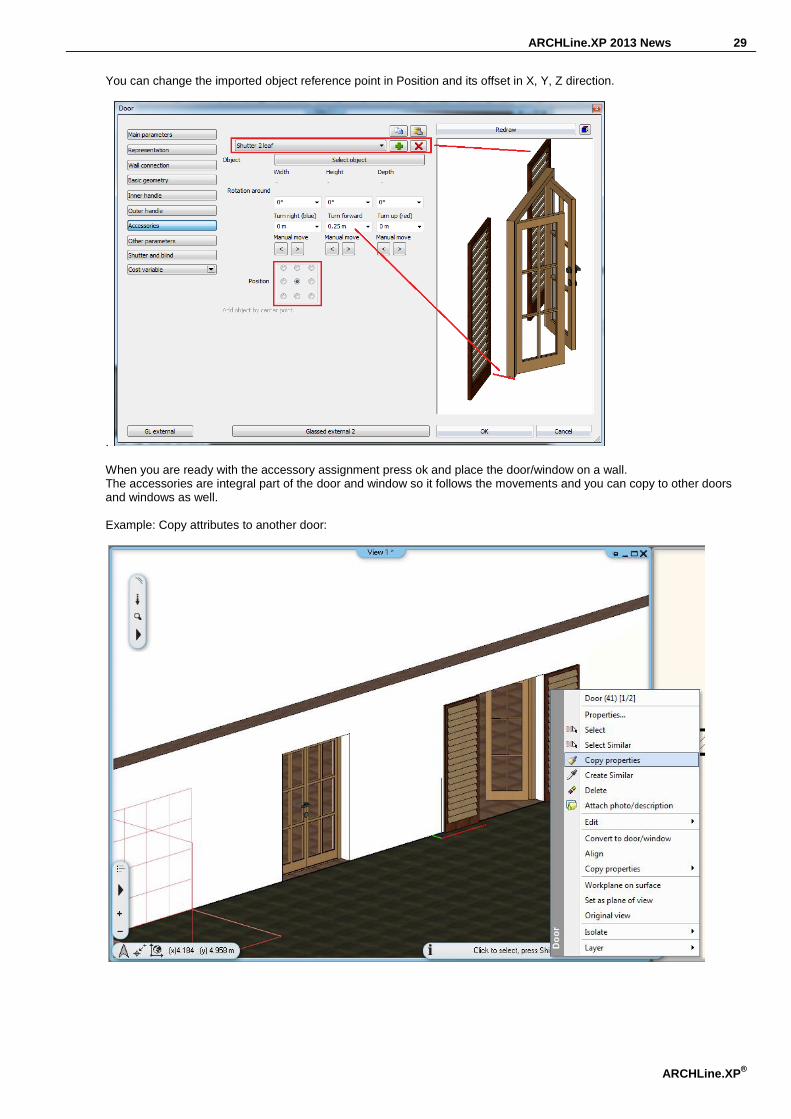
You can change the imported object reference point in Position and its offset in X, Y, Z direction.
. When you are ready with the accessory assignment press ok and place the door/window on a wall. The accessories are integral part of the door and window so it follows the movements and you can copy to other doors and windows as well. Example: Copy attributes to another door:

30

ARCHLine.XP 2013 News 31
ARCHLine.XP®
9. Banister improvement
The distance between banister rails can be controlled independently for each staircase thread or a standalone balustrade threads. The start end ending distance between newel posts and the first banister can be defined as symmetric or asymmetric.

32
10. Gutter and downspout
ARCHLine.XP supports the gutter and downspout design collecting rainwater from the roof. Menu: Building > Outdoor Tools > Gutter Menu: Building > Outdoor Tools > Gutter on Roof Edge
Gutter on Roof Edge
You can select the roof edges directly in 3D where the gutter will be aligned and later assign the points where a downspout will be installed.
Downspouts
You can add the downspouts in 3D with the Add downspout command.

ARCHLine.XP 2013 News 33
ARCHLine.XP®
3D editing
You can edit the gutter and downspouts in 3D with the markers related to nodes and edges.

34
11. Modelling tools
ARCHLine.XP 2013 introduces three new modelling tools, to design complex objects as soft furniture. Menu (Architecture): Building > Furniture Design Menu (Interior): Furniture > Furniture Design
11.1. Loft
A loft is a complex 3D solid between several cross sections and extruded along a path. The path can be straight or curved. Menu (Architecture): Building > Furniture Design > Loft Menu (Interior): Furniture > Furniture Design > Loft
This picture displays 3D model of a chair leg where three different cross-sections are connected along the curved path.
Cross-Section Steps
Cross-sections can be defined by two methods:
1. Selecting existing profile from profile library. Click first on the red circle icon and then click on the blue plus icon in the middle of the panel.

ARCHLine.XP 2013 News 35
ARCHLine.XP®
Select the new cross-section with its reference point in the upcoming Profile dialog. Press Ok to return to Loft dialog. The selected profile will be inserted into the Favourites List.
2. Drawing the geometry as a profile. When you draw the cross-section you must also define its reference point. Click first on the red circle icon and then click on the yellow five-pointed star icon. The dialog disappears temporary and you can draw the cross-section in the 2D or 3D workspace. When you finish the profile definition press ENTER and the dialog comes back again.
3. Add next cross-section Use the “Prepare new” button on the left side of a panel. This button appears as green plus icon. You can define the place of the new cross-section along the path with the path slider or type its distance from the path starting or ending point. You can resize the new cross-section width and height or change its profile with clicking on another profile from Favourites or as written in point 1 and 2 either. See on the picture below. The above mentioned controls are marked with red frames. The new cross-section is displayed with green shape. You will add the new cross-section to the loft with clicking on the green tick button on the right side of the panel.

36
Smooth fit Specifies that a smooth surface or sharp edge is drawn between the cross sections. See the smooth connection for the same loft below.

ARCHLine.XP 2013 News 37
ARCHLine.XP®
4. Delete cross-section The actually selected cross-section is highlighted with red colour. You can select the previous or the next crooks-section with the Item index. The item index list appears at the left side of the panel on top of the Prepare new / Remove actual buttons. It consists of two numbers separated by a “/” mark. The first number is the sequence number of the current item. The second number is the total amount of the available items. Click on “Remove actual” button to delete the actually selected cross-section.

38

ARCHLine.XP 2013 News 39
ARCHLine.XP®
Hotspot control The path intersects the cross sections on the cross section hotspot. Click on the black gear like icon to change the hotspot position.

40
Path definition
Cross-sections can be defined by two methods: Path can be defined by two methods: 1. Selecting existing profile from profile library.
Click first on left on the path like icon and then click on the blue plus icon in the middle of the panel. Select the new profile in the upcoming Profile dialog. Press Ok to return to Loft dialog. The selected profile will be inserted into the Favourites List.
2. Drawing the geometry as a path. Draw the path as a polyline before you start the Loft command.
Click on the yellow five-pointed star icon. The dialog disappears temporary and you can select the items drawn previously in the 2D or 3D workspace. When you click on an item and the dialog comes back again. The new path is inserted into the Favourites List as CUSTOM PROFILE.

ARCHLine.XP 2013 News 41
ARCHLine.XP®
Ending conditions You can edit the beginning and end section of a loft upon your design request as horizontal, perpendicular or vertical separately. See this example:
Enclosing box control The dialog displays the size of the actual path. Changing these values you can stretch the loft in both direction. See this example:

42
Orientation The loft can have a vertical or horizontal orientation. You can switch between horizontal and vertical in the dialog box Orientation list. See this example:
2D general properties
The 2D general properties contain the loft 2D representation properties as Layer, colour, etc. In addition you can choose the loft 2D representation as simplified, symbol or top view.
Save loft into OLI library
ARCHLine.XP 2013 News 43
ARCHLine.XP®
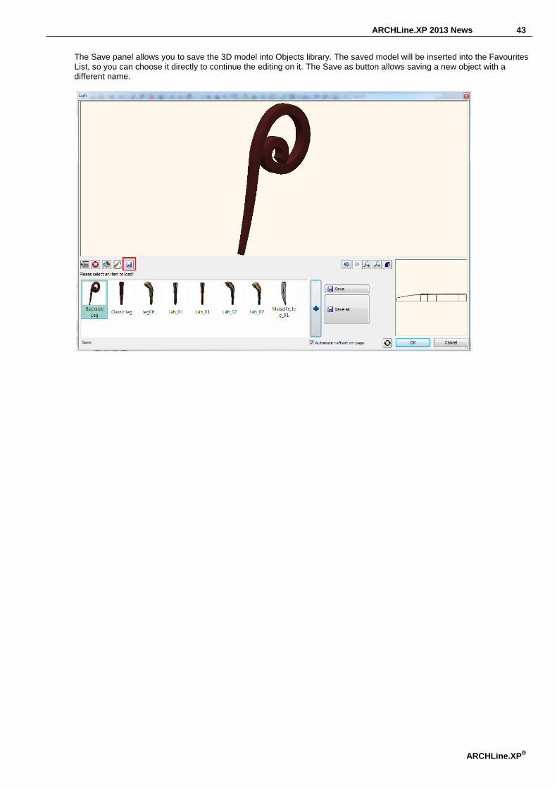
The Save panel allows you to save the 3D model into Objects library. The saved model will be inserted into the Favourites List, so you can choose it directly to continue the editing on it. The Save as button allows saving a new object with a different name.
44
11.2. Smart Object Parts
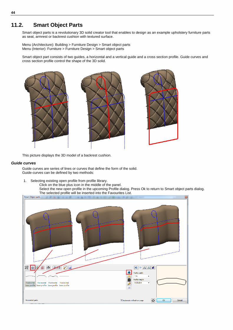
Smart object parts is a revolutionary 3D solid creator tool that enables to design as an example upholstery furniture parts as seat, armrest or backrest cushion with textured surface. Menu (Architecture): Building > Furniture Design > Smart object parts Menu (Interior): Furniture > Furniture Design > Smart object parts Smart object part consists of two guides, a horizontal and a vertical guide and a cross section profile. Guide curves and cross section profile control the shape of the 3D solid.
This picture displays the 3D model of a backrest cushion.
Guide curves
Guide curves are series of lines or curves that define the form of the solid. Guide-curves can be defined by two methods: 1. Selecting existing open profile from profile library.
Click on the blue plus icon in the middle of the panel. Select the new open profile in the upcoming Profile dialog. Press Ok to return to Smart object parts dialog. The selected profile will be inserted into the Favourites List.

ARCHLine.XP 2013 News 45
ARCHLine.XP®
2. Drawing the guide curves.
Click on the yellow five-pointed star icon. The dialog disappears temporary and you can draw the guide curves in the 2D or 3D workspace.
When you finish the guide curves definition press ENTER and the dialog comes back again displaying the smart object part with the new guide curves. The new guide is inserted into the Favourites List as CUSTOM PROFILE.
Modify the guide curves
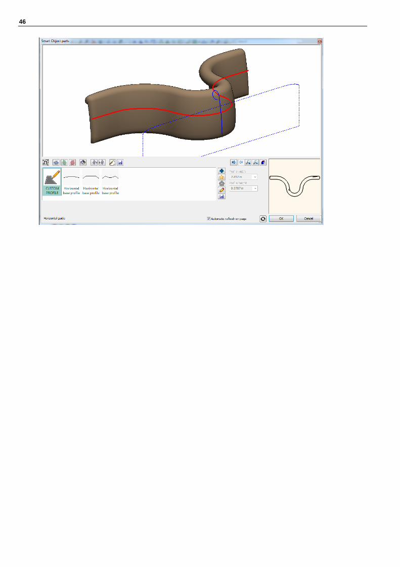
Use the “Modify profile” button on the left side of a panel. This button appears as pencil icon. You have to place the guide curves on the drawing and edit it with clicking on the curves or corner points. When you finish the guide curves definition press ENTER and the dialog comes back again displaying the smart object part with the new guide curves. See on the picture below. .
46

ARCHLine.XP 2013 News 47
ARCHLine.XP®
Vertical guide curves
Vertical guide curves can be defined in the same way as horizontal guide curves.

48
Cross-Section
Cross-sections can be defined by two methods:
1. Selecting existing profile from profile library. Click first on the red circle icon and then click on the blue plus icon in the middle of the panel. Select the new cross-section with its reference point in the upcoming Profile dialog. Press Ok to return to Smart Object parts dialog. The selected profile will be inserted into the Favourites List.
2. Drawing the geometry as a profile. When you draw the cross-section you must also define its reference point. Click first on the red circle icon and then click on the yellow five-pointed star icon. The dialog disappears temporary and you can draw the cross-section in the 2D or 3D workspace. When you finish the profile definition press ENTER and the dialog comes back again.
Modify the cross-section
Use the “Modify profile” button on the left side of a panel. This button appears as pencil icon. You have to place the cross-section on the drawing and edit it with clicking on the curves or corner points. When you finish the cross-section definition press ENTER and the dialog comes back again displaying the smart object part with the new cross-section. See on the picture below. .

ARCHLine.XP 2013 News 49
ARCHLine.XP®

50
Textured surface effects
You can assign textured various surface effects to the front and backside separately: 1. Add the first effect
Use the “Effects” button on the top side of a panel. This button appears as textured surface icon. Chose an effect from the predefined list. When you click on an effect the dialog will display the appropriate parameters of the effect. You can set always the affected area and the effect geometry. You will add the new effect to the smart object part with clicking on the green tick button on the right side of the panel.
2. Add next effect Use the “Prepare new” button on the left side of a panel. This button appears as green plus icon. Choose another effect from the predefined list. When you click on an effect the dialog will display the appropriate parameters of the effect. You can set always the affected area and the effect geometry.

ARCHLine.XP 2013 News 51
ARCHLine.XP®
You will add the new effect to the smart object part with clicking on the green tick button on the right side of the panel.
3. Delete an effect The actually selected Effect- is highlighted in the Favourites list. You can select the previous or the next Effect with the Item index. The item index list appears at the left side of the panel on top of the Prepare new / Remove actual buttons. It consists of two numbers separated by a “/” mark. The first number is the sequence number of the current item. The second number is the total amount of the available items. Click on “Remove actual” button to delete the actually selected Effect.

52
2D general properties
The 2D general properties contain the loft 2D representation properties as Layer, colour, etc. In addition you can choose the loft 2D representation as simplified, symbol or top view.

ARCHLine.XP 2013 News 53
ARCHLine.XP®
Save smart object part into OLI library
The Save panel allows you to save the 3D model into Objects library. The saved model will be inserted into the Favourites List, so you can choose it directly to continue the editing on it. The Save as button allows saving a new object with a different name.

54
11.3. Furniture Assembly
Furniture Assembly is a platform that integrates flexible tools to compose complex furniture that consists of multiple pieces and requires assembly. The dialog consists of the following easy to use 3D panels:
-Accessories:
Accessories can be defined by this method:
1. Click on an existing object, displayed with red enclosing box. Click on the green plus icon in the left side of the panel. The selected item will be duplicated displaying the new object. If you wish to select another one choose from the Favourites list or insert a new one with a click on the blue plus icon... The new object will replace the actually selected one.

ARCHLine.XP 2013 News 55
ARCHLine.XP®
You can adjust the placement plane and reference point of this object by clicking on the green or red stickers on the 3D preview.
You can change the position and the orientation of the new item before fixing it with the green tick icon.
The new item is integrated now into the assembly. There is no need to be very precise in this phase as you can change the position later as well.

56
2D general properties
The 2D general properties contain the loft 2D representation properties as Layer, colour, etc. In addition you can choose the loft 2D representation as simplified, symbol or top view.
-Materials
The furniture itself is composed of different materials. Using the Material Panel you can change the material on the selected surface. All the same option:
All the same option allows you to handle all the surfaces in one step when defining the material on their surfaces. When this option is on you can handle all similar surfaces together. When this option is off you can handle the selected surface only.

ARCHLine.XP 2013 News 57
ARCHLine.XP®
Save into OLI library
The Save panel allows you to save the assembled 3D model into Objects library. The saved model will be inserted into the Favourites List, so you can choose it directly to continue the editing on it. The Save as button allows saving a new object with a different name.

58
11.4. Parasol and Awning
ARCHLine.XP 2013 enhanced the soft furnishing tools with parasol and awning design. Menu (Architecture): Building > Indoor Tools > Soft Furnishing Menu (Interior): Furnishing > Soft Furnishing

ARCHLine.XP 2013 News 59
ARCHLine.XP®
11.4.1. Awning
Menu (Architecture): Building > Indoor Tools > Soft Furnishing Menu (Interior): Furnishing > Soft Furnishing ARCHLine.XP comes with a new tool that makes easy to design awning as a secondary covering attached to the exterior wall of a building. It is composed of canvas fabric that is stretched tightly over a structure of aluminium, or steel. You can parameterize its size, angle and its elevation from the floor.

60
11.4.2. Parasol
Menu (Architecture): Building > Indoor Tools > Soft Furnishing Menu (Interior): Furnishing > Soft Furnishing ARCHLine.XP enables to design parasol to protect against rain or sunlight. It is composed of canvas fabric that is stretched over a structure of aluminium or steel. You can parameterize its main components as sides, structure and umbrella measurement and elevation from the floor.

ARCHLine.XP 2013 News 61
ARCHLine.XP®
11.5. Cabinet wizard – Different frame thickness on top
Menu (Architecture): Building > Furniture Design Menu (Interior): Furnishing > Furniture Design A Cabinet wizard has a new parameter that enable to set up the cabinet frame thickness on top separately.

62
11.6. Custom worktop profile
Menu (Architecture): Building > Furniture Design Menu (Interior): Furnishing > Furniture Design Using the Worktop Wizard Custom option you can create your Custom Profile Layout for your worktop. Pressing the ... button on the right side of the Type list you can place and edit the profile layout directly on the 2D floor plan workspace.
You can edit the profile directly with commands related to the profile corner points and edge markers, or make a transformation using the Edit Profile Option list.

ARCHLine.XP 2013 News 63
ARCHLine.XP®
12. Roof
12.1. Roof Survey
Menu (Architecture): Building > Roof Roof Survey is required in the following cases:
1. To replace the roof covering with a heavier tile; 2. Showing calculations for strengthening works for building regulations approval 3. Recommended alterations to truss rafters / other structural supports
From a Structural point of view, if the existing roof tile covering is to be replaced with a new heavier roof tile then a full structural appraisal is required to ensure that the current roof structure is suitable to carry the increased loadings.
ARCHLine.XP provides a new set of commands to support roof survey. It is based on measured inputs of roof edges, parallel ridge and eave (if exists) and diagonals and for specific cases like single roof plane a height difference between ridge and eave. Roof Survey offers two outputs.
1. Create the model in 3D with the appropriate inclination angle, or 2. Place horizontally the roof planes near to each other
It displays all the measured length and calculates the plane area and exports it into XML output.

64
Steps or roof survey:
In the first phase you have to draw the roof plane using the measured length of roof edges like the figure below. There is no need to be precise with the roof estimated 2D drawing but it is very important to measure the real length as precise as possible. The drawing below indicates the result of a surveyed roof with real roof edge annotations. The triangle with bold lines displays the difference between the annotated length and the 2D drawing line.
12.1.1. First surveyed roof plane
Choose a roof plane that contains a horizontal roof eave:
Click on the horizontal roof eave and define its length. Later click on the next edges one after another and enter their length. When you close the loop the following dialog displays:
In case of the first roof plane choose the first option. As the roof plane inclination is unknown at this point you will place it in horizontal position temporary.

ARCHLine.XP 2013 News 65
ARCHLine.XP®
12.1.2. Second surveyed roof plane
The next roof plane to be surveyed must have a common edge with the previous one. So in this example the common edge will be the edge indicated with 5.233 m quote. Click on the horizontal roof eave and define its length. Click on the next edges consecutively and enter their length. When you close the loop the following dialog displays:
When the roof plane has only four nodes choose the first option. If you survey a roof plane containing more than 4 nodes you have to define additional diagonals on the roof plane to reconstruct the shape precisely. You have to measure the nodes number minus 4 diagonals. IT means if you have 5 nodes you need to add one diagonal, and if you have 6 nodes you have to measure 2 diagonals additionally, etc. Select the parallel edges indicated with 5.663 m and 6.687 m quotes. When you close the parallel edges selection the following dialog displays:
In case of the second roof plane choose the second option. The roof plane inclination is calculated as a result of the geometry of the first and the second roof plane common edge and surveyed values.

66
12.1.3. Next surveyed roof planes
The next roof planes must have a common edge with the previous one as well. So in this example the common edge will be the edge indicated with 5.565 m quote. Click on the horizontal roof eave and define its length. Click on the next edges consecutively and enter their length. When you close the loop the following dialog displays:
As the roof plane has five nodes you have to define one diagonal to complete the geometry. Choose the second option and click on the endpoints of the diagonal indicated with 5.874 annotation. Type this value and press ENTER. At this point the same dialog comes again and selects the first option now to define the parallel ridge and eave.

ARCHLine.XP 2013 News 67
ARCHLine.XP®
When you close the parallel edges selection the following dialog displays:
In case of the third or more roof planes choose the third option. The roof plane inclination is already calculated and the third roof plane will be adjoined using the same roof slope.

68
Note: At this point you cannot continue the survey with the next roof plane as the common edge is horizontal. Horizontal common edge means indefinite condition to go further with. The roof survey has to continue in anticlockwise direction returning to the first surveyed roof plane.
As you see the roof survey requires very precise input that is difficult to provide in most cases. For this reason the final result will contain some error in the geometry that need to be edited and corrected at the end.
Select the roof planes to be rotated and click on the blue anticlockwise marker and select the Rotate from command and define the rotation graphically as indicated.

ARCHLine.XP 2013 News 69
ARCHLine.XP®
Move the roof nodes to complete the survey.
You will receive similar result like this:

70
12.1.4. Display roof plane length and area
You can get length and area information with Show Length and Area command. Select the command and click on the roof planes consecutively.
12.1.5. Add custom text to annotations
You can assign your custom text to roof single and common edges with Add User Info to Single Edge and Add User Info to Common Edge command. Select the command and click on the roof planes
12.2. Roof – Ridge elevation:
12.3. Same height
Pop Up Menu: Roof > Same height The command adjusts the elevation of a ridge to another ridge. You have to select first the ridge to change its elevation and after the second ridge to pick up its elevation. Later click on the roof planes you wish to update.

ARCHLine.XP 2013 News 71
ARCHLine.XP®
The result:
12.4. Asymmetric Roof: Different elevation
Property dialog: Roof > Pitch and Shape The command enables to change the roof structural edge elevation separately. The rafter and the purlins are following the changes. The battens keeps its place if you wish to follow the rafter new position you have to press the “Delete and rebuild all battens” button.

72
The result:

ARCHLine.XP 2013 News 73
ARCHLine.XP®
13. Terrain
13.1. Terrain change elevation for all terrain points
Pop Up Menu: Terrain > Raise/lower terrain height The command helps to raise or lower all terrain points except the Zone and Plateau in one step.
The result looks similar like that:
74
14. Miscellaneous
14.1. Offset simplification
The offset command is simplified, there is no dialog anymore, and you can define the offset commands interactively on the workspace.
14.2. Smooth nodes
Path edition options are enhanced with insert smooth node option. A smooth node has two opposing control handles that form a straight line. The curve that runs through a smooth node is not necessary being symmetrical.
The command inserts new node into selected segment while maintaining smooth curves. Click on a polyline or other path, and then click on the segment of the path you wish to edit. Select the Insert Smooth Node command and insert a new node into selected segment.

ARCHLine.XP 2013 News 75
ARCHLine.XP®
14.3. Fillet All
Rectangle and polyline editing options are enhanced with Fillet All option. You can easily fillet the corners of a rectangle or polyline in one step: Click on one of the edges of the polyline or rectangle and select the Fillet All tool command Specify the fillet radius. All corners of the polyline will get filleted.
14.4. Split the slab
The command splits a slab into two slabs. All properties will be copied to the separated slabs as layer, geometry, materials etc.
14.5. Selection - cycling through overlapping objects
When you have more objects that overlap each other or are contained within another, it can be difficult to select the right one with the mouse click. ARCHLine.XP 2013 offers the new Selection Cycling option of selecting overlapped objects in crowded drawing area.
Menu: File > Options If the selection cycling option is on, any ambiguous selection display the small selection cycling panel, and you can choose in cycle which object to select. You can enable the selection cycling option in Preference / User Interface panel.

76
15. Align
The Align command aligns and/or distributes the selected objects on floor plan. The alignment applied only along the horizontal and vertical axes. Menu: Edit > Align
1. The Move with Align dialog box displays. 2. Select a line as horizontal and vertical axes. 3. Select the objects to be aligned or aligned proportional (distributed)

ARCHLine.XP 2013 News 77
ARCHLine.XP®
Left
Align to the horizontal axes by the left side of the selected objects with offset value.
Right
Align to the horizontal axes by the right side of the selected objects with offset value.
Top
Align to the vertical axes by the upper side of the selected objects with offset value.
Bottom
Align to the vertical axes by the lower side of the selected objects with offset value.
Offset
Distance between the horizontal or vertical axes and the selected objects.
Align proportional
Aligns the selected objects keeping their location relative to each other.
Align proportional
Aligns proportionally the selected objects on the distance between the two far position objects.

78

ARCHLine.XP 2013 News 79
ARCHLine.XP®
16. DWG export – multiply floors together
You can export a multiple floor plans workspace into a series of DWG files as one file for each floor in one step. Menu: File > Export
17. Improved Importing for DWG file format
Menu: File > Import
AutoCAD 2013 introduced a new "AutoCAD 2013 DWG” file format. The ARCHLine.XP 2013 import capabilities of DWG are improved so you can import the new 2013 DWG format as well.
18. PDF import
The PDF Import allows you to import a PDF documents in ARCHLine.XP as a raster image.
Menu: File > Import > PDF as Image
Resolution
The PDF importer converts PDF files to image format. The resolution option enables to customize the resolution quality in DPI. You can choose among standard resolution values as:
72 DPI 96 DPI 150 DPI 300 DPI 600 DPI

80
All pages
The converter supports single and multiple-page PDF file import as well. When the option All pages is enabled, every pages is imported as a new image.
Selected pages
If you import a multiple-page PDF file you can specify a selection to import. Type the page numbers or page ranges separated by semicolon for example: 1; 3; 6-12
ARCHLine.XP 2013 News 81
ARCHLine.XP®
19. Export file formats
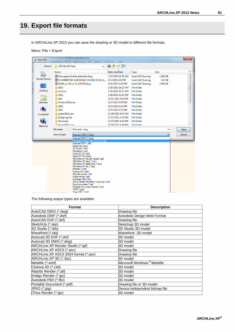
In ARCHLine.XP 2013 you can save the drawing or 3D model to different file formats. Menu: File > Export
The following output types are available:
Format Description AutoCAD DWG (*.dwg) Drawing file Autodesk DWF (*.dwf) Autodesk Design Web Format AutoCAD DXF (*.dxf) Drawing file SketchUp (*.skp) Sketchup 3D model 3D Studio (*.3ds) 3D Studio 3D model Wavefront (*.obj) Wavefront 3D model Autocad 3D DXF (*.dxf) 3D model Autocad 3D DWG (*.dwg) 3D model ARCHLine.XP Render Studio (*.tgf) 3D model ARCHLine.XP ASCII (*.asc) Drawing file ARCHLine.XP ASCII 2004 format (*.asc) Drawing file ARCHLine.XP 3D (*.3as) 3D model Metafile (*.wmf) Microsoft Windows
® Metafile
Cinema 4D (*.c4d) 3D model Atlantis Render (*.atl) 3D model |Indigo Render (*.igs) 3D model Autodesk FBX (*.fbx) 3D model Portable Document (*.pdf) Drawing file or 3D model JPEG (*.jpg) Device-independent bitmap file |Thea Render (*.igs) 3D model

82
19.1. Indigo render export
ARCHLine.XP supports the Indigo native render file format. Indigo Renderer is an unbiased, physically based and photorealistic renderer. See more: http://www.indigorenderer.com/ Menu: File > Export
Activate the 3D model workspace.
In the Export dialog box, choose the type „Indigo render (.igs).
Enter a file name, and click Save.
ARCHLine.XP creates the file with „. igs” extension and a folder with the same name and „.tex” extension that contains all the textures referenced in their 3D model.
Note: In order to import properly the file with „. igs” extension with other applications on another computer remembers to
copy the „.tex” extension folder together!
19.2. Autodesk FBX export
ARCHLine.XP supports the Autodesk® FBX® file format. Autodesk® FBX® provides higher-fidelity data export to several Autodesk packages as Autodesk® 3ds Max® and Autodesk® Maya® software. See more: http://en.wikipedia.org/wiki/FBX Menu: File > Export
Activate the 3D model workspace.
In the Export dialog box, choose the type Autodesk FBX (*.fbx)
Enter a file name, and click Save. ARCHLine.XP creates the file with „.fbx” extension and a folder with the same name and „.tex” extension that contains all the textures referenced in their 3D model.
Note: In order to import properly the file with „.fbx” extension with other applications on another computer remember to
copy the „.tex” extension folder together!

ARCHLine.XP 2013 News 83
ARCHLine.XP®
20. Change model in one material – Paper model
In architecture there is a need to create section view, where is necessary to display the mass volume.
The building itself is composed of different materials, which have in section view different hatching. Therefore, these materials must be replaced with one, to all materials combined in one and join surfaces in 3D. The paper model method enables to create the 3D model in just one material.
This function temporarily changes every material to one material, but the project remembers the distributions of materials and
next time switching off the paper model function the 3D model restores the assigned materials. Menu: View > 2D -> 3D > By classes
84
ARCHLine.XP 2013 News 85
ARCHLine.XP®
21. ARCHLine.XP Layer Tools - Summary
Layer is essential tools in drawing management. For this reason ARCHLine.XP offers a rich set of layer tools. Organizing layers can be confusing, if you have lots of layers. Summary of the most frequently used ARCHLine.XP layer tools. Menu (Architecture): Modify > Layer Menu (Interior): Edit > Modify > Layer
Layer manager
This dialog manages layers and layer properties. You can change the current layer, create new ones, delete or turn on and off layers and lock/unlock them, change the printable status. In layer control mode you can assign properties such as colour and line type, line weight.
Move Objects to New Layer
This tool will move objects from one layer to another, by selecting the destination layer from a dialog.
Layer Walk
This tool displays objects on layers that you select in the Layer Walk dialog. This tool is very helpful to check which object lies on which layer.
Change to Current Layer
This tool moves objects to the current layer.
5. Make Object’s Layer Current
This command changes the current layer by selecting an object as reference. It will use the object’s layer as current layer. This command is accessible in layer control mode only.
22. Hide and Isolate Objects
ARCHLine.XP offers has four new commands that isolate the selected objects (hide everything except the selected ones) or hide the selected ones either in 2D or 3D workspace. It is very practical command when you have a large drawing and need to display only one object or a small number of objects. Menu: View > Isolate
Isolate Object
The Isolate Object command hides all objects except the one you select.
Isolate Selection The Isolate Selection command hides all objects except the selected ones.
End Object Isolation The End Object Isolation command displays all objects again.
Hide Selection
The Hide Selection command hides selected objects.
Select Similar
The Select Similar command allows you to select objects that are similar to a selected object. The command will select all of the objects with the same type in the drawing regardless of their properties.
You can apply editing commands in the Property grid that will be valid for the whole selection. The objects remain selected so you can apply more commands to the selected objects.

86
23. Quantity take-off
23.1. Room book – Excel output
A Room book report command is enhanced with new details. Using the Room book report feature, you can view three kind of list of all Room books referenced in the current plan sorted out by floors and apartments. Menu: Add-on > Quantity take-off Calculation of used area:

ARCHLine.XP 2013 News 87
ARCHLine.XP®
Room book information in details
Combined list

88
23.2. Tiling – Excel output
A Tiling report command is enhanced with new details. Using the Tiling report feature, you can view four kind of list of all tiling and areas without tiles referenced in the current plan. Menu: Add-on > Quantity take-off

ARCHLine.XP 2013 News 89
ARCHLine.XP®

90
24. Delete unused materials from a project
When you save your project you can decide to keep all materials you have ever imported into your project. It can grow up to a significant quantity. Put a checkmark in the Purge unused materials ...feature to have the program automatically purge all materials no longer in use. Deleting or purging unused materials will allow you to reduce the overall size of your project.