Architecture of the DOCTOR Virtualized Node
60
Project ANR: DOCTOR <ANR-14-CE28-0001> DeplOyment and seCurisaTion of new functiOnalities in virtualized networking enviRonnements Deliverable D1.2 Architecture of the DOCTOR Virtualized Node Version 1.0, 21 December 2015 Authors Orange Patrick Truong, Bertrand Mathieu Thales François-Xavier Aguessy, Olivier Bettan Montimage Edgardo Montes de Oca, Antonio Ortiz, Wissam Mallouli ICD Hoang Long Mai, Alain Ploix, Guillaume Doyen CNRS-LORIA Thibault Cholez, Xavier Marchal, Cédric Enclos Abstract: In line with network softwarisation that relies on the NFV and SDN principles, the document describes the design of the virtualized network infrastructure we propose in the DOCTOR project for securely deploying network services, with a focus on Naming Data Networking as the main use case. The DOCTOR virtualized node supports the Virtualized Network Functions we target in the project while adopting the recommendations by the ETSI NFV group. This means that we also propose a Control and Management plane for the virtualized node, which integrates the DOCTOR Security Orchestration for configuring and monitoring VNFs. The DOCTOR Security Orchestration then cooperates in the southbound face with a SDN control- ler so as to secure and apply network policies for the overall virtualized network.
-
Upload
khangminh22 -
Category
Documents
-
view
0 -
download
0
Transcript of Architecture of the DOCTOR Virtualized Node

Project ANR: DOCTOR
<ANR-14-CE28-0001>
DeplOyment and seCurisaTion of new functiOnalities
in virtualized networking enviRonnements
Deliverable D1.2
Architecture of the DOCTOR Virtualized Node
Version 1.0, 21 December 2015
Authors
Orange Patrick Truong, Bertrand Mathieu Thales François-Xavier Aguessy, Olivier Bettan
Montimage Edgardo Montes de Oca, Antonio Ortiz, Wissam Mallouli ICD Hoang Long Mai, Alain Ploix, Guillaume Doyen
CNRS-LORIA Thibault Cholez, Xavier Marchal, Cédric Enclos
Abstract:
In line with network softwarisation that relies on the NFV and SDN principles, the document
describes the design of the virtualized network infrastructure we propose in the DOCTOR
project for securely deploying network services, with a focus on Naming Data Networking as
the main use case. The DOCTOR virtualized node supports the Virtualized Network Functions
we target in the project while adopting the recommendations by the ETSI NFV group. This
means that we also propose a Control and Management plane for the virtualized node, which
integrates the DOCTOR Security Orchestration for configuring and monitoring VNFs. The
DOCTOR Security Orchestration then cooperates in the southbound face with a SDN control-
ler so as to secure and apply network policies for the overall virtualized network.
Deliverable D1.2: Architecture of the DOCTOR Virtualized Node
2/60 DOCTOR Project, <ANR-14-CE28-0001>
TABLE OF CONTENTS
1 Introduction ................................................................................................................................ 3
2 Overview of the DOCTOR Virtualized Network Infrastructure ..................................................... 4
3 Architecture of the DOCTOR Virtualized Node .......................................................................... 10
3.1 Infrastructure Layer .......................................................................................................... 11
3.2 Virtualization Layer ........................................................................................................... 12
3.2.1 Type-1 vs Type-0 Virtualization Performance Analysis .............................................. 12
3.2.2 Setting up Virtual Networking .................................................................................... 18
3.3 Application Layer .............................................................................................................. 19
3.3.1 IP Protocol Stack ....................................................................................................... 20
3.3.2 NDN Protocol Stack .................................................................................................. 20
3.3.3 HTTP/NDN Gateway .................................................................................................. 25
3.3.4 MMT Network Probes ............................................................................................... 30
3.3.5 NDN Firewall ............................................................................................................. 33
4 DOCTOR Control and Management Plane ................................................................................ 34
4.1 Comparison with the ETSI NFV Management and Orchestration ..................................... 35
4.2 OpenStack for NFV........................................................................................................... 38
4.2.1 Opportunities and Challenges ................................................................................... 38
4.2.2 Academic Efforts to Enhance OpenStack with NFV Requirements ........................... 40
4.2.3 Open Consortiums .................................................................................................... 41
4.2.4 Conclusion ................................................................................................................ 41
4.3 Monitoring and Securing the DOCTOR Virtualized Infrastructure ..................................... 42
4.3.1 Network Monitoring with Distributed Virtualized Probes ............................................ 42
4.3.2 Proactive Security Analysis and Remediation Proposal with CyberCAPTOR ............ 43
4.3.3 Reactive Security Analysis using CyberCAPTOR Attack Graphs ............................... 45
4.3.4 Dealing with Scalability and Availability by Distributing the SDN Controller ............... 45
4.4 DOCTOR Management and Orchestration of VNFs .......................................................... 48
4.4.1 Orchestration Tools for Docker Containers ............................................................... 48
4.4.2 CyberCAPTOR and MMT Operator for Orchestration Management .......................... 51
4.5 DOCTOR SDN Control Plane ............................................................................................ 51
4.5.1 CyberCAPTOR and MMT Operator for SDN Controller Management ........................ 52
4.5.2 Integration Strategies of ICN into SDN Control Domains ........................................... 52
4.5.3 Controlling Virtual Networks ...................................................................................... 55
5 Conclusion ................................................................................................................................ 57
6 References ................................................................................................................................ 58

Deliverable D1.2: Architecture of the DOCTOR Virtualized Node
3/60 DOCTOR Project, <ANR-14-CE28-0001>
1 Introduction
Current networks generally consist of heterogeneous and vendor-locked hardware and soft-
ware components, with no support for interoperability, and therefore leading to complex network
management. This vertical segmentation prevents telcos from deploying new services rapidly.
Moreover, innovation cycles are often long, meaning that network operators are very careful when
working on a new paradigm or technology. Any new networking solution actually requires to be
fully designed (including often cumbersome procedures for standardization), evaluated, monitored
and secured to ensure that it does not disturb existing services and can provide rapid return on
investments. Faced with those limitations, telcos have recently been able to foster a new approach
for building their networks thanks to the wider adoption of virtualization techniques in data centers.
Virtualization provides greater flexibility in sharing hardware resources, which results in cost reduc-
tion and faster service deployment. We are thus seeing the emergence of network softwarisation,
which consists in building Network Functions Virtualization (NFV) components, which are treated
as virtualized software instances deployed in Virtual Machines (VMs). Those VMs can then be
chained and managed via Software-Defined Networking (SDN) controllers to create end-to-end
communication services.
In the first deliverable D1.1 of the project DOCTOR, we have presented the different require-
ments and challenges of network softwarisation that need to be considered, when designing a
NFV-based architecture for securely deploying new networking services in virtualized environ-
ments, taking the NDN delivery service as the main use case. The present document carries for-
ward the work, and we especially refine the overall architecture we have proposed in the delivera-
ble D1.1.
The Section 2 describes the structure of the virtualized network infrastructure proposed in
the DOCTOR project, which consists of a virtualized node, carrying the different Virtualized Net-
work Functions we target in the project, and a control and management plane with the northbound
face for managing and orchestrating the VMs (used for deploying VNFs) and the southbound face
for controlling the deployed virtualized network services so as to enforce network monitoring and
security. The architecture of the DOCTOR virtualized node is designed with respect to the require-
ments and challenges highlighted in the deliverable D1.1 and it is detailed in Section 3. We then
present in Section 4 the control and management plane for operating on the virtualized node based
on the ETSI recommendations and the SDN principles. The Section 5 concludes the document
with some guidelines for the next steps in the project.

Deliverable D1.2: Architecture of the DOCTOR Virtualized Node
4/60 DOCTOR Project, <ANR-14-CE28-0001>
2 Overview of the DOCTOR Virtualized Network Infrastructure
Our main objective in the DOCTOR project is to design a flexible and secure service-aware
network architecture. The DOCTOR virtualized network architecture is designed with the NFV con-
cept to efficiently host network functions and services which can be performed at high throughput.
Based on the SDN principles, the network control is separated from the data plane and it is dele-
gated to a controller, which configures routing data, manages and orchestrates network services
as well as network monitoring, making it possible to secure the overall virtualized architecture for
the detection of network anomalies or attacks.
Figure 1 shows an overview of the DOCTOR virtualized network infrastructure, including the
functional blocks and their interactions. Note that the interactions or interfaces are numbered in
Figure 1 with two colors (green and purple) to separate the SDN control plane for virtual network
configuration from the NFV management plane, which is more related to the virtualization-related
functions and the forwarding plane.
Figure 1: Overview of the DOCTOR virtualized network infrastructure

Deliverable D1.2: Architecture of the DOCTOR Virtualized Node
5/60 DOCTOR Project, <ANR-14-CE28-0001>
The following table summarizes the main interfaces of the DOCTOR virtualized network infrastruc-
ture:
Interface Main functionalities
DOCTOR
Management
and
Orchestration
Interface 1 Cooperation between the MMT Operator and the Cyber-
CAPTOR manager. The MMT Operator takes decisions
based on information from the CyberCAPTOR.
Interface 2 Through the VNF Manager (VNFM), the MMT Operator can
manage and control the VNFs:
i) to coordinate monitoring enabled on VNFs for net-
work security purposes,
ii) to manage the distributed SDN controllers – cf. Sec-
tion 4.3.4
(via interface 4);
iii) to configure the network functions (via interface 5);
iv) to (implicitly) request specific tasks to the hypervisor
when required by the VNFM for configuring a net-
work function (e.g. increase compute resources for
supporting a network configuration),
(via interface 6).
Interface 3 The MMT Operator can directly send a request to the Virtu-
alized Infrastructure Manager (VIM) to perform virtualiza-
tion-related tasks: e.g. shutdown a VNF, or migrating a VNF
on another physical host, etc.
Interface 4 The VNFM manages the Element Managers for network
monitoring and also managing/sending requests to the dis-
tributed SDN controllers (cf. Section 4.3.4).
Interface 5 The VNFM configures the network functions (implemented
by the VNFs) on behalf of the MMT Operator – e.g. for ap-
plying remediations or corrections on the VNFs in reaction
to network misuses (attacks or anomalies).
Interface 6 The VNFM interacts with the Virtualized Infrastructure Man-
ager (VIM) to orchestrate or allocate new resources for the
VNFs.
Interface 7 The VIM controls the hypervisor on the DOCTOR virtualized
node, and it executes the requests from the VNFM (from
the interface 6).
DOCTOR
SDN Control
Interface 8 The VIM has also a southbound interface to the DOCTOR
(centralized) SDN controller. This is the interface between
the NFV Management and Orchestration, and the SDN con-
trol plane.
Interface 9 The SDN controller controls and configures virtual switches
based on information from the DOCTOR Security Orches-
trator, so as to secure the overall virtualized network.

Deliverable D1.2: Architecture of the DOCTOR Virtualized Node
6/60 DOCTOR Project, <ANR-14-CE28-0001>
We describe hereafter those interfaces between the functional blocks of the DOCTOR virtual-
ized network infrastructure.
We first design a virtualized node, which means that we will able to deploy multiple network
services as software instances or Virtualized Network Functions (VNFs) over a single physical host.
Each deployed VNF will thus be run into one or several Virtual Machines (VMs), depending on the
design. As such, the DOCTOR virtualized node can be structured into three layers. The application
layer contains the VNFs, deployed as virtual machines over a virtualization layer which provides an
abstraction for the underlying hardware resources offered by the physical host. A virtual network
based on programmable virtual switches will then be implemented to ensure end-to-end network
connectivity between those virtualized network services, but also to enable network automation for
the control plane.
The DOCTOR virtualized node being flexible to host any existing or new network service, we
target in the project, so as to assert our design, the deployment of the IP and NDN protocol stacks,
as well as an HTTP/NDN gateway for exchanging HTTP traffics between NDN and IP domains.
Monitoring the network is a critical task for network operators. It is the basis for the security task
but it is also valuable for the network knowledge (network load, type of traffic, peak hours) and this
is more important when the network operator is deploying any new network service, such as the
NDN protocol as expected in the project as the main use case. To this end, we will implement spe-
cific virtualized functions dedicated to traffic monitoring and analysis for network security (espe-
cially detection and mitigation of network attacks related to NDN). In particular, each virtualized
network service deployed in the application layer of the virtualized node will be linked with an Ele-
ment Manager (EM), which integrates a network monitoring function (provided by the MMT - Mon-
timage Monitoring Tool – probe; see Section 3.3.4) along with a distributed SDN (Software-Defined
Networking) Controller (dSDNC) - see Figure 1 for illustration. As described in details in Section
4.3.4, those pairs of virtualized MMT probes and distributed SDN controller allow to distribute the
complexity of traffic monitoring over different virtualized network functions in order to consolidate,
inter-correlate and aggregate monitored data (pre-processing) before sending to the MMT Opera-
tor (via a VNF Manager – interface 2 in Figure 1) for deeper analysis in the context of unveiling net-
work anomalies or attacks. Note that detailed implementation methods are outside the scope of
the present document, and will be further analyzed later in the project.
The DOCTOR virtualized network infrastructure also includes a framework to provide dynam-
ic configuration and management, as well as real-time security enforcement in the virtualized net-
work. The proposed control and management plane (as represented on the right side in Figure 1)
consists of two functioning blocks
Infrastructure management and orchestration on the Northbound face.
Virtual network control on the Southbound face.
The Northbound face consists of functions for management and orchestration of VNFs, which are:
1. The Virtualized Infrastructure Manager (VIM) is responsible for provisioning hardware re-
sources to VMs (computing, storage, networking, including VM (re)configuration or migra-
tion, etc.) when necessary, based on the MMT Operator decisions (interface 3 on Figure 1).
To this end, the VIM controls the hypervisor of the DOCTOR virtualized node by using the
interface 7 in Figure 1.
2. Monitoring and securing the VNFs so as to secure the whole virtualized networking infra-
structure. Those security functions are implemented by the DOCTOR Security Orchestrator.
The MMT operator is responsible for coordinating traffic monitoring enabled with the MMT
probes implemented in each virtualized network service deployed in the project (interface 4

Deliverable D1.2: Architecture of the DOCTOR Virtualized Node
7/60 DOCTOR Project, <ANR-14-CE28-0001>
in Figure 1). The MMT Operator interacts with the CyberCAPTOR manager (interface 1 in
Figure 1, as also described in Section 4.3.2) for network security analysis (detection and
remediation).
3. Management and configuration of the network functions (implemented with the VNFs) on
behalf of the MMT Operator that can take information from the CyberCaptor manager for
network security pocicies. The MMT Operator is thus able to apply remediations or correc-
tions on the virtualized network functions in response to network misuses (interface 2 in
Figure 1), through the VNF Manager using the interface 5 in Figure 1. If needed, the VNF
Manager can ask the VIM, via interface 6 in Figure 1, to orchestrate (or allocate new) hard-
ware resources for the VNFs
The Southbound face of the DOCTOR Control and Management Plane implements the
DOCTOR SDN control plane which consists of a SDN controller interacting with virtual networks
for dynamic configuration (interface 9 in Figure 1). Following the SDN principles, the DOCTOR con-
troller is mainly designed to acquire a global view of the network and to provide for centralized,
intelligence-based network control. It actually interfaces with the DOCTOR Security Orchestrator
(via the VIM using interface 8 in Figure 1) to get informed on attacks or anomalies detected with the
assistance of CyberCAPTOR, so as to correctly configure virtual networks. Its role includes e.g.
setting up the HTTP/NDN gateway to deliver traffic between heterogeneous network domains (i.e.
IP and NDN), traffic load balancing, setting up rules for a firewall or an IPS/IDS service, add-
ing/removing routes in NDN or IP router’s forwarding tables, etc.
Figure 2: High-level view of the ETSI NFV reference architecture [1]
It is worth of noting that the DOCTOR virtualized network infrastructure is designed with re-
spect to the recommendations by the ETSI NFV group (refer to our first deliverable D1.1 for a de-
tailed description of those recommendations) while leveraging the SDN principles for decoupling
the control functions from the data plane. As a reminder, Figure 2 [1] gives the high-level represen-

Deliverable D1.2: Architecture of the DOCTOR Virtualized Node
8/60 DOCTOR Project, <ANR-14-CE28-0001>
tation of the NFV reference architectural framework. The ETSI NFV reference architectural frame-
work consists of three working domains:
Network Functions are implemented as software-only components. In the NFV context, a
Virtualized Network Function (VNF) is a virtualisation of a network function, meaning that
the network function is implemented as a piece of software run in a virtual machine. Several
implementation schemes exist depending on the configuration. One VNF can be deployed
over multiple VMs, where each VM hosts a single component of the VNF. However, in other
cases, the whole VNF can be deployed in a single VM as well. Moreover, there may also be
several VNFs deployed over a single physical machine (vertical scalability) or VNFs may be
deployed over multiple physical hosts (horizontal scalability).
The NFV Infrastructure (NFVI) represents the underlying physical hardware resources (in-
cluding computing, storage and network) and how these resources can be virtualised. In
particular, the NFVI supports the execution of the VNFs. The NFVI may consist of a single
host or a cluster of machines distributed across several locations. From the VNF's perspec-
tive, the virtualisation layer provides an abstraction of the hardware resources that finally
look like a single entity providing the VNF with desired virtualised resources.
NFV Management and Orchestration, which covers the orchestration and lifecycle man-
agement of physical and/or software resources that support the infrastructure virtualisation,
and the lifecycle management of VNFs. More precisely, NFV Management and Orchestra-
tion only focuses on all virtualisation-specific management tasks necessary in the NFV
framework.
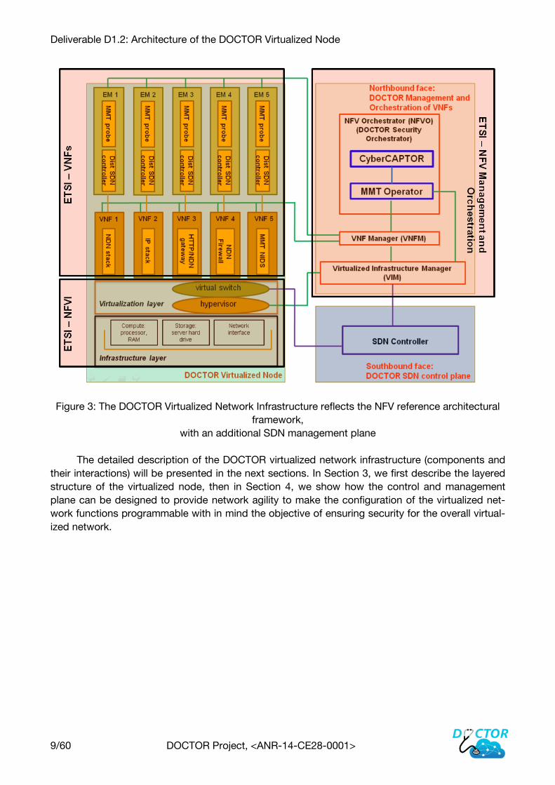
Figure 3 compares the DOCTOR Virtualized Network Infrastructure against the ETSI NFV ref-
erence architectural framework: we consciously respect the ETSI recommendations when design-
ing our virtualized infrastructure. The application layer of the DOCTOR virtualized node consists of
the different VNFs which execute network services we target in the project, and the virtualization
and infrastructure layers of the node represents the NFVI. The Northbound face of the Control and
Management plane in the DOCTOR virtualized infrastructure implements then the NFV Manage-
ment and Orchestration. The DOCTOR controller in the southbound face is intended to make the
behavior of the virtualized network services programmable, allowing them to be managed and con-
trolled by a central element. This leads to the adoption of the SDN principles for the design of the
controller in the project, so as to enable a clear separation between the control and forwarding
planes, with a centralization of network control to dynamically configure the network functions
through well-defined interfaces.
Deliverable D1.2: Architecture of the DOCTOR Virtualized Node
9/60 DOCTOR Project, <ANR-14-CE28-0001>
Figure 3: The DOCTOR Virtualized Network Infrastructure reflects the NFV reference architectural
framework,
with an additional SDN management plane
The detailed description of the DOCTOR virtualized network infrastructure (components and
their interactions) will be presented in the next sections. In Section 3, we first describe the layered
structure of the virtualized node, then in Section 4, we show how the control and management
plane can be designed to provide network agility to make the configuration of the virtualized net-
work functions programmable with in mind the objective of ensuring security for the overall virtual-
ized network.

Deliverable D1.2: Architecture of the DOCTOR Virtualized Node
10/60 DOCTOR Project, <ANR-14-CE28-0001>
3 Architecture of the DOCTOR Virtualized Node
Focusing on the DOCTOR virtualized node
This section defines the architecture of the DOCTOR virtualized node enabling network ser-
vices to be flexibly and securely deployed.
The DOCTOR virtualized node will be implemented on a single Linux server that provides the
hardware resources for virtualization as required for supporting the execution environment for Vir-
tualized Network Functions (VNFs). This server, providing the physical infrastructure for enabling
NVF is also referred to as the NFVI node in the ETSI naming convention.
We detail hereafter the different layers that structure the DOCTOR virtualized node. For the
virtualization layer, as the constraints in the project require low-level network access at high
throughput for network monitoring and name-based forwarding in NDN, we focus our analysis on
the type-1 and type-0 virtualization techniques, and we will argue why we should orient our choice
towards the Linux container-based virtualization technology Docker. We will then analyse which
network processing elements will be virtualized in DOCTOR. Those VNFs will be implemented as
Docker containers (as illustrated in Figure 4) to compose the application layer of our virtualized
node while providing the functions needed for traffic monitoring so as to apply security as well as
efficient orchestration and management for the overall virtualized network infrastructure.

Deliverable D1.2: Architecture of the DOCTOR Virtualized Node
11/60 DOCTOR Project, <ANR-14-CE28-0001>
Figure 4: The DOCTOR Virtualized Node
3.1 Infrastructure Layer
The Infrastructure layer of the DOCTOR virtualized node represents the physical hardware
resources, including computing, storage and networking, which provide processing, storage and
network connectivity to VNFs through the virtualisation layer. These hardware resources are pro-
vided by commodity servers. We do not plan in the project to virtualize shared network storage
(NAS) as we will use storage that resides on the server itself.
One of the main outcome of the DOCTOR project is a real testbed offering an experimental
environment to develop and test the different VNFs envisioned in the project (routing, monitoring,
security, etc.), with the goal to offer an end-to-end NDN connectivity over a virtualized infrastruc-
ture following the latest ETSI NFV recommendations. To this end, we ordered and installed several
servers to support our future experiments. The testbed is bi-located in Nancy and Troyes and will
ultimately involve external users to generate real traffic through the infrastructure. The testbed is
composed of a set of servers on each site, interconnected by a VPN tunnel as illustrated in Figure
5. Following the NFV philosophy, the infrastructure is composed of standard x86 servers. For ex-
ample, the servers on the LORIA site are two R730 servers with the following configuration:
CPU : Xeon E5-2630 v3 ([email protected])
RAM : 64GB DDR4@2133MHz
Storage : 2x400Go SAS SSD + 4To SATA HDD
Network : Intel X540 2x10Gbps + Intel i350 2x1Gbps

Deliverable D1.2: Architecture of the DOCTOR Virtualized Node
12/60 DOCTOR Project, <ANR-14-CE28-0001>
More information on the physical hardware infrastructure will be given in task 4.
Figure 5: The DOCTOR testbed
3.2 Virtualization Layer
The virtualisation layer abstracts the hardware resources and decouples the deployment of
VNFs from the underlying hardware, thus ensuring a hardware independent lifecycle for the VNFs.
In short, the virtualisation layer is responsible for:
Abstracting and logically partitioning physical resources, commonly as a hardware abstrac-
tion layer.
Enabling the software that implements the VNF to use the underlying virtualised infrastruc-
ture.
Providing virtualised resources to the VNF, so that the latter can be executed.
The ETSI group does not propose or recommend a specific virtualization technology to sup-
port the execution of VNFs and their chaining. In DOCTOR, we only analyse the type-1 and type-0
virtualization techniques so as to meet the requirements of high throughput for processing packets,
which are important for efficient real-time network monitoring as well for low-latency name-based
forwarding in NDN. As presented in the first deliverable D1.1, those virtualization methods allow a
low-level access to the hardware resources, especially the network interface. We first focus our
analysis on the type-1 virtualization solution KVM that is used in the OpenStack suite, and then we
analyze the container-based type 0 virtualization Docker. Performance evaluations, presented
hereafter, allow us to assert Docker as the most suitable virtualization technology for the DOCTOR
requirements.
3.2.1 Type-1 vs Type-0 Virtualization Performance Analysis
In this section, we compare two virtualization solutions: KVM and Docker, in the context of
NFV, in order to choose the most suitable technology according to DOCTOR's objectives.
The following resources were used during the tests:
a workstation: Core i5 [email protected], 16GB DDR3@1600Mhz, Linux 3.13, Docker 1.6.0,
OpenStack via Devstack
a first server (server1): 2*Xeon [email protected], 48GB DDR3@1600Mhz, Linux 3.19,
Docker 1.7.0

Deliverable D1.2: Architecture of the DOCTOR Virtualized Node
13/60 DOCTOR Project, <ANR-14-CE28-0001>
a second server (server2): Xeon [email protected], 32GB DDR3@1600Mhz, Linux 3.19,
Docker 1.7.0
KVM 3.2.1.1
The KVM images used for our test are deployed thanks to the OpenStack environment.
Openstack being a complete cloud architecture, it executes a lot of different modules that con-
sumes significant resources, even without any workload (cf Section 4.2 for more details). More
precisely, we used the Devstack environment that enables an easy installation of Openstack on a
single machine, by opposition to the production guidelines that separate management modules
and computation modules. This will create a bias overestimating the absolute resource consump-
tion of KVM in our measurements, but this does not change the general tendency of KVM resource
consumption for additional VM. The Figure 6 shows the default resources consumption of the
workstation when the KVM hypervisor is launched within OpenStack.
Figure 6: Idle CPU cost of OpenStack
We used the module “Horizon” to design the network that will chain the virtual machines.
Horizon is a web interface that communicates with the OpenStack REST API and most of the con-
figuration can be done with this tool. An example of virtual network that can be created by Horizon
is illustrated in the Figure 7. It is composed of two subnetworks, each containing two virtual ma-
chines. Routers and sub-networks are OpenStack agents and have embedded network applica-
tions like DHCP, DNS, etc. Unfortunately, it is quite difficult to change the default routes.
Deliverable D1.2: Architecture of the DOCTOR Virtualized Node
14/60 DOCTOR Project, <ANR-14-CE28-0001>
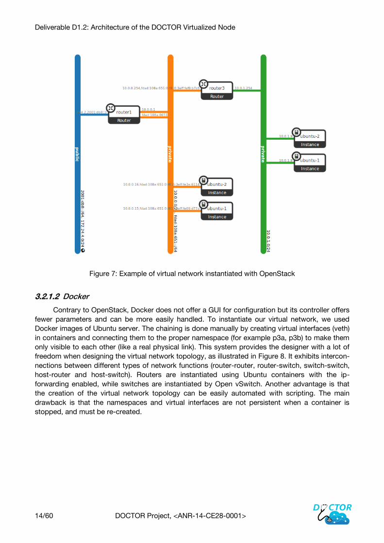
Figure 7: Example of virtual network instantiated with OpenStack
Docker 3.2.1.2
Contrary to OpenStack, Docker does not offer a GUI for configuration but its controller offers
fewer parameters and can be more easily handled. To instantiate our virtual network, we used
Docker images of Ubuntu server. The chaining is done manually by creating virtual interfaces (veth)
in containers and connecting them to the proper namespace (for example p3a, p3b) to make them
only visible to each other (like a real physical link). This system provides the designer with a lot of
freedom when designing the virtual network topology, as illustrated in Figure 8. It exhibits intercon-
nections between different types of network functions (router-router, router-switch, switch-switch,
host-router and host-switch). Routers are instantiated using Ubuntu containers with the ip-
forwarding enabled, while switches are instantiated by Open vSwitch. Another advantage is that
the creation of the virtual network topology can be easily automated with scripting. The main
drawback is that the namespaces and virtual interfaces are not persistent when a container is
stopped, and must be re-created.
Deliverable D1.2: Architecture of the DOCTOR Virtualized Node
15/60 DOCTOR Project, <ANR-14-CE28-0001>
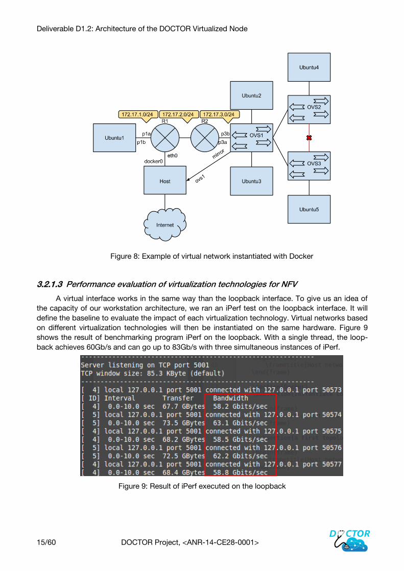
Figure 8: Example of virtual network instantiated with Docker
Performance evaluation of virtualization technologies for NFV 3.2.1.3
A virtual interface works in the same way than the loopback interface. To give us an idea of
the capacity of our workstation architecture, we ran an iPerf test on the loopback interface. It will
define the baseline to evaluate the impact of each virtualization technology. Virtual networks based
on different virtualization technologies will then be instantiated on the same hardware. Figure 9
shows the result of benchmarking program iPerf on the loopback. With a single thread, the loop-
back achieves 60Gb/s and can go up to 83Gb/s with three simultaneous instances of iPerf.
Figure 9: Result of iPerf executed on the loopback
Deliverable D1.2: Architecture of the DOCTOR Virtualized Node
16/60 DOCTOR Project, <ANR-14-CE28-0001>
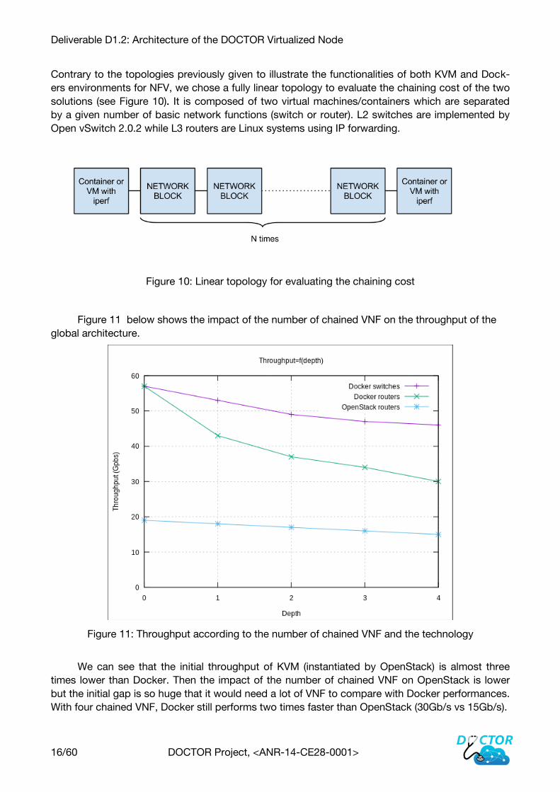
Contrary to the topologies previously given to illustrate the functionalities of both KVM and Dock-
ers environments for NFV, we chose a fully linear topology to evaluate the chaining cost of the two
solutions (see Figure 10). It is composed of two virtual machines/containers which are separated
by a given number of basic network functions (switch or router). L2 switches are implemented by
Open vSwitch 2.0.2 while L3 routers are Linux systems using IP forwarding.
Figure 10: Linear topology for evaluating the chaining cost
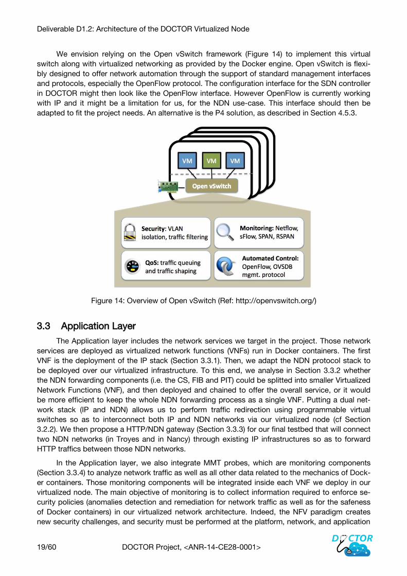
Figure 11 below shows the impact of the number of chained VNF on the throughput of the
global architecture.
Figure 11: Throughput according to the number of chained VNF and the technology
We can see that the initial throughput of KVM (instantiated by OpenStack) is almost three
times lower than Docker. Then the impact of the number of chained VNF on OpenStack is lower
but the initial gap is so huge that it would need a lot of VNF to compare with Docker performances.
With four chained VNF, Docker still performs two times faster than OpenStack (30Gb/s vs 15Gb/s).

Deliverable D1.2: Architecture of the DOCTOR Virtualized Node
17/60 DOCTOR Project, <ANR-14-CE28-0001>
We also studied the impact of the number of connections, simply running different instances
of iPerf on the two solutions. We can see with a single connection, the system is already under
heavy load. It is due to the OpenStack Neutron module and that is why it is recommended to install
it on a separate and dedicated server.
1 connection:
Docker OpenStack
Throughput (Gbps) 58 20
CPU usage 2c@100% 4c@80%
2 connections:
Docker OpenStack
Throughput (Gbps) 73 20
CPU usage 4c@90% 4c@88%
3 connections:
Docker OpenStack
Throughput (Gbps) 75 20
CPU usage 4c@95% 4c@93%
Finally, we performed a last evaluation to see the relative cost of the different solutions when
we want to go in the physical network with the network adapter.
Figure 12: Relative CPU cost of the network throuput

Deliverable D1.2: Architecture of the DOCTOR Virtualized Node
18/60 DOCTOR Project, <ANR-14-CE28-0001>
As illustrated in Figure 12, we can see that a container that is linked directly to the host has
the same cost. If this container is behind 4 switch containers the cost is 20% more than the native
solution and if these containers are routers, the cost up to 60% cost overhead. In the case of KVM,
the cost is already heavy with about 3 times the cost of the native solution and it is slightly greater
when the virtual machine is behind 4 routers with 3.2 times the cost of the native solution.
The partial conclusion we can draw from these measurements is that, without specific tech-
nologies accelerating network processing on KVM (like the 6windgate) Docker is the technology
that offer the best performances for our envisioned use of NFV with a small number of chained
network functions.
3.2.2 Setting up Virtual Networking
In Doctor, we aim to have several protocol stacks deployed in the virtualized node. Then we
need one component being able to redirect incoming packets towards to the appropriate virtual
container (containing the appropriate network stack). This component is usually the virtual switch
in current virtualised environment and is able to route packets toward virtualised applications,
based on the IP address. But in Doctor, since we address the NDN use-case and NDN being a
new network protocol which can work without IP (directly on top of Ethernet), this virtual switch
should be adapted to work with other parameters.
We will analyse during the implementation of our virtualized node the most suitable way to
take into consideration information from the network interface, e.g.; from the Ethernet layer if pos-
sible to determine whether the traffic is related IP or NDN.
Figure 13: DOCTOR virtual switch
Our virtual switch needs to be programmable with dynamic configuration facilities so as to
give it special policies or forwarding requirements. An interface is then required between this virtual
switch and a SDN controller (or another similar component).
The configuration of the central element of the virtual switch will allow to set up network con-
nectivity between several Doctor nodes, so as to configure the full network topology, according to
the network and applications requirements.
Deliverable D1.2: Architecture of the DOCTOR Virtualized Node
19/60 DOCTOR Project, <ANR-14-CE28-0001>
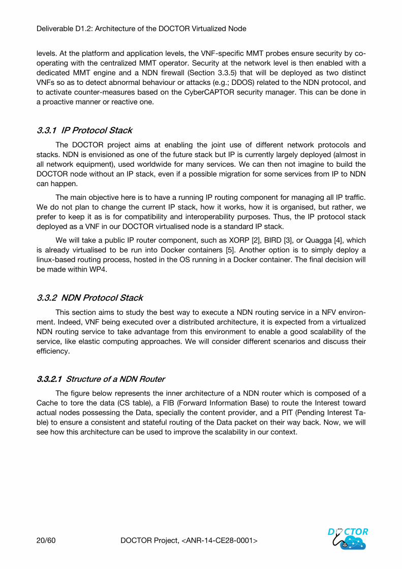
We envision relying on the Open vSwitch framework (Figure 14) to implement this virtual
switch along with virtualized networking as provided by the Docker engine. Open vSwitch is flexi-
bly designed to offer network automation through the support of standard management interfaces
and protocols, especially the OpenFlow protocol. The configuration interface for the SDN controller
in DOCTOR might then look like the OpenFlow interface. However OpenFlow is currently working
with IP and it might be a limitation for us, for the NDN use-case. This interface should then be
adapted to fit the project needs. An alternative is the P4 solution, as described in Section 4.5.3.
Figure 14: Overview of Open vSwitch (Ref: http://openvswitch.org/)
3.3 Application Layer
The Application layer includes the network services we target in the project. Those network
services are deployed as virtualized network functions (VNFs) run in Docker containers. The first
VNF is the deployment of the IP stack (Section 3.3.1). Then, we adapt the NDN protocol stack to
be deployed over our virtualized infrastructure. To this end, we analyse in Section 3.3.2 whether
the NDN forwarding components (i.e. the CS, FIB and PIT) could be splitted into smaller Virtualized
Network Functions (VNF), and then deployed and chained to offer the overall service, or it would
be more efficient to keep the whole NDN forwarding process as a single VNF. Putting a dual net-
work stack (IP and NDN) allows us to perform traffic redirection using programmable virtual
switches so as to interconnect both IP and NDN networks via our virtualized node (cf Section
3.2.2). We then propose a HTTP/NDN gateway (Section 3.3.3) for our final testbed that will connect
two NDN networks (in Troyes and in Nancy) through existing IP infrastructures so as to forward
HTTP traffics between those NDN networks.
In the Application layer, we also integrate MMT probes, which are monitoring components
(Section 3.3.4) to analyze network traffic as well as all other data related to the mechanics of Dock-
er containers. Those monitoring components will be integrated inside each VNF we deploy in our
virtualized node. The main objective of monitoring is to collect information required to enforce se-
curity policies (anomalies detection and remediation for network traffic as well as for the safeness
of Docker containers) in our virtualized network architecture. Indeed, the NFV paradigm creates
new security challenges, and security must be performed at the platform, network, and application
Deliverable D1.2: Architecture of the DOCTOR Virtualized Node
20/60 DOCTOR Project, <ANR-14-CE28-0001>
levels. At the platform and application levels, the VNF-specific MMT probes ensure security by co-
operating with the centralized MMT operator. Security at the network level is then enabled with a
dedicated MMT engine and a NDN firewall (Section 3.3.5) that will be deployed as two distinct
VNFs so as to detect abnormal behaviour or attacks (e.g.; DDOS) related to the NDN protocol, and
to activate counter-measures based on the CyberCAPTOR security manager. This can be done in
a proactive manner or reactive one.
3.3.1 IP Protocol Stack
The DOCTOR project aims at enabling the joint use of different network protocols and
stacks. NDN is envisioned as one of the future stack but IP is currently largely deployed (almost in
all network equipment), used worldwide for many services. We can then not imagine to build the
DOCTOR node without an IP stack, even if a possible migration for some services from IP to NDN
can happen.
The main objective here is to have a running IP routing component for managing all IP traffic.
We do not plan to change the current IP stack, how it works, how it is organised, but rather, we
prefer to keep it as is for compatibility and interoperability purposes. Thus, the IP protocol stack
deployed as a VNF in our DOCTOR virtualised node is a standard IP stack.
We will take a public IP router component, such as XORP [2], BIRD [3], or Quagga [4], which
is already virtualised to be run into Docker containers [5]. Another option is to simply deploy a
linux-based routing process, hosted in the OS running in a Docker container. The final decision will
be made within WP4.
3.3.2 NDN Protocol Stack
This section aims to study the best way to execute a NDN routing service in a NFV environ-
ment. Indeed, VNF being executed over a distributed architecture, it is expected from a virtualized
NDN routing service to take advantage from this environment to enable a good scalability of the
service, like elastic computing approaches. We will consider different scenarios and discuss their
efficiency.
Structure of a NDN Router 3.3.2.1
The figure below represents the inner architecture of a NDN router which is composed of a
Cache to tore the data (CS table), a FIB (Forward Information Base) to route the Interest toward
actual nodes possessing the Data, specially the content provider, and a PIT (Pending Interest Ta-
ble) to ensure a consistent and stateful routing of the Data packet on their way back. Now, we will
see how this architecture can be used to improve the scalability in our context.

Deliverable D1.2: Architecture of the DOCTOR Virtualized Node
21/60 DOCTOR Project, <ANR-14-CE28-0001>
Figure 15: Architecture of a NDN router
First Proposal: Adding a CS 3.3.2.2
The figure below represents an architecture where another CS is created to provide the NDN
routing service with more caching resources. This could be done automatically by the orchestrator
of the system if the initial cache is full and if additional resources are available.
Figure 16: NDN router with two CS
However, we can exhibit a scenario where this architecture fails:
an Interest for the Data D enters from CS1
D is retrieved and stored in CS1
another Interest for D enters from CS2
D is retrieved a second time and dropped in CS1 (already present)
a third Interest for D enters from CS2
D is retrieved a second time and stored in CS2 (D is now present in both caches)
This scenario show that the cache is not efficiently used because the same data can indiffer-
ently traverse different caches, leading to cache miss or duplicate entries.

Deliverable D1.2: Architecture of the DOCTOR Virtualized Node
22/60 DOCTOR Project, <ANR-14-CE28-0001>
Second Proposal: Adding a CS with a Load Balancer 3.3.2.3
In the architecture depicted below, we fix the previous problem by introducing have a new
component: a load balancer LB, that will map content (prefix) with a given CS.
Figure 17: NDN router with two CS and a load balancer component
For example, when a second cache is instantiated, the first reduces is prefix range from [a-z]
to [a-m] while the second stores range [n-z]. Let's consider the following scenario:
an Interest for the Data /A/pics/myPicture.png enters from CS1 and is retrieved and cached
an Interest for the Data /Z/movies/myMovie.avi enters from CS1 and is retrieved and
cached
a new cache CS2 is instantiated
another Interest for the Data /Z/movies/myMovie.avi enters from CS2 is retrieved and
cached
the Data is duplicated in both caches
If nothing is done to properly populate CS2 with some data of CS1, and clean them after-
wards, the caches are not used efficiently upon instantiation. Of course, this drawback is more im-
portant if a MFU caching policy is used than a LRU that increases the cache turnover. Anyway, the
cache efficiency will progressively increase when the new content are stored by the right cache.
Third Proposal: Adding a CS and a PIT 3.3.2.4
This architecture associates a dedicated PIT to each CS. It offers the benefit to balance the
load of the PIT. We can however notice that a single FIB serving multiple PIT/CS becomes a single
point of failure in this virtual network architecture. We propose in the next subsection to also dis-
tribute this part.

Deliverable D1.2: Architecture of the DOCTOR Virtualized Node
23/60 DOCTOR Project, <ANR-14-CE28-0001>
Figure 18: NDN router with duplicated CS and PIT
Fourth Proposal: Duplicating a Complete NDN Router 3.3.2.5
Finally, we also duplicate the FIB table, leading to a fully duplicated NDN node with its three
inner tables as illustrated in the figure below:
Figure 19: Architecture with two fully replicated NDN nodes
This solution is the easiest to implement since it does not involve a deep rewriting of NFD in-
to different modules. It also keeps consistent the chaining between the three tables that were not
designed to be split in the first place. Finally, it should also offer better reliability and load balancing
as all tables are duplicated.
Fifth Proposal: Duplicating Complete NDN Router, No Load Balancer 3.3.2.6
The previous solution used a load balancer to distribute the traffic processing on different
NDN-based VNF. However, the load balancer can create a single point of failure in the system. Al-
ternatively, we can imagine other solutions that do not involve such component, even though they
might be less efficient. Figure 20 illustrates a NDN router connected to 7 faces.

Deliverable D1.2: Architecture of the DOCTOR Virtualized Node
24/60 DOCTOR Project, <ANR-14-CE28-0001>
Figure 20: NDN router connected to 7 faces
Let us consider that this VNF is duplicated and that the new instance keeps the same con-
nections and adds a new one between the two NDN routers so that they can access their respec-
tive caches.
Figure 21: Duplicated NDN routers connected to 7 faces
Let us now consider the following scenario:
R1 receives an Interest I for a content accessible through R6
According to R1 FIB, NDN1 and NDN2 are possible next hops toward R6
I is sent toward NDN1 and NDN2
NDN1 and NDN2 forward I toward R6
R6 receives I from two faces (NDN1 and NDN2) and adds both to its PI
R6 sends the corresponding Data back to NDN1 and NDN2
NDN1 and NDN2 forward the Data toward R1
R1 considers the first Data and drops the second
This scenario highlights the fact that this scheme does not work. Instead of performing load
balancing, it actually increases network overhead and congestion. To address this problem, some
links must be only used as backup paths and the load balancing is performed by distributing link
priority between the NDN routers. In the following figure, NDN1 will take in charge packets from

Deliverable D1.2: Architecture of the DOCTOR Virtualized Node
25/60 DOCTOR Project, <ANR-14-CE28-0001>
R1, R2 and R7 while NDN2 will take in charge packets from R3, R4, R5 and R6. Each time a packet
must be forwarded toward a path that is not under the responsibility of the current node, it is for-
warded to the concerned NDN router through a default route. This solution can provide the net-
work with alternative paths in case of a VNF failure. However the caching performance should be
under the one achieved with a smart load balancer.
Figure 22: Duplicated NDN routers with link priorities
Conclusion 3.3.2.7
To conclude this part, we explored different solutions to enable the scalability of a NDN rout-
ing function (NFD) in the context of a NVF environment. We consider that the best solution is to
keep a monolithic NFD coupled with a load-balancer as a VNF component. In fact, this solution
seems to offer the best performances and need a reduced amount of engineering work, mainly
focused on the development of a VNF offering a NDN load-balancing service and on expanding the
ability of NFD to dynamically size each table upon instantiation.
3.3.3 HTTP/NDN Gateway
Named Data Networking (NDN) [6] is a disruptive content-based networking technology. It is
one of the most famous implementation of the Information Centric Networking (ICN) paradigm [7],
aiming to represent the future of the Internet
In the last decade, HTTP became the most used protocol for offering new services and ap-
plication on the Internet.
Since the DOCTOR project envisions to evaluate new networking protocol stacks, NDN ap-
pears as a natural candidate. However since HTTP is conceived to work on top of IP, using HTTP-
based commercial services with NDN is not straightforward. Some research work exists to make it
and mainly two options:
1. To use a NDN library in the users’ browser in order to natively “speak” NDN without the
need to deploy a NDN stack in the end-users’ devices. Such a library exists for Firefox, but
after some testing weeks, we gave up this option because it is limited in functionalities, per-
formance and mainly because it is not working really well.

Deliverable D1.2: Architecture of the DOCTOR Virtualized Node
26/60 DOCTOR Project, <ANR-14-CE28-0001>
2. To have gateways between the end-user browser and the service platforms, which can
adapt the HTTP messages into/from NDN messages. This option is not transparent to end-
users, since they have to configure their browsers to use a proxy, but that’s all. This solu-
tion works for all browsers, and do not add specificity in the end-users software. It is also
transparent to service providers. Since we want to address commercial web sites in the
project, we selected such a solution.
In our work, we defined two kinds of gateways : 1) one ingress gateway, aiming at converting
HTTP users’ requests into NDN interest messages and converting NDN Data messages into HTTP
replies, sent to the end-users. 2) One egress gateway, the counterpart of the first one, aiming at
converting NDN interest messages into HTTP requests towards to commercial web site and con-
verting HTTP replies into NDN Data messages.
The ingress gateway (iGW) is then the one closer to the end-user, while the egress gateway
(eGW) is the one closest to the web site. The following picture presents those 2 gateways integrat-
ed in the network, on the path between the end-users and the web server.
Figure 23: ingress and egress HTTP/NDN gateways
Internal architecture of the ingress gateway
The ingress gateway (iGW) is the first network equipment, whose role is to convert HTTP re-
quests into NDN interests. It is composed of two modules (Figure 24): one HTTP module and one
NDN module.
HTTP Request Handler: This component is in charge of communicating with the client. It is
similar to a proxy.
HTTP Request Parser: This component makes the correspondence between the HTTP re-
quests and the NDN interest packet. It is responsible of building the various fields of the in-
terest message based on the HTTP fields, computing and managing the various segments
that can compose a request.
HTTP NDN Interface: This is a data structure, enabling the interface between the HTTP
module and the NDN module. Each entry contains one fragment of the request or the entire
request (if not fragmented).

Deliverable D1.2: Architecture of the DOCTOR Virtualized Node
27/60 DOCTOR Project, <ANR-14-CE28-0001>
NDN Producer: This component announces the NDN prefix of the iGW (i.e. its name, so that
NDN messages can be routed to it) into the NDN network. It also receives all NDN messag-
es sent by the eGW, and has 2 sub-components
– Interest Handler: This component replies to the eGW requesting fragment of the Inter-
est message, corresponding to one of the HTTP request. The content to be sent in the
NDN Data message is retrieved from the data structure HTTP NDN interface.
– Signature Module: This component applies the signature algorithm to the Data packet
before sending it.
NDN Consumer: This component is composed of 3 sub-components.
– Data Handler: This component receives the Data packets, sent by the eGW, in re-
sponse to the Interest sent by the iGW.
– Data Parser: This module analyses the NDN Data packet to extract the HTTP reply (to
send to the HTTP module). It also checks if the reply is complete or if other segments
need to be retrieved.
– Timeout Handler: If no Data message is received for a given Interest after a timeout,
this sub-component resends the Interest message (for a maximum given number of
times).
Face Processor: This component checks for incoming NDN packet and forwards it to the
NDN producer or the NDN consumer depending on the packet type.
Figure 24: Ingress Gateway
Internal architecture of the egress gateway
The egress gateway (eGW) aims at reforming the HTTP request sent by the end-users and at
sending it to the web serveur. The eGW comprises the following components (Figure 25):
Face Processor: Like in the iGW, this component decodes NDN packets and forwards to
the appropriate module.
NDN Producer: This component handles interests sent by the iGW. It includes:
– Interest Handler: This component extracts the request transported by the NDN Inter-
est message. If the HTTP request is fragmented, it requests next fragment to the iGW.
– Signature Module: This component applies the signature algorithm to the Data packet
before sending it.

Deliverable D1.2: Architecture of the DOCTOR Virtualized Node
28/60 DOCTOR Project, <ANR-14-CE28-0001>
NDN Consumer: This component sends Interest packets toward the iGW for requesting re-
mainging fragments (if any).
– Data Handler: Like iGW, this component receives the Data packets, sent by the iGW. If
the HTTP request is fragmented, this component stores the received packet in the
“HTTP Request store” base and sends an Interest for the next fragment. If it is the last
(or only one) fragment, it rebuilds the HTTP request based on received fragments and
sends it towards the web server.
– Timeout Handler: This component resends an Interest in case the interest timeout has
expired.
Clear Store: This component removes all completed requests with replies sent to the end-
users. It also removes fragment of replies in case of fragmented response.
HTTP Request Store: This is a data structure used to temporarily store fragments of the
HTTP requests.
HTTP Response Store: This is a data structure used to temporarily store fragments of the
HTTP replies.
HTTP Side module: This component is related to HTTP.
– HTTP Client: This component sends rebuilt HTTP requests toward the web server and
manages the reception of the replies (verifying if they are fragmented)
– Cache Policy: Before sending the Data packet, this component applied the caching
policy, to be applied by the intermediate NDN nodes (based on a specific configuration).
Figure 25: Egress Gateway
NDN packet Naming
For the HTTP/NDN gateway, we need to define a naming scheme which will allow to identify
NDN interest messages (and associated Data messages), related to the HTTP request. This naming
will then help to route packet in the NDN network and helps to rebuild, in the eGW, the HTTP re-
quest as initiated by the end-user.
The naming we have defined is a hierarchical naming scheme including the following fields:

Deliverable D1.2: Architecture of the DOCTOR Virtualized Node
29/60 DOCTOR Project, <ANR-14-CE28-0001>
/name_gw/meth_http/serv_http/URI/[id_body]/req_frag/req_frag_id/rep_frag_id
The segments of the naming scheme have the following meaning:
name_gw: It enables to route packet in the NDN network, toward the destination eGW or
iGW gateway. For this, the gateways should have already announced their prefix (which is
this value for this field).
meth_http: This is the HTTP method of the request (e.g GET, POST, CONNECT),
serv_http: This is the name of the HTTP web server which this request is destinated to. The
value of this field is extracted from the Header, in conformance with the IETF RFC, following
the format : Name/IP@:[Port]
URI: It is the URI of the requested resource.
id_body: This field is added only in case the HTTP request contains a body (e.g. POST
method). It is a string identifying the body.
req_frag: In case the HTTP request size is more than a NDN Interest packet size, it should
be fragmented. This field indicates the number of fragments.
req_frag_id: This field indicates the id (sequence number) of the fragment this interest is re-
lated to.
rep_frag_id: A HTTP reply can be very long and thus fragmented in many segments. This
field indicated the id of the fragment related to this packet.
HTTP Request to NDN interest
When receiving a HTTP request, the iGW extracts information it needs to build the NDN In-
terest packet. For this, we build the fields of the NDN Interest packet:
Name: To build the name for the NDN content, the iGW takes the HTTP method, the desti-
nation web server and the requested URI (as described in the previous section).
Exclude: In order to allow the eGW to rebuild the full HTTP request, the iGW should send to
the eGW all the HTTP headers. To do that, we decided to include all the HTTP headers in
the NDN field, called “Exclude”. It is another way to use this field, but is has the advantage
of not having to modify the NDN fields and protocol.
Since in NDN, there is no endpoint, the gateways should announce their prefix in the NDN
network so that packets are routed towards them. This is particularly useful for fragmented
HTTP requests since it allows the eGW to request the missing fragments to the iGW. For
this, we also add the name of the iGW in the Exclude field.
MustBeFresh: For all Interest messages, this field is set to 1.
Nonce: This field is automatically managed by the NDN stack
Lifetime: This field takes the value defined in the configuration file on the iGW.
HTTP Reply to NDN Data
When receiving the HTTP reply, the eGW builds the NDN Data packet with the following
fields:
Name: It is the same name as the Interest packet,
ContentType: The default content type : BLOB,

Deliverable D1.2: Architecture of the DOCTOR Virtualized Node
30/60 DOCTOR Project, <ANR-14-CE28-0001>
FreshnessPeriod: This field is defined based on the caching policy defined in the configura-
tion file of the eGW. If it is decided not to cache the HTTP reply then the FreshnessPeriod
field is set to 0 for all Data packets,
FinalBlockId: In case the HTTP reply is fragmented in several packets, this field is set to 0
for all packets except the last one for which it is set to 1.
Contenu: This field includes the whole HTTP reply if sent in one packet. Otherwise, it con-
tains one fragment of the reply.
SignInfo: It mentions the signature type used for signing Data packets (SHA256withRSA).
Signature: This field contains the result of the signature.
3.3.4 MMT Network Probes
MMT (Montimage Monitoring Tool) is a monitoring solution that combines a set of functionali-
ties presented in the following bullets:
Data capture, filtering and storage,
Events extraction and statistics collection, and,
Traffic analysis and reporting providing, network, application, flow and user level visibility.
Through its real-time and historical views, MMT facilitates network performance monitoring
and operation troubleshooting. With its advanced rules engine, MMT can correlate network events
in order to detect performance, operational, and security incidents. An easy-to use customizable
graphical user interface makes MMT suitable for different user needs.
MMT is composed of a set of complementary, yet independent, modules as shown in the fol-
lowing Figure 26.
Traffic Analysis
Flow Identification
Flow Classification
Information extraction
DPI
Packet
Pa
cke
t C
ap
ture
En
gin
e
Pa
cke
t F
ilte
rin
g
Montimge Monitoring
Tool Probe
Security Analysis
QoS Analysis
Extraction rules
Events
KPI extraction
Traffic Statistics
Figure 26: MMT Global Architecture
MMT-Capture: allows the capture of network packets based on the libpcap library.

Deliverable D1.2: Architecture of the DOCTOR Virtualized Node
31/60 DOCTOR Project, <ANR-14-CE28-0001>
MMT-Filter: is a basic filtering capability provided by MMT that permits to focus on only
some specific types of traffic depending on the usage of the network probe.
MMT-DPI is the core packet processing module, it is a C library that analyses network traf-
fic using Deep Packet and Flow Inspection (DPI/DFI) techniques in order to extract hun-
dreds of network and application based events, measure network and per-application
QoS/QoE parameters and KPIs. In the context of Doctor, a new plugin to manage NDN pro-
tocol stack has been developed to extract different NDN protocol fields’ values and perform
basis statistics. These extracted metadata is important to be able to perform security anal-
ysis of the communication between different NDN nodes and detect potential security
flaws.
MMT-Security is an advanced rule engine that analyses and correlates network and appli-
cation events to detect performance, operational and security incidents. It is powered with
self-learning capabilities to derive the baseline network for dynamic threshold based analy-
sis and potential Deny of Service (DoS) attacks detection.
MMT-QoS is an interesting module in MMT that allows to provide a certain visibility on the
quality of the network in terms of different KPI like delays, jitter, response time etc.
MMT Features
Granular traffic analysis capabilities through the ability to extract a wide range of network
and application based traffic parameters and events (RTT, jitter, loss, HTTP response time,
VoIP MOS, Video QoE, etc.)
Application classification making possible the detection of applications using non-standard
port numbers like P2P applications.
Powerful rule engine: that allows the detection of the occurrence of complex sequence of
events that conventional monitoring does not detect. This can be used for example to
monitor the access control policy (authorized users are authenticated prior to using a criti-
cal business application), for anomaly or attacks detection (excessive login attempts on the
application server), advanced performance monitoring (identification of VoIP calls with QoS
parameters exceeding acceptable quality thresholds), etc.
Configurable reports: MMT traffic reports and charts are 100% configurable. The user can
edit pre-configured reports and create new ones. Different chart types and graphs can be
used including (pie, bars, XYcharts, Stacked area charts, sequence charts, tables, hierar-
chical tables, etc.).
Per application reports: MMT is capable of decoding and analysing the message exchange
of more than 150 widely used application protocols (HTTP, POP, SMTP, etc.). This gives a
possibility to create application based reports. This can be useful for example to monitor
the response time of an HTTP server, the variation over time of the quality of VoIP calls, or
to draw the message exchange sequence with a business application.
Multi-platform solution: MMT is available on Windows and Linux based distributions. It can
be installed as software on commodity hardware or optimized for integration in dedicated
probes.
Modular solution: MMT is a modular solution composed of three components, MMT-Extract
for the traffic processing and data decoding, MMT-Sec for rules analysis, and MMT-Operator for
the data aggregation, correlation and reporting. It is possible to integrate MMT-Extract and MMT-
Sec in third party traffic probes and to connect MMT-Operator with existing systems.
Deliverable D1.2: Architecture of the DOCTOR Virtualized Node
32/60 DOCTOR Project, <ANR-14-CE28-0001>
MMT as a NIDS 3.3.4.1
MMT can be deployed as a Network based intrusion detection system (NIDS) in a separate
virtual machine. This online NIDS is placed at a strategic point within the network to monitor traffic
to and from the different Virtualized Network Functions (NDN nodes, HTTP/NDN Gateway, Firewall
etc.) on the network. The chaining virtual machine is configured by the virtualization layer compo-
nent (e.g. Open vSwitch) to place the MMT NIDS just after the HTTP/NDN and intercept then the
traffic in the NDN based network. In this way, MMT performs an analysis of passing traffic on the
entire subnet, and matches the traffic that is passed on the subnets to the library of known attacks
(under study for the NDN use case). Once an attack is identified, or abnormal behaviour is detect-
ed, the alert can be sent to the administrator via MMT Operator.
Benefit
The benefit on deploying MMT as a NIDS is to monitor the whole NDN network traffic. In this
case, several metrics mainly related to QoS can be measured (e.g. response time) and the global
view on the network can allow the detection of collaborative attacks targeting different NDN nodes.
Limits
NIDSs are used to monitor NDN network traffic and alert on suspicious activity that is not
consistent with network policy. Typically one network node is tapped from which the NIDS then
gains its input. What network node should actually be tapped for the NIDS depends on the network
structure in use. However, IDS systems in general function best in environments with limited
amounts of noise. In very noisy environments the systems typically produce large amounts of alerts
including a number of false positives depending on the system in use.
Network Intrusion Detection Systems (NIDS) are placed at a strategic point or points within
the network to monitor traffic to and from the different devices on the network
Network policy is typically defined in the NIDS using either a scripting language or a set of
signatures known to be malignant. Both approaches are used in systems available today, and ar-
guments to favour either one exist.
MMT deployed inside each VNF 3.3.4.2
A partial version of MMT tool can be deployed in each virtualized network function VNF. It al-
lows the analysis of metrics and security indicators related to this specific VNF. In this context, the
events extraction and statistics collection are specific to this VNF. Thus, only part of the parsing
plugins in MMT-DPI are needed to fulfil the list of protocols used by the VNF. Besides, the security
analysis and intrusion detection only target the risks and vulnerabilities identified for the specific
VNF. Indeed, the security analysis methodology and properties of an NDN node are different from
the one for a firewall or a HTTP/NDN gateway.
Benefit
The performance of the monitoring tool is better when it focuses on only part of the network
traffic. Besides, the monitoring tool can analyse specific VNF security issues and apply advanced
algorithms to detect pre-identified risks and attacks targeting the single VNF.
Deliverable D1.2: Architecture of the DOCTOR Virtualized Node
33/60 DOCTOR Project, <ANR-14-CE28-0001>
Limits
The monitoring tool installed in each VNF consumes part of the memory and CPU basically
allocated for the VNF. This can have an impact on the network operation and can add delays in
communications. Besides, the monitoring tool has only a local visibility on the local VNF traffic
which comprises the detection of collaborative attacks or attacks involving different network paths.
This last limitation is addressed by the sharing of data between MMT probes (P2P cooperation) in
order to improve intrusion detection capability.
3.3.5 NDN Firewall
The security of NDN is a crucial point to assess before planning a large-scale deployment.
However, the security of a new network stack can be considered from different points of view. Of
course the security of the protocol, infrastructure and data is crucial. But we think that adopting
the point of view of network administrators is also mandatory, as it is an important stakeholder.
Several key components that secure the current Internet architecture are still missing in NDN,
in particular a firewall able to enforce security policies defined by network administrators (and
sometimes by ISP). We previously designed such a firewall for CCN [8], including a syntax for the
definition of rules. In particular, based on CCN features embedded in Interest and Data packets (for
example, regarding the authentication or the semantics of the content name), our firewall can filter
the traffic passing though it according to a set of filtering rules.
In this project, we will improve this first Content-Centric firewall [8] in several ways:
adapt the firewall to the NDN protocol
design a specific VNF following NFV standard
implement the VNF in a container
improve the language for the definition of rules and add new filtering features
perform a performance evaluation of our prototype
integrate the firewall to the global DOCTOR architecture
Those contributions will be made in the context of Task 3.

Deliverable D1.2: Architecture of the DOCTOR Virtualized Node
34/60 DOCTOR Project, <ANR-14-CE28-0001>
4 DOCTOR Control and Management Plane
Focusing on the DOCTOR Control and Management Plane
This section describes in details the control and management plane for the DOCTOR virtual-
ized network infrastructure. In conformance with the ETSI reference architecture, it is separated in
two management domains. The first stands for the tenant domain and it contains all monitoring
and control elements related to the performance and security of VNF with a full abstraction of their
virtualization (in other words as if the VNF were deployed in bare metal infrastructure). The second
domain is the infrastructure domain and it deals with all NFV-related monitoring and control ele-
ments. In the context of the Doctor project, we first consider a deployment scenario of a private
NFV infrastructure in which a single actor operates both the tenant domain and the infrastructure
one. As such, it enables the loose coupling of these two domains through dedicated communica-
tion points that are useful to bring, among others, a fully secured infrastructure. From a functional
perspective and as previously represented in Figure 1 of Section 2, the DOCTOR control and man-
agement plane consists of two functional parts: the Northbound face and the Southbound face.
The Northbound face enables the management and orchestration of the VNFs deployed on
the DOCTOR virtualized node. This covers the configuration of network functions as well as the
orchestration and lifecycle management of physical and/or software resources that support the
infrastructure virtualisation provided by Docker Engine. Only configuration and management tasks
necessary for running and provisioning VNFs as Docker containers are in the scope of the

Deliverable D1.2: Architecture of the DOCTOR Virtualized Node
35/60 DOCTOR Project, <ANR-14-CE28-0001>
DOCTOR Northbound face, which corresponds then to the NFV Management and Orchestration
domain as specified by the ETSI group in its NFV reference architecture (refer to Section 4.1 for a
comparison).
The Southbound face of the DOCTOR control and management plane is related to the SDN-
based control plane. The objectives are to outsource the control of programmable virtual network
switches to a software controller. The central task for coordination and programming virtual net-
work switches is performed by the DOCTOR controller, which has a global and logically-
centralized network view to enforce network policies in the prevention or reaction of detected at-
tacks or traffic anomalies. To this end, the DOCTOR controller works in collaboration with the
DOCTOR Security Orchestrator, consisting of the MMT Operator (which orchestrates traffic and
process monitoring in virtualized network functions) and the CyberCAPTOR manager (for security
assessment based on missuses in monitored traffics). SDN controllers are generally implemented
in a logically-centralized way (similarly to a client-server layout). In the DOCTOR project, for the
SDN management plane, we want to go a step further and we will consider how virtualized network
functions can benefit from their interactions with the underlying SDN network, chaining the differ-
ent virtualized monitoring components to define end-to-end secure network services. We describe
thus in Section 4.3.4, some insights to design a distributed architecture for setting up a decentral-
ized SDN controller that can scale up with the number of managed VNFs.
4.1 Comparison with the ETSI NFV Management and Orchestration
The Northbound face of the DOCTOR Control and Management plane for management and
orchestration of VNFs has been designed with respect to the recommendations of the ETSI NFV
group concerning the NFV Management and Orchestration (NFV-MANO) detailed in [9].
As a reminder, Figure 27 gives the detailed view of the NFV reference Management and Or-
chestration architectural framework.
Figure 27: ETSI NFV Management and Orchestration (MANO) architecture [9]

Deliverable D1.2: Architecture of the DOCTOR Virtualized Node
36/60 DOCTOR Project, <ANR-14-CE28-0001>
The main components of the NFV-MANO architecture are:
The NFV Orchestrator (NFVO), which is responsible of the orchestration of infrastructure re-
sources across multiple Virtualized Infrastructure Managers (VIM) and of the lifecycle man-
agement of Network Services.
The VNF Manager (VNFM), which is responsible for the lifecycle management of VNF in-
stances (starting, initial configuration, scaling, shutdown, etc.).
The Virtualized Infrastructure Manager (VIM), which is responsible for controlling and man-
aging the NFV Infrastructure compute, storage and network resources inside a domain.
The NS Catalogue, the repository of all on-board Network Services templates.
The VNF Catalogue, the repository of all on-board Virtual Network Functions Packages
(VNF Descriptors, software images, etc.).
The NFV Instances, the repository of the information related to each VNF instance and
Network Service instance. It is updated during the lifecycle of instances.
The NFVI Resources, the repository of available/reserved/allocated NFVI resources ab-
stracted by the VIM.
The Element Manager (EM), associated with one VNF, is responsible for: configuring and
securing the network function implemented by the VNF, collecting its performance, and ac-
counting its usage.
The OSS/BSS (Operations Support System/Business Support System) corresponds to all
the operator's other operations and business support functions, that may interact with the
MANO functional blocks.
Figure 28 compares the architecture of DOCTOR Management and Orchestration, with the
reference ETSI NFV-MANO architecture. In the context of the DOCTOR project, we do not need all
the components of the ETSI NFV-MANO. For example, we do not provide the VNF Catalogue, the
NFV Instances Catalogue and NFVI Resource repository. These components are necessary for a
complex infrastructure, with many tenants, and numerous VNFs and Network Services. In our in-
frastructure, there are only five different VNFs, a few network services, and only one VIM (one in-
frastructure domain). Thus, we do not need the complexity of all the components of the NFV-
MANO infrastructure. The other components (NFV Orchestrator, VNF Manager, VIM and NFV In-
stances) constitute the Doctor “Management and Orchestration of VNFs” component (as illustrated
by Figure 28).

Deliverable D1.2: Architecture of the DOCTOR Virtualized Node
37/60 DOCTOR Project, <ANR-14-CE28-0001>
Figure 28: Management and Orchestration of the DOCTOR virtualized node
The DOCTOR Management and Orchestration works hand in hand with the the DOCTOR
SDN control plane. The VIM is piloted by the MMT Operator, in order to start, stop or manage
VNFs during runtime. MMT also pilot the SDN Controller, to send new configuration to VNFs
through the EMs and reconfigure the infrastructure network via programmable virtual switches. In
addition, CyberCAPTOR does a risk assessment analysis and provide remediations and counter-
measures to decrease the risk on the infrastructure, through MMT Operator. These components,
the MMT Operator and the CyberCaptor manager, form the whole DOCTOR Security Orchestrator,
which is equivalent to the ETSI NFV Orchestrator with a main focus on the monitoring and security
aspects.
The next sections will detail the DOCTOR Control and Management plane (including the
DOCTOR Management and Orchestration and the DOCTOR SDN control plane as illustrated in
Figure 28). In Section 4.2, we first review the OpenStack ecosystem to analyze whether the
DOCTOR project should rely on software components of OpenStack to deploy our virtualized in-
frastructure. In particular, this study on OpenStack allows us to strengthen our analysis on Docker
as the first choice to implement the virtualization layer for VNFs in DOCTOR. In Section 4.3, we
describe our framework for enabling network monitoring and security services in the DOCTOR vir-
tualized network infrastructure. Then, we expose in Sections 4.4 and 4.5 our architectural baseline
to manage, control and orchestrate the virtualized network functions so as to enforce those moni-
toring and security services.

Deliverable D1.2: Architecture of the DOCTOR Virtualized Node
38/60 DOCTOR Project, <ANR-14-CE28-0001>
4.2 OpenStack for NFV
Since the birth of NFV, OpenStack is thought as the most promising framework to implement
the architectural model designed by ETSI, and today, many developments efforts for NFV are
based on this framework. The purpose of this subsection is (1) to review the current state of inte-
gration of NFV related technologies into OpenStack and (2) analyze and decide whether or not se-
lecting this technology as a core framework for the Doctor project and its requirements. To that
aim, we briefly remind some of the global challenges OpenStack faces to meet NFV requirements.
Then, we review the academic efforts, which propose to fill this gap by designing, implementing
and integrating functional blocks whose aim is to make OpenStack an NFV-compliant solution.
Finally, we present the orientations, results and perspectives of open consortiums, which put a
strong effort in pushing OpenStack as a leading technology for NFV.
4.2.1 Opportunities and Challenges
As presented in Deliverable D1.1 of the Doctor project, OpenStack was initially designed and
implemented to orchestrate a set of data-center resources whose goal is to provide cloud services
and especially an Infrastructure as a Service (IaaS) capable of operating end-host virtual machines.
To that aim, a modular architecture addresses the virtualization of storage (Cinder and Swift), com-
pute (Nova) and network (Neutron) resources. Additionally, others components (e.g. Keystone,
Heat and Horizon among others) enable the proper management (e.g. respectively authentication,
orchestration and administration) of these resources to provide an elastic and scalable cloud infra-
structure.
Focusing on the network part, the Neutron component is in charge of the management all
networking aspects of the framework. Basically, it provides to tenants the virtualization of several
L2 networks through the use of OpenVSwitch and VXLAN/GRE encapsulation, configuration and
routing capabilities through respectively a DHCP and L3 agents and finally openness toward any
advanced networking function (e.g. Load Balancer as a Service or VPN as a Service) through a
plugin architecture1. To that aim, Neutron leverages SDN since all network functions are deployed
as software components it orchestrates. From an architectural perspective, Neutron relies on
namespaces, which are at the root of container-based virtualization, to enable the isolation of
these functions on both the neutron host and compute nodes.
Despite the integration of a flexible networking component in OpenStack, the overall archi-
tecture cannot intrinsically satisfy to NFV requirements, especially since the design of all of these
components is oriented toward an end-host virtual machine usage (i.e. clients or mainly servers).
For instance, the Nova scheduler service, which is in charge of selecting on which host a VM
should be instantiated, relies on a "Filter and Weight" algorithm which manages resources with
policies applicable for end-host VM2 (e.g. available RAM on a compute node) while in case of a
NFV context, the scheduling of VNF must be achieved with mainly network constraints (e.g. band-
width or any QoS requirements) making OpenStack not intrinsically suitable for a NFV usage
[10][11]. In this context, in [10], Yoshida et al. identify the gap between NFV Infrastructure (NFVI)
requirements and the Nova scheduler. Figure 29 presents the overall comparison results they pro-
1 See http://docs.OpenStack.org/admin-guide-cloud/networking.html 2 See http://docs.OpenStack.org/juno/config-reference/content/section_compute-scheduler.html

Deliverable D1.2: Architecture of the DOCTOR Virtualized Node
39/60 DOCTOR Project, <ANR-14-CE28-0001>
vide expressed in terms of plugins the infrastructure must provide in order to enable an efficient
NFVI scheduling. One can see that OpenStack only considers Operational requirements (e.g. IT
Redundancy) and VNF requirements (e.g. physical and virtual machine resources) as inputs of the
scheduler while all network related requirements are currently unavailable (e.g. Network resource
redundancy, QoS and all virtual link requirements) making the OpenStack Nova scheduler not in-
trinsically appropriated for a NFV usage.
Figure 29: From [10] comparison between the OpenStack scheduler and NFVI requirements
With the same idea, the implementation of the Neutron component relies on a single network
component (the network node, which can however be distributed) toward which external commu-
nications basically converge. As such, in case of a NFV use case, the scalability and reliability of
this component must be made compatible with the large pool of VNF the infrastructure will host.
To illustrate this issue, we consider the experimental results provided by Callegati et al.[12], who
performed a basic benchmark of a standard OpenStack infrastructure composed of three nodes
(compute, network and control) hosting a single VNF (a DPI located on the compute node) and
evaluated the throughput of the overall infrastructure in a multi-tenant context. The results clearly
show that OpenStack cannot scale according to the number of packets per second (pps) to pro-
cess. For instance, in case of small packets size (64 Bytes), the infrastructure cannot reach the
1GB/s throughput of the physical interfaces, by limiting the actual throughput to 75kpps, and thus
only reaching 75Mbps. Even worst, an increase in one unit in the number of tenants decreases the
number of packets per second and per tenant of about 10%, making the infrastructure not scalable
in that context. Beyond this benchmarck, from a technical perspective, the basic bridging of VM to
the virtual L2 backbone (through OVS) must also be enhanced to enable the service chaining which
is at the core of NFV. In a complex NFV infrastructure, the latter remains also a challenge since the
optimal coupling of several VNF in order to guarantee a global network performance is not trivial
[13].
To conclude, despite the intrinsic integration of SDN at the core of the Neutron component,
its use in a NFV context requires enhancements and this statement also applies for other Open-
Stack components (such as Nova and Glance to manage VNF images, as identified by the Open-

Deliverable D1.2: Architecture of the DOCTOR Virtualized Node
40/60 DOCTOR Project, <ANR-14-CE28-0001>
Stack telco working group) to make OpenStack an fully NFV compliant framework. On the basis of
this statement, we review the set of academic efforts and open-consortium initiatives that aim at
filling the gap between OpenStack and NFV.
4.2.2 Academic Efforts to Enhance OpenStack with NFV Requirements
Among the different contributions provided by academics, a particular attention is drawn to
the scheduling issue of VNF in an OpenStack cloud. As shown previously, while network-related
constraints must be integrated into the scheduler algorithm, such as QoS VNF requirements or the
need to address the highly distributed topology built by the NFV cloud infrastructure (e.g. in case
of a deployment targeting a CPE (Customer Premise Equipment) use-case), it appears that (1)
OpenStack components must be enriched and (2) new scheduling algorithms must be integrated.
In this direction, the authors of [11] identifies the set of changes which must be integrated on the
Nova and Neutron components to support such a scheduling as well as the flow sequence of mes-
sages which enable the configuration of the overall cloud infrastructure for the VNF setup. As a
complementary piece, in [10], the authors propose a Multi-objective Resource Scheduling Algo-
rithm (MORSA) to optimize the NFV Infrastructure (NFVI) resources. The authors especially address
the case where the NFVI includes a wide variety of resource types and stakeholders. MORSA al-
lows the NFVI Resource Scheduler to optimize simultaneously the combination of possibly conflict-
ing objectives with multi-faceted constraints in complex real world situations. With the same idea,
in [14], Scharf et al. propose an extension of the OpenStack scheduler, which integrates bandwidth
constraints for the VNF placement. Their solution is thought to be lightweight regarding the set of
changes it requires on the OpenStack infrastructure, thus potentially easing its adoption.
Beyond the proposal for OpenStack extension to address particular points of the NFVI, other
contributions propose a full-platform, bringing NFV functionalities, on the basis of the OpenStack
implementation. Among them, [15], Ge et al. propose OpenANFV whose purpose is to bridge the
gap between software-based Middleboxes (MBs) and commodity hardware. To consolidate vari-
ous hardware resources in an elastic, programmable and reconfigurable manner, the authors de-
sign and implemented a flexible and consolidated framework to support virtualized accelerators for
MBs in a cloud environment. OpenANFV is seamlessly and efficiently put into OpenStack to pro-
vide high performance on top of commodity hardware to cope with various virtual function re-
quirements. OpenANFV works as an independent component to manage and virtualize the accel-
eration resources (e.g. Cinder manages block storage resources and Nova manages computing
resources). Specially, OpenANFV mainly has the following three features:
(1) Automated Management. Provisioning for multiple Virtualized Network Functions (VNFs) is au-
tomated to meet the dynamic requirements of NFV environment. Such automation alleviates
the time pressure of the complicated provisioning and configuration as well as reduces the
probability of manually induced configuration errors.
(2) Elasticity. VNFs are created, migrated, and destroyed on demand in real time. The reconfigu-
rable hardware resources in pool can rapidly and flexibly offload the corresponding services to
the accelerator platform in the dynamic NFV environment.
(3) Coordinating with OpenStack. The design and implementation of the OpenANFV APIs coordi-
nate with the mechanisms in OpenStack to support required virtualized MBs for multiple ten-
ants.
In [16], Soares et al. also present a full implementation of NFV. The Cloud4NFV platform fol-
lows the major NFV standard guidelines and its current implementation lays part of its foundations

Deliverable D1.2: Architecture of the DOCTOR Virtualized Node
41/60 DOCTOR Project, <ANR-14-CE28-0001>
on cloud infrastructure management and SDN platforms, OpenStack and OpenDaylight respective-
ly. The most relevant functionalities of the platform are:
(1) Automated deployment, configuration and lifecycle management (e.g. instantiation, configura-
tion, update, scale up/down, termination, etc.) of services (i.e. VNFs).
(2) Exposure of functionalities such as: service deployment and provisioning; service monitoring
and reconfiguration; and service teardown.
(3) Federated management and optimization of WAN and IT/cloud resources for accommodating
VNFs. It takes advantage of already established cloud management platforms, namely those
at the infrastructure level.
(4) Support of SFC. The platform exposes an SFC model that allows the association between dif-
ferent VNFs.
4.2.3 Open Consortiums
The OPNFV consortium (https://www.opnfv.org) aims at providing a reference implementa-
tion of the NFV architecture fully compliant with the ETSI specification. Rather than providing fully
designed and implemented components, OPNFV integrates ready-to-use or slightly adapted com-
ponents, which already exist in the open-source community. In June 2015, the first release of
OPNFV, Arno was released. It is mainly based on OpenStack Juno and OpenDaylight Helium as
core components. One can note that, at the moment and regarding the ETSI reference architec-
ture, OPNFV chose to only implement elements that take part of the NFV Infrastructure and keep
the VNF manager and the orchestrator components for future work.
Finally, the Telco Working group, which is an integrated part of the OpenStack consortium, is
devoted to the evolution of OpenStack toward an NFV support. The methodology of the working
group consists in considering the ETSI NFV use-cases as primary requirements and address, ac-
cording to established priorities, the development/patch elements in the OpenStack reference ar-
chitecture. To that aim, a blueprint is provided and currently some of basic enhancements have
been implemented and tested while most of them are still under specification and/or integration.
For instance, ground enhancements such as the advanced support of two interfaces from one VM
attached to the same or different network or the SR-IOV Networking Support are completed
points. However, more advanced ones such as (1) VLAN trunking networks for NFV (mainly VLAN
tagged traffic transmissible over a tenant network), (2) Framework for Advanced Services in Virtual
Machines, (3) Neutron Services Insertion, Chaining, and Steering, and (4) Open vSwitch-based Se-
curity Groups: Open vSwitch Implementation of FirewallDriver, are still under development.
4.2.4 Conclusion
According to the previously exposed set of arguments and efforts related to OpenStack and
its gap toward NFV, the conclusion we draw concerning the adaption of OpenStack as a core
technology for the Doctor project are as follows. Firstly, we identify that even if first developments
are ongoing with the provision of first releases, it appears that the maturity and stability of this
technology is not clearly established (e.g. the OPNFV Arno release does not provide a full imple-
mentation of the NFV architecture). Secondly, the current effort in this direction focuses on IP
based VNF solutions since the sole implementation of NFV with standard network functions is al-
ready a challenge. The Doctor consortium have especially identified that ICN deployment works
are currently based on lightweight infrastructures to be able to address related challenges in a step
by step manner (see for instance section 4.5.2 on the coupling of ICN with SDN). Finally, industrial

Deliverable D1.2: Architecture of the DOCTOR Virtualized Node
42/60 DOCTOR Project, <ANR-14-CE28-0001>
partners of the consortium do not identify OpenStack at the core of their roadmap for the integra-
tion of outputs of the project. For all these reasons, rather than relying on OpenStack as a core
framework for all the project contributions (i.e. design and implementation of components), the
Doctor consortium rather proposes to select part of components that are compatible with the ETSI
NFV standard architecture while meeting the project objectives and straightly integrate them into
an adhoc architecture.
NB: one can note that OpenStack will be used in the Doctor testbed solely as an experimentation
means, enabling for instance the implementation of advanced networking topologies or emulating
users through virtual machines. However, in this context it will be completely transparent regarding
the project objectives and will not be considered as NFV framework.
4.3 Monitoring and Securing the DOCTOR Virtualized Infrastructure
Network security must be considered parallel to the traffic management and as an integral
part of the network management. In SDN, due to its dynamic nature, this becomes even more criti-
cal since a security lapse of the centralized controller will adversely affect setting the traffic flow
rules on other data path elements managed by the same controller. Similarly, network security pol-
icies and procedures must be updated in the case there are changes in the architecture or topolo-
gy. The combination of proactive and reactive techniques synchronized with traffic management
leads to a better security framework. Proactive operations help minimizing security lapses and ser-
vice degradation; thus favouring a controllable usage of resources. From a responsibility estab-
lishment perspective, such a security statement means that (1) the security monitoring and en-
forcement must be achieved in both the tenant domain and the infrastructure one, and (2) the enti-
ties in charge of the security management must cooperate through dedicated communication
points. More specifically, VNF monitoring and control through SDN is achieved in the tenant do-
main with distributed probes coupled with a distributed SDN controller, as described in sections
4.3.1 and 4.3.4. By contrast overall security analysis is achieved in the infrastructure domain with
the CyberCaptor component we present in sections 4.3.2 and 4.3.3.
4.3.1 Network Monitoring with Distributed Virtualized Probes
Figure 30: Distributed virtualized probes
Figure 30 represents the distributed deployment scenario for MMT virtualized probes in an
SDN environment. As depicted, MMT probes capture performance and security meta-data from
each virtual machine in order to detect potential incidents. These data are also used to perform
countermeasures to mitigate attacks and security risks (see section 4.3.3). MMT probes have the
capacity of P2P communication, so they can share relevant information with the aim of increasing

Deliverable D1.2: Architecture of the DOCTOR Virtualized Node
43/60 DOCTOR Project, <ANR-14-CE28-0001>
the efficiency of the mechanisms and, thus, ensure the correct operation of the whole NDN net-
work.
To perform coordination and orchestration of the whole monitoring system, a central MMT
Operator will receive information from the distributed MMT probes. The MMT Operator is also in
charge of correlating events to create real-time reports and alerts to inform network managers of
the system activities, attacks avoided and countermeasures taken. Furthermore, it will be able to
globally analyze the information provided by individual MMT probes with the ultimate objective of
detecting complex situations that may compromise the system.
Besides, the MMT Operator can control the different virtualized probes deployed with differ-
ent VNF in order to configure them. It can activate or deactivate specific meta-data extraction (ac-
cording to the context of monitoring) and also order specific detection algorithms according to the
risks identified at runtime. The MMT Operator is indeed aware about the imminent risks thanks to
its cooperation with CyberCAPTOR tools. It also manages different countermeasures by contacting
either the SDN controller if a specific change in the topology is requested or the VNF orchestrator
to deploy new NDN nodes or undeploy infected ones.
4.3.2 Proactive Security Analysis and Remediation Proposal with CyberCAPTOR
CyberCAPTOR [17] is the instantiation name of the Cyber Security Generic Enabler that has
been developed in the FP7 research project FIWARE [18]. The main goals of CyberCAPTOR are to
better understand the actual risk exposure of a future Internet system through the detection of po-
tential attacks or non-authorized usage in order to propose possible remediations.
CyberCAPTOR goes beyond today’s offers typically used by SMEs and/or citizens (e.g. Fire-
wall, Anti-virus) as it not only enables complex attack detection, but also automatically computes
possible remediations depending on the company assets (sensitive data and resources) and the IT
system vulnerabilities.
The main features of CyberCAPTOR can be summarized as follows:
1. Collect the vulnerabilities and evaluate the potential threats,
2. Identify most probable and impacting attacks,
3. Assess risk and propose remediation solutions,
4. Deliver a visualization service centered on risk/attrition level.
To achieve those objectives, CyberCAPTOR includes the following components:
- Cyber Data Extraction: This unit is in charge of extracting and processing all the raw cyber
security relevant data about an information system: network topology, firewall rules, vulner-
ability scan results (e.g. by Nessus), scoring preferences, etc. The output of this component
is then used as input to the Attack Path engine and Remediation engine (see below).
- Attack Graph Engine (MulVAL): MulVAL is an attack graph engine able to generate, from the
output of Cyber Data Extraction (the parts related to the network topology and vulnerabili-
ties of the information system) the attack graph containing all possible attack paths (chain
of vulnerability exploitation) of an information system. This engine also combines the attack
graph with the Common Vulnerability Scoring System (CVSS), to provide a quantitative
analysis of individual vulnerabilities.
- Scored Attack Paths: The scoring engine analyses the main attack paths of the attack
graph provided by the Attack Graph Engine and computes a score for each attack path

Deliverable D1.2: Architecture of the DOCTOR Virtualized Node
44/60 DOCTOR Project, <ANR-14-CE28-0001>
based on its business impact and probability of occurrence. The score basically represents
the risk level.
- Remediation engine: The remediation engine helps to mitigate the risks and take efficient
actions in accordance with the security policy by computing the different means to break
the attack graph (so-called remediations) according to the AND/OR graph formalism and
estimating a cost for each one.
- Visualization interface: CyberCAPTOR-client, the visualization interface provides a user in-
terface for an operator to pilot the aforementioned components and to analyse dynamically
the risk of an Information System. A security operator can use this application to visualize
the possible attack paths that can face his/her Information System with their attrition level
and the remediations that can correct them.
CyberCAPTOR has not been created for analysing vulnerabilities in a virtualized environment.
It thus has to be adapted (in particular with adding new attack rules for the attack graph engine) to
take into account the particularities of an environment using SDN and NFV technologies. It also
has to evolve to tackle the specific threat and vulnerabilities of NDNs.
Figure 31: Online risk analysis using CyberCAPTOR
In the context of Doctor, the risk analysis process will be supported by the input of MMT Op-
erator that has a global visibility about the network status (e.g. topology and deployed NVFs) as
well as the detection status of potentials attacks and intrusions. This information (that changes
during the network operator) can affect the risk analysis process. As shown in Figure 31, the MMT

Deliverable D1.2: Architecture of the DOCTOR Virtualized Node
45/60 DOCTOR Project, <ANR-14-CE28-0001>
Operator will send periodically (or when a major change is detected) the new status of the network
to CyberCAPTOR that will perform the 4 tasks presented previously in this sections.
4.3.3 Reactive Security Analysis using CyberCAPTOR Attack Graphs
Starting from the main attack paths computed by CyberCAPTOR, it is possible to generate
models called attack patterns to deduce for each attack path the characteristics of traffic, caches
or forwarding tables, which are potential evidences that an attack is occurring or ongoing. By iden-
tifying the main vulnerabilities and threats aiming virtualized network, we define the metrics and
indicators to be collected for dynamic security monitoring and assessment, thanks to dedicated
virtual probes based on MMT. MMT can be deployed in several strategic network observation
points to perform local analysis. Besides, locally collected data are shared among the different
monitoring entities providing thus a distributed knowledge plane. The data is then processed by
virtualized components running detection algorithms. The choice of the detection method (e.g. sta-
tistical model, learning methods, etc.) is adapted to the considered attack scenario characteristics
and to the observed elements (e.g., traffic, routing tables, caches etc.).
By integrating MMT and CyberCAPTOR, the detection of vulnerabilities becomes a dynamic
process which constitutes an important added-value for the assurance of security in such virtual-
ized environment. The scalability of the solution is guaranteed by limiting the attack path analysis
to only the dynamically detected protocols and applications, and by providing MMT with the set of
properties that are needed for a given situation
Besides, dedicated components allow identifying a set of countermeasures that can be en-
gaged over the virtualized networking architecture to stop or mitigate an attack and allow the sys-
tem to return to normal behavior (for example, by configuring a virtualized Firewall, or deploying
new rules for virtual Intrusion Detection Systems). On the basis of this identification, for each of the
detected attacks provided as an output of MMT, a set of automated or semi-automated con-
trol actions will be selected and orchestrated in a distributed manner. For this, a decen-
tralized orchestration plane, relying on autonomous components is implemented over virtualized
MMT. Cooperative algorithms potentially relying on the peer-to-peer paradigm are considered to
deal with the scalability and dynamics of the system. Also, the configuration changes made on
controlled components are achieved through a SDN approach.
4.3.4 Dealing with Scalability and Availability by Distributing the SDN Controller
According to the ETSI Management and Orchestration specification Erreur ! Source du renvoi
introuvable., an NFV framework is separated into two administrative domains, which are namely
the Infrastructure Domain and the Tenant domain. The document also reminds the need for a con-
trol and management framework located within the tenant domain in charge of all FCAPS (Fault
Configuration Accounting Performance and Security) functional areas. This section of the delivera-
ble addresses this part of the NFV framework. It especially provides a brief literature review as well
as architectural guidelines for the design and implementation of a scalable and reliable SDN-based
solution for the control of ICN VNF deployed within a dedicated tenant domain.
The concept of SDN consists in separating the data plane for the network plane in order to
let both of these plans act more efficiently. From one side the data plane only focuses on forward-
ing issues, such as performance. Form the other side, the control plane, through the use of both a
centralized and software-oriented approach, enables the implementation of efficient and well-
Deliverable D1.2: Architecture of the DOCTOR Virtualized Node
46/60 DOCTOR Project, <ANR-14-CE28-0001>
performing control mechanisms. OpenFlow is the protocol that stands for the key-enabler of the
SDN paradigm.
Despite SDN and OpenFlow are now a well-adopted technology, it raises some open ques-
tions regarding (1) its scalability due to the centralized architecture it relies on; (2) its capability to
provide high-availability able to deal with controller or switch failures and (3) and support of dy-
namics, especially in environments such as NFV where VNF and flows they carry faces potential
churn (i.e. start and stop of VNF, migration, etc.). In this context we briefly review in this section
research efforts related to scalability issues of SDN. Then, we present some of the current solu-
tions that propose to enhance the scalability through different distribution strategies. Finally, we lay
the foundations of the solutions the Doctor project will explore, design and implement in task 3.
Scalability Issues in SDN 4.3.4.1
To understand the scalability support of SDN and especially in case of OpenFlow, some
studies have benchmarked basic architectures relying on current early released implementations.
In [19], Tavakoli et al. experimented NOX, the first implementation of a SDN controller in a datacen-
ter context where flow establishments are numerous. They especially measure that NOX can only
support 30 thousand requests of flow initiation per second while maintaining a sub 10ms time for
the installation time. Complementary, in [20], Dixit et al. identified that among different standard
system performance metrics, CPU usage acts as the bottleneck for SDN. Starting from this state-
ment, in [21], Hu et al. explore, through the means of analytical modeling, different strategies for
the distribution of a SDN controller. Their study encompasses standard distributed models such as
centralized, hierarchical, decentralized with a global view and decentralized with a local view. On
the basis of simulation results, they conclude that the solutions bringing the best scalability sup-
port are (with equal results) the hierarchical and decentralized with a local view models. As such,
this study confirms the limits of centralization in SDN and the relevance of distributed approaches.
Following this direction, In [22], Yeganeh et al. also gather major elements regarding scalability
concerns in SDN but they rather bring a relevant –one step backward- analysis on their intrinsic
association with the SDN paradigm. They especially argue that SDN is no more and no less than a
traditional distributed system and that, on the basis on this statement, the centrality of SDN must
be interpreted as logical only (i.e. with the provision of a global view to control components). In
other words, SDN controllers can be distributed with any type of strategies without breaking the
SDN concept.
Distributed Implementations of SDN Controllers 4.3.4.2
Currently, the distribution of SDN controllers is addressed in several proposals. The key ele-
ment, on which these proposals differ, relies in the strategies proposed by the authors to build and
maintain a global network state view or, at the opposite, to only rely on partial views. Since such
strategies are at the core of the DOCTOR project design choices in task 3, we briefly review them
below.
A first set of controllers propose to distribute the global network state on the set of network
controllers and to maintain this state through consistency mechanisms provided by distributed da-
tabases. For instance, in [23], Koponen et al. present their guidelines for the design and implemen-
tation of Onix, which proposes to distribute the SDN control functionality for both scalability and
reliability purposes. They especially present their solution to distribute a NIB (Network Information
Base) on the basis of both a transactional database (SQL like) dedicated to long term data storage

Deliverable D1.2: Architecture of the DOCTOR Virtualized Node
47/60 DOCTOR Project, <ANR-14-CE28-0001>
and consistency and a one-hop DHT for fast data storage and retrieval. With a similar idea, in [24],
Berde et al. present ONOS, and especially propose two prototype versions which differ on the
strategy they implement to deal with data distribution of the network state. The first prototype ver-
sion is based on a graph database (Titan), coupled with Cassandra, a NoSQL key-value store,
which also relies on a one-hop distributed hash table. The second prototype version especially
replaces the DHT component with RAMCloud, a dedicated distributed key-value store which offers
very low read/write latency, in order to improve the global performance of the controller infrastruc-
ture against the network response time. By contrast with the two previously exposed solutions, in
[25], Tootoonchian et al. present HyperFlow which proposes to keep a global consistent network
state by (1) instantiating as many controller as needed on an managed domain so that controlled
elements are always close from a controller and (2) to provide all of these controllers a replica of
the global network state by synchronizing them through a publish-subscribe framework.
A second set of strategies consist in avoiding the building of a global network state distribut-
ed on several control nodes which may be costly and bring poor performance and rather to imple-
ment restricted view, built on the basis of a distribution criterion.
A first example of such a strategy is proposed by Yeganeh et al. [26], the authors of Kandoo.
Kandoo proposes a hierarchical structure of SDN controllers composed of two levels. The first lev-
el stands for local controllers, which are close from switches and enable a local answer to Open-
Flow requests coming from the controlled switches. That way, they act as a shield for the second
level of the structure which hosts a root controller in charge of dealing with all requests requiring
the global network state. The global resulting infrastructure provides a two-level distribution strate-
gy based-on the scope of the OpenFlow requests. Finally, Phemius et al. also address the avoid-
ance of a global view building and maintenance with the proposal of DISCO [27], which deals with
the case of multi-domain control. DISCO enables the East-West communication between intra-
domain controllers, which share only inter-domain information, through a dedicated messaging
bus. With a similar idea, [28] and [29] also propose East-West communications between SDN con-
trollers so as to enable, with the help of a dedicated signaling protocol end-to-end paths.
Motivation for a Highly Distributed Approach in the Doctor Architecture 4.3.4.3
The context of the Doctor project focuses on an Internet Service Provider (ISP) which among
the different application layer traffic sources it forwards choose either to use an IP forwarding or an
ICN one. As such, it will host dedicated VNF at different locations of its network topology (for in-
stance in CPE or at the core of its network), which need to scale in order to support the large num-
ber of users and induced traffic an ISP has to face. Moreover, the support of dynamics, due to traf-
fic condition changes or the implementation of a remediation action occurring after an attack de-
tection (as studied further in tasks 2 and 3), need to be addressed by the control plane. Finally,
high availability must also be at the core of the control plane design with recovery mechanisms.
Given these requirements and in conformance with the previously exposed review of pro-
posals targeting standard IP flows controlled by an OpenFlow based solution, the use of highly
distributed models such as peer-to-peer (P2P) ones appears as potential relevant candidates since
they natively support (1) scalability with algorithm and protocol of a low complexity (e.g. O(log N) or
O(1) for Distributed Hash-Tables (DHT)), (2) dynamics with auto-organization and maintenance pro-
tocols and finally, (3) high availability, through the native avoidance of any central point of failure.
However, if from that perspective P2P solutions appear as a promising candidate, their actu-
al relevance to a NFV infrastructure hosting ICN-based protocol stacks use-case must be carefully

Deliverable D1.2: Architecture of the DOCTOR Virtualized Node
48/60 DOCTOR Project, <ANR-14-CE28-0001>
studied (this work will be achieved in task 3) since several design choices must be made in ac-
cordance with the constraints brought by the SDN context. At first, the case of ICN control must
be carefully considered given the difference it brings in flow establishments and the size of flow
tables, which largely exceeds those of IP-based flows. Then, we consider the decentralization lev-
el, which ranges from a fully decentralized control plane where micro SDN controllers are directly
integrated into VNF up to higher degrees of centrality where SDN controllers are fewer than VNF
and gathers a subset of VNF around one control points, which are then organized in a flat topology
consisting in east-west controller communications. Thirdly, the strategy for the distribution of in-
formation must be considered since one of the key concepts of SDN is to bring the controller a
global view to ease all decision-making processes and allow a fast response time. Solutions ena-
bling such a global logical view while relying on a distributed approach (e.g. DHT) will be consid-
ered as candidates. Finally, the overall control framework must support a response time that satis-
fies with SDN requirements and, as such, it must integrate at the design stage elements that ena-
ble the SDN decision-making to process requests in a timely manner. More specifically, the control
response time will be strongly impacted by communication latencies and as such, topological con-
straints (such as the network distance) between VNF and controllers and also controllers and their
peers will be addressed in this context.
4.4 DOCTOR Management and Orchestration of VNFs
We describe in this section the Northbound face of the DOCTOR virtualized node for the manage-
ment and orchestration of VNFs (while respecting the ETSI NFV-MANO as discussed in Section
4.1). The emphasis is especially on how to design a VNF management and orchestration plane so
as to support the monitoring and security services (described in the previous Section 4.3).
4.4.1 Orchestration Tools for Docker Containers
Docker being adopted in DOCTOR as the virtualization technology for deploying VNFs, we
describe here the software tools which allow us to implementat the DOCTOR Management and
Orchestration (DOCTOR-MANO).
Docker Toolbox 4.4.1.1
Docker provides a set of tools for creating, provisioning and managing containers in different
ways or scenarios, from the deployment of small or single dockerized applications to more com-
plex distributed dockerized applications. In particular, the Docker toolbox includes the following
tools that may be interesting for the projects.
Docker Swarm: this tool enables the management and orchestration of hardware resources
at the multi-host level. Distributed applications often require intensive resources to be also
distributed at different physical servers. Docker Swarm provides clustering a group of
Docker engines into a single, virtual Docker Engine (remind that a Docker engine is respon-
sible for virtualizing hardware resources on one server). It enables thus to deploy docker-
ized applications over multiple physical hosts with a native scheduling function to assign
and orchestrate containers to the underlying physical nodes with maximized performance
and resource utilization.
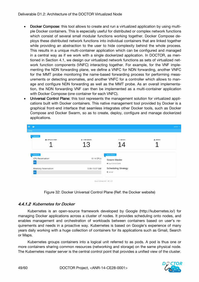
Deliverable D1.2: Architecture of the DOCTOR Virtualized Node
49/60 DOCTOR Project, <ANR-14-CE28-0001>
Docker Compose: this tool allows to create and run a virtualized application by using multi-
ple Docker containers. This is especially useful for distributed or complex network functions
which consist of several small modular functions working together. Docker Compose de-
ploys these distributed network functions into individual containers that are linked together
while providing an abstraction to the user to hide complexity behind the whole process.
This results in a unique multi-container application which can be configured and managed
in a central way as if we work with a single dockerized application. In DOCTOR, as men-
tioned in Section 4.1, we design our virtualized network functions as sets of virtualized net-
work function components (VNFC) interacting together. For example, for the VNF imple-
menting the NDN forwarding plane, we define a VNFC for NDN forwarding, another VNFC
for the MMT probe monitoring the name-based forwarding process for performing meas-
urements or detecting anomalies, and another VNFC for a controller which allows to man-
age and configure NDN forwarding as well as the MMT probe. As an overall implementa-
tion, the NDN forwarding VNF can then be implemented as a multi-container application
with Docker Compose (one container for each VNFC).
Universal Control Plane: this tool represents the management solution for virtualized appli-
cations built with Docker containers. This native management tool provided by Docker is a
graphical front-end interface that seamless integrates other Docker tools, such as Docker
Compose and Docker Swarm, so as to create, deploy, configure and manage dockerized
applications.
Figure 32: Docker Universal Control Plane (Ref: the Docker website)
Kubernetes for Docker 4.4.1.2
Kubernetes is an open-source framework developed by Google (http://kubernetes.io/) for
managing Docker applications across a cluster of nodes. It provides scheduling onto nodes, and
enables management and orchestration of workloads between containers based on user’s re-
quirements and needs in a proactive way. Kubernetes is based on Google’s experience of many
years daily working with a huge collection of containers for its applications such as Gmail, Search
or Maps.
Kubernetes groups containers into a logical unit referred to as pods. A pod is thus one or
more containers sharing common resources (networking and storage) on the same physical node.
The Kubernetes master server is the central control point that provides a unified view of the cluster.

Deliverable D1.2: Architecture of the DOCTOR Virtualized Node
50/60 DOCTOR Project, <ANR-14-CE28-0001>
A minion or Kubernetes node is a worker node that run tasks delegated by the master. Minions can
run one or more pods. There is a single master node that can control multiple minions. The follow-
ing figure shows an overview of the Kubernetes architecture.
Figure 33: Architecture of Kubernetes for managing Docker containers
In relation with DOCTOR, one or several Kubernetes PODs may be deployed for each imple-
mentation of our DOCTOR virtualized node in one physical server. The physical server is thus the
minion server, and a Kubernetes master can then be deployed to manage all the deployed minions
Deliverable D1.2: Architecture of the DOCTOR Virtualized Node
51/60 DOCTOR Project, <ANR-14-CE28-0001>
(i.e. virtualized nodes) at different sites such as Troyes and Nancy for our final testbed implementa-
tion.
The details and final architectural decision for the implementation of the DOCTOR Manage-
ment and Orchestration of VNFs, either DOCKER tools or Kubernetes, will be provided later in the
project. We actually need more fined evaluations of those tools when the implementations of our
VNFs are available later.
4.4.2 CyberCAPTOR and MMT Operator for Orchestration Management
Security functions must be deployable, manageable, and controllable especially in virtualized
environment. Thus the DOCTOR project leverage NFV ability to virtualize not only network but
also security functions (i.e.NFV for security). Meantime the DOCTOR security features are intended
to act on virtualized networks and functions. We also need concomitant smart provision-
ing/orchestration of these security features, both for the enforcement of the security policies and
the security monitoring. Managing security policies within a virtualized infrastructure is a difficult
challenge. First, the transient nature of the infrastructure state introduces risks of potential conflicts
between inconsistent provisioning of ICT (availability constraints mainly) versus Security related
requirements (Integrity, Confidentiality, data loss, etc.). Second, the multi-party architecture has
significant implications on dependencies, control and responsibilities perimeters that impact the
ability to deploy security in the right time at the right place. Last but not least, the software pre-
dominant technologies will come with its own set of constraints (performances, scalability, interop-
erability,…) that will dramatically impact implementation and fine localization of the policies en-
forcement. Thus, smart strategies, algorithms are needed to distribute policies along data paths
and resources used across the architecture.
CyberCAPTOR allows determining the most probable attack paths in an NDN infrastructure
deployed on a virtualized network and the remediations to prevent or detect them. These remedia-
tions can consist of deploying new Security Virtualized Network Functions that either block the
attack (NDN firewall, Intrusion Prevention System…) or detect its occurrence (Deep Packet Inspec-
tion MMT probe…). CyberCAPTOR also simulates the application of the remediation to give to the
operator an insight of the impact it may have on the currently deployed network configuration.
Then, if the operator validates this remediation, it pushes this remediation to the NFV Orchestrator,
via the MMT Operator.
In parallel, network incidents and attacks need to be dealt with in a timely manner, so as to
reduce their malicious impact on the network. Monitoring and smart detection approaches are en-
abled by usage of Software Defined & virtualization technologies. Smart monitoring should encom-
pass events related to flows (e.g. when some flow is detected as suspicious, the flow can be re-
routed to a specific place of the topology, safe and dedicated to flow analysis). It finally enables
definition of new type of remediation/counter measures, benefiting from the flexibility of the securi-
ty functions orchestration in order to mitigate security breaches and maintain correct and continu-
ous operations.
4.5 DOCTOR SDN Control Plane
This section focuses on the design of the SDN control plane for the DOCTOR virtualized net-
work infrastructure. Implemented and operated in the infrastructure management domain, the SDN
controller works with the MMT operator for managing the network monitoring functions, and the

Deliverable D1.2: Architecture of the DOCTOR Virtualized Node
52/60 DOCTOR Project, <ANR-14-CE28-0001>
CyberCAPTOR manager allows to assert network security based on events detected by the MMT
operator. The SDN controller can interact with the virtual network, for instance to deploy counter-
measures in reaction to detected anomalies. We also describe in Section 4.5.2 how we can design
the SDN controller to manage name-based forwarding semantics in virtualized NDN networking.
4.5.1 CyberCAPTOR and MMT Operator for SDN Controller Management
The second type of remediations and counter-measures that will be provided by CyberCAP-
TOR benefits from the flexibility for implementing mitigation strategies via Software Defined Net-
work, in order to reconfigure Virtual Network functions or the network infrastructure.
For design time, in order to decrease the risk of an attack path, this new type of remediation
will be compared with the deployment of new VNFs and the operator will choose in CyberCAPTOR
the best remediations among both types. If a reconfiguration remediation is selected by an opera-
tor, CyberCAPTOR will send the new configuration of the equipment to the SDN controller, via the
MMT Operator.
In a similar way, for the attacks that have been detected and are currently happening, coun-
ter-measures based on the reconfiguration of the network (add new detections rules to a MMT
probe or to an IPS, reroute some flows…) can be achieved dynamically through SDN.
4.5.2 Integration Strategies of ICN into SDN Control Domains
Moving from a lab-restricted implementation to a concrete deployment in current Internet
implies that ICN [34] Interest and Data packets are able to transit through an IP domain (e.g. an
autonomous system). In this context, these packets are to be processed correctly in order to: (1)
forward them to appropriate destinations, and (2) cache some ICN data if necessary. The pro-
grammable and extensible features of SDN [35][36] as well as its well-adoption makes this tech-
nology a key toward the deployment of ICN in IP domains. However, by looking more specifically
at the coupling strategies of these two technologies, it appears that operations within an SDN-
controlled IP network domain, in order to correctly process ICN packets, depend on how ICN ca-
pabilities are integrated in the latter. More information can be found in [37], where Syrivelis et al.
study coupling strategies of these two technologies. From our side, in the following, we also iden-
tified different strategies, currently proposed in the dedicated literature, and we classify them ac-
cording to the features they induce. On that basis, we motivate the Doctor position in conformance
with the NFV paradigm.
Integration Level 4.5.2.1
The first and main criterion to compare different integration strategies of ICN capabilities in a
SDN domain relies in the nature of the implemented topology. The topology refers to the location
where the ICN nodes are located in a managed domain, and it is driven by the service network
functional needs. More specifically, the different topologies proposed in the dedicated literature
may be seen as different steps in the necessary incremental ICN deployment.
The first step, standing for the weakest coupling between ICN and SDN, consists in deploy-
ing ICN over an IP domain where no ICN node is introduced. The functional related need stands for
the pure and seamless ICN traffic transit through an IP domain controlled by SDN. In [38], Markus
et al. propose the use of OF switches as intermediate nodes to forward packets between CCN

Deliverable D1.2: Architecture of the DOCTOR Virtualized Node
53/60 DOCTOR Project, <ANR-14-CE28-0001>
nodes. These OF Switches do not have any ICN forwarding or routing functionality. However, they
implement ICN modules in a SDN controller in order to calculate the path and establish the topolo-
gy between OF switches in an OpenFlow domain. ICN packets are recognized when entering the
SDN domain (with, for instance, a dedicated transport number), and the controller is requested to
calculate the path and push forwarding rules into concerned switches. This strategy is the simplest
in terms of implementation efforts because it only requires additional functionalities in the controller
and does not require any other change in switches, protocol or CCN nodes. In other words, the
main idea of this solution consists in using OF switches as pure-overlays, meaning that the switch-
es, in this solution, do not have any ICN forwarding or routing functionality. From an architectural
point of view, this approach gives a solution to partial integration of ICN in IP networks enabling
non-ICN clients to access ICN content.
To improve the ICN packet processing in a SDN domain, and as a second step of integration,
a network operator may deploy some ICN nodes spread at strategic locations, but not in every
nodes. The architecture presented in [39] instantiates such a strategy with a topology that relies on
the placement on ICN capabilities in the sole ingress and egress nodes of an OpenFlow domain.
The authors first present their vision of the SDN and ICN combination, without taking into account
limitations of current (November 2013) available equipment. They also present a large-scale exper-
imentation over the OFELIA testbed. ICN data packets (content or content requests) are transport-
ed over IP using the CONET protocol, which is seen as a new layer-4 protocol in the IP architec-
ture. To avoid ICN prefix processing at each node of the OpenFlow domain, the authors propose a
tagging strategy using tagging capabilities of OpenFlow switches (> v1.2). However, to be able to
conduct large-scale experiments, they modified their proposal in order meet with the OFELIA
testbed specifications [40]. OFELIA was, at that time, based on equipment (e.g. OpenFlow switch-
es) running version 1.0 of the OpenFlow protocol, which only supports TCP or UDP as layer-4 pro-
tocols, and not CONET. As a consequence, CONET experimentations over OFELIA, were conduct-
ed with an encapsulation in the transport layer where the tagging process was implemented in
ports fields of the UDP header. The difference with classical IP/UDP datagrams is achieved with
dedicated addresses in the IP header.
As a third step of deployment, a strategy consisting in considering a SDN domain as a mix of
ICN-capable and IP-capable nodes can be implemented. NDNFlow [41] illustrates such a strategy.
In this proposal, some local paths between ICN nodes separated by pure IP switches are over-
layed using local tunnels. These overlay connections are driven by a SDN controller which intro-
duces a specific communication channel for enabling exchanges between ICN-capable nodes and
a dedicated controller module taking part in it. Whatever the controlled protocol stack, the control
protocol used between all these entities is OpenFlow with the integration of ICN specific elements.
As such NDNFlow is a complete solution for a partial integration of ICN in an IP/SDN infrastructure
which preserves the use of current protocol but do not attempt to mix them for both uses.
Finally, the last strategy consists in considering a support of ICN functionalities in every
nodes of the SDN domain, thus inducing the strongest coupling between these technologies. As
an illustration of this strategy, In Nguyen et al. [42], the authors present a topology, which relies on
the sole implementation of ICN nodes in the OpenFlow domain, each one connected to an ordinary
OpenFlow switch performing forwarding based on usual IP suite rules. This solution enables the
creation of exclusive ICN islands using ordinary OpenFlow switches by providing them the ability
to forward ICN packets by pushing ICN forwarding engine (i.e. prefixes) in the IP header. This ena-
bles a full integration of ICN in an OpenFlow domain, without any modification in OpenFlow or
CCN protocols. However, the IP header is used in a dedicated and exclusive way where some
fields (addresses, and others) carry values issued from the hash of ICN prefixes. An important part

Deliverable D1.2: Architecture of the DOCTOR Virtualized Node
54/60 DOCTOR Project, <ANR-14-CE28-0001>
of the complexity of this strategy relies in the design the controller in charge of pushing the appro-
priate forwarding rules in the OpenFlow switches of the CCN nodes and, in [43], Nguyen et al. ex-
plain how they implement ICN modules in the controller to manage the routing and caching issues.
Functional Criteria 4.5.2.2
These different strategies of integration induce various design of the control plane, control
protocols and also transport strategies for ICN data packets to be processed. As such we leverage
them as comparison criteria we briefly explain here after.
As a first criterion, we consider the design of the control plane of the SDN domain, and its
potential adaption to consider the requirements of ICN nodes. In conformance with current state of
the art, it seems that most of the solutions proceed by adding a special design ICN module as an
extension of an existing SDN controller. This is what is done in [39], with the FloodLight SDN con-
troller, in [41] with POX, in [38] with TREMA and in [43] with Beacon.
The control protocol implementation is a second comparison criterion, and more diversity is
found concerning the design of the architecture of necessary control flows between the controller
(with its ICN module add-on) and the nodes (either ICN aware or pure IP). Solutions are various
compromise driven by on one hand the need to satisfy most of ICN functionalities (basically for-
warding, but also caching and eventually security), and on the other hand the need to keep the
solution compatible with existing SDN Openflow protocol versions. In [38], [43] and [44] , control
flows are limited to regular SDN OpenFlow traffic. In [41], an ICN module maintains control connec-
tions with ICN nodes, and at the same time, a SDN controller maintains control connections with
each of the IP nodes (OpenFlow switches). Finally, in [39], the control flows design is based on the
extension of the OpenFlow protocol to enable it to transport ICN control messages.
Finally, the data-plane design stands for the third criterion. Most of solutions are intended to
enable the SDN domain to process both ICN packets and IP ones. This criterion targets at first the
encapsulation strategy and a basic ICN encapsulation is mostly used (ICN over UDP over IP). In
[38], ICN data packets are basically encapsulated in UDP, assuming a known reserved port num-
ber to let the ingress SDN switch identifying ICN traffic. In [42], the ICN data flows are still encap-
sulated in IP, but in such a way that it is not possible to support at the same time both non-ICN
packets and ICN ones. In [44], Atsushi et al. propose a very similar solution by putting forward the
conservation of prefix hierarchy in the hash calculation operation. Finally, in [39], the authors pro-
pose a new transport protocol especially designed for ICN messages. Ad-hoc tunnels are also
used to create connectivity between ICN nodes through any kind of network [44], [41]. Finally, one
can remark that the data-plane design requires the special use of IP suite protocol fields like IP
addresses and transport protocols ports. These parameters are in several solutions used to carry
hashes of ICN prefixes.
The DOCTOR project may be analysed according to the above criteria.
The functional need is the total decoupling of a SDN operator infrastructure from the virtualized
ICN nodes in one tenant. The topology is thus an operator infrastructure providing resources to its
tenant with an SDN driven infrastructure. The tenant uses virtual components that are ICN nodes,
easily placed in the tenant infrastructure thanks to NFV capabilities of operator infrastructure.
Concerning control plane, in Doctor, two planes are to be considered: the infrastructure con-
trol plane that we aim to let pure standard SDN, and the tenant control plane for ICN. Doing this,
we avoid integration of ICN control in the SDN control plane, and fell free to design ICN control

Deliverable D1.2: Architecture of the DOCTOR Virtualized Node
55/60 DOCTOR Project, <ANR-14-CE28-0001>
plane as translation of SDN controller paradigm in the ICN world, without any compatibility con-
straint.
4.5.3 Controlling Virtual Networks
The virtual switch in the Doctor should be dynamically configurable by a controller. This con-
troller might be a SDN logically-centralized controller or a distributed controller. We might imagine
to have controllers such as Open Daylight [30], or ONOS [31]. These controllers are from the Open
Source community (Linux Foundation), are working well and more and more used. However, these
controllers are currently running with the OpenFlow protocol as the interface between the controller
and the controlled network entities, which might be limiting for our architecture, since we will de-
ploy the NDN protocol stack. Indeed NDN is not IP-based, whereas OpenFlow is currently defined
to work with IP addresses. One option could be to go into the source code of the OpenFlow soft-
ware and make the appropriate changes to make it usable for our own needs. But this possibility
might be not so easy.
An alternative is to use the Programming Protocol-Independent Packet Processor (P4) lan-
guage solution [32][33]. P4 is a language to express how network equipment (such as switches or
routers) can process packets. P4 is based on the simple match-action model. It is then very similar
to OpenFlow configuration actions, but declared with a specific language, which might be more
generic. We can then think to write our matching rules for the NDN protocol and the related ac-
tions. Figure 34, from [32], presents this model.
Figure 34: Using P4 for controlling a virtual switch

Deliverable D1.2: Architecture of the DOCTOR Virtualized Node
56/60 DOCTOR Project, <ANR-14-CE28-0001>
For being usable, the network equipment should understand the P4 language. Currently,
some are compatible, such as the PISA (Protocol-Independent Switch Architecture) chips, but
since in the DOCTOR project, we’ll have software NDN nodes, hosted on Linux machines, we
could use P4 for Linux systems as well.
This P4 solution looks promising, open and easy to do. However, there is a fundamental limi-
tation of P4 that prevents it to be used to easily parse NDN packets. In fact, according to the spec-
ification of the P4 language, it describes headers by a list of fields and their length, but it only al-
lows one variable length field per header while the NDN packet structure heavily relies on a Type-
Length-Value blocks. Before considering further to use P4 in the DOCTOR architecture, we will
have to investigate this problem in Task4 to realise if it can be quickly addressed or if it deserves
dedicated research that might not be in the direct scope of DOCTOR.

Deliverable D1.2: Architecture of the DOCTOR Virtualized Node
57/60 DOCTOR Project, <ANR-14-CE28-0001>
5 Conclusion
The present deliverable D1.2 details the DOCTOR virtualized network architecture that ena-
bles to deploy network services within well-defined network monitoring and security management.
The design proposal respects the reference NFV architecture as standardized by the ETSI group
(cf. Figure 3).
We first describe the DOCTOR virtualized node supporting the virtualized network functions
we target in the project (namely the IP and NDN protocol stacks, HTTP/NDN ingress and egress
gateways, monitoring probes and the NDN firewall). We then propose a control and management
plane for monitoring and securing the virtualized node. This control and management plane inte-
grates in the northbound face the DOCTOR Security Orchestration for provisioning, managing and
configuring the deployed VNFs. The DOCTOR Security Orchestrator actually consists of i) the MMT
Operator for coordinating the MMT monitoring probes integrated with each VNF; and ii) the Cyber-
CAPTOR manager which represents the reference element for network security detection. The
MMT Operator is able to configure VNFs based on information provided by CyberCAPTOR, and it
also works with a SDN controller implemented in the southbound face to provide automation when
configuring or controlling virtual networks, so as to secure the overall virtualized architecture.
It must be noted that this document establishes an initial set of design features and guide-
lines that will be rigorously updated during the project development as long as we implement the
functional blocks of the DOCTOR virtualized network infrastructure. The architectural process is
thus meant to be an iterative and incremental approach. Our first candidate architecture will be a
high-level design that we can test against use cases, requirements, known constraints or issues.
As we refine our candidate architecture by implementation, we could learn more details about the
design and could be able to further expand use case scenarios with new resulting requirements
and improve our approach to address emerging issues.

Deliverable D1.2: Architecture of the DOCTOR Virtualized Node
58/60 DOCTOR Project, <ANR-14-CE28-0001>
6 References
[1] Network Functions Virtualisation (NFV); Architectural Framework, ETSI GS NFV-INF 002
V1.2.1 (2014-12),
http://etsi.org/deliver/etsi_gs/NFV/001_099/002/01.02.01_60/gs_NFV002v010201p.pdf
[2] XORP http://www.xorp.org/
[3] The BIRD Internet Routing Daemon : http://bird.network.cz/
[4] Quagga : http://www.nongnu.org/quagga/
[5] Quagga in Docker : https://github.com/ewindisch/docker-quagga
[6] V. Jacobson, D. K. Smetters, J. D. Thornton, M. F. Plass, N. H. Briggs and R. L. Braynard,
“Networking named content”, in Proceedings of the 5th international conference on
Emerging networking experiments and technologies, p. 1–12, ACM CoNEXT 2009.
[7] G. Xylomenos, C. N. Ververidis, V. A. Siris, N. Fotiou, C. Tsilopoulos, X. Vasilakos, K. V.
Katsaros and G. C. Polyzos, “A survey of information-centric networking research”,
Communications Surveys & Tutorials, IEEE (Volume: 16 , Issue: 2 ). 2013.
[8] Goergen, T. Cholez, J. Francois and T. Engel, “A semantic firewall for Content Centric
Networking”, in Proceedings of 13th IFIP/IEEE International Symposium on Integrated
Network Management (IM2013). Ghent, Belgium: IEEE Communications Society, May
2013.
[9] Network Functions Virtualisation (NFV); Management and Orchestration, ETSI GS NFV-
MAN 001 V1.1.1 (2014-12), http://www.etsi.org/deliver/etsi_gs%5CNFV-
MAN%5C001_099%5C001%5C01.01.01_60%5Cgs_NFV-MAN001v010101p.pdf
[10] M. Yoshida, W. Shen, T. Kawabata, K. Minato and W. Imajuku, “MORSA: A multi-objective
resource scheduling algorithm for NFV infrastructure”, in Network Operations and
Management Symposium (APNOMS), 2014 16th Asia-Pacific, vol., no., pp.1-6, 17-19 Sept.
2014. doi: 10.1109/APNOMS.2014.6996545.
[11] F. Lucrezia, G. Marchetto, F. Risso and V. Vercellone, “Introducing Network-Aware Sched-
uling Capabilities in OpenStack”, in: First IEEE Conference on Network Softwarization
(Netsoft 2015), London, UK, April 2015.
[12] F. Callegati, W. Cerroni, C. Contoli, G. Santandrea, “Performance of multi-tenant virtual
networks in OpenStack-based cloud infrastructures”, in Globecom Workshops (GC
Wkshps), 2014 , vol., no., pp.81-85, 8-12 Dec. 2014. doi:
10.1109/GLOCOMW.2014.7063390
[13] F. Callegati, W. Cerroni, C. Contoli, G. Santandrea, “Implementing dynamic chaining of
Virtual Network Functions in OpenStack platform”, in Transparent Optical Networks
(ICTON), 2015 17th International Conference on , vol., no., pp.1-4, 5-9 July 2015
[14] Scharf, M.; Stein, M.; Voith, T.; Hilt, V., "Network-Aware Instance Scheduling in
OpenStack," in Computer Communication and Networks (ICCCN), 2015 24th International
Conference on , vol., no., pp.1-6, 3-6 Aug. 2015. doi: 10.1109/ICCCN.2015.7288436
[15] Xiongzi Ge, Yi Liu, David H.C. Du, Liang Zhang, Hongguang Guan, Jian Chen, Yuping
Zhao, and Xinyu Hu. 2014. OpenANFV: accelerating network function virtualization with a
consolidated framework in OpenStack. In Proceedings of the 2014 ACM conference on
SIGCOMM (SIGCOMM'14). ACM, New York, NY, USA, 353-354.
DOI=http://dx.doi.org/10.1145/2619239.2631426
[16] Soares, J.; Dias, M.; Carapinha, J.; Parreira, B.; Sargento, S., "Cloud4NFV: A platform for
Virtual Network Functions," in Cloud Networking (CloudNet), 2014 IEEE 3rd International
Conference on , vol., no., pp.288-293, 8-10 Oct. 2014. doi:

Deliverable D1.2: Architecture of the DOCTOR Virtualized Node
59/60 DOCTOR Project, <ANR-14-CE28-0001>
10.1109/CloudNet.2014.6969010CyberCAPTOR Github home page:
https://github.com/fiware-cybercaptor/
[17] CyberCAPTOR Github home page : https://github.com/fiware-cybercaptor/
[18] FIWARE Cyber Security Generic Enabler :
https://forge.fiware.org/plugins/mediawiki/wiki/fiware/index.php/FIWARE.ArchitectureDesc
ription.Security.CyberSecurity.
[19] Arsalan Tavakoli, Martin Casado, Teemu Koponen, and Scott Shenker. Applying NOX to
the Datacenter. Proc. of workshop on Hot Topics in Networks (HotNets-VIII), 2009.
[20] Advait Dixit, Fang Hao, Sarit Mukherjee, T.V. Lakshman, and Ramana Kompella. 2013. To-
wards an elastic distributed SDN controller. In Proceedings of the second ACM SIGCOMM
workshop on Hot topics in software defined networking (HotSDN '13). ACM, New York, NY,
USA, 7-12. DOI=http://dx.doi.org/10.1145/2491185.2491193
[21] Jie Hu; Chuang Lin; Xiangyang Li; Jiwei Huang, "Scalability of control planes for Software
defined networks: Modeling and evaluation," in Quality of Service (IWQoS), 2014 IEEE 22nd
International Symposium of , vol., no., pp.147-152, 26-27 May 2014
[22] Yeganeh, S.H.; Tootoonchian, A.; Ganjali, Y., "On scalability of software-defined network-
ing," in Communications Magazine, IEEE , vol.51, no.2, pp.136-141, February 2013 doi:
10.1109/MCOM.2013.6461198
[23] Teemu Koponen, Martin Casado, Natasha Gude, Jeremy Stribling, Leon Poutievski, Min
Zhu, Rajiv Ramanathan, Yuichiro Iwata, Hiroaki Inoue, Takayuki Hama, and Scott Shenker.
2010. Onix: a distributed control platform for large-scale production networks. In Proceed-
ings of the 9th USENIX conference on Operating systems design and implementation
(OSDI'10). USENIX Association, Berkeley, CA, USA, 1-6.
[24] Pankaj Berde, Matteo Gerola, Jonathan Hart, Yuta Higuchi, Masayoshi Kobayashi, Toshio
Koide, Bob Lantz, Brian O'Connor, Pavlin Radoslavov, William Snow, and Guru Parulkar.
2014. ONOS: towards an open, distributed SDN OS. In Proceedings of the third workshop
on Hot topics in software defined networking (HotSDN '14). ACM, New York, NY, USA, 1-6.
DOI=http://dx.doi.org/10.1145/2620728.2620744
[25] Tootoonchian, A., & Ganjali, Y. (2010, April). HyperFlow: A distributed control plane for
OpenFlow. In Proceedings of the 2010 internet network management conference on Re-
search on enterprise networking (pp. 3-3). USENIX Association.
[26] Soheil Hassas Yeganeh and Yashar Ganjali. 2012. Kandoo: a framework for efficient and
scalable offloading of control applications. In Proceedings of the first workshop on Hot
topics in software defined networks (HotSDN '12). ACM, New York, NY, USA, 19-24.
DOI=http://dx.doi.org/10.1145/2342441.2342446
[27] Phemius, K.; Bouet, M.; Leguay, J., "DISCO: Distributed multi-domain SDN controllers" in
Network Operations and Management Symposium (NOMS), 2014 IEEE , vol., no., pp.1-4,
5-9 May 2014. doi: 10.1109/NOMS.2014.6838330
[28] Salvestrini, F.; Carrozzo, G.; Ciulli, N., "Towards a Distributed SDN Control: Inter-Platform
Signaling among Flow Processing Platforms," in Future Networks and Services
(SDN4FNS), 2013 IEEE SDN for , vol., no., pp.1-7, 11-13 Nov. 2013.
[29] Pingping Lin; Jun Bi; Ze Chen; Yangyang Wang; Hongyu Hu; Anmin Xu, "WE-bridge: West-
east bridge for SDN inter-domain network peering," in Computer Communications Work-
shops (INFOCOM WKSHPS), 2014 IEEE Conference on , vol., no., pp.111-112, April 27
2014-May 2 2014
[30] The OpenDaylight Project, https://www.opendaylight.org/
[31] The ONOS (Open Network Operating System) Project : onosproject.org/

Deliverable D1.2: Architecture of the DOCTOR Virtualized Node
60/60 DOCTOR Project, <ANR-14-CE28-0001>
[32] Pat Bosshart, Dan Daly, Glen Gibb, Martin Izzard, Nick McKeown, Jennifer Rexford, Cole
Schlesinger, Dan Talayco, Amin Vahdat, George Varghese and David Walker. 2014. P4:
Programming Protocol-independent Packet Processors. SIGCOMM Comput. Commun.
Rev. 44, 3 (July 2014), 87-95.
[33] Pat Bosshart , Glen Gibb , Hun-Seok Kim , George Varghese , Nick McKeown , Martin Iz-
zard , Fernando Mujica and Mark Horowitz, “Forwarding metamorphosis: fast programma-
ble match-action processing in hardware for SDN”, in Proceedings of the ACM SIGCOMM
2013 conference on SIGCOMM, August 12-16, 2013, Hong Kong, China.
[34] Bengt Ahlgren, Christian Dannewitz, Claudio Imbrenda, Dirk Kutscher, and B•orje Ohlman.
A survey of information-centric networking. Communications Magazine, IEEE, 50(7):26-36,
2012.
[35] Nick McKeown, Tom Anderson, Hari Balakrishnan, Guru Parulkar, Larry Peterson, Jennifer
Rexford, Scott Shenker, and Jonathan Turner. Openflow: enabling innovation in campus
networks. ACM SIGCOMM Computer Communication Review, 38(2):69-74, 2008.
[36] Bruno Nunes, Manoel Mendonca, Xuan-Nam Nguyen, Katia Obraczka, Thierry Turletti, et
al. A survey of software-defined networking: Past, present, and future of programmable
networks. Communications Surveys & Tutorials, IEEE, 16(3):1617-1634, 2014.
[37] Dimitris Syrivelis, George Parisis, Dirk Trossen, Paris Flegkas, Vasilis Sourlas, Thanasis
Korakis, and Leandros Tassiulas. Pursuing a software defined information-centric network.
In Software Defined Networking (EWSDN), 2012 European Workshop on, pages 103-108.
IEEE, 2012
[38] Markus Vahlenkamp, Fabian Schneider, Dirk Kutscher, and Jan Seedorf. Enabling infor-
mation centric networking in ip networks using sdn. In Future Networks and Services
(SDN4FNS), pages 1-6, IEEE 2013.
[39] Stefano Salsano, Nicola Blefari-Melazzi, Andrea Detti, Giacomo Morabito, and Luca Veltri.
Information centric networking over sdn and openflow: Architectural aspects and experi-
ments on the ofelia testbed. Computer Networks, 57(16):3207-3221, 2013.
[40] OFELIA Project. http://www.fp7-ofelia.eu/.
[41] van Adrichem, N.L.M.; Kuipers, F.A., "NDNFlow: Software-defined Named Data Network-
ing," in Network Softwarization (NetSoft), 2015 1st IEEE Conference on , vol., no., pp.1-5,
13-17 April 2015
[42] Xuan Nam Nguyen, Damien Saucez, and Thierry Turletti. Providing ccn functionalities over
openflow switches. Research Report. 2013. Available at: https://hal.inria.fr/hal-00920554
[43] Xuan Nam Nguyen, Damien Saucez, and Thierry Turletti. Effcient caching in content-
centric networks using openflow. In IEEE INFOCOM 2013 Workshop, pages 1-2, 2013.
[44] Peyman TalebiFard, Ravishankar Ravindran, Asit Chakraborti, Jianli Pan, Anu Mercian,
Guoqiang Wang, Victor C.M. Leung. An Information Centric Networking Approach Towards
Contextualized Edge Service in IEEE 12th Consumer Communications and Networking
Conference (CCNC): CCNC 2015 - Industrial Program, 2015
[45] Atsushi Ooka, Shingo Ata, Tetsushi Koide, HIDEyuki Shimonishi, and Masayuki Murata.
Openflow-based content-centric networking architecture and router implementation. In Fu-
ture Network and Mobile Summit (FutureNetworkSummit), 2013, pages 1-10. IEEE, 2013.