
Doctor of Philosophy - IIT Guwahati
255
Intrusion Detection System for Attacks in Wi-Fi Networks: A Discrete Event System Approach Thesis submitted in partial fulfilment of the requirements for the award of the degree of Doctor of Philosophy in Computer Science and Engineering by Mayank Agarwal Under the supervision of Dr. Santosh Biswas Prof. Sukumar Nandi Department of Computer Science and Engineering Indian Institute of Technology Guwahati Guwahati - 781039, India NOVEMBER, 2016
-
Upload
khangminh22 -
Category
Documents
-
view
2 -
download
0
Transcript of Doctor of Philosophy - IIT Guwahati

Intrusion Detection System for Attacks in Wi-Fi Networks: A
Discrete Event System Approach
Thesis submitted in partial fulfilment of the requirementsfor the award of the degree of
Doctor of Philosophy
in
Computer Science and Engineering
by
Mayank Agarwal
Under the supervision of
Dr. Santosh BiswasProf. Sukumar Nandi
Department of Computer Science and Engineering
Indian Institute of Technology Guwahati
Guwahati - 781039, India
NOVEMBER, 2016

Copyright c© Mayank Agarwal 2016. All Rights Reserved.

Dedicated to
Parents, elder brother Nitin, cousin Anshul and friends !
Whose love, blessings, constant inspiration and love made my path
of success


People are often unreasonable, illogical, and self-centered.
Forgive them anyway.
If you are kind,
people may accuse you of selfish ulterior motives.
Be kind anyway.
If you are successful,
you will win some false friends and some true enemies.
Succeed anyway.
If you are honest and frank,
people may cheat you.
Be honest and frank anyway.
What you spend years building,
someone could destroy overnight.
Build anyway.
If you find serenity and happiness,
they may be jealous.
Be happy anyway.
The good you do today,
people will often forget tomorrow.
Do good anyway.
Give the world the best you have,
and it may never be enough.
Give the best you’ve got anyway.
You see, in the final analysis it is between you and God;
It was never between you and them anyway.
∼ Mother Teresa


Acknowledgements
This thesis is a result of combination of efforts of so many people who have helped me
directly or indirectly during my exciting journey of PhD.
First and foremost I would like to profusely thank my supervisors Dr. Santosh Biswas and
Prof. Sukumar Nandi. For Dr. Santosh Biswas I would like to say that I am so fortunate to
have him as my supervisor. He has given me a free hand and allowed me sufficient time
to think on my own. He never forced me or chained me with deadlines, albeit he always
made me aware of the clock ticking away! The biggest quality that I found in him is that he
allows a student to evolve as per their potential. The amount of patience and perseverance
he possess is simply amazing. It is said that “In pursuit of perfection you achieve excellence”.
During my journal revisions, at times I used to get bored due to the monotonous nature of
review, but he always had the energy, enthusiasm to read it another time and improve the
manuscript. He is just a call away whenever I felt like discussing my research with him.
Apart from technical discussion related to PhD, we had many candid discussions on various
topics which I would always cherish.
For Prof. Sukumar Nandi, I can say he is reservoir of knowledge and has ample of expe-
rience. During my PhD journey, many times I used to feel that I have reached a dead end
in pursuit of my goal. So many negative thoughts flashed my mind making me feel that
my entire effort and energy might prove to be futile. At that time, I have poured out my
anxiety and feelings to him. He has always provided me with a new direction and given a
ray of hope. Suddenly from all the negative thoughts, I used to come out with a new vigor
to explore the new directions suggested by him. Apart from this, he has helped me im-
prove my technical writing. His suggestions on the editing of manuscript, the flow between
paragraph, grammar etc., have been invaluable. He also provided me with various opportu-
nities to organize workshop and conferences during my PhD. His backing and support has
allowed me to grow as a person and acquire many skills that have shaped my personality.
I also thank him for allowing me to be a part of the Information Security Education and
Awareness (ISEA) program - an ambitious program by the government of India to promote
information security education and training across India. Thanks to the ISEA project, I got
the learn many things while at the same time helping me financially after my scholarship
period ended.

It is an extreme delight to have Prof. Diganta Goswami, Dr. Sanasam Ranbir Singh and
Dr. Partha Sarathi Mandal as the honourable members of my thesis doctoral committee. I
would like to express my earnest gratitude to all of them for their invaluable time in eval-
uating the work progress and fruitful advices towards improving the work quality. It is a
matter of great pride and honour to be a student of IIT Guwahati. I express my sincere
gratitude to all persons whose persistent efforts have ensured that this place remained con-
ducive for research and academic development. I owe my sincere thanks to Prof. Purandar
Bhaduri (former Head, Deptt. of CSE), Prof. Shivashankar B. Nair (former Head, Deptt. of
CSE), Prof. Diganta Goswami (Current Head, Deptt. of CSE), Prof. Gautam Barua (former
Director), and Prof. Gautam Biswas (present Director), all the Deans and administrative
staffs of the institute. I also express my sincere regards to all respected faculties and staffs
of the department of CSE for their extended help and support. I feel privileged to have
received the prestigious Tata Consultancy Services (TCS) research fellowship for pursuing
my doctoral research. I would like to acknowledge the support granted to me by TCS. It
ensured me that I could present my research work at both national and international plat-
forms and meet fellow researchers as well as experts in my field. I would like to thank Mr.
Rahul Pandey, the former program manager and Mr. Sachin Parkhi, the present program
manager for helping us with various queries from time to time and ensuring that all things
executed systematically and smoothly. I am grateful to Mr. Sunil Kumar Barua, Deputy
Registrar of Academic Affairs. He has skilfully handled all our queries related to TCS in
a friendly manner despite his heavy workload. Many thanks to Mr. Rijumoni Dutta from
academic affairs and Mr. Sunil Sarma, Ms. Kajal Lata from finance section for handling our
TCS related matters. Thank you TCS for your wonderful initiative for promoting research
in India.
The office staffs at the Department of CSE were always cordial and supportive. I would
like to thank Mr. Souvik, Mr. Prashanta, Mr. Monojit Bhattacharjee, Ms. Gauri and Mr. Pra-
bin Bharali for handling our office related matters with a smile. I would like to acknowledge
the support and assistance provided to us by the scientific officers Mr. Nanu Alan Kachari,
Mr. Bhriguraj Borah and Mr. Raktajit Pathak. They have always strived very hard to ensure
that we do not face any issues related to network, printer etc. At a personal level, I must
say that it is pleasure to have learnt many things from them.
A special thanks must go to all security guards, janitors, housekeeping staffs, mess staff,
canteen staffs, hostel caretaker, wardens, doctors, medical staff, and drivers for making
our life so easy in IITG. These people form the lifeline of our stay at IIT Guwahati and are
really the unsung heroes. When you stay at such extended periods in a residential campus,
your friends and colleagues becomes your family. You share your happiness, sorrows, grief,
festivals, moments to remember, birthdays with them! This acknowledgment would be

incomplete without mentioning their names.
Among friends, I would first like to thank my dear friend Vikas Kumar. Right from my ini-
tial days at IIT Guwahati he has always been there for me. In fact, our numerous discussions
in wireless security helped me choose the same topic for my doctoral research.
No amount of thanks and appreciation would be enough to acknowledge the support and
learning provided to me by Shirshendu Das and Vishal Deshpande. Shirshendu Das has
been like an elder brother, mentor, friend and a teacher. Shirshendu Das has been the most
versatile person I have met at IIT Guwahati. I must admit that during my initial phase
I used to fear coding long lines of code. His tips and guidance helped me overcome the
fear which later proved to be instrumental for me in my doctoral research. My interactions
with him have helped me evolve as a better person. Whenever I have sought advice from
him with regards to any matter, he has always been there to guide me. Amidst all my
joys, sorrows, turmoil, hardships and frustrations Vishal Deshpande has been like a shadow
throughout my PhD journey. I thank him for walking along with me in my journey. There
has been so much to learn from Vishal. His ability to remain patient and calm amidst
success, disappointments without getting flustered is noteworthy. Thank you Vishal for
your unwavering support and friendship. The company of Mahesh Patel made the journey
more rich and entertaining. Very few people can offer help as whole heartedly as Mahesh
does. I would always value the lovely moments Mahesh, Vishal and I shared on the mess
table. Thank You Mahesh.
I am thankful to Shashi Shekar Jha for the numerous discussion on the various topics
(both technical and non-technical) we had together. His insights and ideas about things
are quite worthy. For Nilkanta, let me thank him for generating interest in watching other
sports too :). The outings with Nilkanta, Shashi and Shirshendu Das will remain etched
into my memory for life! Thank you Shilpa for being such a good friend in my PhD journey.
The library sittings, long walks, lab hours spent out together, lengthy chats would always
be cherished in my memory. Thank you Basant for the proof reads I gave to you from time
to time and the wonderful moments over evening tea. Thank you Dipika for the innocence
filled conversations that made the mood lighter and brighter!
Smrati has always been very caring and helpful despite her heavy workload. At troubled
times, she is just a call away. For Jayshree, I would say that one can learn from her that how
can we balance our passion and PhD together. Her amazing talent in art, music and dance
added thrill to our PhD journey. I would also like to thank my friend Isha Vishan for the
various candid conversations and satires together. Thank you Smrati, Jayshree and Isha.
During my doctoral research I got to interact a lot students few of which deserve an ac-
knowledgment. First, a big thankyou to Mohit Kumar for preparing this wonderful LATEX

template for thesis writing! Thankyou Hema for the wonderful moments at tea, your sug-
gestion, thoughts and honest opinions regarding various matters. Never change ! I would
like to acknowledge Dilip Pasumarthi, Sanketh Purwar, Argha Sen and Prabal Ghosh for
their research inputs and the technical discussions we had together. Thanks to each one of
you. It was a nice feeling to be associated with Sambhav Kothari and Nitish Garg, whom
I had mentored to create few in-house projects at IITGuwahati. There is no surreal feeling
than contributing to your institution! Thank you Sambhav Kothari and Nitish Garg.
I am thankful to Gurudutt Rao and Nilesh Jha with whom I always had endless discussion
on academic related activities right from my BTech days. Thank you guys. My school friends
Niraj, Prashant, Srijoy and Souvik always cheered me up during my difficult times of my
PhD. Although we met infrequently, having group interactions with them always had a
lasting memory. Thank you Mahendra Mehra and Ashish Mangal for retaining the same
energy in our friendship though we were separated by distance. Thank you both of you
for always being there. Amrita Banerjee deserves a special mention in my thesis for her
constant support and companionship throughout my PhD despite being miles away. Thanks
Amrita. Thank you Anasree Chatterjee for your kind friendship and the small pep-talks we
used to share. Thank you Subarna Chatterjee for the wonderful moments at the TaCTiCS
conference. It’s very rare to have met people at conferences with such great energy and
enthusiasm. I am indebted to one of the most talented guy I met at IIT Guwahati - Ashish
Namdeo for his support during the course of my PhD. I am particularly thankful to Ankur
Jain and Ankan Shrivastava who were my wall mates during my stay at the hostel for the
fun filled moments we spent together.
I am grateful to all the teachers that have taught me right from my school days till my
college life. Only because of their toil and efforts I could reach this place. This acknowl-
edgment would be incomplete without mentioning the names of two ladies - Mrs. Sandhya
Sundarkar and Mrs. Shibani Ray. Both of them have loved me like their own son right
from my school days and they continue to do so. I feel so honoured to have lived under the
umbrella of their love and blessings. Thank you Mrs. Chaitali Biswas Dutta for the delicious
homemade food you served me on various occasions. I am grateful to Mr. Dipul who used
to iron my clothes. While traveling to conferences, I used to give my clothes at the eleventh
hour and he ensured that they are ironed perfectly on time. Thank you to the guys at Bani
Mandir, Core 3, IIT Guwahati, for always being so helpful with regards to our printing and
photocopy needs.
I wish to acknowledge Dr. Arnab Sarkar for the off topics discussions we had. It is
rare for a faculty to be so open to the thoughts of students. I wish to thank Dr. Vijaya
Saradhi for helping me take interest in Linux Scripting which eventually proved very useful

in simplifying my tasks. I would like to acknowledge Dr. T. Venkatesh for suggesting me
CRAWDAD – ‘A Community Resource for Archiving Wireless Data’ which eventually helped
me learn to analyze network traces. Thank you Dr. Kalpesh Kapoor for reaching out to me
in my initial days. Your tips, discussions on things, life, PhD have always been handy. The
first Diwali that was away from home made me feel homesick. Dr. Hemangee Kapoor called
us to her house for Diwali celebrations. It was a very sweet gesture on her part. Thank you
Madam for those wonderful memories.
Among other notable mentions include Debanjan, Sibaji, Mamata Di, Mr. Shrinivasa
Naika, Mrs. Amrita Bose Paul, Mrs. Maushumi Barooah, Jaideep, Achyut Mani Tripathi,
Deepak, Saptarshi, Piyoosh, Sandip Chakraborty, Sukarn, Rakesh Pandey, Nayantara, Sujata
Kulkarni, Swarup, Shuvendu Rana, Nidhi and Sangita Roy whom I need to acknowledge
for being a part of this wonderful journey of doctoral research. And thank you to all the
wonderful people who have helped me in my pursuit whom I did not mention here. I
sincerely acknowledge your efforts too! I would like to acknowledge those anonymous
users, bloggers, forum moderators whose answers to various queries have helped me when
I got stuck. A big thanks also goes out to Google, Wikipedia and online cloud storage
providers like Dropbox, Copy.com, MEGA which ensured that our data remained safe and
secure. I express my gratitude to my AMD and Acer Vertion Desktop, HP laptops and who
have stood by me in all my experiments. I must acknowledge my cell phone and bicycle.
Both of them have been used so roughly and yet they have always remained my faithful
partners. Many thanks to my hostel room A-117, Barak Hostel, which has been my second
home for last 6 years.
Without having an adequate support from your family members, traveling the doctoral
journey could only remain a dream. I would like to thank my uncle, Mr. Rajendra Agrawal
who motivated me to opt for doctoral research. If he had not motivated me, I would have
certainly missed the exciting journey one goes through in a doctoral research. I would
also like to acknowledge my uncle, Mr. Ajay Agarwal, who has always been a source of
inspiration right from my early days of PhD. Whenever I used to feel low and disheartened
with regards to my PhD research, he has always re-kindled a ray of optimism inside me. My
elder brother Nitin Agarwal has always been caring and supportive. His guidance on various
matters with regards to career, both personal and professionalism has helped me immensely.
A special thanks goes to my cousin Anshul Agarwal. I have admired his presence in my life.
He has also been a source of motivation to me in my doctoral research and always given me
hope. His work ethics are a source of inspiration to me. I am grateful to my sister-in-law
Ms. Priya for the warm welcome and care she has taken whenever we have met. Thank you
Priya! The laughter and cuteness of my little niece Aarohi has always bought smiles on my
face :). Thanks Aarohi. I would also like to thank Mrs. Arti Agarwal, my aunt for her love

and affection! Many thanks to my aunt Mrs. Vandana Agrawal for her care too!
The highest amount of acknowledgment goes out to my parents. I was always a difficult
child to handle right from my childhood. Their sacrifices ensured that no obstacles could
hinder the pace of my journey. Thank you Mother (Mrs. Ramlata Agarwal) and Father (Mr.
Naresh Kumar Agarwal) for being so very kind, supportive, caring and for all your love.
This thesis is a culmination of your blessings! Last, but not the least I would like to thank
Almighty for his grace.
May 3, 2017 Mayank Agarwal

Declaration
I certify that
• The work contained in this thesis is original and has been done by myself and under
the general supervision of my supervisor(s).
• The work reported herein has not been submitted to any other Institute for any degree
or diploma.
• Whenever I have used materials (concepts, ideas, text, expressions, data, graphs,
diagrams, theoretical analysis, results, etc.) from other sources, I have given due
credit by citing them in the text of the thesis and giving their details in the references.
Elaborate sentences used verbatim from published work have been clearly identified
and quoted.
• I also affirm that no part of this thesis can be considered plagiarism to the best of
my knowledge and understanding and take complete responsibility if any complaint
arises.
• I am fully aware that my thesis supervisor(s) are not in a position to check for any
possible instance of plagiarism within this submitted work.
May 3, 2017 Mayank Agarwal


Department of Computer Science and EngineeringIndian Institute of Technology GuwahatiGuwahati - 781039, India
Dr. Santosh BiswasAssociate ProfessorEmail : [email protected] : +91-361-258-2364
Prof. Sukumar NandiProfessor
Email : [email protected] : +91-361-258-2357
Certificate
This is to certify that this thesis entitled “Intrusion Detection System for Attacks in Wi-Fi
Networks: A Discrete Event System Approach" submitted by Mayank Agarwal, in partial
fulfilment of the requirements for the award of the degree of Doctor of Philosophy, to the
Indian Institute of Technology Guwahati, Assam, India, is a record of the bonafide research
work carried out by him under my guidance and supervision at the Department of Com-
puter Science and Engineering, Indian Institute of Technology Guwahati, Assam, India. To
the best of my knowledge, no part of the work reported in this thesis has been presented
for the award of any degree at any other institution.
Date: May 3, 2017
Place: IIT Guwahati
Dr. Santosh Biswas Prof. Sukumar Nandi


Publications Related to Thesis
Journals
1. Agarwal, M., Biswas, S. and Nandi, S. “Advanced Stealth Man in The Middle Attack
in WPA2 Encrypted Wi-Fi Networks”, IEEE Communications Letters, Vol. 19, No. 4,
Pages: 581–584, April 2015.
2. Agarwal, M., Biswas, S. and Nandi, S. “Intrusion Detection System for PS-Poll DoS
Attack in 802.11 Networks using Real Time DES”, IEEE/CAA Journal of Automatica
Sinica, 2015. (Accepted)
3. Agarwal, M., Biswas, S. and Nandi, S. “DES Framework for Fault Diagnosis with
Measurement Inconsistency: IDS for DHCP Attack ”, IEEE/CAA Journal of Automatica
Sinica, 2016. (Accepted)
Communicated
• Agarwal, M., D., Biswas, S. and Nandi, S. “Intrusion Detection System for Evil Twin
Attack in Wi-Fi networks using Discrete Event System Framework”, WPC Springer,
March 2016, (Under Review).
Conferences
1. Agarwal, M., Biswas, S. and Nandi, S. “Detection of De-authentication DoS attacks
in Wi-Fi Networks: A Machine Learning Approach”, “Detection of De-authentication
DoS attacks in Wi-Fi Networks: A Machine Learning Approach”, IEEE SMC 2015
Conference, Pages: 246–251, October 2015, Hong Kong.
2. Agarwal, M., Biswas, S. and Nandi, S. “I2-diagnosability framework for detection of
Advanced Stealth Man in the Middle attack in Wi-Fi networks ”, 23rd Mediterranean
Conference on Control and Automation, Pages: 349–356, June 2015, Spain.
3. Agarwal, M., Biswas, S. and Nandi, S. “Detection of De-authentication Denial of Ser-
vice attack in 802.11 networks” In: Annual IEEE India Conference (INDICON), Pages:
1–6, December 2013. Mumbai, India.

Other Publications
1. Barbhuiya, F., Agarwal, M., Purwar, S., Biswas, S. and Nandi, S. “Application of
stochastic discrete event system framework for detection of induced low rate TCP
attack”, ISA Transactions, Elsevier, Vol. 58, Pages: 474–492, September 2015.
2. Agarwal, M., Pasumarthi, D., Biswas, S. and Nandi, S. “Machine learning approach for
detection of flooding DoS attacks in 802.11 networks and attacker localization”, Inter-
national Journal of Machine Learning and Cybernetics, Springer, Pages: 1–17, Novem-
ber 2014.
3. A. Bhandari, M., Agarwal, M., Biswas, S. and Nandi, S. “Intrusion Detection System
for Identification of Throughput Degradation Attack on TCP”, “Intrusion Detection
System for Identification of Throughput Degradation Attack on TCP”, NCC, Pages:
1–6, March 2016.

Abstract
Wireless Fidelity (Wi-Fi) has brought about a paradigm shift in the area of communica-
tion. Recent advances in Wi-Fi technology have made it possible to achieve gigabit speeds
on wireless medium making them a cost effective solution as compared to wired deploy-
ment. However, all these benefits comes at the price of security. As wireless communication
is inherently broadcast, any user within the wireless range of the communicating devices
can eavesdrop on the traffic exchange between the Wi-Fi clients without their knowledge.
In addition, a poorly configured Wi-Fi network is vulnerable to misuse and various types of
network attacks. In order to detect these attacks, the network administrator usually deploys
Intrusion Detection System (IDS), which is primarily a hardware device and (or) software
program that monitors the Wi-Fi network or host activities for malicious behavior. Among
the two widely used IDS design techniques, signature based IDS checks for fixed patterns
to identify attacks whereas anomaly based IDS uses statistical features to detect attacks.
Although signature and anomaly based IDSs detect most classes of attacks, there exists a
class of attacks in Wi-Fi network like evil twin attack, Stealth Man-in-the-Middle (SMiTM)
attack, power save Denial of Service (DoS) attack, rogue Dynamic Host Control Protocol
(DHCP) attack etc., that do not differ in semantics or statistics under normal and attack
circumstances. As a result, signature and anomaly based IDSs are unable to detect such
attacks. The objective of this thesis is to design and develop wireless IDSs for such class of
attacks which are not detectable by signature and anomaly based IDSs.
In the first contribution of this thesis, we propose an IDS for detecting evil twin attack
in Wi-Fi network. In evil twin attack, an attacker mimics a genuine Access Point (AP) by
spoofing its Service Set IDentifier (SSID) and MAC address. If a client connects to evil twin
AP, an attacker can re-direct it to phishing websites, steal sensitive information, capture
client’s credentials etc. In the second contribution of this thesis, we propose a novel insider
attack termed as ‘Advanced Stealth Man-in-the-Middle (ASMiTM)’ attack which enables an
attacker to launch a Man-in-the-Middle attack in WPA2 encrypted Wi-Fi network. We also
propose an IDS for detecting the proposed ASMiTM attack. In the third contribution of this
thesis, we propose an IDS for detecting Power Save DoS (PS-DoS) attack in Wi-Fi network.
In PS-DoS attack, an attacker spoofs as a genuine client and fetches the buffered frames
at the AP while the client is in power save state thereby causing frame losses to the client.
In the final contribution of this thesis, we propose an IDS for detecting rogue DHCP server
xix

attack in Wi-Fi network. In rogue DHCP server attack, an attacker sets up a rogue DHCP
server and sends fictitious IP address, DNS and gateway address (or a combination of these)
to the client requesting DHCP services. By supplying false information, an attacker can re-
direct client’s traffic via its terminal thereby sniffing client’s information, re-directing clients
to phishing websites, install malware into the client’s machine etc.
The hallmark of each of the IDSs proposed for the above attacks is that they do not
require any sort of protocol modifications, encryptions, certificate management etc., and
can be readily deployed on both legacy as well as modern network. In addition, all of the
proposed IDSs are developed using the Failure Detection and Diagnosis (FDD) theory of
Discrete Event System (DES). Developing of the proposed IDSs using the DES framework
helps to prove the correctness and completeness of the IDS which ensures that the attacker
does not escape detection under any circumstances. A DES is characterized by a discrete
state space and event driven dynamics. For FDD, DES models are designed for the system
(network) under normal and failure (attack) conditions. Following that, a state estimator
called diagnoser (or detector, if only detection of failure is required) is designed which
observes sequence of events generated by the system to decide whether the states through
which the system traverses correspond to normal or faulty DES model. In the proposed
DES based IDSs, attacks are mapped to failures and the diagnoser is implemented as the
IDS engine.
For each of the DES framework used in IDS for detection of the attack, we first show
how the same DES framework can be used for fault detection in a benchmark process of
two/three tank system. This illustrates how the DES theory mainly developed for fault
detection of large systems like chemical, mechanical etc., is also applicable for intrusion
detection in wireless network. Furthermore, all attacks discussed earlier have been imple-
mented on practical testbed and the results are shown in terms of accuracy and detection
rate of the IDS. In summary, this thesis provides an insight into design of IDS for various
MAC layer attacks in 802.11 Wi-Fi network that cannot be detected using standard signa-
ture or anomaly based IDSs.
xx

Contents
Abstract xix
List of Figures xxvii
List of Tables xxxi
List of Algorithms xxxiii
List of Symbols xxxv
List of Abbreviations xxxvii
1 Introduction 1
1.1 Motivation and Contribution . . . . . . . . . . . . . . . . . . . . . . . . . . . 5
1.1.1 802.11 Terminologies . . . . . . . . . . . . . . . . . . . . . . . . . . 6
1.1.2 Failure Detection and Diagnosis (FDD) of Discrete Event System (DES)
and IDS . . . . . . . . . . . . . . . . . . . . . . . . . . . . . . . . . . 7
1.1.3 Evil Twin Attack . . . . . . . . . . . . . . . . . . . . . . . . . . . . . 8
1.1.4 Advanced Stealth Man-in-the-Middle (ASMiTM) Attack . . . . . . . . 10
1.1.5 Power Save Denial of Service (PS-DoS) Attack . . . . . . . . . . . . . 14
1.1.6 Rogue Dynamic Host Control Protocol (DHCP) Attack . . . . . . . . 16
1.2 Organization of the Thesis . . . . . . . . . . . . . . . . . . . . . . . . . . . . 19
2 IDS for Evil Twin Attack in Wi-Fi networks using DES Framework 21
2.1 Introduction . . . . . . . . . . . . . . . . . . . . . . . . . . . . . . . . . . . . 21
2.2 Background and Motivation . . . . . . . . . . . . . . . . . . . . . . . . . . . 25
xxi

2.2.1 Vulnerabilities of Management and Control Frames in 802.11 Wi-Fi
networks . . . . . . . . . . . . . . . . . . . . . . . . . . . . . . . . . 25
2.2.2 Evil Twin Attack . . . . . . . . . . . . . . . . . . . . . . . . . . . . . 26
2.2.3 Existing Approaches to Detect or Prevent Evil Twin Attack . . . . . . 28
2.3 Proposed Scheme for the Detection of Evil Twin Attack . . . . . . . . . . . . 32
2.3.1 Working Principle of the IDS for Detecting Evil Twin Attack . . . . . 33
2.3.2 IDS Components . . . . . . . . . . . . . . . . . . . . . . . . . . . . . 35
2.3.3 Attacker and IDS Assumptions . . . . . . . . . . . . . . . . . . . . . . 36
2.4 FDD Theory of DES: Three Tank System . . . . . . . . . . . . . . . . . . . . 37
2.4.1 DES Modeling: Measurement Limitations and Failure Diagnosis . . . 38
2.4.2 Application of Failure Detection and Diagnosis Theory of DES on
Three Tank System . . . . . . . . . . . . . . . . . . . . . . . . . . . . 40
2.4.3 Diagnosability . . . . . . . . . . . . . . . . . . . . . . . . . . . . . . 46
2.4.4 DES Diagnoser Construction and Fault Detection in Three Tank System 47
2.5 DES Model of Evil Twin Attack . . . . . . . . . . . . . . . . . . . . . . . . . 51
2.5.1 An Example of Evil Twin Attack Detection Using DES Diagnoser . . . 58
2.6 Results and Discussions . . . . . . . . . . . . . . . . . . . . . . . . . . . . . 58
2.6.1 Network Setup for Evil Twin . . . . . . . . . . . . . . . . . . . . . . . 58
2.6.2 Detection Rate and Accuracy of the Proposed DES Based IDS . . . . 59
2.6.3 Correctness of the DES Diagnoser . . . . . . . . . . . . . . . . . . . . 60
2.6.4 Discussion . . . . . . . . . . . . . . . . . . . . . . . . . . . . . . . . . 61
2.7 Conclusion . . . . . . . . . . . . . . . . . . . . . . . . . . . . . . . . . . . . 62
3 IDS for ASMiTM Attack in Wi-Fi Networks using I2-DES 65
3.1 Introduction . . . . . . . . . . . . . . . . . . . . . . . . . . . . . . . . . . . . 65
3.2 Background and Proposed ASMiTM Attack . . . . . . . . . . . . . . . . . . . 68
3.2.1 ARP Spoofing Attack . . . . . . . . . . . . . . . . . . . . . . . . . . . 68
3.2.2 Hole 196 . . . . . . . . . . . . . . . . . . . . . . . . . . . . . . . . . 70
3.2.3 Stealth Man in the Middle (SMiTM) Attack . . . . . . . . . . . . . . 70
3.2.4 Wireless Denial of Service (WDoS) Attack . . . . . . . . . . . . . . . 72
xxii

3.2.5 Proposed ASMiTM Attack . . . . . . . . . . . . . . . . . . . . . . . . 73
3.2.6 Existing Approaches to Detect or Prevent ASMiTM attack . . . . . . 75
3.3 Proposed Scheme for the Detection of ASMiTM Attack . . . . . . . . . . . . 76
3.3.1 ARP Probe as Indicator Event and Importance of Updation of PAC-
NUM value . . . . . . . . . . . . . . . . . . . . . . . . . . . . . . . . 78
3.3.2 IDS Components . . . . . . . . . . . . . . . . . . . . . . . . . . . . . 79
3.3.3 Attacker and IDS Assumptions . . . . . . . . . . . . . . . . . . . . . . 80
3.4 FDD Theory of I2-DES: Two Tank System . . . . . . . . . . . . . . . . . . . . 80
3.4.1 Need for I2-DES Framework . . . . . . . . . . . . . . . . . . . . . . . 81
3.4.2 I2-DES Model: Measurement Limitations and Failure Diagnosis . . . 82
3.4.3 Application of Failure Detection and Diagnosis Theory of I2-DES on
Two Tank System . . . . . . . . . . . . . . . . . . . . . . . . . . . . . 84
3.4.4 Diagnosability . . . . . . . . . . . . . . . . . . . . . . . . . . . . . . 90
3.4.5 I2-Diagnoser Construction and Failure Diagnosis in I-Diagnosability vs
I2-Diagnosability Framework for the Two Tank System . . . . . . . . 92
3.5 I2-DES Model for ASMiTM attack . . . . . . . . . . . . . . . . . . . . . . . . 96
3.5.1 An Example of ASMiTM attack Detection Using I2-DES Diagnoser . . 100
3.6 Results and Discussion . . . . . . . . . . . . . . . . . . . . . . . . . . . . . . 101
3.6.1 Network Setup for Evil Twin . . . . . . . . . . . . . . . . . . . . . . . 101
3.6.2 Detection Rate and Accuracy of the Proposed I2-DES Based IDS . . . 103
3.6.3 Correctness of the I2-DES Diagnoser . . . . . . . . . . . . . . . . . . 104
3.6.4 Discussion . . . . . . . . . . . . . . . . . . . . . . . . . . . . . . . . . 105
3.7 Conclusion . . . . . . . . . . . . . . . . . . . . . . . . . . . . . . . . . . . . 105
4 IDS for PS-Poll DoS Attack in Wi-Fi Networks using RTDES Framework 107
4.1 Introduction . . . . . . . . . . . . . . . . . . . . . . . . . . . . . . . . . . . . 107
4.2 Background and Motivation . . . . . . . . . . . . . . . . . . . . . . . . . . . 110
4.2.1 Power Save Feature of 802.11 Standard . . . . . . . . . . . . . . . . 110
4.2.2 Vulnerabilities in Power Save Feature of 802.11 Standard . . . . . . 111
4.2.3 Existing Approaches to Detect or Prevent PS-DoS Attack . . . . . . . 112
4.3 Proposed Scheme for the Detection of PS-DoS Attack . . . . . . . . . . . . . 114
xxiii

4.3.1 Working Principle of the IDS for Detecting PS-DoS Attack . . . . . . 115
4.3.2 IDS Components . . . . . . . . . . . . . . . . . . . . . . . . . . . . . 116
4.3.3 Attacker and IDS Assumptions . . . . . . . . . . . . . . . . . . . . . . 118
4.4 FDD Theory of RTDES: Three Tank System . . . . . . . . . . . . . . . . . . . 120
4.4.1 RTDES Modeling: Measurement Limitations and Failure Diagnosis . 121
4.4.2 Application of Failure Detection and Diagnosis Theory of RTDES on
Three Tank System . . . . . . . . . . . . . . . . . . . . . . . . . . . . 123
4.4.3 Diagnosability . . . . . . . . . . . . . . . . . . . . . . . . . . . . . . 129
4.4.4 RTDES Diagnoser Construction Fault Detection in Three Tank System 130
4.5 RTDES Model for PS-DoS Attack . . . . . . . . . . . . . . . . . . . . . . . . 134
4.5.1 An Example of PS-DoS Attack Detection Using RTDES Diagnoser . . 139
4.6 Results and Discussions . . . . . . . . . . . . . . . . . . . . . . . . . . . . . 141
4.6.1 Network Setup for PS-DoS . . . . . . . . . . . . . . . . . . . . . . . . 141
4.6.2 Detection Rate and Accuracy of the Proposed RTDES Based IDS . . . 141
4.6.3 Network Load because of Power Save Probes . . . . . . . . . . . . . 143
4.6.4 Correctness of the RTDES Diagnoser . . . . . . . . . . . . . . . . . . 144
4.6.5 Discussion . . . . . . . . . . . . . . . . . . . . . . . . . . . . . . . . . 147
4.7 Conclusion . . . . . . . . . . . . . . . . . . . . . . . . . . . . . . . . . . . . 147
5 IDS for Rogue DHCP Server Attack in Wi-Fi Networks using MIDES Framework149
5.1 Introduction . . . . . . . . . . . . . . . . . . . . . . . . . . . . . . . . . . . . 149
5.2 Background and Motivation . . . . . . . . . . . . . . . . . . . . . . . . . . . 153
5.2.1 Basic Operation of DHCP . . . . . . . . . . . . . . . . . . . . . . . . 153
5.2.2 Vulnerabilities in DHCP Message Exchange . . . . . . . . . . . . . . 155
5.2.3 Existing Approaches to Detect or Prevent Rogue DHCP Server Attack 156
5.3 Proposed Scheme for the Detection of Rogue DHCP Server Attack . . . . . . 157
5.3.1 Working Principle of the IDS for Detecting Rogue DHCP Server Attack 158
5.3.2 IDS Components . . . . . . . . . . . . . . . . . . . . . . . . . . . . . 159
5.3.3 Attacker and IDS Assumptions . . . . . . . . . . . . . . . . . . . . . . 160
5.4 FDD Theory of MIDES: Two Tank System . . . . . . . . . . . . . . . . . . . . 161
xxiv

5.4.1 Need for MIDES Framework . . . . . . . . . . . . . . . . . . . . . . . 162
5.4.2 MIDES Model: Measurement Limitations and Failure Diagnosis . . . 164
5.4.3 MIDES Model: Measurement Inconsistency . . . . . . . . . . . . . . 165
5.4.4 Application of Failure Detection and Diagnosis Theory of MIDES on
Two Tank System . . . . . . . . . . . . . . . . . . . . . . . . . . . . . 166
5.4.5 Diagnosability . . . . . . . . . . . . . . . . . . . . . . . . . . . . . . 172
5.4.6 MIDES Diagnoser Construction and Inconsistency Handling in MLDES
vs MIDES Framework for the Two Tank System . . . . . . . . . . . . 173
5.5 MIDES Model for Rogue DHCP Server Attack . . . . . . . . . . . . . . . . . 182
5.5.1 An Example of Rogue DHCP Server Attack Detection Using MIDES
Diagnoser . . . . . . . . . . . . . . . . . . . . . . . . . . . . . . . . . 187
5.6 Results and Discussions . . . . . . . . . . . . . . . . . . . . . . . . . . . . . 188
5.6.1 Network Setup for Rogue DHCP Server Attack . . . . . . . . . . . . . 188
5.6.2 Detection Rate and Accuracy of the Proposed MIDES Based IDS . . . 189
5.6.3 Network Load because of DHCP Probes . . . . . . . . . . . . . . . . . 190
5.6.4 Correctness of the MIDES Diagnoser . . . . . . . . . . . . . . . . . . 191
5.6.5 Discussion . . . . . . . . . . . . . . . . . . . . . . . . . . . . . . . . . 192
5.7 Conclusion . . . . . . . . . . . . . . . . . . . . . . . . . . . . . . . . . . . . 192
6 Conclusions and Future Work 195
6.1 Summary of Contribution of the Thesis . . . . . . . . . . . . . . . . . . . . . 196
6.2 Scope of Future Work . . . . . . . . . . . . . . . . . . . . . . . . . . . . . . 198
xxv


List of Figures
1.1 Basic components of 802.11 Wi-Fi network . . . . . . . . . . . . . . . . . . . 6
1.2 Four-way handshake between a client and access point. . . . . . . . . . . . . 8
2.1 Normal and evil twin setup . . . . . . . . . . . . . . . . . . . . . . . . . . . 23
2.2 Four-way handshake between a client and access point . . . . . . . . . . . . 25
2.3 Evil twin setup . . . . . . . . . . . . . . . . . . . . . . . . . . . . . . . . . . 26
2.4 Timeline for launching evil twin attack . . . . . . . . . . . . . . . . . . . . . 26
2.5 Association response frame format . . . . . . . . . . . . . . . . . . . . . . . 27
2.6 Flowchart of detection of evil twin attack . . . . . . . . . . . . . . . . . . . . 33
2.7 Timeline of detection of evil twin attack . . . . . . . . . . . . . . . . . . . . 34
2.8 Components of the proposed IDS for detection of evil twin attack . . . . . . 35
2.9 The three tank system . . . . . . . . . . . . . . . . . . . . . . . . . . . . . . 40
2.10 DES of the three tank system shown in Fig. 2.9 . . . . . . . . . . . . . . . . 43
2.11 Diagnoser obtained for the DES model of the three tank system shown in Fig.
2.10 . . . . . . . . . . . . . . . . . . . . . . . . . . . . . . . . . . . . . . . . 50
2.12 Normal and attack DES model for evil twin attack . . . . . . . . . . . . . . . 51
2.13 Diagnoser for evil twin attack . . . . . . . . . . . . . . . . . . . . . . . . . . 57
2.14 Experimental setup for evil twin attack . . . . . . . . . . . . . . . . . . . . . 59
2.15 Size of database growth of the IDS . . . . . . . . . . . . . . . . . . . . . . . 60
2.16 Memory usage of the IDS . . . . . . . . . . . . . . . . . . . . . . . . . . . . 60
2.17 CPU utilization of the proposed IDS . . . . . . . . . . . . . . . . . . . . . . 61
3.1 ARP cache mappings under normal and spoofing conditions . . . . . . . . . 69
3.2 SMiTM Attack . . . . . . . . . . . . . . . . . . . . . . . . . . . . . . . . . . . 71
xxvii

3.3 Cipher-block chaining Message authentication code Protocol (CCMP) encap-
sulation . . . . . . . . . . . . . . . . . . . . . . . . . . . . . . . . . . . . . . 71
3.4 WDoS Attack . . . . . . . . . . . . . . . . . . . . . . . . . . . . . . . . . . . 72
3.5 ASMiTM attack . . . . . . . . . . . . . . . . . . . . . . . . . . . . . . . . . . 73
3.6 Experimental setup for ASMiTM attack . . . . . . . . . . . . . . . . . . . . . 77
3.7 Components of the proposed IDS for detection of ASMiTM attack . . . . . . 79
3.8 The two tank system . . . . . . . . . . . . . . . . . . . . . . . . . . . . . . . 84
3.9 DES of the Two Tank System Shown in Fig. 3.8 . . . . . . . . . . . . . . . . 86
3.10 I2-DES Diagnoser of the Two Tank System Shown in Fig. 3.8 . . . . . . . . . 95
3.11 Normal and Attack I2-DES Model of ASMiTM Attack . . . . . . . . . . . . . 97
3.12 Diagnoser for ASMiTM Attack . . . . . . . . . . . . . . . . . . . . . . . . . . 99
3.13 FromDS frame . . . . . . . . . . . . . . . . . . . . . . . . . . . . . . . . . . 102
3.14 A ToDS Frame. Converting a ToDS frame to FromDS requires the cyclic shifts
as shown . . . . . . . . . . . . . . . . . . . . . . . . . . . . . . . . . . . . . 102
4.1 Frame format of null data frame . . . . . . . . . . . . . . . . . . . . . . . . 110
4.2 Timeline for launching PS-DoS attack . . . . . . . . . . . . . . . . . . . . . . 111
4.3 Timeline for detecting the PS-DoS attack . . . . . . . . . . . . . . . . . . . . 116
4.4 Components of the proposed IDS for detection of PS-DoS attack . . . . . . . 117
4.5 The three tank system . . . . . . . . . . . . . . . . . . . . . . . . . . . . . . 124
4.6 RTDES of the three tank system shown in Fig. 4.5 . . . . . . . . . . . . . . . 126
4.7 Diagnoser obtained from Fig. 4.6 . . . . . . . . . . . . . . . . . . . . . . . . 134
4.8 DES model for PS-DoS attack . . . . . . . . . . . . . . . . . . . . . . . . . . 135
4.9 Diagnoser for PS-DoS attack. . . . . . . . . . . . . . . . . . . . . . . . . . . 139
4.10 Experimental setup . . . . . . . . . . . . . . . . . . . . . . . . . . . . . . . . 141
4.11 Network traffic with and without use of IDS . . . . . . . . . . . . . . . . . . 143
4.12 Six possible cases of arrival of null data frames . . . . . . . . . . . . . . . . 145
5.1 Four way DHCP handshake . . . . . . . . . . . . . . . . . . . . . . . . . . . 153
5.2 Rogue DHCP setup . . . . . . . . . . . . . . . . . . . . . . . . . . . . . . . . 154
5.3 Timeline of the rogue DHCP server attack . . . . . . . . . . . . . . . . . . . 154
xxviii

5.4 Timeline of the rogue DHCP server attack detection methodology. . . . . . 159
5.5 Components of the proposed IDS for detection of rogue DHCP server attack 159
5.6 The two tank system . . . . . . . . . . . . . . . . . . . . . . . . . . . . . . . 167
5.7 MIDES of the Two Tank System Shown in Fig. 5.6 . . . . . . . . . . . . . . . 169
5.8 Case 1: MLDES diagnoser assuming no measurement inconsistent transition
is observed . . . . . . . . . . . . . . . . . . . . . . . . . . . . . . . . . . . . 177
5.9 Case 2: MLDES diagnoser considering measurement inconsistent transition
as unmeasurable. . . . . . . . . . . . . . . . . . . . . . . . . . . . . . . . . 178
5.10 Case 3: MIDES diagnoser considering measurement inconsistent transition
as measurable and tries to predict the possible O-node(s). . . . . . . . . . . 179
5.11 Normal and attack model in rogue DHCP server attack . . . . . . . . . . . . 183
5.12 Diagnoser for rogue DHCP server attack . . . . . . . . . . . . . . . . . . . . 186
5.13 Experimental setup for rogue DHCP server attack . . . . . . . . . . . . . . . 188
5.14 Network load with and without IDS . . . . . . . . . . . . . . . . . . . . . . . 190
xxix


List of Tables
2.1 Types of rogue access point . . . . . . . . . . . . . . . . . . . . . . . . . . . 22
2.2 Differentiating parameters of the second association response . . . . . . . . 34
2.3 Sensor map for three tank system . . . . . . . . . . . . . . . . . . . . . . . . 41
2.4 Transitions along with their representation. Events, sensor conditions, con-
troller commands of the DES model of the three tank system shown in Fig.
2.10 . . . . . . . . . . . . . . . . . . . . . . . . . . . . . . . . . . . . . . . . 44
2.5 Model variables and their domains . . . . . . . . . . . . . . . . . . . . . . . 51
2.6 Transition table for DES model shown in Fig. 2.12 . . . . . . . . . . . . . . . 53
2.7 Detection rate statistics using the proposed IDS . . . . . . . . . . . . . . . . 59
2.8 All possible attack cases for proving the correctness of the DES diagnoser . . 62
2.9 Comparison of existing mitigation solutions for Evil Twin attack . . . . . . . 62
3.1 ASMiTM Detection Table . . . . . . . . . . . . . . . . . . . . . . . . . . . . . 78
3.2 Sensor map for two tank system . . . . . . . . . . . . . . . . . . . . . . . . . 85
3.3 Transitions along with their representation. Events, Sensor Conditions, Con-
troller Commands of the I2-DES model of the two Tank System shown in Fig.
3.9 . . . . . . . . . . . . . . . . . . . . . . . . . . . . . . . . . . . . . . . . 87
3.4 Duration (in mins) of SMiTM vs ASMiTM attack. . . . . . . . . . . . . . . . 102
3.5 Comparison of SMiTM, WDoS and ASMiTM Attacks . . . . . . . . . . . . . . 103
3.6 ASMiTM Attack Detection and Accuracy Statistics . . . . . . . . . . . . . . . 104
4.1 Sensor map for three tank system . . . . . . . . . . . . . . . . . . . . . . . . 125
4.2 Transitions along with their representation. Events, sensor conditions, con-
troller commands of the RTDES model of the three tank system shown in Fig.
4.6 . . . . . . . . . . . . . . . . . . . . . . . . . . . . . . . . . . . . . . . . 127
4.3 Transition table for Fig. 4.8 . . . . . . . . . . . . . . . . . . . . . . . . . . . 138
xxxi

4.4 Parameters values for beacon interval and listen intervals . . . . . . . . . . . 140
4.5 PS-DoS attack detection and accuracy statistics . . . . . . . . . . . . . . . . 142
4.6 Comparison of existing mitigation solutions for PS-DoS attack . . . . . . . . 147
5.1 Sensor map for two tank system . . . . . . . . . . . . . . . . . . . . . . . . . 168
5.2 Transitions along with their representation. Events, sensor conditions, con-
troller commands of the MIDES model of the two tank system shown in Fig.
5.7 . . . . . . . . . . . . . . . . . . . . . . . . . . . . . . . . . . . . . . . . 170
5.3 Notations used in DES modeling for rogue DHCP server . . . . . . . . . . . 183
5.4 Transition table for DES Model shown in Fig. 5.11. Assumption: 2 Genuine
DHCP Servers and 1 Rogue DHCP Server . . . . . . . . . . . . . . . . . . . . 184
5.5 Detection rate statistics with and without the use of measurement inconsis-
tent based IDS . . . . . . . . . . . . . . . . . . . . . . . . . . . . . . . . . . 189
5.6 Comparison of existing mitigation solutions for Rogue DHCP Server attack . 192
xxxii

List of Algorithms
1 Algorithm for construction of diagnoser O for an DES model G . . . . . . . . 48
2 Algorithm for construction of diagnoser O for an I2-DES model G . . . . . . . 93
3 Algorithm for construction of diagnoser O for an RTDES model G . . . . . . . 131
4 Algorithm for construction of diagnoser O for an MIDES model G . . . . . . . 174
5 Estimator diagnoser for the MIDES framework . . . . . . . . . . . . . . . . . 180
xxxiii


List of Symbols
Symbols Description
G MIDES model
Σ Set of events of the MIDES model G
V Set of model variables of the MIDES model G,
= Set of transitions of the MIDES model G,
τ A transition τ ∈ =
X Finite set of states of the MIDES model G
X0 Initial state of the MIDES model G
σ Event on which the transition τ is enabled
check(V ) Condition(s) on a subset of the model variables for τ .
assign(V ) Assignment(s) on a subset of the model variables for τ .
L(G) Set of all traces generated by G
XN Set of all normal states of the MIDES model G.
XFi Set of all faulty states of the MIDES model G.
Fi ith failure
σFi Event related to causing failure Fi
O Diagnoser of the MIDES model G
Z Set of diagnoser nodes called O-nodes
Z0 Initial state of the diagnoser
A Set of diagnoser transitions called O-transitions
τub Measurement Inconsistent G-transition
zub Measurement inconsistent O-node.
xxxv


List of Abbreviations
Terms Abbreviations
AAA Authentication Authorization and Accounting
ACK Acknowledgment
AID Association ID
AP Access Point
ARP Address Resolution Protocol
ARR Analytical Redundancy
BI Beacon Interval
BSS Basic Service Set
BSSID Basic Service Set Identifier
CA Certification Authority
CPU Central Processing Unit
CTS Clear to Send
CVE Common Vulnerability Exposure
DB Database
DEAUTH Deauthentication
DES Discrete Event System
DHCP Dynamic Host Configuration Protocol
DIFS Distributed Inter Frame Spacing
DNS Domain Name System
DoS Denial of Service
DST Destination
FCS Frame Check Sequence
xxxvii

FDD Failure Detection and Diagnosis
FN False Negative
FP False Positive
FSM Finite State Automata
GTK Group Temporal Key
HIDS Host Intrusion Detection System
HTTP Hypertext Transfer Protocol
HVAC Heating Ventilation Air-Conditioning
IAT Inter Arrival Time
IBSS Independent Basic Service Set
ICMP Internet Control Message Protocol
ID IDentifier
IDS Intrusion Detection System
IEEE Institute of Electrical and Electronics Engineers
IP Internet Protocol
LAN Local Area Network
LI Listen Interval
MAC Media Access Control
MD5 Message Digest 5
MIDES Measurement Inconsistent Discrete Event System
MITM Man-in-the-Middle
MLDES Measurement Limitation Discrete Event System
NIC Network Interface Controller
NIDS Network Intrusion Detection System
OS Operating System
PACNUM Packet Number
PCA Principal Component Approach
PHY Physical
PMK Pairwise Master Key
xxxviii

PTK Pairwise Transient Key
RAP Rogue Access Point
RFC Request for Comment
RSSI Received Signal Strength Indicator
RST Reset
RTDES Real Time Discrete Event System
RTS Request to Send
RTT Round Trip Time
SIFS Short Inter Frame Spacing
SRC Source
SSID Service Set Identifier
SVM Support Vector Machine
TCP Transmission Control Protocol
TIM Traffic Indication Message
TP True Positive
TSF Timing Synchronization Function
USB Universal Serial Bus
VPN Virtual Private Network
WEP Wired Equivalent Privacy
Wi-Fi Wireless Fidelity
WLAN Wireless Local Area Network
WPA Wi-Fi Protected Access
WPA2 Wi-Fi Protected Access II
WPA-PSK Wi-Fi Protected Access-Pre-Shared Key
xxxix


“If you spend more on coffee than on IT security, you will be
hacked. What’s more, you deserve to be hacked.”
Richard Clarke
White House Cybersecurity Advisor
1Introduction
Wi-Fi has bought about a paradigm shift in the way people communicate. Rapid deploy-
ment of Wi-Fi networks across colleges, libraries, offices, malls, airports, food courts etc.,
has made it possible for people to stay connected while on the move. Portable devices such
as laptops, cellphones, Personal Digital Assistants (PDAs), tablets, phablets etc., have Wi-Fi
chip-set pre-built into them. Furthermore, the price of wireless networking equipment have
dropped significantly over the years. Wireless Network Interface Cards (NICs) are nearing
the price of their wired counterparts.
Wireless Local Area Network (WLAN) technology has progressed at a rapid pace. The
initial Institute of Electrical and Electronic Engineers (IEEE) 802.11 standard which was
released in the year 1997 supported data rates up to 2 Mbps. In subsequent years, devices
capable of supporting data rates upto 54 Mbps became a commonplace. Furthermore,
with the release of 802.11n standard, that utilizes Multiple Input Multiple Output (MIMO)
technology, data rates up to 300 Mbps is possible. The latest 802.11ac standard breaks
the gigabit barrier for Wi-Fi networks and supports data rates upto 1300 Mbps! There are
many reasons why organizations are fast moving towards deploying wireless LANs over
wired LANs. Few of those reasons are listed below:
• Increased productivity because of increased mobility.
• Lower infrastructure cost compared to wired networks.
• Rapid deployment and expansion schedules.
• Aesthetically unobtrusive.
• Provides support to a large number of Wi-Fi compatible devices.
1

1. Introduction
Unfortunately, wireless networking is a double-edged sword. The initial developers of
Wi-Fi technology primarily focused on the ease of access with little regards to the security
aspect. Although, wireless users are presented with lot of opportunities in terms of flexi-
bility and ease of usage, there is no denying the fact that these users are subject to greater
security risks as compared to their wired counterparts. Throughout the entire process, the
integrity and confidentiality of the information traveling through the air has always been a
matter of concern as communication over a wireless medium is always susceptible to eaves-
dropping. In contrast, wired networks are difficult (not impossible) to eavesdrop as the
wired infrastructure are relatively secured. With wireless networking, there is no physical
security. An attacker just needs to be in the vicinity of the target network in order to sniff
the network’s traffic. Such promiscuous eavesdropping of the network traffic by an attacker
can never be prevented in wireless network because of its broadcast nature.
An attacker armed with a Wi-Fi device and a penetration Operating Systems (OSs) like
BackTrack (now Kali Linux) [1], BackBox Linux [2] can easily launch a myriad of attacks
on a Wi-Fi network. These penetrating OSs come pre-installed with various packet crafting
and hacking tools like aircrack-ng suite [3], scapy [4], Airpwn [5], AirJack [6], WifiCop-
per [7] etc., which ease the process of launching various attacks even for novice attackers.
Given the rapid deployment of Wi-Fi networks, it is imperative that adequate security ar-
rangements are put in place to ensure protection of these networks against various security
threats. The increased number of networked machines has led to a rise in unauthorized
activity [8], not only from external attackers, but also from internal sources such as dis-
gruntled employees and people abusing their privileges for personal gain [9]. Moreover,
because of lack of proper authentication of the communicating parties, inherent protocol
weakness, bugs in Wi-Fi router software, drivers etc., Wi-Fi networks are prone to various
attacks like Man-in-the-Middle (MiTM), unauthorized access, spoofing, Denial of Service
(DoS), privacy threats [10, 11, 12, 13] etc. This mandates the requirement for a suitable
intrusion detection system for detecting various attacks in a Wi-Fi network.
Network administrators deploy a number of security measures like access control list,
anti-malware, anti-spyware, anti-virus, biometric authentication, disabling insecure services
and ports, encryption, firewalls, honeypots, honeynets, Intrusion Prevention System (IPS),
Intrusion Detection System (IDS), proxy servers, smart cards, Virtual Private Network (VPN)
etc., in order to protect the network assets and resources. Three primary goals of network
security are:
• Confidentiality: It ensures that the precious business data is available only to the
intended and the authorized persons. Individuals who are not authorized to use the
data are not permitted to use the same.
2

• Integrity: It ensures that the data is accurate and consistent. The function of integrity
is to make sure that the data is accurate and is in its original form and has not been
altered in any form by noise, hackers etc.
• Availability: It ensures that the data, resources or services are available to the genuine
users, whenever they require it.
Intrusion is any set of actions that attempt to compromise the confidentiality, integrity
or availability of a network or host resource [14]. An Intrusion Detection System (IDS)
monitors the network or host activities in real-time and alerts for potential vulnerabilities
and attacks. IDS is a vital security component of an organization these days. IDS helps
to detect an attack before it inflicts widespread damage. IDS has received a considerable
attention in recent years. Depending on their deployment and characteristic features, IDSs
can be classified into 6 major categories:
1. Passive IDS: A passive IDS works by monitoring and analyzing the network traffic and
raising an alert to the administrator if potential vulnerabilities or attacks are observed.
A passive IDS cannot take any action on its own. Although these IDSs are easier to
deploy, it may generate too many alerts for the administrator if they are improperly
configured. As an example, if the attack traffic and genuine traffic is not defined
properly, an administrator may receive too many false alerts.
2. Active IDS: Unlike passive IDS, an active IDS can be configured to take necessary
action without the intervention of an administrator. An active IDS provides real time
network protection against potential security breaches. However, when an active IDS
is configured improperly, it results in denial of access to genuine users or services.
3. Network Based IDS (NIDS): A NIDS is deployed to monitor the network activities of
an organization. It is generally placed along the network boundary. A NIDS typically
consists of a NIC operating in promiscuous mode which monitors all the network
traffic traveling through it.
4. Host Based IDS (HIDS): A host-based IDS is deployed on individual hosts that needs
to be monitored. Unlike NIDS, the HIDS monitors the activities of only the host
system on which it is installed. The HIDS monitors the operating system and network
activities of the host on which it is installed and triggers an alarm whenever any
suspicious activities are observed.
5. Signature Based IDS or Knowledge Based IDS: A signature-based IDS refers to a
database of known intrusion patterns typically known as signatures for detecting in-
trusions. It monitors the host or network activities by correlating the traffic generated
3

1. Introduction
using the attack signatures and raising an alarm whenever there is a match. The ad-
vantages of signature-based IDS is the fast and accurate detection of known attacks,
low false alarm rate etc. On the other hand, the major drawback of a signature-based
IDS is that it needs a regular update of its attack signatures for detecting new attacks.
If an attack signature is not present in its database, a signature-based IDS ignores the
threat. Therefore, these IDS perform poorly when it comes to detecting zero-day at-
tacks and latest threats whose signatures are not present in the database. Snort [15]
and EMERALD [16] are some of the prominently used signature-based IDSs.
A simple example of a Snort signature for “land” attack is as follows.
alert ip any any − > any any (msg : “BAD TRAFFIC sameSRC/DST ′′;
sameip; reference : cve, CV E − 1999− 0016;
reference : url, www.cert.org/advisories/CA− 1997− 28.html;
classtype : bad− unknown; sid : 527; rev : 3; )
This signature raises an alarm whenever an Internet Protocol (IP) packet having same
source and destination address is observed.
6. Anomaly Based IDS: Unlike signature-based IDSs, anomaly-based IDSs have the ca-
pability to detect both known and unknown attacks. An anomaly-based IDS builds
a normal profile of a host or network based on statistical evaluation. The normal
profile is built by observing statistics like CPU usage, memory utilization, disk ac-
tivity, processor usage, network bandwidth usage, number of users logged in, count
of failed logins, amount of mails sent and received etc. Anomaly-based IDS marks
any deviation from the normal activity as suspicious and raises an alarm. Although
anomaly-based IDS can detect new attacks, it suffers from high false alarm rate, i.e.,
it marks normal activities as suspicious. For example, suppose that an anomaly based
system reports 3 failed login attempts as an intrusion attempt. Therefore, if a genuine
user, forgets his password and enters a wrong password 3 times, the activity is marked
as suspicious by the anomaly-based IDS. A review of various anomaly-based IDSs can
be found in [17, 18].
A signature or anomaly-based IDS can be deployed as a host-based or network-based
IDS. Rest of this thesis mainly deals with wireless NIDS and henceforth unless explicitly
mentioned, the term IDS refers to wireless NIDS.
4

1.1. Motivation and Contribution
1.1 Motivation and Contribution
In signature-based IDSs, a set of known attack patterns or signatures are stored in a database
and the system or network activity is compared with these signatures. If a match is found,
an alert is raised signaling the detection of malicious activity. Although signature-based
IDSs can detect known attacks accurately, they require constant signature updates in order
to make them effective to detect new attacks. Many signature detectors are designed to use
tightly defined signatures that prevents them from detecting variants of common attacks.
Anomaly-based IDS makes use of statistical features of traffic and behavior in order to detect
malicious activities. As anomaly-based IDS uses statistical inferences it is capable to detect
new attacks as well. However, they usually produce a large number of false alarms because
of the unpredictable and dynamic behavior of users, systems and networks. Further, they
require extensive “training sets” of system or network event records in order to characterize
normal and attack behavior, which is a difficult task. If such tasks of characterizing the nor-
mal and attack behavior are assigned to security experts, it may lead to conflicting opinions
as different security experts consider different factors for marking a host or network activity
as normal or attack. Therefore, designing an anomaly based IDS is always a challenging
task.
There are certain class of attacks which cannot be effectively detected by signature or
anomaly-based IDSs as the semantics of the network remain the same during normal and
attack conditions. Some of them are:
1. Evil Twin attack.
2. Advanced Stealth Man-in-the-Middle (ASMiTM) attack.
3. Power Save Denial of Service (PS-DoS) attack.
4. Rogue Dynamic Host Control Protocol (DHCP) attack.
These attacks are detailed next. Each of these attacks have the following two properties
which makes them subtle:
1. They can be launched by injecting very few frames in the network, typically one or two
while leaving all other statistical properties of network traffic intact. So, no anomaly
is noticed in the network when such attack occurs.
2. The sequence of frame exchange under normal and attack scenarios is same. So,
developing a signature or anomaly pattern is quite difficult and may result in high
false alarm rate.
5

1. Introduction
AttackerM
Client C1
Client C2
Client C3
Wired Backbone
APG
“Wi-Fi Hotspot”
Basic Service Set
(BSS)
IDS
Figure 1.1: Basic components of 802.11 Wi-Fi network
1.1.1 802.11 Terminologies
In this subsection, we look at the basic terminologies and components of a 802.11 Wi-Fi
network. These are explained using Fig. 1.1. The symbols shown in Fig. 1.1 are used
throughout the thesis for consistency and readability purposes e.g., Clients C1, C2, C3,
attacker M and Access Point G etc.
1. Basic Service Set (BSS): The core unit of an 802.11 network is called a Basic Service
Set (BSS). A BSS consists of a central Access Point (AP) and a set of client(s). In Fig.
1.1 the circle consisting of AP and the clients C1, C2 and C3 together constitute a BSS.
2. Access Point (AP): The AP coordinates all the activities within the BSS. All the clients
within a BSS communicate via the AP. The AP acts as a central arbiter. If the client C1
wants to communicate with client C2, C1 first sends message to the AP which in turn
forwards the message to client C2. Due to this centralized control, BSS networks are
also known as infrastructure networks. We denote the AP using the symbol G (G →Genuine).
3. Clients: The clients are Wi-Fi devices that connect to the AP in order to access the
services provided by the AP. In Fig. 1.1, the clients C1, C2 and C3 are associated with
the AP G.
4. Service-Set IDentifier (SSID): A BSS is identified by a Service-Set IDentifier (SSID).
This can generally be thought of as the name of the wireless network. In Fig. 1.1, the
SSID of the network is ‘WiFi-Hotspot’.
5. Authentication: Authentication is the process by which a client establishes its identity
6

1.1. Motivation and Contribution
with the AP.
6. Association: Association is the process by which a client officially joins an 802.11
network and becomes eligible to access the services provided by the AP. Only after a
successful authentication a client is allowed to associate.
7. De-authentication: De-authentication is the process by which a client terminates its
connection with the AP.
8. Attacker: The attacker is an intruder who has the capability to launch various attacks
such as Man-in-the-Middle (MiTM), Denial of Service (DoS), unauthorized access,
spoofing attacks etc. We denote the attacker using the symbol M (M → Malicious).
The attacker M may or may not be associated with the AP.
1.1.2 Failure Detection and Diagnosis (FDD) of Discrete Event System (DES)
and IDS
The theory of Failure Detection and Diagnosis (FDD) of Discrete Event System (DES) has
been mainly applied for large systems like chemical reaction chambers, HVAC (Heating,
Ventilating, and Air Conditioning) plants, hybrid systems [19, 20, 21, 22, 23, 24, 25, 26, 27]
etc. An overview of FDD using DES is discussed in [28, 29]. DES based FDD have various
frameworks depending on the system under consideration. For example, in distributed sys-
tems Petri Net-based frameworks are preferred [30, 31, 32, 33], while in a system involving
stochastic process, a stochastic DES based framework is recommended [34, 35]. In cases
where the underlying system involves incomplete or partial observation, frameworks based
on partial observation and learning needs to be used [36]. For faults related to timing of
events, a Real Time DES (RTDES) [37, 38, 39, 40] based framework proves to be beneficial.
The central idea of DES modeling is to develop the normal and failure model correspond-
ing to normal and failure scenarios. Subsequently, a diagnoser which is a state estimator is
built using the states traversed in the normal and fault models. The diagnoser determines
whether the system is operating under faulty, non-faulty or un-certain conditions.
DES based IDSs have been found to be effective in detecting security attacks in wired
networks [41, 42]. To the best of our knowledge, we have shown for the first time that
this framework can also be applied to detect attacks in Wi-Fi networks. The motivation
behind using DES based IDS is the similarity between the attacks occurring in networks
and faults1 in DES. Under normal condition (when no attacker is present), the sequence
of frame exchange can be captured as the normal DES model of the network. An attack
1In this thesis, the terms attack, fault and failure are used interchangeably.
7

1. Introduction
leads to deviation from the normal network activity. This deviation is captured as a faulty
(attack) DES model. Using the information of the normal model, faulty (attack) model and
the observable frames, the diagnoser is constructed that serves as an IDS engine. Diagnosers
have the capability to capture the difference between the normal and the fault models aiding
in attack (fault) detection thereby having the capability of behaving as an IDS.
Throughout this thesis, we have adapted different DES paradigms for developing IDS for
detection of MAC layer attacks in Wi-Fi networks. Irrespective of the paradigm used, the
core DES philosophy remains the same. DES based IDS basically comprises 3 simple steps:
1) Design the normal DES model using the system behavior under normal network condi-
tion. 2) Design the faulty DES model using the system behavior under attack condition.
3) Design a diagnoser which basically serves as an IDS engine using the normal model
and faulty model. The diagnoser is basically a state estimator that determines whether the
system is moving as per the normal or faulty model using the observed system values (i.e.,
network features, characteristics, sequence of frame exchange etc.). An added advantage of
using a DES based IDS is that it is formally verifiable, which ascertains whether all possible
attack cases are detected, thereby making the detection scheme robust.
We now look into the evil twin attack, ASMiTM attack, PS-DoS attack and rogue DHCP
attacks briefly. We also describe briefly the literature survey for the prevention/detection of
these attacks and the issues associated with them. We also show how DES based IDS can
prove to be an effective mechanism for detecting such attacks without any need for protocol
modification, encryption or installation of proprietary hardware.
1.1.3 Evil Twin Attack
Client
802.11 Access Point
Authentication Request
Authentication Response
Association Request
Association Response
Data Exchange
State 1
State 2
State 2
State 3
State 3
Handshake (1/4)
Handshake (2/4)
Handshake (3/4)
Handshake (4/4)
Figure 1.2: Four-way handshake between a client and access point.
When a client connects to a Wi-Fi network it first needs to establish a connection with
the wireless Access Point (AP). This connection is established using a four way handshake
8

1.1. Motivation and Contribution
that occurs between client and AP as shown in Fig. 1.2. Once this handshake is successful,
the client can access services offered by the AP. The AP acts a central arbiter between the
client and the outside world. Once the client is connected to the AP all its communication
is managed by the AP. An attacker can easily create a Rogue AP (RAP) in order to lure
the client(s) into connecting them. A RAP is a software based AP that can provide all the
services of the genuine AP. Usually, an attacker sets up such RAP at public places like malls,
libraries, coffee shops etc. If a client connects to a RAP setup by an attacker, the attacker
can gain complete control over client’s activity.
Evil twin is a special form of RAP wherein an attacker spoofs the Media Access Control
(MAC) address and the Service-Set IDentifier (SSID) i.e., the network name of the genuine
AP2. When a client sees the list of available Wi-Fi APs, it sees only one AP instead of two
APs as the evil twin AP spoofs both the MAC address and the SSID of the genuine AP.
Modern operating systems choose the AP with a higher signal strength in-case of multiple
APs configured with the same name. In presence of an evil twin AP, if the signal strength of
the evil twin AP exceeds the signal strength of the genuine AP, the client(s) get associated
with the evil twin AP. The attacker setting up the evil twin AP must provide a working
Internet connection to the clients connecting into it else they would switch to other APs
citing lack of internet connectivity.
Various solutions have been suggested in the literature to detect/prevent the evil twin
attack. Few solutions propose deployment of expensive hardware in order to detect the
presence of evil twin [43, 44, 45]. However, deploying such hardware increases the opera-
tional as well as maintenance costs. Authors in [43, 46] suggest protocol modifications in
order to detect the evil twin attack. Though the methods suggested in [43, 46] are effective,
they require software as well as hardware upgrades making the deployment cumbersome.
Few methods suggested in [47, 48, 49, 50, 51, 52, 53] etc., are based on frame measure-
ment characteristics. Since these methods are based on a similar philosophy we look into
few generic methods suggested by these authors. In [50], the authors use the response time
of a DNS query. They assume that the evil twin AP uses the services of the genuine AP to
provide Internet services. As a result of the additional hop (Client Evil twin AP Gen-
uine AP), this delay can be seen on the client as well as the genuine AP side. For example,
the technique in [51] uses the inter-arrival time of the frames as a frame measure. Again, it
assumes that the additional hop leads to delay in the arrival of DNS response. Technique in
[52] collects various frame statistics on the core switch assuming that the evil twin uses the
genuine AP for Internet services and consequently the frames from the client reach the core
switch. However, all these techniques fail, if the evil twin provides its own private Internet
2Genuine AP implies an AP setup by network administrator.
9

1. Introduction
connection. Few methods suggest use of encryption and digital certificates for ensuring the
genuine AP identity [54, 55, 56, 57]. The usage of digital certificate introduces additional
issues like certificate renewal, revocation and other certificate management issues which
increases the complexity of such schemes.
From the review, it may be stated that an evil twin attack detection scheme needs to have
the following features
• No modification of 802.11 protocol.
• Easy deployment to existing as well as new networks.
• Hardware costs should not be prohibitive.
• Should not require patching of underlying operating system or installation of new
software.
• Scheme should have low overheard.
As a part of the first contribution, we have applied the DES framework for developing an
IDS to detect the evil twin attack. It has been shown that the proposed scheme is scalable,
does not require modification in the 802.11 protocol, does not require encryption and is
formally verifiable. The summary of our contributions are:
1. We propose a DES based IDS that detects the evil twin AP in Wi-Fi networks. We
augment the DES based IDS with model variables to overcome the state explosion
problem.
2. The only hardware requirement is a sensor capable of sniffing the wireless data. So
the cost of scheme is low and can be readily applied to legacy as well as existing
networks.
1.1.4 Advanced Stealth Man-in-the-Middle (ASMiTM) Attack
An attacker launches a MiTM attack in order to place itself between two communicating
parties. By establishing a MiTM, an attacker can sniff the entire communication taking
place between them. Traditionally MiTM has been achieved via Address Resolution Proto-
col (ARP) spoofing. When two hosts want to communicate with each other, they need to
know the MAC address of each other. Given the IP address of a host, the ARP is used to
determine its MAC or physical address. If the sender does not know the MAC address of
10

1.1. Motivation and Contribution
the destination, it sends a broadcast ARP request asking for the MAC address correspond-
ing to the destination host’s IP address. All the hosts receiving this broadcast ARP request
frame check the IP address whose MAC address is requested. Only the destination host
identifies that the ARP request is meant for its IP address and sends back its corresponding
MAC address in a unicast ARP reply frame. The ARP request/response frame exchange is
unauthenticated. The IP-MAC mapping in the request/response frame is sent in plain text
and hence is susceptible to attacks. As ARP has no mechanism for checking the authenticity
of the information being sent, a host receiving an ARP frame directly updates the ARP cache
entry without verifying the genuineness of the source. In addition, hosts also cache all ARP
replies sent to them even if no explicit ARP request is initiated by the host
In ARP spoofing attack [58, 59, 60], an attacker crafts and sends spoofed ARP frames
(i.e., ARP frames having wrong IP:MAC mapping) to victim host thereby poisoning victim’s
ARP cache. This is called ARP spoofing. ARP spoofing leads to many other attacks. In
the ARP based Man-in-the-Middle Attack, the attacker spoofs ARP frames and inserts itself
between the communication path of two target systems. This allows the attacker to sniff all
the frames transferred between the target systems and paves way for the attacker to alter
the messages (if it desires). An attacker can also use the ARP spoofing methods to launch
DoS attack, MAC Flooding attacks etc.
ARP spoofing is still possible in open Wi-Fi networks. However, it was presumed that ARP
spoofing would not be possible in Wi-Fi Protected Access II (WPA2) encrypted Wi-Fi net-
works. In WPA2 encrypted Wi-Fi network, two different set of keys are used for encryption
purposes. A ‘Pairwise Transient Key’ (PVTKY) and a ‘Group Transient Key’ (GRPKY). All uni-
cast messages are encrypted using the PVTKY. Both clients and the AP can encrypt as well
as decrypt frames using PVTKY. The PVTKY is unique for every client that is associated with
the AP. A client gets a fresh PVTKY for every new association with the same AP. The GRPKY
can only be used by the AP for encryption purposes while the clients use it for decryption
purposes. GRPKY cannot be used by clients for encryption purposes and is common among
all clients associated with the same AP.
We propose a novel attack termed as ‘ASMiTM attack’ that exploits the Hole 196 vulnera-
bility [61] and in addition breaks the replay counter synchronization between the genuine
AP and the client. The combination of exploiting the Hole 196 vulnerability and break-
ing the replay counter (hence ‘advanced’), results in MiTM attack and a prolonged ARP
cache poisoning without the knowledge of genuine AP (hence ‘stealth’). To prevent re-
play attacks in the WPA2 encrypted Wi-Fi networks, each frame contains a packet number
which is monotonically increasing. Frames received with lesser packet number than the
current packet number are dropped by the client assuming them to be replay frame(s).
11

1. Introduction
As the spoofed ARP frame does not reach the genuine AP because of exploitation of Hole
196 vulnerability, the AP continues to send frame(s) with the old packet number which are
dropped by the client. Thus, in ASMiTM attack the attacker not only is able to sniff the
frames between two communicating parties but also causes frame losses between the client
and the AP due to out of sync packet number value. Currently, WPA2 is the best known and
widely used encryption algorithm for Wi-Fi networks. As ASMiTM attack makes it possible
to launch an insider attack in a WPA2 enabled Wi-Fi network, it possesses serious secu-
rity concerns for organizations. Surveys have shown that insider threats have caused more
damage to an organization than outsider threats [62, 63, 64, 65]. Keeping this in mind,
ASMiTM attack is a serious threat in WPA2 enabled Wi-Fi networks.
In ASMiTM attack, if ARP spoofing can be prevented/detected, the ASMiTM attack cannot
take place. We now see various measures that have been suggested in the literature to
defend against the ARP spoofing attacks. The best way to prevent ARP attacks is to manually
assign static IPs to all the systems and maintain static IP-MAC pairings at all the systems
[66]. As Wi-Fi networks are mostly deployed in dynamic environments, this scheme is not
suitable. It is quite cumbersome to physically go to every new machine and perform its IP
configuration. For wired networks, port based solutions have been suggested to counter
ARP spoofing [67]. In this approach, each port of the switch is tied to a fixed MAC address.
A change in the transmitter’s MAC address can result in port shutdown or ignoring the
change. The problem with this approach is that if the first sent packet itself has a spoofed
MAC address then the whole system fails. In Wi-Fi networks, the clients connect to AP over
the air rather than switches. Software based solutions like ARPWATCH [68], COLASOFT-
CAPSA [69] keep a watch on changes in the IP-MAC pairs on the switch and report for
changes in IP-MAC mapping. If any ambiguity is observed in the IP-MAC mapping it is
reported to the administrator. These software solutions are inexpensive as compared to
the switches having advanced port security features. However, their response time is slow
making them ineffective. Several cryptography based techniques have been suggested to
prevent ARP attacks namely S-ARP [70], TARP [71]. Addition of cryptographic features in
ARP lead to various issues like performance penalty, faster battery draining and changes in
basic ARP protocol.
Signature-based IDSs like Snort [15] can be used to detect ARP attacks and inform the
administrator with an alarm. However, if signature-based IDSs are used for detection of ARP
attacks it leads to large number of false positives. Only one ARP request/response frame
is needed to poison the ARP cache. So, ARP spoofing does not induce any sort of anomaly
in terms of frame injection, bandwidth utilization etc. So using anomaly-based IDS might
prove in-effective in detecting the ARP spoofing attacks. One obvious solution for ASMiTM
12

1.1. Motivation and Contribution
attack is to never use GRPKY and always use PVTKY even for broadcast messages. However,
if PVTKY is used for broadcast message, the AP has to send the same message encrypted
using the PVTKY of every client that is associated with the AP. This not only adds a huge
burden on the AP but also necessitates protocol changes in WPA2.
From the earlier observations it can be concluded that detecting or preventing ARP spoof-
ing attack is difficult. As ASMiTM attack is based on ARP spoofing, detection of ASMiTM
attack is a challenging task. For the evil twin attack, the system is found to be diagnosable
using a simple DES framework. This means that if an evil twin attack occurs it is possible to
confirm its occurrence by analyzing frame sequence and frame characteristics within finite
amount of time after the evil twin attack takes place. ASMiTM attack is detectable under
certain network conditions while non-detectable under other network conditions. In certain
circumstances it is not possible to detect the occurrence of ASMiTM attack within finite time
after the ASMiTM attack occurs. This attack can be detected using active probing. Here an
IDS (actively) sends specially crafted ‘probe’ frames to ascertain the presence of an attacker.
A ‘probe’ frame is a normal network frame injected with special parameters. Crafting of the
‘probe’ frame is vital as improper crafting may lead to an attacker escaping detection. The
design philosophy of active probing is that, after the injection of ‘probe’ frame, both the
attacker and the genuine client/server are forced to reply to the ‘probe’ frame. Based on
the ‘probe’ response, the presence/absence of the attacker is ascertained.
In [72], authors have given a DES framework called I-diagnosability for partial diagnosis
problems. Here some indicator events are defined and failure diagnosis (attack detection) is
tested only in those paths where a fault (attack) is followed by an indicator event. The paths
where there are no indicator events, may contain some (fault or normal) uncertain states,
but that does hinder diagnosis of the system as a whole. For ASMiTM attack, the paths
where smaller packet number is sent in the ‘probe’ frame than the current packet number
synchronized at the AP and client, no indicator event is available. The I-diagnosability
cannot be directly applied for the detection of ASMiTM attack as I-diagnosability requires
that the fault (attack) must be diagnosable whenever the fault is followed by an indicator
event. However, if a probe is sent with a smaller packet number than the current packet
number synchronized at the AP and client, ASMiTM attack cannot be ascertained as the
genuine client drops the frame having smaller packet number assuming it to be replay
frame. So, the ‘probe’ response from the genuine client is not possible, hampering fault
diagnosis (attack detection). As a result, the I-diagnosability framework fails to detect
the ASMiTM attack. Hence, we propose an I2-diagnosability (Induced I-diagnosability) DES
framework that improves over I-diagnosability framework [72] and is adopted for modeling
and designing IDS for the detection of ASMiTM attack. The proposed IDS detects ASMiTM
13

1. Introduction
attack and does not require any sort of encryption, protocol changes, software or hardware
upgrades etc. The contributions of this scheme are enumerated below:
1. An new DES paradigm termed as I2-diagnosability (Induced I-diagnosability) frame-
work based IDS has been designed to detect the ASMiTM attack. Like the previous
DES framework, we have made used of DES model state variables in order to deal
with very large size of the domains of the variables.
2. The I2-diagnosability framework based IDS has a high detection rate and accuracy
while at the same time adds minimal overhead in terms of probes injected.
1.1.5 Power Save Denial of Service (PS-DoS) Attack
Wi-Fi devices like smart-phones, laptops, PDAs etc., have limited battery life owing to which
conserving battery life is important. In order to preserve the battery life, the 802.11 Wi-Fi
standard provides power management feature that allows clients to enter into sleep state
to preserve energy without any frame losses. A client uses null data or PS-Poll frame3 to
inform the AP whether it is in sleep state or wake-up state. A client sends a null data frame
with PwrMgmt bit set to 1 (0) to the AP to inform that it is in sleep (wake-up) state. Null data
frame does not contain any data. Encryption schemes like Wired Equivalent Privacy (WEP),
WPA, WPA2, etc., only encrypt the data payload but leaves the MAC header in plain-text. So,
the null data frames(s) are sent in the plain text and no authentication option is available
to check for their genuineness. As a result, an attacker can send spoofed null data frames
on behalf of the genuine client and falsely inform the AP that the client has woken up. Due
to lack of authentication, the AP believes that the client has woken up and transmits all the
buffered frames to the attacker. The attacker acknowledges the buffered frames on behalf
of the sleeping client. When the genuine client actually wakes up, there are no buffered
frames available for it (as they have already been retrieved by the attacker) causing Power
Save Denial of Service (PS-DoS) attack. An attacker can repeat this procedure with multiple
clients causing severe frame losses for the clients under attack.
Current approaches to prevent or detect the PS-DoS attack require encryption, change in
protocol or installation of proprietary hardware. In Wi-Fi networks, only the data frames
are encrypted. The management and control frames are unencrypted. Null data does not
contain any data payload (hence the name ‘null data’). So this frame is sent in clear text
even on encrypted networks. Bellardo et al. in [73] suggests that all management and con-
trol frames should also be encrypted in addition to the data frames. Although, encryption3Null data and PS-Poll frame have the same functionality. So, in this thesis, we explain the concepts using
null data frame only. In case of exceptions, a clear distinction is made.
14

1.1. Motivation and Contribution
does prevent spoofing, thereby alleviating the PS-DoS attack, encryption of management
and control frames require firmware upgrades on both client and AP which leads to in-
creased deployment costs. If all the frames are encrypted, decryption of these encrypted
frames result in extra CPU cycles leading to faster draining of batteries.
Qureshi et al. [74] propose an encryption based scheme to prevent the PS-DoS attack by
encrypting the Association ID (AID) portion of the PS-Poll frame using pre-established Pair-
wise Transient Key (PVTKY). As PVTKY is only available in WPA2 encryption technique, this
method is not useful for detection of PS-DoS attack on those Wi-Fi networks that are either
open or use WEP based encryption. Null data frame also does not contain the AID field,
which limits this method to those clients which use PS-Poll frames to inform whether they
are entering sleep state or not. Leandro Meiners [75] proposes that the clients must use
non-empty data frame like ICMP/ARP for reporting the change in power save mode. The
motive behind this solution is to eliminate all possible frame candidates that are vulnerable
to the PS-DoS attack. As ICMP/ARP frame contains data, the encryption of the data portion,
prevents possible spoofing by an adversary. However, this solution has fundamental draw-
backs. First, it breaks the AP compatibility with those clients that use traditional frames
like null data frames, PS-Poll frames to inform about the change in power save mode. The
null data frames are used by NICs for managing power, scanning channel and keeping the
association awake [76]. Eliminating the processing of such frames would prevent the client
from performing these functions.
Faria et al. [77] use the AP(s) as sensors and obtain the Received Signal Strength Indica-
tor (RSSI) values for each client within its range. They have shown that the signalprints of a
client and its physical location are closely correlated. Azimi et al. [78] and Chen et al. [79]
also make use of physical layer countermeasures like RSSI values and Radio Frequency (RF)
signal print to detect and localize the attacker. In RSSI based techniques, the approximate
location of the sender is determined. Then the location of the source MAC address in the
received null data frame is determined. If the difference in the location exceeds a certain
threshold, the frame is not processed and tagged as spoofed. Though physical layer counter-
measures are effective, they require specialized hardware and firmware changes in 802.11
which are costly. If the clients are located close to each other, their physical characteristics
are similar, which may result in false positives, since a genuine client might be classified as
an attacker. For PS-DoS attack, writing a signature or generating an anomaly pattern is not
possible as the syntax and sequence of network traffic under normal and attack situations
do not differ. So, it is not possible to detect these attacks using signature/anomaly-based
IDS. These drawbacks in the existing techniques motivated us to propose a novel approach
for detecting the PS-DoS attack.
15

1. Introduction
The simple (untimed) DES framework and the I2-diagnosability framework discussed ear-
lier cannot be used to detect the PS-DoS attack. Both DES and I2-diagnosability framework
do not incorporate timing information in their modeling scheme. PS-DoS attack manifests
itself with respect to timing information associated with transmitted frames. Hence, for
detecting PS-DoS attack, we use the delay-deadline based diagnosability framework known
as Real Time Discrete Event System (RTDES) framework [80]. In the RTDES framework,
while modeling the system, the timing information of the events is also specified. Faults
(attacks) are manifested in terms of variation of timing (delay-deadline). The contributions
of this scheme are enumerated below:
1. A RTDES framework based IDS has been designed to deal with PS-DoS attack. To deal
with the state explosion problem in DES modeling, model variables are used.
2. The RTDES framework based IDS has minimal resource overhead and has high attack
detection rate and accuracy.
1.1.6 Rogue Dynamic Host Control Protocol (DHCP) Attack
As seen earlier, a client performs a four-way handshake in order to authenticate and as-
sociate with the AP. Following the successful four-way handshake, the client solicits the
AP for its IP configuration. Most wireless APs do provide an interface for a Dynamic Host
Configuration Protocol (DHCP) service. The DHCP service provides a pool of IP addresses
that can be allocated when a client requests for an IP address. The primary function of a
DHCP server is to allocate IP address and other vital information like subnet mask, default
gateway, DNS address to the clients requesting it. The client does a four-way handshake
with the DHCP server in order to obtain its IP configuration. On open Wi-Fi networks the
information exchange between the client and the DHCP server is done in plain text making
it susceptible to spoofing. It is also possible for a Wi-Fi network to have multiple DHCP
servers. Multiple DHCP servers are usually deployed for fault tolerance and management
of IP addresses in case one of the DHCP server fails.
The DHCP does not have any means to authenticate the frame exchange between the
client and the DHCP server. As a result, it is possible for an attacker to set up a rogue DHCP
server by spoofing the IP and MAC address of the genuine DHCP server and send fictitious
IP address, DNS and gateway address (or a combination of these) to the client(s) requesting
DHCP services. If a client receives multiple DHCPOFFER(s) from different DHCP server(s)
(one from the genuine and other from the rogue DHCP server) it is free to choose the offer
of its choice. If the client accepts the IP configuration from the rogue DHCP server then
16

1.1. Motivation and Contribution
it may lead to serious security concerns. By supplying wrong default gateway and DNS
server address an attacker setting up the rogue DHCP server can re-direct client’s traffic via
its terminal thereby sniffing client’s information, re-directing clients to phishing websites,
install malware into the client’s machine etc. Thus, a rogue DHCP server is a serious threat
to a Wi-Fi network.
Various approaches have been suggested in the literature to detect or prevent the rogue
DHCP server attack. In DHCP snooping feature [81], an administrator can configure in-
dividual switch ports to be trusted or not trusted. Only trusted ports are allowed to serve
DHCPOFFER and ‘DHCP Acknowledgment’ (DHCPACK) frames. If a non trusted port is gen-
erating DHCPOFFER or DHCPACK frame, it is blocked at the switch level itself. The clients
in Wi-Fi networks are connected over the air to the AP and not via switches. So, DHCP
snooping technique might not work in the case of Wi-Fi networks. Some security experts
postulate for network wide scanning for studying the IP-MAC mappings of all the clients in
the network. As the IP address of the genuine DHCP server(s) is known beforehand, those
IP addresses providing DHCP service but not in the white-list of genuine DHCP server(s)
list can be marked as rogue [82]. However network wide scanning leads to generation of
too much traffic and white-list based methods can be defeated by spoofing the IP and MAC
address of the genuine DHCP server.
As DHCP lacks authentication mechanism, the RFC 3118 [83] provided the authentica-
tion option with an aim to resolve the security related issues associated with DHCP. The
authors in [84] suggest the use of RSA signatures for authentication purposes. Although
RSA provides a significant level of security, it is computationally expensive which may fur-
ther lead to faster draining of the batteries of hand-held Wi-Fi devices like smart-phones,
laptops, PDAs etc. The major issue in the adoption of the authentication option in Wi-Fi
network is because of handling of key management for the large number of clients [85]. Xu
et al. [86], Glazer et al. [87], Demerjian et al. [88] propose various methods that make
use of digital certificates for both entity authentication as well as message authentication
and is based on RFC 3118. The usage of digital certificate provides sufficient authentication
and protects against the rogue DHCP server attacks. However, the usage of digital signa-
ture brings in issues like certificate management, revocation, overhead between client and
DHCP server, trust issues etc.
Graaf et al. [89] in their patent describe a method that makes use of special Authentica-
tion, Authorization and Accounting (AAA) server that achieves authentication using shared
secret between client and AAA server. Similar to this method, the authors in [90] make
use of Kerberos V for mutual authentication of the DHCP server and the client, and for the
DHCP message authentication. The main disadvantage of these schemes is the additional
17

1. Introduction
communication overhead between the Kerberos, AAA server and the DHCP server. Also,
The sequence of frame exchange in the four-way handshake remains the same under nor-
mal and rogue DHCP server conditions. Somers et al. [91] describe a method where in
they calculate trustworthiness scores based on the DHCP offers received from the DHCP
server(s) present in the network. However, the method is prone to large number of false
positives because of its scoring methodology. From the various methods discussed above,
it can be concluded that rogue DHCP server cannot be effectively detected by simply ob-
serving the frame exchange between the client and the DHCP server. A rogue DHCP server
does not bring about a significant change in the network traffic. As a result, generation of
signature or statistics from this four way frame exchange is difficult and may result in high
amounts of false positives [92]. In brief, the drawbacks of the existing schemes to detect
or prevent the rogue DHCP server attack are: 1) Require Digital Certificates. 2) Use of
specialized servers like AAA, Kerberos. 3) Requires extensive key management strategies.
Rogue DHCP attack is similar to an evil twin attack and clearly lacks signature or anomaly.
However, in all the DES frameworks discussed till now, we have assumed that the diag-
noser/IDS always receives frames from the genuine client as well as the attacker reliably
under normal, attack and probing conditions. However, many times the IDS fails to capture
few frame(s) because of frame losses, capturing errors etc., leading to inconsistent mea-
surement. The DES based fault detection framework handles measurement inconsistency
rather strictly. DES framework assumes measurement inconsistent transitions as perma-
nently unmeasurable and never uses them for fault diagnosis. These inconsistent transitions
are inherently measurable, so considering them as permanently unmeasurable may lead to
weak diagnosis.
In order to overcome this problem, we propose a Measurement Inconsistent Discrete
Event System (MIDES) framework which does not assume measurement inconsistent tran-
sitions as permanently unmeasurable; albeit if a transition is measured then it is used for
fault diagnosis and if the same transition leads to measurement inconsistency the possible
system state(s) are predicted using an estimator diagnoser. We have used the MIDES based
Intrusion Detection System (IDS) for rogue DHCP server attack detection. The steps to
model is same as those of the previous DES frameworks i.e., to construct the normal and
fault model followed by diagnoser construction. The MIDES diagnoser proceeds in exactly
the same manner as the previously discussed DES frameworks (simple (untimed) DES, I2-
DES, RTDES) unless a measurement inconsistency occurs. If a measurement inconsistency
occurs (because of frame loss), the estimator diagnoser predicts the possible system states
and continues fault diagnosis. The contributions of the scheme are enumerated below:
1. We propose a modified DES based FDD scheme called Measurement Inconsistency
18

1.2. Organization of the Thesis
DES (MIDES), which is capable of diagnosing the faults even when measurement in-
consistency occurs. In contrast to traditional DES, the MIDES scheme handles the
measurement inconsistency in a flexible manner, instead of assuming them as perma-
nently unmeasurable. To handle the state explosion problem, the MIDES framework
is augmented with model variables.
2. We develop an MIDES based IDS in order to detect rogue DHCP server in Wi-Fi net-
works and demonstrate its efficacy. The IDS designed using MIDES based framework
does not require change in protocol, generates minimal extra traffic overhead and
does not require patching in individual hosts.
1.2 Organization of the Thesis
The aim of this thesis is to provide a DES based IDS for detection of those attacks which
does not have signature pattern or anomaly profile. A variety of MAC layer attacks are
considered like evil twin attack, power-save DoS (PS-DoS) attack and rogue DHCP attack.
In all of these attacks, the frame exchange sequence during normal and attack scenarios
do not differ significantly. As a result, generation of signature or observation of anomaly
is difficult. Even if a signature or anomaly-based IDS is developed, it may result in high
amounts of false positives. This has enabled the study of feasibility of the basic idea of
the thesis i.e., “use of DES paradigm for developing IDS” for different MAC layer attacks
in 802.11 Wi-Fi networks. Though we have considered attacks taking place at the MAC
layer, each attack requires a different DES philosophy for the development of the IDS. This
shows that even though all the attacks exists at MAC layer, their characteristic features and
detection philosophy differs significantly. The chapter wise organization of the thesis is
given below:
Chapter 2: In this chapter, a DES based IDS for evil twin attack detection has been
proposed.
Chapter 3: In this chapter, we propose a novel attack termed as ASMiTM attack. In
addition, we propose a new DES framework known as I2-DES framework which is an im-
provement over I-DES framework. Using the I2-DES framework, we also propose an I2-DES
based IDS to detect the ASMiTM attack.
Chapter 4: This chapter presents a novel technique for detecting Power Save DoS attack
using RTDES framework.
Chapter 5: This chapter proposes MIDES based DES for designing an IDS to detect rogue
DHCP server attack in Wi-Fi networks. In order to handle measurement inconsistency, we
19

1. Introduction
propose the MIDES framework. The normal DES diagnosability considers measurement
inconsistency as permanently unmeasurable leading to weak diagnosis.
Chapter 6: This final chapter highlights the conclusions arrived at and also summarizes
the contributions made. New avenues for future research have also been described.
[[]X]\\
20

“People often represent the weakest link in the security chain
and are chronically responsible for the failure of security sys-
tems.”
Bruce Schneier
American cryptographer
2Intrusion Detection System for Evil Twin
Attack in Wi-Fi networks using Discrete
Event System Framework
2.1 Introduction
The IEEE 802.11 standard [93] consists of a Medium Access Control (MAC) and Physical
Layer (PHY) specification for wireless connectivity for fixed, portable and moving clients
within a Local Area Network (LAN). The 802.11 MAC layer is common to all 802.11
PHY layer specifications like Frequency Hopping Spread Spectrum (FHSS), Direct Sequence
Spread Spectrum (DSSS), Orthogonal Frequency Division Multiplexing (OFDM), Infrared
Medium etc. The 802.11 MAC performs important functions like: scanning for available
Wi-Fi networks, authentication and association with a Wi-Fi network, fragmentation to de-
liver large sized frames, power save operations, managing the frame delivery etc. The initial
IEEE 802.11 standard released in the year 1997 supported a maximum data rate of just 2
Mbps. So, the initial development was more focused on increasing the performance rather
than security. As a result, the 802.11 MAC layer remained susceptible to many attacks
which exploit their design weakness, features, loopholes etc.
Over the years as the technology improved, the Wi-Fi devices became more advanced
supporting higher data transfer rates and encryption schemes like Wi-Fi Protected Access
(WPA), Wi-Fi Protected Access II (WPA2) etc. However, in order to maintain the backward
compatibility and the existence of a large number of legacy devices, the MAC layer vulner-
21

2. IDS for Evil Twin Attack in Wi-Fi networks using DES Framework
abilities that exist in the initial standard continued to stay even in recent standards that are
released. The existence of a large number of free and unsecured Wi-Fi APs across the world
make it difficult to prevent the occurrence of security threats in a Wi-Fi network. Informa-
tion traveling in an open Wi-Fi network can be easily spoofed, hijacked or altered. Even if
strong encryption schemes like WPA2 is used, because of the inherent protocol weakness, at-
tacks like deauthentication/deassociation, duration inflation, attacks against 802.11i, probe
request flood, authentication or association request flood, rogue access point, evil twin etc.,
can be launched on a Wi-Fi network by an attacker.
In this chapter, we focus on the evil twin attack which is a special form of a rogue ac-
cess point. Rogue Access Point (RAP) are APs installed without an explicit authorization
from a network administrator [94] or created by an attacker in order to lure the clients
into connecting to them. By setting up a RAP, an attacker can re-direct clients to fake login
portal(s), steal passwords, access credit card information by eavesdropping on communica-
tion links, launch Man-in-the-Middle attack etc. [95, 96]. Ma et al. [97] have provided a
comprehensive taxonomy of different classes of RAP as shown in Table 2.1.
Table 2.1: Types of rogue access point
Type of RogueAccess Point (RAP)
How it is Exploited
Improperly Configured APAdministrators setting default/weak passwords or unknowingly installingfaulty/buggy device driver making AP vulnerable
Unauthorized AP Setup without the prior permission of the network administrator
Compromised AP Attacker cracks the encryption key using key cracking tools to evade security
Evil Twin (Phishing) APClone (mimic) a genuine Wi-Fi AP by spoofing its MAC address andService-Set IDentifier (SSID) i.e., the network name of the genuine AP
In evil twin attack, an attacker creates a software based AP by spoofing the MAC address
and Service-Set IDentifier (SSID) i.e., the network name of the genuine AP1. If the client
connects to the evil twin AP, an attacker can gain complete control over client’s activity.
When a client sees the list of available Wi-Fi APs, it sees only one AP instead of two APs
as the evil twin AP spoofs both the MAC address and the SSID of the genuine AP. Modern
operating systems choose the AP with a higher signal strength in-case there are multiple APs
configured with the same name. If the signal strength of the evil twin AP exceeds the signal
strength of the genuine AP, the client(s) get associated with the evil twin AP. Higher signal
strength leads to higher throughput and lesser frame loss. Hence a client always prefers to
opt for APs offering higher signal strength. All modern operating systems display the list of
available APs in order of their signal strengths offered.
1Genuine AP implies an AP setup by an authorized network administrator.
22

2.1. Introduction
Evil Twin AP using genuine AP for Internet
Access
Evil AP
AttackerM
Evil Twin AP provides private Internet Access bypassing genuine AP
AttackerM
Genuine AP(G)
Genuine AP(G)
Genuine AP(G)
(a) (b) (c)
Normal Scenario
Evil AP
C1 C2 C1 C2 C1 C2
Figure 2.1: Normal and evil twin setup
It must be noted that the evil twin must provide Internet connection to the clients con-
necting into it. Under normal circumstances, the AP provides the Internet connection as
shown in Fig. 2.1 (a). If the evil twin does not provide Internet, the clients will dis-connect
from the evil twin AP and switch to other APs available. For providing Internet, the evil twin
can bridge the connection using the genuine AP as shown in Fig. 2.1 (b) (as genuine AP is
already configured to provide Internet services) or the evil twin may provide a private In-
ternet connection all by itself as shown in Fig. 2.1 (c). A private connection by the attacker
helps it to overcome many rogue AP detection methodologies that might be configured on
the genuine AP or on the core switch as explained in the later section. In our work, we
assume that the attacker setting up the evil twin provides private Internet connection. Our
detection methodology is capable to detect the presence of evil twin irrespective of the type
of Internet access provided by the attacker.
Existing solutions to detect the presence of evil twin require installation of proprietary
hardware [43, 44, 45], protocol and client side modifications such as modifications to
drivers [98], operating system [99], patching client software [100], encryption [43, 101,
102] etc., measuring frame features characteristics like Round Trip Time (RTT) [50], Inter
Arrival Time (IAT) [47], response time for Domain Name Server (DNS) query [49] etc.,
[48, 51, 53, 103, 104] etc. However these methods are either too expensive, require proto-
col modifications, encryption, suffer from high false positive rate, lack formalism and have
scalability issues. The frame exchange sequence under normal and evil twin circumstances
shows no significant difference. Only few frames need to be injected in the Wi-Fi network
to launch the evil twin attack. As a result, generation of signature for evil twin is very dif-
ficult, and usage of anomaly-based IDS might result in high false positive rate. Hence, we
propose a Discrete Event System (DES) based Intrusion Detection System (IDS) that helps
23

2. IDS for Evil Twin Attack in Wi-Fi networks using DES Framework
to overcome the drawbacks listed above and detect the evil twin AP with high detection
rate and accuracy.
DES based IDS have been found to be effective in detecting security attacks in wired
networks [41, 42], where attacks are mapped to failures and the diagnoser is implemented
as the IDS engine. The central idea of DES modeling is to develop the normal and failure
model corresponding to normal and failure scenarios. Subsequently, a diagnoser which is
a state estimator is built using the states traversed in the normal and fault models. The
diagnoser determines whether the system is operating under normal or failure (attack)
conditions. In order to show that DES framework basically developed for industrial process
systems can also be applied to detect evil twin attack, we first show how the DES framework
can be used to detect failures a benchmark process of three-tank system.
However, the classical DES theory cannot be directly applied for developing an IDS for
detection of evil twin attack for the following reason: Evil twin frame exchange involves
many parameters like source and destination MAC address, retry bit, sequence numbers
and Association IDentifier (AID) that need to be modeled. As the range of these parame-
ters is very large, the DES model may have extremely large number of states. Throughout
this thesis, we augment the DES framework with model variables, which preserve the ad-
vantages of the DES modeling framework and at the same time address the issue of state
explosion. The proposed scheme is scalable, does not require modification in the 802.11
protocol, encryption, maintenance of white-list etc. and is formally verifiable. The summary
of our contributions are:
1. We propose a DES based IDS that detects the evil twin AP in Wi-Fi networks. The
developed IDS adheres to the 802.11 standard and does not require protocol modifi-
cations.
2. The only hardware requirement is a sensor capable of sniffing the wireless data. So
the cost of scheme is low and can be readily applied to legacy as well as existing
networks.
3. As DES is a formal paradigm, the correctness of the proposed scheme is verified by
considering all possible attack scenarios. We augment the proposed DES based IDS
with model variables to overcome the state explosion problem.
The rest of the chapter is organized as follows. In Section 2.2 we discuss the basics of 802.11
authentication and association mechanism followed by the evil twin attack. A detailed study
of the existing approaches to tackle the evil twin attack is also presented in this section. In
Section 2.3 we describe the proposed methodology to detect evil twin attack. In Section
24

2.2. Background and Motivation
2.4, we consider the Fault Detection and Diagnosis (FDD) of pump valve system using DES.
Section 2.5 describes the DES modeling and the diagnoser construction for the evil twin
attack. The correctness of the IDS along with its detection rate, accuracy and network load
of the IDS are described in Section 2.6. Section 2.7 concludes the chapter.
2.2 Background and Motivation
In this section, we look into authentication and association process of 802.11 Wi-Fi net-
works and the vulnerabilities associated with them. The evil twin attack is elaborated next.
We also discuss the existing approaches to mitigate the evil twin attack and discuss their
drawbacks.
Figure 2.2 shows the four-way handshake that takes place between a client and the AP
[105]. It also shows the various states a client traverses before it can start exchanging data
with the AP. A Wi-Fi client can be in one of the three states (State 1, State 2, State 3) at any
given time. Only after the four way handshake is successful a client can access the services
offered by the AP.
Wi-FiClient
802.11 Access Point
Authentication Request
Authentication Response
Association Request
Association Response
Data Exchange
State 1
State 2
State 2
State 3
State 3
Handshake (1/4)
Handshake (2/4)
Handshake (3/4)
Handshake (4/4)
Figure 2.2: Four-way handshake between a client and access point
2.2.1 Vulnerabilities of Management and Control Frames in 802.11 Wi-Fi net-
works
802.11 frames are divided into three categories: Management, Control and Data frames.
The management and control frames are important frames which facilitates client’s con-
nection establishment, maintenance and termination. The data frames contain the data
payload to be exchanged with the AP. The various encryption schemes of 802.11 Wi-Fi net-
works like WEP, WPA and WPA2 encrypt only data frames. The management and control
frames travel in plain text even on encrypted Wi-Fi networks making them vulnerable to
25

2. IDS for Evil Twin Attack in Wi-Fi networks using DES Framework
spoofing. All the frames exchanged in the four-way handshake are management frames
making them vulnerable to spoofing. We now describe the evil twin attack in detail.
Evil Twin AP provides private Internet Access bypassing genuine AP
AttackerM
Genuine AP(G)
Evil AP
C1 C2
Figure 2.3: Eviltwin setup
TimeT1
Evil AP(M)
Client (C1)
T2
C1 sends Authentication Request to G
T3
G sends Authentication Response to C1
T4 T5 T6 T7
1st Timeslot 2nd Timeslot 3rd Timeslot 4th Timeslot 5th Timeslot 6th Timeslot
Genuine AP(G)
C1 sends Association
Request to G
G sends Association Response to C1
(2nd Response)
M sends Association
Response to C1
(1st Response)
C1 is associated with M as M’s response was received first
Figure 2.4: Timeline for launching evil twin attack
2.2.2 Evil Twin Attack
The evil twin attack is explained using the network setup shown in Fig. 2.3 and the timeline
in Fig. 2.4. We assume an open Wi-Fi network. G is the genuine AP, M is the evil twin AP,
C1 is a client that wishes to connect to G which is unaware of the existence of M . From
Fig. 2.2, it can be seen that the attacker needs to do the following to launch the evil twin
attack:
1. Spoof Authentication Response Frame [Handshake (2/4)].
2. Spoof Association Response Frame [Handshake (4/4)].
We now explain how the attacker achieves these goals using the timeline shown in Fig. 2.4.
Each of the distinct time-slots shown in above timeline are explained as follows:
1. [1st Timeslot (T1) −Handshake(1/4)] : C1 sends authentication request frame to G.
M sniffs the authentication request from C1.
2. [2nd Timeslot (T2) − Handshake(2/4)] : G replies to C1 with a successful authenti-
cation response2. C1 is now authenticated to G. Authentication process in an open
Wi-Fi network does not involve any sort of key exchange. It involves a simple frame
exchange between the client and the AP. Sending an authentication response by M
might expose M to be detected by an IDS. M does not explicitly authenticate C1 as G
2Henceforth in this thesis, an authentication response would mean a successful authentication response.
26

2.2. Background and Motivation
would anyway authenticate C1. M maintains a list of clients authenticated to G. M
also keeps a record of the parameters sent by G to C1 when G sends an authentication
response to C1. M then readies itself expecting a possible association request from
C1.
3. [3rd Timeslot (T3)−Handshake(3/4)] : C1 sends an association request frame to G.
4. [4th Timeslot (T4)−Handshake(4/4)] : (Spoofed Association Response Frame) M
sends a successful association response3 to C1.
5. [5th Timeslot (T5)] :G too sniffs an association request frame from C1 sent in time-slot
(T3). So, G also sends an association response to C1.
Here the important point to note is that the client C1 associates with the AP whose asso-
ciation response it receives first (M in this case). The first response can be either from the
genuine AP (G) or evil twin AP (M) depending on their proximity to the client C1.
Frame Control
Duration ID
Address 1Client MAC
Address 2BSSID (AP
MAC)
Address 3AP MAC
Sequence Control
Network Data
FCSChecksum
Address 4Unused
ProtocolVersion
Type0
Sub-Type1
ToDS FromDS MoreFrag
PowerMgmt
Retry WEP OrderMore Data
Figure 2.5: Association response frame format
For concealing identity, M needs to manipulate few fields of an association response
frame shown in bold in Fig. 2.5.
• Type and Sub-Type fields: The Type field has its bit set to 0 while the Subtype field
has its bit set to 1 indicating that the frame is of association response type.
• Address 1, Address 2 and Address 3 Fields: In an association response, the Address
1 contains the client’s MAC address, Address 2 is Basic Service Set IDentifier (BSSID)
address and Address 3 fields contains the AP’s MAC address. The attacker sets the
MAC address of the genuine AP in the Address 2 and Address 3 fields so that frames
appear to come from the genuine AP.
• Sequence Control Field: This is a 12 bit field that increments by 1 for every frame
that is transmitted. As it is a 12 bit field, it can take any of the possible 212 = 4096 [0−3Henceforth in this thesis, an association response would mean a successful association response.
27

2. IDS for Evil Twin Attack in Wi-Fi networks using DES Framework
4095] values. When a client associates with an AP the association response frame
contains the sequence number. The start value varies with the implementation.
• FCS - Frame Check Sequence: This field computes the checksum of the frame which
is useful for the checking its integrity. So the checksum value varies depending on the
values of various fields of the frame.
It can be observed that the above parameters of the association response frame can be
manipulated easily by an attacker. For example, setting the Type-Subtype, MAC address and
computing checksum is trivial. The sequence number increments by 1 for every frame. So,
given an initial sequence number the future sequence numbers can be predicted. Keeping
these factors in mind, it can be observed that the attacker can tweak these parameters in
order to escape detection. Due to these reasons evil twin is a stealthy attack.
2.2.3 Existing Approaches to Detect or Prevent Evil Twin Attack
Now we look into the existing schemes for detection and prevention of evil twin attack.
These can be broadly classified into four categories.
Monitoring Wireless and Wired Traffic
Most of the wireless-side solutions try to deploy sniffers throughout the network to gather
vital information statistics like Service Set IDentifier (SSID), MAC Address of AP, Received
Signal Strength Indicator (RSSI) values etc. SSID is basically the name assigned to a Wi-Fi
hotspot. The information collected using these sniffers can help the network administrators
to detect RAPs. Many enterprise level wireless sniffers such as Motorola AirDefence [44],
AirMagnet Wi-Fi Analyzer PRO [106] and Airwave [45] are available today which can auto-
mate the process of evil twin detection. However the solutions offered here are proprietary
and the products are very expensive.
Maintaining White-list of Authorized AP(s)
In this technique white-lists of authorized MAC addresses of the APs are maintained and an
alert is raised whenever a new AP with a MAC address not in the authorized list is found.
Kao et al. [52] and Whelan et al. [107] detect the presence of rogue AP by maintaining
a white-list of the authorized MAC address of the genuine APs in the Wi-Fi networks. The
sniffer monitors the wireless traffic continuously and if an AP is found whose MAC address
is not in the white-list, it is marked as rogue AP. Sriram et al. [108] and Chirumamilla et
28

2.2. Background and Motivation
al. [109] suggested an agent based IDS for finding out RAP(s). The task of the agent is to
monitor the network and detect the presence of new APs. New APs not listed in authorized
lists are marked as RAP. Shrestha et al. [110] propose a method to maintain a centralised
server called AP registration centre (APRC) that maintains a list of authorised APs with
their MAC address. A wireless user can check if a specific AP is genuine by querying APRC
about its legitimacy in a secure way using the concept of voting and signal strength-based
authentication. In evil twin AP, both the SSID and MAC address are spoofed. As a result,
the above techniques fails as evil twin’s MAC address matches with the MAC address of
the authorized AP. Thus maintenance of white-list of authorized APs is not sufficient for
detection of evil twin AP.
In [111], the authors describe a technique known as Dense Array of Inexpensive Ra-
dios (DAIR), in which they make use of the organization’s desktop computers by equipping
them with inexpensive USB-based wireless adapters. These wireless adapters continuously
monitor the network and summarize all SSID’s and BSSID’s (Access Point MAC addresses)
that it overhears to a database server every 90 seconds and report for anomalies. However
there are two problems associated with this approach. First, the performance of the desk-
top computers is degraded because of the presence of wireless adapters on it. Second, the
centralized database server cannot differentiate between the genuine AP and evil twin as
evil twin AP has the same SSID and BSSID as that of genuine AP.
Frame Feature Extraction and Timing Based Methods
In frame feature extraction technique, the system first aggregates/logs all the packets using
the mirror port of a core switch or by using the packets received from the wireless sensors
deployed throughout the network segments. Using the information from the collected pack-
ets, various frame features are extracted to gain vital information regarding the presence
or absence of rouge AP. The choice of the appropriate feature plays an important role in
determining the success of the algorithm.
Some authors assume that evil twin AP forms a bridge between genuine AP and the client
to provide Internet services to the clients. Han et al. [49] have suggested a method in
which they measure the round trip time (RTT) for a DNS query. Similarly Mano et al. [50]
have also made use of a local RTT metric and a frame payload slicing technique to detect
rogue APs. The authors propose that the additional hop because of the evil twin induces
extra delay which can be seen in the RTT. Kim et al. [112] also use the RTT measurements
without relying on information from authorized lists of APs or users. Yimin et al. [51] have
suggested the use of Inter-arrival time (IAT) to capture the additional delay induced by
29

2. IDS for Evil Twin Attack in Wi-Fi networks using DES Framework
evil twin. Aggarwal et al. [113] propose a method that computes the expected processing
delay of the wireless access point by analyzing the measured RTT delay and the expected
processing delay, and validating the Wi-Fi APs based upon the analysis. Based on this
analysis it is determined if the AP is genuine or rogue. These schemes fail when evil twin
AP provides its own private connection circumventing the effect because of additional hop.
The feature extraction and timing based solutions listed above suffer from the following
drawbacks. First, it results in an additional load on the core switch. Second, the approach
may result in lot of false positives in case the packets are queued by a busy router. Third,
if the attacker provides its own private connection, the traffic does not even reach the
core switch, leaving the attack undetected. Fourth, an attacker can simply send a spoofed
response to the client, so as to avoid the time delay that may incur because of an additional
hop [49] thereby circumventing the timing based detection techniques. To elaborate, the
rogue AP can simply forge a response to the client, thus avoiding the time penalty of the
additional wireless link. Fifth, these techniques involve wireless Network Interface Card
(NIC) driver modifications which may not be practically feasible due to severe limitations
[114]. Finally timing based solution are strictly technology dependent. With the rapid
increase in wireless transmission rates (e.g. 802.11 ac) the differences in delay between
the wired and wireless medium is slowly fading out [115]. As a result a distinct separation
of wired and wireless terminals using timing based scheme becomes difficult.
Agrawal [116] have suggested an anomaly-based solution by maintaining an authenti-
cated list and by comparing the traffic generated against this list. If any discrepancy is
found in the traffic pattern, it rejects the frames coming to the AP assuming it to be coming
from the evil AP. However, the method to profile the authenticated traffic is cumbersome
and is susceptible to errors. Yu et al. [117] propose the use of TCP profiling for identifying
the wired and wireless traffic. Using this information and the fact that the evil AP uses the
genuine AP for Internet services, the delay incurred in the additional hop can be seen in the
profiling. Kohno et al. [118] have shown that clock skews can be used to generate a reliable
fingerprint of a device. Jana et al. [53] and Lanze et al. [119] have used the clock skew
to detect unauthorized APs present in the network. They calculate the clock skews of var-
ious APs present using the IEEE 802.11 Time Synchronization Function (TSF) timestamps
sent out in the beacon/probe response frames. If the clock skew calculated for a device
differs from the existing clock skews maintained in master database, it is termed as rogue
AP. Bratus et al. [120] showed that it is possible for an attacker to synchronize the time-
stamp of its rogue AP with that of the genuine AP’s TSF in-order to pass the clock skew
test thereby circumventing the detection procedure. An attacker can choose not to send
beacons or probe response frame inorder to avoid its clock skew calculation. Beacon finger-
30

2.2. Background and Motivation
printing based methods are suggested in [121, 122]. A beacon frame is sent by the genuine
AP every 100ms in order to inform the clients about its presence. However, the attacker
setting up the evil twin can configure itself and disable beacon sending circumventing the
said method.
Proprietary Hardware or Software Patching
Pradip et al. [43] propose the presence of a special probing unit to detect the rouge APs.
The special probing unit sends a pre-detection message with a proprietary information bit
to an associated AP in the communication network. This message indicates the associated
APs the beginning of the rogue AP detection mode and informs them not to respond to any
probe requests. Further the special probing unit broadcasts a probe request message in the
communication network. Any AP which responds to this request is marked as rogue. This
technique suffers from two drawbacks. Not responding to 802.11 probe requests results in
violation of the 802.11 standards. Second, an attacker may not respond to probe request
to remain hidden. As a result, this method cannot detect those rogue AP(s) which do not
respond to probe request sent by the special probing unit. In addition to this, the system
makes use of proprietary bit and a probing unit. Many legacy system may not be able to
support the proprietary bit and hence this system is not scalable.
The method in [98] uses an apparatus for passively identifying the Angle-of-Arrival (AoA)
of a received Wi-Fi signal, using a standard off-the-shelf Wi-Fi receiver. Based on the AoA
of the frames, the position of the rogue AP is determined and is compared with the location
of the genuine AP. If a discrepancy is found, then the presence of rogue AP is ascertained.
Although AoA based methods do provide promising results, the main concern is the deploy-
ment of special hardware and the effort involved for training and calibrating these systems.
Ahmad et al. [99] propose a client centric solution using the RSSI values measured over
time between client and APs. In their method, the AP piggybacks AP-sensitive information
in IEEE 802.11 beacon frame. As a result of piggbacking, a client can manipulate the in-
formation in the beacon frame along with the measured RSSI values in order to detect the
rogue AP without authentication and association to any AP.
A client centric solution is proposed in [101] to detect the evil twin AP by monitoring the
Wi-Fi frames traveling in the air. Kumar et al. [46] propose a method to detect the evil
twin AP which requires modifications to the Operating System, Probe Response frame, and
Access Point. Mustafa et al. [102] propose a CETAD mechanism which leverages the public
servers to detect evil twin attacks. CETAD requires installing an app at the client device and
does not require to change the hotspot APs. In order to detect an evil twin AP, the CETAD
31

2. IDS for Evil Twin Attack in Wi-Fi networks using DES Framework
technique analyzes the traffic patterns and explores the similarities between the genuine
APs and discrepancies between evil twin APs and genuine ones. Client centric solutions
requires patching the client software, modifications to operating system and hence are not
scalable.
To summarize the drawbacks of the current approaches to tackle the evil twin AP attack
are as follows:
• Expensive Deployment.
• Requires change in 802.11 protocol.
• Requires proprietary hardware.
• Patching client software.
• Result in large number of false positives and false negatives.
So a scheme for detecting evil twin AP is required having the following features.
• No modification of 802.11 protocol.
• Easy deployment to existing as well as new networks.
• Hardware costs should not be prohibitive.
• Should not require patching of underlying operating system or installation of new
software.
• Scheme should have low overheard.
The semantics and network behavior seen under normal and the presence of evil twin is
similar. Hence generation of appropriate signatures or statistics for anomaly-based detec-
tion may lead to a lot of false positives. In such cases, a DES based IDS have proven to
be an effective mechanism for detection of network attacks without any need for protocol
modification, encryption or installation of proprietary hardware. A DES based IDS can be
formally proved to be correct. In this chapter, we propose a DES based IDS for detecting
evil twin AP that incorporates the features listed above and overcomes the drawbacks of the
existing approaches.
2.3 Proposed Scheme for the Detection of Evil Twin Attack
This section describes the working principle of the proposed IDS, its components and the
assumptions of IDS and attacker.
32

2.3. Proposed Scheme for the Detection of Evil Twin Attack
Start
Auth Req
Auth Res
Asso Req
Only 1 Association response.
Only 1 Asso Res?
Exit
2 Asso Responses, Probable Evil Twin
N
Normal Network Conditions.
(Evil Twin Absent)
Y
Analyze the Sequence Number, Retry Bit and AID to determine the presence of Evil Twin
Figure 2.6: Flowchart of detection of evil twin attack
2.3.1 Working Principle of the IDS for Detecting Evil Twin Attack
The working principle of the IDS for the detection of evil attack is explained using the
flowchart shown in Fig. 2.6. Initially the authentication request (Auth Req) and authen-
tication response (Auth Res) frames are observed by the IDS for the client. After the IDS
sniffs the association request (Asso Req) frame it checks whether the client receives one or
two association responses. If only one association response is obtained then the network is
under normal circumstances. However, if two association responses are obtained then the
activity is marked as suspicious and further analysis is done for determining the presence
of evil twin. It must be noted that if two association responses are received, it cannot be
directly marked as an attack activity as two association responses can also be obtained un-
der normal circumstances (For example, in case the acknowledgment for the first response
is not obtained by the AP, the AP retransmits the association response making it a genuine
second response). The retry bits, sequence number and AID of both responses are analyzed
for concluding if evil twin AP is present. The characteristics features of these parameters
that help in detection of evil twin are shown in Table 2.2
33

2. IDS for Evil Twin Attack in Wi-Fi networks using DES Framework
Table 2.2: Differentiating parameters of the second association response
Parameter Normal Conditions Evil Twin Conditions
Sequence NumberHas same sequence numberas the first response.
Has different sequence numberas compared to the first response.
Retry Bit Has Retry Bit set to 1. Has Retry Bit set to 0.
Association ID(AID)
Has same AIDas the first response.
Has different AIDas compared to the firstresponse.
Out of the eight possible attack cases, six cases can be directly detected using the combi-
nation of the values of sequence number and retry bit obtained using the two association
responses. Only two cases require the checking of the AID. So the evil twin AP escapes
detection only when it does not send an association response at the first place. If the evil
twin AP does not send an association response, the client connects to genuine AP making
the evil twin dormant entity. Hence an evil twin AP tries to send a successful association
response to every client requesting association with the AP. However sending of association
response leads to the detection of evil twin AP by the IDS.
Time
Evil AP(M)
Client (C1)
T1 T2
C1 sends Authentication Request to G
T3
G sends Authentication Response to C1
T4 T5
1st Timeslot 2nd Timeslot 3rd Timeslot 4th Timeslot
Genuine AP(G)
C1 sends Association
Request to G
RS1AssRetry = 0RS1AssSeq = 512
RS1AssAID = 7
RS2AssRetry = 1RS2AssSeq = 512
RS2AssAID = 9
G sends Association Response to C1
(2nd Response)
M sends Association Response to C1
(1st Response)
T6
5th Timeslot
Figure 2.7: Timeline of detection of evil twin attack
Using the above explanation we show an example of evil twin attack detection technique
with the help of the timeline shown in Fig. 2.7. We denote G as the genuine AP, M as the
evil twin AP, C1 as the client that wishes to connect to G who is unaware of the existence
of M . We assume that the evil AP sends the first response. The first four timeslots are
34

2.3. Proposed Scheme for the Detection of Evil Twin Attack
same as those explained in Subsection 2.2.2. In brief, they indicate the four-way handshake
which includes the first association response. In the 5th timeslot the IDS sniffs the second
association response sent to the client C1. The second response has the same sequence
number, retry bit set to 1 but has a different AID as compared to the first response. As the
AID differs in the second response despite the retry bit being set, the response must have
been sent by the evil twin AP leading to its detection. The same scenario is explained using
the timeline shown in Fig. 2.7.
• [5th Timeslot (T5)] : IDS sniffs the second association response. IDS checks that first
and second association response have retry bit set to 0 and 1 respectively while both
the responses have identical sequence number (512) and but different AID (7 & 9).
An AP assign only a single AID to a particular client. Here, as both the responses
contain different AIDs (despite the second response being a retransmitted one), one
of the association response must be sent by the attacker setting up the evil twin AP.
So, the presence of evil twin attack is detected.
Wi-Fi Sniffer
Evil TwinHandler
Network Frames
Events:Auth ReqAuth ResAsso ReqAsso ResDataACKDeauthentication
Frames to monitored AP DES
DiagnoserDetection of
Evil Twin
Figure 2.8: Components of the proposed IDS for detection of evil twin attack
2.3.2 IDS Components
The components of the IDS are shown in Fig. 2.8 and explained as follows:
• Wi-Fi Sniffer: The Wi-Fi sniffer works in promiscuous mode and captures all Wi-Fi
frames traveling in the network. Only those frames destined to and from the moni-
tored AP are sniffed. Frames destined to non-monitored APs are dropped. The Wi-Fi
sniffer forwards the captured frames to the “Evil Twin Handler”.
• Evil Twin Handler: The “Evil Twin Handler” is responsible for extracting vital infor-
mation like retry bit, sequence number, AID from the association response frames.
The “Evil Twin Handler” component is also responsible for the generation of events
35

2. IDS for Evil Twin Attack in Wi-Fi networks using DES Framework
like Auth Req, Auth Res, Asso Req, Asso Res, Data, ACK, Deauthentication and forward-
ing them to the DES Diagnoser. The DES diagnoser determines if the evil twin attack
has occurred or not based on the sequence of events captured.
• DES Diagnoser: The DES diagnoser is actually implemented as a software module
and used as attack detector. The DES diagnoser forms the crux of the detection
methodology and is constructed from the DES model under normal and attack condi-
tions. The construction of the diagnoser is described in Subsection 2.4.4.
2.3.3 Attacker and IDS Assumptions
In this sub-section, we look at the attacker and IDS assumptions along with the motivation
behind each assumption.
Attacker Assumptions
• Attacker (evil twin AP) does not send beacon frames neither replies to probe
request.
Beacon frames are sent by an AP periodically to inform about its presence. The trans-
mission of beacon frame by the attacker may lead to its detection since beacon frame
consists of vital information about the network. Methods like [53, 118, 123] use the
beacon frame information to detect evil twin AP. By not sending beacons, the attacker
overcomes the methods suggested in [53, 118, 123] and also conceals its identity.
• Attacker does not depend on the genuine AP to provide Internet to the client and
uses its own private connection.
Most of the rogue AP/evil twin AP setup studied in the literature assume that the
attacker is connected to the genuine AP, to provide Internet services to the client.
We assume that the attacker provides private connection for each client connected
to it. Many techniques [49, 50, 51] use the additional delay induced (because of the
additional hop traversed to connect to the genuine AP to provide Internet connection)
for detecting the evil twin AP.
• Only one evil twin AP is present.
We consider the presence of a single evil twin AP in the network for simplicity of
illustration. Our proposed scheme works even if multiple evil twin APs are present.
• Attacker aims to associate maximum clients to it to cause maximum damage
The attacker always sends an association response to an association request. This en-
36

2.4. FDD Theory of DES: Three Tank System
ables the attacker to cause maximum damage to the connected clients by re-directing
them to phishing websites, steal credentials etc.
IDS Assumptions
• Monitoring of authorized APs only.
The IDS maintains a white-list of the MAC address of the AP that need to protected.
Only the frames destined to and from these APs are monitored. Frames destined to
other APs are discarded.
• Genuine AP always replies to client’s request.
We assume that the genuine AP always replies to client’s request i.e., there is no
instance of DoS attack on genuine AP.
• Proposed IDS has sniffing capabilities.
The IDS has the ability to promiscuously sniff the Wi-Fi frames traveling in the air.
2.4 Fault Detection and Diagnosis Theory of Discrete Event Sys-
tem (DES): Three Tank System
In this section we present the DES framework augmented with model variables. The DES
model G is defined as:
G = 〈X,X0,Σ,=, V 〉 (2.1)
• X is the finite set of states.
• X0 is the initial state.
• Σ is the set of events. Note that an event can be measurable or unmeasurable.
• = is the set of transitions.
• V is the set of model variables. Each element vi of V can take values from a domain
Domi.
A transition τ ∈ = is defined as a five-valued tuple 〈x, x+, σ, check(v), assign(v)〉, where
• x is the initial state of the transition denoted as initial(τ).
• x+ is the final state of the transition denoted as final(τ).
37

2. IDS for Evil Twin Attack in Wi-Fi networks using DES Framework
• σ ∈ {Σ ∪ ε} is an event on which the transition τ is enabled.
• check(V ) represents the conditions on a subset of the model variables. For firing τ ,
along with the enabling event σ, check(V ) should hold true.
• assign(V ) represents a subset of the model variables and assignment of the values
from their corresponding domain, when τ fires.
A trace of the model G is a sequence of transitions generated by G denoted as s =
〈τ1, τ2, · · · , τf 〉, where initial(τi+1) = final(τi), for i = 1 to (f − 1). We denote initial(τ1)
as initial(s) and final(τf ) as final(s). The set of all traces generated by G is the language
of G, denoted as L(G). Naturally, L(G) is a subset of =w, where =w is the set of all infinite
sequences of =. Any finite member of L(G) is in =∗, the Kleene closure of =. The post lan-
guage of G after a trace s is denoted as L(G)/s = {t ∈ =∗ | st ∈ L(G)}. Lf (G)/s ⊂ L(G)/s
comprises finite prefixes of the infinite traces of L(G)/s.
2.4.1 DES Modeling: Measurement Limitations and Failure Diagnosis
Limitations of measurement give rise to uncertainty in transitions in the observed dynamics
of the model. In this sub-section the notion of measurement limitation in the DES frame-
work is formally introduced and the consequent uncertainty in transitions in G is character-
ized. In order to explain the definitions in a more clear and concise way we take help of the
three tank system explained in Subsection 2.4.2. Very briefly, the three tank system involves
filling of tank T1 followed by filling of tank T2. Both the tanks are drained into tank T3. After
tank T3 gets full, the mixture in tank T3 is drained off. We have reproduced few standard
definitions available in the DES literature [72, 124, 125] for the sake of completeness and
simplicity of explanation.
Definition 1. Measurable and unmeasurable events/transitions: Any event that can
(cannot) be measured using sensors are measurable (unmeasurable) events. A transition
τi = 〈x, x+, σ, check(V ), assign(V )〉 is said to be a measurable (unmeasurable) transition
if σ is a measurable (unmeasurable) event. =m and =u denote the set of measurable and
unmeasurable transitions. In Fig. 2.10 the event “T1Filling” is a measurable event so the
transition τ1 associated with the event “T1Filling” is also measurable.
Definition 2. Measurement equivalent transitions and states: Two transitions
〈x1, x+1 , σ1, check1(V ), assign1(V )〉 and 〈x2, x
+2 , σ2, check2(V ), assign2(V )〉 are equivalent
if σ1 = σ2 (same event), check1(V ) ≡ check2(V ) (same equalities over the same subset of
variables in V ), and assign1(V ) ≡ assign2(V ) (same subset of model variables with same
38

2.4. FDD Theory of DES: Three Tank System
assignment). If τ1 ≡ τ2 then the source states of the transitions are equivalent and so are the
destination states, i.e., x1 ≡ x2 and x+1 ≡ x+
2 . In Fig. 2.10, upon comparing the transitions
τ1 and τ ′1 we observe that the same event (T1Filling) is associated with both the transitions.
So, τ1 ≡ τ ′1 which implies s0 ≡ s′0 and s1 ≡ s′1. As a result when the event “T1Filling” occurs,
it cannot be said with certainty whether the system has taken the transition τ1 or τ ′1. So,
the transitions τ1 and τ ′1 are said to be measurement equivalent transitions.
Definition 3. Projection and Inverse Projection Operator: A projection operator P :
=∗ → =∗m is defined as: P (ε) = ε(null string); P (τ) = τ if τ ∈ =m ; P (τ) = ε if τ ∈ =u ;
P (sτ) = P (s)P (τ), where s ∈ Lf (G), τ ∈ =. The function P erases the unmeasurable
transitions from the argument finite trace. P (s) is termed as the measurable finite trace
corresponding to the finite trace s. An inverse projection operator P−1 : =∗m → 2=∗
is defined as: P−1(s) = {s′ ∈ Lf (G) | sEs′}. Thus, P−1(s) encompasses all possible
sequences of transitions that are equivalent to the finite trace s. The projection function
P , the inverse function P−1 and the measurement equivalence E of finite traces can be
extended to traces ∈ =w, in a natural way.
Definition 4. Measurable Equivalent Traces: Two finite traces s and s′ are said to be
measurement equivalent if the following relation holds: P (s) = 〈τ1, τ2, ...τn〉, P (s′) =
〈τ ′1, τ ′2, ...τ ′n〉 and τiEτ ′i , 1 ≤ i ≤ n.
We use the symbol E to denote measurement equivalence of finite traces as well as that
of transitions, with slight abuse of notation. The equivalence of finite traces s and s′ implies
that if measurable transitions are extracted from s and s′ by use of the operator P , then all
the transitions are measurement equivalent. Following Definition 2, it can be seen that the
trace 〈τ1, τ2, τ3〉 in Fig. 2.10, is measurement equivalent to the trace 〈τ ′1, τ ′2, τ ′3〉.
Definition 5. NormalG-state/G-transition and FailureG-state/G-transition: States that
are traversed by the system when operating without any faults (attack) are known as nor-
mal G-state. XN denotes the set of all normal states. A G-transition 〈x, x+〉 is called a
normal G-transition if x, x+ ∈ XN . States that are traversed by the system when operating
under failure circumstances are known as Failure G-state. XFi denotes the set of all failure
states. A G-transition 〈x, x+〉 is called a failure G-transition if x, x+ ∈ XFi . In Fig. 2.10,
the states s0, s1, s2 are normal G-states. The transitions associated with these states viz.
τ1, τ2 are normal G-transitions. The states s′0, s′1, s′2 are failure G-states. The transitions
associated with these states viz. τ ′1, τ′2 are failure G-transitions.
Definition 6. Failure causing G-transition: A transition 〈x, x+〉, where x ∈ XN and
x+ ∈ XFi , is called a failure causing G-transition indicating the occurrence of some fail-
ure. Since failures are assumed to be permanent, there is no transition from any x ∈ XFi
39

2. IDS for Evil Twin Attack in Wi-Fi networks using DES Framework
to x+ ∈ XN . In Fig. 2.10, the transition τ0F1 is the failure causing G-transition as it moves
the model from normal to the failure state. All failure causing G-transition are inherently
unmeasurable.
The objective of the failure diagnosis problem is to determine the occurrence of a failure
Fi. If the event (σ) corresponding to τFi is measurable, failure diagnosis is trivial. So
the failure causing transitions are assumed to be unmeasurable. For such failure causing
transitions, σ is unmeasurable. As σ is unmeasurable, there are no checks or assignment for
model variables. As failures are assumed to be permanent, there is no transition from any
state in xFi to any state in XN . The event related to causing Fi is denoted as σFi .
2.4.2 Application of Failure Detection and Diagnosis Theory of DES on Three
Tank System
Reservoir Tank 1MT1
Tank T1
Valve V1
Valve V3
Reservoir Tank 2MT2
Valve V2
Tank T2
Valve V4
Tank T3
Valve V5
Q1 Q2
Q3 Q4
Q5
Pump P1 Pump P2
Figure 2.9: The three tank system
We demonstrate the Failure Detection and Diagnosis (FDD) theory of the DES using an
example of three connected tanks [126] viz. T1, T2 and T3 as shown in Fig. 2.9. Tanks
T1 and T2 are supplied substances from reservoir tanks MT1 and MT2 using pumps P1 and
P2, respectively. The flow through pumps P1 and P2 are controlled using valves V1 and V2,
respectively. Tanks T3 and T1 are connected by means of valve V3. Tanks T3 and T2 are
connected by means of valve V4. This broad arrangement of three tanks is used in many
40

2.4. FDD Theory of DES: Three Tank System
industrial process e.g., which require mixing of two substances in a predetermined ratio (β,
say). To elaborate, MT1 and MT2 contain the substances that are to be mixed and the ratio
of the volume of tank T1 to T2 is β : 1. For this example, we assume β = 1 (so 1 unit of
substance is added from each tank). First the substance from MT1 is filled in the tank T1
followed by filling of T2 from MT2. Then the substances from T1 and T2 are drained into
the tank T3. The substance in T3 is stirred to ensure that the mixture is homogeneous. Once
T1 and T2 are emptied, they are refilled again and the process repeats. When T3 is full the
homogenous mixture is drained out for usage.
The control of flows in the system is done by opening and closing of the valves by a
controller which in turn depends on the two types of sensor outputs viz. (i) level sensors of
the tanks and (ii) flow sensors of the valves. The tanks are equipped with two level sensors
each in order to determine whether the level of the substance in the tank is low or high.
For example, in the tank T1 if the level of substance is at the lowest (highest) point, the
low (high) level sensor indicated by T1Low (T1High) gives output 1. There is a flow sensor
(indicated as Q1, · · · , Q5) beside every valve that indicates whether substance is flowing
through the adjoining pipe or not. For example, Q3 = 1 (0) if substance is flowing (not
flowing) through the pipe corresponding to Q3 which connects T1 to T3. Table 2.3 shows
the details of the sensors, their possible outputs and their interpretations.
Table 2.3: Sensor map for three tank system
Sensor Possible Outputs Interpretation
TiLow (i = 1, 2, 3)01
TiLow = 0 implies substance in the tank Ti is NOT at the lowest level.TiLow = 1 implies substance in the tank Ti IS at the lowest level.
TiHigh (i = 1, 2, 3)01
TiHigh = 0 implies substance in the tank Ti is NOT at the highest level.TiHigh = 1 implies substance in the tank Ti IS at the highest level.
Qi (i = 1, 2, 3, 4, 5)01
NO Flow measured by Flow sensor QiPOSITIVE Flow measured by Flow sensor Qi
Now we elaborate the working of the three tank system in terms of sensor outputs and
controller commands to open/close the valves. Initially, all the tanks have their substances
at the lowest levels, indicated by T1Low = T2Low = T3Low = 1 (and obviously T1High =
T2High = T3High = 0). As all the valves are closed there is no flow in any of the pipes,
so flow sensor outputs: Q1 = 0, · · · , Q5 = 0. First T1 is to be filled which is initiated by
the controller issuing the command CV1 = 1. This results in opening of the valve V1 to
allow the flow of substance into T1. Once the substance starts flowing into T1 from MT1,
Q1 becomes 1 and T1Low becomes 0. After the tank T1 is full T1High becomes 1 and the
controller issues the command CV1 = 0 to close the valve V1. Flow to T1 stops and Q1
becomes 0.
41

2. IDS for Evil Twin Attack in Wi-Fi networks using DES Framework
Next, in a similar manner, valve V2 is opened (Q2 = 1 and T2Low = 0) in order to fill the
tank T2. After T2 gets full, T2High = 1 and controller makes CV2 = 0 which stops the flow
to T2 making Q2 = 0. After both T1 and T2 are full the controller issues the command CV3
= 1 and CV4 = 1 which open the valves V3, V4 simultaneously and substances from T1 and
T2 are allowed to fall into the tank T3; Q3 = 1, Q4 = 1 and T3Low = 0. We have assumed
that β = 1 and the flow rate from T1 and T2 to T3 are same. So T1 and T2 get emptied at
the same time (sensor outputs T2Low = 1 and T2Low = 1). Tanks T1 and T2 are refilled
again and the process continues till T3 becomes full. In the current system it is assumed
that the volume of the tank T3 is ‘h’ times the volume of the tanks T1 and T2 taken together.
So after ‘h’ iterations of dropping of the substances from T1 and T2, T3 gets full (indicated
by T3High = 1). Controller opens the valve V5 by the command CV5 = 1 and the mixture
is drained out for usage. When T3 becomes empty (indicated by T3Low = 1) the whole
process is repeated.
We consider the ‘stuck-closed’ fault of valve V5 (denoted as F1) for the three connected
tank system. Due to the ‘stuck-closed’ fault of valve V5, the mixture does not drain out of
the tank T3 (i.e., Q5 = 0) even when the controller issues the command CV5 = 1. The
‘stuck-closed’ fault results in stalling of the system. Such catastrophic faults can be detected
by DES models without needing to resort to any complex frameworks like hybrid systems
that employ continuous dynamics [72].
Now we discuss the modeling of the three tank system using the DES framework. The DES
model G used to represent three tank system under normal and fault scenarios is shown in
Fig. 2.10. The various components of G are as follows:
X = {s0, s1, s2, s3, s4, s5, s6, s7, s8, s′0, s′1, s′2, s′3, s′4, s′5, s′6, s′7, s′9}
X0 = {s0}
Σ = { T1Empty, T1Filling, T1Full, T2Empty, T2Filling, T2Full, T3Empty, T3Filling, T3Full_Drain,
T1 & T2Refill, T3Full }
= = {τ0, τ1, τ2, τ3, τ4, τ5, τ6, τ7, τ8, τ9, τ11, τ0F1, τ′1, τ′2, τ′3, τ′4, τ′5, τ′6, τ′7, τ′8, τ′10, τ
′12}
V = {ε}4
States and transitions belonging to normal (attack) model are denoted by the non-primed
(primed) notations. The occurrence of fault is modeled by the failure causing transition
τ0F1. For simplicity of illustration, we assume that fault can occur only from state s0.
4As the number of states in the three tank system are not large, model variables are not used. So corre-sponding to each transition of the three tank system both check(V ) and assign(V ) are set to 〈−,−〉. Howeverthe model variables are used in the proposed IDS for detection of the evil twin attack in order to avoid the stateexplosion problem. The details are elaborated later while discussing the DES model of evil twin attack in latersections.
42

2.4. FDD Theory of DES: Three Tank System
s0 s1 s22 s3 s4 s55 s66 s7
s’0
T1
FillingT1
FullT2
FillingT3
FillingT1
EmptyT2
Empty
F1
s’1 s’2’ ’2 s’3 s’4 s’5’ ’5’ s’6’6 s’7’ ’10
’
s’9’
T3 Empty
s8
T3
Full_DrainT2
Full
T1 & T2 Refill
T1 & T2 Refill
T1
FillingT1
FullT2
FillingT3
FillingT1
EmptyT2
EmptyT2
Full
T3
Full
T3
Full
Figure 2.10: DES of the three tank system shown in Fig. 2.9
In Fig. 2.10, the transitions are not explicitly detailed as their six tuples, however, the
corresponding event is shown. Table 2.4 illustrates the events corresponding to the sensor
outputs and control commands. The transitions which are enabled by these events are
shown in Table 2.4. For explanation of the modeling we discuss the details of a normal
G-transition (τ1) and an Fi-G-transition (τ ′10).
τ1 has the event T1Filling. When the sensor outputs for the tank T1 are – T1Low = 1
and T1High = 0, the controller issues the command CV1 = 1 which opens the valve V1.
This allows flowing of the substance to T1 and the flow sensor output Q1 = 1. These sensor
outputs and the controller command are represented by the event T1Filling that corresponds
to the transition τ1.
From s0 there is another transition τ0F1. τ0F1 indicates occurrence of a failure. Let us
consider the Fi-G-transition τ ′10 which has the event T3Full associated with it. When the
system is in state s′7 (if Fi has occurred), the sensor outputs for the T3 are – T3Low = 0 and
T3High = 1, indicating that T3 is full and the mixture must be drained out. Upon reading
the sensor outputs, the controller issues the command CV5 = 1 which should open the valve
V5 leading to draining out of the mixture. However, because of failure Fi, the valve remains
stuck-closed and as the mixture does not flow out, resulting in the sensor Q5 outputting 0.
If the fault has occurred the controller maintains the command CV5 = 1 perpetually
because T3 does not become empty and the sensor output T3Low = 1, which makes CV5 =
0, never occurs. As a result the system moves from state s′7 to s′9 and continues to remain
there forever, which is modeled as the self loop τ ′12 (and the event is T3Full). On the other
hand, if the system is normal, T3 becomes empty and it is modeled by the transition τ11. In
a similar manner, referring to Table 2.4 and the discussion on the working of the three tank
system, the whole modeling given in Fig. 2.10 can be explained.
In the three tank system under consideration, we have assumed that the volume of the
43

2. IDS for Evil Twin Attack in Wi-Fi networks using DES Framework
Table 2.4: Transitions along with their representation. Events, sensor conditions, controllercommands of the DES model of the three tank system shown in Fig. 2.10
Transition What it Represents Event Sensor Conditions Controller Commands
τ0 All Tanks are Empty StartT1Low = 1, T2Low = 1, T3Low = 1,T1High = 0, T2High = 0, T3High = 0,Q1 = 0, Q2 = 0, Q3 = 0, Q4 = 0, Q5 = 0.
CV1 = 0, CV2 = 0, CV3 = 0,CV4 = 0, CV5 = 0,
τ1 & τ ′1 Tank T1 Filling T1FillingT1Low = 0, T2Low = 1, T3Low = 1,T1High = 0, T2High = 0, T3High = 0,Q1 = 1, Q2 = 0, Q3 = 0, Q4 = 0, Q5 = 0.
CV1 = 1, CV2 = 0, CV3 = 0,CV4 = 0, CV5 = 0,
τ2 & τ ′2 Tank T1 Full T1FullT1Low = 0, T2Low = 1, T3Low = 1,T1High = 1, T2High = 0, T3High = 0,Q1 = 0, Q2 = 0, Q3 = 0, Q4 = 0, Q5 = 0.
CV1 = 0, CV2 = 0, CV3 = 0,CV4 = 0, CV5 = 0,
τ3 & τ ′3 Tank T2 Filling T2FillingT1Low = 0, T2Low = 0, T3Low = 1,T1High = 1, T2High = 0, T3High = 0,Q1 = 0, Q2 = 1, Q3 = 0, Q4 = 0, Q5 = 0.
CV1 = 0, CV2 = 1, CV3 = 0,CV4 = 0, CV5 = 0,
τ4 & τ ′4 Tank T2 Full T2FullT1Low = 0, T2Low = 0, T3Low = 1,T1High = 1, T2High = 1, T3High = 0,Q1 = 0, Q2 = 0, Q3 = 0, Q4 = 0, Q5 = 0.
CV1 = 0, CV2 = 0, CV3 = 0,CV4 = 0, CV5 = 0,
τ5 & τ ′5Tank T3 Filling,T1 and T2 Draining
T3FillingT1Low = 0, T2Low = 0, T3Low = 0,T1High = 0, T2High = 0, T3High = 0,Q1 = 0, Q2 = 0, Q3 = 1, Q4 = 1, Q5 = 0.
CV1 = 0, CV2 = 0, CV3 = 1,CV4 = 1, CV5 = 0,
τ6 & τ ′6 Tank T1 Empty T1EmptyT1Low = 1, T2Low = 0, T3Low = 0,T1High = 0, T2High = 0, T3High = 0,Q1 = 0, Q2 = 0, Q3 = 0, Q4 = 0, Q5 = 0.
CV1 = 0, CV2 = 0, CV3 = 0,CV4 = 0, CV5 = 0,
τ7 & τ ′7 Tank T2 Empty T2EmptyT1Low = 1, T2Low = 1, T3Low = 0,T1High = 0, T2High = 0, T3High = 0,Q1 = 0, Q2 = 0, Q3 = 0, Q4 = 0, Q5 = 0.
CV1 = 0, CV2 = 0, CV3 = 0,CV4 = 0, CV5 = 0,
τ8 & τ ′8 Tank T1 & T2 Re-Filling T1 & T2RefillT1Low = 1, T2Low = 1, T3Low = 0,T1High = 0, T2High = 0, T3High = 0,Q1 = 0, Q2 = 0, Q3 = 0, Q4 = 0, Q5 = 0.
CV1 = 0, CV2 = 0, CV3 = 0,CV4 = 0, CV5 = 0,
τ9 Tank T3 Full and Draining T3Full_DrainT1Low = 1, T2Low = 1, T3Low = 0,T1High = 0, T2High = 0, T3High = 1,Q1 = 0, Q2 = 0, Q3 = 0, Q4 = 0, Q5 = 1.
CV1 = 0, CV2 = 0, CV3 = 0,CV4 = 0, CV5 = 1,
τ0F1 Failure Causing FaultT1Low = 1, T2Low = 1, T3Low = 1,T1High = 0, T2High = 0, T3High = 0,Q1 = 0, Q2 = 0, Q3 = 0, Q4 = 0, Q5 = 0.
CV1 = 0, CV2 = 0, CV3 = 0,CV4 = 0, CV5 = 0,
τ11 & τ ′11 Tank T3 Empty T3EmptyT1Low = 1, T2Low = 1, T3Low = 1,T1High = 0, T2High = 0, T3High = 0,Q1 = 1, Q2 = 0, Q3 = 0, Q4 = 0, Q5 = 0.
CV1 = 1, CV2 = 0, CV3 = 0,CV4 = 0, CV5 = 0,
τ ′10, τ ′12 Tank T3 Full T3FullT1Low = 1, T2Low = 1, T3Low = 0,T1High = 0, T2High = 0, T3High = 1,Q1 = 1, Q2 = 0, Q3 = 0, Q4 = 0, Q5 = 0.
CV1 = 0, CV2 = 0, CV3 = 0,CV4 = 0, CV5 = 1,
tank T3 is h = 4 times the volume of tank T1 and T2 taken together. This implies that after
four iterations of draining of the substance from both T1 and T2 the tank T3 gets full. So,
from the DES model in Fig. 2.10 it can be observed that in order for T3 to get full, the
system moves in the trace containing transitions 〈τ1, τ2, τ3, τ4, τ5, τ6, τ7, τ8〉 for three times
and during the fourth iteration the system takes the trace 〈τ1, τ2, τ3, τ4, τ5, τ6, τ7, τ9〉 which
breaks out of the loop and the tank T3 gets filled. Thus, the trace containing the transition
τ8 is traversed three times while the transition τ9 is traversed only once out of four times.
Now we discuss measurable/unmeasurable transitions of the model and consequently
the equivalent states and transitions are identified. In this system all the sensor outputs are
44

2.4. FDD Theory of DES: Three Tank System
measurable and so are the controller commands. So any transition whose enabling event
is based on the change in some sensor output or controller command, is measurable. For
example, in case of τ2 the event is T1Full, whose corresponding change in sensor outputs
are T1Low = 0 (from 1), T1High = 1 (from 0), Q1 = 0 (from 1) and controller command
is CV1 = 0 (from 1). So τ2 is a measurable transition. In a similar way it can be shown
that all transitions except τ0F1 are measurable. τ0F1 is the failure causing transition and
is unmeasurable because it is not caused by a change of any sensor output or controller
command.
Two transitions are measurement equivalent if the corresponding changes in the sensor
outputs and the controller commands are same. Events associated with equivalent transi-
tions are also same. For example, transitions τ2 and τ ′2 are measurement equivalent because
the are caused by same changes in sensor outputs and controller commands i.e., T1Low =
0, T1High = 1, Q1 = 0 and controller command is CV1 = 0. Also the event associated
with both these transitions is T1Full. As per the Definition 2, s0Es′0 and s1Es
′1, because
the source states and also the destination states of equivalent transitions are equivalent.
In a similar way it can be verified that τiEτ ′i , 1 ≤ i ≤ 8. It may be noted that in case of
Fi-transitions τ ′i , 1 ≤ i ≤ 8 there is an equivalent normal transition e.g., τ1Eτ′1. So, after the
failure as long as the system moves through Fi-transitions τ ′i , 1 ≤ i ≤ 8, the fault cannot
be diagnosed because there is no transition that distinguishes the faulty behavior from the
normal condition. To elaborate, Fi-transitions τ ′i , 1 ≤ i ≤ 8 do not capture failure mani-
festation (in terms of distinguishing sensor outputs and controller commands) and hence
cannot detect the fault.
Now let us consider the transitions τ9 and τ ′10. The sensor outputs and the controller
command for the transition τ9 are T3Low = 0, T3High = 1, CV5 = 1 and Q5 = 1. In case
of the transition τ ′10 the sensor outputs and controller command are T3Low = 0, T3High =
1, CV5 = 1 and Q5 = 0. It may be noted that for both the transitions, the controller issues
the command CV5 = 1 after detecting that T3 is full (by sensor outputs T3Low = 0, T3High
= 1). In case of τ9, as the system is normal the valve V5 opens and the substance is drained
out, which is captured by sensor output Q5 = 1. However, in case of τ ′10, as the system is
faulty, even when the controller issues the command CV5 = 1 there is no flow out of T3
and Q5 = 0. So transition τ ′10 captures the fault manifestation i.e., the valve V5 does not
open after T3 is full (T3Low = 0, T3High = 1) and controller issues the command CV5 = 1.
As Fi-transition τ ′10 captures failure manifestation its occurrence is required for detection of
Fi. In a similar way it can be verified that τ ′12 can also detect the fault.
45

2. IDS for Evil Twin Attack in Wi-Fi networks using DES Framework
2.4.3 Diagnosability
The objective of the failure diagnosis problem is to determine the occurrence of a failure Fi.
If the event (σ) corresponding to τFi is measurable, failure diagnosis is trivial. So the failure
causing transitions are assumed to be unmeasurable. For such failure causing transitions,
σ is unmeasurable. As σ is unmeasurable, there are no checks or assignment for model
variables. As failures are assumed to be permanent, there is no transition from any state in
xFi to any state in XN . The event related to causing Fi is denoted as σFi .
Informally, an DES G is diagnosable if it is always possible to determine the failure status
of the states beyond a certain point along all the possible traces of G after the occurrence of
a failure, using the sequence of measurements. A few terms are introduced before formally
defining diagnosability.
Let ψ(XFi) = {s|s ∈ Lf (G) and final(s) ∈ XFi and s ends in a measurable transition }.
Definition 7. Fi-Diagnosability: An DES model G (under a given measurement limitation)
is said to be diagnosable for failure Fi iff the following holds.
(∃nj ∈ N)[∀s ∈ Ψ(XFi)](∀t ∈ Lf (G)/s)[|t| ≥ nj ⇒ D] (2.2)
where the condition D is ∀y ∈ {P−1[P (st)]}, final(y) ∈ XFi
The above definition means the following. Let s be any finite prefix of a trace of G that
ends in an Fi-state and let t be any sufficiently long continuation of s. Condition D then
requires that every sequence of transitions, measurement indistinguishable with st, should
end into an Fi-state. This implies that, along every continuation t of s, one can detect the
occurrence of failure Fi with a finite delay, specifically in at most nj transitions of the system
after s.
The fault diagnosis problem is to determine if the fault Fi has occurred within finite
number nFi (where nFi ∈ N) say, of transitions after the occurrence of the failure caus-
ing transition τFi . Let us consider a trace of the DES model of the three tank system;
s = 〈τ0, τ0F1, τ′1〉; obviously s ∈ Ψ(XFi). For diagnosing Fi, any sufficiently long but fi-
nite extension t of s of length nFi must ascertain that fault has occurred. In this case,
if we extend s = 〈τ0, τ1Fi , τ′1〉 as t = 〈(τ ′2, τ ′3, τ ′4, τ ′5, τ ′6, τ ′7, τ ′8, τ ′1)k〉, where k is arbitrarily
large, we get ∃y = 〈τ0, τ1, (τ2, τ3, τ4, τ5, τ6, τ7, τ8, τ1)k〉 ∈ P−1(P (st)) ∧ final(y) = x1 /∈XFi . In other words, as the Fi-G-trace 〈τ ′1, (τ ′2, τ ′3, τ ′4, τ ′5, τ ′6, τ ′7, τ ′8, τ ′1)k〉 is equivalent to
〈τ1, (τ2, τ3, τ4, τ5, τ6, τ7, τ8, τ1)k〉 (normal condition), so this Fi-G-trace cannot detect the
fault. As already discussed, as none of the transitions involved in the Fi-G-trace under
question captures failure manifestation, it is not helpful in fault detection.
46

2.4. FDD Theory of DES: Three Tank System
In this example there is only one more way of extending s, namely, t1 is 〈τ ′1, · · · , τ ′7, τ ′10, (τ′12)k〉.
It may be noted that @y ∈ P−1(P (st1)) such that final(y) /∈ XFi . So the fault is diagnos-
able. In other words, the transitions τ ′10 and τ ′12 capture failure manifestation. So the trace
st1 detects the fault making the fault diagnosable.
2.4.4 DES Diagnoser Construction and Fault Detection in Three Tank System
The diagnoser is a directed graph represented byO = 〈Z,A〉; where Z is the set of diagnoser
nodes, calledO-nodes, andA ⊆ Z×Z is the set of diagnoser transitions, calledO-transitions.
Each O-node z ∈ Z corresponds to a set of G-states representing the uncertainty about the
actual state. Similarly, each O-transition a ∈ A of the form 〈zi, zf 〉 is a set of measurement
equivalent transitions representing the uncertainty about the actual measurable transition
that occurs. The unmeasurable successor (set) of a set Y of states is defined as U(Y ) =⋃x∈Y {x+|τ = 〈x, x+〉 ∈ =u}. The unmeasurable reach of a set Y of states, denoted as
U∗(Y ), is the reflexive-transitive closure of unmeasurable successors of Y .
Diagnoser Construction: The states in X0 are partitioned into equivalent subsets denoted
as X01, X02, · · ·X0m. For all i, 1 ≤ i ≤ m, an initial O-node z0i is obtained as the un-
measurable reach of X0i, i.e., z0i = U∗(X0i). The set of all initial O-nodes is denoted as
Z0 = z01 ∪ · · · ∪ z0m. The initial O-nodes capture the fact that the diagnoser can infer
a set z0i of possible initial system states (or their unmeasurable reach) by measuring the
variables without waiting for the first measurable transition. Given any O-node z, the O-
transitions emanating from z are obtained as follows. Let =mz denote the set of measurable
G-transitions from the states x ∈ z. Let Az be the set of all equivalence classes of =mz under
E. For each a ∈ Az, a successor O-node z+ of z such that z+ = final(a) can be created as
follows. Let z+a = {final(τ)|τ ∈ a}; then z+ = U∗(z+
a ) and a is designated as: 〈z, z+〉. The
set of the diagnoser transitions is augmented as: A ← A ∪ {a}, and the set of O-nodes is
augmented as: Z ← Z ∪ {z+}. Each a ∈ A is an ordered pair 〈z, z+〉, where z = initial(a)
and z+ = final(a). Thus, each O-node contains equivalent states. The detailed algorithm
for diagnoser construction is shown in Algorithm 1
Henceforth, we refer to states, transitions, and traces of G as G-states, G-transitions and
G-traces, respectively. Similarly, for the diagnoser nodes and transitions, we use O-nodes,
O-transitions and O-traces respectively. Now, we look into few definitions and properties
related to the diagnoser.
Definition 8. (Embedding of G-traces in O-traces): Given a O-trace γ = 〈a1, a2, . . . , ak〉,a G-trace s, where P (s) = 〈τ1, τ2..., τk〉, is said to be embedded in γ, if τi ∈ ai, 1 ≤ i ≤ k.
The set of all G-traces embedded in a O-trace γ is represented as AD(γ).
47

2. IDS for Evil Twin Attack in Wi-Fi networks using DES Framework
Algorithm 1: Algorithm for construction of diagnoser O for an DES model GInput: DES model GOutput: DES Diagnoser
1 Partition X0 into equivalent subsets X01, X02, . . . , X0m
2 for all i, 1 ≤ i ≤ m do3 z0i = U∗(X0i)4 end5 Z0 ← z01 ∪ · · · ∪ z0m
6 Z ← Z0
7 A← φ8 for all z ∈ Z do
/* Find the set of measurable G-transitions (=mz) outgoing from z */9 =mz ← {τ |τ ∈ =m ∧ initial(τ) ∈ z}
/* Find the set of all measurement equivalent classes Az, of =mz */10 for all a ∈ Az do11 z+
a = {final(τ)|τ ∈ a}12 z+ = U∗(z+
a )13 Z = Z ∪ {z+}14 A = A ∪ {a}15 end16 end
Property 1. If two traces t, y ∈ AD(γ), where t is Fi-G-trace and y is non-Fi-G-trace, then
the O-nodes traversed by γ are Fi-uncertain.
Proof. The property also follows from the diagnoser construction. As any O-transition a ∈ γhas an non-Fi-G-transition and a Fi-G-transition (which are equivalent), so source and
destination O-nodes of a are Fi-uncertain.
Definition 9. Fi-O-node: An O-node, which contains an Fi-G state, is called an Fi-O-
node, denoted as zFi . The set of all Fi-O-nodes is denoted as ZFi . In Fig. 2.11 the O-nodes
z0, . . . , z7, z9 are Fi-O-nodes as each O-node contains an Fi-G-state.
Definition 10. Fi-certain O-node and Fi-uncertain O-node: An Fi-O-node z is called an
Fi-certainO-node if z ⊆ XFi . In Fig. 2.11 theO-node z9 are Fi-certainO-node as it contains
only failure G-states. An Fi-O-node which is not Fi-certain is called Fi-uncertain-O-node.
In Fig. 2.11 the O-nodes z0, . . . , z7 are Fi-uncertain O-nodes as they contain both normal
G-states as well as failure G-states.
In words, Fi-certain O-node comprises only Fi-G states, while Fi-uncertain O-node com-
prises some Fi-G states and some non Fi-G-states. So, if the diagnoser reaches any Fi-
certain O-node failure is diagnosed. By Property 1 and Definition 8, if there is a O-trace γ
48

2.4. FDD Theory of DES: Three Tank System
which moves in Fi-uncertain O-nodes, there is a Fi-G-trace t which is embedded in γ. After
failure, diagnoser moves in γ by virtue of t. However, as there is another non-Fi-G-trace y
say, equivalent to t, fault cannot be diagnosed till γ is exited.
Definition 11. Fi-O-path (γFi): A path of the diagnoser O is a sequence of O-transitions
γ = 〈a1, a2, ...〉, with the consecution property initial(ai+1) = final(ai), i ≥ 1. An Fi-O-
path γ is an O-path in which every O-node is an Fi-O-node.
Definition 12. Fi-uncertain cycle: An Fi-uncertain cycle is an Fi-O-cycle in which there is
no Fi-certain O-node. In Fig. 2.11, the O-transitions sequence 〈a1, a2, a3, a4, a5, a6, a7, a8〉associated with the diagnoser state sequence is 〈z0, z1, z2, z3, z4, z5, z6, z7, z0〉 represents an
Fi-uncertain cycle. This is because, none of the O-nodes (z0, z1, z2, z3, z4, z5, z6, z7, z0) is an
Fi-certain O-node.
Definition 13. Fi-indeterminate cycle: An Fi-uncertain cycle γ in which the Fi-states
contained in the O-nodes of γ form a cycle in G comprising transitions from γ, is called an
Fi-indeterminate cycle. Consider a sequence 〈x1, x2, x3, · · · , xk〉 that corresponds to a normal
cycle and measurement equivalent failure cycle 〈x′1, x′2, x′3, · · · , x′k〉. If the system is under
normal conditions, the diagnoser moves into normal cycle and once a failure occurs it moves
in the failure cycle. As both the normal and attack cycles are measurement equivalent, the
normal and failure cycles are indistinguishable from one another. As a result of the presence
of the indeterminate cycle it is not possible to predict whether the diagnoser is moving under
normal or failure cycle leading to non-diagnosability. Thus, an Fi-indeterminate cycle is an
Fi-uncertain cycle with the special property as stated below:
“There is also a cycle involving Fi-states of the composite model that corresponds to
the Fi-uncertain diagnoser cycle.” In simple words, the existence of an Fi-indeterminate
cycle in the diagnoser implies that there are at least two measurement indistinguishable
syntactic cycles in G, one comprising only non-Fi-states and the other comprising Fi-states.
This implies that if the system moves in an Fi-indeterminate cycle, then the measurable
variables are observed to be similar in both non-Fi and Fi conditions. Thus, if the diagnostic
estimate moves along such an Fi-indeterminate cycle, then the fault Fi cannot be diagnosed,
because, at each point in the cycle there exists uncertainty regarding the occurrence of Fiand as faults are assumed to be permanent, the system may not exit from such a cycle. The
existence of an Fi-indeterminate cycle thwarts diagnosability. The equivalence between Fi-
diagnosability and the absence of Fi-indeterminate cycles has been formally established for
DES models [72].
We highlight the significance of the presence and absence of Fi-indeterminate cycle on
fault diagnosis. The diagnoser for the DES model of Fig. 2.10 is shown in Fig. 2.11. Some
49

2. IDS for Evil Twin Attack in Wi-Fi networks using DES Framework
a12 :’
a’
z0
(s0, s’0)a0:
0F1
a’
z1
(s1, s’1)a
’z2
(s2, s’2)a
’
z3
(s3, s’3)
a’
z4
(s4, s’4)
z5
(s5, s’5)a a
’
z7
(s7, s’7)z6
(s6, s’6)a
’
a8 :’
z8
(s8)a
a’
z9
(s’9)
T1
FillingT1
FullT2
Filling
T3
FillingT1
EmptyT2
EmptyT3
Full_Drain
T2
Full
T1 & T2 Refill
T3
Empty
T3
Full
T3
Full
Figure 2.11: Diagnoser obtained for the DES model of the three tank system shown in Fig.2.10
of the initial steps for this example are as follows:
• The initial state of the diagnoser i.e., z0 is obtained as follows. First, s0 ∈ X0 is
inserted in z0. Now, all states in U∗(s0) are inserted in z0; s′0 is within unmeasurable
reach of s0 and is inserted in z0. So, z0 = 〈s0, s′0〉.
• The outgoing O-transitions from z0 are obtained as follows. Here, =mz0 = {τ1, τ′1}
which are all the outgoing measurable transitions from G-states in z0. Now, Az1 =
{{τ1, τ′1}} as τ1Eτ
′1. Corresponding to {τ1, τ
′1} there is a O-transition a1.
• The destination O-node corresponding to a1 is obtained as follows. z1a1+ = {〈s1, s
′1〉}
as a1 comprises O-transitions τ1, τ′1 and final(τ1) = s1 and final(τ ′1) = s′1. Further,
z+1 = {s1, s
′1} as U∗({s1}) = {s1, s
′1} and U∗({s′1}) = {s′1}. Thus, the destination
O-node of the O-transition a1 is z1 : {〈s1, s′1〉}.
There is no Fi-indeterminate cycle present in the diagnoser for the benchmark process
of two-tank system shown in Fig. 2.11. Hence the fault is diagnosable. Referring to the
diagnoser the Fi-certain O-node z9 comprises the Fi-G-state s′9. The state s′9 corresponds to
controller command ‘ValveOPEN ’ but flowmeter outputs (Q5 = 0 i.e., no-flow). As discussed
earlier, the combination “ValveOPEN but Q5 = 0” detects the fault.
In the next section, we propose a DES based IDS for the detection of the evil twin attack
which is based on the application of the adapted DES framework presented in this section.
50

2.5. DES Model of Evil Twin Attack
s0 s1 s3s2 s5s4
Auth Req
Failure/attack
Auth Res
Asso Req
ACK
Data
s'0 s'1 s'3s'2 s'4
Auth Req
Auth Res
Asso Req
ACK
DataAsso Res
Rbit=1
s'7
s'8
s'9
s'10
s'11
s'12
s'13
s'14
Case 1
Case 2
Case 3
Case 4
Case 5
Case 6
Case 7
Case 8
’ ’ ’’
’ ’
’
’
’
’
’’
’
’
’
Deauthentication
Asso ResRbit=0
Asso ResRbit=1
Asso ResRbit=0
Asso ResRbit=1AID ≡
Deauthentication’
s6
ACK
Data
Asso ResRbit=1AID ≡
s'6
ACK
DATA’
’
Asso Res: Rbit=0 & Seq ≡
Asso Res: Rbit=0 & Seq
Asso Res: Rbit=1 & Seq
Asso Res: Rbit=0 & Seq ≡
Asso Res: Rbit=0 & Seq
Asso Res: Rbit=1 & Seq
Asso Res: Rbit=1, Seq ≡AID
Asso Res: Rbit=1, Seq ≡AID
Deauthentication
Dea
uth
en
tica
tio
n
’
’
’
’
’
’
’
’
F1
Figure 2.12: Normal and attack DES model for evil twin attack
Table 2.5: Model variables and their domains
Model Variable Domain What it holds
macsrc, macdst {xx : xx : xx : xx : xx : xx |x ∈ [0− F ]} Source and destination MAC address.
RS1AssSeq,RS2AssSeq {0, · · · , 4095} Sequence number of the first and thesecond association response frame
RS1AssRetry,RS2AssRetry {0, 1} Retry bit value of the first andthe second association response frame
RS1AssAID,RS2AssAID {0, · · · , 2007} Association ID(AID) of the first andthe second association response frame
2.5 DES Model of Evil Twin Attack
The DES model G under normal and evil twin attack scenarios is shown in Fig. 2.12. For
readability purposes Fig. 2.12 is annotated with transition number τi and the event because
of which the transition τi is enabled. The transitions of the DES model G shown in Fig.
2.12 are explained in Table 2.6. States and transitions belonging to normal (attack) model
51

2. IDS for Evil Twin Attack in Wi-Fi networks using DES Framework
are denoted by the non-primed (primed) notations. The various components of G are as
follows:
X = {s0, s1, s2, s3, s4, s5, s6, s′0, s′1, s′2, s′3, s′4, s′6, s′7, s′8, s′9, s′10, s
′11, s
′12, s
′13, s
′14}
Σ = {Auth Req, Auth Res, Asso Req, Asso Res, Data, ACK, Deauthentication}
= = {τ1, τ2, τ3, τ4, τ5, τ6, τ7, τ8, τ9, τ10, τ11, τ12, τ′1, τ′2, τ′3, τ′4, τ′5, τ′6, τ′8, τ′9, τ′10, τ
′11, τ
′13, τ
′14, τ
′15,
τ ′16, τ′17, τ
′18, τ
′19, τ
′20, τ
′21, τ
′22, τ
′23, τ
′24, τ
′25, τ
′26, τ
′27, τ
′28}
V = {macsrc,macdst, RS1AssSeq,RS2AssSeq,RS1AssRetry,RS2AssRetry,RS1AssAID,
RS2AssAID} is the set of model variables. Their domains are shown in Table 2.5. Here
RS1AssSeq,RS2AssSeq represents the sequence number of first and second association re-
sponse respectively. RS1AssRetry,RS2AssRetry represents the value of the retry bit of
first and second association response respectively. RS1AssAID,RS2AssAID represents the
value of the AID bit of first and second association response respectively.
—Behavior Under Normal Conditions and its DES Model: Under normal conditions
(evil twin absent), either one or two association responses are received. In case only one
response is received no checks are required to be performed on the sequence number and
retry bit. However, it is possible that two association responses are obtained under normal
circumstances for a single association request. If the first association response is lost the AP
retransmits the association response making it the genuine second association response. In
such a case, even though both the responses are sent by the genuine AP, the IDS checks for
the sequence number, retry bit and the AID to verify that the second association response
was from genuine AP.
States {s0, s1, s2, s3, s4, s5, s6} and transitions {τ1, τ2, τ3, τ4, τ5, τ6, τ7, τ8, τ9, τ10, τ11, τ12} rep-
resent the DES model of the system under normal conditions.
• s0 : The model starts at state s0. In state s0, the client is about to send an authentica-
tion request (“Auth Req”) frame to the AP.
• τ1(s0 → s1) : Step 1 of the four-way handshake between client and the AP. Here the
client sends an authentication request (“Auth Request”) to the AP. As this is the first
frame from client to the AP, there are no checks made for this frame. So, check(V ) =
{−−}5 as no checks are made here and assign(V ) = {macsrc ← macclient,macdst ←macAP}. macsrc ← macclient is the assignment of SRC MAC (client MAC address
in this case) address to model variable macsrc. macdst ← macAP is the assignment of
DST MAC (AP’s MAC address in this case) to model variable6 macdst. The assignment5Henceforth, we concentrate more on the check(V) and assign(V) parameters. If either of check(V) and
assign(V) are {−−} the corresponding explanation is skipped. The values of check(V ) and assign(V ) areshown in Table 2.6
6If model variables (V) are not used then there would be 248 ∗ 248 transitions (and states) from s0, each
52

2.5. DES Model of Evil Twin Attack
Table 2.6: Transition table for DES model shown in Fig. 2.12
Trans-ition
InitialState
FinalState
Event check(V) assign(V) Remarks
τ1 (τ ′1) s0 (s′0) s1 (s′1) Auth Req −− macSRC ← macclient,macDST ← macAP
Step 1 of four wayhandshake. Authentication Request
τ2 (τ ′2) s1 (s′1) s2 (s′2) Auth ResmacSRC ≡ macAP,macDST ≡ macclient
−− Step 2 of four wayhandshake. Authentication Response.
τ3 (τ ′3) s2 (s′2) s3 (s′3) Asso ReqmacSRC ≡ macclient,macDST ≡ macAP
−− Step 3 of four wayhandshake. Association Request.
τ4 (τ ′4) s3 (s′3) s4 (s′4) Asso ResmacSRC ≡ macAP,macDST ≡ macclient
RS1AssRetry ← 0,RS1AssSeq ← seq_no,RS1AssAID ← AID,
Step 4 of four wayhandshake. Association Response.
τ9 (τ ′9) s3 (s′3) s6 (s′6) Asso ResmacSRC ≡ macAP,macDST ≡ macclient
RS1AssRetry ← 1,RS1AssSeq ← seq_no,RS1AssAID ← AID,
Step 4 of four wayhandshake. Association Response.(Re-transmitted)
τ6 (τ ′6)τ11 (τ ′11)
s4 (s′4)s6 (s′6)
s4 (s′4)s6 (s′6)
DatamacSRC ≡ macAP,macDST ≡ macclient
−− Data Exchange
τ5 (τ ′5)τ10 (τ ′10)
s4 (s′4)s6 (s′6)
s4 (s′4)s6 (s′6)
ACKmacSRC ≡ macclient,macDST ≡ macAP
−− Acknowledgments from the AP
τ7
τ12
s4
s6
s5
s5Asso Res
macSRC ≡ macAP,macDST ≡ macclient,RS2AssSeq ≡ RS1AssSeq,RS2AssRetry ≡ 1,RS2AssAID ≡ RS1AssAID,
−− Second AssociationResponse. AID Same
τ ′13 s′4 s′7Asso Res(Case 1)
macSRC ≡ macAP,macDST ≡ macclient,RS1AssRetry ≡ 0, RS2AssRetry ≡ 0,RS2AssSeq ≡ RS1AssSeq
−−Second AssociationResponse must have R = 1.Evil Twin Present.
τ ′14 s′4 s′8Asso Res(Case 2)
macSRC ≡ macAP,macDST ≡ macclient,RS1AssRetry ≡ 0, RS2AssRetry ≡ 0,RS2AssSeq 6= RS1AssSeq
−−
Second AssociationResponse must have R = 1and same sequence number.Evil Twin Present.
τ ′15 s′4 s′9Asso Res(Case 3)
macSRC ≡ macAP,macDST ≡ macclient,RS1AssRetry ≡ 0, RS2AssRetry ≡ 1,RS2AssSeq ≡ RS1AssSeq,RS2AssAID 6= RS1AssAID,
−−
Second AssociationResponse isre-transmitted. Must have sameAID. Evil Twin Present.
τ ′16 s′4 s′10Asso Res(Case 4)
macSRC ≡ macAP,macDST ≡ macclient,RS1AssRetry ≡ 0, RS2AssRetry ≡ 1,RS2AssSeq 6= RS1AssSeq
−−
Second AssociationResponse must havesequence number if R = 1.Evil Twin Present.
τ ′17 s′6 s′11Asso Res(Case 5)
macSRC ≡ macAP,macDST ≡ macclient,RS1AssRetry ≡ 1, RS2AssRetry ≡ 0,RS2AssSeq ≡ RS1AssSeq
−−
Second AssociationResponse must have R = 1if 1st Response has R = 1Evil Twin Present.
τ ′18 s′6 s′12Asso Res(Case 6)
macSRC ≡ macAP,macDST ≡ macclient,RS1AssRetry ≡ 1, RS2AssRetry ≡ 0,RS2AssSeq 6= RS1AssSeq
−−
Second AssociationResponse must have R = 1if 1st Response has R = 1Evil Twin Present.
τ ′19 s′6 s′13Asso Res(Case 7)
macSRC ≡ macAP,macDST ≡ macclient,RS1AssRetry ≡ 1, RS2AssRetry ≡ 1,RS2AssSeq ≡ RS1AssSeq,RS2AssAID 6= RS1AssAID,
−−Similar to Case 3. Second AssociationResponse must have sameAID. Evil Twin Present.
τ ′20 s′6 s′14Asso Res(Case 8)
macSRC ≡ macAP,macDST ≡ macclient,RS1AssRetry ≡ 1, RS2AssRetry ≡ 1,RS2AssSeq 6= RS1AssSeq
−−
Second AssociationResponse cannot have differentsequence number if R = 1.Evil Twin Present.
τ8
τ ′8τ ′21
τ ′22
τ ′23
τ ′24
τ ′25
τ ′26
τ ′27
τ ′28
s5
s′4s′7s′8s′9s′10
s′11
s′12
s′13
s′14
s0
s′0s′0s′0s′0s′0s′0s′0s′0s′0
DeauthenticationmacSRC ≡ macclient,macDST ≡ macAP,
−− Deauthentication Frame
53

2. IDS for Evil Twin Attack in Wi-Fi networks using DES Framework
done in this step helps to identify a client uniquely. The corresponding mapping for
the same can be seen in the transition τ2 which is explained next.
• τ2(s1 → s2) : Step 2 of the four-way handshake between client and the AP. After
receiving the “Auth Req” frame from the client the AP sends an authentication re-
sponse (“Auth Res”) frame to the client. Here, a check needs to be done to ensure
whether the client which solitics the “Auth Res” has sent an “Auth Req” previously
or not. So, when sending an “Auth Res” a check is done on the source MAC and
destination MAC addresses. A rule of thumb for the networks is that the source and
destination address of a request frame get reversed in its corresponding response
frame i.e., the source MAC address of the “Auth Req” frame becomes the destination
MAC address of the “Auth Res” frame. As the AP sends the “Auth Res” to the client
the check(V ) = {macsrc ≡ macAP} and {macdst ≡ macclient}. The check(V ) checks
whether the “Auth Res” belongs to the “Auth Req” frame sent in the previous step and
does not belong to any other client and the source and destination MAC address are
properly set.
• τ3(s2 → s3) : Step 3 of the four-way handshake between client and the AP. After
successful authentication, the client sends an association request (“Asso Req”) frame.
Here, check(V ) checks that the client which has successfully authenticated in the
previous step is sending the “Asso Req” frame. Here check(V ) is same as τ1.
• τ4(s3 → s4) : Step 4 of the four-way handshake between client and the AP. It repre-
sents the association response (“Asso Res”) frame sent by the AP to the client. Here
check(V ) checks that the “Asso Res” belongs the “Asso Req” frame received in the
previous step and does not belong to any other client. In assign(V ), RS1AssRetry,
RS1AssSeq, RS1AssAID stores the value of the retry bit, sequence number and the
AID of the first association response received by the client. Here RS1AssRetry is set
to 0 implying that this is the first association response from the AP. Here check(V ) is
same as τ2.
• τ5(s4 � s4) : This represents the ACK frames sent by the AP to the client for the data
frames sent in the previous step. Here check(V ) is reversed as compared to τ6 since
the direction of frame travel is reversed.
• τ6(s4 � s4) : This represents the data frames sent by the client to the AP. Here
check(V ) checks whether the data frames are sent by the same client which associated
in τ4.
representing the possible source and destination MAC address (as MAC address are 48 bit) sent in the requestframe leading to state explosion problem.
54

2.5. DES Model of Evil Twin Attack
• τ7(s4 → s5) : The transition τ7 represents the second association response. In case the
first association response is lost, the AP retransmits the second association response
with exactly the same parameters except that it has retry bit (RS1AssRetry) set to 1. It
may happen that the client has already processed the first association response frame
but the acknowledgment (ACK) sent by the client for the first association response is
lost. As a result the AP assumes that the first association response is lost and sends the
second association response. Here check(V ) checks that “Asso Res” is a re-transmitted
frame of the previously sent first association response.
• τ8(s5 → s0) : Here the client sends deauthentication to the AP and ends its association
with the AP. The check(V ) checks whether the deauthentication frame is received
from the client that was associated previously. The DES model returns to start state
s0 via the transition τ8.
• τ9(s3 → s6) : This is similar to τ4 except for RS1AssRetry set to 1 in the assign(V ).
As Wi-Fi is a lossy medium, it is possible that the client might not receive the “Asso
Res” with RS1AssRetry is set to 0 and receive the “Asso Res” with RS1AssRetry set to
1 as its first association response.
• τ10(s6 � s6) : Similar to transition τ5.
• τ11(s6 � s6) : Similar to transition τ6.
• τ12(s6 → s5) : Similar to transition τ7.
—Behavior Under Attack Conditions and its DES Model: Under attack conditions (evil
twin present), two association responses are always received. One response is from the gen-
uine AP while the other is from the evil twin AP. The order of receipt of response depends
on the network conditions. Here, the three parameters viz. retry bit, sequence number and
the AID are compared to determine the presence of evil twin. Only few cases require com-
paring the AIDs of both the association responses obtained else the retry bit and sequence
number are enough to detect the presence of evil twin.
States {s′0, s′1, s′2, s′3, s′4, s′6, s′7, s′8, s′9, s′10, s′11, s
′12, s
′13, s
′14} and transitions
{τ ′1, τ ′2, τ ′3, τ ′4, τ ′5, τ ′6, τ ′8, τ ′9, τ ′10, τ′11, τ
′13, τ
′14, τ
′15, τ
′16, τ
′17, τ
′18, τ
′19, τ
′20, τ
′21, τ
′22, τ
′23, τ
′24, τ
′25, τ
′26, τ
′27, τ
′28}
represent the DES model of the system under attack conditions.
For the attack model we analyze the characteristics of second association response as
the first four steps (τ ′1, τ′2, τ′3, τ′4) are same as those under normal conditions. For each
transition representing the second response, check(V ) checks whether the second response
55

2. IDS for Evil Twin Attack in Wi-Fi networks using DES Framework
has the same source and destination MAC address as the first association response. Next,
the various characteristics of the second response is shown below.
• τ ′13(s′4 → s′7) : [Case 1 of Table 2.6,RS1AssRetry ≡ 0, RS2AssRetry ≡ 0,RS2AssSeq ≡RS1AssSeq ] Here the second association response has an identical sequence number
as that of first association response. However the retry bit of the second association
response is set to 0.
• τ ′14(s′4 → s′8) : [Case 2 of Table 2.6,RS1AssRetry ≡ 0, RS2AssRetry ≡ 0,RS2AssSeq 6=RS1AssSeq] Here, the first association response and second association response have
different sequence number but both have retry bit set to 0.
• τ ′15(s′4 → s′9) : [Case 3 of Table 2.6,RS1AssRetry ≡ 0, RS2AssRetry ≡ 1,RS2AssSeq ≡RS1AssSeq, RS2AssAID 6= RS1AssAID]. Here the sequence number of second asso-
ciation response is same as that of first association response. The retry bit of second
association response is set to 1. For this case, Association ID (AID) needs to be taken
into account as analyzing only retry bit and sequence numbers leads to inconclusive
results. In this case, the AID of second association response is different from that of
first association response.
• τ ′16(s′4 → s′10) : [Case 4 of Table 2.6,RS1AssRetry ≡ 0, RS2AssRetry ≡ 1,RS2AssSeq 6=RS1AssSeq] Here the second association response has retry bit 1 and has a different
sequence number than the first association response.
• τ ′17(s′6 → s′11) : [Case 5 of Table 2.6,RS1AssRetry ≡ 1, RS2AssRetry ≡ 0,RS2AssSeq ≡RS1AssSeq] Here the second association response has retry bit 0. Also the sequence
number of both responses are equivalent.
• τ ′18(s′6 → s′12) : [Case 6 of Table 2.6,RS1AssRetry ≡ 1, RS2AssRetry ≡ 0,RS2AssSeq 6=RS1AssSeq] Here the retry bit of second association response is set to 1 but the se-
quence number of second association response is different than that of the first asso-
ciation response.
• τ ′19(s′6 → s′13) : [Case 7 of Table 2.6,RS1AssRetry ≡ 1, RS2AssRetry ≡ 1,RS2AssSeq ≡RS1AssSeq, RS2AssAID 6= RS1AssAID] Similar to Case 3. For this case too, AID
needs to be taken into account.
• τ ′20(s′6 → s′14) : [Case 8 of Table 2.6,RS1AssRetry ≡ 1, RS2AssRetry ≡ 1,RS2AssSeq 6=RS1AssSeq] Here the second association response has retry bit 1. Also the sequence
number of both responses are not equivalent.
• τ ′21, . . . , τ′28 : Deauthentication frame sent by the client to the AP. Similar to τ8.
56

2.5. DES Model of Evil Twin Attack
Diagnoser construction for Evil Twin attack
Auth Req
Deauthentication
’z0
s0, s’0
z1
s1, s’1’
z2
s2, s’2
z3
s3, s’3’
0F1
a0
a1
Auth Res
z6
s6, s’6
’
Asso Req
z11
s’11
z12
s’12
z13
s’13
z14
s’14
z7
s’7
z8
s’8
z9
s’9
z10
s’10
a2 a3
a9
Case 1a’
Asso Res : Rbit=0 & Seq
Case 2a’
Asso Res : Rbit=0 & Seq
Case 3a’
Asso Res : Rbit=1, Seq ≡ , AID
Case 4a’
Asso Res : Rbit=1 & Seq
Case 5
a’
Asso Res : Rbit=0
& Seq
Asso Res : Rbit=0
& Seq Case 7
a’
Asso Res : Rbit=1, Seq ≡ , AID
Case 8a’
Asso Res : Rbit=1
& Seq
Case 6a’
a ’
a’
a’
a’
a’
a’
a’
a’
a’
z5
s5
z4
s4, s’4’
a4
Asso ResRbit=0
Asso ResRbit=1AID ≡
a7
a29
a’
a’
a12
’
a8
Data
ACK
ACK
Data
Deauthentication
a’
Figure 2.13: Diagnoser for evil twin attack
Figure 2.13 is the diagnoser for the DES model G shown in Fig. 2.12. The diagnoser is
built following the Algorithm 1. In order to detect evil twin attack, the diagnoser should
reach any of the Fi-certain O-nodes (attack certain O-node) 〈z7, z8, z9, z10, z11, z12, z13, z14〉.The equivalence between Fi-diagnosability and the absence of Fi-indeterminate cycles has
been formally established for DES models [72]. Fi-uncertain O-nodes comprise some
normal O-nodes and some Fi-certain-O-nodes. So, Fi-uncertain O-nodes cannot detect
whether the system is under normal or faulty (attack) conditions. On the other hand,
Fi-certain O-nodes can detect that a fault (attack) has occurred because the Fi-certain
states comprise only Fi-O-nodes. Presence of Fi-indeterminate cycles imply that after fail-
ure Fi, the system can move indefinitely in Fi-uncertain O-nodes making the fault (attack)
non-diagnosable. Upon observing the diagnoser shown in Fig. 2.13, there exists no Fi-
indeterminate cycles. As no Fi-indeterminate cycles exists in the diagnoser, the fault (at-
tack) is diagnosable. So, the DES diagnoser which is implemented as an IDS engine detects
all possible cases of evil twin attack.
57

2. IDS for Evil Twin Attack in Wi-Fi networks using DES Framework
2.5.1 An Example of Evil Twin Attack Detection Using DES Diagnoser
We consider the Case 3 of Table 2.6 for the example. In Case 3, the first association response
has retry bit 0, the second response has retry bit 1, both the responses have identical se-
quence number and different AID. The O-trace 〈a1, a2, a3, a4〉 represents the four way hand-
shake between the client and the AP taking the diagnoser to O-node z4. Next, the IDS sniffs
a second response for the association request sent. As two association responses are re-
ceived for one association request, IDS treats this as suspicious activity. “Evil Twin Handler”
generates the event “Asso Res” and the diagnoser reaches state z9. The diagnoser O-node
z9 corresponds to the second association response having retry bit 1, identical sequence
number as the first association response and different AID. Under normal circumstances,
the AID of the second association response must be same as that of the first association re-
sponse. The diagnoser reaches O-node z9 which is an Fi-certain O-node. So the diagnoser
successfully determines the presence of evil twin AP. In a similar manner all the evil twin
attack scenarios shown in Table 2.8 can be shown to be detected by the diagnoser.
2.6 Results and Discussions
This section describes the statistics related to detection rate, accuracy, and the impact of the
IDS on the system resources.
2.6.1 Network Setup for Evil Twin
The network setup for the evil twin attack is shown in Fig. 2.14. We denote C1, C2 as
the clients, G as the genuine AP with SSID as “FreeWiFi” having the MAC address as
00:19:D2:AC:B6:23 running on channel 6 and M as the evil twin AP. The evil twin AP
is setup using the airbase-ng utility of the aircrack-ng suite [3]. To obtain the MAC address,
SSID and the channel number on which the genuine AP is running the attacker analyzes the
information sent in the beacon frames by the genuine AP. The SSID, MAC address and the
channel on which the evil twin runs is identical to that of the genuine AP. The evil twin AP is
configured on a machine having Backtrack 5R3 operating system with kernel version 3.2.6.
The IDS is located close to the genuine AP so that frames traveling to and from the genuine
AP are not lost. The IDS is implemented in C language running on a machine with Ubuntu
12.04 (kernel 3.2.0) installed. We used smartphones, laptops and desktops equipped with
wireless cards as clients for testing the the IDS. The vital information required for detect-
ing the presence of evil twin are extracted from the authentication request, authentication
response, association request, and association response are stored in the MySQL database.
58

2.6. Results and Discussions
Table 2.7: Detection rate statistics using the proposed IDS
Run #Attack Instances
launchedInstances detectedusing proposed IDS
DetectionRate %
Run #Attack Instances
launchedInstances detectedusing proposed IDS
DetectionRate %
1 120 111 92.50 6 120 119 99.17
2 120 113 94.13 7 120 114 95.00
3 120 115 95.83 8 120 120 100.00
4 120 118 98.33 9 120 117 97.50
5 120 114 95.00 10 120 114 95.00
The experiments lasted for a period of 24 hours which is later divided into ten runs as
shown in Table 2.7.
Wired backbone
SSID: FreeWiFi MAC: 00:19:D2:AC:B6:23
C1
Attacker
Evil AP
CnNormal Clients
SSID: FreeWiFi MAC: 00:19:D2:AC:B6:23
Private InternetConnection
G
M
C2
IDS
Figure 2.14: Experimental setup for evil twin attack
2.6.2 Detection Rate and Accuracy of the Proposed DES Based IDS
The metrics used for measuring the performance of IDS are detection rate and accuracy.
Detection Rate is defined as the number of attacks detected by the IDS to the total number
of attacks actually present. Detection Rate = TP/(TP + FN). Accuracy is the proportion
of the total number of attacks that are correctly detected. Accuracy = TP/(TP + FP ).
Here, TP is True Positive, FP is False Positive, and FN is False Negative. A TP is an
instance, which is actually an attack and is classified as attack by the IDS. A FP (FN) is a
case when an IDS classifies a normal(attack) activity as attack(normal) activity.
Table 2.7 shows the detection rate and accuracy for the proposed IDS. As seen, the detec-
tion rate is in the range of 92-100% mark. During our experiments the evil twin terminal is
always kept active. So the detection ratio under ideal circumstances should had been 100%.
However, it falls below that mark in certain runs. Our scheme works on the assumption of
receipt of two association responses in lieu of one association request frame. As wireless
59

2. IDS for Evil Twin Attack in Wi-Fi networks using DES Framework
is a noisy medium, it is observed that in certain cases the IDS fails to capture one of the
two association responses. As a result, it treats the evil twin scenario as normal network
scenario (since it receives only one association response frame). On the other hand, the ac-
curacy touches 100% in all the runs. It is because once the IDS receives multiple association
responses, presence of evil twin is accurately determined (i.e., no false positives).
0 4 8 12 16 20 24Time (hour)
0
1000
2000
3000
Dat
abas
e us
age
(KB
)
Database usage by the IDS
Figure 2.15: Size of database growth ofthe IDS
0 4 8 12 16 20 24Time (hour)
40000
45000
50000
55000
60000
65000
Mem
ory
usag
e (K
B)
Memory Usage of IDS
Figure 2.16: Memory usage of the IDS
Fig. 2.15, Fig. 2.16 and Fig. 2.17 represent the database size growth, memory usage, and
CPU usage respectively of the IDS over a period of 24 hours. As seen in Fig. 2.15, database
occupies a maximum space of 2750 KB over 24 hours usage. We also flush our DB every
24 hours so that, the size of DB does not grow over the period of time. From Fig. 2.16,
we see that the memory utilization of the IDS reaches a peak value of mere 62 MB when
it runs continuously for a period of 24 hours. We also observe that the proposed IDS is
lightweight and does not consume excessive amounts of memory. Similar observations can
be made for the CPU utilizations. During the four runs of the IDS, we can see the average
CPU utilization by the IDS is just 1-2% as seen in Fig. 2.17. Some spikes can be seen in the
CPU utilization graph, but they do not exceed 3% usage. Hence the proposed IDS is CPU
friendly.
2.6.3 Correctness of the DES Diagnoser
There are a number of ways in which the evil twin attack can be launched. In order to
ensure that all possible cases are detected by the proposed DES based IDS, the correctness
of the DES diagnoser is must. The correctness ensures that all possible cases are detectable
by the proposed DES based IDS. In order to prove the correctness of the diagnoser shown
in Fig. 2.13 we consider 10 possible cases enumerated in Table 2.8. We explain only Case
1 of Table 2.8. Case 1 has the following characteristics: RS1AssRetry ≡ 0, RS2AssRetry ≡0, RS2AssSeq ≡ RS1AssSeq i.e., the first and the second response have retry bit set to 0
and both have the same sequence number. From a networking point of view as the retry
bit of second association response is 0, its sequence number cannot be the same as the first
60

2.6. Results and Discussions
0 2 4 6 8 10 14 18 22
01
23
4
CPU Utilization, Run 1
0 2 4 6 8 10 14 18 22
01
23
4
CPU Utilization, Run 2
0 2 4 6 8 10 14 18 22
01
23
4
CPU Utilization, Run 3
0 2 4 6 8 10 14 18 22
01
23
4
CPU Utilization, Run 4
X = Time (hours) Y = % CPU Utilization
Figure 2.17: CPU utilization of the proposed IDS
response (hence, the second association response must be sent by the evil twin AP).
As shown in Fig. 2.13, trace 〈a1, a2, a3, a4〉 represents the four-way handshake explained
earlier. The transition a13 is the second association response received by client. It has retry
bit (RS2AssRetry) is set to 0 and has identical sequence number as the first association
response. It takes the diagnoser to state z7 which is Fi-certain (attack) state. As Fi-certain
(attack) state is reached the diagnoser detects the presence of evil twin in the network. In a
similar manner all the 10 cases shown in Table 2.8 are correctly identified by the diagnoser.
This proves that the proposed DES based IDS can detect all possible attack cases for evil
twin AP ensuring that the attacker does not escape detection.
2.6.4 Discussion
Table 2.9 compares the various existing mitigation techniques for the evil twin attack. The
other features that we compare are the requirements of maintaining white list of authorized
APs, timing based methods, collecting frame features, proprietary hardware and resource
overhead. The remarks column of Table 2.9 describes the pros and cons of the techniques
discussed.
The proposed method depends highly on the ability of the IDS to capture the association
response frames correctly. If the IDS misses one of the association response frames, the IDS
considers the network to be under normal conditions. The environment considered is an
61

2. IDS for Evil Twin Attack in Wi-Fi networks using DES Framework
Table 2.8: All possible attack cases for proving the correctness of the DES diagnoser
Case#
O-transitionTraversed
Fi-certain stateReached?
ActualActivity
Diag.Conclusion.
Remarks
1 a1, a2, a3, a4, a13a13a13 Y, z7 A ASecond AssociationResponse must have R = 1
2 a1, a2, a3, a4, a14a14a14 Y, z8 A ASecond AssociationResponse must have R = 1and identical sequence number.
3 a1, a2, a3, a4, a15a15a15 Y, z9 A ASecond AssociationResponse must have same AID.
4 a1, a2, a3, a4, a16a16a16 Y, z10 A ASecond AssociationResponse cannot have differentsequence number if R = 1.
5 a1, a2, a3, a9, a17a17a17 Y, z11 A ASecond AssociationResponse must have R = 1.
6 a1, a2, a3, a9, a18a18a18 Y, z12 A ASecond AssociationResponse must have R = 1.
7 a1, a2, a3, a9, a19a19a19 Y, z13 A A Similar to Case 3
8 a1, a2, a3, a9, a20a20a20 Y, z14 A ASecond AssociationResponse cannot have differentsequence number if R = 1.
9 a1, a2, a3, a4a4a4 N, z4 N NNormal Case as only oneResponse obtained).
10 a1, a2, a3, a4a4a4 N, z4 N N Similar to Case 9.
Cases Correctly Identified by the Diagnoser 10/10NOTE: Case 1-8: Attacker Present And Active. Case 9: Attacker Present But Passive. Case 10: Attacker Absent.A denotes ‘Attack’. N denotes ‘Normal’ conditions.
Table 2.9: Comparison of existing mitigation solutions for Evil Twin attack
MethodDetects Evil Twin
attack
Maintaining
White-list of
Authorized AP(s)
Requires
Timing
Characteristics
Requires
Traffic
Profiling
Requires
Specialized
hardware
Overhead Remarks
Maintaining White-list [52, 107]N Y N N N N Does not detect evil twin AP.
Maintaining RTT, IAT [49, 50, 51, 113]Y N Y Y Y High Requires precise timing characteristics.
Frame Feature Extraction [117, 118, 121]Y N Y Y Y High
Require precision in measurements of traffic.
Prone to false positives
Proposed SchemeY N N N N Low
Easy to deploy. Encryption Free. Low resource overhead.
Formally verifiable. No protocol modification required.
open Wi-Fi network, but the methods can be extended to encrypted Wi-Fi networks also.
2.7 Conclusion
In this chapter, the DES framework has been adapted and used for building an IDS for the
evil twin attack. In evil twin attack, an attacker creates a rogue AP by cloning the genuine
AP’s MAC address and SSID (network name) in order to eavesdrop on client’s communica-
tion, re-direct clients to malicious websites, steal credentials of the clients connecting to it
62

2.7. Conclusion
etc. Existing schemes for evil twin attack detection and prevention suffer from expensive
setup, deployment issues, maintenance, scalability and lack formal frameworks for design
of the attack detector etc. The DES based IDS addresses all these issues associated with the
existing approaches. It is also shown that the DES framework needs to be augmented with
model variables to make it capable of modeling and detecting the evil twin attack. The IDS
is verified on a test bed and the results illustrate detection rate exceeding 92% mark and
100% accuracy.
In the next chapter, we propose Advanced Stealth Man-in-the-Middle (ASMiTM) attack
that makes use of ARP spoofing in order to establish a Man-in-the-Middle environment on
WPA2 encrypted Wi-Fi networks. WPA2 encryption is currently the best available encryption
method and the fact that ASMiTM attack can be launched on WPA2 encrypted networks,
ASMiTM attack poses a serious security threat. We also propose an I2-diagnosability (In-
duced I-diagnosability) DES framework that improves over I-diagnosability framework [72]
and is adopted for modeling and designing IDS for the detection of ASMiTM attack.
[[]X]\\
63


“The man who trades freedom for security does not deserve
nor will he ever receive either.”
Benjamin Franklin
American Statesman, Scientist, Philosopher
3Advanced Stealth MiTM Attack in Wi-Fi
Networks and its Detection using I2-Discrete
Event System based IDS
3.1 Introduction
A Man-in-the-Middle (MiTM) attack is a type of attack where an attacker inserts itself be-
tween two communicating parties in order to intercept the communication between them.
In this chapter, we propose a new insider attack termed as “Advanced Stealth Man-in-the-
Middle” (ASMiTM) that combines Stealth Man-in-the-Middle (SMiTM) [61] and Wireless
Denial of Service (WDoS) [61] attacks. Both SMiTM and WDoS attacks exploit the Hole
196 vulnerability in the Wi-Fi Protected Access II (WPA2) encrypted Wi-Fi networks.
WPA2 is currently the best encryption method and is widely used these days. WPA2 uses
two different keys for encryption purposes: Group Transient Key (GRPKY) and Pairwise
Transient Key (PVTKY). The broadcast messages are protected using the GRPKY. The GRPKY
is a one-way key shared between all clients that are associated with the AP. The GRPKY is
used by the AP for encryption while the clients use it for decryption of broadcast/multicast
traffic. The unicast messages are protected using the PVTKY. The PVTKY is a two-way key
and is unique to every client. This key is used by both the AP and the client for encryption
and decryption of unicast (one-to-one) traffic. For every new association a new PVTKY is
generated for the client. However, malicious insiders1 can launch ASMiTM attack exploiting
1ASMiTM attack is an example of insider attack. For simplicity of explanation we refer malicious insider as‘attacker’ in the thesis to maintain uniformity of the terminology used.
65

3. IDS for ASMiTM Attack in Wi-Fi Networks using I2-DES
the Hole 196 vulnerability and spoof as AP to inject broadcast/multicast frames encrypted
with the GRPKY.
In a SMiTM attack, an attacker poisons the Address Resolution Protocol (ARP) cache of
a client to setup a Man-in-the-Middle (MiTM) environment to intercept the client’s traffic.
However, SMiTM attack is usually short lived because a fresh ARP update replaces the
poisoned ARP cache entries with genuine ones. Regular insertion of spoofed ARP frames
is required to sustain the attack but such regularity may lead to SMiTM attack detection.
Technique suggested in [127] can detect SMiTM attack using ARP probing.
To prevent replay attacks in WPA2 encrypted networks, each frame contains a packet
number which is monotonically increasing. Frames having lesser packet number than the
expected packet number value are dropped by the AP/client assuming them to be replay
frame(s). In a WDoS attack, an attacker inflates the broadcast packet number value of
a client to a higher value. This results in genuine broadcast/multicast frames sent to the
clients with lower packet number values being dropped by the clients assuming them to be
replay frame(s).
In this chapter, we propose an ASMiTM attack that prolongs the effects of the individual
SMiTM and WDoS attacks while preserving stealthiness. Furthermore, the proposed AS-
MiTM attack causes dropping of broadcast/multicast frames leading to tougher detection
as compared to the detection of the individual SMiTM and WDoS attacks. The probing
technique suggested in [127] for detecting SMiTM attack fails to detect ASMiTM attack.
ASMiTM attack enables an attacker to steal intellectual property, client’s credentials etc.,
without involving any brute force or key cracking. Our findings are significant as various
surveys [63, 64, 65] reveal that insider attacks have caused more losses to an organization
than outsider attacks. As WPA2 is one of the most advanced and widely used encryption
techniques for securing Wi-Fi networks, ASMiTM attack is a major security threat with vir-
tually no quick fix.
As seen in the previous chapter, DES based IDS can prove to be effective in detection
of network attacks. The network attacks are mapped to failures and the diagnoser is im-
plemented as the IDS engine. A DES model is said to be diagnosable, if there exists no
failure indeterminate cycle in the DES diagnoser for all the failure types. This property
is termed as diagnosability condition. DES diagnosability (analysis) has been comprehen-
sively studied in the literature [72, 128, 124, 129, 80, 130, 131]. The DES framework offers
numerous advantages in terms of modeling the system and studying the associated failure
diagnosis problem. This stringent requirement of DES diagnosability requiring absence of
Fi-indeterminate cycle renders many systems non-diagnosable. The DES framework used
in evil twin attack cannot be used for the detection of ASMiTM attack directly. In evil twin
66

3.1. Introduction
attack, the responses from the attacker and the genuine AP could be differentiated on the
basis of frame features like sequence number, retry bit, and AID. This helped to identify the
presence of evil twin in the network. However, in ASMiTM attack such differentiation is not
possible because of the very nature of ASMiTM attack.
Hence, we require an active DES based IDS, that has the capability to inject frames (called
‘probes’) into the network in order to create differences between the normal and attack
scenario, so that ASMiTM attack can be detected. For such attacks, where only partial
diagnosis is possible (since attack detection directly depends on sending of properly crafted
probe frames), I-diagnosability provides a weaker and a relaxed notion for diagnosability
by associating indicator events with the failures (attacks) [72], [124]. A DES model is said
to be I-diagnosable if there exists an observable indicator event following the failure and
the occurrence of the failure can be detected within finite time after the indicator event
has occurred. Some system failures are rendered non-diagnosable by the I-Diagnosability
framework even in the presence of observable indicator events following the failure. The I-
diagnosability DES framework fails to detect the ASMiTM attack. For detection of ASMiTM
attack it is important that ‘probe’ frame is crafted appropriately. If frame features of ‘probe’
frame is incorrectly crafted or supplied with inappropriate values, it may lead to wrong
conclusion regarding the state of the network (an attack case concluded as normal).
In order to diagnose ASMiTM attack reliably, we propose a new diagnosability framework
known as Induced I-Diagnosability (I2-Diagnosability). Under this framework, given a DES
model and an indicator event, an empowering event2 ensures that the indicator event sen-
sitizes the failure (attack). The I2-DES modeling framework first develops normal and fault
model corresponding to normal and fault scenarios. Subsequently, an I2 diagnoser is built
and implemented as an IDS engine which determines whether the system is operating un-
der normal failure (attack) conditions. We first show how the proposed I2-DES modeling
framework can be used to detect the faults in a benchmark process of two-tank system sys-
tem. Following that we propose an I2-DES based IDS for detection of the ASMiTM attack.
The summary of our contributions are:
1. We propose a new DES diagnosability framework termed as I2-diagnosability frame-
work that overcomes the drawbacks of I-diagnosability framework.
2. We propose an I2-diagnosability based IDS for detecting ASMiTM attack in 802.11 Wi-
Fi networks. We also show that I-Diagnosability framework based IDS fails to diagnose
2For example, to check whether a bulb is working or not, we need to turn ON the switch and check forillumination. The turning ON of the switch is the indicator event. The indicator event helps to sensitize thefailure (whether the bulb is working or not). The presence of main power supply empowers the indicator eventand hence the main supply becomes empowering event.
67

3. IDS for ASMiTM Attack in Wi-Fi Networks using I2-DES
the ASMiTM attack whereas the I2-Diagnosability framework based IDS successfully
diagnoses the ASMiTM attack.
3. We augment the I2-diagnosability based IDS with model variables to overcome the
state explosion problem. It has been shown that the proposed scheme is scalable,
does not require alteration in the 802.11 protocol stack, nor injects too much traffic
into the network on account of probes and is formally verifiable.
The rest of the chapter is organized as follows. Section 3.2 elaborates the 802.11 basics
and ASMiTM attack. The detection methodology for ASMiTM attack is discussed in Section
3.3. Section 3.4 describes the I2-Discrete Event System and the terminology associated with
it. We consider the Fault Detection and Diagnosis (FDD) of pump valve system to illustrate
the proposed I2-Diagnosability framework. In Section 3.5, the proposed I2-Diagnosability
framework for ASMiTM attack is illustrated. We also show how I-Diagnosability framework
fails to detect the ASMiTM attack and proposed I2-Diagnosability framework successfully
detects it. The results obtained using the proposed approach are shown in Section 3.6.
Section 3.7 concludes the chapter.
3.2 Background and Proposed ASMiTM Attack
In this section, we look into the ARP spoofing attack, Hole 196 vulnerability, SMiTM attack
and WDoS attack. We then propose the ASMiTM attack that combines SMiTM and WDoS
attacks.
3.2.1 ARP Spoofing Attack
ARP protocol is used for getting the MAC address of a client when its IP address is already
known. We consider the example depicted in Fig. 3.1. C1, C2, M are three Wi-Fi clients
connected to an AP . The IP-MAC mapping of these three client is shown in Fig. 3.1. If C1
wishes to send data to C2, it needs to know the MAC address of C2. For obtaining the MAC
address of C2, C1 sends an ARP request with source (SRC) IP address set to C1’s IP address,
source MAC address set to C1’s MAC address, destination IP address set to C2’s IP address
and destination MAC address set to broadcast address (FF:FF:FF:FF:FF:FF). Since ARP
request is a broadcast frame it is received by both C2 and M but only C2 responds to the
ARP request since the destination IP address in ARP request frame is of C2. C2 stores the
IP-MAC mapping of C1 received in ARP request message without any authentication in its
ARP cache table. C2 responds with an ARP reply frame consisting of the source IP address
68

3.2. Background and Proposed ASMiTM Attack
set to C2’s IP address, source MAC address set to C2’s MAC address, destination IP address
set to C1’s IP address and destination MAC address set to C1’s MAC address. Thus C1 and
C2 both have the IP-MAC mapping of each other and can communicate. Their mappings are
shown in Fig. 3.1 in the row containing ‘ARP Cache under normal conditions’. In a similar
manner other IP-MAC mappings are obtained. This describes the working of ARP protocol.
Wired backbone
Attacker MIP-M
MAC-M
User C1
IP-C1
MAC-C1
User C2
IP-C2
MAC-C2
ARP Cache under normal conditions
IP-M : MAC-MIP-C2 : MAC-C2
IP-C1 : MAC-C1
IP-C2 : MAC-C2
IP-C1 : MAC-C1
IP-M : MAC-M
ARP Cache under ARP spoofing by malicious user M
IP-C2 : MAC-MIP-C1 : MAC-C1
IP-C2 : MAC-C2IP-C1 : MAC-M
Figure 3.1: ARP cache mappings under normal and spoofing conditions
However, ARP protocol is vulnerable. The vulnerability of the ARP protocol lies in the
non-verification of IP:MAC mappings in the ARP request and ARP response frames. The
protocol is designed to trust the information contained in the ARP request and response
frames. Referring to the previous example, let M be an attacker. M sends an spoofed
ARP request with source IP address set to C1’s IP address, source MAC address set to M ’s
MAC address, destination IP address set to C2’s IP address and destination MAC address set
to broadcast address (FF:FF:FF:FF:FF:FF). The mapping of source IP address and source
MAC address in the ARP request frame is wrong (IP:C1-MAC:M). The attacker M maps
the source IP address of C1’s with it MAC address. When C2 receives the spoofed ARP
request frame, it stores the IP-MAC mapping of C1 as IP-C1:MAC-M in ARP cache without
verification. This phenomenon of invalidating the ARP cache is known as ARP poisoning
and the attack is termed as ARP spoofing. Thus, because of ARP spoofing C2’s ARP cache is
poisoned and C1’s IP is mapped to M ’s MAC address in the ARP cache of C2. So when C2
sends data to C1, it actually reaches M because of in-correct IP-MAC mapping of C1 in C2’s
ARP cache. On similar lines, M can poison the cache of C1. This enables M to intercept
data between C1 and C2 thereby becoming a Man-in-the-Middle for clients C1 and C2.
69

3. IDS for ASMiTM Attack in Wi-Fi Networks using I2-DES
3.2.2 Hole 196
“Hole 196” vulnerability can lead to a potentially fatal insider attack (i.e., must be per-
formed within the network.), where an insider can bypass the WPA2 PVTKY encryption and
authentication to scan the authorized devices for vulnerabilities, install malware/spyware
on these and steal personal or confidential corporate information from the devices. Al-
though specifically mentioned for WPA2, the vulnerability applies to the WPA version also,
irrespective of the authentication method used (TKIP/AES).
The Hole 196 vulnerability exposes authorized client(s) of a WPA2 secured Wi-Fi network
to insider attacks. SRC MAC spoofing is not possible in WPA2 networks as client’s MAC ad-
dress is used for the computation of its PVTKY. If an attacker creates a MAC frame with
spoofed SRC MAC address, then the decapsulation procedure at the receiver generates an
error. However, GRPKYs do not have this property [93]. Clients cannot use the GRPKY for
encryption as per the 802.11 standard. However, by exploiting the Hole 196 vulnerability,
an attacker can spoof as AP and inject broadcast/multicast frames by encrypting them us-
ing the GRPKY. This vulnerability of GRPKY is known as “Hole 196” [61]. “Hole 196” is
the name of WPA2 vulnerability that was showcased by AirTight Networks researchers at
the Black Hat and Defcon security conferences in Las Vegas. The vulnerability is so named
because it is buried on the page 196 of the of the 1232-page IEEE 802.11 Standard (Re-
vision, 2007). The “Hole 196” vulnerability affects Wi-Fi networks of all sorts, including
those using robust Enterprise encryption.
It is easy to exploit the “Hole 196” vulnerability. Hence, the vulnerability can lead to
practical insider attacks (launched by disgruntled employees or Cyberspies) when compared
with the WPA TKIP vulnerability, which was largely of theoretical interest in nature and
difficult to exploit for launching any practical attacks.
3.2.3 Stealth Man in the Middle (SMiTM) Attack
SMiTM attack exploits the Hole 196 vulnerability to set up a Man-in-the-Middle environ-
ment by injecting spoofed ARP frames to poison the ARP cache of the client(s) in the net-
work. By poisoning the ARP cache of a client, an attacker re-directs traffic coming from the
client to a different target. In this attack, an attacker spoofs as the AP and injects falsified
ARP frames encrypted with the GRPKY. A small network setup demonstrating the SMiTM
attack is shown in Fig. 3.2. M is the attacker, C1 is the victim client connected to the
same AP and GTWY is the gateway. GRPKY denotes the group transient key, PVTKYC1 and
PVTKYM represent pairwise transient key of C1 and M , respectively.
70

3.2. Background and Proposed ASMiTM Attack
Gateway GTWY IP-GTWY : MAC-GTWY
SSID: CompanyAPEncryption: WPA2
1
2
Wired backbone
C1 sends data to the GTWY encrypted with PVTKYC1
M sends spoofed ARP frame to C1
with IP-GTWY : MAC-M mapping
4
3
M forwards the received data to the GTWY and sends the
response back to victim.Due to ARP poisoning,
C1's data is forwarded to Minstead of the GTWY
M (attacker) IP-M : MAC-M
PVTKYM
C1 (client) IP-C1: MAC-C1
PVTKYC1
GRPKY
ARP Cache of C1 after receiving frame in Step 1:
IP-GTWY : MAC-M
Figure 3.2: SMiTM Attack
M crafts a spoofed ARP request frame with source IP-MAC mapping set to IP-GTWY :MAC-
M (i.e., spoofing gateway’s IP address with the attacker’s MAC address) and destination
IP-MAC mapping set to IP-C1:Broadcast MAC (FF:FF:FF:FF:FF:FF). M spoofs as AP and
encrypts the ARP frame with the GRPKY. When the client C1 processes this frame, it up-
dates its ARP cache with IP-GTWY :MAC-M (poisoned) mapping. As M spoofs the MAC
address of the AP and encrypts the ARP frame using the GRPKY, the client C1 assumes that
the frame came from genuine AP and updates its ARP cache. Due to ARP cache poisoning of
the client C1, frames sent by C1 to the GTWY first reach M . In order to escape detection,
M forwards the frame to the GTWY . After receiving the corresponding response from the
GTWY , M forwards the response back to the client C1 so that M ’s identity as Man-in-the-
Middle is concealed. Thus, in SMiTM attack, an attacker is successful in establishing MiTM
on a WPA2 encrypted Wi-Fi network. However, a fresh ARP update from the GTWY or
resetting of the ARP cache by the host OS refreshes the ARP cache of C1 thereby clearing
the poisoned ARP entries.
MACHeader
CCMP Header
Data MIC FCS
PNByte 1
PNByte 2
PNByte 6
PNByte 3
PNByte 4
PNByte 5
Reserved00000000
Reserved0000
Ext IV1
KeyID
8 8 4Variable
Figure 3.3: Cipher-block chaining Message authentication code Protocol (CCMP) encapsu-lation
71

3. IDS for ASMiTM Attack in Wi-Fi Networks using I2-DES
3.2.4 Wireless Denial of Service (WDoS) Attack
The WPA2 encryption technique prevents replay attacks by using a replay counter known
as packet number (PACNUM henceforth) in every frame. Fig. 3.3 shows the frame for-
mat of Cipher-block chaining Message authentication code (CCMP) Protocol encapsulation.
The PACNUM is a 48-bit (6 octets shown in bold in Fig. 3.3) monotonically incrementing
non-negative integer, initialized to 1 when the corresponding transient key is initialized.
The client and its associated AP maintain a separate 48 bit replay counter for unicast and
broadcast traffic. The PACNUM value at the AP and the client are always in sync. A client
discards any frame that is receives with the broadcast PACNUM value less than or equal to
its current PACNUM value.
We explain the WDoS attack using an example shown in Fig. 3.4. The locally cached
broadcast PACNUM value at the client C1 and the AP is 780. M spoofs as the AP and sends
a broadcast frame encrypted with the GRPKY having high PACNUM value (say, 1500). In
this frame the FromDS bit is set to 1 and the ToDS bit is set to 0 to make the frame appear to
be coming from the AP. All clients (including the client C1) update their broadcast PACNUM
value to 1500. As the AP did not send this frame, it is unaware of the change (being a
broadcast frame, it reaches the AP, but the setting of FromDS bit to 1 makes the AP drop the
frame) in the broadcast PACNUM value of the client C1. As a result, it sends the successive
broadcast/multicast frames with old PACNUM values – 781, 782 and so on. The client C1
drops all broadcast/multicast frames having PACNUM value less than 1500, resulting in a
loss of frames because of WDoS attack.
M sends spoofed ARP Frame with PACNUM = 1500 encrypted with GRPKY
PN = 780 PN = 780
PACNUM = 781PACNUM = 782
XC1 drops all the frames till the PACNUM value is 1500
AP
M (attacker) IP-M : MAC-M
PVTKYM
C1 (client) IP-C1: MAC-C1
PVTKYC1
Client
Figure 3.4: WDoS Attack
72

3.2. Background and Proposed ASMiTM Attack
3.2.5 Proposed ASMiTM Attack
ASMiTM attack exploits the Hole 196 vulnerability to launch a more powerful version of
Man-in-the-Middle attack. Very briefly, an attacker spoofs as AP, crafts an ARP request frame
containing forged IP-MAC mapping for the gateway, encrypts it using GRPKY along with a
high PACNUM value in order to poison the ARP cache for a longer duration. The forged
ARP information reaches the clients, who update their ARP cache with the spoofed IP-MAC
mapping of the gateway address. The basic network setup used for illustrating the ASMiTM
attack is shown in Fig. 3.5. Some details of the network like keys and the IP:MAC mapping
of the M , C1 and GTWY are also shown.
GTWY IP-GTWY : MAC-GTWY
SSID: CompanyAPEncryption: WPA2
1
2
Wired backbone
M (attacker) IP-M : MAC-M
PVTKYM
3
4
1M sends a spoofed ARP request frame with falsified mapping(IP-GTWY : MAC-M) encrypted with the GRPKY and high PACNUM value.
2C1 sends data to the GTWY encrypted with PVTKYC1
Due to ARP poisoning AP forwards data to M instead of the GTWY
3
4
AP receives above frame and sends it to C1
567
5
7
M forwards the reply from GTWY to C16
M forwards the received data from C1 to the GTWY
C1 (client) IP-C1: MAC-C1
PVTKYC1
Intrusion Detection System (IDS)
GTWY replies to M for the frame sent by M in Step 4.
Figure 3.5: ASMiTM attack
Step 1: M needs to perform the following four tasks to launch ASMiTM attack:
1. ARP Poisoning: M crafts a spoofed ARP request frame with source IP address set
to GTWY ’s IP address, source MAC address set to M ’s MAC address, destination IP
address set to C1’s IP address and destination MAC address set to broadcast MAC ad-
dress. By spoofing the GTWY ’s IP address with its own MAC address, traffic traveling
to GTWY first arrives at M ’s terminal.
2. Reset ToDS and set FromDS bit: M resets the ToDS bit and sets the FromDS bit to
make the ARP request frame appear to be coming from the AP. ToDS and FromDS bits
are instrumental in determining the direction in which the frame is traveling. The
frame travels from client (AP) to AP (client) if the ToDS (FromDS) bit is set.
73

3. IDS for ASMiTM Attack in Wi-Fi Networks using I2-DES
3. Set high PACNUM value: In order to make the attack more potent, the PACNUM
value in the ARP request frame in advanced. As a result the broadcast PACNUM value
of the client C1 is set to a higher value. The increase in PACNUM value ensures that
ARP cache of C1 does not get the genuine IP:MAC mapping via a fresh ARP update,
resulting in longer attack duration. Under plain MiTM and SMiTM attack PACNUM is
not altered.
4. Transmit the ARP request frame: M encrypts the ARP request frame with the GRPKY
and transmits it.
When the client C1 receives this spoofed ARP frame, its ARP cache is poisoned and its
broadcast PACNUM value is advanced to the value received in the frame. As a result
of ARP poisoning, the client C1’s ARP cache has IP-MAC mapping for the GTWY as IP-
GTWY :MAC-M . Now, for C1, M is the gateway. So traffic sent to GTWY by C1 now
arrives at M ’s terminal first.
Step 2: To send (unicast) data to the GTWY , C1 encrypts the frame using PVTKYC1 and
transmits it. AP decrypts the frame sent by the client C1 and finds that the frame needs to
be forwarded to M .
Step 3: In Step 2, the client C1 intended to send the frame to the GTWY . However, be-
cause of ARP poisoning of C1 (in Step 1) the frame is sent to M instead of the GTWY . In
order to send data to M , the AP encrypts the received frame from C1 with PVTKYM and
forwards it. So the frame sent by the client C1 to the GTWY is intercepted by M before
reaching the GTWY . This results in M becoming the Man-in-the-Middle for the client C1
and the GTWY .
Step 4: To escape detection, M must behave like an intermediary. So it forwards the re-
ceived frame from C1 to the GTWY by encrypting it using PVTKYM .
Step 5: The AP forwards the response obtained from the GTWY back to M . In case the
ARP cache had not been poisoned in Step 1, this response would have come to C1 directly.
To evade detection, M must forward this frame back to the client C1. This is important
since M needs to hide its identity.
Step 6: M encrypts the received frame in the previous step using PVTKYM , sets the desti-
nation MAC address to C1’s MAC address and transmits the frame.
Step 7: Upon receiving the frame sent in the previous step, the AP encrypts it using
PVTKYC1 and forwards it to the client C1. So, the client C1 is unaware about the pres-
ence of M behaving as Man-in-the-Middle.
The AP is unaware about the change in the PACNUM value of the client C1. So, the AP
continues to send broadcast frames with old PACNUM which are eventually dropped by
client. C1, thus becomes a victim of ASMiTM attack. In the following section we propose a
74

3.2. Background and Proposed ASMiTM Attack
probing based solution to detect the presence of ASMiTM attack in the Wi-Fi network.
3.2.6 Existing Approaches to Detect or Prevent ASMiTM attack
As the ASMiTM attack is very recent, to the best of author’s knowledge no practical solutions
exist for its detection. The 802.11 standard does not provide any mechanism to detect the
source MAC forgery of the frames encrypted using the GRPKY. This leaves the client with no
option but to accept forged frames encrypted with the GRPKY that has correct semantics,
as seen in the case of ASMiTM attack. The sequence and semantics of the ARP operations
under normal and ASMiTM attack are the same. As a result, detecting ASMiTM attack
using signature-based attack detection schemes is difficult. As explained earlier, anomaly-
based schemes leads to high false alarm rate. One possible solution is to upgrade the
WPA2 protocol while maintaining backward compatibility to prevent misuse of the GRPKY.
Technique proposed in [127] can detect SMiTM attack using ARP probing but not ASMiTM
attack as it increases the PACNUM in order to nullify the effect of ARP probe proposed in
[127].
APs can be configured to enable client isolation. Client isolation [132, 59] does not allow
communication between users associated with the same AP. Client isolation is not a part of
802.11 standard. As a result, its implementation varies across vendors. If client isolation
is enabled, it might not stop an attacker from injecting spoofed GRPKY frames, but the
responses from the attacker are not forwarded to the client. To circumvent client isolation,
an attacker can setup a fake wired side gateway, and send a spoofed GRPKY to poison
the ARP cache so that all traffic is forwarded to the fake gateway. Client isolation also
prevents sharing data between users which may render this technique as not so feasible
approach on networks which require sharing [133]. ARP spoofing detection utilities like
arpwatch, DecaffeintID [134] can be useful to detect ARP spoofing, however installing these
utilities on all endpoints is often cumbersome. Most of the utilities do not support all
available platforms (e.g., iPads, iPhones, MacOS, Android Phones, Blackberry, Windows
Mobile, Symbian, Windows 7, 8.1, 10 etc.).
Nam et al. [135] propose a voting based mechanism for identifying the attacker poisoning
the ARP cache of the clients as long as there are more genuine clients in the network than
non-genuine ones. However, providing fairness in voting among the various heterogeneous
devices like laptops, smartphones, PDAs and other Wi-Fi devices which possess differential
computing capabilities is quite a challenge. The proposed method requires extensive main-
tenance of tables by the clients and mapping of genuine IP-MAC mappings in a long-term
table. Its also sends ten ARP requests in order to check the IP-MAC mapping mapping before
75

3. IDS for ASMiTM Attack in Wi-Fi Networks using I2-DES
entering the mapping to the long term table. This leads to a huge addition to the network
traffic.
Abraham et al. [136] propose a method to verify the ARP request frames using digi-
tal signatures encrypted using asymmetric cryptography. However, this methods requires
additional administrative overhead like key maintenance, key revocation etc. In addition,
this method requires protocol modifications which is cumbersome. One possible solution is
to change the GRPKY periodically. However, an attacker can obtain the fresh GRPKY using
tools like wpa_supplicant [137]. Another solution is to completely disable the use of GRPKY
and use PVTKY even for broadcast traffic by individually sending the broadcast frame to ev-
ery associated client using its PVTKY. However, this solution adds a huge burden on the AP
in terms of the number of frames to be transmitted, which defeats the purpose of group
communications in the first place [138]. The footprint of the ASMiTM attack is limited
to air, which renders wired side solutions useless. So currently no fool-proof methods are
available to mitigate ASMiTM attack. ASMiTM attack requires installation of a wireless IDS
that actively monitors the Wi-Fi communication between the users.
3.3 Proposed Scheme for the Detection of ASMiTM Attack
In this section, we look into the principle to detect the ASMiTM attack, architecture of the
proposed IDS followed by the list of attacker and IDS assumptions.
The ASMiTM attack poisons the ARP cache, so it is essential to verify IP-MAC mapping
sent in the ARP request frame. To verify these mapping we make use of ARP probes. ARP
probe are ARP request frames that are crafted and injected by the IDS. The source IP and
source MAC address in the ARP probe frame is set to IP and MAC address of the IDS respec-
tively. The destination IP is set to IP address being verified and destination MAC address
is the broadcast MAC address. A client receiving ARP probe treats it like a normal ARP re-
quest. The client whose MAC address is being queried in the ARP probe replies to the ARP
probe. Depending on the response received for the ARP probe the IDS determines whether
ASMiTM attack has occurred or not.
Figure 3.6 shows a simplified block diagram of the network setup for ASMiTM attack and
its detection. M is the attacker, C1 is the victim client and GTWY is the gateway of the
network. IDS monitors the activities of the network and raises an alarm if ASMiTM attack
is detected. The attack conditions are same as explained in the earlier section i.e., the
attacker spoofs the GTWY IP with its own MAC address in an ARP request frame and sets
high PACNUM value. We now see how ARP probe helps the IDS to create difference in the
76

3.3. Proposed Scheme for the Detection of ASMiTM Attack
ARP sequence under normal and ASMiTM attack conditions. For every step shown in Fig.
3.6, a row is added in Table 3.1. Assume the current value of PACNUM for GTWY synced
at AP is 780 and the PACNUM value set by the attacker in ARP request frame be 1500.
GTWY IP-GTWY : MAC-GTWY
1
M (attacker) IP-M : MAC-M
PVTKYM
3
C1 (client) IP-C1: MAC-C1
PVTKYC1
2 ARP Probe sent By IDS (received by all clientsincluding the GTWY)
Launch ASMiTM attack
1st ARP Probe Response (From M)
4 2nd ARP Probe Response (From GTWY)
AP G
Intrusion Detection System (IDS)
Figure 3.6: Experimental setup for ASMiTM attack
Step 1: Here M launches the ASMiTM attack on C1. Row 1 of Table 3.1 is updated.
Step 2: To verify the genuineness of IP-MAC mapping in the ARP request frame sent in
Step 1, IDS sends ARP probe with IP-MAC mapping shown in row 2 of Table 3.1. The IDS
also updates the PACNUM value in the ARP probe to 1501 so that the PACNUM value for
GTWY and AP are in sync.
Step 3: In order to evade detection, M re-sends the same IP-MAC mapping i.e., IP-
GTWY :MAC-M , in response to the ARP probe sent by the IDS. This is shown in the row 3
of Table 3.1. Referring the mapping of the GTWY in Step 1 and 3, it is evident that both
are same. At this point, it cannot be determined whether an ASMiTM attack has occurred
or not.
Step 4: The GTWY replies with its IP-MAC mapping i.e., IP-GTWY :MAC-GTWY and
sends it to the IDS. This populates the row 4 of Table 3.1. As can be seen, there is a mis-
match in the IP-MAC mapping for the GTWY in row 3 and row 4 of Table 3.1. The same
IP (IP-GTWY ) is mapped to two different MAC addresses (MAC-M) and (MAC-GTWY )
which is not possible. This ambiguity of IP-MAC mapping provides enough evidence of the
presence of an attacker performing ASMiTM attack.
77

3. IDS for ASMiTM Attack in Wi-Fi Networks using I2-DES
Table 3.1: ASMiTM Detection Table
Step # Action SRC IP SRC MAC DST IP DST MACValue of FramePACNUM
Step 1Forged ARP Frame with highPACNUM encrypted with GRPKY
IP GTWY MAC M IP C1 FF-FF-FF-FF-FF-FF 1500
Step 2 ARP Probe by IDS IP IDS MAC IDS IP GTWY FF-FF-FF-FF-FF-FF 1501Step 3 ARP probe response by M IP GTWY MAC M IP IDS MAC IDS 1502Step 4 ARP probe response by GTWY IP GTWY MAC GTWY IP IDS MAC IDS 1503
In this example, we have assumed that M responds first to the ARP probe and then
the GTWY responds. This order depends on the network circumstances. If the GTWY
responds first, the presence of the attacker is determined in row 3 of Table 3.1. Thus ARP
probe helps to detect ASMiTM attack.
3.3.1 ARP Probe as Indicator Event and Importance of Updation of PACNUM
value
Under normal circumstances, when ARP probe is sent only one response is obtained. This
probe response has the same IP-MAC mapping as the one sent in the initial ARP request
frame for which the probe frame is sent. In case an attacker is present in the network,
there are two possibilities: a) getting two ARP responses and both having different IP-MAC
mapping for the same IP address queried in the ARP probe. b) single ARP response but
containing a different IP-MAC mapping when compared to the IP-MAC mapping received
in the earlier ARP request frame for which the probe is sent. The receiving of multiple
responses or mis-matching responses for the same IP in response to the ARP probe sent by
the IDS, helps in the detection of ASMiTM attack. So, the ARP probes have the capability to
differentiate between the normal and attack scenarios leading to the detection of ASMiTM
attack. As a result, ARP probe is designated as an indicator event in the I2-DES model for
ASMiTM attack.
In order to understand the importance of updating the PACNUM, we once again visit the
Table 3.1. If the IDS did not update the PACNUM value to 1501 in Step 2, it would have
sent the ARP probe with a PACNUM value 781. As C1’s PACNUM value is updated to 1500
in Step 1 by the attacker, C1 on receiving the ARP probe with PACNUM value 781 drops it
assuming it to be a replay frame. So only one response (the one obtained in row 3 of Table
3.1) to the ARP probe is obtained. Since the IP-MAC mapping obtained in response to the
ARP probe matches with the IP-MAC mapping that is sent in original ARP request frame (the
one obtained in Step 1), the IDS in-correctly concludes that the network is under normal
conditions.
78

3.3. Proposed Scheme for the Detection of ASMiTM Attack
So simply sending ARP probes is not sufficient. The ARP probe must be sent with an
updated PACNUM value so that the genuine host (gateway in our case) always responds.
As the IDS monitors the communication promiscuously, it updates the PACNUM value of C1
to 1500 before sending ARP probe. The sending of ARP probe with an updated PACNUM
value is instrumental for the detection of ASMiTM attack. In the proposed I2-DES based
IDS the sending of the ARP probe is designated as the indicator event while updating the
PACNUM is designated as the empowering event. In the following section, we demonstrate
the application of I2-Diagnosability framework for the detection of ASMiTM attack.
Wi-Fi Sniffer
Network Frames
ARP Probe
Events:ARP-REQUESTARP-RESPONSEARP-PROBE-REQUEST ARP-PROBE-RESPONSEDEAUTHENTICATIONFr
ame
s to
m
on
ito
red
AP
I2-DESDiagnoser
Detection ofASMiTM
attack
ARP Handler
Figure 3.7: Components of the proposed IDS for detection of ASMiTM attack
3.3.2 IDS Components
The block diagram for the IDS used for detection of the ASMiTM attack is shown in Fig.
3.7. The different components are described as follows:
• Wi-Fi Sniffer: A Wi-Fi sniffer is capable of capturing all the Wi-Fi frame(s) traveling in
the network. However, in our proposed scheme, only the frames destined to and from
the monitored APs are captured. Frame(s) to other APs are ignored. The Wi-Fi sniffer
forwards the captured frame(s) to ‘ARP Handler’.
• ARP Handler: The ARP Handler is responsible for extracting vital information like SRC
IP and MAC address from the frame headers. The ARP Handler component is responsible
for the generation of events like ARP-REQUEST, ARP-RESPONSE, ARP-PROBE-REQUEST,
APR-PROBE-RESPONSE, DEAUTHENTICATION. The ARP Handler also makes use of the
value of the attributes like source MAC address (MACS), source IP address (IPS), destina-
tion MAC address (MACD) and destination IP address (IPD) contained in these network
frames (events). The ARP Handler forwards these event(s) and attribute(s) to the I2
diagnoser which determines if ASMiTM attack has occurred or not.
• I2 Diagnoser: The I2 diagnoser is implemented as a software module and used for attack
detection purposes. The I2 diagnoser is constructed from the DES model under normal
79

3. IDS for ASMiTM Attack in Wi-Fi Networks using I2-DES
and attack conditions and is the principle component of the detection methodology. The
construction and uses of the I2 diagnoser are described in Subsection 3.4.5.
3.3.3 Attacker and IDS Assumptions
• Attacker spoofs the gateway IP address with its own MAC .: This is done by the
attacker to cause maximum damage. This ensures that all the frames traveling to the
gateway, first reaches the attacker’s terminal.
• Attacker knows GRPKY of the Wi-Fi network: As ASMiTM attack is an insider attack,
the attacker knows the GRPKY of the network.
• IDS has sniffing and injection capabilities: The IDS needs to sniff the frames traveling
to and from the monitored AP while it needs injection capabilities to send ARP probe
frames.
So, from the above discussion it is clear that capturing of various frames and sending of
ARP probes (events) is necessary for the detection of ASMiTM attack. However, it is vital to
craft the ARP probes correctly. If the ARP probe is not crafted with suitable parameters, the
ASMiTM attack cannot be detected. We now look how the I2 DES framework is capable of
detecting the ASMiTM attack in all cases and the I-diagnosability framework fails to detect
the presence of ASMiTM attack.
3.4 Fault Detection and Diagnosis Theory of I2-Discrete Event
System: Two Tank System
In this section we present the proposed the I2-DES framework augmented with model vari-
ables. The I2-DES model G is defined as:
G = 〈X,X0,Σ,=, V 〉 (3.1)
• X is the finite set of states.
• X0 is the initial state.
• Σ is the set of events. Note that an event can be measurable or unmeasurable.
• = is the set of transitions.
80

3.4. FDD Theory of I2-DES: Two Tank System
• V is the set of model variables. Each element vi of V can take values from a domain
Domi.
A transition τ ∈ = is defined as a five-valued tuple 〈x, x+, σ, check(v), assign(v)〉, where
• x is the initial state of the transition denoted as initial(τ).
• x+ is the final state of the transition denoted as final(τ).
• σ ∈ {Σ ∪ ε} is an event on which the transition τ is enabled.
• check(V ) represents the conditions on a subset of the model variables. For firing τ ,
along with the enabling event σ, check(V ) should hold true.
• assign(V ) represents a subset of the model variables and assignment of the values
from their corresponding domain, when τ fires.
A trace of the model G is a sequence of transitions generated by G denoted as s =
〈τ1, τ2, · · · , τf 〉, where initial(τi+1) = final(τi), for i = 1 to (f − 1). We denote initial(τ1)
as initial(s) and final(τf ) as final(s). The set of all traces generated by G is the language
of G, denoted as L(G). Naturally, L(G) is a subset of =w, where =w is the set of all infinite
sequences of =. Any finite member of L(G) is in =∗, the Kleene closure of =. The post lan-
guage of G after a trace s is denoted as L(G)/s = {t ∈ =∗ | st ∈ L(G)}. Lf (G)/s ⊂ L(G)/s
comprises finite prefixes of the infinite traces of L(G)/s.
3.4.1 Need for I2-DES Framework
Discrete Event Systems (DES) approach has been extensively used for failure detection and
diagnosis. A DES model is said to be diagnosable if after the occurrence of a fault, the
model can accurately predict whether the system is in normal or failure state using a subset
of measurable state variables. A common approach used for such purposes is to build a
diagnoser which is a state estimator of the DES model. Using the diagnoser it can be
ascertained within finite time whether the system is in failure state after the occurrence of a
failure event. A DES model is said to be diagnosable, if there exists no failure indeterminate
cycle in the DES diagnoser for all the failure types. This property is termed as diagnosability
condition. DES diagnosability (analysis) has been comprehensively studied in the literature
[72], [80], [124], [128], [129], [130], and [131]. The DES framework offers numerous
advantages in terms of modeling the system and studying the associated failure diagnosis
problem.
81

3. IDS for ASMiTM Attack in Wi-Fi Networks using I2-DES
This stringent requirement of DES diagnosability requiring absence of Fi-indeterminate
cycle renders many systems non-diagnosable. To overcome this stringent requirement, I-
diagnosability provides a weaker and a relaxed notion for diagnosability by associating
indicator events with the failures [72], [124]. A DES model is said to be I-diagnosable if
there exists an observable indicator event following the failure and the occurrence of the
failure can be detected within finite time after the indicator event has occurred following
the failure. Some systems failures are rendered non-diagnosable by the I-diagnosability
framework even in the presence of observable indicator events following the failure. In
order to diagnose such systems, we propose a new diagnosability framework known as
Induced I-Diagnosability (I2-Diagnosability). Under this framework, given a DES Model G
and an indicator event, an empowering event ensures that the indicator event sensitizes the
failure.
3.4.2 I2-DES Model: Measurement Limitations and Failure Diagnosis
Limitations of measurement give rise to uncertainty in transitions in the observed dynam-
ics of the model. In this sub-section the notion of measurement limitation in the I2-DES
framework is formally introduced and the consequent uncertainty in transitions in G is
characterized. In order to explain the definitions in a more clear and concise way we take
help of the two tank system explained in Subsection 3.4.3. Very briefly, the two tank system
involves filling of tank T1, followed by filling of tank T2. After tank T2 gets full, the mixture
in tank T2 is drained off. We have reproduced few standard definitions available in the DES
literature [72, 124, 125] for the sake of completeness and simplicity of explanation.
Definition 14. Measurable and unmeasurable events/transitions: Any event that can
(cannot) be measured using sensors are measurable (unmeasurable) events. A transition
τi = 〈x, x+, σ, check(V ), assign(V )〉 is said to be a measurable (unmeasurable) transition
if σ is a measurable (unmeasurable) event. =m and =u denote the set of measurable and
unmeasurable transitions. In Fig. 3.9 the event “T1Filling” is a measurable event so the
transition τ1 associated with the event “T1Filling” is also measurable.
Definition 15. Measurement equivalent transitions and states: Two transitions
〈x1, x+1 , σ1, check1(V ), assign1(V )〉 and 〈x2, x
+2 , σ2, check2(V ), assign2(V )〉 are equivalent
if σ1 = σ2 (same event), check1(V ) ≡ check2(V ) (same equalities over the same subset of
variables in V ), and assign1(V ) ≡ assign2(V ) (same subset of model variables with same
assignment). If τ1 ≡ τ2 then the source states of the transitions are equivalent and so are the
destination states, i.e., x1 ≡ x2 and x+1 ≡ x+
2 . In Fig. 3.9, upon comparing the transitions
τ1 and τ ′1 we observe that the same event (T1Filling) is associated with both the transitions.
82

3.4. FDD Theory of I2-DES: Two Tank System
So, τ1 ≡ τ ′1 which implies s0 ≡ s′0 and s1 ≡ s′1. As a result when the event “T1Filling” occurs,
it cannot be said with certainty whether the system has taken the transition τ1 or τ ′1. So,
the transitions τ1 and τ ′1 are said to be measurement equivalent transitions.
Definition 16. Projection and Inverse Projection Operator: A projection operator P :
=∗ → =∗m is defined as: P (ε) = ε(null string); P (τ) = τ if τ ∈ =m ; P (τ) = ε if τ ∈ =u ;
P (sτ) = P (s)P (τ), where s ∈ Lf (G), τ ∈ =. The function P erases the unmeasurable
transitions from the argument finite trace. P (s) is termed as the measurable finite trace
corresponding to the finite trace s. An inverse projection operator P−1 : =∗m → 2=∗
is defined as: P−1(s) = {s′ ∈ Lf (G) | sEs′}. Thus, P−1(s) encompasses all possible
sequences of transitions that are equivalent to the finite trace s. The projection function
P , the inverse function P−1 and the measurement equivalence E of finite traces can be
extended to traces ∈ =w, in a natural way.
Definition 17. Measurable Equivalent Traces: Two finite traces s and s′ are said to
be measurement equivalent if the following relation holds: P (s) = 〈τ1, τ2, ...τn〉, P (s′) =
〈τ ′1, τ ′2, ...τ ′n〉 and τiEτ ′i , 1 ≤ i ≤ n.
We use the symbol E to denote measurement equivalence of finite traces as well as that
of transitions, with slight abuse of notation. The equivalence of finite traces s and s′ implies
that if measurable transitions are extracted from s and s′ by use of the operator P , then all
the transitions are measurement equivalent. Following Definition 15, it can be seen that the
trace 〈τ1, τ2, τ3〉 in Fig. 3.9, is measurement equivalent to the trace 〈τ ′1, τ ′2, τ ′3〉.
Definition 18. Normal G-state/G-transition and Failure G-state/G-transition: States
that are traversed by the system when operating without any faults (attack) are known as
normal G-state. XN denotes the set of all normal states. A G-transition 〈x, x+〉 is called a
normal G-transition if x, x+ ∈ XN . States that are traversed by the system when operating
under failure circumstances are known as Failure G-state. XFi denotes the set of all failure
states. A G-transition 〈x, x+〉 is called a failure G-transition if x, x+ ∈ XFi . In Fig. 3.9,
the states s0, s1, s2 are normal G-states. The transitions associated with these states viz.
τ1, τ2 are normal G-transitions. The states s′0, s′1, s′2 are failure G-states. The transitions
associated with these states viz. τ ′1, τ′2 are failure G-transitions.
Definition 19. Failure causing G-transition: A transition 〈x, x+〉, where x ∈ XN and
x+ ∈ XFi , is called a failure causing G-transition indicating the occurrence of some failure.
Since failures are assumed to be permanent, there is no transition from any x ∈ XFi to
x+ ∈ XN . In Fig. 3.9, the transition τ0F1 is the failure causing G-transition as it moves
the model from normal to the failure state. All failure causing G-transition are inherently
unmeasurable.
83

3. IDS for ASMiTM Attack in Wi-Fi Networks using I2-DES
The objective of the failure diagnosis problem is to determine the occurrence of a failure
Fi. If the event (σ) corresponding to τFi is measurable, failure diagnosis is trivial. So
the failure causing transitions are assumed to be unmeasurable. For such failure causing
transitions, σ is unmeasurable. As σ is unmeasurable, there are no checks or assignment for
model variables. As failures are assumed to be permanent, there is no transition from any
state in xFi to any state in XN . The event related to causing Fi is denoted as σFi .
3.4.3 Application of Failure Detection and Diagnosis Theory of I2-DES on Two
Tank System
Reservoir Tank 1MT1
Tank T1
Tank T2
Valve V1
Valve V2
Q1
Q2
Q3
Pump P1
Valve V3
Figure 3.8: The two tank system
We demonstrate the Failure Detection and Diagnosis (FDD) theory of the DES using an
example of two connected tanks viz. T1 and T2 as shown in Fig. 3.8. Tank T1 is supplied
substance from reservoir tank MT1 using pump P1. The flow through pump P1 is controlled
using valve V1. Tanks T1 and T2 are connected by means of valve V2. Tank T2 has an outlet
pipe whose flow is controlled by means of valve V3. This broad arrangement of two tanks is
used in many industrial process which require mixing of two substances in a predetermined
ratio. First the substance from MT1 is filled in the tank T1. The volume of T2 is same as that
of volume of tank T1. When T1 is full, the valve V2 is opened which drains out the substance
from tank T1 into tank T2. As the volume of both the tanks is same, the emptying of tank
84

3.4. FDD Theory of I2-DES: Two Tank System
T1 implies that the tank T2 is full. The substances in tank T1 and T2 are stirred to ensure
that the mixture is homogeneous. Later, when T2 becomes full the valve V3 is opened and
substance from tank T2 is drained out for usage. Once T1 and T2 are emptied, they are
refilled again and the process repeats.
The control of flows in the system is done by opening and closing of the valves by a
controller which in turn depends on the two types of sensor outputs viz. (i) level sensors of
the tanks and (ii) flow sensors of the valves. The tanks are equipped with two level sensors
each in order to determine whether the level of the substance in the tank is low or high.
For example, in the tank T1 if the level of substance is at the lowest (highest) point the low
(high) level sensor, indicated by T1Low (T1High), gives output 1. There is a flow sensor
(indicated as Q1, Q2 , Q3) beside every valve that indicates whether substance is flowing
through the adjoining pipe or not. For example, Q1 = 1 (0) if substance is flowing (not
flowing) through the pipe corresponding to Q1 which connects MT1 to T1. Table 3.2 shows
the details of the sensors, their possible outputs and their interpretations.
Table 3.2: Sensor map for two tank system
Sensor Possible Outputs Interpretation
TiLow (i = 1, 2)01
TiLow = 0 implies substance in the tank Ti is NOT at the lowest level.TiLow = 1 implies substance in the tank Ti IS at the lowest level.
TiHigh (i = 1, 2)01
TiHigh = 0 implies substance in the tank Ti is NOT at the highest level.TiHigh = 1 implies substance in the tank Ti IS at the highest level.
Qi (i = 1, 2, 3)01
NO Flow measured by Flow sensor QiPOSITIVE Flow measured by Flow sensor Qi
Now we elaborate the working of the two tank system in terms of sensor outputs and
controller commands to open/close the valves. Initially, all the tanks have their substances
at the lowest levels, indicated by T1Low = T2Low = 1 (and obviously T1High = T2High
= 0). As all the valves are closed there is no flow in any of the pipes, so flow sensor
outputs: Q1 = Q2 = Q3 = 0. First T1 is to be filled which is initiated by the controller
issuing the command CV1 = 1. This results in opening of the valve V1 to allow the flow
of substance into T1. Once the substance starts flowing into T1 from MT1, Q1 becomes 1
and T1Low becomes 0. After the tank T1 is full T1High becomes 1 and the controller issues
the command CV1 = 0 to close the valve V1. Flow to T1 stops and Q1 becomes 0. After
T1 becomes full the controller issues the command CV2 = 1 which opens the valves V2 and
substance from T1 is allowed to fall into the tank T2; Q2 = 1 and T2Low = 0. As the volume
of T2 is same as the volume of T1, the emptying of tank T1 (i.e., T1Low = 1) implies that
the tank T2 gets full (i.e., T2High = 1).
We consider the fault of the flow sensor Q3 for the current system. Due to the fault in the
85

3. IDS for ASMiTM Attack in Wi-Fi Networks using I2-DES
flow sensor Q3, it always reports a positive flow even if there is no flow measured on the
pipe where the sensor Q3 is placed. So, even when the valve V3 remains in a closed position
(which ensures that there should not be any flow seen from flow sensor Q3), the flow
sensor Q3 still reports positive flow. Due to the faulty flow sensor Q3, incorrect conclusions
are obtained for the two tank system.
Now we discuss the modeling of the two tank system using the I2-DES framework. The
I2-DES model G used to represent two tank system under normal and fault scenarios is
shown in Fig. 3.9. The various components of G are as follows:
X = {s0, s1, s2, s3, s4, s5, s6, s7, s′0, s′1, s′2, s′3, s′4, s′5, s′6, s′7, s′8}
X0 = {s0}
Σ = { T1Filling, T1Full, V2Open, T2Filling, T2Full, T2Drain, V3Open, T2Intermediate }
= = {τ0, τ1, τ2, τ3, τ4, τ5, τ6, τ7, τ8, τ9, τ0F1, τ′1, τ′2, τ′3, τ′4, τ′5, τ′6, τ′7, τ′8, τ′9, τ′10}
V = {ε}3
s0 s1 s22 s3
F1
’10
(EMPOWERING)
s44 s5 s6 s776
8
s'0 s'1 s'2’ ’2 s'3’ s'4’4 s'5’ s'6 s'7’7’6
’8
s'8
’9
(INDICATOR)
(INDICATOR)
T1
FillingT1
Full
T2
FillingT2
Full
T2
Drain(Q3 = 1)
T2
Drain(Q3 = 1)
V3
Open V2
Open
T2
High = 0
T1
FillingT1
Full
T2
FillingT2
Full
V3
Open V2
Open (EMPOWERING)
T2
High = 1(INDICATO
R)T2
Drain(Q3 = 1)
T2
Drain(Q3 = 1)
(INDICATOR)
(INDICATOR)
T2
Drain(Q3 = 1)
Figure 3.9: DES of the Two Tank System Shown in Fig. 3.8
States and transitions belonging to normal (fault) model are denoted by the non-primed
(primed) notations. The occurrence of fault is modeled by the failure causing transition
τ0F1. For simplicity of illustration, we assume that fault can occur only from state s0. In Fig.
3.9, the transitions are not explicitly detailed as their six tuples, however, the corresponding
3As the number of states in the two tank system are not large, model variables are not used as explained inearlier chapter.
86

3.4. FDD Theory of I2-DES: Two Tank System
Table 3.3: Transitions along with their representation. Events, Sensor Conditions, Con-troller Commands of the I2-DES model of the two Tank System shown in Fig. 3.9
Transition What it Represents Event Sensor Conditions Controller Commands
τ0 All Tanks are Empty StartT1Low = 1, T2Low = 1,T1High = 0, T2High = 0,Q1 = 0, Q2 = 0, Q3 = 0.
CV1 = 0, CV2 = 0, CV3 = 0.
τ1 & τ ′1 Tank T1 Filling T1FillingT1Low = 0, T2Low = 1,T1High = 0, T2High = 0,Q1 = 1, Q2 = 0, Q3 = 0.
CV1 = 1, CV2 = 0, CV3 = 0.
τ2 & τ ′2 Tank T1 Full T1FullT1Low = 0, T2Low = 1,T1High = 1, T2High = 0,Q1 = 0, Q2 = 0, Q3 = 0.
CV1 = 0, CV2 = 0, CV3 = 0.
τ3 & τ ′3 Valve V2 Open V2OpenT1Low = 0, T2Low = 1,T1High = 1, T2High = 0,Q1 = 0, Q2 = 1, Q3 = 0.
CV1 = 0, CV2 = 1, CV3 = 0.
τ4 & τ ′4 Tank T2 Filling T2FillingT1Low = 0, T2Low = 0,T1High = 0, T2High = 0,Q1 = 0, Q2 = 1, Q3 = 0.
CV1 = 0, CV2 = 1, CV3 = 0.
τ5 & τ ′5 Tank T2 Full T2FullT1Low = 1, T2Low = 0,T1High = 0, T2High = 1,Q1 = 0, Q2 = 0, Q3 = 0.
CV1 = 0, CV2 = 0, CV3 = 0.
τ6 & τ ′6 Valve V3 Open V3OpenT1Low = 1, T2Low = 0,T1High = 0, T2High = 1,Q1 = 0, Q2 = 0, Q3 = 1.
CV1 = 0, CV2 = 0, CV3 = 1.
τ7 Tank T2 Intermediate T2IntermediateT1Low = 1, T2Low = 0,T1High = 0, T2High = 0,Q1 = 0, Q2 = 0, Q3 = 1.
CV1 = 0, CV2 = 0, CV3 = 1.
τ8 & τ ′8 Tank T2 Drain T2DrainT1Low = 1, T2Low = 0,T1High = 0, T2High = 0,Q1 = 0, Q2 = 0, Q3 = 1.
CV1 = 0, CV2 = 0, CV3 = 1.
τ9 Tank T2 Drain T2DrainT1Low = 1, T2Low = 0,T1High = 0, T2High = 0,Q1 = 0, Q2 = 0, Q3 = 1.
CV1 = 0, CV2 = 0, CV3 = 1.
τ ′7 Tank T2 Intermediate T2IntermediateT1Low = 1, T2Low = 0,T1High = 0, T2High = 1,Q1 = 0, Q2 = 0, Q3 = 1.
CV1 = 0, CV2 = 0, CV3 = 1.
τ ′9 & τ ′10 Tank T2 Drain T2DrainT1Low = 1, T2Low = 0,T1High = 0, T2High = 1,Q1 = 0, Q2 = 0, Q3 = 1.
CV1 = 0, CV2 = 0, CV3 = 1.
τ0F1 Failure Causing FaultT1Low = 1, T2Low = 1,T1High = 0, T2High = 0,Q1 = 0, Q2 = 0, Q3 = 0.
CV1 = 0, CV2 = 0, CV3 = 0.
event is shown. Table 3.3 illustrates the events corresponding to the sensor outputs and
control commands. The transitions which are enabled by these events are shown in the
Table 3.3. For explanation of the modeling we discuss the details of a normal G-transition
(τ1) and an Fi-G-transition (τ ′9).
τ1 has the event T1Filling. When the sensor outputs for the tank T1 are – T1Low = 1
87

3. IDS for ASMiTM Attack in Wi-Fi Networks using I2-DES
and T1High = 0, the controller issues the command CV1 = 1 which opens the valve V1.
This allows flowing of the substance to T1 and the flow sensor output Q1 = 1. These sensor
outputs and the controller command are represented by the event T1Filling that corresponds
to the transition τ1.
From s0 there is another transition τ0F1 which indicates the occurrence of a failure. Let
us consider the Fi-G-transition τ ′9 which has the event T2Drain associated with it. When
the system is in state s′5 (if Fi has occurred), the sensor outputs for the T2 are – T2Low = 0
and T2High = 1, indicating that T2 is full. Now the controller issues the command to open
the valve V3 so that tank T2 can be emptied. After the command to open valve V3 is issued,
the system reaches the state s′6. As the valve V3 is opened, the substance in tank T2 should
drain out. While the substance in tank T2 drains out, the level of substance in the tank
T2 (which was full before the valve V3 was opened) begins to falls gradually. However, at
state s′7 when the sensor outputs that the level of substance in tank T2 is still at the highest
level despite the controller command to open valve V3 (CV3 = 1). Next, the flow sensor
also outputs positive flow (transition τ ′9) while the level of substance in tank T2 continues
to remain at the highest level (indicated by the sensor outputs: T2Low = 0 and T2High =
1). Such conflicting scenario is not possible in the normal operations (indication of positive
by the flow sensor Q3 and the substance in tank T2 being at the highest level). As we have
assumed that the level sensors report correct readings, it can be ascertained that the flow
sensor Q3 incorrectly reported that a positive flow was observed.
If the fault has occurred the controller maintains the command CV3 = 1 perpetually
because T2 does not become empty and the sensor output T2Low = 1, which makes CV3 =
0, never occurs. As a result the system moves from state s′7 to s′8 and continues to remain
there forever, which is modeled as the self loop τ ′10 (and the event is T2Drain). On the other
hand, if the system is normal, T2 becomes empty and it is modeled by the transition τ9. In
a similar manner, referring to Table 3.3 and the discussion on the working of the two tank
system, the whole modeling given in Fig. 3.9 can be explained.
Now we discuss measurable/unmeasurable transitions of the model and consequently
the equivalent states and transitions are identified. In this system all the sensor outputs are
measurable and so are the controller commands. So any transition whose enabling event
is based on the change in some sensor output or controller command, is measurable. For
example, in case of τ2 the event is T1Full, whose corresponding change in sensor outputs
are T1Low = 0 (from 1), T1High = 1 (from 0), Q1 = 0 (from 1) and controller command
is CV1 = 0 (from 1). So τ2 is a measurable transition. In a similar way it can be shown
that all transitions except τ0F1 are measurable. τ0F1 is the failure causing transition and
is unmeasurable because it is not caused by a change of any sensor output or controller
88

3.4. FDD Theory of I2-DES: Two Tank System
command.
Two transitions are measurement equivalent if the corresponding changes in the sensor
outputs and the controller commands are same. Events associated with equivalent transi-
tions are also same. For example, transitions τ2 and τ ′2 are measurement equivalent because
the are caused by same changes in sensor outputs and controller commands i.e., T1Low =
0, T1High = 1, Q1 = 0 and controller command is CV1 = 0. Also the event associated with
both these transitions is T1Full. As per the Definition 15, s0Es′0 and s1Es
′1, because the
source states and also the destination states of equivalent transitions are equivalent. In a
similar way it can be verified that τiEτ ′i , 1 ≤ i ≤ 6 and τ8Eτ′8 are measurement equivalent
transitions. It may be noted that in case of Fi-transitions τ ′i , 1 ≤ i ≤ 6 and τ ′8, there is an
equivalent normal transition e.g., τ1Eτ′1. So, after the failure as long as the system moves
through Fi-transitions τ ′i , 1 ≤ i ≤ 6 and τ8Eτ′8, the fault cannot be diagnosed because there
is no transition that distinguishes the faulty behavior from the normal condition. To elab-
orate, Fi-transitions τ ′i , 1 ≤ i ≤ 6 and τ ′8 do not capture failure manifestation (in terms of
distinguishing sensor outputs and controller commands) and hence cannot detect the fault.
Now let us consider the transitions τ7, τ9 and τ ′7, τ′9. The sensor outputs and the controller
command for the transition τ7 are T2Low = 0, T2High = 0, CV3 = 1 and Q3 = 1. It
indicates that once the valve V3 was opened, the level of liquid from tank T2 started to
reduce gradually (indicated by T2Low = 0, T2High = 0). The sensor outputs and the
controller command for the transition τ9 are T2Low = 1, T2High = 0, CV3 = 1 and Q3 = 1.
The ‘T2 Drain’ event empties the tank completely (indicated by T2Low = 1, T2High = 0).
In case of the transition τ ′7 the sensor outputs and controller command are T2Low =
0, T3High = 1, CV3 = 1 and Q3 = 1. It may be noted that the controller issues the
command CV3 = 1 after detecting that T2 is full (by sensor outputs T2Low = 0, T2High = 1).
However, despite the command CV3 = 1 the substance in the tank T2 continues to remain
at the highest level (T2High = 1). In addition, the flow sensor Q3 reports positive flow i.e.,
Q3 = 1. As we have assumed that the level sensors are reliable, the reporting of positive
flow by the flow sensor Q3 despite the fact that the level of substance in tank T2 remained
at the highest level after the controller issued the command to open the valve V3, the failure
of the flow sensor Q3 is ascertained. So transition τ ′7, τ′9 captures the fault manifestation. As
Fi-transition τ ′7, τ′9 captures failure manifestation its occurrence is required for detection of
Fi.
89

3. IDS for ASMiTM Attack in Wi-Fi Networks using I2-DES
3.4.4 Diagnosability
The objective of the failure diagnosis problem is to determine the occurrence of a failure Fi.
If the event (σ) corresponding to τFi is measurable, failure diagnosis is trivial. So the failure
causing transitions are assumed to be unmeasurable. For such failure causing transitions,
σ is unmeasurable. As σ is unmeasurable, there are no checks or assignment for model
variables. As failures are assumed to be permanent, there is no transition from any state in
xFi to any state in XN . The event related to causing Fi is denoted as σFi .
Informally, an DES G is diagnosable if it is always possible to determine the failure status
of the states beyond a certain point along all the possible traces of G after the occurrence of
a failure, using the sequence of measurements. A few terms are introduced before formally
defining diagnosability.
Let ψ(XFi) = {s|s ∈ Lf (G) and final(s) ∈ XFi and s ends in a measurable transition }.
Definition 20. Fi-Diagnosability: An DES model G (under a given measurement limita-
tion) is said to be diagnosable for failure Fi iff the following holds.
(∃nj ∈ N)[∀s ∈ Ψ(XFi)](∀t ∈ Lf (G)/s)[|t| ≥ nj ⇒ D] (3.2)
where the condition D is ∀y ∈ {P−1[P (st)]}, final(y) ∈ XFi
The above definition means the following. Let s be any finite prefix of a trace of G that
ends in an Fi-state and let t be any sufficiently long continuation of s. Condition D then
requires that every sequence of transitions, measurement indistinguishable with st, should
end into an Fi-state. This implies that, along every continuation t of s, one can detect the
occurrence of failure Fi with a finite delay, specifically in at most nj transitions of the system
after s.
Definition 21. Indicator transitions: An indicator transition is a measurable event that
sensitize a failure. A system can have multiple transitions that can qualify to be indicator
transition. =I denotes the set of indicator transitions.
The following definition, suggested in [72], which formalizes the notion of diagnosability
(of the failure Fi) for DES models is adopted for I2-DES models. Let Ψ(XFi) = {s ∈ Lf (G)|the last transition of s is measurable and final(s) ∈ XFi}.
Definition 22. I-Diagnosability: An I-DES model G is said to be I-diagnosable for a failure
Fi under a measurement limitation if the following holds:
∃n ∈ N[∀s ∈ Ψ(XFi){(∀it ∈ Lf (G)/s)(|t| ≥ n⇒ D)}],where D is ∀u ∈ P−1[P (sit)], final(u) ∈ XFi .
90

3.4. FDD Theory of I2-DES: Two Tank System
Definition 22 means the following. Let s be any finite trace of G that contains an Fi-
state and let it be any sufficiently long continuation of trace s. Event i is an indicator
event and t is any sufficiently long continuation of trace si. Condition D then requires
that every sequence of transitions, measurement equivalent with sit (i.e., belonging to
P−1(P (sit))), should end into an Fi-state. This implies that, along every continuation it
of s, one can detect the occurrence of failure corresponding to Fi within a finite delay,
specifically in at most n transitions of the system after si. However, there is a possibility
∃u ∈ P−1[P (sit)], final(u) 6∈ XFi in which case the system is non-I-diagnosable.
Definition 23. I2-Diagnosability: An I2-DES model G is said to be I2-diagnosable for a
failure Fi under a measurement limitation if the following holds:
∃n ∈ N[∀s ∈ Ψ(XFi){(∀ejit ∈ Lf (G)/s)(|t| ≥ n⇒ D)}],where D is ∀u ∈ P−1[P (sejit)], final(u) ∈ XFi .
The I2-diagnosability condition D consists of the empowering event ‘e’ and the optional
trace j that executes between the empowering event ‘e’ and the indicator event i. The
notations s, i, t have the same implication as those in I-diagnosability definition. The em-
powering event ‘e’ ensures that the indicator event ‘i’ sensitizes the occurrence of failure
corresponding to Fi within a finite delay, specifically in at most n transitions of the system
after seji. Thus it can be seen that the definitions of I-Diagnosability and I2-Diagnosability
differ in terms of the empowering event ‘e’ and the trace ‘j’ that executes between the
empowering event ‘e’ and indicator event i. The trace ‘j’ can be null also.
The fault diagnosis problem is to determine if the fault Fi has occurred within finite
number nFi (where nFi ∈ N) say, of transitions after the occurrence of the failure causing
transition τFi . Let us consider a trace of the DES model of the two tank system; s =
〈τ0, τ0F1, τ′1〉; obviously s ∈ Ψ(XFi). For diagnosing Fi, any sufficiently long but finite
extension t of s of length nFi must ascertain that fault has occurred. In this case, if we
extend s = 〈τ0, τ0F1, τ′1〉 as t = 〈(τ ′2, τ ′3, τ ′4, τ ′5, τ ′6, τ ′8, τ ′1)k〉, where k is arbitrarily large, we get
∃y = 〈τ0, τ1, (τ2, τ3, τ4, τ5, τ6, τ8, τ1)k〉 ∈ P−1(P (st)) ∧ final(y) = x1 /∈ XFi . In other words,
as the Fi-G-trace 〈τ ′1, (τ ′2, τ ′3, τ ′4, τ ′5, τ ′6, τ ′8, τ ′1)k〉 is equivalent to 〈τ1, (τ2, τ3, τ4, τ5, τ6, τ8, τ1)k〉(normal condition), so this Fi-G-trace cannot detect the fault. As already discussed, as none
of the transitions involved in the Fi-G-trace under question captures failure manifestation,
it is not helpful in fault detection.
In this example there is only one more way of extending s, namely, t1 is 〈τ ′1, · · · , τ ′6, τ ′7, τ ′9, (τ ′10)k〉.It may be noted that @y ∈ P−1(P (st1)) such that final(y) /∈ XFi . So the fault is diagnos-
able. In other words, the transitions τ ′7, τ′9 and τ ′10 capture failure manifestation. So the
trace st1 detects the fault making the fault diagnosable.
91
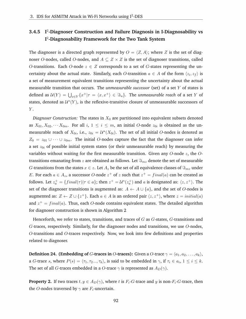
3. IDS for ASMiTM Attack in Wi-Fi Networks using I2-DES
3.4.5 I2-Diagnoser Construction and Failure Diagnosis in I-Diagnosability vs
I2-Diagnosability Framework for the Two Tank System
The diagnoser is a directed graph represented by O = 〈Z,A〉; where Z is the set of diag-
noser O-nodes, called O-nodes, and A ⊆ Z × Z is the set of diagnoser transitions, called
O-transitions. Each O-node z ∈ Z corresponds to a set of G-states representing the un-
certainty about the actual state. Similarly, each O-transition a ∈ A of the form 〈zi, zf 〉 is
a set of measurement equivalent transitions representing the uncertainty about the actual
measurable transition that occurs. The unmeasurable successor (set) of a set Y of states is
defined as U(Y ) =⋃x∈Y {x+|τ = 〈x, x+〉 ∈ =u}. The unmeasurable reach of a set Y of
states, denoted as U∗(Y ), is the reflexive-transitive closure of unmeasurable successors of
Y .
Diagnoser Construction: The states in X0 are partitioned into equivalent subsets denoted
as X01, X02, · · ·X0m. For all i, 1 ≤ i ≤ m, an initial O-node z0i is obtained as the un-
measurable reach of X0i, i.e., z0i = U∗(X0i). The set of all initial O-nodes is denoted as
Z0 = z01 ∪ · · · ∪ z0m. The initial O-nodes capture the fact that the diagnoser can infer
a set z0i of possible initial system states (or their unmeasurable reach) by measuring the
variables without waiting for the first measurable transition. Given any O-node z, the O-
transitions emanating from z are obtained as follows. Let =mz denote the set of measurable
G-transitions from the states x ∈ z. Let Az be the set of all equivalence classes of =mz under
E. For each a ∈ Az, a successor O-node z+ of z such that z+ = final(a) can be created as
follows. Let z+a = {final(τ)|τ ∈ a}; then z+ = U∗(z+
a ) and a is designated as: 〈z, z+〉. The
set of the diagnoser transitions is augmented as: A ← A ∪ {a}, and the set of O-nodes is
augmented as: Z ← Z ∪ {z+}. Each a ∈ A is an ordered pair 〈z, z+〉, where z = initial(a)
and z+ = final(a). Thus, each O-node contains equivalent states. The detailed algorithm
for diagnoser construction is shown in Algorithm 2
Henceforth, we refer to states, transitions, and traces of G as G-states, G-transitions and
G-traces, respectively. Similarly, for the diagnoser nodes and transitions, we use O-nodes,
O-transitions and O-traces respectively. Now, we look into few definitions and properties
related to diagnoser.
Definition 24. (Embedding of G-traces in O-traces): Given a O-trace γ = 〈a1, a2, . . . , ak〉,a G-trace s, where P (s) = 〈τ1, τ2..., τk〉, is said to be embedded in γ, if τi ∈ ai, 1 ≤ i ≤ k.
The set of all G-traces embedded in a O-trace γ is represented as AD(γ).
Property 2. If two traces t, y ∈ AD(γ), where t is Fi-G-trace and y is non-Fi-G-trace, then
the O-nodes traversed by γ are Fi-uncertain.
92

3.4. FDD Theory of I2-DES: Two Tank System
Algorithm 2: Algorithm for construction of diagnoser O for an I2-DES model GInput: I2-DES model GOutput: I2-DES Diagnoser
1 Partition X0 into equivalent subsets X01, X02, . . . , X0m
2 for all i, 1 ≤ i ≤ m do3 z0i = U∗(X0i)4 end5 Z0 ← z01 ∪ · · · ∪ z0m
6 Z ← Z0
7 A← φ8 for all z ∈ Z do
/* Find the set of measurable G-transitions (=mz) outgoing from z */9 =mz ← {τ |τ ∈ =m ∧ initial(τ) ∈ z}
/* Find the set of all measurement equivalent classes Az, of =mz */10 for all a ∈ Az do11 z+
a = {final(τ)|τ ∈ a}12 z+ = U∗(z+
a )13 Z = Z ∪ {z+}14 A = A ∪ {a}15 end16 end
Proof. The property also follows from the diagnoser construction. As any O-transition a ∈ γhas an non-Fi-G-transition and a Fi-G-transition (which are equivalent), so source and
destination O-nodes of a are Fi-uncertain.
Definition 25. Fi-O-node: An O-node, which contains an Fi-G state, is called an Fi-O-
node, denoted as zFi . The set of all Fi-O-nodes is denoted as ZFi . In Fig. 3.10 the O-nodes
z0, . . . , z6, z8, z9 are Fi-O-nodes as each O-node contains an Fi-G-state.
Definition 26. Fi-certain O-node and Fi-uncertain O-node: An Fi-O-node z is called an
Fi-certainO-node if z ⊆ XFi . In Fig. 3.10 theO-node z9 are Fi-certainO-node as it contains
only failure G-states. An Fi-O-node which is not Fi-certain is called Fi-uncertain-O-node.
In Fig. 3.10 the O-nodes z0, z1, z2 are Fi-uncertain O-nodes as they contain both normal
G-states as well as failure G-states.
In words, Fi-certain O-node comprises only Fi-G states, while Fi-uncertain O-node com-
prises some Fi-G states and some non Fi-G-states. So, if the diagnoser reaches any Fi-
certain O-node failure is diagnosed. By Property 2 and Definition 24, if there is a O-trace γ
which moves in Fi-uncertain O-nodes, there is a Fi-G-trace t which is embedded in γ. After
failure, diagnoser moves in γ by virtue of t. However, as there is another non-Fi-G-trace y
say, equivalent to t, fault cannot be diagnosed till γ is exited.
93

3. IDS for ASMiTM Attack in Wi-Fi Networks using I2-DES
Definition 27. Fi-O-path (γFi): A path of the diagnoser O is a sequence of O-transitions
γ = 〈a1, a2, ...〉, with the consecution property initial(ai+1) = final(ai), i ≥ 1. An Fi-O-
path γ is an O-path in which every O-node is an Fi-O-node.
Definition 28. Fi-uncertain cycle: An Fi-uncertain cycle is an Fi-O-cycle in which there
is no Fi-certain O-node. In Fig. 3.10, the O-transitions sequence 〈a1, a2, a3, a4, a5, a6, a8〉associated with the diagnoser state sequence is 〈z0, z1, z2, z3, z4, z5, z6, z0〉 represents an Fi-
uncertain cycle. This is because, none of the O-nodes (z0, z1, z2, z3, z4, z5, z6, z0) is an Fi-
certain O-node.
Definition 29. Fi-indeterminate cycle: An Fi-uncertain cycle γ in which the Fi-states
contained in the O-nodes of γ form a cycle in G comprising transitions from γ, is called an
Fi-indeterminate cycle. Consider a sequence 〈x1, x2, x3, · · · , xk〉 that corresponds to a normal
cycle and measurement equivalent failure cycle 〈x′1, x′2, x′3, · · · , x′k〉. If the system is under
normal conditions, the diagnoser moves into normal cycle and once a failure occurs it moves
in the failure cycle. As both the normal and attack cycles are measurement equivalent, the
normal and failure cycles are indistinguishable from one another. As a result of the presence
of the indeterminate cycle it is not possible to predict whether the diagnoser is moving under
normal or failure cycle leading to non-diagnosability. Thus, an Fi-indeterminate cycle is an
Fi-uncertain cycle with the special property as stated below:
“There is also a cycle involving Fi-states of the composite model that corresponds to
the Fi-uncertain diagnoser cycle.” In simple words, the existence of an Fi-indeterminate
cycle in the diagnoser implies that there are at least two measurement indistinguishable
syntactic cycles in G, one comprising only non-Fi-states and the other comprising Fi-states.
This implies that if the system moves in an Fi-indeterminate cycle, then the measurable
variables are observed to be similar in both non-Fi and Fi conditions. Thus, if the diagnostic
estimate moves along such an Fi-indeterminate cycle, then the fault Fi cannot be diagnosed,
because, at each point in the cycle there exists uncertainty regarding the occurrence of Fiand as faults are assumed to be permanent, the system may not exit from such a cycle. The
existence of an Fi-indeterminate cycle thwarts diagnosability. The equivalence between Fi-
diagnosability and the absence of Fi-indeterminate cycles has been formally established for
DES models [72].
Definition 30. Fi-I-indeterminate cycle: An Fi-indeterminate cycle having an indicator
transition embedded inside it is called an Fi-I-indeterminate cycle. A diagnoser having Fi-I-
indeterminate cycle is non-diagnosable w.r.t to I-diagnosability framework.
Definition 31. Fi-I2-indeterminate cycle:An Fi–I-indeterminate cycle having an empower-
ing transition embedded inside it is called an Fi-I2-indeterminate cycle. For a system to be I2-
94

3.4. FDD Theory of I2-DES: Two Tank System
diagnosable it is essential that the I2-diagnoser should not contain any Fi-I2-indeterminate
cycle.
a’
z0
(s0, s’0)
a0:
0F1
a’
z1
(s1, s’1)a
’z2
(s2, s’2)a
’
z3
(s3, s’3)a, ’5
z4
(s4, s’4)z5
(s5, s’5)
a6 :’
z6
(s6, s’6)
z7
(s7)
z8
(s’7)z9
(s’8)a10 :
’7
a8 :’
a7 :
7
a11 :’9
a12 :’10
a9 :
9
(INDICATOR)
T1
Filling
T1
Full
T2
FillingT2
Full
T2
Drain(Q3 = 1)
V3
Open
V2
Open
(INDICATOR)
T2
Drain(Q3 = 1)
(EMPOWERING)
T2
High = 1
(EMPOWERING)
T2
High = 0
(INDICATOR)
T2
Drain(Q3 = 1)
(INDICATOR)
T2
Drain(Q3 = 1)
Figure 3.10: I2-DES Diagnoser of the Two Tank System Shown in Fig. 3.8
Now we show that the above fault is non-I-diagnosable but I2-diagnosable. First let us
look at the fault diagnosis approach under I-diagnosability framework. The I-diagnosability
framework does not require any empowering event. In this example, the flow sensor Q3
acts as an indicator event. The positive flow indicated by the flow sensor Q3 ensures that
the substance in tank T2 is drained out. We now show that the diagnoser shown in Fig. 3.10
is non-I-diagnosable but I2-Diagnosable.
In the diagnoser shown in Fig. 3.10, we can see that the trace corresponding to
〈a1, a2, a3, a4, a5, a6, a8〉 forms an Fi-I-indeterminate cycle. As explained earlier, presence
of Fi-I-indeterminate cycles leads to non-diagnosability under I-diagnosability framework.
An Fi-I-indeterminate cycle requires two conditions to be satisfied: 1) Presence of Fi-I-
uncertain cycle. 2) A faulty G-cycle within the Fi-I-uncertain cycle. The Fi-uncertain cy-
cle is composed of the O-nodes z0, z1, z2, z3, z4, z5, z6, z0 and within the Fi-uncertain cycle,
the faulty G-cycle is composed of the G-states s′0, s′1, s′2, s′3, s′4, s′5, s′6, s′0 making it an Fi-I-
indeterminate cycle, leading to non-diagnosability. As a result, no fault diagnosis is possible
in such a scenario. As it can be observed from Fig. 3.10, the transition τ ′8 is the indicator
transition. Since the flow sensor Q3 is faulty, and as the diagnoser has no means to check
95

3. IDS for ASMiTM Attack in Wi-Fi Networks using I2-DES
for the correctness of the flow sensor Q3, the faulty state of Q3 cannot be observed. Thus
the I-diagnosability framework fails to detect the presence of fault.
The absence of the empowering event, that ensures that the indicator event sensitizes
the sensor, leads to non-diagnosability of the fault. Now we look at how the presence of
the empowering event along with the indicator event ascertains the presence of the fault.
The empowering event is not present in the I-diagnosability framework but is a part of the
I2-diagnosability framework. The I2-diagnosability framework ensures that the flow sensor
Q3 is sensitized such that even if the flow sensor Q3 reports incorrect system state (i.e.,
reports positive flow despite no flow).
We look at the trace corresponding to 〈a1, a2, a3, a4, a5, a6, a10, a11〉 and show how the
combination of empowering event and indicator event can help sensitize the failure and
eventually help in fault diagnosis. We consider only the failure trace to explain the sig-
nificance of the proposed I2-diagnosability framework. At O-node z6, the controller issued
the command to open the valve V3. As we have assumed that the flow sensor Q3 is faulty,
it reports positive flow is observed even if no flow is observed. We now show how the
empowering event (T2High = 1, courtesy transition τ ′7) sensitizes the faulty sensor Q3.
Since the controller has already issued command to open the valve V3 (CV3), the level
of substance in tank T2 should start falling gradually. The empowering event checks for
the level of substance in tank T2 after the valve V3 is opened. In this example, the level of
substance in tank T2 is still at the highest level (indicated by the sensor output T2Low = 0
and T2High = 1) even after the valve V3 is opened. However, the flow sensor Q3 reports
positive flow. Since the level of substance in tank T2 remains at the highest level even after
the valve V3 is opened, and we have assumed that the level sensors report correct readings,
we can conclude that the flow sensor Q3 is faulty (since if Q3 reports positive flow, level of
substance in tank T2 should fall). The presence of the empowering event (checking for the
level of substance in tank T2 after valve V3 is opened) ensures that the flow sensor Q3 is
sensitized.
As seen, the fault in the flow sensor Q3 which is non-diagnosable under I-diagnosability
framework is diagnosable using the I2-DES framework. The only requirement of the I2-DES
framework is the presence of the empowering event before the indicator event.
3.5 I2-DES Model for ASMiTM attack
The I2-DES model G under normal and ASMiTM attack scenarios is shown in Fig. 3.11. For
readability purposes Fig. 3.11 is annotated with transition number τi and the event because
96

3.5. I2-DES Model for ASMiTM attack
of which the transition τi is enabled. States and transitions belonging to normal (attack)
model are denoted by non-primed (primed) notations. The various components of G are as
follows:
X = {s0, s1, s2, s3, s4, s5, s6, s′0, s′1, s′2, s′3, s′4, s′5, s′6, s′7, s′8, s′9}
Σ = {ARP-REQUEST, ARP-RESPONSE, ARP-PROBE-REQUEST, APR-PROBE-RESPONSE,
UPDPACNUM , DEAUTHENTICATION }
= = {τ0, τ1, τ2, τ3, τ4, τ5, τ6, τ7, τ8, τ′1, τ′2, τ′3, τ′4, τ′5, τ′6, τ′7, τ′8, τ′9, τ′10, τ
′11, τ
′12}
V = {ipsrc, ipdst,macsrc,macdst, PACNUM} is the set of model variables. The domain
of both macsrc and macdst is {xx : xx : xx : xx : xx : xx|x ∈ [0 − F ] } while that of ipsrcand ipdst is {y : y : y : y|y ∈ [0− 255] }. macsrc (ipsrc) and macdst (ipdst) holds source and
destination MAC (IP) address contained in the frame respectively. PACNUM contains the
packet number of the frame sent and its domain is decimal {0, · · · , 248}.
s0 s1 s2 s3
ARPREQUEST
ARP-PROBE-RESPONSE
Attack
'
''
s4 s5 s6
ARP-PROBE-REQUEST
ARP-PROBE-RESPONSE
ARP-PROBE-REQUEST
UPDPACNUM
DEAUTHENTICATION
s’0 s’1 s’2 s’3
DEAUTHENTICATION
ARPREQUEST
ARP-PROBE-RESPONSE
’ ’
’
s’4 s’5 s’6
’
’
’
ARP-PROBE-REQUEST
ARP-PROBE-RESPONSE
ARP-PROBE-REQUEST
UPDPACNUM
DEAUTHENTICATION
s’7
ARP-PROBE-RESPONSE
(MismatchedIP-MAC mapping)
s’8
ARP-PROBE-RESPONSE
s’9
ARP-PROBE-RESPONSE
(MismatchedIP-MAC mapping)
’’
'
0F1
DEAUTHENTICATION
Figure 3.11: Normal and Attack I2-DES Model of ASMiTM Attack
—Behavior Under Normal Conditions (Attacker absent): States {s0, s1, s2, s3, s4, s5, s6}and transitions {τ0, τ1, τ2, τ3, τ4, τ5, τ6, τ7, τ8} represent the DES model of the system under
normal conditions.
97

3. IDS for ASMiTM Attack in Wi-Fi Networks using I2-DES
• s0 : The model starts at state s0. In state s0, the client is about to send an “ARP-
REQUEST” frame to the AP.
• τ1(s0 → s1) : Here the client sends an ARP request (“ARP-REQUEST”) to the AP. As
no checks are made check(V ) = {−−} and assign(V ) = {ipsrc ← ipC1 ,macsrc ←macC1 , ipdst ← ipGTWY ,macdst ← macbrodcast}. ipsrc ← ipC1 and macsrc ← macC1 is
the assignment of SRC IP and MAC address of C1 to model variable ipsrc and macsrcrespectively. On similar lines, the ipdst and macdst is assigned GTWY IP address and
broadcast address respectively. The model variables are used in order to avoid the
state explosion problem as explained in the previous chapter.
• τ2(s1 → s2) : The IDS sends an ARP probe in order to verify the genuineness of the IP-
MAC mapping received during transition τ1. Here check(V ) = {ipsrc ≡ ipIDS ,macsrc ≡macIDS , ipdst ≡ ipC1 ,macdst ≡ macbrodcast}.
• τ3(s2 → s3) : Here C1 replies to the ARP probe sent in previous step. This response
has the same mapping as that received in transition τ1. Here check(V ) = {ipsrc ≡ipC1 ,macsrc ≡ macC1 , ipdst ≡ ipIDS ,macdst ≡ macIDS}. The DES model returns to
start state s0 and the IDS monitors for new ARP request frames sent.
• τ5(s1 → s4) : As the IDS monitors the network activities, it updates the PACNUM value
for C1 by using the value of PACNUM obtained in the previous step. Here check(V )
ensures that PACNUM of that client is updated whose ARP request is obtained in the
previous step. The event UPDPACNUM syncs the PACNUM at AP for C1.
• τ6(s4 → s5) : The ARP probe sent here is similar to the one sent in transition τ2 except
for the fact that it has the PACNUM updated.
• τ7(s5 → s6) : This is the ARP response by the C1. This is similar to the transition τ3
explained above. Here too, the IP-MAC mapping obtained are same as those obtained
in transition τ1. The DES model returns to start state s0 and the IDS monitors for new
ARP request frames sent.
• τ7(s6 → s0) and τ4(s3 → s0) : The client eventually sends a deauthentication frame to
end the association with the AP.
—Behavior Under Attack Conditions (Attacker Present): For attack conditions we
discuss only those states and transitions that differ from normal conditions. Here M
sends a spoofed ARP request frame with IP-MAC mapping as IP-GTWY:MAC-M . States
{s′0, s′1, s′2, s′3, s′4, s′5, s′6, s′7, s′8, s′9} and transitions
98

3.5. I2-DES Model for ASMiTM attack
{τ ′1, τ ′2, τ ′3, τ ′4, τ ′5, τ ′6, τ ′7, τ ′8, τ ′9, τ ′10, τ′11, τ
′12} represent the DES model of the system under at-
tack conditions.
• τ ′9(s′6 → s′7) : This is the second response to the ARP probe sent in transition τ ′9.
However, the IP-MAC mapping obtained here are different than the IP-MAC mapping
obtained in transition τ ′1. Here check(V ) = {ipsrc ≡ ipGTWY ,macsrc 6≡ macM , ipdst ≡ipIDS ,macdst ≡ macIDS}.
• τ ′7(s′5 → s′6) : In this case, the first response (τ ′7) to the ARP probe has a different
IP-MAC mapping than the one received in transition τ ′1.
We look into the diagnoser construction in the next section.
DEAUTHENTICATION
’z0
s0, s’0
z1
s1, s’1’
z2
s2, s’2
z3
s3, s’3’
’
z4
s4, s’4
z5
s5, s’5
z6
s6, s’6
z7
s’7
z8
s’8
’
0F1
a0a2 a3
a5
a12
a1
ARPREQUEST
ARP-PROBE-RESPONSE
ARP-PROBE-REQUEST
a4
z9
s’9
’ ’
’
’
’
a6 a7 a9
z10s’0
z11s’1
z12s’2
z13s’3
’’’
’
z17s’7
(Empowering Event)
z14s’4
z15s’5
z16s’6
’’’
z19s’9
z18s’8
’
’
’
’
’
ARP-PROBE-RESPONSE
ARP-PROBE-REQUEST
UPDPACNUM
ARP-PROBE-RESPONSE
(MismatchedIP-MAC mapping)
ARP-PROBE-RESPONSE
(MismatchedIP-MAC mapping)
a10 a11
’
’
a8
a13a14a15
a18a19a20
a24
a22a23
a21
a16
a17
ARP-PROBE-RESPONSE
DEA
UTH
ENTIC
ATIO
N
a25
DEA
UTH
ENTIC
ATIO
N
Figure 3.12: Diagnoser for ASMiTM Attack
Diagnoser construction ASMiTM Attack
99

3. IDS for ASMiTM Attack in Wi-Fi Networks using I2-DES
The diagnoser obtained from the I2-DES model of the ASMiTM attack in Fig. 3.11 is
shown in Fig. 3.12. Some of the initial steps for this example are as follows.
1. The initial state of the diagnoser i.e., Z0 is obtained as follows. X0 is partitioned into
measurement equivalent subsets of G-states which in our case is one i.e., X0 = {X01};there is only a single initial G-state s0 (as shown in Fig. 3.11) and X01 = {s0}. Since
X0 can be partitioned into only one subset of measurement equivalent initial G-states,
Z0 = z01 and z01 = U∗(X01) = U∗(s0) = {s0, s′0}. Thus, there is only one initial O-
node z0 (as shown in Fig. 3.12) and z0 = {s0, s′0}.
2. The outgoing O-transitions from z0 are obtained as follows. Here, =mz0 = {τ1, τ′1}
which are all the outgoing measurable transitions from G-states in z01. Now, Az01 =
{τ1, τ′1}, as {τ1, τ
′1} forms a set of measurement equivalent transitions. Corresponding
to {τ1, τ′1} there is O-transition a1.
3. The destination O-node corresponding to a1 is obtained as follows. z0+a1 = {s1, s
′1} as
a1 comprises G-transitions {τ1, τ′1} and final(τ1) = s1 and final(τ ′1) = s′1. Further,
z+1 = {s1, s
′1} as U∗(s1) = {s1} and U∗(s′1) = {s′1} since there is no unmeasurable
transition emanating from either of states s1 or s′1. Thus, the destination O-node
of the O-transition a1 is z1 : {s1, s′1}. Similarly, the construction of the diagnoser
continues till no more new O-nodes are created in Step 3.
The diagnoser for ASMiTM attack shown in Fig. 3.12 has one Fi-I-indeterminate cycle
〈z0, z1, z2, z3, z0〉∆=Y 1. It can be observed that the diagnoser states z0 : {s0, s
′0}, z1 : {s1, s
′1},
z2 : {s2, s′2}, z3 : {s3, s
′3} are Fi-uncertain O-nodes (as per Definition 26). Thus, Y 1 is an
Fi-uncertain cycle. This cycle also contains the indicator event ARP-PROBE-REQUEST. The
O-transition a2 comprises an indicator transition τ2, τ′2. Now, the Fi-states contained in the
O-nodes of Y 1 i.e., s′0, s′1, s′2 and s′3 which form a failure cycle in G. Hence, Y 1 is an Fi-
I-indeterminate cycle (as per Definition 30). After occurrence of failure Fi (i.e., ASMiTM
attack), if the system moves in the cycle s′0, s′1, s′2 and s′3 infinitely long, then the system is
not Fi-I-diagnosable by the DES Fi-I-diagnosability definition. In [72], it is proved that a
DES model is Fi-Ii-diagnosable (for failure Fi and with respect to indicator transition set Ii)
if there exists no Fi-Ii-indeterminate cycle in the diagnoser. As Fi-I-indeterminate cycle is
present, I-diagnosability framework fails to detect ASMiTM attack.
3.5.1 An Example of ASMiTM attack Detection Using I2-DES Diagnoser
The empowering event (UPDPACNUM) is instrumental in-order to detect the ASMiTM
attack. As a result of updation of PACNUM, both M and C1 reply to the ARP probe frame
100

3.6. Results and Discussion
which eventually leads to the detection of ASMiTM attack. Referring the diagnoser shown
in Fig. 3.12, it can be seen that there are two attack certain O-nodes: 〈z7, z8〉. The O-
transition a5 comprises the empowering transition (UPDPACNUM) τ5, τ′5. The O-transition
a6 comprises an indicator transition τ6, τ′6 (ARP-PROBE-REQUEST). From the O-node 〈z5〉,
two distinct traces can be seen in the diagnoser. The first trace is along 〈z5, z6, z7, z10〉∆=Y 2,
the second trace corresponds to 〈z5, z8, z9, z10〉∆=Y 3. The trace corresponding to Y 2 consists
of an attack certain O-node 〈z7〉. The O-transition a9 corresponds to the failure (attack)
transition τ ′9. Similarly in Y 3, the attack certain O-node 〈z8〉 has O-transition a10 which
corresponds to the failure (attack) transition τ ′10. There are no Fi-I2-indeterminate cycle in
the I2 diagnoser shown in Fig. 3.12. So the fault (ASMiTM attack) is diagnosable using
the I2-DES framework. The empowering event, UPDPACNUM ensures that the PACNUM
counter at the AP and clients are always in sync. This ensures that multiple responses are
obtained to ARP-PROBE-REQUEST which is crucial in detection of ASMiTM attack.
3.6 Results and Discussion
In this section we show statistics of the proposed IDS in terms of detection rate and accuracy
followed by the correctness of the proposed scheme.
3.6.1 Network Setup for Evil Twin
The setup for the ASMiTM attack is shown in Fig. 3.5. In an ASMiTM attack the attacker
needs to spoof as AP and use the GRPKY for encryption. This is implemented by: (i) using
wpa_supplicant [137] to obtain the most recent GRPKY used by the clients. (ii) slight modi-
fication of the MadWifi [139] drivers so that the attacker can use the GRPKY for encryption.
(iii) converting a ToDS frame to a FromDS frame. This conversion can be done by a cyclic
shift of the address fields of the MAC frame format, setting the ToDS bit to 0 and FromDS
bit to 1, as shown in Fig. 3.14. The IDS (wireless sniffer) promiscuously monitors the net-
work communication. The wireless sniffer is written completely in C Language and runs on
a Ubuntu 12.04 machine. We used MySQL as the database to maintain information about
each client(s) associated with the AP being monitored. The IDS sniffs for the ARP frames
traveling to and from the AP and the associated clients and injects ARP probes when its
sees an ARP request. For crafting ARP probes we use scapy [4] library. The wpa_supplicant,
MadWifi drivers, scapy, Ubuntu and MySQL are all open source and available for Linux
platform.
Table 3.4 shows the experimentally derived durations of SMiTM and ASMiTM attack on
101

3. IDS for ASMiTM Attack in Wi-Fi Networks using I2-DES
Frame Control
Duration ID
Address 1FF:FF:FFFF:FF:FF
Address 2BSSID (AP MAC
Address)
Address 3SRC MAC Address
Sequence Control
Data FCS
ProtocolVersion
Type Sub-Type
ToDS0
FromDS1
MoreFrag
Retry WEP OrderMore Data
PowerMgmt
Figure 3.13: FromDS frame
Frame Control
Duration ID
Address 1BSSID (AP MAC
Address)
Address 2SRC MAC Address
Address 3FF:FF:FFFF:FF:FF
Sequence Control
Data FCS
ProtocolVersion
Type Sub-Type
ToDS1
FromDS0
MoreFrag
Retry WEP OrderMore Data
PowerMgmt
Figure 3.14: A ToDS Frame. Converting a ToDS frame to FromDS requires the cyclic shiftsas shown
Table 3.4: Duration (in mins) of SMiTM vs ASMiTM attack.
OS Default ARP Refresh Rate SMiTM ASMiTM
XPSP3 2 2 17.4
BackTrack5R3 6 3.8 23.2
Windows 7 Persistent 1.7 11.9
Ubuntu 14.04 Persistent 7.3 9.2
the basis of ARP refresh policy of different operating systems. As seen in row two of Table
3.4, the effect of SMiTM attack on the XPSP3 machine lasts till the ARP cache is refreshed
i.e., 2 minutes. However, on the BackTrack5R3 machine the effect of SMiTM attack is
nullified even before the default ARP cache refresh time, because of arrival of a fresh ARP
update at the 3.8th minute. Windows 7 and Ubuntu 14.04 have persistent ARP caches.
In such cases, SMiTM attack is nullified only by fresh ARP updates. So, SMiTM attack is
invalidated only if genuine IP:MAC mapping are present in the ARP cache. This occurs
under the following two conditions, whichever is earlier – (i) arrival of a fresh ARP update.
(ii) ARP refresh – which erases all the ARP entries (including the spoofed ones). As ARP
refresh clears all the ARP entries, the client needs to re-obtain the IP:MAC mapping of
the target host with which it wishes to communicate. The client can obtain the (genuine)
mapping using the standard ARP request/response sequence. However, ARP refresh cannot
nullify the effect of ASMiTM attack. Even if ARP refresh clears the falsified IP:MAC mapping
102
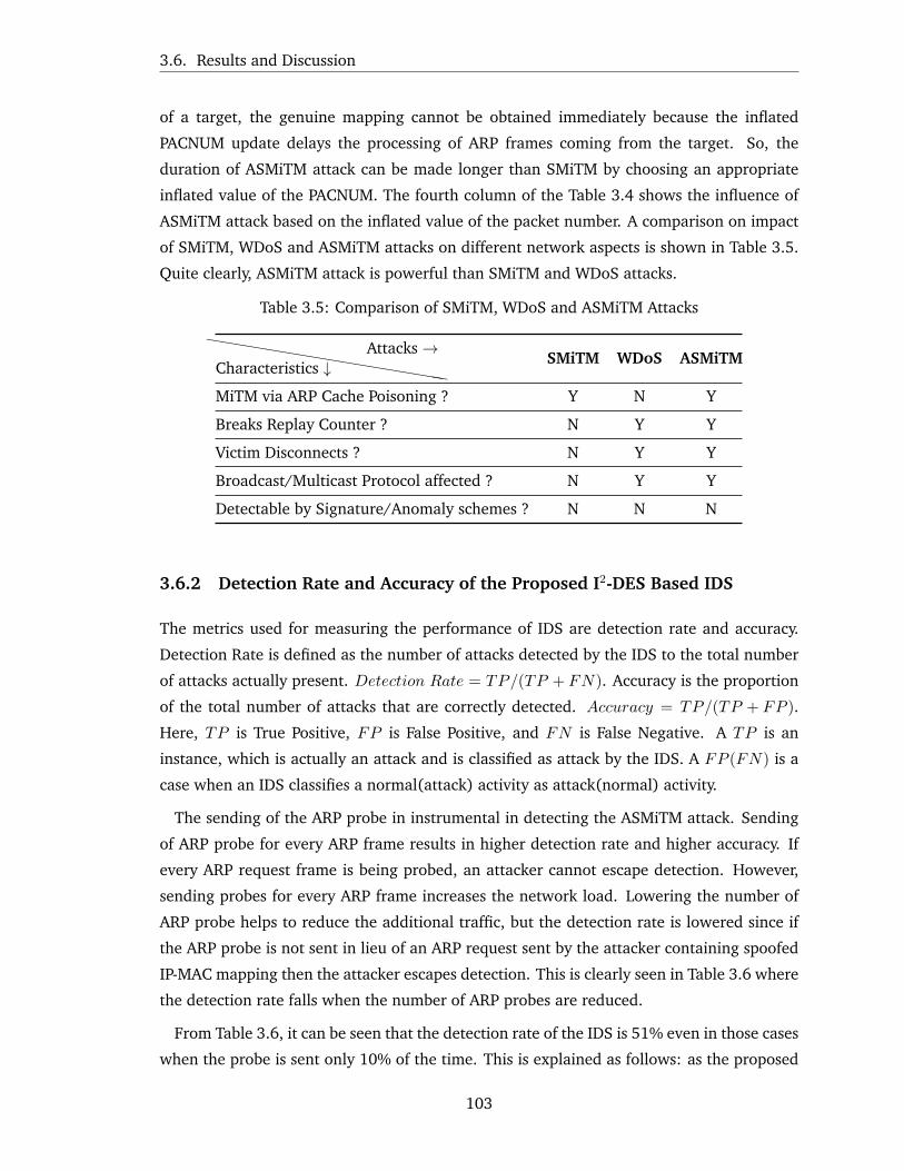
3.6. Results and Discussion
of a target, the genuine mapping cannot be obtained immediately because the inflated
PACNUM update delays the processing of ARP frames coming from the target. So, the
duration of ASMiTM attack can be made longer than SMiTM by choosing an appropriate
inflated value of the PACNUM. The fourth column of the Table 3.4 shows the influence of
ASMiTM attack based on the inflated value of the packet number. A comparison on impact
of SMiTM, WDoS and ASMiTM attacks on different network aspects is shown in Table 3.5.
Quite clearly, ASMiTM attack is powerful than SMiTM and WDoS attacks.
Table 3.5: Comparison of SMiTM, WDoS and ASMiTM Attacks
hhhhhhhhhhhhhhhhhCharacteristics ↓Attacks→
SMiTM WDoS ASMiTM
MiTM via ARP Cache Poisoning ? Y N Y
Breaks Replay Counter ? N Y Y
Victim Disconnects ? N Y Y
Broadcast/Multicast Protocol affected ? N Y Y
Detectable by Signature/Anomaly schemes ? N N N
3.6.2 Detection Rate and Accuracy of the Proposed I2-DES Based IDS
The metrics used for measuring the performance of IDS are detection rate and accuracy.
Detection Rate is defined as the number of attacks detected by the IDS to the total number
of attacks actually present. Detection Rate = TP/(TP + FN). Accuracy is the proportion
of the total number of attacks that are correctly detected. Accuracy = TP/(TP + FP ).
Here, TP is True Positive, FP is False Positive, and FN is False Negative. A TP is an
instance, which is actually an attack and is classified as attack by the IDS. A FP (FN) is a
case when an IDS classifies a normal(attack) activity as attack(normal) activity.
The sending of the ARP probe in instrumental in detecting the ASMiTM attack. Sending
of ARP probe for every ARP frame results in higher detection rate and higher accuracy. If
every ARP request frame is being probed, an attacker cannot escape detection. However,
sending probes for every ARP frame increases the network load. Lowering the number of
ARP probe helps to reduce the additional traffic, but the detection rate is lowered since if
the ARP probe is not sent in lieu of an ARP request sent by the attacker containing spoofed
IP-MAC mapping then the attacker escapes detection. This is clearly seen in Table 3.6 where
the detection rate falls when the number of ARP probes are reduced.
From Table 3.6, it can be seen that the detection rate of the IDS is 51% even in those cases
when the probe is sent only 10% of the time. This is explained as follows: as the proposed
103

3. IDS for ASMiTM Attack in Wi-Fi Networks using I2-DES
Table 3.6: ASMiTM Attack Detection and Accuracy Statistics
% ProbesSent
Attack Instanceslaunched
Instances detectedusing proposed IDS
DetectionRate %
% ProbesSent
Attack Instanceslaunched
Instances detectedusing proposed IDS
DetectionRate %
100 500 495 99 50 500 395 79
90 500 490 98 40 500 335 67
80 500 465 93 30 500 305 61
70 500 440 88 20 500 280 56
60 500 410 82 10 500 255 51
IDS is a detection system and not a prevention system, it behaves aggressively once the
presence of the attack is ascertained. To be specific, once a client is detected to be under
ASMiTM attack, the future communication involving the client is not verified by sending
the ARP probes. They are directly marked as a possible attack instance. This approach has
been adopted since the attacker wants to cause maximum damage to the clients inflicted
by the ASMiTM attack. Hence, the detection rate is higher even under the case when the
probes sent are low. The accuracy, on the other hand, always stays 100% as long as the IDS
receives multiple responses having mis-matched IP-MAC mapping for ARP probe in case a
falsified IP-MAC pair is advertised by the attacker.
3.6.3 Correctness of the I2-DES Diagnoser
The I2-DES modeling helps us to formalize a given system and check for correctness and
completeness [72]. In this section we show the correctness and completeness of the pro-
posed scheme by considering all the exhaustive cases of the ASMiTM attack. For every case
considered, we have shown that the proposed scheme successfully detects the presence of
the ASMiTM attack. The proving of correctness and completeness by considering all the
exhaustive cases helps to ascertain that the attacker does not escape detection, making the
detection scheme robust. In order to prove the correctness of the diagnoser shown in Fig.
3.12, we consider 3 possible cases based on the behavior of the attacker launching ASMiTM
attack.
1. Case 1: Attacker present and its sends spoofed IP-MAC mapping to launch ASMiTM attack
: In this case, after receiving the ARP request the IDS checks the PACNUM value in
the frame and sends an ARP probe with an updated PACNUM. The diagnoser reaches
O-node z5. On observing an ARP probe response containing a mis-matched IP-MAC
mapping, the I2 diagnoser reaches the O-node z8 which is an Fi-certain O-node. So, the
I2 diagnoser correctly identifies the presence of attack. In this case we have assumed that
the attacker’s response to the ARP probe comes before the response of the genuine host.
104

3.7. Conclusion
It is also possible that the order of receipt of the ARP probes is reversed. In that case,
the diagnoser eventually reaches the O-node z7 which is again an Fi-certain O-node. So,
irrespective of the order of arrival of the ARP probe response, the presence of ASMiTM
attack is detected.
2. Case 2: Attacker present but is passive: The attacker is present in the network but only lis-
tens to the network traffic passively. No frame injection is done by the attacker. So, when
the ARP probe is sent only the genuine client replies. The probe response contains the
same IP-MAC mapping as seen during the initial ARP request. The diagnoser traverses
the O-nodes z0, z1, z4, z5, z6, z0 during this process. As none of the O-nodes traversed by
the diagnoser is an Fi-certain (attack) O-node, the I2 diagnoser reports correctly that the
network is under normal conditions.
3. Case 3: Attacker absent: Here, the attacker is not present in the network. This case is
identical to Case 2.
So, all possible cases of arrival of ARP frames are analyzed and the diagnoser which is
implemented as an IDS engine correctly reports the network conditions in each of the case.
3.6.4 Discussion
As ASMiTM attack is proposed by us, to the best of authors’s knowledge there are no existing
schemes to compare the performance of our scheme with any method that exists in the
literature. However, the proposed method depends highly on the ability of the IDS to
capture the frames correctly. If the IDS misses critical frames like ARP probe response or
misses the initial ARP frame sent by the attacker, the detection rate falls. The environment
considered is a WPA2 encrypted Wi-Fi network as the ASMiTM attack attack can only occur
in such networks. ASMiTM attack attacks is not possible in open and WEP based Wi-Fi
networks. Also, we have assumed that the attacker does not do a DoS on the AP or any
other client while launching the attack.
3.7 Conclusion
In this work, we propose ASMiTM attack that uses ARP spoofing to set up a MiTM envi-
ronment in WPA2 encrypted Wi-Fi networks. The proposed ASMiTM attack is an insider
attack that exploits the Hole 196 vulnerability by combining SMiTM and WDoS attacks.
This combination results in amplification of the individual effects of SMiTM and WDoS at-
tacks in terms of duration of attack life, detection complexity and stealthiness. ASMiTM
105

3. IDS for ASMiTM Attack in Wi-Fi Networks using I2-DES
attack can break the protocols that rely on broadcast/multicast traffic, sniff private data
of clients, inject malwares etc. We also propose an I2-DES based IDS in order to detect
the ASMiTM attack. The existing I-diagnosability framework cannot be used for detec-
tion of ASMiTM attack. The proposed I2-DES framework overcomes the shortcomings of
the I-diagnosability framework but requires an additional empowering event, which is in-
strumental for attack (failure) diagnosis. The empowering event along with the indicator
event of I2-Diagnosability framework ascertain that system rendered non-diagnosable by
I-diagnosability framework becomes diagnosable.
In the next chapter, we look into Power Save Denial of Service (PS-DoS) attack where
an attacker launches DoS attack on the clients. The PS-DoS attack induces frame losses
for those clients which are in sleep state in order to conserve their battery life. PS-DoS
attack manifests itself in time rather than frame feature characteristics. The PS-DoS attack
exploits the timing characteristics involved in the power save operation of 802.11 networks.
For such attacks, where timing of occurrence of events is critical, Real Time DES (RTDES)
framework are suited because of their capability of representing timing faults leading to
failures (attacks) in terms of erroneous delay and deadlines. We propose an RTDES [37, 38]
based IDS is proposed in order to detect PS-DoS attack in the next chapter.
[[]X]\\
106

“If someone steals your password, you can change it. But if
someone steals your thumbprint, you can’t get a new thumb.
The failure modes are very different.”
Bruce Schneier
American cryptographer
4Intrusion Detection System for PS-Poll DoS
Attack in Wi-Fi Networks using Real Time
Discrete Event System
4.1 Introduction
In the earlier chapters, we saw how an attacker launched a MiTM attack using evil twin
or ASMiTM attack in order to compromise client’s security. In this chapter, we look into
PS-DoS attack. In PS-DoS attack an attacker can cause frame losses to the client without
establishing a MiTM connection. The rapid expansion of Wi-Fi networks coupled with the
availability of handled devices like smart-phones, tablets, phablets etc., having full support
for Wi-Fi connectivity has made it possible for the users to stay connected to the Internet all
day along. From the point of view of portability and form factor these handheld devices are
equipped with limited battery life. Wi-Fi usage leads to higher consumption of battery so if
appropriate power saving measures are not employed, the battery of these Wi-Fi device(s)
would drain out quickly.
The power save feature of 802.11 standard [93] allows the clients to enter into sleep state
to conserve battery life. If any data arrives for the client while it is in sleep state, the AP
buffers the data and delivers to the target client when it wakes up. A client informs the AP
about its change in power save state from sleep to awake and vice-versa using a PS-Poll or
null data frame. A null data frame is so named because it has no data payload field. Its
purpose is to indicate a change in the power save mode of the client.
107

4. IDS for PS-Poll DoS Attack in Wi-Fi Networks using RTDES Framework
In this chapter we focus on the Power Save Denial of Service (PS-DoS) attack. PS-DoS
attack can cause degradation of service by inducing frame losses for sleeping clients and no
formal solution is available for its detection. This motivated us to take up PS-DoS attack
and propose a solution for it. In PS-DoS attack, an attacker crafts spoofed null data frame in
order to fetch buffered frame(s) at the AP causing frame losses for the client whose frames
are buffered at the AP. An attacker repeats this process for different clients which leads
to severe frame losses for the clients and finally resulting in the PS-DoS attack. We have
considered the case in which the attacker causes frame losses to multiple clients. This helps
the attacker increase the potency of PS-DoS attack. If the attack is restricted to only one
client the PS-DoS attack can be trivially detected using standard anomaly-based technique
[140]. The impact of PS-DoS attack on a single client is limited and does not lead to DoS on
the network. In order to have a higher attack impact, the attacker targets multiple clients in
the network. All the clients whose buffered frames are retrieved by the attacker are termed
as victim clients.
Current methods to prevent the PS-DoS attack include encryption [73, 74, 75], Received
Signal Strength Indicator (RSSI) based methods [77, 78, 79], up-gradation to newer stan-
dards [141, 142] which necessitate firmware upgrades. Encryption requires systematic ar-
rangement of key establishment, key renewal, key revocation leading to increased deploy-
ment and maintenance costs. Up-gradation to newer standards require firmware upgrades
on the client as well as server, which often incur high cost. Moreover, presence of legacy
network(s) makes this task difficult. Received Signal Strength Indicator (RSSI) based ap-
proaches can help detect the PS-DoS attack. However, the use of RSSI based techniques
require additional specialized hardware equipment which increase costs. So we can see
that existing methods escalate deployment and maintenance costs. Signature based IDS
uses predefined signatures while anomaly-based IDS makes use of profiling to detect at-
tacks [92]. An attacker crafts the spoofed null data frame using the same parameters as
those used by the client while sending a null data frame. Also, injection of just one null
data frame is enough to induce frame losses for a client. As a result, generation of signa-
ture or statistics for PS-DoS attack is difficult as may not prove to be effective in detecting
the PS-DoS attack. Usage of such IDSs may lead to high false positive rate. We therefore
propose a Real Time Discrete Event System (RTDES) based IDS that helps to overcome the
drawbacks listed above and detect the PS-DoS attack with high detection rate and accuracy.
The core idea of any DES based IDS is to develop the normal and failure model corre-
sponding to normal and failure (attack) scenarios. Subsequently, a diagnoser which is a
state estimator is built using the states traversed in the normal and fault (attack) models.
The diagnoser which is implemented as the IDS engine observes sequence of events gener-
108

4.1. Introduction
ated by the system and raises an alarm if the sequence deviates from the normal behavior.
The proposed RTDES framework requires certain extensions over classical theory [125] and
techniques, which have been used in [143, 144, 41]. The modifications are made as follows:
• The PS-DoS attack manifests itself in time. As a result, timing (delay-deadline) in-
formation needs to be incorporated in the model. In order to incorporate timing
information we have used the RTDES framework [39] instead of un-timed one.
• The sequence of power save frame exchange under normal and attack conditions is
similar. This leads to creation of identical models under normal and attack scenarios
thwarting diagnosablity. To create differences between normal and attack scenarios,
power save probes are injected into the network. It may be noted that power save
probes maintain the 802.11 protocol standard.
• We incorporate model variables in the RTDES based IDS in order to overcome the
state explosion problem.
The summary of our contributions are:
1. We propose an RTDES based IDS that detects the PS-DoS attack in Wi-Fi networks.
The developed IDS adheres to the 802.11 standard.
2. The only hardware requirement is a sensor capable of sniffing the wireless data. So
the cost of the proposed scheme is low and can be readily applied to legacy as well as
existing networks.
3. As DES is a formal paradigm, the correctness of the scheme is verified by considering
all possible attack scenarios based on the arrival timing of the PS-Poll and null data
frames.
The rest of the chapter is organized as follows. Section 4.2 describes the power save
feature of 802.11 networks and the security vulnerabilities associated with it. We also
look into the current approaches to tackle the PS-DoS attack. In Section 4.3, we describe
the proposed mechanism for detection of PS-DoS attack. In Section 4.4, we introduce the
concept of Failure Detection and Diagnosis (FDD) using Real Time Discrete Event System
(RTDES) using a benchmark process of three-tank system. We describe the RTDES based
IDS to detect the PS-DoS attack in Section 4.5. The correctness of the RTDES based IDS
along with its detection rate, accuracy and network load of the IDS are described in Section
4.6. Section 4.7 concludes the work.
109

4. IDS for PS-Poll DoS Attack in Wi-Fi Networks using RTDES Framework
4.2 Background and Motivation
In this section we look at the power save feature and the vulnerabilities associated with it.
We look at how these vulnerabilities can be exploited to launch the PS-DoS attack. Next,
we look at the existing solutions to detect the PS-DoS attack.
4.2.1 Power Save Feature of 802.11 Standard
Hand-held devices usually have limited battery, so an effective power saving mechanism
is must. The 802.11 standard incorporates a power saving feature that enables a client to
enter into sleep state, which consumes much less power. When a client is in sleep state,
it can neither transmit nor receive frame(s). A client enters into sleep (awake) state by
sending null data frame with Power Mgmt bit set to 1 (0). If any data arrives for the client
while it is in sleep state, the AP buffers the data on behalf of the client. The AP sets the
client’s Association IDentifier (AID) bit to 1 in the Traffic Indication Map (TIM) message
of the successive beacon frames until the client retrieves all the buffered frames at the AP.
Beacon frames are periodically sent by the AP to help the clients detect the presence of the
AP. The beacon frame includes TIM information element which consists of a list of AID(s)
of those client(s) whose frame(s) are buffered at the AP.
Frame Control
Duration ID
Address 1 Address 2Address 3
BSSID Sequence
ControlNetwork
DataFCS
ChecksumAddress 4Unused
ProtocolVersion
Type2
Sub-Type4
ToDS FromDS MoreFrag
PowerMgmt0/1
Retry WEP OrderMore Data
0 : Active Mode (Wake State)1 : In-Active Mode (Sleep State)
1 bit
Figure 4.1: Frame format of null data frame
A client in sleep state must periodically wake up and listen to the beacon frame. A client
uses the value of Listen Interval (LI) for waking up periodically. If a client is in sleep state,
it must wake up after LI number of beacons to check for the presence of buffered frames at
the AP. For example, if the client is in sleep state and its LI is 5, the client needs to wake up
every 5th beacon to check if any frame(s) are buffered at the AP. The value of LI is decided
during the association process. The LI is a 2 byte element in the association request frame
sent by the client to the AP. The AP needs to buffer the frame(s) for a sleeping client at-least
for the corresponding client’s LI. A sleeping client wakes up after the LI duration and reads
110

4.2. Background and Motivation
the TIM element of the beacon frame. If the AID of the client is set (reset) in TIM it implies
that data is buffered (not buffered) at the AP. The client sends a null data frame with Power
Mgmt bit set to 0 (indicating that it is awake) to retrieve the buffered frame(s) at the AP.
If a client continues to remain in sleep state even after its LI expires, the AP discards the
buffered frame(s) for the corresponding client.
4.2.2 Vulnerabilities in Power Save Feature of 802.11 Standard
Encryption schemes like WEP, WPA, WPA2 etc., encrypt only the data payload keeping
other fields in clear-text. PS-Poll and null data frame does not contain any data, and are
sent in clear-text. Being un-encrypted, spoofing these frames is trivial. The PS-DoS attack
is explained using Fig. 4.2.
Beacon_1 Beacon_2 Beacon_3 Beacon_4 Beacon_5Time
AP G
Attacker M
TIM Status ofClient C1
Client C1
1st BI
Client C2
0 1 00
P=1 P=1
Data for Client C1
Data for Client C1 Buffered
By AP since Client C1 is sleeping
M sends a P=0 to fetch the
buffered frames meant for Client C1
AP resets the TIM for Client C1
C1 wakes after its listen interval expires and sees its TIM reset and goes back to
sleep
C1 sends P=1 to inform AP that it goes into sleep mode
2nd BI 3rd BI 4th BI
0
BI = Beacon Interval
5th BI
Figure 4.2: Timeline for launching PS-DoS attack
Clients M , C1 and C2 are associated with the same AP. M is the attacker while C1 and C2
are genuine clients. We assume Beacon Interval(BI) as 100ms and C1’s LI as 5 for the
purpose of explanation. The BI is available in all the beacon frames transmitted by the AP.
M gets the LI and AID of the client C1 by eavesdropping on the association process between
the client C1 and the AP. The timeline shown in Fig. 4.2 is explained below:
• [1st BI] : C1 sends null data frame with PwrMgmt = 1 to the AP to inform that it is
entering sleep state. TIM for C1 is set to 0 as there are no outstanding frame(s) for
C1 at the AP.
• [2nd BI] : C2 sends one data frame to C1 which is buffered by the AP as C1 is in sleep
111

4. IDS for PS-Poll DoS Attack in Wi-Fi Networks using RTDES Framework
state. AID in the TIM for C1 is set to 1 in all successive beacon frames till all the
buffered frame(s) are retrieved by C1.
• [3rd BI] : M captures a beacon and finds the AID of C1 is set in TIM. The attacker
sends a spoofed null data frame with source (SRC) MAC address set to MAC address
of C1 and PwrMgmt bit set to 0. On receiving the null data frame the AP sends all the
buffered frames which are acknowledged by M on behalf of C1. After all buffered
frames of C1 are delivered, the AP resets the AID of C1 in TIM of the successive
beacons.
• [4th BI] : No frame exchange for C1. TIM = 0 for C1.
• [5th BI] : C1’s LI expires. It wakes up to read the TIM bit of the beacon frame. C1
finds that its AID in TIM is reset indicating absence of any buffered data at the AP. C1
goes back to sleep state by sending null data frame with PwrMgmt = 1 to the AP.
As seen above, the attacker M silently steals the buffered frame(s) targeted at C1. C1 as
a result becomes a victim of PS-DoS attack as it does not receive the intended frame(s).
C2 also indirectly becomes a victim as it assumes that frame(s) are successfully delivered
to C1, but instead they are delivered to M . So in the PS-DoS attack both the sender and
the receiver are victimized. M should repeat this process for different clients at arbitrary
intervals in the network to cause frame losses to clients resulting in the PS-DoS attack. The
attacker should choose arbitrary intervals to launch PS-DoS attack. If attacks are launched
at regular intervals may lead to detection by an anomaly-based IDS. The PS-DoS attack can
be easily launched using minimal resources and possesses the potential to cause high frame
losses. In the following sub-section, we look into various approaches to detect and prevent
the PS-DoS attack.
4.2.3 Existing Approaches to Detect or Prevent PS-DoS Attack
Encryption based methods
An intuitive solution is to encrypt all the management and control frames along with the
data frames as suggested by Bellardo et al. in [73]. Encryption requires an establishment
of systematic secure key distribution, management, renewal and revocation system, which
involves a huge overhead. As the PS-DoS attack involves spoofing of PS-Poll and null data
frame, encrypting all management and control frames can prevent the PS-DoS attack. How-
ever, encrypting and decryption all management and control frames puts additional load on
112

4.2. Background and Motivation
the clients and the AP. This in turn leads to increased CPU cycles leading to faster drain-
ing off the batteries of the clients. It also necessitates up-gradation of the client and the
AP firmware which is costly. Qureshi et al. [74] propose an encryption based scheme to
prevent the PS-DoS attack by encrypting the AID portion of the PS-Poll frame using pre-
established PVTKY. As PVTKY is used, this method is not applicable to open and WEP based
networks. Null data frame does not contain the AID field, which limits this method to those
clients using PS-Poll frames for power save operations.
Leandro Meiners [75] proposes that the clients must use non-empty data frame like
ICMP/ARP for reporting the change in power save mode. The motive behind this solution
is to eliminate all possible frame candidates that are vulnerable to the PS-DoS attack. As
ICMP/ARP frame contain data, the data portion is encrypted which prevents possible spoof-
ing by an adversary. However, this solution has fundamental drawbacks. First, it breaks
the AP compatibility with those clients that use traditional frames like null data frames to
inform about the change in power save mode. The null data frames are used by Network
Interface Card (NICs) for managing power, scanning channel and keeping the association
awake [76]. Eliminating the processing of such frames prevents the client from performing
these functions.
Received Signal Strength Indicator (RSSI) based Methods
Faria et al. [77] use the AP(s) as sensors and obtain the RSSI values for each client within
its range. They have shown that the signalprints of a client and its physical location are
closely correlated. Azimi et al. [78] and Chen et al. [79] also make use of physical layer
countermeasures like RSSI values and RF signal print to detect and localize the attacker.
In RSSI based techniques the approximate location of the sender is determined. Following
this, the location of the source MAC address in the received frame is determined. If the
difference in the location exceeds a certain threshold, the frame is not processed and tagged
as spoofed. Though physical layer countermeasures are effective, they require specialized
hardware and firmware changes in 802.11. If the clients are located close to each other,
their physical characteristics are similar, which may result in false positives.
Up-gradation to Newer IEEE Standards
IEEE 802.11w standard provides protection for the management frames. However, the pro-
posed standard does not include protection for control frames [142]. PS-Poll frame being
a control frame, 802.11w leaves the PS-Poll frame unprotected. So, upgrading to 802.11w
protocol does not help to prevent PS-DoS attack. It also involves additional deployment
113

4. IDS for PS-Poll DoS Attack in Wi-Fi Networks using RTDES Framework
costs, firmware upgrades for both the client and the AP. A large number of legacy devices
exist today, which do not support 802.11w standard [141].
In brief, the drawbacks of the existing schemes to detect or prevent the PS-DoS attack are:
• Requirement of Encryption.
• Firmware up-gradation
• Up-gradation to newer standards.
• Installation of specialized hardware.
From the above summary it is clear that a strategy to detect the PS-DoS attack is required
having the following features.
• No alteration in 802.11 protocol is required.
• Hardware costs should not be exorbitant.
• It must be easily deployable to the existing as well as new networks.
• It must not require patching of underlying operating system or installation of new
software.
• If the IDS generates extra traffic, it should be as low as possible.
Signature and anomaly-based IDS usually generate a lot of false positives when used for
detecting the PS-DoS attack and related attacks, which do not alter frame semantics under
normal and attack conditions. In such cases, DES based IDS have proven to be an effective
mechanism for detecting network attacks without any need for protocol modification, en-
cryption or installation of proprietary hardware. A DES based IDS can be formally proved
to be correct. In this chapter we propose RTDES based IDS for the PS-DoS attack that incor-
porates the features listed above and overcomes the drawbacks of the existing approaches.
4.3 Proposed Scheme for the Detection of PS-DoS Attack
In this section we present the working principle of the IDS to detect the PS-DoS attack
followed by attacker and IDS components.
114

4.3. Proposed Scheme for the Detection of PS-DoS Attack
4.3.1 Working Principle of the IDS for Detecting PS-DoS Attack
Principle: If the buffered frames for a client are fetched before the expiry of its LI, IDS
marks this activity as suspicious. Such activity cannot be directly marked as attack since
the 802.11 standard permits the Wi-Fi clients to wake up earlier than their scheduled wake
up. This is plausible as it may happen that the client may have to transmit some critical
data for which it may have to break its sleep cycle. So, every client that wakes up earlier
than its scheduled wake up cannot be assumed to be an occurrence of the PS-DoS attack.
In the proposed scheme we have the dummy clients as part of detection methodology. The
dummy clients are software controlled and their communication is handled by the IDS.
The IDS ensures that the dummy clients never wake up before the expiry of their LI. Only
the IDS possesses the dummy client’s MAC address which is regularly updated. The need
for updating the dummy MAC address and other characteristics of the dummy clients are
explained later. Upon observing an early wake up frame1 for any client(s) associated with
the monitored AP, the IDS sends a power save probe to the dummy client. As the dummy
client is in sleep state at the time IDS sends a power save probe, the frame is buffered at
the AP. The power save probe is a simple 802.11 data frame sent from IDS destined to the
dummy client. If the buffered frame(s) meant for the dummy client are fetched before the
expiry of the LI of the dummy client to whom the probe is sent, the presence of the PS-DoS
attack is confirmed.
Reason: The dummy clients never wake up before the expiry of their LI. So, if the
buffered frames meant for the dummy clients are fetched before the expiry of their LI,
it must have been fetched by the attacker on behalf of the dummy client in its quest to fetch
the buffered frame(s) of the sleeping clients.
Using the above principle we show an example of the PS-DoS attack detection technique
with the help of the timeline shown in Fig. 4.3. M , C1 and C2 are associated with the same
AP. M is the attacker, C1 and C2 are the genuine clients while D1 is the dummy client. The
timeline has 7 distinct time slots. Each time slot corresponds to a Beacon Interval (BI).
• [1st BI] : C1 goes to sleep. C1’s scheduled wake up is at BI6. The dummy client D1 is
in sleep state. D1’s scheduled wake up is at BI7.
• [2nd BI] : C2 sends data to C1. As C1 is in sleep state, the data is buffered by the AP.
The AP sets the AID for C1 in TIM bit for successive beacons till all buffered frame(s)
are retrieved by C1.
1For simplicity of explanation of the formal (RTDES) modeling we refer null data frame with PwrMgmt = 1as sleep frame and null data frame with PwrMgmt = 0 as wake frame.
115

4. IDS for PS-Poll DoS Attack in Wi-Fi Networks using RTDES Framework
Time
Dummy Client D1
Attacker(M)
Client(C1)
Beacon1 Beacon2 Beacon3
C1 sends P=1to AP (C1 enters
sleep state)
Data for Client C1 from C2
(buffered at AP)
Beacon4
M sends spoofed null data Frame with source address as MAC C1 (Fetch buffered
at AP meant for C1)
Beacon5
IDS sends Probe to Dummy Client D1
Beacon6 Beacon7
Spoofed null dataFrame with source address as MAC D1 (M is caught, since D1
cannot wake up here)
D1
scheduled wakeup
C1 scheduled wakeup(no buffered frames)
1st BI 2nd BI 3rd BI 4th BI 5th BI 6th BI
D1 in sleep state
BI = Beacon Interval
Figure 4.3: Timeline for detecting the PS-DoS attack
• [3rd BI] :M sends a wake frame spoofing as C1 to the AP. All buffered frame(s) meant
for C1 are retrieved by M . M acknowledges the AP on behalf of C1.
• [4th BI] : IDS observes early wake from the client C1. IDS sends a power save probe
to the dummy client D1 to verify the early wake of C1. The dummy client’s scheduled
wake up is at BI7. The AP resets the AID for C1 in the TIM bit for successive beacons
as no buffered data is left at the AP.
• [5th BI] : IDS sniffs a wake frame to retrieve buffered frame targeted at D1. As D1
never fetches frame before scheduled wake up, the request for fetching frame(s) must
have been made by the attacker on behalf of the dummy client. Thus, presence of the
PS-DoS attack is detected.
• [6th BI] : C1’s scheduled wake up time. C1 finds its TIM is reset and goes back to
sleep.
• [7th BI] : D1’s scheduled wake up time. D1 goes back to sleep as no buffered frame(s)
are present for it.
As seen, C1 is the victim client that lost its buffered frame(s) because of the PS-DoS attack
by M . The sending of power save probes to D1 helps to detect the presence of M in the
network. The timing of the response of the power save probes is vital in ascertaining the
presence of attacker.
4.3.2 IDS Components
The block diagram for detecting the PS-DoS attack is shown in Fig. 4.4. The components
are described as follows:
116

4.3. Proposed Scheme for the Detection of PS-DoS Attack
Wi-Fi Sniffer
Power SaveHandler
Dummy MACs
Network Frames
PowerSave
Probe
Events:SleepPower Save ProbePower Save Probe ResponseACKEarly WakeProper WakeData
PowerSave
Frames RTDESDiagnoser
Detection ofPS-DoS
Figure 4.4: Components of the proposed IDS for detection of PS-DoS attack
• Wi-Fi Sniffer: The Wi-Fi sniffer works in promiscuous mode and captures all Wi-Fi
frame(s) traveling in the network. Only those frame(s) destined to and from the
monitored AP are sniffed. Frame(s) to other APs are dropped. The Wi-Fi sniffer
forwards the captured frame(s) to “Power Save Handler”.
• Power Save Handler: The Power Save Handler is responsible for extracting vital
information like LI, BI, AID, MAC address of the source (SRC) client from frame
headers. The Power Save Handler component is also responsible for the generation of
events like Sleep, ACK, Early Wake, Proper Wake, Power Save Probe, Power Save Probe
Response, Data. The Power Save Handler forwards the generated event(s) to RTDES
diagnoser. The RTDES diagnoser determines if the PS-DoS attack has occurred or not
based on the events captured.
• Dummy clients: IDS maintains a list of dummy clients with it. The dummy clients
are software controlled and their communication is handled by the IDS. As already
explained in the principle of attack detection, the 802.11 standard allows a client to
wake up before the expiry of its LI. In order to check the genuineness of the early
wake frame sent by the client, the IDS sends a power save probe destined to a dummy
client while it is in sleep state. As the communication of the dummy clients is handled
by the IDS, the dummy clients never wake up before the expiry of their LI. So, in-case
a wake frame is seen to fetch the buffered frame(s) meant for the dummy client in
the network before the expiry of its LI (i.e., LI of dummy client), the IDS raises an
alarm indicating the occurrence of the PS-DoS attack. In case the buffered frame(s)
are fetched after the expiry of the LI of a dummy client the network is assumed to be
operating under normal conditions.
• RTDES Diagnoser: The RTDES diagnoser is actually implemented as a software mod-
ule and used as attack detector. The RTDES diagnoser forms the crux of the detection
117

4. IDS for PS-Poll DoS Attack in Wi-Fi Networks using RTDES Framework
methodology and is constructed from the DES model under normal and attack condi-
tions. The construction and uses of the diagnoser are described in Subsection 4.4.4.
4.3.3 Attacker and IDS Assumptions
Attacker Assumptions
• Attacker fetches buffered frame(s) at the AP immediately for the clients that are
in sleep mode.
An attacker fetches frame(s) buffered at the AP for the targeted sleeping clients imme-
diately. If the attacker delays in fetching the frame(s) buffered at the AP it is possible
that the real client may wake up and fetch the frame(s). This may reduce the impact
of PS-DoS attack. Clients staying awake persistently never have buffered frame(s) at
the AP. So the PS-DoS attack is not possible on such clients.
• Attacker launches the PS-DoS attack on multiple clients simultaneously at arbi-
trary intervals.
The attacker targets multiple clients simultaneously. The attacker first does a passive
scanning of the network to determine the list of associated clients with the target
AP. The attacker eavesdrops on the communication between the clients and the AP
to obtain useful parameters like the network’s BI, client’s LI and AID. Using these
parameters the attacker crafts spoofed null data frame in order to fetch the buffered
frame(s) at the AP for the targeted sleeping clients. For the success of the PS-DoS
attack on a client, two conditions must be satisfied – (i) the client is in sleep mode
and (ii) the AP has buffered frame(s) for the client. Experimentally it has been ob-
served that occurrence of these two scenarios is infrequent. So, in order to increase
the impact of the PS-DoS attack to a reasonable level, multiple clients are targeted by
the attacker.
IDS Assumptions
• Monitoring of the authorized AP(s) only.
The IDS maintains a white-list of the MAC address of the AP that need to be protected.
Only the frame(s) destined to and from these AP(s) are monitored. Frame(s) destined
to other AP(s) are discarded as the primary goal of installing the IDS is to detect the
attacks on the APs deployed by the administrator and not other AP(s).
• IDS keeps track of sleep and wake up schedules of the associated clients.
Wi-Fi clients follow their sleep and wake schedule(s) so that they can conserve power
118

4.3. Proposed Scheme for the Detection of PS-DoS Attack
by being in sleep state when they have no data to transmit. In case of the PS-DoS
attack the frequency of early wake by the clients get increased as the attacker fetches
the buffered frame(s) available at the AP on behalf of the clients while they are in
sleep state. By keeping a track of the sleep and wake schedules, the IDS can identify
those clients that wake up earlier than their scheduled wakeup timing. Clients which
are frequently seen to wake up before completion of their sleep schedule(s) may be
the potential victims of the PS-DoS attack. This also helps the IDS to determine the
number of dummy clients to be kept in the network by following the philosophy –
more the potential victims, more dummy clients are needed.
• Proposed IDS has sniffing and injection capabilities.
The IDS sniffs the wireless frames traveling in the air. If the IDS observes an early
wake frame it sends a power save probe destined to the dummy client. The IDS
maintains a list of AIDs, LI, sleep-wake timing of all the associated clients for the AP
begin monitored. If the IDS does not have sniffing capabilities then early wake by the
clients cannot be detected. If the IDS does not posses the frame injection capability,
it cannot inject power save probes into the network to ascertain the presence of the
attacker.
• IDS regularly updates the dummy client’s MAC address list.
IDS regularly updates the dummy client’s MAC address list to prevent possible learn-
ing of the dummy client’s MAC address by the attacker. To elaborate, most of the
Wi-Fi clients are mobile in nature. As a result, large number of clients join and leave
the network over a period of time. Even though the genuine clients have fixed MAC
addresses, their joining and leaving pattern with respect to the network is highly dy-
namic. A genuine client may join the network and leave the network in a few minutes
or hours and may never return to the same network. Few of the clients may join the
network and leave after some time and may associate to some other AP in the same
network. However, some of the clients (like employees working for a firm) may show
a static behavior in terms of joining and leaving, but they are few. To mimic a similar
dynamic trend with that of the genuine clients, the IDS regularly updates the dummy
client’s MAC address list. So, even if the genuine clients have fixed MAC addresses
the attacker cannot learn whether the clients are normal or dummy by looking at
whether the MAC address appeared in the historical data. In other words, if the list
of dummy client’s MAC address is not dynamic in nature, an attacker may eventually
learn the list of dummy MAC address in the network by observing the historical data
of the MAC addresses seen in the network. Once the attacker gets the MAC addresses
of these dummy clients, it does not respond to any of the power save probes having
119

4. IDS for PS-Poll DoS Attack in Wi-Fi Networks using RTDES Framework
these MAC addresses assuming them to be dummy clients. So, the list of dummy
client’s MAC address needs to be updated regularly to prevent such possible learning
by the attacker.
So, from the above discussion it is clear that timing of the various network activities
(sending probe, fetching probe frames etc.) is important in order to detect the PS-DoS
attack. As RTDES modeling is capable of capturing timing information into the model, we
have chosen the RTDES framework for modeling the PS-DoS attack.
4.4 Fault Detection and Diagnosis Theory of Real Time Discrete
Event System (RTDES): Three Tank System
In this section we present the RTDES framework augmented with model variables. The
RTDES model G is defined as:
G = 〈X,X0,Σ,=, V, t〉 (4.1)
where
• X is the finite set of states.
• X0 is the initial state.
• Σ is the set of events. Note that an event can be measurable or unmeasurable.
• = is the set of transitions.
• V is the set of model variables. Each element vi of V can take values from a domain
Domi.
• t is a clock variable with type(t) = N, the set of all natural numbers. The clock variable
represents time on a global clock.
A transition τ ∈ = from a state x to another state x+ is an ordered seven-tuple
τ = 〈x, x+, σ, lτ , uτ , check(V ), assign(V )〉, where,
• x is the initial state of the transition, denoted as initial(τ).
120

4.4. FDD Theory of RTDES: Three Tank System
• x+ is the final state of the transition, denoted as final(τ).
• σ is the event on which the transition is fired.
• lτ , uτ are the delay and deadline time bounds, denoted as delay(τ) and deadline(τ),
respectively. Let tcτ be the time instant when τ is enabled. A transition can take place
at any time instant t when tcτ + lτ ≤ t ≤ tcτ +uτ , provided that the transition remains
enabled throughout the interval [tcτ , t]. Therefore, a transition does not take place
before the delay and must take place before the deadline.
• check(V ) represents conditions on a subset of model variables. For firing τ , along
with the enabling event σ, check(V ) should hold true.
• assign(V ) represents a subset of model variables and assignment of values from their
corresponding domain, when τ fires.
A transition τ from x to x+ is denoted as τ : 〈x, x+〉 for brevity when its other components
are clear from the context. The tick transition, or simply tick, denoted as η, is defined as
η = 〈x, x, true,−,−,−,−〉. Each occurrence of tick results in an increment of the clock
t by 1 and leaves the other variables unchanged. In fact, tick is the only transition that
changes the value of t. Tick occurs infinitely often and is not explicitly included in =. No
model variables are defined for the tick transition.
A trace of model G is a sequence of transitions generated by G denoted as s = 〈τ1, τ2, · · · 〉,where initial(τ1) is an initial state, and the juxtaposition property holds, that is, initial(τi+1) =
final(τi), for i ≥ 1. Henceforth, we assume the juxtaposition property for “sequence of
transitions”. A state x is said to be in a trace s, if x = initial(τi), for some i ≥ 1. The
set of all traces generated by G along with all their finite prefixes is the language of G,
denoted as L(G). Lf (G) denotes the subset of L(G) comprising the finite prefixes. For
any trace s = 〈τ1, τ2, · · · 〉, initial(s) = initial(τ1) and for a finite trace s = 〈τ1, τ2, · · · τf 〉,final(τf ) = final(s). Naturally, L(G) is a subset of =w, where =w is the set of all infinite
sequences of =; Lf (G) is a subset of =∗, the Kleene closure of =. The post language of G
after a trace s is denoted as L(G)/s = {t ∈ =∗ | st ∈ L(G)}. Lf (G)/s ⊂ L(G)/s comprises
finite prefixes of the infinite traces of L(G)/s.
4.4.1 RTDES Modeling: Measurement Limitations and Failure Diagnosis
Limitations of measurement give rise to uncertainty in transitions in the observed dynam-
ics of the model. In this sub-section the notion of measurement limitation in the RTDES
framework is formally introduced and the consequent uncertainty in transitions in G is
121

4. IDS for PS-Poll DoS Attack in Wi-Fi Networks using RTDES Framework
characterized. In order to explain the definitions in a more clear and concise way we take
help of the three tank system explained in Subsection 4.4.2. Very briefly, the three tank sys-
tem involves filling of tank T1 followed by filling of tank T2. Both the tanks are drained into
tank T3. After tank T3 gets full, the mixture in tank T3 is drained off. We have reproduced
few standard definitions available in the RTDES literature [72, 124, 125] for the sake of
completeness and simplicity of explanation.
Definition 32. Measurable and unmeasurable events/transitions: Any event that can
(cannot) be measured using sensors are measurable (unmeasurable) events. A transition
τi = 〈x, x+, σ, check(V ), assign(V )〉 is said to be a measurable (unmeasurable) transition
if σ is a measurable (unmeasurable) event. =m and =u denote the set of measurable and
unmeasurable transitions. In Fig. 4.6 the event “T1Filling” is a measurable event so the
transition τ1 associated with the event “T1Filling” is also measurable.
Definition 33. Measurement equivalent transitions and states: Two transitions
〈x1, x+1 , σ1, lτ1, uτ1, check1(V ), assign1(V )〉 and 〈x2, x
+2 , σ2, lτ2, uτ2, check2(V ), assign2(V )〉
are equivalent if σ1 = σ2 (the same event), lτ1 = lτ2 & uτ1 = uτ2 (the same delay and
deadline), check1(V ) ≡ check2(V ) (the same equalities over the same subset of variables
in V ), and assign1(V ) ≡ assign2(V ) (the same subset of model variables with the same
assignment). If τ1 ≡ τ2 then the source states of the transitions are equivalent and so are the
destination states, i.e., x1 ≡ x2 and x+1 ≡ x+
2 . In Fig. 4.6, upon comparing the transitions
τ1 and τ ′1 we observe that the same event (T1Filling) is associated with both the transitions.
Their delay-deadlines are also same. So, τ1 ≡ τ ′1 which implies s0 ≡ s′0 and s1 ≡ s′1. As a
result when the event “T1Filling” occurs, it cannot be said with certainty whether the system
has taken the transition τ1 or τ ′1. So, the transitions τ1 and τ ′1 are said to be measurement
equivalent transitions.
Definition 34. Projection and Inverse Projection Operator: A projection operator P :
=∗ → =∗m is defined as: P (ε) = ε(null string); P (τ) = τ if τ ∈ =m ; P (τ) = ε if τ ∈ =u ;
P (sτ) = P (s)P (τ), where s ∈ Lf (G), τ ∈ =. The function P erases the unmeasurable
transitions from the argument finite trace. P (s) is termed as the measurable finite trace
corresponding to the finite trace s. An inverse projection operator P−1 : =∗m → 2=∗
is defined as: P−1(s) = {s′ ∈ Lf (G) | sEs′}. Thus, P−1(s) encompasses all possible
sequences of transitions that are equivalent to the finite trace s. The projection function
P , the inverse function P−1 and the measurement equivalence E of finite traces can be
extended to traces ∈ =w, in a natural way.
Definition 35. Measurable Equivalent Traces: Two finite traces s and s′ are said to
be measurement equivalent if the following relation holds: P (s) = 〈τ1, τ2, ...τn〉, P (s′) =
〈τ ′1, τ ′2, ...τ ′n〉 and τiEτ ′i , 1 ≤ i ≤ n.
122

4.4. FDD Theory of RTDES: Three Tank System
We use the symbol E to denote measurement equivalence of finite traces as well as that
of transitions, with slight abuse of notation. The equivalence of finite traces s and s′ implies
that if measurable transitions are extracted from s and s′ by use of the operator P , then all
the transitions are measurement equivalent. Following Definition 33, it can be seen that the
trace 〈τ1, τ2, τ3〉 in Fig. 4.6, is measurement equivalent to the trace 〈τ ′1, τ ′2, τ ′3〉.
Definition 36. Normal G-state/G-transition and Failure G-state/G-transition: States
that are traversed by the system when operating without any faults (attack) are known as
normal G-state. XN denotes the set of all normal states. A G-transition 〈x, x+〉 is called a
normal G-transition if x, x+ ∈ XN . States that are traversed by the system when operating
under failure circumstances are known as Failure G-state. XFi denotes the set of all failure
states. A G-transition 〈x, x+〉 is called a failure G-transition if x, x+ ∈ XFi . In Fig. 4.6,
the states s0, s1, s2 are normal G-states. The transitions associated with these states viz.
τ1, τ2 are normal G-transitions. The states s′0, s′1, s′2 are failure G-states. The transitions
associated with these states viz. τ ′1, τ′2 are failure G-transitions.
Definition 37. Failure causing G-transition: A transition 〈x, x+〉, where x ∈ XN and
x+ ∈ XFi , is called a failure causing G-transition indicating the occurrence of some failure.
Since failures are assumed to be permanent, there is no transition from any x ∈ XFi to
x+ ∈ XN . In Fig. 4.6, the transition τ0F1 is the failure causing G-transition as it moves
the model from normal to the failure state. All failure causing G-transition are inherently
unmeasurable.
The objective of the failure diagnosis problem is to determine the occurrence of a failure
Fi. If the event (σ) corresponding to τFi is measurable, failure diagnosis is trivial. So
the failure causing transitions are assumed to be unmeasurable. For such failure causing
transitions, σ is unmeasurable. As σ is unmeasurable, there are no checks or assignment for
model variables. As failures are assumed to be permanent, there is no transition from any
state in xFi to any state in XN . The event related to causing Fi is denoted as σFi .
4.4.2 Application of Failure Detection and Diagnosis Theory of RTDES on
Three Tank System
We demonstrate the Failure Detection and Diagnosis (FDD) theory of the RTDES using an
example of three connected tanks [126] viz. T1, T2 and T3 as shown in Fig. 4.5. Tanks
T1 and T2 are supplied substances from reservoir tanks MT1 and MT2 using pumps P1 and
P2, respectively. The flow through pumps P1 and P2 are controlled using valves V1 and V2,
respectively. Tanks T3 and T1 are connected by means of valve V3. Tanks T3 and T2 are
123

4. IDS for PS-Poll DoS Attack in Wi-Fi Networks using RTDES Framework
[1-3]
[1-4]
[1-5]
Reservoir Tank 1MT1
Tank T1
Reservoir Tank 2MT2
Tank T2
Tank T3
[1-3]
[1-4]
Valve V1 Valve V2
Valve V4
Valve V5
Q1 Q2
Q3 Q4
Q5
Pump P1 Pump P2
Valve V3
Figure 4.5: The three tank system
connected by means of valve V4. This broad arrangement of three tanks is used in many
industrial process [145] e.g., which require mixing of two substances in a predetermined
ratio (β, say). To elaborate, MT1 and MT2 contain the substances that are to be mixed and
the ratio of the volume of tank T1 to T2 is β : 1. For this example, we assume β = 1 (so
1 unit of substance is added from each tank). First the substance from MT1 is filled in the
tank T1 followed by filling of T2 from MT2. Then the substances from T1 and T2 are drained
into the tank T3. The substance in T3 is stirred to ensure that the mixture is homogeneous.
Once T1 and T2 are emptied, they are refilled again and the process repeats. When T3 is full
the homogenous mixture is drained out for usage.
The control of flows in the system is done by opening and closing of the valves by a
controller which in turn depends on the two types of sensor outputs viz. (i) level sensors of
the tanks and (ii) flow sensors of the valves. The tanks are equipped with two level sensors
each in order to determine whether the level of the substance in the tank is low or high.
For example, in the tank T1 if the level of substance is at the lowest (highest) point, the
low (high) level sensor indicated by T1Low (T1High) gives output 1. There is a flow sensor
(indicated as Q1, · · · , Q5) beside every valve that indicates whether substance is flowing
through the adjoining pipe or not. For example, Q3 = 1 (0) if substance is flowing (not
flowing) through the pipe corresponding to Q3 which connects T1 to T3. Table 4.1 shows
124

4.4. FDD Theory of RTDES: Three Tank System
the details of the sensors, their possible outputs and their interpretations.
Table 4.1: Sensor map for three tank system
Sensor Possible Outputs Interpretation
TiLow (i = 1, 2, 3)01
TiLow = 0 implies substance in the tank Ti is NOT at the lowest level.TiLow = 1 implies substance in the tank Ti IS at the lowest level.
TiHigh (i = 1, 2, 3)01
TiHigh = 0 implies substance in the tank Ti is NOT at the highest level.TiHigh = 1 implies substance in the tank Ti IS at the highest level.
Qi (i = 1, 2, 3, 4, 5)01
NO Flow measured by Flow sensor QiPOSITIVE Flow measured by Flow sensor Qi
Now we elaborate the working of the three tank system in terms of sensor outputs and
controller commands to open/close the valves. Initially, all the tanks have their substances
at the lowest levels, indicated by T1Low = T2Low = T3Low = 1 (and obviously T1High =
T2High = T3High = 0). As all the valves are closed there is no flow in any of the pipes, so
flow sensor outputs: Q1 = 0, · · · , Q5 = 0. First T1 is to be filled which is initiated by the
controller issuing the command CV1 = 1. This results in opening of the valve V1 to allow
the flow of substance into T1. One important point to be noted here is that all the controller
commands are bound by strict time constrains i.e., the controller defines the delay-deadline
between which the commands needs to be executed. For example, in Fig. 4.6, when the
controller issues the command CV1 = 1 it has to be issued within [1−3] time units. Similarly,
for other commands also the time constrains shown in terms of delay-deadline in Fig. 4.6
needs to be followed. Once the substance starts flowing into T1 from MT1, Q1 becomes 1
and T1Low becomes 0. After the tank T1 is full T1High becomes 1 and the controller issues
the command CV1 = 0 to close the valve V1. Flow to T1 stops and Q1 becomes 0.
Next, in a similar manner, valve V2 is opened within the delay-deadline of [1 − 3] time
units in order to fill the tank T2 (Q2 = 1 and T1Low = 0). After T2 gets full, T2High = 1
and controller makes CV2 = 0 which stops the flow to T2 making Q2 = 0. After both T1 and
T2 are full the controller issues the command CV3 = 1 and CV4 = 1 which open the valves
V3, V4 simultaneously (within the delay-deadline of [1− 4] time units) and substances from
T1 and T2 are allowed to fall into the tank T3; Q3 = 1, Q4 = 1 and T3Low = 0. We have
assumed that β = 1 and the flow rate from T1 and T2 to T3 are same. So T1 and T2 get
emptied at the same time (sensor outputs T2Low = 1 and T2Low = 1). Tanks T1 and T2
are refilled again and the process continues till T3 becomes full. In the current system it is
assumed that the volume of the tank T3 is ‘h’ times the volume of the tanks T1 and T2 taken
together. So after ‘h’ iterations of dropping of the substances from T1 and T2, T3 gets full
(indicated by T3High = 1). Controller opens the valve V5 by the command CV5 = 1 (within
the delay-deadline of [1−5] time units) and the mixture is drained out of tank T3 for usage.
When T3 becomes empty (indicated by T3Low = 1) the whole process is repeated.
125

4. IDS for PS-Poll DoS Attack in Wi-Fi Networks using RTDES Framework
Here, we consider those failures that are manifested in terms of time i.e., in terms of
delay-deadline. As seen earlier, once the tank T3 gets full, it needs to be emptied with the
delay-deadline of [1−5] time units in order to ensure smooth operations. However, because
of some fault, the tank T3 get emptied during [6−10] time units instead of the scheduled [1−5] time units. Although, the tank gets emptied eventually, the late emptying of the tank leads
to degraded system performance. Such faults can be detected by RTDES models without
needing to resort to any complex frameworks like hybrid systems that employ continuous
dynamics [72]. Now we discuss the modeling of the three tank system using the RTDES
framework. The RTDES model G used to represent three tank system under normal and
fault scenarios is shown in Fig. 4.6. The various components of G are as follows:
X = {s0, s1, s2, s3, s4, s5, s6, s7, s8, s′0, s′1, s′2, s′3, s′4, s′5, s′6, s′7, s′9}
X0 = {s0}
Σ = { T1Empty, T1Filling, T1Full, T2Empty, T2Filling, T2Full, T3Empty, T3Filling, T3Full_Drain,
T1 & T2Refill, T3Full }
= = {τ0, τ1, τ2, τ3, τ4, τ5, τ6, τ7, τ8, τ9, τ11, τ0F1, τ′1, τ′2, τ′3, τ′4, τ′5, τ′6, τ′7, τ′8, τ′10, τ
′11}
V = {ε}2
s0 s1 s2[1- 3]2
[0 - ∞]s3 s4 s5[0 - ∞] [1- 4][1- 3]
s6[0 - ∞]
s7[0 - ∞]
s’0
F1
[0- ∞]
[0- ∞]
s’1 s’2’
[1- 3]
’2[0 - ∞]
s’3 s’4 s’5’
[0 - ∞]
’5[1- 4]
’[1- 3]
s’6’6
[0 - ∞]s’7
’[0 - ∞]
’10[6 - 10]
’[0- ∞]
s’9
[0- ∞]
[0- ∞]
s8[1- 5]
’[0- ∞]
T1
FillingT1
Full
T2
FillingT3
FillingT1
EmptyT2
Empty
T3
Empty
T3
Full_DrainT2
Full
T1
FillingT1
Full
T2
FillingT3
FillingT1
EmptyT2
EmptyT3
Full_DrainT2
Full
T3
Empty
T1 & T2 Refill
T1 & T2 Refill
Figure 4.6: RTDES of the three tank system shown in Fig. 4.5
States and transitions belonging to normal (fault) model are denoted by the non-primed
(primed) notations. The occurrence of fault is modeled by the failure causing transition
τ0F1. For simplicity of illustration, we assume that fault can occur only from state s0. In Fig.
4.6, the transitions are not explicitly detailed as their six tuples, however, the corresponding2As the number of states in the three tank system is not large, model variables are not used as explained in
earlier chapters.
126

4.4. FDD Theory of RTDES: Three Tank System
Table 4.2: Transitions along with their representation. Events, sensor conditions, controllercommands of the RTDES model of the three tank system shown in Fig. 4.6
Transition What it Represents Event Delay Deadline Sensor Conditions Controller Commands
τ0 All Tanks are Empty Start 0 ∞T1Low = 1, T2Low = 1, T3Low = 1,T1High = 0, T2High = 0, T3High = 0,Q1 = 0, Q2 = 0, Q3 = 0, Q4 = 0, Q5 = 0.
CV1 = 0, CV2 = 0, CV3 = 0,CV4 = 0, CV5 = 0,
τ1 & τ ′1 Tank T1 Filling T1Filling 1 3T1Low = 0, T2Low = 1, T3Low = 1,T1High = 0, T2High = 0, T3High = 0,Q1 = 1, Q2 = 0, Q3 = 0, Q4 = 0, Q5 = 0.
CV1 = 1, CV2 = 0, CV3 = 0,CV4 = 0, CV5 = 0,
τ2 & τ ′2 Tank T1 Full T1Full 0 ∞T1Low = 0, T2Low = 1, T3Low = 1,T1High = 1, T2High = 0, T3High = 0,Q1 = 0, Q2 = 0, Q3 = 0, Q4 = 0, Q5 = 0.
CV1 = 0, CV2 = 0, CV3 = 0,CV4 = 0, CV5 = 0,
τ3 & τ ′3 Tank T2 Filling T2Filling 1 3T1Low = 0, T2Low = 0, T3Low = 1,T1High = 1, T2High = 0, T3High = 0,Q1 = 0, Q2 = 1, Q3 = 0, Q4 = 0, Q5 = 0.
CV1 = 0, CV2 = 1, CV3 = 0,CV4 = 0, CV5 = 0,
τ4 & τ ′4 Tank T2 Full T2Full 0 ∞T1Low = 0, T2Low = 0, T3Low = 1,T1High = 1, T2High = 1, T3High = 0,Q1 = 0, Q2 = 0, Q3 = 0, Q4 = 0, Q5 = 0.
CV1 = 0, CV2 = 0, CV3 = 0,CV4 = 0, CV5 = 0,
τ5 & τ ′5Tank T3 Filling,T1 and T2 Draining
T3Filling 1 4T1Low = 0, T2Low = 0, T3Low = 1,T1High = 0, T2High = 0, T3High = 0,Q1 = 0, Q2 = 0, Q3 = 1, Q4 = 1, Q5 = 0.
CV1 = 0, CV2 = 0, CV3 = 1,CV4 = 1, CV5 = 0,
τ6 & τ ′6 Tank T1 Empty T1Empty 0 ∞T1Low = 1, T2Low = 0, T3Low = 0,T1High = 0, T2High = 0, T3High = 0,Q1 = 0, Q2 = 0, Q3 = 0, Q4 = 0, Q5 = 0.
CV1 = 0, CV2 = 0, CV3 = 0,CV4 = 0, CV5 = 0,
τ7 & τ ′7 Tank T2 Empty T2Empty 0 ∞T1Low = 1, T2Low = 1, T3Low = 0,T1High = 0, T2High = 0, T3High = 0,Q1 = 0, Q2 = 0, Q3 = 0, Q4 = 0, Q5 = 0.
CV1 = 0, CV2 = 0, CV3 = 0,CV4 = 0, CV5 = 0,
τ8 & τ ′8 Tank T1 & T2 Re-Filling T1 & T2 Refill 0 ∞T1Low = 1, T2Low = 1, T3Low = 0,T1High = 0, T2High = 0, T3High = 0,Q1 = 0, Q2 = 0, Q3 = 0, Q4 = 0, Q5 = 0.
CV1 = 0, CV2 = 0, CV3 = 0,CV4 = 0, CV5 = 0,
τ9 Tank T3 Full and Draining T3Full_Drain 1 5T1Low = 1, T2Low = 1, T3Low = 0,T1High = 0, T2High = 0, T3High = 1,Q1 = 0, Q2 = 0, Q3 = 0, Q4 = 0, Q5 = 1.
CV1 = 0, CV2 = 0, CV3 = 0,CV4 = 0, CV5 = 1,
τ1Fi Failure Causing Fault 0 ∞T1Low = 1, T2Low = 1, T3Low = 1,T1High = 0, T2High = 0, T3High = 0,Q1 = 0, Q2 = 0, Q3 = 0, Q4 = 0, Q5 = 0.
CV1 = 0, CV2 = 0, CV3 = 0,CV4 = 0, CV5 = 0,
τ11 & τ ′11 Tank T3 Empty T3Empty 0 ∞T1Low = 1, T2Low = 1, T3Low = 1,T1High = 0, T2High = 0, T3High = 0,Q1 = 1, Q2 = 0, Q3 = 0, Q4 = 0, Q5 = 0.
CV1 = 1, CV2 = 0, CV3 = 0,CV4 = 0, CV5 = 0,
τ ′10 Tank T3 Full and Draining T3Full_Drain 6 10T1Low = 1, T2Low = 1, T3Low = 0,T1High = 0, T2High = 0, T3High = 1,Q1 = 0, Q2 = 0, Q3 = 0, Q4 = 0, Q5 = 1.
CV1 = 0, CV2 = 0, CV3 = 0,CV4 = 0, CV5 = 1,
event is shown with their respective delay-deadline. Table 4.2 illustrates the events corre-
sponding to the sensor outputs and control commands. The transitions which are enabled
by these events are shown in the Table 4.2. For explanation of the modeling we discuss the
details of a normal G-transition (τ1) and an Fi-G-transition (τ ′10).
τ1 has the event T1Filling. When the sensor outputs for the tank T1 are – T1Low = 1
and T1High = 0, the controller issues the command CV1 = 1 which opens the valve V1
(within the delay-deadline of [1− 3] time units). This allows flowing of the substance to T1
and the flow sensor output Q1 = 1. These sensor outputs and the controller command are
represented by the event T1Filling that corresponds to the transition τ1.
From s0 there is another transition τ0F1 which indicates the occurrence of a failure. Let us
consider the Fi-G-transition τ ′10 which has the event T3Full associated with it and is issued
within the delay-deadline of [6 − 10] time units. When the system is in state s′7 (if Fi has
127

4. IDS for PS-Poll DoS Attack in Wi-Fi Networks using RTDES Framework
occurred), the sensor outputs for the T3 are – T3Low = 0 and T3High = 1, indicating that T3
is full and the mixture must be drained out. Upon reading the sensor outputs, the controller
issues the command CV5 = 1 (within the delay-deadline of [1− 5] time units) which should
open the valve V5 leading to draining out of the mixture. However, because of failure Fi,
the command is executed between the delay-deadline of [6 − 10] time units affecting the
performance of the system. Although, even after late execution of the controller command,
the tank T3 eventually gets empty, however, this delay leads to serious performance issues.
The system moves from state s′7 to s′9.
On the other hand, if the system is normal, when T3 becomes full, the controller issues
the command to empty the tank T3 within the delay-deadline of [1 − 5] time units. This is
indicated by the transition τ10. Following that the tank T3 becomes empty and it is modeled
by the transition τ11. In a similar manner, referring to Table 4.2 and the discussion on the
working of the three tank system, the whole modeling given in Fig. 4.6 can be explained.
In the three tank system under consideration, we have assumed that the volume of the
tank T3 is h = 4 times the volume of tank T1 and T2 taken together. This implies that after
four iterations of draining of the substance from both T1 and T2 the tank T3 gets full. So,
from the RTDES model in Fig. 4.6 it can be observed that in order for T3 to get full, the
system moves in the trace containing transitions 〈τ1, τ2, τ3, τ4, τ5, τ6, τ7, τ8〉 for three times
and during the fourth iteration the system takes the trace 〈τ1, τ2, τ3, τ4, τ5, τ6, τ7, τ9〉 which
breaks out of the loop and the tank T3 gets filled. Thus, the trace containing the transition
τ8 is traversed three times while the transition τ9 is traversed only once out of four times.
Now we discuss measurable/unmeasurable transitions of the model and consequently
the equivalent states and transitions are identified. In this system all the sensor outputs are
measurable and so are the controller commands. So any transition whose enabling event
is based on the change in some sensor output or controller command, is measurable. For
example, in case of τ2 the event is T1Full, whose corresponding change in sensor outputs
are T1Low = 0 (from 1), T1High = 1 (from 0), Q1 = 0 (from 1) and controller command
is CV1 = 0 (from 1). So τ2 is a measurable transition. In a similar way it can be shown
that all transitions except τ0F1 are measurable. τ0F1 is the failure causing transition and
is unmeasurable because it is not caused by a change of any sensor output or controller
command.
Two transitions are measurement equivalent if the corresponding changes in the sensor
outputs and the controller commands are same. Events associated with equivalent transi-
tions are also same. For example, transitions τ2 and τ ′2 are measurement equivalent because
the are caused by same changes in sensor outputs, delay-deadline and controller commands
i.e., T1Low = 0, T1High = 1, Q1 = 0, delay-deadline of [0 −∞] and controller command
128

4.4. FDD Theory of RTDES: Three Tank System
is CV1 = 0. Also the event associated with both these transitions is T1Full. As per the
Definition 33, s0Es′0 and s1Es
′1, because the source states and also the destination states
of equivalent transitions are equivalent. In a similar way it can be verified that τiEτ ′i ,
1 ≤ i ≤ 8. It may be noted that in case of Fi-transitions τ ′i , 1 ≤ i ≤ 8 there is an equivalent
normal transition e.g., τ1Eτ′1. So, after the failure as long as the system moves through Fi-
transitions τ ′i , 1 ≤ i ≤ 8, the fault cannot be diagnosed because there is no transition that
distinguishes the faulty behavior from the normal condition. To elaborate, Fi-transitions τ ′i ,
1 ≤ i ≤ 8 do not capture failure manifestation (in terms of distinguishing sensor outputs
and controller commands) and hence cannot detect the fault.
Now let us consider the transitions τ9 and τ ′10. The sensor outputs and the controller
command for the transition τ9 are T3Low = 0, T3High = 1, CV5 = 1 and Q5 = 1 with the
delay-deadline of [1−5] time units. In case of the transition τ ′10 the sensor outputs are same
expect for the fact that the command is executed within the delay-deadline of [6− 10] time
units. It may be noted that for both the transitions, the controller issues the command CV5
= 1 after detecting that T3 is full (by sensor outputs T3Low = 0, T3High = 1). In case of τ9,
as the system is normal as it is executed within the delay-deadline of [1− 5] time units and
is captured by the sensor output Q5 = 1. However, in case of τ ′10, the controller issues the
command CV5 = 1 within the delay-deadline of [6− 10] time units which deviates in terms
of the scheduled time of [1 − 5] units. So transition τ ′10 captures the fault manifestation.
As Fi-transition τ ′10 captures failure manifestation its occurrence is required for detection
of Fi. Next we look at the diagnosability condition and the diagnoser construction for the
three tank system.
4.4.3 Diagnosability
The objective of the failure diagnosis problem is to determine the occurrence of a failure Fi.
If the event (σ) corresponding to τFi is measurable, failure diagnosis is trivial. So the failure
causing transitions are assumed to be unmeasurable. For such failure causing transitions,
σ is unmeasurable. As σ is unmeasurable, there are no checks or assignment for model
variables. As failures are assumed to be permanent, there is no transition from any state in
xFi to any state in XN . The event related to causing Fi is denoted as σFi .
Informally, an DES G is diagnosable if it is always possible to determine the failure status
of the states beyond a certain point along all the possible traces of G after the occurrence of
a failure, using the sequence of measurements. A few terms are introduced before formally
defining diagnosability.
Let ψ(XFi) = {s|s ∈ Lf (G) and final(s) ∈ XFi and s ends in a measurable transition }.
129

4. IDS for PS-Poll DoS Attack in Wi-Fi Networks using RTDES Framework
Definition 38. Fi-Diagnosability: An DES model G (under a given measurement limita-
tion) is said to be diagnosable for failure Fi iff the following holds.
(∃nj ∈ N)[∀s ∈ Ψ(XFi)](∀t ∈ Lf (G)/s)[|t| ≥ nj ⇒ D] (4.2)
where the condition D is ∀y ∈ {P−1[P (st)]}, final(y) ∈ XFi
The above definition means the following. Let s be any finite prefix of a trace of G that
ends in an Fi-state and let t be any sufficiently long continuation of s. Condition D then
requires that every sequence of transitions, measurement indistinguishable with st, should
end into an Fi-state. This implies that, along every continuation t of s, one can detect the
occurrence of failure Fi with a finite delay, specifically in at most nj transitions of the system
after s.
The fault diagnosis problem is to determine if the fault Fi has occurred within finite
number nFi (where nFi ∈ N) say, of transitions after the occurrence of the failure caus-
ing transition τFi . Let us consider a trace of the RTDES model of the three tank sys-
tem; s = 〈τ0, τ0F1, τ′1〉; obviously s ∈ Ψ(XFi). For diagnosing Fi, any sufficiently long
but finite extension t of s of length nFi must ascertain that fault has occurred. In this
case, if we extend s = 〈τ0, τ1Fi , τ′1〉 as t = 〈(τ ′2, τ ′3, τ ′4, τ ′5, τ ′6, τ ′7, τ ′8, τ ′1)k〉, where k is arbi-
trarily large, we get ∃y = 〈τ0, τ1, (τ2, τ3, τ4, τ5, τ6, τ7, τ8, τ1)k〉 ∈ P−1(P (st)) ∧ final(y) =
x1 /∈ XFi . In other words, as the Fi-G-trace 〈τ ′1, (τ ′2, τ ′3, τ ′4, τ ′5, τ ′6, τ ′7, τ ′8, τ ′1)k〉 is equivalent
to 〈τ1, (τ2, τ3, τ4, τ5, τ6, τ7, τ8, τ1)k〉 (normal condition), so this Fi-G-trace cannot detect the
fault. As already discussed, as none of the transitions involved in the Fi-G-trace under
question captures failure manifestation, it is not helpful in fault detection.
In this example there is only one more way of extending s, namely, t1 is 〈τ ′1, · · · , τ ′7, τ ′10〉. It
may be noted that @y ∈ P−1(P (st1)) such that final(y) /∈ XFi (Since the delay-deadline of
τ ′10 is [6, 10] as against the delay deadline for τ9 which is [1, 5]). So the fault is diagnosable.
In other words, the transition τ ′10 captures failure manifestation. So the trace st1 detects
the fault making the fault diagnosable.
4.4.4 RTDES Diagnoser Construction Fault Detection in Three Tank System
The diagnoser is a directed graph represented byO = 〈Z,A〉; where Z is the set of diagnoser
nodes, calledO-nodes, andA ⊆ Z×Z is the set of diagnoser transitions, calledO-transitions.
Each O-node z ∈ Z corresponds to a set of G-states representing the uncertainty about the
actual state. Similarly, each O-transition a ∈ A of the form 〈zi, zf 〉 is a set of measurement
equivalent transitions representing the uncertainty about the actual measurable transition
130

4.4. FDD Theory of RTDES: Three Tank System
that occurs. The unmeasurable successor (set) of a set Y of states is defined as U(Y ) =⋃x∈Y {x+|τ = 〈x, x+〉 ∈ =u}. The unmeasurable reach of a set Y of states, denoted as
U∗(Y ), is the reflexive-transitive closure of unmeasurable successors of Y .
Diagnoser Construction: The states in X0 are partitioned into equivalent subsets denoted
as X01, X02, · · ·X0m. For all i, 1 ≤ i ≤ m, an initial O-node z0i is obtained as the un-
measurable reach of X0i, i.e., z0i = U∗(X0i). The set of all initial O-nodes is denoted as
Z0 = z01 ∪ · · · ∪ z0m. The initial O-nodes capture the fact that the diagnoser can infer
a set z0i of possible initial system states (or their unmeasurable reach) by measuring the
variables without waiting for the first measurable transition. Given any O-node z, the O-
transitions emanating from z are obtained as follows. Let =mz denote the set of measurable
G-transitions from the states x ∈ z. Let Az be the set of all equivalence classes of =mz under
E. For each a ∈ Az, a successor O-node z+ of z such that z+ = final(a) can be created as
follows. Let z+a = {final(τ)|τ ∈ a}; then z+ = U∗(z+
a ) and a is designated as: 〈z, z+〉. The
set of the diagnoser transitions is augmented as: A ← A ∪ {a}, and the set of O-nodes is
augmented as: Z ← Z ∪ {z+}. Each a ∈ A is an ordered pair 〈z, z+〉, where z = initial(a)
and z+ = final(a). Thus, each O-node contains equivalent states. The detailed algorithm
for diagnoser construction is shown in Algorithm 3
Algorithm 3: Algorithm for construction of diagnoser O for an RTDES model GInput: RTDES model GOutput: RTDES Diagnoser
1 Partition X0 into equivalent subsets X01, X02, . . . , X0m
2 for all i, 1 ≤ i ≤ m do3 z0i = U∗(X0i)4 end5 Z0 ← z01 ∪ · · · ∪ z0m
6 Z ← Z0
7 A← φ8 for all z ∈ Z do
/* Find the set of measurable G-transitions (=mz) outgoing from z */9 =mz ← {τ |τ ∈ =m ∧ initial(τ) ∈ z}
/* Find the set of all measurement equivalent classes Az, of =mz */10 for all a ∈ Az do11 z+
a = {final(τ)|τ ∈ a}12 z+ = U∗(z+
a )13 Z = Z ∪ {z+}14 A = A ∪ {a}15 end16 end
Henceforth, we refer to states, transitions, and traces of G as G-states, G-transitions and
131

4. IDS for PS-Poll DoS Attack in Wi-Fi Networks using RTDES Framework
G-traces, respectively. Similarly, for the diagnoser nodes and transitions, we use O-nodes,
O-transitions and O-traces respectively. Now, we look into few definitions and properties
related to diagnoser.
Definition 39. (Embedding of G-traces in O-traces): Given a O-trace γ = 〈a1, a2, . . . , ak〉,a G-trace s, where P (s) = 〈τ1, τ2..., τk〉, is said to be embedded in γ, if τi ∈ ai, 1 ≤ i ≤ k.
The set of all G-traces embedded in a O-trace γ is represented as AD(γ).
Property 3. If two traces t, y ∈ AD(γ), where t is Fi-G-trace and y is non-Fi-G-trace, then
the O-nodes traversed by γ are Fi-uncertain.
Proof. The property also follows from the diagnoser construction. As any O-transition a ∈ γhas an non-Fi-G-transition and a Fi-G-transition (which are equivalent), so source and
destination O-nodes of a are Fi-uncertain.
Definition 40. Fi-O-node: An O-node, which contains an Fi-G state, is called an Fi-O-
node, denoted as zFi . The set of all Fi-O-nodes is denoted as ZFi . In Fig. 4.7 the O-nodes
z0, . . . , z7, z9, . . . , z18 are Fi-O-nodes as each O-node contains an Fi-G-state.
Definition 41. Fi-certain O-node and Fi-uncertain O-node: An Fi-O-node z is called an
Fi-certain O-node if z ⊆ XFi . In Fig. 4.7 the O-node z9 are Fi-certain O-node as it contains
only failure G-states. An Fi-O-node which is not Fi-certain is called Fi-uncertain-O-node.
In Fig. 4.7 the O-nodes z0, . . . , z7 are Fi-uncertain O-nodes as they contain both normal
G-states as well as failure G-states.
In words, Fi-certain O-node comprises only Fi-G states, while Fi-uncertain O-node com-
prises some Fi-G states and some non Fi-G-states. So, if the diagnoser reaches any Fi-
certain O-node failure is diagnosed. By Property 3 and Definition 39, if there is a O-trace γ
which moves in Fi-uncertain O-nodes, there is a Fi-G-trace t which is embedded in γ. After
failure, diagnoser moves in γ by virtue of t. However, as there is another non-Fi-G-trace y
say, equivalent to t, fault cannot be diagnosed till γ is exited.
Definition 42. Fi-O-path (γFi): A path of the diagnoser O is a sequence of O-transitions
γ = 〈a1, a2, ...〉, with the consecution property initial(ai+1) = final(ai), i ≥ 1. An Fi-O-
path γ is an O-path in which every O-node is an Fi-O-node.
Definition 43. Fi-uncertain cycle: An Fi-uncertain cycle is an Fi-O-cycle in which there
is no Fi-certain O-node. In Fig. 4.7, the O-transitions sequence 〈a1, a2, a3, a4, a5, a6, a7, a8〉associated with the diagnoser state sequence is 〈z0, z1, z2, z3, z4, z5, z6, z7, z0〉 represents an
Fi-uncertain cycle. This is because, none of the O-nodes (z0, z1, z2, z3, z4, z5, z6, z7, z0) is an
Fi-certain O-node.
132

4.4. FDD Theory of RTDES: Three Tank System
Definition 44. Fi-indeterminate cycle: An Fi-uncertain cycle γ in which the Fi-states
contained in the O-nodes of γ form a cycle in G comprising transitions from γ, is called an
Fi-indeterminate cycle. Consider a sequence 〈x1, x2, x3, · · · , xk〉 that corresponds to a normal
cycle and measurement equivalent failure cycle 〈x′1, x′2, x′3, · · · , x′k〉. If the system is under
normal conditions, the diagnoser moves into normal cycle and once a failure occurs it moves
in the failure cycle. As both the normal and attack cycles are measurement equivalent, the
normal and failure cycles are indistinguishable from one another. As a result of the presence
of the indeterminate cycle it is not possible to predict whether the diagnoser is moving under
normal or failure cycle leading to non-diagnosability. Thus, an Fi-indeterminate cycle is an
Fi-uncertain cycle with the special property as stated below:
“There is also a cycle involving Fi-states of the composite model that corresponds to
the Fi-uncertain diagnoser cycle.” In simple words, the existence of an Fi-indeterminate
cycle in the diagnoser implies that there are at least two measurement indistinguishable
syntactic cycles in G, one comprising only non-Fi-states and the other comprising Fi-states.
This implies that if the system moves in an Fi-indeterminate cycle, then the measurable
variables are observed to be similar in both non-Fi and Fi conditions. Thus, if the diagnostic
estimate moves along such an Fi-indeterminate cycle, then the fault Fi cannot be diagnosed,
because, at each point in the cycle there exists uncertainty regarding the occurrence of Fiand as faults are assumed to be permanent, the system may not exit from such a cycle. The
existence of an Fi-indeterminate cycle thwarts diagnosability. The equivalence between Fi-
diagnosability and the absence of Fi-indeterminate cycles has been formally established for
DES models [72].
The diagnoser for the RTDES model of Fig. 4.6 is shown in Fig. 4.7. Some of the initial
steps for this example are as follows:
• The initial state of the diagnoser i.e., z0 is obtained as follows. First, s0 ∈ X0 is
inserted in z0. Now, all states in U∗(s0) are inserted in z0; s′0 is within unmeasurable
reach of s0 and is inserted in z0. So, z0 = 〈s0, s′0〉.
• The outgoing O-transitions from z0 are obtained as follows. Here, =mz0 = {τ1, τ′1}
which are all the outgoing measurable transitions from G-states in z0. Now, Az1 =
{{τ1, τ′1}} as τ1Eτ
′1. Corresponding to {τ1, τ
′1} there is a O-transition a1.
• The destination O-node corresponding to a1 is obtained as follows. z1a1+ = {〈s1, s
′1〉}
as a1 comprises O-transitions τ1, τ′1 and final(τ1) = s1 and final(τ ′1) = s′1. Further,
z+1 = {s1, s
′1} as U∗({s1}) = {s1, s
′1} and U∗({s′1}) = {s′1}. Thus, the destination
O-node of the O-transition a1 is z1 : {〈s1, s′1〉}.
133

4. IDS for PS-Poll DoS Attack in Wi-Fi Networks using RTDES Framework
a’
[1- 3]
z0
(s0, s’0)
a0:
0F1
[0- ∞]
a’
[0- ∞]
z1
(s1, s’1)
a’
[1- 3]
z2
(s2, s’2)
a’
[0- ∞]
z3
(s3, s’3)
a’
[1- 4]
z4
(s4, s’4)
z5
(s5, s’5)
a
[0- ∞]
a’
[0- ∞]
z7
(s7, s’7)z6
(s6, s’6)
a’
[0- ∞]
a8 :’
[0- ∞]
z8
(s8)
a
[1- 5]
a’
[6- 10]
z9
(s’9)a
’[1- 3]
z10
(s’0)
a’
[0- ∞]
z11
(s’1)
a’
[1- 3]
z12
(s’2)
a’
[0- ∞]
z13
(s’3)
a’
[1- 4]
z14
(s’4)
z15
(s’5)
a’
[0- ∞]
z17
(s’7)z16
(s’6)
a’
[0- ∞]
a19 :’
[0- ∞]
a’
[6- 10]
z18
(s’9)
a21 :’
[0- ∞]
a11 :’
[0- ∞]
T1
FillingT1
FullT2
FillingT2
Full
T3
FillingT1
EmptyT2
EmptyT3
Full_Drain
T1 & T2 Refill
T3
Full_Drain
T3
Empty
T3
Empty
Figure 4.7: Diagnoser obtained from Fig. 4.6
There is no Fi-indeterminate cycle present in the diagnoser for the pump valve system
shown in Fig. 4.7. Hence the fault is diagnosable. Referring to the diagnoser the Fi-certain
O-node z9 comprises the Fi-G-state s′9. The state s′9 corresponds to controller command
‘ValveOPEN ’ after the tank T3 is full, but the command is executed between the delay-
deadline of [6, 10] units. As discussed earlier, the command must execute within the delay-
deadline of [1, 5] units. So, the fault which manifested in terms of time, has been successfully
diagnosed using the RTDES framework.
4.5 RTDES Model for PS-DoS Attack
The RTDES model G used to represent PS-DoS attack under normal and attack scenarios is
shown in Fig. 4.8. For readability purposes Fig. 4.8 is annotated with transition number
τi, delay-deadline of the transition [delay, deadline] and the event because of which the
transition τi is fired. The transitions of the RTDES model G shown in Fig. 4.8 are explained
in Table 4.3. States and transitions belonging to normal (attack) model are denoted by the
non-primed (primed) notations. The various components of G are as follows:
134

4.5. RTDES Model for PS-DoS Attack
X = {s0, s1, s2, s3, s4, s5, s6, s7, s′0, s′1, s′2, s′3, s′4, s′5}
Σ = {Sleep, ACK, Early Wake, Proper Wake, Data, Power Save Probe, Power Save Probe
Response}
V = {macsrc,macdst} is the set of model variables. The domain of both macsrc and
macdst is
{ xx : xx : xx : xx : xx : xx|x ∈ [0− F ] }. macsrc and macdst holds source and destination
MAC address contained in the frame respectively.
= = {τ1, τ2, τ3, τ4, τ5, τ6, τ7, τ8, τ9, τ10, τ11, τ12, τ13, τ14, τ′1, τ′2, τ′3, τ′4, τ′5, τ′6, τ′8, τ′15}
s0 s1 s3s2 s5s4[DIFS, ∞] [DIFS, LI- ][SIFS, ∞] [SIFS, ∞]
[LI- , LI]
[DIFS, ∞]
[DIFS, ∞]
Data
[ LI2- , LI2]
s6
[SIFS, ∞]s7
[DIFS, ∞]
Sleep ACK Early Wake
Power Save Probe
Proper Wake
ACK
Data
Sleep
Failure / attack[0, ∞]
ACK
ACK
ACKF
s'0 s'1 s'3s'2 s'5s'4[DIFS, ∞] [DIFS, LI- ][SIFS, ∞] [SIFS, ∞] [DIFS, ∞]
Data
SleepACK Early Wake
Power Save Probe Response
ACK
ACK
' ' ' '
'
'
'
[SIFS, ∞]
[DIFS, ∞]
[SIFS, ∞]
[DIFS, ∞]
[SIFS, ∞]
[DIFS, ∞]'[DIFS, LI2- ]
Power Save Probe
Power Save Probe Response Sleep
Figure 4.8: DES model for PS-DoS attack
—Behavior Under Normal Conditions: States {s0, s1, s2, s3, s4, s5, s6, s7} and transitions
{τ1, τ2, τ3, τ4, τ5, τ6, τ7, τ8, τ9, τ10, τ11, τ12, τ13, τ14} represent the DES model of the system un-
der normal conditions.
• s0 : The model starts at state s0. In state s0, the client is about to send a sleep frame
to the AP.
• τ1(s0 → s1) : At state s0, the client sends a sleep frame to the AP and the model
reaches state s1 by traversing transition τ1. The initial (τ1) ≡ s0, final (τ1) ≡ s1,
σ ≡ Sleep. Here check(V ) = {−−} and assign(V ) = {macsrc ← macclient,macdst ←macAP}. macsrc ← macclient is the assignment of SRC MAC address to model variable.
If model variables (V) are not used it leads to state explosion problem as explained in
earlier chapters. macsrc and macdst ← macAP is the assignment of DST MAC address
135

4. IDS for PS-Poll DoS Attack in Wi-Fi Networks using RTDES Framework
to model variable macdst. The sleep frame must be sent after the medium is free
for at-least the Distributed Inter Frame Spacing (DIFS) duration. Hence the delay
duration is DIFS time units. The client may send the sleep frame anytime after the
DIFS duration. So, the deadline is assumed to be infinite. The “Power Save Handler”
generates the “Sleep” event.
• τ2(s1 → s2) : After receiving the sleep frame from the client, the AP sends an ac-
knowledgment (ACK) to the client. This is indicated by the transition τ2. The ACK
must be received after Short Inter Frame Spacing (SIFS) duration has elapsed. The
receipt of ACK frame allows the client to enter sleep state. While a client is in sleep
state, any frame(s) destined for the client are buffered at the AP. Here check(V ) =
{macsrc ≡ macAP,macdst ≡ macclient}. These conditions are checked to verify that
the ACK belongs the sleep frame received in the previous step and does not belong to
any other client. As no assignment is done during this transition assign(V ) = {−−}.All ACK events have delay-deadline as [SIFS,∞] in model G shown in Fig. 4.8.
• τ3(s2 → s3) and τ10(s2 → s6) : At state s2 the sender sends a wake frame. Now there
arises two possibilities. The client wakes up before or after the expiry of LI. If the
client wakes up before the expiry of LI (denoted by event “Early Wake”), the RTDES
model takes transition τ3. The delay-deadline for transition τ3 is [DIFS,LI − δ]. δ is
subtracted from LI as the clients tend to wake up just before the expiry of LI [76].
If the client wakes up after the expiry of LI (denoted by event “Proper Wake”), the
RTDES model takes transition τ10. In both the transitions, check(V ) = {macsrc ≡macclient,macdst ≡ macAP} and assign(V ) = {−−}.
• τ4(s3 → s4) and τ11(s6 → s7) : The transition τ4, τ11 are the ACK frames sent
by the AP to the client. Their explanation is similar to transition τ2 above. Here
check(V ) = {macsrc ≡ macAP,macdst ≡ macclient} and assign(V ) = {−−}.
• τ5, τ6(s4 � s4) and τ7(s4 → s1) : At state s4 the client fetches the buffered frame(s)
at the AP. The client also responds with ACK frame for the data successfully received.
At state s4 the transition τ5 represents the data received by the client and transi-
tion τ6 represents the ACK sent to the AP by the client. After the communication
between the client and the AP ends, the client sends a sleep frame to the AP. Transi-
tion τ7 denotes the sending of sleep frame by the client to the AP. The delay-deadline
of transition τ7 is [DIFS,∞]. For transition τ5, check(V ) = {macSRC ≡ macAP,
macDST ≡ macclient} to check whether the data frame(s) are being sent to the the
same client from which the wake frame is obtained in transition τ3. For transitions
τ6, τ7 check(V ) = {macSRC ≡ macclient,macDST ≡ macAP} checks whether the ACK
136

4.5. RTDES Model for PS-DoS Attack
frame received for the data frame(s) sent in transition τ5 belong to the same client.
The checks for transition τ7 is the same as τ6. assign(V ) = {−−} for both τ6, τ7.
• τ8(s4 → s5) : The transition sequence 〈τ3, τ4, τ5, τ6, τ7〉 represents waking of the client
before the expiry of LI (Early Wake). The IDS sends power save probe frame to deter-
mine if the early wake is initiated by the client or the attacker. The power save probe
consists of a data frame having SRC MAC address of IDS and DST MAC of a dummy
client in it. The delay-deadline of transition τ8 representing the sending of power
save probe is [DIFS,∞]. Here check(V ) = {−−} and assign(V ) = {macSRC ←macIDS ,macDST ← macD1}.
• τ9(s5 → s0) : The transition τ9 represents the “power save probe response” to the
power save probe sent by the IDS. The delay-deadline of transition τ9 is [LI2− δ, LI2].
LI2 is the LI of the dummy client D1. The delay-deadline [LI2 − δ, LI2] represents
the time after the expiry of LI2. Here check(V ) = {macSRC ≡ macD1 , macDST ≡macIDS} to check that the power save probe response received is for the power save
probe sent in transition τ8. Here assign(V ) = {−−}.
• 〈τ10, τ11, τ12, τ13, τ14〉(s2 → s6 → s7 → s1) : The transition sequence 〈τ10, τ11, τ12, τ13, τ14〉represents waking of the client after the expiry of LI (Proper Wake). As the client
wakes up after the expiry of its LI, no power save probe is sent. check(V ) and
assign(V ) are the same as for the Early Wake scenario explained earlier.
—Behavior Under Attack Conditions: For attack conditions we discuss only those states
and transitions that differ from normal conditions. States {s′0, s′1, s′2, s′3, s′4, s′5} and transi-
tions {τ ′1, τ ′2, τ ′3, τ ′4, τ ′5, τ ′6, τ ′8, τ ′15} represent the DES model of the system under attack con-
ditions.
• τ ′15(s′5 → s′0) : The transition τ ′15 represents the “power save probe response” to the
power save probe sent by the IDS during transition τ ′8. The delay-deadline of the
transition τ ′15 representing the power save probe response is [DIFS,LI2 − δ]. The
delay-deadline [DIFS,LI2 − δ] represents the time before the expiry of LI2. Here
check(V ) = {macSRC ≡ macD1 ,macDST ≡ macAP}. The check is done to ensure that
the response received for the power save probe is the one which is sent during the
transition τ8′. As no assignment is done, assign(V ) = {−−}.
An important thing to note here is that the transitions τ9, τ′9 both represent the same
event, “Power Save Probe Response”. However, the delay-deadline are different for
both. τ9 has delay-deadline of [LI2−δ, LI2] representing fetching of the frame(s) after
137

4. IDS for PS-Poll DoS Attack in Wi-Fi Networks using RTDES Framework
Table 4.3: Transition table for Fig. 4.8
TransitionInitialState
FinalState
Event Delay Deadline check(V ) assign(V )
(τ) (x) (x+) (σ) (lτ ) (uτ )
τ1 (τ ′1) s0 (s′0 ) s1 (s′1 ) Sleep DIFS ∞ –macSRC ← macclientmacDST ← macAP
τ2 (τ ′2) s1 (s′1 ) s2 (s′2 ) ACK SIFS ∞ macSRC ≡ macAPmacDST ≡ macclient
–
τ3 (τ ′3) s2 (s′2 ) s3 (s′3 ) Early Wake DIFS LI − δ macSRC ≡ macclientmacDST ≡ macAP
–
τ4 (τ ′4) s3 (s′3 ) s4 (s′4 ) ACK SIFS ∞ macSRC ≡ macAPmacDST ≡ macclient
–
τ5 (τ ′5) s4 (s′4 ) s4 (s′4 ) Data DIFS ∞ macSRC ≡ macAPmacDST ≡ macclient
–
τ6 (τ ′6) s4 (s′4 ) s4 (s′4 ) ACK SIFS ∞ macSRC ≡ macclientmacDST ≡ macAP
–
τ7 s4 s1 Sleep DIFS ∞ macSRC ≡ macclientmacDST ≡ macAP
–
τ8 (τ ′8) s4 (s′4 ) s5 (s′5 ) Power Save Probe DIFS ∞ –macSRC ← macIDSmacDST ← macD1
τ9 s5 s0 Power Save Probe Response LI2 − δ LI2macSRC ≡ macD1
macDST ≡ macIDS–
τ10 s2 s6 Proper Wake LI − δ LImacSRC ≡ macclientmacDST ≡ macAP
–
τ11 s6 s7 ACK SIFS ∞ macSRC ≡ macAPmacDST ≡ macclient
–
τ12 s7 s7 Data DIFS ∞ macSRC ≡ macAPmacDST ≡ macclient
–
τ13 s7 s7 ACK SIFS ∞ macSRC ≡ macclientmacDST ≡ macAP
–
τ14 s7 s1 Sleep DIFS ∞ macSRC ≡ macclientmacDST ≡ macAP
–
τ ′15 s′5 s′0 Power Save Probe Response DIFS LI2 − δmacSRC ≡ macD1
macDST ≡ macAP–
the expiry of the LI of the dummy client. On the other hand, τ9′
has delay-deadline
of [DIFS,LI2 − δ] representing fetching of the frames before the expiry of the LI
of the dummy client. This timing difference is successfully captured by the RTDES
framework and proves vital in detecting PS-DoS attack as explained later.
Diagnoser construction for PS-DoS attack
Fig. 4.9 is the diagnoser for the RTDES model G shown in Fig. 4.8. The diagnoser is
built following the steps listed in Algorithm 3. In order for the diagnoser to detect PS-DoS
attack, the diagnoser should reach the O-node z8 which is an Fi-certain O-node (attack
certain O-node). However, if the diagnoser gets stuck in an Fi-indeterminate cycle before
reaching z8 it leads to non-diagnosability. The RTDES diagnoser for PS-DoS attack shown
in Fig. 4.9 does not have any Fi-indeterminate cycles. As the diagnoser does not have
138

4.5. RTDES Model for PS-DoS Attack
any Fi-indeterminate cycles, the fault (attack) is diagnosable. Thus the RTDES framework
successfully detects the PS-DoS attack in 802.11 networks.
Power Save Probe
[LI2- , LI2]
Power Save
Probe Response
[DIFS, ∞]
’z0
s0, s’0
z1
s1, s’1’
z2
s2, s’2
z3
s3, s’3’
a1
z8
s’0
a2 a3
a’a
’
a’
a’
a’
a’
z5
s5, s’5
z4
s4, s’4’
a4
a7
[DIFS, ∞]
Sleep ACK
[SIFS, ∞] [DIFS, LI- ]
Early Wake ACK[SIFS, ∞]
’a8
Sleep [DIFS, ∞]
a9
a6: 6 , ’6
ACK
[SIFS, ∞]
a5: 5 , ’5
DATA
[DIFS, ∞]
z9
s’1
z10
s’2
z11
s’3
z13
s’5
z12
s’4
a15: ’15
[DIFS,LI2- ]
z6
s6
z7
s7
a13: 13
ACK
[SIFS, ∞]
a12: 12
DATA
[DIFS, ∞]
a14: 14
Sleep
[DIFS, ∞]
a10: 10[LI- , LI ]
Proper Wake
a11: 11
Power SaveProbe Response
a 0:
0,
0F1
Figure 4.9: Diagnoser for PS-DoS attack.
4.5.1 An Example of PS-DoS Attack Detection Using RTDES Diagnoser
The diagnoser for the RTDES model G for PS-DoS attack shown in Fig. 4.8 is shown in
Fig. 4.9. The parameters taken for the explanation of PS-DoS attack are shown in Table
4.4. The client sends a sleep frame and receives an ACK from the AP. The O-transitions
a1, a2 denote that. The IDS sniffs a wake frame from a client at 1600 ms. As 1600 ms
is less than the LI expiry time of 1950 ms, IDS treats this as suspicious activity. “Power
Save Handler” generates the event “Early Wake” and the diagnoser reaches sate z3. The
AP responds with an ACK frame and the client and the AP continue data exchange. The
diagnoser O-transitions a5, a6 denote the DATA and ACK events respectively. Currently the
diagnoser is in O-node z4 which is composed of states s4 and s′4 which are measurement
equivalent. As a result, at z4 it cannot be ascertained whether an attack has taken place or
not.
139

4. IDS for PS-Poll DoS Attack in Wi-Fi Networks using RTDES Framework
To ascertain the presence of an attacker, the IDS sends a power save probe frame which
has SRC MAC as IDS MAC address DST MAC address as the dummy client’s MAC address.
“Power Save Handler” generates the event “Power Save Probe” and the diagnoser moves
to O-node z5. Now, assume that the IDS sniffs a wake frame meant to fetch the buffered
frame(s) for the dummy client at 3600 ms instead of the dummy client’s LI expiry interval
of 4950 ms. “Power Save Handler” generates the event “Power Save Probe Response” for the
event. Dummy client never wake up early for data fetch which means that the query to fetch
the frame(s) is sent by the attacker. The early fetching is denoted byO-transition a15 and the
diagnoser reachesO-node z8 which is an Fi-certainO-node. Thus the diagnoser successfully
determines the presence of the attacker. Once the attack is detected, the diagnoser traverses
only Ficertain O-nodes sequence 〈z8, z9, z10, z11, . . . , z8〉 as failures (attack) are assumed to
be permanent.
Table 4.4: Parameters values for beacon interval and listen intervals
Parameter Real Client Dummy Client
Beacon Interval (BI) 100 ms 100 ms
Listen Interval (LI) 20 50
Delta (δ) 50 ms 50 ms
BI * LI 2000 ms 5000 ms
BI * LI - δ 1950 ms 4950 ms
Early Wake (For this example) 1600 ms 3600 ms
Now we look into an example corresponding to normal network conditions. Under nor-
mal network condition the diagnoser must not reach any Fi-certain O-node. The states
and transitions till O-node z2 are similar to those explained above for the attack scenario.
We assume the case of proper wake for normal network scenarios. The IDS sniffs a wake
frame from the client. The “Power Save Handler” generates the event “Proper Wake”. As
the wake frame is received after the expiry of the LI of the client, the IDS does not send
any power save probes. The client receives an ACK from the AP. The “Power Save Handler”
generates the event “ACK”. The diagnoser traverses O-transition sequence 〈a10, a11〉 during
this process. At O-node z7 the client receives buffered frame(s) from the AP and sends ACK
back to the AP. The “Power Save Handler” generates the events “Data” and “ACK” respec-
tively. The O-transitions for “Data” and “ACK” events are a12, a13 respectively. After the
buffered frame(s) are retrieved, the client sends a sleep frame to the AP to inform the AP
that it is entering the sleep state. The “Power Save Handler” generates the event “Sleep”.
The O-transition for “Sleep” event is a14. So, the O-nodes sequence traversed during nor-
mal conditions by the diagnoser is given as 〈z0, z1, z2, z6, z7〉, none of which are Fi-certain
140

4.6. Results and Discussions
O-node. So, the diagnoser reports it correctly as normal activity.
4.6 Results and Discussions
In this section we discuss the accuracy, detection rate and network load of the proposed IDS
followed by proving the correctness of the RTDES diagnoser.
Wired backbone
Genuine AP (G)SSID: FreeWiFi MAC: 00:19:D2:AC:B6:23
C1
Attacker
IDS
Send spoofed Null Data / PS-Poll Frames to fetch buffered frames at AP of the sleeping
clients
C2 C3Normal Clients
M
Figure 4.10: Experimental setup
4.6.1 Network Setup for PS-DoS
The network setup for the PS-DoS attack is shown in Fig. 4.10. We have an open AP with
SSID “FreeWiFi”, IDS, three client machines and one attacker machine. The IDS has two
network interfaces. The attacker machine (M) is equipped with BackTrack 5R3 [146]. The
IDS is implemented in C language on Ubuntu 12.04 machine. Scapy is used for injecting
power save probes in the network. The three clients (C1, C2 and C3) have Ubuntu 12.04,
Windows XP and Windows 7. The experiment is performed for a duration of 3 hours and
the attack is launched randomly on different systems.
4.6.2 Detection Rate and Accuracy of the Proposed RTDES Based IDS
The metrics used for measuring the performance of IDS are detection rate and accuracy.
Detection Rate is defined as the number of attacks detected by the IDS to the total number
of attacks actually present. Detection Rate = TP/(TP + FN). Accuracy is the proportion
141

4. IDS for PS-Poll DoS Attack in Wi-Fi Networks using RTDES Framework
Table 4.5: PS-DoS attack detection and accuracy statistics
% ProbesSent
Attack Instanceslaunched
Instances detectedusing proposed IDS
DetectionRate %
% ProbesSent
Attack Instanceslaunched
Instances detectedusing proposed IDS
DetectionRate %
100 400 396 99 50 400 320 80
90 400 388 97 40 400 288 72
80 400 368 92 30 400 264 66
70 400 356 89 20 400 248 62
60 400 336 84 10 400 236 59
of the total number of attacks that are correctly detected. Accuracy = TP/(TP + FP ).
Here, TP is True Positive, FP is False Positive, and FN is False Negative. A TP is an
instance, which is actually an attack and is classified as attack by the IDS. A FP (FN) is a
case when an IDS classifies a normal(attack) activity as attack(normal) activity.
Table 4.5 shows the detection rate of the proposed IDS under various probing circum-
stances. The number of power save probes sent is varied between 10% to 100%. An
interesting observation can be made from Table 4.5 that the detection rate is 99% even
when 100% power save probes are sent. Wi-Fi being a lossy medium it is quite possible
that the IDS may fail to capture the spoofed null data frame sent by the attacker to the
AP. As the spoofed null data frame is not captured, no probes are sent by the IDS. In such
cases, even if the IDS captures all other null data frames successfully and sends probes for
the captured null data frames (so 100% percent probing from IDS perspective), the detec-
tion rate remains less than 100% (99% in this case) because of the failure in capturing the
(spoofed) null data frame. In general, various kinds of frame losses may lead to a reduced
detection rate. On the other hand, the accuracy touches 100% in all the runs. The IDS
raises an alarm only when frames for dummy clients are fetched. Once frames for dummy
stations are fetched, the IDS is 100% sure about the presence of PS-DoS attacker. So, no
false positives are encountered which ensures that the accuracy stays at 100%.
From Table 4.5, it can be seen that the detection rate of the IDS is 59% even in those cases
when the probe is sent only 10% of the time. This is explained as follows: as the proposed
IDS is a detection system and not a prevention system, it behaves aggressively once the
presence of the attack is ascertained. For example, consider the network setup shown in
Fig 4.10. Assume that the attacker is under the process of fetching buffered frame(s) for
the client C2 of the network. Once the IDS ascertains that frames for C2 are being fetched
by the attacker, all the subsequent early frame fetches using the MAC address of the client
C2 are marked as frame(s) captured by the attacker without sending any additional power
save probes. This approach taken by the IDS seems plausible as the attacker is assumed to
fetch all the buffered frame(s) for a client at the AP while the client C2 is in sleep state.
142

4.6. Results and Discussions
Hence, the detection rate is higher even under the case when the probes sent are low.
0 30 60 90 120 150 180Time (minutes)
0
1000
2000
3000
4000
5000N
umbe
r of f
ram
esTraffic without IDSTraffic with IDS
Figure 4.11: Network traffic with and without use of IDS
4.6.3 Network Load because of Power Save Probes
Power save probes and the dummy clients are required for detecting the PS-DoS attack,
which lead to an increase in the network traffic. However, there is a trade-off between the
sending of probes and detection rate. As seen in Table 4.5, the detection rate falls with the
reduction in the probes sent. This is because as the number of probes sent are reduced, the
chances of the attacker escaping detection increases. For example, consider an early wake
frame sent by the attacker for which no power save probe is sent. The attacker fetches
the buffered frame(s) using the spoofed wake frame but is not caught as no power save
probe frame is sent. Although, sending of lesser probes conserves network bandwidth, it
affects the detection rate. However, no proportional drop is observed when the percentage
of probes is reduced.
Power save probes are sent only in those cases when a sleeping client has buffered
frame(s) and are fetched before the expiry of the client’s LI. The graph in Fig. 4.11 shows
the network traffic with and without the use of IDS during a three hour test run. In the test
run, the IDS varies the dummy clients from one to five depending upon the frequency of
improper wakes by the clients in the three hour test run. As explained earlier, the number of
dummy clients are decided by the IDS. Different runs may have different number of dummy
clients depending on the characteristics of the network and the number of observed early
wakes. So, it can be observed that at few points the overhead is slightly above the normal
traffic. At places where the frequency of improper wakes is low, the traffic with and with-
143

4. IDS for PS-Poll DoS Attack in Wi-Fi Networks using RTDES Framework
out IDS almost overlaps. The reason for such an observation is that when the frequency of
improper wakes by the clients is low, fewer power save probes are injected into the network
and the number of dummy clients is also low. In the test run, an average of 1.14% to 6.23%
increase in the network traffic is observed as a result of injecting power save probes in the
network which is reasonable considering the detection rate and accuracy obtained.
Now, we discuss intuitively why the traffic overheard because of the power save probes
and presence of the dummy clients is not high. Under normal circumstances when the
clients do not wake up early, the IDS does not send any power save probes to the dummy
clients. So, the proposed scheme does not add any kind of overhead under normal net-
work conditions. Under attack conditions, a power save probe is sent only when buffered
frame(s) are present at the AP and the client wakes up early. Even under those circum-
stances, only one power save probe frame is sent per client irrespective of the number of
buffered frame(s) present at the AP for that client. So, the overhead caused by sending
probes is low.
In the proposed scheme, a minimum number of dummy clients are present in the network
at a given instant. Though, this feature is implementation specific, a bare minimum of one
dummy client is required for the detection scheme to work correctly. By observing the
frequency of improper sleep and wake cycles, the IDS can increase or decrease the number
of dummy clients in the network. This dynamic behavior for the presence of the dummy
clients adopted by the IDS coupled with the sending of only one power save probe for every
early wake per client leads to sparse overhead of the traffic generated by the dummy clients.
So, the overhead induced by the dummy clients in the network is low.
4.6.4 Correctness of the RTDES Diagnoser
The RTDES modeling helps us to formalize a given system and check for correctness and
completeness [72]. In this section we show the correctness and completeness of the pro-
posed scheme by considering all the exhaustive cases of the PS-DoS attack. For each and
every case considered, we have shown that the proposed scheme successfully detects the
presence of the PS-DoS attack. The proving of correctness and completeness by considering
all the exhaustive cases helps to ascertain that the attacker does not escape from detection
thus making the detection scheme robust. If formal modeling is not taken into considera-
tion, the system might contain certain loopholes unobserved, which can be exploited by an
attacker in order to evade detection. Formalism helps us to verify all the possible states a
system may traverse during its lifetime thereby ensuring no such loopholes are left.
There are a number of ways in which the PS-DoS attack can be launched. In order to
144

4.6. Results and Discussions
s7
a b
Proper Wake
Early Wake
*
1
Attacker Absent
Attacker Present
2
a b
Proper Wake
Early Wake
3
a b
Proper Wake
Early Wake
PAActive
AttackerPassive
Attacker
Normal Conditions (No attack)
Attack Conditions Normal Conditions
(No attack)
Figure 4.12: Six possible cases of arrival of null data frames
prove the correctness of the diagnoser shown in Fig. 4.9, we consider 6 possible cases of
the arrival of null data frame which are depicted in the tree shown in Fig. 4.12. We denote
C1 as the victim client, M as the attacker, C2 as the genuine client and D1 as the dummy
client.
1. Attacker Absent (Normal Network Conditions):
a) Proper Wake: In this case C1 wakes after the expiry of its LI. Initially C1 sends
a sleep frame to the AP and receives an ACK from the AP. The diagnoser takes O-
transition sequence 〈a1, a2〉. C1 sends a wake frame after expiry of LI and receives
an ACK from the AP. The diagnoser takes O-transition sequence 〈a10, a11〉. At state
z7, C1 fetches the buffered frame(s) from the AP and sends ACK back to the AP. This
is indicated by O-transition sequence 〈a12, a13〉. After exchanging the frame(s), C1
sends a sleep frame to the AP and the diagnoser reaches state z1. None of the states
traversed by the diagnoser is an Fi-certain (attack) state. Hence the diagnoser treats
the scenario as normal network activity.
b) Early Wake: Here C1 sends a wake frame before the expiry of its LI. To verify the
genuineness of the wake frame power save probe is sent to D1. The initial sleep and
ACK frames are represented by the O-transition sequence 〈a1, a2〉. The early wake
is denoted by the O-transition a3. The O-transition a4 is the ACK sent by the AP in
response to early wake. At state z4 C1 fetches the buffered frame(s) from the AP and
sends back the ACK to the AP. The O-transition sequence 〈a5, a6〉 denotes the fetching
and ACK events. The sending of power save probe frame is denoted by O-transition
a8. The power save probe response is obtained after the expiry of the LI of D1. M
is assumed to fetch every buffered frame(s) available instantly. As M did not fetch
the frame(s) available for D1 the early wake frame sent by C1 must be genuine. The
145

4. IDS for PS-Poll DoS Attack in Wi-Fi Networks using RTDES Framework
diagnoser takes the O-transition a9. This completes the detection cycle of IDS and it
returns to start state and monitors again for the PS-DoS attack. Even though an early
wake frame is received, no states traversed by the diagnoser is an Fi-certain (attack)
state, which exemplifies that the network is under normal conditions.
2. Attacker Present (Active Attacker):
M needs to send a wake frame before the expiry of LI of C1 in order to successfully
launch the PS-DoS attack. The diagnoser must reach an Fi-certainO-node to ascertain
that the attacker is caught.
a) Proper Wake: In this case, M sends a spoofed wake frame after the expiry of the LI
of C1. C1 also wakes up after expiry of its LI to check for buffered frame(s) at the AP.
Both C1 andM are awake simultaneously and both receive the buffered frame(s) from
the AP. The diagnoser follows the O-transition sequence 〈a1, a2, a10, a11, a12, a13〉. As
none of theO-nodes are Fi-certain (attack) the diagnoser treats this as normal activity.
As both C1 and M are awake simultaneously M does not cause any frame losses to C1
defeating the purpose of the PS-DoS attack. Technically, the PS-DoS attack is launched
by M but has not caused any frame losses to C1. Due to this, the diagnoser treats this
as normal activity as it causes no frame losses.
b) Early Wake: The O-nodes and O-transitions till z5 are as explained in Early Wake
scenario of Case 1. M is assumed to fetch every buffered frame(s) and does not
possess the knowledge of the MAC address of D1. Due to this M fetches the buffered
frame(s) targeted at D1 before the expiry of LI of D1. This is indicated by the O-
transition a15 which takes the diagnoser to state z8 which is an Fi-certain (attack)
state. As Fi-certain (attack) state is reached the diagnoser detects the PS-DoS attack
in the network. As failures are assumed to be permanent, the diagnoser moves into
an attack certain cycle 〈z8, z9, z10, z11, z12, z13, z8〉.
3. Attacker Present but Passive (Passive Attacker):
In this case M only eavesdrops on the network. It does not send a wake frame in spite
of buffered frame(s) being available at the AP. As attacker does not send spoofed wake
frames at all, no PS-DoS attack is possible.
a) Proper Wake: Same as Proper Wake of Case 1.
b) Early Wake: Same as Early Wake of Case 1.
The network remains under normal circumstances in-spite of the presence of M . The
diagnoser correctly labels this condition as normal activity of the network.
146

4.7. Conclusion
4.6.5 Discussion
Table 4.6 compares the various existing mitigation techniques for the PS-DoS attack. We
have categorized the PS-DoS attack based on the frame type used for launching it, viz.,
PS-Poll or Null data frame. The other features that we compare are the requirements of au-
thentication, encryption, specialized hardware and resource overhead. The remarks column
of Table 4.6 describes the pros and cons of the techniques discussed.
Table 4.6: Comparison of existing mitigation solutions for PS-DoS attack
Method
Detects PS-DoS
attack using
PS-Poll
Detects PS-DoS
attack using
Null Data
Requires
encryption
Requires
Non Null Data/
PS-Poll Frame
Requires
Specialized
hardware
Overhead Remarks
Encryption [73, 74]Y Y Y N N High Difficult to deploy. Requires upgradation on client and AP.
Non null data frame [75]Y Y N Y Y High Requires upgradation on client and AP.
RSSI based Methods [77, 78, 79]Y Y N N Y High Increase in cost due to specialized hardware
Proposed SchemeY Y N N N Low
Easy to deploy. Encryption Free. Low resource overhead.
Formally verifiable. No protocol modification required.
The proposed method depends highly on the ability of the IDS to capture the power save
frames correctly. If the IDS misses critical frames like power save probe probe response
or misses the initial null data frame or PS-Poll frame sent by the attacker, the detection
rate falls. The environment considered is an open Wi-Fi network, but the methods can be
extended to encrypted Wi-Fi networks also.
4.7 Conclusion
In this chapter, RTDES framework has been adapted and used for detecting the PS-DoS
attack in 802.11 Wi-Fi networks. In the PS-DoS attack an attacker fetches the buffered
frame(s) of the genuine clients while they are in sleep state by injecting spoofed null data
or a PS-Poll frame causing frame losses. Existing schemes for the PS-DoS attack detection
or prevention suffer from expensive setup, maintenance, scalability, deployment issues and
lack of formal frameworks for design of the attack detector etc. The proposed RTDES
based IDS helps to detect the PS-DoS attack with high detection rate and accuracy and
overcomes the shortcomings of existing approaches. It is also shown that the delay-dealine
DES framework needs to be augmented with model variables to make it capable of modeling
and detecting the PS-DoS attack. The proposed IDS makes use of active probing in order
to create differences between normal and attack scenario. Though injecting power save
probes increases network traffic, but with slight increase in overall traffic presence of the
PS-DoS attack is determined accurately. Another major advantage of RTDES based IDS is
that it does not require protocol modifications, use of any encryption algorithms or firmware
147

4. IDS for PS-Poll DoS Attack in Wi-Fi Networks using RTDES Framework
upgrades either on the AP or on the client side. Besides this, the proposed methodology can
be applied on legacy as well as modern day systems.
The attacks discussed till now have been detected successfully using different DES frame-
works namely: untimed DES, I2-DES and RTDES. However, in all these DES frameworks
we have assumed that the IDS reliably receives the frame(s) from the genuine client, the
attacker and during probing. However, Wi-Fi being a lossy medium, frame losses are com-
mon. So, it is possible that few frames might not be captured or missed by the IDS because
of capturing errors. Such frame losses lead to inconsistent measurement which may hamper
the attack detection rate in case critical frames are lost. The traditional DES frameworks
treat such inconsistent measurements as permanently unmeasurable and never uses them
for fault diagnosis (attack detection) which may lead to weak diagnosis. In the next chapter,
we develop an IDS for rogue DHCP server attack using the proposed Measurement Inconsis-
tent Discrete Event System (MIDES) framework which is capable of handling inconsistent
measurements in an efficient manner as compared to traditional DES frameworks.
[[]X]\\
148

“Uncertainty is the only certainty there is, and knowing how
to live with insecurity is the only security.”
John Allen Paulos
American professor
5Intrusion Detection System for Rogue DHCP
Server Attack in Wi-Fi Networks using
Measurement Inconsistency Discrete Event
System
5.1 Introduction
As seen in Chapter 2, in order to authenticate and associate itself with the AP a client needs
to perform a four-way handshake with the AP. After the client is successfully authenticated
and associated with the AP it requests for its IP configuration. The IP configuration can be
done statically or dynamically. Static IP configuration is tedious in dynamic environments
as the network administrator has to go to every client’s terminal and set its IP configura-
tion manually. Wi-Fi networks are usually deployed in dynamic environments like airports,
malls, libraries etc., which makes static IP configuration cumbersome. To solve this problem
and to automate the task of IP configuration, Dynamic Host Configuration Protocol (DHCP)
is used. The DHCP server contains a pool of IP address that can be allocated when a client
requests for an IP address. The primary function of a DHCP server is to allocate IP address
and other vital information like subnet mask, default gateway, DNS address to the clients
requesting it.
A client needs to perform a four-way handshake with the DHCP server in order to obtain
its IP configuration. In Wi-Fi networks, the initial four-way handshake is usually followed
by the four way DHCP handshake. It is also possible for an administrator to have multiple
DHCP server(s). Multiple DHCP server(s) are usually deployed for providing fault toler-
149

5. IDS for Rogue DHCP Server Attack in Wi-Fi Networks using MIDES Framework
ance, in case one of the DHCP server fails. When multiple DHCP server(s) are present,
the client may obtain multiple DHCP offers i.e., multiple IP configurations. The client is
free to choose any one of these multiple offers. The four way DHCP handshake that oc-
curs between the client and the DHCP server is vulnerable to various security attacks as the
frame exchange during the four-way handshake occurs in plain text. An attacker can set
up a rogue DHCP server (software based DHCP server) [147] by spoofing the IP and MAC
address of the genuine DHCP server and sending fictitious IP address, DNS and gateway
address (or a combination of these) to the client requesting DHCP services. By supplying
wrong default gateway and DNS server address an attacker can re-direct client’s traffic via
its terminal thereby sniffing client’s information, re-directing clients to phishing websites,
install malware into the client’s machine etc. Thus, a rogue DHCP server is a serious threat
to a Wi-Fi network.
Current methods to prevent the rogue DHCP server include use of network wide scan-
ning and monitoring [81], protocol modifications [148], use of white-list of genuine DHCP
servers [82], digital certificates [86, 87, 88] and various authentication methods [83, 84],
use of specialized servers [90, 89]. The use of digital certificate offer robust protection
but adds to certificate management issues and increases communication overhead. Use
of asymmetric key requires higher computation and may lead to faster battery draining of
handheld Wi-Fi devices. The sequence of frame exchange in the four-way handshake re-
mains the same nor the traffic statistics shows significant deviations under under normal
and rogue DHCP server conditions. As a result, generation of signature or statistics from
this four way frame exchange is difficult and may result in high amounts of false positives.
So we see that existing methods to detect rogue DHCP server escalate deployment and
maintenance costs.
In this chapter we propose the Measurement Inconsistent Discrete Event System (MIDES)
based DES framework to design an IDS to combat against rogue DHCP server attacks. Sim-
ilar to the DES framework discussed till now (simple (untimed) DES, I2-DES and RTDES)
MIDES based DES framework for IDS, requires modeling of the network under normal and
rogue DHCP server attack(s) conditions. Following that, an estimator diagnoser is built
that determines the network conditions based on the sequence of DHCP frame exchange
and detects the rogue DHCP server attack if the sequence violates the normal behavior.
Rogue DHCP server attack is similar to evil twin based attack. So the DES framework
[124] used for evil twin based attacks (in Chapter 2) should have been applicable for rogue
DHCP server attack also. However, it may be noted that in all the DES frameworks (simple
(untimed) DES, I2-DES and RTDES) discussed in the last three chapters, we have assumed
that the IDS reliably receives the frame(s) from the genuine client, the attacker and during
150

5.1. Introduction
probing. However, frame losses are common in Wi-Fi networks. So, it not uncommon that
few frames might be lost or missed because of capturing related issues. Such lost or missed
frames lead to inconsistent measurement which may hamper the attack detection rate in
case critical frames are lost. For example, if the probe response is not captured by the IDS,
it may conclude the network to be under normal circumstances even when it may be under
attack circumstances.
As in the previous three chapters, in this chapter also we show that the DES framework
basically developed for industrial processes for fault diagnosis can also be used for detection
of network attacks. One of the major infrastructure involved in any fault diagnosis scheme
is the sensors that measure the system parameters continuously [149]. The success of any
fault diagnosis scheme depends on the ability of the sensors to reliably report about the state
of the system they are monitoring. Most of the fault diagnosis schemes implicitly assume
that the sensors always report reliable readings [150]. However, there are instances when
the sensors provide inconsistent measurements because of intermittent faults, degradation
and aging, error on communication paths etc. [150], which may hamper fault diagnosis.
Many fault diagnosis schemes like Analytical Redundancy (ARR), Principal Component
Analysis (PCA) etc., can handle inconsistent measurements by the sensors. ARR based
methods consist of two steps. 1) Residuals are generated by comparing the measured sig-
nals from the system with estimated values. 2) Perform fault diagnosis based on the differ-
ence of the measured and estimated values. The residual signal and estimation filters are
designed such that they are sensitive to faults, while at the same time robust to known or un-
known disturbances in order to avoid false alarms. Depending on the nature of inconsistent
measurements, specially designed estimation filters (e.g., Kalman filter, Unscented Kalman
filters [151] etc.) have been suggested in the literature. In PCA model, the measurement
space is partitioned as principal component subspace and a residual component subspace.
The principal (residual) component subspace represents the normal (fault) condition. The
final diagnosis is performed using statistical hypothesis testing of the two subspaces. In
order to cater the inconsistent measurements, various methods like Iterative Principal Com-
ponents Analysis (IPCA) Imputation Algorithm, IPCA Data Reconciliation [152, 153] etc.,
are employed that improve fault diagnosis. Though these schemes have mechanisms to
handle measurement inconsistency, however, these schemes are computationally expensive
and require extensive training depending on the system under consideration.
DES model based methods are used in fault diagnosis for a wide range of applications
because of simplicity of both the model and the associated algorithms [124, 128]. A mea-
surement inconsistent transition is sometimes measurable and sometimes unmeasurable.
However, the DES philosophy suggested in [124, 128] which is based on Measurement
151

5. IDS for Rogue DHCP Server Attack in Wi-Fi Networks using MIDES Framework
Limitation, handles measurement inconsistency rather strictly. The framework called Mea-
surement Limitation DES (MLDES) treats such inconsistent measurements as permanently
unmeasurable and never uses them for fault diagnosis even if they may be measurable in
future and could aid in fault diagnosis. These inconsistent transitions are inherently mea-
surable, so considering them as permanently unmeasurable may lead to weak diagnosis.
For example, if the IDS is unable to capture the probe response during a particular instance,
it does not imply that all future probe responses are unmeasurable.
This motivated us to come up with a new DES framework that can handle measurement
inconsistent transitions in a much more efficient manner. So we propose a Measurement
Inconsistent Discrete Event System (MIDES) framework which does not assume measure-
ment inconsistent transitions as permanently unmeasurable. If a transition is measured it
is used for fault (attack) diagnosis and if the same transition leads to measurement incon-
sistency the possible system state is predicted using an estimator diagnoser. So, if the DES
framework used for evil twin detection is used for rogue DHCP server attack detection it
may hamper the detection rate because of measurement inconsistency arising out of frame
losses or capturing errors. Hence, we propose a MIDES based IDS for the detection of rogue
DHCP server attack in Wi-Fi networks. The summary of our contributions are:
1. Unlike the traditional DES based fault diagnosis, which assumes measurement inconsis-
tencies as permanently unmeasurable, our proposed Measurement Inconsistent Discrete
Event System (MIDES) framework handles measurement inconsistent transitions in a
flexible manner. If the measurement inconsistent transitions are observable, the pro-
posed MIDES framework uses them for fault diagnosis, else if they are unobservable
it tries to perform fault diagnosis by predicting the possible state(s) the system could
be in using the subsequent measured transitions. In order to show the effectiveness
of the proposed MIDES framework in handling inconsistency, a benchmark process of
two-tank system is considered. Here, the traditional DES based fault diagnosis proposed
in Sampath et al. [124] and Zad et et al. [128] fails to diagnose the fault because of
measurement inconsistency, while the proposed framework successfully diagnoses it.
2. We have also developed a MIDES based Intrusion Detection System (IDS) that detects
the rogue DHCP server attack in Wi-Fi networks. Wi-Fi networks usually involve a lot
of measurement inconsistencies because of frame losses. The traditional Measurement
Limitation DES (MLDES) based IDS assumes that all the network frames are always
measurable and marks missed frames as permanently unmeasurable, thereby having
lower detection rate and accuracy as compared to the proposed MIDES based IDS.
The rest of the chapter is organized as follows. In Section 5.2, we discuss the security
152

5.2. Background and Motivation
vulnerabilities associated with Wi-Fi networks, rogue DHCP server attack and the current
approaches to tackle the rogue DHCP server attack. In Section 5.3, we describe the proposed
scheme to detect the rogue DHCP server attack. In Section 5.4, we introduce the concept
of Failure Detection and Diagnosis (FDD) using Measurement Inconsistent Discrete Event
System (MIDES). Section 5.5 describes the MIDES based IDS to detect the rogue DHCP
server. The correctness of the IDS along with its detection rate and accuracy are described
in Section 5.6. Section 5.7 concludes the work.
5.2 Background and Motivation
5.2.1 Basic Operation of DHCP
ClientAP with DHCP
Configured
DHCPDISCOVER (Broadcast)
DHCPOFFER (Multiple Offers Possible, Unicast)
DHCPREQUEST (Broadcast)
DHCPACK (Unicast)
Data Exchange
Figure 5.1: Four way DHCP handshake
The DHCP server contains a pool of IP address that can be allocated when a client requests
for an IP address. The basic DHCP operation is shown in Fig. 5.1 and is explained as follows:
1. A client broadcasts a DHCPDISCOVER message to the DHCP server. All the DHCP
server(s) present in the network receive the DHCPDISCOVER message. The client chooses
a random number known as Transaction ID which is used by the client and DHCP server
to associate DHCP messages and their responses between the client and the server. The
Transaction ID is unique for every DHCP handshake.
2. Each DHCP server that receives the DHCPDISCOVER replies with a DHCPOFFER mes-
sage consisting of an IP address from its pool. This is a unicast message.
3. Upon receiving multiple DHCP offer(s) from the DHCP server(s), the client chooses one
of the offer(s) based on the parameters in the DHCPOFFER message and replies with
a broadcast DHCPREQUEST message. The broadcast DHCPREQUEST message which
contains the DHCP server identifier ensures two things: it informs the selected DHCP
153

5. IDS for Rogue DHCP Server Attack in Wi-Fi Networks using MIDES Framework
server about the acceptance of its DHCP offer while at the same time informing other
DHCP server(s) about the rejection of their offers.
4. The selected DHCP server replies with a unicast DHCPACK message to the client. The
DHCPACK message binds the IP address allocated by the DHCP server to the MAC ad-
dress of the client. The DHCP server also includes a lease period with the DHCPACK
message. The client needs to renew the lease before the lease period expires.
1. Client C1 sends DHCPDISCOVER
(broadcast)
Genuine AP (G) with DHCP server
running
2. Both M and G respond with DHCP offer
3. C1 sends DHCPREQEUST
to M as it receives M’s
offer first
Client C1
4. M confirms the binding of C1
with it
Rogue DHCPserver (M) M
G
Figure 5.2: Rogue DHCP setup
Time
T1
Ro
gue
DH
CP
Se
rver
(M)
T2
Client (C1) sends DHCPDISCOVER
message(broadcast)
T3
M responds with DHCPOFFER
message(unicast)
(1st Offer)
T4 T5 T6
1st Timeslot 2nd Timeslot 3rd Timeslot 4th Timeslot 5th Timeslot 6th Timeslot
Ge
nu
ine
DH
CP
Se
rve
r (G)
C1 responds with DHCPREQUEST to M as M’s offer was received
first (broadcast)
G responds with DHCPOFFER
message(unicast)
(2nd Offer)
M responds with DHCPACK message
(unicast)
C1 is configures itself with IP, DNS, Gateway address received from M
T7
Figure 5.3: Timeline of the rogue DHCP server attack
154

5.2. Background and Motivation
5.2.2 Vulnerabilities in DHCP Message Exchange
The DHCP is inherently insecure, as an attacker can easily spoof the DHCP messages ex-
changed between the client and the DHCP server. The rogue DHCP server is explained using
Fig. 5.2 and Fig. 5.3. Client C1 and attacker M who sets up the rogue DHCP server are
associated with the genuine AP G which is configured as the DHCP server. The timeline
shown in Fig. 5.3 explains the operation of the rogue DHCP server attack.
• [1st Timeslot] : C1 broadcasts DHCPDISCOVER message requesting for an IP address.
• [2nd Timeslot] : (1st offer.) As the DHCPDISCOVER message is a broadcast message both
M and G receive the DHCPDISCOVER message. In this scenario, we assume that M
responds first to the DHCPDISCOVER message. M spoofs the IP and MAC address of G
and sends a unicast DHCPOFFER message to C1.
• [3rd Timeslot] : (2nd offer.) Here G responds with a DHCPOFFER message to the client.
If the first DHCPOFFER contains all the necessary information requested by the client C1,
it accepts those parameters and ignores all the subsequent DHCP offer(s) sent to it. So, if
the DHCP offer from the rogue DHCP server M reaches the client C1 first, . Subsequently,
accepts the offer from the rogue DHCP server M and ignores the offer from G.
• [4th Timeslot] : As C1 receives the DHCPOFFER from M first, it sends a broadcast
DHCPREQUEST to M requesting for the assigned IP along with other parameters like
DNS, gateway address.
• [5th Timeslot] : M sends back a unicast DHCPACK message confirming the mapping of
C1 along with a lease time. M also sends the DNS, gateway address in the DHCPACK
message.
• [6th Timeslot] : C1 configures itself with the IP, DNS, gateway address offered by M .
As seen above, the rogue DHCP server M is successful in assigning the IP, DNS, gateway
address to C1. M may give its own IP address as gateway address so that C1’s traffic is
routed via M in order to sniff C1’s data. Worse, M can assign a fake DNS server and direct
the client C1 to a genuine looking phishing website to steal C1’s credentials. As can be
observed, the rogue DHCP server can be easily launched using minimal resources and can
cause serious damage to a client. In the following sub-section, we look in to the various
approaches to detect and prevent the rogue DHCP server.
155

5. IDS for Rogue DHCP Server Attack in Wi-Fi Networks using MIDES Framework
5.2.3 Existing Approaches to Detect or Prevent Rogue DHCP Server Attack
1. DHCP Snooping, network wide scanning and monitoring: With the DHCP snoop-
ing feature [81], an administrator can configure individual switch ports to be trusted
or not trusted. Only trusted ports are allowed to serve DHCPOFFER and DHCPACK
frames. If a non trusted port is generating DHCPOFFER or DHCPACK frame, it is
blocked at the switch level itself. This feature works well for wired networks however,
for Wi-Fi networks the AP itself has the DHCP component inside it. In Wi-Fi networks
the clients are connected over the air to the AP and are not connected via switches.
Hence, DHCP snooping technique may not work in the case of Wi-Fi networks. Some
security experts postulate for network wide scanning for studying the IP-MAC mappings
of all the clients in the network. As the IP address of the genuine DHCP server(s) is
known beforehand, those IP addresses providing DHCP service but not in the white-
list of genuine DHCP server(s) list can be marked as rogue [82]. However network
wide scanning leads to generation of too much traffic and white-list based methods
can be defeated by spoofing the IP and MAC address of the genuine DHCP server.
2. Authenticating DHCP messages and use of digital certificates: As DHCP lacks au-
thentication, the RFC 3118 [83] provided the authentication option with an aim to
resolve the security related issues associated with DHCP. The authors in [84] suggest
the use of RSA signatures for authentication purposes. Although RSA provides a sig-
nificant level of security, it is computationally expensive which may further lead to
faster draining of the batteries of hand-held Wi-Fi devices. The major issue in the
adoption of the authentication option in Wi-Fi network is the handling and manage-
ment of key management for the large number of clients [85, 154]. Xu et al. [86],
Glazer et al. [87], Demerjian et al. [88] proposed various methods that make use
of digital certificates for both entity authentication as well as message authentica-
tion and is based on RFC 3118. Younes et al. [148] introduces a modified scheme
called Secure DHCP (S-DHCP) to secure DHCP protocol. For authentication its uses
two methods: a) Using Diffie-Hellman key exchange algorithm and a strong crypto-
graphic one-way hash function b) Use of digital signature to authenticate the DHCP
messages exchanged between the clients and server. The usage of digital certificate
provides sufficient authentication and protects against the rogue DHCP server attacks.
However, the usage of digital signature brings in issues like certificate management,
revocation, overhead between client and DHCP server, trust issues etc.
3. Using specialized servers for DHCP frame authentication: Graaf et al. [89] in
their patent describe a method that makes use of special Authentication, Authoriza-
156

5.3. Proposed Scheme for the Detection of Rogue DHCP Server Attack
tion and Accounting (AAA) server that achieves authentication using shared secret
between client and AAA server. Similar to this method, the authors in [90] make use
of Kerberos V for mutual authentication of the DHCP server and the client, and for
the DHCP message authentication. The main disadvantage of this methodology is the
additional communication overhead between the Kerberos, AAA server and the DHCP
server.
4. Signature and Anomaly-based IDS: Signature-based IDS makes use of predefined
signature patterns while anomaly-based IDS makes use of statistical methods to detect
attacks [92]. The sequence of frame exchange in the four-way handshake remains
the same under normal and rogue DHCP server conditions. So, just by observing
the frame exchange the presence of rogue DHCP server cannot be detected. A rogue
DHCP server does not bring about a significant change in the network traffic also. As
a result, generation of signature or statistics from this four way frame exchange is
difficult and may result in high amounts of false positives [92].
In brief, the drawbacks of the existing schemes to detect or prevent the rogue DHCP server
attack are: 1) Require Digital Certificates. 2) Use of specialized servers like Kerberos. 3)
Requires extensive key management strategies. From the above summary it is clear that a
strategy to detect the rogue DHCP server attack should have the following features:
• Should not require use of digital certificate or extensive key management.
• Should not require additional client communication.
• Hardware costs should not be high.
• It must be easily deployable to existing and new networks
• Should not require patching of underlying operating system or installation of new soft-
ware.
5.3 Proposed Scheme for the Detection of Rogue DHCP Server
Attack
In this section we look into the principle to detect the rogue DHCP server attack, the archi-
tecture of the proposed IDS followed by attacker and IDS assumptions.
157

5. IDS for Rogue DHCP Server Attack in Wi-Fi Networks using MIDES Framework
5.3.1 Working Principle of the IDS for Detecting Rogue DHCP Server Attack
Principle: If a client receives multiple offers from the DHCP server(s), IDS marks that
activity as suspicious. Such activity cannot be marked as rogue DHCP server as multiple
genuine DHCP servers can be present in the network which reply to the DHCPDISCOVER
message. We have the dummy clients as a part of the detection methodology. The dummy
clients are software controlled and their communication is handled by the IDS. The dummy
clients have fixed IP-MAC mapping pre-configured at the genuine DHCP server. Only the IDS
possesses the dummy client’s IP-MAC mapping. Upon observing more than one DHCPOFFER
frame(s) for any client(s) associated with the monitored AP, the IDS sends a DHCP probe
on behalf of the dummy client. The DHCP probe is a DHCPDISCOVER frame with source
MAC address of the dummy client. If the IP address offered to the dummy client in the
DHCPOFFER message is different than the one pre-configured on the DHCP server, the
presence of the rogue DHCP server is confirmed.
Reason: DHCP server provides an option to bind MAC address to fixed IP address. If
DHCPDISCOVER is received from such clients whose IP-MAC mapping is pre-configured at
the DHCP server, the server offers the pre-configured IP address to the client and not a ran-
domly available IP address from the pool. The dummy clients have their IP-MAC mapping
already pre-configured. If an IP-MAC mapping is pre-configured at the DHCP server, the
DHCP server provides that IP address to the respective client only. Even if the client having
a pre-configured IP-MAC mapping is not present in the network and the address pool of the
DHCP server is exhausted, the DHCP server does not allocate the pre-configured IP address
to any other client requesting for an IP address. Hence, if the DHCPOFFER message des-
tined to dummy clients contain an IP address different than the one that is pre-configured
for it at the genuine DHCP server, the presence of rogue DHCP server is confirmed.
Using the above principle we show an example of the rogue DHCP server detection by
taking help of the timeline shown in Fig. 5.4. D1 is the dummy client whose IP-MAC
mapping is already pre-configured at G. The timeline has 8 distinct time slots.
• [7th Timeslot] : IDS observes two DHCP offer frames. In order to verify that the offers
sent are genuine, the IDS sends a broadcast DHCP PROBE.
• [8th Timeslot] : G and M offer an IP address to the dummy client D1 in response to the
DHCP probe sent in previous step. The IP address for the dummy client D1 is already
pre-configured at G. So G offers the same pre-configured IP address to D1. However,
M offers a different IP address to D1 as it is unaware of the address pre-configured at G
for D1. This discrepancy in the offered address to D1 confirms the presence of the rogue
158

5.3. Proposed Scheme for the Detection of Rogue DHCP Server Attack
Time
T1R
ogu
e D
HC
P
Serv
er (M)
T2
Client (C1) sends DHCPDISCOVER
message(broadcast)
T3
M responds with DHCPOFFER
message(unicast)
(1st Offer)
T4 T5 T6
1st Timeslot 2nd Timeslot 3rd Timeslot 4th Timeslot 5th Timeslot 6th Timeslot
Ge
nu
ine
DH
CP
Se
rve
r (G)
C1 responds with DHCPREQUEST to M as M’s offer was received
first (broadcast)
G responds with DHCPOFFER
message(unicast)
(2nd Offer)
M responds with DHCPACK message
(unicast)
C1 is configures itself with IP, DNS, Gateway address received from M
T7
7th Timeslot
Du
mm
y C
lien
t D1
T8
M sends DHCPOFFER to D1 (M is caught,
since IP address offered to M is non-
configured)
IDS sniffs two DHCPOFFERS and sends
“DHCP-PROBE” to Dummy MAC D1
Figure 5.4: Timeline of the rogue DHCP server attack detection methodology.
DHCP server M .
The feature of the IDS wherein it actively injects DHCP probe into the network in order to
detect the presence of rogue DHCP server is called as active probing mechanism.
Wi-Fi Sniffer
DHCP Handler
Dummy MACs
Network Frames
DHCP Probe
Events:DHCPDISCOVER DHCPOFFERDHCPREQUEST DHCPACKDHCP-PROBE DHCPRELEASEDHCP-PROBE-RESPONSE-OFFERACKNOWLEDGMENTDEAUTHENTICATIONFr
ame
s to
m
on
ito
red
AP
MIDESDiagnoser
Detection ofEvil DHCP
Server
Figure 5.5: Components of the proposed IDS for detection of rogue DHCP server attack
5.3.2 IDS Components
The block diagram for the IDS used for detection of the rogue DHCP server is shown in Fig.
5.5. The different components are described as follows:
• Wi-Fi Sniffer: A Wi-Fi sniffer is capable of capturing all the Wi-Fi frame(s) traveling in
159

5. IDS for Rogue DHCP Server Attack in Wi-Fi Networks using MIDES Framework
the network. However, in our proposed scheme, only the frames destined to and from
the monitored APs are captured. Frame(s) to other APs are ignored. The Wi-Fi sniffer
forwards the captured frame(s) to ‘DHCP Handler’.
• DHCP Handler: The DHCP Handler is responsible for extracting vital information like
IP and MAC addresses of the source (SRC) client from the frame headers. The DHCP
Handler component is responsible for the generation of events like DHCPDISCOVER,
DHCPOFFER, DHCPREQUEST, DHCPACK, DHCPRELEASE, DHCP-PROBE, DHCP-PROBE-
RESPONSE-OFFER, ACKNOWLEDGMENT, DEAUTHENTICATION. The DHCP Handler also
makes use of the value of the attributes like source MAC address (MACS), source IP ad-
dress (IPS), destination MAC address (MACD), destination IP address (IPD), Transaction
IDentifier (TID) contained in these network frames (events). The DHCP handler for-
wards these event(s) and attribute(s) to the MIDES diagnoser which determines if the
rogue DHCP server is present or not.
• Dummy clients: The IDS maintains a list of dummy clients whose IP-MAC mappings are
pre-configured at the genuine DHCP server and its behavior is handled by the IDS. In
order to check the authenticity of the multiple DHCPOFFER(s) received, the IDS sends
a DHCP probe on behalf of the dummy client. The DHCP probe is a DHCPDISCOVER
message with source MAC address of the dummy client. If the IP address offered to the
dummy client matches with the IP address pre-configured for it, the network is under
normal conditions else the IDS raises an alarm signaling the presence of a rogue DHCP
server for the reasons explained earlier.
• MIDES Diagnoser: The MIDES diagnoser is implemented as a software module and
used for attack detection purposes. The MIDES diagnoser is constructed from the DES
model under normal and attack conditions and is the principle component of the detec-
tion methodology. The construction and uses of the MIDES diagnoser are described in
Subsection 5.4.6.
5.3.3 Attacker and IDS Assumptions
• Attacker sends DHCPOFFER for every DHCPDISCOVER message: This is done by the
attacker to inject forged IP, gateway, and DNS address to the clients.
• Attacker spoofs the IP and MAC address of the genuine DHCP server: By doing this
the attacker makes the rogue DHCP server more stealthier in nature.
160

5.4. FDD Theory of MIDES: Two Tank System
• IDS has sniffing and injection capabilities: The IDS needs to sniff the frames traveling
to and from the monitored AP while it needs injection capabilities to send DHCP probe
frames.
• Dummy clients can never get an IP address other than the one pre-configured for
them at the DHCP server: as their IP-MAC mapping is pre-configured at the DHCP server.
• IDS regularly updates the dummy client’s MAC address list: This is done to prevent
possible learning of the IP-MAC mappings of the dummy clients by the attacker.
So, from the above discussion it is clear that capturing of various frames (events) is
necessary for the detection of rogue DHCP server. However, as Wi-Fi is a lossy medium it
is possible that some frames may get lost or the IDS fails to capture few of the frames at a
particular instance. Such frames cannot be modeled as permanently unmeasurable as they
may be measurable in future. This leads to measurement inconsistency. We now look how
the MIDES framework that is capable of incorporating the measurement inconsistency and
can help to detect the presence of rogue DHCP server in the network even if certain frames
are lost.
5.4 Fault Detection and Diagnosis Theory of Measurement In-
consistent Discrete Event System (MIDES): Two Tank Sys-
tem
In this section we present the proposed the MIDES framework augmented with model vari-
ables. The MIDES model G is defined as:
G = 〈X,X0,Σ,=, V 〉 (5.1)
• X is the finite set of states.
• X0 is the initial state.
• Σ is the set of events. Note that an event can be measurable or unmeasurable.
• = is the set of transitions.
• V is the set of model variables. Each element vi of V can take values from a domain
Domi.
161

5. IDS for Rogue DHCP Server Attack in Wi-Fi Networks using MIDES Framework
A transition τ ∈ = is defined as a five-valued tuple 〈x, x+, σ, check(v), assign(v)〉, where
• x is the initial state of the transition denoted as initial(τ).
• x+ is the final state of the transition denoted as final(τ).
• σ ∈ {Σ ∪ ε} is an event on which the transition τ is enabled.
• check(V ) represents the conditions on a subset of the model variables. For firing τ ,
along with the enabling event σ, check(V ) should hold true.
• assign(V ) represents a subset of the model variables and assignment of the values
from their corresponding domain, when τ fires.
A trace of the model G is a sequence of transitions generated by G denoted as s =
〈τ1, τ2, · · · , τf 〉, where initial(τi+1) = final(τi), for i = 1 to (f − 1). We denote initial(τ1)
as initial(s) and final(τf ) as final(s). The set of all traces generated by G is the language
of G, denoted as L(G). Naturally, L(G) is a subset of =w, where =w is the set of all infinite
sequences of =. Any finite member of L(G) is in =∗, the Kleene closure of =. The post lan-
guage of G after a trace s is denoted as L(G)/s = {t ∈ =∗ | st ∈ L(G)}. Lf (G)/s ⊂ L(G)/s
comprises finite prefixes of the infinite traces of L(G)/s.
5.4.1 Need for MIDES Framework
As seen earlier, the assumption of the MLDES based framework wherein the inherently mea-
surable inconsistent transition(s) are modeled as permanently unmeasurable ones leading
to weaker fault diagnosis. Consequently if MLDES framework based IDS is developed for
Wi-Fi networks, it treats frame losses as permanently unmeasurable which results in lower
attack detection rate. We now show how the MLDES may prove to be ineffective while at
the same time the MIDES framework can still perform fault diagnosis in case an inconsistent
behavior occurs.
As seen in Section 5.2, a four-way handshake occurs between the client and the DHCP
server when the client requests for an IP address from the DHCP server. All the 4 frames
which are a part of the four-way handshake are measurable frames. Let us assume that
in a particular instance, the Wi-Fi sniffer captures the DHCP handshake in the following
sequence: DHCPDISCOVER, DHCPOFFER, DHCPACK. As it can be seen that the third frame
(DHCPREQUEST) of the four-way handshake is missed by the Wi-Fi sniffer in this instance.
The missing of the DHCPREQUEST during this instance is termed a measurement incon-
sistency. We use the term measurement inconsistent since DHCPREQUEST by itself is not
162

5.4. FDD Theory of MIDES: Two Tank System
unmeasurable. It is not be measured by the sniffer during a particular instance (hence
“inconsistency”).
The existing MLDES philosophy terms DHCPREQUEST as permanently unmeasurable
transition. It further implies that even if there exists a trace that can lead to fault diagnosis
using the DHCPREQUEST frame in future, it should not be used for fault diagnosis. So, the
MLDES philosophy may result in lower attack detection (fault diagnosis) as occasionally
lost frames (which are inherently measurable) are modeled as permanently unmeasurable.
On the other hand, the proposed MIDES framework takes into account the measurement
inconsistency and tries to predict the system state on observing the DHCPACK event. On
observing the DHCPACK frame directly after the DHCPOFFER frame, the MIDES assumes
that the four-way handshake of the client is completed and waits for the future frames.
Hence, we have suggested the MIDES framework that takes into account the measurement
inconsistency and tries to predict the state of the system by observing the future transitions.
An added advantage of any DES based IDS is that they do not require protocol modifica-
tion, encryption or installation of proprietary hardware. A DES based IDS can be formally
proved to be correct. In this chapter we propose a MIDES based IDS for the rogue DHCP
server attack that incorporates the features listed above and overcomes the drawbacks of
the existing approaches like cryptographic requirements, certificate management, protocol
modifications etc.
The MIDES framework basically combines the philosophies of measurement limitation
and measurement inconsistency. Just like MLDES the MIDES framework assumes perma-
nently measurable transitions as measurable transitions while permanently unmeasurable
transitions are modeled as unmeasurable transitions and are never used for fault diagno-
sis. The principle difference lies in the treatment of those transitions that are sometimes
measurable and sometimes unmeasurable leading to inconsistency. The MLDES framework
treats all such transitions as permanently unmeasurable. As against this, the MIDES frame-
work assumes measurement inconsistent transition(s) as measurable at the instances when
it is measured and tries to predict the behavior of a system should an inconsistency arise.
Thus the proposed framework not only encompasses the salient features of MLDES but also
extends the MLDES in order to incorporate the inconsistent behavior which is ignored by
the MLDES framework. In the following sub-sections, we have separately discussed the ter-
minologies associated with the measurement limitations and measurement inconsistency.
163

5. IDS for Rogue DHCP Server Attack in Wi-Fi Networks using MIDES Framework
5.4.2 MIDES Model: Measurement Limitations and Failure Diagnosis
Limitations of measurement give rise to uncertainty in transitions in the observed dynam-
ics of the model. In this sub-section the notion of measurement limitation in the MIDES
framework is formally introduced and the consequent uncertainty in transitions in G is
characterized. In order to explain the definitions in a more clear and concise way we take
help of the three tank system explained in Subsection 5.4.4. Very briefly, the two tank sys-
tem involves filling of tank T1, followed by filling of tank T2. After tank T2 gets full, the
mixture in tank T2 is drained off. We have reproduced few standard definitions available in
the DES literature [72, 124, 125] for the sake of completeness and simplicity of explanation.
Definition 45. Measurable and unmeasurable events/transitions: Any event that can
(cannot) be measured using sensors are measurable (unmeasurable) events. A transition
τi = 〈x, x+, σ, check(V ), assign(V )〉 is said to be a measurable (unmeasurable) transition
if σ is a measurable (unmeasurable) event. =m and =u denote the set of measurable and
unmeasurable transitions. In Fig. 5.7 the event “T1Filling” is a measurable event so the
transition τ1 associated with the event “T1Filling” is also measurable.
Definition 46. Measurement equivalent transitions and states: Two transitions
〈x1, x+1 , σ1, check1(V ), assign1(V )〉 and 〈x2, x
+2 , σ2, check2(V ), assign2(V )〉 are equivalent
if σ1 = σ2 (same event), check1(V ) ≡ check2(V ) (same equalities over the same subset of
variables in V ), and assign1(V ) ≡ assign2(V ) (same subset of model variables with same
assignment). If τ1 ≡ τ2 then the source states of the transitions are equivalent and so are the
destination states, i.e., x1 ≡ x2 and x+1 ≡ x+
2 . In Fig. 5.7, upon comparing the transitions
τ1 and τ ′1 we observe that the same event (T1Filling) is associated with both the transitions.
So, τ1 ≡ τ ′1 which implies s0 ≡ s′0 and s1 ≡ s′1. As a result when the event “T1Filling” occurs,
it cannot be said with certainty whether the system has taken the transition τ1 or τ ′1. So,
the transitions τ1 and τ ′1 are said to be measurement equivalent transitions.
Definition 47. Projection and Inverse Projection Operator: A projection operator P :
=∗ → =∗m is defined as: P (ε) = ε(null string); P (τ) = τ if τ ∈ =m ; P (τ) = ε if τ ∈ =u ;
P (sτ) = P (s)P (τ), where s ∈ Lf (G), τ ∈ =. The function P erases the unmeasurable
transitions from the argument finite trace. P (s) is termed as the measurable finite trace
corresponding to the finite trace s. An inverse projection operator P−1 : =∗m → 2=∗
is defined as: P−1(s) = {s′ ∈ Lf (G) | sEs′}. Thus, P−1(s) encompasses all possible
sequences of transitions that are equivalent to the finite trace s. The projection function
P , the inverse function P−1 and the measurement equivalence E of finite traces can be
extended to traces ∈ =w, in a natural way.
Definition 48. Measurable Equivalent Traces: Two finite traces s and s′ are said to
164

5.4. FDD Theory of MIDES: Two Tank System
be measurement equivalent if the following relation holds: P (s) = 〈τ1, τ2, ...τn〉, P (s′) =
〈τ ′1, τ ′2, ...τ ′n〉 and τiEτ ′i , 1 ≤ i ≤ n.
We use the symbol E to denote measurement equivalence of finite traces as well as that
of transitions, with slight abuse of notation. The equivalence of finite traces s and s′ implies
that if measurable transitions are extracted from s and s′ by use of the operator P , then all
the transitions are measurement equivalent. Following Definition 46, it can be seen that the
trace 〈τ1, τ2, τ3〉 in Fig. 5.7, is measurement equivalent to the trace 〈τ ′1, τ ′2, τ ′3〉.
Definition 49. Normal G-state/G-transition and Failure G-state/G-transition: States
that are traversed by the system when operating without any faults (attack) are known as
normal G-state. XN denotes the set of all normal states. A G-transition 〈x, x+〉 is called a
normal G-transition if x, x+ ∈ XN . States that are traversed by the system when operating
under failure circumstances are known as Failure G-state. XFi denotes the set of all failure
states. A G-transition 〈x, x+〉 is called a failure G-transition if x, x+ ∈ XFi . In Fig. 5.7,
the states s0, s1, s2 are normal G-states. The transitions associated with these states viz.
τ1, τ2 are normal G-transitions. The states s′0, s′1, s′2 are failure G-states. The transitions
associated with these states viz. τ ′1, τ′2 are failure G-transitions.
Definition 50. Failure causing G-transition: A transition 〈x, x+〉, where x ∈ XN and
x+ ∈ XFi , is called a failure causing G-transition indicating the occurrence of some failure.
Since failures are assumed to be permanent, there is no transition from any x ∈ XFi to
x+ ∈ XN . In Fig. 5.7, the transition τ0F1 is the failure causing G-transition as it moves
the model from normal to the failure state. All failure causing G-transition are inherently
unmeasurable.
5.4.3 MIDES Model: Measurement Inconsistency
A DES consists of a set of states and transitions emanating from those states. Consider
a DES G whose measurable transitions include: τ1, τ2, τ3, · · · , τi, τj , τk. Consider a state x
of the same DES which has the transitions τ1, τ2, τ3, · · · , τi(i < k) emanating from state
x. Let us assume that a transition τk is observed at state x. As transition τk cannot be
executed from state x, transition τk is said to be measurement inconsistent with respect to
state x. A point to be noted here is that only measurable transitions can be measurement
inconsistent. However, if the transition τk emanates from some future DES state y, then
it is possible that the transition sequence between state x upto y is missed. This does not
imply that the transition sequence between the states x and y is unmeasurable. It simply
means that during a particular instance the transition sequence between the states x and
165

5. IDS for Rogue DHCP Server Attack in Wi-Fi Networks using MIDES Framework
y is missed. Measurement inconsistent transitions are measurable transitions but become
unmeasurable temporarily.
Definition 51. Measurement Inconsistency Causing G-transition (τub): Given a G-state
xub and a G-transition τub, such that initial(τub) 6= xub and τub ∈ =m, then the G-transition
τub is termed as measurement inconsistency causing G-transition if τub is observed at state
xub. As shown in Fig. 5.7, if a G-transition sequence τ1, τ3 is observed, then the measure-
ment inconsistency causing G-transition (τub) is τ3 whereas the measurement inconsistency
causing G-state (xub) is s1. This is because on observing G-transition τ1 the DES model
moves to G-state s1. At s1 the observed G-transition is τ3 which is a measurement inconsis-
tent G-transition as none of the outgoing G-transitions from G-state s1 is τ3.
Under MLDES philosophy the measurement inconsistent G-transition τub(τ3) is modeled
permanently unmeasurable and is not be used for fault diagnosis at all. In contrast, under
MIDES framework upon observation of τub(τ3) the framework tries to predict the possible
G-states the model could be in. The MIDES framework also considers all future measure-
ments of τub(τ3) for fault diagnosis instead of assuming it to be permanently unmeasurable.
Unlike ML based DES where the transitions are classified offline as measurable or unmea-
surable in the proposed MIDES framework the measurement inconsistent transitions are
determined online. So at a given instance, if no inconsistency arises, the MIDES framework
behaves identical to the MLDES framework. In case an inconsistency arises, the proposed
MIDES framework calls an estimator to predict the system state based on future transitions
observed. This concept is elaborated later.
5.4.4 Application of Failure Detection and Diagnosis Theory of MIDES on Two
Tank System
We demonstrate the Failure Detection and Diagnosis (FDD) theory of the MIDES using an
example of two connected tanks [126] viz. T1 and T2 as shown in Fig. 5.6. Tank T1 is
supplied substance from reservoir tank MT1 using pump P1. The flow through pump P1 is
controlled using valve V1. Tanks T1 and T2 are connected by means of valve V2. Tank T2 has
an outlet pipe whose flow is controlled by means of valve V3. This broad arrangement of
two tanks is used in many industrial process. First the substance from MT1 is filled in the
tank T1 followed by filling of T2. The volume of T2 is ‘n’ times the volume of tank T1. So
the tank T1 needs to be filled and empited ‘n’ times before T2 gets full. The substances in
tank T1 and T2 are stirred to ensure that the mixture is homogeneous. Once T1 and T2 are
emptied, they are refilled again and the process repeats. When T2 is full the homogenous
mixture is drained out for usage.
166

5.4. FDD Theory of MIDES: Two Tank System
Reservoir Tank 1MT1
Tank T1
Tank T2
Valve V1
Valve V2
Q1
Q2
Q3
Pump P1
Valve V3
Figure 5.6: The two tank system
The control of flows in the system is done by opening and closing of the valves by a
controller which in turn depends on the two types of sensor outputs viz. (i) level sensors of
the tanks and (ii) flow sensors of the valves. The tanks are equipped with two level sensors
each in order to determine whether the level of the substance in the tank is low or high.
For example, in the tank T1 if the level of substance is at the lowest (highest) point, the
low (high) level sensor indicated by T1Low (T1High) gives output 1. There is a flow sensor
(indicated as Q1, Q2, Q3) beside every valve that indicates whether substance is flowing
through the adjoining pipe or not. For example, Q1 = 1 (0) if substance is flowing (not
flowing) through the pipe corresponding to Q1 which connects MT1 to T1. Table 5.1 shows
the details of the sensors, their possible outputs and their interpretations.
With the advent of sophisticated instruments and advancement of electronics, these bench-
mark process of two-tank system can be controlled electronically by remotely sending sig-
nals over the communication medium [155]. However, inconsistencies may arise in the
system because of signal losses/degradation [150].
Now we elaborate the working of the two tank system in terms of sensor outputs and
controller commands to open/close the valves. Initially, all the tanks have their substances
at the lowest levels, indicated by T1Low = T2Low = 1 (and obviously T1High = T2High =
0). As all the valves are closed there is no flow in any of the pipes, so flow sensor outputs:
Q1 = 0, Q2 = 0, Q3 = 0. First T1 is to be filled which is initiated by the controller issuing the
command CV1 = 1. This results in opening of the valve V1 to allow the flow of substance
167

5. IDS for Rogue DHCP Server Attack in Wi-Fi Networks using MIDES Framework
Table 5.1: Sensor map for two tank system
Sensor Possible Outputs Interpretation
TiLow (i = 1, 2)01
TiLow = 0 implies substance in the tank Ti is NOT at the lowest level.TiLow = 1 implies substance in the tank Ti IS at the lowest level.
TiHigh (i = 1, 2)01
TiHigh = 0 implies substance in the tank Ti is NOT at the highest level.TiHigh = 1 implies substance in the tank Ti IS at the highest level.
Qi (i = 1, 2, 3)01
NO Flow measured by Flow sensor QiPOSITIVE Flow measured by Flow sensor Qi
into T1. While the tank T1 is getting filled, care must be taken to ensure that the valve V2 is
always in a closed state. Once the substance starts flowing into T1 from MT1, Q1 becomes 1
and T1Low becomes 0. After the tank T1 is full T1High becomes 1 and the controller issues
the command CV1 = 0 to close the valve V1. Flow to T1 stops and Q1 becomes 0.
After T1 becomes full the controller issues the command CV2 = 1 which opens the valves
V2 and substance from T1 is allowed to fall into the tank T2; Q2 = 1 and T2Low = 0. As the
volume of T2 is ‘n’ times the volume of T1, this process of filling and emptying of tank T1
repeats ‘n’ times till T2 gets full (i.e., T2High = 1). While the tank T2 is getting filled, care
must be taken to ensure that the valve V3 is always in a closed state.
We consider the ‘stuck-open’ fault of valve V3 for the current system. As a result of ‘stuck-
open’ fault, the flow sensor always reports a positive flow (Q3 = 1) despite the close valve
command is issued by the controller. Due to the ‘stuck-open’ fault, the mixture from tank
T2 is drained out before it gets full thereby degrading the overall system process.
Now we discuss the modeling of the two tank system using the MIDES framework. The
MIDES model G used to represent two tank system under normal and fault scenarios is
shown in Fig. 5.7. The various components of G are as follows:
X = {s0, s1, s2, s3, s4, s5, s6, s7, s8, s′0, s′1, s′2, s′3, s′4, s′5}
X0 = {s0}
Σ = { T1Empty, T1Filling, T1Full, T2Empty, T2Filling, T2Full, T2Drain, V2Close, V3Close,
V3Open }
= = {τ0, τ1, τ2, τ3, τ4, τ5, τ6, τ7, τ8, τ9, τ10, τ0F1, τ′1, τ′2, τ′3, τ′4, τ′5}
V = {ε}1
States and transitions belonging to normal (fault/attack) model are denoted by the non-
primed (primed) notations. The occurrence of fault is modeled by the failure causing tran-
sition τ0F1. For simplicity of illustration, we assume that fault can occur only from state1As the number of states in the two tank system are not large, model variables are not used as explained in
earlier chapters.
168

5.4. FDD Theory of MIDES: Two Tank System
s0 s1 s22 s3 s4 s5 s6 s7
s’0
F1
s’1 s’2’ ’2 s’3 s’4 s’5’ ’5’
s8
’6
T1
FillingT1
FullT2
FillingT2
Full
Q3 = 0(V3
Close)
T1
Empty
T2
Drain
T2
Empty
T1
FillingT1
Full
T2
Filling
T1
Empty
Q2 = 0(V2
Close)
Q2 = 0(V2
Close)
Q3 = 1(V3 Stuck
Open)
Q3 = 1(V3
Open)
Figure 5.7: MIDES of the Two Tank System Shown in Fig. 5.6
s0. In Fig. 5.7, the transitions are not explicitly detailed as their six tuples, however, the
corresponding event is shown. Table 5.2 illustrates the events corresponding to the sen-
sor outputs and control commands. The transitions which are enabled by these events are
shown in the Table 5.2. For explanation of the modeling we discuss the details of a normal
G-transition (τ1) and an Fi-G-transition (τ ′5).
τ1 has the event T1Filling. When the sensor outputs for the tank T1 are – T1Low = 1
and T1High = 0, the controller issues the command CV1 = 1 which opens the valve V1.
This allows flowing of the substance to T1 and the flow sensor output Q1 = 1. These sensor
outputs and the controller command are represented by the event T1Filling that corresponds
to the transition τ1.
From s0 there is another transition τ0F1 which indicates the occurrence of a failure. Let
us consider the Fi-G-transition τ ′5 which has the event V3Close associated with it. When
the system is in state s′4 (if Fi has occurred), the sensor outputs for the T2 are – T2Low =
0 and T2High = 0, indicating that T2 is filling and hence it must be ensured that the valve
V3 is closed so that the substance getting filled in tank T2 does not drain out. Upon reading
the sensor outputs, the controller issues the command to close the valve V3 so that tank T2
can be filled. However, because of failure F1, the valve V3 remains ‘stuck-open’ and as the
substance flows out of the tank T2, the sensor Q3 outputs 1. So, in this case, despite the
substance flowing from tank T1 to tank T2, the level sensor for tank T2 are – T2Low = 1 and
T2High = 0, i.e., T2 always remains at the lowest level. Due to stuck open fault of valve V3,
eventually the tank T1 is emptied and the system returns to the state s′0.
If the fault has occurred the controller maintains the command CV3 = 0 perpetually
because T2 does not become full and the sensor output T2High = 1, which makes CV3 =
1, never occurs. As a result the system moves from state s′4 to s′5 and eventually returns
169

5. IDS for Rogue DHCP Server Attack in Wi-Fi Networks using MIDES Framework
Table 5.2: Transitions along with their representation. Events, sensor conditions, controllercommands of the MIDES model of the two tank system shown in Fig. 5.7
Transition What it Represents Event Sensor Conditions Controller Commands
τ0 All Tanks are Empty StartT1Low = 1, T2Low = 1,T1High = 0, T2High = 0,Q1 = 0, Q2 = 0, Q3 = 0.
CV1 = 0, CV2 = 0, CV3 = 0.
τ1 & τ ′1 Tank T1 Filling T1FillingT1Low = 0, T2Low = 1,T1High = 0, T2High = 0,Q1 = 1, Q2 = 0, Q3 = 0.
CV1 = 1, CV2 = 0, CV3 = 0.
τ2 & τ ′2 Close Valve V2 V2CloseT1Low = 0, T2Low = 1,T1High = 0, T2High = 0,Q1 = 1, Q2 = 0, Q3 = 0.
CV1 = 1, CV2 = 0, CV3 = 0.
τ3 & τ ′3 Tank T1 Full T1FullT1Low = 0, T2Low = 1,T1High = 1, T2High = 0,Q1 = 0, Q2 = 0, Q3 = 0.
CV1 = 0, CV2 = 0, CV3 = 0.
τ4 & τ ′4 Tank T2 Filling T2FillingT1Low = 0, T2Low = 0,T1High = 1, T2High = 0,Q1 = 0, Q2 = 1, Q3 = 0.
CV1 = 0, CV2 = 1, CV3 = 0.
τ5 Close Valve V3 V3CloseT1Low = 0, T2Low = 0,T1High = 1, T2High = 0,Q1 = 0, Q2 = 1, Q3 = 0.
CV1 = 0, CV2 = 1, CV3 = 0.
τ6 & τ ′6 Tank T1 Empty T1EmptyT1Low = 1, T2Low = 0,T1High = 0, T2High = 0,Q1 = 0, Q2 = 0, Q3 = 0.
CV1 = 0, CV2 = 0, CV3 = 0.
τ7 Tank T2 Full T2FullT1Low = 1, T2Low = 0,T1High = 0, T2High = 1,Q1 = 0, Q2 = 0, Q3 = 0.
CV1 = 0, CV2 = 0, CV3 = 0.
τ8 Tank T2 Drain T2DrainT1Low = 1, T2Low = 0,T1High = 0, T2High = 0,Q1 = 0, Q2 = 0, Q3 = 1.
CV1 = 0, CV2 = 0, CV3 = 1.
τ9 Open Valve V3 V3OpenT1Low = 1, T2Low = 0,T1High = 0, T2High = 0,Q1 = 0, Q2 = 0, Q3 = 1.
CV1 = 0, CV2 = 0, CV3 = 1.
τ10 Tank T2 Empty T2EmptyT1Low = 1, T2Low = 1,T1High = 0, T2High = 0,Q1 = 0, Q2 = 0, Q3 = 0.
CV1 = 0, CV2 = 0, CV3 = 0.
τ ′5 Close Valve V3 V3CloseT1Low = 0, T2Low = 1,T1High = 1, T2High = 0,Q1 = 0, Q2 = 0, Q3 = 1.
CV1 = 0, CV2 = 0, CV3 = 1.
τ0F1 Failure Causing FaultT1Low = 1, T2Low = 1,T1High = 0, T2High = 0,Q1 = 0, Q2 = 0, Q3 = 0.
CV1 = 0, CV2 = 0, CV3 = 0.
to state s′1 when tank T1 becomes empty. On the other hand, if the system is normal, T2
gets filled which makes T1 empty and it is modeled by the transition τ6. So, in this case,
after the substance flows from tank T1 to tank T2, the level sensor for tank T2 are – T2Low
170

5.4. FDD Theory of MIDES: Two Tank System
= 0 and T2High = 0, i.e., T2 is getting filled as the level sensor T2Low = 1 changes to
T2Low = 0 indicating accumulation of filling of substance in tank T2 from tank T1. This
is in sharp contrast to the failure case where the level sensor for tank T2 always showed
T2Low = 1 and remained at the lowest level. In a similar manner, referring to Table 5.2 and
the discussion on the working of the two tank system, the whole modeling given in Fig. 5.7
can be explained.
In the two tank system under consideration, we have assumed that the volume of the tank
T2 is h = 2 times the volume of tank T1. This implies that after two iterations of draining
of the substance from T1 the tank T2 gets full. So, from the MIDES model in Fig. 5.7 it
can be observed that in order for T2 to get full, the system moves in the trace containing
transitions 〈τ1, τ2, τ3, τ4, τ5, τ6〉 twice and during the third iteration the system takes the
trace 〈τ1, τ2, τ3, τ4, τ5, τ7, τ8, τ9, τ10〉 which breaks out of the loop and the tank T2 gets filled.
Now we discuss measurable/unmeasurable transitions of the model and consequently
the equivalent states and transitions are identified. In this system all the sensor outputs are
measurable and so are the controller commands. So any transition whose enabling event
is based on the change in some sensor output or controller command, is measurable. For
example, in case of τ3 the event is T1Full, whose corresponding change in sensor outputs
are T1Low = 0 (from 1), T1High = 1 (from 0), Q1 = 0 (from 1) and controller command
is CV1 = 0 (from 1). So τ3 is a measurable transition. In a similar way it can be shown
that all transitions except τ0F1 are measurable. τ0F1 is the failure causing transition and
is unmeasurable because it is not caused by a change of any sensor output or controller
command.
Two transitions are measurement equivalent if the corresponding changes in the sensor
outputs and the controller commands are same. Events associated with equivalent transi-
tions are also same. For example, transitions τ3 and τ ′3 are measurement equivalent because
the are caused by same changes in sensor outputs and controller commands i.e., T1Low =
0, T1High = 1, Q1 = 0 and controller command is CV1 = 0. Also the event associated
with both these transitions is T1Full. As per the Definition 46, s2Es′2 and s3Es
′3, because
the source states and also the destination states of equivalent transitions are equivalent.
In a similar way it can be verified that τiEτ ′i , 1 ≤ i ≤ 4. It may be noted that in case of
Fi-transitions τ ′i , 1 ≤ i ≤ 4 there is an equivalent normal transition e.g., τ1Eτ′1. So, after the
failure as long as the system moves through Fi-transitions τ ′i , 1 ≤ i ≤ 4, the fault cannot
be diagnosed because there is no transition that distinguishes the faulty behavior from the
normal condition. To elaborate, Fi-transitions τ ′i , 1 ≤ i ≤ 4 do not capture failure mani-
festation (in terms of distinguishing sensor outputs and controller commands) and hence
cannot detect the fault.
171

5. IDS for Rogue DHCP Server Attack in Wi-Fi Networks using MIDES Framework
Now let us consider the transitions τ4 and τ ′5. The sensor outputs and the controller
command for the transition τ4 are T2Low = 0, T2High = 0, CV3 = 0 and Q3 = 0. In case
of the transition τ ′5 the sensor outputs and controller command are T2Low = 1, T2High =
0, CV3 = 0 and Q3 = 1. It may be noted that for both the transitions, the controller issues
the command CV3 = 0 after detecting that T2 is getting filled (by sensor outputs T2Low
= 0, T2High = 0). In case of τ4, as the system is normal the tank T2 gets filled eventually.
However, in case of τ ′5, as the system is faulty, even when the controller issues the command
CV3 = 0 there is positive flow out of T2 and the flow sensorQ3 = 1. So transition τ ′5 captures
the fault manifestation i.e., the valve V3 remains open while tank T2 is getting filled (T2Low
= 0, T2High = 0) even after the controller issues the command CV3 = 0. As Fi-transition
τ ′5 captures failure manifestation its occurrence is required for detection of Fi.
5.4.5 Diagnosability
The objective of the failure diagnosis problem is to determine the occurrence of a failure Fi.
If the event (σ) corresponding to τFi is measurable, failure diagnosis is trivial. So the failure
causing transitions are assumed to be unmeasurable. For such failure causing transitions,
σ is unmeasurable. As σ is unmeasurable, there are no checks or assignment for model
variables. As failures are assumed to be permanent, there is no transition from any state in
xFi to any state in XN . The event related to causing Fi is denoted as σFi .
Informally, an DES G is diagnosable if it is always possible to determine the failure status
of the states beyond a certain point along all the possible traces of G after the occurrence of
a failure, using the sequence of measurements. A few terms are introduced before formally
defining diagnosability.
Let ψ(XFi) = {s|s ∈ Lf (G) and final(s) ∈ XFi and s ends in a measurable transition }.
Definition 52. Fi-Diagnosability: An DES model G (under a given measurement limita-
tion) is said to be diagnosable for failure Fi iff the following holds.
(∃nj ∈ N)[∀s ∈ Ψ(XFi)](∀t ∈ Lf (G)/s)[|t| ≥ nj ⇒ D] (5.2)
where the condition D is ∀y ∈ {P−1[P (st)]}, final(y) ∈ XFi
The above definition means the following. Let s be any finite prefix of a trace of G that
ends in an Fi-state and let t be any sufficiently long continuation of s. Condition D then
requires that every sequence of transitions, measurement indistinguishable with st, should
end into an Fi-state. This implies that, along every continuation t of s, one can detect the
occurrence of failure Fi with a finite delay, specifically in at most nj transitions of the system
172

5.4. FDD Theory of MIDES: Two Tank System
after s.
The fault diagnosis problem is to determine if the fault Fi has occurred within finite
number nFi (where nFi ∈ N) say, of transitions after the occurrence of the failure causing
transition τFi . Let us consider a trace of the MIDES model of the two tank system; s =
〈τ0, τ0F1, τ′1〉; obviously s ∈ Ψ(XFi). For diagnosing Fi, any sufficiently long but finite
extension t of s of length nFi must ascertain that fault has occurred. In this case, if we
extend s = 〈τ0, τ1Fi , τ′1〉 as t = 〈τ ′2, τ ′3, τ ′4, 〉, we get ∃y = 〈τ0, τ1, τ2, τ3, τ4〉 ∈ P−1(P (st)) ∧
final(y) = x1 /∈ XFi . In other words, as the Fi-G-trace 〈τ ′1, τ ′2, τ ′3, τ ′4〉 is equivalent to
〈τ1, τ2, τ3, τ4〉 (normal condition), so this Fi-G-trace cannot detect the fault. As already
discussed, as none of the transitions involved in the Fi-G-trace under question captures
failure manifestation, it is not helpful in fault detection.
In this example there is only one more way of extending s, namely, t1 is 〈τ ′1, τ ′2, τ ′3, τ ′4, τ ′5〉.It may be noted that @y ∈ P−1(P (st1)) such that final(y) /∈ XFi . So the fault is diag-
nosable. In other words, the transition τ ′5 captures failure manifestation. So the trace st1
detects the fault making the fault diagnosable.
5.4.6 MIDES Diagnoser Construction and Inconsistency Handling in MLDES
vs MIDES Framework for the Two Tank System
The diagnoser is a directed graph represented by O = 〈Z,A〉; where Z is the set of diag-
noser O-nodes, called O-nodes, and A ⊆ Z × Z is the set of diagnoser transitions, called
O-transitions. Each O-node z ∈ Z corresponds to a set of G-states representing the un-
certainty about the actual state. Similarly, each O-transition a ∈ A of the form 〈zi, zf 〉 is
a set of measurement equivalent transitions representing the uncertainty about the actual
measurable transition that occurs. The unmeasurable successor (set) of a set Y of states is
defined as U(Y ) =⋃x∈Y {x+|τ = 〈x, x+〉 ∈ =u}. The unmeasurable reach of a set Y of
states, denoted as U∗(Y ), is the reflexive-transitive closure of unmeasurable successors of
Y .
Diagnoser Construction: The states in X0 are partitioned into equivalent subsets denoted
as X01, X02, · · ·X0m. For all i, 1 ≤ i ≤ m, an initial O-node z0i is obtained as the un-
measurable reach of X0i, i.e., z0i = U∗(X0i). The set of all initial O-nodes is denoted as
Z0 = z01 ∪ · · · ∪ z0m. The initial O-nodes capture the fact that the diagnoser can infer
a set z0i of possible initial system states (or their unmeasurable reach) by measuring the
variables without waiting for the first measurable transition. Given any O-node z, the O-
transitions emanating from z are obtained as follows. Let =mz denote the set of measurable
G-transitions from the states x ∈ z. Let Az be the set of all equivalence classes of =mz under
173

5. IDS for Rogue DHCP Server Attack in Wi-Fi Networks using MIDES Framework
E. For each a ∈ Az, a successor O-node z+ of z such that z+ = final(a) can be created as
follows. Let z+a = {final(τ)|τ ∈ a}; then z+ = U∗(z+
a ) and a is designated as: 〈z, z+〉. The
set of the diagnoser transitions is augmented as: A ← A ∪ {a}, and the set of O-nodes is
augmented as: Z ← Z ∪ {z+}. Each a ∈ A is an ordered pair 〈z, z+〉, where z = initial(a)
and z+ = final(a). Thus, each O-node contains equivalent states. The detailed algorithm
for diagnoser construction is shown in Algorithm 4
Algorithm 4: Algorithm for construction of diagnoser O for an MIDES model GInput: MIDES model GOutput: MIDES Diagnoser
1 Partition X0 into equivalent subsets X01, X02, . . . , X0m
2 for all i, 1 ≤ i ≤ m do3 z0i = U∗(X0i)4 end5 Z0 ← z01 ∪ · · · ∪ z0m
6 Z ← Z0
7 A← φ8 for all z ∈ Z do
/* Find the set of measurable G-transitions (=mz) outgoing from z */9 =mz ← {τ |τ ∈ =m ∧ initial(τ) ∈ z}
/* Find the set of all measurement equivalent classes Az, of =mz */10 for all a ∈ Az do11 z+
a = {final(τ)|τ ∈ a}12 z+ = U∗(z+
a )13 Z = Z ∪ {z+}14 A = A ∪ {a}15 end16 end
Henceforth, we refer to states, transitions, and traces of G as G-states, G-transitions and
G-traces, respectively. Similarly, for the diagnoser nodes and transitions, we use O-nodes,
O-transitions and O-traces respectively. Now, we look into few definitions and properties
related to diagnoser.
Definition 53. (Embedding of G-traces in O-traces): Given a O-trace γ = 〈a1, a2, . . . , ak〉,a G-trace s, where P (s) = 〈τ1, τ2..., τk〉, is said to be embedded in γ, if τi ∈ ai, 1 ≤ i ≤ k.
The set of all G-traces embedded in a O-trace γ is represented as AD(γ).
Property 4. If two traces t, y ∈ AD(γ), where t is Fi-G-trace and y is non-Fi-G-trace, then
the O-nodes traversed by γ are Fi-uncertain.
Proof. The property also follows from the diagnoser construction. As any O-transition a ∈ γhas an non-Fi-G-transition and a Fi-G-transition (which are equivalent), so source and
174

5.4. FDD Theory of MIDES: Two Tank System
destination O-nodes of a are Fi-uncertain.
Definition 54. Fi-O-node: An O-node, which contains an Fi-G state, is called an Fi-O-
node, denoted as zFi . The set of all Fi-O-nodes is denoted as ZFi . In Fig. 5.8 the O-nodes
z0, . . . , z5, z9 are Fi-O-nodes as each O-node contains an Fi-G-state.
Definition 55. Fi-certain O-node and Fi-uncertain O-node: An Fi-O-node z is called an
Fi-certain O-node if z ⊆ XFi . In Fig. 5.8 the O-node z9 are Fi-certain O-node as it contains
only failure G-states. An Fi-O-node which is not Fi-certain is called Fi-uncertain-O-node.
In Fig. 5.8 the O-nodes z0, . . . , z5 are Fi-uncertain O-nodes as they contain both normal
G-states as well as failure G-states.
In words, Fi-certain O-node comprises only Fi-G states, while Fi-uncertain O-node com-
prises some Fi-G states and some non Fi-G-states. So, if the diagnoser reaches any Fi-
certain O-node failure is diagnosed. By Property 4 and Definition 53, if there is a O-trace γ
which moves in Fi-uncertain O-nodes, there is a Fi-G-trace t which is embedded in γ. After
failure, diagnoser moves in γ by virtue of t. However, as there is another non-Fi-G-trace y
say, equivalent to t, fault cannot be diagnosed till γ is exited.
Definition 56. Fi-O-path (γFi): A path of the diagnoser O is a sequence of O-transitions
γ = 〈a1, a2, ...〉, with the consecution property initial(ai+1) = final(ai), i ≥ 1. An Fi-O-
path γ is an O-path in which every O-node is an Fi-O-node.
Definition 57. Fi-uncertain cycle: An Fi-uncertain cycle is an Fi-O-cycle in which there is
no Fi-certain O-node.
Definition 58. Fi-indeterminate cycle: An Fi-uncertain cycle γ in which the Fi-states
contained in the O-nodes of γ form a cycle in G comprising transitions from γ, is called an
Fi-indeterminate cycle. Consider a sequence 〈x1, x2, x3, · · · , xk〉 that corresponds to a normal
cycle and measurement equivalent failure cycle 〈x′1, x′2, x′3, · · · , x′k〉. If the system is under
normal conditions, the diagnoser moves into normal cycle and once a failure occurs it moves
in the failure cycle. As both the normal and attack cycles are measurement equivalent, the
normal and failure cycles are indistinguishable from one another. As a result of the presence
of the indeterminate cycle it is not possible to predict whether the diagnoser is moving under
normal or failure cycle leading to non-diagnosability. Thus, an Fi-indeterminate cycle is an
Fi-uncertain cycle with the special property as stated below:
“There is also a cycle involving Fi-states of the composite model that corresponds to
the Fi-uncertain diagnoser cycle.” In simple words, the existence of an Fi-indeterminate
cycle in the diagnoser implies that there are at least two measurement indistinguishable
175

5. IDS for Rogue DHCP Server Attack in Wi-Fi Networks using MIDES Framework
syntactic cycles in G, one comprising only non-Fi-states and the other comprising Fi-states.
This implies that if the system moves in an Fi-indeterminate cycle, then the measurable
variables are observed to be similar in both non-Fi and Fi conditions. Thus, if the diagnostic
estimate moves along such an Fi-indeterminate cycle, then the fault Fi cannot be diagnosed,
because, at each point in the cycle there exists uncertainty regarding the occurrence of Fiand as faults are assumed to be permanent, the system may not exit from such a cycle. The
existence of an Fi-indeterminate cycle thwarts diagnosability. The equivalence between Fi-
diagnosability and the absence of Fi-indeterminate cycles has been formally established for
DES models [72].
The algorithm for the construction of the MIDES based diagnoser is exactly the same
as that for the MLDES based diagnoser which is explained in Subsection 5.4.6. Just like
MLDES diagnoser, the MIDES diagnoser takes into consideration the measurement equiv-
alent transitions and states, the failure causing transitions and handles the unmeasurable
transition by not using it for fault diagnosis. The principle difference between the MLDES
framework and the proposed MIDES framework lies in the manner in which they handle
the measurement inconsistency. Now we look into the few terminologies that are required
only for the MIDES framework.
Definition 59. Incoming Transition Set (ITS): The ITS represents the set of all incomings
O-transitions on the O-node z. The ITS of an O-node z ∈ Z is defined as:
ITS(z) = {∀a ∈ A|final(a) = z}.
Definition 60. Reachable O-node Rzi,zj : Given two O-nodes zi, zj ∈ Z, O-node zj is said
to be reachable from zi if there exists an O-path γ = 〈a1, a2, · · · , an〉 such that initial(a1) =
zi and final(an) = zj . If zj is reachable from zi then it is denoted as Rzi,zj .
Definition 61. Reachable O-node set RSzi : Given an O-node zi ∈ Z and the set of all
diagnoser nodes (z1, z2, · · · , zn) ∈ Z, the reachable O-node set contains all the O-node(s)
that are reachable from zi.
RSzi =⋃
1≤j≤n{zj |Rzi,zj}
Given an O-node zi its RSzi can be calculated using Depth First Search (DFS) algorithm.
Given an O-node zi its DFS(zi) gives all the O-nodes that are reachable it.
Definition 62. Measurement Inconsistency Causing O-transition ai by virtue of G-
transition (τub): Given anO-node zub and aG-transition τub ∈ ai, such that ∀ai if initial(ai) =
zub and τub 6∈ ai then ai is said to be measurement inconsistency causing O-transition by
virtue of G-transition τub. In other words, an O-node zub may have many O-transitions ai
176

5.4. FDD Theory of MIDES: Two Tank System
emanating from it, but none of the G-transitions in ai contain the G-transition τub which is
measured. If the diagnoser is at O-node zub and a measurement inconsistent O-transition
ai occurs by virtue of G-transition τub then, the diagnoser cannot continue further fault
diagnosis. zub is said to be measurement inconsistency causing O-node.
As shown in Fig. 5.8, if an O-transition sequence a1, a2, a1 is observed by virtue of G-
transition τ1(τ ′1), τ2(τ ′2), τ1(τ ′1)2, then the measurement inconsistency causing O-transition
is a1 caused by virtue of G-transition τ1τ′1 whereas the measurement inconsistency causing
O-node is z2. This is because on observing O-transition a1 by virtue of G-transitions τ1(τ ′1)
the diagnoser reaches the O-node z1. At z1 the O-transition is a2 is observed by virtue
of G-transition τ2(τ ′2) taking the diagnoser to the O-node z2. As none of the outgoing O-
transitions from O-node z2 has an G-transition τ1(τ ′1) in it, O-node z2 is the measurement
inconsistency causing O-node.
a’
z0
(s0, s’0)a0:
0F1
a’
z1
(s1, s’1)a
’z2
(s2, s’2)a
’z3
(s3, s’3)
a
z4
(s4, s’4)
z5
(s5, s’5)
az7
(s7, s’7)z6
(s6)z8
(s8)
a’
z9
(s’5)
a’
z10
(s’0)a
’z11
(s’1)a
’z12
(s’2)a
’z13
(s’3)
a ’
z14
(s’4)
a12 :’
a6 :
6
aaa10 :
10
T1
FillingT1
FullT2
Filling
T2
Full
Q3 = 0(V3
Close)
T1
Empty
T2
Drain
T2
Empty
Q2 = 0(V2
Close)
Q3 = 1(V3 Stuck
Open)
Q3 = 1(V3
Open)
Figure 5.8: Case 1: MLDES diagnoser assuming no measurement inconsistent transition isobserved
Inconsistency Handling: MLDES vs MIDES Framework
In order to explain the significance of the MIDES framework we now look into the fault di-
agnosis mechanism under measurement inconsistency. We first consider the scenario where
2As τ1 and τ ′1 are measurement equivalent transitions, it cannot be ascertained whether the O-transition a1is observed by virtue of G-transition τ1(τ ′1). Similar case holds true for τ2 and τ ′2.
177

5. IDS for Rogue DHCP Server Attack in Wi-Fi Networks using MIDES Framework
no measurement inconsistent transition occurs. Then we look into different approaches fol-
lowed by MLDES based diagnoser to handle the measurement inconsistency. Following that
we see how the proposed MIDES diagnoser offers a novel way of handling measurement
inconsistency as compared to the philosophy adopted by the MLDES based diagnoser.
Case 1: MLDES Diagnoser – No measurement inconsistent transition observed The
diagnoser shown in Fig. 5.8 is constructed using the philosophy proposed in [124]. As
observed, the MLDES diagnoser shown in Fig. 5.8 contains no Fi-uncertain cycle, so no Fi-
indeterminate cycle is present in the diagnoser. As the diagnoser does not contain any
Fi-indeterminate cycle(s) the fault is diagnosable. As explained earlier, s0Es′0, s1Es
′1,
s2Es′2, . . . , s5Es
′5 are the measurement equivalent states and τ1Eτ
′1, τ2Eτ
′2, . . . , τ4Eτ
′4 are
the measurement equivalent transitions. Let us consider an O-trace a1, a2, a3, a4, a11 by
virtue ofG-transitions τ1(τ ′1), τ2(τ ′2), τ3(τ ′3), τ4(τ ′4), τ ′5. On observingO-transitions a1, a2, a3, a4
by virtue ofG-transitions τ1(τ ′1), τ2(τ ′2), τ3(τ ′3), τ4(τ ′4) (corresponding events: T1Filling, V1Close,
T1Full, T2Filling) the diagnoser moves toO-node z4. AtO-node z4 the controller has already
issued commands to open valve V3 in order to drain out the liquid from tank T2. Since the
command the open the valve V3 is issued, the output of flowmeter should be Q3 = 1 under
normal scenarios. However, the output of flowmeter should be Q3 = 0. Comparing the
transitions τ5 and τ ′5 it can be observed that these transitions are not measurement equiv-
alent. τ5 (τ ′5) denotes flow (no flow) through the pipe after the controller has issued the
commands for opening the valve V3. On observing Q3 = 0, the diagnoser moves to O-node
z9 by virtue of G-transition τ ′5(O-transition a10). O-node z10 is an Fi-certain O-node, so
the occurrence of the fault is ascertained. As no measurement inconsistency is observed,
both the MLDES and MIDES based diagnosers handle the given O-trace a1, a2, a3, a4, a11 in
exactly the same manner. Now we look into those cases where measurement inconsistency
are observed.
a’
z0
(s0, s’0)a0:
0F1
a’
z1
(s1, s’1)a
’z2
(s2, s’2)a
’z3
(s3, s’3)z4
(s4, s’4, s5, s’5)
a6 :’
T1
Filling
T1
FullT2
Filling
T1
Empty
Q2 = 0(V2
Close)
Figure 5.9: Case 2: MLDES diagnoser considering measurement inconsistent transition asunmeasurable.
Case 2: MLDES Diagnoser – Considering measurement inconsistent transition as
unmeasurable: In this diagnoser shown in Fig. 5.9, let us assume that after the tank T2
is full, the flow sensor (Q3) cannot record the state of the flow because of measurement
178

5.4. FDD Theory of MIDES: Two Tank System
inconsistency. Since measurement inconsistent transitions are assumed to be unmeasur-
able in this case, the model and diagnoser considers G-transitions τ5, τ′5 as permanently
unmeasurable and hence not used for fault diagnosis. As G-transitions τ5, τ′5 are unmea-
surable, the resultant O-node z4 is composed of s4, s′4, s5, s
′5 (s′5 gets included because of
unmeasurable reach of s′4). As explained earlier, presence of Fi-indeterminate cycles leads
to non-diagnosability. An Fi-indeterminate cycle requires two conditions to be satisfied: 1)
Presence of Fi-uncertain cycle. 2) A faulty G-cycle within the Fi-uncertain cycle. The Fi-
uncertain cycle is composed of the O-nodes z0, z1, z2, z3, z4, z0 and within the Fi-uncertain
cycle, the faulty G-cycle is composed of the G-states s′0, s′1, s′2, s′3, s′4, s′5 making it an Fi-
indeterminate cycle, leading to non-diagnosability. As a result, no fault diagnosis is possible
in such a scenario. As it can be observed from Fig. 5.8, the transition τ ′5 is critical for fault
diagnosis and since it is considered permanently unmeasurable because of measurement in-
consistency the fault is rendered non-diagnosable. All future measurements of τ ′5 are never
used for fault diagnosis thus, making a potential diagnosable system as non-diagnosable.
a’
z0
(s0, s’0)a0:
0F1
a’
z1
(s1, s’1)a
’z2
(s2, s’2)a
’z3
(s3, s’3)
a
z4
(s4, s’4)
z5
(s5, s’5)
az7
(s7, s’7)z6
(s6)z8
(s8)
a’
z9
(s’5)
a’
z10
(s’0)a
’z11
(s’1)a
’z12
(s’2)a
’z13
(s’3)
a’
z14
(s’4)
a12 :’
a6 :
6
aaa10 :
10
apredicted
’
T1
FillingT1
FullT2
Filling
T2
Full
Q3 = 0(V3
Close)
T1
Empty
T2
DrainT2
Empty
Q2 = 0(V2
Close)
Q3 = 1(V3 Stuck
Open)
Q3 = 1(V3
Open)
Figure 5.10: Case 3: MIDES diagnoser considering measurement inconsistent transition asmeasurable and tries to predict the possible O-node(s).
Case 3: MIDES Estimator Diagnoser – Considering measurement inconsistent tran-
sition as measurable and tries to predict the possible O-node(s)
Here, at O-node z1 the diagnoser observes O-transition a3 by virtue of G-transition τ3(τ ′3).
179

5. IDS for Rogue DHCP Server Attack in Wi-Fi Networks using MIDES Framework
So the diagnoser comes to a halt. Now the proposed MIDES estimator diagnoser tries to
predict the possible states the diagnoser could be in on observing the O-transition a3. The
proposed MIDES estimator diagnoser predicts that the diagnoser would be in O-node z3
(shown in dotted lines in Fig. 5.10) on observation of O-transition a3 and starts fault
diagnosis from z3. The detailed algorithm for the proposed MIDES estimator diagnoser is
shown in Algorithm 5 and is explained next.
Algorithm 5: Estimator diagnoser for the MIDES frameworkInput: zub: Measurement Inconsistent O-node, Measurement Inconsistent
O-transition ai by virtue of G-transition (τub).Output: Zub a union of O-node(s) z1, z2, · · · , zn where zi(1 ≤ i ≤ n) is the
possible O-node(s) the diagnoser is expected to be in when themeasurement inconsistency occurs.
1 Zub ← φ2 foreach z ∈ RSzub do3 if τub ∈ ai such that ai ∈ ITS(z) then4 Zub ← Zub ∪ z5 end6 end7 if ∀z ∈ Zub, z is Fi-certain then8 Occurrence of Fi is diagnosed. Exit9 else if |Zub| == 1 then
10 Find the O-node z ∈ Z corresponding to zub and continue fault diagnosis with zas present O-node.
11 else12 Retain zub as it is and treat all future O-transition by virtue of G-transition τub
in sequence as measurement inconsistent G-transition and goto Step 1.13 end
Zub is initialized to null set (Line 1). Next, every O-node z that is reachable from O-node
zub is calculated using ITS(z) (Line 2). For every O-node z that is reachable from zub,
its incoming transition set (Definition 59) is calculated (Line 3). It is possible that many
O-nodes are reachable from zub whereas only few of those O-node(s) have an incoming
O-transition ai by virtue of the G-transition τub in it. All those O-nodes that are reachable
from zub and have an incoming O-transition ai, by virtue of the G-transition τub in it are
stored in Zub (Line 4). The concept behind the incoming O-transition set and calculating
the reachable O-node(s) is that, these O-nodes have an incoming O-transition containing
the G-transition τub and they represent the possible O-node(s) the diagnoser is expected to
be in, on occurrence of the measurement inconsistent O-transition ai. After all reachable
O-node(s) and their incoming O-transition set are scanned, the resultant Zub is considered.
If all the O-nodes z in Zub are Fi-certain (Line 7) then, fault Fi has surely occurred, as
explained below. Zub represents the set of O-node(s) where the diagnoser is expected to
180

5.4. FDD Theory of MIDES: Two Tank System
be in when the measurement inconsistency occurs. As all such O-node(s) are Fi-certain it
implies that all the G-states in such nodes are faulty G-states. So Fi is considered diagnosed
and the diagnosis procedure is complete. However, if some of the O-nodes in Zub are
Fi-uncertain, then it is checked if Zub is a singleton set (Line 9). If yes, it is mapped
directly to an O-node z ∈ Z of the diagnoser and further diagnosis is carried out beginning
from z (Line 10). If Zub contains multiple Fi-uncertain O-nodes (Line 11) the estimator
diagnoser treats all futureO-transitions by virtue ofG-transitions (τ1, τ2, . . . , τj) in sequence
as measurement inconsistent G-transition(s) and the process repeats (Line 12).
Using Algorithm 5, we look how MIDES estimator diagnoser handles the measurement
inconsistent G-transition τ3(τ ′3). Here τub is τ3(τ ′3) and zub is z1. We follow Algorithm 5
in a step wise manner for clarity. Zub is initialized to φ (Line 1). All O-nodes reachable
from O-node z1 are calculated using Definition 61 i.e., RSz1 is {z0, z1, z2, · · · , z15} (Line 2).
For each of these O-nodes z its incoming transition set is calculated (Line 3). As a result,
only those O-node(s) having an incoming O-transition ai containing the G-transition τ3(τ ′3)
are selected and stored in the set Zub. In this example, only the O-node z3 satisfies the
said criteria. So, the set Zub contains only z3 (Line 4). However, the O-node z3 is an Fi-
uncertain O-node. Accordingly, the lines 7,8 of Algorithm 5 are skipped as it checks for
the presence of only Fi-certain O-nodes. Zub consists of only single element (z3) which can
be mapped directly to the O-node z3 ∈ Z of the original diagnoser. Next, the diagnoser
marks z3 as its current O-node, measures the future G-transitions and continues the fault
diagnosis starting from O-node z3 (Line 9,10). As Zub consists of singleton O-node z3, lines
11, 12 of Algorithm 5 are skipped.
So by predicting the possible O-nodes on occurrence of measurement inconsistency (in-
stead of assuming the event to be permanently unmeasurable), the MIDES framework han-
dles the measurement inconsistency in an enhanced manner as compared to the MLDES
framework.
Corollary 1. MIDES Diagnosability Condition: The MIDES diagnoser can diagnose a fault
if the following two conditions hold: 1) No Fi-indeterminate cycles. 2) After any mea-
surement inconsistency causing O-transition ai by virtue of τub is observed, the estimator
diagnoser’s prediction should result in a singleton O-node.
Proof: If the diagnoser contains Fi-indeterminate cycles then obviously the fault cannot
be diagnosed. Once an inconsistency occurs the diagnoser can continue only when the
estimator diagnoser’s prediction results in a singleton O-node.
181

5. IDS for Rogue DHCP Server Attack in Wi-Fi Networks using MIDES Framework
5.5 MIDES Model for Rogue DHCP Server Attack
The MIDES model G used to represent the rogue DHCP server under normal and attack
scenarios is shown in Fig. 5.11 and is annotated with transition number τi and the event
because of which the transition τi is fired. The transitions of the MIDES model G are ex-
plained in Table 5.4. States and transitions belonging to normal (attack) model are denoted
by the non-primed (primed) notations. For simplicity of illustration, we assume that the at-
tack initiates from the start state i.e., state s0. As already stated, the occurrence of attack
is unmeasurable so the corresponding transition (τiFi) associated with the occurrence of
attack is also unmeasurable. Our proposed MIDES based IDS works even if multiple gen-
uine and rogue DHCP server exists in the network. However, for simplicity of illustration
we consider that two genuine and one rogue DHCP server are present. The IDS maintains a
whitelist of the IP and MAC addresses of both the genuine DHCP servers as well as IP-MAC
mappings of the dummy clients. The attacker is assumed to spoof the IP and MAC address
of the genuine DHCP server.
The various components of the MIDES model G are as follows:
X = {s0, s1, s2, s3, s4, s5, s6, s7, s8, s9, s10, s′0, s′1, s′2, s′3, s′4, s′5, s′6, s′7, s′8, s′9, s′10, s
′11, s
′12,
s′13, s′14, s
′15, s
′16, s
′17, s
′18}
= = {τ1, τ2, τ3, τ4, τ5, τ6, τ7, τ8, τ9, τ10, τ11, τ12, τ13, τ14, τ′1, τ′2, τ′3, τ′4, τ′5, τ′6, τ′7, τ′8, τ′9, τ′10,
τ ′11, τ′12, τ
′13, τ
′14, τ
′15, τ
′16, τ
′17, τ
′18, τ
′19, τ
′20, τ
′21, τ
′22, τ
′23, τ
′24, τ
′25, τ
′26, τ
′27}
Σ = { DHCPDISCOVER, DHCPOFFER, DHCPREQUEST, DHCPACK, DHCP-PROBE, DHCP-
PROBE-RESPONSE-OFFER, DHCPRELEASE, DEAUTHENTICATION, ACKNOWLEDGMENT}.
Σ is used to model the events associated with the corresponding transitions. The DHCP Han-
dler generates all these events as well as stores the information associated with every cor-
responding event triggered into the model variables like ips,macs, id which are explained
below.
V = {ips,macs, id} is the set of model variables. The model variable macs(ips) stores
the MAC (IP) address of the frame and its domain is {xx : xx : xx : xx : xx : xx|x ∈ [0−F ]}
({x.x.x.x|x ∈ [0− 255]}). The id (Transaction IDentifier) is a random number generated by
the client and is used by both client and DHCP server for syncing DHCP message exchange
between them. The domain of transaction ID is hexadecimal.
Henceforth in the discussion, we use the short notations shown in Table 5.3. A com-
bination of notations is used for representing the packet features, e.g., DHCPDISIPSrepresents the source IP address of the DHCPDISCOVER frame. The subscript can be any
one of the IPS, IPD, MACS, MACD, or TRANS_ID.
182

5.5. MIDES Model for Rogue DHCP Server Attack
Table 5.3: Notations used in DES modeling for rogue DHCP server
Notation Meaning Notation Meaning
IPS Source IP Address DHCPOFR DHCPOFFER Frame
IPD Destination IP Address DHCPREQ DHCPREQUEST Frame
MACS Source MAC Address DHCPACK DHCPACK Frame
MACD Destination MAC Address DHCPPRB DHCP Probe Frame
DHCPDIS DHCPDISCOVER Frame DHCPPRBRES DHCP Probe Response Frame
DHCPREL DHCPRELEASE Frame DEAUTH DEAUTHENTICATION Frame
ACK acknowledgment Frame TRANS_ID Transaction ID of DHCP Frame.
—Behavior Under Normal Conditions: States {s0, s1, s2, s3, s4, s5, s6, s7, s8, s9, s10} and
transitions {τ1, τ2, τ3, τ4, τ5, τ6, τ7, τ8, τ9, τ10, τ11, τ12, τ13, τ14} represent the system under nor-
mal conditions.
s0
'
s1 s2 s3 s4 s5 s6 s7 s8
DHCPRELEASE
s9
DEAUTHEN-TICATION
s10
DEAUTHENTICATION
s'0
DHCPDISCOVER
s'1 s'2 s'3
DHCPACK
s'4
DHCPREQUEST
DHCPPROBE
DHCPDISCOVER
DHCPACK
DHCPREQUEST
DHCP-PROBE-
RESPONSE
OFFERDHCP
PROBEDHCPACKDHCP
REQUEST
ACKNOWLEDGMENT
ACKNOWLEDGMENT
Attack
s'5 s'6 s'8 s'11DHCP-PROBE-RESPONSE-OFFER
DHCPACK
DHCPREQUEST
s'14 s'16
DHCP-PROBE-RESPONSEOFFER
DHCPREQUEST
s'7
s'15
s'12
DHCPACK
DHCPREQUEST
s'13
s'18s'17
DHCPREQUEST
DHCPACK
DHCP-PROBE-RESPONSEOFFER
DHCP-PROBE-RESPONSEOFFER
DHCPACK
DHCP-PROBE-RESPONSEOFFER
DHCP-PROBE-RESPONSEOFFER
DHCP
RELEASE
s'9
DEAUTHEN-TICATION
s'10
DEAUTHEN
TICATION
DHCP-OFFER
DHCP-OFFER
'
'
'
'
'
'
'
'
'
'
'
'' '
'
' '
'
' '
'
'0F1
DHCP-
OFFER
DHCP-
OFFER
'
DHCP-PROBE-
RESPONSE
OFFER
DHCP-PROBE-RESPONSEOFFER
DHCP-PROBE-RESPONSEOFFER
DHCP-PROBE-RESPONSEOFFER
'
'
'
Figure 5.11: Normal and attack model in rogue DHCP server attack
• s0 The model starts at state s0. At state s0, the client is about to send a DHCPDISCOVER
frame to the DHCP server.
• τ1(s0 → s1) : At state s0, the client sends a DHCPDISCOVER frame to the DHCP server
and the model reaches state s1 by traversing transition τ1. The “DHCP Handler” gets
the “DHCPDISCOVER” frame and generates the “DHCPDISCOVER” event. The initial
(τ1) = s0, final (τ1) = s1, σ = DHCPDISCOVER. As this is the first frame of the DHCP
frame exchange, no checks are done; so check(V ) = {−−} and assign(V ) = { macs ←DHCPDISMACS , id ← DHCPDISTRANS_ID }. The model variables macs and id
183

5. IDS for Rogue DHCP Server Attack in Wi-Fi Networks using MIDES Framework
are used to store the values of source MAC address and transaction ID of the DHCP
message exchange, respectively. For example, macs ← DHCPDISMACS represents the
assignment of SRC MAC address in the DHCPDISCOVER frame to model variable macs.
If model variables (V) are not used it leads to state explosion problem as explained in
previous chapters. The handler stores the information associated with each triggering
event into the model variable.
• τ2(s1 → s2) : After receiving the DHCPDISCOVER frame from the client the DHCP
server replies with a DHCPOFFER frame. Event generated: “DHCPOFFER”. This is the
first offer received by the client. Here check(V ) = { macs ≡ DHCPOFRMACD,
id ≡ DHCPOFRTRANS_ID }. The transaction ID is used to sync DHCP four-way
handshake. The check macs ≡ DHCPOFRMACD is done in order to ensure that the
DHCPOFFER is for the same client that sent the DHCPDISCOVER in transition τ1. Hence
the macs is compared with the destination MAC address of the DHCPOFFER frame; the
source and destination MAC of a request frame get reversed during a response frame.
τ3 is similar to τ2 except that is represents the second DHCPOFFER to the client. For
the subsequent transitions, the check(V ) and assign(V ) are similar to those explained
Table 5.4: Transition table for DES Model shown in Fig. 5.11. Assumption: 2 GenuineDHCP Servers and 1 Rogue DHCP Server
Trans-ition
InitialState
FinalState
Event Check(V) Assign(V) Remarks
τ1 (τ ′1) s0 (s′0) s1 (s′1) DHCPDISCOVER −− macs← DHCPDISMACS ,id← DHCPDISTRANS_ID
Step 1 of four way DHCPhandshake. DHCPDISCOVER
τ2 (τ ′2)τ3 (τ ′3)
s1 (s′1)s2 (s′2)
s2 (s′2)s2 (s′2)
DHCPOFFERmacs ≡ DHCPOFRMACD,id ≡ DHCPOFRTRANS_ID
−− Step 2 of four way DHCPhandshake. DHCPOFFER
τ4 (τ ′4) s2 (s′2) s3 (s′3) DHCPREQUESTmacs ≡ DHCPREQMACS ,id ≡ DHCPREQTRANS_ID
−−Step 3 of four way DHCPhandshake. DHCPREQUEST .(for DHCPOFFER of τ2)
τ5 (τ ′5) s3 (s′3) s4 (s′4) DHCPACKmacs ≡ DHCPACKMACD,id ≡ DHCPACKTRANS_ID
−−Step 4 of four way DHCPhandshake. DHCPACK .(for DHCPOFFER of τ2)
τ6 (τ ′6) s4 (s′4) s5 (s′5) DHCP-PROBE −−ips← DHCPPRBIPS ,macs← DHCPPRBMACS ,id← DHCPPRBTRANS_ID
DHCP probe on behalfof dummy client(sent by IDS).
τ7 (τ ′7)τ ′21 (τ ′16)τ ′27 (τ ′22)τ8 (τ ′8)
s5 (s′5)s′14 (s′11)s′18 (s′15)s6 (s′6)
s6 (s′6)s′15 (s′11)s′11 (s′15)s6 (s′6)
DHCP-PROBE-RESPONSE-OFFER
macs ≡ DHCPPRBRESMACD,id ≡ DHCPPRBRESTRANS_ID,ips ≡ DHCPPRBRESIPD,
−− Pre-Configured IP obtained.Rogue DHCP server absent.
τ9 (τ ′9)τ ′18(τ ′23)τ ′25
s6 (s′6)s′12 (s′15 )s′14
s7 (s′7)s′13 (s′16)s′17
DHCPREQUESTmacs ≡ DHCPREQMACS ,id ≡ DHCPREQTRANS_ID
−− DHCPREQUEST forDHCP-PROBE.
τ10 (τ ′10)τ ′19 (τ ′24)τ ′26
s7 (s′7)s′13 (s′16)s′17
s8 (s′8)s′11 (s′11)s′18
DHCPACKmacs ≡ DHCPACKMACD,id ≡ DHCPACKTRANS_ID
−− DHCPACK forDHCP-PROBE..
τ11 (τ ′11) s8 (s′11) s9 (s′9) DHCPRELEASE macs ≡ DHCPRELMACS −− DHCPRELEASE
τ13 (τ ′13)τ12 (τ ′12)
s8 (s′11)s9 (s′9)
s10 (s′10)s10 (s′10)
DEAUTHENTICATION macs ≡ DEAUTHMACS −− DEAUTHENTICATION
τ14 (τ ′14) s10 (s′10) s0 (s′0) acknowledgment macs ≡ ACKMACD −− acknowledgmentfrom the AP
τ ′15
τ ′17
τ ′20
s′8s′6s′5
s′11
s′12
s′14
DHCP-PROBE-RESPONSE-OFFER
macs ≡ DHCPPRBRESMACD,id ≡ DHCPPRBRESTRANS_ID,ips 6≡ DHCPPRBRESIPD
−−Non Pre-Configured IPobtained. Rogue DHCPServer Present.
184

5.5. MIDES Model for Rogue DHCP Server Attack
in transitions τ1, τ2 and can be referred from Table 5.4. Table 5.4 also has the Remarks
column that explains the significance of the particular event observed.
• τ4(s2 → s3) : At state s2, the client accepts one of the two offers it received. Event
generated: “DHCPREQUEST”. On acceptance, the client sends a DHCPREQUEST frame
to the DHCP server whose IP address is selected by the client.
• τ5(s3 → s4) : The transition τ4 is the DHCPACK frame sent by the DHCP server to the
client. Event generated: “DHCPACK”. This confirms the mapping of the IP address of the
client with the DHCP server along with a lease.
• τ6(s4 → s5) : The transition sequence 〈τ1, τ2, τ3, τ4〉 represents the four way DHCP hand-
shake. In order to verify that the IP address assigned to the client is by the genuine DHCP
server, the IDS broadcast the DHCP probe frame. Event generated: “DHCP-PROBE”.
The DHCP probe is a DHCPDISCOVER frame with source MAC address set to the MAC
address of the dummy client. Here: check(V ) = {−−} and assign(V ) = { ips ←DHCPPRBIPS , macs ← DHCPPRBMACS , id ← DHCPPRBTRANS_ID }. Here
macs stores the dummy client’s MAC address.
• τ7(s5 → s6) : The transition τ7 represents the DHCP probe response to the DHCP probe
(τ6) sent by the IDS. Event generated: “DHCP-PROBE-RESPONSE-OFFER”. The DHCP
probe response is a DHCPOFFER frame that contains the IP address offered to the dummy
client by the DHCP server. Here: check(V ) = { macs ≡ DHCPPRBRESMACD,
id ≡ DHCPPRBRESTRANS_ID, ips ≡ DHCPPRBRESIPD }. Under normal cir-
cumstances, the IP address offered is the same as the one pre-configured at the DHCP
server. In DHCP-PROBE-RESPONSE-OFFER, the offered IP address by the DHCP server
is checked (ips ≡ DHCPPRBRESIPD) to ensure that the IP address assigned to the
dummy client matches with the one that is pre-configured for it at the DHCP server. τ8 is
the second DHCP-PROBE-RESPONSE-OFFER similar to τ7.
• τ9(s6 → s7) and τ10(s7 → s8) : The transitions τ9 and τ10 represent the DHCPREQUEST
and DHCPACK frames, respectively of the above DHCP probe response. Their explanation
is similar to the transitions τ4 and τ5 explained earlier. The ‘DHCP Handler’ generates the
“DHCPREQUEST” (τ8) and “DHCPACK” (τ9) event, respectively.
• τ11(s8 → s9) : The transition τ11 represents the DHCPRELEASE frame. Event generated:
“DHCPRELEASE”. A client sends a DHCPRELEASE frame when it wishes to no longer use
the IP address assigned by the DHCP server.
• τ12(s9 → s10) and τ13(s8 → s10) The clients may directly send a deauthentication frame
185

5. IDS for Rogue DHCP Server Attack in Wi-Fi Networks using MIDES Framework
to leave the network. Event generated: “DEAUTHENTICATION”. The transitions τ12, τ13
represent the sending of deauthentication frame by the client.
• τ14(s10 → s0) : The AP sends an acknowledgment (ACK) frame to the client sending the
deauthentication frame. The “DHCP Handler” generates the “Acknowledgment” event.
’
DHCPDISCOVER
AC
KN
OW
LEDG
EMEN
T
z0
s0, s’0
z1
s1, s’1’
z2
s2, s’2
z3
s3, s’3’
DHCPACK
’z4
s4, s’4
z5
s5, s’5’
z6
s6, s’6
z7
s7, s’7
’z8
s8, s’8
z11
s’11’ ’
’z12
s’12
z13
s’13
’ ’
’
z14
s’14’
z15
s’15
z16
s’16’ ’
’z17
s’17
z18
s’18’ ’
DHCP-PROBE-
RESPONSEOFFER
DHCPACK
DHCPREQUEST
DHCPREQUEST
DHCPACK
DHCPREQUEST
DHCPREQUEST
DHCPACK
DHCP-PROBE-RESPONSE
OFFER
DHCP-PROBE-
RESPONSEOFFER
DHCP-PROBE-RESPONSE OFFER
DHCP-PROBE-
RESPONSEOFFER
DHCP-PROBE-RESPONSE
OFFER
’z20
s’10’
’
DHCPRELEASE
z19
s’9
DEAUTHTHEN-TICATION
DEAUTHENTICATION
z9
s9
z10
s10
DHCPRELEASE
DEAUTHTHEN-TICATION
DEAUTHTHENTICATION
0F1
DHCPACK
DHCP-OFFER
DHCPREQUEST
DHCP-OFFER
DHCP PROBE
’
a0a2
a3
a4 a5
a14
a6
a7
a8
a10
a20
a17 a18a19
a23 a24a21
a26 a27a25
a28 a29a15
a11 a12
a13
a1
a30
a22' DHCP-PROBE-
RESPONSEOFFER
DH
CP
-P
RO
BE-
RES
PO
NSE
OFF
ER
a9
a16 ’DHCP-PROBE-
RESPONSEOFFER
’
’ACKNOWLEDGEMENT
a31
’
Figure 5.12: Diagnoser for rogue DHCP server attack
—Behavior Under Attack Conditions: States {s′0, s′1, s′2, s′3, s′4, s′5, s′6, s′7, s′8, s′9, s′10, s′11,
s′12, s′13, s
′14, s
′15, s
′16, s
′17, s
′18} and transitions {τ ′1, τ ′2, τ ′3, τ ′4, τ ′5, τ ′6, τ ′7, τ ′8, τ ′9, τ ′10, τ
′11, τ
′12, τ
′13,
τ ′14, τ′15, τ
′16, τ
′17, τ
′18, τ
′19, τ
′20, τ
′21, τ
′22, τ
′23, τ
′24, τ
′25, τ
′26, τ
′27} represent the system under attack
conditions. For attack conditions we discuss only those states and transitions that differ
from the normal scenario.
• τ ′15(s′8 → s′11), τ ′17(s′6 → s′12), and τ ′20(s′5 → s′14) : The transitions τ ′15, τ ′17 and τ ′20
represents the “DHCP probe response” to the DHCP probe sent by the IDS. Event gen-
erated: “DHCP-PROBE-RESPONSE-OFFER”. Under attack conditions the DHCPOFFER
frame offers an IP address which is different than the one pre-configured at the DHCP
server for the dummy client. Here check(V ) = { macs ≡ DHCPPRBRESMACD,
186

5.5. MIDES Model for Rogue DHCP Server Attack
id ≡ DHCPPRBRESTRANS_ID, ips 6≡ DHCPPRBRESIPD }. The check ips 6≡DHCPPRBRESIPD signifies that the offered IP address to the dummy client differs
from the one that is pre-configured for the dummy client.
Diagnoser construction for rogue DHCP server attack
Fig. 5.12 is the diagnoser for the MIDES model G shown in Fig. 5.11. In order for the
diagnoser to detect the rogue DHCP server attack, the diagnoser should reach any one of
the Fi-certain O-node(s) z11, z12, z13, z14, z15, z16, z17, z18, z19 or z20. However, if the diag-
noser gets stuck in an Fi-indeterminate cycle before reaching any of the Fi-certain O-nodes
it leads to non-diagnosability. On observing the MIDES diagnoser shown in Fig. 5.12, there
are two cycles. a) Cycle 1 is composed of O-nodes z0, z1, z2, z3, z4, z5, z6, z7, z8, z9, z10, z0.
However, this is an Fi-uncertain cycle and not an Fi-indeterminate cycle as there is no loop
involving the failure transitions (i.e., Fi-transitions of cycle 1 τ ′1, τ′2, τ′3, τ′4, τ′5, τ′6, τ′7, τ′8, τ′9, τ′10
does not form a cycle in G). b) Similar reasons hold for second Fi-uncertain cycle which
is composed of O-nodes z0, z1, z2, z3, z4, z5, z6, z7, z8, z10, z0. As the diagnoser does not have
any Fi-indeterminate cycles, the fault is diagnosable (i.e., rogue DHCP server can be de-
tected) even if the traditional MLDES framework is used and no measurement inconsis-
tency is observed. However, if measurement inconsistency is observed, it may lead to non-
diagnosability if MLDES framework is used. Now, we look at an example on how the pro-
posed MIDES based IDS detects the rogue DHCP server attack if measurement inconsistent
transition is observed.
5.5.1 An Example of Rogue DHCP Server Attack Detection Using MIDES Di-
agnoser
Let us assume that the sequence of frames observed is in the following order: DHCPDIS-
COVER, DHCPOFFER, DHCPOFFER, DHCPREQUEST, DHCPACK, DHCP-PROBE, DHCP-PROBE-
RESPONSE-OFFER, DHCP-PROBE-RESPONSE-OFFER, DHCPREQUEST, DHCP-PROBE-RESPONSE-
OFFER. On observing DHCPDISCOVER frame the diagnoser moves from O-node z0 to z1 via
the G-transition τ1(τ ′1). As τ1 and τ ′1 are measurement equivalent it cannot be ascertained
at this point whether an attack has taken place or not. On observing the subsequent events,
it can be noted that the diagnoser on observing the DHCPREQUEST frame reaches the O-
node z7. Now the diagnoser observes the DHCP-PROBE-RESPONSE-OFFER frame which
results in measurement inconsistency, as no outgoing transition from O-node z7 consists
of the DHCP-PROBE-RESPONSE-OFFER event (transition τ ′15). So the estimator diagnoser
starts to predict the possible O-nodes that can be directly reached from z7 using the ‘Reach-
187

5. IDS for Rogue DHCP Server Attack in Wi-Fi Networks using MIDES Framework
Wired backbone
C1 Attacker
IDS
C3Normal Clients
G
M
C2
Attacker sets up a Rogue DHCP Server and provides the gateway
address of his own machine to sniff client’s data
Genuine DHCP Server 1
Genuine DHCP Server 2
Figure 5.13: Experimental setup for rogue DHCP server attack
able O-node set RSzi ’ defined in Definition 61. RSz7 is: (z8, z9, z10, z11, z19, z20). For each
O-node in RSz7, the incoming G-transition(s) are checked against the G-transition (τ ′15).
We observe that only the O-node z11 remains out of all the reachable O-node(s), that ful-
fills the criteria of reachability and has an incoming O-transition a15 caused by G-transition
τ ′15. Now, the predicted O-node z11 can be mapped directly to the O-node z11 ∈ Z of the
original diagnoser. So, the diagnoser marks z11 as its current state and continues the fault
diagnosis. As the O-node z11 traversed by the diagnoser is an Fi-certain O-node, the system
is under faulty (attack) conditions. Thus, the proposed MIDES framework helps to detect
the presence of rogue DHCP server even if measurement inconsistency occurs.
5.6 Results and Discussions
In this section we show the network test bed, the detection rate, accuracy and network load
of the proposed IDS followed by the proof of the correctness.
5.6.1 Network Setup for Rogue DHCP Server Attack
The network setup for the rogue DHCP server attack is shown in Fig. 5.13. We denote C1
as the client, G as the genuine AP with DHCP configured. As seen there are two DHCP
servers, the first being the AP G itself and second one on the wired side. The rogue DHCP
server is setup on a machine having Kali Linux 2.0 (x64) operating system with kernel 4.0
using the isc-dhcp-server package which provides a DHCP server environment. The IDS is
located close to the genuine AP G so that frames traveling to and fro from the genuine
AP are not lost. The IDS is implemented in python using the scapy library which possess
both frame capturing and injection capabilities. The IDS runs on an Ubuntu 14.04 (x64)
188

5.6. Results and Discussions
machine having Wi-Fi connectivity. We have used smart-phones, laptops, and desktops
equipped with wireless card as clients for testing the IDS.
5.6.2 Detection Rate and Accuracy of the Proposed MIDES Based IDS
The metrics used for measuring the performance of IDS are detection rate and accuracy.
Detection Rate is defined as the number of attacks detected by the IDS to the total number
of attacks actually present. Detection Rate = TP/(TP + FN). Accuracy is the proportion
of the total number of attacks that are correctly detected. Accuracy = TP/(TP + FP ).
Here, TP is True Positive, FP is False Positive, and FN is False Negative. A TP is an
instance, which is actually an attack and is classified as attack by the IDS. A FP (FN) is a
case when an IDS classifies a normal(attack) activity as attack(normal) activity.
Table 5.5: Detection rate statistics with and without the use of measurement inconsistentbased IDS
Run #Attack Instances
launchedInstances detected
using MLDES based IDSInstances detected
using MIDES based IDSUndetected Cases
using MIDES Based IDSDetection Rateusing MLDES
Detection Rateusing MIDES
%Improvement
1 120 109 118 2 90.83 98.33 7.50
2 120 112 117 3 93.33 97.50 4.17
3 120 104 120 0 86.67 100.00 13.33
4 120 106 120 0 88.33 100.00 11.67
5 120 120 120 0 100.00 100.00 0.00
Average Improvement in detection rate because of Measurement Inconsistent based DES 91.83 99.17 7.33
Table 5.5 shows the detection rate of the IDS under MLDES and MIDES framework and
the improvement observed because of the application of MIDES framework. In every run
shown in Table 5.5, 120 instances of the DHCPDISCOVER messages are sent in presence
of two genuine and one rogue DHCP server and their responses are recorded. As seen, the
lowest detection rate observed using MLDES framework is mere 86.67% and the average
detection rate during the 5 runs is 91.83%. In contrast to this, when the proposed MIDES
framework is applied the average detection rate during the 5 runs increases to 99.17%. As
explained earlier, Wi-Fi being a lossy medium, few frames might get lost in transit. The
MLDES fails to detect the presence of rogue DHCP server in case few frame(s) are lost. But,
the proposed MIDES based IDS has the ability to detect the rogue DHCP server even if few
frame(s) are lost thereby leading to higher attack detection rate.
A point to be noted here is that, even after the application of the MIDES framework the
IDS does not have a detection rate of 100% in all the cases. This is because if the key frames
responsible for the detection of rogue DHCP server are lost, the MIDES based IDS is unable
to detect the attack. Few cases arise when the set Zub contains more than one O-node which
cannot be mapped to any singleton O-node of the diagnoser. This results in uncertainty.
189

5. IDS for Rogue DHCP Server Attack in Wi-Fi Networks using MIDES Framework
0 10 20 30 40 50 60Time (minutes)
0
1000
2000
3000
4000
5000
6000
7000N
umbe
r of f
ram
esTotal frames without DHCP probeTotal frames with DHCP probe
Figure 5.14: Network load with and without IDS
Capturing errors also results in lower detection rate. For example, if the IDS captures only
one DHCP offer frame out of three possible offers and the captured frame belongs to the
genuine DHCP server, the proposed IDS treats it as normal network activity. On the other
hand, the accuracy touches 100% in all the runs. The IDS alerts for the presence of rogue
DHCP server only when it receives a non-predefined IP address in response to a DHCP-
PROBE. So, obviously there cannot be any false positives as the attacker does not have the
IP-MAC mapping configured at the genuine DHCP server ensuring 100% accuracy. because,
once the IDS receives a DHCP probe response containing a non-predefined IP address, the
presence of rogue DHCP server is confirmed.
5.6.3 Network Load because of DHCP Probes
In Fig. 5.14 we show the number of frames seen in the network with and without the use of
IDS. With the use of proposed IDS, DHCP probes are injected into the network as a part of
the detection methodology. However, it can be seen in Fig. 5.14 that despite the injection of
the DHCP probes into the network, the total frames seen in the network with and without
the IDS are almost same. This signifies that traffic injection because of DHCP probes is
low. Thus, it can be seen that the proposed MIDES based IDS detects the presence of rogue
DHCP server effectively.
190

5.6. Results and Discussions
5.6.4 Correctness of the MIDES Diagnoser
The MIDES modeling helps us to formalize a given system and check for correctness and
completeness [72]. In this section we show the correctness and completeness of the pro-
posed scheme by considering all the exhaustive cases of the rogue DHCP server attack. For
every case considered, we have shown that the proposed scheme successfully detects the
presence of the rogue DHCP server attack. The proving of correctness and completeness
by considering all the exhaustive cases helps to ascertain that the attacker does not escape
from detection, thus making the detection scheme robust.
There are a number of ways in which the rogue DHCP server attack can be launched. In
order to prove the correctness of the diagnoser shown in Fig. 5.12, we consider five possible
cases based on the arrival of DHCP frames. We assume that two genuine and one rogue
DHCP server are present.
1. Attacker present and its offer is received after receiving two offers from the genuine DHCP
server: In this case, after receipt of multiple DHCPOFFERs the IDS sends a DHCP-PROBE.
For the DHCP-PROBE, 3 offers are obtained. Here we assume that both the genuine
DHCP server have already responded before the attacker replies with a DHCPOFFER. On
obtaining two DHCP offers the diagnoser reaches O-node z6. Upon observing the third
DHCP-PROBE-RESPONSE-OFFER, the MIDES diagnoser reaches the O-node z12 which is
an Fi-certain (attack certain) O-node. So, the MIDES diagnoser correctly identifies the
presence of attack.
2. Attacker present and its offer is received before the two offers are sent from the genuine
DHCP server: This is similar to the case explained above. On observation of a DHCP-
PROBE-RESPONSE-OFFER containing a non-pre-configured IP address, the diagnoser
reaches the O-node z14. As z14 is an Fi-certain O-node, the MIDES diagnoser correctly
identifies the presence of the attack.
3. Attacker present and its offer is received between the two offers are sent from the genuine
DHCP server: This is similar to the case explained above. On observation of a DHCP-
PROBE-RESPONSE-OFFER containing a non-pre-configured IP address, the diagnoser
reaches the O-node z12. As z14 is an Fi-certain O-node, the MIDES diagnoser correctly
identifies the presence of the attack.
4. Attacker present but is passive: Here, the attacker is present in the network, but only
listens to the network traffic passively. No frame injection is done by the attacker. So,
when two DHCPOFFERs are seen in the network and the DHCP probe is sent, only the
reply from the genuine DHCP server is seen. Both the offers contain pre-configured IP
191

5. IDS for Rogue DHCP Server Attack in Wi-Fi Networks using MIDES Framework
address. The O-trace traversed by the diagnoser is z0, z1, . . . , z10 none of which are Fi-
certain (attack) O-node. So, the MIDES diagnoser reports correctly that the network is
under normal conditions.
5. Attacker absent: Here, the attacker is not present in the network. This case is identical
to Case 4.
So, all possible cases of arrival of DHCP frames are analyzed and the diagnoser which is
implemented as an IDS engine correctly reports the network conditions in each of the case.
5.6.5 Discussion
Table 5.6 compares the various existing mitigation techniques for the rogue DHCP server
attack. We have categorized the rogue DHCP server as simple and evil. In an evil (simple)
rogue DHCP server attack the attacker spoofs (does not spoof) the IP and MAC address
of the genuine DHCP server. The other features that we compare are the requirements of
authentication, digital certificates, protocol changes and resource overhead. The remarks
column of Table 5.6 describes the pros and cons of the techniques discussed.
Table 5.6: Comparison of existing mitigation solutions for Rogue DHCP Server attack
Method
Detects Simple
Rogue DHCP
Server
Detects Evil
Rogue DHCP
Server
Requires
authen-
tication
Requires
Digital
Certificate
Protocol
Changes
Required
Overhead Remarks
DHCP Snooping [81]N N N N N N Difficult to deploy. Requires Switch Configuration. Works on wired LAN.
Network Scan [82]Y N N N N High Cannot detect the evil rogue DHCP server.
Authentication [83]Y Y Y Could be used Y High Increase in resource overhead because of authentication
Digital Certificate [86, ?]Y Y Y Y Y High Issues like certificate management, revocation, trust issues etc.
Proposed SchemeY Y N N N Low
Easy to deploy. Free of Digital Certificates. Low resource overhead.
Formally verifiable. No protocol modification required.
5.7 Conclusion
In this chapter, we proposed MIDES framework that can perform fault diagnosis even if mea-
surement inconsistent transitions are observed. The traditional MLDES framework models
inconsistency as permanently unmeasurable, thereby making fault diagnosis weak. The
proposed MIDES estimator diagnoser is based on measurement inconsistency and predicts
the possible system state by using the subsequent measured transitions, thereby improving
the fault diagnosis. We have illustrated the efficacy of our proposed framework using a
benchmark process of two-tank system. Further, the proposed MIDES framework is also
used to develop an IDS for detection of the rogue DHCP server attack in Wi-Fi networks.
192

5.7. Conclusion
The proposed IDS detects the rogue DHCP server with high detection rate and accuracy
as the lost frames are not considered permanently unmeasurable unlike MLDES. A slight
increase in the network traffic is seen for the proposed IDS because of the injection of
DHCP probes. However, given the improvement in attack detection rate and accuracy of
the proposed IDS the slight increase in the network traffic induced because of probing is
acceptable. Other major advantages of the proposed IDS is that it does not require any
encryption algorithms, protocol modifications, or firmware upgrades either on the AP or on
the clients and encompasses all the salient features of the MLDES framework. Although the
proposed framework has been shown for rogue DHCP server attack, it can be applied to any
system that contains factors which may lead to inconsistency.
The MIDES framework can also be used to detect all the previous attacks that have been
discussed in Chapters 2-4. However, the MIDES framework needs to be adapted in ac-
cordance to the respective attack. For example, in PS-DoS attack the RTDES framework
incorporates the timing related information in the model but assumes measurement incon-
sistency as permanently unmeasurable. If MIDES framework is used along with the RTDES
framework, the resultant framework can take care of both the timing information in the
DES model as well as deal with measurement inconsistency more efficiently. In this man-
ner, MIDES framework can be applied to existing DES frameworks in order to provide more
robust fault (attack) detection.
[[]X]\\
193


“You can’t hold firewalls and intrusion detection systems ac-
countable. You can only hold people accountable.”
Daryl White,
U.S. Department of the Interior, Chief Information Officer
6Conclusions and Future Work
The exponential growth of Wi-Fi networks across the globe has bought about a paradigm
shift in the way humans communicate. An array of Wi-Fi Access Points (APs) are deployed at
various locations from airports, libraries and shopping malls to coffee shops and hospitals,
to provide Internet connectivity. Many of these APs are open and unsecured making them a
soft target for attackers. An attacker present within the wireless range of a communicating
client and AP can easily sniff their data exchange. An attacker can use this information to
launch various attacks on the clients and the AP. In addition to this, the inherent protocol
vulnerabilities that exist at the lower layers of the 802.11 protocol stack make it difficult to
prevent various attacks.
An Intrusion Detection System (IDS) is deployed these days in most of the networks as the
principal network security component. An IDS monitors the network for malicious activities
and raises an alarm when it finds one. By raising an alarm, it provides an oppurtunity for
the network administrator to take corrective steps so that the threat does not spread or
inflict further damage. An IDS can be broadly classified as signature and anomaly-based
depending on their approach to detect malicious activity. Signature-based IDS uses fix
patterns (known as signatures) while anomaly-based IDS uses statistical values to detect
presence of malicious activities. However, there are certain classes of known attacks like
evil twin attack, Stealth Man-in-the-Middle (SMiTM) attack, power save Denial of Service
(DoS) attack, rogue Dynamic Host Control Protocol (DHCP) attack etc. for which these IDSs
cannot generate effective alarms. For these attacks signatures cannot be written because
they do not change the semantics and sequence of network frames. Further, these attacks
do not bring about a significant change in the behavior of the system. As a result, if anomaly-
based IDS is used for detecting such attacks, it leads to generation of large number of false
195

6. Conclusions and Future Work
alarms.
Existing methods to detect these attacks include patching client software, use of preshared
keys, network wide scanning, encryption, use of digital certificates, proprietary hardware,
upgrading software/hardware or modification in the 802.11 protocol. These techniques suf-
fer from various drawbacks like expensive setup and deployment, scalability issues, change
in protocol, difficulty in deploying to existing Wi-Fi networks, lacking formalism etc. Every
attack posses its own set of characteristics and challenges, so the IDS needs to be tuned in
appropriately.
Recently, with phenomenal growth in man made and highly complex dynamic systems,
Discrete Event Systems (DES) has been widely used to model different aspects of these sys-
tems such as automation systems, computer systems, networks, communication systems,
power plants and analog circuits, manufacturing systems, traffic systems etc. Failure De-
tection and Diagnosis (FDD) of DES has been widely used to determine if the system is
working under normal or faulty condition.
6.1 Summary of Contribution of the Thesis
In this thesis, we have devised mechanism for detecting MAC layer attacks of the 802.11
Wi-Fi networks. We have adopted FDD theory of DES to detect the different MAC layer
attacks. The individual contributions of each chapters through 2 to 5 are as follows:
Contributions of Chapter 2: An evil twin is a Rogue Access Point (RAP) setup by cloning
the MAC address and the SSID (network name) of an existing AP. An evil twin is setup by an
attacker to lure the clients into connecting to them. Once a client is connected, an attacker
eavesdrops on its communication to steal confidential information. In this contribution we
proposed a detection mechanism for evil twin using a DES based IDS. For detecting evil
twin attack, the frame exchange between the client, genuine AP and the evil twin AP are
analyzed and based on the frame features the presence of evil twin is ascertained. The IDS
ensures that the attacker setting up the evil twin is caught the moment it sends a successful
association request to the client. An attacker can tweak various frame features in order
to escape detection, however the IDS is capable to detect all such instances of evil twin
attack. The framework does not require protocol modifications, encryption or certificate
management etc. Further, this being a software based approach which runs in one host and
does not require any kind of software or hardware upgrading or software patching on the
client/AP.
Contributions of Chapter 3: We propose the ASMiTM attack and an I2-DES based IDS
196

6.1. Summary of Contribution of the Thesis
for its detection. In ASMiTM attack an attacker poisons the ARP cache of a victim in a Wi-Fi
Protected Access II (WPA2) encrypted Wi-Fi network. ASMiTM attack cannot be detected
by passively observing the frame exchange between the client, attacker and AP. In ASMiTM
attack the genuinity of network traffic is verified by sending suitable ARP probe packets to
the hosts and validating their responses. The ARP probes are normal ARP frames crafted
with special parameters to determine if the attack has taken place or not.
For ASMiTM attack, deterministic diagnosis of states is not sufficient because of inher-
ent uncertainties (because of increase in PACNUM value) in the ARP request frame by the
attacker. So there are paths in the DES model which lead to uncertain states about the pres-
ence of an attack. To deal with this, I2-diagnosability framework has been adopted where
empowering and indicator events are defined. Failure diagnosis is tested only on path(s)
where a fault is followed by an empowering and indicator event. The I-diagnosis framework
does not guarantee detection of ASMiTM attack as it does not check for the empowering
event. The detection scheme is successfully validated on a testbed with differential probing
rates and the results show the effectiveness of the proposed technique.
Contributions of Chapter 4: The 802.11 Wi-Fi standard provides power management
feature that allow clients to enter into sleep state to preserve energy without any frame
losses. In PS-DoS attack, the attacker exploits the vulnerability of the power save feature
to retrieve the buffered frame(s) of the sleeping clients from the AP causing frame losses
for the targeted client(s). In this contribution a novel scheme has been proposed which
can detect the presence of PS-DoS attacker by injecting power save probes in the network
and analyzing their responses. As compared to the evil twin and ASMiTM attack, the PS-
DoS attack manifests itself with respect to to timing information associated with the frame
transmission. So, simply checking for the frame features of the null data frames do not
help to detect the presence of PS-DoS attack. Accordingly an RTDES framework has been
chosen for designing an IDS for PS-DoS attack as it can incorporate timing information in
the DES model. The detection mechanism is verified on a test bed and results illustrated
high detection rate and 100% accuracy with little increase in the network overhead because
of power save probe injection.
Contributions of Chapter 5: In the above three contributions, DES modeling is designed
assuming there are no frame losses. Wi-Fi being a lossy medium frame losses are not un-
common. Although the accuracy of our proposed IDSs stays at 100%, the detection rate
varies because of frame losses. All the DES paradigms discussed earlier consider frame
losses as permanently unmeasurable thereby affecting the detection rate. In the last con-
tribution, we propose a new DES paradigm known as the MIDES which can perform attack
detection even under frame losses.
197

6. Conclusions and Future Work
For showing its practical utility we have developed a MIDES based detection mechanism
for the rogue DHCP server attack in Wi-Fi network. The MIDES based IDS has an additional
feature that it can detect the presence of rogue DHCP server even if few frames are missed
by the IDS because of capturing errors. An attacker sets up a rogue DHCP server (soft-
ware based DHCP server) by spoofing the IP and MAC address of the genuine DHCP server
and sending fictitious IP address, DNS and gateway address (or a combination of these) to
the client requesting DHCP services. By supplying wrong default gateway and DNS server
address an attacker can re-direct client’s traffic via its terminal thereby sniffing client’s infor-
mation, re-directing clients to phishing websites, install malware into the client’s machine
etc. The proposed IDS does not violate the standard DHCP because the only additional
requirement is the DHCP probes, which are nothing but DHCP related frames. Experimen-
tal results illustrated high attack detection rate and 100% accuracy for rogue DHCP server
attack. We also show that the proposed MIDES based IDS improves in terms of detection
rate as compared to the traditional MLDES based IDS.
6.2 Scope of Future Work
The IDS mechanism presented in this thesis successfully detects attacks prevalent on the
MAC layer of the 802.11 protocol. Various DES paradigms like RTDES, I2, MLDES, MIDES
have been used depending on the characteristics of the attack under consideration. The
following are possible future research direction.
• A unified or an integrated DES framework may be developed to deal with attacks in
different scenarios.
• The proposed IDS works strictly for 802.11 networks. Various other protocols that use
wireless transmission like 802.15.4, 802.16, Bluetooth, NFC also consist of various
security vulnerabilities. We hope to extend the DES frameworks in order to detect
security attacks in these protocols.
• With the advances in technology, it is now possible to achieve gigabit speeds in Wi-
Fi networks. The advent of 802.11 ac/ad etc. are now replacing traditional Wi-Fi
standard like 802.11 b/g/n. Frame capturing and processing on such high speed
networks remains a challenging task and needs to be further explored.
• The Internet of Things (IoT) is a promising technology and has found applications
across various domains like smart homes, smart grids, health monitoring, machine-to-
machine (M2M) communication, home and building automation etc. IoT uses wire-
198

6.2. Scope of Future Work
less communication as a major means of transmitting information. As much of the
information transmitted is sensitive in nature, attacker can launch various attacks to
hijack the information. A DES framework can be used to ensure protection from such
malicious users under IoT environment.
[[]X]\\
199


Bibliography
[1] Kali Linux. http://www.kali.org/.
[2] BackBox Linux. http://www.backbox.org/.
[3] Aircrack-ng Suite. http://www.aircrack-ng.org/, 2015.
[4] Scapy - A powerful interactive packet manipulation program. http://www.secdev.
org/projects/scapy/.
[5] Airpwn - Tool for generic packet injection on an 802.11 network. http://
sourceforge.net/projects/airpwn/.
[6] AirJack - device driver for 802.11(a/b/g) raw frame injection and reception.
[7] WifiCopper 802.11b Packet Injector. http://nutsaboutnets.com/
wificopper-802-11-packet-injector/.
[8] CERT. Attack Prevention Technology White Paper. http://www.cert.org/stats/
cert_stats.html.
[9] M. G. Gouda and C. T. Huang. CSI/FBI computer crime and security survey. Com-
puter Security Journal, XV(2):20–51, 1999.
[10] Michael Kennedy and Rossilawati Sulaiman. Following the Wi-Fi breadcrumbs: Net-
work based mobile application privacy threats. In International Conference on Elec-
trical Engineering and Informatics (ICEEI), pages 265–270. IEEE, 2015.
[11] Huaxin Li, Zheyu Xu, Haojin Zhu, Di Ma, Shuai Li, and Kai Xing. Demographics
inference through Wi-Fi network traffic analysis. In IEEE INFOCOM 2016-The 35th
Annual IEEE International Conference on Computer Communications, pages 1–9. IEEE,
2016.
[12] S. Plosz, A. Farshad, M. Tauber, C. Lesjak, T. Ruprechter, and N. Pereira. Security vul-
nerabilities and risks in industrial usage of wireless communication. In Proceedings
of the 2014 IEEE Emerging Technology and Factory Automation (ETFA), pages 1–8,
September 2014.
201

Bibliography
[13] Rajeev Singh and Teek Parval Sharma. On the IEEE 802.11i Security: A Denial of
Service Perspective. Security and Communication Networks, 8(7):1378–1407, 2015.
[14] R. Heady, G. Lugar, M. Servilla, and A. Maccabe. The Architecture of a Network Level
Intrusion Detection System. Technical report, Department of Computer Science, Uni-
versity of New Mexico, 1990.
[15] M. Roesch. SNORT - Lightweight Intrusion Detection for Networks. In USENIX System
Administration Conference, pages 229–238, 1999.
[16] P. A. Porras and P. G. Neumann. EMERALD: Event Monitoring Enabling Responses to
Anomalous Live Disturbances. In National Information Systems Security Conference,
pages 1–13, 1997.
[17] V. Chandol, A. Banerjee, and V. Kumar. Anomaly detection: A Survey. ACM Comput-
ing Survey, 41(3):1–58, 2009.
[18] A. Patcha and J. Park. An Overview of Anomaly Detection Techniques: Existing
Solutions and Latest Technological Trends. Computer Networks, 51(12):3448–3470,
2007.
[19] Shreekant Gayaka and Bin Yao. Fault detection, identification and accommodation
for an electro-hydraulic system: An adaptive robust approach. In Proceedings of the
17th IFAC World Congress, pages 13815–13820, 2008.
[20] A Alaghi, N. Karimi, M. Sedghi, and Z. Navabi. Online NoC Switch Fault Detection
and Diagnosis Using a High Level Fault Model. In 22nd IEEE International Symposium
on Defect and Fault-Tolerance in VLSI Systems, DFT ’07., pages 21–29, September
2007.
[21] Luiz Fernando Gonçalves, Jefferson Luiz Bosa, Tiago Roberto Balen, Marcelo Soares
Lubaszewski, Eduardo Luis Schneider, and Renato Ventura Henriques. Fault detec-
tion, diagnosis and prediction in electrical valves using self-organizing maps. Journal
of Electronic Testing: Theory and Applications, 27(4):551–564, August 2011.
[22] Seokin Hong and Soontae Kim. Lizard: Energy-efficient hard fault detection, diag-
nosis and isolation in the ALU. In IEEE International Conference on Computer Design
(ICCD), pages 342–349, October 2010.
[23] Xiang Yu and Jin Jiang. Hybrid Fault-Tolerant Flight Control System Design
Against Partial Actuator Failures. IEEE Transactions on Control Systems Technology,
20(4):871–886, July 2012.
202

Bibliography
[24] Chen-Fu Chien, Chia-Yu Hsu, and Pei-Nong Chen. Semiconductor fault detection and
classification for yield enhancement and manufacturing intelligence. Flexible Services
and Manufacturing Journal, 25(3):367–388, 2013.
[25] Sang-Jo Youk, Seung-Sun Yoo, Chang-Yong Lee, Jeong-Ho Kho, and Geuk Lee. Devel-
opment of Fault Detection System in Air Handling Unit. In International Conference
on Convergence and Hybrid Information Technology, pages 287–292, August 2008.
[26] Z. Gao, C. Cecati, and S. X. Ding. A Survey of Fault Diagnosis and Fault-Tolerant Tech-
niques 2014;Part I: Fault Diagnosis With Model-Based and Signal-Based Approaches.
IEEE Transactions on Industrial Electronics, 62(6):3757–3767, June 2015.
[27] N. Kanagawa and S. Takai. Verification and synthesis for failure diagnosis of discrete
event systems subject to permanent sensor failures. In Proceedings of the 2014 IEEE
Emerging Technology and Factory Automation (ETFA), pages 1–8, September 2014.
[28] Stephane Lafortune. Diagnosis of Discrete Event Systems. In Encyclopedia of Systems
and Control, pages 1–10. Springer London, 2014.
[29] J. Zaytoon and S. Lafortune. Overview of fault diagnosis methods for Discrete Event
Systems. Annual Reviews in Control, 37(2):308–320, December 2013.
[30] C. Mahulea, C. Seatzu, M.P. Cabasino, and M. Silva. Fault Diagnosis of Discrete-
Event Systems Using Continuous Petri Nets. IEEE Transactions on Systems, Man and
Cybernetics, Part A: Systems and Humans, 42(4):970–984, July 2012.
[31] M.P. Fanti, AM. Mangini, and W. Ukovich. Fault Detection by Labeled Petri Nets in
Centralized and Distributed Approaches. IEEE Transactions on Automation Science
and Engineering, 10(2):392–404, April 2013.
[32] D. Lefebvre. On-Line Fault Diagnosis With Partially Observed Petri Nets. IEEE Trans-
actions on Automatic Control, 59(7):1919–1924, July 2014.
[33] Baisi Liu, Mohamed Ghazel, and Armand Toguyéni. Diagnosis of Labeled Time Petri
Nets Using Time Interval Splitting. IFAC Proceedings Volumes, 47(3):1784–1789,
2014.
[34] Ming Chang, Wei Dong, Yindong Ji, and Lang Tong. On Fault Predictability in
Stochastic Discrete Event Systems. Asian Journal of Control, 15(5):1458–1467, 2013.
[35] J. Chen and R. Kumar. Failure Detection Framework for Stochastic Discrete Event
Systems With Guaranteed Error Bounds. IEEE Transactions on Automatic Control,
60(6):1542–1553, June 2015.
203

Bibliography
[36] R.H. Kwong and D.L. Yonge-Mallo. Fault Diagnosis in Discrete-Event Systems: In-
complete Models and Learning. IEEE Transactions on Systems, Man, and Cybernetics
Part B: Cybernetics, 41(1):118–130, February 2011.
[37] Jonathan S. Ostroff and W. Murry Wonham. A Framework for Real-time Discrete
Event Control. IEEE Transactions on Automatic Control, 35(4):386–397, April 1990.
[38] Jonathan S. Ostroff. Deciding Properties of Timed Transition Models. IEEE Transac-
tions on Parallel and Distributed Systems, 1(2):170–183, April 1990.
[39] Prodip Bhowal, Dipankar Sarkar, Siddhartha Mukhopadhyay, and Anupam Basu.
Fault Diagnosis in Discrete Time Hybrid Systems - A Case Study. Information Sci-
ences, 177(5):1290–1308, March 2007.
[40] Abdellah Benzaouia, Mustapha Ouladsine, and Bouchra Ananou. Fault tolerant con-
trol for switching discrete-time systems with delays: An improved cone complemen-
tarity approach. International Journal of Systems Science, 45(10):2116–2126, 2014.
[41] Neminath Hubballi, Santosh Biswas, S. Roopa, Ritesh Ratti, and Sukumar Nandi.
LAN attack detection using Discrete Event Systems. ISA Transactions, 50(1):119–
130, 2011.
[42] FA Barbhuiya, Mayank Agarwal, Sanketh Purwar, Santosh Biswas, and Sukumar
Nandi. Application of stochastic discrete event system framework for detection of
induced low rate TCP attack. ISA transactions, 58:474–492, 2015.
[43] Pradip K. Dubey and Jitesh Narayan Verma. Method And Apparatus For Detect-
ing a Rogue Access Point in a Communication Network. http://www.google.com/
patents/US20120124665, 2012.
[44] Tired of Rogues: Solutions for Detecting and Eliminating Rogue Wireless Net-
work, Air Defense Whitepaper. http://wirelessnetworks-asia.motorola.com/
products/images/air_defense/downloads/White_Paper/Solutions_Detecting_
Eliminating_Rogue.pdf, 2008.
[45] AirWave Wireless Management Suite, Whitepaper, Aruba. http://moonblinkwifi.
com/files/airwave-solution-guide.pdf, 2006.
[46] A. Kumar and P. Paul. Security analysis and implementation of a simple method
for prevention and detection against Evil Twin attack in IEEE 802.11 wireless LAN.
In 2016 International Conference on Computational Techniques in Information and
Communication Technologies (ICCTICT), pages 176–181, March 2016.
204

Bibliography
[47] R. Beyah, S. Kangude, G. Yu, B. Strickland, and J. Copeland. Rogue access point
detection using temporal traffic characteristics. In IEEE Global Telecommunications
Conference, GLOBECOM ’04., volume 4, pages 2271–2275, November 2004.
[48] P. Chumchu, T. Saelim, and C. Sriklauy. A new MAC address spoofing detection
algorithm using PLCP header. In International Conference on Information Networking
(ICOIN), pages 48–53, January 2011.
[49] Hao Han, Bo Sheng, C.C. Tan, Qun Li, and Sanglu Lu. A Timing-Based Scheme
for Rogue AP Detection. IEEE Transactions on Parallel and Distributed Systems,
22(11):1912–1925, November 2011.
[50] Chad D. Mano, Andrew Blaich, Qi Liao, Yingxin Jiang, David A. Cieslak, David C.
Salyers, and Aaron Striegel. RIPPS: Rogue Identifying Packet Payload Slicer De-
tecting Unauthorized Wireless Hosts Through Network Traffic Conditioning. ACM
Transactions on Information Systems Security, 11(2):2:1–2:23, May 2008.
[51] Yimin Song, Chao Yang, and Guofei Gu. Who is peeping at your passwords at Star-
bucks?; To catch an evil twin access point. In IEEE/IFIP International Conference on
Dependable Systems and Networks (DSN), pages 323–332, July 2010.
[52] Kuo-Fong Kao, Tau-Heng Yeo, Wai-Shuen Yong, and Hui-Hsuan Chen. A location-
aware rogue AP detection system based on wireless packet sniffing of sensor APs.
In Proceedings of the 2011 ACM Symposium on Applied Computing, SAC ’11, pages
32–36, New York, USA, 2011. ACM.
[53] Suman Jana and Sneha K. Kasera. On Fast and Accurate Detection of Unauthorized
Wireless Access Points Using Clock Skews. IEEE Transactions on Mobile Computing,
9(3):449–462, March 2010.
[54] Bhagyavati, Wayne C. Summers, and Anthony DeJoie. Wireless security techniques:
An overview. In Proceedings of the 1st Annual Conference on Information Security
Curriculum Development, InfoSecCD ’04, pages 82–87, New York, USA, 2004.
[55] Prakash Iyer, Victor Lortz, Lee Tapper, Roger Chandler, and Roxanne Gryder. Public
WLAN Hotspot Deployment and Interworking. Intel Technology Journal, 7(3), 2003.
[56] Ajah Ifeyinwa Angela. Evaluation of Enhanced Security Solutions in 802.11-Based
Networks. International Journal of Network Security & Its Applications, 6(4):1–14,
2014.
205

Bibliography
[57] Avinash Srinivasan and Lashidhar Chennupati. Robust Authentication of Public Ac-
cess Points Using Digital Certificates–A Novel Approach. In Cyberspace Safety and
Security, pages 153–164. Springer, 2012.
[58] Kemal Bicakci and Bulent Tavli. Denial-of-Service attacks and countermeasures in
IEEE 802.11 wireless networks. Computer Standard and Interfaces, 31(5):931–941,
September 2009.
[59] Dr Mirzoev, Stacey White, et al. The Role of Client Isolation in Protecting Wi-Fi Users
from ARP Spoofing Attacks. arXiv preprint arXiv:1404.2172, 2014.
[60] Sean Whalen. An Introduction to ARP Spoofing. http://rootsecure.net/content/
downloads/pdf/arp_spoofing_intro.pdf, April 2001.
[61] Md Sohail Ahmad. WPA TOO! DEFCON, 18:1–32, July 2010.
[62] Survey: Insider attacks cause more damage than outside assault. http://www.
covertix.com/survey-insider-attacks-cause-more-damage-than-outside-assault/,
2013.
[63] Interesting Insider Threat Statistics. http://www.cert.org/blogs/
insider-threat/post.cfm?EntryID=60.
[64] Data Leakage Worldwide White Paper: The High Cost of Insider Threats .
http://www.cisco.com/c/en/us/solutions/collateral/enterprise-networks/
data-loss-prevention/white_paper_c11-506224.html.
[65] Breaches Down, Insider Attacks Up, Verizon Business/Secret Ser-
vice Study Says. http://www.darkreading.com/attacks-breaches/
breaches-down-insider-attacks-up-verizon-business-secret-service-study-says/
d/d-id/1134067.
[66] Charles M Kozierok. The TCP/IP guide: A comprehensive, illustrated Internet protocols
reference. No Starch Press, 2005.
[67] Cisco Systems. Cisco Nexus 7000 Series NX-OS Security Configuration Guide, Re-
lease 4.1 Configuring Port Security. http://www.cisco.com/en/US/docs/switches/
datacenter/sw/4_1/nx-os/security/configuration/guide/sec_portsec.pdf.
[68] Arpwatch. http://www.arpalert.org.
[69] Colasoft-Capsa. http://www.colasoft.com.
206

Bibliography
[70] Mohamed G. Gouda and Chin-Tser Huang. A secure Address Resolution Protocol.
Computer Networks, 41(1):57–71, 2003.
[71] Wesam Lootah, William Enck, and Patrick McDaniel. TARP: Ticket-based Address
Resolution Protocol. In Annual Computer Security Applications Conference, pages
106–116, 2005.
[72] Meera Sampath, Raja Sengupta, Stephane Lafortune, Kasim Sinnamohideen, and
Demosthenis C. Teneketzis. Diagnosability of Discrete-Event Systems. IEEE Transac-
tions on Automatic Control, 40(9):1555–1575, September 1995.
[73] John Bellardo and Stefan Savage. 802.11 Denial-of-Service Attacks: Real Vulnerabil-
ities and Practical Solutions. In Proceedings of the USENIX Security Symposium, pages
15–28, August 2003.
[74] Zaffar I. Qureshi, Baber Aslam, Athar Mohsin, and Yonus Javed. A solution to spoofed
PS-Poll based Denial of Service attacks in IEEE 802.11 WLANs. In Proceedings of the
11th WSEAS International Conference on Communications, volume 11, pages 7–11,
2007.
[75] Leandro Meiners. But...my station is awake! (Power Save Denial of Service in
802.11 Networks). http://corelabs.coresecurity.com/index.php?module=
Wiki&action=view&type=publication&name=WiFi_Power_Save_DoS, September
2009.
[76] Wenjun Gu, Zhimin Yang, Dong Xuan, Weijia Jia, and Can Que. Null Data Frame:
A Double-Edged Sword in IEEE 802.11 WLANs. IEEE Transactions on Parallel and
Distributed Systems, 21(7):897–910, 2010.
[77] Daniel B. Faria and David R. Cheriton. Detecting identity-based attacks in wireless
networks using signalprints. In Proceedings of the 5th ACM workshop on Wireless
security, WiSe ’06, pages 43–52, September 2006.
[78] Babak Azimi-Sadjadi, Aggelos Kiayias, Alejandra Mercado, and Bulent Yener. Robust
key generation from signal envelopes in wireless networks. In Proceedings of the 14th
ACM conference on Computer and Communications Security, CCS ’07, pages 401–410,
2007.
[79] Yingying Chen, W. Trappe, and R.P. Martin. Detecting and Localizing Wireless Spoof-
ing Attacks. In Proceedings of the 4th Annual IEEE Conference on Sensor, Mesh and Ad
Hoc Communications and Networks, pages 193–202, 2007.
207

Bibliography
[80] Santosh Biswas, Dipankar Sarkar, Prodip Bhowal, and Siddhartha Mukhopadhyay.
Diagnosis of delay-deadline failures in real time Discrete Event Models. ISA Transac-
tions, 46(4):569–582, 2007.
[81] Cisco. DHCP Snooping. http://www.cisco.com/c/en/us/td/docs/switches/lan/
catalyst6500/ios/12-2SX/configuration/guide/book/snooDHCP.html.
[82] R. Spacil, J. Ikonen, and J. Porras. Forcing usage rules in public wireless LANs. In
Proceedings of 27th Annual IEEE Conference on Local Computer Networks, pages 415–
420. IEEE, 2002.
[83] R. Droms. RFC 3118 - Dynamic Host Configuration Protocol. https://tools.ietf.
org/html/rfc3118, June 2001.
[84] R. Droms. RFC 2131 - Dynamic Host Configuration Protocol. https://tools.ietf.
org/html/rfc2131, March 1997.
[85] Dumitru Daniel Dinu and Mihai Togan. DHCP server authentication using digital
certificates. In 10th International Conference on Communications (COMM), pages 1–
6. IEEE, 2014.
[86] Y. Xu, S. Manning, and M. Wong. An Authentication Method based on Certificate for
DHCP. Technical report, DHC Internet Draft, September 2011.
[87] Glenn Glazer, Cora Hussey, and Roy Shea. Certificate-Based Authentication for
DHCP, 2003.
[88] Jacques Demerjian and Ahmed Serhrouchni. DHCP authentication using certifi-
cates. In Security and Protection in Information Processing Systems, pages 457–472.
Springer, 2004.
[89] Kathryn De Graaf, John Liddy, Paul Raison, John C Scano, and Sanjay Wadhwa. Dy-
namic host configuration protocol (DHCP) authentication using challenge handshake
authentication protocol (CHAP) challenge, October 2013. US Patent 8,555,347.
[90] Ken Hornstein, Ted Lemon, Bernard Adoba, and Jonathan Trostle.
DHCP Authentication Via Kerberos V. https://tools.ietf.org/html/
draft-hornstein-dhc-kerbauth-01, October 2001.
[91] J. Somers and Y. Kudo. System and method for protecting devices on dynamically
configured network, December 2014. US Patent 8,910,282.
208

Bibliography
[92] Pedro Garcia-Teodoro, J Diaz-Verdejo, Gabriel Maciá-Fernández, and Enrique
Vázquez. Anomaly-based network intrusion detection: Techniques, systems and
challenges. Computers & Security, 28(1):18–28, February 2009.
[93] IEEE. Standard for Information technology-Telecommunications and information
exchange between systems-Local and metropolitan area networks-Specific require-
ments - Part 11: Wireless LAN Medium Access Control (MAC) and Physical Layer
(PHY) Specifications. IEEE Std 802.11-2007 (Revision of IEEE Std 802.11-1999),
pages C1–1184, December 2007.
[94] Wei Wei, Kyoungwon Suh, Bing Wang, Yu Gu, J. Kurose, D. Towsley, and S. Jaiswal.
Passive Online Detection of 802.11 Traffic Using Sequential Hypothesis Testing with
TCP ACK-Pairs. IEEE Transactions on Mobile Computing, 8(3):398–412, March 2009.
[95] K. Sui, Y. Zhao, D. Pei, and L. Zimu. How bad are the rogues’ impact on enterprise
802.11 network performance? In 2015 IEEE Conference on Computer Communica-
tions (INFOCOM), pages 361–369, April 2015.
[96] Min-Woo Park, Young-Hyun Choi, Jung-Ho Eom, and Tai-Myoung Chung. Danger-
ous Wi-Fi access point: Attacks to benign smartphone applications. Personal and
Ubiquitous Computing, 18(6):1373–1386, 2014.
[97] Liran Ma, Amin Y. Teymorian, Xiuzhen Cheng, and Min Song. RAP: Protecting com-
modity Wi-Fi networks from rogue access points. In The Fourth International Con-
ference on Heterogeneous Networking for Quality, Reliability, Security and Robustness
Workshops, QSHINE ’07, pages 21:1–21:7, New York, USA, 2007. ACM.
[98] Asaf Tzur, Ofer Amrani, and Avishai Wool. Direction Finding of rogue Wi-Fi ac-
cess points using an off-the-shelf MIMO-OFDM receiver. Physical Communication,
17:149–164, 2015.
[99] N. M. Ahmad, A. H. M. Amin, S. Kannan, M. F. Abdollah, and R. Yusof. A RSSI-based
rogue access point detection framework for Wi-Fi hotspots. In IEEE 2nd International
Symposium on Telecommunication Technologies (ISTT), pages 104–109, November
2014.
[100] Fu-Hau Hsu, Chuan-Sheng Wang, Yu-Liang Hsu, Yung-Pin Cheng, and Yu-Hsiang
Hsneh. A client-side detection mechanism for evil twins. Computers & Electrical
Engineering, pages 1–10, 2015.
[101] Yu Hsiang Hsneh, Fu Hau Hsu, Shih Jen Chen, Yao Hsin Chen, Yan Ling Hwang,
Chuan Sheng Wang, and Yu Liang Hsu. ET Detector: A Client-Based Solution to
209

Bibliography
Detect an Evil Twin Access Point. In Applied Mechanics and Materials, volume 764,
pages 900–904. Trans Tech Publ, 2015.
[102] H. Mustafa and W. Xu. CETAD: Detecting evil twin access point attacks in wireless
hotspots. In IEEE Conference on Communications and Network Security (CNS), pages
238–246, October 2014.
[103] Fabian Lanze, Andriy Panchenko, Ignacio Ponce-Alcaide, and Thomas Engel.
Hacker’s toolbox: Detecting software-based 802.11 evil twin access points. In 12th
Annual IEEE Consumer Communications and Networking Conference (CCNC), pages
225–232, 2015.
[104] SungBae Kang, DaeHun Nyang, and KyungHee Lee. Evil-Twin Detection Scheme
Using SVM with Multi-Factors. The Journal of Korean Institute of Communications
and Information Sciences, 40(2):334–348, 2015.
[105] Mayank Agarwal, Dileep Pasumarthi, Santosh Biswas, and Sukumar Nandi. Machine
learning approach for detection of flooding DoS attacks in 802.11 networks and at-
tacker localization. International Journal of Machine Learning and Cybernetics, pages
1–17, 2014.
[106] Best Practices for Securing Your Wireless LAN - NLE, Whitepaper, AirMag-
net, 2004. http://www.nle.com/literature/Airmagnet_WLAN_Security_Best_
Practices.pdf.
[107] R. Whelan, L. Van Wagenen, and R. Morris. System and method for detecting unau-
thorized wireless access points, July 2014. US Patent 8,787,576.
[108] V.S.S. Sriram, G. Sahoo, and K.K. Agrawal. Detecting and eliminating Rogue Access
Points in IEEE-802.11 WLAN - A multi-agent sourcing Methodology. In IEEE 2nd
International Conference on Advanced Computing (ICAA), pages 256–260, February
2010.
[109] Mohan K Chirumamilla. Agent based Intrusion Detection and Response system for
Wireless LANs. In Proceedings of IEEE International Conference on Communications,
pages 492–496, 2003.
[110] R. Shrestha and S. Y. Nam. Access point selection mechanism to circumvent rogue
access points using voting-based query procedure. IET Communications, 8(16):2943–
2951, 2014.
210

Bibliography
[111] Paramvir Bahl, Ranveer Chandra, Jitendra Padhye, Lenin Ravindranath, Manpreet
Singh, Alec Wolman, and Brian Zill. Enhancing the security of corporate Wi-Fi net-
works using DAIR. In Proceedings of the 4th International Conference on Mobile Sys-
tems, Applications and Services, MobiSys ’06, pages 1–14, 2006.
[112] Iluk Kim, Jungtaek Seo, Taeshik Shon, and Jongsub Moon. A novel approach to
detection of mobile rogue access points. Security and Communication Networks,
7(10):1510–1516, 2014.
[113] A. Aggarwal, E.T.L. Hardie, S.M. Das, R. Gupta, and A.F. Naguib. Detection of falsi-
fied wireless access points, June 2014. US Patent 8,750,267.
[114] Fabian Lanze, Andriy Panchenko, Ignacio Ponce-Alcaide, and Thomas Engel. Unde-
sired Relatives: Protection Mechanisms Against the Evil Twin Attack in IEEE 802.11.
In Proceedings of the 10th ACM Symposium on QoS and Security for Wireless and Mo-
bile Networks, pages 87–94, New York, USA, 2014.
[115] Diogo Mónica and Carlos Ribeiro. WiFiHop - Mitigating the Evil twin attack through
multi-hop detection. In Proceedings of the 16th European Conference on Research in
Computer Security, ESORICS’11, pages 21–39, 2011.
[116] Neha Agrawal and Shashikala Tapaswi. Wireless Rogue Access Point Detection Using
Shadow Honeynet. Wireless Personal Communications, 83(1):551–570, 2015.
[117] James Yu. Applying TCP Profiling to Detect Wireless Rogue Access Point. In Pro-
ceedings of the International Conference on Wireless Networks (ICWN), pages 1–7. The
Steering Committee of The World Congress in Computer Science, Computer Engi-
neering and Applied Computing (WorldComp), 2014.
[118] Tadayoshi Kohno, Andre Broido, and KC Claffy. Remote Physical Device Fingerprint-
ing. In Proceedings of the 2005 IEEE Symposium on Security and Privacy, SP ’05, pages
211–225, 2005.
[119] Fabian Lanze, Andriy Panchenko, Benjamin Braatz, and Thomas Engel. Letting the
puss in boots sweat: Detecting fake access points using dependency of clock skews
on temperature. In Proceedings of the 9th ACM symposium on Information, computer
and communications security, pages 3–14. ACM, 2014.
[120] Sergey Bratus, Chrisil Arackaparambil, Anna Shubina, and Dartmouth College. De-
tection of Rogue APs Using Clock Skews: Does it Really Work? http://www.cs.
dartmouth.edu/~cja/papers/toorcon11_ver6a.pdf, 2009.
211

Bibliography
[121] B. Alotaibi and K. Elleithy. An empirical fingerprint framework to detect Rogue Ac-
cess Points. In Systems, Applications and Technology Conference (LISAT), 2015 IEEE
Long Island, pages 1–7, May 2015.
[122] K. F. Kao, W. C. Chen, J. C. Chang, and H. T. Chu. An Accurate Fake Access Point
Detection Method Based on Deviation of Beacon Time Interval. In IEEE Eighth Inter-
national Conference on Software Security and Reliability-Companion (SERE-C), pages
1–2, June 2014.
[123] Kangsuk Chae, Jiawei Shao, Souhwan Jung, Changmoon Han, Seongsoo Bae, and
Injang Jeong. A Scheme of Detection and Prevention Rogue AP using Comparison
Security Condition of AP. UACEE International Journal of Advances in Computer Net-
works and Its Security, 2012.
[124] Meera Sampath, Raja Sengupta, Stephane Lafortune, Kasim Sinnamohideen, and
Demosthenis C. Teneketzis. Failure Diagnosis Using Discrete-Event Models. IEEE
Transactions on Control Systems Technology, 4(2):105–124, 1996.
[125] Christos G. Cassandras and Stephane Lafortune. Introduction to Discrete Event Sys-
tems. Springer-Verlag New York, Inc., Secaucus, NJ, USA, 2006.
[126] K. Renganathan and VidhyaCharan Bhaskar. An observer based approach for achiev-
ing fault diagnosis and fault tolerant control of systems modeled as hybrid Petri nets.
ISA Transactions, 50(3):443–453, 2011.
[127] V. Kumar, S. Chakraborty, F.A. Barbhuiya, and S. Nandi. Detection of Stealth Man-in-
the-Middle attack in Wireless LAN. In 2nd IEEE International Conference on Parallel
Distributed and Grid Computing, pages 290–295, December 2012.
[128] S. Hashtrudi Zad, Raymond H. Kwong, and W. M. Wonham. Fault Diagnosis in
Discrete-Event Systems: Framework and Model Reduction. IEEE Transactions on
Automatic Control, 48(7):1199–1212, July 2003.
[129] Santosh Biswas, Dipankar Sarkar, Siddhartha Mukhopadhyay, and Amit Patra. Fair-
ness of Transitions in Diagnosability of Discrete Event Systems. Discrete Event Dy-
namic Systems, 20(3):349–376, September 2010.
[130] S. Bavishi and E. Chong. Automated fault diagnosis using a discrete event systems
framework. IEEE International Symposium Intelligent Control, pages 213–218, 1994.
[131] G. Provan and Y.L. Chan. Model based diagnosis and control reconfiguration for
Discrete Event Systems: An Integrated approach. In 38th IEEE Conference on CDC,
pages 1762–1768, Phonix, 1998.
212

Bibliography
[132] Understanding Wireless Isolation. http://www.wirelessisolation.com.
[133] Security Watch A guide to Wireless Security. https://technet.microsoft.com/
en-us/magazine/958125c2-036f-4420-afc4-65dce49a83f1.
[134] DecaffeinatID: A Very Simple IDS / Log Watching App / ARPWatch
For Windows. http://www.irongeek.com/i.php?page=security/
decaffeinatid-simple-ids-arpwatch-for-windows.
[135] Seung Yeob Nam, Sirojiddin Djuraev, and Minho Park. Collaborative approach to
mitigating ARP poisoning-based Man-in-the-Middle attacks. Computer Networks,
57(18):3866–3884, 2013.
[136] S.P. Abraham, G. Cherian, and J. Malinen. Systems and methods for broadcast WLAN
messages with message authentication, November 2014.
[137] Linux WPA/WPA2/IEEE 802.1X Supplicant. http://hostap.epitest.fi/wpa_
supplicant/.
[138] N.S. Dade and S.K. Lundsgaard. Detection of unauthorized changes to an address
resolution protocol cache in a communication network, June 2012.
[139] MadWifi. http://madwifi-project.org/.
[140] R. Bansal, S. Tiwari, and D. Bansal. Non-cryptographic methods of MAC spoof detec-
tion in wireless LAN. In 16th IEEE International Conference on Networks, pages 1–6,
December 2008.
[141] CWNP | Wireless LAN Security and IEEE 802.11w. http://www.cwnp.com/cwnp_
wifi_blog/wireless-lan-security-and-ieee-802-11w/.
[142] Joshua Wright. How 802.11w will improve wireless security.
http://www.networkworld.com/article/2312251/network-security/
how-802-11w-will-improve-wireless-security.html, May 2006.
[143] R. Sekar, M. Bendre, D. Dhurjati, and P. Bollineni. A Fast Automaton-Based Method
for Detecting Anomalous Program Behaviors. In Proceedings of the 2001 IEEE Sym-
posium on Security and Privacy, SP ’01, pages 144–155, 2001.
[144] S.-J. Whittaker, M. Zulkernine, and K. Rudie. Towards Incorporating Discrete-Event
Systems in Secure Software Development. In Third International Conference on Avail-
ability, Reliability and Security, 2008. ARES 08., pages 1188–1195, March 2008.
213

Bibliography
[145] H. Noura, D. Theilliol, and J.C. Ponsart A. Chamseddine. Application to a Three-tank
System. Fault-tolerant Control Systems, pages 109–156, 2009.
[146] BackTrack. http://www.backtrack-linux.org/.
[147] Detecting Rogue DHCP Servers. https://www.plixer.com/blog/
detect-network-threats/detecting-rogue-dhcp-servers/.
[148] Osama S Younes. A Secure DHCP Protocol to Mitigate LAN Attacks. Journal of
Computer and Communications, 4(1):39–50, 2016.
[149] Mattias Krysander and Erik Frisk. Sensor placement for fault diagnosis. IEEE Trans-
actions on Systems, Man and Cybernetics, Part A: Systems and Humans, 38(6):1398–
1410, 2008.
[150] H. Gao, T. Chen, and L. Wang. Robust fault detection with missing measurements.
International Journal of Control, 81(5):804–819, 2008.
[151] Xiao Lu, Linglong Wang, Haixia Wang, and Xianghua Wang. Kalman filtering for
delayed singular systems with multiplicative noise. IEEE/CAA Journal of Automatica
Sinica, 3(1):51–58, 2016.
[152] Fanhua Shang, Yuanyuan Liu, James Cheng, and Hong Cheng. Robust Principal
Component Analysis with Missing Data. In Proceedings of the 23rd ACM Interna-
tional Conference on Conference on Information and Knowledge Management, CIKM
’14, pages 1149–1158, New York, USA, 2014. ACM.
[153] Imtiaz S.A., S.L. Shah, and S. Narasimhan. Missing Data Treatment using Iterative
PCA and Data Reconciliation. In 7th International Conference on Dynamics and Con-
trol of Process Systems, 2004.
[154] D. Daniel Dinu and M. Togan. DHCPAuth 2014; A DHCP message authentication
module. In IEEE 10th Jubilee International Symposium on Applied Computational
Intelligence and Informatics (SACI), pages 405–410, May 2015.
[155] James Weimer, Seyed Alireza Ahmadi, José Araujo, Francesca Madia Mele, Dario
Papale, Iman Shames, Henrik Sandberg, and Karl Henrik Johansson. Active actuator
fault detection and diagnostics in HVAC systems. In Proceedings of the Fourth ACM
Workshop on Embedded Sensing Systems for Energy-Efficiency in Buildings, pages 107–
114. ACM, 2012.
[[]X]\\
214

Vitae
Mayank Agarwal was born in Nasik, Maharashtra, India on
26th May, 1987. He completed his schooling from Vidya
Vikasini English High School, Vasai Road in the year 2003.
He did his Bachelor of Engineering (B.E.) degree from the
Department of Information Technology at Sardar Patel In-
stitute of Technology, Mumbai University, India in the year
2009. Following that, he joined as an assistant professor
in the same department for a period of 18 months. He
joined the Ph.D program at the Department of Computer
Science and Engineering, Indian Institute of Technology Guwahati in the December
2010. Dr. Santosh Biswas and Prof. Sukumar Nandi were his PhD supervisors. He has
received TCS Research Fellowship from TATA Consultancy Services, India for pursuing
his PhD programme. His research interests include network and wireless security, net-
work security and discrete event system modeling. He also has a Youtube channel -
EasyVideoSeries (https://youtube.com/EasyVideoSeries) where he has more than
500 videos on Windows, Linux and Microsoft Office. He has mentored many inhouse
projects at IITGuwahati which have been deployed for the benefit of the campus com-
munity.
Contact InformationEmail : [email protected], [email protected]
Web : http://iitg.ernet.in/stud/mayank.agl/
: https://youtube.com/EasyVideoSeries/
Address : Mayank Agarwal,
C/o Mr. Ajay Agarwal,10 Shirish Apartment,
Jaitala Road, Nagpur 440022. Maharashtra, India
[[]X]\\