Architecture for Provenance Systems
162
PROVENANCE Enabling and Supporting Provenance in Grids for Complex Problems Contract Number: 511085 An Architecture for Provenance Systems Authors: Paul Groth Sheng Jiang Simon Miles Steve Munroe Victor Tan Sofia Tsasakou Luc Moreau Reviewers: All project partners Identifier: D3.1.1 (Final Architecture) Type: Deliverable Version: 0.6 Version: October 24, 2006 Status: public Abstract This document covers the logical and process architectures of provenance sys- tems. The logical architecture identifies key roles and their interactions, whereas the process architecture discusses distribution and security. A fundamental aspect of our presentation is its technology-independent nature, which makes it reusable: the principles that are exposed in this document may be applied to different tech- nologies. Copyright @ 2005, 2006 by the PROVENANCE consortium The PROVENANCE project receives research funding from the European Commission’s Sixth Framework Programme 1
-
Upload
independent -
Category
Documents
-
view
1 -
download
0
Transcript of Architecture for Provenance Systems

PROVENANCEEnabling and Supporting Provenance in Grids for Complex Problems Contract Number: 511085
An Architecture for Provenance Systems
Authors: Paul GrothSheng JiangSimon MilesSteve MunroeVictor TanSofia TsasakouLuc Moreau
Reviewers: All project partnersIdentifier: D3.1.1 (Final Architecture)Type: DeliverableVersion: 0.6Version: October 24, 2006Status: public
Abstract
This document covers the logical and process architectures of provenance sys-tems. The logical architecture identifies key roles and their interactions, whereasthe process architecture discusses distribution and security. A fundamental aspectof our presentation is its technology-independent nature, which makes it reusable:the principles that are exposed in this document may be applied to different tech-nologies.
Copyright @ 2005, 2006 by the PROVENANCE consortiumThe PROVENANCE project receives research funding from the European Commission’s Sixth Framework Programme
1

PROVENANCEEnabling and Supporting Provenance in Grids for Complex Problems Contract Number: 511085
Executive SummaryProvenance Definition
According to the Oxford English Dictionary, provenance is defined as (i) the fact ofcoming from some particular source or quarter; origin, derivation. (ii) the history orpedigree of a work of art, manuscript, rare book, etc.; concr., a record of the ultimatederivation and passage of an item through its various owners.
Provenance is already well understood in the study of fine art where it refers tothe trusted, documented history of some art object. Given that documented history,the object attains an authority that allows scholars to understand and appreciate itsimportance and context relative to other works. Art objects that do not have a trusted,proven history may be treated with some scepticism by those that study and viewthem. This same concept of provenance may also be applied to data and informationgenerated within computer systems. This being so, one of our primary objectives isto define a representation of provenance that is suitable for computer systems, and thenecessary architecture to make use of such a representation. Hence, in this context, wedefine the provenance of a piece of data as the process that led to that piece of data.
Computational Provenance
Generally, in computer systems, applications produce data. Our vision is to trans-form applications into so called provenance-aware applications, so that when they run,they produce a description of their execution. Such descriptions, which we refer to asprocess documentation, are stored in a provenance store, which is a repository for thestorage and management of process documentation. Additionally, the provenance storealso provides querying facilities to enable services to retrieve the provenance of dataitems. In support of this vision we have designed a provenance architecture, includingsuitable data models and the necessary underpinning functionality, with concerns forscalability and security.
The development of the architecture has been strongly influenced by the service-oriented architectural style, according to which services or actors interact with eachother by exchanging messages. By enabling actors to make execution-related asser-tions, or p-assertions, we ensure that necessary and sufficient forms of process docu-mentation are captured to be able to give a complete account of any data item’s prove-nance. For example, the p-assertion model allows us to document various aspects ofexecution, and thus provide descriptions of those parts of an execution that relate to,or impact upon, a given data item. This allows a user to determine the data item’s rela-tionships to other data items and processes, such as its dependencies or causal effectsand, at the same time, provides a description of the data flow through an application.
The p-assertions within a provenance store are organised in a conceptual structure,called the p-structure, based around interaction records, each of which is a collectionof p-assertions that relate to a single interaction (i.e. an individual message exchange).
Copyright @ 2005, 2006 by the PROVENANCE consortiumThe PROVENANCE project receives research funding from the European Commission’s Sixth Framework Programme
2

PROVENANCEEnabling and Supporting Provenance in Grids for Complex Problems Contract Number: 511085
The p-structure provides a hierarchical view of process documentation that facilitatesthe retrieval of p-assertions, independently of the actual technology used in a givenapplication.
Provenance Functionality
From a functional perspective, the provenance store supports two operations: record-ing p-assertions and queries over p-assertions.
In order to record p-assertions, the architecture offers a recording interface basedon the p-assertion recording protocol (PReP). PReP is designed to be stateless to allowfor asynchronous and out-of-order recording by actors. Furthermore, the provenancestore’s behaviour is specified to ensure that p-assertions do not become modified ordeleted, preserving documentation in its original form, thus reflecting execution as itwas originally documented.
Once recorded, documentation is then available for third parties to obtain the prove-nance of data items, which is achieved via a process documentation query interface forthe retrieval of p-assertions and their contents, and a provenance query interface forthe retrieval of a data item’s provenance. Querying the provenance of a given data iteminvolves: identification of the data item at a specific point during execution, and scop-ing of the process of interest to filter causal and functional relationships. The output ofqueries comes in the form of a collection of p-assertions representing a portion of thedata flow graph, which allows a user to understand the provenance of the data item inquestion up to the specified point in execution.
Non-Functional Considerations
In terms of non-functional requirements, a provenance architecture must address threeimportant considerations: scalability, security and management.
For many applications, extremely large amounts of process documentation can po-tentially be captured. This presents problems for recording, querying, managementand storage of such information. Consequently, there is a need to deal explicitly withsuch scalability issues and, since the applications that record provenance may be dis-tributed and large scale, the sheer quantity of recorded p-assertions requires a scalablemeans of storing them. To achieve this, the architecture enables several recordingpatterns that provide flexible ways for recording actors to record p-assertions. Forexample, one pattern allows different actors to record p-assertions in different stores,even if they refer to the same interaction. Because the documentation of a single pro-cess may end up being recorded in several provenance stores, in order to collect all thep-assertions about a process, it is necessary to provide directional view links to theseprovenance stores, where other parts of the documentation may be found.
For some applications, p-assertions may relate to large data sets, such as an actor’sstate, for example. In such cases, storage capacity problems can arise that are dealtwith by allowing p-assertions to reference data that may be stored externally. The re-
Copyright @ 2005, 2006 by the PROVENANCE consortiumThe PROVENANCE project receives research funding from the European Commission’s Sixth Framework Programme
3

PROVENANCEEnabling and Supporting Provenance in Grids for Complex Problems Contract Number: 511085
placement of a data item with a reference can be seen as the result of a transformation,and constitutes just one of the possible ways that messages can be transformed usingseveral documentation styles, which provide for more flexible ways to make assertionsabout data, and enable requirements on scalability and security to be met.
Security represents a central concern in many application domains, and it is stan-dard software engineering methodology to integrate security features at the earliesttime possible in the development life-cycle. Security concerns, both in relation to theinteractions of the internal components of provenance systems and the actors usingsuch systems are addressed, to ensure that appropriate access control for provenancestores is maintained. In addition, it is important that p-assertions can be attributed tothe actor responsible for creating them, which is achieved by the inclusion of assertionsignatures.
Management is not specific to provenance, but should contain functionality that iscommon to most data management systems, such as notification to users of changesto a provenance store (e.g. the addition or removal of p-assertions) and indexing of aprovenance store’s contents.
By developing an industrial strength provenance architecture, the EU Provenanceproject has made possible the capture and exploitation of provenance, and thus greatlyfacilitates the growth and utility of Grid-based applications by explicitly tackling theproblems of trust, accountability, compliance and validation in such open, distributedsystems.
Copyright @ 2005, 2006 by the PROVENANCE consortiumThe PROVENANCE project receives research funding from the European Commission’s Sixth Framework Programme
4

PROVENANCEEnabling and Supporting Provenance in Grids for Complex Problems Contract Number: 511085
Members of the PROVENANCE consortium:
IBM United Kingdom Limited United KingdomUniversity of Southampton United KingdomUniversity of Wales, Cardiff United KingdomDeutsches Zentrum fur Luft- und Raumfahrt s.V. GermanyUniversitat Politecnica de Catalunya SpainMagyar Tudomanyos Akademia Szamitastechnikai esAutomatizalasi Kutato Intezet Hungary
Copyright @ 2005, 2006 by the PROVENANCE consortiumThe PROVENANCE project receives research funding from the European Commission’s Sixth Framework Programme
5

PROVENANCEEnabling and Supporting Provenance in Grids for Complex Problems Contract Number: 511085
Contents
1 Introduction 101.1 Motivation . . . . . . . . . . . . . . . . . . . . . . . . . . . . . . . . 101.2 Structure of Document . . . . . . . . . . . . . . . . . . . . . . . . . 111.3 Status of this Document . . . . . . . . . . . . . . . . . . . . . . . . . 131.4 Acknowledgements . . . . . . . . . . . . . . . . . . . . . . . . . . . 13
2 Provenance Definition 152.1 Common Sense Definition . . . . . . . . . . . . . . . . . . . . . . . 152.2 Context: Service Oriented Architectures . . . . . . . . . . . . . . . . 152.3 Definition of Provenance . . . . . . . . . . . . . . . . . . . . . . . . 162.4 Representation of Provenance . . . . . . . . . . . . . . . . . . . . . 172.5 Provenance Lifecycle and Three Provenance Views . . . . . . . . . . 202.6 Beyond Computer Data . . . . . . . . . . . . . . . . . . . . . . . . . 222.7 The Nature of Queries . . . . . . . . . . . . . . . . . . . . . . . . . 242.8 Conclusion . . . . . . . . . . . . . . . . . . . . . . . . . . . . . . . 25
3 Logical Architecture 263.1 Architecture vs System . . . . . . . . . . . . . . . . . . . . . . . . . 263.2 Role Definition . . . . . . . . . . . . . . . . . . . . . . . . . . . . . 263.3 Logical Architecture . . . . . . . . . . . . . . . . . . . . . . . . . . 273.4 The P-Header . . . . . . . . . . . . . . . . . . . . . . . . . . . . . . 303.5 Conclusion . . . . . . . . . . . . . . . . . . . . . . . . . . . . . . . 32
4 Security Architecture 334.1 Background . . . . . . . . . . . . . . . . . . . . . . . . . . . . . . . 334.2 Provenance Related Security Issues . . . . . . . . . . . . . . . . . . 364.3 Provenance Store Security Architecture . . . . . . . . . . . . . . . . 38
4.3.1 Components of Security Architecture . . . . . . . . . . . . . 384.3.2 Interaction Between Components . . . . . . . . . . . . . . . 42
4.4 Security in Other Architecture Components . . . . . . . . . . . . . . 454.4.1 Between other components and the provenance store . . . . . 454.4.2 Intermediate components . . . . . . . . . . . . . . . . . . . . 464.4.3 Delegation of identity or access control . . . . . . . . . . . . 46
Copyright @ 2005, 2006 by the PROVENANCE consortiumThe PROVENANCE project receives research funding from the European Commission’s Sixth Framework Programme
6

PROVENANCEEnabling and Supporting Provenance in Grids for Complex Problems Contract Number: 511085
4.5 Additional security issues . . . . . . . . . . . . . . . . . . . . . . . . 484.6 Conclusion . . . . . . . . . . . . . . . . . . . . . . . . . . . . . . . 50
5 Scalability Architecture 515.1 Recording Patterns . . . . . . . . . . . . . . . . . . . . . . . . . . . 51
5.1.1 SeparateStore Pattern . . . . . . . . . . . . . . . . . . . . . . 525.1.2 ContextPassing Pattern . . . . . . . . . . . . . . . . . . . . . 535.1.3 SharedStore Pattern . . . . . . . . . . . . . . . . . . . . . . . 555.1.4 Pattern Application . . . . . . . . . . . . . . . . . . . . . . . 56
5.2 Linking . . . . . . . . . . . . . . . . . . . . . . . . . . . . . . . . . 575.2.1 View Links . . . . . . . . . . . . . . . . . . . . . . . . . . . 575.2.2 Object Links . . . . . . . . . . . . . . . . . . . . . . . . . . 585.2.3 Linking Summary . . . . . . . . . . . . . . . . . . . . . . . 58
5.3 Data Staging . . . . . . . . . . . . . . . . . . . . . . . . . . . . . . . 605.4 References . . . . . . . . . . . . . . . . . . . . . . . . . . . . . . . . 61
5.4.1 By-Value versus By-Reference recording . . . . . . . . . . . 615.4.2 Record-Once versus Record-Many . . . . . . . . . . . . . . . 62
5.5 P-Assertion Templates . . . . . . . . . . . . . . . . . . . . . . . . . 625.6 Large Query Results . . . . . . . . . . . . . . . . . . . . . . . . . . 635.7 Security . . . . . . . . . . . . . . . . . . . . . . . . . . . . . . . . . 645.8 Conclusion . . . . . . . . . . . . . . . . . . . . . . . . . . . . . . . 66
6 Provenance Modelling 676.1 Identifying Interactions . . . . . . . . . . . . . . . . . . . . . . . . . 676.2 Identifying P-Assertions and Data . . . . . . . . . . . . . . . . . . . 686.3 Interaction Contexts and the P-Header . . . . . . . . . . . . . . . . . 696.4 Interaction P-Assertion Modelling . . . . . . . . . . . . . . . . . . . 706.5 Documentation Style Modelling . . . . . . . . . . . . . . . . . . . . 736.6 Actor State P-Assertion Modelling . . . . . . . . . . . . . . . . . . . 766.7 Relationship P-Assertion Modelling . . . . . . . . . . . . . . . . . . 776.8 The P-Structure . . . . . . . . . . . . . . . . . . . . . . . . . . . . . 786.9 Security . . . . . . . . . . . . . . . . . . . . . . . . . . . . . . . . . 826.10 Conclusion . . . . . . . . . . . . . . . . . . . . . . . . . . . . . . . 82
7 Functionality 867.1 Recording Interface . . . . . . . . . . . . . . . . . . . . . . . . . . . 867.2 Provenance Query Interface . . . . . . . . . . . . . . . . . . . . . . . 89
7.2.1 Query Data Handles . . . . . . . . . . . . . . . . . . . . . . 907.2.2 Relationship Target Filters . . . . . . . . . . . . . . . . . . . 937.2.3 Provenance Query Results . . . . . . . . . . . . . . . . . . . 97
7.3 Process Documentation Query Interface . . . . . . . . . . . . . . . . 987.4 Management Interface . . . . . . . . . . . . . . . . . . . . . . . . . 99
7.4.1 Notification of Provenance Store Use . . . . . . . . . . . . . 99
Copyright @ 2005, 2006 by the PROVENANCE consortiumThe PROVENANCE project receives research funding from the European Commission’s Sixth Framework Programme
7
PROVENANCEEnabling and Supporting Provenance in Grids for Complex Problems Contract Number: 511085
7.4.2 Provenance Store Utility . . . . . . . . . . . . . . . . . . . . 1007.5 Policies . . . . . . . . . . . . . . . . . . . . . . . . . . . . . . . . . 100
7.5.1 Provenance Store Capability Policies . . . . . . . . . . . . . 1017.6 Security . . . . . . . . . . . . . . . . . . . . . . . . . . . . . . . . . 1047.7 Conclusion . . . . . . . . . . . . . . . . . . . . . . . . . . . . . . . 104
8 Actor Behaviour 1058.1 Introduction . . . . . . . . . . . . . . . . . . . . . . . . . . . . . . . 1058.2 Architectural Rules . . . . . . . . . . . . . . . . . . . . . . . . . . . 1058.3 Tracers . . . . . . . . . . . . . . . . . . . . . . . . . . . . . . . . . 107
8.3.1 Session Tracer . . . . . . . . . . . . . . . . . . . . . . . . . 1078.3.2 Other Tracers . . . . . . . . . . . . . . . . . . . . . . . . . . 108
8.4 Security . . . . . . . . . . . . . . . . . . . . . . . . . . . . . . . . . 1088.5 Documentation Style Driven Message Transformation . . . . . . . . . 1108.6 Actor Capability Policies . . . . . . . . . . . . . . . . . . . . . . . . 112
8.6.1 Recording . . . . . . . . . . . . . . . . . . . . . . . . . . . . 1128.6.2 Querying . . . . . . . . . . . . . . . . . . . . . . . . . . . . 1138.6.3 Service Requirement Policies . . . . . . . . . . . . . . . . . 113
8.7 Actor Side Library . . . . . . . . . . . . . . . . . . . . . . . . . . . 1138.8 Conclusion . . . . . . . . . . . . . . . . . . . . . . . . . . . . . . . 114
9 Justification 1159.1 Software Requirements Document . . . . . . . . . . . . . . . . . . . 115
9.1.1 Functional Requirements . . . . . . . . . . . . . . . . . . . . 1159.1.2 Performance Requirements . . . . . . . . . . . . . . . . . . . 1209.1.3 Interface Requirements . . . . . . . . . . . . . . . . . . . . . 1219.1.4 Operational Requirements . . . . . . . . . . . . . . . . . . . 1219.1.5 Documentation Requirements . . . . . . . . . . . . . . . . . 1229.1.6 Security Requirements . . . . . . . . . . . . . . . . . . . . . 1229.1.7 Other Requirements . . . . . . . . . . . . . . . . . . . . . . 124
9.2 Tools Requirements . . . . . . . . . . . . . . . . . . . . . . . . . . . 1249.3 Scalability Requirements . . . . . . . . . . . . . . . . . . . . . . . . 1279.4 Requirements from the OTM/EHCR Application . . . . . . . . . . . 1289.5 Requirements from the Aerospace Engineering Application . . . . . . 1329.6 Implementation Recommendations . . . . . . . . . . . . . . . . . . . 134
9.6.1 Provenance Store . . . . . . . . . . . . . . . . . . . . . . . . 1349.6.2 Processing and UI Services . . . . . . . . . . . . . . . . . . . 1359.6.3 Actor-Side Libraries . . . . . . . . . . . . . . . . . . . . . . 1359.6.4 Application Use of Provenance Architecture . . . . . . . . . . 136
9.7 Conclusion . . . . . . . . . . . . . . . . . . . . . . . . . . . . . . . 137
Copyright @ 2005, 2006 by the PROVENANCE consortiumThe PROVENANCE project receives research funding from the European Commission’s Sixth Framework Programme
8

PROVENANCEEnabling and Supporting Provenance in Grids for Complex Problems Contract Number: 511085
10 Related Work 13810.1 Fine Granularity Provenance Systems . . . . . . . . . . . . . . . . . 13810.2 Domain Specific Provenance Systems . . . . . . . . . . . . . . . . . 139
10.2.1 Current Practises of Document Management Systems . . . . . 14010.3 Provenance in Database Systems . . . . . . . . . . . . . . . . . . . . 14110.4 Middleware Provenance Systems . . . . . . . . . . . . . . . . . . . . 14210.5 Conclusions . . . . . . . . . . . . . . . . . . . . . . . . . . . . . . . 143
11 Conclusion 14411.1 Summary . . . . . . . . . . . . . . . . . . . . . . . . . . . . . . . . 144
A Notes 146
B Abbreviations 148
C XML Schema Diagrams 149
Index 151
Copyright @ 2005, 2006 by the PROVENANCE consortiumThe PROVENANCE project receives research funding from the European Commission’s Sixth Framework Programme
9
PROVENANCEEnabling and Supporting Provenance in Grids for Complex Problems Contract Number: 511085
Chapter 1
Introduction
1.1 MotivationThe importance of understanding the process by which a result was generated is fun-damental to many real life applications (science, engineering, medicine, supply man-agement, etc). Without such information, users cannot reproduce, analyse or validateprocesses or experiments. Provenance is therefore important to enable users, scientistsand engineers to trace how a particular result has been arrived at.
We propose a definition of provenance that is suited to the computational modelunderpinning service oriented architectures, an architectural style regarded as suitablefor large scale, open systems. Based on such a definition, we conceive a computer-based representation of provenance that allows us to perform useful reasoning aboutthe origin of results.
Our overall aim is to present an architecture for provenance systems, its rationaleand a methodology guiding its use. According to Kruchten [Kru95], several views ofan architecture can be considered:
• The logical architecture primarily supports the functional requirements, i.e. whatthe system should provide in terms of services to its users: the system is decom-posed into a set of abstractions, and their high level interactions are identified.
• The process architecture takes into account some non-functional requirementsby addressing issues such as concurrency and distribution, system integrity,fault-tolerance and how the main abstractions from the logical view fit withinthe process architecture.
• The development architecture focuses on the actual software module organisa-tion, including libraries.
• Finally, the physical architecture takes into account primarily non-functional re-quirements of the system such as availability, reliability, performance and scala-bility.
Copyright @ 2005, 2006 by the PROVENANCE consortiumThe PROVENANCE project receives research funding from the European Commission’s Sixth Framework Programme
10
PROVENANCEEnabling and Supporting Provenance in Grids for Complex Problems Contract Number: 511085
This document covers the logical and process architectures of provenance systems.Specifically, the logical architecture identifies key roles and their interactions, whereasthe process architecture discusses distribution, scalability and security. A fundamen-tal aspect of our presentation is its technology-independent nature, which makes itreusable: the principles that are exposed in this document may be applied to differenttechnologies. Despite this technology-independent view, where appropriate we high-light how the architecture can be considered within Service Oriented Architecture andworkflow enactment engine scenarios to address the emphasis on these areas expressedin the Technical Annex of the original project proposal.
The development and physical architectures are presented in separate documents,explaining how the architectural design is mapped onto the Web Services stack ofstandards, and how each individual architecture component is implemented [Ran05,HI05].
1.2 Structure of DocumentThis document is structured as follows.
Chapter 2: Provenance Definition Based on the common sense definition of prove-nance, we propose a new definition of provenance that is suited to the compu-tational model underpinning service oriented architectures. Since our aim is toconceive a computer-based representation of provenance that allows us to per-form useful reasoning about the origin of results, we examine the nature of suchrepresentation, which is articulated around the documentation of execution.
Chapter 3: Logical Architecture We then examine the architecture of a provenancesystem, centred around the notion of a provenance store. We also examine mod-els of execution documentation.
Chapter 4: Security Architecture Although security is a non-functional requirement,software engineering methodology strongly recommends that security consider-ations be integrated into the development life-cycle as early as possible. Manyof the application domains in which a provenance architecture could potentiallybe deployed have stringent requirements on access to data manipulated withinthe system. A security architecture that helps address these issues is discussedin this chapter.
Chapter 5: Scalability Architecture This chapter discusses scalability in the prove-nance architecture. Architectural scalability addresses how architectural com-ponents can be organised and used by implementations to cater for increasinglylarge loads in terms of such measures as computation, bandwidth and storage.The chapter first presents a set of recording patterns that identify communica-tions between key architecture roles. Second, it explains how the data organ-isation adopted by the provenance store allows for data that is geographically
Copyright @ 2005, 2006 by the PROVENANCE consortiumThe PROVENANCE project receives research funding from the European Commission’s Sixth Framework Programme
11
PROVENANCEEnabling and Supporting Provenance in Grids for Complex Problems Contract Number: 511085
distributed. It then goes on to explain how the staging of data, references andtemplates can be integrated into the provenance architecture to address scalabil-ity.
Chapter 6: Provenance Modelling This chapter describes the various data modelsfor the information recorded in the provenance store. From the modelling, asystem designer can derive how this information can be organised, identifiedand extended.
Chapter 7: Functionality This chapter provides a more detailed description of thefunctionality supported by a provenance system. It relies on an overall model ofinformation recorded in the provenance store, which is acted upon by recording,querying and managing capabilities. This presentation is in natural language,informal, and will be used to derive more detailed, technology-specific presen-tations.
Chapter 8: Actor Behaviour This chapter describes the expectations on actor be-haviour so that process documentation can be correctly recorded and provenancequestions usefully answered.
Chapter 9: Justification This chapter describes how the software requirements iden-tified by the EU Provenance project for a provenance system are satisfied by thearchitecture.
Chapter 10: Related Work The chapter presents related work and discusses how ourapproach to provenance differs from existing systems.
Notes A set of technology-specific comments.
Index An index of terms defined in this document.
During the presentation, it is sometimes convenient to refer to specific technologiesand explain how the ideas that are currently exposed apply to such technologies. Inorder to avoid cluttering the presentation with technology-specific comments, we havegrouped all of them in Appendix A.
In developing the ideas contained within this document, the requirements of thefollowing stakeholders are considered: End Users, Developers and System Managers.In particular, this involves adopting several views of the architecture as follows:
• The logical architecture, which forms the bulk of the presentation addresses theneeds of users by defining the services and interfaces that users can interact withthe architecture (cf. Chapters 6 and 7).
• The process architecture address non-functional aspects such as security anddistribution allowing system managers to deploy the architecture (cf. Chapters4 and 5).
Copyright @ 2005, 2006 by the PROVENANCE consortiumThe PROVENANCE project receives research funding from the European Commission’s Sixth Framework Programme
12

PROVENANCEEnabling and Supporting Provenance in Grids for Complex Problems Contract Number: 511085
• The development architecture provides developers with the means to build uponand adapt the architecture to their needs (cf Chapter 8).
This document is the outcome of a rigorous software engineering process. In orderto clearly identify design decisions, and their relationship with captured requirements,design decisions are marked by the symbol †, and a cross-reference to original require-ment and analysis appears in the margin. In the online version of this document, thelink can simply be followed by clicking on the requirement reference; for the paperversion, a page number is also provided for convenience.
1.3 Status of this DocumentThis report has been a live document during the course of the EU Provenance project.Different chapters contribute to different milestones of the project, summarised in thefollowing table, with schedules of drafts, reviews and final revisions.
Once a chapter has been finalised, following changes have been agreed and clearlydocumented.Milestone Chapters Draft by Review by Final byLogical architecture frozen: 2, 3 24/6/05 8/7/05 15/7/05Functional architecture frozen: 4, 5 7/10/05 21/10/05 28/10/05Requirement analysis: 9 30/11/05 10/12/05 20/12/05Final architecture frozen: 6, 7, 8, 10 5/2/06 18/2/06 21/2/06Final Deliverable: 2 to 10 15/09/06 15/10/06 31/10/06
For reference, the versions of individual chapters are summarised in the followingtable.
Chapter RevisionChapter 1 Revision: 1.42Chapter 2 Revision: 1.48Chapter 3 Revision: 1.63Chapter 4 Revision: 1.61Chapter 5 Revision: 1.68Chapter 6 Revision: 1.99Chapter 7 Revision: 1.102Chapter 8 Revision: 1.87Chapter 9 Revision: 1.127
1.4 AcknowledgementsThis document was reviewed internally by project members. Special thanks to AndicsArpad, Alexis Biller, Miguel Branco, Liming Chen, Arnaud Contes, Frank Danne-mann, Vikas Deora, Neil Hardman, Guy Kloos, Michael Luck, John Ibbotson, Omer
Copyright @ 2005, 2006 by the PROVENANCE consortiumThe PROVENANCE project receives research funding from the European Commission’s Sixth Framework Programme
13

PROVENANCEEnabling and Supporting Provenance in Grids for Complex Problems Contract Number: 511085
Rana, Andreas Schreiber, Laszlo Varga, Javier Vazquez, Fenglian Xu, and Steven Will-mott for their contributions. We also thank Jim Myers for his comments.
The architectural design presented in this document is the output of research fundedin part by the EU Provenance project (IST 511085). It draws on the recording pro-tocol (PReP), the P-Structure, the query interface and requirements of the PASOA(Provenance-Aware Service Oriented Architecture) project (EPSRC GR/S67623/01).
Specifically, this document is inspired by the following EU Provenance publica-tions [And05a, And05b, MCG+05, XBC+05, IHT05, IGM05, Ran05, KS05] and PA-SOA publications [GLM04b, GLM04a, GLM04c, MGBM06, GMF+05a, GMF+05b,GMM05, WMF+05b, Bra05, MM06].
Copyright @ 2005, 2006 by the PROVENANCE consortiumThe PROVENANCE project receives research funding from the European Commission’s Sixth Framework Programme
14
PROVENANCEEnabling and Supporting Provenance in Grids for Complex Problems Contract Number: 511085
Chapter 2
Provenance Definition
2.1 Common Sense DefinitionWe first introduce the common sense definition of the word ‘provenance’. Its etymol-ogy is the French verb ‘provenir’, which means to come forth, originate. According tothe Oxford English Dictionary, provenance is defined as follows.
Definition 2.1 (OED Provenance Definition) (i) the fact of coming from some par-ticular source or quarter; origin, derivation. (ii) the history or pedigree of a work ofart, manuscript, rare book, etc.; concr., a record of the ultimate derivation and passageof an item through its various owners. 2
Likewise, the Merriam-Webster Online Dictionary defines provenance as follows.
Definition 2.2 (MWO Provenance Definition) (i) the origin, source; (ii) the historyof ownership of a valued object or work of art or literature. 2
Both definitions are compatible since they regard provenance as the derivation froma particular source to a specific state of an item. The nature of the derivation, or history,may take different forms, or may emphasise different properties according to interest.For instance, for a piece of art, provenance usually identifies its chain of ownership.Alternatively, the actual state of a painting may be understood better by studying thedifferent restorations it underwent.
From Definitions 2.1 and 2.2, we can also distinguish two different understandingsof provenance: first, as a concept, it denotes the source or derivation of an object;second, more concretely, it is used to refer to a record of such a derivation. We shallreturn to such a distinction when we define the notion of provenance we adopt in thisproject.
2.2 Context: Service Oriented ArchitecturesGiven that our work predominantly focuses on Grid and Web Services, we summarisesome relevant terminology in this section. We take the broad view that open, large-
Copyright @ 2005, 2006 by the PROVENANCE consortiumThe PROVENANCE project receives research funding from the European Commission’s Sixth Framework Programme
15

PROVENANCEEnabling and Supporting Provenance in Grids for Complex Problems Contract Number: 511085
scale systems are typically designed using a service-oriented approach [SH05], usuallyreferred to as service-oriented architectural style [Bur00]. As far as services are con-cerned, we do not intend to restrict ourselves to a specific technology; instead, we takeservices to be components that take inputs and produce outputs. Such services are (1)brought together to solve a given problem typically via a workflow that specifies theircomposition. In this abstract view, invocations of services take place using messages (2)that are constructed in accordance with service interface specifications. In a service- (3)oriented architecture (SOA), clients typically invoke services, which may themselvesact as clients for other services; hence, we use the term actor to denote either a clientor a service in a SOA. An actor that sends a message is referred to as a sender, whereasan actor that receives a message is known as a receiver. One message exchanged be-tween a sender and a receiver is termed an interaction. Hence, a given interactioncomprises two views: the sending of the message and its receiving. The running of anapplication programmed in a SOA style requires the execution of the workflow, whichcharacterises composition of the services that belong ‘to the application. Hence, theexecution of a workflow is referred to as a process. (We note that this use of the term (4)‘process’ differs from the one in ‘process architecture’.)
Actors may have internal states that change during the course of execution. Anactor’s state is not directly observable by other actors; to be seen by another actor, thestate (or part of it) has to be communicated within a message sent by the actor owningthe state. (5)
Our broad, technology-independent approach to SOAs has formal foundations inthe π-calculus [Mil99] and asynchronous distributed systems [Lyn95, Tel94]. Accord-ing to such a view of the world, messages are the only mechanism used to transferinformation between actors. The π-calculus is of interest in this context because ofits approach to defining events that are internal to actors as hidden communications;an asynchronous view of distributed systems is, however, a better match to service-oriented architectures.
2.3 Definition of ProvenanceIn this section, we focus on data produced by computer systems, and we define theprovenance of a piece of data (or data item). Specifically, we consider service-orientedarchitectures, as discussed in Section 2.2, since they constitute the architectural stylegenerally adopted to build large scale open systems. (In Section 2.6, we examinehow our definition of provenance can be extended to cater for objects or events of thephysical world.)
The two common sense definitions consider provenance to be the derivation froma particular source to a specific state of an item. We have identified a process in aSOA as the execution of a workflow, which we broadly see as a specification of a givenservice composition. Hence, by having a description of the process that resulted ina data item, we can explain how such a data item has been obtained. Inspired by
Copyright @ 2005, 2006 by the PROVENANCE consortiumThe PROVENANCE project receives research funding from the European Commission’s Sixth Framework Programme
16
PROVENANCEEnabling and Supporting Provenance in Grids for Complex Problems Contract Number: 511085
previous work [GLM04a, GLM04c, GLM04b, TGX05, MGBM06, SM03b], the EUProvenance project pre-prototype [XBC+05], its requirements documents [And05a,And05b], and an architecture strawman [MCG+05], we propose the following defini-tion of provenance, which makes explicit the notion of process.
Definition 2.3 (Provenance of a piece of data) The provenance of a piece of data isthe process that led to that piece of data. 2
In relation to the two common sense definitions of provenance, we note that Definition2.3 is concerned with provenance as a concept. Ultimately, our aim is to conceive acomputer-based representation of provenance that allows us to perform useful analysisand reasoning to support our use cases. Consequently, the provenance of a piece ofdata is to be represented in a computer system by some suitable documentation of theprocess that led to the data.
While specific applications determine the actual form that such documentationshould take, we can identify several of its general properties. Documentation can becomplete or partial (for instance, when the computation has not yet terminated); it canbe accurate or inaccurate; it can present conflicting or consensual views of the actorsinvolved; it can be descriptive or conceptual; and it can abstract more or less fromreality.
2.4 Representation of ProvenanceIn this section, we introduce the key elements that form the representation of prove-nance in a SOA; further refinement will ultimately lead to data types for provenancerepresentation (cf. Chapter 6).
In the previous section, we stated that provenance of a data item is to be representedin a computer system by some suitable documentation of the process that led to it. Tothis end, we distinguish a specific piece of information documenting some step of aprocess from the whole documentation of the process. The former shall be referred toas a p-assertion, which we define as follows.
Definition 2.4 (p-assertion) A p-assertion is an assertion that is made by an actorand pertains to a process. 2
From this definition, we derive the notion of process documentation.
Definition 2.5 (Process Documentation) The documentation of a process consists ofa set of p-assertions made by the actors involved in the process. 2 (6)
We note that a given p-assertion may belong to the provenance representation ofmultiple pieces of data. When a p-assertion is created (and later recorded), it docu-ments a step of a process in progress, which ultimately will lead to a piece of data.At the time of the p-assertion creation, we may not know the piece of data that will
Copyright @ 2005, 2006 by the PROVENANCE consortiumThe PROVENANCE project receives research funding from the European Commission’s Sixth Framework Programme
17

PROVENANCEEnabling and Supporting Provenance in Grids for Complex Problems Contract Number: 511085
be produced; however, the p-assertion being recorded constitutes an element of theprovenance representation of the data. For instance, when some quality wood is beingtransported in the Amazon forest, one may not know that it will be used for creatingthe frame for a future famous painting, still to be painted and framed.
Among all the p-assertions, we now introduce two kinds of p-assertions that allowus to capture an explicit description of the flow of data in a process: interaction p-assertions and relationship p-assertions.
Computer science has a long tradition of focusing on communications and interac-tions as a central concept used in the study and modelling of complex systems, e.g.,programming language semantics, process algebra and more recently in biological sys-tems models. In the context of SOAs, interactions consist of the messages exchangedbetween actors. By capturing all the interactions that take place between actors in-volved in the computation of some data, one can replay an execution, analyse it, verifyits validity or compare it with another execution. Describing such interactions is thuscore to the documentation of process.
Therefore, the documentation of a process includes a set of interaction p-assertions,each describing an interaction between actors involved in the process.
Definition 2.6 (Interaction p-assertion) An interaction p-assertion is an assertion ofthe contents of a message by an actor that has sent or received that message; themessage must include information that allows it to be identified uniquely. 2
We do not prescribe the nature of the assertion of the message contents; instead, suchdecisions are left to the specific application. For instance, an interaction p-assertioncould simply contain a copy of the message exchanged between two actors. Alterna-tively, if some data contained in the message is regarded as confidential by the actoror too large to be manipulated, the assertion may consist of the message in which thedata concerned has been replaced by some other data or a pointer. (7)
A crucial element of an interaction p-assertion is information to identify a mes-sage uniquely. Such information allows us to establish a flow of data between actors.Indeed, let us consider two interaction p-assertions: actor A making an assertion αA
that it sent actor B a message with identity i, and actor B making an assertion αB
that it received from A a message with the same identity i. Such a pair of interactionp-assertions αA, αB is said to be matching; it identifies a flow of data from actor A toB.
Actors may directly return outputs for the inputs they receive; alternatively, theymay invoke other actors in order to obtain intermediate results that help them returntheir outputs. In both circumstances, the relationship between the outputs and the in-puts of the actor is not explicit in the messages themselves, and can only be understoodby an analysis of the actor’s business logic, which is private to the actor.
We do not expect the source code of the actor to be made available, because itmay not be feasible, or the code may not be at a suitable level of abstraction. Instead,in order to permit some understanding of the flow of data, an actor may decide to
Copyright @ 2005, 2006 by the PROVENANCE consortiumThe PROVENANCE project receives research funding from the European Commission’s Sixth Framework Programme
18

PROVENANCEEnabling and Supporting Provenance in Grids for Complex Problems Contract Number: 511085
“volunteer” some information that is only available to it. An actor may provide re-lationship p-assertions that identify the relationship between its outputs (whether asreturned result or invocation message to other actors) and its inputs (or intermediaryresults received from invoked actors).
Definition 2.7 (Relationship p-assertion) A relationship p-assertion is an assertionby an actor that the sending of a message would not be occurring or a data item it issending would not be as it is (the effect), if it had not received other messages or dataitems had not been as they are (the causes), and that this relationship is due to its ownaction, expressible as the function applied to the causes to produce the effect. 2
While matching interaction p-assertions denote a flow of data between actors, relation-ships explain how data flows inside actors. Relationship p-assertions are directionalsince they explain how some data was computed from other data.
Figure 2.1 illustrates two actors. The first is a primitive actor, i.e., one that receivesa message and produces a result, but does not invoke subsequent actors, or alterna-tively, an actor that does not make assertions of the invocations it makes of subsequentactors (say, for privacy reasons). In order to contribute some information about itsinternal flow of information, it can indicate that its output data (in the output message)is a function of the input data (contained in the input message). The second actor ofFigure 2.1 is not primitive, and makes assertions of the contents of the messages itsends to and receives from another actor that it invokes. Like the first actor, it mayindicate that its output is a function of its input; alternatively, it may explain how thedata contained in the secondary invocation message and its result relate to the inputand output.
f
M1
M2
f
M1
M2
f
M1
M2
M3
M4f2
f1
d1
d2
d3
d4
d1
d2
interaction key p-assertion type p-assertion content1 interaction M12 interaction M22 relationship d2=f(d1)
interaction key p-assertion type p-assertion content1 interaction M12 interaction M23 interaction M34 interaction M42 relationship d2=f(d1)3 relationship d3=f1(d1)2 relationship d2=f2(d4,d1)
Figure 2.1: Data flow assertions by opaque and transparent actors
Copyright @ 2005, 2006 by the PROVENANCE consortiumThe PROVENANCE project receives research funding from the European Commission’s Sixth Framework Programme
19
PROVENANCEEnabling and Supporting Provenance in Grids for Complex Problems Contract Number: 511085
Figure 2.1 displays the ideal case of purely functional actors, which do not maintaina persistent state across invocations. The same approach generalises to stateful actors:the data in an output message can be a function of the data received during a previousinteraction and kept in a persistent store. On the right-hand side of Figure 2.1, we see (8)a symbolic representation of the p-assertions generated by the actors. Each p-assertionhas a type and a content, and is asserted in the context of an interaction identified by akey.
Hence, interaction p-assertions denote data flows between actors, whereas relation-ship p-assertions denote data flows within actors. Such data flows are core elements toreconstitute functional data dependencies in execution. In the most general case, suchdata flows constitute a directed acyclic graph (DAG). From a specific data item, thedata flow DAG indicates where and how the data item is used; vice versa, followingrelationships in reverse helps us identify how a data item was produced. The data flowDAG is thus a core element of provenance representation, but it is not the only one;other p-assertions can provide further information about internal states of actors duringexecution, as we now explain.
Interaction and relationship p-assertions capture the flow of data in a process. Insome circumstances, however, actors’ internal states may also be necessary to under-stand the functionality, performance or accuracy of actors, and therefore the nature ofthe result they compute. Hence, we introduce the notion of an actor state p-assertion(†) as the documentation provided by an actor about its internal state in the context of [SR-1-6, p. 116]a specific interaction.
Definition 2.8 (Actor State p-assertion) An actor state p-assertion is an assertion,by an actor, of data received from an (unspecified) internal component of the actor justbefore, during or just after a message is sent or received. It can, therefore, be viewedas documenting part of the state of the actor at an instant, and may be the cause, butnot effect, of other events in a process. 2
Actor state p-assertions can be extremely varied: they may include the function theactor performs, the workflow that is being executed, the amount of disk and CPU aservice used in a computation, the floating point precision of the results it produced,or application-specific state descriptions.
In summary, p-assertions can be of three(†) disjoint kinds: interaction p-assertions, [SR-1-12, p. 118]relationship p-assertions and actor state p-assertions. We note that p-assertions areindependent of the actual service technology used to implement applications.
2.5 Provenance Lifecycle and Three Provenance ViewsIn the previous section, we characterised the syntactic nature of p-assertions, in theform of a broad classification in three different categories, according to whether theydocument interactions, relationships or actor states. We now focus on a dynamic char-acterisation of p-assertions and, in particular, when they are created, recorded, queried
Copyright @ 2005, 2006 by the PROVENANCE consortiumThe PROVENANCE project receives research funding from the European Commission’s Sixth Framework Programme
20
PROVENANCEEnabling and Supporting Provenance in Grids for Complex Problems Contract Number: 511085
and managed, with respect to process execution. These different phases identify aprovenance lifecycle, which we now describe. (We note that such a lifecycle is to beunderstood in the context of application execution and should be distinguished froma methodology that identifies design steps in order to conceive an application that isprovenance aware.)
Before discussing the provenance lifecyle, it is necessary to introduce an archi-tectural element, which we expand upon in Chapter 3. Since we aim to provide along-term facility for storing the provenance representation of data items, we delegateto a specific element, which we refer to as a provenance store, the role of making per-sistent, managing and providing controlled access to such provenance representation.The choice of an explicit architectural element to embody this role in no way impliesany form of physical deployment; instead, it helps us identify the kind of functionalitythat is necessary in order to offer support for provenance.
The provenance lifecycle is composed of four different phases. As execution pro-ceeds, actors create p-assertions that are aimed at representing their involvement in acomputation. After their creation, p-assertions are stored in a provenance store, withthe intent they can be used to reconstitute the provenance of some data. The prove-nance store therefore acts as storage of p-assertions. After a data item has been com-puted, users (or applications) may need to obtain the provenance of this data item: theycan do so by querying the provenance store. At the most basic level, the result of thequery is the set of p-assertions pertaining to the process that produced the data. Moreadvanced query facilities may return a representation derived from p-assertions that isof interest to the user. We will come back to this aspect in Section 2.7. Finally, as timeprogresses, the provenance store and its contents may need to be managed to handledistribution, change management, curation etc. In summary, the provenance lifecyleis composed of four different phases: (i) creating, (ii) recording, (iii) querying and(iv) managing. A provenance system should provide support for all these phases.
We previously discussed the two understandings of provenance that Definitions 2.1and 2.2 imply: conceptual and representational (in a computer system). In light of theprovenance lifecycle, we can refine this view and distinguish three understandings ofprovenance. (i) As before, provenance can be seen as a concept from which wecan explain how a result has been achieved. (ii) The recording phase of the prove-nance lifecycle results in a set of p-assertions accumulated in the provenance store.These p-assertions constitute a documentation of execution, which includes informa-tion from which a representation of the provenance of the data we are interested incan be derived. (iii) Alternatively, the lifecycle querying phase suggests that prove-nance queries filter out p-assertions and make them available in some representation(whether as a set of p-assertions or in some other form), which constitutes a query-timerepresentation of provenance.
When designing a generic provenance system, we cannot anticipate all forms ofqueries that users may wish to issue. Hence, to be able to support complex queryingfunctionality, it is important to provide a complete and detailed set of p-assertionsabout the aspect of execution we are permitted to document. This inevitably may
Copyright @ 2005, 2006 by the PROVENANCE consortiumThe PROVENANCE project receives research funding from the European Commission’s Sixth Framework Programme
21

PROVENANCEEnabling and Supporting Provenance in Grids for Complex Problems Contract Number: 511085
raise scalability concerns that have to be addressed by the architectural design forthe lifecycle recording phase. Symmetrically, the challenge for a query facility is toidentify a subset of useful p-assertions, by selecting, scoping and filtering p-assertions.(These aspects are discussed further in Section 2.7.)
2.6 Beyond Computer DataWe specifically restricted Definition 2.3 to the provenance of electronic data containedin a computer system. Our rationale was that our primary focus is on service orientedarchitectures, used in building open, large scale systems. However, objects in the realworld also have a provenance. The purpose of this section is to examine how theapproach we propose to track provenance of data can be extended to track provenanceof physical world entities.
Initially, we consider a restrictive deployment, as illustrated in Figure 2.2. On theleft hand side, we see a computer application, in a SOA style, composed of a set ofactors and producing some result. With the approach presented in this chapter, p-assertions describing execution are stored in a provenance store. The actors howeverare not traditional processing actors that take inputs and produce outputs as result oftheir internal behaviour. Instead, such actors are directly wired to “actuator/sensor”pairs that operate on objects in the physical world and sense their environment, allrepresented on the right hand of the picture. (The actual “wiring” is represented bydashed lines.) Such actuators can be robots, taking objects as input and assemblingthem, painting them, wrapping them, or even shipping them. Sensors perceive eventsin the physical world, such as movement sensors, cameras, radar. Information cantransit from an actor to an actuator: it can be seen as control order for the actuator;vice versa, sensors can feed back information to the computer system. We assumehere that the mapping is one to one, i.e., for one actor there exists one and only oneactuator/sensor, that an actuator is directly driven by an actor, and that an actor reactsto information provided by a sensor. The outcome of the chain of actuators/sensors isa physical artifact. We note that either the actuator or the sensor functionality in anactuator/sensor pair may be void.
Given this mapping assumption, the computer system’s workflow mirrors a physi-cal process in the physical world. The ultimate electronic data produced by the com-puter system is thus an electronic proxy for the physical world artifact. By querying theprovenance of the electronic data, we can therefore obtain an accurate representationof the provenance of the physical artifact, due to the one to one mapping assumption.This requires some explicit actor state p-assertions to be recorded by actors in thecomputer application, which describe the activated actuators and the sensed data theyreturn.
In practise, the one to one assumption may not necessarily hold, which means thatthe physical process may not directly be mirrored in the computer system. Specifically,we consider the case in which there may be actuators or sensors that are not directly
Copyright @ 2005, 2006 by the PROVENANCE consortiumThe PROVENANCE project receives research funding from the European Commission’s Sixth Framework Programme
22

PROVENANCEEnabling and Supporting Provenance in Grids for Complex Problems Contract Number: 511085
DataPhysicalartefact
Application
Actors
Actuators/sensors
Figure 2.2: Mapping to the Physical World
under the control of the computer application, e.g. in a system where machines arecontrolled by humans. In such circumstances, the provenance of the electronic dataonly helps us to derive a partial representation of the provenance of the physical arti-fact. Such a limitation may be alleviated if an actor is capable of recording p-assertionsabout the part of the physical process that is not directly mirrored in the computer sys-tem, as if a one-to-one mapping existed. (We note that this also applies to any processwhere actors are not able to record documentation of process themselves.)
The discussion in this section has focused on physical artifacts. However, theprinciples just exposed remain applicable to other “things” in the real world, suchas choices made by users, outcomes of a decision making process, or events observedby sensors or users. What the provenance system requires is either a user interface orsensor to act as an actor, recording p-assertions about the actions that occurred in thephysical world, or another actor to relate such actions on behalf of the physical processthat is not observed by sensors or users.
Consequently, we can now extend our definition of provenance to encompass thephysical world.
Definition 2.9 (Provenance of an entity) The provenance of an entity (whether com-puter based or in the physical world) at a given point in execution is the process thatled to that entity at that point. 2
In the rest of the document, we continue to refer to the provenance of “data items”unless we specifically wish to refer to the provenance of physical world entities.
Additionally, we note that earlier we used the term actor to denote either a clientor a service in a SOA. As the physical world is not so clearly describable in terms ofclients and services, we broaden the definition of actor to mean any entity that acts.
Copyright @ 2005, 2006 by the PROVENANCE consortiumThe PROVENANCE project receives research funding from the European Commission’s Sixth Framework Programme
23

PROVENANCEEnabling and Supporting Provenance in Grids for Complex Problems Contract Number: 511085
2.7 The Nature of QueriesThe purpose of a provenance query about a given data item is to identify a set ofp-assertions that were submitted to the provenance store during some execution thatresulted in the data item. The intent of such a query is that the selected p-assertions,which we refer to as the query result, provide a description of the process that led to thedata, i.e., the provenance of the data, expressed at a level of abstraction that is suitablefor the requester.
Hence, given a query, the purpose of a query engine is to decide which p-assertionsbelong to a query result. Several factors can be taken into account in order to decideif a p-assertion belongs to a query result. It is the purpose of the query to specify suchfactors. In the rest of the section, we discuss some of the factors that a provenancesystem needs to support.
Open systems may introduce an understanding of a process’s scope that differsfrom one in closed systems. Indeed, in a traditional batch system, the beginning of aprocess is marked by its submission to the batch system (or by its scheduling) and itsend is defined by the termination of execution and deallocation of resources. Whilesuch a clearly defined beginning and end of process can still be achieved in a well-structured and controlled closed computation performed in an open environment, itno longer applies when previous results are opportunistically and serendipitously dis-covered and reused to produce some data. As an illustration, consider a process p1
producing a result r1, which is itself later discovered and used by a distinct process p2
producing r2. In this example, the end of process p1 is marked by the production of re-sult r1, while process p2 begins after the production and discovery of r1 and terminateswith result r2. Another design could have conceived a process p3 producing a similarfinal result r′2, where p3 is the composition of p1 and p2. If we are not interested in tem-poral details, and the fact that intermediary result r1 was stored and discovered, bothresults r2 and r′2 have similar provenance, but were produced by apparently differentprocesses, p2 and p3, respectively. The reason for this difference is that p3 is conceivedas a closed experiment, producing r′2, whereas p2 opportunistically reused an existingresult. There is no right or wrong interpretation in this example: whether p2 or p3 isthe process of interest is to be decided at query time, by the querier.
Let us now assume that the provenance representation we discuss here is madeavailable for all data or objects. Given that the state of our universe, including all elec-tronic data, is derived from the “Big Bang”, we do not expect provenance queries toreturn all p-assertions back to such a point. Hence, we need mechanisms to specifyhow far back in the execution we include p-assertions in the query result. Such mech-anisms can be varied: we introduce them briefly here and discuss them later in Section7.2. (i) A limit can be set on the length of the relationship chains. (ii) Relationshipchains can be traversed until the data being transferred satisfies some property, suchas being of a given type. (iii) Given that actors can describe themselves by the func-tionality they perform on their inputs, functionalities of interest identify p-assertionsthat belong to the query result or that are to be rejected. (iv) Actors may record
Copyright @ 2005, 2006 by the PROVENANCE consortiumThe PROVENANCE project receives research funding from the European Commission’s Sixth Framework Programme
24

PROVENANCEEnabling and Supporting Provenance in Grids for Complex Problems Contract Number: 511085
p-assertions describing their state and messages they exchange; a query may identifythat an actor should be seen as private, as if itself and the other actors it invoked didnot record any p-assertions.
This discussion on provenance queries lead us to enumerate some properties of thecomputer representation of provenance.
Definition 2.10 (Computer Representation of Provenance) The computer represen-tation of the provenance of a data item has the following properties:
1. it is the result of a query;
2. it describes the process that led to the data item;
3. it constitutes a DAG.
2
2.8 ConclusionIn this chapter, we have introduced our definition of provenance of a data item andhow it can be extended to physical world entities. We have shown how provenancecan be represented in a computer system, and have identified a provenance lifecyclecomposed of four phases: creating, recording, querying and managing. In the nextchapter, we introduce an architecture that provides support for these four lifecyclephases.
Copyright @ 2005, 2006 by the PROVENANCE consortiumThe PROVENANCE project receives research funding from the European Commission’s Sixth Framework Programme
25
PROVENANCEEnabling and Supporting Provenance in Grids for Complex Problems Contract Number: 511085
Chapter 3
Logical Architecture
3.1 Architecture vs SystemIn the context of this document, a provenance system is defined as a computer sys-tem that deals with all issues pertaining to the recording, maintaining, visualising,reasoning and analysis of the documentation of process that underpins the notion ofprovenance. Such a system is a software implementation of a provenance architecture,which identifies the different roles in such a system, their interactions and the kind ofprovenance representation they are expected to support.
The provenance lifecycle is composed of four phases concerned with creating,recording, querying and managing p-assertions. We now describe the roles of theactors involved in each phase of the lifecycle and then present a logical architecturethat supports these actors in performing the activities of the lifecycle.
3.2 Role DefinitionWe can classify the actors involved in the provenance lifecycle according to their rolein a provenance system. Briefly, the responsibilities of each role are as follows.
• An application actor is responsible for carrying out the application’s businesslogic.
• A provenance store is responsible for making persistent, managing and provid-ing controlled access to recorded p-assertions.
• An asserting actor is an actor that creates p-assertions about an execution.
• A recording actor is an actor that submits p-assertions to a provenance store forrecording.
• A querying actor is an actor that issues provenance queries to a provenancestore.
Copyright @ 2005, 2006 by the PROVENANCE consortiumThe PROVENANCE project receives research funding from the European Commission’s Sixth Framework Programme
26

PROVENANCEEnabling and Supporting Provenance in Grids for Complex Problems Contract Number: 511085
• A managing actor is an actor that interacts with the provenance store for man-agement purposes.
3.3 Logical ArchitectureIn order to support capturing, recording, querying and managing the categories ofp-assertions introduced in the previous chapter, we have specified a provenance ar-chitecture that takes into account a broad range of use cases [MGBM06, And05a].The architecture is summarised in Figure 3.1 (†), which we discuss in the rest of this [GR-EHCR.6, p. 131]section. Central to the architecture is the notion of a provenance store, which is aservice designed to store and maintain provenance representation beyond the lifetimeof a Grid or other application. Such a service may encapsulate at its core the func-tionality of a physical database, but also provides additional functionality pertinent tothe requirements of the provenance architecture. In particular, the provenance store’sresponsibility is to offer long-term persistence of p-assertions.
In a given application, one or more provenance stores may be used in order toact as storage for p-assertions: multiple provenance stores may be required for scal-ability reasons or for dealing with the physical deployment of a given application,possibly involving firewalls (†). The logical architecture does not prescribe the num- [GR-OTM.3, p. 129]ber of provenance stores, nor their use for a given application, for a given domain,or other. Scalability concerns, network topology, legal and sociological applicationrequirements may all influence the specific deployment to be adopted by applicationdesigners.
In order to accumulate p-assertions, a provenance store provides a recording inter-face (†) that allows recording actors to submit p-assertions related to their interactions [SR-1-1, p. 115]and internal states, for recording purposes. The recording interface supports the sec-ond phase of the provenance lifecycle (storing) and is further specified in Section 7.1.A provenance store is not just a sink for p-assertions: it must also support some queryfacility that allows, in its simplest form, browsing of its contents and, in its more com-plex form, search, analysis and reasoning over process documentation so as to supportuse cases. To this end, we introduce query interfaces (†) that offer multiple levels of [SR-1-1, p. 115]query capability; the query interfaces support the third phase of the provenance life-cycle (querying) and are specified in Sections 7.2 and 7.3. Finally, since provenancestores need to be configured and managed, an appropriate management interface is in-troduced, which supports the fourth phase of the provenance lifecycle. (A descriptionof its functionality is found in Section 7.4.)
Some actor-side libraries (†) facilitate the tasks of recording p-assertions in a se- [SR-1-9, p. 117]cure, scalable and coherent manner and of querying and managing provenance stores.They are also designed to ease integration with legacy applications. We also expectactor-side libraries to provide some support to create common forms of p-assertions(the first phase of the provenance lifecycle); further details can be found in Section8.7.
Copyright @ 2005, 2006 by the PROVENANCE consortiumThe PROVENANCE project receives research funding from the European Commission’s Sixth Framework Programme
27

PROVENANCEEnabling and Supporting Provenance in Grids for Complex Problems Contract Number: 511085
ApplicationServices
WorkflowEnactment
Engine
Domain-SpecificServices
Actor-Side Recording
Library
User
AuditorServiceQuality
Analyser
TraceComparator
Traceto WorkflowConverter
Re-enactor
SemanticValidity
Analyser
PublicationGenerator
TraceVisualiser /
Browser
Trace DifferenceVisualiser
TraceValidity
Visualiser
ServiceQuality
Visualiser
WorkflowConstructer
PresentationUIs
ProvenanceStores
Query Interface
Recording Interface
Man
agem
ent
Inte
rface
Actor-Side QueryLibrary
Actor-Side Management
Library
Policy-Based Matchmaking
DiscoveryNegotiation
ServiceRequirement &
Capability Policy
Provenance Store Policy
User Requirement
Policy
ProcessingServices
ManagementUIs
Application UI
Examples of presentation UIs
Examples of processing services
Examples of application services
Figure 3.1: Architecture of a Provenance-Aware Application
Copyright @ 2005, 2006 by the PROVENANCE consortiumThe PROVENANCE project receives research funding from the European Commission’s Sixth Framework Programme
28

PROVENANCEEnabling and Supporting Provenance in Grids for Complex Problems Contract Number: 511085
The interfaces and libraries shown in Figure 3.1 have different purposes: the inter-faces specify the messages accepted and returned by provenance stores, and will be thefocus of a standardisation proposal to ensure that applications, written in multiple pro-gramming languages, can inter-operate with different implementations of provenancestores; the libraries are convenient mechanisms for offering bindings to the interfacesfor specific programming languages. During an application’s execution, all applica- (9)tion services are expected to submit p-assertions to a provenance store; this not onlyapplies to domain-specific services, but also to generic middleware, such as workflowenactment engines, registries and application user interfaces. (10)
Once p-assertions have been recorded in a provenance store, process documenta-tion can be used by processing services (†) and presentation user interfaces(†). The [SR-1-4, p. 116]
[SR-4-2, p. 122]former provide added-value to the query interfaces by further searching, analysing andreasoning over recorded p-assertions, whereas the latter essentially visualise query re-sults and processing services’ outputs.
Figure 3.1 provides examples of such processing services and presentation UIs of-fering functionality; details of such services are discussed in [MGBM06, WMF+05a].They typically are application specific and therefore cannot be characterised in a genericprovenance architecture. For instance, processing services can offer auditing facili-ties (†), can analyse quality of service based on previous execution, can compare the [SR-1-7, p. 117]processes used to produce several data items, can verify that a given execution wassemantically valid [WMF+05a], can identify points in the execution where results areno longer up-to-date in order to resume execution from these points, can re-constructa workflow from an execution trace, or can generate a textual description of an ex-ecution. Presentation user interfaces can, for instance, offer browsing facilities overprovenance stores, visualise differences in different executions, illustrate executionfrom a more user-oriented viewpoint, visualise the performance of execution, and beused to construct provenance-based workflows.
We note that such a list of processing services and presentation UIs is illustrativeand not exhaustive; furthermore, it does not represent a commitment by the EU Prove-nance project to deliver these services specifically. The services that are provided bythe project are defined and designed in a separate document [Ran05].
Another kind of user interface to the provenance store is also identified in the ar-chitecture. This is the management user interface, which allows users to manage thecontents of the provenance store.
To be generic, a provenance architecture must be deployable in many differentcontexts and must support user preferences. To adapt the behaviour of the architec-ture to the prevailing circumstances and preferences, several policies are introducedto help configure the system in its different aspects. Specifically, (i) policies stateuser requirements about recording, e.g., to identify the provenance stores to use, thelevel of documentation required by the user, desired security aspects; (ii) policiesspecify capabilities of recording process documentation that services may wish to ad-vertise (such as their ability to provide some type of actor states p-assertions), andany requirements they have on other services they rely upon in order to perform this
Copyright @ 2005, 2006 by the PROVENANCE consortiumThe PROVENANCE project receives research funding from the European Commission’s Sixth Framework Programme
29
PROVENANCEEnabling and Supporting Provenance in Grids for Complex Problems Contract Number: 511085
documenting (such as their need for high throughput or highly persistent provenancestores); (iii) policies define configurations of provenance stores, from a deploymentand security viewpoint (e.g., resources they use, their access control list, or registrywhere they should be advertised). Policies are further specified in Section 7.5. Bymaking explicit all these policies, it becomes possible to discover services that matchuser or other service needs. When requested policies conflict with discovered policies,negotiation can be initiated to find a compromise between the offer and demand.
Figure 3.1 displays how applications can integrate with the provenance system. Itis however important to clarify the scope of the architecture that we are addressingin this document. This is precisely the purpose of Figure 3.2, which introduces acircle around the architectural elements that are discussed in this document. Othercomponents are excluded from further discussion because their behaviours are entirelyapplication-dependent, apart from that specified in provenance-specific policies.
3.4 The P-HeaderIn Section 3.2, we introduced the roles of actors involved in the provenance life-cycleand their general responsibilities. Roles place more specific obligations on actors withrespect to supporting actors in other roles. Largely, this is a matter of providing ad-equate information in the correct format: for example, an asserting actor must createp-assertions in a format that a provenance store can make persistent and a provenancestore must provide p-assertions in a format that querying actors can interpret. We spec-ify how p-assertions and other data should be modelled to provide such consistency inChapter 6.
In order for p-assertions to be created, asserting actors need to identify which pro-cess they are making an assertion about, which requires some shared context betweenasserting actors. As it is application actors that make assertions, we place a further obli-gation on them to pass context information between each other regarding the processbeing executed. As this would often be achieved by putting the context informationin the header of an application message (it could be exchanged by other, application-specific means), we call this information the p-header , defined as follows.
Definition 3.1 (p-header) The p-header of an interaction is provenance-related con-textual information, sent along with the interaction’s message. 2
In practise, the p-header can contain an identifier for the interaction to which thecontext information applies and the locations of provenance stores where p-assertionsdocumenting the same process are stored. Additionally, the p-header can contain a setof tracers, which are used to demarcate where one process starts and ends. A traceris a token added to a p-header by an application actor, where the same tracer is addedto the p-headers of all interactions in the same process by the same application actor.Additionally, where a tracer is included in the p-header of a message received by an
Copyright @ 2005, 2006 by the PROVENANCE consortiumThe PROVENANCE project receives research funding from the European Commission’s Sixth Framework Programme
30

PROVENANCEEnabling and Supporting Provenance in Grids for Complex Problems Contract Number: 511085
Application
Services
Client-Side
Recording
Library
User
Presentation
UIs
Query Interface
Recording
Interface
Management
Interface
Actor-Side
Query
Library
Client-Side
Management
Library
Processing
Services
Management
UIs
Scope of a
standardised
Provenance
system
Provenance
Store
Figure 3.2: Provenance Logical Architecture and its Scope
Copyright @ 2005, 2006 by the PROVENANCE consortiumThe PROVENANCE project receives research funding from the European Commission’s Sixth Framework Programme
31

PROVENANCEEnabling and Supporting Provenance in Grids for Complex Problems Contract Number: 511085
application actor, that actor is obliged to copy the tracer into the p-header of all inter-actions within the same process. Using tracers, a querying actor can determine whichinteractions were part of a single process, because their p-headers will all contain thesame tracer, and whether one process is contained within another, because the tracersof the former’s interactions will be a subset of the tracers of the latter’s interactions.The structure of p-headers and tracers is discussed in more detail in Chapter 6.
3.5 ConclusionIn this chapter, we have presented the logical architecture that underlies our prove-nance system and the roles of the actors that interact within that architecture. Duringthe provenance lifecycle, the actors perform several roles: application actors executeprocesses; asserting actors create p-assertions about these processes; and recordingactors record p-assertions in provenance stores, which allow querying actors to re-trieve p-assertions and managing actors to maintain them. The recording, query andmanagement functions of the provenance stores are made available through fixed, pre-specified interfaces, making it possible to program an application to take advantage ofthe architecture. Policies control the run-time behaviour of architectural componentsdeployed in different contexts, and each role places obligations on the actors playingthem.
The remaining chapters of this document examine the issues that affect the funda-mental parts of the architecture or that cut across a provenance system as a whole.
Copyright @ 2005, 2006 by the PROVENANCE consortiumThe PROVENANCE project receives research funding from the European Commission’s Sixth Framework Programme
32

PROVENANCEEnabling and Supporting Provenance in Grids for Complex Problems Contract Number: 511085
Chapter 4
Security Architecture
One of the key features for a provenance architecture within the context of this projectis security. Many of the application domains in which a provenance architecture couldpotentially be deployed in have stringent requirements on access to data manipulatedwithin the system. Correspondingly, p-assertions that incorporate or are derived fromthese data are likely to have similar security restrictions on them as well. Althoughsecurity is a non-functional requirement, software engineering methodology stronglyrecommends that security considerations be integrated into the development life-cycleas early as possible. With this as a motivating factor, we proceed in this chapter tooutline a security architecture for the logical architecture that we described in Chapter3. In addition, the remaining chapters of this document will contain a security section(if relevant) that may make reference to the material presented in this chapter.
In Section 4.1, we briefly define some of the common security concepts that weuse in this document. In Section 4.2, we survey the security issues relevant to theconception of provenance. Following that, we present the security architecture for theprovenance store and describe the functionality and interaction between its constituentcomponents in 4.3. In Section 4.4, we discuss the security issues pertaining to othercomponents in the logical architecture. We then outline the security issues that remainunaddressed in Section 4.5, and conclude in Section 4.6.
4.1 BackgroundThis section provides a brief narrative that encompasses some of the more commonterminologies encountered in the field of electronic security. It is not intended to bea comprehensive treatise of the area, and merely seeks to provide a conceptual back-ground for the security discussion in the remaining sections of this document.
We consider a system that offers some functionality through a set of resources thatcan be accessed and manipulated. It is usually the case that these resources can onlybe accessible or manipulated in specific ways in order to ensure that the functionalityoffered by the entire system is unaffected. The integrity of a resource is a property of
Copyright @ 2005, 2006 by the PROVENANCE consortiumThe PROVENANCE project receives research funding from the European Commission’s Sixth Framework Programme
33
PROVENANCEEnabling and Supporting Provenance in Grids for Complex Problems Contract Number: 511085
that resource that is preserved as long as the resource is accessed or manipulated inthe prescribed manner. It is assumed that these restrictions on resource manipulationnecessary to preserve its integrity are known to the entity responsible for the systemresources, which we shall term as the system administrator . Hence for the trivialcase where a system administrator accesses or manipulates a system resource, there isno risk of intentional resource integrity violation. The role of a system administratorwould be roughly analogous to that of a managing actor within the context of theprovenance architecture.
However, systems are generally useful only where their functionality (as providedby their internal resources) is accessible to external entities. In situations such as this,the system administrator may not have direct control over these external entities andcannot ensure that their behaviour is compliant with preservation of resource integrity.There is therefore the need to perform access control to these resources, and this istypically achieved by restricting access (out of the overall group of entities that arecapable of accessing the system resources) to a specific group of entities that are trustedby the system administrator . We do not consider in our discussion the context of trustand how it is established in the first instance between the system administrator and agroup of external entities.
A preliminary and necessary requirement for access control is authentication, whichis the process of producing an identity based on some credentials submitted by the en-tity to the security infrastructure. An identity produced from a successful authentica-tion process can subsequently be used in access control to ascertain whether an entity’saccompanying request to access some resource in a specific manner is permitted or not.An entity that is allowed to access a given resource in a specific manner is said to beauthorised to perform that access on the specific resource, and such an authorisationcan be expressed in different ways.
For example, in a mandatory access control system, entities are authorised to ac-cess resources on the basis of the relationship between different security labels or clear-ance levels assigned to the various resources and entities. In a discretionary accesscontrol system, authorisations are generally expressed in the form of a direct relation-ship between a given identity and the resources accessible to it. In a role based accesscontrol (RBAC) system, entities are classified into different roles or groups; each roleor group corresponds to differing levels of access clearance to different resources inthe system. The roles are generally structured, with higher level roles subsuming theclearance rights of lower level roles beneath them in the hierarchy. Entities can assumeseveral roles, and can move between different roles during the lifetime of the system.
The set of authorisations in a system is typically predetermined by the system ad-ministrator according to some existing security policies, and the scope of enforcementof this policy is generally known as a security domain. It should be noted that theidentity produced from an authentication process is only meaningful to the systemperforming the authentication; it is entirely possible that a single entity may be rep-resented in different systems with different internal system identities. Authenticationand access control are often tightly interlinked components in a security architecture.
Copyright @ 2005, 2006 by the PROVENANCE consortiumThe PROVENANCE project receives research funding from the European Commission’s Sixth Framework Programme
34

PROVENANCEEnabling and Supporting Provenance in Grids for Complex Problems Contract Number: 511085
Situations may arise when a data resource (or a copy of it) has to be transportedacross an open medium, such as a network connection, where it is no longer protectedby the security infrastructure of the system. Privacy is a property of this data that isachieved in this context by transforming the data into a form (typically via the use ofsymmetric cryptographic mechanisms) that is unintelligible to entities that were notoriginally authorised to access it. Integrity of this data is achieved in this contextby ensuring that any processing or modification of the data while in transit becomesdetectable. This generally involves the use of asymmetric cryptographic mechanismssuch as digital signatures.
Signatures are generated by using the private portion of a public/private key pairto generate a message digest on a piece of data. Only the owner of the private keyis capable of generating a digest on that data that can subsequently be verified suc-cessfully by any entity possessing the public portion of the key pair. This ensures thatany modification of the data by any entity other than the owner would be detectablevia an unsuccessful verification attempt. In addition, the uniqueness of the private keyenables the establishment of a direct link between the key owner and a piece of datasigned with that key. This is sometimes useful in attempting to guarantee the propertyof non-repudiation, which seeks to ensure that an individual is held accountable foran action in the system and cannot deny having undertaken this action post hoc. Ifsuch an action is expressible in the form of a data item, then a signature on this itemundisputedly establishes corresponding responsibility for the action on the key owner.
Certificates are electronic documents used to link a public key with an identityof an entity possessing the corresponding private key. The reliability of this link isestablished by a signature on the certificate by a party trusted by all entities that usethe certificates. This trusted party is usually a certificate authority (CA), who is theprimary entity responsible for the life cycle management of these certificates within aPublic Key Infrastructure (PKI).
Interactions across different security domains can sometimes occur, particularly inlarge scale, distributed systems exemplified by the Grid or the Web Services environ-ment. For example, a workflow initiated by an individual may interact with resourcesfrom several systems, each with separately administered access control schemes. Here,the individual would need to authenticate to the relevant security components of eachof these systems, since the individual would very likely have distinct internal identitiesin the different security domains. Federation of identity is a method which seeks tosimplify the security procedure, and hence the overall workflow process, by requiringthe individual to authenticate only once (usually known as single sign-on) in order toaccess resources across several security domains. In order to accomplish this whilestill retaining the original level of security, the infrastructure of each of these secu-rity domains needs to be structured to communicate relevant information, particularlypertaining to actor identities, between themselves.
Another requirement that arises within a distributed environment is the need fordelegation of access control rights . For example, during the process of workflow exe-cution by an enactment engine, a service invoked by the workflow engine might need
Copyright @ 2005, 2006 by the PROVENANCE consortiumThe PROVENANCE project receives research funding from the European Commission’s Sixth Framework Programme
35

PROVENANCEEnabling and Supporting Provenance in Grids for Complex Problems Contract Number: 511085
to invoke another service in order to fulfil the requested functionality. If these servicesexist in different security domains, then the individual responsible for initiating theworkflow would need to authenticate twice: once to each of them. Once again, a sin-gle sign-on capability can be provided if a mechanism is implemented in the securityinfrastructure that empowers the first service to invoke the second service based on theaccess control rights transferred to it from the individual concerned. Note here thatwhile the conception of single sign-on is the same as is the case in identity federation,the motivating situations are slightly different. Delegation of access control generallyalso carries the implication that the delegated access rights are only qualified within acertain context: for example, during the duration of a workflow or to access specificresources only. There must be a way to ensure that a service that has been delegatedsome rights from an individual does not maintain the ability to use these rights indef-initely outside of the given context, nor to delegate it further onwards to other entitiesunless permitted to do so.
It needs to be borne in mind that delegation of access control and federation of iden-tity are not novel security methodologies nor do they enhance the security capabilitiesof a system. They merely provide a way to maintain the existing level of security in in-dividual security domains while attempting to simplify the security requirements thatarise when complex interactions between these different domains occur.
4.2 Provenance Related Security IssuesIn this section, we outline the security issues that we believe are relevant pertainingto our notion of provenance. We note however that not all of these issues are relevantin the context of the software requirements (see Chapter 9), and the eventual securityarchitecture will only address those that are.
1. Access control to the provenance store. This is the primary security issue as theprovenance store is considered to be central to the logical architecture. Whilethe access control mechanisms utilised are situated in the context of the specificrequirements of the project, this notion of security here is conceptually identicalto the general case of securing a database with multiple users.
2. Integrity and non-repudiation of p-assertions. Recording actors store p-assertionscreated by asserting actors in the provenance store. In the event that the assertingactor is not the recording actor, there is a need to ensure that information withinthe p-assertion is not altered unintentionally or maliciously by either the record-ing actor or provenance store. This can be achieved by having the asserting actorsign the p-assertion it creates. The signature also serves the additional purpose ofensuring that the asserting actor cannot deny responsibility for the creation of thep-assertion in question. This can be necessary when legal or other requirementsmandate establishment of liability for the consequences arising from utilisingthe information in a p-assertion. This issue is discussed further in Section 6.9.
Copyright @ 2005, 2006 by the PROVENANCE consortiumThe PROVENANCE project receives research funding from the European Commission’s Sixth Framework Programme
36

PROVENANCEEnabling and Supporting Provenance in Grids for Complex Problems Contract Number: 511085
3. Ascertaining asserter identity in a p-assertion. The structure for holding p-assertions created by an asserting actor will also hold the identity of this actor(Figure 6.10). By implication of the previous point we discussed, the asserteridentity should correlate with the identity associated with the signature on thep-assertion, since only the asserting actor should sign the p-assertion. A checkcan be done to ascertain whether this is true, and can be undertaken by eitherthe provenance store to which the p-assertion is recorded to, or by the queryingactor retrieving the p-assertion in question.
4. Derivation of authorisation information relating to p-assertions. It is likely thatp-assertions will contain or be derived in some fashion from an existing piece ofdata in the system. For example, an application actor with access to a databasemay send a message containing an item from that database to another actor. Thisitem is likely to have certain access control restrictions enforced upon it withinthe security domain of the database in question. When a p-assertion is createdfor the transmitted message and recorded to the provenance store, appropriateaccess control restrictions (or authorisations) must now be established for thisnew entry to ensure that any future access to it is in accordance with the securitypolicies of the provenance store.
In some situations, it may be useful to relate the authorisation for the newlyrecorded p-assertion in some way to the access control restrictions on the orig-inal database item that the p-assertion is based upon. This effectively allowsfor a more flexible specification of authorisations on p-assertions by taking intoaccount information other than that found in statically predefined security poli-cies on the provenance store. A possible approach towards this end is for therecording actor to submit additional information along with the p-assertion to bestored. This additional information would be created by the asserting actor andcan then be utilised in an automated manner by the provenance store to generateappropriate authorisations for the new p-assertion.
5. Context-based authorisation specifications. As we have seen in Chapter 3, pro-cessing services provide added-value to the query interfaces by further search-ing, analysing and reasoning over recorded p-assertions. Some of the operationsthat can be performed by a processing service have a well defined functionality;for example, comparing processes used to produce several data items. In orderto perform this operation, a certain set of p-assertions identified by certain crite-ria will need to be retrieved from the provenance store. Another operation, forexample, verifying that a given execution was semantically valid, will requirethe retrieval of another set of different p-assertions. Situations may arise whereit is useful to ensure that certain actors are authorised to access only the relevantp-assertion subset necessary for a specific operation (or more generally, any typeof context in which provenance representations can be used in). This would re-quire an ability to express authorisations at this level, as well as some way to
Copyright @ 2005, 2006 by the PROVENANCE consortiumThe PROVENANCE project receives research funding from the European Commission’s Sixth Framework Programme
37

PROVENANCEEnabling and Supporting Provenance in Grids for Complex Problems Contract Number: 511085
translate these context-based authorisations into finer grained authorisations atthe p-assertion level.
4.3 Provenance Store Security ArchitectureIn this section, we present the logical design for a security architecture for the prove-nance store, having identified it as being the central component in the provenancearchitecture. Security issues pertaining to the other components in the logical archi-tecture are addressed in the following section. An overview of this architecture isillustrated in Fig. 4.1 (†); components enclosed in ovals indicate that they potentially [OTM-17, p. 131](although not necessarily) exist in security domains separate from the domain of theprovenance store. We first describe the functionality of each of these components andthen proceed to outline the possible interactions between them. Finally, we discusssome of the broader security issues that are not considered in this architecture.
4.3.1 Components of Security ArchitectureThe provenance store exposes three different interfaces (recording, management, query)for different purposes. All of these interfaces can be enhanced with additional secu-rity relevant operations or parameters. The identity validator (†) accepts all incom- [SR-6-5, p. 123]ing requests and accompanying credentials (such as certificates) over a secure linksupporting either transport or message level encryption. It is also important that thevalidator and actor interacting with it mutually authenticate each other during this se-cure transmission. This is necessary from the viewpoint of the provenance store asthe identity of the actor is the first step towards enforcing appropriate access control.However, it is equally relevant as well for the actor who needs to circumvent potentialimpersonations of a valid provenance store by malicious parties that would then gainunauthorised access to the p-assertions.
The identity validator then performs four functions:
1. Verifies that the submitted credentials are valid within the context of the domain.This may require interaction with the trust mediator (†) in the event where fed- [OTM-19, p. 132]erated identity validation is required. It also needs to take into account that thesubmitted credentials may imply some form of delegation.
2. Maps these credentials to an internal representation (IR). This could assume acombination of various forms (an identity, a role, a list of attributes, a list ofprivileges, etc). This should include basic role information to support an RBACimplementation. A common way of doing this is to map the identity to a rolewhich has a predefined set of authorisations or privileges.
3. Ensures that the asserter identity on the submitted p-assertion tallies with theidentity associated with the signature, if any, on the p-assertion. This operation
Copyright @ 2005, 2006 by the PROVENANCE consortiumThe PROVENANCE project receives research funding from the European Commission’s Sixth Framework Programme
38
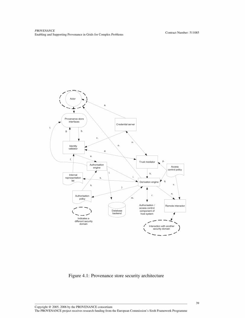
PROVENANCEEnabling and Supporting Provenance in Grids for Complex Problems Contract Number: 511085
Database backend
Identity validator
Authorisation engine
Credential server
Trust mediator
Provenance store interfaces
b.
Actor
Authorisation / access control component of host system
Derivation engine
Indicates a different security
domain
Internal representation
list
a.
c.
e.
d.
f.
g.
h.i.
j.k.
Access control policy
Authorisation policy
l.
o.
p.
q.
r.
s.
t.
m.
Remote interactor
n.
Interaction with another security domain
u.
v.
Figure 4.1: Provenance store security architecture
Copyright @ 2005, 2006 by the PROVENANCE consortiumThe PROVENANCE project receives research funding from the European Commission’s Sixth Framework Programme
39
PROVENANCEEnabling and Supporting Provenance in Grids for Complex Problems Contract Number: 511085
is optional, and correlates with the third security issue in Section 4.2. If theasserter identity is to be utilised in the access control decision, then it needs tobe mapped to a corresponding IR as well.
4. Formats the request into an appropriate representation for access control pur-poses.
The first two functions are performed with help from an internal representation listthat specifies the appropriate mapping relationships, including roles.
The credential server(†) fulfils the role of being a trusted third party holding identity- [GR-OTM.5, p. 129]related information for all potential users of the provenance system within a given se-curity domain, as well as providing them with suitable credentials and other relatedsecurity tokens for authentication purposes . The authorisation engine (†) essentially [SR-6-1, p. 122]performs the access control functionality in two main ways based on the authorisa-tions specified in the authorisation policy (†) and the IR produced from the identity [SR-6-1, p. 122]validator:
• The request is granted or denied solely on the basis of the information from theauthorisation policy and the IR related to the identity of the requesting actor.It is also possible that the IR of the asserting actor is taken into account in theaccess control decision as well; we assume that this possibility exists, but usethe term IR to refer to the IR of the recording actor for the sake of brevity in theremaining discussion. If granted, the requested operation is performed and theappropriate acknowledgement or data item is returned directly to the requestorwithout further intervention from the authorisation engine.
• The granting of the request may additionally be dependent on information con-tained within the data item that the request is related to (such a condition wouldbe specified accordingly in the authorisation policy). For example, a read oper-ation associated with an IR on a given p-assertion might be permitted only if thep-assertion contained relevant information pertaining to that IR. In this case, thep-assertion in question would have to be retrieved first and assessed accordinglyby the authorisation engine before a final decision can be made on granting ordenying the request.
Depending on the nature of the authorisation engine, it may be necessary that theassignment of a role to an IR for the case of a RBAC should be achieved by the au-thorisation engine instead of the identity validator. In addition, it is possible to employeither one or both of these two approaches to specifying authorisation:
• an identity / role is assumed to have no authorisations in the initial case, andexplicit authorisations have to be granted;
• an identity / role is assumed to have complete authorisation in the initial case,and explicit restrictions have to be placed.
Copyright @ 2005, 2006 by the PROVENANCE consortiumThe PROVENANCE project receives research funding from the European Commission’s Sixth Framework Programme
40

PROVENANCEEnabling and Supporting Provenance in Grids for Complex Problems Contract Number: 511085
The semantics and the granularity of the authorisation assertions within the autho-risation policy will determine how fine grained and flexible access control can be inthe infrastructure. Ideally, authorisations should be specifiable at the level of individualp-assertions, and could be refined to individual elements within a p-assertion if suchneed arises. Current authorisation systems in use provide differing levels of seman-tic expressibility and granularity for the authorisation policies they employ. In termsof semantic expressibility, a possible example could be authorisation systems that al-low restriction on access based on additional characteristics such as user attributes,time of day or processing time of job, in contract to simpler systems that only permituser identity in the authorisation expression. If an existing system is to be used as abuilding block for the provenance store security infrastructure, it should therefore in-corporate sufficient expressibility and granularity to satisfy the security requirementsof the project (Section 9.1.6).
Additionally, we note that the content-based authorisation described in Section 4.2would require a higher level policy language to describe, that would then subsequentlyrequire translation into the lower level assertions of the authorisation policy (as accesscontrol can only be meaningfully performed at this level). This feature is not spec-ified in the software requirements (Section 9.1.6), and merely represents an optionalenhancement to the actual security architecture to be implemented.
The access control policy (†) is a higher level security policy that specifies the ways [SR-6-1, p. 122]in which the authorisation policy and/or internal representation list can be modifiedby the components which access them. It also describes in a high level manner theconfiguration of the provenance store from a security viewpoint and the protocols thatexternal entities (such as actors or other provenance stores) need to adhere to in orderto communicate with it. The access control policy, authorisation policy and internalrepresentation list would constitute the security policy of the provenance store as awhole (Section 7.6). The database backend provides actual physical storage for thep-assertions.
The trust mediator is used to support federation of authentication and/or authori-sation for the case where distributed provenance stores (Section 5.2) exist in differentsecurity domains. Its role is to obtain security assertions or credentials from other rele-vant entities in order to support the specific federation methodology employed. Furtherdetails on the need for federation, particularly with regards to distributed provenancestores can be found in (Section 5.7).
These entities could be a trusted third party (such as the credential server) in thelocal or remote security domain, or the trust mediator of another provenance store.The gathered assertions or credentials can then be used locally (for example, to verifyother credentials received by the identity validator) or can be passed on to the remoteinteractor. Like the trust mediator, the remote interactor is intended to interact withexternal entities, but within a more general context rather than a security specific one.The remote interactor uses the credentials provided by the trust mediator for securecommunication towards this end. The operational parameters for both the trust medi-ator and remote interactor can be configured via the access control policy.
Copyright @ 2005, 2006 by the PROVENANCE consortiumThe PROVENANCE project receives research funding from the European Commission’s Sixth Framework Programme
41

PROVENANCEEnabling and Supporting Provenance in Grids for Complex Problems Contract Number: 511085
The derivation engine (†) provides the following functionality: [SR-6-2, p. 123]
1. Derives new authorisations from existing authorisation information. For the caseof the third security issue for provenance as identified in Section 4.2, the autho-risation information would originate with the p-assertion as part of submittedrequest from the actor. Alternatively, there may be a need to correlate the autho-risations as specified in the access control policy with the authorisations in thehost systems security architecture, in the event that a tighter integration betweenboth architectures is required.
2. Creates a set of appropriate authorisations corresponding to a higher level context-based authorisation specification. This corresponds to the fourth security issuefor provenance, and can be considered to be optional functionality.
The derivation engine may additionally need to interact with other external systemsin order to perform specific tasks related to the storage and retrieval of p-assertions. Itwill perform these via the remote interactor.
4.3.2 Interaction Between ComponentsWe illustrate the interaction between these components using some simple scenariosin a technology independent manner. The flows of information are denoted by labelledarrows in Fig. 4.1 and our description makes reference to them accordingly in brackets.
Scenario 1: Submission of a p-assertion to be stored by a recording actor
1. The p-assertion along with other relevant information is submitted as a an in-vocation message (b.) in accordance to the schema of the recording interface.The submission link is secured using appropriate actor side library functionality(Section 8.7), which may involve encryption or signing of the invocation mes-sage. The required credentials can be obtained (if necessary) from the credentialserver prior to the invocation process. (a.).
2. The identity validator intercepts the message and attempts to verify the submittedcredentials; again this may involve another interaction with the credential server(c.). An attempt is made to resolve the supplied credential information with theinternal representation list (f.) If the credentials cannot be verified, but there isadditional information present to indicate the manner in which they might beverified, an appropriate request is sent off to the trust mediator (d.).
3. Depending on the methodology used for federation purposes (see Section 5.7),the trust mediator may opt to contact a trusted third party (the credential serveror another entity) within the current or remote security domain (u.) to obtain thenecessary credentials to communicate with the party that is capable of verifyingthe actor’s credentials.
Copyright @ 2005, 2006 by the PROVENANCE consortiumThe PROVENANCE project receives research funding from the European Commission’s Sixth Framework Programme
42

PROVENANCEEnabling and Supporting Provenance in Grids for Complex Problems Contract Number: 511085
4. The external communication with the designated party is handled by the remoteinteractor using the credentials obtained by the trust mediator. If the result ofthis interaction is the verification of the actor’s credentials, there may arise aneed to add new updates to the local IR or authorisation policy. Such a decision(if required), is made by the derivation engine (h.), which will in turn make theappropriate additions to the internal representation list (s.) and the authorisationpolicy (j.). The entire operation is mediated using the guidelines specified in theaccess control policy (q.)
5. If the credentials fail to be verified successfully, an appropriate security excep-tion is returned via a fault (g.). Otherwise, the validator converts the store requestinto an appropriate format and sends it off to the authorisation engine (e) alongwith the role and accompanying security attributes.
6. The authorisation engine first needs to ascertain whether the store request isvalid for the specified role based on the authorisations specified in the accesscontrol policy (k.). If it is not, an appropriate security exception is again returnedvia a fault (t.). Otherwise, new authorisation information for the p-assertionto be stored needs to be determined. The authorisation engine formulates anappropriate statement which is then sent off to the derivation engine (i.). Forthe case of the third security issue mentioned in Section 4.2, the submitted p-assertion will also contain accompanying authorisation information; this willbe also be taken into account in the formulated statement of the authorisationengine.
7. The derivation engine subsequently creates new authorisation information fromthe formulated statement based on the rules prescribed in the access control pol-icy (q). For purposes of maximising performance, this new authorisation infor-mation could have been created by the recording actor doing the submission sothat the derivation engine uses it directly without any further processing. Thenew authorisation for the p-assertion to be stored is added to the authorisationpolicy (j). The p-assertion is now sent onwards to the database backend, alongwith relevant authorisation information or metadata that it is meant to be storedwith (l.).
8. An acknowledgement (as well as other pertinent information) is returned to thederivation engine (m.), which is processed accordingly and another acknowl-edgement returned to the recording actor (o).
Scenario 2 : Retrieval of a p-assertion by a querying actor
The sequence of interactions is nearly identical to that for the case of storage. Theprimary difference arises from the fact that there is no need for the derivation engineto generate new authorisation information as there is no new p-assertion to be stored.
Copyright @ 2005, 2006 by the PROVENANCE consortiumThe PROVENANCE project receives research funding from the European Commission’s Sixth Framework Programme
43
PROVENANCEEnabling and Supporting Provenance in Grids for Complex Problems Contract Number: 511085
However, when the requested p-assertion is returned (m.), further transformations maybe performed on it, in accordance to the initial authorisation information associatedwith the request as well as any additional authorisation information stored and asso-ciated with the p-assertion itself. The transformations which are undertaken by thederivation engine, may take the form of filtering out portions of the p-assertion ortransforming the information in the p-assertion in some specific manner.
Depending on various factors such as the particular deployment of provenancestores, the p-assertions returned and the nature of the request made by the queryingactor, there may arise a need for the provenance store to engage in remote interactionswith other systems (potentially located in different security domains as well) in orderto return a satisfactory result set to the querying actor. This activity is undertaken bythe remote interactor (n.), which will procure the necessary security credentials forits interaction from the trust mediator. Again, this operation is coordinated under theguidelines specified in the access control policy (p., q., v.).
Scenario 3: Management of the provenance store by a managing actor
Management operations on the stored p-assertions are achieved in an identicalmanner to that for scenario 1 and 2. Submission of a management operation requestis treated like the submission of a p-assertion to be stored, with the difference that themanagement request is not stored but rather processed by the derivation engine and theappropriate functionality then enacted. This may require retrieval of p-assertions, if so,these are then returned to the managing actor in a similar manner to that in Scenario2. There may also be modifications of internal representation list/authorisation policywhich may include deletion, modification and addition of entries. All of these oper-ations are consequent on the identity validator first recognising that the authenticatedmanaging actor has the role or capability to perform these management type activities(see Section 7.6).
Scenario 4 : Integrating authorisations of the provenance store and the host system
This can be accomplished by providing a link / interface between the access control/authorisation components of the host system and the derivation engine. If the prove-nance store architecture is tightly integrated with its host system, this link may notneed to be secured as all communications between the architectures are internal withinthe operating system, rather than through an exposed network medium. Changes thatneed to be made to the authorisation policy / internal representation list can then bepropagated through the derivation engine (r).
An implementation of the provenance architecture may require distributed prove-nance stores for reasons such as scalability, as will be discussed in Chapter 5. In suchan instance, p-assertions related to a specific workflow or sequence of execution maybe stored in multiple provenance stores by the responsible recording actors. Conse-
Copyright @ 2005, 2006 by the PROVENANCE consortiumThe PROVENANCE project receives research funding from the European Commission’s Sixth Framework Programme
44

PROVENANCEEnabling and Supporting Provenance in Grids for Complex Problems Contract Number: 511085
quently, a query to retrieve a group of related p-assertions may potentially require aseries of queries to the various provenance stores holding the desired p-assertions. Wediscuss the security implications of this requirement in Section 5.7.
4.4 Security in Other Architecture ComponentsIn the previous subsection, we presented and described the functioning of a securityarchitecture to protect the provenance store, a key component of the logical archi-tecture. Here, we study the security considerations underlying interactions involvingother components of the logical architecture.
4.4.1 Between other components and the provenance storeThe other components in the logical architecture that interact directly with the prove-nance store will now require corresponding security functionality as well in order toensure their interactions are secured properly. We describe the nature of the requiredfunctionality below for application services, management UIs and processing services.
1. A facility is required for accessing credentials that are to be submitted to theidentity validator in the provenance store. This can be provided as additionallibraries in the corresponding actor side libraries (Section 8.7) or as interfacesthat permit interoperation with external third party applications that provide cre-dential generating functionality. A straightforward example would be a keystoremanager application that generates, archives keys and certificates and obtainsapproval for these certificates from a CA.
2. If a keystore or some other facility for storing cryptographically generated ma-terial is to be used by the actor side libraries, it has to be secured appropriately(e.g. located in a secure account, encrypted and contents accessible only by theprovision of a username/password combination).
3. A facility is required for accessing specific security mechanisms such as signingor time stamping. This is necessary, for example, when the asserting actor needsto sign the p-assertion it created (see related security issue 2).
4. For the case where authorisation information is desired to be submitted along-side p-assertions, an interface must be provided as part of the domain specificservices that allows the retrieval of this information from the appropriate loca-tions (such as a local database). This interface should be congruent with thespecific format in which the authorisation information can be expressed in.
Copyright @ 2005, 2006 by the PROVENANCE consortiumThe PROVENANCE project receives research funding from the European Commission’s Sixth Framework Programme
45
PROVENANCEEnabling and Supporting Provenance in Grids for Complex Problems Contract Number: 511085
4.4.2 Intermediate componentsBy intermediate components, we refer to components that are not directly accessibleby the user. Such components may themselves be invoked or accessed by other com-ponents rather than by the user, and may interact directly with the provenance store.For example, a user may use a presentation UI to access a presentation service whichin turn accesses the provenance store. In the application domain, a user may access anapplication UI that in turn invokes a chain of other application services before a finalinvocation is made to the provenance store. In such cases, the intermediate componentmay require authentication of incoming requests to it. It is possible to reuse the secu-rity architecture developed for the provenance store for this particular component aswell. The primary differences would be, with reference to Fig. 4.1, are:
1. As the incoming request is to the intermediate component, it is unlikely to be a p-assertion, rather a generic data item (which may contain a p-assertion) submittedin accordance with the schema of the interface to this intermediate component.
2. The derivation engine will not be used to create new authorisation informationas the submitted data item is not intended to be stored. However it may be usedin performing some security-related functionality on the data item, for exampleencrypting or filtering out a certain portion of it. This will be accomplishedin conjunction with security policy dictating the operation of this intermediatecomponent.
3. Once the request is approved by the authorisation engine, it is sent off (l) tosome internal function of the intermediate component for further processing,rather than to a database backend (as is the case for the provenance store). Oncethis processing is complete, a result is returned to the invoking actor (m) and /or a further invocation is made to another component.
4.4.3 Delegation of identity or access controlThe need to delegate access control may arise if the intermediate component describedpreviously exists in a separate security domain from both the user and the provenancestore. Consider again the logical architecture in Fig. 4.1 and assume that a user isperforming a query on the provenance store through the presentation UI and a pro-cessing service. Assume now three separate security domains: one containing the userand the presentation UI, another the processing service, and the third encapsulating theprovenance store.
When the presentation UI under the users control sends a request to the presenta-tion service, an appropriate credential is submitted by the user for purposes of authen-tication. If the request is authorised, the presentation service will then decide the typeand number of provenance store queries that need to be made in order to satisfy therequest. When making these queries, the presentation service needs to present suitable
Copyright @ 2005, 2006 by the PROVENANCE consortiumThe PROVENANCE project receives research funding from the European Commission’s Sixth Framework Programme
46

PROVENANCEEnabling and Supporting Provenance in Grids for Complex Problems Contract Number: 511085
authentication credentials to the provenance store. There are essentially two ways toproceed here:
• Authenticate to the provenance store using the credentials of the presentation ser-vice, whereupon subsequent authorisation decisions will be based on the identityor associated role of the presentation service. This approach requires the presen-tation service to be trusted and known to the provenance store security admin-istrators, and that it has the appropriate authorisation to access a wide enoughpool of p-assertions to satisfy requests from all potential users (or at least usersthat are known within the security domain of the presentation service).
• Authenticate to the provenance store on behalf of the original user. This ap-proach requires that a form of delegated identity or access control credential becreated by the presentation service, possibly in negotiation with the presentationUI. The identity validator of the provenance store must then be able to recogniseand process this delegated credential accordingly, and infer the identity or asso-ciated role of the original user. Subsequent authorisation decisions are then onthe basis of the users identity, and may also need to take into account additionalconstraints specified in the delegated credential itself.
The first approach is suitable if all potential users making queries can ever only doso through the medium of a presentation service. Here, the responsibility of checkingauthorisations for the actual users is effectively offloaded from the provenance store tothe various presentation services in the system. If the number of presentation servicesknown within the provenance store security domain is significantly smaller than thepotential number of users, then the overhead of authorisation is equivalently reducedas there is now only a need to check on these presentation services.
There are some drawbacks however with this approach however. Firstly, authori-sation policies are likely to be duplicated between many presentation services, as itis unlikely that authorisation for a specific user will differ between different services.Accordingly, changes or additions to these authorisation policies must then also bepropagated between the different copies on all services. Lastly, application servicesstoring p-assertions through the recording interface must now provide authorisationinformation pertaining to presentation services rather than specific users. This maynecessitate additional overhead in communication between application services andpresentation services.
The second approach therefore appears to be a more feasible one. There will how-ever be an overhead associated with communication between the presentation UI andthe presentation service in order to create an appropriate delegation credential. De-pending on the delegation act itself, there may be a need also for further communica-tion between the security architecture of the provenance store and the user / presenta-tion UI during the authentication or authorisation process in the security architecture ofthe provenance store. This might happen, for example, when delegating access control
Copyright @ 2005, 2006 by the PROVENANCE consortiumThe PROVENANCE project receives research funding from the European Commission’s Sixth Framework Programme
47
PROVENANCEEnabling and Supporting Provenance in Grids for Complex Problems Contract Number: 511085
is expressed through the modification of the authorisation policy in the provenancestore to reflect the delegation of authorisations between the security domains of theuser and the provenance store.
Even when credential delegation is used, the presentation service may also havean installed security policy that dictates the nature of the results to be returned to theuser / presentation UI. For example, assume that a request from the user to the pre-sentation service results in several corresponding query requests being sent in turn tothe provenance store along with a delegated credential. P-assertions pertaining to theauthorisation associated with this credential are then returned to the presentation ser-vice. At this point, the security policy of the presentation service as pertaining to theuser in question may dictate further processing of the results (such as transforming orfiltering it in some way) before finally returning it to the user. In this case, filtering ortransforming of the returned results based on authorisation considerations happens attwo stages: once at the provenance store, and then subsequently at the presentation ser-vice. In both stages, it is performed by the derivation engine of the respective securityarchitecture. There may also be need to communicate between the authorisation en-gines of both the presentation service and provenance store via their respective remoteinteractors and trust mediators, if complex authorisation decisions are to be affected.
The description in this subsection is equally applicable to intermediate componentsin other places in the logical architecture, for example with an application service thatis located in a different security domain from the actual application service that makesthe final submission of p-assertions to the provenance store. Similarly, delegation ofidentity or access control can also occur multiple times if there is an invocation of achain of application services (such as that might occur in a workflow), with all theseservices located in different security domains. In cases like this, it is necessary toensure that the delegation mechanism being used (for example, proxy certificates) cansupport multiple acts of delegation.
4.5 Additional security issuesWhile this chapter discusses security considerations for all components of the logicalarchitecture, the primary focus is on the security architecture for the provenance storeas we have established it as the core component in the logical architecture. The con-struction and implementation of this architecture will therefore take precedence oversecurity considerations for other components. In particular, if the provenance systemis to be integrated into an independent application domain of which the developers ofthe provenance system have no control over, then it is assumed that some, if not all,of the security issues relating to the application services have already been addressedadequately. Such issues include the need for delegation of access control, which wasalready discussed at the end of the previous section. In this section, we describe a fewmore of these types of security issues. We state where we do not consider an issue to beunder the purview of the security work to be achieved for the provenance architecture.
Copyright @ 2005, 2006 by the PROVENANCE consortiumThe PROVENANCE project receives research funding from the European Commission’s Sixth Framework Programme
48
PROVENANCEEnabling and Supporting Provenance in Grids for Complex Problems Contract Number: 511085
1. Mutual authentication and secure transport of p-assertions between two appli-cation actors. Both activities have to be handled or negotiated between the twoactors involved in the production of interaction p-assertions. This issue is en-tirely within the responsibility of the application domain.
2. Anonymisation of data. Some applications (for example Medical applicationsusing sensitive patient data) require the exchange of patient-related informationduring the interaction of services. Legal restrictions mandate that data of thisnature is anonymised (patient identity is removed) and depersonalised (i.e. theidentity of the patient cannot be traced based on other information in the record).This requirement is also outside the context of the security architecture.
3. Support for multiple authentication schemes. To enhance security in some ap-plication scenarios, authentication requires a combination of security credentialsin order to be successful. The identity validator of the component in questionmust then be able to support the use of multiple security credentials. There is noexplicit requirement for multiple authentication to be handled by the provenancestore, although this could be employed in the application domain itself for whichit assumes full responsibility for.
4. Specifying policies in an RBAC fashion. It may be useful for authorisation tobe performed in a RBAC fashion in the provenance store; the authorisation en-gine, policy and internal representation list would thereby need to incorporatethe necessary semantics to express RBAC-type assertions.
5. Long term storage of process documentation. If a third party database provideris used, then process documentation may need to be encrypted or signed bythe remote interactor prior to sending it off for storage. In the event that thisdocumentation is intended to be stored for a relatively long period (e.g. 100years), a situation likely to arise is one where the original cryptographic keysand / or algorithms become outdated or expire. Such issues must be cateredfor in some way, for example, by having a key archival facility and re-signing/ re-encrypting provenance information periodically over the intended storageduration.
6. Expiry of certificates. For workflows that run over a relatively long period, it ispossible that certificates could expire in the middle of a workflow run. If an actoruses a certificate as part of the authentication process to the provenance store,then expiry of this certificate would mean that submission invocations that wereonce accepted within the context of this workflow have now become invalid. Toavoid situations like this, proper management of certificates and keys at the actorend is called for (i.e. workflow duration is estimated against certificate life timeprior to commencing a workflow). Alternatively, the provenance store securitypolicy could be articulated appropriately to avoid this situation. For example,
Copyright @ 2005, 2006 by the PROVENANCE consortiumThe PROVENANCE project receives research funding from the European Commission’s Sixth Framework Programme
49

PROVENANCEEnabling and Supporting Provenance in Grids for Complex Problems Contract Number: 511085
the authorisation component could keep track of all invocations from a givenactor within the context of a specific activity and allow remaining invocations toproceed in that activity as long as the initial invocations were signed with a validcertificate.
4.6 ConclusionIn this chapter, we discussed security issues that were relevant in the context of prove-nance. The security architecture for the provenance store is then presented along withan explanation of the functionality of its constituent components. This is followedby an illustration of the interaction of these various components in for some standardinteractions with the provenance store. We then discuss security issues pertaining toother components of the architecture. Finally, we outline several peripheral securityissues, of which some may need to be addressed in the development of the securityarchitecture. In the following chapters, we will again discuss security issues (whererelevant) with appropriate references to this chapter.
Copyright @ 2005, 2006 by the PROVENANCE consortiumThe PROVENANCE project receives research funding from the European Commission’s Sixth Framework Programme
50
PROVENANCEEnabling and Supporting Provenance in Grids for Complex Problems Contract Number: 511085
Chapter 5
Scalability Architecture
After introducing a logical architecture for provenance systems in Chapter 3, this chap-ter now discusses scalability in the architecture. Architectural scalability addresseshow architectural components can be organised and used by implementations to caterfor increasingly large loads in terms of such measures as computation, bandwidth andstorage. The chapter first presents a set of recording patterns that identify communi-cations between key architecture roles. Second, it explains how the data organisationadopted by the provenance store allows for data that is geographically distributed. Itthen goes on to explain how the staging of data, references and templates can be in-tegrated into the provenance architecture to address scalability. Finally, it discussesthe security implications of these architectural concepts. The design presented in thischapter is inspired by previous scalability analyses and use cases [IGM05].
5.1 Recording PatternsTo be able to cope with the documentation of a single execution, provenance storesmay have to be distributed since there can be a large quantity of data, in a large amountof assertions, recorded by a high number of actors deployed in many organisations,each with their own security domain, privacy requirements, etc. The requirement forrecording process documentation in distributed provenance stores, such that all doc-umentation related to an execution can be retrieved again, presents a developer withseveral deployment problems. These include where to store process documentation,how many provenance stores to deploy, where in the network topology to deployprovenance stores, and how application actors can associate process documentationstored across provenance stores. Therefore, one aim of the distribution architecture isto present a set of deployment patterns (†) that address these problems. [SR-2-4, p. 120]
A pattern [AIS77, Ale79, GHJV95] describes a solution to a common design prob-lem; the solution described must strike a balance between being concrete enough to beapplicable and abstract enough so that it can be applied to a range of similar problemsituations. In the context of a provenance architecture, patterns allow us to present
Copyright @ 2005, 2006 by the PROVENANCE consortiumThe PROVENANCE project receives research funding from the European Commission’s Sixth Framework Programme
51

PROVENANCEEnabling and Supporting Provenance in Grids for Complex Problems Contract Number: 511085
a solution that any developer can use to integrate p-assertion recording into their ap-plication. We now describe a set of patterns for p-assertion recording adopted from[Gro05]. The format is as follows:
Each section title is a short name of the pattern that reflects the solution.
Diagram A diagram that shows the pattern visually. Diagrams have a common vi-sual appearance. Provenance Stores are labelled and denoted by a 3D cylinder. Actorsare denoted by boxes. A single message exchange is denoted by a line with an ar-row head. The arrow denotes the direction of the message flow. Dotted lines followthe same convention but denote multiple message exchanges. A circle above a linedenotes information inside the message.
Context The situation in which the pattern applies and why this pattern exists.
Problem Describes the problem that the pattern solves providing more detail as towhen the pattern should be applied.
Solution A description of how to apply the pattern including the interactions be-tween actors and any properties an actor is expected to have in order to function in thepattern.
5.1.1 SeparateStore PatternDiagram See Figure 5.1.
Context Application actors want to make available information about their interac-tions and associated state. This pattern exists because querying actors want to knowhow application actors have interacted in the past in order to produce a piece of data.To know how application actors performed, these application actors must make avail-able information about their actions.
Problem An application actor, A, may be involved in a large number of interac-tions over its lifetime and cannot retain all the process documentation itself. Like-wise, querying actors would like to access information about A’s previous messageexchanges and states, even when A is not available. For example, A may have beenshut down, moved or be under repair.
Copyright @ 2005, 2006 by the PROVENANCE consortiumThe PROVENANCE project receives research funding from the European Commission’s Sixth Framework Programme
52
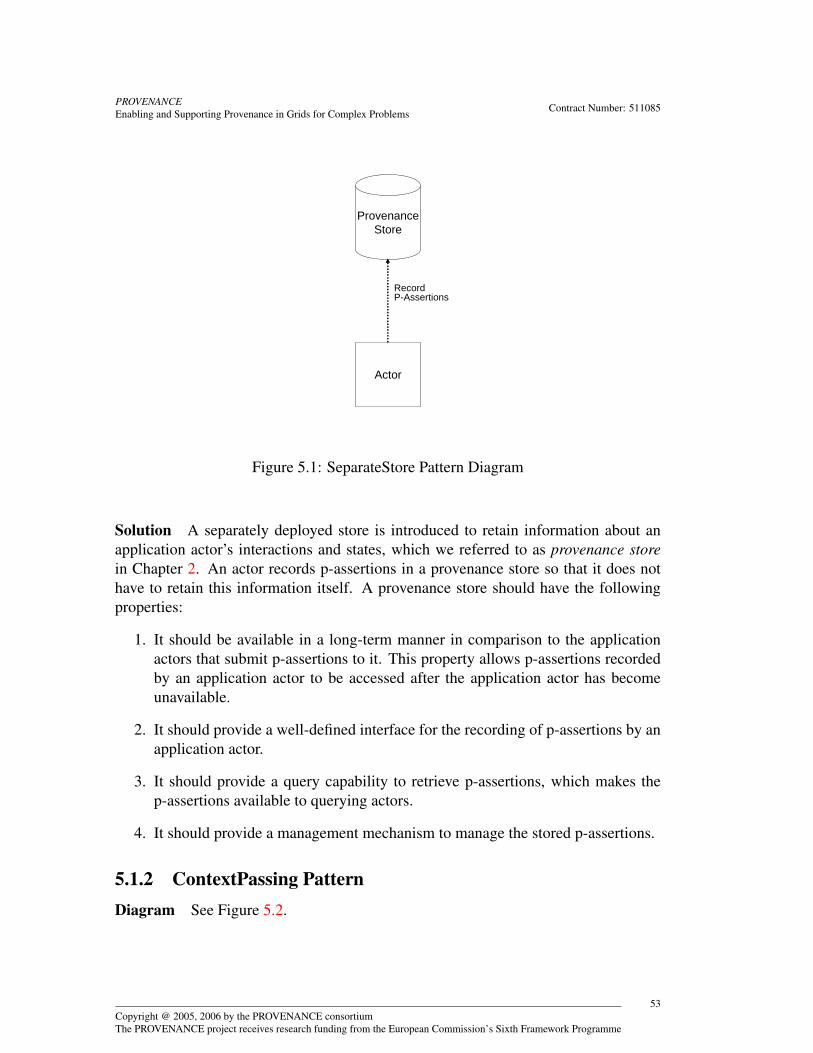
PROVENANCEEnabling and Supporting Provenance in Grids for Complex Problems Contract Number: 511085
Actor
ProvenanceStore
Record P-Assertions
Figure 5.1: SeparateStore Pattern Diagram
Solution A separately deployed store is introduced to retain information about anapplication actor’s interactions and states, which we referred to as provenance storein Chapter 2. An actor records p-assertions in a provenance store so that it does nothave to retain this information itself. A provenance store should have the followingproperties:
1. It should be available in a long-term manner in comparison to the applicationactors that submit p-assertions to it. This property allows p-assertions recordedby an application actor to be accessed after the application actor has becomeunavailable.
2. It should provide a well-defined interface for the recording of p-assertions by anapplication actor.
3. It should provide a query capability to retrieve p-assertions, which makes thep-assertions available to querying actors.
4. It should provide a management mechanism to manage the stored p-assertions.
5.1.2 ContextPassing PatternDiagram See Figure 5.2.
Copyright @ 2005, 2006 by the PROVENANCE consortiumThe PROVENANCE project receives research funding from the European Commission’s Sixth Framework Programme
53
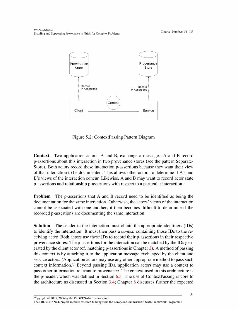
PROVENANCEEnabling and Supporting Provenance in Grids for Complex Problems Contract Number: 511085
Client Service
ProvenanceStore
ProvenanceStore
Record P-Assertions Record
P-Assertions
Context
Figure 5.2: ContextPassing Pattern Diagram
Context Two application actors, A and B, exchange a message. A and B recordp-assertions about this interaction in two provenance stores (see the pattern Separate-Store). Both actors record these interaction p-assertions because they want their viewof that interaction to be documented. This allows other actors to determine if A’s andB’s views of the interaction concur. Likewise, A and B may want to record actor statep-assertions and relationship p-assertions with respect to a particular interaction.
Problem The p-assertions that A and B record need to be identified as being thedocumentation for the same interaction. Otherwise, the actors’ views of the interactioncannot be associated with one another; it then becomes difficult to determine if therecorded p-assertions are documenting the same interaction.
Solution The sender in the interaction must obtain the appropriate identifiers (IDs)to identify the interaction. It must then pass a context containing those IDs to the re-ceiving actor. Both actors use these IDs to record their p-assertions in their respectiveprovenance stores. The p-assertions for the interaction can be matched by the IDs gen-erated by the client actor (cf. matching p-assertions in Chapter 2). A method of passingthis context is by attaching it to the application message exchanged by the client andservice actors. (Application actors may use any other appropriate method to pass suchcontext information.) Beyond passing IDs, application actors may use a context topass other information relevant to provenance. The context used in this architecture isthe p-header, which was defined in Section 6.3. The use of ContextPassing is core tothe architecture as discussed in Section 3.4; Chapter 8 discusses further the expected
Copyright @ 2005, 2006 by the PROVENANCE consortiumThe PROVENANCE project receives research funding from the European Commission’s Sixth Framework Programme
54

PROVENANCEEnabling and Supporting Provenance in Grids for Complex Problems Contract Number: 511085
behaviour of actors regarding such contexts. Identifiers and contexts are also discussedin Sections 6.1 and 6.3.
5.1.3 SharedStore PatternDiagram See Figure 5.3.
Client Service
ProvenanceStore
Record P-Assertions
Record P-Assertions
Figure 5.3: SharedStore Pattern Diagram
Context Actors record p-assertions in provenance stores following the SeparateStoreand ContextPassing patterns.
Problem The SeparateStore and ContextPassing patterns may lead developers to be-lieve that for every application actor, there is a corresponding provenance store. How-ever, developers may not want to deploy a provenance store for every application actor,especially when the number of application actors is large. Also, in order to retrieve theprovenance of a result each provenance store must be contacted resulting in slowerquery performance.
Solution Application actors are allowed to record p-assertions in a shared prove-nance store.
The SharedStore pattern clarifies the way in which SeparateStore and ContextPass-ing can be applied. Both SeparateStore and ContextPassing are agnostic as to whatprovenance store an actor may use to record its p-assertions. SharedStore emphasises
Copyright @ 2005, 2006 by the PROVENANCE consortiumThe PROVENANCE project receives research funding from the European Commission’s Sixth Framework Programme
55
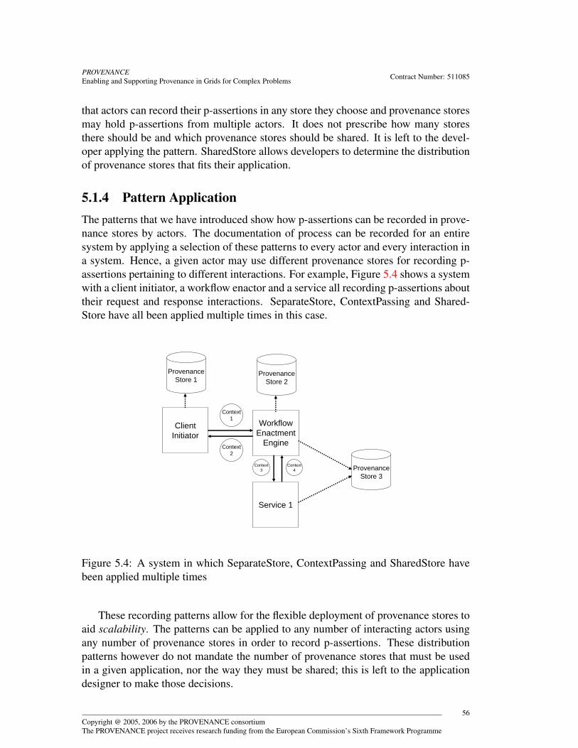
PROVENANCEEnabling and Supporting Provenance in Grids for Complex Problems Contract Number: 511085
that actors can record their p-assertions in any store they choose and provenance storesmay hold p-assertions from multiple actors. It does not prescribe how many storesthere should be and which provenance stores should be shared. It is left to the devel-oper applying the pattern. SharedStore allows developers to determine the distributionof provenance stores that fits their application.
5.1.4 Pattern ApplicationThe patterns that we have introduced show how p-assertions can be recorded in prove-nance stores by actors. The documentation of process can be recorded for an entiresystem by applying a selection of these patterns to every actor and every interaction ina system. Hence, a given actor may use different provenance stores for recording p-assertions pertaining to different interactions. For example, Figure 5.4 shows a systemwith a client initiator, a workflow enactor and a service all recording p-assertions abouttheir request and response interactions. SeparateStore, ContextPassing and Shared-Store have all been applied multiple times in this case.
ClientInitiator
WorkflowEnactment
Engine
Service 1
ProvenanceStore 1
ProvenanceStore 2
ProvenanceStore 3
Context1
Context2
Context3
Context4
Figure 5.4: A system in which SeparateStore, ContextPassing and SharedStore havebeen applied multiple times
These recording patterns allow for the flexible deployment of provenance stores toaid scalability. The patterns can be applied to any number of interacting actors usingany number of provenance stores in order to record p-assertions. These distributionpatterns however do not mandate the number of provenance stores that must be usedin a given application, nor the way they must be shared; this is left to the applicationdesigner to make those decisions.
Copyright @ 2005, 2006 by the PROVENANCE consortiumThe PROVENANCE project receives research funding from the European Commission’s Sixth Framework Programme
56
PROVENANCEEnabling and Supporting Provenance in Grids for Complex Problems Contract Number: 511085
5.2 LinkingBy the definition of the p-assertion recording patterns, an actor is allowed to record itsp-assertions in any provenance store. This means that the documentation of processthat led to a result can exist across any number of provenance stores. There are severalbenefits in allowing documentation to be recorded across multiple stores: the elimi-nation of a central point of failure, the spreading of demand across multiple servicesand the ability for provenance stores to exist in different network areas (for example,one provenance store may be behind a firewall whereas another is not). In general,allowing p-assertions to be recorded across multiple stores increases the flexibility andscalability of systems recording p-assertions. The scalability and flexibility are key toallowing these patterns to be applied to the large scale, open, distributed systems thatwe consider.
Given that the p-assertions documenting a given execution may be spread acrossmultiple stores, there must be some mechanism to retrieve these p-assertions in orderto validate, visualise or replay the represented process. To facilitate such a retrievalmechanism, we introduce the notion of a link, which intuitively is a pointer to a prove-nance store.
Definition 5.1 (Link) A link is a reference to a provenance store. 2
We note that links are necessarily unidirectional: a link always points to a remoteprovenance store location. Links are used in two instances, which we now describe.
5.2.1 View LinksThe first use of a link deals with the situation where a client’s view of an interactionand a service’s view of the same interaction as identified by a shared interaction IDare stored in two different provenance stores. It is necessary for each actor to record alink, which we refer to as a View Link(†), that points to the provenance store where the [GR-OTM.5, p. 129]opposite party recorded their p-assertions. Hence, the client in an interaction records alink to the provenance store that the service used to record p-assertions for the given in-teraction, and vice-versa. This allows querying actors to navigate from one provenancestore to the other in order to retrieve both views of an interaction. We note that ViewLinks point to provenance stores only, not to particular pieces of data in a provenancestore; the actual data of interest can be found by the ID identifying the interactionsuniquely.
If an actor A interacting with actor B has to assert, in provenance store PA, that Bis recording its view of the interaction in another provenance store, then actor A has tobecome aware that the store used by B is PB. Either such knowledge is built into A,or it is communicated to A in the course of execution. If it is built into A, then suchknowledge is part of A’s state, and can be asserted by A as an actor state p-assertion.Alternatively, if it is to be communicated to A, then such knowledge can be passed aspart of a context, as formalised by the ContextPassing pattern (for instance, when B
Copyright @ 2005, 2006 by the PROVENANCE consortiumThe PROVENANCE project receives research funding from the European Commission’s Sixth Framework Programme
57
PROVENANCEEnabling and Supporting Provenance in Grids for Complex Problems Contract Number: 511085
returns a result to A). Hence, A can assert the link as part of an interaction p-assertion.It is the responsibility of the provenance store to extract View Links from actor stateor interaction p-assertions and make them readily available to the querier.
5.2.2 Object LinksRelationship p-assertions allow relationships between both messages and data to beexpressed. We model relationship p-assertions as one-to-many triples between dataor messages. (Details about the modelling can be found in Chapter 6.) Each tripleconsists of a subject, a relation and several objects. A relationship p-assertion made byan actor is a directional relation with the subject of the relation referring to the localcurrent interaction p-assertion (or data contained in it).
The object of a relation p-assertion may be local or remote. Hence, we introducea second usage of links to cater for the situation in which an application actor recordsa relationship p-assertion between a local p-assertion and a remote p-assertion. Inthis case, the application actor needs to record which provenance store the remote p-assertion being related to is stored in; such a link is referred to as an Object Link(†). [GR-OTM.5, p. 129]Again, an Object Link only points to the provenance store and not to a particular pieceof data in the store.
5.2.3 Linking SummaryFigure 5.5 shows an example of how both Object and View Links are recorded. ActorA sends a message (M2) to actor B as a consequence of message M1. This interactionis identified by the key 2. In the context (shown by the circle) of the message, A putsa link to the provenance store, PA, that it uses for the interaction with B. Actor Bthen extracts the link from the context and records it as an interaction p-assertion inthe provenance store PB. As a result, a View Link from PB to PA is created (shownby the arch VL 1). Likewise, A knows from its configuration that B always stores itsp-assertions in PB. Hence, A records a link to PB as an actor state p-assertion in PA,which creates a corresponding View Link shown by the arc VL 2. Finally, A makesa relationship p-assertion between its interaction with B and a previous interactionidentified by the key 2 containing M2. As part of the p-assertion, it adds a link tothe provenance store, PR, where the p-assertions related to the other interaction werestored. It then records the relationship p-assertion in PA, which creates an Object Linkfrom PA to PR shown by the arc OL. Figure 5.6 shows the contents of the provenancestores PA and PB after all p-assertions have been recorded.
Both View Links and Object Links allow data and p-assertions stored across prove-nance stores to be retrieved by querying actors. View and Object Links can be con-trasted as follows. A View Link points to another store that contains a piece of datawritten by another actor (which is providing a different view on a same interaction).An Object Link points to another store containing a piece of data asserted by the sameactor (which is making assertions about another interaction).
Copyright @ 2005, 2006 by the PROVENANCE consortiumThe PROVENANCE project receives research funding from the European Commission’s Sixth Framework Programme
58
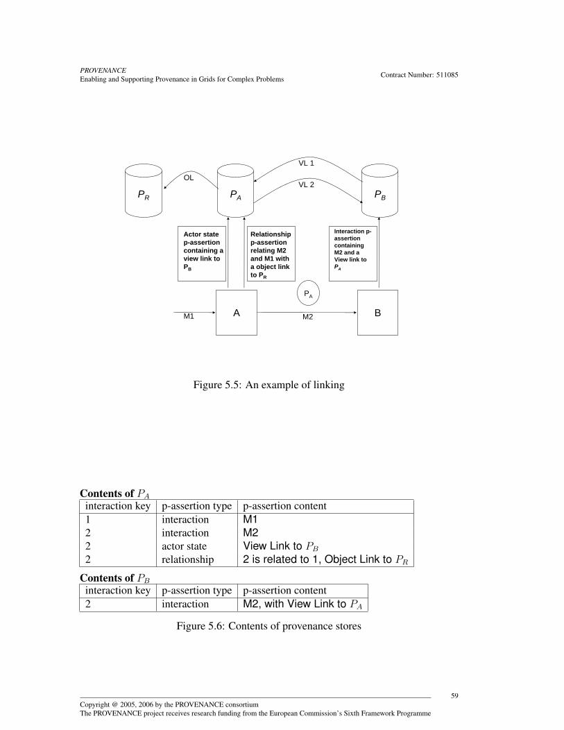
PROVENANCEEnabling and Supporting Provenance in Grids for Complex Problems Contract Number: 511085
A B
PA PBPR
PA
Actor state p-assertion containing a view link to PB
Relationshipp-assertion relating M2 and M1 with a object link to PR
Interaction p-assertioncontaining M2 and a View link to PA
VL 1
VL 2OL
M1 M2
Figure 5.5: An example of linking
Contents of PA
interaction key p-assertion type p-assertion content1 interaction M12 interaction M22 actor state View Link to PB
2 relationship 2 is related to 1, Object Link to PR
Contents of PB
interaction key p-assertion type p-assertion content2 interaction M2, with View Link to PA
Figure 5.6: Contents of provenance stores
Copyright @ 2005, 2006 by the PROVENANCE consortiumThe PROVENANCE project receives research funding from the European Commission’s Sixth Framework Programme
59
PROVENANCEEnabling and Supporting Provenance in Grids for Complex Problems Contract Number: 511085
Links provide a scalable solution to the problem of connecting distributed processdocumentation. Similar to the Web, the unidirectional nature of links prevents theproblem of having to synchronise between provenance stores when recording a link.Instead, each recording actor is responsible for recording a link just as each web pageauthor is responsible for adding links to other pages as appropriate. Recording of linksis lightweight as the information needed to establish a link is minimal. Furthermore,the link structure provides a structured simple mechanism for querying actors to tra-verse provenance stores in order to perform queries.
5.3 Data StagingA provenance store that manages p-assertions over an extended lifecycle requires ex-tensive management and data storage features (see Implementation RecommendationsIR-PS-9, p 135 and IR-PS-8, p 134). These features are typically provided within an or-ganisation on managed servers administered centrally. In many cases, such provenancestores may not be close enough (in terms of network topology) for actors to record p-assertions with acceptable performance. An example of this might be where processdocumentation is being recorded for a workflow running on a computing cluster withhigh speed networking support between the clustered processors. Slower speed net-works connect the cluster to other servers which include a managed provenance store.Communicating directly with the managed provenance store would impact the perfor-mance of the clustered workflow. Hence, systems designers may choose to includedata staging in their design. Data staging is the buffering of data at temporary storagesites until that data can be moved to a final storage site.
Data staging can be done via the creation of local temporary provenance stores (i.e.stores that are deployed close to the recording actor with good connectivity and thatexist solely for the purpose of data staging). Such a temporary store could be deployedon the same host as the recording actor itself. Creation of temporary provenance storesshould be done through a factory mechanism and configured in such a way that once allrecording is finished by the actor/actors using it, the documentation is then transferredto the next provenance store. We note that data may be staged several times as it istransferred to the final set of managed provenance stores. The transfer of data maybe accomplished either by a push from one provenance store to the next or pulled bythe latter from the former. This is a flexible approach that supports multiple firewalland network topologies. Finally, if the provenance store is temporary, a shutdownmechanism is required that safely archives or discards the staged documentation. Theuse of temporary stores allows for efficient use of network bandwidth by actors aswell as ensuring that staged data can be both protected with appropriate access controlmechanisms and queried over.
Whether a provenance store is temporary or permanent, its behaviour as a datastaging provenance store is determined by a policy. A provenance store can act asboth a regular and data staging store for different actors depending on the associated
Copyright @ 2005, 2006 by the PROVENANCE consortiumThe PROVENANCE project receives research funding from the European Commission’s Sixth Framework Programme
60
PROVENANCEEnabling and Supporting Provenance in Grids for Complex Problems Contract Number: 511085
policies. Furthermore, policies are necessary to determine whether provenance storesshould push or pull staged data. Policies for data staging are defined in Definition 7.9,page 102.
Data staging implies the need to copy or move data between various provenancestores. A provenance store can copy data to a target provenance store by first query-ing itself (using the query interface) for the particular p-assertions to be copied andthen recording those p-assertions in the target provenance store (using the recordinginterface). The provenance store is acting as a recording actor in this case and not anasserting actor. The provenance store may use implementation specific functionalityfor deleting p-assertions if movement of data is necessary. Likewise, implementationspecific functionality may be implemented to update linking information (see Sec-tion 7.4.2).
The copying and deletion of p-assertions between provenance stores have an ef-fect on querying those p-assertions: they are available for search and retrieval from adifferent set of stores. For a querying actor expecting to find process documentationin a store from which it has been deleted, there should be a mechanism by which itcan find the new location of that documentation. This is a data management issue outof scope of this architecture (we assume that, in general, p-assertions are not deletedfrom stores), but suggested mechanisms are given in Section 7.4, such as the sendingof notifications when p-assertions are moved to another store.
The querying over staged data is challenging. For example, data may be in transitwhen a query is issued to a provenance store. If the data necessary to answer a queryis in transit to another provenance store, is not readily available and the query cannotbe answered. One solution to the problem is to inform querying actors when data isfinished being transferred and where that data now resides through the use of notifica-tions (Section 7.4). The remote interactor of the security architecture (Section 4.3.1)can be used in the sending of these notifications, as well as supporting any securityrequirements implicit with such notifications.
5.4 ReferencesIn many applications, the size of the messages being transferred between actors may beso large or bandwidth costs so high that the actor cannot record a copy of the messagein the provenance store. In other instances, actors may wish to record multiple p-assertions that contain the same data but only record that data one time. Both theseproblems can be solved through the use of references. References differ from links.Links point to provenance stores whereas references point to data.
5.4.1 By-Value versus By-Reference recordingTo address the situation where an actor does not wish to record data by-value in a p-assertion, we introduce the notion of recording a reference to a message outside the
Copyright @ 2005, 2006 by the PROVENANCE consortiumThe PROVENANCE project receives research funding from the European Commission’s Sixth Framework Programme
61

PROVENANCEEnabling and Supporting Provenance in Grids for Complex Problems Contract Number: 511085
provenance system. An actor may store its application data on some persistent storageoutside a provenance store, such as a shared file system. If the persistent storageprovides some unique identifier for the data (for example, a path), the identifier canbe placed inside a p-assertion that is submitted to the provenance store. A querierthen must resolve the path in order to obtain the corresponding data. In this case, thelifetime of the application data in the persistent storage must be equivalent to that ofthe provenance store.
Another solution is for the provenance store to periodically resolve the referencesdownloading the data into a separate logical repository in the provenance store. Theprovenance store can then inform querying actors that it has a copy of the referenceddata that it can provide. However, this solution implies that the provenance store canunderstand the reference scheme used. Policies identify how provenance stores dealwith referenced data. See Definition 7.8, page 101, for a discussion of such a policy.
5.4.2 Record-Once versus Record-ManyApplications, especially those which iterate heavily, may record the same p-assertioncontent multiple times leading to potentially large amounts of redundant informationwithin the provenance store. To address this we allow references to data items withinprovenance stores.
A p-assertion has a unique key (cf. Figure 6.2, page 69). If an actor records a subse-quent p-assertion that has the same content as a previously recorded p-assertion, it maychoose to replace the contents of the new p-assertion with the previous p-assertion’skey thereby reducing the new p-assertion’s size. If there are multiple p-assertions to berecorded, an actor may repeatedly replace the p-assertion content with the appropriatep-assertion key. Querying the p-assertion can then include a lookup stage that replacesthe recorded identifier with the contents of the message that matches the identifier.
Both referencing mechanisms are explained in terms of replacing the whole contentof p-assertions or messages. However, if a subpart of a message or p-assertion can beidentified that subpart may also be replaced by references. For a further discussion ofmodelling references, see documentation styles 6.13, page 74 and 6.15, page 74.
5.5 P-Assertion TemplatesP-Assertions may often follow the same pattern. They may contain the same structureor data with minor changes in between. For example, during an iterative workflow,p-assertions may be generated that have roughly the same data where one or two pa-rameters in the data may be changed (for instance the state of the loop counter forthat iteration). The p-assertions generated by the actors in the workflow follow a tem-plate: for every iteration, put Y in position X of the p-assertion content. P-AssertionTemplates, then, are algorithms that actors use to generate p-assertions.
Copyright @ 2005, 2006 by the PROVENANCE consortiumThe PROVENANCE project receives research funding from the European Commission’s Sixth Framework Programme
62

PROVENANCEEnabling and Supporting Provenance in Grids for Complex Problems Contract Number: 511085
Typically, such templates are defined locally and used to create p-assertions, whichare then recorded in a provenance store. However, it may be the case that the structureof a p-assertion is large or the computation required for its generation is so complexthat creation of the actual p-assertion may negatively affect the performance of theactor. Therefore, a provenance store may allow actors to upload templates to it. Theactor can then record a p-assertion by sending a template identifier and its parametersto the provenance store. The provenance store can then either generate the p-assertionand place it in its own repository or dynamically generate the p-assertion as and whena query needs it. This reduces the amount of data and processing an actor must recordto provide process documentation, thereby, increasing the scalability of the system.P-Assertion Templates must be expressed in a language that both asserting actors andprovenance stores understand. The choice of such a language is implementation de-pendent and can be specified through policies that govern templates (see Definition7.10, page 102).
Templates are derived from work in mobile code [ACV97]. Extensive literature isavailable about mobile code/agents. Implementers should consult this literature whenimplementing this portion of the architecture.
5.6 Large Query ResultsProcess documentation stored across multiple provenance stores is likely to be mas-sive. Query interfaces such as those defined in Section 7.2 allow querying actors toobtain the process documentation that most precisely fits their provenance questions.However, even with precise queries, the number and size of p-assertions returned tothe querying actors may be large. Therefore, we outline the following techniques fordealing with large query results. Each of which allows querying actors to obtain infor-mation as needed from the provenance store.
To handle large numbers of p-assertions, provenance stores should allow for thebuffering of p-assertions. A querier can then retrieve iteratively the p-assertions asneeded instead of in one large message. A specification of such an interface can befound in Section 7.2. Furthermore, to support p-assertions that contain large dataitems (images for example), query interfaces should allow the sending of keys forthose p-assertions instead of the p-assertions themselves. In some cases, the contentof a p-assertion may also be large. Provenance stores may also wish to support theiterative retrieval of p-assertion content. This notion is supported through the Pro-cess Documentation Query interface defined in Section 7.2 as well as ImplementationRecommendation IR-PS-7, p 134.
Copyright @ 2005, 2006 by the PROVENANCE consortiumThe PROVENANCE project receives research funding from the European Commission’s Sixth Framework Programme
63

PROVENANCEEnabling and Supporting Provenance in Grids for Complex Problems Contract Number: 511085
5.7 SecurityAs discussed earlier, linking provides a mechanism to discover related p-assertions inmultiple stores. A potential security issue arises if the querying actor is not recognisedor does not have the necessary authorisation to retrieve the relevant p-assertions in thesecurity domains of all these stores. Consider a querying actor submitting a complexquery to the provenance store, whereupon the querying functionality determines thenecessary p-assertions required to satisfy the query and attempts to retrieve them fromthe provenance store. In the event that not all of the required p-assertions can be foundlocally, there are two possible ways to proceed:
• The querying functionality itself can use the links in the available p-assertions tolocate other distributed provenance stores which it subsequently needs to query.Thus, the querying functionality queries the distributed provenance stores onbehalf of the querying actor.
• The querying functionality can return the available p-assertions to the queryingactor, which then itself has to navigate the links and make queries to the relevantdistributed provenance stores.
In the first approach, the provenance store to which the original query is directedneeds to interact with other provenance stores, possibly in other security domains. Thisinteraction will be handled by the remote interactor using credentials (if necessary) ac-quired by the trust mediator in the manner previously detailed in Scenario 2 in Section4.3.2. The remote interactor may also choose to use the delegated credentials of thequerying actor in its interaction with the remote provenance store, if so desired.
In the second approach, the querying actor will need to obtain the necessary cre-dentials in order to communicate with the remote provenance stores, possibly througha credential server. Alternatively, depending on the federation methodology employed,the querying actor could attempt to authenticate directly using its own credentials andthe remote provenance store would attempt to verify its credentials in the manner out-lined in Scenario 1 in Section 4.3.2.
Another security concern revolves around the need to establish liability for erro-neous context information. In Section 5.1.2, we discussed the use of a context con-taining IDs to identify an interaction between two actors. Since p-assertions in theprovenance store are matched on the basis of these IDs, it may be useful to providenon-repudiation on such generated IDs in application domains where the need to iden-tify matching p-assertions correctly is critical. As an example, if a client records X forits ID in its own p-assertion and sends a service Y as an ID instead, the client’s sig-nature on Y would establish its liability for the subsequent inability to obtain a matchbetween both IDs. The signature permits us to rule out other possible mitigating fac-tors for the discrepancy, such as transmission errors or an error on the part of the ser-vice actor. Signatures are supported by following Implementation RecommendationIR-ASL-5, p 135.
Copyright @ 2005, 2006 by the PROVENANCE consortiumThe PROVENANCE project receives research funding from the European Commission’s Sixth Framework Programme
64

PROVENANCEEnabling and Supporting Provenance in Grids for Complex Problems Contract Number: 511085
The security policy in such an instance should therefore dictate that the client actorsign the IDs it generates (or the context containing such IDs) to the service actor (seeRule 8.11). This signature activity could be encompassed within the mandate of theprotocol governing a secure interaction between both the client and service actors. Ona similar note, we observe that since the view link is crucial in locating a related p-assertion for a given interaction, its non-repudiation can also be achieved by ensuringthat the recorded link is signed as well. If the recorded link is part of the contents of arecorded p-assertion, then a signature on the entire content will suffice. Signatures onp-assertions are discussed in Section 6.9.
Furthermore, if p-assertions are copied or moved between stores that are locatedin different security domains (i.e. for the staging of data), the access control restric-tions on them in their new destinations needs to be defined. In the simplest case, thenewly moved or copied p-assertions retain the same access control restrictions thatwere associated with them in their original domain. These restrictions can be providedas authorisation information along with the p-assertions as they are recorded to theirnew destinations, where they can be processed by the derivation engine in the mannerdescribed in Section 4.3.1.
If the authorisation information involves identities from the originating domain thatare currently unknown in the destination domain, then this identity information needsto be communicated between the trust mediators of both domains. The communicationcan be performed when the p-assertions are initially recorded, or at a later time whena request is made to the provenance store from an entity that is not recognisable in thenew provenance store domain. The process of moving p-assertions between differentstores also needs to ensure that the transfer medium is secure (if such a requirementis present), and that both stores are properly authenticated to each other prior to themovement.
Security considerations can also arise in the use of references, where a p-assertioncontains a unique identifier for data stored elsewhere rather than the actual data itself.In this case, both the asserting and querying actor may require some sort of assur-ance that any data eventually retrieved by resolving the identifier in the p-assertionis actually the same piece of data that was referred to by the identifier at the time ofp-assertion creation by the asserting actor. This can be accomplished by having thequerying actor include a digest of the data being referred to along with the identifierof that data in the p-assertion. The signature on the p-assertion assures that the digestand the identifier will not be changed. Subsequently, if the referenced data is retrievedlater, its digest can be computed and compared against the digest within the p-assertionas a check of its integrity. Digests can be provided through the reference-digest docu-mentation style (Definition 6.14 page 74, Section 6.5).
When references are being used, it may also be possible for the provenance storeto resolve the references itself (Section 5.4). Retrieval of the remotely stored data willbe achieved by the remote interactor of the security architecture, with the requiredcredentials being obtained by the trust mediator (Section 4.3.1).
Copyright @ 2005, 2006 by the PROVENANCE consortiumThe PROVENANCE project receives research funding from the European Commission’s Sixth Framework Programme
65
PROVENANCEEnabling and Supporting Provenance in Grids for Complex Problems Contract Number: 511085
5.8 ConclusionThis chapter presented the architecture facets that addresses problems of scalability inprovenance systems. The chapter presented three deployment patterns, which identifycommunication between key architecture roles and that can be applied by developersto deploy their provenance system in a distributed manner to promote scalability. Itthen discussed how provenance retrieval could be enabled across a set of distributedprovenance stores via linking, which supports the deployment of multiple distributedprovenance stores. Data staging was presented as a mechanism for minimising the useof network bandwidth and for allowing p-assertions to be recorded in a timely mannerby recording actors. The chapter then presented two notions of recording by referenceeither by referring to p-assertions already recorded or by referring to data stored atsome other location from within a p-assertion. References support scalability by notduplicating data and allowing data to be kept in a single location. P-Assertion Tem-plates were then described as a mechanism to offload the generation of p-assertionsto provenance stores reducing the computational load on asserting actors. We thendiscussed how large query results could be handled. Finally, we addressed relevantsecurity issues that pertain to these scalability solutions.
This chapter has presented architectural solutions to scalability for provenance sys-tems. However, implementations of the architecture can also address the above is-sues in technology specific ways. For example, provenance stores can use clustering[IGM05] and database management technologies to handle large loads. Likewise, inWeb Service implementations, where XML is the common format, binary/compresseddata representation should also be supported. These implementation specific scalabil-ity solutions are supported by the flexibility and design decisions prescribed in thisarchitecture.
Copyright @ 2005, 2006 by the PROVENANCE consortiumThe PROVENANCE project receives research funding from the European Commission’s Sixth Framework Programme
66
PROVENANCEEnabling and Supporting Provenance in Grids for Complex Problems Contract Number: 511085
Chapter 6
Provenance Modelling
In Section 2.4, we discussed the representation of provenance and introduced the con-cept of a p-assertion as an assertion by an actor about a process. We identified threetypes of p-assertion: interaction, relationship and actor state p-assertions. In this sec-tion, we identify how each type of p-assertion can be modelled, i.e. we define thedata structure used to represent each type of p-assertion. Based on these models, weintroduce a common structure according to which p-assertions are structured in theprovenance store.
We note that the p-assertion models presented could be instantiated in differentlanguages, such as XML, RDF or even application-specific binary formats. The choiceis specific to the application that will make use of the process documentation andthe infrastructure on which it is run. To depict the models in the sections below, weadopt a graphical representation of XML Schema, but this should not be interpreted asprescribing the method of encoding. A description of the graphical representation canbe found in Appendix C.
6.1 Identifying InteractionsEvery p-assertion is made in the context of an interaction: an interaction p-assertionasserts the content of a message sent or received in an interaction, an actor state p-assertion asserts the state of an actor at a specific instant during an interaction and arelationship p-assertion relates an interaction to other interactions. Therefore, in orderto model p-assertions, we must provide a way to identify an interaction.
Definition 6.1 (Interaction Key) An interaction key is a globally unique identifier foran interaction. 2
In Figure 6.1, we specify our model for referring to a single interaction: the inter-action key. This key is made up of three parts: the address from which the messagecame, the messageSource, the address to which the message was sent, the messageSinkand an identifier that specifies a particular interaction between these two addresses, the
Copyright @ 2005, 2006 by the PROVENANCE consortiumThe PROVENANCE project receives research funding from the European Commission’s Sixth Framework Programme
67

PROVENANCEEnabling and Supporting Provenance in Grids for Complex Problems Contract Number: 511085
interactionId. An instance of this data structure must be sent along with every p-assertion when the p-assertion is recorded in a provenance store, so that the store isaware to which interaction the p-assertion pertains.
Definition 6.2 (Message Source) A message source is the address from which a mes-sage was sent. 2
Definition 6.3 (Message Sink) A message sink is the address to which a message wassent. 2
Definition 6.4 (Interaction Identifier) An interaction identifier is a value that is uniquefor a given message sent from one message source to one message sink. 2
Figure 6.1: Model for identifying an interaction
6.2 Identifying P-Assertions and DataIn addition to identifying the interaction about which an assertion is being made,every p-assertion has its own identifier: the local p-assertion identifier. Each p-assertion made by one asserting actor about one interaction must have a different localp-assertion identifier. With both interaction identifiers and local p-assertion identifiers,we can construct a global p-assertion key (GPAK) as shown in Figure 6.2. A GPAKconsists of an interaction key, whether the sender or receiver in the interaction made theassertion (the view kind) and the local p-assertion id. A GPAK (†) uniquely identifies [AER-6, p. 133]a p-assertion whether that p-assertion is stored in a provenance store or not.
Copyright @ 2005, 2006 by the PROVENANCE consortiumThe PROVENANCE project receives research funding from the European Commission’s Sixth Framework Programme
68
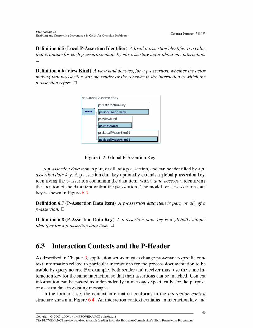
PROVENANCEEnabling and Supporting Provenance in Grids for Complex Problems Contract Number: 511085
Definition 6.5 (Local P-Assertion Identifier) A local p-assertion identifier is a valuethat is unique for each p-assertion made by one asserting actor about one interaction.2
Definition 6.6 (View Kind) A view kind denotes, for a p-assertion, whether the actormaking that p-assertion was the sender or the receiver in the interaction to which thep-assertion refers. 2
Figure 6.2: Global P-Assertion Key
A p-assertion data item is part, or all, of a p-assertion, and can be identified by a p-assertion data key. A p-assertion data key optionally extends a global p-assertion key,identifying the p-assertion containing the data item, with a data accessor, identifyingthe location of the data item within the p-assertion. The model for a p-assertion datakey is shown in Figure 6.3.
Definition 6.7 (P-Assertion Data Item) A p-assertion data item is part, or all, of ap-assertion. 2
Definition 6.8 (P-Assertion Data Key) A p-assertion data key is a globally uniqueidentifier for a p-assertion data item. 2
6.3 Interaction Contexts and the P-HeaderAs described in Chapter 3, application actors must exchange provenance-specific con-text information related to particular interactions for the process documentation to beusable by query actors. For example, both sender and receiver must use the same in-teraction key for the same interaction so that their assertions can be matched. Contextinformation can be passed as independently in messages specifically for the purposeor as extra data in existing messages.
In the former case, the context information conforms to the interaction contextstructure shown in Figure 6.4. An interaction context contains an interaction key and
Copyright @ 2005, 2006 by the PROVENANCE consortiumThe PROVENANCE project receives research funding from the European Commission’s Sixth Framework Programme
69
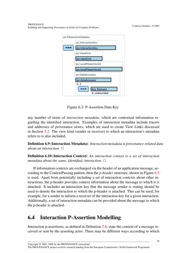
PROVENANCEEnabling and Supporting Provenance in Grids for Complex Problems Contract Number: 511085
Figure 6.3: P-Assertion Data Key
any number of items of interaction metadata, which are contextual information re-garding the identified interaction. Examples of interaction metadata include tracersand addresses of provenance stores, which are used to create View Links discussedin Section 5.2. The view kind (sender or receiver) to which an interaction’s metadatarefers to is also included.
Definition 6.9 (Interaction Metadata) Interaction metadata is provenance-related dataabout an interaction. 2
Definition 6.10 (Interaction Context) An interaction context is a set of interactionmetadata about the same, identified, interaction. 2
If information contexts are exchanged via the header of an application message, ac-cording to the ContextPassing pattern, then the p-header structure, shown in Figure 6.5is used. Apart from potentially including a set of interaction contexts about other in-teractions, the p-header provides context information about the message to which it isattached. It includes an interaction key that the message sender is stating should beused to denote the interaction to which the p-header is attached. This can be used, forexample, for a sender to inform a receiver of the interaction key for a given interaction.Additionally, a set of interaction metadata can be provided about the message to whichthe p-header is attached.
6.4 Interaction P-Assertion ModellingInteraction p-assertions, as defined in Definition 2.6, state the content of a message re-ceived or sent by the asserting actor. There may be different ways according to which
Copyright @ 2005, 2006 by the PROVENANCE consortiumThe PROVENANCE project receives research funding from the European Commission’s Sixth Framework Programme
70
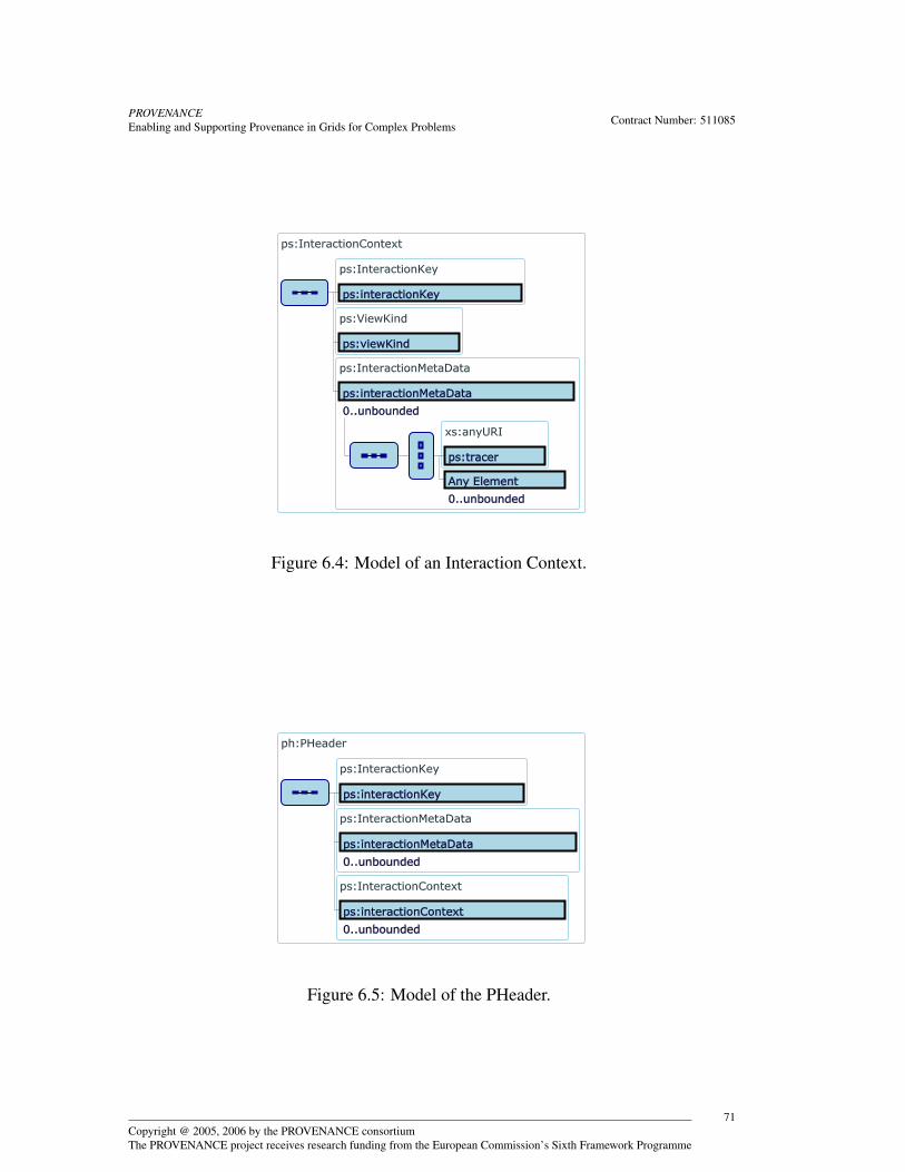
PROVENANCEEnabling and Supporting Provenance in Grids for Complex Problems Contract Number: 511085
Figure 6.4: Model of an Interaction Context.
Figure 6.5: Model of the PHeader.
Copyright @ 2005, 2006 by the PROVENANCE consortiumThe PROVENANCE project receives research funding from the European Commission’s Sixth Framework Programme
71

PROVENANCEEnabling and Supporting Provenance in Grids for Complex Problems Contract Number: 511085
the content of a message may be asserted: for instance, the message content may beasserted verbatim as the asserting actor received/sent it, or an altered description maybe asserted in which, for example, sensitive or large data items within the message arereplaced with references to those copies of the data items stored elsewhere, or are re-placed with references and a digest of the data. Therefore, in modelling an interactionp-assertion, we need a data structure in which asserting actors can declare not only thecontent of the message but also the documentation style (†) that has been applied to [GR-OTM.1, p. 128]it. If no change has been made between the message content sent/received and thatasserted in the p-assertion, a ‘verbatim’ documentation style is asserted. A taxonomyof documentation styles is given in Section 6.5.
We define a data type InteractionPAssertion to represent any interaction p-assertionand depict its structure in Figure 6.6. A p-assertion consists of three pieces of informa-tion: local p-assertion identifier, localPAssertionId; an identifier specifying the docu-mentation style applied to the message content, documentation style; and the messagecontent itself, shown as ‘any’ as it is entirely application-dependent and so no genericdata structure can be specified for it. For example, the message content may be a SOAP
or a CORBA message.
Figure 6.6: Model for an interaction p-assertion
We remind the reader that the purpose of an interaction p-assertion is to describean interaction that took place in a process; ultimately, that p-assertion may be returnedby a provenance query about the result produced by that process. The act of construct-ing a documentation item, i.e. a p-assertion, is itself a computation. Our rationalefor introducing the concept of documentation style is that such a computation is sosmall or trivial (e.g. verbatim copy of a message) that it simply can be described bydocumentation style. If an application needs to perform a complex computation in-volving multiple actors in order to produce a p-assertion, we expect such a complexcomputation to be documented fully by using the p-assertion model of documentationintroduced in this chapter. It is up to the application designer to decide the level ofdocumentation that is required for a given computation: if the process of creating p-
Copyright @ 2005, 2006 by the PROVENANCE consortiumThe PROVENANCE project receives research funding from the European Commission’s Sixth Framework Programme
72
PROVENANCEEnabling and Supporting Provenance in Grids for Complex Problems Contract Number: 511085
assertions needs to be documented by p-assertions itself, we must have a base caseaccording to which we agree not to document a computation further: this is preciselythe role of documentation style.
6.5 Documentation Style ModellingWhen an actor documents an interaction, it constructs an interaction p-assertion (spec-ified in Section 6.4), which states the content of a message received or sent by theasserting actor. We regard the activity of constructing a p-assertion from a messageas an atomic transformation, which needs to be qualified by the asserting actor so thatquerying actors can understand the nature of the transformation that was applied to anapplication message. This is exactly the purpose of Documentation Style, which wenow define.
Definition 6.11 (Documentation Style) Documentation style is a representation ofthe transformation according to which the content of a message or actor’s state isasserted in a p-assertion. 2
Given such an explicit representation of a message transformation, documentationstyle can be used for different purposes:
1. A documentation style is an explicit representation of the transformations thathappened to a message, which enables a querying actor to navigate the contentsof an assertion, through the use of corresponding schemas, and determine howthe original message was transformed.
2. Once an application designer has identified the type of transformation that needsto be applied to a message, documentation style can be used by the assertingactor in order to construct a p-assertion from a message; such an operation istypically facilitated by an actor-side library (Implementation RecommendationIR-ASL-7, p 135.).
For some particular documentation styles, it is also possible to reverse the ap-plied transformation to determine the original message, in which the documentationstyle of a p-assertion also represents the reverse transformation that can be appliedto it. While we do not limit the set of permitted documentation styles, since manywill be application-specific, some are essential across applications and worth definingexplicitly for interoperability, e.g. tools can be developed to interpret these standardstyles. There are several types of documentation style that the provenance architecturestandardises upon, each of which have different motivations. These are verbatim, ref-erence, anonymous, security-signing and security-encryption, which we now describe.
Definition 6.12 (Verbatim Documentation Style) The verbatim documentation styledenotes a null transformation applied to the contents of a message.2
Copyright @ 2005, 2006 by the PROVENANCE consortiumThe PROVENANCE project receives research funding from the European Commission’s Sixth Framework Programme
73

PROVENANCEEnabling and Supporting Provenance in Grids for Complex Problems Contract Number: 511085
Such a style is the simplest documentation style as no transformation actually hap-pens and the data is copied to the p-assertion in a “verbatim” way.
Section 5.4 introduces the notion of reference in order to provide scalable handlingof large p-assertions. Such references are handled by the reference documentationstyle, which we now define.
Definition 6.13 (Reference Documentation Style) The reference documentation styledenotes a transformation of a message by which a part of (or the whole of) its contentshas been replaced by a reference to the location where the actual contents can befound.2
Section 5.7 discussed security implications of Reference Documentation Style; inorder to ensure that the querier of a p-assertion who dereferences a reference accessesthe same data as intended by the recorder of the p-assertion, a digest may be associatedwith the reference.
Definition 6.14 (Reference-Digest Documentation Style) The reference-digest doc-umentation style denotes a transformation of a message by which a part of (or thewhole of) its contents has been replaced by a reference to the actual location where itcan be found and a digest of the substituted data.2
Section 5.4.2 introduced the notion of allowing actors to record references to p-assertions that have already been recorded in a provenance store. This allows actors toavoid recording multiple duplicate p-assertions. To support these references that pointinternally to a provenance store, we introduce the following documentation style.
Definition 6.15 (Internal Reference Documentation Style) The internal reference doc-umentation style denotes a transformation of a message by which a part of (or thewhole of) its contents has been replaced by a global p-assertion key, which refers toanother p-assertion that contains the actual data.2
This documentation style allows actors to avoid duplicating data unnecessarily.The style is a special case of the reference documentation style.
Section 9.4 introduces the requirement for anonymisation of patient identifiersfrom the OTM/EHCR application (GR-OTM.1, GR-EHCR.4). These application re-quirements are handled by anonymous documentation style, which we now define.
Definition 6.16 (Anonymous Documentation Style) The anonymous documentationstyle denotes a transformation of a message by which a part of (or the whole of) itscontents has been replaced by an “anonymous” identifier. This identifier hides theactual data without losing the link to them. 2
Consider the case of medical data for example, where information for each patientis kept. It may be necessary to hide the patient name from the provenance store dueto medical data privacy policies. In order to support this requirement, the anonymous
Copyright @ 2005, 2006 by the PROVENANCE consortiumThe PROVENANCE project receives research funding from the European Commission’s Sixth Framework Programme
74
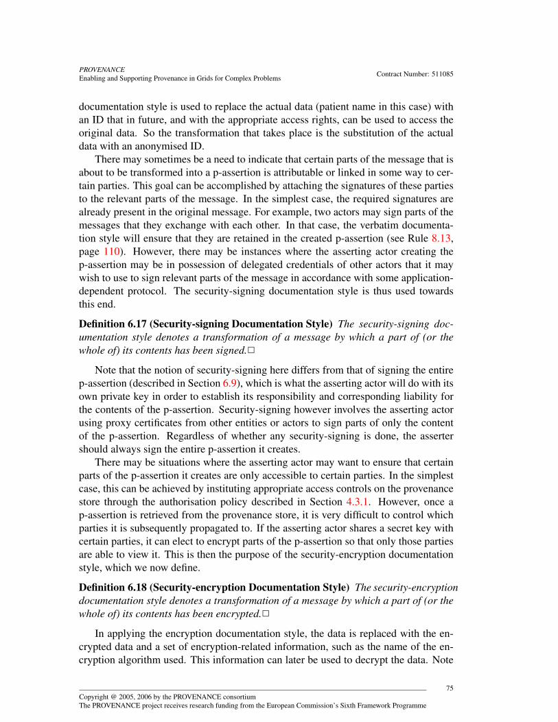
PROVENANCEEnabling and Supporting Provenance in Grids for Complex Problems Contract Number: 511085
documentation style is used to replace the actual data (patient name in this case) withan ID that in future, and with the appropriate access rights, can be used to access theoriginal data. So the transformation that takes place is the substitution of the actualdata with an anonymised ID.
There may sometimes be a need to indicate that certain parts of the message that isabout to be transformed into a p-assertion is attributable or linked in some way to cer-tain parties. This goal can be accomplished by attaching the signatures of these partiesto the relevant parts of the message. In the simplest case, the required signatures arealready present in the original message. For example, two actors may sign parts of themessages that they exchange with each other. In that case, the verbatim documenta-tion style will ensure that they are retained in the created p-assertion (see Rule 8.13,page 110). However, there may be instances where the asserting actor creating thep-assertion may be in possession of delegated credentials of other actors that it maywish to use to sign relevant parts of the message in accordance with some application-dependent protocol. The security-signing documentation style is thus used towardsthis end.
Definition 6.17 (Security-signing Documentation Style) The security-signing doc-umentation style denotes a transformation of a message by which a part of (or thewhole of) its contents has been signed.2
Note that the notion of security-signing here differs from that of signing the entirep-assertion (described in Section 6.9), which is what the asserting actor will do with itsown private key in order to establish its responsibility and corresponding liability forthe contents of the p-assertion. Security-signing however involves the asserting actorusing proxy certificates from other entities or actors to sign parts of only the contentof the p-assertion. Regardless of whether any security-signing is done, the assertershould always sign the entire p-assertion it creates.
There may be situations where the asserting actor may want to ensure that certainparts of the p-assertion it creates are only accessible to certain parties. In the simplestcase, this can be achieved by instituting appropriate access controls on the provenancestore through the authorisation policy described in Section 4.3.1. However, once ap-assertion is retrieved from the provenance store, it is very difficult to control whichparties it is subsequently propagated to. If the asserting actor shares a secret key withcertain parties, it can elect to encrypt parts of the p-assertion so that only those partiesare able to view it. This is then the purpose of the security-encryption documentationstyle, which we now define.
Definition 6.18 (Security-encryption Documentation Style) The security-encryptiondocumentation style denotes a transformation of a message by which a part of (or thewhole of) its contents has been encrypted.2
In applying the encryption documentation style, the data is replaced with the en-crypted data and a set of encryption-related information, such as the name of the en-cryption algorithm used. This information can later be used to decrypt the data. Note
Copyright @ 2005, 2006 by the PROVENANCE consortiumThe PROVENANCE project receives research funding from the European Commission’s Sixth Framework Programme
75
PROVENANCEEnabling and Supporting Provenance in Grids for Complex Problems Contract Number: 511085
that this encryption documentation style is unrelated to the encryption discussed in4.3.2. For that case, encryption is applied for the purposes of securing the communi-cation channel between the recording actor and the provenance store.
All previous documentation styles denote an atomic transformation (which is notdescribed in terms of internal steps). We now define the means by which severaltransformations can be applied to a single message.
Definition 6.19 (Composite Documentation Style) A composite documentation styledenotes that more than one atomic documentation style has been applied to a message.2
The atomic documentation styles described above can be used in any combinationfor the same message. This means that several transformations may happen eitherat different parts of the message or at the same part of it. The resulting messageconsists of the composition of all the transformations. A composite documentationstyle denotes that a set of atomic transformations has been applied to a message.
Documentation styles allow actors to express transformations they have performedon messages when asserting interaction p-assertions for those messages. Documenta-tion styles are mandatory for interaction p-assertions because querying actors need tobe able to determine whether two interaction p-assertions are matching (see 2.6). Us-ing the documentation styles of the two interaction p-assertions, a querier can generatethe original message from both p-assertions and determine whether they are matching,irrespective of how the message was transformed when being asserted. In the case ofactor state p-assertions, there is no application-independent notion of “matching” actorstate p-assertions. However, we allow the documentation style that has been applied inasserting an actor state p-assertion to be declared along with the state (see below). Re-lationship p-assertions do not have documentation styles: all the fields in a relationshipp-assertion are necessary so that the provenance query functionality can be performedin an application independent manner.
6.6 Actor State P-Assertion ModellingActor state p-assertions, as defined in Definition 2.8, are assertions made by an actorabout its internal state in the context of a specific interaction. Each actor in an in-teraction sends or receives a message, so an actor state p-assertion asserts somethingabout the state of the actor just before or just after it sent or received the message. Forexample, a service with an incoming message buffer may assert the state of its bufferjust before and after receiving a message. Often, after an actor receives a message, itperforms an execution that the message has triggered and, similarly, before sending amessage, it performs an execution that resulted in that message. Therefore, a commonsubset of actor state p-assertions give details of the execution that took place just af-ter receiving or just before sending a message. For example, a service may assert thecomputational resources allocated to an execution. For example, the actor state mayname the workflow that the interaction occurred as part of.
Copyright @ 2005, 2006 by the PROVENANCE consortiumThe PROVENANCE project receives research funding from the European Commission’s Sixth Framework Programme
76
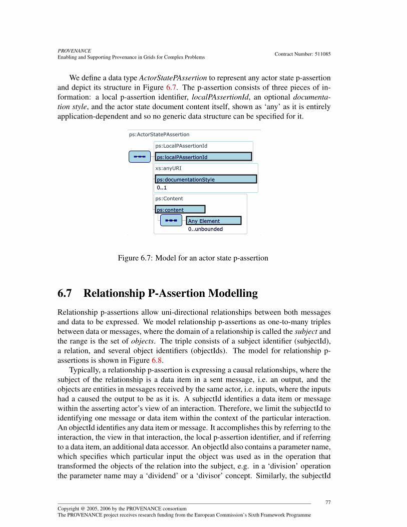
PROVENANCEEnabling and Supporting Provenance in Grids for Complex Problems Contract Number: 511085
We define a data type ActorStatePAssertion to represent any actor state p-assertionand depict its structure in Figure 6.7. The p-assertion consists of three pieces of in-formation: a local p-assertion identifier, localPAssertionId, an optional documenta-tion style, and the actor state document content itself, shown as ‘any’ as it is entirelyapplication-dependent and so no generic data structure can be specified for it.
Figure 6.7: Model for an actor state p-assertion
6.7 Relationship P-Assertion ModellingRelationship p-assertions allow uni-directional relationships between both messagesand data to be expressed. We model relationship p-assertions as one-to-many triplesbetween data or messages, where the domain of a relationship is called the subject andthe range is the set of objects. The triple consists of a subject identifier (subjectId),a relation, and several object identifiers (objectIds). The model for relationship p-assertions is shown in Figure 6.8.
Typically, a relationship p-assertion is expressing a causal relationships, where thesubject of the relationship is a data item in a sent message, i.e. an output, and theobjects are entities in messages received by the same actor, i.e. inputs, where the inputshad a caused the output to be as it is. A subjectId identifies a data item or messagewithin the asserting actor’s view of an interaction. Therefore, we limit the subjectId toidentifying one message or data item within the context of the particular interaction.An objectId identifies any data item or message. It accomplishes this by referring to theinteraction, the view in that interaction, the local p-assertion identifier, and if referringto a data item, an additional data accessor. An objectId also contains a parameter name,which specifies which particular input the object was used as in the operation thattransformed the objects of the relation into the subject, e.g. in a ‘division’ operationthe parameter name may a ‘dividend’ or a ‘divisor’ concept. Similarly, the subjectId
Copyright @ 2005, 2006 by the PROVENANCE consortiumThe PROVENANCE project receives research funding from the European Commission’s Sixth Framework Programme
77
PROVENANCEEnabling and Supporting Provenance in Grids for Complex Problems Contract Number: 511085
can have a parameter name specifying which output of the operation the subject refersto. Finally, the objectId optionally contains an object link giving the address of theprovenance store in which the p-assertion is kept.
Definition 6.20 (Data Accessor) A data accessor is a reference to the location of ap-assertion data item within a p-assertion’s content. 2
Definition 6.21 (Parameter Name) A parameter name is an identifier for an entity’srole in a relationship, where that entity is documented by a p-assertion data item. 2
There is no bound on the relationships that can be asserted between entities in p-assertions. However, to aid interoperability, we provide a core set of terms essentialto find the provenance of entities. The causal relationships ontology aims to definecausal relations between properties of the system at different instants. We define “Ccaused E according to A” as A’s belief/assertion that E would not have become true ifC had not been true, all else being equal. The full ontology, and the namespace usedfor the terms, is given in [Rel06].
The ontology includes a property, wasCausedBy, which is a relation between an ef-fect and its cause, and two classes, Cause and Effect that can be used to classify causesand effects. Using the causal relationships ontology, we can specify causal relationsbetween the contents of interaction p-assertions (and actor state p-assertions). In par-ticular, wasCausedBy can be used as the relation term in a relationship p-assertion,while Cause and Effect can be used as parameter names. More generally, application-specific relations may sub-class wasCausedBy to indicate that they are causal relations(as opposed to structural, temporal or other relations between entities).
6.8 The P-StructureUp to this point the architecture has assumed that a provenance store contains a col-lection of p-assertions. However, if this collection has no structure several problemsmay arise: the inability to identify one p-assertion from another, the inability to tell theinteraction context of an actor state p-assertion, the inability to causally relate one p-assertion to another, and therefore the inability for a querier to retrieve the provenanceof a piece of data. To solve these problems, we introduce the notion of a p-structure(†). [SR-2-1, p. 120]
Definition 6.22 (p-structure) The p-structure is a common logical structure of theprovenance store shared by all actors including asserting, recording, querying andmanaging actors. 2
The p-structure is designed specifically for organising p-assertions in a manner thatallows the provenance of a piece of data to be retrieved. We now detail the p-structureitself and then show how parts of the p-structure, including p-assertions, can be iden-tified. Figure 6.9 shows the p-structure. It reflects the models discussed above.
Copyright @ 2005, 2006 by the PROVENANCE consortiumThe PROVENANCE project receives research funding from the European Commission’s Sixth Framework Programme
78

PROVENANCEEnabling and Supporting Provenance in Grids for Complex Problems Contract Number: 511085
Figure 6.8: Relationship p-assertion model
Copyright @ 2005, 2006 by the PROVENANCE consortiumThe PROVENANCE project receives research funding from the European Commission’s Sixth Framework Programme
79
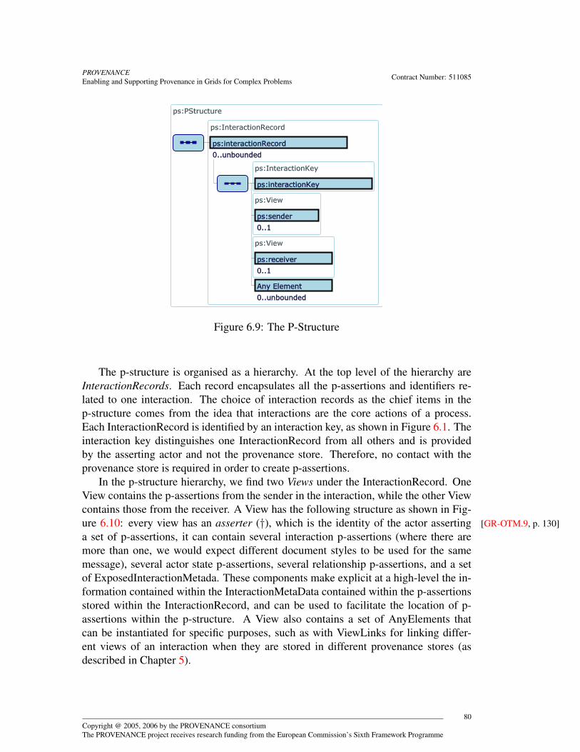
PROVENANCEEnabling and Supporting Provenance in Grids for Complex Problems Contract Number: 511085
Figure 6.9: The P-Structure
The p-structure is organised as a hierarchy. At the top level of the hierarchy areInteractionRecords. Each record encapsulates all the p-assertions and identifiers re-lated to one interaction. The choice of interaction records as the chief items in thep-structure comes from the idea that interactions are the core actions of a process.Each InteractionRecord is identified by an interaction key, as shown in Figure 6.1. Theinteraction key distinguishes one InteractionRecord from all others and is providedby the asserting actor and not the provenance store. Therefore, no contact with theprovenance store is required in order to create p-assertions.
In the p-structure hierarchy, we find two Views under the InteractionRecord. OneView contains the p-assertions from the sender in the interaction, while the other Viewcontains those from the receiver. A View has the following structure as shown in Fig-ure 6.10: every view has an asserter (†), which is the identity of the actor asserting [GR-OTM.9, p. 130]a set of p-assertions, it can contain several interaction p-assertions (where there aremore than one, we would expect different document styles to be used for the samemessage), several actor state p-assertions, several relationship p-assertions, and a setof ExposedInteractionMetada. These components make explicit at a high-level the in-formation contained within the InteractionMetaData contained within the p-assertionsstored within the InteractionRecord, and can be used to facilitate the location of p-assertions within the p-structure. A View also contains a set of AnyElements thatcan be instantiated for specific purposes, such as with ViewLinks for linking differ-ent views of an interaction when they are stored in different provenance stores (asdescribed in Chapter 5).
Copyright @ 2005, 2006 by the PROVENANCE consortiumThe PROVENANCE project receives research funding from the European Commission’s Sixth Framework Programme
80

PROVENANCEEnabling and Supporting Provenance in Grids for Complex Problems Contract Number: 511085
Figure 6.10: A View in the P-Structure
Copyright @ 2005, 2006 by the PROVENANCE consortiumThe PROVENANCE project receives research funding from the European Commission’s Sixth Framework Programme
81

PROVENANCEEnabling and Supporting Provenance in Grids for Complex Problems Contract Number: 511085
the number of p-assertions that the store should expect to receive in this view(which can be asserted by the recording actor as part of the recording protocol) anda View Link . All of these are optional. Each p-assertion is defined by an associatedmodel described above.
Definition 6.23 (View) A view is the set of p-assertions by one actor about one inter-action. 2
Definition 6.24 (Asserter Identity) An asserter identity is an identifier for an assert-ing actor. 2
We note that the definition of p-structure does not dictate its internal implemen-tation. Instead, the p-structure facilitates the asserting, recording, querying and man-agement of p-assertions by allowing actors to address and create p-assertions with acommon knowledge about how p-assertions are logically associated with one another.
6.9 SecurityAs discussed in Section 4.2, integrity and non-repudiation of p-assertions as well asthe need to verify asserter identity in a p-assertion are important security require-ments. Both these requirements can be fulfilled by having an asserting actor sign (†) [SR-6-6, p. 123]the created p-assertion. A subsequent check can then be done to determine whether theidentity associated with the signature corresponds with the identity of the asserter asrecorded in the p-assertion. This can be accomplished either by the provenance storeprior to storing a submitted p-assertion (Definition 7.13), or if it is not done here, by aquerying actor prior to processing the p-assertion in some manner.
To provide for this, the model should state where in the p-structure the signaturesas well as the certificates necessary to verify them are to be found. Therefore, we aug-ment the three p-assertion models to include an optional fourth element: the signatureapplied to that p-assertion in recording. These models, with the additional signatureelement, are shown in Figures 6.11, 6.12 and 6.13. The signature is shown as ‘any’ asit is entirely application-dependent and so no generic data structure can be specifiedfor it.
6.10 ConclusionIn this chapter, we discussed how p-assertions may be modelled within an application.We presented a model for how interactions, p-assertions and the data contained inp-assertions can be identified, as well as a model of an interaction context and thep-header in which this context information can be passed between actors. We thenprovided more detailed models for interaction p-assertions, actor state p-assertions,and relationship p-assertions. The p-assertion models were designed to be extensible
Copyright @ 2005, 2006 by the PROVENANCE consortiumThe PROVENANCE project receives research funding from the European Commission’s Sixth Framework Programme
82

PROVENANCEEnabling and Supporting Provenance in Grids for Complex Problems Contract Number: 511085
Figure 6.11: Model for a secured interaction p-assertion
Figure 6.12: Model for a secured actor state p-assertion
Copyright @ 2005, 2006 by the PROVENANCE consortiumThe PROVENANCE project receives research funding from the European Commission’s Sixth Framework Programme
83
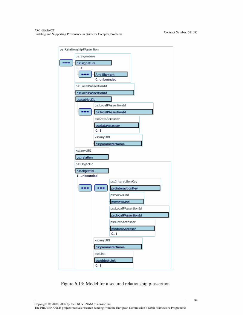
PROVENANCEEnabling and Supporting Provenance in Grids for Complex Problems Contract Number: 511085
Figure 6.13: Model for a secured relationship p-assertion
Copyright @ 2005, 2006 by the PROVENANCE consortiumThe PROVENANCE project receives research funding from the European Commission’s Sixth Framework Programme
84
PROVENANCEEnabling and Supporting Provenance in Grids for Complex Problems Contract Number: 511085
and uniquely identifiable. Combining the above models, we defined the p-structureas a common logical structure of the provenance store shared by all actors. In thenext chapter, we describe the functionality of the provenance store, which utilises thep-structure to accomplish its task.
Copyright @ 2005, 2006 by the PROVENANCE consortiumThe PROVENANCE project receives research funding from the European Commission’s Sixth Framework Programme
85
PROVENANCEEnabling and Supporting Provenance in Grids for Complex Problems Contract Number: 511085
Chapter 7
Functionality
This chapter discusses the functionality of the provenance store: for each of the record-ing, querying and management interfaces, it provides an informal description, in En-glish, of the functionality that is supported by the provenance store. Such informalpresentation will serve at the derivation of a more detailed specification and serviceinterface specifications, which will be part of a separate document.
7.1 Recording InterfaceProvenance stores provide a recording interface based on the P-assertion RecordingProtocol (PReP) , which defines the messages that actors can exchange with the prove-nance store in order to record p-assertions [GLM04a, GLM04c, GMF+05b, GMM05].The protocol is designed to be asynchronous so that p-assertions can be recorded atany time to the selected provenance store. The protocol is also designed to have thefollowing properties:
1. A protocol is stateless when an actor can understand a message without relyingon any previous or subsequent messages. By supporting this property, the prove-nance store can record any p-assertion with only the information in the protocolmessages it receives. This allows for out-of-order message delivery and for un-finished interaction records to be present in the provenance store.
2. Idempotence (†) is the quality of something that has the same effect if used mul- [SR-2-3, p. 120]tiple times as it does if used only once. With this property, once a p-assertion hasbeen submitted to a provenance store then that p-assertion cannot be overwrittenor modified. In other words, an actor cannot retract its assertion.
3. The protocol terminates. This means that an actor will not be indefinitely record-ing p-assertions for one interaction.
These properties are discussed in greater detail in other documents [GLM04c,GMF+05b]. PReP assumes a model in which application actors send application mes-
Copyright @ 2005, 2006 by the PROVENANCE consortiumThe PROVENANCE project receives research funding from the European Commission’s Sixth Framework Programme
86
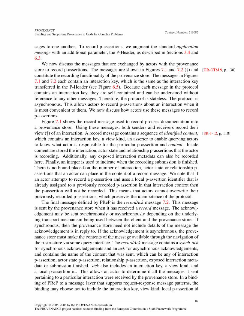
PROVENANCEEnabling and Supporting Provenance in Grids for Complex Problems Contract Number: 511085
sages to one another. To record p-assertions, we augment the standard applicationmessage with an additional parameter, the P-Header, as described in Sections 3.4 and6.3.
We now discuss the messages that are exchanged by actors with the provenancestore to record p-assertions. The messages are shown in Figures 7.1 and 7.2 (†) and [GR-OTM.9, p. 130]constitute the recording functionality of the provenance store. The messages in Figures7.1 and 7.2 each contain an interaction key, which is the same as the interaction keytransferred in the P-Header (see Figure 6.5). Because each message in the protocolcontains an interaction key, they are self-contained and can be understood withoutreference to any other messages. Therefore, the protocol is stateless. The protocol isasynchronous. This allows actors to record p-assertions about an interaction when itis most convenient to them. We now discuss how actors use these messages to recordp-assertions.
Figure 7.1 shows the record message used to record process documentation intoa provenance store. Using these messages, both senders and receivers record theirview (†) of an interaction. A record message contains a sequence of identified content, [SR-1-12, p. 118]which contains an interaction key, a view kind, an asserter to enable querying actorsto know what actor is responsible for the particular p-assertion and content. Insidecontent are stored the interaction, actor state and relationship p-assertions that the actoris recording. Additionally, any exposed interaction metadata can also be recordedhere. Finally, an integer is used to indicate when the recording submission is finished.There is no bound placed on the number of interaction, actor state or relationship p-assertions that an actor can place in the content of a record message. We note that ifan actor attempts to record a p-assertion and uses a local p-assertion identifier that isalready assigned to a previously recorded p-assertion in that interaction context thenthe p-assertion will not be recorded. This means that actors cannot overwrite theirpreviously recorded p-assertions, which preserves the idempotence of the protocol.
The final message defined by PReP is the recordAck message 7.2. This messageis sent by the provenance store when it has received a record message. The acknowl-edgement may be sent synchronously or asynchronously depending on the underly-ing transport mechanism being used between the client and the provenance store. Ifsynchronous, then the provenance store need not include details of the message theacknowledgement is in reply to. If the acknowledgement is asynchronous, the prove-nance store must make the contents of the message available through the navigation ofthe p-structure via some query interface. The recordAck message contains a synch ackfor synchronous acknowledgements and an ack for asynchronous acknowledgements,and contains the name of the content that was sent, which can be any of interactionp-assertion, actor state p-assertion, relationship p-assertion, exposed interaction meta-data or submission finished. ack also includes an interaction key, a view kind, anda local p-assertion id. This allows an actor to determine if all the messages it sentpertaining to a particular interaction were received by the provenance store. In a bind-ing of PReP to a message layer that supports request-response message patterns, thebinding may choose not to include the interaction key, view kind, local p-assertion id
Copyright @ 2005, 2006 by the PROVENANCE consortiumThe PROVENANCE project receives research funding from the European Commission’s Sixth Framework Programme
87

PROVENANCEEnabling and Supporting Provenance in Grids for Complex Problems Contract Number: 511085
Figure 7.1: Record Message
Copyright @ 2005, 2006 by the PROVENANCE consortiumThe PROVENANCE project receives research funding from the European Commission’s Sixth Framework Programme
88
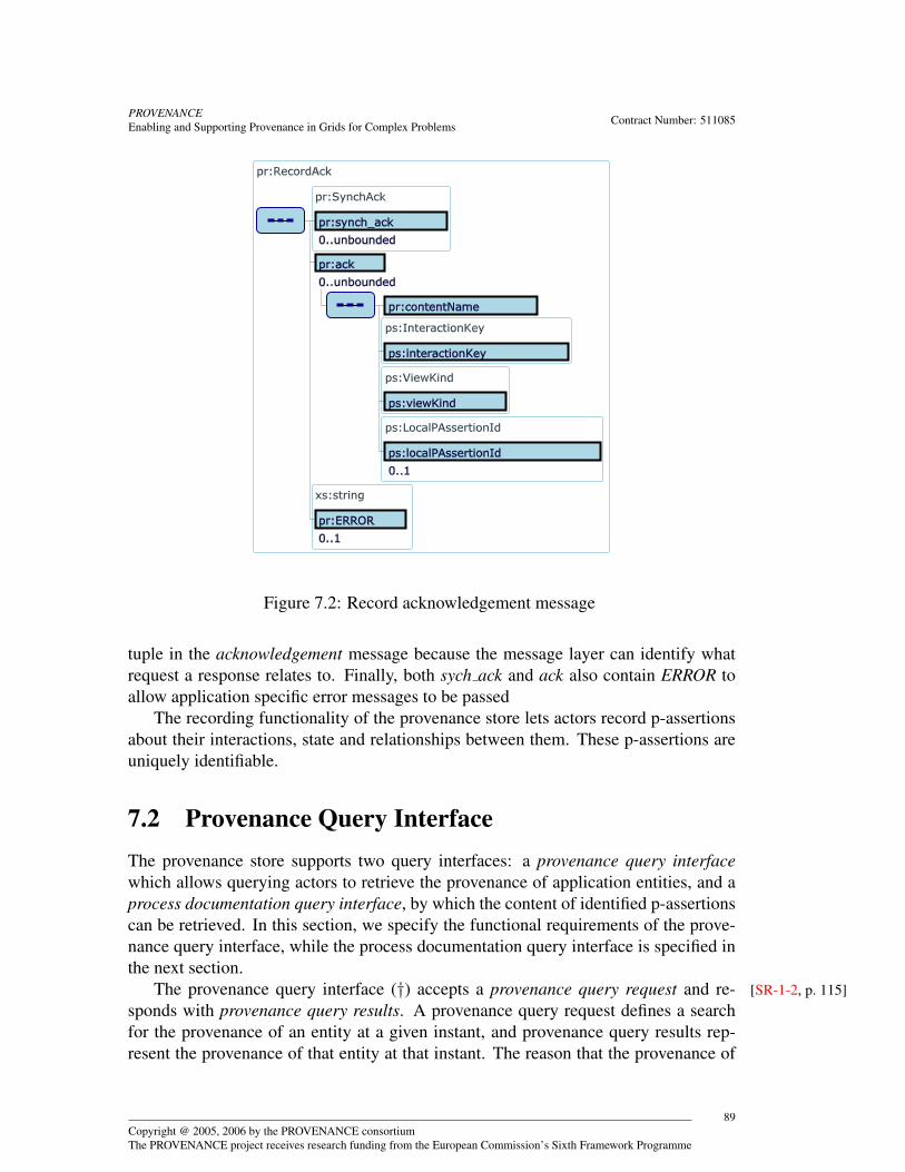
PROVENANCEEnabling and Supporting Provenance in Grids for Complex Problems Contract Number: 511085
Figure 7.2: Record acknowledgement message
tuple in the acknowledgement message because the message layer can identify whatrequest a response relates to. Finally, both sych ack and ack also contain ERROR toallow application specific error messages to be passed
The recording functionality of the provenance store lets actors record p-assertionsabout their interactions, state and relationships between them. These p-assertions areuniquely identifiable.
7.2 Provenance Query InterfaceThe provenance store supports two query interfaces: a provenance query interfacewhich allows querying actors to retrieve the provenance of application entities, and aprocess documentation query interface, by which the content of identified p-assertionscan be retrieved. In this section, we specify the functional requirements of the prove-nance query interface, while the process documentation query interface is specified inthe next section.
The provenance query interface (†) accepts a provenance query request and re- [SR-1-2, p. 115]sponds with provenance query results. A provenance query request defines a searchfor the provenance of an entity at a given instant, and provenance query results rep-resent the provenance of that entity at that instant. The reason that the provenance of
Copyright @ 2005, 2006 by the PROVENANCE consortiumThe PROVENANCE project receives research funding from the European Commission’s Sixth Framework Programme
89
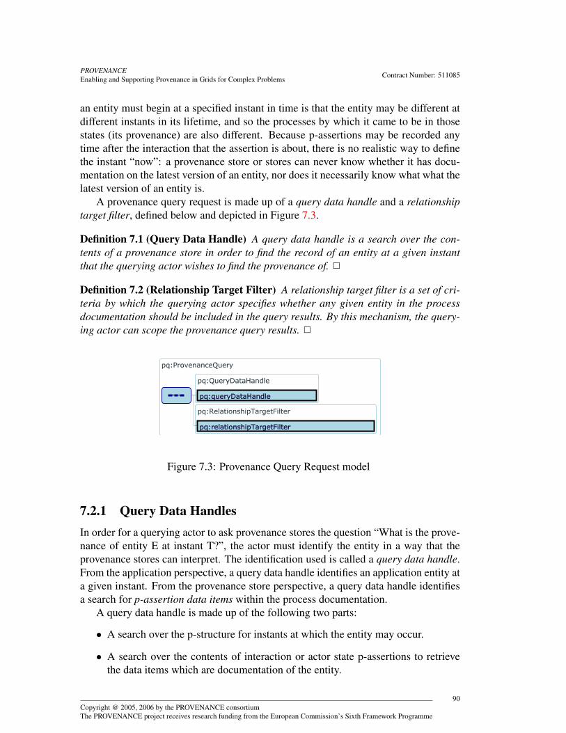
PROVENANCEEnabling and Supporting Provenance in Grids for Complex Problems Contract Number: 511085
an entity must begin at a specified instant in time is that the entity may be different atdifferent instants in its lifetime, and so the processes by which it came to be in thosestates (its provenance) are also different. Because p-assertions may be recorded anytime after the interaction that the assertion is about, there is no realistic way to definethe instant “now”: a provenance store or stores can never know whether it has docu-mentation on the latest version of an entity, nor does it necessarily know what what thelatest version of an entity is.
A provenance query request is made up of a query data handle and a relationshiptarget filter, defined below and depicted in Figure 7.3.
Definition 7.1 (Query Data Handle) A query data handle is a search over the con-tents of a provenance store in order to find the record of an entity at a given instantthat the querying actor wishes to find the provenance of. 2
Definition 7.2 (Relationship Target Filter) A relationship target filter is a set of cri-teria by which the querying actor specifies whether any given entity in the processdocumentation should be included in the query results. By this mechanism, the query-ing actor can scope the provenance query results. 2
Figure 7.3: Provenance Query Request model
7.2.1 Query Data HandlesIn order for a querying actor to ask provenance stores the question “What is the prove-nance of entity E at instant T?”, the actor must identify the entity in a way that theprovenance stores can interpret. The identification used is called a query data handle.From the application perspective, a query data handle identifies an application entity ata given instant. From the provenance store perspective, a query data handle identifiesa search for p-assertion data items within the process documentation.
A query data handle is made up of the following two parts:
• A search over the p-structure for instants at which the entity may occur.
• A search over the contents of interaction or actor state p-assertions to retrievethe data items which are documentation of the entity.
Copyright @ 2005, 2006 by the PROVENANCE consortiumThe PROVENANCE project receives research funding from the European Commission’s Sixth Framework Programme
90

PROVENANCEEnabling and Supporting Provenance in Grids for Complex Problems Contract Number: 511085
Because interaction and actor state p-assertions are also part of the p-structure,these parts can be combined into a single search over the contents of a provenancestore, represented by a p-structure. We will look at how the querying actor specifieseach part of the search below.
Identifying Instants
Following the formulation of a system as being a collection of distributed interactingactors, described in Chapter 2, there are three ways in which to identify a documentedinstant in the past:
• The instant at which an actor sent a message.
• The instant at which an actor received a message.
• The instant at which an actor accessed an asserted part of its state, i.e. the instantto which an actor state refers.
These are apparent in the p-structure as the following.
• An interaction p-assertion in the sender’s view of an interaction.
• An interaction p-assertion in the receiver’s view of an interaction.
• An actor state p-assertion whose content specifies to which instant it applies, e.g.just before or just after sending or receiving a message.
The identities of the actors involved in an interaction are apparent in the messagesource, message sink and asserter elements of the p-structure.
Identifying Data Items
The entity of which the querying actor wishes to find the provenance must be apparentin the interaction or actor state p-assertions in order for the provenance store to findit. The entity may not always be present as an exact copy of data: it may appear by areference in a p-assertion or otherwise implied by application-specific structures. Forinstance, application messages may refer to a data item by the name of the file in whichit is contained, but the querying actor wishes to find the provenance of the data, ratherthan the file.
The query data handle includes a search over the contents of p-assertions to re-trieve data items which are documentation of the entity. This search is expressed in aparticular search language, and the range of search languages supported by any oneprovenance store may vary.
A search language must assume some format and structure of the documents overwhich it searches, which we call the document language, e.g. the XPath search lan-guage assumes the XML document language. However, a provenance store is agnostic
Copyright @ 2005, 2006 by the PROVENANCE consortiumThe PROVENANCE project receives research funding from the European Commission’s Sixth Framework Programme
91
PROVENANCEEnabling and Supporting Provenance in Grids for Complex Problems Contract Number: 511085
to and unaware of the structure of application messages and assertions of state it con-tains. In fact, application messages may have used different formats, so p-assertionswithin one provenance store may use different document languages. Therefore, a querydata handle may also specify document language mappings [ZDF+05] between thedocument language used for a p-assertion and the document language required for thesearch.
Definition 7.3 (Document Language Mapping) A document language mapping is adefinition of how to transform documents formatted in one document language intoanother document language. 2
Composition of Provenance Queries
A query data handle is a search for an entity at an instant within a p-structure. Primar-ily, this p-structure will be the full contents of a provenance store. However, in somecases a query data handle may be better expressed as a composition of provenancequeries, i.e. one provenance query is performed and the results are searched over byanother provenance query. For example, to find the provenance of the second itemadded to a set, we can first determine the provenance of the set, and then identify fromthat the item added second, so the provenance of the item can then be found. In thiscase, the search that the query data handle specifies is over a p-structure formed fromthe results of another provenance query.
In general terms, we divide the query data handle into the search to be performedand the p-structure over which it will search. That p-structure, referred to by a p-structure reference, can be one of three possibilities (also depicted in Figure 7.4).
• The contents of the provenance store.
• The results of another provenance query, in the form of a p-structure.
• A p-structure given by another p-structure reference but, in addition, includ-ing the transitive closure of relationships with a given relation name in that p-structure, i.e. wherever there is a relationship of the specified type from A toB and one from B to C, the transitive closure will also contain a relationshipp-assertion from A to C.
Definition 7.4 (P-Structure Reference) A p-structure reference is a declaration ofthe p-structure over which a provenance query’s entity search will be executed. 2
Model
A model of the query data handle is shown in Figure 7.5. The search element specifiesa search, in the chosen search language, over the p-structure for data items within p-assertions asserted about sending or receiving messages at given instants. The pStruc-tureReference refers to the set of p-assertions that the search will be conducted over,
Copyright @ 2005, 2006 by the PROVENANCE consortiumThe PROVENANCE project receives research funding from the European Commission’s Sixth Framework Programme
92

PROVENANCEEnabling and Supporting Provenance in Grids for Complex Problems Contract Number: 511085
Figure 7.4: P-Structure Reference model
and is one of the options discussed in the section above. The documentLanguageMap-pings specify how p-assertion contents are mapped to the document language requiredby the search.
Figure 7.5: Query Data Handle model
7.2.2 Relationship Target FiltersThe set of process documentation about entities that ultimately have some causal in-fluence on the entity identified by a query data handle could be vast, and most of itirrelevant to a querying actor for any one purpose. Therefore, we need to allow thequerying actor to specify the scope of the provenance query, i.e. a definition of what
Copyright @ 2005, 2006 by the PROVENANCE consortiumThe PROVENANCE project receives research funding from the European Commission’s Sixth Framework Programme
93
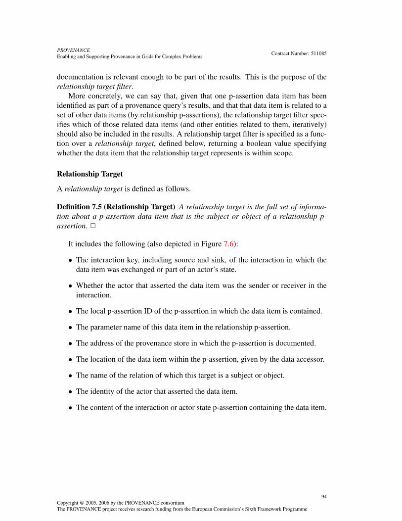
PROVENANCEEnabling and Supporting Provenance in Grids for Complex Problems Contract Number: 511085
documentation is relevant enough to be part of the results. This is the purpose of therelationship target filter.
More concretely, we can say that, given that one p-assertion data item has beenidentified as part of a provenance query’s results, and that that data item is related to aset of other data items (by relationship p-assertions), the relationship target filter spec-ifies which of those related data items (and other entities related to them, iteratively)should also be included in the results. A relationship target filter is specified as a func-tion over a relationship target, defined below, returning a boolean value specifyingwhether the data item that the relationship target represents is within scope.
Relationship Target
A relationship target is defined as follows.
Definition 7.5 (Relationship Target) A relationship target is the full set of informa-tion about a p-assertion data item that is the subject or object of a relationship p-assertion. 2
It includes the following (also depicted in Figure 7.6):
• The interaction key, including source and sink, of the interaction in which thedata item was exchanged or part of an actor’s state.
• Whether the actor that asserted the data item was the sender or receiver in theinteraction.
• The local p-assertion ID of the p-assertion in which the data item is contained.
• The parameter name of this data item in the relationship p-assertion.
• The address of the provenance store in which the p-assertion is documented.
• The location of the data item within the p-assertion, given by the data accessor.
• The name of the relation of which this target is a subject or object.
• The identity of the actor that asserted the data item.
• The content of the interaction or actor state p-assertion containing the data item.
Copyright @ 2005, 2006 by the PROVENANCE consortiumThe PROVENANCE project receives research funding from the European Commission’s Sixth Framework Programme
94
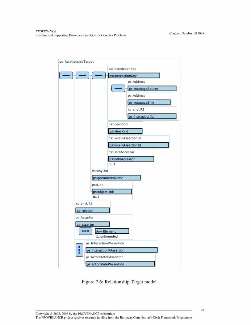
PROVENANCEEnabling and Supporting Provenance in Grids for Complex Problems Contract Number: 511085
Figure 7.6: Relationship Target model
Copyright @ 2005, 2006 by the PROVENANCE consortiumThe PROVENANCE project receives research funding from the European Commission’s Sixth Framework Programme
95
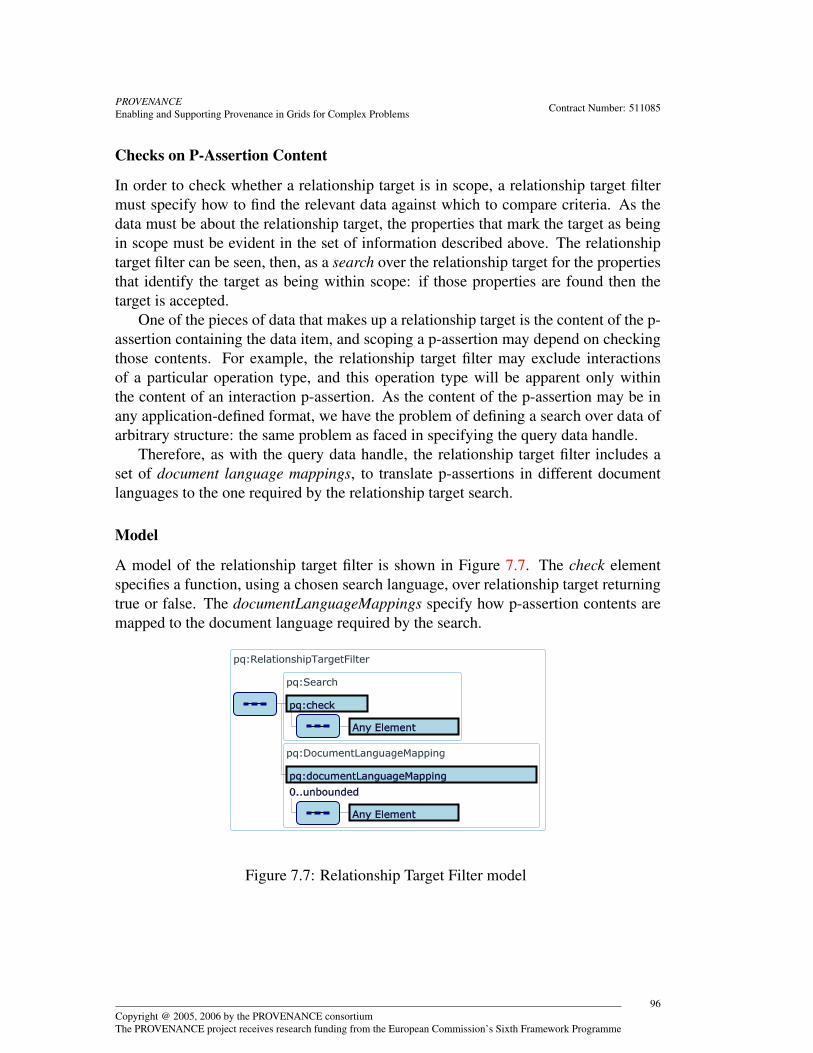
PROVENANCEEnabling and Supporting Provenance in Grids for Complex Problems Contract Number: 511085
Checks on P-Assertion Content
In order to check whether a relationship target is in scope, a relationship target filtermust specify how to find the relevant data against which to compare criteria. As thedata must be about the relationship target, the properties that mark the target as beingin scope must be evident in the set of information described above. The relationshiptarget filter can be seen, then, as a search over the relationship target for the propertiesthat identify the target as being within scope: if those properties are found then thetarget is accepted.
One of the pieces of data that makes up a relationship target is the content of the p-assertion containing the data item, and scoping a p-assertion may depend on checkingthose contents. For example, the relationship target filter may exclude interactionsof a particular operation type, and this operation type will be apparent only withinthe content of an interaction p-assertion. As the content of the p-assertion may be inany application-defined format, we have the problem of defining a search over data ofarbitrary structure: the same problem as faced in specifying the query data handle.
Therefore, as with the query data handle, the relationship target filter includes aset of document language mappings, to translate p-assertions in different documentlanguages to the one required by the relationship target search.
Model
A model of the relationship target filter is shown in Figure 7.7. The check elementspecifies a function, using a chosen search language, over relationship target returningtrue or false. The documentLanguageMappings specify how p-assertion contents aremapped to the document language required by the search.
Figure 7.7: Relationship Target Filter model
Copyright @ 2005, 2006 by the PROVENANCE consortiumThe PROVENANCE project receives research funding from the European Commission’s Sixth Framework Programme
96
PROVENANCEEnabling and Supporting Provenance in Grids for Complex Problems Contract Number: 511085
7.2.3 Provenance Query ResultsThe response to a provenance query is a representation of the provenance of an entityat a given instant, i.e. the one specified by the query data handle. Provenance queryresults are comprised of start p-assertion data keys and a set of full relationships,defined below and depicted in Figure 7.8:
Definition 7.6 (Provenance Query Result Start) A provenance query result start isthe p-assertion data key(s) to the process documentation of the entity for which theprovenance was found, i.e. the key(s) for the p-assertion data item(s) found by resolv-ing the query data handle. 2
Definition 7.7 (Provenance Query Result Full Relationships) A provenance queryresult full relationship is a relationship between two p-assertion data items in theprovenance of entity found by the query. 2
Figure 7.8: Provenance Query Result model
Full relationships are adapted versions of relationship p-assertions in the processdocumentation, differing in two regards. First, because a relationship p-assertion canhave multiple objects, and not every object may be within scope of the provenancequery results, a full relationship is between strictly one subject and one object, toindicate that that exact relationship is within scope. If multiple objects of a relationship
Copyright @ 2005, 2006 by the PROVENANCE consortiumThe PROVENANCE project receives research funding from the European Commission’s Sixth Framework Programme
97

PROVENANCEEnabling and Supporting Provenance in Grids for Complex Problems Contract Number: 511085
p-assertion are within scope, there will be one full relationship for each object returnedin the provenance query results. The second difference is that a relationship p-assertionis asserted within the context of an interaction, while a full relationship is designed tobe independent of any one interaction (as it documents the provenance of an entity, notan interaction), so that the form in which each is specified may differ. In particular,part of the global p-assertion key of the subject of a relationship p-assertion can bedetermined from the identity of the interaction that the relationship p-assertion makesan assertion about, while this must be made explicit in a full relationship.
The model for the subjects of full relationships is shown in Figure 7.9, and themodel for objects is identical.
Figure 7.9: Full Relationship Subject model
7.3 Process Documentation Query InterfaceProvenance query results include a related p-assertion data keys. To retrieve the actualprocess documentation that makes up the provenance of an entity at an instant, thequerying actor uses the process documentation query interface. This interface givesdirect access to the process documentation contents, by allowing the querying actor tosearch over and retrieve parts of the p-structure (†). [TSR-1-4, p. 125]
Copyright @ 2005, 2006 by the PROVENANCE consortiumThe PROVENANCE project receives research funding from the European Commission’s Sixth Framework Programme
98

PROVENANCEEnabling and Supporting Provenance in Grids for Complex Problems Contract Number: 511085
At minimum, the process documentation query interface must allow the queryingactor to perform the following operations (†). [SR-1-2, p. 115]
• Retrieve the contents of a p-assertion with a given global p-assertion key.
• Retrieve all p-assertions asserted about one interaction, identified by an interac-tion key, by one actor, identified as the sender or receiver or by its identity.
• Retrieve all p-assertions asserted about one interaction, identified by an interac-tion key.
The actual results of the query depend on the contents of the provenance storeto which the query is sent, because the query will only return data contained in thatprovenance store, and the access control restrictions placed on the querying actor bythe store.
As the amount of data returned may be large in volume, the process documentationquery interface should allow for the iterative retrieval of query results. By this mech-anism, a querying actor should be able to process the results in manageable chunks.(†) [TSR-1-2, p. 125]
Ideally, the process documentation query interface should allow more than theabove minimum operations, so that queries can be used to search for and retrieve morep-assertion data meeting different criteria, e.g. to retrieve all interaction p-assertionsof a particular type, and possibly to perform transformations on the results before re-turning, so that the querying actor receives the results in the form they can most easilyprocess.
The process documentation query interface is not more fully specified here becausethere are a range of query languages already available that can be used to query a set ofstored data, and the ideal one will depend on the structure of a particular application’sp-assertion content.
7.4 Management InterfaceWithin a provenance architecture, a management interface is necessary in order tofacilitate the administration, reuse and maintenance of provenance stores. Such aninterface may provide generic data storage administration capabilities and will not,in itself, be provenance specific. This being so, this section merely suggests someuseful functionality that a management interface might have, and we do not make anycommitments to a formal specification of the suggested functionality described below.
7.4.1 Notification of Provenance Store UseManaging actors might like to be informed when operations are performed on a prove-nance store. For example, they might like to know when a p-assertion has been
Copyright @ 2005, 2006 by the PROVENANCE consortiumThe PROVENANCE project receives research funding from the European Commission’s Sixth Framework Programme
99
PROVENANCEEnabling and Supporting Provenance in Grids for Complex Problems Contract Number: 511085
recorded. A management interface should provide the following functionality regard-ing notification.
• Notification
A management interface should be able to notify subscribed managing actors ofrecord and query operations. (†) [SR-4-2, p. 122]
• Subscription management
A management interface should allow actors to manage their subscription infor-mation e.g. where notifications are sent to.
7.4.2 Provenance Store Utility• Link Modification
A management interface could provide functionality to update links. This isuseful when process documentation has been moved from one provenance storeto another and contains links.
• Deletion
Ideally, p-assertions are never deleted, but in some circumstances, such as datastaging, it may be necessary for an application to delete particular p-assertionsthat have been moved to a new provenance store. A management interface mayprovide this deletion capability.
• Setup and management of indexes
Provenance stores hold a large amount of p-assertions. No matter how these p-assertions are organised, some storage structures may be suitable for some queryoperations and not suitable for others. A management interface should provide amechanism to setup and manage indexes in terms of time, tracer or other criteria,so that p-assertions can be organised into multiple views and structures, thusfacilitating querying.
7.5 PoliciesPolicies describe the capabilities, requirements and general characteristics of compo-nents in service oriented systems. In the Provenance architecture, they are importantfor providing interoperability, enabling users to identify services and provenance storesthat provide the required functionality. In Chapter 3, policies identified for the Prove-nance architecture were clarified into the three distinct areas shown below.
• Service requirement and capability policies.
Copyright @ 2005, 2006 by the PROVENANCE consortiumThe PROVENANCE project receives research funding from the European Commission’s Sixth Framework Programme
100

PROVENANCEEnabling and Supporting Provenance in Grids for Complex Problems Contract Number: 511085
• Provenance store policies.
• User requirement policies.
Although we list service and user requirement policies, these are, in effect, sub-sets of the policies describing service and provenance store capabilities. For example,a service may require that a provenance store can cope with high levels of through-put, which may be necessary in situations of data staging where large numbers ofp-assertions are being moved around from store to store. However, such policies canbe seen as a subset of the policies expressing the capabilities of provenance stores, andas such we avoid repetition by only describing policies that specify capabilities.
7.5.1 Provenance Store Capability PoliciesPolicies describing the capabilities of provenance stores are necessary to enable ser-vices that want to record p-assertions to find provenance stores that offer the requiredcapabilities. In this section, we provide a description of several policies that are nec-essary to ensure provenance store interoperability. Note that policies for service capa-bilities are described in Chapter 8, Section 8.6.
In certain situations, a recording service may need to store the data about which itmakes assertions in some persistent storage location external to the provenance store.In these cases, the data is referenced in the associated p-assertions to enable queryingactors to dereference the data when the p-assertions are obtained from the provenancestore. An alternative method is for the provenance store itself to periodically resolvethe references contained in p-assertions, retrieve the data and store it locally (see Chap-ter 5, Section 5.4 for a discussion of reference recording). Provenance stores may alsoperform this functionality more or less frequently. To be useful, this capability of theprovenance store must be advertised by an appropriate policy so that querying servicescan discover it.
A data upload policy therefore is defined as follows.
Definition 7.8 (Data Upload Policy) A data upload policy identifies if and how fre-quently a provenance store has to resolve a reference contained in a p-assertion. 2
When applications are running with high throughput, and large amounts of p-assertions are being recorded, it may sometimes be necessary to create a temporaryprovenance store close to the application actors (in terms of network location) in orderto cut down on communication costs (this technique is called data staging and a moredetailed discussion can be found in Chapter 5, Section 5.3, and see Chapter 6, Section6.5 for a discussion on the reference documentation style). When the process for whichp-assertions are being recorded finishes, the temporary provenance store can query it-self to obtain all of its p-assertion content and transfer this to another provenance store.In terms of policy, several criteria need to be specified.
Copyright @ 2005, 2006 by the PROVENANCE consortiumThe PROVENANCE project receives research funding from the European Commission’s Sixth Framework Programme
101

PROVENANCEEnabling and Supporting Provenance in Grids for Complex Problems Contract Number: 511085
• A temporary provenance store must indicate in its data staging policy the factthat it is temporary.
• It must describe where (i.e. which other provenance stores) p-assertions can bemigrated to.
• In some cases, a provenance store may act as a persistent store for one assertingactor but perform data staging for another asserting actor. The different formsof data storage performed by a provenance store for different asserting actorsshould be specified.
• The above kinds of data staging represent cases where a data staging provenancestore ‘pushes’ the data over to another provenance store. However, there may becases where it is more desirable to have provenance stores ‘pull’ assertions fromother data staging stores. Both functionalities are catered for by a provenancestore’s ability to query and record p-assertions (see Section 7.2 and Section 7.1respectively).
In summary, the definition for a data staging policy must capture these criteria andwe present such a definition below.
Definition 7.9 (Data Staging Policy) A data staging policy must specify whether ornot a provenance store is capable of data staging and, if so, to which other prove-nance stores it can send its contents, its data staging capabilities for different classesof recording actors, and whether it is capable of both recording p-assertions into otherprovenance stores (push-based data staging) or querying other provenance stores(pull-based staging), or both. 2
When an asserting actor is recording many p-assertions iteratively, templates can beused to cut down on computational costs (see Chapter 5, Section 5.5 for a discussion).In essence, templates can generate p-assertions given a correct set of parameters byan asserting service. In some cases, the provenance store may allow a recording actorto submit a template which can subsequently be sent parameters by a recording actorleading the template to generate the appropriate p-assertions. For this to be practical,both recording actors and provenance stores must share the same template languagefor producing p-assertions.
A p-assertion template policy is defined in the following manner.
Definition 7.10 (P-Assertion Template Policy) A provenance store template policymust indicate the ability of the store to accept templates from asserting actors, whatlanguages for producing p-assertions the store supports and from which recordingactors it can accept templates from. 2
When querying a provenance store, a querying service must know what searchlanguage is supported by the provenance store for queries (Section 7.2 describes the
Copyright @ 2005, 2006 by the PROVENANCE consortiumThe PROVENANCE project receives research funding from the European Commission’s Sixth Framework Programme
102
PROVENANCEEnabling and Supporting Provenance in Grids for Complex Problems Contract Number: 511085
approach taken in the architecture for provenance store querying). Several search lan-guages may be supported by any given store (such as XPath in the case of an XML
document language), and the query languages supported should be advertised by apolicy.
The definition of a search language policy is given below.
Definition 7.11 (Search Language Policy) A search language policy states the kindsof search languages the provenance store supports. 2
A provenance store can potentially hold very large amounts of p-assertions, andto manage these it may be necessary to perform indexing of the contents of prove-nance stores to facilitate search and retrieval (see section 7.4.2). The different index-ing schemes offered by a provenance store (e.g. by time, trace etc.) should be madeavailable to querying services by appropriate policies.
The index management policy definition is as follows.
Definition 7.12 (Index Management Policy) The index management policy must statethat a provenance store can or cannot perform indexing and, if it can, the differentkinds of indexing offered by the store must be enumerated. 2
As noted in Section 6.9, the asserting actor signs the p-assertion it creates; this sig-nature can then be subsequently verified by either the provenance store or the queryingactor that retrieves this p-assertion at a later stage. If the provenance store is responsi-ble for the verification process, then this occurs at the time the p-assertion is submittedfor storage by the recording actor. If the signature does not verify, an appropriate errormessage should be generated. To indicate that a given provenance store can indeed val-idate the signature on a p-assertion and determine its corresponding asserter identity,we require a suitable policy to state such capability, which we define below.
Definition 7.13 (Security Signature Checking Policy) A security signature checkingpolicy states whether or not a provenance store has the capability to examine and val-idate the signatures placed in a p-assertion by an asserting actor, as well stating whataction is to be taken if a conflict is detected (e.g. sending an error message). 2
It is important to note that the validity of the signature on a submitted p-assertion isindependent of whether the recording actor has the appropriate access rights to recordthat p-assertion to the provenance store in the first instance. For example, a recordingactor may have access rights to store p-assertions in a provenance store, but may berefused if the p-assertions it submits do not have valid signatures. Conversely, a record-ing actor may possess correctly signed p-assertions, but not have the authorisations torecord them to a specific provenance store.
Given such policies, services can understand the behaviour of a given provenancestore. By allowing services without prior knowledge of a provenance store to discoverits policies, they can thus understand how to interact with and what to expect from it,and this ensures interoperability.
Copyright @ 2005, 2006 by the PROVENANCE consortiumThe PROVENANCE project receives research funding from the European Commission’s Sixth Framework Programme
103
PROVENANCEEnabling and Supporting Provenance in Grids for Complex Problems Contract Number: 511085
7.6 SecurityThe security policy of the provenance store essentially encompasses the internal repre-sentation list, authorisation policy and access control policy components of the prove-nance store security architecture as discussed in Section 4.3. The information in allthese components are provided by the system administrator of the provenance storeprior to its deployment; for example, the potential users of the store may interact withthe administrator who subsequently classifies them into roles and assigns authorisa-tions accordingly in the authorisation policy.
The access control policy also defines the manner or protocols used by the remoteinteractor in any secure interaction with other entities, for example other actors, prove-nance stores or trusted third parties. Advertisement of this portion of the policy to otherentities interested in interacting with the provenance store supports interoperability asfar as secure communication is concerned.
During the operation of the provenance store, changes may need to be made to thesecurity policy. This could entail, for example, adding or removing identities from theinternal representation list and creating or modifying existing authorisations in the au-thorisation policy. These changes can be achieved through a security specific sectionin the management interface. Correspondingly, the security policy should be initiallyset to ensure that only trusted managing actors are authorised to make changes of thisnature. The same comment is equally applicable to other non-security functionalityexposed by the management interface that we have already described, such as prove-nance store utility (see Section 7.4).
Moving p-assertions between different provenance stores has implications on theauthorisations associated with these p-assertions; this issue has already been discussedin Section 5.7.
7.7 ConclusionThis chapter presented a more detailed, informal description of functionality to besupported by the provenance store. Ultimately, it will lead to separate specificationdocuments that will define how the interfaces are instantiated in specific infrastruc-tures.
Copyright @ 2005, 2006 by the PROVENANCE consortiumThe PROVENANCE project receives research funding from the European Commission’s Sixth Framework Programme
104

PROVENANCEEnabling and Supporting Provenance in Grids for Complex Problems Contract Number: 511085
Chapter 8
Actor Behaviour
8.1 IntroductionSo far, we have defined an architecture and a data model for provenance systems.The architecture identifies different roles and functional interfaces that characterisethe behaviour of actors to some extent. However, the architectural framework doesnot (and cannot!) enforce allowed actor behaviours, because p-assertion recordingis a voluntary activity by applications and because enforcing very specific behaviourwould make the system excessively inefficient.
Instead, this chapter describes the behavioural constraints that actors must followso that process documentation can correctly be recorded; if such behaviour is followed,querying actors can have the expectation that their provenance questions will be use-fully answered. These constraints provide bounds for actor behaviour in provenance-aware systems.
To be systematic, behavioural constraints are expressed as named architecturalrules , which express a behaviour that an actor must follow. These behavioural rulesare aimed at designers of provenance-aware applications: the reference semantics ofthe provenance architecture is only defined in the case where behavioural rules are fol-lowed. In this chapter, we use the words ’should’ and ’must’ to indicate requirementslevels as specified in [Bra97].
8.2 Architectural RulesThis section introduces rules that actors playing a particular role must follow in orderfor process documentation to be recorded, managed and queried correctly.
Fundamental to the provenance architecture is the ability to distinguish interactionsfrom one another. To ensure that interactions are uniquely identified, we introduce theunique interaction key rule.
Copyright @ 2005, 2006 by the PROVENANCE consortiumThe PROVENANCE project receives research funding from the European Commission’s Sixth Framework Programme
105

PROVENANCEEnabling and Supporting Provenance in Grids for Complex Problems Contract Number: 511085
Rule 8.1 (Unique Interaction Key Rule) A sender asserting actor (i.e. a sender inthe role of an asserting actor) must assign a unique interaction key to an interaction.2
There are many ways actors can obtain interaction keys. For example, an actorcould generate an interaction key itself or obtain an interaction key from a namingservice. The interaction key assigned to an interaction by a sender must be passed tothe receiver in an interaction so that the receiver may also record p-assertions aboutthe same interaction. Therefore, we introduce the interaction key transmission rule.
Rule 8.2 (Interaction Key Transmission Rule) A sender asserting actor must trans-mit the interaction key it assigns to an interaction to the receiver in that interaction.2
In order for the provenance of a piece of data to be retrieved, p-assertions must beassociated with a particular interaction. The appropriate interaction rule governs howp-assertions should be associated with a particular interaction.
Rule 8.3 (Appropriate Interaction Rule) An asserting actor must use the interactionkey associated with an interaction, I , when asserting p-assertions about I .2
Given that an actor can record p-assertions in multiple provenance store, we intro-duce the following recording consistency rule.
Rule 8.4 (Recording Consistency Rule) All p-assertions pertaining to one interac-tion from a particular actor must be recorded in the same provenance store. 2
The recording consistency rule implies that the documentation of an interaction froma given actor’s viewpoint is kept in a single place, which allows for efficient storage,fast query processing and easy consistency checks.
Furthermore, if p-assertions are recorded across multiple provenance store, actorsneed to record links between provenance stores so that the provenance of a data itemcan be found. Therefore, we introduce the link recording rule.
Rule 8.5 (Link Recording Rule) An actor must record a view link (see Section 5.2.1)to the provenance store that contains the corresponding actors view of the interactionif the view is in another provenance store. Moreover, if an actor makes a relationshipp-assertion where objects of the relationship are in other provenance stores, actorsmust create object links (see Section 5.2.2) for them. 2
As we can see from these rule definitions, it is difficult to conceive a protocolthat would enforce their execution. Should such a protocol be designed, it wouldrequire multiple extra message exchanges between actors, which would impact onapplication performance. Instead, the rules are aimed at designers, who we expect willimplement them in their provenance-aware applications. To help them, the actor sidelibrary discussed in Section 8.7 provides some support to this end.
Copyright @ 2005, 2006 by the PROVENANCE consortiumThe PROVENANCE project receives research funding from the European Commission’s Sixth Framework Programme
106

PROVENANCEEnabling and Supporting Provenance in Grids for Complex Problems Contract Number: 511085
8.3 TracersSection 3.4 introduced tracers as a mechanism for demarcating processes. Tracers (†) [AER-9, p. 133]are tokens that are passed between actors based on the actor’s internal knowledge andthe semantics of each tracer. The semantics of a tracer are defined by the rules used byactors to determine when to generate and/or propagate it. These rules are defined bythe tracer’s type. This section describes a particular type of tracer and its semantics. Ifan actor follows the rules placed on it by a tracer’s semantics, more detailed processdocumentation can be recorded.
We begin by defining the notion of a computational activity. This definition isderived from the definition of an activity in WS-Context [LNP04]. A computationalactivity is a conceptual grouping of actors cooperating to perform some work. It rep-resents the execution of a series of related interactions between a set of actors; theseinteractions are explicitly related via a tracer. This notion can be used to scope pro-cesses.
For the purpose of this discussion, we assume a pure client-server model, in whichmessages are categorised into requests and responses, and in which all requests to anactor are followed by a response from that actor to the originator of the request.
Given this assumption, an actor, A, is said to be inferior to another actor, B, whenA received a request from B and A returned a response back to B. Likewise, an actorB is said to be superior to an actor, A, when it sent a request to A and receives aresponse back from A. Using these definitions, we can now present a particular typeof tracer.
Additionally, we define the notion of a task: a task is a independent computationwithin an actor that has a defined start point and end point. A request-response pairdefines the start point and end point of a task, respectively.
Each tracer type has a generation rule and several propagation rules. A generationrule defines when an actor should create a tracer. A propagation rule details when anactor should propagate a tracer that it has received in a request.
8.3.1 Session TracerWe now define a tracer type that is useful for grouping together interactions that belongto the same workflow. It shows how interactions can be part of sub-workflows whoseresults are used in a larger workflow. Tracers of this type are termed session tracersand follow the subsequent three rules.
Rule 8.6 (Generation Rule) An actor must generate a new session tracer at the startof each task and add the tracer to all requests within that task. 2
Rule 8.7 (Propagation Rule: to inferior) An actor must add any session tracers re-ceived from a superior actor to all requests it makes to inferiors within the task startedby the superior’s request. 2
Copyright @ 2005, 2006 by the PROVENANCE consortiumThe PROVENANCE project receives research funding from the European Commission’s Sixth Framework Programme
107

PROVENANCEEnabling and Supporting Provenance in Grids for Complex Problems Contract Number: 511085
Rule 8.8 (Propagation Rule: to superior) An inferior actor must add the session trac-ers supplied by its superior to its response to the superior. 2
Figure 8.1 shows an example of how session tracers are generated and propagated.Each actor is a box. Tracers are labelled by a lower case letter. In this example, a GUIinvokes a workflow enactment engine with a tracer a. The enactment engine invokesthe actors C and D with the tracers a and b. The enactment engine passes alongthe tracer according to propagation rule 8.7 and adds its own tracer to the requestaccording to the generation rule. Actor C invokes the actor E within the task startedby the request from the enactment engine. C passes the tracers it receives along withits own tracer to E, which returns a response to C. The response contains the tracersa, b, and c per propagation rule 8.8. Each actor responds to its superior until the GUIreceives a result from the enactment engine and finishes its task. In this example, acomputational activity (the execution of a workflow) is defined by the tracer a.
Workflow
Enactment
Engine
C
D
Ea b
a b
a b
a b
a b c
a b c
GUI
a
a
Figure 8.1: Diagram showing session tracers
8.3.2 Other TracersOther types of tracers are conceivable. They may be generic or application specific.These tracer types may also use a messaging model other than the client-service modelpresented here. For example, an application specific tracer in the medical domain couldbe used to identify what interactions belong to a particular patient’s case.
8.4 SecurityHere, we discuss the constraints on the behaviour of the actors as well the provenancesystem as a whole in order that process documentation be recorded securely and in anon-repudiatable fashion. For the case of actors, we can introduce two rules:
Copyright @ 2005, 2006 by the PROVENANCE consortiumThe PROVENANCE project receives research funding from the European Commission’s Sixth Framework Programme
108
PROVENANCEEnabling and Supporting Provenance in Grids for Complex Problems Contract Number: 511085
Rule 8.9 (Signature Rule) Asserting actors must digitally sign the p-assertions theycreate.2
The designated locations for the signatures are shown in Figure 6.11, 6.12 and 6.13.This rule ensures that accountability for the information contained within a p-assertioncan be traced back to its creator.
Rule 8.10 (Mutual Authentication Rule) Recording actors must mutually authenti-cate with the provenance store that they record their p-assertions to.2
This rule ensures that the identity of the recording actor can be extracted for accesscontrol purposes as detailed in Chapter 4.3.1. Conversely, the recording actor needs toensure that it is submitting its p-assertion to the intended provenance store. In order toallow these two constraints on actor behaviour to be enforced, an additional constraintmay be required on the provenance system as a whole. We describe this as a rule aswell:
Rule 8.11 (Secure Behaviour Rule) Actors should use the necessary security func-tionality and credentials required to interact with each other or the provenance storein a secure manner as dictated by the appropriate policies. This functionality andcredentials should ideally be provided by the environment in which the actors operatein.2
An example of such security functionality could be a signature generating algo-rithm, while credentials such as certificates could be provided through key stores.
Independently of the p-assertions they assert and record to provenance stores, ap-plication actors may also choose to interact with each other in a secure manner as well.The rules constraining their behaviour in this instance will be entirely dependent on therequirements of the application domain they operate in, and so is outside the scope ofdiscussion of this document. However, the nature of the security-specific interactionsthat they engage in may need to be reflected in the process documentation assertedpertaining to their interaction as a whole. Below, we provide some constraining ruleson the types of p-assertions that need to be produced by the participating actors as aresult of a security-specific interaction.
Rule 8.12 (Error Message Rule) Security-specific error messages and exceptions ex-changed between actors should be asserted as p-assertions in the same manner asnormal interactions. 2
As an example, a sender application actor invoking a receiver actor may not be au-thenticated properly or does not have the appropriate access rights corresponding toits request on that service. The service actor will return an appropriate error messageindicating the appropriate fault; this message should be documented as a p-assertionin the normal manner by both sender and receiver.
Copyright @ 2005, 2006 by the PROVENANCE consortiumThe PROVENANCE project receives research funding from the European Commission’s Sixth Framework Programme
109
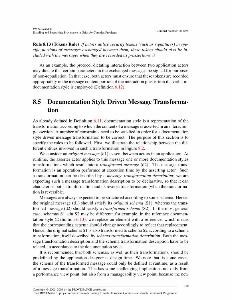
PROVENANCEEnabling and Supporting Provenance in Grids for Complex Problems Contract Number: 511085
Rule 8.13 (Tokens Rule) If actors utilise security tokens (such as signatures) in spe-cific portions of messages exchanged between them, these tokens should also be in-cluded with the messages when they are recorded as p-assertions.2
As an example, the protocol dictating interaction between two application actorsmay dictate that certain parameters in the exchanged messages be signed for purposesof non-repudiation. In that case, both actors must ensure that these tokens are recordedappropriately in the message content portion of the interaction p-assertion if a verbatimdocumentation style is employed (Definition 6.12).
8.5 Documentation Style Driven Message Transforma-tion
As already defined in Definition 6.11, documentation style is a representation of thetransformation according to which the content of a message is asserted in an interactionp-assertion. A number of constraints need to be satisfied in order for a documentationstyle driven message transformation to be correct. The purpose of this section is tospecify the rules to be followed. First, we illustrate the relationship between the dif-ferent entities involved in such a transformation in Figure 8.2.
We consider an original message (d1) as sent between actors in an application. Atruntime, the asserter actor applies to this message one or more documentation stylestransformations which result into a transformed message (d2). The message trans-formation is an operation performed at execution time by the asserting actor. Sucha transformation can be described by a message transformation description; we areexpecting such a message transformation description to be declarative, so that it cancharacterise both a tranformation and its reverse transformation (when the transforma-tion is reversible).
Messages are always expected to be structured according to some schema. Hence,the original message (d1) should satisfy its original schema (S1), whereas the trans-formed message (d2) should satisfy a transformed schema (S2). In the most generalcase, schemas S1 adn S2 may be different: for example, in the reference documen-tation style (Definition 6.13), we replace an element with a reference, which meansthat the corresponding schema should change accordingly to reflect that replacement.Hence, the original schema S1 is also transformed to schema S2 according to a schematransformation, itself described by schema transformation description. Both the mes-sage transformation description and the schema transformation description have to berelated, in accordance to the documentation style.
It is recommended that both schemas, as well as their transformations, should bepredefined by the application designer at design time. We note that, is some cases,the schema of the transformed message could only be defined at runtime, as a resultof a message transformation. This has some challenging implications not only froma performance view point, but also from a manageability view point, because the new
Copyright @ 2005, 2006 by the PROVENANCE consortiumThe PROVENANCE project receives research funding from the European Commission’s Sixth Framework Programme
110
PROVENANCEEnabling and Supporting Provenance in Grids for Complex Problems Contract Number: 511085
OriginalSchema(S1)
TransformedSchema(S2)
TransformedMessage(d2)
OriginalMessage(d1)
SchemaTransformationdescription
Schema transformation
satisfies satisfies
Message transformation
Actor-SideLibrary
MessageTransformationdescription
is compliant with
Figure 8.2: Documentation Style Driven Message Transformation
schema has to be published and shared so that querying actors can make use of it. Toavoid such problems, we recommend that designers identify at design time the schemaS2 of the transformed message.
Such constraints on transformations can be formalised in the following behaviouralrules. When a documentation styles are used, transformations are applied in accor-dance with the Rules 8.14, 8.15 and 8.16.
Rule 8.14 (Message Transformation Rule) A message must be transformed accord-ing to a message transformation description as defined by the documentation stylebeing used. 2
Rule 8.15 (Schema Transformation Rule) The schema of a message being trans-formed must also be transformed according to a schema transformation descriptionas defined by the documentation style being used. 2
Copyright @ 2005, 2006 by the PROVENANCE consortiumThe PROVENANCE project receives research funding from the European Commission’s Sixth Framework Programme
111

PROVENANCEEnabling and Supporting Provenance in Grids for Complex Problems Contract Number: 511085
Rule 8.16 (Transformation Description Compliance Rule) The message transforma-tion description of a given documentation style must be compliant with the schematransformation description of that documentation style. 2
The actor side library provides some support for the above mechanisms (see Sec-tion 8.7). Specifically, the message transformation description that happens at runtimeis part of the actor side library implementation.
8.6 Actor Capability PoliciesIn order for users of a provenance system to be able to record p-assertions, they mustbe able to discover services capable of asserting and recording process documenta-tion. By advertising their capabilities in policies, such services allow potential usersto find them. In this section, we describe the various service capability policies thatensure that services can be found and understood by users, and by doing so we ensureinteroperability.
The standard capabilities of a provenance-aware service include record and query.For each, there are several policies that are necessary to specify.
8.6.1 RecordingAsserting actors should advertise the kinds of p-assertions that they can assert. Thus,for example, an application service actor may be designed to document all, some, ornone of its internal state as actor state p-assertions; the different levels of documen-tation detail available should be stated in a policy. Similarly, asserting actors mayhave the ability to document certain relationships between interaction or actor statep-assertions, which may be of interest to a user and, thus, must advertise such capa-bilities in order that users can discover which asserting actors offer the right kinds ofdocumentation capabilities.
Definition 8.1 (Assertion Category policy) An assertion category policy should spec-ify what categories of p-assertions a service can record. 2
Services may offer all, or only a subset of documentation styles (see Chapter 6,Section 6.5 for a discussion of documentation styles). Users must be able to chooseservices offering the desired documentation style and this capability should be ex-pressed by an appropriate policy.
Definition 8.2 (Documentation Style Policy) A documentation style policy should de-scribe the various different kinds of documentation style a recording service offers. 2
Different provenance stores may have different restrictions on access as dictatedby their respective access control and authorisation policies (Section 4.3.1); recordingservices must specify which provenance stores they are able to record to and underwhat restrictions.
Copyright @ 2005, 2006 by the PROVENANCE consortiumThe PROVENANCE project receives research funding from the European Commission’s Sixth Framework Programme
112
PROVENANCEEnabling and Supporting Provenance in Grids for Complex Problems Contract Number: 511085
Definition 8.3 (Recipient Store Policy) A recipient store policy should specify whichprovenance stores a service can record to. 2
8.6.2 QueryingJust as in the case of recording, different provenance stores have different restrictionson query operations as dictated by their respective access control and authorisationpolicies (Section 4.3.1); querying services must specify which provenance stores theyare able to query and under what restrictions.
Definition 8.4 (Query Store Policy) A query store policy states the which provenancestores a querying service has access to. 2
8.6.3 Service Requirement PoliciesService requirement policies describe any requirements that a service may have on theprovenance store such as, for example, that a store must have a high level of through-put, which may be necessary in situations of data staging where large numbers ofp-assertions are being moved around from store to store, and will be specified by theservice administrator. However, such requirements policies can be seen as a subsetof the policies described elsewhere for provenance store capabilities (see Chapter 7,Section 7.5). Services with requirements must match these to the capabilities of theavailable provenance stores using the advertised policies.
8.7 Actor Side LibraryIn this section, we introduce the actor side library and its usage. The actor side li-brary (ASL) is a collection of functions, which allow provenance-aware applicationsto communicate with provenance store services. It also provides functionality to helpapplication developers enforce the above-mentioned rules.
Although the actor side library is an important part of functionality of a provenancesystem, much of its detail is implementation specific. Many implementation recom-mendations have been identified in Section 9.6.3. A separate document [JGM+06] hasalso been provided referring to our specific implementation of actor side library. Inthis section, however, we only give a brief account of the role of such a library.
An implementation of the actor side library should contain at least one of actor sidequery library, actor side record library and actor side management library. It shouldalso contain a number of facilities, each of which enforces certain rule(s).
An application developer can use the actor side library to communicate with prove-nance store services. He can also ensure actor behaviour rules are suitably enforced inhis provenance-aware applications by invoking these corresponding facilities. After in-tegration with applications, the actor side library becomes a part of provenance-awareapplications and should be distributed with the applications.
Copyright @ 2005, 2006 by the PROVENANCE consortiumThe PROVENANCE project receives research funding from the European Commission’s Sixth Framework Programme
113
PROVENANCEEnabling and Supporting Provenance in Grids for Complex Problems Contract Number: 511085
8.8 ConclusionThis chapter has defined a number of expectations on actor behaviour. These expec-tations include a set of architectural rules that inform system developers about actorbehaviour with respect to the identification of interactions and the recording of links.We also provide a description of tracers in terms of propagation rules. Security rulesare also introduced. These rules define actor behaviour for recording p-assertions ina secure manner. Furthermore, we discuss how actors are expected to transform p-assertions when using documentation styles. Policies are then defined for provenance-aware actors. Finally, actor side libraries are introduced as the architectural componentthat can be used by system developers to make sure their actors adhere to the rules andexpectations defined in the chapter. Actors must follow the expectations outlined herein order for process documentation to be correctly recorded, managed, and queried.
Copyright @ 2005, 2006 by the PROVENANCE consortiumThe PROVENANCE project receives research funding from the European Commission’s Sixth Framework Programme
114

PROVENANCEEnabling and Supporting Provenance in Grids for Complex Problems Contract Number: 511085
Chapter 9
Justification
In this chapter, we study the impact of various requirements on the architecture andhow these are addressed (or otherwise) by features of the architecture. In some specificcases, the requirements lead to implementation recommendations, which we enumer-ate in Section 9.6. The requirements we study are those from the software require-ments document [And05b], from the security [IHT05], scalability [IGM05] and tools[Ran05] workpackages, and additional requirements from the two target applicationdomain areas (organ transplant management [VSWTV05] and aerospace engineering[KS05]).
All requirements enumerated in this chapter are quoted verbatim from the originaldocuments.
9.1 Software Requirements DocumentThis section explains how the software requirements for provenance system are sat-isfied by the functionality provided by the architecture described in this document.These requirements are sourced from the software requirements document [And05b]and are listed in the remaining sections of this chapter along with the correspondingfeature of the provenance architecture that addresses it.
9.1.1 Functional RequirementsSR-1-1 The provenance architecture should provide for the recording and querying of inter-action and actor provenance. 2
Design Feature: The architecture includes recording and querying interfaces whichcan be used respectively to store and retrieve p-assertions to/from the provenance store(cf. section 3.3, p. 27 and section 3.3, p. 27)). 2
SR-1-2 The provenance architecture should allow the retrieval of a provenance trace fromthe provenance store. Either a complete trace or a subset may be retrieved. 2
Copyright @ 2005, 2006 by the PROVENANCE consortiumThe PROVENANCE project receives research funding from the European Commission’s Sixth Framework Programme
115

PROVENANCEEnabling and Supporting Provenance in Grids for Complex Problems Contract Number: 511085
Design Feature: The architecture provides a query interface (cf. section 3.3, p. 27)with multiple levels of query capability that support the required granularity of traceto be retrieved. The navigation capability allows p-assertions to be retrieved fromthe provenance store (cf. section 7.3, p. 99), whereas the provenance-specific querycapability allows for more process-oriented results to be retrieved (cf. section 7.2,p. 89). 2
SR-1-3 The provenance architecture should allow the back-up of a provenance store to betaken. This will generally include an archiving facility that allows data within a provenancestore to be saved for future use. 2
Design Feature: Retrieval of data for purposes of archival is supported through ap-propriate use of the querying interface (cf. section 7.3, p. 99); the specific functionalityof archival is outside the domain of the logical architecture, but would require the useof a long-term persistent storage capability. 2
SR-1-4 The provenance architecture should allow comparisons to be made across Prove-nance Records within a provenance store with reference to particular data attributes within aProvenance Record. 2
Design Feature: The architecture provides a query interface with multiple levels ofquery capability and granularity: for example, at the level of a single interaction or ac-tor state p-assertion, or the specific items within each of these (cf. section 7.3, p. 99).The queries can be generated in the appropriate format to allow accessibility at thedesired level. Comparisons are not performed by the querying interface, but are theresponsibility of processing services (cf. section 3.3, p. 29). (Implementation Recom-mendation IR-P-1, p 135.) 2
SR-1-5 The provenance architecture should allow the results of a query to the provenancestore to be captured for future use. A query in this context must be specified with reference tothe structure of the provenance store. 2
Design Feature: The results of a query are returned by the query interface (cf. section3.3, p. 27), and can be subsequently stored for future use. The provenance architecturehowever does not manage any storage space (except in the internal implementation ofthe provenance store itself); therefore, managing the storage of queries and results isoutside the scope of the architecture. 2
SR-1-6 The provenance architecture should allow a user to access a Provenance Recordbased on the time and date (calendric information) at which the Record was stored. 2
Design Feature: The recording interface (cf. section 3.3, p. 27) does not mandatewhen the provenance store actually stores p-assertions in persistent storage. This de-sign decision allows implementers to choose efficient implementation techniques thatdo not impact performance of the store, such as asynchronous storing. Thus, it is
Copyright @ 2005, 2006 by the PROVENANCE consortiumThe PROVENANCE project receives research funding from the European Commission’s Sixth Framework Programme
116
PROVENANCEEnabling and Supporting Provenance in Grids for Complex Problems Contract Number: 511085
unclear what the semantics of such a time information would actually be, given thatstoring time is not specified by the architecture. Alternatively, we could request prove-nance stores to add time information when an p-assertion is submitted through therecording interface. Given the asynchronous nature of the recording protocol, this mo-ment is not clearly specified either. Ultimately, other forms of time information may beof use to some applications: time a p-assertion is backed up, time a p-assertion is repli-cated, . . . . We see such information as a form of metadata relating to the lifecycle ofp-assertions within provenance stores. The provenance architecture however does notspecify such a lifecycle because it may constrain implementers of provenance storesunduly. Instead, several alternate approaches are proposed to support this requirement.First, asserters of p-assertions can use actor state p-assertions (cf. section 2.4, p. 20) toassert the time at which interactions occur, or can define types of p-assertions that con-tain suitable time information. Second, a generic metadata facility can be used to an-notate (with time information or other) p-assertions recorded in the provenance store;such metadata facility is generic and does not belong to the provenance architecture.(Implementation Recommendation IR-PS-1, p 134.) Third, the principles described inthis architecture can also been applied for the interaction(s) between an asserter anda provenance store. Both can document their execution in a provenance store, and inparticular the time at which they send and receive a record message, which can be ex-pressed as actor state p-assertion. (Implementation Recommendation IR-PS-2, p 134.)2
SR-1-7 The provenance architecture should allow a user to verify the contents of a prove-nance store against a specified set of rules. Verification in this context means that the contentsof the provenance store meet the set of constraints expressed by the set of rules. 2
Design Feature: The trace comparison service or semantic validity analyser are ex-amples (cf. section 3.3, p. 29) of the processing services group (cf. section 3.3, p. 29),introduced by the logical architecture. Such services need to be implemented and haveto make use of the query interface (cf. section 3.3, p. 27) to retrieve information fromthe provenance store. 2
SR-1-8 The provenance architecture should allow a user to specify a time period in the futureat which a provenance query may be submitted to a provenance store. A scheduler will be madeavailable that allows queries to be stored to disk, and dispatched to the store in the future. 2
Design Feature: The scheduling functionality can be achieved by a service that formspart of the processing services group (cf. section 3.3, p. 29). 2
SR-1-9 The provenance architecture should allow capabilities provided by the tools to beaccessible as an API. This is to allow such capabilities to be embedded within an existingapplication. 2
Copyright @ 2005, 2006 by the PROVENANCE consortiumThe PROVENANCE project receives research funding from the European Commission’s Sixth Framework Programme
117
PROVENANCEEnabling and Supporting Provenance in Grids for Complex Problems Contract Number: 511085
Design Feature: It is the responsibility of tools developers to provide libraries similarto actor-side libraries that expose the provenance store functionality (cf. section 3.3,p. 27). 2
SR-1-10 As part of the initialisation of the provenance recording process, the provenancearchitecture should allow a service or user to specify the identity of the provenance store towhich data should be recorded. 2
Design Feature: The provenance store to be used can be specified as part of a con-figuration decision by the service or a user. The actor-side libraries (cf. section 3.3,p. 27) should be configurable and allow the identity of provenance stores to be speci-fied. (Implementation Recommendation IR-ASL-1, p 135.) 2
SR-1-11 The system should support the multiple storage of a provenance record, i.e. thesystem should provide a way to store copies of a provenance record in more than one repository.2
Design Feature: Copies of provenance records can be obtained via the query inter-faces (cf. section 3.3, p. 27); however, storage and retrieval across multiple repositoriesis a storage layer issue that is not addressed by the architecture, but is left to specificimplementations of provenance stores. (Implementation Recommendation IR-PS-3,p 134.) 2
SR-1-12 The system should support the recording of different provenance information viewsrelated to an event or an entity. 2
Design Feature: The recording protocol supports different views of interactions (sendersand receivers) (cf. section 7.1, p. 87) and allows different assertions to be made aboutinteractions, states and relationships (cf. section 2.4, p. 20). 2
SR-1-13 The provenance architecture should support the migration of provenance data amongprovenance stores. 2
Design Feature: Migration of p-assertions is composed of querying of the sourceprovenance store, followed by recording into the target provenance store, and finallydeletion of the p-assertions in the source provenance store. The recording and queryinginterfaces (cf. section 3.3, p. 27, section 3.3, p. 27) can be used to that end. On theother hand, the provenance store does not provide any deletion or update capability inits APIs so as to offer immutability. Such functionality may instead be offered by thestorage layer. The issue of migration of p-assertions is also discussed in Section 5.3.(Implementation Recommendation IR-PS-5, p 134.) 2
SR-1-14 The system should support the storage of recorded provenance data for an indefiniteperiod of time. 2
Copyright @ 2005, 2006 by the PROVENANCE consortiumThe PROVENANCE project receives research funding from the European Commission’s Sixth Framework Programme
118

PROVENANCEEnabling and Supporting Provenance in Grids for Complex Problems Contract Number: 511085
Design Feature: This is a non-functional requirement that cannot be enforced by thelogical architecture. This is essentially a quality of service element that has to be pro-vided by the host of a provenance store. In addition, implementations of provenancestore should consider the expiry of cryptographic public keys. (Implementation Rec-ommendation IR-PS-10, p 135.) 2
SR-1-15 The provenance architecture should support the storage of results of analysis andreasoning operations performed on the provenance data by tools that are not part of the genericarchitecture (3rd party tools on the application layer). 2
Design Feature: The architecture is open and allows for analysis and reasoning ser-vices to be implemented as processing services (cf. section 3.3, p. 29) that interact withthe provenance through its query interface (cf. section 3.3, p. 27). As indicated in SR-1-5, the actual storage functionality is beyond the remit of the provenance architecture.2
SR-1-16 The provenance architecture should provide support for maximum automation ofthe provenance recording mechanism. 2
Design Feature: The recording interface (cf. section 3.3, p. 27) provides for therecording of one or more p-assertions, and as such offers no automation. Such a fea-ture has to be offered by the actor-side libraries (cf. section 3.3, p. 27). Two differentapproaches may be adopted by these: policies allow users to specify in a declarativemanner what information and when it should be recorded. (Implementation Recom-mendation IR-ASL-2, p 135.) Alternatively, automation support may also be providedwith knowledge of the actor hosting environment, for instance to capture invoked mes-sages, or to recover information from logs. (Implementation Recommendation IR-ASL-3, p 135.) 2
SR-1-17 The provenance architecture should be deployable as an integrated part of a system,as a service within the same administrative domain as the client system and as a 3rd (external)party operated service, too. 2
Design Feature: The APIs of the query, submission and management libraries (cf.section 3.3, p. 27) allow integration into the existing system, whilst the UIs, processing(cf. section 3.3, p. 29) and presentation services allow the provenance architecture tobe used as an external third-party service. The derivation engine (cf. section 4.3.1,p. 42) of the provenance security architecture allows policies of the client domain tobe reflected into the provenance access control functionality. 2
SR-1-18 Client side components of the provenance architecture should not block an execut-ing workflow if any provenance services are unavailable. 2
Copyright @ 2005, 2006 by the PROVENANCE consortiumThe PROVENANCE project receives research funding from the European Commission’s Sixth Framework Programme
119
PROVENANCEEnabling and Supporting Provenance in Grids for Complex Problems Contract Number: 511085
Design Feature: No requirements on synchronous or asynchronous behaviour shouldbe assumed. This is an implementation issue and hence not applicable within thecontext of a logical architecture. Capability to handle errors as suggested by this re-quirement (or others) may be offered by actor side libraries (cf. section 3.3, p. 27).(Implementation Recommendation IR-ASL-4, p 135.) 2
9.1.2 Performance RequirementsSR-2-1 The additional execution overhead for an application recording provenance informa-tion should be kept to a minimum. 2
Design Feature: Execution overhead is implementation-specific and cannot be en-forced or specified at architectural level. The architecture however is designed in sucha way that it allows asynchronous recording and has ways of dealing with large datastructures allowing impact of p-assertion recording to be minimised. 2
SR-2-2 : Storage space requirements of the provenance architecture for provenance infor-mation recording should be kept at a reasonably low level. 2
Design Feature: The p-structure (cf. section 6.8, p. 78) is a well-defined data struc-ture whose space requirement can be predicted at design time. A trade-off exists be-tween the amount of storage required to document execution and its level of detail.Since storage requirements can be predicted, the designer of a provenance-aware ap-plication may therefore take decisions to record (or not) aspects of execution that arerelevant (or not) to the provenance queries to be supported by the application. 2
SR-2-3 : The provenance architecture should guarantee reliable once-and-once-only deliv-ery of provenance information to and from a provenance store. 2
Design Feature: The architecture is agnostic about the transport layer used to deliverrecord messages to the provenance store. Protocols that offer the guarantee of once-and-once-only delivery may be used in applications that have such a requirement. Wenote that the provenance store has the idempotence property (cf. section 2, p. 86),which allows a same message (with same local identified) to be submitted multipletimes, with the guarantee that it affects the provenance store at most once. 2
SR-2-4 The provenance architecture should be capable of handling large amounts of prove-nance data submitted frequently by user applications. The provenance architecture should notbe the cause of any bottlenecks in the overall system due to the processing of provenance data.2
Design Feature: The protocol used for submission in the architecture provides sev-eral ways of dealing with large amounts of data. On the one hand, appropriate record-ing patterns (cf. section 5.1, p. 51) allow for deployment of provenance stores that arelocal to the asserter, and therefore avoid transfer of large amounts of data over long
Copyright @ 2005, 2006 by the PROVENANCE consortiumThe PROVENANCE project receives research funding from the European Commission’s Sixth Framework Programme
120
PROVENANCEEnabling and Supporting Provenance in Grids for Complex Problems Contract Number: 511085
distance network. On the other hand, assertions (or part of them) may be passed byreference, and can be used to prevent the submission of large data sets; such a facilityis offered by documentation style (cf. section 6.4, p. 72). 2
9.1.3 Interface RequirementsSR-3-1-1 All of the functions of the provenance architecture should be accessible throughits API so it can be used as an embedded component in a system. 2
SR-3-1-2 The provenance architecture should support a rich set of published, generic ap-plication programming interfaces (APIs) that allow application specific analysis and reasoningtools to be built upon. 2
SR-3-1-3 The provenance architecture should provide a programmatic interface for the ad-ministration of the system. 2
Design Feature: SR-3-1-1, SR-3-1-2 and SR-3-1-3 are all catered for via the man-agement and provenance querying actor side libraries. The Provenance Architectureshould make no assumptions about the contents of this API, or the particular protocolthat is used to access services made available through this API. 2
SR-3-1-4 The provenance architecture should support an XML-based API format for prove-nance data. 2
Design Feature: The architecture described in this document is format and technol-ogy neutral. Its implementation by EU Provenance will be Web Services based, andtherefore, will be offering WSDL specifications to describe service interfaces. 2
SR-3-2-1 Export formats for provenance data should be non-proprietary to allow tools andapplications to be built without violating IPR rules. A format based on an existing data rep-resentation standard (with special focus on XML defined by XML Schema) would be highlypreferred. 2
Design Feature: The architecture described in this document is format and technol-ogy neutral. Its implementation by EU Provenance will be Web Services based, andits query functionality will return XML representations of p-assertions. 2
9.1.4 Operational RequirementsSR-4-1 Provenance information displayed by the provenance architecture on a human com-puter interface (HCI) should be updatable on user request. 2
Copyright @ 2005, 2006 by the PROVENANCE consortiumThe PROVENANCE project receives research funding from the European Commission’s Sixth Framework Programme
121
PROVENANCEEnabling and Supporting Provenance in Grids for Complex Problems Contract Number: 511085
Design Feature: Once retrieved from the provenance store, any p-assertion or deriveddata can be viewed or rendered by a user interface. Such data can be updated locally,but by its immutability property, documentation of execution cannot be changed in theprovenance store. (Implementation Requirement IR-PS-5, p 134.) 2
SR-4-2 HCIs presented by the provenance architecture for displaying the contents of aprovenance store should support continuous monitoring, i.e. the displayed information shouldbe updated automatically on every change as soon as possible. 2
Design Feature: A processing service, such as the provenance store visualiser (cf.section 3.3, p. 29) may poll the provenance store, by repeatedly issuing queries, oralternatively can subscribe to notification of change (cf. section 7.4.1, p. 100) in theprovenance store. We note that the architecture does not guarantee any real-time con-straint, and therefore the timeliness of such notifications is not specified. 2
SR-4-3 The update frequency of provenance information displayed by the system on a HCIshould be configurable based on policies. 2
Design Feature: Following requirement SR-4-3, such policies are specific to theprovenance store visualiser (cf. section 3.3, p. 29). 2
SR-4-4 Human-computer interfaces presented by the provenance tools should be designedto allow multilingual support. 2
Design Feature: (Implementation Requirement IR-P-2, p 135.) 2
9.1.5 Documentation RequirementsSR-5-1 Detailed documentation of the provenance architecture public interfaces should beproduced both for APIs and HCIs. 2
Design Feature: This document provides concepts, definitions and abstract descrip-tions, which should be referred to by the documentation of specific components. 2
SR-5-2 A detailed description of the administrative interface of the provenance architectureshould be produced. 2
Design Feature: This document provides concepts, definitions and abstract descrip-tions, which should be referred to by the documentation of specific components. 2
9.1.6 Security RequirementsSR-6-1 The provenance architecture should have a configurable access control system overthe resources it provides, with a granularity that is sufficient to protect these resources. 2
Copyright @ 2005, 2006 by the PROVENANCE consortiumThe PROVENANCE project receives research funding from the European Commission’s Sixth Framework Programme
122
PROVENANCEEnabling and Supporting Provenance in Grids for Complex Problems Contract Number: 511085
Design Feature: The authorisation engine (cf. section 4.3.1, p. 40) provides accesscontrol functionality, which is configurable through the access control policies in thesecurity architecture (cf. section 4.3.1, p. 40, section 4.3.1, p. 41). The access controlfunctionality could be configured to reflect the functionality of other access controlsystems. (Implementation Recommendation IR-PS-6, p 134.) 2
SR-6-2 The provenance architecture should allow both automated and manual determinationof access control rights. 2
Design Feature: The access control policies (cf. section 4.3.1, p. 41) in the securityarchitecture are manually determined by the system administrator . The derivationengine (cf. section 4.3.1, p. 42) allows automated generation of access control rightson the basis of access control statements accompanying provenance information thatis meant to be stored. 2
SR-6-3 The provenance architecture should allow a service or user to request the level ofsecurity they wish to be associated with the recording process. The level of security can rangefrom no security through encrypted data transfer to more complex security mechanisms. 2
Design Feature: The user can determine the required level of security to be used inthe recording process from the access control policy (cf. section 4.3.1, p. 41) in thesecurity architecture of the provenance system. 2
SR-6-4 The provenance architecture should provide a way to map access rights informationof embedding systems into its security subsystem. 2
Design Feature: The derivation engine (cf. section 4.3.1, p. 42) of the provenancesecurity architecture allows policies / access control rights of the embedding systemto be reflected into the provenance access control functionality. (Implementation Rec-ommendation IR-PS-6, p 134.) 2
SR-6-5 Security related procedures for accessing the provenance system should be sub-sumed under the existing security related procedures for the embedding system if possible,so that changes or additions to the existing procedures are minimised. 2
Design Feature: The derivation engine (cf. section 4.3.1, p. 42) of the provenancesecurity architecture allows policies / access control rights of the embedding system tobe reflected into the provenance access control functionality. In addition, the identityvalidator (cf. section 4.3.1, p. 38) can accept a multiplicity of security credentials,including the ones used for authenticating to the embedding system. 2
SR-6-6 The provenance architecture should provide a mechanism for recording provenancedata in an unmodifiable form and also ensuring that the party responsible for the recordingprocess cannot deny having recorded that provenance data. 2
Copyright @ 2005, 2006 by the PROVENANCE consortiumThe PROVENANCE project receives research funding from the European Commission’s Sixth Framework Programme
123
PROVENANCEEnabling and Supporting Provenance in Grids for Complex Problems Contract Number: 511085
Design Feature: Process documentation will not be overwritten, modified or deletedby any operation in the supplied APIs. (Implementation Requirement IR-PS-5, p 134.)Non-repudiation can be accomplished using signatures, and the P-structure supportsthe signing of a p-assertion by an asserting actor (cf. section 6.9, p. 82). Signingfunctionality can be provided by actor side libraries. (Implementation recommendationIR-ASL-5.) 2
SR-6-7 The provenance architecture should provide a mechanism for the authentic times-tamping of provenance records. Authenticity should be guaranteed by the mechanism on alevel that is enough even for the use in legal procedures. 2
Design Feature: Asserters of p-assertions can use actor state p-assertions (cf. sec-tion 2.4, p. 20) to assert the time at which interactions occur, or can define types ofp-assertions that contain suitable time information. Second, a generic metadata facil-ity can be used to annotate (with time information or other) p-assertions recorded inthe provenance store. (Implementation Requirement IR-PS-1, p 134.) In either case,access can be provided to a trusted third party time stamping service. (ImplementationRequirement IR-APP-4, p 137.) We also refer the reader to SR-1-6 for an analysis oftimestamping by the provenance store. 2
9.1.7 Other RequirementsSR-7-1 The provenance architecture should have the properties of cost efficiency and ro-bustness versus an in-application hand-engineered logging system. 2
Design Feature: The Provenance system is not a logging system and therefore com-parison is difficult. Cost efficiency and robustness are deployment and implementationproperties. 2
SR-7-2 The provenance architecture should be loosely coupled and independent from theapplications as much as possible. Integration costs for existing systems should be minimal,ideally existing system components should remain unaffected. 2
Design Feature: Addressed by features for SR-1-16, SR-1-17, SR-6-4, SR-6-5. 2
9.2 Tools RequirementsIn this section, we discuss some of the requirements of the tools workpackage (asdetailed in the tools workpackage deliverable D6.1.1 [Ran05]) and their impact onthe architecture. Note that some requirements marked TSR-* in the tools documentdo not have corresponding requirements on the architecture (most after TSR-4-2 arerequirements on the tools rather than the provenance architecture), so are not includedhere.
Copyright @ 2005, 2006 by the PROVENANCE consortiumThe PROVENANCE project receives research funding from the European Commission’s Sixth Framework Programme
124
PROVENANCEEnabling and Supporting Provenance in Grids for Complex Problems Contract Number: 511085
TSR-1-1 Provenance Architecture should support a Query Interface and a Submission/RecordingInterface to the provenance store. Tools may make use of this interface to retrieve one or morep-assertions from the provenance store. 2
Design Feature: See the Design Feature for SR-1-1. 2
TSR-1-2 Provenance Architecture should provide support for storing results generated froma Query locally at the provenance store. These results can then be read from a temporarystorage area by the Tools. 2
Design Feature: The query interface temporarily stores results from a query, for it-erative retrieval (cf. section 7.3, p. 99). 2
TSR-1-3 Provenance Architecture should not impose constraints on access to the store viathe Query or Management Interfaces. Tools may be able to read all or part of the PS directly.2
Design Feature: The query interface (cf. section 3.3, p. 27) can provide clients withdirect access to all or part of the process documentation contained in a provenancestore, depending on access control policies. The provenance architecture cannot pre-vent access to the back-end storage of process documentation by means other than theprescribed interfaces. 2
TSR-1-4 The Query interface at the PS should allow search to be carried out on a data at-tribute or value. For instance, the tools may generate an Xpath query that needs to be processedby the PS, and this query would be defined with reference to one or more namespaces. 2
Design Feature: The navigation capability of the query interface (cf. section 7.3,p. 98) is based on evaluating expressions against a hierarchical view of the documen-tation in provenance stores. 2
TSR-1-6 The Recording interface at the PS may attach a timestamp with each p-assertionrecorded. This timestamp may be in addition to one generated by the application submittingthe p-assertion. Generally, no timestamp is produced by the tools. 2
Design Feature: See the Design Features for SR-1-6 and SR-6-7. According to theSR-6-7, the tools may have to invoke the necessary timestamping functionality. 2
TSR-1-8 The Query interface at the PS should provide some indication to the Tools aboutthe list of queries that are waiting to be answered by the PS. Essentially, if a message queueexists at the PS, the contents and size of this query should be accessible via the Managementinterface at the PS. 2
Design Feature: See the Design Feature for SR-1-8. A processing service whichprovides a scheduling/buffering facility can also provide a message queue for interro-gation. The management interface of the provenance store provides functionality formanaging process documentation. 2
Copyright @ 2005, 2006 by the PROVENANCE consortiumThe PROVENANCE project receives research funding from the European Commission’s Sixth Framework Programme
125
PROVENANCEEnabling and Supporting Provenance in Grids for Complex Problems Contract Number: 511085
TSR-1-9 The Provenance Architecture should support a registry service to enable the soft-ware interfaces for all Tools to be visible. This is particularly true for any visualisation toolsthat may be application specific. Information about new tools, or updated versions of existingtools should be accessible through such a registry. This would be associated with ‘ProcessingServices’ in the Logical Architecture. 2
Design Feature: The provenance architecture does not contain a registry, but onemay be deployed as part of an application and used to register provenance architecturecomponents. 2
TSR-1-10 The Management interface at the PS should enable the identity of the PS to bequeried. 2
Design Feature: The obtaining of certificates and public keys for services can beachieved by many mechanisms, and is out of scope for the provenance architecture. 2
TSR-1-17 The Provenance Architecture should not assume the existence of a particular setof services in the Tools Suite. 2
Design Feature: No particular set of processing services, UIs or other tools are as-sumed or required in the provenance architecture. 2
TSR-1-18 The Provenance Architecture should not necessitate the submission of a p-assertionfrom a particular type of client. No requirements on synchronous or asynchronous behaviourshould be assumed. 2
Design Feature: See the Design Feature for SR-1-18. 2
TSR-3-1-1 All of the functions of the provenance architecture should be accessible throughits API so it can be used as an embedded component in a system. 2
Design Feature: See the Design Feature for SR-3-1-1. 2
TSR-4-1 The Provenance Architecture should make no assumption about the types or modesof user interfaces being supported. 2
Design Feature: The provenance architecture does not make any assumptions aboutthe types or modes of user interfaces being supported. 2
TSR-6-2 The Provenance Architecture should allow such access control to be supported(and configured) through the Management interface of the PS, and a specialist CredentialsManagement service (or similar). 2
Design Feature: See the Design Feature of SR-6-2 for the ways in which the archi-tecture supports configuration of access control . 2
TSR-6-6 The Provenance Architecture should make no assumption about the recording for-mat used. 2
Copyright @ 2005, 2006 by the PROVENANCE consortiumThe PROVENANCE project receives research funding from the European Commission’s Sixth Framework Programme
126
PROVENANCEEnabling and Supporting Provenance in Grids for Complex Problems Contract Number: 511085
Design Feature: The provenance architecture is format and technology-independent.2
9.3 Scalability RequirementsIn this section, we discuss some of the requirements of the scalability workpackage (asdetailed in the scalability workpackage deliverable D5.1.1 [IGM05]) and their impacton the logical architecture.
SL-1 The provenance query interface should support the retrieval of large result sets. 2
Design Feature: The query interface allows actors to iterate over query results (cf.7.3). (Implementation Recommendation IR-PS-7, p 134.) 2
SL-2 The provenance recording interface should support references to data within a p-assertion.2
Design Feature: The architecture supports storing data reference in the provenancestore instead of the actual data through the use of documentation style (cf. section 6.4,p. 72). (Implementation Recommendation IR-APP-2, p 136.) 2
SL-3 The provenance recording interface should support the recording of repeated p-assertions.2
Design Feature: An actor can make a p-assertion that refers to an already recordedp-assertion by using the global p-assertion key of the previously recorded p-assertion.(cf. 6.2 p. 60). 2
SL-4 The provenance architecture should support handling of large p-assertion messages. 2
Design Feature: This is addressed by the documentation style through reference aswell as the asynchronous nature of the recording protocol. An actor can record areference to a p-assertion instead of the entire message itself. Likewise, an actor couldsplit up the content of the large p-assertion into several smaller p-assertions and recordthose separately (cf. section 6.4, p. 72). (Implementation Recommendation IR-APP-2,p 136.) Also see Design Feature for SR-2-4. 2
SL-5 Provenance stores should be able to exchange their contents. 2
Design Feature: See the Design Feature for SR-1-13. 2
SL-6 The provenance store recording interface should support the SOAP MTOM recom-mendations for non-XML data. 2
Copyright @ 2005, 2006 by the PROVENANCE consortiumThe PROVENANCE project receives research funding from the European Commission’s Sixth Framework Programme
127
PROVENANCEEnabling and Supporting Provenance in Grids for Complex Problems Contract Number: 511085
Design Feature: The architecture is logical and does not specify specific transportprotocols. This is an implementation concern. 2
SL-7 The provenance store should support multiple actors recording, querying it simultane-ously. 2
Design Feature: The recoding, querying interfaces place no limit on the numberof actors that can use these interfaces. (Implementation Recommendation IR-PS-9,p 135.) 2
SL-8 The provenance store implementation should be able to manage large amount of p-assertions. 2
Design Feature: The management interface places no limit on the number of p-assertions that can be managed. (Implementation Recommendation IR-PS-8, p 134.)2
SL-9 Provenance actors should have no affinity to a provenance store. 2
Design Feature: The logical architecture does not prescribe or enforce what prove-nance store an actor can use. 2
9.4 Requirements from the OTM/EHCR ApplicationIn this section, we discuss the requirements of the Organ Transplant Management ap-plication on the provenance architecture. We make reference to the General Rules(and sometimes section numbers) in deliverable D8.1.1 [VSWTV05]. Not all GeneralRules listed in that document are included as requirements here: General Rules OTM4 and 10–23 and EHCR 7–17 are design decisions regarding the intended use of theprovenance architecture (and compatible with it) rather than requirements.
GR-OTM.1 Anonymisation of patient identifiers must be carried out before any data isstored in Provenance stores. A system wide anonymisation mechanism is required. 2
Design Feature: Asserting actors can replace patient identifiers with anonymous IDsin interaction p-assertions. Documentation style (cf. section 6.4, p. 72) can then beused to ensure that querying actors know this replacement has occurred. (Implemen-tation Recommendation IR-APP-1, p 136.) 2
GR-OTM.2 Source medical data is never stored in Provenance stores but only referencedtherein. A system wide medical data referencing scheme is required. 2
Copyright @ 2005, 2006 by the PROVENANCE consortiumThe PROVENANCE project receives research funding from the European Commission’s Sixth Framework Programme
128

PROVENANCEEnabling and Supporting Provenance in Grids for Complex Problems Contract Number: 511085
Design Feature: Asserting actors can replace sensitive data with references to otherdata stores in interaction p-assertions. Documentation style (cf. section 6.4, p. 72)can then be used to ensure that querying actors know this replacement has occurred.(Implementation Recommendation IR-APP-2, p 136.) 2
GR-OTM.3 Each application component (actor/service) is shadowed by its own local Prove-nance store. 2
Design Feature: Multiple provenance stores can be deployed within a single appli-cation (cf. section 3.3, p. 27). 2
GR-OTM.5 Provenance stores are interlinked and communicate with one another, they areconsidered to be in one single-sign-on domain for security purposes, even though the applica-tion components will generally not be. 2
Design Feature: Provenance stores can contain view links (cf. section 5.2.1, p. 57)and object links (cf. section 5.2.2, p. 58) which reference provenance stores containingrelated documentation. Querying actors can then follow these links to obtain the fullprovenance of an application entity. Single sign-on is possible with the security archi-tecture because the credential server may be in an independent security domain fromof any provenance store or application actor (cf. section 4.3, p. 38). (ImplementationRecommendation IR-PS-4, p 134.) 2
GR-OTM.6 All decision, result and edit (and possibly consult) actions/events are recordedin the system by the actor responsible for carrying them out. 2
Design Feature: This matches the requirements on actor behaviour and so is com-patible with the architecture. (Implementation Recommendation IR-APP-3, p 137.)2
GR-OTM.7 ...process documentation is expected to be available indefinitely, however theunderlying medical data may be removed over time due to the application of data retentionpolicies. 2
Design Feature: This matches the intended use of the provenance architecture. Pro-cess documentation will not be overwritten, modified or deleted by any operation in thesupplied APIs. (Implementation Recommendation IR-PS-5, p 134.) Any subsequentdangling links must be dealt with at the application level. 2
GR-OTM.8 Messages stored in the Provenance system MAY NOT be the complete mes-sages originally sent, but a reduced form removing sensitive medical data. 2
Design Feature: Asserting actors can replace sensitive data with references to otherdata stores in interaction p-assertions. Documentation style (cf. section 6.4, p. 72)can then be used to ensure that querying actors know this replacement has occurred.(Implementation Recommendation IR-APP-2, p 136.) 2
Copyright @ 2005, 2006 by the PROVENANCE consortiumThe PROVENANCE project receives research funding from the European Commission’s Sixth Framework Programme
129

PROVENANCEEnabling and Supporting Provenance in Grids for Complex Problems Contract Number: 511085
GR-OTM.9 All messages sent in the system are stored by BOTH the sender and the receiver.2
Design Feature: It is possible to distinguish which actor in an interaction is assertingdocumentation using the record data structure (cf. section 7.1, p. 87) and for a queryingactor to distinguish which actor asserted each p-assertion in a provenance store (cf.section 6.8, p. 80). 2
GR-EHCR.1 In order to assembly the full EHCR of the patient, the EHCR application usesthe Provenance information returned from the Provenance store. 2
Design Feature: If the provenance of the patient contains all information to be in-cluded in the EHCR, then the query interface supports this action (cf. section 3.3,p. 27). 2
GR-EHCR.2 The EHCR application will use the one Provenance store per actor/service/data-store approach to store p-assertions. 2
Design Feature: Multiple provenance stores can be deployed within a single appli-cation (cf. section 3.3, p. 27). With this, deployers can associate one provenance storeto one application actor if they wish. 2
GR-EHCR.3 The Provenance system connects the distributed Provenance stores and an-swers Provenance questions as if the distributed Provenance stores were logically a singlecentralised Provenance store. 2
Design Feature: This functionality is an illustration of a processing service (cf. sec-tion 3.3, p. 29), which can query multiple distributed stores and return combined re-sults. 2
GR-EHCR.4 Patient information is stored in the Provenance system only through refer-ences using the Global Medical Patient ID (GMPID). 2
Design Feature: Asserting actors can replace patient identifiers with anonymous IDsin interaction p-assertions. Documentation style (cf. section 6.4, p. 72) can then beused to ensure that querying actors know this replacement has occurred. (Implemen-tation Recommendation IR-APP-1, p 136.) 2
GR-EHCR.5 Health care data are stored in the Provenance system only through referencesusing the system wide medical referencing scheme. 2
Design Feature: Asserting actors can replace sensitive data with references to otherdata stores in interaction p-assertions. Documentation style (cf. section 6.4, p. 72)can then be used to ensure that querying actors know this replacement has occurred.(Implementation Recommendation IR-APP-2, p 136.) 2
Copyright @ 2005, 2006 by the PROVENANCE consortiumThe PROVENANCE project receives research funding from the European Commission’s Sixth Framework Programme
130

PROVENANCEEnabling and Supporting Provenance in Grids for Complex Problems Contract Number: 511085
GR-EHCR.6 Provenance activities related to the assembly of the full EHCR is in the controlof the EHCR store and is hidden from medical applications. 2
Design Feature: Processing services and querying actors can be totally independentfrom application actors following the provenance architecture (cf. section 3.3, p. 27).2
OTM-15 Provenance stores are... linked together to answer queries in a form of overlayinfrastructure spanning all relevant OTM/EHCR services” (Section 4.1, page 48 of D8.1.1). 2
Design Feature: Provenance stores can contain view links (cf. section 5.2.1, p. 57)and object links (cf. section 5.2.2, p. 58) which reference provenance stores containingrelated documentation. Querying actors can then follow these links to obtain the fullprovenance of an application entity. 2
OTM-16 [By using the provenance architecture in the application, we aim to] provide acoherent way of tracking/locating interim results related to a case across all records / documents/ reports” (Section 4.1.1, page 48 of D8.1.1). 2
Design Feature: Interim results and metadata are communicated between applicationactors or are part of their state, so will be apparent in interaction and actor state p-assertions. Relationship p-assertions allow these to be associated with a particularpatient or outcome (cf. section 2.4, p. 20). 2
OTM-17 [By using the provenance architecture in the application, we aim to] provide (with-out additional security clearance) a small amount of anonymised, low security risk meta-datato characterise the result types, decisions and outcomes without being exposed to the details ofeach decision.” (Section 4.1.1, page 48 of D8.1.1). 2
Design Feature: The provenance security architecture ensures secure access to pro-cess documentation (cf. section 4.3, p. 38). 2
OTM-18 [By using the provenance architecture in the application, we aim to] provide askeleton / framework for a more detailed probe which is able to apply security clearance toretrieve detailed records as needed in conjunction with Provenance meta-data.” (Section 4.1.1,page 48 of D8.1.1). 2
Design Feature: Replacing data with references in interaction p-assertions, wherethe references point to databases in other security domains, allows multiple steps ofsecurity clearance. Querying actors can be aware of, and so follow, the references byuse of documentation style (cf. section 6.4, p. 72). (Implementation RecommendationIR-APP-2, p 136.) 2
Copyright @ 2005, 2006 by the PROVENANCE consortiumThe PROVENANCE project receives research funding from the European Commission’s Sixth Framework Programme
131
PROVENANCEEnabling and Supporting Provenance in Grids for Complex Problems Contract Number: 511085
OTM-19 In general, access to Provenance stores will be available to persons across multiplehospitals / entities whereas internal data stores, generally are not accessible to anybody butlocal teams. If absolutely necessary however in certain cases, data could be included. Suchneeds will be evaluated on a case-by-case basis.” (Section 4.1.1, page 49 of D8.1.1). 2
Design Feature: The provenance store security architecture makes provision for in-teraction between different security domains through the trust mediator (cf. section 1,p. 38). 2
9.5 Requirements from the Aerospace Engineering Ap-plication
In this section, we discuss requirements of the Aerospace Engineering application (asdetailed in the workpackage deliverable D7.1.1 [KS05]) and their impact on the logicalarchitecture.
AER-1 The need for physical distribution is not expected to be necessary considering theestimated amount of provenance data (Section 4.1 of D7.1.1). 2
Design Feature: The provenance store is designed to be standalone in the initial in-stance; and is meant to accommodate distribution when circumstances require it (cf.section 3.3, p. 27). 2
AER-2 Data sets are referenced from the provenance store using URIs to the data server orsimilar pointers (Section 4.1 of D7.1.1). 2
Design Feature: Asserting actors can place references to data sets in the data serverp-assertions. Documentation style (cf. section 6.4, p. 72) can then be used to ensurethat querying actors know this. (Implementation Recommendation IR-APP-2, p 136.)2
AER-3 For practical reasons, it should be possible to provide a matching (or similar) accesscontrol list (ACL) in the provenance system to the ACL used for the data server (Section 4.2.1.of D7.1.1). 2
Design Feature: The access control list (cf. section 4.3.1, p. 41) of the provenancesystem should be able to express the same access control semantics and restrictions asthe access control list of the embedding system (the data server), using the derivationengine (cf. section 4.3.1, p. 42) of the security architecture if necessary. 2
AER-4 The provenance data should be exportable into files and capable of being movedalong with the simulations data (Section 4.2.1. of D7.1.1). 2
Copyright @ 2005, 2006 by the PROVENANCE consortiumThe PROVENANCE project receives research funding from the European Commission’s Sixth Framework Programme
132

PROVENANCEEnabling and Supporting Provenance in Grids for Complex Problems Contract Number: 511085
Design Feature: The provenance store provides a querying interface (cf. section 3.3,p. 27) that allows (a subset of) p-assertions to be retrieved from the provenance store,and a recording interface (cf. section 3.3, p. 27) that allows p-assertions to be recorded(i.e., the provenance store offers both import and export facilities). 2
AER-5 Data integrity between the provenance store and the linked information on the dataserver (Section 4.2.1. of D7.1.1). 2
Design Feature: It is the responsibility of the application to keep track of data move-ments and make corresponding updates to the provenance store. 2
AER-6 All p-assertions need to be uniquely identifiable by an assertion ID (Section 5.1 ofD7.1.1). 2
Design Feature: Provenance modelling introduces the notion of a global p-assertionkey (GPAK), which uniquely identifies a p-assertion (cf. section 6.2, p. 68). 2
AER-7 It would be useful to provide a way to generate unique IDs in a provenance storeclient-side library (Section 4.2.2.1 of D7.1.1). 2
Design Feature: Actor side libraries can provide functionality for generation of uniqueIDs (Implementation recommendation IR-ASL-6, p 135.) 2
AER-8 It would be useful for a user to supply an intuitive name for all interactions betweenparticular actors in a given workflow execution. 2
Design Feature: This requirement can be modelled as metadata about interactions inactor state p-assertions (cf. section 2.4, p. 20). 2
AER-9 The user interface needs to be intuitive and easy to use as the results may be verylarge and quite complex during a targeted typical simulation of a weeks duration. 2
Design Feature: User interface functionality is to be provided appropriately by thepresentation UIs in the provenance architecture (cf. section 3.3, p. 29). 2
AER-10 All p-assertions need to be time stamped by the provenance store. 2
Design Feature: This requirement is analysed as SR-1-6. 2
AER-11 A distinction between process defining and run time p-assertions has to be made.2
Design Feature: This can be supported by using different tracers for the two p-assertions types (cf. section 8.3, p. 107). Another option would be to model thedistinction as metadata about interactions in the actor state p-assertions (cf. section2.4, p. 20). 2
Copyright @ 2005, 2006 by the PROVENANCE consortiumThe PROVENANCE project receives research funding from the European Commission’s Sixth Framework Programme
133

PROVENANCEEnabling and Supporting Provenance in Grids for Complex Problems Contract Number: 511085
9.6 Implementation RecommendationsThis section contains a series of implementation recommendations that follow ouranalysis of technical requirements. Such recommendations suggest features that maybe implemented by specific components of the architecture, namely the provenancestore, processing and UI services, and actor-side libraries, and also by applicationsmaking use of the provenance architecture.
9.6.1 Provenance StoreIR-PS-1 A provenance store implementation may use a metadata infrastructure suchas RDF to annotate p-assertions with metadata information about time at which p-assertions are received through the recording interface or stored in persistent storage.2
IR-PS-2 A provenance store implementation may document its interactions with as-serters by storing p-assertions in some provenance store (itself or another one). Thisallows the provenance to document back ups, replication, time, etc. 2
IR-PS-3 A provenance store implementation may use a storage layer that offersreplication of p-assertions in order to be fault-tolerant. 2
IR-PS-4 Provenance stores for an application can be deployed in security domainsto which all querying actors have credentials to access. Tools can provide single-signon by storing credentials and using as appropriate for each provenance store. 2
IR-PS-5 Process documentation cannot be removed from the data storage using theprovenance store APIs; instead, it may be removed, following data retention policies,by making direct access to the storage layer, using curation methodology typical oflong term storage. 2
IR-PS-6 The access control functionality of the provenance store may provide a wayto model the expression of access control policies and rules so that they are functionallyand / or semantically equivalent to the access control policies of other data stores 2
IR-PS-7 Scalability of query results can be implemented by caching of the resultswithin the provenance store. A set of interface operations allows actors to iterate andretrieve the cached results in response to a query request. 2
IR-PS-8 Management of large number of p-assertions can be addressed by imple-menting the provenance store persistent store component using a proprietary or opensource database management system. 2
Copyright @ 2005, 2006 by the PROVENANCE consortiumThe PROVENANCE project receives research funding from the European Commission’s Sixth Framework Programme
134
PROVENANCEEnabling and Supporting Provenance in Grids for Complex Problems Contract Number: 511085
IR-PS-9 Implementations of the provenance recording, query and management in-terfaces should be clusterable. 2
IR-PS-10 Implementations of provenance store should consider long term storageof p-assertions and the necessity to keep a long term copy of public keys (which mayexpire) to verify signed assertions. 2
9.6.2 Processing and UI ServicesIR-P-1 A processing service should allow for comparison of p-assertions. 2
IR-P-2 UI services presented by the provenance system should be designed to allowmultilingual support. 2
9.6.3 Actor-Side LibrariesIR-ASL-1 Actor side libraries should allow for identification of the provenance storeto be used. However, it should also ensure that all p-assertions pertaining to one in-teraction from a particular actor must be recorded in the same provenance store, Rule8.4. 2
IR-ASL-2 Actor side libraries may provide re-usable functionality to communicateand interact with the assigned provenance store. 2
IR-ASL-3 Actor side libraries may provide functionality to mutually authenticatewith the assigned provenance store. This also helps actors in obeying Rule 8.10. 2
IR-ASL-4 An actor may provide functionality to record a view link to the provenancestore that contains the corresponding actors view of the interaction if the view is inanother provenance store. This also helps actors in obeying Rule 8.5. 2
IR-ASL-5 Actor side libraries may provide functionality for generation of uniqueIDs. This helps actors in obeying Rule 8.1. 2
IR-ASL-6 Actor side libraries may provide functionality to add assigned InteractionKey into its asserting message. This also helps actors in obeying Rule 8.2. 2
IR-ASL-7 Actor side libraries may provide functionality for generation of a newsession tracer and add it into task message. This helps actors in obeying Rule 8.6. 2
Copyright @ 2005, 2006 by the PROVENANCE consortiumThe PROVENANCE project receives research funding from the European Commission’s Sixth Framework Programme
135
PROVENANCEEnabling and Supporting Provenance in Grids for Complex Problems Contract Number: 511085
IR-ASL-8 Actor side libraries may provide functionality to add any session tracersreceived from a superior actor to all requests it makes to inferiors within the task startedby the superior’s request. This helps actors in obeying Rule 8.7. 2
IR-ASL-9 Actor side libraries may provide functionality to add the session tracerssupplied by its superior to its response to the superior. This helps actors in obeyingRule 8.8. 2
IR-ASL-10 Actor side libraries may support declarative policy specification thatspecify what information needs to be recorded and when. This helps actors in obeyingrules in Section 8.6. 2
IR-ASL-11 Actor side libraries may be customised for specific actor hosting envi-ronment to capture information automatically from existing logs or from runtime envi-ronment. It may also use security functionality and credentials provided by the hostingenvironment. This helps actors in obeying Rule 8.11. 2
IR-ASL-12 Actor side libraries may provide a range of error handlers and other facil-ities to desynchronise application execution from execution documentation recording.This helps actors in obeying Rule 8.12. 2
IR-ASL-13 Actor side libraries may provide the necessary access to cryptographicfunctionality and material (such as key stores) in order to accomplish functionalitysuch as signing or encrypting. This helps actors in obeying Rule 8.9. 2
IR-ASL-14 Actor side libraries may provide functionality to transform messages ac-cording to particular documentation styles. This helps actors in obeying rules in Sec-tion 8.5. 2
9.6.4 Application Use of Provenance ArchitectureIR-APP-1 A documentation style can be created that marks a message as havingbeen anonymised. Patient IDs can then be anonymised in an application message be-fore asserting its content in an interaction p-assertion, and the anonymised documen-tation style used. 2
IR-APP-2 A documentation style can be created that marks data as having been re-placed by a reference. Sensitive data or large data sets can then be replaced withreferences in an application message before asserting its content in an interaction p-assertion, and the reference documentation style used. 2
Copyright @ 2005, 2006 by the PROVENANCE consortiumThe PROVENANCE project receives research funding from the European Commission’s Sixth Framework Programme
136

PROVENANCEEnabling and Supporting Provenance in Grids for Complex Problems Contract Number: 511085
IR-APP-3 Decisions and events are triggered by information being received and pro-duce results (information being sent). Therefore, they can be modelled as relationshipsbetween interactions. Additional information about an event can be supplied as actorstate relating to those interactions. 2
IR-APP-4 Support and access to a trusted third party time stamping facility can besupported. 2
9.7 ConclusionAll requirements have been analysed from an architectural viewpoint. Either require-ments were addressed by some specific design features of the architecture, which weexplicitly referred to in the analysis, or they were beyond the remit of the architecture,and may have led to implementation recommendations for the different componentsidentified by the architecture.
Copyright @ 2005, 2006 by the PROVENANCE consortiumThe PROVENANCE project receives research funding from the European Commission’s Sixth Framework Programme
137

PROVENANCEEnabling and Supporting Provenance in Grids for Complex Problems Contract Number: 511085
Chapter 10
Related Work
At the beginning of this report, we defined provenance as the process that leads to aresult. Prior research has referred to this concept using several other terms includingaudit trails, lineage [Lan91b], and dataset dependence [AH97]. We use these termsinterchangeably to refer to the process that leads to a result. Much of the literatureconsiders what we term a provenance system, i.e. a system that records the docu-mentation of a process and allows a representation of the provenance of a result to beretrieved. The literature can be divided into four categories: fine granularity prove-nance systems, domain specific provenance systems, provenance in database systems,and middleware provenance systems. This review gives a brief summary and analysisof the literature pertaining to each of these categories.
10.1 Fine Granularity Provenance SystemsThe following systems record the documentation of a script or program execution,thereby allowing a representation of the provenance of a script/program’s result to beretrieved. These systems differ from workflow centric systems because of the finergranularity of process documentation they achieve, where granularity of documenta-tion means how detailed the documentation of a process is. If a system records all theinstructions in a program, whereas another system records the name of the programbeing run, the first system will record documentation at a finer granularity. With finergranularity documentation, the corresponding representation of provenance for a resultcan be more detailed.
One example is the Transparent Result Caching (TREC) prototype [VA98]. TRECuses the Solaris UNIX proc system to intercept various UNIX system calls in order tobuild a dependency map. Using this map, a trace of a program’s execution can be trans-parently captured, which can be used to keep web page caches current, and to providean ‘unmake’ function. Although TREC has several limitations, including high over-head, it is an interesting case for determining the bounds on process documentationgranularity.
Copyright @ 2005, 2006 by the PROVENANCE consortiumThe PROVENANCE project receives research funding from the European Commission’s Sixth Framework Programme
138

PROVENANCEEnabling and Supporting Provenance in Grids for Complex Problems Contract Number: 511085
Another technique for capturing fine granularity process documentation is the sub-pushdown algorithm [Mar01]. However, this algorithm can only be used to recorddocumentation of array operations in the Array Manipulation Language and was im-plemented in a prototype database system, ArrayDB, and allows the provenance of anarray in ArrayDB to be retrieved. A more comprehensive system is audit facilitiesdesigned for the S language [BJMC88]. S is an interactive system for statistical anal-ysis. The result of users commands are automatically recorded in an audit file. Theseresults include the modification or creation of data objects as well as the commandsthemselves. The AUDIT utility can then be used to analyse the audit file to retrieve theprovenance of a statistical analysis. This utility can also create a script to re-execute aseries of commands from the audit file.
A similar fine granularity technique for recording the documentation of a processhas been used in security for mobile agent systems. Using a technique called interac-tion tracing, a user sending a mobile agent can verify that it has correctly executed onthe host platform. Interaction tracing treats a mobile agent as a black box, recordingall its inputs/outputs [Tan04]. Although interaction tracing is not concerned with theprovenance of a result, it presents a novel notion for recording process documentation.
10.2 Domain Specific Provenance SystemsMuch of the research into provenance has come in the context of domain specific ap-plications. Some of the first research in provenance was in the area of geographicinformation systems (GIS). Knowing the provenance of map products is critical inGIS applications because it allows one to determine their quality. Lanter [Lan91b]developed two systems for recording process documentation and retrieving the prove-nance of map products in a GIS. The first system was a meta-database for recordingdocumentation of a GIS process, while the second was for tracking Arc/Info GIS op-erations from a graphical user interface with a command line [Lan91a, LE91]. Theworkflow centric user interface was integrated into a software product called Geo-lineus, which is one of the few lineage systems to be incorporated into a commercialsoftware product [Bos02]. Another GIS system that includes process tracking is Geo-Opera, which is based on non-domain specific software [AH97]. Many of the ideasin Geo-Opera are extended from GOOSE, which uses data attributes to point to thelatest inputs/outputs of a data transformation. All inputs/outputs must be stored inGOOSE, and data transformations are programs or scripts [AA93]. Both GOOSE andGeo-Opera are workflow based systems.
Another domain where provenance is of interest is satellite image processing. TheEarth System Science Workbench (ESSW) is designed for processing satellite imagerylocally. It provides a lab notebook service for tracking processing steps and a No-Duplicate-Write-Once Read-Many storage service for storing files. As a workflow isrun inside ESSW, the results of each metadata described step is stored in the lab note-book service. ESSW is noteworthy because it emphasises the need to have immutable
Copyright @ 2005, 2006 by the PROVENANCE consortiumThe PROVENANCE project receives research funding from the European Commission’s Sixth Framework Programme
139

PROVENANCEEnabling and Supporting Provenance in Grids for Complex Problems Contract Number: 511085
process documentation.In chemistry, the CMCS project has developed a system for managing metadata in
multi-scale chemistry collaborations [MPL+03]. The CMCS project is based on theScientific Application Middleware project [MCE+03], which we discuss in greater de-tail later in this review. Another domain where provenance tools are being developedis bioinformatics. The myGrid project has implemented a system for recording thedocumentation of process in the context of in-silico experiments represented as work-flows aggregating Web Services [GGS+03]. In myGrid, documentation is recordedabout workflow execution and stored in the user’s personal repository along with anyother metadata that might be of interest [ZGG+03]. Using this personal repository, theprovenance of bioinformatics results can be determined. The focus of myGrid is aboutpersonalising the way provenance is presented to the user, and highlights the need forprovenance in the bioinformatics domain.
The needs of particular domains have led to the development of specific systemsfor recording domain dependent process documentation, which allow the provenanceof results to be retrieved. The majority of the systems, however, are designed forone particular domain and are not general in nature, but they do provide insight intohow a general provenance system might be designed to meet the needs of a variety ofdomains. For example, the systems tend to use a workflow centric approach. Also, thesystems highlight the need to both record the set of transformations as well as the dataused in a process.
10.2.1 Current Practises of Document Management SystemsProvenance has been formally and explicitly defined document management systemsin museums, libraries and archival management.
In terms of this document, two of the most related works are as follows. First,the International Standard for Archival Description [ISA00] is a descriptive standardfor archival records. It can be applied to units of description at any level from thecollection to the individual item, and includes the archival history of an item and theimmediate source of acquisition, i.e. from where the item was last obtained.
Second, the Encoded Archival Description DTD [EAD02] is a standard for encod-ing archival finding aids using SGML or XML. It includes two pieces of information:the provenance of the material being described, meaning the chain of ownership of thematerials, and information about the immediate source of acquisition.
As can be seen from the above provenance definitions, standards and use context,provenance in these domains is mainly referred to the acquisition and creation infor-mation, and the history of the ownership and custody of a resource (description ordata).
Copyright @ 2005, 2006 by the PROVENANCE consortiumThe PROVENANCE project receives research funding from the European Commission’s Sixth Framework Programme
140

PROVENANCEEnabling and Supporting Provenance in Grids for Complex Problems Contract Number: 511085
10.3 Provenance in Database SystemsProvenance in database systems has focused on the data lineage problem [CWW00],which involves determining the set of source data used to produce a given item. In[WS97] Woodruff et al. attempt to solve this problem using weak inversion, which is atechnique that, given some output data and a weak inversion function f−w, attempts tolazily recreate the input data used to generate the output. Unfortunately, this requiresthe user who creates a new database view to also define an inversion function for thatview. This technique has been used to improve database visualisation [Woo98]. In[CWW00] Cui et al. formalise the data lineage problem and present algorithms togenerate lineage data in relational databases. The generation algorithms are similarto automatically creating weak inversion functions for every new view in a database,which allows users to “drill through” the lineage of a data item seeing the source data(tuples) that contributed to the given data item [CW00]. This work was also extendedto deal with general transformations of data sets inside a data warehouse [CW03].Another system that examines the data lineage problem in a data warehouse contextis AutoMed [FP03]. Process documentation is recorded in AutoMed by recordingschema transformations, a series of which is termed a schema transformation pathway.From these transformation pathways, the lineage of a data item can be retrieved. Thegranularity of this approach depends on the granularity and number of schemas definedin the system.
Buneman et al. [BKT01] redefine the data lineage problem as “why-provenance”and define a new type of provenance for databases, namely, “where-provenance”.“Why-provenance” refers to why a piece of data is in the database, i.e. what datasets (tuples) contributed to a data item, whereas, “where-provenance” addresses thelocation of a data element in the source data. Based on this terminology, a formalmodel of provenance is developed applying to both relational and XML databases. Inother work [BKKT02], Buneman argues for a time-stamped based archiving mecha-nism for change tracking in contrast to diff-based mechanisms which, it is argued, maynot capture the complete process of database modification because there may be multi-ple changes between each archive of the database. Therefore, a diff-based mechanismis not a reliable approach for the development of a general provenance system, and thetime-stamped approach is advocated.
The research into provenance in database systems is well grounded, systematic,and formal. Because databases have a well defined and fixed set of transformations,the community has focused mainly on the data lineage problem. Moreover, they dealonly with closed systems. However, in open, distributed systems the number of trans-formations can be infinite, therefore, work is needed in developing systems that canhandle any kind of transformation in such open systems. Cui et al. [CW03] is a firststep toward addressing this problem, but it only pertains to one particular context, thedata warehouse.
Copyright @ 2005, 2006 by the PROVENANCE consortiumThe PROVENANCE project receives research funding from the European Commission’s Sixth Framework Programme
141

PROVENANCEEnabling and Supporting Provenance in Grids for Complex Problems Contract Number: 511085
10.4 Middleware Provenance SystemsSeveral middleware systems have been developed to provide provenance support toapplications. These systems aim to provide a general mechanism for recording processdocumentation and retrieving provenance for use with multiple applications acrossdomains and beyond the confines of a local machine.
In [RXBR04] Ruth et al. presents a system based around the concept of an e-notebook. Each user is required to have an individual e-notebook which can recorddata and transformations, either through connections directly to instruments, or via di-rect input from the user. Data stored in an e-notebook is represented as a DAG andcan be shared with other e-notebooks via a peer-to-peer mechanism. A DAG may spanmultiple e-notebooks to take in account multiple individuals participating in a process.To enable support of trust and credential tracking, each node in a DAG must be dig-itally signed by the node’s creator. This system is noteworthy because of its use ofthe notebook metaphor, and its approach to trust of the stored process documentation.However, there are questions as to whether this approach is appropriate for large scaledistributed systems in terms of scalability.
Another system supporting provenance is Scientific Application Middleware (SAM)[MCE+03]. SAM provides facilities for storing and managing records, metadata andsemantic relationships, and is built on the WebDav standard. Support for provenanceis provided by adding metadata to files stored in a SAM repository. SAM is of interestbecause it does not specify the format of the data or metadata that it handles, but in-stead acts as an open repository. However, this lack of structure means that retrievingthe provenance of a result in its entirety can be difficult.
The Chimera Virtual Data System is a virtual data catalogue, which is defined bya virtual data schema and accessed via a query language [FVWY02]. The schema isdivided into three parts: a transformation, a derivation and a data object. A transfor-mation represents an executable, a derivation represents the execution of a particularexecutable, and a data object is the input or output of a derivation. The virtual datalanguage provided by Chimera is used to both describe schema elements and querythe data catalogue. Using the virtual data language, a user can query the catalogue toretrieve the DAG of transformations that led to a result. The benefit of using a com-mon description language is that relationships between entities can be extracted byanalysing the transformation descriptions without having to understand the underlyingdata. Process documentation in Chimera is stored in the Provenance TransformationCatalog (PTC). However, the data stored in the PTC is limited to a defined schemaand does not allow for arbitrary information. Likewise, there is currently no supportfor associating data in the PTC, making determining data lineage difficult. Chimerais, however, noteworthy because it is specifically designed to work with large scaledistributed systems.
[SM03a] argued for infrastructure support for recording process documentation inGrids and presented a trial implementation of an architecture that was used to demon-strate several mechanisms for handling the documentation after it was recorded. The
Copyright @ 2005, 2006 by the PROVENANCE consortiumThe PROVENANCE project receives research funding from the European Commission’s Sixth Framework Programme
142

PROVENANCEEnabling and Supporting Provenance in Grids for Complex Problems Contract Number: 511085
system is based around a workflow enactment engine submitting data to a provenanceservice. The data submitted represents information about the invocation of variousWeb Services specified by the executing workflow script. This system is interestingfrom the perspective of the work presented in this document since it is both Web Ser-vices based, and was designed with Grid applications in mind. The drawbacks of thissystem, however, are that it relies completely on a workflow enactment engine, and itlacks demonstration in any large scale system.
10.5 ConclusionsIn this chapter we have reviewed relevant work carried out in other areas. We havediscussed the state of the art in a number of provenance related computational sys-tems from those covering fine granularity provenance to a number of domain specificsystems, including document management systems. Additionally, we examined howprovenance related work is carried out in database systems and we discussed severalmiddleware provenance systems. In terms of their relation to the work in this docu-ment, the finer granularity systems are not designed specifically for determining theprovenance of data items, and they may carry excessive overheads for the kinds oflarge scale systems that we consider. In addition our approach is to design a generalpurpose provenance architecture that overcomes the limitations of the domain specificprovenance systems described above. We have also addressed the kinds of multipletransformations to data items that can occur in open, distributed systems that currentdatabase systems do not handle, due to their closed world assumptions.
In comparison to current systems available, the architecture presented in this doc-ument provides an implementation independent, general specification for industrialstrength Grid-based applications that overcomes many of the limitations of previousprovenance systems.
Copyright @ 2005, 2006 by the PROVENANCE consortiumThe PROVENANCE project receives research funding from the European Commission’s Sixth Framework Programme
143

PROVENANCEEnabling and Supporting Provenance in Grids for Complex Problems Contract Number: 511085
Chapter 11
Conclusion
11.1 SummaryIn this document, we have presented a logical architecture for provenance systems andthe accompanying details required to understand how such an architecture functions.We have proposed a definition of provenance suitable for representation in a compu-tational system, in Chapter 2, as “The provenance of an entity in a given state is theprocess that led to that entity being in that state.”, and a concrete representation of thisconcept, process documentation, in terms of interactions between actors and states ofthose actors during interaction. In Chapter 3, we present the logical architecture itselfwhich defines the components of a system for the recording, maintaining, visualising,reasoning and analysis of process documentation.
Chapters 4 and 5 address the security and scalability aspects of the architecturerespectively. A security architecture, complementary to the logical architecture, is pre-sented that provides secure transmission and access control to provenance stores, anda series of scenarios is given to illustrate how different modes of interaction with thesecured system will take place. For scalability, the need for distribution of provenancestores is emphasised, and a set of deployment patterns for recording of process docu-mentation to distributed stores is given.
In Chapters 6, and 7, we provide further detail about the functionality of the prove-nance architecture. Chapter 6 describes the underpinning data model of the provenancearchitecture. In Chapter 7, we detail the functionality available through the three in-terfaces of a provenance store: recording, query and management. In Chapter 8, weenumerate the constraints that application actors have to satisfy in order to successfullyrecord documentation of execution and issue queries about the provenance of data.
Finally, Chapters 9 and 10 place the work in context. In the former chapter, wecompare the logical architecture to the software requirements captured in the EUProvenance project, showing how each is addressed by our design, and in Chapter 10we discuss related work.
Throughout this document, we highlight ways that the technology-independent ar-
Copyright @ 2005, 2006 by the PROVENANCE consortiumThe PROVENANCE project receives research funding from the European Commission’s Sixth Framework Programme
144
PROVENANCEEnabling and Supporting Provenance in Grids for Complex Problems Contract Number: 511085
chitecture presented herein can be applied to Service Oriented Architectures and sci-entific workflows. For example, the architecture defines workflows in Chapter 2 andidentifies workflow enactment engines as a potential example of application services inFigure 3.1). Chapter 5 discusses data staging in relation to workflows, and Appendix Aincludes a note, which discusses how workflow languages and enactment engines arerelated to the production of p-assertions. Other references to workflows can be foundin the index provided.
Other work produced by the EU Provenance project provides a detailed method-ology that enables application designers to incorporate the provenance architecturedescribed in this document[MMT+06].
A set of associated documents are available (see list below) that describe otherwork performed by the EU provenance project and can be found at the project’s publicweb site: www.gridprovenance.org.
• A set of open specifications of the architecture
• An instantiation of the architecture for the Web Services stack.
• A design for implementation of the architecture.
• An application of the methodology and architecture to an organ transplant man-agement system.
• An application of the methodology and architecture to an aerospace engineeringsystem.
Each of these have contributes to fulfilling the projects obligations for the threesets of stakeholders identified in Chapter 1. For example, the methodology addressesthe needs of users and developers. The open specifications address the needs of de-velopers and the design implementation addresses the needs of system managers whomust deploy a realized vision of the architecture in their domain.
Copyright @ 2005, 2006 by the PROVENANCE consortiumThe PROVENANCE project receives research funding from the European Commission’s Sixth Framework Programme
145
PROVENANCEEnabling and Supporting Provenance in Grids for Complex Problems Contract Number: 511085
Appendix A
Notes
This appendix refers to annotations introduced in the margin of the architecture docu-ment.
Note 1: Specifically, the following are all considered as “services” because they alltake some inputs and produce some outputs: Web Service, Corba or RMI objects,command line program. 2
Note 2: With such a broad definition, we see that WS-BPEL, WSFL, VDL, Dagman’sDAGs or Gaudi are all workflow frameworks capable of expressing the composition ofservices. Likewise, a script calling several command line commands is also regardedas a workflow. 2
Note 3: Such messages take the form of SOAP messages for Web services. In the caseof command line executables, we do not have explicit messages; instead, they takesome explicit arguments potentially representing both inputs and outputs. We alsosee a memory shared by two threads as a way of implementing such message-passingmechanism; the message itself is the information stored in the shared memory. 2
Note 4: Our definition of process, like the Unix notion of process, refers to an instanceof a running program (workflow here). It has a beginning, and, if it is finite, it has anend. 2
Note 5: At this stage of the specification, we do not make the distinction between re-source and service [CaIFF+04] since they are defined in the context of the specific WebServices technology. Our broad view of message allows us to include in a message thenecessary reference to resources, as required by WSRF. 2
Note 6: Should the actors involved in the process be the only one to document it? Theanswer is yes. Indeed, if actors are not involved in the process, then no message hasbeen sent to them. Hence, they cannot be aware of the process, and therefore could notpossible provide any documentation relevant to this specific execution. 2
Note 7: In a grid application based on command line executables, an interaction p-assertion can include the executable fully qualified name, its inputs and its outputs,
Copyright @ 2005, 2006 by the PROVENANCE consortiumThe PROVENANCE project receives research funding from the European Commission’s Sixth Framework Programme
146
PROVENANCEEnabling and Supporting Provenance in Grids for Complex Problems Contract Number: 511085
whereas in a Web Services based approach, interactions documentation can includeinput and output SOAP messages, and a reference to the service, port and operationbeing invoked. In the latter case, we note that an interaction p-assertion potentiallyincludes not only the SOAP message body, but also its envelope, containing valuableinformation such as security, addressing, resource or coordination contexts. 2
Note 8: We note that capturing such data dependencies in large scale databases is thefocus of research on data provenance in databases; techniques developed in such acontext may have to be integrated with the proposed approach. 2
Note 9: In a concrete instantiation of the logical architecture for Java and Web Ser-vices technologies, interfaces will be specified by WSDL, whereas libraries will beJava classes, generated by wsdl2java, implementing the stubs necessary to commu-nicate with the provenance stores, and extended with some hand written conveniencefunctions. 2
Note 10: In Chapter 2, we have defined a workflow as the specification of a givenservice composition. In the context of Web Services, such a service composition canbe expressed in a workflow language, such as WS-BPEL or other, which can be exe-cuted (or enacted) by a component usually referred to as workflow enactment engine.The workflow enactment engine is just one of the actors that is involved in an appli-cation and is therefore expected to contribute p-assertions. We anticipate that for agiven workflow language, many p-assertions may be derived automatically from theworkflow script itself. For instance, interaction p-assertions can be produced for eachservice invocation; likewise, relationship p-assertions can be derived from so-calleddata links. 2
Copyright @ 2005, 2006 by the PROVENANCE consortiumThe PROVENANCE project receives research funding from the European Commission’s Sixth Framework Programme
147

PROVENANCEEnabling and Supporting Provenance in Grids for Complex Problems Contract Number: 511085
Appendix B
Abbreviations
This appendix contains abbreviations used in this document.
CA Certificate AuthorityGPAK Global P-Assertion KeyGPID Global P-Assertion IdentifierGUI Graphical User InterfaceIR Internal RepresentationPReP P-Assertion Recording ProtocolRBAC Role Based Access ControlRDF Resource Description FrameworkUI User InterfaceXML Extensible Markup Language
Copyright @ 2005, 2006 by the PROVENANCE consortiumThe PROVENANCE project receives research funding from the European Commission’s Sixth Framework Programme
148

PROVENANCEEnabling and Supporting Provenance in Grids for Complex Problems Contract Number: 511085
Appendix C
XML Schema Diagrams
Figure C.1 gives an example of a small XML Schema displayed as a diagram. We willnow explain the format of the diagram with reference to this figure.
Figure C.1: An example XML Schema diagram
Figure C.1 defines the structure of type ts:Test. The type Test contains a sequenceof elements, which we now detail. One element in the sequence is ts:testName, whichcan be any type and must occur once and only once in an instance of ts:Test. ts:Nameis followed by element ts:testNumber, which must contain a string. The ts:testNumberelement must occur at least once and can occur as many times as needed. This isdenoted by the “1..unbounded” under the element. Finally, the sequence contains achoice between two elements, ts:startTest and ts:stopTes, either of which must containa date.
Below is a simple of description of each of the parts of the XML Schema diagramformat.
Copyright @ 2005, 2006 by the PROVENANCE consortiumThe PROVENANCE project receives research funding from the European Commission’s Sixth Framework Programme
149

PROVENANCEEnabling and Supporting Provenance in Grids for Complex Problems Contract Number: 511085
An element (instance) is represented by the quali-fied name of the element in the box. By default anelement must occur once and only once. Wherethis restriction does not hold, the text “1..un-bounded”, “0..unbounded”, “0..N”, “1..N” (whereN is an integer) appears under the element box.The left hand number is the minimum occurrencesof the element at the position in the XML doc-ument, the right hand number is the maximum(with “unbounded” for no maximum).
A complex type is denoted by a lightly markedbox with the qualified name of the type at the topleft. The structure of the type is given by the ele-ments, types and control structures within the box.
A horizontal sequence of dots represents a se-quence of elements or control structures, that mustappear in an element conforming to the type in thesurrounding type box.
A vertical sequence of dots represents a choice be-tween elements or control structures, that must ap-pear in an element conforming to the type in thesurrounding type box.
Copyright @ 2005, 2006 by the PROVENANCE consortiumThe PROVENANCE project receives research funding from the European Commission’s Sixth Framework Programme
150
PROVENANCEEnabling and Supporting Provenance in Grids for Complex Problems Contract Number: 511085
Index
access control, 34, 36, 40, 65delegation of, 35, 46
ack message, 87activity, 107actor, 16
actor state, 16actor side library, 113actor side management library, 113actor side query library, 113actor side record library, 113actor state p-assertion, 20, 76actor-side library, 27application services, 29architecture
logical, 27views, 10
asserter identity, 82authentication, 34, 40
mutual, 49authorisation, 34, 37
engine, 40
certificate, 35, 49, 82proxy, 48, 75
content, 87credential, 34
server, 40, 64
data accessor, 78data staging, 60derivation engine, 42, 65documentation style, 72, 73
anonymous, 74composite, 76internal reference, 74rationale, 72
reference, 74reference-digest, 74security-encryption, 75security-signing, 75verbatim, 73
exposed interaction metadata, 80, 87
federation, 35, 41, 64
idempotence, 86identified content, 87identity validator, 38implementation recommendations, 134inferior, 107interaction, 16interaction context, 30, 70interaction identifier, 68interaction key, 67interaction metadata, 70, 80interaction p-assertion, 18, 70interaction record, 80interface, 16internal representation list, 40, 104IR
IR-APP-1, 136IR-APP-2, 136IR-APP-3, 137IR-APP-4, 137IR-ASL-1, 135IR-ASL-10, 136IR-ASL-11, 136IR-ASL-12, 136IR-ASL-13, 136IR-ASL-14, 136IR-ASL-2, 135
Copyright @ 2005, 2006 by the PROVENANCE consortiumThe PROVENANCE project receives research funding from the European Commission’s Sixth Framework Programme
151

PROVENANCEEnabling and Supporting Provenance in Grids for Complex Problems Contract Number: 511085
IR-ASL-3, 135IR-ASL-4, 135IR-ASL-5, 135IR-ASL-6, 135IR-ASL-7, 135IR-ASL-8, 136IR-ASL-9, 136IR-P-1, 135IR-P-2, 135IR-PS-1, 134IR-PS-10, 135IR-PS-2, 134IR-PS-3, 134IR-PS-4, 134IR-PS-5, 134IR-PS-6, 134IR-PS-7, 134IR-PS-8, 134IR-PS-9, 135
linkdefinition, 57object link, 58view link, 57
local p-assertion identifier, 69
management interface, 27management user interface, 29matching, 18message, 16message sink, 68message source, 68message transformation description, 110
negotiation, 30non-repudiation, 35, 36, 64, 82, 110
p-assertion, 17, 68p-assertion data item, 69p-assertion data key, 69P-assertion Recording Protocol (PReP), 86
messages, 88, 89p-assertion template, 62p-header, 30, 70
p-structure, 78parameter name, 78patterns, 51
p-assertion recording, 52application of, 56ContextPassing, 53SeparateStore, 52SharedStore, 55
policies, 29policy, 100
service requirement, 29, 100access control, 41, 104, 112authorisation, 40, 75, 104, 112data staging, 102data upload, 101index management, 103provenance store, 30, 101search language, 103security, 41, 104signature signing, 103templates, 102user requirement, 29, 101
presentation user interface, 29privacy, 35, 74process, 16process documentation, 17process documentation query, 98processing services, 29provenance
architecture, 26definition, 23definition MWO, 15definition OED, 15query, 24system, 26
provenance lifecycle, 21provenance query
composition of, 92document language mapping, 92full relationships, 97p-structure reference, 92provenance query result start, 97query data handle, 90
Copyright @ 2005, 2006 by the PROVENANCE consortiumThe PROVENANCE project receives research funding from the European Commission’s Sixth Framework Programme
152
PROVENANCEEnabling and Supporting Provenance in Grids for Complex Problems Contract Number: 511085
relationship target, 94relationship target filter, 90
provenance role, 26provenance store, 26, 27provenance store utilities, 100
indexes, 100link modification, 100
query engine, 24query result, 24querying interfaces, 27
receiver, 16recordAck message, 87recording interface, 27references, 61
external, 61internal, 62
relationship p-assertion, 19, 77remote interactor, 41, 61, 64, 104requirement
AER-1, 132AER-10, 133AER-11, 133AER-2, 132AER-3, 132AER-4, 132AER-5, 133AER-6, 133AER-7, 133AER-8, 133AER-9, 133GR-EHCR.1, 130GR-EHCR.2, 130GR-EHCR.3, 130GR-EHCR.4, 130GR-EHCR.5, 130GR-EHCR.6, 131GR-OTM.1, 128GR-OTM.2, 128GR-OTM.3, 129GR-OTM.5, 129GR-OTM.6, 129
GR-OTM.7, 129GR-OTM.8, 129GR-OTM.9, 130OTM-15, 131OTM-16, 131OTM-17, 131OTM-18, 131OTM-19, 132SL-1, 127SL-2, 127SL-3, 127SL-4, 127SL-5, 127SL-6, 127SL-7, 128SL-8, 128SL-9, 128SR-1-1, 115SR-1-10, 118SR-1-11, 118SR-1-12, 118SR-1-13, 118SR-1-14, 118SR-1-15, 119SR-1-16, 119SR-1-17, 119SR-1-18, 119SR-1-2, 115SR-1-3, 116SR-1-4, 116SR-1-5, 116SR-1-6, 116SR-1-7, 117SR-1-8, 117SR-1-9, 117SR-2-1, 120SR-2-2, 120SR-2-3, 120SR-2-4, 120SR-3-1-1, 121SR-3-1-2, 121SR-3-1-3, 121SR-3-1-4, 121
Copyright @ 2005, 2006 by the PROVENANCE consortiumThe PROVENANCE project receives research funding from the European Commission’s Sixth Framework Programme
153
PROVENANCEEnabling and Supporting Provenance in Grids for Complex Problems Contract Number: 511085
SR-3-2-1, 121SR-4-1, 121SR-4-2, 122SR-4-3, 122SR-4-4, 122SR-5-1, 122SR-5-2, 122SR-6-1, 122SR-6-2, 123SR-6-3, 123SR-6-4, 123SR-6-5, 123SR-6-6, 123SR-6-7, 124SR-7-1, 124SR-7-2, 124TSR-1-1, 125TSR-1-10, 126TSR-1-17, 126TSR-1-18, 126TSR-1-2, 125TSR-1-3, 125TSR-1-4, 125TSR-1-6, 125TSR-1-8, 125TSR-1-9, 126TSR-3-1-1, 126TSR-4-1, 126TSR-6-2, 126TSR-6-6, 126
requirementsAER requirements, 132documentation requirements, 122functional requirements, 115interface requirements, 121operational requirements, 121other requirements, 124OTM EHCR requirements, 128performance requirements, 120scalability requirements, 127security requirements, 122tools requirements, 124
role
application actor, 26asserting actor, 26managing actor, 27provenance store actor, 26querying actor, 26recording actor, 26
ruleappropriate interaction, 106architectural rules, 105assertion category policy, 112documentation style policy, 112error rule, 109inferior propagation rule, 107interaction key transmission, 106link recording, 106mutual authentication rule, 109query store policy, 113recipient store policy, 113recording consistency, 106secure behaviour rule, 109service requirement policies, 113signature rule, 109superior propagation rule, 108tokens rule, 110tracer generation rule, 107unique interaction key, 105
scalability, 27architectural, 51implementation, 66
schema transformation description, 110security domain, 34, 46, 64sender, 16signature, 35, 64, 75, 82, 103, 110single sign-on, 35stateless, 86superior, 107synch ack message, 87system administrator, 34, 104, 123
task, 107tracer, 30
session tracer, 107
Copyright @ 2005, 2006 by the PROVENANCE consortiumThe PROVENANCE project receives research funding from the European Commission’s Sixth Framework Programme
154

PROVENANCEEnabling and Supporting Provenance in Grids for Complex Problems Contract Number: 511085
trust mediator, 38, 64
view, 82view kind, 69
workflow, 16, 60, 62, 146enactment, 29, 56, 108, 147
Copyright @ 2005, 2006 by the PROVENANCE consortiumThe PROVENANCE project receives research funding from the European Commission’s Sixth Framework Programme
155

PROVENANCEEnabling and Supporting Provenance in Grids for Complex Problems Contract Number: 511085
Bibliography
[AA93] G. Alonso and A. El Abbadi. Goose: Geographic object oriented supportenvironment. In Proc. of the ACM workshop on Advances in GeographicInformation Systems, pages 38–49, Arlington, Virginia, November 1993.
[ACV97] Gian Pietro Picco Antonio Carzaniga and Giovanni Vigna. Designingdistributed applications with mobile code paradigms. In Proceedings ofthe 19th international conference on Software engineering, pages 22–32, Boston, Massachusetts, May 1997.
[AH97] G. Alonso and C. Hagen. Geo-opera: Workflow concepts for spatialprocesses. In Proc. 5th Intl. Symposium on Spatial Databases (SSD ’97),Berlin, Germany, June 1997.
[AIS77] Christopher Alexander, Sara Ishikawa, and Murray Silverstein. A Pat-tern Language. Oxford University Press, 1977.
[Ale79] Christopher Alexander. The Timeless Way of Building. Oxford Univer-sity Press, 1979.
[And05a] Arpad Andics (ed.). D2.1.1: User requirements document. Technicalreport, MTA SZTAKI, February 2005.
[And05b] Arpad Andics (ed.). D2.2.1: Software requirements document. Techni-cal report, MTA SZTAKI, February 2005.
[BJMC88] R. A. Becker and J. M. J. M. Chambers. Auditing of data analyses. SIAMJournal of Scientific and Statistical Computing, 9(4):747–760, 1988.
[BKKT02] P. Buneman, S. Khanna, K.Tajima, and W.C. Tan. Archiving scientificdata. In Proc. of the 2002 ACM SIGMOD International Conference onManagement of Data, pages 1–12. ACM Press, 2002.
[BKT01] P. Buneman, S. Khanna, and W.C. Tan. Why and where: A characteri-zation of data provenance. In Int. Conf. on Databases Theory (ICDT),2001.
Copyright @ 2005, 2006 by the PROVENANCE consortiumThe PROVENANCE project receives research funding from the European Commission’s Sixth Framework Programme
156
PROVENANCEEnabling and Supporting Provenance in Grids for Complex Problems Contract Number: 511085
[Bos02] R. Bose. A conceptual framework for composing and managing scien-tific data lineage. In Proceedings of the 14th International Conferenceon Scientific and Statistical Database Management, pages 15–19, Edin-burgh, Scotland, July 2002.
[Bra97] S. Bradner. Rfc 2119 — key words for use in rfcs to indicate requirementlevels. http://www.faqs.org/rfcs/rfc2119.html, March 1997.
[Bra05] Miguel S. Branco. A provenance infrastructure for the atlas experimentat cern. 9 month report, University of Southampton; Faculty of Engi-neering, Science and Mathematics; School of Electronics and ComputerScience, 2005.
[Bur00] Steve Burbeck. The tao of e-business services. Technical report, Emerg-ing Technologies, IBM Software Group, October 2000.
[CaIFF+04] Karl Czajkowski, Donal Ferguson adn Ian Foster, Jeffrey Frey, SteveGraham, Igor Sedukhin, David Snelling, Steve Tuecke, and WilliamVambenepe. The WS-Resource Framework, March 2004.
[CW00] Y. Cui and J. Widom. Practical lineage tracing in data warehouses. InProceedings of the 16th International Conference on Data Engineering(ICDE’00), San Diego, California, February 2000.
[CW03] Y. Cui and J. Widom. Lineage tracing for general data warehouse trans-formations. The VLDB Journal, 12(1):41–58, 2003.
[CWW00] Y. Cui, J. Widom, and J. L. Wiener. Tracing the lineage of view data in awarehousing environment. ACM Trans. Database Syst., 25(2):179–227,2000.
[EAD02] Encoded archival description. http://www.loc.gov/ead/, 2002.
[FP03] H. Fan and A. Poulovassilis. Tracing data lineage using schema transfor-mation pathways. In B. Omelayenko and M. Klein, editors, Knowledgetransformation for the Semantic Web, pages 64–79. IOS Press, 2003.
[FVWY02] I. Foster, J. Voeckler, M. Wilde, and Y.Zhao. Chimera: A virtual datasystem for representing, querying and automating data derivation. InProc. of the 14th Conf. on Scientific and Statistical Database Manage-ment, July 2002.
[GGS+03] M. Greenwood, C. Goble, R. Stevens, J. Zhao, M. Addis, D. Marvin,L. Moreau, and T. Oinn. Provenance of e-science experiments - experi-ence from bioinformatics. In Simon J Cox, editor, Proc. UK e-ScienceAll Hands Meeting 2003, pages 223–226, September 2003.
Copyright @ 2005, 2006 by the PROVENANCE consortiumThe PROVENANCE project receives research funding from the European Commission’s Sixth Framework Programme
157
PROVENANCEEnabling and Supporting Provenance in Grids for Complex Problems Contract Number: 511085
[GHJV95] Erich Gamma, Richard Helm, Ralph Johnson, and John Vlissides. De-sign Patterns. Addison-Wesley Professional, 1995.
[GLM04a] Paul Groth, Michael Luck, and Luc Moreau. Formalising a protocolfor recording provenance in grids. In Proceedings of the UK OST e-Science second All Hands Meeting 2004 (AHM’04), Nottingham, UK,September 2004.
[GLM04b] Paul Groth, Michael Luck, and Luc Moreau. A protocol for record-ing provenance in service-oriented grids. In Teruo Higashino, edi-tor, Proceedings of the 8th International Conference on Principles ofDistributed Systems (OPODIS’04), volume Lecture Notes in ComputerScience, pages 124–139, Grenoble, France, December 2004. Springer-Verlag.
[GLM04c] Paul Groth, Michael Luck, and Luc Moreau. A protocol for recordingprovenance in service-oriented grids. In Proceedings of the 8th Interna-tional Conference on Principles of Distributed Systems (OPODIS’04),volume 3544 of Lecture Notes in Computer Science, pages 124–139,Grenoble, France, December 2004. Springer-Verlag.
[GMF+05a] Paul Groth, Simon Miles, Weijian Fang, Sylvia C. Wong, Klaus-PeterZauner, and Luc Moreau. Recording and using provenance in a pro-tein compressibility experiment. In Proceedings of the 14th IEEE In-ternational Symposium on High Performance Distributed Computing(HPDC’05), July 2005.
[GMF+05b] Paul Groth, Simon Miles, Weijian Fang, Sylvia C. Wong, Klaus-PeterZauner, and Luc Moreau. Recording and using provenance in a pro-tein compressibility experiment. In Proceedings of the 14th IEEE In-ternational Symposium on High Performance Distributed Computing(HPDC’05), 2005.
[GMM05] Paul Groth, Simon Miles, and Luc Moreau. Preserv: Provenance record-ing for services. In Proceedings of the UK OST e-Science second AllHands Meeting 2005 (AHM’05), Nottingham,UK, September 2005.
[Gro05] Paul T. Groth. On the record: Provenance in large scale, open, dis-tributed systems. Technical report, University of Southampton; Facultyof Engineering, Science and Mathematics; School of Electronics andComputer Science, July 2005.
[HI05] Neil Hardman and John Ibbotson. D9.3.1: Functional prototype. Tech-nical report, IBM, September 2005.
Copyright @ 2005, 2006 by the PROVENANCE consortiumThe PROVENANCE project receives research funding from the European Commission’s Sixth Framework Programme
158
PROVENANCEEnabling and Supporting Provenance in Grids for Complex Problems Contract Number: 511085
[IGM05] John Ibbotson, Paul Groth, and Simon Miles. D5.1.1: Scalability re-quirements. Technical report, IBM Hursley, September 2005.
[IHT05] John Ibbotson, Neil Hardman, and Victor Tan. D4.1.1: Security require-ments. Technical report, IBM Hursley, September 2005.
[ISA00] General international standard archival description (isad(g)).http://www.icacds.org.uk/eng/ISAD(G).pdf, 2000.
[JGM+06] Sheng Jiang, Paul Groth, Simon Miles, Victor Tan, Steve Munroe, SofiaTsasakou, and Luc Moreau. Client side library design and implementa-tion. Technical report, 2006.
[Kru95] Philippe Kruchten. Architectural blueprints — the “4+1” view. modelof software architecture. IEEE Software, 12(6), November 1995.
[KS05] Guy K. Kloss and Andreas Schreiber. D7.1.1: Application 1: Aerospaceengineering. specification of mapping to provenance architecture, anddomain specific provenance handling. Technical report, GermanAerospace (DLR), September 2005.
[Lan91a] D.P. Lanter. Design of a lineage-based meta-data base for gis. Cartog-raphy and Geographic Information Systems, 18(4):255–261, 1991.
[Lan91b] D.P. Lanter. Lineage in gis: The problem and a solution. TechnicalReport 90-6, National Center for Geographic Information and Analysis(NCGIA), UCSB, Santa Barbara, CA, 1991.
[LE91] D.P. Lanter and R. Essinger. User-centered graphical user interface de-sign for gis. Technical Report 91-6, National Center for GeographicInformation and Analysis (NCGIA). UCSB, 1991.
[LNP04] Mark Little, Eric Newcomer, and Greg Pavlik (Editors). Web servicescontext specification committee draft version 0.8. Committee draft ver-sion 0.8, Arjuna Technologies, Fujitsu, IONA Technologies, Oracle andSun, November 2004.
[Lyn95] Nancy Lynch. Distributed Algorithms. Morgan Kaufmann Publishers,December 1995.
[Mar01] A. P. Marathe. Tracing lineage of array data. J. Intell. Inf. Syst., 17(2-3):193–214, 2001.
[MCE+03] J.D. Myers, A.R. Chappell, M. Elder, A. Geist, and J. Schwidder. Re-integrating the research record. IEEE Computing in Science & Engi-neering, pages 44–50, 2003.
Copyright @ 2005, 2006 by the PROVENANCE consortiumThe PROVENANCE project receives research funding from the European Commission’s Sixth Framework Programme
159
PROVENANCEEnabling and Supporting Provenance in Grids for Complex Problems Contract Number: 511085
[MCG+05] Luc Moreau, Liming Chen, Paul Groth, John Ibbotson, Michael Luck,Simon Miles, Omer Rana, Victor Tan, Willmott, and Fenglian Xu. Log-ical architecture strawman for provenance systems. Technical report,University of Southampton, 2005.
[MGBM06] Simon Miles, Paul Groth, Miguel Branco, and Luc Moreau. The re-quirements of recording and using provenance in e-science experiments.Journal of Grid Computing, 2006.
[Mil99] Robin Milner. Communicating and mobile systems: the π-calculus.Cambridge University Press, 1999.
[MM06] Simon Miles and Luc Moreau. Querying the provenance of electronicand physical entities. Technical report, University of Southampton, Jan-uary 2006.
[MMT+06] Steve Munroe, Simon Miles, Victor Tan, Paul Groth, Sheng Jiang, LucMoreau, , John Ibbotson, and Javier Vazquez-Salceda. PrIMe: Amethodology for developing provenance-aware applications. Technicalreport, University of Southampton, 2006.
[MPL+03] J. D. Myers, C. Pancerella, C. Lansing, K. L. Schuchardt, and B. Didier.Multi-scale science: supporting emerging practice with semantically de-rived provenance. In ISWC 2003 Workshop: Semantic Web Technologiesfor Searching and Retrieving Scientific Data, Sanibel Island, Florida,USA, October 2003.
[Ran05] Omer F. Rana. D6.1.1: Tools description document. Technical report,University of Cardiff, December 2005.
[Rel06] Causal relationships ontology. http://twiki.pasoa.ecs.soton.ac.uk/pub/PASOA/Ontologies/causal.owl, 2006.
[RXBR04] P. Ruth, D. Xu, B. K. Bhargava, and F. Regnier. E-notebook middlewarefor acccountability and reputation based trust in distributed data sharingcommunities. In Proc. 2nd Int. Conf. on Trust Management, Oxford,UK, volume 2995 of LNCS. Springer, 2004.
[SH05] Munindar P. Singh and Michael N. Huhns. Service-Oriented Comput-ing: Semantics, Processes, Agents. John Wiley & Sons, Ltd., 2005.
[SM03a] M. Szomszor and L. Moreau. Recording and reasoning over data prove-nance in web and grid services. In Int. Conf. on Ontologies, Databasesand Applications of Semantics, volume 2888 of LNCS, 2003.
Copyright @ 2005, 2006 by the PROVENANCE consortiumThe PROVENANCE project receives research funding from the European Commission’s Sixth Framework Programme
160

PROVENANCEEnabling and Supporting Provenance in Grids for Complex Problems Contract Number: 511085
[SM03b] Martin Szomszor and Luc Moreau. Recording and reasoning over dataprovenance in web and grid services. In International Conference onOntologies, Databases and Applications of SEmantics (ODBASE’03),volume 2888 of Lecture Notes in Computer Science, pages 603–620,Catania, Sicily, Italy, November 2003.
[Tan04] V. H. K. Tan. Interaction tracing for mobile agent security. PhD thesis,University of Southampton, 2004.
[Tel94] Gerard Tel. Introduction to Distributed Algorithms. Cambridge Univer-sity Press, 1994.
[TGX05] Paul Townend, Paul Groth, and Jie Xu. A provenance-aware weightedfault tolerance scheme for service-based applications. In In Proc. of the8th IEEE International Symposium on Object-oriented Real-time dis-tributed Computing (ISORC 2005), May 2005.
[VA98] A. Vahdat and T. Anderson. Transparent result caching. In Proc. ofthe 1998 USENIX Technical Conference, New Orleans, Louisiana, June1998.
[VSWTV05] Javier Vzquez-Salceda, Steve Willmott, Kifor Tams, and Lszl Zs. Varga.D8.1.1: Application 2: Organ transplant management. specification ofmapping to provenance architecture, and domain specific provenancehandling. Technical report, UPC, September 2005.
[WMF+05a] Sylvia C. Wong, Simon Miles, Weijian Fang, Paul Groth, and LucMoreau. Provenance-based validation of e-science experiments. In Pro-ceedings of 4th Internation Semantic Web Conference (ISWC’05), vol-ume 3729 of Lecture Notes in Computer Science, pages 801–815, Gal-way, Ireland, November 2005. Springer-Verlag.
[WMF+05b] Sylvia C. Wong, Simon Miles, Weijian Fang, Paul Groth, and LucMoreau. Validation of e-science experiments using a provenance-basedapproach. In Proceedings of Fourth All Hands Meeting (AHM’05), Not-tingham, September 2005.
[Woo98] Allison Gyle Woodruff. Data Lineage and Information Density inDatabase Visualization. PhD thesis, University of California at Berke-ley, 1998.
[WS97] A. Woodruff and M. Stonebraker. Supporting fine-grained data lineagein a database visualization environment. In Proc. of the 13th Interna-tional Conference on Data Engineering, pages 91–102, Birmingham,England, April 1997.
Copyright @ 2005, 2006 by the PROVENANCE consortiumThe PROVENANCE project receives research funding from the European Commission’s Sixth Framework Programme
161
PROVENANCEEnabling and Supporting Provenance in Grids for Complex Problems Contract Number: 511085
[XBC+05] Fenglian Xu, Alexis Biller, Liming Chen, Victor Tan, Paul Groth, Si-mon Miles, John Ibbotson, and Luc Moreau. A proof of concept designfor provenance. Technical report, University of Southampton, February2005.
[ZDF+05] Yong Zhao, Jed Dobson, Ian Foster, Luc Moreau, and Michael Wilde.A notation and system for expressing and executing cleanly typed work-flows on messy scientific data. Sigmod Record, 34(3), September 2005.
[ZGG+03] J. Zhao, C. Goble, M. Greenwood, C. Wroe, and R. Stevens. Annotating,linking and browsing provenance logs for e-science. In Proc. of theWorkshop on Semantic Web Technologies for Searching and RetrievingScientific Data, October 2003.
Copyright @ 2005, 2006 by the PROVENANCE consortiumThe PROVENANCE project receives research funding from the European Commission’s Sixth Framework Programme
162