Architecture and origin of an amalgamated f luvial sheet sand, lower Castlegate Formation, Book...
21
Architecture and origin of an amalgamated f luvial sheet sand, lower Castlegate Formation, Book Cliffs, Utah Brett T. McLaurin a, ⁎ , Ron J. Steel b,1 a Department of Geoscience, University of Nevada Las Vegas, 4505 South Maryland Parkway, Las Vegas, NV 89154-4010, USA b Geological Sciences Department, The University of Texas at Austin1 University Station C1100Austin, TX 78712-0254, USA Received 4 October 2005; received in revised form 10 October 2006; accepted 18 October 2006 Abstract Amalgamated, fluvial sheet sandstones in the stratigraphic record are often interpreted as the deposits of braided rivers. Alluvial sequence stratigraphic models show these sheet sandstones overlying sequence boundaries and deposited during low rates of base level rise and fall. Since sequence stratigraphic models rely on the balance between creation/destruction of accommodation and sediment supply, is the sheet- like nature of these units controlled by channel style, by aggradation rates tied to base level changes or a combination of both? The lower member of the Castlegate Formation in the Book Cliffs of eastern Utah, U.S.A., was selected to answer these questions regarding the origin and architecture of amalgamated sheet sandstones. The lower Castlegate is 60 m thick and is underlain by a regional sequence boundary. Delineation of the alluvial architecture utilized a combination of outcrop photography, measured sections, and paleochannel dimension estimation at two outcrops in the type area. Architectural components within the outcrops were defined and include 1) basal, thalweg-fill units, 2) inclined sandy or heterolithic barform deposits, and 3) overbank siltstone and mudstone. Thalweg-fill units represent deposition in the topographically lowest part of the channel and are preferentially preserved. Thalweg units exist as single units or as a composite of multiple thalweg units. Overlying thalweg units, inclined barform deposits are in places preserved and genetically linked to an underlying thalweg-fill unit. Bar accretion directions, when combined with paleocurrent indicators, show that lateral, downstream and upstream accretion all occur in the lower Castlegate. Overbank deposits are rarely preserved, but where present they typically overlie bar deposits. The architectural components stack to form a threefold, cyclic hierarchy of 1) channel-bar systems (2–12 m thick), 2) channel belts (2–16 m thick), and 3) stacked channel-belt complexes (17–40 m thick). Complete channel-bar systems are rarely preserved and occur locally as a succession of multiple, stacked thalweg-fill units. The lack of barforms within a composite thalweg unit suggests that channel migration is the dominant process controlling preservation within channel-bar systems, possibly associated with a component of local avulsion. Channel belts are composed of stacked channel-bar systems capped by a barform. The barform is preserved due to a regional avulsion moving the active channel to another location within the floodplain, isolating it from potential reworking. Stacked channel-belt complexes are characterized by alternations of thalweg-dominated and barform- dominated channel belts. The mechanism responsible for deposition at the stacked channel-belt complex scale may be creation/ destruction of accommodation associated with base level changes. Paleochannel reconstructions show that channel flow depths using bar and underlying thalweg thickness were up to 7.6 m. Channel depth estimates utilizing a cross-bed set thickness of 26 cm averaged 4.6–7.7 m. These values were used to calculate channel widths which were estimated at 143–365 m up to a maximum of approximately 1 km. Regional paleoflow within the lower Castlegate was dominantly southeast directed. The architectural components, paleochannel characteristics, and paleocurrent data Sedimentary Geology 197 (2007) 291 – 311 www.elsevier.com/locate/sedgeo ⁎ Corresponding author. Tel.: +1 702 895 1162; fax: +1 702 895 4064. E-mail addresses: [email protected] (B.T. McLaurin), [email protected] (R.J. Steel). 1 Tel.: +1 512 471 0954; fax: +1 512 471 9425. 0037-0738/$ - see front matter. Published by Elsevier B.V. doi:10.1016/j.sedgeo.2006.10.005
Transcript of Architecture and origin of an amalgamated f luvial sheet sand, lower Castlegate Formation, Book...

7 (2007) 291–311www.elsevier.com/locate/sedgeo
Sedimentary Geology 19
Architecture and origin of an amalgamated f luvial sheet sand, lowerCastlegate Formation, Book Cliffs, Utah
Brett T. McLaurin a,⁎, Ron J. Steel b,1
a Department of Geoscience, University of Nevada Las Vegas, 4505 South Maryland Parkway, Las Vegas, NV 89154-4010, USAb Geological Sciences Department, The University of Texas at Austin1 University Station C1100Austin, TX 78712-0254, USA
Received 4 October 2005; received in revised form 10 October 2006; accepted 18 October 2006
Abstract
Amalgamated, fluvial sheet sandstones in the stratigraphic record are often interpreted as the deposits of braided rivers.Alluvial sequencestratigraphic models show these sheet sandstones overlying sequence boundaries and deposited during low rates of base level rise and fall.Since sequence stratigraphic models rely on the balance between creation/destruction of accommodation and sediment supply, is the sheet-like nature of these units controlled by channel style, by aggradation rates tied to base level changes or a combination of both?
The lower member of the Castlegate Formation in the Book Cliffs of eastern Utah, U.S.A., was selected to answer thesequestions regarding the origin and architecture of amalgamated sheet sandstones. The lower Castlegate is 60 m thick and isunderlain by a regional sequence boundary. Delineation of the alluvial architecture utilized a combination of outcrop photography,measured sections, and paleochannel dimension estimation at two outcrops in the type area. Architectural components within theoutcrops were defined and include 1) basal, thalweg-fill units, 2) inclined sandy or heterolithic barform deposits, and 3) overbanksiltstone and mudstone. Thalweg-fill units represent deposition in the topographically lowest part of the channel and arepreferentially preserved. Thalweg units exist as single units or as a composite of multiple thalweg units. Overlying thalweg units,inclined barform deposits are in places preserved and genetically linked to an underlying thalweg-fill unit. Bar accretion directions,when combined with paleocurrent indicators, show that lateral, downstream and upstream accretion all occur in the lowerCastlegate. Overbank deposits are rarely preserved, but where present they typically overlie bar deposits.
The architectural components stack to form a threefold, cyclic hierarchy of 1) channel-bar systems (2–12 m thick), 2) channelbelts (2–16 m thick), and 3) stacked channel-belt complexes (17–40 m thick). Complete channel-bar systems are rarely preservedand occur locally as a succession of multiple, stacked thalweg-fill units. The lack of barforms within a composite thalweg unitsuggests that channel migration is the dominant process controlling preservation within channel-bar systems, possibly associatedwith a component of local avulsion. Channel belts are composed of stacked channel-bar systems capped by a barform. The barformis preserved due to a regional avulsion moving the active channel to another location within the floodplain, isolating it frompotential reworking. Stacked channel-belt complexes are characterized by alternations of thalweg-dominated and barform-dominated channel belts. The mechanism responsible for deposition at the stacked channel-belt complex scale may be creation/destruction of accommodation associated with base level changes.
Paleochannel reconstructions show that channel flow depths using bar and underlying thalweg thickness were up to 7.6 m.Channel depth estimates utilizing a cross-bed set thickness of 26 cm averaged 4.6–7.7 m. These values were used to calculatechannel widths which were estimated at 143–365 m up to a maximum of approximately 1 km. Regional paleoflow within the lowerCastlegate was dominantly southeast directed. The architectural components, paleochannel characteristics, and paleocurrent data
⁎ Corresponding author. Tel.: +1 702 895 1162; fax: +1 702 895 4064.E-mail addresses: [email protected] (B.T. McLaurin), [email protected] (R.J. Steel).
1 Tel.: +1 512 471 0954; fax: +1 512 471 9425.
0037-0738/$ - see front matter. Published by Elsevier B.V.doi:10.1016/j.sedgeo.2006.10.005

292 B.T. McLaurin, R.J. Steel / Sedimentary Geology 197 (2007) 291–311
suggest the lower Castlegate member was deposited in low to intermediate-sinuosity rivers influenced by autocyclic processes atsmaller scales and allocyclic processes at the larger outcrop scale.Published by Elsevier B.V.
Keywords: Alluvial architecture; Paleochannel; Barforms; Book Cliffs; Clastic sediments; Aggradation
1. Introduction
The application of sequence stratigraphic concepts tofluvial successions has resulted in models that typicallyshow varying amounts of sandbody amalgamation as afunction of changes in the rates of base level rise and fall(Wright and Marriott, 1993; Shanley and McCabe,1994; Olsen et al., 1995; Schwans, 1995; Atchley et al.,2004). Such models include a sequence, bounded byerosional unconformities, with 1) the basal portionconsisting of a sheet sand formed by amalgamatedchannel belts representing lower rates of aggradation.The above researchers consider such sheet sands to belowstand deposits and associated with low rates ofrelative base level rise and fall. 2) As the rate of relativebase level rise increases, fluvial channels and channelbelts become more ribbon-like, are less connected, andare separated by extensive floodplain deposits. In caseswhere connection with marine deposits can be clearlyestablished, this part of the sequence is commonlymapped as time equivalent to transgression at thecontemporary shoreline. Within this more loosely-connected succession of fluvial sand bodies, andconsistent with the idea of maximum transgression ofthe coeval shoreline, incursions of tidally-influencedand/or marginal marine deposits occur; 3) Decreasingrates of base level rise or increasing rates of fall result inan increasingly amalgamated channel-belt successionand this, in turn, is truncated by a sequence boundarycaused by extensive erosion (negative accommodation).
This paper focuses on the architecture of the basal,amalgamated parts of this type of alluvial sequence. Thelack of muddy deposits, coarse grain-size and frequencyof erosion surfaces has led some to consider such sandsheets as the product of braided-river systems (Moody-Stuart, 1966; Van De Graaff, 1972; Campbell, 1976;Chan and Pfaff, 1991). Studies of temporal changes inaccommodation and its interaction with sediment supply,however, suggest that the river style may respond tochanging base level conditions (Wright and Marriott,1993; Shanley andMcCabe, 1994; Ethridge et al., 1998).Hence, an amalgamated fluvial sand sheet may not ne-cessarily be the product of a braided river system but
could be a longer term amalgamation product of theremains of higher-sinuosity channel belts (Miall, 1980).Other researchers have examined settings where ribbon-like sandstone bodies encased in muddier deposits aretraditionally thought to represent high-sinuosity rivers.These examples (Bentham et al., 1993; Adams andBhattacharya, 2005), however, are interpreted as braidedriver systems deposited under high rates of aggradation.
In an attempt to further explore the autocyclic andallocyclic controls on deposition of ancient fluvialsystems, our study seeks to evaluate the detailedarchitecture of an amalgamated fluvial deposit: theLate Cretaceous lower member of the CastlegateFormation. This unit crops out along the Book Cliffs ineast-central Utah, U.S.A. and provides excellent expo-sure in which to critically assess these aspects of fluvialdeposition. The specific goals, within the lowerCastlegate Formation, were to identify and quantify, ifpossible, (a) architectural components (thalweg-fill,barform, overbank elements); (b) how these componentsintegrate into channel-bar systems, and (c) how channel-bar systems combine to form channel belts. These goalsare key to evaluating whether alluvial architecture is afunction of river paleochannel planform, preservationassociated with varying rates aggradation and degrada-tion, or a combination whereby channel pattern changesin response to changes in rates of aggradation/degrada-tion. Unraveling the role of intrabasinal and extrabasinalprocesses in development of fluvial successions hasimplications for sequence stratigraphy, paleogeographyand reservoir characterization.
2. Geologic setting
The Castlegate Formation is a dominantly fluvialsuccession, approximately 160 m thick, which crops outas part of the Mesaverde Group along the Book Cliffs ofeast-central Utah. This unit is the nonmarine component ofa second-order (10 s of millions of years duration; Vailet al., 1977), easterly prograding, Campanian age clasticwedge sourced from the Sevier orogenic belt (Armstrong,1968). In its type area (Fig. 1), where the CastlegateFormation was examined, the unit is divided into three

Fig. 1. Overview of the Castlegate Formation in the type area in Price Canyon. View is looking to the east. The lower and middle Castlegate membersdefine the third-order Castlegate sequence, spanning the interval from 79–74 million years before present. The focus of this paper is the lowerCastlegate member.
293B.T. McLaurin, R.J. Steel / Sedimentary Geology 197 (2007) 291–311
informal members by Chan and Pfaff (1991) and Olsenet al. (1995): 1) The lower Castlegate, approximately 60 mthick, is a sheet-like sandstone body formed by anamalgamation of fluvial channel belts, that lack anyinternal zones of continuous overbank fines (althoughthere are some laterally continuousmajor erosion surfaces).This interval is the focus of the present study; 2) the middleCastlegate, 60–80 m thick, is relatively mudstone-proneand contains more isolated channel belts, as well as somebrackish-influenced units (Olsen et al., 1995;Yoshida et al.,1996;McLaurin and Steel, 2000); 3) the uppermost level ofthe Castlegate Formation, the Bluecastle Tongue, is anamalgamated fluvial sandstone body 20 m thick, similar tothe lower Castlegate, but with an overall coarser grain size.The Castlegate Formation is Campanian in age withdeposition estimated to have occurred between 79 and74 million years before present, based on ammonitebiostratigraphy integrated with palynostratigraphy (Fouchet al., 1983; Franczyk, 1989; Franczyk et al., 1990;Nichols, 1994) (Fig. 2). The unit disconformably overliesthe coal-bearing coastal plain deposits of the BlackhawkFormation (Spieker and Reeside, 1925) and is overlain, inturn, by the fluvial Price River Formation (Fig. 1).
3. Methods
Deciphering the architecture of amalgamated sheetsandstones and the possible controls on this architecturerequires detailed analysis of 2-D (and if possible 3-D)outcrops, something that may not be easily achievedsimply through the measuring of vertical sections alone.The cliff-forming nature of these sheet sandstones plusthe abrupt lateral facies changes can even complicateattempts to measure multiple, tightly-spaced vertical
sections. Thus the concepts of architectural elementanalysis (Miall, 1985) are used here as an aid tounderstanding the building-blocks of fluvial succes-sions. The approach to analyzing the alluvial architec-ture of the lower Castlegate utilized integration ofmeasured sections with high-resolution outcrop photo-mosaics. Combining photomosaics with the measure-ment of vertical sedimentary profiles documentedsedimentary structures, erosion surfaces, grain-sizetrends and paleocurrent patterns. This methodologywas applied to two lower Castlegate outcrops located inthe type area, north of Price, Utah (Fig. 3). One of thesesections shows the architecture roughly parallel to theregional paleoflow (PC 1), the other perpendicular to thepaleoflow (PC 2).
4. Architectural components
The three architectural components observed withinthe lower Castlegate are: 1) erosionally-based, cross-stratified lensoid and sheet sandstone units, 2) large-scale inclined heterolithic or sandy strata, and 3) siltstoneand mudstone units.
4.1. Erosionally-based, cross-stratified lensoid andsheet sandstone units
4.1.1. DescriptionThese sandstone units average 2.1 m thick and
overlie planar, basal erosion surfaces that lack signifi-cant relief (Fig. 4). Impressions of wood and occasionalmudstone rip-up clasts occur at the base of thesesandstone bodies. Sandstone units grade from fine- ormedium-grained upward to very fine- or fine-grained

Fig. 2. Campanian stratigraphy in the Book Cliffs of Utah in the Price Canyon area. Compiled from Fouch et al. (1983) and Krystinik and DeJarnett(1995). Hiati are shaded.
294 B.T. McLaurin, R.J. Steel / Sedimentary Geology 197 (2007) 291–311
and are dominated by planar-tabular and trough cross-stratified sets. Maximum set thickness is 50 cm andaverage set thickness 26 cm. The sandstone bodies arelocally capped by intervals of ripple cross-laminatedsandstone up to 50 cm thick. The ripple cross-laminatedintervals increase in thickness towards the top of thelower Castlegate as the overall grain size decreases.Thicker sandstone bodies (N2 m) show significantamounts of soft-sediment deformation and some appearmassive. Where the sandbodies are sheet-like, they havelengths along depositional dip of greater than 100 m andthicknesses up to 6.7 m. Lensoid bodies are on the orderof 30–50 m long parallel to depositional dip and lessthan 3 m thick. Erosionally-based sandstone units of thistype tend to be stacked vertically and combine to form athick sandstone sheet. There is often a gradual transitionfrom bodies of this type to the overlying accretionarystrata.
4.1.2. InterpretationThe coarser nature of this lithofacies, the basal
erosion surface, and mudstone rip-up clasts at the basestrongly suggest deposition in the thalweg, or deepestportion of the channel. The thicker, soft-sedimentdeformed sandstones could reflect slumping of bankmaterial into the channel indicating a level of bank-material cohesiveness. The thalweg-fill bodies in theupper levels of the lower Castlegate member arecomposed almost entirely of ripple cross-lamination,suggesting an overall time trend of decreasing flowdepth and/or velocity, or a change in the grain size.Thalweg units are often vertically stacked and areanalogous with Friend's (1983) deposits of stackedchannel sandstones within the lower portion of channelsuccessions. Such units are herein described ascomposite thalweg deposits, preserving the lowerremnants of multiple thalweg units. Other researchers

Fig. 3. Basemap illustrating the location of the studied lower Castlegate outcrops. Location 1 is the Price Canyon 1 locality and Location 2 is the PriceCanyon 2 locality. Topographic maps are from the Kyune and Standardville, U.S. Geological Survey 1:24,000 quadrangles. The southeast regionalpaleoflow represents the mean of all paleocurrent indicators within the lower Castlegate member.
295B.T. McLaurin, R.J. Steel / Sedimentary Geology 197 (2007) 291–311
have observed units with similar characteristics tothalweg-fill units (Puigdefábregas and Van Vilet,1978; Bluck, 1980; Nwajide and Hoque, 1984; Smith,1987). In most cases these “coarse members” (Smith,1987) and “in-channel deposits” (Bluck, 1980) aregrouped with overlying barforms.
4.2. Inclined heterolithic or sandy strata
4.2.1. DescriptionThis architectural component is a single, large-scale
(up to 8 m thick), either heterolithic or sandy inclinedbedded unit (Fig. 4). It is commonly gradational fromcoarser, underlying thalweg units but is overall finer-grained than the latter (very fine- to fine-grained). Unitsconsist of 10–20 cm thick, ripple cross-laminated orplanar cross-stratified sets, separated in many places bymuddy drapes. These units become dominated entirely byripple cross-lamination toward the top of the lowerCastlegate. Where the units are heterolithic, sandstonebeds are typically separated by 10–20 cm thick siltstonebeds. Dip angles of the inclined units are higher in thesection normal to regional paleoflow (5°–20°), whereasthe section parallel to paleoflow exhibits overall shallowerdipswith values typically less than 5°. The direction of dip
for the inclined units is difficult to determine due to thecliff-forming nature of the outcrops. Any reference to thedips is described in terms of apparent dip direction.Apparent dip directions within this architectural compo-nent are varied with inclined beds dipping upstream,downstream and normal to the regional paleoflowdirection. The thickness of inclined units averages 3 mwith lengths normal to paleoflow of greater than 100 m.Inclined components may stack as multistorey units, andthis is most obvious where successive units dip inopposite directions. In some cases siltstone and mudstonegradationally cap the inclined strata, but these fine-grained intervals are typically truncated by overlyingthalweg units.
4.2.2. InterpretationThe units of inclined strata are interpreted as
barforms. The inclination of the bedding reflectsaccretion due to bar migration. The amalgamated natureof the lower Castlegate only rarely allows the completepreservation of these components. Although the accre-tion direction could not be directly measured in outcrop,estimates were based on the interpretation of architec-tural panels. Results from eleven barforms indicate thataccretion was parallel and normal relative to the regional

Fig. 4. Examples of architectural components within the lower Castlegate member. (A) This photograph is from approximately 10 m above the base ofthe lower Castlegate at Price Canyon locality 1 (PC 1). The outcrop face is parallel to the southeast regional paleoflow. An erosion surface (1) marksthe base of the sheet sandstone unit (2). Soft sediment deformation (3) is observed in sheet sandbodies. Inclined accretionary units (4) are accretinginto the outcrop, perpendicular to the regional paleof low (northeast), and are finer-grained than the overlying sheet sandstone. (B) Examples ofarchitectural components from Price Canyon locality 2 (PC2) are 30–40 m above the base of the lower Castlegate. This outcrop face is orientednormal to the southeast regional paleoflow. It illustrates how the architectural components stack in alternations of an erosion surface (1) overlain by asheet or lensoid sandstone unit (2), followed by barforms (3) that accrete in opposite directions (northeast versus southwest). Overbank deposits (4)gradationally overlie the accretionary unit. A close-up of the overbank siltstone is in Fig. 5.
296 B.T. McLaurin, R.J. Steel / Sedimentary Geology 197 (2007) 291–311
paleoflow. Integrating paleocurrent data with baraccretion information allows reconstruction of thetypes of bars. Miall (1993), utilizing architecturalelement analysis, suggests that a variance of less than60° between bar accretion direction and paleocurrentindicators reveal that bar growth was parallel or obliqueto local flow. Hence, these types of elements areconsidered downstream accretion units. Where thevariance is greater than 60° the element is interpretedto be formed by lateral accretion. Within the lowerCastlegate member, lateral, downstream, and upstreamaccreting bars were identified.
The preserved bar additionally can give an indicationof paleoflow depth. Genetically, there is a linkagebetween thalweg-fill and bar deposits in the studiedinterval. Barform accretion surfaces pass into underly-ing thalweg deposits and merge with the basal erosionsurface. The linkage observed between bar and thalwegsuggests that flow depths should be measured from the
top of the bar to the base of the linked, underlyingthalweg-fill unit. Since the bar tops may be truncated byan overlying thalweg-fill unit, our estimates should beconsidered minima. Of twenty-two barforms examined,average flow depth is estimated at 3.7 m.
4.3. Siltstone and mudstone units
4.3.1. DescriptionThis is the least common of the three main
architectural components in the lower Castlegatemember. They are typically of limited lateral extent(∼40 m), and average 2.2 m thick (Fig. 4). These finer-grained units gradationally overlie accretionary bar-forms and are, in turn, overlain by thalweg sandstonebodies (Fig. 5). The siltstone is gray and contains plantfragments, some of which are coalified. Interbeds (10sof cm) of fine-grained, ripple cross-laminated sandstoneand layers of siderite concretions also occur. Some of

Fig. 5. Interval of siltstone, mudstone and fine-grained sandstonewithin the lower Castlegate member at the Price Canyon locality 2(PC2). The photograph was taken 35 m above the base of the unit.
297B.T. McLaurin, R.J. Steel / Sedimentary Geology 197 (2007) 291–311
these coarser sandstone components contain mudstonerip-up clasts. Occasional wood impressions and frag-ments contain the trace fossil Teredolites.
4.3.2. InterpretationSiltstone and mudstone intervals represent deposition
on the floodplain away from the active channel areas orlocally from infill of abandoned channel areas. Therarity of these intervals within the lower CastlegateFormation is attributed to erosion by channel incisionand deposition of overlying thalweg-fill units. Thepresence of thin sandstone beds within these muddierintervals reflects flood events. In addition, the presenceof Teredolites indicates brackish water influence.Paleosols were not observed in these finer-graineddeposits, possibly due to frequent channel shifting,which would hinder development.
5. Cyclic hierarchy
The architectural components defined above stack toform a hierarchy of distinct cyclical packages. Thesepackages at the smallest scale represent the fluvial processof channel migration. Channel migration cycles representthe passage of individual channel-bar systems, whereas
channel-bar systems stack in channel belts bounded byavulsion events. At a larger scale multiple channel beltsstack vertically into packages of alternating thalweg-dominated and barform-dominated zones (stacked chan-nel-belt complexes) (Fig. 6). The process responsible forthis scale of deposition is uncertain, but Miall and Arush(2001) suggest that higher-frequency, intra-Castlegatesequence boundaries occur. This would indicate anallocyclic control on the alluvial architecture at this scale.
5.1. Channel-bar systems
The architectural components defined above shouldideally stack to form a single channel-bar bodyconsisting of thalweg, bar and overbank mudstone.This would be similar to the fining-upward successionsdescribed by Allen (1965) that represents the migrationand infilling of a channel followed by abandonment andestablishment of floodplain deposition. Within the lowerCastlegate, preserved channel-bar bodies average 5 mthick. In a dynamic system such as a fluvial environ-ment, preservation is a critical factor that will directlyimpact the resulting alluvial architecture (Miall, 1980;Siegenthaler and Huggenberger, 1993; Bristow, 1996;Lewin and Macklin, 2003). Vertically, multiple thalweg-fill units may stack without preserving the individual barand floodplain components of each channel-bar system.Thus, the only part of each channel-bar system that ispreserved is the topographically lowest part of thesystem; the thalweg-fill unit. Similar relationships havebeen observed within Quaternary gravel (Siegenthalerand Huggenberger, 1993) and sandy fluvial deposits(Lewin and Macklin, 2003). Stacking of multiplethalweg-fill units produces a composite thalweg unit.Composite thalweg-fill units average 4.7 m thick withinthe lower Castlegate sections. The composite nature ofthe thalweg bodies indicates generation by the repeatedmigration of channel-bar systems under low rates ofaggradation (Miall, 1980). The migration or combing(Todd and Went, 1991) process removes the bars andfloodplain fines and allows the longer-term aggradationof several generations of thalweg-fills. Some bars maybe partially preserved within these composite thalwegbodies, supporting the idea that these are the remnants ofmultiple channel-bar systems. An alternative is that thatthe resulting architecture may not represent repeatedmigration of a single channel-bar system across aspecific location (i.e. the same river is responsible foreach channel-bar cycle). Rather, the composite thalwegcould be the product of different rivers that weredeposited under low rates of aggradation. Withinbraided river systems, a degree of avulsion is associated

Fig. 6. Schematic diagram illustrating relationship between channel-bar systems, channel belts, and stacked channel-belt complexes. Not to scale.(A) Idealized succession of well-preserved channel-bar systems. When such a succession is deposited during low rates of aggradation with frequentchannel migration the result is (B). (B) Channel belt and stacked channel-belt complex succession within the lower Castlegate member. Note that thecomposite thalweg is actually the amalgamated remnant of the topographically lowest thalweg-fill units of multiple channel-bar systems. Theuppermost bar and f loodplain deposits are preserved due to avulsion of the active channel belt to another location in the f loodplain. The upper partof a series of stacked channel belts is marked by the occurrence of an expanded channel-bar system. Deposition of this type of channel-bar systemoccurs during high rates of aggradation allowing the preservation of a complete channel-bar system. Such an occurrence delineates the upper intervalof a stacked channel-belt complex. Zones where multiple bars are well-preserved can also indicate the top of a stacked channel belt complex.
298 B.T. McLaurin, R.J. Steel / Sedimentary Geology 197 (2007) 291–311
with channel migration (Lewin and Macklin, 2003).These avulsions would be considered local (Heller andPaola, 1996; Slingerland and Smith, 2004). With localavulsion, the active channel is more likely to reoccupyits original course due to the likelihood of variation indeposition between a dominant and secondary channel(Richards et al., 1993).
The composite thalweg-fill appears to be similar to thestacked “fossil meander belts” of Puigedefábregas andVan Vilet (1978). The meander belts they describe arecomposed of incomplete channel-fill successions with theuppermost interval better preserved. This preserveduppermost sequence suggests abandonment of themeander belt. Similar patterns of composite thalwegswith amore complete uppermost succession preserved aredescribed in the Morrison Formation as channel-scalesequences (Godin, 1991), and fining-upward sequenceswithin a single storey (Robinson and McCabe, 1997).
5.2. Channel belts
A channel belt is defined as “...the sedimentsdeposited by a river between successive avulsions in
the area of floodplain directly affected by the channelactivity” (Fisk, 1944). An indicator that an avulsion hasoccurred within an alluvial succession is the preservationof a bar-top sequence (Bristow, 1996). Although bar-topmay primarily include the muddier floodplain componentof alluvial systems, we suggest that the preservation of abarform may also indicate that avulsion has occurred.Within the lower Castlegate, a channel belt is describedas a succession from a composite thalweg-fill unitoverlain by a barform which may be in turn overlain byoverbank deposits. Critical to this argument is thedocumentation that thalweg deposits are often compo-sites of the remnants of the topographically lower parts ofmultiple channel-bar systems. The barforms within thesechannel-bar systems are poorly preserved or notpreserved at all due to migration of channels and localavulsion within the channel belt (Fig. 6). After avulsionhas occurred, the uppermost barform deposited ispreserved because the active channel belt is at anotherlocation within the floodplain (i.e. the barform is nowisolated from potential reworking by channel migration).Channel-belt thicknesses within the lower Castlegaterange from 2.4 m to 15.6 m. No pattern in channel-belt
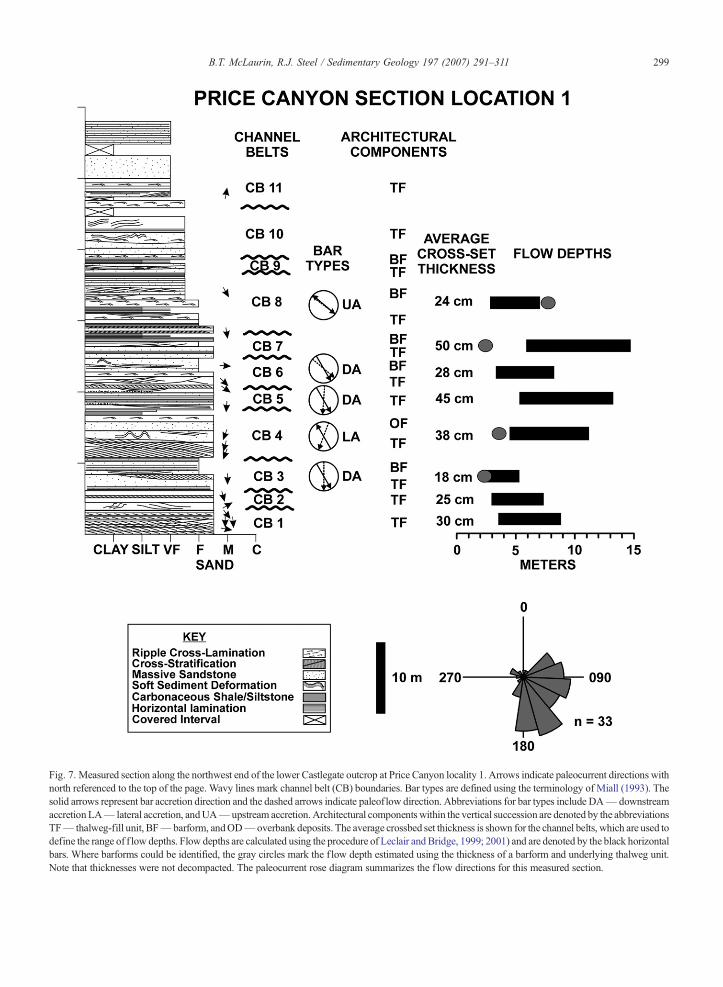
Fig. 7. Measured section along the northwest end of the lower Castlegate outcrop at Price Canyon locality 1. Arrows indicate paleocurrent directions withnorth referenced to the top of the page. Wavy lines mark channel belt (CB) boundaries. Bar types are defined using the terminology of Miall (1993). Thesolid arrows represent bar accretion direction and the dashed arrows indicate paleof low direction. Abbreviations for bar types include DA— downstreamaccretion LA— lateral accretion, andUA— upstream accretion.Architectural components within the vertical succession are denoted by the abbreviationsTF— thalweg-fill unit, BF— barform, andOD— overbank deposits. The average crossbed set thickness is shown for the channel belts, which are used todefine the range of f low depths. Flow depths are calculated using the procedure of Leclair and Bridge, 1999; 2001) and are denoted by the black horizontalbars. Where barforms could be identified, the gray circles mark the f low depth estimated using the thickness of a barform and underlying thalweg unit.Note that thicknesses were not decompacted. The paleocurrent rose diagram summarizes the f low directions for this measured section.
299B.T. McLaurin, R.J. Steel / Sedimentary Geology 197 (2007) 291–311

Fig. 8. Photograph of the lower Castlegate member at Price Canyon locality 1. Outcrop faces southwest and is parallel to the regional paleof low. Theoutcrop photo was taken at a slightly different angle than that used to construct the interpretive panel in Fig. 9. Channel belt boundaries are indicatedon the photograph to provide a point of reference with Fig. 9. Numbers refer to the channel belts defined within the architectural panel (Fig. 9) andmeasured section (Fig. 7).
300 B.T. McLaurin, R.J. Steel / Sedimentary Geology 197 (2007) 291–311
thickness was observed stratigraphically or laterally inthe sections examined.
At the channel-belt scale, the most likely processcontrolling the alluvial architecture is regional avulsion(Heller and Paola, 1996; Heller et al., 2004). In such asetting, a significant period of time elapses before theactive channel returns to its former position. This allowsfloodplain deposits to aggrade to a significant thickness.Erosive processes from re-establishment of the activechannel remove much or all of the floodplain deposits,resulting in preservation of underlying bar deposits.Slingerland and Smith (2004) consider avulsions to behierarchical with a channel-belt composed of smaller-scale avulsions. This would result in a channel beltcontrolled by regional-scale avulsion containing multi-ple channel-bar systems under the influence of localavulsion. This supports the idea that channel-belt scalebodies are minimally influenced by relative sea-levelchanges and are a result of autocyclic processes (Helleret al., 2004).
There are examples within the lower Castlegatewhere a single thalweg-fill unit of limited lateral extent(b50 m) has a complete overlying bar and floodplainsuccession preserved. This presents some confusion inthe terminology because it would seem that this shouldbe termed a channel-bar system and not a channel belt.Here, it is suggested that in times of rapid verticalaggradation in the basin, or rapid avulsion of the rivers,
single channel-bar systems will mimic the morecomplex channel belts developed during times of lessrapid vertical aggradation of alluvium; i.e. the activechannel avulses after deposition of a single channel-barsystem. Therefore, the thicker channel-bar examples arealso likely to be the products of avulsion events. Theseare referred to as expanded channel-bar systems. Insupport of this argument: 1) marked erosion surfacesoccur at base of thalweg-fill units; 2) bar accretiondirection is opposite from bars below the erosionsurface; 3) locally, multi-storey bars are preserved(bars apparently cut into one another); and, 4) 3–5 mthick floodplain deposits overlie barform deposits.
5.3. Stacked channel-belt complexes
Within the outcrops examined, there are patternswhereby thalweg-dominated channel belt intervalsvertically alternate with barform-dominated channelbelt intervals. In many cases, the barforms are thickerand capped by extensive floodplain deposits. The termstacked channel-belt complex is used to describe theseintervals that are a series of three to four stacked channelbelts. The three stacked channel-belt complexes in thelower Castlegate are from 17 m to 40 m thick and arecapped by thicker overbank deposits. Since we considerthe autocyclic processes of channel migration andavulsion dominant at the smaller scales, the question

Fig. 9. Interpretive panel of the architecture of the lower Castlegate member at Price Canyon locality 1, illustrating the distribution of the threearchitectural components of the alluvial system. Channel belts are numbered 1–11. Note the zones of preserved bars and their relationship to thedefined stacked channel-belt complexes.
301B.T. McLaurin, R.J. Steel / Sedimentary Geology 197 (2007) 291–311
arises as to what type of process gave rise to the stackedchannel-belt complexes. Identification of the trace fossilTeredolites indicates the incursion of brackish-waterconditions in intervals of overbank deposits. Further-more, the occurrence of overbank deposits indicates thataggradation rates were higher, allowing for completepreservation of a channel-bar system or channel belts.These characteristics may signify accommodationcreation/destruction related to changes in base level onthe scale of the stacked channel-belt complex. However,interpretation of high-frequency sequences and se-quence boundaries within the lower Castlegate membershould utilize an integrative approach combining faciescharacteristics, changes in architecture and petrographiccharacteristics (Miall and Arush, 2001). Although theevidence for multiple, high-frequency sequences islimited, examining patterns of preservation withinalluvial successions may give an indication of allocycliccontrols.
6. Lower Castlegate sections
6.1. Price Canyon 1 (PC 1)
This locality is north of the type section in Price RiverCanyon, east of U.S. Highway 6. The outcrop is orientedsubparallel to the southeast regional paleoflow of thelower Castlegate member. The vertical profile was
measured along the northwest end of the outcrop(Fig. 7) and records a transition from dominantly fine tomedium-grained, cross-stratified sandstone in the lowerintervals of the section to fine to very-fine grained, ripple-laminated sandstone towards the top of the unit and itstransition to the middle Castlegate member. The overallalluvial architecture within this outcrop can be expressedas a cyclic hierarchy of channel-bar systems, channelbelts, and stacked channel-belt complexes (Figs. 8 and 9).Composite thalweg units dominate channel belts 1, 2 andthe basal part of 3. The upper portion of channel belt 3 andparts of 4 show multiple episodes of bar growth withpreservation of thin thalweg-fill units, representingexpanded channel-bar systems. Barforms in channelbelts three and four reflect growth by downstream andlateral accretion, respectively. The lower series of channelbelts 1–4 (approximately 20 m thick), has an irregularlypreserved capping of overbank deposits that mark the topof a stacked channel-belt complex. Channel belts 5, 6 andthe lower 10 meters of 7 reflect a return to dominantlycomposite thalweg units. Barforms are preserved in theupper part of channel belt 7 and the upper part of channelbelt 8. The barform within channel belt 7 indicatesdeposition by lateral accretion. The barform at the top ofchannel belt 8 records upstream accretion such as thatdescribed in modern, mid-channel braid bars (Bristow,1993). The bar is, in turn, capped by irregularly preservedoverbank deposits delineating the top of stacked channel-

Fig. 10. Measured section along the northeast end of the lower Castlegate outcrop at Price Canyon locality 2. Arrows indicate paleocurrent directions withnorth referenced to the top of the page.Wavy linesmark channel belt (CB) boundaries. Bar types are defined using the terminology ofMiall (1993). The solidarrows represent bar accretion direction and the dashed arrows indicate paleoflowdirection.Abbreviations for bar types includeDA— downstream accretionandLA— lateral accretion.Architectural componentswithin the vertical succession are denoted by the abbreviations TF— thalweg-fill unit, BF— barform,and OD— overbank deposits. The average crossbed set thickness is shown for the channel belts, which are used to define the range of flow depths. Flowdepths are calculated using the procedure of Leclair and Bridge, 1999; 2001) and are denoted by the black horizontal bars. Where barforms could beidentified, the gray circles mark the f low depth estimated using the thickness of a barform and underlying thalweg unit. Note that thicknesses were notdecompacted. The paleocurrent rose diagram summarizes the flow directions for this measured section.
302 B.T. McLaurin, R.J. Steel / Sedimentary Geology 197 (2007) 291–311
belt complex 2. Above channel belt 8, channel belts 9, 10,and 11 represent a return to a composite thalweg-dominated succession that leads up to the base of themiddle Castlegate member. These belts are in the basalinterval of stacked channel-belt complex 3.
6.2. Price Canyon 2 (PC 2)
This outcrop lies approximately 200 m west of thePrice Canyon 1 locality. The section examined here isperpendicular to the regional paleoflow and shows

Fig. 11. Photograph of the lower Castlegate member at the Price Canyon 2 locality. Outcrop faces southeast. Photograph includes PC 2A and thelower part of PC 2B. Channel belt boundaries have been added to provide a reference with the architectural interpretation (Fig. 12). Channel beltsdefined here may not necessarily correlate with those at the Price Canyon 1 locality.
303B.T. McLaurin, R.J. Steel / Sedimentary Geology 197 (2007) 291–311
better barform preservation and development than at PC1. The measured section was taken along the northeastend of the outcrop and was taken through all of PC 2Aand the lower two channel belts of PC2B (Fig. 10). Toaid in defining architectural components, the outcropwas divided into two interpretive panels (PC 2A and PC2B). The top of the uppermost channel belt in PC 2A isthe basal surface of panel PC 2B (Fig. 11).
Channel belts 1, 2, 3, and 4 comprise the lower 20 mof the lower Castlegate member. They are dominated bycomposite thalweg units, particularly in channel belts 2and 4, which are each approximately 6 m thick. Channelbelts 1 and 3 have thinner (∼2 m thick), compositethalweg bodies. Barforms are sandy within these lowerchannel belts and are accreting in a northeasterly di-rection, perpendicular to the regional paleoflow. Wherepaleocurrent data could be obtained, they indicate thatchannel belt 1 was downstream accreting, whereas chan-nel belts 2, 3, and 4 were laterally accreting. Channel belt4 is capped by 90 cm of overbank deposited siltstone.Channel belts 5 and 6 are characteristic of channel-barsystems that mimic channel belts. Higher aggradationrates during deposition of these channel-bar systemsallowed preservation of barforms that are more hetero-lithic than bars from the underlying units. The barforms in
channel belts 5 and 6 accreted to the northeast andsouthwest, respectively. Paleocurrent data illustrates thatchannel belt 5 was downstream accreting and channel belt6 was laterally accreting. Channel belt 6 preserves acomplete vertical succession of thalweg, barform, andoverbank deposits. The overbank deposits are 3 m thickand cap a stacked channel-belt complex, 40 m thick,which contains channel belts 1–6 (Fig. 12).
Channel belts 7–13 are defined from interpretivepanel PC 2B (Figs. 13 and 14). These channel belts areinterpreted primarily from the architectural panelbecause the measured section only extends through thelower part of channel belt 8. Channel belt 7 contains acomposite thalweg unit that is overlain by a northeast-erly accreting barform. Southeast directed paleocurrentsindicate that this bar was laterally accreting. Channelbelts 8–10 contain composite thalweg units that range inthickness from 2.8 to 5.1 m. Barform units accreted tothe southwest in channel belt 8 and to the northeast inchannel belts 9 and 10. Channel belt 10 is capped by 2 mof overbank deposits, defining the top of a secondstacked channel-belt complex. Barforms within thischannel belt complex range from 3.0 m to 7.9 m thick.Channel belts 11–13 have similar composite thalwegunit thicknesses (3.4 to 5.6 m) to those channel belts in

Fig. 12. Interpretive panel outlining the alluvial architecture of PC 2A. Channel belts are numbered 1–6 within this single stacked channel-beltcomplex.
304 B.T. McLaurin, R.J. Steel / Sedimentary Geology 197 (2007) 291–311
the underlying stacked channel belt complex. However,the preserved bars are thinner (1.7 to 3.4 m). The bars inchannel belts 11 and 12 were accreting to the northeastwith the barform in channel belt 13 exhibiting asouthwest accretion direction.
7. Lower Castlegate channel characteristics
Van De Graaff (1972) interpreted the CastlegateSandstone as deposits of a braided or low-sinuosity river.His depositional model was based on characteristics ofthese river types as outlined by Allen (1965). Thesecriteria included coarse nature of the bedload, lack offloodplain deposits, and low variance in direction ofpaleocurrent indicators. Miall (1993, 1994), using theconcept of architectural element analysis (Miall, 1985),suggested that lithofacies assemblages within the lowerCastlegate were similar to those of sandy braided rivers,like that of the South Saskatchewan River (Cant andWalker, 1978). In addition, the multilateral nature of thesandbodies and lack of preserved channel margins wasevidence for a low to moderate sinuosity, multi-channel,fluvial system. (Miall, 1994).
The assessment of paleochannel pattern or sinuosityneeds to incorporate factors that include paleochanneldimension reconstruction and paleocurrent variance(Bridge, 1985). Other characteristics previously usedto determine channel pattern, including proportion and
grain size of channel fills relative to lateral accretionelements, have been challenged (Bristow, 1987; Bridge,1993). These criteria are not necessarily indicative ofdeposition in rivers of a particular sinuosity and shouldbe used with caution, although the characteristics of theparticular bar types in the lower Castlegate will bediscussed and compared with modern settings.
Estimates of paleochannel depth and width as well asoverall channel belt dimensions are important indetermining channel pattern and provide data to predictthe continuity and connectivity of subsurface fluvialreservoirs. The outcrop thickness and width of sand-stone bodies may not reflect the actual dimensions of theoriginal river because of modification by channelprocesses after deposition. Thus, assessments of channeldepth and width should be considered minimums.Studies that address the dimensions of paleochannelsand how they might relate to channel style includeBridge (1985), Bridge and Mackey (1993), Bridge andTye (2000), and Bridge et al. (2000).
7.1. Channel depth
Within the lower Castlegate member the first step inreconstructing paleochannel dimensions involved esti-mation of flow depths. Flow depths were measured fromthe top of a barform to the base of the underlyingthalweg-fill unit. The results show that minimum flow

Fig. 13. Photograph of PC 2B taken at the same outcrop as PC 2A but at a different elevation and angle compared to Fig. 11. Channel belt boundarieshave been added to provide a point of reference to the architectural panel. Numbers refer to the individual channel belts.
305B.T. McLaurin, R.J. Steel / Sedimentary Geology 197 (2007) 291–311
depths range from 1.1 to 7.6 m (n=22). An additionalmethod of flow depth estimation to complementchannel-bar thickness, uses average cross bed setthickness to reconstruct dune height and extrapolatethat result to flow depth (Leclair and Bridge, 1999;Leclair and Bridge, 2001). Using this approach, duneheight is considered approximately three times the meancross bed set thickness. Once dune height is recon-structed, flow depth is six to ten times the dune height.The average set thickness recorded from measuredsections is 26 cm (n=77). This results in flow depthsranging between 4.6 and 7.7 m. These values are similarto those obtained from measurement of the channel-barthickness. The upper limit of flow depth from the thickerpreserved sets is 14.7 m and should be considered amaximum for the lower Castlegate. Adams andBhattacharya (2005) used the same methodology todetermine flow depths in the Blackhawk and Castlegateformations, approximately 100 km southwest of thecurrent study area. There, they estimated Castlegateflow depths of 2.2–3.6 m. Note that direct comparisonsbetween our results and the results of Adams andBhattacharya (2005) should be approached carefully.The outcrops they examined are in closer proximity tothe source area and may have been deposited undersubsidence conditions that differ significantly from that
in the type area (Robinson and Slingerland, 1998).Hajek and Heller (2004), utilizing outcrop LIDARscanning, interpret an increase in flow depth from thebase to the top of the lower Castlegate member. Theirresults show an increase from flow depths of 2–3 m inthe lower parts of the unit to 4–5 m in the upper part ofthe unit. These overall values agree with those in thepresent study, though we could not document a patternof increasing flow depth vertically through the section.
7.2. Channel width
The width dimensions of thalweg and bar unitsmeasured within the lower Castlegate are minimums,due to the size of these features being larger than theoutcrop panels. Average panel widths for thalweg andbar units are similar, 30 m and 35 m, respectively. Thegreatest outcrop-measured widths of these elementsexceeded 100 m. Since the actual dimensions of theelements are probably much greater than what wasobserved, an empirical regression equation was used thatincorporates mean bankfull channel depth to calculatebankfull channel width. Regression relationships devel-oped by Bridge and Mackey (1993) use the equation
wc ¼ 8:88d1:82m
Fig. 14. Interpretive panel for PC 2B. Channel belts are numbered 7–13. Stacked channel-belt complexes 2 and 3 are defined in this part of theoutcrop.
306 B.T. McLaurin, R.J. Steel / Sedimentary Geology 197 (2007) 291–311
in which wc, is the bankfull channel width, and dm is themean bankfull depth. The mean bankfull depth isconsidered to be approximately one-half of the maxi-mum bankfull depth (thickness of the channel-barsystem). Though care must be exercised in using suchempirical methods to estimate sandbody dimensions,Bridge et al. (2000) used this procedure on Cretaceousdeposits in South America and determined that the flowdepth values generally predicted the widths that wereobserved in outcrop. Using the flow depth range of 4.6–7.7 m which were derived from the cross-set thickness,resulted in channel widths of 143–365 m using thechannel width calculation of Bridge and Mackey (1993).The maximum calculated paleodepth of 14.7 m resultedin a channel-width exceeding 1 km. Miall (1993)suggested that sandstone bodies in the lower Castlegatewere probably less than 400 m in width, with smallerchannels and barforms exceeding 120 m. Robinson andSlingerland (1998) noted that several channel sandstonebodies within the type area averaged approximately 94mwide.
7.3. Paleocurrent data
Paleocurrent directional data are commonly used tointerpret channel sinuosity. A low dispersion in thepaleocurrent values is consistent with a low-sinuosity orbraided stream interpretation (Bridge, 1985). A higher
dispersion of values can indicate deposition in higher-sinuosity or meandering stream settings (Bluck, 1971).Within the lower Castlegate member, a total of 51paleocurrent directions were taken from trough andplanar cross-stratified sets at the two localities. Themean transport direction was to the southeast with acircular standard deviation of 68°. By comparison, thecircular standard deviation for the middle Castlegatemember is 127°, which has been interpreted as depositsof high-sinuosity rivers (Lawton, 1986; Olsen et al.,1995). There are significant differences in the paleocur-rent directions between the PC 1 and PC 2 locations.The PC 1 locality (n=33) shows a strong southeast-directed flow, while the PC 2 locality (n=18) showsnortheast directed flow. This disparity between the twolocations may be attributed to outcrop orientation or thelower number of paleocurrent measurements that wererecorded at PC 2. A southeast directed regional paleo-flow is consistent with the results of other studies on theCastlegate Formation (Van De Graaff, 1972; Lawton,1986; Chan and Pfaff, 1991; Miall, 1993; Robinson andSlingerland, 1998). Distribution of paleocurrent data byarchitectural component indicates a more southeasterlyflow direction (mean of 152°) for thalweg-fill unitscompared to an east-southeast flow within the bar units(mean of 110°). Bar units exhibit a higher circularstandard deviation of 72° versus 56° for the thalwegunits. Bridge et al. (2000) suggest a relationship
307B.T. McLaurin, R.J. Steel / Sedimentary Geology 197 (2007) 291–311
between paleocurrent range and channel sinuosity.Applying two methods, the circular arc and sine-generated curve, sinuosity, sn can be estimated byusing ϕ, which is half of the maximum paleocurrentrange in radians. The equation for sinuosity using thecircular arc method is:
sn ¼ /=sin/
The equation for calculating sinuosity with the sine-generated curve method is:
sn ¼ 4:84=ð4:84−/2ÞInstead of using the maximum paleocurrent range as
Bridge et al. (2000) suggest, we elected to use thecircular standard deviation (Mardia, 1972). Le Roux(1992, 1994) notes that using the total range of allpaleocurrent data to calculate sinuosity will result inoverestimation. By using the circular standard deviation,sinuosity can be better approximated without beingconcerned over potentially anomalous readings. Sincebarform accretion and associated paleocurrents can behighly variable in both meandering and braided streams,paleocurrents taken from thalweg-fill units were used tocalculate sinuosity. Using both methods of Bridge et al.(2000), sinuosity within the thalweg units (using thecircular standard deviation of 56°) was 1.2, with thesinuosity in the 1.3 to 1.4 range if paleocurrents frombarforms are included. Additional methods of sinuositycalculation from paleocurrent datasets are described byLe Roux (1992, 1994) and Ghosh (2000). The sinuosityis estimated based on calculating the consistency ratio,which is derived from the vector magnitude (Curray,1956). Graphical relationships between the consistencyratio and the sinuosity value are outlined by Le Roux(2001). This approach better addresses the problem ofhigh paleocurrent dispersion than the method of Bridgeet al. (2000). Sinuosity values from thalweg-fill unitswere 1.5 and 1.6 using the methods of Ghosh (2000) andLe Roux (1994), respectively. However, the inclusion ofbarform paleocurrents results in a 2.4–2.5 range whichwould classify the lower Castlegate as deposits of highsinuosity streams. The total ranges of sinuosity values(1.2 to 1.6) calculated for the lower Castlegate areconsistent with deposition in an “intermediate sinuosity”setting as described by Miall (1996) for sinuosity valuesin the 1.2 to 1.5 range.
7.4. Bar types
Although accretion may appear to parallel theoutcrop face, there may be a component of accretion
into or out of the outcrop. Combining paleocurrent datawith accretion direction provides the range of bar types.Of the twelve bars where accretion and paleocurrentdata were available, 59% of the bars are lateral accretionelements, 33% downstream accreting, and 8% upstreamaccreting. Lateral accretion elements were dominant,particularly in the PC 2 section, normal to the regionalpaleoflow. The bars in this section are well-preservedand often are heterolithic. Vertically there is nodiscernible trend in the type of bars that occur.
Previous studies that examined relationships betweenbar types and channel style, suggested that lateralaccretion could be used as a distinguishing criterion ofhigh sinuosity rivers (Moody-Stuart, 1966; Miall, 1980).However lateral accretion is not necessarily confined tomeandering rivers and may also be recognized inbraided systems (Bluck, 1979; Allen, 1983; Bridge,1985; Miall, 1994) Detailed analyses of braid bars inmodern sandy rivers suggests that lateral accretion andeven upstream accretion can be significant componentsof mid-channel bars (Bristow, 1987, 1993; Best et al.,2003). Studies of the modern Brahmaputra River byBristow (1987) show that braid bars can grow primarilyby lateral accretion relative to downstream accretion,thus the dominance of lateral accretion elements is notsignificant in determining the sinuosity of lowerCastlegate rivers.
8. Discussion
8.1. Lower Castlegate channel style
Analysis of the lower Castlegate member indicatesthat the rivers were of a low to intermediate sinuosity,confirming previous interpretations (Van De Graaff,1972; Miall, 1993, 1994). Calculated channel depthsand widths are comparable with those from modern,sandy, braided river systems (Bristow, 1987, 1993; Bestet al., 2003). Bar accretion pattern, though notdiagnostic of sinuosity, was dominantly laterallyaccreting particularly in the section normal to regionalpaleoflow. The orientation of these accretionary bodiescoupled with the paleocurrent data shows that there mayhave been local, more sinuous reaches. Bristow (1987)notes that lateral accretion surfaces in the Brahmaputraare low-angle because of the high width/depth of thechannels. Lower Castlegate accretion surfaces dip atangles up to 20°, which is a reflection of a lower width/depth. The paleocurrent directions are southeastwarddirected with a standard deviation of 73°. Thisinformation on paleocurrent variability was used toestimate the channel sinuosity using equations outlined

308 B.T. McLaurin, R.J. Steel / Sedimentary Geology 197 (2007) 291–311
in Bridge et al. (2000). Furthermore, other methods ofcalculating channel sinuosity (Le Roux, 1992, 1994,2001; Ghosh, 2000) provide similar results. The resultssuggest that channel sinuosity was in the 1.2 to 1.6 rangewhich falls in the “intermediate sinuosity” categorydescribed by Miall (1996). The facies associations andscale of architectural components show a strongcorrelation with the architectural model for a deep,perennial, sandy braided river (Miall, 1985, 1996)which is consistent with the original interpretation ofMiall (1993). The results show that there is nostratigraphic trend in flow depth, channel width, orchannel sinuosity. The transition to the overlying, high-sinuosity deposits of the middle Castlegate memberappears to be fairly abrupt. This change in channel stylemay reflect increasing aggradation rates within themiddle Castlegate member as base level rose (Miall,1994; Olsen et al., 1995; Yoshida et al., 1996; McLaurinand Steel, 2000).
8.2. Controls on the cyclic architectural hierarchy
The model of Shanley andMcCabe (1994) suggests arelationship between base-level cycles and fluvialdeposition. Their model is conceptual and it assumes asingle cycle of base level fall and rise, producing anamalgamated lowstand to transgressive, single episodeof incised valley fill. Their interpretations suggest thatthe lowstand deposits within the incised valley would becharacterized as low-sinuosity or braided rivers. Fromthe evidence examined in this study, the lowerCastlegate would fit into this type of model. Thoughthere may be a more local, relatively higher-sinuositycomponent to reaches within the Castlegate deposits, theinterpretations of channel style vary little from those ofprevious workers (Van De Graaff, 1972; Miall, 1993,1994).
The interpretation of a cyclical hierarchy withinfluvial deposits has been previously documented (Miall,1980; Godin, 1991). The models of Miall (1980) inparticular, note the occurrence of smaller-scale, auto-cyclic controlled cycles “nested” within a larger scalecycle of allocyclic origin. Godin (1991) documented athree-fold hierarchy within the Morrison Formation inNew Mexico. There, the macroform scale was repre-sented by 1–6 m thick cycles, channel-scale cycles inthe 1–10 m range and sheet, or avulsion controlledcycles at the scale of 4–16 m. In this study of the lowerCastlegate, a similar three cycle hierarchy is documen-ted. At the smallest scale (2–12 m) are the channel-barsystems. Channel-bar systems can stack to form channelbelts (2–16 m), which in turn, form stacked channel-belt
complexes (17–40 m). The channel-bar systems andchannel-belts reflect an autocyclic control on deposition.The stacked channel-belt complexes are more problem-atic in determining the dominant control.
The autocyclic processes that combine to give thelower Castlegate its small-scale architecture are lateralchannel migration and local avulsion. The sheet-likenature of many of the sandstone bodies suggests thatlower Castlegate channels were highly mobile (Friend,1983). Supporting this interpretation is the lack ofclearly-identifiable cut banks. Channel margins werenon-cohesive and easily reworked as the active channelmigrated. As a result, thalweg-fill units are preserved asa series of stacked channel-bar systems. In many casesthe barforms are not preserved for individual channel-bar systems. The migration of the channels eroded thebarforms resulting in a stacked succession of thalweg-fill units. Lewin and Macklin (2003) address preserva-tion factors associated with Quaternary alluvial deposi-tion. They recognize that lateral migration duringaggradation will result in preservation of truncatedlower members. Such thalweg-fill units represent thetopographically lowest position in the river and are mostlikely to be preserved (Todd and Went, 1991;Siegenthaler and Huggenberger, 1993). The stackingof multiple, thalweg units in the lower Castlegate istermed a composite thalweg-fill. Local avulsion mayhave combined with channel migration to result in thisscale of architecture.
Where a barform is observed overlying a compositethalweg unit is interpreted as the top of a channel belt.Bristow (1996) suggests that a preserved bartopsequence or barform may indicate that avulsionoccurred and that the active channel belt moved toanother location within the floodplain. There was asufficient interval of time between avulsions to allowfloodplain aggradation and hence preservation of thebarform before the active channel belt returned to itsformer position. The avulsion process at this scale maybe more characteristic of a regional avulsion (Heller andPaola, 1996) compared to a shorter-lived local avulsionthat may affect architecture of a channel-bar system.
The stacked channel-belt complex is characterized bydecameter-scale alternation of thalweg-dominated chan-nel belts and barform dominated channel belts. Theprocess controlling cyclicity at this scale is questionable,with minor evidence to support an allocyclic or potentialbase level effect on architectural style. The brackish-water trace fossil Teredolites was identified in overbankdeposits at the top of channel-belt complexes, indicatingsome level of marine incursion. This combined with thealternations of thalweg and bar intervals may reflect

309B.T. McLaurin, R.J. Steel / Sedimentary Geology 197 (2007) 291–311
longer-term changes in aggradation rates. Miall andArush (2001) using a variety of facies, architectural andpetrographic characteristics suggest the occurrence ofone or more cryptic sequence boundaries within thelower Castlegate. It appears from their work that theintra-Castlegate sequence boundary they identifiedcorrelates with the base of stacked channel-belt complex2. An integrated approach such as that of Miall andArush (2001) at a number of lower Castlegate outcropswould help to consolidate interpretations of allocycliccontrol at this scale. At a scale larger than the stackedchannel-belt complex is the Castlegate sequence, withsequence boundaries at the base of the lower Castlegatemember and at the base of the Bluecastle Tongue.Evidence of base level rise in the middle Castlegatemember is documented from the occurrence of tidal andbrackish-water indicators as well as an interval ofestuarine deposits (Høgseth, 1995; Olsen et al., 1995;Yoshida et al., 1996; McLaurin and Steel, 2000).
9. Conclusions
The lower Castlegate member represents a lowstand,amalgamated sheet sandstone deposited by low tointermediate sinuosity rivers. Within this sheet sand-stone, three architectural components were identified;thalweg-fill units, barforms, and overbank deposits.These components combine to form a three-fold“nested” cyclic hierarchy of autocyclic-controlledprocesses at the smaller scale with possible allocycliccontrol on the larger scale. The defined hierarchy fromthe smallest scale to the largest includes:
1) Channel-bar systems (2–12 m) are the products ofchannel migration and possibly minor avulsiveprocesses. The frequent migration of the activechannel, under low rates of aggradation, eroded anybarforms that may have been deposited, preservingonly the topographically lowest part of the channel-bar system. The result is a succession typified bysuperimposed thalweg units with poorly or unpre-served bars, termed a composite thalweg unit.
2) The channel-belt (2–16 m) typically is a compositethalweg unit overlain by a single barform which maybe capped by overbank deposits. The presence of abarform suggests that avulsion occurred and theactive channel belt had moved to another location inthe floodplain. The process involved with channel-belt development may be regional scale avulsionswhich would have allowed increased aggradation ofthe floodplain prior to return of the active channelbelt to its former location.
3) Stacked channel-belt complexes (17–40 m) arecharacterized by intervals of thalweg-dominatedchannel belts overlain by barform dominated channelbelts. The process responsible for this scale ofcyclicity is questionable but may be related to baselevel rise, indicated by brackish-water trace fossils.
No vertical trends in channel-bar or channel-beltthickness, flow depth, or paleocurrent variance could bedetermined that might indicate a change in sinuosity ofthe lower Castlegate rivers through time. This suggeststhat the change in channel style to the overlying middleCastlegate member represents an abrupt shift thatoccurred as the rates of base level rise continued toincrease, eventually bringing a wedge of tidal andbrackish-water influence landward.
Acknowledgements
This paper represents a portion of the senior author'sdoctoral dissertation at the University of Wyoming.Norsk Hydro provided financial support for part of thiswork. We appreciate the thoughtful and constructivecomments of Chris Fielding, Dale Leckie, TrevorElliott, and an anonymous reviewer. Thanks to JoeScott, Jack Deibert, Anton Wroblewski, Jeff Crabaugh,Tara Benda, and Sue Ei for field assistance.
References
Adams, M.M., Bhattacharya, J.P., 2005. No change in f luvial styleacross a sequence boundary, Cretaceous Blackhawk and Castle-gate Formations of central Utah, U.S.A. Journal of SedimentaryResearch 75, 1038–1051.
Allen, J.R.L., 1965. A review of the origin and characteristics of recentalluvial sediments. Sedimentology 5, 89–191.
Allen, J.R.L., 1983. Studies in f luviatile sedimentation: bars, bar-complexes and sandstone sheets (low-sinuosity braided streams) inthe Brownstones (L. Devonian), Welsh Borders. SedimentaryGeology 22, 237–293.
Armstrong, R.L., 1968. Sevier orogenic belt in Nevada and Utah.Geological Society of America Bulletin 79, 429–458.
Atchley, S.C., Nordt, L.C., Dworkin, S.I., 2004. Eustatic control onalluvial sequence stratigraphy: a possible example from theCretaceous–Tertiary transition of the Tornillo Basin, Big BendNational Park, west Texas, U.S.A. Journal of SedimentaryResearch 74, 391–404.
Bentham, P.A., Talling, P.J., Burbank, D.W., 1993. Braided stream andf lood-plain deposition in a rapidly aggrading basin; the EscanillaFormation, Spanish Pyrenees. In: Best, J.L., Bristow, C.S. (Eds.),Braided Rivers. Geological Society of London Special Publication,vol. 75, pp. 177–194.
Best, J.L., Ashworth, P.J., Bristow, C.S., Roden, J., 2003. Three-dimensional sedimentary architecture of a large, mid-channel sandbarid bar, Jamuna River, Bangladesh. Journal of SedimentaryResearch 73, 516–530.

310 B.T. McLaurin, R.J. Steel / Sedimentary Geology 197 (2007) 291–311
Bluck, B.J., 1971. Sedimentation in the meandering River Endrick.Scottish Journal of Geology 7, 93–138.
Bluck, B.J., 1979. Structure of coarse grained braided stream alluvium.Transactions of the Royal Society of Edinburgh 70, 181–221.
Bluck, B.J., 1980. Structure, generation and preservation of upwardfining, braided stream cycles in the Old Red Sandstone of Scotland.Transactions of the Royal Society of Edinburgh 71, 29–46.
Bridge, J.S., 1985. Paleochannel patterns inferred from alluvial deposits:a critical evaluation. Journal of Sedimentary Petrology 55, 579–589.
Bridge, J.S., 1993. The interaction between channel geometry, waterf low, sediment transport and deposition in braided rivers. In: Best,J.L., Bristow, C.S. (Eds.), Braided Rivers. Geological SocietySpecial Publication, vol. 75, pp. 13–71.
Bridge, J.S., Mackey, S.D., 1993. A theoretical study of f luvialsandbody dimensions. In: Flint, S.S., Bryant, I.D. (Eds.), TheGeologic Modelling of Hydrocarbon Reservoirs and OutcropAnalogues. International Association of Sedimentologists SpecialPublication, vol. 15, pp. 213–236.
Bridge, J.S., Tye, R.S., 2000. Interpreting the dimensions of ancientf luvial channel bars, channels, and channel belts from wireline-logs and cores. American Association of Petroleum GeologistsBulletin 84, 1205–1228.
Bridge, J.S., Jalfin, G.A., Georgieff, S.M., 2000. Geometry, lithofaciesand spatial distribution of Cretaceous f luvial sandstone bodies, SanJorge Basin, Argentina: outcrop analog for the hydrocarbon-bearingChubut Group. Journal of Sedimentary Research 70, 341–359.
Bristow, C., 1987. Brahmaputra River: channel migration and depos-ition. In: Ethridge, F.G., Flores, R.M., Harvey, M.D. (Eds.), RecentDevelopments in Fluvial Sedimentology. SEPM Special Publica-tion, vol. 39, pp. 63–74.
Bristow, C., 1993. Sedimentary structures exposed in bar tops in theBrahmaputra River, Bangladesh. In: Best, J.L., Bristow, C.S.(Eds.), Braided Rivers. Geological Society Special Publication,vol. 75, pp. 277–289.
Bristow, C., 1996. Reconstructing f luvial channel morphology fromsedimentary sequences. In: Carling, P.A., Dawson, M.R. (Eds.),Advances in Fluvial Dynamics and Stratigraphy. John Wiley &Sons, Ltd., pp. 351–371.
Campbell, C.V., 1976. Reservoir geometry of a f luvial sheet sand-stone. American Association of Petroleum Geologists Bulletin 60,1009–1020.
Cant, D.J., Walker, R.G., 1978. Fluvial processes and facies sequencesin the sandy, braided South Saskatchewan River, Canada. Sedi-mentology 25, 625–648.
Chan, M.A., Pfaff, B.J., 1991. Fluvial sedimentology of the Upper Cre-taceous Castlegate Sandstone, Book Cliffs, Utah. In: Chidsey Jr., T.C.(Ed.), Geology of East-Central Utah. Utah Geological AssociationPublication, vol. 19, pp. 95–109.
Curray, J.R., 1956. The analysis of two-dimensional orientation data.Journal of Geology 64, 117–131.
Ethridge, FG., Wood, L.J., Schumm, S.A., 1998. Cyclic variables con-trolling f luvial sequence development: problems and perspectives. In:Shanley, K.W., McCabe, P.J. (Eds.), Relative Role of Eustasy, Climateand Tectonism in Continental Rocks. Special Publication, vol. 59.SEPM (Society for Sedimentary Geology), pp. 17–29.
Fisk, H.N., 1944. Geological Investigation of the Alluvial Valley of theLower Mississippi River. Mississippi River Commission, Vicks-burg, Mississippi.
Fouch, T.D., Lawton, T.F., Nichols, D.J., Cashion, W.B., Cobban, W.A.,1983. Patterns and timing of synorogenic sedimentation in UpperCretaceous rocks of central and northeast Utah. In: Reynolds, M.W.,Dolly, E.D. (Eds.), Mesozoic Paleogeography of the West-Central
United States, SEPM, Rocky Mountain Section, Second RockyMountain Paleogeography Symposium, pp. 305–336.
Franczyk, K.J., 1989. Depositional controls on the Late CampanianSego Sandstone and implications for associated coal-formingenvironments in the Uinta and Piceance Basins. U.S. GeologicalSurvey Bulletin 1787-F, 17.
Franczyk, K.J., Pitman, J.K., Nichols, D.J., 1990. Sedimentology,mineralogy, palynology, and depositional history of some upper-most Cretaceous and lowermost Tertiary rocks along the UtahBook and Roan Cliffs East of Green River. U.S. Geological SurveyBulletin 1787-N, 27.
Friend, P.F., 1983. Towards the field classification of alluvial archi-tecture or sequence. In: Collinson, J.D., Lewin, J. (Eds.), AlluvialSedimentation. International Association of SedimentologistsSpecial Publication, vol. 6, pp. 345–354.
Ghosh, P., 2000. Estimation of channel sinuosity from paleocurrent data:a method using fractal geometry. Journal of Sedimentary Research70, 449–455.
Godin, P., 1991. Fining-upwards cycles in the sandy-braided riverdeposits of the Westwater Canyon Member (Upper Jurassic),Morrison Formation, New Mexico. Sedimentary Geology 70,61–82.
Hajek, E, Heller, P.L., 2004. Determining f luvial stacking patterns inthe lower Castlegate Sandstone (Campanian, Helper, Utah) usingLIDAR imaging. Geological Society of America Annual MeetingAbstracts with Programs, vol. 36, p. 462.
Heller, P.L., Paola, C., 1996. Downstream changes in alluvial archi-tecture: an exploration of controls on channel-stacking patterns.Journal of Sedimentary Research 66, 297–306.
Heller, P.L., Jones, H., Paola, C., 2004. Autocyclic avulsion clusters inalluvial basins; example from the Maastrichtian/Paleocene ofWyoming. Geological Society of America Annual MeetingAbstracts with Programs, vol. 36, p. 462.
Høgseth, K., 1995. Sedimentology and sequence stratigraphy of theCastlegate Formation, Price Canyon, Utah. Unpublished M.Sc.thesis, University of Bergen, 110 pp.
Krystinik, L.F., DeJarnett, B.B., 1995. Lateral variability of sequencestratigraphic framework in the Campanian and Lower Maastrich-tian of the Western Interior Seaway. In: Van Wagoner, J.C.,Bertram, G.T. (Eds.), Sequence Stratigraphy of Foreland BasinDeposits—Outcrop and Subsurface Examples from the Cretaceousof North America. American Association of Petroleum GeologistsMemoir, vol. 64, pp. 11–26.
Lawton, T.F., 1986. Fluvial systems of the Upper Cretaceous Mesa-verde Group and North Horn Formation, central Utah - A recordof transition from thin-skinned to thick-skinned deformation inthe foreland region. In: Peterson, J.A. (Ed.), Paleotectonics andsedimentation in the Rocky Mountain region, United States.American Association of Petroleum Geologists Memoir, vol. 41,pp. 423–442.
Leclair, S.F., Bridge, J.S., 1999. Interpreting the height of dunes andpaleochannel depths from the thickness of medium-scale sets ofcross strata. American Association of Petroleum Geologists An-nual Meeting Expanded Abstracts, p. A80.
Leclair, S.F., Bridge, J.S., 2001. Quantitative interpretation of sedi-mentary structures formed by river dunes. Journal of SedimentaryResearch 71, 713–716.
Lewin, J.,Macklin,M.G., 2003. Preservation potential for LateQuaternaryriver alluvium. Journal of Quaternary Science 18, 107–120.
Le Roux, J.P., 1992. Determining the channel sinuosity of ancientf luvial systems from paleocurrent data. Journal of SedimentaryPetrology 62, 283–291.

311B.T. McLaurin, R.J. Steel / Sedimentary Geology 197 (2007) 291–311
Le Roux, J.P., 1994. The angular deviation of paleocurrent directionsas applied to the calculation of channel sinuosities. Journal of Sedi-mentary Research. Section A, Sedimentary Petrology and Processes64, 86–87.
Le Roux, J.P., 2001. Estimation of channel sinuosity from paleocurrentdata: a method using fractal geometry—discussion. Journal ofSedimentary Research 71, 1029–1030.
Mardia, K.V., 1972. Statistics of Directional Data. Academic Press,London. 357 pp.
McLaurin, B.T., Steel, R.J., 2000. Fourth order nonmarine to marinesequences, middle Castlegate Formation, Book Cliffs, Utah. Geo-logy 28, 359–362.
Miall, A.D., 1980. Cyclicity and the facies model concept in f luvialdeposits. Bulletin of Canadian Petroleum Geology 28, 59–80.
Miall, A.D., 1985. Architectural element analysis: a new method offacies analysis applied to f luvial deposits. Earth-Science Reviews22, 261–308.
Miall, A.D., 1993. The architecture of f luvial–deltaic sequences in theUpper Mesaverde Group (Upper Cretaceous), Book Cliffs, Utah.In: Best, J.L., Bristow, C.S. (Eds.), Braided Rivers. GeologicalSociety Special Publication, vol. 75, pp. 305–332.
Miall, A.D., 1994. Reconstructing f luvial macroform architecture fromtwo-dimensional outcrops: examples from the Castlegate Sandstone,Book Cliffs, Utah. Journal of Sedimentary Petrology 64, 146–158.
Miall, A.D., 1996. The Geology of f luvial Deposits. Springer-Verlag,Berlin. 582 pp.
Miall, A.D., Arush, M., 2001. Cryptic sequence boundaries in braidedf luvial successions. Sedimentology 48, 971–985.
Moody-Stuart, M., 1966. High- and low-sinuosity deposits, withexamples from the Devonian of Spitsbergen. Journal of Sedimen-tary Petrology 36, 1102–1117.
Nichols, D.J., 1994. A revised palynostratigraphic zonation of the non-marine upper Cretaceous, Rocky Mountain region, United States.In: Caputo, M.V., Peterson, J.A., Franczyk, K.J. (Eds.), MesozoicSystems of the Rocky Mountain Region, USA. Rocky MountainSection, SEPM, Denver, Colorado, pp. 503–521.
Nwajide, C.S., Hoque, M., 1984. Paleohydraulic reconstruction of aLater Cretaceous River in the middle Benue trough (Nigeria) andits limitations. Palaeogeography, Palaeoclimatology, Palaeoecol-ogy 47, 245–259.
Olsen, T., Steel, R., Høgseth, K., Skar, T., Røe, S.L., 1995. Sequentialarchitecture in a f luvial succession: sequence stratigraphy in theUpper Cretaceous Mesaverde Group, Price Canyon, Utah. Journalof Sedimentary Research 65, 265–280.
Puigdefábregas, C., Van Vilet, A., 1978. Meandering stream depositsfrom the Tertiary of the southern Pyrenees. In: Miall, A.D. (Ed.),f luvial Sedimentology. Canadian Society of Petroleum GeologistsMemoir, vol. 5, pp. 469–485.
Richards, K., Shobhit, C., Friend, P., 1993. Avulsive channel systems:characteristics and examples. In: Best, J.L., Bristow, C.S. (Eds.),
Braided Rivers. Geological Society Special Publication, vol. 75,pp. 195–203.
Robinson, J.W., McCabe, P.J., 1997. Sandstone-body and shale bodydimensions in a braided f luvial system: Salt Wash SandstoneMember (Morrison Formation), Garfield County, Utah. AmericanAssociation of Petroleum Geologists Bulletin 81, 1267–1291.
Robinson, R.A.J., Slingerland, R.L., 1998. Grain-size trends, basinsubsidence and sediment supply in the Campanian CastlegateSandstone and equivalent conglomerates of central Utah. BasinResearch 10, 109–127.
Schwans, P., 1995. Controls on sequence stacking and f luvial toshallow-marine architecture in a foreland basin. In: Van Wagoner,J.C., Bertram, G.T. (Eds.), Sequence Stratigraphy of ForelandBasin Deposits—Outcrop and Subsurface Examples from theCretaceous of North America. American Association of PetroleumGeologists Memoir, vol. 64, pp. 55–102.
Shanley, K.W., McCabe, P.J., 1994. Perspectives on the sequencestratigraphy of continental strata. American Association of Petro-leum Geologists Bulletin 78, 544–568.
Siegenthaler, C., Huggenberger, P., 1993. Pleistocene Rhine gravel:deposits of a braided river system with dominant pool preservation.In: Best, J.L., Bristow, C.S. (Eds.), Braided Rivers. GeologicalSociety Special Publication, vol. 75, pp. 147–162.
Slingerland, R., Smith, N.D., 2004. River avulsions and their deposits.Annual Review of Earth and Planetary Sciences 32, 257–285.
Smith, R.M.H., 1987. Morphology and depositional history ofexhumed Permian point bars in the southwestern Karoo, SouthAfrica. Journal of Sedimentary Petrology 57, 19–29.
Spieker, E.M., Reeside, J.B., 1925. Cretaceous and Tertiary formationsof the Wasatch Plateau, Utah. Geological Society of AmericaBulletin 36, 435–454.
Todd, S.P., Went, D.J., 1991. Lateral migration of sand-bed rivers:examples from the Devonian Glashabeg Formation, SW Irelandand the Cambrian Alderney Sandstone Formation, ChannelIslands. Sedimentology 38, 997–1020.
Vail, P.R., Mitchum, R.M., Thompson III, S., 1977. Seismic strati-graphy and global changes of sea level, part 4: global cycles ofrelative changes in sea level. In: Payton, C.E. (Ed.), SeismicStratigraphy-Applications to Hydrocarbon Exploration. AmericanAssociation of Petroleum Geologists Memoir, vol. 26, pp. 83–97.
Van De Graaff, F.R., 1972. f luvial-deltaic facies of the CastlegateSandstone (Cretaceous), east-central Utah. Journal of SedimentaryPetrology 42, 558–571.
Wright, V.P., Marriott, S.B., 1993. The sequence stratigraphy of f luvialdepositional systems: the role of f loodplain sediment storage.Sedimentary Geology 86, 203–210.
Yoshida, S., Willis, A., Miall, A.D., 1996. Tectonic control of nestedsequence architecture in the Castlegate Sandstone (Upper Cretaceous),Book Cliffs, Utah. Journal of Sedimentary Research 66, 737–748.