ArcGIS Engine Developer Guide - Esri Support
374
ArcGIS ® 9.0 ArcGIS ® Engine Developer Guide
-
Upload
khangminh22 -
Category
Documents
-
view
0 -
download
0
Transcript of ArcGIS Engine Developer Guide - Esri Support

ArcGIS® 9.0
ArcGIS® Engine Developer Guide

Copyright © 2004 ESRIAll Rights Reserved.Printed in the United States of America.
The information contained in this document is the exclusive property ofESRI. This work is protected under United States copyright law and thecopyright laws of the given countries of origin and applicable internationallaws, treaties, and/or conventions. No part of this work may bereproduced or transmitted in any form or by any means, electronic ormechanical, including photocopying or recording, or by any informationstorage or retrieval system, except as expressly permitted in writing byESRI. All requests should be sent to Attention: Contracts Manager, ESRI,380 New York Street, Redlands, California 92373-8100, USA.
The information contained in this document is subject to change withoutnotice.
ContrContrContrContrContribibibibibuting uting uting uting uting WrWrWrWrWriteriteriteriteritersssssEuan Cameron, Chris Davies, Rob Elkins, Kylie Evans, Anne Frankland,Shelly Gill, Sean Jones, Allan Laframboise, Glenn Meister, Dan O’Neill,Rohit Singh, Steve Van Esch, Zhiqian Yu
U.S. Government Restricted/Limited RightsU.S. Government Restricted/Limited RightsU.S. Government Restricted/Limited RightsU.S. Government Restricted/Limited RightsU.S. Government Restricted/Limited RightsAny software, documentation, and/or data delivered hereunder issubject to the terms of the License Agreement. In no event shallthe U.S. Government acquire greater than RESTRICTED/LIMITEDRIGHTS. At a minimum, use, duplication, or disclosure by theU.S. Government is subject to restrictions as set forth in FAR§52.227-14 Alternates I, II, and III (JUN 1987); FAR §52.227-19(JUN 1987) and/or FAR §12.211/12.212 (Commercial TechnicalData/Computer Software); and DFARS §252.227-7015(NOV 1995) (Technical Data) and/or DFARS §227.7202(Computer Software), as applicable. Contractor/Manufacturer is ESRI,380 New York Street, Redlands, California 92373-8100, USA.
PUBLISHED BY
ESRI380 New York Street
Redlands, California 92373-8100
ESRI, ArcView, ArcIMS, SDE, the ESRI globe logo, ArcObjects, ArcGIS,ArcMap, ArcCatalog, ArcScene , ArcInfo, ArcEditor,ArcGlobe,StreetMap,ArcReader, ArcToolbox, 3D Analyst, ArcSDE, GIS by ESRI,the ArcGIS logo, and www.esri.com, and @esri.com are trademarks,registered trademarks, or service marks of ESRI in the United States,the European Community, or certain other jurisdictions.
Other companies and products mentioned herein are trademarks orregistered trademarks of their respective trademark owners.
Attribution.pmd 4/2/2004, 9:29 AM2

Contents
CHAPTER 1: INTRODUCING ARCGIS ENGINE .................................................... 1
ArcGIS 9 overview ............................................................................................................................... 2Overview of ArcGIS Engine .............................................................................................................. 6Who can use ArcGIS Engine? ...................................................................................................... 10ArcGIS Engine capabilities .............................................................................................................. 12Getting started .................................................................................................................................. 16Using this book .................................................................................................................................. 18Developer resources ........................................................................................................................ 19
CHAPTER 2: ARCGIS SOFTWARE ARCHITECTURE ........................................... 21
ArcGIS software architecture ....................................................................................................... 22ArcGIS application programming interfaces ............................................................................. 27ArcGIS Engine libraries .................................................................................................................... 30
CHAPTER 3: DEVELOPING WITH ARCGIS CONTROLS ................................. 39
What are the ArcGIS Controls? ................................................................................................... 40Working with the ArcGIS Controls ........................................................................................... 41MapControl and PageLayoutControl ........................................................................................ 44GlobeControl and SceneControl ................................................................................................ 45ReaderControl .................................................................................................................................. 46TOCControl and ToolbarControl ............................................................................................... 47Building applications with the ToolbarControl ........................................................................ 48Building applications without the ToolbarControl ................................................................. 53
CHAPTER 4: DEVELOPER ENVIRONMENTS ........................................................ 55
The Microsoft Component Object Model ............................................................................... 56Developing with ArcObjects ........................................................................................................ 68The Visual Basic environment ........................................................................................................ 77The Visual Basic development environment .............................................................................. 90Visual C++ ........................................................................................................................................... 97.NET application programming interface ................................................................................ 139Java application programming interface ................................................................................... 175C++ application programming interface .................................................................................. 189
CHAPTER 5: LICENSING AND DEPLOYMENT ................................................ 213
ArcGIS license options .................................................................................................................. 214Standalone executable license initialization ............................................................................ 215Deploying ArcGIS Engine Runtime ............................................................................................ 225Authorizing your ArcGIS Engine application ........................................................................ 236
Toc.pmd 4/2/2004, 9:36 AM3

iv • ArcGIS Engine Developer Guide
CHAPTER 6: DEVELOPER SCENARIOS ................................................................ 239
Building applications with ActiveX ............................................................................................ 240Building applications with visual JavaBeans ............................................................................. 262Building applications with Windows Controls ....................................................................... 288Building a command line Java application ................................................................................ 314Building a command line C++ application ............................................................................... 331
APPENDIX A: READING THE OBJECT MODEL DIAGRAMS ..................... 345
Interpreting the object model diagrams ................................................................................... 346
APPENDIX B: ARCGIS DEVELOPER RESOURCES ............................................ 349
ArcGIS Software Developer Kit .................................................................................................. 350ArcGIS Developer Online Website ............................................................................................ 353
GLOSSARY .......................................................................................................................... 355
Toc.pmd 4/2/2004, 9:36 AM4

IntroducingArcGIS Engine1
ESRI® ArcGIS® Engine is a platform for building custom stand-alone geographic
information systems (GIS) applications which support multiple application
programming interfaces (APIs), include advanced GIS functionality, and are built
using industry standards.
This chapter will introduce you, the developer, to the ArcGIS Engine developer kit
and the ArcGIS Engine Runtime, discussing how to use it and its different
components.
Topics covered in this chapter include:
• an overview of ArcGIS 9 • introduction to ArcGIS Engine • ArcGIS Engine
users • capabilities of ArcGIS Engine • a description of this book
Ch01_Intro.pmd 4/1/2004, 2:50 PM1

2 • ArcGIS Engine Developer Guide
ArcGIS provides a scalable framework for implementing GIS for a single user orfor many users on desktops and servers. This book focuses on building and de-ploying custom applications using ArcGIS Engine. It will be of greatest use todevelopers who want to embed mapping and GIS functionality in custom appli-cations. It provides an overview of ArcGIS Engine, its components, and thepossibilities ArcGIS Engine offers developers who wish to build and deploycustom GIS applications and solutions. In addition, several scenarios are used toillustrate, with code examples, the various types of applications that can bedeveloped with ArcGIS Engine.
AN OVERVIEW OF ARCGIS 9
ArcGIS 9 is an integrated family of GIS software products for building a com-plete GIS. It is based on a common library of shared GIS software componentscalled ArcObjects. ArcGIS 9 consists of four key parts:
• ArcGIS Desktop—an integrated suite of advanced GIS applications.
• ArcGIS Engine—embeddable GIS component libraries for building customapplications using multiple application programming interfaces.
• ArcGIS Server—a platform for building server-side GIS applications in enter-prise and Web computing frameworks. Used for building both Web servicesand Web applications.
• ArcIMS—GIS Web server to publish maps, data, and metadata through openInternet protocols.
ARCGIS 9 OVERVIEW
Developers wishing to customize ArcGIS Desktopapplications or work with ArcGIS Server should
refer to the ArcGIS Desktop DeveloperGuide and the ArcGIS Server Administrator
and Developer Guide.
Ch01_Intro.pmd 4/1/2004, 2:50 PM2

Chapter 1 • Introducing ArcGIS Engine • 3
ARCGIS 9 OVERVIEW
ArcObjectsArcGISDesktop
ArcGISServer
ArcGISEngine
Each of the GIS frameworks also includes the ArcSDE® gateway, an interface formanaging geodatabases in numerous relational database management systems(RDBMS).
ArcGIS is a platform for building geographic information systems. ArcGIS 9extends the system with major new capabilities in the areas of geoprocessing, 3Dvisualization, and developer tools. Two new products, ArcGIS Engine andArcGIS Server, are introduced at this release, making ArcGIS a complete systemfor application and server development.
There is a wide range of possibilities when developing with ArcGIS. Developerscan:
• Configure/Customize ArcGIS applications such as ArcMap™ andArcCatalog™.
• Extend the ArcGIS architecture and data model.
• Embed maps and GIS functionality in other applications with ArcGIS Engine.
• Build and deploy custom desktop applications with ArcGIS Engine.
• Build Web services and applications with ArcGIS Server.
The ArcGIS system is built and extended using software components calledArcObjects™. ArcObjects includes a wide variety of programmable componentsranging from fine-grained objects, such as individual geometry objects, to coarse-
grained objects, such as a mapobject that can be used to interactwith existing ArcMap documents.These components aggregate com-prehensive GIS functionality fordevelopers.
ArcGIS 9 has a common developerexperience across all ArcGIS prod-ucts (Engine, Server, and Desktop).You, as a developer, can work withArcObjects using standard pro-gramming frameworks to extendArcGIS Desktop, build customapplications with ArcGIS Engine,and to implement enterprise GISapplications using ArcGIS Server.
As noted previously, this bookfocuses on building and deployingcustom applications using ArcGISEngine. If you wish to customizeArcGIS Desktop applications orwork with ArcGIS Server, refer tothe ArcGIS Desktop Developer Guideand the ArcGIS Server Administratorand Developer Guide.
Ch01_Intro.pmd 4/1/2004, 2:50 PM3

4 • ArcGIS Engine Developer Guide
ARCGIS 9 OVERVIEW
The ArcGIS system is available in a number of programming frameworks includ-ing: C++, COM, .NET, and Java™.
Each of the ArcGIS product architectures built with ArcObjects representsalternative application development containers for GIS software developers,including desktops, embeddable engines, and servers.
ArcGIS Desktop includes a series of Windows® desktop application frameworks(for example, applications for map, catalog, toolbox, and globes) with user inter-face components. ArcGIS Desktop is available at three functional levels (Arc-View®, ArcEditor™, and ArcInfo™) and can be customized and extended usingthe ArcGIS Desktop developer kit.
The software developer kit (SDK) for ArcGIS Desktop is included with Arc-View, ArcEditor, and ArcInfo and supports the COM and .NET programmingframeworks. Many developers apply the Desktop SDK to add extended func-tions, new GIS tools, custom user interfaces, and full extensions for improvingprofessional GIS productivity of the ArcGIS Desktop applications.
ArcGIS Server defines and implements a set of standard GIS Web services (forexample, mapping, data access, data access, geocoding, and so on) as well assupporting enterprise-level application development based on ArcObjects for theserver.
XMLData
ArcGISClients
Components
ArcGISEngine
Applicationservers
Mobile GISApplications
DBMS
ArcIMS
ArcSDE
ArcGIS Server
ArcReader
ArcView
ArcEditor
ArcInfo
Customapplications
ArcGIS Desktop
PDA
A r c O b j e c t s
NumerousFile-baseddata types
DesktopDeveloper Kit
ArcEngineDeveloper Kit
ArcGIS ServerDeveloper Kit
TabletPC
Ch01_Intro.pmd 4/1/2004, 2:50 PM4

Chapter 1 • Introducing ArcGIS Engine • 5
The ArcGIS Server developer kit enables developers to build central GIS serversto host GIS functions that are accessed by many users, perform back office pro-cessing on large central GIS databases, build and deliver GIS Web applications,and to perform distributed GIS computing.
ArcGIS Engine, the focus of this guide, is a simple, application-neutral program-ming environment for ArcObjects. Its SDK provides a series of embeddableArcGIS components that are used outside of the ArcGIS Desktop applicationframework (for example, mapping objects are managed as a part of ArcGISEngine, rather than in ArcMap). Using the ArcGIS Engine developer kit, devel-opers can build focused GIS solutions with simple interfaces to access any set ofGIS functions or embed GIS logic in existing user applications in order to deployGIS to broad groups of users.
ARCGIS 9 OVERVIEW
ArcGIS Engine and its developer kit will bediscussed in more detail later in this chapter and
throughout this book.
Ch01_Intro.pmd 4/1/2004, 2:50 PM5

6 • ArcGIS Engine Developer Guide
OVERVIEW OF ARCGIS ENGINE
ArcGIS Engine is a complete library of embeddable GIS components fordevelopers to build custom applications. Using ArcGIS Engine, you can
embed GIS functions intoexisting applications, includingMicrosoft® Office productslike Word and Excel, and buildfocused custom applicationsthat deliver advanced GISsystems to many users. ArcGISEngine consists of a softwaredevelopment kit and a re-distributable runtime provid-ing the platform for all ArcGISapplications.
The five parts of ArcGIS Engineare outlined below:
1. Base Services—The core GISArcObjects required foralmost any GIS applicationsuch as feature geometry anddisplay.
2. Data Access—ArcGIS Engine provides access to a wide variety of raster andvector formats including the power and flexibility of the geodatabase.
3. Map Presentation—ArcObjects for map creation and display with symbology,labeling, and thematic mapping capabilities including custom applications.
4. Developer Components—High-level user interface controls for rapid applica-tion development and a comprehensive help system for effective development.
5. Runtime Options—ArcGIS Engine Runtime is deployable with the standardfunctionality or with additional options for advanced functionality.
Each of these parts, except runtime options, is made available through theArcGIS Engine SDK The ArcGIS Engine Runtime and its Options, althoughintegral factors in the development of a custom GIS application, specificallyinvolve application deployment, and so are considered separately.
ARCGIS ENGINE SOFTWARE DEVELOPER KIT
The ArcGIS Engine developer kit is a component-based software developmentproduct for building and deploying custom GIS and mapping applications. TheArcGIS Engine developer kit is not an end user product, but rather a toolkit forapplication developers. It can be used to build basic map viewers or comprehen-sive and dynamic GIS editing tools. With the ArcGIS Engine developer kit, you,as a developer, have an unprecedented flexibility for creating customized inter-faces for maps. You can use one of several APIs to create unique applications orcombine ArcGIS Engine components with other software components to realizea synergistic relationship between maps and the information that users manage.
ArcGIS Engine developer kit and Runtime usedto build and deploy a custom solution to many
users.
RuntimeOptions
DeveloperComponents
MapPresentation
DataAccess
BaseServices
Components of ArcGIS Engine
Ch01_Intro.pmd 4/1/2004, 2:51 PM6

Chapter 1 • Introducing ArcGIS Engine • 7
Using ArcGIS Engine, the map itself can be either an incidental element withinor the central component of an application. If, for example, the focus of yourapplication is a database with information about businesses, ArcGIS Engine canenable the application to display a form with a map highlighting the businesslocation of interest when your user performs a query on the database.
The ArcGIS Engine developer kit provides access to a large collection of GIScomponents, or ArcObjects, that fall into the categories discussed earlier—baseservices, data access, and map presentation. The fourth part of ArcGIS Enginethat was discussed, developer components, is also included in the SDK. These arevalue-added developer controls for creating a high-quality map user interface. Thefollowing ArcGIS Controls, or visual components, are provided to assist withapplication development:
• MapControl
• PageLayoutControl
• SceneControl
• GlobeControl
• ToolbarControl
• TOCControl
• ReaderControl
• Collection of commands, tools, and menus for use with the ToolbarControl
OVERVIEW OF ARCGIS ENGINE
An ArcGIS Engine Controls-based application
Chapter 3, ‘Developing with ArcGIS Controls’,discusses each of these visual components in
detail.
Ch01_Intro.pmd 4/1/2004, 2:51 PM7

8 • ArcGIS Engine Developer Guide
ARCGIS ENGINE RUNTIME
The final component of ArcGIS Engine is its runtime options. All applicationsbuilt with the ArcGIS Engine SDK require the ArcGIS Engine Runtime, withappropriate level of license, in order to execute successfully. The ArcGIS EngineRuntime is the platform on which ArcGIS Desktop is built; this allows users ofArcGIS Desktop applications to execute custom Engine-based applications, ifpermitted by the ArcGIS Engine application developer. There are multipleArcGIS Engine Runtime Options ranging from standard to enterprise options.
Standard ArcGIS Engine functionalityThe standard Engine Runtime provides the core function-ality of all ArcGIS applications. This level of ArcGISEngine Runtime provides the ability to work with severaldifferent raster and vector formats. Map presentation andcreation along with the ability to explore features byperforming a wide range of spatial or attribute searches.This level also makes available basic data creation, editingof shapefiles and simple personal geodatabases, and GISanalysis.
Geodatabase Update OptionThe Geodatabase Update Option for the ArcGIS EngineRuntime adds the ability to create and update a multiuserenterprise geodatabase. This includes the ability to workwith schemas and versioned geodatabases. The Geodata-
base Update Option unlocks the ArcGIS Engine Runtime with the necessaryArcObjects to run custom solutions. These solutions include applications thatdeal with GIS data automation and compilation and the construction and mainte-nance of geodatabase features. The Geodatabase Update Option provides theability to programmatically create geodatabase behaviors such as topologies,subtypes, and geometric networks.
ArcGIS Engine developers with access to an RDBMS via ArcSDE are able tobuild and deploy multiuser editing applications to endusers that have the ArcGISEngine Runtime with the Geodatabase Update Option installed and configured.
Other ArcGIS Engine optionsThree additional runtime options are available for the ArcGIS Engine Runtime:
1. Spatial Option—The ArcGIS Engine Spatial Option provides a powerful setof functions that allow applications to create, query, and analyze cell-basedraster data. This type of analysis allows your user to derive information abouttheir data, identify spatial relationships, find suitable locations, and calculatethe accumulated cost of traveling from one point to another. Other advancedapplications that this runtime option supports include the calculation of slope,aspect, and contours against digital elevation models.
2. 3D Option—The 3D Option for ArcGIS Engine Runtime enables the visual-ization of data in 3D. This option supplements standard ArcGIS Engine withthe components for viewing a surface from multiple viewpoints and determin-
OVERVIEW OF ARCGIS ENGINE
ArcGIS Engine Standard Functionality· Map interaction· Map creation· Map analysis· Data creation (shapefile and personal geodatabase)· Developer controls· Developer technologies
Geodatabase Update Runtime Option· Data creation· Data management
Other ArcGIS Engine Runtime Options· Spatial· 3D· StreetMap USA
ArcGIS Engine Runtime deployment options
The availability of the different levels of function-ality is controlled by a software authorization file
that can be configured by the end user or thedeveloper of the application. For more details on
deploying and configuring the ArcGIS EngineRuntime, refer to Chapter 5, ‘Licensing and
deployment’.
Ch01_Intro.pmd 4/1/2004, 2:51 PM8

Chapter 1 • Introducing ArcGIS Engine • 9
ing what is visible from a chosen location. The SceneControl andGlobeControl provide the interface for viewing multiple layers of 3D andglobal data for visualizing data, creating surfaces, and analyzing surfaces.
3. StreetMap™ USA Option—The StreetMap Runtime Option provides street-level mapping, address matching, and basic routing for the United States.StreetMap layers automatically manage, label, and draw features such as locallandmarks, streets, parks, water bodies, and other features resulting in richcartographic street network for the US. All data is provided in a compressedformat on CD–ROM.
OVERVIEW OF ARCGIS ENGINE
Ch01_Intro.pmd 4/1/2004, 2:51 PM9

10 • ArcGIS Engine Developer Guide
WHO CAN USE ARCGIS ENGINE?
Many users require focused, lightweight access to GIS. They need much less thana complete GIS application such as ArcView, yet require access to sophisticatedGIS logic in their applications. In cases where users need focused, customizedaccess to GIS, ArcGIS Engine provides a lower-cost, lightweight option.
STAND-ALONE APPLICATION DEVELOPERS
There are many potential users of GIS-enhanced applications who are not GISprofessionals and are just not equipped to take advantage of the comprehensivetools available on the market without a steep learning curve. In order to providespatial solutions to non-GIS users, developers need the ability to build domainspecific, easy-to-use applications that can incorporate the power of a comprehen-sive GIS system into a user-friendly experience. These applications, if built fromscratch, can be an overwhelming development effort and may not be time or costeffective.
You can use the ArcGIS Engine developer kit to successfully build stand-aloneapplications. There is a wide variety of types of applications that can be built,ranging from graphical user interface (GUI) applications to command line, batchdriven applications. GUI applications will make use of the extensive ArcGISControls exposed in the developer kit. These controls include everything you needto build a sophisticated front end application. You can leverage your chosen APIto integrate the ArcGIS Controls with other third-party components and create aunique user interface for your custom ArcGIS Engine application.
ARCGIS DESKTOP USERS
ArcMap, one of the ArcGIS Desktop applications, is an excellent way to createdata and author maps for use in custom applications. The MapControl andPageLayoutControl provided with ArcGIS Engine can work with the map docu-ments created in ArcMap. The SceneControl and GlobeControl can display docu-
An application built in Java using theGlobeControl
Ch01_Intro.pmd 4/1/2004, 2:51 PM10

Chapter 1 • Introducing ArcGIS Engine • 11
ments authored in the ArcScene™ and ArcGlobe™ applications. Using the ArcGISDesktop applications to create and manage maps used in custom applications cansave you a lot of development and effort. ArcGIS Desktop also provides tools tobuild and manage geodatabases, shapefiles, and other forms of spatial data.
The underlying components of ArcGIS Desktop are the same ArcObjects compo-nents that make up ArcGIS Engine. This allows every ArcGIS Desktop user theability to run ArcGIS Engine applications. You can develop and deploy Engine-based applications to ArcGIS Desktop users or extend ArcToolbox™ with acustom toolset built with the ArcGIS Engine developer kit.
ARCGIS SERVER USERS
ArcGIS Server administrators can provide server objects and Web services toArcGIS Engine applications. This allows the integration of desktop functionalitywith server functionality.
WHO CAN USE ARCGIS ENGINE?
`
`
ArcObjectsArcObjectsArcObjects
ArcObjectsProxies
ArcObjectsProxies
ArcObjectsProxies
ArcObjects
ArcObjectsProxies
ArcObjects
`
` `
GIS Server
Desktop applications(single user)
.NET/Java ADF
ArcGIS Engine
ArcGIS Desktop
Server applications(Multi-user)
.NET/Java ADF
Server ObjectManager
Server Object Containers
Ch01_Intro.pmd 4/1/2004, 2:51 PM11

12 • ArcGIS Engine Developer Guide
ARCGIS ENGINE CAPABILITIES
The capabilities of ArcGIS Engine are extensive. As an ArcGIS Engine devel-oper, you can implement these and many other functions using its developer kit:
• Display a map with multiple map layers such as road, streams, and boundaries.
• Pan and zoom throughout a map.
• Identify features on a map.
• Search for and find features on a map.
• Display labels with text from field values.
• Draw images from aerial photography or satellite imagery.
• Draw graphic features such as points, lines, circles, and polygons.
• Draw descriptive text.
• Select features along lines and inside boxes, areas, polygons, and circles.
• Select features within a specified distance of other features.
• Find and select features with a Structured Query Language (SQL) expression.
• Render features with thematic methods such as value map, class breaks, anddot density.
• Dynamically display real time or time series data.
• Find locations on a map by geocoding addresses or street intersections.
• Transform the coordinate system of your map data.
• Perform geometric operations on shapes to create buffers; calculate differ-ences; and find intersections, union, or inverse intersections of shapes.
• Manipulate the shape or rotation of a map.
• Create and update geographic features and their attributes.
EDITING FEATURES
ArcGIS Engine developer kit enables you to build applications that create,modify, and remove vector-shaped features in a geodatabase or shapefile. Thestandard ArcGIS Engine Runtime is used to run applications that edit shapefilesor the simple features of a personal geodatabase. However, to leverage the fullfunction of the enterprise geodatabase, the Geodatabase Update Option of theArcGIS Engine Runtime is required.
The items listed at right, if deployed, areincluded in the standard ArcGIS Engine Runtime
functionality and would not require any of theadditional Runtime Options.
A software authorization file controls theavailability of the various levels of ArcGIS Engine
Runtime functionality. For more details ondeploying and configuring the ArcGIS EngineRuntime, refer to Chapter 5, ‘Licensing and
deployment’.
Ch01_Intro.pmd 4/1/2004, 2:51 PM12

Chapter 1 • Introducing ArcGIS Engine • 13
SPATIAL MODELING AND ANALYSIS
You can extend the capabilities of ArcGIS Engine by adding the Spatial Optionto the ArcGIS Engine Runtime. This option provides a broad range of powerfulspatial modeling and analysis functions. You can create, query, map, and analyzecell-based raster data; perfom integrated raster/vector analysis; derive new infor-mation from existing data; query information across multiple data layers; and fullyintegrate cell-based raster data with vector data in a custom ArcGIS Engineapplication.
For example, you can:
• Convert features (points, lines, or polygons) to rasater
• Create raster buffers based on distance or proximity from freatures or rasters.
• Generate density maps from points features.
• Derive contours, slope, view shed, aspect, and hillshades
• Perform gird classification and display
• Use data from standard formats including TIFF, BIL, IMG, USGS DEM,SDTS, DTED, and many others.
ARCGIS ENGINE CAPABILITIES
An application, developed using the MapControl,that utilizes the Spatial Option for the ArcGIS
Engine Runtime
Ch01_Intro.pmd 4/1/2004, 2:51 PM13

14 • ArcGIS Engine Developer Guide
3D VISUALIZATION AND MORE
The ArcGIS Engine Runtime 3D Option extends the capabilities of ArcGISEngine even further by enabling you to build applications that effectively visual-ize and analyze surface and globe data using the Scene and Globe controls. Youcan create applications that view a surface from multiple viewpoints, query a
surface, determine what is visible from a chosen locationon a surface, and display a realistic perspective image bydraping raster and vector data over a surface.
You can, for example:
• Display Scene and Globe documens
• Perform interactive perspective viewing, including panand zoom, rotate, tilt, and fly-through simulations, forpresentation and analysis.
• Display real-world surface features such as buildings
• Perform viewshed and line-of-sight analysis, spotheight interpolation, profiling, and steepest pathdetermination.
ARCGIS ENGINE CAPABILITIES
Java code for the inset GlobeControl-basedapplication
Display of aSceneControl-
based application
Ch01_Intro.pmd 4/1/2004, 2:51 PM14

Chapter 1 • Introducing ArcGIS Engine • 15
STREET-LEVEL DATA
StreetMap USA provides detailed street data for the entire United States. Youcan include and use this data in your ArcGIS Engine application through the useof the StreetMap USA Runtime Option. With this option, you can useStreetMap data sources just like any other feature class dataset. The StreetMapUSA Option extends the underlying geodatabase object model within ArcObjectsso that your applications can seamlessly use StreetMap data sources as geodata-base objects.
This option provides:
• Nationwide address matching
• Street and landmark database
• StreetMap group layer that displays different levels of details at differentscales
• Basic street level routing
ARCGIS ENGINE CAPABILITIES
Ch01_Intro.pmd 4/1/2004, 2:51 PM15

16 • ArcGIS Engine Developer Guide
GETTING STARTED
Once you have the ArcGIS Engine developer kit installed, you are ready to startdeveloping ArcGIS Engine applications. However, good applications requirecareful planning; working with ArcObjects is no exception. Before beginning yourdevelopment, feel free to read through and use, as necessary, the dicussions andchecklists in this section. They are provided in order to help you formulate yourplans and ensure you're getting started on the right foot.
DETERMINE THE TYPE OF APPLICATION
A wide variety of applications can be developed with ArcGIS Engine. Theseapplications vary from simple consoles that perform operations such as databaseediting and analyses, to more complex Windows applications that contain con-trols and visual components for user interaction and geographic data display. Ingeneral there are three types of ArcGIS Engine applications:
1. Stand-alone, non-visual applications, such as console and utility applications
2. Stand-alone, visual applications, such as Windows and control-based applica-tions
3. Embedded applications, such as components that are inserted into existingapplications
Ultimately, the type of application you develop will depend on the functionalrequirements of the project at hand.
Checklist:
What type of application are you developing? Non-visual, visual, orembedded?
Do you plan to migrate the functionality to ArcGIS Desktop orArcGIS Server products?
What platform do you want to support now and into the future?Windows? UNIX®? Both?
CHOOSE AN API AND DEVELOPMENT ENVIRONMENT
Since ArcGIS Engine provides four developer APIs—COM, .NET, Java, andC++—you can use any development environment that supports these APIs forapplication development. For non-visual applications, common language choicesinclude C++ and Java. For visual applications, many languages are available withWindows capabilities such as Visual Basic® (VB) 6, C#.NET, Java, and VisualC++® (VC++). Below are some possible APIs, development environments, andlanguages for ArcGIS Engine.
• COM—Visual Studio® 6.0 (VB6, VC++)
• .NET—Visual Studio .NET (VB.Net, C#)
• Java—Eclipse, Websphere Studio, Intelli J, JBuilder™, and so on.
• C++—Visual Studio 6.0, C++ Builder
The environment you choose to develop with will ultimately depend on yourprogramming skills, the functionality you wish to provide end users, and whether
Some examples of ArcGIS Engine applicationsare provided in Chapter 6, ‘Developer scenarios’.Additional samples are included with the ArcGIS
Developer Help system.
Visual Studio .NET
Websphere Studio
Ch01_Intro.pmd 4/1/2004, 2:51 PM16

Chapter 1 • Introducing ArcGIS Engine • 17
GETTING STARTED
or not you are integrating with other existing applications or technologies.
Checklist:
What development environment and language are you the most familiarwith?
Which ArcGIS Engine API do you plan to use?
Which development environment and language is best suited for thetype of the development you wish to undertake?
DEVELOP YOUR APPLICATION
At this point, assuming that a proper project development plan is in place, you areready to dive into the ArcGIS Engine SDK and start developing your application.You may want to start by identifying the libraries and objects that will be neces-sary to provided the functionality for the application. Use the developer helpresources to assist you in this process, including the ArcGIS Developer Helpsystem, the Developer Guide series, samples included in the help system, and theArcGIS Developer Online site.
Checklist:
Identify the ArcObjects functionality required.
What ArcGIS Engine library references will be required?
What ArcGIS license will be required to run the application?
Are ArcGIS Engine Runtime Options required?
How do you plan to deploy the application?
Have you implemented the correct license check-out code?
DEPLOY YOUR APPLICATION
Application deployment is an issue that should be considered long before applica-tion development begins. ArcGIS Engine applications can be deployed in a num-ber of ways and it is possible to have a number of end-user software and licenseconfigurations. Therefore, there are a number of issues that you need to consider.
Checklist:
Will they have ArcGIS Desktop installed or the ArcGIS EngineRuntime or both? Which license will your application check-out?
What ArcGIS license will your end-users have on their systems?ArcInfo, ArcEditor or ArcView?
How should you package and deploy the application?
Will I need to provide new versions in the future?
How will I distribute the application?
Chapter 5, ‘Licensing and deployment’, discussesthe various aspects of this checklist.
Each functional group of ArcObjects, or library,used must be referenced in your development
environment for your application to compile andrun successfully. The various libraries available inArcGIS Engine are discussed in detail in Chapter
2, ‘ArcGIS software architecture’.
Throughout most of this book, VB 6 is used asthe language to illustrate most coding conceptsand is often the easiest language to learn when
getting started. See Chapter 4, ‘Developerenvironments’, for programming guidelines for
VB and some of the other environmentssupported by the ArcGIS Engine APIs.
ArcGIS Developer Online can be accessed fromhttp://arcgisdeveloperonline.esri.com.
Ch01_Intro.pmd 4/1/2004, 2:51 PM17

18 • ArcGIS Engine Developer Guide
USING THIS BOOK
This book, ArcGIS Engine Developer Guide, is an introduction for developers whowant to build stand-alone GIS applications. This guide will help you, as thedeveloper, become familiar with the ArcGIS Engine object model by introducingall of the ArcGIS Engine developer kit components, discussing relevant aspectsof building applications, introducing supported APIs, and providing developerscenarios which produce real-world GIS applications.
To serve the widest base of developers, most of the code samples providedwithin this book use the COM Visual Basic 6 API. However, the developerscenarios cover the full range of supported APIs and a chapter is devoted to API-specifc usages.
The first two chapters of this book provide an overview of ArcGIS Engine andits capabilities, including architecture and components. The remaining chaptersfocus on developing applications usages of each particular supported API.
CHAPTER GUIDE
Chapter 1, ‘Introducing ArcGIS Engine’, gives developers an overview of theArcGIS Engine product, it's capabilities, and developer resources.
Chapter 2, ‘ArcGIS software architecture’, describes ArcGIS Engine architectureand how the software components interact inside the system.
‘Developing with ArcGIS Controls’ is detailed in Chapter 3. It describes each ofthe controls and provides some considerations for their use in application devel-opment.
Chapter 4, ‘Developer environments’, introduces you to the multiple APIs sup-ported by ArcGIS Engine. This chapter steps through each API from the basics toadvanced usage topics.
‘Licensing and deployment’, issues are addressed in Chapter 5. It details thelicensing options, discusses deployment strategies for your application, includinginitialization and license checking.
Chapter 6, ‘Developer scenarios’, guides you through the creation and deploymentof several types of stand-alone applications utilixing each of the supported APIs
This book also contains a number of appendicies that provide detailed informa-tion about the object model diagrams available in the ArcGIS Developer Helpsystem and additional developer resources.
Ch01_Intro.pmd 4/1/2004, 2:51 PM18

Chapter 1 • Introducing ArcGIS Engine • 19
DEVELOPER RESOURCES
The following topics describe some of the additional resources available toArcGIS developers. More in-depth coverage on the resources available to devel-opers is covered in Appendix B.
ARCGIS DEVELOPER HELP SYSTEM
The ArcGIS Developer Help system is an essential resource for both the begin-ning and experienced ArcObjects developers. It contains information on develop-ing with ArcObjects including sample code, technical documents, and objectmodel diagrams. In addition, it also serves as a reference guide containing infor-mation on every object within ArcObjects. The help system is available to VisualBasic, .NET, Java, and C++ developers. You can start the ArcGIS DeveloperHelp system through the ArcGIS program group from the Windows Start button.
THE ARCGIS DEVELOPER SERIES
This book is one in a series of books for ArcGIS developers.
The ArcGIS Desktop Developer Guide is for developers who want to customize orextend one of the ArcGIS Desktop applications, such as ArcMap or ArcCatalog.Developers can use Visual Basic for Applications (VBA) to customize and eitherVisual Basic, Visual C++, or .NET to extend the applications.
The ArcGIS Server Administrator and Developer Guide is for developers who want touse ArcGIS Server to build custom server applications. Server developers canbuild Web services and Web applications that do simple mapping or includeadvanced GIS functionality. Several scenarios illustrate with code examples someof the different types of applications that can be developed using one of themultiple ArcGIS Server developer kits. This book also serves as the administra-tion guide to ArcGIS Server.
The VB6 version of ArcGIS Developer Help isinstalled in a typical installation. Follow thecustom installation procedures to access the
C++, Java, or .NET versions.
Ch01_Intro.pmd 4/1/2004, 2:51 PM19

20 • ArcGIS Engine Developer Guide
DEVELOPER RESOURCES
ARCGIS DEVELOPER ONLINE WEB SITE
ArcGIS Developer Online is a Web-based equivalent of the ArcGIS DeveloperHelp system and is available at the following URL:http://arcgisdeveloperonline.esri.com.
The online site has several advantages including being accessible via a Webbrowser and a connection to the Internet. The site is continually updated, makingit the most up-to-date reference for developers.
ESRI SUPPORT CENTER
The ESRI Support Center at http://support.esri.com contains software information,technical documents, samples, forums, and a knowledge base for all ArcGISproducts.
ArcGIS developers can take advantage of the forums, knowledge base, andsamples sections to aid in development of their ArcGIS applications.
TRAINING
ESRI offers a number of instructor-led and Web-based training courses for theArcGIS developer. These courses range from introductory level for VBA to themore advanced courses in component development for ArcGIS Desktop, Engine,and Server.
For more information, visit http://www.esri.com and select the Training and Eventstab.
The ESRI Virtual Campus can be found directly at http://campus.esri.com.
The ESRI Support Center at http://support.esri.com
ArcGIS Developer Online at http://arcgisdeveloperonline.esri.com
The ESRI Virtual Campus athttp://campus.esri.com
Ch01_Intro.pmd 4/1/2004, 2:51 PM20

ArcGIS softwarearchitecture2
The architecture of ArcGIS has evolved over several releases of the
technology to be a modular, scalable, cross platform architecture
implemented by a set of software components called ArcObjects.
This chapter focuses on the main themes of this evolution at ArcGIS 9, and
introduces the reader to the various libraries that
compose the ArcGIS system.
Ch02_DevKit.pmd 4/1/2004, 2:49 PM21

22 • ArcGIS Engine Developer Guide
The ArcGIS Architecture has evolved over several releases of the technology tobe a modular, scalable, cross platform architecture implemented by a set ofsoftware components called ArcObjects.
This section focuses on the main themes of this evolution at ArcGIS 9 andintroduces the reader to the libraries that compose the ArcGIS system.
The ArcGIS software architecture supports a number of products, each with itsunique set of requirements. The components that make up ArcGIS, ArcObjects,are designed and built to support this. This chapter introduces you to ArcObjects.
ArcObjects is a set of platform-independent software components, written inC++, that provide services to support GIS applications on the desktop, in theform of thick and thin clients, and on the server.
As stated, the language chosen to develop ArcObjects was C++; in addition tothis language, ArcObjects makes use of the Microsoft Component Object Model(COM). COM is often thought of as simply specifying how objects are imple-mented and built in memory and how these objects communicate with oneanother. While this is true, COM also provides a solid infrastructure at the oper-ating system level to support any system built using COM. On Microsoft Win-dows operating systems, the COM infrastructure is built directly into the operat-ing system. For operating systems other than Microsoft Windows, this infrastruc-ture must be provided for the ArcObjects system to function.
Not all ArcObjects components are created equal. The requirements of a particu-lar object, in addition to its basic functionality, vary depending on the final enduse of the object. This end use broadly falls into one of the three ArcGISproduct families:
• ArcGIS Engine—Use of the object is within a custom application. Objectswithin the Engine must support a variety of uses; simple map dialog boxes,multithreaded servers, and complex Windows desktop applications are allpossible uses of Engine objects. The dependencies of the objects within theEngine must be well understood. The impact of adding dependencies externalto ArcObjects must be carefully reviewed, since new dependencies may intro-duce undesirable complexity to the installation of the application built on theEngine.
• ArcGIS Server—The object is used within the server framework, whereclients of the object are most often remote. The remoteness of the client canvary from local, possibly on the same machine or network, to distant, whereclients can be on the Internet. Objects running within the server must bescalable and thread safe to allow execution in a multithreaded environment.
• ArcGIS Desktop—Use of the object is within one of the ArcGIS Desktopapplications. ArcGIS Desktop applications have a rich user experience, withapplications containing many dialog boxes and property pages that allow endusers to work effectively with the functionality of the object. Objects thatcontain properties that are to be modified by users of these applicationsshould have property pages created for these properties. Not all objectsrequire property pages.
ARCGIS SOFTWARE ARCHITECTURE
For a detailed explanation of COM see theCOM section of Chapter 4, 'Developer
environments'.
ArcGIS Engine
DeveloperComponents
Map Presentation
MapAnalysis
DataAccess
BaseServices
Ch02_DevKit.pmd 4/1/2004, 2:49 PM22

Chapter 2 • The ArcGIS software architecture • 23
Many of the ArcObjects that make up ArcGIS are used within all three of theArcGIS products. The product diagrams on these pages show that the objectswithin the broad categories, Base Services, Data Access, Map Analysis, and MapPresentation, are contained in all three products. These four categories containthe majority of the GIS functionality exposed to developers and users in ArcGIS.
This commonality of function between all the products is important for develop-ers to understand, since it means that when working in a particular category,much of the development effort can be transferred between the ArcGIS productswith little change to the software. After all, this is exactly how the ArcGISarchitecture is developed. Code reuse is a major benefit of building a modulararchitecture, but code reuse does not simply come from creating components in amodular fashion.
The ArcGIS architecture provides rich functionality to the developer, but it is nota closed system. The ArcGIS architecture is extendable by developers external toESRI. Developers have been extending the architecture for a number of years,and the ArcGIS 9 architecture is no different; it, too, can be extended. However,ArcGIS 9 introduces many new possibilities for the use of objects created byESRI and you. To realize these possibilities, components must meet additionalrequirements to ensure that they will operate successfully within this new andsignificantly enhanced ArcGIS system. Externally, some of the changes fromArcGIS 8 to ArcGIS 9 appear superficial, an example being the breakup of thetype libraries into smaller libraries. That, along with the fact that the objects withtheir methods and properties, that were present at 8.3 are still available at 9.0,masks the fact that internally ArcObjects has undergone some significant work.
The main focus of the changes made to the ArcGIS architecture at 9.0 revolvesaround four key concepts:
• Modularity—A modular system where the dependencies between componentsare well-defined in a flexible system.
• Scalability—ArcObjects must perform well in all intended operating environ-ments, from single user desktop applications to multiuser/multithreadedserver applications.
• Multiple Platform Support—ArcObjects for the Engine and Server should becapable of running on multiple computing platforms.
• Compatibility—ArcObjects 9.0 should remain equivalent, both functionallyand programmatically, to ArcObjects 8.3.
MODULARITY
The esriCore object library, shipped as part of ArcGIS 8.3, effectively packagedall of ArcObjects into one large block of GIS functionality; there was no distinc-tion between components. The ArcObjects components were divided into smallergroups of components, these groups being packaged in DLLs. The one largelibrary, while simplifying the task of development for external developers, pre-vented the software from being modular. Adding the type information to all theDLLs, while possible, would have greatly increased the burden on external devel-opers and hence was not an option. In addition the DLL structure did not alwaysreflect the best modular breakup of software components based on functionalityand dependency.
ArcGIS Desktop
ArcGIS Server
ARCGIS SOFTWARE ARCHITECTURE
WebDevelopment
Framework
Map Presentation
MapAnalysis
DataAccess
BaseServices
UserInterface
Map Presentation
MapAnalysis
DataAccess
Applications
Extensions
Base Services
Ch02_DevKit.pmd 4/1/2004, 2:49 PM23

24 • ArcGIS Engine Developer Guide
ESRI has developed a modular architecture forArcGIS 9 by a process of analyzing features and
functions and matching that with end userrequirements and deployment options based on
the three ArcGIS product families. Developerswho have extended the ArcGIS 8 architecture
with custom components are encouraged to gothrough the same process to restructure their
source code into similar modular structures.
An obvious functionality split to make is userinterface and nonuser interface code. UI libraries
tend to be included only with the ArcGISDesktop products.
There is always a trade-off in performance and manageability when consideringarchitecture modularity. For each criteria, thought is given to the end use and themodularity required to support that. As an example, the system could be dividedup into many small DLLs with only a few objects in each. While this provides aflexible system for deployment options, at minimum memory requirements itwould affect performance due to the large number of DLLs being loaded andunloaded. Conversely, one large DLL containing all objects is not a suitablesolution either. Knowing the requirements of the components allows them to beeffectively packaged into DLLs.
The ArcGIS 9 architecture is divided into a number of libraries. It is possible fora library to have any number of DLLs and EXEs within it. The requirements thatcomponents must meet to be within a library are well-defined. For instance, alibrary such as esriGeometry (from the Base Services set of modules) has therequirement of being thread safe, scalable, with no user interface components,and deployable on a number of computing platforms. These requirements aredifferent from libraries such as esriArcMap (from the Applications category)which does have user interface components and is a Windows-only library.
All the components in the library will share the same set of requirements placedon the library. It is not possible to subdivide a library into smaller pieces fordistribution. The library defines the namespace for all components within it and isseen in a form suitable for your chosen API.
• Type Library—COM
• .NET Interop Assembly—.NET
• Java Package—Java
• Header File—C++
SCALABILITY
The ArcObjects components within ArcGIS Engine and ArcGIS Server must bescalable. Engine objects are scalable because they can be used in many differenttypes of applications; some require scalability while others do not. Server objectsare required to be scalable to ensure that the server can handle many users con-necting to it, and as the configuration of the server grows so does the perfor-mance of the ArcObjects components running on the server.
The scalability of a system is achieved using a number of variables involving thehardware and software of the system. In this regard, ArcObjects supportsscalability with the effective use of memory within the objects and the ability toexecute the objects within multithreaded processes.
There are two considerations when multithreaded applications are discussed:thread safety and scalability. It is important for all objects to be thread safe, butsimply having thread-safe objects does not automatically mean that creatingmultithreaded applications is straightforward or indeed that the resulting appli-cation will provide vastly improved performance.
The ArcObjects components contained in the Base Services, Data Access, MapAnalysis, and Map Presentation categories are all thread safe. This means thatapplication developers can use them in multithreaded applications; however
For this discussion, thread safety refers toconcurrent object access from multiple threads.
ARCGIS SOFTWARE ARCHITECTURE
Ch02_DevKit.pmd 4/1/2004, 2:49 PM24

Chapter 2 • The ArcGIS software architecture • 25
The classic singleton per process model meansthat all threads of an application will still access
the main thread hosting the singleton objects.This effectively reduces the application to a
single threaded application.
programmers must still write multithreaded code in such a way as to avoid appli-cation failures due to deadlock situations and so forth.
In addition to the ArcObjects components being thread safe for ArcGIS 9, theapartment threading model used by ArcObjects was analyzed to ensure thatArcObjects could be run efficiently in a multithreaded process. A model referredto as “Threads in Isolation” was used to ensure that the ArcObjects architecture isused efficiently.
This model works by reducing cross-thread communication to an absolute mini-mum or better still, removing it entirely. For this to work, the singleton objects atArcGIS 9 were changed to be singletons per thread and not singletons per pro-cess. The resource overhead of hosting multiple singletons in a process wasoutweighed by the performance gain of stopping cross-thread communicationwhere the singleton object is created in one thread (normally the Main STA) andthe accessing object is in another thread.
ArcGIS is an extensible system and for the Threads in Isolation model to work,all singleton objects must adhere to this rule. If you are creating singleton objectsas part of your development, you must ensure that these objects adhere to therule.
MULTIPLE PLATFORM SUPPORT
As stated earlier, ArcObjects components are C++ objects, meaning that anycomputing platform with a C++ compiler can potentially be a platform forArcObjects. In addition to the C++ compiler, the platform must also supportsome basic services required by ArcObjects.
While many of the platform differences do not affect the way in whichArcObjects components are developed, there are areas where differences doaffect the way code is developed. The byte order of different computing architec-tures varies between little endian and big endian. This is most readily seen whenobjects read and write data to disk. Data written using one computing platformwill not be compatible if read using another platform, unless some decoding isperformed. All of the ArcGIS Engine and ArcGIS Server objects support thismultiple platform persistence model. ArcObjects components always persistthemselves using the little endian model; when the objects read persisted data, itis converted to the appropriate native byte order. In addition to the byte orderdifferences, there are other areas of functionality that differ between platforms;the directory structure, for example, uses different separators for Windows andUNIX—‘\’ and ‘/’, respectively. Another example is the platform specific areasof functionality such as OleDB.
COMPATIBILITY
Maintaining compatibility of the ArcGIS system between releases is important toensure that external developers are not burdened with changing their code towork with the latest release of the technology. Maintaining compatibility at theobject level was a primary goal of the ArcGIS 9 development effort. While thisobject-level compatibility has been maintained, there are some changes betweenthe ArcGIS 8 and ArcGIS 9 architectures that will affect developers, mainlyrelated to the compilation of the software.
Microsoft Windows is a little endian platform,while Sun Solaris is a big endian platform.
While the aim of ArcGIS releases is to limit thechange in the APIs, developers should still testtheir software thoroughly with later releases.
ARCGIS SOFTWARE ARCHITECTURE
Ch02_DevKit.pmd 4/1/2004, 2:49 PM25

26 • ArcGIS Engine Developer Guide
While the changes required to software created for use with ArcGIS 8 to workwith ArcGIS 9 are minimal, it is important to understand that, to realize anyexisting investment in the ArcObjects architecture at ArcGIS 9, you must reviewyour developments with respect to the ArcGIS Engine, ArcGIS Server, andArcGIS Desktop.
ESRI understands the importance of a unified software architecture and hasmade numerous changes for ArcGIS 9 in order that the investment in ArcObjectscan be realized on multiple products. If you have been involved in creatingextensions to the ArcGIS architecture for ArcGIS 8, you should think how thenew ArcGIS 9 architecture affects the way your components are implemented.
ARCGIS SOFTWARE ARCHITECTURE
Ch02_DevKit.pmd 4/1/2004, 2:49 PM26

Chapter 2 • The ArcGIS softwre architecture • 27
ARCGIS APPLICATION PROGRAMMING INTERFACES
The functionality of ArcObjects can be accessed using four application program-ming interfaces (APIs). The choice of which API to use is not a simple one andwill depend on a number of factors including; the ArcGIS product that you aredeveloping with, the end user functionality that you are developing and yourdevelopment experience with particular languages. The supported 4 APIs sup-ported by ArcGIS Engine are:
• COM—Any COM compliant language (Visual Basic, Visual C++, Delphi, etc)can be used with this API.
• .NET—Visual Basic .NET and C# are supported by this API.
• Java—Sun™ Java2 Platform Standard Edition
• C++—Microsoft VC++ 6.0, Microsoft VC++ .NET 2003, Sun Solaris Forte6 Update 2, Linux GCC 3.2
When working with ArcObjects developers can consume functionality exposedby the ArcObjects or extend the functionality of ArcObjects with their owncomponents. When referring to these APIs there are differences with respect toconsuming and extending the ArcObjects architecture.
CONSUMING API
All 4 APIs support consuming the functionality of the ArcObjects; however, notall Interfaces implemented by ArcObjects are supported on all platforms. In somecases interfaces make use of data types that are not compatible with an API. Insituations like this an alternative implementation of the interface is provided fordevelopers to use. The naming convention of a ‘GEN’ postfix on the interfacename is used to signify this kind of interface; IFoo would have an IFooGENinterface. This alternative interface is usable by all APIs; however if the nongeneric interface is supported by the API it is possible to continue to use the APIspecific interface.
EXTENDING API
Extending ArcObjects is all about creating your own objects and adding them tothe ArcObjects architecture. ArcObjects is written to be extensible in almost allareas. Support for extending the Architecture varies between the APIs, and insome cases varies between languages of an API.
The COM API provides the most possibilities of extending the system. Thelimitation within this API is with the Visual Basic language. Visual basic does notsupport the implementation of interfaces that have one or more of the followingcharacteristics:
• The interface inherits from an interface other than IUnknown or IDispatch.ICurve which inherits from IGeometry cannot be implemented in VB for thisreason.
• Method names on an interface starting with an underscore (“_”). You will notfind functions beginning with “_” in ArcObjects.
• A parameter of a method uses a data type not supported by Visual Basic.IActiveView cannot be implemented in Visual Basic for this reason.
It is important not to confuse the Visual C++support available through the COM API, and the
native C++ API.
Since ArcObjects are developed in C++, there aresome case where data types compatible withC++ have been used for performance reasons.
These performance considerations mostly affectthe internals of ArcObjects, hence using one of
the generic interfaces should not adversely affectperformance or your ArcObjects developments.
Ch02_DevKit.pmd 4/1/2004, 2:49 PM27

28 • ArcGIS Engine Developer Guide
In addition to the limitations on the interfaces supported by VB, the binary re-usetechnique of COM Aggregation is not supported by VB. This means that certainparts of the Architecture cannot be extended; Custom Features is one suchexample. In reality the above limitations of Visual Basic have little effect on thevast majority of developers, since the percentage of ArcObjects affected is small,and for this small percentage it is unlikely that developers will have a need toextend the architecture. Other COM languages such as Visual C++ do not haveany of these limitations.
The .NET API supports extending ArcObjects fully, with the one exception beinginterfaces that make use of non OLE Automation compliant data types (see thetable below for a complete list of all OLE Automation compliant datatypes).
The majority of differences between the APIssupport for ArcObjects revolves around datatypes. All APIs fully support the automation
compliant data types show on the right. Differ-ences occur with data types that are not ole
automation compliant.
The Java and C++ APIs have similar limited support for extending ArcObjects.Developers of these APIs are restricted to only being able to create customcommands and tools. These commands and tools can then be used with theToolbarControl. This may appear to be a severe limitation, but despite thisrestriction these APIs still have much to attract the developer. TheToolbarControl along with the other ArcGIS Controls offers a rich developmentenvironment to work with. The ArcGIS Desktop applications are rich profes-sional GIS applications with a lot of functionality, but if viewed simply theapplications can be broken down into a series of Toolbars, along with a TOCand map viewing area. The desktop applications are all extended by adding newcommands and tools. In a similar way developers can build applications withrich functionality using any of the 4 ArcGIS Engine APIs.
OLE Automation Data types
ARCGIS APPLICATION PROGRAMMING INTERFACES
Type DescriptionBooleanunsigned chardoublefloatintlongshortBSTRCURRENCYDATESCODETypedef enum myenumInterface IDispatch *Interface IUnknown *dispinterface Typename *Coclass Typename *[oleautomation] interface Typename * SAFEARRAY (TypeName)TypeName*Decimal
Data item that can have the value True or False.8-bit unsigned data item.64-bit IEEE floating-point number.32-bit IEEE floating-point number.Signed integer, whose size is system dependent.32-bit signed integer.16-bit signed integer.Length-prefixed string.8-byte, fixed-point number.64-bit, floating-point fractional number of days since Dec 30, 1899.For 16-bit systems - Built-in error that corresponds to VT_ERROR.Signed integer, whose size is system dependent.Pointer to the IDispatch interface.Pointer to an interface that does not derive from IDispatch.Pointer to an interface derived from IDispatch.
Pointer to a coclass name (VT_UNKNOWN).Pointer to an interface that derives from IDispatch.
TypeName is any of the above types. Array of these types.
TypeName is any of the above types. Pointer to a type.96-bit unsigned binary integer scaled by a variable power of 10. A decimal data type that provides a size and scale for a number (as in coordinates).
Ch02_DevKit.pmd 4/1/2004, 2:49 PM28

Chapter 2 • The ArcGIS software architecture • 29
The COM and .NET APIs are only supported on the Microsoft Windows plat-form, while the Java and C++ APIs are supported on all the platforms supportedby ArcGIS Engine.
ARCGIS APPLICATION PROGRAMMING INTERFACES
Ch02_DevKit.pmd 4/1/2004, 2:49 PM29

30 • ArcGIS Engine Developer Guide
Contains components that exposeservices used by the other librariescomposing ArcGIS.
Defined types used by userinterface components in theArcGIS system such asICommand and ITool.
Contains the core geometryobjects and defines andimplements the spatial referenceobjects for coordinate systems.
Contains types for all the definitions relatingto data access. Features, tables, networks,and TINs are all defined in this library.
Contains components that supportdrawing symbology to an outputdevice.
Contains the workspace factories andworkspaces for vector and raster dataformats supported by the geodatabasethat are stored within an RDBMS.
Contains the objects used toobtain a connection to theArcGIS Server.
Contains the workspace factories andworkspaces for vector data formatssupported by the geodatabase API.
Contains the workspacefactories and workspacesfor file-based rasterdata formats.
Contains the objects required tosupport a distributed geodatabase.
Provides workspaces forworking with OleDB-baseddata sources.
Contains objects for workingwith remote GIS servicesprovided by either ArcIMSor the ArcGIS Server.
Contains the objects requiredto generate output to bothprinters and plotters orexporting to files.
1System
2SystemUI
3Geometry
Server5
4Display
7GeoDatabase
6Output
Carto
DataSources-GDB
1011
DataSources-OleDB
9DataSources-
File8
GISClient
DataSource-Raster
12
GeoDatabase-Distributed
13
ARCGIS ENGINE LIBRARIES
Ch02_DevKit.pmd 4/1/2004, 2:49 PM30

Chapter 2 • The ArcGIS software architecture • 31
The libraries contained within the ArcGIS Engine are summarized below. Thediagrams that accompany this section indicate the library architecture of theArcGIS Engine. Understanding the library structure, their dependencies and basicfunctionality will help you as a developer navigate through the components ofArcGIS Engine.
The libraries are discussed in dependency order. The diagrams show this withsequential numbers in the upper right corner of the library block. For example,System, as the library at the base of the ArcGIS architecture, is numbered onewhile GeoDatabase, numbered seven, depends on the six libraries that proceed itin the diagram—System, SystemUI, Geometry, Display, Server, and Output.
SYSTEM
The System library is the lowest level library in the ArcGIS architecture. Thelibrary contains components that expose services used by the other librariescomposing ArcGIS. There are a number of interfaces defined within System thatcan be implemented by the developer. The AoInitializer object is defined inSystem, all developers must use this object to initialize and un-initialize theArcGIS Engine in applications that make use of Engine functionality. The devel-oper does not extend this library but can extend the ArcGIS system by imple-menting interfaces contained within this library.
SYSTEMUIThe SystemUI library contains the interface definitions for user interface compo-nents that can be extended within the ArcGIS Engine. These include theICommand, ITool, and IToolControl interfaces. The developer uses these interfacesto extend the UI components that the ArcGIS Engine’s developer componentsuse. The objects contained within this library are utility objects available to thedeveloper to simplify some user interface developments. The developer does notextend this library but can extend the ArcGIS system by implementing interfacescontained within this library.
GEOMETRY
The Geometry library handles the geometry, or shape, of features stored in fea-ture classes or other graphical elements. The fundamental geometry objects thatmost users will interact with are Point, MultiPoint, Polyline and Polygon. Besidesthose top-level entities are geometries that serve as building blocks for polylinesand polygons. Those are the primitives that compose the geometries. They areSegment, Path, and Ring. Polylines and polygons are composed of a sequence ofconnected segments that form a Path. A segment consists of two distinguishedpoints, the start and the end point, and an element type that defines the curvefrom start to end. The kinds of segments are CircularArc, Line, EllipticArc, andBezierCurve. All geometry objects can have Z, M, and IDs associated with theirvertices. The fundamental geometry objects all support geometric operations suchas Buffer, Clip, and so on. The geometry primitives are not meant to be extendedby developers.
Entities within a GIS refer to real-world features; the location of these real-world features is defined by a geometry along with a spatial reference. Spatial
Knowing the library dependency order isimportant since it affects the way in which
developers interact with the libraries as theydevelop software. As an example C++ developers
must include the type libraries in the librarydependency order to ensure correct compilation.
Understanding the dependencies also helps whendeploying your developments.
ARCGIS ENGINE LIBRARIES
For a comprehensive discussion on each library,refer to the library overview topics, a part of thelibrary reference section of the ArcGIS Developer
Help system.
Ch02_DevKit.pmd 4/1/2004, 2:49 PM31

32 • ArcGIS Engine Developer Guide
reference objects, for both projected and geographic coordinate systems areincluded in the Geometry library. Developers can extend the spatial referencesystem by adding new spatial references and projections between spatial refer-ences.
DISPLAY
The Display library contains objects used for the display of GIS data. In additionto the main display objects responsible for the actual output of the image, thelibrary contains objects that represent symbols and colors used to control theproperties of entities drawn on the display. The library also contains objects thatprovide the user with visual feedback when interacting with the display. Devel-opers most often interact with the Display through a view similar to the onesprovided by the Map or PageLayout objects. All parts of the library can be ex-tended; commonly extended are symbols, colors, and display feedbacks.
SERVER
The Server library contains objects that allow you to connect and work withArcGIS Servers. Developers gain access to an ArcGIS Server using theGISServerConnection object. The GISServerConnection object gives access to theServerObjectManager. Using this object, a developer works with ServerContextobjects to manipulate ArcObjects running on the server. The Server library is notextended by developers. Developers can also use the GISClient library wheninteracting with the ArcGIS Server.
OUTPUT
The Output library is used to create graphical output to devices, such as printersand plotters, and hardcopy formats such as enhanced metafiles and raster imageformats (JPG, BMP, etcetera). The developer uses the objects in the library withother parts of the ArcGIS system to create graphical output. Usually these wouldbe objects in the Display and Carto libraries. Developers can extend the Outputlibrary for custom devices and export formats.
GEODATABASE
The GeoDatabase library provides the programming API for the geodatabase. Thegeodatabase is a repository of geographic data built on standard industry rela-tional and object relational database technology. The objects within the libraryprovide a unified programming model for all supported data sources withinArcGIS. The GeoDatabase library defines many of the interfaces that are imple-mented by data source providers higher in the architecture. The geodatabase canbe extended by developers to support specialized types of data objects (Features,Classes, etcetera); in addition, it can also have custom vector data sources addedusing the PlugInDataSource objects. The native data types supported by thegeodatabase cannot be extended.
GISCLIENT
The GISClient library allows developers to consume Web services; these Webservices can be provided by ArcIMS and ArcGIS Server. The library includesobjects for connecting to GIS servers to make use of Web services. There is
ARCGIS ENGINE LIBRARIES
Ch02_DevKit.pmd 4/1/2004, 2:49 PM32

Chapter 2 • The ArcGIS software architecture • 33
Raster Data Objects (RDO) is a COM API thatprovides display and analysis support for file
based raster data.
support for ArcIMS Image and Feature Services. The library provides a commonprogramming model for working with ArcGIS Server objects in a stateless man-ner either directly or through a Web service catalog. The ArcObjects componentsrunning on the ArcGIS Server are not accessible through the GISClient interface.To gain direct access to ArcObjects running on the server, you should use func-tionality in the Server library.
DATASOURCESFILE
The DataSourcesFile library contains the implementation of the GeoDatabaseAPI for file-based data sources. These file based data sources include shapefile,coverage, TIN, CAD, SDC, StreetMap, and VPF. The DataSourcesFile library isnot extended by developers.
DATASOURCESGDBThe DataSourcesGDB library contains the implementation of the GeoDatabaseAPI for the database data sources. These data sources include Microsoft Accessand relational database management systems supported by ArcSDE—IBM®
DB2®, Informix®, Microsoft SQL Server™, and Oracle®. The DataSourcesGDBlibrary is not extended by developers.
DATASOURCESOLEDBThe DataSourcesOleDB library contains the implementation of the GeoDatabaseAPI for the Microsoft OLE DB data sources. This library is only available on theMicrosoft Windows operating system. These data sources include any OLE DBsupported data provider and text file workspaces. The DataSourcesOleDB libraryis not extended by developers.
DATASOURCESRASTER
The DataSourcesRaster library contains the implementation of the GeoDatabaseAPI for the raster data sources. These data sources include relational databasemanagement systems supported by ArcSDE—IBM DB2, Informix, MicrosoftSQL Server, and Oracle—along with supported RDO raster file formats. Devel-opers do not extend this library when support for new raster formats is required,rather they extend RDO. The DataSourcesRaster library is not extended bydevelopers.
GEODATABASEDISTRIBUTED
The GeoDatabaseDistributed library supports distributed access to an enterprisegeodatabase by providing tools for importing data into and exporting data out ofa geodatabase. The GeoDatabaseDistributed library is not extended by develop-ers.
CARTO
The Carto library supports the creation and display of maps; these maps canconsist of data in one map or a page with many maps and associated marginalia.The PageLayout object is a container for hosting one or more maps and theirassociated marginalia: North arrows, legends, scale bars, etcetera. The Map objectis a container of layers. The Map object has properties that operate on all layers
ARCGIS ENGINE LIBRARIES
Ch02_DevKit.pmd 4/1/2004, 2:49 PM33

34 • ArcGIS Engine Developer Guide
Contains the objects for displayingdata. The PageLayout and Mapobjects are in this library alongwith map layers and renderers forall the supported data types.
Contains core spatial analysis operationsthat are used by the ArcGIS SpatialAnalyst and ArcGIS 3D Analyst extensions.
Supports the creation andanalysis of utility networks.
Contains objects for performinganalysis and supports the displayof globe data.
Performs 3D analysis ofdata and supports 3Ddata display.
Contains objects related to working withlocation data, either route events orgeocoding locations.
Contains controls for applicationdevelopment including commands andtools for use with the controls.
Spatial-Analyst
21
Carto14
Network-Analysis
16
Location15
18GeoAnalyst
3DAnalyst19
GlobeCore20
Controls17
ARCGIS ENGINE LIBRARIES
Ch02_DevKit.pmd 4/1/2004, 2:49 PM34

Chapter 2 • The ArcGIS software architecture • 35
The ArcGIS Server uses the MapServer object forits MapService.
within the map—spatial reference, map scale, etcetera—along with methods thatmanipulate the map’s layers. There are many different types of layers that can beadded to a map. Different data sources often have an associated layer responsiblefor displaying the data on the map, vector features are handled by the FeatureLayerobject, raster data by the RasterLayer, TIN data by the TinLayer, and so on. Layerscan, if required, handle all the drawing operations for their associated data, but itis more common for layers to have an associated Renderer object. The propertiesof the Renderer object control how the data is displayed in the map. Rendererscommonly use symbols from the Display library for the actual drawing, the ren-derer simply matches a particular symbol with the properties of the entity that isto be drawn. A Map object, along with a PageLayout object, can contain elements.An element has geometry to define its location on the map or page, along withbehavior that controls the display of the element. There are elements for basicshapes, text labels, complex marginalia, and so on. The Carto library also containssupport for map annotation and dynamic labeling.
Although developers can directly make use of the Map or PageLayout objects intheir applications, it more common for developers to use a higher level objectsuch as the MapControl, PageLayoutControl, or an ArcGIS application. These higherlevel objects simplify some tasks, although they always provide access to thelower level Map and PageLayout objects, allowing the developer fine control ofthe objects.
The Map and PageLayout objects are not the only objects in Carto that expose thebehavior of map and page drawing. The MxdServer and MapServer objects bothsupport the rendering of maps and pages, but instead of rendering to a window,these objects render directly to a file.
Using the MapDocument object developers can persist the state of the map andpage layout within a map document (.mxd), which can be used in ArcMap or oneof the ArcGIS controls.
The Carto library is commonly extended in a number of areas. Custom renderers,layers, etcetera, are common. A custom layer is often the easiest method ofadding custom data support to a mapping application.
LOCATION
The Location library contains objects that support geocoding and working withroute events. The geocoding functionality can be accessed through fine-grainedobjects for full control, or the GeocodeServer objects offers a simplified API.Developers can create their own geocoding objects. The linear referencing func-tionality provides objects for adding events to linear features and rendering theseevents using a variety of drawing options. The developer can extend the linearreference functionality.
NETWORKANALYSIS
The NetworkAnalysis library provides objects for populating a geodatabase withnetwork data and objects to analyze the network when it is loaded in the geoda-tabase. Developers can extend this library to support custom network tracing.The library is meant to work with utility networks: gas lines, electricity supplylines, etcetera.
ARCGIS ENGINE LIBRARIES
Ch02_DevKit.pmd 4/1/2004, 2:49 PM35

36 • ArcGIS Engine Developer Guide
CONTROLS
The Controls library is used by developers to build or extend applications withArcGIS functionality. The ArcGIS Controls simplify the development process byencapsulating ArcObjects and providing a coarser grained API. Although thecontrols encapsulate the fine grained ArcObjects they do not restrict access tothem. The MapControl and PageLayoutControl encapsulate the Carto library’s Mapand PageLayout objects respectively. The ReaderControl encapsulates both the Mapand PageLayout objects, and provides a simplified API when working with thecontrol. If the map publisher has granted permission the developer can access theinternal objects, in a similar way to the Map and PageLayout controls. The libraryalso contains the TOCControl that implements a table of contents and aToolbarControl for hosting commands and tools that work with a suitable control.
Developers extend the Controls library by creating their own commands and toolsfor use with the controls. To support this the library has the HookHelper object.This object makes it straightforward to create a command that works with any ofthe controls, in addition to ArcGIS applications such as ArcMap.
GEOANALYST
The GeoAnalyst library contains objects that support core spatial analysis func-tions. These functions are used within both the SpatialAnalyst and 3DAnalystlibraries. Developers can extend the library by creating a new type of rasteroperation. A license for either the ArcGIS Spatial Analyst or 3D Analyst™ exten-sion or the ArcGIS Engine Runtime Spatial or 3D option is required to make useof the objects in this library.
3DANALYST
The 3DAnalyst library contains objects for working with 3D scenes in a similarway that the Carto library contains objects for working with 2D maps. The Sceneobject is one of the main objects of the library since it is the container for datasimilar to the Map object. The Camera and Target objects specify how the scene isviewed regarding the positioning of the features relative to the observer. A sceneconsists of one or more layers; these layers specify the data in the scene and howthe data is drawn.
It is not common for developers to extend this library. A license for either theArcGIS 3D Analyst extension or the ArcGIS Engine Runtime 3D option isrequired to work with objects in this library.
GLOBECORE
The GlobeCore library contains objects for working with globe data in a similarway that the Carto library contains objects for working with 2D maps. The Globeobject is one of the main objects of the library since it is the container for datasimilar to the Map object. The GlobeCamera object specifies how the globe isviewed regarding the positioning of the globe relative to the observer. The globecan have one or more layers; these layers specify the data on the globe and howthe data is drawn.
ARCGIS ENGINE LIBRARIES
ArcGIS Engine comes with over 150 commands.
The contents of the Map and PageLayoutcontrols can be specified programmatically, or
they can load Map Documents
The ReaderControl only supports Published MapFiles (PMF)
Ch02_DevKit.pmd 4/1/2004, 2:49 PM36

Chapter 2 • The ArcGIS software architecture • 37
The GlobeCore library has a developer control along with a set of commands andtools to use with this control. This control can be used in conjunction with theobjects in the Controls library.
It is not common for developers to extend this library. A license for either theArcGIS 3D Analyst extension or the ArcGIS Engine Runtime 3D option isrequired to work with objects in this library.
SPATIALANALYST
The SpatialAnalyst library contains objects for performing spatial analysis onraster and vector data. Developers most commonly consume the objects withinthis library and do not extend it. A license for either the ArcGIS Spatial Analystextension or the ArcGIS Engine Runtime Spatial option is required to work withobjects in this library.
ARCGIS ENGINE LIBRARIES
Ch02_DevKit.pmd 4/1/2004, 2:49 PM37

Ch02_DevKit.pmd 4/1/2004, 2:49 PM38

Developing withArcGIS Controls3
ArcGIS Engine provides a number of high-level developer controls that enable
you to build or extend applications with ArcGIS functionality and create a high-
quality map-based user interface. These include the MapControl,
PageLayoutControl, ReaderControl, TOCControl, and ToolbarControl. The
GlobeControl and SceneControl are also available but applications using these
controls must be be authorized with the ArcGIS Engine 3D option.
This chapter includes:
• an overview of each control • a discussion of themes and concepts common
to each of the ArcGIS Controls • considerations for building applications with
or without the ToolbarControl.
Ch03_EngineApps.pmd 4/1/2004, 6:18 PM39

40 • ArcGIS Engine Developer Guide
The ArcGIS Controls are high-level developer components that firstly enabledevelopers to build and extend applications with ArcGIS functionality andsecondly provide a graphical user interface (GUI).
Each of the following ArcGIS Controls is available as an ActiveX control, .NetWindows control, and Visual JavaBean:
• MapControl—similar to the 'data'
• PageLayoutControl
• ToolbarControl
• TOCControl (Table of Contents Control)
• SceneControl
• GlobeControl
• ReaderControl
The ArcGIS Controls can be used to build applications in two ways: Firstly, theArcGIS Control(s) can be embedded into an existing application to add additionalmapping capability, or secondly, the ArcGIS Control(s) can be used to create anew stand-alone application. In either case, an individual ArcGIS Control can beembedded into an application or the TOCControl and ToolbarControl can be usedin conjunction with another ArcGIS Control to provide part of the applicationsframework.
WHAT ARE THE ARCGIS CONTROLS?
Deployment of applications built with either theGlobeControl or SceneControl requires the
ArcGIS Engine 3D Option.
Ch03_EngineApps.pmd 4/1/2004, 6:18 PM40

Chapter 3 • Developing with ArcGIS Controls • 41
WORKING WITH THE ARCGIS CONTROLS
All properties accessible via the property pagescan be set in code by the developer.
There are some common themes and concepts, applicable to all of the ArcGISControls, that should be understood in order to effectively build applicationsusing the ArcGIS Controls.
EMBEDDABLE COMPONENTS
Each ArcGIS Control is an embeddable component that can be dropped withina container form or dialog provided by a visual design environment. Once
within a container the ArcGIS Control can be resized and repositionedalong with other embeddable components such as command buttonsand combo boxes to provide a user interface in the application.
PROPERTY PAGES
Each ArcGIS Control has a set of property pages that are accessible inmost visual design environments, once the control is embedded within acontainer, by right clicking on the control and choosing ‘Properties’
from the context menu. Theseproperty pages provide shortcutsto a selection of a control’s prop-erties and methods, and allow adeveloper to build an applicationwith little or no code.
ARCOBJECTS
Each ArcGIS Control simplifiesthe development process by encap-sulating coarse grained ArcObjects,while still providing access to finergrained ArcObjects. For example,the PageLayoutControl encapsu-lates the PageLayout object. The
PageLayout contains at least one MapFrame element containing a Map and the Mapcan contain multiple raster, feature, or custom Layer objects. Each ArcGIS Con-trol provides shortcuts to frequently used properties and methods on theArcObjects they encapsulate. For example, the MapControl has a SpatialReferenceproperty that is a shortcut to the SpatialReference property of the Map object.Each ArcGIS Control also has some helper methods that perform common tasks.For example, the MapControl has an AddShapeFile method. The ArcGIS Controlsare typically a starting point for developing applications not only because theyprovide user interface, but by providing a direct route into the object model.
EVENTS
Each ArcGIS Control fires events in response to keyboard and mouse interactionsby the end user. Other events fire in response to actions occurring within thecontrols. For example, when a map document is loaded into the MapControl theOnMapReplaced event is fired, or when an object is dragged over the MapControlvia drag and drop the OnOleDrop event is fired.
Ch03_EngineApps.pmd 4/1/2004, 6:18 PM41

42 • ArcGIS Engine Developer Guide
WORKING WITH THE ARCGIS CONTROLS
BUDDY CONTROLS
The ToolbarControl and TOCControl each work in conjunction with one other‘buddy control’. Typically the ‘buddy control’ is a MapControl,PageLayoutControl, ReaderControl, SceneControl, or GlobeControl. The ‘buddycontrol’ can be set at design time though the control property pages (in develop-ment environments that support property page capability) or programmaticallyusing the SetBuddyControl.
CONTROL COMMANDS
The ArcGIS Engine provides a set of commands, tools, and menus that workwith the ArcGIS Controls. For example, there is a suite of map navigation,feature selection, and graphic element commands that work with the MapControland PageLayoutControl. Likewise there is a suite of commands for theSceneControl, GlobeControl, and ReaderControl. For applications using anindividual control, these commands can work directly with the control by pro-grammatically creating a new instance of the command and passing the control tothe command’s OnCreate event. For applications using the ToolbarControl inconjunction with a ‘buddy control’, these commands can be added to theToolbarControl either through the property pages at design time, or programmati-cally, or at run-time by the end user if the ToolbarControl is in customize mode.
Developers can also extend the suite of commands provided by the ArcGISEngine by creating their own custom commands, tools, and menus to work withthe ArcGIS Controls. The HookHelper, GlobeHookHelper, and SceneHookHelperobjects can be used to simplify this development. Refer to the ‘Building Applica-tions’ scenario in Chapter 6, ‘Developer Scenarios’ to see how to build a customcommand using the HookHelper object.
MAP AUTHORING
The ArcGIS Desktop applications can be used to pre-author documents that canbe loaded into the ArcGIS Controls, to quickly produce high quality mapping. Forexample, ArcMap can be used to author map documents that can be loaded intothe MapControl and PageLayoutControl. Pre-authoring documents can save asubstantial amount of time as it saves having to programmatically build up mapsand symbology from scratch. Once a document is loaded into an ArcGIS Controlany layers, elements, and symbols can be accessed programmatically through theobject model if their appearance subsequently needs changing.
For more details on how the controls worktogether, see the TOCControl and ToolbarControl
sections below.
Ch03_EngineApps.pmd 4/1/2004, 6:18 PM42

Chapter 3 • Developing with ArcGIS Controls • 43
WORKING WITH THE ARCGIS CONTROLS
The table below summarizes the types of document that can be loaded into eachArcGIS Control.
Published Map Files (*.pmf)
MapDocument
(*.mxd,*.mxt)
LayerFiles(*.lyr)
SceneDocument
(*.sxd,*.sxt)
GlobeDocument
(*.3dd,*.sdt)
no permissionto load in acustomizedapplication(ArcReader
application only
permission toload in a
customizedapplication
permission toload a
customizedapplication
and unrestrictedaccess to
its contents MapControl Yes Yes No No No No Yes
PageLayoutControl Yes **Yes No No No No Yes
SceneControl No **Yes Yes No No No No
GlobeControl No **Yes No Yes No No No
ReaderControl No No No No No Yes Yes
*ArcReaderControl No No No No No Yes Yes
* The ArcReaderControl is only available with the ArcGIS Publisher extension. However, it is listed here due toits similarity with the ReaderControl.
** There are no properties available on the ArcGIS Controls to directly load Layer files (*.lyr). However, theycan be loaded indirectly via the MapDocument object.
Ch03_EngineApps.pmd 4/1/2004, 6:18 PM43

44 • ArcGIS Engine Developer Guide
MAPCONTROL AND PAGELAYOUTCONTROL
The MapControl and PageLayoutControl correspond to the ‘data’ and ‘layout’views of the ArcMap desktop application. The MapControl encapsulates the Mapobject and the PageLayoutControl encapsulates the PageLayout object. Map docu-ments authored with the ArcMap application can be loaded into the MapControland PageLayoutControl, to save the developer programmatically composing thecartography.
The map document can be set at design time though the MapControl andPageLayoutControl property pages (in development environments that supportproperty page capability) and the control can be set to ‘link’ or ‘contain’ the mapdocument. When ‘linking’ the control will read the map document whenever thecontrol is created on the container and will display the most recent updates to themap document. When ‘containing’ the control will copy the contents of the mapdocument into the control and will not display any further updates made to themap document from that point onwards. Alternatively, a map document can beloaded into the control programmatically using the LoadMxFile method.
Not only can the MapControl and PageLayoutControl read map documents, theycan also write map documents (*.mxd). Both controls implement theIMxdContents interface that enables the MapDocument object to write the contentsof the MapControl and PageLayoutControl to a new map document.
Helper methods such as TrackRectangle, TrackPolygon, TrackLine, and TrackCircleexist on the MapControl for tracking or ‘rubber banding’ shapes on the display.The VisibleRegion property can be used to change the shape of the MapControl’sdisplay area. Helper methods such as FindElementByName and LocateFrontElement
exist on the PageLayoutControl to help the developermanage elements, whilst the Printer andPrinterPageCount properties together with thePrintPageLayout method assist with printing tasks.
Applications built using the MapControl and PageLayoutControl,respectively
Ch03_EngineApps.pmd 4/1/2004, 6:18 PM44

Chapter 3 • Developing with ArcGIS Controls • 45
GLOBECONTROL AND SCENECONTROL
The GlobeControl and SceneControl correspond to the 3D views of theArcGlobe and ArcScene desktop applications. The GlobeControl encapsulates theGlobeViewer object and the SceneControl encapsulates the SceneViewer object.Globe and Scene documents authored with the ArcGlobe and ArcScene applica-tions can be loaded into the GlobeControl and SceneControl respectively, to savethe developer programmatically composing the cartography.
Both the GlobeControl and SceneControl have built in navigation capability thatallows the end user to move around the 3D view and visualize the 3D data,without having to use the available control commands or a custom command. Touse the built in navigation, the Navigate property must be set either through theproperty pages or programmatically. The end user can use the left mouse buttonnavigate backwards and forwards and to the left and right of the display, and theright mouse button to zoom in and out on the display.
Deployment of applications built with either theGlobeControl or SceneControl requires the
ArcGIS Engine 3D Option.
Applications built using the GlobeControl and SceneControl,respectively
Ch03_EngineApps.pmd 4/1/2004, 6:18 PM45

46 • ArcGIS Engine Developer Guide
READERCONTROL
The ReaderControl corresponds to the ‘data’ and ‘layout’ views of theArcReader™ desktop application, together with its Table of Contents. TheReaderControl also contains the internal windows and tools used by theArcReader desktop application, such as the Find window and the Identify tool.Published Map Files (PMF) authored with the ArcMap desktop application andpublished with the ArcGIS Publisher extension can be loaded into theReaderControl, if published with permission to load into a customizedArcReader application.
The ReaderControl has a simple self-contained object model that exposes all thefunctionality of the ArcReader desktop application and does not require access toArcObjects. As such, developing applications with the ReaderControl does notrequire previous experience with ArcObjects. However, if a Published Map Filewas published with unrestricted access to its contents, developers can access theunderlying ArcObjects and develop with the ReaderControl in a similar way tothe MapControl and PageLayoutControl.
While the ArcReaderControl is not available with ArcGIS Engine, it is mentionedhere due to its similarity with the ReaderControl; the ArcReaderControl has thesame simple self-contained object model as the ReaderControl. However, theArcReaderControl cannot be used as a ‘buddy control’ to work in conjunctionwith the TOCControl or ToolbarControl, nor can developers access any underly-ing ArcObjects. Developing with the ArcReaderControl requires the ArcGISPublisher extension and applications built with the ArcReaderControl can be
deployed on to any machine that has the free ArcReader desktop application.A ReaderControl application
ArcReader is available for download.To get your free copy, go to
http://www.esri.com/software/arcgis/arcreader.
Ch03_EngineApps.pmd 4/1/2004, 6:18 PM46

Chapter 3 • Developing with ArcGIS Controls • 47
TOCCONTROL AND TOOLBARCONTROL
TOCCONTROL
The TOCControl works in conjunction with a ‘buddy control’. The ‘buddy con-trol’ can be a MapControl, PageLayoutControl, ReaderControl, SceneControl, or
GlobeControl. The ‘buddy control’ can be set at designtime though the TOCControl property pages (in develop-ment environments that support property page capability)or programmatically using the SetBuddyControl methodwhen the container hosting the TOCControl is displayed.Each TOCControl ‘buddy control’ implements theITOCBuddy interface. The TOCControl uses the ‘buddycontrol’ to display an interactive tree view of its map,layer and symbology contents, and to keep its contentssynchronized with the ‘buddy control’. For example, ifthe TOCControl has a MapControl as its ‘buddy’, and amap layer is removed from the MapContol, the map layerwill also be removed from the TOCControl. Likewise, ifthe end user interacts with the TOCControl to uncheck amap layers visibility, the layer will no longer be visiblewithin the MapControl.
TOOLBARCONTROL
The ToolbarControl works in conjunction with a ‘buddy control’. The ‘buddycontrol’ can be a MapControl, PageLayoutControl, ReaderControl, SceneControl,or GlobeControl. The ‘buddy control’ can be set at design time though theToolbarControl property pages (in development environments that supportproperty page capability) or programmatically using the SetBuddyControl methodwhen the container hosting the ToolbarControl is displayed. The ToolbarControlhosts a panel of commands, tools, tool controls, and menus that work with thedisplay of the ‘buddy control’.
Each ToolbarControl ‘buddy control’implements the IToolbarBuddy interface.This interface is used to set theCurrentTool property of the ‘buddycontrol’. For example, imagine aToolbarControl that is hosting a ‘PageZoom In’ tool and has aPageLayoutControl as its ‘buddy’. Whenthe end user clicks on the ‘Page ZoomIn’ tool on the ToolbarControl it willbecome the CurrentTool of thePageLayoutControl. The implementationof the ‘Page Zoom In’ tool will querythe ToolbarControl to access its ‘buddycontrol’ (the PageLayoutControl) andretrieve the PageLayout. It will thenprovide the implementation for display-ing the rectangle dragged by the end userand changing the extent of thePageLayout.
An application that uses the ToolbarControl andthe GlobeControl
A TOCControl application
Ch03_EngineApps.pmd 4/1/2004, 6:18 PM47

48 • ArcGIS Engine Developer Guide
BUILDING APPLICATIONS WITH THE TOOLBARCONTROL
The ToolbarControl is typically used in conjunction with a ‘buddy control’ and aselection of the control commands to quickly provide a functional GIS applica-tion. The ToolbarControl is not only providing a part of the user interface, it isalso providing a part of the applications framework. ArcGIS Desktop applica-tions like ArcMap, ArcGlobe, and ArcScene have a powerful and flexible frame-work that include user interface components such as toolbars, commands, menus,dockable windows, and status bars. This framework enables the end user tocustomize the application by allowing them to reposition, add, and remove mostof these user interface components.
Many development environments provide some pieces of a framework in theform of simple dialogs, forms, and multiple docking interface (MDI) applications.They also provide generic user interface components like buttons, status bars, andlist boxes. However, a substantial amount of coding can still be required toprovide toolbars and menus that host commands, especially if they need to becustomized by the end user.
The ToolbarControl and the objects within its library can supply pieces of aframework similar to the ArcGIS Desktop application framework. The developercan use some or all of these framework pieces when building an application withthe ToolbarControl.
COMMANDS
ArcGIS Engine provides several suites of control commands that work with theArcGIS Controls to perform some specific action. Developers can extend thissuite of control commands by creating their own customized commands thatperform some specific piece of work. All of these command objects implementthe ICommand interface that is used by the ToolbarControl to call methods andaccess properties at appropriate times.
The ICommand::OnCreate method is called shortly after the Command object ishosted on the ToolbarControl. The method is passed a handle or ‘hook’ to theapplication that the command will work with. The implementation of a com-mand normally tests to see if the ‘hook’ object is supported (that is, the com-mand tests to see that the ‘hook’ is an object that the command can work with).If the ‘hook’ is not supported the command disables itself. If the ‘hook’ is sup-ported the command stores the ‘hook’ for later use. For example, if an ‘OpenMap Document’ command is to work with the MapControl orPageLayoutControl and they are passed to the OnCreate method as the ‘hook’, thecommand will store the ‘hook’ for later use. If the ToolbarControl is passed tothe OnCreate event as the ‘hook’, the command would normally check the type of‘buddy control’ being used in conjunction with the ToolbarControl using theBuddy property. For example, if a command hosted on the ToolbarControl onlyworks with the ReaderControl and the ToolbarControl ‘buddy’ is a MapControl,the command should disable itself.
Ch03_EngineApps.pmd 4/1/2004, 6:18 PM48

Chapter 3 • Developing with ArcGIS Controls • 49
To help developers create custom commands to work with the ArcGIS Controlsand the ArcGIS desktop applications, HookHelper, GlobeHookHelper, andSceneHookHelper objects exist.
• The HookHelper is used for custom commands that work with theMapControl, PageLayoutControl, ToolbarControl, and the ArcMap desktopapplication.
• The SceneHookHelper is used for custom commands that work with theSceneControl, ToolbarControl, and the ArcScene desktop application.
• The GlobeHookHelper is used for custom commands that work with theGlobeControl, ToolbarControl, and the ArcGlobe desktop application.
Rather than the developer adding code into a commands OnCreate method todetermine the type of ‘hook’ passed to the command, the helper object handlesthis. The helper objects are used to hold into the ‘hook’ and return ActiveView,PageLayout, Map, Globe, and Scene objects (depending on the type of helper object)regardless of the type of ‘hook’ that is passed. Refer to the ‘Building Applica-tions’ scenario in Chapter 6, ‘Developer Scenarios’ to see how to build a customcommand using the HookHelper object that works with a MapControl,PageLayoutControl, and ToolbarControl.
The ICommand::OnClick method is called when the end user clicks on a commanditem hosted on the ToolbarControl. Depending on the type of command it willtypically do some work using the ‘hook’ to access the required objects from the‘buddy control’. There are three types of command:
• A single click command implementing the ICommand interface that responds toa single click. A click results in a call to the ICommand::OnClick method, andsome action is performed. By changing the ICommand::Checked value simplecommand items can behave like a toggle. Single click commands are the onlytypes of command that can be hosted on a menu.
• A command item or tool implementing both the ICommand and ITool inter-faces, that requires end user interaction with the display of the ‘buddy con-trol’. The ToolbarControl maintains one CurrentTool. When the end user clicksthe tool on the ToolbarControl it becomes the CurrentTool, and the previoustool is deactivated. The ToolbarControl will set the CurrentTool of the ‘buddycontrol’. While the tool is the CurrentTool it will receive mouse and key eventsfrom the ‘buddy control’.
• A command item or tool control implementing both the ICommand andIToolControl interfaces. This is typically a user interface component like aListbox or ComboBox hosted on the ToolbarControl. The ToolbarControlhosts a small window supplied by a window handle from theIToolControl::hWnd property. Only a single instance of a particular tool controlcan be added to the ToolbarControl.
BUILDING APPLICATIONS WITH THE TOOLBARCONTROL
Ch03_EngineApps.pmd 4/1/2004, 6:18 PM49

50 • ArcGIS Engine Developer Guide
Commands can be added to ToolbarControl in two ways, firstly, by specifying aUID object that uniquely identifies a command (using a GUID), or secondly bysupplying an instance of an existing Command object to the AddItem method.Where possible commands should be added to the ToolbarControl by specifying aUID. If a UID is supplied, the ToolbarControl can identify whether this com-mand has previously been added, and if so can reuse the previous instance of thecommand. When an existing instance of a Command object is added to theToolbarControl there is no unique identifier for the command, and multipleinstances of the same command can exist on the ToolbarControl.
TOOLBARITEM
A ToolbarItem is a single command or menu hosted on a ToolbarControl orToolbarMenu. The IToolbarItem interface has properties to determine the appear-ance of the item to the end user. For example, whether the item has a verticalline to its left signifying that it begins a Group and whether the Style of the itemdisplays with a bitmap, a caption, or both. The Command and Menu propertiesreturn the actual command or menu that the ToolbarItem represents.
UPDATING COMMANDS
By default the ToolbarControl updates itself automatically every half a second, toensure that the appearance of each ToolbarItem hosted on the ToolbarControl issynchronised with the Enabled, Bitmap, and Caption properties of its underlyingcommand. Changing the UpdateInterval property can alter the frequency of theupdate. An UpdateInterval of 0 will stop any updates from happening automati-cally, and the developer must call the Update method programmatically to refreshthe state of each ToolbarItem.
The first time the Update method is called in an application, the ToolbarControlwill check whether the ICommand::OnCreate method of each ToolbarItem’s under-lying command has been called. If the method has not been called theToolbarControl is automatically passed as the ‘hook’ to the ICommand::OnCreatemethod.
BUILDING APPLICATIONS WITH THE TOOLBARCONTROL
Ch03_EngineApps.pmd 4/1/2004, 6:18 PM50

Chapter 3 • Developing with ArcGIS Controls • 51
TOOLBARMENU
The ToolbarControl can host an item that is a drop down menu. A ToolbarMenuitem presents a vertical list of single click command items. The user must select
one of the command items on the ToolbarMenu, or click outside of theToolbarMenu to make it disappear. A ToolbarMenu can only host com-mand items (no tools or tool controls are permitted). The ToolbarMenuitself can be either hosted on the ToolbarControl, hosted on anotherToolbarMenu as a ‘sub menu’, or it can appear as a ‘popup menu’ andused for a right click context menu. Refer to the ‘Building Applications’scenario in Chapter 6, ‘Developer Scenarios’ to see how to build a‘popup menu’ hosting some control commands that work with thePageLayoutControl.
COMMAND POOL
Each ToolbarControl and ToolbarMenu has a CommandPool that is usedto manage the collection of Command objects that it is using. Normally, adeveloper will not interact with the CommandPool. When a command isadded to the ToolbarControl either through the property pages of theToolbarControl or programmatically the command is automaticallyadded to the CommandPool. Command objects are added to the
CommandPool either as a UID object that uniquely identifies the command (using aGUID) or as an existing instance of a Command object.
If an existing instance of a Command object is added there is no unique identifierfor the command and multiple instances of the same command can exist in theCommandPool. If a UID object is supplied, the CommandPool can identify whetherthe command already exists in the CommandPool, and if so can reuse the previousinstance of the command. The CommandPool manages this by tracking whether theOnCreate method of a command has been called. If the OnCreate method hasbeen called it will reuse the command and increment its UsageCount.
For example, if a ‘Zoom In’ tool is added to a ToolbarControl twice, with theUID supplied, when one of the ‘Zoom In’ items on the ToolbarControl is se-lected and appears ‘pressed’ the other ‘Zoom In’ item will also appear ‘pressed’because they are both using the same Command object. When an applicationcontains multiple ToolbarControls or ToolbarMenus the developer should ensureeach ToolbarControl and ToolbarMenu uses the same CommandPool, to ensure thatonly one instance of a command is created in the application.
CUSTOMIZATION
The ToolbarControl has a Customize property that can be set to put theToolbarControl into customize mode. This changes the behavior of theToolbarControl and allows the end user to rearrange, remove, and add items aswell as change their appearance.
• Use the left mouse button to select an item on the ToolbarControl, either dragthe selected item to a new position or drag and drop the item off theToolbarControl to remove it.
BUILDING APPLICATIONS WITH THE TOOLBARCONTROL
Hosting the ToolbarMenu as a popoup
Ch03_EngineApps.pmd 4/1/2004, 6:18 PM51

52 • ArcGIS Engine Developer Guide
• Use the right mouse button to select an item and display a customize menu.The customize menu can be used to remove the item or change the Style(bitmap, caption or both) and Grouping of the ToolbarItem.
While the ToolbarControl is in Customize mode the developer can programmati-cally launch the modeless CustomizeDialog. The CustomizeDialog lists all of thecontrol commands, together with any custom commands, toolsets, and menus. Itdoes this by reading entries from the ‘ESRI Controls Commands’, ‘ESRI ControlsToolbars,’ and ‘ESRI Controls Menus’ component categories. If required thedeveloper can change the CustomizeDialog to use alternative component catego-ries. The end user can add these commands, toolsets and menus to theToolbarControl either by dragging and dropping them onto the ToolbarControl ordouble clicking on them.
The CustomizeDialog is modeless to allow the user to interact with theToolbarControl. When the CustomizeDialog is launched with the StartDialogmethod, the method call returns immediately while the CustomizeDialog remainsopen on the screen. In order to keep a reference to the CustomizeDialog while itis open, it is sensible practice to store a class level variable to theCustomizeDialog and to listen to its ICustomizeDialogEvents. Refer to the ‘BuildingApplications’ scenario in Chapter 6, ‘Developer Scenarios’ to see how to displaythe CustomizeDialog when the ToolbarControl is in Customize mode.
OPERATION STACK
The ToolbarControl has an OperationStack that is used to manage undo and redofunctionality. Operations are added to the operation stack by each ToolbarItem’sunderlying command, so that the operation can be rolled forward and then rolledback as desired. For example, when a graphic element is moved, the operationcan be undone by moving the graphic back to its original location. Whether ornot a command makes use of an OperationStack depends upon its implementa-tion. Typically a developer creates a single ControlsOperationStack for an applica-tion (by default the OperationStack property is Nothing) and sets it into eachToolbarControl. Undo and Redo commands can be added to the ToolbarControlthat step through the OperationStack.
BUILDING APPLICATIONS WITH THE TOOLBARCONTROL
Ch03_EngineApps.pmd 4/1/2004, 6:18 PM52

Chapter 3 • Developing with ArcGIS Controls • 53
BUILDING APPLICATIONS WITHOUT THE TOOLBARCONTROL
While building applications with the ToolbarControl can quickly provide piecesof a framework similar to the ArcGIS Desktop application framework, there aretimes when the ToolbarControl is not required for an application:
• the visual appearance of the ToolbarControl may not match that of theapplication
• the overhead of implementing Command objects for the ToolbarControl is notrequired
• there is an existing application framework present in the application
• the ToolbarControl and the commands it hosts do not easily work acrossmultiple ‘buddy controls’
In such circumstances, the developer must work directly with the MapControl,PageLayoutControl, SceneControl, GlobeControl, or ReaderControl. Any addi-tional user interface components needed by the application such as commandbuttons, status bars, and list boxes may be supplied by development environ-ment.
For example, building map navigation functionality into a MapControl applica-tion can be achieved by:
• setting the resulting Envelope of the IMapControl2::TrackRectangle method intothe IMapControl2::Extent property within the MapControl’s OnMouseDownevent to create ‘Zoom In’ functionality.
• setting the Envelope of the IMapControl2::FullExtent property into theIMapControl2::Extent property to create ‘Full Extent’ functionality. This codecould be placed within the Click event of command button supplied by thedevelopment environment.
Alternatively, the controls commands that are provided with ArcGIS Engine, orany custom commands that make use of either the HookHelper, SceneHookHelper,or GlobeHookHelper objects will work directly with an individual ArcGIS Control.However, the developer becomes responsible for calling ICommand::OnCreate andICommand::OnClick methods at the appropriate times and reading properties onthe ICommand interface to build up the user interface as follows:
• A new instance of a command is created programmatically and the individualArcGIS Control is passed to the OnCreate event. For example, if the 3D‘Zoom FullExtent’ command is to work with the GlobeControl, theGlobeControl must be passed as the ‘hook’ to the OnCreate method.
• A developer can use the CommandPool object without the ToolbarControl inorder to manage the commands used by an application. The CommandPool willprovide support for calling the OnCreate method of each command based onits Hook property.
• If the command only implements the ICommand interface, the developer cancall the OnClick method at the appropriate time to perform the specific action.If the command is a tool that implements both the ICommand and ITool inter-faces the developer must set the tool to be the CurrentTool in the ArcGIS
Ch03_EngineApps.pmd 4/1/2004, 6:18 PM53

54 • ArcGIS Engine Developer Guide
Control. The ArcGIS Control will send any keyboard and mouse events to thetool.
• A Command’s Enabled, Caption, and Bitmap properties can be read and set intothe properties of a command button supplied by the development environ-ment to build up the user interface of the application.
While this approach to building applications requires more programming on thebehalf of the developer, building from scratch does allow more flexibility.
BUILDING APPLICATIONS WITHOUT THE TOOLBARCONTROL
Ch03_EngineApps.pmd 4/1/2004, 6:18 PM54

55
Developerenvironments4
ArcObjects is based on Microsoft’s Component Object Model. End users of ArcGIS
applications don’t necessarily have to understand COM, but if you’re a developer
intent on developing applications based on ArcObjects or extending the existing
ArcGIS applications using ArcObjects, an understanding of COM is a requirement
even if you plan to use the C++, Java, or .NET APIs and not COM specifically. The
level of understanding required depends on the depth of customization or
development you wish to undertake. At a minimum, review the Microsoft
Component Object Model and Developing with ArcObjects sections and then
proceed to the later API-specific section of your choice.
Each API-specific section introduces you to programming techniques of supported
languages and details advanced features particular to development with
ArcObjects.
Topics covered in this chapter include:
• the Microsoft Component Object Model • developing with ArcObjects • Visual
Basic, both as a platform and as your development environment • Visual C++ •
the .NET API • the Java API • the C++ API
Ch04_EngineAPIs.pmd 4/2/2004, 9:04 AM55

56 • ArcGIS Engine Developer Guide
THE MICROSOFT COMPONENT OBJECT MODEL
Before discussing COM specifically, it is worth considering the wider use of soft-ware components in general. There are a number of factors driving the motivationbehind software components, but the principal one is the fact that software devel-opment is a costly and time-consuming venture.
In an ideal world, it should be possible to write a piece of code once and thenreuse it again and again using a variety of development tools, even in circum-stances that the original developer did not foresee. Ideally, changes to the code’sfunctionality made by the original developer could be deployed without requiringexisting users to change or recompile their code.
Early attempts at producing reusable chunks of code revolved around the creationof class libraries, usually developed in C++. These early attempts suffered fromseveral limitations, notably difficulty of sharing parts of the system (it is very diffi-cult to share binary C++ components—most attempts have only shared sourcecode), problems of persistence and updating C++ components without recompiling,lack of good modeling languages and tools, and proprietary interfaces andcustomization tools.
To counteract these and other problems, many software engineers have adoptedcomponent-based approaches to system development. A software component is abinary unit of reusable code.
Several different but overlapping standards have emerged for developing andsharing components. For building interactive desktop applications, Microsoft’sCOM is the de facto standard. On the Internet, JavaBeans is viable technology. Ata coarser grain appropriate for application-level interoperability, the ObjectManagement Group (OMG) has specified the common object request brokerarchitecture (CORBA).
To understand COM (and therefore all COM-based technologies), it’s importantto realize that it isn’t an object-oriented language but a protocol or standard.COM is more than just a technology; it is a methodology of software develop-ment. COM defines a protocol that connects one software component, or mod-ule, with another. By making use of this protocol, it’s possible to build reusablesoftware components that can be dynamically interchanged in a distributedsystem.
COM also defines a programming model, known as interface-based programming.Objects encapsulate the manipulation methods and the data that characterize eachinstantiated object behind a well-defined interface. This promotes structured andsafe system development since the client of an object is protected from knowing anyof the details of how a particular method is implemented. COM doesn’t specifyhow an application should be structured. As an application programmer workingwith COM, language, structure, and implementation details are left up to you.
COM does specify an object model and programming requirements that enableCOM objects to interact with other COM objects. These objects can be within asingle process, in other processes, or even on remote machines. They can bewritten in other languages and may have been developed in very different ways.That is why COM is referred to as a binary specification or standard—it is astandard that applies after a program has been translated to binary machine code.
ESRI chose COM as the component technologyfor ArcGIS because it is a mature technology that
offers good performance, many of today’sdevelopment tools support it, and there are a
multitude of third-party components that can beused to extend the functionality of ArcObjects.
The key to the success of components is thatthey implement, in a very practical way, many of
the object-oriented principles now commonlyaccepted in software engineering. Componentsfacilitate software reuse because they are self-
contained building blocks that can easily beassembled into larger systems.
Ch04_EngineAPIs.pmd 4/2/2004, 9:04 AM56

Chapter 4 • Developer environments • 57
COM allows these objects to be reused at a binary level, meaning that third partydevelopers do not require access to source code, header files, or object libraries inorder to extend the system even at the lowest level.
COMPONENTS, OBJECTS, CLIENTS, AND SERVERS
Different texts use the terms components, objects, clients, and servers to meandifferent things. (To add to the confusion, various texts refer to the same thingusing all of these terms.) Therefore, it is worthwhile to define the terminologythat this book will use.
COM is a client/server architecture. The server (or object) provides some func-tionality, and the client uses that functionality. COM facilitates the communica-tion between the client and the object. An object can at the same time be a serverto a client and be a client of some other object’s services.
ClientVBApp.exe
Server / ClientArcMap.exe
ServerMap.dll
The client and its servers can exist in the same process or in a different processspace. In-process servers are packaged in Dynamic Link Library (DLL) form, andthese DLLs are loaded into the client’s address space when the client first accessesthe server. Out-of-process servers are packaged in executables (EXE) and run intheir own address space. COM makes the differences transparent to the client.
When creating COM objects, the developer must be aware of the type of serverthat the objects will reside in, but if the creator of the object has implementedthem correctly, the packaging does not affect the use of the objects by the client.
There are pros and cons to each method of packaging that are symmetricallyopposite. DLLs are faster to load into memory, and calling a DLL function isfaster. EXEs, on the other hand, provide a more robust solution (if the serverfails, the client will not crash), and security is better handled since the server hasits own security context.
In a distributed system, EXEs are more flexible, and it does not matter if theserver has a different byte ordering from the client. The majority of ArcObjectsservers are packaged as in-process servers (DLLs). Later, you will see the perfor-mance benefits associated with in-process servers.
In a COM system, the client, or user of functionality, is completely isolated fromthe provider of that functionality, the object. All the client needs to know is thatthe functionality is available; with this knowledge, the client can make methodcalls to the object and expect the object to honor them. In this way, COM is saidto act as a contract between client and object. If the object breaks that contract,the behavior of the system will be unspecified. In this way, COM development isbased on trust between the implementer and the user of functionality.
In the ArcGIS applications there are many objects that provide, via their inter-faces, thousands of properties and methods. When you use the ESRI objectlibraries you can assume that all these properties and interfaces have been fullyimplemented, and if they are present on the object diagrams, they are there touse.
Objects are instances of COM classes thatmake services available for use by a client. Henceit is normal to talk of clients and objects instead
of clients and servers. These objects are oftenreferred to as COM objects and component
objects. This book will refer to them simply asobjects.
Client and server
COM+ server
MyComputer
process space
YourComputer
process space
Objects inside an out-of-process server areaccessed by COM-supplied proxy objects whichmake access transparent to the client. The COM
run-time handles the remoting layer
COMobjects
yourEXE
server
myEXE
client
Objects inside an out-of-process server areaccessed by COM-supplied proxy objects which
make access transparent to the client
MyComputer
process space process space
COM out-of-process server
COMobject
s
myEXE
client
proxyobject
yourEXE
server
proxyobject
MyComputer
process space
Objects inside an in-process server are accesseddirectly by their clients.
COM in-process server
myDLLCOM
objects
client
yourDLL
server
THE MICROSOFT COMPONENT OBJECT MODEL
Ch04_EngineAPIs.pmd 4/2/2004, 9:04 AM57

58 • ArcGIS Engine Developer Guide
CLASS FACTORY
Within each server there is an object called a class factory that the COM runtimeinteracts with in order to instantiate objects of a particular class. For everycorresponding COM class there is a class factory. Normally, when a client requestsan object from a server, the appropriate class factory creates a new object andpasses out that object to the client.
SINGLETON OBJECTS
While this is the normal implementation, it is not the only implementation pos-sible. The class factory can also create an instance of the object the first time and,with subsequent calls, pass out the same object to clients. This type of implemen-tation creates what is known as a singleton object since there is only one instanceof the object per process.
GLOBALLY UNIQUE IDENTIFIERS
A distributed system potentially has many thousands of interfaces, classes, andservers, all of which must be referenced when locating and binding clients andobjects together at runtime. Clearly, using human-readable names would lead tothe potential for clashes, hence COM uses Globally Unique Identifiers (GUIDs),128 bit numbers that are virtually guaranteed to be unique in the world . It ispossible to generate 10 million GUIDs per second until the year 5770 A.D., andeach one would be unique.
The COM API defines a function that can be used to generate GUIDs; in addi-tion, all COM-compliant development tools automatically assign GUIDs whenappropriate. GUIDs are the same as Universally Unique Identifiers (UUIDs),defined by the Open Group’s Distributed Computing Environment (DCE) speci-fication. Below is a sample GUID in registry format. {E6BDAA76-4D35-11D0-98BE-00805F7CED21}
COM CLASSES AND INTERFACES
Developing with COM means developing using interfaces, the so-called interface-based programming model. All communication between objects is made via theirinterfaces. COM interfaces are abstract, meaning there is no implementationassociated with an interface; the code associated with an interface comes from aclass implementation. The interface sets out what requests can be made of anobject that chooses to implement the interface.
How an interface is implemented differs between objects. Thus the objectsinherit the type of interface, not its implementation, which is called type inherit-ance. Functionality is modeled abstractly with the interfaces and implementedwithin a class implementation. Classes and interfaces are often referred to as the“what” and “how” of COM. The interface defines what an object can do, and theclass defines how it is done.
COM classes provide the code associated with one or more interfaces, thus encap-sulating the functionality entirely within the class. Two classes can both have thesame interface, but they may implement them quite differently. By implementingthese interfaces in this way, COM displays classic object-oriented polymorphicbehavior. COM does not support the concept of multiple inheritance; however,this is not a shortcoming since individual classes can implement multiple inter-
THE MICROSOFT COMPONENT OBJECT MODEL
GUIDGEN.EXE is a utility that ships withMicrosoft’s Visual Studio and provides an easy-to-
use user interface for generating GUIDs. It canbe found in the directory <VS Install
Dir>\Common\Tools.
The acronym GUID is commonly pronounced“gwid”.
Classfactory A
IClassFactory
IUnknown
COMobject A
InterfaceA
IUnknown
COMobject B
InterfaceB
IUnknown
COMobject B
InterfaceB
IUnknown
Classfactory B
IClassFactory
IUnknown
A server is a binary file that contains all thecode required by one or more COM classes. Thisincludes both the code that works with COM toinstantiate objects into memory and the code to
perform the methods supported by the objectscontained within the server.
Ch04_EngineAPIs.pmd 4/2/2004, 9:04 AM58

Chapter 4 • Developer environments • 59
Access-Workspace-
Factory
Workspace-Factory
Workspace
This is a simplified portion of the geodatabaseobject model showing type inheritance among
abstract classes and coclasses and instantiation ofclasses.
faces. See the diagram to the left on polymorphic behavior.
Within ArcObjects are three types of classes that the developer must be aware of:abstract classes, coclasses, and classes. An abstract class cannot be created; it issolely a specification for instances of subclasses (through type inheritance).ArcObjects Dataset or Geometry classes are examples of abstract classes. Anobject of type Geometry cannot be created, but an object of type Polyline can.This Polyline object in turn implements the interfaces defined within the Geom-etry base class, hence any interfaces defined within object-based classes are acces-sible from the coclass.
A coclass is a publicly creatable class. In other words, it is possible for COM tocreate an instance of that class and give the resultant object to the client in orderfor the client to use the services defined by the interfaces of that class. A classcannot be publicly created, but objects of this class can be created by otherobjects within ArcObjects and given to clients to use.
To the left is a diagram that illustrates the polymorphic behavior exhibited inCOM classes when implementing interfaces. Notice that both the Human andParrot classes implement the ITalk interface. The ITalk interface defines themethods and properties, such as StartTalking, StopTalking, or Language, but clearlythe two classes implement these differently.
INSIDE INTERFACES
COM interfaces are how COM objects communicate with each other. Whenworking with COM objects, the developer never works with the COM objectdirectly but gains access to the object via one of its interfaces. COM interfacesare designed to be a grouping of logically related functions. The virtual functionsare called by the client and implemented by the server; in this way an object’sinterfaces are the contract between the client and object. The client of an objectis holding an interface pointer onto that object. This interface pointer is referredto as an opaque pointer since the client cannot gain any knowledge of the imple-mentation details within an object or direct access to an object’s state data. Theclient must communicate through the member functions of the interface. Thisallows COM to provide a binary standard through which all objects can effec-tively communicate.
Interfaces allow developers to model functionality abstractly. Visual C++ devel-opers see interfaces as a collection of pure virtual functions, while Visual Basicdevelopers see an interface as a collection of properties, functions, and subrou-tines.
The concept of the interface is fundamental in COM. The COM Specification(Microsoft, 1995) emphasizes these four points when discussing COM interfaces:
1. An interface is not a class. An interface cannot be instantiated by itself since itcarries no implementation.
2. An interface is not an object. An interface is a related group of functions andis the binary standard through which clients and objects communicate.
THE MICROSOFT COMPONENT OBJECT MODEL
This diagram shows how common behavior,expressed as interfaces, can be shared amongmultiple objects, animals in this example, to
support polymorphism.
HumanIBirth
ITalk
IWalk
IDeath
ParrotIBirth
ITalk
IWalk
IFly
IDeath
DogIBirth
IWalk
IDeath
Classes
Interfaces
IBirth
ITalk
IWalk
IFly
IDeath
Ch04_EngineAPIs.pmd 4/2/2004, 9:04 AM59

60 • ArcGIS Engine Developer Guide
3. Interfaces are strongly typed. Every interface has its own interface identifier,thereby eliminating the possibility of a collision between interfaces of thesame human-readable name.
4. Interfaces are immutable. Interfaces are never versioned. Once defined andpublished, an interface cannot be changed.
Once an interface has been published, it is not possible to change the externalsignature of that interface. It is possible at any time to change the implementa-tion details of an object that exposes an interface. This change may be a minorbug fix or a complete reworking of the underlying algorithm; the clients of theinterface do not care since the interface appears the same to them. This meansthat when upgrades to the servers are deployed in the form of new DLLs andEXEs, existing clients need not be recompiled to make use of the new function-ality. If the external signature of the interface is no longer sufficient, a newinterface is created to expose the new functions. Old or deprecated interfaces arenot removed from a class to ensure all existing client applications can continue tocommunicate with the newly upgraded server. Newer clients will have the choiceof using the old or new interfaces.
THE IUNKNOWN INTERFACE
All COM interfaces derive from the IUnknown interface, and all COM objectsmust implement this interface. The IUnknown interface performs two tasks: itcontrols object lifetime and provides runtime type support. It is through theIUnknown interface that clients maintain a reference on an object while it is inuse—leaving the actual lifetime management to the object itself.
Object lifetime is controlled with two methods, AddRef and Release, and aninternal reference counter. Every object must have an implementation ofIUnknown in order to control its own lifetime. Anytime an interface pointer iscreated or duplicated, the AddRef method is called, and when the client nolonger requires this pointer, the corresponding Release method is called. When thereference count reaches zero, the object destroys itself.
Clients also use IUnknown to acquire other interfaces on an object. QueryInterface isthe method that a client calls when another interface on the object is required.When a client calls QueryInterface, the object provides an interface and callsAddRef. In fact, it is the responsibility of any COM method that returns aninterface to increment the reference count for the object on behalf of the caller.The client must call the Release method when the interface is no longer needed.The client calls AddRef explicitly only when an interface is duplicated.
When developing a COM object, the developer must obey the rules ofQueryInterface. These rules dictate that interfaces for an object are symmetric,transitive, and reflexive and are always available for the lifetime of an object. Forthe client this means that, given a valid interface to an object, it is always valid toask the object, via a call to QueryInterface, for any other interface on that objectincluding itself. It is not possible to support an interface and later deny access tothat interface, perhaps because of time or security constraints. Other mechanisms
THE MICROSOFT COMPONENT OBJECT MODEL
The name IUnknown came from a 1988internal Microsoft paper called Object Archi-tecture: Dealing with the Unknown – or –
Type Safety in a Dynamically Extensible ClassLibrary.
An interface’s permanence is not restricted tosimply its method signatures, but it extends toits semantic behavior as well. For example, an
interface defines two methods, A and B, with norestrictions placed on their use. It breaks the
COM contract if at a subsequent releaseMethod A requires that Method B be executed
first. A change like this would force possiblerecompilations of clients.
Ch04_EngineAPIs.pmd 4/2/2004, 9:04 AM60

Chapter 4 • Developer environments • 61
Since IUnknown is fundamental to all COMobjects, in general there are no references to
IUnknown in any of the ArcObjects documenta-tion and class diagrams.
Smart pointers are a class-based smart type andare covered in detail later in this chapter.
The method QueryInterface is often referredto by the abbreviation QI.
must be used to provide this level of functionality. Some classes support theconcept of optional interfaces. Depending on the coclass, they may optionallyimplement an interface; this does not break this rule since the interface is eitheralways available or always not available on the class.
When requested for a particular interface, the QueryInterface method can return analready assigned piece of memory for that requested interface, or it can allocate anew piece of memory and return that. The only case when the same piece ofmemory must be returned is when the IUnknown interface is requested. Whencomparing two interface pointers to see if they point to the same object, it isimportant that a simple comparison not be performed. To correctly compare twointerface pointers to see if they are for the same object, they both must be que-ried for their IUnknown, and the comparison must be performed on the IUnknownpointers. In this way, the IUnknown interface is said to define a COM object’sidentity.
It’s good practice in Visual Basic to call Release explicitly by assigning an interfaceequal to Nothing to release any resources it’s holding. Even if you don’t call Re-lease, Visual Basic will automatically call it when you no longer need the object—that is, when it goes out of scope. With global variables, you must explicitly callRelease. In Visual Basic, the system performs all these reference-counting opera-tions for you, making the use of COM objects relatively straightforward.
In C++, however, you must increment and decrement the reference count toallow an object to correctly control its own lifetime. Likewise, the QueryInterfacemethod must be called when asking for another interface. In C++ the use ofsmart pointers simplifies much of this. These smart pointers are class based andhence have appropriate constructors, destructors, and overloaded operators toautomate much of the reference counting and query interface operations.
INTERFACE DEFINITION LANGUAGE
Microsoft Interface Definition Language (MIDL) is used to describe COM objectsincluding their interfaces. This MIDL is an extension of the Interface DefinitionLanguage (IDL) defined by the Distributed Computing Environment (DCE), whereit used to define remote procedure calls between clients and servers. The MIDLextensions include most of the Object Definition Language (ODL) statements andattributes. ODL was used in the early days of OLE Automation for the creation oftype libraries.
TYPE LIBRARY
A type library is best thought of as a binary version of an IDL file. It contains abinary description of all coclasses, interfaces, methods, and types contained within aserver or servers.
There are several COM interfaces provided by Microsoft that work with typelibraries. Two of these interfaces are ITypeInfo and ITypeLib. By utilizing thesestandard COM interfaces, various development tools and compilers can gaininformation about the coclasses and interfaces supported by a particular library.
In order to support the concept of a language-independent development set ofcomponents, all relevant data concerning the ArcObjects libraries is shippedinside type libraries. There are no header files, source files, or object files suppliedor needed by external developers.
THE MICROSOFT COMPONENT OBJECT MODEL
The rules of QueryInterface dictate thatinterfaces of an object are reflexive, symmetric,
and transitive. It is always possible, holding avalid interface pointer on an object, to get any
other interface on that object.
MIDL is commonly referred to simply as IDL.
The IDL defines the public interface thatdevelopers use when working with ArcObjects.
When compiled, the IDL creates a type library.
Ch04_EngineAPIs.pmd 4/2/2004, 9:04 AM61

62 • ArcGIS Engine Developer Guide
serverclass
outbound interfaceinbound interface
clientclass
interfaceinterfaceinterface
In the diagrams in this book and the ArcObjectsobject model diagrams, outbound interfaces are
depicted with a solid circle on the interface jack.
INBOUND AND OUTBOUND INTERFACES
Interfaces can be either inbound or outbound. An inbound interface is the mostcommon kind—the client makes calls to functions within the interface containedon an object. An outbound interface is one where the object makes calls to theclient—a technique analogous to the traditional callback mechanism.
There are differences in the ways these interfaces are implemented. The implementerof an inbound interface must implement all functions of the interface; failure to doso breaks the contract of COM. This is also true for outbound interfaces. If you useVisual Basic, you don’t have to implement all functions present on the interfacesince it provides stub methods for the methods you don’t implement. On the otherhand, if you use C++ you must implement all the pure virtual functions to compilethe class.
Connection points is a specific methodology for working with outbound COMinterfaces. The connection point architecture defines how the communicationbetween objects is set up and taken down. Connection points are not the mostefficient way of initializing bidirectional object communication, but they are incommon use because many development tools and environments support them.
Dispatch event interfacesThere are some objects with ArcObjects that support two outbound event inter-faces that look similar to the methods they support. An example of two suchinterfaces are the IDocumentEvents and the IDocumentEventsDisp. The “Disp” suffixdenotes a pure Dispatch interface. These dispatch interfaces are used by VBA whendealing with certain application events, such as loading documents. A VBA program-mer works with the dispatch interfaces, while a developer using another develop-ment language uses the nonpure dispatch interface. Since these dispatch eventinterfaces are application specific, the details are discussed in the application chap-ters of the book, not the framework chapter.
Default interfacesEvery COM object has a default interface that is returned when the object iscreated if no other interface is specified. All the objects within the ESRI objectlibraries have IUnknown as their default interface, with a few exceptions.
The default interface of the Application object for both ArcCatalog and ArcMap isthe IApplication interface. These uses of nonIUnknown default interfaces are arequirement of Visual Basic for Applications and are found on the ArcMap andArcCatalog application-level objects.
This means that variables that hold interface pointers must be declared in acertain way. For more details, see the coding sections later in this chapter. WhenCOM objects are created, any of the supported interfaces can be requested atcreation time.
THE MICROSOFT COMPONENT OBJECT MODEL
The reason for making IUnknown the defaultinterface is because the VB object browser hides
information for the default interface. The factthat it hides IUnknown is not important for VB
developers.
Ch04_EngineAPIs.pmd 4/2/2004, 9:04 AM62

Chapter 4 • Developer environments • 63
IDispatch interfaceCOM supports three types of binding:1. Late. This is where type discovery is left until runtime. Method calls made by
the client but not implemented by the object will fail at execution time.2. ID. Method IDs are stored at compile time, but execution of the method is
still performed through a higher-level function.3. Custom vTable (early). Binding is performed at compile time. The client can
then make method calls directly into the object.The IDispatch interface supports late- and ID-binding languages. The IDispatchinterface has methods that allow clients to ask the object what methods it sup-ports.
Assuming the required method is supported, the client executes the method bycalling the IDispatch::Invoke method. This method, in turn, calls the requiredmethod and returns the status and any parameters back to the client on comple-tion of the method call.
Clearly, this is not the most efficient way to make calls on a COM object. Latebinding requires a call to the object to retrieve the list of method IDs; the clientmust then construct the call to the Invoke method and call it. The Invoke methodmust then unpack the method parameters and call the function.
All these steps add significant overhead to the time it takes to execute a method.In addition, every object must have an implementation for IDispatch, whichmakes all objects larger and adds to their development time.
ID binding offers a slight improvement over late binding in that the method IDsare cached at compile time, which means the initial call to retrieve the IDs is notrequired. However, there is still significant call overhead because theIDispatch::Invoke method is still called in order to execute the required method onthe object.
Early binding, often referred to as custom vTable binding, does not use theIDispatch interface. Instead, a type library provides the required information atcompile time to allow the client to know the layout of the server object. Atruntime, the client makes method calls directly into the object. This is the fastestmethod of calling object methods and also has the benefit of compile-time typechecking.
Objects that support both IDispatch and custom vTable are referred to as dualinterface objects. The object classes within the ESRI object libraries do notimplement the IDispatch interface; this means that these object libraries cannot beused with late-binding scripting languages such as JavaScript or VBScript sincethese languages require that all COM servers accessed support the IDispatchinterface.
Careful examination of the ArcGIS class diagrams indicates that the Applicationobjects support IDispatch because there is a requirement in VBA for the IDispatchinterface.
THE MICROSOFT COMPONENT OBJECT MODEL
Binding is the term given to the process ofmatching the location of a function given a
pointer to an object.
Custom vTable binding 825,000 20,000
Late binding 22,250 5,000
Binding typeIn process
DLLOut of process
DLL
This table shows the number of function callsthat can be made per second on a typical
Pentium® III machine.
vTable
vTable
GetTypeInfoCount
GetTypeInfo
GetIDsOfNames
Invoke
Name
Document
StatusBar
QueryInterface
AddRef
Release
QueryInterface
AddRef
Release
Name
Description
AreaOfInterest
Custom - Map
Dual - Application
IUnknown
IMap
IUnknown
IDispatch
IApplication
These diagrams summarize the custom andIDispatch interfaces for two classes in
ArcObjects. The layout of the vTable displays thedifferences. It also illustrates the importance ofimplementing all methods—if one method is
missing, the vTable will have the wrong layout,and hence, the wrong function pointer would be
returned to the client, resulting in a systemcrash.
Ch04_EngineAPIs.pmd 4/2/2004, 9:04 AM63

64 • ArcGIS Engine Developer Guide
All ActiveX controls support IDispatch. This means it is possible to use the vari-ous ActiveX controls shipped with ArcObjects to access functionality fromwithin scripting environments.
INTERFACE INHERITANCE
An interface consists of a group of methods and properties. If one interfaceinherits from another, then all of the methods and properties in the parent aredirectly available in the inheriting object.
The underlying principle here is interface inheritance, rather than the implementa-tion inheritance you may have seen in languages such as SmallTalk and C++. Inimplementation inheritance, an object inherits actual code from its parent; ininterface inheritance, it’s the definitions of the methods of the object that arepassed on. The coclass that implements the interfaces must provide the imple-mentation for all inherited interfaces.
Implementation inheritance is not supported in a heterogeneous developmentenvironment because of the need to access source and header files. For reuse ofcode, COM uses the principles of aggregation and containment. Both of these arebinary-reuse techniques.
AGGREGATION AND CONTAINMENT
For a third-party developer to make use of existing objects, using either contain-ment or aggregation, the only requirement is that the server housing the containedor aggregated object is installed on both the developer and target release ma-chines. Not all development languages support aggregation.
The simplest form of binary reuse is containment. Containment allows modifica-tion of the original object’s method behavior but not the method’s signature.With containment, the contained object (inner) has no knowledge that it iscontained within another object (outer). The outer object must implement all theinterfaces supported by the inner. When requests are made on these interfaces,the outer object simply delegates them to the inner. To support new functionality,the outer object can either implement one of the interfaces without passing thecalls on or implement an entirely new interface in addition to those interfacesfrom the inner object.
COM aggregation involves an outer object that controls which interfaces itchooses to expose from an inner object. Aggregation does not allow modificationof the original object’s method behavior. The inner object is aware that it is beingaggregated into another object and forwards any QueryInterface calls to the outer(controlling) object so that the object as a whole obeys the laws of COM.
To the clients of an object using aggregation, there is no way to distinguish whichinterfaces the outer object implements and which interfaces the inner objectimplements.
Custom features make use of both containment and aggregation. The developeraggregates the interfaces where no customizations are required and contains thosethat are to be customized. The individual methods on the contained interfaces canthen either be implemented in the customized class, thus providing custom function-ality, or the method call can be passed to the appropriate method on the containedinterface.
THE MICROSOFT COMPONENT OBJECT MODEL
Interfaces that directly inherit from an interfaceother than IUnknown cannot be implemented
in VB.
COMaggregation
class
interface1
method3method4
interface2
IUnknown
IUnknown
class
method1method2
COMcontainment
feature
interface2
method7method8
interface4
IUnknown
IUnknown
class
method1method2
method5method6
interface3
method3method4
interface1
Customfeature
class
interface1
method3method4
interface2
IUnknown (inner)
IUnknown (controlling)
class
method1method2
child class
parent class
Ch04_EngineAPIs.pmd 4/2/2004, 9:04 AM64

Chapter 4 • Developer environments • 65
Aggregation is important in this case since there are some hidden interfaces definedon a feature that cannot be contained. For more information on custom features, seeVolume 2, Chapter 8, ‘Accessing the geodatabase’.
Visual Basic 6 does not support aggregation, so it can’t be used to create customfeatures.
THREADS, APARTMENTS, AND MARSHALING
A thread is a process flow through an application. There are potentially manythreads within Windows applications. An apartment is a group of threads thatwork with contexts within a process. With COM+, a context belongs to oneapartment. There are potentially many types of contexts; security is an exampleof a type of context. Before successfully communicating with each other, objectsmust have compatible contexts.
COM supports two types of apartments: single-threaded apartment andmultithreaded apartment (MTA). COM+ supports the additional thread-neutralapartment (TNA). A process can have any number of STAs; each process createsone STA called the main apartment. Threads that are created as apartmentthreaded are placed in an STA. All user-interface code is placed in an STA toprevent deadlock situations. A process can only have one MTA. A thread that isstarted as multithreaded is placed in the MTA. The TNA has no threads perma-nently associated with it; rather, threads enter and leave the apartment whenappropriate.
In-process objects have an entry in the registry, the ThreadingModel, that informsthe COM service control manager (SCM) into which apartment to place theobject. If the object’s requested apartment is compatible with the creator’s apart-ment, the object is placed in that apartment; otherwise, the SCM will find orcreate the appropriate apartment. If no threading model is defined, the objectwill be placed in the main apartment of the process. The ThreadingModel registryentry can have the following values:
1. Apartment. Object must be executed within the STA. Normally used by UIobjects.
2. Free. Object must be executed within the MTA. Objects creating threads arenormally placed in the MTA.
3. Both. Object is compatible with all apartment types. The object will be createdin the same apartment as the creator.
4. Neutral. Objects must execute in the TNA. Used by objects to ensure there isno thread switch when called from other apartments. This is only availableunder COM+.
Marshaling enables a client to make interface function calls to objects in otherapartments transparently. Marshaling can occur between COM apartments ondifferent machines, between COM apartments in different process spaces, andbetween COM apartments in the same process space (STA to MTA, for example).COM provides a standard marshaler that handles function calls that use automa-tion-compliant data types (see table below). Nonautomation data types can be
THE MICROSOFT COMPONENT OBJECT MODEL
Although an understanding of apartments andthreading is not essential in the use of
ArcObjects, basic knowledge will help youunderstand some of the implications with certain
development environments highlighted later inthis chapter.
Apartments
process spaceThreadneutral
apartment
Single threaded apartment(main apartment)
Single threaded apartment
Single threaded apartment
Multi-threaded apartment
Think of the SCM (pronounced scum) as theCOM runtime environment. The SCM interactswith objects, servers, and the operating systemand provides the transparency between clients
and the objects that they work with.
Ch04_EngineAPIs.pmd 4/2/2004, 9:04 AM65

66 • ArcGIS Engine Developer Guide
handled by the standard marshaler as long as proxy stub code is generated; other-wise, custom-marshaling code is required.
unsigned char
Boolean
Type
8-bit unsigned data item
Data item that can have the value True or False
Description
float
double
32-bit IEEE floating-point number
64-bit IEEE floating-point number
long
int
32-bit signed integer
Signed integer, whose size is system dependent
BSTR
short
Length-prefixed string
16-bit signed integer
DATE
CURRENCY
64-bit, floating-point fractional number of days since Dec 30, 1899
8-byte, fixed-point number
Typedef enum myenum
SCODE
Signed integer, whose size is system dependent
For 16-bit systems - Built-in error that corresponds to VT_ERROR
Interface IUnknown *
Interface IDispatch *
Pointer to an interface that does not derive from IDispatch
Pointer to the IDispatch interface
Coclass Typename *
dispinterface Typename *
Pointer to a coclass name (VT_UNKNOWN)
Pointer to an interface derived from IDispatch
SAFEARRAY(TypeName)
[oleautomation] interface Typename *
TypeName is any of the above types. Array of these types
Pointer to an interface that derives from IDispatch
Decimal
TypeName*
96-bit unsigned binary integer scaled by a variable power of 10. A decimal datatype that provides a size and scale for a number (as in coordinates)
TypeName is any of the above types. Pointer to a type
COMPONENT CATEGORY
Component categories are used by client applications to find all COM classes of aparticular type that are installed on the system efficiently. For example, a clientapplication may support a data export function in which you can specify theoutput format—a component category could be used to find all the data exportclasses for the various formats. If component categories are not used, the applica-tion has to instantiate each object and interrogate it to see if it supports therequired functionality, which is not a practical approach. Component categoriessupport the extensibility of COM by allowing the developer of the client applica-tion to create and work with classes that belong to a particular category. If at alater date a new class is added to the category, the client application need not bechanged to take advantage of the new class; it will automatically pick up the newclass the next time the category is read.
COM AND THE REGISTRY
COM makes use of the Windows system registry to store infor-mation about the various parts that compose a COM system. Theclasses, interfaces, DLLs, EXEs, type libraries, and so forth, areall given unique identifiers (GUIDs) that the SCM uses whenreferencing these components. To see an example of this, runregedit, then open HKEY_CLASSES_ROOT. This opens a listof all the classes registered on the system.
COM makes use of the registry for a number of housekeepingtasks, but the most important and most easily understood is
the use of the registry when instantiating COM objects into memory. In the
THE MICROSOFT COMPONENT OBJECT MODEL
ESRI keys in the Windows system registry
Ch04_EngineAPIs.pmd 4/2/2004, 9:04 AM66

Chapter 4 • Developer environments • 67
simplest case, that of an in-process server, the steps are as follows:
1. Client requests the services of a COM object.
2. SCM looks for the requested objects registry entry by searching on the class ID(a GUID).
3. DLL is located and loaded into memory. The SCM calls a function within theDLL called DllGetClassObject, passing the desired class as the first argument.
4. The class object normally implements the interface IClassFactory. The SCMcalls the method CreateInstance on this interface to instantiate the appropriateobject into memory.
5. Finally, the SCM asks the newly created object for the interface that the clientrequested and passes that interface back to the client. At this stage, the SCMdrops out of the equation, and the client and object communicate directly.
From the above sequence of steps, it is easy to imagine how changes in theobject’s packaging (DLL versus EXE) make little difference to the client of theobject. COM handles these differences.
AUTOMATION
Automation is the technology used by individual objects or entire applications toprovide access to their encapsulated functionality via a late-bound language.Commonly, automation is thought of as writing macros, where these macros canaccess many applications in order for a task to be done. ArcObjects, as alreadystated, does not support the IDispatch interface; hence, it cannot be used aloneby an automation controller.
It is possible to instantiate an instance of ArcMap by cocreating the documentobject and making calls into ArcMap via the document object or one of itsconnected objects. There are, however, problems with this approach since theautomation controller instance and the ArcMap instance are running in separateprocesses. Many of the objects contained within ArcObjects are process depen-dent, and therefore simple Automation will not work.
THE MICROSOFT COMPONENT OBJECT MODEL
The function DllGetClassObject is the functionthat makes a DLL a COM DLL. Other functions,
such as DllRegisterServer andDllUnregisterServer, are nice to have but notessential for a DLL to function as a COM DLL.
Ch04_EngineAPIs.pmd 4/2/2004, 9:04 AM67

68 • ArcGIS Engine Developer Guide
DEVELOPING WITH ARCOBJECTS
ArcGIS applications are built using ArcObjects and can be developed via severalAPIs. These include COM (VB, VC++, Delphi™, MainWin), .NET (VB.NET andC#), Java, and C++. Some APIs are more suitable than others for developingcertain applications. This is briefly discussed later, but you should also read theappropriate developer guide for the product you are working with for moreinformation and recommendations on which API to use.
The subsequent sections of this chapter cover some general guidelines and consid-erations when developing with ArcObjects regardless of the API. Some of themore common API languages each have a section describing the developmentenvironment, programming techniques, resources, and other issues you mustconsider when developing with ArcObjects.
CODING STANDARDS
Each of the language-specific sections begins with a section on coding standardsfor that language. These standards are used internally at ESRI and are followed bythe samples that ship with the software.
To understand why standards and guidelines are important, consider that in anylarge software development project, there are many backgrounds represented bythe team members. Each programmer has personal opinions concerning how codeshould look and be built. If each programmer engineers code differently, it be-comes increasingly difficult to share work and ideas. On a successful team, thedevelopers adapt their coding styles to the tone set by the group. Often, thismeans adapting one’s code to match the style of existing code in the system.
Initially, this may seem burdensome, but adopting a uniform programming styleand set of techniques invariably increases software quality. When all the code in aproject conforms to a standard set of styles and conventions, less time is wastedlearning the particular syntactic quirks of individual programmers, and more timecan be spent reviewing, debugging, and extending the code. Even at a social level,uniform style encourages team-oriented, rather than individualist, outlooks—leading to greater team unity, productivity, and ultimately, better software.
GENERAL CODING TIPS AND RESOURCES
This section on general coding tips will benefit all developers working withArcObjects no matter what language they are using. Code examples are shown inVBA, however.
Class diagramsGetting help with the object model is fundamental to successfully working withArcObjects. The appendix, ‘Reading the object model diagrams’, provides adetailed introduction of the class diagrams and shows many of the commonroutes through the objects. The class diagrams are most useful if viewed in theearly learning process in printed form. This allows developers to appreciate theoverall structure of the object model implemented by ArcObjects. When you arecomfortable with the overall structure, the PDF files included with the softwaredistribution can be more effective to work with. The PDF files are searchable;you can use the Search dialog box in Acrobat Reader to find classes and interfacesquickly.
For simplicity, some samples will not follow thecoding standards. As an example, it is recom-mended that when coding in Visual Basic, all
types defined within an ESRI object library areprefixed with the library name, for example,esriGeometry.IPolyline. This is only done in
samples where a name clash will occur. Omit-ting this text makes the code easier to under-
stand for developers new to ArcObjects.
Ch04_EngineAPIs.pmd 4/2/2004, 9:04 AM68

Chapter 4 • Developer environments • 69
Object browsersIn addition to the class diagram PDF files, the type library information can beviewed using a number of object browsers depending on your developmentplatform.
Visual Basic and .NET have built-in object browsers; OLEView (a free utilityfrom Microsoft) also displays type library information. The best object viewer touse in this environment is the ESRI object viewer. This object viewer can be usedto view type information for any type library that you reference within it. Infor-mation on the classes and interfaces can be displayed in Visual Basic, Visual C++,or object diagram format. The object browsers can view coclasses and classes butcannot be used to view abstract classes. Abstract classes are only viewable on theobject diagrams, where their use is solely to simplify the models.
Java and C++ developers should refer to the ArcObjects JavaDoc or ArcGISDeveloper Help.
Component helpAll interfaces and coclasses are documented in the component help file. Ulti-mately, this will be the help most commonly accessed when you get to know theobject models better.
For Visual Basic and .NET developers this is a compiled HTML file that can beviewed by itself or when using an IDE. If the cursor is over an ESRI type whenthe F1 key is pressed, the appropriate page in the ArcObjects Class Help in theArcGIS Developer Help system is displayed in the compiled HTML viewer.
For Java and C++ developers, refer to ArcObjects JavaDoc or ArcGIS DeveloperHelp system
Code wizardsThere are a number of code generation wizards available to help with the cre-ation of boiler plate code in Visual Basic, Visual C++, and .NET. While thesewizards are useful in removing the tediousness in common tasks, they do notexcuse you as the developer from understanding the underlying principles of thegenerated code. The main objective should be to read the accompanying docu-mentation and understand the limitations of these tools.
Indexing of collectionsAll collection-like objects in ArcObjects are zero-based for their indexing. This isnot the case with all development environments; Visual Basic has both zero- andone-based collections. As a general rule, if the collection base is not known,assume that the collection base is zero. This ensures that a runtime error will beraised when the collection is first accessed (assuming the access of the collectiondoes not start at zero). Assuming a base of one means the first element of a zero-based collection would be missed and an error would only be raised if the end ofthe collection were reached when the code is executed.
DEVELOPING WITH ARCOBJECTS
This graph shows the performance benefits ofaccessing a collection using an enumerator
opposed to the elements index. As expected, thegraph shows a classic power trend line (y=cxb).
Ch04_EngineAPIs.pmd 4/2/2004, 9:04 AM69

70 • ArcGIS Engine Developer Guide
Accessing collection elementsWhen accessing elements of a collection sequentially, it is best to use an enumera-tor interface. This provides the fastest method of walking through the collection.The reason for this is that each time an element is requested by index, internallyan enumerator is used to locate the element. Hence, if the collection is loopedover getting each element in turn, the time taken increases by power (y=cxb).
Enumerator useWhen requesting an enumerator interface from an object, the client has no ideahow the object has implemented this interface. The object may create a newenumerator, or it may decide for efficiency to return a previously created enu-merator. If a previous enumerator is passed to the client, the position of theelement pointer will be at the last accessed element. To ensure that the enumera-tor is at the start of the collection, the client should reset the enumerator beforeuse.
Error handlingAll methods of interfaces, in other words, methods callable from other objects,should handle internal errors and signify success or failure via an appropriateHRESULT. COM does not support passing exceptions out of interface methodcalls. COM supports the notion of a COM exception. A COM exception utilizesthe COM error object by populating it with relevant information and returning anappropriate HRESULT to signify failure. Clients, on receiving the HRESULT,can then interrogate the COM Error object for contextual information about theerror. Languages, such as Visual Basic, implement their own form of exceptionhandling. For more information, see the appropriate API language that you aredeveloping with.
Notification interfacesThere are a number of interfaces in ArcObjects that have no methods. These areknown as notification interfaces. Their purpose is to inform the applicationframework that the class that implements them supports a particular set offunctionality. For instance, the application framework uses these interfaces todetermine if a menu object is a root-level menu (IRootLevelMenu) or a contextmenu (IShortcutMenu).
Client-side storageSome ArcObjects methods expect interface pointers to point to valid objectsprior to making the method call. This is known as client storage since the clientallocates the memory needed for the object before the method call. Say you havea polygon, and you want to get its bounding box. To do this, use theQueryEnvelope method on IPolygon. If you write the following code: Dim pEnv As IEnvelope
pPolygon.QueryEnvelope pEnv
you’ll get an error because the QueryEnvelope method expects you (the client) tocreate the Envelope. The method will modify the envelope you pass in and returnthe changed one back to you. The correct code is shown below.
DEVELOPING WITH ARCOBJECTS
Exception handling is language specific, and sinceCOM is language neutral, exceptions are not
supported.
Ch04_EngineAPIs.pmd 4/2/2004, 9:04 AM70

Chapter 4 • Developer environments • 71
Dim pEnv As IEnvelope
Set pEnv = New Envelope
pPolygon.QueryEnvelope pEnv
How do you know when to create and when not to create? In general, all meth-ods that begin with “Query”, such as QueryEnvelope, expect you to create theobject. If the method name is GetEnvelope, then an object will be created for you.The reason for this client-side storage is performance. Where it is anticipated thatthe method on an object will be called in a tight loop, the parameters need onlybe created once and simply populated. This is faster than creating new objectsinside the method each time.
Property by value and by referenceOccasionally, you will see a property that can be set by value or by reference,meaning that it has both a put_XXX and a putref_XXX method. On first appear-ance this may seem odd—why does a property need to support both? A VisualC++ developer sees this as simply giving the client the opportunity to pass own-ership of a resource over to the server (using the putref_XXX method). A VisualBasic developer will see this as quite different; indeed, it is likely because of theVisual Basic developer that both By Reference and By Value are supported on theproperty.
To illustrate this, assume there are two text boxes on a form, Text1 and Text2.With a propput, it is possible to do the following in Visual Basic: Text1.text = Text2.text
It is also possible to write this: Text1.text = Text2
or this:
Text1 = Text2All these cases make use of the propput method to assign the text string of textbox Text2 to the text string of text box Text1. The second and third cases workbecause, since no specific property is stated, Visual Basic looks for the propertywith a DISPID of 0.
This all makes sense assuming that it is the text string property of the text boxthat is manipulated. What happens if the actual object referenced by the variableText2 is to be assigned to the variable Text1? If there was only a propput methodit would not be possible, hence the need for a propputref method. With thepropputref method, the following code will achieve the setting of the objectreference. Set Text1 = Text2
Initializing Outbound interfacesWhen initializing an Outbound interface, it is important to only initialize thevariable if the variable does not already listen to events from the server object.Failure to follow this rule will result in an infinite loop.
As an example, assume there is a variable ViewEvents that has been dimensionedas: Private WithEvents ViewEvents As Map
DEVELOPING WITH ARCOBJECTS
DISPIDs are unique IDs given to properties andmethods in order for the IDispatch interface toefficiently call the appropriate method using the
Invoke method.
Notice the use of the “Set”.
Ch04_EngineAPIs.pmd 4/2/2004, 9:04 AM71

72 • ArcGIS Engine Developer Guide
To correctly sink this event handler, you can write code within the OnClick eventof a UI button control, like this:Private Sub UIButtonControl1_Click()
Dim pMxDoc As IMxDocument
Set pMxDoc = ThisDocument
' Check to see that the map is different than what is currently connected
If (Not ViewEvents Is pMxDoc.FocusMap) Then
' Sink the event since listener has not been initialized with this map
Set ViewEvents = pMxDoc.FocusMap
End If
End Sub
Notice in the above code the use of the Is keyword to check for object identity.
DATABASE CONSIDERATIONS
When programming against the database, there are a number of rules that mustbe followed to ensure that the code will be optimal. These rules are detailedbelow.
If you are going to edit data programmatically, that is, not use the editing tools inArcMap, you need to follow these rules in order to ensure that custom objectbehavior (such as network topology maintenance or triggering of custom feature-defined methods) is correctly invoked in response to the changes your applicationmakes to the database. You must also follow these rules in order to ensure thatyour changes are made within the multiuser editing (long transaction) framework.
Edit sessionsMake all changes to the geodatabase within an edit session, which is bracketedbetween StartEditing and StopEditing method calls on the IWorkspaceEdit interfacefound on theWorkspace object.
This behavior is required for any multiuser update of the database. Starting anedit session gives the application a state of the database that is guaranteed not tochange, except for changes made by the editing application.
In addition, starting an edit session turns on behavior in the geodatabase such thata query against the database is guaranteed to return a reference to an existingobject in memory if the object was previously retrieved and is still in use.
This behavior is required for correct application behavior when navigating be-tween a cluster of related objects while making modifications to objects. In otherwords, when you are not within an edit session, the database can create a newinstance of a COM object each time the application requests a particular objectfrom the database.
Edit operationsGroup your changes into edit operations, which are bracketed between theStartEditOperation and StopEditOperation method calls on the IWorkspaceEdit inter-face.
DEVELOPING WITH ARCOBJECTS
Ch04_EngineAPIs.pmd 4/2/2004, 9:04 AM72

Chapter 4 • Developer environments • 73
You may make all your changes within a single edit operation if so required. Editoperations can be undone and redone. If you are working with data stored inArcSDE®, creating at least one edit operation is a requirement. There is no addi-tional overhead to creating an edit operation.
Recycling and nonrecycling cursorsUse nonrecycling search cursors to select or fetch objects that are to be updated.Recycling cursors should only be used for read-only operations, such as drawingand querying features.
Nonrecycling cursors within an edit session create new objects only if the objectto be returned does not already exist in memory.
Fetching properties using query filtersAlways fetch all properties of the object; query filters should always use “*”. Forefficient database access, the number of properties of an object retrieved fromthe database can be specified. As an example, drawing a feature requires only theOID and the Shape of the feature, hence the simpler renderers only retrieve thesetwo columns from the database. This optimization speeds up drawing but is notsuitable when editing features.
If all properties are not fetched, then object-specific code that is triggered maynot find the properties that the method requires. For example, a custom featuredeveloper might write code to update attributes A and B whenever the geometryof a feature changes. If only the geometry was retrieved, then attributes A and Bwould be found to be missing within the OnChanged method. This would causethe OnChanged method to return an error, which would cause the Store to returnan error and the edit operation to fail.
Marking changed objectsAfter changing an object, mark the object as changed (and ensure that it is up-dated in the database) by calling Store on the object. Delete an object by callingthe Delete method on the object. Set versions of these calls also exist and shouldbe used if the operation is being performed on a set of objects to ensure optimalperformance.
Calling these methods guarantees that all necessary polymorphic object behaviorbuilt into the geodatabase is executed (for example, updating of network topol-ogy or updating of specific columns in response to changes in other columns inESRI-supplied objects). It also guarantees that developer-supplied behavior iscorrectly triggered.
Update and insert cursorsNever use update cursors or insert cursors to update or insert objects into objectand feature classes in an already loaded geodatabase that has active behavior.
Update and insert cursors are bulk cursor APIs for use during initial databaseloading. If used on an object or feature class with active behavior, they willbypass all object-specific behavior associated with object creation (such as topol-ogy creation) and with attribute or geometry updating (such as automatic recalcu-lation of other dependent columns).
DEVELOPING WITH ARCOBJECTS
Ch04_EngineAPIs.pmd 4/2/2004, 9:04 AM73

74 • ArcGIS Engine Developer Guide
Shape and ShapeCopy geometry propertyMake use of a Feature object’s Shape and ShapeCopy properties to optimally re-trieve the geometry of a feature. To better understand how these properties relateto a feature’s geometry, refer to the diagram to the left to see how features com-ing from a data source are instantiated into memory for use within an application.
Features are instantiated from the data source using the following sequence:
1. The application requests a Feature object from a data source by calling theappropriate geodatabase API method calls.
2. The geodatabase makes a request to COM to create a vanilla COM object ofthe desired COM class (normally this class is esriGeoDatabase.Feature).
3. COM creates the Feature COM object.
4. The geodatabase gets attribute and geometry data from a data source.
5. The vanilla Feature object is populated with appropriate attributes.
6. The Geometry COM object is created and a reference is set in the Feature object.
7. The Feature object is passed to the application.
8. The Feature object exists in the application until it is no longer required.
USING A TYPE LIBRARY
Since objects from ArcObjects do not implement IDispatch, it is essential to makeuse of a type library in order for the compiler to early-bind to the correct datatypes. This applies to all development environments, although for Visual Basic,Visual C++, and .NET, there are wizards that help you set this reference.
The type libraries required by ArcObjects are located within the ArcGIS installfolder. For example, the COM type libraries can be found in the COM folderwhile the .NET Interop assemblies are within the DotNet folder. Many differentfiles can contain type library information, including EXEs, DLLs, OLE customcontrols (OCXs), and object libraries (OLBs).
COM DATA TYPES
COM objects talk via their interfaces, and hence, all data types used must besupported by IDL. IDL supports a large number of data types; however, not alllanguages that support COM support these data types. Because of this,ArcObjects does not make use of all the data types available in IDL but limits themajority of interfaces to the data type supported by Visual Basic. The table belowshows the data types supported by IDL and their corresponding types in a varietyof languages.
DEVELOPING WITH ARCOBJECTS
Application
DatabaseCOM
7
Geodatabase API
8
5
6
2 4
3
7
1
The diagram above clearly shows that theFeature, which is a COM object, has another
COM object for its geometry. The Shapeproperty of the feature simply passes the
IGeometry interface pointer to this geometryobject out to the caller that requested the
shape. This means that if more than one clientrequested the shape, all clients point to the
same geometry object. Hence, this geometryobject must be treated as read-only. No changesshould be performed on the geometry returned
from this property, even if the changes aretemporary. Anytime a change is to be made to a
feature’s shape, the change must be made onthe geometry returned by the ShapeCopyproperty, and the updated geometry should
subsequently be assigned to the Shape property.
Ch04_EngineAPIs.pmd 4/2/2004, 9:04 AM74

Chapter 4 • Developer environments • 75
charboolean unsigned char unsupported
charbyte unsigned char unsupported
charsmall char unsupported
shortshort short Integer
intlong long Long
longhyper __int64 unsupported
floatfloat float Single
doubledouble double Double
charchar unsigned char unsupported
shortwchar_t wchar_t Integer
intenum enum Enum
Interface Ref.Interface Pointer Interface Pointer Interface Ref.
ms.com.VariantVARIANT VARIANT Variant
java.lang.StringBSTR BSTR String
[true/false]VARIANT_BOOL short (-1/0) Boolean
IDL Microsoft C++ Visual Basic JavaLanguage
Base types
Extendedtypes
Note the extended data types at the bottom of the table: VARIANT, BSTR, andVARIANT_BOOL. While it is possible to pass strings using data types like charand wchar_t, these are not supported in languages such as Visual Basic. VisualBasic uses BSTRs as its text data type. A BSTR is a length-prefixed wide charac-ter array, where the pointer to the array points to the text contained within it andnot the length prefix. Visual C++ maps VARIANT_BOOL values onto 0 and –1for the False and True values, respectively. This is different from the normalmapping of 0 and 1. Hence, when writing C++ code, be sure to use the correctmacros—VARIANT_FALSE and VARIANT_TRUE—not False and True.
USING COMPONENT CATEGORIES
Component categories are used extensively in ArcObjects so that developers canextend the system without requiring any changes to the ArcObjects code that willwork with the new functionality.
ArcObjects uses component categories in two ways. The first requires classes tobe registered in the respective component category at all times, for example,ESRI Mx Extensions. Classes, if present in that component category, have anobject that implements IExtension interface and are instantiated when the ArcMapapplication is started. If the class is removed from the component category, theextension will not load, even if the map document (MXD file) is referencing thatextension.
The second use is when the application framework uses the component categoryto locate classes and display them to a user to allow some user customization tooccur. Unlike the first method, the application remembers (inside its map docu-ment) the objects being used and will subsequently load them from the mapdocument. An example of this is the commands used within ArcMap. ArcMapreads the ESRI Mx Commands category when the Customization dialog box isdisplayed to the user. This is the only time the category is read. Once the userselects a command and adds it to a toolbar, the map document is used to deter-mine what commands should be instantiated. Later, when this chapter coversdebugging Visual Basic code, you’ll see the importance of this.
Now that you’ve seen two uses of component categories, you will see how to getyour classes registered into the correct component category. Development envi-ronments have various levels of support for component categories; ESRI pro-
DEVELOPING WITH ARCOBJECTS
Ch04_EngineAPIs.pmd 4/2/2004, 9:04 AM75

76 • ArcGIS Engine Developer Guide
vides two ways of adding classes to a component category. The first can only beused for Commands and command bars that are added to either ArcMap orArcCatalog. Using the Add From File button on the Customize dialog box(shown to the left), it is possible to select a server. All classes in that server arethen added to either the ESRI Gx Commands or the ESRI Mx Commands,depending on the application being customized. While this utility is useful, it islimited since it adds all the classes found in the server. It is not possible to removeclasses, and it only supports two of the many component categories implementedwithin ArcObjects.
Distributed with ArcGIS applications is a utility application called the Compo-nent Category Manager, shown to the left. This small application allows you toadd and remove classes from any of the component categories on your system,not just ArcObjects ones. Expanding a category displays a list of classes in thecategory. You can then use the Add Object button to display a checklist of all theclasses found in the server. You check the required classes, and these checkedclasses are then added to the category.
Using these ESRI tools is not the only method to interact with componentcategories. During the installation of the server on the target user’s machine, it ispossible to add the relevant information to the Registry using a registry script.Below is one such script. The first line tells Windows for which version ofregedit this script is intended. The last line, starting with “[HKEY_LOCAL_”,executes the registry command; all the other lines are comments in the file.REGEDIT4
; This Registry Script enters coclasses into their appropriate ComponentCategory
; Use this script during installation of the components
; Coclass: Exporter.ExportingExtension
; CLSID: {E233797D-020B-4AD4-935C-F659EB237065}
; Component Category: ESRI Mx Extensions
[HKEY_LOCAL_MACHINE\SOFTWARE\Classes\CLSID\{E233797D-020B-4AD4-935C-F659EB237065}\Implemented Categories\{B56A7C45-83D4-11D2-A2E9-080009B6F22B}]
The last line in the code above is one continuous line in the script.
The last method is for the self-registration code of the server to add the relevantclasses within the server to the appropriate categories. Not all developmentenvironments allow this to be set up. Visual Basic has no support for componentcategories, although there is an add-in that adds this functionality. See the sec-tions on Visual Basic Developer Add-ins and Active Template Library (ATL) laterin this chapter.
DEVELOPING WITH ARCOBJECTS
The Customize dialog box in ArcMap andArcCatalog
The Component Category Manager
Ch04_EngineAPIs.pmd 4/2/2004, 9:04 AM76

Chapter 4 • Developer environments • 77
The tables below summarize suggestednaming standards for the various ele-
ments of your Visual Basic projects.
cls
frm
Prefix
Class
Form
Module Type
prj
bas
Project
Standard
Name your modules according to the overallfunction they provide; do not leave any with
default names (such as “Form1”, “Class1”, or“Module1”). Additionally, prefix the names of
forms, classes, and standard modules with threeletters that denote the type of module, as shown
in the table above.
cbo
chk
Prefix
Combo box
Check box
Control Type
cdl
cmd
Common dialog
Command button
fra
frm
Frame
Form
grd
gph
Grid
Graph
iml
img
Image list
Image
lst
lbl
List box
Label
map
lvw
Map control
List view
mnu
msk
Menu
Masked edit
opt
ole
Option button
OLE client
pbr
pic
Progress bar
Picture box
srl
rtf
Scroll bar
Rich text box
sbr
sld
Status bar
Slider
txt
tab
Text box
Tab strip
tbr
tmr
Tool bar
Timer
tvwTree view
As with modules, name your controls accordingto the function they provide; do not leave them
with default names since this leads to decreasedmaintainability. Use the three-letter prefixes
above to identify the type of the control.
This section is intended for both VB6 and VBA developers. Differences in thedevelopment environments are clearly marked throughout the text.
USER INTERFACE STANDARDS
Consider preloading forms to increase the responsiveness of your application. Becareful not to preload too many (preloading three or four forms is fine).
Use resource files (.res) instead of external files when working with bitmap files,icons, and related files.
Make use of constructors and destructors to set variable references that are onlyset when the class is loaded. These are the VB functions: Class_Initialize() andClass_Terminate() or Form_Load() and Form_Unload(). Set all variables to Nothingwhen the object is destroyed.
Make sure the tab order is set correctly for the form. Do not add scroll bars to thetabbing sequence; it is too confusing.
Add access keys to those labels that identify controls of special importance on theform (use the TabIndex property).
Use system colors where possible instead of hard-coded colors.
Variable declaration• Always use Option Explicit (or turn on Require Variable Declaration in the VB
Options dialog box). This forces all variables to be declared before use andthereby prevents careless mistakes.
• Use Public and Private to declare variables at module scope and Dim in localscope. (Dim and Private mean the same at Module scope; however, using Privateis more informative.) Do not use Global anymore; it is available only forbackward compatibility with VB 3.0 and earlier.
• Always provide an explicit type for variables, arguments, and functions.Otherwise, they default to Variant, which is less efficient.
• Only declare one variable per line unless the type is specified for each variable.
This line causes count to be declared as a Variant, which is likely to be unintended. Dim count, max As Long
This line declares both count and max as Long, the intended type. Dim count As Long, max As Long
These lines also declare count and max as Long and are more readable. Dim count As Long
Dim max As Long
ParenthesesUse parentheses to make operator precedence and logic comparison statementseasier to read. Result = ((x * 24) / (y / 12)) + 42
If ((Not pFoo Is Nothing) And (Counter > 200)) Then
THE VISUAL BASIC ENVIRONMENT
Ch04_EngineAPIs.pmd 4/2/2004, 9:04 AM77

78 • ArcGIS Engine Developer Guide
Use the following notation for naming variablesand constants:
[<libraryName.>][<scope_>]<type><name>
<name> describes how the variable is used orwhat it contains. The <scope> and <type>
portions should always be lowercase, and the<name> should use mixed case.
stdole
esriGeometry
Library Name
<empty>
Standard OLE COM Library
ESRI Object Library
Library
Simple variable data type
<libraryName>
g
c
Prefix
m
<empty>
public variable defined in a class form orstandard module
constant within a form or class
Variable scope
private variable defined in a class or form
local variable
<scope>
Boolean
Data Type
byte or unsigned char
function
handle
int (integer)
long
a pointer
string
b
Prefix
by
fn
h
i
l
p
s
doubled
<type>
Order of conditional determinationVisual Basic, unlike languages such as C and C++, performs conditional tests onall parts of the condition, even if the first part of the condition is False. Thismeans you must not perform conditional tests on objects and interfaces that hadtheir validity tested in an earlier part of the conditional statement. ' The following line will raise a runtime error if pFoo is NULL
If ((Not pFoo Is Nothing) And (TypeOf pFoo.Thing Is IBar)) then
End If
' The correct way to test this code is
If (Not pFoo Is Nothing) Then
If (TypeOf pFoo.Thing Is IBar) Then
' Perform action on IBar thing of Foo
End If
End If
IndentationUse two spaces for indentation or a tab width of two. Since there is only everone editor for VB code, formatting is not as critical an issue as it is for C++ code.
Default propertiesAvoid using default properties except for the most common cases. They lead todecreased legibility.
Intermodule referencingWhen accessing intermodule data or functions, always qualify the reference withthe module name. This makes the code more readable and results in more effi-cient runtime binding.
Multiple property operationsWhen performing multiple operations against different properties of the sameobject, use a With … End With statement. It is more efficient than specifying theobject each time. With frmHello
.Caption = "Hello world"
.Font = "Playbill"
.Left = (Screen.Width - .Width) / 2
.Top = (Screen.Height - .Height) / 2
End With
ArraysFor arrays, never change Option Base to anything other than zero (which is thedefault). Use LBound and UBound to iterate over all items in an array. myArray = GetSomeArray
For i = LBound(myArray) To UBound(myArray)
MsgBox cstr(myArray(i))
Next I
THE VISUAL BASIC ENVIRONMENT
Ch04_EngineAPIs.pmd 4/2/2004, 9:04 AM78

Chapter 4 • Developer environments • 79
Bitwise operatorsSince And, Or, and Not are bitwise operators, ensure that all conditions usingthem test only for Boolean values (unless, of course, bitwise semantics are whatis intended). If (Not pFoo Is Nothing) Then
' Valid Foo do something with it
End If
Type suffixesRefrain from using type suffixes on variables or function names (such as myString$or Right$(myString)), unless they are needed to distinguish 16-bit from 32-bitnumbers.
Ambiguous type matchingFor ambiguous type matching, use explicit conversion operators (such as CSng,CDbl, and CStr), instead of relying on VB to pick which one will be used.
Simple image displayUse an ImageControl rather than a PictureBox for simple image display. It is muchmore efficient.
Error handlingAlways use On Error to ensure fault-tolerant code. For each function that doeserror checking, use On Error to jump to a single error handler for the routine thatdeals with all exceptional conditions that are likely to be encountered. After theerror handler processes the error—usually by displaying a message—it shouldproceed by issuing one of the recovery statements shown on the table to the left.
Error handling in Visual Basic is not the same as general error handling in COM(see the section ‘Working with HRESULTs’).
Event functionsRefrain from placing more than a few lines of code in event functions to preventhighly fractured and unorganized code. Event functions should simply dispatch toreusable functions elsewhere.
Memory managementTo ensure efficient use of memory resources, the following points should beconsidered:
• Unload forms regularly. Do not keep many forms loaded but invisible sincethis consumes system resources.
• Be aware that referencing a form-scoped variable causes the form to beloaded.
• Set unused objects to Nothing to free up their memory.
• Make use of Class_Initialize() and Class_Terminate() to allocate and destroyresources.
Exit Sub
RecoveryStatement
Raise
Resume
ResumeNext
Frequency
usually
often
rarely
very rarely
Meaning
Function failed, pass controlback to caller
Raise a new error code inthe caller's scope
Error condition removed,reattempt offendingstatement
Ignore error and continuewith next statement
THE VISUAL BASIC ENVIRONMENT
Ch04_EngineAPIs.pmd 4/2/2004, 9:04 AM79

80 • ArcGIS Engine Developer Guide
While Wend constructsAvoid While … Wend constructs. Use the Do While … Loop or Do Until ... Loopinstead because you can conditionally branch out of this construct. pFoos.Reset
Set pFoo = pFoos.Next
Do While (Not pFoo Is Nothing)
If (pFoo.Answer = "Done") Then Exit Loop
Set pFoo = pFoos.Next
Loop
The Visual Basic Virtual MachineThe Visual Basic Virtual Machine (VBVM) contains the intrinsic Visual Basiccontrols and services, such as starting and ending a Visual Basic application,required to successfully execute all Visual Basic developed code.
The VBVM is packaged as a DLL that must be installed on any machine wantingto execute code written with Visual Basic, even if the code has been compiled tonative code. If the dependencies of any Visual Basic compiled file are viewed,the file msvbvm60.dll is listed; this is the DLL housing the Virtual Machine.
For more information on the services provided by the VBVM, see the sections‘Interacting with the IUnknown interface’ and ‘Working with HRESULTs’ in thischapter.
Interacting with the IUnknown interfaceThe section on COM contains a lengthy section on the IUnknown interface andhow it forms the basis on which all of COM is built. Visual Basic hides thisinterface from developers and performs the required interactions (QueryInterface,AddRef, and Release function calls) on the developer’s behalf. It achieves thisbecause of functionality contained within the VBVM. This simplifies develop-ment with COM for many developers, but to work successfully with ArcObjects,you must understand what the VBVM is doing.
Visual Basic developers are used to dimensioning variables as follows: Dim pColn as New Collection 'Create a new collection object
PColn.Add "Foo", "Bar" 'Add element to collection
It is worth considering what is happening at this point. From a quick inspectionof the code it looks like the first line creates a collection object and gives thedeveloper a handle on that object in the form of pColn. The developer then calls amethod on the object Add. Earlier in the chapter you learned that objects talk viatheir interfaces, never through a direct handle on the object itself. Remember,objects expose their services via their interfaces. If this is true, something isn’tadding up.
What is actually happening is some “VB magic” performed by the VBVM andsome trickery by the Visual Basic Editor in the way that it presents objects andinterfaces. The first line of code instantiates an instance of the collection class,then assigns the default interface for that object, _Collection, to the variable pColn.It is this interface, _Collection, that has the methods defined on it. Visual Basic hashidden the interface-based programming to simplify the developer experience.
The VBVM was called the VB Runtime in earlierversions of the software.
THE VISUAL BASIC ENVIRONMENT
Ch04_EngineAPIs.pmd 4/2/2004, 9:04 AM80

Chapter 4 • Developer environments • 81
This is not an issue if all the functionality implemented by the object can beaccessed via one interface, but it is an issue when there are multiple interfaces onan object that provides services.
The Visual Basic Editor backs this up by hiding default interfaces from theIntelliSense completion list and the object browser. By default, any interfaces thatbegin with an underscore, “_”, are not displayed in the object browser (to displaythese interfaces, turn Show Hidden Member on, although this will still not dis-play default interfaces).
You have already learned that the majority of ArcObjects have IUnknown as theirdefault interface and that Visual Basic does not expose any of IUnknown’s meth-ods, namely, QueryInterface, AddRef, and Release. Assume you have a class Foo thatsupports three interfaces, IUnknown (the default interface), IFoo, and IBar. Thismeans that if you were to dimension the variable pFoo as below, the variable pFoowould point to the IUnknown interfaces. Dim pFoo As New Foo ' Create a new Foo object
pFoo.??????
Since Visual Basic does not allow direct access to the methods of IUnknown, youwould immediately have to QI for an interface with methods on it that you cancall. Because of this, the correct way to dimension a variable that will holdpointers to interfaces is as follows: Dim pFoo As IFoo ' Variable will hold pointer to IFoo interface
Set pFoo = New Foo ' Create Instance of Foo object and QI for IFoo
Now that you have a pointer to one of the object’s interfaces, it is an easy matterto request from the object any of its other interfaces. Dim pBar as IBar 'Dim variable to hold pointer to interface
Set pBar = pFoo 'QI for IBar interface
By convention, most classes have an interface with the same name as the classwith an “I” prefix; this tends to be the interface most commonly used whenworking with the object. You are not restricted to which interface you requestwhen instantiating an object; any supported interface can be requested, hence thecode below is valid. Dim pBar as IBar
Set pBar = New Foo 'CoCreate Object
Set pFoo = pBar 'QI for interface
Objects control their own lifetime, which requires clients to call AddRef anytimean interface pointer is duplicated by assigning it to another variable and to callRelease anytime the interface pointer is no longer required. Ensuring that there area matching number of AddRefs and Releases is important, and fortunately, VisualBasic performs these calls automatically. This ensures that objects do not “leak”.Even when interface pointers are reused, Visual Basic will correctly call release onthe old interface before assigning the new interface to the variable. The codebelow illustrates these concepts; note the reference count on the object at thevarious stages of code execution.
THE VISUAL BASIC ENVIRONMENT
Ch04_EngineAPIs.pmd 4/2/2004, 9:04 AM81

82 • ArcGIS Engine Developer Guide
Private Sub VBMagic()
' Dim a variable to the IUnknown interface on the simple object
Dim pUnk As IUnknown
' Co Create simpleobject asking for the IUnknown interface
Set pUnk = New SimpleObject 'refCount = 1
' We need access to methods lets QI for a useful interface
' Define the interface we are to request
Dim pMagic As ISimpleObject
' Perform the QI operation
Set pMagic = punk 'refCount = 2
' Dim another variable to hold another interface on the object
Dim pMagic2 As IAnotherInterface
' QI for that interface
Set pMagic2 = pMagic 'refCount = 3
' Release the interface pointer
Set pMagic2 = Nothing 'refCount = 2
' Release the interface
Set pMagic = Nothing 'refCount = 1
' Now reuse the pUnk variable - what will VB do for this?
Set pUnk = New SimpleObject 'refCount = 1, then 0, then 1
' Let the interface variable go out of scope and VB to tidy up
End Sub'refCount = 0
Often interfaces have properties that are actually pointers to other interfaces.Visual Basic allows you to access these properties in a shorthand fashion bychaining interfaces together. For instance, assume that you have a pointer to theIFoo interface, and that interface has a property called Gak that is an IGak inter-face with the method DoSomething(). You have a choice on how to access theDoSomething method. The first method is the long-handed way. Dim pGak as IGak
Set pGak = pFoo 'Assign IGak interface to local variable
pGak.DoSomething 'Call method on IGak interface
Alternatively, you can chain the interfaces and accomplish the same thing on oneline of code. pFoo.Gak.DoSomething 'Call method on IGak interface
When looking at the sample code, you will see both methods. Normally theformer method is used on the simpler samples, as it explicitly tells you whatinterfaces are being worked with. More complex samples use the shorthandmethod.
See Visual Basic Magic sample on the disk forthis code. You are encouraged to run the sampleand step though the code. This object also uses
an ATL C++ project to define the SimpleObjectand its interfaces; you are encouraged to look atthis code to learn a simple implementation of a
C++ ATL object.
THE VISUAL BASIC ENVIRONMENT
Ch04_EngineAPIs.pmd 4/2/2004, 9:04 AM82

Chapter 4 • Developer environments • 83
This technique of chaining interfaces together can always be used to get the valueof a property, but it cannot always be used to set the value of a property. Inter-face chaining can only be used to set a property if all the interfaces in the chainare set by reference. For instance, the code below would execute successfully. Dim pMxDoc As ImxDocument
Set pMxDoc = ThisDocument
pMxDoc.FocusMap.Layers(0).Name = "Foo"
The above example works because both the Layer of the Map and the Map of thedocument are returned by reference. The lines of code below would not worksince the Extent envelope is set by value on the active view. pMxDoc.ActiveView.Extent.Width = 32
The reason that this does not work is that the VBVM expands the interface chainin order to get the end property. Because an interface in the chain is dealt with byvalue, the VBVM has its own copy of the variable, not the one chained. To setthe Width property of the extent envelope in the above example, the VBVMmust write code similar to this: Dim pActiveView as IActiveView
Set pActiveView = pMxDoc.ActiveView
Dim pEnv as IEnvelope
Set pEnv = pActiveView.Extent ' This is a get by value,
PEnv.Width = 32 ' The VBVM has set its copy of the Extent and not
' the copy inside the ActiveView
For this to work the VBVM requires the extra line below. pActiveView.Extent = pEnv ' This is a set by value,
Accessing ArcObjectsYou will now see some specific uses of the create instance and query interfaceoperations that involve ArcObjects. To use an ArcGIS object in Visual Basic orVBA, you must first reference the ESRI library that contains that object. If youare using VBA inside of ArcMap or ArcCatalog, most of the common ESRIobject libraries are already referenced for you. In standalone Visual Basic applica-tions or components you will have to manually reference the required libraries.
You will start by identifying a simple object and an interface that it supports. Inthis case, you will use a Point object and the IPoint interface. One way to set thecoordinates of the point is to invoke the PutCoords method on the IPoint interfaceand pass in the coordinate values. Dim pPt As IPoint
Set pPt = New Point
pPt.PutCoords 100, 100
The first line of this simple code fragment illustrates the use of a variable to holda reference to the interface that the object supports. The line reads the IID forthe IPoint interface from the ESRI object library. You may find it less ambiguous(as per the coding guidelines), particularly if you reference other object librariesin the same project to precede the interface name with the library name, forexample: Dim pPt As esriGeometry.IPoint
THE VISUAL BASIC ENVIRONMENT
To find out what library an ArcObject is in,review the object model diagrams or the
developer help or use the LibraryLocator tool inyour developer kit tools directory.
IID is short for Interface Identifier, a GUID.
Ch04_EngineAPIs.pmd 4/2/2004, 9:04 AM83

84 • ArcGIS Engine Developer Guide
That way, if there happens to be another IPoint referenced in your project, therewon’t be any ambiguity as to which one you are referring to.
The second line of the fragment creates an instance of the object or coclass, thenperforms a QI operation for the IPoint interface that it assigns to pPt.
With a name for the coclass as common as Point, you may want to precede thecoclass name with the library name, for example: Set pPt = New esriGeometry.Point
The last line of the code fragment invokes the PutCoords method. If a methodcan’t be located on the interface, an error will be shown at compile time.
Working with HRESULTsSo far you have seen that all COM methods signify success or failure via anHRESULT that is returned from the method; no exceptions are raised outside ofthe interface. You have also learned that Visual Basic raises exceptions whenerrors are encountered. In Visual Basic, HRESULTs are never returned frommethod calls, and to confuse you further when errors do occur, Visual Basicthrows an exception. How can this be? The answer lies with the Visual BasicVirtual Machine. It is the VBVM that receives the HRESULT; if this is anythingother than S_OK, the VBVM throws the exception. If it was able to retrieve anyworthwhile error information from the COM error object, it populates the VisualBasic Err object with that information. In this way, the VBVM handles allHRESULTs returned from the client.
When implementing interfaces in Visual Basic, it is good coding practice to raisean HRESULT error to inform the caller that an error has occurred. Normally, thisis done when a method has not been implemented. ' Defined in Module
Const E_NOTIMPL = &H80004001 'Constant that represents HRESULT
'Added to any method not implemented
On Error GoTo 0
Err.Raise E_NOTIMPL
You must also write code to handle the possibility that an HRESULT other thanS_OK is returned. When this happens, an error handler should be called and theerror dealt with. This may mean simply telling the user, or perhaps it may meanautomatically dealing with the error and continuing with the function. The choicedepends on the circumstances. Below is a very simple error handler that will catchany error that occurs within the function and report it to the user. Note the useof the Err object to provide the user with some description of the error.Private Sub Test()
On Error GoTo ErrorHandler
' Do something here
Exit Sub ' Must exit sub here before error handler
ErrorHandler:
Msgbox "Error In Application – Description " & Err.Description
End Sub
A QI is required since the default interface ofthe object is IUnknown. Since the pPt variable
was declared as type IPoint, the defaultIUnknown interface was QI’d for the IPoint
interface.
THE VISUAL BASIC ENVIRONMENT
Coclass is an abbreviation of component objectclass.
This is the compilation error message shownwhen a method or property is not found on an
interface.
Ch04_EngineAPIs.pmd 4/2/2004, 9:04 AM84

Chapter 4 • Developer environments • 85
Working with propertiesSome properties refer to specific interfaces in the ESRI object library, and otherproperties have values that are standard data types, such as strings, numericexpressions, Boolean values, and so forth. For interface references, declare aninterface variable and use the Set statement to assign the interface reference to theproperty. For other values, declare a variable with an explicit data type or useVisual Basic’s Variant data type. Then, use a simple assignment statement to assignthe value to the variable.
Properties that are interfaces can either be set by reference or set by value. Prop-erties that are set by value do not require the Set statement. Dim pEnv As IEnvelope
Set pEnv = pActiveView.Extent 'Get extent property of view
pEnv.Expand 0.5, 0.5, True 'Shrink envelope
pActiveView.Extent = pEnv 'Set By Value extent back on IActiveView
Dim pFeatureLayer as IfeatureLayer
Set pFeatureLayer = New FeatureLayer 'Create New Layer
Set pFeatureLayer.FeatureClass = pClass 'Set ByRef a class into layer
As you might expect, some properties are read-only, others are write-only, andstill others are read–write. All the object browsers and the ArcObjects Class Help(found in the ArcGIS Developer Help system) provide this information. If youattempt to use a property and either forget or misuse the Set keyword, VisualBasic will fail the compilation of the source code with a method or “data mem-ber not found error message”. This error may seem strange since it may be givenfor trying to assign a value to a read-only property. The reason for the message isthat Visual Basic is attempting to find a method in the type library that maps tothe property name. In the above examples, the underlying method calls in thetype library are put_Extent and putref_FeatureClass.
Working with methodsMethods perform some action and may or may not return a value. In some in-stances, a method returns a value that’s an interface; for example, in the codefragment below, EditSelection returns an enumerated feature interface: Dim pApp As IApplication
Dim pEditor As IEditor
Dim pEnumFeat As IEnumFeature 'Holds the selection
Dim pID As New UID
'Get a handle to the Editor extension
pID = "esriEditor.Editor"
Set pApp = Application
Set pEditor = pApp.FindExtensionByCLSID(pID)
'Get the selection
Set pEnumFeat = pEditor.EditSelection
In other instances, a method returns a Boolean value that reflects the success ofan operation or writes data to a parameter; for example, the DoModalOpenmethod of GxDialog returns a value of True if a selection occurs and writes theselection to an IEnumGxObject parameter.
THE VISUAL BASIC ENVIRONMENT
Ch04_EngineAPIs.pmd 4/2/2004, 9:04 AM85

86 • ArcGIS Engine Developer Guide
Be careful not to confuse the idea of a Visual Basic return value from a methodcall with the idea that all COM methods must return an HRESULT. The VBVMis able to read type library information and set up the return value of the VBmethod call to be the appropriate parameter of the COM method.
Working with eventsEvents let you know when something has occurred. You can add code to respondto an event. For example, a command button has a Click event. You add code toperform some action when the user clicks the control. You can also add eventsthat certain objects generate. VBA and Visual Basic let you declare a variable withthe keyword WithEvents. WithEvents tells the development environment that theobject variable will be used to respond to the object’s events. This is sometimesreferred to as an “event sink”. The declaration must be made in a class module ora form. Here’s how you declare a variable and expose the events of an object inthe Declarations section: Private WithEvents m_pViewEvents as Map
Visual Basic only supports one outbound interface (marked as the default out-bound interface in the IDL) per coclass. To get around this limitation, thecoclasses that implement more than one outbound interface have an associateddummy coclass that allows access to the secondary outbound interface. Thesecoclasses have the same name as the outbound interface they contain, minus the I. Private WithEvents m_pMapEvents as MapEvents
Once you’ve declared the variable, search for its name in the Object combo boxat the top left of the Code window. Then, inspect the list of events you canattach code to in the Procedure/Events combo box at the top right of the Codewindow.
Not all procedures of the outbound event interface need to be stubbed out, asVisual Basic will stub out any unimplemented methods. This is different frominbound interfaces, where all methods must be stubbed out for compilation tooccur.
Before the methods are called, the hookup between the event source and sinkmust be made. This is done by setting the variable that represents the sink to theevent source. Set m_pMapEvents = pMxDoc.FocusMap
Pointers to valid objects as parametersSome ArcGIS methods expect interfaces for some of their parameters. Theinterface pointers passed can point to an instanced object before the method callor after the method call is completed.
For example, if you have a polygon (pPolygon) whose center point you want tofind, you can write code like this: Dim pArea As IArea
Dim pPt As IPoint
Set pArea = pPolygon ' QI for IArea on pPolygon
Set pPt = pArea.Center
You don’t need to create pPt because the Center method creates a Point object for
THE VISUAL BASIC ENVIRONMENT
Ch04_EngineAPIs.pmd 4/2/2004, 9:04 AM86

Chapter 4 • Developer environments • 87
you and passes back a reference to the object via its IPoint interface. Only meth-ods that use client-side storage require you to create the object prior to themethod call.
Passing data between modulesWhen passing data between modules it is best to use accessor and mutator func-tions that manipulate some private member variable. This provides data encapsu-lation, which is a fundamental technique in object-oriented programming. Publicvariables should never be used.
For instance, you might have decided that a variable has a valid range of 1–100.If you were to allow other developers direct access to that variable, they couldset the value to an illegal value. The only way of coping with these illegal valuesis to check them before they get used. This is both error prone and tiresome toprogram. The technique of declaring all variables private member variables of theclass and providing accessor and mutator functions for manipulating these vari-ables will solve this problem.
In the example below, these properties are added to the default interface of theclass. Notice the technique used to raise an error to the client.Private m_lPercentage As Long
Public Property Get Percentage() As Long
Percentage = m_lPercentage
End Property
Public Property Let Percentage(ByVal lNewValue As Long)
If (lNewValue >= 0) And (lNewValue <= 100) Then
m_lPercentage = lNewValue
Else
Err.Raise vbObjectError + 29566, "MyProj.MyObject", _
"Invalid Percentage Value. Valid values (0 -> 100)"
End If
End Property
When you write code to pass an object reference from one form, class, or moduleto another, for example: Private Property Set PointCoord(ByRef pPt As IPoint)
Set m_pPoint = pPt
End Property
your code passes a pointer to an instance of the IPoint interface. This means thatyou are only passing the reference to the interface, not the interface itself; if youadd the ByVal keyword (as follows), the interface is passed by value. Private Property Let PointCoord(ByVal pPt As IPoint)
Set m_pPoint = pPt
End Property
In both of these cases the object pointed to by the interfaces is always passed byreference. In order to pass the object by value, a clone of the object must bemade, and that is passed.
THE VISUAL BASIC ENVIRONMENT
Ch04_EngineAPIs.pmd 4/2/2004, 9:04 AM87

88 • ArcGIS Engine Developer Guide
Using the TypeOf keywordTo check whether an object supports an interface, you can use Visual Basic’sTypeOf keyword. For example, given an item selected in the ArcMap table ofcontents, you can test whether it is a FeatureLayer using the following code: Dim pDoc As IMxDocument
Dim pUnk As IUnknown
Dim pFeatLyr As IGeoFeatureLayer
Set pDoc = ThisDocument
Set pUnk = pDoc.SelectedItem
If TypeOf pUnk Is IGeoFeatureLayer Then ' can we QI for IGeoFeatureLayer?
Set pFeatLyr = pUnk ' actually QI happens here
' Do something with pFeatLyr
End If
Using the Is operatorIf your code requires you to compare two interface reference variables, you canuse the Is operator. Typically, you can use the Is operator in the following circum-stances:
• To check if you have a valid interface. Dim pPt As IPoint
Set pPt = New Point
If (Not pPt Is Nothing) Then 'a valid pointer?
...' do something with pPt
End If
• To check if two interface variables refer to the same actual object. Say you’vegot two interface variables of type IPoint, pPt1, and pPt2. Are they pointing tothe same object? If they are, then pPt1 Is pPt2.
The Is keyword works with the COM identity of an object. Below is an examplethat illustrates the use of the Is keyword when finding out if a certain method onan interface returns a copy of or a reference to the same real object.
In the following example, the Extent property on a map (IMap) returns a copy,while the ActiveView property on a document (IMxDocument) always returns areference to the real object. Dim pDoc As IMxDocument
Dim pEnv1 As IEnvelope, pEnv2 as IEnvelope
Dim pActView1 As IActiveView
Dim pActView2 as IActiveView
Set pDoc = ThisDocument
Set pEnv1 = pDoc.ActiveView.Extent
Set pEnv2 = pDoc.ActiveView.Extent
Set pActView1 = pDoc.ActiveView
Set pActView2 = pDoc.ActiveView
' Extent returns a copy,
' so pEnv1 Is pEnv2 returns False
Debug.Print pEnv1 Is pEnv2
' ActiveView returns a reference,
THE VISUAL BASIC ENVIRONMENT
Ch04_EngineAPIs.pmd 4/2/2004, 9:04 AM88

Chapter 4 • Developer environments • 89
' so pActView1 Is pActView2
Debug.Print pActView1 Is pActView2
Iterating through a collectionIn your work with ArcMap and ArcCatalog, you’ll discover that in many casesyou’ll be working with collections. You can iterate through these collections withan enumerator. An enumerator is an interface that provides methods for travers-ing a list of elements. Enumerator interfaces typically begin with IEnum and havetwo methods: Next and Reset. Next returns the next element in the set and ad-vances the internal pointer, and Reset resets the internal pointer to the beginning.
Here is some VBA code that loops through the selected features (IEnumFeature) ina map. To try the code, add the States sample layer to the map and use the Selecttool to select multiple features (drag a rectangle to do this). Add the code to aVBA macro, then execute the macro. The name of each selected state will beprinted in the debug window. Dim pDoc As IMxDocument
Dim pEnumFeat As IEnumFeature
Dim pFeat As IFeature
Set pDoc = ThisDocument
Set pEnumFeat = pDoc.FocusMap.FeatureSelection
Set pFeat = pEnumFeat.Next
Do While (Not pFeat Is Nothing)
Debug.Print pFeat.Value(pFeat.Fields.FindField("state_name"))
Set pFeat = pEnumFeat.Next
Loop
Some collection objects, the Visual Basic Collection being one, implement aspecial interface called _NewEnum. This interface, because of the _ prefix, ishidden, but Visual Basic developers can still use it to simplify iterating through acollection. The Visual Basic For Each construct works with this interface toperform the Reset and Next steps through a collection. Dim pColn as Collection
Set pColn = GetCollection()' Collection returned from some function
Dim thing as Variant ' VB uses methods on _NewEnum to step through
For Each thing in pColn ' an enumerator.
MsgBox Cstr(thing)
Next
THE VISUAL BASIC ENVIRONMENT
Enumerators can support other methods, butthese two methods are common among all
enumerators.
Ch04_EngineAPIs.pmd 4/2/2004, 9:04 AM89

90 • ArcGIS Engine Developer Guide
THE VISUAL BASIC DEVELOPMENT ENVIRONMENT
In the previous section of this chapter, we focused primarily on how to writecode in the VBA development environment embedded within the ArcGIS Desk-top applications. This section focuses on particular issues related to creatingActiveX DLLs that can be added to the applications and writing externalstandalone applications using the Visual Basic development environment.
Creating COM componentsMost developers use Visual Basic to create a COM component that works withArcMap or ArcCatalog. Earlier in this chapter you learned that since the ESRIapplications are COM clients—their architecture supports the use of softwarecomponents that adhere to the COM specification—you can build componentswith different languages including Visual Basic. These components can then beadded to the applications easily. For information about packaging and deployingCOM components that you’ve built with Visual Basic, see the last section of thischapter.
This section is not intended as a Visual Basic tutorial; rather, it highlights aspectsof Visual Basic that you should know in order to be effective when working withArcObjects.
In Visual Basic you can build a COM component that will work with ArcMap orArcCatalog by creating an ActiveX DLL. This section will review the rudimentarysteps involved. Note that these steps are not all-inclusive. Your project mayinvolve other requirements.
1. Start Visual Basic. In the New Project dialog box, create an ActiveX DLLProject.
2. In the Properties window, make sure that the Instancing property for theinitial class module and any other class modules you add to the Project is set to5—MultiUse.
3. Reference the ESRI Object Libraries that you will require.
4. Implement the required interfaces. When you implement an interface in a classmodule, the class provides its own versions of all the public procedures speci-fied in the type library of the interface. In addition to providing a mappingbetween the interface prototypes and your procedures, the Implements state-ment causes the class to accept COM QueryInterface calls for the specifiedinterface ID. You must include all the public procedures involved. A missingmember in an implementation of an interface or class causes an error. If youdon’t put code in one of the procedures in a class you are implementing, youcan raise the appropriate error (Const E_NOTIMPL = &H80004001). Thatway, if someone else uses the class, they’ll understand that a member is notimplemented.
5. Add any additional code that’s needed.
6. Establish the Project Name and other properties to identify the component. Inthe Project Properties dialog box, the Project Name you specify will be usedas the name of the component’s type library. It can be combined with thename of each class the component provides to produce unique class names(these names are also called ProgIDs). These names appear in the ComponentCategory Manager. Save the project.
The ESRI VB Add-In interface implementer canbe used to automate steps 3 and 4.
Ch04_EngineAPIs.pmd 4/2/2004, 9:04 AM90

Chapter 4 • Developer environments • 91
7. Compile the DLL.
8. Set the component’s Version Compatibility to binary. As your code evolves, it’sgood practice to set the components to Binary Compatibility so, if you makechanges to a component, you’ll be warned that you’re breaking compatibility.For additional information, see the ‘Binary compatibility mode’ help topic inthe Visual Basic online help.
9. Save the project.
10. Make the component available to the application. You can add a componentto a document or template by clicking the Add from file button in the Cus-tomize dialog box’s Commands tab. In addition, you can register a componentin the Component Category Manager.
Implementing interfacesYou implement interfaces differently in Visual Basic depending on whether theyare inbound or outbound interfaces. An outbound interface is seen by VisualBasic as an event source and is supported through the WithEvents keyword. Tohandle the outbound interface, IActiveViewEvents, in Visual Basic (the defaultoutbound interface of the Map class), use the WithEvents keyword and provideappropriate functions to handle the events. Private WithEvents ViewEvents As Map
Private Sub ViewEvents_SelectionChanged()
' User changed feature selection update my feature list form
UpdateMyFeatureForm
End Sub
Inbound interfaces are supported with the Implements keyword. However, unlikethe outbound interface, all the methods defined on the interface must be stubbedout. This ensures that the vTable is correctly formed when the object is instanti-ated. Not all of the methods have to be fully coded, but the stub functions mustbe there. If the implementation is blank, an appropriate return code should begiven to any client to inform them that the method is not implemented (see thesection ‘Working with HRESULTs’). To implement the IExtension interface, codesimilar to below is required. Note that all the methods are implemented.Private m_pApp As IApplication
Implements IExtension
Private Property Get IExtension_Name() As String
IExtension_Name = "Sample Extension"
End Property
Private Sub IExtension_Startup(ByRef initializationData As Variant)
Set m_pApp = initializationData
End Sub
Private Sub IExtension_Shutdown()
Set m_pApp = Nothing
End Sub
THE VISUAL BASIC DEVELOPMENT ENVIRONMENT
Visual Basic automatically generates thenecessary GUIDs for the classes, interfaces, and
libraries. Setting binary compatibility forces VB toreuse the GUIDs from a previous compilation of
the DLL. This is essential since ArcMap storesthe GUIDs of commands in the document for
subsequent loading.
Ch04_EngineAPIs.pmd 4/2/2004, 9:04 AM91

92 • ArcGIS Engine Developer Guide
After the applicable ESRI object libraries arereferenced, all the types contained within them
are available to Visual Basic. IntelliSense willalso work with the contents of the object
libraries.
Setting references to the ESRI object librariesThe principal difference between working with the VBA development environ-ment embedded in the applications and working with Visual Basic is that thelatter environment requires that you load the appropriate object libraries so thatany object variables that you declare can be found. If you don’t add the refer-ence, you’ll get the error message to the left. In addition, the global variablesThisDocument and Application are not available to you.
Adding a reference to an object libraryDepending on what you want your code to do, you may need to add several ESRIobject and extension libraries. You can determine what library an object belongsto by reviewing the object model diagrams, searching developer help, or using theLibraryLocator tool located in the tools directory of your developer kit.
To display the References dialog box in which you can set the references youneed, select References in the Visual Basic Project menu.
After you set a reference to an object library by selecting the check box next to itsname, you can find a specific object and its methods and properties in the objectbrowser.
If you are not using any objects in a referenced library, you should clear the checkbox for that reference to minimize the number of object references Visual Basicmust resolve, thus reducing the time it takes your project to compile. You shouldnot remove a reference for an item that is used in your project.
You can’t remove the “Visual Basic for Applications” and “Visual Basic objectsand procedures” references because they are necessary for running Visual Basic.
Referring to a documentEach VBA project (Normal, Project, TemplateProject) has a class calledThisDocument, which represents the document object. Anywhere you write codein VBA you can reference the document as ThisDocument. Further, if you arewriting your code in the ThisDocument Code window, you have direct access to allthe methods and properties on IDocument. This is not available in Visual Basic.You must first get a reference to the Application and then the document. Whenadding both extensions and commands to ArcGIS applications, a pointer to theIApplication interface is provided.Implements IExtension
Private m_pApp As IApplication
Private Sub IExtension_Startup(ByRef initializationData As Variant)
Set m_pApp = initializationData ' Assign IApplication
End Sub
Implements ICommand
Private m_pApp As IApplication
Private Sub ICommand_OnCreate(ByVal hook As Object)
Set m_pApp = hook ' QI for IApplication
End Sub
THE VISUAL BASIC DEVELOPMENT ENVIRONMENT
Ch04_EngineAPIs.pmd 4/2/2004, 9:04 AM92

Chapter 4 • Developer environments • 93
Singletons are objects that only support oneinstance of the object. These objects have a class
factory that ensures that anytime an object isrequested, a pointer to an already existing object
is returned.
Now that a reference to the application is in an IApplication pointer membervariable, the document, and hence all other objects, can be accessed from anymethod within the class. Dim pDoc as IDocument
Set pDoc = m_pApp.Document
MsgBox pDoc.Name
Getting to an objectIn the previous example, navigating around the objects within ArcMap was astraightforward process since a pointer to the Application object, the root objectof most of the ArcGIS application’s objects, was passed to the object via one ofits interfaces. This, however, is not the case with all interfaces that are imple-mented within the ArcObjects application framework. There are cases when youmay implement an object that exists within the framework and there is no possi-bility to traverse the object hierarchy from that object. This is because very fewobjects support a reference to their parent object (the IDocument interface has aproperty named Parent that references the IApplication interface). In order to givedevelopers access to the application object, there is a singleton object that pro-vides a pointer to the running application object. The code below illustrates itsuse. Dim pAppRef As New AppRef
Dim pApp as IApplication
Set pApp = pAppRef
You must be careful to ensure that this object is only used where the implementa-tion will only ever run within ArcMap and ArcCatalog. For instance, it would notbe a good idea to make use of this function from within a custom feature sincethat would restrict what applications could be used to view the feature class.
Running ArcMap with a command line argumentYou can start ArcMap from the command line and pass it an argument that iseither the pathname of a document (.mxd) or the pathname of a template(.mxt). In the former case, ArcMap will open the document; in the latter case,ArcMap will create a new document based on the template specified.
You can also pass an argument and create an instance of ArcMap by supplyingarguments to the Win32 API’s ShellExecute function or Visual Basic’s Shell func-tion as follows: Dim ret As Variant
ret = Shell("d:\arcgis\bin\arcmap.exe _
d:\arcgis\bin\templates\LetterPortrait.mxt", vbNormalFocus)
By default, Shell runs other programs asynchronously. This means that ArcMapmight not finish executing before the statements following the Shell function areexecuted.
To execute a program and wait until it is terminated, you must call three Win32API functions. First, call the CreateProcessA function to load and executeArcMap. Next, call the WaitForSingleObject function, which forces the operatingsystem to wait until ArcMap has been terminated. Finally, when the user hasterminated the application, call the CloseHandle function to release the
THE VISUAL BASIC DEVELOPMENT ENVIRONMENT
In Visual Basic, it is not possible to determinethe command line used to start the application.
There is a sample on disk that provides thisfunctionality. It can be found at <ArcGIS Devel-
oper Kit install>\samples\COMTechniques\Command Line.
Ch04_EngineAPIs.pmd 4/2/2004, 9:04 AM93
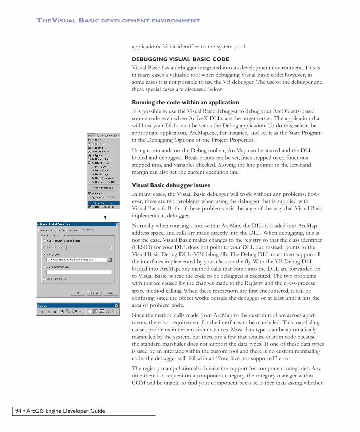
94 • ArcGIS Engine Developer Guide
application’s 32-bit identifier to the system pool.
DEBUGGING VISUAL BASIC CODE
Visual Basic has a debugger integrated into its development environment. This isin many cases a valuable tool when debugging Visual Basic code; however, insome cases it is not possible to use the VB debugger. The use of the debugger andthese special cases are discussed below.
Running the code within an applicationIt is possible to use the Visual Basic debugger to debug your ArcObjects-basedsource code even when ActiveX DLLs are the target server. The application thatwill host your DLL must be set as the Debug application. To do this, select theappropriate application, ArcMap.exe, for instance, and set it as the Start Programin the Debugging Options of the Project Properties.
Using commands on the Debug toolbar, ArcMap can be started and the DLLloaded and debugged. Break points can be set, lines stepped over, functionsstepped into, and variables checked. Moving the line pointer in the left-handmargin can also set the current execution line.
Visual Basic debugger issuesIn many cases, the Visual Basic debugger will work without any problems; how-ever, there are two problems when using the debugger that is supplied withVisual Basic 6. Both of these problems exist because of the way that Visual Basicimplements its debugger.
Normally when running a tool within ArcMap, the DLL is loaded into ArcMapaddress space, and calls are made directly into the DLL. When debugging, this isnot the case. Visual Basic makes changes to the registry so that the class identifier(CLSID) for your DLL does not point to your DLL but, instead, points to theVisual Basic Debug DLL (VB6debug.dll). The Debug DLL must then support allthe interfaces implemented by your class on the fly. With the VB Debug DLLloaded into ArcMap, any method calls that come into the DLL are forwarded onto Visual Basic, where the code to be debugged is executed. The two problemswith this are caused by the changes made to the Registry and the cross-processspace method calling. When these restrictions are first encountered, it can beconfusing since the object works outside the debugger or at least until it hits thearea of problem code.
Since the method calls made from ArcMap to the custom tool are across apart-ments, there is a requirement for the interfaces to be marshaled. This marshalingcauses problems in certain circumstances. Most data types can be automaticallymarshaled by the system, but there are a few that require custom code becausethe standard marshaler does not support the data types. If one of these data typesis used by an interface within the custom tool and there is no custom marshalingcode, the debugger will fail with an “Interface not supported” error.
The registry manipulation also breaks the support for component categories. Anytime there is a request on a component category, the category manager withinCOM will be unable to find your component because, rather than asking whether
THE VISUAL BASIC DEVELOPMENT ENVIRONMENT
Ch04_EngineAPIs.pmd 4/2/2004, 9:04 AM94

Chapter 4 • Developer environments • 95
your DLL belongs to the component category, COM is asking whether the VBdebugger DLL belongs to the component category, which it obviously doesn’t.What this means is that anytime a component category is used to automate theloading of a DLL, the DLL cannot be debugged using the Visual Basic debugger.
This obviously causes problems for many of the ways to extend the framework.The most common way to extend the framework is to add a command or tool.How component categories were used in this instance was discussed previously.Remember the component category was only used to build the list of commandsin the dialog box. This means that if the command to be debugged is alreadypresent on a toolbar, the Visual Basic debugger can be used. Hence, the procedurefor debugging Visual Basic objects that implement the ICommand interface is toensure that the command is added to a toolbar when ArcMap is executedstandalone and, after saving the document, loading ArcMap through thedebugger.
In some cases, such as extensions and property pages, it is not possible to use theVisual Basic debugger. If you have access to the Visual C++ debugger, you canuse one of the options outlined below. Fortunately, there are a number of ESRIVisual Basic Add-ins that make it possible to track down the problem quickly andeffectively. The add-ins described below, in the section ‘Visual Basic DeveloperAdd-ins’, provide error log information including line and module details. Asample output from an error log is given below; note the call stack informationalong with line numbers.Error Log saved on : 8/28/2000 - 10:39:04 AM
Record Call Stack Sequence - Bottom line is error line.
chkVisible_MouseUp C:\Source\MapControl\Commands\frmLayer.frm Line : 196
RefreshMap C:\Source\MapControl\Commands\frmLayer.frm Line : 20
Description
Object variable or With block variable not set
Alternatives to the Visual Basic debuggerIf the Visual Basic debugger and add-ins do not provide enough information, theVisual C++ debugger can be used, either on its own or with C++ ATL wrapperclasses. The Visual C++ debugger does not run the object to be debugged out ofprocess from ArcMap, which means that none of the above issues apply. Commondebug commands are given in the section ‘Debugging tips in Visual Studio’. Bothof the techniques below require the Visual Basic project to be compiled withdebug symbol information.
The Visual C++ Debugger can work with this symbolic debug information andthe source files.
Visual C++ debuggerIt is possible to use the Visual C++ debugger directly by attaching to a runningprocess that has the Visual Basic object to be debugged loaded and setting a breakpoint in the Visual Basic file. When the line of code is reached, the debugger willhalt execution and step you into the source file at the correct line. The requiredsteps are shown below.
THE VISUAL BASIC DEVELOPMENT ENVIRONMENT
Create debug symbol information using theCreate Symbolic Debug info option on the
Compile tab of the Project Properties dialog box.
Ch04_EngineAPIs.pmd 4/2/2004, 9:04 AM95

96 • ArcGIS Engine Developer Guide
1. Start an appropriate application, such as ArcMap.exe.
2. Start Microsoft Visual C++.
3. Attach to the ArcMap process using Menu option Build -> Start Debug ->Attach to process.
4. Load the appropriate Visual Basic Source file into the Visual C++ debuggerand set the break point.
5. Call the method within ArcMap.
No changes can be made to the source code within the debugger, and variablescannot be inspected, but code execution can be viewed and altered. This is oftensufficient to determine what is wrong, especially with logic-related problems.
ATL rrapper classesUsing the ATL, you can create a class that implements the same interfaces as theVisual Basic class. When you create the ATL object, you create the Visual Basicobject. All method calls are then passed to the Visual Basic Object for execution.You debug the contained object by setting a break point in the appropriate C++wrapper method, and when the code reaches the break point, the debugger isstepped into the Visual Basic code. For more information on this technique, lookat the ATL debugger sample in the Developer Samples of the ArcGIS DeveloperHelp system.
THE VISUAL BASIC DEVELOPMENT ENVIRONMENT
Ch04_EngineAPIs.pmd 4/2/2004, 9:04 AM96

Chapter 4 • Developer environments • 97
VISUAL C++
Developing in Visual C++ is a large and complex subject, as it provides a muchlower level of interaction with the underlying Windows APIs and COM APIswhen compared to other development environments.
While this can be a hindrance for rapid application development, it is the mostflexible approach. A number of design patterns like COM aggregation and single-tons are possible in Visual C++ that are not possible in Visual Basic 6. By usingstandard class libraries like Active Template Library (ATL), the complex COMplumbing code can be hidden. However it is still important to have a thoroughunderstanding of the underlying ATL COM implementation.
The documentation in this section is based on Microsoft Visual C++ version 6,and provides some guidance for ArcGIS development in this environment. Withthe release of Visual Studio C++.Net, (also referred to as VC7), many newenhancements are available to the C++ developer. While VC7 can work with themanaged .Net environment, and it is possible to work with the ArcGIS .Net API,this will only add an additional overhead to access the underlying ArcGIS COMobjects. So for the purposes of ArcGIS development in VC7 it is recommendedto work the “traditional” way, that is directly with the ArcGIS COM interfacesand objects.
With the addition of Visual C#.Net language, is worth considering portingVC++ code to this environment and using the ArcGIS .Net API. The syntax ofC# is not unlike C++, but the resulting code is generally simpler and more consis-tent.
This section is intended to serve two main purposes:
1. To familiarize you with general Visual C++ coding style and debugging, begin-ning with a discussion on ATL.
2. To detail specific usage requirements and recommendations for working withthe ArcObjects programming platform in Visual C++.
WORKING WITH ATL
This section cannot hope to cover all the topics that a developer working withATL should know in order to become an effective ATL C++ developer, but itwill serve as an introduction to getting started with ATL. ATL helps you imple-ment COM objects and it saves typing, but it does not excuse you from knowingC++ and how to develop COM objects.
ATL is the recommended framework for implementing COM objects. The ATLcode can be combined with MFC (Microsoft Foundation Class Library) codewhich provides more support for writing applications. An alternative to MFC isto use the Windows Template Library (WTL). This is based on the ATL templatemethodology and provides many wrappers for window classes and other applica-tion support for ATL. WTL is available for download from Microsoft, at the timeof writing version 7.1 is the latest and can be used with Visual C++ versions 6and Visual C++.Net (VC7).
ATL in briefATL is a set of C++ template classes designed to be small, fast, and extensible,based loosely on the Standard Template Library (STL). STL provides generic
There are many enhancements to ATL in VC7.Some of the relevant changes are covered in the
topic, ‘ATL and Visual C++.NET’, later in thissection.
Ch04_EngineAPIs.pmd 4/2/2004, 9:04 AM97

98 • ArcGIS Engine Developer Guide
VISUAL C++
template classes for C++ objects like vectors, stacks and queues. ATL also pro-vides a set of wizards that extend the Visual Studio development environment.These wizards automate some of the tedious plumbing code that all ATL projectsmust have. The wizards include, but are not limited, to the following:
• Application—used to initialize an ATL C++ project.
• Object—used to create COM objects. Both C++ and IDL code is generated,along with the appropriate code to support the creation of the objects atruntime.
• Property—used to add properties to interfaces.
• Method—used to add methods to interfaces; both the Property and MethodWizards require you to know some IDL syntax.
• Interface Implementation—used to implement stub functions for existinginterfaces.
• Connection Point Implement — used to implement outbound events inter-faces.
Typically these are accessed by a right-click on a project, class or interface inVisual Studio Workspace/Class View.
ATL provides base classes for implementing COM objects, as well as implementa-tions for some of the common COM interfaces, including IUnknown, IDispatch,and IClassFactory. There are also classes that provide support for ActiveX controlsand their containers.
ATL provides the required services for exposing ATL-based COM objects—thesebeing registration, server lifetime and class objects.
These template classes build a hierarchy that sandwiches your class. These inherit-ances are shown below. The CComxxxThreadModel supports thread-safe access toglobal, instance, and static data. The CComObjectRootEx provides the behavior forthe IUnknown methods. The interfaces at the second level represent the interfacesthat the class will implement; these come in two varieties. The IxxxImpl are ATL-supplied interfaces that also include an implementation; the other interfaces havepure virtual functions that must be fully implemented within your class. TheCComObject class inherits your class; this class provides the implementation of theIUnknown methods along with the object instantiation and lifetime control.
ATL and DTCAlong with smart types, covered later in this chapter, Direct-To-COM (DTC)provides some useful compiler extensions you can use when creating ATL-basedobjects. The functions __declspec and __uuidof are two such functions, but themost useful is the #import command.
COM interfaces are defined in IDL, then compiled by the Microsoft IDL com-piler (MIDL.exe). This results in the creation of a type library and header files.The project uses these files automatically when compiling software that refer-ences these interfaces. This approach is limited in that when working with inter-faces you must have access to the IDL files. As a developer of ArcGIS, you onlyhave access to the ArcGIS type library information contained in “.olb” and “.ocx”
CComObject<CMyObject>
CMyObject
CComObjectRootEx<>
IMyInt2
IMyIntIXxxImpl
CComXxxThreadModel
The hierarchical layers of ATL
A more detailed discussion on Direct To COM(DTC), follows in the later section, ‘Direct-To-
COM Smart Types’.
Ch04_EngineAPIs.pmd 4/2/2004, 9:04 AM98

Chapter 4 • Developer environments • 99
VISUAL C++
files. While it is possible to engineer a header file from a type library, it is a te-dious process. The #import command automates the creation of the necessary filesrequired by the compiler. Since the command was developed to support DTCwhen using it to import ArcGIS type libraries there are a number of parametersthat must be passed so that the correct import takes place. For further informa-tion on this process, see the later section ‘Importing ArcGIS type libraries’.
Handling errors in ATLIt is possible to just return an E_FAIL HRESULT code to indicate the failurewithin a method, however this does not give any indication to the caller of thenature of the failure. There are a number of windows standard HRESULTavailable, for example E_INVALIDARG (One or more arguments are invalid),E_POINTER (Invalid Pointer). These error codes are listed in the windowheader file winerror.h. Not all development environments have comprehensivesupport for HRESULT, Visual Basic clients often see error results as “Automa-tion Error – Unspecified Error”. ATL provides a simple mechanism for workingwith the COM error information object that can provide an error string descrip-tion, as well as an error code.
When creating an ATL object, the Object Wizard has an option to supportISupportErrorInfo. If you toggle the option on, when the wizard completes yourobject will implement the interface ISupportErrorInfo and a method will be addedthat looks something like this:STDMETHODIMP MyClass::InterfaceSupportsErrorInfo(REFIID riid)
{
static const IID* arr[] =
{
&IID_IMyClass,
};
for (int i = 0; i < sizeof(arr) / sizeof(arr[0]); i++)
{
if (InlineIsEqualGUID(*arr[i], riid))
return S_OK;
}
return S_FALSE;
}
It is now possible to return rich error messages by calling one of the ATL errorfunctions. These functions even work with resource files to ensure easy interna-tionalization of the message strings.
// Return a simple string
AtlReportError(CLSID_MyClass, _T(“No connection to Database.”),IID_IMyClass, E_FAIL);
// Get the Error Text from a resource string
AtlReportError(CLSID_MyClass, IDS_DBERROR, IID_IMyClass, E_FAIL,_Module.m_hInstResource);
To extract an error string from a failed method use the windows functionGetErrorInfo. This is used to retrieve the last IErrorInfo object on the currentthread and clears the current error state.
Although Visual C++ does support an exceptionmechanism (try ... catch), it is not recommended
to mix this with COM code. If an exceptionunwinds out of a COM interface there is no
guarantee the client will be able to catch thisand the most likely result is a crash.
Ch04_EngineAPIs.pmd 4/2/2004, 9:04 AM99

100 • ArcGIS Engine Developer Guide
VISUAL C++
Linking ATL codeOne of the primary purposes of ATL is to support the creation of small fastobjects. To support this, ATL gives the developer a number of choices whencompiling and linking the source code. Choices must be made about how to linkor dynamically access the C runtime (CRT) libraries, the registration code, and thevarious ATL utility functions. If no CRT calls are made in the code, this can beremoved from the link. If CRT calls are made and the linker switch_ATL_MIN_CRT is not removed from the link line the error shown below willgenerate during the link stage of the build. When compiling a debug build, therewill probably not be a problem, however, depending on the code written theremay be problems when compiling a release build. If you receive this error eitherremove the CRT calls or change the linker switches.LIBCMT.lib(crt0.obj) : error LNK2001: unresolved external symbol _main
ReleaseMinSize/History.dll : fatal error LNK1120: 1 unresolved externals
Error executing link.exe.
If the utilities code is dynamically loaded at runtime, you must ensure that theappropriate DLL (ATL.DLL) is installed and registered on the user’s system. TheArcGIS runtime installation at 9.0 will install ATL.dll. The table below showsthe various choices and the related linker switches.
Utilities Registrar
Debug static dynamic
RelMinSizedynamic dynamic
RelMinDependstatic static
CRT
yes
no
no
Symbols
_ATL_MIN_CRT_ATL_DLL
_ATL_MIN_CRT_ATL_STATIC_REGISTRY
By default there are build configurations for ANSI and Unicode builds. A compo-nent that is built with ANSI compilation will run on Windows9x, howeverconsidering that ArcGIS is only supported on unicode operating systems (Win-dows NT®, Windows 2000 and Windows XP), these configurations are redun-dant. To delete a configuration in Visual Studio, select “Build / Configurations...”. Then delete Win32 Debug, Win32 Release MinSize, Win32 ReleaseMinDependency.
Registration of a COM componentThe ATL project wizard generates the windows standard entry points for registra-tion. This code will register the .dll’s type library and execute a registry script file(.rgs) script for each COM object within the dll. Additional C++ code to performother registration tasks can be inserted into these functions.STDAPI DllRegisterServer(void)
{
// registers object in .rgs, typelib and all interfaces in typelib
// TRUE instructs the type library to be registered
return _Module.RegisterServer(TRUE);
}
STDAPI DllUnregisterServer(void)
{
return _Module.UnregisterServer(TRUE);
}
Ch04_EngineAPIs.pmd 4/2/2004, 9:04 AM100

Chapter 4 • Developer environments • 101
VISUAL C++
ATL provides a text file format “.rgs” that is parsed by ATLs registrar componentwhen a .dll is registered and unregistered. The .rgs file is built into a .dll as acustom resource. The file can be edited to add additional registry entries andcontains, ProgID, ClassID and component category entries to place in the registry.The syntax describes keys, values and names and sub keys to be added or removedfrom the registry. The format can be summarized as follows:[NoRemove | ForceRemove | val] Name | [ = s ‘Value’ | d ‘ Value’ | b ‘Value ]
{
.. optional subkeys for the registry
}
NoRemove signifies that the registry key should not be removed on un-registration.ForceRemove will ensure the key and sub-keys are removed before registering thenew keys. The s, d and b values indicate string (enclosed with apostrophes),double word (32bit integer value) and binary registry values. A typical registrationscript is shown below.HKCR
{
SimpleObject.SimpleCOMObject.1 = s ‘SimpleCOMObject Class’
{
CLSID = s ‘{2AFFC10E-ECFB-4697-8B3D-0405650B7CFB}’
}
SimpleObject.SimpleCOMObject = s ‘SimpleCOMObject Class’
{
CLSID = s ‘{2AFFC10E-ECFB-4697-8B3D-0405650B7CFB}’
CurVer = s ‘SimpleObject.SimpleCOMObject.1’
}
NoRemove CLSID
{
ForceRemove {2AFFC10E-ECFB-4697-8B3D-0405650B7CFB} = s ‘SimpleCOMObjectClass’
{
ProgID = s ‘SimpleObject.SimpleCOMObject.1’
VersionIndependentProgID = s ‘SimpleObject.SimpleCOMObject’
InprocServer32 = s ‘%MODULE%’
{
val ThreadingModel = s ‘Apartment’
}
‘TypeLib’ = s ‘{855DD226-5938-489D-986E-149600FEDD63}’
‘Implemented Categories’
{
{7DD95801-9882-11CF-9FA9-00AA006C42C4}
}
}
}
}
NoRemove CLSID ensures the registry key “CLSID” is never removed. This is thesubkey below which all COM objects register their ProgID’s and GUIDS, so itsremoval would result in a serious corruption of the registry. InprocServer32 is thestandard COM mechanism that relates a component GUID to a .dll file, ATL will
Ch04_EngineAPIs.pmd 4/2/2004, 9:04 AM101

102 • ArcGIS Engine Developer Guide
VISUAL C++
insert the correct module name using the %MODULE% variable. Other entriesunder the GUID specify the ProgID, threading model and type-library to use withthis component.
To register a COM CoClass into a component category, there are two approaches,the recommended approach is illustrated above, place GUIDs for componentcategories beneath an ‘Implemented Categories’ key, which in turn is under theGUID of the CoClass. The second approach is to use ATL macros in an objectsheader file; BEGIN_CATEGORY_MAP, IMPLEMENTED_CATEGORY andEND_CATEGORY_MAP. However these macros do not correctly removeregistry entries as explained in MSDN article Q279459 BUG: Component CategoryRegistry Entries Not Removed in ATL Component. A header file is supplied with theGUIDs of all the component categories used by ArcGIS, this is available in\Program Files\ArcGIS\include\CatIDs\ArcCATIDs.h.
Debugging ATL codeIn addition to the standard Visual Studio facilities, ATL provides a number ofdebugging options that provide specific support for debugging COM objects. Theoutput of these debugging options is displayed in the Visual C++ Output win-dow. The QueryInterface call can be debugged by setting the symbol_ATL_DEBUG_QI, AddRef and Release calls with the symbol_ATL_DEBUG_INTERFACES, and leaked objects can be traced by monitoringthe list of leaked interfaces at termination time when the_ATL_DEBUG_INTERFACES symbol is defined. The leaked interfaces list hasentries like the following: INTERFACE LEAK: RefCount = 1, MaxRefCount = 3, {Allocation = 10}
On its own, this does not tell you much apart from the fact that one of yourobjects is leaking because an interface pointer has not been released. However,the Allocation number allows you to automatically break when that interface isobtained by setting the m_nIndexBreakAt member of the CComModule at serverstart-up time. This in turn calls the function DebugBreak() to force the executionof the code to stop at the relevant place in the debugger. For this to work theprogram flow must be the same, but it can be very useful.extern “C”
BOOL WINAPI DllMain(HINSTANCE hInstance, DWORD dwReason, LPVOID /*lpReserved*/)
{
if (dwReason == DLL_PROCESS_ATTACH)
{
_Module.Init(ObjectMap, hInstance, &LIBID_HISTORYLib);
DisableThreadLibraryCalls(hInstance);
_Module.m_nIndexBreakAt = 10;
}
else if (dwReason == DLL_PROCESS_DETACH)
{
_Module.Term();
}
return TRUE;
}
If the GUID of a component is changed duringdevelopment, or the type library name is
changed, then it is important to keep the .rgscontent consistent with these changes, otherwisethe registry will be incorrect and object creation
can fail.
Ch04_EngineAPIs.pmd 4/2/2004, 9:04 AM102

Chapter 4 • Developer environments • 103
VISUAL C++
Boolean typesHistorically ANSI C did not have a boolean data type and used int value instead,where 0 represents false and non zero represents true. However the bool data-type has now become part of ANSI C++. COM API’s are language independentand define a different boolean type VARIANT_BOOL. Additionally win32 APIuses a different BOOL type. It is important to use the correct type at the appro-priate time. The following table summarizes their usage:
String typesConsidering that strings (sequences of text characters) are a simple concept, theyhave unfortunately become a complex and confusing topic in C++. The two mainreasons for this confusion are the lack of C++ support for variable length stringscombined with the requirement to support ANSI and Unicode character setswithin the same code. However as ArcGIS is only available on Unicode plat-forms, it may simplify development to remove the ANSI requirements.
The C++ convention for strings is an array of characters terminated with a 0.This is not always good for performance when calculating lengths of large strings.To support variable length strings, the character arrays can be dynamically allo-cated and released on the heap, typically using malloc and free or new and delete.Consequently a number of wrapper classes provide this support; CString definedin MFC and WTL, is the most widely used. Additionally for COM usage theBSTR type is defined and the ATL wrapper class CComBSTR is available.
To allow for international character sets, Microsoft Windows migrated from a8bit ANSI characters strings (8bit char) representation (found on win95, win98and winME platforms) to a 16bit Unicode characters (16bit unsigned short).Unicode is synonymous with wide characters (wchar_t). In COM APIsOLECHAR is the type used and is defined to be wchar_t on Windows. Windowsoperating systems like winNT, win2000 and winXP natively support Unicodecharacters. To allow the same C++ code to be compiled for ANSI andUNICODE platforms, compiler switches are used to change windows API func-tions (e.g. SetWindowText) to resolve to an ANSI version (SetWindowTextA) ora Unicode version (SetWindowTextW). Additionally character independent types(TCHAR defined in tchar.h) were introduced to represent a character, on anANSI build this is defined to be a char and on a Unicode build this is a wchar_t(typedef defined as unsigned short). To perform standard C string manipulation
Ch04_EngineAPIs.pmd 4/2/2004, 9:04 AM103

104 • ArcGIS Engine Developer Guide
VISUAL C++
there are typically three different definitions of the same function, for examplefor a case insensitive comparison strcmp provides the ANSI version, wcscmp pro-vides the Unicode version and _tcscmp provides the TCHAR version. There is alsoa fourth version _mbscmp which is a variation of the 8bit ANSI version that willinterpret multi-byte character sequences (MBCS) within the 8 bit string.// Initialize some fixed length strings
char* pNameANSI = “Bill”; // 5 bytes (4 characters plus a terminator)
wchar_t* pNameUNICODE = L”Bill”; // 10 bytes (4 16bit characters plus a16bit terminator)
TCHAR* pNameTCHAR = _T(“Bill”); // either 5 or 10 depending on compilersettings
COM APIs represent variable length strings with a BSTR type; this is a pointer toa sequence of OLECHAR characters, which is defined as Unicode characters andis the same as a wchar_t. A BSTR must be allocated and released with theSysAllocString and SysFreeString windows functions and unlike C strings theycan contain embedded zero characters (although this is unusual). The BSTR alsohas a count value, which is stored 4 bytes before the BSTR pointer address. TheCComBSTR wrappers are often used to manage the life time of a string.
Do not pass a pointer to a C style array of Unicode characters (OLECHAR orwchar_t) to a function expecting a BSTR. The compiler will not raise an error asthe types are identical. However the function receiving the BSTR can behaveincorrectly or crash when accessing the string length (which will be randommemory values).ipFoo->put_WindowTitle(L”Hello”); // This is bad!ipFoo->put_WindowTitle(CComBSTR(L”Hello”)); // This correctly initializes
and passes a BSTR
ATL provides conversion macros to switch strings between ANSI (A), TCHAR(T), Unicode (W) and OLECHAR (OLE). Additionally the types can have aconst modifier (C). These macros use the abbreviations shown in brackets with a“2” between them. For example to convert between OLECHAR (e.g. a inputBSTR) to const TCHAR (for use in a windows function) use the OLE2CT con-version macro. To convert ANSI to Unicode use A2W. These macros require theUSES_CONVERSION macro to be placed at the top of a method, this willcreate some local variables that are used by the conversion macros. When thesource and destination character sets are different and the destination type in nota BSTR, the macro allocates the destination string on the call stack (using the_alloca runtime function). It’s important to realize this especially when usingthese macros within a loop; the stack may grow very large and run out of stackspace.
STDMETHODIMP CFoo::put_WindowTitle(BSTR bstrTitle)
{
USES_CONVERSION;
if (::SysStringLen(bstrTitle) == 0)
return E_INVALIDARG;
::SetWindowText(m_hWnd, OLE2CT(bstrTitle));
return S_OK;
}
To check if two CComBSTR strings are different,do not use the not equal (“!=”) operator. The
“==” operator performs a case sensitivecomparison of the string contents, however “!=”will compare pointer values and not the string
contents, typically returning false.
Ch04_EngineAPIs.pmd 4/2/2004, 9:04 AM104
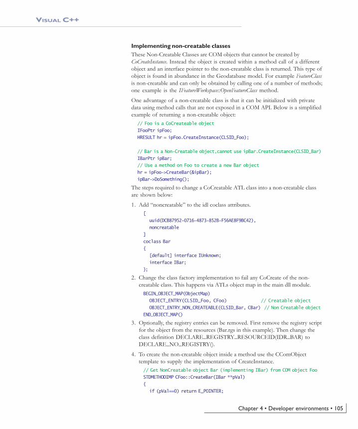
Chapter 4 • Developer environments • 105
VISUAL C++
Implementing non-creatable classesThese Non-Creatable Classes are COM objects that cannot be created byCoCreateInstance. Instead the object is created within a method call of a differentobject and an interface pointer to the non-creatable class is returned. This type ofobject is found in abundance in the Geodatabase model. For example FeatureClassis non-creatable and can only be obtained by calling one of a number of methods;one example is the IFeatureWorkspace::OpenFeatureClass method.
One advantage of a non-creatable class is that it can be initialized with privatedata using method calls that are not exposed in a COM API. Below is a simplifiedexample of returning a non-creatable object:
// Foo is a CoCreateable object
IFooPtr ipFoo;
HRESULT hr = ipFoo.CreateInstance(CLSID_Foo);
// Bar is a Non-Creatable object,cannot use ipBar.CreateInstance(CLSID_Bar)
IBarPtr ipBar;
// Use a method on Foo to create a new Bar object
hr = ipFoo->CreateBar(&ipBar);
ipBar->DoSomething();
The steps required to change a CoCreatable ATL class into a non-creatable classare shown below:
1. Add “noncreatable” to the idl coclass attributes.[
uuid(DCB87952-0716-4873-852B-F56AE8F9BC42),
noncreatable
]
coclass Bar
{
[default] interface IUnknown;
interface IBar;
};
2. Change the class factory implementation to fail any CoCreate of the non-creatable class. This happens via ATLs object map in the main dll module.BEGIN_OBJECT_MAP(ObjectMap)
OBJECT_ENTRY(CLSID_Foo, CFoo) // Creatable object
OBJECT_ENTRY_NON_CREATEABLE(CLSID_Bar, CBar) // Non Creatable object
END_OBJECT_MAP()
3. Optionally, the registry entries can be removed. First remove the registry scriptfor the object from the resources (Bar.rgs in this example). Then change theclass definition DECLARE_REGISTRY_RESOURCEID(IDR_BAR) toDECLARE_NO_REGISTRY().
4. To create the non-creatable object inside a method use the CComObjecttemplate to supply the implementation of CreateInstance.// Get NonCreatable object Bar (implementing IBar) from COM object Foo
STDMETHODIMP CFoo::CreateBar(IBar **pVal)
{
if (pVal==0) return E_POINTER;
Ch04_EngineAPIs.pmd 4/2/2004, 9:04 AM105

106 • ArcGIS Engine Developer Guide
VISUAL C++
// Smart pointer to non-creatable object Bar
IBarPtr ipBar = 0;
// C++ Pointer to Bar, with ATL template to supply CreateInstance imple-mentation
CComObject<CBar>* pBar = 0;
HRESULT hr = CComObject<CBar>::CreateInstance(&pBar);
if (SUCCEEDED(hr))
{
// Increment the ref count from 0 to 1 to protect the object
// from being released in any initialization code.
pBar->AddRef();
// Call C++ methods (not exposed to COM) to initialize the Bar object
pBar->InitialiseBar(10);
// QI to IBar and hold a smart pointer reference to the object Bar
hr = pBar->QueryInterface(IID_IBar, (void**)&ipBar);
pBar->Release();
}
// return IBar pointer to the caller
*pVal = ipBar.Detach();
return S_OK;
}
ATL in Visual C++.NETVisual C++ version 6 is used for the majority of this help. However with therelease of Visual C++.Net (also known as VC7), there are enhancements andchanges that are relevent to the ArcGIS ATL developer, some of these aresummerized below:
Attribute-based programming—This is a major change introduced in VC7.Attributes are inserted in the source code enclosed in square brackets, for ex-ample [ coclass ]. Attributes are designed to simplify COM programming and.NET Framework common language runtime development. When you includeattributes in your source files, the compiler works with provider dynamic-linklibraries (DLL) to insert code or modify the code in the generated object files.There are attributes that aid in the creation of .idl files, interfaces, type libraries,and other COM elements. In the integrated development environment (IDE),attributes are supported by the wizards and by the Properties window. The ATLwizards make extensive use of attributes to inject the ATL boiler plate code intothe class. Consequently typical COM CoClass header files in VC7 contain muchless ATL code than at VC6. As IDL is generated from attributes, there is typicallyno .idl file present in COM projects as before and the idl file is generated atcompile time.
Build configurations—There are only two default build configurations in VC7,these are ANSI Debug and Release based builds. As ArcGIS is only available on
Ch04_EngineAPIs.pmd 4/2/2004, 9:04 AM106

Chapter 4 • Developer environments • 107
VISUAL C++
Unicode platforms it is recommended to change these by modifying the projectproperties. The general project properties page has an option for “Character Set”,simply change this from “Use Multi-Byte Character Set” to “Use Unicode Charac-ter Set”.
Character conversion macros—The character conversion macros(USES_CONVERSION, W2A, W2CT etc) have improved alternative versions.These no longer allocate space on the stack, so they can be used in loops withoutrunning out of stack space. The USES_CONVERSION macro is also no longerrequired. They are now implemented as classes and begin with a “C”, for exampleCW2A, CW2CT.
Safe array support—This is available with CComSafeArray andCComSafeArrayBound classes.
Module level global—The module level global CComModule _module hasbeen split into a number of related classes for example CAtlComModule andCAtlWinModule. To retrieve the resource module instance use the followingcode: _AtlBaseModule.GetResourceInstance();
String support—General variable length string support is now available throughCString in ATL. This is defined in the header file atlstr.h and cstringt.h. If ATL iscombined with MFC this defaults to MFC’s CString implementation.
File path handling—A collection of related functions for processing thecomponents of file paths are available through the CPath class defined inatlpath.h.
ATLServer—This is a new selection of ATL classes designed for writing webapps, XML web services and other Server applications.
#import issues—When using #import, a few modifications are required com-pared to VC6. For example the #import of esriSystem requires an exclude orrename of “GetObject” and the #import of esriGeometry requires an exclude orrename of “ISegment”.
ATL REFERENCES
Microsoft MSDN provides a wealth of documentation, articles and samples, thatare installed with Visual Studio products. ATL reference documentation forVisual Studio version 6 is under:
MSDN Library - October 2001 / Visual Tools and Languages / Visual Studio 6.0Documentation / Visual C++ Documentation / Reference / Active Template Library
Additional documentation is also available on the MSDN Web site athttp://www.msdn.microsoft.com
The following books are also useful:
Grimes, Richard. ATL COM Programmer’s Reference. Chicago: Wrox Press Inc.,1988
Grimes, Richard. Professional ATL COM Programming. Chicago: Wrox Press Inc.,1988
Grimes, Richard, and Reilly Stockton, and Alex Stockton, and Julian Templeman.Beginning ATL 3 COM Programming. Chicago: Wrox Press Inc. 1999.
Ch04_EngineAPIs.pmd 4/2/2004, 9:04 AM107

108 • ArcGIS Engine Developer Guide
VISUAL C++
King, Brad and George Shepherd. Inside ATL. Redmond, WA: Microsoft Press,1999.
Rector, Brent, and Chris Sells, and Jim Springfield. ATL Internals. Reading, MA:Addison-Wesley, 1999.
SMART TYPES
Smart types are objects that behave like types. They are C++ class implementa-tions that encapsulate a data type, wrapping it with operators and functions thatmake working with the underlying type easier and less error prone. When thesesmart types encapsulate an interface pointer, they are referred to as smart pointers.Smart pointers work with the IUnknown interface to ensure that resource alloca-tion and deallocation is correctly managed. They accomplish this by variousfunctions, construct and destruct methods, and overloaded operators. There arenumerous smart types available to the C++ programmer. The two main types ofsmart types covered here are defined by Direct-To-COM and the Active TemplateLibrary.
Smart types can make the task of working with COM interfaces and data typeseasier, since many of the API calls are moved into a class implementation; how-ever they must be used with caution, and never without a clear understanding ofhow they are interacting with the encapsulated data type.
Direct-To-COM smart typesThe smart type classes supplied with DTC are known as the Compiler COMSupport Classes and consist of:
• _com_error—this class represents an exception condition in one of the COMsupport classes. This object encapsulates the HRESULT and the IErrorInfoCOM exception object.
• _com_ptr_t—this class encapsulates a COM interface pointer. See below forcommon uses.
• _bstr_t—this class encapsulates the BSTR data type. The functions and opera-tors on this class are not as rich as the ATL CComBSTR smart type, hence thisis not normally used.
• _variant_t—this class encapsulates the VARIANT data type. The functionsand operators on this class are not as rich as the ATL CComVariant smart type,hence this is not normally used.
To define a smart pointer for an interface you can use the macro_COM_SMARTPTR_TYPEDEF like this:
_COM_SMARTPTR_TYPEDEF(IFoo, __uuidof(IFoo));
The compiler expands this as follows:typedef _com_ptr_t< _com_IIID<IFoo, __uuidof(IFoo)> > IFooPtr;
Once declared, it is simply a matter of declaring a variable as the type of theinterface and appending Ptr to the end of the interface. Below are some commonuses of this smart pointer that you will see in the numerous C++ samples.// Get a CLSID GUID constant
extern “C” const GUID __declspec(selectany) CLSID_Foo = \
{0x2f3b470c,0xb01f,0x11d3,{0x83,0x8e,0x00,0x00,0x00,0x00,0x00,0x00}};
Ch04_EngineAPIs.pmd 4/2/2004, 9:04 AM108

Chapter 4 • Developer environments • 109
VISUAL C++
// Declare Smart Pointers for IFoo, IBar and IGak interfaces
_COM_SMARTPTR_TYPEDEF(IFoo, __uuidof(IFoo));
_COM_SMARTPTR_TYPEDEF(IBar, __uuidof(IBar));
_COM_SMARTPTR_TYPEDEF(IGak, __uuidof(IGak));
STDMETHODIMP SomeClass::Do()
{
// Create Instance of Foo class and QueryInterface (QI) for IFoo interface
IFooPtr ipFoo;
HRESULT hr = ipFoo.CreateInstance(CLSID_Foo);
if (FAILED(hr)) return hr;
// Call method on IFoo to get IBar
IBarPtr ipBar;
hr = ipFoo->get_Bar(&ipBar);
if (FAILED(hr)) return hr;
// QI IBar interface for IGak interface
IGakPtr ipGak(ipBar);
// Call method on IGak
hr = ipGak->DoSomething();
if (FAILED(hr)) return hr;
// Explicitly call Release()
ipGak = 0;
ipBar = 0;
// Let destructor call IFoo’s Release
return S_OK;
}
One of the main advantages of using the DTC smart pointers is that they areautomatically generated from the “#import” compiler statement for all interfaceand CoClass definitions in a type library. For more details on this functionality, seethe later section ‘Importing ArcGIS Type Libraries’.
Although is is possible to create an object implicitly in a DTC smart pointersconstructor, for example:IFooPtr ipFoo(CLSID_Foo)
This will raise a C++ exception if there is an error during object creation (e.g. ifthe “.dll” file containing the object implementation was accidentally deleted).This exception will typically be unhandled and cause a crash. A more robustapproach is to avoid exceptions in COM and call CreateInstance explicitly andhandle the failure code, for example:IFooPtr ipFoo;HRESULT hr = ipFoo.CreateInstance(CLSID_Foo);if (FAILED(hr))
return hr; // return object creation failure code to caller
Ch04_EngineAPIs.pmd 4/2/2004, 9:04 AM109

110 • ArcGIS Engine Developer Guide
VISUAL C++
Active Template Library smart typesATL defines various smart types, as seen in the list below. You are free to com-bine both the ATL and DTC smart types in your code. However it is typical touse the DTC for smart pointers as they are easily generated by importing typelibraries. For BSTR and VARIANT types the ATL versions for CComBSTR,CComVariant are typically used..
ATL smart types:
• CComPtr—class encapsulates a COM interface pointer by wrapping theAddRef and Release methods of the IUnknown interface.
• CComQIPtr—class encapsulates a COM interface and supports all three meth-ods of the IUnknown interface: QueryInterface, AddRef, and Release.
• CComBSTR—class encapsulates the BSTR data type.
• CComVariant—class encapsulates the VARIANT data type
• CRegKey—class provides methods for manipulating Windows registry entries.
• CComDispatchDriver—class provides methods for getting and setting proper-ties, and calling methods through an object’s IDispatch interface.
• CSecurityDescriptor—Class provides methods for setting up and working withthe Discretionary Access Control List (DACL).
This section examines the first four smart types and their uses. The example codebelow written with ATL smart pointers, looks like the following:// Get a CLSID GUID constant
extern “C” const GUID __declspec(selectany) CLSID_Foo = \
{0x2f3b470c,0xb01f,0x11d3,{0x83,0x8e,0x00,0x00,0x00,0x00,0x00,0x00}};
STDMETHODIMP SomeClass::Do ()
{
// Create Instance of Foo class and QI for IFoo interface
CComPtr<IFoo> ipFoo;
HRESULT hr = CoCreateInstance(CLSID_Foo, NULL, CLSCTX_INPROC_SERVER,IID_IFoo, (void **)&ipFoo);
if (FAILED(hr)) return hr;
// Call method on IFoo to get IBar
CComPtr<IBar> ipBar;
HRESULT hr = ipFoo->get_Bar(&ipBar);
if (FAILED(hr)) return hr;
// IBar interface for IGak interface
CComQIPtr<IGak> ipGak(ipBar);
// Call method on IGak
hr = ipGak->DoSomething();
if (FAILED(hr)) return hr;
// Explicitly call Release()
ipGak = 0;
Differences in implementation of equality (“==“) operator for smart pointer comparisons. The
COM specification states object indentity isperformed by comparing the pointer values of
IUnknown*. The DTC smart pointers willperform necessary QI and comparison when
using the “==” operator. However the ATL smartpointers will not do this and you must use the
ATL IsEqualObject() method.
Ch04_EngineAPIs.pmd 4/2/2004, 9:04 AM110

Chapter 4 • Developer environments • 111
VISUAL C++
ipBar = 0;
// Let destructor call Foo’s Release
return S_OK;
}
The most common smart pointer seen in the Visual C++ samples is the DTCtype. In the examples below, which illustrate the BSTR and VARIANT datatypes, the DTC pointers are used. When working with CComBSTR, use the textmapping L”” to declare constant OLECHAR strings. For more information onstring data types see the information on ‘ATL String Types’ later in this Visual ++section. CComVariant derives directly from the VARIANT data type, meaningthat there is no overloading with its implementation, which in turn simplifies ituse. It has a rich set of constructors and functions that make working withVARIANTs straightforward; there are even methods for reading and writingfrom streams. Be sure to call the Clear method before reusing the variable. ipFoo->put_Name(CComBSTR(L”NewName”));
if FAILED(hr)) return hr;
// Create a VT_I4 variant (signed long)
CComVariant vValue(12);
// Change its data type to a string
hr = vValue.ChangeType(VT_BSTR);
if (FAILED(hr)) return hr;
Some method calls in idl are marked as being optional and take a variant param-eter. However in VC++ these parameters still have to be supplied. To signify thata parameter value is not supplied a variant is passed specifying an error code ortype DISP_E_PARAMNOTFOUND: CComBSTR documentFilename(L”World.mxd”);
CComVariant noPassword;
noPassword.vt = VT_ERROR;
noPassword.scode = DISP_E_PARAMNOTFOUND;
HRESULT hr = ipMapControl->LoadMxFile(documentFilename, noPassword);
When working with CComBSTR and CComVariant, the Detach() function releasesthe underlying data type from the smart type and can be used when passing aresult as an [out] parameter of a method. The use of the Detach method withCComBSTR is shown below:STDMETHODIMP CFoo::get_Name(BSTR* name)
{
if (name==0) return E_POINTER;
CComBSTR bsName(L”FooBar”);
*name = bsName.Detach();
}
CComVariant myVar(ipSmartPointer) will result in a variant type of boolean(VT_BOOL) and not a variant with an object reference (VT_UNKNOWN) asexpected. It is better to pass unambiguous types to constructors, i.e. types whichare not themselves smart types with overloaded cast operators.
CComVariant(VARIANT_TRUE) will create ashort integer variant (type VT_I2) and not a
boolean variant (type VT_BOOL) as expected.You can use CComVariant(true) to create a
boolean variant.
Ch04_EngineAPIs.pmd 4/2/2004, 9:04 AM111

112 • ArcGIS Engine Developer Guide
VISUAL C++
// Perform QI it IUnknownIUnknownPtr ipUnk = ipSmartPointer;// Ensure we use IUnknown* constructor of CComVariantCComVariant myVar2(ipUnk.GetInterfacePtr());
A common practice with smart pointers is to use Detach() to return an object froma method call. When returning an interface pointer the COM standard is toincrement reference count of the [out] parameter inside the method implementa-tion. It is the callers responsibility to call Release when the pointer is no longerrequired. Consequently care must be taken to avoid calling Detach() directly on amember variable, a typical pattern is show below:STDMETHODIMP CFoo::get_Bar(IBar **pVal)
{
if (pVal==0) return E_POINTER;
// Constructing a local smart pointer using another smart pointer
// results in an AddRef (if pointer is not 0).
IBarPtr ipBar(m_ipBar);
// Detach will clear the local smart pointer and the
// interface is written into the output parameter.
*pVal = ipBar.Detach();
// This can be combined into one line
// *pVal = IBarPtr(m_ipBar).Detach();
return S_OK;
}
The above pattern has the same result as the following code, note that a condi-tional test for a 0 pointer is required before AddRef can be called, callingAddRef (or any method) on a 0 pointer will result in an access violation excep-tion and typically crash the application:STDMETHODIMP CFoo::get_Bar(IBar **pVal)
{
if (pVal==0) return E_POINTER;
// copy the interface pointer (no AddRef) into the output parameter
*pVal = m_ipBar;
// Make sure interface pointer is non 0 before calling AddRef
if (*pVal)
*pVal->AddRef();
return S_OK;
}
When using a smart pointer to receive an object from from an [out] parameter ona method, use the smart pointer “&” de-reference operator. This will cause theprevious interface pointer in the smart pointer to be released. The smart pointer isthen populated with the new [out] value. The implementation of the method will
Ch04_EngineAPIs.pmd 4/2/2004, 9:04 AM112

Chapter 4 • Developer environments • 113
VISUAL C++
have already incremented the object reference count. This will be released whenthe smart pointer goes out of scope: {
IFooPtr ipFoo1, ipFoo2;
ipFoo1.CreateInstance(CLSID_Foo);
ipFoo2.CreateInstance(CLSID_Foo);
// Initalise ipBar Smart pointer from Foo1
IBarPtr ipBar;
ipFoo1->get_Bar(&ipBar);
// The “&” de-reference will call Release on ipBar
// ipBar is then repopulate with a new instance of IBar
ipFoo2->get_Bar(&ipBar);
}
// ipBar goes out of scope and the smart pointer destructor calls Release
Naming conventions
Type namesAll type names (class, struct, enum, and typedef) begin with an uppercase letter anduse mixed case for the rest of the name: class Foo : public CObject { . . .};
struct Bar { . . .};
enum ShapeType { . . . };
typedef int* FooInt;
Typedefs for function pointers (callbacks) append Proc to the end of their names. typedef void (*FooProgressProc)(int step);
Enumeration values all begin with a lowercase string that identifies the project; inthe case of ArcObjects this is esri, and each string occurs on separate lines: typedef enum esriQuuxness
{
esriQLow,
esriQMedium,
esriQHigh
} esriQuuxness;
Function namesName functions using the following conventions:
For simple accessor and mutator functions, use Get<Property> andSet<Property>: int GetSize();
void SetSize(int size);
If the client is providing storage for the result, use Query<Property>: void QuerySize(int& size);
Ch04_EngineAPIs.pmd 4/2/2004, 9:04 AM113

114 • ArcGIS Engine Developer Guide
VISUAL C++
For state functions, use Set<State and Is<State> or Can<State>: bool IsFileDirty();
void SetFileDirty(bool dirty);
bool CanConnect();
Where the semantics of an operation are obvious from the types of arguments,leave type names out of the function names.
Instead of: AddDatabase(Database& db);
consider using: Add(Database& db);
Instead of: ConvertFoo2Bar(Foo* foo, Bar* bar);
consider using: Convert(Foo* foo, Bar* bar)
If a client relinquishes ownership of some data to an object, useGive<Property>. If an object relinquishes ownership of some data to a client,use Take<Property>: void GiveGraphic(Graphic* graphic);
Graphic* TakeGraphic(int itemNum);
Use function overloading when a particular operation works with differentargument types: void Append(const CString& text);
void Append(int number);
Argument namesUse descriptive argument names in function declarations. The argument nameshould clearly indicate what purpose the argument serves: bool Send(int messageID, const char* address, const char* message);
DEBUGGING TIPS IN DEVELOPER STUDIO
Visual C++ comes with a feature-rich debugger. These tips will help you get themost from your debugging session.
Backing up after failureWhen a function call has failed and you’d like to know why (by stepping intoit), you don’t have to restart the application. Use the Set Next Statementcommand to reposition the program cursor back to the statement that failed(right-click on the statement to bring up the debugging context menu). Then,just step into the function.
Edit and ContinueVisual Studio 6 allows changes to source code to be made during a debuggingsession. The changes can be recompiled and incorporated into the executing codewithout stopping the debugger. There are some limitations to the type of changesthat can be made, in this case the debug session must be restarted. This feature isenabled by default, the settings are available in “Settings” of the project menu
Here are some suggestions for a namingconvention. These help identify the variables
usage and type and so reduce coding errors. Thisis an abridged Hungarian notation:
[<scope>_]<type><name>
c
m
Prefix
g
<empty>
Static class member (including constants)
Instance class members
Variable scope
Globally static variable
local variable or struct or public classmember
<type>
Boolean
Data Type
byte or unsigned char
short used as size
DWORD, double word or unsigned long
int (integer)
long
a pointer
string
function
handle
ASCIIZ null-terminated string
WORD unsigned int
short used as coordinates
b
Prefix
by
cx / cy
dw
i
l
p
s
fn
h
sz
w
x, y
doubled
floatf
smart pointerip
<name> describes how the variable is used orwhat it contains. The <scope> and <type>
portions should always be lowercase, and the<name> should use mixed case:
m_hWnd
Variable Name
ipEnvelope
m_pUnkOuter
c_isLoaded
g_pWindowList
a handle to a HWND
Description
a smart pointer to a COM interface
a pointer to an object
a static class member
a global pointer to an object
Ch04_EngineAPIs.pmd 4/2/2004, 9:04 AM114

Chapter 4 • Developer environments • 115
VISUAL C++
then Select “C/C++ tab. Select “General” from the “Category” group box. In theDebug info group box, select “Program Database for Edit and Continue”.
Unicode string displaySet your debugger options to display Unicode strings (click the Tools menu,click Options, click Debug, then check the Display Unicode Strings check box).
Variable value displayPause the cursor over a variable name in the source code to see its currentvalue. If it is a structure, click it and bring up the QuickWatch dialog box (theEyeglasses icon or Shift+F9) or drag and drop it into the Watch window.
Undocking windowsIf the Output window (or any docked window, for that matter) seems toosmall to you, try undocking it to make it a real window. Just right-click it andtoggle the Docking View item.
Conditional break pointsUse conditional break points when you need to stop at a break point only oncesome condition is reached (a for-loop reaching a particular counter value). To doso, set the break point normally, then bring up the Breakpoints window (Ctrl+Bor Alt+F9). Select the specific break point you just set and then click the Condi-tion button to display a dialog in which you specify the break point condition.
Preloading DLLsYou can preload DLLs that you wish to debug before executing the program. Thisallows you to set break points up front rather than wait until the DLL has beenloaded during program execution. (Click Project, click Settings, click Debug, clickCategory, then click Additional DLLs.) Then, click in the list area below to addany DLLs you wish to have preloaded.
Changing display formatsYou can change the display format of variables in the QuickWatch dialog box orin the Watch window using the formatting symbols in the following table.
d, i
Symbol
signed decimal integer
Format
0xF000F065
Value
-268373915
Displays
u unsigned decimal integer 0x0065 101
o unsigned octal integer 0xF065 0170145
x, X hexadecimal integer 61541 0x0000F065
l, h long or short prefix for d, I, u, o, x, X 00406042, hx 0x0C22
f signed floating-point 3./2. 1.500000
e signed scientific notation 3./2. 1.500000e+00
g e or f, whichever is shorter 3./2. 1.5
c single character 0x0065 'e'
s string 0x0012FDE8 "Hello"
su Unicode string "Hello"
hr string 0 S_OK
To use a formatting symbol, type the variable name followed by a comma and theappropriate symbol. For example, if var has a value of 0x0065, and you want to
Ch04_EngineAPIs.pmd 4/2/2004, 9:04 AM115

116 • ArcGIS Engine Developer Guide
VISUAL C++
see the value in character form, type var,c in the Name column on the tab of theWatch window. When you press ENTER, the character-format value appears:var,c = ‘e’. Likewise, assuming that hr is a variable holding HRESULTS, view ahuman-readable form of the HRESULT by typing “hr,hr” in the Name column.
You can use the formatting symbols shown in the following table to format thecontents of memory locations.
ma
Symbol
mw
mu
64 ASCII characters
Format
8 words
2-byte characters (Unicode)
0x0012ffac.4...0...".0W&.......1W&.0.:W..1...."..1.JO&.1.2.."..1...0y....1
Value
0x0012ffac34B3 00CB 3084 809422FF 308A 2657 0000
0x0012fc608478 77f4 ffff ffff0000 0000 0000 0000
m16 bytes in hex, followed by 16 ASCIIcharacters
0x0012ffacB3 34 CB 00 84 30 94 80FF 22 8A 30 57 26 00 00 .4...0....".0W&..
mb16 bytes in hex, followed by 16 ASCIIcharacters
0x0012ffacB3 34 CB 00 84 30 94 80FF 22 8A 30 57 26 00 00 .4...0...".0W&..
md 4 double-words0x0012ffac00CB34B3 80943084 308A22FF 00002657
With the memory location formatting symbols, you can type any value or expres-sion that evaluates to a location. To display the value of a character array as astring, precede the array name with an ampersand, &yourname. A formattingcharacter can also follow an expression:• rep+1,x• alps[0],mb• xloc,g• count,dTo watch the value at an address or the value pointed to by a register, use the BY,WO, or DW operator:• BY returns the contents of the byte pointed at.• WO returns the contents of the word pointed at.• DW returns the contents of the doubleword pointed at.Follow the operator with a variable, register, or constant. If the BY, WO, or DWoperator is followed by a variable, then the environment watches the byte, word,or doubleword at the address contained in the variable.
You can also use the context operator { } to display the contents of any location.
Ch04_EngineAPIs.pmd 4/2/2004, 9:04 AM116

Chapter 4 • Developer environments • 117
VISUAL C++
To display a Unicode string in the Watch window or the QuickWatch dialog box,use the su format specifier. To display data bytes with Unicode characters in theWatch window or the QuickWatch dialog box, use the mu format specifier.
Keyboard shortcutsThere are numerous keyboard shortcuts that make working with the VisualStudio editor faster. Some of the more useful keyboard shortcuts follow.
The text editor uses many of the standard shortcut keys used by Windowsapplications, such as Word. Some specific source code editing shortcuts arelisted below.
Correctly indent selected code based on surrounding lines.
Action
Find the matching brace.
Display list of members.
Complete the word, once the number of letters entered allows the editor to recognize it. Use full whencompleting function and variable names.
Indents selection one tab stop to the right.
Indents selection one tab to the left.
Alt+F8
Shortcut
Ctrl+]
Ctrl+J
Ctrl+Spacebar
Tab
Shift+Tab
Below is a table of common keyboard shortcuts used in the debugger.
Add or remove breakpoint from current line.
Action
Remove all breakpoints.
Disable breakpoints.
Display auto window and move cursor into it.
Display call stack window and move cursor into it.
Display locals window and move cursor into it.
Display auto window and move cursor into it.
End debugging session.
Execute code one statement at a time, stepping into functions.
Execute code one statement at a time, stepping over functions.
Restart a debugging session.
Resume execution from current statement to selected statement.
Run the application.
Run the application without the debugger.
Set the next statement.
Stop execution.
F9
Shortcut
Ctrl+Shift+F9
Ctrl+F9
Ctrl+Alt+A
Ctrl+Alt+C
Ctrl+Alt+L
Ctrl+Alt+A
Shift+F5
F11
F10
Ctrl+Shift+F5
Ctrl+F10
F5
Ctrl+F5
Ctrl+Shift+F10
Ctrl+Break
Loading the following shortcuts can greatly increase your productivity with theVisual Studio development environment.
Ch04_EngineAPIs.pmd 4/2/2004, 9:04 AM117
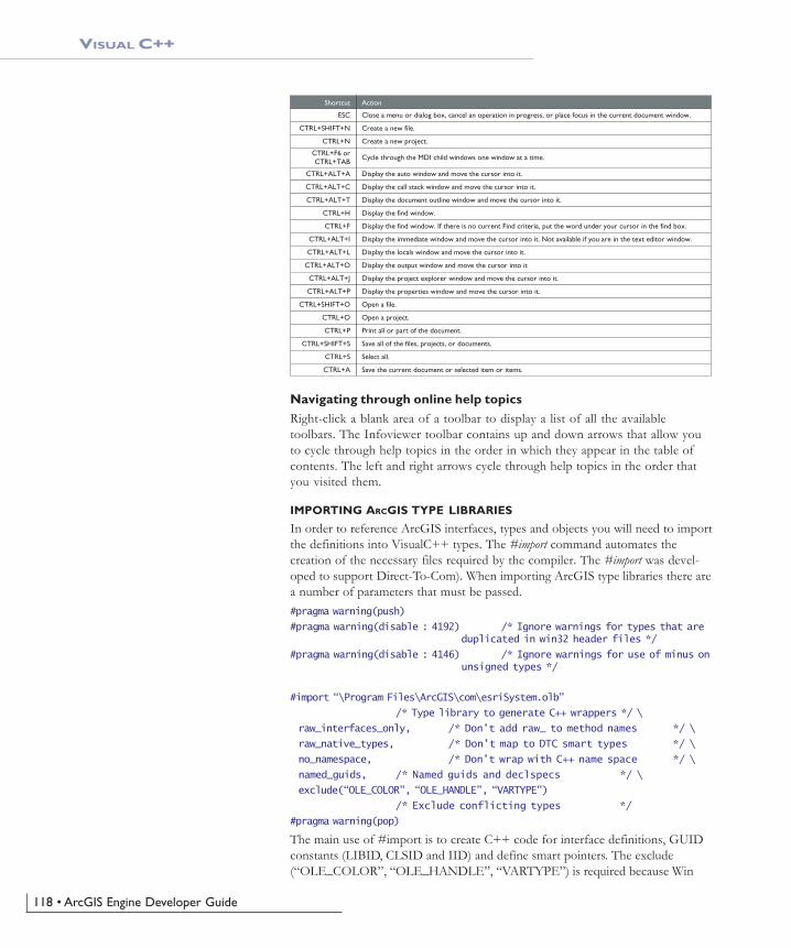
118 • ArcGIS Engine Developer Guide
VISUAL C++
Close a menu or dialog box, cancel an operation in progress, or place focus in the current document window.
Action
Create a new file.
Create a new project.
Cycle through the MDI child windows one window at a time.
Display the auto window and move the cursor into it.
Display the call stack window and move the cursor into it.
Display the document outline window and move the cursor into it.
Display the find window.
Display the find window. If there is no current Find criteria, put the word under your cursor in the find box.
Display the immediate window and move the cursor into it. Not available if you are in the text editor window.
Display the locals window and move the cursor into it.
Display the output window and move the cursor into it
Display the project explorer window and move the cursor into it.
Display the properties window and move the cursor into it.
Open a file.
Open a project.
Print all or part of the document.
Save all of the files, projects, or documents.
Select all.
Save the current document or selected item or items.
ESC
Shortcut
CTRL+SHIFT+N
CTRL+N
CTRL+F6 orCTRL+TAB
CTRL+ALT+A
CTRL+ALT+C
CTRL+ALT+T
CTRL+H
CTRL+F
CTRL+ALT+I
CTRL+ALT+L
CTRL+ALT+O
CTRL+ALT+J
CTRL+ALT+P
CTRL+SHIFT+O
CTRL+O
CTRL+P
CTRL+SHIFT+S
CTRL+S
CTRL+A
Navigating through online help topicsRight-click a blank area of a toolbar to display a list of all the availabletoolbars. The Infoviewer toolbar contains up and down arrows that allow youto cycle through help topics in the order in which they appear in the table ofcontents. The left and right arrows cycle through help topics in the order thatyou visited them.
IMPORTING ARCGIS TYPE LIBRARIES
In order to reference ArcGIS interfaces, types and objects you will need to importthe definitions into VisualC++ types. The #import command automates thecreation of the necessary files required by the compiler. The #import was devel-oped to support Direct-To-Com). When importing ArcGIS type libraries there area number of parameters that must be passed.#pragma warning(push)
#pragma warning(disable : 4192) /* Ignore warnings for types that are duplicated in win32 header files */
#pragma warning(disable : 4146) /* Ignore warnings for use of minus on unsigned types */
#import “\Program Files\ArcGIS\com\esriSystem.olb”
/* Type library to generate C++ wrappers */ \
raw_interfaces_only, /* Don’t add raw_ to method names */ \
raw_native_types, /* Don’t map to DTC smart types */ \
no_namespace, /* Don’t wrap with C++ name space */ \
named_guids, /* Named guids and declspecs */ \
exclude(“OLE_COLOR”, “OLE_HANDLE”, “VARTYPE”)
/* Exclude conflicting types */
#pragma warning(pop)
The main use of #import is to create C++ code for interface definitions, GUIDconstants (LIBID, CLSID and IID) and define smart pointers. The exclude(“OLE_COLOR”, “OLE_HANDLE”, “VARTYPE”) is required because Win
Ch04_EngineAPIs.pmd 4/2/2004, 9:04 AM118

Chapter 4 • Developer environments • 119
VISUAL C++
dows defines these to be unsigned longs, which conflicts with the ArcGIS defini-tion of long—this was required to support Visual Basic as a client of ArcObjects,since Visual Basic has no support for unsigned types. There are no issues withexcluding these.
You can view the code generated by #import in the “.tlh” files (type libraryheader file - similar format to a .h). You may also find a “.tli” file (type libraryimplementation - corresponds to .cpp). These files can be large but are onlyregenerated when the type libraries change.
As there are many type libraries at ArcGIS 9 for different functional areas you canstart by just importing those that contain the definitions that you require. How-ever #import does not automatically include all other definitions that the im-ported type library requires. For example when importing the type libraryesriGeometry it will contain references to types that are defined in esriSystem, soesriSystem must be imported before esriGeometry.
A complete list of library dependencies can be found in the Overview topic foreach library.
Choosing the minimum set of type libraries helps reduce compilation time, al-though this is not always significant. Here are some steps to help determine theminimum number type libraries required:
1. Do a compilation and look at the “missing type definition” errors generatedfrom code, e.g. “ICommand not found”.
2. Place a #import statement for the library you need a reference for into yourstdafx.h file. Use the LibraryLocator utility or component help to assist in thistask.
3. Compile the project a second time.
4. The compiler will issue errors for types it cannot resolve in the imported typelibraries, these are typically type definitions like WKSPoint or interfaces thatare inherited into other interfaces. For example if working with geometryobjects like points, start by importing esriGeometry, the compiler will issuevarious errors like :c:\temp\sample\debug\esrigeometry.tlh(869) : error C2061: syntax error :identifier ‘WKSPoint’Looking up the definition of WKSPoint you see it is defined in esriSystem.Therefore importing esriSystem before esriGeometry will resolve all theseissues.
Below is a typical list of imports for working with the ActiveX controls.#pragma warning(push)
#pragma warning(disable : 4192) /* Ignore warnings for types that areduplicated in win32 header files */
#pragma warning(disable : 4146) /* Ignore warnings for use of minus onunsigned types */
#import “\Program Files\ArcGIS\com\esriSystem.olb” raw_interfaces_only,raw_native_types, no_namespace, named_guids, exclude(“OLE_COLOR”,“OLE_HANDLE”, “VARTYPE”)
#import “\Program Files\ArcGIS\com\esriSystemUI.olb” raw_interfaces_only,raw_native_types, no_namespace, named_guids
Ch04_EngineAPIs.pmd 4/2/2004, 9:04 AM119

120 • ArcGIS Engine Developer Guide
VISUAL C++
#import “\Program Files\ArcGIS\com\esriGeometry.olb” raw_interfaces_only,raw_native_types, no_namespace, named_guids
#import “\Program Files\ArcGIS\com\esriDisplay.olb” raw_interfaces_only,raw_native_types, no_namespace, named_guids
#import “\Program Files\ArcGIS\com\esriOutput.olb” raw_interfaces_only,raw_native_types, no_namespace, named_guids
#import “\Program Files\ArcGIS\com\esriGeoDatabase.olb”raw_interfaces_only, raw_native_types, no_namespace, named_guids
#import “\Program Files\ArcGIS\com\esriCarto.olb” raw_interfaces_only,raw_native_types, no_namespace, named_guids
// Some of the Engine controls
#import “\Program Files\ArcGIS\bin\TOCControl.ocx” raw_interfaces_only,raw_native_types, no_namespace, named_guids
#import “\Program Files\ArcGIS\bin\ToolbarControl.ocx”raw_interfaces_only, raw_native_types, no_namespace, named_guids
#import “\Program Files\ArcGIS\bin\MapControl.ocx” raw_interfaces_only,raw_native_types, no_namespace, named_guids
#import “\Program Files\ArcGIS\bin\PageLayoutControl.ocx”raw_interfaces_only, raw_native_types, no_namespace, named_guids
// additionally for 3D controls#import “\Program Files\ArcGIS\com\esri3DAnalyst.olb” raw_interfaces_only,raw_native_types, no_namespace, named_guids#import “\Program Files\ArcGIS\com\esriGlobeCore.olb” raw_interfaces_only,raw_native_types, no_namespace, named_guids#import “\Program Files\ArcGIS\bin\SceneControl.ocx” raw_interfaces_only,raw_native_types, no_namespace, named_guids#import “\Program Files\ArcGIS\bin\GlobeControl.ocx” raw_interfaces_only,raw_native_types, no_namespace, named_guids
A similar issue arises when writing IDL that contains definitions from other typelibraries. In this situation use importlib just after the library definition. For ex-ample writing an external command for ArcMap would require you to create aCOM object implementing ICommand. This definition is in esriSystemUI and isimported into the IDL as follows: library WALKTHROUGH1CPPLib
{
importlib(“stdole32.tlb”);
importlib(“stdole2.tlb”);
importlib(“\Program Files\ArcGIS\com\esriSystemUI.olb”);
coclass ZoomIn
{
[default] interface IUnknown;
interface ICommand;
}
};
ATL AND THE ACTIVEX CONTROLS
This section covers how to use ATL to add controls to a dialog. Although ATL isfocused on providing COM support it also supplies some useful windows pro-gramming wrapper classes. One of the most useful is CWindow, this is a wrapper
For a general discussion of ATL, see the earliersection ‘ATL in Brief ’.
Ch04_EngineAPIs.pmd 4/2/2004, 9:04 AM120

Chapter 4 • Developer environments • 121
VISUAL C++
around a window handle (HWND). The method names on CWindow correspondto the win32 api functions. For example:HWND buttonHWnd = GetDlgItem( IDC_BUTTON1 ); // Get window handle of
button
CWindow myButtonWindow( buttonHWnd ); // Attach window handle to CWindow class
myButtonWindow.SetWindowText(_T(“Button Title”)); // Win32 function to change button caption
CWindow is a generic wrapper for all window handles, so for specific windowsmessages to window common controls, like buttons, tree views or edit boxes, oneapproach is to send window messages direct to the window, for example:// Set button to be checked (pushed-in or ticked, depending on button style)
myButtonWindow.SendMessage(BM_SETCHECK, BST_CHECKED);
However there are some wrapper classes for these standard window commoncontrols in a header file atlcontrols.h. This is available as part of an ATL sampleATLCON supplied in MSDN. See the following article “HOWTO: Using ClassWrappers to Access Windows Common Controls in ATL”. This header file is an earlyversion of WTL (Windows Template Libraries), available for download fromMicrosoft.
Visual Studio Resource editor can be used to design and position windows com-mon controls and ActiveX® controls on a dialog. To create and manipulate thedialog a C++ class is typically created that inherits from CAxDialogImpl. Thisclass provides the plumbing to create and manage the ActiveX control on awindow. The ATL wizard can be used to supply the majority of the boiler platecode. The steps to create a dialog and add an ActiveX control in an ATL projectare discussed below.
1. Select the menu option “Insert / New ATL Object”.
2. Select the “Miscellaneous” category and then select the “Dialog” object.
3. A dialog resource and a class inheriting from CAxDialogImpl will be added toyour project.
4. Right click on the dialog in resource view and select “Insert ActiveX Control”,this will display a list of available ActiveX control.
5. Double click on a control in the list to add the control to the dialog.
Ch04_EngineAPIs.pmd 4/2/2004, 9:04 AM121

122 • ArcGIS Engine Developer Guide
VISUAL C++
6. Right click on the control and select “Properties” to set the controls designtime properties.
Accessing a control on a dialog through a COM interfaceTo retrieve a handle to the control that is hosted on a form, use GetDlgControlATL method that is inherited from CAxDialogImpl to take a resource ID andreturn the underlying control pointer:ITOCControlPtr ipTOCControl;
GetDlgControl(IDC_TOCCONTROL1, IID_ITOCControl, (void**) &ipTOCControl);
ipTOCControl->AboutBox();
Listening to events from a controlThe simplest way to add events is use the class wizard. Simply right-click on thecontrol and select “Events...”. Next select the resource ID of the control andthen select the event (e.g. OnMouseDown). Now click “Add Handler”. Finallyensure the dialog begins listening to events by addingAtlAdviseSinkMap(this,TRUE) to the OnInitDialog. To finish listening to eventsadd a message handler for OnDestroy and add a call to AtlAdviseSinkMap(this,FALSE).
Creating a control at run timeThe CAxWindow class provides a mechanism to create and host ActiveX controlsin a similar manner to any other window class. This may be desirable if the parentwindow of the control is also created at runtime.AtlAxWinInit();
CAxWindow wnd;
//m_hWnd is the parent window handle
//rect is the size of ActiveX control in client coordinates
//IDC_MYCTL is a unique id to identify the controls window
RECT rect = {10,10,400,300};
wnd.Create(m_hWnd, rect, _T(“esriReaderControl.ReaderControl”),WS_CHILD|WS_VISIBLE, 0, IDC_MYCTL);
Make sure dialogs that host ActiveX controlsinherit from CAxDialogImpl and not
CDialogImpl. If this mistake is made theDoModal method of the dialog simply exits with
no obvious cause.
Make sure applications that use windowscommon controls, like treeview, correctly call
InitCommonControlsEx to load the windowclass, otherwise the class will not function
correctly.
Make sure applications using COM objects callCoInitialize. This initialises COM in the applica-
tion, without this call any CoCreate calls will fail.
For a detailed discussion on handling events inATL, see the section ‘Handling COM events in
ATL’.
Ch04_EngineAPIs.pmd 4/2/2004, 9:04 AM122

Chapter 4 • Developer environments • 123
VISUAL C++
Setting the buddy control propertyThe ToolbarControl and TOCControl need to be associated with a “buddy”control on the dialog. This is typically performed in the OnInitDialog windowsmessage handler of a dialog.LRESULT CEngineControlsDlg::OnInitDialog(UINT uMsg, WPARAM wParam, LPARAMlParam, BOOL& bHandled)
{
// Get the Control’s interfaces into class member variables
GetDlgControl(IDC_TOOLBARCONTROL, IID_IToolbarControl, (void **)&m_ipToolbarControl);
GetDlgControl(IDC_TOCCONTROL, IID_ITOCControl, (void **) &m_ipTOCControl);
GetDlgControl(IDC_PAGELAYOUTCONTROL, IID_IPageLayoutControl, (void **)&m_ipPageLayoutControl);
// Connect to the controls
AtlAdviseSinkMap(this, TRUE);
// Set buddy controls
m_ipTOCControl->SetBuddyControl(m_ipPageLayoutControl);
m_ipToolbarControl->SetBuddyControl(m_ipPageLayoutControl);
return TRUE;
}
Known limitations of Visual Studio C++ Resource Editor and ArcGIS
ActiveX controls
Buddy property on property page is disabledIn Visual Studio C++ you cannot set the “Buddy” property of the TOCControland the ToolbarControl through the “General” property page. Visual C++ doesnot support controls finding other controls at design time. However this step canbe performed in code in OnInitDialog method.
ToolbarControl does not resize to the height of one buttonIn other environments (Visual Basic 6, .Net) the ToolbarControl will automati-cally resize to be one button high. However in Visual Studio C++ 6 it can be anysize. In MFC and ATL the ActiveX® host classes do not allow controls to deter-mine their own size.
Design time property pages disappear when display context sensitive helpWhen viewing the controls property page at design time, using right click andselecting “whats’ This?” will result in the help tip to display, however the prop-erty pages will then close. This is a limitation of the Visual Studio floating win-dows combined with the floating tip window from HTML help. Clicking the“Help” button provides the same text for the whole property page.
MFC AND THE ACTIVEX CONTROLS
There are many choices in how to work with ArcGIS ActiveX Controls in VC++,firstly which framework is used to host the controls (for example ATL or
Ch04_EngineAPIs.pmd 4/2/2004, 9:04 AM123

124 • ArcGIS Engine Developer Guide
VISUAL C++
MFC), secondly what the control will be hosted on (Dialog, MDI app etc). Thissection discusses MFC and hosting the control on a dialog.
Creating an MFC dialog-based applicationIf you do not have a dialog in your application or component here are the stepsto create an MFC dialog application.
1. Launch Visual Studio C++ 6 and select “New”
2. Select Projects Tab and select “MFC AppWizard (exe)” Enter Project nameand location for project, click OK
3. For wizard step 1 - From the radio buttons change the application type to“Dialog Based”, Click Next For wizard step 2 - The default project featuresare fine, although you can uncheck AboutBox to simplify the application.Ensure support for “ActiveX Controls” is checked.
4. Click Next For wizard step 3 - The default settings in this page are fine, theMFC dll is shared, click Next.
5. For wizard step 4 - This shows you what the wizard will generate, click “Fin-ish”
You should now have a simple dialog based application - in the resource view youwill see “TODO: Place Dialog Controls Here”. You can place buttons, list boxesetc in this dialog, also the dialog can host an ActiveX controls, there are twoapproaches to doing this as discussed below. You can also compile and run thisapplication.
Hosting controls on an MFC dialog and access using with usingIDispatch1. Right click on the MFC dialog and select “Insert ActiveX control”
2. Double click on a control from the list box and the con-trol appears on the dialog with a default size.
3. Size and position the control as required.
4. Repeat steps 1 to 3 for each control.
5. You can right click on the control and select “Properties”to set the controls design time properties.
6. To access the control in code, you will need ArcGISinterface definitions for IMapControl etc. To do this usethe #import in you stdafx.h file. See section ImportingArcGIS type libraries on how to do this.
7. MFC provides control hosting on a dialog, this will trans-late windows messages like WM_SIZE into appropriatecontrol method calls. However to be able to make callson a control there are a few steps to go from a resourceID to a controls interface. The following code illustratessetting the TOCControl’s Buddy to be the MapControl:
Inserting ActiveX controls on a dialog in VisualStudio C++ Design time. The TOCControl,
MapControl have been added to the dialog, theToolbarControl is next.
Ch04_EngineAPIs.pmd 4/2/2004, 9:04 AM124

Chapter 4 • Developer environments • 125
VISUAL C++
// Code to set the Buddy property of the TOCControl to be the MapControl
//
// Get a pointer to the PageLayoutControl and TOCControl
IPageLayoutControlPtr ipPageLayoutControl;
GetDlgControl(IDC_PAGELAYOUTCONTROL1, IID_IPageLayoutControl, (void**)&ipPageLayoutControl);
ITOCControlPtr ipTOCControl;
GetDlgControl(IDC_TOCCONTROL1, IID_ITOCControl, (void**) &ipTOCControl);
// Get the IDispatch of the PageLayoutControl
IDispatchPtr ipBuddyDisp = ipPageLayoutControl;
// Set the TOCControls Buddy to the map control
ipTOCControl->putref_Buddy(ipBuddyDisp);
8. To catch events from the controls, simply double click on the control on theform and supply the name of a method to be called. By default the wizard willadd an extra word “On” to the beginning of the event handler. Remove thisto avoid the event handler name becoming “OnOnMouseDownMapcontrol1”.The wizard will then automatically generate the necessary MFC sink mapmacros to listen to events.
Adding controls to an MFC dialog using IDispatch wrappersAs all ActiveX controls support IDispatch, this is the typical approach to add anActiveX control to an MFC project:
1. Select Project / Add / Components and Controls
2. Select “Registered ActiveX Controls”
3. Double click to select control(e.g. ESRI TOCControl),then click “OK” to “Insert Component?” then click“OK” to generate wrappers. This will add an icon for thecontrol to the “Controls” toolbar in Visual Studio
4. Additional source files are added to your project (e.g.toccontrol.cpp and toccontol.h). These files contain awrapper class (e.g. CTOCControl) to provide methodsand properties to access the control. This class willinvoke the control through the IDispatch calling mecha-nism. Note that IDispatch does incur some performanceoverhead to package parameters when making methodand property calls. The wrapper class inherits from aMFC CWnd class that hosts an ActiveX control.
5. Repeat steps 1 to 4 to add each control to the projects“Controls” toolbar.
6. Select a control from the “Controls” toolbar and drag itonto the dialog.
7. You can right click on the control, select properties and this will allow designtime properties to be set on the control. Note. in Visual Studio C++ youcannot set the “Buddy” property of the TOCControl and the ToolbarControl.
Addin Control wrappers in Visual Studio C++Design time. The TOCControl, MapControl andToolbarControl have been added to the “Con-
trols” toolbar and to the dialog.
Ch04_EngineAPIs.pmd 4/2/2004, 9:04 AM125

126 • ArcGIS Engine Developer Guide
VISUAL C++
This environment does not support controls finding other controls at designtime. However this step can be performed in code in on OnInitDialogmethod.// Note no addref performed with GetControlUnknown, so no need to release
this pointer
LPUNKNOWN pUnk = m_mapcontrol.GetControlUnknown();
LPDISPATCH pDisp =
0;pUnk->QueryInterface(IID_IDispatch, (void **) &pDisp);
// Set TOCControls buddy to be MapControl
m_toccontrol.SetRefBuddy(pDisp);
pDisp->Release();
8. Right click on the control and select “Class Wizard” to launch the class wiz-ard. Select “Member Variables tab and click on the resource ID correspondingto the control to give the control member variable name. The dialog classmember variable can now used to invoke methods and properties on thecontrol.
9. To catch control events, select the “Message Maps” tab of the class wizard andselect the resource ID of the control. In the list of messages select the eventto catch e.g. OnBeginLabelEdit. Double click on this event and a handler forthis event will be added to your dialog class. By default the wizard will add anextra word “On” to the beginning of the event handler. Remove this to avoidthe event handler name becoming “OnOnBeginLabelEditToccontrol1”.
HANDLING COM EVENTS IN ATL
Here is a summary of terminology used here when discussing COM events inVisual C++ and ATL.
Inbound interface—This is the normal case where a COM object implements apredefined interface.
Do not use the method GetIDispatch (inher-ited from MFC’s CCmdTarget) on the wrapper
classes, it is intended for objects which areimplementing IDispatch and not the wrapper
classes that are calling IDispatch. Instead to geta controls IDispatch use
m_mapcontrol.GetControlUnknown() and thenQueryInterface to IDispatch (see the above
example of setting the Buddy property).
Visual Studio C++ Class Wizard. Adding membervariables to the dialog for the ActiveX Controls.
Ch04_EngineAPIs.pmd 4/2/2004, 9:04 AM126

Chapter 4 • Developer environments • 127
VISUAL C++
Outbound interface—This is an interface of methods which a COM objectwill fire at various times. For example the Map CoClass will fire an event on theIActiveViewEvents in response to changes in the map.
Event source—The source COM object will fire events to an outbound interfacewhen certain actions occur. For example the Map CoClass is a source ofIActiveViewEvents and will fire the IActiveViewEvents::ItemAdded event whena new layer is added to the map. The source object can have any number ofclients (or event sink objects) listening to events. Also a source object may havemore than one outbound interface, for example the MapCoClass also fires eventson an IMapEvents interface. An event source will typically declare its outboundinterfaces in idl with the [source] tag.
Event sink—A COM object that listens to events is said to be a sink for events.The sink object implements the outbound interface, this is not always advertisedin the type libraries as the sink may listen to events internally. An event sinktypically uses the connection point mechanism to register its interest in the events ofa source object.
Connection point—COM objects which are the source of events typically usethe connection point mechanism to allow sinks to hook up to a source. Theconnection point interfaces are standard COM interfaces IConnectionPointContainerand IConnectionPoint.
Fire event—When a source object needs to inform all the sinks of a particularaction, the source is said to fire an event. This results in the source iterating allthe sinks and making the same method call on each. For example when a layer isadded to a map, The Map CoClass is said to fire the ItemAdded event. So all theobjects listening to the Map’s outbound IActiveViewEvents interface will be calledon their implementation of the ItemAdded method.
Advise and unadvise events—To begin receiving events a sink object is said toadvise a source object that it needs to receive events. When events are no longerrequired the sink will unadvise the source.
The ConnectionPoint mechanismThe source object implements IConnectionPointContainer interface allowing sinks toquery a source for a specific outbound interface. The following steps are per-formed to begin listening to an event. ATL implements this with the AtlAdvisemethod.
1. The sink will QIs to the source object’s IConnectionPointContainer and callFindConnectionPoint suppling an interface ID for an outbound interface. To beable to receive events the sink object must implement this interface.
2. The source may implement many outbound interfaces and will return a pointerto a specific connection point object implementing IConnectionPoint represent-ing one outbound interface.
3. The sink calls IConnectionPoint::Advise passing a pointer to its own IUnknownimplementation. The source will store this with any other sinks that may belistening to events. If the call to Advise was successful then the sink will begiven an identifier (a simple unsigned long - called a cookie) to give back tothe source at a later point when it no longer needs to listen to events.
Ch04_EngineAPIs.pmd 4/2/2004, 9:04 AM127

128 • ArcGIS Engine Developer Guide
VISUAL C++
The connection is now complete, methodswill be called on any listening sinks by thesource. The sink will typically hold ontoan interface pointer to the source, so whena sink has finished listening it can bereleased from the source object by callingIConnectionPoint::Unadvise. This isimplemented with AtlUnadvise.
IDispatch events versus pure COM eventsAn outbound interface can be a pure dispatch interface. This means instead ofthe source calling directly onto a method in a sink, the call is made via theIDispatch::Invoke mechanism. The IDispatch mechanism has a performanceoverhead to package parameters compared to a pure vtable COM call. Howeverthere are some situations where this must be used. ActiveX controls must imple-ment their default outbound interface as a pure IDispatch interface, for exampleIMapControlEvents2 is a pure dispatch interface. Secondly Microsoft VisualBasic
6 can only be a source of pure IDispatch events. The connectionpoint mechanism is the same as for pure COM mechanism, themain difference being in how the events are fired.
ATL provides some macros to assist with listening to IDispatchevents, this is discussed in MSDN under “Event Handling andATL”. There are two templates available IDispEventImpl andIDispEventSimpleImpl which are discussed in the followingsections.
Using IDispEventImpl to listen to eventsThe ATL template IDispEventImpl will use a type library to“crack” the IDispatch calls and process the arguments into C++method calls. The Visual Studio class wizard can provide thismechanism automatically when adding an ActiveX controls to adialog. Simply right click on the Control and select “Events”. Inthe class wizard select the resource ID of the control and thenchoose the event, then select “Add Handler”.
The code below illustrates the event handling code added by the wizard, withsome modifications to ensure advise and unadvise are performed.#pragma once
#include “resource.h” // main symbols
#include <atlhost.h>
////////////////////////////////////////////////////////////////////////////
// CMyDialog
class CMyDialog :
public CAxDialogImpl<CMyDialog>,
public IDispEventImpl<IDC_MAPCONTROL1, CMyDialog>
{
Connection point mechanism for hooking Sourceto Sink objects
There is a bug in the wizard as it does not addthe advise and unadvise code to the dialog. To fixthis issue add a message handler for OnDestroy.
Then in the OnInitDialog handler callAtlAdviseSinkMap with a TRUE second param-
eter to begin listening to events. Place acorresponding call to AtlAdviseSinkMap (with
FALSE as the Second parameter) in theOnDestroy handler. This is discussed further in
MSDN article “BUG: ActiveX Control EventsAre Not Fired in ATL Dialog (Q190530)”.
Visual Studio C++ Class Wizard. Adding eventhandler to an ActiveX control on a dialog.
Ch04_EngineAPIs.pmd 4/2/2004, 9:04 AM128

Chapter 4 • Developer environments • 129
VISUAL C++
public
enum { IDD = IDD_MYDIALOG };
BEGIN_MSG_MAP(CMyDialog)
MESSAGE_HANDLER(WM_INITDIALOG, OnInitDialog)
// Add a handler to ensure event unadvise occurs
MESSAGE_HANDLER(WM_DESTROY, OnDestroy)
COMMAND_ID_HANDLER(IDOK, OnOK)
COMMAND_ID_HANDLER(IDCANCEL, OnCancel)
END_MSG_MAP()
LRESULT OnInitDialog(UINT uMsg, WPARAM wParam, LPARAM lParam, BOOL&bHandled)
{
// Calls IConnectionPoint::Advise() for each control on the dialog boxwith sink map entry.
AtlAdviseSinkMap(this, TRUE);
return 1; // Let the system set the focus
}
LRESULT OnDestroy(UINT uMsg, WPARAM wParam, LPARAM lParam, BOOL& bHandled)
{
// Calls IConnectionPoint::Unadvise() for each control on the dialog boxwith sink map entry.
AtlAdviseSinkMap(this, FALSE);
return 0;
}
LRESULT OnOK(WORD wNotifyCode, WORD wID, HWND hWndCtl, BOOL& bHandled)
{
EndDialog(wID);
return 0;
}
LRESULT OnCancel(WORD wNotifyCode, WORD wID, HWND hWndCtl, BOOL& bHandled)
{
EndDialog(wID);
return 0;
}
// ATL callback from SinkMap entry
VOID __stdcall OnMouseDownMapcontrol1(LONG button, LONG shift, LONG x,LONG y, DOUBLE mapX, DOUBLE mapY)
{
MessageBox(_T(“MouseDown!”));
}
BEGIN_SINK_MAP(CMyDialog)
//Make sure the Event Handlers have __stdcall calling convention
Ch04_EngineAPIs.pmd 4/2/2004, 9:04 AM129

130 • ArcGIS Engine Developer Guide
VISUAL C++
// The 0x1 is the Dispatch ID of the OnMouseDown method
SINK_ENTRY(IDC_MAPCONTROL1, 0x1, OnMouseDownMapcontrol1)
END_SINK_MAP()
};
Using IDispEventSimpleImpl to listen to eventsAs the name of this template suggests it is a simpler version of IDispEventImpl.The type library is no longer used to turn the IDispatch arguments into a C++method call. While this may be a simpler implementation, it does now require thedeveloper to supply a pointer to a structure describing the format of the eventparameters. This structure is typically placed in the .cpp, for example here is thestructure describing the parameters of a OnMouseDown event for theMapControl:_ATL_FUNC_INFO g_ParamInfo_MapControl_OnMouseDown =
{
CC_STDCALL, // Calling convention.
VT_EMPTY, // Return type.
6, // Number of arguments.
{VT_I4, VT_I4, VT_I4, VT_I4, VT_R8, VT_R8} // VariantArgument types.
};
The header file now inherits from IDispEventSimpleImpl and uses a differentmacro SINK_ENTRY_INFO in the SINK_MAP. Also the events interface ID isrequired, #import can be used to define this symbol. Note that a dispatch inter-face is normally prefixed with DIID instead of IID.#pragma once
#include “resource.h” // main symbols
#include <atlhost.h>
// reference to structure defining event parameters
extern _ATL_FUNC_INFO g_ParamInfo_MapControl_OnMouseDown;
////////////////////////////////////////////////////////////////////////////
// CMyDialog2
class CMyDialog2 :
public CAxDialogImpl<CMyDialog2>,
public IDispEventSimpleImpl<IDC_MAPCONTROL1, CMyDialog2,&DIID_IMapControlEvents2>
{
public:
// Message handler code removed, it is the same as CMyDialog usingIDispEventSimple
BEGIN_SINK_MAP(CMyDialog2)
// Make sure the Event Handlers have __stdcall calling convention
// The 0x1 is the Dispatch ID of the OnMouseDown method
SINK_ENTRY_INFO(IDC_MAPCONTROL1, // ID of event source
DIID_IMapControlEvents2, // interface to listen to
0x1, // dispatch ID of MouseDown
The following issues with events are documentedin MSDN Knowledge Base when using
IDispEventImpl. Fixes to ATL code are shown inMSDN for these issues, however it is not always
desirable to modify or copy ATL header files. Inthis case the IDispEventSimpleImpl can be used
instead.BUG: Events Fail in ATL Containers when
Enum Used as Event Parameter (Q237771)BUG: IDispEventImpl Event Handlers May
Give Strange Values for Parameters(Q241810)
See the ‘Importing ArcGIS type libraries’ sectionfor more explanation of #import.
Ch04_EngineAPIs.pmd 4/2/2004, 9:04 AM130

Chapter 4 • Developer environments • 131
VISUAL C++
OnMapControlMouseDown, // method to call when event arrives
&g_ParamInfo_MapControl_OnMouseDown) // parameter info for method call
END_SINK_MAP()
};
Listening to more than one IDispatch event interface on a COMobjectIf a single COM object needs to receive events from more than one IDispatchsource, then this can cause compiler issues with ambiguous definitions of theDispEventAdvise method. This is not normally a problem in a dialog asAtlAdviseSinkMap will handle all the connections. The ambiguity can be avoidedby introducing different typedefs each time IDispEventSimpleImpl is inherited.The following example illustrates a COM object called CListen which is a sink fordispatch events from a MapControl and a PageLayoutControl.#pragma once
#include “resource.h” // main symbols
// This is the parameter information
extern _ATL_FUNC_INFO g_ParamInfo_MapControl_OnMouseDown;
extern _ATL_FUNC_INFO g_ParamInfo_PageLayoutControl_OnMouseDown;
//
// Define some typedefs of the dispatch template
//
class CListen; // forward definition
typedef IDispEventSimpleImpl<0, CListen, &DIID_IMapControlEvents2>
IDispEventSimpleImpl_MapControl;
typedef IDispEventSimpleImpl<1, CListen, &DIID_IPageLayoutControlEvents>
IDispEventSimpleImpl_PageLayoutControl;
////////////////////////////////////////////////////////////////////////////
// CListen
class ATL_NO_VTABLE CListen :
public CComObjectRootEx<CComSingleThreadModel>,
public CComCoClass<CListen,&CLSID_Listen>,
public IDispEventSimpleImpl_MapControl,
public IDispEventSimpleImpl_PageLayoutControl,
public IListen
{
public:
CListen()
{
}
DECLARE_REGISTRY_RESOURCEID(IDR_LISTEN)
Ch04_EngineAPIs.pmd 4/2/2004, 9:04 AM131

132 • ArcGIS Engine Developer Guide
VISUAL C++
DECLARE_PROTECT_FINAL_CONSTRUCT()
BEGIN_COM_MAP(CListen)
COM_INTERFACE_ENTRY(IListen)
END_COM_MAP()
// Associated source and dispatchID to a method call
BEGIN_SINK_MAP(CListen)
SINK_ENTRY_INFO(0, // ID of event source
DIID_IMapControlEvents2, // interface to listen to
0x1, // dispatch ID to receive
OnMapControlMouseDown, // method to call when event arrives &g_ParamInfo_MapControl_OnMouseDown) // parameter info for
method call
SINK_ENTRY_INFO(1,
DIID_IPageLayoutControlEvents,
0x1,
OnPageLayoutControlMouseDown,
&g_ParamInfo_PageLayoutControl_OnMouseDown)
END_SINK_MAP()
// IListen
public:
STDMETHOD(SetControls)(IUnknown* pMapControl, IUnknown*pPageLayoutControl);
STDMETHOD(Clear)();
private:
void __stdcall OnMapControlMouseDown(long button, long shift, long x, longy, double mapX, double mapY);
void __stdcall OnPageLayoutControlMouseDown(long button, long shift, longx, long y, double pageX, double pageY);
IUnknownPtr m_ipUnkMapControl;
IUnknownPtr m_ipUnkPageLayoutControl;
};
The implementaion of CListen contains the following code to start listening tothe controls, the typdef avoids the ambiguity of the DispEventAdvise implemen-tation. // Start listening to the MapControl
IUnknownPtr ipUnk = pMapControl;
HRESULT hr = IDispEventSimpleImpl_MapControl::DispEventAdvise(ipUnk);
if (SUCCEEDED(hr))
m_ipUnkMapControl = ipUnk; // Store pointer to MapControl for Unadvise
// Start listening to the PageLayoutControl
ipUnk = pPageLayoutControl;
hr = IDispEventSimpleImpl_PageLayoutControl::DispEventAdvise(ipUnk);
if (SUCCEEDED(hr))
m_ipUnkPageLayoutControl = ipUnk; // Store pointer to PageLayoutControl for Unadvise
Ch04_EngineAPIs.pmd 4/2/2004, 9:04 AM132

Chapter 4 • Developer environments • 133
VISUAL C++
The implementation of CListen also contains the following code to UnAdviseand stop listening to the controls. // Stop listening to the MapControl
if (m_ipUnkMapControl!=0)
IDispEventSimpleImpl_MapControl::DispEventUnadvise(m_ipUnkMapControl);
m_ipUnkMapControl = 0;
if (m_ipUnkPageLayoutControl!=0)
IDispEventSimpleImpl_PageLayoutControl::DispEventUnadvise(m_ipUnkPageLayoutControl);
m_ipUnkPageLayoutControl= 0;
Creating a COM events sourceIn order for an object to be a source of events it will need to provide an imple-mentation of IConnectionPointContainer and a mechanism to track which sinksare listening to which IConnectionPoint interfaces. ATL provides this throughthe IConnectionPointContainerImpl template. Additionally ATL provides a wizard togenerate code to fire IDispatch events for all members of a given dispatch eventsinterface. Below are the steps to modify an ATL COM CoClass to support aconnection point:
1. First make sure your ATL CoClass has been compiled at least once. This willallow the wizard to find an initial type library.
2. In Class View, Right click on the COM object and select “Implement Connec-tion Point...”
3. Either use a definition of events from the idl in the project, or select “AddType Lib” to browse to another definition.
4. Check the outbound interface to be implemented in the CoClass.
5. Clicking OK will modify ur ATL class and generate the proxy classes in aheader file (with a name ending in CP) for firing events.
Generating Event Firing Code
Ch04_EngineAPIs.pmd 4/2/2004, 9:04 AM133

134 • ArcGIS Engine Developer Guide
VISUAL C++
If the wizard fails to run then use the following example that illustrates aCoClass that is a source of ITOCControlEvents. ITOCControlEvents is a puredispatch interface.#pragma once
#include “resource.h” // main symbols
#include “TOCControlCP.h” // Include generated connection point classfor firing events
//////////////////////////////////////////////////////////////////////////
// CMyEventSource
class ATL_NO_VTABLE CMyEventSource :
public CComObjectRootEx<CComSingleThreadModel>,
public CComCoClass<CMyEventSource,&CLSID_MyEventSource>,
public IMyEventSource,
public CProxyITOCControlEvents< CMyEventSource >, // Generated ConnectionPoint class
public IConnectionPointContainerImpl< CMyEventSource > // Implementation of Connection point Container
{
public:
CMyEventSource()
{
}
DECLARE_REGISTRY_RESOURCEID(IDR_MYEVENTSOURCE)
DECLARE_PROTECT_FINAL_CONSTRUCT()
BEGIN_COM_MAP(CMyEventSource)
COM_INTERFACE_ENTRY(IMyEventSource)
COM_INTERFACE_ENTRY(IConnectionPointContainer) // Allow QI to thisinterface
END_COM_MAP()
// List of available connection points
BEGIN_CONNECTION_POINT_MAP(CMyEventSource)
CONNECTION_POINT_ENTRY(DIID_ITOCControlEvents)
END_CONNECTION_POINT_MAP()
};
The connection point class (TOCControlEventsCP.h in the above example)contains code to fire an event to all sink objects on a connection point.
There is one method on the class for each event beginning “Fire_...”. Eachmethod will build a parameter list of variants to pass as an argument to thedispatch Invoke method. Each sink is iterated, a pointer to the sink is stored in avector m_vec member variable inherited from IConnectionPointContainerImpl.
Ch04_EngineAPIs.pmd 4/2/2004, 9:04 AM134

Chapter 4 • Developer environments • 135
VISUAL C++
Note that m_vec can contain pointers to 0 and this must be checked for beforefiring the event.template <class T>
class CProxyITOCControlEvents : public IConnectionPointImpl<T,&DIID_ITOCControlEvents, CComDynamicUnkArray>
{
public:
VOID Fire_OnMouseDown(LONG button, LONG shift, LONG x, LONG y)
{
// Package each of the parameters into an IDispatch argument list
T* pT = static_cast<T*>(this);
int nConnectionIndex;
CComVariant* pvars = new CComVariant[4];
int nConnections = m_vec.GetSize();
// Iterate each sink object
for (nConnectionIndex = 0; nConnectionIndex < nConnections;nConnectionIndex++)
{
pT->Lock();
CComPtr<IUnknown> sp = m_vec.GetAt(nConnectionIndex);
pT->Unlock();
IDispatch* pDispatch = reinterpret_cast<IDispatch*>(sp.p);
// Note m_vec can contain 0 entries so it is important to check forthis
if (pDispatch != NULL)
{
// Build up the argument list
pvars[3] = button;
pvars[2] = shift;
pvars[1] = x;
pvars[0] = y;
DISPPARAMS disp = { pvars, NULL, 4, 0 };
// Fire the dispatch method, 0x1 is the DispatchId for MouseDown
pDispatch->Invoke(0x1, IID_NULL, LOCALE_USER_DEFAULT,DISPATCH_METHOD, &disp, NULL, NULL, NULL);
}
}
delete[] pvars; // clean up the parameter list
}
VOID Fire_OnMouseUp(LONG button, LONG shift, LONG x, LONG y)
{
// ... Other events
To fire an event from the source, simply call the Fire_OnMouseDown whenrequired.
A similar approach can be used for firing events to a pure COM (non IDispatch)interface. The wizard will not generate the connection point class so this must be
Ch04_EngineAPIs.pmd 4/2/2004, 9:04 AM135

136 • ArcGIS Engine Developer Guide
VISUAL C++
written by hand, the following example illustrates a class that will fire anITOCBuddyEvents::ActiveViewReplaced event, ITOCBuddyEvents is a pureCOM, non-IDispatch interface. The key difference is that there is no need topackage the parameters, a direct method call can be made.template < class T >
class CProxyTOCBuddyEvents : public IConnectionPointImpl< T,&IID_ITOCBuddyEvents, CComDynamicUnkArray >
{
// This class based on the ATL generated connection point class - but this is not an IDispatch based events
public:
void Fire_ActiveViewReplaced(IActiveView* pNewActiveView)
{
T* pT = static_cast< T* >(this);
int nConnectionIndex;
int nConnections = this->m_vec.GetSize();
for (nConnectionIndex = 0; nConnectionIndex < nConnections;nConnectionIndex++)
{
pT->Lock();
CComPtr< IUnknown > sp=this->m_vec.GetAt(nConnectionIndex);
pT->Unlock();
ITOCBuddyEvents* pTOCBuddyEvents = reinterpret_cast< ITOCBuddyEvents*>(sp.p);
if (pTOCBuddyEvents)
pTOCBuddyEvents->ActiveViewReplaced(pNewActiveView);
}
}
};
IDL declarations for an object that supports eventsWhen an object is exported to a type library the event interfaces are declared byusing the [source] tag against the interface name. For example an object that firesITOCBuddyEvents declares[source] interface ITOCBuddyEvents;
If the outbound interface is a dispatch events interface dispinterface is used insteadof interface . Additionally a CoClass can have a default outbound interface andthis is specified with the [default] tag. Default interfaces are identified by somedesign environments (e.g. VisualBasic 6). For example here is the declaration forthe default outbound events interface:[default, source] dispinterface IMyEvents2;
Event circular reference issuesAfter a sink has performed an Advise on the source there is typically a COMcircular reference. This occurs because the source has an interface pointer to asink in order to fire events, this keeps the sink alive. Similarly a sink object has apointer back to the source so it can perform the unadvise at a later point. This
Ch04_EngineAPIs.pmd 4/2/2004, 9:04 AM136

Chapter 4 • Developer environments • 137
VISUAL C++
keeps the source alive. Therefore these two objects will never be release and maycause substantial memory leaks. There are a number of ways to tackle this issue:
1. Ensure the advise and unadvise is made on a method or windows message thatare guaranteed to happen in pairs and are independent of an objects life cycle.For example in a CoClass that is also receiving windows messages usetheWindows messages OnCreate (WM_CREATE) and OnDestroy(WM_DESTROY) to advise and unadvise.
2. If a ATL dialog class needs to listen to events then one approach is to makethe dialog a private COM class and implement the events interface directly onthe dialog. ATL allows this without much extra coding. This approach isillustrated below. The dialog class creates a CustomizeDialog CoClass andlistens to ICustomizeDialogEvents. The OnInitDialog and OnDestroy meth-ods (corresponding to window messages) are used to Advise and Unadvise onthe CustomizeDialog.class CEngineControlsDlg :
public CAxDialogImpl<CEngineControlsDlg>,
public CComObjectRoot, // Make Dialog Class a COM Object aswell
public ICustomizeDialogEvents // Implement this interface directly on this object
CEngineControlsDlg() : m_dwCustDlgCookie(0) {} // initialise cookie for event listening
// ... Event handlers and other standard dialog code has been removed ...
BEGIN_COM_MAP(CEngineControlsDlg)
COM_INTERFACE_ENTRY(ICustomizeDialogEvents) // Make sure QI works for this event interface
END_COM_MAP()
// ICustomizeDialogEvents implementation to receive events on this dialog
STDMETHOD(OnStartDialog)();
STDMETHOD(OnCloseDialog)();
ICustomizeDialogPtr m_ipCustomizeDialog; // The source of events
DWORD m_dwCustDlgCookie; // Cookie for CustomizeDialogEvents
}
The dialog needs to be created like a noncreateble COM object rather than onthe stack as a local variable, this allocates the object on the heap and allows itto be released through the COM reference counting mechanism.// Create dialog class on the heap using ATL CComObject template
CComObject<CEngineControlsDlg> *myDlg;
CComObject<CEngineControlsDlg>::CreateInstance(&myDlg);
myDlg->AddRef(); // Keep dialog alive until we’re done with it
myDlg->DoModal(); // Launch the dialog, when method returns dialog has exited
myDlg->Release(); // typically the refcount now goes to 0 and frees the dialog object
Ch04_EngineAPIs.pmd 4/2/2004, 9:04 AM137

138 • ArcGIS Engine Developer Guide
VISUAL C++
3. Implement an intermediate COM object for use by the sink, this is sometimescalled a listener or event helper object. This object typically contains no imple-mentation but simply uses C++ method calls to forward on events to the sinkobject. The listener has its reference count incremented by the source, but thesinks reference count is unaffected. This breaks the cycle, allowing the sink’sreference count to reach 0, when all other references are released. As the sinkexecutes its destuctor code it instucts the listener to unadvise and release thesource.
An alternative to using C++ pointers to communicate between listener and sink,is to use an interface pointer which is a weak reference. That is the listener con-tains a COM pointer to the sink but does not increment the sinks reference count.It is the responsibility of the sink to ensure this pointer is not accessed after thesink object has been released.
Ch04_EngineAPIs.pmd 4/2/2004, 9:04 AM138

Chapter 4 • Developer environments • 139
.NET APPLICATION PROGRAMMING INTERFACE
WHAT IS THE .NET FRAMEWORK?
The .NET Framework is an integral Windows component that supports buildingand running the next generation of applications and XML Web services. The.NET Framework is designed to fulfill the following objectives:
• To provide a consistent object-oriented programming environment whetherobject code is stored and executed locally, executed locally but Internet-distributed, or executed remotely.
• To provide a code-execution environment that minimizes software deploy-ment and versioning conflicts.
• To provide a code-execution environment that guarantees safe execution ofcode, including code created by an unknown or semi-trusted third party.
• To provide a code-execution environment that eliminates the performanceproblems of scripted or interpreted environments.
• To make the developer experience consistent across widely varying types ofapplications, such as Windows-based applications and Web-based applications.
• To build all communication on industry standards to ensure that code based onthe .NET Framework can integrate with any other code.
The .NET Framework has two main components: the common language runtimeand the .NET Framework class library. The common language runtime is thefoundation of the .NET Framework. You can think of the runtime as an agentthat manages code at execution time, providing core services such as memorymanagement, thread management, and remoting, while also enforcing strict typesafety and other forms of code accuracy that ensure security and robustness. Infact, the concept of code management is a fundamental principle of the runtime.Code that targets the runtime is known as managed code, while code that doesnot target the runtime is known as unmanaged code. The class library, the othermain component of the .NET Framework, is a comprehensive, object-orientedcollection of reusable types that you can use to develop applications ranging fromtraditional command-line or graphical user interface (GUI) applications to appli-cations based on the latest innovations provided by ASP.NET, such as Web Formsand XML Web services.
The .NET Framework can be hosted by unmanaged components that load thecommon language runtime into their processes and initiate the execution ofmanaged code, thereby creating a software environment that can exploit bothmanaged and unmanaged features. The .NET Framework not only providesseveral runtime hosts, but also supports the development of third-party runtimehosts.
For example, ASP.NET hosts the runtime to provide a scalable, server-sideenvironment for managed code. ASP.NET works directly with the runtime toenable ASP.NET applications and XML Web services, both of which are dis-cussed later in this topic.
Internet Explorer is an example of an unmanaged application that hosts theruntime (in the form of a MIME type extension). Using Internet Explorer tohost the runtime enables you to embed managed components or Windows Formscontrols in HTML documents. Hosting the runtime in this way makes managed
This section, ‘What is the .NET Framework?’summarizes the Microsoft overview of the .NET
Framework available online as part of MSDNLibrary. The complete text is available at http://
www.msdn.microsoft.com/library/default.asp?url=/library/en-us/cpguide/html/
cpovrintroductiontonetframeworksdk.asp
Ch04_EngineAPIs.pmd 4/2/2004, 9:04 AM139

140 • ArcGIS Engine Developer Guide
.NET APPLICATION PROGRAMMING INTERFACE
mobile code (similar to Microsoft ActiveX controls) possible, but with significantimprovements that only managed code can offer, such as semi-trusted executionand secure isolated file storage.
The following sections describe the main components and features of the .NETFramework in greater detail.
Features of the Common Language RuntimeThe common language runtime manages memory, thread execution, code execu-tion, code safety verification, compilation, and other system services. Thesefeatures are intrinsic to the managed code that runs on the common languageruntime.
With regards to security, managed components are awarded varying degrees oftrust, depending on a number of factors that include their origin (such as theInternet, enterprise network, or local computer). This means that a managedcomponent might or might not be able to perform file-access operations, registry-access operations, or other sensitive functions, even if it is being used in the sameactive application.
The runtime enforces code access security. For example, users can trust that anexecutable embedded in a Web page can play an animation on screen or sing asong, but cannot access their personal data, file system, or network. The securityfeatures of the runtime thus enable legitimate Internet-deployed software to beexceptionally feature rich.
The runtime also enforces code robustness by implementing a strict type-and-code-verification infrastructure called the common type system (CTS). The CTSensures that all managed code is self-describing. The various Microsoft and third-party language compilers generate managed code that conforms to the CTS. Thismeans that managed code can consume other managed types and instances, whilestrictly enforcing type fidelity and type safety.
In addition, the managed environment of the runtime eliminates many commonsoftware issues. For example, the runtime automatically handles object layout andmanages references to objects, releasing them when they are no longer being used.This automatic memory management resolves the two most common applicationerrors, memory leaks and invalid memory references.
The runtime also accelerates developer productivity. For example, programmerscan write applications in their development language of choice, yet take fulladvantage of the runtime, the class library, and components written in otherlanguages by other developers. Any compiler vendor who chooses to target theruntime can do so. Language compilers that target the .NET Framework makethe features of the .NET Framework available to existing code written in thatlanguage, greatly easing the migration process for existing applications.
While the runtime is designed for the software of the future, it also supportssoftware of today and yesterday. Interoperability between managed andunmanaged code enables developers to continue to use necessary COM compo-nents and DLLs.
The runtime is designed to enhance performance. Although the common languageruntime provides many standard runtime services, managed code is never inter-
Ch04_EngineAPIs.pmd 4/2/2004, 9:04 AM140

Chapter 4 • Developer environments • 141
.NET APPLICATION PROGRAMMING INTERFACE
preted. A feature called just-in-time (JIT) compiling enables all managed code torun in the native machine language of the system on which it is executing. Mean-while, the memory manager removes the possibilities of fragmented memory andincreases memory locality-of-reference to further increase performance.
Finally, the runtime can be hosted by high-performance, server-side applications,such as Microsoft SQL Server and Internet Information Services (IIS). Thisinfrastructure enables you to use managed code to write your business logic, whilestill enjoying the superior performance of the industry’s best enterprise serversthat support runtime hosting.
.NET Framework class libraryThe .NET Framework class library is a collection of reusable types that tightlyintegrate with the common language runtime. The class library is object oriented,providing types from which your own managed code can derive functionality.This not only makes the .NET Framework types easy to use, but also reduces thetime associated with learning new features of the .NET Framework. In addition,third-party components can integrate seamlessly with classes in the .NET Frame-work.
For example, the .NET Framework collection classes implement a set of inter-faces that you can use to develop your own collection classes. Your collectionclasses will blend seamlessly with the classes in the .NET Framework.
As you would expect from an object-oriented class library, the .NET Frameworktypes enable you to accomplish a range of common programming tasks, includingtasks such as string management, data collection, database connectivity, and fileaccess. In addition to these common tasks, the class library includes types thatsupport a variety of specialized development scenarios. For example, you can usethe .NET Framework to develop the following types of applications and ser-vices:
• Console applications.
• Windows GUI applications (Windows Forms).
• ASP.NET applications.
• XML Web services.
• Windows services.
For example, the Windows Forms classes are a comprehensive set of reusabletypes that vastly simplify Windows GUI development. If you write an ASP.NETWeb Form application, you can use the Web Forms classes.
Client application developmentClient applications are the closest to a traditional style of application in Win-dows-based programming. These are the types of applications that display win-dows or forms on the desktop, enabling a user to perform a task. Client applica-tions include applications such as word processors and spreadsheets, as well ascustom business applications such as data-entry tools, reporting tools, and so on.Client applications usually employ windows, menus, buttons, and other GUIelements, and they likely access local resources such as the file system and periph-erals such as printers.
Ch04_EngineAPIs.pmd 4/2/2004, 9:04 AM141

142 • ArcGIS Engine Developer Guide
.NET APPLICATION PROGRAMMING INTERFACE
Another kind of client application is the traditional ActiveX control (now re-placed by the managed Windows Forms control) deployed over the Internet as aWeb page. This application is much like other client applications: it is executednatively, has access to local resources, and includes graphical elements.
In the past, developers created such applications using C/C++ in conjunctionwith the Microsoft Foundation Classes (MFC) or with a rapid application devel-opment (RAD) environment such as Microsoft Visual Basic. The .NET Frame-work incorporates aspects of these existing products into a single, consistentdevelopment environment that drastically simplifies the development of clientapplications.
The Windows Forms classes contained in the .NET Framework are designed tobe used for GUI development. You can easily create command windows, buttons,menus, toolbars, and other screen elements with the flexibility necessary toaccommodate shifting business needs.
For example, the .NET Framework provides simple properties to adjust visualattributes associated with forms. In some cases the underlying operating systemdoes not support changing these attributes directly, and in these cases the .NETFramework automatically recreates the forms. This is one of many ways in whichthe .NET Framework integrates the developer interface, making coding simplerand more consistent.
Unlike ActiveX controls, Windows Forms controls have semi-trusted access to auser’s computer. This means that binary or natively executing code can accesssome of the resources on the user’s system (such as GUI elements and limited fileaccess) without being able to access or compromise other resources. Because ofcode access security, many applications that once needed to be installed on a user’ssystem can now be safely deployed through the Web. Your applications can imple-ment the features of a local application while being deployed like a Web page.
Server application developmentServer-side applications in the managed world are implemented through runtimehosts. Unmanaged applications host the common language runtime, which allowsyour custom managed code to control the behavior of the server. This modelprovides you with all the features of the common language runtime and classlibrary while gaining the performance and scalability of the host server.
Server-side managed codeASP.NET is the hosting environment that enables developers to use the .NETFramework to target Web-based applications. However, ASP.NET is more thanjust a runtime host; it is a complete architecture for developing Web sites andInternet-distributed objects using managed code. Both Web Forms and XML Webservices use IIS and ASP.NET as the publishing mechanism for applications, andboth have a collection of supporting classes in the .NET Framework.
XML Web services, an important evolution in Web-based technology, are distrib-uted, server-side application components similar to common Web sites. However,unlike Web-based applications, XML Web services components have no UI andare not targeted for browsers such as Internet Explorer and Netscape Navigator.Instead, XML Web services consist of reusable software components designed to
Ch04_EngineAPIs.pmd 4/2/2004, 9:04 AM142

Chapter 4 • Developer environments • 143
.NET APPLICATION PROGRAMMING INTERFACE
be consumed by other applications, such as traditional client applications, Web-based applications, or even other XML Web services. As a result, XML Webservices technology is rapidly moving application development and deploymentinto the highly distributed environment of the Internet.
If you have used earlier versions of ASP technology, you will immediately noticethe improvements that ASP.NET and Web Forms offer. For example, you candevelop Web Forms pages in any language that supports the .NET Framework. Inaddition, your code no longer needs to share the same file with your HTTP text(although it can continue to do so if you prefer). Web Forms pages execute innative machine language because, like any other managed application, they takefull advantage of the runtime. In contrast, unmanaged ASP pages are always
scripted and interpreted. ASP.NET pages arefaster, more functional, and easier to developthan unmanaged ASP pages because they interactwith the runtime like any managed application.
The .NET Framework also provides a collectionof classes and tools to aid in development andconsumption of XML Web services applications.XML Web services are built on standards such as
SOAP (a remote procedure-call protocol), XML (an extensible data format), andWSDL ( the Web Services Description Language). The .NET Framework is builton these standards to promote interoperability with non-Microsoft solutions.
For example, the Web Services Description Language tool included with the.NET Framework SDK can query an XML Web service published on the Web,parse its WSDL description, and produce C# or Visual Basic source code thatyour application can use to become a client of the XML Web service. The sourcecode can create classes derived from classes in the class library that handle all theunderlying communication using SOAP and XML parsing. Although you can usethe class library to consume XML Web services directly, the Web Services De-scription Language tool and the other tools contained in the SDK facilitate yourdevelopment efforts with the .NET Framework.
If you develop and publish your own XML Web service, the .NET Frameworkprovides a set of classes that conform to all the underlying communication stan-dards, such as SOAP, WSDL, and XML. Using those classes enables you to focuson the logic of your service, without concerning yourself with the communica-tions infrastructure required by distributed software development.
Finally, like Web Forms pages in the managed environment, your XML Webservice will run with the speed of native machine language using the scalablecommunication of IIS.
INTEROPERATING WITH COM
Code running under the .NET Framework’s control is called managed code;conversely, code executing outside the .NET Framework is termed unmanagedcode. COM is one example of unmanaged code. The framework promotesinteraction with unmanaged code and for COM, the technology that bridges thisgap is COM Interop, which is part of the .NET Framework itself.
This diagram illustrates a basic network schemawith managed code running in different server
environments. Servers such as IIS and SQL Servercan perform standard operations while your
application logic executes through the managedcode.
Ch04_EngineAPIs.pmd 4/2/2004, 9:04 AM143

144 • ArcGIS Engine Developer Guide
.NET APPLICATION PROGRAMMING INTERFACE
For COM Interop to work, the CLR requires metadata for all the COM types.This means that the COM type definitions normally stored in the type librariesneed to be converted to .NET metadata. This is easily accomplished with theType Library Importer utility (tlbimp.exe) which ships with the .NET FrameworkSDK. This utility generates interop assemblies containing the metadata for all theCOM definitions in a type library. Once metadata is available, .NET clients canseamlessly create instances of COM types and call its methods as though theywere native .NET instances.
Primary interop assembliesPrimary interop assemblies (PIAs) are the official, vendor-supplied, .NET typedefinitions for interoperating with underlying COM types. Primary interop assem-blies are strongly named by the COM library publisher to guarantee uniqueness.
ESRI provides primary interop assemblies for all the ArcObjects type librariesthat are implemented with COM. ArcGIS .NET developers should only use theseprimary interop assemblies which are installed in the Global Assembly Cache(GAC) during install if version 1.1 of the .NET Framework is detected. ESRIonly supports the interop assemblies that ship with ArcGIS. You can identify avalid ESRI assembly by its public key (8FC3CC631E44AD86).
COM wrappersThe .NET runtime provides wrapper classes to make both managed andunmanaged clients believe they are communicating with objects within their
respective environment.When managed clients calla method on a COMobject, the runtime createsa runtime callable wrapper(RCW) which handles themarshaling between thetwo environments. Simi-larly, the .NET runtimecreates COM callablewrappers for the reversecase, COM clients commu-nicating with .NET com-ponents.
Exposing .NET components to COMWhen creating .NET components that COM clients will make use of, follow theguidelines listed below to ensure interoperability.
• Avoid using parameterized constructors.
• Avoid using static methods.
• Define event-source interfaces in managed code.
• Include HRESULTs in user-defined exceptions.
Ch04_EngineAPIs.pmd 4/2/2004, 9:04 AM144

Chapter 4 • Developer environments • 145
.NET APPLICATION PROGRAMMING INTERFACE
• Supply Globally Unique Identifiers (GUIDs) for types that require them.
• Expect inheritance differences
For more information review ‘Interoperating with Unmanaged Code’ in theMSDN help collection.
Performance considerationsCOM Interop clearly adds a new layer of overhead to applications but the overallcost of interoperating between COM and .NET is very small and often unnotice-able. However, the cost creating wrappers and having them marshal betweenenvironments does add up; if you suspect COM Interop is the bottleneck in yourapplication’s performance, try creating a COM worker class that wraps all thechatty COM calls into one function which managed code can invoke. This im-proves performance by limiting the marshaling between the two environments.
COM to .NET type conversionGenerally speaking, the type library importer imports types with the same namethey originally had in COM. All imported types are additionally added to anamespace which have the following naming convention: ESRI.ArcGIS plus thename of library. For example, the namespace for the Geometry library isESRI.ArcGIS.Geometry. All types are identified by their complete namespaceand type name.
Classes, Interfaces, and MembersAll COM coclasses are converted to managed classes; the managed classes havethe same name as the original with ‘Class’ appended. For example, the Pointcoclass is PointClass.
All classes additionally have an interface with the same name as the coclass thatcorresponds to the default interface for the coclass. For example, the PointClasshas a Point interface. The type library importer adds this interface so clients canregister as event sinks.
The .NET classes additionally have class members which .NET supports butCOM does not. Each member of each interface the class implements is added asa class member. Any property or method a class implants can be accessed directlyfrom the class rather than having to cast to a specific interface. Since interfacemember names are not unique, name conflicts are resolved by prefixing theinterface name and an underscore to the name of each conflicting member.When member names conflict, the first interface listed with the coclass remainsunchanged.
Properties in C# that have by-reference or multiple parameters are not supportedwith the regular property syntax. In these cases, it is necessary to use the accessormethods instead. The following code excerpt shows an example. ILayer layer = mapControl.get_Layer(0);
MessageBox.Show(layer.Name);
EventsThe type library importer creates several types that enable managed applicationsto sink to events fired by COM classes. The first type is a delegate that is named
Ch04_EngineAPIs.pmd 4/2/2004, 9:04 AM145

146 • ArcGIS Engine Developer Guide
.NET APPLICATION PROGRAMMING INTERFACE
after the event interface plus an underscore followed by the event name, and thenthe word EventHandler. For example, the SelectionChanged event defined onthe IActiveViewEvents interface has the following delegate defined:IActiveViewEvents_SelectionChangedEventHandler. The importer additionallycreates an event interface with a ‘_Event’ suffix added to the end of the originalinterface name. For example, IActiveViewEvents generatesIActiveViewEvents_Event. Use the event interfaces to set up event sinks.
Non-Ole Automation Compliant TypesCOM types that are not OLE automation compliant generally do not work in.NET. ArcGIS contains a few non-compliant methods and these are unfortu-nately not usable in .NET. However, in most cases, supplemental interfaces havebeen added which have the offending members rewritten compliantly. Forexample, when defining an envelope via a point array you can’t useIEnvelope::DefineFromPoints; instead, you must useIEnvelopeGEN::DefineFromPoints.[VB.NET]
Dim pointArray(1) As IPoint
pointArray(0) = New PointClass
pointArray(1) = New PointClass
pointArray(0).PutCoords(0, 0)
pointArray(1).PutCoords(100, 100)
Dim env As IEnvelope
Dim envGEN As IEnvelopeGEN
env = New EnvelopeClass
envGEN = New EnvelopeClass
‘Won’t compile
‘env.DefineFromPoints(2, pointArray)
‘Doesn’t work
env.DefineFromPoints(2, pointArray(0))
‘Works
envGEN.DefineFromPoints(pointArray)
[C#]
IPoint[] pointArray = new IPoint[2];
pointArray[0] = new PointClass();
pointArray[1] = new PointClass();
pointArray[0].PutCoords(0,0);
pointArray[1].PutCoords(100,100);
IEnvelope env = new EnvelopeClass();
IEnvelopeGEN envGEN = new EnvelopeClass();
//Won’t compile
//env.DefineFromPoints(3, ref pointArray);
Ch04_EngineAPIs.pmd 4/2/2004, 9:04 AM146

Chapter 4 • Developer environments • 147
.NET APPLICATION PROGRAMMING INTERFACE
//Doesn’t work
env.DefineFromPoints(3, ref pointArray[0]);
//Works
envGEN.DefineFromPoints(ref pointArray);
.NET PROGRAMMING TECHNIQUES AND CONSIDERATIONS
This section contains several programming tips and techniques to help developerswho are moving to .NET.
Casting between interfaces (QueryInterface).NET uses casting to jump from one interface to another interface on the sameclass. In COM this is called QueryInterface. VB.NET and C# cast differently.
VB.NETThere are two types of casts, implicit and explicit. Implicit casts require notadditional syntax whereas explicit cast require cast operators.
geometry = point ‘Implicit cast
geometry = CType(point, IGeometry) ‘Explicit cast
When casting between interfaces it perfectly acceptable to use implicit casts asthere is no chance of data loss as there is when casting between numeric types.However, when casts fail an exception (System.InvalidCastException) is thrown;to avoid handling unnecessary exceptions, it’s best to test if the object imple-ments both interfaces beforehand. The recommend technique is to use theTypeOf keyword which is a comparison clause that tests whether an object isderived from or implements a particular type, such as an interface. The examplebelow performs an implicit conversion from an IPoint to an IGeometry only if atruntime it is determined that the Point class implements IGeometry.
Dim point As New PointClass
Dim geometry As IGeometry
If (TypeOf point Is IGeometry) Then
geometry = point
End If
If you prefer using the Option Strict On statement to restrict implicit conver-sions, use the CType function to make the cast explicit. The example below addsan explicit cast to the code sample above.
Dim point As New PointClass
Dim geometry As IGeometry
If (TypeOf point Is IGeometry) Then
geometry = CType(point, IGeometry)
End If
C#In C#, the best method for casting between interfaces is to use the as operator.Using the as operator is a better coding strategy than a straight cast because ityields a null on a conversion failure rather than raising an exception.
The first line of code below is a straight cast. This is acceptable practice if youare absolutely certain the object in question implements both interfaces; if the
Ch04_EngineAPIs.pmd 4/2/2004, 9:04 AM147

148 • ArcGIS Engine Developer Guide
.NET APPLICATION PROGRAMMING INTERFACE
object does not implement the interface you are attempting to get a handle to,.NET will throw an exception. A safer model is to use the as operator whichreturns a null if the object cannot return a reference to the desired interface.
IGeometry geometry = point; // straight cast
IGeometry geometry = point as IGeometry; // as operator
The example below shows how to handle to possibility of a returned null inter-face handle.
IPoint point = new PointClass();
IGeometry geometry = point;
IGeometry geometry = point as IGeometry;
if (geometry != null)
{
Console.WriteLine(geometry.GeometryType.ToString());
}
Binary compatibilityMost existing ArcGIS Visual Basic 6 developers are familiar with the notion ofbinary compatibility. This compiler flag in Visual Basic ensures that componentsmaintain the same GUID each time they are compiled. When this flag is not set,a new GUID is generated for each class every time the project is compiled. Thishas the adverse side-effect of having to then re-register the components in theirappropriate component categories.
To keep from having the same problem in .NET, you can use the GUIDAtrributeclass to manually specify a GUID for a class. Explicitly specifying a GUIDguarantees that it will never change. If you do not specify a GUID, the typelibrary exporter will automatically generate one when you first export yourcomponents to COM and although the exporter is meant to keep using the sameGUIDs on subsequent exports, it’s not guaranteed to do so.
The example below shows a GUID attribute being applied to a class.[VB.NET]
<GuidAttribute(“9ED54F84-A89D-4fcd-A854-44251E925F09”)> _
Public Class SampleClass
‘
End Class
[C#]
[GuidAttribute(“9ED54F84-A89D-4fcd-A854-44251E925F09”)]
Public class SampleClass
{
//
}
EventsAn event is a message sent by an object to signal the occurrence of an action. Theaction could be caused by user interaction, such as a mouse click, or it could betriggered by some other program logic. The object that raises (triggers) the eventis called the event sender. The object that captures the event and responds to it iscalled the event receiver.
Ch04_EngineAPIs.pmd 4/2/2004, 9:04 AM148

Chapter 4 • Developer environments • 149
.NET APPLICATION PROGRAMMING INTERFACE
In event communication, the event sender class does not know which object ormethod will receive (handle) the events it raises. What is needed is an intermedi-ary (or pointer-like mechanism) between the source and the receiver. The .NETFramework defines a special type (<Delegate>) that provides the functionalityof a function pointer.
A delegate is a class that can hold a reference to a method. Unlike other classes, adelegate class has a signature, and it can hold references only to methods thatmatch its signature. A delegate is thus equivalent to a type-safe function pointeror a callback.
To consume an event in an application, you must provide an event handler (anevent-handling method) that executes program logic in response to the event andregister the event handler with the event source and it must have the same signa-ture as the event delegate. This process is referred to as event wiring.
The ArcObjects code excerpt below shows a custom ArcMap command wiring upto the Map object’s selection changed event. For simplicity, the event is wired upin the OnClick event.[VB.NET]
‘Can’t use WithEvents because the outbound interface is not the
‘default interface
‘IActiveViewEvents is the sink event interface
‘SelectionChanged is the name of the event
‘IActiveViewEvents_SelectionChangedEventHandler is the delegate name
‘Declare the delegate
Private SelectionChanged As IActiveViewEvents_SelectionChangedEventHandler
Private m_mxDoc As IMxDocument
Public Overloads Overrides Sub OnCreate(ByVal hook As Object)
Dim app As IApplication
app = hook
m_mxDoc = app.Document
End Sub
Public Overrides Sub OnClick()
Dim map As Map
map = m_mxDoc.FocusMap
‘Create an instance of the delegate, add it to SelectionChanged event
SelectionChanged = NewIActiveViewEvents_SelectionChangedEventHandler(AddressOf OnSelectionChanged)
AddHandler map.SelectionChanged, SelectionChanged
End Sub
‘Event handler
Private Sub OnSelectionChanged()
MessageBox.Show(“Selection Changed”)
End Sub
Ch04_EngineAPIs.pmd 4/2/2004, 9:04 AM149

150 • ArcGIS Engine Developer Guide
.NET APPLICATION PROGRAMMING INTERFACE
[C#]
// IActiveViewEvents is the sink event interface
// SelectionChanged is the name of the event
// IActiveViewEvents_SelectionChangedEventHandler is the delegate name
IActiveViewEvents_SelectionChangedEventHandler m_selectionChanged;
private ESRI.ArcGIS.ArcMapUI.IMxDocument m_mxDoc;
public override void OnCreate(object hook)
{
IApplication app = hook as IApplication;
m_mxDoc = app.Document as IMxDocument;
}
public override void OnClick()
{
IMap map = m_mxDoc.FocusMap;
// Create a delegate instance and add it to SelectionChanged event
m_selectionChanged = newIActiveViewEvents_SelectionChangedEventHandler(SelectionChanged);
((IActiveViewEvents_Event)map).SelectionChanged += m_selectionChanged;
}
// Event hanlder
private void SelectionChanged()
{
MessageBox.Show(“Selection changed”);
}
Error handlingThe error handling construct in Visual Studio .NET is known as structuredexception handling. The constructs used may be new to Visual Basic users, butshould be familiar to users of C++ or Java.
Structured exception handling is straightforward to implement, and the sameconcepts are applicable to either VB.NET or C#. VB.NET allows backwardcompatibility by also providing unstructured exception handling, via the familiarOn Error GoTo statement and Err object, although this model is not discussed inthis section.
ExceptionsExceptions are used to handle error conditions in Visual Studio .NET. Theyprovide information about the error condition.
An exception is an instance of a class which inherits from the System.Exceptionbase class. Many different types of exception class are provided by the .NETFramework, and it is also possible to create your own exception classes. Eachtype extends the basic functionality of the System.Exception class by allowingfurther access to information about the specific type of error that has occurred.
An instance of an Exception class is created and thrown when the .NET Frame-work encounters an error condition. You can deal with exceptions by using theTry, Catch Finally construct.
Ch04_EngineAPIs.pmd 4/2/2004, 9:04 AM150

Chapter 4 • Developer environments • 151
.NET APPLICATION PROGRAMMING INTERFACE
Try, Catch, FinallyThis construct allows you to catch errors that are thrown within your code. Anexample of this construct is shown below. An attempt is made to rotate anenvelope, which throws an error.[VB.NET]
Dim env As IEnvelope = New EnvelopeClass()
env.PutCoords(0D, 0D, 10D, 10D)
Dim trans As ITransform2D = env
trans.Rotate(env.LowerLeft, 1D)
Catch ex As System.Exception
MessageBox.Show(“Error: “ + ex.Message)
‘ Perform any tidy up code.
End Try
[C#]
{
IEnvelope env = new EnvelopeClass();
env.PutCoords(0D, 0D, 10D, 10D);
ITransform2D trans = (ITransform2D) env;
trans.Rotate(env.LowerLeft, 1D);
}
catch (System.Exception ex)
{
MessageBox.Show(“Error: “ + ex.Message);
}
{
// Perform any tidy up code.
}
You place a try block is placed around the code which may fail. If the applicationthrows an error within the Try block, the point of execution will switch to thefirst Catch block.
The Catch block handles a thrown error. The application executes the Catchblock when the Type of a thrown error matches the Type of error specified bythe Catch block. You can have more than one Catch block to handle differentkinds of errors. The code shown below checks first if the exception thrown is aDivideByZeroException.[VB.NET]
...
Catch divEx As DivideByZeroException
‘ Perform divide by zero error handling.
Catch ex As System.Exception
‘ Perform general error handling.
...
[C#]
...
catch (DivideByZeroException divEx)
{
Ch04_EngineAPIs.pmd 4/2/2004, 9:04 AM151

152 • ArcGIS Engine Developer Guide
.NET APPLICATION PROGRAMMING INTERFACE
// Perform divide by zero error handling.
}
catch (System.Exception ex)
{
// Perform general error handling.
}
...
If you do have more than one Catch block, note that the more specific exceptionTypes should precede the general System.Exception, which will always succeedthe type check.
The application always executes the Finally block, either after the Try blockcompletes, or after a Catch block, if an error was thrown. The Finally blockshould therefore contain code which must always be executed, for example toclean up resources like file handles or database connections.
If you do not have any cleanup code, you do not need to include a Finally block.
Code without exception handlingIf a line of code not contained in a Try block throws an error, the .NET runtimesearches for a Catch block in the calling function, continuing up the call stackuntil a Catch block is found.
If no Catch block is specified in the call stack at all, the exact outcome maydepend on the location of the executed code and the configuration of the .NETruntime. It is therefore advisable to at least include a Try, Catch, Finally constructfor all entry points to a program.
Errors from COM componentsThe structured exception handling model differs from the HRESULT model usedby COM. C++ developers can easily ignore an error condition in an HRESULT ifthey wished; in Visual Basic 6 however, an error condition in an HRESULTpopulates the Err object and raises an error.
The .NET runtime’s handling of errors from COM components is somewhatsimilar to the way COM errors were handled at VB 6. If a .NET program calls afunction in a COM component (through the COM interop services) and returnsan error condition as the HRESULT, the HRESULT is used to populate aninstance of the COMException class. This is then thrown by the .NET runtime,where you can handle it in the usual way, by using a Try, Catch Finally block.
It is advisable therefore to enclose all code that may raise an error in a COMcomponent within a Try block with a corresponding Catch block to catch aCOMException. Below is the first example rewritten to check for an error from aCOM component.[VB.NET]
Dim env As IEnvelope = New EnvelopeClass()
env.PutCoords(0D, 0D, 10D, 10D)
Dim trans As ITransform2D = env
trans.Rotate(env.LowerLeft, 1D)
Catch COMex As COMException
If (COMex.ErrorCode = -2147220984) Then
Ch04_EngineAPIs.pmd 4/2/2004, 9:04 AM152

Chapter 4 • Developer environments • 153
.NET APPLICATION PROGRAMMING INTERFACE
MessageBox.Show(“You cannot rotate an Envelope”)
MessageBox.Show _
(“Error “ + COMex.ErrorCode.ToString() + “: “ + COMex.Message)
End If
Catch ex As System.Exception
MessageBox.Show(“Error: “ + ex.Message)
...
[C#]
{
IEnvelope env = new EnvelopeClass();
env.PutCoords(0D, 0D, 10D, 10D);
ITransform2D trans = (ITransform2D) env;
trans.Rotate(env.LowerLeft, 1D);
}
catch (COMException COMex)
{
if (COMex.ErrorCode == -2147220984)
MessageBox.Show(“You cannot rotate an Envelope”);
MessageBox.Show (“Error “ + COMex.ErrorCode.ToString() + “: “ +COMex.Message);
}
catch (System.Exception ex)
{
MessageBox.Show(“Error: “ + ex.Message);
}
...
The COMException class belongs to the System.Runtime.InteropServicesnamespace. It provides access to the value of the original HRESULT via theErrorCode property which you can test to find out which error condition oc-curred.
Throwing errors and the exception hierarchyIf you are coding a user interface, you may wish to attempt to correct the errorcondition in code and try the call again. Alternatively you may wish to report theerror to the user to let them decide which course of action to take; here you canmake use of the Message property of the Exception class to identify the problem.
However, if you are writing a function that is only called from other code, youmay wish to deal with an error by creating a specific error condition and propa-gating this error to the caller. You can do exactly this by using the Throw key-word.
To simply throw the existing error to the caller function, write your error handlersimply by using the Throw keyword, as shown below.[VB.NET]
Catch ex As System.Exception
...
Ch04_EngineAPIs.pmd 4/2/2004, 9:04 AM153

154 • ArcGIS Engine Developer Guide
.NET APPLICATION PROGRAMMING INTERFACE
[C#]
catch (System.Exception ex)
{
throw;
}
...
If you wish to propagate a different or more specific error back to the caller, youshould create a new instance of an Exception class, populate it appropriately, andthrow this exception back to the caller. The example shown below uses theApplicationException constructor to set the Message property.[VB.NET]
Catch ex As System.Exception
Throw New ApplicationException _
(“You had an error in your application”)
...
[C#]
catch (System.Exception ex)
{
throw new ApplicationException(“You had an error in your application”);
}
...
If you do this however, the original exception is lost. In order to allow completeerror information to be propagated, the Exception class includes theInnerException property. This property should be set to equal the caught excep-tion, before the new exception is thrown. This creates an error hierarchy. Again,the example shown below uses the ApplicationException constructor to set theInnerException and Message properties.[VB.NET]
Catch ex As System.Exception
Dim appEx As System.ApplicationException = _
New ApplicationException(“You had an error in your application”, ex)
Throw appEx
...
[C#]
catch (System.Exception ex)
{
System.ApplicationException appEx =
new ApplicationException(“You had an error in your application”, ex);
throw appEx;
}
...
In this way, the function that eventually deals with the error condition can accessall the information about the cause of the condition and its context.
If you throw an error, the application will execute the current function’s Finallyclause before control is returned to the calling function.
Ch04_EngineAPIs.pmd 4/2/2004, 9:04 AM154
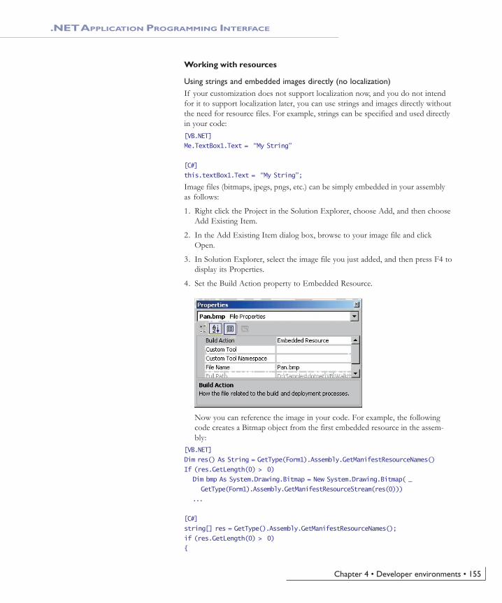
Chapter 4 • Developer environments • 155
.NET APPLICATION PROGRAMMING INTERFACE
Working with resources
Using strings and embedded images directly (no localization)If your customization does not support localization now, and you do not intendfor it to support localization later, you can use strings and images directly withoutthe need for resource files. For example, strings can be specified and used directlyin your code:[VB.NET]
Me.TextBox1.Text = “My String”
[C#]
this.textBox1.Text = “My String”;
Image files (bitmaps, jpegs, pngs, etc.) can be simply embedded in your assemblyas follows:
1. Right click the Project in the Solution Explorer, choose Add, and then chooseAdd Existing Item.
2. In the Add Existing Item dialog box, browse to your image file and clickOpen.
3. In Solution Explorer, select the image file you just added, and then press F4 todisplay its Properties.
4. Set the Build Action property to Embedded Resource.
Now you can reference the image in your code. For example, the followingcode creates a Bitmap object from the first embedded resource in the assem-bly:
[VB.NET]
Dim res() As String = GetType(Form1).Assembly.GetManifestResourceNames()
If (res.GetLength(0) > 0)
Dim bmp As System.Drawing.Bitmap = New System.Drawing.Bitmap( _
GetType(Form1).Assembly.GetManifestResourceStream(res(0)))
...
[C#]
string[] res = GetType().Assembly.GetManifestResourceNames();
if (res.GetLength(0) > 0)
{
Ch04_EngineAPIs.pmd 4/2/2004, 9:04 AM155

156 • ArcGIS Engine Developer Guide
.NET APPLICATION PROGRAMMING INTERFACE
System.Drawing.Bitmap bmp = new System.Drawing.Bitmap(
GetType().Assembly.GetManifestResourceStream(res[0]));
...
Creating resources filesBefore attempting to provide localized resources, you should ensure you arefamiliar with the process of creating resources files for your .NET projects. Evenif you do not intend to localize your resources, you can still use resources files,instead of using images and strings directly as described above.
Visual Studio .NET projects use an XML-based file format to contain managedresources. These XML files have the extension .resx and can contain any kind ofdata (images, cursors, etc.) providing the data is converted to ASCII format. Resxfiles are compiled to .resources files which are binary representations of theresource data. Binary .resources files can be embedded by the compiler either intothe main project assembly, or into a separate satellite assembly which containsonly resources.
The following options are available to create your resources files. Each is dis-cussed below.
• Creating a .resx file for string resources
• Creating resources files for image resources
• Compiling a .resx file into a .resources file
Creating a .resx file for string resourcesIf all you need to localize is strings (not images or cursors), you can use VisualStudio.NET to create a new .resx file which will be automatically compiled into a.resources module embedded in the main assembly.
1. Right click the Project name in the Solution Explorer, select Add, and thenselect Add New Item.
2. In the Add New item dialog select Assembly Resource File.
Ch04_EngineAPIs.pmd 4/2/2004, 9:04 AM156

Chapter 4 • Developer environments • 157
.NET APPLICATION PROGRAMMING INTERFACE
3. Open the new .resx file in Visual Studio, and add name-value pairs for theculture-specific strings in your application.
4. When you compile your project, the .resx file will be compiled to a .resourcesmodule inside your main assembly.
Creating resources files for image resourcesThe process of adding images, icons, or cursors to a resources file in .NET is morecomplex than creating a file containing only string values, because the toolscurrently available in the Visual Studio .NET IDE can only be used to add stringresources.
However, a number of sample projects are available with Visual Studio .NETFramework SDK which can help you work with resource files. One such sampleis the Resource Editor (ResEditor).
The ResEditor sample can be used to add images, icons, imagelists and strings to aresources file. The tool cannot be used to add cursor resources. Files can be savedas either .resx or .resource files.
Creating resources files programmaticallyYou can create XML .resx files containing resources programmatically by usingthe ResXResourceWriter class (part of the .NET framework). You can createbinary .resources files programmatically by using the ResourceWriter class (also part
A list of tools useful for working with resourcescan be found in the Microsoft .NET Framework
documentation at http://msdn.microsoft.com/library/default.asp?url=/library/en-us/cptutorials/
html/appendix_b__resource_tools.asp.
Additional information on theResEditor samplecan be found at http://msdn.microsoft.com/
library/default.asp?url=/library/en-us/cptutorials/html/resource_editor__reseditor_.asp.
The ResEditor sample is provided by Microsoftas source code. You must build the sample first ifyou wish to create resource files using this tool.
You can find information on building the SDKsamples under the SDK sub-directory of your
Visual Studio .NET installation.
Ch04_EngineAPIs.pmd 4/2/2004, 9:04 AM157

158 • ArcGIS Engine Developer Guide
.NET APPLICATION PROGRAMMING INTERFACE
of the .NET framework). These classes will allow more flexibility to add thekind of resources you require.
These classes may be particularly useful if you wish to add resources whichcannot be handled by the .NET Framework SDK samples and tools, for example,cursors. The basic usage of the two classes is very similar, first create a newresource writer class specifying the file name, then add resources individually byusing the AddResource method.
The code below demonstrates how you could create a new .resx file using theResXResourceWriter class, and add a bitmap and a cursor to the file.[VB.NET]
Dim img As System.Drawing.Image = CType(NewSystem.Drawing.Bitmap(“ABitmap.bmp”), System.Drawing.Image)
Dim cur As New System.Windows.Forms.Cursor(“Pencil.cur”)
Dim rsxw As New System.Resources.ResXResourceWriter(“en-AU.resx”)
rsxw.AddResource(“MyBmp_jpg”, img)
rsxw.AddResource(“Mycursor_cur”, cur)
rsxw.Close()
[C#]
System.Drawing.Image img = (System.Drawing.Bitmap) newSystem.Drawing.Bitmap(“ABitmap.bmp”);
System.Windows.Forms.Cursor cur = newSystem.Windows.Forms.Cursor(“Pencil.cur”);
System.Resources.ResXResourceWriter rsxw = newSystem.Resources.ResXResourceWriter(“en-GB.resx”);
rsxw.AddResource(“MyBmp_jpg”, img);
rsxw.AddResource(“Mycursor_cur”, cur);
rsxw.Close();
The PanTool developer sample (Samples\Map Analysis\Tools) includes a scriptcalled “MakeResources” that shows you how to use the ResXResourceWriter classto write bitmap, cursor files and strings into an .resx file. It also shows you howto read from a .resx file using the ResXResourceReader class. The sample includesa .resx file that holds a bitmap, two cursors, and three strings.
Compiling a .resx file into a .resources fileXML-based .resx files can be compiled to binary .resources files either by usingthe Visual Studio IDE, or by using the ResX Generator (ResXGen) sample in thetutorial.
• Any .resx file included in a Visual Studio project will be compiled to a .re-sources module when the project is built. See the ‘Using resources with local-ization’ section below for more information on how multiple resource files areused for localization.
• If you wish you can convert a .resx file into a .resources file independently ofthe build process, using the .NET Framework SDK command resgen, forexample:resgen PanToolCS.resx PanToolCS.resources
More information on the ResXGen can be foundat http://msdn.microsoft.com/library/
default.asp?url=/library/en-us/cptutorials/html/ResX_Generator__RESXGEN_.asp.
Ch04_EngineAPIs.pmd 4/2/2004, 9:04 AM158

Chapter 4 • Developer environments • 159
.NET APPLICATION PROGRAMMING INTERFACE
Using resources with localizationThis section explains how you can localize resources for your customizations.
How to use resources with localizationIn .NET, a combination of a specific Language and Country/Region is called aculture . For example, the American dialect of English is indicated by the string“en-US”, and the Swiss dialect of French is indicated by “fr-CH”.
If you wish your project to support various cultures (languages and dialects), youshould construct a separate .resources file containing culture-specific strings andimages for each culture.
When you build a .NET project which uses resources, .NET embeds the default.resources file in the main assembly. Culture-specific .resources files are compiledinto satellite assemblies (using the naming convention <Main AssemblyName>.resources.dll), and placed in sub-directories of the main build directory.The sub-directories are named after the culture of the satellite assembly theycontain, for example Swiss-French resources would be contained in a sub-direc-tory called “fr-CH”.
When an application runs, it automatically uses the resources contained in thesatellite assembly with the appropriate culture. The appropriate culture is deter-mined from the Windows settings. If a satellite assembly for the appropriateculture cannot be found, the default resources (those embedded in the mainassembly) will be used instead.
The following sections give more information on creating your own .resx and.resources files.
Embedding a default .Resources file in your project1. Right click the Project name in the Solution Explorer, click Add, and then
click Add Existing Item to browse to your .resx or .resources file.
2. In Solution Explorer, select the file you just added, and then click F4 todisplay its Properties.
3. Set the Build Action property to Embedded Resource.
This will ensure that your application always has a set of resources to fall backon if there isn’t a resource dll for the culture your application runs in.
Creating .Resources.dll files for cultures supported by your project1. First ensure you have a default .resx or .resources file in your project.
2. Take the default .resx or .resources file and create a separate localized file foreach culture you want to support.
• Each file should contain resources with the same Names - the Value of eachresource in the file should contain the localized value.
• Localized resource files should be named according to their culture, e.g.<BaseName>.<Culture>.resx or <BaseName>.<Culture>.resources.
3. Add the new resources files to the project, ensuring each one has its BuildAction set to Embedded Resource.
The Visual Basic .NET and C# flavors of the PanTool developer sample illustrate how to localize
resources for German language environments.The sample can be found in the Developer
Samples\ArcMap\Commands and Tools\Pan Toolfolder. Strictly speaking, the sample only requires
localized strings, but the images have beenchanged for the “de” culture as well, to serve as
illustration.
A batch file named buildResources.bat has beenprovided in the Pan Tool sample to create thedefault .resources files and the culture-specific
satellite assemblies.
Ch04_EngineAPIs.pmd 4/2/2004, 9:04 AM159

160 • ArcGIS Engine Developer Guide
.NET APPLICATION PROGRAMMING INTERFACE
4. Build the project
The compiler and linker will create a separate satellite assembly for eachculture. The satellite assemblies will be placed in sub-directories under thedirectory holding your main assembly. The sub-directories will be named byculture, which allows the .NET runtime to locate the resources appropriate tothe culture the application runs in.
The main (default) resources file will be embedded in the main assembly.
Assembly versioning and redirectionApplications that are built using a specific version of a strongly named assemblyrequire the same assembly at run time. For example, if you create an applicationthat uses ESRI.ArcGIS.System version 9.0.452, you will not be able to run thisapplication on a system that has a newer version of ESRI.ArcGIS.System (e.g.9.0.0.692) installed. This may be the case if someone has installed a newer ver-sion of ArcGIS; however, using configuration files you can redirect an applica-tion to use a newer version of an assembly.
You have two choices for redirecting assemblies:
• Application configuration files
• Machine configuration files
Application configuration filesApplication configuration files contain settings specific to an application. This filecontains configuration settings that the common language runtime reads (such asassembly binding policy, remoting objects, and so on), and settings that the appli-cation can read.
The name and location of the application configuration file depend on theapplication’s host, which can be one of the following:
• Executable–hosted application—The configuration file for an applicationhosted by the executable host is in the same directory as the application. Thename of the configuration file is the name of the application with a .configextension. For example, an application called myApp.exe can be associatedwith a configuration file called myApp.exe.config.
• ASP.NET-hosted application—ASP.NET configuration files are calledWeb.config. Configuration files in ASP.NET applications inherit the settings ofconfiguration files in the URL path. For example, given the URLwww.esri.com/aaa/bbb, where www.esri.com/aaa is the Web application, theconfiguration file associated with the application is located at www.esri.com/aaa. ASP.NET pages that are in the subdirectory /bbb use both the settingsthat are in the configuration file at the application level and the settings in theconfiguration file that is in /bbb.
• Internet Explorer-hosted application—If an application hosted in InternetExplorer has a configuration file, the location of this file is specified in a<link> tag with the following syntax:<link rel=”ConfigurationFileName” href=”location”>
Ch04_EngineAPIs.pmd 4/2/2004, 9:04 AM160

Chapter 4 • Developer environments • 161
.NET APPLICATION PROGRAMMING INTERFACE
In this tag, location is a URL to the configuration file. This sets the applicationbase. The configuration file must be located on the same Web site as theapplication.
Machine configuration filesThe machine configuration file, Machine.config, contains settings that apply to anentire computer. This file is located in the %runtime install path%\Config direc-tory. Machine.config contains configuration settings for machine-wide assemblybinding, built-in remoting channels, and ASP.NET.
The configuration system first looks in the machine configuration file for the<appSettings> element and other configuration sections that a developer mightdefine. It then looks in the application configuration file. To keep the machineconfiguration file manageable, it is best to put these settings in the applicationconfiguration file. However, putting the settings in the machine configuration filecan make your system more maintainable. For example, if you have a third-partycomponent that both your client and server application use, it is easier to put thesettings for that component in one place. In this case, the machine configurationfile is the appropriate place for the settings, so you don’t have the same settings intwo different files.
The configuration file below shows how to bind to an assembly and then redirectit to a newer version.<configuration>
<runtime>
<assemblyBinding xmlns=”urn:schemas-microsoft-com:asm.v1">
<dependentAssembly>
<assemblyIdentity name=”ESRI.ArcGIS.System”
publicKeyToken=”8fc3cc631e44ad86"
culture=”neutral” />
<!— Assembly versions can be redirected in application, publisherpolicy, or machine configuration files. —>
<bindingRedirect oldVersion=”9.0.0.452" newVersion=”9.0.0.692"/>
</dependentAssembly>
</assemblyBinding>
</runtime>
</configuration>
ARCGIS DEVELOPMENT USING .NET
Using .NET you can customize the ArcGIS applications, create standalone appli-cations that use ESRI’s types, and extend ESRI’s types. For example, you cancreate a custom tool for ArcMap, create a standalone application that uses theMapControl, or create a custom layer. This section discusses several key issuesrelated to developing with ArcGIS and .NET.
Registering .NET components with COMExtending the ArcGIS applications with custom .NET components requiresregistering the components in the COM registry and exporting the .NET assem-blies to a type library (tlb). When developing a component, there are two waysto perform this task, you can use the RegAsm utility that ships with the .NET
Deploying an application using XCOPY will notcopy the settings in the machine configuration
file.
Ch04_EngineAPIs.pmd 4/2/2004, 9:04 AM161

162 • ArcGIS Engine Developer Guide
.NET APPLICATION PROGRAMMING INTERFACE
Framework SDK, or use Visual Studio.NET which has a ‘Register for COMInterop’ compiler flag.
The example below shows an EditTools assembly being register with COM. The/tlb parameter specifies that a type library should additionally be generated andthe /codebase option indicates that the path to the assembly should be includedin the registry settings. Both of these parameters are required when extendingthe ArcGIS applications with .NET components.regasm EditTools.dll /tlb:EditTools.tlb /codebase
Visual Studio.NET performs this same operation automatically if you set the‘Register for COM Interop’ compiler flag – this is the simplest way to perform theregistration on a development machine. To check a project’s settings, select‘Project Properties’ from the ‘Project’ menu and then look at the Build propertyunder ‘Configuration Properties’. The very last item is ‘Register for COMInterop’, set this property to True.
Registering .NET classes in COM component categoriesMuch of ArcGIS’s extensibility relies on COM component categories. In fact,most custom ArcGIS components must be registered in component categoriesappropriate to their intended context and function in order for the host applica-tion to make use of their functionality. For example, all ArcMap commands andtools must be registered in the ESRI Mx Commands component category. Thereare a few different ways you can register a .NET component in a particularcategory but before doing so, the .NET components must be registered withCOM. See the ‘Registering .NET Components with COM’ section above fordetails.
Customize dialogCustom .NET ArcGIS commands and tools can quickly be added to toolbars viathe ‘Add From File…” button on the Customize dialog. In this case, you simplyhave to browse for the tlb and open it. The ArcGIS framework will automati-cally added the classes you select in the type library to the appropriate componentcategory.
Categories utilityAnother option is to use the Component Categories Manager (Categories.exe). Inthis case you select the desired component category in the utility and then browsefor your type library and select the appropriate class.
COMRegisterFunctionThe final and recommended solution is to add code to your .NET classes that willautomatically register them in a particular component category whenever thecomponent is registered with COM. The .NET Framework contains two at-tribute classes (ComRegisterFunctionAttribute andComUnregisterFunctionAttribute) that allow you to specify methods which willbe called whenever your component is being registered or unregistered. Bothmethods are passed the CLSID of the class currently being registered and withthis information you can you can write code inside the methods to make theappropriate registry entries or deletions. Registering a component in a component
Ch04_EngineAPIs.pmd 4/2/2004, 9:04 AM162

Chapter 4 • Developer environments • 163
.NET APPLICATION PROGRAMMING INTERFACE
category requires that you also know the component category’s unique ID(CATID).
The code excerpt below shows a custom ArcMap command that automaticallyregisters itself in the MxCommands component category whenever the .NETassembly in which it resides is registered with COM.
public sealed class AngleAngleTool: BaseTool
{
[ComRegisterFunction()]
static void Reg(String regKey)
{
Microsoft.Win32.Registry.ClassesRoot.CreateSubKey(regKey.Substring(18)+ “\\Implemented Categories\\” + “{B56A7C42-83D4-11D2-A2E9-080009B6F22B}”);
}
[ComUnregisterFunction()]
static void Unreg(String regKey)
{
Microsoft.Win32.Registry.ClassesRoot.DeleteSubKey(regKey.Substring(18)+“\\Implemented Categories\\” + “{B56A7C42-83D4-11D2-A2E9-080009B6F22B}”);
}
To simplify this process, ESRI provides classes for each component categoryArcGIS exposes with static functions to register and unregister components.Each class knows the GUID of the component category it represents so register-ing custom components becomes greatly simplified. For more details on usingthese classes see the ‘Working with the ESRI .NET Component Category Classes’section below.
Simplify your code using the ESRI.ArcGIS.Utility assemblyPart of the ArcGIS Developer Kit includes a number of .NET utility classes thatfacilitate .NET development by taking advantage of a few .NET capabilitiesincluding object inheritance and static functions.
Working with the ESRI .NET Base ClassesESRI provides two abstract base classes (BaseCommand and BaseTool) to helpyou create new custom commands and tools for ArcGIS. The classes are abstractclasses (marked as MustInherit in Visual Basic .NET), which means that althoughthe class may contain some implementation code, it cannot itself be instantiateddirectly and can only be used by being inherited by another class. Both base classesare defined in the ESRI.ArcGIS.Utility assembly and belong to theESRI.ArcGIS.Utility.BaseClasses namespace.
These base classes simplify the creation of custom commands and tools by pro-viding a default implementation for each of the members of ICommand andITool. Instead of stubbing out each member and providing implementation code,you only have to override the members that your custom command or tool re-quires. The exception is ICommand::OnCreate; this member must be overriddenin your derived class.
Using these base classes is the recommended way to create commands and toolsfor ArcGIS applications in .NET languages. You can create similar COM classes
Ch04_EngineAPIs.pmd 4/2/2004, 9:04 AM163

164 • ArcGIS Engine Developer Guide
.NET APPLICATION PROGRAMMING INTERFACE
from first principles; however, you should find the base class technique to be aquicker, simpler, less error-prone method of creating commands and tools.
SyntaxBoth base classes additionally have an overloaded constructor, allowing you toquickly set many of the properties of a command or tool (such as Name andCategory) via constructor parameters.
The overloaded BaseCommand constructor has the following signature:[VB.NET]
Public Sub New( _
ByVal bitmap As System.Drawing.Bitmap _
ByVal caption As String _
ByVal category As String _
ByVal helpContextId As Integer _
ByVal helpFile As String _
ByVal message As String _
ByVal name As String _
ByVal tooltip As String)
[C#]
public BaseCommand(
System.Drawing.Bitmap bitmap,
string caption,
string category,
int helpContextId,
string helpFile,
string message,
string name,
string toolTip,
);
The overloaded BaseTool constructor has the following signature:[VB.NET]
Public Sub New( _
ByVal bitmap As System.Drawing.Bitmap _
ByVal caption As String _
ByVal category As String _
ByVal cursor As System.Windows.Forms.Cursor _
ByVal helpContextId As Integer _
ByVal helpFile As String _
ByVal message As String _
ByVal name As String _
ByVal tooltip As String _
)
[C#]
public BaseTool(
System.Drawing.Bitmap bitmap,
string caption,
string category,
Ch04_EngineAPIs.pmd 4/2/2004, 9:04 AM164

Chapter 4 • Developer environments • 165
.NET APPLICATION PROGRAMMING INTERFACE
System.Windows.Forms.Cursor cursor,
int helpContextId,
string helpFile,
string message,
string name,
string toolTip,
);
Inheriting the base classesYou can use these parameterized constructors when you write your new classes,for example as shown below for a new class called PanTool that inherits theBaseTool class.[VB.NET]
Public Sub New()
MyBase.New( Nothing, “Pan”, “My Custom Tools”, _
System.Windows.Forms.Cursors.Cross, 0, “”, “Pans the map.”,“PanTool”, “Pan”)
End Sub
[C#]
public PanTool() : base ( null,”Pan”, “My Custom Tools”,
System.Windows.Forms.Cursors.Cross, 0, “”,”Pans the map.”, “PanTool”,“Pan”)
{
...
}
Setting base class members directlyAs an alternative to using the parameterized constructors, you can alternativelyset the members of the base class directly.
The base classes expose their internal member variables to the inheritor class, oneper property, so that you can directly access them in your derived class. Forexample, instead of using the constructor to set the ‘Caption’ or overriding theCaption function, you can set the ‘m_caption’ class member variable declared inthe base class.[VB.NET]
Public Sub New()
MyBase.New()
MyBase..m_bitmap = NewSystem.Drawing.Bitmap([GetType]().Assembly.GetManifestResourceStream(“Namespace.Pan.bmp”))
MyBase..m_cursor = System.Windows.Forms.Cursors.Cross
MyBase..m_category = “My Custom Tools”
MyBase..m_caption = “Pan”
MyBase..m_message = “Pans the map.”
MyBase..m_name = “PanTool”
MyBase..m_toolTip = “Pan”
End Sub
Ch04_EngineAPIs.pmd 4/2/2004, 9:04 AM165

166 • ArcGIS Engine Developer Guide
.NET APPLICATION PROGRAMMING INTERFACE
[C#]
public PanTool()
{
base.m_bitmap = newSystem.Drawing.Bitmap(GetType().Assembly.GetManifestResourceStream(“Namespace.Pan.bmp”));
base.m_cursor = System.Windows.Forms.Cursors.Cross;
base.m_category = “My Custom Tools”;
base.m_caption = “Pan”;
base.m_message = “Pans the map.”;
base.m_name = “PanTool”;
base.m_toolTip = “Pan”;
}
Overriding membersWhen you create custom commands and tools that inherit a base class, you willmore than likely need to override a few members. When you override a memberin your class, the implementation code that you provide for that member will beexecuted instead of the default member implementation inherited from the base
class. For example, the OnClick method in the BaseCommand has no implemen-tation code at all (OnClick will not do anything by default), which may be suit-able for a tool but probably not for a command.
To override any member, you can right-click the member of the base class in theSolution Explorer Window then choose Add, Override to stub out the memberas overridden. (Note that if you right-click on the member of the underlyinginterface (ICommand or ITool) instead of the base class member, the overriddenmember will not include the overrides keyword, and the method will instead beshadowed).[VB.NET]
Public Overrides Sub OnClick()
‘ Your OnClick
End Sub
[C#]
public override void OnClick()
{
// Your OnClick
}
Alternatively, to override a member of the base class, choose (Overrides) fromthe right hand drop-down list in the code window wizard bar, and then choosethe member you wish to override from the left hand drop-down list. This willstub out the member as overridden.
What do the base classes do by default?The table below shows the base class members that have a significant base classimplementation, along with a description of that implementation. Override thesemembers when the base class behavior is not consistent with your customization.For example, Enabled is set to True by default, if you want your custom com-mand enabled only when a specific set of criteria has been met, you must over-ride this property in your derived class.
Ch04_EngineAPIs.pmd 4/2/2004, 9:04 AM166

Chapter 4 • Developer environments • 167
.NET APPLICATION PROGRAMMING INTERFACE
Working with the ESRI .NET component category classesTo help the register .NET components in COM component categories, ESRIprovides the ESRI.ArcGIS.Utility.CATIDs namespace which has classes thatrepresent each of the ArcGIS component categories. Each class knows itsCATID and exposes static methods (Register and Unregister) for adding andremoving components. Registering your component becomes as easy as addingCOM registration methods with the appropriate attributes, and passing the re-ceived CLSID to the appropriate static method.
The example below shows a custom Pan tool that registers itself in the ESRI MxCommands component category. Notice in this example we are usingMxCommands.Register and MxCommands.Unregister instead ofMicrosoft.Win32.Registry.ClassesRoot.CreateSubKey andMicrosoft.Win32.Registry.ClassesRoot.DeleteSubKey.[VB.NET]
Public NotInheritable Class PanTool
Inherits BaseTool
<ComRegisterFunction()> _
Public Shared Sub Reg(ByVal regKey As [String])
MxCommands.Register(regKey)
End
<ComUnregisterFunction()> _
Public Shared Sub Unreg(ByVal regKey As [String])
MxCommands.Unregister(regKey)
End Sub
[C#]
public sealed class PanTool : BaseTool
{
[ComRegisterFunction()]
static void Reg(string regKey)
{
MxCommands.Register(regKey);
}
Ch04_EngineAPIs.pmd 4/2/2004, 9:04 AM167

168 • ArcGIS Engine Developer Guide
.NET APPLICATION PROGRAMMING INTERFACE
[ComUnregisterFunction()]
static void Unreg(string regKey)
{
MxCommands.Unregister(regKey);
}
Extending the ServerWhen using .NET to create a COM object for use in the GIS server, there aresome specific guidelines you need to follow to ensure that you can use your objectin a server context, and to ensure that it will perform well in that environment.The guidelines below apply specifically to COM objects you create to run withinthe server.
• You must explicitly create an interface that your COM class implements.Unlike Visual Basic 6, .NET will not create an implicit interface for yourCOM class that you can use when creating the object in a server context.
• Your COM class should be marshaled using the Automation marshaller. Youspecify this by adding the AutomationProxyAttribute attribute to your classwith a value of true.
• Your COM class should generate a dual class interface. You specify this byadding the ClassInterfaceAttribute attribute to your class with a value ofClassInterfaceType.AutoDual.
• To ensure that your COM object performs well in the server, it must inheritfrom ServicedComponent which is in the System.EnterpriseServices assembly.This is necessary due to the current COM interop implementation of the.NET framework.
For more details and an example of a custom Server COM object written in.NET, see Chapter 4, ‘Developing ArcGIS Server applications’ in the ArcGISServer Administrator and Developer Guide.
Releasing COM references
ArcGIS Engine and ArcGIS Desktop applicationsAn unexpected crash may occur when a standalone application attempts toshutdown. For example, an application hosting a MapControl with a loaded mapdocument will crash on exit. The crashes result from COM objects hangingaround longer than expected. To stop the crash, all COM references must beunloaded prior to shutdown. To help unload COM references, a static Shutdownfunction has been added to the ESRI.ArcGIS.Utility assembly. The followingcode excerpt shows the function in use.[VB.NET]
Private Sub Form1_Closing(ByVal sender As Object, ByVal e AsSystem.ComponentModel.CancelEventArgs) Handles MyBase.Closing
ESRI.ArcGIS.Utility.COMSupport.AOUninitialize.Shutdown()
End Sub
[C#]
private void Form1_Closing(object sender, CancelEventArgs e)
{
ESRI.ArcGIS.Utility.COMSupport.AOUninitialize.Shutdown();
}
Ch04_EngineAPIs.pmd 4/2/2004, 9:04 AM168

Chapter 4 • Developer environments • 169
.NET APPLICATION PROGRAMMING INTERFACE
The AOUninitalize.Shutdown function handles most of the shut down problems instandalone applications but you may still experience problems as there are COMobjects that additionally require explicit releasing; in these cases, callSystem.Runtime.InteropServices.Marshal.ReleaseComObject() to decrement the refer-ence count which allows the application to terminate cleanly. The StyleGallery isone such object and the following example documents how to handle referencesto this class.[VB.NET]
Dim styleGallery As IStyleGallery
styleGallery = New StyleGalleryClass
MessageBox.Show(styleGallery.ClassCount)
Marshal.ReleaseComObject(styleGallery)
[C#]
IStyleGallery sg = new StyleGalleryClass() as IStyleGallery;
MessageBox.Show(sg.ClassCount.ToString());
Marshal.ReleaseComObject(sg);
Working with geodatabase cursors in ArcGIS ServerSome objects that you can create in a server context may lock or use resourcesthat the object frees only in its destructor. For example, a geodatabase cursor mayacquire a shared schema lock on a file-based feature class or table on which it isbased, or may hold onto an SDE stream.
While the shared schema lock is in place, other applications can continue to queryor update the rows in the table, but they cannot delete the feature class or modifyits schema. In the case of file-based data sources, such as shapefiles, updatecursors acquire an exclusive write lock on the file, which will prevent otherapplications from accessing the file for read or write. The effect of these locks isthat the data may be unavailable to other applications until all of the referenceson the cursor object are released.
In the case of SDE data sources, the cursor holds onto an SDE stream, and if theapplication has multiple clients, each may get and hold onto an SDE stream,eventually exhausting the maximum allowable streams. The effect of the numberof SDE streams exceeding the maximum is that other clients will fail to opentheir own cursors to query the database.
Because of the above reasons, it’s important to ensure that your reference to anycursor your application opens is released in a timely manner. In .NET, your refer-ence on the cursor (or any other COM object) will not be released until garbagecollection kicks in. In a web application or web service, servicing multiple con-current sessions and requests, relying on garbage collection to release referenceson objects will result in cursors and their resources not being released in a timelymanner.
To ensure a COM object is released when it goes out of scope, the WebControlsassembly contains a helper object called WebObject. Use the ManageLifetimemethod to add your COM object to the set of objects that will be explicitlyreleased when the WebObject is disposed. You must scope the use of WebObjectwithin a Using block. When you scope the use of WebObject within a using block,any object (including your cursor) that you have added to the WebObject using theManageLifetime method will be explicitly released at the end of the using block.
Ch04_EngineAPIs.pmd 4/2/2004, 9:04 AM169

170 • ArcGIS Engine Developer Guide
.NET APPLICATION PROGRAMMING INTERFACE
The following example demonstrates this coding pattern:[VB.NET]
Private Sub doSomething_Click(ByVal sender As System.Object, ByVal e AsSystem.EventArgs) Handles doSomething.Click
Dim webobj As WebObject = New WebObject
Dim ctx As IServerContext = Nothing
Try
Dim serverConn As ServerConnection = New ServerConnection(“doug”,True)
Dim som As IServerObjectManager = serverConn.ServerObjectManager
ctx = som.CreateServerContext(“Yellowstone”, “MapServer”)
Dim mapsrv As IMapServer = ctx.ServerObject
Dim mapo As IMapServerObjects = mapsrv
Dim map As IMap = mapo.Map(mapsrv.DefaultMapName)
Dim flayer As IFeatureLayer = map.Layer(0)
Dim fClass As IFeatureClass = flayer.FeatureClass
Dim fcursor As IFeatureCursor = fClass.Search(Nothing, True)
webobj.ManageLifetime(fcursor)
Dim f As IFeature = fcursor.NextFeature()
Do Until f Is Nothing
‘ do something with the feature
f = fcursor.NextFeature()
Loop
Finally
ctx.ReleaseContext()
webobj.Dispose()
End Try
End Sub
[C#]
private void doSomthing_Click(object sender, System.EventArgs e)
{
using (WebObject webobj = new WebObject())
{
ServerConnection serverConn = new ServerConnection(“doug”,true);
IServerObjectManager som = serverConn.ServerObjectManager;
IServerContext ctx =som.CreateServerContext(“Yellowstone”,”MapServer”);
IMapServer mapsrv = ctx.ServerObject as IMapServer;
IMapServerObjects mapo = mapsrv as IMapServerObjects;
IMap map = mapo.get_Map(mapsrv.DefaultMapName);
IFeatureLayer flayer = map.get_Layer(0) as IFeatureLayer;
IFeatureClass fclass = flayer.FeatureClass;
Ch04_EngineAPIs.pmd 4/2/2004, 9:04 AM170

Chapter 4 • Developer environments • 171
.NET APPLICATION PROGRAMMING INTERFACE
IFeatureCursor fcursor = fclass.Search(null, true);
webobj.ManageLifetime(fcursor);
IFeature f = null;
while ((f = fcursor.NextFeature()) != null)
{
// do something with the feature
}
ctx.ReleaseContext();
}
}
The WebMap, WebGeocode and WebPageLayout objects also have a ManageLifetimemethod. If you are using, for example, a WebMap and scope your code in a usingblock, you can rely on these objects to explicitly release objects you add withManageLifetime at the end of the using block.
Deploying .NET ArcGIS customizationsAll ArcGIS Engine and Desktop customizations require an ArcGIS installation onall client machines. The ArcGIS installation must include the ESRI primaryinterop assemblies which the setup program installs in the global assembly cache.For example, deploying a standalone GIS application that only requires anArcGIS Engine license requires an ArcGIS Engine installation on all target ma-chines.
Standalone applicationsDeploying standalone applications to either ArcGIS Engine or Desktop clientsinvolves copying over the executable to the client machine. Copying over theexecutable can be as simple as using xcopy or more involved such as creating acustom install/setup program. Note, aside from the ArcGIS primary interopassemblies and the .NET Framework assemblies, all dependencies must addition-ally be packaged and deployed.
ArcGIS componentsComponents that extend the ArcGIS applications are trickier to deploy thanstandalone applications because they must be registered with COM and in specificcomponent categories. As discussed earlier, implementing COMRegisterFunctionand COMUnregisterFunctions facilitates deployment by providing self categoryregistration but this only occurs when the components are registered.
There are two techniques for registering components with COM. One option isto run the register assembly utility (RegAsm.exe) that ships with the .NETFramework SDK. This is typically not a viable solution as client machines may ormay not have this utility and it’s difficult to automate. The second and recom-mended approach is to add an automatic registration step to a custom setup/install program.
The key to creating a custom install program that both deploys and registerscomponents is the System.Runtime.InteropServices.RegistrationServices class.This class has the members: RegisterAssembly and UnregisterAssembly, whichregister and unregister managed classes with COM. These are the same functions
Ch04_EngineAPIs.pmd 4/2/2004, 9:04 AM171

172 • ArcGIS Engine Developer Guide
.NET APPLICATION PROGRAMMING INTERFACE
the RegAsm utility uses. Using these functions inside a custom installer classalong with a setup program is the complete solution.
The basic steps below outline the creation of a deployable solution. Note, thesteps assume you are starting with a solution that already contains a project withat least one COM enabled class.
1. In Visual Studio.NET, add a new Installer Class and name it accordingly.
Override the Install and Uninstall functions that are implemented in theInstaller base class and use the RegistrationServices class’s RegisterAssemblyand UnregisterAssembly methods to register the components. Make sure youuse the SetCodeBase flag; this indicates that the code base key for the assemblyshould be set in the registry.[VB.NET]
Public Overrides Sub Install(ByVal stateSaver AsSystem.Collections.IDictionary)
MyBase.Install(stateSaver)
Dim regsrv As New RegistrationServices
regsrv.RegisterAssembly(MyBase.GetType().Assembly,AssemblyRegistrationFlags.SetCodeBase)
End Sub
Public Overrides Sub Uninstall(ByVal savedState AsSystem.Collections.IDictionary)
MyBase.Uninstall(savedState)
Dim regsrv As New RegistrationServices
regsrv.UnregisterAssembly(MyBase.GetType().Assembly)
End Sub
End Class
[C#]
public override void Install(IDictionary stateSaver)
{
base.Install (stateSaver);
Ch04_EngineAPIs.pmd 4/2/2004, 9:04 AM172

Chapter 4 • Developer environments • 173
.NET APPLICATION PROGRAMMING INTERFACE
RegistrationServices regSrv = new RegistrationServices();
regSrv.RegisterAssembly(base.GetType().Assembly,AssemblyRegistrationFlags.SetCodeBase);
}
public override void Uninstall(IDictionary savedState)
{
base.Uninstall (savedState);
RegistrationServices regSrv = new RegistrationServices();
regSrv.UnregisterAssembly(base.GetType().Assembly);
}
2. Add a Setup program to your solution.
a. In the Solution Explorer, right-click on the new project and select ‘Add ->Project Output’. Select the project you wish to deploy and choose ‘Primaryoutput’.
b. From the list of detected dependencies that is regenerated, remove allreferences to ESRI primary interop assemblies (e.g. ESRI.ArcGIS.System)and stdole.dll. The only items typically left in the list are your tlb and‘Primary output from <AssemblyName><Version>’ which represents thedll or exe you are compiling.
c. The final steps involve associating the custom installation steps configuredin the new installer class with the Setup project. To do this, right-click onthe Setup project in the Solution Explorer and choose ‘View CustomActions’.
d. In the resulting view, right-click on ‘Install’ folder and choose ‘Add CustomAction’. Double-click the ‘Application’ folder, then double-click the ‘Pri-mary output from <AssemblyName><Version>’ item. This steps associatesthe custom install function created earlier with the setup’s custom installaction.
e. Repeat the last step for the setup’s uninstall.
Ch04_EngineAPIs.pmd 4/2/2004, 9:04 AM173

174 • ArcGIS Engine Developer Guide
.NET APPLICATION PROGRAMMING INTERFACE
3. Finally, rebuild the entire solution to generate the setup executable. Runningthe executable on a target machine installs the components and registers themwith COM. The COMRegisterFunction routines then register the componentsin the appropriate component categories.
ArcGIS Server deploymentsTo deploy web applications developed on a development server to product pro-duction servers, use the built-in Visual Studio.NET tools.
1. In the Solution Explorer, click on your project.
2. Click the Project menu, then select Copy Project.
3. In the Copy Project dialog, specify the deployment location.
4. Click OK.
In addition to copying the project, you must copy and register any related dllscontaining custom COM objects onto your web server and all the GIS server’sserver object container machines.
Ch04_EngineAPIs.pmd 4/2/2004, 9:04 AM174

Chapter 4 • Developer environments • 175
The ArcGIS version 9.0 Java API is a programming interface which interoperateswith ArcObjects and is specifically designed to target Java developers. Java tech-nology is both a platform and an object-oriented programming language devel-oped by Sun Microsystems which comes in three versions and consists of twocomponents:
Versions:
• Java 2 platform, Standard Edition ( J2SE)
• Java 2 platform, Enterprise Edition ( J2EE)
• Java 2 platform, Micro Edition (J2ME)
Components:
• Java Virtual Machine (JVM) - Java runtime and client/server compilers.
• Java Application Programming Interface (API) - Suite of core, integration,and user interface toolkits.
The Java language is important because it is an open standard. All implementa-tions of the programming language must meet the standards provided by theJVM. This enables applications to run on any hardware platforms that host theJVM.
PLATFORM CONFIGURATION
This section will describe all the necessary configurations needed to be productivewith the Java API including classpath and environment settings.
Java Developer KitIn order to develop with ArcObjects using the Java API, you must have theJava 2 Platform Standard Software Developer Kit (J2SDK) installed. All of yourJ2SDK tools are located in the install directory. You can either explicitly invokethem from that directory or add it to your PATH environment variable. Addingthe directory to your PATH variable involves two steps:
1. Create a new environment variable named JAVA_HOME.JAVA_HOME=[path to JDK install directory]
For example:JAVA_HOME=c:\j2sdk
2. Edit the PATH variable to include the bin directory of JAVA_HOME.PATH=..;%JAVA_HOME%\bin
In order to compile server-based applications like servlets and EJBs, you will alsoneed to install and include the Java 2 Enterprise Edition toolkit in your classpath.Java application servers generally provide this or you can get the reference imple-mentation provided by Sun Microsystems.
ArcGIS EngineThe ArcGIS Engine developer kit uses standard Java Native Interface (JNI) toaccess core ArcObjects components. This requires some native libraries to be inthe developer’s path when compiling and running applications. You must be sureto include the correct paths to invoke interoperabilty into native ArcObjects.
JAVA APPLICATION PROGRAMMING INTERFACE
Setting the JAVA_HOME variable is notabsolutely necessary; however, some Java IDEs
and Java tools require it be set.
Adding the PATH variable allows you to runexecutables (javac, java, javadoc, etc.) from any
directory on your system.
Ch04_EngineAPIs.pmd 4/2/2004, 9:04 AM175

176 • ArcGIS Engine Developer Guide
The native *.dlls are located in the following location:..\ArcGIS\bin
ESRI recommends setting an ARCENGINEHOME environment variable andadded the bin directory to your PATH variable. Although this is not a require-ment to use the ArcGIS Engine developer kit, the developer samples all use thisvariable to ensure your classpath setting are accurate.
Setting the ARCENGINEHOME variable:ARCENGINEHOME=[path to ArcGIS install directory]
For example:ARCENGINEHOME=c:\ArcGIS
Editing the PATH variable enables your system to use the native resource librariesthat ship with the ArcGIS Engine Runtime. Edit the PATH directory to includethe jre\bin directory of ARCENGINEHOME.PATH=..%ARCENGINEHOME%\java\jre\bin
ClasspathThe Java API provides Java Archive (JAR) files (*.jar) for ArcObjects and thenative runtime libraries. These JAR files are located on disk at%ARCENGINEHOME%\java
All Java applications built with any of the ArcGIS developer kits must have thefollowing JARs referenced in the respective application’s classpath:
• arcobjects.jar—contains all of the non-UI classes in one complete archive
• jintegra.jar—contains all classes for the runtime library that handles interop toCOM
In addition, individual arcgis_xxx.jar files should be added to your classpath asneeded. For example, applications that leverage the Java visual beans includedwith ArcObjects, require that the arcgis_visualbeans.jar file be added in theclasspath.
JREThe ArcGIS Engine and Server developer kits include a version of the JavaRuntime Environment (JRE). This enables you to run any ArcGIS Java applica-tion as long as all the necessary settings described above are local to the runtime.You will notice the necessary *.dlls in the bin directory and the necessary *.jars inthe library extension directory. All you need to do to get started with thisruntime environment is ensure that the bin directory is added to your PATHenvironment variable:PATH=..\ArcGIS\java\jre\bin
JAVA APPLICATION PROGRAMMING INTERFACE
Ch04_EngineAPIs.pmd 4/2/2004, 9:04 AM176
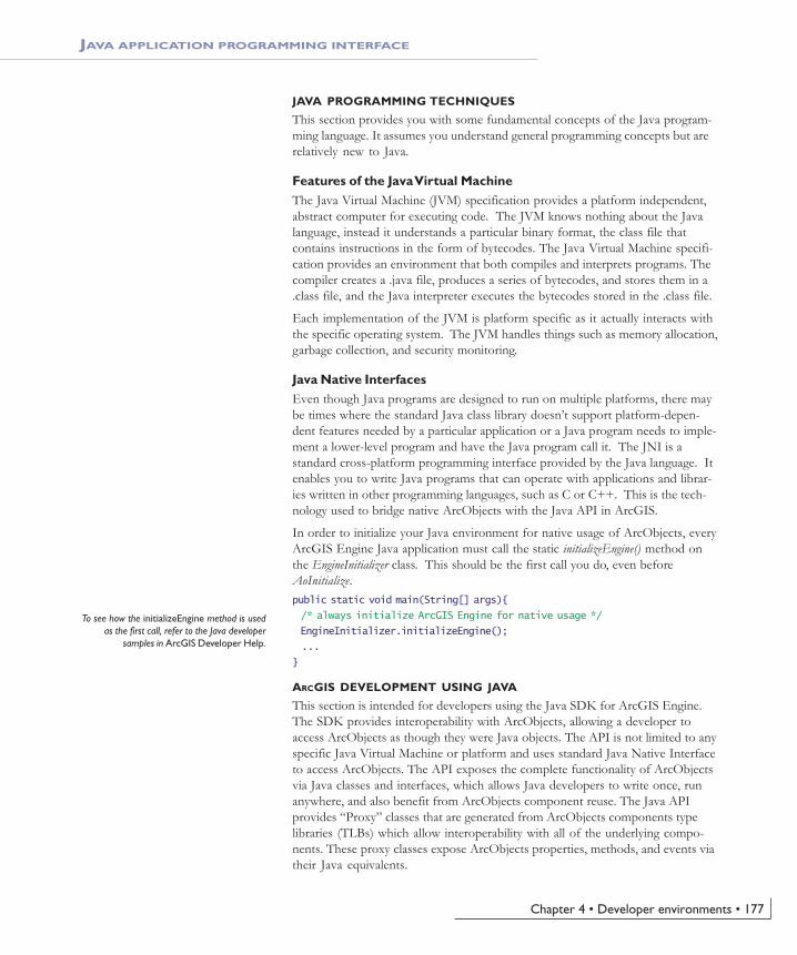
Chapter 4 • Developer environments • 177
JAVA PROGRAMMING TECHNIQUES
This section provides you with some fundamental concepts of the Java program-ming language. It assumes you understand general programming concepts but arerelatively new to Java.
Features of the Java Virtual MachineThe Java Virtual Machine (JVM) specification provides a platform independent,abstract computer for executing code. The JVM knows nothing about the Javalanguage, instead it understands a particular binary format, the class file thatcontains instructions in the form of bytecodes. The Java Virtual Machine specifi-cation provides an environment that both compiles and interprets programs. Thecompiler creates a .java file, produces a series of bytecodes, and stores them in a.class file, and the Java interpreter executes the bytecodes stored in the .class file.
Each implementation of the JVM is platform specific as it actually interacts withthe specific operating system. The JVM handles things such as memory allocation,garbage collection, and security monitoring.
Java Native InterfacesEven though Java programs are designed to run on multiple platforms, there maybe times where the standard Java class library doesn’t support platform-depen-dent features needed by a particular application or a Java program needs to imple-ment a lower-level program and have the Java program call it. The JNI is astandard cross-platform programming interface provided by the Java language. Itenables you to write Java programs that can operate with applications and librar-ies written in other programming languages, such as C or C++. This is the tech-nology used to bridge native ArcObjects with the Java API in ArcGIS.
In order to initialize your Java environment for native usage of ArcObjects, everyArcGIS Engine Java application must call the static initializeEngine() method onthe EngineInitializer class. This should be the first call you do, even beforeAoInitialize.public static void main(String[] args){
/* always initialize ArcGIS Engine for native usage */
EngineInitializer.initializeEngine();
...
}
ARCGIS DEVELOPMENT USING JAVA
This section is intended for developers using the Java SDK for ArcGIS Engine.The SDK provides interoperability with ArcObjects, allowing a developer toaccess ArcObjects as though they were Java objects. The API is not limited to anyspecific Java Virtual Machine or platform and uses standard Java Native Interfaceto access ArcObjects. The API exposes the complete functionality of ArcObjectsvia Java classes and interfaces, which allows Java developers to write once, runanywhere, and also benefit from ArcObjects component reuse. The Java APIprovides “Proxy” classes that are generated from ArcObjects components typelibraries (TLBs) which allow interoperability with all of the underlying compo-nents. These proxy classes expose ArcObjects properties, methods, and events viatheir Java equivalents.
JAVA APPLICATION PROGRAMMING INTERFACE
To see how the initializeEngine method is usedas the first call, refer to the Java developer
samples in ArcGIS Developer Help.
Ch04_EngineAPIs.pmd 4/2/2004, 9:04 AM177

178 • ArcGIS Engine Developer Guide
InterfacesNative ArcObjects uses an interface-based programming model. The concept ofan interface is fundamental to ArcObjects and emphasizes four points:
1. An interface is not a class.
2. An interface is not an object.
3. Interfaces are strongly typed.
4. Interfaces are immutable.
ArcObjects interfaces are abstract, meaning there is no implementation associatedwith an interface. Objects use type inheritance; the code associated with aninterface comes from the class implementation.
This model shares some features of the Java interface model, which was intro-duced to enhance Java’s single-inheritance model. An interface in the Java lan-guage is a specification of methods that an object declares it implements. A Javainterface does not include instance variables or implementation code.
The Java API has two objects for every ArcObjects interface: a correspondinginterface and an interface proxy class. The interface is named in the ArcObjectsstyle, prefixed with an I. The interface proxy class appends the term proxy to thename. An example of this mapping is provided below:interface IArea : IUnknown public interface IArea{}
public class IAreaProxy implements IArea{}
The proxy classes are used internally by the Java API to provide implementationto respective interfaces. An application developer should never use the defaultconstructor of these classes as it holds no implementation. ArcObjects requiresdevelopers to go through an interface to access objects. The Java language doesnot use this model; subsequently, the Java API to ArcObjects has two ways ofaccessing objects—by interface or by class./* use the class implementing IPoint */
IPoint iPoint = new Point();
/* access object through class */
Point cPoint = new Point();
You cannot access objects through the default interface proxy class:IPointProxy proxyPoint = new IPointProxy(); // incorrect usage
This will be discussed in more depth in subsequent sections.
ArcObjects interfaces are immutable and subsequently never versioned. Aninterface is never changed once it is defined and published. When an interfacerequires additional methods, the API defines a new interface by the same namewith a version number appended to it as described in the following table.interface IGeometry : IUnknown public interface IGeometry{}interface IGeometry2 : IGeometry public interface IGeometry2 extends
IGeometry{}
interface IGeometry3 : IGeometry2 public interface IGeometry3 extends IGeometry2{}
public interface IGeometry4 extends IGeometry3{}
JAVA APPLICATION PROGRAMMING INTERFACE
Ch04_EngineAPIs.pmd 4/2/2004, 9:04 AM178

Chapter 4 • Developer environments • 179
ClassesIn the ArcObjects model, classes provide the implementation of the definedinterfaces. ArcObjects provides three types of classes: abstract classes, classes, andcoclasses. These classes can be distinguished through the object model diagramsprovided in ArcGIS Developer Help. It is important to be familiar with thembefore you begin to use the three class types.
In ArcObjects, an abstract class cannot be used to create new objects and areabsent in the Java API. These classes are specifications in ArcObjects for instancesof subclasses through type inheritance. An abstract class enumerates what inter-faces are to be implemented by the implementing subclass but does not providean implementation to those interfaces. For each abstract class in ArcObjects thereare subclasses that provide the implementation.
A class cannot be publicly created in ArcObjects; however, objects of this classcan be created as a property of another class or instantiated by objects fromanother class. In the Java API, the default constructor normally used to create aclass is undefined for ArcObjects classes./* the constructor for FeatureClass() is unsupported*/
FeatureClass fc = new FeatureClass();
The following example illustrates this behavior while stepping you through theprocess of opening a feature class.IWorkspaceFactory wf = new ShapefileWorkspaceFactory();
IFeatureWorkspace fw = newIFeatureWorkspaceProxy(wf.openFromFile("\path\to\data", 0));
/* create a Feature Class from FeatureWorkspace */
IFeatureClass fc = fw.openFeatureClass("featureclass name");
In ArcObjects, a CoClass is a publicly creatable class. This means that you cancreate your own objects merely by declaring a new object as shown below./* create an Envelope from the Envelope CoClass */
Envelope env = new Envelope();
StructsA structure defines a new data type made up of elements called members. Javadoes not have structures as complex data types. The Java language provides thisfunctionality though classes; you can simply declare a class with the appropriateinstance variables. For each structure in ArcObjects, there is a representative Javaclass with publicly declared instance variables matching the structure members asoutlined below.struct WKSPointZ public class _WKSPointZ ... {
double X public double x;double Y public double y;double Z public double z;
}
You can work with these classes like any other class in Java:_WKSPointZ pt = new _WKSPointZ();
pt.x = 2.23;
pt.y = -23.14;
pt.z = 4.85;
System.out.println(pt.x + " " + pt.y + " " + pt.z);
JAVA APPLICATION PROGRAMMING INTERFACE
Ch04_EngineAPIs.pmd 4/2/2004, 9:04 AM179
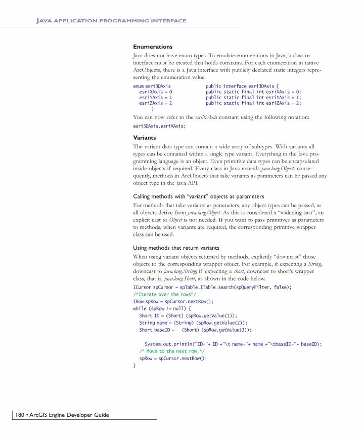
180 • ArcGIS Engine Developer Guide
EnumerationsJava does not have enum types. To emulate enumerations in Java, a class orinterface must be created that holds constants. For each enumeration in nativeArcObjects, there is a Java interface with publicly declared static integers repre-senting the enumeration value.enum esri3DAxis public interface esri3DAxis {
esriXAxis = 0 public static final int esriXAxis = 0;esriYAxis = 1 public static final int esriYAxis = 1;esriZAxis = 2 public static final int esriZAxis = 2;
}
You can now refer to the esriXAxis constant using the following notation:esri3DAxis.esriXAxis;
VariantsThe variant data type can contain a wide array of subtypes. With variants alltypes can be contained within a single type variant. Everything in the Java pro-gramming language is an object. Even primitive data types can be encapsulatedinside objects if required. Every class in Java extends java.lang.Object; conse-quently, methods in ArcObjects that take variants as parameters can be passed anyobject type in the Java API.
Calling methods with “variant” objects as parametersFor methods that take variants as parameters, any object types can be passed, asall objects derive from java.lang.Object. As this is considered a “widening cast”, anexplicit cast to Object is not needed. If you want to pass primitives as parametersto methods, when variants are required, the corresponding primitive wrapperclass can be used.
Using methods that return variantsWhen using variant objects returned by methods, explicitly “downcast” thoseobjects to the corresponding wrapper object. For example, if expecting a String,downcast to java.lang.String; if expecting a short, downcast to short’s wrapperclass, that is, java.lang.Short, as shown in the code below.ICursor spCursor = spTable.ITable_search(spQueryFilter, false);
/*Iterate over the rows*/
IRow spRow = spCursor.nextRow();
while (spRow != null) {
Short ID = (Short) (spRow.getValue(1));
String name = (String) (spRow.getValue(2));
Short baseID = (Short) (spRow.getValue(3));
System.out.println("ID="+ ID +"\t name="+ name +"\tbaseID="+ baseID);
/* Move to the next row.*/
spRow = spCursor.nextRow();
}
JAVA APPLICATION PROGRAMMING INTERFACE
Ch04_EngineAPIs.pmd 4/2/2004, 9:04 AM180

Chapter 4 • Developer environments • 181
IRowBuffer is a superinterface of IRow and defines the getValue(int) method as:public Object getValue(int index)
throws IOException,
AutomationException
The value of the field with the specified index.
Parameters:
index - The index (in)
Returns:
return value. A Variant
The return value is an Object, specified by the javadoc as “variant”. Therefore, thevalue can be downcasted to String or Short, depending upon their type in thegeodatabase being queried.
CastingArcObjects follows an interface-based programming style. Many methods useinterface types as parameters and have interfaces as return value. When the returnvalue of a method is an interface type, the method returns an object implement-ing that interface. When a method takes an interface type as parameter, it cantake in any object implementing that interface. This style of programming has theadvantage that the same method can work with many different object types,provided they all implement the said interface.
For example, IFeature.getShape() method returns an object implementing IGeometry.The object returned could potentially be any one of the following classes thatimplement IGeometry: BezierCurve, CircularArc, EllipticArc, Envelope,GeometryBag, Line, MultiPatch, Multipoint, Path, Point, Polygon, Polyline, Ray,Ring, Sphere, TriangleFan, Triangles, or TriangleStrip.
Casting is used to convert between types. There are three types of potential castsyou, as a developer, may be tempted to use with the Java API:1. Interface to concrete class casting2. Interface cross-casting3. Interface downcastingIt is important to understand that objects returned from methods withinArcObjects can behave differently than objects implicitly defined because theobject reference is not held in the JVM.
If you have a method, doSomeProcessingOnPolygon(Polygon p), that operates only onPolygon objects, and you want to pass the object obtained as a result ofIFeature.getShape(), you need a way to convert the “type” of the object fromIGeometry to Polygon. In Java, this is done using a class cast operation:/* incorrect usage: will give ClassCastException */
Polygon poly = (Polygon)geom;
However, use the same code with the ArcObjects Java API, and you will get aClassCastException. The reason for the exception is that the “geom” object refer-ence is actually a reference to the native ArcObjects component. As a conse-quence of the interoperability between Java and the native ArcObjects compo-nents, the logic of casting this object reference to the Polygon object resides in theconstructor of the Polygon object, and not in the JVM.
JAVA APPLICATION PROGRAMMING INTERFACE
Ch04_EngineAPIs.pmd 4/2/2004, 9:04 AM181

182 • ArcGIS Engine Developer Guide
Every class in the Java API has a constructor that takes in a single object asparameter. This constructor can create the corresponding object using the refer-ence to the ArcObjects component. Therefore, to achieve the equivalent of aclass casting when using the Java API, use the “object constructor” of the classbeing casted to.Polygon poly = new Polygon(geom);
The following code illustrates the object constructor being used to “cast” thegeom object to a Polygon:IFeature feature = featureClass.getFeature(i);
IGeometry geom = feature.getShape();
if (geom.getGeometryType() == esriGeometryType.esriGeometryPolygon){
/*Note: "Polygon p = (Polygon) geom;" will give ClassCastException*/
Polygon poly = new Polygon(geom);
doSomeProcessingOnPolygon(poly);
}
The Polygon object thus constructed will implement all interfaces implemented bythe Polygon class. Consequently, you can call methods belonging to any of theimplemented interfaces on the poly object.
You could write all your code using the object constructors alone, but there aretimes when it might be better to cast an object implementing a particular inter-face, not to a class type, but to another interface implemented by that object.
Continuing the previous example, suppose you want to use thedoSomeProcessingOnPolygon(Polygon p) method not only on Polygon objects but onother objects implementing IArea, such as Envelope and Ring. You could write ageneric doSomeProcessingOnArea(IArea area) method that works on all objectsimplementing IArea. As Polygon, Envelope, and Ring objects all implement the IAreainterface, you could pass in those objects to this generic method, thereby prevent-ing the need to write additional methods for each object type, such asdoSomeProcessingOnEnvelope(Envelope env) and doSomeProcessingOnRing(Ring ring). Toaccomplish this, you would need to cast from the IGeometry type to the IAreatype. In Java, this is typically done using interface cross-casting./* incorrect usage: will give ClassCastException */
IArea area = (IArea) geom ;
However, for the same reason noted in the class-cast above, such a cast wouldfail with a ClassCastException. To be able to cast to the ArcObjects interface, youwill need to use the interface proxy classes discussed earlier in this section. In theJava API, you achieve the equivalent of an interface cross-casting by using theInterfaceProxy of the interface being casted to.IArea area = new IAreaProxy(geom);
The following code shows the use of an InterfaceProxy class to cross-cast the geomobject to IArea:IFeature feature = featureClass.getFeature(i);
IGeometry geom = feature.getShape();
/*Note: "IArea area = (IArea) geom;" will give ClassCastException*/
IArea area = new IAreaProxy(geom);
doSomeProcessingOnArea(area);
Using the IAreaProxy class as shown in the code above allows you to access the
JAVA APPLICATION PROGRAMMING INTERFACE
Ch04_EngineAPIs.pmd 4/2/2004, 9:04 AM182

Chapter 4 • Developer environments • 183
object through its IArea interface so that it can then be passed to a method thattakes an argument of type IArea. Thus, in this particular example, one methodcan deal with three different object types. However, only methods belonging tothe IArea interface will be valid for the area object. To call other methods of theobject, you will need to either class-cast to the appropriate object type using itsobject constructor or get a reference to the other interfaces using theInterfaceProxy classes.
InstanceofThe instanceof operator in Java allows a developer to determine if its first operandis an instance of its second.operand1 instanceof operand2
You can use instanceof in ArcObjects—Java when the logic behind the type isheld in Java. You cannot use instanceof when the type is held in ArcObjects asthe logic of determining whether an object is an instance of a specified typeresides in the constructors of that object type and not the JVM. Point point = new Point();
point.putCoords(0, 0);
point.putCoords(10, 10);
point.putCoords(20, 20);
if(point instanceof IGeometry){
System.out.println(" point is a IGeometry");
geom = point;
}
if(point instanceof IClone){
System.out.println(" point is a IClone");
}
The above code works since the type information is held in Java for Point. Whenyou construct a Point object, a proxy class for each implementing interface is alsoconstructed. This allows you to use instanceof on any of these types. Developerswould have access to any methods on Point implementing the IGeometry or ICloneinterfaces.
This is backwards compatible as well: if(geom instanceof Polyline){
System.out.println(" geom is a Polyline");
}
else if(geom instanceof Point){
System.out.println(" geom is a Point");
pnt = (IPoint)geom; // allowable cast as the type is held in JVM
}
Since a direct cast of the geom object into Point was created, the geom object is oftype Point and instanceof can be used to check this information. However, sincethe type information was known before it was checked above, it is not extremelyuseful. What would be useful is to apply the above logic on methods that returnobjects of super interfaces.
JAVA APPLICATION PROGRAMMING INTERFACE
Ch04_EngineAPIs.pmd 4/2/2004, 9:04 AM183

184 • ArcGIS Engine Developer Guide
Consider the IWorkspaceFactory.openFromFile() method which returns anIWorkspace. Since the object returned is a Java object which implementsIWorkspace, you cannot check if the returned object is of any of the knownimplementing classes that implement IWorkspace. In this case, to check for typeinformation, you should call a method on the returned object which is expected.If the method does not throw an exception, it is of that type. This occurs be-cause the logic on this object is declared at runtime and is held inside the underly-ing ArcObjects component. RasterWorkspaceFactory rasterWkspFactory = new RasterWorkspaceFactory();
IWorkspace wksp = rasterWkspFactory.openFromFile( aPath, 0 );
if(wksp instanceof RasterWorkspace){
/*code does not execute as logic is in ArcObjects*/
System.out.println(" wksp is a RasterWorkspace");
rasWksp = (RasterWorkspace)wksp;
}
else{
try{
rasWksp = (RasterWorkspace)wksp;
rasWksp.openRasterDataset( aRaster );
}catch(Exception e){
/*code executes if wksp is not a RasterWorkspace*/
System.out.println(" wksp is not a RasterWorkspace");
}
}
Methods that take out parametersArcObjects provides many methods that return more than one value. The JavaAPI requires sending single element arrays as paramters to such methods. Basi-cally, you pass in single element arrays of the object that you want to be returned,and ArcObjects fills in the first elements of those arrays with the return value.Upon returning from the method call, the first element of the array contains thevalue that has been set during the method call. One such method, that you will beusing in this section is the toMapPoint of IARMap interface. Take a look at thejavadoc of this method:public void toMapPoint(int x,
int y,
double[] xCoord,
double[] yCoord)
throws IOException,
AutomationException
Converts a point in device coordinates (typically pixels) to coordinates inmap units.
Converts the x and y screen coordinates supplied in pixels to x and y mapcoordinates. The returned map coordinates will be in MapUnits.
Parameters:
x - The x (in)
JAVA APPLICATION PROGRAMMING INTERFACE
Ch04_EngineAPIs.pmd 4/2/2004, 9:04 AM184
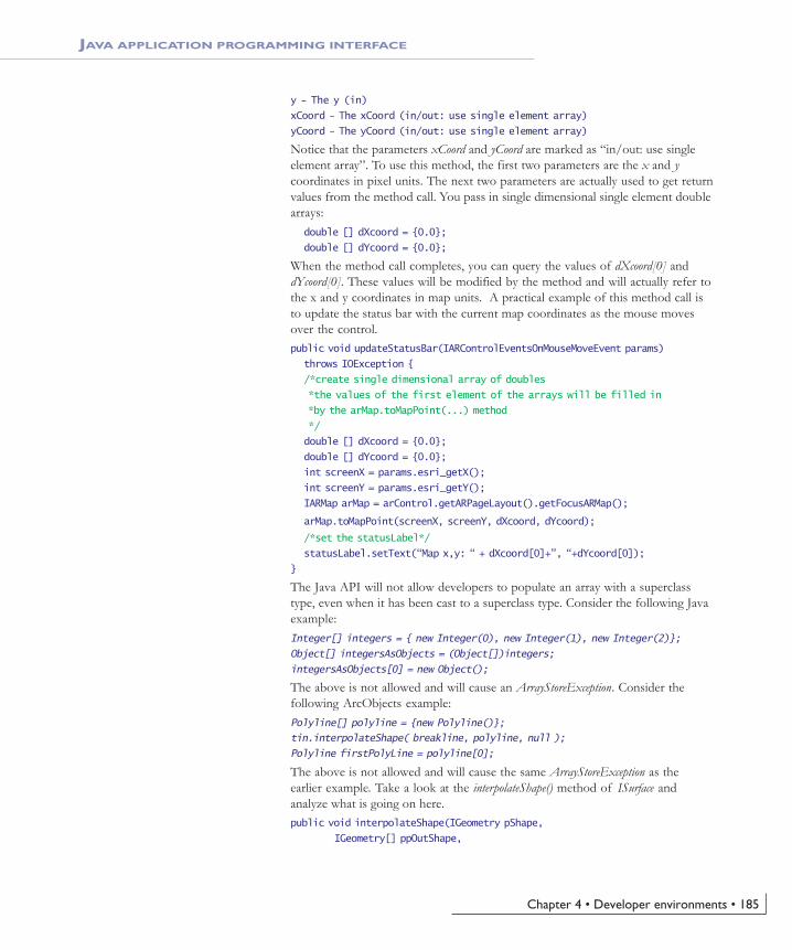
Chapter 4 • Developer environments • 185
y - The y (in)
xCoord - The xCoord (in/out: use single element array)
yCoord - The yCoord (in/out: use single element array)
Notice that the parameters xCoord and yCoord are marked as “in/out: use singleelement array”. To use this method, the first two parameters are the x and ycoordinates in pixel units. The next two parameters are actually used to get returnvalues from the method call. You pass in single dimensional single element doublearrays:
double [] dXcoord = {0.0};
double [] dYcoord = {0.0};
When the method call completes, you can query the values of dXcoord[0] anddYcoord[0]. These values will be modified by the method and will actually refer tothe x and y coordinates in map units. A practical example of this method call isto update the status bar with the current map coordinates as the mouse movesover the control.public void updateStatusBar(IARControlEventsOnMouseMoveEvent params)
throws IOException {
/*create single dimensional array of doubles
*the values of the first element of the arrays will be filled in
*by the arMap.toMapPoint(...) method
*/
double [] dXcoord = {0.0};
double [] dYcoord = {0.0};
int screenX = params.esri_getX();
int screenY = params.esri_getY();
IARMap arMap = arControl.getARPageLayout().getFocusARMap();
arMap.toMapPoint(screenX, screenY, dXcoord, dYcoord);
/*set the statusLabel*/
statusLabel.setText(“Map x,y: “ + dXcoord[0]+”, “+dYcoord[0]);
}
The Java API will not allow developers to populate an array with a superclasstype, even when it has been cast to a superclass type. Consider the following Javaexample:Integer[] integers = { new Integer(0), new Integer(1), new Integer(2)};
Object[] integersAsObjects = (Object[])integers;
integersAsObjects[0] = new Object();
The above is not allowed and will cause an ArrayStoreException. Consider thefollowing ArcObjects example:Polyline[] polyline = {new Polyline()};
tin.interpolateShape( breakline, polyline, null );
Polyline firstPolyLine = polyline[0];
The above is not allowed and will cause the same ArrayStoreException as theearlier example. Take a look at the interpolateShape() method of ISurface andanalyze what is going on here.public void interpolateShape(IGeometry pShape,
IGeometry[] ppOutShape,
JAVA APPLICATION PROGRAMMING INTERFACE
Ch04_EngineAPIs.pmd 4/2/2004, 9:04 AM185

186 • ArcGIS Engine Developer Guide
Object pStepSize)
throws IOException,
AutomationException
Parameters:
pShape - A reference to a com.esri.arcgis.geometry.IGeometry (in)
ppOutShape - A reference to a com.esri.arcgis.geometry.IGeometry (out: use single element array)
pStepSize - A Variant (in, optional, pass null if not required)
Throws:
IOException - If there are communications problems.
AutomationException - If the remote server throws an exception.
IGeometry is a super-interface to IPolyline, and the Polyline class implements bothinterfaces. In the first attempt youe tried to send a single element Polyline arrayinto a method which requires an in/out IGeometry parameter. This causes anArrayStoreException as ArcObjects is attempting to populate an IPolyline array withan IGeometry object, attempting to place a super-class type into a subclass array.The correct way to use this method is outlined below:/*Set up the array and call the method*/
IGeometry[] geoArray = {new Polyline()};
tin.interpolateShape( breakline, geoArray, null );
/* "Cast" the first array element as a Polyline - this is
* the equivalent of calling QueryInterface on IGeometry
*/
IPolyline firstPolyLine = new IPolylineProxy(geoArray[0]);
Non-OLE Automation Compliant TypesArcObjects types that are not OLE automation compliant types do not workwithin the Java API. ArcObjects contains a few of these methods and unfortu-nately such methods are not usable in the Java API. However, in most cases,supplemental interfaces have been added which have the offending methodsoverwritten as automation compatible. These new interfaces are appended withthe letters “GEN”, implying that they are generic for all supported APIs.
IPoint[] points = new Point[2];
points[0] = new Point();
points[1] = new Point();
points[0].putCoords(0, 0);
points[1].putCoords(10, 10);
IEnvelope env = new Envelope();
IEnvelopeGEN envGEN = new Envelope();
/*not automation compatible - throws exception*/
env.defineFromPoints(2, points[0]);
/*automation compatible*/
envGEN.defineFromPoints(points);
JAVA APPLICATION PROGRAMMING INTERFACE
Ch04_EngineAPIs.pmd 4/2/2004, 9:04 AM186

Chapter 4 • Developer environments • 187
Using visual beansThe Java API provides a set of reusable components as prebuilt pieces of soft-ware code designed to provide graphical functions. As a visual beans developer,you only need to write code to “buddy” them into your ArcGIS Engine applica-tion. The use of beans creates a bridge between Java and the ActiveX controlsprovided by ArcGIS. These visual components are heavyweight AWT compo-nents and conform to the JavaBeans™ component architecture, allowing them tobe used as drag and drop components for designing Java GUIs in JavaBean-compatible IDEs.
Mixing heavyweight and lightweight componentsOne of the primary goals of the Swing architecture was that it be based on theexisting AWT architecture. This allows developers to mix both kinds of compo-nents in the same application. When using the ArcObjects JavaBeans with Swingcomponents, care should be taken while mixing the heavyweight and lightweightcomponents. For guidelines, refer to the article ‘Mixing heavy and light compo-nents’ at http://java.sun.com/products/jfc/tsc/articles/mixing/.
If using Swing components, disable lightweight popups where the option isavailable, using code similar to:
jComboBox.setLightWeightPopupEnabled(false);
jPopupMenu.setLightWeightPopupEnabled(false);
Listening to eventsAll ArcObjects JavaBean are capable of firing events. For instance, the ARControlbean fires the following events:void onAction(IARControlEventsOnActionEvent theEvent)
void onAfterScreenDraw(IARControlEventsOnAfterScreenDrawEvent theEvent)
void onBeforeScreenDraw(IARControlEventsOnBeforeScreenDrawEvent theEvent)
void onCurrentViewChanged(IARControlEventsOnCurrentViewChangedEventtheEvent)
void onDocumentLoaded(IARControlEventsOnDocumentLoadedEvent theEvent)
void onDocumentUnloaded(IARControlEventsOnDocumentUnloadedEventtheEvent)
void onDoubleClick(IARControlEventsOnDoubleClickEvent theEvent)
void onFocusARMapChanged(IARControlEventsOnFocusARMapChangedEventtheEvent)
void onKeyDown(IARControlEventsOnKeyDownEvent theEvent)
void onKeyUp(IARControlEventsOnKeyUpEvent theEvent)
void onMouseDown(IARControlEventsOnMouseDownEvent theEvent)
void onMouseMove(IARControlEventsOnMouseMoveEvent theEvent)
void onMouseUp(IARControlEventsOnMouseUpEvent theEvent)
JAVA APPLICATION PROGRAMMING INTERFACE
Ch04_EngineAPIs.pmd 4/2/2004, 9:04 AM187

188 • ArcGIS Engine Developer Guide
To add and remove listeners for the events, the beans have methods of the formaddXYZEventListener and removeXYZEventListener. Adapter classes are provided asa convenience for creating listener objects.
public void addIARControlEventsListener(IARControlEvents theListener)throws IOException
public void removeIARControlEventsListener(IARControlEventstheListener)
throws IOException
The following code shows using an anonymous inner class with theIARControlEventsAdapter to add event listeners for onDocumentLoaded andonDocumentUnloaded events to the arControl object:arControl = new ARControl();
...
/*wire up the events for arControl*/
arControl.addIARControlEventsListener(new IARControlEventsAdapter(){
public void onDocumentLoaded(IARControlEventsOnDocumentLoadedEvent evt)
throws IOException{
/*set the statusbar text to point to the currently loaded docu-ment*/
statusLabel.setText(" Document filename: "+arControl.getDocumentFilename());
/*Determine whether permission to toggle TOC visibility*/
if (arControl.hasDocumentPermission(
esriARDocumentPermissions.esriARDocumentPermissionsViewTOC))
{
tocVisibilityCheckBox.setEnabled(true);
tocVisibilityCheckBox.setSelected(arControl.isTOCVisible());
} else {
JOptionPane.showMessageDialog((Component)arg0.getSource(),
"You do not have permission toggle TOC visibility");
}
}
public void onDocumentUnloaded(IARControlEventsOnDocumentUnloadedEventevt)
throws IOException{
/*set the statusbar text to empty string*/
statusLabel.setText("");
}
});
It is worthwhile to note that the events fired by the beans are custom events forwhich the listeners are provided as part of the Java API. Adding listeners fromthe java.awt.event package (such MouseListener) to the beans will not be helpful asthe JavaBeans do not fire those events. Instead, you could use similar events, suchas onMouseDown, onMouseUp, and onMouseMove, provided by the correspondingevent listener, which in the case of ARControl is IARControlEvents.
JAVA APPLICATION PROGRAMMING INTERFACE
Ch04_EngineAPIs.pmd 4/2/2004, 9:04 AM188

Chapter 4 • Developer environments • 189
C++ is an object-oriented programming language which evolved in the mid 1980sfrom its predecessor, C. C++ is endowed with many features which give thelanguage an unrivaled expressive power, such as object orientation with inherit-ance, operator overloading, virtual functions, templates, and a library of usefuland often necessary functions called the Standard Template Library (STL). TheC++ language has been standardized by the International Organization for Stan-dardization (ISO) and several influential national standards organizations.
Developers may consider using the ArcGIS C++ API, as opposed to one of theother APIs, for the following reasons:
• Execution speed—C++ code typically executes faster than the equivalentJava, Visual Basic, and C# code.
• Cross-platform compatibility—Visual Basic and C# are currently used prima-rily on the Windows platform. C++ and Java are inherently more cross-platform.
• Prior familiarity—If the developers in your organization already have a gooddeal of experience using the language, then C++ is a logical choice.
This section is intended to serve two main purposes:
1. To familiarize you with general C++ coding style and debugging.
2. To provide an introduction to the ArcGIS C++ API, detailing specific usagerequirements and recommendations for working with the ArcObjects pro-gramming platform.
C++ DEVELOPMENT TECHNIQUES
Naming conventions
Type namesAll type names (class, struct, enum, and typedef) begin with an uppercase letter anduse mixed case for the rest of the name: class Foo : public CObject { . . .};
struct Bar { . . .};
enum ShapeType { . . . };
typedef int* FooInt;
Typedefs for function pointers (callbacks) append Proc to the end of their names. typedef void (*FooProgressProc)(int step);
Enumeration values all begin with a lowercase string that identifies the project; inthe case of ArcObjects this is esri, and each string occurs on separate lines: typedef enum esriQuuxness
{
esriQLow,
esriQMedium,
esriQHigh
} esriQuuxness;
C++ APPLICATION PROGRAMMING INTERFACE
Ch04_EngineAPIs.pmd 4/2/2004, 9:04 AM189

190 • ArcGIS Engine Developer Guide
Function namesName functions using the following conventions:
For simple accessor and mutator functions, use Get<Property> andSet<Property>: int GetSize();
void SetSize(int size);
If the client is providing storage for the result, use Query<Property>: void QuerySize(int& size);
For state functions, use Set<State and Is<State> or Can<State>: bool IsFileDirty();
void SetFileDirty(bool dirty);
bool CanConnect();
Where the semantics of an operation are obvious from the types of arguments,leave type names out of the function names.
Instead of: AddDatabase(Database& db);
consider using: Add(Database& db);
Instead of: ConvertFoo2Bar(Foo* foo, Bar* bar);
consider using: Convert(Foo* foo, Bar* bar)
If a client relinquishes ownership of some data to an object, useGive<Property>. If an object relinquishes ownership of some data to a client,use Take<Property>: void GiveGraphic(Graphic* graphic);
Graphic* TakeGraphic(int itemNum);
Use function overloading when a particular operation works with differentargument types: void Append(const CString& text);
void Append(int number);
Argument namesUse descriptive argument names in function declarations. The argument nameshould clearly indicate what purpose the argument serves: bool Send(int messageID, const char* address, const char* message);
Smart typesSmart types are objects that behave like types. They are C++ class implementa-tions that encapsulate a data type, wrapping it with operators and functions thatmake working with the underlying type easier and less error prone. When thesesmart types encapsulate an interface pointer, they are referred to as smart pointers.Smart pointers work with the IUnknown interface to ensure that resource alloca-tion and deallocation is correctly managed. They accomplish this by variousfunctions, construct and destruct methods, and overloaded operators.
Here are some suggestions for a namingconvention. These help identify the variables
usage and type and so reduce coding errors. Thisis an abridged Hungarian notation:
[<scope>_]<type><name>
c
m
Prefix
g
<empty>
Static class member (including constants)
Instance class members
Variable scope
Globally static variable
local variable or struct or public classmember
<type>
Boolean
Data Type
byte or unsigned char
short used as size
DWORD, double word or unsigned long
int (integer)
long
a pointer
string
function
handle
ASCIIZ null-terminated string
WORD unsigned int
short used as coordinates
b
Prefix
by
cx / cy
dw
i
l
p
s
fn
h
sz
w
x, y
doubled
floatf
smart pointerip
<name> describes how the variable is used orwhat it contains. The <scope> and <type>
portions should always be lowercase, and the<name> should use mixed case:
m_hWnd
Variable Name
ipEnvelope
m_pUnkOuter
c_isLoaded
g_pWindowList
a handle to a HWND
Description
a smart pointer to a COM interface
a pointer to an object
a static class member
a global pointer to an object
C++ APPLICATION PROGRAMMING INTERFACE
Ch04_EngineAPIs.pmd 4/2/2004, 9:04 AM190

Chapter 4 • Developer environments • 191
Smart types can make the task of working with COM interfaces and data typeseasier, since many of the API calls are moved into a class implementation; how-ever they must be used with caution, and never without a clear understanding ofhow they are interacting with the encapsulated data type.
The smart types supplied with the C++ API consist of:
• _com_ptr_t - this class encapsulates a COM interface pointer, creating a smartpointer.
• CComBSTR - class encapsulates the BSTR data type.
• CComVariant - class encapsulates the VARIANT data type
To define a smart pointer for an interface you can use the macro_COM_SMARTPTR_TYPEDEF like this: _COM_SMARTPTR_TYPEDEF(IFoo, __uuidof(IFoo));
The compiler expands this as follows: typedef _com_ptr_t< _com_IIID<IFoo, __uuidof(IFoo)> > IFooPtr;
Once declared, it is simply a matter of declaring a variable as the type of theinterface and appending Ptr to the end of the interface. Below are some commonuses of this smart pointer that you will see in the numerous C++ samples. // Get a CLSID GUID constant
extern “C” const GUID __declspec(selectany) CLSID_Foo = \
{0x2f3b470c,0xb01f,0x11d3,{0x83,0x8e,0x00,0x00,0x00,0x00,0x00,0x00}};
// Declare Smart Pointers for IFoo, IBar and IGak interfaces
_COM_SMARTPTR_TYPEDEF(IFoo, __uuidof(IFoo));
_COM_SMARTPTR_TYPEDEF(IBar, __uuidof(IBar));
_COM_SMARTPTR_TYPEDEF(IGak, __uuidof(IGak));
HRESULT SomeClass::Do()
{
// Create Instance of Foo class and QueryInterface (QI) for IFoo inter-face
IFooPtr ipFoo;
HRESULT hr = ipFoo.CreateInstance(CLSID_Foo);
if (FAILED(hr)) return hr;
// Call method on IFoo to get IBar
IBarPtr ipBar;
hr = ipFoo->get_Bar(&ipBar);
if (FAILED(hr)) return hr;
// QI IBar interface for IGak interface
IGakPtr ipGak(ipBar);
// Call method on IGak
hr = ipGak->DoSomething();
if (FAILED(hr)) return hr;
C++ APPLICATION PROGRAMMING INTERFACE
Ch04_EngineAPIs.pmd 4/2/2004, 9:04 AM191

192 • ArcGIS Engine Developer Guide
// Explicitly call Release()
ipGak = 0;
ipBar = 0;
// Let destructor call IFoo’s Release
return S_OK;
}
When working with CComBSTR, use the text mapping L”” to declare constantOLECHAR strings. To display a CComBSTR at the command line, use wcerr.You will need to include iostream to use wcerr. CComBSTR bsName(L”Matt”);
std::wcerr << L”The name is “ << (BSTR) bsName << std::endl;
CComVariant derives directly from the VARIANT data type, meaning that there isno overloading with its implementation, which in turn simplifies it use. It has arich set of constructors and functions that make working with VARIANTsstraightforward; there are even methods for reading and writing from streams. Besure to call the Clear method before reusing the variable. ipFoo->put_Name(CComBSTR(L”NewName”));
if FAILED(hr)) return hr;
// Create a VT_I4 variant (signed long)
CComVariant vValue(12);
// Change its data type to a string
hr = vValue.ChangeType(VT_BSTR);
if (FAILED(hr)) return hr;
Some method calls in idl are marked as being optional and take a variant param-eter. However in VC++ these parameters still have to be supplied. To signify thata parameter value is not supplied a variant is passed specifying an error code ortype DISP_E_PARAMNOTFOUND: CComBSTR documentFilename(L”World.mxd”);
CComVariant noPassword;
noPassword.vt = VT_ERROR;
noPassword.scode = DISP_E_PARAMNOTFOUND;
HRESULT hr = ipMapControl->LoadMxFile(documentFilename, noPassword);
However, if you do have a value that you wish to pass in for the variant, use thesmart type, CComVariant. int val = 1;
CComVariant smartVal(val);
ipRowBuffer->put_Value(2, smartVal);
If you have used smart pointers before, youmight have seen differences in the implementa-tion of the equality (“== “) operator for smart
pointer comparisons. The COM specificationstates object indentity is performed by compar-
ing the pointer values of IUnknown*. Our smartpointers will perform necessary QI and compari-
son when using the “==” operator.
CComVariant(VARIANT_TRUE) will create ashort integer variant (type VT_I2) and not a
boolean variant (type VT_BOOL) as expected.You can use CComVariant(true) to create a
boolean variant.
CComVariant myVar(ipSmartPointer) willresult in a variant type of boolean
(VT_BOOL) and not a variant with anobject reference (VT_UNKNOWN) as
expected. It is better to pass unambigu-ous types to constructors, i.e. types which
are not themselves smart types withoverloaded cast operators.// Perform QI it IUnknown
IUnknownPtr ipUnk = ipSmartPointer;// Ensure we use IUnknown* constructor
of CComVariantCComVariant
myVar2(ipUnk.GetInterfacePtr());
C++ APPLICATION PROGRAMMING INTERFACE
Ch04_EngineAPIs.pmd 4/2/2004, 9:04 AM192

Chapter 4 • Developer environments • 193
When working with CComBSTR and CComVariant, the Detach() function releasesthe underlying data type from the smart type and can be used when passing aresult as an [out] parameter of a method. The use of the Detach method withCComBSTR is shown below: HRESULT CFoo::get_Name(BSTR* name)
{
if (name==0) return E_POINTER;
CComBSTR bsName(L”FooBar”);
*name = bsName.Detach();
}
A common practice with smart pointers is to use Detach() to return an object froma method call. When returning an interface pointer the COM standard is toincrement reference count of the [out] parameter inside the method implementa-tion. It is the callers responsibility to call Release when the pointer is no longerrequired. Consequently care must be taken to avoid calling Detach() directly on amember variable, a typical pattern is show below: HRESULT CFoo::get_Bar(IBar **pVal)
{
if (pVal==0) return E_POINTER;
// Constructing a local smart pointer using another smart pointer
// results in an AddRef (if pointer is not 0).
IBarPtr ipBar(m_ipBar);
// Detach will clear the local smart pointer and the
// interface is written into the output parameter.
*pVal = ipBar.Detach();
// This can be combined into one line
// *pVal = IBarPtr(m_ipBar).Detach();
return S_OK;
}
The above pattern has the same result as the following code, note that a condi-tional test for a 0 pointer is required before AddRef can be called, callingAddRef (or any method) on a 0 pointer will result in an access violation excep-tion and typically crash the application: HRESULT CFoo::get_Bar(IBar **pVal)
{
if (pVal==0) return E_POINTER;
// copy the interface pointer (no AddRef) into the output parameter
*pVal = m_ipBar;
// Make sure interface pointer is non 0 before calling AddRef
if (*pVal)
*pVal->AddRef();
return S_OK;
}
C++ APPLICATION PROGRAMMING INTERFACE
Ch04_EngineAPIs.pmd 4/2/2004, 9:04 AM193

194 • ArcGIS Engine Developer Guide
When using a smart pointer to receive an object from from an [out] parameter ona method, use the smart pointer “&” de-reference operator. This will cause theprevious interface pointer in the smart pointer to be released. The smart pointer isthen populated with the new [out] value. The implementation of the method willhave already incremented the object reference count. This will be released whenthe smart pointer goes out of scope: {
IFooPtr ipFoo1, ipFoo2;
ipFoo1.CreateInstance(CLSID_Foo);
ipFoo2.CreateInstance(CLSID_Foo);
// Initalise ipBar Smart pointer from Foo1
IBarPtr ipBar;
ipFoo1->get_Bar(&ipBar);
// The “&” de-reference will call Release on ipBar
// ipBar is then repopulate with a new instance of IBar
ipFoo2->get_Bar(&ipBar);
}
// ipBar goes out of scope and the smart pointer destructor calls Release
Debugger
Visual C++ comes with a feature-rich debugger. These tips will help you get themost from your debugging session.
Backing up after failureWhen a function call has failed and you’d like to know why (by stepping intoit), you don’t have to restart the application. Use the Set Next Statementcommand to reposition the program cursor back to the statement that failed(right-click on the statement to bring up the debugging context menu). Then,just step into the function.
Edit and ContinueVisual Studio 6 allows changes to source code to be made during a debuggingsession. The changes can be recompiled and incorporated into the executing codewithout stopping the debugger. There are some limitations to the type of changesthat can be made, in this case the debug session must be restarted. This feature isenabled by default, the settings are available in “Settings” of the project menuthen Select “C/C++ tab. Select “General” from the “Category” group box. In theDebug info group box, select “Program Database for Edit and Continue.”
Unicode string displaySet your debugger options to display Unicode strings (click the Tools menu,click Options, click Debug, then check the Display Unicode Strings check box).
C++ APPLICATION PROGRAMMING INTERFACE
Ch04_EngineAPIs.pmd 4/2/2004, 9:04 AM194

Chapter 4 • Developer environments • 195
Variable value displayPause the cursor over a variable name in the source code to see its currentvalue. If it is a structure, click it and bring up the QuickWatch dialog box (theEyeglasses icon or Shift+F9) or drag and drop it into the Watch window.
Undocking windowsIf the Output window (or any docked window, for that matter) seems toosmall to you, try undocking it to make it a real window. Just right-click it andtoggle the Docking View item.
Conditional break pointsUse conditional break points when you need to stop at a break point only oncesome condition is reached (a for-loop reaching a particular counter value). To doso, set the break point normally, then bring up the Breakpoints window (Ctrl+Bor Alt+F9). Select the specific break point you just set and then click the Condi-tion button to display a dialog in which you specify the break point condition.
Preloading DLLsYou can preload DLLs that you wish to debug before executing the program. Thisallows you to set break points up front rather than wait until the DLL has beenloaded during program execution. (Click Project, click Settings, click Debug, clickCategory, then click Additional DLLs.) Then, click in the list area below to addany DLLs you wish to have preloaded.
Changing display formatsYou can change the display format of variables in the QuickWatch dialog box orin the Watch window using the formatting symbols in the following table.
d, i
Symbol
signed decimal integer
Format
0xF000F065
Value
-268373915
Displays
u unsigned decimal integer 0x0065 101
o unsigned octal integer 0xF065 0170145
x, X hexadecimal integer 61541 0x0000F065
l, h long or short prefix for d, I, u, o, x, X 00406042, hx 0x0C22
f signed floating-point 3./2. 1.500000
e signed scientific notation 3./2. 1.500000e+00
g e or f, whichever is shorter 3./2. 1.5
c single character 0x0065 'e'
s string 0x0012FDE8 "Hello"
su Unicode string "Hello"
hr string 0 S_OK
To use a formatting symbol, type the variable name followed by a comma and theappropriate symbol. For example, if var has a value of 0x0065, and you want tosee the value in character form, type var,c in the Name column on the tab of the
C++ APPLICATION PROGRAMMING INTERFACE
Ch04_EngineAPIs.pmd 4/2/2004, 9:04 AM195

196 • ArcGIS Engine Developer Guide
Watch window. When you press ENTER, the character-format value appears:var,c = ‘e’. Likewise, assuming that hr is a variable holding HRESULTS, view ahuman-readable form of the HRESULT by typing “hr,hr” in the Name column.
You can use the formatting symbols shown in the following table to format thecontents of memory locations.
ma
Symbol
mw
mu
64 ASCII characters
Format
8 words
2-byte characters (Unicode)
0x0012ffac.4...0...".0W&.......1W&.0.:W..1...."..1.JO&.1.2.."..1...0y....1
Value
0x0012ffac34B3 00CB 3084 809422FF 308A 2657 0000
0x0012fc608478 77f4 ffff ffff0000 0000 0000 0000
m16 bytes in hex, followed by 16 ASCIIcharacters
0x0012ffacB3 34 CB 00 84 30 94 80FF 22 8A 30 57 26 00 00 .4...0....".0W&..
mb16 bytes in hex, followed by 16 ASCIIcharacters
0x0012ffacB3 34 CB 00 84 30 94 80FF 22 8A 30 57 26 00 00 .4...0...".0W&..
md 4 double-words0x0012ffac00CB34B3 80943084 308A22FF 00002657
With the memory location formatting symbols, you can type any value or expres-sion that evaluates to a location. To display the value of a character array as astring, precede the array name with an ampersand, &yourname. A formattingcharacter can also follow an expression:• rep+1,x• alps[0],mb• xloc,g• count,dTo watch the value at an address or the value pointed to by a register, use the BY,WO, or DW operator:• BY returns the contents of the byte pointed at.• WO returns the contents of the word pointed at.• DW returns the contents of the doubleword pointed at.Follow the operator with a variable, register, or constant. If the BY, WO, or DWoperator is followed by a variable, then the environment watches the byte, word,or doubleword at the address contained in the variable.
You can also use the context operator { } to display the contents of any location.
You can apply formatting symbols to structures,arrays, pointers, and objects as unexpanded
variables only. If you expand the variable, thespecified formatting affects all members. You
cannot apply formatting symbols to individualmembers.
C++ APPLICATION PROGRAMMING INTERFACE
Ch04_EngineAPIs.pmd 4/2/2004, 9:04 AM196

Chapter 4 • Developer environments • 197
To display a Unicode string in the Watch window or the QuickWatch dialog box,use the su format specifier. To display data bytes with Unicode characters in theWatch window or the QuickWatch dialog box, use the mu format specifier.
Keyboard shortcutsThere are numerous keyboard shortcuts that make working with the VisualStudio editor faster. Some of the more useful keyboard shortcuts follow.
The text editor uses many of the standard shortcut keys used by Windowsapplications, such as Word. Some specific source code editing shortcuts arelisted below.
Correctly indent selected code based on surrounding lines.
Action
Find the matching brace.
Display list of members.
Complete the word, once the number of letters entered allows the editor to recognize it. Use full whencompleting function and variable names.
Indents selection one tab stop to the right.
Indents selection one tab to the left.
Alt+F8
Shortcut
Ctrl+]
Ctrl+J
Ctrl+Spacebar
Tab
Shift+Tab
Below is a table of common keyboard shortcuts used in the debugger.
Add or remove breakpoint from current line.
Action
Remove all breakpoints.
Disable breakpoints.
Display auto window and move cursor into it.
Display call stack window and move cursor into it.
Display locals window and move cursor into it.
Display auto window and move cursor into it.
End debugging session.
Execute code one statement at a time, stepping into functions.
Execute code one statement at a time, stepping over functions.
Restart a debugging session.
Resume execution from current statement to selected statement.
Run the application.
Run the application without the debugger.
Set the next statement.
Stop execution.
F9
Shortcut
Ctrl+Shift+F9
Ctrl+F9
Ctrl+Alt+A
Ctrl+Alt+C
Ctrl+Alt+L
Ctrl+Alt+A
Shift+F5
F11
F10
Ctrl+Shift+F5
Ctrl+F10
F5
Ctrl+F5
Ctrl+Shift+F10
Ctrl+Break
C++ APPLICATION PROGRAMMING INTERFACE
Ch04_EngineAPIs.pmd 4/2/2004, 9:04 AM197

198 • ArcGIS Engine Developer Guide
Loading the following shortcuts can greatly increase your productivity with theVisual Studio development environment.
Close a menu or dialog box, cancel an operation in progress, or place focus in the current document window.
Action
Create a new file.
Create a new project.
Cycle through the MDI child windows one window at a time.
Display the auto window and move the cursor into it.
Display the call stack window and move the cursor into it.
Display the document outline window and move the cursor into it.
Display the find window.
Display the find window. If there is no current Find criteria, put the word under your cursor in the find box.
Display the immediate window and move the cursor into it. Not available if you are in the text editor window.
Display the locals window and move the cursor into it.
Display the output window and move the cursor into it
Display the project explorer window and move the cursor into it.
Display the properties window and move the cursor into it.
Open a file.
Open a project.
Print all or part of the document.
Save all of the files, projects, or documents.
Select all.
Save the current document or selected item or items.
ESC
Shortcut
CTRL+SHIFT+N
CTRL+N
CTRL+F6 orCTRL+TAB
CTRL+ALT+A
CTRL+ALT+C
CTRL+ALT+T
CTRL+H
CTRL+F
CTRL+ALT+I
CTRL+ALT+L
CTRL+ALT+O
CTRL+ALT+J
CTRL+ALT+P
CTRL+SHIFT+O
CTRL+O
CTRL+P
CTRL+SHIFT+S
CTRL+S
CTRL+A
Navigating through online Help topicsRight-click a blank area of a toolbar to display a list of all the availabletoolbars. The Infoviewer toolbar contains up and down arrows that allow youto cycle through help topics in the order in which they appear in the table ofcontents. The left and right arrows cycle through help topics in the order thatyou visited them.
ARCGIS DEVELOPMENT USING C++
The upcoming sections are intended for developers using C++ to develop withArcGIS Engine. The ArcGIS Engine Developer Kit gives developers access toArcObjects and is designed to satisfy requirements for C++ development projectsthat require ArcObjects without the ArcGIS Desktop applications.
Building an understanding of COM and ArcObjectsThe C++ API for ArcGIS gives the C++ developer access to the ArcObjectscomponents used to build the ArcGIS family of products; these components arethemselves written in C++ using the COM framework. While it is not necessaryto write any COM code in order to use the C++ API, a basic understanding ofhow COM objects work is necessary in order to use ArcObjects. If you are unfa-miliar with the ArcObjects framework, the initial two sections of this chapter,‘The Microsoft Component object model’ and ‘Developing with ArcObjects’, arerecommended reading.
C++ APPLICATION PROGRAMMING INTERFACE
Ch04_EngineAPIs.pmd 4/2/2004, 9:04 AM198

Chapter 4 • Developer environments • 199
Getting helpFor help on the objects used in this API (interfaces, classes, and so on), refer tothe ArcGIS Developer Help for C++ that installed with ArcGIS Engine. If youaccepted the default installation options, it can be accessed from Start Menu ->Programs -> ArcGIS -> Developer Help -> C++ Help.
Supported compilersThe compilers in Visual Studio 6.0 and Visual Studio .NET 2003 are supportedby the ArcGIS C++ API.
Development environmentsAs an ArcGIS C++ API developer, you can choose any development environ-ment. However, if you wish to use an integrated development environment(IDE), either Visual Studio 6.0 or Visual Studio .NET 2003 (7.1) is recom-mended. If you don’t wish to use an IDE, you can write your code in any texteditor and then compile it from the command line. If you choose this option, werecommend using the nmake utility from a Windows command prompt. Yourchoice of development environment depends entirely on your personal preferenceand the tools available. The following sections focus on each of these threeoptions.
ARCGIS DEVELOPMENT USING C++ IN VISUAL STUDIO 6.0
Set up your applicationTo begin creating your ArcGIS Engine application in Visual Studio 6.0, startMicrosoft Visual C++ and use the Win32 Console Application wizard to createan empty project. Choose File > New, select Win32 Console Application, andtype in the name of the project and choose its location.
Next, set the required project options. On the C/C++ tab of the Project Menu -> Settings dialog, select ‘Preprocessor’ from the Category combobox. In theAdditional Include Directories text box, type the path to ArcSDK.h. In addition,type in the location of the ArcGIS Engine olb files. Don’t forget to separate thetwo paths with a semi-colon.
Next, go to the Preprocessor Definitions text box and type in‘ESRI_WINDOWS’ to define the ESRI_WINDOWS symbol. Similar to theinclude directories, symbols need to be separated with commas.
It is recommended that you use the /GX and /NOLOGO compiler flags. /GXenables synchronous exception handling and /NOLOGO prevents display of acompiler startup banner and informational compiler messages. Activate /GX byopening the project Property Pages, navigating to C/C++ -> C++ Language, andchecking ‘Enable exception handling’. Set /NOLOGO by checking the ‘SuppressStartup Banner and Information Messages’ option from the menu bar, Project ->Settings -> C/C++ tab -> Customize category.
Finally, go to Project > Add to Project > New in order to add some files to theproject; these will eventually contain your code. Select the type of file you wishto add and give it a name. Add as many files as you need for your application. Youare ready to write your code. Don’t forget to start by including ArcSDK.h!
In addition to the Start Menu -> Programsshortcut, the C++ version of ArcGIS Developer
Help can also be accessed from your ArcGISEngine installation directory. Open it by navigat-
ing to <ArcGIS install directory>\DeveloperKit\Help\COM and double-clicking on
ArcGISDevHelpVC.chm.
You are also able to mix and match by coding inone development environment and compile in
another. For example, you can write code inVisual Studio but compile and build it via a
script utilizing the command line tools.
The ArcSDK.h and ArcGIS Engine olb files areinstalled, by default, in the <ArcGIS install
directory>\include\CPPAPI and <ArcGIS installdirectory>\com folders respectively.
C++ APPLICATION PROGRAMMING INTERFACE
Ch04_EngineAPIs.pmd 4/2/2004, 9:04 AM199

200 • ArcGIS Engine Developer Guide
Compile your applicationTo compile an ArcGIS Engine application in Visual Studio 6.0, type F7 or chooseBuild -> Build YourApplicationName.exe.
Run your applicationBefore you can run an ArcGIS Engine command line application from withinVisual Studio 6.0, you need to set up the arguments. Arguments are added to yourprogram by customizing your project settings;: go to the Project menu -> Settings-> Debug tab and add any arguments to the Program arguments text box.
Once the arguments are added, run the application by choosing Build -> ExecuteYourApplicationName.exe or by typing CONTROL-F5. To run the application indebug mode, choose Build -> Start Debug -> Go, or type F5.
ARCGIS DEVELOPMENT USING C++ IN VISUAL STUDIO .NET
Set up your applicationThe easiest way to program with the C++ API in .NET is to use the C/C++Console Application wizard. This wizard is not the same as the Win32 ConsoleProject and Console Application (.NET) wizards. To access the C/C++ ConsoleApplication wizard, you must install Academic Tools for VS .NET 2003 fromhttp://www.msdnaa.net/Resources/display.aspx?ResID=1911. Once you haveinstalled the wizard, choose New > Project, click the Visual C++ Projects folder,and select C/C++ Console Application.
Now you are ready to proceed with your project options. First, add some addi-tional include directories. Do this by selecting Project Menu -> Properties, click-ing on the C/C++ folder, and clicking General. In the Additional Include Direc-tories text box, type the path to ArcSDK.h. In addition, type in the location ofthe ArcGIS Engine olb files. Remember to separate the paths with a semi-colon!You can also click on the ellipses to add new directories.
Next, click on Preprocessor and in the Preprocessor Definitions text box type in‘ESRI_WINDOWS’ to define the ESRI_WINDOWS symbol. You can also clickon the ellipses to define symbols.
Now you are ready to write your code. Don’t forget to start by includingArcSDK.h!
Compile your applicationTo compile an ArcGIS Engine application in Visual Studio .NET 2003, chooseBuild -> Build Solution.
Run your applicationBefore you can run an ArcGIS Engine command line application from withinVisual Studio .NET 2003, you need to set up the arguments. Arguments areadded to your program by customizing your project settings; go to the Projectmenu -> Properties -> Debugging item and add any arguments to ‘CommandArguments’. Make sure the configuration you are working on is selected in theconfiguration combobox.
The ArcSDK.h and ArcGIS Engine olb files areinstalled, by default, in the <ArcGIS install
directory>\include\CPPAPI and <ArcGIS installdirectory>\com folders respectively.
C++ APPLICATION PROGRAMMING INTERFACE
Ch04_EngineAPIs.pmd 4/2/2004, 9:04 AM200

Chapter 4 • Developer environments • 201
Finally, run the application by choosing Debug -> Start Without Debugging or bytyping CONTROL-F5. If you wish to run the application in debug mode, chooseDebug -> Start, or type F5.
ARCGIS DEVELOPMENT WITH NMAKE AND THE WINDOWS COM-MAND PROMPT
Set up a compiler for use from the command promptFrom the command prompt you have your choice of supported compilers; yourfirst step will be to select one and prepare it for use. The command line buildtools of Visual Studio are not available by default, so you need to use a providedbatch file, vcvars32.bat, to configure one of the Visual Studio compilers forcommand line compilation and execution.
Access the Visual Studio 6.0 compiler from the command lineThe command line build tools of Visual Studio are not available by default.However a batch file, called vcvars32.bat, is provided to make them available.The vcvars32.bat file must be run each time you open a new command prompt.Alternatively you can create your own batch file that runs vcvars32.bat and opensa command prompt that is ready for development. Each process is describedbelow.
• Run vcvars32.bat from a command prompt
1. Open a command prompt and cd to the directory containing vcvars32.bat.
2. Type vcvars32.bat to run the batch file.
3. For development, cd to the directory containing your code and begin.The Visual Studio command line build tools will be available from yourcommand prompt.
4. For execution, run your exe with any necessary parameters.
• Create a batch file to run vcvars32.bat for you
1. Navigate to the directory in which you wish to store the batch file
2. Right-click in the directory and choose New -> Text Document
3. Change the name of the file to end in .bat (cmdpromptdevel.bat, for ex-ample) and click yes to confirm the name change.
4. Right-click the file and choose Edit
5. Find vcvars32.bat, right-click the file and choose Edit.
6. Copy all of the text in vcvars32.bat into the batch file you created andopened above and close vcvars32.bat
7. Add the following line to your batch file:%SystemRoot%\system32\cmd.exe
This line opens a command prompt.
8. When you wish to develop on the command line, double-click your batchfile. A command prompt will open with the necessary environment alreadyset up for you. You can also create a shortcut to your batch file and add itto the Start Menu or a toolbar.
The vcvars32.bat file’s default location isProgram Files\Microsoft Visual Studio\VC98\Bin
(Visual Studio 6.0).
The vcvars32.bat file’s default location isProgram Files\Microsoft Visual Studio\VC98\Bin
(Visual Studio 6.0).
C++ APPLICATION PROGRAMMING INTERFACE
Ch04_EngineAPIs.pmd 4/2/2004, 9:04 AM201

202 • ArcGIS Engine Developer Guide
9. For development, cd to the directory containing your code and begin.The Visual Studio command line build tools will be available from yourcommand prompt.
10. For execution, run your exe with any necessary parameters.
Access the Visual Studio .NET 2003 compiler from the command lineThe command line build tools of Visual Studio are not available by default.However, Visual Studio .NET 2003 includes a command prompt that makes thetools available. To open the command prompt and access these tools, go to theStart Menu -> All Programs -> Microsoft Visual Studio .NET 2003 -> VisualStudio .NET Tools -> Visual Studio .NET 2003 Command Prompt.
When opened, the prompt automatically runs a batch file, vcvars32.bat, thatmakes the build tools available. The vcvars32.bat file’s default location is Pro-gram Files\Microsoft Visual Studio .NET 2003\Vc7\bin.
Set up your applicationOpen your favorite text editor and begin writing your code. Use a Makefile to setthe following include directories, and compiler options.
1. Use the /I compiler option to add ProgramFiles\ArcGIS\include\CPPAPI and Program Files\ArcGIS\Com as additionalinclude directories.
2. Use the /D compiler option to define the ESRI_WINDOWS symbol to directthe compiler to read the Windows support headers from withinArcSDK.h.
3. Use the /GX compiler flag to enable synchronous exception handling.
4. Use the /NOLOGO compiler flag to prevent display of a compilerstartup banner and informational compiler messages.
Customizing the sample MakefileAs a convenience, an example Makefile, named Makefile.Windows, is includedwith ArcGIS Engine for your use. The following steps highlight the specific areasof the file that must be customized for it to be used in your development process.The modifications shown are based on an application that is written in a singlefile, my_application.cpp, which takes in a single file.
1. Throughout the makefile, update the program name, currently ‘basic_sample’,to reflect your application name.# Set up the program name
PROGRAM = my_application.exe
…
# Program name updates — source and object file lists
CPPSOURCES = my_application.cpp
CPPOBJECTS = my_application.obj
…
# Program name updates –- dependencies list
my_application.obj: my_application.cpp my_application.h
If you didn’t install to the default location, findand use your install location to add the
\include\CPPAPI and \Com folders as includedirectories.
If desired, you can utilize the sampleMakefile.Windows provided with ArcGIS Engine.
Refer to the next section for details on thissample file.
The template, Maekfile.Windows, can be foundin ArcGIS Developer Help under Development
Environments > C++ > Makefiles.
The comment text used here to describe thecode of the Makefile has been modified from the
actual comments within the file to reflect thesteps being taken.
C++ APPLICATION PROGRAMMING INTERFACE
Ch04_EngineAPIs.pmd 4/2/2004, 9:04 AM202

Chapter 4 • Developer environments • 203
2. The compiler options outlined in Steps 2 through 4 above have been set foryou, however you need to complete Step 1 yourself in order to prepare thetemplate for use in your applications.…
# Setting up the include directories
INCLUDEDIRS = \
/I “C:\Program Files\ArcGIS\include\CPPAPI” \
/I “C:\Program Files\ArcGIS\Com”
…
# Setting up the compiler options
CPPFLAGS = /DESRI_WINDOWS $(INCLUDEDIRS) /nologo /GX
3. Provide dependencies lists for your application.…
# Program name updates –- dependencies list
my_application.obj: my_application.cpp my_application.h
With your Makefile prepared, you are ready to write your code. Don’t forget tostart by including ArcSDK.h!
Compile your applicationOnce Makefile.Windows is ready to compile your application, you can compilefrom the command line by typing ‘nmake /f Makefile.Windows’.
Run your applicationBefore you can run an ArcGIS Engine command line application the commandline parameters must be set up. Update your makefile to include variables for eachinput parameter and a run target.
An example of these modifications is shown below:# Setting up the program argument
INPUT = C:\Data\inputfile
…
# Setting up a run target
run:
$(PROGRAM) $(INPUT)
Once Makefile.Windows is ready for use with your application, you will be ableto run from the command line by typing ‘nmake /f Makefile.Windows run’.
Although the compiler options have already beenset in the template, the line is included here to
illustrate the use of the built-in CPPFLAGSmacro.
This line was also shown in Step 1to illustratethe update of the program name.
C++ APPLICATION PROGRAMMING INTERFACE
Ch04_EngineAPIs.pmd 4/2/2004, 9:04 AM203

204 • ArcGIS Engine Developer Guide
ARCOBJECTS C++ PRACTICES
The following are some of our recommendations for programming with theArcGIS C++ API.
Recommended function usageThe C++ API provides it’s own implementation of certain functions:
• AoInitialize—used where CoInitialize would be used in COM programming.extern “C” HRESULT AoInitialize(LPVOID pvReserved);
This function initializes ArcGIS Engine and COM. The initialization must bedone prior to any ArcObjects being used and in addition to the use of theIAoInitialize interface, which handles licensing for the application.
• AoUninitialize—used where CoUninitialize would be used in COM program-mingextern “C” void AoUninitialize(void);
This function uninitializes ArcGIS Engine and COM.
• AoExit—used where exit would be used in non-ArcObjects code, as well asreturn would be used in main().extern “C” VOID AoExit (int number);
AoExit must be called before an application is exited. This allows portabilityto supported operating systems that require AoExit to correctly clean upvarious ArcGIS Engine and COM elements.
The following example illustrates how the three functions discussed above shouldbe used within an application:int main (int argc, char* argv[])
{
// Initialize ArcGIS Engine and COM
::AoInitialize(NULL);
// ArcGIS Engine licensing
{
IAoInitialize ipInit(CLSID_AoInitialize);
esriLicenseStatus status;
ipInit->Initialize(esriLicenseProductCodeEngine, &status);
// ArcObjects Code here
ipInit->Shutdown();
}
// Uninitialize ArcGIS Engine and COM
::AoUninitialize();
// Exit the application
AoExit(0);
}
Note that IAoInitialize is scoped so that it willbe out of scope before AoUninitialize is called.
For the sake of simplicity the code snippets givendon’t always check HRESULTs, although as a
developer you should always do so.
C++ APPLICATION PROGRAMMING INTERFACE
Ch04_EngineAPIs.pmd 4/2/2004, 9:04 AM204
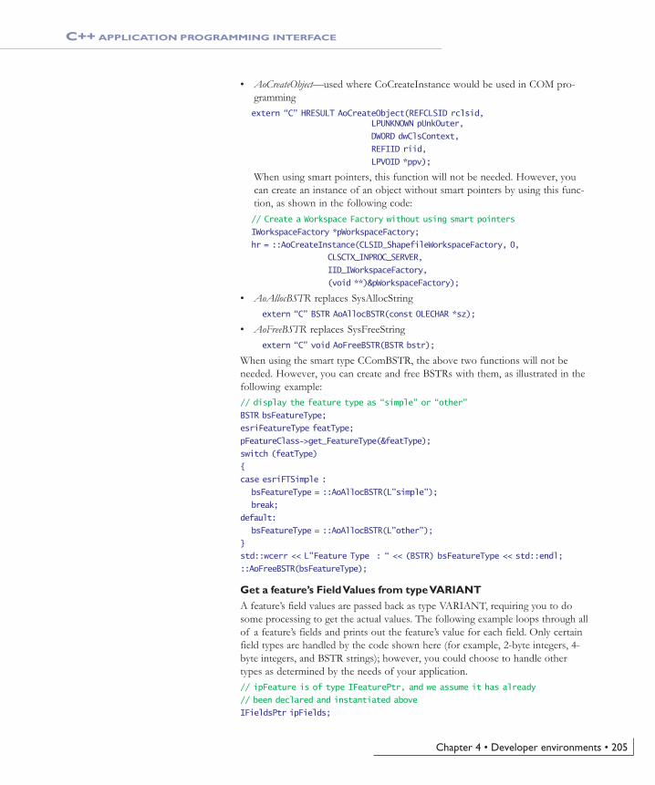
Chapter 4 • Developer environments • 205
• AoCreateObject—used where CoCreateInstance would be used in COM pro-grammingextern “C” HRESULT AoCreateObject(REFCLSID rclsid,
LPUNKNOWN pUnkOuter,
DWORD dwClsContext,
REFIID riid,
LPVOID *ppv);
When using smart pointers, this function will not be needed. However, youcan create an instance of an object without smart pointers by using this func-tion, as shown in the following code:// Create a Workspace Factory without using smart pointers
IWorkspaceFactory *pWorkspaceFactory;
hr = ::AoCreateInstance(CLSID_ShapefileWorkspaceFactory, 0,
CLSCTX_INPROC_SERVER,
IID_IWorkspaceFactory,
(void **)&pWorkspaceFactory);
• AoAllocBSTR replaces SysAllocStringextern “C” BSTR AoAllocBSTR(const OLECHAR *sz);
• AoFreeBSTR replaces SysFreeStringextern “C” void AoFreeBSTR(BSTR bstr);
When using the smart type CComBSTR, the above two functions will not beneeded. However, you can create and free BSTRs with them, as illustrated in thefollowing example:// display the feature type as “simple” or “other”
BSTR bsFeatureType;
esriFeatureType featType;
pFeatureClass->get_FeatureType(&featType);
switch (featType)
{
case esriFTSimple :
bsFeatureType = ::AoAllocBSTR(L”simple”);
break;
default:
bsFeatureType = ::AoAllocBSTR(L”other”);
}
std::wcerr << L”Feature Type : “ << (BSTR) bsFeatureType << std::endl;
::AoFreeBSTR(bsFeatureType);
Get a feature’s Field Values from type VARIANTA feature’s field values are passed back as type VARIANT, requiring you to dosome processing to get the actual values. The following example loops through allof a feature’s fields and prints out the feature’s value for each field. Only certainfield types are handled by the code shown here (for example, 2-byte integers, 4-byte integers, and BSTR strings); however, you could choose to handle othertypes as determined by the needs of your application.// ipFeature is of type IFeaturePtr, and we assume it has already
// been declared and instantiated above
IFieldsPtr ipFields;
C++ APPLICATION PROGRAMMING INTERFACE
Ch04_EngineAPIs.pmd 4/2/2004, 9:04 AM205

206 • ArcGIS Engine Developer Guide
hr = ipFeature->get_Fields(&ipFields);
long fieldCount;
hr = ipFields->get_FieldCount(&fieldCount);
IFieldPtr ipField;
CComVariant fieldValue;
for (long i=0; i<fieldCount; i++)
{
hr = ipFields->get_Field(i, &ipField);
hr = ipFeature->get_Value(i, &fieldValue);
// Get field’s value based on its type
switch (fieldValue.vt)
{
case VT_I2:
std::cerr << fieldValue.iVal << std::endl;
break;
case VT_I4:
std::cerr << fieldValue.lVal << std::endl;
break;
case VT_R4:
std::cerr << fieldValue.fltVal << std::endl;
break;
case VT_R8:
std::cerr << fieldValue.dblVal << std::endl;
break;
case VT_BSTR:
std::wcerr << fieldValue.bstrVal << std::endl;
break;
default:
std::wcerr << “Field type not supported.\n”;
break;
}
}
Cocreate an object with a smart pointer reference after the smart pointer isdeclared:A class is often cocreated at the same time that a smart pointer is declared:IFooPtr ipFoo(CLSID_Foo);
However, in certain cases, it may be necessary for you to declare the smartpointer first and cocreate the class later. This can be accomplished in the manner
C++ APPLICATION PROGRAMMING INTERFACE
Ch04_EngineAPIs.pmd 4/2/2004, 9:04 AM206

Chapter 4 • Developer environments • 207
below. Notice the use of the ‘dot’ member selection operator, as opposed to thearrow member selection operator that is usually used with smart pointer types:IFooPtr ipFoo;
// more code would be here
ipFoo.CreateInstance(CLSID_Foo);
Inline Query Interface (QI)You can use the built-in smart types to QI to other supported interfaces of acoclass on which you have an interface:// ipTin is of type ITinPtr and is an interface to an instance of
// the Tin coclass
// The Tin coclass supports both the ITin and ITinSurface interfaces
// GetVolume is a method on the ITinSurface interface
((ITinSurfacePtr) ipTin)->GetVolume(…);
Raw pointers in function signaturesRather than having a smart pointer in the function signature, consider using a rawpointer to save the overhead of a call to the smart pointer constructor/destructorupon invocation of the function. You can still pass smart pointer objects tofunctions since each smart pointer has an overloaded pointer operator that re-turns the underlying raw pointer. The following example illustrates this:HRESULT DoRasterOp(IRaster* pRaster); // Function dec: raw pointer
IRasterPtr ipRaster;
HRESULT hr = DoRasterOp(ipRaster); // Pass in smart pointer
Return ArcObjects from functionsThis tip builds on the previous one. In this case, raw pointers are used in thefunction declaration and a double indirection is used for the object that will bereturned. This allows you to alter what the pointer you are passed points to.Next, initialize a smart pointer object with the value you wish to return andassign it to the pointer you were passed in.
HRESULT GetTinWorkspace(char* path, ITinWorkspace** ppTinWorkspace)
{
HRESULT hr = S_OK;
IWorkspaceFactoryPtr ipWorkspaceFactory(CLSID_TinWorkspaceFactory);
IWorkspacePtr ipWork;
hr = ipWorkspaceFactory->OpenFromFile(CComBSTR(path), 0, &ipWork);
if (FAILED(hr) || ipWork == 0)
return E_FAIL;
// Initialize ipTinWorkspace with ipWork
ITinWorkspacePtr ipTinWorkspace(ipWork);
*ppTinWorkspace = ipTinWorkspace;
// AddRef() if the assignment worked
if (*ppTinWorkspace)
(*ppTinWorkspace)->AddRef();
return hr;
}
Notice the call to AddRef. This is required toensure that resources are managed properly.
C++ APPLICATION PROGRAMMING INTERFACE
Ch04_EngineAPIs.pmd 4/2/2004, 9:04 AM207

208 • ArcGIS Engine Developer Guide
IUIDThere are several methods in ArcObjects that take an IUID object as a parameter.An IUID object is a globally unique identifier object. It can be either a GUID, asshown in the example below, or a ProgID.IUIDPtr ipUID(CLSID_UID);
IEnumLayerPtr ipEnumLayer;
// use IGeoFeatureLayer’s GUID
hr = ipUID->put_Value(CComVariant(L”{E156D7E5-22AF-11D3-9F99-00C04F6BC78E}”));
hr = ipMap->get_Layers(ipUID, VARIANT_TRUE, &ipEnumLayer);
Replicate the functionality of instanceof (Java) or TypeOf (Visual Basic)It is common to have an interface pointer that could point to one of severalcoclasses. You can find out more information about the coclass by attempting toQI to other interfaces using if/else logic. For example, both the RasterDataset andFeatureDataset coclasses implement IDataset. If you are passed IDataset as a func-tion parameter you can determine which coclass the IDataset references as fol-lows:
void Foo (IDataset *pDataset)
{
IFeatureDatasetPtr ipFeatureDataset(ipDataset);
if (ipFeatureDataset != 0)
{
// use IFeatureDataset methods
}
else
{
IRasterDataset2Ptr ipRasterDataset(ipDataset);
if (ipRasterDataset!= 0)
{
// use IRasterDataset2 methods
}
}
}
ESRI System interfacesThe System library within ArcGIS Engine, which is included with ArcSDK.h,contains a number of interfaces that simplify programming. It contains compo-nents that expose services used by the other ArcGIS libraries.
GROUPS OF OBJECTS IN INTERFACES WITHOUT STL
ArcObjects contains several interfaces for managing groups of objects. Althoughthey are not all discussed here, the examples given illustrate some that can greatlysimplify your work with COM objects in C++. Standard Template Library (STL)types exist which are similar to some of these; however, these interfaces are oftensimpler than their STL counterparts and are already set up to be used with COMobjects. For additional details on any of the interfaces below, see ArcGIS Devel-oper Help for C++.
For further details on GUIDs, see ‘The MicrosoftComponent Object Model’ section earlier in this
chapter.
C++ APPLICATION PROGRAMMING INTERFACE
Ch04_EngineAPIs.pmd 4/2/2004, 9:04 AM208

Chapter 4 • Developer environments • 209
IArrayThe IArray interface provides access to members that control a simple array ofobjects. There are multiple related interfaces, such as IDoubleArray andIVariantArray. The following code snippet shows how to add the geometries ofthe features in a FeatureCursor to an array.// ipFeatureLayer is of type IFeatureLayerPtr and ipQueryFilter is of
// type IQueryFilterPtr. Both have already been declared and
// instantiated.
IArrayPtr ipCacheArray (CLSID_Array);
IFeatureCursorPtr ipFeatureCursor;
ipFeatureLayer->Search(ipQueryFilter, VARIANT_FALSE, &ipFeatureCursor);
IFeaturePtr ipFeature;
while (ipFeatureCursor->NextFeature(&ipFeature) == S_OK)
{
IGeometryPtr ipGeom;
ipFeature->get_ShapeCopy(&ipGeom);
ipCacheArray->Add((IUnknownPtr) ipGeom);
}
ISetThe ISet interface provides access to members that control a simple set of uniqueobjects. For example, the following code snippet cycles through a map’s layersand attempts to add all of the unique feature class workspaces that aren’t beingedited to a set.// ipMap is of type IMapPtr and was previously
// declared and instantiated
ISetPtr ipSet(CLSID_Set);
ILayerPtr ipLayer;
IFeatureLayerPtr ipFeatLayer;
IFeatureClassPtr ipFeatClass;
IDatasetPtr ipDataset;
IWorkspacePtr ipWorkspace;
IWorkspaceEditPtr ipWorkspaceEdit;
long layerCount;
hr = ipMap->get_LayerCount(&layerCount);
for (long i=0; i<layerCount; i++)
{
hr = ipMap->get_Layer(i, &ipLayer);
ipFeatLayer = ipLayer;
// layer might not be a feature layer
if (ipFeatLayer == 0 || FAILED(hr)) continue;
hr = ipFeatLayer->get_FeatureClass(&ipFeatClass);
// layer could reference bogus data
if (ipFeatClass == 0 || FAILED(hr)) continue;
ipDataset = ipFeatClass;
hr = ipDataset->get_Workspace (&ipWorkspace);
ipWorkspaceEdit = ipWorkspace;
C++ APPLICATION PROGRAMMING INTERFACE
Ch04_EngineAPIs.pmd 4/2/2004, 9:04 AM209

210 • ArcGIS Engine Developer Guide
// some data are not editable
if (ipWorkspaceEdit == 0 || FAILED(hr)) continue;
VARIANT_BOOL beingEdited;
hr = ipWorkspaceEdit->IsBeingEdited(&beingEdited);
if (!beingEdited)
{
// only adds unique workspaces
hr = ipSet->Add(ipWorkspace);
}
}
Copy objectsThe IClone interface is helpful when comparing and copying objects, saving timeand computing resources. Many coclasses support the IClone interface. See thedocumentation for IClone in ArcGIS Developer Help for details. The followingcode snippet clones a Point object:// ipMouseClickPoint is of type IPointPtr and was previously declared //and instantiated.
IClonePtr ipClone (ipMouseClickPoint);
IClonePtr ipCloned;
ipClone->Clone(&ipCloned);
Error handlingCOM methods return an HRESULT to signify the success or failure of a call, asdiscussed in the ‘Developing with ArcObjects’ section early in this chapter. Whenyou are programming with the C++ API you should check the returnedHRESULT of all calls to COM objects.
There are a few common HRESULTs that can be returned.
• S_OK signifies success
• E_FAIL indicates a failure.
• E_NOTIMPL indicates a method is not implemented
There are some macros that can be used to test the returned HRESULT.
• bool FAILED(HRESULT)For example, if the opening of a workspace in which you want to processdata fails, you will not be able to use the data. At that point, you should exitthe application to avoid a crash later on.// Open the workspace
IWorkspaceFactoryPtr ipWorkspaceFactory(CLSID_RasterWorkspaceFactory);
IWorkspacePtr ipWorkspace;
HRESULT hr = ipWorkspaceFactory->OpenFromFile(inPath, 0, &ipWorkspace);
if (FAILED(hr) || ipWorkspace == 0)
{
std::cerr << “Could not open the workspace.” << std::endl;
return E_FAIL;
}
You might notice that the samples and scenariosdo not follow the Good Error Handling practiced
outlined here. This is done simply to increasecode readability since error checking is not the
focus of those bits of code.
C++ APPLICATION PROGRAMMING INTERFACE
Ch04_EngineAPIs.pmd 4/2/2004, 9:04 AM210

Chapter 4 • Developer environments • 211
• bool SUCCEEDED(HRESULT)For example, if you are going to create a new raster dataset, you must firstknow that no dataset already exists with the desired name. To find out if sucha dataset exists, try to open it. If it succeeds, you know that you cannot createa new dataset with that name.// Check for existence of a dataset with the desired output name.
// If such exists, we can’t create a new one with the name.
IRasterDatasetPtr ipExistsCheck;
hr = ipRastWork->OpenRasterDataset(outFile, &ipExistsCheck);
if (SUCCEEDED(hr))
{
std::cerr << “A dataset with the output name already exists!” <<std::endl;
return E_FAIL;
}
Troubleshooting• Cannot open include file “ArcSDK.h”—If your sample is not compiling because
it cannot open ArcSDK.h, make sure that you have the correct argument forthe include directory: ArcGIS\include\CPPAPI. If it is correct and it is stillnot working, make sure the file is in that directory.
• Cannot open type library file “esriSystem.olb” —If your sample is not compilingbecause it cannot open an ESRI OLB file, make sure that you have the correctargument for the include directory: ArcGIS\Com. If it is correct and it is stillnot working, make sure the file is in that directory.
• Code is compiling but will not run. Sometimes I get an odd “abnormal program termina-tion” error.—If samples or your own code compiles but fails to run, make sureyou registered your ArcGIS Engine. Use the SoftwareAuthorization tool,found in Start > All Programs > ArcGIS and check current configuration. Ifthe configuration does not list “standardengine”, run the tool and follow itsprompts.
• Error: Please define either ESRI_WINDOWS or ESRI_UNIX—You need toinform the compiler which set of header files to use. You forgot to define theESRI_WINDOWS symbol.
LimitationsWhen using the C++ API, only Windows C++ command line applications aresupported. However, GUI applications can be built with the COM API (includ-ing Visual C++), and several ActiveX controls provide GIS functionality tostandalone GUI applications. For details, see the ‘Visual C++’ section earlier inthis chapter.
C++ APPLICATION PROGRAMMING INTERFACE
Ch04_EngineAPIs.pmd 4/2/2004, 9:04 AM211

Ch04_EngineAPIs.pmd 4/2/2004, 9:04 AM212

Licensing anddeployment5
Developing ArcGIS Engine applications cannot be undertaken in isolation from the
deployment of the final application. Deployment of your application involves three
separate processes: license initialization within your application, installation of the
ArcGIS Engine Runtime software, and the authorization of its use.
This chapter details each of these processes and examines the deployment
decisions that you , as developer, must make prior to distributing your ArcGIS
Engine applications.
Ch05_License.pmd 4/2/2004, 9:11 AM213

214 • ArcGIS Engine Developer Guide
ARCGIS LICENSE OPTIONS
One of the most important decisions you make as an ArcGIS Engine developer isto determine what the functional requirements of your prospective applicationare and the minimum licensing level needed to meet those needs. In most cases, itis inefficient for you to develop an application that requires an ArcGIS EngineRuntime with 3D, Spatial, and GeoDatabase options, just because you didn'tassess the actual needs of your organization or client and plan accordingly.
This section of the chapter details the myriad of licensing options available.
Ch05_License.pmd 4/2/2004, 9:11 AM214

Chapter 5 • Licensing and deployment • 215
One of the most important decisions you make as an ArcGIS Engine developer isto determine what the functional requirements of your prospective applicationare and the minimum licensing level needed to meet those needs. In most cases, itis inefficient for you to develop an application that requires an ArcGIS EngineRuntime with 3D, Spatial, and GeoDatabase options, just because you didn'tassess the actual needs of your organization or client and plan accordingly.
This section of the chapter details the myriad of options available for intializingyour application with multiple levels of licensing. It first dicusses them in detailand then provides a number of sample license initialization situations.
LICENSE INITIALIZATION
Each stand-alone application developed using ArcObjects must initialize itselfwith a suitable license to ensure it runs successfully on any machine to which it isdeployed. License initialization must be performed by an application, at applica-tion start time, before any ArcObjects are accessed. Failure to do so will result inapplication errors.
There are two types of licenses to consider when initializing an application:product licenses and, if an application uses any of the ArcGIS extension features,extension licenses. Each of these types of licenses are made available in certainlicense flavors—Engine Single Use, Desktop Concurrent Use, and Desktop SingleUse.
• Engine Single Use—provides access to either the ArcGIS Engine or Enginewith GeoDatabase Editing licenses. Each single use license is only available tothe machine on which it is installed.
• Desktop Concurrent Use—FlexLM technology is used to provide concurrentaccess to the ArcGIS Desktop products, ArcView, ArcEditor, ArcInfo, and itsextensions. The licenses can be available to multiple machines; they are storedon a license manager and checked out when being used.
• Desktop Single Use—provides access to Single Use ArcView, ArcEditor, andArcInfo licenses. Like the Engine Single Use licenses, each one is availableonly to the machine on which it is installed. Even though this is significantlydifferent than the Desktop Concurrent Use licensing, they actually utilize thesame technology. This means that there is no mechanism for you, as an ArcGISEngine developer, to differentiate between a Single Use and a Desktop Con-current license, and hence, they should be treated as the same.
CONSIDERATIONS FOR APPLICATIONS NOT USING ARCGISRUNTIME OPTIONS
Once an application has been initialized with a license it cannot be re-initialized;an application is initialized with a license for the duration of its life. Wheninitializing an application with a license the following must be considered:
• The types of product license that the application can run with. For example,an enterprise geodatabase editing application will not be able to run with anArcGIS Engine license or an ArcView license. However, it will be able to runwith an ArcGIS Engine with GeoDatabase Editing license, an ArcEditorlicense or an ArcInfo license.
STANDALONE EXECUTABLE LICENSE INITIALIZATION
Each of the sample applications that you build inChapter 6, 'Developer scenarios', also illustrates
the license initialization process.
While every standalone application must beinitialized, the following examples illustrate
situations that do not qualify as standalone andtherefore don't need to be initialized as
described:
• The application is a DLLthat will be incorpo-rated into an application that will itself perform
the license configuration.
• The application is an extension to ArcMap oranother third party application. The extension is
responsible for license management.
Ch05_License.pmd 4/2/2004, 9:11 AM215

216 • ArcGIS Engine Developer Guide
• The types of product license available to the application. For example, anapplication that can be run with an ArcGIS Engine license will also run withan ArcView, ArcEditor and ArcInfo license. However, you may not want toconsume an ArcInfo license with such an application.
Using an ArcView license on an ArcGIS Engine application will give you accessto all the functionality available to a standard Engine license. Likewise, using anArcEditor license on an ArcGIS Engine application with GeoDatabase Editingwill give you access to all the functionality available to an Engine license withGeoDatabase Editing.
Additional considerations for applications using ArcGIS extensionsWhen an application is initialized with a particular product license, a connectionis made to a license server. All subsequent calls to check extensions out and in aremade to the same license server. As such, you cannot use a combination of li-censes from difference license servers or Engine Single Use.
• If an application is initialized with a Desktop Concurrent license, the applica-tion will subsequently only be able to access that Desktop Concurrent licenseserver and its extension licenses.
• If an application is initialized with a Desktop Single Use license, the applica-tion will subsequently only be able to access that single use license server andits extension licenses.
• If an application is initialized with the Engine Single Use license on yourmachine, the application will subsequently only be able to access the EngineSingle Use extension licenses.
It is possible before initialization has been performed to query the license servers(Desktop Concurrent or Single Use) and Engine Single Use to see if the licensesyou require are available. If all the licenses you require are available using EngineSingle Use then we recommend you use it in preference to the Desktop Concur-rent and Desktop Single Use licenses. This means you will not limit the DesktopConcurrent licenses available to any other users.
The following extensions are available with Engine Single Use licenses:
• 3D Analyst
• Spatial Analyst
• StreetMap
STANDALONE EXECUTABLE LICENSE INITIALIZATION
For applications developed using the ArcGISControls, Table 1 describes each Controls run-
time license requirements.
Ch05_License.pmd 4/2/2004, 9:11 AM216

Chapter 5 • Licensing and deployment • 217
ArcGIS EngineSingle Use
licence
ArcReaderControlArcReaderControl ✓✓
✓
✓
✓
✓
✓
✓
✓
✓
✓
✓
✓
✓
✓
✓
✓
MapControl
PageLayoutControl
ReaderControl
ToolbarControl
TOCControl
GlobeControl
SceneControl
ArcGIS EngineSingle Use licencewith Engine SingeUse 3D Analyst
extension
ArcView, ArcEditor,ArcInfo Single
Use or DesktopCocurrent licence
ArcView, ArcEditor,ArcInfo Single
Use or DesktopCocurrent licencewith 3D Analyst
Extension
ArcReader
ENGINE SINGLE USE DESIGNER OPTION
The Engine Single Use designer extension is required when developing applica-tions with ArcObjects. This license works differently to the other extensions inthat:
• The extension is only needed when designing and developing applications; it isnever needed at run-time.
• The extension does not need to be checked out; it is automatically checkedout for you.
ArcGIS EngineSingle Use
licence
ArcReaderControlArcReaderControl
✓✓
✓
✓
✓
✓
✓
✓
✓
✓
✓
MapControl
PageLayoutControl
ReaderControl
ToolbarControl
TOCControl
GlobeControl
SceneControl
ArcGIS EngineSingle Use licencewith Engine Singe
Use designerextension
ArcGIS EngineSingle Use licencewith Engine Singe
Use designerextension and 3DAnalyst extension
ArcView, ArcEditor,ArcInfo Single
Use or DesktopCocurrent licence
ArcView, ArcEditor,ArcInfo Single
Use or DesktopCocurrent licence
with PublisherExtension
INITIALIZING AN APPLICATION WITH A LICENSE
The initialization of an application with a license must be performed in thefollowing order:
1. Check the product license is available.
2. Check extension licenses are available (if required).
3. Initialize the application with the product license.
4. As required, perform extension check outs and check ins.
5. Shutdown the application.
STANDALONE EXECUTABLE LICENSE INITIALIZATION
For applications that are developed using theArcGIS Controls, Table 2 describes each Controls
design-time license requirements.
Ch05_License.pmd 4/2/2004, 9:11 AM217

218 • ArcGIS Engine Developer Guide
STANDALONE EXECUTABLE LICENSE INITIALIZATION
CHECKING PRODUCT LICENSE AVAILABILITY
The product license that is chosen determines the functionality the applicationwill be able to access. Once the product license has been initialized it cannot bechanged for the duration of the applications life.
• If the product you require is not licensed you may optionally initialize theapplication with a higher product license.
• If there are no appropriate product licenses available the application shouldinform the user of the issue, and either allow the user to resolve the issue orexit the application.
CHECKING EXTENSION LICENSE AVAILABILITY
If an application has been designed to use extension functionality, it may checkfor the availability of extension licenses before the application is initialized.Checking the availability of an extension license must be done in conjunctionwith the product license that the application will ultimately be initialized with, asnot every extension license is available with every product license.
• If an extension required by the application for it to run successfully is notavailable, the application should inform the user of the issue, and exit theapplication.
• If the extension functionality is not necessary for the application to function,and the extension license is unavailable, the application should disable to theuser the functionality dependant upon the extension.
INITIALIZING THE APPLICATION
Once it has been established that the appropriate product and extension licensesare available the application should be initialized with the product license. Onceinitialized it is not possible to re-initialize the application.
CHECKING EXTENSIONS IN AND OUT
Extensions can either be checked out as and when an application requires theextension functionality, and checked in once the application has finished with thefunctionality; or the extension can be checked out directly after the application isinitialized and checked back in before shutdown. The way that the extensions arechecked in and out will depend on the type of product license the applicationwas initialized with.
• If the application was initialized with either of the Engine Single Use li-censes, any extensions used by the application will also be Engine Single Use.As such any extensions can be checked out directly after the application isinitialized and checked back in before shutdown.
• If the application was initialized with a license server and the extensions arerequired by the application for it to run successfully, the extensions should bechecked out directly after the application is initialized and checked back inbefore shutdown.
Ch05_License.pmd 4/2/2004, 9:11 AM218

Chapter 5 • Licensing and deployment • 219
STANDALONE EXECUTABLE LICENSE INITIALIZATION
• If the application was initialized with a license server and the extensionfunctionality is not necessary for the application to function, the extensionscan either be checked out directly after the application is initialized or checkedout as and when the extension functionality is required. When the extension ischecked in the functionality should be disabled.
SHUTDOWN
Before an application is shut down the AoInitialize object must be shut down.This ensures that any ESRI libraries that have been used are unloaded.
LICENSE INITIALIZATION FAILURE
If a product or extensions fails to check out the license status indicates the reasonfor the failure. Licenses can fail to check out for the following reasons:
• A product is not licensed.
• A license is unavailable because it is already being used (Desktop Concurrentlicenses only).
• An unexpected license failure due to system administration problems.
• The license is already initialized. An application is initialized with a productlicense for the duration of it life. It is possible to check what product licensean application has been initialized with. For example, if an application con-taining some enterprise GeoDatabase editing has been initialized with anEngine Single Use with GeoDatabase Editing or an ArcEditor or ArcInfolicense, the editing functionality can be enabled. If however the applicationhas been initialized with an Engine Single Use or ArcView license the editingfunctionality must be disabled.
EXAMPLE ONE
The application requires a minimum of an ArcGIS Engine license. If an ArcGISEngine license is not available, the application can run with an ArcView orArcEditor license but not an ArcInfo license (ArcInfo will provide all the func-tionality we require but we do not wish to consume an ArcInfo license for oursimple application). The application also requires 3D Analyst and Spatial Analystextension functionality for it to run successfully, so both of these extensions needto be checked out for the duration of the application. The following steps aretaken to initialize the application with a license.
Can the application be initialized with the ArcGIS Engine productlicense?1. Check whether an ArcGIS Engine product license is available.
2. Check whether a 3D Analyst extension license is available with the ArcGISEngine product license.
3. Check whether a Spatial Analyst extension license is available with theArcGIS Engine product license.
If any of these licenses are not available then the application cannot be initializedwith an ArcGIS Engine license. Can the application be initialized with an Arc-View product license instead?
Ch05_License.pmd 4/2/2004, 9:11 AM219

220 • ArcGIS Engine Developer Guide
STANDALONE EXECUTABLE LICENSE INITIALIZATION
If all of these licenses are available, initialize the application.
4. Check out the ArcGIS Engine product license by initializing the application.
If the license failed to check out, can the application be initialized with an Arc-View product license instead?
If the license checked out, check the extension licenses out.
5. Check out the 3D Analyst extension.
6. Check out the Spatial Analyst extension.
If either of the extension licenses failed to check out, the application cannot run.
If the extension licenses are checked out, the application has been successfullyconfigured with licenses.
Can the application be initialized with the ArcView product license?1. Check whether an ArcView product license is available.
2. Check whether a 3D Analyst extension license is available with the ArcViewproduct license.
3. Check whether a Spatial Analyst extension license is available with the Arc-View product license.
If any of these licenses are not available then the application cannot be initializedwith an ArcView license. Can the application be initialized with an ArcEditorproduct license instead?
If all of these licenses are available, initialize the application.
4. Check out the ArcView product license by initializing the application.
If the license failed to check out, can the application be initialized with anArcEditor product license instead?
If the license checked out, check the extension licenses out.
5. Check out the 3D Analyst extension.
6. Check out the Spatial Analyst extension.
If either of the extension licenses failed to check out, the application cannot run.Checking out Desktop Concurrent licenses may fail here as they may have beenchecked out by another application since this application checked their availabil-ity.
If the extension licenses are checked out, the application has been successfullyconfigured with licenses.
Can the application be initialized with the ArcEditor product license?1. Check whether an ArcEditor product license is available.
2. Check whether a 3D Analyst extension license is available with the ArcEditorproduct license.
3. Check whether a Spatial Analyst extension license is available with theArcEditor product license.
If any of these licenses are not available then the application cannot be initialized
Ch05_License.pmd 4/2/2004, 9:11 AM220

Chapter 5 • Licensing and deployment • 221
with an ArcEditor license and the application cannot run.
If all of these licenses are available, initialize the application.
4. Check out the ArcEditor product license by initializing the application.
If the license failed to check out, the application cannot run.
If the license checked out, check the extension licenses out.
5. Check out the 3D Analyst extension.
6. Check out the Spatial Analyst extension.
If either of the extension licenses failed to check out, the application cannot run.Checking out Desktop Concurrent licenses may fail here as they may have beenchecked out by another application since this application checked their availabil-ity.
If the extension licenses are checked out, the application has been successfullyconfigured with licenses.
EXAMPLE 2
The application is an enterprise GeoDatabase editing application so requires aminimum of an ArcGIS Engine with GeoDatabase Editing license. If an ArcGISEngine with GeoDatabase Editing license is not available, the application can runwith an ArcEditor or ArcInfo license. The application requires the Spatial Analystextension functionality for it to run successfully, so the extension needs to bechecked out for the duration of the application. The following steps are taken toinitialize the application with a license.
Can the application be initialized with the ArcGIS Engine with geoda-tabase editing product license?1. Check whether an ArcGIS Engine with GeoDatabase Editing product license
is available.
2. Check whether a Spatial Analyst extension license is available with theArcGIS Engine with GeoDatabase Editing product license.
If any of these licenses are not available then the application cannot be initializedwith an ArcGIS Engine with GeoDatabase Editing license. Can the applicationbe initialized with an ArcEditor product license instead?
If all of these licenses are available, initialize the application.
3. Check out the ArcGIS Engine with GeoDatabase Editing product license byinitializing the application.
If the license failed to check out, can the application be initialized with anArcEditor product license instead?
If the license checked out, check the extension license out.
4. Check out the Spatial Analyst extension.
If the extension licenses failed to check out, the application cannot run. Checking
STANDALONE EXECUTABLE LICENSE INITIALIZATION
Ch05_License.pmd 4/2/2004, 9:11 AM221

222 • ArcGIS Engine Developer Guide
out Desktop Concurrent licenses may fail here as they may have been checked outby another application since this application checked their availability.
If the extension license checked out, the application has been successfully config-ured with licenses.
Can the application be initialized with the ArcEditor product license?1. Check whether an ArcEditor product license is available.
2. Check whether a Spatial Analyst extension license is available with theArcEditor product license.
If any of these licenses are not available then the application cannot be initializedwith an ArcEditor license. Can the application be initialized with an ArcInfoproduct license instead?
If all of these licenses are available, initialize the application.
3. Check out the ArcEditor product license by initializing the application.
If the license failed to check out, can the application be initialized with anArcInfo product license instead?
If the license checked out, check the extension license out.
4. Check out the Spatial Analyst extension.
If the extension license failed to check out, the application cannot run. Checkingout Desktop Concurrent licenses may fail here as they may have been checked outby another application since this application checked their availability.
If the extension license checked out, the application has been successfully config-ured with licenses.
Can the application be initialized with the ArcInfo product license?1. Check whether an ArcInfo product license is available.
2. Check whether a Spatial Analyst extension license is available with theArcInfo product license.
If any of these licenses are not available then the application cannot be initializedwith an ArcInfo license and the application cannot run.
If all of these licenses are available, initialize the application.
3. Check out the ArcInfo product license by initializing the application.
If the license failed to check out, the application cannot run.
If the license checked out, check the extension license out.
4. Check out the Spatial Analyst extension.
If the extension license failed to check out, the application cannot run. Checkingout Desktop Concurrent licenses may fail here as they may have been checked outby another application since this application checked their availability.
If the extension license checked out, the application has been successfully config-ured with licenses.
STANDALONE EXECUTABLE LICENSE INITIALIZATION
Ch05_License.pmd 4/2/2004, 9:11 AM222

Chapter 5 • Licensing and deployment • 223
EXAMPLE 3
The application requires a minimum of an ArcGIS Engine license. If an ArcGISEngine license is not available, the application should be able to run with anArcView, ArcEditor or ArcInfo license. The application requires 3D Analystfunctionality, but not for the application to run successfully, so the extension willbe checked out as needed.
Can the application be initialized with the ArcGIS product license?1. Check whether an ArcGIS Engine product license is available.
2. Check whether a 3D Analyst extension license is available with the ArcGISEngine product license.
If either of these licenses are not available then the application cannot be initial-ized with an ArcGIS Engine license. Can the application be initialized with anArcView product license instead?
If both these licenses are available, initialize the application.
3. Check out the ArcGIS Engine product license by initializing the application.
If the license failed to check out then the application cannot run. Can the appli-cation be initialized with an ArcView product license instead?
If the license is checked out, the application has been successfully configuredwith a license, but the functionality using the 3D Analyst extension should bedisabled.
Can the application be initialized with the ArcView product license?1. Check whether an ArcView product license is available.
2. Check whether a 3D Analyst extension license is available with the ArcViewproduct license.
If either of these licenses are not available then the application cannot be initial-ized with an ArcView license. Can the application be initialized with anArcEditor product license instead?
If both these licenses are available, initialize the application.
3. Check out the ArcView product license by initializing the application.
If the license failed to check out then the application cannot run. Can the appli-cation be initialized with an ArcEditor product license instead?
If the license is checked out, the application has been successfully configuredwith a license, but the functionality using the 3D Analyst extension should bedisabled.
Can the application be initialized with the ArcEditor product license?1. Check whether an ArcEditor product license is available.
2. Check whether a 3D Analyst extension license is available with the ArcEditorproduct license.
If either of these licenses are not available then the application cannot be initial-ized with an ArcInfo license. Can the application be initialized with an ArcInfo
STANDALONE EXECUTABLE LICENSE INITIALIZATION
Ch05_License.pmd 4/2/2004, 9:11 AM223

224 • ArcGIS Engine Developer Guide
product license instead?
If both these licenses are available, initialize the application.
3. Check out the ArcEditor product license by initializing the application.
If the license failed to check out then the application cannot run. Can the appli-cation be initialized with an ArcInfo product license instead?
If the license is checked out, the application has been successfully configuredwith a license, but the functionality using the 3D Analyst extension should bedisabled.
Can the application be initialized with the ArcInfo product license?1. Check whether an ArcInfo product license is available.
2. Check whether a 3D Analyst extension license is available with the ArcInfoproduct license.
If either of these licenses are not available then the application cannot be initial-ized with an ArcInfo license.
If both these licenses are available, initialize the application.
3. Check out the ArcInfo product license by initializing the application.
If the license failed to check out then the application cannot run.
If the license is checked out, the application has been successfully configuredwith a license, but the functionality using the 3D Analyst extension should bedisabled.
Using the 3D Analyst functionality1. Check whether the 3D Analyst extension is already checked out
If the license is checked out the application can use the 3D Analyst functionality.
If the license is not checked out, check the license out.
2. Check out the 3Dl Analyst extension.
If the license failed to check out then the application cannot use the 3D Analystfunctionality. Checking out a Desktop Concurrent license may fail here as it mayhave been checked out by another application since this application checked itsavailability.
If the license is checked out the application can use the 3D Analyst.
STANDALONE EXECUTABLE LICENSE INITIALIZATION
Ch05_License.pmd 4/2/2004, 9:11 AM224

Chapter 5 • Licensing and deployment • 225
The ArcGIS Engine Runtime setup program is available for deployment onMicrosoft Windows operating systems.
The following includes a brief introduction to the technology used to create thesetup program and discusses various deployment methods for the ArcGIS EngineRuntime setup on Windows.
WHAT IS THE ARCGIS ENGINE RUNTIME SETUP?
The ArcGIS Engine Runtime setup was created using Microsoft Windows In-staller technology. This technology uses a package file (.msi) and a client-sideinstaller service (msiexec.exe). The Windows Installer is a service that runs onyour operating system. This service enables the operating system to manage theinstallation and uses the information contained within the package file to installthe software.
The Msiexec.exe program is a component of Windows Installer. Msiexec.exe usesa dynamic link library, Msi.dll, to read the package files (.msi), apply transforms(.mst), and incorporate command-line options.
More information on Windows Installer can be found in the Windows InstallerSoftware Development Kit (SDK).
http://www.microsoft.com/msdownload/platformSDK/sdkupdate/
DEPLOYING ARCGIS ENGINE RUNTIME
An ArcGIS Engine Runtime developed application requires ArcGIS EngineRuntime to be installed on the end-user’s machine. To ensure that ArcGIS EngineRuntime is on the machine, you can:
Have the user run the ArcGIS Engine Runtime setup directly1. The user can launch the setup from an ArcGIS Engine Runtime CD
2. Before proceeding with the setup, the user will need to check if ArcGISEngine Runtime has already been installed on their machine. To check ifArcGIS Engine Runtime is on the machine:
i. Go to Control Panel > Add/Remove Programs.
ii. In the programs list, check if ArcGIS Engine Runtime is listed. If itis, ArcGIS Engine Runtime has been installed on this machine. Click SupportInformation to verify the product version number is 9.0.
3. If ArcGIS Engine Runtime is installed on the machine, the user can proceedwith installing your developed application.
4. If the ArcGIS Engine Runtime setup is launched, and ArcGIS EngineRuntime already exists on the machine the setup will execute as a maintenanceinstallation.
5. Before proceeding with the setup, the user must check that no ArcGISproducts of version less than 9.0 are installed on the machine. This includes:ArcIMS, ArcGIS Desktop, ArcGIS Workstation and ArcReader. To check ifany of these products are on the machine:
i. Go to Control Panel > Add/Remove Programs.
DEPLOYING ARCGIS ENGINE RUNTIME
Ch05_License.pmd 4/2/2004, 9:11 AM225

226 • ArcGIS Engine Developer Guide
ii. In the programs list, check to see if any ArcGIS Products areinstalled on the machine. If an ArcGIS product is listed, click SupportInformation to determine the product version number. If the version is lessthan 9.0, the product should be removed before installing ArcGIS EngineRuntime 9.0.
6. If ArcGIS Engine Runtime is not installed on the machine, the user mustlaunch the ArcGIS Engine Runtime Setup.exe before installing your devel-oped application.
7. If your application requires the Java or .NET installation feature, the usermust check that these features are installed. Java and .NET are optionalinstallation features and are not installed with a typical ArcGIS EngineRuntime installation. To check if these features are installed:
i. Go to Control Panel > Add/Remove Programs
ii. In the programs list, check if ArcGIS Engine Runtime is listed. Ifit is, ArcGIS Engine Runtime has been installed on this machine.
iii. Click Change on the ArcGIS Engine Runtime feature, then Modify.The Select Features dialog box shows the current state of the ArcGIS En-gine Runtime installation. A hard drive icon illustrates the features installedon the machine. A red cross illustrates the features not installed on themachine, but available for installation.
iv. To install a feature, the user must select the feature, right click andselect Will be installed on local hard drive.
Include the ArcGIS Engine Runtime setup in your application’s setupprogram1. As a developer, you can include the ArcGIS Engine Runtime setup in your
application’s setup using a number of methods. The methods for deployingArcGIS Engine Runtime are discussed later in this chapter.
2. Before your setup launches the ArcGIS Engine Runtime setup, you need todetermine if ArcGIS Engine Runtime already exists on the user’s machine byperforming a system check. Performing a system check is discussed later in thischapter.
3. If ArcGIS Engine Runtime is not installed on the machine, you can install itby using one of the deployment options discussed below.
4. If ArcGIS Engine Runtime is already installed on the machine, you do notneed to install ArcGIS Engine Runtime and you can instead proceed withinstalling your application only.
5. If your application requires the Java or .NET installation feature, you mustcheck that these features are installed (discussed later in this chapter). Javaand .NET are optional installation features and are not installed with atypical ArcGIS Engine Runtime installation. If these features are not in-stalled and your application requires one or both of them, you will need toinstall the feature(s) required.
DEPLOYING ARCGIS ENGINE RUNTIME
Ch05_License.pmd 4/2/2004, 9:11 AM226

Chapter 5 • Licensing and deployment • 227
ARCGIS ENGINE RUNTIME SETUP FEATURES
An .msi setup consists of features. Features are a group of components a user caninstall. The ArcGIS Engine Runtime setup consists of the following installationfeatures:
ArcEngine
JavaRuntime
DotNetRuntime
ArcGIS Engine
ArcGIS Engine Java Runtime
ArcGIS Engine .Net Runtime
ArcGIS Engine
Java Archives
.Net Assemblies
Feature Descriptive Feature Name Description
SYSTEM REQUIREMENTS FOR ARCGIS ENGINE RUNTIME
ArcGIS Engine Runtime is supported on Windows NT SP 6a, Windows 2000,Windows XP Professional and Windows 2003 Server.
For additional or updated information regarding ArcGIS Engine Runtime systemrequirements, visit: http://support.esri.com.
ARCGIS ENGINE RUNTIME INSTALLATION LOCATION
The ArcGIS 9.0 products, ArcGIS Engine Runtime, ArcGIS Engine DeveloperKit, ArcGIS Desktop, ArcReader standalone and ArcGIS Server will install to thesame installation directory. The first ArcGIS 9.0 product installed will determinethe installation location for all subsequent ArcGIS 9.0 products.
NOTE: If you have ArcIMS® ArcMap Server 9.0 already installed, ArcGIS 9.0products will default to the ArcIMS installation location.
For example, if ArcGIS Desktop is installed to C:\Desktop, the installationlocation for ArcGIS 9.0 will be C:\Desktop\ArcGIS. If you install ArcGISEngine Runtime next, you will not be provided with the opportunity to browseto an installation location. The ArcGIS Desktop installation has predeterminedthe installation location for all ArcGIS 9.0 products. Therefore, in this example,ArcGIS Engine Runtime will also be installed to C:\Desktop\ArcGIS.
If you run out of disk space while installing an ArcGIS 9.0 product, you willneed to uninstall all ArcGIS 9.0 products (listed above) and reinstall them to alocation where more disk space is available. ArcGIS 9.0 products (excludingArcSDE, ArcIMS and ArcINFO Workstation) cannot be installed to differentlocations.
DEPLOYMENT METHODS
There are two recommended methods for deploying ArcGIS Engine Runtime.
1. The user installs ArcGIS Engine Runtime setup directly from the CDThe ArcGIS Engine Runtime setup can be redistributed on CD. You may copythe contents of ArcGIS Engine Runtime CD image and create additionalCD’s, or you may contact ESRI to obtain additional ArcGIS Engine RuntimeCD’s.
Additional requirements for running the setup directly from the CD:• The user will need to check if ArcGIS Engine Runtime has already been
installed on their machine. If ArcGIS Engine Runtime is already installed on
DEPLOYING ARCGIS ENGINE RUNTIME
Ch05_License.pmd 4/2/2004, 9:11 AM227

228 • ArcGIS Engine Developer Guide
the machine, the user can proceed with installing your developed application.If the ArcGIS Engine Runtime setup is launched, and ArcGIS EngineRuntime already exists on the machine the setup will execute as a maintenanceinstallation.
• ArcGIS Engine Runtime 9.0 cannot be installed on a machine with anyArcGIS Products less than version 9.0. ArcGIS Products less than version 9.0must be uninstalled before installing ArcGIS Engine Runtime 9.0.
• If any of the ArcGIS Engine Runtime features required for your applicationare not installed, the user should install them. If the required ArcGIS EngineRuntime features are on the machine they do not have to run the ArcGISEngine Runtime setup.
For additional ArcGIS Engine Runtime CD’s contact ESRI Customer Service atwww.esri.com, or in the U.S. call 888-377-4575, or contact your local ESRIRegional Office.
2. Incorporate the ArcGIS Engine Runtime setup to run within yourapplication’s setup programArcGIS Engine can be installed without a user interface by running the setupusing Windows Installer command line parameters.
The ArcGIS Engine Runtime setup can be incorporated using the followingoptions:
a. At the end of an msi-based setup
b. Within a batch file
c. Within a scripted setup
Examples of these options are provided in this chapter.
Additional requirements for incorporating ArcGIS Engine Runtimesetup:If any of the ArcGIS Engine Runtime features required for your application arenot installed, your setup should add them. If the required ArcGIS EngineRuntime features are on the machine, you do not have to run the ArcGIS EngineRuntime setup.
When ArcGIS Engine Runtime is installed, a registry entry is created for it atthe following location:HKEY_LOCAL_MACHINE\Software\ESRI\ArcGIS Engine Runtime
The RealVersion value of this registry key will be 9.0
You can use this key to check whether ArcGIS Engine Runtime is installed onthe user’s machine.
1. Perform a system check for ArcGIS Engine Runtime optional installationfeaturesIf your application requires ArcGIS Engine Runtime .NET or Java featuresto be installed, you must check the user’s system for the presence of theappropriate .NET or Java installation feature as well as ArcGIS EngineRuntime (see Perform a system check for ArcGIS Engine Runtime).
DEPLOYING ARCGIS ENGINE RUNTIME
Ch05_License.pmd 4/2/2004, 9:11 AM228

Chapter 5 • Licensing and deployment • 229
The following registry entry will determine the installation state of ArcGISEngine Runtime features:
[HKEY_CLASSES_ROOT\Installer\Features\7A1A3A9178A2BC74EB114EA6B5DB1C1B]
“Registry”=””
“ArcEngine”=””
“DotNetRuntime”=”ArcEngine” or “?ArcEngine”
“JavaRuntime”=”ArcEngine” or “?ArcEngine”
To determine if the .NET feature is installed:The .NET ArcGIS Engine installation feature requires .NET Framework 1.1to be installed on the machine. The following registry key can be used todetermine whether the .NET ArcGIS Engine feature is installed:
HKEY_CLASSES_ROOT\Installer\Features\7A1A3A9178A2BC74EB114EA6B5DB1C1B
The DotNetRuntime string value represents the .NET ArcGIS Engine installa-tion feature.
If a DotNetRuntime string value under this registry key is not displayed,.NET Framework 1.1 was not installed on the machine at the time theArcGIS Engine Runtime setup was run.
If the DotNetRuntime feature IS NOT installed then”DotNetRuntime”=”?ArcEngine”
If DotNetRuntime IS installed then”DotNetRuntime”=”ArcEngine”
To determine if the Java feature is installed:The following registry key can be used to determine whether the .Java ArcGISEngine feature is installed:
HKEY_CLASSES_ROOT\Installer\Features\7A1A3A9178A2BC74EB114EA6B5DB1C1B
The JavaRuntime string value represents the .Java ArcGIS Engine installationfeature.If JavaRuntime IS NOT installed then
”JavaRuntime”=”?ArcEngine”
If JavaRuntime IS installed then”JavaRuntime”=”ArcEngine”
If you detect that a required installation feature is not installed, you will needto install only that feature using the ADDLOCAL Windows Installer com-mand within your script. For example, ADDLOCAL=DotNetRuntime orADDLOCAL=JavaRuntime.
If you choose to install only the DotNetRuntime or JavaRuntime feature, andthe ArcEngine feature (main ArcGIS Engine installation feature) has not beeninstalled, the setup will include the ArcEngine feature during installation.
If .NET Framework 1.1 is not detected on the machine, the DotNetRuntimefeature will be hidden, and will not be installed.
The following are requirements that need to be taken into consideration whenincorporating the ArcGIS Engine Runtime setup within your application’s setupprogram.
DEPLOYING ARCGIS ENGINE RUNTIME
Ch05_License.pmd 4/2/2004, 9:11 AM229

230 • ArcGIS Engine Developer Guide
2. The ArcGIS Engine Runtime setup uses Windows Installer 2.0.
• The ArcGIS Engine Runtime setup uses Windows Installer 2.0. WindowsInstaller version 2.0 must be installed and running on the target machine priorto running the Engine Runtime setup using command line parameters. Tocheck the version of Windows Installer on the machine:
i. Locate msiexec.exe in the system32 folder.
ii. Right click on msiexec.exe and select Properties.
iii.On the Properties dialog box, select the Version tab to check the fileversion.
• If you are including the ArcGIS Engine Runtime setup in a non-msi-basedsetup, the end-user will require Microsoft Installer version 2.0 to be installedon their machine. The ArcGIS Engine Runtime setup uses the WindowsInstaller technology.
• If you will be launching the Engine Runtime setup at the end of an msi-basedsetup, you must create your msi setup using Windows Installer version 2.0 orhigher, to be compatible with the ArcGIS Engine Runtime setup.
• The ArcGIS Engine Runtime msi cannot be nested within an msi. Each prod-uct, including ArcGIS Engine Runtime must be listed individually in Add/Remove Programs.
• The Windows installer version 2.0 setup is available from <ArcGIS EngineRuntime CD>\Support\MSI\instmsiw.exe
3. Perform a system check for ArcGIS Engine Runtime
If you are including the ArcGIS Engine Runtime setup, in your application’ssetup program, you must perform a system check on the users machine todetect whether ArcGIS Engine Runtime has already been installed. If theArcGIS Engine Runtime setup is launched, and ArcGIS Engine Runtimealready exists on the machine the setup will execute as a maintenance installa-tion.
Sample Scripts:The following is an example of the command line parameters implementedwithin a batch file that could be used to install only the ArcGIS Engine Runtime.NET feature:REM ############################
REM Set variables
SET MSI_PATH=\\CDROM\Setup.msi
REM ############################
REM Launch MSI Silently - NO UI
msiexec.exe /i “%MSI_PATH%” /qn ADDLOCAL=DotNetRuntime
Note: In the above example, if .NET Framework 1.1 is not detected on themachine, the DotNetRuntime feature will not be installed.
The following is an example of the command line parameters implemented
DEPLOYING ARCGIS ENGINE RUNTIME
Ch05_License.pmd 4/2/2004, 9:11 AM230
Chapter 5 • Licensing and deployment • 231
within a batch file that could be used to install only the ArcGIS Engine RuntimeJava feature:REM ############################
REM Set variables
SET MSI_PATH=\\CDROM\Setup.msi
REM ############################
REM Launch MSI Silently - NO UI
msiexec.exe /i “%MSI_PATH%” /qn ADDLOCAL=JavaRuntime
DEPLOYMENT OPTION EXAMPLES
The following are examples of deployment options for the ArcGIS EngineRuntime setup.
At the end of an MSI-based setupThe following example uses Wise for Windows Installer MSI Authoring programto launch the ArcGIS Engine Runtime setup at the end of another Msi-basedsetup. The ArcGIS Engine Runtime setup will be launched after clicking theFinish button. The example below suggests custom actions behind the Finishbutton.
This example assumes that the ArcGIS Engine Runtime setup resides in thesame location as your application’s setup program. In this case, Setup.exe residesin a folder named ArcEngine. To launch ArcGIS Engine Runtime Setup.exelocated in an ArcEngine folder on your application’s media:
1. Create Properties MSI_PATH and ArcEngineExists and initialize them to 1 inthe Property table.
2. Perform a system check for ArcGIS Engine Runtime at the beginning of yoursetup program. The system check should search for the following registry keyand set the property ArcEngineExists to True if the registry value returned is9.0. HKEY_LOCAL_MACHINE\Software\ESRI\ArcGIS Engine Runtimeand the RealVersion value will be 9.0.
3. Create a Custom action called Launch_Engine_MSI. Use the “Execute Pro-gram from Path” type of custom action. Set the Property in this customaction to MSI_PATH. The path to execute the program from is the path
DEPLOYING ARCGIS ENGINE RUNTIME
Ch05_License.pmd 4/2/2004, 9:11 AM231

232 • ArcGIS Engine Developer Guide
specified in the Property field, in this case MSI_PATH. No Command Line isneeded as setup.exe is being launched.
4. In the Exit Dialog of your application’s setup program, add two actionsbehind the Finish button control.
The first action sets the MSI_PATH property to[SourceDir]ArcEngine\Setup.exe. This will change depending on where theArcGIS Engine Runtime setup is located on the media. In this example,Setup.exe is located on the CD in a folder named ArcEngine.
DEPLOYING ARCGIS ENGINE RUNTIME
Ch05_License.pmd 4/2/2004, 9:11 AM232

Chapter 5 • Licensing and deployment • 233
The second action calls the Launch_Engine_MSI that you previously created.
Both these custom actions should execute only if the propertyArcEngineExists does not equal True.
Within a scripted setupA scripted setup can be used to install ArcGIS Engine Runtime using commandline parameters (the example below uses the Wise Install Master Setup AuthoringSoftware):
Note: In the example below MSI_PATH will change depending on where theArcGIS Engine Runtime setup is located on the media. In this example,Setup.msi is located on the CD in a folder named ArcEngineRem Set variable
Set Variable MSI_PATH to \\CDROM\ArcEngine\Setup.msi
Rem Launch ArcGIS Runtime setup program silently – No UI
Execute %SYS32%\msiexec.exe /i %MSI_PATH% /qn (Wait)
Rem Launch ArcGIS Runtime setup program silently – No UI except for a modaldialog box displayed at the end
Execute %SYS32%\msiexec.exe /i %MSI_PATH% /qn+ (Wait)
Within a batch fileThe following are examples of command line parameters implemented within abatch file that could be used to install ArcGIS Engine Runtime:
Note: In the example below MSI_PATH will change depending on where theArcGIS Engine Runtime setup is located on the media. In this example,Setup.msi is located on the CD in a folder named ArcEngine.REM ############################
REM Set variables
SET MSI_PATH=\\CDROM\ArcEngine\Setup.msi
REM ############################
REM Launch MSI Silently - NO UI
msiexec.exe /i “%MSI_PATH%” /qn
REM Launch MSI Silently - Reduced UI
msiexec.exe /i “%MSI_PATH%” /qb
REM Launch MSI Silently - No UI except for a modal dialog box displayed atthe end.
msiexec.exe /i “%MSI_PATH%” /qn+
DEPLOYING ARCGIS ENGINE RUNTIME
Ch05_License.pmd 4/2/2004, 9:11 AM233

234 • ArcGIS Engine Developer Guide
Launch the setup from the ArcGIS Engine Runtime CDThe ArcGIS Engine Runtime setup can be launched manually from the CD usingsetup.exe.
1. Copy the contents of the ArcGIS Engine Runtime CD image and createadditional CD’s, or include the ArcGIS Engine Runtime CD image on thesame CD as your application’s setup program
2. Inform your user of the following:
a. Check to see if ArcGIS Engine Runtime 9.0 is already installed on themachine
b. Check that no ArcGIS Products of version less than 9.0 are installed on themachine. If they are, they must be uninstalled before installing ArcGIS EngineRuntime 9.0.
c. If ArcGIS Engine Runtime 9.0 is already installed, proceed with the devel-oped application’s setup program.
d. If ArcGIS Engine Runtime 9.0 is not installed, launch Setup.exe from theArcGIS Engine Runtime CD image location. Once installation of ArcGISEngine Runtime is complete, launch the developed application’s setup pro-gram.
HOW TO USE INSTALLATION COMMAND LINE PARAMETERS
The ArcGIS Engine Runtime setup can be installed using the .msi file and client-side installer service (msiexec.exe) command line parameters. The table belowillustrates some available msiexec.exe command line parameters:
(SOURCE: http://msdn.microsoft.com/library/default.asp?url=/library/en-us/msi/setup/command_line_options.asp)
/l
/a
/x
/q
/? or /h
Package | ProductCode
Package
Package | ProductCode
n | b | r | f
Installs or configures a product.
Administrative installation option. Installs a product on the network.
Uninstalls a product.
Sets user interface level.
Note that the ! option is available with Windows Installer version 2.0and works only with basic UI. It is not valid with full UI.
No UINo UIBasic UI. Use qb! to hide the Cancel button.Reduces UI with no modal dialog box displayed at the end of the installation.Full UI and any authored FatalError, UserExit, or Exit modal dialog boxes at the end.No UI except for a modal dialog box displayed at the end.Basic UI with a modal dialog box displayed at the end. The modal box is not displayed in the user cancels the installation. Use qb+! or qb!+ to hide the Cancel button.Basic UI with no modal dialog boxes. Please note that /qb+- is not a supported UI level. Use qb-! or qb!- to hide the Cancel button.
qqnqbqr
qf
qn+qb+
qb-
Displays copyright information for Windows Installer.
Option Parameters Description
For more Windows Installer command parameters see http://msdn.microsoft.com/library/default.asp?url=/library/en-us/msi/setup/command_line_options.asp
DEPLOYING ARCGIS ENGINE RUNTIME
Ch05_License.pmd 4/2/2004, 9:11 AM234

Chapter 5 • Licensing and deployment • 235
DEPLOYING ARCGIS ENGINE RUNTIME
Examples:To perform a typical installation without a user interface and to a non-defaultinstallation location, the following command can be used:Msiexec.exe /i <setup location>\setup.msi /qn InstallDir=C:\Mysetup
To perform a typical installation with a basic user interface (progress bar) and to anon-default installation location, the following commandn can be used:Msiexec.exe /i <setup location>/setup.msi /qb InstallDir=C:\Mysetup
To perform a complete installation without a user interface and to the defaultinstallation location, the following command can be used:Msiexec.exe /i <setup location>\setup.msi /qn ADDLOCAL=All
To perform a custom installation without a user interface and to the defaultinstallation location, the following command can be used:Msiexec.exe /i <setup location>\setup.msi /qnADDLOCAL=<feature1>,<feature2>,....
The features available to install are specified with the ADDLOCAL parameter.ArcGIS Engine has the following installation features:
ArcEngine
JavaRuntime
DotNetRuntime
ArcGIS Engine
ArcGIS Engine Java Runtime
ArcGIS Engine .Net Runtime
ArcGIS Engine
Java Assemblies
.Net Assemblies
Feature Descriptive Feature Name Description
To perform a custom installation without a user interface consisting of theArcGIS Engine and .NET installation features, the following command can beused:Msiexec.exe /i <setup location>\setup.msi /qnADDLOCAL=ArcEngine,DotNetRuntime
DEPLOYMENT GUIDELINES
• You must not uninstall ArcGIS Engine Runtime during the uninstallation ofthe your developed application.
• You must recommend that the user manually uninstall ArcGIS EngineRuntime, only if the user knows there are no third-party applications using it.NOTE: ArcGIS Engine Runtime should be uninstalled using the ControlPanel, not by deleting files from disk.
• The ArcGIS Engine Runtime cannot be included in an authored MSI file(nested MSI setup).
• Your application setup program should not launch the ArcGIS EngineRuntime setup if it is already installed on the machine.
• You cannot redistribute individual Engine Runtime files; the deploymentmethods discussed in this chapter are the only means of deploying ArcGISEngine Runtime files.
Ch05_License.pmd 4/2/2004, 9:11 AM235

236 • ArcGIS Engine Developer Guide
AUTHORIZING YOUR ARCGIS ENGINE APPLICATION
The final step in developing and deploying ArcGIS Engine applications is toensure that all client machines have the correct license configuration to supportyour ArcGIS Engine application. This section details the various ways end usersand developers can “authorize” the ArcGIS Engine Runtime components onclient systems.
Software Authorization is the process of unlocking the underlying ArcGIS En-gine Runtime software components. As a developer, you did this yourself whenyou installed and set up the ArcGIS Engine Developer Kit. Once you had in-stalled the software, a Software Authorization wizard opened. It asked that you
navigate to the authorization file (.ecp) that hadbeen issued to you when you registered theproduct. Only after the authorization file wasread and accepted, were you able to design andrun applications that use ArcGIS Engine compo-nents. All deployed applications must be autho-rized in a similar manner, although there a num-ber of different ways to achieve "authorization."
As discussed earlier in this chapter, every applica-tion you build and deploy must first initializeitself with a suitable license. The store of 'suit-able' licenses that your application initializesitself against are contained within the softwareauthorization or keycode file, whichever isapplicable, on the client machine or network. Ifyour application attempts to initialize against alicense that is not contained in the authorizationfile or, if all instances of the needed license havebeen checked out, then your application will notbe able to run.
You, as the developer, must think in advance about how your clients will acquireand access an authorization or keycode file suitable to run your application. Yourclients may fall into three categories:
• Licensed ArcGIS Desktop users who have access to the license features thatyour application uses.
• Those that will acquire the ArcGIS Engine Runtime software and/or itsauthorizations directly from ESRI.
• Those who will receive the ArcGIS Engine Runtime software and authoriza-tions packaged within your application and have no direct contact with ESRI.
The following sections discuss the software authorization process for each ofthese three user types.
License initialization must be built into yourapplication. For more information, see the earliersection 'Standalone executable license initializa-
tion'.
The Software Authorization Wizard opens afterinstalling ArcGIS Engine Developer Kit. However,
installations of ArcGIS Engine Runtime do nottrigger the Software Authorization Wizard to
start automatically.
Ch05_License.pmd 4/2/2004, 9:11 AM236

Chapter 5 • Licensing and deployment • 237
ARCGIS DESKTOP USERS
If your client is a licensed ArcGIS Desktop user, you and your client would gothrough the following process to install and run an application that you built:
1. You review and confirm licensing requirements of your application—Arc-View, ArcEditor, or ArcInfo (single use or concurrent) along with any neces-sary extensions.
2. Your client confirms that they have the applicable ArcGIS Desktop authoriza-tion or keycode files available for use with your application, as determined inthe previous step.
3. You or your client installs your custom ArcGIS Engine application.
4. Upon application start up, it initializes and checks out an available licensefrom the client's previously existing authorization or keycode file.
END USER LICENSES ARCGIS RUNTIME WITH ESRI
The second type of end user purchases and/or authorizes the ArcGIS EngineRuntime software themselves. You and your client would go through the follow-ing process to install and run an application that you built:
1. You review and confirm licensing required by your application.
2. Your client purchases ArcGIS Engine Runtime and any needed options (3D,GeoDatabase, Spatial, StreetMap, etcetera), as determined in the previousstep.
3. Your client registers the ArcGIS Engine product, and options if necessary,with ESRI (http://www.service.esri.com).
4. Your client receives an authorization file(.ecp) from ESRI and saves it to their com-puter.
5. Your client installs the ArcGIS EngineRuntime software.
6. Once the installation is complete, your clientnavigates to the \ArcGIS\bin folder andruns the SoftwareAuthorization.exe itcontains.
7. When asked by the Software Authorizationwizard, your client navigates to the locationof their authorization file.
8. You or your client installs your customArcGIS Engine application.
9. Upon application start up, it initializes andchecks out an available license from theclient's authorization file.
AUTHORIZING YOUR ARCGIS ENGINE APPLICATION
If your client does not register and receive theirauthorization file in advance, the Software
Authorization wizard directs them to do so.
Ch05_License.pmd 4/2/2004, 9:11 AM237

238 • ArcGIS Engine Developer Guide
AUTHORIZING YOUR ARCGIS ENGINE APPLICATION
The final type of end user has no direct contact with ESRI. Instead your applica-tion calls the SoftwareAuthorization.exe or the IAuthorizeLicense object, con-tained in your installation program or application, to unlock the functionality ofArcGIS Engine. This would require that you 'hardcode' the authorization keycode into your program. The advantage of this method is that the software willbe authorized silently and does not require prompting your user for any registra-tion information. In this case, you and your client would go through the follow-ing process to install and run an application that you built:
1. You review and confirm licensing required by your application.
2. You purchase the necessary redistributable ArcGIS Engine Runtime productand any needed options (3D, GeoDatabase, Spatial, etcetera), as determined inthe previous step.
3. You register the ArcGIS Engine product, and options if necessary, with ESRI(http://www.service.esri.com).
4. You receive a redistributable authoriztion file (.ecp) and add its features intothe code for your application.
5. Your client installs your custom-built ArcGIS Engine application. This
a. installs ArcGIS Engine Runtime software, and
b. automatically runs the SoftwareAuthorization.exe in \ArcGIS\bin\ or usesthe IAuthorizeLicense object.
6. Upon application start up, it initializes and checks out an available licensefrom the client's authorization file.
To run the SoftwareAuthorization tool fromwithin your application's installation program,
use the following arguments:/LIF <filename> /S
The /S triggers the tool to run silently with nouser interface displaying.
Although the redistribution of authoriza-tion files within your application is
documented here, there are restrictionsupon its use:
• If your application will be used solely withinyour organization, you can redistribute in thismanner. However, you cannot distribute it in
excess of the number of licenses you havepurchased.
• If the application will be used or sold to athird party, use of a 'redistributable' authoriza-
tion file violates the standard ESRI SoftwareMaster License Agreement and an individual
contract must be negotiated. Contact the ESRIBusiness Partner Group or your InternationalDistributor for information on such licensing.
For additional information on your right to useand deploy ArcGIS Engine applications, see
footnotes 12 and 23 of the ESRI SoftwareMaster License Agreement.
See the developer help for more information onthe IAuthorizeLicense interface.
Ch05_License.pmd 4/2/2004, 9:11 AM238

Developerscenarios6
Throughout this book, you have been introduced to
several programming concepts and patterns and have
been introduced to some new APIs. This chapter is intended to
apply these concepts by walking you through some application development
scenarios. Each of the scenarios builds and deploys an application using the tools
and APIs available in ArcGIS Engine. Each scenario is available complete as an
ArcGIS developer sample included in the ArcGIS Engine Developer Kit.
The developer scenarios included are:
• building applications with ActiveX • building applications with Visual JavaBeans •
building applications with Windows controls• building a command line Java
application • building a command line C++ application.
Ch06_DevScenarios.pmd 4/2/2004, 9:15 AM239

240 • ArcGIS Engine Developer Guide
This walkthrough is for developers who want to build and deploy an applicationusing ActiveX. It describes the process of building and deploying an applicationusing the ArcGIS Controls.
You can find this sample in<install_location>\DeveloperKit\Samples\Developer_Guide_Scenarios\ArcGIS_Engine\Building_an_ArcGIS_Control_Application\Map_Viewer
PROJECT DESCRIPTION
The goal of this scenario is to demonstrate and familiarize you with the stepsrequired to develop and deploy a GIS application using the standard ArcGISControls within a COM API. This scenario uses the MapControl, PageLayoutControl,TOCControl, and ToolbarControl as ActiveX Controls within the Microsoft VisualBasic 6.0 development environment. C++, Java, and .NET programmers shouldrefer to the following scenarios available later in this chapter: Building a com-mand line C++ application, Building applications with visual JavaBeans, Buildinga command line Java application, and Building applications with Windows Con-trols.
This scenario demonstrates the steps required to create a GIS application forviewing map documents pre-authored using ArcMap, an ArcGIS Desktop applica-tion. The scenario covers the following techniques:
• Loading and embedding the ArcGIS Controls in Microsoft Visual Basic 6.0.
• Loading pre-authored map documents into the MapControl andPageLayoutControl.
• Setting ToolbarControl and TOCControl buddy controls.
• Handling form resize.
• Adding Control commands and tools to the ToolbarControl.
• Creating popup menus.
• Managing label editing in the TOCControl.
• Drawing shapes on the MapControl.
• Creating a custom tool to work with the MapControl, PageLayoutControl, andToolbarControl.
• Customizing the ToolbarControl.
• Deploying the application onto a Windows operating system.
CONCEPTS
This scenario is implemented using the Microsoft Visual Basic 6.0 developmentenvironment and uses the ArcGIS Controls as ActiveX components. ActiveXrefers to a set of technologies that enables software components written indifferent languages to work together in a networked environment. Each ActiveXArcGIS control has events, properties, and methods that can be accessed once thecontrol is embedded within an ActiveX container, like a Visual Basic form. Theobjects and functionality within each control can be combined with other ESRIArcObjects and custom controls to create customized end user applications.
ActiveX is another term for a Microsoft Compo-nent Object Model (COM) object. All of ArcOb-jects is based on COM, and the ArcGIS Controls
are COM objects.
BUILDING APPLICATIONS WITH ACTIVEX
Rather than walk through this scenario, you canget the completed application from the samples
installation location. The sample is installed aspart of the ArcGIS developer samples.
The ArcGIS developer samples are not includedin the 'typical' installation of the ArcGIS Engine
Developer Kit. If you do not have them installed,rerun the Developer Kit install wizard, choose
Custom or Modify, and select the samplesfeature under Software Developer Kit.
Ch06_DevScenarios.pmd 4/2/2004, 9:15 AM240

Chapter 6 • Developer scenarios • 241
The scenario could have been written in any other COM development environ-ment that fully supports ActiveX, including Microsoft Visual C++, BorlandDelphi, Sybase PowerBuilder, and Microsoft Visual Basic for Applications (VBA).Visual Basic, while not providing all the functionality of a development environ-ment such as Visual C++, was chosen because it appeals to a wider audience.Whichever development environment you use, your future success with theArcGIS Controls depends on your skill in both the programming environment andArcObjects.
The MapControl, PageLayoutControl, TOCControl, and ToolbarControl are used in thisscenario to provide the user interface of the application. The ArcGIS Controlsare used in conjunction with other ArcObjects and Control commands by thedeveloper to create a GIS viewing application.
DESIGN
The scenario has been designed firstly to highlight how the ArcGIS Controlsinteract with each other and secondly to expose a part of each ArcGIS Controlsobject model to the developer.
Each ActiveX ArcGIS control has a set of property pages that can be accessedonce the control is embedded within an ActiveX container. These property pagesprovide shortcuts to a selection of a control’s properties and methods and allow adeveloper to build an application without writing any code. This scenario doesnot use the property pages, but rather builds up the application programmatically.For further information about the property pages, refer to ArcGIS Developer Help.
REQUIREMENTS
To successfully follow this scenario you need the following (the requirements fordeployment are covered later in the Deployment section):
• An installation of the ArcGIS Engine Developer Kit with an authorizationfile enabling it for development use.
• An installation of the Microsoft Visual Basic 6.0 development environmentand an appropriate license.
• Familiarity with Microsoft Windows operating systems and a working knowl-edge of Microsoft Visual Basic 6.0. While the scenario provides some informa-tion about how to use the ArcGIS Controls in Microsoft Visual Basic 6.0, it isnot a substitute for training in the development environment.
• While no experience with other ESRI software is required, previous experi-ence with ArcObjects and a basic understanding of ArcGIS applications, suchas ArcMap and ArcCatalog, is advantageous.
• Access to the sample data and code that comes with this scenario. This islocated at<install_location>\DeveloperKit\Samples\Developer_Guide_Scenarios\ArcGIS_Engine\Building_an_ArcGIS_Control_Application\Map_Viewer
BUILDING APPLICATIONS WITH ACTIVEX
The ArcGIS developer samples are not includedin the 'typical' installation of the ArcGIS Engine
Developer Kit. If you do not have them installed,rerun the Developer Kit install wizard, choose
Custom or Modify, and select the samplesfeature under Software Developer Kit.
Ch06_DevScenarios.pmd 4/2/2004, 9:15 AM241

242 • ArcGIS Engine Developer Guide
The controls and libraries used in this scenario are as follows:
• MapControl • TOCControl
• PageLayoutControl • ToolbarControl
• Carto Object Library • System Object Library
• Display Object Library • SystemUI Object Library
• Geometry Object Library
In Visual Basic, these control and library names are prefixed with 'esri'.
IMPLEMENTATION
The implementation below provides you with all the code you will need tosuccessfully complete the scenario. It does not provide step-by-step instructionsto develop applications in Visual Basic 6.0, as it assumes that you have a workingknowledge of the development environment already.
Loading the ArcGIS ControlsBefore you start to program your application, the ArcGIS Controls and the otherArcGIS Engine library references that the application will use should be loadedinto the development environment.
1. Start Visual Basic and create a new ‘Standard EXE’ project from the Newproject dialog box.
2. Click the Project menu and choose Components.
3. In the Components dialog box, check ‘ESRI MapControl’, ‘ESRIPageLayoutControl’, ‘ESRI TOCControl’, and ‘ESRI ToolbarControl’. Click OK.
The controls will now appear in the Visual Basic toolbox.
The ‘ESRI Automatic’ References Visual BasicAdd-In can be used to quickly select and refer-
ence the ArcGIS Controls and other ArcGISEngine libraries that you frequently use in Visual
Basic 6.0. To load the Add-In select ‘Add-InManager…’ from the ‘Add-Ins’ menu, select ‘ESRI
Automatic References’ and check the loadbehaviour check boxes. To then display the Add-Inselect ‘ESRI Automatic References’ from the ‘Add-
Ins’ menu.
BUILDING APPLICATIONS WITH ACTIVEX
ESRIMapControl
ESRIPageLayoutControl
ESRITOCControl
ESRIToolbarControl
Ch06_DevScenarios.pmd 4/2/2004, 9:15 AM242

Chapter 6 • Developer scenarios • 243
4. Click on the Project menu again and choose References.
5. In the References dialog box, check ‘ESRI Carto Object Library’, ‘ESRIDisplay Object Library’, ‘ESRI Geometry Object Library’, ‘ESRI SystemObject Library’, and ‘ESRI SystemUI Object Library’. Click OK.
Embedding the ArcGIS Controls in a containerBefore you can access each control’s properties, methods, and events, each controlneeds embedding within an ActiveX container. Once the controls are embeddedwithin the form, they will shape the application’s user interface.
1. Open the Visual Basic Form.
2. Double-click the MapControl icon in the Visual Basic toolbox to add aMapControl onto a form.
3. Repeat to add the PageLayoutControl, TOCControl, and ToolbarControl.
4. Resize and reposition each control on the form as shown.
BUILDING APPLICATIONS WITH ACTIVEX
Ch06_DevScenarios.pmd 4/2/2004, 9:15 AM243

244 • ArcGIS Engine Developer Guide
Loading Map Documents into the PageLayoutControl andMapControlIndividual data layers or map documents pre-authored using ArcMap, an ArcGISDesktop application, can be loaded into the MapControl and PageLayoutControl.You can either load the sample map document provided or you can load in yourown map document. Later you will add a dialog box to browse to a map docu-ment.
1. Double-click on the form to display the code window.
2. Select the Form_Load event and enter the following code (if you are usingyour own map document, substitute the filename).Private Sub Form_Load()
'Check and load a pre-authored map document into the PageLayoutControlusing relative paths.
Dim sFileName As String
sFileName = "..\..\..\..\..\..\Data\ArcGIS_Engine_Developer_Guide\Gulfof St. Lawrence.mxd"
If PageLayoutControl1.CheckMxFile(sFileName) Then
PageLayoutControl1.LoadMxFile sFileName
End If
End Sub
3. Select the PageLayoutControl_ OnPageLayoutReplaced event and enter thefollowing code to load the same map document into the MapControl. TheOnPageLayoutReplaced event will be triggered whenever a document isloaded into the PageLayoutControl.Private Sub PageLayoutControl1_OnPageLayoutReplaced(ByVal newPageLayoutAs Variant)
'Load the same pre-authored map document into the MapControl.
MapControl1.LoadMxFile PageLayoutControl1.DocumentFilename
'Set the extent of the MapControl to the full extent of the data.
MapControl1.Extent = MapControl1.FullExtent
End Sub
Setting the TOCControl and ToolbarControl Buddy ControlsFor the purpose of this application the TOCControl and ToolbarControl will workin conjunction with the PageLayoutControl rather than the MapControl. To do thisthe PageLayoutControl must be set as the buddy control. The TOCControl uses thebuddy’s ActiveView to populate itself with maps, layers, and symbols, while anycommand, tool, or menu items present on the ToolbarControl will interact with thebuddy control’s display.
1. Double-click on the form to display the code window.
BUILDING APPLICATIONS WITH ACTIVEX
Ch06_DevScenarios.pmd 4/2/2004, 9:15 AM244

Chapter 6 • Developer scenarios • 245
2. Select the Form_Load event and enter the following after the load documentcode:Private Sub Form_Load()
'Check and load a pre-authored map document into the PageLayoutControlusing relative paths.
Dim sFileName As String
sFileName = "..\..\..\..\..\..\Data\ArcGIS_Engine_Developer_Guide\Gulfof St. Lawrence.mxd"
If PageLayoutControl1.CheckMxFile(sFileName) Then
PageLayoutControl1.LoadMxFile sFileName
End If
'Set buddy controls.
TOCControl1.SetBuddyControl PageLayoutControl1
ToolbarControl1.SetBuddyControl PageLayoutControl1
End Sub
3. Run the application. The map document has been loaded into thePageLayoutControl, and the TOCControl lists the data layers in the map docu-ment. Use the TOCControl to toggle layer visibility by checking and uncheckingthe boxes. By default, the focus map of the map document is loaded into theMapControl. At this point the ToolbarControl is empty because no commandshave been added to it. Try resizing the form, and note that the control’s do notchange size.
Handling Form ResizeWhen the form is resized at run time, the PageLayoutControl and MapControl do notautomatically resize themselves. To resize the controls so that they always fill theextent of the form, you must respond to the Form_Resize event. If thePageLayoutControl or MapControl contain a lot of data, redrawing this data duringthe Form_Resize can be costly. To increase performance you can suppress the dataredraw until the resizing is complete. During the resize a stretched bitmap will bedrawn instead.
BUILDING APPLICATIONS WITH ACTIVEX
Ch06_DevScenarios.pmd 4/2/2004, 9:15 AM245

246 • ArcGIS Engine Developer Guide
1. Double-click on the form to display the code window.
2. Select the Form_Resize event and enter the following code:Private Sub Form_Resize()
Dim dWidth As Double, dheight As Double, dMargin As Double
'Set the margin size.
dMargin = TOCControl1.Left
'Resize the PageLayoutControl.
dheight = Form1.ScaleHeight - PageLayoutControl1.Top - dMargin
If dheight > 0 Then PageLayoutControl1.Height = dheight
dWidth = Form1.ScaleWidth - TOCControl1.Width - (dMargin * 2)
If dWidth > 0 Then PageLayoutControl1.Width = dWidth
'Resize the MapControl.
dheight = Form1.ScaleHeight - MapControl1.Top - dMargin
If dheight > 0 Then MapControl1.Height = dheight
End Sub
3. Select the Form_Load event and add the following code at the end of theprocedure:Private Sub Form_Load()
'Set buddy controls…
'Suppress drawing while resizing
MapControl1.SuppressResizeDrawing False, Form1.hWnd
PageLayoutControl1.SuppressResizeDrawing False, Form1.hWnd
End Sub
4. Run the application and try resizing the form.
Adding Commands to the ToolbarControlThe ArcGIS Engine comes with more than 120 commands and tools that workwith the MapControl, the PageLayoutControl, and the ToolbarControl directly. Thesecommands and tools provide you with a lot of frequently used GIS functionalityfor map navigation, graphics management, and feature selection. You will nowadd some of these commands and tools to your application.
1. Double-click on the form to display the code window.
2. Select the Form_Load event and add the following code before the loaddocument code:Private Sub Form_Load()
Dim sProgID As String
'Add generic commands.
BUILDING APPLICATIONS WITH ACTIVEX
Ch06_DevScenarios.pmd 4/2/2004, 9:15 AM246

Chapter 6 • Developer scenarios • 247
sProgID = "esriControlTools.ControlsOpenDocCommand"
ToolbarControl1.AddItem sProgID, , , False, , esriCommandStyleIconOnly
'Add PageLayout navigation commands.
sProgID = "esriControlTools.ControlsPageZoomInTool"
ToolbarControl1.AddItem sProgID, , , True, , esriCommandStyleIconOnly
sProgID = "esriControlTools.ControlsPageZoomOutTool"
ToolbarControl1.AddItem sProgID, , , False, , esriCommandStyleIconOnly
sProgID = "esriControlTools.ControlsPagePanTool"
ToolbarControl1.AddItem sProgID, , , False, , esriCommandStyleIconOnly
sProgID = "esriControlTools.ControlsPageZoomWholePageCommand"
ToolbarControl1.AddItem sProgID, , , False, , esriCommandStyleIconOnly
sProgID = "esriControlTools.ControlsPageZoomPageToLastExtentBackCommand"
ToolbarControl1.AddItem sProgID, , , False, , esriCommandStyleIconOnly
sProgID = "esriControlTools.ControlsPageZoomPageToLastExtentForwardCommand"
ToolbarControl1.AddItem sProgID, , , False, , esriCommandStyleIconOnly
'Add Map naviagtion commands.
sProgID = "esriControlTools.ControlsMapZoomInTool"
ToolbarControl1.AddItem sProgID, , , True, , esriCommandStyleIconOnly
sProgID = "esriControlTools.ControlsMapZoomOutTool"
ToolbarControl1.AddItem sProgID, , , False, , esriCommandStyleIconOnly
sProgID = "esriControlTools.ControlsMapPanTool"
ToolbarControl1.AddItem sProgID, , , False, , esriCommandStyleIconOnly
sProgID = "esriControlTools.ControlsMapFullExtentCommand"
ToolbarControl1.AddItem sProgID, , , False, , esriCommandStyleIconOnly
'Load a pre-authored…
End Sub
3. Run the application. The ToolbarControl now contains ArcGIS Engine com-mands and tools that you can use to navigate the map document loaded intothe PageLayoutControl. Use the page layout commands to navigate around theactual page layout and the map commands to navigate around the data presentin the data frames. Use the open document command to browse and loadother map documents.
BUILDING APPLICATIONS WITH ACTIVEX
Ch06_DevScenarios.pmd 4/2/2004, 9:15 AM247

248 • ArcGIS Engine Developer Guide
Creating a Popup Menu for the PageLayoutControlAs well as adding Control commands to the ToolbarControl to work with thebuddy control, as in the previous step, you can also create popup menus from theControl commands. You will add a popup menu that works with thePageLayoutControl to your application. The popup menu will display whenever theright mouse button is used on the display area of the PageLayoutControl.
1. Add the following code to the general declarations area of the form:Option Explicit
Private m_pToolbarMenu As IToolbarMenu 'The popup menu
2. Add the following code to the Form_Load event after the code adding thecommands to the ToolbarControl but before the load document code.Private Sub Form_Load()
'Add Map naviagtion commands…
'Create a new ToolbarMenu.
Set m_pToolbarMenu = New ToolbarMenu
'Share the ToolbarControl’s command pool.
Set m_pToolbarMenu.CommandPool = ToolbarControl1.CommandPool
'Add commands to the ToolbarMenu.
sProgID = "esriControlTools.ControlsPageZoomInFixedCommand"
m_pToolbarMenu.AddItem sProgID, , , False, esriCommandStyleIconAndText
sProgID = "esriControlTools.ControlsPageZoomOutFixedCommand"
m_pToolbarMenu.AddItem sProgID, , , False, esriCommandStyleIconAndText
sProgID = "esriControlTools.ControlsPageZoomWholePageCommand"
m_pToolbarMenu.AddItem sProgID, , , False, esriCommandStyleIconAndText
sProgID = "esriControlTools.ControlsPageZoomPageToLastExtentBackCommand"
m_pToolbarMenu.AddItem sProgID, , , True, esriCommandStyleIconAndText
sProgID = "esriControlTools.ControlsPageZoomPageToLastExtentForwardCommand"
m_pToolbarMenu.AddItem sProgID, , , False, esriCommandStyleIconAndText
'Set the hook to the PageLayoutControl.
m_pToolbarMenu.SetHook PageLayoutControl1
'Load a pre-authored…
End Sub
3. Add the following code to the PageLayoutControl1_OnMouseDown event.Private Sub PageLayoutControl1_OnMouseDown(ByVal button As Long, ByValshift As Long, ByVal x As Long, ByVal y As Long, ByVal pageX AsDouble, ByVal pageY As Double)
'Popup the ToolbarMenu
If button = vbRightButton Then
m_pToolbarMenu.PopupMenu x, y, PageLayoutControl1.hWnd
End If
End Sub
BUILDING APPLICATIONS WITH ACTIVEX
Ch06_DevScenarios.pmd 4/2/2004, 9:15 AM248

Chapter 6 • Developer scenarios • 249
4. Run the application. Right-click on the PageLayoutControl’s display area todisplay the popup menu, and navigate around the page layout.
Controlling Label Editing in the TOCControlBy default, the TOCControl allows users to automatically toggle the visibility oflayers and to change map and layer names as they appear in the table of contents.You will add code to prevent users from editing a name and replacing it with anempty string.
1. Add the following code to the beginning of the Form_Load event to triggerthe TOCControl label editing events.Private Sub Form_Load()
'Set label editing to manual.
TOCControl1.LabelEdit = esriTOCControlManual
'Add generic commands…
End Sub
2. Add the following code to the TOCControl1_OnEndLableEdit event.Private Sub TOCControl1_OnEndLabelEdit(ByVal x As Long, ByVal y As Long,ByVal newLabel As String, pcanEdit As Boolean)
'If the new label is an empty string, then prevent the edit.
If newLabel = "" Then pcanEdit = False
End Sub
3. Run the application. To edit a map, layer, heading, or legend class label in theTOCControl, click on it once, and click on it a second time to invoke label
BUILDING APPLICATIONS WITH ACTIVEX
Ch06_DevScenarios.pmd 4/2/2004, 9:15 AM249

250 • ArcGIS Engine Developer Guide
editing. Try replacing the label with an empty string. You can use the ESC keyon the keyboard at any time during the edit to cancel it.
Drawing Shapes on the MapControlYou will now use the MapControl as an overview window and draw the currentextent of the focus map within the PageLayoutControl on its display. As you navi-gate around the data within the data frame of the PageLayoutControl, you will seethe MapControl overview window update.
1. Add the following code to the general declarations area of the form.Option Explicit
Private m_pToolbarMenu As IToolbarMenu
Private m_pEnvelope As IEnvelope 'The envelope drawn on the MapControl
Private m_pFillSymbol As ISimpleFillSymbol 'The symbol used to draw the'envelope on the MapControl
Private WithEvents m_pTransformEvents As DisplayTransformation'The PageLayoutControl's focus map events
2. Create a new public sub routine called CreateOverviewSymbol. This is where youwill create the symbol used in the MapControl to represent the extent of thedata in the focus map of the PageLayoutControl. Add the following code to thesub routine:Private Sub CreateOverviewSymbol()
'Get the IRGBColor interface.
Dim pColor As IRgbColor
Set pColor = New RgbColor
'Set the color properties.
pColor.RGB = RGB(255, 0, 0)
'Get the ILine symbol interface.
Dim pOutline As ILineSymbol
Set pOutline = New SimpleLineSymbol
BUILDING APPLICATIONS WITH ACTIVEX
Navigating around the focus map using the mapnavigation tools will change the extent of the
focus map in the PageLayoutControl and causethe MapControl to update. Navigating around
the page layout with the page layout navigationtools will change the extent of the page layout
(not the extent of the focus map in thePageLayoutControl), so the MapControl will not
update.
Ch06_DevScenarios.pmd 4/2/2004, 9:15 AM250

Chapter 6 • Developer scenarios • 251
'Set the line symbol properties.
pOutline.Width = 1.5
pOutline.Color = pColor
'Get the IFillSymbol interface.
Set m_pFillSymbol = New SimpleFillSymbol
'Set the fill symbol properties.
m_pFillSymbol.Outline = pOutline
m_pFillSymbol.Style = esriSFSHollow
End Sub
3. Call the CreateOverviewSymbol sub routine from the Form_Load event beforethe TOCControl label editing code.Private Sub Form_Load()
'Create symbol used on the MapControl.
CreateOverviewSymbol
'Set label editing to manual…
End if
4. The default event interface of the PageLayoutControl is theIPageLayoutControlEvents. These events do not tell you when the extent of themap within the data frame changes. To do this you will use theITransformEvents interface of the PageLayoutControl’s focus map. Add the fol-lowing code to the PageLayoutControl_OnPageLayoutReplaced event directlyabove the load document code.Private Sub PageLayoutControl1_OnPageLayoutReplaced(ByVal newPageLayoutAs Variant)
'Get the IActiveView of the focus map in the PageLayoutControl.
Dim pActiveView As IActiveView
Set pActiveView = PageLayoutControl1.ActiveView.FocusMap
'Trap the ITranformEvents of the PageLayoutCntrol's focus map.
Set m_pTransformEvents = pActiveView.ScreenDisplay.DisplayTransformation
'Get the extent of the focus map.
Set m_pEnvelope = pActiveView.Extent
'Load the same pre-authored map document into the MapControl.
MapControl1.LoadMxFile PageLayoutControl1.DocumentFilename
'Set the extent of the MapControl to the full extent of the data.
MapControl1.Extent = MapControl1.FullExtent
End Sub
5. Add the following code to the m_pTransformEvents_VisibleBoundsUpdatedevent. This event is triggered whenever the extent of the map is changed andis used to set the envelope to the new visible bounds of the map. By refreshingthe MapControl you force it to redraw the shape on its display.
BUILDING APPLICATIONS WITH ACTIVEX
Ch06_DevScenarios.pmd 4/2/2004, 9:15 AM251

252 • ArcGIS Engine Developer Guide
Private Sub m_pTransformEvents_VisibleBoundsUpdated(ByVal sender AsesriDisplay.IDisplayTransformation, ByVal sizeChanged As Boolean)
'Set the extent to the new visible extent.
Set m_pEnvelope = sender.VisibleBounds
'Refresh the MapControl's foreground phase.
MapControl1.Refresh esriViewForeground
End Sub
6. Add the following code to the MapControl_OnAfterDraw event to draw theenvelope with the symbol you created earlier onto the MapControl’s display.Private Sub MapControl1_OnAfterDraw(ByVal display As Variant, ByValviewDrawPhase As Long)
If m_pEnvelope Is Nothing Then Exit Sub
'If the foreground phase has drawn
Dim pViewDrawPhase As esriViewDrawPhase
pViewDrawPhase = viewDrawPhase
If pViewDrawPhase = esriViewForeground Then
'Draw the shape on the MapControl.
MapControl1.DrawShape m_pEnvelope, m_pFillSymbol
End If
End Sub
7. Run the application. Use the map navigation tools that you added earlier tochange the extent of the focus map in the PageLayoutControl. The new extent isdrawn on the MapControl.
BUILDING APPLICATIONS WITH ACTIVEX
Ch06_DevScenarios.pmd 4/2/2004, 9:15 AM252

Chapter 6 • Developer scenarios • 253
Creating a Custom ToolCreating custom commands and tools to work with the MapControl andPageLayoutControl is very much like creating commands for the ESRI ArcMapapplication that you may have done previously. You will create a custom tool thatadds a text element containing today’s date to the PageLayoutControl at the locationof a mouse click. You will, however, create the command to work with theMapControl and ToolbarControl as well as the PageLayoutControl.
The code for this custom tool is available with the rest of this scenario's sourcecode. If you want to use the custom command directly, rather than creating ityourself, go directly to Step 12.
1. Start Visual Basic and create a new ActiveX DLL project from the Newproject dialog box.
2. Name the project EngineScenarioCommands.
3. Click the Project menu again and choose References.
4. In the References dialog box, check ESRI Carto Object Library, ESRI ControlCommands Object Library, ESRI Display Object Library, ESRI GeometryObject Library, ESRI System Object Library, and ESRI SystemUI ObjectLibrary. Click OK.
5. Add a class module to the project and name it AddDateTool.
6. Add in the ControlCommands.res Visual Basic resource file from its location inthis sample's source code. To do this you will need the VB6 Resource EditorAdd-in.
7. Add the following code to the general declarations area of the AddDateToolclass module.Option Explicit
Implements ICommand
Implements ITool
Private m_pHookHelper As IHookHelper
Private m_pBitmap As IPictureDisp
8. Add the following code to the Class_Initialize and Class_Terminate methods.Private Sub Class_Initialize()
'Load resources
Set m_pBitmap = LoadResPicture("Date", vbResBitmap)
'Create a HookHelper
Set m_pHookHelper = New HookHelper
End Sub
Private Sub Class_Terminate()
'Clear variables
Set m_pHookHelper = Nothing
Set m_pBitmap = Nothing
End Sub
BUILDING APPLICATIONS WITH ACTIVEX
The command class is implemented in aseparate ActiveX DLL project rather than insidethe ActiveX exe project, because the commandwill not become a COM class unless it is in a
DLL.
This scenario's source code is located at<install_location>\DeveloperKit\Samples\
Developer_Guide_Scenarios\ArcGIS_Engine\Building_an_ArcGIS_Control_Application\
Map_Viewer.
Ch06_DevScenarios.pmd 4/2/2004, 9:15 AM253

254 • ArcGIS Engine Developer Guide
9. You now need to stub out all of the properties and events of the ICommandinterface, even if you are not going to use some of these. Add the followingcode to the ICommand properties and methods.Private Property Get ICommand_Bitmap() As esriSystem.OLE_HANDLE
ICommand_Bitmap = m_pBitmap
End Property
Private Property Get ICommand_Caption() As String
ICommand_Caption = "Add Date"
End Property
Private Property Get ICommand_Category() As String
ICommand_Category = "CustomCommands"
End Property
Private Property Get ICommand_Checked() As Boolean
ICommand_Checked = False
End Property
Private Property Get ICommand_Enabled() As Boolean
If Not m_pHookHelper.ActiveView Is Nothing Then
ICommand_Enabled = True
Else
ICommand_Enabled = False
End If
End Property
Private Property Get ICommand_HelpContextID() As Long
'Not implemented
End Property
Private Property Get ICommand_HelpFile() As String
'Not implemented
End Property
Private Property Get ICommand_Message() As String
ICommand_Message = "Adds a date element to the page layout"
End Property
Private Property Get ICommand_Name() As String
ICommand_Name = "CustomCommands_Add Date"
End Property
Private Sub ICommand_OnClick()
'Not implemented
End Sub
Private Sub ICommand_OnCreate(ByVal Hook As Object)
Set m_pHookHelper.Hook = Hook
End Sub
BUILDING APPLICATIONS WITH ACTIVEX
Ch06_DevScenarios.pmd 4/2/2004, 9:15 AM254

Chapter 6 • Developer scenarios • 255
Private Property Get ICommand_Tooltip() As String
ICommand_Tooltip = "Add date"
End Property
10. You now need to stub out all of the properties and events of the ITool inter-face, even if you are not going to use some of these. Add the following codeto the ITool properties and methods:Private Property Get ITool_Cursor() As esriSystem.OLE_HANDLE
‘Not implemented
End Property
Private Function ITool_Deactivate() As Boolean
ITool_Deactivate = True
End Function
Private Function ITool_OnContextMenu(ByVal x As Long, ByVal y As Long) AsBoolean
'Not implemented
End Function
Private Sub ITool_OnDblClick()
'Not implemented
End Sub
Private Sub ITool_OnKeyDown(ByVal keyCode As Long, ByVal shift As Long)
'Not implemented
End Sub
Private Sub ITool_OnKeyUp(ByVal keyCode As Long, ByVal shift As Long)
'Not implemented
End Sub
Private Sub ITool_OnMouseDown(ByVal button As Long, ByVal shift As Long,ByVal x As Long, ByVal y As Long)
'Get the active view.
Dim pActiveView As IActiveView
Set pActiveView = m_pHookHelper.ActiveView
'Create a new text element.
Dim pTextElement As ITextElement
Set pTextElement = New TextElement
'Create a text symbol.
Dim pTextSymbol As ITextSymbol
Set pTextSymbol = New TextSymbol
'Create a font.
Dim pFont As stdole.StdFont
Set pFont = New stdole.StdFont
pFont.Name = "Arial"
BUILDING APPLICATIONS WITH ACTIVEX
The ICommand_OnCreate event ispassed a handle or hook to the applica-tion that the command will work with. In
this case it can be a MapControl,PageLayoutControl, or ToolbarControl.
Rather than adding code into theOnCreate event to determine the type of
hook that is being passed to the com-mand, you will use the HookHelper to
handle this. A command or tool needs toknow how to handle the hook it gets
passed, so a check is needed to deter-mine the type of ArcGIS Control that hasbeen passed. The HookHelper is used tohold the hook and return the ActiveView
regardless of the type of hook (in thiscase either a MapControl,
PageLayoutControl, or ToolbarControl).
Ch06_DevScenarios.pmd 4/2/2004, 9:15 AM255

256 • ArcGIS Engine Developer Guide
pFont.Bold = True
pFont.Size = 25
'Set the symbol properties.
pTextSymbol.Font = pFont
'Set the text element properties
pTextElement.Symbol = pTextSymbol
pTextElement.Text = Date
'QI for IElement
Dim pElement As IElement
Set pElement = pTextElement
'Create a page point.
Dim pPoint As IPoint
Set pPoint = pActiveView.ScreenDisplay.DisplayTransformation.ToMapPoint(x, y)
'Set the elements geometry.
pElement.Geometry = pPoint
'Add the element to the graphics container.
pActiveView.GraphicsContainer.AddElement pTextElement, 0
'Refresh the graphics
pActiveView.PartialRefresh esriViewGraphics, Nothing, Nothing
End Sub
Private Sub ITool_OnMouseMove(ByVal button As Long, ByVal shift As Long,ByVal x As Long, ByVal y As Long)
'Not implemented
End Sub
Private Sub ITool_OnMouseUp(ByVal button As Long, ByVal shift As Long,ByVal x As Long, ByVal y As Long)
'Not implemented
End Sub
Private Sub ITool_Refresh(ByVal hdc As esriSystem.OLE_HANDLE)
'Not implemented
End Sub
11. You now need to compile your project into an ActiveX DLL. Give it thename ControlCommands.dll.
12. Register the ControlCommands.dll.
13. In the Visual Basic Standard executable project that you created at the begin-ning of this scenario, select the Form_Load event and add the following codeafter the code to add the map navigation commands.Private Sub Form_Load()
'Add Map navigation commands…
'Add custom date tool.
sProgID = "EngineScenarioCommands.AddDateTool"
BUILDING APPLICATIONS WITH ACTIVEX
Ch06_DevScenarios.pmd 4/2/2004, 9:15 AM256

Chapter 6 • Developer scenarios • 257
ToolbarControl1.AddItem sProgID, , , True, , esriCommandStyleIconAndText
'Create a new ToolbarMenu…
End Sub
14. Run the application and use the AddDateTool to add a text element to thePageLayoutControl containing today’s date.
Customizing the ToolbarControlAs well as adding Controls commands and tools to the ToolbarControl in theForm_Load event, you can also add them by customizing the ToolbarControl andusing the customize dialog box. To do this you will place the ToolbarControl incustomize mode and display the customize dialog box.
1. Add the following code to the general declarations area of the form:Option Explicit
Private m_pToolbarMenu As IToolbarMenu
Private m_pEnvelope As IEnvelope
Private m_pFillSymbol As IFillSymbol
Private WithEvents m_pTransformEvents As DisplayTransformation
Private WithEvents m_pCustomizeDialogEvents As CustomizeDialog‘The customize dialog events
Private m_pCustomizeDialog As ICustomizeDialog'The customize dialog box used by the ToolbarControl
2. Add a new sub routine called CreateCustomizeDialog and add the followingcode to it. This is where you will create the customize dialog box. Add thefollowing code to the sub routine:Private Sub CreateCustomizeDialog()
Set m_pCustomizeDialog = New CustomizeDialog
Set m_pCustomizeDialogEvents = m_pCustomizeDialog
'Set the title.
BUILDING APPLICATIONS WITH ACTIVEX
Ch06_DevScenarios.pmd 4/2/2004, 9:15 AM257

258 • ArcGIS Engine Developer Guide
m_pCustomizeDialog.DialogTitle = "Customize ToolbarControl Items"
'Show the 'Add from File' button.
m_pCustomizeDialog.ShowAddFromFile = True
'Set the ToolbarControl that new items will be added to.
Set m_pCustomizeDialog.DoubleClickDestination = ToolbarControl1
End Sub
3. Call the CreateCustomizeDialog sub routine from the Form_Load event beforethe call to the CreateOverviewSymbol sub routine.Private Sub Form_Load()
'Create the customize dialog box for the ToolbarControl.
CreateCustomizeDialog
'Create symbol used on the MapControl…
End Sub
4. Add a check box to the Form and give it the name ‘chkCustomize’ and thecaption ‘Customize’.
5. Add the following code to the chkCustomize_Click event.Private Sub chkCustomize_Click()
'Show or hide the customize dialog box.
If chkCustomize.Value = 0 Then
m_pCustomizeDialog.CloseDialog
Else
m_pCustomizeDialog.StartDialog ToolbarControl1.hWnd
End If
End Sub
6. Add the following code to the m_pCustomizeDialogEvents_OnCloseDialogand m_pCustomizeDialogEvents_OnStartDialog events.Private Sub m_pCustomizeDialogEvents_OnCloseDialog()
ToolbarControl1.Customize = False
chkCustomize.Value = 0
End Sub
Private Sub m_pCustomizeDialogEvents_OnStartDialog()
ToolbarControl1.Customize = True
End Sub
7. Run the application and check the customize box to put the ToolbarControlinto customize mode and open the customize dialog box.
BUILDING APPLICATIONS WITH ACTIVEX
Ch06_DevScenarios.pmd 4/2/2004, 9:15 AM258

Chapter 6 • Developer scenarios • 259
8. On the Commands tab select the Graphic Element category and double-clickthe Select Elements command to add it to the ToolbarControl. By right-clickingon an item on the ToolbarControl, you can adjust its appearance in terms ofstyle and grouping.
9. Stop customizing the application. Use the select tool to move the text elementcontaining today’s date.
BUILDING APPLICATIONS WITH ACTIVEX
In the customize dialog box the ‘AddFrom File…’ button could be used to
browse to and select the ControlCommands.dll file you compiled earlier.The AddDateTool will be added to the
customize dialog box under theCustomCommands category.
Ch06_DevScenarios.pmd 4/2/2004, 9:15 AM259

260 • ArcGIS Engine Developer Guide
DEPLOYMENT
To successfully deploy this application onto another machine, the applicationmust configure a license. First, it must check that the product license is available,and second it must initialize the license. If this license configuration fails, theapplication cannot run.
1. Add the following member variable to the general declarations area of theform:Option Explicit
Private m_pAoInitialize As IAoInitialize 'The initialization object
2. Add the following code to the beginning of the Form_Load event:Private Sub Form_Load()
'Create a new AoInitialize object.
Set m_pAoInitialize = New AoInitialize
If m_pAoInitialize Is Nothing Then
MsgBox "Unable to initialize. This application cannot run!"
Unload Form1
Exit Sub
End If
'Determine if the product is available.
If m_pAoInitialize.IsProductCodeAvailable(esriLicenseProductCodeEngine)= esriLicenseAvailable Then
If m_pAoInitialize.Initialize(esriLicenseProductCodeEngine) <>
esriLicenseCheckedOut Then
MsgBox "The initialization failed. This application cannot run!"
Unload Form1
Exit Sub
End If
Else
MsgBox "The ArcGIS Engine product is unavailable. This applicationcannot run!"
Unload Form1
Exit Sub
End If
End Sub
3. Add the following code to the Form_Unload event:Private Sub Form_Unload(Cancel As Integer)
'Shut down the AoInitilaize object
m_pAoInitialize.Shutdown
End Sub
4. Compile the application into an executable.
BUILDING APPLICATIONS WITH ACTIVEX
When developing a stand-alone execut-able using ESRI ArcObjects, it is the
responsibility of the application to checkand configure the licensing options. The
CoClass AoInitialize and the IAoInitializeinterface it implements are designed to
support license configuration. Licenseinitialization must be performed at
application start time, before any ESRIArcObjects functionality is accessed.
Failure to do so will resolve in applicationerrors.
Ch06_DevScenarios.pmd 4/2/2004, 9:15 AM260

Chapter 6 • Developer scenarios • 261
BUILDING APPLICATIONS WITH ACTIVEX
To successfully deploy this application onto a user’s machine:
• The application’s executable and the DLL containing the custom commandwill need to be deployed onto the user’s machine.
• The user’s machine will need an installation of the ArcGIS Engine Runtimeand a standard ArcGIS Engine license.
ADDITIONAL RESOURCES
The following resources may help you understand and apply the concepts andtechniques presented in this scenario.
• Additional documentation available in the ArcGIS Engine Developer Kitincluding ArcGIS Developer Help, component help, object model diagrams, andsamples to help you get started.
• ArcGIS Developer Online—Web site providing the most up-to-date informa-tion for ArcGIS Developers including updated samples and technical docu-ments. Go to http://arcgisdeveloperonline.esri.com.
• ESRI online discussion forums—Web sites providing invaluable assistancefrom other ArcGIS developers. Go to http://support.esri.com and click theUser Forums tab.
• Microsoft documentation on the Visual Basic 6 development environment.
Ch06_DevScenarios.pmd 4/2/2004, 9:15 AM261

262 • ArcGIS Engine Developer Guide
BUILDING APPLICATIONS WITH VISUAL JAVABEANS
This walkthrough is for developers who want to build and deploy an applicationusing visual Java components. It describes the process of building and deployingan application using the visual JavaBeans available in the ArcGIS Engine Devel-oper Kit.
You can find this sample in<install_location>\DeveloperKit\Samples\Developer_Guide_Scenarios\ArcGIS_Engine\Building_an_ArcGIS_Control_Application\Map_Viewer
PROJECT DESCRIPTION
This scenario demonstrates the steps required to create a GIS application forviewing map documents pre-authored using ArcMap, an ArcGIS Desktop applica-tion. The scenario covers the following techniques:
• Setting up the development environment
• Building a GUI using the visual components
• Loading map documents
• Adding commands to the toolbar
• ‘Buddying up’ the ToolbarControl and TOCControl
• Adding toolbar items to the ToolbarControl
• Creating popup menu using ToolbarMenu
• Controlling Label Editing in the TOCControl component
• Drawing an ‘overview rectangle’ on the MapControl
• Creating a custom tool
• Customizing the ToolbarControl
• Deploying using an executable JAR
CONCEPTS
The ArcGIS Engine Developer Kit provides reusable visual Java componentscorresponding to each ArcGIS Control. This developer scenario will show howthese components can be embedded in a Java GUI to build a ‘map viewer’ appli-cation.
The visual components provided by the ArcGIS Engine Developer Kit are heavy-weight AWT components that conform to the JavaBeans component architecture,allowing them to be used as drag and drop components for designing Java GUIsin JavaBean compatible IDEs. Each component has certain properties and meth-ods and is capable of firing events. Internally, the Java components use JNI (JavaNative Interface) to host the ArcGIS Controls, thereby providing nearly the samespeed of execution as any native application built using the controls. By assem-bling the ArcGIS Engine visual components in a Java application and ‘wiringthem up’ with each other and with other ArcObjects components, custom GISapplications can be rapidly built and deployed on supported ArcGIS Engineplatforms.
Rather than walk through this scenario, you canget the completed application from the samples
installation location. The sample is installed aspart of the ArcGIS developer samples.
The ArcGIS developer samples are not includedin the 'typical' installation of the ArcGIS Engine
Developer Kit. If you do not have them installed,rerun the Developer Kit install wizard, choose
Custom or Modify, and select the samplesfeature under Software Developer Kit.
Ch06_DevScenarios.pmd 4/2/2004, 9:15 AM262

Chapter 6 • Developer scenarios • 263
DESIGN
In this application, the MapControl, PageLayoutControl, TOCControl, andToolbarControl components are hosted inside a javax.swing.JFrame container andinteract with each other and with other ArcGIS Engine objects to provide GISviewing capability.
The scenario starts with building a GUI using the GridLayout layout manager toposition the components. Once the components are added to the JFrame con-tainer, they are connected with each other using the setBuddy method. At thisstage, the application is ready to function as a simple map viewer.
The scenario then extends the functionality of the simple map viewer by buildingcustom tools and demonstrating event handling. To achieve this, it explores theAPI of the visual and other nonvisual ArcGIS Engine components further.
While the components can be used as ‘drag and drop’ JavaBeans in a Java IDEsupporting visual GUI design, in this scenario, we will programmatically place thecomponents; this gives us a better understanding of the code. For information onusing the components as ‘drag and drop’ beans, refer to ArcGIS Developer Help.
REQUIREMENTS
In order to successfully follow this scenario you need the following (the require-ments for deployment are covered later in the Deployment section):
• An installation of the ArcGIS Engine Developer Kit (including Java) with anauthorization file enabling it for development use.
• An installation of the Java 2 Platform, Standard Edition (J2SE) SoftwareDevelopment Kit (SDK), preferably 1.4.2 or later. If you do not already haveone available, download it from the Java Website at http://java.sun.com/j2se/downloads.html
• A Java IDE of your choice or your favorite text editor.
• A beginner to intermediate knowledge of the Java programming language.
• While no experience with other ESRI software is required, previous experi-ence with ArcObjects and a basic understanding of maps are advantageous.
• Access to the sample data and code that comes with this scenario.<install_location>\DeveloperKit\Samples\Developer_Guide_Scenarios\ArcGIS_Engine\Building_an_ArcGIS_Control_Application\Map_Viewer
To build this application, the following visual components from the ArcGISEngine Developer Kit will be used:
• map.MapControl
• pagelayout.PageLayoutControl
• TOC.TOCControl
• toolbar.ToolbarControl
• toolbar.ToolbarMenu
In the Java API, these are prefixed by 'com.esri.arcgis.beans'.
BUILDING APPLICATIONS WITH VISUAL JAVABEANS
The visual JavaBeans are not included in the'typical' installation of the ArcGIS Engine
Developer Kit. If you do not have them installed,rerun the Developer Kit install wizard, chooseCustom or Modify, and select the Java featureunder ArcGIS Engine. In addition, for access tothe Javadoc and other Java-specific documenta-
tion, select the Java feature under SoftwareDeveloper Kit.
The ArcGIS developer samples are not includedin the 'typical' installation of the ArcGIS Engine
Developer Kit. If you do not have them installed,rerun the Developer Kit install wizard, choose
Custom or Modify, and select the samplesfeature under Software Developer Kit.
Ch06_DevScenarios.pmd 4/2/2004, 9:15 AM263

264 • ArcGIS Engine Developer Guide
In addition, objects from the following libraries will be used:
• Carto • Geometry
• Display • SystemUI
In the Java API, their package names se are prefixed by 'com.esri.arcgis'.
In order to reference the above mentioned packages, the following JAR files mustbe added to your classpath:
• arcobjects.jar, located at <install_location>\ArcGIS\java\opt
• arcgis_visualbeans.jar, located at <install_location>\ArcGIS\java\opt
• jintegra.jar, , located at <install_location>\ArcGIS\java
IMPLEMENTATION
To implement this scenario follow the steps below. While the scenario specificallyuses the Gulf of St Lawrence map document located installed with the samples,you can use your own map document instead. The implementation below pro-vides you with all the code you will need to successfully complete the scenario. Itdoes not provide step-by-step instructions to develop applications in Java, as itassumes that you have a working knowledge of the development environmentalready.
Setting up the development environmentTo compile and run applications using the ArcGIS Engine Developer Kit, thePATH environment variable should include:
• Path to ArcGIS/bin
• Path to J2SE SDK/bin
• Path to J2SE SDK/jre/bin
To set the PATH on Windows:
1 Right-click on the My computer icon and select the Properties item from thedropdown menu.
2. In the System Properties window, click the Advanced tab.
3. Click the Environment Variables button.
4. In the Environment Variables window, double-click on the Path variable inthe System variables.
5. Add the path to ArcGIS\bin folder and the bin directories of your J2SE SDKand JRE to the Variable value text field. For example, if ArcGIS DeveloperKit is installed in C:\Program Files\ArcGIS and J2SE SDK is installed inC:\j2sdk1.4.2, the following would be required to be added to the PATHenvironment variable:C:\Program Files\ArcGIS\Bin;C:\j2sdk1.4.2\jre\bin;C:\j2sdk1.4.2\bin
BUILDING APPLICATIONS WITH VISUAL JAVABEANS
Ch06_DevScenarios.pmd 4/2/2004, 9:15 AM264

Chapter 6 • Developer scenarios • 265
Building a GUI using the visual components1. Create a new Java class called MapViewerFrame.java. This class will provide
the GUI and functionality of the map viewer application. Implement thisclass as a subclass of javax.swing.JFrame. Add an event listener forwindowClosing event to exit the application when the frame is closed byclicking on the X button.//MapViewerFrame.java
import javax.swing.JFrame;
import java.awt.event.WindowAdapter;
import java.awt.event.WindowEvent;
public class MapViewerFrame extends JFrame {
//constructor
public MapViewerFrame() {
setTitle("MapViewer");
}
public void buildAndShow() throws IOException {
this.show();
addEventListeners();
}
public void addEventListeners()throws IOException {
addWindowListener(new WindowAdapter() {
public void windowClosing(WindowEvent e) {
System.exit(0);
}
});
}
}
2. Create a new Java class called MapViewer.java. This class will provide themain() method to construct the MapViewerFrame, give it an initial size, andlaunch it://MapViewer.java
import java.awt.Dimension;
import java.awt.Toolkit;
import java.io.IOException;
import javax.swing.UIManager;
import com.esri.arcgis.system.EngineInitializer;
public class MapViewer {
static {
try {
UIManager.setLookAndFeel("com.sun.java.swing.plaf.windows.WindowsLookAndFeel");
} catch (Exception e) {
//ignore
}
}
BUILDING APPLICATIONS WITH VISUAL JAVABEANS
Use your favorite text editor or IDE to writeyour source code.
Ch06_DevScenarios.pmd 4/2/2004, 9:15 AM265

266 • ArcGIS Engine Developer Guide
public static void main(String[] args) throws IOException {
EngineInitializer.initializeVisualBeans();
MapViewerFrame mapViewerFrame = new MapViewerFrame();
Dimension d = Toolkit.getDefaultToolkit().getScreenSize();
int width = d.width;
int height = d.height;
mapViewerFrame.setBounds(width/6, height/6, width*2/3, height*2/3);
mapViewerFrame.buildAndShow();
}
}
3. At this stage you should be able to compile both the MapViewerFrame andMapViewer Java files. To do so, the Java compiler needs to be told where tofind the referenced Java classes. This is done by specifying the classpath.
To compile using the command line, cd to the directory containing theMapViewerFrame and MapViewer Java code and give a command similar to:javac -classpath “C:\ProgramFiles\ArcGIS\java\opt\arcgis_visualbeans.jar;C:\Program Files\ArcGIS\java\opt\arcgis_engine.jar;C:\ProgramFiles\ArcGIS\java\jintegra.jar;.” *.java
This compiles the Java program and produces a MapViewerFrame.class and aMapViewer.class file. If you get a ‘NoClassDefFoundError’ error, double-checkyour classpath, and make sure it includes the required JAR files—arcobjects.jar,arcgis_ visualbeans.jar, and jintegra.jar.
4. Launch the MapViewer class, and make sure a blank Java frame comes upbefore proceeding to the next step.
5. Next, add member variables for the components to be added to theMapViewerFrame class, and construct these components in the constructor.//MapViewerFrame.java
import javax.swing.JFrame;
import java.awt.event.WindowAdapter;
BUILDING APPLICATIONS WITH VISUAL JAVABEANS
Any application that uses visual JavaBeancomponents of the ArcGIS Engine Developer Kit
should include the following three JAR files in itsclasspath:
…\ArcGIS\java\opt\arcobjects.jar…\ArcGIS\java\opt\arcgis_ visualbeans.jar
…\ArcGIS\java\jintegra.jar
These files provide the runtime libraries neededfor accessing ArcObjects from Java.
When using a Java IDE, the classpath is typicallyset by adding the above mentioned JAR files as
referenced libraries in the Java build path.
To run the Java program, click the Run button inyour IDE or give the following command from
the command line:
java -classpath “C:\ProgramFiles\ArcGIS\java\opt\arcgis_visualbeans.jar;
C:\Program Files\ArcGIS\java\opt\arcgis_engine.jar;C:\Program
Files\ArcGIS\java\jintegra.jar;.” MapViewer
Ch06_DevScenarios.pmd 4/2/2004, 9:15 AM266

Chapter 6 • Developer scenarios • 267
BUILDING APPLICATIONS WITH VISUAL JAVABEANS
import java.awt.event.WindowEvent;
//add new imports for this step:
import javax.swing.JLabel;
import java.awt.BorderLayout;
import java.awt.Dimension;
import javax.swing.JPanel;
import com.esri.arcgis.beans.TOC.TOCControl;
import com.esri.arcgis.beans.map.MapControl;
import com.esri.arcgis.beans.pagelayout.PageLayoutControl;
import com.esri.arcgis.beans.toolbar.ToolbarControl;
public class MapViewerFrame extends JFrame {
PageLayoutControl pageLayout;
MapControl map;
TOCControl toc;
ToolbarControl toolbar;
JLabel statusLabel;
//constructor
public MapViewerFrame() {
setTitle(“MapViewer”);
pageLayout = new PageLayoutControl();
map = new MapControl();
toc = new TOCControl();
toolbar = new ToolbarControl();
statusLabel = new JLabel(" ");
6. Set the size of the map and toolbar components in the constructor whileallowing BorderLayout to manage the size of the remaining components. //set constraints on the size of map and toolbar
//let the layout manager manage the size of all other components
map.setSize(new Dimension(200,200));
toolbar.setSize(new Dimension(900, 25));
}
7. In the MapViewerFrame interface, the toolbar component will occupyBorderLayout.NORTH and the pageLayout component will occupy the mainpanel, such as the BorderLayout.CENTER position.
The BorderLayout.WEST position will be occupied by both the TOC and mapcomponents. To achieve this, create a new method to build a JPanel contain-ing the two controls with the desired layout: //new method to build the left panel
private JPanel buildMapTOCPanel() {
JPanel leftPanel = new JPanel();
leftPanel.setLayout(new BorderLayout());
leftPanel.add(toc, BorderLayout.CENTER);
leftPanel.add(map, BorderLayout.SOUTH);
return leftPanel;
}
Ch06_DevScenarios.pmd 4/2/2004, 9:15 AM267

268 • ArcGIS Engine Developer Guide
BUILDING APPLICATIONS WITH VISUAL JAVABEANS
8. In the BorderLayout.SOUTH position of the MapViewerFrame, add a JLabelto act as a status bar. The buildAndShow() method should look like thefollowing once you have updated it with all layout locations:public void buildAndShow()throws IOException {
JPanel mapTOCPanel = buildMapTOCPanel();
this.getContentPane().add(toolbar, BorderLayout.NORTH);
this.getContentPane().add(pageLayout, BorderLayout.CENTER);
this.getContentPane().add(mapTOCPanel, BorderLayout.WEST);
this.getContentPane().add(statusLabel, BorderLayout.SOUTH);
this.show();
addEventListeners();
}
9. Compile and run the application to confirm that the GUI has been laid out asshown:
As a standard Java layout manager (BorderLayout) has been used to position thecomponents, it manages the layout and sizes of the components for you. Youshould be able to resize the frame and see that the components get placed appro-priately without requiring any explicit resizing code.
Loading map documents1. Now that the components have been added, you can load map documents into
the controls. To do this, add the following code to the end of thebuildAndShow() method, just after addEventListeners().public void buildAndShow() throws IOException {
. . .
. . .
Ch06_DevScenarios.pmd 4/2/2004, 9:15 AM268
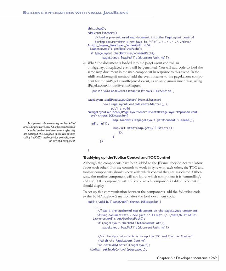
Chapter 6 • Developer scenarios • 269
BUILDING APPLICATIONS WITH VISUAL JAVABEANS
this.show();
addEventListeners();
//load a pre-authored map document into the PageLayout control
String documentPath = new java.io.File("../../../../../data/ArcGIS_Engine_Developer_Guide/Gulf of St. Lawrence.mxd").getAbsolutePath();
if (pageLayout.checkMxFile(documentPath))
pageLayout.loadMxFile(documentPath,null);
2. When the document is loaded into the pageLayout control, anonPageLayoutReplaced event will be generated. You will add code to load thesame map document in the map component in response to this event. In theaddEventListeners() method, add the event listener to the pageLayout compo-nent for the onPageLayoutReplaced event, as an anonymous inner class, usingIPageLayoutControlEventsAdapter. public void addEventListeners()throws IOException {
. . .
pageLayout.addIPageLayoutControlEventsListener(
new IPageLayoutControlEventsAdapter() {
public voidonPageLayoutReplaced(IPageLayoutControlEventsOnPageLayoutReplacedEventevt) throws IOException{
map.loadMxFile(pageLayout.getDocumentFilename(),null, null);
map.setExtent(map.getFullExtent());
});
}
});
}
‘Buddying up’ the ToolbarControl and TOCControlAlthough the components have been added to the JFrame, they do not yet ‘knowabout each other’. For the controls to work in sync with each other, the TOC andtoolbar components should know with which control they are associated. Other-wise, the toolbar component will not know which component it is ‘controlling’,and the TOC component will not know which component’s table of contents itshould display.
To set up this communication between the components, add the following codeto the buildAndShow() method after the load document code.
public void buildAndShow() throws IOException {
. . .
//load a pre-authored map document on the pageLayout component
String documentPath = new java.io.File("../../data/Gulf of St. Lawrence.mxd").getAbsolutePath();
if (pageLayout.checkMxFile(documentPath))
pageLayout.loadMxFile(documentPath,null);
//set buddy controls to wire up the TOC and Toolbar Control
//with the PageLayout Control
toc.setBuddyControl(pageLayout);
toolbar.setBuddyControl(pageLayout);
As a general rule when using the Java API ofArcGIS Engine Developer Kit, all methods should
be called on the visual components after theyare displayed. The exception to this rule is whencalling 'setXYZ()' methods—for example, to set
the size of a component.
Ch06_DevScenarios.pmd 4/2/2004, 9:15 AM269

270 • ArcGIS Engine Developer Guide
BUILDING APPLICATIONS WITH VISUAL JAVABEANS
}
Adding commands to the toolbarThe toolbar control has been added to the user interface and, by default, thiscontrol is not populated with any tools. You will begin to add tools in the follow-ing steps.
The ArcGIS Engine Developer Kit comes with more than 120 commands and toolsthat work with the MapControl, the PageLayoutControl, and the ToolbarControl.These commands and tools provide a lot of frequently used GIS functionality formap navigation, graphics management, and feature selection. You will now addsome of these commands and tools to your application.
1. To add the prebuilt toolbar commands, add the following imports:import com.esri.arcgis.controltools.ControlsOpenDocCommand;
import com.esri.arcgis.systemUI.esriCommandStyles;
2. In the buildAndShow() method, add the prebuilt commands to the toolbarafter calling this.show() and before the addEventListeners() call: this.show();
toolbar.addItem( new ControlsOpenDocCommand(), 0, -1, false, 0,esriCommandStyles.esriCommandStyleIconOnly );
toolbar.addItem( new ControlsPageZoomInTool(), 0, -1, false, 0,esriCommandStyles.esriCommandStyleIconOnly );
toolbar.addItem( new ControlsPageZoomOutTool(), 0, -1, false, 0,esriCommandStyles.esriCommandStyleIconOnly );
toolbar.addItem( new ControlsPagePanTool(), 0, -1, false, 0,esriCommandStyles.esriCommandStyleIconOnly );
toolbar.addItem( new ControlsPageZoomWholePageCommand(), 0, -1,false, 0, esriCommandStyles.esriCommandStyleIconOnly );
toolbar.addItem( new ControlsPageZoomPageToLastExtentBackCommand(),0, -1, false, 0,esriCommandStyles.esriCommandStyleIconOnly );
toolbar.addItem( newControlsPageZoomPageToLastExtentForwardCommand(), 0,-1, false, 0,
esriCommandStyles.esriCommandStyleIconOnly );
toolbar.addItem( new ControlsMapZoomInTool(), 0, -1, false, 0,esriCommandStyles.esriCommandStyleIconOnly );
toolbar.addItem( new ControlsMapZoomOutTool(), 0, -1, false, 0,esriCommandStyles.esriCommandStyleIconOnly );
toolbar.addItem( new ControlsMapPanTool(), 0, -1, false, 0,esriCommandStyles.esriCommandStyleIconOnly );
toolbar.addItem( new ControlsMapFullExtentCommand(), 0, -1, false,0, esriCommandStyles.esriCommandStyleIconOnly );
addEventListeners();
Ch06_DevScenarios.pmd 4/2/2004, 9:15 AM270

Chapter 6 • Developer scenarios • 271
BUILDING APPLICATIONS WITH VISUAL JAVABEANS
//load a pre-authored map document on the pageLayout component
3. Run the application.
The map document has been loaded into the pageLayout component, and thetoc component lists the data layers in the map document. Use the toc compo-nent to toggle layer visibility. By default the focus map of the map documentis loaded into the map component. Also note that the commands have beenadded to the toolbar component.
Creating popup menu using ToolbarMenuArcGIS Engine provides a ToolbarMenu component that can be used to addpopup menus to other components, such as the MapControl and PageLayoutControl.In this step, you will add a popup menu to the pageLayout component. Thepopup menu will contain prebuilt commands from thecom.esri.arcgis.beans.toolbaritems package.
To display the popup menu, an event handler will be added to the pageLayoutcomponent for the onMouseDown event. If the right mouse button is clicked,the menu will be displayed.
1. Add the following imports to MapViewerFrame.java:import com.esri.arcgis.beans.toolbar.ToolbarMenu;
import com.esri.arcgis.beans.pagelayout.IPageLayoutControlEventsAdapter;
importcom.esri.arcgis.beans.pagelayout.IPageLayoutControlEventsOnMouseDownEvent;
2. Construct a new ToolbarMenu object in the MapViewerFrame contstructor, asshown below:public class MapViewerFrame extends JFrame{
PageLayoutControl pageLayout;
MapControl map;
TOCControl toc;
ToolbarControl toolbar;
ToolbarMenu popupMenu;
JLabel statusLabel;
3. Add a member variable for popupMenu and surround in a try/catch block:public MapViewerFrame(){
setTitle( "MapViewer" );
Ch06_DevScenarios.pmd 4/2/2004, 9:15 AM271

272 • ArcGIS Engine Developer Guide
BUILDING APPLICATIONS WITH VISUAL JAVABEANS
try {
pageLayout = new PageLayoutControl();
map = new MapControl();
toc = new TOCControl();
toolbar = new ToolbarControl();
popupMenu = new ToolbarMenu();
statusLabel = new JLabel( " " );
// set constraints on the size of the map and toolbar
// let the layout manager
map.setSize( new Dimension( 200, 200 ) );
toolbar.setSize( new Dimension( 900, 25 ) );
} catch (Exception e) {
e.printStackTrace();
}
}
4. Add prebuilt commands from the com.esri.arcgis.beans.toolbaritems packageto the popupMenu component, after the call to this.show() in thebuildAndShow() method:this.show();
// add popup menu items
popupMenu.addItem( new ControlsPageZoomInFixedCommand(), 0, -1,false, esriCommandStyles.esriCommandStyleIconAndText );
popupMenu.addItem( new ControlsPageZoomOutFixedCommand(), 0, -1,false, esriCommandStyles.esriCommandStyleIconAndText );
popupMenu.addItem( new ControlsPageZoomWholePageCommand(), 0, -1,false, esriCommandStyles.esriCommandStyleIconAndText );
popupMenu.addItem( newControlsPageZoomPageToLastExtentBackCommand(), 0, -1, false, esriCommandStyles.esriCommandStyleIconAndText );
popupMenu.addItem( newControlsPageZoomPageToLastExtentForwardCommand(),
0, -1, false, esriCommandStyles.esriCommandStyleIconAndText );
//add Generic commands to the toolbar
. . .
5. Associate the popupMenu with the pageLayout component, along with thecode that sets up the buddy controls, in the buildAndShow() method://set buddy controls to wire up the TOC and ToolbarControl
//with the pageLayout object
toc.setBuddyControl(pageLayout);
toolbar.setBuddyControl(pageLayout);
popupMenu.setHookByRef(pageLayout);
}
Ch06_DevScenarios.pmd 4/2/2004, 9:15 AM272

Chapter 6 • Developer scenarios • 273
6. In the addEventListeners() method, add the event listener to the pageLayoutcomponent for the onMouseDown event, as an anonymous inner class, usingIPageLayoutControlEventsAdapter:pageLayout.addIPageLayoutControlEventsListener(
new IPageLayoutControlEventsAdapter(){
public void onMouseDown(IPageLayoutControlEventsOnMouseDownEventevt) throws IOException {
//if Right mouse button(2) is pressed, display the popup menu
if(evt.getButton() == 2)
popupMenu.popupMenu(evt.getX(), evt.getY(),pageLayout.getHWnd());
}
});
7. Run the application.
Right-click on the pageLayout component to display the popup menu, andnavigate around the page layout.
Controlling Label Editing in the TOCControlBy default the TOCControl allows users to automatically toggle the visibility oflayers and to change map and layer names as they appear in the table of contents.You will add code to prevent users from editing a name and replacing it with anempty string.
1. Add the following imports to MapViewerFrame.java for classes used in thisstep:import com.esri.arcgis.beans.TOC.ITOCControlEventsAdapter;
import com.esri.arcgis.beans.TOC.ITOCControlEventsOnEndLabelEditEvent;
import com.esri.arcgis.beans.TOC.esriTOCControlEdit;
BUILDING APPLICATIONS WITH VISUAL JAVABEANS
Ch06_DevScenarios.pmd 4/2/2004, 9:15 AM273

274 • ArcGIS Engine Developer Guide
2. In the buildAndShow() method, set the labelEdit to manual:. . .
this.show();
//set label editing to manual
toc.setLabelEdit(esriTOCControlEdit.esriTOCControlManual);
//add popup menu items
. . .
3. In the addEventListeners() method, add the event listener to the toc compo-nent for the onEndLabelEdit event, as an anonymous inner class, usingITOCControlEventsAdapter. After adding this, your addEventListeners()method should look like this:private void addEventListeners() throws IOException {
. . .
toc.addITOCControlEventsListener(new ITOCControlEventsAdapter(){
public void onEndLabelEdit(ITOCControlEventsOnEndLabelEditEventlabelEditEvt)
throws IOException {
String newLabel = labelEditEvt.getNewLabel();
//if the new label is an empty string, prevent the //edit
if (newLabel.equals(""))
labelEditEvt.setCanEdit(false);
}
});
}
4. Run the application. To edit a map, layer, heading, or legend class label in thetoc component, click on it once, then click on it a second time to invoke labelediting. Try replacing the label with an empty string. You will be able to re-place the label with strings other than an empty string. You can use the Esckey on the keyboard at any time during the edit to cancel it.
BUILDING APPLICATIONS WITH VISUAL JAVABEANS
Ch06_DevScenarios.pmd 4/2/2004, 9:15 AM274

Chapter 6 • Developer scenarios • 275
Drawing an ‘overview rectangle’ on the MapControlYou will now use the map component as an overview window and draw on itsdisplay the current extent of the focus map within the pageLayout component.As you navigate around the data within the data frame of the pageLayout com-ponent, you will see the map component’s overview window update.
1. Add the following imports to the MapViewerFrame.java for classes used inthis step:import com.esri.arcgis.beans.map.IMapControlEvents2Adapter;
import com.esri.arcgis.beans.map.IMapControlEvents2OnAfterDrawEvent;
import com.esri.arcgis.carto.Map;
import com.esri.arcgis.carto.esriViewDrawPhase;
import com.esri.arcgis.display.DisplayTransformation;
import com.esri.arcgis.display.ITransformEventsAdapter;
import com.esri.arcgis.display.ITransformEventsVisibleBoundsUpdatedEvent;
import com.esri.arcgis.display.RgbColor;
import com.esri.arcgis.display.SimpleFillSymbol;
import com.esri.arcgis.display.SimpleLineSymbol;
import com.esri.arcgis.geometry.IEnvelope;
2. Add the following class members to MapViewerFrame:public class MapViewerFrame extends JFrame {
SimpleFillSymbol fillSymbol; //The symbol used to draw the envelope
IEnvelope currentExtent; //The envelope drawn on the MapControl
Map focusMap; //The PageLayoutControl's focus map
PageLayoutControl pageLayout;
. . .
3. Create a new private method called createOverviewSymbol(). This is whereyou will create the symbol used in the map control to represent the extent ofthe data in the pageLayout control. Add the following code to the sub routine:private void createOverviewSymbol() throws IOException{
RgbColor color = new RgbColor();
color.setRed(255);
color.setGreen(0);
color.setBlue(0);
color.setTransparency((byte)255);
SimpleLineSymbol outline = new SimpleLineSymbol();
outline.setWidth(15);
outline.setColor(color);
fillSymbol = new SimpleFillSymbol();
color.setTransparency((byte) 0);
fillSymbol.setColor(color);
fillSymbol.setOutline(outline);
}
BUILDING APPLICATIONS WITH VISUAL JAVABEANS
Navigating around the focus map usingthe map navigation tools will change the
extent of the focus map in thePageLayoutControl and cause theMapControl to update. Navigating
around the page layout with the pagelayout navigation tools will change the
extent of the page layout (not the extentof the focus map in the
PageLayoutControl), so the MapControlwill not update.
Ch06_DevScenarios.pmd 4/2/2004, 9:15 AM275

276 • ArcGIS Engine Developer Guide
4. Call the createOverviewSymbol from the buildAndShow() method, after the callsetting label editing to manual://set label editing to manual
toc.setLabelEdit(esriTOCControlEdit.esriTOCControlManual);
//create symbol used to draw overview on the MapControl
createOverviewSymbol();
//add popup menu items
. . .
5. In the event listener for IPageLayoutControlEvents added in theaddEventListeners() method earlier, get a reference to the pageLayoutcomponent’s focus map. Store the extent of the focusMap in thecurrentExtent member variable. This extent will be used to draw the over-view rectangle on the map component. To achieve this, add the lines of code(shown in bold) after loading the map documents and setting its extent in theonPageLayoutReplaced event handler:pageLayout.addIPageLayoutControlEventsListener(
new IPageLayoutControlEventsAdapter() {
public void onPageLayoutReplaced(IPageLayoutControlEventsOnPageLayoutReplacedEvent
evt) throws IOException{
map.loadMxFile(pageLayout.getDocumentFilename(), null, null);
map.setExtent(map.getFullExtent());
focusMap = new Map(pageLayout.getActiveView().getFocusMap());
currentExtent = focusMap.getExtent();
}
});
6. The default events of the PageLayoutControl are theIPageLayoutControlEvents. These events do not tell us when the extent ofthe map within the data frame changes. To do this you will trap theITransformEvents of the PageLayoutControl’s focus map. Add the followingevent listeners to listen to the DisplayTransformation object’svisibleBoundsUpdated event.
The visibleBoundsUpdated event is triggered whenever the extent of the mapis changed and is used to set the envelope to the new visible bounds of themap. By refreshing the MapControl you force it to redraw the shape on itsdisplay.pageLayout.addIPageLayoutControlEventsListener(
new IPageLayoutControlEventsAdapter() {
public void onPageLayoutReplaced(IPageLayoutControlEventsOnPageLayoutReplacedEvent evt) throws IOException{
map.loadMxFile(pageLayout.getDocumentFilename(), null,null);
map.setExtent(map.getFullExtent());
BUILDING APPLICATIONS WITH VISUAL JAVABEANS
Ch06_DevScenarios.pmd 4/2/2004, 9:15 AM276
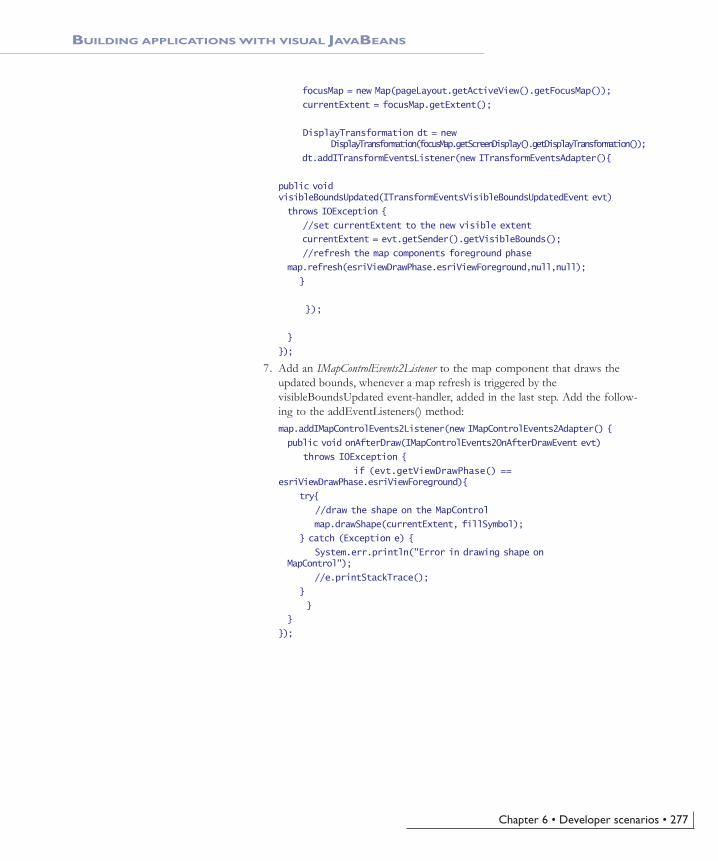
Chapter 6 • Developer scenarios • 277
focusMap = new Map(pageLayout.getActiveView().getFocusMap());
currentExtent = focusMap.getExtent();
DisplayTransformation dt = new DisplayTransformation(focusMap.getScreenDisplay().getDisplayTransformation());
dt.addITransformEventsListener(new ITransformEventsAdapter(){
public voidvisibleBoundsUpdated(ITransformEventsVisibleBoundsUpdatedEvent evt)
throws IOException {
//set currentExtent to the new visible extent
currentExtent = evt.getSender().getVisibleBounds();
//refresh the map components foreground phase
map.refresh(esriViewDrawPhase.esriViewForeground,null,null);
}
});
}
});
7. Add an IMapControlEvents2Listener to the map component that draws theupdated bounds, whenever a map refresh is triggered by thevisibleBoundsUpdated event-handler, added in the last step. Add the follow-ing to the addEventListeners() method:map.addIMapControlEvents2Listener(new IMapControlEvents2Adapter() {
public void onAfterDraw(IMapControlEvents2OnAfterDrawEvent evt)
throws IOException {
if (evt.getViewDrawPhase() ==esriViewDrawPhase.esriViewForeground){
try{
//draw the shape on the MapControl
map.drawShape(currentExtent, fillSymbol);
} catch (Exception e) {
System.err.println("Error in drawing shape onMapControl");
//e.printStackTrace();
}
}
}
});
BUILDING APPLICATIONS WITH VISUAL JAVABEANS
Ch06_DevScenarios.pmd 4/2/2004, 9:15 AM277

278 • ArcGIS Engine Developer Guide
8. Run the application. Use the map navigation tools that you added earlier tochange the extent of the focus map in the pageLayout component, and ob-serve that the new extent is drawn on the map component, as a red rectangle.
Creating a custom toolYou will create a custom tool that can be added to the ToolbarControl. This toolwill add today’s date as a text element to the PageLayoutControl, at the location ofa mouse click.
The tool will be built as a generic tool so it could be work with MapControl andToolbarControl as well as the PageLayoutControl.
Custom tools can be built as Java classes that implement the following twointerfaces:
import com.esri.arcgis.systemUI.ICommand;
import com.esri.arcgis.systemUI.ITool;
1. Create a new Java class AddDateCommand.java:import com.esri.arcgis.systemUI.ICommand;
import com.esri.arcgis.systemUI.ITool;
public class AddDateCommand implements ICommand, ITool {
}
As this class implements the ICommand and ITool interfaces, it will compile onlyafter all methods belonging to these interfaces have been implemented.
2. Add implementation for all methods defined in ICommand, as shown below.The implementation of onCreate and onClick methods will be done in thenext step, so you can leave an ‘empty’ implementation for now.import java.io.IOException;
import java.text.SimpleDateFormat;
import java.util.Date;
BUILDING APPLICATIONS WITH VISUAL JAVABEANS
Ch06_DevScenarios.pmd 4/2/2004, 9:15 AM278

Chapter 6 • Developer scenarios • 279
import com.esri.arcgis.carto.IActiveView;
import com.esri.arcgis.carto.TextElement;
import com.esri.arcgis.carto.esriViewDrawPhase;
import com.esri.arcgis.display.TextSymbol;
import com.esri.arcgis.geometry.IPoint;
import com.esri.arcgis.support.ms.stdole.StdFont;
import com.esri.arcgis.systemUI.ICommand;
import com.esri.arcgis.systemUI.ITool;
public class AddDateCommand implements ICommand, ITool {
/**
* @see com.esri.arcgis.systemUI.ICommand#isEnabled()
*/
public boolean isEnabled() throws IOException, AutomationException {
return true;
}
/**
* @see com.esri.arcgis.systemUI.ICommand#isChecked()
*/
public boolean isChecked() throws IOException, AutomationException {
return false;
}
/**
* @see com.esri.arcgis.systemUI.ICommand#getName()
*/
public String getName() throws IOException, AutomationException {
return “CustomCommands_Add Date”;
}
/**
* @see com.esri.arcgis.systemUI.ICommand#getCaption()
*/
public String getCaption() throws IOException, AutomationException {
return "Add Date";
}
/**
* @see com.esri.arcgis.systemUI.ICommand#getTooltip()
*/
public String getTooltip() throws IOException, AutomationException {
return "Add date";
}
/**
* @see com.esri.arcgis.systemUI.ICommand#getMessage()
*/
public String getMessage() throws IOException, AutomationException {
return "Adds a date element to the page layout";
}
/**
* @see com.esri.arcgis.systemUI.ICommand#getHelpFile()
*/
BUILDING APPLICATIONS WITH VISUAL JAVABEANS
Ch06_DevScenarios.pmd 4/2/2004, 9:15 AM279

280 • ArcGIS Engine Developer Guide
public String getHelpFile() throws IOException, AutomationException {
return null;
}
/**
* @see com.esri.arcgis.systemUI.ICommand#getHelpContextID()
*/
public int getHelpContextID() throws IOException, AutomationException {
return 0;
}
/**
* @see com.esri.arcgis.systemUI.ICommand#getBitmap()
*/
public int getBitmap() throws IOException, AutomationException {
return 0;//We rely on being displayed as text
}
/**
* @see com.esri.arcgis.systemUI.ICommand#getCategory()
*/
public String getCategory() throws IOException, AutomationException {
return “CustomCommands”;
}
/**
* @see com.esri.arcgis.systemUI.ICommand#onCreate(java.lang.Object)
*/
public void onCreate(Object obj) throws IOException,AutomationException {
//to be added later
}
/**
* @see com.esri.arcgis.systemUI.ICommand#onClick()
*/
public void onClick() throws IOException, AutomationException {
}
}
3. The onCreate method is passed a reference of the application that the com-mand works with. In this case, it can be a MapControl, PageLayoutControl, orToolbarControl. Rather than adding logic in the onCreate method to determinethe type of object passed to the hook method, you will use the HookHelperclass to handle this. A command or tool needs to know how to handle thehook it gets passed, so a check is needed to determine the type of ArcGISControl has been passed. The HookHelper is used to hold the hook and returnthe ActiveView regardless of the type of hook (in this case either aMapControl, PageLayoutControl, or ToolbarControl).
Add the HookHelper member variable to the AddDateCommand class:public class AddDateCommand implements ICommand, ITool{
HookHelper hookHelper;
BUILDING APPLICATIONS WITH VISUAL JAVABEANS
Ch06_DevScenarios.pmd 4/2/2004, 9:15 AM280

Chapter 6 • Developer scenarios • 281
4. In the onCreate method, construct the hookhelper and use the setHookByRefmethod to pass the controls object.public void onCreate(Object obj) throws IOException, AutomationException{
hookHelper = new HookHelper();
hookHelper.setHookByRef( obj );
}
5. Add implementation for all methods defined in ITool interface to theAddDateCommand class. Not all methods will be used, but they need to beimplemented to be able to compile the class. In the following code, pay atten-tion to the onClick() method, as this method creates a TextElement with thecurrent date as its text and adds it to the graphics container of the hookobject./**
* @see com.esri.arcgis.systemUI.ITool#getCursor()
*/
public int getCursor() throws IOException, AutomationException {
return 0;
}
/**
* @see com.esri.arcgis.systemUI.ITool#onMouseDown(int, int, int,int)
*/
public void onMouseDown(int button, int shift, int x, int y)
throws IOException, AutomationException {
Date today = new Date();
//format the date in the form "Wed 27 Aug, 2003"
SimpleDateFormat formatter;
formatter = new SimpleDateFormat("EEE d MMM, yyyy");
String dateString = formatter.format(today);
//create a font
StdFont font = new StdFont();
font.setName("Arial");
font.setBold(true);
//create a text symbol
TextSymbol textSymbol = new TextSymbol();
textSymbol.setFont(font);
textSymbol.setSize(15);
//create a text element to be added to the graphics container
TextElement textElement = new TextElement();
textElement.setSymbol(textSymbol);
textElement.setScaleText(false);
textElement.setText(dateString);
BUILDING APPLICATIONS WITH VISUAL JAVABEANS
Ch06_DevScenarios.pmd 4/2/2004, 9:15 AM281

282 • ArcGIS Engine Developer Guide
//add the text element to the graphics container
IActiveView activeView = hookHelper.getActiveView();
IPoint pt = activeView.getScreenDisplay().getDisplayTransformation().toMapPoint(x,y);
textElement.setGeometry(pt);
activeView.getGraphicsContainer().addElement(textElement, 0);
//refresh the view
activeView.partialRefresh(esriViewDrawPhase.esriViewGraphics, null, null);
}
/**
* @see com.esri.arcgis.systemUI.ITool#onMouseMove(int, int, int, int)
*/
public void onMouseMove(int arg0, int arg1, int arg2, int arg3)
throws IOException, AutomationException {
}
/**
* @seecom.esri.arcgis.systemUI.ITool#onMouseUp(int, int, int, int)
*/
public void onMouseUp(int arg0, int arg1, int arg2, int arg3)
throws IOException, AutomationException {
}
/**
* @see com.esri.arcgis.systemUI.ITool#onDblClick()
*/
public void onDblClick() throws IOException, AutomationException {
}
/**
* @see com.esri.arcgis.systemUI.ITool#onKeyDown(int, int)
*/
public void onKeyDown(int arg0, int arg1)
throws IOException, AutomationException {
}
/**
* @see com.esri.arcgis.systemUI.ITool#onKeyUp(int, int)
*/
public void onKeyUp(int arg0, int arg1)
throws IOException, AutomationException {
}
/**
* @see com.esri.arcgis.systemUI.ITool#onContextMenu(int, int)
*/
public boolean onContextMenu(int arg0, int arg1)
throws IOException, AutomationException {
return false;
}
BUILDING APPLICATIONS WITH VISUAL JAVABEANS
Ch06_DevScenarios.pmd 4/2/2004, 9:15 AM282

Chapter 6 • Developer scenarios • 283
/**
* @see com.esri.arcgis.systemUI.ITool#refresh(int)
*/
public void refresh(int arg0) throws IOException, AutomationException {
}
/**
* @see com.esri.arcgis.systemUI.ITool#deactivate()
*/
public boolean deactivate() throws IOException, AutomationException {
return true;
}
6. The AddDateCommand class is now complete. Compile it.
7. In MapViewerFrame, add an instance of the AddDateCommand to thetoolbar component in the buildAndShow() method, after the lines of codethat add prebuilt commands to the toolbar:toolbar.addItem(new AddDateCommand(),0, -1, true, 0, esriCommandStyles.esriCommandStyleTextOnly);
8. Recompile and launch MapViewer class. A new Add date tool will come upon the toolbar. Select that tool and click on the page layout to add today’sdate at that point.
Customizing the ToolbarControlIn addition to adding ArcGIS Engine commands and tools to the ToolbarControlusing addItem() as shown above, you can also add them by customizing theToolbarControl using the customize dialog box. To do this, you will place theToolbar component in customize mode and display the customize dialog box.
1. Add the following imports for this section:import javax.swing.JCheckBox;
import java.awt.event.ActionEvent;
import java.awt.event.ActionListener;
BUILDING APPLICATIONS WITH VISUAL JAVABEANS
Ch06_DevScenarios.pmd 4/2/2004, 9:15 AM283
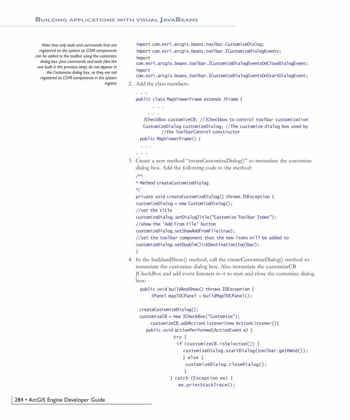
284 • ArcGIS Engine Developer Guide
import com.esri.arcgis.beans.toolbar.CustomizeDialog;
import com.esri.arcgis.beans.toolbar.ICustomizeDialogEvents;
importcom.esri.arcgis.beans.toolbar.ICustomizeDialogEventsOnCloseDialogEvent;
importcom.esri.arcgis.beans.toolbar.ICustomizeDialogEventsOnStartDialogEvent;
2. Add the class members.. . .
public class MapViewerFrame extends JFrame {
. . .
. . .
JCheckBox customizeCB; //JCheckbox to control toolbar customization
CustomizeDialog customizeDialog; //The customize dialog box used by //the ToolbarControl constructor
public MapViewerFrame() {
. . .
. . .
3. Create a new method “createCustomizeDialog()” to instantiate the customizedialog box. Add the following code to the method:/**
* Method createCustomizeDialog.
*/
private void createCustomizeDialog() throws IOException {
customizeDialog = new CustomizeDialog();
//set the title
customizeDialog.setDialogTitle("Customize Toolbar Items");
//show the 'Add From File' button
customizeDialog.setShowAddFromFile(true);
//set the toolbar component that the new items will be added to
customizeDialog.setDoubleClickDestination(toolbar);
}
4. In the buildandShow() method, call the createCustomizeDialog() method toinstantiate the customize dialog box. Also instantiate the customizeCBJCheckBox and add event listeners to it to start and close the customize dialogbox:public void buildAndShow() throws IOException {
JPanel mapTOCPanel = buildMapTOCPanel();
createCustomizeDialog();
customizeCB = new JCheckBox("Customize");
customizeCB.addActionListener(new ActionListener(){
public void actionPerformed(ActionEvent e) {
try {
if (customizeCB.isSelected()) {
customizeDialog.startDialog(toolbar.getHWnd());
} else {
customizeDialog.closeDialog();
}
} catch (Exception ee) {
ee.printStackTrace();
BUILDING APPLICATIONS WITH VISUAL JAVABEANS
Note that only tools and commands that areregistered on the system as COM components
can be added to the toolbar using the customizedialog box. Java commands and tools (like the
one built in the previous step) do not appear inthe Customize dialog box, as they are not
registered as COM components in the systemregistry
Ch06_DevScenarios.pmd 4/2/2004, 9:15 AM284

Chapter 6 • Developer scenarios • 285
}
}});
...
5. To add the Customize check box to the GUI, modify the code to add thetoolbar and check box to a new JPanel. Add this panel to theBorderLayout.NORTH position instead of adding just the toolbar in thatposition. JPanel topPanel = new JPanel();
topPanel.setLayout(new BorderLayout());
topPanel.add(toolbar, BorderLayout.CENTER);
topPanel.add(customizeCB, BorderLayout.EAST);
this.getContentPane().add(topPanel, BorderLayout.NORTH);
this.getContentPane().add(toolbar, BorderLayout.NORTH);//deletethis line
this.getContentPane().add(pageLayout, BorderLayout.CENTER);
this.getContentPane().add(mapTOCPanel, BorderLayout.WEST);
6. In the createCustomizeDialog() method, add event listener to the customizedialog box to put the toolbar in ‘customize’ state when the dialog box isstarted and in the normal state when it is closed:private void createCustomizeDialog() throws IOException {
customizeDialog = new CustomizeDialog();
//set the title
customizeDialog.setDialogTitle("Customize Toolbar Items");
//show the ‘Add From File’ button
customizeDialog.setShowAddFromFile(true);
//set the toolbar component that the new items will be added to
customizeDialog.setDoubleClickDestinationByRef(toolbar);
customizeDialog.addICustomizeDialogEventsListener(newICustomizeDialogEvents(){
public void onStartDialog(ICustomizeDialogEventsOnStartDialogEventarg0)
throws IOException {
toolbar.setCustomize(true);
}
public void onCloseDialog(ICustomizeDialogEventsOnCloseDialogEventarg0)
throws IOException {
toolbar.setCustomize(false);
customizeCB.setSelected(false);
}});
}
7. Run the application and check the ‘customize’ check box to put the toolbarinto ‘customize’ mode and open the customize dialog box.
8. On the Commands tab, select the Graphic Element category, and drag theSelect Elements command to the toolbar to add it there. By right-clicking on
BUILDING APPLICATIONS WITH VISUAL JAVABEANS
Ch06_DevScenarios.pmd 4/2/2004, 9:15 AM285

286 • ArcGIS Engine Developer Guide
an item on the toolbar, you can adjust the appearance in terms of style andgrouping.
9. Stop customizing the application. Use the Select tool to move the text ele-ment containing today’s date.
BUILDING APPLICATIONS WITH VISUAL JAVABEANS
Ch06_DevScenarios.pmd 4/2/2004, 9:15 AM286

Chapter 6 • Developer scenarios • 287
DEPLOYMENT
To successfully deploy this application onto a user’s machine, you will create anexecutable JAR file. Users will then be able to launch the application by using theJRE installed as part of ArcGIS Engine Developer Kit or Runtime, by giving thefollowing command:java –jar mapviewer.jar
To create an executable JAR:
1. In the directory where the compiled Java class files are present, create a filecalled “manifest.txt”.
2. Add the following single line to the manifest.txt file:Main-Class: com.esri.arcgis.scenario.beans.MapViewer
3. Make sure to hit enter at the end of the first line.
4. Save the file, and open a command window. cd to the directory containing themanifest.txt file.
5. Give the following command to create the executable JAR file:jar cmf manifest.txt mapviewer.jar *.class
6. A mapviewer.jar file will be created. This is the executable JAR that can belaunched using the JRE included as part of the ArcGIS Engine Developer Kit,as follows:"C:\Program Files\ArcGIS\java\jre\bin\java" -jar mapviewer.jar
This command can be bundled in a batch file or shell script to provide a launchscript.
ADDITIONAL RESOURCES
The following resources may help you understand and apply the concepts andtechniques presented in this scenario.
• Additional documentation available in the ArcGIS Engine Developer Kitincluding ArcGIS Developer Help, javadoc, object model diagrams, and samplesto help you get started.
• ArcGIS Developer Online—Web site providing the most up-to-date informa-tion for ArcGIS Developers including updated samples and technical docu-ments. Go to http://arcgisdeveloperonline.esri.com.
• ESRI online discussion forums—Web sites providing invaluable assistancefrom other ArcGIS developers. Go to http://support.esri.com and click theUser Forums tab.
• Sun’s Java Tutorial at http://java.sun.com/docs/books/tutorial/
• Helpful Web sites for Java in general, such as Javaranch (http://www.javaranch.com/)—a friendly place for Java greenhorns.
BUILDING APPLICATIONS WITH VISUAL JAVABEANS
Ch06_DevScenarios.pmd 4/2/2004, 9:15 AM287

288 • ArcGIS Engine Developer Guide
This walkthrough is for developers who want to build and deploy an applicationusing .NET. It describes the process of building and deploying an applicationusing the ArcGIS Controls.
You can find this sample in<install_location>\DeveloperKit\Samples\Developer_Guide_Scenarios\ArcGIS_Engine\Building_an_ArcGIS_Control_Application\Map_Viewer
PROJECT DESCRIPTION
The goal of the Building applications with Windows Controls scenario is todemonstrate and make you familiar with the steps required to develop and deploya GIS application using the standard ArcGIS Controls within the MicrosoftVisual Studio.NET API. The scenario uses the MapControl, PageLayoutControl,TOCControl, and ToolbarControl as Windows Controls within the Microsoft VisualStudio .NET development environment. COM, Java, and C++ programmersshould refer to the following scenarios: Building applications with ActiveX,Building applications with visual JavaBeans, Building a command line Java appli-cation, and Building a command line C++ application.
The scenario demonstrates the steps required to create a GIS application forviewing map documents pre-authored using ArcMap, an ArcGIS Desktop applica-tion. The scenario covers the following techniques:
• Loading and embedding the ArcGIS Controls in Microsoft Visual Studio.NET.
• Loading pre-authored map documents into the MapControl andPageLayoutControl.
• Setting ToolbarControl and TOCControl buddy controls.
• Handling form resize.
• Adding ArcGIS Engine commands and tools to the ToolbarControl.
• Creating popup menus.
• Managing label editing in the TOCControl.
• Drawing shapes on the MapControl.
• Creating a custom tool to work with the MapControl, PageLayoutControl, andToolbarControl.
• Customizing the ToolbarControl.
• Deploying the application onto a Windows operating system.
CONCEPTS
This scenario is implemented using the Microsoft Visual Studio .NET develop-ment environment and uses the ESRI interop assemblies to host the ArcGISControls inside .NET Windows Controls in a .NET form. These interoperabilityassemblies act as a bridge between the unmanaged code of COM and the man-aged .NET code. Any references to the members of the COM ArcGIS Controlsare routed to the interop assemblies and forwarded to the actual COM object.Likewise, responses from the COM object are routed to the interop assembly andforwarded to the .NET application. Each ArcGIS Engine control has events,
BUILDING APPLICATIONS WITH WINDOWS CONTROLS
Rather than walk through this scenario, you canget the completed application from the samples
installation location. The sample is installed aspart of the ArcGIS developer samples.
The ArcGIS developer samples are not includedin the 'typical' installation of the ArcGIS Engine
Developer Kit. If you do not have them installed,rerun the Developer Kit install wizard, choose
Custom or Modify, and select the samplesfeature under Software Developer Kit.
Ch06_DevScenarios.pmd 4/2/2004, 9:15 AM288

Chapter 6 • Developer scenarios • 289
properties, and methods that can be accessed once embedded within a containersuch as a .NET form. The objects and functionality within each control can becombined with other ESRI ArcObjects and custom controls to create customizedend user applications.
The scenario has been written in both C# and Visual Basic .NET, though thefollowing implementation concentrates on the C# scenario. Many developers willfeel more comfortable with Visual Basic .NET, as the code looks familiar toVisual Basic 6.0, while the syntax of the of the C# programming language willbe familiar to Java and C++ programmers. Whichever development environmentyou use, your future success with the ArcGIS Controls depends on your skill inboth the programming environment and ArcObjects.
The MapControl, PageLayoutControl, TOCControl, and ToolbarControl are used in thisscenario to provide the user interface of the application. The ArcGIS Controlsare used in conjunction with other ArcObjects and ArcGIS Engine commands bythe developer to create a GIS viewing application.
DESIGN
The scenario has been designed firstly to highlight how the ArcGIS Controlsinteract with each other, and secondly to expose a part of each ArcGIS Controlsobject model to the developer.
Each .NET ArcGIS Engine control has a set of property pages that can be ac-cessed once the control is embedded within a .NET Form. These property pagesprovide shortcuts to a selection of a control’s properties and methods, and allowa developer to build an application without writing any code. This scenario doesnot use the property pages, but rather builds up the application programmatically.For further information about the property pages, refer to the ArcGIS DeveloperHelp.
REQUIREMENTS
To successfully follow this scenario you need the following (the requirements fordeployment are covered later in the Deployment section):
• An installation of the ArcGIS Engine Developer Kit with an authorizationfile enabling it for development use.
• An installation of the Microsoft Visual Studio .NET 2003 developmentenvironment and the Microsoft .NET Framework 1.1. and an appropriatelicense.
• Familiarity with Microsoft Windows operating systems and a working knowl-edge of Microsoft Visual Studio .NET and either the C# or Visual Basic .NETprogramming language. While the scenario provides some information abouthow to use the ArcGIS Controls in Microsoft Visual Studio .NET, it is not asubstitute for training in the development environment.
• While no experience with other ESRI software is required, previous experi-ence with ArcObjects and a basic understanding of ArcGIS applications, suchas ArcMap and ArcCatalog, is advantageous.
BUILDING APPLICATIONS WITH WINDOWS CONTROLS
Ch06_DevScenarios.pmd 4/2/2004, 9:15 AM289

290 • ArcGIS Engine Developer Guide
• Access to the sample data and code that comes with this scenario. This islocated at<install_location>\DeveloperKit\Samples\Developer_Guide_Scenarios\ArcGIS_Engine\Building_an_ArcGIS_Control_Application\Map_Viewer
The controls and libraries used in this scenario are as follows:
• AxMapControl • AxTOCControl
• AxPageLayoutControl • AxToolbarControl
• ESRI.ArcGIS.Carto • ESRI.ArcGIS.System
• ESRI.ArcGIS.Display • ESRI.ArcGIS.SystemUI
• ESRI.ArcGIS.Geometry • ESRI.ArcGIS.Utility
• esriMapControl • esriTOCControl
• esriPageLayoutControl • esriToolbarControl
IMPLEMENTATION
The implementation below provides you with all the code you will need tosuccessfully complete the scenario. It does not provide step-by-step instructionsto develop applications in Microsoft Visual Studio .NET, as it assumes that youhave a working knowledge of the development environment already.
Loading the ArcGIS ControlsBefore you start to program your application, the ArcGIS Controls and the otherArcGIS Engine library references that the application will use should be loadedinto the development environment.
1. Start Visual Studio .NET and create a new Visual C# ‘Windows Application’project from the New project dialog box.
2. Name the project ‘Controls’, and browse to a location to save the project.
3. Right-click in the Windows Forms tab of the Toolbox and select ‘Add/Remove Items…’ from the context menu.
The AxControlName .NET Frameworkcomponents represent the control that is
hosted within a .NET Form, whilst theesriControlName assemblies contain the
object and interfaces from inside thecontrol’s type library.
BUILDING APPLICATIONS WITH WINDOWS CONTROLS
The ArcGIS developer samples are not includedin the 'typical' installation of the ArcGIS Engine
Developer Kit. If you do not have them installed,rerun the Developer Kit install wizard, choose
Custom or Modify, and select the samplesfeature under Software Developer Kit.
Ch06_DevScenarios.pmd 4/2/2004, 9:15 AM290

Chapter 6 • Developer scenarios • 291
4. In the Customize Toolbox dialog box, select .NET Framework componentsand check ‘AxMapControl’, ‘AxPageLayoutControl’, ‘AxTOCControl’, and‘AxToolbarControl’. Click OK. The controls will now appear in the WindowsForms tab of the toolbox.
5. Click on the Project menu and choose Add Reference….
6. In the Add Reference dialog box, double click ‘ESRI.ArcGIS.Carto’,‘ESRI.ArcGIS.Display’ ‘ESRI.ArcGIS.Geometry’, ‘ESRI.ArcGIS.System’,‘ESRI.ArcGIS.SystemUI’ ESRI.ArcGIS.Utility. Click OK.
The ESRI .NET assemblies, will be used toinstantiate and make calls on the objects in theESRI object libraries from your C# project using
the COM interoperability services provided bythe .NET framework.
BUILDING APPLICATIONS WITH WINDOWS CONTROLS
Ch06_DevScenarios.pmd 4/2/2004, 9:15 AM291

292 • ArcGIS Engine Developer Guide
Embedding the ArcGIS Controls in a ContainerBefore you can access each control’s properties, methods, and events, each controlneeds embedding within a .NET container. Once the controls are embeddedwithin the form, they will shape the application’s user interface.
1. Open the .NET Form in design mode.
2. Double-click the AxMapControl in the Windows Forms tab of the toolbox toadd a MapControl onto the form.
3. Repeat to add the AxPageLayoutControl, AxTOCControl, andAxToolbarControl.
4. Resize and reposition each control on the form as shown.
5. Double-click on the form to display the form’s code window. Add the follow-ing ‘using’ directives to the top of the code window:using System;
using System.Windows.Forms;
using ESRI.ArcGIS.SystemUI;
using ESRI.ArcGIS.Carto;
using ESRI.ArcGIS.Display;
using ESRI.ArcGIS.Geometry;
using ESRI.ArcGIS.esriSystem;
using esriToolbarControl;
using esriTOCControl;
In .NET a variable is fully qualified using aNamespace. Namespaces are a concept in .NETthat allow objects to be organized hierarchically,
regardless of the assembly they are defined in. Tomake code simpler and more readable, thedirectives act as shortcuts when referencing
items specified in namespaces.
Remember that C# is case sensitive. If you startby typing “ESRI.”, the auto completion feature ofIntelliSense will allow you to complete the next
section of code by pressing Tab.
BUILDING APPLICATIONS WITH WINDOWS CONTROLS
Ch06_DevScenarios.pmd 4/2/2004, 9:15 AM292

Chapter 6 • Developer scenarios • 293
Loading Map Documents into the PageLayoutControl andMapControlIndividual data layers or map documents pre-authored using ArcMap, an ArcGISDesktop application, can be loaded into the MapControl and PageLayoutControl.You can either load the sample map document provided or you can load in yourown map document. Later you will add a dialog box to browse to a map docu-ment.
1. Select the Form_Load event and enter the following code (if you are usingyour own map document substitute the correct filename):private void Form1_Load(object sender, System.EventArgs e)
{
//Load a pre-authored map document into the PageLayoutControl usingrelative paths.
string fileName =@"..\..\..\..\..\..\..\..\Data\\ArcGIS_Engine_Developer_Guide\Gulf of St.Lawrence.mxd";
if (axPageLayoutControl1.CheckMxFile(fileName))
{
axPageLayoutControl1.LoadMxFile(fileName,"");
}
}
2. Display the form in design mode and select axPageLayoutControl1 from theProperties window and display the axPageLayoutControl events. Double-clickon the OnPageLayoutReplaced event to add an event handler to the codewindow.
3. In the axPageLayoutControl_OnPageLayoutReplaced event enter the follow-ing code to load the same map document into the MapControl. The
BUILDING APPLICATIONS WITH WINDOWS CONTROLS
Ch06_DevScenarios.pmd 4/2/2004, 9:15 AM293
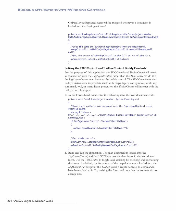
294 • ArcGIS Engine Developer Guide
OnPageLayoutReplaced event will be triggered whenever a document isloaded into the PageLayoutControl.
private void axPageLayoutControl1_OnPageLayoutReplaced(object sender,ESRI.ArcGIS.PageLayoutControl.IPageLayoutControlEvents_OnPageLayoutReplacedEvente)
{
//Load the same pre-authored map document into the MapControl.axMapControl1.LoadMxFile(axPageLayoutControl1.DocumentFilename,null,
null);
//Set the extent of the MapControl to the full extent of the data.
axMapControl1.Extent = axMapControl1.FullExtent;
}
Setting the TOCControl and ToolbarControl Buddy ControlsFor the purpose of this application the TOCControl and ToolbarControl will workin conjunction with the PageLayoutControl, rather than the MapControl. To do thisthe PageLayoutControl must be set as the buddy control. The TOCControl uses thebuddy’s ActiveView to populate itself with maps, layers, and symbols, while anycommand, tool, or menu items present on the ToolbarControl will interact with thebuddy control’s display.
1. In the Form_Load event enter the following after the load document code:private void Form1_Load(object sender, System.EventArgs e)
{
//Load a pre-authored map document into the PageLayoutControl usingrelative paths.
string fileName =@"..\..\..\..\..\..\..\..\Data\\ArcGIS_Engine_Developer_Guide\Gulf of St.Lawrence.mxd";
if (axPageLayoutControl1.CheckMxFile(fileName))
{
axPageLayoutControl1.LoadMxFile(fileName,"");
}
//Set buddy controls.
axTOCControl1.SetBuddyControl(axPageLayoutControl1);
axToolbarControl1.SetBuddyControl(axPageLayoutControl1);
}
2. Build and run the application. The map document is loaded into thePageLayoutControl, and the TOCControl lists the data layers in the map docu-ment. Use the TOCControl to toggle layer visibility by checking and uncheckingthe boxes. By default, the focus map of the map document is loaded into theMapControl. At this point the ToolbarControl is empty because no commandshave been added to it. Try resizing the form, and note that the controls do notchange size.
BUILDING APPLICATIONS WITH WINDOWS CONTROLS
Ch06_DevScenarios.pmd 4/2/2004, 9:15 AM294

Chapter 6 • Developer scenarios • 295
Handling Form ResizeWhen the form is resized at run time the PageLayoutControl and MapControl do notautomatically resize themselves. To resize the controls so that they always fill theextent of the form, you must anchor the controls to the form. If thePageLayoutControl or MapControl contain a lot of data, redrawing this data duringthe Form_Resize can be costly. To increase performance you can suppress the dataredraw until the resizing is complete. During the resize a stretched bitmap will bedrawn instead.
1. Display the form in design mode and select axPageLayoutControl1 from theProperties window. Click on the anchor property and anchor theaxPageLayoutControl to the top, left, bottom, and right of the form.
2. Anchor the axMapcontrol to the top, left, and bottom of the form.
BUILDING APPLICATIONS WITH WINDOWS CONTROLS
Ch06_DevScenarios.pmd 4/2/2004, 9:15 AM295

296 • ArcGIS Engine Developer Guide
BUILDING APPLICATIONS WITH WINDOWS CONTROLS
3. Add the following code to the beginning of the Form_Load event:private void Form1_Load(object sender, System.EventArgs e)
{
//Suppress drawing while resizing
this.SetStyle(ControlStyles.EnableNotifyMessage,true);
}
4. Add the following constants to the class:public class Form1 : System.Windows.Forms.Form
{
…
private const int WM_ENTERSIZEMOVE = 0x231;
private const int WM_EXITSIZEMOVE = 0x232;
…
5. Add the following code to override the OnNotifyMessage method.protected override void OnNotifyMessage(System.Windows.Forms.Message m)
{
base.OnNotifyMessage (m);
if (m.Msg == WM_ENTERSIZEMOVE)
{
axMapControl1.SuppressResizeDrawing(true, 0);
axPageLayoutControl1.SuppressResizeDrawing(true, 0);
}
else if (m.Msg == WM_EXITSIZEMOVE)
{
axMapControl1.SuppressResizeDrawing(false, 0);
axPageLayoutControl1.SuppressResizeDrawing(false, 0);
}
}
6. Build and then run the application. Try resizing the Form.
Adding Commands to the ToolbarControlThe ArcGIS Engine comes with over 120 commands and tools that work with theMapControl, the PageLayoutControl and the ToolbarControl directly. These commandsand tools provide you with a lot of frequently used GIS functionality for mapnavigation, graphics management and feature selection. You will now add someof these commands and tools to your application.
1. In the Form_Load event add the following code before the load documentcode.private void Form1_Load(object sender, System.EventArgs e)
{
string progID;
//Add generic commands
progID = "esriControlToolsGeneric.ControlsOpenDocCommand";
This method of suppressing resize drawingworks by examining the windows messages sent
to the form. When a form starts resizing,windows sends the WM_ENTERSIZEMOVEWindows(messge). At this point we suppress
drawing to the MapControl andPageLayoutControl and draw using a “stretchy
bitmap”. When windows sends theWM_EXITSIZEMOVE the form is released from
resizing and we resume with a full redraw atthe new extent.
Ch06_DevScenarios.pmd 4/2/2004, 9:15 AM296
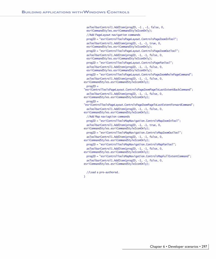
Chapter 6 • Developer scenarios • 297
BUILDING APPLICATIONS WITH WINDOWS CONTROLS
axToolbarControl1.AddItem(progID, -1 , -1, false, 0,esriCommandStyles.esriCommandStyleIconOnly);
//Add PageLayout navigation commands
progID = "esriControlToolsPageLayout.ControlsPageZoomInTool";
axToolbarControl1.AddItem(progID, -1, -1, true, 0,esriCommandStyles.esriCommandStyleIconOnly);
progID = "esriControlToolsPageLayout.ControlsPageZoomOutTool";
axToolbarControl1.AddItem(progID, -1, -1, false, 0,esriCommandStyles.esriCommandStyleIconOnly);
progID = "esriControlToolsPageLayout.ControlsPagePanTool";
axToolbarControl1.AddItem(progID, -1, -1, false, 0,esriCommandStyles.esriCommandStyleIconOnly);
progID = "esriControlToolsPageLayout.ControlsPageZoomWholePageCommand";
axToolbarControl1.AddItem(progID, -1, -1, false, 0,esriCommandStyles.esriCommandStyleIconOnly);
progID ="esriControlToolsPageLayout.ControlsPageZoomPageToLastExtentBackCommand";
axToolbarControl1.AddItem(progID, -1, -1, false, 0,esriCommandStyles.esriCommandStyleIconOnly);
progID ="esriControlToolsPageLayout.ControlsPageZoomPageToLastExtentForwardCommand";
axToolbarControl1.AddItem(progID, -1, -1, false, 0,esriCommandStyles.esriCommandStyleIconOnly);
//Add Map naviagtion commands
progID = "esriControlToolsMapNavigation.ControlsMapZoomInTool";
axToolbarControl1.AddItem(progID, -1, -1, true, 0,esriCommandStyles.esriCommandStyleIconOnly);
progID = "esriControlToolsMapNavigation.ControlsMapZoomOutTool";
axToolbarControl1.AddItem(progID, -1, -1, false, 0,esriCommandStyles.esriCommandStyleIconOnly);
progID = "esriControlToolsMapNavigation.ControlsMapPanTool";
axToolbarControl1.AddItem(progID, -1, -1, false, 0,esriCommandStyles.esriCommandStyleIconOnly);
progID = "esriControlToolsMapNavigation.ControlsMapFullExtentCommand";
axToolbarControl1.AddItem(progID, -1, -1, false, 0,esriCommandStyles.esriCommandStyleIconOnly);
//Load a pre-authored…
}
Ch06_DevScenarios.pmd 4/2/2004, 9:15 AM297

298 • ArcGIS Engine Developer Guide
Creating a Popup Menu for the PageLayoutControlAs well as adding ArcGIS Engine commands to the ToolbarControl to work withthe buddy control, as in the previous step, you can also create popup menus fromthe ArcGIS Engine commands. You will add a popup menu that works with thePageLayoutControl to your application. The popup menu will display whenever theright mouse button is used on the display area of the PageLayoutControl.
1. Add the following member variable to the class:public class Form1 : System.Windows.Forms.Form
{
private ESRI.ArcGIS.ToolbarControl.AxToolbarControlaxToolbarControl1;
private ESRI.ArcGIS.TOCControl.AxTOCControl axTOCControl1;
private ESRI.ArcGIS.MapControl.AxMapControl axMapControl1;
private ESRI.ArcGIS.PageLayoutControl.AxPageLayoutControlaxPageLayoutControl1;
private IToolbarMenu m_ToolbarMenu = new ToolbarMenuClass(); //Thepopup menu
…
2. Add the following code to the Form_Load event after the code adding thecommands to the ToolbarControl, but before the load document code.private void Form1_Load(object sender, System.EventArgs e)
{
//Add Map naviagtion commands…
BUILDING APPLICATIONS WITH WINDOWS CONTROLS
2. Build and then run the application. The ToolbarControl now contains ArcGISEngine commands and tools that you can use to navigate the map documentloaded into the PageLayoutControl. Use the page layout commands to navigatearound the actual page layout and the map commands to navigate around thedata present in the data frames. Use the open document command to browseand load other map documents.
Ch06_DevScenarios.pmd 4/2/2004, 9:15 AM298

Chapter 6 • Developer scenarios • 299
BUILDING APPLICATIONS WITH WINDOWS CONTROLS
//Share the ToolbarControl’s command pool
m_ToolbarMenu.CommandPool = axToolbarControl1.CommandPool;
//Add commands to the ToolbarMenu
progID = "esriControlToolsPageLayout.ControlsPageZoomInFixedCommand";
m_ToolbarMenu.AddItem(progID, -1, -1, false,esriCommandStyles.esriCommandStyleIconAndText);
progID = "esriControlToolsPageLayout.ControlsPageZoomOutFixedCommand";
m_ToolbarMenu.AddItem(progID, -1, -1, false,esriCommandStyles.esriCommandStyleIconAndText);
progID = "esriControlToolsPageLayout.ControlsPageZoomWholePageCommand";
m_ToolbarMenu.AddItem(progID, -1, -1, false,esriCommandStyles.esriCommandStyleIconAndText);
progID ="esriControlToolsPageLayout.ControlsPageZoomPageToLastExtentBackCommand";
m_ToolbarMenu.AddItem(progID, -1, -1, true,esriCommandStyles.esriCommandStyleIconAndText);
progID ="esriControlToolsPageLayout.ControlsPageZoomPageToLastExtentForwardCommand";
m_ToolbarMenu.AddItem(progID, -1, -1, false,esriCommandStyles.esriCommandStyleIconAndText);
//Set the hook to the PageLayoutControl
m_ToolbarMenu.SetHook(axPageLayoutControl1);
//Load a pre-authored…
}
3. Display the Form in design mode and select axPageLayoutControl1 from theProperties window and display the axPageLayoutControl events. Double clickon the OnMouseDown event to add an event handler to the code window.
4. In the axPageLayoutControl_OnMouseDown event add the following code:private void axPageLayoutControl1_OnMouseDown(object sender,ESRI.ArcGIS.PageLayoutControl.IPageLayoutControlEvents_OnMouseDownEvente)
{
//Popup the ToolbarMenu
if (e.button == 2)
{
m_ToolbarMenu.PopupMenu(e.x,e.y,axPageLayoutControl1.hWnd);
}
}
Ch06_DevScenarios.pmd 4/2/2004, 9:15 AM299

300 • ArcGIS Engine Developer Guide
BUILDING APPLICATIONS WITH WINDOWS CONTROLS
5. Build and run the application. Right click on the PageLayoutControl’s displayarea to display the popup menu, and navigate around the page layout.
Controlling Label Editing in the TOCControlBy default the TOCControl allows users to automatically toggle the visibility oflayers and to change map and layer names as they appear in the table of contents.You will add code to prevent users from editing a name, and replacing it with anempty string.
1. Add the following code to the beginning of the Form_Load event.private void Form1_Load(object sender, System.EventArgs e)
{
//Set label editing to manual
axTOCControl1.LabelEdit = esriTOCControlEdit.esriTOCControlManual;
//Add generic commands
}
2. Display the Form in design mode and select AxTOCControl1 from the Proper-ties window and display the AxTOCControl events. Double click onOnEndLabelEdit to add an event handler to the code window.
3. Add the following code to the axTOCControl_OnEndLableEdit eventprivate void axTOCControl1_OnEndLabelEdit(object sender,ESRI.ArcGIS.TOCControl.ITOCControlEvents_OnEndLabelEditEvent e)
{
//If the new label is an empty string then prevent the edit
string newLabel = e.newLabel;
if (newLabel.Trim() == "")
{
e.canEdit = false;
}
}
Ch06_DevScenarios.pmd 4/2/2004, 9:15 AM300

Chapter 6 • Developer scenarios • 301
Drawing Shapes on the MapControlYou will now use the MapControl as an overview window and draw on its displaythe current extent of the focus map within the PageLayoutControl. As you navigatearound the data within the data frame of the PageLayoutControl you will see theMapControl overview window update.
1. Add the following member variables to the class: public class Form1 : System.Windows.Forms.Form
{
private ESRI.ArcGIS.ToolbarControl.AxToolbarControl axToolbarControl1;
private ESRI.ArcGIS.TOCControl.AxTOCControl axTOCControl1;
private ESRI.ArcGIS.MapControl.AxMapControl axMapControl1;
private ESRI.ArcGIS.PageLayoutControl.AxPageLayoutControlaxPageLayoutControl1;
private IToolbarMenu m_ToolbarMenu = new ToolbarMenuClass();
private IEnvelope m_Envelope; //The envelope drawn on the MapControl
private Object m_FillSymbol; //The symbol used to draw the envelope onthe MapControl
private ITransformEvents_VisibleBoundsUpdatedEventHandlervisBoundsUpdatedE; //The PageLayoutControl's focus map events
The variable declared as visBoundsUpdatedE is adelegate. A delegate is a class that can hold a
reference to a specific method and link this to aspecific event. The linking process between theevent and the method is sometimes known in
.NET as wiring.
BUILDING APPLICATIONS WITH WINDOWS CONTROLS
Navigating around the focus map using the mapnavigation tools will change the extent of the
focus map in the PageLayoutControl and causethe MapControl to update. Navigating around
the page layout with the page layout navigationtools will change the extent of the page layout
(not the extent of the focus map in thePageLayoutControl), so the MapControl will not
update.
4. Build and run the application. To edit a map, layer, heading or legend classlabel in the TOCControl, click on it once, and then click on it a second time toinvoke label editing. Try replacing the label with an empty string. You can usethe ESC key on the keyboard at any time during the edit to cancel it.
Ch06_DevScenarios.pmd 4/2/2004, 9:15 AM301

302 • ArcGIS Engine Developer Guide
2. Create a new function called CreateOverviewSymbol. This is where you willcreate the symbol used in the MapControl to represent the extent of the data inthe focus map of the PageLayoutControl. Add the following code to the func-tion.private void CreateOverviewSymbol()
{
//Get the IRGBColor interface
IRgbColor color = new RgbColor();
//Set the color properties
color.RGB = 255;
//Get the ILine symbol interface
ILineSymbol outline = new SimpleLineSymbol();
//Set the line symbol properties
outline.Width = 1.5;
outline.Color = color;
//Get the IFillSymbol interface
ISimpleFillSymbol simpleFillSymbol = new SimpleFillSymbolClass();
//Set the fill symbol properties
simpleFillSymbol.Outline = outline;
simpleFillSymbol.Style = esriSimpleFillStyle.esriSFSHollow;
m_FillSymbol = simpleFillSymbol;
}
3. Call the CreateOverviewSymbol function from the Form_Load event beforethe TOCControl label editing code.private void Form1_Load(object sender, System.EventArgs e)
{
//Create symbol used on the MapControl
CreateOverviewSymbol();
//Set label editing to manual…
}
4. Add the following OnVisibleBoundsUpdated function. This function will belinked to an event raised whenever the extent of the map is changed and isused to set the envelope to the new visible bounds of the map. By refreshingthe MapControl you force it to redraw the shape on its display.private void OnVisibleBoundsUpdated(IDisplayTransformation sender, boolsizeChanged)
{
//Set the extent to the new visible extent
m_Envelope = sender.VisibleBounds;
//Refresh the MapControl's foreground phase
axMapControl1.ActiveView.PartialRefresh(esriViewDrawPhase.esriViewForeground, null, null);
}
5. The default event interface of the PageLayoutControl is theIPageLayoutControlEvents. These events do not tell us when the extent ofthe map within the data frame changes. To do this you will use the
BUILDING APPLICATIONS WITH WINDOWS CONTROLS
Ch06_DevScenarios.pmd 4/2/2004, 9:15 AM302

Chapter 6 • Developer scenarios • 303
BUILDING APPLICATIONS WITH WINDOWS CONTROLS
ItransformEvents interface of the PageLayoutControl’s focus map. Add thefollowing code to the PageLayoutControl_OnPageLayoutReplaced eventhandler directly above the load document code.private void axPageLayoutControl1_OnPageLayoutReplaced(object sender,ESRI.ArcGIS.PageLayoutControl.IPageLayoutControlEvents_OnPageLayoutReplacedEvente)
{
//Get the IActiveView of the focus map in the PageLayoutControl
IActiveView activeView = (IActiveView)axPageLayoutControl1.ActiveView.FocusMap;
//Trap the ITranformEvents of the PageLayoutCntrol's focus mapvisBoundsUpdatedE = newITransformEvents_VisibleBoundsUpdatedEventHandler(OnVisibleBoundsUpdated);
((ITransformEvents_Event)activeView.ScreenDisplay.DisplayTransformation).VisibleBoundsUpdated += visBoundsUpdatedE;
//Get the extent of the focus map
m_Envelope = activeView.Extent;
//Load the same pre-authored map document into the MapControl
axMapControl1.LoadMxFile(axPageLayoutControl1.DocumentFilename,null,null);
//Set the extent of the MapControl to the full extent of the data
axMapControl1.Extent = axMapControl1.FullExtent;
}
6. Display the Form in design mode and select axMapControl1 from the Proper-ties window and display the axMapControl events. Double click onOnAfterDraw to add an event handler to the code window.
7. Add the following code to the axMapControl_OnAfterDraw event handler todraw the envelope with the symbol you created earlier onto the MapControl’sdisplay.private void axMapControl1_OnAfterDraw(object sender,ESRI.ArcGIS.MapControl.IMapControlEvents2_OnAfterDrawEvent e)
{
if (m_Envelope == null)
{
return;
}
//If the foreground phase has drawn
esriViewDrawPhase viewDrawPhase = (esriViewDrawPhase) e.viewDrawPhase;
if (viewDrawPhase == esriViewDrawPhase.esriViewForeground)
{
IGeometry geometry = m_Envelope;
axMapControl1.DrawShape(geometry, ref m_FillSymbol);
}
}
Ch06_DevScenarios.pmd 4/2/2004, 9:15 AM303

304 • ArcGIS Engine Developer Guide
8. Build and run the application. Use the map navigation tools that you addedearlier to change the extent of the focus map in the PageLayoutControl. Thenew extent is drawn on the MapControl.
Creating a Custom ToolCreating custom commands and tools to work with the MapControl andPageLayoutControl is very much like creating commands for the ESRI ArcMapapplication that you may have done previously. You will create a custom tool thatadds a text element containing today’s date to the PageLayoutControl at the locationof a mouse click. You will however, create the command to work with theMapControl and ToolbarControl as well as the PageLayoutControl.
The code for this custom tool is available with the rest of this scenario’s sourcecode. If you want to use the custom command directly, rather than creating ityourself, go directly to Step 24.
1. Create a new Visual C# ‘Class Library’ project from the New project dialogbox.
2. Name the project Commands, and browse to a location to save the project.
3. Click on the Project menu and choose Add Reference….
4. In the Add Reference dialog box, check ‘ESRI.ArcGIS.Carto’,‘ESRI.ArcGIS.Display’, ‘ESRI.ArcGIS.Geometry’, ‘ESRI.ArcGIS.System’,‘ESRI.ArcGIS.SystemUI’, ‘ESRI.ArcGIS.Utility’, and‘ESRI.ArcGIS.ControlCommands’.
5. Add one class to the project, named AddDateTool.
6. Click on the Project menu and choose Add Existing Item. Browse to thedate.bmp from its location in this sample’s source code and add it into yourproject.
7. Click on the date.bmp in the Solution Explorer window to display its proper-ties in the Properties window. Change the Build Action property to EmbeddedResource. This bitmap will be used on the face of the command button.
BUILDING APPLICATIONS WITH WINDOWS CONTROLS
This scenario’s source code is located at<install_location>\DeveloperKit\Samples\
Developer_Guide_Scenarios\ArcGIS_Engine\Building_an_ArcGIS_Control_Application\
Map_Viewer.
Ch06_DevScenarios.pmd 4/2/2004, 9:15 AM304

Chapter 6 • Developer scenarios • 305
BUILDING APPLICATIONS WITH WINDOWS CONTROLS
8. Change the namespace of both the AddDateTool to beCSharpDotNETCommands.namespace CSharpDotNETCommands
{
….
9. Add the following using directives to the top of the AddDateTool class codewindow.using System;
using ESRI.ArcGIS.Carto;
using ESRI.ArcGIS.Display;
using ESRI.ArcGIS.Geometry;
using ESRI.ArcGIS.SystemUI;
using ESRI.ArcGIS.esriSystem;
using ESRI.ArcGIS.ControlCommands;
using ESRI.ArcGIS.Utility.BaseClasses;
using System.Runtime.InteropServices;
10. Specify that the AddDateTool class inherits from the ESRI BaseTool abstractclass. Also add the sealed class modifier.public sealed class AddDateTool : BaseTool
11. Add the following code to AddDateTool class constructor:public AddDateTool()
{
//Get an array resources in the assmebly
string[] res = GetType().Assembly.GetManifestResourceNames();
//Set the tool properties
base.m_bitmap = newSystem.Drawing.Bitmap(GetType().Assembly.GetManifestResourceStream(res[0]));
base.m_caption = “Add Date”;
base.m_category = "CustomCommands";
base.m_message = "Adds a date element to the page layout";
base.m_name = "CustomCommands_Add Date";
base.m_toolTip = "Add date";
}
12. Add the following member variable to the AddDateTool class.public sealed class AddDateTool : BaseTool
{
//The HookHelper object that deals with the hook passed to the OnCreateevent
private IHookHelper m_HookHelper = new HookHelperClass();
…
13. In the Class View window, navigate to the BaseCommand OnCreate methodand right click to display the context menu. Select Add, and then Override toadd the property to the code window.
14. Add the following code to overridden OnCreate method.public override void OnCreate(object hook)
{
m_HookHelper.Hook = hook;
}
The class constructor is a method that is calledwhen the class is created. It can be used to set
up members of the class. The constructormethod has the same name as the class; it
differs from other methods, in that it has noreturn type.
Instead of implementing the Bitmap, Caption,Category, Name, Message and Tooltip methods
individually, you can set the values that should bereturned from these methods, and rely on the
BaseTool class to provide the implementation forthese methods. The other members will be leftto return the default values as implemented by
the BaseTool class.
To override properties and methods in VisualBasic .NET, select (Overrides) from the ‘Class
Name’ combo box and the property or methodname from the ‘Method Name’ combo box at
the top of the code window.
To change a namespace in Visual Basic .NET,right click on the project in the Solution
Explorer and select Properties. In the projectProperty Pages select General and change the
Root Namespace. Press OK.
Abstract classes are classes that cannot beinstantiated, and frequently contain only partial
implementation code, or not implementation atall. They are closely related to interfaces;
however, they differ significantly from interfacesin that a class may implement any number of
interfaces, but it can inherit from only oneabstract class. Inheriting the ESRI BaseTool
abstract class will allow you to create commandsand tools more quickly and simply than directlyimplementing the esriSystemUI ICommand and
ITool interfaces.
The sealed class modifier states that a classcannot be inherited from. As this class is not
designed for this purpose it is prudent to addthis modifier to prevent other classes from
inheriting this class.
Ch06_DevScenarios.pmd 4/2/2004, 9:15 AM305

306 • ArcGIS Engine Developer Guide
BUILDING APPLICATIONS WITH WINDOWS CONTROLS
15. In the Class View window, navigate to the BaseCommand Enabled propertyand right click to display the context menu. Select Add, and then Override toadd the property to the code window.
16. Add the following code to override the default Enabled value as implementedby the BaseTool class.
public override bool Enabled
{
get
{
//Set the enabled property
if (m_HookHelper.ActiveView != null)
{
return true;
}
else
{
return false;
}
}
}
17. In the Class View window, navigate to the BaseTool OnMouseDown methodand right click to display the context menu. Select Add, and then Override toadd the property to the code window.
18. Add the following code to the override the default OnMouseDown function-ality as implemented by the BaseTool class.public override void OnMouseDown(int Button, int Shift, int X, int Y)
{
base.OnMouseDown (Button, Shift, X, Y);
//Get the active view
IActiveView activeView = m_HookHelper.ActiveView;
//Create a new text element
ITextElement textElement = new TextElementClass();
//Create a text symbol
ITextSymbol textSymbol = new TextSymbolClass();
textSymbol.Size = 25;
//Set the text element properties
textElement.Symbol = textSymbol;
textElement.Text = DateTime.Now.ToShortDateString();
//QI for IElement
IElement element = (IElement) textElement;
//Create a page point
IPoint point = new PointClass();
point = activeView.ScreenDisplay.DisplayTransformation.ToMapPoint(X,Y);
The ICommand_OnCreate event is passed ahandle or hook to the application that the
command will work with. In this case it can be aMapControl, PageLayoutControl or
ToolbarControl. Rather than adding code into theOnCreate event to determine the type of hookthat is being passed to the command, you will
use the HookHelper to handle this. A commandor tool needs to know how to handle the hook
it gets passed, so a check is needed to deter-mine the type of ArcGIS Control has been passed.
The HookHelper is used to hold the hook andreturn the ActiveView regardless of the type of
hook (in this case either a MapControl,PageLayoutControl or ToolbarControl).
Ch06_DevScenarios.pmd 4/2/2004, 9:15 AM306

Chapter 6 • Developer scenarios • 307
BUILDING APPLICATIONS WITH WINDOWS CONTROLS
//Set the elements geometry
element.Geometry = point;
//Add the element to the graphics container
activeView.GraphicsContainer.AddElement(element, 0);
//Refresh the graphics
activeView.PartialRefresh(esriViewDrawPhase.esriViewGraphics, null,null);
}
19. ArcGIS Engine expects the custom command to be a COM class; thereforeyou must specify that the .NET class you have created is also exposed as aCOM class by creating a COM callable wrapper for it. In the Solution Ex-plorer window, right click on the Commands project and select Propertiesfrom the context menu.
20. In the project Property Pages dialog box, select Configuration Properties; andthen click Build. In the right-hand pane, change the Register for COM Interopproperty to True. Click OK.
21. In the code window of the AddDateTool class add the following code to thebeginning of the AddDateTool class declaration, to specify attributes requiredby COM.[ClassInterface(ClassInterfaceType.None)]
[Guid("D880184E-AC81-47E5-B363-781F4DC4528F")]
22. Add the following code to the AddDateTool class after the member variables.The code defines functions that register and unregister the AddDateTool classto the ESRI Controls Commands component category using the categoriesutility.//Register in the 'ESRI Controls Commands' component category
#region Component Category Registration
[ComRegisterFunction()]
[ComVisible(false)]
static void RegisterFunction(String sKey)
{
string fullKey = sKey.Remove(0, 18) + @"\Implemented Categories";
Microsoft.Win32.RegistryKey regKey = Microsoft.Win32.Registry.ClassesRoot.OpenSubKey(fullKey, true);
if (regKey != null)
{
regKey.CreateSubKey("{B284D891-22EE-4F12-A0A9-B1DDED9197F4}");
}
}
[ComUnregisterFunction()]
[ComVisible(false)]
static void UnregisterFunction(String sKey)
{
string fullKey = sKey.Remove(0, 18) + @"\Implemented Categories";
Microsoft.Win32.RegistryKey regKey = Microsoft.Win32.Registry.ClassesRoot.OpenSubKey(fullKey, true);
if (regKey != null)
Setting the Register for COM Interop propertyto True will invoke the Assembly Registration
Tool (Regasm.exe). This will add the informationabout the class to the registry that a COM
client would expect to find.
If the Register for COM Interop property isdisabled, check that the project is a C# class
library type.
A new GUID can be generated by using theGuidGen.exe utility included with Visual Studio
.NET or by selecting Create GUID from theTools menu. The GUID should be specified in the
format shown, without curly braces.
Ch06_DevScenarios.pmd 4/2/2004, 9:15 AM307

308 • ArcGIS Engine Developer Guide
BUILDING APPLICATIONS WITH WINDOWS CONTROLS
{
regKey.DeleteSubKey("{B284D891-22EE-4F12-A0A9-B1DDED9197F4}");
}
}
#endregion
23. Build the project.
24. In the Visual Studio .NET ‘Windows Application’ project that you created atthe beginning of this scenario, add the following code after the code to addthe map navigation commands.private void Form1_Load(object sender, System.EventArgs e)
{
//Add Map naviagtion commands…
//Add custom date tool
progID = "CSharpDotNETCommands.AddDateTool";
axToolbarControl1.AddItem(progID, -1, -1, true, 0, esriCommandStyles.esriCommandStyleIconAndText);
//Add commands to the ToolbarMenu
}
25. Build and run the application and use the AddDateTool to add a text elementto the PageLayoutControl containing today’s date.
Ch06_DevScenarios.pmd 4/2/2004, 9:15 AM308

Chapter 6 • Developer scenarios • 309
BUILDING APPLICATIONS WITH WINDOWS CONTROLS
Customizing the ToolbarControlAs well as adding ArcGIS Engine commands and tools to the ToolbarControl in theForm_Load event, you can also add them by customizing the ToolbarControl andusing the customize dialog box. To do this you will place the ToolbarControl incustomize mode and display the customize dialog box.
1. Add the following member variables to the class:public class Form1 : System.Windows.Forms.Form
{
…
private ITransformEvents_VisibleBoundsUpdatedEventHandler visBoundsUpdatedE;private ICustomizeDialog m_CustomizeDialog = new
CustomizeDialogClass(); //The CustomizeDialog used by the ToolbarControl
private ICustomizeDialogEvents_OnStartDialogEventHandler startDialogE; //The CustomizeDialog start event
private ICustomizeDialogEvents_OnCloseDialogEventHandler closeDialogE; //The CustomizeDialog close event
2. Create a new function called CreateCustomizeDialog. This is where you willcreate the customize dialog box by adding the following code to the function:private void CreateCustomizeDialog()
{
//Set the customize dialog box events
startDialogE = new
ICustomizeDialogEvents_OnStartDialogEventHandler(OnStartDialog);
((ICustomizeDialogEvents_Event)m_CustomizeDialog).OnStartDialog +=startDialogE;
closeDialogE = new
ICustomizeDialogEvents_OnCloseDialogEventHandler(OnCloseDialog);
((ICustomizeDialogEvents_Event)m_CustomizeDialog).OnCloseDialog +=
closeDialogE;
//Set the title
m_CustomizeDialog.DialogTitle = “Customize ToolbarControl Items”;
//Show the ‘Add from File’ button
m_CustomizeDialog.ShowAddFromFile = true;
//Set the ToolbarControl that new items will be added to
m_CustomizeDialog.SetDoubleClickDestination(axToolbarControl1);
}
3. Call the CreateCustomizeDialog function from the Form_Load event beforethe call to the CreateOverviewSymbol sub routine.private void Form1_Load(object sender, System.EventArgs e)
{
//Create the customize dialog box for the ToolbarControl
CreateCustomizeDialog();
//Create symbol used on the MapControl…
}
Visual Studio .NET provides the ability to specifyfunctions that execute when an assembly
exposed for COM interop is registered andunregistered on a system. This allows you to
register your class in a component category thatthe Customize Dialog box will look for.
The ComVisible attribute is set to false toensure that this method cannot be called directly
by a COM client. It does not affect the methodbeing called when the assembly is registered
with COM.
Ch06_DevScenarios.pmd 4/2/2004, 9:15 AM309

310 • ArcGIS Engine Developer Guide
BUILDING APPLICATIONS WITH WINDOWS CONTROLS
4. Add a check box to the Form and give it the name ‘chkCustomize’ and thecaption ‘Customize’.
5. Display the Form in design mode and select chkCustomize from the Propertieswindow and display the chkCustomize events. Double click onCheckedChanged to add an event handler to the code window.
6. Add the following code to the chkCustomize_ CheckedChanged event.private void chkCustomize_CheckedChanged(object sender, System.EventArgse)
{
//Show or hide the customize dialog
if (chkCustomize.Checked == false)
{
m_CustomizeDialog.CloseDialog();
axToolbarControl1.Customize = false;
}
else
{
m_CustomizeDialog.StartDialog(axToolbarControl1.hWnd);
axToolbarControl1.Customize = true;
}
}
7. Add the following OnStartDialog and OnCloseDialog event handlers. Thesefunctions will be wired to events raised whenever the customize dialog box isopened or closed.private void OnStartDialog()
{
axToolbarControl1.Customize = true;
}
private void OnCloseDialog()
{
axToolbarControl1.Customize = false;
chkCustomize.Checked = false;
}
8. Build and run the application and check the customize box to put theToolbarControl into customize mode and open the customize dialog box.
Ch06_DevScenarios.pmd 4/2/2004, 9:15 AM310

Chapter 6 • Developer scenarios • 311
BUILDING APPLICATIONS WITH WINDOWS CONTROLS
9. On the Commands tab select the Graphic Element category, and double clickon the Select Elements command to add it to the ToolbarControl. By rightclicking on an item on the ToolbarControl you can adjust its appearance in termsof style, and grouping.
10. Stop customizing the application. Use the select tool to move the text ele-ment containing today’s date.
Ch06_DevScenarios.pmd 4/2/2004, 9:15 AM311
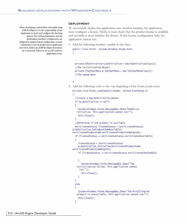
312 • ArcGIS Engine Developer Guide
BUILDING APPLICATIONS WITH WINDOWS CONTROLS
DEPLOYMENT
To successfully deploy this application onto another machine, the applicationmust configure a license. Firstly, it must check that the product license is availableand secondly it must initialize the license. If this license configuration fails, theapplication cannot run.
1. Add the following member variable to the class.public class Form1 : System.Windows.Forms.Form
{
…
private IAoInitialize m_AoInitialize = new AoInitializeClass();
//The initialization object
private IToolbarMenu m_ToolbarMenu = new ToolbarMenuClass();
//The popup menu
…
}
2. Add the following code to the very beginning of the Form_Load event.private void Form1_Load(object sender, System.EventArgs e)
{
//Create a new AoInitialize object
if (m_AoInitialize == null)
{
System.Windows.Forms.MessageBox.Show("Unable to initialize. This application cannot run!");
this.Close();
}
//Determine if the product is available
esriLicenseStatus licenseStatus = (esriLicenseStatus)m_AoInitialize.IsProductCodeAvailable(esriLicenseProductCode.esriLicenseProductCodeEngine);
if (licenseStatus == esriLicenseStatus.esriLicenseAvailable)
{
licenseStatus = (esriLicenseStatus)m_AoInitialize.Initialize(esriLicenseProductCode.
esriLicenseProductCodeEngine);
if (licenseStatus != esriLicenseStatus.esriLicenseCheckedOut)
{
System.Windows.Forms.MessageBox.Show("The initialization failed. This application cannot run!");
this.Close();
}
}
else
{
System.Windows.Forms.MessageBox.Show("The ArcGIS Engine product is unavailable. This application cannot run!");
this.Close();
}
When developing a stand-alone executable usingESRI ArcObject’s it is the responsibility of the
application to check and configure the licensingoptions. The CoClass AoInitialize and theIAoInitialize interface it implements are
designed to support license configuration. Licenseinitialization must be preformed at application
start time, before any ESRI ArcObject functional-ity is accessed. Failure to do so will resolve in
application errors.
Ch06_DevScenarios.pmd 4/2/2004, 9:15 AM312
Chapter 6 • Developer scenarios • 313
BUILDING APPLICATIONS WITH WINDOWS CONTROLS
//Create the customize dialog box for the ToolbarControl
…
}
3. Display the Form in design mode and select Form1 from the Properties win-dow and display the Form events. Double click on the Closing event to add anevent handler to the code window.
4. In the Form_Closing event add the following code:private void Form1_Closing(object sender,
System.ComponentModel.CancelEventArgs e)
{
//Release COM objects and shut down the AoInitilaize object
ESRI.ArcGIS.Utility.COMSupport.AOUninitialize.Shutdown();
m_AoInitialize.Shutdown();
}
5. Build the project and build the solution in release mode.
To successfully deploy this application onto a users machine:
• The application’s executable and the DLL containing the custom commandwill need to be deployed onto the users machine. The Assembly RegistrationTool (RegAsm.exe) must be used to add information about the custom class tothe registry.
• The users machine will need an installation of the ArcGIS Engine Runtimeand a standard ArcGIS Engine license.
• The users machine will need an installation of the Microsoft .NET Frame-work 1.1.
ADDITIONAL RESOURCES
The following resources may help you understand and apply the concepts andtechniques presented in this scenario.
• Additional documentation available in the ArcGIS Engine Developer Kitincluding ArcGIS Developer Help, component help, object model diagrams, andsamples to help you get started.
• ArcGIS Developer Online—Web site providing the most up-to-date informa-tion for ArcGIS Developers including updated samples and technical docu-ments. Go to http://arcgisdeveloperonline.esri.com.
• ESRI online discussion forums—Web sites providing invaluable assistancefrom other ArcGIS developers. Go to http://support.esri.com and click theUser Forums tab.
• Microsoft documentation on the Visual Studio .NET development environ-ment.
Ch06_DevScenarios.pmd 4/2/2004, 9:15 AM313
314 • ArcGIS Engine Developer Guide
This walkthrough is intended for programmers who want to learn more about theJava API in ArcGIS Engine. To get the most out of this scenario you shouldunderstand basic Java programming concepts such as classes, inheritance, andusing packages. Some familiarity with ArcObjects will also be helpful, althoughnot required. Although this scenario does require conceptual knowledge of theJava language, it does not require a lot of programming experience. The codeused in this example provides an easy entry point to learn about the Java API inArcGIS Engine on a small and simple scale.
You can find this sample in<install_location>\DeveloperKit\Samples\Developer_Guide_Scenarios\ArcGIS_Engine\Building_a_Command_Line_Application\Converting_A_Tin_To_Point_Shapefile
PROJECT DESCRIPTION
This scenario will cover several aspects of the ArcGIS Engine API. The goal ofthis exercise is to create a standalone command line application with the ArcGISEngine Java API. The application will take as input a TIN representation of asurface and create a three-dimensional shapefile representing the interpolated TINnodes. Once you have completed this scenario, you will understand the tech-niques required to work with the ArcGIS Engine Java API.
CONCEPTS
Terrain data is collected mostly as a sequence of discrete (X, Y, Z) data points.Digital terrain models (DTM) are generally organized such that mass points lie ina grid pattern or they represent nodes of triangles in an array referred to as trian-gulated irregular network or TIN. The nodes will be converted to points and usedto create a new feature class. This exercise will use the TIN object and theITinAdvanced interface it implements. ITinAdvanced provides access to basic prop-erties and is a starting point to the underlying data structure. In addition, thescenario utilizes the GeometryDef and FieldsEdit objects to populate the newlycreated feature class.
DESIGN
The application will be written entirely in the Java language. This allows you towrite code once on any platform and deploy the application on any supportedArcGIS Engine platform. This scenario will use Microsoft Windows XP as thedeveloper platform, but can easily be followed on any UNIX-based developerplatforms.
We will use Ant, a cross-platform Java-based build tool, to build and deploy thescenario. Ant executes tasks implemented as Java classes, which allow it to inheritthe platform independence of Java. ArcGIS Engine Developer Kit includes anextended version of Ant called arcgisant. This scenario will use arcgisant, but youare free to use any version of Ant 1.5.x or greater.
REQUIREMENTS
In order to successfully follow this scenario you need the following (the require-ments for deployment are covered later in the Deployment section):
• An installation of the ArcGIS Engine Developer Kit (including Java) with anauthorization file enabling it for development use.
BUILDING A COMMAND LINE JAVA APPLICATION
Rather than walk through this scenario, you canget the completed application from the samples
installation location. The sample is installed aspart of the ArcGIS developer samples.
The ArcGIS developer samples are not includedin the 'typical' installation of the ArcGIS Engine
Developer Kit. If you do not have them installed,rerun the Developer Kit install wizard, choose
Custom or Modify, and select the samplesfeature under Software Developer Kit.
The Java API is not included in the 'typical'installation of the ArcGIS Engine Developer Kit. Ifyou do not have it installed, rerun the DeveloperKit install wizard, choose Custom or Modify, and
select the Java feature under ArcGIS Engine. Inaddition, for access to the Javadoc and other Java-
specific documentation, select the Java featureunder Software Developer Kit.
Ch06_DevScenarios.pmd 4/2/2004, 9:15 AM314

Chapter 6 • Developer scenarios • 315
• An installation of the Java 2 Platform, Standard Edition (J2SE) SoftwareDevelopment Kit (SDK), preferably 1.4.2 or later. If you do not already haveone available, download it from the Java Website at http://java.sun.com/j2se/downloads.html
• A Java IDE of your choice or your favorite text editor.
• An understanding of basic Java programming concepts such as classes, inherit-ance, and using packages.
• While no experience with other ESRI software is required, previous experi-ence with ArcObjects is helpful.
• A TIN dataset
• Access to the sample data and code that comes with this scenario.<install_location>\DeveloperKit\Samples\Developer_Guide_Scenarios\ArcGIS_Engine\Building_a_Command_Line_Application\Converting_A_Tin_To_Point_Shapefile
Objects from the following libraries will be used:
• DataSourcesFile • Geometry
• GeoDatabase • System
In the Java API, their package names se are prefixed by 'com.esri.arcgis'.
IMPLEMENTATION
To implement this scenario follow the steps below. This implementation providesyou with all the code you will need to successfully complete the scenario. It doesnot provide step-by-step instructions to develop applications in Java, as it as-sumes that you have a working knowledge of the development environmentalready.
Setting up environment variablesAny windows user can add, modify, or remove a user environment variable.Setting such environment variables will make most effective use of this scenario.You will add three environment variables and their respective executable (bin)folders to the global PATH variable.
1. Right-click My Computer, and then click Properties.
2. Click the Advanced tab.
3. Click Environment Variables.
4. Under System Variables click New.For Variable name: type 'ARCENGINEHOME'.For Variable value: type in the root level ArcGIS Engine install directory (forexample, C:\ArcGIS).
5. Click OK.
6. Under System variables single-click on Path and click Edit.
7. Append the following to the beginning of Variable value:%ARCENGINEHOME%\bin;
8. Click OK until you have closed all System Properties dialog boxes.
BUILDING A COMMAND LINE JAVA APPLICATION
The ArcGIS developer samples are not includedin the 'typical' installation of the ArcGIS Engine
Developer Kit. If you do not have them installed,rerun the Developer Kit install wizard, choose
Custom or Modify, and select the samplesfeature under Software Developer Kit.
Ch06_DevScenarios.pmd 4/2/2004, 9:15 AM315

316 • ArcGIS Engine Developer Guide
Repeat the steps above to add the following environment variables:
• JAVA_HOME=J2SE SDK install directory
• ANT_HOME=%ARCENGINEHOME\DeveloperKit\tools\arcgisant
Before proceeding with building the application itself, you need to prepare thebuild scripts. It is vital to set up the build structure as illustrated to the left inorder for the scripts to work correctly.
• TintoPoint folder—root folder for the project
• src folder—subfolder containing all of the application's source code
• build.xml—Ant build script file.
• properties.xml—external Ant properties file, which extends the build environ-ment.
• sample.properties—external Java properties file with command line param-eters.
The three files—build.xml, properties.xml, and sample.properties—must becreated before you can build and deploy the scenario.
Creating the samples.properties fileLet's begin by creating the sample.properties file. This file provides the buildscript with necessary command line arguments to successfully execute the applica-tion created in this exercise. This file will use the variable=argument pattern.
1. Create a text file named sample.properties and add the following lines of codeto it. Revise the arguments for the variables input.tin.path andoutput.shape.path to match the paths to your TIN dataset and outputshapefile dataset.# TinToPoint
unit.name=TintoPoint
main.class=engine.scenario.analyst3d.TintoPoint
#TinToPoint command line args
input.tin.path=\<path to TIN dataset>
output.shape.path=\<path to generated shapefile dataset>
2. Save and close the file.
Creating the properties.xml fileThe properties.xml file sets Ant properties for the build environment. Ant prop-erties can be set explicitly or loaded from a file. For simplicity, you will add thedependent properties from a file, properties.xml.
1. Create an XML file named properties.xml and add the following Ant proper-ties:<!— :mode=ant —>
<!— ========================================= —>
<!— load environment variables —>
<!— ========================================= —>
<property environment="env"/>
BUILDING A COMMAND LINE JAVA APPLICATION
To compile and run applications using the ArcGISEngine Developer Kit, the PATH environment
variable should include paths to ArcGIS/bin andJ2SE SDK/bin. In addition, ArcGIS Engine
Developer Kit ships with an extended version ofAnt called arcgisant. The path to this tool
should also be included.
Folder and file structure required in order forthe build scripts to work as desired.
Ch06_DevScenarios.pmd 4/2/2004, 9:15 AM316

Chapter 6 • Developer scenarios • 317
<property name="arcengine.home" value="${env.ARCENGINEHOME}" />
<property name="ant.home" value="${engine.home}/developerkit/tools/ant"/>
<!— ========================================= —>
<!— directory mappings —>
<!— ========================================= —>
<property name="root.dir" location="${basedir}"/>
<property name="src.dir" location="src"/>
<property name="build.dir" location="build"/>
<property name="class.dir" location="${build.dir}/classes"/>
<!— ========================================= —>
<!— library dependency settings —>
<!— ========================================= —>
<!— library directory mappings —>
<property name="arcgis.dir" location="${engine.home}/java"/>
<!— each library has its own unique directory structure —>
<property name="arcgis.subdir" value="opt"/>
<!— jar file mappings —>
<property name="jintegra.jar" location="${arcgis.dir}/jintegra.jar"/>
<property name="arcobjects.jar" location="${arcgis.dir}/${arcgis.subdir}/arcobjects.jar"/>
2. Save and close the file.
Creating the build.xml fileAnt build scripts are written in XML and contain one project and at least onetask. Each project defines one or more targets that combine tasks for execution.In this scenario, the project name is “ArcGIS Engine Developer Scenario” and itsbuild script needs to contain the four private and three public targets, as listedrespectively below:
• init—creates the build directory structure.
• validate-engine—ensures that the ArcGIS Engine Developer environment isproperly set.
• compile—compiles the scenario.
• execute—runs the scenario in a separate JVM instance.
• all—the default target, which builds the entire scenario.
• clean—cleans all build products.
• run-scenario—builds and runs the scenario application.
In order to get an idea of the structure of Ant targets, let’s have a look at asample compile target line by line.<target name="compile" depends="validate-engine">
As shown in the first line, this target has a name to reference and depends onanother target. To ensure a successful build, the ‘depends’ attribute is used toconfirm that the environment is set correctly.
BUILDING A COMMAND LINE JAVA APPLICATION
To learn more about private and public targetsused in Ant scripts, see the Ant documentation
available from the Apache Ant Web site,http://ant.apache.org/.
Ch06_DevScenarios.pmd 4/2/2004, 9:15 AM317

318 • ArcGIS Engine Developer Guide
<!— compile the java code from ${src.dir} into ${class.dir} —>
<javac srcdir="${src.dir}" destdir="${class.dir}">
<classpath refid="compile.classpath"/>
In the last section of this sample target, one of Ant’s core tasks, ‘javac’, is createdto compile the files in the source directory and place them in the class directory.The javac task supports a classpath task to ensure the classpath settings.
The complete sample target, including closure of the XML tags, then is as shownbelow:<target name="compile" depends="validate-engine">
<!— compile the java code from ${src.dir} into ${class.dir} —>
<javac srcdir="${src.dir}" destdir="${class.dir}">
<classpath refid="compile.classpath"/>
</javac>
</target>
Now that you've got a basic understanding of targets and their usage in Ant, let'sproceed with creating the build.xml file for this scenario.
1. Create an XML file named build.xml and add the following:<?xml version="1.0"?>
<!DOCTYPE project[
<!ENTITY properties SYSTEM "file:properties.xml">
]>
<!— :mode=ant —>
<project name="ArcGIS Engine Developer Scenario" default="all"basedir=".">
<!— import external XML fragments —>
&properties;
<!— import sample properties —>
<property file="sample.properties"/>
<path id="compile.classpath">
<pathelement location="${jintegra.jar}"/>
<pathelement location="${arcobjects.jar}"/>
</path>
<path id="run.classpath">
<path refid="compile.classpath"/>
<pathelement location="${class.dir}"/>
</path>
<!— ========================================= —>
<!— private targets —>
<!— ========================================= —>
<target name="init">
<!— create the time stamp —>
<tstamp/>
<!— create the build directory structure used by compile —>
<mkdir dir="${build.dir}"/>
<mkdir dir="${class.dir}"/>
BUILDING A COMMAND LINE JAVA APPLICATION
The entire build script is not discussed in detailhere; to learn more about building Ant scriptssee the Ant documentation available from theApache Ant Web site, http://ant.apache.org/.
Ch06_DevScenarios.pmd 4/2/2004, 9:15 AM318

Chapter 6 • Developer scenarios • 319
</target>
<target name="validate-engine" depends="init">
<condition property="engine.available">
<and>
<isset property="env.ARCENGINEHOME"/>
</and>
</condition>
<fail message="Missing dependencies: ARCENGINEHOME environmentvariable not correctly set" unless="engine.available"/>
</target>
<target name="compile" depends="validate-engine">
<!— javac resolver needed to run inside of Websphere Studio —>
<available classname="org.eclipse.core.launcher.Main"property="build.compiler"
value="org.eclipse.jdt.core.JDTCompilerAdapter"classpath="${java.class.path}" />
<!— compile the java code from ${src.dir} into ${class.dir} —>
<javac srcdir="${src.dir}" destdir="${class.dir}">
<classpath refid="compile.classpath"/>
</javac>
</target>
<target name="execute" depends="compile" if="input.tin.path">
<java classname="${main.class}" failonerror="true" fork="true">
<classpath refid="run.classpath"/>
<!— values must be set correctly in sample.properties —>
<arg value="${input.tin.path}"/>
<arg value="${output.shape.path}"/>
</java>
</target>
<!— ========================================= —>
<!— public targets —>
<!— ========================================= —>
<target name="all" depends="compile" description="build everything">
<echo message="application built"/>
</target>
<target name="clean" description="clean all build products">
<!— delete the ${build} directory trees —>
<delete dir="${build.dir}"/>
<echo message="build directory gone!"/>
</target>
<target name="run-scenario" depends="execute" description="execute thesample with args set in sample.properties"/>
</project>
BUILDING A COMMAND LINE JAVA APPLICATION
Ch06_DevScenarios.pmd 4/2/2004, 9:15 AM319

320 • ArcGIS Engine Developer Guide
2. Save and close the file.
Testing your build environmentNow that you've set up all the necessary files for building your application, let'stest it before proceeding.
1. Open a command prompt and cd into the root folder of your project. Forexample,cd C:\TintoPoint
2. You should have all the build script files located in this root directory.
3. Type 'arcgisant' at the command prompt.
4. You should receive output similar to the following:Buildfile: build.xml
init:
[mkdir] Created dir: Q:\dop\dev\ant\projects\engine.scenario\build
[mkdir] Created dir: Q:\dop\dev\ant\projects\engine.scenario\build\classes
validate-engine:
compile:
BUILD FAILED
file:Q:/dop/dev/ant/projects/engine.scenario/build.xml:49: srcdir"Q:\dop\dev\ant\projects\engine.scenario\src" does not exist!
Total time: 1 second
The build should fail since you do not have any source to build yet. If you lookon disk at your project directory, you should notice a build folder was created.This is where all build products will be generated.
Clean up the build with the following command:arcgisant clean
This should generate output similar to the following:Buildfile: build.xml
clean:
[delete] Deleting directory Q:\dop\dev\ant\projects\engine.scenario\build
[echo] build directory gone!
BUILD SUCCESSFUL
Total time: 1 second
Now that your build environment is prepared, youe can proceed with writing theJava source code for the example application.
Creating the TintoPoint main class1. Begin you source code by adding the signature for the main class in this exer-
cise:package engine.scenario.analyst3d;
public class TintoPoint{}
The class will eventually have three private static methods and one public mainentry point. For the sake of simplicity, private static methods are used to do the
BUILDING A COMMAND LINE JAVA APPLICATION
Use your favorite text editor or IDE to writeyour source code.
Ch06_DevScenarios.pmd 4/2/2004, 9:15 AM320

Chapter 6 • Developer scenarios • 321
work for the application. While some Java developers believe that, when amethod can be either static or an instance, an instance method should be utilized,this scenario uses the simplest approach—static methods. Each of these methodswill be covered in upcoming sections.
Next, let's look at what imports are required by the class.
As discussed earlier, this scenario uses the datasourcesfile, geodatabase, geometry,and system Java packages.
• datasourcesfile—provides workspace factories and workspaces for vector dataformats supported by the geodatabase API. You will be use theShapefileWorkspaceFactory class in this exercise to create your generated 3Dshapefile.
• geodatabase—provides all definitions relating to data access including Tins andFeatureClasses. You will be use the GeometryDef class to define spatial quali-ties for your generated feature class.
• geometry—contains the core geometry objects, as well as spatial referenceinformation. In this scenario, you will use the Point class as a representation ofall the TIN nodes in your input TIN dataset.
• system—contains objects that expose services used by the other librarieswithin ArcGIS Engine. You will use the use AoInitializer object to initializeand un-initialize your application.
2. Below the package declaration you made above, import the classes as shown.Use fully qualified imports so you can see explicitly which classes from theArcGIS Engine Java API you are working with.import java.io.File;
import java.io.IOException;
import com.esri.arcgis.datasourcesfile.ShapefileWorkspaceFactory;
import com.esri.arcgis.geodatabase.Field;
import com.esri.arcgis.geodatabase.Fields;
import com.esri.arcgis.geodatabase.GeometryDef;
import com.esri.arcgis.geodatabase.IEnumTinNode;
import com.esri.arcgis.geodatabase.IFeatureBuffer;
import com.esri.arcgis.geodatabase.IFeatureClass;
import com.esri.arcgis.geodatabase.IFeatureClassProxy;
import com.esri.arcgis.geodatabase.IFeatureCursor;
import com.esri.arcgis.geodatabase.IFeatureWorkspace;
import com.esri.arcgis.geodatabase.IFeatureWorkspaceProxy;
import com.esri.arcgis.geodatabase.IFieldEdit;
import com.esri.arcgis.geodatabase.IFields;
import com.esri.arcgis.geodatabase.IFieldsEdit;
import com.esri.arcgis.geodatabase.ITinAdvanced;
import com.esri.arcgis.geodatabase.ITinNode;
import com.esri.arcgis.geodatabase.IWorkspaceFactory;
import com.esri.arcgis.geodatabase.Tin;
import com.esri.arcgis.geodatabase.esriFeatureType;
import com.esri.arcgis.geodatabase.esriFieldType;
import com.esri.arcgis.geodatabase.esriTinQualification;
BUILDING A COMMAND LINE JAVA APPLICATION
The datasourcesfile, geodatabase, geometry, andsystem Java packages are the equivalent of theDataSourcesFile, GeoDatabase, Geometry, and
System libraries of ArcGIS Engine.
Ch06_DevScenarios.pmd 4/2/2004, 9:15 AM321

322 • ArcGIS Engine Developer Guide
import com.esri.arcgis.geometry.IPoint;
import com.esri.arcgis.geometry.ISpatialReference;
import com.esri.arcgis.geometry.Point;
import com.esri.arcgis.geometry.esriGeometryType;
import com.esri.arcgis.system.AoInitialize;
import com.esri.arcgis.system.EngineInitializer;
import com.esri.arcgis.system.esriLicenseExtensionCode;
import com.esri.arcgis.system.esriLicenseProductCode;
Now that the imports have all been made, you can add methods to your class.
Adding the tinToPoint methodThis method performs most of the work for the application. It will take, asparameters, a path to your TIN file, the name of the TIN, a path to an outputshapefile, and a name for the output shapefile.
1. Create the signature for the tinToPoint method as follows:/**
* @param tinPath – path to input tin data source
* @param tinName – name of input tin data source
* @param shapePath – path to output shapefile data source
* @param shapeFile – name of output shapefile data source
*/
private static void tinToPoint(String tinPath, String tinName,String shapePath, String shapeFile){
Initially, you need to open your TIN dataset from its file location, which is passedas a parameter to the method, by instantiating a new Tin class. The Tin classimplements many interfaces; you will use methods provided by the ITinAdvancedand IGeoDataset interfaces. By calling the init() method, exposed by theITinAdvanced interface, you can open the specified TIN.
2. Instantiate the new Tin class by adding the following code below the signaturefor your method.try{
//Get tin from tin file
ITinAdvanced tinAdv = new Tin();
String path = tinPath + File.separator + tinName;
System.out.println(" - Path to Tin: " + path);
tinAdv.init(path);
System.out.println(" - Calculating ... ");
Tin tin = new Tin(tinAdv);
3. Next, get the spatial reference of the Tin and send it as a parameter to acreateBasicFields() method that will be defined in the next section. In addition,you need to send a geometry type point since your resulting feature class willbe a point feature class.ISpatialReference tinSpatialRef = tin.getSpatialReference();
IFields fields = createBasicFields(esriGeometryType.esriGeometryPoint, false, true, tinSpatialRef);
BUILDING A COMMAND LINE JAVA APPLICATION
Note about try/catch here. TODO
The ITinAdvanced interface requires an ArcGISEngine Runtime license with 3D option or an
ArcGIS 3D Analyst extension when deployed. Youwill add code for detecting for this license and
checking it out later in this exercise.
Ch06_DevScenarios.pmd 4/2/2004, 9:15 AM322

Chapter 6 • Developer scenarios • 323
4. Now that the basic fields have been generated, the next step is to create anoutput shapefile. WorkspaceFactory is used as a dispenser of workspaces tocreate an instance of a ShapefileWorkspaceFactory class. The IFeatureWorkspaceinterface is used to access and manage datasets. You will cross-cast to thereturned object that implements IWorkspace by creating an instance ofIFeatureWorkspaceProxy class using its object constructor. Finally, your outputshapefile is generated using the createFeatureClass() method to create astandalone feature class. // create output shapefile
IWorkspaceFactory wkspFactory = new ShapefileWorkspaceFactory();
IFeatureWorkspace featureWksp = new IFeatureWorkspaceProxy(
wkspFactory.openFromFile(shapePath, 0));
IFeatureClass outFC = new IFeatureClassProxy(featureWksp.createFeatureClass( shapefile,
fields,
null,
null,
esriFeatureType.esriFTSimple,
"Shape",
"”));
5. The final step in creating this method is to populate the newly created featureclass with the value of the nodes from your input TIN. ThemakeNodeEnumerator() method returns enumerations of nodes based on anextent and a criteria. The extent used is that of the input TIN dataset and alldata inside the TIN is used as the criteria. Once an enumeration object is filledwith your TIN nodes, use a FeatureCursor as a data access object to iterate overthe set of rows in your newly created feature class and a FeatureBuffer object tohold the state of the row. Next, create an instance of the Point class andpopulate it with your TIN nodes by instantiating an ITinNode interface withthe objects returnd by your enumeration. While your node is not null, loopthrough them and populate your feature class. // get tin node enum
IEnumTinNode enum = tin.makeNodeEnumerator(tin.getExtent(),esriTinQualification.esriTinInsideDataArea, null);
IFeatureCursor outCursor = outFC.IFeatureClass_insert(true);
IFeatureBuffer outBuffer = outFC.createFeatureBuffer();
IPoint point = new Point();
ITinNode node = enum.IEnumTinNode_next();
while(node != null){
node.queryAsPoint(point);
outBuffer.setShapeByRef(point);
outCursor.insertFeature(outBuffer);
node = enum.IEnumTinNode_next();
}
BUILDING A COMMAND LINE JAVA APPLICATION
Ch06_DevScenarios.pmd 4/2/2004, 9:15 AM323

324 • ArcGIS Engine Developer Guide
6. Finish the code for the tintoPoint method by catching any exceptions.System.out.println(" - Path to Generated Shapefile: " +
shapePath +
File.separator +
shapeFile);
}catch (Exception ex) {
ex.printStackTrace();
}
}
You've now completed the code that results in a new shapefile representing thenodes of the intput TIN on disk.
7. Review the code for the full method below to make sure your's matches./**
* @param tinPath – path to input tin data source
* @param tinName – name of input tin data source
* @param shapePath – path to output shapefile data source
* @param shapeFile – name of output shapefile data source
*/
private static void tinToPoint(String tinPath,
String tinName,
String shapePath,
String shapeFile){
try{
//Get tin from tin file
ITinAdvanced tinAdv = new Tin();
String path = tinPath + File.separator + tinName;
System.out.println(" - Path to Tin: " + path);
tinAdv.init(path);
System.out.println(" - Calculating ... ");
Tin tin = new Tin(tinAdv);
ISpatialReference tinSpatialRef = tin.getSpatialReference();
IFields fields = createBasicFields(esriGeometryType.esriGeometryPoint,
false,
true,
tinSpatialRef);
// create output shapefile
IWorkspaceFactory wkspFactory = new ShapefileWorkspaceFactory();
IFeatureWorkspace featureWksp = new IFeatureWorkspaceProxy(
wkspFactory.openFromFile(shapePath, 0));
IFeatureClass outFC = new IFeatureClassProxy(featureWksp.createFeatureClass( shapefile, fields, null, null,
esriFeatureType.esriFTSimple, "Shape", "”));
// get tin node enum
IEnumTinNode enum = tin.makeNodeEnumerator(tin.getExtent(),
esriTinQualification.esriTinInsideDataArea,
null);
BUILDING A COMMAND LINE JAVA APPLICATION
Ch06_DevScenarios.pmd 4/2/2004, 9:15 AM324

Chapter 6 • Developer scenarios • 325
// store node to shapefile
IFeatureCursor outCursor = outFC.IFeatureClass_insert(true);
IFeatureBuffer outBuffer = outFC.createFeatureBuffer();
IPoint point = new Point();
ITinNode node = enum.IEnumTinNode_next();
while(node != null){
node.queryAsPoint(point);
outBuffer.setShapeByRef(point);
outCursor.insertFeature(outBuffer);
node = enum.IEnumTinNode_next();
}
System.out.println(„ - Path to Generated Shapefile: " +
shapePath +
File.separator +
shapeFile);
}catch (Exception ex) {
ex.printStackTrace();
}
}
Creating the basic fields for the 3D shapefileNow that the method that performs the conversion from TIN to shapefile hasbeen created, the next step is to define the schema structure for the output 3Dshapefile. The tinToPoint() method defined above uses the createBasicFields methodyou create here to generate a fields object and send it as a parameter to thecreateFeatureClass() method.
1. Create the signature for this method as follows:/**
* @param shapeType - a geometry object type
* @param hasM - m-value precision defined
* @param hasZ - z-value precision defined
* @param spatialRef - Spatial Reference
*
* @return IFields - a collection of columns in a table
*/
private static IFields createBasicFields(int shapeType, boolean hasM,
boolean hasZ, ISpatialReference spatialRef){
2. Use a GeometryDef object to define spatial qualities of your feature class. Themost fundamental spatial quality that the method will take as a parameter isthe geometry type. Create new fields using the IFieldsEdit interface and returnthis object.try {
Fields fields = new Fields();
IFieldsEdit fieldsEdt = fields;
Field field = new Field();
IFieldEdit fieldEdt = field;
GeometryDef geometryDef = new GeometryDef();
BUILDING A COMMAND LINE JAVA APPLICATION
Ch06_DevScenarios.pmd 4/2/2004, 9:15 AM325

326 • ArcGIS Engine Developer Guide
double dGridSize;
if (spatialRef.hasXYPrecision()) {
double[] xmin = {0};
double[] ymin = {0};
double[] xmax = {0};
double[] ymax = {0};
spatialRef.getDomain(xmin, xmax, ymin, ymax);
double dArea = (xmax[0] - xmin[0]) * (ymax[0] - ymin[0]);
dGridSize = Math.sqrt(dArea / 100);
}else {
dGridSize = 1000;
}
geometryDef.setGeometryType(shapeType);
geometryDef.setHasM(hasM);
geometryDef.setHasZ(hasZ);
geometryDef.setSpatialReferenceByRef(spatialRef);
geometryDef.setGridCount(1);
geometryDef.setGridSize(0,dGridSize);
// add oid field - must come before geometry field
fieldEdt = new Field();
fieldEdt.setName("OBJECTID");
fieldEdt.setAliasName("OBJECTID");
fieldEdt.setType(esriFieldType.esriFieldTypeOID);
fieldsEdt.addField(fieldEdt);
//add Geometry field
fieldEdt = new Field();
fieldEdt.setName("SHAPE");
fieldEdt.setIsNullable(true);
fieldEdt.setType(esriFieldType.esriFieldTypeGeometry);
fieldEdt.setGeometryDefByRef(geometryDef);
fieldEdt.setRequired(true);
fieldsEdt.addField(fieldEdt);
return fieldsEdt;
}catch (IOException ex) {
ex.printStackTrace();
return null;
}
}
Initializing ArcObjectsEvery application built with the ArcGIS Engine Developer Kit must initializeArcObjects at a product level, including any appropriate extension licenses. TheAoInitialize object is used to accomplish this task. This class initializes theArcObjects runtime environment and must be the first ArcObjects componentcreated. Two methods will be called from this object:
• initialize( int product code )—This method takes an integer value representing aproduct code. The Java API provides an interface called esriLicenseProductCode
BUILDING A COMMAND LINE JAVA APPLICATION
Ch06_DevScenarios.pmd 4/2/2004, 9:15 AM326

Chapter 6 • Developer scenarios • 327
which exposes static integer fields representing the different ESRI productlevels. See the javadoc description for a full list of products.
• CheckOutExtension( int extensioncode )—This method takes an integer valuerepresenting an extension license code. The Java API provides an interfacecalled esriLicenseExtensionCode which exposes static integer fields representingthe different ESRI extension products available.
This application requires an ArcGIS Engine Runtime license with 3D Analystextension license.
1. Create the signature for this method as follows:private static void licenseCheckOut(){}
2. Implement the private method./**
* Initialize ArcObjects product usage and check out
* available 3D Analyst extension license
*/
private static void licenseCheckOut(){
try{
AoInitialze aoInit = new AoInitialize();
aoInit.initialze(esriLicenseProductCode.esriLicenseProductCodeEngine);
aoInit.checkOutExtension(esriLicenseExtensionCode.esriLicenseExtensionCode3DAnalyst);
}catch(IOException e){
System.out.println(„Program Exit: Unable to initialize ArcObjects„);
System.exit(0);
}
}
Putting it all togetherNow that the private methods have all been constructed, you need to create anentry point for your application. This main method will take command linearguments and pass them to the tinToPoint method created in earlier steps.
1. First, insert some logic to ensure that you have the correct number of argu-ments in the form of an if/else code block./*
* Description:
* Main Method - Application Entry Point
*/
public static void main(String[] args) {
if(args.length != 2){
System.out.println( "Tin to Point: ArcGIS Engine DeveloperScenario");
System.out.println("Usage: TintoPoint [Path-to-tin] [Path-to-output-shapefile]");
System.exit(0);
}else{
BUILDING A COMMAND LINE JAVA APPLICATION
Ch06_DevScenarios.pmd 4/2/2004, 9:15 AM327

328 • ArcGIS Engine Developer Guide
System.out.println( "Tin to Point: ArcGIS Engine Developer Sample");
String inDataset = args[0];
String outDataset = args[1];
This application takes two arguments: an input full path to your TIN dataset anda full path to the generated output shapefile. Once the application determines thecorrect amount of arguments they can be split into the path and name formatrequired by the tinToPoint() method generated earlier.
2. Add in the following code below the if/else code back you just created. String inDataPath = inDataset.substring( 0,inDataset.lastIndexOf(File.separator));
String inDataName = inDataset.substring(inDataset.lastIndexOf(File.separator) + 1));
String outDataPath = outDataset.substring( 0,outDataset.lastIndexOf(File.separator));
String outDataName = outDataset.substring(outDataset.lastIndexOf(File.separator) + 1));
The next step in creating the main method is to initialize the programming envi-ronment. In the ArcGIS Java API, this is handled by calling the static classEngineInitializer. This class is a facade class exposed by the Java API to ensureoptimal use of native ArcObjects for Java. Following that, the staticlicenseCheckOut() method described above must be called.
3. Add the following code to the main method.EngineInitializer.initilizeEngine();
licenseCheckOut();
4. The last step is to call the static worker method tintoPoint() and pass in thestring parameters.tinToPoint(inDataPath, inDataName, outDataPath, outDataName);
System.out.println("Tin to Point - Done");
}
}
The code for the command line application is now complete.
DEPLOYMENT
There are many options to deploying your Java application and while you are freeto choose any method you are comfortable with, this scenario utilizes the Antbuild scripts you created earlier.
Redo the build steps you tested earlier.
1. Open a command prompt and cd into the root folder of your project. Forexample,cd C:\TintoPoint
2. You should have all the build script files located in this root directory.
3. Type 'arcgisant' at the command prompt.
4. You should receive output similar to the following:Buildfile: build.xml
init
validate-engine:
BUILDING A COMMAND LINE JAVA APPLICATION
This exercise does not implement any logic thatdetermines if the arguments being passed are
valid strings or datapaths. This validation processmay be beneficial when developing a production
application.
Ch06_DevScenarios.pmd 4/2/2004, 9:15 AM328

Chapter 6 • Developer scenarios • 329
compile:
execute:
[java] Tin to Point: ArcGIS Engine Developer Sample
[java] - Path to Tin: Q:\dop\data\imagery\tin\bachtin
[java] - Calculating ...
[java] - Path to Generated Shapefile:Q:\dop\data\workspace\newshp.shp
[java] Tin to Point - Done
run-scenario:
BUILD SUCCESSFUL
Total time: 9 seconds
If for any reason your build fails, ensure you have your environment correctly setand parameters correctly set in the sample.properties file. If your build does notcompile, ensure that your source code is correct.
TROUBLESHOOTING
If your build returns the following:Buildfile: build.xml
init:
validate-engine:
compile:
execute:
[java] Tin to Point: ArcGIS Engine Developer Scenario
[java] Usage: TintoPoint [Path-to-tin] [Path-to-output-shapefile]
run-scenario:
BUILD SUCCESSFUL
then your source code has successfully compiled, but you have not provided pathvariables in the sample.properties file.
If your build returns the following:Buildfile: build.xml
init:
validate-engine:
compile:
execute:
[java] Tin to Point: ArcGIS Engine Developer Sample
[java] java.lang.StringIndexOutOfBoundsException: String index out ofrange: -1
[java] at java.lang.String.substring(String.java:1444)
[java] at engine.scenario.analyst3d.TintoPoint.main(Unknown Source)
[java] Exception in thread "main"
BUILD FAILED
file:Q:/dop/dev/ant/projects/engine.scenario/build.xml:53: Java returned: 1
Total time: 1 second
BUILDING A COMMAND LINE JAVA APPLICATION
Ch06_DevScenarios.pmd 4/2/2004, 9:15 AM329

330 • ArcGIS Engine Developer Guide
then your source code has compiled, but you have not provided valid variablestrings representing your data paths. Ensure that you have provided data paths inthe following format:
• C:\\data\\imagery\\tin\\bachtin
• C:\\data\\workspace\\newshp.shp
ADDITIONAL RESOURCES
The following resources may help you understand and apply the concepts andtechniques presented in this scenario.
• Additional documentation available in the ArcGIS Engine Developer Kitincluding ArcGIS Developer Help, component help, object model diagrams, andsamples to help you get started.
• ArcGIS Developer Online—Web site providing the most up-to-date informa-tion for ArcGIS Developers including updated samples and technical docu-ments. Go to http://arcgisdeveloperonline.esri.com.
• ESRI online discussion forums—Web sites providing invaluable assistancefrom other ArcGIS developers. Go to http://support.esri.com and click theUser Forums tab.
Java enjoys a huge community with many resources for its developers. The fol-lowing is a list of URLs that most developers keep in their toolkit. These links,while correct at publication, are subject to change.
• Sun’s Java and JDK FAQ (http://java.sun.com/products/jdk/faq.html)—High-level introductory FAQs about Java.
• Sun’s Java (http://java.sun.com/)—The source for Java technology.
• Sun’s Java Tutorial (http://java.sun.com/docs/books/tutorials)—On-Lineversion of the book from Addison-Wesley. Learing all about Java.
• Thinking in Java (http://www.mindview.net/Books/TIJ)—On-Line versionfo book from Prentice Hall. Very good for learning about Object-OrientedProgramming concepts in Java.
The Apache Ant project is an extremely successful open source project and carriesthe trademark of many resources.
• The Apache Ant Project (http://ant.apache.org)—this is where the Antproject lives.
• Java Development with Ant (http://www.manning.com/antbook)—excellentbook covering Ant 1.5.
• Ant in Anger (http://ant.apache.org/ant_in_anger.html)—this documentdescribes stategies and some basic examples of how to use Ant.
• jGuru (http://www.jguru.com/forums/home.jsp?topic=Ant)—jGuru hostsan interactive Ant discussion forum.
BUILDING A COMMAND LINE JAVA APPLICATION
Ch06_DevScenarios.pmd 4/2/2004, 9:15 AM330

Chapter 6 • Developer scenarios • 331
BUILDING A COMMAND LINE C++ APPLICATION
This scenario is designed to introduce the ArcGIS Engine C++ API for cross-platform applications. To get the most out of this scenario you should understandbasic C/C++ programming concepts such as the preprocessor, functions, andmemory management. Some familiarity with ArcObjects will also be helpful,although not required. Although this scenario does require conceptual knowledgeof the C++ language, it does not require a lot of programming experience. Thecode used in this example provides an easy entry point to learn about the C++API to ArcGIS Engine on a small and simple scale.
The purpose of this scenario is not to teach how to set up a C++ environment orhow to compile on each supported operating system. Throughout this scenario itis assumed that you have a functional C++ environment and know how tocompile a C++ program in that environment. What this scenario does provide isthe steps to take and the code to write in order to create a command line applica-tion which computes the slope of a given digital elevation model.
You can find this sample in<install_location>\DeveloperKit\Samples\Developer_Guide_Scenarios\ArcGIS_Engine\Building_a_Command_Line_Application\Computing_the_slope_of_a_raster_dataset
PROJECT DESCRIPTION
This scenario covers some aspects of the ArcGIS Engine C++ API. The goal ofthe RasterSlope scenario is to create a standalone command line application withthe ArcGIS C++ API. The application will take as input a digital elevation model(DEM) and will build and persist the slope map raster dataset. Once you havecompleted this scenario, you will understand the techniques required to workwith the ArcGIS Engine C++ API, including using the Spatial Analyst extension.In particular, the scenario covers the following techniques:
• Programming with the ArcGIS Engine C++ Developer Kit in a standard texteditor.
• Parsing command line arguments.
• Enabling extensions: in particular, the Spatial Analyst extension.
• Performing the calculation of slope on a raster dataset.
• Persisting the resultant raster dataset.
• Deploying the application on all platforms supported by the ArcEngine C++API.
CONCEPTS
Slope datasets are often used as inputs in physical process models. Slope is com-monly expressed in degrees or as a percentage. In our slope calculation a param-eter (zFactor) can be specified which specifies the number of ground x,y units in1 z unit. This allows you to create a slope dataset with different z units than theinput surface. To build the slope dataset, you will use the RasterSurfaceOp classand the ISurfaceOp interface it implements. You will also use the Raster class andthe IRasterBandCollection interface it implements to persist the resulting rasterdataset.
Rather than walk through this scenario, you canget the completed application from the samples
installation location. The sample is installed aspart of the ArcGIS developer samples.
The ArcGIS developer samples are not includedin the 'typical' installation of the ArcGIS Engine
Developer Kit. If you do not have them installed,rerun the Developer Kit install wizard, choose
Custom or Modify, and select the samplesfeature under Software Developer Kit.
For a more in-depth explanation of slope, seethe Burrough and McDonnell reference listed inthe 'Additional resources' section at the end of
this scenario.
Although this scenario steps you through C++development, solution code is also available in
other programming languages, including C#, Java,Visual Basic 6, Visual Basic .NET and Visual
C++.
Ch06_DevScenarios.pmd 4/2/2004, 9:15 AM331

332 • ArcGIS Engine Developer Guide
BUILDING A COMMAND LINE C++ APPLICATION
The role of the software is to calculate the slope of a given raster dataset. Theuser’s job is to provide a console at which to run the scenario, as well as a digitalelevation model on which to run the scenario. Since this is a cross-platformapplication, the console can be on any supported platform.
DESIGN
The application will be written entirely in the C++ language. This allows you, asthe developer, to write code once on any supported platform and deploy theapplication on all supported ArcGIS Engine platforms. This scenario usesMicrosoft Windows XP as the developer platform and nmake to compile and runthe application from the command line, using the .NET 2003 compiler. How-ever, it can easily be followed on any other supported platforms and using anysupported build strategy. Both Visual Studio 6.0 and Visual Studio .NET 2003projects are included with the solution code available in the Developer Kit.
In the design, some safeguards were taken to insure that the application remainedcross-platform. They include avoiding function calls and datatypes defined out-side the ArcGIS Engine and the C++ API as well as platform-independent pathprocessing. For example, it should not matter whether the user has “/” or “\” asthe path separator in the arguments to the application as long as the path sepa-rated is used by the operating system on which the application is being executed.In addition, C++ standards need to be followed to avoid compiler dependencies.
REQUIREMENTS
In order to successfully follow this scenario you need the following:
• An installation of the ArcGIS Engine Developer Kit (including Native C++)with an authorization file enabling it for development use.
• A text editor such as Notepad or Microsoft Visual C++.
• A supported C/C++ compiler. This scenario uses the Microsoft Visual C++Compiler .NET 2003 (7.1). For setup details, see the C++ API section ofChapter 4, 'Developer environments'.
• A configured ArcObjects environment. For setup details, see the C++ APIsection of Chapter 4, 'Developer environments'.
• ArcSDK.h: the ArcGIS Engine C++ API header file.
• A familiarity with the operating system you have chosen to work on, and abasic foundation in C++ programming.
• While no experience with other ESRI software is required, previous experi-ence with ArcObjects and a basic understanding of maps is advantageous.
• Access to the sample data, solution code, and Makefiles that come with thisscenario. This is located at<install_location>\DeveloperKit\Samples\Developer_Guide_Scenarios\ArcGIS_Engine\Building_a_Command_Line_Application\Computing_the_slope_of_a_raster_dataset
• An ArcGIS Spatial Analyst or ArcGIS Engine Runtime with Spatial optionlicense is required for the application to run once deployed.
• To run the application, you will need a raster dataset.
For more detailed information, see the C++aaplication programming interface section of
Chapter 4, 'Developer environments'.
The ArcGIS developer samples are not includedin the 'typical' installation of the ArcGIS Engine
Developer Kit. If you do not have them installed,rerun the Developer Kit install wizard, choose
Custom or Modify, and select the samplesfeature under Software Developer Kit.
The C++ API is not included in the 'typical'installation of the ArcGIS Engine Developer Kit. Ifyou do not have it installed, rerun the DeveloperKit install wizard, choose Custom or Modify, and
select the Native C++ feature under SoftwareDeveloper Kit.
Ch06_DevScenarios.pmd 4/2/2004, 9:15 AM332

Chapter 6 • Developer scenarios • 333
IMPLEMENTATION
The implementation below provides you with all the code you will need tosuccessfully complete the scenario. It does not provide step-by-step instructionsto compile C++ applications, as it assumes that you already have a workingknowledge of your chosen development environment. Error checking has beenleft out to increase code readability.
This scenario’s sample application demonstrates spatial analyst functionality; thefull source code is available in the samples included in the ArcGIS Engine Devel-oper Kit. Here are the files discussed in this scenario:
• RasterSlope.cpp—Main C++ source file
• RasterSlope.h—Main C++ header file
• Makefile.Windows.template—nmake utility file template. During this exer-cise, you will copy this file from the solution code and rename itMakefile.Windows. You will then update it while following the scenario.
• Makefile.Windows—nmake utility file that specifies compiler settings andrules, file dependencies, input arguments, and an execution rule for our appli-cation. In the solution code, this file is the completed Makefile for the sce-nario. As you work through the scenario, the name will refer to the Makefileyou are building.
• PathUtilities.cpp—Platform independent path processing helper functionimplementation file
• PathUtilities.h—Platform independent path processing helper function headerfile
Creating your build environmentThis scenario uses nmake to build and deploy its application. In order to utilizenmake, you must write a Makefile for it to execute. This scenario is not designedto teach you the basics of project management with the nmake utility. However,this scenario will step you through the parts of the Makefile that must be cus-tomized for each application you build.
First, copy Makefile.Windows.template from this scenario's solution code to yourcoding directory. Once you have the file copied to your coding directory, followthe steps outlined below to prepare it for use:
1. Rename your copy of Makefile.Windows.template to Makefile.Windows.
2. Open the newly renamed Makefile.Windows.
3. Update PROGRAM to be RasterSlope.exe.
4. Update INCLUDEDIRS macro, which contains the include directories to passto the compiler, to reflect where you installed ArcGIS Engine.
5. Update CPPSOURCES to be RasterSlope.cpp.
6. Update CPPOBJECTS to be RasterSlope.obj.
7. Update the dependencies line from basic_sample.obj to be for RasterSlope.objand to depend on RasterSlope.cpp and RasterSlope.h.
The C++ API section of Chapter 4, 'Developerenvironments' has a detailed discussion of error
checking. You are encouraged to read it for moreinformation.
A template copy of Makefile.Windows, like theone provided in this scenario's solution code, is
included in the ArcGIS Engine Developer Kit andcan be accessed from the help system under
Development Environments -> C++ -> Makefilesas Makefile.Windows.
BUILDING A COMMAND LINE C++ APPLICATION
If you are unfamiliar with the nmake utility, seethe Microsoft Developer Network (MSDN) for
further information.
Replacing all instances of basic_sample in yourMakefile.Windows file with RasterSlope willcomplete steps 3 and 5 through 7 listed at
right.
Ch06_DevScenarios.pmd 4/2/2004, 9:15 AM333
334 • ArcGIS Engine Developer Guide
You are now ready to compile with nmake. When this scenario directs you to doso, you will need to use the “f ” flag to specify the name of the Makefile thatshould be used. At the command line, you will type:nmake /f Makefile.Windows.
Setting execution parametersTo use the Makefile to facilitate running the scenario, the parameters need to bestored within it and a target must be set to run the application. To set up yourmakefile to do this, you need to update the parameters to match the data youwish to process, and the name you want the output to be given.
1. Near the beginning of Makefile.Windows, find the lines:#
# Command line parameters: Edit these parameters so that you can
# easily run the sample by typing “nmake /f Makefile.Windows run”.
#
# You will need to:
# (1) Describe parameters here. ex: IN_SHAPEFILE is the input shapefile
# (2) Define parameters below this comment box.
# ex: IN_SHAPEFILE = “c:\data\shapefile.shp”
# (3) Add the parameters to the run target at the end of this file
# ex: $(PROGRAM) $(IN_SHAPEFILE)
#
2. Below it, add parameters for running this sample. For example, if your inputraster is “C:\MyComputer\Rasters\RasterDataset” and your output dataset isgoing to be named “tempslope” you will add the following lines:IN_RASTER = “C:\MyComputer\Rasters\RasterDataset”
OUT_RASTER = “tempslope”
3. At the end of Makefile.Windows there is a run target that currently onlyexecutes the program. Update that run target to also pass in the input param-eters. If you used the variable names IN_RASTER and OUT_RASTER as shown in theexample above, the run target should now look as follows:#
# Run target: “nmake /f Makefile.Windows run” to execute the application
#
run:
$(PROGRAM) $(IN_RASTER) $(OUT_RASTER)
You are now ready to run the application with nmake. When this scenario directsyou to do so, you will need to use the “f ” flag to specify the name of theMakefile that should be used. On a Windows system, you will type:nmake /f Makefile.Windows run
This will have the same affect as typing “RasterSlope.exeC:\MyComputer\Rasters\RasterDataset tempslope” at the command line.
BUILDING A COMMAND LINE C++ APPLICATION
The command line build tools of Visual Studio(nmake, cl, link, for example) are not available
by default. However, a batch file provided byMicrosoft makes them available in Windows. Thisbatch file, called vcvars32.bat, must be run eachtime you open a new command prompt. You canautomate this process by either creating a batch
file which runs the Visual Studio 6.0 version ofvcvars32.bat and opens a command prompt
which is ready for development, or by using theVisual Studio .NET 2003 Command Prompt
which runs vcvars32.bat for you. For details, seethe C++ API section in Chapter 4, 'Developer
environments.'
Ch06_DevScenarios.pmd 4/2/2004, 9:15 AM334

Chapter 6 • Developer scenarios • 335
Processing the argumentsThe user provides the input and output file information for this application atruntime (either through the Makefile or at the command line). To get the specificsof that information, in order to use it in the program, some argument processingmust be done.
1. Create a new file, RasterSlope.h, in your text editor. Place the contents of thefile in a #ifndef and #define section. Include a header file so that information(such as a usage message) can be displayed to the user.#ifndef __RASTERSLOPE_ESRISCENARIO_h__
#define __RASTERSLOPE_ESRISCENARIO_h__
#include <iostream>
#endif // __RASTERSLOPE_ESRISCENARIO_h__
2. In another new file, RasterSlope.cpp, begin implementing your slope applica-tion. First include the header file you created in the last step. Then start writ-ing the main function. For now, just process the arguments in it. Make surethe correct number of arguments were entered, else print out a usage messageand exit. Since the first argument will be the program name, it can be ignored.The second argument is the input data and the third is the resulting slope file.You will check if the arguments passed are valid later in the program’s execu-tion.#include “RasterSlope.h”
int main(int argc, char* argv[])
{
if (argc != 3)
{
std::cerr << “Usage: RasterSlope [sourceFile] [outputFile]”
<< std::endl;
return 0;
}
char* source = argv[1];
char* result = argv[2];
return 0;
}
3. However, you will need to have the path and the file name of the inputseparately. To get this information, you will create a new file, in which youwill place the path parsing utility functions. Start a new file, PathUtilities.h,and declare a helper function to get the parent directory and another to get thefile name.#ifndef __PATHUTILITIES_ESRISCENARIO_H__
#define __PATHUTILITIES_ESRISCENARIO_H__
#include <iostream>
#include <ArcSDK.h>
BUILDING A COMMAND LINE C++ APPLICATION
There are three ways to scope members in anamespace. The following are examples of each
using cerr, a member of namespace std:
1. using namespace std;2. using std::cerr;
3. std::cerr << "Prepend namespace";
The third method is used throughout thisscenario.
Ch06_DevScenarios.pmd 4/2/2004, 9:15 AM335

336 • ArcGIS Engine Developer Guide
// Extract the shape file name from the full path of the file
HRESULT GetFileFromFullPath(const char* inFullPath, BSTR* outFileName);
// Remove the file name from the full path and return the directory
HRESULT GetParentDirFromFullPath(const char* inFullPath, BSTR* outFilePath);
#endif // __PATHUTILITIES_ESRISCENARIO_H__
4. Implement the path utility functions in the new file PathUtilities.cpp.#include “PathUtilities.h”
// Function to remove the file name from the full path and return the
// path to the directory. Caller is responsible for freeing the memory
// in outFilePath (or pass in a CComBSTR which has been cast to a BSTR
// to let the CComBSTR handle memory management).
HRESULT GetParentDirFromFullPath(const char* inFullPath, BSTR* outFilePath)
{
if (!inFullPath || !outFilePath)
return E_POINTER;
// Initialize output
*outFilePath = 0;
const char *pathEnd = strrchr(inFullPath, ‘/’); // UNIX
if (pathEnd == 0)
pathEnd = strrchr(inFullPath, ‘\\’); // Windows
if (pathEnd == 0)
return E_FAIL;
int size = strlen(inFullPath) - strlen(pathEnd);
char *tmp = new char[size+1];
strncpy(tmp, inFullPath, size);
*(tmp+size) = ‘\0’;
CComBSTR bsTmp (tmp);
delete[] tmp;
if (!bsTmp)
return E_OUTOFMEMORY;
*outFilePath = bsTmp.Detach();
return S_OK;
}
// Function to extract the file (or directory) name from the full path
// of the file. Caller is responsible for freeing the memory in
// outFileName (or pass in a CComBSTR which has been cast to a BSTR
// to let the CComBSTR handle memory management).
HRESULT GetFileFromFullPath(const char* inFullPath, BSTR *outFileName)
{
BUILDING A COMMAND LINE C++ APPLICATION
Ch06_DevScenarios.pmd 4/2/2004, 9:15 AM336

Chapter 6 • Developer scenarios • 337
if (!inFullPath || !outFileName)
return E_POINTER;
*outFileName = 0;
const char* name = strrchr(inFullPath, ‘/’); // UNIX
if (name == 0)
name = strrchr(inFullPath, ‘\\’); // Windows
if (name == 0)
return E_FAIL;
name++;
char* tmp = new char[strlen(name)+1];
strcpy(tmp, name);
CComBSTR bsTmp (tmp);
delete[] tmp;
if (!bsTmp)
return E_OUTOFMEMORY;
*outFileName = bsTmp.Detach();
return S_OK;
}
5. Use the functions in PathUtilities.h to parse the input.
a. Update RasterSlope.h to include PathUtilities.h so that you can use thefunctions you wrote above. Find#include <iostream>
and below it, add#include “PathUtilities.h”
b. In RasterSlope.cpp’s main program, parse the input to get the path and thefile name. Findchar* result = argv[2];
return 0;
Between these two lines, insert// Parse path
CComBSTR sourceFilePath;
CComBSTR sourceFileName;
HRESULT hr = GetParentDirFromFullPath(source, &sourceFilePath);
if (FAILED(hr) || sourceFilePath.Length() <= 0)
{
std::cerr << “Couldn’t parse source file path.” << std::endl;
return 0;
}
hr = GetFileFromFullPath(source, &sourceFileName);
if (FAILED(hr) || sourceFileName.Length() <= 0)
{
BUILDING A COMMAND LINE C++ APPLICATION
Ch06_DevScenarios.pmd 4/2/2004, 9:15 AM337

338 • ArcGIS Engine Developer Guide
std::cerr << “Couldn’t parse source file name.” << std::endl;
return 0;
}
6. Update the Makefile to reflect the new PathUtilities.cpp and PathUtilities.hfiles, including RasterSlope’s dependency upon it.
7. Compile and run the application. It should simply exit and not appear to doanything although it is parsing the arguments.
Accessing ArcGIS EngineIn order to use ArcGIS Engine, it must be initialized and the proper files in-cluded. When done using ArcGIS Engine, it must be uninitializd.
1. At the top of RasterSlope.h, but below the inclusions for iostream andPathUtilities.h, add an inclusion for ArcSDK.h. It should now appear asfollows:#include <iostream>
#include “PathUtilities.h”
#include <ArcSDK.h>
2. AoExit() must be called before the application is exited. This allows portabil-ity to supported operating systems which require AoExit() to correctly cleanup various ArcGIS Engine and COM elements. Update RasterSlope.cpp’smain() to use this function instead of return.int main(int argc, char* argv[])
{
if (argc != 3)
{
std::cerr << “Usage: RasterSlope [sourceFile] [outputFile]”
<< std::endl;
AoExit(0);
return 0;
}
char* source = argv[1];
char* result = argv[2];
...
{
std::cerr << “Couldn’t parse source file path.” << std::endl;
AoExit(0);
return 0;
}
hr = GetFileFromFullPath(source, &sourceFileName);
if (FAILED(hr) || sourceFileName.Length() <= 0)
{
std::cerr << “Couldn’t parse source file name.” << std::endl;
AoExit(0);
return 0;
}
BUILDING A COMMAND LINE C++ APPLICATION
The code shown in gray has already beenentered in previous steps. It is given here to
illustrate the accurate placement of the code youare adding in this step.
Ch06_DevScenarios.pmd 4/2/2004, 9:15 AM338

Chapter 6 • Developer scenarios • 339
AoExit(0);
return 0;
}
3. Write helper functions that initialize and shutdown the engine. These aregeneral functions which you can use in any command line application.
a. In RasterSlope.h:#include <ArcSDK.h>
bool InitializeWithExtension(esriLicenseProductCode product,
esriLicenseExtensionCode extension);
void ShutdownApp(esriLicenseExtensionCode license);
b. At the bottom of RasterSlope.cpp:bool InitializeWithExtension(esriLicenseProductCode product,
esriLicenseExtensionCode extension)
{
::AoInitialize(0);
IAoInitializePtr ipInit(CLSID_AoInitialize);
esriLicenseStatus licenseStatus = esriLicenseFailure;
ipInit->IsExtensionCodeAvailable(product, extension, &licenseStatus);
if (licenseStatus == esriLicenseAvailable)
{
ipInit->Initialize(product, &licenseStatus);
if (licenseStatus == esriLicenseCheckedOut)
ipInit->CheckOutExtension(extension, &licenseStatus);
}
return (licenseStatus == esriLicenseCheckedOut);
}
void ShutdownApp(esriLicenseExtensionCode license)
{
// Scope ipInit so released before AoUninitialize call
{
IAoInitializePtr ipInit(CLSID_AoInitialize);
esriLicenseStatus status;
ipInit->CheckInExtension(license, &status);
ipInit->Shutdown();
}
::AoUninitialize();
}
Command line applications can be run against any ArcGIS Engine installation—Runtime or Developer Kit—or any installation of the ArcGIS Desktop products,(ArcView, ArcEditor, or ArcInfo). However, this particular application requires aSpatial license in addition to the core license. Depending on the core productlicense being used , Engine or Desktop, either a Spatial option for the ArcGIS
BUILDING A COMMAND LINE C++ APPLICATION
It appears that a new instance of AoInitialize iscreated in ShutdownApp(). However, it is a
singleton object and so returns a pointer to theAoInitialize object that was previously created.
Ch06_DevScenarios.pmd 4/2/2004, 9:15 AM339

340 • ArcGIS Engine Developer Guide
Engine Runtime or an ArcGIS Spatial Analyst extension must also be available.Your application must confirm the availability of and then check out the neces-sary licenses as required.
4. In RasterSlope.cpp’s main(), initialize ArcGIS Engine and set up the licensingfor the product. Next, shutdown and uninitialize ArcGIS Engine. These linesof code can be placed after the command line arguments have been processed;that part of the application does not need access to ArcGIS Engine and, if thearguments are invalid, there is no reason to start ArcGIS Engine.if (FAILED(hr) || sourceFileName.Length() <= 0)
{
std::cerr << “Couldn’t parse source file name.” << std::endl;
AoExit(0);
}
if (!InitializeWithExtension(esriLicenseProductCodeEngine, esriLicenseExtensionCodeSpatialAnalyst))
if (!InitializeWithExtension(esriLicenseProductCodeArcView,
esriLicenseExtensionCodeSpatialAnalyst))
if (!InitializeWithExtension(esriLicenseProductCodeArcEditor,
esriLicenseExtensionCodeSpatialAnalyst))
if (!InitializeWithExtension(esriLicenseProductCodeArcInfo, esriLicenseExtensionCodeSpatialAnalyst))
{
std::cerr << “Exiting Application: Engine Initialization failed”<< std::endl;
ShutdownApp(esriLicenseExtensionCodeSpatialAnalyst);
AoExit(0);
}
// Insert code here
ShutdownApp(esriLicenseExtensionCodeSpatialAnalyst);
AoExit(0);
5. Compile the application using the nmake utility as you did earlier in the sce-nario.
6. Run the application. It still appears not to do anything, however now it is alsoperforming the license checking.
Computing the SlopeAt this point, you've determined the dataset on which to compute the slope andhave accessed ArcGIS Engine. Now, the slope calculation itself can be per-formed. This action is done in a separate function, CalculateSlope(), which is calledfrom main().
1. Place a declaration for CalculateSlope() in RasterSlope.h. Give it an HRESULTreturn type so that it can be used for error checking.void ShutdownApp(esriLicenseExtensionCode license);
HRESULT CalculateSlope(BSTR inPath, BSTR inName, BSTR outFile);
BUILDING A COMMAND LINE C++ APPLICATION
Any additional extension functionality must usean extension license that matches the core
license being used at that time. If the applicationinitially accesses an Engine Runtime license, itmust use the 3D or Spatial options for ArcGISEngine if they are required. If the application
initially accesses an ArcGIS Desktop license(ArcView, ArcEditor, or ArcInfo), it must use 3Dor Spatial Analyst extension licenses if they are
required.
This is a placeholder comment to indicate whereadditional code will be placed later in the
exercise.
Ch06_DevScenarios.pmd 4/2/2004, 9:15 AM340

Chapter 6 • Developer scenarios • 341
2. After the ShutdownApp() function in RasterSlope.cpp, add the implementationfor CalculateSlope(). Place the function only in this step. Upcoming steps willcontinue to place code into the CalculateSlope() function, unless otherwiseindicated.HRESULT CalculateSlope(BSTR inPath, BSTR inName, BSTR outFile)
{
}
3. Open the input raster workspace.HRESULT CalculateSlope(BSTR inPath, BSTR inName, BSTR outFile)
{
// Open the workspace
IWorkspaceFactoryPtr ipWorkspaceFactory(CLSID_RasterWorkspaceFactory);
IWorkspacePtr ipWorkspace;
HRESULT hr = ipWorkspaceFactory->OpenFromFile(inPath, 0, &ipWorkspace);
if (FAILED(hr) || ipWorkspace == 0)
{
std::cerr << “Could not open the workspace factory.” << std::endl;
return E_FAIL;
}
4. Query Interface to get access to the raster-specific workspace functionalityand open the input raster dataset.HRESULT hr = ipWorkspaceFactory->OpenFromFile(inPath, 0, &ipWorkspace);
if (FAILED(hr) || ipWorkspace == 0)
{
std::cerr << “Could not open the workspace factory.” << std::endl;
return E_FAIL;
}
// Open the raster dataset
IRasterWorkspacePtr ipRastWork(ipWorkspace);
IRasterDatasetPtr ipRastDataset;
hr = ipRastWork->OpenRasterDataset(inName, &ipRastDataset);
if (FAILED(hr) || ipRastDataset == 0)
{
std::cerr << “Could not open the raster dataset.” << std::endl;
return E_FAIL;
}
5. To perform the slope calculation, use the ISurfaceOp interface’s Slope() function.To do this you need to access the ISurfaceOp interface on the workspace. To setup that workspace, Query Interface to IRasterAnalysisEnvironment.hr = ipRastWork->OpenRasterDataset(inName, &ipRastDataset);
if (FAILED(hr) || ipRastDataset == 0)
{
std::cerr << “Could not open the raster dataset.” << std::endl;
return E_FAIL;
}
BUILDING A COMMAND LINE C++ APPLICATION
Ch06_DevScenarios.pmd 4/2/2004, 9:15 AM341

342 • ArcGIS Engine Developer Guide
// Set up the ISurfaceOp interface to calculate slope
IRasterAnalysisEnvironmentPtr ipRastAnalEnv(CLSID_RasterSurfaceOp);
ipRastAnalEnv->putref_OutWorkspace(ipWorkspace);
ISurfaceOpPtr ipSurfOp(ipRastAnalEnv);
6. You are now ready to perform the slope calculation and end theCalculateSlope() function. Return the HRESULT returned by that function, toindicate if the calculation was successful.ISurfaceOpPtr ipSurfOp(ipRastAnalEnv);
IGeoDatasetPtr ipGeoDataIn(ipRastDataset);
IGeoDatasetPtr ipGeoDataOut;
HRESULT slopeHR = ipSurfOp->Slope(ipGeoDataIn, esriGeoAnalysisSlopeDegrees,
0,
&ipGeoDataOut);
if (FAILED(slopeHR) || ipGeoDataOut == 0)
{
std::cerr << “slopeHR = “ << slopeHR << std::endl;
return slopeHR;
}
return slopeHR;
7. CalculateSlope() has now been completely implemented and is ready for use. Inthe main function, after the engine has been initialized, call the CalculateSlope()function. Delete the placeholder comment.// Insert code here
hr = CalculateSlope(sourceFilePath, sourceFileName, CComBSTR(result));
if (FAILED(hr))
std::cerr << “The slope calculation failed.” << std::endl;
else
std::wcerr << L“The slope of “ << (BSTR) sourceFileName << L“ has been calculated.” << std::endl;
ShutdownApp(esriLicenseExtensionCodeSpatialAnalyst);
8. Compile the application and then run it. Notice that the output data’s pathinformation is never used and that the result of the slope calculation is notstored anywhere.
Persisting the resultWhen the slope is computed, the result is only created in memory. To save it, youmust programmatically persist it to disk.
1. Since you cannot create a new raster dataset where one already exists, makesure that the output slope file does not exist yet. This can be done in theCalculateSlope() function by trying to open a workspace with the desired name.If such an open is successful, then there is already a dataset with that name.
BUILDING A COMMAND LINE C++ APPLICATION
Ch06_DevScenarios.pmd 4/2/2004, 9:15 AM342

Chapter 6 • Developer scenarios • 343
To perform this check, place the following code after the input dataset isopened in CalculateSlope().hr = ipRastWork->OpenRasterDataset(inName, &ipRastDataset);
if (FAILED(hr) || ipRastDataset == 0)
{
std::cerr << “Could not open the raster dataset.” << std::endl;
return E_FAIL;
}
// Check for existence of a dataset with the desired output name.
IRasterDatasetPtr ipExistsCheck;
hr = ipRastWork->OpenRasterDataset(outFile, &ipExistsCheck);
if (SUCCEEDED(hr))
{
std::cerr << “A dataset with the output name already exists!” << std::endl;
return E_FAIL;
}
// Set up the ISurfaceOp interface to calculate slope
2. Once its been determined that no such dataset exists, you can save the onecreated by the slope operation. The save is done through theIRasterBandCollection interface after the slope is computed.HRESULT CalculateSlope(BSTR inPath, BSTR inName, BSTR outFile)
{
…
HRESULT slopeHR = ipSurfOp->Slope(ipGeoDataIn,esriGeoAnalysisSlopeDegrees,
0,
&ipGeoDataOut);
if (FAILED(slopeHR) || ipGeoDataOut == 0)
{
std::cerr << “slopeHR = “ << slopeHR << std::endl;
return slopeHR;
}
// Persist the result
IRasterBandCollectionPtr ipRastBandColl(ipGeoDataOut);
IDatasetPtr ipOutDataset;
ipRastBandColl->SaveAs(outFile, ipWorkspace, CComBSTR(L”GRID”),
&ipOutDataset);
return slopeHR;
}
3. Compile and run the application. Browse to where the slope data was created.A new ESRI grid was generated with your output name.
BUILDING A COMMAND LINE C++ APPLICATION
Ch06_DevScenarios.pmd 4/2/2004, 9:15 AM343

344 • ArcGIS Engine Developer Guide
DEPLOYMENT
The final part of the development process is your application's successful deploy-ment to an enduser's machine. Doing so requires the following:
• An installation of ArcGIS Engine Runtime with Spatial option on the usermachine.
• A copy of the application's executable, created at compile time, residing onthe enduser's machine.
Once these requirements are in place, your enduser will be able to create a slopefile for any dataset just by typing the following at the command line:RasterSlope inputRaster outputRaster
where inputRaster is the full path (including file name) to the raster data file andoutputRaster is the name of the output slope file that to be created.
Alternatively, your enduser can use the nmake utility to run the sample. To do so,an appropriate Makefile with the correct arguments must be made and the fol-lowing entered at the command line:nmake /f Makefile.Windows run
ADDITIONAL RESOURCES
The following resources may help you understand and apply the concepts andtechniques presented in this scenario.
• Additional documentation available in the ArcGIS Engine Developer Kitincluding ArcGIS Developer Help, component help, object model diagrams, andsamples to help you get started.
• ArcGIS Developer Online—Web site providing the most up-to-date informa-tion for ArcGIS Developers including updated samples and technical docu-ments. Go to http://arcgisdeveloperonline.esri.com.
• ESRI online discussion forums—Web sites providing invaluable assistancefrom other ArcGIS developers. Go to http://support.esri.com and click theUser Forums tab.
• Principles of Geographical Information Systems. Peter A. Burrough and Rachel A.McDonnell. Oxford University Press. 1998.
BUILDING A COMMAND LINE C++ APPLICATION
The output slope file is created in the samedirectory as its parent raster file.
Ch06_DevScenarios.pmd 4/2/2004, 9:15 AM344

345
Reading theobject model
diagramsA
The ArcObjects object model diagrams are an important supplement to the
information you receive in object browsers. This chapter describes the
diagram notation used throughout this book and in the object model
diagrams that are accessed through ArcGIS Developer Help.
appendixa_OMD.pmd 4/2/2004, 9:18 AM345

346 • ArcGIS Engine Developer Guide
INTERPRETING THE OBJECT MODEL DIAGRAMS
Types of Classes
An abstract class cannot be used to create new objects, it is aspecification for instances of subclasses (through typeinheritance.)
A coclass can directly create objects by declaring a new object.
A class cannot directly create objects, but objects of a class canbe created as a property of another class or instantiated byobjects from another class.
Types of Relationships
Associations represent relationships between classes. Theyhave defined multiplicities at both ends.
Type inheritance defines specialized classes of objects thatshare properties and methods with the superclass and haveadditional properties and methods. Note that interfaces insuperclasses are not duplicated in subclasses.
Instantiation specifies that one object from one class has amethod with which it creates an object from another class.
Composition is a relationship in which objects from the "whole"class control the lifetime of objects from the "part" class.
An N-ary association specifies that more than two classes areassociated. A diamond is placed at the intersection of theassociation branches.
A Multiplicity is a constraint on the number of objects that canbe associated with another object. Association and compositionrelationships have multiplicities on both sides. This is the notationfor multiplicities:
1 - One and only one (if none shown, one is implied)
0..1 - Zero or one
M..N - From M to N (positive integers)
* or 0..* - From zero to any positive integer
1..* - From one to any positive integer
Object model key
Interface key
Property GetProperty PutProperty Get/PutProperty Put by Reference
FunctionEvent function
AbstractClass
Type inheritance
Instantiation
Association
Composition
1..*Multiplicity
Class
Inbound interface
Outbound interface
Interface:Inherited interface
Properties
Methods
Inbound interface
Outbound interface
Interface:Inherited interface
Properties
Methods
CoClassInbound interface
Outbound interface
Interface:Inherited interface
Properties
Methods
Special Interfaces
(Optional) represents interfaces that are inherited by some subclassesbut not all. The subclasses list the optional interfaces they implement.
(Instance) represents interfaces that are only on specific instances ofthe class.
(<classname>) indicates the name of the helper class required tosupport this event interface in Visual Basic.
The diagram notation used in this book and the ArcObjects object model dia-grams is based on the Unified Modeling Language (UML) notation, an industry-diagramming standard for object-oriented analysis and design, with some modifi-cations for documenting COM-specific constructs.
The object model diagrams are an important supplement to the information youreceive in object browsers. The development environment, Visual Basic or other,lists all of the classes and members but does not show the structure or relation-ships of those classes. These diagrams complete your understanding of theArcObjects components.
Object Model Diagram key showing the types ofArcObjects and the relationships between them.
appendixa_OMD.pmd 4/2/2004, 9:18 AM346

Appendix A • Reading the object model diagrams • 347
CLASSES AND OBJECTS
There are three types of classes shown in the UML diagrams: abstract classes,coclasses, and classes.
abstractclass
class
Typeinheritance
Instantiation
Association
Composition
1..*
Multiplicity
coclass
A coclass represents objects that you can directly create using the object declara-tion syntax in your development environment. In Visual Basic, this is writtenwith the Dim pFoo As New FooObject syntax.
A class cannot directly create new objects, but objects of a class can be created asa property of another class or by functions from another class.
An abstract class cannot be used to create new objects; it is a specification forsubclasses. An example is that a “line” could be an abstract class for “primaryline” and “secondary line” classes. Abstract classes are important for developerswho wish to create a subclass of their own since it shows which interfaces arerequired and which are optional, for the type of classs they are implementing.Required interfaces must be implemented on any subclass of the abstract class toensure the new class behaves correctly in the ArcObjects system.
RELATIONSHIPS
Among abstract classes, coclasses, and classes, there are several types of classrelationships possible.
1..*
1..*Owner Land parcel
In this diagram, an owner can own one or many land parcels, and a land parcelcan be owned by one or many owners.
Associations represent relationships between classes. They have defined multiplici-ties at both ends.
A Multiplicity is a constraint on the number of objects that can be associated withanother object. This is the notation for multiplicities:
1—One and only one. Showing this multiplicity is optional; if none is shown, “1”is implied.
0..1—Zero or one
M..N—From M to N (positive integers)
* or 0..*—From zero to any positive integer
1..*—From one to any positive integer
INTERPRETING THE OBJECT MODEL DIAGRAMS
appendixa_OMD.pmd 4/2/2004, 9:18 AM347

348 • ArcGIS Engine Developer Guide
TYPE INHERITANCE
Type inheritance defines specialized classes that share properties and methods with thesuperclass and have additional properties and methods.
Line
Primaryline
Secondaryline
This diagram shows that a primary line (creatable class) and secondary line(creatable class) are types of a line (abstract class).
INSTANTIATION
Instantiation specifies that one object from one class has a method with which itcreates an object from another class.
TransformerPole
A pole object might have a method to create a transformer object.
COMPOSITION
Composition is a stronger form of aggregation in which objects from the “whole”class control the lifetime of objects from the “part” class.
CrossarmPole1..*
A pole contains one or many crossarms. In this design, a crossarm cannot berecycled when the pole is removed. The pole object controls the lifetime of thecrossarm object.
INTERPRETING THE OBJECT MODEL DIAGRAMS
appendixa_OMD.pmd 4/2/2004, 9:18 AM348

349
ArcGIS developerresourcesB
ESRI has created two essential resources for ArcGIS developers: the ArcGIS
Software Developer Kit and ArcGIS Developer Online (http://
ArcGISDeveloperOnline.esri.com).
AppendixB.pmd 4/2/2004, 9:21 AM349

350 • ArcGIS Engine Developer Guide
ARCGIS SOFTWARE DEVELOPER KIT
The ArcGIS Software Developer Kit (SDK) is the collection of diagrams, utili-ties, add-ins, samples, and documentation geared to help developers implementcustom ArcGIS functionality.
ARCGIS DEVELOPER HELP SYSTEM
The ArcGIS Developer Help System is the gateway to all the SDK documenta-tion including help for the add-ins, developer tools, and samples; in addition, itserves as the complete syntactical reference for all object libraries.
Each supported API has a version of the help system that works in concert withit. Regardless of the API you choose to use, you will see the appropriate libraryreference syntax and have a help system that is integrated with your developmentenvironment. For example, if you are a Visual Basic 6 developer you will useArcGISDevHelp.chm which has the VB6 syntax and integrates with the VB6
IDE thereby providing F1 helpsupport in the Code Window.
The help systems reside in theDeveloperKit\Help folder but aretypically launched from the startmenu or F1 help in Visual Basic 6and Visual Studio.NET 2003. Thegraphic below shows the start menuoptions for opening the help systems.
SAMPLES
The ArcGIS Developer Kit contains over 600 samples many of which are writtenin several languages. The samples are described in the help system and the sourcecode and project files are installed in the DeveloperKit\samples folder. The helpsystem’s table of contents for the samples section mirrors the samples directorystructure.
The help system organizes samples by functionality. For example, all theGeodatabase samples are grouped underSamples\Geodatabase. Most first tier group-ings are further subdivided. You can also findsamples in the SDK using the ‘Query theSamples’ topic in the help system which lists allthe samples alphabetically; in addition, you cansort the list by language. For example, you canelect to only list the available Java samples.
Installing the samples source code and projectfiles is an option in the install. The samples areinstalled under theArcGIS\DeveloperKit\samples folder. If youdon’t have this folder on your computer, youcan rerun the install program and check onSamples under Developer Kit.
A typical SDK installation
AppendixB.pmd 4/2/2004, 9:21 AM350

Appendix B • ArcGIS developer resources • 351
ARCGIS SOFTWARE DEVELOPER KIT
DEVELOPER TOOLS
The ArcGIS Developer Tools are executables that ESRI has provided to facilitateyour ArcObjects development. You may find some of these tools essential. Forexample, if you are a Visual Basic 6 desktop developer you will likely use theCategories.exe tool to register components in component categories.
Each of the developer tools is installed in the DeveloperKit\tools folder exceptfor the Component Category Manager, which is located in the ArcGIS\bin folder.Please refer to ArcGIS Developer Help for a detailed discussion of each tool andinstructions for their use.
Tools available with each ArcGIS Developer Kit
• Component Categories Manager—Registers components within a specificcomponent category.
• Fix Registry Utility—Fixes corruptions in the Component Categories sectionof the registry.
• GUID Tool—Generates GUIDs, in registry format, for use within sourcecode.
• Library Locator—Identifies object library containing a specified interface,coclass, enumeration, or structure.
Additional tools available in the Desktop Developer Kit
• ESRI Object Browser—Advanced object browser.
• Extract VBA—Extracts VBA code from a corrupt map document (mxd).
ADD-INS
The ESRI add-ins automate some of the tasks performed by the software engi-neer when developing with ArcObjects, as well as provide tools that make debug-ging code easier. ESRI provides add-ins for the Visual Basic 6 IDE and the VisualStudio.NET IDE.
Visual Basic 6 add-ins
The following Visual Basic 6 add-ins are available but only installed if you selectthem during the installation process:
• ESRI Align Controls with Tab Index—Ensures control creation order matchestab index.
• ESRI Automatic References—Automatically adds ArcGIS library references.
• ESRI Code Converter—Converts projects from ArcGIS 8.X to ArcGIS 9.X.
• ESRI Command Creation Wizard—Facilitates the creation of commands andtools.
• ESRI Compile and Register—Aids in compiling components and registeringthese in desired component categories.
• ESRI ErrorHandler Generator—Automates the generation of error handlingcode.
Installation dialog box for selecting the VisualBasic add-ins.
AppendixB.pmd 4/2/2004, 9:21 AM351

352 • ArcGIS Engine Developer Guide
• ESRI ErrorHandler Remover—Removes the error handlers from the sourcefiles.
• ESRI Interface Implementer—Automatically stubs out implemented inter-faces.
• ESRI Line Number Generator—Adds line numbers to the appropriate lineswithin source files.
• ESRI Line Number Remover—Removes the line numbers from source files.
Visual Studio.NET add-ins
The following .NET add-ins are automatically installed during setup if a versionof Visual Studio.NET 2003 is detected:
• ESRI Component Category Registrar—Stubs out registration functions toenable self component category registration.
• ESRI Guid Generator—Inserts a GUID attribute.
ARCGIS SOFTWARE DEVELOPER KIT
AppendixB.pmd 4/2/2004, 9:21 AM352

Appendix B • ArcGIS developer resources • 353
ARCGIS DEVELOPER ONLINE WEBSITE
ArcGIS Developer Online is the place to find the most up-to-date ArcGIS 9developer information including sample code, technical documents, object modeldiagrams, and the complete object library reference.
The web site is a reflection of the ArcGIS Developer Help system except it isonline and therefore more current. The web site has some additional featuresincluding an advanced search utility that enables you to control the scope of yoursearches. For example, you can create a search that only scans the library refer-ence portion of the help system.
Visit the site today (http://arcgisdeveloperonline.esri.com).
AppendixB.pmd 4/2/2004, 9:21 AM353

AppendixB.pmd 4/2/2004, 9:21 AM354

GlossaryC
The following is a glossary of common terms used throughout this
book. While it is not meant to be an all-encompassing list, its should
provide you with a quick reference to ArcGIS Engine-specific
terminology.
Glossary.pmd 4/2/2004, 9:24 AM355

356 • ArcGIS Engine Developer Guide
GLOSSARY
abstract class
Active Server Pages
Active Template Library
add-in
ADF
ADF runtime
apartment
API
application programminginterface
application Web service
ArcGIS Server Web service
arcgisant
ArcObjects
ASCII
ASP
A specification for subclasses that is often shown on object model diagrams tohelp give structure to the diagram. An abstract class is not defined in a typelibrary and cannot be instantiated.A Microsoft server-side scripting environment that can be used to create and rundynamic, interactive Web server applications, which are typically coded inJavaScript or VBScript. An ASP file contains not only text and HTML tags,smiilar to standard Web documents, but also commands written in a scriptinglanguage, which can be carried out on the server.
A set of C++ template classes, designed to be small, fast, and extensible.
An extension to a development environment that performs a custom task. ESRIprovides various developer add-ins as part of the ArcGIS developer kit.
Application Developer Framework. The set of custom Web controls and tem-plates that can be used to build Web applications that communicate with a GISserver. ArcGIS Server includes an ADF for both .NET and Java.The components required to run an application built with the ADF. See also ADF.
A group of threads working within a process that work within the same context.See also MTA, STA, thread, TNA.See application programming interface.
A set of routines, protocols, and tools that application developers use to build orcustomize a program or set of programs. APIs make it easier to develop a pro-gram by providing building blocks for a preconstructed interface instead ofrequiring direct programming of a device or piece of software. They also guaran-tee that all programs using a common API will have similar interfaces. APIs canbe built for programming languages such as C, COM, Java, and so on.
A Web service that solves a particular problem, for example, a Web service thatfinds all of the hospitals within a certain distance of an address. An applicationWeb service can be implemented using the native Web service framework of aWeb server, for example, an ASP.NET Web service (WebMethod) or Java Webservice (Axis).
A Web service processed and executed from within an ArcGIS Server. Each Webservice is a distinct HTTP endpoint (URL). Administrators can exposeMapServer and GeocodeServer objects as generic ArcGIS Server Web services foraccess across the Internet. See also Web service catalog.
The command, provided with the Java ADF, that starts the Apache ANT toolthat builds and deploys Web applications. See also ADF.
A library of software components that makes up the foundation of ArcGIS.ArcGIS Desktop, ArcGIS Engine, and ArcGIS Server are all built on top of theArcObjects libraries.
American Standard Code for Information Interchange. The de facto standard forthe format of text files in computers and on the Internet. Each alphabetic,numeric, or special character is represented with a 7-bit binary number (a stringof seven 1s and 0s). 128 possible characters are defined.See Active Server Pages.
Glossary.pmd 4/2/2004, 9:24 AM356

Appendix C• Glossary • 357
GLOSSARY
ASP.NET
assembly
ATL
authentication
.bat file
big endian
binary
by value
C++
Cascading Style Sheets
CASE
class
A programming framework built on the Common Language Runtime (CLR) thatcan be used on a server to build Web applications in any programming languagesupported by .NET. See also Active Server Pages.
A package of software and its associated resources. Typically, an ArcGIS Win32assembly will include executables and DLLs, object libraries, registry files, andhelp files for a unit of software. A .NET assembly is a unit of software builtwith a .NET language that uses the .NET Framework and the CLR to execute.
See Active Template Library.
The process of obtaining identification credentials, such as a name and password,from a user and validating those credentials against some authority. If the creden-tials are valid, the entity that submitted the credentials is considered an authenti-cated identity. Authentication can be used to determine whether an entity hasaccess to a given resource.
Sometimes referred to as a batch file, a file that contains commands that can berun in a command window. It is used to perform repetitive tasks and to runscheduled commands.A computer hardware architecture in which, within a multibyte numeric repre-sentation, the most significant byte has the lowest address and the remainingbytes are encoded in decreasing order of significance. See also little endian.Any file format for digital data encoded as a sequence of bits (1s and 0s) but notconsisting of a sequence of printable characters (ASCII format). The term isoften used for executable machine code, such as a DLL or EXE file that containsinformation that can be directly loaded or exectued by the computer.
A way of passing a parameter to a function such that a temporary copy of thevalue of the parameter is created. The function makes changes to this temporarycopy, which is discarded after the function exits. If the parameter is a referenceto an underlying object, any changes made to the underlying object will be pre-served after the function exits.
A common object-oriented programming language, with many different imple-mentations designed for different platforms.
A standard for defining the layout or presentation of an HTML or XML docu-ment. Style information includes font size, background color, text alignment, andmargins. Multiple stylesheets may be applied to “cascade” over previous stylesettings, adding to or overriding them. The World Wide Web Consortium (W3C)maintains the CSS standard. See also World Wide Web Consortium.
Computer-aided software engineering. A category of software that provides adevelopment environment for programming teams. CASE systems offer tools toautomate, manage, and simplify the development process. Complex tasks thatoften require many lines of code are simplified with CASE user interfaces andcode generators.
A template for a type of object in an object-oriented programming language. Aclass may be considered to be a set of objects that share a common structure andbehavior.
Glossary.pmd 4/2/2004, 9:24 AM357

358 • ArcGIS Engine Developer Guide
class identifier
client
cloning
CLR
CLSID
coclass
COM
COM contract
COM interface
COM-compliant language
command
command bar
command line
component
component category
Component CategoryManager
Component Object Model
computer-aided softwareengineering
A COM term refering to the globally unique number that is used by the systemregistry and the COM framework to identify a particular coclass. See also GUID.
An application, computer, or device in a client/server model that makes requeststo a server.
The process of creating a new instance of a class with the same state as an exist-ing instance.
Common Language Runtime. The execution engine for .NET Framework appli-cations, providing services such as code loading and execution and memorymanagement.
See class identifier.
A template for an object that can be instantiated in memory.
See Component Object Model.
The COM requirement that interfaces, once published, cannot be altered.
A grouping of logically related virtual functions, implemented by a server object,allowing a client to interact with the server object. Interfaces form the basis ofCOM’s communication between objects and the basis of the COM contract.
A language that can be used to create COM components.
Any class in an ArcGIS system that implements the ICommand interface and cantherefore be added to a menu or toolbar in an ArcGIS application.
A toolbar, menu bar, menu, or context menu in an ArcGIS application.
An onscreen interface in which the user types in commands at a prompt. Ingeoprocessing, any tool added to the ArcToolbox™ window can be run from thecommand line.A binary unit of code that can be used to create COM objects.
A section of the registry that can be used to categorize classes by their functional-ity. Component categories are used extensively in ArcGIS to allow extensibilityof the system.
An ArcGIS utility program (Categories.exe) that can be used to view and manipu-late component category information.
A binary standard that enables software components to interoperate in a net-worked environment regardless of the language in which they were developed.Developed by Microsoft, COM technology provides the underlying services ofinterface negotiation, lifecycle management (determining when an object can beremoved from a system), licensing, and event services (putting one object intoservice as the result of an event that has happened to another object). TheArcGIS system is created using COM objects.
See CASE.
GLOSSARY
Glossary.pmd 4/2/2004, 9:24 AM358

Appendix C• Glossary • 359
container account
container process
Content Standard for DigitalGeospatial Metadata
control
control points
creation time
CSDGM
CSS
custom
data type
database management system
database support
DBMS
DCOM
debug
deeply stateful application
default interface
The operating system account that server object container processes run as, whichis specified by the GIS server post installation utility. Objects running in a servercontainer process have the same access rights to system resources as the containeraccount.
A process in which one or more server objects is running. Container processes runon SOC machines and are started and shut down by the SOM.
A publication authored by the Federal Geographic Data Committee (FGDC) thatspecifies the information content of metadata for a set of digital geospatial data.The purpose of the standard is to provide a common set of terminology anddefinitions for concepts related to the metadata. All U.S. government agencies(federal, state, and local) that receive federal funds to create metadata mustfollow this standard.
A component with a user interface. In ArcGIS, the term often refers to theMapControl, PageLayoutControl, TOCControl, ToolbarControl, orArcReaderControl, which are parts of ArcGIS Engine.
See control.
The time it takes to initialize an instance of a server object when server objectsare created in the GIS server either as a result of the server starting or in responseto a request for a server object by a client.
See Content Standard for Digital Geospatial Metadata.
See Cascading Style Sheets.
Functionality provided or created by a party who is not the original softwaredeveloper.The attribute of a variable, field, or column in a table that determines the kindof data it can store. Common data types include character, integer, decimal,single, double, and string.
A set of computer programs that organizes the information in a database accord-ing to a conceptual schema and provides tools for data input, verification, stor-age, modification, and retrieval.
The proprietary database platforms supported by a program or component.
See database management system.
Distributed Component Object Model. Extends COM to support communicationamong objects on different computers on a network.
To test a program or component in order to determine the cause of faults.
An application that uses the GIS server to maintain application state by changingthe state of a server object or its related objects. Deeply stateful applicationsrequire non-pooled server objects.
When a COM object is created, the interface that is returned automatically if noother interface is specified. Most ArcObjects classes specify IUnknown as thedefault interface.
GLOSSARY
Glossary.pmd 4/2/2004, 9:24 AM359

360 • ArcGIS Engine Developer Guide
deployment
developer sample
development environment
device context
display
DLL
dockable window
dynamic link library
early binding
EJB
EMF
Enterprise JavaBeans
EOBrowser
event handling
executable file
extension
Federal Geographic DataCommittee
The installation of a component or application to a target machine.
A sample contained in the ArcGIS Developer Help system.
A software product used to write, compile, and debug components or applica-tions.
Represents a surface that can be drawn to, for example, a screen, bitmap, orprinter. In ArcGIS, the Display abstract class is used to abstract a device context.
Often used to refer to subclasses of the Display abstract class. For example,“when drawing to the display” means when drawing to any of the displaycoclasses; “the display pipeline” refers to the sequence of calls made when draw-ing occurs.See dynamic link library.
A window that can exist in a floating state or be attached to the main applicationwindow.
Modules of code containing a set of routines that are called from procedures. ADLL is loaded and linked to an application at runtime by its calling modules(EXE or DLL).
A technique that an application uses to access an object. In early binding, anobject’s properties and methods are defined from a class, instead of being checkedat runtime as in late binding. This difference often gives early binding perfor-mance benefits over late binding. See also late binding.
See Enterprise JavaBeans.
Enhanced Metafile. A spool file format used in printing by the Windows operat-ing system.
The server-side component architecture for the J2EE platform. EJB enablesdevelopment of distributed, transactional, secure, and portable Java applications.
An ArcGIS utility application that can be used to investigate the contents ofobject libraries.
Sinking an event interface raised by another class.
A binary file containing a program that can be implemented or run. Executablefiles are designated with a .exe extension.
In ArcGIS, an optional software module that adds specialized tools and function-ality to ArcGIS Desktop. ArcGIS Network Analyst, StreetMap, and ArcGISBusiness Analyst are examples of ArcGIS extensions.
An organization established by the United States Federal Office of Managementand Budget responsible for coordinating the development, use, sharing, anddissemination of surveying, mapping, and related spatial data. The committee iscomprised of representatives from federal and state government agencies,academia, and the private sector. The FGDC defines spatial data metadata stan-dards for the United States in its Content Standard for Digital GeospatialMetadata and manages the development of the National Spatial Data Infrastruc-ture (NSDI).
GLOSSARY
Glossary.pmd 4/2/2004, 9:24 AM360

Appendix C• Glossary • 361
FGDC
framework
GDB
GDI
GeocodeServer
geodatabase
geometry
geoprocessing tool
GIS server
GUID
hexadecimal
HKCR
HRESULT
IDE
IDispatch
IDL
See Federal Geographic Data Committee.
The existing ArcObjects components that comprise the ArcGIS system.
See geodatabase.
Graphical Device Interface. A standard for representing graphical objects andtransmitting them to output devices, such as a monitor. GDI generally refers tothe Windows GDI API.An ArcGIS Server software component that provides programmatic access to anaddress locator and performs single and batch address matching. It is designed foruse in building Web services and Web applications using ArcGIS Server.An object-oriented data model introduced by ESRI that represents geographicfeatures and attributes as objects and the relationships between objects but ishosted inside a relational database management system. A geodatabase can storeobjects, such as feature classes, feature datasets, nonspatial tables, and relation-ship classes.
The measures and properties of points, lines, and surfaces. In a GIS, geometry isused to represent the spatial component of geographic features. An ArcGISgeometry class is one derived from the Geometry abstract class to represent ashape, such as a polygon or point.
An ArcGIS tool that can create or modify spatial data, including analysis func-tions (overlay, buffer, slope), data management functions (add field, copy, re-name), or data conversion functions.The components of ArcGIS Server that host and run server objects. A GIS serverconsists of a server object manager and one or more server object containers.
Globally Unique Identifier. A string used to uniquely identify an interface, class,type library, or component category. See also class identifier.
A number system using base 16 notation.
HKEY_CLASSES_ROOT registry hive. A Windows registry root key that pointsto the HKEY_LOCAL_MACHINE\Software\Classes registry key. It displaysessential information about OLE and association mappings to support drag-and-drop operations, Windows shortcuts, and core aspects of the Windows userinterface.
A 32-bit integer returned from any member of a COM interface indicating suc-cess or failure, often written in hexadecimal notation. An HRESULT can alsogive information about the error that occured when calling a member of a COMinterface. Visual Basic translates HRESULTS into errors; Visual C++ developerswork directly with HRESULT values.
See integrated development environment.
A generic COM interface that has methods allowing clients to ask which membersare supported. Classes that implement IDispatch can be used for late binding andID binding.
See Interface Definition Language.
GLOSSARY
Glossary.pmd 4/2/2004, 9:24 AM361

362 • ArcGIS Engine Developer Guide
IID
impersonation
implement
inbound interface
inheritance
in-process
integrated developmentenvironment
Interface Definition Language
IUnknown
JavaServer Faces
JavaServer Pages
JavaServer Pages StandardTag Library
JSF
JSP
JSTL
late binding
Interface Identifier. A string that provides the unique name of an interface. AnIID is a type of Globally Unique Identifier. See also GUID.
A process by which a Web application assumes the identity of a particular userand thus gains all the privileges to which that user is entitled.
Regarding an interface, to provide code for each of the members of an interface(the interface is defined separately).
An interface implemented by a class, on which a client can call members. See alsooutbound interface.
In object-oriented programming, the means to derive new classes or interfacesfrom existing classes or interfaces. New classes or interfaces contain all the meth-ods and properties of another class or interface, plus additional methods andproperties. Inheritance is one of the defining characteristics of an object-orientedsystem.
Within the process space of a client application, a class contained in a DLL is in-process, as objects are loaded into the process space of the client EXE. A compo-nent contained in a separate EXE is out-of-process.
A software development tool for creating applications, such as desktop and Webapplications. IDEs blend user interface design and layout tools with coding anddebugging tools, which allows a developer to easily link functionality to userinterface components.A language used to define COM interfaces. The Microsoft implementation ofIDL may be referred to as MIDL or Microsoft IDL.All COM interfaces inherit from the IUnknown interface, which controls objectlifetime and provides runtime type support.A framework for building user interfaces for Java Web applications. JSF is de-signed to ease the burden of writing and maintaining applications that run on aJava application server and render their user interfaces back to a target client.A Java technology that enables rapid development of platform-independent Web-based applications. JSP separates the user interface from content generation,enabling designers to change the overall page layout without altering the underly-ing dynamic content.
A Java technology that encapsulates core functionality common to many Web-based applications as simple tags. JSTL includes tags for structural tasks such asiteration and conditionals, manipulation of XML documents, internationalizationand locale-sensitive formatting, and SQL.See JavaServer Faces.
See JavaServer Pages.
See JavaServer Pages Standard Tag Library.
A technique that an application uses for determining data type at runtime usingthe IDispatch interface, rather than when the code is compiled. Late binding isgenerally used by scripting languages. See also early binding.
GLOSSARY
Glossary.pmd 4/2/2004, 9:24 AM362
Appendix C• Glossary • 363
LIBID
library
license
little endian
macro
map document
MapServer
marshaling
members
memory leak
MTA
network
object
Object Definition Language
Library Identifier. A type of GUID consisting of a unique string assigned to atype library. See also GUID.
In object-oriented programming, generic, platform independent term indicating alogical grouping of classes. ArcGIS is composed of approximately 50 libraries.Although the term library refers to a conceptual grouping of ArcGIS types,libraries do have multiple representations on disk: one per development environ-ment. In COM, OLBs contain all the type information; in .NET, Assembliescontain the type information; and in Java, JAR files contain the type information.
The grant to a party of the right to use a software package or component.
A computer hardware architecture in which, within a multibyte numeric repre-sentation, the least significant byte has the lowest address and the remaining bytesare encoded in increasing order of significance. See also big endian.A computer program, usually a text file, containing a sequence of commands thatare executed as a single command. Macros are used to perform commonly usedsequences of commands or complex operations.
In ArcMap, the file that contains one map; its layout; and its associated layers,tables, charts, and reports. Map documents can be printed or embedded in otherdocuments. Map document files have a .mxd extension.An ArcGIS Server software component that provides programmatic access to thecontents of a map document on disk and creates images of the map contentsbased on user requests. It is designed for use in building map-based Web servicesand Web applications using ArcGIS Server.The process that enables communication between a client object and serverobject in different apartments of the same process, between different processes,or between different processes on different machines by specifying how functioncalls and parameters are to be passed over these boundaries.
Refers collectively to the properties and methods, or functions, of an interface orclass.
When an application or component allocates a section of memory and does notfree the memory when finished with it, it is said to have a memory leak; thememory cannot then be used by any other application.Multiple threaded apartment. An apartment that can have multiple threadsrunning. A process can only have one MTA. See also apartment, STA, thread,TNA.1. A set of edge, junction, and turn elements and the connectivity between them,also known as a logical network. In other words, an interconnected set of linesrepresenting possible paths from one location to another. A city streets layer is anexample of a network. 2. In computing, a group of computers that share soft-ware, data, and peripheral devices, as in a LAN or WAN.
In object-oriented programming, an instance of a class.
Similar to Interface Definition Language but used to define the objects containedin an object library. See also Interface Definition Language, object library.
GLOSSARY
Glossary.pmd 4/2/2004, 9:24 AM363

364 • ArcGIS Engine Developer Guide
A binary file that stores information about a logical collection of COM objectsand their properties and methods in a form that is accessible to other applicationsat runtime. Using a type library, an application or browser can determine whichinterfaces an object supports and invoke an object’s interface methods.
A graphical representation of the types in a library and their relationships.
The process of precreating a collection of instances of classes, such that theinstances can be shared between multiple application sessions at the request level.Pooling objects allows the separation of potentially costly initialization andaquisition of resources from the actual work the object does. Pooled objects areused in a stateless manner.
A programming model in which developers define the data type of a data struc-ture as well as the functions, or types of operations, that can be applied to thedata structure. Developers can also create relationships between objects. Forexample, objects can inherit characteristics from other objects.
See OLE custom control.
See Object Definition Language.
Open Geodata Interoperability Specification. A specification, developed by theOpen GIS Consortium, to support interoperability of GIS systems in a heteroge-neous computing environment.
See object library.
Object Linking and Embedding. A distributed object system and protocol fromMicrosoft that allows applications to exchange information. Applications usingOLE can create compound documents that link to data in other applications. Thedata can be edited from the document without switching between applications.Based on the Component Object Model, OLE allows the development of reus-able objects that are interoperable across multiple applications.
Also known as an ActiveX Control, an OLE custom control is contained in a filewith the extension .ocx. The ArcGIS controls are ActiveX Controls.
A utility, available as part of Microsoft Visual Studio, that can be used to viewtype information stored in a type library or object library or inside a DLL.
Within the process space of a client application, a component contained in anEXE is out-of-process; instantiated classes are loaded into the process space ofthe EXE in which they are defined rather than into that of the client. See also in-process.
An interface implemented by a class, on which that object can make calls to itsclients; analogous to a callback mechanism. See also inbound interface.
Portable Document Format. A proprietary file format from Adobe that createslightweight text-based, formatted files for distribution to a variety of operatingsystems.A measure of the speed at which a computer system works. Factors affectingperformance include availability, throughput, and response time.
object library
object model diagram
object pooling
object-oriented programming
OCX
ODL
OGIS
OLB
OLE
OLE Custom Control
OleView
out-of-process
outbound interface
performance
GLOSSARY
Glossary.pmd 4/2/2004, 9:24 AM364

Appendix C• Glossary • 365
The process by which information indicating the current state of an object iswritten to a storage medium such as a file on disk. In ArcObjects, persistence isachieved via the standard COM interfaces IPersist and IPersistStream or theArcObjects interface IPersistVariant.
See data type.
A generic term often referring to the operating system of a machine. May alsorefer to a programming language or development environment, such as COM,.NET, or Java.
An additional read-only data source provided by either ESRI or a third partydeveloper. It may be a data source forming part of the core ArcObjects or anextension.See Published Map File.
A string value, stored in the system registry, identifying a class by library and classname, for example, esriCarto.FeatureLayer. The ProgID registry key also containsthe human-readable name of a class, the current version number of the class, anda unique class identifier. ProgIDs are used in VB object instantiation. See alsoclass identifier, IID.
A user interface component that provides access to change the properties of anobject or objects.
A local representaion of a remote object, supporting the same interfaces as theremote object. All interaction with the remote object from the local process isforced via the proxy object. A local object makes calls on the members of a proxyobject as if it were working directly with the remote object.A file exported by the Publisher extension that can be read by ArcReader. Pub-lisher Map Files end with a .pmf extension.
A client may request a reference to a different interface on an object by callingthe QueryInterface method of the IUnknown interface.
A spatial data model that defines space as an array of equally sized cells arrangedin rows and columns. Each cell contains an attribute value and location coordi-nates. Unlike a vector structure, which stores coordinates explicitly, raster coordi-nates are contained in the ordering of the matrix. Groups of cells that share thesame value represent geographic features. See also vector.
The process by which objects in an object pool are replaced by new instances ofobjects. Recycling allows for objects that have become unusable to be destroyedand replaced with fresh server objects and to reclaim resources taken up by staleserver objects.
A pointer to an object, interface, or other item allocated in memory. COM objectskeep a running total of the references to themselves via the IUnknown interfacemethods AddRef and Release.A utility, part of the Windows operating system, that allows you to view and editthe system registry.
To add information about a component to the system registry, generally per-formed using RegSvr32.
persistence
pixel type
platform
plug-in data source
PMF
ProgID
property page
proxy object
Published Map File
query interface
raster
recycling
reference
Regedit
register
GLOSSARY
Glossary.pmd 4/2/2004, 9:24 AM365

366 • ArcGIS Engine Developer Guide
Stores information about system configuration for a Windows machine. COMuses the registry extensively, storing details of COM components includingProgIDs and ClassIDs, file location of the binary code, marshaling information,and categories in which they participate.A file containing information in Windows Registry format. Double clicking a .regfile in Windows will enter the information in the file to the system registry. Oftenused to register components to component categories.A Windows utility that can add information about a component to the systemregistry. A component must be registered before it can be used.
To reinstantiate an object and its state from persisted storage.
To draw to a display. The conversion of the geometry, coloring, texturing, light-ing, and other characteristics of an object into a display image.
The host that provides the services required for compiled code to execute. TheService Control Manager is effectively the runtime environment for COM. TheVisual Basic Virtual Machine (VBVM) is the runtime environment that runsVisual Basic code.
A system that does not show negative effects when its size or complexity growsgreater.
Service Control Manager. An administrative tool that enables the creation andmodification of system services. It effectively serves as the runtime environmentfor COM.
A set of instructions in plain text, usually stored in a file and interpreted, orcompiled, at runtime. In geoprocessing, scripts can be used to automate tasks,such as data conversion, or generate geodatabases and can be run from theirscripting application or added to a toolbox. Geoprocessing scripts can be writtenin any COM-compliant scripting language, such as Python, JScript, or VBScript.
A form of persistence, in which an object is written out in sequence to a target,usually a stream. See also persistence.
1. A computer in a network that is used to provide services, such as access to filesor e-mail routing, to other computers in the network. Servers may also be used tohost Web sites or applications that can be accessed remotely. 2. An item thatprovides functionality to a client—for example, a COM component or object to auser application using components or to a database client utility using a databaseon a server machine.The operating system account that the server object manager service runs as. Theserver account is specified by the GIS server post installation utility.
A space on the GIS server where a server object and its associated objects arerunning. A server context runs within a server container process. A developer getsa reference to a server object through the server object’s server context and cancreate other objects within a server object’s context.
A location on a file system used by a GIS server for temporary files that arecleaned up by the GIS server.
registry
registry file
RegSvr32
rehydrate
render
runtime environment
scalable
SCM
script
serialization
server
server account
server context
server directory
GLOSSARY
Glossary.pmd 4/2/2004, 9:24 AM366

Appendix C• Glossary • 367
A coarse-grained ArcObjects component that manages and serves a GIS resource,such as a map or a locator. A server object is a high-level object that simplifies theprogramming model for doing certain operations and hides the fine-grainedArcObjects that do the work. Server objects also have SOAP interfaces, whichmakes it possible to expose server objects as Web services that can be consumedby clients across the Internet.
Describes whether server objects share processes with other server objects. Serverobjects with high isolation run dedicated processes, whereas server objects withlow isolation share processes with other server objects of the same type.Defines what a server object’s initialization parameters are and what methods andproperties it exposes to developers. At ArcGIS version 9.0, there are two serverobject types: MapServer and GeocodeServer.The process by which a Web application maintains information across a sequenceof requests by the same client to the same Web application.
An application that uses the session state management capabilities of a Webserver to maintain application state and makes stateless use of server objects inthe GIS server. Shallowly stateful applications can use pooled server objects.
A class for which there can only be one instance in any process.
A Visual C++ class implementation that encapsulates an interface pointer, pro-viding operators and functions that can make working with the underlying typeeasier and less error prone.
Simple Object Access Protocol. An XML-based protocol developed byMicrosoft/Lotus/IBM for exchanging information between peers in a decentral-ized, distributed environment. SOAP allows programs on different computers tocommunicate independently of an operating system or platform by using theWorld Wide Web’s HTTP and XML as the basis of information exchange. SOAPis now a W3C specification. See also XML, World Wide Web Consortium.
Server object container. A process in which one or more server objects is running.SOC processes are started and shut down by the SOM. The SOC processes run onthe GIS server’s container machines. Each container machine is capable of host-ing multiple SOC processes. See also SOM.
Server object manager. A Windows service that manages the set of server objectsthat are distributed across one or more server object container machines. Whenan application makes a connection to an ArcGIS Server over a LAN, it is makinga connection to the SOM. See also SOC.
See Structured Query Language.
Single threaded apartment. An apartment that only has a single thread. Userinterface code is usually placed in an STA. See also apartment, MTA, thread,TNA.An application that runs by itself, not within an ArcGIS application.
The current data contained by an object.
server object
server object isolation
server object type
session state
shallowly stateful application
singleton
smart pointer
SOAP
SOC
SOM
SQL
STA
standalone application
state
GLOSSARY
Glossary.pmd 4/2/2004, 9:24 AM367

368 • ArcGIS Engine Developer Guide
An operation that makes changes to an object or one of its associated objects—forexample, removing a layer from a map. See also stateless operation.
An object that stores no state data in between member calls.
An operation that does not make changes to an object—for example, drawing amap. See also stateful operation.
A mode of data delivery in which objects provide data storage. Stream objectscan contain any type of data in any internal structure. See also persistence.
A syntax for defining and manipulating data from a relational database. Devel-oped by IBM in the 1970s, SQL has become an industry standard for querylanguages in most relational database management systems.
Scene Document. A document saved by ArcScene™ that has the extension .sxd.
The process of automatically updating certain elements of a metadata file.
A computer to which an application is deployed.
A process flow through an application. An application can have many threads.See also apartment, MTA, STA, TNA.
Thread neutral apartment. An apartment that has no threads permanently associ-ated with it; threads enter and leave the apartment as required. See also apart-ment, MTA, STA, thread.
A command that requires interaction with the user interface before an action isperformed. For example, with the Zoom In tool, you must click or draw a boxover the geographic data or map before it is redrawn at a larger scale. Tools can beadded to any toolbar.A kind of inheritance in which an interface may inherit from a parent interface.A client may call the child interface as if it were the parent, as all the same mem-bers are supported.A collection of information about classes, interfaces, enumerations, and so on,that is provided to a compiler for inclusion in a component. Type libraries are alsoused to allow features such as IntelliSense to function correctly. Type librariesusually have the extension .tlb.
User interface. The portion of a computer’s hardware and software that facili-tates human interaction. The UI includes items that can be displayed on screen,and interacted with by using the keyboard, mouse, video, printer, and data cap-ture.
Unified Modeling Language. A graphical language for object modeling. See alsoCASE.
Uniform Resource Locator. A standard format for the addresses of Web sites. AURL looks like this: www.esri.com. The first part of the address indicates whatprotocol to use, while the second part specifies the IP address or the domainname where the Web site is located.
The amount of time between when a client gets a reference to a server object andwhen the client releases it.
stateful operation
stateless
stateless operation
stream
Structured Query Language
SXD
synchronization
target computer
thread
TNA
tool
type inheritance
type library
UI
UML
URL
usage time
GLOSSARY
Glossary.pmd 4/2/2004, 9:24 AM368

Appendix C• Glossary • 369
A COM object that encapsulates a large number of fine-grained ArcObjectsmethod calls and exposes a single coarse-grained method call. Utility COM ob-jects are installed on a GIS server and called by server applications to minimizethe round trips between the client application and the GIS server. See also Com-ponent Object Model.
A data type that can contain any kind of data.
Visual Basic. A programming language developed by Microsoft based on an ob-ject-oriented form of the BASIC language and intended for application develop-ment. Visual Basic runs on Microsoft Windows platforms.
Visual Basic for Applications. The embedded programming environment forautomating, customizing, and extending ESRI applications, such as ArcMap andArcCatalog. It offers the same tools as Visual Basic in the context of an existingapplication. A VBA program operates on objects that represent the applicationand can be used to create custom symbols, workspace extensions, commands,tools, dockable windows, and other objects that can be plugged in to the ArcGISframework.
Visual Basic Virtual Machine. The runtime environment used by Visual Basic codewhen it runs.1. A coordinate-based data model that represents geographic features as points,lines, and polygons. Each point feature is represented as a single coordinate pair,while line and polygon features are represented as ordered lists of vertices. At-tributes are associated with each feature, as opposed to a raster data model,which associates attributes with grid cells. 2. Any quantity that has both magni-tude and direction. See also raster.
A directory name, used as a URL, that corresponds to a physical directory on aWeb server.
A Microsoft implementation of the C++ language, which is used in the Microsoftapplication Visual Studio, producing software that can be used on Windowsmachines.
See World Wide Web Consortium.
The amount of time it takes between a client requesting and receiving a serverobject.
An application created and designed specifically to run over the Internet.
A file that contains a user interface as well as all the code and necessary files touse as a starting point for creating a new customized Web application. ArcGISServer contains a number of Web application templates.The visual component of a Web form that executes its own action on the server.Web controls are designed specifically to work on Web forms and are similar inappearance to HTML elements.Based on ASP.NET technology, Web forms allow the creation of dynamic Webpages in a Web application. Web forms present their user interface to a client in aWeb browser or other device but generally execute their actions on the server.
utility COM object
variant
VB
VBA
VBVM
vector
virtual directory
Visual C++
W3C
wait time
Web application
Web application template
Web control
Web form
GLOSSARY
Glossary.pmd 4/2/2004, 9:24 AM369

370 • ArcGIS Engine Developer Guide
A computer that manages Web documents, Web applications, and Web servicesand makes them available to the rest of the world.
A software component accessible over the World Wide Web for use in otherapplications. Web services are built using industry standards such as XML andSOAP and thus are not dependent on any particular operating system or program-ming language, allowing access through a wide range of applications.A collection of ArcGIS Server Web services. A Web service catalog is itself aWeb service with a distinct endpoint (URL) and can be queried to obtain the listof Web services in the catalog and their URLs. See also ArcGIS Server Webservice.
An organization that develops standards for the World Wide Web and promotesinteroperability between Web technologies, such as browsers. Members fromaround the world contribute to standards for XML, XSL, HTML, and many otherWeb-based protocols.
Web Service Description Language. The standard format for describing the meth-ods and types of a Web service, expressed in XML.
See XML Metadata Interchange.
Extensible Markup Language. Developed by the World Wide Web Consortium,XML is a standard for designing text formats that facilitates the interchange ofdata between computer applications. XML is a set of rules for creating standardinformation formats using customized tags and sharing both the format and thedata across applications.
A standard produced by the Object Management Group that specifies how tostore a UML model in an XML file. ArcGIS can read models in XMI files.
Extensible Style Language. A set of standards for defining XML documentpresentation and transformation. An XSL stylesheet may contain informationabout how to display tagged content in an XML document, such as font size,background color, and text alignment. An XSL stylesheet may also contain XSLTcode that describes how to transform the tagged content in an XML documentinto an output document with another format. The World Wide Web Consortiummaintains the XSL standards. See also XML, World Wide Web Consortium.
Extensible Style Language Transformations. A language for transforming thetagged content in an XML document into an output document with anotherformat. An XSL stylesheet contains the XSLT code that defines each transforma-tion to be applied. Transforming a document requires the original XML docu-ment, an XSL document containing XSLT code, and an XSLT parser to executethe transformations. The World Wide Web Consortium maintains the XSLTstandard. See also XML, XSL, World Wide Web Consortium.
Web server
Web service
Web service catalog
World Wide Web Consortium
WSDL
XMI
XML
XML Metadata Interchange
XSL
XSLT
GLOSSARY
Glossary.pmd 4/2/2004, 9:24 AM370