bipolar transistor tester / digital ic tester for physics lab - arXiv
Upload
khangminh22Category
view
4download
0
User’sManual
IM AQ1300-02EN16th Edition
AQ1300/AQ1301 ETHERNETMulti Field TesterOperation Guide
IM AQ1300-02EN 1
16th Edition: April 2021 (YMI)All Rights Reserved, Copyright © 2009 Yokogawa Electric CorporationAll Rights Reserved, Copyright © 2010 Yokogawa Test & Measurement Corporation
Thank you for purchasing the AQ1300/AQ1301 ETHERNT Multi Field Tester. This operation guide focuses on the handling precautions, basic operations, and specifications of the AQ1300/AQ1301.Use these manuals together with this operation guide.
List of ManualsThe AQ1300 and AQ1301 comes with the following manuals. Please keep them in a safe place.Manual Title Manual No. DescriptionAQ1300/AQ1301 ETHERNET Multi Field Tester Operation Guide IM AQ1300-02EN This manual.AQ1300 MFT10GbE Setup Software Installation Manual IM AQ1300-62EN Explains how to install AQ1300/AQ1301 setup software. AQ1301 1G ETHERNET Multi Field Tester IM AQ1301-92Z1 A manual for China.AQ1300 10G ETHERNET Multi Field Tester IM AQ1300-92Z1 A manual for China.AQ1300/AQ1301 ETHERNET Multi Field Tester User’s Manual (included in CD) IM AQ1300-01EN Explains all AQ1300/AQ1301 features, except for the
communication features, and how to use them.AQ1300/AQ1301 ETHERNET Multi Field Tester Communication Interface User's Manual (included in CD)
IM AQ1300-17EN Explains the features related to using communication commands to control AQ1300/AQ1301.
AQ1300/AQ1301 Setup Software User’s Manual (included in CD) IM AQ1300-61EN Explains how to use a PC to create AQ1300/AQ1301 setup files, display result files, and generate CSV files.
AQ1300 MFT10GbE ETHERNET Remote Control Window User’s Manual (in CD) IM AQ1300-63EN Explains how to remotely control AQ1300/AQ1301 from a PC.739874 AC Adapter User’s Manual IM 739874-01EN Explains the handlling precautions for AC adapter.739874 Precauciones de seguridad Меры предосторожности 이 기기의 안전한 사용을 위해
IM 739874-02Z4 Explains the handlling precautions for AC adapter.
739874 本设备的安全使用注意事项 為了安全地使用本機器 IM 739874-02ZH Explains the handlling precautions for AC adapter.Model 739882 Battery Pack (MFT) Handling Precautions IM 739882-01EN Explains the handlling precautions for the battery pack.Model 739882 Battery Pack IM 739882-92Z1 A manual for China.Model 735454 Optical Transceiver Module IM 735454-01EN Explain the handling precautions of the 735454.* The “-EN” and “-Z1“ in the manual number is the language code.
Contact information of Yokogawa offices worldwide is provided on the following sheet.
Document No. DescriptionPIM 113-01Z2 List of worldwide contacts
2 IM AQ1300-02EN
Notes• This manual (IM AQ1300-02EN 10th edition) applies to AQ1300/AQ1301 ETHERNET Multi Field Testers with firmware version
R1.11.01.001 and later. If you are using an older version, you will not be able to use all the features described in this manual. Check the firmware version of
your product on the product information screen. For information on how to view the product information, see section 16.4 in the user’s manual, IM AQ1300-01EN. For information on how to update the firmware, see section 16.5 in the user’s manual, IM AQ1300-01EN.
• The contents of this manual are subject to change without prior notice as a result of continuing improvements to the instrument’s performance and functionality. The figures given in this manual may differ from those that actually appear on your screen.
• Every effort has been made in the preparation of this manual to ensure the accuracy of its contents. However, should you have any questions or find any errors, please contact your nearest YOKOGAWA dealer.
• Copying or reproducing all or any part of the content of this manual without the permission of YOKOGAWA is strictly prohibited.
Trademarks• Microsoft, Windows, Windows XP, Windows Vista and Windows 7 are either registered trademarks or trademarks of Microsoft
Corporation in the United States and/or other countries.• Adobe and Acrobat are trademarks of Adobe Systems Incorporated.• In this manual, the ® and TM symbols do not accompany their respective registered trademark or trademark names.• Other company and product names are registered trademarks or trademarks of their respective holders.
Revisions• November 2009 1st Edition • March 2010 2nd Edition • June 2014 7th Edition• November 2011 3rd Edition • June 2012 4th Edition • December 2014 8th Edition• March 2013 5th Edition • August 2013 6th Edition • November 2015 9th Edition• July 2016 10th Edition • October 2017 11th Edition • December 2017 12th Edition• April 2018 13th Edition • April 2019 14th Edition • January 2021 15th Edition• April 2021 16th Edition
IM AQ1300-02EN 3
Product RegistrationThank you for purchasing YOKOGAWA products.YOKOGAWA provides registered users with a variety of information and services.Please allow us to serve you best by completing the product registration form accessible from our homepage.
https://tmi.yokogawa.com/
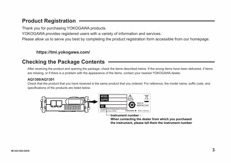
Checking the Package ContentsAfter receiving the product and opening the package, check the items described below. If the wrong items have been delivered, if items are missing, or if there is a problem with the appearance of the items, contact your nearest YOKOGAWA dealer.
AQ1300/AQ1301Check that the product that you have received is the same product that you ordered. For reference, the model name, suffix code, and specifications of the products are listed below.
Instrument number :When contacting the dealer from which you purchased the instrument, please tell them the instrument number
xxx-xxxx
4 IM AQ1300-02EN
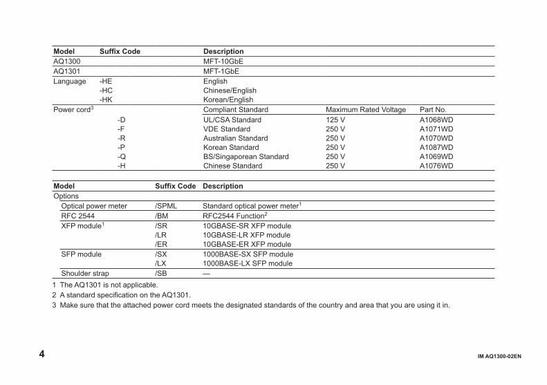
Model Suffix Code DescriptionAQ1300 MFT-10GbEAQ1301 MFT-1GbELanguage -HE
-HC-HK
EnglishChinese/EnglishKorean/English
Power cord3 Compliant Standard Maximum Rated Voltage Part No.-D-F-R-P-Q-H
UL/CSA StandardVDE StandardAustralian StandardKorean StandardBS/Singaporean StandardChinese Standard
125 V250 V250 V250 V250 V250 V
A1068WDA1071WDA1070WDA1087WDA1069WDA1076WD
Model Suffix Code DescriptionOptions
Optical power meter /SPML Standard optical power meter1
RFC 2544 /BM RFC2544 Function2
XFP module1 /SR/LR/ER
10GBASE-SR XFP module10GBASE-LR XFP module10GBASE-ER XFP module
SFP module /SX/LX
1000BASE-SX SFP module1000BASE-LX SFP module
Shoulder strap /SB —1 The AQ1301 is not applicable.2 A standard specification on the AQ1301.3 Make sure that the attached power cord meets the designated standards of the country and area that you are using it in.

IM AQ1300-02EN 5
AccessoriesThe instrument is shipped with the following accessories. Make sure that all accessories are present and undamaged.
Power cord (one cord that matches the suffix code is included)5
D F R P Q H
AC adapter 739874
Battery pack(lithium-ion)739882
Hand strapB8070CX
Shoulder strapB8070CY1
Ferrite coreA1190MN
ManualsPrinted manualsIM AQ1300-02EN(This manual)IM AQ1300-62ENIM AQ1300-92Z1 orIM AQ1301-92Z1IM 739874-01ENIM 739874-02Z4IM 739874-02ZHIM AQ739882-01ENIM AQ739882-92Z1PIM113-01Z2
Manual CDB8078VC4
IM AQ1300-01ENIM AQ1300-17ENIM AQ1300-61ENIM AQ1300-63EN
1 Included with models that have the /SB option installed.2 Included with AQ1300/AQ1301 Series that have the /SR, /LR, or /ER option installed.3 Included with models that have the /SX or /LX option installed.4 You can purchase the printed manuals separately. Contact your nearest YOKOGAWA dealer to purchase a copy.5 Make sure that the attached power cord meets the designated standards of the country and area that you are using it in.
Application software CDB8078WF• Setup software• Control window
XFP module2 SFP module3
6 IM AQ1300-02EN
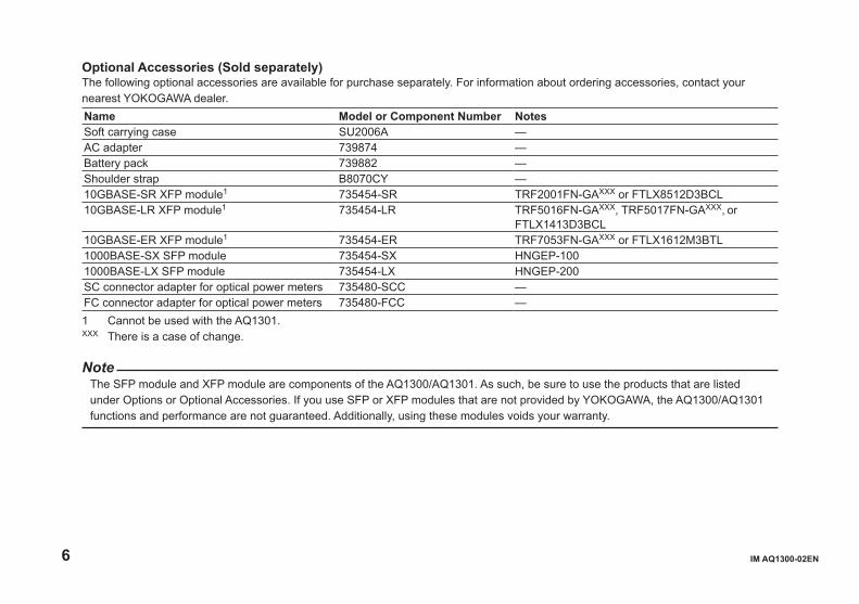
Optional Accessories (Sold separately)The following optional accessories are available for purchase separately. For information about ordering accessories, contact your nearest YOKOGAWA dealer.Name Model or Component Number NotesSoft carrying case SU2006A —AC adapter 739874 —Battery pack 739882 —Shoulder strap B8070CY —10GBASE-SR XFP module1 735454-SR TRF2001FN-GAXXX or FTLX8512D3BCL10GBASE-LR XFP module1 735454-LR TRF5016FN-GAXXX, TRF5017FN-GAXXX, or
FTLX1413D3BCL10GBASE-ER XFP module1 735454-ER TRF7053FN-GAXXX or FTLX1612M3BTL1000BASE-SX SFP module 735454-SX HNGEP-1001000BASE-LX SFP module 735454-LX HNGEP-200SC connector adapter for optical power meters 735480-SCC —FC connector adapter for optical power meters 735480-FCC —1 Cannot be used with the AQ1301.XXX There is a case of change.
NoteThe SFP module and XFP module are components of the AQ1300/AQ1301. As such, be sure to use the products that are listed under Options or Optional Accessories. If you use SFP or XFP modules that are not provided by YOKOGAWA, the AQ1300/AQ1301 functions and performance are not guaranteed. Additionally, using these modules voids your warranty.
IM AQ1300-02EN 7
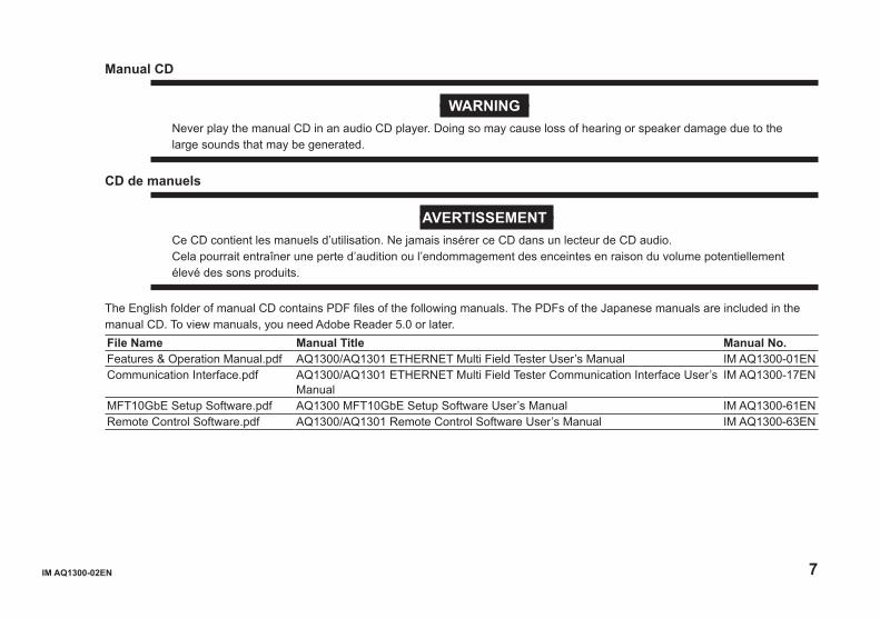
Manual CD
WARNINGNever play the manual CD in an audio CD player. Doing so may cause loss of hearing or speaker damage due to the large sounds that may be generated.
CD de manuels
AVERTISSEMENTCe CD contient les manuels d’utilisation. Ne jamais insérer ce CD dans un lecteur de CD audio.Cela pourrait entraîner une perte d’audition ou l’endommagement des enceintes en raison du volume potentiellement élevé des sons produits.
The English folder of manual CD contains PDF files of the following manuals. The PDFs of the Japanese manuals are included in the manual CD. To view manuals, you need Adobe Reader 5.0 or later.File Name Manual Title Manual No.Features & Operation Manual.pdf AQ1300/AQ1301 ETHERNET Multi Field Tester User’s Manual IM AQ1300-01ENCommunication Interface.pdf AQ1300/AQ1301 ETHERNET Multi Field Tester Communication Interface User’s
ManualIM AQ1300-17EN
MFT10GbE Setup Software.pdf AQ1300 MFT10GbE Setup Software User’s Manual IM AQ1300-61ENRemote Control Software.pdf AQ1300/AQ1301 Remote Control Software User’s Manual IM AQ1300-63EN
8 IM AQ1300-02EN
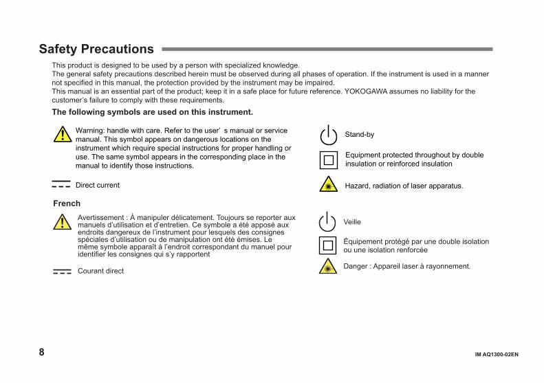
Safety PrecautionsThis product is designed to be used by a person with specialized knowledge.The general safety precautions described herein must be observed during all phases of operation. If the instrument is used in a manner not specified in this manual, the protection provided by the instrument may be impaired.This manual is an essential part of the product; keep it in a safe place for future reference. YOKOGAWA assumes no liability for the customer’s failure to comply with these requirements.The following symbols are used on this instrument.
Warning: handle with care. Refer to the user’ s manual or service manual. This symbol appears on dangerous locations on the instrument which require special instructions for proper handling or use. The same symbol appears in the corresponding place in the manual to identify those instructions.
Hazard, radiation of laser apparatus.
Stand-by
Direct current
Equipment protected throughout by double insulation or reinforced insulation
Veille
Équipement protégé par une double isolation ou une isolation renforcée
Danger : Appareil laser à rayonnement.
French Avertissement : À manipuler délicatement. Toujours se reporter aux
manuels d’utilisation et d’entretien. Ce symbole a été apposé aux endroits dangereux de l’instrument pour lesquels des consignes spéciales d’utilisation ou de manipulation ont été émises. Le même symbole apparaît à l’endroit correspondant du manuel pour identifier les consignes qui s’y rapportent
Courant direct
IM AQ1300-02EN 9
Failure to comply with the precautions below could lead to injury or death.
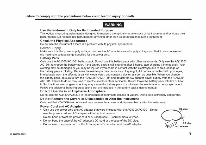
WARNINGUse the Instrument Only for Its Intended PurposeThis optical measuring instrument is designed to measure the optical characteristics of light sources and evaluate their performance. Do not use this instrument for anything other than as an optical measuring instrument.Check the Physical AppearanceDo not use the instrument if there is a problem with its physical appearance.Power SupplyMake sure that the power supply voltage matches the AC adapter’s rated supply voltage and that it does not exceed the maximum voltage range specified for the power cord.Battery PackOnly use the AQ1300/AQ1301 battery pack. Do not use this battery pack with other instruments. Only use the AQ1300/AQ1301 to charge the battery pack. If the battery pack is still charging after 5 hours, stop charging it immediately. Your clothing may be damaged or you may be injured if you come in contact with the electrolyte due to fluid leakage or the battery pack exploding. Because the electrolyte may cause loss of eyesight, if it comes in contact with your eyes, immediately wash the affected area with clean water, and consult a doctor as soon as possible. When you change the battery pack, be sure to turn the AQ1300/AQ1301 off, and detach the AC adapter power supply from the AQ1300/AQ1301. Failure to do so may lead to electric shock or other accidents. Do not throw the battery pack into fire or heat it. Such actions are dangerous as they may cause the battery pack to explode or the electrolyte to be sprayed about. Follow the additional handling precautions that are included in the battery pack’s user’s manual.Do Not Operate in an Explosive AtmosphereDo not use the AQ1300/AQ1301 in the presence of flammable gasses or vapors. Doing so is extremely dangerous.Do Not Remove the Covers or Disassemble or Alter the InstrumentOnly qualified YOKOGAWA personnel may remove the covers and disassemble or alter the instrument.Power Cord and AC Adapter• Only use the power cord and AC adapter that were included with the AQ1300/AQ1301. Do not
use the power cord and AC adapter with other instruments.• Do not bend or twist the power cord or AC adapter's DC cord numerous times.• Do not bend the base of the AC adapter's DC cord or the base of the DC plug.• Do not wrap the power cord or the AC adapter's DC cord around the AC adapter.
DC code
DC plugAC adapter
10 IM AQ1300-02EN
• Do not bundle the power cord or the AC adapter's DC cord too tightly.• Do not use the AQ1300/AQ1301 with the power cord or the AC adapter's DC cord in a bundled condition.• When the power cord or AC adapter's DC cord is connected to the outlet or the AQ1300/AQ1301, do not move the
AC adapter or the AQ1300/AQ1301.• Do not carry the AC adapter while pulling on the power cord or the AC adapter’s DC cord.• Do not allow the power cord or the AC adapter’s DC cord to be caught in doors, shelf doors, and so on.• Do not alter, process, or repair the power cord or the AC adapter’s DC cord. If a cord is damaged, contact your
nearest YOKOGAWA dealer.• Do not use the AQ1300/AQ1301 with the AC adapter hanging in the air.
French
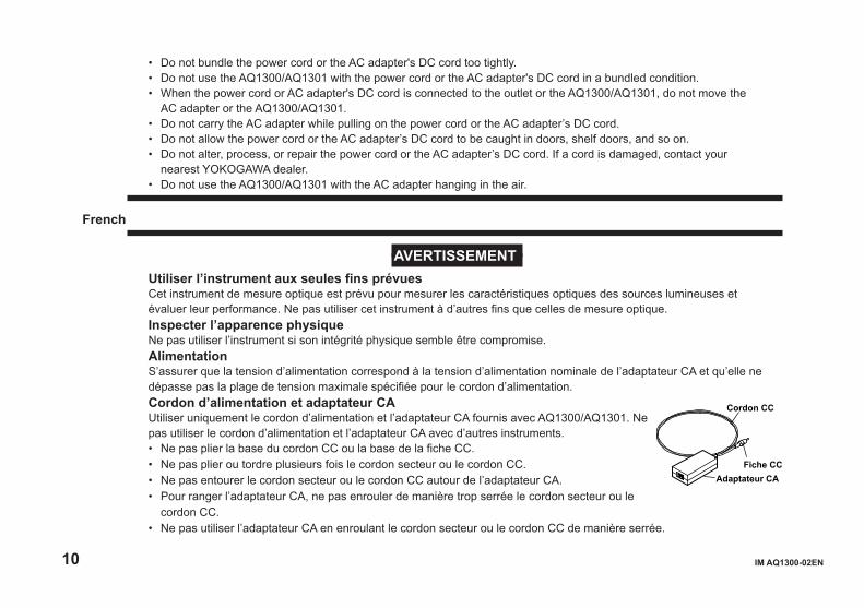
AVERTISSEMENTUtiliser l’instrument aux seules fins prévuesCet instrument de mesure optique est prévu pour mesurer les caractéristiques optiques des sources lumineuses et évaluer leur performance. Ne pas utiliser cet instrument à d’autres fins que celles de mesure optique.Inspecter l’apparence physiqueNe pas utiliser l’instrument si son intégrité physique semble être compromise.AlimentationS’assurer que la tension d’alimentation correspond à la tension d’alimentation nominale de l’adaptateur CA et qu’elle ne dépasse pas la plage de tension maximale spécifiée pour le cordon d’alimentation.Cordon d’alimentation et adaptateur CAUtiliser uniquement le cordon d’alimentation et l’adaptateur CA fournis avec AQ1300/AQ1301. Ne pas utiliser le cordon d’alimentation et l’adaptateur CA avec d’autres instruments.• Ne pas plier la base du cordon CC ou la base de la fiche CC.• Ne pas plier ou tordre plusieurs fois le cordon secteur ou le cordon CC.• Ne pas entourer le cordon secteur ou le cordon CC autour de l’adaptateur CA.• Pour ranger l’adaptateur CA, ne pas enrouler de manière trop serrée le cordon secteur ou le
cordon CC.• Ne pas utiliser l’adaptateur CA en enroulant le cordon secteur ou le cordon CC de manière serrée.
Cordon CC
Fiche CCAdaptateur CA
IM AQ1300-02EN 11
• Ne pas déplacer l’adaptateur CA ou l’instrument de mesure lorsque l’adaptateur est branché sur la prise de courant ou raccordé à l’instrument de mesure.
• Ne pas porter l’adaptateur CA tout en tirant sur le cordon CC.• Veiller à ne pas coincer le cordon secteur ou le cordon CC dans une porte, une armoire, etc.• Ne pas modifier, usiner ou réparer le cordon secteur ou le cordon CC. Si le cordon secteur ou le cordon CC est
endommagé, contacter le revendeur YOKOGAWA le plus proche.• Ne pas utiliser AQ1300/AQ1301 avec l’adaptateur CA flottant dans l’air.Pack de batteries Utiliser exclusivement le pack de batteries de l’AQ1300/AQ1301. Ne pas utiliser ce pack de batteries avec d’autres instruments. Recharger le pack de batteries à l’aide de l’AQ1300/AQ1301 uniquement. Si le pack de batteries est encore en charge au bout de 6 heures, interrompre la charge. Tout contact avec l’électrolyte échappé en raison d’une fuite ou d’une explosion du pack de batteries peut endommager les vêtements ou causer des blessures. L’électrolyte peut entraîner la cécité, par conséquent, en cas de contact avec les yeux, rincer immédiatement à l’eau et consulter un médecin dans les plus brefs délais. Lors du remplacement du pack de batteries, toujours mettre l’AQ1300/AQ1301 hors tension et débrancher l’adaptateur c.a. de l’AQ1300/AQ1301. Le non-respect de cette consigne peut entraîner un choc électrique ou tout autre accident. Tenir le pack de batteries éloigné de toute source de chaleur et des flammes pour éviter le risque d’explosion du pack de batteries ou de déversement d’électrolyte. Respecter les consignes de manipulation supplémentaires fournies dans le manuel d’utilisation du pack de batteries.Faisceau laserNe pas fixer directement ou indirectement le faisceau laser, ni la réflexion spéculaire du faisceau en l’absence d’équipement de protection. Ne pas orienter le faisceau laser en direction des yeux. Le faisceau laser peut entraîner la cécité ou causer des lésions oculaires. Recouvrir le connecteur optique à l’aide du cache pendant les périodes de non-utilisation.Ne pas utiliser dans un environnement explosifNe pas utiliser l’instrument en présence de gaz ou de vapeurs inflammables. Cela pourrait être extrêmement dangereux.Ne pas retirer le capot, ni démonter ou modifier l’instrumentSeul le personnel YOKOGAWA qualifié est habilité à retirer le capot et à démonter ou modifier l’instrument. Certains composants à l’intérieur de l’instrument sont à haute tension et par conséquent, représentent un danger.
12 IM AQ1300-02EN
CAUTIONOperating Environment LimitationsThis product is a Class A (for industrial environments) product. Operation of this product in a residential area may cause radio interference in which case the user will be required to correct the interference.About Strage MediumDo not remove USB memory or turn off the power when the USB memory access indicator is blinking or when data is being saved or loaded from internal memory. Doing so may damage the storage medium (USB memory or internal memory) or corrupt its data..
French
ATTENTIONLimitations relatives à l’environnement opérationnelCe produit est un produit de classe A (pour environnements industriels). L’utilisation de ce produit dans un zone résidentielle peut entraîner une interférence radio que l’utilisateur sera tenu de rectifier.Support de stockageN’enlevez pas un dispositif de mémoire USB et ne coupez pas l’alimentation électrique lorsque l’indicateur d’accès à la mémoire USB clignote ou lorsque les données sont en train d’être enregistrées ou chargées à partir d’une mémoire interne. Vous risqueriezd’endommager le support de stockage (mémoire USB ou mémoire interne) ou les données qu’il contient.

IM AQ1300-02EN 13
Safety Precautions for Laser ProductsWhen optical transceiver module (XFP module or SFP module ) is installed in the AQ1300 or AQ1301, AQ1300 or AQ1301 is a Class 1 laser product as defined by IEC60825-1:2007 Safety of Laser Products—Part1: Equipment classification and requirements. In addition, this instrument complies with 21 CFR 1040.10, 1040.11 except for deviations pursuant to Laser Notice No. 50, dated June 24, 2007.
Laser Class 1 Label
Model (optical transceiver module)
Class Center Wavelength
Maximum Output Power1
Beam Divergence (full angle at 1/e2)
Pulse Duration and Repetition Rate
Supplier Code
735454-SR 1 850 nm 0.78 mW 23.1° CW TRF2001FN-GAXXX
1 850 nm 0.7 mW 20° CW FTLX8512D3BCL735454-LR 1 1310 nm 15.6 mW 11.5° CW TRF5016FN-GAXXX, TRF5017FN-GAXXX,
or FTLX1413D3BCL735454-ER 1 1550 nm 10.0 mW 11.5° CW TRF7053FN-GAXXX or FTLX1612M3BTL735454-SX 1 850 nm 2.4 mW 23.1° Pulse 625 MHz HNGEP-100735454-LX 1 1310 nm 3.0 mW 11.5° Pulse 625 MHz HNGEP-2001 Under single fault conditions.XXX There is a case of change.
Laser classes differ depending on the standard number and the year of the standard.Take safety measures according to the laser class corresponding to standard number and year of the country or region that the instrument will be used in.

14 IM AQ1300-02EN
Regulations and Sales in Various Countries and RegionsWaste Electrical and Electronic Equipment (WEEE), Directive
(This directive is valid only in the EU.) This product complies with the WEEE Directive marking requirement. This marking indicates that you must not discard this
electrical/electronic product in domestic household waste. Product Category With reference to the equipment types in the WEEE directive Annex I, this product is classified as a “Monitoring and Control
instrumentation” product. Do not dispose in domestic household waste. When disposing products in the EU, contact your local Yokogawa office in Europe.
EU Battery Directive, DIRECTIVE (This directive is valid only in the EU.)
Batteries are included in this product. This marking indicates they shall be sorted out and collected as ordained in the EU battery directive.
Battery type: 1. Lithium battery You cannot replace batteries by yourself. When you need to replace batteries, contact your local Yokogawa office in
Europe. 2. lithium-ion battery When you remove batteries from this product and dispose them, discard them in accordance with domestic law
concerning disposal. Take a right action on waste batteries, because the collection system in the EU on waste batteries are regulated. For instructions on how to remove the battery pack, see section 15.6 in the user’s manual (File Name: Features & Operation Manual.pdf).
Authorized Representative in the EEAYokogawa Europe B. V. is Authorized Representative of Yokogawa Test & Measurement Corporation in the EEA for this Product. To contact Yokogawa Europe B. V., see the separate list of worldwide contacts, PIM 113-01Z2.
IM AQ1300-02EN 15
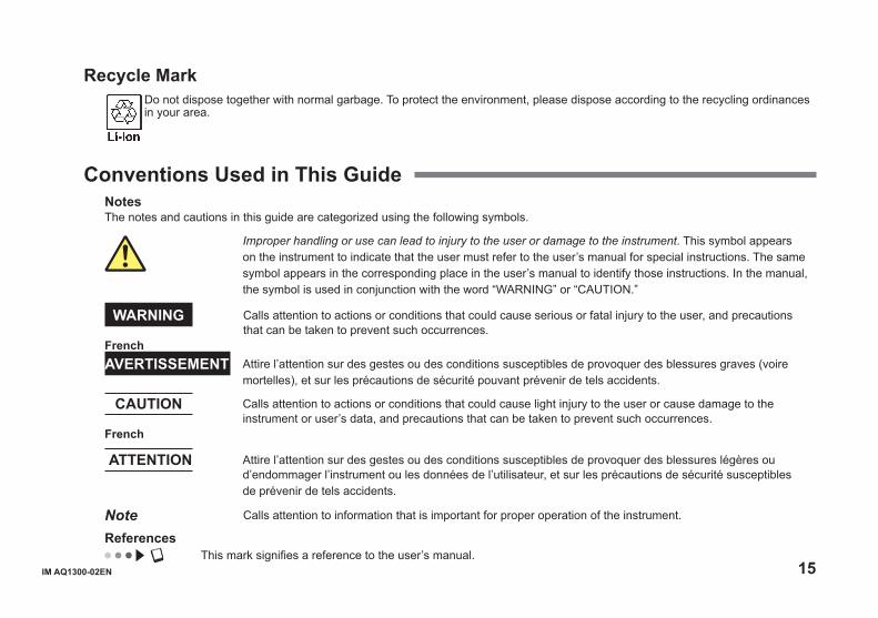
Recycle Mark Do not dispose together with normal garbage. To protect the environment, please dispose according to the recycling ordinances in your area.
Conventions Used in This GuideNotesThe notes and cautions in this guide are categorized using the following symbols.
Improper handling or use can lead to injury to the user or damage to the instrument. This symbol appears on the instrument to indicate that the user must refer to the user’s manual for special instructions. The same symbol appears in the corresponding place in the user’s manual to identify those instructions. In the manual, the symbol is used in conjunction with the word “WARNING” or “CAUTION.”
WARNING Calls attention to actions or conditions that could cause serious or fatal injury to the user, and precautions that can be taken to prevent such occurrences.
FrenchAVERTISSEMENT Attire l’attention sur des gestes ou des conditions susceptibles de provoquer des blessures graves (voire
mortelles), et sur les précautions de sécurité pouvant prévenir de tels accidents.
CAUTION Calls attention to actions or conditions that could cause light injury to the user or cause damage to the instrument or user’s data, and precautions that can be taken to prevent such occurrences.
French
ATTENTION Attire l’attention sur des gestes ou des conditions susceptibles de provoquer des blessures légères ou d’endommager l’instrument ou les données de l’utilisateur, et sur les précautions de sécurité susceptibles de prévenir de tels accidents.
Note Calls attention to information that is important for proper operation of the instrument.
References This mark signifies a reference to the user’s manual.
16 IM AQ1300-02EN
ContentsProduct Registration ................................................................3Checking the Package Contents .............................................3Safety Precautions ..................................................................8Regulations and Sales in Various Countries and Regions ....14Conventions Used in This Guide ...........................................15
Names and Functions of Parts ...................................18
Display Screen ....................................................................19
Making Preparations for Measurements ................21
Operating Precautions ..........................................................21Attaching the Strap ................................................................22 Connecting the Power Supply ...............................................23Installing Interface Modules ..................................................27 Connecting Optical Fiber Cables ..........................................28Connecting Peripheral Devices .............................................31
Common Operations .......................................................32
Key Operations .....................................................................33Rotary Knob and Arrow Key Operations ...............................35Setting the Date and Time .....................................................37
Setup ......................................................................................38
Selecting a Setup File ...........................................................38Configuring Test Items ..........................................................41Changing Parameters (When necessary) .............................42
Measuring .............................................................................47
Starting and Stopping Measurement.....................................47Saving the Measured Results ...............................................55
Specifications .....................................................................56
Display ..................................................................................56Measurement Ports ...............................................................56Test Menu ..............................................................................57Test Mode ..............................................................................58Transmission Feature ...........................................................58Reception Feature .................................................................60Loopback Feature .................................................................61Statistics Feature ..................................................................62Emulation Feature .................................................................63Remote Control .....................................................................64Phase Test ............................................................................64Test pass/fail results ..............................................................64Other features .......................................................................65Optical Power Meter (AQ1300 Option) .................................66RFC2544 (An option on the AQ1300, standard on the AQ1301) ................................................................................67VLAN Configuration Confirmation Feature ............................70E-OAM Test Feature .............................................................71
IM AQ1300-02EN 17
Y.1564 Test Feature ..............................................................73Storage ..................................................................................75PC Interface ..........................................................................75General Specifications ..........................................................76External Dimensions .............................................................78
18 IM AQ1300-02EN
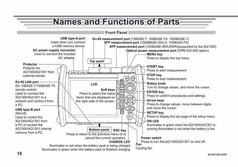
Names and Functions of PartsNames and Functions of PartsFront Panel
MENU
F1
F2
F3
F4
F5
ESC
ENTER
START STOP
SETUP
MENU keyPress to display the top menu.
START keyPress to start measurement.STOP keyPress to stop measurement.Rotary knobTurn to change values, and move the cursor.ENTER keyPress to confirm procedures and settings.Arrow keysPress to change values, move between digits, and move the cursor.SETUP keyPress to display the top page of the setup menu.ON LEDIlluminates in green when the AQ1300/AQ1301 is running Illuminates in red when the battery is low
Power switchPress to turn the AQ1300/AQ1301 on and off.CHARGE LED
Illuminates in red when the battery pack is being charged Illuminates in green when the battery pack is finished charging
ESC key Press to return to the previous menu or to
cancel the current operation.
Optical power measurement port (OPM AQ1300 option) DC power supply connector Used to connect the included
AC adapter.
XFP measurement port (10GBASE-SR/LR/ER)(supported by the AQ1300)
USB type-A port Used when you connect a USB memory device.
SFP measurement port (1000BASE-SX/LX, 100BASE-FX) RJ-45 measurement port (10BASE-T, 100BASE-TX, 1000BASE-T)
ProtectorProtects the AQ1300/AQ1301 from external shocks
Soft keys Press to select the menu
items that are displayed on the right side of the screen.
RJ-45 LAN port(for 10BASE-T/100BASE-TX remote control)Used to connect the AQ1300/AQ1301 to a network and control it from a PC.USB type-B port(Mini-B)Used to control the AQ1300/AQ1301 from a PC or access the AQ1300/AQ1301 internal memory from a PC.
LCD
Top panel
Bottom panel
FanCooling fan
IM AQ1300-02EN 19
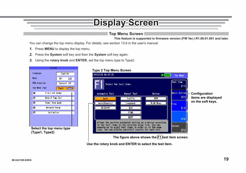
Display ScreenDisplay ScreenTop Menu Screen
This feature is supported in firmware version (FW Ver.) R1.08.01.001 and later.You can change the top menu display. For details, see section 13.6 in the user's manual.
1. Press MENU to display the top menu.
2. Press the System soft key and then the System soft key again.
3. Using the rotary knob and ENTER, set the top menu type to Type2.
Select the top menu type (Type1, Type2)
Type 2 Top Menu Screen
The figure above shows the F1 test item screen.
Use the rotary knob and ENTER to select the test item.
Configuration items are displayed on the soft keys.
20 IM AQ1300-02EN
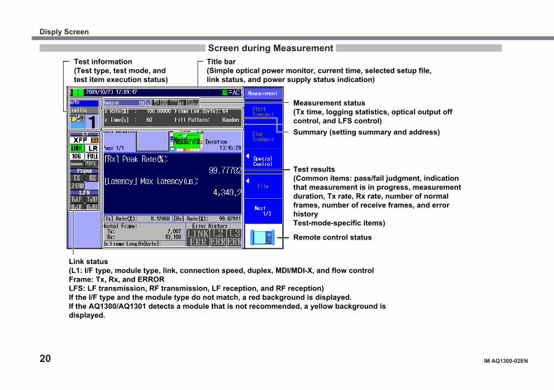
Screen during Measurement
Link status(L1: I/F type, module type, link, connection speed, duplex, MDI/MDI-X, and flow controlFrame: Tx, Rx, and ERRORLFS: LF transmission, RF transmission, LF reception, and RF reception)If the I/F type and the module type do not match, a red background is displayed.If the AQ1300/AQ1301 detects a module that is not recommended, a yellow background is displayed.
Title bar(Simple optical power monitor, current time, selected setup file, link status, and power supply status indication)
Measurement status(Tx time, logging statistics, optical output off control, and LFS control)
Test information(Test type, test mode, and test item execution status)
Summary (setting summary and address)
Remote control status
Test results(Common items: pass/fail judgment, indication that measurement is in progress, measurement duration, Tx rate, Rx rate, number of normal frames, number of receive frames, and error historyTest-mode-specific items)
Disply Screen
IM AQ1300-02EN 21
Making Preparations for MeasurementsMaking Preparations for MeasurementsOperating Precautions
Safety PrecautionsIf you are using this instrument for the first time, make sure to thoroughly read “Safety Precautions,” on pages 7 and 8.Do Not Remove the CaseDo not remove the case from the instrument. Doing so is extremely dangerous. For internal inspection and adjustment, contact your nearest YOKOGAWA dealer.Unplug If Abnormal Behavior OccursIf you notice smoke or unusual odors coming from the instrument, immediately turn off the power, unplug the power cord, and contact your nearest YOKOGAWA dealer.Use the AC Adapter and Power Cord CorrectlyDo not place objects on top of the AC adapter or power cord, and keep them away from heat sources. When removing the plug from the power outlet, do not pull on the cord. Pull from the plug. If the AC adapter or power cord is damaged, contact your nearest YOKOGAWA dealer. Refer to page 3 for the part number to use when placing an order.
General Handling PrecautionsDo Not Place Objects on Top of the Instrument. Do Not Block the Inlet and Vent Holes.Never place objects such as other instruments or objects that contain water on top of the instrument. In addition, there are inlet holes on the bottom panel and vent holes on the rear panel. Do not block these holes. Doing so may damage the instrument.Do Not Subject the Inputs and Outputs to Mechanical ShockIf the I/O connectors or adapters are subjected to mechanical shock, they may be damaged. The instrument may not perform measurements correctly due to damage or deformation that is not visible to the naked eye.Do Not Scratch the LCDBecause the LCD can be easily scratched, do not allow any sharp objects near it. Also, do not apply vibration or shock to it.During Extended Periods of Non-UseUnplug the power cord from the outlet, and remove the battery pack from the instrument.When Carrying the InstrumentRemove the power cord and connecting cables. When carrying the instrument, grasp the protector or the attached strap firmly.
22 IM AQ1300-02EN
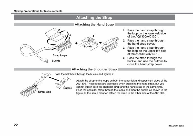
Attaching the StrapAttaching the Hand Strap
1. Pass the hand strap through the loop on the lower-left side of the AQ1300/AQ1301.
2. Pass the hand strap through the hand strap cover.
3. Pass the hand strap through the loop on the upper-left side of the AQ1300/AQ1301.
4. Pass the strap through the buckle, and use the buttons to close the hand strap cover.
1
2 3 4
Strap loops
Buckle
Buckle
Attaching the Shoulder StrapPass the belt back through the buckle and tighten it.
Attach the strap to the loops on both the upper-left and upper-right sides of the AQ1300. These loops are also used when attaching the hand strap, but you cannot attach both the shoulder strap and the hand strap at the same time. Pass the shoulder strap through the loops and then the buckle as shown in the figure. In the same manner, attach the strap to the other side of the AQ1300. Strap loop
Buckle
Making Preparations for Measurements
IM AQ1300-02EN 23
Connecting the Power SupplyUsing the AC Adapter
WARNING• Confirm that the AQ1300/AQ1301 is off before you connect the power supply.• Make sure that the power supply voltage matches the AC adapter’s rated supply voltage and that it does not exceed
the maximum voltage range specified for the power cord.• Only use the AC adapter that was included with the AQ1300/AQ1301.• Do not connect or disconnect the AC adapter while the AQ1300/AQ1301 is on.• If you are using the AQ1300/AQ1301 for a long time with the AC adapter connected, remove the battery pack from
the instrument.• If an appropriate AC outlet for the supplied power cord is unavailable, do not use the instrument.
French
AVERTISSEMENT• Vérifier que l’AQ1300/AQ1301 est hors tension avant de raccorder au secteur.• Vérifier que la tension d’alimentation correspond à la tension d’alimentation nominale de l’adaptateur c.a. et qu’elle
ne dépasse pas la plage de tension maximale spécifiée pour le cordon d’alimentation.• Utiliser exclusivement l’adaptateur c.a. dédié pour l’instrument.• Ne pas brancher, ni débrancher l’adaptateur c.a. pendant que l’AQ1300/AQ1301 est sous tension.• Si l’AQ1300/AQ1301 est utilisé de manière prolongée avec l’adaptateur c.a., retirer le pack de batteries de l’AQ1300/
AQ1301.• N’utiliser l’instrument que si une prise secteur appropriée est disponible pour le branchement du cordon d’alimentation.
Making Preparations for Measurements
24 IM AQ1300-02EN
Power cord
AC adapter
Ferrite core (Pass the cord through twice.)
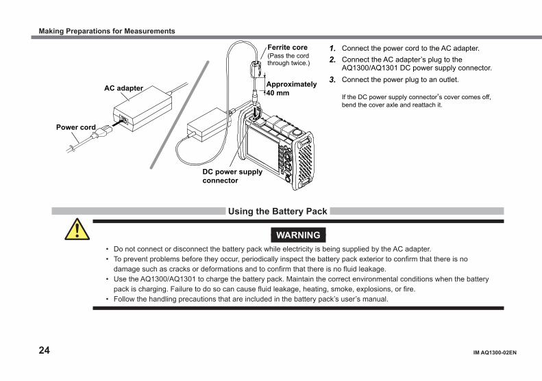
1. Connect the power cord to the AC adapter.2. Connect the AC adapter’s plug to the
AQ1300/AQ1301 DC power supply connector.3. Connect the power plug to an outlet.
If the DC power supply connector’s cover comes off, bend the cover axle and reattach it.
DC power supply connector
Approximately 40 mm
Using the Battery Pack
WARNING• Do not connect or disconnect the battery pack while electricity is being supplied by the AC adapter.• To prevent problems before they occur, periodically inspect the battery pack exterior to confirm that there is no
damage such as cracks or deformations and to confirm that there is no fluid leakage.• Use the AQ1300/AQ1301 to charge the battery pack. Maintain the correct environmental conditions when the battery
pack is charging. Failure to do so can cause fluid leakage, heating, smoke, explosions, or fire.• Follow the handling precautions that are included in the battery pack’s user’s manual.
Making Preparations for Measurements
IM AQ1300-02EN 25
French
AVERTISSEMENT• Ne pas installer, ni déposer le pack de batteries lorsque l’électricité est alimentée par l’adaptateur c.a.• À titre préventif, inspecter régulièrement le boîtier extérieur du pack de batteries afin de déceler tout signe
d’endommagement, comme l’apparition de fissures ou de déformations, et vérifier qu’il n’y a aucune fuite.• Recharger le pack de batteries à l’aide de l’AQ1300/AQ1301. Respecter les consignes environnementales prescrites pour la
recharge du pack de batteries, afin d’éviter les risques de fuite, de surchauffe, de fumée, d’explosion ou d’incendie.• Respecter les consignes de manipulation indiquées dans le manuel d’utilisation du pack de batteries.
Lock the cover.
Battery pack
Top panel
Bottom panel Bottom panel
Battery case
Battery cover
Hooks
Hook holes Electrodes
Release the lock.
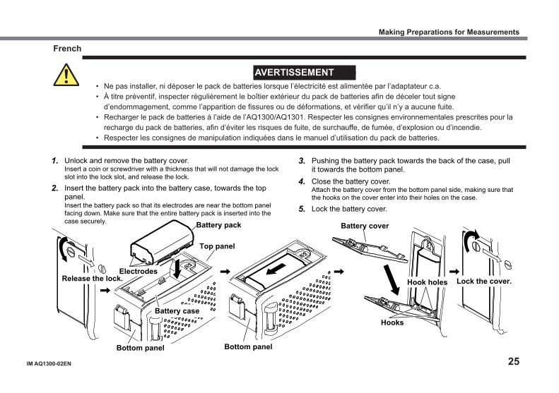
1. Unlock and remove the battery cover. Insert a coin or screwdriver with a thickness that will not damage the lock
slot into the lock slot, and release the lock.
2. Insert the battery pack into the battery case, towards the top panel.
Insert the battery pack so that its electrodes are near the bottom panel facing down. Make sure that the entire battery pack is inserted into the case securely.
3. Pushing the battery pack towards the back of the case, pull it towards the bottom panel.
4. Close the battery cover. Attach the battery cover from the bottom panel side, making sure that
the hooks on the cover enter into their holes on the case.
5. Lock the battery cover.
Making Preparations for Measurements
26 IM AQ1300-02EN
NoteOver Discharge and Long Periods of Storage• If you do not use the instrument for an extended period of time with the battery pack connected to the AQ1300/AQ1301, the battery
pack may become over discharged. This shortens the service life of the battery pack. To avoid over discharging, if you will not use the AQ1300/AQ1301 for one week or longer, charge the battery pack, remove it from the instrument, and store the battery pack away from direct sunlight in a location that has an ambient temperature of 10°C to 30°C.
• When you store the battery pack for six months or longer, to replace the power that has been lost through self discharge, recharge the battery using the AQ1300/AQ1301 once every six months.
• Avoid storing the battery pack for an extended period of time when it is fully charged (after it has just been charged) or when it has no power left (when the AQ1300/AQ1301 will not turn on). Storing the battery pack under these conditions will degrade its performance and reduce its longevity. It is better to store the battery pack when it is 40 to 50% charged. This is equivalent to the state the battery is in after you turn off the AQ1300/AQ1301 and charge an empty battery for an hour at room temperature.
• Use the AQ1300/AQ1301 to charge the battery pack prior to its first use or if it has not been used for an extended period of time.
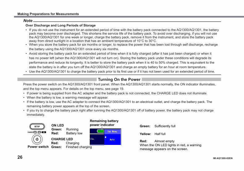
Turning On the PowerPress the power switch on the AQ1300/AQ1301 front panel. When the AQ1300/AQ1301 starts normally, the ON indicator illuminates, and the top menu appears. For details on the top menu, see page 19.• If power is being supplied from the AC adapter and the battery pack is not connected, the CHARGE LED does not illuminate.• When the battery is low, a warning message will appear.• If the battery is low, use the AC adapter to connect the AQ1300/AQ1301 to an electrical outlet, and charge the battery pack. The
remaining battery power appears at the top of the screen.• If you try to charge the battery pack right after running the AQ1300/AQ1301 off of battery power, the battery pack may not charge
immediately.
Remaining battery power indicator Green: Sufficiently full
Yellow: Half full Red: Almost empty When the ON LED lights in red, a warning message appears on the screen.
CHARGE LED Red: Charging Green: Finished charging
ON LED Green: Running Red: Battery low
SETUP
CHARGE ON
Power switch
Making Preparations for Measurements
IM AQ1300-02EN 27
When the Power-on Operation Does Not Finish NormallyTurn off the power switch, and check the following items.• Is the AC adapter connected correctly? See page 23.• Is the battery pack loaded correctly? See page 24.• Are you holding down the power switch for at least 2 seconds?If the AQ1300/AQ1301 still does not work properly after checking these items, contact your nearest YOKOGAWA dealer for repairs.
Warm UpTo enable more accurate measurements, allow the AQ1300/AQ1301 to warm up for at least 5 minutes after it is turned on.
Installing Interface Modules
CAUTION• Be extremely careful of static electricity when you install or remove XFP or SFP modules. Electrostatic discharges
during the installation or removal of these modules may cause them to malfunction.• Do not install or remove XFP or SFP modules while cables are connected to them. Doing so may damage the instrument.• Do not install or remove XFP or SFP modules while the AQ1300/AQ1301 is performing measurements. Doing so
may damage the instrument.
French
ATTENTION• Prendre garde à l’électricité statique lors de l’installation ou de la dépose des modules XFP ou SFP. Les
décharges statiques qui se forment lors de l’installation ou de la dépose de ces modules peuvent provoquer leur dysfonctionnement.
• Ne pas installer ou déposer les modules XFP ou SFP si des câbles y sont branchés. Le cas échéant, un endommagement de l’équipement risquerait de se produire.
• Ne pas installer ou déposer les modules XFP ou SFP pendant que le dispositif AQ1300/AQ1301 procède à des mesures. Le cas échéant, un endommagement de l’équipement risquerait de se produire.
Making Preparations for Measurements

28 IM AQ1300-02EN
Installing an interface module (An SFP module in this example)
Removing an interface module (An SFP module in this example)
Pull the lever up and towards you.
Align the XFP or SFP module with the matching installation guides and slowly insert the module into the instrument. Press firmly until the module is fully inserted into the connector shell.
Pull the lever that is at the top of the XFP or SFP module up and towards you, and slowly pull the module free of the connector shell and out of the instrument.
Connecting Optical Fiber Cables
WARNING• If XFP or SFP modules are installed in the AQ1300/AQ1301, light is emitted from the source ports when the
instrument is turned on. Do not disconnect the connected optical fiber cables. Visual impairment may occur if the light enters the eye.
• Close the covers of any measurement ports that do not have optical fiber cables connected to them. Visual impairment may occur if light that is mistakenly emitted from these ports enters the eye.
Making Preparations for Measurements
IM AQ1300-02EN 29
CAUTION• Insert the optical fiber cable connectors slowly and straight into the optical ports. If you shake the connector to the
left and right or force it into the port, the optical connector or optical port may be damaged.• If you use optical connectors that do not meet the specifications, the AQ1300/AQ1301 optical ports may be damaged.
Use optical connectors that are approved or used by national or local telecom carriers and providers in your area.• Use optical fiber cable connectors that match the universal adapters or connector adapters that are attached to the
AQ1300/AQ1301 optical ports.
French
AVERTISSEMENT• Si les modules XFP ou SFP sont installés dans le dispositif AQ1300/AQ1301, la lumière est émise par des ports
de source lumineuse lors de la mise sous tension de l’instrument. Ne pas débrancher les câbles à fibre optique connectés. Des lésions oculaires peuvent être causées si le faisceau lumineux pénètre dans l’œil.
• Couvrir les caches des ports de mesure libres. Une déficience visuelle peut se produire si la lumière émise par erreur de ces ports pénètre dans l’œil.
ATTENTION• Insérer les connecteurs de câbles à fibre optique délicatement et sans les incliner dans les ports optiques. Éviter de
faire pression sur le connecteur ou de forcer pour l’insérer dans le port, car cela pourrait endommager le connecteur optique ou le port optique.
• Toujours utiliser des connecteurs optiques conformes aux spécifications, à défaut de quoi les ports optiques de l’AQ1300/AQ1301 pourraient être endommagés. Utiliser des connecteurs optiques homologués ou utilisés par les entreprises et les fournisseurs de services de télécommunications de votre région.
• Utiliser les connecteurs de câbles à fibre optique correspondant aux adaptateurs universels ou les adaptateurs de connecteurs reliés aux ports optiques AQ1300/AQ1301.
Making Preparations for Measurements
30 IM AQ1300-02EN
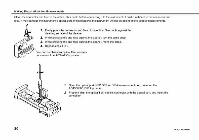
Clean the connector end face of the optical fiber cable before connecting it to the instrument. If dust is adhered to the connector end face, it may damage the instrument’s optical port. If this happens, the instrument will not be able to make correct measurements.
1. Firmly press the connector end face of the optical fiber cable against the cleaning surface of the cleaner.
2. While pressing the end face against the cleaner, turn the cable once. 3. While pressing the end face against the cleaner, move the cable. 4. Repeat steps 1 to 3.
1. Open the optical port (XFP, SFP, or OPM measurement port) cover on the AQ1300/AQ1301 top panel.
2. Properly align the optical fiber cable’s connector with the optical port, and insert the connector.
You can purchase an optical fiber connec-tor cleaner from NTT-AT Corporation.
Making Preparations for Measurements
IM AQ1300-02EN 31
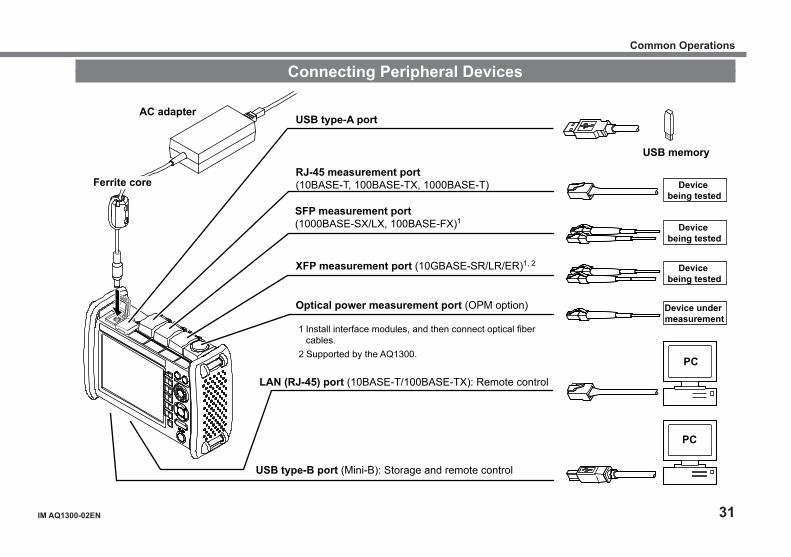
Connecting Peripheral Devices
AC adapter
Ferrite core
USB type-A port
RJ-45 measurement port (10BASE-T, 100BASE-TX, 1000BASE-T)
SFP measurement port (1000BASE-SX/LX, 100BASE-FX)1
XFP measurement port (10GBASE-SR/LR/ER)1, 2
Optical power measurement port (OPM option)
LAN (RJ-45) port (10BASE-T/100BASE-TX): Remote control
USB type-B port (Mini-B): Storage and remote control
1 Install interface modules, and then connect optical fiber cables.
PC
Device being tested
Device under measurement
USB memory
PC
Device being tested
Device being tested
2 Supported by the AQ1300.
Common Operations

32 IM AQ1300-02EN
Common OperationsCommon OperationsTo make this guide easier to read, we have omitted or simplified explanations of the kinds of operations listed below.• Repetitive operations.• Detailed operations for proceeding to the desired setup menu or dialog box and information about the accompanying screen changes.• Setup items that users can configure if they have a general understanding of them.Below, we will compare examples of detailed setup operation explanations with explanations that have been omitted or simplified.
Common Operations
IM AQ1300-02EN 33
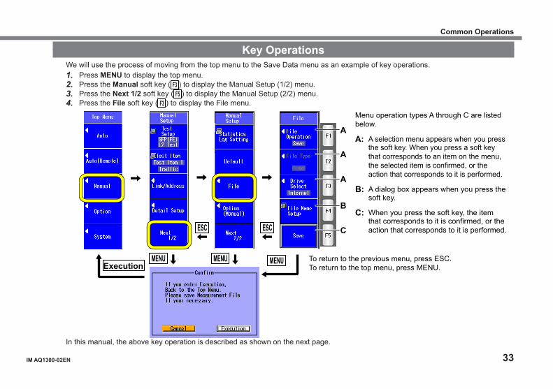
Key OperationsWe will use the process of moving from the top menu to the Save Data menu as an example of key operations.1. Press MENU to display the top menu.2. Press the Manual soft key ( F3 ) to display the Manual Setup (1/2) menu.3. Press the Next 1/2 soft key ( F5 ) to display the Manual Setup (2/2) menu.4. Press the File soft key ( F3 ) to display the File menu.
MENU
ESC ESC
MENU MENU Execution
A
A
A
B
C
Menu operation types A through C are listed below.
A: A selection menu appears when you press the soft key. When you press a soft key that corresponds to an item on the menu, the selected item is confirmed, or the action that corresponds to it is performed.
B: A dialog box appears when you press the soft key.
C: When you press the soft key, the item that corresponds to it is confirmed, or the action that corresponds to it is performed.
To return to the previous menu, press ESC. To return to the top menu, press MENU.
In this manual, the above key operation is described as shown on the next page.
Common Operations
34 IM AQ1300-02EN
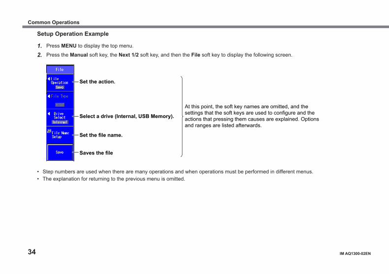
Setup Operation Example
1. Press MENU to display the top menu.
2. Press the Manual soft key, the Next 1/2 soft key, and then the File soft key to display the following screen.
Set the action.
Select a drive (Internal, USB Memory).
Set the file name.
Saves the file
At this point, the soft key names are omitted, and the settings that the soft keys are used to configure and the actions that pressing them causes are explained. Options and ranges are listed afterwards.
• Step numbers are used when there are many operations and when operations must be performed in different menus.• The explanation for returning to the previous menu is omitted.
Common Operations

IM AQ1300-02EN 35
Rotary Knob and Arrow Key OperationsAs an example of rotary knob and arrow key operations, we will use the dialog box that appears when you press the System soft key in the system setup.1. Press the System soft key ( F5 ) to display the System menu.2. Press the System soft key to display the System Setup dialog box.3. Use the rotary knob or the arrow keys to move the cursor to the item that you want to configure or execute.
The item at the cursor location is highlighted.4. Press ENTER.
• Next, follow the instructions in the figure below that correspond to the type of item that you are configuring or executing.• In this guide, steps 3 and 4 listed above are indicated using the expression “using the rotary knob and ENTER.”
F
H
G
D
E
For setup operation types E and G, to reset the selected item to its previous settings, press ESC. To return to the top menu, press MENU.
The item at the cursor location is highlighted. Setup operation types D through H are listed below. D: Press ENTER to confirm the item or execute its corresponding
action. E: Press ENTER to display a menu. Turn the rotary knob or
press the up and down arrow keys to move the cursor to the item that you want to select. Then press ENTER to select the item.
F: The selected setting switches each time you press ENTER. G: Press ENTER to display a text box. Turn the rotary knob or
press the up and down arrow keys to increase or decrease a number. To move between digits, press the left and right arrow keys. After you have entered a number, press ENTER to set the value to that number.
H: Press ENTER to display a dialog box.
Example of menu for E
Example of text box for G
In this manual, the above key operations are described as shown on the next page.
Common Operations
36 IM AQ1300-02EN
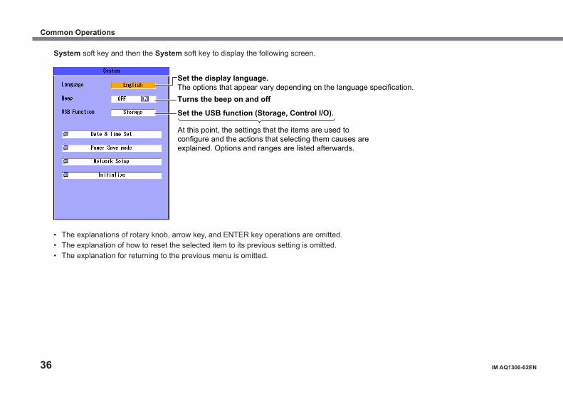
System soft key and then the System soft key to display the following screen.
At this point, the settings that the items are used to configure and the actions that selecting them causes are explained. Options and ranges are listed afterwards.
Set the display language.The options that appear vary depending on the language specification.Turns the beep on and off
Set the USB function (Storage, Control I/O).
• The explanations of rotary knob, arrow key, and ENTER key operations are omitted.• The explanation of how to reset the selected item to its previous setting is omitted.• The explanation for returning to the previous menu is omitted.
Common Operations
IM AQ1300-02EN 37
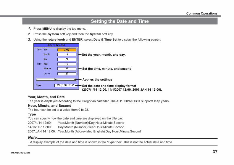
Setting the Date and Time1. Press MENU to display the top menu.
2. Press the System soft key and then the System soft key.
3. Using the rotary knob and ENTER, select Date & Time Set to display the following screen.
Set the year, month, and day.
Set the time, minute, and second.
Applies the settings
Set the date and time display format(2007/1/14 12:00, 14/1/2007 12:00, 2007.JAN.14 12:00).
Year, Month, and DateThe year is displayed according to the Gregorian calendar. The AQ1300/AQ1301 supports leap years.Hour, Minute, and SecondThe hour can be set to a value from 0 to 23.TypeYou can specify how the date and time are displayed on the title bar.2007/1/14 12:00: Year/Month (Number)/Day Hour:Minute:Second14/1/2007 12:00: Day/Month (Number)/Year Hour:Minute:Second2007.JAN.14 12:00: Year.Month (Abbreviated English).Day Hour:Minute:Second
NoteA display example of the date and time is shown in the “Type” box. This is not the actual date and time.
Common Operations
38 IM AQ1300-02EN
Setup Setup We will use the Auto mode settings as an example.
Selecting a Setup Filesection 4.1, “Selecting a Setup File” in the user’s manual
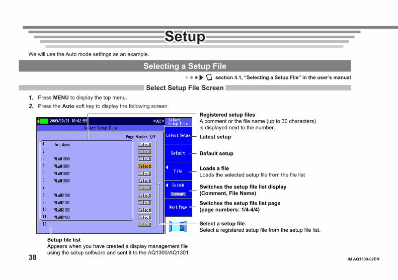
Select Setup File Screen1. Press MENU to display the top menu.2. Press the Auto soft key to display the following screen.
Latest setup
Default setup
Switches the setup file list display (Comment, File Name)
Switches the setup file list page (page numbers: 1/4-4/4)
Setup file listAppears when you have created a display management file using the setup software and sent it to the AQ1300/AQ1301
Loads a file Loads the selected setup file from the file list
Select a setup file.Select a registered setup file from the setup file list.
Registered setup filesA comment or the file name (up to 30 characters) is displayed next to the number.
IM AQ1300-02EN 39
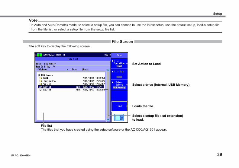
NoteIn Auto and Auto(Remote) mode, to select a setup file, you can choose to use the latest setup, use the default setup, load a setup file from the file list, or select a setup file from the setup file list.
File ScreenFile soft key to display the following screen.
Set Action to Load.
Select a drive (Internal, USB Memory).
File listThe files that you have created using the setup software or the AQ1300/AQ1301 appear.
Select a setup file (.sd extension) to load.
Loads the file
Setup
40 IM AQ1300-02EN
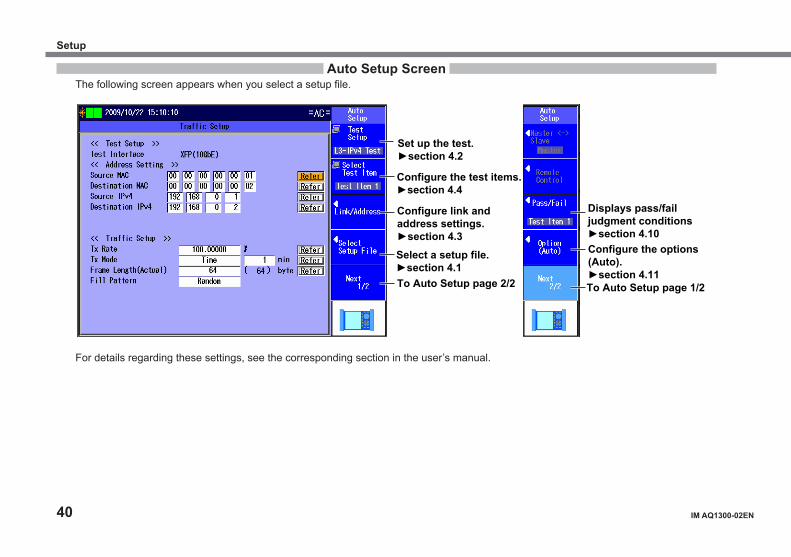
Auto Setup ScreenThe following screen appears when you select a setup file.
Set up the test. ►section 4.2
Displays pass/fail judgment conditions ►section 4.10
Configure the test items.►section 4.4
Configure link and address settings. ►section 4.3 Select a setup file. ►section 4.1 To Auto Setup page 2/2
Configure the options (Auto). ►section 4.11 To Auto Setup page 1/2
For details regarding these settings, see the corresponding section in the user’s manual.
Setup
IM AQ1300-02EN 41
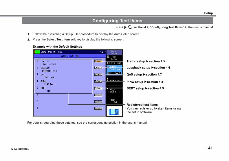
Configuring Test Itemssection 4.4, “Configuring Test Items” in the user’s manual
1. Follow the “Selecting a Setup File” procedure to display the Auto Setup screen.
2. Press the Select Test Item soft key to display the following screen.
Registered test items You can register up to eight items using the setup software.
Example with the Default Settings
Traffic setup ►section 4.5
Loopback setup ►section 4.6
QoS setup ►section 4.7
PING setup ►section 4.8
BERT setup ►section 4.9
For details regarding these settings, see the corresponding section in the user’s manual.
Setup

42 IM AQ1300-02EN
Changing Parameters (When necessary)Changing the Test Settings
Section 4.2, “Setting Up a Test” in the user’s manual1. Follow the “Selecting a Setup File” procedure to display the Auto Setup screen.
2. Press the Test Setup soft key to display the following screen.
Set the test interface (XFP(10GbE), SFP(GbE), SFP(FE), RJ-45). XFP is supported by AQ1300. Set the test layer (L2 Test, L3-IPv4 Test, L3-IPv6 Test).
Select this check box to add UDP to Tx frames.This setting can be selected when Test Layer is set to L3-IPv4 Test or L3-IPv6 Test.
Select this check box to treat oversize frames like normal frames.
For details regarding these settings, see section 4.2 in the user’s manual.
Setup
IM AQ1300-02EN 43
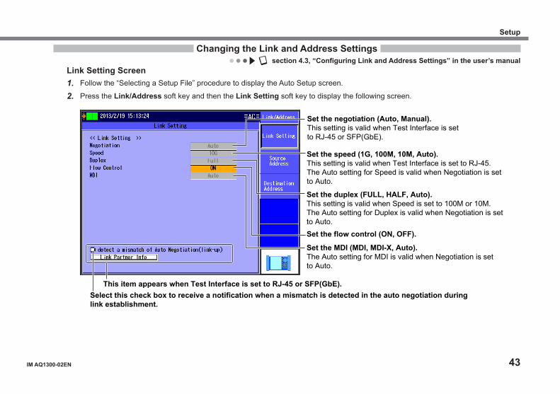
Changing the Link and Address Settingssection 4.3, “Configuring Link and Address Settings” in the user’s manual
Link Setting Screen1. Follow the “Selecting a Setup File” procedure to display the Auto Setup screen.
2. Press the Link/Address soft key and then the Link Setting soft key to display the following screen.
Set the speed (1G, 100M, 10M, Auto). This setting is valid when Test Interface is set to RJ-45. The Auto setting for Speed is valid when Negotiation is set to Auto.
Set the negotiation (Auto, Manual). This setting is valid when Test Interface is set to RJ-45 or SFP(GbE).
Set the MDI (MDI, MDI-X, Auto). The Auto setting for MDI is valid when Negotiation is set to Auto.
Set the flow control (ON, OFF).
Set the duplex (FULL, HALF, Auto). This setting is valid when Speed is set to 100M or 10M. The Auto setting for Duplex is valid when Negotiation is set to Auto.
This item appears when Test Interface is set to RJ-45 or SFP(GbE).Select this check box to receive a notification when a mismatch is detected in the auto negotiation during link establishment.
Setup
44 IM AQ1300-02EN
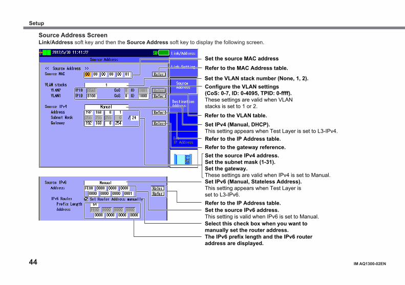
Source Address ScreenLink/Address soft key and then the Source Address soft key to display the following screen.
Select this check box when you want to manually set the router address.
Set the source MAC address
Set the VLAN stack number (None, 1, 2). Configure the VLAN settings (CoS: 0-7, ID: 0-4095, TPID: 0-ffff). These settings are valid when VLAN stacks is set to 1 or 2.
Set the source IPv4 address. Set the subnet mask (1-31). Set the gateway. These settings are valid when IPv4 is set to Manual.
Set IPv4 (Manual, DHCP). This setting appears when Test Layer is set to L3-IPv4.
Set IPv6 (Manual, Stateless Address). This setting appears when Test Layer is set to L3-IPv6.
Set the source IPv6 address. This setting is valid when IPv6 is set to Manual.
The IPv6 prefix length and the IPv6 router address are displayed.
Refer to the MAC Address table.
Refer to the VLAN table.
Refer to the IP Address table. Refer to the gateway reference.
Refer to the IP Address table.
Setup
IM AQ1300-02EN 45
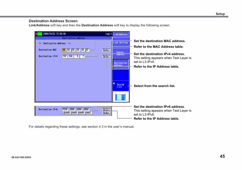
Destination Address ScreenLink/Address soft key and then the Destination Address soft key to display the following screen.
Set the destination MAC address.
Set the destination IPv4 address. This setting appears when Test Layer is set to L3-IPv4.
Set the destination IPv6 address. This setting appears when Test Layer is set to L3-IPv6.
Refer to the MAC Address table.
Refer to the IP Address table.
Refer to the IP Address table.
Select from the search list.
For details regarding these settings, see section 4.3 in the user’s manual.
Setup
46 IM AQ1300-02EN
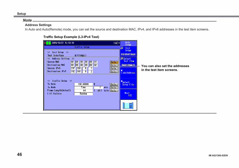
NoteAddress SettingsIn Auto and Auto(Remote) mode, you can set the source and destination MAC, IPv4, and IPv6 addresses in the test item screens.
You can also set the addresses in the test item screens.
Traffic Setup Example (L3-IPv4 Test)
Setup
IM AQ1300-02EN 47
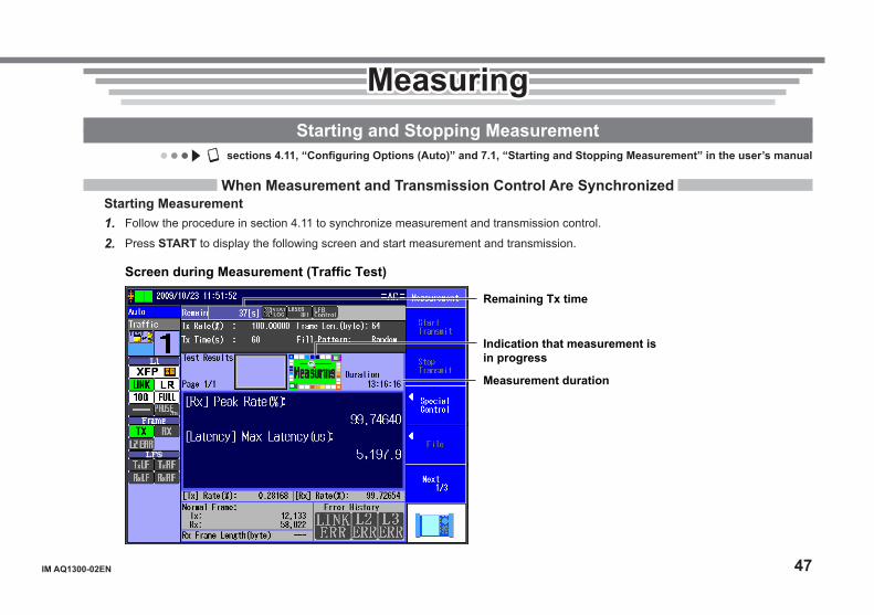
MeasuringMeasuringStarting and Stopping Measurement
sections 4.11, “Configuring Options (Auto)” and 7.1, “Starting and Stopping Measurement” in the user’s manual
When Measurement and Transmission Control Are SynchronizedStarting Measurement1. Follow the procedure in section 4.11 to synchronize measurement and transmission control.
2. Press START to display the following screen and start measurement and transmission.
Indication that measurement is in progress
Measurement duration
Remaining Tx time
Screen during Measurement (Traffic Test)
48 IM AQ1300-02EN
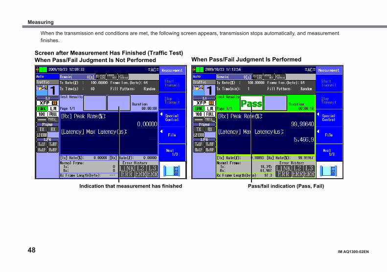
When the transmission end conditions are met, the following screen appears, transmission stops automatically, and measurement finishes.
Indication that measurement has finished
Screen after Measurement Has Finished (Traffic Test) When Pass/Fail Judgment Is Not Performed
Pass/fail indication (Pass, Fail)
When Pass/Fail Judgment Is Performed
Measuring
IM AQ1300-02EN 49
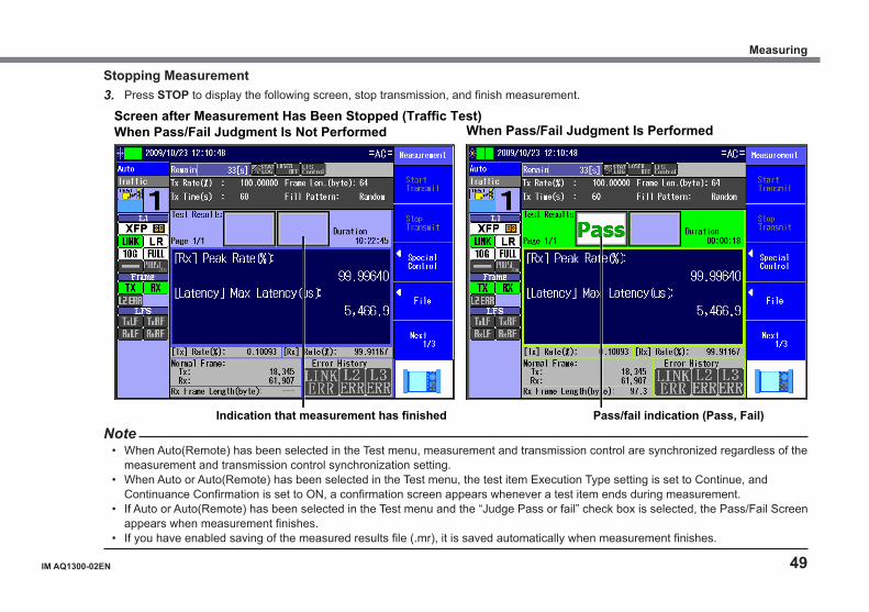
Stopping Measurement3. Press STOP to display the following screen, stop transmission, and finish measurement.
Screen after Measurement Has Been Stopped (Traffic Test) When Pass/Fail Judgment Is Not Performed When Pass/Fail Judgment Is Performed
Indication that measurement has finished Pass/fail indication (Pass, Fail)Note
• When Auto(Remote) has been selected in the Test menu, measurement and transmission control are synchronized regardless of the measurement and transmission control synchronization setting.
• When Auto or Auto(Remote) has been selected in the Test menu, the test item Execution Type setting is set to Continue, and Continuance Confirmation is set to ON, a confirmation screen appears whenever a test item ends during measurement.
• If Auto or Auto(Remote) has been selected in the Test menu and the “Judge Pass or fail” check box is selected, the Pass/Fail Screen appears when measurement finishes.
• If you have enabled saving of the measured results file (.mr), it is saved automatically when measurement finishes.
Measuring
50 IM AQ1300-02EN
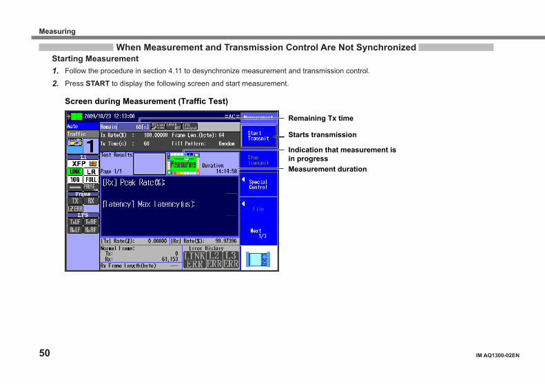
When Measurement and Transmission Control Are Not SynchronizedStarting Measurement1. Follow the procedure in section 4.11 to desynchronize measurement and transmission control.
2. Press START to display the following screen and start measurement.
Indication that measurement is in progress Measurement duration
Remaining Tx time
Screen during Measurement (Traffic Test)
Starts transmission
Measuring
IM AQ1300-02EN 51
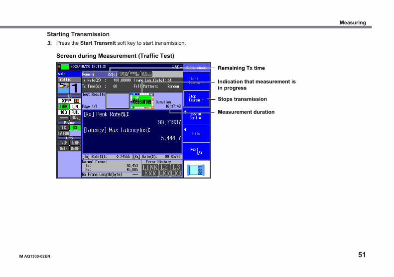
Starting Transmission3. Press the Start Transmit soft key to start transmission.
Indication that measurement is in progress
Measurement duration
Remaining Tx time
Screen during Measurement (Traffic Test)
Stops transmission
Measuring

52 IM AQ1300-02EN
When the transmission end conditions are met, transmission stops automatically.
4. Press STOP to display the following screen and stop measurement.
Indication that measurement has finished Pass/fail indication (Pass, Fail)
Screen after Measurement Has Finished (Traffic Test)When Pass/Fail Judgment Is Not Performed When Pass/Fail Judgment Is Performed
Measuring
IM AQ1300-02EN 53
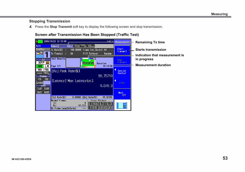
Stopping Transmission4. Press the Stop Transmit soft key to display the following screen and stop transmission.
Indication that measurement is in progress
Measurement duration
Remaining Tx time
Screen after Transmission Has Been Stopped (Traffic Test)
Starts transmission
Measuring
54 IM AQ1300-02EN
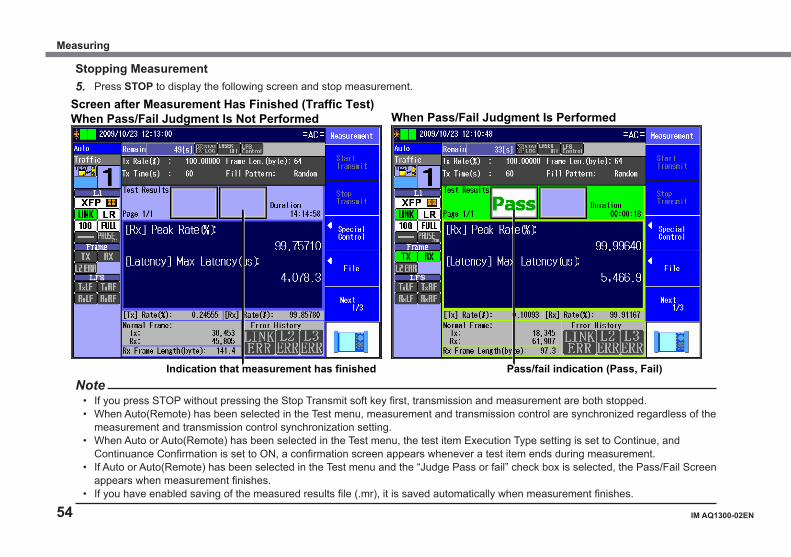
Stopping Measurement5. Press STOP to display the following screen and stop measurement.
Screen after Measurement Has Finished (Traffic Test) When Pass/Fail Judgment Is Not Performed When Pass/Fail Judgment Is Performed
Indication that measurement has finished Pass/fail indication (Pass, Fail)Note
• If you press STOP without pressing the Stop Transmit soft key first, transmission and measurement are both stopped.• When Auto(Remote) has been selected in the Test menu, measurement and transmission control are synchronized regardless of the
measurement and transmission control synchronization setting.• When Auto or Auto(Remote) has been selected in the Test menu, the test item Execution Type setting is set to Continue, and
Continuance Confirmation is set to ON, a confirmation screen appears whenever a test item ends during measurement.• If Auto or Auto(Remote) has been selected in the Test menu and the “Judge Pass or fail” check box is selected, the Pass/Fail Screen
appears when measurement finishes.• If you have enabled saving of the measured results file (.mr), it is saved automatically when measurement finishes.
Measuring
IM AQ1300-02EN 55
Saving the Measured Resultssection 9.2, “Saving and Loading Data” in the user’s manual
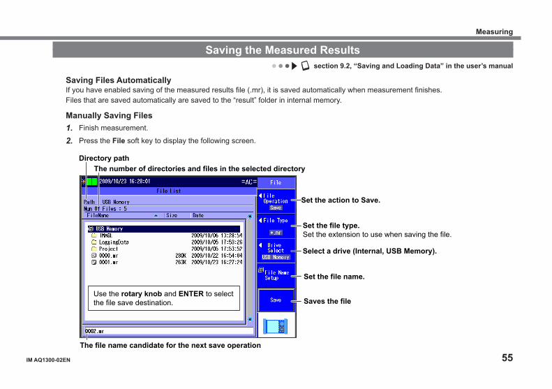
Saving Files AutomaticallyIf you have enabled saving of the measured results file (.mr), it is saved automatically when measurement finishes.Files that are saved automatically are saved to the “result” folder in internal memory.
Manually Saving Files1. Finish measurement.
2. Press the File soft key to display the following screen.
Set the action to Save.
Use the rotary knob and ENTER to select the file save destination.
Directory path The number of directories and files in the selected directory
The file name candidate for the next save operation
Saves the file
Set the file name.
Select a drive (Internal, USB Memory).
Set the file type.Set the extension to use when saving the file.
Measuring
56 IM AQ1300-02EN
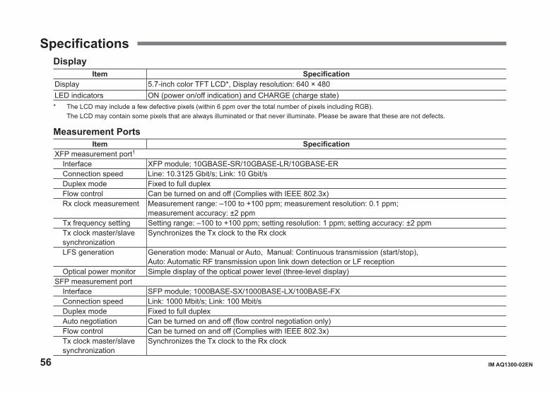
SpecificationsDisplay
Item SpecificationDisplay 5.7-inch color TFT LCD*, Display resolution: 640 × 480LED indicators ON (power on/off indication) and CHARGE (charge state)* The LCD may include a few defective pixels (within 6 ppm over the total number of pixels including RGB). The LCD may contain some pixels that are always illuminated or that never illuminate. Please be aware that these are not defects.
Measurement PortsItem Specification
XFP measurement port1Interface XFP module; 10GBASE-SR/10GBASE-LR/10GBASE-ER Connection speed Line: 10.3125 Gbit/s; Link: 10 Gbit/sDuplex mode Fixed to full duplexFlow control Can be turned on and off (Complies with IEEE 802.3x)Rx clock measurement Measurement range: –100 to +100 ppm; measurement resolution: 0.1 ppm;
measurement accuracy: ±2 ppmTx frequency setting Setting range: –100 to +100 ppm; setting resolution: 1 ppm; setting accuracy: ±2 ppm Tx clock master/slave synchronization
Synchronizes the Tx clock to the Rx clock
LFS generation Generation mode: Manual or Auto, Manual: Continuous transmission (start/stop),Auto: Automatic RF transmission upon link down detection or LF reception
Optical power monitor Simple display of the optical power level (three-level display)SFP measurement port
Interface SFP module; 1000BASE-SX/1000BASE-LX/100BASE-FXConnection speed Link: 1000 Mbit/s; Link: 100 Mbit/sDuplex mode Fixed to full duplexAuto negotiation Can be turned on and off (flow control negotiation only)Flow control Can be turned on and off (Complies with IEEE 802.3x)Tx clock master/slave synchronization
Synchronizes the Tx clock to the Rx clock
IM AQ1300-02EN 57
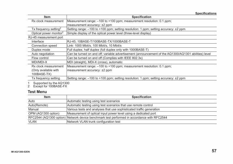
Item SpecificationRx clock measurement Measurement range: –100 to +100 ppm; measurement resolution: 0.1 ppm;
measurement accuracy: ±2 ppmTx frequency setting2 Setting range: –100 to +100 ppm; setting resolution: 1 ppm; setting accuracy: ±2 ppm Optical power monitor2 Simple display of the optical power level (three-level display)
RJ-45 measurement portInterface RJ-45; 10BASE-T/100BASE-TX/1000BASE-TConnection speed Link: 1000 Mbit/s, 100 Mbit/s, 10 Mbit/sDuplex mode Full duplex, half duplex (full duplex only with 1000BASE-T)Auto negotiation Can be turned on and off; variable advertisement (announcement of the AQ1300/AQ1301 abilities) level Flow control Can be turned on and off (Complies with IEEE 802.3x)MDI/MDI-X MDI (straight), MDI-X (cross), automaticRx clock measurement(Only available with 100BASE-TX)
Measurement range: –100 to +100 ppm; measurement resolution: 0.1 ppm; measurement accuracy: ±2 ppm
Tx frequency setting Setting range: –100 to +100 ppm; setting resolution: 1 ppm; setting accuracy: ±2 ppm1 Supported by the AQ13002 Except for 100BASE-FX
Test MenuItem Specification
Auto Automatic testing using test scenariosAuto(Remote) Automatic testing using test scenarios that use remote controlManual Various tests and analyses that use sophisticated traffic generationOPM (AQ1300 option) Measurement of optical input power level using a dedicated portRFC2544 (AQ1300 option) Network device benchmark test performed in accordance with RFC2544VLAN Network VLAN trunk configuration test
Specifications
58 IM AQ1300-02EN
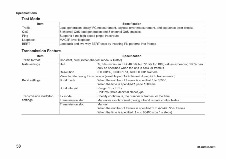
Test ModeItem Specification
Traffic Load generation, delay/IFG measurement, payload error measurement, and sequence error checksQoS 8-channel QoS load generation and 8-channel QoS statisticsPing Supports 1 ms high-speed pings; tracerouteLoopback MAC/IP level loopbackBERT Loopback and two-way BERT tests by inserting PN patterns into frames
Transmission FeatureItem Specification
Traffic format Constant, burst (when the test mode is Traffic)Rate settings Unit %, bits (minimum IFG: 48 bits but 72 bits for 10G; values exceeding 100% can
only be specified when the unit is bits), or frame/sResolution 0.00001%, 0.00001 bit, and 0.00001 frame/sVariable rate during transmission (variable per QoS channel during QoS transmission)
Burst settings Burst mode When the number of frames is specified:1 to 65535When the time is specified:1 μs to 1000 ms
Burst interval Range: 1 μs to 1 sUnit: ms (three decimal places)/μs
Transmission start/stop settings
Tx mode Specify continuous, the number of frames, or the timeTransmission start Manual or synchronized (during inband remote control tests)Transmission stop Manual
When the number of frames is specified: 1 to 4294967295 framesWhen the time is specified: 1 s to 86400 s (in 1 s steps)
Specifications
IM AQ1300-02EN 59
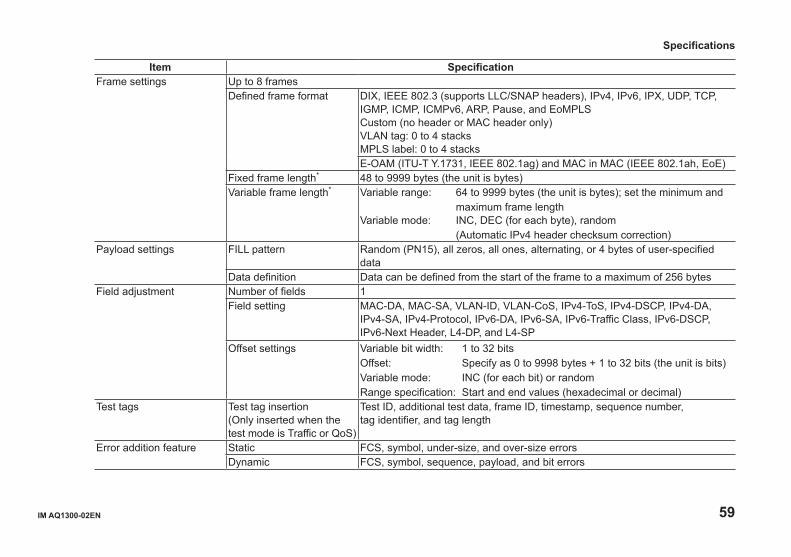
Item SpecificationFrame settings Up to 8 frames
Defined frame format DIX, IEEE 802.3 (supports LLC/SNAP headers), IPv4, IPv6, IPX, UDP, TCP, IGMP, ICMP, ICMPv6, ARP, Pause, and EoMPLSCustom (no header or MAC header only)VLAN tag: 0 to 4 stacksMPLS label: 0 to 4 stacksE-OAM (ITU-T Y.1731, IEEE 802.1ag) and MAC in MAC (IEEE 802.1ah, EoE)
Fixed frame length* 48 to 9999 bytes (the unit is bytes)Variable frame length* Variable range: 64 to 9999 bytes (the unit is bytes); set the minimum and
maximum frame lengthVariable mode: INC, DEC (for each byte), random
(Automatic IPv4 header checksum correction)Payload settings FILL pattern Random (PN15), all zeros, all ones, alternating, or 4 bytes of user-specified
dataData definition Data can be defined from the start of the frame to a maximum of 256 bytes
Field adjustment Number of fields 1Field setting MAC-DA, MAC-SA, VLAN-ID, VLAN-CoS, IPv4-ToS, IPv4-DSCP, IPv4-DA,
IPv4-SA, IPv4-Protocol, IPv6-DA, IPv6-SA, IPv6-Traffic Class, IPv6-DSCP, IPv6-Next Header, L4-DP, and L4-SP
Offset settings Variable bit width: 1 to 32 bitsOffset: Specify as 0 to 9998 bytes + 1 to 32 bits (the unit is bits)Variable mode: INC (for each bit) or randomRange specification: Start and end values (hexadecimal or decimal)
Test tags Test tag insertion(Only inserted when the test mode is Traffic or QoS)
Test ID, additional test data, frame ID, timestamp, sequence number, tag identifier, and tag length
Error addition feature Static FCS, symbol, under-size, and over-size errorsDynamic FCS, symbol, sequence, payload, and bit errors
Specifications

60 IM AQ1300-02EN
Item SpecificationTransmission by QoS channel
Number of channels Up to 8Rate setting Unit: %Burst setting Can only be specified on channel 1Fixed frame length* 48 to 9999 bytes (the unit is bytes)Variable frame length* Variable range: 64 to 9999 bytes (the unit is bytes); set the minimum and
maximum frame lengthVariable mode: INC, DEC (for each byte), random
(Automatic IPv4 header checksum correction)Laser on/off Manual operation (on/off)Linkdown transmission continuation
On/off (only for 10G)
*: If the interface is 100BASE-TX, the guaranteed operating range of the frame length is 48 to 2048 bytes.
Reception FeatureItem Specification
Reception specifications Frame length* 48 to 9999 bytesMinimum IFG 5 bytes
Oversize Range 65 to 10000 bytesBase filter feature Number of filters 2
Method Field specification and pattern filterCombination AND/ORFrame pass condition Match/MismatchOffset settings Offset: 0 to 255 bytes
Bit/MaskBit offset: 0 to 47 bitsBit width: 1 to 48 bitsComparison byte length: Maximum 6 bytes
Delay time and IFG measurement feature
Measurement resolution 100 nsMaximum measurement duration
Approx. 430 s
Specifications

IM AQ1300-02EN 61
Item SpecificationPayload error measurement feature
Detects errors using the CRC in the Tx frame payload
BERT feature BERT frame Random pattern (PBRS15)Sequence error check feature
Number of loss packets, number of reorder packets, number of duplicate packets, and max burst loss number
QoS channel measurement feature
Number of channels Up to 8 or up to 7 plus otherQoS filter classification Number of filters: 2
Method: Field specification and pattern filterPattern setting: Can be set for each channel
Pattern filter Number of filters: 2 (conditions can be specified for each channel independently)
Comparison and mask patterns: 1 to 4 bytesOffset specification: 0 to 255 bytesTwo-filter combination: AND
Per-channel measurement feature
Delay time and IFG measurement, payload error measurement, and sequence error checks
Pause feature Stops transmission when a pause frame is received*: If the interface is 100BASE-TX, the guaranteed operating range of the frame length is 48 to 2048 bytes.
Loopback FeatureItem Specification
Target frame(Supports VLAN, two stacks)
Instrument’s own ports or all ports (excluding layer 2 broadcast and multicast frames and any VLAN’s that are not the instrument’s VLAN—that do not have the same VLAN-ID or TPID)
Field switching L2 test MAC address DA/SAL3 test IP address DA/SA, TCP/UDP DstPORT/SrcPORT
Specifications
62 IM AQ1300-02EN
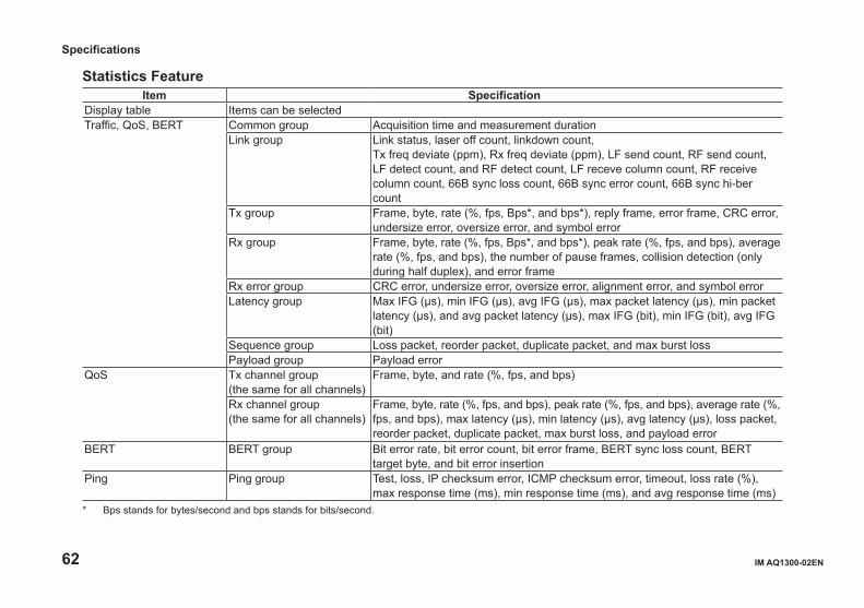
Statistics FeatureItem Specification
Display table Items can be selectedTraffic, QoS, BERT Common group Acquisition time and measurement duration
Link group Link status, laser off count, linkdown count, Tx freq deviate (ppm), Rx freq deviate (ppm), LF send count, RF send count, LF detect count, and RF detect count, LF receve column count, RF receive column count, 66B sync loss count, 66B sync error count, 66B sync hi-ber count
Tx group Frame, byte, rate (%, fps, Bps*, and bps*), reply frame, error frame, CRC error, undersize error, oversize error, and symbol error
Rx group Frame, byte, rate (%, fps, Bps*, and bps*), peak rate (%, fps, and bps), average rate (%, fps, and bps), the number of pause frames, collision detection (only during half duplex), and error frame
Rx error group CRC error, undersize error, oversize error, alignment error, and symbol errorLatency group Max IFG (μs), min IFG (μs), avg IFG (μs), max packet latency (μs), min packet
latency (μs), and avg packet latency (μs), max IFG (bit), min IFG (bit), avg IFG (bit)
Sequence group Loss packet, reorder packet, duplicate packet, and max burst lossPayload group Payload error
QoS Tx channel group(the same for all channels)
Frame, byte, and rate (%, fps, and bps)
Rx channel group (the same for all channels)
Frame, byte, rate (%, fps, and bps), peak rate (%, fps, and bps), average rate (%, fps, and bps), max latency (μs), min latency (μs), avg latency (μs), loss packet, reorder packet, duplicate packet, max burst loss, and payload error
BERT BERT group Bit error rate, bit error count, bit error frame, BERT sync loss count, BERT target byte, and bit error insertion
Ping Ping group Test, loss, IP checksum error, ICMP checksum error, timeout, loss rate (%), max response time (ms), min response time (ms), and avg response time (ms)
* Bps stands for bytes/second and bps stands for bits/second.
Specifications

IM AQ1300-02EN 63
Emulation FeatureItem Specification
IPv4 host (Supports VLAN, two stacks)
ARP reply Reply target: Instrument’s own ports, All addresses, or All VLAN/addressesPing reply Reply target: Instrument’s own portsAutomatic MAC address acquisition
Specify the target IP address
Automatic IP address acquisition
Uses DHCP to acquire the instrument’s IP address
Automatic MAC generation Generates own MAC address based on its own IP address and VLAN IDIPv6 host (Supports VLAN, two stacks)
NDP reply Reply target: Instrument’s own portsPing reply Reply target: Instrument’s own portsAutomatic MAC address acquisition
Uses NDP to acquire the instrument’s MAC address; specify the target IP address
Address autoconfiguration Uses stateless autoconfiguration to resolve the instrument’s port and its IPv6 address
Ping test (Supports VLAN, two stacks)
Number of targets 1 hostFrame length IPv4: 64(+VLAN max. two stacks) to 9999 bytes
IPv6: 84(+VLAN max. two stacks) to 9999 bytesTx mode Continuous, frames, or time
Number of frames: 1 to 4294967295Time: 1 s to 86400 s
Transmission interval 1 ms, 10 ms, 100 ms, or 1 sTimeout 100 ms or 1 s
Traceroute (Supports VLAN, two stacks)
Reply Reply target: PingPacket Type: Ping; max TTL: 1 to 64Traceroute test Route information up to the destination and response time
Specifications
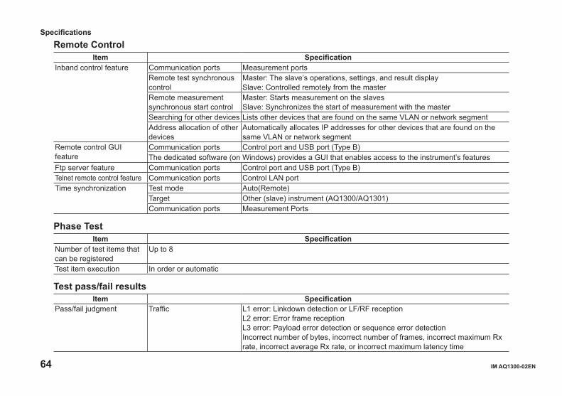
64 IM AQ1300-02EN
Remote ControlItem Specification
Inband control feature Communication ports Measurement portsRemote test synchronous control
Master: The slave’s operations, settings, and result displaySlave: Controlled remotely from the master
Remote measurement synchronous start control
Master: Starts measurement on the slavesSlave: Synchronizes the start of measurement with the master
Searching for other devices Lists other devices that are found on the same VLAN or network segmentAddress allocation of other devices
Automatically allocates IP addresses for other devices that are found on the same VLAN or network segment
Remote control GUI feature
Communication ports Control port and USB port (Type B)The dedicated software (on Windows) provides a GUI that enables access to the instrument’s features
Ftp server feature Communication ports Control port and USB port (Type B)Telnet remote control feature Communication ports Control LAN portTime synchronization Test mode Auto(Remote)
Target Other (slave) instrument (AQ1300/AQ1301)Communication ports Measurement Ports
Phase TestItem Specification
Number of test items that can be registered
Up to 8
Test item execution In order or automatic
Test pass/fail resultsItem Specification
Pass/fail judgment Traffic L1 error: Linkdown detection or LF/RF receptionL2 error: Error frame receptionL3 error: Payload error detection or sequence error detectionIncorrect number of bytes, incorrect number of frames, incorrect maximum Rx rate, incorrect average Rx rate, or incorrect maximum latency time
Specifications
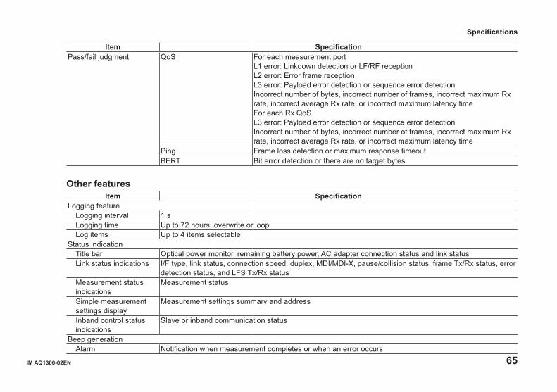
IM AQ1300-02EN 65
Item SpecificationPass/fail judgment QoS For each measurement port
L1 error: Linkdown detection or LF/RF receptionL2 error: Error frame receptionL3 error: Payload error detection or sequence error detectionIncorrect number of bytes, incorrect number of frames, incorrect maximum Rx rate, incorrect average Rx rate, or incorrect maximum latency timeFor each Rx QoSL3 error: Payload error detection or sequence error detectionIncorrect number of bytes, incorrect number of frames, incorrect maximum Rx rate, incorrect average Rx rate, or incorrect maximum latency time
Ping Frame loss detection or maximum response timeoutBERT Bit error detection or there are no target bytes
Other featuresItem Specification
Logging featureLogging interval 1 sLogging time Up to 72 hours; overwrite or loopLog items Up to 4 items selectable
Status indicationTitle bar Optical power monitor, remaining battery power, AC adapter connection status and link statusLink status indications I/F type, link status, connection speed, duplex, MDI/MDI-X, pause/collision status, frame Tx/Rx status, error
detection status, and LFS Tx/Rx statusMeasurement status indications
Measurement status
Simple measurement settings display
Measurement settings summary and address
Inband control status indications
Slave or inband communication status
Beep generationAlarm Notification when measurement completes or when an error occurs
Specifications
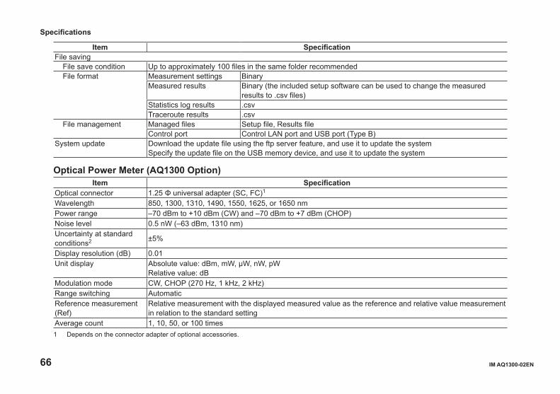
66 IM AQ1300-02EN
Item SpecificationFile saving
File save condition Up to approximately 100 files in the same folder recommendedFile format Measurement settings Binary
Measured results Binary (the included setup software can be used to change the measured results to .csv files)
Statistics log results .csvTraceroute results .csv
File management Managed files Setup file, Results fileControl port Control LAN port and USB port (Type B)
System update Download the update file using the ftp server feature, and use it to update the systemSpecify the update file on the USB memory device, and use it to update the system
Optical Power Meter (AQ1300 Option)Item Specification
Optical connector 1.25 Φ universal adapter (SC, FC)1
Wavelength 850, 1300, 1310, 1490, 1550, 1625, or 1650 nmPower range –70 dBm to +10 dBm (CW) and –70 dBm to +7 dBm (CHOP)Noise level 0.5 nW (–63 dBm, 1310 nm)Uncertainty at standard conditions2 ±5%
Display resolution (dB) 0.01Unit display Absolute value: dBm, mW, μW, nW, pW
Relative value: dBModulation mode CW, CHOP (270 Hz, 1 kHz, 2 kHz)Range switching AutomaticReference measurement (Ref)
Relative measurement with the displayed measured value as the reference and relative value measurement in relation to the standard setting
Average count 1, 10, 50, or 100 times1 Depends on the connector adapter of optional accessories.
Specifications
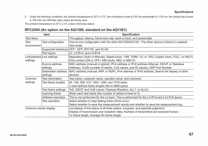
IM AQ1300-02EN 67
2 Under the following conditions: the ambient temperature is 23°C ± 2°C, the modulation mode is CW, the wavelength is 1310 nm, the optical input power is 100 mW, and SM fiber optic cables are being used.
The ambient temperature is 23°C ± 2°C unless otherwise stated.
RFC2544 (An option on the AQ1300, standard on the AQ1301)Item Specification
Test items Throughput, latency, frame loss rate, back to back, and packet jitterTest environment
Test configuration One-to-one configuration with the other AQ1300/AQ1301. The other device is fixed to Loopback Test mode.
Supported interfaces XFP1, SFP, SFP-FE, and RJ-45Test layers L2, L3-IPv4, and L3-IPv6
Link/address settings
Link settings Negotiation (Auto or Manual), Speed (Auto, 10M, 100M, 1G, or 10G), Duplex (Auto, FULL, or HALF)Flow control (ON or OFF), MDI (Auto, MDI, or MDI-X)
Source address settings
MAC address (manual or global), IPv4 address or IPv6 address (Manual, DHCP, or Stateless Address), VLAN (number of stacks, CoS values, and ID values), UDP Port Number
Destination address settings
MAC address (manual, ARP, or NDP), IPv4 address or IPv6 address, Search list display of other devices
Common settings
Test information Test name, customer name, operator name, and commentTest frame lengths 64, 128, 256, 512, 1024, 1280, and 1518 bytes
3 user-defined frame lengths (64 to 9999 bytes)Test frame settings ToS, DSCP, and CoS values, Payload (Random, ALL1, or ALL0)Learning frame When each test starts (the number of retries is fixed to 3)Address resolution This is not performed for the L2 layer. This is performed for the L3-IPv4 and L3-LPv6 layers.Test operation Select whether to stop testing when errors occur.
Select whether to save the measurement results and whether to save the measurement log.Common results display List display of the status of all tests (status, progress, and pass/fail judgment)
Display of transmission and reception rates, Number of transmitted and received framesTx frame length, Average Rx frame length
Specifications
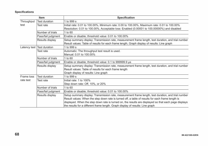
68 IM AQ1300-02EN
Item SpecificationThroughput test
Test duration 1 to 999 sTest rate Initial rate: 0.01 to 100.00%, Minimum rate: 0.00 to 100.00%, Maximum rate: 0.01 to 100.00%
Resolution: 0.01 to 100.00%, Acceptable loss: Enabled (0.00001 to 100.00000%) and disabledNumber of trials 1 to 60Pass/fail judgment Enable or disable; threshold value: 0.01 to 100.00%Results display Setup summary display: Transmission rate, measurement frame length, test duration, and trial number
Result values: Table of results for each frame length, Graph display of results: Line graphLatency test Test duration 1 to 999 s
Test rate Automatic: The throughput test result is used.Manual: 0.01 to 100.00%
Number of trials 1 to 60Pass/fail judgment Enable or disable; threshold value: 0.1 to 999999.9 μsResults display Setup summary display: Transmission rate, measurement frame length, test duration, and trial number
Result values: Table of results for each frame lengthGraph display of results: Line graph
Frame loss rate test
Test duration 1 to 999 sTest rate Initial rate: 1 to 100%
Step down rate: Off, 10%, or 20%Number of trials 1 to 60Pass/fail judgment Enable or disable; threshold value: 0.01 to 100.00%Results display Setup summary display: Transmission rate, measurement frame length, test duration, and trial number
Result values: When the step down rate is turned off, a table of results for each frame length is displayed. When the step down rate is turned on, the results are displayed so that each page displays the results for a different frame length. Graph display of results: Line graph
Specifications
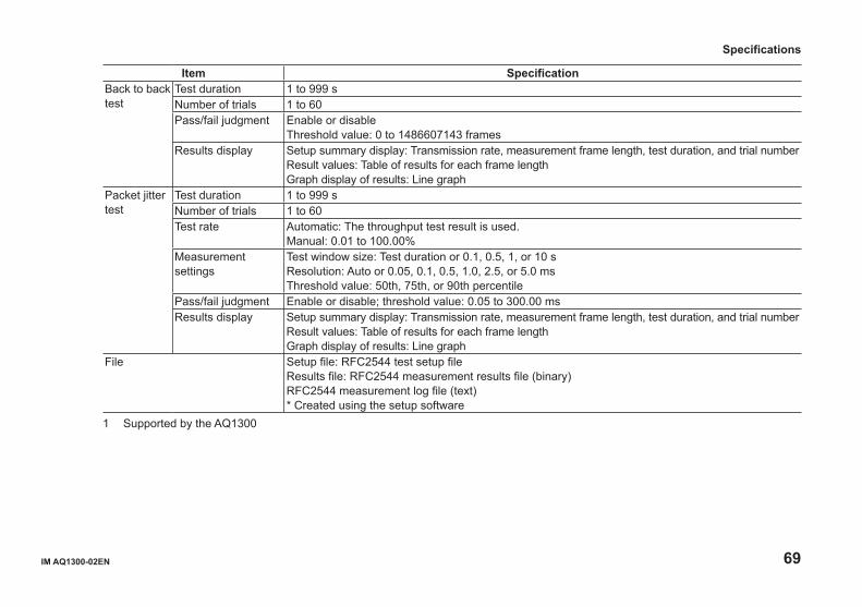
IM AQ1300-02EN 69
Item SpecificationBack to back test
Test duration 1 to 999 sNumber of trials 1 to 60Pass/fail judgment Enable or disable
Threshold value: 0 to 1486607143 framesResults display Setup summary display: Transmission rate, measurement frame length, test duration, and trial number
Result values: Table of results for each frame lengthGraph display of results: Line graph
Packet jitter test
Test duration 1 to 999 sNumber of trials 1 to 60Test rate Automatic: The throughput test result is used.
Manual: 0.01 to 100.00%Measurement settings
Test window size: Test duration or 0.1, 0.5, 1, or 10 sResolution: Auto or 0.05, 0.1, 0.5, 1.0, 2.5, or 5.0 msThreshold value: 50th, 75th, or 90th percentile
Pass/fail judgment Enable or disable; threshold value: 0.05 to 300.00 msResults display Setup summary display: Transmission rate, measurement frame length, test duration, and trial number
Result values: Table of results for each frame lengthGraph display of results: Line graph
File Setup file: RFC2544 test setup fileResults file: RFC2544 measurement results file (binary)RFC2544 measurement log file (text)* Created using the setup software
1 Supported by the AQ1300
Specifications

70 IM AQ1300-02EN
VLAN Configuration Confirmation FeatureItem Specification
Test items Throughput, latency, frame loss rate, back to back, and packet jitterTest environment
Test configuration single AQ1300/AQ1301, or one-to-one configuration with the other AQ1300/AQ1301.Supported interfaces
XFP1, SFP, SFP-FE, and RJ-45
Test layers L2, L3-IPv4, and L3-IPv6Common features
VLAN ID definition file loading
TXT/CSV files
Transmission feature
Tx mode Repeat count: 1 to 15Tx interval 1ms, 10ms, 100ms, or 1sFrame length 64 (+VLAN tag length) to 9999 bytes
74 to 9999 bytes for IPv6 testingVLAN stack 1 or 2Defined frame format
MAC, TYPE, IPv4, IPv6, UDP
Tx VLAN ID 0 to 4095Reception feature
Rx mode Planned value comparison or monitorDisplay mode Map/ListPlanned VLAN ID 0 to 4095
Statistics feature measurement duration, Rx ID Success, Plan, Rx ID Fail, Rx ID Error Test pass/fail results
Pass/fail judgment Comparison with planned VLAN ID
File Setup file: VLAN test setup file (binary)Results file: VLAN measurement result file (binary)VLAN ID definition file: VLAN ID list file (text or csv)
1 Supported by the AQ1300
Specifications
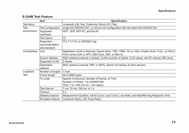
IM AQ1300-02EN 71
E-OAM Test FeatureItem Specification
Test items Loopback (LB) Test, Continuity Check (CC) TestTest environment
Test configuration single AQ1300/AQ1301, or one-to-one configuration with the other AQ1300/AQ1301.Supported interfaces
XFP1, SFP, SFP-FE, and RJ-45
Test layers L2Supported recommendation and standard
ITU-T Y.1731 or IEEE802.1ag
Link/address Link Negotiation (Auto or Manual), Speed (Auto, 10M, 100M, 1G, or 10G), Duplex (Auto, FULL, or HALF)Flow control (ON or OFF), MDI (Auto, MDI, or MDI-X)
Source address MAC address (manual or global), VLAN (number of stacks, CoS values, and ID values), MD LevelSupported VLAN 2 stacksDestination address
MAC address (manual, ARP, or NDP), Search list display of other devices
Loopback Test
Number of targets 1 hostFrame length 64 to 9999 bytesTx mode Specify Continuous, Number of frames, or Time
Number of frames: 1 to 4294967295Time: 1 to 1440 min (in 1 min steps)
Test interval 1 ms, 10 ms, 100 ms, or 1 sTimeout 5 sStatistics feature Measurement Duration, Send Count, Loss Count, Loss Rate, and Max/Min/Avg Response TimeEmulation feature Loopback Reply, Link Trace Reply
Specifications
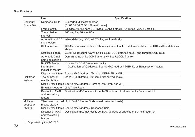
72 IM AQ1300-02EN
Item SpecificationContinuity Check Test
Number of MEP Supported Multicast address[01:80:C2:00:00:30 + Domain Level]
Frame length 93 bytes (VLAN: none), 97 bytes (VLAN: 1 stack), 101 Bytes (VLAN: 2 stacks)Transmission interval
100 ms, 1 s, 10 s, or 60 s
Automatic add RDI flags feature
When detecting LOC, set RDI flags automatically
Status feature CCM transmission status, CCM reception status, LOC detection status, and RDI addition/detection status
Statistics feature CCM/RDI Tx count, CCM/RDI Rx count, LOC detected count, and Through CCM countAutomatic Dmain name acquisition
Domain name of Tx CCM frame apply first Rx CCM frame’s
Rx CCM Frame information indication feature
Indicate Rx CCM Frame informationDestination MAC address, Source MAC address, MEP ID, or Transmission interval
Display result items Source MAC address, Terminal MEP(MEP or MIP)Link trace feature
The number of results display
Up to 64 (LTRframe First-come-first-served basis)
Display result items Source MAC address, Terminal MEP (MEP or MIP)Emulation feature Link Trace ReplyDestination MAC address setting feature
Destination MAC address is set MAC address of selected entry from result list
Multicast Loopback feature
T h e n u m b e r o f results display
Up to 64 (LBRframe First-come-first-served basis)
Display result items Source MAC address, Response TimeDestination MAC address setting feature
Destination MAC address is set MAC address of selected entry from result list
1 Supported by the AQ1300
Specifications
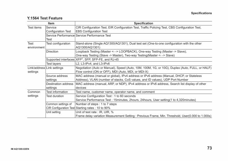
IM AQ1300-02EN 73
Y.1564 Test FeatureItem Specification
Test items Service Configuration Test
CIR Configuration Test, EIR Configuration Test, Traffic Policing Test, CBS Configuration Test, EBS Configuration Test
Service Performance Test
Service Performance Test
Test environment
Test configuration Stand-alone (Single AQ1300/AQ1301), Dual test set (One-to-one configuration with the other AQ1300/AQ1301)
Direction Loopback Testing (Master <- -> LOOPBACK), One-way Testing (Master -> Slave), One-way Testing (Slave -> Master), Two-way Testing(Master <- -> Slave)
Supported interfaces XFP1, SFP, SFP-FE, and RJ-45Test layers L2, L3-IPv4, and L3-IPv6
Link/address settings
Link settings Negotiation (Auto or Manual), Speed (Auto, 10M, 100M, 1G, or 10G), Duplex (Auto, FULL, or HALF)Flow control (ON or OFF), MDI (Auto, MDI, or MDI-X)
Source address settings
MAC address (manual or global), IPv4 address or IPv6 address (Manual, DHCP, or Stateless Address), VLAN (number of stacks, CoS values, and ID values), UDP Port Number
Destination address settings
MAC address (manual, ARP, or NDP), IPv4 address or IPv6 address, Search list display of other devices
Common settings
Test information Test name, customer name, operator name, and commentTest duration Service Configuration Test : 1 to 60 seconds
Service Performance Test : 15minutes, 2hours, 24hours, User setting(1 to 4,320minutes)Common settings of CIR Configuration Test
Number of steps : 1 to 7 stepsStarting rates : 10 to 90%
Unit setting Unit of test rate : IR, UIR, %Frame delay variation Measurement Setting : Previous Frame, Min. Threshold, User(0.000 to 1.000s)
Specifications
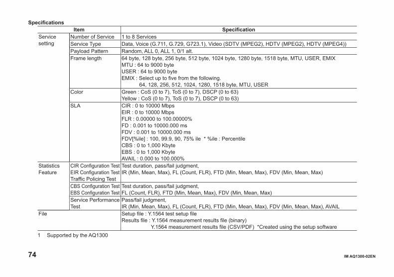
74 IM AQ1300-02EN
Item SpecificationService setting
Number of Service 1 to 8 ServicesService Type Data, Voice (G.711, G.729, G723.1), Video (SDTV (MPEG2), HDTV (MPEG2), HDTV (MPEG4))Payload Pattern Random, ALL 0, ALL 1, 0/1 alt.Frame length 64 byte, 128 byte, 256 byte, 512 byte, 1024 byte, 1280 byte, 1518 byte, MTU, USER, EMIX
MTU : 64 to 9000 byteUSER : 64 to 9000 byteEMIX : Select up to five from the following. 64, 128, 256, 512, 1024, 1280, 1518 byte, MTU, USER
Color Green : CoS (0 to 7), ToS (0 to 7), DSCP (0 to 63)Yellow : CoS (0 to 7), ToS (0 to 7), DSCP (0 to 63)
SLA CIR : 0 to 10000 MbpsEIR : 0 to 10000 MbpsFLR : 0.00000 to 100.00000%FD : 0.001 to 10000.000 msFDV : 0.001 to 10000.000 msFDV[%ile] : 100, 99.9, 90, 75% ile * %ile : PercentileCBS : 0 to 1,000 KbyteEBS : 0 to 1,000 KbyteAVAIL : 0.000 to 100.000%
Statistics Feature
CIR Configuration TestEIR Configuration TestTraffic Policing Test
Test duration, pass/fail judgment,IR (Min, Mean, Max), FL (Count, FLR), FTD (Min, Mean, Max), FDV (Min, Mean, Max)
CBS Configuration TestEBS Configuration Test
Test duration, pass/fail judgment,FL (Count, FLR), FTD (Min, Mean, Max), FDV (Min, Mean, Max)
Service Performance Test
Pass/fail judgment,IR (Min, Mean, Max), FL (Count, FLR), FTD (Min, Mean, Max), FDV (Min, Mean, Max), AVAIL
File Setup file : Y.1564 test setup fileResults file : Y.1564 measurement results file (binary) Y.1564 measurement results file (CSV/PDF) *Created using the setup software
1 Supported by the AQ1300
Specifications
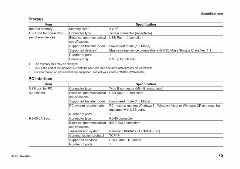
IM AQ1300-02EN 75
StorageItem Specification
Internal memory Memory size1 2 GB2
USB port for connecting peripheral devices
Connector type Type A connector (receptacle)Electrical and mechanical specifications
USB Rev. 1.1 compliant
Supported transfer mode Low speed mode (1.5 Mbps)Supported devices3 Mass storage device compatible with USB Mass Storage Class Ver. 1.1 Number of ports 1Power supply 5 V, up to 500 mA
1 The memory size may be changed.2 This is the part of the memory in which the user can load and save data through file operations.3 For information on devices that are supported, contact your nearest YOKOGAWA dealer.
PC InterfaceItem Specification
USB port for PC connection
Connector type Type B connector (Mini-B, receptacle)Electrical and mechanical specifications
USB Rev. 1.1 compliant
Supported transfer mode Low speed mode (1.5 Mbps)PC system requirements PC must be running Windows 7, Windows Vista or Windows XP and must be
equipped with USB ports.Number of ports 1
RJ-45 LAN port Connector type RJ-45 connectorElectrical and mechanical specifications
IEEE 802.3 compliant
Transmission system Ethernet (100BASE-TX/10BASE-T)Communication protocol TCP/IPSupported services DHCP and FTP serverNumber of ports 1
Specifications
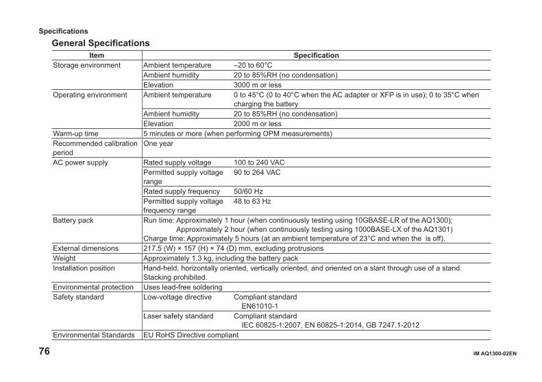
76 IM AQ1300-02EN
General SpecificationsItem Specification
Storage environment Ambient temperature –20 to 60°CAmbient humidity 20 to 85%RH (no condensation)Elevation 3000 m or less
Operating environment Ambient temperature 0 to 45°C (0 to 40°C when the AC adapter or XFP is in use); 0 to 35°C when charging the battery
Ambient humidity 20 to 85%RH (no condensation)Elevation 2000 m or less
Warm-up time 5 minutes or more (when performing OPM measurements)Recommended calibration period
One year
AC power supply Rated supply voltage 100 to 240 VACPermitted supply voltage range
90 to 264 VAC
Rated supply frequency 50/60 HzPermitted supply voltage frequency range
48 to 63 Hz
Battery pack Run time: Approximately 1 hour (when continuously testing using 10GBASE-LR of the AQ1300); Approximately 2 hour (when continuously testing using 1000BASE-LX of the AQ1301)
Charge time: Approximately 5 hours (at an ambient temperature of 23°C and when the is off).External dimensions 217.5 (W) × 157 (H) × 74 (D) mm, excluding protrusionsWeight Approximately 1.3 kg, including the battery packInstallation position Hand-held, horizontally oriented, vertically oriented, and oriented on a slant through use of a stand.
Stacking prohibited.Environmental protection Uses lead-free solderingSafety standard Low-voltage directive Compliant standard
EN61010-1Laser safety standard Compliant standard
IEC 60825-1:2007, EN 60825-1:2014, GB 7247.1-2012Environmental Standards EU RoHS Directive compliant
Specifications
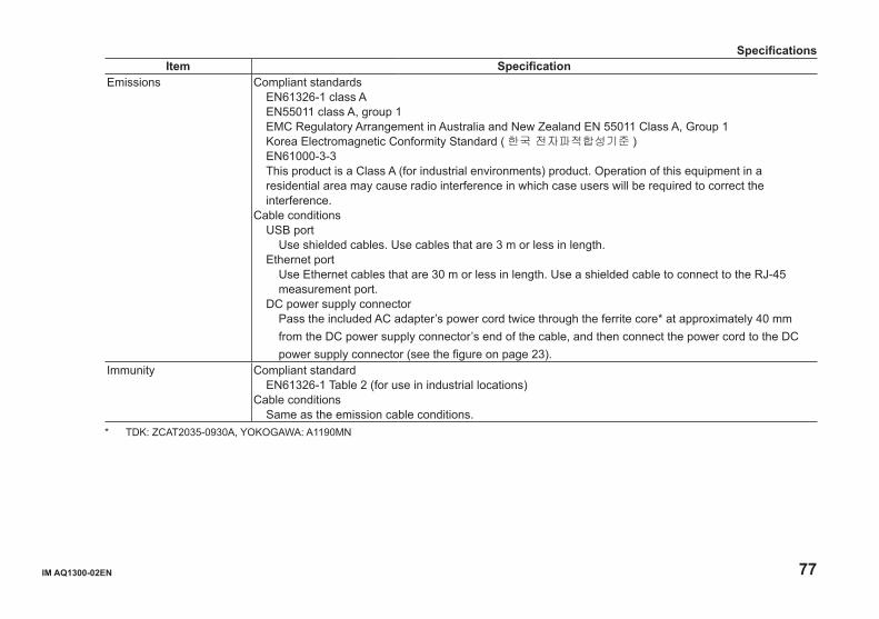
IM AQ1300-02EN 77
Item SpecificationEmissions Compliant standards
EN61326-1 class AEN55011 class A, group 1EMC Regulatory Arrangement in Australia and New Zealand EN 55011 Class A, Group 1Korea Electromagnetic Conformity Standard ( 한국 전자파적합성기준 )EN61000-3-3This product is a Class A (for industrial environments) product. Operation of this equipment in a residential area may cause radio interference in which case users will be required to correct the interference.
Cable conditionsUSB port
Use shielded cables. Use cables that are 3 m or less in length.Ethernet port
Use Ethernet cables that are 30 m or less in length. Use a shielded cable to connect to the RJ-45 measurement port.
DC power supply connectorPass the included AC adapter’s power cord twice through the ferrite core* at approximately 40 mm from the DC power supply connector’s end of the cable, and then connect the power cord to the DC power supply connector (see the figure on page 23).
Immunity Compliant standardEN61326-1 Table 2 (for use in industrial locations)
Cable conditionsSame as the emission cable conditions.
* TDK: ZCAT2035-0930A, YOKOGAWA: A1190MN
Specifications
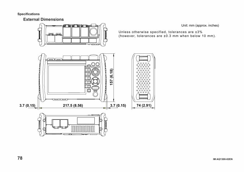
78 IM AQ1300-02EN
External Dimensions
3.7 (0.15) 217.5 (8.56) 3.7 (0.15) 74 (2.91)15
7 (6
.18)
Unit: mm (approx. inches)
Unless otherwise speci f ied, to lerances are ±3% (however, to lerances are ±0.3 mm when below 10 mm).
Specifications

IM AQ1300-02EN 79
Memo

80 IM AQ1300-02EN
Memo
Copyright © 2022 FDOKUMEN