
Applications of 40Gb/s Chirp-Managed Laser in Access and Metro Networks
13
JOURNAL OF LIGHTWAVE TECHNOLOGY, VOL. 27, NO. 3, FEBRUARY 1, 2009 253 Applications of 40-Gb/s Chirp-Managed Laser in Access and Metro Networks Jianjun Yu, Senior Member, IEEE, Zhensheng Jia, Student Member, IEEE, Ming-Fang Huang, Student Member, IEEE, Muhammad Haris, Philip N. Ji, Ting Wang, Senior Member, IEEE, and Gee-Kung Chang, Fellow, IEEE Abstract—We investigate 40-Gb/s cost-efficient transmitter for access and metro networks. This 40-Gb/s transmitter comprises a standard directly modulated distributed-feedback (DFB) laser and a subsequent optical filter. Large dispersion tolerance of this transmitter is realized by chirp control through the phase correla- tion between adjacent bits for the destructive interference in order to erase the power of “0” bits while enhancing the extinction ratio. The chirp model of the DFB laser and the optimum parameters of the optical filter have been numerically analyzed. The chirp-man- aged 42.8-Gb/s transmission over 20-km standard single mode fiber (SSMF or SMF-28) without dispersion compensation and a centralized lightwave WDM-PON system are experimentally demonstrated. We have also realized the transmission over 100-m graded index plastic optical fiber (GI-POF). Moreover, the appli- cation in the metro network over 240-km SSMF or SMF-28 has also been investigated in this paper. Index Terms—Access network, adiabatic chirp, amplitude mod- ulation (AM), directly modulated lasers (DMLs), dispersion com- pensation, frequency, metro network, phase correlation. I. INTRODUCTION T HE demand of bandwidth for Internet traffic and access networks in the premises are rapidly increasing, fueled by video and graphic-rich applications. Therefore, the data rate at 40 Gb/s per channel is expanding to next-generation optical access networks and very-short-reach (VSR) optical links. Unlike long-haul and metro networks, access and VSR networks require low hardware cost and low operation expenses to make the transmission technology attractive and practical. Currently, there is a growing interest in utilizing directly mod- ulated lasers (DMLs) in cost-sensitive metro and access optical links because of their potentially low cost, compact size, low power consumption, and high output power characteristics when compared with other transmitter sources using external modulation (EM) scheme such as electro-absorption modulator (EAM) or Mach–Zehnder modulator (MZM) [1]–[3]. As it is Manuscript received June 20, 2008; revised September 04, 2008. Current ver- sion published February 13, 2009. J. Yu, P. N. Ji, and T. Wang are with NEC Laboratories America, Princeton, NJ 08540 USA (e-mail: [email protected]; [email protected]). Z. Jia, M.-F. Huang, and M. Haris are with NEC Laboratories America, Princeton, NJ 08540 USA and also with the School of Electrical and Computer Engineering, Georgia Institute of Technology, Atlanta, GA 30087 USA. G.-K. Chang is with the School of Electrical and Computer Engineering, Georgia Institute of Technology, Atlanta, GA 30087 USA. Color versions of one or more of the figures in this paper are available online at http://ieeexplore.ieee.org. Digital Object Identifier 10.1109/JLT.2008.2006064 well known, however, DMLs are the carrier density modulation via drive current, giving rise to inherent and highly compo- nent-specific frequency chirp, i.e., a residual phase modulation (PM) accompanying the desired intensity modulation (IM). This chirp results in broad spectrum that severely limits the maximum transmission distance within 20 and 2-km SSMF for 10 and 40 Gb/s without dispersion compensation because of its interaction with fiber dispersion along the transmission link. One way to overcome this issue is to use the special fiber with a negative dispersion characteristic, which is a good choice to take advantage of the positive chirp characteristics of DMLs to increase the reach without dispersion compensation modules that can cost as much as the transmission fiber [4]–[6]. How- ever, it is only suitable to new deployment of optical transport system but not fit to upgrade and change of the installed base of metro fiber links. Chirp-managed laser (CML) can provide a good optical source for access systems [7], [8]. In order to support high dispersion tolerance, a DFB laser biased at high direct current (DC) far above the threshold is used, digital data directly modu- late this DFB laser, and a suitable optical filter is used to control the phase between the adjacent bits. The additional benefits of the higher bias are high output power, wide modulation bandwidth, low timing jitter, and suppressed transient chirp. CML technology simultaneously meets two market needs: 1) the data rate upgrade from 2.5 to 10 Gb/s, even to 40 Gb/s, in the emerging metro market and 2) the migration of small form factor pluggable optics from short-reach to high-performance long-reach and WDM links. The directly modulated signals have low extinction ratio (ER) and an accompanying adiabatic chirp. An optical spectrum reshaping (OSR) filter is placed at the laser output to perform frequency modulation (FM) to amplitude modulation (AM) conversion to increase the ER and convert the slowly varying adiabatically chirped pulses to flat-topped chirp pulses with abrupt phase transitions [9]. The output of the CML has been shown to have tolerance to both negative and positive dispersion for 10-Gb/s optical links [7]. The CML technique has been applied in 10-Gb/s data links with 200-km transmission over SMF without dispersion com- pensation [10] and 675-km transmission using a combination of electronic dispersion compensation (EDC) and tunable dis- persion compensating modules at the receiver [8]. In this paper, we develop a 40-Gb/s CML transmitter with high dispersion tol- erance using a simple combination of a directly modulated DFB laser and the subsequent conventional optical filter. This paper is organized as follows. In Section II, we theo- retically analyze the chirp characteristics of DMLs, operation 0733-8724/$25.00 © 2009 IEEE
-
Upload
independent -
Category
Documents
-
view
3 -
download
0
Transcript of Applications of 40Gb/s Chirp-Managed Laser in Access and Metro Networks
JOURNAL OF LIGHTWAVE TECHNOLOGY, VOL. 27, NO. 3, FEBRUARY 1, 2009 253
Applications of 40-Gb/s Chirp-Managed Laser inAccess and Metro Networks
Jianjun Yu, Senior Member, IEEE, Zhensheng Jia, Student Member, IEEE,Ming-Fang Huang, Student Member, IEEE, Muhammad Haris, Philip N. Ji,
Ting Wang, Senior Member, IEEE, and Gee-Kung Chang, Fellow, IEEE
Abstract—We investigate 40-Gb/s cost-efficient transmitter foraccess and metro networks. This 40-Gb/s transmitter comprisesa standard directly modulated distributed-feedback (DFB) laserand a subsequent optical filter. Large dispersion tolerance of thistransmitter is realized by chirp control through the phase correla-tion between adjacent bits for the destructive interference in orderto erase the power of “0” bits while enhancing the extinction ratio.The chirp model of the DFB laser and the optimum parameters ofthe optical filter have been numerically analyzed. The chirp-man-aged 42.8-Gb/s transmission over 20-km standard single modefiber (SSMF or SMF-28) without dispersion compensation anda centralized lightwave WDM-PON system are experimentallydemonstrated. We have also realized the transmission over 100-mgraded index plastic optical fiber (GI-POF). Moreover, the appli-cation in the metro network over 240-km SSMF or SMF-28 hasalso been investigated in this paper.
Index Terms—Access network, adiabatic chirp, amplitude mod-ulation (AM), directly modulated lasers (DMLs), dispersion com-pensation, frequency, metro network, phase correlation.
I. INTRODUCTION
T HE demand of bandwidth for Internet traffic and accessnetworks in the premises are rapidly increasing, fueled
by video and graphic-rich applications. Therefore, the datarate at 40 Gb/s per channel is expanding to next-generationoptical access networks and very-short-reach (VSR) opticallinks. Unlike long-haul and metro networks, access and VSRnetworks require low hardware cost and low operation expensesto make the transmission technology attractive and practical.Currently, there is a growing interest in utilizing directly mod-ulated lasers (DMLs) in cost-sensitive metro and access opticallinks because of their potentially low cost, compact size, lowpower consumption, and high output power characteristicswhen compared with other transmitter sources using externalmodulation (EM) scheme such as electro-absorption modulator(EAM) or Mach–Zehnder modulator (MZM) [1]–[3]. As it is
Manuscript received June 20, 2008; revised September 04, 2008. Current ver-sion published February 13, 2009.
J. Yu, P. N. Ji, and T. Wang are with NEC Laboratories America, Princeton,NJ 08540 USA (e-mail: [email protected]; [email protected]).
Z. Jia, M.-F. Huang, and M. Haris are with NEC Laboratories America,Princeton, NJ 08540 USA and also with the School of Electrical and ComputerEngineering, Georgia Institute of Technology, Atlanta, GA 30087 USA.
G.-K. Chang is with the School of Electrical and Computer Engineering,Georgia Institute of Technology, Atlanta, GA 30087 USA.
Color versions of one or more of the figures in this paper are available onlineat http://ieeexplore.ieee.org.
Digital Object Identifier 10.1109/JLT.2008.2006064
well known, however, DMLs are the carrier density modulationvia drive current, giving rise to inherent and highly compo-nent-specific frequency chirp, i.e., a residual phase modulation(PM) accompanying the desired intensity modulation (IM).This chirp results in broad spectrum that severely limits themaximum transmission distance within 20 and 2-km SSMFfor 10 and 40 Gb/s without dispersion compensation because ofits interaction with fiber dispersion along the transmission link.One way to overcome this issue is to use the special fiber witha negative dispersion characteristic, which is a good choice totake advantage of the positive chirp characteristics of DMLs toincrease the reach without dispersion compensation modulesthat can cost as much as the transmission fiber [4]–[6]. How-ever, it is only suitable to new deployment of optical transportsystem but not fit to upgrade and change of the installed baseof metro fiber links.
Chirp-managed laser (CML) can provide a good opticalsource for access systems [7], [8]. In order to support highdispersion tolerance, a DFB laser biased at high direct current(DC) far above the threshold is used, digital data directly modu-late this DFB laser, and a suitable optical filter is used to controlthe phase between the adjacent bits. The additional benefitsof the higher bias are high output power, wide modulationbandwidth, low timing jitter, and suppressed transient chirp.CML technology simultaneously meets two market needs: 1)the data rate upgrade from 2.5 to 10 Gb/s, even to 40 Gb/s, inthe emerging metro market and 2) the migration of small formfactor pluggable optics from short-reach to high-performancelong-reach and WDM links. The directly modulated signalshave low extinction ratio (ER) and an accompanying adiabaticchirp. An optical spectrum reshaping (OSR) filter is placedat the laser output to perform frequency modulation (FM) toamplitude modulation (AM) conversion to increase the ERand convert the slowly varying adiabatically chirped pulses toflat-topped chirp pulses with abrupt phase transitions [9]. Theoutput of the CML has been shown to have tolerance to bothnegative and positive dispersion for 10-Gb/s optical links [7].
The CML technique has been applied in 10-Gb/s data linkswith 200-km transmission over SMF without dispersion com-pensation [10] and 675-km transmission using a combinationof electronic dispersion compensation (EDC) and tunable dis-persion compensating modules at the receiver [8]. In this paper,we develop a 40-Gb/s CML transmitter with high dispersion tol-erance using a simple combination of a directly modulated DFBlaser and the subsequent conventional optical filter.
This paper is organized as follows. In Section II, we theo-retically analyze the chirp characteristics of DMLs, operation
0733-8724/$25.00 © 2009 IEEE
254 JOURNAL OF LIGHTWAVE TECHNOLOGY, VOL. 27, NO. 3, FEBRUARY 1, 2009
principle of this highly chirp-controlled transmitter, and theoptimal parameters of the OSR filter and DML. In Section III,we demonstrate the simulation and experimental results ofthe 40-Gb/s CML transmission over 20-km SSMF withoutdispersion compensation. We apply this 40-Gb/s DML in aWDM-PON system with centralized lightwave in Section IV.The 40-Gb/s CML transmission over 100-m graded indexplastic optical fiber (GI-POF) is discussed in Section V. InSection VI, we show the 40-Gb/s CML transmission over240-km SMF-28. Finally, the conclusions are summarized inSection VII.
II. PRINCIPLE OF THE CML TRANSMITTER
A. Chirp Characteristics of DMLs
The performance of DMLs strongly depends on the charac-teristics of the laser frequency chirp. At high data rates ( 2.5Gbit/s), the frequency chirp of DMLs has two major compo-nents: the transient chirp and the adiabatic chirp. At lower datarates, the thermal chirp becomes dominant. Here we focus onhigh data rate operation. The chirp of a DML is relatedto the laser output optical power through the expression[11]
(1)
where is the linewidth enhancement factor and is the adia-batic chirp coefficient. In (1), the first term is a structure-inde-pendent transient chirp, and the second term is a structure-de-pendent adiabatic chirp. DMLs can be classified as transient oradiabatic chirp dominated. Transient chirp dominated DMLs ex-hibit significantly more overshoot and ringing in output powerand frequency deviations. The frequency difference betweensteady-state “1”s and “0”s is relatively small. On the other hand,adiabatic chirp dominated DMLs exhibit damped oscillationsand large frequency difference between steady-state “1”s and“0”s. In (1), the output power is related to the photon den-sity through the relation
(2)
and the photon density is determined by the well-knownsmall-signal single-mode laser rate equations in the simple formas follows:
(3)
(4)
(5)
where is the current waveform injected in the active layer,is the carrier density, is the optical frequency, is the
Plank’s constant, is the differential quantum efficiency, isthe confinement factor, is the carrier density at transparency,
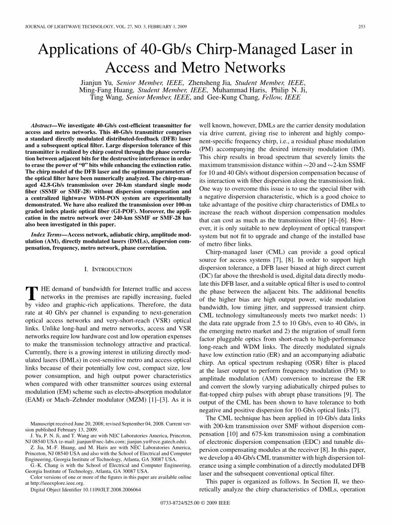
Fig. 1. Schematic of chirped-managed DML transmitter.
is the fraction of spontaneous emission noise coupled into thelasing mode, is the differential gain coefficient, is the non-linear gain compression factor (gain saturation coefficient),is the photon lifetime, is the carrier lifetime, is the volumeof the active layer, and is the same as (1), i.e., the linewidthenhancement factor. It should be noticed that, in a first approx-imation, static temperature (25 C) dependence of the value ofeach parameter has been ignored here. From (1)–(5), we cansee that the minimum number of parameters that have to be es-timated is ten in addition to thelasing wavelength . In (1), the parameter can be calculatedas well as the adiabatic chirp coefficient , which is directly re-lated to the nonlinear gain compression factor
(6)
Therefore, based on (1)–(6) of the chirp model (alreadyincluding the drive current (DC) bias), we can design theparameters of the DMLs to offer suitable chirp response for thegeneration of the phase correlation.
B. Operating Principle
The high dispersion tolerance is mainly because of the phase-correlative modulation among the adjacent bits via preciselycontrolling the frequency chirp in the DML modulation. Theadiabatic chirp makes the “1” bits blue shifted relative to the “0”bits. By controlling the modulation depth, the phase flip between0 and in the middle of the space bit could be realized, whichleads to the destructive interference between the energies on ei-ther side of the middle of the space after the dispersion-inducedbroad spectrum. The out of phase is the key to the dispersiontolerance. This resulting phase correlation and destructive inter-ference along the fiber transmission are similar to that for opticalduobinary modulation, but here, we don’t require pre-coder, en-coder, and external modulator in the transmitter side and the de-coder in the receiver side.
The CML transmitter comprises a DML and the subsequentoptical filter, the schematic diagram is shown in Fig. 1. TheDML is a high-speed standard DFB laser, the optical filter isa conventional bandpass filter [12]. The highly chirp-controlledmodulation creates two distinct frequency peaks in Fig. 1 inset

YU et al.: APPLICATIONS OF 40-Gb/s CHIRP-MANAGED LASER IN ACCESS AND METRO NETWORKS 255
Fig. 2. Schematic of signal waveform.
(i). The main function of the filter is to increase the extinctionratio by passing the “1” bits while attenuating “0” bits in inset(ii), and simultaneously suppress the transient chirp and shapeit into the top-flatted chirp. To realize the proper phase flip be-tween the bits, much higher driven bias compared to the con-ventional direct modulation is employed. The additional bene-fits of the higher bias are high output power and wide modu-lation bandwidth due to the high operation point. We can alsoachieve the stable single mode operation and low timing jitter,and make the laser be the adiabatic chirp dominated via suppres-sion of the transient chirp because the working condition is faraway from the threshold of the laser. For a 40-Gb/s data rate, thepulsewidth is 25 ps, to get the phase shift, adiabatic chirp needto be equal to ps GHz, that means the “1” bithas 20 GHz blue shift relative to entire “0” bit. The generation ofsuitable adiabatic chirp by adjusting bias and laser parametersis the first step to achieve the higher dispersion tolerance, whichis due to the AM to FM conversion (“1” bit has blue shift dueto the higher intensity compared to “0” bits). However, this re-sults in a low extinction ratio (ER 1–2 dB) accompanying thehigher bias. Therefore, a subsequent optical filter is employed toperform the FM to AM conversion by passing the “1” bits andattenuating the “0” bits for increasing the ER. Considering the1 0 1 bit sequence, the original binary signal, the directly mod-ulated signal, the filtered signal and the transmitted signal areshown in Fig. 2. The change of correlative phase flips and ERare also shown here. It is clearly seen that the eye would closeand the original bit could not be recognized (the dashed linein “after transmission”) without the destructive interference be-tween the adjacent “1” bits.
C. Optimization Parameters of the Optical Filter
Since the filter plays an important part in the CML genera-tion, we study the optimization parameters of the optical filter.The subsequent optical filter has two main functions: one is toperform the FM to AM conversion by passing the “1” bits andattenuating the “0” bits for increasing the ER. Additional effect
Fig. 3. Transfer function of the Gaussian filter.
of the optical filter is to suppress the transient chirp and shapeit into the top-flatted chirp waveform for keeping the out ofphase difference during the “0” bit. In dependence on the spe-cific application, the filter design includes development of thefilter with prescribed magnitude and phase response. Varioustypes of optical filters can be a candidate for optimal OSR filter:
1) Butterworth: Maximally flat magnitude response in thepass band, the disadvantage is some overshoot and ringingin step response.
2) Chebyshev: Better rate of attenuation beyond the pass-band than Butterworth, the disadvantage is considerablymore ringing in step response than Butterworth.
3) Bessel: A uniform time delay within pass band and thebest step response with minimal overshoot or ringing. Theadvantage is slower initial rate of attenuation beyond thepass band compared with Butterworth and other filters.
4) Rectangular and Trapezoid: Ideal selectivity, absolutelyflat magnitude and phase of the frequency response. Thedisadvantage is that it requires truncation of the impulseresponse and signal delay at simulations with periodicboundary conditions.
5) Gaussian: Smooth transfer function without dispersion,more importantly, it is easily implemented to the realdesign and application in optical communication systems.
Based on the above-mentioned reasons, we select the Gaussianfilter type in our simulation model. The Gaussian filter transfercharacteristic is determined by the parameter bandwidth
, central frequency and Gaussian order of thefilter, the expression is shown as
(7)
with the assumption of vanishing phase and .Filter order sets the attenuation rate at transition from pass bandto stop band. Fig. 3 shows the basic transfer function of theGaussian filter.
As mentioned before, passing the signal through the edge ofthe filter not only improves the ER but also produces vestigialsideband (VSB) effect, which adds blue transient chirp at the
256 JOURNAL OF LIGHTWAVE TECHNOLOGY, VOL. 27, NO. 3, FEBRUARY 1, 2009
Fig. 4. Transfer characteristics of bandpass optical Gaussian filters. (a)Gaussian filter with different orders and the same 3-dB bandwidth. (b)Gaussian filter with different bandwidths and the same order.
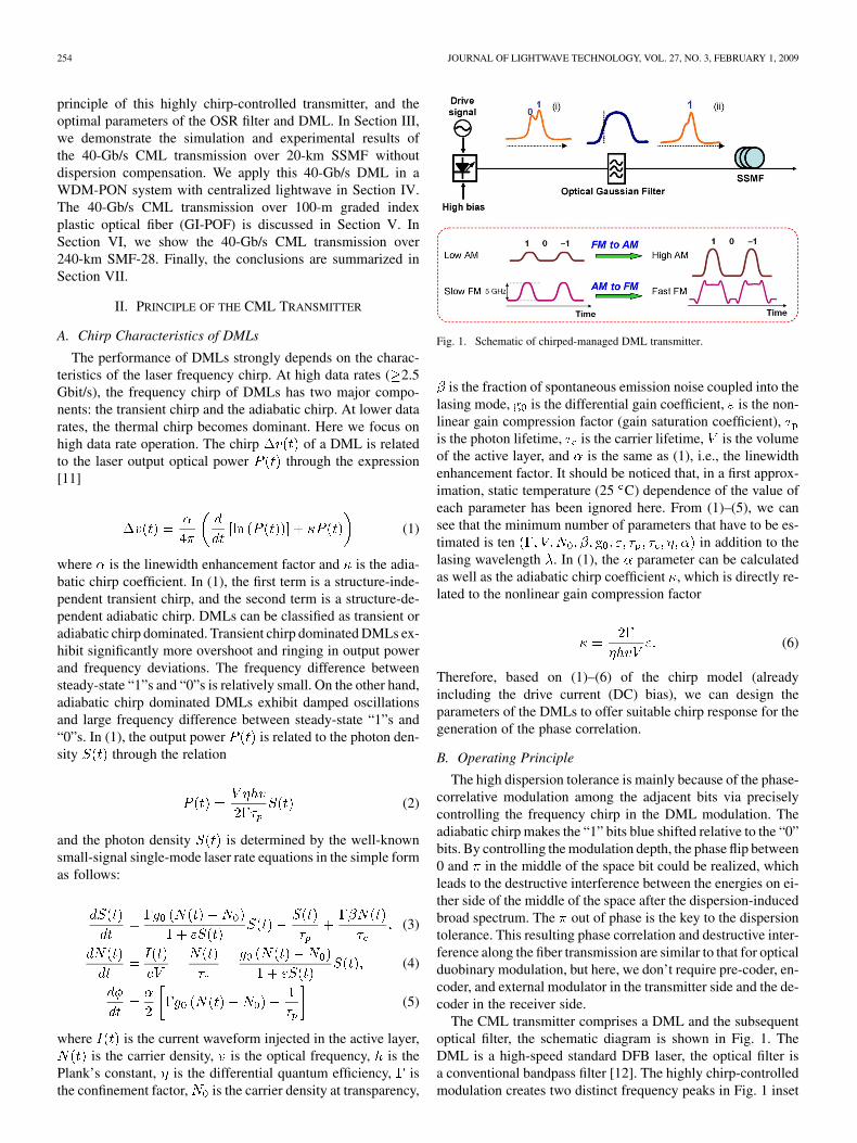
“1” to “0” and “0” to “1” transitions, further improving the eyeopening after fiber dispersion. The VSB filtering reduces the in-formation bandwidth as well. Fig. 4(a) and (b) shows the transferspectrum of this Gaussian optical filter in the different of orderand bandwidths set, respectively. It is noted that the Gaussianorder can be set as the noninteger value. It is clearly seen thatthe top becomes flat and the roll-off response is very sharp. Re-garding the 40-Gb/s signals, we simulate the best transfer spec-trum with the bandwidth of 54 GHz and Gaussian order of 1.7.The transfer spectrum is shown in Fig. 5.
D. Parameters Optimization of DML (Laser Model)
A typical single-mode dynamic laser model (LaserSM_REmodule in VPI) based on standard rate equations is used inthe simulation. This module simulates the dynamics and noisecharacteristics of a directly-modulated single-mode laser drivenby an electrical current waveform. The model describes theevolution of optical power, phase and carrier density averagedover the whole laser cavity. The model is ideal for modelingmetro transmission systems using directly-modulated lasers, as
Fig. 5. Transfer spectrum for 40-Gb/s signals.
TABLE ISUMMARY OF LASER INTRINSIC PARAMETERS
it takes into account the relaxation oscillation, turn-on jitter,laser chirp, intensity and phase noise which can significantlyaffect the system performance. The chirp control in this directlymodulated transmitter comes from two important sections: 1)generating proper chirp frequency in the laser and (2) chirpfiltering and conversion in the subsequent optical filters. Weprovide the theoretical analysis for the proper chirp generation(adiabatic chirp) in the laser with very high bias. According tothe analysis of the chirp model, we performed the multi-param-eters sweeping so as to find the optimized laser structure whichis suitable to get the out of phase for the transmission of thedirectly modulated signals. The results are provided in Table I.
All of the parameters above are used for 10-Gb/s signals; re-garding 40-Gb/s signals, the drive amplitude is 21 mA and thebias is 85 mA, the nonlinear gain coefficient is changed into5.0e-23, and the others keep the same as parameters for 10-Gb/ssignals.
• Bias current-related characteristics:Compared with the conventional DML, the lower thresholdis required because we need to bias this laser roughly 5 6times threshold. Because of inaccuracy of the results below
YU et al.: APPLICATIONS OF 40-Gb/s CHIRP-MANAGED LASER IN ACCESS AND METRO NETWORKS 257
Fig. 6. Resonant frequency and damping as functions of bias current.
Fig. 7. Amplitude and phase response in the DML intensity modulation.
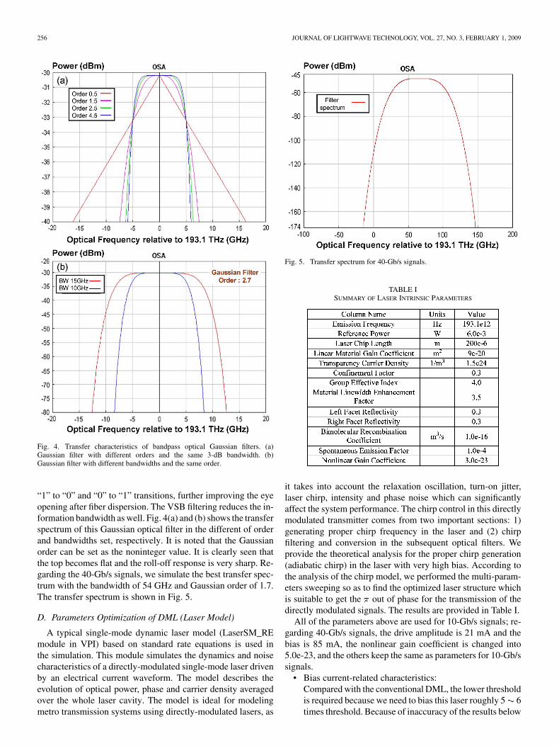
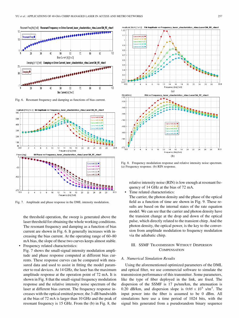
the threshold operation, the sweep is generated above thelaser threshold for obtaining the whole working conditions.The resonant frequency and damping as a function of biascurrent are shown in Fig. 6. It generally increases with in-creasing the bias current. At the operating range of 60–80mA bias, the slope of these two curves keeps almost stable.
• Frequency related characteristics:Fig. 7 shows the small-signal intensity modulation ampli-tude and phase response computed at different bias cur-rents. These response curves can be compared with mea-sured data and used to assist in fitting the model param-eter to real devices. At 14 GHz, the laser has the maximumamplitude response at the operation point of 72 mA. It isshown in Fig. 8 that the small-signal frequency modulationresponse and the relative intensity noise spectrum of thelaser at different bias current. The frequency response in-creases with the optical emitted power, the 3-dB bandwidthat the bias of 72 mA is larger than 10 GHz and the peak ofresonant frequency is 15 GHz. From the (b) in Fig. 8, the
Fig. 8. Frequency modulation response and relative intensity noise spectrum.(a) Frequency response. (b) RIN response.
relative intensity noise (RIN) is low enough at resonant fre-quency of 14 GHz at the bias of 72 mA.
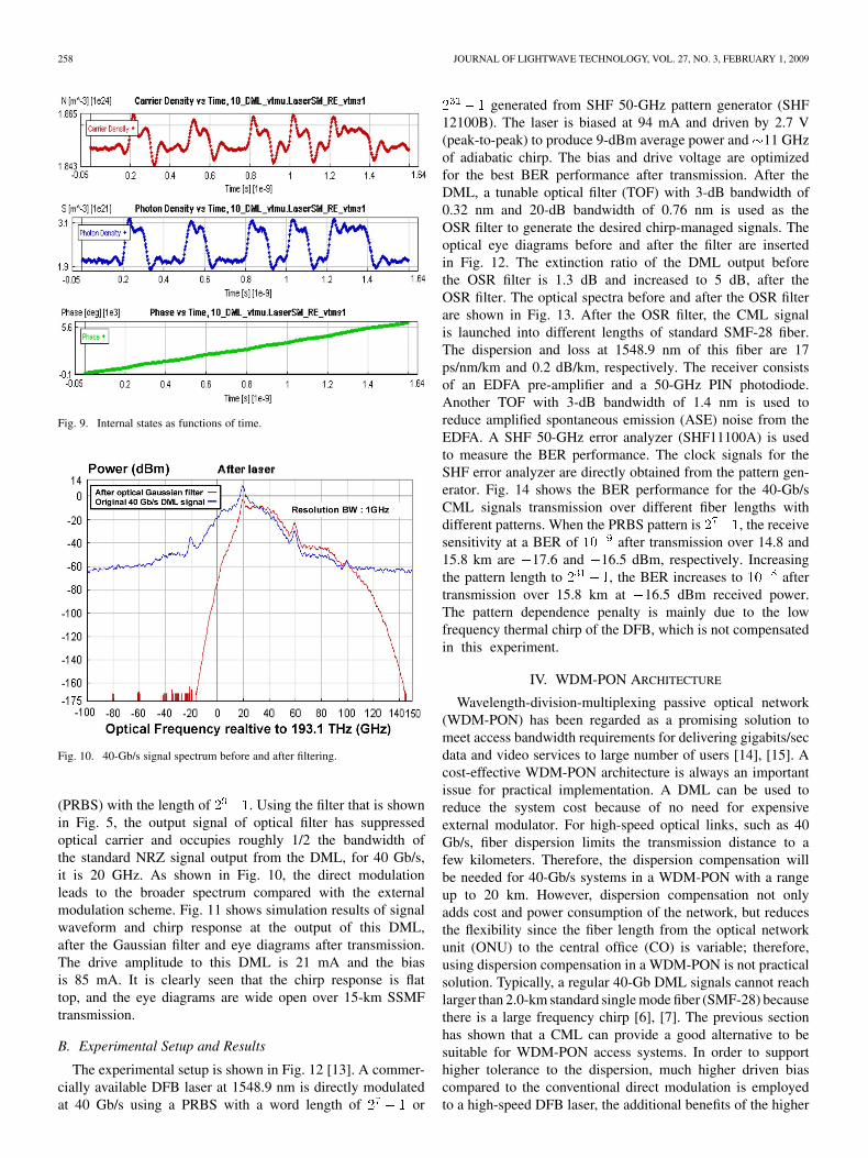
• Time related characteristics:The carrier, the photon density and the phase of the opticalfield as a function of time are shown in Fig. 9. These re-sults are based on the internal states of the rate equationmodel. We can see that the carrier and photon density havethe transient change at the drop and down of the opticalpulse, which directly related to the transient chirp. And thephoton density, the optical power, is the key to the conver-sion from amplitude modulation to frequency modulationvia the adiabatic chirp.
III. SSMF TRANSMISSION WITHOUT DISPERSION
COMPENSATION
A. Numerical Simulation Results
Using the aforementioned optimized parameters of the DMLand optical filter, we use commercial software to simulate thetransmission performance of this transmitter. Some parameters,like the type of fiber deployed in the link, are fixed. Thedispersion of the SSMF is 17 ps/nm/km, the attenuation is0.20 dB/km, and dispersion slope is s/m . Theinput power into the fiber is assumed to be 0 dBm. Allsimulations here use a time period of 1024 bits, with thesignal bits generated from a pseudorandom binary sequence
258 JOURNAL OF LIGHTWAVE TECHNOLOGY, VOL. 27, NO. 3, FEBRUARY 1, 2009
Fig. 9. Internal states as functions of time.
Fig. 10. 40-Gb/s signal spectrum before and after filtering.
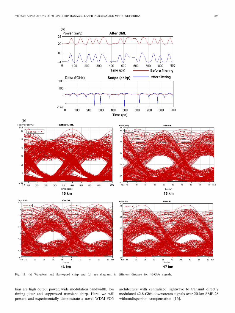
(PRBS) with the length of . Using the filter that is shownin Fig. 5, the output signal of optical filter has suppressedoptical carrier and occupies roughly 1/2 the bandwidth ofthe standard NRZ signal output from the DML, for 40 Gb/s,it is 20 GHz. As shown in Fig. 10, the direct modulationleads to the broader spectrum compared with the externalmodulation scheme. Fig. 11 shows simulation results of signalwaveform and chirp response at the output of this DML,after the Gaussian filter and eye diagrams after transmission.The drive amplitude to this DML is 21 mA and the biasis 85 mA. It is clearly seen that the chirp response is flattop, and the eye diagrams are wide open over 15-km SSMFtransmission.
B. Experimental Setup and Results
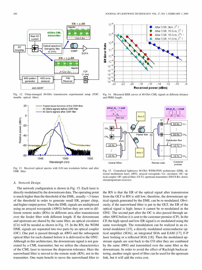
The experimental setup is shown in Fig. 12 [13]. A commer-cially available DFB laser at 1548.9 nm is directly modulatedat 40 Gb/s using a PRBS with a word length of or
generated from SHF 50-GHz pattern generator (SHF12100B). The laser is biased at 94 mA and driven by 2.7 V(peak-to-peak) to produce 9-dBm average power and 11 GHzof adiabatic chirp. The bias and drive voltage are optimizedfor the best BER performance after transmission. After theDML, a tunable optical filter (TOF) with 3-dB bandwidth of0.32 nm and 20-dB bandwidth of 0.76 nm is used as theOSR filter to generate the desired chirp-managed signals. Theoptical eye diagrams before and after the filter are insertedin Fig. 12. The extinction ratio of the DML output beforethe OSR filter is 1.3 dB and increased to 5 dB, after theOSR filter. The optical spectra before and after the OSR filterare shown in Fig. 13. After the OSR filter, the CML signalis launched into different lengths of standard SMF-28 fiber.The dispersion and loss at 1548.9 nm of this fiber are 17ps/nm/km and 0.2 dB/km, respectively. The receiver consistsof an EDFA pre-amplifier and a 50-GHz PIN photodiode.Another TOF with 3-dB bandwidth of 1.4 nm is used toreduce amplified spontaneous emission (ASE) noise from theEDFA. A SHF 50-GHz error analyzer (SHF11100A) is usedto measure the BER performance. The clock signals for theSHF error analyzer are directly obtained from the pattern gen-erator. Fig. 14 shows the BER performance for the 40-Gb/sCML signals transmission over different fiber lengths withdifferent patterns. When the PRBS pattern is , the receivesensitivity at a BER of after transmission over 14.8 and15.8 km are 17.6 and 16.5 dBm, respectively. Increasingthe pattern length to , the BER increases to aftertransmission over 15.8 km at 16.5 dBm received power.The pattern dependence penalty is mainly due to the lowfrequency thermal chirp of the DFB, which is not compensatedin this experiment.
IV. WDM-PON ARCHITECTURE
Wavelength-division-multiplexing passive optical network(WDM-PON) has been regarded as a promising solution tomeet access bandwidth requirements for delivering gigabits/secdata and video services to large number of users [14], [15]. Acost-effective WDM-PON architecture is always an importantissue for practical implementation. A DML can be used toreduce the system cost because of no need for expensiveexternal modulator. For high-speed optical links, such as 40Gb/s, fiber dispersion limits the transmission distance to afew kilometers. Therefore, the dispersion compensation willbe needed for 40-Gb/s systems in a WDM-PON with a rangeup to 20 km. However, dispersion compensation not onlyadds cost and power consumption of the network, but reducesthe flexibility since the fiber length from the optical networkunit (ONU) to the central office (CO) is variable; therefore,using dispersion compensation in a WDM-PON is not practicalsolution. Typically, a regular 40-Gb DML signals cannot reachlarger than 2.0-km standard single mode fiber (SMF-28) becausethere is a large frequency chirp [6], [7]. The previous sectionhas shown that a CML can provide a good alternative to besuitable for WDM-PON access systems. In order to supporthigher tolerance to the dispersion, much higher driven biascompared to the conventional direct modulation is employedto a high-speed DFB laser, the additional benefits of the higher
YU et al.: APPLICATIONS OF 40-Gb/s CHIRP-MANAGED LASER IN ACCESS AND METRO NETWORKS 259
Fig. 11. (a) Waveform and flat-topped chirp and (b) eye diagrams in different distance for 40-Gb/s signals.
bias are high output power, wide modulation bandwidth, lowtiming jitter and suppressed transient chirp. Here, we willpresent and experimentally demonstrate a novel WDM-PON
architecture with centralized lightwave to transmit directlymodulated 42.8-Gb/s downstream signals over 20-km SMF-28withoutdispersion compensation [16].
260 JOURNAL OF LIGHTWAVE TECHNOLOGY, VOL. 27, NO. 3, FEBRUARY 1, 2009
Fig. 12. Chirp-managed 40-Gb/s transmission experimental setup (TOF:tunable optical filter).
Fig. 13. Received optical spectra with 0.01-nm resolution before and afterOSR filter.
A. Network Design
The network configuration is shown in Fig. 15. Each laser isdirectly modulated by the downstream data. The operating pointis much higher than the threshold of the DML, usually 3 timesof the threshold in order to generate small ER, proper chirp,and higher output power. Then the DML signals are multiplexedusing an arrayed waveguide (AWG) before they are sent to dif-ferent remote nodes (RNs) in different area after transmissionover the feeder fiber with different length. If the downstreamand upstream are shared by the same fiber, an optical circulator(Cir) will be needed as shown in Fig. 15. In the RN, the WDMDML signals are separated into two parts by an optical coupler(OC). One part is passed through an AWG and the subsequentoptical filter for each channel before it is delivered to the ONU.Although in this architecture, the downstream signal is not gen-erated by a CML transmitter, but we utilize the characteristicsof the CML laser to increase the dispersion tolerance. Here thenarrowband filter is moved to the remote node (RN), not in thetransmitter. One main benefit to move the narrowband filter to
Fig. 14. Measured BER curves of 40-Gb/s CML signals in different distanceand PRBS length.
Fig. 15. Centralized lightwave 40-Gb/s WDM-PON architecture (DML: di-rected modulation laser; AWG: arrayed waveguide; Cir: circulator; OC: op-tical coupler; OF: optical filter; US Tx: upstream transmitter; DS/US Rx: down-stream/upstream receiver).
the RN is that the ER of the optical signal after transmissionfrom the OLT to RN is still low; therefore, the downstream op-tical signals generated by the DML can be re-modulated. Obvi-ously, if the narrowband filter is put in the OLT, the ER of theoptical signal is high; hence it cannot be re-modulated in theONU. The second part after the OC is also passed through an-other AWG before it is sent to the customer premise (CP). In theCP, the high-speed and low-ER signal is re-modulated using thesame wavelength. The remodulation can be realized in an ex-ternal modulator [15], a directly modulated semiconductor op-tical amplifier (SOA), an integrated SOA and EAM [17], F-Plaser locking or a reflected SOA [18]. Then the modulated up-stream signals are sent back to the CO after they are combinedby the same AWG and transmitted over the same fiber as thedownstream. In order to avoid the effect of Rayleigh backscat-tering, another single spool of fiber can be used for the upstreamlink, but it will add the extra cost.
YU et al.: APPLICATIONS OF 40-Gb/s CHIRP-MANAGED LASER IN ACCESS AND METRO NETWORKS 261
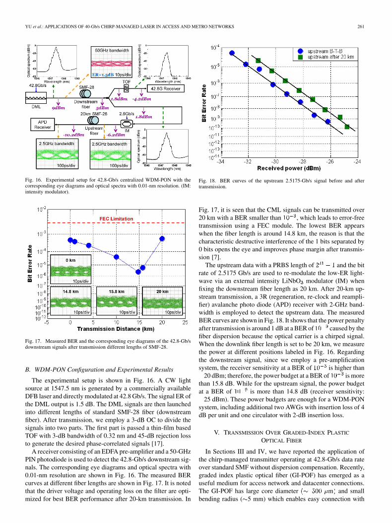
Fig. 16. Experimental setup for 42.8-Gb/s centralized WDM-PON with thecorresponding eye diagrams and optical spectra with 0.01-nm resolution. (IM:intensity modulator).
Fig. 17. Measured BER and the corresponding eye diagrams of the 42.8-Gb/sdownstream signals after transmission different lengths of SMF-28.
B. WDM-PON Configuration and Experimental Results
The experimental setup is shown in Fig. 16. A CW lightsource at 1547.5 nm is generated by a commercially availableDFB laser and directly modulated at 42.8 Gb/s. The signal ER ofthe DML output is 1.5 dB. The DML signals are then launchedinto different lengths of standard SMF-28 fiber (downstreamfiber). After transmission, we employ a 3-dB OC to divide thesignals into two parts. The first part is passed a thin-film basedTOF with 3-dB bandwidth of 0.32 nm and 45-dB rejection lossto generate the desired phase-correlated signals [17].
A receiver consisting of an EDFA pre-amplifier and a 50-GHzPIN photodiode is used to detect the 42.8-Gb/s downstream sig-nals. The corresponding eye diagrams and optical spectra with0.01-nm resolution are shown in Fig. 16. The measured BERcurves at different fiber lengths are shown in Fig. 17. It is notedthat the driver voltage and operating loss on the filter are opti-mized for best BER performance after 20-km transmission. In
Fig. 18. BER curves of the upstream 2.5175-Gb/s signal before and aftertransmission.
Fig. 17, it is seen that the CML signals can be transmitted over20 km with a BER smaller than , which leads to error-freetransmission using a FEC module. The lowest BER appearswhen the fiber length is around 14.8 km, the reason is that thecharacteristic destructive interference of the 1 bits separated by0 bits opens the eye and improves phase margin after transmis-sion [7].
The upstream data with a PRBS length of and the bitrate of 2.5175 Gb/s are used to re-modulate the low-ER light-wave via an external intensity LiNbO modulator (IM) whenfixing the downstream fiber length as 20 km. After 20-km up-stream transmission, a 3R (regeneration, re-clock and reampli-fier) avalanche photo diode (APD) receiver with 2-GHz band-width is employed to detect the upstream data. The measuredBER curves are shown in Fig. 18. It shows that the power penaltyafter transmission is around 1 dB at a BER of caused by thefiber dispersion because the optical carrier is a chirped signal.When the downlink fiber length is set to be 20 km, we measurethe power at different positions labeled in Fig. 16. Regardingthe downstream signal, since we employ a pre-amplificationsystem, the receiver sensitivity at a BER of is higher than
20 dBm; therefore, the power budget at a BER of is morethan 15.8 dB. While for the upstream signal, the power budgetat a BER of is more than 14.8 dB (receiver sensitivity:
25 dBm). These power budgets are enough for a WDM-PONsystem, including additional two AWGs with insertion loss of 4dB per unit and one circulator with 2-dB insertion loss.
V. TRANSMISSION OVER GRADED-INDEX PLASTIC
OPTICAL FIBER
In Sections III and IV, we have reported the application ofthe chirp-managed transmitter operating at 42.8-Gb/s data rateover standard SMF without dispersion compensation. Recently,graded index plastic optical fiber (GI-POF) has emerged as auseful medium for access network and datacenter connections.The GI-POF has large core diameter m and smallbending radius ( 5 mm) which enables easy connection with
262 JOURNAL OF LIGHTWAVE TECHNOLOGY, VOL. 27, NO. 3, FEBRUARY 1, 2009
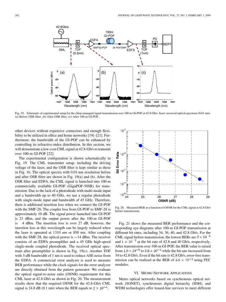
Fig. 19. Schematic of experimental setup for the chirp-managed signal transmission over 100 m GI-POF at 42.8 Gb/s. Inset: received optical spectrum (0.01 nm).(a) Before OSR filter. (b) After OSR filter. (c) After 100-m GI-POF.
other devices without expensive connectors and enough flexi-bility to be utilized in office and home networks [19]–[21]. Fur-thermore, the bandwidth of the GI-POF can be enhanced bycontrolling its refractive-index distribution. In this section, wewill demonstrate a low-cost CML signal at 42.8-Gb/s to transmitover 100-m GI-POF [22].
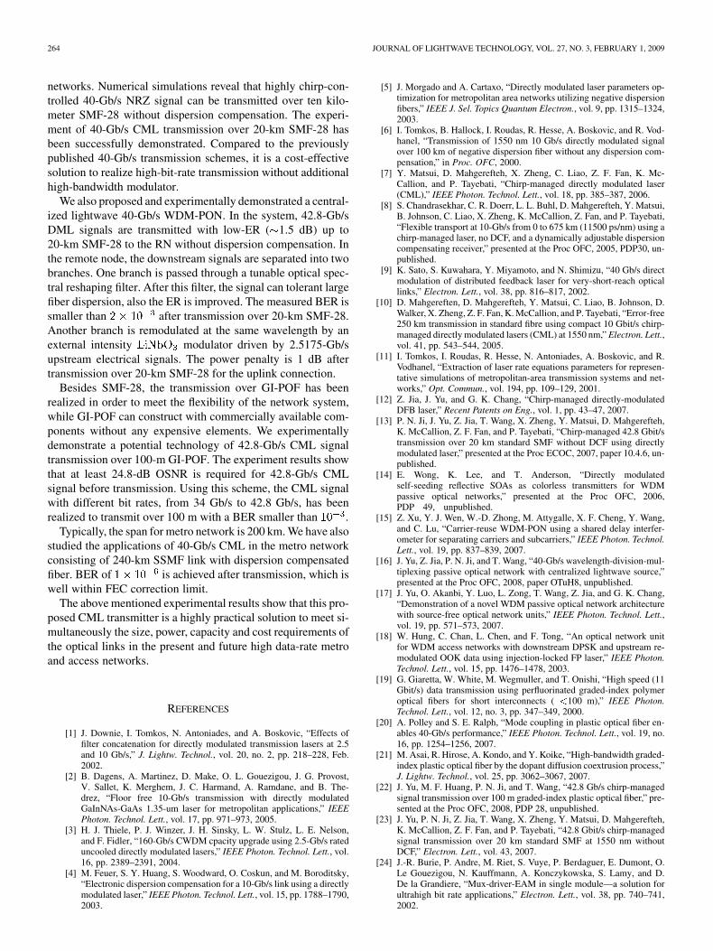
The experimental configuration is shown schematically inFig. 19. The CML transmitter setup, including the drivingvoltage of the laser, and the OSR filter is kept similar as thesein Fig. 16. The optical spectra with 0.01-nm resolution beforeand after OSR filter are shown in Fig. 19(a) and (b). After theOSR filter and EDFA, the CML signal is launched into 100-mcommercially available GI-POF (GigaPOF-50SR) for trans-mission. Due to the lack of a photodiode with multi-mode inputand a bandwidth up to 40 GHz, we use a regular photodiodewith single-mode input and bandwidth of 45 GHz. Therefore,there is additional insertion loss when we connect the GI-POFwith the SMF-28. The coupler loss from GI-POF to SMF-28 isapproximately 10 dB. The signal power launched into GI-POFis 23 dBm, and the output power after the 100-m GI-POFis 4 dBm. The insertion loss is over 27 dB, however, theinsertion loss at this wavelength can be largely reduced whenthe laser is operated at 1310 nm or 850 nm. After couplingwith the SMF-28, the optical power is 14 dBm. The receiverconsists of an EDFA preamplifier and a 45 GHz high-speedsingle-mode coupled photodiode. The received optical spec-trum after preamplifier is shown in Fig. 19(c). Another TOFwith 3-dB bandwidth of 1 nm is used to reduce ASE noise fromthe EDFA. A commercial error analyzer is used to measureBER performance while the clock signals for the error analyzerare directly obtained from the pattern generator. We evaluatethe optical signal-to-noise ratio (OSNR) requirement for thisCML laser at 42.8 Gb/s as shown in Fig. 20. The measurementresults show that the required OSNR for the 42.8-Gb/s CMLsignal is 24.8 dB (0.1 nm) when the BER equals to .
Fig. 20. Measured BER as a function of OSNR for the CML signal at 42.8 Gb/sbefore transmission.
Fig. 21 shows the measured BER performance and the cor-responding eye diagrams after 100-m GI-POF transmission atdifferent bit rates, including 34, 36, 40, and 42.8 Gb/s. For theCML signal before transmission, the lowest BERs areand at the bit rate of 42.8 and 40 Gb/s, respectively.After transmission over 100-m GI-POF, the BER value is raisedfrom to while the bit rate increased from34 to 42.8 Gb/s. Even if the bit rate is 42.8 Gb/s, error-free trans-mission can be realized at the BER of using FECmodules.
VI. METRO NETWORK APPLICATIONS
Metro optical networks based on synchronous optical net-work (SONET), synchronous digital hierarchy (SDH), andWDM technologies offer leased-line services to meet different

YU et al.: APPLICATIONS OF 40-Gb/s CHIRP-MANAGED LASER IN ACCESS AND METRO NETWORKS 263
Fig. 21. Measured BER values and the corresponding eye diagrams in differentbit rates after 100-m GI-POF transmission.
Fig. 22. Experimental setup for 42.8-Gb/s CML transmission over 240 km ofSMF-28 fiber and eye diagram (10 ps/div) after transmission.
connectivity needs. Typically, a span of a metro network isup to 200 km, however, none of the existing transmitters cansimultaneously meet the requirements for long reach, low costand low power consumption. Low power consumption can beachieved using an EAM [24]. Nevertheless, the transmissiondistance is limited within 100-km at 10-Gb/s bit rate due tothe broad spectrum associated with transient chirp. Recently, a10-Gb/s CML signal has been transmitted over 250-km SMFwith a 4.8 dB power penalty in [10]. In this section, we present42.8-Gb/s CML signal transmission results at 1547.38 nm overcompensated 240-km SMF-28 fiber. This transmitter setup iseconomical and transmission of these CML signals beyond200-km of SMF-28 at 42.8-Gb/s makes it attractive for metroarea network applications. Fig. 18 shows the setup for thisexperiment. Eye diagram after 240-km transmission is alsoincluded in figure.
The DML is driven by 42.8 Gb/s with a PRBS length of. DML is biased and OSR filter with 3-dB bandwidth of 0.32
Fig. 23. Optical spectrum before and after 240-km SMF-28 transmission ofCML signal at 42.8 Gb/s.
nm is used, which is similar to previous sections to generate aCML signal. Resulting CML signal is launched into three spansof 80-km SMF-28 and the matched dispersion compensationfiber (DCF). The EDFAs are employed as the in-line amplifiersto compensate the insertion loss of the fiber spans. Input totalpower into each span of SMF-28 is set to 8 dBm, and inputpower into corresponding DCF is set to 0 dBm for reducingnonlinear effects. The average insertion loss in 80-km SMF-28and DCF in each span is 17 and 5 dB, respectively. Seven DFBlasers with channel spacing of 200 GHz at varying wavelengthsare multiplexed using an AWG and they are also launched intothe transmission fiber to run the EDFAs in saturation enhancingsystem OSNR.
The receiver consists of an EDFA pre-amplifier and a 50 GHzPIN photodiode. Another TOF with 3-dB bandwidth of 0.5 nmis used to reduce amplified spontaneous emission (ASE) noisefrom the EDFA. BER of is measured after transmissionwhich is well above forward-error correction (FEC) thresholdwhich allow corrected BER. Optical spectra before andafter transmission are also presented in Fig. 23. The measuredeye diagram after transmission is inserted in Fig. 22.
VII. CONCLUSION
We have presented a novel transmitter consisting of a DMLand the subsequent optical Gaussian filter. The reach that thistransmitter can achieve without dispersion compensation is su-perior to the best reported DML-based and duobinary transmit-ters in access network application. The high dispersion toleranceis mainly because of the phase-correlative modulation amongthe adjacent bits by controlling the adiabatic chirp in the directmodulation. The phase flip between 0 and in the middle of thespace bit leads to destructive interference between the energieson either side of the middle of the space after the dispersion-in-duced broad spectrum. The DML signals can pass through anoptical spectral reshaping (OSR) filter to perform the FM toAM conversion by passing the “1” bits while attenuating “0”bits for increasing the ER. VPI software is used to find out theoptimum parameters of the OSR filter. We develop a high dis-persion tolerant 40-Gb/s CML transmitter at 1550 nm for ultrashort-reach optical links at high-speed data rate in the access
264 JOURNAL OF LIGHTWAVE TECHNOLOGY, VOL. 27, NO. 3, FEBRUARY 1, 2009
networks. Numerical simulations reveal that highly chirp-con-trolled 40-Gb/s NRZ signal can be transmitted over ten kilo-meter SMF-28 without dispersion compensation. The experi-ment of 40-Gb/s CML transmission over 20-km SMF-28 hasbeen successfully demonstrated. Compared to the previouslypublished 40-Gb/s transmission schemes, it is a cost-effectivesolution to realize high-bit-rate transmission without additionalhigh-bandwidth modulator.
We also proposed and experimentally demonstrated a central-ized lightwave 40-Gb/s WDM-PON. In the system, 42.8-Gb/sDML signals are transmitted with low-ER ( 1.5 dB) up to20-km SMF-28 to the RN without dispersion compensation. Inthe remote node, the downstream signals are separated into twobranches. One branch is passed through a tunable optical spec-tral reshaping filter. After this filter, the signal can tolerant largefiber dispersion, also the ER is improved. The measured BER issmaller than after transmission over 20-km SMF-28.Another branch is remodulated at the same wavelength by anexternal intensity modulator driven by 2.5175-Gb/supstream electrical signals. The power penalty is 1 dB aftertransmission over 20-km SMF-28 for the uplink connection.
Besides SMF-28, the transmission over GI-POF has beenrealized in order to meet the flexibility of the network system,while GI-POF can construct with commercially available com-ponents without any expensive elements. We experimentallydemonstrate a potential technology of 42.8-Gb/s CML signaltransmission over 100-m GI-POF. The experiment results showthat at least 24.8-dB OSNR is required for 42.8-Gb/s CMLsignal before transmission. Using this scheme, the CML signalwith different bit rates, from 34 Gb/s to 42.8 Gb/s, has beenrealized to transmit over 100 m with a BER smaller than .
Typically, the span for metro network is 200 km. We have alsostudied the applications of 40-Gb/s CML in the metro networkconsisting of 240-km SSMF link with dispersion compensatedfiber. BER of is achieved after transmission, which iswell within FEC correction limit.
The above mentioned experimental results show that this pro-posed CML transmitter is a highly practical solution to meet si-multaneously the size, power, capacity and cost requirements ofthe optical links in the present and future high data-rate metroand access networks.
REFERENCES
[1] J. Downie, I. Tomkos, N. Antoniades, and A. Boskovic, “Effects offilter concatenation for directly modulated transmission lasers at 2.5and 10 Gb/s,” J. Lightw. Technol., vol. 20, no. 2, pp. 218–228, Feb.2002.
[2] B. Dagens, A. Martinez, D. Make, O. L. Gouezigou, J. G. Provost,V. Sallet, K. Merghem, J. C. Harmand, A. Ramdane, and B. The-drez, “Floor free 10-Gb/s transmission with directly modulatedGaInNAs-GaAs 1.35-um laser for metropolitan applications,” IEEEPhoton. Technol. Lett., vol. 17, pp. 971–973, 2005.
[3] H. J. Thiele, P. J. Winzer, J. H. Sinsky, L. W. Stulz, L. E. Nelson,and F. Fidler, “160-Gb/s CWDM cpacity upgrade using 2.5-Gb/s rateduncooled directly modulated lasers,” IEEE Photon. Technol. Lett., vol.16, pp. 2389–2391, 2004.
[4] M. Feuer, S. Y. Huang, S. Woodward, O. Coskun, and M. Boroditsky,“Electronic dispersion compensation for a 10-Gb/s link using a directlymodulated laser,” IEEE Photon. Technol. Lett., vol. 15, pp. 1788–1790,2003.
[5] J. Morgado and A. Cartaxo, “Directly modulated laser parameters op-timization for metropolitan area networks utilizing negative dispersionfibers,” IEEE J. Sel. Topics Quantum Electron., vol. 9, pp. 1315–1324,2003.
[6] I. Tomkos, B. Hallock, I. Roudas, R. Hesse, A. Boskovic, and R. Vod-hanel, “Transmission of 1550 nm 10 Gb/s directly modulated signalover 100 km of negative dispersion fiber without any dispersion com-pensation,” in Proc. OFC, 2000.
[7] Y. Matsui, D. Mahgerefteh, X. Zheng, C. Liao, Z. F. Fan, K. Mc-Callion, and P. Tayebati, “Chirp-managed directly modulated laser(CML),” IEEE Photon. Technol. Lett., vol. 18, pp. 385–387, 2006.
[8] S. Chandrasekhar, C. R. Doerr, L. L. Buhl, D. Mahgerefteh, Y. Matsui,B. Johnson, C. Liao, X. Zheng, K. McCallion, Z. Fan, and P. Tayebati,“Flexible transport at 10-Gb/s from 0 to 675 km (11500 ps/nm) using achirp-managed laser, no DCF, and a dynamically adjustable dispersioncompensating receiver,” presented at the Proc OFC, 2005, PDP30, un-published.
[9] K. Sato, S. Kuwahara, Y. Miyamoto, and N. Shimizu, “40 Gb/s directmodulation of distributed feedback laser for very-short-reach opticallinks,” Electron. Lett., vol. 38, pp. 816–817, 2002.
[10] D. Mahgereften, D. Mahgerefteh, Y. Matsui, C. Liao, B. Johnson, D.Walker, X. Zheng, Z. F. Fan, K. McCallion, and P. Tayebati, “Error-free250 km transmission in standard fibre using compact 10 Gbit/s chirp-managed directly modulated lasers (CML) at 1550 nm,” Electron. Lett.,vol. 41, pp. 543–544, 2005.
[11] I. Tomkos, I. Roudas, R. Hesse, N. Antoniades, A. Boskovic, and R.Vodhanel, “Extraction of laser rate equations parameters for represen-tative simulations of metropolitan-area transmission systems and net-works,” Opt. Commun., vol. 194, pp. 109–129, 2001.
[12] Z. Jia, J. Yu, and G. K. Chang, “Chirp-managed directly-modulatedDFB laser,” Recent Patents on Eng., vol. 1, pp. 43–47, 2007.
[13] P. N. Ji, J. Yu, Z. Jia, T. Wang, X. Zheng, Y. Matsui, D. Mahgerefteh,K. McCallion, Z. F. Fan, and P. Tayebati, “Chirp-managed 42.8 Gbit/stransmission over 20 km standard SMF without DCF using directlymodulated laser,” presented at the Proc ECOC, 2007, paper 10.4.6, un-published.
[14] E. Wong, K. Lee, and T. Anderson, “Directly modulatedself-seeding reflective SOAs as colorless transmitters for WDMpassive optical networks,” presented at the Proc OFC, 2006,PDP 49, unpublished.
[15] Z. Xu, Y. J. Wen, W.-D. Zhong, M. Attygalle, X. F. Cheng, Y. Wang,and C. Lu, “Carrier-reuse WDM-PON using a shared delay interfer-ometer for separating carriers and subcarriers,” IEEE Photon. Technol.Lett., vol. 19, pp. 837–839, 2007.
[16] J. Yu, Z. Jia, P. N. Ji, and T. Wang, “40-Gb/s wavelength-division-mul-tiplexing passive optical network with centralized lightwave source,”presented at the Proc OFC, 2008, paper OTuH8, unpublished.
[17] J. Yu, O. Akanbi, Y. Luo, L. Zong, T. Wang, Z. Jia, and G. K. Chang,“Demonstration of a novel WDM passive optical network architecturewith source-free optical network units,” IEEE Photon. Technol. Lett.,vol. 19, pp. 571–573, 2007.
[18] W. Hung, C. Chan, L. Chen, and F. Tong, “An optical network unitfor WDM access networks with downstream DPSK and upstream re-modulated OOK data using injection-locked FP laser,” IEEE Photon.Technol. Lett., vol. 15, pp. 1476–1478, 2003.
[19] G. Giaretta, W. White, M. Wegmuller, and T. Onishi, “High speed (11Gbit/s) data transmission using perfluorinated graded-index polymeroptical fibers for short interconnects ( �100 m),” IEEE Photon.Technol. Lett., vol. 12, no. 3, pp. 347–349, 2000.
[20] A. Polley and S. E. Ralph, “Mode coupling in plastic optical fiber en-ables 40-Gb/s performance,” IEEE Photon. Technol. Lett., vol. 19, no.16, pp. 1254–1256, 2007.
[21] M. Asai, R. Hirose, A. Kondo, and Y. Koike, “High-bandwidth graded-index plastic optical fiber by the dopant diffusion coextrusion process,”J. Lightw. Technol., vol. 25, pp. 3062–3067, 2007.
[22] J. Yu, M. F. Huang, P. N. Ji, and T. Wang, “42.8 Gb/s chirp-managedsignal transmission over 100 m graded-index plastic optical fiber,” pre-sented at the Proc OFC, 2008, PDP 28, unpublished.
[23] J. Yu, P. N. Ji, Z. Jia, T. Wang, X. Zheng, Y. Matsui, D. Mahgerefteh,K. McCallion, Z. F. Fan, and P. Tayebati, “42.8 Gbit/s chirp-managedsignal transmission over 20 km standard SMF at 1550 nm withoutDCF,” Electron. Lett., vol. 43, 2007.
[24] J.-R. Burie, P. Andre, M. Riet, S. Vuye, P. Berdaguer, E. Dumont, O.Le Gouezigou, N. Kauffmann, A. Konczykowska, S. Lamy, and D.De la Grandiere, “Mux-driver-EAM in single module—a solution forultrahigh bit rate applications,” Electron. Lett., vol. 38, pp. 740–741,2002.
YU et al.: APPLICATIONS OF 40-Gb/s CHIRP-MANAGED LASER IN ACCESS AND METRO NETWORKS 265
Jianjun Yu (M’03–SM’04) received the B.S. degreein optics from Xiangtan University, Xiangtan, China,in 1990 and the M.E. and Ph.D. degrees in opticalcommunications from the Beijing University of Postsand Telecommunications, Beijing, in 1996 and 1999,respectively.
From June 1999 to January 2001, he was with theResearch Center COM, Technical University of Den-mark, Lyngby, as an Assistant Research Professor.From February 2001 to December 2002, he was aMember of the Technical Staff with Bell Labs’ Lu-
cent Technologies and Agere Systems in New Jersey. He joined the GeorgiaInstitute of Technology, Atlanta, in January 2003, where he was on the researchfaculty and served as Director of the Optical Network Laboratory. He is cur-rently a Member of Technical Staff of NEC Laboratories America, Princeton,NJ. He is also an Adjunct Professor with the Georgia Institute of Technologyand the Beijing University of Posts and Telecommunications. His current re-search interests include 100-Gb/s high-speed transmission systems, new mod-ulation-format techniques, radio-over-fiber systems and networks, wavelength-division-multiplexing passive optical networks and optical-label switching inoptical networks. He has coauthored more than 250 peer-reviewed journal andconference papers and is the first author of more than 100 of them. He holds twoU.S. patents and has five patents pending.
Dr. Yu is a Senior Member of the IEEE Lasers and Electro-Optics Society(LEOS). He served as a Guest Editor for a special issue, “Convergence of Op-tical and Wireless Networks,” for the JOURNAL OF LIGHTWAVE TECHNOLOGY.He is a technical committee member of the IEEE LEOS annual meetingsfrom 2005–2007 and OFC 2009. He is an Associate Editor for the JOURNAL
OF LIGHTWAVE TECHNOLOGY and the Optical Society of Americal Journal ofOptical Networks.
Zhensheng Jia (S’06) was born in Tianjin, China. Hereceived the B.E. and M.S.E degrees in physical elec-tronics and optoelectronics from Tsinghua Univer-sity, Beijing China, in 1999 and 2002, respectively.He is currently working toward the Ph.D. degree atGeorgia Institute of Technology, Atlanta.
During 2002–2004, he was a Research Engineeron transport and access networks in the OpticalSystem and Network Lab, Technical Division,China Telecom Beijing Research Institute (CTBRI),Beijing. His research interests include optical mil-
limeter-wave signal generation, transmission and processing for symmetricoptical-wireless access networks, high-speed TDM/WDM PON, ultrahighdata rate (100 Gb/s) optical transmission systems, and nonlinear optical signalprocessing.
Mr. Jia was one of the recipients of the 2007 IEEE/LEOS Graduate Stu-dents Fellowship Award and the 2008 PSC Bor-Uei Chen Memorial Scholar-ship Award.
Ming-Fang Huang (S’04) received the B.S. degreein physics from Tamkang University, Taipei, Taiwan,in 2001 and the M.E. and Ph.D. degrees in electro-optical engineering from National Chiao Tung Uni-versity, Hsinchu, Taiwan, in 2003 and 2007, respec-tively.
She is currently a Postdoctoral Fellow with theSchool of Electrical and Computer Engineering,Georgia Institute of Technology, Atlanta. Her currentresearch interests include long-haul transmission,new modulation format technologies, wavelength-di-
vision multiplexing passive optical network, time-division-multiplexing passiveoptical network, and radio-over-fiber systems.
Muhammad Harris , photograph and biography not available at the time ofpublication.
Philip N. Ji , photograph and biography not available at the time of publication.
Ting Wang , photograph and biography not available at the time of publication.
Gee-Kung Chang (F’05) received the B.Sc. de-gree from National Tsinghua University, Hsinchu,Taiwan, and the M.Sc. and Ph.D. degrees from theUniversity of California, Riverside, all in physics.
He is the Byers Endowed Chair Professor inOptical Networking in the School of Electrical andComputer Engineering, Georgia Institute of Tech-nology (Georgia Tech), Atlanta. He is an EminentScholar of Georgia Research Alliance. He serves asthe leader and Associate Director of OptoelectronicsIntegration and Packaging Alliance of National
Science Foundation-funded ERC Microsystem Packaging Research Center atGeorgia Tech. He is also an Associate Director of Georgia Tech BroadbandInstitute. He devoted a total of 23 years of service to the Bell Systems—BellLabs, Bellcore, and Telcordia Technologies where he served in various researchand management positions, including Director and Chief Scientist of OpticalInternet Research, Director of the Optical Networking Systems and Testbed,Director of the Optical System Integration and Network Interoperability. Priorto joining Georgia Tech, he served as Vice President and Chief TechnologyStrategist of OpNext, Inc., a spin-out of Hitachi Telecom, where he was incharge of technology planning and product strategy for advanced high-speedoptoelectronic components and systems for computing and communicationsystems. He has been granted 40 U.S. patents in the area of optoelectronic de-vices, high-speed integrated circuits, optoelectronics switching components forcomputing and communication systems, WDM optical networking elementsand systems, multiwavelength optical networks, optical network security,optical label switching routers, and optical interconnects for next generationservers and computers. He has coauthored over 230 peer-reviewed journal andconference papers.
Dr. Chang is a Fellow of the Optical Society of America, the IEEE Lasers andElectro-Optics Society, and the Photonic Society of Chinese-Americans. He wasthe recipient of Bellcore President’s Award in 1994 for his leadership role in Op-tical Networking Technology Consortium. He won the R&D 100 Award in 1996for his contribution to Network Access Module. He was elected as a TelcordiaFellow in 1999 for pioneering work in optical networking project, MONET andNGI. He has been serving in many IEEE LEOS and OSA conferences and com-mittees. He has served three times as the lead guest editor for special issues ofthe JOURNAL OF LIGHTWAVE TECHNOLOGY. The first issue was published in De-cember 2000 on Optical Networks, the second one in November 2004 on Metroand Access Networks, and an upcoming one in 2007 on Convergence of OpticalWireless Access Networks.