Application Report Using Texas Instruments Spice Models in PSpice
15
Application Report SLOA070 – September 2001 1 Using Texas Instruments Spice Models in PSpice Bruce Carter ABSTRACT Texas Instruments provides Spice models for operational amplifiers. These Spice models, however, are in a generic text format. This note describes how to take these models and import them into the most widely used simulation program—PSpice ™ . Contents 1 Introduction .................................................................................................................................. 2 2 Obtaining the Spice Model .......................................................................................................... 2 3 Create a PSpice Model ................................................................................................................. 4 4 Edit the Part Symbol .................................................................................................................... 5 5 Simulating With the Part Symbol ................................................................................................ 7 5.1 Creating a Simulation Profile ............................................................................................... 8 5.2 Drawing the Schematic ...................................................................................................... 10 5.3 Displaying the Simulation Results .................................................................................... 11 6 Conclusions................................................................................................................................ 12 7 Appendix A: Example Spice Model ........................................................................................... 13 List of Figures 1 Searching for a Part on the Texas Instruments Home Page ....................................................................... 2 2 Search Results ................................................................................................................................................. 2 3 Technical Documentation Box ....................................................................................................................... 3 4 Spice Model Link .............................................................................................................................................. 3 5 Example of How to Download File to Disk .................................................................................................... 3 6 PSpice Model Editor Icon ................................................................................................................................ 4 7 Suggested Storage Location for New Library ............................................................................................... 4 8 Creating an OrCad Capture Library ............................................................................................................... 4 9 Status File Created by a Good Spice Model .................................................................................................. 5 10 OrCad Capture Icon ......................................................................................................................................... 5 11 Library Editing Window ................................................................................................................................... 5 12 Raw Part Symbol .............................................................................................................................................. 6 13 Pin Number Assignments for the THS4131 ................................................................................................... 6 14 Progressive Steps in Making Part Symbol .................................................................................................... 7 15 Creating a New Project .................................................................................................................................... 8 16 Creating a New Simulation Profile ................................................................................................................. 8 17 Simulation Type and Frequency Settings ..................................................................................................... 9 18 Adding the Library to the Simulation Profile................................................................................................. 9 19 Adding the New Library to Capture.............................................................................................................. 10 20 Example PSpice Schematic .......................................................................................................................... 11 21 Simulation Results ......................................................................................................................................... 12 PSpice is a trademark of Cadence. All other trademarks are the property of their respective owners.
-
Upload
independent -
Category
Documents
-
view
6 -
download
0
Transcript of Application Report Using Texas Instruments Spice Models in PSpice

Application Report SLOA070 – September 2001
1
Using Texas Instruments Spice Models in PSpice Bruce Carter
ABSTRACT
Texas Instruments provides Spice models for operational amplifiers. These Spice models, however, are in a generic text format. This note describes how to take these models and import them into the most widely used simulation program—PSpice™.
Contents 1 Introduction .................................................................................................................................. 2 2 Obtaining the Spice Model .......................................................................................................... 2 3 Create a PSpice Model ................................................................................................................. 4 4 Edit the Part Symbol .................................................................................................................... 5 5 Simulating With the Part Symbol ................................................................................................ 7
5.1 Creating a Simulation Profile............................................................................................... 8 5.2 Drawing the Schematic ...................................................................................................... 10 5.3 Displaying the Simulation Results .................................................................................... 11
6 Conclusions................................................................................................................................ 12 7 Appendix A: Example Spice Model........................................................................................... 13
List of Figures
1 Searching for a Part on the Texas Instruments Home Page ....................................................................... 2 2 Search Results ................................................................................................................................................. 2 3 Technical Documentation Box ....................................................................................................................... 3 4 Spice Model Link.............................................................................................................................................. 3 5 Example of How to Download File to Disk .................................................................................................... 3 6 PSpice Model Editor Icon ................................................................................................................................ 4 7 Suggested Storage Location for New Library............................................................................................... 4 8 Creating an OrCad Capture Library ............................................................................................................... 4 9 Status File Created by a Good Spice Model.................................................................................................. 5 10 OrCad Capture Icon ......................................................................................................................................... 5 11 Library Editing Window................................................................................................................................... 5 12 Raw Part Symbol.............................................................................................................................................. 6 13 Pin Number Assignments for the THS4131................................................................................................... 6 14 Progressive Steps in Making Part Symbol .................................................................................................... 7 15 Creating a New Project .................................................................................................................................... 8 16 Creating a New Simulation Profile ................................................................................................................. 8 17 Simulation Type and Frequency Settings ..................................................................................................... 9 18 Adding the Library to the Simulation Profile................................................................................................. 9 19 Adding the New Library to Capture.............................................................................................................. 10 20 Example PSpice Schematic .......................................................................................................................... 11 21 Simulation Results......................................................................................................................................... 12
PSpice is a trademark of Cadence. All other trademarks are the property of their respective owners.
SLOA070
2 Using Texas Instruments Spice Models in PSpice
1 Introduction Spice models have been a mainstay of applications departments at semiconductor companies for decades. They have been provided for simulation purposes, and distributed in print, floppy disk—more recently through CDs and the World Wide Web. They are provided in ASCII text format, which is generic and allows importation into a variety of programs.
Unfortunately, the world has long since progressed beyond ASCII text entry Spice. The author remembers college classes where Spice was implemented on a mainframe. The schematic was reduced to numbered nodes, and each connection was painstakingly typed onto a punch card. Years later, the schematic was typed into an ASCII .cir file and PSpice was run from DOS, the resulting table of results seemed almost magical.
Microsoft Windows introduced a new element to PSpice—graphical interface. Designers, finally free of the need to meticulously type in ASCII files, could access part symbols and draw schematics on the screen—the designers produced schematics for documentation. The intuitive advantage is obvious: instead of a list of circuit connections, the designer can see the schematic. The chance of error transcribing a schematic into a list of connections is all but eliminated. There is a problem, however. The parts available to the designer are limited to the list available in the program’s library. From the very beginning, PSpice has provided a method to enter new part symbols, but few designers have been able to understand the process, which is anything but intuitive. This document walks the designer through the process with a THS4131.
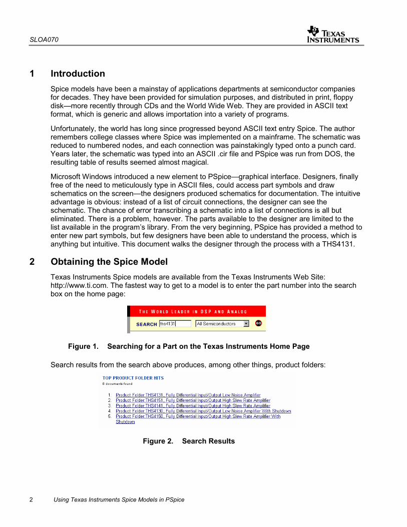
2 Obtaining the Spice Model Texas Instruments Spice models are available from the Texas Instruments Web Site: http://www.ti.com. The fastest way to get to a model is to enter the part number into the search box on the home page:
Figure 1. Searching for a Part on the Texas Instruments Home Page
Search results from the search above produces, among other things, product folders:
Figure 2. Search Results

SLOA070
Using Texas Instruments Spice Models in PSpice 3
The product folder conveniently places all documentation related to the part in one place. Click on the device product folder for the desired device. When the product folder comes up, the Spice models are found in the lower left hand side of the product folder in the technical documentation box, related docs link:
Figure 3. Technical Documentation Box
When the related docs link is clicked, the link to the Spice model comes up.
Figure 4. Spice Model Link
Different web browsers behave differently when the link is clicked. Designers need to save the ASCII text file to the desired location on their hard drive:
Figure 5. Example of How to Download File to Disk
This download example is from Internet Explorer 5.5. Take note of the filename, and the folder name where it is placed—both are needed in a moment.
Texas Instruments Spice models are stored in the .zip format. The designer needs to have some type of decompression software, such as WinZip, to extract the actual Spice model file from the .zip archive. Once that has been done, the designer has the file shown in Appendix A, slom129_1.txt.

SLOA070
4 Using Texas Instruments Spice Models in PSpice
A quick examination shows that it is essentially a .cir file—a legacy from PSpice’s past. This document describes how to create a PSpice symbol. PSpice is the most widely used simulation program, but these techniques are similar in many CAD programs, so hopefully this note provides some general guidance for the designer with a different simulation program.
3 Create a PSpice Model Open the PSpice model editor (not the Capture program). Figure 6 shows the Model Editor icon:
Figure 6. PSpice Model Editor Icon
When the program opens, select File, then New.
Next select Model, Import, and then the file name of the model. The ASCII text file appears in the right window, and the left window shows that the model name is THS4131, and the type is SUBCKT.
Next do a File, Save, and give it a filename.
• Suggestion 1: Make the library name the same name as the part, because it may be the only part that has to be created.
• Suggestion 2: Save it in the UserLib folder:
Figure 7. Suggested Storage Location for New Library
Next, do a File, Create Capture Parts. A dialog Box appears. Browse to the location where the new library is stored, and select it. The bottom box is then filled with the same filename, in the same location, with a .olb extension:
Figure 8. Creating an OrCad Capture Library

SLOA070
Using Texas Instruments Spice Models in PSpice 5
Click OK, and the library should create with no errors:
Figure 9. Status File Created by a Good Spice Model
Click OK to close the status file, and exit the model editor. There should now be two files in the destination directory—THS4131.lib and ths4131.olb. Both are necessary for simulation.
4 Edit the Part Symbol It is now time to edit the part symbol created above. The procedure above created an OrCad capture library with a single part in it—the THS4131. Libraries are edited in OrCad capture. Double click on the capture icon:
Figure 10. OrCad Capture Icon
Next, go to File, Open, Library, and browse to the location of THS4131.olb. Then click on Open.
A window opens that listing the parts in the library:
Figure 11. Library Editing Window
Double click on the name THS4131. The part symbol comes up on the screen:

SLOA070
6 Using Texas Instruments Spice Models in PSpice
Figure 12. Raw Part Symbol
For a designer used to the triangle graphic for operational amplifiers, who knows what the pin numbers should be—this is not very useful. At this point, open a Notepad window with Spice model raw text file. Looking at the text in Appendix A, the numbers inside the box in the symbol above represent the following pins:
• 1: Noninverting Input
• 2: Inverting Input
• 3: Positive Supply
• 4: Negative Supply
• 5: Noninverting Output
• 5B: Inverting Output
• 17: V(OCM)
The numbers on the outside of the box have no relationship to the pin numbers on the IC. There is a lot of work to be done to make the OrCad part symbol usable. Pin number assignments can be obtained from the data sheet:
Figure 13. Pin Number Assignments for the THS4131
Figure 14 shows the steps involved in making a usable part symbol from the raw symbol:

SLOA070
Using Texas Instruments Spice Models in PSpice 7
Figure 14. Progressive Steps in Making Part Symbol
There is some artistic license involved in the creation of a part symbol. The process described here creates a symbol, although not necessarily the best symbol. The steps used to create the part symbol above were:
1. In the part editor window, go to Option, Part Properties, Pin Names Visible (in box), and then False. The pin names inside the box disappear—a good thing, because they were confusing.
2. Select and delete the box. The proper outline for an op amp is a triangle.
3. Resize the part outline. A lot of op amps are drawn on a 0.4 by 0.4 grid.
4. Use the line tool to create the triangle outline of an op amp body.
5. Move the pins and labels to the desired positions. In this case, the inverting input will be on the top left, the + and – power will be on the top and bottom, respectively, the outputs are on the right, and V(OCM) is on the bottom.
6. Edit the pin numbers and pin types. Do not change the pin name because that is the way the symbol relates back to the Spice model. When a V(OCM) pin is present, it should be a bidirectional type. Everything else can be input or output. The example shows the power pins as inputs. If they are given the type power, they are invisible.
7. Use the text tool to add the - and + to the inputs.
8. Use the circle and line tools to finish graphical details. Note that the inverting input is opposite the noninverting output and vice versa. This is best for completing feedback loops.
When the part symbol is correct, save the library. The program also prompts to save the part.
5 Simulating With the Part Symbol Schematics are drawn, and PSpice simulations are run from within the capture program, the same program used to edit the library symbol above.

SLOA070
8 Using Texas Instruments Spice Models in PSpice
5.1 Creating a Simulation Profile
Choose File, New, Project. When a dialog box appears, enter a name, and enable the Analog and Mixed A/D radio button:
Figure 15. Creating a New Project
Then click OK. A second dialog box appears allowing the user to either create a blank project or clone an existing project. If this is a first time design, or if it is very different from existing projects, then select blank. This document assumes no prior simulation profile exists, and blank was selected.
Figure 16. Creating a New Simulation Profile
The simulation profile name does not have to be the same name as the project, but it can be. The process of creating a simulation profile involves several steps, as can be seen on the next dialog box.

SLOA070
Using Texas Instruments Spice Models in PSpice 9
Figure 17. Simulation Type and Frequency Settings
Fortunately for the designer, the defaults are chosen well. It is important to set the Analysis type, whether the sweep is logarithmic or linear, the start frequency, end frequency, and points per decade. For this example, a logarithmic AC Sweep was selected, with a start frequency of 100 Hz and an end frequency of 1 MHz. Be careful with the number of points per decade; they can increase the file size and execution time. One hundred is usually sufficient for all but the most detailed linear sweeps.
The next step is to add the library (.lib) file to the simulation profile. Click on the Library tab:
Figure 18. Adding the Library to the Simulation Profile
Browse to the location of the .lib file, and select either Add as Global or Add to Design. If the part is used in multiple projects, add it as a global. Click OK, and the simulation profile is saved.

SLOA070
10 Using Texas Instruments Spice Models in PSpice
5.2 Drawing the Schematic
At this point, the schematic can be drawn. This document assumes that the designer is familiar with PSpice and how to draw a schematic in Capture with the symbols required to simulate properly.
Prior to placing the new part in the schematic, it is necessary to add the library to the library list:
Figure 19. Adding the New Library to Capture
First, click the Add Library box. Then browse to the location of the new library. Once it has been added, then highlight the part in the part list. The schematic symbol should appear in the lower right hand corner, and it is available for placement once OK has been clicked.
The example below shows the THS 4131 used as a unity gain, one pole low-pass filter. The dc voltage labels do not appear until the circuit has been simulated.

SLOA070
Using Texas Instruments Spice Models in PSpice 11
Figure 20. Example PSpice Schematic
5.3 Displaying the Simulation Results
To run the simulation from the simulation profile, select PSpice, Run. When the probe window appears, the plot will be blank. Select Trace, Add Trace, and then the voltage or current desired.
• Suggestion: The right hand box has mathematical operators. The DB() operator is very convenient. When it is clicked, it appears in the bottom box.
The desired trace in this case is the differential gain. This requires a little work on the part of the designer. The way to get the differential output is to use the DB() operator, then the difference of the two outputs in the ()’s:
DB(V(OUT+)-V(OUT-))
When the plot comes up, the designer may want to change the axis settings and / or window size. A little experimentation yields the desired results.
Figure 21 shows the simulation results:

SLOA070
12 Using Texas Instruments Spice Models in PSpice
Figure 21. Simulation Results
This is the result that is expected, so the Spice model has been successfully translated into a PSpice simulation.
6 Conclusions Texas Instruments Spice models, in their downloaded form, are not directly usable in PSpice. They can be used successfully following the procedure given in this note.
SLOA070
Using Texas Instruments Spice Models in PSpice 13
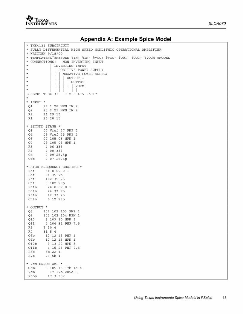
Appendix A: Example Spice Model * THS4131 SUBCIRCUIT * FULLY DIFFERENTIAL HIGH SPEED MONLITHIC OPERATIONAL AMPLIFIER * WRITTEN 9/18/00 * TEMPLATE=X^@REFDES %IN+ %IN- %VCC+ %VCC- %OUT+ %OUT- %VOCM @MODEL * CONNECTIONS: NON-INVERTING INPUT * | INVERTING INPUT * | | POSITIVE POWER SUPPLY * | | | NEGATIVE POWER SUPPLY * | | | | OUTPUT + * | | | | | OUTPUT - * | | | | | | VOCM * | | | | | | | .SUBCKT THS4131 1 2 3 4 5 5b 17 * * INPUT * Q1 27 1 28 NPN_IN 2 Q2 25 2 29 NPN_IN 2 R2 26 29 15 R1 26 28 15 * SECOND STAGE * Q3 07 Vref 27 PNP 2 Q4 09 Vref 25 PNP 2 Q5 07 105 06 NPN 1 Q7 09 105 08 NPN 1 R3 4 06 333 R4 4 08 333 Cc 0 09 25.5p Ccb 0 07 25.5p * HIGH FREQUENCY SHAPING * Ehf 34 0 09 0 1 Lhf 34 35 7n Rhf 102 35 25 Chf 0 102 23p Ehfb 24 0 07 0 1 Lhfb 24 33 7n Rhfb 12 33 25 Chfb 0 12 23p * OUTPUT * Q8 102 102 103 PNP 1 Q9 102 102 104 NPN 1 Q10 3 103 30 NPN 5 Q11 4 104 31 PNP 7.5 R5 5 30 4 R7 31 5 4 Q8b 12 12 13 PNP 1 Q9b 12 12 15 NPN 1 Q10b 3 13 22 NPN 5 Q11b 4 15 23 PNP 7.5 R5b 5b 22 4 R7b 23 5b 4 * Vcm ERROR AMP * Gcm 0 105 16 17b 1e-4 Vcm 17 17b 285e-3 Rtop 17 3 30k

SLOA070
14 Using Texas Instruments Spice Models in PSpice
Rbot 17 4 30k Rcm 16 5 10k Ccm 16 5b 100p Rcm2 16 5b 10k Ccm2 16 5 100p * BIAS SOURCES * V1 3 Vref 1.85 I1 3 27 DC 2.1e-3 I2 3 25 DC 2.1e-3 I3 0 103 DC 1.225e-3 I4 26 4 DC 2.1e-3 I5 104 0 DC 1.86e-3 I6 0 13 DC 1.225e-3 I7 15 0 DC 1.86e-3 .MODEL NPN_IN NPN + IS=170E-18 BF=400 NF=1 VAF=100 IKF=0.0389 ISE=7.6E-18 + NE=1.13489 BR=1.11868 NR=1 VAR=4.46837 IKR=8 ISC=8E-15 + NC=1.8 RB=25 RE=0.1220 RC=20 CJE=120.2E-15 VJE=1.0888 MJE=0.381406 + VJC=0.589703 MJC=0.265838 FC=0.1 CJC=133.8E-15 XTF=272.204 TF=12.13E-12 + VTF=10 ITF=0.147 TR=3E-09 XTB=1 XTI=5 KF=7.5E-14 .MODEL NPN NPN + IS=170E-18 BF=100 NF=1 VAF=100 IKF=0.0389 ISE=7.6E-18 + NE=1.13489 BR=1.11868 NR=1 VAR=4.46837 IKR=8 ISC=8E-15 + NC=1.8 RB=250 RE=0.1220 RC=200 CJE=120.2E-15 VJE=1.0888 MJE=0.381406 + VJC=0.589703 MJC=0.265838 FC=0.1 CJC=133.8E-15 XTF=272.204 TF=12.13E-12 + VTF=10 ITF=0.147 TR=3E-09 XTB=1 XTI=5 .MODEL PNP PNP + IS=296E-18 BF=100 NF=1 VAF=100 IKF=0.021 ISE=494E-18 + NE=1.49168 BR=0.491925 NR=1 VAR=2.35634 IKR=8 ISC=8E-15 + NC=1.8 RB=250 RE=0.1220 RC=200 CJE=120.2E-15 VJE=0.940007 MJE=0.55 + VJC=0.588526 MJC=0.55 FC=0.1 CJC=133.8E-15 XTF=141.135 TF=12.13E-12 + VTF=6.82756 ITF=0.267 TR=3E-09 XTB=1 XTI=5 .ENDS

IMPORTANT NOTICE
Texas Instruments Incorporated and its subsidiaries (TI) reserve the right to make corrections, modifications,enhancements, improvements, and other changes to its products and services at any time and to discontinueany product or service without notice. Customers should obtain the latest relevant information before placingorders and should verify that such information is current and complete. All products are sold subject to TI’s termsand conditions of sale supplied at the time of order acknowledgment.
TI warrants performance of its hardware products to the specifications applicable at the time of sale inaccordance with TI’s standard warranty. Testing and other quality control techniques are used to the extent TIdeems necessary to support this warranty. Except where mandated by government requirements, testing of allparameters of each product is not necessarily performed.
TI assumes no liability for applications assistance or customer product design. Customers are responsible fortheir products and applications using TI components. To minimize the risks associated with customer productsand applications, customers should provide adequate design and operating safeguards.
TI does not warrant or represent that any license, either express or implied, is granted under any TI patent right,copyright, mask work right, or other TI intellectual property right relating to any combination, machine, or processin which TI products or services are used. Information published by TI regarding third–party products or servicesdoes not constitute a license from TI to use such products or services or a warranty or endorsement thereof.Use of such information may require a license from a third party under the patents or other intellectual propertyof the third party, or a license from TI under the patents or other intellectual property of TI.
Reproduction of information in TI data books or data sheets is permissible only if reproduction is withoutalteration and is accompanied by all associated warranties, conditions, limitations, and notices. Reproductionof this information with alteration is an unfair and deceptive business practice. TI is not responsible or liable forsuch altered documentation.
Resale of TI products or services with statements different from or beyond the parameters stated by TI for thatproduct or service voids all express and any implied warranties for the associated TI product or service andis an unfair and deceptive business practice. TI is not responsible or liable for any such statements.
Following are URLs where you can obtain information on other Texas Instruments products & applicationsolutions:
Products Applications
Amplifiers amplifier.ti.com Audio www.ti.com/audio
Data Converters dataconverter.ti.com Automotive www.ti.com/automotive
DSP dsp.ti.com Broadband www.ti.com/broadband
Interface interface.ti.com Digital Control www.ti.com/digitalcontrol
Logic logic.ti.com Military www.ti.com/military
Power Mgmt power.ti.com Optical Networking www.ti.com/opticalnetwork
Microcontrollers microcontroller.ti.com Security www.ti.com/security
Telephony www.ti.com/telephony
Video & Imaging www.ti.com/video
Wireless www.ti.com/wireless
Mailing Address: Texas Instruments
Post Office Box 655303 Dallas, Texas 75265
Copyright 2003, Texas Instruments Incorporated